Embed Size (px)
Citation preview
Ultimate Guide to Power Supplyfor Industrial Applications
Ultimate Guide to Power Supply - Industrial Applications © 2020 SL Power Electronics Corporation. All rights reserved.
Ultimate Guide to
for Industrial Applications
Power Supply
© 2020 SL Power Electronics Corporation. All rights reserved.
Ultimate Guide to Power Supplyfor Industrial Applications
Ultimate Guide to Power Supply - Industrial Applications © 2020 SL Power Electronics Corporation. All rights reserved. Page 2
CONTENTS
Considerations for choosing the optimum power supply for test equipment
What to look for in your next power supply
Power supply common mode noise
Managing interfaces in power supplies for test equipment
No load power loss measurement considerations
DoE level VI: Getting your measurement technique right
External power supplies - Energy efficiency requirements
3
7
11
15
18
20
24
Ultimate Guide to Power Supplyfor Industrial Applications
Ultimate Guide to Power Supply - Industrial Applications © 2020 SL Power Electronics Corporation. All rights reserved.
Considerations for choosing the optimum power supply for test equipment
The challenges in choosing the right power supply to use for new test equipment designs can be overcome by carefully choosing the right product for the application.
When choosing a power supply, the basic starting point involves volts and amps, cooling requirements, size, and regulatory certifications, to name a few. If the criteria for choosing were only these parameters, an engineer’s job would be easy as there would be many available options from which to choose. However, there are other important parameters that test equipment designers must consider when choosing the right power supply to integrate into their equipment. Electrical noise, in its many forms, is a major concern because the speed and accuracy of the equipment rests greatly on the ability to minimize noise, and keep it away from the sensitive electronics which sample and report the data that the equipment is designed to measure. Also important is the environment where the equipment can be used.
Electrical noise is a random or undesired fluctuation in the electrical signals or voltage source. It can be either differential mode (across power or signal lines) or common mode (between a power or signal line and a common ground) noise. Radiated noise is a form of electromagnetic interference (EMI) transmitted through the air by cables and components with AC voltages or currents. The radiated coupling can be very local; for example, between a transformer and a nearby wire or PCB trace, and become conducted noise. Differential mode noise (aka ripple and noise) can range from a few microvolts in linear type power supplies, up to hundreds of millivolts in switching types. The values for the levels of this noise are normally specified by the manufacturers in both rms and pk-pk, although the pk-pk noise is generally 10 times higher than the rms noise, and is potentially more troublesome to sensitive electronic circuits. Mitigation of the effects of this type of noise requires additional filtering, but since this noise is known when choosing the power supply, the effort required to minimize it is relatively easy.
Common mode noise (between power or signal lines and ground) on the output of a power supply is often overlooked and rarely specified on power supply datasheets. This may be due to lack of knowledge by power supply manufacturers of its impact on product performance, or that it may not be an issue for the types of applications that they target with their products. The power supply output, in some applications, is often shorted to earth or chassis in the end application. In this case, the common mode noise will likely not be an issue.
However, it can be instructive to know and understand the common mode currents that flow in the circuit while making their way to ground. If the output of the power supply is connected to chassis/earth ground somewhere on the load board (electronics circuitry), there can be common mode currents flowing through the board. In addition, if the PCB layout is not done properly, the current can flow through sensitive parts of the circuitry and cause it to malfunction.
All switching power supplies will have some level of common mode noise, the extent of which is dependent on many factors including power supply topology, filter designs and input-to-output isolation, to name a few. Since most power supply manufacturers do not specify the common mode noise performance on any of their documentation, the equipment designers are left in the dark when it comes to the common mode noise they will need to deal with. Power supplies that address common mode noise by minimizing it to practical levels, and also characterize the common mode noise profile of the units are worth serious consideration. Such power supplies will allow test equipment design engineers to determine the potential effects of this noise before spending hours or days characterizing this themselves.
Emissions, both radiated and conducted, are also a major concern when integrating a power supply into test equipment. Test equipment, like many other types of applications, needs to comply with certain levels of EMI. Both radiated emissions (RE) and conducted emissions (CE) need to be within either class A or class B of CISPR22/EN55022/FCC Part 15, depending on where the end equipment is meant to be used. Open frame power supplies typically meet class B for CE, and class A for RE. Power supplies are normally tested with
NOISE
Page 3
ENVIRONMENT
Ultimate Guide to Power Supplyfor Industrial Applications
Ultimate Guide to Power Supply - Industrial Applications © 2020 SL Power Electronics Corporation. All rights reserved.
LEVELS
1 & 2
LEVEL
3
LEVEL
4
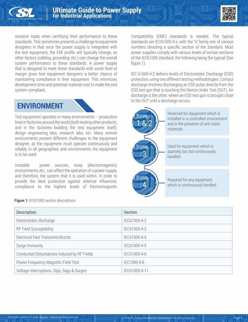
Reserved for equipment which is installed in a controlled environment and in the presence of anti-static materials.
Used for equipment which is sparsely, but not continuously handled.
Required for any equipment which is continuously handled.
Figure 1: IEC61000 section descriptions
resistive loads when certifying their performance to these standards. This sometimes presents a challenge to equipment designers in that once the power supply is integrated with the test equipment, the EMI profile will typically change, as other factors (cabling, grounding, etc.) can change the overall system performance to these standards. A power supply that is designed to meet these standards with some level of margin gives test equipment designers a better chance of maintaining compliance in their equipment. This minimizes development time and potential material cost to make the end system compliant.
Test equipment operates in many environments – production lines in factories around the world (both testing other products, and in the factories building the test equipment itself), design engineering labs, research labs, etc. Many remote environments present different challenges to the equipment designer, as the equipment must operate continuously and reliably in all geographies and environments the equipment is to be used.
Unstable power sources, noisy (electromagnetic) environments, etc., can affect the operation of a power supply, and therefore, the system that it is used within. In order to provide the best protection against external influences, compliance to the highest levels of Electromagnetic
Compatibility (EMC) standards is needed. The typical standards are IEC61000-4-x, with the “x” being one of various numbers denoting a specific section of the standard. Most power supplies comply with various levels of certain sections of the IEC61000 standard, the following being the typical (See figure 1).
IEC 61000-4-2 defines levels of Electrostatic Discharge (ESD) protection, using two different testing methodologies. Contact discharge involves discharging an ESD pulse directly from the ESD test gun that is touching the Device Under Test (DUT). Air discharge is the other, where an ESD test gun is brought close to the DUT until a discharge occurs.
Description Section
Electrostatic discharge IEC61000-4-2
RF Field Susceptibility IEC61000-4-3
Electrical Fast Transients/Bursts IEC61000-4-4
Surge Immunity IEC61000-4-5
Conducted Disturbances induced by RF Fields IEC61000-4-6
Power Frequency Magnetic Field Test IEC1000-4-8
Voltage Interruptions, Dips, Sags & Surges IEC61000-4-11
Page 4
Ultimate Guide to Power Supplyfor Industrial Applications
Ultimate Guide to Power Supply - Industrial Applications © 2020 SL Power Electronics Corporation. All rights reserved.
For test equipment which comes in contact with operators regularly, level 4 (8kV contact, 15kV air) would provide the best protection for all environments.
IEC61000-4-5 relates to the immunity requirements, test methods, and range of recommended test levels for equipment to unidirectional surges caused by over-voltages from switching and lightning transients. Several test levels are defined which relate to different environment and installation conditions. These requirements are developed for and are applicable to all types of electrical and electronic equipment, including test equipment. Areas around the world where unstable and unconditioned AC sources provide the power for test equipment – in labs, in factories, etc. will potentially subject the equipment to various surges that could potentially shut down, or even damage the equipment. Power supplies that are compliant to level 4 (4kV), will provide superior protection against high levels (2kV line-line, 4kV line-GND) of input surges.
IEC61000-4-11 defines the immunity test methods and range of preferred test levels for electrical and electronic equipment connected to low-voltage power supply networks for voltage dips, short interruptions, and voltage variations. This standard applies to electrical and electronic equipment having a rated input current not exceeding 16A per phase, for connection to 50Hz or 60Hz AC networks.
The standard describes three different tests:1. Voltage dips are defined as sudden reduction in
voltage to lower voltages for a short period of time,followed by recovery to the original voltage.
2. Short interruptions are defined as a disappearance of ACvoltage for a short period of time, typically not exceedingone minute, followed by recovery to the original voltage.Short interruptions can be considered as voltage dips tozero volts.
3. Voltage variations are gradual changes of the supplyvoltage to a higher or lower value than the rated voltage.The duration can be short or long.
The ability for a power supply to continue to operate during dips in input (mains) voltage and interruptions ensures that the equipment it is used in will also continue to function through these anomalies, minimizing any downtime. These voltage dips and interruptions vary in magnitude and length (See figure 2).
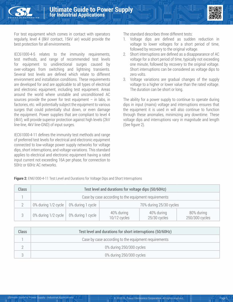
Figure 2: EN61000-4-11 Test Level and Durations for Voltage Dips and Short Interruptions
Class Test level and durations for voltage dips (50/60Hz)
1 Case by case according to the equipment requirements
2 0% during 1/2 cycle 0% during 1 cycle 70% during 25/30 cycles
3 0% during 1/2 cycle 0% during 1 cycle 40% during10/12 cycles
40% during 25/30 cycles
80% during 250/300 cycles
Class Test level and durations for short interruptions (50/60Hz)
1 Case by case according to the equipment requirements
2 0% during 250/300 cycles
3 0% during 250/300 cycles
Page 5
Ultimate Guide to Power Supplyfor Industrial Applications
Ultimate Guide to Power Supply - Industrial Applications © 2020 SL Power Electronics Corporation. All rights reserved.
Power supplies that have higher levels of hold-up time perform the best when subjected to these voltage dips and interruptions. They are able to ride through them, without output voltage deviation. Power supplies with short hold-up times will typically shut down and restart during these dips. The equipment designer will need to understand the operational nature of the equipment to determine if an intermittent shutdown is acceptable.
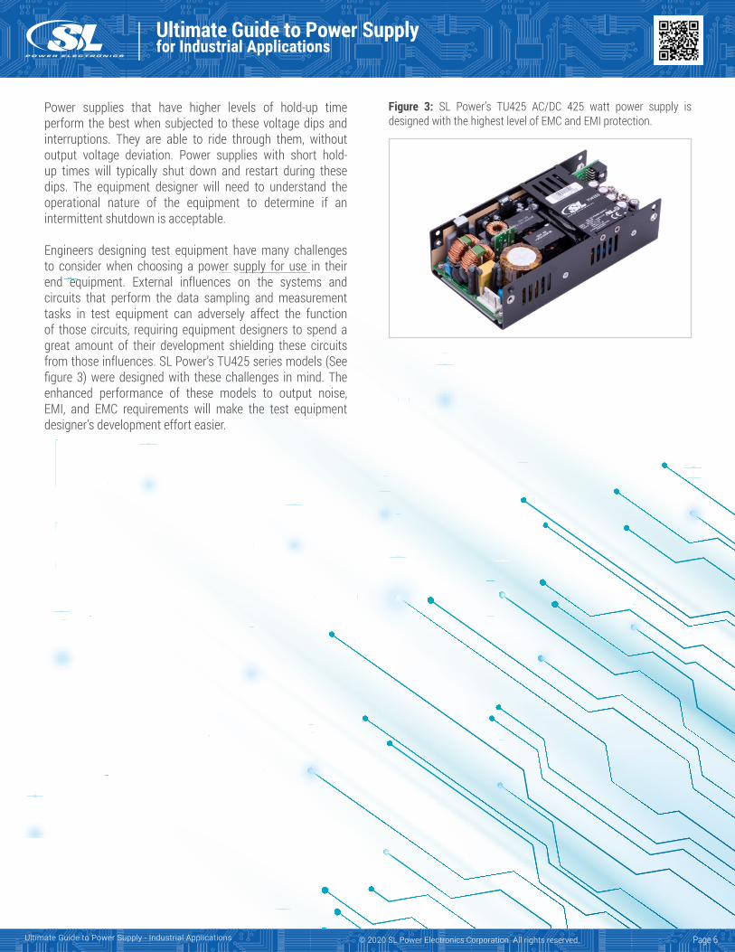
Engineers designing test equipment have many challenges to consider when choosing a power supply for use in their end equipment. External influences on the systems and circuits that perform the data sampling and measurement tasks in test equipment can adversely affect the function of those circuits, requiring equipment designers to spend a great amount of their development shielding these circuits from those influences. SL Power’s TU425 series models (See figure 3) were designed with these challenges in mind. The enhanced performance of these models to output noise, EMI, and EMC requirements will make the test equipment designer’s development effort easier.
Figure 3: SL Power’s TU425 AC/DC 425 watt power supply is designed with the highest level of EMC and EMI protection.
Page 6
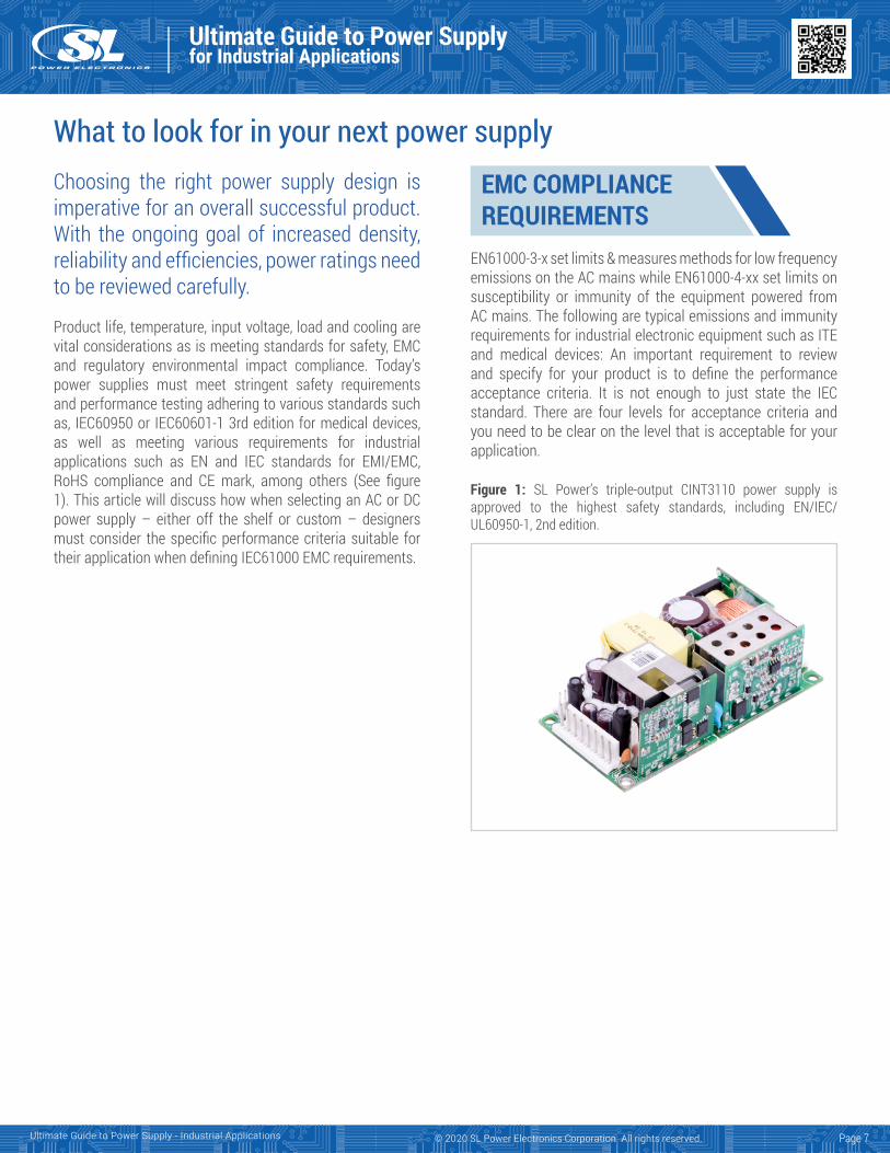
Figure 1: SL Power’s triple-output CINT3110 power supply is approved to the highest safety standards, including EN/IEC/UL60950-1, 2nd edition.
Ultimate Guide to Power Supplyfor Industrial Applications
Ultimate Guide to Power Supply - Industrial Applications © 2020 SL Power Electronics Corporation. All rights reserved.
What to look for in your next power supplyChoosing the right power supply design is imperative for an overall successful product. With the ongoing goal of increased density, reliability and efficiencies, power ratings need to be reviewed carefully.
Product life, temperature, input voltage, load and cooling are vital considerations as is meeting standards for safety, EMC and regulatory environmental impact compliance. Today’s power supplies must meet stringent safety requirements and performance testing adhering to various standards such as, IEC60950 or IEC60601-1 3rd edition for medical devices, as well as meeting various requirements for industrial applications such as EN and IEC standards for EMI/EMC, RoHS compliance and CE mark, among others (See figure 1). This article will discuss how when selecting an AC or DC power supply – either off the shelf or custom – designers must consider the specific performance criteria suitable for their application when defining IEC61000 EMC requirements.
EN61000-3-x set limits & measures methods for low frequency emissions on the AC mains while EN61000-4-xx set limits on susceptibility or immunity of the equipment powered from AC mains. The following are typical emissions and immunity requirements for industrial electronic equipment such as ITE and medical devices: An important requirement to review and specify for your product is to define the performance acceptance criteria. It is not enough to just state the IEC standard. There are four levels for acceptance criteria and you need to be clear on the level that is acceptable for your application.
EMC COMPLIANCEREQUIREMENTS
Page 7
Ultimate Guide to Power Supplyfor Industrial Applications
Ultimate Guide to Power Supply - Industrial Applications © 2020 SL Power Electronics Corporation. All rights reserved.
1. Normal performance within the specification limits.2. Temporary degradation or loss of function or performance
which is self-recoverable.3. Temporary degradation or loss of function or performance
which requires operator intervention or system reset.4. Degradation or loss of function which is not recoverable due
to damage of equipment or software or loss of data. In allcases, equipment shall not become dangerous or unsafeas a result of the application of the tests. The performanceacceptance criteria can be different for the various level orthe test.
Acceptance Criteria Section
Limits for Harmonic Current IEC61000-3-2
Limitation Voltage Fluctuation/Flicker IEC61000-3-3
High Current Voltage Fluctuation/Flicker IEC61000-3-5
Electrostatic Discharge Test IEC61000-4-2
Radiated RFI Immunity IEC61000-4-3
Electrical Fast Transients/Burst IEC61000-4-4
Main Surges IEC61000-4-5
Conducted RFI IEC61000-4-6
Harmonics and Inter-Harmonics IEC61000-4-7
Mains Frequency Magnetic Field IEC61000-4-8
Pulsed Magnetic Field IEC61000-4-9
Damped Oscillatory Magnetic Field IEC61000-4-10
Supply Voltage Dips and Interruptions IEC61000-4-11
Oscillatory Waves Immunity IEC61000-4-12
Page 8
The ESD threat is divided into four threat levels depending on material and ambient humidity. Threat level 1 is considered the least severe while threat level 4 is the most severe.
The IEC 61000-4-2 standard defines four standard levels of ESD protection, using two different testing methodologies. Contact discharge involves discharging an ESD pulse directly from the ESD test gun that is touching the device under test. This is the preferred method of testing. However, the standard provides for an alternate test methodology known as air discharge for cases where contact discharge testing is not possible. In the air discharge test, the ESD test gun is brought close to the device under test until a discharge occurs. Although this is an alternate method, it is not intended to imply that the test severity is equivalent between the test methods.
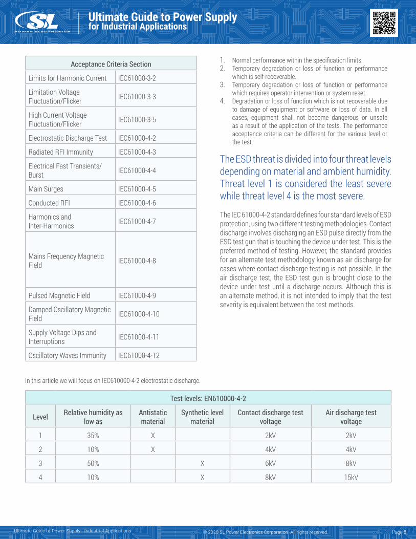
In this article we will focus on IEC610000-4-2 electrostatic discharge.
Test levels: EN610000-4-2
Level Relative humidity as low as
Antistatic material
Synthetic level material
Contact discharge test voltage
Air discharge test voltage
1 35% X 2kV 2kV
2 10% X 4kV 4kV
3 50% X 6kV 8kV
4 10% X 8kV 15kV
EN610000-4-2 POWERSUPPLY CONSIDERATIONS
Ultimate Guide to Power Supplyfor Industrial Applications
Ultimate Guide to Power Supply - Industrial Applications © 2020 SL Power Electronics Corporation. All rights reserved.
Without careful consideration of the various discharge paths within the power supply, unexpected arcing and damage to the power supply can occur. Testing to the standard and providing a test report is some assurance that the product will perform well within the confines of the specification.
Internal type power supplies are meant to be handled only during the manufacturing process, as parts are installed in end equipment. Therefore the assumption might be that the power supply is to be designed for and tested to level 3. However, as internal power supplies are increasingly being designed into portable devices such as home healthcare equipment, power supplies meeting the level 4 test parameters will provide to the end system designer a more robust power supply potentially allowing easier system compliance to level 4.
External power supplies, however, are commonly handled frequently, and therefore it would be beneficial for engineers choosing an external power supply for use with their system to opt for a power supply compliant with level 4 test levels.From both a technical and marketing (other power supply vendors already advertise level 4 compliance) perspective, it would be recommended that new products be designed and tested to the level 4 requirements.
An engineering analysis should be performed to ensure that there would not be significant unit cost adder inorder for the power supply design to be compliant with the more stringent standard, as well as a review of available test equipment to ensure that a significant capital equipment expenditure is not necessary.
From a power supply design perspective, designing a product to comply with the IEC61000-4-2 ESD requirements can be a challenge at the higher discharge voltages. This becomes even more challenging with a Class II AC input (two wire, no earth ground conductor).When the ESD discharge is applied to the output or signal pin, the voltage is developed across various isolating barriers and capacitors. This occurs because the AC mains are virtually grounded at some point so applied ESD voltage appears between the point where the charge is applied and earth ground.
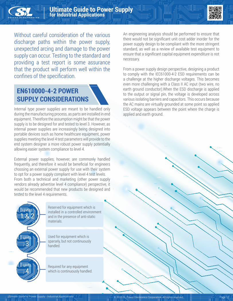
LEVELS
1 & 2
LEVEL
3
LEVEL
4
Reserved for equipment which is installed in a controlled environment and in the presence of anti-static materials.
Used for equipment which is sparsely, but not continuously handled.
Required for any equipment which is continuously handled.
Page 10
TYPES OF NOISE AND COUPLING
Ultimate Guide to Power Supplyfor Industrial Applications
Ultimate Guide to Power Supply - Industrial Applications © 2020 SL Power Electronics Corporation. All rights reserved.
Power supply common mode noiseNoise in the electronics realm is a random or undesired fluctuation in the electrical signals or voltage source. It is often conducted through interconnect cables and conducting metal parts such as brackets, shields and chassis.
Radiated noise is a form of electromagnetic interference transmitted through the air by cables and components with AC voltages or currents. The radiated coupling can be very local, for example between a transformer and a nearby wire or PCB trace, and become conducted noise.
Industrial and medical instruments operate in a noisy environment and are prone to interference from common mode noise present as a result of lack of knowledge or understanding of the inference mechanisms.
Common mode noise currents often follow a large loop area which then radiate to the environment adding to the system electromagnetic emissions. It can also create spurious conducted signals within a system that causes communications errors and malfunctions due to signal disturbances. Sensitive measurement devices can malfunction or interpret the noise as data and result in erroneous data.
AC line transients, such as line surges due to lightning strikes, power switching from motor controls, circuit breakers or relays actuating, can cause both differential and common mode disturbances on the AC mains that propagate through the power supply to the electronics or is coupled across conductors and result in malfunctions or damage to the electronics.
Differential mode, also known as Normal mode noise is the ac voltage disturbance across signal or power lines or current through them. The noise follows the signal and power paths. This is what one would expect normally when reviewing a wiring diagram or schematic. Common mode noise is the ac
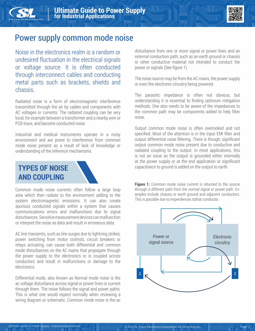
disturbance from one or more signal or power lines and an external conduction path, such as an earth ground or chassis or other conductive material not intended to conduct the power or signals (See figure 1).
The noise source may be from the AC mains, the power supply or even the electronic circuitry being powered.
The parasitic impedance is often not obvious, but understanding it is essential to finding optimum mitigation methods. One also needs to be aware of the impedances to the common path may be components added to help filter noise.
Output common mode noise is often overlooked and not specified. Most of the attention is in the input EMI filter and output differential noise filtering. There is though, significant output common mode noise present due to conductive and radiated coupling to the output. In most applications, this is not an issue as the output is grounded either internally at the power supply or at the end application or significant capacitance to ground is added on the output to earth.
Figure 1: Common mode noise current is returned to the source through a different path from the normal signal or power path. Ex-amples include chassis or earth ground and adjacent conductors. This is possible due to impendences tothat conductor.
Electroniccircuitry
Power orsignal source
z z
Page 11
NOISE SOURCES
Ultimate Guide to Power Supplyfor Industrial Applications
Ultimate Guide to Power Supply - Industrial Applications © 2020 SL Power Electronics Corporation. All rights reserved.
A typical power supply consists of an AC/DC rectification stage followed by a high frequency DC/DC stage and control circuitry to regulate the output voltage.
Noise from the power supply mainly originates from the switching power semiconductors. Switch mode power supplies are much more efficient, smaller and more economical than linear power supplies they have displaced during the past few decades. Power supply designers have made improvements in reducing noise generated in the power supply from leaking out to connected or nearby equipment. However, noise is still a challenge and common mode noise is often overlooked, partially due to the lack of specifications defining a requirement for output common mode noise.
The nature of switching power supplies is that there are high dv/dt and di/dt circuits in order to achieve the high efficiency, reduced size and cost. With parasitic capacitance as part of the product due to the nature of physics of materials and electromagnetics, we have a natural high harmonic noise source that is heavily filtered within the power supply, but not perfect in containing it within the boundary of the power source.
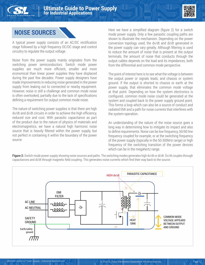
Here we have a simplified diagram (figure 2) for a switch mode power supply. Only a few parasitic coupling paths are shown to illustrate the mechanism. Depending on the power conversion topology used, the dv/dt and di/dt generated in the power supply can vary greatly. Although filtering is used to reduce the amount of noise that is present at the output terminals, the amount of noise that conducts through the output cables depends on the load and its impedances, both from the differential and common mode perspective.
The point of interest here is to see what the voltage is between the output power or signals leads, and chassis or system ground. If the output is shorted to chassis or earth at the power supply, that eliminates the common mode voltage at that point. Depending on how the system electronics is configured, common mode noise could be generated at the system and coupled back to the power supply ground point. This forms a loop which can also be a source of conduct and radiated EMI and a path for noise currents that interferes with the system operation.
An understanding of the nature of the noise source goes a long way in determining how to mitigate its impact and also to define requirements. Noise can be low frequency, 50/60 line frequency coupled for example, or at the switching frequency of the power supply (typically in the 50-300kHz range) or high frequency of the switching transition of the power devices which can be in the megahertz range.
Figure 2: Switch mode power supply showing noise sources and paths. The switching modes generates high dv/dt or di/dt. Dv/dt couples through capacitances and di/dt through magnetic field coupling. This generates noise currents which find their way back to the source.
AC LINE
EMI FILTER
AC NEUTRAL
SAFETY GROUND
HEATSINK
COMMON MODEVOLTAGE APPEARSBETWEEN OUTPUTAND GROUNDEarth/safety
ground
PARASITIC CAPACITANCEHIGH dv/dt
Page 12
COMMON MODE NOISE MITIGATION
Ultimate Guide to Power Supplyfor Industrial Applications
Ultimate Guide to Power Supply - Industrial Applications © 2020 SL Power Electronics Corporation. All rights reserved.
Understanding what your system may be sensitive too will help you determine acceptable solutions.
For instrumentation systems monitoring low frequency signals in the low Hz to a few 100 Hz and a floating power source, AC mains noise can be a significant problem in high impedance applications. The relatively small capacitive coupling between the AC mains and the output can be enough to generate 10’s of volts of common mode noise.
When making measurements, you need to be aware of the potential impact the measurement method may have on the results. The measurement method may result in higher readings, due to long leads and loops for high frequencies for example. Or lower the reading by loading down the noise source due to probe impedance itself. Give some thought to what you’re measuring. Try to distinguish between the noise frequencies that are causing the problem and other noise frequencies that are present and only masking the real noise issue. It can be advantageous to filter out frequency ranges in order to see noise of a particular frequency when the noise is a combination of low and high frequency.
A simple low pass and high pass filter can be made using an R-C network. This allows investigation of the frequencies ofinterest.
This is suitable for typical applications, but for systems having a very high impedance (> MΩ) requirement between the power supply and ground, than a high impedance active voltage probe will be needed to avoid loading down the measurement point.
To get an understanding of the noise source impedance, and hence an appreciation of what will be needed to filter it, measuring the open circuit voltage and short circuit current will be helpful.
Measure the open circuit voltage from the output return lead, or the other polarity, and the system or earth ground point. You can use an oscilloscope to do this being careful to keep the test lead short if measuring in the few megahertz and higher. You can also use a spectrum analyzer which will be more instructive in revealing the frequencies of the noise. This will be helpful to know so you can then select the proper component values needed if additional filtering is required.
However, the input to a spectrum analyzer is usually 50 or 75 Ω so this could be loading down the noise source. You could monitor the same point with an oscilloscope to see how much it is being loaded.
Common mode noise is present in power systems and can cause interference issues. The impact depends on the application. Always measure to understand the source well. Follow a structured approach to mitigation methods – measure, understand, apply and verify solutions.
Once you have a good idea of the noise frequency spectrum, source impedance and the frequencies that are an issue, you can make informed decisions on the ways to mitigate the noise issue:1. Ferrite material, clamp on cores, inductors, toroid’s and
the like are quiet effective at reducing offending currentsif the proper material is selected. There are a numberof manufacturers for ferrite material, and some provideexcellent characterization data showing impedance verse frequency.
2. For high frequency noise in the 10 – 20 MHz andhigher range, selecting a material with a high resistivecharacteristics is often more effective than materials with a reactive characteristics. The resistive element helpsdampen and dissipate the energy, while reactive parts willpresent impedance, but may contribute to resonancesdepending on the capacitance of the network. However,at lower frequencies, having a higher reactive elementmay be better as the energy involved could be significantand just providing high impedance will reduce the currentflow and reduce the common mode noise.
3. When selecting capacitors, be aware of the tolerancevariation of the materials over temperature and appliedvoltage. They can be very significant and be less effectiveover the operating temperature of the product. Also,
Page 13
Ultimate Guide to Power Supplyfor Industrial Applications
Ultimate Guide to Power Supply - Industrial Applications © 2020 SL Power Electronics Corporation. All rights reserved.
select the value to coincide with its minimum impedance at the frequency of interest.
4. Check for resonances when adding capacitance andinductance to your filter. The resonant frequency can becalculated and depending on the noise level and frequency, you may be able to measure the voltage if you’re gettingworse results after applying the filter components.
5. Minimize capacitive coupling between noisy signals;separate power and signal lines, shield noisy cables.
6. Minimize dv/dt; ground output return to chassis/earth
ground near the power supply if possible, shunt noise to power supply chassis near power output.
7. Decouple noise from source to load; add common modeinductor or ferrite cores on power cables. Select ferritematerial that has a high impedance in the offendingfrequency range.
8. Shield the noise source from sensitive circuitry.9. Select Power Supplies with acceptable common mode
noise.
Page 14
Ultimate Guide to Power Supplyfor Industrial Applications
Ultimate Guide to Power Supply - Industrial Applications © 2020 SL Power Electronics Corporation. All rights reserved.
Managing interfaces in power supplies for test equipmentAn awareness of standards for conducted and radiated emissions helps in fielding power supplies that don’t cause havoc in attached electronics.
Innovations such as the Internet of Things (IoT), 5G cellular standards, WiGig, 4K video, and other developments are causing quite a flurry of market activity. In fact, they are driving the creation of myriad new devices and making existing products more functional. But these innovations are also creating formidable challenges for test equipment designers. One of them involves integrating a power supply into a design.
Specialized power supplies are now designed with operational parameters most important to test equipment performance. These important parameters include conducted and radiated electromagnetic interference (EMI), electromagnetic compatibility (EMC), differential/common mode noise, thermal performance, regulatory requirements, product life and other more application-specific factors. A power supply that excels at these parameters can be integrated into test equipment with less effort.
This is particularly true for electromagnetic noise. Equipment designers can spend significant amounts of time alleviating power supply noise effects by adding filters and/or taking numerous measurements to ensure readings are accurate and not influenced by noise.
It is useful to consider the standards that can apply to noise levels in test equipment. EMI limits, for example,are detailed in various industry standards:
EN55011 is a European standard that applies to industrial, scientific and medical (ISM) equipment. (CISPR 11, by the International Committee on Radio Frequency Interference, is an international standard that is essentially equivalent to EN55011.) The standard divides these products into two groups, Group 1 and Group 2. EN55011 Group 1 limits are identical to EN 55022 limits. Group 2 pertains to products that use RF as an output. Therefore, switch-mode power supplies are not considered in Group 2.EN55022 (CISPR 22) applies to information technology
equipment (ITE). EN55015 (CISPR 15) applies to lighting equipment. Both EN55011 and EN55022 contain two classes: Class A and Class B. EN55015 has only one set of limits: Class A equipment is that used in a domestic environment which may cause radio interference with other equipment nearby. Class B equipment is designed to be used in a domestic environment and won’t cause radio interference with nearby equipment.
For conducted interference, EN 55022 and EN 55011 measure the emissions from equipment in the 150 kHz to 30 MHz range, while EN 55015 measures over the extended range of 9 kHz to 30 MHz using a conducted measurement technique on the ac mains input cable. The conducted emission limits in these standards are intended to protect equipment connected to the same ac mains supply.
For radiated interference, EN 55022 and EN 55011 measure equipment emissions in the frequency range from 30 MHz to 1 GHz while EN 55015 measures the emission from equipment in the frequency range 30 MHz to 300 MHz using a receiving antenna and recording the over-the-air signals. The radiated emission limits applied by these standards aim to protect equipment near the device being tested.
Power supply manufacturers test their products to these standards, usually powering a resistive load. Of course, once power supplies are integrated into end equipment, the load profiles may change. End equipment can change the EMI profile, perhaps forcing the supply to stray from the EMI limits. It then becomes the job of equipment designers to bring EMI in the end equipment below the applicable limits. This is one reason equipment designers often use power supplies that meet EMI standards with a wide margin of safety: Such supplies are more likely to avoid EMI concerns when built into end equipment.
Page 15
EMC
Ultimate Guide to Power Supplyfor Industrial Applications
Ultimate Guide to Power Supply - Industrial Applications © 2020 SL Power Electronics Corporation. All rights reserved.
Other operational parameters that test-equipment designers are concerned with relate to EMC. In general, EMC standards cover many different parameters that deal with outside influences that can affect the operation of both power supplies and the end equipment they are used in. EMC standards for power supplies are listed under IEC61000 (in Europe, EN61000). Equipment that goes through testing to this standard can have one of four levels of acceptance criteria:1. Criteria A — Normal performance within limits specified
by the manufacturer, requestor or purchaser2. Criteria B — Temporary loss of function or degradation
of performance which ceases after the disturbanceis removed and from which the equipment-under-testrecovers its normal performance without operatorintervention.
3. Criteria C — Temporary loss of function or degradation ofperformance, and the operator must intervene to correctit.
4. Criteria D — An unrecoverable loss of function ordegradation of performance caused by damage tohardware or software, or loss of data.
Not all of the above standards may apply for all test equipment, and the performance levels and criteria of those standards will also vary, depending on the environments in which the end equipment is being designed to operate.
Makers of power supplies should specify not just the IEC/EN61000 standard the supply follows, but also the level and operational criteria with which the supply complies. Stating that the power supply complies to a given standard without specifying the test level at which it complies and the performance criteria during the test, does not give the system designer enough details to evaluate the supply. Power supplies that meet tougher standards can give equipment designers confidence that their system-level EMC tests won’t cause problems without adding filters or other protections.
An equally important source of noise is CMN. CMN on the output of a power supply is often overlooked and rarely specified. This oversight may be because the designer doesn’t know how it can impact product performance, but also because it may not be an issue. Power supply outputs are often referenced to earth or chassis ground in end applications. In this case, CMN will likely not be an issue. However, it can be instructtive to understand the common-mode currents that flow while making their way to ground.
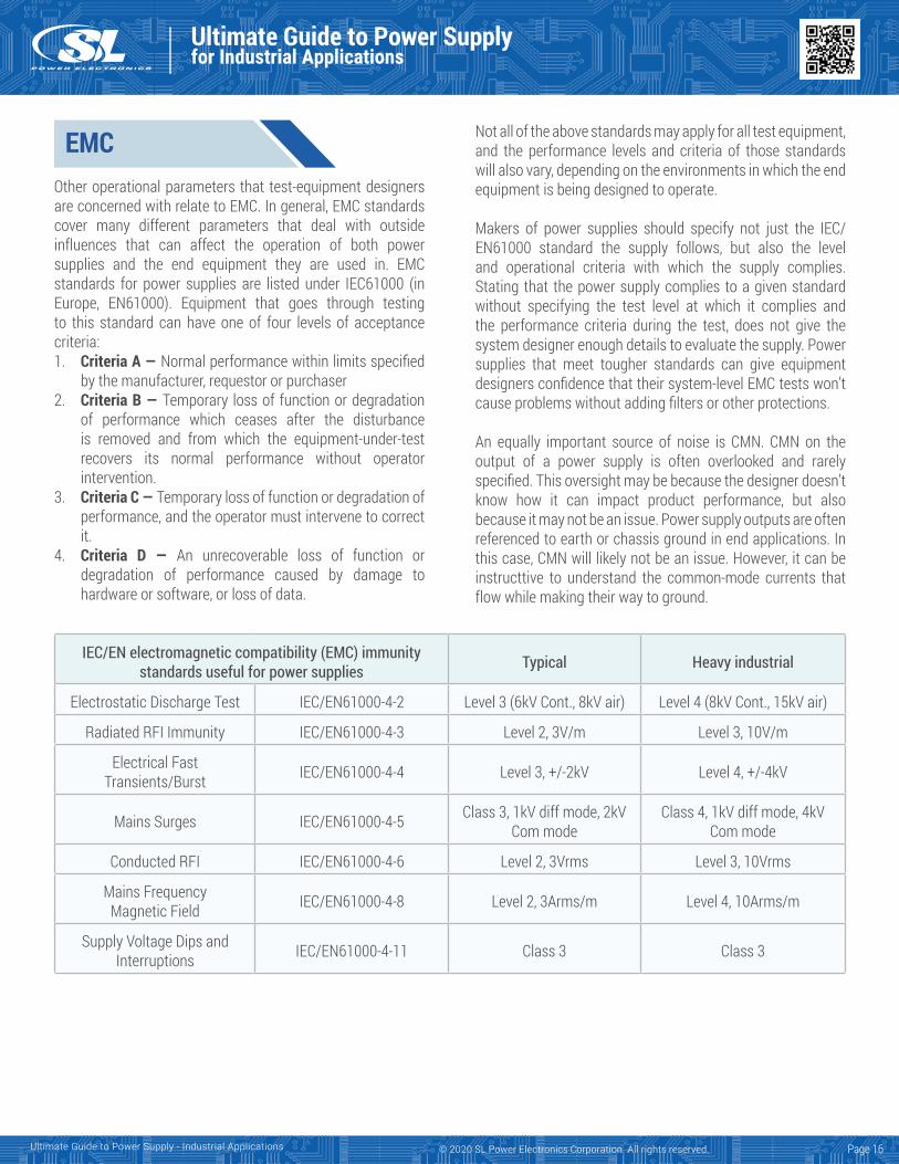
IEC/EN electromagnetic compatibility (EMC) immunity standards useful for power supplies Typical Heavy industrial
Electrostatic Discharge Test IEC/EN61000-4-2 Level 3 (6kV Cont., 8kV air) Level 4 (8kV Cont., 15kV air)
Radiated RFI Immunity IEC/EN61000-4-3 Level 2, 3V/m Level 3, 10V/m
Electrical Fast Transients/Burst IEC/EN61000-4-4 Level 3, +/-2kV Level 4, +/-4kV
Mains Surges IEC/EN61000-4-5 Class 3, 1kV diff mode, 2kV Com mode
Class 4, 1kV diff mode, 4kV Com mode
Conducted RFI IEC/EN61000-4-6 Level 2, 3Vrms Level 3, 10Vrms
Mains Frequency Magnetic Field IEC/EN61000-4-8 Level 2, 3Arms/m Level 4, 10Arms/m
Supply Voltage Dips and Interruptions IEC/EN61000-4-11 Class 3 Class 3
Page 16
Ultimate Guide to Power Supplyfor Industrial Applications
Ultimate Guide to Power Supply - Industrial Applications © 2020 SL Power Electronics Corporation. All rights reserved.
All in all, many power supplies specify performance to a few parameters, leaving designers to tackle others during development. A power supply that can performs well for most, if not all of these important parameters, will ensure an easier integration effort for design engineers. Review those datasheets carefully, as what you don’t see may cause extra work later.
The EN 55103-1 EMC standard (for audio, video, audio-visual and entertainment lighting control apparatus), EN55022, and associated standards (CISPR 22) give limits and measurement methods for common-mode disturbances on telecommunications and network ports. However, it is common practice to reference the output of the power supply to ground in this type of equipment. Refer to these standards for the measurement method and limit.
For applications where these standards do not apply, loads can see adverse effects from common-mode voltages. If the output of the power supply connects to chassis/earth ground somewhere on the load board (electronics circuitry), there can be common mode currents flowing through the board. Also, if the printed circuit board layout is subpar, current can flow through sensitive parts of the circuitry and cause malfunctions. In the case of test equipment, the current may cause erroneous measurement readings unless the common-mode noise (CMN) is filtered or potential errors filtered out by data sampling.
CMN can be specified in Volts rms or peak-to-peak, or in units of current (mA). Designers concerned with CMN tend to analyze it based upon its effects on their design.
Power supply datasheets typically do not specify CMN. It may be impractical to eliminate CMN, but a power supply that can specify a CMN value, both high frequency noise and low frequency noise, will give system designers some idea of the components needed to integrate the power supply into their equipment.
Page 17
SCOPE
EQUIPMENT CONSIDERATIONS
Ultimate Guide to Power Supplyfor Industrial Applications
Ultimate Guide to Power Supply - Industrial Applications © 2020 SL Power Electronics Corporation. All rights reserved.
No load power loss measurement considerations
No load power or standby power refers to the electric power consumed by electronic equipment while in a standby mode. It is a condition in which the input of a power supply is connected to an AC source consistent with the power supply’s nameplate AC voltage, but the output is not connected to a product or any other load.
In the past, standby power was largely not a consideration for users, electricity providers, manufacturers, or government regulators. In the first decade of the twenty-first century, awareness of the issue grew and it became an important consideration for all parties. Up to the middle of the decade, standby power was often several watts or even tens of watts per appliance. By 2010, regulations were in place in most developed countries restricting standby power of devices sold to one watt, then half watt from 2013. A new Department of Energy (DOE) standard (Level VI) in effect in the USA as of February 10, 2016, limits the standby power to less than 0.1W for external power supplies (EPS) with nameplate ratings of 49 watt or less, 0.210 Watts for 49 < Pout < 250, and 0.5 Watts for Pout > 250W.
The International Electro-technical Commission (IEC) introduced the IEC62301 standard that specifies methods of measurement of electrical power consumption in standby mode. Accurate measurement of standby power needs care, but is technically straightforward in most cases when the IEC62301 is followed.
1. The ambient temperature should be 23°C ± 5 with still air.2. AC power source should not exceed 2% harmonic content,
up to and including 13th harmonic.3. The crest factor should be between 1.34 and 1.49.4. Measurements of power less than 0.5 W shall be made
with an uncertainty of less than or equal to 0.01W at the95% confidence level.
5. Power measurement instrument shall have a resolutionof 0.01W or better.
6. Power measurement instrument should have to becapable of intergrating energy over any user selectedtime interval with an energy resolution of less than orequal to 0.1mWhand integrating time displayed with aresolution of 1 second or less.
If power consumption is stable (defined as less than 5% variation from the mean over an interval of 5 minutes), the power consumption can be read directly from the meter. If power consumption fluctuates, energy consumption should be measured over a period of time and then divided by the measurement period to determine average power.
However, the standby power can be asymmetrical and complicated further with low duty cycle current pulses. So do not assume that a standby power profile is symmetrical and therefore can be accurately quantified with gaps between measurements by integration over a long period of time. Such a measurement technique may miss events and provide only an average approximation power rather than a precise true power.
The instability in power is due to the power analyzer sampling technique not the device under test. High performance power analyzers are required to achieve measurement stability and reflect the true standby power with a short measurement time.
It is a good practice to disconnect the unit under test from load when measuring no load input power since some electronic loads may still provide a slight load even though it is set to zero. Verify the power analyzer is connected according to the manufacturers’ recommendations as the power analyzers may also add load to the reading if not properly connected.
Page 18
MEASUREMENTCONSIDERATIONS
Ultimate Guide to Power Supplyfor Industrial Applications
Ultimate Guide to Power Supply - Industrial Applications © 2020 SL Power Electronics Corporation. All rights reserved.
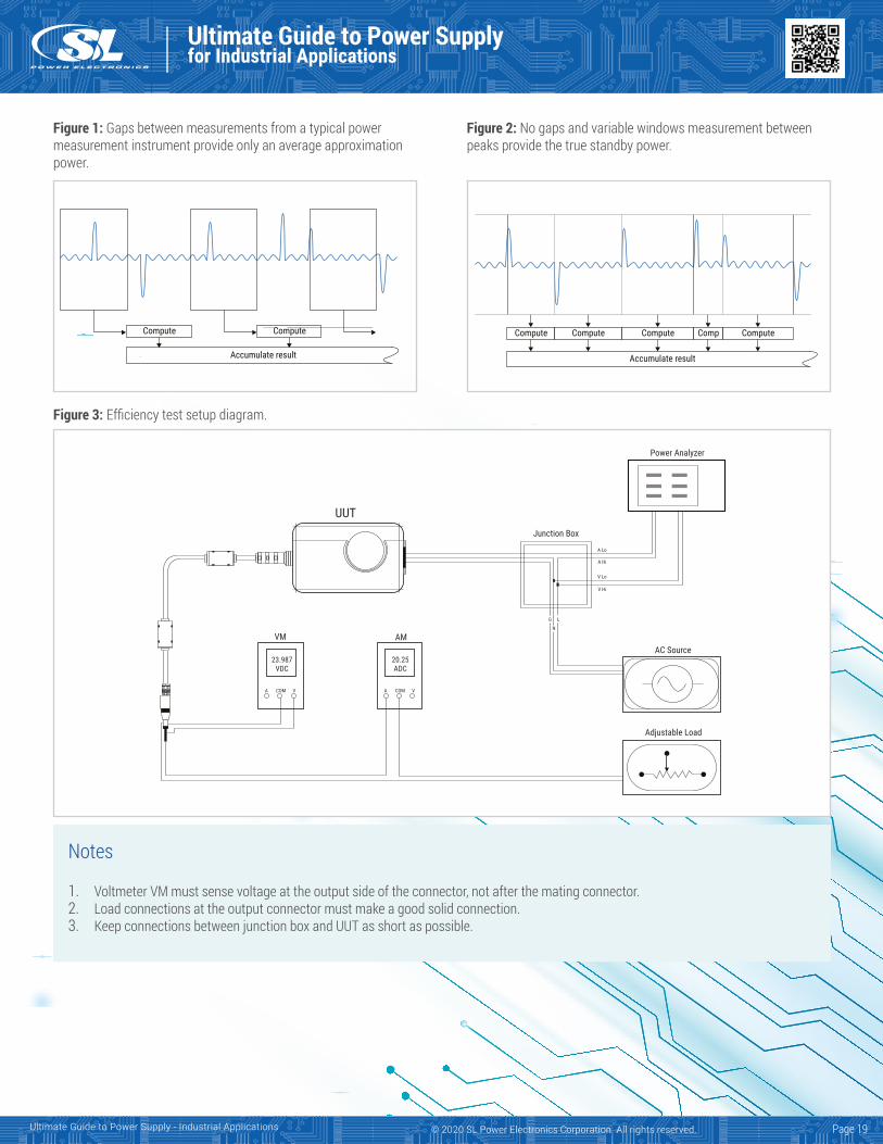
Figure 1: Gaps between measurements from a typical power measurement instrument provide only an average approximation power.
Figure 2: No gaps and variable windows measurement between peaks provide the true standby power.
Figure 3: Efficiency test setup diagram.
Notes
1. Voltmeter VM must sense voltage at the output side of the connector, not after the mating connector.2. Load connections at the output connector must make a good solid connection.3. Keep connections between junction box and UUT as short as possible.
Compute
Accumulate result
Compute
Accumulate result
Compute Compute Compute Comp Compute
UUTJunction Box
Power Analyzer
VM AM
23.987VDC
20.25ADC
A COM V A COM V
A Lo
A Hi
V Lo
V Hi
LG
N
AC Source
Adjustable Load
Page 19
Ultimate Guide to Power Supplyfor Industrial Applications
Ultimate Guide to Power Supply - Industrial Applications © 2020 SL Power Electronics Corporation. All rights reserved.
DoE Level VI: Getting your measurement technique rightThe new DoE Level VI efficiency standard (DoE 10 CFR Part 430) mandates that no-load power consumption does notexceed 0.100W for external power supplies (EPSs) rangingfrom 1W to ≤49W, and does not exceed 0.210W for EPS>49W to ≤250W. The standard boosts the mandatory averageefficiency by about 1% over the Level V standard and setsstandards for power ratings above 250W for the first time.
The new regulations apply to all direct and indirect operation EPSs. The regulations also extend their scope to encompass lower voltage DC-output EPSs, multiple-output voltage EPSs, and EPSs with nameplate output power ratings exceeding 250W.The compliance date for the new requirements was February 10, 2016.
SL Power’s TE Series external power supplies meet Level VI energy-efficiency standards plus enhanced EMI/EMC performance.
Page 20
TEST METHODOLOGYThe test method is defined in Appendix Z of the 10 CFR part 430 standard. This can be found on the Electronic Code of Federal Regulations website. In summary, the DoE’s Level VI standards specify that the unit under test (UUT), intended for operation in the US, must be tested at 115V AC, 60 Hz. Here is an interesting point: If it cannot operate at 115V, 60Hz, it should not be tested at all. The input voltage source impedance needs to be low enough not to impact the results. Regardless of the AC source type, the total harmonic distortion (THD) of the supply voltage when supplying the UUT in the specified mode must not exceed 2%, up to and including the 13th harmonic (as specified in IEC 62301). In addition, the peak value of the test voltage must be within 1.34 and 1.49 times its RMS value (as specified in IEC 62301).
DoE Level VI standards also dictate that the power measurement instrument must have a resolution of 0.01W or better for power measurements of 10W or less, 0.1W or better for power measurements of greater than 10W up to 100W, and 1W or better for power measurements of greater than 100W.
Furthermore, the standards specify that the UUT must be tested at the load conditions as shown in this table:
The UUT must be operated at 100% of nameplate output urrent for at least 30 minutes. After this warm-up period, if the power level does not drift by more than 5% from the maximum value observed, the UUT can be considered stable, and the measurements can be recorded. If AC input power is not stable over a five-minute period, the guidelines established by IEC 62301 for measuring average power or accumulated energy over time for both AC input and DC output are followed.
The new requirements further state that efficiency measurements shall be conducted in sequence from Load Condition 1 to Load Condition 5 as indicated in the table above. Efficiency is calculated by dividing the devices’ measured DC output power at a given load condition by the true AC input power measured at that load condition. The input power must be measured with an appropriate watt meter or power analyzer. Average efficiency is calculated as the arithmetic mean of the efficiency values calculated at Load Conditions 1, 2, 3, and 4.
Load condition 1 100% +/- 2%
Load condition 2 75% +/- 2%
Load condition 3 50% +/- 2%
Load condition 4 25% +/- 2%
Load condition 5 0%
Ultimate Guide to Power Supplyfor Industrial Applications
Ultimate Guide to Power Supply - Industrial Applications © 2020 SL Power Electronics Corporation. All rights reserved.
It is critical to use short and properly sized test cables to reduce cable power loss as much as possible. It is also recommended to measure the output voltage right at the output connector, not after a mating connector. The standard allows cutting the
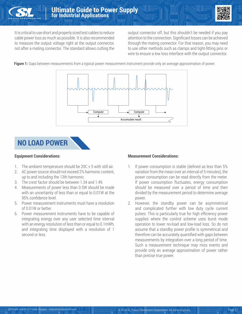
Figure 1: Gaps between measurements from a typical power measurement instrument provide only an average approximation of power.
Compute
Accumulate result
Compute
Page 21
output connector off, but this shouldn’t be needed if you pay attention to the connection. Significant losses can be achieved through the mating connector. For that reason, you may need to use other methods such as clamps and tight-fitting pins or wire to ensure a low loss interface with the output connector.
NO LOAD POWERMeasurement Considerations:
1. If power consumption is stable (defined as less than 5%variation from the mean over an interval of 5 minutes), the power consumption can be read directly from the meter.If power consumption fluctuates, energy consumptionshould be measured over a period of time and thendivided by the measurement period to determine averagepower.
2. However, the standby power can be asymmetricaland complicated further with low duty cycle currentpulses. This is particularly true for high efficiency powersupplies where the control scheme uses burst modeoperation to lower no-load and low-load loss. So do notassume that a standby power profile is symmetrical andtherefore can be accurately quantified with gaps betweenmeasurements by integration over a long period of time.Such a measurement technique may miss events andprovide only an average approximation of power ratherthan precise true power.
Equipment Considerations:
1. The ambient temperature should be 20C ± 5 with still air.2. AC power source should not exceed 2% harmonic content,
up to and including the 13th harmonic.3. The crest factor should be between 1.34 and 1.49.4. Measurements of power less than 0.5W should be made
with an uncertainty of less than or equal to 0.01W at the95% confidence level.
5. Power measurement instruments must have a resolutionof 0.01W or better.
6. Power measurement instruments have to be capable ofintegrating energy over any user selected time intervalwith an energy resolution of less than or equal to 0.1mWh, and integrating time displayed with a resolution of 1second or less.
Ultimate Guide to Power Supplyfor Industrial Applications
Ultimate Guide to Power Supply - Industrial Applications © 2020 SL Power Electronics Corporation. All rights reserved.
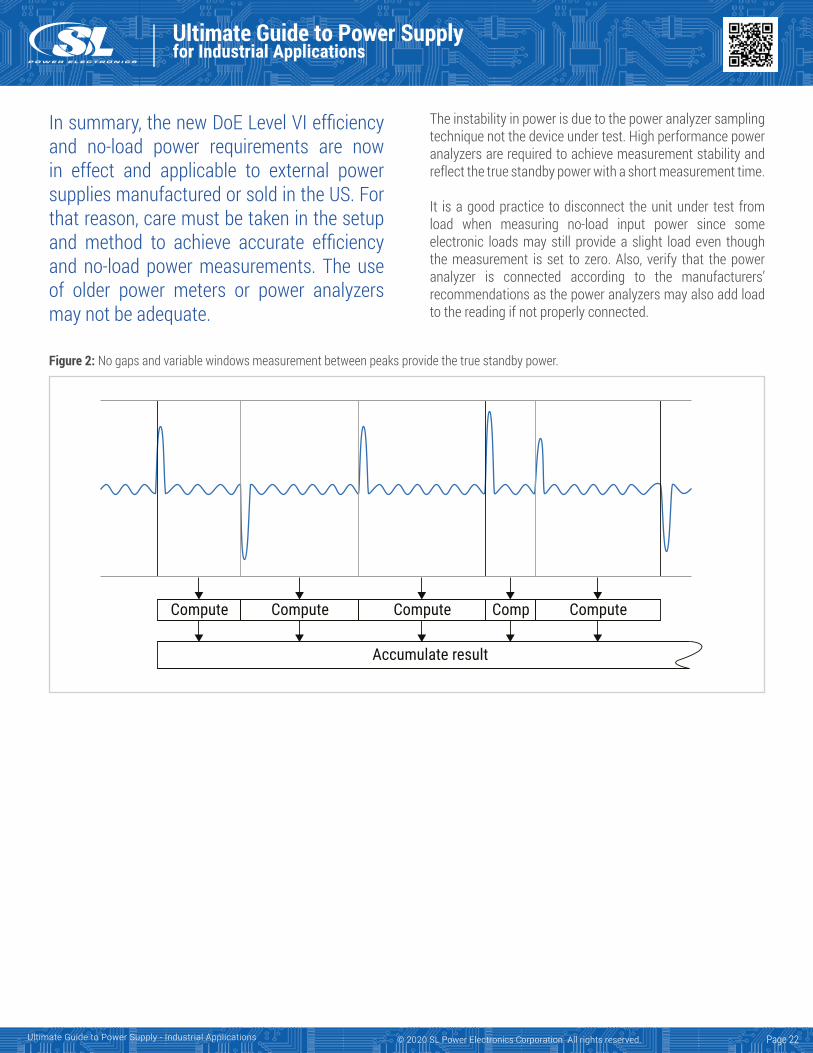
Figure 2: No gaps and variable windows measurement between peaks provide the true standby power.
Page 22
Accumulate result
Compute Compute Compute Comp Compute
In summary, the new DoE Level VI efficiency and no-load power requirements are now in effect and applicable to external power supplies manufactured or sold in the US. For that reason, care must be taken in the setup and method to achieve accurate efficiency and no-load power measurements. The use of older power meters or power analyzers may not be adequate.
The instability in power is due to the power analyzer sampling technique not the device under test. High performance power analyzers are required to achieve measurement stability and reflect the true standby power with a short measurement time.
It is a good practice to disconnect the unit under test from load when measuring no-load input power since some electronic loads may still provide a slight load even though the measurement is set to zero. Also, verify that the power analyzer is connected according to the manufacturers’ recommendations as the power analyzers may also add load to the reading if not properly connected.
Ultimate Guide to Power Supplyfor Industrial Applications
Ultimate Guide to Power Supply - Industrial Applications © 2020 SL Power Electronics Corporation. All rights reserved.
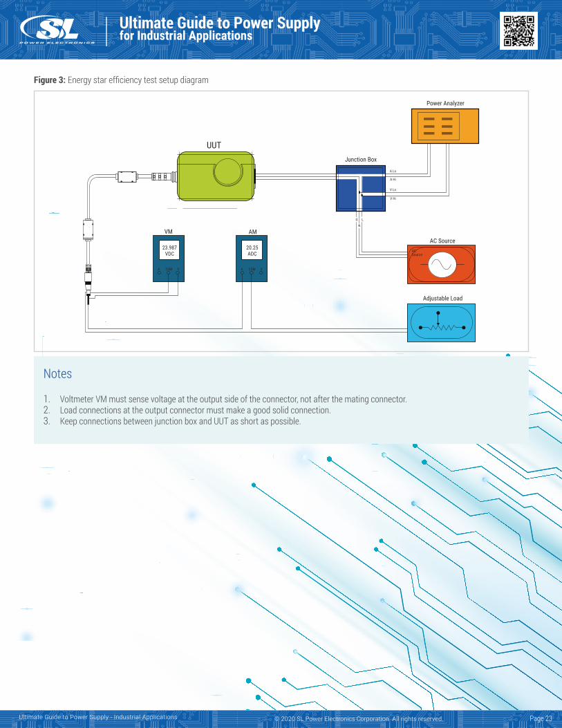
Figure 3: Energy star efficiency test setup diagram
Notes
1. Voltmeter VM must sense voltage at the output side of the connector, not after the mating connector.2. Load connections at the output connector must make a good solid connection.3. Keep connections between junction box and UUT as short as possible.
UUTJunction Box
Power Analyzer
VM AM
23.987VDC
20.25ADC
A COM V A COM V
A Lo
A Hi
V Lo
V Hi
LG
N
AC SourceACSource
Adjustable Load
Page 23
NEW LEVEL VI REQUIREMENT
COMPLIANCE DATE
Ultimate Guide to Power Supplyfor Industrial Applications
Ultimate Guide to Power Supply - Industrial Applications © 2020 SL Power Electronics Corporation. All rights reserved.
External power supplies: Energy efficiency requirementsIn the early 1990’s, the U.S. Environmental Protection Agency (EPA) started a voluntary program to promote energy efficiency and reduce pollution, which eventually became the Energy Star program. However, it was not until 2004 that the first mandatory regulations dictating average efficiency minimums and no-load power consumption for External Power Supplies (EPS) were put into place.
As different countries enacted stricter requirements and moved from voluntary to mandatory programs, the Energy Star program defined the International Efficiency Marking Protocol to minimize confusion between regions and their similar standards. The defined markings set minimum average efficiency and maximum no-load power consumption levels for EPS. The evolution of the various marking levels is detailed below:
1. Level I: Power supply does not meet any of the standardsdefined
2. Level II: Power supply meets minimum efficiencies thatwere set required by China in November 2005
3. Level III: Power supply meets Energy Star Tier 1, CEC Tier1, and Australian MEPS standards
4. Level IV: Power supply meets EISA 2007, CEC Tier 2 andthe Australian MEPS High Efficiency category
5. Level V: Power supply meets CEC Tier 3 and EU phase 2standards
6. Level VI: Power supply meets DOE new standards,effective in the US as of February 10, 2016
Below are the countries or regions mandating that external power supplies (EPS) (with some exemptions) shipped across their borders meet specific efficiency levels:
The new U.S. DoE Level VI efficiency standard mandates that No-Load power consumption shall not exceed 0.100 W for an EPS ranging from 49W to ≤250W output power rating. It boosts the mandatory average efficiency by about 1%, and sets standards for adapters with power ratings above 250 W for the first time. The new regulations apply to all direct and indirect operation EPS, and also extend their scope to encompass lower voltage DC-output and multiple-output voltage EPS.
The new rule mandates that EPS efficiency and no-load power levels comply with “Level VI” standards, effective as of February 10th, 2016. According to the new rule, all EPS products manufactured after this date and shipped into the U.S. must meet the new Level VI standards.EPS’s that are compliant will be marked with the letters “VI” similar to items shown in Figure I.
It should be noted that there is in place a Code of Conduct that was generated in October 2013 by a working group from the EC Joint Research Centre. This Code of Conduct includes a 2-tier implementation of efficiency and no-load power levels.The levels in Tier 1 (Jan 2014 are slightly less stringent thanthe U.S. DoE Level VI requirements, and Tier 2 levels (Jan2016) are slightly more stringent. The European Commissionhas not formally enacted these levels as a firm regulationsuch as ErPII, and it has not yet been decided whether toenact regulations with the Code of Conduct levels or to beconsistent with the U.S. DoE Level VI requirements.
Table 1: Current efficiency levels
Figure 1: Efficiency Level VI Marking
VILevel Country
IV United States (current)
IV Canada (current)
V European Union (current)
VI United States (2/10/16)
Page 24
Ultimate Guide to Power Supplyfor Industrial Applications
Ultimate Guide to Power Supply - Industrial Applications © 2020 SL Power Electronics Corporation. All rights reserved.
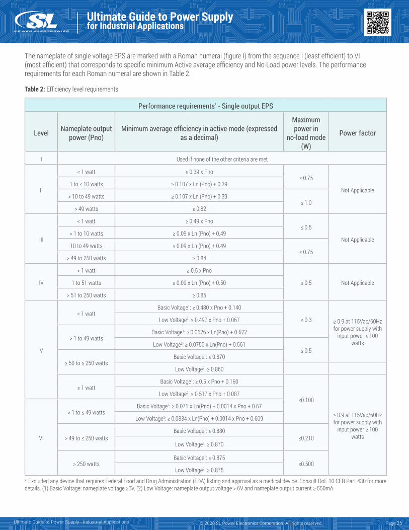
The nameplate of single voltage EPS are marked with a Roman numeral (figure I) from the sequence I (least efficient) to VI (most efficient) that corresponds to specific minimum Active average efficiency and No-Load power levels. The performance requirements for each Roman numeral are shown in Table 2.
Table 2: Efficiency level requirements
* Excluded any device that requires Federal Food and Drug Administration (FDA) listing and approval as a medical device. Consult DoE 10 CFR Part 430 for moredetails. (1) Basic Voltage: nameplate voltage ≥6V. (2) Low Voltage: nameplate output voltage > 6V and nameplate output current ≥ 550mA.
Performance requirements* - Single output EPS
Level Nameplate output power (Pno)
Minimum average efficiency in active mode (expressed as a decimal)
Maximum power in
no-load mode (W)
Power factor
I Used if none of the other criteria are met
II
< 1 watt ≥ 0.39 x Pno≤ 0.75
Not Applicable1 to ≤ 10 watts ≥ 0.107 x Ln (Pno) + 0.39
> 10 to 49 watts ≥ 0.107 x Ln (Pno) + 0.39≤ 1.0
> 49 watts ≥ 0.82
III
< 1 watt ≥ 0.49 x Pno≤ 0.5
Not Applicable> 1 to 10 watts ≥ 0.09 x Ln (Pno) + 0.49
10 to 49 watts ≥ 0.09 x Ln (Pno) + 0.49≤ 0.75
> 49 to 250 watts ≥ 0.84
IV
< 1 watt ≥ 0.5 x Pno
≤ 0.5 Not Applicable1 to 51 watts ≥ 0.09 x Ln (Pno) + 0.50
> 51 to 250 watts ≥ 0.85
V
< 1 wattBasic Voltage1: ≥ 0.480 x Pno + 0.140
≤ 0.3 ≥ 0.9 at 115Vac/60Hz for power supply with
input power ≥ 100 watts
Low Voltage2: ≥ 0.497 x Pno + 0.067
> 1 to 49 wattsBasic Voltage1: ≥ 0.0626 x Ln(Pno) + 0.622
Low Voltage2: ≥ 0.0750 x Ln(Pno) + 0.561≤ 0.5
≥ 50 to ≥ 250 wattsBasic Voltage1: ≥ 0.870
Low Voltage2: ≥ 0.860
≤ 1 wattBasic Voltage1: ≥ 0.5 x Pno + 0.160
≤0.100
≥ 0.9 at 115Vac/60Hz for power supply with
input power ≥ 100 watts
Low Voltage2: ≥ 0.517 x Pno + 0.087
VI
> 1 to ≤ 49 wattsBasic Voltage1: ≥ 0.071 x Ln(Pno) + 0.0014 x Pno + 0.67
Low Voltage2: ≥ 0.0834 x Ln(Pno) + 0.0014 x Pno + 0.609
> 49 to ≤ 250 wattsBasic Voltage1: ≥ 0.880
≤0.210Low Voltage2: ≥ 0.870
> 250 wattsBasic Voltage1: ≥ 0.875
≤0.500Low Voltage2: ≥ 0.875
Page 25
Ultimate Guide to Power Supplyfor Industrial Applications
Ultimate Guide to Power Supply - Industrial Applications © 2020 SL Power Electronics Corporation. All rights reserved.
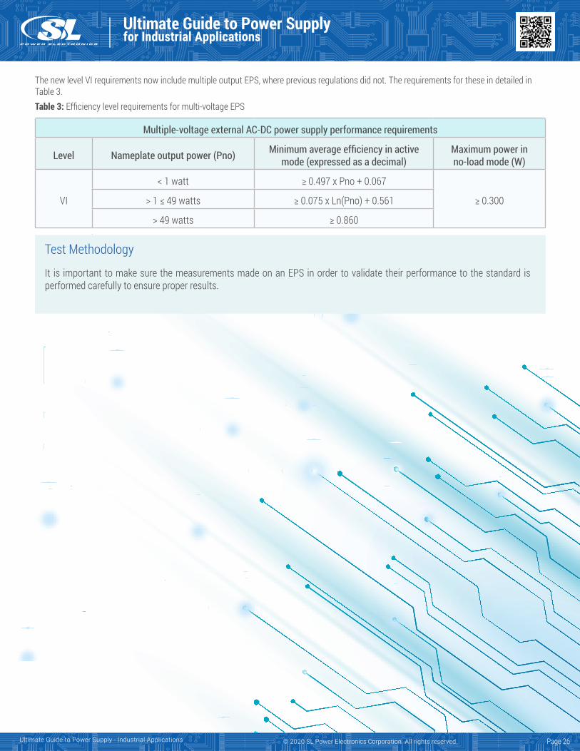
The new level VI requirements now include multiple output EPS, where previous regulations did not. The requirements for these in detailed in Table 3.Table 3: Efficiency level requirements for multi-voltage EPS
Test Methodology
It is important to make sure the measurements made on an EPS in order to validate their performance to the standard is performed carefully to ensure proper results.
Multiple-voltage external AC-DC power supply performance requirements
Level Nameplate output power (Pno) Minimum average efficiency in active mode (expressed as a decimal)
Maximum power in no-load mode (W)
VI
< 1 watt ≥ 0.497 x Pno + 0.067
≥ 0.300> 1 ≤ 49 watts ≥ 0.075 x Ln(Pno) + 0.561
> 49 watts ≥ 0.860
Page 26
6050 King DriveVentura, CA 93003
© 2020 SL Power Electronics Corporation. All rights reserved.