Embed Size (px)
Citation preview
30 -Watt Transistor Power Supply
RadwEIectronIcs HUGO GERNSBACK, Editor
TELEVISION SERVICING HIGH FIDELITY
Horizontal Ringing - Causes and Cures
Build a 1 -Tube
Audio Vtvm
Electronic Boat Horn
and
Low -Power Loud Hailer
How to Improve
Your All -Wave Radio
How Stereo Discs
Work (See page 26
35c U.S. and Canada
www.americanradiohistory.com
KT-22
KT_23
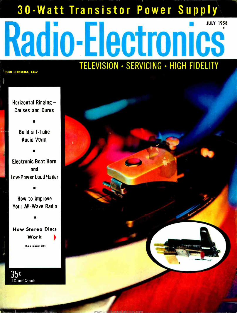
Have the best in Hi -Fi Sound
... and save with a Jensen High Fidelit y Speaker eaker
Now you can have famous Jensen authentic high fidelity loudspeaker performance plus the fun and satisfaction of building your
own speaker system (and save money) with any one of Jensen's eight Hi -Fi loudspeaker kits. Choose from kits ranging from the
modest KDU -12 two -way Budget Duette to the superlative KT -31 Imperial 3 -way system. You can build your own enclosure,
build into your custom home music installation, or install in a Jensen factory -built cabinet. In every speaker kit you get the same
high quality matched components used in Jensen's factory assembled reproducers -and at far less cost, too. Select the kit that best fits
your budget and space, follow simplified plans, and enjoy the finest in sound reproduction. Send for our free Catalog 165 -B,,
KDU-11
KDU-12
36 PAGE JENSEN MANUAL 1060
This la your guide to kit selection and enclosure construction. Complete data and instructions ter all Jensen Speaker Kits from the famous 3 -way "Imperial" system to the budget coat 2- way "Duetts system. Describes Bass- Ultratlex and Back- loading Folded Horn enclosures in complete detail with ex. pioded views and simplified wiring Instructions. JENSEN MANUAL 1060- Net Each .....5O
INSTALL A JENSEN SPEAKER KIT IN A JENSEN ENCLOSURE. If you don't want to build your own enclosure, you can install a Jensen speaker kit in one of Jensen's many fine furniture speaker cabinets. Catalog 165 -B gives com- plete details and suggestions for cabinet -kit combinations.
f,f
Model KT-31 KT-321 t KT-21 KT-22 KT-23 KD U-10 KDU-11
Type 3 -way 3 -way
Imperial Tri -plex -wo
Concert o -15 30- 15.000
-tom cr : '
Concert -12 2-way Om- ., -way Duette temporary ,r Contemporary
2 -way Automobile or Duet e Table Frequency Rangeht 25 -17H1. 30 -1 ?HL 30- 15.000 40- 15,00e
20 16
50- 15.000 50- 15,000 55- 13,000 Power Rating (Watts) Impedance (Ohms)
35 35 30 25 20 20 15 16 16 16 16 S 4 4 Components:
L-F ("Woofer ") P15 -1.í. P15 -LL l P15 -LL P12 -NI, 1'12 -RL P8 -RL P69 -RLI 69JIOt hl -F (\tld- }fange) II-I' ("Tweeter" or
' Supertweet er' )
RP -201 I RP -201
RP -302 RP -302 RP -102 RP -102 RP -103 RI' -103 RP -103 V P35 -H Networks A -61; A -402 A -61; A -402 A -204 A -204 A -204 Capacitor Capacitor Capacitor Controls
"t. yet ST -917: ST -901 ST -901 S901 ST -901 shipping R (Lbs.) 4:1 43 29 19 15 7 681 3'''% Net. Price 5184.50 $169.50 S99.50 $73.00 S42.75 $24.75 $23.75 S10.50
dpeclal "woofer" for "Imperial" Back -Loading folded horn -not available separately. f6 x 9 Oval -not available separately. tt Includes M -1131 Intrarange equalizer -not available separately. **Special M -F and H -F Controls -not available separately. tttL -F response depends on enclosure. (UHL -Upper Hearing Limit).
Jenen MANUFACTURING
COMPANY Division of The Muter Co.
6601 S. Laramie Ave. Chicago 38, Illinois
In Canada: J. R. Longstalle Co., Ltd., Toronto
In Mexico: Radios Y Television, S.A., Mexico D.F.
www.americanradiohistory.com

Train at Home for SUCCESS in
RADIO -TELEVISION
You Learn at Home by Actual Practice With NRI kits you build actual Radio- TelePision circuits and testing instrument. Practice locating and fixing RadioTelevision troubles. Learn soon to earn extra money.
Join the thousands N.R.I. has trained for Successful Careers in Radio -TV
Get the benefit of NRI's 40 years experience training men for success in this field. Get personal attention of experienced instructors. Also get practice with Radio -TV equipment -learn by doing -with kits supplied as part of your course. Courses are easy to learn. Most successful NRI men start without any knowdege of Radio, many 1. E. Smith
without a high school education. Founder
Find Out What Radio-TV Offers You As trained Radio -TV Technician, you are prepared to supply much needed services. The technician is a respected and appreciated member of his community. Get Sample Lesson FREE. See how practical NRI has made learning at home. Mail the coupon. You also get 64 -page Catalog telling about NRI, the lessons, equipment supplied, instruction services.
N. R.1. TRAINED THESE MEN FOR SUCCESS
Good Jobs in Radio -TV Communications NRI trained men hold good jobs as operators and technicians is Radio and Television broadcasting stations, with Police, Marine and Aviation stations. IntE-ssting work, gcod pay.
There's Good Pay in Radio -TV Servicing NRI trained technicians are needed, paid well, to help maintain 150 million home and auto Radios, 38 million TV sets. Color TV adding opportunities. Excellent field for spare time earning.
JULY, I-158
"I am a polio ptain and have a good spare Radio- Televi- sion service b so. Just opened new shop." . W. LEWIS, Pensacola, Fiorr a.
"Enrolled while meat market manager. Got serviceman job. In a year my pay increased 50%." C. CARTER, San Bernardino,
a. California.
"Received my License and work- , d on ships. Now Chief Engineer
at ion WAPA. Grateful to R. D. ARNOLD, Rum -
:,rd, Rhode Island.
Have a Radar job. Also do spare time Radio -Television serv- icing. Have my own amateur Radio Station." F. ZAWAKE, Scranton, Pennsylvania.
Added Income Soon -$10, $15
a Week in Your Spare Time Soon after enrolling, many NRI students earn $10,$15 a week extra fixing sets in spare time. Vacuum Tube Voltmeter you build with parts we send helps you locate and fix troubles. Special lessons show you how. Many students use spare time earnings to pay for their training, and provide capital to start their own businesses when they get their National Radio Institute Diploma.
Color TV Making More Jobs Radio -Television is an industry noted for continued and spectacular growth. Number of trained men employed has increased steadily. Color TV and other late developments are creating need for more technicians. The future is very bright for trained men. Find out how you can get ready at low cost, on easy terms. Send for FREE Sample Lesson and Catalog. Mail coupon today - National Radio Institute, Dept. 8GF, Washington 16, D. C.
VETERANS- Approved under GI Bills E,ecUwk,
-Y.p
. P r r E uted
lob and Career
Opportunities
Send for Sample Lesson and
Catalog FREE
MAIL COUPON TODAY NATIONAL RADIO INSTITUTE Dept. 8GF, Washington 16, D. C.
Mail me Sample Lesson and 64 -Page Catalog, FREE. (No Salesman will call. Please write plainly.)
Name_ Age_ _ _
Address.
City Zone___State_____ ACCREDITED MEMBER, NATIONAL HOME STUDY COUNCIL'
3
www.americanradiohistory.com

IMAM IItRStiRI
eACK PUBAkP
JULY, 1958
[Radio-Electronics Formerly RADIO -CRAFT Incorporating SHORT WAVE CRAFT TELEVISION NEWS RADIO I. TELEVISION
EDITORIAL 25 Service Technician and Client -Hugo Gernsback
AUDIO -HIGH FIDELITY V 26 How the Stereo Disc Works -Norman H. Crowhurst
29 Four -Track Tape Head 30 Hi -Fi Record Care -- Arthur A. Hundlev 32 Custom Preamp for Your Hi -Fi System -E. J. Porto 35 New Discs and Stereo Tapes- Reviewed by Chester Santon 36 An Expand -to- Stereo Unit
TELEVISION 37 Horizontal Ringing -Jesse Dines 39 Paralleled Resistors Cause TVI -James A. McRoberts
V 40 Translators- Television's Last Frontier -Robert B. Cooper, Jr. 43 More Crosshatch Generators -Robert G. Middleton 45 Britain's New TV Tape Recorder 46 TV DX- Robert B. Cooper, Jr. 47 TV Service Clinic -Conducted by Robert G. Middleton
RADIO 49 Improving the Tinall All ve Radio -Hector E. French, W1JKZ
V 51 Transistors Replace the V rator -Bill Hamlin. W1MCA 53 Three -Way Portables -Tips and Techniques -Jack Darr 55 Three -Transistor Pocket Radio
WHAT'S NEW 56 Pictorial Report of New Developments
TEST INSTRUMENTS 57 Build an Audio Vtvm- Forrest H. Frantz, Sr. 76 Add an Amplitude Calibrator to Your Scope -Paul S. Lederer 78 High- Impedance Rf Probe -Frank H. Tooker
ELECTRONICS 81 Electronic Boat Horn and Hailer -Homer L. Davidson 86 Transistor and Hybrid Dc Amplifiers -Bert J. Hill
V 88 Communications via Meteor Bursts -G. Franklin Montgomery
118 Books 100 Patents 113 Business and People 109 Radio- Electronic Circuits 110 Correction 116 Technical Literature
14 Correspondence 95 Technicians' News 105 New Devices 102 Technotes 92 New Tubes and Semiconductors 111 Try This One
6 News Briefs 94 50 Years Ago
ON THE COVER
(Story on page 26)
New stereo equipment in action, with the Electro- Voice ceramic stereo car- tridge playing and (below) in exploded form (see box on page 27).
Color original by Haber- show; turntable courtesy H. H. Scott Inc.; arm by Rek- O -Kut; Audio Fidelity record.
Hugo Gernsback Editor and Publisher
M. Harvey Gernsback ....................Editorial Director
Fred Shunaman Managing Editor
Robert F. Scott W2PWG, Technical Editor
Larry Steckler Associate Editor
I. Queen Editorial Associate
Robert G. Middleton Television Consultant'
Elizabeth Stalcup Production Manager
Cathy Coccozza .....,.,Advertising Production
Wm. Lyon McLaughlin ....Tech. Illustration Director
Sol Ehrlich Art Director
Staff Artist
Lee Robinson General Manager
John J. Lamson Sales Manager
G. Aliqup circulation Manager
Adam J. Smith ....Director, Newsstand Sales
Robert Fallath Promotion Manager
Fred Neinast
Average Paid Circulation Over 195,000
Assoc
S MAti e
C RADIO -ELECTRONICS is indexed in Applied Science & Technology Index (Formerly Industrial Arts Index) eQ
RADIO- ELECTRONICS. July, 1958. Vol. XXIX, No. 7. Published monthly at Mt. Morris, Ill.. by Gernsback Publications, Inc. Second -chess mail privileges authorized at 20e. Morris. Ill. Copyright 1958 by Gernsback Publications. Inc. All rights reserved minder Universal, International and Pan -American Copyright Conventions. SUBSCRIPTION RATES: U. S., U. S. possessions and Canada, $4.00 for one year; $7.00 for two years; $9.00 for three years; single copies 35c, Pan -American countries $4.50 for one year; $8.00 for two years; $10.50 for three years. All other countries $5.00 a year; $9.00 for two years; $12.00 for three years. SUBSCRIPTIONS: Address correspondence to Radio- Electronics, Subscription Dept., 404 N. Wesley Ave., Mt. Morrie. Ill., or 154 West 14th St., New York 11, N. Y. When requesting a change of address, please furnish an address label from a recent issue. Allow one month for change of address. GERNSBACK PUBLICATIONS, INC. Executive, Editorial and Advertising Offices, 154 West 14th St., New York 11, N. Y. Telephone Algonquin 5- 7755. Hugo Gernsback. Chairman of the Board; M. Harvey Gernsback, President; G. Aliquo, Secretary. BRANCH ADVERTISING OFFICES and FOREIGN AGENTS listed on page 122. POSTMASTER: If undeliverable, send Forro 3579 to: RADIO -ELECTRONICS. 154 West 14th St., New York 11, N. Y. *Trademark registered U. S. Pat. O18ce.
4 RADIO -ELECTRONICS
www.americanradiohistory.com

INTO
RON1CS-RADIO EL Learn ALL 8 PHASES in ONE MODERN HOME -STUDY COURSE
At Hume - In Sparc Time -
YOU GET ALL THIS NEWEST
PRACTICAL EQUIPMENT
Parts to build a modern TV set, including all tubes plus a large screen Picture Tube
Parts to build a powerful Superhet Receiver, standard broadcast and short wave
Parts to conduct many experiments and build Continuity Checker, RF Ocillator, TV Circuits, Audio Oscillator, TRF Receiver, Signal Generator
A Valuable Professional Multitester o.
YOUR NATIONAL SCHOOLS TELERAMA COURSE COVERS ALL 8 PHASES 1. TELEVISION, INCLUDING COLOR TV 2. RADIO, FM AND AM 3. INDUSTRIAL ELECTRONICS 4. SOUND RECORDING AND HI FIDELITY
5. PREPARATION FOR FCC LICENSE 6. AUTOMATION 7. RADAR AND MICRO WAVES 8. COMMUNICATIONS
YOU ARE NEEDED IN THE TELEVISION -ELECTRONICS -RADIO INDUSTRY! You can build a secure future for yourself if you get into Elec- tronics NOW! Today's shortage of trained technicians creates tremendous opportunities. National Schools Shop- Method trained technicians are in constant and growing demand for high -pay jobs in Broadcasting and Communications, Electronic Research, Serv- icing and Repair, and many other branches.
Let National Schools, a Resident Technical School for over 50 years train you for today's unlimited op- portunities in electronics! Our Shop Method trains you to be a MASTER - TECHNICIAN. Completely up to date, developed by experienced in- structors and engineers, your Tele- rama Course will teach you all phases of the industry quickly, clearly and correctly. You can master the most modern projects, such as Color TV, printed circuits - even prepare for FCC License without taking a special
course. You can handle sales, servic- ing, manufacturing, or make good money in your own business. SEND FOR FACTS TODAY! EARN AS YOU LEARN. Many of our students earn their entire tuition and more in Spare Time jobs we show them how to do while learning. YOU GET EVERYTHING YOU NEED - Clear, profusely illustrated lessons, shop- tested manuals, modern circuit diagrams, practical job projects - all the valuable equipment shown above
Hp MEMBER
- many other materials and services - consultation privilege with our
qualified staff, and Graduate Em- ployment Service. EVERYTHING YOU NEED for outstanding success in Electronics
if you wish to take your training in
our Resident School Los tt Angeles,
s,
the world's TV cap s
start NOW in
our big, modern Shops, ork with
Radio -TV Studios. Here you Wunt
work with
Electronic equipment-Profes-
sionally
most com-
plete
installed-finest, school.
Expert,
t,friendl offered structors.
any
attention. on. Graduate Employment
attention. finding home near
school Help
part
time lob while you
eaoo heckbox in coupon tor lull
learn.
information.
NATIONAL SCHOOLS
FREE! Fully illustrated "Career" Book in
TV- Radio- Electronics. PLUS actual sample lesson -yours at no cost, no obligation.
CLIP COUPON NOW ... MAIL IT TODAY!
APPROVED FOR G.I. TRAINING
NATIONAL SCHOOLS 4000 5. FIGUEROA ST., LOS ANGELES 37, CALIF.
JULY, 1958
I
I
TECHNICAL TRADE TRAINING SINCE 1905 LOS ANGELES 37, CALIFORNIA
(GET FAST SERVICE -MAIL NOW TO
NATIONAL SCHOOLS, DEUT. RG -78 I 4000 S. FIGUEROA ST
LOS ANGELES 37, CALIF. Rush free TV -Radio "Opportunity Book and sample I
I lesson. No salesman will call. I
NAME AGE
ADDRESS
CITY ZONE STATE
Check II interested ONLY in Resident School (raining At los Angeles.
VETERANS. Give dote of D,,rho,ge
/ 1
5
www.americanradiohistory.com

SUITS NEED PRESSING - MERIT DEFLECTION YOKES
DO NOT! Merit deflection yokes are cosine wound TO FORM,
not pressed. Pressing can lead to distortion and poor focusing. Pressing after winding frequently
causes breakdown.
MERIT COILS AND TRANSFORMERS HAVE "BUILT -IN" ADVANTAGES.
COMPARE IT WITH MERIT MERIT COIL AND TRANSFORMER CORP MERIT PLAZA HOLLYWOOD, FLORIDA
ews
Briefs MONAURAL NOW, STEREO LATER is the plan being advanced by one phono cartridge maker. Shure Brothers, Inc., has introduced its new monaural Dynetic cartridge with the guarantee that each person who buys one now can, if he wishes, exchange it next fall or spring for a stereo model and receive credit for 75,, of the original purchase price ($27.50) of the monaural unit. The stereo cartridge will sell for $45, or $24.37 if a monaural cartridge is traded in. A similar deal is being offered in connection with the com- pany's Dynetic tone arms. MORE RADIO STATIONS would be squeezed into the broadcast band under an FCC proposal which would permit new stations to operate on some of the hitherto sacrosanct "clear- channel" fre- quencies. The commission selected 12 of the 24 so- called "class 1 -A" clear channels (frequencies preserved for exclusive use of a single station) and proposed that other stations be allowed to operate on them, protecting the dominant station by using directional antennas or lower power at night.
The FCC also proposed to let one additional full -time 50 -kw outlet operate on each of 5 of the 12 frequencies selected. Stations occupying the 12 clear channels which would be affected are all located in the Eastern US. The added stations would be in the West or South- west. An increase in the current 50 -kw power ceiling for at least some clear - channel stations is also favored, the FCC indicated. Clear- channel broad- casters have asked for a ceiling as high as 750 kw.
The commission has been deliberating on various suggested changes in the clear -channel setup for more than 12 years and its proposal is its first specific step toward altering the status of clear - channel stations. It is unlikely that the commission will take any final action in this case before the end of 1958 - and, of course, the proposal may be altered considerably after the comments of interested parties have been filed. NEARLY 70,000,000 TV SETS are in use throughout the world, on the basis of an estimate of overseas television receivers released by the US Information Agency.
At the end of this .rear's first quarter, USIA reported, there were 18,478,000 sets in use in foreign countries, ex- cluding Canada. There are an estimated 47,500,000 sets in the US and about 3,000,000 in Canada. The USIA said the first quarter of 1958 saw the biggest growth to date in foreign television, the Free World adding 1,500,000 receivers
6 RADIO -ELECTRONICS
www.americanradiohistory.com

LET DEVRY TECH PREPARE YOU IN SPARE TIME AT HOME AS AN
AN INDEX to a
BETTER JOB, A BRIGHTER
FUTURE
rElectronics
ELECTRONICS TECHNICIAN Guided
Missiles
Television
NO PREVIOUS TECHNICAL EXPERIENCE
OR ADVANCED EDUCATION NEEDED!
Laborers and bookkeepers, store clerks, shop men, farm- ers, salesmen - men of nearly every calling - have taken the DeVry Tech program and today have good jobs or service shops of their own in Electronics. You don't have to quit your present job. If you are 17 to 55, see how you may get your- self ready for a future in the fast -growing Electronics field.
Whether you prepare at home or in our well- equipped Chicago or Toronto Laboratories, you get sound, basic training in both principles and practice. At home, you use educational movies. You build actual circuits and test equipment. You read simple directions, follow clear illustrations. When you finish, you are prepared to step into a good job in an excitingly different field. You may even start a service shop of your own. Mail coupon for free facts today.
Live -Wire Employment Service Draft Age? Puts you in touch with job opportunities -or helps you oward a better position in
&e plant where you are now employed.
We have valuable information for every man of draft age; so
if you are subject to military service, be sure to check the coupon.
SAMPLE BOOKLE We'll give you a free copy of an interesting booklletet,
,
FREE! "Electronics and YOU.' See for yourself how you may take advantage of the opportunities in this fast - growing field.
"One of North America's Foremost Electronics Training Centers'
Accredi ed Member of National
Home Study Council
Micro -Waves
Communications
Radio
Industrial Electronics
Computers
Automation Electronics
Remote Control Systems
Broadcasting
DEVRY TECHNICAL INSTITUTE CHICAGO 41, ILLINOIS
FORMERLY
DEFOREST'S TRAINING, INC.
JULY, 1958
MAIL TODAY FOR FREE FACTS
DeVry Technical Institute 4141 Belmont Ave., Chicago 41, III., Dept. RE-2-0
Please give me your FREE booklet, "Electronics and YOU," and tell me how I may prepare to enter one or more branches of Electronics as listed above.
NAME AGE Please Print
STREET APT.
CITY ZONE STATE
Check here if subject to military training.
1090 DeVry Tech's Canadian Training Center is located at 626 Roselawn Avenue, Tororto 12, Ontario
7
www.americanradiohistory.com

--I
r Leading Set Makers
Specify Tung -Sol J
High IN PERFORMANCE
NEWS BRIEFS (Continued)
and Communist bloc nations 600,000. During the same period, 57 new TV transmitters went on the air in overseas countries, 46 in the Free World and 11 in Communist countries.
Japan became the fourth overseas country to pass the 1,000,000 -set mark, others being United Kingdom with 8,500,000, USSR 2,500,000 and West Germany 1,500,000.
TELEVISION FOR EIRE: The Irish Gov- ernment has taken the first step toward the establishment of television by ap- pointing a Television Commission to hold hearings and make recommenda- tions. While some parts of the country currently can receive TV programs from England, the Irish Government has made it clear that the future televi- sion system should "provide for the use of the Irish language and for the ade- quate reflection of the national outlook and culture."
COMMANDER EUGENE F. McDONALD, JR., founder and chairman of Zenith Radio Corp., died May 15, less than a month after he stepped down as presi- dent of the Chicago company.
His activities in radio began in 1921 as the Chicago Radio Laboratory, be- coming Zenith in 1923. Also in 1923 he founded Chicago radio station WJAZ :un,l organized the National Association
___ --- -- --1 t Leading r Independent I
1 Service Dealers
I Choose Tung-Sol J
LOW
TUNOSOL® Magic Mirror Aluminized
PICTURE TUBES RECEIVING TUBES
(ti.) ELECTRON TUBE DIVISION TUNG -SOL ILICTRIC INC., NEWARK 4,
8
of Broadcasters, becoming its first president. He and his product began making headlines shortly thereafter when he became second in command on Admiral Donald B. MacMillan's Arctic expedition and succeeded in communi- cating by shortwave with a Navy vessel 12,000 miles distant. This incident was credited with convincing the Navy of the value of long- distance shortwave radio communications.
Partially deaf, he became known as a benefactor of the nation's hard of hearing in 1943 when he introduced an electronic hearing aid at far below the prevailing prices. Among large radio manufacturers he was regarded as a maverick, backing such "unpopular" causes as FM, noncommercial radio and television and pay TV.
ATOMIC TESTS AND MISSILE FIRINGS halfway around the world may be detected by a new method now under development by the Government, accord- ing to the magazine Aviation Week. The long -range detection method utilizes
electromagnetic signals between 10 and 20 kc, generated by the blasts. At these low frequencies, the earth and iono- sphere serve as parallel plates, resulting in high reliability and very little loss of signal.
Missile or nuclear blasts can be pin- pointed through the use of three or more widely separated receiving sta- tions, with calculations based on time difference in the arrival of the signals at the various stations. As a substitute for radar it has the advantage of vastly greater range (not being limited to line -of- sight) and presumably is less vulnerable to enemy interference.
ONE NEW TV STATION has gone on the air: KNME -TV, Albuquerque, N. M 5
The count remains the same, however, because we have also lost a station: KGEZ -TV, Kalispell, Mont 9
Consequently, the total of US operat- ing stations is still 541 (446 vhf and 95 uhf) with 31 noncommercial.
Canada has boosted its station tally to 51 with the addition of :
CJES -TV -1, Estcourt, Que 70 CKTM -TV, Trois Rivieres, Que 13
CJES -TV -1 is a satellite of CJBR- TV in Rimouski, Que.
ONE HOME IN EVERY 14 now is equipped with more than one television receiver, the US Census Bureau reported. Its TV set tabulation, based on a nation -wide sample of 35,000 households, also in- dicated that 83% of US homes had tele- vision in January, 1958, or a total of 41,924,000 homes with receivers.
Television sets in homes totaled 45; 952,000 in January, according to an estimate by Advertising Research Foun- dation based on the Census Depart- ment's sampling results. The saturation figure of 83% compares with 80.27 in April, 1957, and 67.2% in June, 1955, when Census took its first TV survey.
Multiple -set homes increased to 7% of total US households in January, 1958, or almost 3,500,000, from 5' ; in April, 1957, and 4% in February, 1956. The Census Bureau survey was financed by the broadcasting industry.
DR. KARL LARK -HOROVITZ, whose early researches on semiconductors helped pave the way for the development of the transistor, died April 14 at the age of 65. Among other fields of research in which Dr. Lark -Horovitz was inter- nationally known were nuclear physics, X -ray crystal structure and glass. He was head of the Purdue University Physics Department. ELECTRONIC TEACHER is being em- ployed in Britain to train operators of card -punch systems. Its manufacturer says it does the job in one -third the time required by a human teacher. Made by Solartron Electronic Group Ltd., it has been nicknamed Saki (for Solar - tron Automatic Keyboard Instructor).
Utilizing cybernetic principles, Saki displays infinite patience, taking the student step by step from the first lesson to polished performance with
RADIO -ELECTRONICS
www.americanradiohistory.com
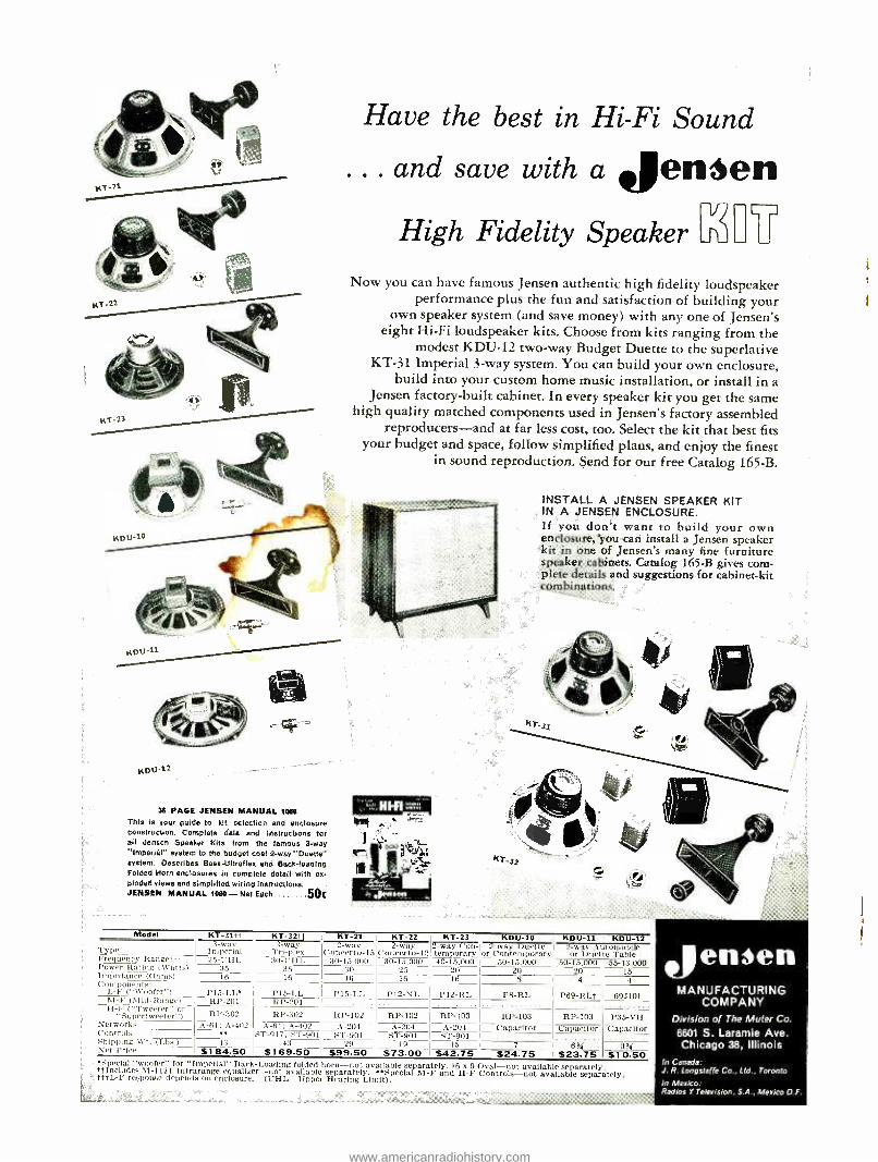
We guarantee to train you until you receive
Your FCC license If you fail to pass your commercial License exam after completing our course, we guar- antee to continue your training, without addi- tional cost of any kind, until you successfully obtain your Commercial license.
"License and Good Job ... Thanks" "After finishing your blaster Course, I passed the FCC exam for the 1st class license. I had my ticket for only one week and I got a job at \VOC -TV. AM -FM. Incidentally, AVOC is the oldest radio sta- tion west of the Mississippi. I sincerely feel that if it weren't for taking your Master Course, I would not have received my 1st class ticket. So I want to take this occasion to again thank you for such a
fine, complete and composite study for electronics work." Francis J. McManus
Davenport, Iowa
Cleveland Institute training in job offers like these:
Service Technician:
Man needed in Cleveland, Ohio to service and maintain electronic medial instruments and equipment. Must have a solid knowledge of electronic fundamentals. A car is required. Company benefits include retirement plan.
West Coast Manufacturer:
We are currently in need of men
with electronics training or experi-
ence in radar maintenance. We would appreciate your referral of interested persons to us."
CLEVELAND INSTITUTE OF RADIO ELECTRONICS Desk RE -19 4900 Euclid Avenue Cleveland 3, Ohio
Successful Electronics
Training
We can train you to pass your License Exams if you've had any practical expe- rience -amateur, military, radio servic- ing, or other. Our proven plan can help put you on the road to success.
Your FCC ticket will be recognized by em- ployers as proof of your technical ability.
Mail Coupon Now and get both FREE
good training doesn't cost
... it pays! Accredited by the National Home Study Council
Cleveland Institute of Radio Electronics
Desk RE -19, 4900 Euclid Ave.
r Cleveland 3, Ohio
Please send Free Booklets prepared to help me get ahead in Electronics. I
have had training or experience in
Electranics as indicated below.
Military [i Radio -TV Servicing ri Manufacturing Li Amateur Radio
In what kind of work are you now engaged?
Broadcasting Home Experimenting Telephone Company Other
In what branch of Elec- tronics are you interested?
Name Age
Address
City Zone State RIJ
1
1
1
1
1
1
1
1
1
1
I I 1
1
1
1
1
1
JULY, 1958 9
www.americanradiohistory.com

Customers Impatient? It's full speed ahead
with
Hz -Kap* Ceramic
Capacitor Kits
No delays! It's always smooth sailing when you use Centralab ceramic capacitor kits. No extra trips to your distributor, no wasted time. The units you need are on hand when you need them.
To keep you on an even keel, these heavy gauge steel kits contain balanced inventories of the most frequently used values. Individual values are prominently and clearly labeled, so you can locate the Ii-Kap you need, instantly. The new rigid plastic package perma-
nently separates and protects the units -yet is easily opened to remove a single capacitor.
So don't be left at sea. Ask your distributor about these four time- saving kits -and while you're at it, be sure to get your free copy of Catalog 30, listing the full line of Centralab capacitors and other quality components. FREE: $4.75 cabinet (4 "x7 "x11 ") with each kit.
D6K -200 Kit -200 Tubular Ceramic BC Hi -Kaps (27 values) DDK -200 Kit -200 Standard Ceramic Disc Hi -Kaps (31 values) TCK -80 Kit- 80 TC (Temp. Compensating) Hi -Kaps (40 values) HVK -150 Kit -150 High Voltage Disc Hi -Kaps (19 values)
Centralab products are listed in COUNTERFACTS, PHOTOFACTS, and THE RADIO- ELECTRONIC MASTER.
Trademark
A DIVISION OF GLOBE. UNION, INC. 922G E. KEEFE AVE. MILWAUKEE 1, WIS.
In Canada: 804 Mt. Pleasant Rd. Toronto, Ontario
SWITCHES PACKAGED ELECTRONIC CIRCUITS CERAMIC CAPACITORS
CONTROLS ENGINEERED CERAMICS SEMI -CONDUCTOR PRODUCTS
NEWS BRIEFS (Continued)
full -time instruction. It resembles a small card punch, but has an additional instruction box with set of lights on its face. The lights instruct a student which keys to press, speeding up as the stu- dent's proficiency increases. The ma- chine detects a student's weak spots and concentrates on them. It's being offered for sale at $1,400 -$1,600. DR. HAROLD S. BLACK. inventor of the negative feedback amplifier, whose in- ventions are credited with having made possible modern multichannel trans- continental and transoceanic communi- cation systems, was awarded the Lamme Gold Medal of the American Institute
of Electrical Engineers June 23 in recognition of "his many outstanding contributions to telecommunications and allied electronic arts, especially the negative feedback amplifier." Dr. Black is a Bell Telephone Laboratories re- search engineer.
Calendar of Events Technical Conference on Nonlinear Magnetics and Magnetic Amplifiers, Aug. 6 -8, Hotel Statler, Los Angeles, Calif. Conference on Electronic Standards and Measurements, Aug 13 -15, Radio Standards Laboratory, Bureau of Standards, Boulder, Colo. West Coast Electronic Show and Con- vention, (WESCON) Aug. 19 -21, Am- bassador Hotel and Pan Pacific Audi- torium, Los Angeles, Calif.
ELECTRONIC SERVICING was a $2.6 bil- lion business in 1957, Electronic Indus- tries Association's servicing committee estimates. Of the total amount, replace- ment parts including tubes and transis- tors accounted for $900,000,000 in fac- tory value, the remaining $1.7 billion representing labor and wholesale and retail markups of repair parts. FIRST ELECTRONIC HIGHWAY system is now in operation at the entrance to RCA's David Sarnoff Research Center, Princeton, N. J. It's a transistorized variation of the automatic electronic vehicle control system developed by an RCA Laboratories research team headed by Dr. Vladimir K. Zworykin. Two wire loops buried in the pavement detect passage and speed of cars. If a car exceeds the speed limit, the circuits automatically illuminate the warning sign at the roadside 20 yards ahead.
END
10 RADIO -ELECTRONICS
www.americanradiohistory.com

For dependability and
long life use
ZENITH QUALITY BATTERIES
EXTRA PROFIT ITEM! Zenith Mercury Batteries
Zenith pioneered the use of Mer- cury cells for transistor radios. They are easy to sell, because they provide up to four times the playing life of ordinary cells -and they provide extra profits because of higher unit price.
JULY, 958
Specially engineered for transistor radio operation
Dependability is built into every battery that carries the Zenith name. Advanced design provides maxi- mum hours of listening pleasure. Special construction insures long life and keeps batteries fresh longer.
Rigid manufacturing specifications, production quality controls and performance tests make doubly certain that all Zenith batteries are completely de- pendable and insure customer satisfaction. A com- plete line of Zenith batteries is available from your Zenith distributor.
40 years of leadership in radionics exclusively. The quality goes in before the Zenith name goes on.
SEE YOUR ZENITH DISTRIBUTOR
ZENITH RADIO CORPORATION PARTS AND ACCESSORIES DIVISION 6001 W. DICKENS, CHICAGO 39, ILLINOIS
11
www.americanradiohistory.com

portable' . or permanent
BOGEN FLEX-PAK` MAKES EVERY PA JOB AN EASY ONE
pre- engineered to serve 90% of your sound installations
Deluxe LX30 30 -Watt Amplifier 4 Microphone Inputs (panel switch con- verts one microphone channel for phono or tuner) ; Built -In Remote Gain- Control Circuit; Exclusive Anti- Feedback Control: Speech Filters; Separate Bass and Treble Tone Controls. H.: . . W. 161/4', D. 13 ". Wgt.: 25 lbs.
Superb L330 30 -Watt Amplifier 3 Microphone Inputs (panel switch con- verts one microphone channel for phono or tuner) ; Speech Filters; Separate Bass and Treble Tone Controls. H. . W. 141/ ". D. 13 ". Wgt.: 24 lbs.
BOGEN'S FLEX -YAK LINE has the flexibility you need to meet virtually every PA installation problem. Flex -Pak units are light, compact, portable, and can be used separately or grouped together. The amplifiers are available in every popular price range and power output ... 13 models in all. That's why, with Flex -Pak, you can tailor the sound system to fit the job, with none of the fuss and bother of custom installations. And remember -you can look to Bogen for all your sound equipment needs ... speakers, microphones, turntables, tuners, and accessories. See your Bogen distributor today.
EASY SERVICE . .. EASY INSTALLATION
i$ ß r _. .. .
Loosen 4 thumbscrews and the lid's off for fast, easy servicing.
Folds back when not 4 thumbscrews attach Easily erased write - in use in easy- sliding accessory record player in's on gain controls wall -mount bracket. mount. mark level settings.
BegetS NG
i licLciolt of The S'i<'plrr Crr¡+urotiml r- - - --
David Bogen Company, Paramus, N. J. , Dept. 61 -7 Gentlemen: Please send me descriptive catalog on your BOGEN FLEX -PAK Public Address Equipment and 2.4-page, illustrated brochtrre, "lVhat You Should Know About Sound Systems."
NAME
MAIL COUPON TODAY ' Check one dealer distributor sound specialist
CITY ZONE STATE
FIRM
M A N U F A C T U R E R S O F HIGH-FIDELITY C O M P O N E N T S P U B L I C A D D R E S S E Q U I P M E N T
12
I
I
J AND INTERCOMMUNICATION SYSTEMS
RADIO -ELECTRONICS
www.americanradiohistory.com

The Future is Wide Open >iii
GUIDED MISSILE
ELECTRONICS when you acquire high -level training in
ELECTRONIC ENGINEERING TECHNOLOGY
CREI prepares you
quickly for success in
GUIDED MISSILES RADN
INSTRUMENTATION AL1OMATION
SERVOMECHANISMS TELfMETERING
COMPUTERS ELECTRONICS MANUFACTURING
AERONAUTICAL ELECTRONICS
COMMUNICATIONS ASTRONAUTICS
Send now for CREI'S NEW FREE BOOKLET Crammed with facts and data -containing a time -proved plan to make you ready for the big jobs and high -salaried careers now being offered in America's fastest growing industry. CREI also offers residence training in Wash- ington, D. C. at the same high technical level. Day and evening classes start at regular intervals. Qualified resi- dence school graduates earn degree as "Associate in Ap- plied Science." Check coupon if you prefer residence or home study information . or write, Capitol Radio Engineering Institute, Dept. 147E, 3224 - 16th St., N.W., Wash. 10, D. C.
TELLS how you can make a secure, lifetime career in the tremendously expanding field of electronics. TELLS what employers demand of YOU in technical knowledge. TELLS what and where the oppor- tunities are -what they pay -the security and other benefits when you qualify. TELLS how you can qualify for top - pay jobs in Radar, Guided Missiles, Servos, Computers, Aeronautical Electronics, Electronic Manufac- turing, Communications. TELLS how we can help YOU become a leader in your profession, in mini- mum time.
JULY, 1958
MAIL TODAY FOR YOUR FREE BOOKLET
CAPITOL RADIO ENGINEERING INSTITUTE ECPD Accredited Technical Institute Curricula- Founded 1927
Dept. 147 -E, 3224 Sixteenth St., N. W., Washington 10, D. C.
I Please send me your course outline and FREE illustrated Booklet, I Your Future in the New World of Electronics" . describing
opportunities and CREI Home Study courses in Practical Electronic Engineering Technology.
Radar, Servo and Computer Engineering Technology
Electronic Engineering Technology Broadcast (AM, FM, TV) Engineering Technology Television Engineering Technology Aeronautical Electronic Engineering Technology
CHECK FIELD OF GREATEST INTEREST
Name Age
I Street
City Zone State I Check: Home Study Residence School Korean Veteran
If you have Iad a high school education, and ex. I
perience in electronics-and I
realize the need of a high - level technical knowledge to I
make good in the better I
electronic lobs - you can I
qualify for CREI home study training. (Electronics exper- ience is not required for od I
mission to CREI Residence School.) Please fill in the I
following information. Employed By I
Type of Present Work I
Education: Yrs. High School
Yrs. College
Electronics Experience _t 13
www.americanradiohistory.com
CORNELL- DUBILIER
CAPACITORS
The extra values are "on the house"
Want more capacitor for your dollar? Here's how: Cornell -Dubilier has originated a "preferred -type" program on twist - prong electrolytics. Now, a relatively few types fill over 90% of all replacement requirements. You need less - to do more. Fewer types means improved production efficiency, lowered costs - savings to you. How is it done? Instead of producing hundreds of types with odd and critical capacitance and voltage ratings, each "preferred type" carries the highest value and rating called for in each category. In most cases you get more capacitor at lower cost - plus added safety factor, im- proved performance and "call- back" protection. It's on the house !
To get more capacitor for your dollar, ask your C -D Distributor about Preferred Type Twist -Prong Electrolytics or write Cornell -Dubilier Electric Corporation, South Plainfield, New Jersey.
CORNELL- DUBILIER CAPACITORS Consistently Dependable
Correspondence
F*,1
NEW CONCEPT IN SOUND Dear Editor:
It has been shown that two radiators of 6 -inch diameter will exhibit the same radiation as a single radiator of 12 -inch diameter'
To quote: "Although two 6 -inch speakers have only one -half the piston area of a 12 -inch speaker, they are as efficient when mutually coupled as a single 12 -inch speaker of similar char- acteristics."
Pursuing this step by step to its logical conclusion, a further subdivision by 2 would result in four diaphragms of 3 -inch diameter, and so on. Thus if D is the original diameter, 12 inches in the example, this is divided by 2, 4, 8, 16 . . . 2" and the number of diaphragms multiplied by the same factors 2, 4, 8 ... 2 ". Since the imped- ance per unit area is established by Rayleigh' and the Bessels functions are available in published reference works', it follows that any subdivision of radia- tion surface may, therefore, be explicitly defined.
The area of each individual dia- phragm becomes Ai = (Dx2- ")'( /4) = D22- _ "(,r /4). (1) and the number of diaphragms becomes 2 ". The total area of the coupled array is therefore
A °= D'2- ' "( /4) x 2 "= D1(;,14)2, -".(2) and the original area is D'(r,14). Thus the resultant area is smaller than the original area, the factor of reduction being 2 ". If the value of n is some quantity like 2, the advantage to be gained is not immediately evident. But suppose we make n = 10, so that 2" becomes 1,028 and 2 - is .0097273 (very approximately). This is to say that for the original 12 -inch speaker we now have 1,028 minute radiators, each only .00097273 foot (roughly .00117 inch) in diameter.
This formidable array may look like an expensive approach but, again, let us go one step further. The total area of this new array, from equation (2), n = 10,
Ae = 122(57/4)2 '" _ .10099 square inch, or exactly 1/1,028 as much as the original area.
Now still one more step. Since the 1,028 individual small radiators are
1Joseph Marshall, Multiple Speakers, RADio- ELECTRONICS, September, 1955, pp. 100 -108.
-Lord Rayleigh, Theory of Sound, Macmillan & Co., London, England, 1898, Vol. 2, pp. 162 -69.
3Jahnke and Emde, Funktionentafeln, Teubner, Leipsig, 1933 ; Zylinderfunktionen, pp. 126 -30 (Ed. 1943 Rev.)
14 RADIO -ELECTRONICS
www.americanradiohistory.com

$®RCA INSTITUTES
OFFERS YOU THE FINEST
OF HOME STUDY TRAINING
R ELECTRONICS
TV SËRVICING
CÓIÓR TV
The equipment illustrated and text material you get
with each course is yours to keep. Practical work with very first lesson. Courses for the beginner and the
advanced student. Pay -as- you -learn. You need pay for only one study group at a time.
SEND FOR THIS
FREE BOOK NOW 1
JULY, I958
Resident School courses in New York City offer compre- hensive training in Television and Electronics. Day and eve- ning classes start four times each year. Detailed informa- tion on request.
RCA Institutes, Inc. Home Study Dept. RE -78 A Service of Radio Corporation of America 350 West Fourth Street, New York 14, N. Y.
Without obligation, send me FREE 52 page CATALOG on Home Study Courses in Radio, Tele- vision and Color TV. No Salesman will call.
Name Please print
Address
City Zone. State
Korean Vets1 Enter discharge date
CANADIANS -Take advantage of these same RCA courses at no additional cost. No postage, no customs, no delay. Send coupon to:
RCA VICTOR COMPANY, LTD. 5001 Cote de Liesse Rd., Montreal 9, Que.
To save time, poste coupon on postcard
15
www.americanradiohistory.com

For the stereo perfectionist The new ESL GYRO /JEWEL
0 No longer need perfectionists compromise with inferior or makeshift stereo pickups. From the distinguished laboratories which achieved the world -
famed ESL Concert Series and C -6o Series cartridges comes a new milestone in audio progress: the ESL GYRO /JEWEL, the stereo cartridge of tomorrow.
0 If you are technicallyminded,youwill be pleased to learn that thetriumphant design of the ESL GYRO /JEWEL is based upon two of ESL's patented, subminiature
DArsonval movements, coupled to the stylus shoe byESL's unique new Gyro/ jewel. 0 You will be pleased, also, to learn that the ESL GYRO /JEWEL excels in vertical
compliance (5 xi o -6 cm/ dyne), lateral compliance (5 x i o -6 cm /dyne), dynamic mass (.003 guts), channel separation (2o to 25 db), and frequency response
( ±3 db from 30 to 15,000 cps, with response extending well beyond 20 kc).
But only through actual listening can you realize the vast superiority of the ESL GYRO /JEWEL. Compare it at your audio dealer's, and you'll want to own
this stereo cartridge that's years ahead. Only $85; write for details.
16
F O R L I S T E N I N G AT I T S B E S T
Electro -Sonic Laboratories, Inc. Dept. E 35 -54 Thirty -sixth Street Long Island City 6, N.Y.
When Converting Your Phono to S'tereo... Uke
The ERIE AUDIO- AMPLIFIER KIT
featuring "PAC" and an ERIE
Printed Wiring Board
these Plug -in Components:
MODEL PAC -AMP- 1
See and hear it at your local distributor
or WrjtC for nearest source.
ERIE "PAC" (Pre- Assembled Components) ERIE PRINTED BOARD
OUTPUT TRANSFORMER
FILTER CAPACITOR
VOLUME CONTROL and SWITCH
TUBE SOCKETS
CAPACITORS
TONE CONTROL
TUBES
SPECIFICATIONS FOR ERIE STANDARD AUDIO-AMPLIFIER Frequency Response: 30 cycles to 12,000 cycles +0, -3.5 db. Sensitivity: 0.56 volt EMS (input at 1 KC) for 2 watt output. Power-Output: 2 watts Input Impedance: 2 megohms. Output Impedance: 4 ohms AC Power Consumption: 17 watts. Overall Dimensions: ós /e'' L x 4'/6" W x31 /e" H Shipping Weight 2 lbs.
\EME /ES STOB SRPOR
ERIE. PA
CORRESPONDENCE (Continued)
coupled, by the original postulate, they may be combined into a single radiating surface and driven by a single voice coil. Whence it follows Quod Error Demonstrandum that the original function of the 12 -inch cone speaker may be accomplished by the much smaller (.1099- square -inch) area pro- vided by a 0.3315- square -inch cone or a round one 0.4225 inch in diameter. Note the further reduction in size afforded by the square cone or pyramidoidic frustratum superfacium.
Obviously the value of n may be made any convenient value; slide rules may be made any length. If n is made large without limit, 2 -" becomes vanishingly small; on reaching infinitesimal values it may be ignored altogether, and the speaker omitted entirely. Erstwhile advocates of large and expensive speak- ers in sound reproduction systems are thus relegated to an era that is already past.
Laboratory corroboration of the basic theory was enlightening. For the experi- ment n was taken as 6, and 32 radiators of .03125 -foot diameter were driven by .015625 -inch diameter voice coils re- moved from as many shortvalve VI model stereococci pickout heads at the retail price of $250 each. Recognition a posteriori of the economy of the com- mon voice coil did not relieve the a priori expense.
The pressure- response curve divided by n corresponded within irrational standard deviations with the frequen- cies. Expressed in decibels, the factor of correlation was n where n is the same n used in equations (1) and (2). Obvi- ously with an increase in values of n, the reduction may be extended to the point where the pressure- response curve may be eliminated completely, and total reliance can be placed hereafter on published data. D. C. BELZ Hope, Ark.
"INDEPENDENT" TECHNICIANS Dear Editor:
I was pleased to see that Howard L. Nowry of Clearwater, Fla., was inter- ested enough in my article "Minimum or Maximum Job" (RADIO- ELECTRONICS, December, 1957, page 98), to write in a letter ( "Just Fix It," May, 1958). Mr. Nowry is very fortunate to be located on the west coast of Florida. Early this year I was passing through this area and the generator on my car died. I dropped the car off at the local car agency and went for a walk while it was being repaired.
Naturally I ended up in a couple of the local TV service shops. Here is the TV situation in that area as I could see it: There are fewer TV technicians per TV sets than I've ever seen. Com- petition is nil. One shop owner offered me a handsome salary to start if I would stay and handle his always bulging bench work. His calls were all routed for 48 hours ahead.
Mr. Nowry is located in a really lush
(Continued on Page 20)
RADIO -ELECTRONICS
www.americanradiohistory.com
What Does F.C.C. Mean To You? What is the F. C. C.?
F. C. C. stands for Federal Communications Commission. This is an agency of the Federal Government, created by Congress in 1934 to regulate all radio communication and radio and television broadcasting in the United States.
What is an F. C.C. Operator License? The F. C. C. requires that only qualified per-
sons be allowed to install, maintain, and operate electronic communications equipment, including radio and television broadcast transmitters. To determine who is qualified to take on such re- sponsibility, the F. C. C. gives technical exami- nations. Operator licenses are awarded to those who pass these examinations. There are different types and classes of operator licenses, based on the type and difficulty of the examination passed.
What are the Different Types of Operator Licenses?
The F. C. C. grants three different types (or groups) of operator licenses- commercial radio - telePHONE, commercial radioteleGRAPH, and amateur.
COMMERCIAL RADIOTELEPHONE oper- ator licenses are those required of technicians and engineers responsible for the proper opera- tion of electronic equipment involved in the transmission of voice, music, or pictures. For example, a person who installs or maintains two - way mobile radio systems or radio and television broadcast equipment must hold a radiotele- PHONE license. (A knowledge of Morse code is NOT required to obtain such a license.)
COMMERCIAL RADIOTELEGRAPH opera- tor licenses are those required of the operators and maintenance men working with communica- tions equipment which involves the use of Morse code. For example, a radio operator on board a merchant ship must hold a radioteleGRAPH license. (The ability to send and receive Morse is required to obtain such a license.)
AMATEUR operator licenses are those re- quired of radio "hams"- people who are radio hobbyists and experimenters. (A knowledge of Morse code is necessary to be a "ham ".)
What are the Different Classes of RadiotelePHONE licenses?
Each type (or group) of license is divided into different classes. There are three classes of radio- telephone licenses, as follows:
(1) Third Class Radiotelephone License. No previous license or on- the -job experience is re- quired to qualify for the examination for this license. The examination consists of F.C.C. Ele- ments I and II covering radio laws, F.C.C. regulations, and basic operating practices.
(2) Second Class Radiotelephone License. No on- the -job experience is required for this exami- nation. However, the applicant must have already passed examination Elements I and II. The second class radiotelephone examination consists of F. C. C. Element III. It is mostly technical and covers basic radiotelephone theory (including electrical calculations), vacuum tubes, transistors, amplifiers, oscillators, power supplies, amplitude modulation, frequency modulation, measuring instruments, transmitters, receivers, antennas and transmission lines, etc.
(3) First Class Radiotelephone License. No on- the -job experience is required to qualify for this examination. However, the applicant must have already passed examination Elements I, II, and III. (If the applicant wishes, he may take all four elements at the same sitting, but this is
not the general practice.) The first class radio- telephone examination consists of F. C. C. Ele- ment IV. It is mostly technical covering ad- vanced radiotelephone theory and basic tele- vision theory. This examination covers generally the same subject matter as the second class ex- amination, but the questions are more difficult and involve more mathematics.
Which License Qualifies for Which Jobs? The THIRD CLASS radiotelephone license is
of value primarily in that it qualifies you to take the second class examination. The scope of authority covered by a third class license is extremely limited.
The SECOND CLASS radiotelephone license qualifies you to install, maintain, and operate most all radiotelephone equipment except com- mercial broadcast station equipment.
The FIRST CLASS radiotelephone license qualifies you to install, maintain, and operate every type of radiotelephone equipment (except amateur, of course) including all radio and tele- vision stations in the United States, and in its Territories and Possessions. This is the highest class of radiotelephone license available.
How Long Does it Take to Prepare for F. C. C. Exams?
The time required to prepare for FCC exami- nations naturally varies with the individual, de- pending on his background and aptitude. Grant- ham training prepares the student to pass FCC exams in a minimum of time.
In the Grantham Correspondence Course, the average beginner with NO previous experience or training in radioelectronics should obtain his second class radiotelephone license after from 200 to 300 hours of study. This same student should then prepare for his first class FCC license in approximately 100 additional hours of study.
In the Grantham Resident Course, the time required to complete the course and get your license (under normal circumstances) is as follows:
In the DAY course (5 days a week) you should get your second class license at the end of the first 9 weeks of classes, and your first class license at the end of 3 additional weeks of classes. This makes a total of 12 weeks (just a little less than 3 months) required to cover the whole course, from "scratch" through first class.
In the EVENING course (2 nights a week) you should get your second class license at the end of the 22nd week of classes and your first class license at the end of 8 additional weeks of classes. This makes a total of approximately
7 months required to cover the whole course, from "scratch" through first class, in the evening course.
The Grantham course is designed specifically to prepare you to pass FCC examinations. All the instruction is presented with the FCC exami- nations in mind. In every lesson test and pre - examination you are given constant practice in answering FCC -type questions, presented in the same manner as the questions you will have to answer on your FCC examinations.
Why Choose Grantham Training? The Grantham Communications Electronics
Course is planned primarily to lead to an F.C.C. license, but it does this by TEACHING elec- tronics. This course can prepare you quickly to pass F. C. C. examinations because it presents the necessary principles of electronics in a
simple "easy to grasp' manner. Each new idea is tied in with familiar ideas. Each new principle is presented first in simple, everyday language. Then after you understand the "what and why" of a certain principle, you are taught the tech- nical language associated with that principle. You learn more electronics in less time, because we make the subject easy and interesting.
Is the Grantham Course a "Memory Course "? No doubt you've heard rumors about "mem-
ory courses" or "cram courses" offering "all the exact FCC questions ". Ask anyone who has an FCC license if the necessary material can be memorized. Even if you had the exact exam questions and answers, it would be much more difficult to memorize this "meaningless" mate- rial than to learn to understand the subject. Choose the school that teaches you to thoroughly understand-choose Grantham School of Elec- tronics.
Is the Grantham Course Merely a
"Coaching Service "? Some schools and individuals offer a "coach-
ing service" in FCC license preparation. The weakness of the "coaching service" method is that it presumes the student already has a know- ledge of technical radio and approaches the subject on a "question and answer" basis. On the other hand, the Grantham course "begins at the beginning" and progresses in logical order from one point to another. Every subject is covered simply and in detail. The emphasis is on making the subject easy to understand. With each lesson, you receive an FCC -type test so you can discover daily just which points you do not understand and clear them up as you go along.
HERE'S PROOF that Grantham Students prepare for F.C.C. examinations in a minimum of time. Here is a list of a few of our recent graduates, the class of license they got, and how long it took them:
License Wks. Albert Meehleib, Box 136, Elrama, Pa. 1st 12 Leo Bishop, 37 Calle Contenta, Flagstaff, Ariz. 1st 12 Carl Deare, Jr., P.O. Box 467, Jeanerette, La. 1st 11 Robert Umthun, 1918 EYe St., NW, Washington, D.C. 1st 21 Dan Breece, Station KOVE, Lander, Wyo. 1st 12 Robert Todd, Station WWBG, Bowling Green, Ohio 1st 13 Jackson York, 1029 N. Quincy St., Arlington, Va. 1st 15 Paul Chuckray, 6874 Weber Rd., Affton, Mo. 1st 11
OUR GUARANTEE: If you should fail the F.C.C. exam after finishing our course, we guarantee to give you additional training at NO ADDITIONAL COST. Read details in our free booklet.
TWO COMPLETE SCHOOLS
To better serve our many students throughout the entire country, Grantham School of Electronics maintains two complete schools - one in Hollywood, California and one in Washington, D,C..Both schools offer the same rapid courses in F.C.C. license preparation, either home study or resident class.
For further details concerning F. C. C. licenses and our training, send for our FREE booklet, "Opportunities in Electronics" . Clip the coupon below and mail it to the School nearest you.
GPt your First Class Commercial F.C.C. License in 12 weeks by training at
GRANTHAM SCHOOL OF ELECTRONICS
HOLLYWOOD DIVISION
1505 N. Western Avenue, Hollywood 27, Calif. Phone: 110 2 -1411
WASHINGTON DIVISION
821 - 19th Street, N.W., Washington 6, D.C. Phone: ST 3 -3614
JULY, 1 958
MAIL TO SCHOOL NEAREST YOU
Grantham Schools, Desk 84 -K 821 - 19th Street N.W. OR 1505 N. Western Ave. Washington 6, D.C. Hollywood 27, Calif.
Please send me your free booklet telling how I can get my commercial F.C.C. license quickly. I understand there is no obligation and no salesman will call.
Name Age
Address
City State
1 am interested in: Home Study, Resident Classes
L J 17
www.americanradiohistory.com

t AYT hi EON MADE IN u. & A 1B3GT
Made possible by
RUGGED, RAYTHEON FLY -BACK LIFE TESTS
At Raytheon, we test tubes to find out how good they are, not how bad. Accepted methods of testing tubes like the 1B3GT often resulted in subpar tubes. To improve and maintain the quality of Raytheon 1B3GT Tubes, Raytheon developed an expensive but super -accurate method of life testing these tubes.
Tests on the improved Raytheon 1B3GT far ex- ceeded our expectations. Receiver life tests of the Raytheon 1B3GT showed not a single failure at 600 hours. (No worries about early life tube failure here.) At 1850 hours a sensational 93% of these tubes were still operating at rated efficiency in spite of the fact that these sets were operated at 10% above their rated line input and cycled on and off every two hours.
These torturous Raytheon Tube tests not only prove the quality of Raytheon Tubes, they help maintain
18
that quality. Tubes are constantly checked and tested and any variance in quality is instantly noted and quickly corrected.
That's why you can use Raytheon TV and Radio Tubes with complete confidence in their quality - with full knowledge that you are giving your customers tubes that are RIGHT ... for Sound and Sight.
New Raytheon 1G3GT, 1J3GT and 1 K3GT Tubes are also subjected to the Raytheon Fly -Back Tests - and as a result meet Raytheon's highest standards of quality. Ask your Raytheon Tube Distributor for them.
RAYTHEON MANUFACTURING COMPANY Receiving Tube and Semiconductor Operations
NEWTON 58, MASS. CHICAGO, ILL. ATLANTA 6, GA. LOS ANGELES 7, CALIF. 55 Chapel Street 9501 Grand Ave. (Franklin Park) 1202 Zonolite Rd., N.E. 2419 So. Grand Ave.
Raytheon makes ? Receiving and Picture Tubes, Reliable Subminiature and Miniature Tubes, all these S Semiconductor Diodes and Transistors, Nucleonic Tubes, Microwave Tubes.
RADIO -ELECTRONICS
www.americanradiohistory.com

Up goes another VVinegard!
More Winegard Colorceptors are being sold today than any other all- channel yagi.
Discover for yourself the profit and personal satisfaction that come from selling the very finest antenna that can be installed on your customer's home. See your distributor for free Winegard sales aids and displays.
Write for Technical bulletin WCL4. Iÿ it1legald CO. 3013 -7 Stoffen Blvd., Burlington, Iowa
Shown to Model CL4 Photo by R. K. Sunderbrucw
www.americanradiohistory.com
HERE IS HOW YOU CAN CONVERT TO STEREO...
You con play any monaural source connected to Amplifier "A" through both amplifiers. effectively doubling power output
Allows you to monitor stereo top recordings as yov make then,
Yoo con r,verse channels it program material requires
lets you play stereo from any source
Pur playing monaural ral ,,.cords with your cierno pic hop
t rovrdes loudness compensation on both channel* if desired
ester poner switch turns on A -C of both amplifiers simultaneously.
Pluv source connected to rn Aj,1if c',
monaural through both amplifiers
The master volume control odiusts volume level of both amplifiers simultaneously
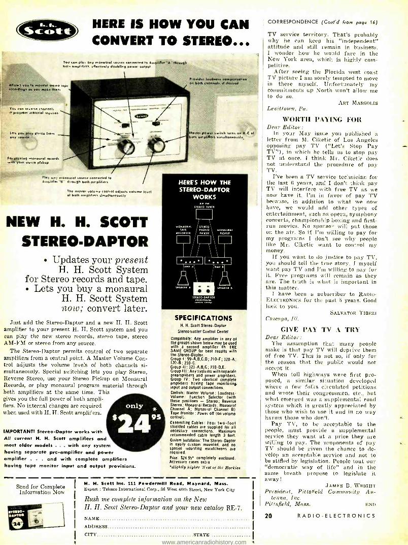
NEW H. H. SCOTT STEREO -DAPTOR
Updates your present H. H. Scott System
for Stereo records and tape. Lets you buy a monaural
H. H. Scott System now; convert later.
Just add the Stereo -Daptor and a new H. H. Scott amplifier to your present H. H. Scott system and you can play the new stereo records, stereo tape, stereo AM -FM or stereo from any source.
The Stereo -Daptor permits control of two separate amplifiers from a central point. A Master Volume Con- trol adjusts the volume levels of both channels si- multaneously. Special switching lets you play Stereo, Reverse Stereo, use your Stereo Pickup on Monaural Records, or play monaural program material through both amplifiers at the same time. This gives you the full power of both ampli- fiers. No internal changes are required when used with H. H. Scott amplifiers.
HERE'S HOW THE STEREO -DAPTOR
WORKS
MO su Of At rAPE
RECORDE I AM FM
SIEREO TUNER
I I
STEREO MONO PICKUP
II AMP
SPEAKER A
MONAURAL PICKUP
AMP e
SPEAKER K
IMPORTANT! Stereo -Daptor works with All current H. H. Scott amplifiers and most older models . . . with any system having separate pre -amplifier and power amplifier . . . and with complete amplifiers having tape monitor input and output provisions.
Send for Complete Information Now
SPECIFICATIONS H. H. Scott Stereo -Daptor
Stereomaster Control Center
Compatiäbty: Any amplifier in any of the groups shown below may be used with a second amplifier IN THE SAME GROUP for best results with the Stereo -Daptor. Group I:99- A,B.C,D;210 -F; 120 -A; 120 -B; 210 -C. Group 11: 121- A;B,C; 210 -D,E. Group III : Any systems with separate preamplifiers and power amplifiers. Group IV: Two identical complete amplifiers having tape monitoring input and output connections. Controls: Master Volume: Loudness- Volume : Function Selector (with these positions - Stereo; Reverse Stereo; Monaural Records; Monaural Channel A; Monaural Channel B) Tape Monitor : Power off Ion volume control). Connecting Cables: Four two -foot shielded cables are supplied for all necessary connections. Maximum recommended cable length 3 feet. Custom Installation: The Stereo -Daptor is easily custom mounted, and no special mounting escutcheons are required. Price: $24.95 completely enclosed. Accessory cases extra -
'lightly higher (Vest of the Rockies
H. H. Scott Inc. ill Powdermill Road, Maynard, Mass. Export : Telesco International Corp., 36 West 40th Street, New York City
Rush me complete information on the New H. H. Scott Stereo - Daptor and your new catalog RE -7.
NAME
ADDRESS
CITY STATE
CORRESPONDENCE (Cont'd from page 16)
TV service territory. That's probably why he can keep his "independent" attitude and still remain in business. I wonder how he would fare in the New York area, which is highly com- petitive.
After seeing the Florida west coast TV picture I am sorely tempted to move in there myself. Unfortunately my commitments up North won't allow me to do so.
ART MARGOLIS Levittown, Pa.
WORTH PAYING FOR Dear Editor:
In your May issue you published a letter from M. Ciketic of Los Angeles opposing pay TV ( "Let's Stop Pay TV "), in which he tells us to stop pay TV at once. I think Mr. Ciketic does not understand the procedure of pay TV.
I've been a TV service technician for the last 6 years, and I don't think pay TV will interfere with free TV as we now have it. I'm in favor of pay TV because, in addition to what we now have, we would add other types of entertainment, such as opera, symphony concerts, championship boxing and first - run movies. No sponsor will put those on the air. So if I'm willing to pay for my programs I don't see why people like Mr. Ciketic want to control my money.
If you want to do justice to pay TV, you should tell the true story. I myself want pay TV and I'm willing to pay for it. Free programs will remain as they are. The truth is what is important in this matter.
I have been a subscriber to RADIO - ELECTRONICS for the past 5 years. Good luck to you.
SALVATOR TIBERI Chicago, Ill.
GIN E PA% 'l'\ rl'R\' Dear Editor:
The assumption that many people make is that pay TV will deprive then of free TV. This is not so, if only for the reason that the public would not accept it.
When toll highways were first pro- posed, a similar situation developed where a few folks circulated petitions and wrote their congressmen, etc., but what emerged was a supplemental road system which is greatly appreciated by those who wish to use it and in no way harms those who don't.
Pay TV, to be acceptable to the people, must provide a supplemental service they want at a price they are willing to pay. The proponents of pay TV should be given the chance to de- velop an acceptable service and not to be stifled by legislation. People tout our "democratic way of life" and in the same breath propose to legislate it away!
JAMES B. WRIGHT President, Pittslit Id Community An-
tenna, Inc. Pittsfield, Mass. END
20 RADIO -ELECTRONICS
www.americanradiohistory.com
WE'RE MAKING IT EASIER THAN EVER TO BECOME A WELL PAID
RADIO- TELEVISION SERVICE TECHNICIAN
NOW - Just Starts You Training in
`Learn -by- Doing" Way .
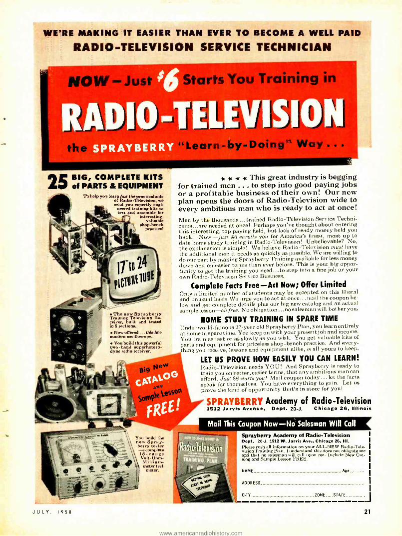
25 BIG, COMPLETE KITS of PARTS & EQUIPMENT
T elp yo-a learn fast the practical side of Radio- Television, we send you expertly engi-
neered training kits to test and assemble for
interesting, valuable
shop -bench practice!
2 The new Sprayberry Training Television Re- ceiver, built and tested in 5 Sections.
Now offered ... this fine modern oscilloscope.
You build this powerful two -band superhetero- dyne radio receiver.
- -or -lc it This great industry is begging for trained men ... to step into good paying jobs or a profitable business of their own! Our new plan opens the doors of Radio -Television wide to every ambitious man who is ready to act at once!
Men by the thousands ... trained Radio - Television Service Techni- cians...are needed at once! Perhaps you've thought about entering this interesting, top paying field, but lack of ready money held you back. Now -just $6 enrolls you for America's finest, most up to date home study training in Radio -Television! Unbelievable? No, the explanation is simple! We believe Radio- Television must have the additional men it needs as quickly as possible. We are willing to do our part by making Sprayberry Training available for less money down and on easier terms than ever before. This is your big oppor- tunity to get the training you need ...to step into a fine job or your own Radio -Television Service Business.
Complete Facts Free -Act Now; Offer Limited Only a limited number of students may be accepted on t h i, I iberal and unusual basis. We urge you to act at once... mail the coupon be- low and get complete details plus our big new catalog and an actual sample lesson -all free. No obligation... no salesman will bother you.
HOME STUDY TRAINING IN SPARE TIME Under world -famous 27 -year old Sprayberry Plan, you learn entirely at home in spare time. You keep on with your present job and income. You train as fast or as slowly as you wish. You get valuable kits of parts and equipment for priceless shop -bench practice. And every- thing you receive, lessons and equipment alike, is all yours to keep.
LET US PROVE HOW EASILY YOU CAN LEARN! Radio- Television needs YOU! And Sprayberry is ready to train you on better, easier terms, that any ambitious man can afford. Just $6 starts you! Mail coupon today ... let the facts speak for themselves. You have everything to gain. Let us prove the kind of opportunity that's in store for you!
SPRAYBERRY Academy of Radio- Television 1512 Jarvis Avenue, Dept. 20 -J, Chicago 26, Illinois
Mail This Coupon Now NO' Salesman Will Call
You build the new Spray- berry tester -a complete 18- range Volt -Ohm- Milliam - meter test
meter.
.._G16s
J U L Y 1958
Sprayberry Academy of Radio- Television Dept. 20 -J, 1512 W. Jarvis Ave., Chicago 26, III. Please rush all information on your ALL -NEW Radio -Tele- vision Training Plan. I understand this does not obligate me and that no salesman will call upon me. Include New Cat- alog and Sample Lesson FREE.
NAME
ADDRESS
CITY
Age
ZONE STATE ____________J 21
www.americanradiohistory.com

NEW
DIODE
SPEEDS
VOICES
AT 6,000,000,000 C. P. S.
How the radio art can be improved through solid state science is illus- trated by a recent development at Bell Telephone Laboratories. To make voice signals travel by microwaves they must first be "converted " - caused to vibrate at billions of cycles per second. To date, it has been possible to accomplish this conversion only at the cost of appreciable loss of signal energy. Could a more efficient converter be provided?
In the field of solid state science it was known -as a laboratory curiosity - that semiconductor diodes can be made not only to convert the frequency of signals, but also to amplify them. At Bell Laboratories Dr. Arthur Uhlir, Jr., and his associates calculated that this amplifying action could be put to prac- tical use. They proved the point by developing a junction diode converter which can deliver up to 40 times as much signal energy as previous converters.
This efficient new converter will be applied in a new Bell System micro- wave highway able to transmit thousands of telephone conversations and a dozen television programs simultaneously at six billion cycles per second. In other forms it is being developed, under Signal Corps contract, for radar and military communications where more efficient frequency conversion can also be used to advantage.
This development is an example of the many different ways in which Bell Laboratories works to improve your telephone service and communications at large.
22
BELL TELEPHONE LABORATORIES WORLD CENTER OF COMMUNICATIONS RESEARCH AND DEVELOPMENT
RADIO -ELECTRONICS
www.americanradiohistory.com

the experts say...
in High Fidelity the best buys
are L-7
E/Ca
KITS and WIRED
BETTER ENGINEERING Since 1945 EICO has pioneered the concept of test instruments in easy -to -build kit form - has become world -famous
for laboratory -precision instruments at low cost. Now EICO is applying its vast experience to the creative engineering of high fidelity. Result: high praise from such
authorities as Canby of AUDIO, Marshall of AUDIOCRAFT, Holt of HIGH FIDELITY. Fantel of POPULAR ELECTRONICS, Stocklin of RADIO TV NEWS, etc. -
as well as from the critical professional engineers in the field.t
SAVE 50% Mass purchasing, and a price policy deliberately aimed to encourage mass sales, make this possible.
EASY INSTRUCTIONS You need no previous technical or assembly experience to build any EICO kit - the instructions are simple, step -by -step, "beginner- tested."
DOUBLE 5 -WAY GUARANTEE Both EICO, and your neighborhood distributor, guarantee the parts, instructions, performance ... as well as lifetime service and
calibration at nominal cost ... for any EICO kit or wired unit.
BEFORIr.YOU BUY, COMPARE At any of 1200 neighborhood EICO distributors coast to coast, you may examine and listen to any EICO component. Compare
critically with equipment several times the EICO cost - then you judge. You'll see why the experts recommend EICO, kit or wired, as best buy.
f Thousands of unsolicited testimonials on file.
e HFS2
Speaker System
v
HFT90 FM Tuner with "eye -tronic" tuning
HFS2 Speaker System: Uniform loading & natural bass 30-200 cps achieved via slot -loaded split conical bass horn of 12 -ft path. Middles & lower highs from front side of 81/2" cone, edge- damped & stiffened for smooth uncolored response. Suspen- sionless, distortionless spike- shaped super -tweeter radiates omni- directionally. Flat 45-20,000 cps, useful to 30 cps. 16 ohms. HWD: 36 ", 151/4 ", 111/2".
. rates as excellent ... unusually musical ... really non -directional" - Canby, AUDIO. "Very impressive" - Marshall (AUDIOCRAFT). Walnut or Mahogany, $139.95. Blonde, $144.95.
HFT90 FM Tuner equals or surpasses wired tuners up to 3X its cost. New, pre -wired, pre -aligned, tem- perature-compensated "front end" - drift -free. Sensitivity, 1.5 uy for 20 db quieting, is 6X that of other kit tuners. DM -70 traveling tuning eye. Response 20- 20,000 cps ±1 db. Cathode follower & multiplex outputs. Kit $39.95 *. Wired $65.95 *. Cover $3.95. *Less cover, excise tax incl.
HF61A Preamplifier, providing the most complete control & switching facilities, and the finest design, offered in a kit preamplifier, " ... rivals the most expensive preamps . . is an example of high engineering skill which achieves fine performance with simple means and low cost." - Joseph Marshall, AUDIOCRAFT. HF61A Kit $24.95, Wired $37.95, HF61 (with Power Supply) Kit $29.95. Wired $44.95.
HF60 60 -Watt Ultra Linear Power Amplifier, with Acro TO -330 Output Transformer, provides wide band- width, virtually absolute stability and flawless tran- sient response. " . is one of the best -performing amplifiers extant; it is obviously an excellent buy." -AUDIOCRAFT Kit Report. Kit $72.95. Wired $99.95. Matching Cover E -2 $4.50.
HF61 Preamplifier
HF50 50 -Watt Ultra -Linear Power Amplifier with ex- tremely high quality Chicago Standard Output Trans- former. Identical in every other respect to HF60 and same specifications up to 50 watts. Kit $57.95. Wired $87.95. Matching Cover E -2 $4.50.
11F30 30 -Watt Power Amplifier employs 4 -EL84 high power sensitivity output tubes in push -pull parallel, permits Williamson circuit with large feed- back & high stability. 2 -EZ81 full -wave rectifiers for highly reliable power supply. Unmatched value in medium -power professional 'amplifiers. Kit $39.95. Wired $62.95. Matching Cover E-4 $3.95.
HF -32 30 -Watt Integrated Amplifier Kit $57.95. Wired $89.95.
HF52 50 -Watt Integrated Amplifier with complete "front end" facilities and Chicago Standard Output Transformer. Ultra -Linear power amplifier essentially identical to HF50. The least expensive means to the highest audio quality resulting from distortion -free high power, virtually absolute stability, flawless transient response and "front end" versatility. Kit $69.95. Wired $109.95. Matching Cover E -1 $4.50.
HF20 '20-Watt Integrated Amplifier, complete with finest preamp -control facilities, excellent output transformer that handles 34 watts peak poyver, plus a full Ultra- Linear Williamson power amplifier circuit. Highly praised by purchasers, it is established as the outstanding value in amplifiers of this class. Kit $49.95. Wired $79.95. Matching Cover E -1 $4.50.
Prices 5% higher in the West
Gi Gì U Có r3
HF52, HF20
Integrated Amplifiers
JULY, 1958
HF12 Integrated Amplifier
HF60, HF50 Power Amplifiers
HF12 12 -Watt Integrated Amplifier, absolutely free of "gimmicks ", provides complete "front end" facili- ties & true fidelity performance of such excellence that we can recommend it for any medium -power high fidelity application. Two HF12's are excellent for stereo, each connecting directly to a tape head with no other electronic equipment required. Kit $34.95. Wired $57.95.
HFS1 TwoWay Speaker System, complete with fac- tory-built cabinet. Jensen 8" woofer, matching Jensen compression -driver exponential horn tweeter. Smooth clean bass; crisp extended highs. 70- 12,000 cps ± 6 db. Capacity 25 w. Impedance 8 ohms. HWD: 11" x 23" x 9 ". Wiring time 15 min. Price $39.95.
THE HI -Fl EXPERTS SAY: For those who have been looking fer a well -
engineered yet inexpensive power amplifier, the newly -released EICO Model HF20 unit might offer a simple solution to their problem. Not only does this unit provide 20 watts of power but the cir- cuit incorporates a preamplifier and a variety of controls on a single chassis."
William A. Stocklin, Editor, RADIO TV NEWS
"The new EICO 'standard' speaker system .
produces sound that to my musical ears rates as excellent, from high top to clean low bottom."
Edward Tatnall Canby, AUDIO Magazine
Fill out coupon on other side for FREE CATALOG
AN. t'
g ter.
HF30 Power Amplifier
33 -00 Northern Boulevard, L. I. C. 1, N. Y.
Over 1 Million EICO instruments in use the world over.
HFSI
Speaker System Q) 1958
23
www.americanradiohistory.com

anr"."--"Yra,
20,000 Ohms /Volt V-O -M #565 KIT 24.95
Wired $29.95
1000 Ohms /Volt V -0 -M
#536 KIT $12.90 Wired $14.90
Reads 0.5 ohms -500 megs, 10
mmfd -5000 mfd, power factor.
R -C BRIDGE 8.
#950B
KIT $19.95 Wired $29.95
COMPARATOR
VTVM PROBES KIT Wired Peak -to -Peak $4.95 $6.95 RF $3.75 $4.95 High Voltage Probe -1 $6.95 High Voltage Probe -2 $4.95
SCOPE PROBES
Demodulator $3.75 $5.75 Direct $2.75 $3.95 Low Capacity $3.75 $5.75
FICO, 33 -00 Northern Blvd. Long Island City 1. N. V. C7
Show me HOW TO SAVE SO% on Test Equip- ment and Hi -Fi. Send me FREE Catalog and name of neighborhood distributor. Name
Address
City Zone State
for COLOR & Monochrome TV servicing
FREE CA TAL OG shows you HOW TO SAVE 50%
on 50 models of top quality professional test equipment.
NM COUPON NOW!
l
NEW! TV -FM SWEEP
GENERATOR &
MARKER -;t 368
* /1it 4 KIT e e _so - $6995
WIRED
$1199'
Entirely electronic sweep circuit (no mechanical devices) with accurately- biased inereductor for excellent linearity. Extremely flat RF output: new ACC circuit automatically adjusts osc. for max. output on each band with min. ampl. variations. Exceptional tuning accuracy: edge -lit hairlines eliminate parallax. Swept Ose. linage 3 -216 me in 5 fund. bands. Variable Marker Range 2.75 mc i 3 fund. bands; 60-225 nie on harmonic band. 4.5 me Xtal Marker Ose., xtal supplied. Ext. Marker provision. Sweep Width 0-3 mc lowest max. devia- tion to 0 -30 me highest max. dev. 2 -way blanking. Narrow range phasing,. Attcnuators: Marker Size, RF Fine, RF Coarse (4 -step decade). Cables: out- put, 'scope horiz., 'scope vertical. Deep- etched satin aluminum panel; rugged grey wrinkle steel cabinet.
NEW! RF
SIGNAL GENERATOR
1'324 KIT $2695
WIRED $3995 ,tea f¡L`
t4.
150 ke to 435 me with ONE generator! Better value than generators selling at 2 or 3 times its costl Ideal for IF -RF alignment, signal tracing trouble- shooting of TV, FM, AM sets; marker gen.; 400 cps audio testing; lab. work. 6 fund. ranges: 150 -400 ke, 400 -1200 ke. 1.2 -3.5 me, 3.5 -11 mc, 11 -37 mc, 37-145 mc; 1 harmonic band 111 -435 mc. Freq. accurate to ±1.5 %; 6:1 vernier tuning & excellent spread at most impor- tant alignment frcgs. Etched tuning dial, plexi- glass windows, edge -lit hairlines. Colpitts RF ose. directly plate- modulated by K- follower for improved mod. Variable depth of int. mod. 0 -50% by 400 cps Colpitts ose. Variable gain ext. ampli- fier: only 3.0 v needed for 305 mod. Turret. mounted coils slug -tuned for max. accuracy. Fine & Coarse (3 -step) RF attenuators. RF output 100,000 uv; AF sine wave output to 10 v. 50 -ohm output Z. 5 -way jack -top binding posts for AF in/ out; coaxial connector & shielded cable for RF out.
I "AU7, 12AV7, selenium rectifier; xmfr- operated. Deep- etched satin aluminum panel; rugged grey wrinkle steel cabinet.
#i0_ e ee e
NEW! DYNAMIC
CONDUCTANCE
TUBE & TRANSISTOR
? TESTER =666 KIT WIREE :6995 51099
* tttttttttt * ¡ - :
COMPLETE with steel cover and handle. SPEED. case, unexcelled accuracy & thoroughness. Tests all receiving tubes (and picture tubes with adapter). Composite indication of Gm, Gp & peak emission. Simultaneous sel of any 1 of 4 combina- tions of 3 plate voltages, 3 screen voltages, 3 ran of continuously variable grid voltage (with 5 accurate pot). New series- string voltages: for 600, 450, 300 ma types. Sensitive 200 ua meter. 5 ranges meter sensitivity (1% shunts & 5% pot). 10 SIX -position lever switches: freepoint connec- tion of each tube pin. 10 pushbuttons: rapid insert of any tube element in leakage test circuit & speedy scl. of individual sections of multi -section tubes in merit tests. Direct -reading of inter- element leakage in ohms. New gear -driven rotichart. Checks n -p-n & p -n -p transistors: separate meter readings of col- lector leakage current & Beta using internal dc power supply. Deep -etched satin aluminum panel; rugged greyss rink le steel cabinet. CRA Adapter$4.50
NEW!
COLOR and Monochrome
DC to 5 MC LAB & TV
5" OSCILLOSCOPE
460 KIT WIRED $7995 $12950
Features DC Amplifiers! Flat from DC -4. 5 Inc, usable to 10 mc. VERT. AMPL.: sens. 25 rms my /in; input Z 3 megs; direct -coupled & push -pull thruont; K- follower coupling bet. stages; 4 -step freq -compensated attenuator up to 1000:1. SWEEP: perfectly linear 10 cps -100 kc (ext. cap. for range to 1 cps); pre. set TV V &H positions; auto. sync. ampl. & lim. PLUS: direct or cap. coupling; bal. or unbal. inputs; edge -lit engraved lucite graph screen; dimmer; filter; bezel fits std photo equipt. High intensity trace CRT. 0.06 oses rise time. Push -pull hor. ampi., flat to 400 kc, sens. 0.6 rms my /in. Built -in volt. calib. Z -axis mod. Sawtooth & 60 cps outputs. Astig. control. Retrace blanking. Phasing control.
5" PUSH -PULL OSCILLOSCOPE
#425 KIT $44.95
Wired $79.95
7" PUSH -PULL OSCILLOSCOPE
#470 KIT $79.95
Wired $129.50
TUBE TESTER =625
KIT $34.95 Wired $49.95
tests 600 mil series string type
tubes b illuminated
roll -chart
Pix Tube Test Adapter $4.50
6V & 12V Battery Elim
& Charger #1050:
KIT $29.95 Wired $38.95
Extra filtered for transistorized eqpt, #1060: KIT $38.95, Wired $47.95
oec tot
4
Sep. hi -gain RF & lo -gain audio
inputs. Special noise
locator. Calibra- ted wattmeter.
KIT 524.95 Wired $39.95
DELUXE MULTI- SIGNAL TRACER #147
NEW! PEAK -to -PEAK
VTVM #232 & UNI -
PROBE (pat. pend.) KIT WIRED
$2995 $4995
Half -turn of probe tip selects DC or AC -Ohms.
Uni -Probe - exclusive with FICO - only 1 probe performs all functions!
Latest circuitry, high sensitivity & precision, wide ranges & versatility. Calibration without removing from cabinet. New balanced bridge circuit. High Z input for negligible loading. 41/2" meter, can't burn-out circuit. 7 non -skip ranges on every function. 4 functions: +DC Volts, -DC Volts, AC Volts,Ohms. Uniform 3 to 1 scale ratio for extreme wide -range accuracy. Zero center. One zero-adj. for all functions & ranges. 1% precision ceramic multi- plier resistors. Measure directly peak -to -peak volt- age of complex & sine waves: 0.4, 14, 42, 140, 420, 1400, 4200. DC /RMS sine volts: 0 -1.5, 5, 15, 50, 150, 500, 1500 (up to 30,000 v. with HVP probe & 250 mc with PRF probe). Ohms: 0.2 ohms to 1000 megs. 12AU7, 6AL5, selenium rectifier; xfmr- operated. Deep- etched satin aluminum-panel, rugged grey wrinkle steel cabinet.
33 -00 Northern Blvd., Lam Island City 1, N.Y.
24 RADIO -ELECTRONICS
www.americanradiohistory.com

Radio -Electronics Hugo Gernsback, Editor
SERVICE TECHNICIAN ANI) CLIENT ... Servicing Today Is Becoming Increasingly Complex ..
VER since the beginning of radio servicing in the middle '20's, the technician -customer relationship has been a difficult one, to say the least. The problem is quite com- plex. On the one side, the lay public does not under-
stand the technicalities involved and usually views any service transaction with suspicion. The technician's dilemma is that he finds it practically impossible to explain his side to the customer. The problem, too, is vastly aggravated by that small minority of dishonest technicians who get wide publicity in the newspapers, while, on the other hand, the hardworking, honest technician hardly ever is mentioned.
Let us stress at once that the situation which prevails with radio and television technicians and the public is not in any way different from other service trades such as plumbing, air conditioning, and refrigerators, dishwashers and other house appliance repair.
As a matter of fact, other trades charge much more in comparison for servicing home appliances and, while there is grumbling by customers here, too, it never seems as severe as it does against the electronic technician. The reason: the customer can readily understand what his plumber is doing, but seldom can he fathom what the TV technician has done to put his set into condition. In many instances, when something goes wrong with a television set, the service technician can repair it without the replace- ment of parts. Hence the customer thinks he is being robbed when he has to pay a service charge. Usually the repair of home appliances means visible parts -the customer can see something for his money. But it is usually the time charge, when only minor repairs are made, that incurs the dis- pleasure of the average TV owner.
We often hear the cry that electronic technicians charge higher fees than doctors. It would appear, however, that physicians are far better off than TV technicians. How many technicians, for instance, have country homes com- pared to physicians?
Customers should realize that the technician, just as the physician, sells his time and time is a limited commodity - he cannot stretch it. Only so many calls can be made each day. Frequently, when the technician is up against a difficult job -such as an intermittent -where the trouble is not immediately apparent, a large amount of time is consumed before it is located. The nontechnical customer immediately becomes suspicious that the service technician is stretching the time simply to extract a higher fee. This is rarely the case, as no technician worth his salt wants to spend more time than is absolutely necessary on any one job. As a matter of fact, it becomes highly irritating to the average technician if he cannot locate the difficulty in fast order.
Another sore point with many customers is the time spent by the technician going to and from his shop, which usually is charged to the customer. After all, the technician has been called to do the work and he cannot be on hand instantaneously. Someone must pay for the elapsed travel time. Nearly all servicing trades today have a fixed charge, whether work is performed or not. In other words, the time consumed coming and going is charged.
Not so long ago, we had a defective faucet on our dish- washer- disposal unit. We made an appointment with a service man for 10 in the morning, but were called out unexpectedly. The service technician could not get on the premises, but we were billed for his time anyway. We paid the charge.
Another point that the public does not often understand too well is that frequently the service technician must
JULY, 1958
choose between the cost of his time and the cost of replacing a part that at the moment might not absolutely need replace- ment. When a technician finds a circuit not operating (par- ticularly sweep circuits) he may replace all the tubes in that section. This is often cheaper to the customer in the long run than removing and replacing them one at a time to find out whether he can get by with one or two. The technician figures that replacing the additional tubes (that presumably are not in new condition at the time) may prevent future trouble when the tubes do cease to function a little later.
Further, the customer should realize that the cost of TV servicing is constantly going up instead of down. This is caused -aside from inflation -by the new shapes and the compactness of sets, which add to the technician's difficulties and increase the service time. The smaller the set becomes, the more difficult it is to service. This situation is aggra- vated in the new sets by the so- called series- string tubes. Here we have the difficulty that a defective tube may be one of 15 and it becomes a very time- consuming job to find out which tube has gone bad.
He should also consider the all- important axiom that as a receiver ages -say it is over 5 years old -it must, as a rule, be serviced more and more! Tubes now go bad more frequently, resistors, capacitors and other components fail! Old age now takes its toll. In such a situation the service technician must be called in more frequently. Curiously, too, he does not cherish working on over -age sets. They are more difficult to service because too many things are apt to go wrong.
In recent years the earlier rush into the field of the electronic technician has slowed. The reason: it is not one that is lucrative. If the technician has a reputation, is honest and conscientious, he is more likely to undercharge than to overcharge.
A few weeks ago, our television set started to misbehave. The picture was jumping and tearing and we suspected bad tubes. A neighborhood technician was called in and he put in two new tubes. The picture thereupon was steady, and he left. That night when we turned on the set, the sound came on but no picture. We called for the technician again and he found another tube had gone bad as well as a fuse. What had happened? Evidently the two new tubes had overloaded one of the circuits when the set was turned on later while all the tubes were still cold. This could happen occasionally and is, at best, an unusual condition. Nevertheless, the technician charged only for the fuse and the tube, but not for his time. This is honest servicing, where the technician takes a loss due to no fault of his own, but it certainly is not lucrative for him.
Service technicians find more and more that they cannot make out in these inflationary clays. Many cannot live on radio and television servicing alone. That is why many technicians have diversified their business by handling industrial equipment, diathermy, automatic doors, photo- flash equipment and, lately, high- fidelity servicing, which is a special field. In these fields, he finds he can charge more for his time.
A word to the consumer. Be choosy when you employ a service technician. If you use one and find that his work is good, that he is courteous and his charges are reasonable, stick with him. If he is a good man and satisfies you, recommend him. If possible, call in a technician who has been recommended to you by friends.
-H. G.
25
www.americanradiohistory.com

AUDIO -HIGH FIDELITY
how
the
STEREO DISC works
RECENT convers on about the mething like arth can a
p . to two ways at the same time and give different in- puts for two preamplifiers ?"
"That's easy," the answer came. "Every groove has two walls and one recording is cut into each wall of the groove."
The puzzled expression on the ques- tioner's face showed that this did not satisfy him -and for good reason. It is impossible for the stylus to follow dif- ferent contours on both walls of the groove at the same time. This may have been a simple explanation but it was certainly not the correct one.
In literature issued by Westrex the difference between cutting the two channels appears somewhat as in Fig. 1. It shows a record cutter that has an angle between the cutting faces of precisely 90'. The two drive mech- anisms, arranged at 45° to the vertical so the total angle between is 90 °, drive this cutter in directions parallel to its faces.
Consequently the diagram may make it seem that the vibrations due to one drive are recorded in one wall of the groove while vibrations due to the other drive are recorded in the other wall.
Stylus and cutter motion In practice, there is invariably some
program in both channels and both vibrations occur at once. So it is more important to consider what happens
CUT ER
5° I j '
I
I i
-"<-\\://
I
/ _
DISC
a 6 c Fig. 1 -The ba.i, behind the wrong idea that each eh: I is cut into one wall of the groove in the -15 -15 ..stem: a- na modulation; b- modnlalion in chan- nel 1 appears to eut ool the right gall; c- halation in channel 2 appear. to
eut on!. the left $ all.
26
The facts on the 45145 system
By NORMAN H. CROWHURST
4 4 CHANNEL I CHANNEL 2
a
2 4 COMBINED MOVEMENT
4 CHANNELI CHANNEL2
C
CHANNEL I
2
I
3
4
CHANNEL 2 e
4
COMBINED MOVEMENT
COMBINED MOVEMENT
4 2 CHANNEL I CHANNEL 2
2
3
4 COMBINED MOVEMENT
4 I
CHANNELI d
CHANNEL 2
COMBINED MOVEMENT
4 CHANNELI CHANNEL 2
COMBINED MOVEMENT
Fig. 2 -:1 more careful :uurl..is of how the cutter, groove and playback stylus move for different intensity and pba.e relations between channels at any frequency: a -in phase; h -out of phase; c- intensit, difference: d -90° phase diterence; t -30° phase difference; f- intensity and phase (30 °) difference.
RADIO -ELECTRONICS
www.americanradiohistory.com

The ESL stereo pickup separates the movement right at the stylus. This is
the prototype model. to the point of the cutter than to the contour produced by its two angular cutting edges. This is because the pick- up stylus will (or should) ride in the bottom of the groove, cut by the point of the cutter, and it is the movement of this point in the groove that deter- mines the program content of the two channels. To clarify this, let us consider what happens with different program combinations.
If both channels carry the same program at the same intensity and in phase, the movement of the cutter and the pickup stylus will be in the form of a lateral vibration (Fig. 2 -a). ( "In phase" as explained further down, refers to the system phase, not that of the cutter drive mechanisms.)
But if the inputs are precisely out of phase, the corresponding output from the loudspeakers on playback should also be out of phase, with one loudspeaker pushing when the other pulls. Then the motion of the cutter, groove and pickup stylus will be up and down in a vertical direction (as shown in Fig. 2 -b) .
If both channels have the same fre- quency in phase, but the intensity of one channel is stronger than the other, the motion will be predominantly lateral, with a slight angle but less than 45° (as shown in Fig. 2 -c).
If both channels carry the same fre- quency, but the phase relationship is neither in nor out of phase, other move- ments can occur. At a phase relation- ship of precisely 90 °, the motion of the cutter and the stylus, will be in a circle (Fig. 2 -d). Other phase relations with equal intensity will produce an elliptical movement, as shown in Fig. 2 -e.
Finally, if there is a difference in both intensity and phase that does not correspond with either an in -phase or out -of -phase condition, the motion of the cutter and ultimately that of the stylus will be in a modified ellipse as shown in Fig. 2 -f.
The motions depicted by Fig. 2, of course, represent only what can hap- pen at one frequency at a time. As prac- tical program material contains a variety of frequencies, at various intensities and phase relationships, the cutter, and hence ultimately the stylus, perform an endless variety of patterns, weaving in and out and up and down.
This explains the nature of the groove and what it represents. Now we
JULY, 1958
The Electro -Voice cartridge, right, is shown in the insert on the cover with the lower part of the housing (shown as white in this photo) removed and the copper clip normally attached to it floating in air. The two ce- ramic elements are clearly seen at the base of the red coupling element, running between it and the grayish mounting block at their opposite ends.
come to the question of how this infor- mation is extracted from the groove by the pickup. But before we proceed, let's clear up the question of phase, because different writings and discussions on the subject use different terms of refer- ence and apparent contradictions arise.
Some refer the phase relationship, between the motion in different direc- tions, to the cutter or pickup mechanism while others refer it to the overall action of the system. The definitions we have used so far, both in the previous article ( "Single- Groove Stereo Discs," RADIO -ELECTRONICS, January, 1958) and in this one, are related to system phase. This is based on the desirability of the lateral direction of cutter and stylus motion corresponding with the in -phase combination of program in the two channels.
But, related to the simple cutter design shown in Fig. 3, an in -phase movement of the two cutter mechanisms will drive the cutter vertically because the outward thrust of both elements results in a downward movement while the inward pull results in an upward movement.
To reverse the phase relationship to come out with the in -phase input to the two microphones producing a lateral cut, all that is necessary is to reverse the connections to one of the cutter coils. Similarly, if we take careful account of the phasing at the pick- up, we can reverse one of the connec- tions between the pickup and the ampli- fier or at the speaker, so lateral motion of the stylus results in in -phase motion of the loudspeaker diaphragms.
So, if we talk about cutter or pickup phasing, in -phase action produces a vertical cut and out -of -phase a lateral one. But referred to the system -the microphone input or loudspeaker out- put, it is just the other way around. To avoid confusion, references to phase
/CUTTER MOTOR CHANNEL I CHANNEL 2
MOUNTING ROD
111 (PARALLEL TO GROOVE)
45° 45°
`CUTTER
Fig. 3 -Basic action of Westrex cutter couples movement in two directions
right at the stylus.
AUDIO -HIGH FIDELITY
The Electro -Voice pickup uses two crys- tal elements
in this article are related to the sys- tem rather than to the cutter or pickup mechanism.
Now to the pickup Basically a pickup for stereophonic
discs can use the same kinds of trans- ducer elements, for converting the mechanical motion of the stylus into electrical output, as nonstereo pickups. The more common forms are magnetic, moving coil, crystal and ceramic. The way these elements operate follows precisely the same principle as their single -channel forebears. Now we come to the real question, how do we separate the two forms of vibration?
There are two extremes in the way this can be done. One method separates the two movements at the stylus point and couples them by separate mech- anisms to individual transducer ele- ments. This is the method used in reverse in the Westrex cutter head. The stylus is carried on a fairly stiff rod, in line with the direction of the groove. The two cutter motors are directly coupled to the stylus point at 45° in two directions, as shown in Fig. 3.
The same method of coupling, applied to a moving -coil pickup, is exemplified in the ESL stereophonic pickup, shown in the photos. It uses two d'Arsonval type moving -coil mechanisms, similar to their well -known single -channel de- sign, both coupled to the same stylus. The stylus is the common point at which the drive separates the two moving -coil transducers.
At the other extreme the stylus motion can be conveyed by a common arm to a pivot or some kind of combina- tion transducer where the two outputs are obtained electrically by separation in the transducer action itself. An example that excellently illustrates this method is the Fairchild stereo- phonic pickup.
The photos are a magnified view of the central element of the professional model of this pickup. As shown, the bobbins are empty and the actual coils have not been wound. The transparent plastic bobbins can clearly be seen at 45° to the square frame. The thin wires passing through the centers of the side suspend the coil assembly and provide a restoring force to center the coil in its neutral position.
The stylus arm, shown coming down at approximately a 45° angle, can move in almost any direction and pro-
27
www.americanradiohistory.com

AUDIO -HIGH FIDELITY
Fig. 4 (a, left, and the same stylus arm
b, right) -The Fairchild cartridge, a moving -coil type, uses to transmit the combined vibrations to a double -coil assembly
mounted in the same magnetic field. duce a corresponding combination piece of compliant or elastic material. movement in the coil. The magnetic Motion at one 45° angle drives one
crystal, while not moving the other one and vice versa.
As a crystal is basically a stiffness or compliant device (the drive force is used to bend it rather than move it) and these elements in this cartridge are rigidly mounted at their other end, the compliant drive from the stylus arm to the crystal represents a mechan- ical potentiometer, both elements of which are a compliance or stiffness. This means that if the compliance of the coupling element is five times that of the crystal, then the motion at the tip of the crystal will only be one -fifth of the stylus' motion in that particular direction.
As crystals produce a high output from a microgroove recording, this method still delivers enough output for any high -fidelity preamplifier and it has the advantage, over the more usual method of coupling through a mechan- ical lever system, that mechanical lever resonances are completely avoided. The dominant mechanical impedance pre- sented to the stylus point is the compli- ance of the stylus arm itself and its elastic coupling member.
If there is any mechanical resonance in the crystal element within the audio range, it will modify the frequency response but will not produce the damaging effect upon the record usu- ally associated with crystals. Also the use of this "potentiometer" arrange- ment restricts the magnitude of move- ment required in the crystal and lets it operate in a range where it is essen-
CRYSTALS RIGIDLY MOUNTED THIS END
field that produces the electrical output when the coils move is produced by pole pieces in front and behind the square. The magnetic poles are not shown in the photo because they would obscure the mechanism.
Obviously, if the stylus moves at a 45° angle one way, one coil will be rotating about its own axis and other- wise not moving and will produce no output, while the other coil will be rotating like a d'Arsonval coil between the two pole pieces and produce an electrical output (Fig. 4 -a) . Motion in the opposite 45° direction will make the first coil produce an output, while the second one rotates about its own axis and does not produce any output (Fig. 4 -b) .
This construction produces better than 20 -db separation between the two motions, over a frequency range extend- ing from the low end up to the region about 10,000 cycles. Above this, separa- tion is not so good, although the re- sponse of the pickup is maintained.
These may be regarded as two extremes in method. Practical pickups may well bridge the gap and produce results by methods that would be diffi- cult to list under either one of these extreme headings, perhaps coming close to achieving it by both of them.
Combination pickup The new Electro -Voice design is one
such method. This pickup is shown in the photos and its basic operation illus- trated by Fig. 5. Like the Westrex cutter, the stylus is supported by a horizontal rod in line with the direc- tion of the groove. However, a much more flexible rod is used because a stereo pickup requires a high compli- ance, or flexibility, while the cutter requires quite a reasonable stiffness.
Underneath the clip toward the right of the photograph is a removable mounting for the stylus and rod, so it can readily be changed without re- placing the pickup. The stylus arm drives the crystals through a triangular
28
CHANNEL I
CRYSTAL
CHANNEL 2 CRYSTAL
STYLUS
Fig. 5 -The Electro-Voice stereophonic pickup uses crystals and transfers the vibrations through an elastic piece that
separates them.
STYLUS MOUNTING ARM
ELASTIC COUPLER
tially linear. Driving the crystal harder (as the normal lever system does) would run it into nonlinear extremes.
With this pickup, separation of channels really takes place in the tri- angular piece of compliant material. But as this is one piece of material and not two separate links, it seems to "split the difference" between the extremes we started out with. An advantage of this design is the rela- tive purity of the separating method, achieving a high order of discrimina- tion against cross -modulation.
Oilier variations in the method of splitting the output can be seen by looking at possible ways of doing it in a magnetic construction (see Fig. 6). Here, the slug of magnetic material that produces the variation in mag- netic reluctance is attached directly to the stylus arm and varies the reluctance of both magnetic circuits, one for each channel. Motion at one 45° angle will change the gaps in that direction but not in the other direction, and there will be an output from only one coil. Motion in the other 46° angle will produce an output from the other coil. The com- plicated motion of the stylus following a stereophonic groove produces an out- put from both coils in the desired stereophonic relationship.
What's the delay? From this discussion it is evident
that there are a variety of ways to make pickups for stereo discs. Also it is evident that there are no serious problems in cutting the discs. A feed- back cutter, such as the Westrex, will do a good job of separating the two channels and avoiding cross -talk, pro- vided the two drives are mounted pre- cisely at 90° to each other. So what are we waiting for? Why have not standards been laid down and records already in production, with pickups to play them?
Here we have a "which came first, the chicken or the egg ?" type of prob- lem. The pickup manufacturers are looking for test records to determine how good their pickups are, while the record manufacturers need some way to measure precisely what they have cut on a recording. The pickup manu- facturers are looking for a perfect or at least adequate test disc or series of test discs, while the recording manu- facturers are looking for a perfect pickup or one adequately within range, to determine precisely what they have on their recording.
COIL FOR CHANNEL 2 COIL FOR CHANNEL I
MAGNET
STYLUS ARM STYLUS
Fig. 6- Another possibility is shown in this diagram of a composite two -coil
magnetic assembly.
RADIO -ELECTRONICS
www.americanradiohistory.com

GROOVE TRAVELS THIS WAY
VERTICAL CAUSES ,WHICH INTRODUCES
MODULATION ANGULAR COMPOTIENT OF
MOVEMENT MOVEMENT ALONG GROOVE
Fig. 7 -How an unduly steep stylus -arm angle might cause the vertical compo- nent of stylus motion to frequency -
modulate the recorded program. Then there has been the decision
about the appropriate groove contour - should the angle be exactly 90° as suggested by Westrex, or would other angles, such as the system proposed by CBS, also be suitable. Also the correct contour for both cutter and stylus has not been selected. Will the contour now standard in the industry for momogroove be used or some other contour? Then we need some way to test for interchannel intermodulation, cross -modulation and other effects that were completely unknown with mono - grooves. The official approval of the Westrex system (which is interpreted to include the CBS technique) may hasten action in standardizing these other points.
Perhaps we should point out here that there is a difference at the cutter end between the drive being at pre- cisely 90', or two separate 45° angles, and the angle of the cutter wedge being the same. If the stylus really runs along the bottom of the groove, it is not important to have the angle of the groove a precise 45° or 90 °. Any angle, so long as it is suitably standardized, will serve the purpose. The important thing is that the stylus must be able to ride the bottom of the groove cor- rectly.
In the design and testing of pickups there are some problems to settle. For example, the Fairchild professional pickup has a stylus -arm angle of about 45' sloping forward (quite apart from the 45' angles of the coils themselves). If the stylus only moves laterally, its motion will be similar to that of any lateral recording. But if the stylus follows a vertical component, even though this may be a partial component due to both the 45° elements, the up- and -down movement of the stylus will also produce a component (approx- imately equal to it) back and forth along the direction of the groove (see Fig. 7) .
This will amount to a Doppler effect along the groove or will result in effec- tive frequency modulation by the ver- tical component. As the vertical com- ponent is not confined to one of the program channels in 45/45, the com- bined vertical or out -of -phase compo- nent of both channels will produce frequency modulation.
We could go on to theorize about this but the real question is, does it really produce distortion? And if it does, is its effect audible as a deteriora-
JULY, 1958
tion of program quality? This is one of many things that still have to be proved. However, it is interesting to note that a new Fairchild pickup has a stylus arm that comes much nearer to being horizontal.
Another thing, this discussion is based on the motion of the stylus re- maining simple at all times -we assume it pivots about the cross -bar junction in the center of the coil. But if the vibrations runs into resonant condi- tions of the cross -wires or stylus arm at any frequency instead of the stylus assembly vibrating as a whole, the investigation becomes even more com- plex and it is possible that some form of intermodulation or other distortion not yet considered may take place.
Each kind of pickup, and each design approach, will have its own problems. In general, the simplest mechanism is most likely to avoid troubles. But the only real way to determine the effect of these different possible forms of distortion is to measure them -to get test discs with different frequencies recorded on the respective channels, determine possible cross -modulation
AUDIO -HIGH FIDELITY
from one channel to the other, or inter - modulation of the audio on one par- ticular channel by other tones on either channel, etc., using discs yet to be made.
Finally, having discovered what de- gree of intermodulation or cross - modulation exists with any particular pickup or record combination, we still have to determine whether this is important in terms of the end result - listening to the stereophonic program. It must be conceded that all of the pickups recently demonstrated have produced quite listenable stereophonic presentation, even though a rigid the- oretical investigation might suggest that some terrible distortion occurs.
From the work done so far and the technological improvement achieved to date, it is evident that stereo discs have a great future. There will be a little shakedown period -getting the bugs out and determining what kinds of dis- tortion really matter or whether they are really present at all -and then it seems we shall have a golden oppor- tunity for getting stereophonic pro- gram at a cost no greater than regular LP's. END
4 -Track Stereo Tapes Coming Competition for the stereo disc is
on the horizon in the form of a compet- itively priced prerecorded four -channel tape, completely enclosed in a cartridge. RCA is marketing the tape cartridges as well as a tape player which accom- modates them. Professional equipment for making the four -channel recordings is being manufactured by Ampex.
The prerecorded four -channel tapes are designed to provide an hour of stereophonic music at a price equivalent to that of stereo discs. The tape plays at a speed of 3s/4 inches per second, has a separation of M25 inch between tracks. One set of two stereo tracks plays in one direction; then by reversing the direction of the tape, the other set is played. Tape width is .043 inch.
One big advantage of the cartridge - loaded tapes, according to the manu- facturers, is that they may merely be dropped into the tape player -as easily as playing a phonograph record.
Stereo discs are already off to a strong start, and are on the market at prices from $3.95 to $6.95. Among stereo discs now becoming available (Right) What the prerecorded tape car- tridge looks like. (Bottom) How four
tracks are placed on V4-inch tape.
TAPE
across the country are those bearing the labels of RCA Victor, Capitol, Decca, ABC -Paramount, Hallmark, Urania, Esoteric, Contemporary, Elec- tra and Omega. Columbia Records, which had announced its own "compat- ible" stereo system, changed its mind and joined the rest of the industry in conforming with the 45 -45 standard.
Such old -line radio and television manufacturers as Motorola, Zenith, Westinghouse, Admiral and Magnavox have already indicated that they plan to incorporate stereo disc players in future hi -fi models.
The jukebox makers aren't ignoring the possibilities of stereo. At least one manufacturer is working on a model which can accommodate stereo discs.
4-TRACK TAPE HEAD
.043 1
.025 .043 .025 - .043 .025 .043
CHANNEL I
-CHANNEL 2
29
www.americanradiohistory.com
AUDIO -HIGH FIDELITY
By ARTHUR A. HUNDLEY*
RECORD CARE Your records need babying for their longer life and your continued enjoyment
WITH the advances in sound recording and reproducing techniques of the past few years, a whole new field of
opportunity for electronic sales and service has opened up. High fidelity is a definite part of the electronics busi- ness and the term "hi fi" is a house- hold word. Improved equipment and know -how have given us the finest facilities for the reproduction of re- corded music, but to maintain this superb quality all equipment must be cared for properly. There is one item which can be performed only by the owner- taking care of his records.
The recording companies record music much as it is played in the concert hall, and record players, amplifiers and speakers reproduce this sound with a lifelike brilliance never before known. However, records not properly cared for lose their fidelity, acquire increased noise and cause general dissatisfaction all around. Regardless of how good the equipment is, it will never sound any better than the record itself !
A good record collection represents a sizable monetary investment and it is up to the purchaser to protect it, both to save money and to gain longer - lasting enjoyment. Record care should be a common -sense item, but seeing how some people abuse their recordings leaves no doubt that instruction in basic care is needed.
*DeVry Technical Institute, Chicago, III.
30
Anyone engaged in the hi -fi field - either sales, installation or servicing - can help both himself and the customer by telling him the basic facts of record care. Often this can result in a satisfied customer because then the enjoyment of hi -fi is a long -term process, rather than existing only when new records are played. A more satisfied customer can mean increased profits from the business, so proper record care is of benefit all around.
Most of the newer records are made of vinylite, a plastic, and are unbreak- able in normal use. But, however, un- breakable they may be, the grooves which make up the musical portion of the disc can be damaged easily. Each groove is only 1 /1,000 inch wide and it doesn't take much of a scratch or abrasion to cut that far into the mate- rial, and the disc can be damaged by even smaller cuts.
This surface damage causes noise and often distorts the music. The hints given here are aimed at reducing noise and distortion, and increasing the use- ful life of a record, thus adding to the listener's enjoyment. Properly cared for, discs can be kept noise -free for a long time.
Record containers Most long playing records are pack-
aged in a cardboard envelope open on only one end, and many of the com- panies are additionally enclosing the
discs in a plastic or paper container which fits inside the cardboard cover. The first rule in record care is always to store each record in its own jacket and, if an inside envelope is included, don't throw it away -use it! Where only the cardboard jacket is furnished, it is wise to buy a cover made of soft plastic into which the record can be placed before insertion into the jacket. These plastic covers are made in 10- and 12 -inch sizes and can be bought from record dealers or radio supply houses. The current retail price is about 10 cents each for the 12 -inch size and somewhat less for the 10 -inch ones. This price is low compared to the cost of replacing the record.
These covers accomplish a twofold purpose: they keep the records clean (more will be said about that later) and decrease surface damage. The in- side of the cardboard containers is not completely smooth and as the disc is slid in or out of it abrasions may occur. The inside cover eliminates this possibility. (Never stack records one on top of the other without first placing them in their containers.)
Additional care is required in re- moving the record from the envelope and replacing it if an inside cover is not used. The best system is to press slightly at both ends of the jacket opening so that the sides are slightly bowed out. The record can then be taken out without too much rubbing
RADIO -ELECTRONICS
www.americanradiohistory.com

against the container. It can be re- placed the same way.
One of the worst enemies of long - playing records is dust, the ordinary kind which accumulates to some degree regardless of all the means taken to prevent it. When dust has settled in the grooves, background noise and dis- tortion occur whenever the record is played. The dust does not allow the needle to follow properly the groove variations which constitute the re- corded sound, and noise is produced.
Storing the records in plastic or paper covers prevents much of the dust pickup which otherwise would occur. Dust can enter into a record cabinet, even with closed doors.
Vinylite has the characteristic that a static- electric charge is developed on the surface when it is rubbed with anything. The charge is strong enough to attract and hold particles of dust which may be lurking near the record. These static charges may be eliminated by spraying the surface with an anti- static fluid or by wiping with a rag which has been treated with the same type of liquid. Both are available at record dealers and supply houses.
These accumulated charges also cause some noise when the record is played, sounding like loud pops. Eliminating the static charge also reduces this type of noise.
The application of these anti -static compounds does not merely eliminate the dust present at that time; its effects last for many months and, after being treated, the record actually repels dust. Once the dust has gotten into the grooves, the pressure of the needle forces it deeper and it becomes all but impossible to remove.
Record handling
Proper handling can also help to prevent dust in the grooves. Our hands have oils on them in varying amounts, and when the grooves are touched with the hands a film of this oil is deposited on the record. This tends to hold any dust which is picked up. To prevent this, the hands and fingers should never touch the grooved area. The disc can be removed from the jacket and placed on the turntable by touching only the edge and the label area in the center. The user must be careful in doing this, but it pays off in increased record life and enjoyment. If the hands do touch the grooves, the residue can be wiped off with a clean, soft rag.
JULY, 1958
It is good practice to replace each record in its individual container immediately after playing, to prevent any damage which could occur if it is left out in the open. And of course, be careful never to drop a record or scrape it against some hard object which could eut into the surface.
If your turntable is not exactly level, the pickup arm may jump grooves and scratch the record. Or, if the record player is mounted or placed so that vibration can shake the tone arm, similar results can occur.
The stylus exerts a great influence on the amount of noise and distortion produced and also on the usable life of the disc. Three general types are in use: metal, sapphire and diamond, with the purchase price and dependability of operation increasing in that order.
As long as the stylus retains its roundness it wears the walls of the record grooves very little. But during use the stylus and disc are in constant contact so some wear occurs on both. The same stylus is used for all records, so any wear affects the stylus much sooner than an individual record. The sides of the stylus become flat and it eventually acts like a chisel, cutting into the record grooves.
Stylus wear begins to manifest itself through noise and distortion and, if allowed to continue, a disc may be ruined in one playing. It is true that some people buy a phonograph and never bother to change the stylus for years, and maybe the gradual increase of noise and distortion seems like a natural thing to them. If these same people were to hear a new recording played with a new stylus, on their own equipment, a valuable lesson would be learned. That is learning the hard way (also called the expensive method).
Metal styli usually begin to show signs of wear after only a few hours of playing. Sapphire needles last con- siderably longer and diamonds wear much longer than sapphire. If used regularly, a metal needle should be replaced every few weeks, a sapphire every few months and a diamond after several years. There is no such thing as a permanent needle, regardless of what the ads say. Of course, these rules have no great accuracy because the actual playing time varies consider- ably. One person may play records less than an hour a week, while others may play them for several hours each day.
As a general estimate, a metal needle
AUDIO -HIGH FIDELITY
should be replaced after about 20 hours of actual use and a sapphire after about 100 hours, and a diamond should last at least 10 times longer than the sap- phire. So for long -run economy a dia- mond stylus, although its initial pur- chase price is higher than the others, outwears a large number of the other types and gives maximum protection to the record collection. It is poor economy to save a few dollars on the cost of a new stylus and waste many dollars in damaged records.
Keeping the stylus clean is also important. A small camel -hair brush will do a good job. And don't forget the stylus pressure. Too much and the stylus will dig into the groove, bringing the disc's life to an early end; too little and the stylus will skip, leaving scratches on the record face. If your pickup arm can be adjusted, keep stylus pressure between 2 and 8 grams. Check this frequently.
Record storage Records should be kept in a closed
cabinet, where dust entrance is kept to a minimum. And, if at all possible, the container should be in a compara- tively dry place where heat is not allowed to become excessive. Moisture and heat are injurious as either can cause warping. Slight warping may show up only as small variations in record speed, called wows. If the warped condition is serious enough, the disc becomes unplayable because the needle will not stay in the grooves.
To minimize these possibilities, discs should be stored in an upright posi- tion, and preferably held together by other records, books or cabinet dividers. This insures that all the records will be straight and will be kept that way because of no room for bending. Lay- ing them flat in piles is not as good as the upright position because, although the bottom ones are held down tight, those near the top could warp.
These rules sound like common sense, but a surprising number of record owners violate them consistently. By following them, the listener can get the most value for his record dollar, listening will be more enjoyable and free from noise and distortion, and long lasting. Dealers and technicians who instruct their customers in these basic facts will then enjoy the results of having customers who are more satisfied and, most likely, will receive increased business as a result. END
31
www.americanradiohistory.com

AUDIO -HIGH FIDELITY
A new English design, this versatile 2 -tube low- distortion unit will help you get the most from your amplifier
The finished preamp with the cover plate re- moved. Careful con- struction will give it a professional appear-
ance.
A look at the hack end of the chassis shows tube placement and po- sitions of the input
jacks.
CUSTOM PREAMP
for your
HI -FI SYSTEM By E. J. PORTO *
POWER amplifiers with relatively high sensitivities -200 to 300 mv- offer many advantages in high - fidelity sound reproduction since
the preceding preamp stages need not be of the high -gain type. Distortion, hum and noise levels, which are ex- tremely critical in these stages, can, therefore, be kept to a minimum.
The Mullard preamp circuit' (see Fig. 1) was designed for use with such power amplifiers and is particularly suited to the Mullard 510 and 520 cir- cuits. Inputs are provided for any type pickup, tape recorder playback heads, and microphone and radio tuner inputs. An auxiliary jack for any other input source convenient to the user is also
International Electronics Corp., New York, N.Y.
'Design was originated in the Mullard Appli- cations Research Laboratory, England.
32
provided. Equalization for disc record- ings conforms to the latest RIAA char- acteristics, which have been adopted by most of the major recording companies. The tape playback characteristic is equalized to standard NARTB tapes.
Low- impedance tone controls with wide frequency coverage supply enough equalization for any application.
How it works
The preamp has two stages, each using an EF86 high -gain pentode. All equalization takes place in the first stage and is controlled by frequency - selective feedback between the plate and grid of Vl. There is no feedback in the second stage and V2's output is fed directly to a passive tone control net- work. This arrangement lets the input impedance of the first stage remain low.
A low impedance at this grid reduces hum pickup as well as the effect of plugging in external low- impedance circuits. The arrangement also results in low gain in the first stage. This reduces Miller effect, between the plate and grid of the first EF86, which can be troublesome when high resistances are used in series with the grid.
Series resistors are used in the input channels so sensitivity and impedance of any channel can be accurately ad- justed. The values given in Fig. 1 are for the most common inputs, but sensi- tivity and impedance' of each channel can be altered by changing the value of the appropriate series resistor.
The preamp's sensitivity can be changed for all input channels by vary- ing V2's output. This is done by altering the ratio of resistors R21 and R22. (The sum of these two resistors should be maintained at 100,000 ohms.) The values of 18,000 and 82,000 ohms shown in Fig. 1 are appropriate for use with the 510 amplifier. With the 520 ampli- fier, and higher -powered types, output is taken directly from V2's plate.
Filter components R13 and C17 shown in the B -plus line should be in- cluded in the main amplifier rather than in the preamp. B -plus current drawn by the preamp is 3 ma at 320 volts.
Preamp performance The values for hum and noise given
for each input channel have been meas- ured with the preamp connected to a Mullard 510 power amplifier. The meas- urements were made at the output of the power amplifier with the preamp's input terminals open. Frequency re- sponse curves were also determined with this combination of preamp and power amplifier. Sensitivity figures that fol- low provide outputs of 40 and 250 mv when V2's plate load is adjusted for use with 510 and 520 power amplifiers, respectively.
Pickup input channels Equalization curves for the magnetic
and the crystal pickup channels are shown in Fig. 2.
Magnetic pickup: Input impedance: Sensitivity at 1.000 cycles:
(a) long playing (b) 78 rpm:
Hum and noise (a) long playing: (b) 78 rpm:
100,000 ohms (approx)
3 mv 9 mv
55 db below 10 watts 57 db below 10 watts
2The impedance of the input channels in- cludes the grid impedance of the EF86 modified by the feedback components as well as the im- pedance of the input network.
RADIO -ELECTRONICS
www.americanradiohistory.com

RI, 2 -2.2 megohms R3- 56,000 ohms R4, 6, 19 -I megohm R5, 28- 68,000 ohms R7, 15- 100,000 ohms R8 -10 megohms, 5% 19, 12- 560,000 ohms, 5% R10-5.6 megohms, 5% RII- 330,000 ohms, 5% R13- 30.000 ohms R14- 220,000 ohms, 5%
*R16- 220,000 ohms *R17 -I megohm RI8 -2,200 ohms R20- 33,000 ohms
*R21- 18,000 ohms *R22- 82,000 ohms
R23 -1,200 ohms *R24- 390,700 ohms
R25, 29. 31 -pot, 253,000 ohms, logarithmic taper R26- 47,000 ohms R27- 39,000 ohms R30 -6,800 ohms
.1II resistors 1/2-watt 10% unless noted `Deposited- carbon low -noise resistors, 10% or better CI -390 µµf, silver mica, 5% C2 -150 gat silver mica, 5% C3 -.0022 µf, silver mica, 5% C4- 560 µµf, silver mica, 5% C5 -220 ggµf, silver mica, 5% C6, 10 -25 µf, 12 volts, electrolytic C7, 8, I I, 12 -0.1 4, 400 volts, paper C9 -8 µf, 350 volts, electrolytic CI3 -560 µµf, silver mica, 10% C14 -.0082 4, silver mica, 10% C15 -.0022 µf, silver mica, 10% C16 -.02 µf, silver mica, 10% CI7 -16 µf, 350 volts, electrolytic J1-7-phono jacks or coaxial connectors 51 -2 -pole 6- position rotary, 2 decks VI, 2 -EF86 Aluminum sheets for chassis and case: 1 -16 x 21/2
inches; 1 -9 x 3 inches; I -8r/8 e I inches; 2- 81/8 e 31/2 inches
Angle brackets 31/2 inches long, 1/2 inch wide in top and bottom corners (4)
Sockets, 9 -pin miniature, with shields (2) Knobs Miscellaneous hardware
*RII
AUXILIARY
B SI -a
330K RADIO
*CI * R12 C '
390µµf 5 TAPE
D I b I
MIKE I
E
C2 * 150µµf (( *R9
560
*RIO
5.6MEG
C3* .0022
R8*
IOMEG
*C4 60µµ
* R14
220K
G PLAY
F
78 RPM
I
A
i
B
220µµf
AUX RI
eJI 2.2MEG
RADIO R2
2 2.2MEG SI-b
TAPE R3 C
J3 56K
MIKE R4
E
R15
Fo
0J4 IMEG MAGNETIC PICKUP RS
J5 68K XTAL PICKUP R6
6 Wh. R7 I MEG
IOO K
This input channel is best suited for variable -reluctance pickups, but mov- ing -coil types which have higher out- puts can be used if a larger value of series resistor (R5) is included. The difference in sensitivity between the long -playing and 78 -rpm channels is taken care of by the amounts of feed- back provided at positions E and F. Crystal pickup: Input impedance : 100,000 ohms Sensitivity at 1,000 cycles:
la) long playing: 50 mv (b) 78 rpm: 150 mv
Hum and noise (a) long playing: 55 db below 10 watts (b) 78 rpm: 55 db below 10 watts Low- and medium -output crystal
pickups can be used for this channel. The input is loaded with 100,000 -ohm resistor R7 so its characteristic ap- proximates that of a magnetic cartridge and lets us use the same feedback net- work. This produces the best compro- mise with most types of pickups. How- ever, if the pickup is not suited to this form of loading, or if its output is too high, it may be connected to the aux- iliary input socket. Tape playback input: Input impedance: 80,000 ohms (approx) Sensitivity at 5,000 cycles: 3 mv Hum and noise: 52 db below 10 watts
The equalization characteristic used for this channel is shown in Fig. 3 and follows the NARTB curves. This chan- nel is intended for replaying pre- recorded tapes with high- impedance heads, and the characteristic adopted gives excellent performance. If greater sensitivity is required, resistor R3 can be decreased until the desired sensitivity is obtained.
JULY, 1958
DEPOSITED - CARBON LOW NOISE
*5%
SELECTOR
8/350V R20
AUDIO -HIGH FIDELITY
230V
R16 © 220K
R17 O IMEG
C7
33 K
R21 18K
CII
j RI 320V
I + 30K
R24 ICI7TI6/350V 390K L _ IN MAIN AMPL
R22 82K
+12.2 K
25 C6 12V
RI8
IMEG
+11.2K 25 CIO 12V
C12
.I 23
Fig. 1- Circuit of the custom preamp.
Microphone input: Input impedance : 1 megohm Sensitivity at 5,000 cycles: 6 my Hum and noise: 44 db below 10 watts
The frequency response of this chan- nel is given in Fig. 4. The microphone input channel is intended for use with high- impedance systems such as crystal or magnetic mikes with transformers. Tuner input: Input impedance : 2 megohms Sensitivity : 250 my
The frequency response of this chan- nel is also given in Fig. 4. With the values of impedance and sensitivity quoted, this channel should meet most requirements. Other values can easily be obtained by changing feedback re- sistor R11 and series resistor R2. If the input impedance of the channel is
2 0
15
15
20 30rL 100
LONG PLAY
`s.
500 IKC FREQ
Ns78 RPM
5 10
Fig. 2- Equalization characteristics of the pickup input channels.
CI3 560µµf
C 10% I5 0022
10%
R25 250K
TREBLE
R26
CI47 K
0082
R 28 68K
39K .02 10%
6
R29 250K BASS
6.8K 10% R30
VOLUME
OUTP
R31 250K
T
J7
too high, it can be reduced by con- necting an appropriate resistor between the input end of R2 and the chassis. Auxiliary input: The auxiliary channel is identical with the tuner input chan- nel. This input, with the values shown in Fig. 1, can therefore be used for high -output crystal pickups or tape re- corders. In addition, the channel can be easily adapted for many other ap- plications. For instance, if series re- sistor Rl is reduced to 1 megohm, the auxiliary input will be suitable for crystal pickups which have low outputs.
Fig. 3- Equalization curve for the tape playback channel.
J ltd 20'1., 50 100 500 IKC 5 10
FREQ
111111111111111111111111111
1IIIIIIIIIIIIII1111itI IIIIIIIIIIIIIIIIIIIIIIII1
RADIO
Fig. 4 - Frequency response of the microphone and radio channels.
33
www.americanradiohistory.com

AUDIO -HIGH FIDELITY
26
A
15
C
15
20 30'ti 100
A= BASS-MAX BOOST TREBLE -FLAT
B. BASS-MAX CUT TREBLE -FLAT
500 IKC FRED
C= TREBLE -MAX BOOST BASS -FLAT
D. TREBLE-MAX CUT BASS -FLAT
5 10
Fig. 5- Effect of Nation- tone -control settings.
Tone control: The treble and bass con- trol characteristics of the preamplifier are shown in Fig. 5. It is evident that an adequate amount of control is pro- vided for almost any application.
Low -impedance controls have been adopted so that any capacitance re- sulting from long coaxial leads between the preamp and main amplifier will have a minimal effect on the preamp's output impedance. Harmonic distortion.: The total har- monic distortion of the preamp is less than 0.157. at normal output levels.
Construction details The chassis and layout of the preamp
have been designed specifically for the home constructor. A conventional box type chassis is not used. Instead, the chassis is made on the unit system, the separate parts being joined together during the assembly of the equipment.
The chassis is made up of five sepa- rate pieces of sheet aluminum. The dimensions are given in Fig. 6. Each piece should be marked as shown and the holes indicated cut. When bending the pieces, the scribed lines should lie exactly along the angles. This assures that the pieces will fit together properly when assembled. For ease of assembly, components should be mounted on two terminal boards, and these should then be bolted to the mounting strip before the strip is attached to the rear plate. Diagrams showing the position of the components on the terminal boards, and the appropriate connections are given in Fig. 7.
When the mounting strip and ter- minal boards have been attached to the rear plate, make all connections between the tube sockets and the components on the terminal boards. (Mount the tube sockets so that the tubes will be outside the completed chassis.)
Mount potentiometers R25, R29 and R31 on the front panel and connect the other components which make up the tone control network to them. Then bolt the front panel to the back panel and connect the remaining components.
34
S I 3-I/2" !-I/2° I/2"-r
¡3/4"
I/2"
3"
i4
e
d
2"
T*
I6"
2'= =¡2-1/4' - 3/4" 31/2 1/2'
I
f
11/fi'
I-3/4"
I
9" B-74
I-3/4"
I-3/4"
FI/8
3//4" 1/2" lr
FRONT PANEL MOUNTING
INPUTS JI -6.
2-3/4
e
1I/ B"
REAR PANEL
1/2"
8-1/8"
I/2"
2-3/4"
1/2"
STRIP
-H e
COVER PLATE (TWO)
e
I-1/4" '1 -1/4---1/2" " I--i/ 4q
3/41
¡
1/4' I/2">
e
T 2-I/2"
HOLE DIMENSION USE
o -DRILL NO 34 - CLEARANCE HOLE
O* COAXIAL CONNECTOR
O °DIA. -I/2 RUBBER GROMMET
` !,a
-30 "DIA, SOCKET -3/4 -TUBE
DIA. POTENTIOMETER
*DIMENSION VARIES WITH CONNECTOR TYPE
Fig. 6- Details of the chassis construction.
VI V2 117
GND LUG 1 R7 1-D- J6
i J41 J3
ISOCKET ISOCKET OUTPU
PIN 9,V1 +{ RI5 ¡-GND PIN 9,V2-"-1 RI9 GND
TERMINAL BOARD I
SI-b C
SI-bD
SI a
SI b
SELECTOR
S I-b E,F
z
:-
PINI VI
CB
PIN 9,V2
GND R161
TERMINAL BOARD 2
CN
PIN I,V2
G D
1
I
R3I
SI-b8
SI bA
SI aC
RII
RS
SI-0E
C7
R29 BASS
TERMINAL BOARD I
6 Fig. 7- Recommended parts
J5
J6
J2
JI
R25 TREBLE R3I VOLUME
TERMINAL BOARD 2
PIN 6, VI
PIN 3,VI
PIN I,VI
PIN 6,V2
PIN 3, V2
230V
ç layout; a -the main chassis; h- terminal board 1; c- terminal board 2.
The supply leads to the tubes should be taken through the grommet hole in the rear panel and soldered into posi- tion. To avoid the expense of a plug and socket, pass these leads through a
small securing clip and knot them at this clip to prevent strain on the solder joints. When the wiring has been com- pleted, fasten the cover plates in place with self- tapping screws. END
RADIO- ELECTRONICS
www.americanradiohistory.com

NEW
Reviewed by CHESTER SANTON
Station WQXR, New York City
THE recording technique that gave the greatest impetus to high fidelity is now 10 years old.
It was in June, 1948, that Columbia's research organization, CBS Laboratories, abolished some of the old record problems and instituted a few new ones with a 12 -inch, 33,A-rpm, unbreakable, Vinylite record containing up to 23- minutes of music on one side. The solution of problems connected with the 78 -rpm speed enlarged enormously the audience for reproduced music. Technically minded listeners, some of them brought into the field by the LP record. devoted the money, time and patience needed to encour- age the development of the microgroove record to its present stage of perfection. How good were the first LP discs? Only one decade later, the question is already difficult to answer because the earliest pressings are no longer on the market. Columbia's New York office generously offered listening facilities for their reference copies on the premises. I declined, however, in view of the unknown factors in playback. Luckily, the WQXR record library held copies of the original pressings going back to the first 12 -inch classical disc -Columbia ML -4001. I proceeded to sample the first 12 releases put out on LP, using as reference my own familiar up -to- date sound system. The first remindful discovery (releases ML -4003 through 4011) were all devoted
to Beethoven. Oddly enough, the first release (ML -4001) which contained the Mendelssohn Violin Concerto in E Minor with Nathan Milstein and the New York Philharmonic under Bruno Walter was found to have the best sound of the group. Next best was ML -4004 (Beethoven's Piano Concerto No. 5 with Serkin and the New York Philharmonic under Walter). Technically, ML -4001 revealed the following: With equaliza- tion controls set for the Columbia LP curve and bass and treble in a "zero" position, rumble traceable to the record was audible. At normal listening level, reduction of the bass setting to "11 o'clock" on the dial removed most of the rumble. Upper frequency response was surpris- ingly good. Use of the 10 -kc filter on my preamp reduced the highs by a minute amount, indicating the presence of some response above that figure. Response behavior when rolled off with the 7 -kc filter denoted a flat curve in the area below 10 kc. In other words, filtering at 7 kc eliminated desired instrumental sound, whereas some subse- quent LP records have used this same filter to flatten the recording curve's peak in that area. In a final gesture of curiosity, I switched to the RIAA position. It thinned out the sound. One clue to the acceptable sound on the first Columbia LP record was found in the timings. Side A ran 11 :20 ; the other side 13 :20. It is a better record than we suspected 10 years ago.
BRITTEN: Young Person's Guide to the Orchestra
DOHNANYI: Variations on a Nursery Tune
Felix Slatkin conducting Concert Arts Symphony Orchestra with Victor Aller, Piano
Capitol Stereo Tape ZF -23 (7 -inch; playing time, 41 min. $14.95) Perhaps stereo will serve as inspiration some
day for another documentary score such as Britten's Guide to the Orchestra, composed for a British film demonstrating the instruments of the orchestra. In the meantime, this veteran display piece takes to stereo like a duck takes
JULY. 1958
to water. The various sections of the orchestra undergo analysis new to recordings. The com- panion piece, Dohnanyi's spoof of other com- posers' styles, also receives excellent performance. The sound is a joy to unreel. The next time a neighbor inquires about the future wonders of stereo on discs, play him this present tape.
(Original Soundtrack Recordings) South Pacific
RCA- Victor Stereo Tape GPS -109 (7 -inch; playing time, 46 min. $18.95)
Raintree County RCA -Victor Stereo Tape CPS -108
(7 -inch; playing time 26 min. $10.95) The transfer of motion -picture soundtracks to
commercial records used to present a problem. The unique film recording curve made much of the middle frequencies, disregarded the intensity of the other frequencies. Happily, the first stereo appearance of the original soundtrack recordings of South Pacific and Raintree County follows the new trend toward wider -range sound. The added spaciousness of stereo heightens the illusion of a present -day movie in your living room. Not a movie -goer, I found the going rather heavy.
TCHAIKOVSKY: Symphony. No. 6 in B Minor
Dimitry Mitropoulos conducting New York Philharmonic Orchestra
Columbia Stereo Tape LMB -19 (7- inch; playing tinte, 40 min. $15.95) Except in the line of duty, I see no reason
ever again to listen to the Pathètique in mono- phonic reproduction. Despite the urgent pace of Mitropoulos, it is a revelation to follow so easily the simultaneous strands of music voiced by instruments in all sections of the orchestra. The sound -controlled warmth on a wide front.
Viva! Percy Faith and His Orchestra
Columbia Stereo Tape GCB -15 (7 -inch; playing time, 21 min. $10.95) Quite a splash of sound in this music of
Mexico, heard here in highly polished arrange- ments. Percy Faith has always taken a keen interest in the engineering accorded his record- ings. Jaded ears are sure to perk up at these refreshing treatments of old favorites such as Mexican Hat Dance, La Cucaracha, Granada, etc.
WAGNER : Die Meistersinger (concert version)
Carl Bamberger conducting Frankfurt Opera Orchestra and Chorus
Concert Hall Society Stereo Tape RX -62 (Two 7 -inch; playing time,
1 hour 40 min. $23.90) Opera in stereo is being listened to by only a
handful of persons at the present time. This is due for a change in the near future as better casts are employed and lower priced stereo is developed on tape and disc. At the present, Concert Hall deserves credit for tackling opera at all. When the imaginary curtain rises on Die Meistersinger's first scene -as set by a wide - range stereo system -the three dimensional opera -house effect forces one to forget that the soloists are relatively stationary in this concert version. Mild division of sound places some
AUDIO -HIGH FIDELITY soloists in one channel, the major part of the orchestra in the other. A vast acoustical domain tends to pull them together. When lower -priced tapes permit full- length recordings of top casts, opera will be stereo's crowning achievement.
Marching Along Frederick Fennell conducting Eastman
Symphonic Wind Ensemble Mercury Stereo Tape MWS 5 -14
(7 -inch; playing time, 16 min. $6.95) Matches in sonic appeal the spectacular
Ruffles and Flourishes tape of Fennell reviewed in May. Here the same crisp, ultra -wide -range recording techniques are applied to brasses, winds and percussion of the Eastman Ensemble led in six favorite Sousa marches. At the top of the list for demonstration of traditional band music in stereo.
The Feathery Feeling David Carroll Orchestra
Mercury Stereo Tape MVS 2 -19 (7 -inch; playing time, 17 min. $7.95) Sugar and spice in a new mixture. A light -
stepping type of dance music, with choral back- ing and electric organ helping the orchestra in the slow numbers. The miking in a very bright studio is plotted out in subdivisions. The two overall stereo microphones are aided by three separate eloseup mikes, one each for piano, bass and drums.
Note: Records below are 12 -inch LP and play back with RIAA curve unless otherwise indicated. The Reiner Sound Fritz Reiner conducting Chicago Sym-
phony Orchestra RCA -Victor LM -2183
This disc is a current favorite when demon- strating the absence of coloration in my latest woofers. The singular qualities of extremely low orchestral bass captured in Ravel's Rhapsodie Espagnole are truly apparent only on woofers whose flatness of response matches that found on the record. The Reiner Sound should help resolve differences of opinion concerning the merit of the most recent woofer designs.
SCHUBERT: Symphony No. 7 in C Major
George Szell conducting Cleveland Or- chestra
Epic LC -3431 Also known as the Symphony No. 9, this
monumental work, Schubert's last in this form, receives at last a recording whose sound is worthy of its stature. The Cleveland orchestra has always enjoyed the advantage of exceptional hall acoustics. Each movement in this release, set forth with admirable clarity and style by George Szell, gives us a chapter of what amounts to a textbook on proper use of good acoustics.
DVORAK: Symphony No. 4 in G Major Scherzo Capriccioso
Sir John Barbirolli conducting Halle Orchestra
Mercury MG -50162 In its technical aspects, this release surpasses
the Angel version which has headed the list in recent years. Although the Halle performance misses some of the Czech idiom found in other versions, Mercury's closer miking reveals for the first time the inner voices of the orchestra. Fabulous presence -no exaggeration of recorded dynamic range. The ingenious, daringly scored Scherzo Capriccioso promises to be one of the leading demonstration items of the day. Very highly recommended for the very finest systems.
Francesconi Plays Kreisler Columbia ML -5255
Such Kreisler favorites as Caprice Viennois, Tambourin Chinois and Schön Rosmarin played by Zino Francescatti in this updated pressing. Pickup is on the distant side, resulting in concert - hall projection of the violin's sound under con- trolled studio conditions. END
Name and address of any manufacturer of records mentioned in this column may be ob- tained by writing Records, RADIO -ELECTRONICS, 154 Weat 14th St., New York li, N. Y.
35
www.americanradiohistory.com

AUDIO -HIGH FIDELITY
an
EXPAND -to- STEREO
unit Compact unit helps you add stereo to your present hi -fi system
HE high -fidelity fan who is looking for a gadget that will help him con- vert his present system to stereo will be interested in the H. H. Scott
Stereomaster Control Center ( Stereo- Daptor) model 135. It is designed primarily for that manufacturer's equipment, but can also be used with any system that uses separate pre - amps and power amplifiers. With the Stereo -Daptor you don't need a spe- cial stereo preamp or amplifier. The equipment you now have handles one channel while a new unit takes care of the other.
When a Stereo -Daptor becomes part of a hi -fi system, it provides for a vari- ety of arrangements- stereo tuner, stereo tape, stereo phono or monaural record and playback. One typical hook- up is shown in the diagram.
Here's how it works. The unit's mas- ter volume control simultaneously ad- justs the levels of both stereo channels, and a master switch ganged to this control turns the amplifiers on and off. Loudness compensation can be switched in if desired. The Stereo -Adaptor's se- lector switch provides for five modes of operation. In the first position, MON- AURAL RECORDS, both main ampli- fier inputs are paralleled through a re- sistor network. In the STEREO position, either tuner, tape or disc stereo sources provide a stereo program. The REVERSE STEREO position lets you reverse the channels (left channel to right speak- er, and vice versa) without juggling in- terconnecting cables around. Last are the CHANNEL A and CHANNEL R posi- tions. When set here, only the one chan- nel selected is heard. This channel is played through both amplifiers and speakers, and is especially convenient when playing from monaural radio, tape or record sources.
If a stereo cartridge is used, mon- aural records may be played in the STEREO as well as theMONAURAL REC- ORDS position. However, when playing a monaural disc with a stereo cartridge the MONAURAL RECORDS position should be used, since at this setting the un- wanted vertical components are com- bined out-of -phase and are thus can- celled. END
36
Rear view of the control unit shows the few connections needed to put it in service.
AM FM
STEREO TUNER
STEREO PHONO PICKUP
STEREO TAPE RECORDER
AMPLIFIER A
g
SPEAKER A
D
MONAURAL PICKUP
AMPLIFIER B I
g g n9
STEREO- DAPTOR SPEAKER B
Fig. 1 -A general stereo hookup wing the Stereo -Daptor.
CHANNEL A TO RECORD TO PLAYBACK JA P JA K
TO AMPLIFIER I8í2
RECORD PLAYBACK
STO TAPE RECORDER ISO
RECORD PLAYBACK
CHANNEL B TO RECORD TO PLAYBACK JACK JACK
STEREO SELECTOR I I . FRONT
5
100K -M/V-
REAR
RECORD PLAYBACK
LOUDNESS
47µµf
IOOK VOLUME Ì .01
µt
.022
TO TAPE STEREO SELECTOR SW SHOWN IN CCW POSITION
RECORDER ISO POS POS I = MONAURAL RECORDS 4 = CHANNEL A
RECORD\ LAYBACK 2 6' STEREO 5 =CHANNEL B
3 = REVERSE STEREO
Fig. 2- Circuit of the Stereo -Daptor
AC RECEPTACLES (2) 117 V/2.5A
The H. H. Scott Stereomaster Control Center
RADIO -ELECTRONICS
www.americanradiohistory.com

H O RI Z O NTAL
By JESSE DINES*
FAULTY component part, im- proper do operating voltage or a component mismatch in the horizontal output (or flyback)
circuit could cause one or several ver- tical bars to appear on the TV raster. These bars may be caused by ringing or an improperly shaped horizontal sweep signal. Ringing refers to damped oscillations which are generated in an L -C tank circuit. Specifically, any inductor in the flyback circuit (includ- ing the yoke, flyback transformer, width coil and linearity coil) will resonate with its inherent stray and distributed capacitances, usually at a frequency from 70 -90 kc.
Ringing caused by the horizontal yoke windings is the most common type. It is viewed as a series of vertical light dark bars on the left side of the raster which diminish gradually toward the raster center (Fig. 1). (The cause and elimination of this ringing are discussed later.) Ringing due to the other inductive components in the fly- back circuit takes the form of one (and sometimes two or three) vertical bars which may appear anywhere on the raster.
Ringing is more noticeable in a raster than a picture. Therefore, when eliminating it always work with the raster. Simply remove the video output .Author "Son icing TV Sweep Systems."
Fig. 1 -Effect of yoke ringing on television picture.
JULY, 1958
a
ringing How to clear up this
common TV trouble
tube to get rid of the picture. Once ring- ing is minimized to the point where it is hardly noticeable, it will not be seen at all when the video is restored.
When a vertical bar appears at the left center of the raster, it is not likely that the trouble is due to ringing. It is a slight foldover caused by an im- properly shaped yoke current trace. Fig. 2 -a shows a yoke current trace which is normal by virtue of its lin- earity. Fig. 2 -b shows the trace with a dip in it. The dip causes the yoke's magnetic field to become distorted, resulting in the electron beam in the C -R tube slowing down at this point, causing foldover.
The dip occurs when the horizontal output or damper tubes do not start and stop conducting at their predetermined times or when either of these tubes conducts more or less heavily than normal. Fig. 2 -c shows how the hori- zontal yoke current is formed. The current through the yoke is the result- ant of the horizontal output and damper tube currents. For the current to be linear, these tubes must start and stop conducting at the designated intervals. For example, if the damper tube stops conducting too soon, then the resultant yoke current will dip in the trace por- tion as shown in Fig. 2 -d. A dip will also occur if the current magnitude of either tube is improper. Fig. 2 -e shows such a dip when the horizontal output tube is conducting lower than normal. Note that, if the trace had two or three dips, there would be two or three vertical bars.
The horizontal linearity coil controls simultaneously the plate voltage of the horizontal output tube and the cathode voltage of the damper tube in the interval when the yoke current is formed. Therefore, an adjustment of this control will sometimes eliminate a vertical bar.
An improper operating voltage (such as drive, B plus, boost, screen and filament) or a mismatch in the circuit (especially between the yoke and fly- back transformer) is likely to cause
TELEVISION
TRACE RETRACE
NORMAL YOKE CURRENT
a
DIP
ABNORMAL YOKE CURRENT
CURRENT T0. 6 DAMPER TUBDUE E DAMPER STOPS
CONDUCTING RESULTANT CURRENT i
/ CURRENT DUE
NOP.IZ OUTPUT STARTS TO HORIZ OUTPUT TUBE
CONDUCTING PRODUCTION OF NORMAL YOKE CURRENT
C
NORMAL TUBE CONDUCTION\ RESULTANT CURRENT
DAMPER TUBE DIP
SCONI CTINGG
333
DIP CURRENT WAVEFORM
a RESULTANT CURRENT
TUBE CONDUCTS LESS HEAVILY
BUMP
HMG :OUTPUT TUBE NORMAL CONDUCTION
BUMP CURRENT WAVEFORM
e
Fig. 2- Normal and distorted N.ISeform.. of horizontal yoke current.
2 BARS ON RASTER
BARS DUE TO VELOCITY MODULATION
a
2 BARS ON RASTER
+ i
BARS DUE TO INTENSITY MODULATION
Fig. 3- Vertical bars due to velocity and intensity modulation. Enlarged view.
improper conduction of the horizontal output and damper tubes. This, too, could cause a vertical bar. Thus, an im- properly adjusted horizontal drive con- trol will result in that ever -familiar bar at the left center of the raster.
Velocity and intensity modulation Vertical bars appear on the raster
via the distorted magnetic field pro- duced by the horizontal yoke. The mag- netic field modulates the C -R tube electron beam, and this is known as velocity modulation. Sometimes bars appear on the raster, due to intensity modulation. That is, the spurious oscil- lations generated in the flyback circuit are radiated into the video sections of the receiver. There they are fed to the
37
www.americanradiohistory.com

TELEVISION
C -R tube gun circuit where they intensity -modulate the beam current.
A close look at how the lines of the raster look when velocity and intensity modulation occur is given in Figs. 3 -a and 3 -b. For velocity modulation, each raster line contains dips (due to dis- torted sweep trace) with the result that two bars appear after one com- plete scanning cycle. In intensity modu- lation, the gun beam is cut off at two points as indicated, which results in the bars.
If the type of modulation cannot be determined by close observation, then it may be found by carefully shielding the high -voltage section of the receiver to note if the vertical lines disappear. If they do, then intensity modulation is causing the trouble. Shielding the tubes in the video sections of the re- ceiver will also eliminate bars due to intensity modulation. Shielding cannot eliminate those due to velocity modula- tion.
Yoke ringing Ringing due to an unbalanced condi-
tion of the horizontal yoke windings is fairly common in the flyback circuit. That is, if the horizontal yoke windings do not have equal impedances, they will not be a proper match for the flyback transformer. In turn, the improper match will result in vertical bars, due to a distorted sweep trace, or ringing as shown in Fig. 1 will result. The reason for the ringing is that, because the mismatch results in improper load- ing for the damper tube, the damper tube cannot perform its function fully and remove damped oscillations which inherently exist in the flyback circuit.
FLYBACK TRANS
HORIZ YOKE
I
Lr TC1 Tc. I
-- - - --1 +C3
L2T .L -, ... I
Y J
Fig 4- horizontal yoke windings show- ing distributed and stray capacitances.
Refer to Fig. 4 to see why the hori- zontal yoke windings must be balanced. Ll and L2 are the high and low hori- zontal yoke windings shown connected to two tap points on the flyback trans- former. Point A represents the elec- trical center, or balance point of the yoke, Cl and C2 the distributed capac- itances of Ll and L2, C3 and C4 the corresponding stray capacitances of the windings.
Assuming that Li equals L2, then Cl = C2 and C3 = 2 x C4. The total capacitance across L2 is C2 + C4 and the total capacitance across L1 is Cl + %C3. Thus, the yoke is not bal- anced, since these capacitances are not equal. To make them equal, an addi- tional capacitor Cx must be connected across Ll, as shown in Fig. 4. Cx is made to equal C4 (or i C3), balancing the yoke.
38
HORIZ YOKE WINDINGS
a 6
FLYBACK TRANS
.04 -.06
POT
}
1140 -170pH
HORIZ YOKE WINDINGS IN PARALLEL
d Fig. 5 -Me hods of eliminating ringing caused by the horizontal yoke windings.
Ringing may be eliminated from a yoke by first removing the balancing capacitor across the horizontal yoke high side (C in Fig. 5 -a) and the resistor in series with it (R in Fig. 5 -b), if one exists, and then substituting a trimmer capacitor and potentiometer for these as shown in Fig. 5 -c. The trimmer and potentiometer are varied for minimum ringing while observing the raster. At this point, the capac- itance and resistance values are meas- ured and fixed components are substi- tuted in their places. The final reading of the potentiometer will usually fall between 500 and 2,000 ohms and that of the trimmer between 30 and 120 µµf.
This method cannot be used for those yokes which have their horizontal wind- ings connected in parallel. It can be used for yokes which employ center - tapped horizontal windings, provided that the original yoke uses a balancing capacitor.
Another effective way to remove yoke ringing is to insert a series resonant trap as in Fig. 5 -d. Typical values of the inductor and capacitor are indicated. The trap resonant frequency is about 75 kc. For best results, different values of inductors and capacitors should be tried. The inductor may be a heavy width or linearity coil.
Flyback transformers The windings of the flyback trans-
former may resonate with its inherent
e
r
is `NEGATIVE OVERSHOOT
Fig. 6- Negative overshoot at horizontal output tube plate causes ringing.
stray -distributed capacitance to produce ringing. This usually results in a lowered high -voltage output and some- times insufficient width. This ringing may be observed at the plate of the horizontal output tube (Fig. 6.) Note the relatively large negative overshoot which does not normally exist. The ringing can be eliminated by inserting
J
an R -C filter network in series with the high -voltage lead (Fig. 7 -a) or an L -C -R filter network (Fig. 7 -b) if the set does not already have one. In this case, the inductor may be a variable rf choke or coil.
A flyback which is mismatched or does not have a proper operating volt- age can cause one or several bars. This condition can result if the core saturation of the flyback is not proper; a slipped, cracked or chipped core can cause drive lines. Fig. 8 shows a TV raster with a vertical line in the center, due to an improper air -gap width. The proper air gap can be inserted into a core by separating its two segments with a pair of long -nosed pliers and then inserting a piece of ordinary tape of the desired width. Extreme caution must be taken while separating the segments, since the flyback winding can easily be damaged.
HORIZ OUTPUT
FLYBACK TRANS
IK IW I3pH FILTER
I50 ppf
6
Fig. 7 -R -C and L -C -R filter networks to remove ringing.
The width and linearity coils are connected in the flyback circuit so that they form isolated adjuncts to the hori- zontal output circuit. Thus, they res- onate easily with their stray and distributed capacitances when shock - excited by the pulses in the flyback circuit. The result is ringing. Placing a damping resistor of about 1,000 ohms across the coil which is ringing should remove the oscillations. If it doesn't remove them completely a new coil should be substituted.
Barkhausen and "spook" oscillations will also cause vertical bars. Bark - hausen results from the spurious oscil- lations of the flyback transformer wind- ing during the time when the horizontal output tube plate is negative with respect to the screen. The oscillations are picked up by the front -end and video stages of the receiver where they ultimately intensity -modulate the C -R tube electron beam. Barkhausen appears as one or more vertical black lines at
HORIZ YOKE
RADIO -ELECTRONICS
www.americanradiohistory.com

(Courtesy Howard W. Sams & Co. Inc.) Fig. 8- Effect of ringing caused by im-
proper flyback transformer air gap.
the extreme left or right of the picture. The presence of Barkhausen may be noted by the large negative overshoot which is seen in the horizontal output tube plate waveform, similar to Fig. 6.
The "spook" takes the form of a vertical line or band at the extreme left of the picture. With strong picture signals, the vertical line is grayish and has crawling diagonal lines within the line's margins. With weaker picture signals the vertical line is very black and has ragged edges. The diagonal lines are caused by the heterodyning action of the incoming signal and the spook oscillation. This oscillation is caused by the damper tube and its associated leads and components. Just like Barkhausen it intensity -modulates the C -R tube electron beam.
Barkhausen and spook oscillations are very similar. To differentiate between them remember that Barkhausen is strongest on high -frequency channels, spooks on low- frequency channels.
Both types of oscillations may be eliminated in more or less the same way. Increase the signal -to -noise ratio of the TV receiver by reorienting the antenna, using new tubes in the front end, alignment, etc. Readjust the width, drive and horizontal linearity controls. Try several horizontal output (for Barkhausen) and damper (for spooks) tubes. Insert 47- or 100 -ohm carbon resistors and 10 -ph chokes in series with the horizontal output tube's screen and control grid (for Barkhausen) or in series with the plate and cathode of the damper tube (for spooks). END
TELEVISION
PARALLELED RESISTORS CAUSE TVI By JAMES A. MCROBERT S
HE practice of paralleling resistors (to lower the combined resistance
or to increase heat dissipation) is not always satisfactory in uhf equipment, and it is advisable to check all channels on a TV set after paralleling compo- nents. This apparently innocent prac- tice can result in parasitic oscillation affecting a channel with the customary signs of interference. Moving a metal object or the hands in the vicinity of the parasitic circuit changes the inter- ference symptom from a grain to a bar type pattern.
The case was a Sparton 29U213 chassis. The repair that caused the trouble was the use of two parallel carbon resistors to replace the original part. Each resistor has inductance and capacitance (Fig. 1). C and Ll are within the body of the resistor, L2 and
CrRE51STOR BODY
r-
L2 ; ^ 13
L__ LI
EN OF LEAD END OF LEAD
Fig. 1 -The L -C -R circuit formed by each resistor.
L3 represent lead inductances. The combination of the two resistors with their distributed properties forms the circuit of Fig. 2. This is equivalent to a damped tank circuit. The two resis- tors were installed in the plate load (Fig. 3) of a sync inverter.
The original trouble was due to a short -circuited tube (V17 -b) which burned the plate load resistor. The service technician replaced it with two resistors which restored the set to apparently normal operation (he failed to check all channels) and the set was returned to the customer. The customer complained of TVI on channel 13 and the set was returned to the shop. I was requested to find the source of the TVI.
A short length of wire was connected to the antenna terminal and the set turned on. Moving the antenna lead about the underside of the chassis while watching the TVI on the screen
Fig. 2- Equivalent circuit of the corn- bined L -C -R values of the two resistors.
disclosed a maximum of intensity near the two replaced resistors. Replacing the paralleled combination with a single resistor eliminated the trouble completely. No further complaint has been received from the customer. Moral: Check all channels of a TV set prior to delivery even after the most simple repair.
The theory is that the pulsed voltages in the sync inverter shocked the res- onant circuit into oscillation. The value of the resistance in series with the resonant circuit was low enough to permit it to oscillate. Sufficient radia- tion existed for an appreciable amount
v2 6SN7-GT SYNC PHASE INV 6.85
TO VERT ose TO HOR Z AFC V25
Fig. 3 -The resistors were the plate load of a sync inverter tube.
of the oscillatory energy to reach the tuner input where it formed an inter- ference pattern with the incoming sig- nal on channel 13. Presence of the symptom at the customer's home and the shop (two widely separated places) almost definitely pointed to trouble within the set instead of general neigh- borhood TVI. The attached antenna wire proved the point as well as localizing the interference. END
NEXT MONTH1111 NI New Tuners Feature Lower Oscillator Drift
The more important and outstanding features of current TV tuners.
Designing a Low -Distortion 12 -Watt Amplifier
A medium -power amplifier sufficient for all the needs of the average musk listener.
® MI Wet Thermistor Relative Humidity Meter e The electronic thermometer is already ....... i humidity meter.
JULY, 1958
well established -now we have an electronic
39
www.americanradiohistory.com

XTAL OSC MULT a 4001i OSC a MOD
TELEVISION
television's laA
Th ,!y programs to many "hidden valleys," which would theïu'ise be without TV. Here we have a rapid, but detailed,
qt what the translator is and how it works
DESPITE till :yision stations E:: :;>_cati r:: the United States. sev :eras. ,)roblems of primary coverage stiri exi
for the genera! publi w? :o want tele- vision and the station Jper atop who wishes to extend Lis >- rag- into shadow and fringe ar-
Although just about r.a:r. and secondary population t _ `.> cur- rently within rang_ e . _ 311,± more television stations, many pockets still exist in which no reception is possible, due to the thoughtlessness of nature and the schemes of man who has located towns deep in mountainous valleys. In some of these valley towns television is a cabled product. soii t? the viewers
RCVING ANT
PREAMP AS REOD
VHF .00I V
ar PART OF US r -17
VHF PREAMP +38 DB 2 -6 +35 ° 7-11
NNVM NNNN GAIN As:
Faye,.
HETERODYNE F9F_: FROM OSO
c.-ti,7uAC
vr+F P?EAM? +3808 2-6 +35 ' 7-;3
yy N/N1A/' 'J1I1N AGC GAIN FRONT- PANEL CONPa7- UP17i_
4-30 AUTOMATIC CONTROL B KEYING
By ROBERT B. COOPER, JR.
much as the street merchant peddles his wares. If you want it, you pay for it. If you don't pay for it. you don't see it!
Boosters vs translators In the mid 50's, many communities in
the northwestern states found good television reception possible on the mountain peaks surrounding their val- ley towns. To the people living in valleys, the problem seemed merely to be one of getting the strong signal from the mountain top to the town below. In most instances cable system esti- mates were too expensive for the num- ber of receivers to be served. A very simple answer was the use of two an- tennas and a commercial booster unit.
`.HF 8V
6AN4 TUNED LINE MIXER
.8-1.2V Fosc
6AN4 FLAT LINE AMPL
Fosc
6AN4 FLAT LINE DOUBLER
AGC VOLTAGE
KEYING 400'i OSC
I/2 Fosc
UHF
737. 6AN4 TUNED LINE INTERMEDIATE AMPL (+6DB)
TONE MODULATE) FOR STATION IDENTIFICATION
117 VAC
2C39 -A DRIVER (+12 DB)
4,200V
One antenna received the distant signal, fed it into the booster unit, and then retransmitted it by the second antenna. These ,4 -watt units often produced fair to good results over small areas, although technical problems such as isolation of the receiving antenna from the retransmitting antenna, etc., were seldom solved. Thus feedback, etc., did much to damage the rebroadcast quality. Coupled with the poor general quality, FCC engineers took a dim view of such proceedings, emphasizing that such booster stations were unlicensed and constituted a violation of the channel assignments in a given area. More than 200 of these units are thought to be in use today.
2C39 -A PIF FINAL --r
( +1208)
800V
XMITTING ANT
NOT PART OF
UST -I0
DIRECTIONAL COUPLER
---- UHF Á
PWR B VSWR METERING SELECTOR SW
10OpA
Fig. 1 -Block diagram of the Adler UST -10 translator.
40 RADIO -ELECTRONICS
www.americanradiohistory.com

AIR HOOD
MICA RING CAPACITOR1 PLATE - II
GRID
RADIATOR
I2C39 RFC FEED THRU
T800V
IIourPUT 1 PLATE
GRIM CAVITY
CATH a HTR TERMINAL
RING CAPACITOR
TUNING J"" PLUNGER 4
HTR TERM
I
C2 R41/
.001
1i+ CATH BIAS
IW5%
CATH CAVITY
L1C3 L
T 6 4 1 G4
TR .001
In 1955, the FCC announced to the not too startled industry that they had uncovered and shut down several illegal mountain -top booster stations, designed to rebroadcast a distant signal into a populated valley area. The FCC declared that such operation was not in keeping with the basic FCC allocation plan for the country nor was the tech- nical competence of the majority of the installations worthy of FCC approval. But a spark had been kindled, the people had demonstrated that they were ready to go to extreme measures to receive television- anything but paying for it on a cabled system.
Following a year and a half test run by RCA, independent television stations (WSM -TV, Nashville) and various other interested parties, the FCC adopted a method by which a low -power repeater converter unit could be lo- cated in a position favorable to a shut -in valley, convert the outlying vhf (or uhf) signal to one of the highest uhf channels currently in use (chan- nels 70 -83), amplify it according to rigid specifications and rebroadcast the "new" signal to the valley below. The translator was born.
What is the translator? Basically, the translator, made by
Adler Electronics, Inc., combines the features of a very compact, self -con- tained television station (which is neither able nor licensed to originate any programming whatsoever) and a mountain -top repeater, similar to those used for mobile communications serv- ices throughout the country (see Fig. 1). About 130 are in use in the US, servicing an estimated 600,000 people. Additional translators are currently operating in Mexico, Canada, Brazil, Cuba and Guam. Later in the year, Korea will be added to this list.
With a vhf input signal of 1,000 µv
JULY, 1958
Fig. 2- A combination electrical mechanical drawing shows the appear- ance of the translator's
output stage.
Front view of the UST -10 translator with the door re-
moved.
2C39 -A FINAL AMPLIFIER COAXIAL TANK
TUNED LINE-6AN4 MIXER ADJUST MEN
TELEVISION
(Left) Unitized transmitting antenna without weather-
proof housing.
or more, the Adler UST -10 translator mixes the received signal through a carefully designed crystal- controlled converter to a vacant, FCC -assigned channel in the upper uhf range, where it is amplified in a high -efficiency coax- ial tank circuit using a 2039 -A trans- mitting tube.
The output of this driver amplifier drives a second 2C39 -A in a final ampli- fier stage (see Fig. 2), also of coaxial tank design, which has a rated output of 10 watts video carrier and 5 watts audio carrier. The output is fed through low -loss coaxial cable to a specially designed unitized weatherproof an- tenna. Each unit of this antenna is made up of four elements (four di- poles, with plane reflector) giving a 9 -db gain over an isotropic radiator, on a pattern 100° wide at the half -power
2C39-A DRIVER COAXIAL TANK
6AN4 MIXER AMPLIFIER CONTROL
POWER SWITCHING AND FUSING
Fig. 3 (below) -Antenna patterns: a - pattern obtained using one standard utilized antenna unit. The , horizontal width at half -power point is 100° and has gain of 9 db; b- uneven power splits, to favor un- usual terrain problems, are possi- ble if special power- splitting trans- formers are used with nn ltisection
unitized antenna.
40°
50°
60°
70°
e
90°
RELATIVE VOLTS PER METER \ FRONT
z0° 10° '° 10° 20° 30°
Q
RELATIVE VOLTS PER METER FRONT
10 °' O° 10°
30° 40°
50°
60°
70°
80°
90°
100°
points. Through the many available antenna patterns, achieved by stacking a number of four- element units, ERP (Effective Radiated Power) values may reach 500 watts in the desired direction, providing more than adequate signal for snow -free reception with a simple receiving antenna, at a distance of 30 miles, under suitable terrain conditions.
41
www.americanradiohistory.com

TELEVISION
.40000#4000#'4 ,
ems.
Translator installation at Blythe, Calif.
Translator circuitry The standard Adler UST -10 provides
sufficient vhf amplification to operate with full uhf output with as little as 1,000 µv, across a 75 -ohm input. Addi- tional vhf preamps can be added ex- ternally to build up the signal to the required level for retransmitting. An age stage in the built -in preamp allows a signal variation of 20 db (fading, etc.) without a measurable fluctuation in the output of the 2C39 -A final stage. A keying device built into this stage au- tomatically turns the transmitter on and off with the base station it is re- broadcasting, and gives the translator's assigned call in International Morse code at predetermined intervals.
Conversion from vhf to uhf is per- formed at a high level, eliminating the problem of uhf noise generation in the mixer. The mixer uses a 6AN4 operat- ing in a grounded -grid circuit to pro- vide stable intermodulation -free opera- tion.
Three separate linear amplifier stages are used to amplify the aural and visual signals from the mixer's output. Under the specifications laid down by the FCC, bandwidth and linearity of the retransmitted signal must be essentially identical to that of the received vhf station, maintaining the high quality enforced at broadcast- ing stations.
Facilities are provided for measur- ing the unit's power output and VSWR with a simple portable service meter (such as a Simpson model 260), and metering jacks are also made available for checking out other stage opera- tions. Under FCC law, a remote
42
control line on the ac supply to the translator must be provided. The UST - 10 takes care of this with a simple two - conductor control cable running down the mountainside to the nearest operat- ing technician. (This is an emergency measure to insure equipment shutdown in the event that some trouble develops that does not automatically shut the translator down.) The unit draws 420 watts from a 60 -cycle single -phase 117 - volt ac line during transmitting periods.
Antenna installations The receiving antenna is normally a
simple Yagi array for the desired chan- nel.
The transmitting antenna, however, is a product of the Adler Co., and al- most any conceivable radiation pattern may be incorporated through special stacking arrangements. This allows for good coverage in any of the oddly shaped valleys found in mountainous areas. Two of the many antenna pat- terns available are shown in Fig. 3.
Uhf to uhf As mentioned earlier, the translator
also provides an answer to coverage - minded television station operators, in filling in nulls and shadows in their coverage areas. For example, in June, 1957, station WWLP, Springfield, Mass. (uhf channel 22), put a repeater unit into operation at Claremont, N. H., as the nation's first station -owned transla- tor unit. At that time, four or five additional Adler units were scheduled for operation in Vermont and New Hampshire in the near future (under WWLP's auspices).
In uhf -to -uhf operation, crystal -con- trolled converters first convert the uhf signal of the commercial station to a vhf channel. Then the signal is ampli- fied and age is applied. Next, it is mixed back to uhf again, this time to the high end of the band. The double conversion is used to obtain the necessary gain through amplification at vhf fre- quencies, and to take advantage of the stability obtainable at lower frequen- cies.
To date, over 150 translator units have been ordered and installed, or are in the process of installation. Most of these units are used in the Rocky Mountain states and along the West Coast. The units are housed in small unimpressive "shacks" whose only virtue seems to be their ability to with- stand being blown clear off these wind- swept peaks.
Power for the unit sometimes pre- sents a problem, as it has to be piped in from some distance away. Normally, this is as large a cost as the actual translator unit itself. Support poles for the receiving and transmitting an- tennas must be rigid and well anchored in most areas to protect them from the elements. Receiving antennas often are specially built of 1 -inch (or larger) diameter tubing, as anything smaller is ripped to shreds by wind, rain and
snow. The transmitting antenna is housed in a Fiberglas weatherproof housing, and once mounted and posi- tioned, needs no further attention.
What does it cost? From small areas comprising 300
people to larger shut -in towns with 25,000 potential viewers, the cost of a translator installation is normally very small -averaging $6,000 per channel - when compared with other systems, such as cabled TV. Additionally, more translator units may be added to the original unit for the rebroadcasting of other channels. With three such units, to serve an area located some miles from a large city having separate stations for each of the three network affiliations, the shut -in area can enjoy television from each of the three major available networks.
In most instances, town or city gov- ernments, local contributions, fund raising campaigns, etc., are used to get the money to pay for the installation. In some instances, a few business - minded appliance dealers will band to- gether to raise the necessary capital in return for the TV sales and service brought on by the advent of television to the area. In no time at all, the unit pays for itself, regardless of how the initial cost is met.
In almost every instance, the installa- tion of a translator has meant television in what was a completely virgin area. This means a goodly number of set sales, installations, and some fast bon- ing up on uhf signal propagation, an- tenna installation, etc. In short, the translator is opening new horizons to the service technician, filling in blind spots, and helping bring closer the day when television will be truly available to every American family, whether they live in downtown Manhattan, New York City, or downtown Manhattan, Nev. END
RADIO -ELECTRONICS
www.americanradiohistory.com

There are many kinds of crosshatch generators, but there are some that make convergence harder instead of easier
more
TELEVISION
NONLINEAR DOT SPACING
Fig. 1 -Red explained that the gener- ator pattern was distorted at the top.
crosshatch generators By ROBERT G. MIDDLETON
TELEVISION CONSULTANT
SEE you're pushing a new car around," Bess remarked.
"Yeah, the ashtrays were getting full on the old one," Fuzzball re-
plied. "How's for a cup of java ?" Fuzz turned to Red. "Do you know
there's more kinds of white -dot and crosshatch generators than Carter has pills ?"
"There's quite a few different kinds," Red agreed.
"Old Fatpants just ordered one that plugs onto the base of the picture tube," Fuzz advised.
"So I hear." "What's the scoop on this generator ?" "Well," Red replied, "the kind you
mention has a high output at video frequency. It puts out enough sock to drive the picture tube directly."
"What do you want to do that for ?" "Sharper dots and finer lines," Red
replied. "When the pulses don't have to go through the receiver circuits, you get a cleaner pattern."
"Are you just filling my ear with smoke ?" Fuzz demanded.
"Look," Red answered, "what's the bandwidth of the signal circuits in a color receiver ?"
"Somewhere from 3 to 3.5 mc." "Right. What does that mean to you ?" "I see what you're driving at," Fuzz
announced. "A narrow pulse has a wide bandwidth. If the pulse is real narrow, the signal circuits will smear it out more or less."
"A remarkable deduction," Red re- plied grinning. "But if we drive the picture tube directly, we can get a bandwidth up into hundreds of mega- cycles, if we want to."
"I don't like it," Fuzz said. "I like that new car you got," Bess
interjected coyly. Fuzz evidently didn't hear. "Because
I got enough trouble already with the larger dots we been using. Some days it gets me swatting flies before I'm done with the convergence."
"Look, Fuzz," Red replied in an
JULY, 1958
exasperated tone, "just because the dots are sharp and small, you don't have to stand there all day like an idiot trying to make them perfectly white."
"Tell me what I am supposed to do, then," Fuzz demanded.
"Just like we always do," Red ex- plained. "Stop converging when the patttern looks real roger from 4 feet back."
"You don't have to be nuts to be a color TV tech ..." Fuzz started to say.
"But it sure helps," Bess completed the saying. "You know, Fuzzy, I was only kidding when I tossed that creamer at you yesterday."
"What creamer ?" asked Fuzzball. "He don't even remember," Red ad-
vised her. "How does the new car run ?" Bess
asked. "OK, I guess," Fuzz replied. "What's
the best kind of pattern generator ?" Red shrugged his shoulders. "There's
lots of good pattern generators around. Let's put it this way- there's certain important things to look for when you're getting a generator."
"Such as ?"
Pattern must be stable "First of all, the pattern has got to be
stable. It's hard enough to converge a picture tube without having the dots jumping around."
Fuzzball rose and bowed to the east three times. "Amen," he said.
"Peace," Red grinned. "Then, the output has got to be
linear," Red added. "You mean to say some pattern gen-
erators have a nonlinear signal ?" "The answer, I am sorry to say, is
yes," Red replied. "Look at this here pattern (Fig. 1)."
"You mean to say the generator's doing that ?" Fuzzball asked incredu- lously. "In other words, I would mis- adjust the vertical linearity, and go away thataway."
"Not only that," Red replied, "linear- ity affects convergence. If you try to straighten up the linearity later, the vertical convergence will be thrown out."
"I would have the set foxed up until Hades won't have it," Fuzz said.
"That's the general idea." "Something ought to be done," Fuzz -
ball said firmly. "The only thing to do is to pay
enough to get a good generator," Red replied.
"And another thing," Fuzz observed, "there's horizontal pulling at the top of the pattern. Was that the generator too ?"
"Man, you're sharp as a wet noodle today. You're using both heads."
"You're a comedian," Fuzz replied sourly. "Was it actually the generator ?"
"Yes," Red advised. "It is caused by nonstandard sync."
"Translation, please," Fuzz asked. "Well," Red explained, "some low -
priced generators have a sync pulse that is wider than a true pulse, but narrower than a blanking pedestal. The receiver doesn't lock on it real good like."
"Maybe you better draw a diagram," Fuzz protested.
"Well, the deal is this," Red ex- plained, "the width of a sync pulse is right for operating a lot of horizontal sync circuits that we find in recent sets. But when you widen that sync pulse out, the sync circuit begins to act up."
"So why is it widened out ?" Fuzz asked with a puzzled look.
"Economy," Red replied; "we want to get horizontal sync. We also want to get horizontal blanking. To save money we want to do both with a simple pulse."
"Now I'm beginning to catch," Fuzz announced. "The pulse is widened out just enough to blank the retrace, hop- ing that it will still work as a sync pulse."
43
www.americanradiohistory.com

TELEVISION
"Smart, smart," Red drawled. "Now then take a look at this one (Fig. 2)."
"The retrace ain't entirely blanked out," Fuzz observed.
"Right. Some of these color sets have a long retrace time. Unless the blanking pulse is standard width, part of the retrace may be unblanked."
"And another thing," Fuzz spoke up. "What ?" "Look at the pincushion. Is that the
generator too ?" "No," Red replied, "that's the picture
tube. It's something that you'll see only on the small- screen color tubes."
"Not many of them around," Fuzz remarked.
"No," Red agreed. "But once in a blue moon we get a call from one of our valued customers who still has one of these old sets in the kid's room or somewhere."
"I'm beginning to get hep to this color TV racket," Fuzz observed proudly.
"Don't pat yourself on the back too hard," Red advised, "you might break your arm."
"His head ain't even screwed on straight," Bess said acidly.
Fuzzball scowled at her and didn't reply. Red grinned.
"No kidding, Red," Fuzzball con- tinued, "do you figure I could hit old Fatpants for a raise ?"
"I would think it over very care- fully," Red suggested.
"But the wheel that squeaks the most gets the grease," Fuzzball ob- served.
"Yes, and after the wheel gets greased several times and still squeaks, it gets replaced," Red explained. "You're a good kid, but not indispensable."
"Old Fatpants wouldn't dare," Fuzz- ball protested.
"Wanna bet ?" Red asked. "Not to change the subject," Fuzz
replied, "but do you figure that small dots or large dots are better ?"
"Depends a lot on conditions," Red explained. "If you're working from the back of the set and looking in a mirror, you need big dots. Can't see the little ones for sour apples."
"I hear they got some generators with adjustable dot size," Fuzzball recalled.
44
Fig. 2 -The retrace wasn't entirely blanked and the pat- tern was pincush-
ioned.
Fig. 3- Rainbow and crosshatch can be shown together on the picture tube.
"Right. Some have a switch for two dot sizes. Some have a control for varying the dot size over quite a range."
Dots or crosshatch "There's another kind of pattern
generator too," Fuzz recalled. "It gives you either white dots or crosshatch."
"Several of them do that," Red agreed. "When you can use crosshatch, it takes the place of big dots. You can see crosshatch a lot better from in back of a set than you can them little dots."
"What other kinds of pattern gener- ators are there ?" Fuzz asked.
"Well, there's the kind that has white dot, crosshatch and rainbow," Red explained.
"That would be a real good deal for installation," Fuzz observed. "Saves you carrying more than one instrument up and down stairs."
"You can run the rainbow and cross- hatch together, too," Red pointed out (Fig. 3).
"Why would you do a thing like that ?" Fuzzball demanded.
"That's in bench work," Red replied. "It marks the rainbow for checking phase in the chroma circuits."
"How would that work ?" Fuzz asked. "Well, each 30° is a basic chroma
axis. But we'll go into that another time.
"I reckon as how," Fuzzball suggest- ed, "these generators you're talking about now have modulated rf output."
"Yes. But they also have video out- put too," Red explained.
"You mean you can drive the picture tube directly ?"
"No, not that. The video output is about i or 2 volts. Just enough to drive at the output of the picture detector."
"What's the idea ?" "Takes us to bench work again. If
you inject a video signal at the picture detector, you split the receiver circuits into two parts."
"I catch," said Fuzz. "If you got a no -color complaint, you can slap the signal in at the detector and see if you get color there."
"You're a brain," Red remarked.
Fuzzball glanced up automatically at Bess. She hadn't heard the remark.
"I still figure old Fatpants ought to give me a raise," Fuzzball mused.
"Take my advice and forget it," Red advised.
"Say, I ran into a new one yester- day," Fuzz announced.
"So? What was that ?" "It was that Sylvania. Didn't have
the usual high- voltage interlock." "What did you do ?" Red asked. "Well, I fumbled around a while,"
Fuzz admitted. "Then you maybe found the shorting
lever on the back of the high -voltage cage ?" Red asked.
Fuzz looked at him in amazement. "You know about it ?"
"Fuzz, wake up," Red grinned. "Remember I told you about that more than three, four months back."
"Must have forgot," Fuzz said, un- believing.
"Sure. Look, I even got a picture of the gismo here in my notebook (Fig. 4)."
"Yop, that's it," Fuzzball agreed. "You press down the lever and hook the trigger wire over it."
"What would you do without me ?" Red asked teasingly.
Fuzzball made a wry face. "I may not be smart, but I'm hep," he remarked.
"You said that before," Bess accused him. "How about turning the record over for a change ?"
Fuzz started to open his mouth, and then coughed violently as Red blew a cloud of smoke into his face.
Fuzzball recovered and wiped the tears from his eyes. "I don't know why I put up with you sometimes," he said bitterly.
"Nobody asked you to," Red observed. "OK, OK," said Fuzz. "But to get
back, how many channels can you tune on the different pattern generators ?"
"Depends," Red replied. "Some have a six -position switch to hit the low channels."
"That would be important some- times," Fuzz observed.
"Very important," Red agreed. "Any
RADIO -ELECTRONICS
www.americanradiohistory.com

a
b Fig. 4 -a -The high -voltage interlock in its normal position ; b- interlock lever sprung down and held by trigger wire.
time you pick up interference in your dot or crosshatch pattern, you have had it. The pattern doesn't lock worth a tinker's dang."
"What other kinds they got ?" Fuzz asked.
"Well, others are continuously tun- able over the low channels," Red ex- plained.
"But none cover the high channels," Fuzz hazarded.
"They all do," Red corrected him. "They all work the high channels on harmonics."
"Is that OK ?" asked Fuzz. "It works," Red replied. "But how
often do you need to go to the high channels anyhow ?"
"Once in a coon's age maybe," Fuzz - ball agreed.
"There are a few pattern generators that have output on only one channel," Red concluded.
"Is that good or bad ?" Fuzz asked. "It ain't bad, really," Red observed.
"If you run into interference, there's a service adjustment for tuning the output over into another channel. Once you set it for your own area, that's all that's necessary."
"A color tech really has to hustle," Fuzzball said, shaking his head.
"He has to fish or cut bait," Red agreed.
"I like that new car you got," Bess remarked to Fuzzball. "How does it ride ?"
JULY, 1958
a
lisiitirlttlrii tl4 lmates* 1111 tiil" EïR#ouA ami sir ?ail lti4li'A a mrnta,±ail.r,ionr
affilL;l9lit Statti!'111 riiìfl9ateEitita;Aimut i.a.x.t.i:mitagr
1111ï1.11111111111 s.1111iiriNVIPMMI
TELEVISION
Fig. 5- a- Misconverged crosshatch pattern, three beams; b- misconverged pattern, two beams.
"Pretty good, I guess," Fuzzball re- plied casually.
"Now here," said Red reaching into his inside pocket, "is the way a mis- converged crosshatch pattern looks with three beams on, and with two beams on (Fig. 5)."
"I recollect some techs cut off the blue beam to start," Fuzz remarked. "It's often less confusing to get the parallel lineups with only two guns on."
"Do you know how to turn guns on and off the easy way ?" Red asked.
"Don't reckon I do," Fuzzball ad- mitted.
"Let me clue you in. You can get a switch box to plug on the base of the picture tube."
b
"There's a deal," Fuzz said enthu- siastically.
"Saves a lot of horsing around," Red agreed. "The switch has positions for red, green or blue output. Gives you all three guns together if you want. You can also switch a meter or scope on to any grid or to the cathodes of the pic- ture tube."
"That's for me," Fuzzball said brightly.
Bess leaned her elbows on the coun- ter. "I guess I got to walk home again after dark by myself," she remarked.
"You're safe," Fuzzball reassured her.
"Never did see a man go through a door so fast," Red informed Bess a moment later. END
BRITAIN'S NEW TV TAPE RECORDER RECORDING HEAD
.. .. - ERASE -IEAD we ,
CUE HEAD
TAKE -UP SPOOL
CAPSTAN
REPRODUCING HEAD
FEED SPOOL
CONTROL PANEL
A new TV tape recorder, third to be announced within 2 years, has been developed by the British Broadcasting Corp. (BBC). Unlike the Ampex and RCA machines with their 2- inch -wide tape and revolving record playback heads, BBC's VERA (Vision Electronics Recording Apparatus) uses standard %- inch magnetic tape, and has separate record and playback heads so tape may be monitored as it is recorded. Tape
ELECTRONIC AMPLIFIERS, CONTROL CHASSIS
AND'POWER SUPPLY UNITS
Courtesy BBC and Electronic Neva
speed is 200 inches per second, as opposed to 15 inches on American models, and a 24 -inch reel of tape is required for 15 minutes of recording. Picture information is recorded on two longitudinal tracks -0 -100 kc on one and 100 kc -3 me on the other. A third track records audio. BBC has ordered two Ampex Videotape record- ers and plans to test them side -by -side in the field.
45
www.americanradiohistory.com

TELEVISION
By ROBERT B. COOPER, JR.
WITH the sunspot count on its waning side, overall effects of the now -famous 11 -year cycle are being studied, with
particular interest in vhf propagation. In past years, reports which told of
extraordinary long -range reception were often regarded as cases of mistaken identity or perhaps even a deliberate hoax. However, during the past 12 months, we have developed a sixth sense which makes us look twice at such dx loggings. After all, dxing the TV frequencies has been largely a case of exploring the unknown and uncovering new items of information, bit by bit, until we have an end result which indicates a new form of dxing and another mode by which the alert TV dx fan can drag in those faraway tele- vision stations.
March, 1958, was a slow month dx- wise for the greatest majority of TV dx fans across the country. One very unusual occurrence was a full -scale Sporadic E skip break, on March 15, which brought a 6 -hour Es session to just about every section of the country west of the Mississippi. Signals were strong with much co-channel interfer- ence as high as channel 6. At the height of the opening, Ron Pugh of Ft. Bragg, Calif., switched to channel 7 to find KLZ -TV, Denver, Colo., showing with fast -fading audio and video. Reception was short lived, however, running from 1820 -1E32 PST. The distance involved is nearly 950 miles and the event repre- sents one more instance of high -band signal propagation over a Sporadic -E skip distance during a widespread Es opening on the lower channels.
Another totally unexplained series of loggings is reported by Ray F. Boyd, Zirconia, N. C., when on the night of March 14 he logged seven California stations, including KCOP, channel 13, and KABC -TV, channel 7, both Los Angeles. These reports, if accurate, in- volve distances of nearly 2,500 miles on the high -band channels and come very close to providing a set of dis- tances that may not be approached in the near future by TV dx enthusiasts. FM and TV dx
Although you may not be completely aware of it, your television dx reports serve a very valuable scientific purpose. After RADIO -ELECTRONICS finishes with the compilation, the reports are filed away for later study by prominent groups of scientists. Such reports are of definite scientific interest, as they illustrate freaks of nature and are therefore subject to further explanation by properly qualified authorities.
46
However, these reports do not serve as an end, but merely as a means toward an end. To understand completely the actions of vhf -uhf signals in our at- mosphere, stratosphere and ionosphere, we should study not only the piece- meal samples of the spectrum (such as TV provides). We must also make use of every faculty available to us, includ- ing every type of unusual dx report which falls within the vhf -uhf region.
This is where the Frequency Modula- tion (FM) band enters the picture. FM helps fill a frequency range which lays between channels 6 and 7. Many other services such as taxi, police, airport and amateur have room within this range, but only FM is commercially available to the public. We have good reason to believe that the FM band's dx actions will resemble to some extent those of television channel 6, but we can- not be sure. To help fill in our knowl- edge holes, we are instituting an FM dx section, to be run at the beginning as a sidecar of the Television Dx Column.
Some major differences between the two, however, will be immediately self - evident. As FM dxing is not an organ- ized hobby on a national scale, we will find it necessary to set our own limits as to what constitutes dx via FM and expand these guide posts as the hobby develops. We also wish to carry an oc- casional paragraph on antennas, tuners and the like, purely from a sensitivity standpoint. It is hoped that both the hobby and column will grow together. To get the ball rolling, FM dx reports, lists of stations received, and so on are needed to begin our book of standards. Send along your results for listing.
Predictions: July- August, 1958 The first and last weeks of July
normally produce a good deal of Sporadic -E reception, with many ses-
"We've had so much trouble with this set that my husband in- stalled that perma- nent mirror!"
sions running as high as the lower FM channels. The best hours of the day continue to be 0700 -1000, 1200 -1400 and 1700 -2000, all local standard time. By August, E sessions will begin to dwindle toward the normal fall low point, with any sessions after Aug. 15 running from 1600 -2100 local standard time. E skip may hold up weakly as late as early September in southern latitudes along the Gulf Coast. One period expected to be especially hot for Es is July 25 -28.
The summer months, with their slow - moving frontal systems and evening temperature inversions, is always ideal for extending the normal ground -wave range. Just after sunup and from sun- down until midnight are periods usually especially productive over coastal, Gulf Coast and Great Lakes paths. Early evening and on until early morning hours will bring the best high -band ground -wave reception across the Great Plain States. Again, keep tabs on your fringe -area stations and watch for signs of general improvement in fringe - area signals.
The one major meteor shower of the year is due to become apparent in the early morning hours of Aug. 5 -15. The Perseids shower is an annual occur- rence, bringing joy to the heart of meteor -burst enthusiasts all over the country. Bursts on the high -band TV channels (7 -13) are especially profit- able during this period, peaking from the 12th -14th. Careful planning and the checking of operating schedules of stations 800 -1,400 miles distant on channels 7 -13 may result in some ex- cellent loggings on your part, which you are not likely to intercept by any other form of wave propagation.
Report forms
Reporters to the TV Dx Column are urged to drop a postcard to the TV Dx Column, RADIO -ELECTRONICS Magazine, 154 W. 14 St., New York 11, N.Y. In return we mail you a set of prepared dxing forms. These are engineered to extract all necessary information from you the dxer and make dx reporting as painless as possible. Oh yes, they also function on the FM band ... send for yours today ... they're free! END
RADIO -ELECTRONICS
www.americanradiohistory.com

JIIIIIk = JIIIIk
,IIIIF IIIIIIIIII
conducted by
ROBERT G. MIDDLETON TELEVISION CONSULTANT
BSORPTION markers are exten- sively used in color TV serv- ice. An absorption marker out- put, compared with that of a
beat marker, is shown in Fig. 1. An absorption marker produces a dip in the response curve, instead of a "bug."
Absorption markers are used in video - frequency test work because they have no harmonics. Hence, spurious markers, which may confuse the technician, do not occur.
Chroma circuits are commonly aligned using an absorption marker -box such as the RCA WG -295B in series with the output cable from the sweep gen- erator. The WG -295B marker box pro-
Fig. 1- Absorption and beat marker on video -frequency response curve.
vides spot -check frequencies, commonly at 0.5, 1.5, 2.5, 3.0, 3.58, 4.1 and 4.5 mc, as shown in Fig. 2. This is how the markers appear on a demodulated signal.
Undemodulated signals are also com- monly used in chroma circuit testing. Then the same markers appear as shown in Fig. 3.
It is necessary to identify these vari- ous spot -check frequencies. Hence, ter- minals are brought out to the side of the marker box for each marker fre- - quency. If the technician touches a finger to one of the terminals, he de- tunes the respective marker coil in the box. This causes the marker to move on the curve, and identifies it.
Drifting horizontal hold On a Motorola TS -60 the horizontal
hold control has to be reset as the re- ceiver warms up. The trouble started after the germanium rectifiers were re-
JULY, 1958
placed rcith silicon rectifiers. I have replaced numerous parts in the hori- zontal oscillator circuit. What do you suggest as a cure ? -R. L. W., St. Louis, Mo.
Silicon rectifiers have a lower in- ternal resistance than germanium recti- fiers. This raises the B -plus voltage. To obtain original supply voltages, insert series resistors with the silicon recti- fiers. The required values may be found by trial.
Shrinking picture The picture oit a Philco 24C6010
shrinks after operating for about an hour. I checked all components in the vertical section. Can you give me sonie help ? -R. W. G., Silver Spring, Md.
The clue to the trouble is that the picture shrinks after the set has warmed up completely. It is most likely thermal trouble. Use a heat lamp, and you will doubtlessly be able to make the picture shrink rapidly from a cold start. To localize the heat to one corn-
Fig. 2- Series of absorption markers from video -frequency marker box.
ponent at a time, use a cardboard mask with a 1 -inch cutout in front of the lamp.
Snow on one channel A Westinghouse H- 784K21 operates
OK on channels 3 and 8, but has trouble on 13, which is very snowy. Voltages check correctly. The sound is also bad on 13. -0. R. W., Ashland, Ky.
Although voltages measure OK, you will undoubtedly find the trouble in the channel 13 section of the tuner. Look for poor contacts. A coil may be de- fective, but this is less likely.
TELEVISION
I10° conversion A customer wants me to install a
110° picture tube in a Tech- Master r10N. What changes will be required?
-E. J. S., High Falls Park, N. Y. The conversion is practical, but will
work a single 6CD6 to the limit. Paral- leling two 6CD6's would be possible, but would waste power, drawing from 125 to 150 ma. It would be best to parallel two 6BQ6's, which will reduce the drain to 90 -100 nia. The damper should be changed from a 6W4 to 6V3. Of course, a suitable yoke, flyback, and vertical output transformer will have to be used.
Using a Neutrode tuner Can a Neutrode tuner be used in a
G -E 17C125 receiver ? -D. M. B., Blue- field, 11g. Va.
This is principally a mechanical prob- lem. This chassis has a 41 -tie if strip,
The RCA WG -295B Video MultiMarker. so you should be sure to use a tuner with this if output frequency. Also, use a tuner with 6.3 -volt tubes. The present supply voltages in the 17C125 will be suitable for the tuner. When the tuner is installed, be sure to make a complete alignment with a good sweep and marker generator, to get the full bene- fit of the conversion.
Green on the screen Most of the color TV sets here have
a greenish hue during black -and -white reception. If there is any answer to this annoying "gang- green." we in Harris- burg will be most grateful. I. F. B., Harrisburg, Pa.
There are several possible causes of this complaint:
1. A raster which is balanced for one condition of room lighting will be un- balanced with other types of room lighting. It is quite possible to have a neutral gray raster in the afternoon, and a green or blue raster in the evening. Rasters must be balanced for the lighting condition used during black - and -white reception.
2. If the color killer is not set up
Fig. 3 -A series of absorption markers on an undemodulated video -frequency
sweep signal.
47
www.americanradiohistory.com

TELEVISION
far enough, interference and noise get into the chroma channels during black - and- white reception. This causes a bluish -green tint.
3. Any misconvergence will cause color fringing. Green fringing is most objectionable during black- and -white re- ception.
4. Poor tracking of the picture tube or overdrive in highlights past the limits of tracking can also cause greenish areas to apear in a black- and -white pic- ture.
5. It is good practice to balance the background and screen controls, not for a perfectly neutral gray raster, but for a slightly brown raster. Do not put in enough red to make the customer com- plain, but as much as he will go for. The end result is much more satisfac- tory.
Signal radiation A Packard -Bell 2692 receiver radiates
interference to other sets in a duplex. Operation of the Packard -Bell on chan- nel 9 interferes with other reception on channel 13. Can this interference be trapped out, or must the oscillator fre- quency be changed ? -J. J. K., Tucson, Ari._.
Disconnect the lead -in from the re- ceiver and see if the interference to other receivers stops. This will almost certainly be the case, unless the power cord is carrying rf to the power lines. The interference can be trapped. Insert a 212 -mc trap in each lead to the an- tenna coil for channel 9, inside the turret. The traps are very small and easily contained in the turret.
Circuit ghosts I installed two Standard Coil tuners
in RCA 630 -TS chassis, but have a very noticeable ghost. The edges of dark objects are outlined with white lines. The pentode tuner gave less ghost effect. What is causing this trouble ? -H. E. A., Romulus, Mich.
These are circuit ghosts. They are caused by high video peaking (poor alignment). After installing a new tuner, use a good sweep and marker generator to obtain flat response from the rf and if amplifiers. Also, sweep the video amplifier and adjust the peak- ing coils and load resistors, if necessary, to obtain a flat video response. The ghosts will then disappear.
TV causes whistle A 17 -inch Air King TV receiver
causes particularly bad whistling inter- ference in a radio in the same house. All shields are in place, in both the TV and the radio. The same whistle also appears in any radio brought into the house. -C. H. B., Newtown Square, Pa.
This whistling sound is undoubtedly due to the harmonics of the flyback system, which are being picked up by the radio. If you tune the dial of the radio slowly, you will probably note that the whistle is tunable. A beat will be found at intervals of 15,750 cycles. The harmonics are very possibly be-
48
ing conducted by the power line, and an rf filter between the power cord and the receiver chassis will clear up the trouble. A good outside antenna for the radio will also help, as the radio's agc voltage will then be increased. Sometimes the harmonics are radiated by exposed flyback leads and shielding becomes necessary. In some cases the whole interior of the cabinet must be lined with metal foil or copper screen. Even the face of the picture tube may radiate a small harmonic field. This is a source which cannot be readily con- trolled.
Which yoke and flyback One of our customers wants his G -E
24C101 that uses a 24AP4 picture tube converted for a glass 27RP4 or a 27NP4. Can you give me any informa- tion concerning what yoke and flyback transformer to use, and how the con- nections are made ? -P. J. H., Seattle, Wash.
A new yoke and flyback transformer will be required to convert the receiver to either 27RP4 or the 27NP4. The 27- inch tubes all have 90° deflection and require a minimum of 18,000 volts. The 24 -inch tube operates with 12,000 -16; 000 volts. The 27RP4 poses the fewest difficulties. You will find useful data packed with the RCA flyback and yoke for conversion to 27 -inch tubes. These RCA components are a good choice for this conversion.
Callback difficulty I would appreciate your help on a
Trav -Ler model 16G50A. I replaced the output transformer and a burnt re- sistor R108. The set worked OK in the shop, but after delivery to the customer the resistor burned out again. There was also a very loud high -pitched whistle. What could cause this trouble? -A. L., New York
This difficulty has a familiar ring. I have seen several such cases in which marginal electrolytic capacitors in the horizontal sweep and oscillator sections were responsible. The capacitors become poorer as receiver operation is con- tinued, and eventually a breakdown occurs. The basic trouble is a feedback condition. That is, faulty electrolytics permit coupling of the sweep and oscil- lator sections, and also coupling to other receiver sections. This results in an oscillation or squegging, which causes the high -pitched whistle that you note. Make a thorough check of the electrolytics in the horizontal section, and replace any that are below par in capacitance value or power factor.
Defective color tubes In 16 months I have had two 19VP22
picture tubes go bad due to shorts and arcing in the guns (CBS 205 color TV receiver). R. F'. P., Toledo, Ohio
It would appear that there is an operating fault present which causes the picture tubes to arc in the neck and fail. I have personally had very
good experience with the 19VP22 in three receivers and feel that it is a well -made tube.
I have also seen color picture tubes go bad because they were operated at excessively high beam current which overheats the shadow mask and can gas the tube, finally causing arcing and tube failure.
It would be advisable to check the beam current (particularly the red screen current) which is being drawn by the tube with the controls set in usual operating positions. Make sure that you are not exceeding the limits specified by the manufacturer. The red screen is controlled by R8, and the high - voltage value is controlled by R28. The total beam current is also determined by the setting of the brightness con- trol R4.
I 7-inch conversion I have an Automatic TV receiver,
model 707, with a 7JP4 picture tube. I would like to convert this chassis for use with a 12- or 17 -inch picture tube. -R. W., East Orange, N. J.
This conversion is not very practical. The receiver has an rf power supply which provides only 5,000 volts. The 7JP4 picture tube uses electrostatic de- flection, and the receiver does not pro- vide horizontal afc.
A larger picture tube will require a complete rebuilding of the horizontal sweep and high -voltage system, and you are not likely to be very content with the stability of horizontal sync on a large screen without horizontal afc. Hence, a complete conversion would also require putting in additional sync tubes and circuits.
The considerably larger current de- mand of the converted receiver will raise the hum level, drop the B -plus voltage and overheat the power supply and filter.
Our recommendation is to try to utilize this receiver in some manner without conversion. Perhaps you can use it as a second receiver if you do not wish to trade it in on a large- screen set. END
"Does that answer your question regard- ing the high- voltage section ?"
RADIO -ELECTRONICS
www.americanradiohistory.com

Improving the
RADIO
Some simple modifications that will boost the performance of an inexpensive all -wave receiver
J =)MAN[ By HECTOR E. FRENCH, W1JKZ
MOST amateurs and SWL's have seen or used one of the many inexpensive all -wave receivers now on the market. All these
sets give good results, whether the buyer wants a radio for the kitchen, a
, set for listening to shortwave broad- casts or a receiver for phone or CW amateur station operation. But even though these little sets do a wonder- fully effective job, there's only so much the design engineer can do with a limited number of tubes, a small cab- inet and a low selling price. This leaves you the opportunity to improve the receiver yourself by making a few simple, inexpensive modifications.
Fig. 1 shows how a simple audio system responds to a pulse input. This
o
VOLTAGE PULSE INTO AUDIO STAGE
TIME
IIIIlI11111ihi III Illllli1i i i
III SPEAKER OUTPUT
TIME ---b-
Fir. 1- Waveforms showing how a min- imum- design audio channel may respond
to an audio pulse. pulse can be a "click" as from auto- mobile ignition noise, or it can be a "thump" as a bass drum or the lower - toned syllables of male speech. The difficulty is that instead of going through as just a click or a thump, the audio -amplifier speaker cabinet combi- nation reproduces this pulse as a long train of damped oscillations. This makes the click or thump sound much louder than it really is.
The click is reproduced as high - pitched damped oscillation of different parts of the speaker cone. The thump is reproduced as a back -and -forth mo- tion of the entire speaker cone. These oscillations are only slightly damped (by the amplifier, the speaker and the air), so they can go on for as long as 20 or 30 cycles before they die out.
This phenomenon is known as ring- ing or (especially in the low frequen- cies) hangover. The high- frequency ringing changes the normally smooth, silky background hiss of a receiver to a harsh, high -pitched roaring sound, which unfortunately doesn't always stay in the background. The low- frequency
455KC IF TRANS 12
AVC R4
I]
I I
12AV6, I2S07,12AT6 OR EOUIV DET, AVC a AF AMPL C2
VI .02
RI 220K
C6
3.3 MEG
2
R6 33K C4 150µµf
VOL CONT - R3 MEG I C5 .05 R5 4.7MEG
µµf 240 V
12A6, 50L6 -GT, 5005 OR EOUIV AF OUTPUT
V2
OUTPUT TRANS
C I
IITI
TO SPKR
R2 470 K
_ R7 470O
I
ringing or hangover accentuates low - frequency rumble, noise and hum. All this emphasis of undesired noise hurts the signal -to -noise ratio of the re- ceiver and makes the reproduction less pleasant and natural. The question is what can we do about it?
Into the audio circuit The damped waveform goes on for a
number of cycles until the energy in the click or thump has been dissipated. What is needed is a way to use up this energy fast, reducing the length of time this damped wave will last. There are a number of ways to do this.
Fig. 2 shows a simple diode detector and two -stage amplifier representative of the circuit used in most of these small receivers. The grid of audio tube V1 is self -biased through a high -value grid leak. The output tube (V2) uses conventional cathode biasing and a straightforward plate circuit having a small output transformer feeding the speaker voice coil. Capacitor Cl across the output transformer helps eliminate higher -pitched noise components with- out affecting intelligibility.
One problem which makes ringing worse is inherent in the circuit. The output tube has a high plate resistance. This high plate resistance does not help damp out any oscillations in the speaker caused by a click or thump.
Fig. 3 shows one way to improve the situation. This is a very simple modifica- tion. Simply take the B -plus end of Rl (71's plate -load resistor), disconnect it from the B -plus supply and connect it to the plate of the output tube. What you've done is to put a negative feed- back loop around V2 -from the plate of V2 through Rl and C2, back to the grid of V2 again. This has the advantages of not only reducing distortion, but also of reducing V2's plate impedance to the point where the output tube will help damp these spurious speaker oscilla-
4- C3 20
50V
240V 250V
Fig. 2- Second detector and audio am- plifier circuits representative of those
used in many all -Have sets.
tions. This change won't damp the oscil- lations completely- that's too much to expect -but it will give an immediate improvement.
Then, if you wish, you can increase the size of Cl until the high -frequency response just starts to fall off, and de- crease the size of C2 until the bass frequency response just starts to droop. This will give you the ideal bandwidth for your audio section, with a moder- ately sharp drop in response outside this range.
This method is very easy, but it does bring up one problem. It's apt to in- crease the receiver's hum level, since the B -plus for the output tube is usually not as well filtered as the B -plus for the audio input tube V1. Therefore, you may wish to place a 40 -if 450 -volt electrolytic across the B -plus line to V2's plate to reduce any hum to where it can no longer be heard.
Another circuit change Fig. 4 shows still another way to in-
crease the damping of V2. This circuit requires additional components, but avoids the hum problem which might arise with the change shown in Fig. 3. With this circuit (Fig. 4), the functions of the diode rectifiers in V1 are per- formed by one or more crystal diodes. To modify the amplifier, replace the diodes in VI with crystal units, lift Vl's cathode from ground, place a cathode -biasing resistor and capacitor in
DET,AVC a AF AMPL
VI
©C2 ADD AF T
I OUTPUT OUTPUT TRANS
V2
!2L'!+ II SPKR
°SEE TEXT
Fig. 3- Modification showing negative voltage feedback from plate of output
stage.
49
www.americanradiohistory.com

RADIO
1N60 72 DET,
455KC IF TRANS AVC
tt
AC R4
AF AMPL
VI
0C2
D 4 BREAK
Rs 6 ADD
R8 ©
C5
R3 5 T~OGRD(VI) !MEG G BR5
RI 220K
240V
+- 20 ADD I50V
REAK
Fig. 4 -This time negative feedback the cathode circuit and return the cathode circuit to the hot side of the output transformer's secondary. If the set breaks into oscillation, interchange connections to either the primary or the secondary of the output transformer.
The value of the cathode resistor ranges from 1-1.5% of the value of plate resistor R1. Just as in Fig. 3, you may increase the value of Cl until the high- frequency response just starts to droop and decrease the size of C2 until the low- frequency response just starts to fall off. As before, this gives the ideal bandwidth for your audio stages, with a sharp rolloff outside this band.
Some receivers have a noise limiter in the circuit between the plate of Vl and the grid of V2. After making the preceding changes, this limiting circuit should be removed. As originally de- signed, the limiting circuit helped re- duce interference by clipping off any click interference which happened to be higher than the signals. With the modi- fications shown in Figs. 3 and 4, the click interference is well controlled by the added damping presented by the output tube. In listening tests, the damping not only does a better job than the limiting, but also makes the background noise of the receiver less objectionable and cuts down low -fre- quency ringing -two things a clipper circuit cannot do.
Each of these modifications reduces the audio gain of your set. What you are doing is giving up audio gain for audio quality. So if you have more audio gain than you need, you can make the modifications shown in Figs. 3 and 4 at the same time. Or if this combined circuit drops your gain below what you'd like, Fig. 5 shows how to use both feedback systems at the same time, by using a resistance voltage- divider circuit which will cut down the feedback voltage in each feed- back loop.
Now it's the speaker's turn This is, however, only half the prob-
lem of improving the receiver. After making these modifications, you've probably done as much as can conven- iently be done in the electronic end of the audio channel. Now let's see what can be done with the speaker and its mounting.
First, let's take up the high -pitched type of ringing. The length of time this ringing persists (a few milliseconds is
50
AF OUTPUT
V2
R2 470K
OUTPUT TRANS TI
O CI I TO SPKR
i, =
240V 250V
°SEE TEXT
I J
is taken from the speaker terminals. enough to cause trouble) and the fre- quencies at which the ringing occurs depend primarily on the speaker itself, and only partly on the circuit which drives it. At high frequencies the speaker cone breaks up, so while one part of the cone may be moving out- ward from the speaker magnet, another part of the cone may be moving inward toward the speaker magnet. This is the kind of thing that gives speaker design engineers gray hair and makes speaker design as much of an art as it is a science.
Note that modifications of Figs. 3
AF OUTPUT OUTPUT TRANS
V2 T lR CI
47K
1
I SEE TEXT 250V
¡FEEDBACK ¡FEEDBACK
Fig. 5- Method of reducing overall feed- back by using a resistance divider.
and 4 will help reduce ringing at high frequencies by cutting down the length of time this ringing will continue. How- ever, this works well only when the out- put tube (V2) is tightly coupled to the speaker coil. Tight coupling requires a lot of magnetic force in the speaker air gap -the average small -set speaker doesn't have enough magnet to do the job properly. For this application you should look for a small, say 6 -10 inch, public -address type of PM speaker. Not a wide -range hi -fi unit -the extended frequency range of a hi -fi speaker can actually be a disadvantage in radio communication. Instead, look for a husky speaker with a big heavy magnet.
Small speakers, under 6 inches, do not have large magnets and tend to color the reproduced sound, while speakers
II
TO 47St SPKR
larger than 10 inches in diameter are usually expensive and present mounting problems in small apartments.
The speaker you finally select as a replacement must, of course, be mounted in some kind of enclosure. If it fits, it may very well go into the original radio as a replacement. But let's look into the low- frequency considerations, before mounting the speaker.
Low -frequency ringing or hangover is determined by the speaker, the tube which drives it and the speaker en- closure. The type of speaker just recommended for reduction of high - frequency ringing will also be exactly the speaker to use to help reduce the low- frequency ringing. And since we've already modified the receiver so that the output tube is doing its part toward reducing the ringing, that leaves the speaker enclosure as the only remaining variable.
Speaker mountings Fig. 6 shows a speaker mounted in
four ways. Fig. 6 -a shows the speaker mounted on a flat baffle board -the simplest method of all.
This is a convenient and simple mounting, but awkward, since a square baffle 24 inches on a side gives a flat response down only to about 500 cycles, with a severe dip near 950 cycles if the speaker is mounted in the middle of the baffle (this dip looks much worse on the response curve than it sounds). Except for the awkward appearance of the baffle, and the difficulty in finding a place to put it, this is a perfectly good method of mounting.
The second method (Fig. 6 -b) shows the speaker mounted in an open -back cabinet. Most radio and TV sets use this type of mounting. There is a strong resonant peak at a frequency determined by the speaker and the dimensions of the cabinet. This gives the boom to juke- box bass and in a smaller set (includ- ing most of the small all -wave receivers) this peak comes in the middle of the audio range, to increase the apparent audio efficiency. This resonance and the resulting ringing add an unnatural quality to the reproduction, especially to a male voice. While the radio amateur may not be particularly interested in a natural- sounding tone of voice, he is definitely interested in intelligible re-
FRED -.. a 6 c d
Fig. 6- Frequency response of a speaker mounted in various ways: a- baffle board; b-open -back cabinet ; c- vented cabinet ; d.-closed-back cabinet.
RADIO -ELECTRONICS
www.americanradiohistory.com

Mobile power supply which provides B -plus for your car transmitter or receiver has no vibrator
By BILL HAMLIN. W1MCA
TERMINAL STRIP
RADIO
HOW would you like to throw away that old vibrator supply and re- place it with a modern transistor unit that will operate more effi-
ciently over a long and trouble -free life? The transistor vibrator substitute described here is easy to build and provides all the advantages claimed for this type of power supply.
This is a 30 -watt unit approaching the practical limit for automobile type power transistors available at a very low price. Voltage and current output are ideal for small transmitters or large radio receiver B -plus supplies -up to 3C0 volts at 100 ma. This supply must be powered by a 12 -volt battery and uses CBS 2N256 transistors. Current drain is about 2.5-3 amperes. A 150 -volt output is available for receiver or screen power.
How it works Operation of a transistor power
supply is easy to understand. The two transistors function very much like the two contacts of a vibrator, switching current first in one direction and then the other through a transformer pri- mary. The transformer steps up the alternating current to the desired value which is rectified and filtered in the conventional manner.
Thus, it is obvious that the transistors do not themselves supply power but are merely current switches. If they had zero resistance, unlimited power could be handled. However, this is not so. There is resistance in the transistors, generating heat which must be kept lower than maximum allowable junction temperature to keep from ruining the transistors.
To get the maximum amount of power the circuit must have the highest pos- sible efficiency. With a good transformer and proper transistor -to- transformer matching, efficiencies of 755: to 855't
The unit, which nestles in the palm of your hand, has the pow- er transistors mounted on the
outside of its case.
are usual. For 30 watts input from a 12 -volt automobile battery an output of 22.5 watts dc may be obtained from the transistor supply as compared to 45 watts input for 22.5 watts output from an ordinary dynamotor.
The transistor switching action is automatic in a multivibrator circuit. When one transistor is on, the other is off. The on and off conditions alternate at the circuit's natural frequency of oscillation. Frequency of oscillation is determined mainly by transformer de- sign and input voltage. The secret of an efficient switching circuit is to have a rapid current rise to transformer satu- ration, then a sharp current fall, form- ing a square wave. This is why special transformers are necessary to give a good square wave without excessive core loss.
Thus, we find that the few trans- formers now being made specifically for transistor power supplies have either
IMPROVING THE SMALL ALL -WAVE RADIO (Continued) production, and this resonant peak and unnatural sound quality will cut down intelligibility, especially under border- line signal -to -noise conditions.
The third drawing (Fig. 6 -c) shows the speaker mounted in a vented, closed - back cabinet. The response curve here has two small peaks rather than one big one. This is an excellent mounting. The only problem is that the vent opening in the cabinet must be acoustically tuned to match the acoustic properties of the speaker and enclosure. If the vent is not tuned properly, speaker response is apt to be as irregular as that of an open -back cabinet or worse.
The fourth drawing (Fig. 6 -d) shows what is probably the best solution for this application. Mount the speaker in a box with a closed back. The air inside the cabinet acts like a spring, raising
JULY, 1958
the speaker's resonant frequency some- what, but without the resonant peak problems of open -back or vented cab- inets. For best results, an internal vol- ume of 1-4 cubic feet is suggested.
This is not a hard and fast limit; almost any solidly built closed -back cab- inet can be made to work well. If the volume is too small, say below 1 cubic foot, the enclosure starts to take over from the speaker and moves the re- sponse curve over to the right. A volume of more than about 4 cubic feet has very little advantage over a smaller one and takes up room that can be used for something else. An enclosure this size will not have much effect in determining the frequency response limits. The fre- quency response will be flat down to a little bit above the natural resonant frequency of the speaker in free air.
Regardless of size, the enclosure must be solidly built.
After making these modifications, you should be ready to test the receiver. You will find that the strong stations, such as those on the regular broadcast band, will sound clearer, with a cleaner tone. Weak signals which would have been down in the mud before modifica- tion will come through with less strain- ing on your part to identify the station. And both phone and CW signals will be easier to copy through interference. This improvement is due to reduced ringing, smoother frequency response of the audio system and the reduction in harmonic distortion contributed by the improved audio system. This is not intended as a hi -fi modification. Instead it is designed for greater intelligibility under difficult conditions. END
51
www.americanradiohistory.com

RADIO
2N256(2) TTIADTY69S
1N1449(4) BRIDGE RECT
A+ A-8- ISOV 300V
12 V DC OUTPUT INPUT
RI -27 ohms, I waft R2, 3- 220,000 ohms, / watt CI -100 µf, 15 volts, electrolytic C2 -.02 µf, 1,600 volts C3, 4-30 µf, 150 volts, electrolytics D1, 2, 3, 4- bridge rectifier, IN1449 silicon diodes
(4) (Audio Devices A16) L -50 turns No. 12 insulated wire, I/2 -inch- diameter
air core S -spst toggle T -power transformer for transistor power supplies:
12 -volt input; 300 volts out of rectifier, 100 ma (Triad TY -69S or equivalent)
VI, V2 -2N256 (CBS) Case, 33/4 x 3 x 21'g inches Transistor mounting kif, Bendix No. 210 6500 or thin
mica strip (see text) Miscellaneous hardware
Fig. 1- Circuit of a 30 -watt transistor power supply. A 12 -volt input gives you
a 300 -volt output. toroidal or powdered -iron cores because these types have the highest efficiency, especially at higher frequencies of oscillation. The transformer used in the supply described in this article, a Triad TY -69S, has a powdered -iron core with high efficiency at an oscillation fre- quency of 2,000 cycles. Regular lam- inated -steel transformer cores are effi- cient only at much lower frequencies.
Circuit and construction kinks The circuit of the transistor power
supply is shown in Fig. 1. It uses two inexpensive CBS 2N256 transistors, a special Triad transformer and an Audio Devices full -wave silicon -diode bridge rectifier (A16 using four 1N1449 diodes).
Other power transistors such as the 2N155 or 2N176 can also be used. Their power dissipation rating should equal at least 8.5 watts with heat sink. R1 and C2 have a lot to do with the max- imum power output. Lower values of R1 increase power output with its minimum value determined by the transistor's ratings. The value of RI given in Fig. 1 is for the 2N256 or 2N155 transistors having a power gain of 25 db, but transistors with higher power gains require higher values of R1 because higher gain accompanies less transistor base current.
Capacitor C2 is the buffer, similar to the buffer in vibrator supplies. It elim- inates high -voltage spikes that are dangerous to the transistors and diode rectifiers. C2 actually resonates with the transformer. If it is just right, it will boost output slightly and at the same
52
BRIDGE RECT
TERMINAL STRIP
Follow this parts layout to get a neat, compact power supply.
time smooth out the transient spike on the rising square wave. Large values of C2 will smooth better but will lower the frequency of oscillation and reduce output voltage. If a smoother do output is the object rather than maximum power, a 500- to 1,000 -ohm resistor in series with C2 will improve it. However, if the circuit is altered from that shown, because of particular applications or different components available, the right buffer will have to be determined exper- imentally.
A bridge rectifier is used because it gives the highest voltage output and has the lowest reverse voltage on the diodes as compared to other rectifier circuits. Silicon -diode rectifiers are the most compact and, because of their low voltage drop, give the highest voltage output. The Audio Devices rectifier bridge A16 comes in a complete package with all mounting hardware. This line of silicon rectifiers is being offered as replacements in TV sets and are readily available.
This 300 -volt supply is close to the limit for the peak reverse voltage that may be applied to these particular silicon diodes. Higher voltages or doubler circuits, etc. can use inexpensive diodes if two or more are placed in series to divide the reverse voltage across them.
If pulses developed by the oscillating transistors get beyond the supply, inter- ference may be set up in other equip- ment. This interference is eliminated by L and Cl. Coil L is taken from a discarded automobile radio or can be made by winding about 50 turns of No. 12 insulated wire into a cylinder and cementing the turns together.
The transistor supply is built into a 3% by 3 by 21/8-inch box (LMB 135). This appears to be an ideal size and shape for the components. The metal box acts as a heat radiator for the tran- sistors, so if the box is later fastened to metal the transistors will run cooler.
The power transistors have collector and case connected together for better heat transfer. However, the collectors must be insulated from the chassis. This is done with the Bendix automobile transistor mounting kit No. 210 6500 or a thin slice of mica cut to fit can be placed between transistor and chassis. Be sure to insulate the mounting screws with the insulated bushings supplied with the mounting kit.
The silicon power rectifier bridge is fastened to the side of the box as in the photos. It just fits, so a piece of electrical tape across the bottom termi- nal is good insurance against a short. Remaining construction is uncompli- cated. The transistor's electrical connec- tions are on flexible leads under C3 and C4.
There are unlimited uses and varia- tions to the basic supply shown here. I use this particular unit to power a 10 -meter mobile 2E26 transmitter with a transistor modulator. The high fre- quency circuit has only two rf tubes; the remaining parts of the rig use transistors. If you hear W1MCA, give us a call! END
ACME ELECTRONIC TUBE CORP.
RADIO- ELECTRONICS
www.americanradiohistory.com

Part I -It's summer, and the portable radio is back again. Here's how you can get those sets fixed faster and better
fí8.9000,..
Tips and Techniques
LTHOUGH the transistor radio is making great inroads into the new -radio market, a tremen- dous number of tube type
portables are still in use. There are certainly enough to provide a highly profitable source of income for the serv- ice technician who can make them per- form. The low power available and the limited antenna system make it impera- tive that each set be in 100% perfect condition if it is to work at all!
Servicing techniques used with these sets are slightly different from those used with home or auto radios. Several additional points must be checked to see that the finished job meets the necessary standards.
Performance standards which must be met are: selectivity, sensitivity and power output, just as in any radio. In addition, the special power supply used in these sets must meet certain require- ments. Chief among these is its voltage tolerance -the power supply must fur- nish correct operating voltages for the set over a given range of supply volt- age. In normal sets, this range is from 105 -120 volts. In actual service work, the set must be made to operate over a range of 100 -120 volts, without going either too high or too low in power output.
By "too high or too low ", we do not mean the B- voltage, but the much more critical filament voltage. The circuit used in almost all of these sets derives filament voltage for the battery type tubes from the high -voltage supply through a dropping resistor, as shown in Fig. 1. Thus, the filament string serves as a bleeder across the B- voltage. Although there are many variations of this circuit, they can be traced back to this one fundamental type.
Note the shunt resistor shown across the audio tube's heater tap. Since the current drawn by the string is only 50 ma, the shunt resistor is included to
JULY, 1958
3 -WAY PORTABLES
By JACK DARR
compensate for the plate current drawn by the audio output tube. This current, which may go as high as 10 -15 ma, if allowed to flow through the last half of the filament, will cause a momentary overload and in time blow this half of the heater. At a total current of 50 ma, 10 ma is a 20% overload! In some of the older circuits shunts were used across tubes farther along in the string.
Regardless of the presence of shunts, the actual heater voltage measured across a tube is the final criterion to use in judging power supply performance. The voltage tolerance of these little tubes is not nearly so large as that of their ac- powered counterparts. A 50L6, for instance, will work well from 40 to 60 volts or more. By contrast, the 1A7 or 1R5 used as an oscillator mixer in a portable has a normal operating range cutoff of 1.1 to a maximum of 1.4 volts! Below 1.1 volts, the tube's g,,, is so low that the oscillator refuses to function. Above 1.4, the delicate filament's life is shortened very rapidly! Therefore, this voltage is one which the technician must check very closely each time a set is serviced, to avoid short tube life or very poor performance. An accurate low - range voltmeter is a must. (A quick check on the low range of a voltmeter is the open -circuit voltage of a brand - new D flashlight battery -1.56 -1.58 volts.) The power supply must not over- load the tubes at the upper limit, 120 volts, nor underrate them at the lower limit of 105 volts on the input.
FROM TUBE
SEL RECT
25-702 800.8-1K 2K -2.15K
2ND DET,IST OSC, AF AMPL,AVC MIXER I F AMPL AF OUTPUT
+ 40- + 40 ' 100- 50 80 2504
50-75.8
Fig. 1 -Basic circuit of typical three -way portable's power supply.
RADIO
Initial tests When a set is brought in for service,
the quickest check is an operating one. An autotransformer, to vary the ap- plied voltage, is an indispensable tool - one will be discussed later. If the power supply is drawing current (indicated by a slight dip in the autotransformer's meter reading when the set is turned on), but no sound is heard, try in- creasing the line voltage by 5 or 10 volts. If the set plays with a high line voltage, but not at normal voltage, it means that either the power supply or the oscillator tube is below par. When testing, do not keep the line voltage above normal long or the tubes may go.
The easiest way to isolate the weak part is to replace the oscillator tube. If this restores performance at normal line voltage and the set continues to play with the line lowered to 105 volts, the power supply is OK. If the new tube fails to eliminate the difficulty, the power supply is probably weak. (This is assuming that the other tubes have been checked to see that none of them are dead or shorted.) We are discussing oscillator power supply failure because it is probably the most common defect encountered by the technician.
Checking the power supply
To check the power supply, remove the set from its cabinet, a procedure often easier described than done, and measure the output voltage of the selenium rectifier. Normal voltage at this point, junction of Rl, R2 and Cl in Fig. 2, with a 117 -volt input should be about 130 dc. If this dc voltage is less than the applied line voltage, the power supply is weak and trouble may be ex- pected. Typical voltage readings of a weak rectifier will be about 100 volts dc with a 117 -volt line. This lowers the filament voltage too much and the set stops working because of oscillator
53
www.americanradiohistory.com

RADIO
117 VAC
SEL RECT R
130V
R2
+ I
90 -95V (B +TO PLATES a SCREENS)
R3
TC3
7V
FILS RING
Fig. 2- Typical voltages found in port- able power supply.
failure. Voltages may be measured across individual tube sockets, but it is much safer to take this reading at the rectifier, due to the extremely crowded chassis of the average portable. Probing about in those close quarters may result in blowing one or more tubes!
The low voltage may be due to any of several common troubles. In order of their frequency of occurrence (see Fig. 2) : a weak selenium rectifier, low ca- pacitance in the input filter capacitor, (Cl) or a defective surge resistor (R1). This surge resistor protects the filter capacitors from the high initial surge of current when the set is turned on. If it appears charred or discolored, check the voltage drop across it. The total current drawn from the rectifier will run around 70 ma, average. There - fore, the drop across the surge resistor, which has an average size of 30-40 ohms, should be small. If a large drop, more than a volt or two, is measured, replace it. Be sure to duplicate the original value -all resistors used in this type of power supply are critical.
A weak rectifier can be easily checked by substitution. Disconnect the load end of the rectifier, which usually has only one end of the surge resistor connected to it, and bridge in a new unit. This can be done safely by placing the new rectifier on the bench and connecting it into the circuit with a pair of short test leads, with insulated clips on each end. If the voltage output returns to normal, replace the rectifier. A special problem is often found here. For econ- omy reasons, the original unit is usually a 65 -75 -ma type. These should always be replaced with a 100 -ma unit for a greater safety factor and longer life. (Most technicians prefer a greater safety factor than drawing 70 ma from a 75 -ma rectifier, anyhow!)
In many chassis a standard -size 100 - ma unit will not fit, because of the small space allowed. This problem can be met by using either the encapsulated type of selenium rectifier which resembles a large tubular capacitor, or by substitut- ing one of the new silicon units. These are no bigger than a fuse and may be mounted almost anywhere. They come with a special fuse type clip for mounting. If there is not enough room for this, special caps with leads may be slipped over the ends of the rectifier and the whole thing insulated with cambric spaghetti.
Check output voltages very carefully when replacing selenium rectifiers with silicon types -the lower rectifier drop and added current -carrying capacity may cause filter input voltage to rise above normal, resulting in an overload at normal input voltages. If this con-
54
dition occurs, increase the size of the surge resistor to take care of the added voltage. Voltage at the filter input should be approximately 130, with a 117 -volt ac line.
The B -plus section of the filter cir- cuit is conventional. A single pi- section filter is generally used, with a 500-800 - ohm resistor R2 replacing the filter choke. Filter capacitor values run from 30 to 50 pf for the input capacitor Cl
MOUNTING LUG
Q
RESISTOR TERMINALS
CERAMIC BODY
6 Fig. 3 - Filament dropping resistors: a- Candohm type of metal -clad unit found in older sets; b- ceramic -case
type used in newer models.
and about the same at the output (C2), although some set makers use a very large unit for the output (up to 80 µf) to lower the hum level. Included in the assembly is the filament filter capacitor (C3) or capacitors, large units, 75 -100 µf at 8-10 volts. Cl and C2, of course, have a working voltage of 150.
Lowered capacitance in the input filter impairs the performance of the power supply by decreasing the reser- voir of capacitance needed to hold out- put dc voltage up. This is easily checked by bridging a good unit across the sus- pected one. Severe hum with normal voltage may indicate low capacitance in either C2 or C3. Bridge these also.
Filament dropping resistor
The most important resistor in the set is the large unit (R3) that drops the 90 -volt output of the filter to the 6, 7.5 or 9 volts needed for the series - filament string. This resistor ranges from 2,000 to 2,200 ohms, depending upon the number of tubes used. It is
always at least a 10 -watt unit. Older sets used Candohms, while later models use a ceramic -cased tubular resistor, mounted through a hole in the chassis for better heat dissipation, with ter - minals on the bottom (see Fig. 3). A fairly common practice is to divide this resistor into two sections so a filter capacitor can be attached at the mid- point for better hum reduction (see Fig. 4). Due to the high susceptibility of battery type tubes to hum, the filament supply must be a very pure dc. There- fore the filament filter capacitors men- tioned may be found divided into two sections of 100 µf each. One is connected to the tap of the resistor, while the other is connected to the filament of the audio output tube. This tube is always the first in the filament string.
Filament circuits of these sets display a great deal of uniformity in their ar- rangement of tubes -almost all have the tube filaments in the same order. The circuit is set up as in Fig. 5. Be- ginning at the end of the filament re- sistor, they run: audio output tube, if amplifier, mixer- oscillator, first audio -second detector. There is a good reason for this. By placing the audio output tube at the high end of the string, its filament is from 7 to 9 volts above chassis potential. This is the only tube in the string that requires any appreciable bias voltage. By re- turning the bottom end of its grid re- sistor to selected places along the heater string, any desired do bias may be placed on the tube. In these tubes the filament is the cathode and any positive potential on it will be reflected as a negative bias voltage on the grid if the grid is returned to ground. (Because of the ac -de power supply, this is usually a floating ground, seldom the chassis.)
Servicing procedure
The initial tests outlined earlier will reveal most power supply troubles in a matter of minutes. These make up the majority of service jobs. Because of the circuitry, these defects show up unmistakably when the line input
2ND DET, AF IF MIX, ISTAF OUTPUT AMPL OSC AMPL,AVC
FROM B+ FILTER
R3
+ C3 -a +
¶C3 -b
Fig. 4- Alternate arrangement of fila- ment filter capacitors for better hum re- duction. C3 -a and C3 -b may be 100 if each. C3 -a would be rated at 50 -75 volts while C3 -b would have a 10 -volt
rating. 3 I EFFECTIVE BIAS AF OUTPUT
ìRID RESISTOR
OSC, IF AMPL MIXER
2ND DET, IST AFAMPL, a AVC
7V 3.9V 2.6V 1.3V
Fig. 5- Arrangement of tube filaments in portable receiver. Voltages shown are approximate and read with respect to
B- minus.
RADIO -ELECTRONICS
www.americanradiohistory.com

C6
C5
R2
2 NC R F
AMPL
C7
T2
CI
C4
R3
RI
R5
CB
C9
FERRITE ANT
4.711 II LAI C3 °gII
µµf
SI
XTAL AUDIO AMPL T 1305
IST RF AMPI 1.26V
OV
,511 C4.ISV: .01
Z__ TUNIN6__13_167,,e EAÇH
CHART FOR AUDIO AMPL
AUDIO BASE CODE TRANSISTOR RESISTOR
R5
124 1-0038 NONE 126 T-0039 IOOK
128 T -0040 330K 130 T -0041 180K
C51122µµí
RADIO
3- TRANSISTOR POCKET RADIO THE VeeP is a three -transistor trf re-
ceiver with a crystal detector. An earpiece provides private listening. This Philco receiver measures only 3z/4 x 21/2 x 1 inches and is powered by two miniature mercury batteries. All components other than the ferrite an- tenna, tuning capacitor, volume control and batteries are mounted on a printed - circuit board.
When working on this set, remember that the commonest trouble in any transistor receiver is weak or dead batteries. These should be the first parts checked.
For alignment, use a 600 -kc AM rf signal. Connect the generator's output to a loop of six to eight turns of insu- lated wire. Attenuate the generators output to a constant 0.63 -volt level.
Production models of the VeeP use four different audio output transistors (see chart with circuit). No matter which is in the set, use a T -0041 for re- placement, making sure a 180,000 -ohm base bias resistor is in the circuit. END
Below- Schematic of the receiver; left -the printed -circuit board. The circled numerals represent lugs for connections to the board.
IST RF TRANS T 1306 4:- ---- 2NDRF 2NDRFTRANS
,t 1 TI 1 AMPL y r ----, 1N60-A CC2
5i I I.O6V r 2 á t T2 i 1.23
DET 1.2V VOL CONI
50 a o5,(1 ` 1711 á 3 0 I R4 0 3 °°J2 1.3V á 22K 2
56 - ~ t- 5K
1 4 02 R3 K)0K
RI
2.7 K
1.3V
¡SEE CHART
AUDIO AMPL
-6TO -IV
Q t .08V r/ IC9 .56
RS I.3VT005 SE CHART
PHONE Z2K 5700 DC (APPROX)
Three -way PORTABLES voltage is varied. Raising the line volt- age and restoring performance is a sure indication of trouble and replacing the oscillator tube pinpoints it in a hurry.
When making parts replacements in these little sets, remember that some parts have large tolerances, others none at all. Filter capacitors, for instance, are not at all critical -a 50 -30 at 150 volts may be used as a B -plus filter (C1 and C2) in practically all sets, re- gardless of the size of the original. Filament filter capacitors also have a wide tolerance range. So long as it keeps hum level below audibility, the capacitor is big enough! In certain hookups, the filament filters are sepa- rate from the B -plus block. In others, all are in the same can or tube.
A handy test is measuring the total filament voltage from the hot end of
JULY, 1958
(Continued) the filament string (the filament of the audio output tube) to ground or B- minus. Count the number of tubes and add up their filament voltages to de- termine the voltage needed. A standard circuit of a few years ago used three 1.4 -volt and one 3 -volt tube. This gives us 7.2 volts, full rating. Most designers allowed a bit of leeway for line -voltage variation, to prevent the filament volt- age from rising above a safe level. Thus, a string like this would have a normal voltage across it of about 6 -6.3, at normal input. This will place each of the tubes at about 85 -90',; normal filament, well within the tolerance range of 1.1 to 1.4 volts. The filaments used in these tubes are very delicate and even a slight overvoltage shortens their life tremendously.
For this reason, the value of the
filament dropping resistor should never be changed. When making replacements, always use an exact replacement, elec- trically if not physically. Many sets will be found in which an amateur tech- nician has attempted to raise the fila- ment voltage by shunting this resistor -most of these will have from one to four dead tubes! If not, the tubes will probably be paralyzed from operation above the correct filament voltage - they will show filament continuity, but the output will be very small.
Next month we expect to continue with an eye toward excessive battery drain and what to do about it, align- ment problems, some unusual troubles, cabinet repairs and test equipment. The construction of an autotransformer, in- valuable in this type of work, is de- tailed. TO BE CONTINUED
55
www.americanradiohistory.com

what's new
Jr,
ELECTRONICS' ROLE among the instruments aboard Sputnik III is an important one. The numerous measuring and recording de- vices in the satellite -some completely hidden by the metal shell - are pointed out by the numbered lines. (1) a magnetometer for measur- ing earth's field, (2) photomultipliers that measure corpuscular irradia- tion of the sun, (3) solar batteries, (4) device for counting photons in cosmic rays, (5) magnetic ionized manometers, (6) ionic traps, (7) elec- trostatic fluxmeter, (8) mass spectrometer tubes, (9) device to detect heavy nuclear effect in cosmic rays, (10) apparatus for measuring the intensity of primary cosmic irradiation, (11) micro- meteor recorders.
ALL -TRANSISTOR TV CAMERA which will operate for 30 minutes on a hearing -aid battery is being built by Dage Elec- tronics Div., Thompson Products, Inc., for the Army Signal Corps. Of plug -in modular construction, printed- circuit boards contain the power supply, standard broadcast sync, video amplifier, etc. The Vidicon camera, also being offered for broadcast and industrial use at $8,000, may be operated from any 6 -volt power source. It measures 23/s x 53/s x 73/4 inches.
Photo by Sovphoto and Pravda.
SUN -POWERED HEARING AID with four tiny silicon solar cells in the temple of an eyeglass frame, is now being produced by Zenith Radio Corp. The frame also contains a miniature nickel- cadmium battery which is automatically recharged by sunlight and cuts into the circuit when light is insufficient to operate the aid. The hearing aid is a four - transistor design, and the assembly is available as a monaural or binaural unit.
I I r«
'.__ /.itr,#?'ti lli*`.gí .eáv` r,rts Ä + r- `t` ' . ; Q.
.8.0.3.116.
WRAPAROUND TRANSMITTING AN- TENNA for TV channels 2-6, developed by General Electric, consists of a cop- per -clad steel helix coiled around the upper section of the antenna tower. Devel- oped by a team of G -E engi- neers headed by L. O. Krause and R. E. Fisk, the prototype antenna is shown
{ here in a horizontal position at G -E's new test site at Cazenovia, N. Y. Designed to cut costs, it requires but one feed point, as opposed to 16 for a comparable bat- wing type. The first such an- tenna is being built for a channel -2 station.
www.americanradiohistory.com

Author's original unit was not calibrated for db measurements.
By FORREST H. FRANTZ. SR.
A thaudio vtvm is a valuable addi- tion to the hi -fi enthusiast's, hobbyist's or technician's equip- ment. This instrument leads a
many -sided life. It can be used to measure ac voltages, audio amplifier gain and amplifier frequency response. It is often used as a signal tracer and ac null detector. This article describes a simple, compact and inexpensive one - tube audio vtvm and discusses its fea- tures and uses.
An audio voltmeter must meet three basic requirements that a conventional ac voltmeter does not. Its input imped- ance must be high (at least 1 megohm) to prevent excessive audio circuit load- ing. Its lower scale limit must extend to lower ranges (at least down to 0.3 volt on the lowest scale). And its fre- quency response must be flat beyond the limits of the audio range (at least from 15 to 30,000 cycles). The block diagram of Fig. 1 shows the arrange- ment usually used.
Circuitry and construction aids The voltage divider on this meter
(see Fig. 2) consists of resistors R1 through R9 and switch Si. The values shown are for standard 1% resistors and are chosen for 10- decibel range steps. This gives good scale overlap so that any voltage between .012 and 300 can be read in the upper 68% of the meter scale. Another advantage of this arrangement is that a single decibel scale on the meter is good for all switch positions. The meter voltage scales are 0 -10 and 0 -3.
This voltmeter has a two -stage cas- (Continued on Page 74)
JULY, 1958
BUILD an AUDI
VOLTAGE TO BE
MEASURED
TEST INSTRUMENTS
One -tube circuit covers a range of
.03 to 300 volts for all audio measure-
ments
PRECISION VOLTAGE -DIVIDER H
RANGE SWITCH
CONSTANT -GAIN AUDIO AMPL
Fig. 1 -Block diagram of an audio vtvm. 03óc RANGE
RI -30DB SI I2Añ7
750K ,IV
R2 -20 DB
240K _3V Cl .05
-IODB
IV
0DB
3V
+10 DB
10
R6 +20DB 2.4 K 30V
+30DB
100V
+40DB
RIO
V R14 130V /50MA SEL REGT
RII RI2 470K 47K
C2
61_ .01
IOMEG 8 RI3 IOMEG 3
+
C3
10K 125V + C4-a + C4-b
20/150V 15MA
T
METER
1N66(4) CALIBRATION
'R17 CONT 6800
RIB IK
1°1 °4/ 1/2 W PRECISION I
RI- 750,000 ohm, 1% R2- 240,000 ohms, 1% R3- 75,000 ohms, 1% R4- 24,000 ohms, 1% R5 -7,500 ohms, 1% R6 -2,400 chms, 1% R7 -750 ohms, 1% R8-240 ohms, 1% R9 -I I O ohms RIO, 13 -10 megohms R11 -470,000 ohms R12 -47,000 ohms R14- 10,000 ohms
OFF N
52
II7 VAC
RI5, 16-47 ohms R17 -680 ohms R18-pot, 1,000 ohms, miniature All resistors s/2 -watt 10% unless nofed CI -.05 µf C2 -.0I µf C3 -I pf C4 -20-20 µf, 150 volts, electrolytic All capacitors 600 volts paper unless nofed Dl, 2, 3, 4-1N66 (Raytheon) JI, 2 -3 -way binding posts M- 200 -µa dc meter RECT -selenium, 130 volts, 50 ma S1-9-position single -pole rotary S2 -spst toggle T -power transformer: primary, 117 volts; secondary,
125 volts, 15 ma; 6.3 volts, 600 ma V -12AX7 Case, 3 s 5 s 7 inches Chassis Socket, 9 -pin miniature with shield Miscellaneous hardware
Fig. 2- Circuit of the one -tube unit.
57
www.americanradiohistory.com

H EAT H KITS® gave me my start and I'm still sold!"
... they are my lowest cost way to real quality and dependability in electronic equipment of any kind . . .
. The clean, modern styling of HEATHKITS make me proud to own them. They make a handsome and useful addition to my workshop.
... Rigid quality standards of components used in HEATHKITS assure me of performance equal to or surpassing instruments costing many times more.
... after assembling a HEATHKIT myself, I know what "makes it tick "... I know that the thoughtful circuitry design and name -brand components used throughout guarantee
me years of trouble -free service. ... HEATHKITS cost me half as much as ordinary equipment . .. and I get so much
more. In assembling my own instruments I am sure of the quality that goes into them. Plus the complete assembly and operating instructions as well as detailed schematics
that are at my fingertips for future reference."
HEATHKIT
HEATH COMPANY Benton Harbor 20, Michigan
58
a subsidiary of Daysfrom, Inc. I-
NEW: Stereophonic Sound for your home with the new HEATHKIT STEREO CENTER. This, and other exciting new high fidelity developments are now ovailable from the world's largest maker of "do -it- yourself" electronic kits.
NEW: For the Ham Radio fans - an all new Horn Transmitter and companion Receiver - featuring all the latest developments in Ham communication -including single- sideband operation. NEW: A competely up -to -date Oscilloscope answering the long felt needs of electronic engineers and servicemen everywhere.
NEW: A host of newly developed marine instruments for the safety and convenience of the boat owner.
The HEATH TIME PAYMENT PLAN allows you to outfit your whole
workshop at one time with needed test instruments while you pay in easy monthly installments.
RADIO -ELECTRONICS
www.americanradiohistory.com

PROFESSIONAL OSCILLOSCOPE KIT An exciting development in the Heathkit test instrument line is the introduction of the Heathkit model OP -1 Professional Oscilloscope. Emphasizing complete flexibility in any appli- cation, the OP -1 features DC coupled amplifiers and also DC coupled CRT tube un- blanking. The triggered sweep circuit will operate on either internal or external signals and may be either AC or DC coupled. The polarity of the triggering sig- nal may also be selected, and any point on the wave form may be selected for the start of the sweep by using the "trig- gering level" control. An automatic position is also provided, in which the sweep recurs at a 50 cycle rate, but can be driven over a wide range of frequencies with no additional adjust- ments. The sweep frequencies are provided by switch -selected base rates of 2 and .2 milliseconds /CM, and 20, 2. and 1
microseconds /CM, in conjunction with a continuously variable 10 to 1 multiplier. Sweep frequencies are calibrated to within 10% at all control settings, and the sweep frequency may be reduced by adding capacity to the "ext. cap" binding post on the front panel. A 5ADP2 flat face CR tube is used for ac- curate readings on an edge lighted grid screen. A high quality conetic -fernetic CR tube shield prevents stray AC fields from distorting trace. A 12- position vertical attenuator is calibrated in volts -per -CM and the horizontal sweep is calibrated in time - per-CM. Prewired terminal boards are used for rapid, easy assembly of all critical circuits. Simply install and connect the color coded leads. Power supply is transformer operated utilizing silicon diode rectifiers and is fused for protection.. Under development for over a year the OP -1 promises out- standing results in any application requiring the use of an oscilloscope.
HEATHKIT
OP-1
517995
Here's the scope you've been waiting for! AVAILABLE AFTER JUNE 15
Laboratory Performance At Less
Than Utility Scope Price
HEATHKIT 0-12
$6495
"EXTRA DUTY" 5" OSCILLOSCOPE KIT Top quality features at half the cost of ordinary equipment sum up the ad- vantages of this popular kit. Critical observations in your laboratory or shop are handled easily, with clear, sharp pattern displays in every applica- tion. Vertical frequency response extends from 3 CPS to 5 mc +1.5 db -5 db without extra switching. Response is down only 2.2 db at 3.58 mc. The Heath patented sweep circuit functions effectively from 10 CPS to better than 500 kc in five steps, giving you 5 times the usual sweep obtained in other scopes. An automatic sync circuit with self -limiting cathode follower provides excellent linearity and lock -in characteristics. Extremely short retrace time and efficient blanking action. Both vertical and horizontal output amplifiers are push -pull and the scope incorporates a I V peak -to- peak calibrating source, step attenuated and frequency compensated verti- cal input, plastic molded capacitors and top quality parts throughout. The II-tube circuit features a 5UPI cathode ray tube, and provision is made for Z -axis input for intensity modulation of the beam. Frequency response of the horizontal amplifier is within ± 1 db from 1 CPS to 200 kc. Horizontal sensitivity is 0.3 volts RMS per inch. Construction is simplified through the use of two metal circuit boards and precut, cable wiring harness. Shpg. Wt. 22 lbs.
JULY, 1958
A Scope You Will Be
Proud To Own
HEATHKIT 0M-3
$3995
GENERAL PURPOSE 5" OSCILLOSCOPE KIT For servicing and routine laboratory work this fine kit is a favorite with technicians throughout the country. it incorporates many extras not ex- pected at this low price. Features wide vertical amplifier frequency response, extended sweep generator operation, and improved stability. Frequency response of the vertical amplifier is within ± 3 db from 4 CPS to 1.2 mc. Vertical sensitivity is .09 volts RMS per inch at I kc. Sweep generator functions reliably from 20 CPS to over 150 kc. A modern etched circuit board is featured for high stability and reduces assembly time considerably. Standard components are mounted on this board with each position clearly marked preventing wiring errors. Both vertical and horizontal amplifiers are push -pull types. Uses a 5BP1 CRT. Provision for external or internal sweep or sync, built in 1 V peak -to -peak reference voltage and calibrated grid screen. An adjustable "spot shape" control is provided to insure a sharp trace. Input to the vertical amplifiers is through a step attenuated, frequency compensated circuit. The 0M -3 is an extremely versatile in- strument and has a multitude of practical uses in electronic testing fields. Particularly useful in alignment of television receivers, for testing audio amplifiers and circuits, and checking the quality of modulated RF signals in Ham Radio transmitters. Shpg. Wt. 22 lbs.
59
www.americanradiohistory.com
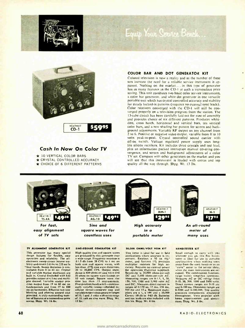
HEATHK IT
CD-1 $5995
Cash In Now On Color TV * 10 VERTICAL COLOR BARS * CRYSTAL CONTROLLED ACCURACY * CHOICE OF 6 DIFFERENT PATTERNS
COLOR BAR AND DOT GENERATOR KIT Colored television is now a reality and as the number of these sets increase the need for a reliable service instrument is ap- parent. Nothing on the market ... in this type of generator has as many features as the CD -1 at such a tremendous price saving. This unit combines two basic color service instruments, a color bar generator. and white dot generator in one versatile portable unit which has crystal controlled accuracy and stability for steady locked -in patterns (requires no external sync leads). Color receivers converged with the CD -1 will still be con- verged properly on a television program from the station. The 13 -tube circuit has been carefully laid out for ease of assembly and provides choice of six different patterns. Produces white - dots, cross hatch. horizontal and vertical bars, ten vertical color bars, and a new shading bar pattern for screen and back- ground adjustments. Variable RF output on any channel from 2 to 6. Positive or negative video output. variable from 0 to 10 volts peak -to -peak. Crystal controlled sound carrier with off -on switch. Voltage regulated power supply uses long - life silicon rectifiers. Kit includes three crystals and test lead, plus an information packed instruction manual covering con- vergence. and screen and background adjustments of a color TV set. Compare with other generators on the market and you will see that this instrument is loaded with extras and top quality all the way through. Shpg. Wt. 13 lbs.
HEATHKIT AG-10 :49's
HEATHK IT
MM-1 HEATHKIT
M-1
For fast, easy alignment
Sine and square waves for
High accuracy in a
An all -round meter of
of TV sets countless uses portable meter many uses
TV ALIGNMENT GENERATOR KIT
This generator has many special design features for flexible, easy operation and reliability. The all - electronic sweep circuit insures sta- bility and covers 3.6 mc to 220 mc in
`four bands. Sweep deviation is con- trollable from 0 to 42 mc. Crystal and variable marker oscillators are built in. Crystal (included with kit) provides output at 4.5 mc and multi- ples thereof. Variable marker pro- vides output from 19 to 60 mc on fundamentals and from 57 to 180 mc on harmonics. Effective two -way blanking and phasing control also provided. A truly outstanding num- ber of features at a tremendous price saving. Shpg. Wt. 16 lbs.
60
SINE- SQUARE GENERATOR KIT
High quality sine and square waves are produced by this generator over a wide range. Frequency response is ±1.5 db from 20 CPS to I mc on both sine and square waves, with less than .25% sine wave distortion. 20 to 20,000 CPS. Output impe- dance is 600 ohms on sine wave and 50 ohms on square wave (except on 10 volt range). Square wave rise time less than .15 microseconds. Five -position bandswitch- continu- ously variable tuning- shielded os- cillator circuit -separate step and variable output attenuators in ranges of 10, I and .1 volts with extra range of .01 volt on sine wave. Shpg. Wt. 12 lbs.
20,000 OHMS /VOLT VOM KIT
This meter is ideal for use in field applications where accuracy is im- portant. Employs a 50 ua 41/2' meter, and features 1% precision multiplier resistors for high ac- curacy. Requires no external power for operation (batteries supplied). Sensitivity is 20,000 ohms -per -volt DC and 5,000 ohms- per -volt AC. Measuring ranges are 0-1.5, 5, 50, 150. 500, 1500 and 5,000 volts AC and DC. Measures direct current in ranges of 0.150 ua, 15 ma. 150 ma. 500 ma and 15 a. Resistance multi- pliers are x I, x 100 and x 10.000 Covers -10 db to +65 db. Batteries and test leads are also included with this kit. Shpg. Wt. 6 lbs.
HANDITESTER KIT
Small enough to carry with you wherever you go, this fine handi- tester is ideal for use in portable applications when making tests away from the work bench or as an "extra" meter in the service shop, when the main instruments are oc- cupied. The combination function - range switch simplifies operation. Measures AC or DC voltage from 0-I0, 30, 300. 1000 and 5000 volts. Direct current ranges are 0 -10 ma and 0 -100 ma. Ohmmeter ranges are 0-3000 and 0- 300.000. Top quality precision components employed throughout. Very popular with home experimenters and electri- cians. Shpg. Wt. 3 lbs.
RADIO.ELECTRONICS
www.americanradiohistory.com

ETCHED CIRCUIT VTVM KIT
The fact that this instrument is outselling all other VTVM's says a great deal about its accuracy, reliability, and overall quality. The precision and quality of the components used in this VTVM cannot be duplicated at this price through any other source. Its attractive appearance as well as its perform- ance will make you proud to own it. A large 41/2" panel meter is used for indication, with clear, sharp calibrations for all ranges. Front panel controls consist of a rotary function switch and a rotary range selector switch, zero -adjust and ohms -ad- just controls. Precision 1 c resistors are used in the voltage divider circuit. An etched circuit board is employed for most of the circuitry. cutting assembly time and eliminating the possibility of wiring errors. It also assures duplication of lab- oratory instrument performance. This multi -function VTVM will measure AC voltage (RMS), AC voltage (peak -to- peak), DC voltage and resistance. There are 7 AC (RMS) and DC voltage ranges of 1.5, 5, 15, 50, 150, 500 and 1500. In addition there are 7 peak -to -peak AC ranges of 0 -4, 14, 40, 140, 400, 1400 and 4,000. Seven ohmmeter ranges providing multiplying factors of x 1, x 10, x 100, x 1000, x 10 k, x 100 k and x 1
megohm. Center scale resistance readings are 10, 100, 1000, 10 k, 100 k ohms, 1 megohm and 10 megohms. A zero- center scale db range is also provided. Battery and test leads included with kit. Shpg. Wt. 7 lbs.
HEATHKIT
V-7A
52450
World's largest selling VTVM kit
* LARGE EASY -TO -READ 41/2" 200 UA METER * 1% PRECISION RESISTORS EMPLOYED FOR HIGH ACCURACY
HEATHKIT C-3
$195o
Checks all types of condensers accurately
CONDENSER CHECKER KIT
Check unknown condenser and resistor values quickly and accurately. Capacity measurements are made in four ranges of .00001 mfd -.005 mfd; .001 mfd -.5 mfd; .1 mfd -50 mfd; 20 mfd -1,000 mid. Checks paper, mica, ceramic, and electro- lytic condensers. Leakage test provides switch selection of five polarizing voltages, 25 volts to 450 volts DC to indicate condenser operating quality under actual load conditions. Electron beam "eye" tube indicates balance and leakage. A spring return test switch automatically discharges con - denser under test and eliminates shock hazard to the operator. Measures resistance from 100 ohms to 5 megohms in two ranges. Shpg. Wt. 7 lbs.
HEATHKIT T-4
$1995
Locate faults quickly by tracing signals
VISUAL -AURAL SIGNAL TRACER KIT
Here is a brand new signal tracer completely re- designed with compact dimensions and new cir- cuit layout. Features built -in speaker and electron beam "eye" tube for signal indication and a unique noise locator circuit. Ideal for use in AM, FM and TV circuit investigation. RF and audio inputs are provided in one convenient probe with switch on probe to select either input. Useful for checking microphones, phono cartridges, record changers. tuners, etc. Makes a handy substitution speaker for servicing TV sets at the shop. Trans- former operated for safety and high. efficiency. Complete with test leads and informative con- struction manual. Shpg. Wt. 6 lbs.
HEATHKIT SG-8
$1950
Easy -to- build -prewound and calibrated coils
RF SIGNAL GENERATOR KIT
Save valuable time in aligning RF tuned circuits of all kinds with this easy -to -use kit. Also a quick way to trace signals in faulty RF, IF and audio circuits. Designed for general service applications - the SG -8 covers 160 kc to 110 me on fundamentals in five bands, and from 110 me to 220 me on cali- brated harmonics. The entire oscillator circuit is built on a special sub -chassis, using prewound and calibrated coils. No further calibration is required so it is ready to use as soon as construction is completed. RF output is in excess of 100,000 microvolts, controlled by both step and continu- ously variable controls. Complete with output cable and instructions. Shpg. Wt. 8 lbs.
HEATH COMPANY a subsidiary of Daystrom, Inc. Benton Harbor 20, Mien.
JULY, 1958 61
www.americanradiohistory.com

Beautifully Styled with Plenty of Room for the Most Complete Stereo System AVAILABLE IN THE FOLLOWING MODELS: Model SE-1B- Stereo Equipment Cabinet (birch) Model SE -1M- Stereo Equipment Cabinet
(mahogany)
Model SC -1BR- Stereo Wing Speaker Enclosure (birch -right end)
Model SC -1BL- Stereo Wing Speaker Enclosure (birch -left end)
Model SC -1MR- Stereo Wing Speaker Enclosure (mahogany- right end)
Model SC-1ML- Stereo Wing Speaker Enclosure (mahogany -left end)
$1499s
$3995
STEREO EQUIPMENT CABINET KIT Imagine! ... Stereophonic sound in your own home. This superbly designed cabinet holds all of your hi -fi stereo equip- ment and lends striking elegance to your living room. The at- tractive gold and black panels, trim and hardware brilliantly highlight the overall effect. Rich toned grille cloth, flecked in gold and black, complement the cabinet. The unit has ample room provided for an AM -FM tuner, tape deck, stereo pre- amplifier, amplifiers, record changer, record storage and speakers. Beautifully grained 3/4'" solid core Philippine ma- hogany or select birch plywood is used for construction. The top features a shaped edge and sliding top panel for easy access to the stereo tape deck and stereo preamplifier. Slid- ing doors are employed for convenient front access to the
AVAILABLE AFTER JUNE 30
changer and record storage compartment. All parts of the cabinet are precut and predrilled for simple assembly. The speaker wings and center cabinet may be purchased separately if desired. Note: the kit is delivered equipped with panels pre- cut to accommodate Heathkit components and also blank panels to cut out for your own equipment. Measurements of the individual component areas follow: tape deck and pream- plifier area 203/4 " L. x 173/4 " W. x 10" D., record changer area 21" W. x 16" D. x 95 /g" H., record storage area 225/3" W. x 141/2" H. x 121/2" D., speaker wing area (inside) 14" W. x 291/2" H. x 153/4" D., AM -FM Tuner area 201/2" W. x 51/4" H. x 14" D., amplifier (2 areas) 151/4" W. x 103/4" H. x 131/4" D.
62
Model HH -1 B Birch
Model HH -1 M Mahogany
Now only 529995 each
The Same Superior Performance At a New Low Price
"LEGATO" HI -FI SPEAKER SYSTEM KIT
The increasing sales of the Legato has made more economical quantity production possible so we are passing the savings on to you by offering you this magnificent speaker system at a reduced price. Truly a "queen" among hi -fi speaker systems, the Legato was specially designed to meet and surpass the most stringent re- quirements of high fidelity sound reproduction. Two 15" Altec Lansing low frequency drivers cover frequencies of 25 to 500 CPS while 'a specially designed exponential horn with high frequency driver covers 500 to 20,000 CPS. A unique crossover network is built in making electronic crossovers unnecessary. Internal re- flections are absorbed by splayed back panel and a 3" fiber glass lining. The Legato emphasizes simplicity of line and form to blend with modem or traditional furnishings. Cabinet construction is 3/4' veneer surface plywood in either African mahogany or white birch and measures 41' L. x 221/4' D. x 34" H. All parts are precut and predrilled for easy assembly. Shpg. Wt. 195 lbs.
HEATHKIT SS-2
$3995
Economical Hi -Fi For Your Home
OPTIONAL LEGS EXTRA
"BASIC RANGE" HI -FI SPEAKER SYSTEM KIT
True high fidelity performance at modest cost make this basic speaker system a spectacular buy for any hi -fi enthusiast. The amazing performance of this popular kit is made possible by the use of high quality speakers in an enclosure specially designed to receive them. The cabinet isa ducted port bass reflex type en- closure 111h" H. x 23" W. x 113/" D. It features an 8" mid range woofer to cover 50 to 1600 CPS and a compression -type tweeter with flared horn covering 1600 to 12,000 CPS. Both speakers are by Jensen. The adjustable flared tweeter horn allows speaker to be used in either upright or horizontal position. The cabinet is constructed of 1/2' veneer surfaced plywood suitable for light or dark finish of your choice. All wood parts are precut and pre - drilled for easy assembly. Shpg. Wt. 25 lbs.
'Attractive brass tip accessory legs convert SS-2 info attractive consolette. Legs screw into brackets provided. All hardware in- cluded. Shpg. Wt. 3 lbs. No. 91 -26 $4.95
RADIO -ELECTRONICS
www.americanradiohistory.com

HIGH FIDELITY STEREO TAPE DECK KIT For your unparalleled enjoyment in the world of stereophonic sound Heathkit brings you an all new stereo tape deck. This tape deck is a precision engineered instrument providing monaural record /playback, and stereo playback of prerecord- ed tapes. Incorporates three separate heads, erase- record- stereo playback (stacked). The mechanical tape deck as- sembly is supplied complete. You build only the record and playback circuit employing two etched circuit boards for ease of wiring. Low noise EF -86 tubes in input stages and efficient push -pull bias -erase oscillator insures complete freedom from hum and noise in recording and playback. Provision made for 33/4 and 71/2 IPS tape speed selected by a push button. Deck handles up to 7" reels of tape. Other features are: provision for monitoring tape while recording, built in VU meter for proper recording level, pause control for editing tape, "fast forward" and "rewind" control. Frequency response at 71/2
IPS tape speed is -±-2 db from 40 to 12,000 CPS, at 33/4 IPS speed 40 to 6,000 CPS. Signal -to -noise ratio is 55 decibels with less than 1% total harmonic distortion. NARTB tape playback equalization. A safety interlock button prevents accidentally switching to record position causing erasure of recorded tapes. Shpg. Wt. 33 lbs.
Model TR -1C monaural tape deck incorporates all of the features described for the model TR -1D with the exception of stereo playback. $131.95.
No. C -TR -1C conversion kit converts model TR -1C to in- clude stereo function of model TR -1D. $15.95.
HEATHKIT
TR-1D $14395
Preassembled Tape Mechanism ,
You Build Only Electronic Circuit
AVAILABLE AFTER JUNE 30
HEATHKIT
5S-1B
$9995
Fill out the Hi -Fi Range of Your SS -2 Speaker
"RANGE EXTENDING" NI -FI SPEAKER SYSTEM KIT This is not a complete speaker system in itself, but is designed to extend the range of the SS -2. The SS -1B uses a 15" woofer and a small super tweeter to supply the very high and very low fre- quencies to fill out the response of the basic SS -2. The SS -2 and SS-1B when used together, form an integrated four speaker system. The SS -2 and SS-1B combination provide an overall response of ± 5
db from 35 to 16,000 CPS. The kit includes circuit for crossover at 600, 1600 and 4,000 CPS. Im- pedance is 16 ohms and power rating is 35 watts. A cortrol is also provided to limit output of super tweeter. The handsome cabinet measures 29' H. x 23' W. x l71' D. Constructed of beautiful % veneer surface plywood. Complete step -by -step instructions make this kit easy to build. No wood- working experience required. Shpg. Wt. 80 lbs.
HEATH COMPANY
JULY, 1958
AVAILABLE AFTER JUNE ?0
HEATHKIT SW-1
PRICE TO BE ANNOUNCED
Save Time Rewinding Tape
"SPEEDWINDER" KIT This handy device leaves your tape recorder free for operation while it rewinds tape at the rate of 1200' in 40 seconds. Prevents unnecessary wear to the tape and recorder by eliminating wear against guides and heads. It will handle up to 101' tape reels as well as 800' reels of 8 and 16 millimeter film. A very useful aid to operators of movie projection equipment. The Heathkie Speedwinder features an automatic shutoff which prevents whipping of tape when it has rewound. A manual shutoff is also provided. An automatic braking device is built in for protection against power failure. Driven by a heavy duty four pole motor. Handsome cabinet is constructed of furniture grade plywood. Step -by -step instructions are provided to make this kit easy to assemble even by one with no experience.
a subsidiary of Daystrom, Inc. B
HEATHKIT TK-1
$995
All The Tools You Need For Building Heathkits
COMPLETE TOOL SET
A clear illustration of just how easy Heathkit building is. The pliers, diagonal sidecutters, two screw drivers and soldering iron are all the basic tools you need . for building practically any Heathkit. Pliers and sidecutters are equipped with insulated rubber handles. The American Beauty soldering iron has a replaceable tip to facilitate cleaning. All the tools are of top quality case hardened steel for rugged duty and long life. With these simple, inexpensive tools in your hand you need not be afraid to tackle the most elaborate kit. The manual included with this handy kit provides you with many useful tips on the use and care of your tools. It shows the all important step of making proper solder connections. A truly worthwhile investment for the beginner in elec- tronic kit building. Shpg. Wt. 3 lbs.
enton Harbor 20, Mich.
63
www.americanradiohistory.com

AVAILABLE AFTER JUNE 3J
HEATHKIT
SP-2 55695
Model SP -1 (monaural) $37.95
Model C -SP -1 (converts SP -1 to SP -2) $21.95
Control both stereo channels simply and conveniently
MONAURAL -STEREO PREAMPLIFIER KIT
This expertly designed preamplifier provides all the controls required for either standard monaural (single channel) or stereo (dual channel) sound reproduction. Features building block design ... you can start with a basic preamplifier and add a second channel for stereo later on, without rewiring. Second channel plugs in for fast conversion. The complete model SP -2 (stereo) features twelve separate inputs, six on each channel with input level controls. Six dual -concentric controls consist of: two 8- position selector switches, two bass, two treble, two volume level and two loudness controls, a scratch filter switch and a 4- position function switch (separate on -off switch). The function switch provides settings for ster- eo, two -channel mix, channel A or B for monaural use. In- puts consist of tape, mike, mag phono and three high -level inputs. Tape input has NARTB equalization and input selec- tor provides for RIAA, LP, 78 record compensation. EF86 tubes are used in the input stages along with hum balance controls to assure low hum and noise. Two cathode follower outputs with level controls provided in addition to two sepa- rate tape outputs for stereo recording. A remote balance con- trol with twenty feet of cable allows balancing the stereo sys- tem from listening position. Construction is greatly simplified through the use of two printed circuit boards (one in each channel) and encapsulated printed circuits. The beautiful vinyl clad steel cover has leather texture in black with inlaid gold design. Built -in power supply.
64
HEATHKIT WA-P2
f1975
Finger -tip controls for your operating convenience
"MASTER CONTROL" PREAMPLIFIER KIT Designed as a control center for basic amplifiers the WA -P2 pro- vides you with true high fidelity performance for the finest audio systems. Five switch -selected inputs accommodate a record changer, tape recorder, AM -FM tuner, TV receiver, microphone, etc., each with level control. Provision is also made for a tape recorder out- put. Ideal for "remote" installations, the WA -P2 features a low impedance cathode -follower output circuit allowing greater length of output lead. Full frequency response is obtained within I t/2 db from 15 to 35,000 CIS and will do full justice to the finest avail- able program sources. Equalization is provided for records through separate turnover and rolloff switches for LP, RIAA, AES, and early 78's. A special hum balance control allows setting for mini- mum hum level. Power for operation is required from basic ampli- fier or external source. Shpg. Wt. 7 lbs.
A low cost versatile performer
HEATHKIT UA-1
"UNIVERSAL" 12 -WATT AMPLIFIER KIT A true high fidelity performer in every sense of the word, the UA -1 makes an ideal basic amplifier for any hi -fi system and is a perfect addition to gear your present hi -fi system for stereo sound. Uses 6BQ5 /EL84 push -pull output tubes for less than 2''; harmonic distortion throughout the entire audio range (20 to 20,000 CPS) at full 12 watt output. The on -off switch is located right on the chassis and an octal socket is provided for connecting a preamplifier for remote control operation. The specially designed output trans- former provides excellent stability and frequency response. Taps for 4, 8 and 16 ohm speakers, with switched damping for "unity" or "maximum" on the 16 -ohm tap. An input level control is pro- vided for use in wired music systems where a preamplifier is not required. This versatile unit is the latest addition to the fine line of Heathkit basic amplifiers. Shpg. Wt. 13 lbs.
RADIO -ELECTRONICS
www.americanradiohistory.com
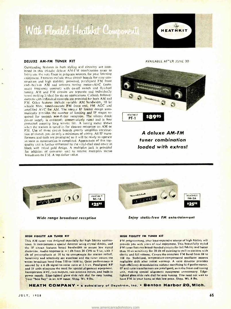
DELUXE AM -FM TUNER KIT
Outstanding features in both styling and circuitry are corn - bined in this 16 -tube deluxe AM -FM combination tuner to bring you the very finest in program sources, for your listening enjoyment. Features include three circuit boards for easy con- struction and high stability -prewired, prealigned FM front end -built -in AM rod antenna -tuning meter -AFC (auto- matic frequency control) with on -off switch and flywheel tuning. AM and FM circuits are separate and individually tuned making it ideal for stereo applications. Cathode follower outputs with individual controls are provided for both AM and FM. Other features include variable AM bandwidth, 10 kc whistle filter, tuned -cascode FM front end, FM AGC and amplified AVC for AM. The unique IF limiter design auto- matically provides the number of limiting and IF stages re- quired for smooth non- flutter reception. The silicon diode power supply is extremely conservatiyely rated and is fuse protected assuring long service life. A tuning meter shows when the station is tuned -in for clearest reception on AM or FM. Use of three circuit boards greatly simplifies construc- tion of circuit, you do only a minimum of wiring. All IF trans- formers and coils are prealigned so it will be ready to operate as soon as construction is completed. Appearance of this top - quality unit is further enhanced by the vinyl -clad steel cover in black with inlaid gold design. A multiplex jack is provided for addition of converter unit to receive multiplex stereo broadcasts on FM. A top dollar value.
AVAILABLE AFTER JUNE 30
HEATHKIT
PT-1 s8995
A deluxe AM -FM
tuner combination loaded with extras!
HEATHKIT BC-1 A
$25"
Wide range broadcast reception
HIGH FIDELITY AM TUNER KIT
This AM tuner was designed especially for high fidelity applica- tions. It incorporates a special detector using crystal diodes. and the IF circuit features broad bandwidth to assure low signal distortion. Audio response is t I db from 20 CPS to 9 kc, with 5
db of pre- emphasis at 10 kc to compensate for station rolloff. Sensitivity and selectivity are excellent and the tuner covers the entire broadcast band from 550 to 1600 kc. Quiet performance is
assured by a 6 db signal -to -noise ratio at 2.5 uv. Prealigned RF and IF coils eliminate the need for special alignment equipment. Incorporates AVC, two outputs, two antenna inputs, and built -in power supply. Edge- lighted glass slide rule dial for easy tuning. Your "best buy" in an AM tuner. Shpg. Wt. 9 lbs..
HEATHKIT FM-3A
Enjoy static -free FM entertainment
HIGH FIDELITY FM TUNER KIT
FM programming, your least expensive source of high fidelity will provide you with years of real enjoyment. This beautifully styled FM tuner features broad -banded circuits for full fidelity and better than 10 uv sensitivity for 20 db of quieting to pull in stations with clarity and full volume. Covers the complete FM band from 88 to 108 mc. Stabilized, temperature- compensated oscillator assures negligible drift after initial warmup. A ratio detector provides high -efficiency demodulation without sacrificing hi -fi performance. IF and ratio transformers are prealigned, as is the front end tuning unit, making special alignment equipment unnecessary. Edge - lighted glass slide rule dial for easy tuning. You need not wait to have FM in your home at this low price. Shpg. Wt. 8 lbs.
HEATH COMPANY 'a subsidiary of Daystrom, Inc. Benton Harbor 20, Mich.
JULY, 1958 65
www.americanradiohistory.com

HEATHKIT
W-7M $5495
55 watts of hi -fi power at only $1 per watt
* BEAUTIFULLY STYLED IN BLACK AND GOLD
* UNITY OR MAXIMUM DAMPING
"EXTRA PERFORMANCE" 55 WATT HI -FI AMPLIFIER KIT
Another Heathkit first! An honestly rated high power amplifier with many top quality features at less than a dollar per watt. Full audio output is conservatively rated at 55 watts from 20 CPS to 20 kc with less than 2% total harmonic distortion throughout the entire range. Unique paired output connections permit instant switch selection of "unity" or "maximum" damping factors for all 4, 8 or 16 ohm speakers. Each output has an optimized current feedback circuit for unity damping so that there will be no compromise in performance when any of the impedances is used. This current feedback circuitry is entirely shorted out when not in use to obtain the highest possible damping factor. Features include level control and "on -off" switch right on the chassis plus provision for remote control from preamp, etc. Famous "bas -bal" circuit conven- iently balances EL -34 output tubes. These heavy duty push - pull tubes operate into a high quality tapped- screen trans- former designed especially for this unit. A 70 -volt output on the transformer provides for P.A. or large music systems. The silicon diode power supply features a protection device that controls current until tubes have warmed up, greatly increasing service life of all components. The stylish black and gold case measures 6" H. x 81/2" D. x 15" W. Convenient pilot light on the chassis. Thoughtful circuit layout makes this kit easy to build. Dollar for watt you can't beat this buy. Shipped express only. Shpg. Wt. 28 lbs.
66
HEATHKIT
W-6M $109'
Plenty of Reserve Power Without Distortion
"HEAVY DUTY" 70 -WATT HI -FI AMPLIFIER KIT
Here is an amplifier that will provide the extra "push" needed to drive any of the fine speaker systems available today, for truly fine performance at any power level. Silicon -diode rectifiers are used to assure long life and a heavy duty trans- former gives you extremely good power supply regulation. Variable damping control provides optimum performance with any speaker system. Quick change plug selects 4, 8 and 16 ohms or 70 volt output and the correct feedback resistance. Frequency response at I watt is from 5 CPS to 80 kc with controlled HF rolloff above 100 kc. At 70 watts output harmonic distortion is below 2 %, 20 to 20,000 CPS and 1M distortion is below 1%. 60 and,6.000 CPS. Hum and noise 88 db below full output. Metered balance circuit. Designed especially for easy assembly and years of depend- able service. Shipped express only. Shpg. Wt. 52'Ibs.
HEATHKIT W-5M
sS975
Top -Flight Performance for the Critical Listener
25 -WATT HI -FI AMPLIFIER KIT
Considered top value in its power class by leading independent research organizations, the W -5M incorporates all the design features required by the super critical listener. Features include a specially designed Peerless output transformer and KT66 tubes. The circuit is rated at 25 watts and will follow instantaneous power peaks of a full orchestra up to 42 watts. A "tweeter saver" sup- presses high frequency oscillation and a new type balancing circuit facilitates adjustment of the "dynamic ".. balance between output tubes. Fre- quency response is ± I db from 5 CPS to 160,000 CPS at I watt and within 2 db front 20 to 20,000 CPS at full 25 watts output. Harmonic distortion is less than I% at 25 watts and IM distortion is 1% at 20 watts (60 and 3,000 CPS, 4: I). Hum and noise are 99 db below 25 watts for truly quiet per- formance. Rich black and gold colored styling. Shipped express only. Shpg. Wt. 31 lbs.
HEATHKIT
W4-AM $3975
Faithful Sound Reproduction with Minimum Investment
20 -WATT HI -FI AMPLIFIER KIT
This fine amplifier will amaze you with its out- standing performance. It features a true Williamson circuit with extended frequency response, low dis- tortion, and low hum levels. Enjoy true hi -fi with only a minimum investment compared to other units on the market. 5881 tubes and a special Chicago -Standard output transformer are em- ployed to give you full fidelity at minimum cost. Frequency response extends from 10 CPS to 100 kc within ± I db at I watt assuring you of full cover- age of the audio range. Clean, clear sound am- plification takes place in circuits that hold harmonic distortion at 1.5% and IM distortion below 2.7% at full 20 watt output. Hum and noise are 95 db below full output. Taps on the output transformer are at 4, 8 or 16 ohms to match the speaker system of your choice. An outstanding performer, this investment will bring you years of listening enjoy - ment. Shipped express only. Shpg. Wt. 28 lbs.
All basic amplifiers recommended for use with tnodel WA -P2, SP -I or SP -2 preamplifiers
RADIO -ELECTRONICS
www.americanradiohistory.com

"BOOKSHELF" 12 -WATT AMPLIFIER KIT
The model EA -2 combines eye -pleasing style and color with many extra features for high quality sound reproduction. This fine amplifier provides full range frequency response from 20 to 20,000 CPS within i-1 db. Harmonic distortion is less than 1% at full 12 watt output over the entire range (20- 20,000 CPS). IM distortion is less than 1.5% at 12 watts with low hum and noise. Miniature tubes are used throughout the ad- vanced circuitry, including EL84 output tubes in a push -pull tapped- screen output circuit using a special designed output transformer. Transformer has taps at 4, 8 and 16 ohms. The model EA -2 has its own built -in preamplifier with provision for three separate inputs, mag phono, crystal phono and tuner. The mag phono input features RIAA equalization. Separate bass and treble controls are provided with boost and cut action. A special hum -balance control assures quiet operation. The luxury styled cabinet has a smooth simulated leather texture in black with inlaid gold design and is constructed of vinyl plastic bonded to steel. It resists scuffing, wear, abrasion, and chemicals. The front panel features brushed -gold trim and buff knobs with gold inserts for a very pleasing appearance. An amber neon pilot lamp indicates when the amplifier is on. Cabinet measures 121/2" W. x 33/16" D. x 43/4" H. making it suitable for use on a bookshelf, end table, etc. High quality is emphasized throughout for performance matching ampli- fiers costing many times more. Shpg. Wt. 15 lbs.
HEATHKIT
EA-2 SZ795
Combines beauty, style and quality
* LESS THAN 1% DISTORTION AT FULL OUTPUT OVER ENTIRE AUDIO RANGE.
* BUILT -IN PREAMPLIFIER
HEATHKIT A9-C $35"
A Bargain Package of Power and Performance
GENERAL -PURPOSE 20 -WATT AMPLIFIER KIT
The A9 -C combines a preamplifier, main amplifier and power supply all on one chassis providing a compact unit to fill the need for a good high fi- delity amplifier with a moderate cash investment. Designed primarily for home installations, it is also capable of fulfilling P.A. requirements. The preamplifier section features four separate switch selected inputs. Separate bass and treble tone con- trols offer 15 db boost and cut. A true high fi- delity performer, the A9 -C covers 20 to 20,000 CPS within ± I db. Front panel is detachable, and can be installed on the outside of a cabinet where the chassis comes through, for custom installa- tions. A fine unit with which to start your hi -fi system. Shpg. Wt. 23 lbs.
HEATHKIT AV-3
Invaluable for Hi -Fi Testing
AUDIO VTVM KIT
Critical AC voltage measurements are made easy with this high quality vacuum tube voltmeter which emphasizes stability, broad frequency re- sponse and sensitivity. Features large 4112" 200 microampere meter, with increased damping in . the meter circuit for stability in low frequency tests. Extremely high voltage range handles meas- urements from a low value of 1 millivolt to a maximum of 300 volts. AC (R MS) voltage ranges are: 0-.01, .03, .1, .3, 1, 3, 10, 30, 100 and 300 volts. Db ranges cover -52 to +52 db. Employs 1'1 precision multiplier resistors for maximum accuracy. High input impedance (I megohm at 1,000 CPS). Frequency response is essentially flat from 10 CPS to 200 kc. Shpg. Wt. 6 lbs.
HEATHKIT AW-1
Measure Exact Power Output
AUDIO WATTMETER KIT
Here is a fine meter to accurately measure output wattage. Five power ranges cover 0-5 mw, 50 mw, 500 mw, 5 w and 50 w full scale. Five switch se- lected db ranges cover -IO db to +30 db. All indications are read directly on the large 41/2° 200 ua meter. Frequency response is ± I db from 10 CPS to 250 kc. External or internal load resistors are selected with convenient front panel switch. Non- inductive load resistors are built in for 4, 8, 16 or 600 ohms impedance. Precision multiplier resistors are used for high accuracy and incorpo- rates a crystal diode bridge for wide -range fre- quency response. Modern styling and convenient front panel design. Cabinet is ventilated to allow efficient cooling of load resistors. Shpg. Wt. 7 lbs.
HEATH COMPANY a subsidiary of Daystrom, Inc. Benton Harbor 2O,Mich.
JULY, 1958 67
www.americanradiohistory.com

CONTEMPORARY Model CE -1B Birch
Model CE -1M Mahogany
HEATHKIT
CE-1
9 $4 5 each
TRADITIONAL Model CE -1T Mahogany
Combine all your Hi -Fi equipment in this attractive cabinet
CHAIRSIDE ENCLOSURE KIT
This Chairside Enclosure lets you combine all of your hi -fi equipment into one compact control center and, at the same time add a beautiful piece of furniture to your home. The CE -1 is designed to house the AM and FM tuners (BC-1A and FM -3A) and the WA -P2 preamplifier along with the majority of record changers which will fit into the space pro- vided. Adequate room is available in the rear of the unit to house any of the Heathkit amplifiers designed to operate with the WA -P2. The enclosure is flexible enough to give you a large choice in component installation. If only one tuner and the preamplifier are used, the two units can be installed in the tilt -out drawer, or if more convenient, either unit can be placed in the space provided in front of the changer compartment. The tilt -out shelf can be installed on either right or left side and the lift -top lid is similarly designed to lift from either side depending on.your choice during construction! Good ventila- tion is achieved through appropriately placed slots in the bottom and back of the enclosure. Overall dimensions are 18 "W. x 24" H. x 351/2" D. The changer compartment meas- ures 173/4" L. x 16" W. x 95 /e" D. All parts are precut and predrilled for easy assembly and attractive hardware is sup- plied to match each style. The contemporary cabinet is avail- able in either mahogany or birch and the traditional cabinet is available in mahogany only. Furniture grade plywood can be finished to your taste. Shpg. Wt. 46 lbs.
HEATHKIT
AG-9A $3450
Your own source of Hi -Fi audio signals
AUDIO SIGNAL GENERATOR KIT
The model AG -9A is "made to order" for high fidelity applications, and provides quick and ac- curate selection of low- distortion signals from 10 CPS to 100 kc. Three rotary switches select two significant figures and a multiplier to determine audio frequency. Incorporates step -type - and a continuously variable output attenuator. Output indicated on large 41/1" panel meter, calibrated in volts and db. Attenuator system operates in 10 db steps, corresponding to meter calibration, in ranges of 0 -.003, .01, .03, ,l, .3, 1, 3 and 10 volts RMS. "Load" switch permits use of built -in 600 - ohm load, or external load of different impedance. Output and frequency indicators accurate to with- in ± 5%. Distortion less than .I of 1% between 20 and 20,000 CPS. Shpg. Wt. 8 lbs.
HEATHKIT
AA-1 $4995
3 Audio test instruments in one compact unit
AUDIO ANALYZER KIT
Complete high fidelity testing facilities are yours in the AA -1. It combines the functions of three separate instruments; an AC VTVM, audio watt- meter and a complete IM analyzer with filters and high and low frequency oscillators built in. VTVM ranges are: 0-.01, .03, .1, .3, 1, 3, 10, 30. 100 and 300 volts (RMS). Db scale reads from -65 to +52 dbm. Wattmeter ranges are: .15 mw, 1.5 mw, 15 mw, 150 mw, 1.5 w, 15 w and 150 w. IM scales are 1 %, 3 %, 10 %, 30% and 100% full scale. Provides internal load resistors of 4, 8, 16 or 600 ohms. Combining and consolidating functions reduces the number of test leads and controls re- quired for the same test. Complete instructions are provided for easy assembly, also valuable in- formation on use of instrument, Shpg. Wt. 13 lbs.
HE AT M K IT
HD-1 $4950
Check amplifier distortion quickly
HARMONIC DISTORTION METER KIT.
Valuable in both designing and servicing of audio circuits, the HD -1 used with an audio signal generator. will accurately measure harmonic dis- tortion at any or all frequencies between 20 and 20,000 CPS. Distortion is read on panel meter in ranges of 0 -1, 3, 10, 30 and 100% full scale. Full scale voltage ranges of 0-1, 3, 10 and 30 volts are provided for the initial reference settings. Signal- to -noise ratio is measured on a separate meter scale calibrated in db. Features high input im- pedance (300,000 ohms) and 1% precision resis- tors in the VTVM voltage divider circuit for excel- lent sensitivity and accuracy. High quality com- ponents insure years of dependable service. Com- plete instructions provided for easy assembly and operation. Shpg. Wt. 13 lbs.
68 RADIO -ELECTRONICS
www.americanradiohistory.com

TRANSISTOR PORTABLE RADIO KIT
The overwhelming sales of this outstanding transistor portable have made a substantial price reduction possible ... in addi- tion, an all new plastic molded case adds the finishing touch to the exceptional circuitry. Six name -brand (Texas Instrument) transistors are used for extra good sensitivity and selectivity. The 4" x 6" PM speaker with heavy magnet provides excellent tone quality. Use of this large speaker and roomy chassis make it unnecessary to crowd components adding greatly to the ease of construction. Transformers are prealine'd so it ready for service as soon as construction is completed. A touchup in alignment is easily accomplished on a station by following simple instructions in manual. Alignment tool furnished. Has built -in rod -type antenna for reception in all locations. Six standard size "D" flashlight cells are used for extremely long battery life (between 500 and 1000 hours) and they can be purchased almost anywhere. Cabinet is two -tone blue molded plastic with pull -out carrying handle. Dimensions are 91/2" L. x 71/a " H. x 4" D. Shpg. Wt. 6 lbs.
Model XR -1 -L: Identical to XR -1 -P except in genuine leather case. Rich, warm sun -tan tone. Leather carrying strap included. Shpg. Wt. 7 lbs.
Leather Case: can be purchased separately if desired. Fits all XR -1P's and XR -1's. No. 93 -1. Shpg. Wt. 3 lbs. $6.95.
HEATHKIT
XR-1-P $2995
Newly designed plastic case ... new low price!
* 4" X 6" SPEAKER FOR "BIG SET" TONE * LONG BATTERY LIFE (500 to 1000 Hours)
HEATHKIT
CT-1
$79,5
Test condensers right in the circuit
HEATHKIT DF-1 $54"
Pin -point your exact location
HEATHKIT FD-1 $35" 5h
(6 volt model FD -1.6) (12 volt model FD -1.12)
Detects gas fumes
HEATHK1T MC-1
$42" Save your
boat batteries
IN- CIRCUIT CAPACI -TESTER KIT
Check most capacitors for `open" or "short" right in the circuit with this handy kit. Detects open capac- itors from about 50 mmf up, not shunted by an excessively low resist- ance value. Checks shorted capaci- tors up to 20 mfd (not shunted by less than 10 ohms). (Does not detect leakage nor check electrolytic con- densers.) Employs a 60 -cycle fre- quency for the short test and a 19 megacycle frequency for the open test. Uses electron beam "eye" tube for quick indication. Test leads in- cluded. Shpg. Wt. 5 lbs.
TRANSISTOR RADIO DIRECTION FINDER KIT
This transistor radio compass will double as a portable radio. Covers, the standard broadcast band from 540 to 1600 kc. Ideal for use aboard boats and also on land by hunters, hikers, etc. A directional high -Q ferrite antenna rotates from the front panel to obtain a fix on a sta- tion. A t ma meter serves as null and tuning indicator. Prealigned IF transformers -six transistor circuit. Powered by tiny 9 -volt battery with spare included. Dimensions 711/2"
W, x5 W H. i53/8" D. Shpg. Wt. Sibs.
FUEL VAPOR DETECTOR KIT
Protect your boat and passengers against fire and explosion with one of these fuel vapor detector kits. Indicates the presence of fumes on a
three -color "safe- dangerous" meter scale and immediately shows if it is safe to start the engine. A pilot lamp shows when the detector is operat- ing. Easy to build and install, even by one not having previous expe- rience. Operates from your boat battery. The kit is complete with heavy -duty neoprene insulated cable and includes spare detector unit. Shpg. Wt. 4 lbs.
MARINE CONVERTER KIT
Charge 6 or 122 volt batteries with this marine converter and battery charger. A panel mounted 25 am- pere meter continuously monitors the charging current. Moisture and fungus proofed for rugged marine use. Convection cooling prevents unsafe temperature rise. The MC -I has no moving parts, tubes nor blowers to wear out or break. Mount- ing brackets are supplied for easy installation on any boat. Ideal for keeping batteries fully charged or to supply extra current for appliances, Shpg. Wt. 16 lbs.
HEATH COMPANY a subsidiary of Daystrom, Inc. Benton Harbor 20,Mich.
JULY, 1958 69
www.americanradiohistory.com

HEATHKIT
TX-1 $22950
Complete Versatility for Top - Notch Amateur Communications
* NEWLY DESIGNED VFO- ROTATING SLIDE RULE DIAL * MODERN STYLING -PROVISION FOR SSB ADAPTER
"APACHE" HAM TRANSMITTER KIT Fresh out of the Heath Company laboratories, the brand -new "Apache" model TX -I ham transmitter features modern styl- ing and the latest in circuitry for extra fine performance. The "Apache" is a high quality transmitter operating with a 150 watt phone input and 180 watt CW input. In addition to CW and phone operation, built -in switch selected circuitry pro- vides for single -sideband transmission through the use of a plug -in external adapter. These SSB adapters will be available in the near future. A compact, stable and completely redesigned VFO provides low drift frequency control necessary for SSB transmission. A slide rule type illuminated rotating VFO dial with vernier tuning provides ample bandspread and precise frequency settings. The bandswitch allows quick selection of the amateur bands on 80, 40, 20, 15 and 10 meters. (11M with crystal control). This unit also has adjustable low level speech clipping and a low distortion modulator stage employ- ing two of the new 6CA7 /EL -34 tubes in push -pull class AB operation. Time sequence keying is provided for "chirpless" break -in CW operation. The final amplifier is completely shielded for greater TVI protection and transmitter stability. Die -cast aluminum knobs and front panel escutcheons add to the attractive styling of the transmitter. Pi network output coupling matches antenna impedances between 50 and 72 ohms. Shpg. Wt. 115 lbs. $50.00 deposit required on C.O.D. orders. Shipped motor freight unless other- wise specified.
70
HEATHK IT
DX-20 $3595
An Ideal Code Transmitter
DX -20 CW TRANSMITTER KIT Designed especially for CW work, the DX -20 features high efficiency at low cost. An ideal rig for the novice or advanced -class CW operator. Plate power input is 50 watts, and covers 80, 40, 20, 15, 11 and 10 meters with single knob band - switching. Features a single 6DQ6A tube in the final amplifier stage and a 6CL6 as a crystal oscil- lator. Pi network output circuit matches various antenna impedances between 50 and 1000 ohms and reduces harmonic output. Top -quality parts are featured throughout, including "potted" trans- formers, etc., for long service life. Complete shield- ing to minimize TVI. Removable metal pull -out plug on left end of cabinet provides access for crystal changing. Very easy to build with complete instructions supplied. Shpg. Wt. 19 lbs.
H EATHK IT
DX-100 $1895°
You'll be Proud to Own This Outstanding Performer
DX -100 PHONE AND CW TRANSMITTER KIT Well known for its high quality and fine per- formance the DX -l00 features a built -in VFO, modulator, and power supply, complete shielding to minimize TVI, and a pi network coupling to match impedances from 50 to 600 ohms. RF out- put is in excess of 100 watts on phone and 120 watts on CW, for clean strong signals on all ham bands from 10 to 160 meters. Single knob bandswitching and illuminated VFO dial and meter face add real operating convenience. RF output stage uses a pair of 6146 tubes in parallel, modulated by a pair of I 625's. High quality components are used through- out, such as potted transformers, silver -plated or solid coin silver switch terminals, aluminum -heat dissipating caps on the final tubes, copper plated chassis, etc. Shpg. Wt. 107 lbs. $50.00 deposit required on C.O.D. orders. Shipped motor freight unless otherwise specified.
HEATHKIT DX-40
$6495
Phone & CW Facilities at Low Cost
DX -40 PHONE AND CW TRANSMITTER KIT An outstanding buy in its power class the DX -40 provides both phone and CW operation on 80, 40, 20, 15, 11 and 10 meters. A single 6146 tube is used in the final amplifier stage to provide full 75 watt plate power input on CW, or controlled carrier modulation peaks up to 60 watts for phone opera- tion. Modulator and power supplies are built in and single -knob bandswitching is combined with the pi network output circuit for complete operating convenience. Complete shielding to minimize TVI. Provision is made for three crystals. A four -position switch selects any of the three crystals or a jack for external VFO. Crystal sockets are reached through access door in rear of cabinet. High quality D'Arsonval movement panel meter. Shpg. Wt. 25 lbs.
RADIO -ELECTRONICS
www.americanradiohistory.com

"MOHAWK" HAM RECEIVER KIT Here is a ham receiver that any radio operator would be proud to own. The "Mohawk" has all the functions required for high quality communications with clear, rock- steady re- ception on all hands. Thts 15 -tube receiver features double conversion with IF's at 1682 kc and 50 kc and covers all of the amateur frequencies from 160 through 10 meters on seven bands with an extra band calibrated to cover 6 and 2 meters using a converter. Receiver accommodations are pro- vided for these converters which will be available in Heathkits soon. The "Mohawk" is specially designed for single -sideband reception with crystal controlled oscillators for upper and lower sideband selection. A completely preassembled, wired and aligned front end coil assembly assures ease of construction and top performance of the finished unit. Other features in- clude five selectivity positions from 5 kc to 500 CPS, bridged T -notch filter for maximum heterodyne rejection. and a built - in 100 kc crystal calibrator. The set provides a 10 db signal - to -noise ratio at less than 1 microvolt input. Front panel features S meter, separate RF, IF and AF gain controls, T- notch tuning, T -notch depth, ANL, AVC, BFO, bandswitch, tuning, antenna trimmer, calibrate set, calibrate on, CW- SSB-AM, receive -standby, upper -lower sideband, selectivity, phone jack and a wide band rotating slide rule type vernier tuning dial with easy to read calibrations. Shpg. Wt. 90 lbs. $50.00 required on C.O.D. orders. Shipped motor freight unless otherwise specified.
HEATHKIT
HEATHKIT
RX-1 $27495
Now in Kit Quality Ham
* PREWIRED AND ALIGNED * CRYSTAL CONTROLLED
FREE RECEPTION.
Form a Top
Band Receiver FRONT END COIL ASSEMBLY. OSCILLATORS FOR DRIFT-
HEATHKIT B-1
$895
Get Proper Match Between Transmitter
and Antenna
ga HEATHKIT
AM-2 51595
Measure Standing Wave Ratio
HEATHKIT VX-1 $2395
Eliminates Hand Switching
HEATHKIT PM-1
s1495
Quick Check of Transmitter Operation
BALUN COIL KIT
Unbalanced coax lines used on the most modern transmitters can be matched to balance lines of either 75 or 300 ohms impedance by using the model B -1 Balun Coil Kit. Can be used with transmitters and re- ceivers without adjustment over the frequency range of 80 through 10 meters, and will handle power inputs up to 200 watts. Cabinet size is 10" square by 5" D. and may be located any distance from the transmitter or antenna. A protective cover is sup- plied to prevent damage in outdoor installations. Shpg. Wt. 4 lbs.
REFLECTED POWER METER KIT The match of your antenna trans- mission system can be checked by measuring the forward and reflected power or standing wave ratio from I:1 to 6:1 with this fine unit. De- signed to handle a peak power of well over 1 kilowatt of energy the AM -2 may be left in the antenna system feed line at all times. Band coverage is l60 meters through 2
meters. Input and output impedances for 50 or 75 ohm lines. No external power required for operation. Cabi- net size is 7S /a "x4'w'x4s/a ". Shpg. Wt. 3 lbs.
HEATH COMPANY a subsidiary
ELECTRONIC VOICE CONTROL KIT This unique device allows you to switch from receiver to transmitter merely by talking into your micro- phone ... you get the advantage of "telephone -type conversation" as in single sideband but with regular AM transmission. The unit is adjustable to all conditions by sensitivity con- trols provided. A variable time delay control changes the "hold" time. Provision is made for receiver and speaker connections and also for a
117 volt antenna relay. Built -in power supply. Complete instructions pro- vided. Shpg. Wt. 5 lbs.
of Daystrom, Inc. Benton
RF POWER METER KIT This self contained unit requires no power for operation. You simply place it close to the transmitter antenna to sample the R F field which is then indicated on the panel meter. Operates with any transmitter having an output frequency between 100 kc and 250 mc, regardless of power. Sensitivity is 0.3 volts R MS full scale, and a special control on the panel allows for further adjustment of the sensitivity. Measures 3Y4' W. x 61' L. x 2' D. An easy way to put your mind at ease concerning transmitter operation. Shpg. Wt. 2 lbs.
Harbor 20.MIch.'
JULY, 1958 71
www.americanradiohistory.com

DUAL- CHASSIS 20 WATT HI -FI AMPLIFIER KIT
Model W3 -AM (Shpg. Wt. 29 lbs.)
$4975
12" UTILITY SPEAKER
Model 401 -6
(Shpg. Wt. 7 lbs.)
$750
BROADCAST BAND RADIO KIT
Model BR -2 $1895 (Shpg. Wt. 10 lbs.) (less cabinet)
GRID DIP METER KIT
Model GD -1B
(Shpg. Wt. 4 lbs.)
2195
ALL -BAND RADIO KIT
Model AR -3 (Shpg. Wt. 12 lbs.)
$2995 (less cabinet)
CRYSTAL RADIO KIT
Model CR -1
(Shpg. Wt. 3 lbs.) $795
ELECTRONIC CROSSOVER KIT "Q" MULTIPLIER KIT
Model X0 -1
(Shpg. Wt. 6 lbs.) $1895
VIBRATOR POWER SUPPLY KIT
6 volt Model VP -1 -6 12 volt Model VP -1 -12
(Shpg. Wt. 4 lbs.)
Model OF -1
(Shpg. Wt. 3 lbs.)
VARIABLE FREQUENCY OSCILLATOR KIT
$995
Model VF -1
(Shpg. Wt. 7 lbs.)
$1950
"AUTOMATIC" CONELRAD ALARM KIT
Model CA -1
(Shpg. Wt. 4 lbs.) $1395
PROFESSIONAL RADIATION COUNTER KIT
Model RC -1
(Shpg. Wt. 8 lbs.)
$7995
ISOLtTION TRANSFORMER KIT
teXtellAVISINielier
Model IT -1
(Shpg. Wt. 9 lbs.)
$1650
DIRECT -READING CAPACITY METER KIT
Model CM -1
(Shpg. Wt. 7 lbs.)
$2950
CATHODE RAY TUBE
CHECKER KIT
ELECTRONIC SWITCH KIT
Model S -3 (Shpg. Wt. 8 lbs.)
REGULATED POWER SUPPLY KIT VOLTAGE CALIBRATOR KIT
$2195 Model PS -3
(Shpg. Wt. 17 lbs.)
TUBE CHECKER KIT
Model TC -2 $2950 (Shpg. Wt. "2 lbs.)
$3550 Model VC -3 (Shpg. Wt. 4 lbs.) $1250
EASY TIME PAYMENTS AVAILABLE FOR YOUR
CONVENIENCE ...
Any order totaling $90 or more can
be paid for in small monthly pay-
ments (send for complete details).
RESISTANCE SUBSTITUTION BOX KIT
Model RS -1
(Shpg- Wt. 2 lbs.)
$550 CONDENSER SUBSTITUTION
BOX KIT Model CS -1
(Shpg. Wt. 2 lbs.)
$550
Model CC -1
(Shpg. Wt. 10 lbs.)
72
LABORATORY RF
GENERATOR KIT
Model LG -1 $4895 (Shpg. Wt. i6 lbs.)
"Q" METER KIT
Model OM -1
(Shpg. Wt. 14 lbs.) $4450
DECADE CONDENSER KIT Model DC -1
(Shpg. Wt. 3 lbs.)
$1650
DECADE RESISTANCE KIT Model DR -1
(Shpg. Wt. 4 lbs.)
$1950
RADIO -ELECTRONICS
www.americanradiohistory.com
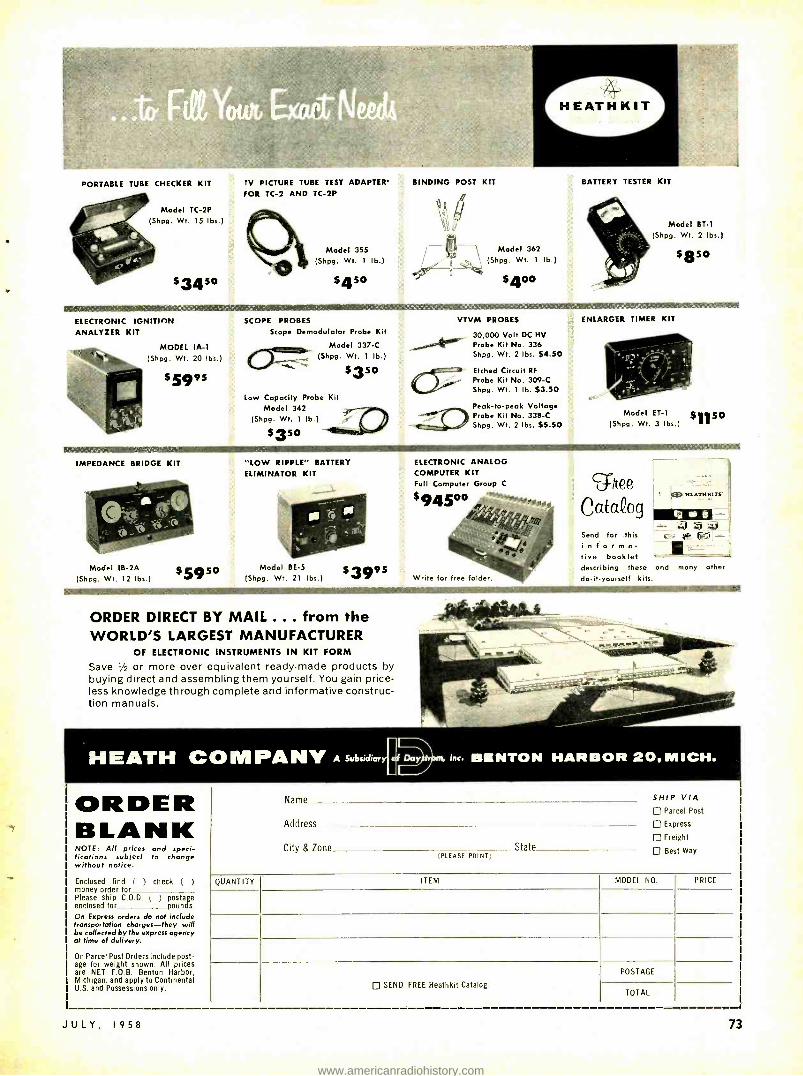
HEATHKIT
PORTABLE TUBE CHECKER KIT
Model TC -2P (Shpg. Wt. 15 lbs.)
$3450
TV PICTURE TUBE TEST ADAPTER' BINDING POST KIT
FOR TC -2 AND TC -2P
Model 355
(Shpg. Wt. 1 Ib.)
$450
Model 362
(Shpg. Wt. 1 Ib.)
$400
BATTERY TESTER KIT
Model BT -1
(Shpg. Wt. 2 lbs.)
$850
IIIMMOWESIMMIMI
ELECTRONIC IGNITION ANALYZER KIT
MODEL IA -1
(Shpg. Wt. 20 lbs.)
$5995
IMPEDANCE BRIDGE KIT
Model IB -2A (Shpg. Wt. 12 lbs.)
s5950
SCOPE PROBES
Scope Demodulator Probe Kit
Model 337 -C /- (Shpg. Wt. 1 lb.)
$350 `s-
Low Capacity Probe Kit Model 342
(Shpg. Wt. I lb.) ± $350 -
"LOW RIPPLE" BATTERY
ELIMINATOR KIT
Model BE -5 $3995 (Shpg. Wt. 21 lbs.)
ORDER DIRECT BY MAIL ... from the WORLD'S LARGEST MANUFACTURER
OF ELECTRONIC INSTRUMENTS IN KIT FORM
Save 1/2 or more over equivalent ready -made products by buying direct and assembling them yourself. You gain price- less knowledge through complete and informative construc- tion manuals.
HEATH C
ORDER BLANK NOTE: All prices and speci- fications subject to change without notice.
Enclosed find ( ) check ( ) money order for Please ship C.O.D. ( ) postage enclosed for pounds.
On Express orders do not include transportation charges -they will be collected by the express agency at time of delivery.
On Parcel Post Orders include post- age for weight shown. All prices are NET F.O.B. Benton Harbor, Michigan, and apply to Continental U.S. and Possessions only.
JULY, 1958
VTVM PROBES
30,000 Volt DC HV Probe Kit No. 336 Shpg. Wt. 2 lbs. $4.50
Etched Circuit RF
Probe Kit No. 309 -C Shpg. Wt. 1 lb. $3.50
Peak -to -peak Voltage Probe Kit No. 338 -C Shpg. Wt. 2 lbs. $5.50
ELECTRONIC ANALOG COMPUTER KIT Full Computer Group C
$945 °O
Write for free folder.
ENLARGER TIMER KIT
Model ET -1 $1150 (Shpg. Wt. 3 lbs.)
ghee Catdog Send for this informa- tive booklet describing these and many other
do -it- yourself kits.
ic-
M PANY A Subsidiary aí Day , Inc. BENTON HARBOR 20, MICH.
Name SHIP VIA Parcel Post
Address Express
Freight
City & Zone State Best Way (PLEASE PRINT)
QUANTITY ITEM MODEL NO. PRICE
SEND FREE Heathkit Catalog
POSTAGE
TOTAL
73
www.americanradiohistory.com

TEST INSTRUMENTS
314" 13/8"' /8 7/8"
I/4"
4 -1/2"
3/4, 3i4. r ' 4
f 5g' stiá e 3/8" 3/16"
13/4"
WALL HOLES ARE 3/32"
BEND UP
1 -3/4"
INSIDE FRONT
3/8" 3/4"
5/16"
3/4'
We I
4 1/2"
Fig. 3- Layout of the meter's interna chassis.
(Continued from Page 57) caded triode amplifier. A dual triode 12AX7 does this job. The rectifier con- sists of four germanium diodes in a full -wave bridge circuit. Negative feed- back from one of the rectifier input terminals to the cathode of the first triode section keeps the amplifier gain constant in spite of line -voltage fluctua- tions and changes in tube emission. It also increases the frequency range over which gain is constant and compensates for diode nonlinearity. The indicator is a 200 -µa meter, necessary to maintain the instrument's linearity.
The actual construction and compo- nent placement in an audio vtvm can spell the difference between excellent and mediocre performance. The big problem is 60 -cycle ac hum pickup, particularly by the voltage divider and first amplifier grid. The 60 -cycle signal can be picked up from ac leads (117 and 6.3 volts) or the power transformer. Hum pickup manifests itself as a residual meter reading even when no voltage is applied to the instrument's input terminals. Build your audio vtvm
in an aluminum case and use an alu- minum chassis. This shields the instru- ment from external hum fields and decreases the chances of picking up hum from the power transformer's field. A steel chassis and case will in- crease coupling between the power - transformer field and the first amplifier grid, and invariably leads to trouble in compact ac vtvm's and amplifiers.
Now what about parts placement? Obviously, the power transformer should be as far from the input voltage divider and first amplifier grid circuit as possible and an aluminum shield should be provided. I did this by mount- ing my power transformer on the upper portion of the instrument case in the corner diagonally opposite the voltage divider and amplifier wiring. (See back - view photo of the instrument.) The intervening chassis acts as a shield.
All other power supply leads and components are mounted above the chassis too. The heater leads are twisted and brought under the chassis to the tube terminals to which they connect. These leads are placed so that they're dressed close to the aluminum chassis and case back when the back is attached. The tube is mounted opposite the power transformer and is shielded to preclude hum pickup at this point.
Underchassis leads are kept short and components are placed so they'll be as close to a metal surface of the chassis or case as possible. The only connection to the chassis is made at the input terminal. All ground connections are returned to one of the potentiom- eter terminals. Although the hum pre- cautions may seem elaborate, they're essential to satisfactory performance in compact high -gain audio equipment. They're a matter of correct design and packaging, and they don't add to the cost nor complicate construction.
The chassis layout is shown in Fig. 3. The front side of the chassis may be used as a template for the switch and terminal holes on the front panel of the
2- 10mt'i w I- Ì
+ 8 I o- i
w-_ h BI I I ca.> 2- a mr% U) m 3- Ñ
w
6mI Nomm%G1'bY9ili m ° 4- 0 r/WAM7 5- F rrl
= ó4 I 10- W I/rNC: - z2 A.PíA //SPi.MM n... .... o ií
0 40pA 80 20 160 200 ORIGINAL SCALE
Fig. 4- Ranges and meter -scale calibra- tion data.
case. The range switch and input termi- nals pass through the chassis and the case and hold them together. The meter mounting -hole positions will depend on the meter you use. Be sure to allow enough space above the meter to mount ON -OFF switch S2 on the front of the case and power transformer T on the side. Meter -scale information is given in Figs. 4 and 5.
My audio vtvm was originally de- signed for a specific application that didn't require the .03 -, 0.1 -volt or decibel meter scales. My voltage divider was slightly different from that shown in the circuit and R18 was set for lower amplifier gain than a .03 -volt bottom range requires.
Fig. 5 shows the meter face with the decibel scale added. Zero db corresponds to .001 watt (0.7746 volt) across 600 ohms. When making volume -level meas- urements read the db scale and note the db setting for RANGE switch Si. The true level in db is the algebraic sum of the scale reading and the db setting of the range selector. REMEMBER: To add numbers with like signs, find their sum and prefix with the common sign. When adding positive and negative numbers, subtract and prefix the sign of the larger number.
For example, if the meter reads -8 db on the +10 db range the true
R4 R3 R2 RI SI R11
A look inside the instrument's case.
74
SI
Bottom view of the built -in chassis reveals the multiplier resistors.
RADIO -ELECTRONICS
www.americanradiohistory.com

TEST INSTRUMENTS
AC VOLTS
O DB= .7746V " = .00I W AT 600,0,
e Fig. 5 -Meter scale as reconstructed
reading is +2 db ( +10 - 8 = +2). Similarly, if the meter reads -5 db on the -10 db range, the true reading is - 15 db.
Calibrating and using the meter To calibrate this audio voltmeter, set
the range switch to the 10 -volt scale and connect the input terminals to a 6.3 -volt transformer secondary. Adjust R18 till the meter reads 6.3 volts. The response of the meter will be within ±0.5 decibel from about 15 cycles to above 100 kilocycles after this calibra- tion has been completed. The meter - scale linearity will be within 3% or 4'% of full scale. If you adjust the meter needle about 2% of full scale above the zero mark with the meter - needle adjusting screw, you'll improve the linearity to 1% or 2 %.
using calibration chart in Fig. 4.
To measure amplifier gain and fre- quency response, connect an audio sig- nal generator to the amplifier's input terminals. Measure the signal generator output and amplifier output with the audio vtvm. Voltage gain = amplifier output voltage divided by signal gen- erator output voltage. Decibel gain = amplifier output decibels minus signal generator output decibels.
The same hookup is used to signal - trace a defective audio amplifier. Check the grids and plates of the tubes for the presence of a signal with the audio vtvm. To signal -trace a radio, tune the receiver to a local radio- station fre- quency. A demodulator probe connected in series with the audio vtvm input is used to check the rf and if stages. This probe is not required for measurements in the audio stages. END
Cease and Desist! The Federal Trade Commis- sion has been hot on the tail of tube distributors who have been trying to palm off used, "reject" or otherwise sub- standard tubes as first quality. The commission recently is- sued a consent order prohibit- ing a firm from representing that tubes are first quality when this is not the fact. In addition the words "seconds" or "rejects" or similar terms must appear in (the com- pany's) advertising . . . when the products are rejects. Familiar? It should be -that has been RADIO -ELEC- TRONICS mail order tube ad- vertising policy since January, 1956!
JULY, 1958
build what it takes to get the best
high fidelity SOUND REPRODUCTION
IT TAKES THE FINEST OF COMPONENTS - PRECISION 181. SIGNATURE LOUD SPEAKER UNITS -
THE D130 EXTENDED
RANGE SPEAKER
00"Ek,
THE 17SDLH HIGH FREQUENCY
ASSEMBLY
024
OR THE 075 HIGH FREQUENCY
UNIT
-to get the best in high fidelity sound. And to get all of the rich, crisp, accurate, deep down bass generated
by your D130, you must mount it in a carefully con-
structed, engineered acoustical enclosure. One of the
most popular enclosures ever made, because of its corn-
pact dimensions and smooth, clean response, is the
JBL Harkness Model C40 -a back -loaded folded horn.
Sound below 150 cps is radiated from the back of your
D130 through the horn. Above 150 cps the speaker acts
as a direct radiator. The six foot long, exponentially - flared horn path is ingeniously folded within sleek, low enclosure measuring only 38" wide. The horn is
completely contained within the enclosure and is
independent of room walls.
BUILD YOUR C40 FROM
PRODUCTION PRINTS
Prove your woodworking skill and get the greatest thrill high fidelity can
give you. Here is a project that will make use of your finest craftsmanship for the enjoyment of yourself and
your family -a project you can show off to others with pride. Detailed production prints, complete with a
list of parts, and step -by -step instructions have now been released
- - by the factory. The set is yours for only three dollars. l /`p jis
r- -- USE THIS FORM TO ORDER YOUR PLANS
JAMES R. LANSING SOUND, INC. 3249 Casitas Ave., Los Angeles 39, Calif.
Gentlemen. Enclosed find $3.00 for one set of Model C40 Production Prints. Please print clearly or type your name and complete address:
Name
Address
L J 75
www.americanradiohistory.com

TEST INSTRUMENTS
add an
amplitude calibrator
to your SCOPE
By PAUL S. LEDERER
THIS circuit is based on an unusual characteristic of some types of semiconductor diodes. It delivers square waves with accurately
known amplitudes, obtained by clipping the 60 -cycle alternating voltage which supplies the low- voltage rectifier circuit of the oscilloscope.
The great usefulness of an amplitude calibrator in an oscilloscope is appar- ent to anyone who has ever used a scope. All expensive precision scopes have such a device. Inexpensive ones usually have a terminal on the panel at which either 6.3 volts rms or 1 volt peak to peak can be obtained. Such a fixed voltage has only limited use. A continuously variable voltage output from the calibrator is preferable. With it, scope deflection due to a voltage of unknown amplitude can be duplicated and its value read on the calibrator dial.
Amplitudes are usually measured on a peak -to -peak basis. While the use of a sinusoidal calibration voltage is sat- isfactory, a square -wave calibration signal allows more precise matching of amplitudes.
Such a square wave may be obtained in two ways. A multivibrator circuit generates very good square waves with a maximum amplitude of about 100 volts. A large number of components is needed and the added drain on the scope power supply may be excessive.
Another common method consists of clipping sine waves. The components required are smaller in number, the principal one being a rectifying diode and a source of dc bias to establish the clipping level. The do bias poses a problem -if a battery is used (for a
76
VOLTS
40
REVERSE
MA
p
20
FORWARD
0
0 VOLTS
R
20
Zener -diode circuit added to a Heathkit 0M -1 scope.
Fig. 1- a- Typical characteristic of a germanium diode, b- character- istic of a silicon junction diode.
ZENER VOLTAGE
80 t
40
VOLTS
REVERSE
o
10 MA FORB'ARD
o i
VOLTS
TO 500 yA
clipping level near 50 volts) it will either have to be replaced frequently (if it's a dry battery) or require a more expensive mercury battery. If a voltage regulator tube is used instead of a battery, extra drain is imposed on the power supply.
A very simple clipped sine -wave type of voltage calibrator can be constructed using newly developed semiconductor diodes. These are silicon -junction di- odes and are similar in many respects to the familiar germanium diodes, like the 1N34. However, there are significant differences which can best be illus- trated by the graphs in Figs. 1 -a and -b.
Fig. 1 -a shows a characteristic typi- cal of a germanium diode. When volt- age is applied in the forward direction, the diode conducts heavily; for voltage in the reverse direction, the diode con- ducts very little (note changed scale on axis for reverse direction).
Fig. 1 -b shows the characteristic of a silicon -junction diode. It is substan- tially like the one shown in Fig. 1 -a except that in the reverse region, when a certain voltage is reached, the diode conducts heavily in the reverse direc- tion. As shown by the graph, the re- verse voltage across the diode will
300V RMS EXISTING SCOPE PWR SUPPLY
Ly ,,,
RI IGOR /IW
R5- SEE TEXT
100 R
1N137 oRIN137A
(A140-70V P-F
MEG
tB)4-7V P-P
20 N
RI- 100,000 ohms, I watt R2 -pot, 100,000 ohms, linear taper R3 -I megohm, 5% R4- 120,000 ohms, 5% RS-See text All resistors 1/2 waft unless noted D -1N137 or IN137A silicon -junction diode
Fig. 2 - Amplitude calibrator circuit.
remain constant over a wide range of reverse currents. Known as Zener voltage, this makes it possible to use a silicon diode as a voltage reference element in many applications.
Circuit action The basic schematic of the voltage
calibrator is shown in Fig. 2. The ac voltage from one side of the power supply winding of my scope (Heath 0M -1), 300 volts rms (420 volts peak) is applied to a 100,000 -ohm linear po- tentiometer in series with a 100,000 - ohm resistor (to. limit current through the diode). Thus about half the ap- plied voltage appears 'across the poten- tiometer and diode. Let us consider the
RADIO -ELECTRONICS
www.americanradiohistory.com

for
LOWEST hum... noise... microphonics in a high -p dual triode ..
the
Am perexe ECC 8 3 A PLUG -IN
REPLACEMENT FOR THE 12AX7
MICROPHONICS:
Negligible in amplifiers requiring an input voltage of at least 50 mv for an output of 5 watts. No special precautions against microphonics necessary even though the tube is mounted in the near vicinity of a loud. speaker with 5% acoustical efficiency.
HUM AND NOISE LEVEL:
Better than -60 db relative to 50 mv when the grid circuit impedance is no greater than 0.5 megohms (at 60 cps), the center tap of the heater is grounded and the cathode resistor is by- passed by a capacitor of at least 100 mfd.
OTHER Amperex TUBES FOR
HIGH -FIDELITY AUDIO APPLICATIONS:
EL84/6BQ5 9 -pin power pentode; 17 W PP
6CA7 /E134 High -power pentode; 100 W PP
EF86/6267 Low -noise high -A pentode ECC81 /124T7 Low -noise medium -µ dual triode ECC82 /12AÚ7 Low -noise low -A dual triode GZ34 Cathode -type rectifier; 250 ma. EZ80 /6V4 9 -pin rectifier; cathode; 90 ma. EZ81 /6CA4 9 -pin rectifier; cathode; 150 ma.
At All Leading Electronic Parts Distributors
Amperex _® ELECTRONIC CORP. 233 Duffy Ave., Hicksvillle, Long Island, N.Y.
JULY, 1958
TEST INSTRUMENTS
action of the circuit during one cycle of the ac. On the positive -going half of the cycle, since the voltage is ap- plied to the diode in the reverse direc- tion, this voltage appears across R2. When the positive -going voltage reaches the Zener voltage of the diode, the diode conducts in the reverse direction and the voltage across it (and conse- quently across R2) remains constant at the diode's Zener voltage for the re- mainder of the half of the cycle until the applied voltage dips below this level again. During the negative half of the applied voltage, the diode conducts heavily in the forward direction, and the voltage across it (and the potenti- ometer) is practically zero. Thus this circuit delivers a positive -going square wave with an amplitude determined by the diode's Zener voltage.
While the particular diode I used (1N137) may no longer be available, type 1N137A has the same character- istics. Manufacturing tolerances spec- ify a range of Zener voltage from 40 -70 for it. The value for any diode can be determined by applying dc from a vari- able power supply to the diode in re- verse direction through a current -lim- iting resistor and measuring the voltage across the diode. The Zener voltage is reached when the voltage across the diode remains constant when the ap- plied voltage is increased.
Zener voltage of the diode I used was 51. Since I wanted a maximum cali- brator output of 50 volts, peak to peak, an additional resistor R5 (2,000 ohms) was inserted in series with R2 to bring the voltage across it to exactly 50. The value of R5 will depend on individual requirements determined by the Zener voltage of the diode available and de- sired full -scale calibrator range. To take advantage of the linearity of the potentiometer, it must be loaded with at least five times its own resistance to reduce the resulting nonlinearity to about 3' . The input resistance of the scope's vertical amplifier and the cali- bration range divider is about 600,000 ohms. A second full -scale range of 5
volts peak to peak is obtained across resistor R4 and scope input in parallel. The divider resistors are composition types, 5% tolerance.
When completed, bring the calibrator output voltages to new terminals mounted on the scope's front panel. To use the calibrator, connect the proper calibrator terminal (A or B) to the scope's vertical input terminal. This gives you a square wave whose height may be varied with R2. When this square wave is adjusted so that its height is the same as that of a displayed waveform, you can read the peak -to- peak voltage of the waveform from R2's calibrated dial.
Calibrating the system against the ac scale of a vtvm showed the voltage calibrator appears to be accurate well within ±10r% of the value. This was considered entirely consistent with the quality of the scope and the measure- ments made with it. END
Y20:0' COLORITE
for ro /nr or ldad aft/ white in
area /ornrer /y using Comtats
and Conical rafle
COLOR ROYAL
TRIO COLOR ANTENNAS FEATURE THE
mag1uI i ome Yelement system
FOR
high forward gain Sharper, Clearer futures 1-1/51h Syno / -to - Norre 7Ia/e.;
flat frequency response Tinìrow,/ Coo/Tart on Black I Nile
Ned R rrodudioa of de C' /or Srf.e d
highest front -to -back ratio for freedom From Co- channel Iterieieom
7A/ Afeelieentasf &pal o,IOOSVILLt, ILLINOIS
Expo., Sales Div., Scheel Intrnational Inc., 5909 N. Lincoln Aye., Chicago, U S.A.
Cable Address: HARSCHEEL
77
www.americanradiohistory.com

TEST INSTRUMENTS
A vtvm probe for measuring rf signal voltages without loading the circuit
High -Impedance By FRANK H. TOOKER
RF PROBES, like that shown in Fig. 1, are excellent for making rf voltage measurements in compar- atively low- impedance circuits.
Poking one of them at a control grid or plate circuit of a pentode rf ampli- fier, however, is often the equivalent of partially shorting from that point to ground! Voltage readings obtained in a receiver under such conditions are about as accurate as those obtained when a 1,000- ohm -per -volt meter is used where a vtvm is needed. What is needed for accurate receiver designing, testing and servicing is an rf equivalent of the vtvm -a probe that can be placed at a point of high -impedance rf with- out materially affecting circuit opera- tion.
The probe shown in the photos and Fig. 2 is one step in this direction. A moment's study of Fig. 2 will reveal that it is a diagram of a cathode fol- lower coupled to a diode rectifier and has a circuit about the same as that of a conventional probe. The tube, a 6AB4, acts as an impedance trans- former. The cathode produces a low impedance to work into the shunt recti- fier, while its grid is at a very high im- pedance (2 megohms shunted by the grid plate capacitance plus a fraction of the grid cathode capacitance), caus- ing minimum loading in the circuit being measured. Of particular interest is the fact that the probe's circuit is linear within 10' up to 34. me with at least 2 volts rms input. A larger input can be used if the tube's plate voltage is increased.
The rf voltage across cathode re- sistor R2 is only slightly lower than that across grid resistor Rl. The probe is designed to be used with a conventional 11- megohm -input vtvm and to produce rms readings on the meter's de scale. Therefore, the slight differences in voltages between the grid and cathode of the 6AB4 can be compensated for by proper selection of filter and multi- plier resistor R3. The accuracy of the readings is somewhere around 10%- about the same as a conventional probe. The regulated power supply, shown in the Fig. 3, plus the 100% degenerative feedback of the cathode follower, gives the circuit extremely high stability. The 6AB4 was selected as a compromise between characteristics and heat gen- erated within the probe. As it is, the probe runs barely hand -warm.
Construction details The probe is built into a 1% x 21 /s x
2% -inch aluminum box. Of course,
78
tubular construction like that of con- ventional probes is also possible.
The probe tip is made to the dimen- sions given in Fig. 4, to fit over a 1 -5/32 -inch hole punched in one end of the box. A socket punch does this job neatly. While only the probe lead goes through it, this hole should be large, to keep stray capacitance to a min- imum. The tubular center shield is re- moved from the 6AB4's socket. Mount the socket so the tube's grid (pin 6) will be directly opposite the center of the 1 -5/32 -inch hole when the two halves of the box are assembled.
PROBE END
6A84 CATH FOLL
Grid capacitor Cl has one lead cut very short. It is mounted toward the center of the socket and tightly against pin 6, to which it is soldered. The other lead is left long to fit up inside the probe tip. By using a couple of terminals for ground connections and a two - terminal tie point, the remainder of
FILTER- MULTIPLIER RESISTOR ISOLATING CAP i AX
PROB
RECT
r PHONE PLUG OR CONNECTOR TO MATCH METER
Fig. 1- Conventional rf probe.
CABLE I
C32.02 y I
CI = 1
6
470PPf
2-1/16" J RI 2.2MEG 7
PI
6AB4
4 3 =
.0047 4701E CABLE 21RG-58A /U)
C2 R2 II SD
.IN66 c 3'-6" 74
PHONE PLUG OR CONNECTOR TO MATCH METER INPUT
TIP r -RING - lSLEEVE
i OTIP SLEEVE
ALLIGATOR CUP
RI -2.2 megohms, 1/2 watt R2 -I,000 ohms, 1/7 watt R3- 470,000 ohms, 1/2 watt C1 -470 üiif, ceramic C2 -.0047 µf, ceramic C3 -.02 µf, ceramic D -1N66 PI- 3- conductor plug (see text) P2- 2- conductor plug to match instrument input V -6AB4 Case, 1% n 21/8 x 2% inches
Fig. 2- Circuit of the
Polystyrene, 11/2 x 11/2 x I/8 inches Polystyrene, I/7 -inch diameter, 5/8 inch long Probe tip Socket, 7 -pin miniature, ceramic Cable, 2- conductor shielded (Belden 8422 or equiva-
lent), 31/2 feet Cable, RG -58A /U coax, 31/2 feet Alligator clip Tinned copper braid Miscellaneous hardware
high -impedance rf probe.
Inside the probe's case.
RADIO -ELECTRONICS
www.americanradiohistory.com

You can do more than ever before with this new portable
AUTOMATIC MONEY -MAKER TESTS TUBES AND TRANSISTORS
Automatically WITH LABORATORY ACCURACY
Saves Servicing Time
Sells More Tubes
Satisfies More Customers
IFMODiEL 675 AUTOMATIC DYNA-QWK DYNAMIC MUTUAL CONDUCTANCE
TUBE & TRANSISTOR TESTER
MORE ACCURATE TEST
Tests Each Section of Multiple Tubes Separately for Gm, Shorts,
Grid Emission and Life Tests each tube for Gas Content and Grid Emission simultaneously with Short check., Instantaneous
Heater Continuity test.
Again, B &K helps servicemen give faster, better service at less cast and make more money. The new automatic Model 675 makes tube checking quick and easy in the home or shop. (Tests transistors, too.) Measures true dynamic mutual conductance. Makes complete tube test in seconds, under actual operating conditions of the set. Checks average set in a few minutes. Simple to operate. No multiple switching. No roll chart. Shows customer the true condition and life expectancy of tubes in the set, sells more tubes on- the -spot, sales call -backs. Quickly pays for itself.
Also makers of famous CRT, DYNA -SCAN, CALIBRATOR
Shows tube condition on "Good -Bad" scale and in micromhos. Large 4'2" meter has two highly accurate ranges calibrated 0 -6000 and 0- 18,000 micromhos. 7 -pin and 9 -pin straighteners are mounted on panel. Automatic line compensation. Special bridge monitors line volt- age continuously. Light weight, easily portable in handsome leatherette - covered carrying case. Operates on 105 -125 volts 60
$16995 cycle a.c. Size: 15' ' x 125," x 6 '. Net wt: 10Sí lb. Net,
SIMPLIFIED AUTOMATIC DYNA -CARD SYSTEM
phenolic With only l 60 heavy -duty, test over yna -Cards you
test over
500 tube types - socket automatically sets connections
for quick, accurate test- Each Dyna- Card is identified and in- dexed, ready to use. Always
aeptng to date simply by new ards- Minimizes obsolescence.
of ChECKS OVER 99%
Y
dthe tubes most widely in television
an ¡s Plu
r s s g e d pótable adio be
ONE on
EXTRA TUBE SALE Pays fah the 5 calls a day Few weeks. Dynes Quik in a
See your B&K Distributor, or write for Bulletin AP12 -E
B s K MANUFACTURING CO. 3726 N. Southport Ave. Chicago 13, Illinois
Canada: Atlas Radio Corp, 50 Wingold, Toronto 10, Ont. Export: Empire Exporters, 458 Broadway, New York 13, N.Y.
TESTS TRANSISTO Transistor RS,
TOO (unction, Sec ion checks barrier point contact
a transistors d alum and silicon diodes, sele-
nium erma, m and silicon
n rectifiers.
JULY, 1953 79
www.americanradiohistory.com

TEST INSTRUMENTS
the components in the circuit can be wired in with 1/2-inch leads.
Two 16 -inch holes are drilled in the end of the probe case opposite the 1 -5/32 -inch hole. These are fitted with 1/2-inch (inside diameter) rubber grommets to accommodate the 31/2 - foot length of coax signal cable and two- conductor shielded power supply cable. Both are anchored inside the probe by bolting their shields to the side of the box. A 6 -inch length of 1/2-inch tinned copper braid with an alligator clip at one end is used for the ground connector. Spread the other end of the braid slightly, tin it, drill a hole for a No. 6 screw, and install the wire under one of the self- tapping screws in the case, as shown in the photos.
The power supply The probe's power supply, shown
in the photos and Fig. 3, is conven- tional and easily built. It is mounted inside a 3 x 4 x 5 -inch gray hammer -tone aluminum box. The jack used for the power supply connections needs a slight modification. These jacks permit a momentary short between the tip and ring contacts while the plug is being inserted. Normally, the tip con- tact is made to fall into the groove on the tip of the plug. Bend the tip con- tact of the jack outward so contact is made to the diameter of the ball of the tip when the plug is inserted. This slight change allows good contact pres- sure without the possibility of a short between tip and ring contacts. The modification is easy and should be made before the jack is installed in the box. Use of the jack specified in the parts list is recommended, although it is possible that other jacks of similar con- struction may be similarly altered. (The possibility of a short can be avoided by using twin -contact coax connectors such as JAN type UG-102/U plug and
PILOT LAMP ASSEMBLY
SWITCH OPTIONAL
i --o
117V AC
T
65MA SEL RECT
RI
E,50V 25MA
Eo6.3V/.5A
+ 27n/IW
, PILOT
R2
IN/2W
40/250V
0A2 REG I50V TIP
5
2,4,7
RING o A J J -SEE TEXT
1 SLEEVE
RI -27 ohms, I watt R2 -1,000 ohms, 2 watts C-40 .tf 250 volts, electrolytic, can type J- 3- conductor phone jack (Switchcraft No. 12B)
modified, see text RECT- selenium, 65 ma, 130 volts T -power transformer: primary, 117 volts; secondary;
6.3V
150 volts, 25 ma; 63 volts, 0.5 ma (Merit P -3046 or equivalent)
V -0A2 Pilot -lamp assembly Socket, 7 -pin miniature Case, 3 z 4 x 5- inches, gray hammer -tone Miscellaneous hardware
Fig. 3 -Power supply for the rf probe.
UG -103 /U receptacle between the power supply and cable. Editor) A 4% -inch rope cleat is fastened to the back of the power supply case. It be- comes a convenient storage place for the power cord.
This high- impedance probe is used to measure rf voltages in much the same way you would use a vtvm to measure dc- keeping in mind of course, that the input limit to the probe is about 2 or 3 volts rms, and remember to set the output of your signal gen-
erator in accordance with that. Despite the tendency toward can-
cellation of input capacitance in the grid circuit of a cathode follower, a small amount (principally the 6AB4's grid plate capacitance) still exists in this probe. Therefore, slight retuning is sometimes necessary when measuring high- frequency tuned circuits. The probe's sensitivity is limited by the sensitivity of the vtvm with which it is used. Multiply meter readings by 1.414 to obtain peak voltage values. END
4 HOLES -N °27 DRILL
I-3/16
I-1/2
PR
I-3/16 I-1./2
1/16
(NOTEI) BE TIP
I 1 I l, RADI US
CEMENTED
DIMENSIONS:INCHES
DETAIL OF PROBE END
2
1/8 DIA (NOTE 2 )
5/8 I/8 POLYSTYRENE
ACTUAL SIZE CAPPROX)
NOTES: (T) Drill hole slightly smaller than end of probe tip. Heat probe tip and press into hole. Allow to cool before disturbing.
(2) Use hand drill. Machine tools cause melting of polysfrene; fouling and wandering of drill. Fig. 4- Details of probe -tip construction.
Component layout inside the power supply.
80
!if probe. power .uppl, and stem.
RADIO -ELECTRONICS
www.americanradiohistory.com

All -transistor 4 -stage amplifier delivers I watt of audio as a penetrating warning horn or portable megaphone
ELECTRONIC
BOAT HORN
and HAILER
By HOMER L. DAVIDSON
EAR the dock, we're coming in
C LEAR
a landing," shouted the boat operator. Yes, this article deals with a small all- transistor combi-
nation boat horn and amplifier. The horn is actually a feedback squeal obtained by coupling the output circuit to the input. A crystal microphone is switched into the circuit for the amplifier.
This is a four -stage job, with a 2N255 power transistor (V4) driving the speaker. The 2N255 is inexpensive and delivers about 1 watt to a metal - cone speaker. This transistor's collector is connected to its case, which is bolted to the chassis. All common ground (positive) connections are made above ground on insulated terminal strips. The mike jack must also be insulated from the metal chassis.
Circuit details A 5 -pf electrolytic capacitor couples
the microphone jack to Vl's base. A momentary- contact telephone type switch in V1's output circuit switches in the amplifier or boat horn. Another 5 -pf capacitor couples the signal to a 10,000 -ohm volume control (R5). This control does two jobs. When using the amplifier, it regulates the signal level applied to V2. In the horn circuit, R5 varies the feedback to V2's base, which varies the horn's tone.
A University MIL 45 -ohm speaker is used in V4's output circuit. Its voice coil matches the 2N255's output imped- ance, doing away with the output transformer.
Assembling the horn I used a small metal case with a
built -in chassis to house the electronic horn. The power transistor is mounted close to the chassis' rear and plugged into a nine -prong miniature tube socket. The chassis acts as a heat sink, although it isn't really necessary as the unit is used only for brief periods. A dpdt telephone type switch is mount- ed on the front panel and wired so that, when it is pushed down, the horn sounds. The 6 -volt battery is fastened to the back panel of the case and wired directly into the circuit. Terminal strips and the unused socket terminal act as
JULY, 1958
fedlRng the comple5 LIENIIIMIGHT -KIT
line, as well as the world's largest stocks of everything in Electronics. You'll want this valuable, money- saving . e t
YOUR WRITE FOR FREE COPY TODAY
ELECTRONICS
.A final t i of the hailer fu'ull+ purl r- -ful.
Layout of part. under Cllr IIIIiIt-In chassis.
C4 BATTERY
c
A look behind the front panel show. the suggested layout of the larger Components.
t Ravvered Trade Mark- Allied Radio CO(
81
Name
Address
City Zone State
www.americanradiohistory.com
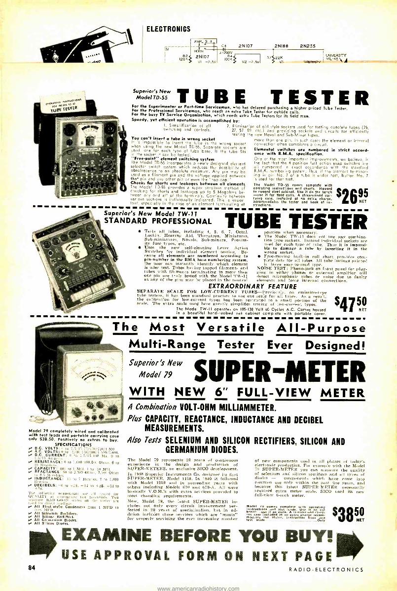
ELECTRONICS
AMPL SI
Fs'
a
ca 2N107 2N188 2N255 (
R2 2N107 -2..5V
f34 I UNIVERSITY I 120K IOOK RT 22K
1t MIL-45\
_ VI -J.V V2 -J.SV V3 4 -JV A
Superior's New Model TD -55
J/200V
TUBE TESTER For the Experimenter or Parttime Serviceman, who has delayed purchasing a higher priced Tube Tester. For the Professional Serviceman, who needs an extra Tube Tester for outside calls. For the busy TV Service Organization, which needs extra Tube Testers for its field men. Speedy, yet efficient operation is accomplished by:
I. Simplification of all 2. Elimination of old style sockets used for testing obsolete tubes (25, swltchinq and cont'ols. 27, 57, 59, etc.) and providing sockets and circuits for efficiently testing the new Novel and Sub -Minar types.
You can't insert a tube in wrong socket more than one pin. In such cases the element or internal It is impossible to insert the tube in the wrong socket connection often completes a circuit, when using the new Model TD -55. Separate sockets are Elemental switches are numbered in strict accord - used, one for each type of tube base. If the tube fits in the socket it can be tested. "Free- point" element switching system The Model TD -55 incorporates a newly designed element selector switch system which reduces the possibility of obsolescence to an absolute minimum. Any pin may be used as a filament pin and the voltage applied between chat pin and any other pia or even the "top- cap." Checks for shorts and leakages between all elements The Model TD -55 provides a super sensitive method of checking for shorts and leakages up to 5 Megohms be- tween any and all of the terminals. Continuity between various sections is individually indicated. This is impor- tant, especially in the case of an element terminating at
once with R.M.A. specification. One of the most important improvements, we believe, is the fact that the 4 position fast action snap switches are all numbered in exact accordance with the standard R.M.A. numbering system. Thus, if the element terminat- ing in pin No. 7 of a tube is under test, button No. 7 is used for that test. The Model TD -55 comes complete with operating instructions and charts. Housed in rugged steel cabinet. Use it on the bench -use it for field calls. A streamlined car- rying cale, included at no extra charge. accommodates the tester and book of in- structions.
$2695 Superior's New Model TW -11 STANDARD PROFESSIONAL TUBE TESTER
le-ts all tubes, including 4, 5, 6, 7, Octal, Lockin, Hearing Aid, Thyratron, Miniatures, Sub -miniatures, Novels, Sub -minars, Proxim- ity fuse types, etc. Uses the new self -cleaning Lever Action Switches for individual element testing. Be- cause all elements are numbered according to pin- number in the RMA base numbering system, the user can instantly identify which element is uder test. Tubes having tapped filaments and tubes with filaments terminating in more than one pin are truly tested with the Model TW -11 as any of the pins may be placed in the neutral
position when necessary. The Model TW -11 does not use any combina- tion type sockets. Instead individual sockets are used for each type of tube. Thus it is impossi- ble to damage a tube by inserting it in the wrong socket. Free -moving built -in roll chart provides corn - plete data for all tubes. Al] tube listings printed in large easy -to -read type.
NOISE TEST: Phono -jack on front panel for plug- ging in either phones or external amplifier will detect microphonic tubes or noise due to faulty elements and lno.e internal connections.
EXTRAORDINARY FEATURE SEPARATE SCALE FOR LOW-CURRENT TUBES- 1'rccio .:y, on emission -type tube testers, it has been standard practice to use one scale for all tubes. As a result, the calibration for low- current types has been restricted to a small portion of the scale. The extra scale used here greatly simplifies testing of low -current types.
The Model TW -I I operates on 105 -130 Volt 60 Cycles A.C. Comes housed in a beautiful hand -rubbed oak cabinet complete with portable cover.
$4750 NET
The Most Versatile All- Purpose
Model 79 completely wired and calibrated with test leads and portable carrying case only $38.50, Positively no extras to buy.
SPECIFICATIONS D.C. VOLTS - 1:-.(1/T50/1,500. A.C. VOLTS: i 1-,.V::u0l,nnt/3.000. i- D.C. CURRENT: 1.7,/15 ILn \ta. 0 to 1.5 I7 .\Inp,i. RESISTANCE: II to 1.000'100,000 Ohm,. 0 to lU V1egoInu.. CAPACITY: not to t Mtrl. 1 to 5u REACTANCE: Si to 2.500 Ohm,, 2,51n Oluns ta 2.5 3le,:alli,i. INDUCTANCE: IS to 7 Henries, 7 to 7,000 Ilea riv+. -
DECIBELS: -r, to +13. +14 to +38, +34 to 1 R.
'l.l,] lolluniug components are all tested for tlI .11,1TV at ii rprapriate test potential.. Two -,p:,rurr BAU -0101D ,vales on the meter are n.r,l tue ,tirent leadinu,. All Electrolytic Condensers from 1 MID to Insu JI PI). All Selenium Rectifiers. All Silicon Rectifiers. All Germanium Diodes. All Silicon Diodes.
Multi -Range Tester Ever Designed! Superior's New
SUPER-METER Mode/ 79
WITH NEW 6" FULL -VIEW METER s ae ee e 4 Combination VOLT -OHM MILLIAMMETER.
Pius CAPACITY, REACTANCE, INDUCTANCE AND DECIBEL MEASUREMENTS.
4/so Tests SELENIUM AND SILICON RECTIFIERS, SILICON AND GERMANIUM DIODES.
The Model 79 represents 20 years of continuous experience in the design and production of SUPER- METERS, an exclusive SICO development. In 1938 Superior Instruments Co. designed its first SUPER -METER, Model 1150. In 1940 it followed with Model 1250 and in succeeding years with others including Models 670 and 670 -A. All were basically V.O.M.'s with extra services provided to meet changing requirements. Now, Model 79, the latest SUPER -METER in- cludes not only every circuit improvement per- fected in 20 years of specialization, but in ad- dition includes those services which are "musts" for properly servicing the ever increasing number
of new components used in all phases of today's electronic production. For example with the Model 79 SUPER -METER you can measure the quality of selenium and silicon rectifiers and all types of diodes - components which have come into common use only within the past five years, and because this latest SUPER -METER necessarily required extra meter scale, SICO used its new full-view 6 -inch meter.
Model 79 comes complete with operating instructions and test leads. Use it on the nch -use it on calls. A streamlined carry- ing case included at no extra charge La modale. tihe tester, instruction book and
test leads Only
$3850
EXAMINE BEFORE YOU BUY! i USE APPROVAL FORM ON NEXT PAGE IIIIIr
84 RADIO -ELECTRONICS
1
www.americanradiohistory.com
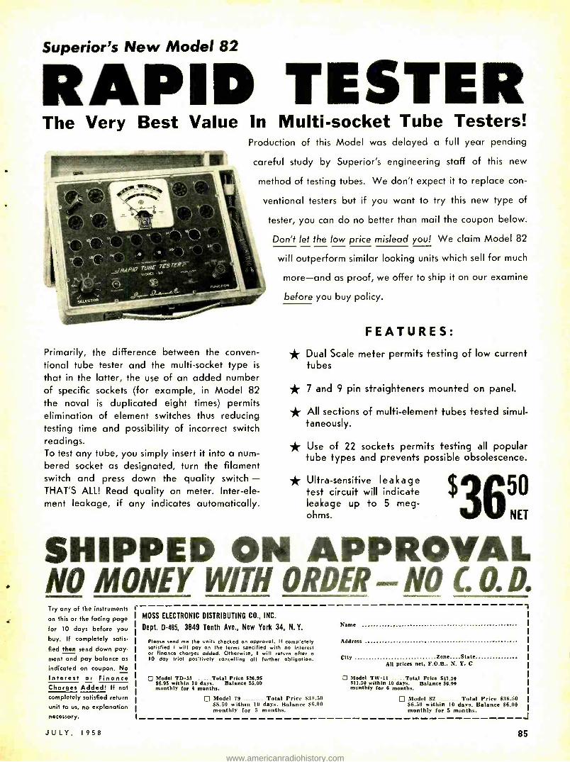
Superior's New Model 82
RAPID T The Very Best
E ST E R Value In Multi- socket Tube Testers!
Production of this Model was delayed a full year pending
careful study by Superior's engineering staff of this new
method of testing tubes. We don't expect it to replace con-
ventional testers but if you want to try this new type of
tester, you can do no better than mail the coupon below.
Don't let the low price mislead you! We claim Model 82
will outperform similar looking units which sell for much
more -and as proof, we offer to ship it on our examine
before you buy policy.
Primarily, the difference between the conven- tional tube tester and the multi- socket type is
that in the latter, the use of an added number of specific sockets (for example, in Model 82 the noval is duplicated eight times) permits elimination of element switches thus reducing testing time and possibility of incorrect switch readings. To test any tube, you simply insert it into a num- bered socket as designated, turn the filament switch and press down the quality switch - THAT'S ALL! Read quality on meter. Inter -ele- ment leakage, if any indicates automatically.
FEATURES: * Dual Scale meter permits testing of low current
tubes
* 7 and 9 pin straighteners mounted on panel.
* All sections of multi -element tubes tested simul- taneously.
* Use of 22 sockets permits testing all popular tube types and prevents possible obsolescence.
* Ultra- sensitive leakage test circuit will indicate leakage up to 5 meg- ohms.
$365° NET
SHIPPED ON APPROVAL NO MONEY WITH ORDER -NO C. 0. D. Try any of the instruments
on this or the facing page
for 10 days before you
buy. If completely satis-
fied then send down pay.
ment and pay balance as
indicated on coupon. No
Interest or Finance Charges Added! If not
completely satisfied return unit to us, no explanation necessary.
JULY, 1958
MOSS ELECTRONIC DISTRIBUTING CO., INC.
Dept. D485, 3849 Tenth Ave., New York 34, N. Y.
Please send me the units checked on approval. If completely satisfied I will pay on the terms specified with no interest or finance charges added. Otherwise, I will return after o 10 day triol positively cancelling all further obligation.
0 Model TD -55 Total Price $26.95 $6.95 within 10 days. Balance $5.00 monthly tor 4 months.
Model 79 Total Price $38.50 $8.50 within 10 days. Balance $6.00 monthly for 5 months.
Name
Address
City Zone. State All prices net, F.O.B., N. Y. C
Q Model TWA" .. ..Total Price $47.50 511.50 within 10 days. Balance $6.00 mcnthly for 6 months.
Model 82 Total Price $36.50 $6.50 within 10 days. Balance $6.00 monthly for S months.
J
85
www.americanradiohistory.com
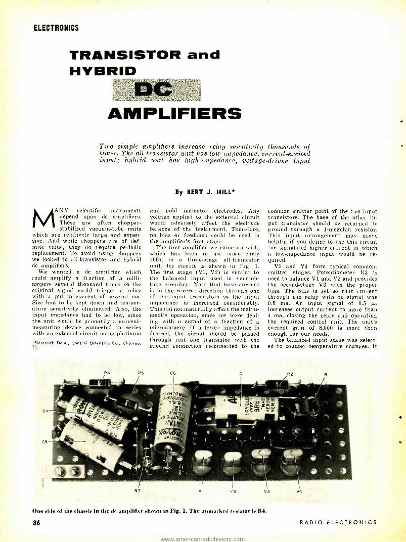
ELECTRONICS
TRANSISTOR and HYBRID
AMPLIFIERS Two simple amplifiers increase relay sensitivity thousands of times. The all -transistor unit has low impedance, current- excited input; hybrid unit has high -impedance, voltage -driven input
MANY scientific instruments depend upon dc amplifiers. These are often chopper - stabilized vacuum -tube units
which are relatively large and expen- sive. And while choppers are of def- inite value, they do require periodic replacement. To avoid using choppers we looked to all- transistor and hybrid do amplifiers.
We wanted a do amplifier which could amplify a fraction of a milli- ampere several thousand times so the original signal could trigger a relay with a pull -in current of several ma. Size had to be kept down and temper- ature sensitivity eliminated. Also, the input impedance had to be low, since the unit would be primarily a current - measuring device connected in series with an external circuit using platinum *Research Dept., Central Scientific Co., Chicago, Ill.
By BERT J. HILL*
and gold indicator electrodes. Any voltage applied to the external circuit would adversely affect the electrode balance of the instrument. Therefore, no bias or feedback could be used in the amplifier's first stage.
The first amplifier we came up with, which has been in use since early 1957, is a three -stage all- transistor unit. Its circuit is shown in Fig. 1. The first stage (V1, V2) is similar to the balanced input used in vacuum - tube circuitry. Note that base current is in the reverse direction through one of the input transistors so the input impedance is increased considerably. This did not materially affect the instru- ment's operation, since we were deal- ing with a signal of a fraction of a microampere. If a lower impedance is desired, the signal should be passed through just one transistor with the ground connection reconnected to the
R6 R5 C6 CI
common emitter point of the two input transistors. The base of the other in- put transistor should be returned to ground through a 1- megohm resistor. This input arrangement may prove helpful if you desire to use this circuit for signals of higher current in which a low- impedance input would be re- quired.
V3 and V4 form typical common - emitter stages. Potentiometer R3 is used to balance V1 and V2 and provides the second -stage V3 with the proper bias. The bias is set so that current through the relay with no signal was 0.5 ma. An input signal of 0.5 pa increases output current to more than 4 ma, closing the relay and operating the required control unit. The unit's current gain of 8,000 is more than enough for our needs.
The balanced input stage was select- ed to counter temperature changes. It
RI
One side of the chassis in the dc amplifier shown in Fig. 1. The unmarked resistor is R4.
86 RADIO -ELECTRONICS
www.americanradiohistory.com

is simple and the problem of matching transistors for V1 and V2 is easily handled. With 1.5 volts applied to the collector and the base open, we meas- ured collector current. Transistors with about the same collector currents are accepted as matched. This balanced stage takes care of temperature changes so that we get satisfactory operation with a "cold" instrument as well as one which has been in opera- tion for many hours.
Our amplifier is exposed to severe ac fields and relatively large capacitors are used. The large time constant is not disadvantageous when working with do variation with a slow rate of change. Under less severe conditions smaller capacitors could be used and in some places they might be eliminated.
The amplifier is powered by batteries or a small ac supply. Circuit design requires two voltage sources.
A hybrid amplifier A second type of amplifier -a hybrid
-is shown in Fig. 2. It uses a 12AX7 in a balanced input stage and two common -emitter transistor stages. This amplifier gave excellent results and since it presents a high impedance to the external circuit, is especially useful where small voltage changes are to be measured without loading the circuit. An input of 5 my increases output current more than 4 ma. Shunt the input with an appropriate resistor and it can be used as a current- actuated device.
We did not try to make either ampli- fier linear as they key a relay and are not used in calibrated measuring devices.
Although the units are simple, they do a good job with no need for voltage stabilization, feedback circuits or spe- cial temperature- compensation net- works. The experimenter should find many applications for both units. END
N PUT
2N35(2)
Cia ELECTRONICS
RI -I megohm R2, 4- 10,000 ohms R3 -pot, 20,000 ohms RS- 47,000 ohms R6-330 ohms R7 -4,700 ohms All resistors 1/2 -watt 10% CI, 2, 3-5 pf, 25 volts, electrolytic C4, 5-10 pf, 15 volts, electrolytic C6-100 pf, 12 volts, electrolytic DI, 2- 1N34 -A (G -E)
Fig. 1- Schematic diagram o 12AX7 yl I
2
RY- 2,500 -ohm coil, closes on 4 ma or less (Sigma 4F -2500 or equivalent
S -spst switch TI, 2- heater transformers: primary, 117 volts;
secondary, 6.3 volts, 600 ma (Triad F -13X or equivalent)
VI, 2 -2N35 (Sylvania) V3, 4 -2N369 (Texas Instruments) Chassis, to suit Miscellaneous hardware
f the all- transistor high -gain dc amplifier.
2N369(2)
We- 2.5K
2.2K /IW RECT I
1N34-A(2) R7
117
RI -4.7 megohms R2 -270 ohms R3, 5-68,000 ohms R4 -pot, 20,000 ohms R6- 47,000 ohms R7 -330 ohms All resistors ' /.watt 10% Cl -O.l pf, 200 volts C2-5 µf, 150 volts, electrolytic C3-5 pf, 25 volts, electrolytic
Fig. 2 -A hybrid v
C4, 5 -10 µf, 15 volts, electrolytic DI, 2- 1N34-A (G -E) RY- 2,500 -ohm coil, closes on 4 ma or less
(Sigma 4F -2500 or equivalent) VI -12AX7 V2, 3 -2N369 (Texas Instruments) Chassis, to suit Power supply delivering 250 volts dc at 10 ma
and 6.3 volts at 300 ma Miscellaneous hardware
ersion of Fig. 1, using a tube and two transistors.
JULY, 1958
R4 BALANCE CONT
A view of the high -gain tube- transistor amplifier in Figu 2.
87
www.americanradiohistory.com

ELECTRONICS
via METEOR BURSTS U- t eors and modern techniques combine to give er-
) wige two-way communications in the 30-100-n1c band
By G. FRANKLIN MONTGOMERY
i
DURING the early Forties, when the FM broadcast service was operating in its old band at 42 to 50 nrc, Federal Communica-
tions Commission monitoring engineers discovered a strange effect. Short bursts of signal were received occasionally from FM stations as far as 1,370 miles away. This distance was -much greater than the 100 miles or so considered maximum line -of- sight. The signal bursts were brief, usually lasting for less than a second. They showed none of the characteristics associated with known abnormal propagation such as ionospheric sporadic -E transmission or atmospheric bending.
After a careful study, E. W. Allen, Jr.' identified the bursts with individual meteors, the small outer -space particles of matter that plunge into the atmos- phere by the billions each day. This intermittent vhf propagation over in- termediate distances has led to some unusual developments.
Meteor bursts are signal reflections from the atmospheric ionization that these high -speed particles produce. Ranging in size from almost micro- scopic grains to an occasional mass of rock or iron weighing several tons, meteors enter the atmosphere at veloci- ties as great as 40 miles per second. At an altitude of about 60 miles, their friction with the thin atmosphere pro- duces temperatures high enough to melt and vaporize the meteor and to split molecules of the air into ions and free electrons.
In the meteor's wake, a miniature ionosphere is formed in the shape of a slender, slowly expanding cylinder, perhaps several miles in length. The ions and electrons produced by this process eventually recombine to form neutral gas molecules, but it may take many seconds for them to do so.
Early experiments After the war, to stu.[y meteor be-
havior, a number of experimenters began measuring radio reflections from meteor trails with vhf radar equipment. About 1950, the idea occurred almost simultaneously to several engineers that meteors might provide useful radio communication from one point to an- other. Shortly thereafter, groups at the Defence Research Telecommunications
Establishment (Canada), the National Bureau of Standards, the Stanford Research Institute and RCA Labora- tories began work to develop regular communication by this means.' Ama- teurs in the US also began work with similar techniques.
Suppose we have two stations, A and B, about 1,000 miles apart. Each station has a transmitter and receiver with antennas beamed toward a patch of sky (about 60 miles up) that can be seen from both stations. Each transmitter radiates a carrier wave continuously. Receiver A is tuned to transmitter B, receiver B to transmitter A. (Trans- mitter frequencies must differ slightly so transmitter A will not interfere with receiver A, nor transmitter B with receiver B.) Ordinarily, each station receives only a very weak signal or none at all. But from time to time, a meteor will pass through the part of the atmosphere included in the antenna beams of both stations. As it does so, it produces a trail of ionization. If this trail is oriented properly with respect to the stations, both will receive a signal burst that may last from less than 1 /10 second to many seconds be- for it fades into the background noise.
Fig. 1 shows the kind of variation that is typical of separate meteor bursts. In addition to the main outlines of an abrupt rise and slow decay in signal amplitude, subsidiary fading is often observed on some bursts. The fading is attributed to breakup of the trail by high -altitude atmospheric winds.
Speeded -up transmission Stations A and B can communicate
with each other during these brief in tervals. With ordinary equipment, how ever, communication is difficult or impossible with the signal lasting fol so short a time. Modern information handling techniques now come into play. If A is to send a message to B the message can be stored at A it record form -on magnetic drums of tape, for example. When a signal burs] occurs at A, the recorded message b played back at high speed and modu lates A's transmitter. The same high speed message at the output of B's receiver is recorded at B. Subsequently when the signal burst has passed, B's record is played back at normal speec so that the message can be understood
This general procedure is the basis for burst communication. Storing in formation at normal speed, playbacl and transmission at high speed, recep tion and recording at high speed, an playback at normal speed are common to all systems now in development Teletypewriter, voice and even facsim ile modulation have been used suc cessfully in meteor -burst experiments Usually the goal is two -way communi cation, with both stations transnrittirn and receiving different messages simul taneously, using the same signal burst This end has already been achieve( with teletypewriter messages sent a up to 40 times the normal speed of 6( words per minute.
In addition to the recording equip ment, control circuits are required a each station to perform certain func tions automatically. When a burst is
received, there must be a thresholc device to judge whether the signa amplitude of the burst is large enougt
Fig. 1- Sketch of typical meteor -burst signals shows amplitude and duration
of received information.
Fig. 2- Message capacity plotted against bandwidth or
transmission speed.
,40.......................
nus t ...IIIimIIIm11i!. gulo mm1oo1o!ill
::::1iE:iiIaiaT g S =a:monu:CE:nm C
w titifalIlllIt'Itii1I11111itiiII111Ri f I Í11111 ,1'lll 'll111 J ç1
¢ RELATIVE BANDWIDTH OR TRANSMISSI N SPEED
88 RADIO -ELECTRONICS
www.americanradiohistory.com

to warrant starting transmission. If it is, the high -speed record and playback units must be signaled to start. When the received burst amplitude falls be- low a preset threshold, these units must be stopped, and so on. In a two -way system, it is almost certain that the received signals at both stations will not behave in exactly the same manner. A code of check signals is often sent around the loop from one station to the other and back before starting trans- mission from either. This procedure may sound like a waste of precious transmitting time, but it is done within a few milliseconds and greatly reduces the possibility of transmission errors.
Fundamental to any communication system is the signal -to -noise ratio at the receiver while the message is in progress. If the message is sent more rapidly than normal, the receiver band- width must be increased to avoid mes- sage distortion. An increased receiver bandwidth admits more noise, which in itself may distort the message. In conventional systems where communi- cation is continuous, a compromise must therefore be made between speed of transmission and degradation of the received signal -to -noise ratio.
Long or short; large or small?
In a meteor -burst system, where communication is intermittent, this compromise has unique consequences. The signal bursts in such a system vary widely in amplitude and duration. A few bursts have very large peak amplitudes; many more have small amplitudes. A particular burst of any amplitude may be short, or it may last for a relatively long time. The bursts can be predicted only statistically. Whether the next burst will be large or small and exactly when it will occur are both matters of chance.
Now, in setting up a system, we may choose to operate only with the few bursts of large amplitude and transmit at high speed. Alternatively, we may use the many bursts of smaller ampli- tude, as well as the large ones, and transmit slowly.
The striking feature of meteor -burst statistics is that it pays to use only the large bursts. The price that must be paid for using them effectively is transmission speed and bandwidth. In addition, a longer wait is required between transmissions, although this waiting period may be unimportant in some applications.
The faster we are prepared to trans- mit and record during a burst, and the fewer bursts we use, the greater the message capacity of the system. (A convenient measure of message capacity is the total length of message that can be sent over the system in a period of time long enough to include a large number of bursts.) Fig. 2 illus- trates this dependence. Relative mes- sage capacity and relative bandwidth or transmission speed are plotted using logarithmic scales. The capacity is not directly proportional to the bandwidth
JULY, 1958
Interior of trailer. Two racks to the rear contain receiving and control equipment. Two central racks are magnetic tape storage, record and play- back units for transmitting and receiving. Tape is stored in vertical perforat- ed metal tanks. Foremost rack contains monitoring equipment.
(Below) Experimental meteor -burst communi- cation station. Four It agi antennas are arranged in double arrays for transmitting and receiv- ing. Radio and terminal equipment are housed in trailer to the rear.
ELECTRONICS
but increases more slowly. In a typical case, it is proportional to the band- width or speed raised to about the 0.4 power.
The choice of operating parameters for a meteor -burst system is made more difficult by the erratic nature of the bursts. Their random occurrence and amplitudes would not be particularly troublesome if we could depend upon known average occurrence rates and average amplitudes. But we cannot.
We do know that a typical system of moderate power may operate with four or five 1- second bursts per minute on the average. Throughout the day, however, the actual number of bursts per minute changes from a high rate in the pre -dawn hours to a low rate at sunset. The total number of bursts varies from day to day.
At any given time, there is a best section of sky toward which the an- tenna beams should be pointed to inter-
Courtesy National Bureau of Standards
cept the greatest number of useful trails. The position of this best section also changes throughout the day and probably with the seasons. All these meteor -burst characteristics have been measured extensively, but they must be known even more exactly to achieve the best communication performance.
Forward- scatter competition In one sense, meteor -burst systems'
are competitors with ionospheric for - ward- scatter systems. Both provide communication over the same distances in the same part of the vhf spectrum, roughly 30 -100 mc. However, meteor - burst systems may be able to use higher frequencies than are profitable for ionospheric scatter.
One distinct advantage of meteor bursts is the lower power required. Most experimental work has been done with transmitter powers from 100 watts to a few kilowatts. Operational scatter
89
www.americanradiohistory.com

TRANSISTOR POWER SUPPLY
SPECIFICATIONS
Input: 115 Volts 50/60 cycles
Output Voltage 0.15 Volts and
0.30 Volts 0-15 MA and 0-60 MA
Output Current: 0' n and current
Accuracy: 27. on both voltage
Less than 500 microvolts (.002%.
at full output) Zero to
Regulation: 1.2 Volts Maximum;
full load current
Internal Impedance: Less than 20 ohms
DC to Radio Frequencies (including 7.0
ohm Meter Fuse, optionally
Terminals: 5 -Way Binding Post
Size; 10's x 61/2rr x 53/4" 16 pounds
MODEL A -400 Especially designed to operate, service
and test transistor portable radios and low power transistor circuits.
Highest quality components combined with careful engineering make this instrument extremely reliable and useful for lobora- ttfry and service applications.
"TRULY A
VARIABLE BATTERY"
645 from Electronic Parts
.4rt Distributors only FEATURES
s Continuously adjustable output using variable autoformer control. Two output voltage ranges for accurate setting of all transistor battery voltages. Two output current ranges monitor current for single transistor or entire set. Extremely low ripple for testing lowest level transistor circuits.
Very low internal impedance providing ex- cellent regulation. Precision D'Arsonval meters provide labora- tory accuracy. Milliameter protected by front panel fuse; additional internal line fuse. Output isolated from line and case, Attractive Slope - Front, Maroon Hammerloid Cabinet - Rubber feet.
Manufactured by
CO
There's always something new being developed by Perma -Power
WILL YOUR REPLACEMENT 'a' h
BURN OUT AGAIN? 1 Aothefi, Not if you use -
The NEW SENCORE 1
Sege "FUSE- SAFE''¡ CIRCUIT TESTER i
Sain 1
1
1
I
Save costly call backs by testing the circuit
1 before replacing
ie
fuse, fuse resistor or circuit breaker.
Individual scale for Ieach value fuse re-
'sistor - no inter- pretation, just read
1 in red or green area. * Measures line current ' and up to 1100 wafts of
power at 115 volts using Iline cord and socket. * Two convenient current Iranges - 0 to 2 amps and
in 0 to 10 amps. Test leads clip in place of fuse or fuse I resistor. .. , . * 5 ohm, 10 watt resistor prevents TV circuit' ' damage and simulates operating conditions. As Recommended by Leading Manufacturers
' Nr o' byg SERVICE I INSTRUMENTS CORP. 171 OFFICIAL RD., ADDISON, ILL.
LCvi our this ad now for further information
1
1
i
all new edition VOL. III. NO. 1
up -to -date component
prices
the quick easy way to figure
service charges
Pail t
OFFICIAL PRICING DIGEST
$8D95 NET MODEL FS -3
AC -DC or both as needed for Fuse Resistor Circuits
1
90
MIS te 10.1.1.1in 1.11101,111.11 MONS
Flat rate and hourly service charges, based on and show- ing regional and national aver ages, plus up -to -date list or resale prices on over 63,000 components. Arranged alpha- betically by manufacturers and products, numerically by part number. Compact, con- venient size fits in tube caddy, toolbox or pocket. $2.50 per copy from your distributor.
ELECTRONIC PUBLISHING COMPANY, INC.
180 N. WACKER DRIVE, CHICAGO 6, ILL.
ELECTRONICS
systems usually require tens of kilo- watts and high -gain antennas. While high -gain antennas are certainly useful for meteor -burst work, satisfactory re- sults have been obtained with simple Yagis of moderate gain. The principal disadvantage, of course, is the complex message- handling equipment needed at the terminals. Perhaps this disadvan- tage will seem less severe after more experience with these devices.
The high frequencies (3 to 30 mc), which we depend on for both inter- mediate- and long- distance communica- tion, have been badly crowded for many years. During ionospheric storms, high - frequency communication is often un- reliable. Even so, there is little hope that future technical improvements will provide space for all of the services that would like to use this part of the spectrum. The situation is rather like an overcrowded bus with more riders than seats. Those standing must either ride uncomfortably until someone abandons a seat, or give up the idea of riding altogether. Meteor -burst com- munication, it is hoped, will provide a larger bus. The hope is bright enough that much effort is being spent on its development. END
References 1E. W. Allen, Jr., "Reflections of Very -High-
Frequency Radio Waves from Meteoric Ioniza- tion," Proceedings of the IRE, Vol. 36, No. 3, pages 346-352 ; March, 1948.
Meteor -burst Communication Papers, Proceed- ings of the pages IRE, Vol. 45, No. 12 pages 1642 -1736 ; December, 1957.
3 "ARRL Merit Award for 1955 Goes to W4HHK and W2UK," QST, Vol. 40, No. 10, page 62; October, 1956.
Scatter Propagation Issue, Proceedings of the IRE, Vol. 43, No. 10, pages 1173-1526 ; October, 1955.
VOICES OF THE SATELLITES Believed to be the only commercially
available recording of the radio signals from Sputnik I and II and Explorer I, II and III, Voices of the Satellites is the work of Prof. Thomas A. Benham of Haverford College, Haverford, Pa. The signals were recorded with a spe-
cially built convertor amplifier. Pro- fessor Benham, who is totally blind, also produces a nonprofit science maga- zine on tape, Science for the Blind, which issues 400 recordings per month. His satellite recording, available on a 5 -inch tape reel or 10 -inch LP record, is distributed by Taben Recordings, Box G -224, Ardmore, Pa. ($3.95).
RADIO -ELECTRONICS
www.americanradiohistory.com

ig Amazing No. 25 Tower to reach
OUNBeSnS w heights in tower engineering
NEW GENER
4 COMMUNICATION
OR HEAVY -DUTY TV TOWER 11G
PURPOSE COMMUNICATION OR HEAVY -DUTY TV TOWER
PU s
and under guy
ROHN now offers a tower a full 33`yo
stronger and more durable than similar
sized and similar type towers that are
found on the market today'.
Z5 These amazing results are achieved
g heavier -duty side rail through using tubing, quality steel that is oft e high-
est grade and a new "zig-zag
ing design. The strength of thünder
mostlondi- to be self -supp g
guyed condition
condi-
tions to 50' an u up to 150'. The tower has been built to
fit a tremendously wide range of needs
in communications, amateur use and as
a heavy -duty TV tower.
FLASH! The "RohnKote" enameling
plant is in operation and ROHN prod-
ucts are available not only
DIPPED GALVANIZING but also
in a specially developed 6 -step enamel-
ing process known as "RohnKote ".
NOW/10 Different Lines of ROHN TOWERS, Including:
No. Packaged Towers in which the sec- tions nestle inside each other.
Widely used for home TV, this tower features "magic triangle" cross bracing con- struction.
look to ROHN for these
requirements, too:
A wide line of all types of accessories for
towers is available but inn adaddition,
ROHN
produces ces a complete
MASTS ' ROOF TOWERS
ROHN masts de-
sign outstanding in
sign and have spe- cial features that make them the best
in the field and in
addition, are as low
or lower in cost than
any other.
TUBING Complete line of
tubing, either plain
or with 6" expanded end; in 10' and 5'
length; 16 or 18
gauge; and in either
hot -dipped galvan- ized or "RohnKote" enameling.
Specially designed roof towers have re-
ceived tremendously wide acceptance and
are available from
heights of 21/2' to
10'. BASES A wide selection for
mast and other watype ll installations;
mounts -for inex-
pensive installations; gable mounts; spe-
cial mounts for an-
tennas; drive -in ground mounts; and
dozens of other spe-
cially designed items.
No. 40 Heavy -duty com- munications tower suitable self -sup- porting at heights up 60' guyed as high as 300'. Ideal for co
mm cro-
-
nications uses of all typto es,
or
mi wave, radio tele- phone, etc.
No. 20 & 30 Heavy -duty com- munications tow- ers in RohnKote enamel.
Fold -Over Towers Ideal for amateurs and experi- menters inasmuch as the tower folds over for convenient an- tenna changing, etc. Supplied in both medium and heavy - duty sizes to handle practically any size beam.
R
Make sure you have full details, catalog and prices on the entire ROHN line. Contact the ROHN representative in your area, or distribu- tor, or contact:
JULY, 1958
Manufacturing Compan 116 LIMESTONE, BELLEVUE LINOIS PHONE 4 -91
91
www.americanradiohistory.com
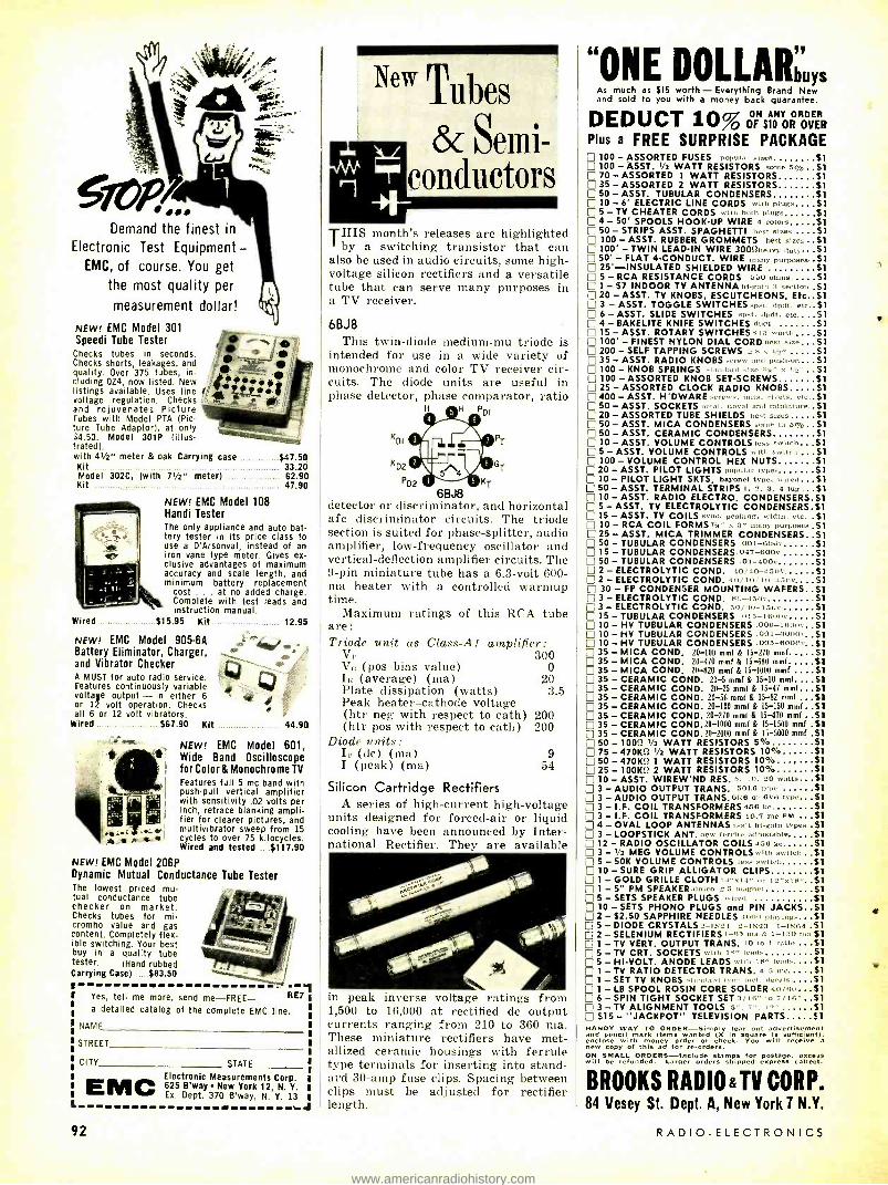
Demand the finest in
Electronic Test Equipment - EMC, of course. You get
the most quality per
measurement dollar!
NEW! EMC Model 301 Speedi Tube Tester
Checks tubes in seconds. Checks shorts, leakages, and quality. Over 375 tubes, in- cluding OZ4, now listed. New listings available. Uses line /, voltage regulation. Checks and rejuvenates Picture Tubes with Model PTA (Pic- ture Tube Adaptor), at only $4.50. Model 301P (illus- trated), with We meter & oak Carrying case $47.50 Kit 33.20 Model 302C, (with 71/2" meter) 62.90 Kit 47.90
NEW! EMC Model 108 Handi Tester The only appliance and auto bat- tery tester in its price class to use a D'Arsonval, instead of an iron vane type meter. Gives ex- clusive advantages of maximum accuracy and scale length, and minimum battery replacement
cost . , . at no added charge, Complete with test leads and instruction manual.
Wired $15.95 Kit 12.95
NEW! EMC Model 905-6A Battery Eliminator, Charger, and Vibrator Checker A MUST for auto radio service. Features continuously variable voltage output - in either 6 or 12 volt operation. Checks all 6 or 12 volt vibrators.
Wired $67.90 Kit
t
44.90
Model 601, Oscilloscope
for Color & Monochrome TV
Features full 5 me band with push -pull vertical amplifier with sensitivity .02 volts per inch, retrace blanking ampli- fier for clearer pictures, and multivibrator sweep from 15 cycles to over 75 kilocycles. Wired and tested ....$117.90
NEW! EMC Wide Band
NEW! EMC Model 20612 Dynamic Mutual Conductance Tube Tester The lowest priced mu- tual conductance tube checker on market. Checks tubes for mi- cromho value and gas content. Completely flex- ible switching. Your best buy in a quality tube tester. (Hand rubbed Carrying Case) ._ $63.50
, Yes, tell me more, send me -FREE- RE7
a detailed catalog of the complete EMC line.
NAME
STREET
CITY STATE
Electronic Measurements Corp. 625 B'way New York 12, N. Y. Ex. Dept, 370 B'way, N. Y. 13
J EMC
92
New Tubes
& Semi- conductors
THIS month's releases are highlighted I by a switching transistor that can also be used in audio circuits, some high - voltage silicon rectifiers and a versatile tube that can serve many purposes in a TV receiver.
6BJ8 This twin -diode medium -mu triode is
intended for use in a wide variety of monochrome and color TV receiver cir- cuits. The diode units are useful in phase detector, phase comparator, ratio
H H PD1
KDI
KD2
PD2 KT
G
6BJ8 detector or discriminator, and horizontal afe discriminator circuits. The triode section is suited for phase -splitter, audio amplifier, low -frequency oscillator and vertical -deflection amplifier circuits. The 9 -pin miniature tube has a 6.3 -volt 600 - ma heater with a controlled warmup time.
Maximum ratings of this RCA tube are: Triode unit as Class -AI amplifier: Vp 300 Va (pos bias value) 0 Ii; (average) (ma) 20 Plate dissipation (watts) 3.5 Peak heater -cathode voltage (htr neg with respect to cath) 200 (htr pos with respect to cath) 200
Diode units: Ip (dc) (ma) I (peak) (ma) 54
Silicon Cartridge Rectifiers A series of high -current high -voltage
units designed for forced -air or liquid cooling have been announced by Inter- national Rectifier. They are available
9
in peak 1,500 to
inverse voltage ratings fi 16,000 at rectified do output
currents ranging from 210 to 360 ma. These miniature rectifiers have met- allized ceramic housings with ferrule type terminals for inserting into stand- ard 30 -amp fuse clips. Spacing between clips must be adjusted for rectifier length.
om
"ONE DOLLARbUYS As much as $15 worth - Everything Brand New and sold to you with a money back guarantee.
DEDUCT 10% FN ANY ORDER
O OF S10 0R OVER
Plus a FREE SURPRISE PACKAGE 100 - ASSORTED FUSES p'pnl:,r ..S1 W0 - ASST. 1/2 WATT RESISTORS some 5 7o ..$1 70 - ASSORTED 1 WATT RESISTORS Si 35 - ASSORTED 2 WATT RESISTORS S1 50 - ASST. TUBULAR CONDENSERS $1 10 - 6' ELECTRIC LINE CORDS .vitli Plug. $1 5 - TV CHEATER CORDS "nh tooth plugs 51
0 4 -50' SPOOLS HOOK -UP WIRE 4 colors 51 50 - STRIPS ASST. SPAGHETTI beer sizes $1 100 - ASST. RUBBER GROMMETS best sines $1 100' - TWIN LEAD -IN WIRE 30012heayy duty S1 50' - FLAT 4- CONDUCT. WIRE many purposes. S1 25'- INSULATED SHIELDED WIRE S1 5 - RCA RESISTANCE CORDS 550 ohms S1 1 - $7 INDOOR TV ANTENNA nl -gala 3 section 51 20 - ASST. TV KNOBS, ESCUTCHEONS. Etc 51 3 - ASST. TOGGLE SWITCHES spat. dpdt, ete $1 6 - ASST. SLIDE SWITCHES =pat, dpdt, etc $1 4- BAKELITE KNIFE SWITCHES dpdt $1 15 -ASST. ROTARY SWITCHE5s15 wor h $1 100' - FINEST NYLON DIAL CORD best size 51 200 - SELF TAPPING SCREWS 2. It s ' $1 35 - ASST. RADIO KNOBS and push -on 51 100 - KNOB SPRINGS n 1: rn nlze :Sk x t ... 51 100 - ASSORTED KNOB SET- SCREWS $1 25- ASSORTED CLOCK RADIO KNOBS $1 400 - ASST. H'DWARE n .. rivets, ete $1 50 - ASST. SOCKETS aatal. ,iv l and miniature $1 20 - ASSORTED TUBE SHIELDS best sizes.... 31 50 - ASST. MICA CONDENSERS is 5% 51 50 - ASST. CERAMIC CONDENSERS $1 10 - ASST. VOLUME CONTROLS leas swtteh 51
E 5 - ASST. VOLUME CONTROLS wish switch , $1 0100- VOLUME CONTROL HEX NUTS Si
20 - ASST. PILOT LIGHTS h i nl:,r types $1
10 - PILOT LIGHT SKTS, bayonet type, wired, $1 50 -ASST. TERMINAL STRIPS 2. 3, 4 lug $1 10 -ASST. RADIO ELECTRO. CONDENSERS $1 5 -ASST. TV ELECTROLYTIC CONDENSER5 S1 15 - ASST. TV COILS -vile. peaking, width. etc. $1 10 - RCA COIL FORMS, s" x a^ many purposes $1 25 - ASST. MICA TRIMMER CONDENSERS 51 50 - TUBULAR CONDENSERS 001 -e0uc $1 15 - TUBULAR CONDENSERS.047 -600 $1 50 - TUBULAR CONDENSERS .oi -4ons Si 2 - ELECTROLYTIC COND. 4.. hi- I ,i v. $1 2 - ELECTROLYTIC COND. 30 - FP CONDENSER MOUNTING WAFERS 51 3 - ELECTROLYTIC COND. 80-450v $1 3 - ELECTROLYTIC COND. 5o /20 -150v $1 15 - TUBULAR CONDENSERS .^l5 -leo0v $e1
10 - HV TUBULAR CONDENSERS .006- 1600v 51 10 - HV TUBULAR CONDENSERS .001- 6000v, S1 10 - HV TUBULAR CONDENSERS .005-6000v. $1 35 - MICA COND. 20 -100 mmf & 15 -270 mmf $1 35 - MICA COND. 20 -470 mmf & 15-680 mmf $1 35 - MICA COND. 20 -820 mmf & 15 -1000 mmf $1 35 - CERAMIC COND. 20 -5 mmf & 15 -10 mmf 51 35 - CERAMIC COND. 20 -25 mmf & 15 -47 mmf $1 35 - CERAMIC COND. 20-56 mmf & 15 -82 mmf $1 35 - CERAMIC COND. 20 -100 mm(& 15-150 mmf $1 35 - CERAMIC COND. 20 -270 mmf & 15-470 mmf $1 35 - CERAMIC COND.20 -1000 mmf & 15 -1500 mmf 51 35 - CERAMIC COND, 20-2000 mmf & 15 -5000 mmf 51 50 - 100'.7 i/2 WATT RESISTORS 5% $1 75 - 470K2 1/2 WATT RESISTORS 10% Si 50 - 470K12 1 WATT RESISTORS 10% Si 25 - 1001M 2 WATT RESISTORS 10% Si 10 - ASST. WIREW'ND RES. s. +0, ' -'o watts 51 3 - AUDIO OUTPUT TRANS. 501.0 type Si 3 - AUDIO OUTPUT TRANS. "N6 or 6V6 type 51 3 - I.F. COIL TRANSFORMERS 4.56 ke 51 3 - I.F. COIL TRANSFORMERS 10.7 me FM 51 4 - OVAL LOOP ANTENNAS -< t hl -galn types $1 3 - LOOPSTICK ANT. t. rrll,. adjustable Si 12 - RADIO OSCILLATOR COILS 450 kc SI 3- V2 MEG VOLUME CONTROLS wish swlnm 51 5 - 50K VOLUME CONTROLS i sa swlteb S1 10 - SURE GRIP ALLIGATOR CLIPS S1 1 -GOLD GRILLE CLOTH 1.1-1 1,,, or 12"x18° $1
1 - 5" PM SPEAKER:,Inieo 145 magnet ..... $1 5 - SETS SPEAKER PLUGS weed $1 10 - SETS PHONO PLUGS and PIN JACKS $1 2 - 52.50 SAPPHIRE NEEDLES nn' playing., 51 5 - DIODE CRYSTALS 2 -í]2l 2 -1x23 1 -1N04 $1 2 - SELENIUM RECTIFIERS 1_05 m:, & 1 -150 ma $1 1 -TV VERT. OUTPUT TRANS. to to 1 ratio SI 5 - TV CRT. SOCKETS with I O' leads $1 5 - HI -VOLT. ANODE LEADS with 18. leads... 31 1 -TV RATIO DETECTOR TRANS. 4.5 me Si 1 - SET TV KNOBS decals S1
D1- LB SPOOL ROSIN CORE SOLDER 4°/0" 51 6 - SPIN TIGHT SOCKET SET 3/16" to 7f16" 51 3 - TV ALIGNMENT TOOLS 5" ; 12` $1 $15 - "JACKPOT" TELEVISION PARTS $1
HANDY WAY TO ORDER- Simply tear out advertisement and pencil mark items wanted (X in square is sufficient); enclose with m ney order or check. You will receive a new copy of this ad for re-orders. ON SMALL ORDERS -Include stamps for postage. excess will be refunded. Larger orders shipped express collect.
BROOKS RADIO &TV CORP. 84 Vesey St. Dept. A, New York 7 N.Y.
RADIO -ELECTRONICS
www.americanradiohistory.com

NEW TUBES & SEMICONDUCTORS (Conl'd)
2N586 A germanium p -n -p alloy -junction
transistor designed for use in low -speed switching applications in industrial and military equipment. It is particularly useful as a relay -actuating device and in voltage -regulator, multivibrator, dc-
OLLECTOR
BASE
EMITTER
2N586 to -dc converter, and power supply cir- cuits. It may also be used in audio oscillator service and in large- signal class -A or class -B push -pull audio - frequency amplifier service.
Tentative maximum ratings in switch- ing service of this RCA transistor are:
VeR -45 VER -12 IC (ma) -250 IE (ma) 250 P° (mw) (25 °C) 250
(55 °C) 125 (71 °C) 60
0C2 A cold- cathode glow- discharge volt-
age- regulator tube using a seven -pin miniature envelope. It is intended for use in voltage -regulator applications where a relatively constant do output voltage is required across a load, inde- pendent of moderate line -voltage varia-
C_ SERIES RES
TO FILTERED UNREGULATED DC BIAS SUPPLY
C+
REG BIAS 75V (APPROX)
C +B- tions. In the circuit shown the RCA 0C2 will supply a regulated output of approximately 75 volts at cathode cur- rents within the range of 5 -30 ma.
In the circuit enough series resistance to limit the operating current through the tube to 30 ma at all times after the starting period is vital. Note, too, that socket connections are made so that the voltage on the load is removed when the tube is taken from its socket.
I N 1575, I N 1 576, I N 1577, I N1578 Stud- mounted, diffused -junction sil-
icon rectifiers designed to handle much larger surge currents than other silicon
r17 CATHODE CONNECTED TO CASE
RECTIFIERS
IN 1575 -76 -77 -78
7/16" HEX
rectifiers with comparable continuous ratings. The cathode is connected to the case.
JULY, 1958
u:4 i I I II xis 10I
MORE RELIABILITY!
MORE EFFICIENCY!_
LONGER LIFE!
CLEANER OUTPUT!
iuuawored
i
Replace troublesome
vibrators mount -
to -mount
Really dependable mobile power is now yours in seconds simply by pl gging a ransis- torized Univistor vibrator substitute into the vibrator socket. Ttl super' rity of transistorized power, quality engineered by Universal, the pioneer in transistorized power components, brings you efficiency and reliability unheard of in today's conven- tional electro- mechanical vibrators priced as much as 50% LESS THAN COMPETING
BRANDS!
The Univistor converts your power supply into a modern all-electronic supply, eliminating moving parts and, consequently, eliminating repeated vibrator maintenance and replace- ments. The Univistor's operating -life is more than 20 times that of a vibrator. It eliminates electrical and mechanical noise -provides cleaner output throughout its entire life. You make one larger unit sale knowing you'll avoid those unprofitable call backs, while your customer gets longer, trouble -free service which more than pays for its cost. Life -to -life, the Univistor actually costs less than a vibrator.
There are no wiring or circuit changes required. Univistors are available with bases corresponding to commercially available vibrators. Since the two germanium power transistors comprising the amplifying elements of the system are independent of the power transformer action, the Univistor may also be interchanged as a separate component in power inverters and converters. In addition, the Univistor can not be damaged by input polarity reversal.
IMMEDIATE DELIVERY FROM STOCK
The next time you replace a vibrator -and you must -you'll supply excel:- tional dependability and efficiency and profit more, too, with Transistorized Univistors! See your Universal distributor or write:
VAC Electronics 7T7\TT7T
A °IVISI°N OFD^ TRANSISTOR PRODUCTS CORP.
DEPT. R7 17 BROOKLYN AVE., WESTBURY, L.I., N.Y., EDGEW00D 3.3304
93
www.americanradiohistory.com
EARN MORE! MAKE FASTER, EASIER
AUTO RADIO REPAIRS
These Howard W. Sams
'AUTO RADIO" MANUALS SHOW YOU HOW!
Most complete auto radio service data available: Schematics, voltages, resistance readings, alignment, chassis photo views keyed to components, replacement parts recommendations - everything you need to know for quicker, easier servicing. Each volume, 81/2 x 11 ".
AR -7. Covers 56 auto radio models pro- duced in 1957. Only $3.75 AR -6. Covers 77 models produced during 1955 -56. Only $3.95 AR -S. Covers 96 models produced during 1954 -55. Only $3.50 AR -4. Covers 61 models produced during 1953. Only $3.00 AR -3. Covers 83 models produced during 1950 -52. Only $3.00 AR -2. Covers 73 models produced in 1949 -50. Only $3.00
GET EXTRA HELP WITH
SAMS "AUTO RADIO REMOVAL" MANUALS
Solves the toughest problem in auto radio servicing -shows fast- est ways to remove radio, power supply and speaker units. Covers all standard and sports model cars. 51/2 x 81/2 ", ARR57. Covers all 1957 cars ARR -56. Covers all 1956 cars. ARR -55. Covers all 1955 cars. Each Volume, only $2.95
SEE THESE BOOKS AT YOUR SAMS DISTRIBUTOR OR MAIL COUPON
Howard W. Sams 8, Co., Inc., Dept.2 -GB not E. Oath St.. Indianapolis 5, Ind.
Send me book(s) checked at right AR -7 AR -3 for 10 days FREE examination. In 10 days 1 will pay for the book(s), plus AR -6 AR -2 a few cents delivery cost, or return
AR -S ARR -51 postpaid. We pay delivery if you remit AR -4 ARR -56 with coupon; same return priv-
ARR -55 liege.
Name
Address
City 'one_State (Outside U.B.A. priced slightly higher)
94
NEW TUBES & SEMICONDUCTORS (Cont'd)
Maximum ratings of these Motorola rectifiers are:
1N1575 -76 -77 -78 PIV 100 200 300 400 RMS input
(sine wave) 71 141 212 283 Half -wave rec-
tified forward current at 25 °C (amps) 3.5 3.5 3.5 3.5
Peak % cycle forward current (60 cycles, 25 °C) (amps) 70 70 70 70
Peak recurrent forward current (60 cycles, 25 °C) (amps) 10 10 10 10
CX7AIH A miniaturized copper -oxide diode
for low- voltage low- current applications in control, instrument, computer and pulsing circuits. Announced by Brad- ley Laboratories Inc., the unit is insu-
lated by a nylon tube housing through which leads are inserted.
Specifications for instrument use are: continuous -duty current rating, 2 ma; ac input, 6 volts rms maximum; peak inverse of 8.5 volts maximum. For other applications, the current value can be increased 5 times and voltage value doubled. Maximum tem- perature rating is 85 °C. END
30 pains 21go In Gernsback Publications
HUGO GERNSBACK, Founder Modern Electrics 1908 Wireless Association of America 1908 Electrical Experimenter 1913 Radio News 1919 Science & Invention 1920 Television 1927 Radio -Craft 1929 Short -Wave Craft 1930 Television News 1931
Some larger libraries still have copies of Modern Electric on file for interested readers.
In July, 1908. Modern Electrics Modern Electric Tubes, by H. Gerns-
back. The Ceraunograph, by the Rev P. J.
Philippe, S.J. A New Detector (Oxyde of Tita-
nium). The Speaking Arc Lamp, by V. H.
Laughter. Telephotography, by the Berlin Cor-
respondent. The Talking Condenser, by H. G.
Hugo. How to Make a Complete 2 -Mile
Wireless Station, by H. Henry. Wireless Without Aerial, by Elliott
Blood. Marconi's Method for Sustaining
Oscillations.
ARKAY STEREO KITS AND
PREW IRED
A IC ess oM -8A FMa1UNER
^Mrta- 20 rib
Out. s dual scum,. tuning
6 g mural ate for sta-
ower supply
Engineered for prom.
Me Ear eSIt Ivdy.
quieting Ereq
standing teat errt
IImil¢r_ eator. meter EM t,on plus
ARKA
-Miracle
K
m
ras WIRED 55911 tuner
TER Most senvU ei 6 Narrow 90 Moat
toter
ng S
7 AM.FM tune
K 532 00
e sf.. -v sv STEREO per
C . f 0 $ag 95
audioDnne .. leIng sound' at.
A May. FOE'
MP t en V u prchannel pre 111FI AMP this dual
wait amp
An engneeri S10RIZED amp 8 2S S59 95
ilLpiece 1RPN5 tro KI1 - ..589 95
Iront end assures wIREO .
Dual Chan -
es -n Hi., soi Ab P.6_
Ereq - response. net
pfe -amp wn catn-
10.a0.0050 cwatt .D¢ak ode follower 90
wnptuts for 6 vil 562.95
pckuD, tumptete wrth MODEL ST.13
Bola hghlY uses.
Go plans. stereo ;VI, td,O,",7 ' ÿ5 slepbY's1l0ek catir siUVe handsome oid panel. lull
..... 349.50
net & rose L ga995 yfIREo _.........__. Kul 57195
y UNITS!
la At
wipl° ARK
SEE N'HEAR
Arxa Ams ar,.amv ta 6wtast' minded. [asr Ìy
ta-Ttos. 1.93 , et.a sa
NEW! Arkay Stereo Dual Channel 55 Watt Amp
SPA -55
This new dual channel 55 watt amplifier can be used as either a Stereo or as a dual channel monaural amplifier. It consists of two identical 271/s watt amplifiers on the same chassis $79.95 Save! Easy -to -build Kit $64.95
120 CEDAR ST NEW YORK 6
R E E i A Book ' Let's Talk About STEREO"- EREO" Available at
Your Dealer's, yours for the asking -No Obligations.
RADIO -ELECTRONICS
www.americanradiohistory.com

Technicians'
News
w1:UtuANTl POLICIES lIlT A strongly worded resolution con-
demning the warranty policies of some television, radio and high -fidelity set manufacturers as "another captive service" was approved by the Federa- tion of Radio & Television Servicemen's Associations of Pennsylvania ( FRTS- AP). Forty delegates from 15 chap- ters, meeting at Ephrata, Pa., blasted receiver producers whose warranties have the effect of "footballing free labor and service for periods up to 1 year."
The resolution was aimed at set makers who offer "free parts and labor" warranties and fix the fees to be paid to service technicians for repairs made under them. The resolution stated that this practice "threatens to under- mine accepted service fees." FRTSAP urged other technicians' associations to join in the protest.
Delegates approved a letter to Bell Telephone Co. of Pennsylvania pro- testing "free service" ads in the classi- fied directories as bait advertising.
Milan Krupa, of Wilkes -Barre, was named to head a committee to investi- gate the possibility of co- sponsoring "Radio Repair Month" next year with the Pennsylvania Association of Broad- casters as a substitute for the annual "Radio Month."
NEW ESFETA OFFICERS Robert Larsen (second from right),
of Valley Stream, L. I., was elected president of the Empire State Federa- tion of Electronic Technicians Associa-
tions (ESFETA) at the annual meeting in Binghamton, N. Y. Other officers (left to right) : George Carlson, James- town; Irving J. Toner, East Aurora, vice president; Frank Kurowski, New Hartford, sergeant -at- arms; Dan Hur- ley, Syracuse, treasurer.
REPAIR RACKET CHARGED New York State authorities took
action to dissolve a TV service company which they said had defrauded its cus- tomers of $1,000,000 in the last 5 years. Attorney General Louis J. Lefkowitz was authorized by State Supreme Court Justice Thomas A. Aurelio to begin action to revoke the charter of Eagle Radio & Television Service, Inc., of Bronx, N. Y.
The Attorney General said his in-
JULY, 1958
Just 2 settings on the NEW Model FC -2
FAST -CHECK TUBE TESTER
tests over 600 tube types
completely, accurately
... AND IN SECONDS!
SIZE. H:11'a" W:14's" D: 4sie"
[NEWJ Special compartment to accommodate line cord and CRT Test Adapter cable
CANNOT BECOME OBSOLETE Engineered to accommodate all future tube types...new tube list- ings furnished periodically.
TRY THE FC -2 BEFORE YOU BUY IT!
Shipped on approval for FREE 10 day trial ... No obligation to buy
EASY TO BUY IF YOU'RE SATISFIED!
Pay in small monthly pay- ments at net cash prices... no financing charges
MODEL FC -2- housed in rugged oak carrying $ 50 case complete with CRT adapter, tube listings only Net
GUARANTEED FOR 1 FULL YEAR
This extremely low price is made possible only because YOU ARE BUYING DIRECT FROM THE MANUFACTURER
NO MULTIPLE SWITCHING
NO ROLL CHART CHECKING The FAST -CHECK enables you to save valuable time and eliminate unprofitable call backs. You earn extra money and win confidence by showing your customer the actual condition and life expectancy of the tube on the large meter scale of the FC -2. The extra tubes you will sell each day will pay for the FAST -CHECK in a very short time.
WIDE RANGE OF OPERATION Checks quality of over 600 tube types ... more than 99% of all TV and radio tubes, including the newest series -string TV tubes, auto 12 plate -volt tubes, OZ4s, magic eye tubes and gas regulators. Checks inter -element shorts and leakage. Checks for gas content. Checks for life expectancy.
IMPORTANT FEATURES Checks each section of multi- section tubes and even
if only one section is defective the tube will read "Bad" 41 long lasting phosphor- bronze tube sockets accom-
modate all present and future tube types -cannot be- come obsolete Less than 10 seconds required to test any tube Large D'Arsonval type meter is extremely sensitive yet rugged -is fully protected against acci- dental burn -out Line isolated 7 -pin and 9 -pin straighteners conveniently mounted on panel Quick reference tube chart lists over 600 tube types Line voltage compensation
INEW1 A specially designed PICTURE TUBE ADAPTER cable now part of the FC -2 ... making it a highly efficient CRT Tester. Rejuvenator. This feature eliminates the need of carrying extra instruments and makes the FC -2 truly on oll- around tube teste?, The adopter enables you to check oll picture tubes (including the new short neck 110 degree picture tubes) for cathode emission, shorts and life expectancy .... also to rejuvenate and restore cathode emission of weak picture tubes.
"You've really mode tube testing a snap" . "I've almost got the cost of the Fast -Check paid off with the extra money I've mode, and its only 2 weeks since I received it" ... "It's easier to use than you said" .. "1 wouldn't ever wont to be without it" ... "1 use it in the shop and take it along on every call .
Names on request
WHAT SERVICEMEN* are
SAYING ABOUT THE FC -2
MAIL COUPON NOW -NO MONEY REQUIRED WITH ORDER
;CENTURY ELECTRONICS C O.,INC. Ill Roosevelt Avenue II
Dept. 1 07 Mineola, N.Y.
IPlease rush the new Model FC 2 FAST -CHECK TUBE TESTER for a 10 day trial period. If 1 am not completely
satisfied I will return the instrument within 10 days without further obligation. If fully satisfied I agree to pay , the down payment within 10 days and the monthly installments as shown. No financing charges are to be added. Should I fail to make payment when due, the unpaid balance shall become due and payable at once.
I
1
1
1
1
BUDGET TERMS: Pay $14.50 within 10 days after receipt of instrument. Bal- ance $11.00 monthly for 5 months, plus shipping charges.
7 PREPAID TERMS: Enclose $69.50 with coupon as payment in full and Century will'poy all shipping costs. 10 day money bock guarantee.
Name
Address
City State
ABSOLUTELY NO RISK ON YOUR PART
95
www.americanradiohistory.com

For protection against heat, humidity or dust - wherever operating conditions are severe -
the installation is safe with QUAM SPEAKERS
featuring the exclusive HUMI -GARD CONE This new Quam exclusive, the Humi -Gard Cone, is a plastic- impregnated synthetic fiber fabric cone that has the response characteristics of an untreated paper cone -yet will outlast treated paper cones at least three to one! Not only is it weather -resistant but abrasion -resistant as well! Whenever a TV set or communications system is subject to extreme conditions of humidity, dust or similar situations harmful to speakers, a Quam speaker with a Humi -Gard Cone is the perfect solution. The Humi -Gard Cone is available in speakers up to 61/2".
Only in Quam speakers do you get the famous patented Adjust -a -Cone Suspension and U- Shaped Pot, and the new exclusive Humi -Gard Cone.
Write for your free copy of Catalog S -757, describing the complete line of Quam Public Address, Outdoor and Intercom speakers.
quaM,it quay fixt,pz ace yarn. spa/ands
QUAM- NICHOLS COMPANY 236 EAST MARQUETTE AVENUE CHICAGO 37, ILLINOIS
in Canada: A. T. R. Armstrong, Ltd., 700 Weston Road, Toronto 9, Ontario D. Eldon McLennan, Ltd., 1624 W. Third Avenue, Vancouver 9, B.C.
6
,1 52995 ppd
Send for it today!
NEVER BEFORE AT THIS LOW PRICE!
Precision, battery -operated transistorized portable
TAPE RECORDER Weighs only 2 lbs. 8 "x7 "x2"
(imported from West Germany)
Precision -engineered -Records, plays back, eras- - Variable speril cant ink. Operates on 4 ordinary t'- batteries. Uses standard " 1 -mil or i_ -mil rape. Playback time about 15 min. Patented motor mount provides l'or forward and reverse winding ; stopping with instantaneous braking action. taking lip all slack tape; preventing tape from spilling. Voice can be dubbed and superimposed on mute or other voice recording land vice versa). Fine. durable. high -quality components. Complete instructions. Servicemen -Dealers! Every service call an easy sale after a simple demon- stration. Renders same functions as machines costing many times as much.
Unconditionally guaranteed for 90 days against mechanical defects. 10-
FILNOR PRODUCTS CO. RÉ i 1 Park
Your cost for sample, only $29.95. Suggested retail sell- ing price, $39.95! On your re- order for two or more, earn an additional 10% discount. Hurry -be the first in your area with this sure -fire item! Everyone will buy! Rush order now!
day money -back guarantee.
Ave., N.Y. 16, N. Y.
TECHNICIANS' NEWS (Continued)
vestigation showed that the company had advertised over the radio that it would repair TV sets on credit with no down payment and nothing to pay until 30 days after completion of the work, when customers would pay 500 a week. Actually, he stated, often no estimate was given and the customer was notified repairs had been made and he could retrieve his set by paying $15 to $35 and the balance in $5 instalments. He said that most customers were told they needed new picture tubes costing $30 to $40, that the charges were often excessive and often the sets failed to work properly after repairs.
PAY TV OPPOSED A resolution stating that pay TV is
not in the best interest of television or the independent service technician was approved by the membership of Asso- ciated Radio Television Service Deal- ers (ARTSD), Columbus, Ohio, and forwarded to Congressman John Vorys and to the Columbus City Council. ARTSD also approved a proposal by Don Wilson that all local TV and radio stations be made associate members with no dues obligations.
Bob Kapp, Mercury TV, was named to the board of directors; Herman Francis was appointed chairman of the ethics committee; Bob Hawthorne, Hawthorne TV, chairman of the tech- nical and educational committee.
LICENSING UPHELD The constitutionality of Detroit's tele-
vision technician licensing ordinance has been upheld by Circuit Judge Horace W. Gilmore, who dismissed a suit brought by William Murphy, owner of Murphy's Radio & TV Service, Detroit. Murphy had refused to apply for a license, contending the law violated the Federal and state constitutions by un- lawfully delegating legislative powers to an administrative board.
NATESA ADDS AFFILIATES The National Alliance of Television
& Electronic Service Associations (NATESA) opened its doors to all state technicians' groups through an amendment to the constitution at its directors' meeting in Springfield, Mo. The directors accepted 14 new organiza- tions into membership, bringing the total of NATESA affiliates to 98.
NATESA's Friends of Service Man- agement Awards were presented to Sylvania, CBS, Sprague Electric Co., Howard W. Sams & Co. and P. R. Mallory & Co. The technical program was highlighted by demonstrations by Winston Starks of Winston Electronics and Norm Peterson of Kingston Elec- tronics. George Crossland of G -E's tube division spoke on customer relations.
Nearly 200 technicians, representing 51 associations from 21 states, attended the session, which covered such issues as captive service, licensing, emblems, membership extension, wholesale abuses, trade schools, adverse publicity and the NATESA advertising and publicity program.
96 RADIO -ELECTRONICS
www.americanradiohistory.com

THIS
DISPLAY
WILL SELL
PICTURE
TUBES
FOR
YOU
IT'S
BIG,
19 "« 23';"
IN
FULL
COLOR
Dr. T. V. SPARK SAYS...
YOU can check your
own picture tube
-Tube 3 years old or older?
Picture lost its brightness?
Picture come on after sound? Look like a photo negative? Brown spot in the center?
ALUMINIZED el
YOU NEED A DEPENDABLE NEW
SILVER VISION PICTURE TUBE...
from CBS -Hytron, a Division of
Columbia Broadcasting System, Inc.
iuulitiiimamr
Get this PA -215 Display Card FREE from your CBS - Hytron distributor
JULY, 1958
tubes semiconductors
CBS- HYTRON, Danvers, Mass., A Division of Columbia Broadcasting System, Inc.
97
www.americanradiohistory.com

...another
M Y service -engineered .0° sip
product of
Your Distributor Has MALLORY -RMC Discaps "On File"
Mallory -RMC Discaps, long the standard in original equipment, are now available for service work. These high quality ceramic disc capacitors are on file" at Mallory Distributors ... espe- cially packaged for your convenience.
Discaps are packed 5 -of -a -kind on a handy 3 "x5" file -card. Knockout panels on the back of the package let you remove one capacitor at a time without disturbing the others or destroying the package.
Mallory -RMC Discaps are made by the world's largest manufacturer of ceramic disc capacitors - are available in popular ratings. You can depend on Discaps for the most critical applications.
Get these from your Mallory Distributor -today.
P.R. MALLORY a CO. Inc.
MALLORY P. R. MALLORY 8 CO. Inc., INDIANAPOLIS 6, INDIANA
Capa- citors Vibrators Resistors Controls Switches Fitters Rectifier: Power Supplies Mercury and Zinc- Carbon Butteries
TECHNICIANS' NEWS (Continued)
The board revealed plans for the biggest convention in NATESA's his- tory Aug. 21 -24 at Chicago's Congress Hotel, and invited all service technicians, including nonmembers.
The social program was highlighted by fishing and airplane trips over the Ozarks, a visit to the nationally tele- vised Country Music Jubilee program and entertainment. Door prizes were supplied by Springfield area jobbers. And, notes our NATESA correspondent, "Joe Driscoll of St. Paul finally wound up the thing by winning the door!"
NEW YORK GROUP ELECTS Robert Cornell was elected president
of Certified Electronic Technicians As- sociation (CETA) at a business meeting held at the New York Trade School. Other officers chosen were: John Hen- dricks, vice president; Nick Colon, Jr., treasurer; Charles Baines, recording secretary ; Alfred Schabhuttl, corre- sponding secretary; Graham Holz - hausen, sergeant -at -arms.
CETA, which is open to technicians who have completed the advanced TV techniques course sponsored by Elec- tronic Industries Association (formerly RETMA), is currently sponsoring a series of lectures on transistors by EIA instructors. Among CETA's other re- cent activities was a technical lecture on automatic fine tuning and other new TV features by a group of Westing-. house representatives, who used the New York Trade School's newly in- stalled closed -circuit system for their demonstrations.
MICHIGAN ELECTIONS New officers of regional Michigan
technicians' associations, as reported by the Alliance of Michigan Elec- tronic Technicians Associations, Inc. (AMETA) :
South Oakland County Television Association -Sam Baldwin, B & G Television, president; John Hengel, Hengel Radio, vice president; John Palmer, Birmingham Television, secre- tary; Harold Ingalls, Dequingre Radio, treasurer.
Radio Television Association (RTA) of Kalamazoo -Maurice McClish, presi- dent; Russell Reynolds, vice president; William G. West, secretary; Harry Reynolds, treasurer; Cliff Bennett, pub- lic relations director.
Tri- County Television Service Dealers Association, Benton Harbor -William Toth, president; Robert Wiley, vice president; Ray Blackburn, recording secretary ; Jim Clupper, corresponding secretary ; Ed Roscher, treasurer.
DAYTON'S "DOG" EXCHANGE The Television & Electronic Service
Association (TESA) of Dayton has inaugurated an exchange service for obsolete tubes and other stock. Each member has been requested to prepare a list of items he wishes to dispose of, and the lists will be circulated to other members -with the hope of eliminating the necessity of placing special orders for old and hard -to -get items. END
98 RADIO -ELECTRONICS
www.americanradiohistory.com
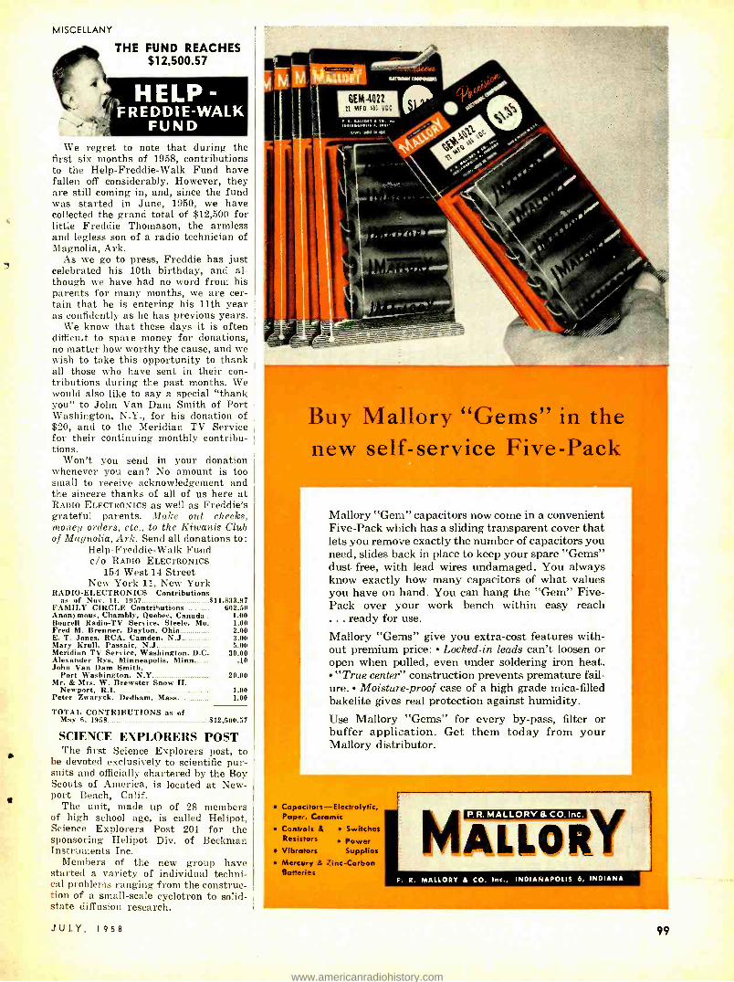
MISCELLANY
THE FUND REACHES $12,500.57
HELP - ' FREDDIE -WALK
FUND We regret to note that during the
first six months of 1958, contributions to the Help- Freddie -Walk Fund have fallen off considerably. However, they are still coming in, and, since the fund was started in June, 1950, we have collected the grand total of $12,500 for little Freddie Thomason, the armless and legless son of a radio technician of Magnolia, Ark.
As we go to press, Freddie has just celebrated his 10th birthday, and al- though we have had no word from his parents for many months, we are cer- tain that he is entering his 11th year as confidently as he has previous years.
We know that these days it is often difficult to spare money for donations, no matter how worthy the cause, and we wish to take this opportunity to thank all those who have sent in their con- tributions during the past months. We would also like to say a special "thank you" to John Van Dam Smith of Port Washington, N.Y., for his donation of $20, and to the Meridian TV Service for their continuing monthly contribu- tions.
Won't you send in your donation whenever you can? No amount is too small to receive acknowledgement and the sincere thanks of all of us here at RADIO ELECTRONICS as well as Freddie's grateful parents. Make out checks, money orders, etc., to the Kiwanis Club of Magnolia, Ark. Send all donations to:
Help- Freddie -Walk Fund coo RADIO ELECTRONICS
154 West 14 Street New York 11, New York
RADIO -ELECTRONICS Contributions as of Nov. 11, 1957 $11,833.97
FAMILY CIRCLE Contributions 602.50 Anonymous, Chambly, Quebec, Canada 1.00 Bourell Radio -TV Service, Steele, Mo 1.00
2.00 3.00 5.00
30.00 .10
Fred M. Brenner, Dayton, Ohio E. T. Jones, RCA, Camden, N.J Mary Krull, Passaic, N.J Meridian TV Service, Washington, D.C Alexander Rys, Minneapolis, Minn John Van Dam Smith,
Port Washington, N.Y Mr. & Mrs. W. Brewster Snow II,
Newport, R.I. Peter Zwaryck, Dedham, Mass
20.00
1.00 1.00
TOTAL CONTRIBUTIONS as of May 6, 1958 $12,500.57
SCIENCE EXPLORERS POST The first Science Explorers post, to
be devoted exclusively to scientific pur- suits and officially chartered by the Boy Scouts of America, is located at New- port Beach, Calif.
The unit, made up of 28 members of high school age, is called Helipot, Science Explorers Post 201 for the sponsoring Helipot Div. of Beckman Instruments Inc.
Members of the new group have started a variety of individual techni- cal problems ranging from the construc- tion of a small -scale cyclotron to solid - state diffusion research.
Buy Mallory "Gems" in the new self-service Five-Pac
Mallory "Gem" capacitors now come in a convenient Five -Pack which has a sliding transparent cover that lets you remove exactly the number of capacitors you need, slides back in place to keep your spare "Gems" dust -free, with lead wires undamaged. You always know exactly how many capacitors of what values you have on hand. You can hang the "Gem" Five - Pack over your work bench within easy reach ... ready for use.
Mallory "Gems" give you extra -cost features with- out premium price: Locked -in leads can't loosen or open when pulled, even under soldering iron heat. "True center' construction prevents premature fail-
ure. Moisture -proof case of a high grade mica -filled bakelite gives real protection against humidity.
Use Mallory "Gems" for every by -pass, filter or buffer application. Get them today from your Mallory distributor.
Capocitors- Electrolytic, Paper, Ceramic
Controls it Switches Resistors
Vibrators Power Supplies
Mercury it Zinc- Carbon Batteries
ilk
P.R. MALLORY & CO.Ine.
MALLORY R. R. MALLORY A CO. Inc., INDIANAPOLIS 6, INDIANA
JULY, 1958 99
www.americanradiohistory.com

FREE! all -steel file cabinets
with your purchase of
PH OTOFACT the world's finest TV -Rodio Service Data
^ FOR REGULAR PHOTOFACT SUBSCRIBERS
You get these valuable File Cabinets ABSOLUTELY FREE from Howard W. Sams if you are a regular subscriber to PHOTOFC-r and buy each Set as issued monthly...
^ "' FOR PHOTOFACT LIBRARY PURCHASERS
You get FREE File Cabinets as you complete your profit- building PHOTO - FACT Library... What's more, you can own the PHOTOFACT Library the new Easy -Buy way. Here's how... ^^ EASY -BUY PLAN No interest. No carrying charge. As little as $10 down. Up to 24 months to pay. And Howard W. Sams will give you absolutely free all the steel file cab- inets you'll need for your Library: Sin- gle- Drawer File Cabinet worth $8.95 with your purchase of 60 Sets of PHOTOFACT Folders; Two single- drawer File Cabinets worth $17.90 with your purchase of 120 Sets; Three single - drawer File Cabinets worth $26.85 with your purchase of 180 Sets; Four single - drawer File Cabinets worth $35.80 with your purchase of 240 Sets.
Take advantage of this money- saving opportunity. Sea your Sams Distributer today, or write to Howard W. Sams ...
OWAR220
D W. SAMS & CO., INC. 5E. 46th St., Indianapolis 5, Indiana
Send me lull details on your FREE File Cabinet otter and EASY -BUY Plan. I'm a Service Technician: Q full time; Q part time
My Distributor le'
Shop Name.
Ann
Address
City Zone State
100
Patents
ULTRASONIC SOLDERING Patent No. 2,815,430
Mortimer E. IT'eiss, Flushing, N. Y. (assigned to Colton industries, Inc., .Metuchen, Y. J.) Aluminum and certain other metals cannot be
soldered because of an oxide film that forms on their surface. To solder efficiently, it is necessary to break down this film while applying heat. This invention uses an ultrasonic vibrator to break down the film, It includes a way of keeping heat TIP 12 Ti TRANSDUCER SWITCH
SUPPORT
FROM LOW-VOLTAGE HEATER TRANSFORMER
FROM ULTRASONIC GENERATOR
front the tip away from the ultrasonic transducer to prevent damage.
The transducer vibrates longitudinally at about 20 kc when energized. These vibrations are trans- mitted through a "velocity transformer" (Ti. T2). Because of T2's smaller diameter, the origin- al velocity is multiplied before reaching the tip. T2 is made of poor heat -conducting metal to iso- late the tip from the transducer. Furthermore, a flange support shunts much of the heat to the outer metal housing, which is perforated.
The soldering tip has its own heating element.
TEMPERATURE CONTROL Patent No. 2.825.868
Ererett O. Olsen, II renfhnm, Sie.'.... ( Issignrd to Foxboro Co., Foxboro, Slags.)
The Curie point, a property of nickel. cobalt and iron alloys, is the temperature at which ferromagnetism disappears, and may vary from 150° to over 2,000 °, depending upon the material. For example, the Curie point of nickel k 662 °.
OVEN
CURRENT LIMITER
0"- 000
AC INPUT o
This control method depends upon the Curie point.
The diagram shows an oven containing a transformer and heating element R. The pri- mary is fed through a current -limiting coil. When power is switched on, ac normally appears across the secondary due to the magnetic core. However, as the core temperature approaches its Curie point. the flux drops substantially and less power flows into the heater. As the core cools, power rises again, and so on.
Oven temperature will stabilize and remain constant somewhat below the Curie point of the transformer core. END
IT FIGURES! My shop with work is overflowing; Outside a bitter wind is blowing. My next call will be again a Call to install a new antenna!
-Phyllis Barlow
"NOISE" BIG Beware Of Cheap Substitutes!
eNO -NOISE NEW RUBBER COAT Insulates SPRAY where applied protects Indefinitely Prevents arc- ing shorting.
n
thoroughly Non- inflammable Contains no
6 Os. Spray Can
Net To Servicemen
S3.25
NO -NOISE VOLUME CONTROL
and CONTACT RESTORER
Cleans Protects Lubricates
NOT A CARBON TET SOLUTION
itT o Ig' : lt onC r $ .00 " M/ i r
S .25
2 Oz. Net To Bottle m(rice-
G O, t To Spray Can 5 rvic,
NO-NOISE
TUNER -TONIC With PERMA -FILM
Economical -a little does a
lot! Cleans, lubricates. restores all tuners, including water type. Non -tonic, non -inflammable. Use for TV. radio and FM
6 Oz. Aerosol Can
Net To Servicemen
$3.25
ELECTRONIC CHEMICAL CORP. 813 Communipaw Avenue Jersey City 4, N. J.
"A Serviceman's Service"
ALL MODEL TELEVISION TUNERS REPAIRED
$ Q 00 plus necessary Q tubes and parts
5 -DAY SERVICE after receipt. 90'Day War- ranty on parts and workmanship.
Send Your Tuners in Now
Television Tuner Service Co. 2534 Rusty Dr, Des Plaines, Ill.
$ Save TEN $ SPECIAL INTRODUCTORY OFFER
Hi -Fi EYE. the RECORD PROTECTOR, tells you at a glance the total hours your stylus (phono needle) has been in use. With only one playing a worn stylus can wipe all the highs from your valued costly records. Yau can rely on Hi -Fi EYE! Easily installed. Operation automatic. Designed to sell for $24.95. SPECIAL INTRODUCTORY OFFER $14.95. Guaranteed. 6 mo. warranty. Don't delay, order today. Patent Pending. No C.O.D's. Calif. add 4%. Distributed by
HI -FI -EYE CO. Box 44739 Hancock Station Los Angeles 44, Calif.
AUGUST RADIO -ELECTRONICS ON SALE JULY 24
RESERVE YOUR COPY NOW
RADIO -ELECTRONICS
www.americanradiohistory.com
FILL OUT AND MAIL TODAY- FOR FREE BOOKLET!
L.
CAPITOL RADIO ENGINEERING INSTITUTE ECPD Accredited Technical Institute Curricula- Founded 1927
Dept. 147 -Y, 3224 Sixteenth St., N. W., Washington 10, D. C. Please send me your course outline and FREE illustrated Booklet, "Your Future in the New World of Electronics" . describing opportunities and CREI Home Study courses in Practical Electronic Engineering Technology.
CHECK El Radar, Servo and Computer Engineering Technology
FIELD OF Electronic Engineering Technology
GREATEST El Broadcast (AM, FM, TV) Engineering Technology
INTEREST Television Engineering Technology Aeronautical Electronic Engineering Technology Q
Name Age
Street
City Zone State Check: Home Study Residence School Korean Veteran
f
hi.e
If you have had a high school education, and ex- perience in electronics -and realize the need of a high - level technical knowledge to make good in the better electronic jobs - you can qualify for CREI home study training. (Electronics exper- ience is not required for ad- mission to CREI Residence School.) Please fill in the following information. Employed By
Type of Present Work
Education: Yrs. High School
Yrs. College
Electronics Experience
e e . and 2 minutes of your time will get you started toward success in
Radio -TV- Electronics The same combination of coupon, scissors and a few minutes have started thousands of ambitious young men on the CREI way toward Electronics career success. Let them do the same for you. We send you a newly -printed, fact -packed book, "Your Future In The New World of Electronics," which gives you the whole story, tells you how to prepare for high pay, security, satisfaction, and the good things of life. Don't put it off. Do it right now.
JULY, 1958
CREI also offers residence training in Washington, D. C. at the same high technical level. Day and evening classes start at regular intervals. Qualified residence school graduates earn degree as "Associate in Applied Science." Check coupon if you prefer residence or home study information . or write, Capitol Radio Engineering Institute, Dept. 147 Y, 3224 - 16th Street, N.W. Washington 10, D. C.
101
www.americanradiohistory.com
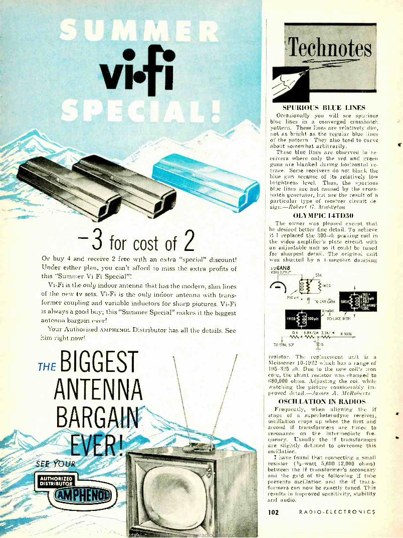
-3 for cost of 2 Or buy 4 and receive 2 free with an extra "special" discount! Under either plan, you can't afford to miss the extra profits of this "Summer Vi -Fi Special "!
Vi -Fi is the only indoor antenna that has the modern, slim lines of the new tv sets. Vi -Fi is the only indoor antenna with trans- former coupling and variable inductors for sharp pictures. Vi -Fi is always a good buy; this "Summer Special" makes it the biggest antenna bargain ever!
Your Authorized AMPHENOL Distributor has all the details. See him right now!
THE BIGGEST
ANTENNA
BARGAIN
e-\ _ EVER! SEE YOUR
Teclmotes
SPURIOUS BLUE LINES Occasionally you will see spurious
blue lines in a converged crosshatch pattern. These lines are relatively dim, not as bright as the regular blue lines of the pattern. They also tend to curve about somewhat arbitrarily.
These blue lines are observed in re- ceivers where only the red and green guns are blanked during horizontal re- trace. Some receivers do not blank the blue gun because of its relatively low brightness level. Thus, the spurious blue lines are not caused by the cross- hatch generator, but are the result of a particular type of receiver circuit de- sign.- Robert G. Middleton
OLYMPIC 14TD30 The owner was pleased except that
he desired better fine detail. To achieve it I replaced the 300 -µh peaking coil in the video amplifier's plate circuit with an adjustable unit so it could be tuned for sharpest detail. The original unit was shunted by a 1- megohm damping v26AN8
VIDEO OUTPUT
REMOVE a
REPLACE WITH
10 K 6.8K /2 3.3K /IW B BOOST
TO SYNC SEP
resistor. The replacement unit is a Meissener 10 -1922 which has a range of 195 -325 µh. Due to the new coil's iron core, the shunt resistor was changed to 680,000 ohms. Adjusting the coil while watching the picture considerably im- proved detail. -James A. McRoberts
OSCILLATION IN RADIOS Frequently, when aligning the if
stage of a superheterodyne receiver, oscillation crops up when the first and second if transformers are tuned to resonance on the intermediate fre- quency. Usually the if transformers are slightly detuned to overcome this oscillation.
I have found that connecting a small resistor (1/2 -watt 5,600- 12,000 ohms) between the if transformer's secondary and the grid of the following if tube prevents oscillation and the if trans- formers can now be exactly tuned. This results in improved sensitivity, stability and audio.
102 RADIO -ELECTRONICS
www.americanradiohistory.com

BUILD 16 RADIO CIRCUITS AT HOME with the New Deluxe 1958
PROGRESSIVE RADIO "EDU -KIT"
A COMPLETE RADIO COURSE
Now Also Includes
* TRANSMITTER
* SIGNAL TRACER
* SIGNAL INJECTOR
* CODE OSCILLATOR
only
* No Knowledge of Radio Necessary
* No Additional Parts or Tools Needed
* EXCELLENT BACKGROUND FOR TV
* School Inquiries Invited
* Attractively Gilt Packed
NO NEED TO SPEND HUNDREDS OF DOLLARS FOR A RADIO COURSE The "Edu -Kit" offers you an outstanding PRACTICAL HOME RADIO COURSE at a rock- bottom price. Our
Kit is designed to train Radio & Electronics Technicians, making use of the most modern methods of home training. You will learn radio theory, construction practice and servicing.
You will learn how to build radios, using regular schematics; how to wire and solder in a professional manner; how to service radios. You will work with the standard type of punched metal chassis as well as the latest development of Printed Circuit chassis.
You will learn the basic principles of radio. You will construct, study and work with RF and AF amplifiers and oscillators, detectors, rectifiers, test equipment. You will learn and practice code, using the Progressive Code Oscillator. You will learn and practice trouble- shooting, using the Progressive Signal Tracer, Progressive Signal njector, Progressive Dynamic Radio & Electronics Tester and the accompanying instructional material.
You will receive training for the Novice. Technician and General Classes of F.C.C. Radio Amateur Licenses. You will build 16 Receiver, Transmitter. Code Oscillator, Signal Tracer and Signal Injector circuits, and learn how to operate them. You will receive an excellent background for Television.
Absolutely no previous knowledge of radio or science is required. The "Edu -Kit" is the product of many rears of teaching and engineering experience. The "EduKit" will provide you with a basic education in Electronics and Radio, worth many times the complete price of S22. 95. The Signal Tracer alone is worth more than the price of the entire Kit.
THE KIT FOR EVERYONE You do not need the slightest background in radio or science. Whether you are interested in Radio & Electronics
because you want an i ting hobby, a well paying business or a job with a future, you will find the "Edu -Kit" s worth -while investment.
Many thousands of individuals of all ages and backgrounds have successfully used the "Edu -Kit" in more than 79 countries of the world- The "Edu -Kit" has been carefully designed, step by step, so that you cannot make a mistake. The "Edu -Kit" allows you to teach yourself at your own rate. No instructor is necessary.
PROGRESSIVE TEACHING METHOD The Progressive Radio "Edu -Kit" is the foremost educational radio kit in the world, and is universally accepted
as the standard it the field of electronics training. The "Edu -Kit'- uses the modern educational principle of "Learn by Doing." Therefore you construct, learn schematics, study theory, practice trouble -shooting -all in a closely integrated program designed to provide an easily -learned, thorough and interesting background in radio.
You begin by examining the various radio parts of the "Edu- Kit." You then learn the function, theory and wiring of these parts. Then you build a simple radio. With this first set you will enjoy listening to regular broadcast , talions, learn theory, practice testing and trouble -shooting. Then you build a more advanced radio, learn more advanced theory and techniques. Gradually, in a progressive manner, and at your own rate, you will find yourself :onstructing more advanced multi -tube radio circuits, and doing work like a professional Radio Technician.
Included in the "Edu -Kit" course are sixteen Receiver, Transmitter, Code Oscillator, Signal Tracer, and Signal Injector circuits. These are not unprofessional "breadboard" experiments, but genuine radio circuits, constructed by means of professional wiring and soldering on metal chassis, plus the new method of radio construction known 55 "Printed Circuitry." These circuits operate on your regular AC or DC house current.
A COMPLETE RADIO COURSE -NOTHING ELSE TO BUY You will receive all parts and instructions necessary to build 16 different radio and electronics circuits, each
guaranteed to operate, Our Kits contain tubes, tube sockets, variable, electrolytic, mica, ceramic and paper fielectric condensers, resistors, tie strips, coils, hardware, tubing, punched metal chassis, Instruction Manuals. wire, solder, etc.
In addition, you receive Printed Circuit materials, including Printed Circuit chassis, special tube sockets, sardware and instructions. You also receive a useful set of tools, a professional electric soldering iron, and a :elf- powered Dynamic Radio & Electronics Tester. The "Edu -Kit" also includes Code Instructions and the Progressive :ode Oscillator, in addition to F.C.C.-type Questions and Answers for Radio Amateur License training. You will also receive lessons for servicing with the Progressive Signal Tracer and the Progressive Signal Injector, a High Fidelity Guide and a Quiz Book. You receive all parts, tools, instructions, etc. There is nothing else to buy. ?verything is yours to keep.
Unconditional Money -Back Guarantee r p,,,....... n.a. Em..K.a has b..n old to many
it o ands of indiv.dualS. schools and organ actions. public and private. throughout the world. It is recognised in terna t,,onany at the ideal radio course. y popular demand, the progressive Radio Edu Kil' Is now aailable in Spanish as well as Engi,sh.
It i understood and agreed that should the Progressive dadin Edu -Rite be returned to Progresive 'Edu -Kit Inc. for any reason whatever, the purchase price will be refunded In full, w clout quibble or question, and without delay.
The high recognition which progrestive 'Edu- K,ts Inc. has earned through its many of service to the public is due to Its unconditional Ds,tence upon the maintenance of perfect ergin ^ng, the highest instructional standards. and lOOeo acherance to its Unconditional MoneyU. n a we
tresult. we do not have A single d.ssat.sed eastern hnt ,. he entire world.
JULY, 1958
Reg. U S. Pat. Of
FREE EXTRAS SET OF TOOLS
SOLDERING IRON ELECTRONICS TESTER TESTER INSTRUCTION
MANUAL HIGH FIDELITY GUIDE QUIZZES TELEVI. SION BOOK RADIO TROUBLE - SHOOTING BOON
MEMBERSHIP IN RADIO - TV CLUB: CONSULTATION SERVICE FCC AMATEUR LICENSE TRAINING PRINT. ED CIRCUITRY PLIERS - CUTTERS ALIGNMENT TOOL CERTIFICATE OF MERIT VALUABLE DIS- COUNT CARD WRENCH
SET
SERVICING LESSONS You will learn troubleshootino
and servicing in a progressive manner. You will practice repairs on the sets that you construct. VOL will learn symptoms and causes of troubles in home, portable and ear radios. You will learn how to use the professional Signal Tracer. the unique Signal Injector and the dy- namic Radio 6 Electronics Tester. While you are learning in thin practical way, you will be able to do many a repair job lar your friends and neighbors, and chartr lees which will far exceed the price of the "Edu- Kit." Our Con. sultation Service will help you with any technical problems you may have.
1. Stataitis. of 25 Poplar Pl., Waterbury, Conn., writes: "I lias, repaired several sets for my friends, and made money. The "Edu -Kit" paid for itself. 1 was W ady to spend $210 for a Course, but I found your ad and sent for your Kit."
FROM OUR MAIL BAG Ben Valerio, P. 0. Box 21.
Magna, Utah: "The Edu -Kit are wonderful. Here I ani sendirt you the questions and also the answers tor them. I have been in Radio for the last seven years. bet like to work with Radio Kits. and like to huild Radio Testing Equip- ment. I enjoyed every minute I worked with the different kits: Il e
Signal Tracer works fine. Also like to let you know that I feel proud of becoming a member of your RadioTV Club."
Robert L. Shull. 1533 Mon- roe Ave.. Huntington, W. Va :
"Thought I would drop you a few line. to say that I received my EduKit, and was really amazed that such a bargin can be had at such a low price. I have already started repairing radios and phone ooraphs. My friends were really surprised to tee me get into the swing of it so quickly. The Trou- bleshooting Tester that comes with the Kit is really swell. and finds the trouble, it there is any to Ise found."
ORDER DIRECT FROM AD RECEIVE FREE BONUS RESISTOR AND CONDENSER KITS WORTH $7.0
-' Send "Edu -Kit" Postpaid. I enclose full payment of $22.95. L Send "Edu -Kit" C.O.D. I will pay $22.95 plus postage. D Send me FREE additional information describing "Edu- Kit,"
Name
Address
PROGRESSIVE "EDU- KITS" INC. 1186 Broadway, Dept. 142G, Hewlett, N.Y.
103
www.americanradiohistory.com

FO R BLANKET COVERAGE
replacement tv transformers of exact re P
every time! it's STANCOR r."
here is PROOF! This table of STANCOR'S ex- act replacement flyback cover- age is based on an actual count of the models listed in the latest STANCOR TV Replacement Guide. Only exact replacement flybacks are listed. These per- centages do not include fly - backs that require chassis or circuit alteration. Actually, true coverage is even higher than these figures indicate since STANCOR covers all of the most heavily produced models.
Manufacturer Stancor EXACT Tiep1. Flybacks COVERAGE
Admiral 9 83% Airline 11 91%
General Electric 14 95% Olympic 4 83% Philco 12 90% RCA 11 91% Silvertone 11 74% Zenith 14 97%
Write now for your free copy of the latest TV Transformer Re- placement Guide, listing over 17,000 TV. models and chassis.
CHICAGO STANDARD TRANSFORMER CORPORATION 3509 ADDISON STREET
ACTUAL SIZE: 21/2"x2 "x7 /e" PRECISION ENGINEERED
When ordering one sample send only $1.00 cash, check, M.O. and pay postman $3.95 plus COD charges on arrival or send $4.98 for postpaid delivery. Sent complete with FREE handy carrying case with tuning knob cpening. Sold on 10 -day money back guarantee. Order now!
CHICAGO 18, ILLINOIS
NEW PORTABLE- TUBELESS - NO BATTERIES
"LIFETIME" RADIO plays forever with electronic self- powered diode detector. Works without tubes, batteries or electrical plug -ins. Half -size of a pack of cigarettes, tucks in shirt pocket, weighs 4 oz. Pulls in stations 60 miles away. Easy tuning knob. Shatterproof ivory plastic case.
Adjustable aerial for additional power. Two Super - phonic Earphones for bedtime listening without disturb- ing others.
SERVICEMEN! DEALERS! Become sales agent, every call an easy sale after one minute demon- stration. Perfect gift for every member of the family. Guaranteed to work and please! Order Now. EXTRA TRADE DISCOUNTS (Plastic Car- rying Case included FREE!)
EDeduct 10'; on order of 3 Deduct 20', on order of 6 Deduct 25' ; on order of 12 or more
STANDARD AMERICAN SUPPLIERS, INC. Midget Dept. RE -7 One Park Ave., New York 16, N.Y.
104
TECHNOTES (Continued)
This grid resistor stunt is not new. It was used many years ago to bypass the use of the Neutrodyne and other patent circuits designed to prevent os- cillation in tuned rf stages. - Eugene M. Funk
SYLVANIA MODEL 614 Between distortion and buzz, the set's
sound was rotten. A scope showed the trouble was caused by oscillation in the audio if amplifier which was over- loading the detector and permitting buzz to come through.
The cure was comparatively simple. Resistor R100 and capacitor C100 (the
rC100T.01
_ REDUCE T0,001
v25U8 SOUND IF AMPL
5100 150.. - INCREASE TO 2200
sound if amplifier cathode resistor and bypass, respectively) were replaced. The .O1 -µf capacitor was replaced with a .001 -µf unit and the 150 -ohm resistor gave way to 220 ohms. The increased bias caused by this change lowered the gain while the reduced bypass capaci- tance helped degenerate the stage fur- ther. -Louis Sherman
ZENITH Y2229R The set was brought to the shop when
our outside man couldn't clear up a weak picture. We soon tracked the lack of signal strength to the detector. We were getting a dim picture (weak contrast), and the age didn't seem to perform properly.
With this ailment, lack of contrast and age, breaking away one end of the 1N64 crystal cut the signal off entirely, so we naturally assumed a new crystal was needed.
But before soldering it in place and just to make sure, we clipped the new crystal in place, using a pair of 12- inch test leads. The trouble was still there, and we spent the next 4 hours hunting for more trouble and wonder- ing about the crystal.
Finally we soldered the new crystal in place, with its short leads and the set worked OK! Seems like the extra inductance of the long test leads we used for a temporary try made the new crystal act as if it, too, were faulty. - Harry J. Miller END
CIVIL SERVICE EXAM Examinations for electronic tech-
nician jobs at $3,175 $7,570 a year, involving installation and maintenance of computers, detectors, test and com- munications equipment in the Wash- ington, D. C., area, have been announced by the US Civil Service Commission. No written test is required, but appli- cants must show they have had adequate experience, training or education. Infor- mation and applications are available from most postoffices and the Civil Serv- ice Commission, Washington 25, D.C.
RADIO -ELECTRONICS
www.americanradiohistory.com
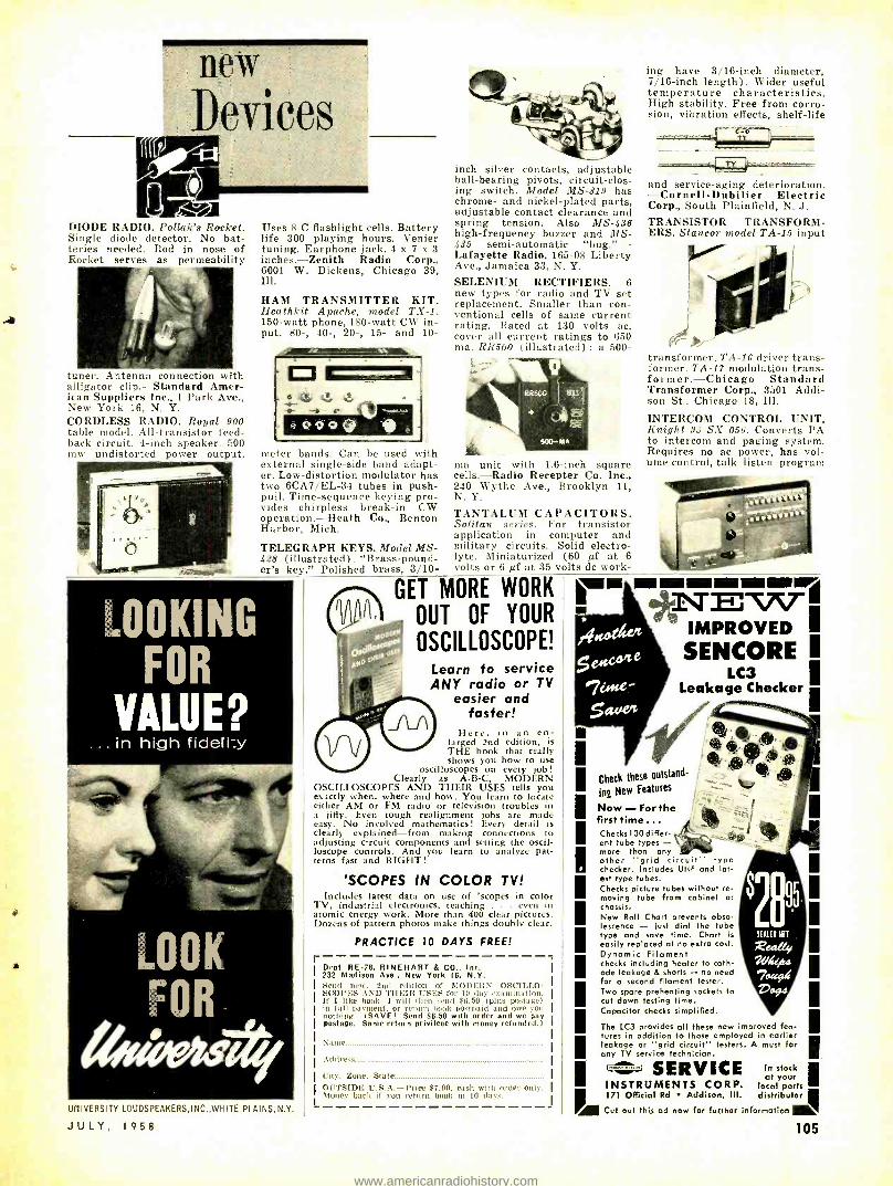
new
Devices
DIODE RADIO. Pollak's Rocket. Single diode detector. No bat- teries needed. Rod in nose of Rocket serves as permeability
tuner. Antenna connection with alligator clip.- Standard Amer- ican Suppliers Inc., 1 Park Ave., New York 16, N. Y. CORDLESS RADIO. Royal 900 table model. All- transistor feed- back circuit. 4 -inch speaker. 500 mw undistorted power output.
Uses 8 C flashlight cells. Battery life 300 playing hours. Venier tuning. Earphone jack. 4 x 7 x 3 inches. -Zenith Radio Corp., 6001 W. Dickens, Chicago 39, Ill.
HAM TRANSMITTER KIT. Heathkit Apache, model TX -1. 150 -watt phone, 180 -watt CW in- put. 80 -, 40 -, 20 -, 15- and 10-
meter bands. Can be used with external single -side band adapt- er. Low- distortion modulator has two 6CA7 /EL -34 tubes in push - pull. Time- sequence keying pro- vides chirpless break -in CW operation. -Heath Co., Benton Harbor, Mich.
TELEGRAPH KEYS. Model MS- 428 (illustrated). "Brass- pound- er's key." Polished brass, 3/10-
inch silver contacts, adjustable ball- bearing pivots, circuit -clos- ing switch. Model MS -319 has chrome- and nickel- plated parts, adjustable contact clearance and spring tension. Also MS -436 high- frequency buzzer and MS- 435 semi -automatic "bug." - Lafayette Radio, 165 -08 Liberty Ave., Jamaica 33, N. Y.
SELENIUM RECTIFIERS. 6 new types for radio and TV set replacement. Smaller than con- ventional cells of same current rating. Rated at 130 volts ac, cover all current ratings to 650 ma. RR500 (illustrated) : a 500-
11111.
ma unit with 1.6 -inch square cells. -Radio Recepter Co. Inc., 240 Wythe Ave., Brooklyn 11, N. Y.
TANTALUM CAPACITORS. Solitan series. For transistor application in computer and military circuits. Solid electro- lyte. Miniaturized (60 µf at 6 volts or 6µf at 35 volts dc work-
ing have 3/16 -inch diameter, 7/16 -inch length). Wider useful temperature characteristics. High stability. Free from corro- sion, vibration effects, shelf -life
and service -aging deterioration. -Cornell- Dubilier Electric Corp., South Plainfield, N. J. TRANSISTOR TRANSFORM- ERS. Stancor model TA -15 input
transformer. TA -16 driver trans- former. TA -17 modulation trans- former.- Chicago Standard Transformer Corp., 3501 Addi- son St., Chicago 18, Ill.
INTERCOM CONTROL UNIT, Knight 93 SX 050. Converts PA to intercom and paging system. Requires no ac power, has vol- ume control, talk -listen -program
GET MORE WORK
OUT OF YOUR
OSCILLOSCOPE! Learn fo service ANY radio or TV
easier and faster!
UNIVERSITY LOUDSPEAKERS,INC.,WHIITE PLAINS, N.Y.
JULY, 1958
Here, in an en- larged 2nd edition, is THE book that really shows you how to use
oscilloscopes on every job! Clearly as A -B -C, MODERN
OSCILLOSCOPES AND THEIR USES tells you exactly when, where and how. You learn to locate either AM or FM radio or television troubles in a jiffy. Even tough realignment jobs are made easy. No involved mathematics! Every detail is clearly explained -from making connections to adjusting circuit components and setting the oscil- loscope controls. And you learn to analyze pat- terns fast and RIGHT!
'SCOPES IN COLOR TV! Includes latest data on use of 'scopes in color
TV, industrial electronics, teaching . . . even in atomic energy work. More than 400 clear pictures. Dozens of pattern photos make things doubly clear.
PRACTICE 10 DAYS FREE!
r Dept. RE -78, RINEHART & CO., Inc. 232 Madison Ave.. New York 16. N.Y. Send non. 2nd edition of DIODEIIN OSCILLO- SCOPES ANI) TIIEIR l'SES for 10 -day examination. If I like book, I will then :('nd $6.50 (phis postage) in full payment. or return boot: postpaid and owe you nothing. (SAVE! Send $6.50 with order and we pay postage. Same return privilege with money refunded.)
Name
Address
City. Zone. State OUTSIDE U.S.A. -Price $7.00, cash with order only Money back if you return hook in 10 days.
l' *]N-:E::-vc1Tu IMPROVED SENCORE Leakage Checker
1
j f
LC3
ICheck these outstand- `° 'ing New Features
Now - For the first time... Checks130differ- ent tube types - more than any other "grid circuit" type checker. Includes UHF and lat- est type tubes. Checks picture tubes without re- moving tube from cabinet or chassis. New Roll Chart prevents obso- lescence - just dial the tube type and save time. Chart is
easily replaced at no extra cost. Dynamic Filament checks including heater to cath- ode leakage & shorts - no need for a second filament tester. Two spare preheating sockets to cut down testing time. Capacitor checks simplified.
The LC3 provides all these new improved fee- tures in addition to those employed in earlier leakage or "grid circuit" testers. A must for any 'TV service technician.
X31
SERVICE INSTRUMENTS CORP.
In stock at your
local parts 171 Official Rd Addison, III. distributor
A. Cut out this od now for further information _ 105
www.americanradiohistory.com

NEW DEVICES (Continued)
switch, all -call switch. Speaker - microphone. Can serve 20 sta- tions, or 40 with accessory switch panel adapter No. 93 SX 057. -Allied Radio Corp., 100 N. Western Ave., Chicago 80. SPEAKER SYSTEMS. Dehonaire models S -3, S -4 and EN -1215 en- closure. Decorator -styled lowboy high -fidelity enclosures with 3-
element 12- or 15 -inch speaker systems. S -3 uses 12 -inch woofer, H -600 reciprocating flare horn with T -30 driver, UXT -5 super tweeter. S -4 has 15 -inch Dif- faxial speaker, H -600 and Hy- personic T -50 driver. EN-1215 is lowboy enclosure only.- Univer- sity Loudspeakers Inc., 800 So. Kensico Ave., White Plains, N. Y. REAR -SEAT SPEAKER. Satel- lite kit. 6 x 9- or 5 x 7 -inch speaker, chrome- plated switch plate and grille, 3- position slide
switch. All hardware.- Oxford Components Inc., 556 W. Mon- roe St., Chicago 6, Ill. STEREO PREAMP KIT. Model SP -6. Inputs for tape deck and magnetie cartridges. 2 outputs for each channel. Function -se- lector switch adjusts for stereo, reversed stereo or monaural. Intermodulation distortion less than 0.25% at full gain. Hum below 70 db. Maximum output levels 3 volts at cathode- follower outputs, 10 volts at tape outputs. Input sensitivity 2 my low level,
0.1 volt high level. Also available wired. -Arkay Kits, 120 Cedar St., New York, N. Y.
STEREO PREAMP. Model 208. 2 independent channels for each
of 5 inputs. Ganged selector, turnover, rolloff, volume, bass and treble controls. Either chan- nel may be used as monaural preamp, driving both power amplifiers. Feedback circuits, do filaments. -Grommes, Div. of Precision Electronics Inc., 9101 King St., Franklin Park, Ill.
LINEAR AMPLIFIER. LA -400 -C Kit. 75 --10 meters. Metering circuit reads rf voltage input, plate current, rf amps output.
400 -watt peak envelope power input with 20 watts drive. Low - impedance input, pi- network out- put, with 4 modified 1625 tet- rodes. TV interference suppres- sion.-P & H Electronics Inc., 424 Columbia, Lafayette, Ind. MOBILE AMPLIFIER. Knight EN -3125. 25 watts. Operates from 6 or 12 volts dc or 110 ac. Inputs for 2 microphones and 2
record players. Phono fader. Response at full output, +2db from 40- 20,000 cycles. Hum level 75 db below stated output. Model KN -3025 is identical, less record player.- Allied Radio Corp., 100 No. Western Ave., Chicago. ERASE HEAD. Type S (transis- tor shown for size comparison). Especially suited for use with transistor circuitry, 55 -db era-
LEARN
sure with 1/2 -watt input. Easily ganged for 2- and 4 -track erasure. - Michigan Magnetica Inc., Vermontville, Mich. HI -FI ACCESSORIES. Vantron Phonobooster model PB -1000 is fully transistorized miniature
preamp. Phon- O- I',acr model PW -1000 (illustrated) provides hum -free power for Phonoboost- er, eliminating all other power connections to main amplifier. - Electronics Div., Van Norman Industries Inc., 186 Granite St., Manchester, N. H. LOW -COST BAFFLE, Universal. Accepts round and oval speakers up to 6 x 9 inches. Unbreakable styrene, 103/4 x 8 x 3% inches in blond, gray and mahogany, for extension speaker and PA
Eliminate Battery Troubles with the all new
BATTERY INSURA tE COMPUTER
TRAIN QUICKLY! OLDEST, BEST EQUIPPED SCHOOL of ITS KIND in U.S. Vet and Non -Veterans- Get practical training in top opportunity fields. Prepare now for a better job and a real future. Advanced education or previous experience not needed. Employment service to graduates.
Enroll NOW -Pay Later Finance Plan and Easy Payment Plan. Also Part Time Employment help for students. Training in Refrigeration and Electric Appliances can be included.
FREE BOOK Clip coupon for Big Free Illus- trated Book. No obligation and
No Salesman [Vili Call. Act NOW. B. W. Cooke, Jr., President
COYNE OPERATED
NOT FOR PROFIT Established 1899
500 S. Pauline. Claitago Dept. B8 -5C
B. W. COOKE, 1r., Pres. COYNE Electrical School 500 S. Paulina St., Chicago 12. Ill. Dept. B8-5C
Send FREE BOOK and full details on: TELEVISION -RADIO ELECTRICITY -ELECTRONICS
NAME
ADDRESS
CITY I_
106
STATE J
SELECT -O- SWITCH 4-WAY SELECTOR SWITCH
I . anten[ta .IN ¡tell 01' a- ahi -fi speaker acitrh. Permit, chattuel ittg one input lo any one of 4
output.. model SS4 LIST $3.25
Switch- in-Base
DUO-JUVENATOR lal'ltlll'I all.l booster. tlll. CRT alruotirol.
model RPS2 LIST S2.95
TELE -LINK 2 -SET TV & FM
COUPLER
Matched t i un.terni- er. for p''al: pertul'tll- anee on 2 TV or FM .et, from one anten- na.
model TL2 LIST S2.95
134 NASSAU ROAD, ROOSEVELT. N.Y.
The revolutionary new electronic discovery - the BATTERY IN- SURANCE COM- PUTER- attaches to the generator of your present car, controls your regulator and generator to give a quick charge or trickle charge to your present automotive battery automatically. Your present battery
should serve you indefinitely with the aid of this all new concept of maintaining an ade- quate charge- Computer controlled model 57.50 Specify make and year of cor -12 or 6 volt system
MacFARLANE INDUSTRIES P.O. Box 33 Redondo Beach, Calif.
WANT MORE MILEAGE
from your classified advertising? Use RADIO -ELECTRONICS Op- portunity Adlets. Rates as low as $5.
See page 114
RADIO -ELECTRONICS
www.americanradiohistory.com

NEW DEVICES (Continued)
purposes.- Saxton Products Inc., 1661 Boone Ave., New York 60. STEREO CONSOLE. Model SA- 103?. Speaker amplifier system for conversion of monaural hi -fi systems. Incorporates new model AA -90. ;B amplifier preamp. Con-
tinuous output 16 watts (32 watts peak). 4- speaker system has 12 -inch woofer, 8 -inch lower mid -range speaker, 6 -inch upper mid- range, 3 -inch tweeter. In 4 finishes. -Pilot Radio Corp., 37 -08 36th St., Long Island City, N. Y. STEREO ARM KITS. Model KT- 12 (12- inch), and KT -16 (16- inch). Identical to Audax mon- aural arm kits, but wired to accept both stereo and monaural cartridges. Model KTS converts monaural kits for stereo, in- cludes cartridge housing, lead
imi010010.1111Z,
wire, gauge tube, 2 aluminum spacers. -Audax Inc., 38 -19 108th St., Corona 68, N. Y. MINIATURE SPEAKER SYS- TEM, the Minstrel. Air chamber serves as phase- matching trans-
former. 9 x 9 x 16 inches. 10 watts. Response 50- 15,000 cycles. Efficiency 7% measured, with 3 octaves of white noise. Imped- ance 4 ohms. Mahogany, walnut, blond or ebony. -Telematic In- dustries, 251 Lee Ave., Brooklyn 6, N. Y. COAXIAL SPEAKER. Projector model WT -6. Weatherproof unit houses 2 individual drivers with separate horns and crossover. High -efficiency woofer has folded exponential horn. Wide -angle tweeter. Power capacity 15
watts. Bell opening 15 inches. Depth 11 inches. -Atlas Sound Corp., 1449 39th St., Brooklyn 18, N. Y.
STEREO CARTRIDGE, Bino- fluid. Compatible with monaural and stereo discs. Flat response 20- 15,000 cycles with rolloff at 14.000. Lateral and vertical com- pliances of 3.5 X 10 -" cm /dyne. Optimum stylus pressure 4-6 grams. Available mounted in
BOOK MANUSCRIPTS CONSIDERED
by Inoperative publisher who offers authors early publication, higher royalty, national distribution. and beautifully designed books. All subjects wel- comed. \trite, or scud your MS directly.
GREENWICH BOOK PUBLISHERS, INC, Alun. MIL DIMS 459 FIFTH AVE.
NEV 1 YORK 17, N. T.
DIGITAL COMPUTER KIT
Build i t- Dnsutor cor -. p,fer c- _uir; and work with them! Basic units can be built within hours. Assemble them into computers and operate. The language of computers is explained and projects included. You will receive 22 transistors and 200 electrical parts. $59.50 plus pcstage. Twelve other kits available. Partial list of courses:
CI Elementary relay brains $12.50 C2 Elementary digital computers $24.50 C3 Elementary analog computers $19.50 C14 Computer Master 50 lessons and projects (digital voltmeter, digital ohmmeter)
I] CI5 Electronics, 40 lessons and 3 text books. $22.50 down and $10 for 5 months. Complete catalog.
EBE Inc., 1015 Atkin Ave. Salt Lake City 6, Utah
Send one transistor computer kit Enroll me in course Enclosed $
Name and address attached
JULY, 1958
Fonofluid 12- or 16 -inch tran- scription arm. -Ronette Acous- tical Corp., 190 Earle Ave., Lyn- brook, N. Y. TURNOVER STEREO CART- RIDGE. Models 8T -4S, 8T -4SD and 8T -4D. Ceramic, for all speeds, stereo or monaural.
Rumble- suppression action. Re- sponse smooth from 20- 20,000 cycles. Output 0.3 volt. Compli- ance 2 X 10 -" cm/dyne. Recom- mended load 2 megohms /100 µµf (each channel). Tracking pres- sure 6 grams. Weight 7.5 grams. Channel isolation 20 db. Avail- able with dual sapphire, dual diamond or sapphire and dia- mond styli ( replaceable). - Sonotone Corp., Elmsford, N. Y. REPLACEMENT CARTRIDGES. Models 1 to 32. New line of 32
units designed to replace 80% of cartridges. Simplified needle changing. Built -in needle guard. Required needle number printed on cartridge. Chart identifies correct replacement. - Jensen Industries, Forest Park, Ill. HI -FI CARTRIDGE. Model 230 Micro -7, production version of experimental Model XP -3. 0.7-
mil diamond stylus. Air damp- ing, high vertical and lateral compliance. Tracking force as low as 1 gram. Output 5 mv.- Fairchild Recording Equipment Co., 10 -40 45th Ave., Long Island City, N. Y.
AUTO ANTENNA. Super "8" adjusts up to 35 °. 4 telescoping sections extend to 57 inches. 54-
inch Elektran lead cable. - Ward Products Corp., 1148 Euclid Ave., Cleveland 15, Ohio.
ANTENNA KIT, Quikie 444 First of series of factory
HARTLEY sets you straight on
AUDIO DESIGN Let this famous British audio expert untangle the mystery of audio design for you. He gives you the foundation you need to understand audio design and do it yourself if you want to. He combines his own mastery of design principles with a hard core of practical facts gleaned from volumes of technical data -saving you grueling hours of research. Hartley outlines for you the design considera- tions in amplifiers, transformers, feedback, tone controls, speakers and enclosures. He shows you how to avoid blind alleys by first deciding what you want -and then working within those limits. He closes with a salty chapter of his own opinions on what ails hi -fi. H. A. Hartley's AUDIO DESIGN HANDBOOK proves you don't need a math or engineering degree to understand audio design. Get a copy and see.
Other G/L Hi -Fi Books Paper cover editions
67- Elements of Tape Recorder Circuits, Herman Burstein and Henry C. Pollak $2.90
66 -Basic Audio Course, Donald C. Hoefler 2.75
64- Understanding Hi -Fi Circuits, Norman H. Crowhurst 2.90
58- Maintaining Hi -Fi Equipment, Joseph Marshall 2.90
56- High -Fidelity Circuit Design (Cloth bound edi- tion only), Norman H. Crowhurst and George Fletcher Cooper 5.95
48 -High Fidelity- Design, Construction, Measure- ments 1.50
H. A. HARTLEY'S
Audio
Design HANDBOOK
H. A. HARTLEY'S AUDIO DESIGN
HANDBOOK Gernsback Library Book No. 11
Paper corer edition $2.90 Cloth bound edition 55.00
12 BIG CHAPTERS Perception of Sound Audio Amplifiers: the Output Stage Audio Amplifiers: Inver- ters and drivers Audio Amplifiers: Voltage Ampl ifieetions Amplifier Design Audio Transformers Negative Feedback Filters and Tone Controls Amplifier Power Supplies Speakers and Enclosures Measurements and Test- ing
Fidelity - Hail and Farewell.
LUS -complete index, dia - schematics, photo -
raphs. -- SEE YOUR DISTRIBUTOR- - -- OR MAIL THIS COUPON TODAY
GERNSBACK LIBRARY, Inc. Dept. 78 154 West 14th St., New York 11, N.Y. My remittance of $ is enclosed. Please .send books checked postpaid. No. 71 H. A. Hartley's Audio Design Handbook
Cloth -bound ed. $5 Paper cover ed. $2.90 67 66 64 58 56 48
Name please print
Street
City Zone State
107
www.americanradiohistory.com

NEW DEVICES (Continued)
assembled antennas. Antenna, mast and transmission line are preconnected. Line equipped with attachment clip for receiver terminals. Gold anodized fin- ish.- Technical Appliance Corp., Sherburne, N. Y.
TUBE GUARD. Protects elec- tric and electronic equipment against current surge when first turned on. Power builds
up to normal over 15- second period as Tube Guard's resist- ance drops from about 125 ohms to 0.2 ohm. Handles up to 300 watts. -NuTronics Co. Inc., Box 66, Bogota, N. J. TV SURGE LIMITER. G -C Sur - gistor model 5303 for black -and- white, model 5302 for color sets. Resistor device limits initial power surge in heater circuit,
Kr- .4001111011111.11.11.1. 6.71
lengthening life of picture and receiving tubes. -G -C Electron- ics Mfg. Co 400 So. Wyman St., Rockford, III. PRINTED -CIRCUIT BREAD- BOARD. SeeZak Printed -Circuit Kit. Plastic laminated pegboard,
50 Presto terminals, 3 feet of 28 -gauge wire. For layout and checking of prototype circuits. - U.M. &F, Mfg. Co., 10929 Van - owen St., No. Hollywood, Calif. METER DE,MONSTRATOR. Vtvm Dynamic Demonstrator. 14% x 23 x 31/2 -inch meter has giant 13 -inch scale. For wall or desk use. Simulates all func- tions of EICO No. 221 vtvm.-
F'`.Í er
Electronic Instrument Co., Inc., 33 -00 Northern Blvd., Long Blvd., Long Island City 1, N. Y. MINIATURE MULTIMETER. AVO Multimisor measures dc voltage in 7 ranges; 2 mv-1,000 volts; accuracy 3 f, sensitivity 10,000 ohms /volt. 5 ac ranges, 200 mv-1,000 volts; accuracy 4%, sensitivity 1,000 ohms /volt. 5 dc ranges, '2µa -lamp. Resist -
All specifications given on these pages a
ance 5 ohms -2 megs.- British Industries Corp., 80 Shore Rd., Port Washington, N. Y. CHASSIS PUNCHES. LT se rit Electrocoating of steel reduce,
tow ,^ETON rur :
tOw nxrON sowCIS
friction, lowering torque neces- sary to cut meta . All standard sizes for round, square, key and D chassis holes. -Walsco Elec- tronics Mfg. Co., 100 W. Green St., Rockford, Ill. SOLDERLESS TERMINALS. Insulated and noninsulated. Ring tongue, spade tongue, hook
GOLDEN TURNSTILE ANTENNA
Completely Preassembled
Non -rusting gold anodized aluminum elements snap into place. Everything is furnished; there is nothing else to buy. You get perfect reception up to 50 miles from transmitters. COMPLETE KIT NO. A -125
(shown above)...... -.... ,. ,. ,List $18.95 TURNSTILE KIT NO. A- 124
standard aluminum elements... ,List $15.95
FM Golden Dipole Kit 2 No. A- 267 List $17.25
Dipole Kit No. A -261 standard aluminum
I elements List $14.95 11
AT YOUR DEALER OR WRITE DIRECT
TELCO ELECTRONICS MFG. CO. Division of G -C Textron Inc.
Lot Angeles- Rockford, Illinois
l0ó
re from manufacturers' data.
MAKE YOUR STANDARD TEST PRODS
MORE EFFECTIVE he fir Of
PNEHE-Z-HOOK TIP CONVERTS YOUR STANDARD TEST PROD
TO A SELF- HOLDING CONNECTOR
SLIPS EASILY
ON OR OFF!
Easy
to use
Here are the TEN E -Z -Hook Tip advantages :
1. Easy to attach - slips 6. Eliminates intermittance easily over test prod tip. -- spring pressure in-
2. Stays on- special chuck sures positive contact. holds tip firmly on prod. 7. Eliminates adjacent shorts
-insulated design gives maximum protection.
8. Connects anywhere - fits large or irregular shaped conductors.
9. Frees your hands - holds test prod for you.
5. Won't slip off - exclu- 10. Makes testing easier - sive hook design clamps saves time -eliminates firmly around conductor. aggravation.
3. Easy to connect or dis- connect - patented de- sign operates with light forward pressure.
'4. Safer checks - hands stay clear of wiring.
No. 56 -1 E -Z -HOOK Tip Only 89ç re. ORDER THROUGH YOUR
PARTS DISTRIBUTOR
iiiiilimos EMI E -z -HOOK TEST PRODUCTS
Dept. G2, 1536 Woodburn Ave., Covington, Ky.
MENHEMMINNIMMIENIS Canadian Rep., Len Finkler & Co., Toronto, Ontario
tongue, flag type and butt con- nectors. Crimping tools avail - "able.- Waldom Electronics Inc., 4625 W. 53rd St., Chicago 32, Ill. TRANSISTOR TESTER KIT. Model T -65. Tests for L he, gain,
i:akage and vhorts of low - medium- and high -power tran- sistors, p -n -p and n -p -n types. Direct -reading gain ranges with 5 injection currents. Provision for future semiconductors - PACO Electronics Co. Inc., 70 -31 84th St., Glendale, N. Y.
SWEEP GENERATORS. Models 601 and 602. 11 switchable bands, max -frequency deviation of ap- proximately 5 to 1. Model 601 covers 12 -225 me with output of 1 volt rais ( into 50- or 75 -ohm
load) to within +0.5 ( b. Model 601 has 1-112-me range, 2.5 volts output. Jerrold Electronics Corp., 23rd á Chestnut Sts., Philadelphia 3, Pa. END
ORDER by MAIL and SAVE!
TV PICTURE TUBES OBP4 .._$ 7.95 7BP4 ....$10.95 2IAMP4 $19.95 2 L P4 ... 8.95 7C P4 .... 17.00 2 I A T P4 .. 20.95 4B /CP4.. 9.95 7GP4 _.. 17.60 2IAUP4 .. 20.95 6DP4 .... 14.95 7HP4 .... 13.60 21EP4 .... 14.95 6EP4 .... 15.90 7LP4 .... 13.60 2I FP4 .... 15.95 6GP4 .... 15.90 701.4 .... 1 1.95 2I W P4 .... 17.30 61(P4 .... 10.95 7T P4 .... 19.30 2I Y P4 .... 15.95 6LP4 .... 10.95 9AP4 _. 19.30 212P4 .... 14.95 6RP4 .... 10.95 20CP4 .... 13.90 2.ICP4 ..... 23.95 6WP4 .... 15.20 20HP4 .... 17.95 24DP-1 .... 26.95 6T P4 .... 10.95 2I A P4 22.10 27 E P4 .... 39.95 7AVP4 .. 15.20 21ALP4 .. 20.95 27RP4 .... 39.95
27"-6 month guarantee -all others 1 year. Alumin- ized Tubes $5.110 more than above prices. These prices ale determined to include the return of an acceptable similar tube under vacuum.
ALL PRICES FOB CHICAGO. ILLINOIS. De. posit requlled, when old tube Is not re- turned. refundable at time of return. 25x0 required on COO shipments. Old tubes n be returned w rned prepaid. We ship anywhere.
WRITE FOR COMPLETE LIST`
-PICTURE TUBE OUTLET -- 3032 Milwaukee Ave., Chicago 18, III.
Dickens 2 -2048
direct by
MAIL! COLOR PRINTS FROM YOUR POSITIVE TRANSPARENCIES
from laboratory to rnu -cu.crum quality COLOR FN,M PROCESSING
Anscochrome, Ektachrome, or Super Anscochrome- 35mm 20 exp, 21/4, 127, or Superslides, mounted $1.25 Unmounted . 1.00 Kodachrome -20 exp . 1.50
COLOR PRINTS L PIPES
2'h x3' /s $.25 3%x x5 .45 5 x 7 1.00 8 010 2.00 35mm duplicates .25 Sorry we do not ship COD
Write today for free mailer and complete price list! tl ,m'c .e4rnCoastLns
la b orafo ri es inc 1160- F Bonifant Street Silver Spring, Maryland
RADIO -ELECTRONICS
www.americanradiohistory.com

DIRECT -READING FREQUENCY METER
This frequency meter uses only two transistors and covers 10- 100,000 cycles for any input signal larger than 0.4 volt. The maximum direct LOW input voltage is limited to 5, and the input impedance is low -about 1,000 ohms. A HIGH input is also provided. It includes a 100,000 -ohm series resistor, so the
2N280 2N284
HIGH .5 100
LOW + T' 25 -1.8V
100K
This square wave is integrated across a capacitor, which charges to a value directly proportional to frequency. The integrated voltage is rectified and applied to a 100 -ga meter which is directly calibrated in frequency.
Four integrating capacitors are needed to cover the frequency range in four decimal scales: 100, 1,000, 10,000, and 100,000 cycles. The range switch has six positions. First is OFF. The following four are the ranges. The last one is CHECK, to check the battery. Control R1, nominally 100,000 ohms, must be adjusted so that the micro - ammeter reaches full deflection for a new battery.
Another facility is provided by push- button S2. By pressing on it, the volt- age- measuring circuit is connected directly to the Low input and measures the input signal voltage. Resistor R2 is adjusted for the microammeter to reach full deflection for an input volt- age of 5.
To calibrate the unit apply line volt-
100 3. MA
+ 2 CHECK ,,-
3K
3K
SD ADJ 10011
"1N476 S2
=6V SI-R .01 I KC
f---o 300
.001 10KC
(-0 100
-7
IN476 SI-b
10K R IIK 22.5V
OFF o
maximum input voltage it can accept is about 500. The two inputs cover practically the entire voltage range for usual signals.
The first stage amplifies the signal to several volts, and with a large ampli- tude input insures some degree of clipping. The second stage has a high quiescent collector current and is very near saturation. It limits the signal coming from the first stage and trans- forms it into a constant -amplitude square wave.
ELECTRONIC Crudely speaking, an electronic baby -
sitter is nothing more than a low -fi hi -gain audio amplifier, and there would be little reason to describe a new one if it did not have some special advan-
12AX7
005
NOOK
10
MEG
117 VAC
JULY, 1958
10 MEG
O 120V
V1,2 BASE
OFF o
age to the HIGH input and adjust resis- tor R3 to read 60 on the meter, with the range switch set on 100 cycles. The cali- bration is then correct for the first three ranges. However, on the fourth range, 100,000 cycles, parasitic capacitances may come into play, and this range would be best calibrated point by point, using an audio generator for reference. The four range capacitors should be precision elements for high accuracy. The circuit originally appeared in F n:kschan, 7- 57. -A. V. J. Martin
BABY -SITTER tage. In this circuit, originally described in Fn nkschau (Germany), February, 1957, the advantages are small size and high sensitivity, as well as economy both in parts and operating costs.
EF4I
130V/20MA SEL RECT
+ L 8
I
é p 83V EF41
5 4
1207
I1 50V
PERFORMANCE
IN A SMALL PACKAGE
The Handy Fire -Pak (Shirt Pocket Size)
Warm lark SERIES
Silicon Rectifiers COMPACT -no special holder required .. .
supported by pigtail leads
VERSATILE -will fit into the smallest pock- et portable ... yet enough power for the biggest color television receiver
ECONOMICAL -Tarzian's mass production means lower cost to you
PROVED- PERFORMANCE --in all electronic applications
Send for data sheets.
SPECIFICATIONS
40K K.200 MAX. AC INPUT VOLTAGE 130 130
MAX. PEAK INVERSE VOLTAGE 400 360 MAX. PEAK CURRENT (MA) 7500 2000 MAX. DC CURRENT (MA) 750 200 APPROX. RECTIFIER VOLTAGE DROP 2 2
MAX. OPERATING TEMP. 100 C 100 °C MAX. SURGE CURRENT (AMPS) 30 20
MIN. SURGE LIMITING RESIS. (OHMS) ..7.5 10
DIMENSIONS
8>'=E5 TINNED
. ER .-iC ROUSING
4,arkes Tarzian.c
DEPT. R -4 RECTIFIER DIVISION, 415 N. COLLEGE AVE.
BLOOMINGTON, INDIANA
IN CANADA: 700 WESTON RD.. TORONTO V. TEL. ROGERS 2.7535 EXPORT: AD AURIESSA, INC., NEW YORK CITY
109
www.americanradiohistory.com

MASTER THE SKILLS OF MAGNETIC RECORDING
TECHNIQUES OF MAGNETIC RECORDING
by Joel Tall Brings the many aspects of this exciting new
medium into focus. Thorough descriptions of the various recording models, techniques, and practi- cal uses in TV, radio, and film as well as in edu- cation, science, business, and law. Excellent chap- ter on recording nature sounds. 112 illus., 472 pp.
'W o. a
$7.95
MANDL'S TELEVISION
000160 SERVICING New Revised Edition
by Matthew Mandl This most popular of all books on practical TV
servicing has just been brought completely up-to- date. Here you'll find practical instructions on UHF and VHF receivers; the principles and serv- icing of the new compatible color system; the function and servicing of transistors; the theory and servicing of printed circuits; principles of cascode tuners, automatically focused tubes and other devices. A unique Master Trouble Index enables you to diagnose and correct the defect immediately from any symptom. 308 illus., 442 pp. $6.50
EVERYTHING YOU NEED TO KNOW ABOUT CIRCUITS
HANDBOOK OF BASIC CIRCUITS:
TV -FM -AM by Matthew Mandl
A unique guide providing detailed description of the major circuits with block diagrams, func- tion, and applications. Any specific circuit is easily located by reference to the complete title listing. Among the 136 systems covered: Hori- zontal -Sweep Output System, Push -Pull Audio Amplifier, Gated -Beam FM Synchrotock A -F-C System, and 12 different Tran- sistor Circuits. 161 illus., 359 pp. $7.50
CLOSED- CIRCUIT and INDUSTRIAL
TELEVISION by Edward M. NoII
The technical aspects- transmission, reception, and equipment, as well as the present and poten- tial applications in industry and business - of closed- circuit TV. Here in non -mathematical terms aré the necessary theory and techniques to handle the special transmission systems, scanning proc- esses, signals, generators, amplifier systems, and cameras used in closed -circuit television. 128 illus., 230 pp., paper- bound. $4.95
THE MACMILLAN COMPANY Dept. RE -1. 60 Fifth Avenue New York 11, N.Y.`
Please send me the books checked below. I enclose $
Tall: TECHNIQUES Mandl: MANDL'S OF MAGNETIC TELEVISION RECORDING $7.95 SERVICING $6.50 Mandl: HANDBOOK OF BASIC CIRCUITS FM -TV -AM $7.50
Name
Address
çity
110
Noll: CLOSED - CIRCUIT AND INDUSTRIAL TELEVISION $4.95
lone State 1
RADIO -ELECTRONIC CIRCUITS (Continued)
The diagram shows a crystal micro- phone driving a 12AX7 double triode - the triode sections are cascaded. The cathodes are grounded, and grid bias is obtained by the grid current flowing through the 10- megohm grid resistors. This insures high gain, and the result- ing distortion is more than tolerable when the signal to be amplified is the wailing of a baby.
The output stage uses a low -power pentode. A 6AU6 can be used in place of the indicated EF41. Use a 150 -ohm cathode resistor with the 6AU6. It drives a small crystal speaker. How- ever, a small dynamic speaker can be used, and may be more easily available. Its transformer should have a primary impedance of about 8,000- 15,000 ohms. This is not a critical value. The trans- former's primary replaces the 15,000 - ohm resistor.
The B -plus voltage is provided by a half -wave transformer and a 130 -volt, 20 -ma selenium rectifier. The trans- former also provides 6.3 volts for the heaters. Total power consumption is only 10 watts.
In use, the microphone is placed in the baby's room. It is connected to the amplifier through any convenient length of shielded wire. The amplifier and speaker are installed in the parents' room, and the volume control set for the required sensitivity. -A. V. J. Martin
VARIABLE BIAS SUPPLY It is useful to have a simple
variable low- current power supply on hand, especially for use in circuit de- velopment where it may be necessary to find that the optimum bias voltage for a particular circuit.
Such a unit is shown in the diagram. It is an ordinary full -wave rectifier circuit, but with the difference that it
PWR TRANS 6SN7-GT
PWR SW
117VAC
8
uses a 6SN7 -GT dual triode as a con- trolled rectifier. A 250,000 -ohm poten- tiometer controls the grid bias and thus the conductance of the tube. This varies the output voltage.
Building the unit presents no special problems. Most of the parts are prob- ably in your junkbox. Better regula- tion and current capacity can be ob- tained by using other tubes. 6BL7 -GT, 6AS7 -G or triode -connected 6Y6 -G's are examples. Charles Erwin Cohn END
CORRECTION The diagrams for Figs. 2 and 3 are
transposed in the article "Spot -O- Matic" in the June issue. The diagram of the basic bridged -T is on page 98 and the variable frequency control cir- cuit is on page 97.
?I cd tie
2-Set TV COUPLER
Rated No.1 by a nationally known
independent product quality rating group as the result of tests made on
10 leading two -set couplers for:
IMPEDANCE MATCH
SIGNAL TRANSFER
TWO -SET ISOLATION
MOSLEY 902
List Price $3.10
Rated FIRST in overall quality for weak signal reception means; the MOSLEY 902 Dual Match 2 -Set TV Coupler can be sold and installed in practically any TV area with full confidence that your custom- ers will be completely satisfied!
Available at Radio and Television Parts Distributors - coast -to- coast,
Mode 8622 ST. CHARLES ROCK ROAD
ST. LOUIS 14, MISSOURI
ENGINEERING Prepay° for 1111 B. S. DEGREE limited oppornt nttles of the IN 27 MONTHS Electronic Age! Earn your Ms. DEGREE IN 27 MI STIIS in Aero- nautical. Chemical. Civil, Electrical w Ltcltanical Engi- neering; in 36 MONTHS in Mathematics, Chemistry, Physics. Intensive. specialized courses. Comprehensive training In electronics, television. advanced radio theory and design, math, nuclear physics and elec. eng. Engi- neering Science preparatory courses. Low rate. Graduates in demand. Spacious campus; 20 bldgs., dorms. gym. placing field. Earn part of your expenses in Fort Wayne.
approved. Enter Sept., Dec., March, June. Catalog. INDIANA TECHNICAL COLLEGE 1778 E. Washington Blvd., Fort Wayne 2. Indiana Please send me free information on B.S. ENGINEERING DEGREE IN 27 MONTHS as checked.
Electronics Chemical Aeronautical B.S.Civil
DEGREE IN 36 MO. in a Math. Chem .0
Electrical
Name
Address
RADIO -ELECTRONICS
www.americanradiohistory.com

try This
one
HOT -TUBE PULLER The handiest and most convenient
hot -tube puller for radio and TV can be obtained (usually free of charge) from a 630 or many other types of old and new TV receivers.
Simply remove and use the rubber grommet mounted in the focus -coil as- sembly. It serves as an excellent hot - tube puller, regardless of tube size. Use it for one day in the field or on the bench and you will never be without one. F. Allen
SOLDERING -IRON HOLDER After inadvertently laying a hot sol-
dering iron on my workbench a couple of times while concentrating on a deli- cate repair job, I began to look around for a simple solution in the form of a soldering -iron holder that would let me replace the iron without lifting my at- tention from the work that happens to be at hand.
I finally hit on it. I happened to have several old PM speakers around. Select- ing one with a strong magnetic field, I cut out the metal between the cone - holding flange, removed the old cone, voice coil, and output transformer mounting strip, and placed the speaker face down on the bench.
I now have a holder that practically takes the iron from my hand whenever I lay it down in its vicinity. I have learned to give the iron a quick quarter twist to free it of the magnet when picking it up to use again. Robert L. Marcon
SALVAGING TRANSISTORS Many of us have transistors with one
or more broken leads around the shop or basement lab. Usually, when a lead breaks off flush or close to the case, the transistor is considered valueless. How- ever, I have developed a method that will save many of these units.
Take a 2- or 3 -inch length of tinned No. 26 or 28 wire. Forni a drop of
SOLDERING IRON
LONG -NOSE PLIERS
TRANSISTOR
DROP OF
SOLDER
solder on one end of this wire. Apply the soldering iron an inch away from the wire's end and allow the drop of molten solder to touch the stub of lead
JULY, 1958
MONTH -LONG JULY SELL -A- BRATION
GIANT PENNY SALE OF OUR SIX MOST POPULAR
POLY -PAK ASSORTMENTS! CERAMI CONDENC SERS PRECISIO RESISTORN S DI
CONSC DENSERS
75 fer 88c 150 for 89c 30 for 88c 60 for 89c 30 for 880 60 10, 89c
o o o
o o o o o o o o o o
o
o
BIG BUYS IN 'MINI' TYPE MICROSCOPE. 100 -200 -300 POWER TELEGRAPH KEY. BAKELITE BASE CHROME PIC TUBE BRITENER, parallel, ser es 3 -SPEED ARM,
cart. 6 sapphire needle TELEPHONE PICKUP COIL, REC. MSGS.
3t /2bm SUBMINI PM SPEAKER,
PILLOW SPEAKER, Crystal. Co -d, plug CRYSTAL HEARING AID PHONE, cord, plug 5,000 -ohm MINI PHONE, ord, plug
BA
lM
ETE Rh rome
CoOr PaE SAd. rW i-lDs
RILL -REAM BIT, r SCOOP! 4 HAMMERS, $1.19 30" wood handles
TRANSISTOR TRANSFORMER, 20K to 1K; 51.39 10K to 2KCT; SOOCT to 3.2 ohms, each $3.99 1 to
" 1 a
IS /B SQUARE METER,
53.99 51.1pp9p
.88 52.99 S1.99 $1.99 52.69 51.19 $1.69 $3.88 $1.19
O to 50 micro A METER, 1S/a" SQUARE TURNER MIKE, crystal. Hand, desk. stand. 100 -8000 cps. s. cable 0 -60 MINUTE TIMER, with alarm 12 -HOUR SPACE CLOCK, operates on 11 /2VDC pen -lite battery LENK SOLDERING GUN. 115VAC. for fine work. Easy-grip. Incl. tip
$5.99 $2.98 $1.00 $1.98 54.99
12" COAX SPEAKER 40 to 15,000 cps range. 12" woofer, built -in ex-
tended range tweeter a crossover. 6 -8 ohm Heavy Alnico magnet. Wt. 5 lbs. Reg. $8.88 $19.95.
POWER SUPPLY COMBINE
Power Transi.: 115 VAC, 60 cycles to 375.
0 -375 VCT @ 200 ma. 5 VCT @ 3A; 6.3 VCl S VCT a 3A; 6.3 VCT @ SA. Both encased w/ color - Coded leads. Ship. $5.88 wt. 13 lbs.
3 -TUBE AC -DC AMP. Fully wired. ready for
use. Reg. $5. sep. OI., tone controls.
$2 99 Lowest price ever! V
TUBES. 51.91 EXTRA
POCKET MULTI -TESTER 31/2 x2011,2" bakelite case. 100 ohms /volt.
Zero adj. 0/15/150/1000 AC A DC V; 0 -150 ma; 0 /100,000 ohms. W /test leads & battery. In usa
orig. pack. $13 value. r
AUTO SPEAKER KIT Rear dock 5 x 7" PM speaker. Switch. ha+rdware+fe' 53.98
KIT. SPEAKER S4.44
World's Smallest RADIO KIT
21/aola /4x13'o" /per. meability tuner, diode.
all parts, directions. $1.1! Reg. $3.50.
FAMOUS Regency Vest Pocket TRANSISTOR
RADIO only $14.95 Including Phone and Batteriesl
Lektenn scoops the field with the "hottest" pocket transis-
tor radio since the advent of the translator! Designed and built by Regency, one of America's great names In Radio. Uses an
e xclu-
sive circuit with 11F. DET and AMP stages. SMALLER THAN A PACK OF CIGARETTES! - only 3%2x1 ". NO EXTERNAL ANTENNA OR GROUND -n0 hanging Ices! Amazing sensitivity, volume and selec- tivity. Attractively designed two -tone styrene case. Variable tuning covers 540 to 1500 Ices. READY TO PLAY when you receive it! 1000 -hour batteries and ultra- sensitive phone Included in this fabulously lime price! Gift packed. \VI. 1 na.
MAN ER G DIODES
I M
CARBON RESISTORS TRANSI SOCle ETS
STOR
6 for 88c 12 Io, 89c 75 for 880 150 fer 89c
6 for 88c 12 for 89c
PLUS YOUR CHOICE OF ANY POLY -PAK LISTED BELOW
FREE WITH EACH $10 ORDER!
SAVE $3 TO $30 d. ON EACH OF THESE
WORLD -FAMOUS
POLY- PAKS SUN BATTERY HUN- DREDS USES 5 HORSESHOE MAG- NETS 3 VARI-LOOPSTICKS 540 -1600 kcs.
sVARIABLES 11/2" q. 10 -365 f. TV STEEL MIRROR, 12o0" 4 r
al G -E
DIODES 1N69 h rm
30 3- SECOND TIM-
6ERS 0 Ib.
HI -Q RESISTORS. 1
2 50
lb-FT. "ZIP" CORD.
s.
5 25' ROLLS "mi- cro" WIRE. 1 Ib. 250 -FT. HOOKUP WIRE. 2 lbs. 115/1 60 FAN MO- TOR. 1 lb. SIGMA
RELAY 10,000 ohm
MINI 40 MOLDED CON- DENSERS. 2 lbs. 20 PRINTED CIR- CUITS. 1 lb.
L5
"RED" DIAL ITES. 1 Ib.
V EE DER -ROOT COUNTER 0 -9999 40 TUBE SOCKETS. 2 lbs. 1" SQ. CRYSTAL MIKE "MICRO" MOTOR. 112 VDC 20 INSTRUMENT KNOBS. 1 lb. 2000 PCS. HARD- WARE. 2 lbs. 6 SILICON DIODES. 1 lb.
SATISFACTION
E
A
C
10 POWER SWITCH- ES. 115 VAC 40 PRINTED C1R. CUIT PART 2 Ibs. 60
lb CsOILS A CHOKES.
2 .
15 VOLUME CON- TROLS. TROLS. 2 lbs.
TASO
PLUGRECEP- CLES.
Si 2 Ibs.
6 ERRIE to 7". 2
Tlbs. CORES,
TO 40 POWER RESIS.
RS. 3 lbs. 7 D0 N ESERS.
TUBULAR 3 Ibs
CON.
60 T EER M Ib.
I N A L STRIPS. I
A1 CM. INI-M
1 Ib. ETER 0-6A.
SE40
HI-Q CONDEN- RS. 2 Ibs.
8 -pe UTDRIVER SET.
EN Ib.
5 0 RAD 1 0. T KNOBS. 2 Ibs. 10
I b. "POLY" BOXES.
1
2 100
bs. RADIO PARTS.
I 7-pES ASS ST.
o 2
R Ibs.
ISTOR
7-pO AS5ST.
c 2
C Ibs.
NDENSER
T2
PNP TRANSIS- ORS. SS lue
70 MICA CONDEN- SERS. 2 Ibs. 15 -pc TWIST DRILL SET. 40 SUBMINI RESIS- TORS. 1 Ib.
1 1bsLECTROLYTICS. GUARANTEED
HOW TO ORDER Check 'tema wanted. Return entire ad w /cheek or M.O. including fR-
roa postage; 30 days. Print name. address,
money
e, s days
o down;
r teenclosed,
rgin. (Canada postage. 4Sc o
1st Ib., 28c ea. addl. Ib.) EXPORT ORDERS INVITED.
LEKTRON 131 Everett Ave.
CHELSEA 50. MASS.
Ciadlie Teleuii>tio#t Tisrzen Senucee FOR THE EXACT TV TUNER REPLACEMENT
USE A CASTLE REBUILT UNIT EVERY REBUILT TUNER CARRIES FULL 90 DAYS WARRANTY
Aligned to Original Standards Under Laboratory Conditions
SAME DAY SERVICE Exchange Tuner shipped same day
defective unit received (Any Tuner, for which a rebuilt``
n out of stock. overhauled & returned within 48 hours. Any $9.95
Dealer Net EACH TUNER
Including All Worn Parts (except tubes, where needed)
Combination UHF /VHF units, S19.90
lust forward defective Tuner prepaid. Complete with good (Il, and all danlat II parts: quote make and mode;.
1723 W. LUNT AVE., 152 MAIN ST., CHICAGO 26, ILL., TORONTO 13, ONT.,
U.S.A. CANADA A M bassador 2 -7505 OXford 4 -5637
Suppliers of rebuilt TV Tuners to leading manufacturers, technicians & service dealers, coast to coast.
111
www.americanradiohistory.com

?erne ?were 2uaFUr
Popular and Fast Moving .. .
"ILLINI a a% CONDENSERS"
t\..4.\Nt"6\0143 ELEGTROMTTE ,
Mede In U. S A
': 20 MFEII st axe rvoG .
Earn greater profits with this quality line of capacitors which are priced to sell Available in variety of sizes with flexible leads or tinned pigtail leads. Attractively packed 10 to colorful display box. One full year unconditional guarantee. Write for catalog. SOLD THROUGH RECOGNIZED DISTRIBUTORS EVERYWHERE
ILLINOIS
L14.\N\' ELECTHOMITE . vase In U. S A. ,È
40 Mgt 4Se WvOÇ
Telephone: EVerglade 4 -1300
CONDENSER COMPANY 1616 N. Throop Street Chicago 22, Illinois
TELEVISI RAp1Ó - CCo-OR ¡V
Only from famous COYNE do you get this modern up- to-the minute TV Home Training. Easy to follow instructions -fully illustrated with 2150 photos and diagrams. Not an old Radio Course with Television tacked on. In- cludes UHF and COLOR TV. Personal guid- ance by Coyne Staff. Practical Grob Guides to help you EARN MONEY QUICKLY IN A TV -RADIO SALES AND SERVICE BUSI- NESS -part time or full time. COSTS MUCH LESS -pay only for training -no costly "put together kits." SEND COUPON FOR FREE BOOK SEND COUPON BELOW for Free Book and full details inclucDne EASY PAY- MENT PLAN. Nfl ( Ilsl' OR OBLIGA- TION-NO SALT \I \N TILL CALL.
B. W. COOKE, Jr., COYN E FOUNDED 1899 Pres.
A TECHNICAL TRADE INSTITUTE OPERATED NOT FOR PROFIT 500 5. Paulina. Dept. B8 -115, Chicago 12, Illinois
COYNE ELECTRICAL SCHOOL Television Home Training Div. 500 S. Paulina St., Chicago 12, Ill., Dept. 88 -H5
Send FREE BOOK and details of your Television Home Training offer.
Name
Address
City State
112
-I
"What do you mean, `He looks like a bum.' Those happen to be
JENSEN NEEDLES, sir!"
TRY THIS ONE (Continued)
at the transistor. Remove the iron and hold steady until set.
This is one operation where the use of paste flux is tolerated. However, after the job is done, wash well with alcohol or carbon tetrachloride.
The pliers serve a twofold purpose. They hold the lead in position and rap- idly dissipate residual heat after the soldering iron is removed. John Bach - tell
SUPPORT FOR TV CHASSIS When pulling the chassis of a table -
model TV receiver, I rest the rear of the chassis on a % x 2% x 24 -inch piece of plywood. This keeps the front end of the chassis and the picture tube from tilting upward and jamming against the inside top of its cabinet.
This same strip of wood is also used when replacing a chassis in its cabinet. It keeps the chassis lined up and helps to keep you from bashing the picture tube against the rear of the cabinet. - I. G. Golden
TV PICTURES ON SCOPE Sometimes while repairing a TV set
it might be advantageous to obtain a picture on the scope screen without using the horizontal deflection circuits. This is a simple matter when the scope is connected as shown in the diagram.
Adjust the scope's vertical gain con- trol for convenient deflection. The scope's sweep oscillator is used for
SCOPE
FROM VERT OUTPUT PLATE VERT HORIZ / GND
ZAXIS GN / FROM TV GND OR El-
FROM VIDEO SIG ELEMENT OF PIX TUBE
horizontal deflection and is set at ap- proximately 15,750 cycles or adjusted so that a picture is brought into view.
The picture on most scopes will be negative if the control element of the picture tube is its cathode and positive if the grid is the control element.
Wth the negative picture, a one -tube amplifier with a resistive plate load can be used to shift the phase 180° and give you a positive picture. Sam H. Gar- ner
TAPE -RECORDING HINT To identify tape recordings, I jot
down the titles of the selections on strips of Labelon "write- on -it" plastic labeling tape and stick them to the magnetic -tape reels and cartons. For recordings made at 71 ips I use blue tape; for 3% -ips recordings I use red tape. The plastic labels are durable and the writing remains clearly legible despite constant handling of the reels. The tape can be purchased from most radio mail -order houses and local dis- tributors.-J. C. Alexander END
RADIO -ELECTRONICS
www.americanradiohistory.com

STAN -BURN CATHODE RAY TUBE SPECIALS
ONE YEAR GUARANTEE STAN STAN
G.E. Type BURNG. E. Type BURN 515.80 IOBP4 ..$10.00 24.75 17LP4 .518.00
19.10 I2LP4A 13.95 37.00 1UAP4A 24.00 12QP4 .. 11.50 28.35 O(-P4A 18.95
20.35 12UP4 .. 15.00 33.60 20('P40e 21.95 20.75 14(114 .. 13.75. 36.00 21AP4 .. 25.00
150P4 .. 14.50 29.75 dIEP4A 20.15 33.75 16ÁP4 . 18.50 34.85 21EP4B 23.25 32.20 161)P4A 15.25 30.90 21FP4 .. 21.15 33.75 1OGP4 __ 18.75 37.00 21MP4 26.25 23 50 16RP4 .. 15.75 29.75 21YP4 22.00 28.40 19KP4A 18.75 34.85 lYP4A 25.00 31.50 18LP4A 16.25 28.30 217.P4 21.00 31.50 I6WP4 16.25 33.60 o17.P4B 24.00 23.50 170P4 15.75 100.00 24AP4 .. 56.00 28.40 17BP4B 18.75 (6 m . guar.) 30.75 17CP4 .. 20.50 48.40 4('PáÁ 38.00 33.90 ...17GP4 21.50 50.00 o41)P4A 39.00 ALUMINIZED -INQUIRE FOR ANY TUBE TYPE NOT
LISTED. STAN -BURN CRT TUBES RCA LICENSED- MED. BY LINCOLN. All orders of 8 or more STAN. BURN CRT are suhiect to additional IOrq dlsmunt. P111, 1.:5 si-Il.11_r'r To CHANGE \a'ITI Ioir NOTICE
WHY IRECORD PLAYERS TAPE
PAY RECORDERS TUNERS AMPLIFIERS SPEAKERS
MORE? ELECTRONIC PARTS &
Top brand nationally adv. merchandise in this and other Radio & TV mags. is yours at low. low cost. Send us your list. Give Mfr's name and Model No. of item. Write for '58 catalogs to Dept. RE -7 today.
SETCHELL-
CARLSON
PORTABLE
TELEVISION WITH 17" ALUMI- NIZED PICTURE TUBE, POWER TRANSFORMER OPERATED, UNIT- IZED CHASSIS. TOP -TUNING. RA- ZOR SHARP PIC- TURES. Has light weight aluminum chassis covered with colorful plastic coated fabric. styled and designed for the finest. mod-
priern :nri outdoor tole viewing. Write for dealer ce sheet
an ricer :cure.
HI -FI DIAMOND NEEDLES -1 Yr. Guar. Ilianumd 1 edles reduce Ievord - ,i11(1 need!, thus g full frequency response and tonal ....,. h e'
h.ls for a longer period of tim SINGLE DIAMOND needle 56.95 DIAMOND SAPP dual needle 7.95
s lhipe ent PPD. )specify cartridge make)
RECORD CHANGERS COLLARO TC -340 4 speed changer...536.75 COLLARO RC -440 4 speed changer... 40.67 COLLARD TC -540 4 speed changer... 45.57 GARRARD RC -88 4 speed changer.... 53.41 GARRARD RC -98 4 speed changer.... 66.15
FREE wood o
n unting base, record wiping cloth and 45 RPM spindle with all
r ders for
Collaro and Garrard changers, with this ad.
VM 4 SPEED HI -FI CHANGER -Model 1210 with Ronette or Asiatic flip -over cartridge $22.95 MONARCH Model UA8U 4 SPEED AUTO. INTERMIX CHANGER $19.95 WEBCOR 4 SPEED CHANGER with tern-over cartridge S23.95 RONETTE (phono fluid) cartridge flip -over type $2.98 SONOTONE cartridge, flip -over $2.98 45 RPM SPINDLE for V.M. or Monarch 51.98 WOOD MOUNTING BASE for V.M. or Monarch ..53.95 MOUNTING BOARD unfinished for V.M. or Monarch $1.50 NEW GENERAL ELECTRIC HI -Fl VARIABLE RELUCTANCE CARTRIDGE. Replaces discon- tinued RPX050 type. Full range reproduction 20- 20,000 cycles. Four gram frocking force for minimum record and stylus wear. 4G050 -Dual Sapphire needles 58.77 4G052- Diamond, Sapphire needles... $18.99
KITS 1 W stock the following manufae- tu
o
rtrs' complete line of kits -see E ref eren ce pages
DYNACO EICO see pages 23 -24 ARKAY see page 94 QUALITY see page 117 ELECTRO -VOICE PRECISE Inside Back Cover BOGEN se
e page 12 CASINO RT
GROMMES TECHMASTER All domestic orders will be shipped prepaid. Send us your list. Order by Mfr. and Model No. of item.
5
$20 WORTH OF ELECTRONIC PARTS IN GRAB -BAG consisting of: Porcelain sockets. coils. speaker. trans(. resin, Bond. ONLY 51.98 (plus 50c postage)
YOU NAME IT -WE HAVE IT Complete line of T.V. & Radio receiving tubes, coils, transf., controls, antennas & accessories-No Mini-
m Order -DEALER DISCOUNTS! Thousands of sat- isfied Hi -Fi enthusiasts and dealers will vouch that STAN -BURN GIVES THE BEST DEAL POSSIBLE!
EXPORT INQUIRIES AND OFFERS INVITED. Terms: 20% with order. Balance C.O.D. All prices F.O.B. NEW YORK Warehouse.
Write for our latest price list and Hi -Fi Catalog RE -7. All Prices Subject to Change Without Notice.
STAN- 558 CONEY I
URN RADIO and ELECTRONICS CO.
LAND AVE. B'KLYN 18, N. Y.
JULY, 1958
Business
''People John T. Thomp-
son joined Ray- theon Manufactur- ing Co., Waltham, Mass. as manager of the newly formed Distribu- tor Products Div. He comes to Raytheon from General Electric, where he was manager of distributor sales for the Electronic Components Div.
Capt. Roland A. Reuther, USN (Ret.) was pro- moted to assistant to the vice- presi- dent of Cleveland Institute of Radio Electronics, Cleve- land, Ohio. He had been active in the school's West Coast sales operation. He retired from the Navy last year after 24 years of active service.
Gordon E. Burns, former regional equipment sales manager for the General Electric Receiving Tube Dept. in Chicago, was promoted to distributor sales manager, heading the G -E receiving tube and electronic com- ponents replacement operation at Owensboro, Ky., headquarters of the division.
Anthony C. Valiulis (left) was ap- pointed executive vice president for General Cement Manufacturing Co.,
tin a
dream I N
trip
for
two
el Ill Rockford, Ill., and Russell D. Gawne was elected vice president in charge of sales. Valiulis has been with the com- pany for 18 years in various capacities, most recently as plant manager of the main plant. Gawne had been general sales manager for the last three of his 17 years with the company.
Aure) G. Petra - sek is now mana- ger of merchandis- ing, receiving tubes, RCA Elec- tron Tube Div., Harrison, N. J. He had been manager -merchandising, market planning, kine- scopes.
to the
BRUSSELS WORLD'S FAIR!
win other exciting prizes... in the big. new Rek -O -Kut contest!
Rek- O -Kut's exciting, new contest is a
music -lover's delight! You can win a
trip for two to the Brussels World's Fair
via Sabena Belgian World Airlines... magnificent Rondine turntables ... and
turntable arms ... just by listening to
a Rek -O -Kut demonstration. Simply
stop in at your high fidelity dealer, ask
him to demonstrate high fidelity repro-
duction on a Rondine turntable, and
fill out an entry blank. There are no
puzzles to solve- no jingles to write - no coupons to clip- nothing to buy!
You'll be eligible for one of the big con-
test prizes ... and you'll have enjoyed
music reproduction at its finest -on a Rondine! Prices from $59.95.
Selected for display at the American Pavilion. Brussels World's Fair!
For the high fidelity dealer nearest you, writer
REK -O -KUT COMPANY, INC. 3.8-19108th Street. Corona 68, New York
113
www.americanradiohistory.com
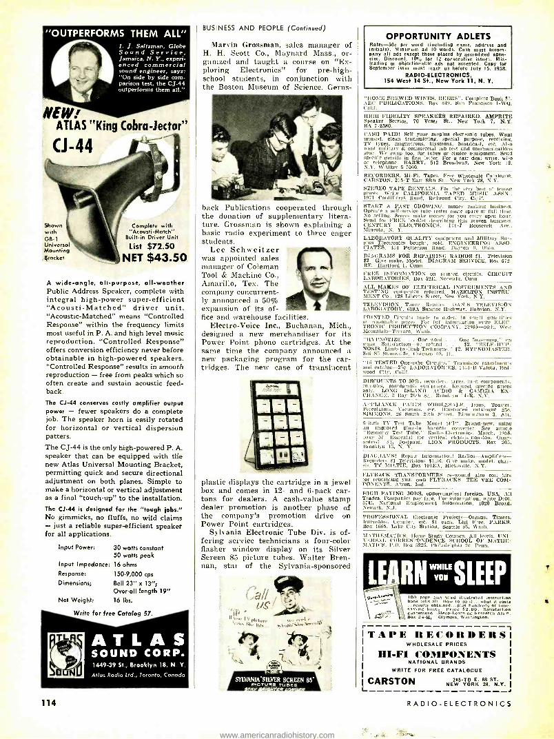
"OUTPERFORMS THEM ALL" I. J. Saltzman, Globe Sound Service, Jamaica, N. Y., experi- enced commercial sound engineer, says: "On side by side com- parison test, the CJ -44 outperforms them all."
NEW: ATLAS "King Cobra -lector"
(J -44
Shown with GB -1 Universal Mounting Bracket
Complete with "Acousti- Match"
Built -in Driver Unit
List $72.50 NET $43.50
A wide -angle, all- purpose, all -weather Public Address Speaker, complete with integral high -power super- efficient "Acousti- Matched" driver unit. "Acoustic- Matched" means "Controlled Response" within the frequency limits most useful in P. A. and high level music reproduction. "Controlled Response" offers conversion efficiency never before obtainable in high -powered speakers. "Controlled Response" results in smooth reproduction - free from peaks which so often create and sustain acoustic feed- back.
The CJ -44 conserves costly amplifier output power - fewer speakers do a complete job. The speaker horn is easily rotated for horizontal or vertical dispersion patters. The CJ -44 is the only high -powered P. A. speaker that can be equipped with the new Atlas Universal Mounting Bracket, permitting quick and secure directional adjustment on both planes. Simple to make a horizontal or vertical adjustment as a final "touch -up" to the installation. The CJ -44 is designed for the "tough jobs." No gimmicks, no fluffs, no wild claims - just a reliable super.-efficient speaker for all applications.
Input Power:
Input Impedance:
Response:
Dimensions;
Net Weight:
30 watts constant 50 watts peak 16 ohms
150 -9,000 cps
Bell 23" x 13 "I Over -all length 19" 16 lbs.
Write for free Catalog 57.
114
1449 -39 St., Brooklyn 18, N. Y.
Atlas Radio Ltd., Toronto, Canada
BUSINESS AND PEOPLE (Continued)
Marvin Grossman, sales manager of H. H. Scott Co., Maynard Mass., or- ganized and taught a course on "Ex- ploring Electronics" for pre -high- school students, in conjunction with the Boston Museum of Science. Gems-
back Publications cooperated through the donation of supplementary litera- ture. Grossman is shown explaining a basic radio experiment to three eager students.
Lee Schweitzer was appointed sales manager of Coleman Tool & Machine Co., Amarillo, Tex. The company concurrent- ly announced a 50% expansion of its of- fice and warehouse facilities.
Electro -Voice Inc., Buchanan, Mich., designed a new merchandiser for its Power Point phono cartridges. At the same time the company announced a new packaging program for the car- tridges. The new case of translucent
plastic displays the cartridge in a jewel box and comes in 12- and 6 -pack car- tons for dealers. A cash -value stamp dealer promotion is another phase of the company's promotion drive on Power Point cartridges.
Sylvania Electronic Tube Div. is of- fering service technicians a four -color flasher window display on its Silver Screen 85 picture tubes. Walter Bren- nan, star of the Sylvania- sponsored
I`
. rr r,t
SYLVANIA :SILVER SCREEN 85" PrCTURr TUBES w
OPPORTUNITY ADLETS Rates -50c per word (including name, address and initials). Minimum ad 10 words. Cash must accom- pany all ads except those placed by accredited agen- cies. Discount, 10% for 12 consecutive issue;. Mis- leading or objectionable ads not accepted. Copy for September issue must reach us before July 15, 1958.
RADIO-ELECTRONICS. 154 West 14 St., New York 11, N. Y.
'HOME BREWED WINES, BEERS ", Complete Book $1. BC PUBLICATIONS, Box 849, San Francisco 1 -WQ, 'alit.
HIGH -FIDELITY SPEAKERS REPAIRED. AMPRITE Speaker Service. 70 Vesey St., New York 7, N.Y. BA 7 -2580.
CASH PAID! Sell your surplus electronic tubes. Want [mused, clean transmitting, special purpose, receiving. TV types, magnetrons. klystrons, broadcast, etc. Also want military & commercial lab test and communications gear. We swap too, for tubes or choice equipment. Send specific details in first letter. For a fair deal write, wire or telephone: BARRY, 512 Broadway, New York 12. K.Y. WAlker 5 -7000.
RECORDERS, Hi -Fi, Tapes. Free Wholesale Catalogue. CARSTON. 215 -T East 88th St.. New York 28, N.Y.
STEREO TAPE RENTALS. For the very best at lowest prices. Write CALIFORNIA TAPED DH'SIC ASSN., 1971 Cordilleras Road, Redwood City, Calif. START A FAST GROWING, money making business. Operate a self -service tube tester route spare or full time. No selling. Stores make money for you every open hour. Send for FREE booklet describing this proven business. CENTURY ELECTRONICS, 111 -J Roosevelt Ave., Mineola, N. Y.
LABORATORY QUALITY equipment and Military Sur- plus Electronics bought. sold. ENGINEERING ASSO- CIATES. 434 Patterson Road- Dayton 9. Ohio.
DIAGRAMS FOR REPAIRING RADIOS $1. Television $2. Give make, Model. DIAGRAM SERVICE, Box 672 - RE. Hartford 1, Conn.
FREE INFORMATION on printed circuits. CIRCUIT LABORATORIES, Box 52E, Norwalk, Conn.
ALL MAKES OF ELECTRICAL INSTRUMENTS AND TESTING equipment repaired. HAZELTON INSTRU- MENT Co.. 128 Liberty Street, New York, N.Y. TELEVISION Tuner Repairs. DAN'S TELEVISION LABORATORY, 619A Sunrise Highway, Babylon, N.Y.
PRINTED Circuits made to order, in small quantities at reasonable prices. For full information write ELEC- TRONIC PRODUCTION COMPANY, 22905 -56th, West Mountlake- Terrace, Wash. "HYPNOTIZE . One word . . . One fingersnap, " on stage. Satisfaction -or refund . . . $2. "SELF -HYP- NOSIS. Limb -by -limb Technique. $2. IIYPNOMASTER. 846 -S5 Sunnyside, Chicago 40, III.
"15 TESTED One -tube Circuits," Transistor experiments and catalog -25e. LABORATORIES, 1131 -B VaIota, Red- wood City, Cal if.
DISCOUNTS TO 50 %, recorders, tapes. hi-fi components, consoles. photograph equipment. Request specific prices only. LONG ISLAND AUDIO & CAMERA EX- CHANGE, 3 Bay 26th St., Brooklyn 14 -R, N.Y.
AI'l'LIANCE PARTS WHOLESALE. Irons. Toaster, Percolators, Vacuums, etc. Illustrated catalogue 25e. SIMMONS, 26 South 20th Street, Birmingham 3, Ala.
5 -inch TV Test Tube. Model 5F1'7. Brand -new. using an improved plug -in harness converter. See article "Economy Test Tube," Radio -Electronics, March, 1958, page 57. Essential for vertical chassis- non -ion. Guar- anteed. $3. postpaid. LION PRODUCTS, Box 205. Brooklyn 15, N. Y.
DIAlIRASISt Repair Information! Radios-Amplifiers - Recorders $1 Televisions $1.50. Give make, model. chas- sis. TV MILTIE, Box 101EA, Hicksville. N.Y.
FLYBACK TRANSFORMERS re -wound also coil kits for rebuilding your own FLYBACKS. TEE VEE COM- PONENTS. Akron, Ind.
HIGH- PAYING JOBS, opportunities; foreign, USA. AU Trades. Companies pay fare. For information. write Dept. 57U, National Employment Information, 1020 Broad, Newark, N.J.
PROFESSIONAL Electronic Projects -Organs, Timers. Intercoms, Counter, etc. $1 each. List Free. PARKS Box 1665, Lake City Station, Seattle 55. Wash.
MATIIEMATIC'S. Home Study Courses. All levels. UNI - VERSAL CORRESPONDENCE SCHOOL OF 1IIATHE- MATIC'S, P.O. Box 5225, Philadelphia 26. Penn.
LE: RNSLEEP 100 page fact -tilled illustrated instruction book tells all. How to do it... what it costs ...results obtained...plus hundreds of time- saving hints. Price $2.00. Satisfaction guaranteed. Sleep- Learning Research Assn. Box 24.18, Olympia. Washington.
L
TAPE RECORDERS WHOLESALE PRICES
HI -FI COMPONENTS NATIONAL BRANDS
WRITE FOR FREE CATALOGUE
CARSTON 215 -TO E. 88 ST. NEW YORK 28, N.Y.
-I
RADIO -ELECTRONICS
www.americanradiohistory.com

SUCCESSFUL TECHNICIANS RELY ON RIDER SERVICE `AIDS' Service technicians the world over have come to rely on Rider Books and Manuals as indispensable 'working tools' at the bench or in the field. Here are just a few of more than 150 Rider titles that spell more electronic know -how -increased income. PORTABLE AND CLOCK RADIOS by Ben Crisses and David Gnessin. This modern book combines theory and bow to put that theory to work. Beginning with typical portable radio circuits, emphasis is placed on filament circuitry and how major problems of current dispersion are han- dled. Transistor circuitry is covered. Stress is placed on portable radio power supplies for bat- tery circuits and battery and AC -DC circuits. Numerous battery testing techniques explained. Covers repair, replacement and alignment plus a detailed discussion of probable mechanical troubles, replacement procedures and short -cuts. Tips on extending the life of the set are discussed. Clock radios, their circuitry, a wide variety of clock movements, how to adjust them and locate defects also covered. Tips on cleaning and lubri- cating clock mechanisms. #224. $2.75. HOME AIR CONDITIONING by J. Derman, H. Sea- man, F. Makatein. Modern up -to- the -minute text provides a firm foundation air conditioning theory upon which the practical know -how for installa- tion and repair can be built. Starting with the basic physics of air conditioning, all component parts including compressors, condensers. capil- lary tubes etc. and their functions are covered. Typical window and packaged installations are described and illustrated. Smaller commercial in- stallations are included. Troubleshooting and re- pair techniques explained. Recent and future developments in air conditioning covered. More than 100 illustrations support text. $3.50. REPAIRING HI -Fl SYSTEMS, by David Fidelman. This book deals with finding the troubles and repairing faults in hi -fi equipment with no test instruments - simple equipment -- and elaborate equipment. Typical troubles are analyzed and re- paired through a system of logical steps. Soft cover, 212 pp... illus. #205, $3.90. REPAIRING TELEVISION RECEIVERS, by Cyrus Glick - stein. The most modern completely practical book. written by an expert with long experience in television receiver repair. Devoted to trouble- shooting and repair techniques which are modern. yet down -to- earth. Covers the use of simple as well as elaborate test equipment of all kinds. Pro- fusely illustrated. Soft Cover, 212 pp.. 51/-." x 81/2", illus. #191, Only $4.40. 3rd SUPPLEMENT to the RECEIVING TUBE SUBSTI- TUTION GUIDEBOOK, by H. A. Middleton. A must for every technician! Contains more than 830 latest receiving tube substitutions more than 200 pic- ture tube substitutions more than 230 American to European tube substitutions more than 200 European to American tube substitutions a cumu- lative index listing the tube types treated in the basic book and all 3 supplements. It pays for itself almost immediately! #139 -3 -Soft Cover, 72 pp., 8!!." x 11 ", illus. Only $1.35. RECEIVING TUBE SUBSTITUTION GUIDEBOOK, by H. A. Middleton. #135 -Soft cover, 224 pp.. 81F." x 11 ", illus., $3.00. FIRST SUPPLEMENT, #139 -Soft cover. 48 pp., VA" x 11 ", illus., $.99.
SECOND SUPPLEMENT, #139 -2 -Soft cover, 48 pp., 81/." x 11 ", illus., $.99. ADVANCED TV SERVICING TECHNIQUES, by Zbar and Schildkraut. A complete advanced TV servic- ing Course, developed by the Radio- Electronics- Television Manufacturers Association. Shows how to use every conceivable type of test equipment. how to service every part of -a TV receiver. Ex- plains latest techniques. Soft cover. 81/2" x 11 ". MAIN TEXT, 192 pp.. illus. #161, $3.60. LABORATORY WORKBOOK, 32 pp. #161 -2. $.95. TV PICTURE TUBE -CHASSIS GUIDE, by Rider Lab Staff. This easy -to -use TV tube type chassis guide covers all picture tube types used in TV. receiver production from 1946 to February 1957 -over 7,000 listings. Organized by chassis number, and in some cases, by models so that the technician can imme- diately locate the correct picture tube type simply by knowing the chassis number, #204, Only $1.35.
RIDER'S NEW S D O SERVICE ( "single diagram only ")
ONLY 50i PER CHASSIS AT YOUR LOCAL JOBBER
TV COMING
JULY Rider books. manuals. S D O. are available at your Parts Jobber. Look for the Rider Bookseller, If these books are not available, order direct.
JOHN F. RIDER PUBLISHER, INC.
116 West 14th Street, New York 11, N. Y.
BUSINESS AND PEOPLE (Continued)
TV show "The Real McCoys," is fea- tured.
Heath Co., Benton Harbor, Mich., which formerly sold its Heathkits by mail order only, will now sell through dealers in key market areas as well. The retail price at dealers will be slightly higher than the mail- order.
Electronic Instrument Co., Long Is- land City, N.Y., has come up with a new display stand as part of a package
deal for distributors of Eico hi -fi and test equipment in kit and wired form.
P. R. Mallory & Co., Indianapolis, Ind., has given service technicians the opportunity to select from a wide range
of its RMC Discap ceramic capacitors from a self -service display.
General Electric Receiving Tube Dept., Owensboro, Ky., has made a new two -tone service case for tubes and ti
: P..
.--T"ers ,.,r
tools available to service technicians through its distributors.
Supreme Publications, Highland Park, Ill., is offering distributors a re-
volving floor rack on a share -the -cost basis. END
Leading Editors Say: "NEWCOMER, OR OLD 'PRO' YOU CAN LEARN ALL ABOUT TELEVISION WITH .. .
BASIC TELEVISION By Dr. Alexander Shure, Ph.D.
Editors of leading electronic maga- zines, service technician publications and industrial magazines -the experts - unanimously acclaim Basic Televi- sion, new five volume "picture- book" training course as the easiest possible way of learning all about black and white television.
Electronic Technician, April 1958 "One picture is worth 10,000 words,' so you can imagine the information con- tained in the more than 700 figures in- cluded here. Each of these drawings is illustrated in the manner which makes the most difficult concept readily un- derstandable. Text is very clear.... If you are a relative newcomer to TV, this work will be a most valuable "Bible "; if you are an old pro, you will be sur- prised at how much you can learn."
Radio Television News, May 1958 "For those who have thought about studying television but have been in- timidated by the, complexity of the average engineering text, this easy -to- take introduction to the subject should be encouraging.... There is no reason why the student with an elementary radio and electronics background couldn't use this 'course' as a spring- board to a career as a service techni- cian in the television field."
Telephony, April 1958 "This is undoubtedly the most under- standable presentation of the basic theory, operation and circuitry of black and white television ever published. Everything from thé transmitter to the picture on the screen is explained with utmost clarity in words as well as illus- trations that `visualize' each concept discussed."
Signal, April 1958 "Only a knowledge of basic electronics and radio is presupposed. The cover- age, ranging from the creation of the TV image in the studio to its appear- ance on the receiver screen, contains many topics absent in the more tradi- tional text."
Navy News, April 1958 "Here is an excellent encyclopedia on television from A to Z... this is, indeed, the most complete work of its kind... suitable for the beginner as well as the advanced technician, and anyone inter- ested in TV."
If you want to learn all about black and white television, quickly, easily and economically, this 5 volume "picture - book" course BASIC TELEVISION is the answer. Now available at your local bookstore or electronic parts distribu- tor. If your dealer does not have this book, order direct.
10 day unconditional money -back guarantee.
SW raw.
John F. Rider Publisher, Inc. 116 West 14th Street New York 11, N. Y. RE -7
I have enclosed S Please send me: _6 vol. Basic Television set (soft cover) $10.00 per set
_Deluxe cloth bound edition, all 5 vols. in single binding, $11.60
I understand I may return the books in 10 days for complete refund of full purchase price if I am not satisfied. NAME Address City____ Zone State
115
www.americanradiohistory.com

-"TAB" Tubes Tested, Inspected, Boxed - New and used Gov't & Mfrs.
Surplus! 6 Mos. Guarantee! No Rejects orders b'10 or more, Receinino t VAC only ppd, 48 star,,
.59111723 .69
.89'11726 1.10
.63'2C51 2.65
.69 2021 .68
.79 3D23 5.00
.65' :7178 5/31
.99 4 -125 29.00
.59 4.250 35.00
.59 4E27 7.00
.59 4PR60 29.50
.99 4X150 19.00 1.00 4X250 35.00
.99 4X500 38.00 1.45 5BP1 3.98 .69 5BP4 1.98 .89 3ST 4.00 .89 IOOT 7.00 .75 250T 20.00 .75 388A 1.00 .69 418A 14.00
2.15 450T 43.00 1.16 807 1.10 1.39 808 1.00 .72 809 3.00 .77 810 10.00 .72 811 3.00 .75 812 3.00
3.49 813 9.00 2.49 814 2.45
.59 815 2.50
.51 8298 8.00
.69 832A 7.00
.89 866A 1.60
.69 6146 4.00
.69 5879 1.20
.69 5881 2.70
.69 6550 3.90 3.29 5842 11.00
.89 5654 1.00 .59, 5894 14.00
Write for Co nplete Tune Lisa Discounts to Qty. Buyers TUBES WANTED! WE BUY! SELL & TRADE!
0A2 .80 68E6 .72 12AT6 0B2 .72 68K7 .99 12AT7 0C3 OD3
.84
.80 6BL7 6BN6
1.95 1.08
12AU6 12AU7
024 1A7
.50 1.00
613Q6 6627
1.19 1.25
12AX7 12BA6
163 185
.78
.78 6C4 6C5
.49
.69. 12BA7 12806
154 1T4
.78
.78 6CB6 6CD6
.80í126E6 1.49'1213E6
1U4 1U3
.68
.89 6H6 6J5
.59
.59 12BH7 1213y7
1X2A 3Q4
.68
.68 6.16 686
.59
.59 12927 12CU6
3Q5 354
.86
.68 6K7 6L6
.79 1.19
12587 12SG7
3V4 584
.99 1.25
654 658
.59
.99 125117 12517
5U4 5V4
.59
.89 6387 6567
.69 12SK7 1.1912SQ7
5Y3 6484
.59
.59 65C7 6SG7
.89 .79
19BG6 1978
68C7 6ÁG7
.79
.89 65H7 6SJ7
.69
.69 25806 25L6
6466 641(5
.99
.69 6587 65L7
.72.25W4
.89 25Z5 13AL5 6AQ5
.59
.66 6SN7 65Q7
2/S1 .74
25Z6 EL34
61157 BATS
3.00 .49
6SR7 6T8
.79.EL37
.98 35L6 6AU4 64U5
1.29 1.19
6U8 6V6
.98 1.39
35W4 35Y4
6AU6 611 %4
.79
.79 6W4 6W6
.79
.89 35Z5 50A5
68Á6 6BA7
.59 1.00
6X4 6X5
.39 5065 .49 SOCS
6606 66E6
.69 .59
61'6 7N7
.89 .89
50L6 KT66
813G6 6BN6
1.50 .79
12AL5 12AQS
.59
.75 75 80
NEW "TEKSEL" SELENIUM FULL WAVE BRIDGE RECTIFIERS. ONE YEAR GTD!
CURR. 18VAC 38VAC 72VAC CONT. 14VDC 28VDC S6VDC
lAMP $ 1.30 $ 2.00 $ 4.00 2AMP 3AMP
2.15 2.90
3.00 4.00
6.25 8.60
6AMP 1OAMP
4.15 6.10
8.00 12.15
18.75 26.30
15AMP 24AMP
9.90 15.00
19.00 29.45
40.00 57.50
144VAC 118VDC $ 9.45
12.30 16.75 36.15 48.90 66.60
108.45
NEW GTD: RADIO & T.V. RECTIFIERS 35MA 404 @, 6 for $2; 65MA 454 @, 5 for $2; 75MA 494 @, 5 for $2; 1OOMA 594 @, 6 for $3; 150MA 704 (,1 , 8 for 35; 250MA 794 @ , 6 for $4; 300MA 884 @ 5 for $4; 350MA $1.00 @, 8 for $7; 400MA $1.10 , 5 for $5; 500MA $1.35 @ , 4 for $5: 65MA 260v 51.10 @, 5 for $5; 100MA/260V $1.25
9 $10; 100MA /156V 95c @; 300MA /156V 51 75. 3 $5. Order $10, Postpaid 48
NEW SILICON 500MA /100 °C /280VAC/ 0ipyJt S® 403p. I.v. Rectifier Hoot Sealed $1.59 @ , `4f 5 for $6.50, 40 for $46. 100 for $100.00.
Order $10 i oatpald 40 elute.,.
HAMS NEW TRANSISTORIZED "TABPAK" D.C. fo D.C. Power Supply!!!
1t\ s1Z7'J Kit o assembled. Filtered. Small in
4V! Quiet! Light W Input 12 to 14VDC. (Low
watts. Current.) Output 450 6 tap @ 253 VDC at up to 150 ma /65 watts.
"TABPAK" Assembled TR39CB $35 "TABPAK" Kit TR39CK $30
NEW TPSK2 DC POWER for TRANSISTORS! Transistors! Filtered Power Supply Kit used to power Leansistor circuits. amplifiers etc. Delivers 12VDC at 2AMPS filtered less than 6.54,4- ripple or 28VDC at IA TPSK2 Kit $18, l'PS2W assembled & wired $24.
1 I5VAI' Inppt Transformer & Full [Nave Bridge Rectifier for 12VDC e 2AMPS. RE('i'KAN KIT RT1K $4.50 RTIW Assembled & Wired $8.50 RT2K Kit 12 or 18V1C at 6 AMPS $9.00 IIT2W Assembled & Wired $14.75 BIWA Battery charger kit 1 to 4 amps charges 2 -4 -6 & 12 volt batteries $9.95
NEW VRII "GE" PHONO CARTRIDGES Postpaid 48 Malts! 46061/Li' 0 r 4006:3/78 DIAMOND $16 401152/L1' &78 TRI-PLAY SAPPHIRE. .. . ._. ..$ $18 4Go53/LP &78 TRI -PLAY DIAMOND SAI'. $18 Á0n5:1 /LP &78 TRI -PLAY DIAMONDS $26
DIAMOND PHONO- NEEDLES! Poetnnid 48 Brate..! REGISTERED ONE YR. GUARANTEED BY THE MFGR! ALL MAKES LP &78 -ONE DIAMOND $6; TWO DIA - MONDS $14; DIAMOND & SAPPHIRE $8. PLEASE BE, \'D CARTRIDGE NA.IIF, et NUMBER
FINEST HI -FI RECORDING TAPE 1200 Ft. -7" Reel Lots Money Back Gtd. $1.45 of 3
Highest quality controlled plastic base tape made by new "Erin" process. Pre- cision `
ate11 & Silt. Gtd. Constant output. Splice Free. Freq. 742 DIPS 40 -15KC Oside Wm! In. New 1st Quality "Mylar" 2400 Ft. -7" Reel Fera, "Erin" Gloss Process Recording tape -$4.49, 3/312.
KITS! "TAB" THE BEST KITS! All Kits Contain Most Popular Values A Sizes Kit 35 Precision Resistors Kit 75 Mica Coed's
Kit 6 Crystal Diodes Kit 8025 ft. Hookup Wirr Kit 100 Fuses Kit 100 Ceramic Cond Kit 18 Rotary Switches Kit 8 Crystals & Holders Kit 65 Inductors 6 Coils Kit 5 Microswitches Kit 10 Wheat Lamps Kit 40 Insulators Kit 85 Insulated Resist. Kit TV Knobs Kit Glyptal Cement E.
Varnish
Kit 18 Switches Kit 3 Transistor Transf. Kit 150 Carbon Resistors Kit 42 Panel Lamps Kit 15 Volume Controls Kit 36 Tube Sockets Kit SO Tubular Coed's Kit SOO Lugs E. Eyelets Kit 10 Xmit Mica Coed's Kit 5 Lbs. Suprise Kit Kit Encapsulation Fluid Kit Volume Control Fluid Kit 35 Power Resistors 99e BUY IO KITS GET ONE IEEE! EACH KIT
"TAB"
TERMS: Money Back Guarantee! our 14th year. $2 mm order F.O.B. N.Y.C. Add hpg charges or for C.O.D. 250/0 Dep. Prices shown subject to hang
111KG LIBERTY ST.. N. Y. 6. N. Y. writ,. r",. Catnloo
PHONE: RECTOR 2.6245
116
technical
Literature
Any or all of these catalogs, bulletins, or periodicals are available to you on request direct to the manufacturers, whose addresses are listed at the end of each item. Use your letter - head-do not use postcards. To facilitate identi- fication, mention the issue and page of RADIO - ELECTRONICS on which the item appears. UNLESS OTHERWISE STATED, ALL ITEMS ARE GRATIS. ALL LITERATURE OFFERS ARE VOID AFTER SIX MONTHS.
TUBE TIPS. by Bud Tomer. The first 12 issues in this series have been bound into one volume (PA- 225), with sections on tube checkers, uhf tubes, new type TV tubes, design and construction fea- tures, the effects of military and indus- trial tube demands, definitions of tube characteristics. - Available through CBS -Hytron distributors. 50c. TANTALUM CAPACITORS engineering bulletin gives electrical characteristics of TAK slug capacitors with graphs showing capacitance and impedance stability from - 55° to 100 °C. -Pyra- mid Electric Co., 1445 Hudson Blvd., North Bergen, N. J. TUBE DATA BOOK. Approximately 1,000
television and radio receiving -tube types are listed, with more than 50 pages of electrical and mechanical operating characteristics and other data in the new Receiving Tube Data Book. Basing diagrams, type information on same page. -Raytheon Manufacturing Co., 55 Chapel St., Newton, Mass. 50c. TRANSISTOR COURSE for home study is outlined in descriptive folder PA -176. Complete table of contents for the 10- lesson course and an explanation of the "learn by doing" approach are in- cluded.- CBS -Hytron Advertising Serv- ice, Parker St., Newburyport, Mass. TELEVISION ACCESSORIES described in a four -page catalog: picture -tube boost- ers and rejuvenators, remote -control extension speaker, CRT substitution tester, dual speaker switches and vol- ume control, antenna selector switch ics, 134 Nassau Rd., Roosevelt, N. Y.
HI -FI CATALOG contains complete spec- ifications, descriptions and prices of the manufacturer's audio, TV and hi fi components, kit or factory- wired.- Arkay Inc., 120 Cedar St., New York 6, N. Y.
CONSTRUCTION MANUAL for photo- electronic relay kit KT -133. Describes in detail the building and applications of a single -tube relay which can be used to activate burglar alarms, door -open- ing motors, counters, etc. Complete specs included. -Lafayette Radio, 165- 08 Liberty Ave., Jamaica 33, N. Y.
SAVE 1/2 - PAY PART-BY-PART-HAVE-FUN
Assembling the SCHOBER
ELECTRONIC ORGAN in KIT form
NO SPECIAL SKILLS NEEDED
Now you can afford a real, full concert organ, just like those made by the foremost organ manufac- turers. Because over 1/2 the cost is saved when you assemble it yourself. And it's REALLY EASY: only 24 separate units, all with printed circuits, and detailed -to- the -smallest -step instructions. In addi- tion, you purchase each of the 24 kits when you are ready for it - and can afford it. You'll get a real kick out of putting the Schober Electronic Organ' together - and then sitting down and pulling the stops for Strings, Trumpets, Clar- inets, Diapasons, Flutes, etc. Electronic Percussion optional; chimes available.
One of the many exclusive features of this excep- tional organ is the handsome console, in a wide variety of finishes. It is equally at home in a tradi- tional or modern setting, and takes little more space than a spinet piano.
Complete descriptive booklet and price list are available on request. And, if you wish to hear the glorious pipe organ tone of the Schober Electronic Organ, a 10" long -playing demonstration recording is available for $2. This is refundable when you order. Write today and see what a fine instrument you can get at such a great saving.
2248 -B Broadway. New York 24, N. Y.
'Designed by Richard H Dorf
NEVER BEFORE
Switchmatic
ANY NUMBER OF
TV OUTLETS FROM
A SINGLE ANTENNA
Wr TELEVISION RECEPTACLES
Here's How It Works
Plug TV into any outlet and the Switchmatic Receptacle automatically switches the antenna to that outlet.
AT PARTS JOBBERS EVERYWHERE
Write for Bulletin µ W -46
* Another Serviceman Designed Product
MANUFACTURED BY
R- COLUMBIA PRODUCTS CO., Inc. Highwood, Illinois
RADIO -ELECTRONICS
www.americanradiohistory.com

TECHNICAL LITERATURE (Continued)
KLYSTRONS AND OTHER POWER TUBES, along with other Eimac products, are listed with technical data in tabular form in a 12 -page tab -indexed Quick Reference Catalog. -Eitel- McCullough Inc., San Bruno, Calif.
PRECISION TAPE REELS, far exceeding NAB standards and engineered for in- creased record reproduce accuracy and greater tape protection, are described and illustrated in a new leaflet. - Ampex Corp., 934 Charter St., Redwood City, Calif.
TUBE PRICE CHART. 11 x 14 inches, de- signed for wall mounting, shows indus- try- recommended retail prices for 839 tubes used in radio, TV and high - fidelity applications. -Tung -Sol Electric Inc., 95 Eighth Ave., Newark 4, N. J. SINGLE -SIDEBAND SPECTRA are dis- cussed with illustrations, graphs and formulas in Vol. 1, No. 3 of The Pan- oramic Analyzer. Testing techniques with spectrum analyzers are detailed in this bulletin designed to aid those using or designing single -sideband equipment. -Panoramic Radio Products Inc., 514 So. Fulton Ave., Mount Vernon, N. Y.
ISOPHASE SPEAKER is described in non- technical terms with good humor by radio and television personality Jean Shepherd in an 8 -page booklet, Isophase, a New Kind of Sound.- Pickering & Co. Inc., Plainview, N. Y.
CAPACITOR REPLACEMENT Manual K- 301 for auto radios gives a complete listing of Atom and Twist -lok elec- trolytic replacement capacitors for all car radios manufactured from 1946 through 1957. Replacements are cross - referenced to the original part numbers and described by rating, part designa- tion and price. The 8 -page manual also contains a separate listing of standard capacitors. -Sprague Products Co., 81 Marshall St., North Adams, Mass.
ELECTRONICS CATALOG contains 28 tabloid -size pages describing hundreds of parts, kits, components, hi -fi and radio items and test equipment. -Olson Radio Warehouse, 260 So. Forge St., Akron 8, Ohio.
ELECTRONIC TECHNICIAN. by Louis H. Morrison, manager, Countermeasures Dept., Wayland Laboratory, Raytheon Manufacturing Co., is one of a series of 30 American Occupations Mono- graphs. The 24 -page booklet describes salaries, working conditions, study re- quirements, opportunities and other aspects of a career as an electronic technician.- Research Publishing Co., Inc., P. O. Box 245, Boston 1, Mass. $1.
APPLICATION BULLETINS on the use of semiconductors, third and fourth in a series, deal with some uses of Zener- diodes. Vol. 1, No. 3 discusses use of Zener power regulators for improved regulation of vacuum tube heaters. Vol. 1, No. 4 gives detailed information on high -speed electronic switching for various computers. -Hoffman Electron- ics Corp., Semiconductor Div., 930 Pit - ner Ave., Evanston, Ill. END
JULY, 1958
AT HEALDS YOU LEARN BY DOING IN MODERN
ELECTRONICS LABORATORIES
HEALD ENGINEERING COLLEGE
Established 1863
Van Ness at Post, RE
San Francisco, Calif.
Never before in American history has the need been so great for Trained Engineers and Technicians. No other type of training can compare with actual shop practice you get at Healds under expert instructors.
Bachelor of Science Degree, 27 Months Radio -TV Technician including Color TV (12 Months) Electronics Technician (12 Months) Industrial Electronics Technician (12 Months) Electronics Engineering (B.S. Degree) Electrical Engineering (B.S. Degree) Mechanical Engineering (B.S. Degree) Civil Engineering (B.S. Degree) Architecture (B.S. Degree)
Heald College ranks FIRST West of the Mississippi in "Who's Who in America"
Approved for Veterans DAY AND EVENING CLASSES
Write for Catalog and Registration Application. New Term Starting Soon.
Your Name ......................
Address
City
State
TAPE RECORDERS HI FI COMPONENTS Tapes- Accessories
UNUSUAL VALUES Send for Free Catalog
DR ESSN ER 69.02 RE: 174 St. Flushing 65. N.Y.
STAMP OF
APPIROVA L!
O
Hi -Fi AM -FM Tuner Kit 528.95°
And they have the finest features and specs. Fully I l tut. trated step -by -step 28 -page 1 snap! assembly a nap! WRITE FOR FREE CATALOG! *Add lOrr for Federal Tar..
QUALITY ELECTRONICS 319 Church Street Dept. RE -7 New York 13, N. Y.
Only Known Merit marks a product as the "BEST"
for quieting Noisy Controls and Switches OUIETROLE produces results superior to any other product. That's why it's known as the "Best" and that's why more users prefer it to any other .
It's the dependable Original product of its kind . .. a first in the Industry.
QUIETROLE Spray_ : a 14:
QuIETSOr.E
ru,rzi cati TV Tuners
In 2 -ox. bottle with droPPer
and 6 -ox. QUIETROLE SpRAY-
1
or the QUIETROLE Bottle with the Eye Dropper Cap
both types offers you
both ithes way
contain-
you of the some un- failing results that
QUIETROLE is known for.
The Lubricant Cleaner of the Electronic World. Tailored for the indus- try by over 15 years of authentic research, plus 4 years of rigid and exacting tests before marketing.
Ask for QUIETROLE and be sure you get it! _1_ manufactured by
COMPANY Spartanburg, South Carolina
gtJ ti I NE«'! I. iPRO'E !
I , SENCORE TRC4
TRANSISTOR CHECKER
r
America's newest,
,ymost
lar lest" y instruments
popu
NOW CHECKS: * Transistors Ifor opens, shorts, Ileakage and cur- rent gain. In-
Idudes new g
pain ower, lest
traon nsistors. * Crystal Diodes checks forward to reverse current ratio on all
Idiodes. * Selenium Rectifiers checks forward and re-
Iverse currents.
IControls ore accurately set for each transistor
111 by referring to replaceable set -up Test leads or socket provides for fast I
on rear. hookup.
See your parts distributor.
byg SERVICE ' sENCOaEi INSTRUMENTS CORP. I
L. 171 OFFICIAL RD., ADDISON, ILL.
Cur out this a
J d now for further information
117
www.americanradiohistory.com

DON'T PULL
THAT TUBE! UNLESS YOU KNOW
WHAT YOU'RE DOING!
Nine times out of ten it is a tube. But which tube? - and why? Sol Heller's new book TV AND RADIO TUBE TROUBLES tells you. No more catch -as -catch -can tube yanking. No more guess- and -pull. Now you can be sure. With this new symptom -analysis technique, you can track down the weirdest tube trouble in any TV or radio set in minutes. Begins where the tube checker leaves off. Analyzes symptoms. Spots troubles. Tells you what to do. One of the most valuable servic- ing aids you can buy. If you're suffering from tired servicing business, loss of customers, or undernourished bank balance, take this prescription at once -in generous doses!
HOW TO GET THIS î4.60 BOOK FOR ONLY $3.35
This brand -new book in a new beautifully designed hard -cover edition is advertised nationally for $4.60. But through the G/L TECHNICIANS' BOOK CLUB you can get it and others equally valuable for only $3.35.
THE G/L TECHNICIANS' BOOK CLUB
has helped tho ,sands of service technicians everywhere
Learn More Do Faster Servicing Earn More Money Save money on the books they need to get ahead.
Here's how it can help you! This unique club offers deluxe hard -cover editions of today's best practical servicing and theory books by well known authors AT A DISCOUNT OF 27'; !
Through mass printing and
NEW DELUXE COVER
direct distribution we can offer you these $4.60 books AT THE WHOLESALE PRICE OF $3.35 -and we pay the postage!
How the Club Works To enroll. select the book you want on the coupon below. SEND NO MONEY. Please select only one book! The one you choose will be sent to you on a No -Risk 10- day inspection plan. If you like the book keep it and send us your re- mittance. If you don't
THESE BOOKS ALREADY PUBLISHED Select TV AND RADIO TUBE TROUBLES
or any one of these books.
Rapid TV Repair -By G. Warren Heath. Handle more jobs, make more looney. This book ,shows you how to get to the heart of tough TV troubles in minutes. Lists hundreds of troubles alphabetically- gives causes, symptom., cures and tells you where the trouble Is most likely to occur. No theory -all practical data. Illustrated. Cross -referenced. Time -saving trouble- shooting chart:. Servicing Color TV -By Robert G. Middleton. Answers all your questions about ilìronta circuits, matrix testing, the flyback system, test equipment and match more. Troubleshooting charts help you find the toughest trouble quickly. TV -It's a Cinch -By E. Aisberg. All about TV theory from studio to picture tube. Writ-
SEND NO MONEY! MAIL THIS COUPON TODAY!
Books To Be Published Soon
RAPID RADIO REPAIR -By G. Warren Heath
SERVICING TAPE RECORDERS OSCILLOSCOPE TECHNIQUES
-By Alfred Has
118
just send it back. A new book is published every three months -you receive your personal copy on the same No- Risk inspection plan as soon as it conies off the press. Keep only the books you want -pay only for those you keep. You agree to take a mini- mum of only 4 books - over the whole enroll- ment period. You may cancel anytime after that. No time limit -no contract to sign.
ten in breezy conversational style illustrated with hun- dreds of specially -drawn humorous sketches.
Servicing Record Changers -By Harry Mileof. Make extra money servicing chan
The V.T.V.M. -By Rhys Samuel. (let more out of this versatile instrument. Sweep and Marker Generators for Television and Radio -By Robert G. Middleton. A must for television servicing.
Probes -By Bruno Zucconi and Martin Clifford. How to use probes for better servicing with today's com- plex test instruments. The Oscilloscope -By George Zwick. Are you getting full use of your ',cover Tills book shows you how!
SEND IN THIS COUPON TODAY - ---i GERNSBACK LIBRARY, INC., Dept. 78C 154 West 14th St., New York 11, N.Y.
Enroll me in the G/L TECHNICIANS' BOOK CLUB. Begin my membership with the book checked below. Please check one only.
TV T and RADIO
TUBE
RAPID TV REPAIR SERVICING COLOR TV TV -IT'S A CINCH THE V.T.V.M.
Name
Street
City
SWEEP AND GENERATORS
MARKER
SERVICING RECORD CHANGERS PROBES THE OSCILLOSCOPE
please print
Zone State s
GENERAL ELECTRIC TV SERVICE GUIDE, Vol. 3, General Electric Co., Television Receiver Dept., Syracuse, N. Y. 11 x 17 inches, 88 pages. $1.75 from G -E TV distributors and indepen- dent parts jobbers.
This guide contains schematic dia- grams, replacement parts lists, model identification photos; tube, test -point and trimmer layout diagrams, wave- forms, production changes and other pertinent servicing information on G -E TV receivers manufactured from 1955 to 1957. Spiral binding permits the guide to lie flat on the workbench. - RFS
PRINCIPLES AND PRACTICES OF' TAPE AND DISC RECORDING, Vols. I and II. Audio Engineering Society. Obtainable from Sumner Hall, Lecture Series Chairman, Amityville, N. Y. 6 x 9 inches. Both volumes $5 for members, $7.50 for nonmembers.
These notes are from a series of lectures, delivered last winter to the Audio Engineering Society, discussing various problems, recent developments and modern techniques. Each volume includes 15 lectures. The notes comprise engineering data, measurements, sys- tems layouts and references.
Volume I deals with studio problems, distortion, recording and reproducing systems. Volume II continues with spe- cific problems relating to tape transport, noise suppression, tape duplication, stereo disk, tape editing, etc. Whether you attended the original lectures or not, these are valuable reference notes. -IQ SELECTION AND APPLICATION OF METALLIC RECTIFIERS, by Stuart P. Jackson. McGraw -Hill Book Co., Inc., 330 W. 42 St., New York 36, N. Y. 6 x 9 inches, 320 pages. $8.
Metallic rectifiers are increasingly being used in all phases of the elec- tronics industry. This book gives infor- mation on their fundamental charac- teristics and their use in many types of electronic and electrical equipment.
The text is broken into three major sections. The first covers rectifier cir- cuits and complex loads and filters. Next comes a discussion of various types of metallic rectifiers and their uses. The last section goes into practi- cal application and circuit. -LS TAPE RECORDER MANUAL, Volume 1. Howard W. Sams & Co., 2201 E. 46th St., Indianapolis 5, Ind. 81/2 x 11 inches, pages not numbered. $2.95.
RADIO -ELECTRONICS
www.americanradiohistory.com

SCHOOL DIRECTORY
L 1 + 2 x 3 does NOT = 9 Don't be held back by lack of math. laiarn math from arithmetic through college -level differential and in- tegral calculus by one orrespondence course. No previous college h -igh
school math necessary. Above -average Intelligence not needed to aster the easy to understand lessons on arithmetic. college igebra, trigonometry, analytic geometry, differen-
tial, and Integral s
-alrttlus. An that Is needed is willingness to work. This course is an excellent re- view for those who took these subjects long ago.
t Complete course 525.00 Ino other texts needed)
plus few cents postage for mailing lessons to and from school. Start Immediately! Work at your rate of speed. _ Mail check of money Prdet
r) M AT H A to C 112 No. Fayette St. Alexandria, Va.
i
Be a "k y" man. Learn how to send and receive messages In International Morse code. Communicate with opera- tors around the globe. Learn at home quickly through famous Candler System. Used by best operatom. Qualify for Amateur or Commercial License. Write for FREE BOOK.
CANDLER SYSTEM CO. Dpt.3 -11. Boxll __ ri. 1)rntcr2O. Colo. USA
ENGINEERING DEGREES E.E.
PACIFIC INTERNATIONAL
UNIVERSITY
Option Electronics or Power
Earned Through
HOME STUDY Residence Classes Also
Available PACIFIC INTERNATIONAL
UNIVERSITY tOperating a a College of
Engineering only at present) 5719 -M, Santa Monica Blvd.,
Hollywood 38, Calif.
GET INTO
ELECTRONICS V'. -i -.I. Ir.ining 1,.,111s technicians. held ngfn° >, ", v: il- I.ts In
t m
' lcaiions. guided mis-
siles, computers, puters, r. tar and automation. Basic and advanced r s in theory and laboratory. Assoc-.
courses In elec-
tronics in 29 mos. B.S. In electronic engineering obtainable. ECPD
a --
credited, G.I. approved. Graduates In all branches of electronics with major companies- Start September, February. Dorms. c 111111.. High School graduate equivalent. quivalent. Catalog.
VALPARAISO TECHNICAL I NSTITUTE
Dept. C Valparaiso, Indiana
ELECTRONICS PREPARE FOR A GOOD JOB!
BROADCAST ENGINEER RADIO SERVICING AUTOMATION
TELEVISION SERVICING BLACK & WHITE -COLOR
APPROVED FOR VETERANS AND SURVIVORS OF VETERANS
BUILDING AIR CONDITIONED SEND FOR FREE LITERATURE
BALTIMORE TECHNICAL INSTITUTE 1425 EUTAW PLACE. BALTIMORE 17. MD.
ELECTRONICS orrg;;; :;,- ENGINEERING DEGREE
Ice'' I N 21 MONTHS )unities t
electronic.: B.J. degree In :17
' oohs, mathematics, atics, electrical e gi
ering, TV. advanc d radio theory and design. Modern labs. Lote tuition, earn board. Also Aero., Chemical, Civil, Electrical. Mech. Engineering. B.S. degree in 36 t . in Math., Chem.. Physics. Also prep courses- G.I. appr. 20 bldg... dorms, gytnn. Enter Sept., Dec., Afar-h. .lune. Catalog. Keeping Pace With Progress.
INDIANA TECHNICAL COLLEGE 1578 E. Washington Boulevard, Fort Wayne 2, Indiana
college grads get ahead faster!
hate higher incun)r: . al rulre mnrr rapidly. (]rasp your eluurli Inc a belirr lice. Share awards await- ing eollege wen. Important firsts visit campus regularly To eniplitt 'r,i -State College graduates. Start any quarter. Approved for Vets.
Bachelor of Science Degree in 27 months
Complete Radio Engineering courses (TV. (.I1F. FM, Electronics). Also Mechanical. Civil, Electrical, Chemi- cal. Aeronautical Engineering in 36 months a B.S. in Business Administration (General Business, Accounting, \Iolnr Transport Management Majors). Superior stu- lerns fa -ter. More professional class hours. Small
class( Enrollment limited. Beautiful campus. Well. ,lipped lab -. )'rep courses. Enter June, Sept., Jan.,
\I.u. Earnest. capable students (whose time and budget requite accelerated courses and modest costs) are in-
cited to write Jean McCarthy, Director o/ 4dmiasions tar Cat,loc and "Your Cnrcer tr
o a ill TRI -STATE COLLEGE 2478 College Avenue, Angola, Indiana
ELECTRIC GENERATOR l'ua tort itsvd )'tank phones. 1rp to 75 volt. : \.(' Wonderful for roperitir iniug. ring light lip Ilt'tlil and other lamps. use as .hncltrr, classroom uses, etc. Each has or 4 live -inch I 11). Lt shape liar magnets (alone north total thst I; generating arma- nur: solid brass gears, and gear crank. Comes astir for use. These ,uv recondi- tioned ulagm -to -, all In good- condition. Gen- erator neigh- over S lbs. Shipping tcr,gld- In Ih -. Item No. 130 -53.95 (P.P. & Hdlg. Ches. 51.25)
TELEPHONE RINGER BELL polarized with strong bar magnet. To be nsrd tcilii i i'iirit I:ener:u or, Item No. l'n. Thee work nier many mile. )viii :,neralnr. Reconditioned. weight
2 !11 Rent No. 131 -52.110. IShpg. cites. 31ìcl
WATTHOUR METER
JULY, 1958
Leading makes-recondition - ed. Ideal for trailer parks. 100 -I10 volts. 60 cycles. 2- wire A.C. 5 amp. Heavy metal case 81 /2" x 61/4" x 5 ". Easy to install. Ship. wt. 14 lbs.
ITEM NO. 33 $4.50 NOW ONLY w 7 (P.P. a Hdlg. Cogs. $1.25)
Amazing Black Light 50 tait ultra -violet light i
Makes couse.. ee -nl objects plot r,
lark. Fits any lamp socket_ 01,11 l
Ils. No. 87, 52.95 (Shoo. chas 35c)
250 Power Telescope Lens Kit %l:dke o . ft. iiieseup, -. Nil 2" diam. focal length, poli.h. .I objective lens and eyepieces. firs SPX 50\ to _ 0X. Full Instiuetl,in. No. 123. $2.95 (Shag. chgs. ano
Super Alnico Magnet Powerful 4 02. Alnico steel , agneI _
Lifts 5 Ils, easily. %tonsures lac" 112". Experlmeriters will find hull. deeds of uses. Usually costs $:i.. -rit No. 86. $1.50 (Shag. Chas. toc)
HUDSON SPECIALTIES CO., 160 W. 14th St. Dept. RE -7 -58, New York 7, N.Y. I ant closing full remittance for items circled helot... e1 Be sure to include shipping charges.)
87 33 86 123 130 131
Name Please Print Clearly
Address
City Zone State
Your choice of school is highly important to your career in
!' INDUSTRIAL r
>, "Al ELECTRONICS
111
o.
MirtA RADIO- TELEVISION
.pela.
'L ELECTRONICS \ t COMMUNICATIONS
Become an ELECTRICAL ENGINEER or an ENGINEERING TECHNICIAN at
MSOE in Milwaukee Choose from courses in:
ELECTRICAL ENGINEERING Bachelor of Science degree in 36 months - Communications or Electrical Power.
ENGINEERING TECHNOLOGY Associate in Applied Science degree in 18 months - Electronics Communications. Electrical Power, or Computers.
MSOE - located in Milwaukee, one of America's largest industrial centers -is a national leader in electronics instruction -with com- plete facilities, including the latest laboratory equipment, visual aid theater, amateur radio transmitter -offers 93 subjects in electrical en- gineering, electronics. radio, tele- vision, electrical power, and elec- tricity.
Advisory committee of leading industrialists. Courses approved for veterans. Over 50,000 former students. Excellent placement rec- ord. Previous educational, military, and practical experience is evalu- at-'d for advanced credit.
QUARTERS BEGIN SEPTEMBER, JANUARY, MARCH, JULY
Choosc r, i. may dept- .:
Poft lOdlil
- wih r future it- liai! con-
MILWAUKEE SCHOOL OF ENGINEERING Dept. RE -758. 1057 N. Milwaukee St. Milwaukee, Wis.
1'4 :t.e slnti free il Ili =mated career booklet (plea, e print I
I'm interested in I Courser
Nan.' \ge ................
)dices. City State
1 am I am not eligible for tetet-ans benefits
(discharge date) 1 1
119
www.americanradiohistory.com

EDMUND SCIENTIFIC CO.
INFRARED SNIPERSCOPE
TELESCOPE & PARTS See in the dark--, ithout being observed. War surplus Sniper - scope M -2. Contains the famous IP25A Image Tube. Govt cost about $1200. Used for industrial plant security: research lab ex- periments: infrared photogra- phy : spectroscopy, etc. Instru- ment complete, ready to use. Includes Power Pack, infrared light source. Will operate from 6 V auto battery. Battery or transformer available.
Shipping $150.00
f.o.b. Barrington, N. J. Send check or M.O. -money -back guarantee! Save still more money! Build your own Sniper - scope! We will furnish instructions- parts, in- cluding: Power Packs, 1P25A image tubes, light units, filters, etc. For details- request FREE Catalog "EK."
Stock No. 85,053 -EK weight approx. 12 lbs
SPECIAL! SPECIAL! INFRARED 1P25A IMAGE TUBE
Stock No. 70,127 -EK $9.95 pstpd. Send check or money order, money -back guarantee
COLOR TV TUBESCOPE Saves time, effort in alignment of color dot pattern. Stock No. 50,139 -EK 22 power $24.50 patpd. Send check or money order, money -back guarantee
GET FREE CATALOG "EK" America'. No. I source of supply for experimenters, hobbyist.. \Cor1d's largest variety of Optical Items. Bargains galore. . war Surplus-Imported --Domes- tic! Microscopes, Telescope.. Sateliitescopes, Color TV Tulrc +tope., Infrared snipt'I - -. ipes and Parts, l'r isms, L'o.,'.. Reticles, Mirrors :iode dozens of other ha m get lint ¡,., i l I icm
WRITE FOR FREE CATALOG EK
BARRINGTON, NEW JERSEY
WE DON'T NEED ENGINEERS but they write to us doily to order our
GENIAC!t Electric Brain Construction Kits. TEACHERS, SCIENTIFIC AMATEURS, INDUS -
TRI. \1. I' 111515 and schools. (See list below.) THOUSANDS OF SATISFIED CUSTOMERS have bought
GENIACS® on a 7 DAY REFUND guarantee We are proud to offer our 1955 Model, with up to the
minute improvements for the thousands of new customers ,ho can use them.
0 WHAT IS A GENIAC,,?
Here is a picture of the 1958 Model GENIAC® in the dis- play rack ($5.00 separately) which comes with every kit.
GENIACy stands for Genius Semi -Automatic Computer. A kit of specially designed switch decks and racks which permit the user to construct more than 125 different machines (following directions and wiring diagrams) and as many more s he is able to design himself. These machines demonstrate the applications of electric circuitry.
APPLICATIONS OF GENIAC® SIMPLE
citing, PUTEIng.IRC
multiplying for binary, nesl PROBLEMS
insymbolic logic, reasoning, comparing, PSYCHOLOGICAL TESTING and EXPERIMENT GAME PLAYING CIRCUITS for Ht tar -toe and nim. ACTUARIAL ANALYSIS.
SOME OF OUR CUSTOMERS Allis- Chalmers Remington -Rand International Business Machines Manuel Missionary College Barnard College
Westinghouse Electric Phillips Laboratories General Insurance Co. of America Lafayette Radio Rohr Air - raft Co. Albert Einstein Medical College Naval Re-
search Laboratories Board of Education, Tecumseh, Nebraska Los Angeles Public Schools Jefferson Union High School Oklahoma A 6 M Courtland Jr. High School Bell Telephone Laboratories.
WHAT COMES WITH THE KIT B OOKS -1. SIMPLE ELECTRIC BRAINS, AND HOW TO MAKE THEM . 04 page experiment manual. -NEW! 2. DESIGNOMAT® with 75 new experiments and methods for designing new machines-NEW! 3. WIRING DI.4GR.AIIS for basic GENIAC® circuits. -NEW! 4. Begin- ner's Manual for the person who has little or no familiarity with electric circuits -NEWT 5. GENIAC® .study guide .
the equivalent of a full course in computer fundamentals, lists additional readings. PARTS -PANELS, DISCS, RACK (for easy a embly and display,. Hardware, wire, tools, battery, holder, etc. for more than 125 machines. SEN:t for your GENIAC® n . At Only $19.95, a bargain, comes complete with over 400 parts and components, 5 books and manuals. We guarantee that if you don not want to keep GENtIA('if after one week you can return it for full
fund. Add 80c west of Miss. 52 outside U.S. Mail Name 6 Ad- dress with check or Money Order to
Oliver Garfield Co., Dept. RE -78 NEW YORK131 N 41EET
120
BOOKS (Continued)
During the past 11 years compila- tions of magnetic recorder diagrams and service data have appeared in various volumes of Record Changer Manual. Now, the large number of makes and models of tape recorders makes it possible to provide complete service information on the latest of these in a separate manual. The manual is a compilation of Photofact folders covering 20 tape-recorder models made by 9 manufacturers during 1956 -57.
ELECTRONIC HOBBYISTS' HAND- BOOK, by Rufus P. Turner. Gernsback Library, Inc., 154 W. 14 St., New York 11, N. Y. 51/2 x 81/2 inches, 160 pages. $2.50.
In his usual clear and practical style, the author slants this book toward the novice and part -time technician. Old and young experimenters will find helpful guidance.
Safety and shop practice are dis- cussed first. The building blocks of electronics- amplifiers, oscillators and power supplies -are described in sep- arate chapters. Diagrams, parts lists and helpful instructions make it easy to follow each project. The advanced chapters show and tell how to build controls and alarms, photoelectric cir- cuits, a stroboscope, metal locator, Geiger counter, etc. -IQ COLOR TV PRINCIPLES AND PRACTICES, General Electric Co., Electronic Components Div., Owens- boro, Ky. and local G -E distributors. 8'% x 11 inches, 135 pages. $5.
Aimed at and written for the tele- vision service technician, this text pre- sents a detailed and interesting picture of how color TV works. The reader is taken through the entire color TV story with numerous illustrations and com- prehensive circuit descriptions.
Starting with a description of the nature of light, showing what happens when you add and subtract colors, the
text continues through NTSC Stand- ards, color TV receiver circuits and a look at an actual color receiver. Among the many subjects covered are: the rf tuner, the Y channel, chroma bandpass amplifier, picture -tube matrixing, static convergence, troubleshooting. If you aren't quite sure of color TV, this text should set you straight. -LS
MATHEMATICS FOR SCIENCE AND ENGINEERING by Philip L. Alger. McGraw -Hill Book Co., Inc., 330 W. 42nd St., New York 36, N.Y. 6 x 9 inches, 360 pages. $6.95.
Mathematics is essential to the solu- tion of engineering problems. This book can help bring your mathematical knowl- edge and skill to college level. Based on Engineering Mathematics by Charles P. Steinmetz, the famous scientist, it be- gins with easy arithmetic and pro- gresses through trigonometry, algebra, series, calculus and differential equa- tions.
Many examples are included to illus- trate how electrical engineering calcu- lations are made. The text advances in easy steps and should be helpful to self -study readers. Among the impor- tant topics are: slide rule, vectors, in- terpolation, Laplace transforms, Boo- lean algebra and probability. Problems and useful tables are given. IQ TELEVISION INTERFERENCE, ITS CAUSES AND CURES, by Phil Rand. Nelson Publishing Co., P. O. Box 36, Redding Ridge, Conn. 8t'/ x 11 inches, 56 pages. $1.75.
A complete revision of Phil's earlier editions of Television Interference pub- lished by Remington Rand and now out of print and unavailable. The material is divided into 10 chapters, each treat- ing a specific phase of TVI and its elimination. Well illustrated with nu- merous charts, graphs, photos and diagrams.-RFS END
Suggested by D. F. Sypolt, Masontown, Va.
"Well, what seems to be the matter with your television set, sir ?"
RADIO -ELECTRONICS
www.americanradiohistory.com

1eeiif /ea4 "geld/ LAFAYETTE STEREO TUNER KIT
Armstrong
Use it as a Binaural- Stereophonic FM -AM tuner
Use it as a Dual - Monaural FM -:1M tuner
Use it as a straight Monaural FM or AAF tuner
THE MOST FLEXIBLE TUNER EVER DESIGNED
Multife' Output for New S FM
10KC Whistle Filter Pre -aligned IF's Tuned Cascade FM
11 Tubes (including 4 dual -purpose) +Tuning Eye + Selenium rectifier Pre ride 17 Tube Performanc:
Separately Tuned FM and AM Sections 12 Tuned Circuits Dual Cathode Follower Output
Circuit with FM /AFC and AFC Defeat Dual Double -Tuned Transformer Coupled Limiters.
More than a year of research, planning and engineering went into the making of the Lafayette Stereo Tuner. Its unique flexibility permits the reception of binaural broadcasting (simultaneous transmission on both FM and AM), the independent operation of both the FM and AM sections at the some time, and the ordinary reception of either FM or AM. The AM and FM sections are separately tuned, each with a separate 3 -gang tuning condenser, separate flywheel tuning and separate volume control for proper balancing when used for binaural programs. Simplified accurate knife -edge tuning is provided by magic eye which operates independently on FM and AM. Automatic frequency control "locks in" FM signal permanently. Aside from its unique flexibility, this is, above all else, o quality high -fidelity tuner incorporating features found exclusively in the highest priced tuners. FM specifications include grounded -grid triode low noise front end with triode mixer, double -tuned dual limiters with Foster -Seeley discriminator, less than 1% harmonic distortion, frequency response 20. 20,000 cps ± 1/2 db, full 200 kc bandwidth and sensitivity of 2 microvolts for 30 db quieting with full limiting at one microvolt. AM specifications include 3 stages of AVC, 10 kc whistle filter,
built -in ferrite coop antenna, less than 1% harmonic distortion, sensitivity of 5 microvolts, 8-kc bandwidth and frequency response 20 -5000 cps ± 3 db. The 5 controls of the KT -500 are FM Volume, AM Volume, FM Tuning, AM Tuning and 5- position Function Selector Switch. Tastefully styled with gold -brass escu- tcheon having dark maroon background plus matching maroon knobs with gold inserts. The Lafayette Stereo Tuner was designed with the builder in mind. Two separate printed circuit boards make construction and wiring simple, even for such a complex unit. Complete kit includes all parts and metal cover, a step -by- step instruction manual, schematic and pictorial diagrams. Size is 133/4" W x 103 /e " D x 41/2" H. Shpg. wt., 18 lbs.
The new Lafayette Model KT -500 Stereo FM -AM Tuner is o companion piece to the Models KT -300 Audio Control Center Kit and KT -460 70 -watt Basic Amplifier Kit and the "Triumvirate" of these 3 units form the heart of a top quality stereo hi -fi system.
KT -500 Net 74.50
TINY 6 TRANSISTOR RADIO LIGHT SMALL SENSITIVE LOW PRICE HIGH PERFORMANCE
PUSH -PULL AUDIO OUTPUT FOR
FAITHFUL TONE QUALITY FULL TONE DYNAMIC SPEAKER BUILT -IN FERRITE BAR ANTENNA TROUBLE -FREE PRINTED CIRCUIT 6 ULTRA -MODERN TRANSISTORS
PLUS GERMANIUM DIODE
SUPERHETERODYNE CIRCUIT HIGHLY STYLED PLASTIC CASE
EARPHONE JACK -BUILT IN- FOR PRIVATE LISTENING ECONOMICAL -USES ONLY ONE
BATTERY
REGULARLY
29.95 Including Earphone,
Battery and Carrying Case
SIZE: 111/13" x214" x41/8" WEIGHT: 12 OUNCES ..t....
FS -110 - LAFAYETTE. "TINY" TRANSISTOR RADIO COMPLETE with Battery, Carrying Case and Earphone Net 29.95 - NEW! POWER MEGAPHONE ... Portable Sound Broadcaster
Uses 8 Flashlight Cells Completely Self- Contained Weighs only 61/2 lbs. with Batteries High Efficiency
Horn Projects Sound 1000 Ft. Shoulder Strap for Portability and Ease of Use Microphone Detachable On 10 -Foot Cord For Construction, Auctions, Carni- vals, Fire & Police Use Also Ideal for Marine, Rail- road, Civil Defense, Sporting Events A power megaphone with many unusual features and many applications. Basically a highly efficient sound projector horn with a built -in microphone, capable of amplifying and projecting the voice with a range of 1000 feet. The microphone is a telephone -type element, easily replaceable, and may be detached and extended up to 10 feet from the horn. The reflex -type horn is extremely light- weight, rubber -rimmed, of strong, sturdy spun aluminum construction with 23/4' air column and is supplied with a strap for carrying or placing on the shoulder. A press -to -talk switch on the micro- phone provides for economy of power use-p wer is used only when ac- tually talking. No warm -up time required -amplification is instantaneous. A patented non -linear current limiting device restricts current flow to safe levels for longest battery life. Uses 8 size "D" flashlight cells in series with an approximate life of about 10 hrs. of use. Battery housing serves as base for entire assembly. Battery compartment opens easily by means of 2 thumbscrews for battery replacement. Size 17" long overall; horn mouth is 12" diem. Shpg, wt., 8 lbs. less batteries.
PA -13 - Power Megaphone, Less batteries Net 29.50 BATTERIES FOR ABOVE- Burgess No. 2 or RCA
V5036 -8 Required Net eoch .13
SHOULDER STRAP &
DETACHABLE MIKE
JUST AIM & TALK
Self- Contained- Only 6'/2 lbs.
THROWS VOICE 1000 FT.
165-08 Liberty Ave.
JAMAICA 33; N. Y. INCLUDE POSTAGE WITH ORDER
NEW YORK, N.Y.
100 6th Ave.
REctor 2.8600
BOSTON, Mass.
110 Federal St.
HUbbard 2.7850
BRONX , N.Y.
542 E. Fordham Rd.
FOrdham 1-8813
NEWARK, Ni. .
24 Central Ave.
MArket 2-1661
PLAINFIELD, N.J.
139 W. 2nd St.
Plainfield 6.4118
JULY, 1958 121
www.americanradiohistory.com

H9 for the 5 TOP NAMES in-, TV & RECEIVING TYPE
TUBES AT SENSIBLE PRICES!
TUBE SPECIALS 10KP7 ....$12.00 C1B 3C31 52.50 WE -350B -$1.75 7SOTL .... 27.00 35TG 1.75 355A 9.00 304TH .. 17.50 803 1.50 CBS -6004 1.00
866A 1.50 AND OTHERS - 304TL .... 17.50 100TH 7.75 WRITE.
Individually boxed. First quality only. Brand New
WRITE FOR LATEST TUBE CATALOG FREE!
Receiving, tranmitting, special purpose tubes, diodes, transistors, etc.
s
2 -COLOR TUBE CARTONS
Keeps your tube stock neat. New safety partition prevents tube breakage. Distinctively litho - graphed in 9losse red and black. The most distinctive tube carton available today. Minimum quan- tity: 100 of any o
ne size. Write
for case lot prices. Packed 1000 to case. F.O.B. N.Y.C. Size For Tube Per 100 Miniature 6AUB, etc $1.00 GT 6SN7, etc 1.25 Large GT 183, etc 1.50 Large G. -..SU4G, etc 2.00
WHITE GLOSSY BOXES Completely blank. No printing o color. Otherwise s above. same Same high quality, same low prices. Specify "WHITE''' when ordering. When color is not stated, 2 color cartons will be shipped.
EQUIPMENT & COMPONENT SPECIALS Bud 77" Panel Space Relay Racks. Standard 19" amateur width -17" deep. Deluxe grey- cracld, finish -louvred side pfnels -top and bottom -baci: door with double lorl: -brand new' in original wrappings - complete with hardware - 511101,1..1 knocli,sl- down- F.0.11. N.Y.C. An excellent blo- at 5>i.I alit 3" Panoramic Adaptor - operates on 110 bAi- 6911'S 1.1 ". FrII111rla Adjustable 4511 II, 17.1 KCS Sweep Width -'- 111111C(' ltd',', l'uu ditimi. Clean, l'sol -aI
5" Panoramic Adaptor - 11:. or swnp width 5000 KCS - Clean. l 'sed Condition. Motel IMP ........... ..............$7!L :,u University Labs 10 Watt Outdoor Loudspeaker. s 1111515 saw to 5000 CPS-Brand New Boxed wìlli 5111unttng Bracket and 111 Foot rubber cord and Autpheuol collator made for Navy-Black Finish- finest construction- Excellent for portable Megaphone Amplifier $12.95 Portable Microphone, Sound -Powered Iltequir,. 1111 Batteries) with chest plate and - strap. Brand N,,* , Illack lini.h with On-Off Switch Button- - - Complete It 2 Foot Rubber lord & Connector Finest Nays loti +rI net ion. New $4. i
6 Henry -500 MA. Chokes -26 OHMS D.C lt,- sislimce. New Open Frame ...... ....$3.95 13 for $9l Grey- t'otmmrcial Finish. Eldico TR -I TV Transmitter - 4E27.4 Modulated liç sil's -Wired All Bands -31111 Warts. . \M ,h
1 'W $27.1.nn TR -I Kit --813 Modulated by 811'.s Complete with RF Seerien with Speech Amplifier & Modulator with soft\ 15011 Volt Power Supply Kit (Les. Tubesl $!I;I. sn 8 Henry Choke -500 MA-Hermetically sea 1, -,I D.C.
-
11,sistant,e.14 DBMS.................. Hewlett- Packard Audio Oscillators complete with ease, all in used clean condition. Model 2006 .
390.00. Model 200C . , . $85.00, Model 200D . .
$95.00. B & W Model No. L -IOOIA Linear Amplifier. Brand New in Sealed B &W Original Carton .
. $240.1111.
28 Volt -10 Amp. Xmfr -I'ri: 115 vac /60 ('I'S $4.50.
Little Gem Xfmr- Itrwld new compact. 1901111 0111115 to 600 Ohms Plate to Line x111(., approx. '2" round x 21.,e high. I'ri. rated at 10 mils. Can also be used as line to grid xfuu'. Individually boxed. 69c each 1111 for $4.0(11. 6 Volt Vibrapack -New Unused. Delivers 3011 Volts D.C. @ 100 via. approx. (regular net errI $;11.110 I SpecIII I $9.95.
1958 VACATION NOTICE CLOSED FROM JUNE 21st UNTIL JULY 7th.
Write for complete tube list. ALI shipments F.O.B. Our Warehouse. Rated firms (Dun & Brad. current F.3 or better) Net 10 Days. 10 day guar. price of mdse. only. All merchandise guaranteed. HOW TO ORDER: Send full remittance and sate C.O.D. collection fee: -Include sufficient money for postage. -We refund unused amount. -If you desire shipment C.O.D., include 25% deposit. -Send cash by registered mail. Subject to price variation aieI stock depletion. No C.O.I).'s on tube cartons.
OPEN MONDAY TO SATURDAY We ar
e
near Prince St. BMT Station Spring St./ IRT Station
13ARRY ELECTRONICS
512 Broadway, Dept. RE -4, N.Y. 12, N.Y. Phone: WAlker 5-7000
122
ADVERTISING INDEX
Radio -Electronics does not assume responsibility for any errors appearing in the index below.
Allied Radio Corp 83 Amperex Electronics Corp 77 Amphenol Electronics Corp 102 Arkay Inc 94 Atlas Sound Corp 114
B & K Manufacturing Co 79 Barry Electronics Corp 122 Bell Telephone Labs 22 Bogen (David) 12 Brooks Radio & Television Corp 92
CBS -Hytron 97 Capitol Radio Engineering Institute 13, 101 Carston Studios 114 Castle Television Services Ltd 111 Centralab Div. of Globe Union 10 Century Electronics Co., Inc 95 Chicago Standard Transformer Corp 104 Cleveland Institute of Radio Electronics 9 Colorfax Labortories, Inc 108 Cornell -Dubilier Electric Corp 14 Coyne Electrical School 106, 112
Delta Electronics Ltd 122 DeRO Electronics 106 DeVry Technical Institute 7 Dressner 117
EBE Inc 107 Edmund Scientific Co 120 Electro -Sonic Labs 16 Electro -Voice Inc Inside Back Cover Electronic Chemical Corp 100 Electronic Instrument Co. (RICO) 23, 24 Electronic Measurement Corp. (EMC) 92 Electronic Publishing Co., Inc 90 Erie Resistor Corp 16 E -Z Hook Test Products Co 108
Filnor Products
MacFarlane Industries 106 Macmillan Co 110 Mallory (P. R.) & Co., Inc 98 -99 Merit Coil & Transformer Corp 6 Mosley Electronics Inc 110 Moss Electronic Distributing Co., Inc..... ....... 84 -85
National Radio Institute 3 National Schools 5 Northrop Aeronautical Institute 82
Opportunity Adlets 114
Perma -Power Co 90 Picture Tube Outlet 108 Progressive Edu -Kits Inc 103
Quality Electronics 117 Quam -Nichols Co 96 Quietrole Co., Inc 117
R- Columbia Products 116 RCA Electron Tube Div Back Cover RCA Institutes 15 Raytheon Manufacturing Co 18 Rek -O -Kut Co., Inc 113 Rider (John F.) Co., Inc 115 Rinehart & Co., Inc 105 Rohn Manufacturing Co 91
Sams (Howard W.) & Co., Inc 94, 100 Schober Organ Co 116 Scott (Hermon Hosmer) Inc 20 Service Instruments Corp 90, 105, 117 Sleep- Learning Research Assn 114 Sprayberry Academy of Radio- Television 21 Stan -Burn Radio & Electronics 113 Standard American Suppliers Inc 104
Tab 116 Tarzian (Sarkes) Inc 109
96 Telco Electronics Manufacturing Co 108 Television Tuner Service Co 100 Transvision Inc 113 Trio Manufacturing Co 77 Tung -Sol Electric Co 8
Garfield (Oliver) Co 120 Gernsback Library Inc 107, 118 Grantham School of Electronics 17 Greenwich Book Publishers 107
Heald Engineering College 117 Heath Co 58 -73 Hi -Fi Eye Co 100 Hudson Specialties Co 119
Illinois Condenser Co 112 Indiana Technical College 110
Jensen Industries 112 Jensen Manufacturing Co Inside Front Cover
Kuhn Electronic Products 122
Lafayette Radio 121 Lansing (James B.) Sound Inc 75 Lektron Inc 111
Universal Transistor Products Corp 93 University Loudspeakers Inc 105
Winegard Co 19
Zenith Radio Corp 11
SCHOOL DIRECTORY PAGE 119
Baltimore Technical Institute Candler System Co. Indiana Technical College Math A to C Milwaukee School of Engineering Pacific International University Tri -State College Valparaiso Technical Institute
BRANCH ADVERTISING OFFICES: Chicago: 600 Waukegan Road, Glenview, Ill., GLenview 4 -6900. Los Angeles: Ralph W. Marker and Associates, 600 South New Hampshire. Tel. Dunkirk 7 -2328. San Francisco: Ralph W. Harker and Associates, 444 Market St. Tel. tlArfield 1 -2481. FOREIGN AGENTS: Great Britain: Atlas Publishing and Distributing Cu.. Ltd., I8 Bride Lane, London E.C. 4. Australia: McGill's Agency, Melbourne. France: Brentano's, Paris 2e. Belgium: Agence et Messageries de la Presse. Bric 'I.. Holland: Trilectron, IIeenistede. Greece: International Book & News Agency, Athens. So. Africa: Central News Agency, Ltd., Johannesburg, Capetown, Durban, Natal: Universal (took Agency, Johannesburg. India: Broad- way News Centre, Dadar, Bombay #14. Pakistan: Paradise Book Stall. Karachi 3.
FINEST CANADIAN QUALITY AT LOW CANADIAN PRICES
TV BROAD -BAND
AMPLIFIER
only,9" 12 DB gain Low Noise Flat for Color
For the first time. it high quality am- plifier at down -to -earth prive -made possible by buying direct. Ideal for fringe area.. 11)11111D R) installations, etc.
Send for descriptive folder and mplete in- formation on other low cost quality products.
DELTA ELECTRONICS LTD. 2098 DUNDAS ST. W. TORONTO 3. CANADA
CRYSTAL CONTROLLED CONVERTERS
POLICE FIRE COMMERCIAL
Precision -Stability Sensitivity
Easy Installation
$32.50 A compact converter supplied with commercial tol-
erance crystals, self contained automatic noise lim- iter. Also models with squelch. Ideal for mobile or home use.
TUNERS Enjoy FM Programs While You Drive.
FM BROADCAST 30 -50 MC
108 -176 MC
from $22.50 WRITE FOR LITERATURE
KUHN ELECTRONICS 20 GLENWOOD CINCINNATI 17, OHIO
RADIO -ELECTRONICS
www.americanradiohistory.com
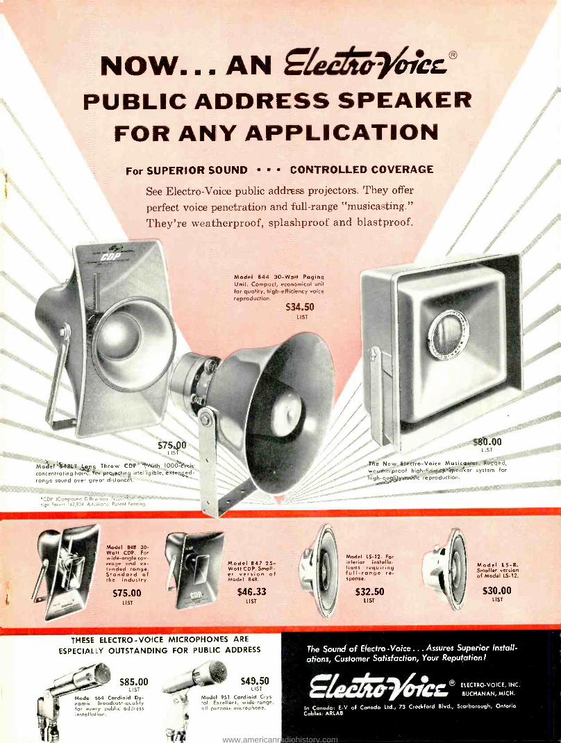
Now... AN giemej-rirka PUBLIC ADDRESS SPEAKER
FOR ANY APPLICATION For SUPERIOR SOUND CONTROLLED COVERAGE
See Electro -Voice public address projectors. They offer
perfect voice penetration and full -range "musicasting."
They're weatherproof, splashproof and blastproof.
Model 844 30 -Wore Paging Unit. Compact, economical unit for quality, high -efficiency voice reproduction.
534.50 LIST
575.00 S80.00
Model 8481.1 Long Throw CDP' With 1000 -cycle concentrating horny. for projecting intelligible, extended- range sound over great distances. ..
The New Electro -Voice Musicuster. Hueq. d, weatherproof high -fidelity speaker system for fiìgh- qualityrrtulîc reproduction-
..
r'
'CDP ICompound D fl ocn o roie ,n Potent 169904. Hddnfnnol Patent Pending.
Model 848 30- Watt CDP. For wide- onglecov- erage and ex- tended range. Standard of the industry.
$75.00 LIST
Model 847 25- Watt CDP. Small- er version of Model 848.
$46.33 LIST
Model LS -12. For interior installa- tions requiring full -range re- sponse.
$32.50 LIST
Model LS -8. Smaller version of Model LS -12.
$30.00 LIST
THESE ELECTRO -VOICE MICROPHONES ARE
ESPECIALLY OUTSTANDING FOR PUBLIC ADDRESS
LIST
Model 664 Cardioid Dy- namic. Broadcast-quality
$49.50 LIST
Model 951 Cardioid Crys- tal. Excellent, wide -range, all purpose microphone.
The Sound of Electro- Voice... Assures Superior Install- ations, Customer Satisfaction, Your Reputation!
g'kettp- Incr.® BUCH NAN I MICH.0
In Canada: E -V of Canada Ltd., 73 Crockford Blvd., Scarborough, Ontario Cables. ARLAB
www.americanradiohistory.com

IF IT'S AN RSA TÚBE...IT HAS TO BE "HEALTHY "!
RCA specializes in the production of "healthy" tubes. Take the RCA- 6AX4 -GT, for example. It features important built -in safety factors that minimize internal breakdowns and "arc- over ", reducing early -hour failures -while providing reliable performance in TV damper circuits. Here are some of the ways RCA builds this "good health" into the 6AX4 -GT:
Heater wire has been specially developed to improve welds, thereby reducing early -hour failures due to an open circuit at the weld point. Heater -spacer assemblies are pre -fired to eliminate leakage -producing contamination during tube production. And micas are specially sprayed to control plate -to- cathode leakage.
These are some of the reasons why many designers and manufacturers of TV sets specify RCA's 6AX4 -GT -the very same reasons why you should always ask your RCA Tube Distributor to "Ship RCA Only "'
OM RADIO CORPORATION OF AMERICA Electron Tube Division Harrison, N. J.
RCA Technical Booklet Available
RCA Receiving Tubes and Pic- ture Tubes for AM, FM,and Tel. evisian Broadcast (1275.H) ... includes socket informa- tion and useful data for more than 700 tube types. Ask your RCA Tube Distributor for your copy today!
www.americanradiohistory.com