Embed Size (px)
Citation preview
MULTI-OUTPUT
DC REGULATED POWER SUPPLY
This series include two-way and three-way DC regulated power supply. Three-way
have high accuracy output, of which two way are adjustable and one way is fixed.
The two adjustable outputs can be selected for constant voltage (C.V.) or constant
current (C.C.), designed in high stability and performance circuit. In constant
voltage operation mode, the output voltage can be arbitrarily adjusted from 0V on
in the nominal range. In constant current operation mode, the output current can be
adjusted from 0A on in the nominal range.
The two outputs can be connected in parallel or in series, while the master adjust
controls the voltage and current setting. The fixed output voltage is 5V. This output
features good stability and low ripple along with overload (e.g. short circuit)
protection.
The unit features small size and excellent performance combined with an elegant
design, being ideal for research, university, industry and appliance maintenance
laboratories.
1. TECHNICAL SPECIFICATION:
1.1 Input voltage: 110VAC or 220VAC 60Hz or 50Hz
1.2 Two adjustable outputs
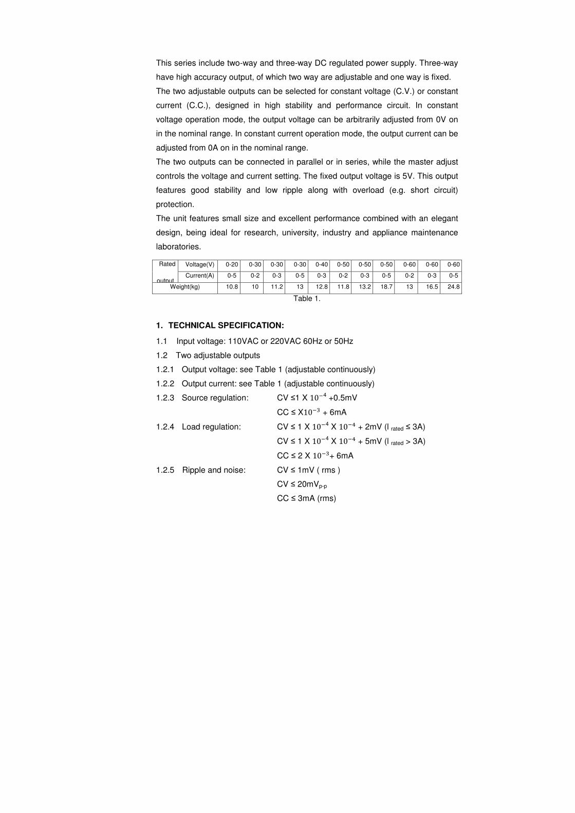
1.2.1 Output voltage: see Table 1 (adjustable continuously)
1.2.2 Output current: see Table 1 (adjustable continuously)
1.2.3 Source regulation: CV ≤1 X 10�4 +0.5mV
CC ≤ X10�� + 6mA
1.2.4 Load regulation: CV ≤ 1 X 10�4 X 10�� + 2mV (l rated ≤ 3A)
CV ≤ 1 X 10�4 X 10�� + 5mV (l rated > 3A)
CC ≤ 2 X 10��+ 6mA
1.2.5 Ripple and noise: CV ≤ 1mV ( rms )
CV ≤ 20mVp-p
CC ≤ 3mA (rms)
Rated
output
Voltage(V) 0-20 0-30 0-30 0-30 0-40 0-50 0-50 0-50 0-60 0-60 0-60
Current(A) 0-5 0-2 0-3 0-5 0-3 0-2 0-3 0-5 0-2 0-3 0-5
Weight(kg) 10.8 10 11.2 13 12.8 11.8 13.2 18.7 13 16.5 24.8
Table 1.
CC ≤ 50 mA p-p
1.2.6 Protection: current-limiting protection
1.2.7 Indication: Voltmeter & Ammeter;
or 3-digit Volt-LCD(LED) & Amp-LCD(LED) .
a. Volt-indication: LCD (LED) ±1%±2digits; meter class of 2.5 (F.S.)
b. Amp-indication: LCD (LED) +2%±2digits; meter class of 2.5 (F.S.)
1.3 Fixed output:
1.3.1 Output voltage: 5V±3%
1.3.2 Output current: 3A
1.3.3 Source regulation: ≤ 1 X 10�� + 1mV
1.3.4 Load regulation: ≤ 1 X 10��
1.3.5 Ripple & noise: ≤ 0.5mV (rms)
≤10mV p-p
1.3.6 Protection: current-limiting & short-circuit protection.
1.4 Operating ambient:
1.4.1 Operating temperature: 0 to +40ºC
1.4.2 Relative humidity: less than 90%
1.5 Size: 360mm X 265mm X 165mm
1.6 Operating time: 8 hours continuously
2. OPERATION
2.1. Controls and description of front-panel
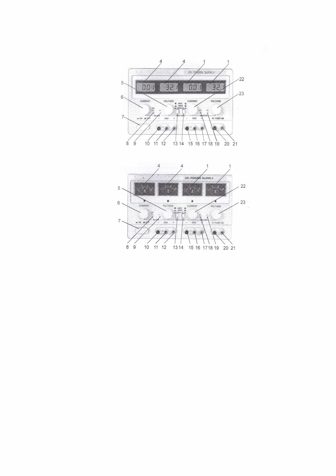
(1) Meter or LCD (LED): indicates master output voltage and current value.
(2) Master output selector: select the voltage or current of the master.
(3) Slave output selector: select the voltage or current of the slave.
(4) Meter or LCD (LED): indicates slave output voltage and current value.
(5) Slave constant voltage adjustment: adjust slave output voltage value.
(6) Slave constant current adjustment: adjust slave output current value,
(adjust the current-limiting protection point)
(7) Power switch: It is set to “ON” state (the switch is pressed in) , the unit is
switched on, at this time, the constant voltage (C.V.) or constant current
(C.C.) indicator is on, otherwise, the unit is in “OFF” state (the switch is
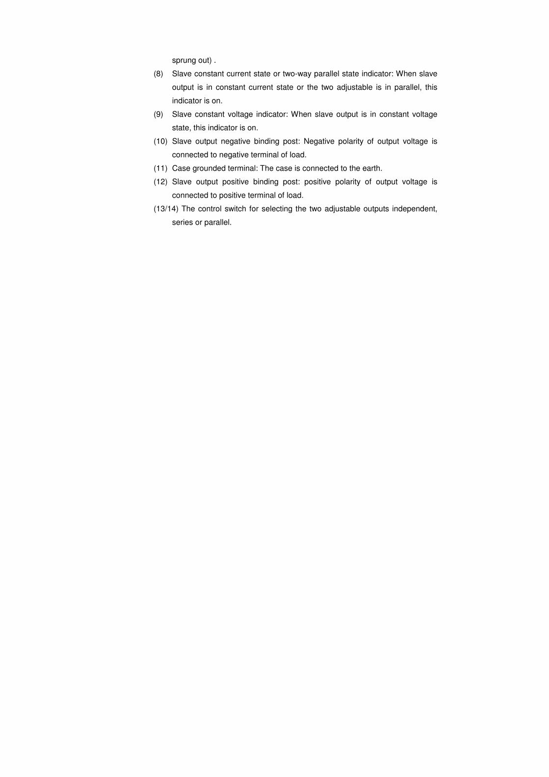
sprung out) .
(8) Slave constant current state or two-way parallel state indicator: When slave
output is in constant current state or the two adjustable is in parallel, this
indicator is on.
(9) Slave constant voltage indicator: When slave output is in constant voltage
state, this indicator is on.
(10) Slave output negative binding post: Negative polarity of output voltage is
connected to negative terminal of load.
(11) Case grounded terminal: The case is connected to the earth.
(12) Slave output positive binding post: positive polarity of output voltage is
connected to positive terminal of load.
(13/14) The control switch for selecting the two adjustable outputs independent,
series or parallel.
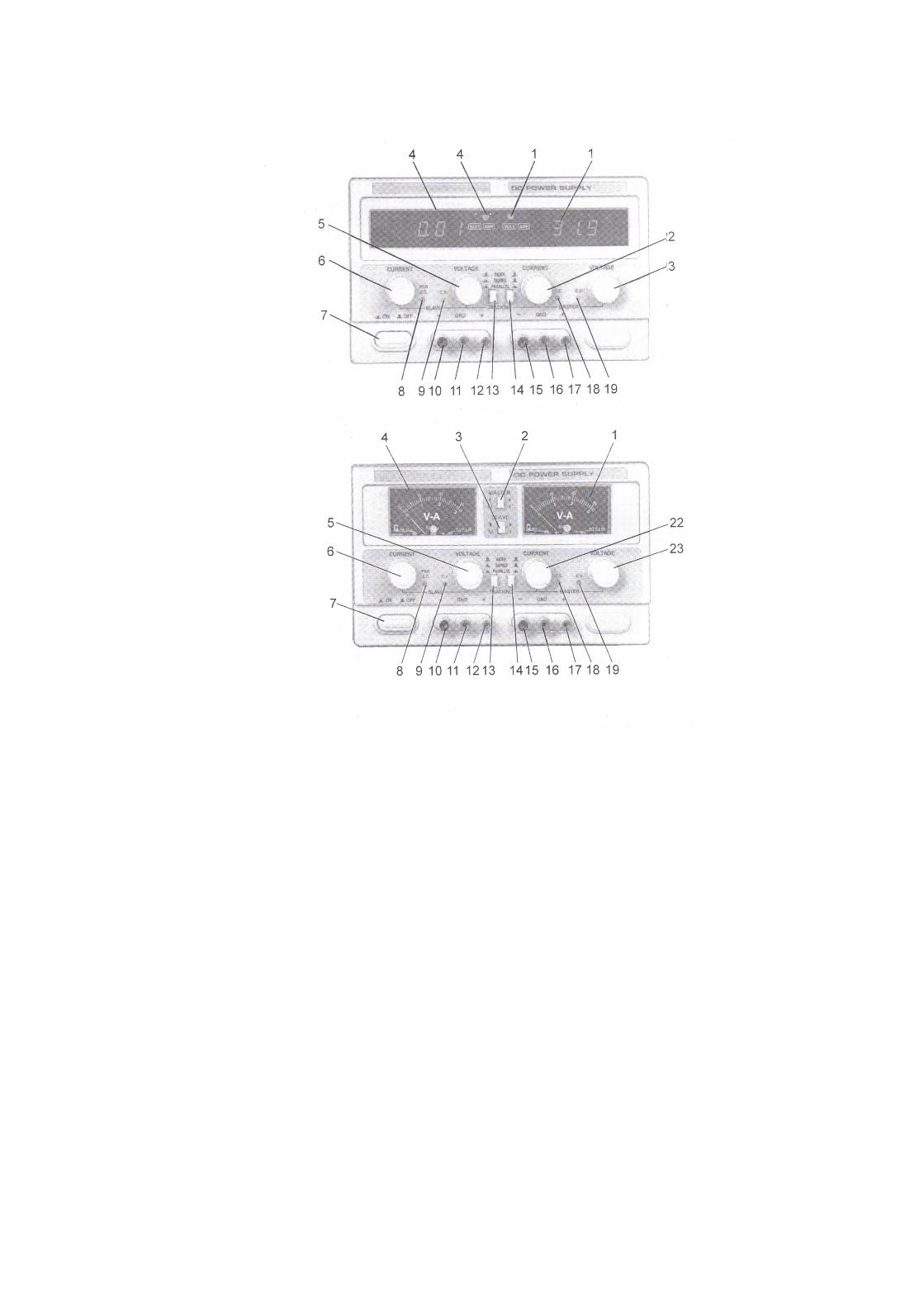
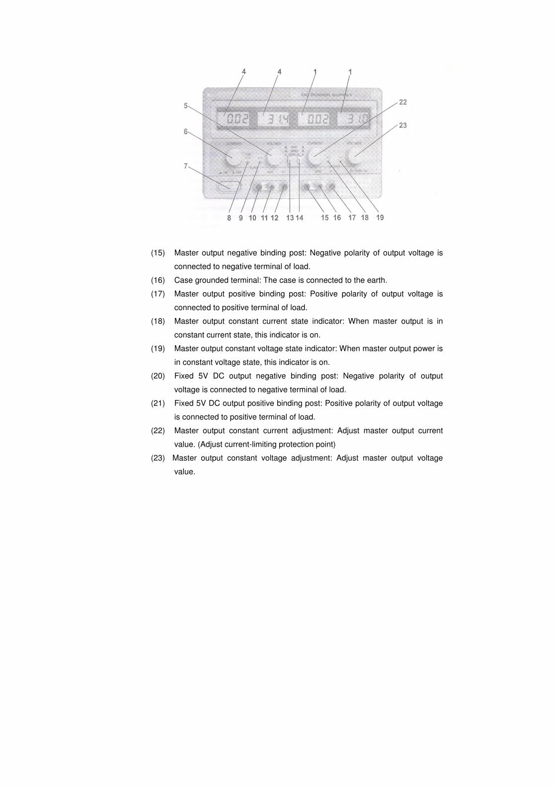
(15) Master output negative binding post: Negative polarity of output voltage is
connected to negative terminal of load.
(16) Case grounded terminal: The case is connected to the earth.
(17) Master output positive binding post: Positive polarity of output voltage is
connected to positive terminal of load.
(18) Master output constant current state indicator: When master output is in
constant current state, this indicator is on.
(19) Master output constant voltage state indicator: When master output power is
in constant voltage state, this indicator is on.
(20) Fixed 5V DC output negative binding post: Negative polarity of output
voltage is connected to negative terminal of load.
(21) Fixed 5V DC output positive binding post: Positive polarity of output voltage
is connected to positive terminal of load.
(22) Master output constant current adjustment: Adjust master output current
value. (Adjust current-limiting protection point)
(23) Master output constant voltage adjustment: Adjust master output voltage
value.
2.2 Operating procedure:
2.2.1 Independence use of two adjustable outputs.
2.2.1.1 Set the (13) and (14) switch to spring out position ( position).
2.2.1.2 When the adjustable output is used as C.V. output, first should rotate
clockwise the C.C. adjustment (6) and (22) to Max., then turn on power
switch (7) , adjust C.V. adjustment (5) and (23) till slave & master DC
output voltage reach required voltage value, at this time, the C.C indicator
(9) and (19) light on.
2.2.1.3 Used as C.C. output, after turning on power switch (7), first rotate
clockwise the C.V. adjustment (5) and (23) to Max., while rotate
counterclockwise the C.C. adjustment (6)and (22)to Min., then connect the
required load, again rotate clockwise adjustment (6) and (22) till output
current reach the required current value. At this time, the C.V. state
indicator (9) and (19) go out and the C.C. state indicator (8) and (18) light
on.
2.2.1.4 Used as the C.V. output, in general the C.C. adjustment (6) and (22)
should be set to Max., but for this unit, the current-limiting protection point
can also be set arbitrarily. Setting procedure is: Turn on power, rotate
counterclockwise the C.C. adjustment (6) and (22) to Min., then make the
positive and negative output terminal in short connection and rotate
clockwise the C.C. adjustment (6) and (22) till output current equal to the
required current-limiting protection point, so the current-limiting protection
point is well set.
2.2.2 Series using of the two adjustable outputs
2.2.2.1 Press in switch (13) ( . position) .switch (14) is set to “OUT” position
( position). At this time, turn the master voltage adjustment (23) and
the slave output voltage tracks strictly the master output voltage, and the
output voltage can be up to 60V (voltage between terminal of (10) and (17)
) .
2.2.2.2 Before the series connecting, it must be examined if the negative terminals
of both master and slave output are connected to GND terminal, if they
are, it must be disconnected, otherwise, short-circuit will be caused in the
slave output when the two outputs are connected in series.
2.2.2.3 When the two outputs are in series, the output voltage is controlled by
master output, but current adjustment of two outputs is still independent.
Therefore, attention should be paid to the position of the C.C adjustment
(6)'. For example, knob (6) is at the position of counterclockwise to end or
current of slave output excesses current-limiting protection point, at this
time, the voltage of slave output will not track the voltage of master. So
knob (6) should be rotated clockwise to Max. When the two output are in
series.
2.2.2.4 By series connection, if there is power output, proper leads corresponding
to output power should be used to short connect the negative terminal of
master output with positive terminal of slave output reliably. Since it is
shorted by a switch inside the unit, current will pass on the shorted switch
when there is power output. This will affect the reliability of the unit.
2.2.3 Parallel using of the two adjustable outputs
2.2.3.1 Press in switch (13) ( position) as well as switch (14) ( position) ,
at this time, the two outputs are in parallel, adjust voltage adjustment (23)
of master output, the voltage of two ways keep same, and slave output
C.C. indicator (8) lights on.
2.2.3.2 When the two outputs are in parallel, the C.C. adjustment (6) of slave
output does not work. When used as C.C. supply, simply adjust the C.C.
adjustment (22) of master output, at this time, output current of both
master and slave output are controlled by it and are same, output current
is up to 6A.
2.2.3.3 While the two outputs in parallel, proper leads corresponding to output
power be used to short reliably the two positive terminals and the two
negative terminals of master & slave output separately, so as to make load
connected reliably with the two parallel outputs. If the load is only
connected to one of the output terminal, unbalance may be caused to
current of the two outputs, this may also damage the series/parallel switch.
2.3 The digital display is in 3-digit. If you need more accurate indication,
please use more precise measuring instrument to calibrate it in outer
circuit.
2.4 Cautions
2.4.1 The unit has perfect protection function, 5V output has reliable protection
for current- limiting and short circuit. The two adjustable outputs have
current-limiting protection. As there is controlling circuit for regulating
transistor's power loss in the circuit, when short circuit occurs, power loss
on large power transistor is not very high, it can not cause any damage to
the unit. But there is still power loss when short circuit, in order to reduce
aging and energy consumption, so this situation should be find as soon as
possible and turn off power, then exclude the faults.
2.4.2 After operating, put the unit in a dry place of good ventilation, and keep it
clean. If it is not in use for a long period, pull off the power supply plug for
storage.
2.4.3 For maintenance, input voltage must be cut off.
2.4.4 The faults may be caused by the improper operation or abnormal
operating ambient and component failure inside the unit. When the faults
occur, the output voltage maybe exceed max. rated output voltage. TAKE
CARE WHEN OPERATION AND AVOID UNNECESSARY DAMAGE OF
LOAD.
2.4.5 For safety operation, the 3-pin ground terminal of power cord must
be grounded securely.