Embed Size (px)
Citation preview
Visit analogcomVisit analogcom
DCDC CONTROLLER Selection Guide
ADI provides complete power solutions with a full lineup of power management products This brochure shows an overview of our high performance DCDC switching regulator controllers for applications including industrial datacom telecom automotive computing infrastructure and consumer electronics We make power design easier with our LTpowerCADreg and LTspicereg simulation programs and our industry-leading field application engineering support A broad selection of demonstration boards are available which includes layout and bill of material files application notes and comprehensive technical documentation
2 DCDC Controller
LTpowerCAD 3LTpowerCAD Power Supply Design Tool
LTspice 4Benefits of Using LTspiceLTspice Demo Circuits
Single Output Buck 5VIN Up to 22 V Down to 22 V 5VIN Up to 38 V 6VIN Up to 60 V 7VIN Up to 150 V 8
Hybrid 9
Multiphase Single Output Buck 10
Multiple Output Buck 11
Boost 12
Buck-Boost 13
BuckBuckBoostmdashIdeal for Automotive Start-Stop Systems 14
LED Drivers 15
Bidirectional 16
SEPIC 18
Inverter 19
Switching Surge Stoppers 20
Isolated Forward Half-Bridge Full-Bridge and Push-Pull 21
Flyback 22
Multiple Topology 23
DDRQDR Memory Termination 24
MOSFET Drivers 25
Digital Power System Management 26
LTpowerPlay 27
Contents
Visit analogcom 3
LTpowerCAD
LTpowerCAD is an easy-to-use power supply design tool with a user-friendly graphical user interface and power design features It supports many power products by Linear Technology now part of Analog Devices Inc Currently most products in the LTpowerCAD tool are for nonisolated switching mode power supplies The LTpowerCAD tool helps power supply designers select a solution for given supply specifications design power stage components estimate supply efficiency and power loss and optimize supply loop stability
and load transient performances Once a circuit design is completed it can be easily exported to the LTspice simulation platform Within the LTpowerCAD program there is also a LTpowerPlannerreg architecture tool for system-level power management design and optimization
The LTpowerCAD program is free download at httpwwwanalogcomLTpowerCAD website and runs on Microsoft Windows 7 or 10 based PC
LTpowerCAD Power Supply Design Tool
LTpowerPlanner Power Tree ExampleSearching a Part in LTpowerCAD
LTpowerCAD X Powerful and Easy-to-Use X Developed by Power Experts X Bench Verified Models X Free Download
wwwanalogcomLTpowerCAD
4 DCDC Controller
LTspice
LTspicereg is a high performance SPICE simulation software schematic capture and waveform viewer with enhancements and models for easing the simula-tion of analog circuits Included in the download of LTspice are macromodels for a majority of Analog Devicesrsquo switching regulators amplifiers as well as a library of devices for general circuit simulation
Benefits of Using LTspice
Our enhancements to SPICE have made simulating switching regulators extremely fast compared to normal SPICE simulators allowing the user to view waveforms for most switching regulators in just a few minutes
Features
X Free Download X Stable SPICE Circuit Simulation
bull Unlimited NodesNets
bull SchematicSymbol Editor
bull Waveform Viewer
bull Library of Passive Devices
X Fast Simulation of Switching Mode Power Supplies (SMPS)
bull Steady State Detection
bull Turn On Transient
bull Step Response
bull EfficiencyPower Computations
X Advanced Analysis and Simulation Options
Download LTspice
Download our LTspice simulation software for the following operating systems
Download for Windows 7 8 and 10
Download for Mac OS X 107+
Download for Windows XP (End of Support)
LTspice Demo Circuits X LTspice provides macromodels for most of Analog Devicesrsquo switching regulators linear regulators amplifiers as well as a library of devices for
general circuit simulation
X Selected Analog Devices devices also have demonstration circuits available for free download These demo circuits are designed to ensure proper performance and have been reviewed by Analog Devicesrsquo factory applications group
X Over 1100 macromodels of ADI products
X 500+ SMPS
Visit analogcom 5
LTC3852
Features
X Charge Pump Input Range 27 V to 55 V
X Controller Input Range 4 V to 38 V
X Integrated Charge Pump Provides 5 V Gate Drive to Logic Level MOSFETs
X RSENSE or DCR Current Sensing
X plusmn125 Output Voltage Accuracy Over Temperature
Single Output Buck
ADIrsquos single output buck step-down DCDC controllers provide up to 98 efficient step-down conversion Output voltages are from 06 V with currents up to 60 amps Features include synchronous or nonsynchronous operation onboard MOSFET drivers low quiescent current tracking tight reference voltage accuracy optional sense resistor current mode or voltage mode control and selectable or synchronizable operating frequency ADI offers several hundred buck controllers The ones listed below are recommended for new designs
For a complete list visit wwwanalogcom
VIN Up to 22 V Down to 22 V
PGO0D
C+
Cndash
RUN
SHDN
TRACKSS
ITH
MODEPLLIN
FREQPLLFLTR
VIN1INTVCC
TG
SW
INTVCC
BG
SENSE+
SENSEndash
VFB
VPUMP
VIN2
GND2
GND1
01 microF
01 microF
47 microF
21 k
LTC3852
22 microF
VIN27 V TO 55 V
VOUT12 V20 A
3852 TA01
036 microH
100 pF
Charge Pump22 microF
1 nF
01 microF
100 k
470 microFtimes2
BOOST
121 k
402 k1
20 k1
953 k+
ONOFF
Part Number
VIN
Range (V)VOUT
Range (V)
IOUT1
Max (A) Operating Frequency2
IQ
(SUPPLY) Package Sync
hron
ous
Rect
ifica
tion
No R
SENS
E
Trac
king
Sync
hron
izab
le
Subl
ogic
Lev
el
MOS
FETs
Pow
er G
ood
Sign
al
Prog
ram
mab
le
Soft-
Star
t
Curr
ent (
I) or
Vo
ltage
( V)
Mod
e Co
ntro
lLTC3852 27 to 55 08 to 090 VIN 25 250 kHz to 750 kHz 7 mA 3x5 QFN-20 radic radic radic radic radic radic radic I
LT3740 22 to 22 08 to 077 VIN 20 300 kHz 25 mA DFN-16 radic radic radic I
LTC3830LTC3830-1 3 to 8 126 to
091 VIN20 100 kHz to 500 kHz 700 microA S8 SO-16 SSOP-16 radic radic radic radic V
LTC3832LTC3832-1 3 to 8 06 to 091 VIN 20 100 kHz to 500 kHz 700 microA SO-8 SSOP-16 radic radic radic radic V
AutomotivemdashLow Quiescent Current
LTC3822-1 275 to 45 06 to 099 VIN 20 300 kHz550 kHz750 kHz 105 microA DFN-12 SSOP-16 radic radic radic radic radic radic I
LTC3822 275 to 45 06 to 099 VIN 20 300 kHz550 kHz750 kHz 360 microA DFN-10 MSOP-10 radic radic radic I
LTC3772LTC3772B 275 to 98 08 to VIN 5 550 kHz 40 microA DFN-8 ThinSOT radic radic I
LTC3801LTC3801B 24 to 98 08 to VIN 5 550 kHz 16 microA ThinSOTtrade radic I
LTC3808 275 to 98 06 to VIN 5 250 kHz to 750 kHz 105 microA DFN-14 SSOP-16 radic radic radic radic radic I
LTC3809LTC3809-1 275 to 98 06 to VIN 5 250 kHz to 750 kHz 105 microA DFN-10 MSOP-10E radic radic radic radic radic I
1 The maximum output current depends on the choice of external components2 The operating frequency can be selected within the range indicated
Low Input Voltage Synchronous Step-Down Regulator
6 DCDC Controller
VIN Up to 38 V
Part Number
VIN
Range (V)VOUT
Range (V)
IOUT1
Max (A) Operating Frequency2
IQ
(SUPPLY) Package Sync
hron
ous
Rect
ifica
tion
Rem
ote
V O
Sens
ing
Sub
Mill
ie
OHM
DCR
Trac
king
Sync
hron
izab
le
Pow
er G
ood
Sign
al
Curr
ent (
I) or
Vo
ltage
( V)
Mod
e Co
ntro
l
Fixed FrequencyLTC3866 45 to 38 06 V to 35 V 40 250 kHz to 770 kHz 32 mA 4x4 QFN-20TSSOP-24 radic radic radic radic radic radic I
LTC3867 4 to 38 06 V to 14 V 30 200 kHz to 12 MHz 35 mA 4x4 QFN-24 radic radic radic radic radic I
LTC3854 45 to 38 08 to 55 25 400 kHz 2 mA 3x3 DFNMSOP-12 radic radic I
LTC3851ALTC3851-1 4 to 38 08 to 55 25 250 kHz to 750 kHz 1 mA QFN-16SSOP-16 radic radic radic I
LTC3775 45 to 38 06 to 08 VIN 25 250 kHz to 1 MHz 35 mA 3x3 QFN-12MSOP-16E radic radic radic V
Constant On-Time (Fast Transient)
LTC3833 45 to 38 06 to 55 30 200 kHz to 2 MHz 2 mA 3x4 QFN-20TSSOP-20 radic radic radic radic radic I
LTC3770 4 to 32 06 to 08 VIN 25 Constant On-Time 13 mA 5x5 QFN-32SSOP-28 radic radic radic radic radic I
LTC3878 4 to 38 08 to 09 VIN 25 Constant On-Time 15 mA SSOP-16 radic I
LTC3879 4 to 38 06 to 09 VIN 25 Constant On-Time 15 mA 3x3 QFN-12MSOP-16E radic radic radic I
AutomotivemdashLow Quiescent CurrentLTC7803 45 to 40 08 to 36 25 100 kHz to 3 MHz 8 microA 3x3 QFN-16MSOP-16E radic Releasing in 2019
LTC3807 4 to 38 08 to 24 25 75 kHz to 900 kHz 50 microA 3x4 QFN-20TSSOP-20 radic radic radic radic I
LTC3835LTC3835-1 4 to 36 08 to 10 25 140 kHz to 650 kHz 80 microA FE20 4x5 QFN GN 3x5 QFN radic radic radic radic I
LTC3834LTC3834-1 4 to 36 08 to 10 25 140 kHz to 650 kHz 30 microA FE20 4x5 QFN GN 3x5 QFN radic radic radic radic I
1 The maximum output current depends on the choice of external components2 The operating frequency can be selected within the range indicated
Additional Features All parts have peak or valley current mode control and a shut-down (run) pin
LTC3866A
Features
X Sub-Milliohm DCR Current Sensing
X High Efficiency Up to 95
X Selectable Current Sensing Limit
X Peak Current Mode Control
X Programmable DCR Temperature Compensation
X Remote VOUT Sensing
X plusmn 05 06 V Output Voltage Accuracy
X Programmable Fixed Frequency 250 kHz to 770 kHz
FREQ MODEPLLIN
RUN PGOOD
TKSS ITEMP
ITH EXTVCC
VFB VIN
DIFFOUT INTVCC
DIFFP BOOST
DIFFN TG
SNSD+ SW
SNSndash BG
3866 TA01a
VOUT15 V30 A
VIN45 V to 20 V
SNSA+ PGND
ILIM CLKOUT
LTC3866
SGNDDemonstration Board
Single Output Buck
High Efficiency 15 V30 A Step-Down Converter with Very Low DCR Sensing
6 DCDC Controller Visit analogcom 7
Part Number
VIN
Range (V) VOUT Range (V)
IOUT1
Max (A) Operating Frequency2
IQ
(SUPPLY) Package Sync
hron
ous
Rect
ifica
tion
No R
SENS
E
Trac
king
Sync
hron
izab
le
Shut
-Dow
n
Pow
er G
ood
Sign
al
Adju
stab
le
Turn
-On
Volta
ge
Curr
ent (
I) or
Vo
ltage
( V)
Mod
e Co
ntro
l
LTC3703-5 41 to 60 08 to 093 VIN 10 100 kHz to 600 kHz 17 mA SSOP-16 TSSOP-28 radic radic radic radic V
LTC3812-5 42 to 60 08 to 093 VIN 20 100 kHz to 1 MHz 3 mA TSSOP-16E radic radic radic radic I
LTC3810-5 42 to 60 08 to 093 VIN 20 100 kHz to 1 MHz 3 mA QFN-32 radic radic radic radic radic radic radic I
LTC3810 62 to 100 08 to 093 VIN 20 100 kHz to 1 MHz 3 mA SSOP-28 radic radic radic radic radic radic radic I
LTC3703 93 to 100 08 to 093 VIN 10 100 kHz to 600 kHz 17 mA SSOP-16 TSSOP-28 radic radic radic radic V
AutomotivemdashLow Quiescent CurrentLTC7800 4 to 60 08 to 24 25 320 kHz to 225 MHz 50 microA 3x4 QFN-20 radic radic radic radic radic I
LTC3891 4 to 60 08 to 24 20 50 kHz to 900 kHz 50 microA 3x4 QFN-20 TSSOP-20E radic radic radic radic radic I
LT3845A 4 to 60 123 to 36 20 100 kHz to 500 kHz 120 microA TSSOP-16E radic radic radic radic I
LTC3864 35 to 60 08 to VIN 5 50 kHz to 850 kHz 40 microA 3x4 QFN-12 MSOP-12E radic radic radic radic radic I
LTC3824 4 to 60 08 to VIN 5 200 kHz to 600 kHz 40 microA MSOP-10 radic I
LT3844 4 to 60 123 to 36 5 100 kHz to 500 kHz 120 microA TSSOP-16E radic radic radic I
LT3800 4 to 60 123 to 36 20 200 kHz 80 microA TSSOP-16E radic radic radic I
LT3840 25 to 60 125 to 60 20 50 kHz to 1 MHz 75 microA TSSOP-28 4x6 QFN-38
LTC3372 45 to 60 08 to 5 15 166 kHz to 500 kHz 1 MHz to 3 MHz 15 microA 7x7 QFN-48 60 V Controller with 4 Monolithic Bucks
1 The maximum output current depends on the choice of external components2 The operating frequency can be selected within the range indicated
Additional Features All parts have programmable soft-start
LTC7800
Features
X Wide VIN Range 4 V to 60 V (65 V Abs Max)
X Low Operating IQ 50 μA
X Wide Output Voltage Range 08 V le VOUT le 24 V
X RSENSE or DCR Current Sensing
X Phase-Lockable Frequency (320 kHz to 225 MHz)
X Programmable Fixed Frequency (320 kHz to 225 MHz)
X Selectable Continuous Pulse-Skipping or Low Ripple
X Burst Modereg Operation at Light Load
VIN
PGOOD
EXTVCC
INTVCC
PGND
FREQ
ITH
TRACKSS
SGND
TG
BOOST
SW
BG
SENSE+
SENSEndash
VFB
LTC7800
INTVCC
VIN4 V to
28 V
33 VVOUT
10 A
Demonstration Board with Gan FETs
High Efficiency 21MHz Step-Down Converter
Single Output Buck
VIN Up to 60 V
8 DCDC Controller
Part Number
VIN
Range (V) VOUT Range (V)
IOUT1
Max (A) Operating Frequency2
IQ
(SUPPLY) Package Sync
hron
ous
Rect
ifica
tion
No R
SENS
E
Trac
king
Sync
hron
izab
le
Shut
-Dow
n
Pow
er G
ood
Sign
al
Adju
stab
le
Turn
-On
Volta
ge
Curr
ent (
I) or
Vo
ltage
( V)
Mod
e Co
ntro
l
LTC3810 62 to 100 08 to 093 VIN 20 100 kHz to 1 MHz 3 mA SSOP-28 radic radic radic radic radic radic radic I
LTC3703 93 to 100 08 to 093 VIN 10 100 kHz to 600 kHz 17 mA SSOP-16 TSSOP-28 radic radic radic radic V
AutomotivemdashLow Quiescent Current
LTC7801 45 to 140 08 V to 60 V 20 50 kHz to 900 kHz 40 microA TSSOP-38 4x5 QFN-24 radic radic radic radic radic radic radic I
LTC3895 45 to 140 08 V to 60 V 20 50 kHz to 900 kHz 40 microA TSSOP-38 (31) radic radic radic radic radic radic radic I
LTC3894 45 to 150 08 V to 60 V 5 50 kHz to 850 kHz 27 microA TSSOP-20 (16) radic radic radic radic radic radic I1 The maximum output current depends on the choice of external components2 The operating frequency can be selected within the range indicated
Additional Features All parts have programmable soft-start
LTC7801
Features
X Wide VIN Range 4 V to 140 V (150 V Abs Max)
X Wide Output Voltage Range 08 V to 60 V
X Adjustable Gate Drive Level 5 V to 10 V (OPTI-DRIVE)
X Low Operating IQ 40 μA (Shutdown = 10 μA)
7801 TA01a
VIN
INTVCC
CPUMP_EN
ITH
SS
FREQ
GND
LTC7801
TG
SW
BG
SENSE+
SENSEndash
EXTVCC
VFB
BOOST
RUN
NDRV
DRVCC
VIN7 V to 140 V
VOUT12 V5 A
VOUT Follows VIN When VIN lt 12 V
Demonstration BoardHigh Voltage Synchronous Step-Down Regulator
Single Output Buck
VIN Up to 150 V
Visit analogcom 9
LTC7821 Hybrid Step-Down Synchronous Controller
Features
X Wide VIN Range 10 V to 72 V (80 V Abs Max)
X Soft Switching for 3times fSW 13 of Inductor Size
X Phase-Lockable Fixed Frequency 200 kHz to 15 MHz
X plusmn1 Regulated Output Voltage Accuracy
X RSENSE or DCR Current Sensing
X Programmable CCM DCM or Burst Mode Operation
X CLKOUT Pin for Multiphase Operation
Demonstration Board (300W)
LTC7820 Fixed Ratio High Power Inductorless (Charge Pump) Controller
Features
X Low Profile High Power Density Capable of 500 W+
X Soft Switching 99 Peak Efficiency and Low EMI
X VIN Max for Voltage Divider (21) 72 V
X VIN Max for Voltage Doubler (12)Inverter (11) 36 V
X Non-Regulated Output
X Soft Start-Up into Steady State Operation
Demonstration Board (240W)
Hybrid and Switched Capacitor DCDC
A hybrid step-down controller combines a switched capacitor circuit with a synchronous step-down controller enabling up to a 50 reduction in DCDC converter solution size compared to traditional step-down solutions This improvement is enabled by a 3X higher switching frequency without compromising efficiency Alternatively when operating at the same frequency an LTC7821 based solution can provide up to a 3 higher efficiency Other benefits include low EMI and reduced MOSFET stress due to a soft-switched front end The LTC7821 is ideal for nonisolated intermediate bus applications in power distribution datacom and telecom as well as emerging 48 V automotive systems
VIN_SENSE VIN
TIMER
FREQ
EXT_REF
FAULT
PGOOD
ITH
EXTVCC
VFB ISNS+
ISNSndash
PGND
INTVCC
BG2
SW3
BOOST3
TG2
MID_SENSE
MID
BOOST2
BG1
SW1
BOOST1
LTC7821
7821 TA01a
TG1
VIN36 V to 72 V
INTVCC
VOUT12 V20 AINTVCC
PGOOD
FAULT
+
+
7820 TA01a
VCCVHIGH_SENSE
UV
HYS_PRGM
PGOOD
FREQ
FAULT GND
INTVCC
G3
G4
INTVCC
TIMER G2
LTC7820
BOOST3
SW3
VLOW_SENSE
VLOW
BOOST2
BOOST1
SW1
G1
INTVCCEXTVCC
RUN
ISENSE+
ISENSEndash
VIN48 V24 V
VOUT20 V10 V or12 V20 A
Load Current Applied After Startup
Part Number
VIN
Range (V)VOUT
Range (V)IOUT
1
Max (A) Operating Frequency2IQ
(SUPPLY) Package Outp
ut V
olta
ge
Regu
latio
n
No R
SENS
E
Sync
hron
izab
le
Shut
dow
n
Pow
er G
ood
Sign
al
Adju
stab
le
Turn
-On
Volta
ge
LTC78203 6 to 72 Note 3 15 100 kHz to 1 MHz 15 mA 4x5 QFN-28 radic radic radic radic radic
LTC7821 10 to 72 09 to 335 25 200 kHz to 15 MHz 05 mA 5x5 QFN-28 radic radic radic radic radic1 The maximum output current depends on the choice of external components2 The operating frequency can be selected within the range indicated3 21 for voltage divider 12 for voltage doubler 11 for inverter
Hybrid Step-Down Synchronous Regulator
Very High Efficiency 240 W Voltage Divider (VOUT = VIN2)
10 DCDC Controller
LTC7851
Features
X Operates with Power Blocks DrMOS or External Gate Drivers and MOSFETs
X Voltage Mode Control with Accurate Current Sharing
X plusmn075 06 V Voltage Reference
X Quad Differential Output Voltage Sense Amplifiers
X Multiphase Capability
X Phase-Lockable Fixed Frequency 250 kHz to 225 MHz
X Lossless Current Sensing Using Inductor DCR or Precision Current Sensing with Sense Resistor or DrMOS with Integrated Current Sensing
Demonstration Board
Multiphase Single Output Buck
The multiphase single output step-down controllers from ADI can be implemented with external power MOSFETs DrMOS or power blocks Multiphase operation clocks multiple DCDC converter sections out-of-phase This significantly reduces the input and output ripple currents resulting in higher efficiency lower EMI and smaller input and output filtering components
DrMOS DrMOS
VOUT110 V90 A
VCCVCC5 V
VIN7 V to14 V
VOUT215 V30 A
7851 TA01
PWM3
VINSNS
ISNS3PISNS3N
PWM4
ISNS4PISNS4NVSNSP4VSNSN4VSNSOUT4
COMP4FB4
ILIM4
FREQ
PWM2
ISNS2PISNS2N
PWM1
ISNS1PISNS1NVSNSP1VSNSN1
VSNSOUT123
COMP123
ILIM123
IAVG123
SGND
FB1
TRACKSS3RUN3RUN2 TRACKSS2
PGOOD4
TRACKSS1
PGOOD1
RUN1
V CCFB23
LTC7851
+DrMOS
DrMOS
DrMOS
DrMOS
+
Part Number
VIN
Range (V) VOUT Range (V) IOUT1 Max (A)
Number of Phases Operating Frequency2 Comments Package
LTC3856 45 to 38 06 to 55 50 to 300 2 to 12 250 kHz to 770 kHz Fixed Frequency 5x5 QFN-32 TSSOP-38
LTC3839 45 to 38 06 to 55 40 to 240 2 to 12 250 kHz to 2 MHz Constant On-Time 5x5 QFN-32
LTC3829 45 to 38 06 to 5 75 to 150 3 to 6 250 kHz to 770 kHz Fixed Frequency 5x6 QFN-36
LTC3861 3 to 24 06 to 45 60 to 360 2 to 12 Up to 225 MHz DrMOS in the Power Stage 5x6 QFN-36
LTC3774 45 to 38 06 to 35 60 to 360 2 to 12 250 kHz to 12 MHz DrMOS in the Power StageSub-Milliohm DCR Sensing 5x6 QFN-36
LTC7851 3 to Note 3 06 to 5 120 to 360 4 to 12 250 kHz to 22 MHz DrMOS in the Power Stage 5x6 QFN-36
LTC7852 Releasing in 2019 6 to 12
1 The maximum output current depends on the choice of external components and number of phases2 The operating frequency can be selected within the range indicated
Additional Features bull All parts have differential VO sensing shut-down (run) pin clock input programmable soft-start and a power good signal
bull All parts are peak current mode controllers except for the LTC7851 and LTC7852 which are voltage mode control
bull Multiple parts can be paralleled for its higher current applications
Four-Phase Synchronous Step-Down Regulator
Visit analogcom 11
Part Number
VIN
Range (V)VOUT Range
(V) IOUT1 Max (A)
Operating Frequency2
IQ
(SUPPLY) Package Num
ber o
f Out
puts
Max
imum
o
f Pha
ses
Rem
ote
Sens
e
Trac
king
Sync
hron
izab
le
EXTV
CC
Curr
ent (
I) or
Vol
tage
( V)
Mod
e Co
ntro
l
DrM
OSP
ower
Blo
ck
Com
patib
le
Sub
Mill
i Ohm
DC
R Se
nsin
g
Pres
et O
utpu
t Vol
tage
s
Adju
stab
le G
ate
Driv
e
LTC3850-1-2 45 to 30 08 to 55 2525 250 kHz to 780 kHz 850 microA QFN-28 SSOP-28 2 2 radic radic radic I
LTC3838-1-2 45 to 38 06 to 55 2525 200 kHz to 2 MHz 3 mA QFN-38 TSSOP-38 2 12 radic radic radic radic I
LTC3855 45 to 38 06 to 33 (12) 2525 250 kHz to 770 kHz 35 mA QFN-38 TSSOP-38 2 12 radic radic radic radic I
LTC3869-2 4 to 38 06 to 125 2525 250 kHz to 780 kHz 3 mA QFN-28 SSOP-28 2 2 radic radic radic I
LTC3853 45 to 24 08 to 135 252525 250 kHz to 750 kHz 41 mA QFN-40 3 12 radic radic radic I
LTC3774 45 to 38 06 to 35 4040 200 kHz to 12 MHz 9 mA QFN-36 2 12 radic radic radic I radic radic
LTC3861-1 3 to 24 06 to 45 4040 Up to 225 MHz 30 mA QFN-36 2 12 radic radic radic V radic radic
LTC3865 45 to 38 06 to 5 2525 250 kHz to 770 kHz 3 mA QFN-32 TSSOP-38 2 2 radic radic radic I radic
LTC3875 45 to 38 06 to 5 4040 250 kHz to 720 kHz 7 mA QFN-40 2 12 radic radic radic radic I radic
LTC7851 3 to 27 06 to 5 30303030 250 kHz to 225 MHz 60 mA 5x9 QFN-58 4 12 radic radic radic radic V radic radic
LTC7852 45 to Note (3) 05 to 2 120120 200 kHz to 12 MHz 15 mA 4x5 QFN
5x6 GQFN 2 6 radic radic I radic radic radic
Low IQLTC3890-1-2-3 4 to 60 08 to 24 2525 50 kHz to 900 kHz 50 microA QFN-32 2 12 radic radic radic I
LTC3892-1-2 4 to 60 08 to 099 VIN
2525 75 kHz to 850 kHz 29 microA QFN-32TSSOP-28 2 12 radic radic radic I radic
LTC3858-1-2 4 to 38 08 to 24 2525 50 kHz to 900 kHz 170 microA QFN-32 2 12 radic radic radic I
LTC3857-1 4 to 38 08 to 24 2525 50 kHz to 900 kHz 50 microA QFN-32SSOP-28 2 12 radic radic radic I
LTC3868-1 4 to 24 08 to 14 2525 50 kHz to 900 kHz 170 microA QFN-32 2 2 radic radic radic I
LTC7810 45 to 140 1 to 60 2525 50 kHz to 750 kHz 16 microA 7x7 eLQFP 2 2 radic radic radic I
SlavesLTC3870-1 45 to 60 05 to 14 2525 100 kHz to 1 MHz 11 mA QFN-28 2 12 radic radic radic I
LTC3874-1 45 to 38 05 to 55 2525 250 kHz to 1 MHz 46 mA QFN-28 2 12 radic radic radic I radic1 The maximum output current depends on the choice of external components2 The operating frequency can be selected within the range indicated
Additional Features All parts have a shut-down (run) pin and a power good signalAll parts are synchronous controllersAll parts have programmable soft-startAll parts have RSEN or DCR current sense
Multiple Output Buck
ADIrsquos multiple output DCDC controllers provide up to three high current outputs with up to 98 efficiency Features include out-of-phase operation onboard MOSFET drivers synchronous or nonsynchronous rectification low quiescent current tracking tight VREF accuracy and choice of current sense resistor Other options include selectable synchronizable switching frequency or constant on-time tracking spread spectrum and extra an LDO output voltage
LTC3850
Features
X Dual 180deg Phased Controllers Reduce Required
X Input Capacitance and Power Supply Induced Noise
X High Efficiency Up to 95
X RSENSE or DCR Current Sensing
Demonstration Board
VOUT133 V
5 A
VOUT225 V5 A
TG1 TG2
BOOST1 BOOST2
SW1 SW2
BG1 BG2
SGND
PGNDFREQPLLFLTR
SENSE1+ SENSE2+
RUN2SENSE1ndash SENSE2ndash
VFB1 VFB2ITH1 ITH2
VIN PGOOD INTVCC
TKSS1 TKSS2
VIN7 V to24 V
LTC3850
MODEPLLINILIM
RUN1
Dual Output 2-Phase Synchronous Step-Down Regulator
12 DCDC Controller
LTC3787
Features
X 2-Phase Operation Reduces Required Input and Output Capacitance and Power Supply Induced Noise
X Synchronous Operation for Highest Efficiency and Reduced Heat Dissipation
X Wide VIN Range 45 V to 38 V (40 V Abs Max) and Operates Down to 25 V After Start-Up
X Output Voltage Up to 60 V
X plusmn1 1200 V Reference Voltage
X RSENSE or Inductor DCR Current Sensing
X 100 Duty Cycle Capability for Synchronous MOSFET
X Low Quiescent Current 135 μA
X Phase-Lockable Frequency (75 kHz to 850 kHz)
Demonstration Board
Boost
ADI offers both synchronous and nonsynchronous boost controllers Features include optional sense resistor onboard LDO multiphase operation high power gate driver programmable fixed switching frequency and low quiescent current Efficiencies up to 97 can be achieved with synchronous rectification
VOUT24 V at 10 A
VINVIN 45 V to 24 V Start-up Voltage
Operates Through Transients Down to 25 V
TG1
BOOST1
SW1
BG1
FREQ
SS SGND
SENSE1+
SENSE1ndash
VFB
ITH
VBIAS
LTC3787
INTVCC
PLLINMODE
TG2
BOOST2
SW2
BG2
SENSE2+
SENSE2ndash
PGND
3787 TA01a
Part Number VIN Range (V) VOUT1 Range (V) IOUT
1 Max (A) IQ (SUPPLY) Operating Frequency2 Package
AutomotivemdashLow Quiescent CurrentSingle PhaseSingle Output Synchronous BoostLTC7804 45 to 40 Up to 60 10 15 microA 100 kHz to 3 MHz Releasing in 2019
LTC3786 45 to 38 Up to 60 10 55 microA 50 kHz to 900 kHz 3x3 QFN-16 MSOP-16E
LTC3769 45 to 60 Up to 60 10 28 microA 50 kHz to 900 kHz 4x4 QFN-24 TSSOP-20
Multiphase Synchronous BoostLTC3787 45 to 38 Up to 60 10 (120) 135 microA 50 kHz to 900 kHz 4x5 QFN-28 TSSOP-28
LTC3788LTC3788-1 45 to 38 Up to 60 1010 Dual VOUT 125 microA 50 kHz to 900 kHz 5x5 QFN-32 SSOP-28
LTC3784 45 to 60 Up to 60 20 28 microA 50 kHz to 900 kHz 4x5 QFN-28 SSOP-28
LTC3897LTC3897-1 45 to 65 Up to 60 20 555 microA 100 kHz to 1 MHz 5x7 QFN-38 TSSOP-38
LTC7841 2-Phase PSM Releasing in 2019 Releasing in 2019
Single Output Multiphase Nonsynchronous BoostLTC3862LTC3862-1LTC3862-2 4 to 36 5 and Higher 5 (60) 18 mA 75 kHz to 500 kHz 5x5 QFN-24 SSOP-24
Dual Output Multiphase Nonsynchronous BoostLTC7840 55 to 60 6 V and Higher 33 3 mA 50 kHz to 450 kHz 4x5 QFN-28 SSOP-28
Single Output Nonsynchronous BoostLTC1872LTC1872B 25 to 98 33 and Higher 3 270 microA 550 kHz SOT-23
LTC3872LTC3872-1 275 to 98 Up to 60 wo RSENSE and Higher wRSENSE
3 250 microA 550 kHz SOT-23 2x3 DFN-8
LT3757A 29 to 40 33 and Higher 3 16 mA 100 kHz to 1 MHz 3x3 DFN-10 MSOP-10
LT3758A 55 to 100 6 and Higher 3 175 mA 100 kHz to 1 MHz 3x3 DFN-10 MSOP-10
LT3759 16 to 42 22 and Higher 3 350 microA 100 kHz to 1 MHz 3x3 DFN-10 MSOP-10
LTC1871LTC1871XLTC1871-1 25 to 36 33 and Higher 3 250 microA 50 kHz to 1 MHz MSOP-10
LTC1871-7 6 to 36 7 and Higher 3 280 microA 50 kHz to 1 MHz MSOP-10
1 The maximum voltage and current depend on the choice of external components2 The operating frequency can be selected within the range indicated
12 V to 24 V10 A 2-Phase Synchronous Boost Converter
Visit analogcom 13
LTC3779
Features
X 4-Switch Current Mode Single Inductor Architecture Allows VIN Above Below or Equal to VOUT
X Wide VIN Range 45 V to 150 V
X Wide Output Voltage Range 12 V le VOUT le 150 V
X Synchronous Rectification Up to 99 Efficiency
Buck-Boost
High performance 4-switch synchronous buck-boost controllers operate from an input voltage that can be above below or equal to the output voltage These buck-boost controllers utilize a single inductor and can deliver efficiencies up to 98 The buck+boost utilize two inductors
3779 TA01a
FREQ
IAVGSNSN
IAVGSNSP
ITH
RUN
SENSEN
SENSEP
SS
VFB
VINOV
VINSNS
VOUTSNS
BOOST1
BOOST2
DRVCC
NDRV
PGNDSGND
SW1
SW2
V5
VIN
TG1BG1
BG2
TG2
LTC3779
VIN20 V TO
120 VVOUT48 V10 A
Part Number
VIN
Range (V) VOUT Range (V)IOUT
1 Max (A) Operating Frequency2 Package Sy
nchr
oniz
able
Curr
ent (
I) or
Vo
ltage
( V)
Mod
e Co
ntro
l
Sync
hron
ous
Rect
ifica
tion
Spre
ad
Spec
trum
IC B
ias
Volta
ge
Gene
rato
r
Max
imum
Po
wer
Poi
nt
Trac
king
Buck-Boost (Single Inductor)
LTC3785 27 to 10 27 to 10 10 100 kHz to 1 MHz QFN-24 V radic
LT8711 45 to 42 08 to Note 3 3 100 kHz to 750 kHz 3x4 QFN-20 TSSOP-20
LTC3780 4 to 36 08 to 30 10 200 kHz to 400 kHz 5x5 QFN-32 SSOP-24 radic I radic
LTC3789 4 to 38 08 to 38 10 200 kHz to 600 kHz 4x5 QFN-28 SSOP-28 radic I radic
LT8705A 28 to 80 13 to 80 10 100 kHz to 400 kHz 5x7 QFN-38 TSSOP-38 radic I radic
LT8390A 4 to 60 1 to 60 10 600 kHz to 2 MHz 4x5 QFN-28 TSSOP-28 radic I radic radic
LT8390 4 to 60 1 to 60 10 150 kHz to 600 kHz 4x5 QFN-28 TSSOP-28 radic I radic radic
LTC3777 45 to 150 12 to 150 10 50 kHz to 600 kHz 7x7 eLQFP radic I radic radic
LTC3779 45 to 150 12 to 150 10 50 kHz to 600 kHz TSSOP-38 (31) radic I radic
LT8490 6 to 80 13 to 80 10 100 kHz to 400 kHz 7x11 QFN-64 radic I radic radic
LT8210 Releasing in 2019
Boost+Buck (2 Inductors Fast Transient Low EMI and Low IQ)
LTC7812 45 to 38 08 to 2460 10 75 kHz to 850 kHz 5x5 QFN-32 radic I radic
LTC7813 45 to 60 08 to 60 10 75 kHz to 850 kHz 5x5 QFN-32 radic I radic
1 The maximum output current depends on the choice of external components2 The operating frequency can be selected within the range indicated3 The maximum output voltage depends on the choice of external components
Demonstration Board
14 DCDC Controller
LTC7815
Features
X Dual Buck Plus Single Boost Synchronous Controllers
X Wide Bias Input Voltage Range 45 V to 38 V
X Outputs Remain in Regulation Through Cold Crank Down to a 25 V Input Supply Voltage
X Buck Output Voltage Range 08 V le VOUT le 24 V
X Boost Output Voltage Up to 60 V
X Low Operating IQ 28 μA (One Channel On)
X RSENSE or DCR Current Sensing
X 100 Duty Cycle for Boost Synchronous MOSFET Even in Burst Mode Operation
X Phase-Lockable Frequency (320 kHz to 225 MHz)
Demonstration Board
BuckBuckBoostmdashIdeal for Automotive Start-Stop Systems
An automotive cold crank condition can cause the battery voltage to drop to as low as 4 V in an automobile or a heavy equipment vehicle If a 5 V or higher output voltage is required for any onboard electronic circuit a step-down only converter from the nominal 12 V or 24 V battery will not be able to maintain regulation when the battery droops The LTC3899 solves this problem by providing a synchronous boost front end converter and two follow-on bucks The LTC3899 can also be used as a general purpose triple output DCDC controller with one boost phase and two buck phases
7815 TA01a
LTC7815
SENSE3ndash
SENSE3+
INTVCC
PGND
RUN1RUN2RUN3
SGNDFREQ
VBIAS
SW1 2 3
VIN25 V TO 28 V
(Start-Up Above 5 V)
VOUT15 V7 A
VOUT1
VOUT233 V10 A
VOUT3Regulated at 10 V when VIN lt 10 V
Follows VIN when VIN gt 10 V +
+
TG2
SW2
BG2
TG1
SW1
BG1
EXTVCC
SENSE1+
SENSE1ndash
VFB1
VFB3
SENSE2+
SENSE2ndash
VFB2
TG3
SW3
BG3
BOOST1 2 3
ITH1 2 3
TRACKSS1 2SS3
Part Number
VIN
Range (V)VOUT Range Boost (V)
VOUT Range Buck (V)
IOUT1 Max (A)
with 12 PhasesIQ
(SUPPLY) Operating Frequency2 Comments
LTC7815 45 to 38 Up to 60 V 08 to 24 BucksmdashUp to 15 A BoostmdashUp to 15 A 29 microA 320 kHz to 225 MHz Targeted at 12 V Automotive
LTC3899 45 to 60 Up to 60 V 08 to 60 BucksmdashUp to 15 A BoostmdashUp to 15 A 29 microA 50 kHz to 900 kHz Ideal for Truck 24 V Double Battery
LTC3859LTC3859ALTC3859AL 45 to 38 Up to 60 V 08 to 24 BucksmdashUp to 15 A
BoostmdashUp to 15 A 29 microA 50 kHz to 900 kHz Targeted at 12 V Automotive Spread Spectrum on 3859AL-2
LTC7816 Releasing in 2019 Pin Compatible with LTC3859AL
LTC7817 Releasing in 2019 BucksmdashUp to 15 A BoostmdashUp to 15 A 10 microA Up to 3 MHz
LTC7818 Releasing in 2019 BucksmdashUp to 15 A BoostmdashUp to 15 A 10 microA Up to 3 MHz Spread Spectrum
LTC7819 Releasing in 20191 The maximum output current depends on the choice of external components and number of phases2 The operating frequency can be selected within the range indicated
Visit analogcom 15
LT8391
Features
X 4-Switch Single Inductor Architecture Allows VIN Above Below or Equal to VOUT
X Synchronous Switching Up to 98 Efficiency
X Proprietary Peak-Buck Peak-Boost Current Mode
X Wide VIN Range 4 V to 60 V
X Wide VOUT Range 0 V to 60 V (51 V LED)
X plusmn3 LED Current Accuracy
X 20001 External and 1281 Internal PWM Dimming
98 Efficient 50 W (25 V 2 A) Buck-Boost LED Driver
Demonstration Board
8391 TA01a
ENUVLO
VREFCTRL2
CTRL1
FAULT
GND
BG1
TG1
LT8391
LSNLSP
SW1
BG2SW2TG2
BST1
BST2
VIN
INTVCC
PWM
FBVOUT
ISPISN
PWMTG
SYNCSPRDRP
RTVCSS
25 V2 ALED
VIN6 V to 55 V
PWM DimAnalog Dim
FAULT
Part Number Topology Dimming Type
Number of LED Strings
LED Configuration
Input Voltage Range (V)
Max Output Voltage (V)
Frequency (MHz)
Overvoltage Protection
Max Junction Temp (˚C) Package
Single LED String
LT3762 Synchronous Boost or SEPIC
2501 INT PWM 30001 PWM 201 Analog
1 Series 25 to 42 60 100 kHz to 1 MHz Yes 150 TSSOP-28E
4x5 QFN-28
LT3755 Buck Boost BuckBoost 30001 PWM 201 Analog 1 Series 45 to 40 75 100 kHz
to 1 MHz Yes 150 3x3 QFN-16 MSOP-16E
LT8391A Synchronous Buck-Boost
1281 Int PWM 20001 PWM 201 Analog
1 Series 4 to 60 60 600 kHz to 2 MHz Yes 150 TSSOP-28E
4x5 QFN-28
LT8391 Synchronous Buck-Boost
1281 Int PWM 20001 PWM 201 Analog
1 Series 4 to 60 60150 kHz
to 650 kHz
Yes 150 TSSOP-28E 4x5 QFN-28
LT3761LT3761A
Buck Boost BuckBoost LED Driver wPWM
30001 PWM 201 Analog 1 Series 45 to 60 80 100 kHz
to 1 MHz Yes 150 MSOP-16E
LT3763 Buck 30001 PWM 1 Series 6 to 60 55 200 kHz to 1 MHz Yes 150 TSSOP-28E
LT3756 Buck Boost BuckBoost 30001 PWM 201 Analog 1 Series 6 to 100 100 100 kHz
to 1 MHz Yes 150 3x3 QFN-16 MSOP-16E
LT3795 Buck Boost BuckBoost 30001 PWM 201 Analog 1 Series 6 to 100 100 100 kHz
to 1 MHz Yes 150 TSSOP-28E
LT3796 Buck Boost BuckBoost
30001 PWM 201 Analog 1 Series 6 to 100 100 100 kHz
to 1 MHz Yes 150 TSSOP-28E
Multiple LED Strings
LT3797 Triple Buck Boost BuckBoost
30001 PWM 201 Analog 3 Series 25 to 40 60
Max 100 100 kHz to 1 MHz Yes 125 7x8 QFN-52
LT3760 String Boost 30001 PWM 251 Analog 8 Eight Parallel
100mA Strings 6 to 40 45 100 kHz to 1 MHz Yes 125 TSSOP-28E
LT3754 String Boost INT PWM 30001
PWM 201 Analog
16 Sixteen Parallel 50mA Strings 6 to 40 45 100 kHz
to 1 MHz Yes 125 5x5 QFN-28
1 The maximum output current depends on the choice of external components
LED Controllers
16 DCDC Controller
Bidirectional
These bidirectional controllers bring a new level of performance and simplicity to automotive dual battery systems Using the same external components for buck and boost modes significantly reduces complexity and solution size Up to 97 efficiency can be achieved and the maximum current delivered in either direction is controlled Multiphase operation supports high power applications
LT8708 (4-Switch BuckBoost)
Features
X Allows VIN Above Below or Equal to VOUT
X Six Independent Forms of Regulation
bull VIN Current (Forward and Reverse)
bull VOUT Current (Forward and Reverse)
bull VIN and VOUT Voltage
X Battery Voltages Can Be the Same
3-Phase Synchronous Step-Down Regulator
CSP
GND
BG1
TG1
CSNIN
CSPIN
VINCHIP
CSNBG2
TG2
CSPOUT
CSNOUT
LT8708
12 VSLA Battery12 V
VOUT
to Loads to Loads
VIN
BIDIRECTIONAL
Six IndependentForms of
Regulation
Up to 98 Efficiency
Part Number VIN Range (V) VOUT Range (V)IOUT
1 Max (A) with 12 Phases
Number of
PhasesIQ
(SUPPLY) Operating Frequency2 Package Topology
LT8708LT8708-1 28 to 80 13 to 80 Up to 180 A (1) 12 39 mA 100 kHz to 400 kHz 5x8 QFN-40 Buck-Boost
LTC3871LTC3871-1LTC3871-2
VIN High ndash Up to 100 V VIN Low ndash Up to 30 V
VIN High ndash Up to 100 V VIN Low ndash Up to 30 V
VIN High ndash Up to 45 A VIN Low ndash Up to 180 A
(2) 12 8 mA 60 kHz to 460 kHz 7x7 LQFP-48 Buck or Boost
LT82283 VIN High ndash Up to 100 V VIN Low ndash Up to 100 V
VIN High ndash Up to 100 V VIN Low ndash Up to 100 V
VIN High ndash Up to 45 A VIN Low ndash Up to 180 A
(1) 12 8 mA 80 kHz to 600 kHz TSSOP-38 Buck or Boost
1 The maximum output current depends on the choice of external components and number of phases2 The operating frequency can be selected within the range indicated3 Releasing in 2019
Visit analogcom 17
Bidirectional (Buck or Boost)
LTC3871 (Buck or Boost)
Features
X Unique Architecture Allows Dynamic Regulation of Input Voltage Output Voltage or Current
X VHIGH Voltages Up to 100 V
X VLOW Voltages Up to 30 V
X Synchronous Rectification Up to 97 Efficiency
X Ideal for 48V12V Battery Systems
Demonstration Boardmdash4 Phases
GND
OVUV
BUCKBuckBoost
Control
PGATETG1
BG1LTC3871
48 VBattery
12 VBattery
Boost Mode
Buck Mode
Up to 12 Phases
TG2
BG2
18 DCDC Controller
LT8711
Features
X Easily Configurable as a Synchronous Buck Boost SEPIC ZETA or Nonsynchronous Buck-Boost Converter
X Wide Input Range 45 V to 42 V (VIN Can Operate to 0 V when EXTVCC gt 45 V)
X Automatic Low Noise Burst Modereg Operation
X Low IQ in Burst Mode Operation (15 μA Operating)
X Input Voltage Regulation for High Impedance Source
Synchronous SEPIC
SEPIC
SEPIC converters operate from an input voltage that is above below or equal to the output voltage The SEPIC provides a simpler solution as compared to synchronous buck-boost controllers but has a lower efficiency power density and maximum output current All of ADIrsquos boost controllers can be designed into a SEPIC converter
Demonstration Board
VOUT
BIAS
INTVEE
BG
CSP
CSN
GND
TG
ENFBIN
EXTVCC
VIN
OPMODE
INTVCC
RT
SYNC
SS
VC
VOUT12 V 4 A(VIN gt 5 V)
VIN45 V TO
40 V
LT8711
FB
VOUT
8711 TA04a
ISP
ISN
Part Number
VIN
Range (V) VOUT1 Max (V)
Output Current1 (A) IQ (SUPPLY) Operating Frequency2 No RSENSE
Synchronous Rectification Package
LT8711 45 to 42 42 10 15 microA 100 kHz to 750 kHz radic TSSOP-203x3 QFN-20
LT3757A 29 to 40 36 3 16 mA 100 kHz to 1 MHz 3x3 DFN-10 MSOP-10E
LT3758A 55 to 100 75 3 175 mA 100 kHz to 1 MHz 3x3 DFN-10 MSOP-10E
LT3759 16 to 42 36 3 350 microA 100 kHz to 1 MHz MSOP-12E
LTC1871LTC1871-1 25 to 36 30 3 550 microA 50 kHz to 1 MHz radic MSOP-10
LTC1871-7 6 to 36 30 3 550 microA 50 kHz to 1 MHz radic MSOP-10
LTC3805LTC3805-5 3 to 75(1) 52 3 360 microA 70 kHz to 700 kHz MSOP-103x3 DFN-10
LT3844 4 to 60 36 3 120 microA 100 kHz to 600 kHz TSSOP-16E
LT3724 74 to 60 36 3 80 microA 200 kHz TSSOP-16
1 The maximum voltage and current depend on the choice of external components2 The operating frequency can be selected within the range indicated
Visit analogcom 19
LTC3896
Features
X Wide VIN + |VOUTndash| Range 4 V to 140 V (150 V Abs Max)
X Wide Output Voltage Range ndash60 V to ndash08 V
X Ground-Referenced ControlInterface Pins
X Adjustable Gate Drive Level 5 V to 10 V (OPTI-DRIVE)
High Efficiency 36 Vndash72 V to ndash48 V2 A Inverting Regulator
Inverter (Positive to Negative)
Inverter DCDC controllers convert a positive input voltage to a negative output Features include optional sense resistor currentmode control integrated MOSFET driver undervoltage lockout selectable operating frequency low quiescent current and wide inputvoltage range
V IN
INTVCC
DRVSET
DRVUV
ITH
SS
VOUT ndash
LTC3896
TG
SW
BG
SENSE+
SENSEndash
VFB
BOOST
NDRV
DRVCC
VIN36 V to 72 V
VOUTndashndash48 V2 A
RUN
PLLIN
PGOOD5 V
0 V
0 V
FREQ
GND
3896 TA01a
Part Number
VIN
Range (V) VOUT1 Max (V) IOUT
1 Max (A) IQ (SUPPLY) Operating Frequency2 Package
LTC3896 4 to 140 ndash080 to ndash60 10 25 mA 50 kHz to 900 kHz TSSOP-38 (31)
LTC3863 35 to 60 ndash040 to ndash150 3 50 microA 50 kHz to 850 kHz MSOP-123x4 DFN-12
LT8711 45 to 42 ndash123 and Lower 10 15 microA 100 kHz to 750 kHz TSSOP-203x3 QFN-20
LT8714 45 to 80 ndash123 and Lower 10 4 mA Up to 750 kHz TSSOP-20
LT3757A 29 to 40 ndash123 and Lower 3 16 mA 100 kHz to 1 MHz 3x3 DFN-10 MSOP-10E
LT3758A 55 to 100 ndash123 and Lower 3 175 mA 100 kHz to 1 MHz 3x3 DFN-10 MSOP-10E
LT3759 16 to 42 ndash123 and Lower 3 350 microA 100 kHz to 1 MHz MSOP-12E
LTC3704 25 to 36 ndash123 and Lower 10 550 microA 50 kHz to 1 MHz MSOP-10
LT3724 4 to 60 ndash123 and Lower 10 100 microA 200 kHz TSSOP-16E
LT3800 4 to 60 ndash123 and Lower 10 80 microA 200 kHz TSSOP-16E
LT3844 4 to 60 ndash123 and Lower 10 120 microA 100 kHz to 600 kHz TSSOP-16E
1 The maximum voltage and current depend on the choice of external components2 The operating frequency can be selected within the range indicated
Demonstration Board
20 DCDC Controller
LTC7862
Features
X VOUT Clamp Stops High Voltage Input Surges
X 100 Duty Cycle Pass-Through Mode During Normal Operation
X Switches During Overvoltage or Overcurrent Transients and Faults and During Start-Up
X High Efficiency Switching Enables Long Duration Surge Protection and High Output Currents
X Wide VIN Range 4 V to 140 V (150 V Abs Max)
X Adjustable Output Voltage Clamp Up to 60 V
VFB
VIN BGTG SENSE+ SENSEndash
LTC7862
VIN4 V to 140 V
150 V Max
TMR
GND
AdjustableVOUT ClampUp to 60 V
7862 PR
Pass-Through During Normal Operation
27 V AdjustableVOUT
150 V
VIN
Part Number
VIN
Range (V)VOUT
1 Clamp Voltage (V)
Output Current1
(A)Synchronous
Operation IQ (SUPPLY) Operating Frequency2 Package
LTC7862 4 to 140 Up to 60 25 Yes 12 mA 50 kHz to 900 kHz 4x5 QFN-20TSSOP-20
LTC7860 35 to 60 200 V + pk 08 to VIN 10 No 077 mA 50 kHz to 850 kHz MSOP-16
1 The maximum voltage and current depend on the choice of external components2 The operating frequency can be selected within the range indicated
Switching Surge Stoppers
These high efficiency switching surge stoppers provide overvoltage and overcurrent protection During normal operation the input voltage is passed through to the output with minimal conduction loss When an input overvoltage condition occurs they start switching as a high efficiency step-down DCDC converter regulating the output voltage and protecting critical downstream components by limiting the output voltage and current ideal for for automotive and industrial applications The LTC7862 drives a N-channel synchronous power MOSFET stage whereas the LTC7860 drives a nonsyn-chronous power stage The LTC7860 and LTC7862 build on popular linear surge stoppers by offering higher efficiency switching protection to increase output current capability and reduce power loss during transients and faults
Demonstration Board
Visit analogcom 21
ADP1074
Features
X Current mode controller for active clamp forward topology
X Integrated 5 kV rated dielectric isolation voltage with Analog Devices Inc patented iCoupler technology
X Wide voltage supply range
bull Primary VIN up to 60 V
bull Secondary VDD2 up to 36 V
Typical Circuit Diagram
Isolated Forward Half-Bridge Full-Bridge and Push-Pull
These types of controllers are well suited for isolated and nonisolated application at power levels from 100 W to several kilowatts The ADP1074 is a current mode fixed frequency active clamp synchronous forward controller designed for isolated DC to DC power supplies Analog Devices propri-etary iCouplersreg are integrated in the ADP1074 to eliminate the bulky signal transformers and opto-couplers that transmit signals over the isolation boundary Integrating the iCouplers reduces system design complexity cost and component count and improves overall system reliability With the integrated isolators and metal-oxide semiconductor field effect transistor (MOSFET) drivers on both the primary and the secondary side the ADP1074 offers a compact system level design and yields a higher efficiency than a nonsynchronous forward converter at heavy loads
Demonstration Board
12VDC8A
ADP1074
Input
BIASWDG
SynchronousRectifier
Active ClampForward
OptionalStart-UpCircuitry
Part Number
VIN3
Range (V) VOUT1 Min (V) IOUT
1 Max (A)Synchronous
Operation Operating Frequency2 Package Topology
ADP1074 Up to 60 11 to 52 50 radic 50 kHz to 600 kHz SSOP-24 Forward
LT8310 6 to 100 12 to 52 10 100 kHz to 500 kHz TSSOP-20 Forward
LT3752LT3752-1
65 to Note 1 12 to 52 50 radic 100 kHz to 500 kHz TSSOP-38 Forward
LT3753 85 to 100 12 to 52 50 radic 100 kHz to 500 kHz TSSOP-38 Forward
LTC3765LTC3766 5 to 75 12 to 52 50 radic 100 kHz to 500 kHz QFN-28 or SSOP-28MSOP-10 Forward
LTC3721-1 Note 1 12 to 52 25 radic Up to 1 MHz SSOP-164x4 QFN-16 Push-Pull
LTC3722-1LTC3722-2 Note 1 12 to 52 75 radic Up to 1 MHz SSOP-16 Full Bridge (ZVS)
LTC3723-2 Note 1 12 to 52 75 radic Up to 1 MHz SSOP-16 Push-Pull
1 The maximum voltage and current depend on the choice of external components2 The operating frequency can be selected within the range indicated3 For higher input voltages consult the factory
22 DCDC Controller
LT3798
Off-Line Isolated Flyback with Active PFC
Flyback
Synchronous and nonsynchronous flyback controllers can be used for isolated and nonisolated DCDC converters This family of current modecontrollers can either regulate the output voltage directly through the iCoupler opto-coupler or integrated primary-side transformer winding
Demonstration Board
3798 TA01a
VIN_SENSE
ENUVLO
VIN DCM
FB
VREF
CTRL2
CTRL1
OVP
GATE
SENSE
INTVCC
GND
LT3798
COMP+VC COMPndash
411
CTRL3
90 Vto 265 V
AC
24 V1 A
Part NumberVIN
Range (V)VOUT
1 Min (V)
Maximum Output Wattage1
(W)Synchronous
OperationIQ
(SUPPLY) Operating Frequency2 Package Comments
LT8316 16 to 6001 45 100 75microA 35kHz to 140kHz TSSOP-20(16) High VIN
LT3798 90 to 275 VAC1 123 80 70 microA 25 kHz to 300 kHz MSOP-16 (12) Active PFC
LT3799 90 to 275 VAC1 123 100+ 70 microA 25 kHz to 300 kHz MSOP-16 (12) LED Driver wActive PFC
LT3748 5 to 100 123 80 300 microA Variable MSOP-16 (12)
LTC3803LTC3803-3 92 to 751 08 80 240 microA 200 kHz or 300 kHz ThinSOT
LTC3803-5 57 to 751 08 80 240 microA 200 kHz ThinSOT
LTC3805 88 to 751 08 80 360 microA 70 kHz to 700 kHz DFN-10 MSOP-10
LTC3805-5 45 to 751 08 80 360 microA 70 kHz to 700 kHz DFN-10 MSOP-10
LTC3873 88 to 751 12 80 360 microA 200 kHz ThinSOT DFN-8
LTC3873-5 4 to 751 12 80 360 microA 200 kHz ThinSOT DFN-8
LTC1871 25 to 751 123 80 250 microA 50 kHz to 1 MHz MSOP-10
LT1725 16 to 751 125 80 250 microA 50 kHz to 250 kHz SO-16 SSOP-16
LT1737 45 to 751 123 80 10 mA 50 kHz to 250 kHz SO-16 SSOP-16
LT3837 45 to 751 123 100 radic 64 mA 50 kHz to 250 kHz TSSOP-16
LT3825 16 to 751 123 100 radic 400 microA 50 kHz to 250 kHz TSSOP-16
ADP1071-1 45 to 601 12 100+ radic 6 mA1 50 kHz to 600 kHz SOIC-W
ADP1071-2 45 to 601 12 100+ radic 6 mA1 50 kHz to 600 kHz SOIC-W
1 The maximum voltage and current depend on the choice of external components2 The operating frequency can be selected within the range indicated
Visit analogcom 23
Multiple Topology
ADI offers DCDC controllers that can be used in multiple converter topologies including buck boost SEPIC flyback forward and inverting Features include a wide input voltage range low quiescent current single and dual outputs along with optional sense resistor
LTC8711
Features
X Easily Configurable as a Synchronous Buck Boost SEPIC ZETA or Nonsynchronous Buck-Boost Converter
X Wide Input Range 45 V to 42 V (VIN Can Operate to 0 V when EXTVCC gt 45 V)
X Automatic Low Noise Burst Modereg Operation
X Low IQ in Burst Mode Operation (15 μA Operating)
X Input Voltage Regulation for High Impedance Source
Nonsynchronous Buck-Boost
BIAS
INTVEE
TG
BG
CSP
CSN
ISN
ISP
GND
ENFBIN
EXTVCC
OPMODE
INTVCC
RT
SYNC
SS
VC
VOUT12 V 35 A (VIN gt 16 V)25 A (9 V lt VIN lt 16 V)15 A (VIN lt 9 V)
VIN5 V to 40 V
LT8711
FB
VIN
VOUT
8711 TA01a
Part Number
VIN
Range (V)VREF
1 V)
IQ (SUPPLY) Operating Frequency2 Package No
RSE
NSE
Buck
Boos
t
Flyb
ack
Forw
ard
Inve
rter
SEPI
C
Zeta
Nons
ynch
rono
us
Buck
-Boo
st
LT8711 45 to 42 08 15 microA 100 kHz to 750 kHz 3x4 QFN-20 TSSOP-20 radic radic radic radic radic
LT3757A 29 to 40 16 or -08 16 mA 100 kHz to 1 MHz 3x3 DFN-10 MSOP-10E radic radic radic radic
LT3758A 55 to 100 16 or -08 175 mA 100 kHz to 1 MHz 3x3 DFN-10 MSOP-10E radic radic radic radic
LT3759 16 to 42 16 or -08 350 microA 100 kHz to 1 MHz MSOP-12E radic radic radic
LTC1871-7 6 to 36 123 250 microA 50 kHz to 1 MHz MSOP-10 radic radic radic radic
LTC1871LTC1871-1 25 to 36 123 250 microA 50 kHz to 1 MHz MSOP-10 radic radic radic radic
LTC1624 35 to 36 119 550 microA 200 kHz SO-8 radic radic radic radic
LTC1625 37 to 36 119 500 microA 150 kHz SSOP-16 radic radic radic radic
LT3724 75 to 60 123 80 microA 200 kHz TSSOP-16 radic radic radic radic
LTC3703-5 41 to 60 08 17 mA 100 kHz to 600 kHz SSOP-16 SSOP-28 radic radic
LT3844 4 to 60 123 120 microA 100 kHz to 600 kHz TSSOP-16E radic radic radic radic
ADP1074 45 to 601 12 6 mA 50 kHz to 600 kHz SOIC-24 radic
1 The maximum output voltage depends on the choice of external components2 The operating frequency can be selected within the range indicated
Demonstration Board
24 DCDC Controller
LTC3876
Features
X Complete DDR Power Solution with VTT Reference
X Wide VIN Range 45 V to 38 V VDDQ 1 V to 25 V
X plusmn067 VDDQ Output Voltage Accuracy
X VDDQ and VTT Termination Controllers
DDRQDR Memory Termination
DDR (Double Data Rate)QDR (Quad Data Rate) termination applications requires that VOUT2 (VTT) is always half of VREF (which is usually VOUT1 or VDDQ) Features include dual and single outputs onboard MOSFET drivers synchronous rectification low quiescent current tracking tight VREF accuracy cur-rent mode or voltage mode control spread spectrum and no need for a current sense resistor
3876 TA01a
VTT075 Vplusmn10 A
LTC3876
VTTRplusmn50 mA
VIN
VIN45V TO
14V
15 V 20 AVDDQ
SENSE1ndash
SENSE1+
BOOST1
TG1
SW1
DRVCC1
INTVCC
BG1
PGND
VOUTSENSE1+
VOUTSENSE1ndash
PGOOD
TRACKSS1
ITH1
SGND
RT
SENSE2ndash
SENSE2+
BOOST2
TG2
SW2
DRVCC2
BG2
VTTRVCC
VTTSNS
VTTR
ITH2
RUN
Part Number
VIN
Range (V) VOUT Range (V)
IOUT1
Max (A)
IQ (SUPPLY) Operating Frequency2 Package D
ual O
utpu
t
Spre
ad
Spec
trum
No R
SENS
E
Trac
king
Sync
hron
izab
le
EXTV
CC
Curr
ent (
I) or
Vo
ltage
( V)
Mod
e
LTC3876 45 to 38 1 to 25 2525 5 mA 200 kHz to 2 MHz QFN-38 TSSOP-38 radic radic radic radic radic y
LTC3776 275 to 98 06 to VIN 66 575 microA 300 kHz to 750 kHz QFN-24 SSOP-24 radic radic radic radic PLL I
LTC3831 3 to 8 125 to 091 VIN 15 147 mA 100 kHz to 500 kHz SSOP-16 radic radic V
LTC3831-1 3 to 8 04 to 091 VIN 15 207 mA 100 kHz to 500 kHz SSOP-16 radic radic V
LTC3718 15 to 36 07 to VREF2 20 1 mA 200 kHz to 15 MHz SSOP-24 radic I
LTC3717LTC3717-1 4 to 36 07 to VREF2 20 1 mA 200 kHz to 15 MHz SSOP-16 radic radic I
1 The maximum output current depends on the choice of external components2 The operating frequency can be selected within the range indicated
Additional Features All parts have synchronous rectification and use the MOSFET RDS(ON) for current sense
DDR3 15 VDDQ 20 A 075 VTT plusmn10 A 45 V to 14 V Input
Demonstration Board
Visit analogcom 25
MOSFET Drivers
ADI offers several types of high speed MOSFET drivers with features that include low and high side driving single or dual outputs inverting or noninverting and some for high voltage application
Part NumberMaximum VIN
Voltage (V)VCC
Input Range (V) SinkSourceIQ
(SUPPLY) PackageSingle (S) or
Dual (D) Description
MOSFET DriversLTC7000LTC7000-1 35 to 135 35 to 15 1 Ω22 Ω 60 microA MSOP-16 S Protected High Side High Voltage
LTC7001 35 to 135 35 to 15 1 Ω22 Ω 27 microA MSOP-10 S High Side High Voltage
LTC7003 35 to 60 35 to 15 1 Ω22 Ω 60 microA MSOP-16 S Protected High Side High Voltage
LTC7004 35 to 60 35 to 15 1 Ω22 Ω 27 microA MSOP-10 S High Side High Voltage
LTC4441 24 5 to 24 6 A6 A 250 microA MSOP-10 SO-8 S Low Side
LTC4440 Up to 80 100 pk 73 to 15 24 A15 Ω 250 microA MSOP-10 SO-8 S High Side High Voltage
LTC4440-5 Up to 60 80 pk 365 to 15 11 A185 Ω 200 microA MSOP-8E ThinSOT S High Side High Voltage
LTC4442LTC4442-1 38 6 to 95 24 A5 A 730 microA DFN-8 MSOP-8 S Synchronous Driver
LTC4444LTC4444-5 100 7 to 15 25 A25 A 350 microA MSOP-8 S Synchronous Driver
LTC4446 Up to 114 72 to 135 055 Ω22 Ω 350 microA MSOP-8 S Synchronous Driver
LTC4449 Up to 38 4 to 65 1 Ω22 Ω 730 microA 2x3 DFN-8 S Synchronous Driver
LTC1693-1 14 45 to 132 14 A17 A 730 microA SO-8 D Dual N-Channel Both Noninverting
LTC1693-2 14 45 to 132 14 A17 A 730 microA SO-8 D Dual N-Channel 1 Noninverting 1 Inverting
LTC1693-3 14 45 to 132 14 A17 A 730 microA MSOP-8 D Single with Output Polarity Select
LTC1693-5 14 45 to 132 14 A17 A 360 microA MSOP-8 D Single P-Channel
DrMOSLTC7050 Releasing in 2019
LTC7051 Releasing in 2019
LTC7000-1
Features
X VIN Range 35 V to 135 V (150 V Abs Max)
X Internal Charge Pump for 100 Duty Cycle
X 1 Ω Pull-Down 22 Ω Pull-Up
X Fast Turn-On and Turn-Off Times
X Short-Circuit Protected
X Adjustable Current Trip Threshold
X Current Monitor Output
X Automatic Restart Timer
X Open-Drain Fault Flag
X Adjustable Turn-On Slew Rate
X Gate Driver Supply from 35 V to 15 V
X CMOS Compatible Input
X MSOP-16 Packages with High Voltage Spacing
Demonstration Board
Turn-On Waveform
Load35 V to 135 V3A Continuous Max
VIN
VCC
FAULT
TIMER
INP
SNS+
SNSndash
BST
TGUP
TGDN
TS
LTC7000-1
VCCUV
VIN35 V
to 135 V
7000 TA01a
ONOFF GND
20 nsDIV
VINP2 VDIV
VIN = 135 V
VLOAD50 VDIV
7000 TA01b
LTC7000 LTC7000-1
Package 16-Lead MSOP MES16
16-Lead MSOP
MES16(12)
High Voltage Pin Spacing 0157 mm 0657 mm
RUNOVLOISETIMON Pins Yes No
26 DCDC Controller
Digital Power System Management
Digital power management is being adopted in the marketplace because of its ability to provide accurate information about the power system and its ability to autonomously control and supervise dozens of voltages with ease These controllers have onboard nonvolatile memory and PMBus interface for real time reporting and controlling of point-of-load (POL) regulators Power management monitoring and control include current voltage operating frequency and temperature Power supply sequencing margining turn-onoff are easily programmed via the PMBus interface
Part NumberVIN
2
Range (V)VOUT
1 Range (V)
Output Current1 (APhase)
Number of OutputsPhases
Current Mode or Voltage Mode Package Features
Step-Down
LTC3880LTC3880-1 45 to 24 05 to 40 ch0 05 to 54 ch1 35 2 Current 6 x 6 QFN-40 Recommend the LTC3887 for New Designs
LTC3882LTC3882-1 30 to 38 05 to 53 35 2 Voltage 6 x 6 QFN-40
LTC3883LTC3883-1 45 to 24 05 to 54 3035 1 Current 5 x 5 QFN-32
LTC3884LTC3884-1 45 to 38 05 to 54 3035 2 Current 7 x 7 WFN-48
LTC3886 45 to 60 05 to 132 30 2 Current 7 x 8 QFN-40
LTC3887LTC3887-1LTC3887-2 45 to 24 05 to 55 303530 2 Current 6 x 6 QFN-40
LTC3889 50 to 60 05 to 40 ch0 05 to 8 ch1 2 Current 7 x 8 QFN-52
Phase ExtendersLTC3870LTC3870-1 45 to 60 05 to 14 30 2 Current 4x5 QFN-28
LTC3874LTC3874-1 45 to 38 Up tp 55 40 2 Current 4x5 QFN-28 Sub Milliohm DCR Sensing
ForwardADP1051ADP1052 Note 1 Note 1 Note 1 1 (typ) max 3 Voltage LFCSP Ideal for Isolated Forward Applications
ADP1055 Note 1 Note 1 Note 1 1 (typ) max 2 Current LFCSP Ideal for Isolated Forward Applications
Power Factor Correction
ADP1047ADP1048 85-265 VRMS 385 VDC Note 1 1 for ADP1047 2 for ADP1048
Average Current Mode TSSOP AC Power Factor Correction PFC PMBus
Control DeviceLTC7106LTC7106-1 25 to 55 NA NA NA NA 2x3 DFN-10 A 7-Bit Current DAC with PMBus Interface
1 The maximum voltage and current depend on the choice of external components2 For higher input voltages consult the factory
LT3884
Features
X PMBusI2C Compliant Serial Interface
X Telemetry Read-Back Includes VIN IIN VOUT IOUT Temperature and Faults
X Programmable Voltage Current Limit Digital Soft-StartStop Sequencing Margining OVUVOC
X Sub-Milliohm DCR Current Sensing
X Digitally Adjustable Loop Compensation Parameters
INTVCC
TG0 TG1
BOOST0 BOOST1
SW0 SW1
BG0
Fault Management
tofromother ADI Devices
SDASCLALERTRUN0RUN1
VSENSE0+
VSENSE0ndash
TSNS0ITH0ITHR0
VSENSE1+
VSENSE1ndash
TSNS1ITH1
ITHR1
FAULT0FAULT1
PGOOD0PGOOD1
BG1
EXTVCCSHARE_CLK
VOUT11 V30 A
3884 TA01a
VOUT018 V30 A
ISENSE0+ ISENSE1
+
ISENSE0ndash ISENSE1
ndash
PMBusInterface
270 microFtimes2
VIN6 V to 15 V
VIN
LTC3884
SGNDPGNDVDD33 VDD25
IIN+ IIN
ndash
Digital Power Monitoring and Control Synchronous Step-Down Regulator
Visit analogcom 27
LTpowerPlay
LTpowerPlayreg is a powerful Windows-based development environment supporting Analog Devicesrsquo Digital Power System Management (PSM) products
Power System Management
LTpowerPlay supports a variety of different tasks such as using it to evaluate Analog Devices ICs by connecting to a demo board system and in an offline mode (with no hardware present) to build a multichip configuration file that can be saved and reloaded at a later time It also provides unprecedented diagnostic and debug features and becomes a valuable diagnostic tool during board bring-up to program or tweak the power management scheme in a system or to diagnose power issues when bringing up rails
Installing LTpowerPlay
Step 1 Download and Install LTpowerPlay
Download LTpowerPlay
Step 2 Request an LTpowerPlay License
When LTpowerPlay launches the first time it will prompt you to request a license
X Click lsquoRequest a License Keyrsquo X Enter the Required Information X Click lsquoSend License Requestrsquo
Note Please ensure your email spam filter is configured to accept emails from lsquolicenseserverltpowerplaycomrsquo
Step 3 Install your LTpowerPlay License File
You will receive an email with your license file and instructions for installing it
LTpowerPlay Dashboard
Analog Devices Inc Worldwide Headquarters
Analog Devices Inc One Technology Way PO Box 9106 Norwood MA 02062-9106 USA Tel 7813294700 (8002625643 USA only) Fax 7814613113
Analog Devices Inc Europe Headquarters
Analog Devices GmbH Otl-Aicher-Str 60-6480807 Muumlnchen Germany Tel 4989769030 Fax 498976903157
Analog Devices Inc Japan Headquarters
Analog Devices KK New Pier Takeshiba South Tower Building 1-16-1 Kaigan Minato-ku Tokyo 105-6891 Japan Tel 81354028200 Fax 81354021064
Analog Devices Inc Asia Pacific Headquarters
Analog Devices 5F Sandhill Plaza 2290 Zuchongzhi Road Zhangjiang Hi-Tech Park Pudong New District Shanghai China 201203 Tel 862123208000 Fax 862123208222
copy2018 Analog Devices Inc All rights reserved Trademarks and registered trademarks are the property of their respective ownersAhead of Whatrsquos Possible is a trademark of Analog DevicesGdcdccontroller-1118(A)
analogcom
DUAL BATTERY CONTROL FOR AUTONOMOUS VEHICLESLT8708
80V BIDIRECTIONAL DCDC BUCK-BOOST CONTROLLER
FOR EVHEV Dual Voltage Redundancy
12V12V 24V24V 48V48V 48V12V 48V24V
LT8708-1 Multiphase Operation for Several Kilowatts
Six Forms of RegulationVoltages amp Currents
Up to 98 Efficiency
BIDIRECTIONAL
LT8708
Li-Ion12V
SLA12V
DATA SHEET wwwanalogcomLT8708
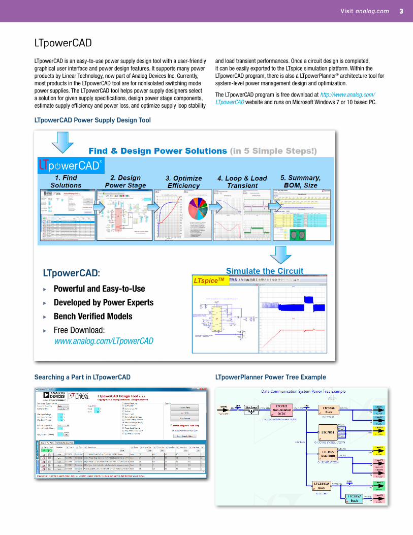
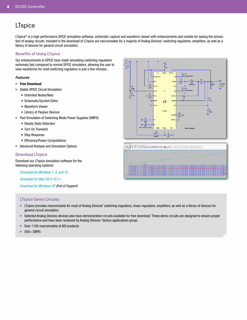
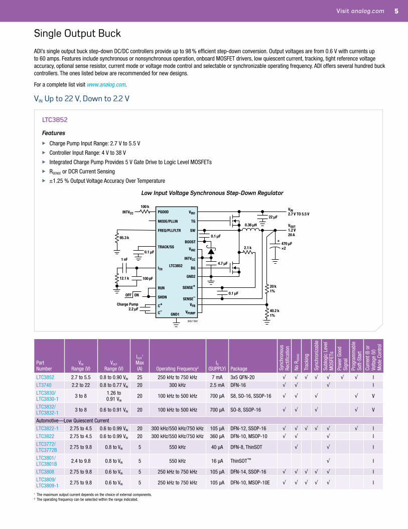
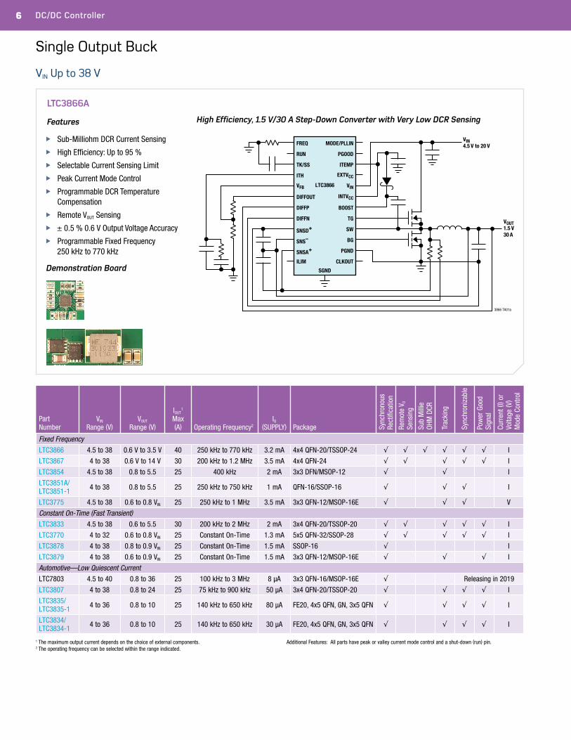
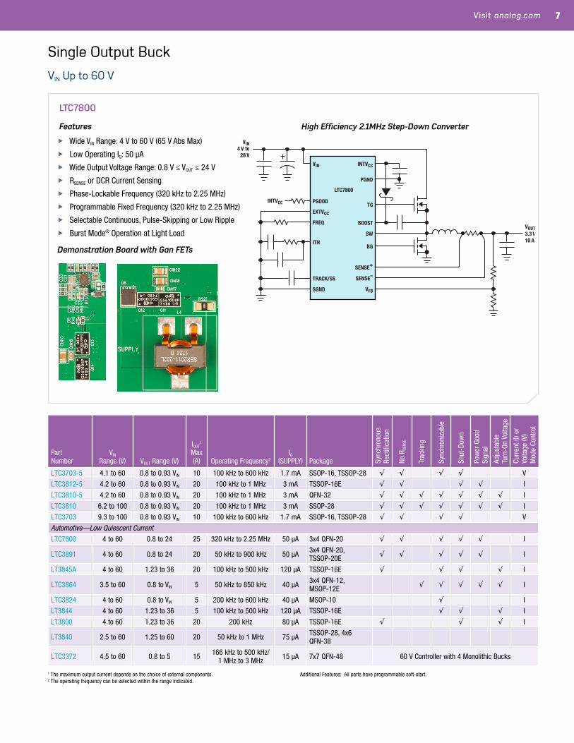
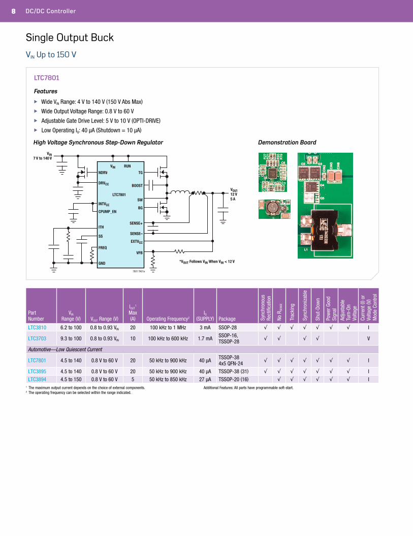
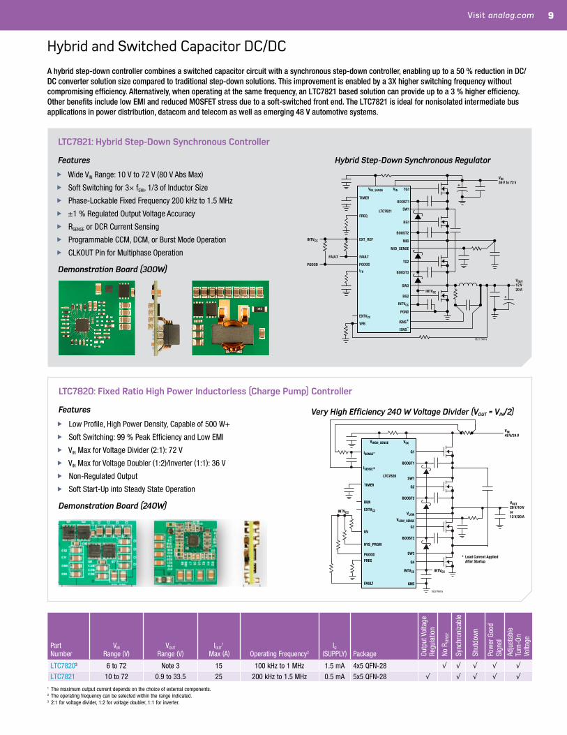
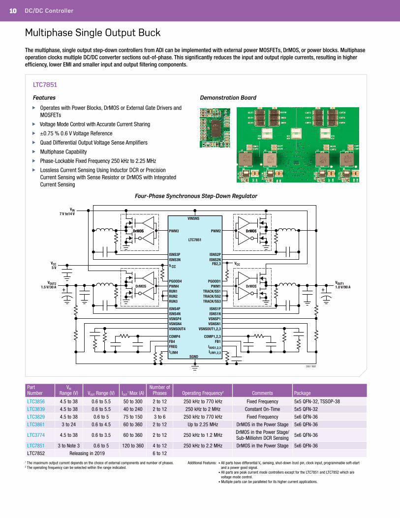
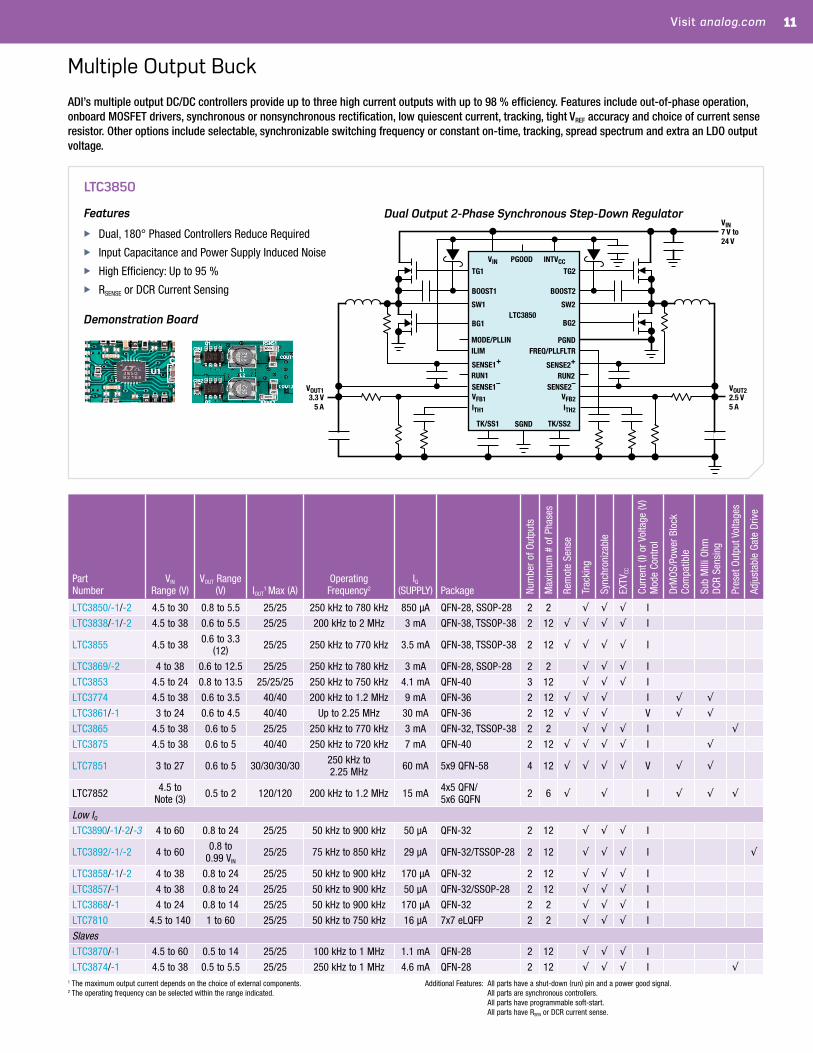
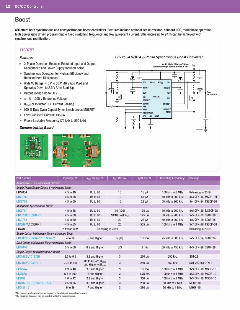
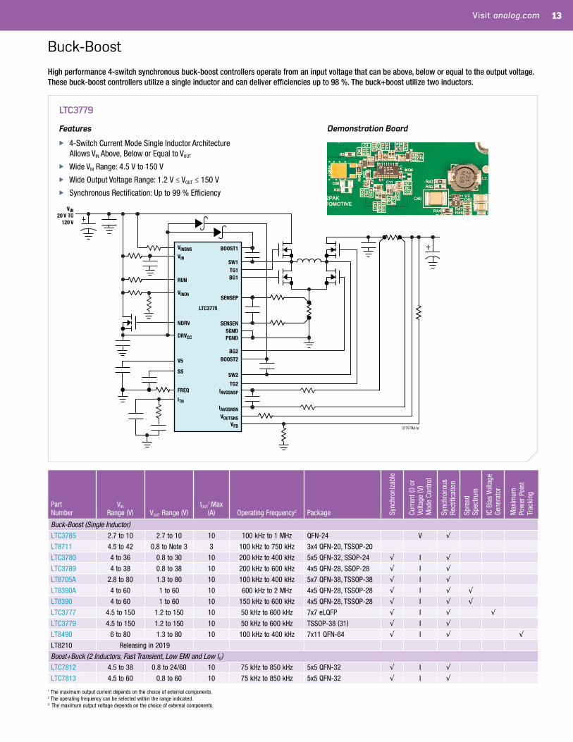
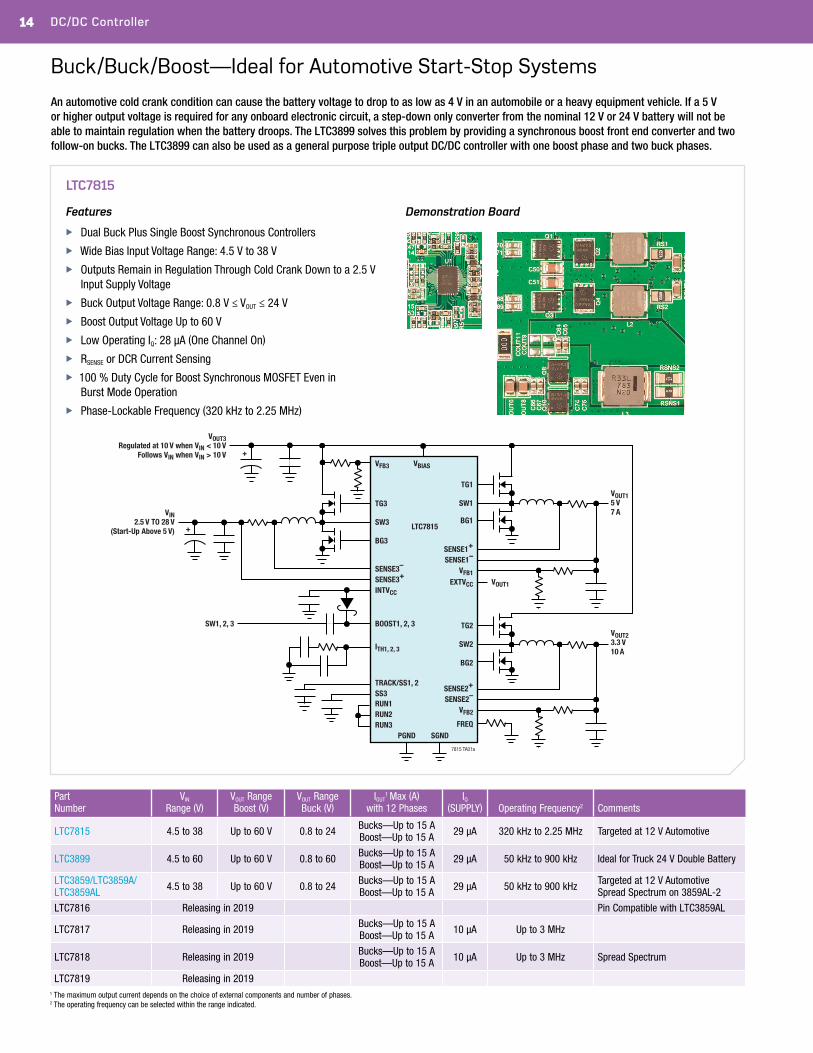
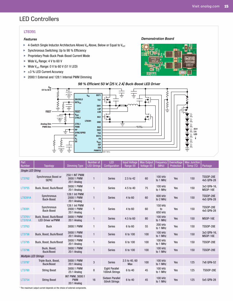
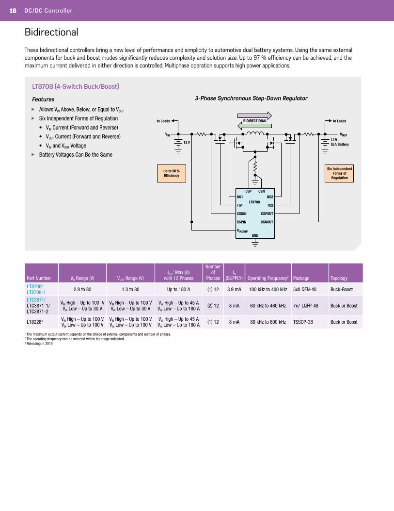
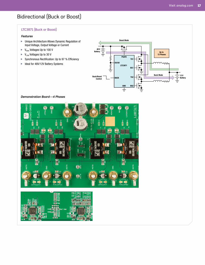
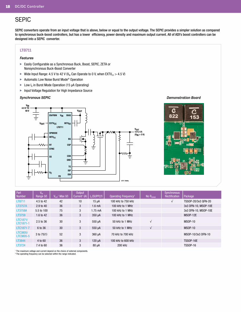
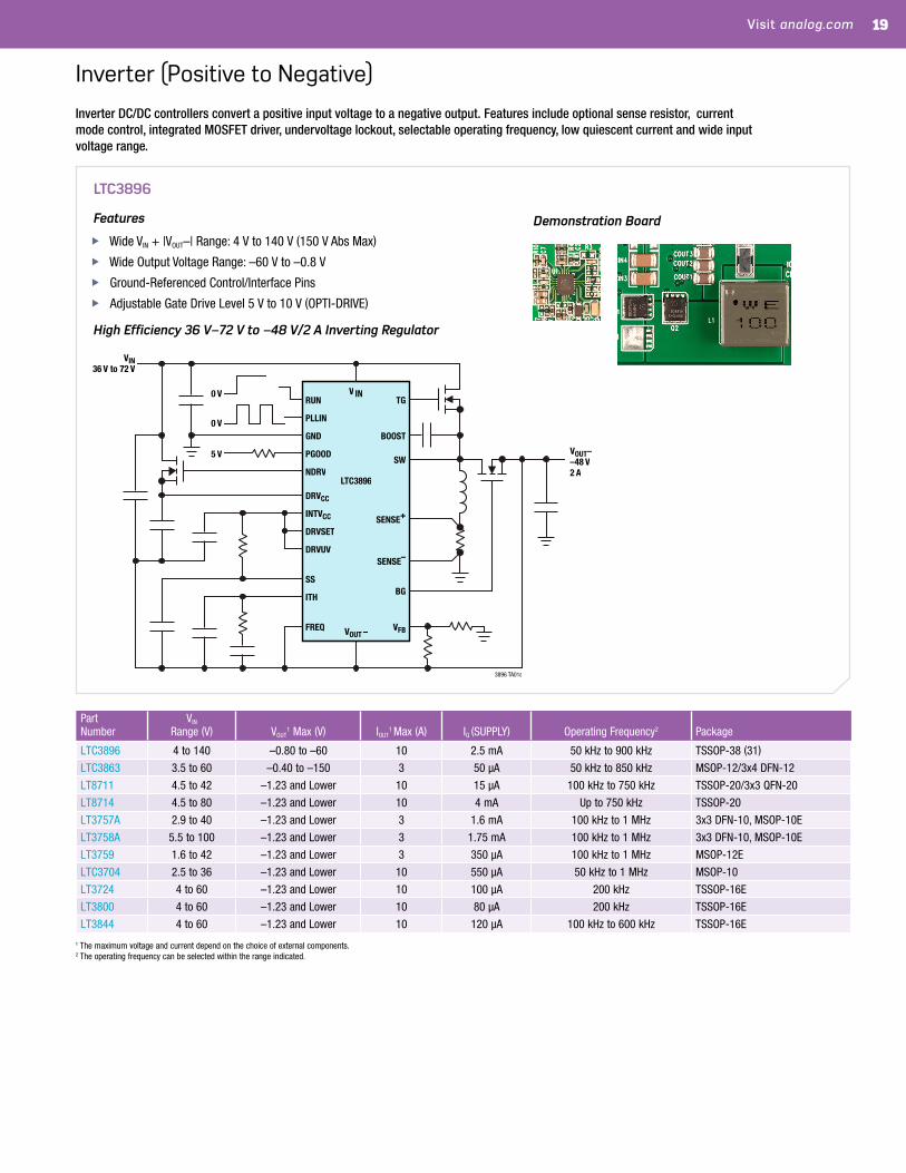
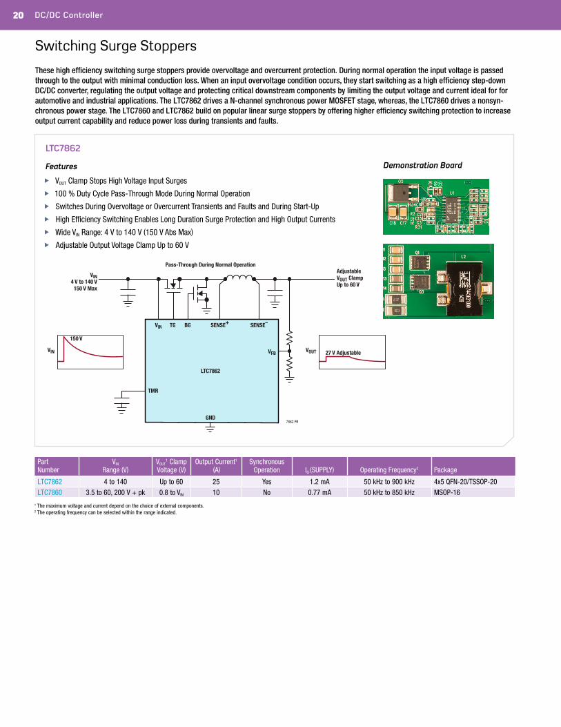
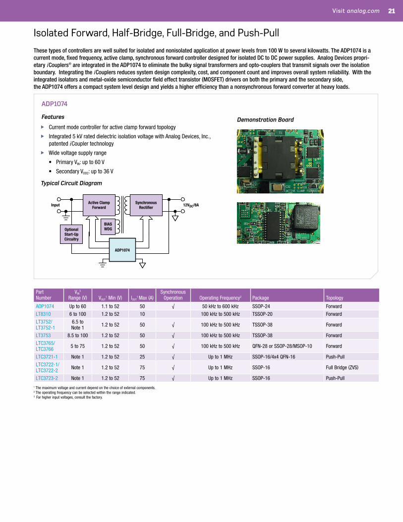
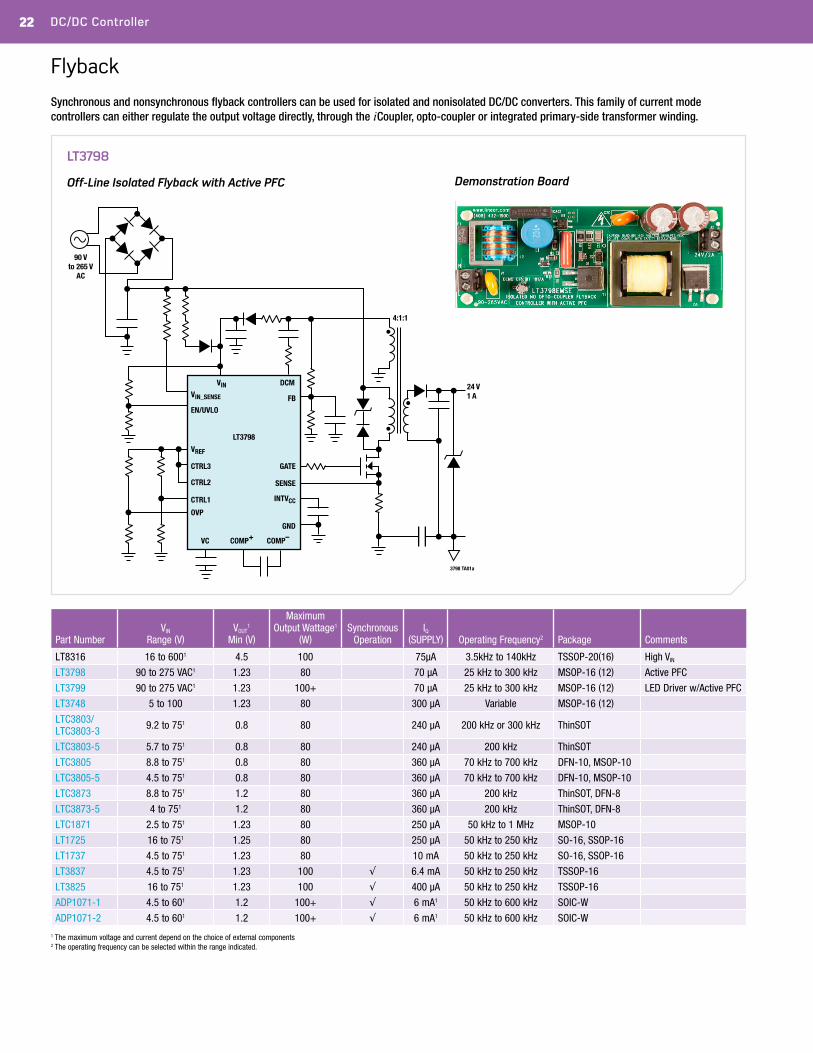
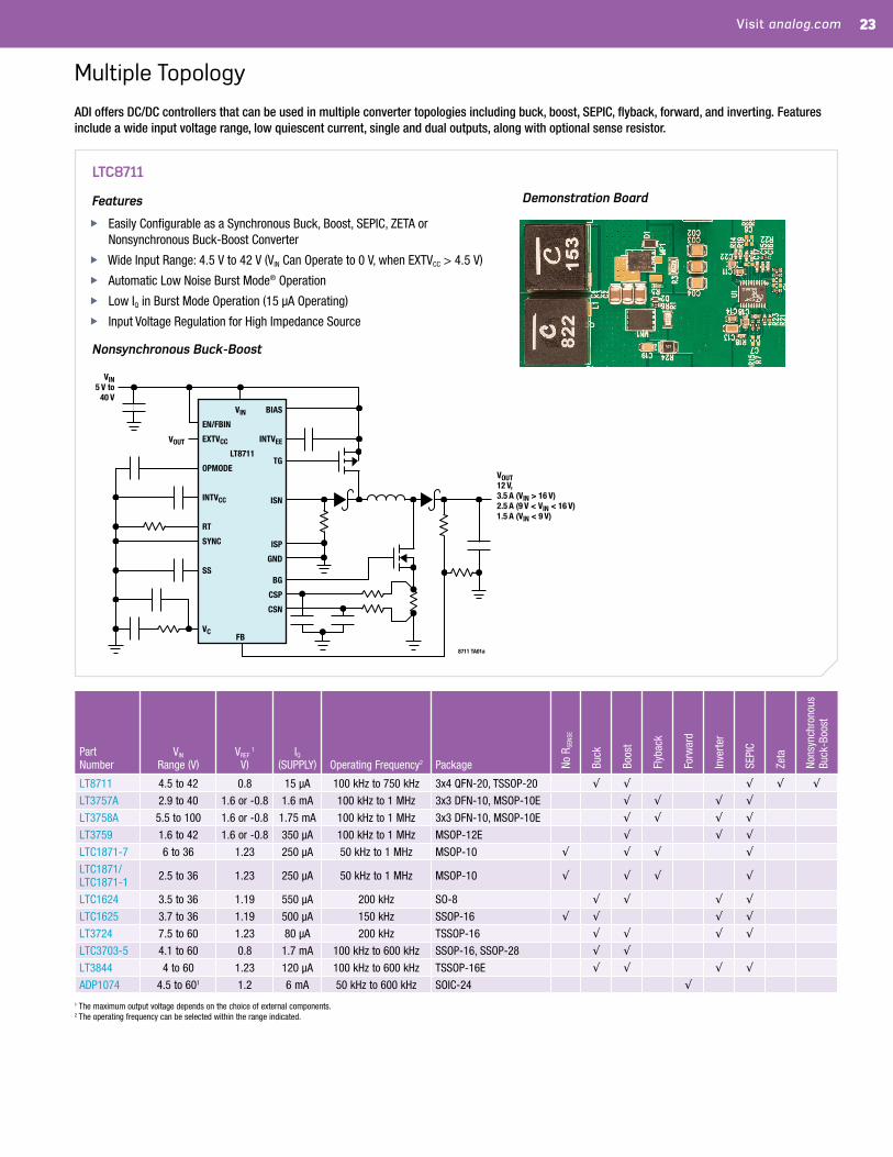
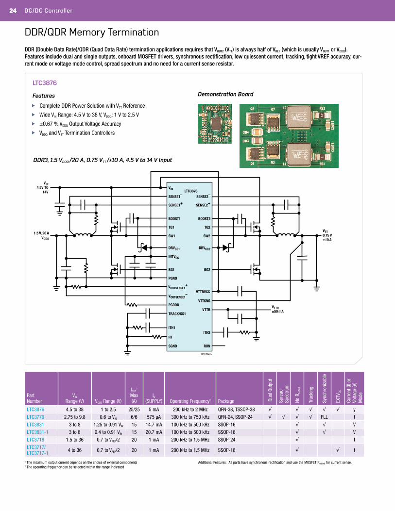
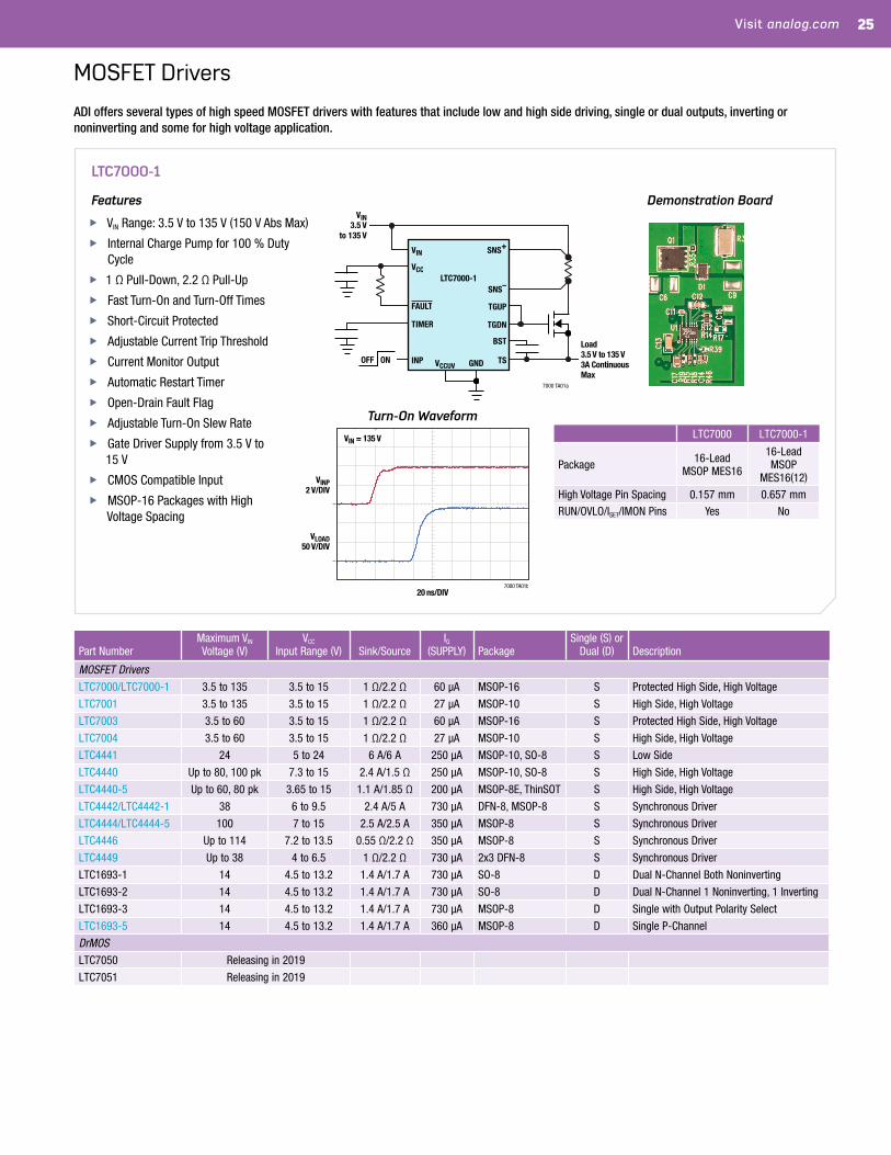
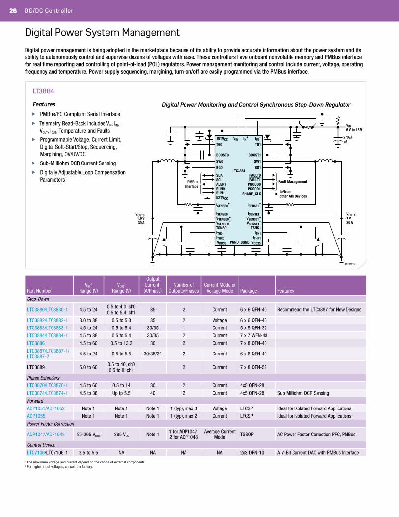
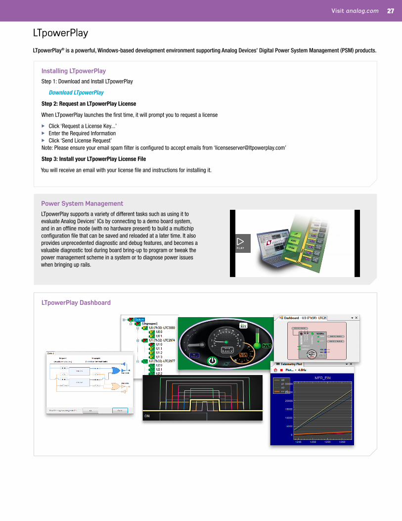
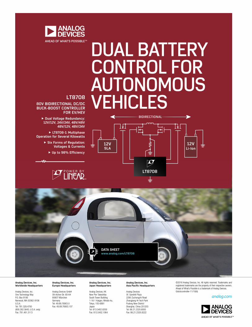