Embed Size (px)
Citation preview
SITOP
siemens.com/sitop
SITOPPower Supply
CatalogKT 10.1
Edition2019/2020
© Siemens 2019
Related catalogs
Industrial Controls IC 10SIRIUS
PDF (E86060-K1010-A101-A9-7600)
SIMATIC ST 70Products forTotally Integrated Automation
PDF (E86060-K4670-A101-B7-7600)
SIMATIC ST PCS 7SIMATIC PCS 7 Process Control SystemVol. 1: System components
E86060-K4678-A111-C5-7600
SIMATIC HMI / ST 80/ST PCPC-based Automation Human Machine Interface SystemsPC-based Automation
E86060-K4680-A101-C6-7600
Motion Control System PM 21SIMOTIONEquipment for Production Machines
E86060-K4921-A101-A4-7600
SITRAINTraining for Industry
www.siemens.com/sitrain
Products for Automation and Drives CA 01Interactive CatalogDownload
www.siemens.com/ca01download
Industry Mall Information and Ordering Platformon the Internet:
www.siemens.com/industrymall
© Siemens 2019
1
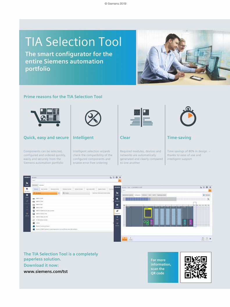
TIA Selection ToolThe smart configurator for the entire Siemens automation portfolio
Prime reasons for the TIA Selection Tool
Quick, easy and secure Intelligent Clear Time-saving
Components can be selected, configured and ordered quickly, easily and securely from the Siemens automation portfolio
Intelligent selection wizards check the compatibility of the configured components and enable error-free ordering
Required modules, devices and networks are automatically generated and clearly compared to one another
Time savings of 80% in design – thanks to ease of use and intelligent support
The TIA Selection Tool is a completely paperless solution.Download it now:www.siemens.com/tst
For more information, scan the QR code
© Siemens 2019

© Siemens 2019
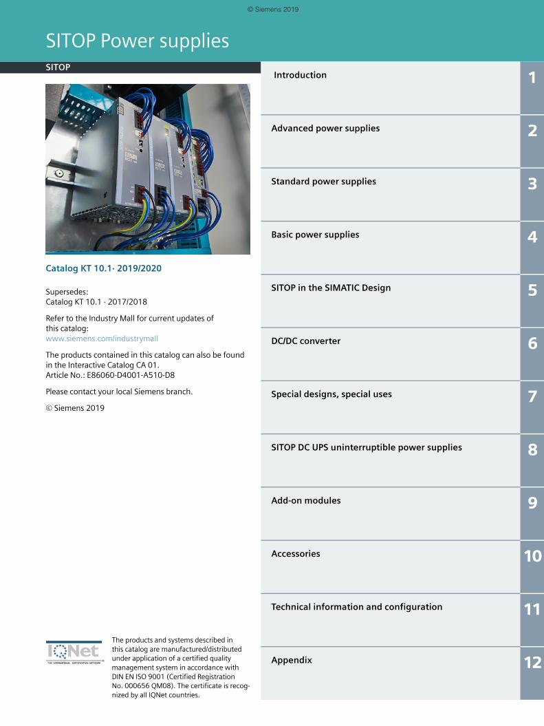
Introduction 1
Advanced power supplies 2
Standard power supplies 3
Basic power supplies 4
SITOP in the SIMATIC Design 5
DC/DC converter 6
Special designs, special uses 7
SITOP DC UPS uninterruptible power supplies 8
Add-on modules 9
Accessories 10
Technical information and configuration 11
Appendix 12
SITOP Power suppliesSITOP
Catalog KT 10.1· 2019/2020
Supersedes:Catalog KT 10.1 · 2017/2018
Refer to the Industry Mall for current updates of this catalog:www.siemens.com/industrymall
The products contained in this catalog can also be found in the Interactive Catalog CA 01.Article No.: E86060-D4001-A510-D8
Please contact your local Siemens branch.
© Siemens 2019
The products and systems described in this catalog are manufactured/distributed under application of a certified quality management system in accordance with DIN EN ISO 9001 (Certified Registration No. 000656 QM08). The certificate is recog-nized by all IQNet countries.
KT10_1_2019_Innentitel.fm Seite 1 Dienstag, 9. Juli 2019 2:21 14
© Siemens 2019

2 Siemens KT 10.1 · 2019/2020
Digital EnterpriseThe building blocks that ensure everything works together perfectly in the digital enterpriseDigitalization is already changing all areas of life and existing business models. It is placing greater pressure on industry while at the same time creating new business opportunities. Today, thanks to scalable solutions from Siemens, companies can already become a digital enterprise and ensure their competitiveness.
Industry faces tremendous challenges
Reduce time-to-market
Boost flexibility
Improve quality
Boost efficiency
Increase security
Today manufacturers have to bring products to market at an ever-increas-ing pace despite the growing complexity of these products. In the past, a major manufac-turer would push aside a small one, but now it is a fast manufacturer that overtakes a slow one.
Consumers want cus-tomized products, but at a price they would pay for a mass-produced item. That only works if production is more flexible than ever before.
To ensure a high level of quality while meeting legal requirements, companies have to establish closed quality loops and enable the traceability of products.
Today the product itself needs to be sustainable and environmentally friendly, while energy efficiency in production has become a competi-tive advantage.
Increasing networking escalates the threat to production facilities of cyberattacks. Today more than ever, com-panies need suitable security measures.
01_Digital Enterprise_EN.fm Seite 2 Dienstag, 9. Juli 2019 3:38 15
© Siemens 2019

3Siemens KT 10.1 · 2019/2020
The digital enterprise has already become a realityTo fully benefit from all the advantages of digitalization, companies first have to achieve complete consistency of their data. Fully digitally integrated business processes, including those of suppliers, can help to create a digital representation of the entire value chain. This requires• the integration of industrial software
and automation,• expansion of the communication net-
works,• security in automation,• and the use of business-specific
industrial services.
MindSphereThe cloud-based open IoT operating system from SiemensWith MindSphere, Siemens offers a cost-effective and scalable cloud platform as a service (PaaS) for the development of appli-cations. The platform, designed as an open operating system for the Internet of Things, makes it possible to improve the efficiency of plants by collecting and analyzing large volumes of production data.
Totally Integrated Automation (TIA)Where digitalization becomes realityTotally Integrated Automation (TIA) ensures the seamless transition from the virtual to the real world. It already encompasses all the necessary conditions for transforming the benefits of digitalization into true added value. The data that will form the digital twin for actual production is generated from a common base.
Digital PlantLearn more about the digital enterprise for the process industrywww.siemens.com/digitalplant
Digital Enterprise SuiteLearn more about the digital enterprise for the discrete industrywww.siemens.com/digital-enterprise-suite
01_Digital Enterprise_EN.fm Seite 3 Dienstag, 9. Juli 2019 3:38 15
© Siemens 2019

4
Notes
01_Digital Enterprise_EN.fm Seite 4 Dienstag, 9. Juli 2019 3:38 15
© Siemens 2019
Siemens KT 10.1 · 2019/2020
11/2 SITOP power supply1/2 Introduction1/3 The product range at a glance1/4 Efficient product selection and planning1/5 Customized power supplies1/6 Selection tables for power supplies
Introduction
© Siemens 2019
1/2 Siemens KT 10.1 · 2019/2020
SITOP power supply
Introduction
1 ■ Overview
SITOP - The heart of automation®
Thanks to their high degree of reliability, SITOP power supplies have established themselves around the world and can cope with even critical network conditions. Our complete range of power packs supplies regulated 24 volt and other output voltages. The unique range of DC UPS and add-on modules extends the power supply system: 24 V supplies are thus protected against interference from the grid and on the direct voltage side.
Top SITOP reliability
SITOP has proved its reliability in almost every supply system in the world. With its flexible wide range input, excellent load characteristics and all relevant certification, SITOP power packs preserve the availability of your plant. Add-on modules counteract disturbances on the DC voltage or line side. And in addition to the uninterruptible power supply, the 24 V power supplies bridge power failures in the range of seconds, minutes or hours.
Even in the event of an overload or short-circuit, the output circuit maintains the selective shutdown of the feeder and the loads continue to be supplied. Redundant power supply solutions can be configured for especially critical applications. Should a replacement be required, our global customer service ensures fast delivery: All SITOP products can be delivered from stock.
Top SITOP efficiency
Lower energy costs are a valuable competitive advantage. SITOP has an essential role to play here: The primary switched mode power supplies work extremely effectively. The SITOP PSU8200 und PSU6200 degree of efficiency is up to 95%, for example. The power loss across the entire performance range is low – even during no-load operation. This is important because power supplies are rarely operated at full load.
The SITOP PSU8600, on the other hand, captures the energy data of all outputs which are then further processed by the energy management systems. The power supply outputs can also be specifically switched off with the support of PROFIenergy, for instance during idle times. Efficiency characterizes the entire process chain: Special tools are provided for easy selection of the power supply and DC UPS, for instance, and users are given all construction data for all commonly used CAE systems along with the corresponding product documentation.
Top SITOP integration
SITOP is the benchmark in integration: The inclusion of the SITOP PSU8600 power supply system and SITOP UPS1600 DC uninterruptible power supply in Totally Integrated Automation, the TIA Portal and the new SITOP Manager at all levels saves time and costs and simplifies fail-
safe engineering. The S7 function blocks evaluate important diagnostic information for the SITOP selectivity modules and the new SITOP PSU6200 product line.
In order to protect PC-based automation systems from power outages, the SITOP UPS1600 can be easily integrated via USB or Ethernet. And the SITOP library for SIMATIC PCS 7 enables transparent 24 V supply in the process control system during ongoing operation. In addition to PROFINET, the SITOP PSU8600 and SITOP UPS1600 can now also communicate via OPC UA. The OPC UA server enables direct incorporation of controllers or PCs, for example, into automation applications with OPC UA clients from different manufacturers.
Three SITOP categories for different industrial power supply requirements
Advanced power supplies
The switched mode power supplies in the Advanced perfor-mance class are the ideal choice for maximum reliability and functionality, as required in the process and automotive indus-tries, in special-purpose machine manufacturing, or in harsh environments. Its overload characteristics, efficiency, and compactness mean that the SITOP PSU8200 product range meets the stringent requirements in these areas. Additionally, SITOP PSU8600 offers a power supply system with open communication for optimum integration into the world of digitalization.
Standard power supplies
Our standard portfolio was designed with typical industrial requirements in mind, such as those encountered in series machine production. The versatile new SITOP PSU6200 was developed on the basis of our experience with the time-proven SITOP smart product line. This new SITOP Standard offers even more efficiency, extensive diagnostic options and enhanced robustness.
Basic power supplies
From flat power supplies for distribution boards, through cost-effective basic power supplies, to slim power supply units for control boxes – SITOP caters to all needs, including in the lower performance range. LOGO!Power offers you miniature power supply units in the LOGO!8 module design, for exam-ple. The extremely space-saving SITOP compact devices are ideally suited for distributed applications. And SITOP lite fulfills the main requirements for reliable primary switched-mode regulators at an affordable price.
© Siemens 2019
1/3Siemens KT 10.1 · 2019/2020
SITOP power supply
The product range at a glance
1Advanced power supplies Advanced power supplies Standard power supplies
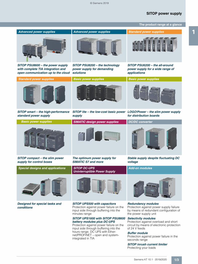
SITOP PSU8600 – the power supply with complete TIA integration and open communication up to the cloud
SITOP PSU8200 – the technology power supply for demanding solutions
SITOP PSU6200 – the all-around power supply for a wide range of applications
Standard power supplies Basic power supplies Basic power supplies
SITOP smart – the high-performance standard power supply
SITOP lite – the low-cost basic power supply
LOGO!Power – the slim power supply for distribution boards
Basic power supplies SIMATIC design power supplies DC/DC converter
SITOP compact – the slim power supply for control boxes
The optimum power supply for SIMATIC S7 and more
Stable supply despite fluctuating DC voltage
Special designs and applications SITOP DC-UPS Uninterruptible Power Supply
Add-on modules
Designed for special tasks and conditions
SITOP UPS500 with capacitorsProtection against power failure on the input side through buffering into the minutes range
SITOP UPS1600 with SITOP PSU8600 battery modules plus DC-UPSProtection against power failure on the input side through buffering into the hours range. DC UPS with Ether-net/PROFINET – open and system-integrated in TIA
Redundancy modulesProtection against power supply failure by means of redundant configuration of the power supply unit
Selectivity modulesProtection against overload and short circuit by means of electronic protection of 24 V feeds
Buffer moduleProtection against power failure in the seconds range
SITOP inrush current limiterProtecting your loads
© Siemens 2019
1/4 Siemens KT 10.1 · 2019/2020
SITOP power supply
Efficient product selection and planning
1 ■ Overview
However sophisticated the requirements are for your power supply, SITOP always provides optimal support for your planning process: from product selection to mechanical and electrical construction and project-specific plant documentation, up to engineering.
SITOP and the TIA Selection Tool make it possible to select your power supply and DC UPS faster and more directly. Moreover, you also receive the right CAD data and circuit diagram macros automatically. And parameter assignment and diagnostics of the modular SITOP PSU8600 power supply system and SITOP UPS1600 DC UPS is easy via the TIA Portal.
Efficiency begins with the right choice
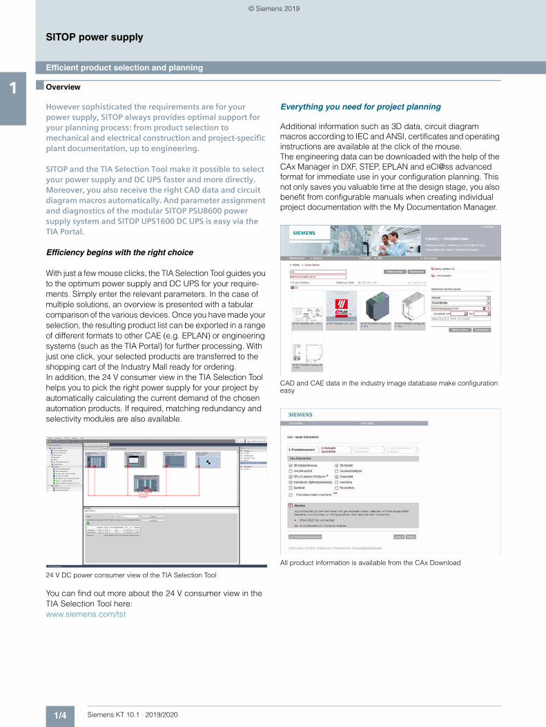
With just a few mouse clicks, the TIA Selection Tool guides you to the optimum power supply and DC UPS for your require-ments. Simply enter the relevant parameters. In the case of multiple solutions, an overview is presented with a tabular comparison of the various devices. Once you have made your selection, the resulting product list can be exported in a range of different formats to other CAE (e.g. EPLAN) or engineering systems (such as the TIA Portal) for further processing. With just one click, your selected products are transferred to the shopping cart of the Industry Mall ready for ordering. In addition, the 24 V consumer view in the TIA Selection Tool helps you to pick the right power supply for your project by automatically calculating the current demand of the chosen automation products. If required, matching redundancy and selectivity modules are also available.
24 V DC power consumer view of the TIA Selection Tool
You can find out more about the 24 V consumer view in the TIA Selection Tool here:www.siemens.com/tst
Everything you need for project planning
Additional information such as 3D data, circuit diagram macros according to IEC and ANSI, certificates and operating instructions are available at the click of the mouse. The engineering data can be downloaded with the help of the CAx Manager in DXF, STEP, EPLAN and eCl@ss advanced format for immediate use in your configuration planning. This not only saves you valuable time at the design stage, you also benefit from configurable manuals when creating individual project documentation with the My Documentation Manager.
CAD and CAE data in the industry image database make configuration easy
All product information is available from the CAx Download
© Siemens 2019
1/5Siemens KT 10.1 · 2019/2020
SITOP power supply
Customized power supplies
1■ Overview
Our well-proven standard power supplies cannot, of course, satisfy the requirements of every application. We make it possible for you to optimize your system to suit application-specific requirements.
You benefit from the expertise of large-scale production and gain maximum development security and quality.
Our customer-specific solutions are used today in many sectors of mechanical engineering, in automation technol-ogy, vehicle electronics, equipment manufacturing and in industrial instrumentation technology.
Our offer is in principle open to every application case. If we have awakened your interest or if you would like to receive further details, please contact your local Siemens represen-tative.
© Siemens 2019
1/6 Siemens KT 10.1 · 2019/2020
SITOP power supply
Selection tables for power supplies
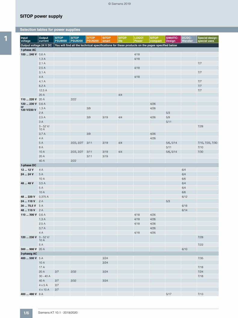
1 Input voltage
Output current
SITOP PSU8600
SITOPPSU8200
SITOPPSU6200
SITOPsmart
SITOPlite
LOGO!Power
SITOPcompact
SIMATIC-Design
DC/DC-Wandler
Special design - special uses
Output voltage 24 V DC You will find all the technical specifications for these products on the pages specified below
1-phase AC
100 ... 240 V 0,6 A 4/18
1,3 A 4/18
2,1 A 7/7
2,5 A 4/18
3,1 A 7/7
4 A 4/18
4,1 A 7/7
6,2 A 7/7
12,5 A 7/7
20 A 4/4
110 ... 220 V 20 A 2/22
120 ... 230 Vor120 V/230 V
0,6 A 4/26
1,3 A 3/9 4/26
2 A 5/3
2,5 A 3/9 3/19 4/4 4/26 5/9
3 A 5/11
3 - 52 V/10 A
7/28
3,7 A 3/9 4/26
4 A 4/26
5 A 2/22, 2/27 3/11 3/19 4/4 5/6, 5/14 7/10, 7/22, 7/30
8 A 5/11 7/10
10 A 2/22, 2/27 3/11 3/19 4/4 5/6, 5/14 7/30
20 A 3/11 3/19
40 A 2/22
1-phase DC
12 ... 12 V 4 A 6/4
24 ... 24 V 5 A 6/4
10 A 6/6
48 ... 48 V 3,5 A 6/4
5 A 6/4
10 A 6/6
48 ... 220 V 0,375 A 6/12
24 ... 110 V 2 A 5/3
30 ... 75,5 V 5 A 6/18
48 ... 110 V 2 A 6/14
110 ... 300 V 0,6 A 4/18 4/26
1,3 A 4/18 4/26
2,5 A 4/18 4/26
3,7 A 4/26
4 A 4/18 4/26
120 ... 230 V 3 - 52 V/10 A
7/28
5 A 7/22
300 ... 900 V 20 A 6/10
3-phasig AC
400 ... 500 V 5 A 3/24 7/35
10 A 3/24
17 A 7/18
20 A 2/7 2/32 3/24 7/24
30 - 40 A 7/18
40 A 2/7 2/32 3/24
4 x 5 A 2/7
4 x 10 A 2/7
400 ... 480 V 8 A 5/17 7/13
© Siemens 2019
1/7Siemens KT 10.1 · 2019/2020
SITOP power supply
Selection tables for power supplies
1
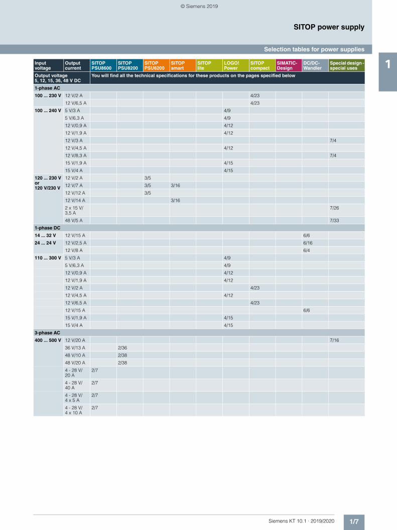
Input voltage
Output current
SITOP PSU8600
SITOPPSU8200
SITOPPSU6200
SITOPsmart
SITOPlite
LOGO!Power
SITOPcompact
SIMATIC-Design
DC/DC-Wandler
Special design - special uses
Output voltage 5, 12, 15, 36, 48 V DC
You will find all the technical specifications for these products on the pages specified below
1-phase AC
100 ... 230 V 12 V/2 A 4/23
12 V/6,5 A 4/23
100 ... 240 V 5 V/3 A 4/9
5 V/6,3 A 4/9
12 V/0,9 A 4/12
12 V/1,9 A 4/12
12 V/3 A 7/4
12 V/4,5 A 4/12
12 V/8,3 A 7/4
15 V/1,9 A 4/15
15 V/4 A 4/15
120 ... 230 Vor120 V/230 V
12 V/2 A 3/5
12 V/7 A 3/5 3/16
12 V/12 A 3/5
12 V/14 A 3/16
2 x 15 V/3,5 A
7/26
48 V/5 A 7/33
1-phase DC
14 ... 32 V 12 V/15 A 6/6
24 ... 24 V 12 V/2,5 A 6/16
12 V/8 A 6/4
110 ... 300 V 5 V/3 A 4/9
5 V/6,3 A 4/9
12 V/0,9 A 4/12
12 V/1,9 A 4/12
12 V/2 A 4/23
12 V/4,5 A 4/12
12 V/6,5 A 4/23
12 V/15 A 6/6
15 V/1,9 A 4/15
15 V/4 A 4/15
3-phase AC
400 ... 500 V 12 V/20 A 7/16
36 V/13 A 2/36
48 V/10 A 2/38
48 V/20 A 2/38
4 - 28 V/20 A
2/7
4 - 28 V/40 A
2/7
4 - 28 V/4 x 5 A
2/7
4 - 28 V/4 x 10 A
2/7
© Siemens 2019

1/8 Siemens KT 10.1 · 2019/2020
SITOP power supply
Notes
1
© Siemens 2019
Siemens KT 10.1 · 2019/2020
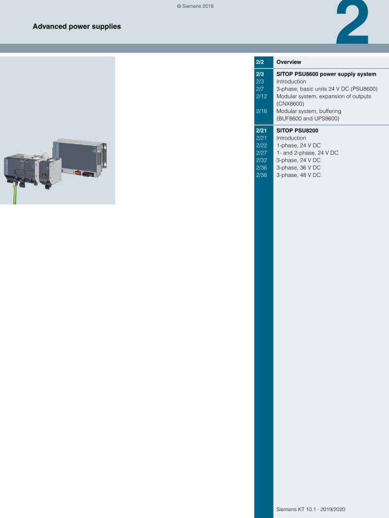
22/2 Overview
2/3 SITOP PSU8600 power supply system2/3 Introduction2/7 3-phase, basic units 24 V DC (PSU8600)2/12 Modular system, expansion of outputs
(CNX8600)2/16 Modular system, buffering
(BUF8600 and UPS8600)
2/21 SITOP PSU82002/21 Introduction2/22 1-phase, 24 V DC2/27 1- and 2-phase, 24 V DC2/32 3-phase, 24 V DC2/36 3-phase, 36 V DC2/38 3-phase, 48 V DC
Advanced power supplies
© Siemens 2019
2/2 Siemens KT 10.1 · 2019/2020
2
Advanced power supplies
Introduction
■ Overview
The switching power supply units in the Advanced performance class are the ideal choice for maximum reliability and functional-ity, as required in the process and automotive industries, in spe-cial-purpose machine manufacturing, or in harsh environments.
The SITOP PSU8200 product range meets the stringent require-ments in these areas, e.g. thanks to its overload characteristics, efficiency, and compactness. Additionally, SITOP PSU8600 of-fers a power supply system with open communication for opti-mum integration in the world of digitalization.
© Siemens 2019
2/3Siemens KT 10.1 · 2019/2020
2
Advanced power suppliesSITOP PSU8600 power supply system
Introduction
■ Overview
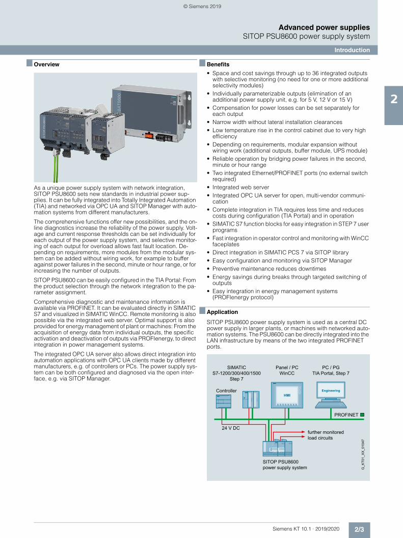
As a unique power supply system with network integration, SITOP PSU8600 sets new standards in industrial power sup-plies. It can be fully integrated into Totally Integrated Automation (TIA) and networked via OPC UA and SITOP Manager with auto-mation systems from different manufacturers.
The comprehensive functions offer new possibilities, and the on-line diagnostics increase the reliability of the power supply. Volt-age and current response thresholds can be set individually for each output of the power supply system, and selective monitor-ing of each output for overload allows fast fault location. De-pending on requirements, more modules from the modular sys-tem can be added without wiring work, for example to buffer against power failures in the second, minute or hour range, or for increasing the number of outputs.
SITOP PSU8600 can be easily configured in the TIA Portal: From the product selection through the network integration to the pa-rameter assignment.
Comprehensive diagnostic and maintenance information is available via PROFINET. It can be evaluated directly in SIMATIC S7 and visualized in SIMATIC WinCC. Remote monitoring is also possible via the integrated web server. Optimal support is also provided for energy management of plant or machines: From the acquisition of energy data from individual outputs, the specific activation and deactivation of outputs via PROFIenergy, to direct integration in power management systems.
The integrated OPC UA server also allows direct integration into automation applications with OPC UA clients made by different manufacturers, e.g. of controllers or PCs. The power supply sys-tem can be both configured and diagnosed via the open inter-face, e.g. via SITOP Manager.
■ Benefits
• Space and cost savings through up to 36 integrated outputs with selective monitoring (no need for one or more additional selectivity modules)
• Individually parameterizable outputs (elimination of an additional power supply unit, e.g. for 5 V, 12 V or 15 V)
• Compensation for power losses can be set separately for each output
• Narrow width without lateral installation clearances• Low temperature rise in the control cabinet due to very high
efficiency• Depending on requirements, modular expansion without
wiring work (additional outputs, buffer module, UPS module)• Reliable operation by bridging power failures in the second,
minute or hour range • Two integrated Ethernet/PROFINET ports (no external switch
required)• Integrated web server• Integrated OPC UA server for open, multi-vendor communi-
cation• Complete integration in TIA requires less time and reduces
costs during configuration (TIA Portal) and in operation• SIMATIC S7 function blocks for easy integration in STEP 7 user
programs• Fast integration in operator control and monitoring with WinCC
faceplates• Direct integration in SIMATIC PCS 7 via SITOP library• Easy configuration and monitoring via SITOP Manager• Preventive maintenance reduces downtimes• Energy savings during breaks through targeted switching of
outputs• Easy integration in energy management systems
(PROFIenergy protocol)
■ Application
SITOP PSU8600 power supply system is used as a central DC power supply in larger plants, or machines with networked auto-mation systems. The PSU8600 can be directly integrated into the LAN infrastructure by means of the two integrated PROFINET ports.
Controller
SITOP PSU8600 power supply system
further monitoredload circuits
24 V DC
G_K
T01_
XX
_010
47
PROFINET
PC / PGTIA Portal, Step 7
SIMATICS7-1200/300/400/1500
Step 7
Panel / PCWinCC
© Siemens 2019
2/4 Siemens KT 10.1 · 2019/2020
2
■ Application (continued)
Advanced power suppliesSITOP PSU8600 power supply system
Introduction
An extremely high level of reliability is achieved for the DC voltage supply by monitoring the individual DC branches for overload and bridging short-term power failures (brownouts). Complete transparency and fast fault localization are achieved by providing comprehensive diagnostic and maintenance infor-mation (e.g. load states of the outputs, phase/network failure, overtemperature) via PROFINET.
Energy-optimized operation is supported by measuring the cur-rent power and voltage values of the individual outputs as well as the individual activation and deactivation of the DC outputs via PROFIenergy during break times.
■ Design
• SITOP PSU8600, 3-phase power supply, 24 V DC/20 A/4 x 5 A with four outputs (max. 5 A per output) and two Ethernet/PROFINET ports
• SITOP PSU8600, 3-phase power supply, 24 V DC/20 A with one output and two Ethernet/PROFINET ports
• SITOP PSU8600, 3-phase power supply, 24 V DC/40 A/4 x 10 A with four outputs (max. 10 A per output) and two Ethernet/PROFINET ports
• SITOP PSU8600, 3-phase power supply, 24 V DC/40 A with one output and two Ethernet/PROFINET ports
Modular system, consisting of:• SITOP CNX8600 4 x 5 A
(expansion module with 4 outputs, each 5 A)• SITOP CNX8600 4 x 10 A
(expansion module with 4 outputs, each 10 A)• SITOP CNX8600 8 x 2.5 A
(expansion module with 8 outputs, each 2.5 A) • SITOP BUF8600 100 ms/40 A
(buffer module with 100 ms at 40 A)• SITOP BUF8600 300 ms/40 A
(buffer module with 300 ms at 40 A)• SITOP BUF8600 4 s/40 A (buffer module with 4 s at 40 A)• SITOP BUF8600 10 s/40 A (buffer module with 10 s at 40 A)• SITOP UPS8600 (UPS module)
- BAT8600 (battery module BAT8600 Pb for buffering in case of power failure 10 min/960 W)
- BAT8600 (battery module BAT8600 LiFePO4 for buffering in case of power failure 14 min/960 W)
Up to 4 CNX8600 expansion modules and up to 2 buffer compo-nents (BUF8600 or UPS8600) can be connected to a PSU8600 basic unit. The connection is made on top of the modules without any wiring using the System Clip Link, a connecting plug for sys-tem data and power supplies. Up to six supplementary modules can be added in random order; this means that existing config-urations do not have to be altered if a module is added at a later stage. Up to 5 BAT8600 battery modules of the same type can be connected to a UPS8600 module. The connection between UPS8600 and BAT8600 via the Energy Storage Link enables in-telligent battery management for optimum battery life.
■ Function
Supply of connected loads
An individual supply voltage can be set at each output of the power supply system. This means you can supply loads with dif-ferent rated voltages simultaneously with only one device. Plus the voltage drop caused by the different cable lengths can be compensated individually, which means each load can be sup-plied with the optimum voltage.
Monitoring of the outputs for overload
Each output of the power supply system is individually moni-tored for overload. If the load current exceeds the set response threshold, the output is shut down according to specified time-current characteristics. All other outputs continue to be supplied reaction-free.
Enabling and disabling the outputs
Each output can be manually enabled or disabled directly on the device (e.g. for commissioning or service) and an overload trip-ping can be reset. Outputs disabled due to overload can also be reset remotely using a remote reset signal (24 V input).
In addition, program-controlled enabling and disabling of the outputs is possible using the integrated Ethernet/PROFINET in-terface. This also means you can disable individual outputs by means of PROFIenergy during breaks to save energy.
Communication
Comprehensive diagnostic information can be queried and pro-cessed via the integrated Ethernet/PROFINET interface during operation for both the device status as well as the status of the individual outputs. This results in complete transparency, mini-mal downtimes and quick fault location. The integrated web server also permits remote monitoring of the power supply sys-tem.
Buffering
If brief voltage dips occur on the mains side, the buffer module provides the load current for supplying the outputs via its energy storage devices. Maintenance-free electrolytic capacitors or double-layer capacitors are used as energy-storage units.
UPS module UPS8600 can be used with the corresponding BAT8600 battery modules to protect against longer power fail-ures. This allows power failures in the minutes to hours range to be bridged. These supplementary modules also make it possi-ble to shut down the system in a specific and safe manner in the event of a power failure. For most power interruptions, however, the bridging time is sufficient so that the system can continue to run without malfunction.
© Siemens 2019
2/5Siemens KT 10.1 · 2019/2020
2
Advanced power suppliesSITOP PSU8600 power supply system
Introduction
■ Integration
Software for TIA-based automation systems
Different software components are available to facilitate easy in-tegration of the SITOP PSU8600 in the TIA environment.
Engineering is simple via the TIA Portal. Special function blocks for SIMATIC S7-300, S7-400, S7-1200 and S7-1500 also support integration in the STEP 7 user program.
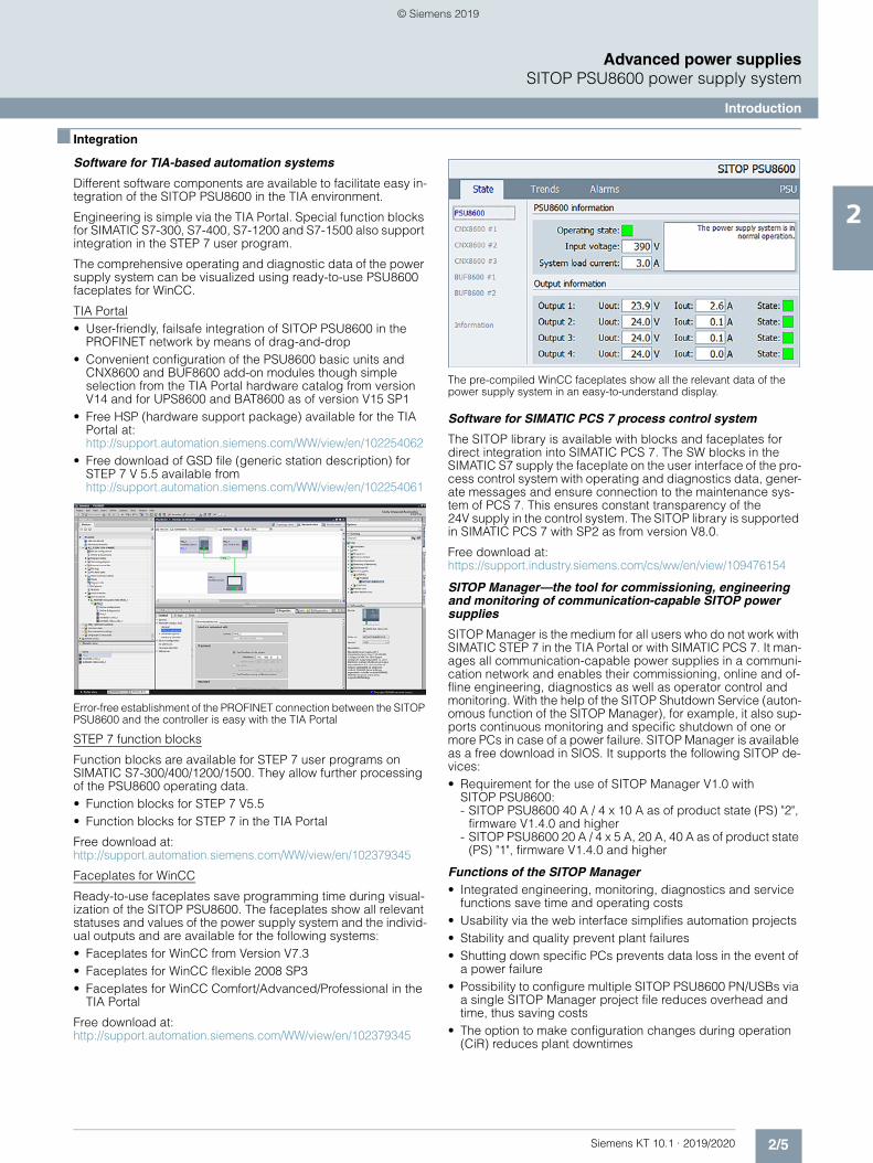
The comprehensive operating and diagnostic data of the power supply system can be visualized using ready-to-use PSU8600 faceplates for WinCC.
TIA Portal• User-friendly, failsafe integration of SITOP PSU8600 in the
PROFINET network by means of drag-and-drop• Convenient configuration of the PSU8600 basic units and
CNX8600 and BUF8600 add-on modules though simple selection from the TIA Portal hardware catalog from version V14 and for UPS8600 and BAT8600 as of version V15 SP1
• Free HSP (hardware support package) available for the TIA Portal at:http://support.automation.siemens.com/WW/view/en/102254062
• Free download of GSD file (generic station description) for STEP 7 V 5.5 available fromhttp://support.automation.siemens.com/WW/view/en/102254061
Error-free establishment of the PROFINET connection between the SITOP PSU8600 and the controller is easy with the TIA Portal
STEP 7 function blocks
Function blocks are available for STEP 7 user programs on SIMATIC S7-300/400/1200/1500. They allow further processing of the PSU8600 operating data.• Function blocks for STEP 7 V5.5• Function blocks for STEP 7 in the TIA Portal
Free download at:http://support.automation.siemens.com/WW/view/en/102379345
Faceplates for WinCC
Ready-to-use faceplates save programming time during visual-ization of the SITOP PSU8600. The faceplates show all relevant statuses and values of the power supply system and the individ-ual outputs and are available for the following systems: • Faceplates for WinCC from Version V7.3• Faceplates for WinCC flexible 2008 SP3• Faceplates for WinCC Comfort/Advanced/Professional in the
TIA Portal
Free download at:http://support.automation.siemens.com/WW/view/en/102379345
The pre-compiled WinCC faceplates show all the relevant data of the power supply system in an easy-to-understand display.
Software for SIMATIC PCS 7 process control system
The SITOP library is available with blocks and faceplates for direct integration into SIMATIC PCS 7. The SW blocks in the SIMATIC S7 supply the faceplate on the user interface of the pro-cess control system with operating and diagnostics data, gener-ate messages and ensure connection to the maintenance sys-tem of PCS 7. This ensures constant transparency of the 24V supply in the control system. The SITOP library is supported in SIMATIC PCS 7 with SP2 as from version V8.0.
Free download at: https://support.industry.siemens.com/cs/ww/en/view/109476154
SITOP Manager—the tool for commissioning, engineering and monitoring of communication-capable SITOP power supplies
SITOP Manager is the medium for all users who do not work with SIMATIC STEP 7 in the TIA Portal or with SIMATIC PCS 7. It man-ages all communication-capable power supplies in a communi-cation network and enables their commissioning, online and of-fline engineering, diagnostics as well as operator control and monitoring. With the help of the SITOP Shutdown Service (auton-omous function of the SITOP Manager), for example, it also sup-ports continuous monitoring and specific shutdown of one or more PCs in case of a power failure. SITOP Manager is available as a free download in SIOS. It supports the following SITOP de-vices:• Requirement for the use of SITOP Manager V1.0 with
SITOP PSU8600:- SITOP PSU8600 40 A / 4 x 10 A as of product state (PS) "2",
firmware V1.4.0 and higher- SITOP PSU8600 20 A / 4 x 5 A, 20 A, 40 A as of product state
(PS) "1", firmware V1.4.0 and higher
Functions of the SITOP Manager• Integrated engineering, monitoring, diagnostics and service
functions save time and operating costs• Usability via the web interface simplifies automation projects• Stability and quality prevent plant failures• Shutting down specific PCs prevents data loss in the event of
a power failure• Possibility to configure multiple SITOP PSU8600 PN/USBs via
a single SITOP Manager project file reduces overhead and time, thus saving costs
• The option to make configuration changes during operation (CiR) reduces plant downtimes
© Siemens 2019
2/6 Siemens KT 10.1 · 2019/2020
2
■ Integration (continued)
Advanced power suppliesSITOP PSU8600 power supply system
Introduction
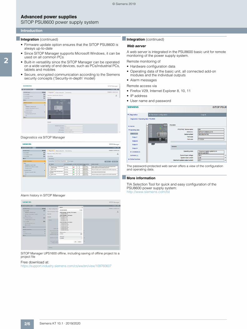
• Firmware update option ensures that the SITOP PSU8600 is always up-to-date
• Since SITOP Manager supports Microsoft Windows, it can be used on all common PCs
• Built-in versatility since the SITOP Manager can be operated on a wide variety of end devices, such as PCs/industrial PCs, tablets and mobiles
• Secure, encrypted communication according to the Siemens security concepts ('Security-in-depth' model)
Diagnostics via SITOP Manager
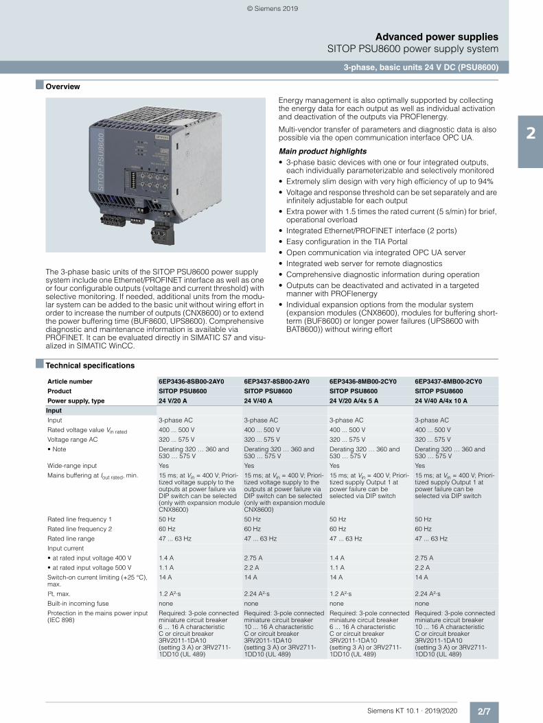
Alarm history in SITOP Manager
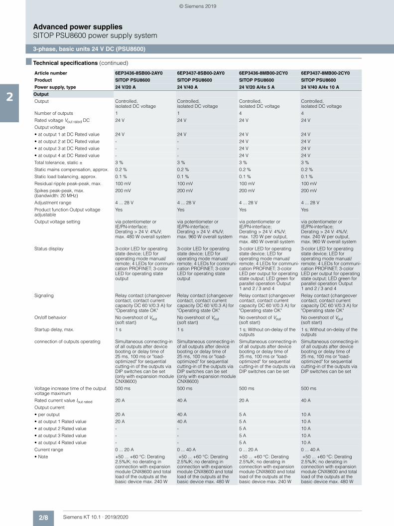
SITOP Manager UPS1600 offline, including saving of offline project to a project file
Free download at: https://support.industry.siemens.com/cs/ww/en/view/109760607
■ Integration (continued)
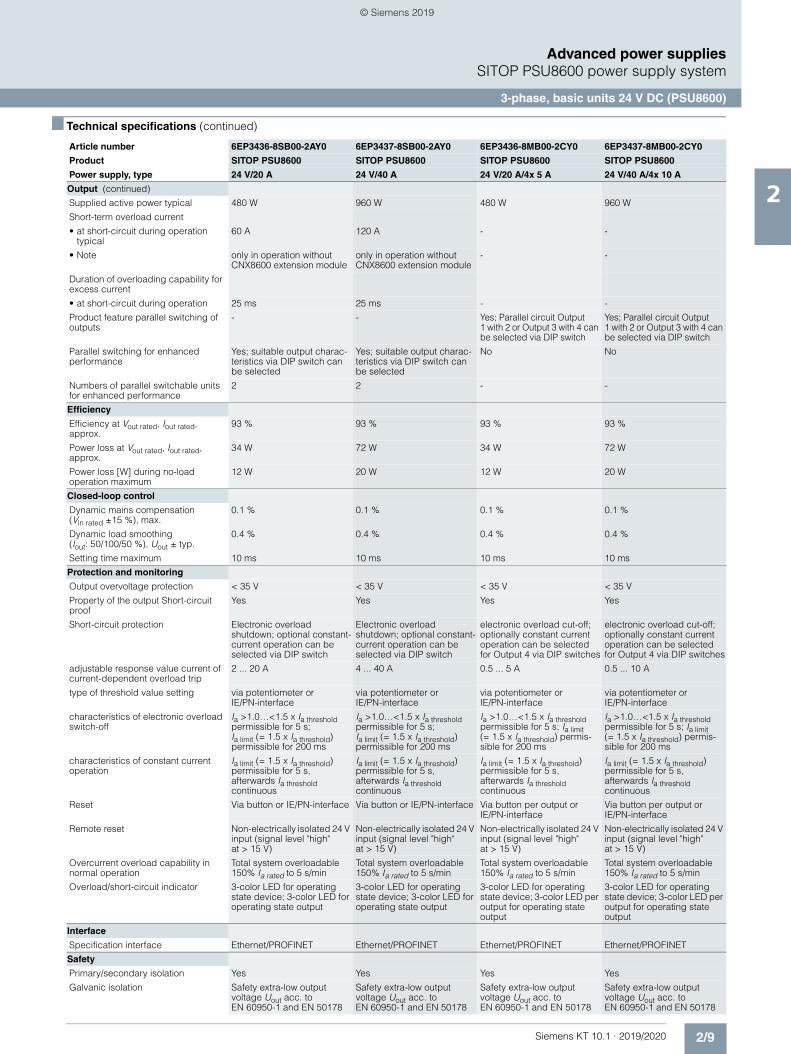
Web server
A web server is integrated in the PSU8600 basic unit for remote monitoring of the power supply system.
Remote monitoring of• Hardware configuration data• Operating data of the basic unit, all connected add-on
modules and the individual outputs• Alarm messages
Remote access via• Firefox V29, Internet Explorer 8, 10, 11• IP address• User name and password
The password-protected web server offers a view of the configuration and operating data.
■ More information
TIA Selection Tool for quick and easy configuration of the PSU8600 power supply system:http://www.siemens.com/tst
© Siemens 2019
2/7Siemens KT 10.1 · 2019/2020
2
Advanced power suppliesSITOP PSU8600 power supply system
3-phase, basic units 24 V DC (PSU8600)
■ Overview
The 3-phase basic units of the SITOP PSU8600 power supply system include one Ethernet/PROFINET interface as well as one or four configurable outputs (voltage and current threshold) with selective monitoring. If needed, additional units from the modu-lar system can be added to the basic unit without wiring effort in order to increase the number of outputs (CNX8600) or to extend the power buffering time (BUF8600, UPS8600). Comprehensive diagnostic and maintenance information is available via PROFINET. It can be evaluated directly in SIMATIC S7 and visu-alized in SIMATIC WinCC.
Energy management is also optimally supported by collecting the energy data for each output as well as individual activation and deactivation of the outputs via PROFIenergy.
Multi-vendor transfer of parameters and diagnostic data is also possible via the open communication interface OPC UA.
Main product highlights• 3-phase basic devices with one or four integrated outputs,
each individually parameterizable and selectively monitored• Extremely slim design with very high efficiency of up to 94%• Voltage and response threshold can be set separately and are
infinitely adjustable for each output• Extra power with 1.5 times the rated current (5 s/min) for brief,
operational overload• Integrated Ethernet/PROFINET interface (2 ports)• Easy configuration in the TIA Portal• Open communication via integrated OPC UA server• Integrated web server for remote diagnostics• Comprehensive diagnostic information during operation• Outputs can be deactivated and activated in a targeted
manner with PROFIenergy• Individual expansion options from the modular system
(expansion modules (CNX8600), modules for buffering short-term (BUF8600) or longer power failures (UPS8600 with BAT8600)) without wiring effort
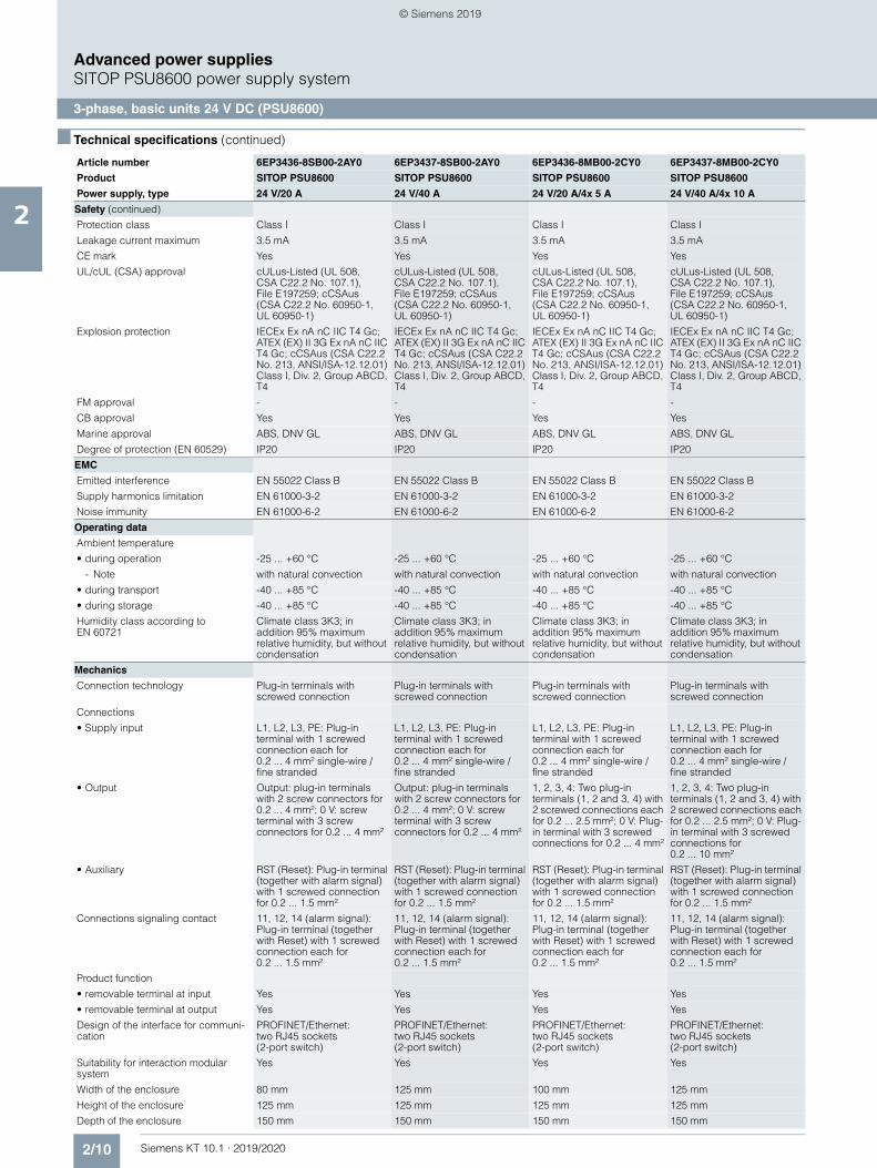
■ Technical specifications
Article number 6EP3436-8SB00-2AY0 6EP3437-8SB00-2AY0 6EP3436-8MB00-2CY0 6EP3437-8MB00-2CY0
Product SITOP PSU8600 SITOP PSU8600 SITOP PSU8600 SITOP PSU8600
Power supply, type 24 V/20 A 24 V/40 A 24 V/20 A/4x 5 A 24 V/40 A/4x 10 A
Input
Input 3-phase AC 3-phase AC 3-phase AC 3-phase AC
Rated voltage value Vin rated 400 ... 500 V 400 ... 500 V 400 ... 500 V 400 ... 500 V
Voltage range AC 320 ... 575 V 320 ... 575 V 320 ... 575 V 320 ... 575 V
• Note Derating 320 … 360 and 530 … 575 V
Derating 320 … 360 and 530 … 575 V
Derating 320 … 360 and 530 … 575 V
Derating 320 … 360 and 530 … 575 V
Wide-range input Yes Yes Yes Yes
Mains buffering at Iout rated, min. 15 ms; at Vin = 400 V; Priori-tized voltage supply to the outputs at power failure via DIP switch can be selected (only with expansion module CNX8600)
15 ms; at Vin = 400 V; Priori-tized voltage supply to the outputs at power failure via DIP switch can be selected (only with expansion module CNX8600)
15 ms; at Vin = 400 V; Priori-tized supply Output 1 at power failure can be selected via DIP switch
15 ms; at Vin = 400 V; Priori-tized supply Output 1 at power failure can be selected via DIP switch
Rated line frequency 1 50 Hz 50 Hz 50 Hz 50 Hz
Rated line frequency 2 60 Hz 60 Hz 60 Hz 60 Hz
Rated line range 47 ... 63 Hz 47 ... 63 Hz 47 ... 63 Hz 47 ... 63 Hz
Input current
• at rated input voltage 400 V 1.4 A 2.75 A 1.4 A 2.75 A
• at rated input voltage 500 V 1.1 A 2.2 A 1.1 A 2.2 A
Switch-on current limiting (+25 °C), max.
14 A 14 A 14 A 14 A
I²t, max. 1.2 A²·s 2.24 A²·s 1.2 A²·s 2.24 A²·s
Built-in incoming fuse none none none none
Protection in the mains power input (IEC 898)
Required: 3-pole connected miniature circuit breaker 6 ... 16 A characteristic C or circuit breaker 3RV2011-1DA10 (setting 3 A) or 3RV2711-1DD10 (UL 489)
Required: 3-pole connected miniature circuit breaker 10 ... 16 A characteristic C or circuit breaker 3RV2011-1DA10 (setting 3 A) or 3RV2711-1DD10 (UL 489)
© Siemens 2019
2/8 Siemens KT 10.1 · 2019/2020
2
■ Technical specifications (continued)
Advanced power suppliesSITOP PSU8600 power supply system
3-phase, basic units 24 V DC (PSU8600)
Output
Output Controlled, isolated DC voltage
Controlled, isolated DC voltage
Controlled, isolated DC voltage
Controlled, isolated DC voltage
Number of outputs 1 1 4 4
Rated voltage Vout rated DC 24 V 24 V 24 V 24 V
Output voltage
• at output 1 at DC Rated value 24 V 24 V 24 V 24 V
• at output 2 at DC Rated value - - 24 V 24 V
• at output 3 at DC Rated value - - 24 V 24 V
• at output 4 at DC Rated value - - 24 V 24 V
Total tolerance, static ± 3 % 3 % 3 % 3 %
Static mains compensation, approx. 0.2 % 0.2 % 0.2 % 0.2 %
Static load balancing, approx. 0.1 % 0.1 % 0.1 % 0.1 %
Residual ripple peak-peak, max. 100 mV 100 mV 100 mV 100 mV
Spikes peak-peak, max. (bandwidth: 20 MHz)
200 mV 200 mV 200 mV 200 mV
Adjustment range 4 ... 28 V 4 ... 28 V 4 ... 28 V 4 ... 28 V
Product function Output voltage adjustable
Yes Yes Yes Yes
Output voltage setting via potentiometer or IE/PN-interface; Derating > 24 V: 4%/V; max. 480 W overall system
via potentiometer or IE/PN-interface; Derating > 24 V: 4%/V; max. 960 W overall system
via potentiometer or IE/PN-interface; Derating > 24 V: 4%/V; max. 120 W per output, max. 480 W overall system
via potentiometer or IE/PN-interface; Derating > 24 V: 4%/V; max. 240 W per output, max. 960 W overall system
Status display 3-color LED for operating state device; LED for operating mode manual/remote; 4 LEDs for communi-cation PROFINET; 3-color LED for operating state output
3-color LED for operating state device; LED for operating mode manual/remote; 4 LEDs for communi-cation PROFINET; 3-color LED for operating state output
3-color LED for operating state device; LED for operating mode manual/remote; 4 LEDs for communi-cation PROFINET; 3-color LED per output for operating state output; LED green for parallel operation Output 1 and 2 / 3 and 4
3-color LED for operating state device; LED for operating mode manual/remote; 4 LEDs for communi-cation PROFINET; 3-color LED per output for operating state output; LED green for parallel operation Output 1 and 2 / 3 and 4
Signaling Relay contact (changeover contact, contact current capacity DC 60 V/0.3 A) for "Operating state OK"
Relay contact (changeover contact, contact current capacity DC 60 V/0.3 A) for "Operating state OK"
Relay contact (changeover contact, contact current capacity DC 60 V/0.3 A) for "Operating state OK"
Relay contact (changeover contact, contact current capacity DC 60 V/0.3 A) for "Operating state OK"
On/off behavior No overshoot of Vout (soft start)
No overshoot of Vout (soft start)
No overshoot of Vout (soft start)
No overshoot of Vout (soft start)
Startup delay, max. 1 s 1 s 1 s; Without on-delay of the outputs
1 s; Without on-delay of the outputs
connection of outputs operating Simultaneous connecting-in of all outputs after device booting or delay time of 25 ms, 100 ms or "load-optimized" for sequential cutting-in of the outputs via DIP switches can be set (only with expansion module CNX8600)
Simultaneous connecting-in of all outputs after device booting or delay time of 25 ms, 100 ms or "load-optimized" for sequential cutting-in of the outputs via DIP switches can be set (only with expansion module CNX8600)
Simultaneous connecting-in of all outputs after device booting or delay time of 25 ms, 100 ms or "load-optimized" for sequential cutting-in of the outputs via DIP switches can be set
Simultaneous connecting-in of all outputs after device booting or delay time of 25 ms, 100 ms or "load-optimized" for sequential cutting-in of the outputs via DIP switches can be set
Voltage increase time of the output voltage maximum
500 ms 500 ms 500 ms 500 ms
Rated current value Iout rated 20 A 40 A 20 A 40 A
Output current
• per output 20 A 40 A 5 A 10 A
• at output 1 Rated value 20 A 40 A 5 A 10 A
• at output 2 Rated value - - 5 A 10 A
• at output 3 Rated value - - 5 A 10 A
• at output 4 Rated value - - 5 A 10 A
Current range 0 ... 20 A 0 ... 40 A 0 ... 20 A 0 ... 40 A
• Note +50 ... +60 °C: Derating 2.5%/K; no derating in connection with expansion module CNX8600 and total load of the outputs at the basic device max. 240 W
+50 ... +60 °C: Derating 2.5%/K; no derating in connection with expansion module CNX8600 and total load of the outputs at the basic device max. 480 W
+50 ... +60 °C: Derating 2.5%/K; no derating in connection with expansion module CNX8600 and total load of the outputs at the basic device max. 240 W
+50 ... +60 °C: Derating 2.5%/K; no derating in connection with expansion module CNX8600 and total load of the outputs at the basic device max. 480 W
Article number 6EP3436-8SB00-2AY0 6EP3437-8SB00-2AY0 6EP3436-8MB00-2CY0 6EP3437-8MB00-2CY0
Product SITOP PSU8600 SITOP PSU8600 SITOP PSU8600 SITOP PSU8600
Power supply, type 24 V/20 A 24 V/40 A 24 V/20 A/4x 5 A 24 V/40 A/4x 10 A
© Siemens 2019
2/9Siemens KT 10.1 · 2019/2020
2
■ Technical specifications (continued)
Advanced power suppliesSITOP PSU8600 power supply system
3-phase, basic units 24 V DC (PSU8600)
Output (continued)
Supplied active power typical 480 W 960 W 480 W 960 W
Short-term overload current
• at short-circuit during operation typical
60 A 120 A - -
• Note only in operation without CNX8600 extension module
only in operation without CNX8600 extension module
- -
Duration of overloading capability for excess current
• at short-circuit during operation 25 ms 25 ms - -
Product feature parallel switching of outputs
- - Yes; Parallel circuit Output 1 with 2 or Output 3 with 4 can be selected via DIP switch
Yes; Parallel circuit Output 1 with 2 or Output 3 with 4 can be selected via DIP switch
Parallel switching for enhanced performance
Yes; suitable output charac-teristics via DIP switch can be selected
Yes; suitable output charac-teristics via DIP switch can be selected
No No
Numbers of parallel switchable units for enhanced performance
2 2 - -
Efficiency
Efficiency at Vout rated, Iout rated, approx.
93 % 93 % 93 % 93 %
Power loss at Vout rated, Iout rated, approx.
34 W 72 W 34 W 72 W
Power loss [W] during no-load operation maximum
12 W 20 W 12 W 20 W
Closed-loop control
Dynamic mains compensation (Vin rated ±15 %), max.
0.1 % 0.1 % 0.1 % 0.1 %
Dynamic load smoothing (Iout: 50/100/50 %), Uout ± typ.
0.4 % 0.4 % 0.4 % 0.4 %
Setting time maximum 10 ms 10 ms 10 ms 10 ms
Protection and monitoring
Output overvoltage protection < 35 V < 35 V < 35 V < 35 V
Property of the output Short-circuit proof
Yes Yes Yes Yes
Short-circuit protection Electronic overload shutdown; optional constant-current operation can be selected via DIP switch
Electronic overload shutdown; optional constant-current operation can be selected via DIP switch
electronic overload cut-off; optionally constant current operation can be selected for Output 4 via DIP switches
electronic overload cut-off; optionally constant current operation can be selected for Output 4 via DIP switches
adjustable response value current of current-dependent overload trip
2 ... 20 A 4 ... 40 A 0.5 ... 5 A 0.5 ... 10 A
type of threshold value setting via potentiometer or IE/PN-interface
via potentiometer or IE/PN-interface
via potentiometer or IE/PN-interface
via potentiometer or IE/PN-interface
characteristics of electronic overload switch-off
Ia >1.0…<1.5 x Ia threshold permissible for 5 s; Ia limit (= 1.5 x Ia threshold) permissible for 200 ms
Ia >1.0…<1.5 x Ia threshold permissible for 5 s; Ia limit (= 1.5 x Ia threshold) permissible for 200 ms
Ia >1.0…<1.5 x Ia threshold permissible for 5 s; Ia limit (= 1.5 x Ia threshold) permis-sible for 200 ms
Ia >1.0…<1.5 x Ia threshold permissible for 5 s; Ia limit (= 1.5 x Ia threshold) permis-sible for 200 ms
characteristics of constant current operation
Ia limit (= 1.5 x Ia threshold) permissible for 5 s, afterwards Ia threshold continuous
Ia limit (= 1.5 x Ia threshold) permissible for 5 s, afterwards Ia threshold continuous
Ia limit (= 1.5 x Ia threshold) permissible for 5 s, afterwards Ia threshold continuous
Ia limit (= 1.5 x Ia threshold) permissible for 5 s, afterwards Ia threshold continuous
Reset Via button or IE/PN-interface Via button or IE/PN-interface Via button per output or IE/PN-interface
Via button per output or IE/PN-interface
Remote reset Non-electrically isolated 24 V input (signal level "high" at > 15 V)
Non-electrically isolated 24 V input (signal level "high" at > 15 V)
Non-electrically isolated 24 V input (signal level "high" at > 15 V)
Non-electrically isolated 24 V input (signal level "high" at > 15 V)
Overcurrent overload capability in normal operation
Total system overloadable 150% Ia rated to 5 s/min
Total system overloadable 150% Ia rated to 5 s/min
Total system overloadable 150% Ia rated to 5 s/min
Total system overloadable 150% Ia rated to 5 s/min
Overload/short-circuit indicator 3-color LED for operating state device; 3-color LED for operating state output
3-color LED for operating state device; 3-color LED for operating state output
3-color LED for operating state device; 3-color LED per output for operating state output
3-color LED for operating state device; 3-color LED per output for operating state output
Interface
Specification interface Ethernet/PROFINET Ethernet/PROFINET Ethernet/PROFINET Ethernet/PROFINET
Safety
Primary/secondary isolation Yes Yes Yes Yes
Galvanic isolation Safety extra-low output voltage Uout acc. to EN 60950-1 and EN 50178
Safety extra-low output voltage Uout acc. to EN 60950-1 and EN 50178
Safety extra-low output voltage Uout acc. to EN 60950-1 and EN 50178
Safety extra-low output voltage Uout acc. to EN 60950-1 and EN 50178
Article number 6EP3436-8SB00-2AY0 6EP3437-8SB00-2AY0 6EP3436-8MB00-2CY0 6EP3437-8MB00-2CY0
Product SITOP PSU8600 SITOP PSU8600 SITOP PSU8600 SITOP PSU8600
Power supply, type 24 V/20 A 24 V/40 A 24 V/20 A/4x 5 A 24 V/40 A/4x 10 A
© Siemens 2019
2/10 Siemens KT 10.1 · 2019/2020
2
■ Technical specifications (continued)
Advanced power suppliesSITOP PSU8600 power supply system
3-phase, basic units 24 V DC (PSU8600)
Safety (continued)
Protection class Class I Class I Class I Class I
Leakage current maximum 3.5 mA 3.5 mA 3.5 mA 3.5 mA
CE mark Yes Yes Yes Yes
UL/cUL (CSA) approval cULus-Listed (UL 508, CSA C22.2 No. 107.1), File E197259; cCSAus (CSA C22.2 No. 60950-1, UL 60950-1)
cULus-Listed (UL 508, CSA C22.2 No. 107.1), File E197259; cCSAus (CSA C22.2 No. 60950-1, UL 60950-1)
cULus-Listed (UL 508, CSA C22.2 No. 107.1), File E197259; cCSAus (CSA C22.2 No. 60950-1, UL 60950-1)
cULus-Listed (UL 508, CSA C22.2 No. 107.1), File E197259; cCSAus (CSA C22.2 No. 60950-1, UL 60950-1)
Explosion protection IECEx Ex nA nC IIC T4 Gc; ATEX (EX) II 3G Ex nA nC IIC T4 Gc; cCSAus (CSA C22.2 No. 213, ANSI/ISA-12.12.01) Class I, Div. 2, Group ABCD, T4
IECEx Ex nA nC IIC T4 Gc; ATEX (EX) II 3G Ex nA nC IIC T4 Gc; cCSAus (CSA C22.2 No. 213, ANSI/ISA-12.12.01) Class I, Div. 2, Group ABCD, T4
IECEx Ex nA nC IIC T4 Gc; ATEX (EX) II 3G Ex nA nC IIC T4 Gc; cCSAus (CSA C22.2 No. 213, ANSI/ISA-12.12.01) Class I, Div. 2, Group ABCD, T4
IECEx Ex nA nC IIC T4 Gc; ATEX (EX) II 3G Ex nA nC IIC T4 Gc; cCSAus (CSA C22.2 No. 213, ANSI/ISA-12.12.01) Class I, Div. 2, Group ABCD, T4
FM approval - - - -
CB approval Yes Yes Yes Yes
Marine approval ABS, DNV GL ABS, DNV GL ABS, DNV GL ABS, DNV GL
Degree of protection (EN 60529) IP20 IP20 IP20 IP20
EMC
Emitted interference EN 55022 Class B EN 55022 Class B EN 55022 Class B EN 55022 Class B
Supply harmonics limitation EN 61000-3-2 EN 61000-3-2 EN 61000-3-2 EN 61000-3-2
Noise immunity EN 61000-6-2 EN 61000-6-2 EN 61000-6-2 EN 61000-6-2
Operating data
Ambient temperature
• during operation -25 ... +60 °C -25 ... +60 °C -25 ... +60 °C -25 ... +60 °C
- Note with natural convection with natural convection with natural convection with natural convection
• during transport -40 ... +85 °C -40 ... +85 °C -40 ... +85 °C -40 ... +85 °C
• during storage -40 ... +85 °C -40 ... +85 °C -40 ... +85 °C -40 ... +85 °C
Humidity class according to EN 60721
Climate class 3K3; in addition 95% maximum relative humidity, but without condensation
Climate class 3K3; in addition 95% maximum relative humidity, but without condensation
Climate class 3K3; in addition 95% maximum relative humidity, but without condensation
Climate class 3K3; in addition 95% maximum relative humidity, but without condensation
Mechanics
Connection technology Plug-in terminals with screwed connection
Plug-in terminals with screwed connection
Plug-in terminals with screwed connection
Plug-in terminals with screwed connection
Connections
• Supply input L1, L2, L3, PE: Plug-in terminal with 1 screwed connection each for 0.2 ... 4 mm² single-wire / fine stranded
L1, L2, L3, PE: Plug-in terminal with 1 screwed connection each for 0.2 ... 4 mm² single-wire / fine stranded
L1, L2, L3, PE: Plug-in terminal with 1 screwed connection each for 0.2 ... 4 mm² single-wire / fine stranded
L1, L2, L3, PE: Plug-in terminal with 1 screwed connection each for 0.2 ... 4 mm² single-wire / fine stranded
• Output Output: plug-in terminals with 2 screw connectors for 0.2 ... 4 mm²; 0 V: screw terminal with 3 screw connectors for 0.2 ... 4 mm²
Output: plug-in terminals with 2 screw connectors for 0.2 ... 4 mm²; 0 V: screw terminal with 3 screw connectors for 0.2 ... 4 mm²
1, 2, 3, 4: Two plug-in terminals (1, 2 and 3, 4) with 2 screwed connections each for 0.2 ... 2.5 mm²; 0 V: Plug-in terminal with 3 screwed connections for 0.2 ... 4 mm²
1, 2, 3, 4: Two plug-in terminals (1, 2 and 3, 4) with 2 screwed connections each for 0.2 ... 2.5 mm²; 0 V: Plug-in terminal with 3 screwed connections for 0.2 ... 10 mm²
• Auxiliary RST (Reset): Plug-in terminal (together with alarm signal) with 1 screwed connection for 0.2 ... 1.5 mm²
RST (Reset): Plug-in terminal (together with alarm signal) with 1 screwed connection for 0.2 ... 1.5 mm²
RST (Reset): Plug-in terminal (together with alarm signal) with 1 screwed connection for 0.2 ... 1.5 mm²
RST (Reset): Plug-in terminal (together with alarm signal) with 1 screwed connection for 0.2 ... 1.5 mm²
Connections signaling contact 11, 12, 14 (alarm signal): Plug-in terminal (together with Reset) with 1 screwed connection each for 0.2 ... 1.5 mm²
11, 12, 14 (alarm signal): Plug-in terminal (together with Reset) with 1 screwed connection each for 0.2 ... 1.5 mm²
11, 12, 14 (alarm signal): Plug-in terminal (together with Reset) with 1 screwed connection each for 0.2 ... 1.5 mm²
11, 12, 14 (alarm signal): Plug-in terminal (together with Reset) with 1 screwed connection each for 0.2 ... 1.5 mm²
Product function
• removable terminal at input Yes Yes Yes Yes
• removable terminal at output Yes Yes Yes Yes
Design of the interface for communi-cation
PROFINET/Ethernet: two RJ45 sockets (2-port switch)
PROFINET/Ethernet: two RJ45 sockets (2-port switch)
PROFINET/Ethernet: two RJ45 sockets (2-port switch)
PROFINET/Ethernet: two RJ45 sockets (2-port switch)
Suitability for interaction modular system
Yes Yes Yes Yes
Width of the enclosure 80 mm 125 mm 100 mm 125 mm
Height of the enclosure 125 mm 125 mm 125 mm 125 mm
Depth of the enclosure 150 mm 150 mm 150 mm 150 mm
Article number 6EP3436-8SB00-2AY0 6EP3437-8SB00-2AY0 6EP3436-8MB00-2CY0 6EP3437-8MB00-2CY0
Product SITOP PSU8600 SITOP PSU8600 SITOP PSU8600 SITOP PSU8600
Power supply, type 24 V/20 A 24 V/40 A 24 V/20 A/4x 5 A 24 V/40 A/4x 10 A
© Siemens 2019
2/11Siemens KT 10.1 · 2019/2020
2
■ Technical specifications (continued)
Advanced power suppliesSITOP PSU8600 power supply system
3-phase, basic units 24 V DC (PSU8600)
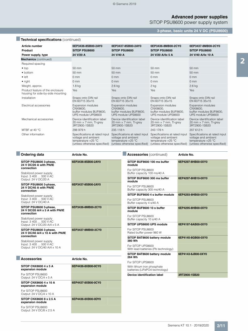
■ Ordering data Article No.
■ Accessories Article No.
■ Accessories (continued) Article No.
Mechanics (continued)
Required spacing
• top 50 mm 50 mm 50 mm 50 mm
• bottom 50 mm 50 mm 50 mm 50 mm
• left 0 mm 0 mm 0 mm 0 mm
• right 0 mm 0 mm 0 mm 0 mm
Weight, approx. 1.8 kg 2.6 kg 2 kg 2.6 kg
Product feature of the enclosure housing for side-by-side mounting
Yes Yes Yes Yes
Installation Snaps onto DIN rail EN 60715 35x15
Snaps onto DIN rail EN 60715 35x15
Snaps onto DIN rail EN 60715 35x15
Snaps onto DIN rail EN 60715 35x15
Electrical accessories Expansion modules CNX8600, buffer modules BUF8600, UPS module UPS8600
Expansion modules CNX8600, buffer modules BUF8600, UPS module UPS8600
Expansion modules CNX8600, buffer modules BUF8600, UPS module UPS8600
Expansion modules CNX8600, buffer modules BUF8600, UPS module UPS8600
Mechanical accessories Device identification label 20 mm × 7 mm, TI-grey 3RT2900-1SB20
Device identification label 20 mm × 7 mm, TI-grey 3RT2900-1SB20
Device identification label 20 mm × 7 mm, TI-grey 3RT2900-1SB20
Device identification label 20 mm × 7 mm, TI-grey 3RT2900-1SB20
MTBF at 40 °C 298 979 h 235 118 h 243 178 h 207 612 h
Other information Specifications at rated input voltage and ambient temperature +25 °C (unless otherwise specified)
Specifications at rated input voltage and ambient temperature +25 °C (unless otherwise specified)
Specifications at rated input voltage and ambient temperature +25 °C (unless otherwise specified)
Specifications at rated input voltage and ambient temperature +25 °C (unless otherwise specified)
Article number 6EP3436-8SB00-2AY0 6EP3437-8SB00-2AY0 6EP3436-8MB00-2CY0 6EP3437-8MB00-2CY0
Product SITOP PSU8600 SITOP PSU8600 SITOP PSU8600 SITOP PSU8600
Power supply, type 24 V/20 A 24 V/40 A 24 V/20 A/4x 5 A 24 V/40 A/4x 10 A
SITOP PSU8600 3-phase, 24 V DC/20 A with PN/IE connection
6EP3436-8SB00-2AY0
Stabilized power supplyInput: 3 400 … 500 V ACOutput: 24 V DC/20 A
SITOP PSU8600 3-phase, 24 V DC/40 A with PN/IE connection
6EP3437-8SB00-2AY0
Stabilized power supplyInput: 3 400 … 500 V ACOutput: 24 V DC/40 A
SITOP PSU8600 3-phase, 24 V DC/20 A/4 x 5 A with PN/IE connection
6EP3436-8MB00-2CY0
Stabilized power supplyInput: 3 400 … 500 V ACOutput: 24 V DC/20 A/4 x 5 A
SITOP PSU8600 3-phase, 24 V DC/40 A/4 x 10 A with PN/IE connection
6EP3437-8MB00-2CY0
Stabilized power supplyInput: 3 400 … 500 V ACOutput: 24 V DC/40 A/4 x 10 A
SITOP CNX8600 4 x 5 A expansion module
6EP4436-8XB00-0CY0
For SITOP PSU8600Output: 24 V DC/4 x 5 A
SITOP CNX8600 4 x 10 Aexpansion module
6EP4437-8XB00-0CY0
For SITOP PSU8600Output: 24 V DC/4 x 10 A
SITOP CNX8600 8 x 2.5 A expansion module
6EP4436-8XB00-0DY0
For SITOP PSU8600Output: 24 V DC/8 x 2.5 A
SITOP BUF8600 100 ms buffer module
6EP4297-8HB00-0XY0
For SITOP PSU8600Buffer capacity 100 ms/40 A
SITOP BUF8600 300 ms buffer module
6EP4297-8HB10-0XY0
For SITOP PSU8600Buffer capacity 300 ms/40 A
SITOP BUF8600 4 s buffer module 6EP4293-8HB00-0XY0
For SITOP PSU8600 Buffer capacity 4 s/40 A
SITOP BUF8600 10 s buffer module
6EP4295-8HB00-0XY0
For SITOP PSU8600 Buffer capacity 10 s/40 A
SITOP UPS8600 UPS module 6EP4197-8AB00-0XY0
For SITOP PSU8600 Rated buffer power 960 W
SITOP BAT8600 battery module 380 Wh
6EP4145-8GB00-0XY0
For SITOP UPS8600With lead batteries (Pb technology)
SITOP BAT8600 battery module 264 Wh
6EP4143-8JB00-0XY0
For SITOP UPS8600
With lithium iron phosphate batteries (LiFePO4 technology)
Device identification label 3RT2900-1SB20
© Siemens 2019
2/12 Siemens KT 10.1 · 2019/2020
2
Advanced power suppliesSITOP PSU8600 power supply system
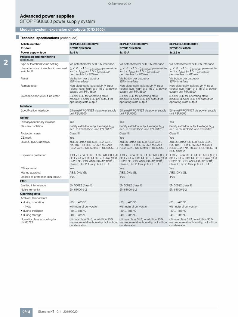
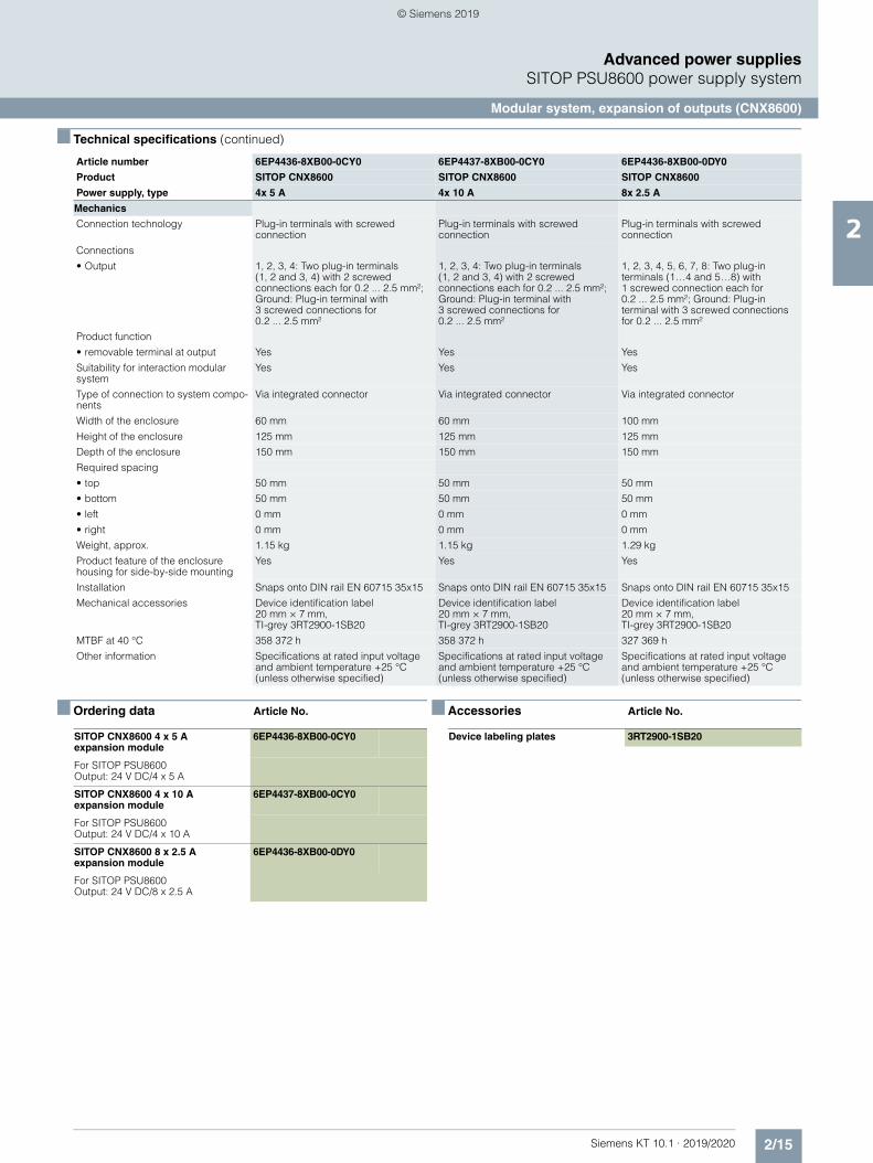
Modular system, expansion of outputs (CNX8600)
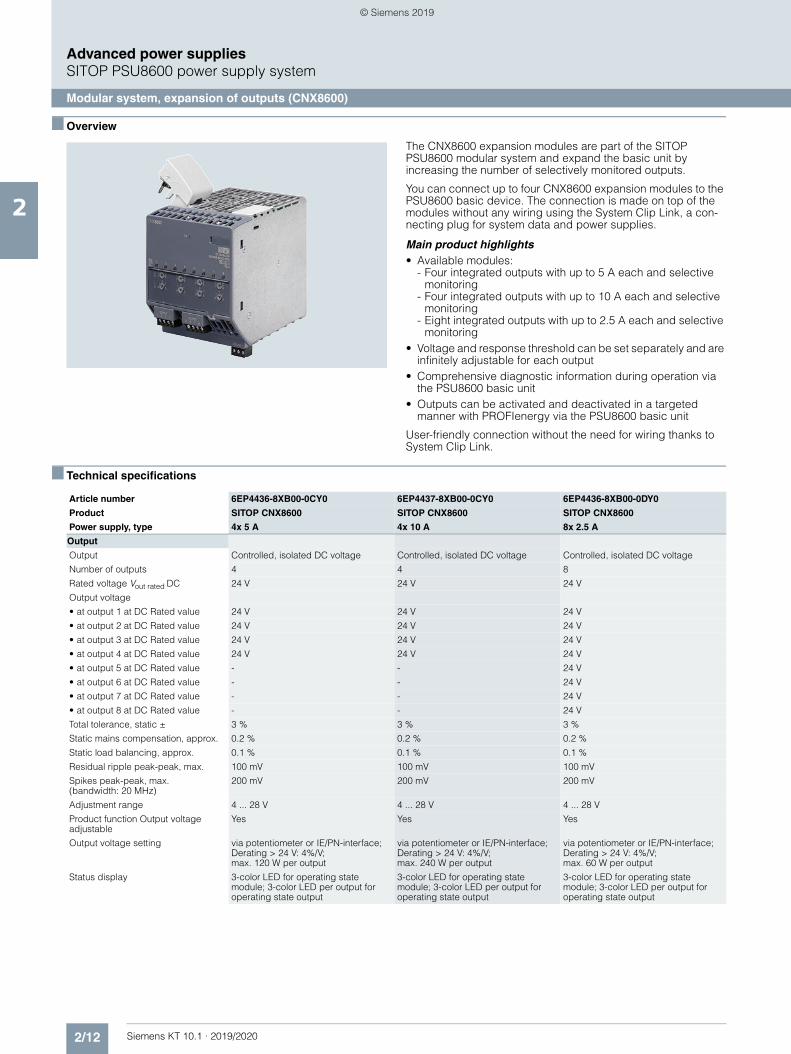
■ Overview
The CNX8600 expansion modules are part of the SITOP PSU8600 modular system and expand the basic unit by increasing the number of selectively monitored outputs.
You can connect up to four CNX8600 expansion modules to the PSU8600 basic device. The connection is made on top of the modules without any wiring using the System Clip Link, a con-necting plug for system data and power supplies.
Main product highlights• Available modules:
- Four integrated outputs with up to 5 A each and selective monitoring
- Four integrated outputs with up to 10 A each and selective monitoring
- Eight integrated outputs with up to 2.5 A each and selective monitoring
• Voltage and response threshold can be set separately and are infinitely adjustable for each output
• Comprehensive diagnostic information during operation via the PSU8600 basic unit
• Outputs can be activated and deactivated in a targeted manner with PROFIenergy via the PSU8600 basic unit
User-friendly connection without the need for wiring thanks to System Clip Link.
■ Technical specifications
Article number 6EP4436-8XB00-0CY0 6EP4437-8XB00-0CY0 6EP4436-8XB00-0DY0
Product SITOP CNX8600 SITOP CNX8600 SITOP CNX8600
Power supply, type 4x 5 A 4x 10 A 8x 2.5 A
Output
Output Controlled, isolated DC voltage Controlled, isolated DC voltage Controlled, isolated DC voltage
Number of outputs 4 4 8
Rated voltage Vout rated DC 24 V 24 V 24 V
Output voltage
• at output 1 at DC Rated value 24 V 24 V 24 V
• at output 2 at DC Rated value 24 V 24 V 24 V
• at output 3 at DC Rated value 24 V 24 V 24 V
• at output 4 at DC Rated value 24 V 24 V 24 V
• at output 5 at DC Rated value - - 24 V
• at output 6 at DC Rated value - - 24 V
• at output 7 at DC Rated value - - 24 V
• at output 8 at DC Rated value - - 24 V
Total tolerance, static ± 3 % 3 % 3 %
Static mains compensation, approx. 0.2 % 0.2 % 0.2 %
Static load balancing, approx. 0.1 % 0.1 % 0.1 %
Residual ripple peak-peak, max. 100 mV 100 mV 100 mV
Spikes peak-peak, max. (bandwidth: 20 MHz)
200 mV 200 mV 200 mV
Adjustment range 4 ... 28 V 4 ... 28 V 4 ... 28 V
Product function Output voltage adjustable
Yes Yes Yes
Output voltage setting via potentiometer or IE/PN-interface; Derating > 24 V: 4%/V; max. 120 W per output
via potentiometer or IE/PN-interface; Derating > 24 V: 4%/V; max. 240 W per output
via potentiometer or IE/PN-interface; Derating > 24 V: 4%/V; max. 60 W per output
Status display 3-color LED for operating state module; 3-color LED per output for operating state output
3-color LED for operating state module; 3-color LED per output for operating state output
3-color LED for operating state module; 3-color LED per output for operating state output
© Siemens 2019
2/13Siemens KT 10.1 · 2019/2020
2
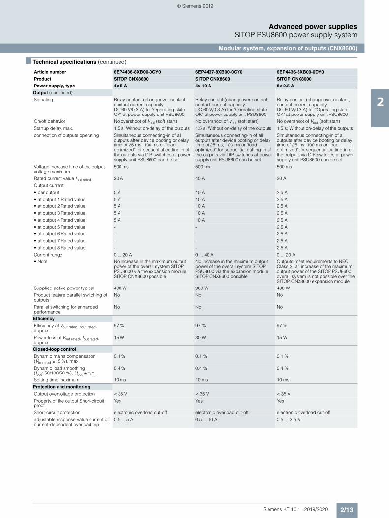
■ Technical specifications (continued)
Advanced power suppliesSITOP PSU8600 power supply system
Modular system, expansion of outputs (CNX8600)
Output (continued)
Signaling Relay contact (changeover contact, contact current capacity DC 60 V/0.3 A) for "Operating state OK" at power supply unit PSU8600
Relay contact (changeover contact, contact current capacity DC 60 V/0.3 A) for "Operating state OK" at power supply unit PSU8600
Relay contact (changeover contact, contact current capacity DC 60 V/0.3 A) for "Operating state OK" at power supply unit PSU8600
On/off behavior No overshoot of Vout (soft start) No overshoot of Vout (soft start) No overshoot of Vout (soft start)
Startup delay, max. 1.5 s; Without on-delay of the outputs 1.5 s; Without on-delay of the outputs 1.5 s; Without on-delay of the outputs
connection of outputs operating Simultaneous connecting-in of all outputs after device booting or delay time of 25 ms, 100 ms or "load-optimized" for sequential cutting-in of the outputs via DIP switches at power supply unit PSU8600 can be set
Simultaneous connecting-in of all outputs after device booting or delay time of 25 ms, 100 ms or "load-optimized" for sequential cutting-in of the outputs via DIP switches at power supply unit PSU8600 can be set
Simultaneous connecting-in of all outputs after device booting or delay time of 25 ms, 100 ms or "load-optimized" for sequential cutting-in of the outputs via DIP switches at power supply unit PSU8600 can be set
Voltage increase time of the output voltage maximum
500 ms 500 ms 500 ms
Rated current value Iout rated 20 A 40 A 20 A
Output current
• per output 5 A 10 A 2.5 A
• at output 1 Rated value 5 A 10 A 2.5 A
• at output 2 Rated value 5 A 10 A 2.5 A
• at output 3 Rated value 5 A 10 A 2.5 A
• at output 4 Rated value 5 A 10 A 2.5 A
• at output 5 Rated value - - 2.5 A
• at output 6 Rated value - - 2.5 A
• at output 7 Rated value - - 2.5 A
• at output 8 Rated value - - 2.5 A
Current range 0 ... 20 A 0 ... 40 A 0 ... 20 A
• Note No increase in the maximum output power of the overall system SITOP PSU8600 via the expansion module SITOP CNX8600 possible
No increase in the maximum output power of the overall system SITOP PSU8600 via the expansion module SITOP CNX8600 possible
Outputs meet requirements to NEC Class 2; an increase of the maximum output power of the SITOP PSU8600 overall system is not possible over the SITOP CNX8600 expansion module
Supplied active power typical 480 W 960 W 480 W
Product feature parallel switching of outputs
No No No
Parallel switching for enhanced performance
No No No
Efficiency
Efficiency at Vout rated, Iout rated, approx.
97 % 97 % 97 %
Power loss at Vout rated, Iout rated, approx.
15 W 30 W 15 W
Closed-loop control
Dynamic mains compensation (Vin rated ±15 %), max.
0.1 % 0.1 % 0.1 %
Dynamic load smoothing (Iout: 50/100/50 %), Uout ± typ.
0.4 % 0.4 % 0.4 %
Setting time maximum 10 ms 10 ms 10 ms
Protection and monitoring
Output overvoltage protection < 35 V < 35 V < 35 V
Property of the output Short-circuit proof
Yes Yes Yes
Short-circuit protection electronic overload cut-off electronic overload cut-off electronic overload cut-off
adjustable response value current of current-dependent overload trip
0.5 ... 5 A 0.5 ... 10 A 0.5 ... 2.5 A
Article number 6EP4436-8XB00-0CY0 6EP4437-8XB00-0CY0 6EP4436-8XB00-0DY0
Product SITOP CNX8600 SITOP CNX8600 SITOP CNX8600
Power supply, type 4x 5 A 4x 10 A 8x 2.5 A
© Siemens 2019
2/14 Siemens KT 10.1 · 2019/2020
2
■ Technical specifications (continued)
Advanced power suppliesSITOP PSU8600 power supply system
Modular system, expansion of outputs (CNX8600)
Protection and monitoring (continued)
type of threshold value setting via potentiometer or IE/PN-interface via potentiometer or IE/PN-interface via potentiometer or IE/PN-interface
characteristics of electronic overload switch-off
Ia >1.0…<1.5 x Ia threshold permissible for 5 s; Ia limit (= 1.5 x Ia threshold) permissible for 200 ms
Ia >1.0…<1.5 x Ia threshold permissible for 5 s; Ia limit (= 1.5 x Ia threshold) permissible for 200 ms
Ia >1.0…<1.5 x Ia threshold permissible for 5 s; Ia limit (= 1.5 x Ia threshold) permissible for 200 ms
Reset Via button per output or IE/PN-interface
Via button per output or IE/PN-interface
Via button per output or IE/PN-interface
Remote reset Non-electrically isolated 24 V input (signal level "high" at > 15 V) at power supply unit PSU8600
Non-electrically isolated 24 V input (signal level "high" at > 15 V) at power supply unit PSU8600
Non-electrically isolated 24 V input (signal level "high" at > 15 V) at power supply unit PSU8600
Overload/short-circuit indicator 3-color LED for operating state module; 3-color LED per output for operating state output
3-color LED for operating state module; 3-color LED per output for operating state output
3-color LED for operating state module; 3-color LED per output for operating state output
Interface
Specification interface Ethernet/PROFINET via power supply unit PSU8600
Ethernet/PROFINET via power supply unit PSU8600
Ethernet/PROFINET via power supply unit PSU8600
Safety
Primary/secondary isolation Yes Yes Yes
Galvanic isolation Safety extra-low output voltage Uout acc. to EN 60950-1 and EN 50178
Safety extra-low output voltage Uout acc. to EN 60950-1 and EN 50178
Safety extra-low output voltage Uout acc. to EN 60950-1 and EN 50178
Protection class Class III Class III Class III
CE mark Yes Yes Yes
UL/cUL (CSA) approval cULus-Listed (UL 508, CSA C22.2 No. 107.1), File E197259; cCSAus (CSA C22.2 No. 60950-1, UL 60950-1)
cULus-Listed (UL 508, CSA C22.2 No. 107.1), File E197259; cCSAus (CSA C22.2 No. 60950-1, UL 60950-1)
cULus-Listed (UL 508, CSA C22.2 No. 107.1), File E197259; cCSAus (CSA C22.2 No. 60950-1, UL 60950-1), NEC class 2
Explosion protection IECEx Ex nA nC IIC T4 Gc; ATEX (EX) II 3G Ex nA nC IIC T4 Gc; cCSAus (CSA C22.2 No. 213, ANSI/ISA-12.12.01) Class I, Div. 2, Group ABCD, T4
IECEx Ex nA nC IIC T4 Gc; ATEX (EX) II 3G Ex nA nC IIC T4 Gc; cCSAus (CSA C22.2 No. 213, ANSI/ISA-12.12.01) Class I, Div. 2, Group ABCD, T4
IECEx Ex nA nC IIC T4 Gc; ATEX (EX) II 3G Ex nA nC IIC T4 Gc; cCSAus (CSA C22.2 No. 213, ANSI/ISA-12.12.01) Class I, Div. 2, Group ABCD, T4
CB approval Yes Yes Yes
Marine approval ABS, DNV GL ABS, DNV GL ABS, DNV GL
Degree of protection (EN 60529) IP20 IP20 IP20
EMC
Emitted interference EN 55022 Class B EN 55022 Class B EN 55022 Class B
Noise immunity EN 61000-6-2 EN 61000-6-2 EN 61000-6-2
Operating data
Ambient temperature
• during operation -25 ... +60 °C -25 ... +60 °C -25 ... +60 °C
- Note with natural convection with natural convection with natural convection
• during transport -40 ... +85 °C -40 ... +85 °C -40 ... +85 °C
• during storage -40 ... +85 °C -40 ... +85 °C -40 ... +85 °C
Humidity class according to EN 60721
Climate class 3K3; in addition 95% maximum relative humidity, but without condensation
Climate class 3K3; in addition 95% maximum relative humidity, but without condensation
Climate class 3K3; in addition 95% maximum relative humidity, but without condensation
Article number 6EP4436-8XB00-0CY0 6EP4437-8XB00-0CY0 6EP4436-8XB00-0DY0
Product SITOP CNX8600 SITOP CNX8600 SITOP CNX8600
Power supply, type 4x 5 A 4x 10 A 8x 2.5 A
© Siemens 2019
2/15Siemens KT 10.1 · 2019/2020
2
■ Technical specifications (continued)
Advanced power suppliesSITOP PSU8600 power supply system
Modular system, expansion of outputs (CNX8600)
■ Ordering data Article No. ■ Accessories Article No.
Mechanics
Connection technology Plug-in terminals with screwed connection
Plug-in terminals with screwed connection
Plug-in terminals with screwed connection
Connections
• Output 1, 2, 3, 4: Two plug-in terminals (1, 2 and 3, 4) with 2 screwed connections each for 0.2 ... 2.5 mm²; Ground: Plug-in terminal with 3 screwed connections for 0.2 ... 2.5 mm²
1, 2, 3, 4: Two plug-in terminals (1, 2 and 3, 4) with 2 screwed connections each for 0.2 ... 2.5 mm²; Ground: Plug-in terminal with 3 screwed connections for 0.2 ... 2.5 mm²
1, 2, 3, 4, 5, 6, 7, 8: Two plug-in terminals (1…4 and 5…8) with 1 screwed connection each for 0.2 ... 2.5 mm²; Ground: Plug-in terminal with 3 screwed connections for 0.2 ... 2.5 mm²
Product function
• removable terminal at output Yes Yes Yes
Suitability for interaction modular system
Yes Yes Yes
Type of connection to system compo-nents
Via integrated connector Via integrated connector Via integrated connector
Width of the enclosure 60 mm 60 mm 100 mm
Height of the enclosure 125 mm 125 mm 125 mm
Depth of the enclosure 150 mm 150 mm 150 mm
Required spacing
• top 50 mm 50 mm 50 mm
• bottom 50 mm 50 mm 50 mm
• left 0 mm 0 mm 0 mm
• right 0 mm 0 mm 0 mm
Weight, approx. 1.15 kg 1.15 kg 1.29 kg
Product feature of the enclosure housing for side-by-side mounting
Yes Yes Yes
Installation Snaps onto DIN rail EN 60715 35x15 Snaps onto DIN rail EN 60715 35x15 Snaps onto DIN rail EN 60715 35x15
Mechanical accessories Device identification label 20 mm × 7 mm, TI-grey 3RT2900-1SB20
Device identification label 20 mm × 7 mm, TI-grey 3RT2900-1SB20
Device identification label 20 mm × 7 mm, TI-grey 3RT2900-1SB20
MTBF at 40 °C 358 372 h 358 372 h 327 369 h
Other information Specifications at rated input voltage and ambient temperature +25 °C (unless otherwise specified)
Specifications at rated input voltage and ambient temperature +25 °C (unless otherwise specified)
Specifications at rated input voltage and ambient temperature +25 °C (unless otherwise specified)
Article number 6EP4436-8XB00-0CY0 6EP4437-8XB00-0CY0 6EP4436-8XB00-0DY0
Product SITOP CNX8600 SITOP CNX8600 SITOP CNX8600
Power supply, type 4x 5 A 4x 10 A 8x 2.5 A
SITOP CNX8600 4 x 5 A expansion module
6EP4436-8XB00-0CY0
For SITOP PSU8600Output: 24 V DC/4 x 5 A
SITOP CNX8600 4 x 10 A expansion module
6EP4437-8XB00-0CY0
For SITOP PSU8600Output: 24 V DC/4 x 10 A
SITOP CNX8600 8 x 2.5 A expansion module
6EP4436-8XB00-0DY0
For SITOP PSU8600Output: 24 V DC/8 x 2.5 A
Device labeling plates 3RT2900-1SB20
© Siemens 2019
2/16 Siemens KT 10.1 · 2019/2020
2
Advanced power suppliesSITOP PSU8600 power supply system
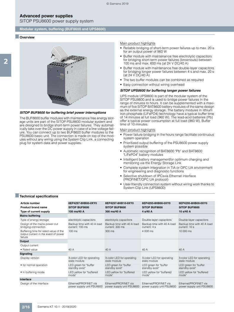
Modular system, buffering (BUF8600 and UPS8600)
■ Overview
SITOP BUF8600 for buffering brief power interruptions
The BUF8600 buffer modules with maintenance free energy stor-age units are part of the SITOP PSU8600 modular system and are designed to bridge short-term power failures. They automat-ically take over the DC power supply in case of a line voltage fail-ure. You can connect up to two BUF8600 buffer modules to the PSU8600 basic unit. The connection is made on top of the mod-ules without any wiring using the System Clip Link, a connecting plug for system data and power supplies.
Main product highlights• Reliable bridging of short-term power failures up to max. 20 s
for an output power of 960 W• Buffer module with maintenance free electrolytic capacitors
for bridging short-term power failures (brownouts) between 100 ms and max. 600 ms (at 24 V DC/40 A)
• Buffer module with maintenance free double-layer capacitors for bridging longer power failures between 4 s and max. 20 s (at 24 V DC/40 A)
• The two buffer modules can be combined as required• Easy connection without wiring overhead
SITOP UPS8600 for buffering longer power failures
UPS module UPS8600 is part of the modular system of the SITOP PSU8600 and is used to bridge power failures in the range of minutes to hours. It can be supplemented with a maxi-mum of five SITOP BAT8600 battery modules of the same design as the external energy storage. The battery modules in lithium iron phosphate (LiFePO4) technology have a typical buffer time of 14 minutes at full load (960 W). The lead-acid batteries (Pb) offer a typical power consumption at full load (960 W). Buffer time of 10 minutes.
Main product highlights• Power failure bridging in the hours range facilitate continuous
system operation• Prioritized output buffering of the PSU8600 power supply
system possible• Automatic recognition of BAT8600 "Pb" and BAT8600
"LiFePO4" battery modules• Intelligent battery managementfor optimum charging and
monitoring via the Energy Storage Link • Complete system integration in TIA or OPC UA environment
for engineering and diagnostic functions• Selective shutdown of IPCsvia Ethernet interface
(PROFINET/OPC UA protocol)• User-friendly connection system without wiring work thanks to
System Clip Link (UPS8600)
■ Technical specifications
Article number 6EP4297-8HB00-0XY0 6EP4297-8HB10-0XY0 6EP4293-8HB00-0XY0 6EP4295-8HB00-0XY0
Product brand name SITOP BUF8600 SITOP BUF8600 SITOP BUF8600 SITOP BUF8600
Type of current supply 100 ms/40 A 300 ms/40 A 4 s/40 A 10 s/40 A
Mains buffering
Type of energy storage electrolytic capacitors electrolytic capacitors Double-layer capacitors Double-layer capacitors
Design of the mains power cut bridging-connection
Backup time with 40 A load current: 100 ms
Backup time with 40 A load current: 300 ms
Backup time with 40 A load current: 4 s
Backup time with 40 A load current: 10 s
Buffering time for rated value of the output current in the event of power failure
100 ms 300 ms 4 000 ms 10 000 ms
Output
Output current
• Rated value 40 A 40 A 40 A 40 A
Signaling
Display version 3-color LED for operating state module
3-color LED for operating state module
3-color LED for operating state module
3-color LED for operating state module
• for normal operation LED green for "buffer standby exist"
LED green for "buffer standby exist"
LED green for "buffer standby exist"
LED green for "buffer standby exist"
• in buffering mode LED yellow for "buffered mode"
LED yellow for "buffered mode"
LED yellow for "buffered mode"
LED yellow for "buffered mode"
Interface
Design of the interface Ethernet/PROFINET via power supply unit PSU8600
Ethernet/PROFINET via power supply unit PSU8600
Ethernet/PROFINET via power supply unit PSU8600
Ethernet/PROFINET via power supply unit PSU8600
© Siemens 2019
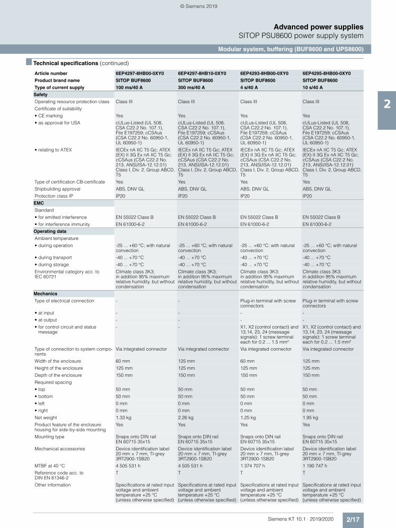
2/17Siemens KT 10.1 · 2019/2020
2
■ Technical specifications (continued)
Advanced power suppliesSITOP PSU8600 power supply system
Modular system, buffering (BUF8600 and UPS8600)
Safety
Operating resource protection class Class III Class III Class III Class III
Certificate of suitability
• CE marking Yes Yes Yes Yes
• as approval for USA cULus-Listed (UL 508, CSA C22.2 No. 107.1), File E197259; cCSAus (CSA C22.2 No. 60950-1, UL 60950-1)
cULus-Listed (UL 508, CSA C22.2 No. 107.1), File E197259; cCSAus (CSA C22.2 No. 60950-1, UL 60950-1)
cULus-Listed (UL 508, CSA C22.2 No. 107.1), File E197259; cCSAus (CSA C22.2 No. 60950-1, UL 60950-1)
cULus-Listed (UL 508, CSA C22.2 No. 107.1), File E197259; cCSAus (CSA C22.2 No. 60950-1, UL 60950-1)
• relating to ATEX IECEx nA IIC T5 Gc; ATEX (EX) II 3G Ex nA IIC T5 Gc; cCSAus (CSA C22.2 No. 213, ANSI/ISA-12.12.01) Class I, Div. 2, Group ABCD, T5
IECEx nA IIC T5 Gc; ATEX (EX) II 3G Ex nA IIC T5 Gc; cCSAus (CSA C22.2 No. 213, ANSI/ISA-12.12.01) Class I, Div. 2, Group ABCD, T5
IECEx nA IIC T5 Gc; ATEX (EX) II 3G Ex nA IIC T5 Gc; cCSAus (CSA C22.2 No. 213, ANSI/ISA-12.12.01) Class I, Div. 2, Group ABCD, T5
IECEx nA IIC T5 Gc; ATEX (EX) II 3G Ex nA IIC T5 Gc; cCSAus (CSA C22.2 No. 213, ANSI/ISA-12.12.01) Class I, Div. 2, Group ABCD, T5
Type of certification CB-certificate Yes Yes Yes Yes
Shipbuilding approval ABS, DNV GL ABS, DNV GL ABS, DNV GL ABS, DNV GL
Protection class IP IP20 IP20 IP20 IP20
EMC
Standard
• for emitted interference EN 55022 Class B EN 55022 Class B EN 55022 Class B EN 55022 Class B
• for interference immunity EN 61000-6-2 EN 61000-6-2 EN 61000-6-2 EN 61000-6-2
Operating data
Ambient temperature
• during operation -25 ... +60 °C; with natural convection
-25 ... +60 °C; with natural convection
-25 ... +60 °C; with natural convection
-25 ... +60 °C; with natural convection
• during transport -40 ... +70 °C -40 ... +70 °C -40 ... +70 °C -40 ... +70 °C
• during storage -40 ... +70 °C -40 ... +70 °C -40 ... +70 °C -40 ... +70 °C
Environmental category acc. to IEC 60721
Climate class 3K3; in addition 95% maximum relative humidity, but without condensation
Climate class 3K3; in addition 95% maximum relative humidity, but without condensation
Climate class 3K3; in addition 95% maximum relative humidity, but without condensation
Climate class 3K3; in addition 95% maximum relative humidity, but without condensation
Mechanics
Type of electrical connection - - Plug-in terminal with screw connectors
Plug-in terminal with screw connectors
• at input - - - -
• at output - - - -
• for control circuit and status message
- - X1, X2 (control contact) and 13,14, 23, 24 (message signals): 1 screw terminal each for 0.2 ... 1.5 mm²
X1, X2 (control contact) and 13,14, 23, 24 (message signals): 1 screw terminal each for 0.2 ... 1.5 mm²
Type of connection to system compo-nents
Via integrated connector Via integrated connector Via integrated connector Via integrated connector
Width of the enclosure 60 mm 125 mm 60 mm 125 mm
Height of the enclosure 125 mm 125 mm 125 mm 125 mm
Depth of the enclosure 150 mm 150 mm 150 mm 150 mm
Required spacing
• top 50 mm 50 mm 50 mm 50 mm
• bottom 50 mm 50 mm 50 mm 50 mm
• left 0 mm 0 mm 0 mm 0 mm
• right 0 mm 0 mm 0 mm 0 mm
Net weight 1.33 kg 2.26 kg 1.25 kg 1.95 kg
Product feature of the enclosure housing for side-by-side mounting
Yes Yes Yes Yes
Mounting type Snaps onto DIN rail EN 60715 35x15
Snaps onto DIN rail EN 60715 35x15
Snaps onto DIN rail EN 60715 35x15
Snaps onto DIN rail EN 60715 35x15
Mechanical accessories Device identification label 20 mm × 7 mm, TI-grey 3RT2900-1SB20
Device identification label 20 mm × 7 mm, TI-grey 3RT2900-1SB20
Device identification label 20 mm × 7 mm, TI-grey 3RT2900-1SB20
Device identification label 20 mm × 7 mm, TI-grey 3RT2900-1SB20
MTBF at 40 °C 4 505 531 h 4 505 531 h 1 374 707 h 1 190 747 h
Reference code acc. to DIN EN 81346-2
T T T T
Other information Specifications at rated input voltage and ambient temperature +25 °C (unless otherwise specified)
Specifications at rated input voltage and ambient temperature +25 °C (unless otherwise specified)
Specifications at rated input voltage and ambient temperature +25 °C (unless otherwise specified)
Specifications at rated input voltage and ambient temperature +25 °C (unless otherwise specified)
Article number 6EP4297-8HB00-0XY0 6EP4297-8HB10-0XY0 6EP4293-8HB00-0XY0 6EP4295-8HB00-0XY0
Product brand name SITOP BUF8600 SITOP BUF8600 SITOP BUF8600 SITOP BUF8600
Type of current supply 100 ms/40 A 300 ms/40 A 4 s/40 A 10 s/40 A
© Siemens 2019
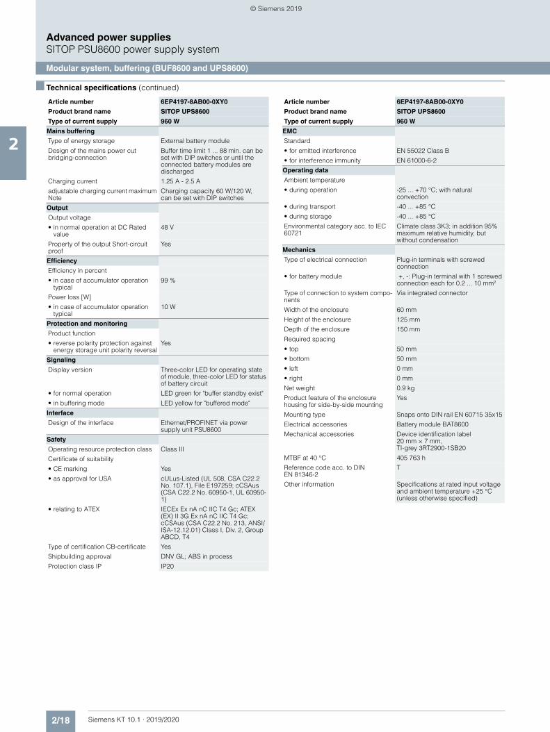
2/18 Siemens KT 10.1 · 2019/2020
2
■ Technical specifications (continued)
Advanced power suppliesSITOP PSU8600 power supply system
Modular system, buffering (BUF8600 and UPS8600)
Article number 6EP4197-8AB00-0XY0
Product brand name SITOP UPS8600
Type of current supply 960 W
Mains buffering
Type of energy storage External battery module
Design of the mains power cut bridging-connection
Buffer time limit 1 ... 88 min. can be set with DIP switches or until the connected battery modules are discharged
Charging current 1.25 A - 2.5 A
adjustable charging current maximum Note
Charging capacity 60 W/120 W, can be set with DIP switches
Output
Output voltage
• in normal operation at DC Rated value
48 V
Property of the output Short-circuit proof
Yes
Efficiency
Efficiency in percent
• in case of accumulator operation typical
99 %
Power loss [W]
• in case of accumulator operation typical
10 W
Protection and monitoring
Product function
• reverse polarity protection against energy storage unit polarity reversal
Yes
Signaling
Display version Three-color LED for operating state of module, three-color LED for status of battery circuit
• for normal operation LED green for "buffer standby exist"
• in buffering mode LED yellow for "buffered mode"
Interface
Design of the interface Ethernet/PROFINET via power supply unit PSU8600
Safety
Operating resource protection class Class III
Certificate of suitability
• CE marking Yes
• as approval for USA cULus-Listed (UL 508, CSA C22.2 No. 107.1), File E197259; cCSAus (CSA C22.2 No. 60950-1, UL 60950-1)
• relating to ATEX IECEx Ex nA nC IIC T4 Gc; ATEX (EX) II 3G Ex nA nC IIC T4 Gc; cCSAus (CSA C22.2 No. 213, ANSI/ISA-12.12.01) Class I, Div. 2, Group ABCD, T4
Type of certification CB-certificate Yes
Shipbuilding approval DNV GL; ABS in process
Protection class IP IP20
EMC
Standard
• for emitted interference EN 55022 Class B
• for interference immunity EN 61000-6-2
Operating data
Ambient temperature
• during operation -25 ... +70 °C; with natural convection
• during transport -40 ... +85 °C
• during storage -40 ... +85 °C
Environmental category acc. to IEC 60721
Climate class 3K3; in addition 95% maximum relative humidity, but without condensation
Mechanics
Type of electrical connection Plug-in terminals with screwed connection
• for battery module +, -: Plug-in terminal with 1 screwed connection each for 0.2 ... 10 mm²
Type of connection to system compo-nents
Via integrated connector
Width of the enclosure 60 mm
Height of the enclosure 125 mm
Depth of the enclosure 150 mm
Required spacing
• top 50 mm
• bottom 50 mm
• left 0 mm
• right 0 mm
Net weight 0.9 kg
Product feature of the enclosure housing for side-by-side mounting
Yes
Mounting type Snaps onto DIN rail EN 60715 35x15
Electrical accessories Battery module BAT8600
Mechanical accessories Device identification label 20 mm × 7 mm, TI-grey 3RT2900-1SB20
MTBF at 40 °C 405 763 h
Reference code acc. to DIN EN 81346-2
T
Other information Specifications at rated input voltage and ambient temperature +25 °C (unless otherwise specified)
Article number 6EP4197-8AB00-0XY0
Product brand name SITOP UPS8600
Type of current supply 960 W
© Siemens 2019
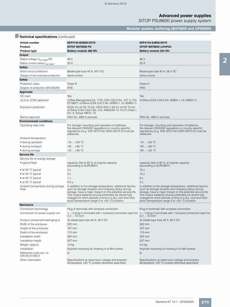
2/19Siemens KT 10.1 · 2019/2020
2
■ Technical specifications (continued)
Advanced power suppliesSITOP PSU8600 power supply system
Modular system, buffering (BUF8600 and UPS8600)
Article number 6EP4145-8GB00-0XY0 6EP4143-8JB00-0XY0
Product SITOP BAT8600 Pb SITOP BAT8600 LiFePO4
Product type Battery module 380 Wh Battery module 264 Wh
Output
Rated voltage Vout rated DC 48 V 48 V
Rated current value Iout rated 20 A 20 A
Safety
Short-circuit protection Blade-type fuse 40 A, 58 V DC Blade-type fuse 40 A, 58 V DC
Design of the overload protection Valve control Valve control
Safety
Protection class Class III Class III
Degree of protection (EN 60529) IP20 IP20
Approvals
CE mark Yes Yes
UL/cUL (CSA) approval cURus-Recognized (UL 1778, CSA C22.2 No. 107.1), File E219627; cCSAus (CSA C22.2 No. 60950-1, UL 60950-1)
cCSAus (CSA C22.2 No. 60950-1, UL 60950-1)
Explosion protection IECEx Ex nA IIC T5 Gc; ATEX (EX) II 3G Ex nA IIC T5 Gc; cCSAus (CSA C22.2 No. 213, ANSI/ISA-12.12.01) Class I, Div. 2, Group ABCD, T5
-
Marine approval DNV GL; ABS in process DNV GL; ABS in process
Environmental conditions
Operating data note For storage, mounting and operation of batteries, the relevant DIN/VDE regulations or country-specific regulations (e.g. VDE 0510 Part 2/EN 50272-2) must be observed.
For storage, mounting and operation of batteries, the relevant DIN/VDE regulations or country-specific regulations (e.g. VDE 0510 Part 2/EN 50272-2) must be observed.
Ambient temperature
• during operation -10 ... +50 °C -10 ... +50 °C
• during transport -40 ... +60 °C -40 ... +80 °C
• during storage -15 ... +40 °C -40 ... +35 °C
Service life
Service life of energy storage
• typical Note capacity falls to 80 % of original capacity (according to EUROBAT)
capacity falls to 80 % of original capacity (according to EUROBAT)
• at 20 °C typical 4 y 15 y
• at 30 °C typical 2 y 10 y
• at 40 °C typical 1 y 9 y
• at 50 °C typical 0.5 y 2 y
Ambient temperature during storage Note
In addition to the storage temperature, additional factors, such as storage duration and charging status during storage, have a major impact on the potential service life. This means batteries should preferably be stored fully charged for short periods of time in a dry, cool and frost-proof (temperature range 0 to +20 °C) location.
In addition to the storage temperature, additional factors, such as storage duration and charging status during storage, have a major impact on the potential service life. This means batteries should preferably be stored fully charged for short periods of time in a dry, cool and frost-proof (temperature range 0 to +20 °C) location.
Mechanics
Connection technology Plug-in terminals with screwed connection Plug-in terminals with screwed connection
Connection for power supply unit +, -: 2 plug-in terminals with 1 screwed connection each for 0.2 ... 10 mm²
+, -: 2 plug-in terminals with 1 screwed connection each for 0.2 ... 10 mm²
Product component belonging to 2x blade-type fuse 40 A, 58 V DC 2x blade-type fuse 40 A, 58 V DC
Width of the enclosure 322 mm 322 mm
Height of the enclosure 187 mm 187 mm
Depth of the enclosure 110 mm 110 mm
Installation width 322 mm 322 mm
Installation height 207 mm 207 mm
Weight, approx. 13 kg 6.5 kg
Installation Keyhole mounting for hooking in to M4 screws Keyhole mounting for hooking in to M4 screws
Reference code acc. to DIN EN 81346-2
G G
Other information Specifications at rated input voltage and ambient temperature +25 °C (unless otherwise specified)
Specifications at rated input voltage and ambient temperature +25 °C (unless otherwise specified)
© Siemens 2019
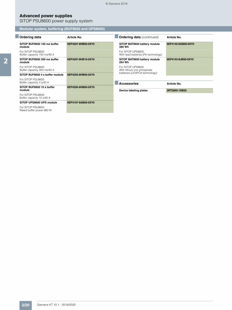
2/20 Siemens KT 10.1 · 2019/2020
2
Advanced power suppliesSITOP PSU8600 power supply system
Modular system, buffering (BUF8600 and UPS8600)
■ Ordering data Article No. ■ Ordering data (continued) Article No.
■ Accessories Article No.
SITOP BUF8600 100 ms buffer module
6EP4297-8HB00-0XY0
For SITOP PSU8600Buffer capacity 100 ms/40 A
SITOP BUF8600 300 ms buffer module
6EP4297-8HB10-0XY0
For SITOP PSU8600Buffer capacity 300 ms/40 A
SITOP BUF8600 4 s buffer module 6EP4293-8HB00-0XY0
For SITOP PSU8600Buffer capacity 4 s/40 A
SITOP BUF8600 10 s buffer module
6EP4295-8HB00-0XY0
For SITOP PSU8600Buffer capacity 10 s/40 A
SITOP UPS8600 UPS module 6EP4197-8AB00-0XY0
For SITOP PSU8600Rated buffer power 960 W
SITOP BAT8600 battery module 380 Wh
6EP4145-8GB00-0XY0
For SITOP UPS8600 With lead batteries (Pb technology)
SITOP BAT8600 battery module 264 Wh
6EP4143-8JB00-0XY0
For SITOP UPS8600 With lithium iron phosphate batteries (LiFePO4 technology)
Device labeling plates 3RT2900-1SB20
© Siemens 2019
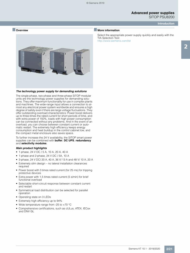
2/21Siemens KT 10.1 · 2019/2020
2
Advanced power suppliesSITOP PSU8200
Introduction
■ Overview
The technology power supply for demanding solutions
The single-phase, two-phase and three-phase SITOP modular units are the technology power supplies for demanding solu-tions. They offer maximum functionality for use in complex plants and machines. The wide-range input allows a connection to al-most any electrical power system worldwide and ensures a high degree of safety even if there are large voltage fluctuations. They offer outstanding overload characteristics: Power boost delivers up to three-times the rated current for short periods of time, and with extra power of 150%, loads with high power consumption can be connected without any problems. And in the event of an overload, you can choose between constant current or auto-matic restart. The extremely high efficiency keeps energy consumption and heat buildup in the control cabinet low, and the compact metal enclosure also saves space.
To further increase the 24 V availability, the SITOP smart power supplies can be combined with buffer, DC UPS, redundancy and selectivity modules.
Main product highlights• 1-phase, 24 V DC / 5 A, 10 A, 20 A, 40 A• 1-phase and 2-phase, 24 V DC / 5A, 10 A• 3-phase, 24 V DC/ 20 A, 40 A, 36 V/ 13 A and 48 V/ 10 A, 20 A• Extremely slim design – no lateral installation clearances
required• Power boost with 3 times rated current (for 25 ms) for tripping
protective devices• Extra power with 1.5 times rated current (5 s/min) for brief
functional overload• Selectable short-circuit response between constant current
and restart • Symmetrical load distribution can be selected for parallel
operation• Operating state on 3 LEDs• Extremely high efficiency up to 94%• Wide temperature range from -25 to +70 °C• Comprehensive certifications, such as cULus, ATEX, IECex
and DNV GL
■ More information
Select the appropriate power supply quickly and easily with the TIA Selection Tool:http://www.siemens.com/tst
© Siemens 2019
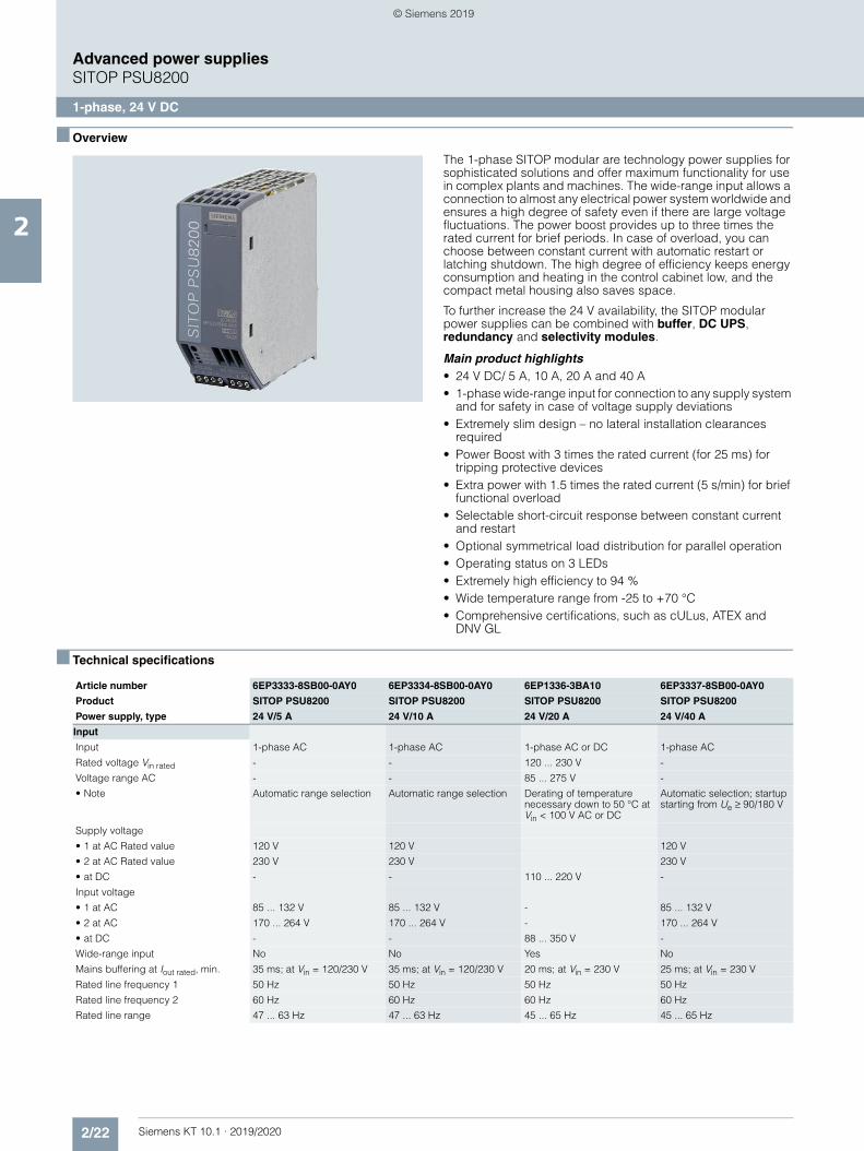
2/22 Siemens KT 10.1 · 2019/2020
2
Advanced power suppliesSITOP PSU8200
1-phase, 24 V DC
■ Overview
The 1-phase SITOP modular are technology power supplies for sophisticated solutions and offer maximum functionality for use in complex plants and machines. The wide-range input allows a connection to almost any electrical power system worldwide and ensures a high degree of safety even if there are large voltage fluctuations. The power boost provides up to three times the rated current for brief periods. In case of overload, you can choose between constant current with automatic restart or latching shutdown. The high degree of efficiency keeps energy consumption and heating in the control cabinet low, and the compact metal housing also saves space.
To further increase the 24 V availability, the SITOP modular power supplies can be combined with buffer, DC UPS, redundancy and selectivity modules.
Main product highlights• 24 V DC/ 5 A, 10 A, 20 A and 40 A• 1-phase wide-range input for connection to any supply system
and for safety in case of voltage supply deviations• Extremely slim design – no lateral installation clearances
required• Power Boost with 3 times the rated current (for 25 ms) for
tripping protective devices• Extra power with 1.5 times the rated current (5 s/min) for brief
functional overload• Selectable short-circuit response between constant current
and restart• Optional symmetrical load distribution for parallel operation• Operating status on 3 LEDs• Extremely high efficiency to 94 %• Wide temperature range from -25 to +70 °C• Comprehensive certifications, such as cULus, ATEX and
DNV GL
■ Technical specifications
Article number 6EP3333-8SB00-0AY0 6EP3334-8SB00-0AY0 6EP1336-3BA10 6EP3337-8SB00-0AY0
Product SITOP PSU8200 SITOP PSU8200 SITOP PSU8200 SITOP PSU8200
Power supply, type 24 V/5 A 24 V/10 A 24 V/20 A 24 V/40 A
Input
Input 1-phase AC 1-phase AC 1-phase AC or DC 1-phase AC
Rated voltage Vin rated - - 120 ... 230 V -
Voltage range AC - - 85 ... 275 V -
• Note Automatic range selection Automatic range selection Derating of temperature necessary down to 50 °C at Vin < 100 V AC or DC
Automatic selection; startup starting from Ue ≥ 90/180 V
Supply voltage
• 1 at AC Rated value 120 V 120 V 120 V
• 2 at AC Rated value 230 V 230 V 230 V
• at DC - - 110 ... 220 V -
Input voltage
• 1 at AC 85 ... 132 V 85 ... 132 V - 85 ... 132 V
• 2 at AC 170 ... 264 V 170 ... 264 V - 170 ... 264 V
• at DC - - 88 ... 350 V -
Wide-range input No No Yes No
Mains buffering at Iout rated, min. 35 ms; at Vin = 120/230 V 35 ms; at Vin = 120/230 V 20 ms; at Vin = 230 V 25 ms; at Vin = 230 V
Rated line frequency 1 50 Hz 50 Hz 50 Hz 50 Hz
Rated line frequency 2 60 Hz 60 Hz 60 Hz 60 Hz
Rated line range 47 ... 63 Hz 47 ... 63 Hz 45 ... 65 Hz 45 ... 65 Hz
© Siemens 2019
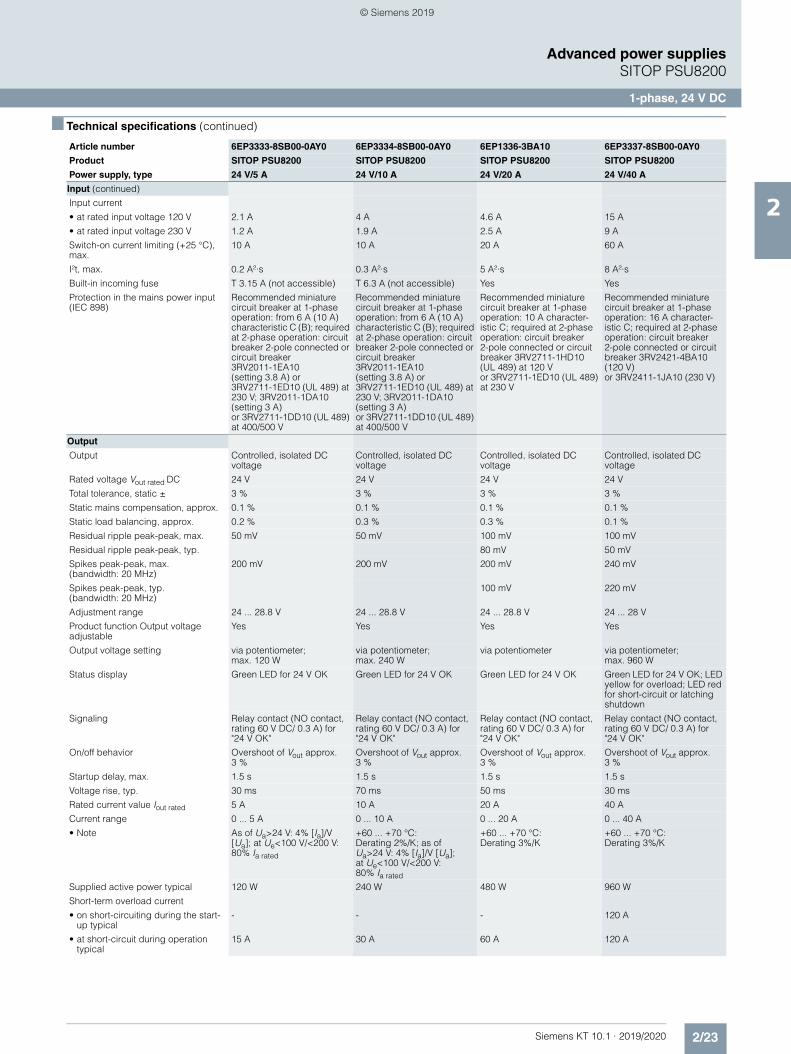
2/23Siemens KT 10.1 · 2019/2020
2
■ Technical specifications (continued)
Advanced power suppliesSITOP PSU8200
1-phase, 24 V DC
Input (continued)
Input current
• at rated input voltage 120 V 2.1 A 4 A 4.6 A 15 A
• at rated input voltage 230 V 1.2 A 1.9 A 2.5 A 9 A
Switch-on current limiting (+25 °C), max.
10 A 10 A 20 A 60 A
I²t, max. 0.2 A²·s 0.3 A²·s 5 A²·s 8 A²·s
Built-in incoming fuse T 3.15 A (not accessible) T 6.3 A (not accessible) Yes Yes
Protection in the mains power input (IEC 898)
Recommended miniature circuit breaker at 1-phase operation: from 6 A (10 A) characteristic C (B); required at 2-phase operation: circuit breaker 2-pole connected or circuit breaker 3RV2011-1EA10 (setting 3.8 A) or 3RV2711-1ED10 (UL 489) at 230 V; 3RV2011-1DA10 (setting 3 A) or 3RV2711-1DD10 (UL 489) at 400/500 V
Recommended miniature circuit breaker at 1-phase operation: from 6 A (10 A) characteristic C (B); required at 2-phase operation: circuit breaker 2-pole connected or circuit breaker 3RV2011-1EA10 (setting 3.8 A) or 3RV2711-1ED10 (UL 489) at 230 V; 3RV2011-1DA10 (setting 3 A) or 3RV2711-1DD10 (UL 489) at 400/500 V
Recommended miniature circuit breaker at 1-phase operation: 10 A character-istic C; required at 2-phase operation: circuit breaker 2-pole connected or circuit breaker 3RV2711-1HD10 (UL 489) at 120 V or 3RV2711-1ED10 (UL 489) at 230 V
Recommended miniature circuit breaker at 1-phase operation: 16 A character-istic C; required at 2-phase operation: circuit breaker 2-pole connected or circuit breaker 3RV2421-4BA10 (120 V) or 3RV2411-1JA10 (230 V)
Output
Output Controlled, isolated DC voltage
Controlled, isolated DC voltage
Controlled, isolated DC voltage
Controlled, isolated DC voltage
Rated voltage Vout rated DC 24 V 24 V 24 V 24 V
Total tolerance, static ± 3 % 3 % 3 % 3 %
Static mains compensation, approx. 0.1 % 0.1 % 0.1 % 0.1 %
Static load balancing, approx. 0.2 % 0.3 % 0.3 % 0.1 %
Residual ripple peak-peak, max. 50 mV 50 mV 100 mV 100 mV
Residual ripple peak-peak, typ. 80 mV 50 mV
Spikes peak-peak, max. (bandwidth: 20 MHz)
200 mV 200 mV 200 mV 240 mV
Spikes peak-peak, typ. (bandwidth: 20 MHz)
100 mV 220 mV
Adjustment range 24 ... 28.8 V 24 ... 28.8 V 24 ... 28.8 V 24 ... 28 V
Product function Output voltage adjustable
Yes Yes Yes Yes
Output voltage setting via potentiometer; max. 120 W
via potentiometer; max. 240 W
via potentiometer via potentiometer; max. 960 W
Status display Green LED for 24 V OK Green LED for 24 V OK Green LED for 24 V OK Green LED for 24 V OK; LED yellow for overload; LED red for short-circuit or latching shutdown
Signaling Relay contact (NO contact, rating 60 V DC/ 0.3 A) for "24 V OK"
Relay contact (NO contact, rating 60 V DC/ 0.3 A) for "24 V OK"
Relay contact (NO contact, rating 60 V DC/ 0.3 A) for "24 V OK"
Relay contact (NO contact, rating 60 V DC/ 0.3 A) for "24 V OK"
On/off behavior Overshoot of Vout approx. 3 %
Overshoot of Vout approx. 3 %
Overshoot of Vout approx. 3 %
Overshoot of Vout approx. 3 %
Startup delay, max. 1.5 s 1.5 s 1.5 s 1.5 s
Voltage rise, typ. 30 ms 70 ms 50 ms 30 ms
Rated current value Iout rated 5 A 10 A 20 A 40 A
Current range 0 ... 5 A 0 ... 10 A 0 ... 20 A 0 ... 40 A
• Note As of Ua>24 V: 4% [Ia]/V [Ua]; at Ue<100 V/<200 V: 80% Ia rated
+60 ... +70 °C: Derating 2%/K; as of Ua>24 V: 4% [Ia]/V [Ua]; at Ue<100 V/<200 V: 80% Ia rated
+60 ... +70 °C: Derating 3%/K
+60 ... +70 °C: Derating 3%/K
Supplied active power typical 120 W 240 W 480 W 960 W
Short-term overload current
• on short-circuiting during the start-up typical
- - - 120 A
• at short-circuit during operation typical
15 A 30 A 60 A 120 A
Article number 6EP3333-8SB00-0AY0 6EP3334-8SB00-0AY0 6EP1336-3BA10 6EP3337-8SB00-0AY0
Product SITOP PSU8200 SITOP PSU8200 SITOP PSU8200 SITOP PSU8200
Power supply, type 24 V/5 A 24 V/10 A 24 V/20 A 24 V/40 A
© Siemens 2019
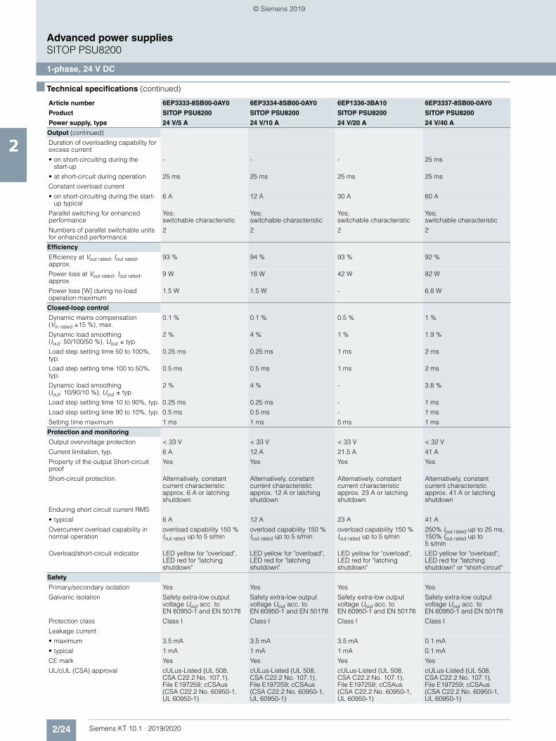
2/24 Siemens KT 10.1 · 2019/2020
2
■ Technical specifications (continued)
Advanced power suppliesSITOP PSU8200
1-phase, 24 V DC
Output (continued)
Duration of overloading capability for excess current
• on short-circuiting during the start-up
- - - 25 ms
• at short-circuit during operation 25 ms 25 ms 25 ms 25 ms
Constant overload current
• on short-circuiting during the start-up typical
6 A 12 A 30 A 60 A
Parallel switching for enhanced performance
Yes; switchable characteristic
Yes; switchable characteristic
Yes; switchable characteristic
Yes; switchable characteristic
Numbers of parallel switchable units for enhanced performance
2 2 2 2
Efficiency
Efficiency at Vout rated, Iout rated, approx.
93 % 94 % 93 % 92 %
Power loss at Vout rated, Iout rated, approx.
9 W 18 W 42 W 82 W
Power loss [W] during no-load operation maximum
1.5 W 1.5 W - 6.8 W
Closed-loop control
Dynamic mains compensation (Vin rated ±15 %), max.
0.1 % 0.1 % 0.5 % 1 %
Dynamic load smoothing (Iout: 50/100/50 %), Uout ± typ.
2 % 4 % 1 % 1.9 %
Load step setting time 50 to 100%, typ.
0.25 ms 0.25 ms 1 ms 2 ms
Load step setting time 100 to 50%, typ.
0.5 ms 0.5 ms 1 ms 2 ms
Dynamic load smoothing (Iout: 10/90/10 %), Uout ± typ.
2 % 4 % - 3.8 %
Load step setting time 10 to 90%, typ. 0.25 ms 0.25 ms - 1 ms
Load step setting time 90 to 10%, typ. 0.5 ms 0.5 ms - 1 ms
Setting time maximum 1 ms 1 ms 5 ms 1 ms
Protection and monitoring
Output overvoltage protection < 33 V < 33 V < 33 V < 32 V
Current limitation, typ. 6 A 12 A 21.5 A 41 A
Property of the output Short-circuit proof
Yes Yes Yes Yes
Short-circuit protection Alternatively, constant current characteristic approx. 6 A or latching shutdown
Alternatively, constant current characteristic approx. 12 A or latching shutdown
Alternatively, constant current characteristic approx. 23 A or latching shutdown
Alternatively, constant current characteristic approx. 41 A or latching shutdown
Enduring short circuit current RMS
• typical 6 A 12 A 23 A 41 A
Overcurrent overload capability in normal operation
overload capability 150 % Iout rated up to 5 s/min
overload capability 150 % Iout rated up to 5 s/min
overload capability 150 % Iout rated up to 5 s/min
250% Iout rated up to 25 ms, 150% Iout rated up to 5 s/min
Overload/short-circuit indicator LED yellow for "overload", LED red for "latching shutdown"
LED yellow for "overload", LED red for "latching shutdown"
LED yellow for "overload", LED red for "latching shutdown"
LED yellow for "overload", LED red for "latching shutdown" or "short-circuit"
Safety
Primary/secondary isolation Yes Yes Yes Yes
Galvanic isolation Safety extra-low output voltage Uout acc. to EN 60950-1 and EN 50178
Safety extra-low output voltage Uout acc. to EN 60950-1 and EN 50178
Safety extra-low output voltage Uout acc. to EN 60950-1 and EN 50178
Safety extra-low output voltage Uout acc. to EN 60950-1 and EN 50178
Protection class Class I Class I Class I Class I
Leakage current
• maximum 3.5 mA 3.5 mA 3.5 mA 0.1 mA
• typical 1 mA 1 mA 1 mA 0.1 mA
CE mark Yes Yes Yes Yes
UL/cUL (CSA) approval cULus-Listed (UL 508, CSA C22.2 No. 107.1), File E197259; cCSAus (CSA C22.2 No. 60950-1, UL 60950-1)
cULus-Listed (UL 508, CSA C22.2 No. 107.1), File E197259; cCSAus (CSA C22.2 No. 60950-1, UL 60950-1)
cULus-Listed (UL 508, CSA C22.2 No. 107.1), File E197259; cCSAus (CSA C22.2 No. 60950-1, UL 60950-1)
cULus-Listed (UL 508, CSA C22.2 No. 107.1), File E197259; cCSAus (CSA C22.2 No. 60950-1, UL 60950-1)
Article number 6EP3333-8SB00-0AY0 6EP3334-8SB00-0AY0 6EP1336-3BA10 6EP3337-8SB00-0AY0
Product SITOP PSU8200 SITOP PSU8200 SITOP PSU8200 SITOP PSU8200
Power supply, type 24 V/5 A 24 V/10 A 24 V/20 A 24 V/40 A
© Siemens 2019
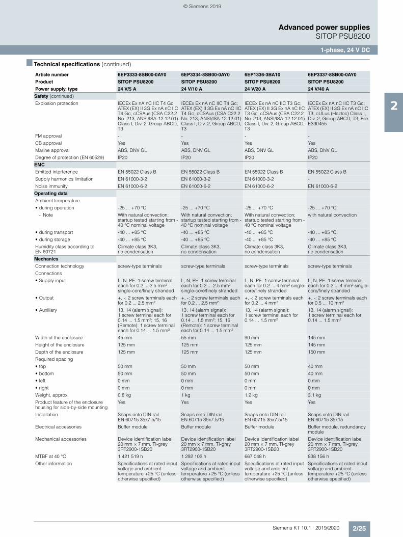
2/25Siemens KT 10.1 · 2019/2020
2
■ Technical specifications (continued)
Advanced power suppliesSITOP PSU8200
1-phase, 24 V DC
Safety (continued)
Explosion protection IECEx Ex nA nC IIC T4 Gc; ATEX (EX) II 3G Ex nA nC IIC T4 Gc; cCSAus (CSA C22.2 No. 213, ANSI/ISA-12.12.01) Class I, Div. 2, Group ABCD, T3
IECEx Ex nA nC IIC T4 Gc; ATEX (EX) II 3G Ex nA nC IIC T4 Gc; cCSAus (CSA C22.2 No. 213, ANSI/ISA-12.12.01) Class I, Div. 2, Group ABCD, T3
IECEx Ex nA nC IIC T3 Gc; ATEX (EX) II 3G Ex nA nC IIC T3 Gc; cCSAus (CSA C22.2 No. 213, ANSI/ISA-12.12.01) Class I, Div. 2, Group ABCD, T3
IECEx Ex nA nC IIC T3 Gc; ATEX (EX) II 3G Ex nA nC IIC T3; cULus (Hazloc) Class I, Div. 2, Group ABCD, T3; File E330455
FM approval - - - -
CB approval Yes Yes Yes Yes
Marine approval ABS, DNV GL ABS, DNV GL ABS, DNV GL ABS, DNV GL
Degree of protection (EN 60529) IP20 IP20 IP20 IP20
EMC
Emitted interference EN 55022 Class B EN 55022 Class B EN 55022 Class B EN 55022 Class B
Supply harmonics limitation EN 61000-3-2 EN 61000-3-2 EN 61000-3-2 -
Noise immunity EN 61000-6-2 EN 61000-6-2 EN 61000-6-2 EN 61000-6-2
Operating data
Ambient temperature
• during operation -25 ... +70 °C -25 ... +70 °C -25 ... +70 °C -25 ... +70 °C
- Note With natural convection; startup tested starting from -40 °C nominal voltage
With natural convection; startup tested starting from -40 °C nominal voltage
With natural convection; startup tested starting from -40 °C nominal voltage
with natural convection
• during transport -40 ... +85 °C -40 ... +85 °C -40 ... +85 °C -40 ... +85 °C
• during storage -40 ... +85 °C -40 ... +85 °C -40 ... +85 °C -40 ... +85 °C
Humidity class according to EN 60721
Climate class 3K3, no condensation
Climate class 3K3, no condensation
Climate class 3K3, no condensation
Climate class 3K3, no condensation
Mechanics
Connection technology screw-type terminals screw-type terminals screw-type terminals screw-type terminals
Connections
• Supply input L, N, PE: 1 screw terminal each for 0.2 ... 2.5 mm² single-core/finely stranded
L, N, PE: 1 screw terminal each for 0.2 ... 2.5 mm² single-core/finely stranded
L, N, PE: 1 screw terminal each for 0.2 ... 4 mm² single-core/finely stranded
L, N, PE: 1 screw terminal each for 0.2 ... 4 mm² single-core/finely stranded
• Output +, -: 2 screw terminals each for 0.2 ... 2.5 mm²
+, -: 2 screw terminals each for 0.2 ... 2.5 mm²
+, -: 2 screw terminals each for 0.2 ... 4 mm²
+, -: 2 screw terminals each for 0.5 ... 10 mm²
• Auxiliary 13, 14 (alarm signal): 1 screw terminal each for 0.14 ... 1.5 mm²; 15, 16 (Remote): 1 screw terminal each for 0.14 ... 1.5 mm²
13, 14 (alarm signal): 1 screw terminal each for 0.14 ... 1.5 mm²; 15, 16 (Remote): 1 screw terminal each for 0.14 ... 1.5 mm²
13, 14 (alarm signal): 1 screw terminal each for 0.14 ... 1.5 mm²
13, 14 (alarm signal): 1 screw terminal each for 0.14 ... 1.5 mm²
Width of the enclosure 45 mm 55 mm 90 mm 145 mm
Height of the enclosure 125 mm 125 mm 125 mm 145 mm
Depth of the enclosure 125 mm 125 mm 125 mm 150 mm
Required spacing
• top 50 mm 50 mm 50 mm 40 mm
• bottom 50 mm 50 mm 50 mm 40 mm
• left 0 mm 0 mm 0 mm 0 mm
• right 0 mm 0 mm 0 mm 0 mm
Weight, approx. 0.8 kg 1 kg 1.2 kg 3.1 kg
Product feature of the enclosure housing for side-by-side mounting
Yes Yes Yes Yes
Installation Snaps onto DIN rail EN 60715 35x7.5/15
Snaps onto DIN rail EN 60715 35x7.5/15
Snaps onto DIN rail EN 60715 35x7.5/15
Snaps onto DIN rail EN 60715 35x15
Electrical accessories Buffer module Buffer module Buffer module Buffer module, redundancy module
Mechanical accessories Device identification label 20 mm × 7 mm, TI-grey 3RT2900-1SB20
Device identification label 20 mm × 7 mm, TI-grey 3RT2900-1SB20
Device identification label 20 mm × 7 mm, TI-grey 3RT2900-1SB20
Device identification label 20 mm × 7 mm, TI-grey 3RT2900-1SB20
MTBF at 40 °C 1 421 519 h 1 292 102 h 667 048 h 838 156 h
Other information Specifications at rated input voltage and ambient temperature +25 °C (unless otherwise specified)
Specifications at rated input voltage and ambient temperature +25 °C (unless otherwise specified)
Specifications at rated input voltage and ambient temperature +25 °C (unless otherwise specified)
Specifications at rated input voltage and ambient temperature +25 °C (unless otherwise specified)
Article number 6EP3333-8SB00-0AY0 6EP3334-8SB00-0AY0 6EP1336-3BA10 6EP3337-8SB00-0AY0
Product SITOP PSU8200 SITOP PSU8200 SITOP PSU8200 SITOP PSU8200
Power supply, type 24 V/5 A 24 V/10 A 24 V/20 A 24 V/40 A
© Siemens 2019
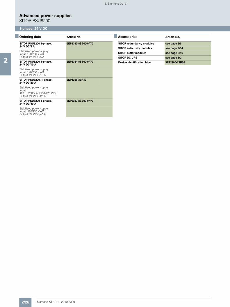
2/26 Siemens KT 10.1 · 2019/2020
2
Advanced power suppliesSITOP PSU8200
1-phase, 24 V DC
■ Ordering data Article No. ■ Accessories Article No.
SITOP PSU8200 1-phase, 24 V DC/5 A
6EP3333-8SB00-0AY0
Stabilized power supplyInput: 120/230 V ACOutput: 24 V DC/5 A
SITOP PSU8200 1-phase, 24 V DC/10 A
6EP3334-8SB00-0AY0
Stabilized power supplyInput: 120/230 V ACOutput: 24 V DC/10 A
SITOP PSU8200, 1-phase, 24 V DC/20 A
6EP1336-3BA10
Stabilized power supplyInput: 120 … 230 V AC/110-220 V DCOutput: 24 V DC/20 A
SITOP PSU8200 1-phase, 24 V DC/40 A
6EP3337-8SB00-0AY0
Stabilized power supplyInput: 120/230 V ACOutput: 24 V DC/40 A
SITOP redundancy modules see page 9/6
SITOP selectivity modules see page 9/14
SITOP buffer modules see page 9/16
SITOP DC UPS see page 8/2
Device identification label 3RT2900-1SB20
© Siemens 2019
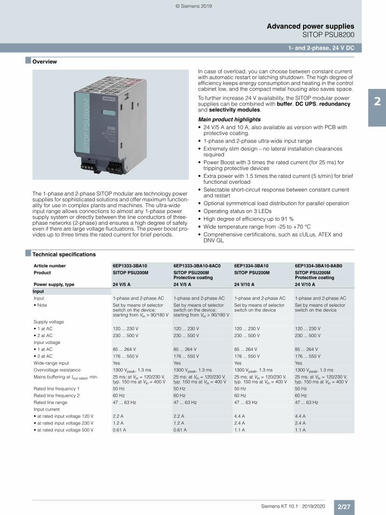
2/27Siemens KT 10.1 · 2019/2020
2
Advanced power suppliesSITOP PSU8200
1- and 2-phase, 24 V DC
■ Overview
The 1-phase and 2-phase SITOP modular are technology power supplies for sophisticated solutions and offer maximum function-ality for use in complex plants and machines. The ultra-wide input range allows connections to almost any 1-phase power supply system or directly between the line conductors of three-phase networks (2-phase) and ensures a high degree of safety even if there are large voltage fluctuations. The power boost pro-vides up to three times the rated current for brief periods.
In case of overload, you can choose between constant current with automatic restart or latching shutdown. The high degree of efficiency keeps energy consumption and heating in the control cabinet low, and the compact metal housing also saves space.
To further increase 24 V availability, the SITOP modular power supplies can be combined with buffer, DC UPS, redundancy and selectivity modules.
Main product highlights• 24 V/5 A and 10 A, also available as version with PCB with
protective coating.• 1-phase and 2-phase ultra-wide input range• Extremely slim design – no lateral installation clearances
required• Power Boost with 3 times the rated current (for 25 ms) for
tripping protective devices• Extra power with 1.5 times the rated current (5 s/min) for brief
functional overload• Selectable short-circuit response between constant current
and restart• Optional symmetrical load distribution for parallel operation• Operating status on 3 LEDs• High degree of efficiency up to 91 %• Wide temperature range from -25 to +70 °C• Comprehensive certifications, such as cULus, ATEX and
DNV GL
■ Technical specifications
Article number 6EP1333-3BA10 6EP1333-3BA10-8AC0 6EP1334-3BA10 6EP1334-3BA10-8AB0
Product SITOP PSU200M SITOP PSU200MProtective coating
SITOP PSU200M SITOP PSU200MProtective coating
Power supply, type 24 V/5 A 24 V/5 A 24 V/10 A 24 V/10 A
Input
Input 1-phase and 2-phase AC 1-phase and 2-phase AC 1-phase and 2-phase AC 1-phase and 2-phase AC
• Note Set by means of selector switch on the device; starting from Vin > 90/180 V
Set by means of selector switch on the device; starting from Vin > 90/180 V
Set by means of selector switch on the device
Set by means of selector switch on the device
Supply voltage
• 1 at AC 120 ... 230 V 120 ... 230 V 120 ... 230 V 120 ... 230 V
• 2 at AC 230 ... 500 V 230 ... 500 V 230 ... 500 V 230 ... 500 V
Input voltage
• 1 at AC 85 ... 264 V 85 ... 264 V 85 ... 264 V 85 ... 264 V
• 2 at AC 176 ... 550 V 176 ... 550 V 176 ... 550 V 176 ... 550 V
Wide-range input Yes Yes Yes Yes
Overvoltage resistance 1300 Vpeak, 1.3 ms 1300 Vpeak, 1.3 ms 1300 Vpeak, 1.3 ms 1300 Vpeak, 1.3 ms
Mains buffering at Iout rated, min. 25 ms; at Vin = 120/230 V, typ. 150 ms at Vin = 400 V
25 ms; at Vin = 120/230 V, typ. 150 ms at Vin = 400 V
25 ms; at Vin = 120/230 V, typ. 150 ms at Vin = 400 V
25 ms; at Vin = 120/230 V, typ. 150 ms at Vin = 400 V
Rated line frequency 1 50 Hz 50 Hz 50 Hz 50 Hz
Rated line frequency 2 60 Hz 60 Hz 60 Hz 60 Hz
Rated line range 47 ... 63 Hz 47 ... 63 Hz 47 ... 63 Hz 47 ... 63 Hz
Input current
• at rated input voltage 120 V 2.2 A 2.2 A 4.4 A 4.4 A
• at rated input voltage 230 V 1.2 A 1.2 A 2.4 A 2.4 A
• at rated input voltage 500 V 0.61 A 0.61 A 1.1 A 1.1 A
© Siemens 2019
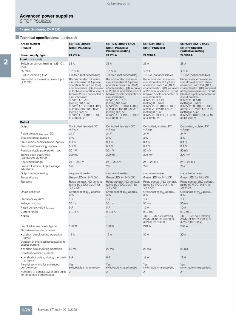
2/28 Siemens KT 10.1 · 2019/2020
2
■ Technical specifications (continued)
Advanced power suppliesSITOP PSU8200
1- and 2-phase, 24 V DC
Input (continued)
Switch-on current limiting (+25 °C), max.
35 A 35 A 35 A 35 A
I²t, max. 1.7 A²·s 1.7 A²·s 4 A²·s 4 A²·s
Built-in incoming fuse T 3.15 A (not accessible) T 3.15 A (not accessible) T 6.3 A (not accessible) T 6.3 A (not accessible)
Protection in the mains power input (IEC 898)
Recommended miniature circuit breaker at 1-phase operation: from 6 A (10 A) characteristic C (B); required at 2-phase operation: circuit breaker 2-pole connected or circuit breaker 3RV2011-1EA10 (setting 3.8 A) or 3RV2711-1ED10 (UL 489) at 230 V; 3RV2011-1DA10 (setting 3 A) or 3RV2711-1DD10 (UL 489) at 400/500 V
Recommended miniature circuit breaker at 1-phase operation: from 6 A (10 A) characteristic C (B); required at 2-phase operation: circuit breaker 2-pole connected or circuit breaker 3RV2011-1EA10 (setting 3.8 A) or 3RV2711-1ED10 (UL 489) at 230 V; 3RV2011-1DA10 (setting 3 A) or 3RV2711-1DD10 (UL 489) at 400/500 V
Recommended miniature circuit breaker at 1-phase operation: from 6 A (10 A) characteristic C (B); required at 2-phase operation: circuit breaker 2-pole connected or circuit breaker 3RV2011-1EA10 (setting 3.8 A) or 3RV2711-1ED10 (UL 489) at 230 V; 3RV2011-1DA10 (setting 3 A) or 3RV2711-1DD10 (UL 489) at 400/500 V
Recommended miniature circuit breaker at 1-phase operation: from 6 A (10 A) characteristic C (B); required at 2-phase operation: circuit breaker 2-pole connected or circuit breaker 3RV2011-1EA10 (setting 3.8 A) or 3RV2711-1ED10 (UL 489) at 230 V; 3RV2011-1DA10 (setting 3 A) or 3RV2711-1DD10 (UL 489) at 400/500 V
Output
Output Controlled, isolated DC voltage
Controlled, isolated DC voltage
Controlled, isolated DC voltage
Controlled, isolated DC voltage
Rated voltage Vout rated DC 24 V 24 V 24 V 24 V
Total tolerance, static ± 3 % 3 % 3 % 3 %
Static mains compensation, approx. 0.1 % 0.1 % 0.1 % 0.1 %
Static load balancing, approx. 0.1 % 0.1 % 0.1 % 0.1 %
Residual ripple peak-peak, max. 50 mV 50 mV 50 mV 50 mV
Spikes peak-peak, max. (bandwidth: 20 MHz)
200 mV 200 mV 200 mV 200 mV
Adjustment range 24 ... 28.8 V 24 ... 28.8 V 24 ... 28.8 V 24 ... 28.8 V
Product function Output voltage adjustable
Yes Yes Yes Yes
Output voltage setting via potentiometer via potentiometer via potentiometer via potentiometer
Status display Green LED for 24 V OK Green LED for 24 V OK Green LED for 24 V OK Green LED for 24 V OK
Signaling Relay contact (NO contact, rating 60 V DC/ 0.3 A) for "24 V OK"
Relay contact (NO contact, rating 60 V DC/ 0.3 A) for "24 V OK"
Relay contact (NO contact, rating 60 V DC/ 0.3 A) for "24 V OK"
Relay contact (NO contact, rating 60 V DC/ 0.3 A) for "24 V OK"
On/off behavior Overshoot of Vout approx. 3 %
Overshoot of Vout approx. 3 %
Overshoot of Vout approx. 3 %
Overshoot of Vout approx. 3 %
Startup delay, max. 1 s 1 s 1 s 1 s
Voltage rise, typ. 50 ms 50 ms 50 ms 50 ms
Rated current value Iout rated 5 A 5 A 10 A 10 A
Current range 0 ... 5 A 0 ... 5 A 0 ... 10 A 0 ... 10 A
• Note - - +60 ... +70 °C: Derating 2%/K (at 120 V, 230 V) or 3.5%/K (at 400 V)
+60 ... +70 °C: Derating 2%/K (at 120 V, 230 V) or 3.5%/K (at 400 V)
Supplied active power typical 120 W 120 W 240 W 240 W
Short-term overload current
• at short-circuit during operation typical
15 A 15 A 30 A 30 A
Duration of overloading capability for excess current
• at short-circuit during operation 25 ms 25 ms 25 ms 25 ms
Constant overload current
• on short-circuiting during the start-up typical
6 A 6 A 12 A 12 A
Parallel switching for enhanced performance
Yes; switchable characteristic
Yes; switchable characteristic
Yes; switchable characteristic
Yes; switchable characteristic
Numbers of parallel switchable units for enhanced performance
2 2 2 2
Article number 6EP1333-3BA10 6EP1333-3BA10-8AC0 6EP1334-3BA10 6EP1334-3BA10-8AB0
Product SITOP PSU200M SITOP PSU200MProtective coating
SITOP PSU200M SITOP PSU200MProtective coating
Power supply, type 24 V/5 A 24 V/5 A 24 V/10 A 24 V/10 A
© Siemens 2019
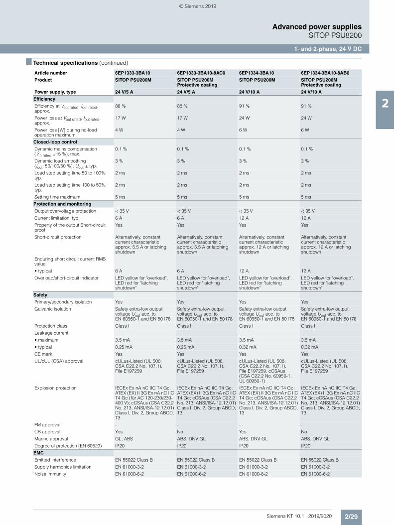
2/29Siemens KT 10.1 · 2019/2020
2
■ Technical specifications (continued)
Advanced power suppliesSITOP PSU8200
1- and 2-phase, 24 V DC
Efficiency
Efficiency at Vout rated, Iout rated, approx.
88 % 88 % 91 % 91 %
Power loss at Vout rated, Iout rated, approx.
17 W 17 W 24 W 24 W
Power loss [W] during no-load operation maximum
4 W 4 W 6 W 6 W
Closed-loop control
Dynamic mains compensation (Vin rated ±15 %), max.
0.1 % 0.1 % 0.1 % 0.1 %
Dynamic load smoothing (Iout: 50/100/50 %), Uout ± typ.
3 % 3 % 3 % 3 %
Load step setting time 50 to 100%, typ.
2 ms 2 ms 2 ms 2 ms
Load step setting time 100 to 50%, typ.
2 ms 2 ms 2 ms 2 ms
Setting time maximum 5 ms 5 ms 5 ms 5 ms
Protection and monitoring
Output overvoltage protection < 35 V < 35 V < 35 V < 35 V
Current limitation, typ. 6 A 6 A 12 A 12 A
Property of the output Short-circuit proof
Yes Yes Yes Yes
Short-circuit protection Alternatively, constant current characteristic approx. 5.5 A or latching shutdown
Alternatively, constant current characteristic approx. 5.5 A or latching shutdown
Alternatively, constant current characteristic approx. 12 A or latching shutdown
Alternatively, constant current characteristic approx. 12 A or latching shutdown
Enduring short circuit current RMS value
• typical 6 A 6 A 12 A 12 A
Overload/short-circuit indicator LED yellow for "overload", LED red for "latching shutdown"
LED yellow for "overload", LED red for "latching shutdown"
LED yellow for "overload", LED red for "latching shutdown"
LED yellow for "overload", LED red for "latching shutdown"
Safety
Primary/secondary isolation Yes Yes Yes Yes
Galvanic isolation Safety extra-low output voltage Uout acc. to EN 60950-1 and EN 50178
Safety extra-low output voltage Uout acc. to EN 60950-1 and EN 50178
Safety extra-low output voltage Uout acc. to EN 60950-1 and EN 50178
Safety extra-low output voltage Uout acc. to EN 60950-1 and EN 50178
Protection class Class I Class I Class I Class I
Leakage current
• maximum 3.5 mA 3.5 mA 3.5 mA 3.5 mA
• typical 0.25 mA 0.25 mA 0.32 mA 0.32 mA
CE mark Yes Yes Yes Yes
UL/cUL (CSA) approval cULus-Listed (UL 508, CSA C22.2 No. 107.1), File E197259
cULus-Listed (UL 508, CSA C22.2 No. 107.1), File E197259
cULus-Listed (UL 508, CSA C22.2 No. 107.1), File E197259, cCSAus (CSA C22.2 No. 60950-1, UL 60950-1)
cULus-Listed (UL 508, CSA C22.2 No. 107.1), File E197259
Explosion protection IECEx Ex nA nC IIC T4 Gc; ATEX (EX) II 3G Ex nA nC IIC T4 Gc (für AC 120-230/230-400 V); cCSAus (CSA C22.2 No. 213, ANSI/ISA-12.12.01) Class I, Div. 2, Group ABCD, T3
IECEx Ex nA nC IIC T4 Gc; ATEX (EX) II 3G Ex nA nC IIC T4 Gc; cCSAus (CSA C22.2 No. 213, ANSI/ISA-12.12.01) Class I, Div. 2, Group ABCD, T3
IECEx Ex nA nC IIC T4 Gc; ATEX (EX) II 3G Ex nA nC IIC T4 Gc; cCSAus (CSA C22.2 No. 213, ANSI/ISA-12.12.01) Class I, Div. 2, Group ABCD, T3
IECEx Ex nA nC IIC T4 Gc; ATEX (EX) II 3G Ex nA nC IIC T4 Gc; cCSAus (CSA C22.2 No. 213, ANSI/ISA-12.12.01) Class I, Div. 2, Group ABCD, T3
FM approval - - - -
CB approval Yes No Yes No
Marine approval GL, ABS ABS, DNV GL ABS, DNV GL ABS, DNV GL
Degree of protection (EN 60529) IP20 IP20 IP20 IP20
EMC
Emitted interference EN 55022 Class B EN 55022 Class B EN 55022 Class B EN 55022 Class B
Supply harmonics limitation EN 61000-3-2 EN 61000-3-2 EN 61000-3-2 EN 61000-3-2
Noise immunity EN 61000-6-2 EN 61000-6-2 EN 61000-6-2 EN 61000-6-2
Article number 6EP1333-3BA10 6EP1333-3BA10-8AC0 6EP1334-3BA10 6EP1334-3BA10-8AB0
Product SITOP PSU200M SITOP PSU200MProtective coating
SITOP PSU200M SITOP PSU200MProtective coating
Power supply, type 24 V/5 A 24 V/5 A 24 V/10 A 24 V/10 A
© Siemens 2019
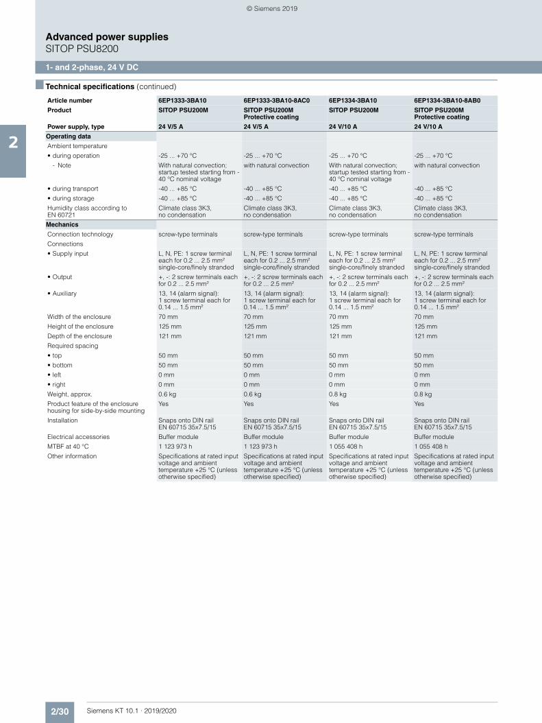
2/30 Siemens KT 10.1 · 2019/2020
2
■ Technical specifications (continued)
Advanced power suppliesSITOP PSU8200
1- and 2-phase, 24 V DC
Operating data
Ambient temperature
• during operation -25 ... +70 °C -25 ... +70 °C -25 ... +70 °C -25 ... +70 °C
- Note With natural convection; startup tested starting from -40 °C nominal voltage
with natural convection With natural convection; startup tested starting from -40 °C nominal voltage
with natural convection
• during transport -40 ... +85 °C -40 ... +85 °C -40 ... +85 °C -40 ... +85 °C
• during storage -40 ... +85 °C -40 ... +85 °C -40 ... +85 °C -40 ... +85 °C
Humidity class according to EN 60721
Climate class 3K3,no condensation
Climate class 3K3,no condensation
Climate class 3K3,no condensation
Climate class 3K3,no condensation
Mechanics
Connection technology screw-type terminals screw-type terminals screw-type terminals screw-type terminals
Connections
• Supply input L, N, PE: 1 screw terminal each for 0.2 ... 2.5 mm² single-core/finely stranded
L, N, PE: 1 screw terminal each for 0.2 ... 2.5 mm² single-core/finely stranded
L, N, PE: 1 screw terminal each for 0.2 ... 2.5 mm² single-core/finely stranded
L, N, PE: 1 screw terminal each for 0.2 ... 2.5 mm² single-core/finely stranded
• Output +, -: 2 screw terminals each for 0.2 ... 2.5 mm²
+, -: 2 screw terminals each for 0.2 ... 2.5 mm²
+, -: 2 screw terminals each for 0.2 ... 2.5 mm²
+, -: 2 screw terminals each for 0.2 ... 2.5 mm²
• Auxiliary 13, 14 (alarm signal): 1 screw terminal each for 0.14 ... 1.5 mm²
13, 14 (alarm signal): 1 screw terminal each for 0.14 ... 1.5 mm²
13, 14 (alarm signal): 1 screw terminal each for 0.14 ... 1.5 mm²
13, 14 (alarm signal): 1 screw terminal each for 0.14 ... 1.5 mm²
Width of the enclosure 70 mm 70 mm 70 mm 70 mm
Height of the enclosure 125 mm 125 mm 125 mm 125 mm
Depth of the enclosure 121 mm 121 mm 121 mm 121 mm
Required spacing
• top 50 mm 50 mm 50 mm 50 mm
• bottom 50 mm 50 mm 50 mm 50 mm
• left 0 mm 0 mm 0 mm 0 mm
• right 0 mm 0 mm 0 mm 0 mm
Weight, approx. 0.6 kg 0.6 kg 0.8 kg 0.8 kg
Product feature of the enclosure housing for side-by-side mounting
Yes Yes Yes Yes
Installation Snaps onto DIN rail EN 60715 35x7.5/15
Snaps onto DIN rail EN 60715 35x7.5/15
Snaps onto DIN rail EN 60715 35x7.5/15
Snaps onto DIN rail EN 60715 35x7.5/15
Electrical accessories Buffer module Buffer module Buffer module Buffer module
MTBF at 40 °C 1 123 973 h 1 123 973 h 1 055 408 h 1 055 408 h
Other information Specifications at rated input voltage and ambient temperature +25 °C (unless otherwise specified)
Specifications at rated input voltage and ambient temperature +25 °C (unless otherwise specified)
Specifications at rated input voltage and ambient temperature +25 °C (unless otherwise specified)
Specifications at rated input voltage and ambient temperature +25 °C (unless otherwise specified)
Article number 6EP1333-3BA10 6EP1333-3BA10-8AC0 6EP1334-3BA10 6EP1334-3BA10-8AB0
Product SITOP PSU200M SITOP PSU200MProtective coating
SITOP PSU200M SITOP PSU200MProtective coating
Power supply, type 24 V/5 A 24 V/5 A 24 V/10 A 24 V/10 A
© Siemens 2019
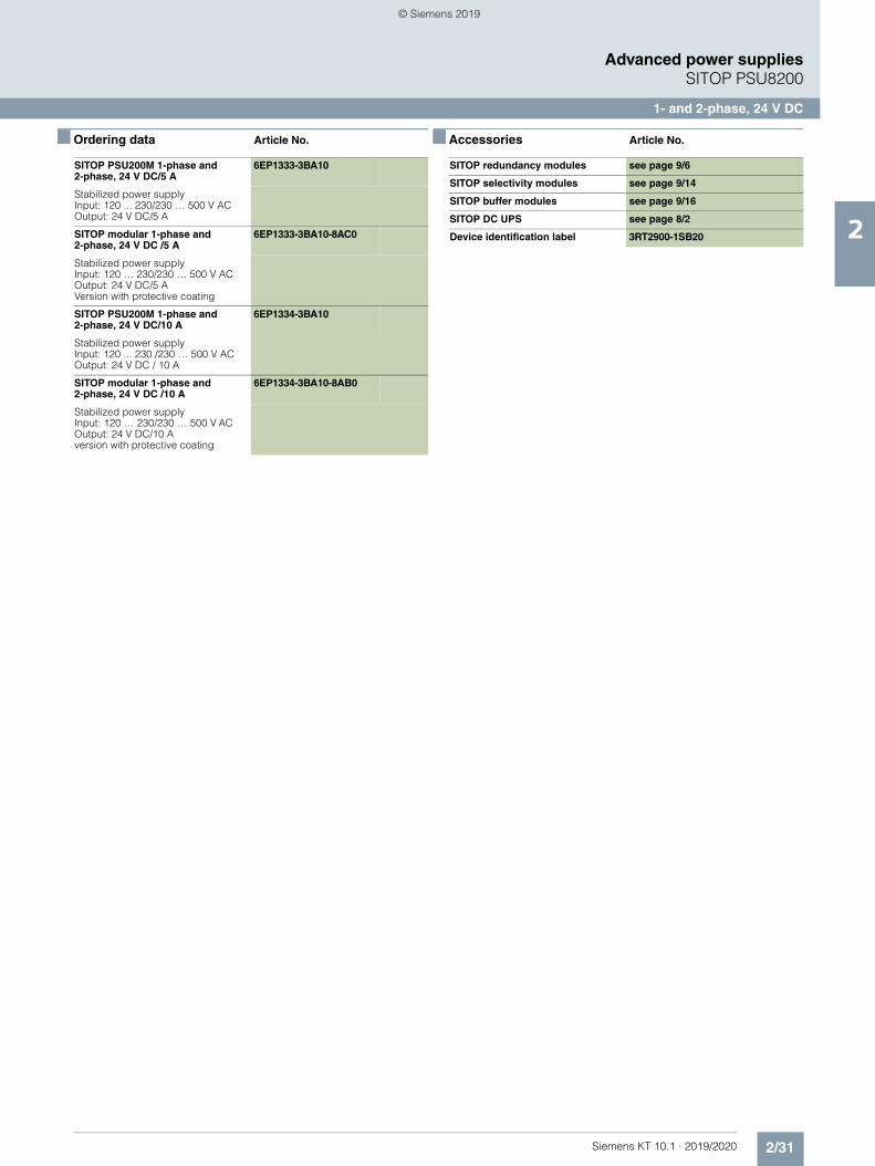
2/31Siemens KT 10.1 · 2019/2020
2
Advanced power suppliesSITOP PSU8200
1- and 2-phase, 24 V DC
■ Ordering data Article No. ■ Accessories Article No.
SITOP PSU200M 1-phase and 2-phase, 24 V DC/5 A
6EP1333-3BA10
Stabilized power supply Input: 120 ... 230/230 … 500 V ACOutput: 24 V DC/5 A
SITOP modular 1-phase and 2-phase, 24 V DC /5 A
6EP1333-3BA10-8AC0
Stabilized power supply Input: 120 … 230/230 … 500 V AC Output: 24 V DC/5 AVersion with protective coating
SITOP PSU200M 1-phase and 2-phase, 24 V DC/10 A
6EP1334-3BA10
Stabilized power supplyInput: 120 ... 230 /230 … 500 V AC Output: 24 V DC / 10 A
SITOP modular 1-phase and 2-phase, 24 V DC /10 A
6EP1334-3BA10-8AB0
Stabilized power supplyInput: 120 … 230/230 … 500 V AC Output: 24 V DC/10 A version with protective coating
SITOP redundancy modules see page 9/6
SITOP selectivity modules see page 9/14
SITOP buffer modules see page 9/16
SITOP DC UPS see page 8/2
Device identification label 3RT2900-1SB20
© Siemens 2019
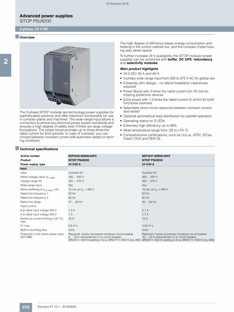
2/32 Siemens KT 10.1 · 2019/2020
2
Advanced power suppliesSITOP PSU8200
3-phase, 24 V DC
■ Overview
The 3-phase SITOP modular are technology power supplies for sophisticated solutions and offer maximum functionality for use in complex plants and machines. The wide-range input allows a connection to almost any electrical power system worldwide and ensures a high degree of safety even if there are large voltage fluctuations. The power boost provides up to three times the rated current for brief periods. In case of overload, you can choose between constant current with automatic restart or latch-ing shutdown.
The high degree of efficiency keeps energy consumption and heating in the control cabinet low, and the compact metal hous-ing also saves space.
To further increase 24 V availability, the SITOP modular power supplies can be combined with buffer, DC UPS, redundancy and selectivity modules.
Main product highlights• 24 V DC/ 20 A and 40 A• 3-phase wide-range input from 320 to 575 V AC for global use• Extremely slim design – no lateral installation clearances
required• Power Boost with 3 times the rated current (for 25 ms) for
tripping protective devices• Extra power with 1.5 times the rated current (5 s/min) for brief
functional overload• Selectable short-circuit response between constant current
and restart• Optional symmetrical load distribution for parallel operation• Operating status on 3 LEDs• Extremely high efficiency up to 94%• Wide temperature range from -25 to +70 °C• Comprehensive certifications, such as cULus, ATEX, IECex,
Class1 Div2 and DNV GL
■ Technical specifications
Article number 6EP3436-8SB00-0AY0 6EP3437-8SB00-0AY0
Product SITOP PSU8200 SITOP PSU8200
Power supply, type 24 V/20 A 24 V/40 A
Input
Input 3-phase AC 3-phase AC
Rated voltage value Vin rated 400 ... 500 V 400 ... 500 V
Voltage range AC 320 ... 575 V 320 ... 575 V
Wide-range input Yes Yes
Mains buffering at Iout rated, min. 15 ms; at Vin = 400 V 10 ms; at Vin = 400 V
Rated line frequency 1 50 Hz 50 Hz
Rated line frequency 2 60 Hz 60 Hz
Rated line range 47 ... 63 Hz 45 ... 65 Hz
Input current
• at rated input voltage 400 V 1.2 A 2.1 A
• at rated input voltage 500 V 1 A 1.7 A
Switch-on current limiting (+25 °C), max.
16 A 13 A
I²t, max. 0.8 A²·s 2.24 A²·s
Built-in incoming fuse none none
Protection in the mains power input (IEC 898)
Required: 3-pole connected miniature circuit breaker 6 ... 16 A characteristic C or circuit breaker 3RV2011-1DA10 (setting 3 A) or 3RV2711-1DD10 (UL 489)
Required: 3-pole connected miniature circuit breaker 10 ... 16 A characteristic C or circuit breaker 3RV2011-1DA10 (setting 3 A) or 3RV2711-1DD10 (UL 489)
© Siemens 2019
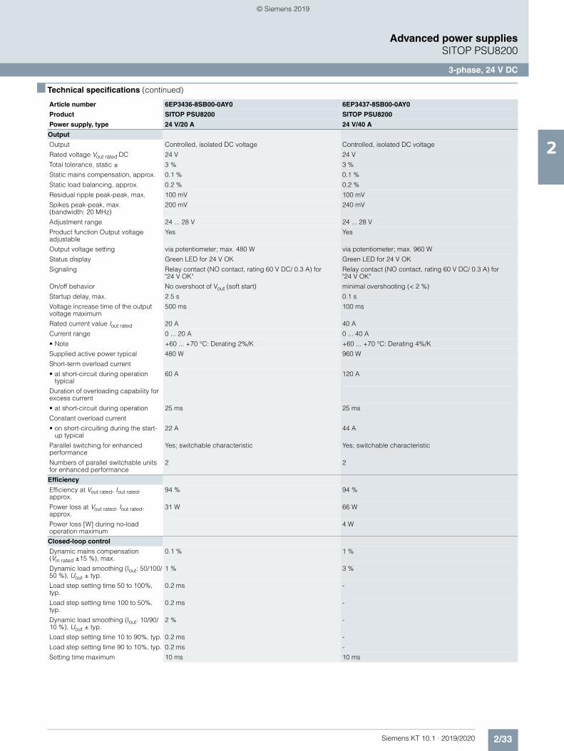
2/33Siemens KT 10.1 · 2019/2020
2
■ Technical specifications (continued)
Advanced power suppliesSITOP PSU8200
3-phase, 24 V DC
Output
Output Controlled, isolated DC voltage Controlled, isolated DC voltage
Rated voltage Vout rated DC 24 V 24 V
Total tolerance, static ± 3 % 3 %
Static mains compensation, approx. 0.1 % 0.1 %
Static load balancing, approx. 0.2 % 0.2 %
Residual ripple peak-peak, max. 100 mV 100 mV
Spikes peak-peak, max.(bandwidth: 20 MHz)
200 mV 240 mV
Adjustment range 24 ... 28 V 24 ... 28 V
Product function Output voltage adjustable
Yes Yes
Output voltage setting via potentiometer; max. 480 W via potentiometer; max. 960 W
Status display Green LED for 24 V OK Green LED for 24 V OK
Signaling Relay contact (NO contact, rating 60 V DC/ 0.3 A) for "24 V OK"
Relay contact (NO contact, rating 60 V DC/ 0.3 A) for "24 V OK"
On/off behavior No overshoot of Vout (soft start) minimal overshooting (< 2 %)
Startup delay, max. 2.5 s 0.1 s
Voltage increase time of the output voltage maximum
500 ms 100 ms
Rated current value Iout rated 20 A 40 A
Current range 0 ... 20 A 0 ... 40 A
• Note +60 ... +70 °C: Derating 2%/K +60 ... +70 °C: Derating 4%/K
Supplied active power typical 480 W 960 W
Short-term overload current
• at short-circuit during operation typical
60 A 120 A
Duration of overloading capability for excess current
• at short-circuit during operation 25 ms 25 ms
Constant overload current
• on short-circuiting during the start-up typical
22 A 44 A
Parallel switching for enhanced performance
Yes; switchable characteristic Yes; switchable characteristic
Numbers of parallel switchable units for enhanced performance
2 2
Efficiency
Efficiency at Vout rated, Iout rated, approx.
94 % 94 %
Power loss at Vout rated, Iout rated, approx.
31 W 66 W
Power loss [W] during no-load operation maximum
4 W
Closed-loop control
Dynamic mains compensation (Vin rated ±15 %), max.
0.1 % 1 %
Dynamic load smoothing (Iout: 50/100/50 %), Uout ± typ.
1 % 3 %
Load step setting time 50 to 100%, typ.
0.2 ms -
Load step setting time 100 to 50%, typ.
0.2 ms -
Dynamic load smoothing (Iout: 10/90/10 %), Uout ± typ.
2 % -
Load step setting time 10 to 90%, typ. 0.2 ms -
Load step setting time 90 to 10%, typ. 0.2 ms -
Setting time maximum 10 ms 10 ms
Article number 6EP3436-8SB00-0AY0 6EP3437-8SB00-0AY0
Product SITOP PSU8200 SITOP PSU8200
Power supply, type 24 V/20 A 24 V/40 A
© Siemens 2019
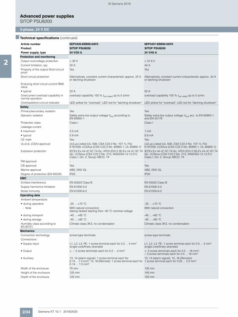
2/34 Siemens KT 10.1 · 2019/2020
2
■ Technical specifications (continued)
Advanced power suppliesSITOP PSU8200
3-phase, 24 V DC
Protection and monitoring
Output overvoltage protection < 32 V < 31.8 V
Current limitation, typ. 22 A 44 A
Property of the output Short-circuit proof
Yes Yes
Short-circuit protection Alternatively, constant current characteristic approx. 22 A or latching shutdown
Alternatively, constant current characteristic approx. 44 A or latching shutdown
Enduring short circuit current RMS value
• typical 22 A 50 A
Overcurrent overload capability in normal operation
overload capability 150 % Iout rated up to 5 s/min overload capability 150 % Iout rated up to 5 s/min
Overload/short-circuit indicator LED yellow for "overload", LED red for "latching shutdown" LED yellow for "overload", LED red for "latching shutdown"
Safety
Primary/secondary isolation Yes Yes
Galvanic isolation Safety extra low output voltage Vout according to EN 60950-1
Safety extra-low output voltage Uout acc. to EN 60950-1 and EN 50178
Protection class Class I Class I
Leakage current
• maximum 3.5 mA 1 mA
• typical 0.9 mA 0.6 mA
CE mark Yes Yes
UL/cUL (CSA) approval cULus-Listed (UL 508, CSA C22.2 No. 107.1), File E197259; cCSAus (CSA C22.2 No. 60950-1, UL 60950-1)
cULus-Listed (UL 508, CSA C22.2 No. 107.1), File E197259; cCSAus (CSA C22.2 No. 60950-1, UL 60950-1)
Explosion protection IECEx Ex nA nC IIC T4 Gc; ATEX (EX) II 3G Ex nA nC IIC T4 Gc; cCSAus (CSA C22.2 No. 213, ANSI/ISA-12.12.01) Class I, Div. 2, Group ABCD, T4
IECEx Ex nA nC IIC T4 Gc; ATEX (EX) II 3G Ex nA nC IIC T4 Gc; cCSAus (CSA C22.2 No. 213, ANSI/ISA-12.12.01) Class I, Div. 2, Group ABCD, T4
FM approval - -
CB approval Yes Yes
Marine approval ABS, DNV GL ABS, DNV GL
Degree of protection (EN 60529) IP20 IP20
EMC
Emitted interference EN 55022 Class B EN 55022 Class B
Supply harmonics limitation EN 61000-3-2 EN 61000-3-2
Noise immunity EN 61000-6-2 EN 61000-6-2
Operating data
Ambient temperature
• during operation -25 ... +70 °C -25 ... +70 °C
- Note With natural convection; startup tested starting from -40 °C nominal voltage
With natural convection
• during transport -40 ... +85 °C -40 ... +85 °C
• during storage -40 ... +85 °C -40 ... +85 °C
Humidity class according to EN 60721
Climate class 3K3, no condensation Climate class 3K3, no condensation
Mechanics
Connection technology screw-type terminals screw-type terminals
Connections
• Supply input L1, L2, L3, PE: 1 screw terminal each for 0.2 ... 4 mm² single-core/finely stranded
L1, L2, L3, PE: 1 screw terminal each for 0.5 ... 4 mm² single-core/finely stranded
• Output +, -: 2 screw terminals each for 0.2 ... 4 mm² +: 2 screw terminals each for 0.5 ... 16 mm²; -: 3 screw terminals each for 0.5 ... 16 mm²
• Auxiliary 13, 14 (alarm signal): 1 screw terminal each for 0.14 ... 1.5 mm²; 15, 16 (Remote): 1 screw terminal each for 0.14 ... 1.5 mm²
13, 14 (alarm signal), 15, 16 (Remote): 1 screw terminal each for 0.05 ... 2.5 mm²
Width of the enclosure 70 mm 135 mm
Height of the enclosure 125 mm 145 mm
Depth of the enclosure 125 mm 150 mm
Article number 6EP3436-8SB00-0AY0 6EP3437-8SB00-0AY0
Product SITOP PSU8200 SITOP PSU8200
Power supply, type 24 V/20 A 24 V/40 A
© Siemens 2019
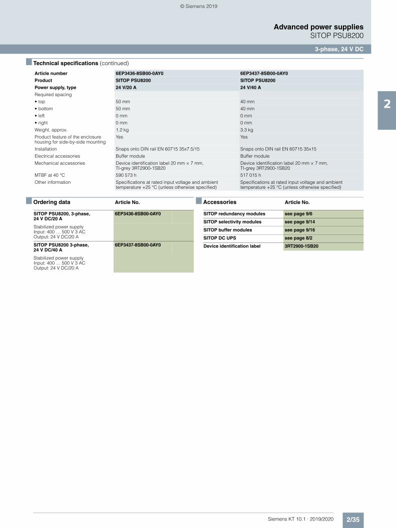
2/35Siemens KT 10.1 · 2019/2020
2
■ Technical specifications (continued)
Advanced power suppliesSITOP PSU8200
3-phase, 24 V DC
■ Ordering data Article No. ■ Accessories Article No.
Required spacing
• top 50 mm 40 mm
• bottom 50 mm 40 mm
• left 0 mm 0 mm
• right 0 mm 0 mm
Weight, approx. 1.2 kg 3.3 kg
Product feature of the enclosure housing for side-by-side mounting
Yes Yes
Installation Snaps onto DIN rail EN 60715 35x7.5/15 Snaps onto DIN rail EN 60715 35x15
Electrical accessories Buffer module Buffer module
Mechanical accessories Device identification label 20 mm × 7 mm, TI-grey 3RT2900-1SB20
Device identification label 20 mm × 7 mm, TI-grey 3RT2900-1SB20
MTBF at 40 °C 590 573 h 517 015 h
Other information Specifications at rated input voltage and ambient temperature +25 °C (unless otherwise specified)
Specifications at rated input voltage and ambient temperature +25 °C (unless otherwise specified)
Article number 6EP3436-8SB00-0AY0 6EP3437-8SB00-0AY0
Product SITOP PSU8200 SITOP PSU8200
Power supply, type 24 V/20 A 24 V/40 A
SITOP PSU8200, 3-phase, 24 V DC/20 A
6EP3436-8SB00-0AY0
Stabilized power supply Input: 400 … 500 V 3 ACOutput: 24 V DC/20 A
SITOP PSU8200 3-phase, 24 V DC/40 A
6EP3437-8SB00-0AY0
Stabilized power supply Input: 400 … 500 V 3 ACOutput: 24 V DC/20 A
SITOP redundancy modules see page 9/6
SITOP selectivity modules see page 9/14
SITOP buffer modules see page 9/16
SITOP DC UPS see page 8/2
Device identification label 3RT2900-1SB20
© Siemens 2019
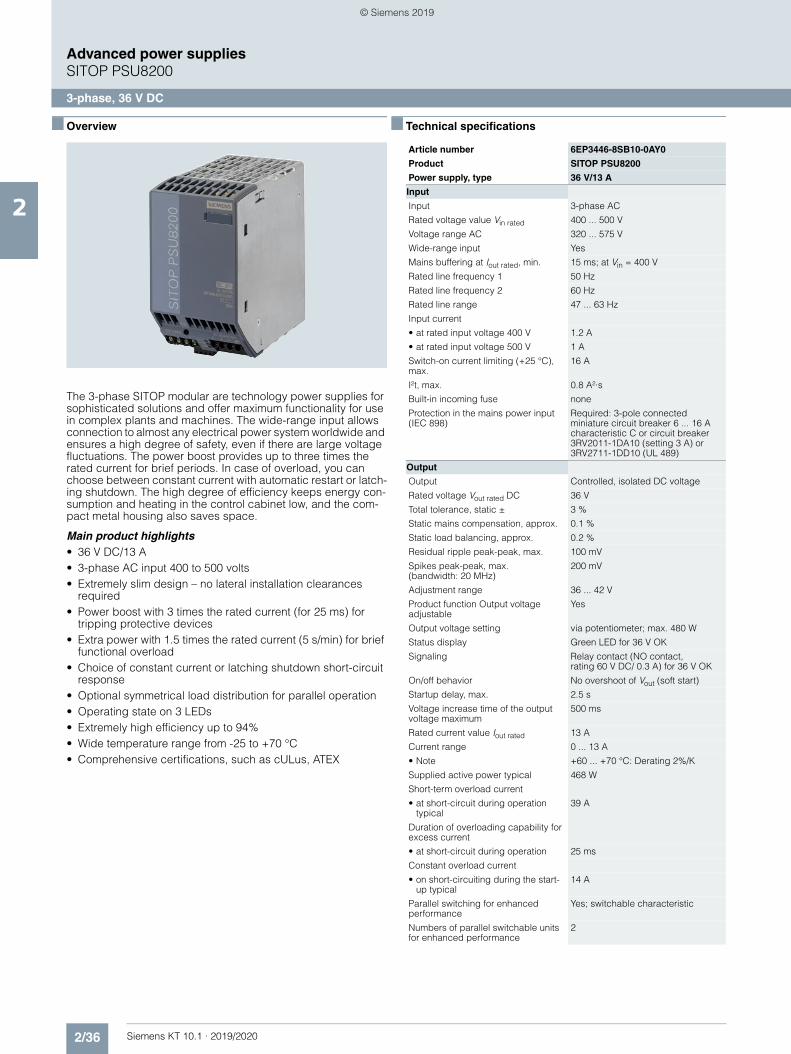
2/36 Siemens KT 10.1 · 2019/2020
2
Advanced power suppliesSITOP PSU8200
3-phase, 36 V DC
■ Overview
The 3-phase SITOP modular are technology power supplies for sophisticated solutions and offer maximum functionality for use in complex plants and machines. The wide-range input allows connection to almost any electrical power system worldwide and ensures a high degree of safety, even if there are large voltage fluctuations. The power boost provides up to three times the rated current for brief periods. In case of overload, you can choose between constant current with automatic restart or latch-ing shutdown. The high degree of efficiency keeps energy con-sumption and heating in the control cabinet low, and the com-pact metal housing also saves space.
Main product highlights• 36 V DC/13 A• 3-phase AC input 400 to 500 volts• Extremely slim design – no lateral installation clearances
required• Power boost with 3 times the rated current (for 25 ms) for
tripping protective devices• Extra power with 1.5 times the rated current (5 s/min) for brief
functional overload• Choice of constant current or latching shutdown short-circuit
response• Optional symmetrical load distribution for parallel operation• Operating state on 3 LEDs• Extremely high efficiency up to 94%• Wide temperature range from -25 to +70 °C• Comprehensive certifications, such as cULus, ATEX
■ Technical specifications
Article number 6EP3446-8SB10-0AY0
Product SITOP PSU8200
Power supply, type 36 V/13 A
Input
Input 3-phase AC
Rated voltage value Vin rated 400 ... 500 V
Voltage range AC 320 ... 575 V
Wide-range input Yes
Mains buffering at Iout rated, min. 15 ms; at Vin = 400 V
Rated line frequency 1 50 Hz
Rated line frequency 2 60 Hz
Rated line range 47 ... 63 Hz
Input current
• at rated input voltage 400 V 1.2 A
• at rated input voltage 500 V 1 A
Switch-on current limiting (+25 °C), max.
16 A
I²t, max. 0.8 A²·s
Built-in incoming fuse none
Protection in the mains power input (IEC 898)
Required: 3-pole connected miniature circuit breaker 6 ... 16 A characteristic C or circuit breaker 3RV2011-1DA10 (setting 3 A) or 3RV2711-1DD10 (UL 489)
Output
Output Controlled, isolated DC voltage
Rated voltage Vout rated DC 36 V
Total tolerance, static ± 3 %
Static mains compensation, approx. 0.1 %
Static load balancing, approx. 0.2 %
Residual ripple peak-peak, max. 100 mV
Spikes peak-peak, max. (bandwidth: 20 MHz)
200 mV
Adjustment range 36 ... 42 V
Product function Output voltage adjustable
Yes
Output voltage setting via potentiometer; max. 480 W
Status display Green LED for 36 V OK
Signaling Relay contact (NO contact, rating 60 V DC/ 0.3 A) for 36 V OK
On/off behavior No overshoot of Vout (soft start)
Startup delay, max. 2.5 s
Voltage increase time of the output voltage maximum
500 ms
Rated current value Iout rated 13 A
Current range 0 ... 13 A
• Note +60 ... +70 °C: Derating 2%/K
Supplied active power typical 468 W
Short-term overload current
• at short-circuit during operation typical
39 A
Duration of overloading capability for excess current
• at short-circuit during operation 25 ms
Constant overload current
• on short-circuiting during the start-up typical
14 A
Parallel switching for enhanced performance
Yes; switchable characteristic
Numbers of parallel switchable units for enhanced performance
2
© Siemens 2019
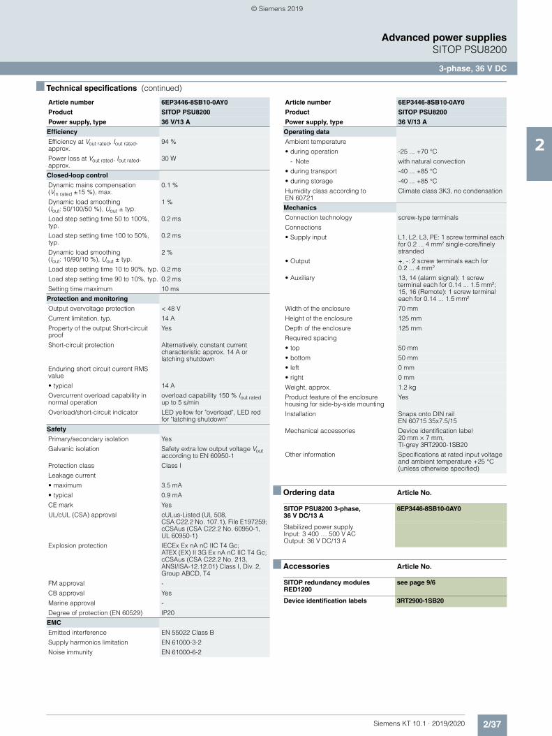
2/37Siemens KT 10.1 · 2019/2020
2
■ Technical specifications (continued)
Advanced power suppliesSITOP PSU8200
3-phase, 36 V DC
■ Ordering data Article No.
■ Accessories Article No.
Efficiency
Efficiency at Vout rated, Iout rated, approx.
94 %
Power loss at Vout rated, Iout rated, approx.
30 W
Closed-loop control
Dynamic mains compensation (Vin rated ±15 %), max.
0.1 %
Dynamic load smoothing (Iout: 50/100/50 %), Uout ± typ.
1 %
Load step setting time 50 to 100%, typ.
0.2 ms
Load step setting time 100 to 50%, typ.
0.2 ms
Dynamic load smoothing (Iout: 10/90/10 %), Uout ± typ.
2 %
Load step setting time 10 to 90%, typ. 0.2 ms
Load step setting time 90 to 10%, typ. 0.2 ms
Setting time maximum 10 ms
Protection and monitoring
Output overvoltage protection < 48 V
Current limitation, typ. 14 A
Property of the output Short-circuit proof
Yes
Short-circuit protection Alternatively, constant current characteristic approx. 14 A or latching shutdown
Enduring short circuit current RMS value
• typical 14 A
Overcurrent overload capability in normal operation
overload capability 150 % Iout rated up to 5 s/min
Overload/short-circuit indicator LED yellow for "overload", LED red for "latching shutdown"
Safety
Primary/secondary isolation Yes
Galvanic isolation Safety extra low output voltage Vout according to EN 60950-1
Protection class Class I
Leakage current
• maximum 3.5 mA
• typical 0.9 mA
CE mark Yes
UL/cUL (CSA) approval cULus-Listed (UL 508, CSA C22.2 No. 107.1), File E197259; cCSAus (CSA C22.2 No. 60950-1, UL 60950-1)
Explosion protection IECEx Ex nA nC IIC T4 Gc; ATEX (EX) II 3G Ex nA nC IIC T4 Gc; cCSAus (CSA C22.2 No. 213, ANSI/ISA-12.12.01) Class I, Div. 2, Group ABCD, T4
FM approval -
CB approval Yes
Marine approval -
Degree of protection (EN 60529) IP20
EMC
Emitted interference EN 55022 Class B
Supply harmonics limitation EN 61000-3-2
Noise immunity EN 61000-6-2
Article number 6EP3446-8SB10-0AY0
Product SITOP PSU8200
Power supply, type 36 V/13 A
Operating data
Ambient temperature
• during operation -25 ... +70 °C
- Note with natural convection
• during transport -40 ... +85 °C
• during storage -40 ... +85 °C
Humidity class according to EN 60721
Climate class 3K3, no condensation
Mechanics
Connection technology screw-type terminals
Connections
• Supply input L1, L2, L3, PE: 1 screw terminal each for 0.2 ... 4 mm² single-core/finely stranded
• Output +, -: 2 screw terminals each for 0.2 ... 4 mm²
• Auxiliary 13, 14 (alarm signal): 1 screw terminal each for 0.14 ... 1.5 mm²; 15, 16 (Remote): 1 screw terminal each for 0.14 ... 1.5 mm²
Width of the enclosure 70 mm
Height of the enclosure 125 mm
Depth of the enclosure 125 mm
Required spacing
• top 50 mm
• bottom 50 mm
• left 0 mm
• right 0 mm
Weight, approx. 1.2 kg
Product feature of the enclosure housing for side-by-side mounting
Yes
Installation Snaps onto DIN rail EN 60715 35x7.5/15
Mechanical accessories Device identification label 20 mm × 7 mm, TI-grey 3RT2900-1SB20
Other information Specifications at rated input voltage and ambient temperature +25 °C (unless otherwise specified)
SITOP PSU8200 3-phase, 36 V DC/13 A
6EP3446-8SB10-0AY0
Stabilized power supplyInput: 3 400 … 500 V ACOutput: 36 V DC/13 A
SITOP redundancy modules RED1200
see page 9/6
Device identification labels 3RT2900-1SB20
Article number 6EP3446-8SB10-0AY0
Product SITOP PSU8200
Power supply, type 36 V/13 A
© Siemens 2019
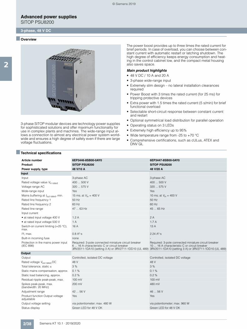
2/38 Siemens KT 10.1 · 2019/2020
2
Advanced power suppliesSITOP PSU8200
3-phase, 48 V DC
■ Overview
3-phase SITOP modular devices are technology power supplies for sophisticated solutions and offer maximum functionality for use in complex plants and machines. The wide-range input al-lows a connection to almost any electrical power system world-wide and ensures a high degree of safety even if there are large voltage fluctuations.
The power boost provides up to three times the rated current for brief periods. In case of overload, you can choose between con-stant current with automatic restart or latching shutdown. The high degree of efficiency keeps energy consumption and heat-ing in the control cabinet low, and the compact metal housing also saves space.
Main product highlights• 48 V DC / 10 A and 20 A• 3-phase wide-range input• Extremely slim design – no lateral installation clearances
required• Power Boost with 3 times the rated current (for 25 ms) for
tripping protective devices• Extra power with 1.5 times the rated current (5 s/min) for brief
functional overload• Selectable short-circuit response between constant current
and restart• Optional symmetrical load distribution for parallel operation• Operating status on 3 LEDs• Extremely high efficiency up to 95%• Wide temperature range from -25 to +70 °C• Comprehensive certifications, such as cULus, ATEX and
DNV GL
■ Technical specifications
Article number 6EP3446-8SB00-0AY0 6EP3447-8SB00-0AY0
Product SITOP PSU8200 SITOP PSU8200
Power supply, type 48 V/10 A 48 V/20 A
Input
Input 3-phase AC 3-phase AC
Rated voltage value Vin rated 400 ... 500 V 400 ... 500 V
Voltage range AC 320 ... 575 V 320 ... 575 V
Wide-range input Yes Yes
Mains buffering at Iout rated, min. 15 ms; at Vin = 400 V 10 ms; at Vin = 400 V
Rated line frequency 1 50 Hz 50 Hz
Rated line frequency 2 60 Hz 60 Hz
Rated line range 47 ... 63 Hz 45 ... 65 Hz
Input current
• at rated input voltage 400 V 1.2 A 2 A
• at rated input voltage 500 V 1 A 1.7 A
Switch-on current limiting (+25 °C), max.
16 A 13 A
I²t, max. 0.8 A²·s 2.24 A²·s
Built-in incoming fuse none -
Protection in the mains power input (IEC 898)
Required: 3-pole connected miniature circuit breaker 6 ... 16 A characteristic C or circuit breaker 3RV2011-1DA10 (setting 3 A) or 3RV2711-1DD10 (UL 489)
Required: 3-pole connected miniature circuit breaker 10 ... 16 A characteristic C or circuit breaker 3RV2011-1DA10 (setting 3 A) or 3RV2711-1DD10 (UL 489)
Output
Output Controlled, isolated DC voltage Controlled, isolated DC voltage
Rated voltage Vout rated DC 48 V 48 V
Total tolerance, static ± 3 % 3 %
Static mains compensation, approx. 0.1 % 0.1 %
Static load balancing, approx. 0.2 % 0.2 %
Residual ripple peak-peak, max. 100 mV 100 mV
Spikes peak-peak, max. (bandwidth: 20 MHz)
200 mV 480 mV
Adjustment range 42 ... 56 V 46 ... 56 V
Product function Output voltage adjustable
Yes Yes
Output voltage setting via potentiometer; max. 480 W via potentiometer; max. 960 W
Status display Green LED for 48 V OK Green LED for 48 V OK
© Siemens 2019
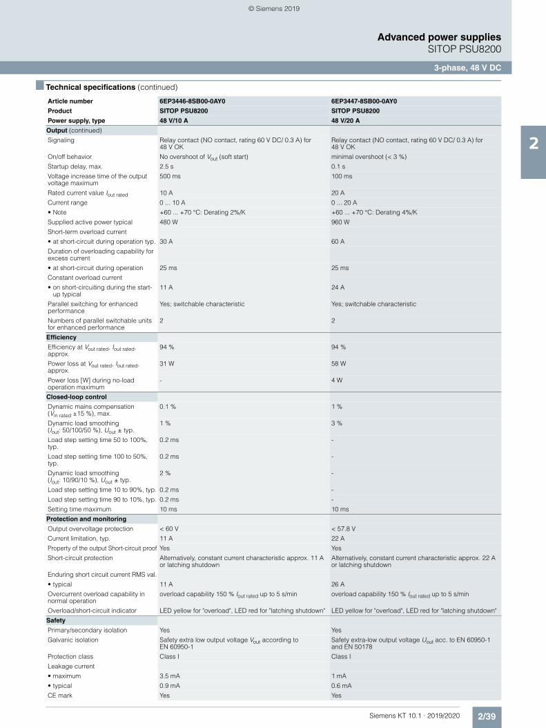
2/39Siemens KT 10.1 · 2019/2020
2
■ Technical specifications (continued)
Advanced power suppliesSITOP PSU8200
3-phase, 48 V DC
Output (continued)
Signaling Relay contact (NO contact, rating 60 V DC/ 0.3 A) for 48 V OK
Relay contact (NO contact, rating 60 V DC/ 0.3 A) for 48 V OK
On/off behavior No overshoot of Vout (soft start) minimal overshoot (< 3 %)
Startup delay, max. 2.5 s 0.1 s
Voltage increase time of the output voltage maximum
500 ms 100 ms
Rated current value Iout rated 10 A 20 A
Current range 0 ... 10 A 0 ... 20 A
• Note +60 ... +70 °C: Derating 2%/K +60 ... +70 °C: Derating 4%/K
Supplied active power typical 480 W 960 W
Short-term overload current
• at short-circuit during operation typ. 30 A 60 A
Duration of overloading capability for excess current
• at short-circuit during operation 25 ms 25 ms
Constant overload current
• on short-circuiting during the start-up typical
11 A 24 A
Parallel switching for enhanced performance
Yes; switchable characteristic Yes; switchable characteristic
Numbers of parallel switchable units for enhanced performance
2 2
Efficiency
Efficiency at Vout rated, Iout rated, approx.
94 % 94 %
Power loss at Vout rated, Iout rated, approx.
31 W 58 W
Power loss [W] during no-load operation maximum
- 4 W
Closed-loop control
Dynamic mains compensation (Vin rated ±15 %), max.
0.1 % 1 %
Dynamic load smoothing (Iout: 50/100/50 %), Uout ± typ.
1 % 3 %
Load step setting time 50 to 100%, typ.
0.2 ms -
Load step setting time 100 to 50%, typ.
0.2 ms -
Dynamic load smoothing (Iout: 10/90/10 %), Uout ± typ.
2 % -
Load step setting time 10 to 90%, typ. 0.2 ms -
Load step setting time 90 to 10%, typ. 0.2 ms -
Setting time maximum 10 ms 10 ms
Protection and monitoring
Output overvoltage protection < 60 V < 57.8 V
Current limitation, typ. 11 A 22 A
Property of the output Short-circuit proof Yes Yes
Short-circuit protection Alternatively, constant current characteristic approx. 11 A or latching shutdown
Alternatively, constant current characteristic approx. 22 A or latching shutdown
Enduring short circuit current RMS val.
• typical 11 A 26 A
Overcurrent overload capability in normal operation
overload capability 150 % Iout rated up to 5 s/min overload capability 150 % Iout rated up to 5 s/min
Overload/short-circuit indicator LED yellow for "overload", LED red for "latching shutdown" LED yellow for "overload", LED red for "latching shutdown"
Safety
Primary/secondary isolation Yes Yes
Galvanic isolation Safety extra low output voltage Vout according to EN 60950-1
Safety extra-low output voltage Uout acc. to EN 60950-1 and EN 50178
Protection class Class I Class I
Leakage current
• maximum 3.5 mA 1 mA
• typical 0.9 mA 0.6 mA
CE mark Yes Yes
Article number 6EP3446-8SB00-0AY0 6EP3447-8SB00-0AY0
Product SITOP PSU8200 SITOP PSU8200
Power supply, type 48 V/10 A 48 V/20 A
© Siemens 2019
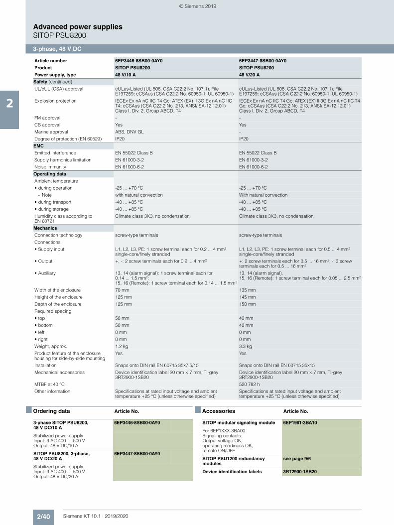
2/40 Siemens KT 10.1 · 2019/2020
2
Advanced power suppliesSITOP PSU8200
3-phase, 48 V DC
■ Ordering data Article No. ■ Accessories Article No.
Safety (continued)
UL/cUL (CSA) approval cULus-Listed (UL 508, CSA C22.2 No. 107.1), File E197259; cCSAus (CSA C22.2 No. 60950-1, UL 60950-1)
cULus-Listed (UL 508, CSA C22.2 No. 107.1), File E197259; cCSAus (CSA C22.2 No. 60950-1, UL 60950-1)
Explosion protection IECEx Ex nA nC IIC T4 Gc; ATEX (EX) II 3G Ex nA nC IIC T4; cCSAus (CSA C22.2 No. 213, ANSI/ISA-12.12.01) Class I, Div. 2, Group ABCD, T4
IECEx Ex nA nC IIC T4 Gc; ATEX (EX) II 3G Ex nA nC IIC T4 Gc; cCSAus (CSA C22.2 No. 213, ANSI/ISA-12.12.01) Class I, Div. 2, Group ABCD, T4
FM approval - -
CB approval Yes Yes
Marine approval ABS, DNV GL -
Degree of protection (EN 60529) IP20 IP20
EMC
Emitted interference EN 55022 Class B EN 55022 Class B
Supply harmonics limitation EN 61000-3-2 EN 61000-3-2
Noise immunity EN 61000-6-2 EN 61000-6-2
Operating data
Ambient temperature
• during operation -25 ... +70 °C -25 ... +70 °C
- Note with natural convection With natural convection
• during transport -40 ... +85 °C -40 ... +85 °C
• during storage -40 ... +85 °C -40 ... +85 °C
Humidity class according to EN 60721
Climate class 3K3, no condensation Climate class 3K3, no condensation
Mechanics
Connection technology screw-type terminals screw-type terminals
Connections
• Supply input L1, L2, L3, PE: 1 screw terminal each for 0.2 ... 4 mm² single-core/finely stranded
L1, L2, L3, PE: 1 screw terminal each for 0.5 ... 4 mm² single-core/finely stranded
• Output +, -: 2 screw terminals each for 0.2 ... 4 mm² +: 2 screw terminals each for 0.5 ... 16 mm²; -: 3 screw terminals each for 0.5 ... 16 mm²
• Auxiliary 13, 14 (alarm signal): 1 screw terminal each for 0.14 ... 1.5 mm²; 15, 16 (Remote): 1 screw terminal each for 0.14 ... 1.5 mm²
13, 14 (alarm signal), 15, 16 (Remote): 1 screw terminal each for 0.05 ... 2.5 mm²
Width of the enclosure 70 mm 135 mm
Height of the enclosure 125 mm 145 mm
Depth of the enclosure 125 mm 150 mm
Required spacing
• top 50 mm 40 mm
• bottom 50 mm 40 mm
• left 0 mm 0 mm
• right 0 mm 0 mm
Weight, approx. 1.2 kg 3.3 kg
Product feature of the enclosure housing for side-by-side mounting
Yes Yes
Installation Snaps onto DIN rail EN 60715 35x7.5/15 Snaps onto DIN rail EN 60715 35x15
Mechanical accessories Device identification label 20 mm × 7 mm, TI-grey 3RT2900-1SB20
Device identification label 20 mm × 7 mm, TI-grey 3RT2900-1SB20
MTBF at 40 °C 520 782 h
Other information Specifications at rated input voltage and ambient temperature +25 °C (unless otherwise specified)
Specifications at rated input voltage and ambient temperature +25 °C (unless otherwise specified)
Article number 6EP3446-8SB00-0AY0 6EP3447-8SB00-0AY0
Product SITOP PSU8200 SITOP PSU8200
Power supply, type 48 V/10 A 48 V/20 A
3-phase SITOP PSU8200, 48 V DC/10 A
6EP3446-8SB00-0AY0
Stabilized power supplyInput: 3 AC 400 … 500 VOutput: 48 V DC/10 A
SITOP PSU8200, 3-phase, 48 V DC/20 A
6EP3447-8SB00-0AY0
Stabilized power supplyInput: 3 AC 400 … 500 VOutput: 48 V DC/20 A
SITOP modular signaling module 6EP1961-3BA10
For 6EP1XXX-3BA00 Signaling contacts: Output voltage OK, operating readiness OK, remote ON/OFF
SITOP PSU1200 redundancy modules
see page 9/6
Device identification labels 3RT2900-1SB20
© Siemens 2019
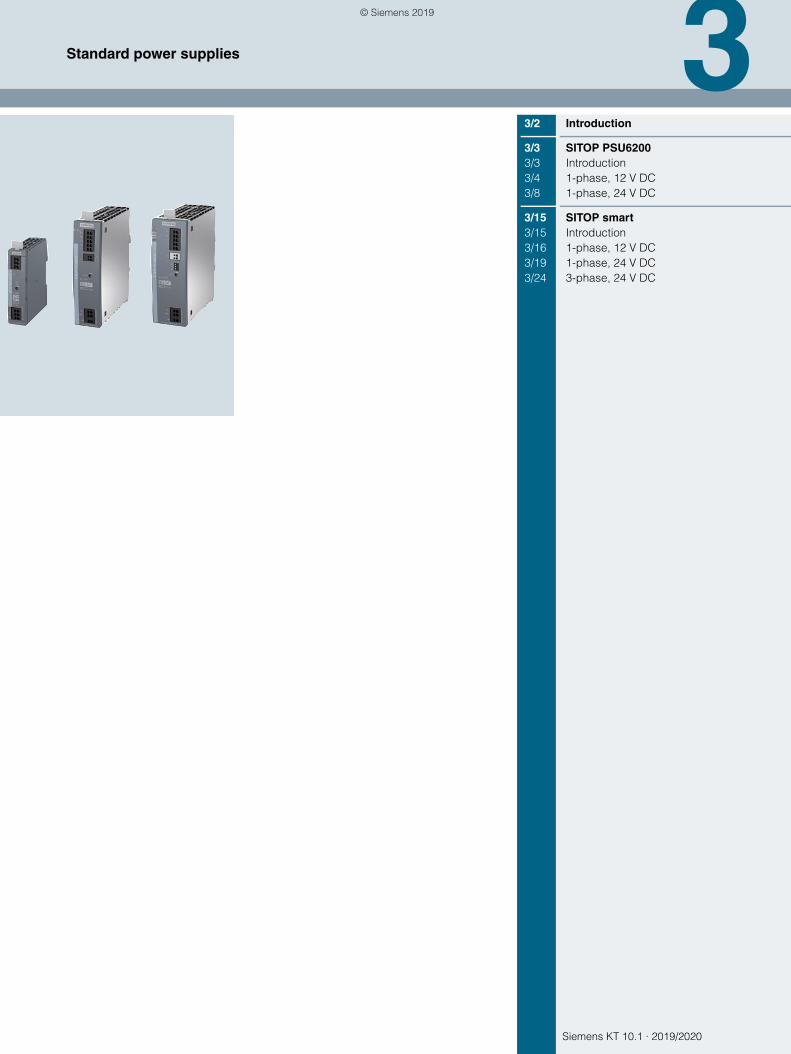
Siemens KT 10.1 · 2019/2020
33/2 Introduction
3/3 SITOP PSU62003/3 Introduction3/4 1-phase, 12 V DC3/8 1-phase, 24 V DC
3/15 SITOP smart3/15 Introduction3/16 1-phase, 12 V DC3/19 1-phase, 24 V DC3/24 3-phase, 24 V DC
Standard power supplies
© Siemens 2019
3/2 Siemens KT 10.1 · 2019/2020
3
Standard power supplies
Introduction
■ Overview
Our standard portfolio has been designed with typical industrial requirements in mind, such as those in series machine produc-tion.
The versatile new SITOP PSU6200 was developed on the basis of our experience with the time-proven SITOP smart product line. This new SITOP Standard offers even more efficiency, extensive diagnostic options and enhanced robustness.
© Siemens 2019
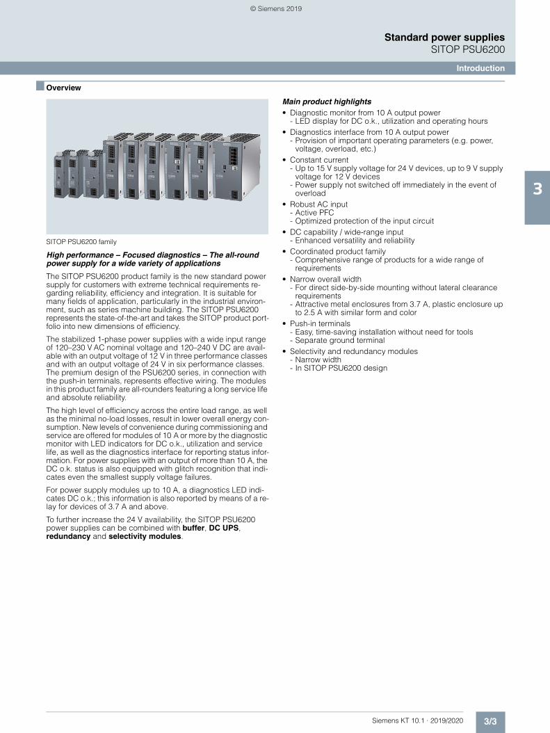
3/3Siemens KT 10.1 · 2019/2020
3
Standard power suppliesSITOP PSU6200
Introduction
■ Overview
SITOP PSU6200 family
High performance – Focused diagnostics – The all-round power supply for a wide variety of applications
The SITOP PSU6200 product family is the new standard power supply for customers with extreme technical requirements re-garding reliability, efficiency and integration. It is suitable for many fields of application, particularly in the industrial environ-ment, such as series machine building. The SITOP PSU6200 represents the state-of-the-art and takes the SITOP product port-folio into new dimensions of efficiency.
The stabilized 1-phase power supplies with a wide input range of 120–230 V AC nominal voltage and 120–240 V DC are avail-able with an output voltage of 12 V in three performance classes and with an output voltage of 24 V in six performance classes. The premium design of the PSU6200 series, in connection with the push-in terminals, represents effective wiring. The modules in this product family are all-rounders featuring a long service life and absolute reliability.
The high level of efficiency across the entire load range, as well as the minimal no-load losses, result in lower overall energy con-sumption. New levels of convenience during commissioning and service are offered for modules of 10 A or more by the diagnostic monitor with LED indicators for DC o.k., utilization and service life, as well as the diagnostics interface for reporting status infor-mation. For power supplies with an output of more than 10 A, the DC o.k. status is also equipped with glitch recognition that indi-cates even the smallest supply voltage failures.
For power supply modules up to 10 A, a diagnostics LED indi-cates DC o.k.; this information is also reported by means of a re-lay for devices of 3.7 A and above.
To further increase the 24 V availability, the SITOP PSU6200 power supplies can be combined with buffer, DC UPS, redundancy and selectivity modules.
Main product highlights• Diagnostic monitor from 10 A output power
- LED display for DC o.k., utilization and operating hours• Diagnostics interface from 10 A output power
- Provision of important operating parameters (e.g. power, voltage, overload, etc.)
• Constant current- Up to 15 V supply voltage for 24 V devices, up to 9 V supply
voltage for 12 V devices- Power supply not switched off immediately in the event of
overload• Robust AC input
- Active PFC- Optimized protection of the input circuit
• DC capability / wide-range input- Enhanced versatility and reliability
• Coordinated product family- Comprehensive range of products for a wide range of
requirements• Narrow overall width
- For direct side-by-side mounting without lateral clearance requirements
- Attractive metal enclosures from 3.7 A, plastic enclosure up to 2.5 A with similar form and color
• Push-in terminals- Easy, time-saving installation without need for tools- Separate ground terminal
• Selectivity and redundancy modules- Narrow width- In SITOP PSU6200 design
© Siemens 2019
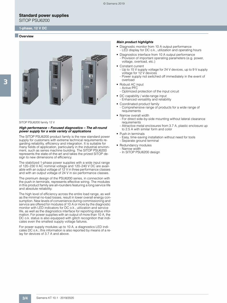
3/4 Siemens KT 10.1 · 2019/2020
3
Standard power suppliesSITOP PSU6200
1-phase, 12 V DC
■ Overview
SITOP PSU6200 family 12 V
High performance – Focused diagnostics – The all-round power supply for a wide variety of applications
The SITOP PSU6200 product family is the new standard power supply for customers with extreme technical requirements re-garding reliability, efficiency and integration. It is suitable for many fields of application, particularly in the industrial environ-ment, such as series machine building. The SITOP PSU6200 represents the state-of-the-art and takes the prized SITOP de-sign to new dimensions of efficiency.
The stabilized 1-phase power supplies with a wide input range of 120–230 V AC nominal voltage and 120–240 V DC are avail-able with an output voltage of 12 V in three performance classes and with an output voltage of 24 V in six performance classes.
The premium design of the PSU6200 series, in connection with the push-in terminals, represents effective wiring. The modules in this product family are all-rounders featuring a long service life and absolute reliability.
The high level of efficiency across the entire load range, as well as the minimal no-load losses, result in lower overall energy con-sumption. New levels of convenience during commissioning and service are offered for modules of 10 A or more by the diagnostic monitor with LED indicators for DC o.k., utilization and service life, as well as the diagnostics interface for reporting status infor-mation. For power supplies with an output of more than 10 A, the DC o.k. status is also equipped with glitch recognition that indi-cates even the smallest supply voltage failures.
For power supply modules up to 10 A, a diagnostics LED indi-cates DC o.k.; this information is also reported by means of a re-lay for devices of 3.7 A and above.
Main product highlights• Diagnostic monitor from 10 A output performance
- LED display for DC o.k., utilization and operating hours• Diagnostics interface from 10 A output performance
- Provision of important operating parameters (e.g. power, voltage, overload, etc.)
• Constant current- Up to 15 V supply voltage for 24 V devices, up to 9 V supply
voltage for 12 V devices- Power supply not switched off immediately in the event of
overload• Robust AC input
- Active PFC- Optimized protection of the input circuit
• DC capability / wide-range input- Enhanced versatility and reliability
• Coordinated product family- Comprehensive range of products for a wide range of
requirements• Narrow overall width
- For direct side-by-side mounting without lateral clearance requirements
- Attractive metal enclosures from 3.7 A, plastic enclosure up to 2.5 A with similar form and color
• Push-in terminals- Easy, time-saving installation without need for tools- Separate ground terminal
• Redundancy modules- Narrow width- In SITOP PSU6200 design
© Siemens 2019
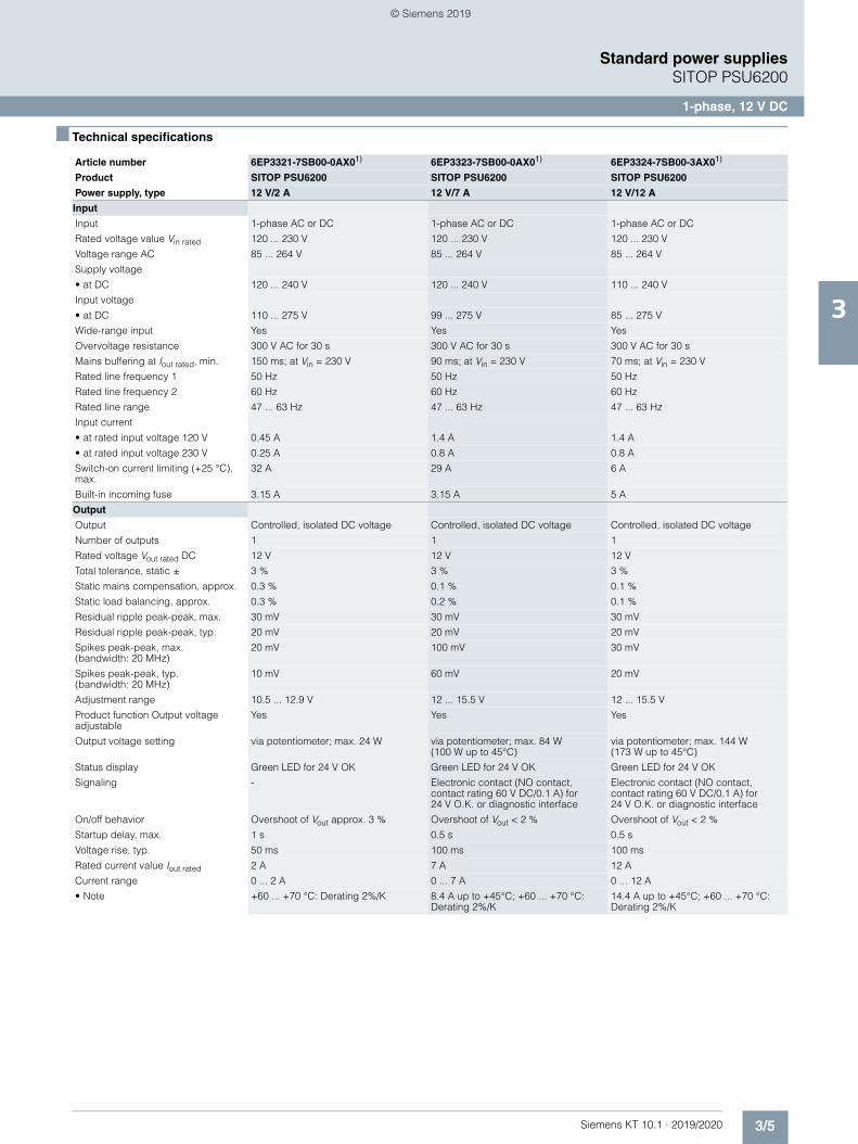
3/5Siemens KT 10.1 · 2019/2020
3
Standard power suppliesSITOP PSU6200
1-phase, 12 V DC
■ Technical specifications
Article number 6EP3321-7SB00-0AX01) 6EP3323-7SB00-0AX01) 6EP3324-7SB00-3AX01)
Product SITOP PSU6200 SITOP PSU6200 SITOP PSU6200
Power supply, type 12 V/2 A 12 V/7 A 12 V/12 A
Input
Input 1-phase AC or DC 1-phase AC or DC 1-phase AC or DC
Rated voltage value Vin rated 120 ... 230 V 120 ... 230 V 120 ... 230 V
Voltage range AC 85 ... 264 V 85 ... 264 V 85 ... 264 V
Supply voltage
• at DC 120 ... 240 V 120 ... 240 V 110 ... 240 V
Input voltage
• at DC 110 ... 275 V 99 ... 275 V 85 ... 275 V
Wide-range input Yes Yes Yes
Overvoltage resistance 300 V AC for 30 s 300 V AC for 30 s 300 V AC for 30 s
Mains buffering at Iout rated, min. 150 ms; at Vin = 230 V 90 ms; at Vin = 230 V 70 ms; at Vin = 230 V
Rated line frequency 1 50 Hz 50 Hz 50 Hz
Rated line frequency 2 60 Hz 60 Hz 60 Hz
Rated line range 47 ... 63 Hz 47 ... 63 Hz 47 ... 63 Hz
Input current
• at rated input voltage 120 V 0.45 A 1.4 A 1.4 A
• at rated input voltage 230 V 0.25 A 0.8 A 0.8 A
Switch-on current limiting (+25 °C), max.
32 A 29 A 6 A
Built-in incoming fuse 3.15 A 3.15 A 5 A
Output
Output Controlled, isolated DC voltage Controlled, isolated DC voltage Controlled, isolated DC voltage
Number of outputs 1 1 1
Rated voltage Vout rated DC 12 V 12 V 12 V
Total tolerance, static ± 3 % 3 % 3 %
Static mains compensation, approx. 0.3 % 0.1 % 0.1 %
Static load balancing, approx. 0.3 % 0.2 % 0.1 %
Residual ripple peak-peak, max. 30 mV 30 mV 30 mV
Residual ripple peak-peak, typ. 20 mV 20 mV 20 mV
Spikes peak-peak, max. (bandwidth: 20 MHz)
20 mV 100 mV 30 mV
Spikes peak-peak, typ. (bandwidth: 20 MHz)
10 mV 60 mV 20 mV
Adjustment range 10.5 ... 12.9 V 12 ... 15.5 V 12 ... 15.5 V
Product function Output voltage adjustable
Yes Yes Yes
Output voltage setting via potentiometer; max. 24 W via potentiometer; max. 84 W (100 W up to 45°C)
via potentiometer; max. 144 W (173 W up to 45°C)
Status display Green LED for 24 V OK Green LED for 24 V OK Green LED for 24 V OK
Signaling - Electronic contact (NO contact, contact rating 60 V DC/0.1 A) for 24 V O.K. or diagnostic interface
Electronic contact (NO contact, contact rating 60 V DC/0.1 A) for 24 V O.K. or diagnostic interface
On/off behavior Overshoot of Vout approx. 3 % Overshoot of Vout < 2 % Overshoot of Vout < 2 %
Startup delay, max. 1 s 0.5 s 0.5 s
Voltage rise, typ. 50 ms 100 ms 100 ms
Rated current value Iout rated 2 A 7 A 12 A
Current range 0 ... 2 A 0 ... 7 A 0 ... 12 A
• Note +60 ... +70 °C: Derating 2%/K 8.4 A up to +45°C; +60 ... +70 °C: Derating 2%/K
14.4 A up to +45°C; +60 ... +70 °C: Derating 2%/K
© Siemens 2019
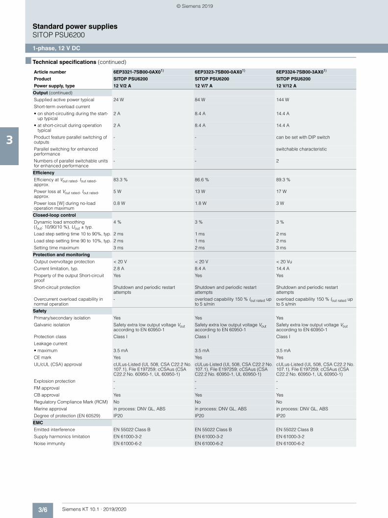
3/6 Siemens KT 10.1 · 2019/2020
3
■ Technical specifications (continued)
Standard power suppliesSITOP PSU6200
1-phase, 12 V DC
Output (continued)
Supplied active power typical 24 W 84 W 144 W
Short-term overload current
• on short-circuiting during the start-up typical
2 A 8.4 A 14.4 A
• at short-circuit during operation typical
2 A 8.4 A 14.4 A
Product feature parallel switching of outputs
- - can be set with DIP switch
Parallel switching for enhanced performance
- - switchable characteristic
Numbers of parallel switchable units for enhanced performance
- - 2
Efficiency
Efficiency at Vout rated, Iout rated, approx.
83.3 % 86.6 % 89.3 %
Power loss at Vout rated, Iout rated, approx.
5 W 13 W 17 W
Power loss [W] during no-load operation maximum
0.8 W 1.8 W 3 W
Closed-loop control
Dynamic load smoothing (Iout: 10/90/10 %), Uout ± typ.
4 % 3 % 3 %
Load step setting time 10 to 90%, typ. 2 ms 1 ms 2 ms
Load step setting time 90 to 10%, typ. 2 ms 1 ms 2 ms
Setting time maximum 3 ms 2 ms 3 ms
Protection and monitoring
Output overvoltage protection < 20 V < 20 V < 20 Vu
Current limitation, typ. 2.8 A 8.4 A 14.4 A
Property of the output Short-circuit proof
Yes Yes Yes
Short-circuit protection Shutdown and periodic restart attempts
Shutdown and periodic restart attempts
Shutdown and periodic restart attempts
Overcurrent overload capability in normal operation
- overload capability 150 % Iout rated up to 5 s/min
overload capability 150 % Iout rated up to 5 s/min
Safety
Primary/secondary isolation Yes Yes Yes
Galvanic isolation Safety extra low output voltage Vout according to EN 60950-1
Safety extra low output voltage Vout according to EN 60950-1
Safety extra low output voltage Vout according to EN 60950-1
Protection class Class I Class I Class I
Leakage current
• maximum 3.5 mA 3.5 mA 3.5 mA
CE mark Yes Yes Yes
UL/cUL (CSA) approval cULus-Listed (UL 508, CSA C22.2 No. 107.1), File E197259; cCSAus (CSA C22.2 No. 60950-1, UL 60950-1)
cULus-Listed (UL 508, CSA C22.2 No. 107.1), File E197259; cCSAus (CSA C22.2 No. 60950-1, UL 60950-1)
cULus-Listed (UL 508, CSA C22.2 No. 107.1), File E197259; cCSAus (CSA C22.2 No. 60950-1, UL 60950-1)
Explosion protection - - -
FM approval - - -
CB approval Yes Yes Yes
Regulatory Compliance Mark (RCM) No No No
Marine approval in process: DNV GL, ABS in process: DNV GL, ABS in process: DNV GL, ABS
Degree of protection (EN 60529) IP20 IP20 IP20
EMC
Emitted interference EN 55022 Class B EN 55022 Class B EN 55022 Class B
Supply harmonics limitation EN 61000-3-2 EN 61000-3-2 EN 61000-3-2
Noise immunity EN 61000-6-2 EN 61000-6-2 EN 61000-6-2
Article number 6EP3321-7SB00-0AX01) 6EP3323-7SB00-0AX01) 6EP3324-7SB00-3AX01)
Product SITOP PSU6200 SITOP PSU6200 SITOP PSU6200
Power supply, type 12 V/2 A 12 V/7 A 12 V/12 A
© Siemens 2019
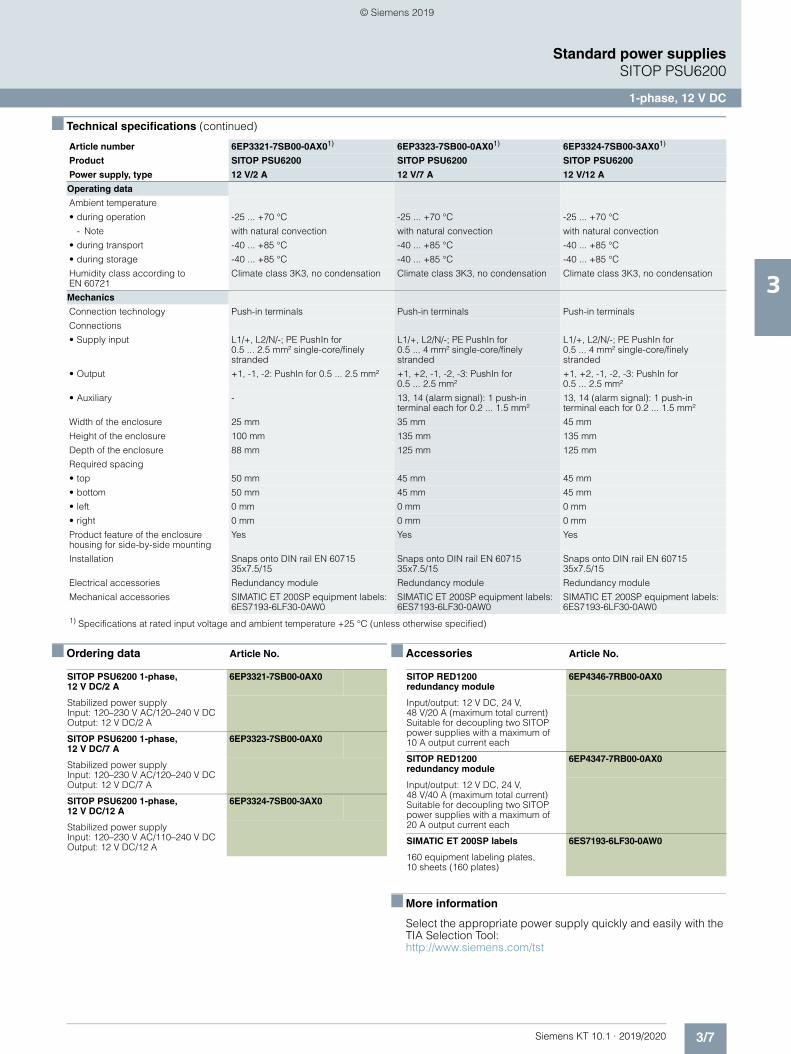
3/7Siemens KT 10.1 · 2019/2020
3
■ Technical specifications (continued)
Standard power suppliesSITOP PSU6200
1-phase, 12 V DC
■ Ordering data Article No. ■ Accessories Article No.
■ More information
Select the appropriate power supply quickly and easily with the TIA Selection Tool:http://www.siemens.com/tst
Operating data
Ambient temperature
• during operation -25 ... +70 °C -25 ... +70 °C -25 ... +70 °C
- Note with natural convection with natural convection with natural convection
• during transport -40 ... +85 °C -40 ... +85 °C -40 ... +85 °C
• during storage -40 ... +85 °C -40 ... +85 °C -40 ... +85 °C
Humidity class according to EN 60721
Climate class 3K3, no condensation Climate class 3K3, no condensation Climate class 3K3, no condensation
Mechanics
Connection technology Push-in terminals Push-in terminals Push-in terminals
Connections
• Supply input L1/+, L2/N/-; PE PushIn for 0.5 ... 2.5 mm² single-core/finely stranded
L1/+, L2/N/-; PE PushIn for 0.5 ... 4 mm² single-core/finely stranded
L1/+, L2/N/-; PE PushIn for 0.5 ... 4 mm² single-core/finely stranded
• Output +1, -1, -2: PushIn for 0.5 ... 2.5 mm² +1, +2, -1, -2, -3: PushIn for 0.5 ... 2.5 mm²
+1, +2, -1, -2, -3: PushIn for 0.5 ... 2.5 mm²
• Auxiliary - 13, 14 (alarm signal): 1 push-in terminal each for 0.2 ... 1.5 mm²
13, 14 (alarm signal): 1 push-in terminal each for 0.2 ... 1.5 mm²
Width of the enclosure 25 mm 35 mm 45 mm
Height of the enclosure 100 mm 135 mm 135 mm
Depth of the enclosure 88 mm 125 mm 125 mm
Required spacing
• top 50 mm 45 mm 45 mm
• bottom 50 mm 45 mm 45 mm
• left 0 mm 0 mm 0 mm
• right 0 mm 0 mm 0 mm
Product feature of the enclosure housing for side-by-side mounting
Yes Yes Yes
Installation Snaps onto DIN rail EN 60715 35x7.5/15
Snaps onto DIN rail EN 60715 35x7.5/15
Snaps onto DIN rail EN 60715 35x7.5/15
Electrical accessories Redundancy module Redundancy module Redundancy module
Mechanical accessories SIMATIC ET 200SP equipment labels: 6ES7193-6LF30-0AW0
SIMATIC ET 200SP equipment labels: 6ES7193-6LF30-0AW0
SIMATIC ET 200SP equipment labels: 6ES7193-6LF30-0AW0
1) Specifications at rated input voltage and ambient temperature +25 °C (unless otherwise specified)
Article number 6EP3321-7SB00-0AX01) 6EP3323-7SB00-0AX01) 6EP3324-7SB00-3AX01)
Product SITOP PSU6200 SITOP PSU6200 SITOP PSU6200
Power supply, type 12 V/2 A 12 V/7 A 12 V/12 A
SITOP PSU6200 1-phase, 12 V DC/2 A
6EP3321-7SB00-0AX0
Stabilized power supplyInput: 120–230 V AC/120–240 V DCOutput: 12 V DC/2 A
SITOP PSU6200 1-phase, 12 V DC/7 A
6EP3323-7SB00-0AX0
Stabilized power supplyInput: 120–230 V AC/120–240 V DCOutput: 12 V DC/7 A
SITOP PSU6200 1-phase, 12 V DC/12 A
6EP3324-7SB00-3AX0
Stabilized power supplyInput: 120–230 V AC/110–240 V DCOutput: 12 V DC/12 A
SITOP RED1200 redundancy module
6EP4346-7RB00-0AX0
Input/output: 12 V DC, 24 V, 48 V/20 A (maximum total current)Suitable for decoupling two SITOP power supplies with a maximum of 10 A output current each
SITOP RED1200 redundancy module
6EP4347-7RB00-0AX0
Input/output: 12 V DC, 24 V, 48 V/40 A (maximum total current)Suitable for decoupling two SITOP power supplies with a maximum of 20 A output current each
SIMATIC ET 200SP labels 6ES7193-6LF30-0AW0
160 equipment labeling plates, 10 sheets (160 plates)
© Siemens 2019
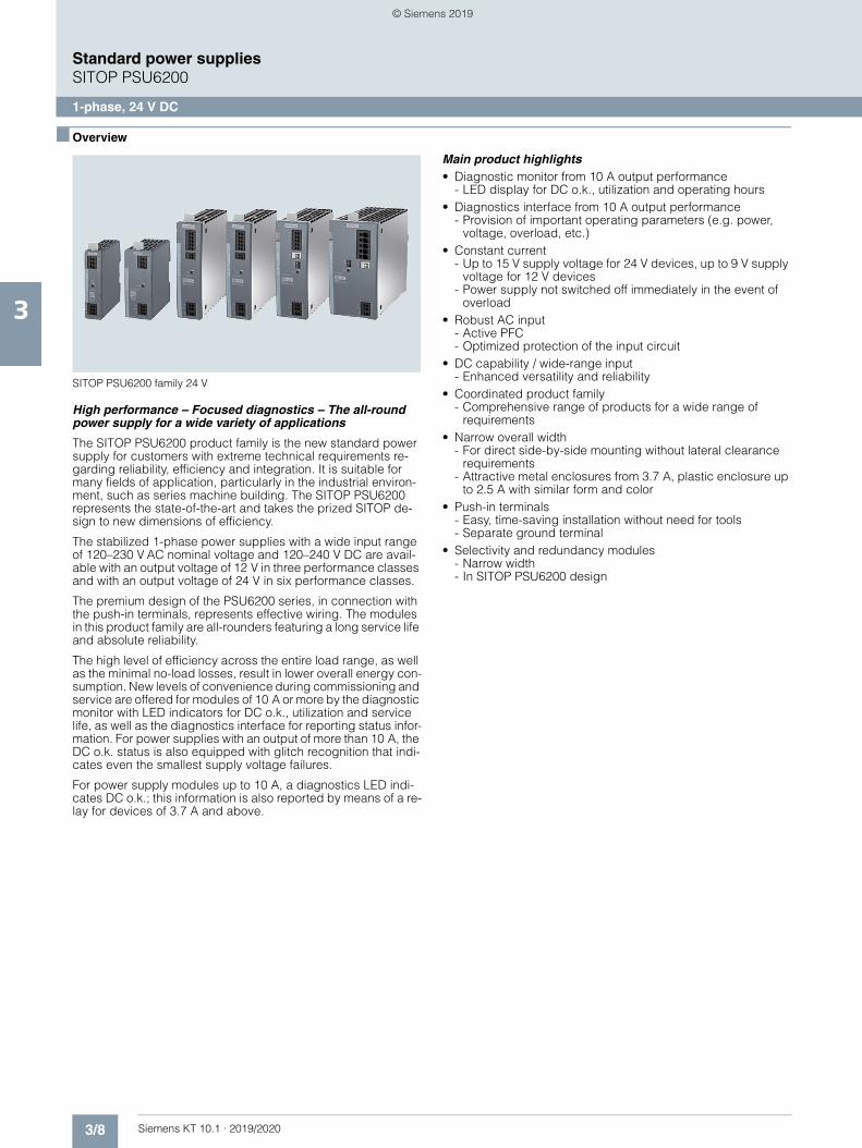
3/8 Siemens KT 10.1 · 2019/2020
3
Standard power suppliesSITOP PSU6200
1-phase, 24 V DC
■ Overview
SITOP PSU6200 family 24 V
High performance – Focused diagnostics – The all-round power supply for a wide variety of applications
The SITOP PSU6200 product family is the new standard power supply for customers with extreme technical requirements re-garding reliability, efficiency and integration. It is suitable for many fields of application, particularly in the industrial environ-ment, such as series machine building. The SITOP PSU6200 represents the state-of-the-art and takes the prized SITOP de-sign to new dimensions of efficiency.
The stabilized 1-phase power supplies with a wide input range of 120–230 V AC nominal voltage and 120–240 V DC are avail-able with an output voltage of 12 V in three performance classes and with an output voltage of 24 V in six performance classes.
The premium design of the PSU6200 series, in connection with the push-in terminals, represents effective wiring. The modules in this product family are all-rounders featuring a long service life and absolute reliability.
The high level of efficiency across the entire load range, as well as the minimal no-load losses, result in lower overall energy con-sumption. New levels of convenience during commissioning and service are offered for modules of 10 A or more by the diagnostic monitor with LED indicators for DC o.k., utilization and service life, as well as the diagnostics interface for reporting status infor-mation. For power supplies with an output of more than 10 A, the DC o.k. status is also equipped with glitch recognition that indi-cates even the smallest supply voltage failures.
For power supply modules up to 10 A, a diagnostics LED indi-cates DC o.k.; this information is also reported by means of a re-lay for devices of 3.7 A and above.
Main product highlights• Diagnostic monitor from 10 A output performance
- LED display for DC o.k., utilization and operating hours• Diagnostics interface from 10 A output performance
- Provision of important operating parameters (e.g. power, voltage, overload, etc.)
• Constant current- Up to 15 V supply voltage for 24 V devices, up to 9 V supply
voltage for 12 V devices- Power supply not switched off immediately in the event of
overload• Robust AC input
- Active PFC- Optimized protection of the input circuit
• DC capability / wide-range input- Enhanced versatility and reliability
• Coordinated product family- Comprehensive range of products for a wide range of
requirements• Narrow overall width
- For direct side-by-side mounting without lateral clearance requirements
- Attractive metal enclosures from 3.7 A, plastic enclosure up to 2.5 A with similar form and color
• Push-in terminals- Easy, time-saving installation without need for tools- Separate ground terminal
• Selectivity and redundancy modules- Narrow width- In SITOP PSU6200 design
© Siemens 2019
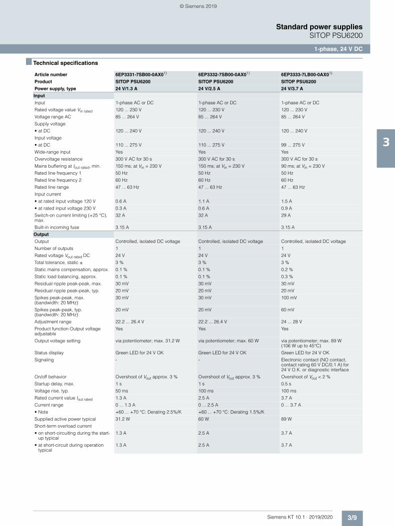
3/9Siemens KT 10.1 · 2019/2020
3
Standard power suppliesSITOP PSU6200
1-phase, 24 V DC
■ Technical specifications
Article number 6EP3331-7SB00-0AX01) 6EP3332-7SB00-0AX01) 6EP3333-7LB00-0AX01)
Product SITOP PSU6200 SITOP PSU6200 SITOP PSU6200
Power supply, type 24 V/1.3 A 24 V/2.5 A 24 V/3.7 A
Input
Input 1-phase AC or DC 1-phase AC or DC 1-phase AC or DC
Rated voltage value Vin rated 120 ... 230 V 120 ... 230 V 120 ... 230 V
Voltage range AC 85 ... 264 V 85 ... 264 V 85 ... 264 V
Supply voltage
• at DC 120 ... 240 V 120 ... 240 V 120 ... 240 V
Input voltage
• at DC 110 ... 275 V 110 ... 275 V 99 ... 275 V
Wide-range input Yes Yes Yes
Overvoltage resistance 300 V AC for 30 s 300 V AC for 30 s 300 V AC for 30 s
Mains buffering at Iout rated, min. 150 ms; at Vin = 230 V 150 ms; at Vin = 230 V 90 ms; at Vin = 230 V
Rated line frequency 1 50 Hz 50 Hz 50 Hz
Rated line frequency 2 60 Hz 60 Hz 60 Hz
Rated line range 47 ... 63 Hz 47 ... 63 Hz 47 ... 63 Hz
Input current
• at rated input voltage 120 V 0.6 A 1.1 A 1.5 A
• at rated input voltage 230 V 0.3 A 0.6 A 0.9 A
Switch-on current limiting (+25 °C), max.
32 A 32 A 29 A
Built-in incoming fuse 3.15 A 3.15 A 3.15 A
Output
Output Controlled, isolated DC voltage Controlled, isolated DC voltage Controlled, isolated DC voltage
Number of outputs 1 1 1
Rated voltage Vout rated DC 24 V 24 V 24 V
Total tolerance, static ± 3 % 3 % 3 %
Static mains compensation, approx. 0.1 % 0.1 % 0.2 %
Static load balancing, approx. 0.1 % 0.1 % 0.3 %
Residual ripple peak-peak, max. 30 mV 30 mV 30 mV
Residual ripple peak-peak, typ. 20 mV 20 mV 20 mV
Spikes peak-peak, max. (bandwidth: 20 MHz)
30 mV 30 mV 100 mV
Spikes peak-peak, typ. (bandwidth: 20 MHz)
20 mV 20 mV 60 mV
Adjustment range 22.2 ... 26.4 V 22.2 ... 26.4 V 24 ... 28 V
Product function Output voltage adjustable
Yes Yes Yes
Output voltage setting via potentiometer; max. 31.2 W via potentiometer; max. 60 W via potentiometer; max. 89 W (106 W up to 45°C)
Status display Green LED for 24 V OK Green LED for 24 V OK Green LED for 24 V OK
Signaling - - Electronic contact (NO contact, contact rating 60 V DC/0.1 A) for 24 V O.K. or diagnostic interface
On/off behavior Overshoot of Vout approx. 3 % Overshoot of Vout approx. 3 % Overshoot of Vout < 2 %
Startup delay, max. 1 s 1 s 0.5 s
Voltage rise, typ. 50 ms 100 ms 100 ms
Rated current value Iout rated 1.3 A 2.5 A 3.7 A
Current range 0 ... 1.3 A 0 ... 2.5 A 0 ... 3.7 A
• Note +60 ... +70 °C: Derating 2.5%/K +60 ... +70 °C: Derating 1.5%/K
Supplied active power typical 31.2 W 60 W 89 W
Short-term overload current
• on short-circuiting during the start-up typical
1.3 A 2.5 A 3.7 A
• at short-circuit during operation typical
1.3 A 2.5 A 3.7 A
© Siemens 2019
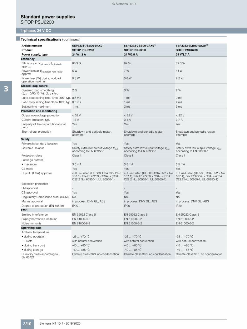
3/10 Siemens KT 10.1 · 2019/2020
3
■ Technical specifications (continued)
Standard power suppliesSITOP PSU6200
1-phase, 24 V DC
Efficiency
Efficiency at Vout rated, Iout rated, approx.
86.3 % 89 % 89.3 %
Power loss at Vout rated, Iout rated, approx.
5 W 7 W 11 W
Power loss [W] during no-load operation maximum
0.8 W 0.8 W 2.2 W
Closed-loop control
Dynamic load smoothing (Iout: 10/90/10 %), Uout ± typ.
2 % 3 % 2 %
Load step setting time 10 to 90%, typ. 0.5 ms 1 ms 2 ms
Load step setting time 90 to 10%, typ. 0.5 ms 1 ms 2 ms
Setting time maximum 1 ms 2 ms 3 ms
Protection and monitoring
Output overvoltage protection < 32 V < 32 V < 32 V
Current limitation, typ. 1.6 A 3.1 A 3.7 A
Property of the output Short-circuit proof
Yes Yes Yes
Short-circuit protection Shutdown and periodic restart attempts
Shutdown and periodic restart attempts
Shutdown and periodic restart attempts
Safety
Primary/secondary isolation Yes Yes Yes
Galvanic isolation Safety extra low output voltage Vout according to EN 60950-1
Safety extra low output voltage Vout according to EN 60950-1
Safety extra low output voltage Vout according to EN 60950-1
Protection class Class I Class I Class I
Leakage current
• maximum 3.5 mA 3.5 mA 3.5 mA
CE mark Yes Yes Yes
UL/cUL (CSA) approval cULus-Listed (UL 508, CSA C22.2 No. 107.1), File E197259; cCSAus (CSA C22.2 No. 60950-1, UL 60950-1)
cULus-Listed (UL 508, CSA C22.2 No. 107.1), File E197259; cCSAus (CSA C22.2 No. 60950-1, UL 60950-1)
cULus-Listed (UL 508, CSA C22.2 No. 107.1), File E197259; cCSAus (CSA C22.2 No. 60950-1, UL 60950-1)
Explosion protection - - -
FM approval - - -
CB approval Yes Yes Yes
Regulatory Compliance Mark (RCM) No No No
Marine approval in process: DNV GL, ABS in process: DNV GL, ABS in process: DNV GL, ABS
Degree of protection (EN 60529) IP20 IP20 IP20
EMC
Emitted interference EN 55022 Class B EN 55022 Class B EN 55022 Class B
Supply harmonics limitation EN 61000-3-2 EN 61000-3-2 EN 61000-3-2
Noise immunity EN 61000-6-2 EN 61000-6-2 EN 61000-6-2
Operating data
Ambient temperature
• during operation -25 ... +70 °C -25 ... +70 °C -25 ... +70 °C
- Note with natural convection with natural convection with natural convection
• during transport -40 ... +85 °C -40 ... +85 °C -40 ... +85 °C
• during storage -40 ... +85 °C -40 ... +85 °C -40 ... +85 °C
Humidity class according to EN 60721
Climate class 3K3, no condensation Climate class 3K3, no condensation Climate class 3K3, no condensation
Article number 6EP3331-7SB00-0AX01) 6EP3332-7SB00-0AX01) 6EP3333-7LB00-0AX01)
Product SITOP PSU6200 SITOP PSU6200 SITOP PSU6200
Power supply, type 24 V/1.3 A 24 V/2.5 A 24 V/3.7 A
© Siemens 2019
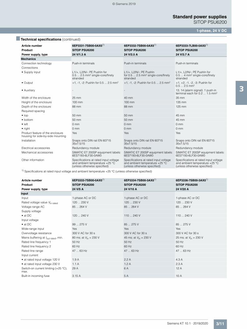
3/11Siemens KT 10.1 · 2019/2020
3
■ Technical specifications (continued)
Standard power suppliesSITOP PSU6200
1-phase, 24 V DC
Mechanics
Connection technology Push-in terminals Push-in terminals Push-in terminals
Connections
• Supply input L1/+, L2/N/-; PE PushIn for 0.5 ... 2.5 mm² single-core/finely stranded
L1/+, L2/N/-; PE PushIn for 0.5 ... 2.5 mm² single-core/finely stranded
L1/+, L2/N/-; PE PushIn for 0.5 ... 4 mm² single-core/finely stranded
• Output +1, -1, -2: PushIn for 0.5 ... 2.5 mm² +1, -1, -2: PushIn for 0.5 ... 2.5 mm² +1, +2, -1, -2, -3: PushIn for 0.5 ... 2.5 mm²
• Auxiliary - - 13, 14 (alarm signal): 1 push-in terminal each for 0.2 ... 1.5 mm²
Width of the enclosure 25 mm 40 mm 35 mm
Height of the enclosure 100 mm 100 mm 135 mm
Depth of the enclosure 88 mm 88 mm 125 mm
Required spacing
• top 50 mm 50 mm 45 mm
• bottom 50 mm 50 mm 45 mm
• left 0 mm 0 mm 0 mm
• right 0 mm 0 mm 0 mm
Product feature of the enclosure housing for side-by-side mounting
Yes Yes Yes
Installation Snaps onto DIN rail EN 60715 35x7.5/15
Snaps onto DIN rail EN 60715 35x7.5/15
Snaps onto DIN rail EN 60715 35x7.5/15
Electrical accessories Redundancy module Redundancy module Redundancy module
Mechanical accessories SIMATIC ET 200SP equipment labels: 6ES7193-6LF30-0AW0
SIMATIC ET 200SP equipment labels: 6ES7193-6LF30-0AW0
SIMATIC ET 200SP equipment labels: 6ES7193-6LF30-0AW0
Other information Specifications at rated input voltage and ambient temperature +25 °C (unless otherwise specified)
Specifications at rated input voltage and ambient temperature +25 °C (unless otherwise specified)
Specifications at rated input voltage and ambient temperature +25 °C (unless otherwise specified)
1) Specifications at rated input voltage and ambient temperature +25 °C (unless otherwise specified)
Article number 6EP3333-7SB00-0AX01) 6EP3334-7SB00-3AX01) 6EP3336-7SB00-3AX01)
Product SITOP PSU6200 SITOP PSU6200 SITOP PSU6200
Power supply, type 24 V/5 A 24 V/10 A 24 V/20 A
Input
Input 1-phase AC or DC 1-phase AC or DC 1-phase AC or DC
Rated voltage value Vin rated 120 ... 230 V 120 ... 230 V 120 ... 230 V
Voltage range AC 85 ... 264 V 85 ... 264 V 85 ... 264 V
Supply voltage
• at DC 120 ... 240 V 110 ... 240 V 110 ... 240 V
Input voltage
• at DC 99 ... 275 V 85 ... 275 V 85 ... 275 V
Wide-range input Yes Yes Yes
Overvoltage resistance 300 V AC for 30 s 300 V AC for 30 s 300 V AC for 30 s
Mains buffering at Iout rated, min. 80 ms; at Vin = 230 V 45 ms; at Vin = 230 V 25 ms; at Vin = 230 V
Rated line frequency 1 50 Hz 50 Hz 50 Hz
Rated line frequency 2 60 Hz 60 Hz 60 Hz
Rated line range 47 ... 63 Hz 47 ... 63 Hz 47 ... 63 Hz
Input current
• at rated input voltage 120 V 1.9 A 2.2 A 4.3 A
• at rated input voltage 230 V 1.1 A 1.2 A 2.3 A
Switch-on current limiting (+25 °C), max.
29 A 6 A 12 A
Built-in incoming fuse 3.15 A 5 A 10 A
Article number 6EP3331-7SB00-0AX01) 6EP3332-7SB00-0AX01) 6EP3333-7LB00-0AX01)
Product SITOP PSU6200 SITOP PSU6200 SITOP PSU6200
Power supply, type 24 V/1.3 A 24 V/2.5 A 24 V/3.7 A
© Siemens 2019
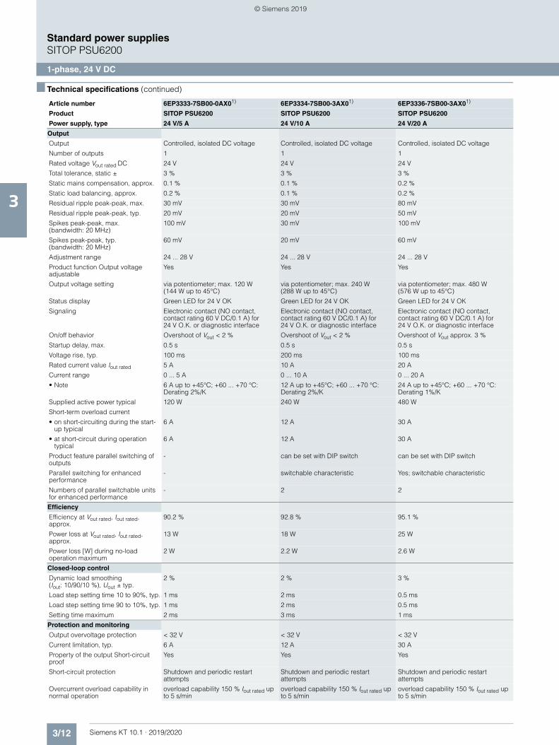
3/12 Siemens KT 10.1 · 2019/2020
3
■ Technical specifications (continued)
Standard power suppliesSITOP PSU6200
1-phase, 24 V DC
Output
Output Controlled, isolated DC voltage Controlled, isolated DC voltage Controlled, isolated DC voltage
Number of outputs 1 1 1
Rated voltage Vout rated DC 24 V 24 V 24 V
Total tolerance, static ± 3 % 3 % 3 %
Static mains compensation, approx. 0.1 % 0.1 % 0.2 %
Static load balancing, approx. 0.2 % 0.1 % 0.2 %
Residual ripple peak-peak, max. 30 mV 30 mV 80 mV
Residual ripple peak-peak, typ. 20 mV 20 mV 50 mV
Spikes peak-peak, max. (bandwidth: 20 MHz)
100 mV 30 mV 100 mV
Spikes peak-peak, typ. (bandwidth: 20 MHz)
60 mV 20 mV 60 mV
Adjustment range 24 ... 28 V 24 ... 28 V 24 ... 28 V
Product function Output voltage adjustable
Yes Yes Yes
Output voltage setting via potentiometer; max. 120 W (144 W up to 45°C)
via potentiometer; max. 240 W (288 W up to 45°C)
via potentiometer; max. 480 W (576 W up to 45°C)
Status display Green LED for 24 V OK Green LED for 24 V OK Green LED for 24 V OK
Signaling Electronic contact (NO contact, contact rating 60 V DC/0.1 A) for 24 V O.K. or diagnostic interface
Electronic contact (NO contact, contact rating 60 V DC/0.1 A) for 24 V O.K. or diagnostic interface
Electronic contact (NO contact, contact rating 60 V DC/0.1 A) for 24 V O.K. or diagnostic interface
On/off behavior Overshoot of Vout < 2 % Overshoot of Vout < 2 % Overshoot of Vout approx. 3 %
Startup delay, max. 0.5 s 0.5 s 0.5 s
Voltage rise, typ. 100 ms 200 ms 100 ms
Rated current value Iout rated 5 A 10 A 20 A
Current range 0 ... 5 A 0 ... 10 A 0 ... 20 A
• Note 6 A up to +45°C; +60 ... +70 °C: Derating 2%/K
12 A up to +45°C; +60 ... +70 °C: Derating 2%/K
24 A up to +45°C; +60 ... +70 °C: Derating 1%/K
Supplied active power typical 120 W 240 W 480 W
Short-term overload current
• on short-circuiting during the start-up typical
6 A 12 A 30 A
• at short-circuit during operation typical
6 A 12 A 30 A
Product feature parallel switching of outputs
- can be set with DIP switch can be set with DIP switch
Parallel switching for enhanced performance
- switchable characteristic Yes; switchable characteristic
Numbers of parallel switchable units for enhanced performance
- 2 2
Efficiency
Efficiency at Vout rated, Iout rated, approx.
90.2 % 92.8 % 95.1 %
Power loss at Vout rated, Iout rated, approx.
13 W 18 W 25 W
Power loss [W] during no-load operation maximum
2 W 2.2 W 2.6 W
Closed-loop control
Dynamic load smoothing (Iout: 10/90/10 %), Uout ± typ.
2 % 2 % 3 %
Load step setting time 10 to 90%, typ. 1 ms 2 ms 0.5 ms
Load step setting time 90 to 10%, typ. 1 ms 2 ms 0.5 ms
Setting time maximum 2 ms 3 ms 1 ms
Protection and monitoring
Output overvoltage protection < 32 V < 32 V < 32 V
Current limitation, typ. 6 A 12 A 30 A
Property of the output Short-circuit proof
Yes Yes Yes
Short-circuit protection Shutdown and periodic restart attempts
Shutdown and periodic restart attempts
Shutdown and periodic restart attempts
Overcurrent overload capability in normal operation
overload capability 150 % Iout rated up to 5 s/min
overload capability 150 % Iout rated up to 5 s/min
overload capability 150 % Iout rated up to 5 s/min
Article number 6EP3333-7SB00-0AX01) 6EP3334-7SB00-3AX01) 6EP3336-7SB00-3AX01)
Product SITOP PSU6200 SITOP PSU6200 SITOP PSU6200
Power supply, type 24 V/5 A 24 V/10 A 24 V/20 A
© Siemens 2019
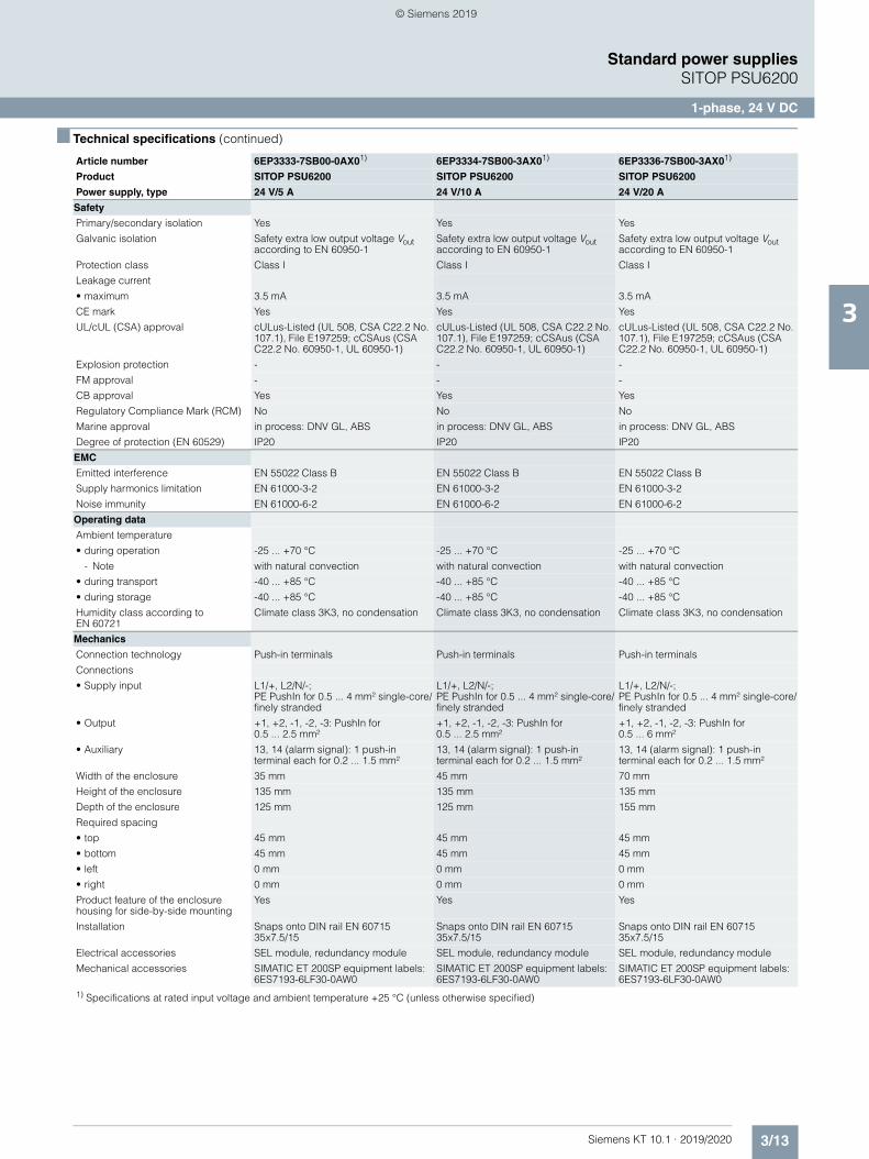
3/13Siemens KT 10.1 · 2019/2020
3
■ Technical specifications (continued)
Standard power suppliesSITOP PSU6200
1-phase, 24 V DC
Safety
Primary/secondary isolation Yes Yes Yes
Galvanic isolation Safety extra low output voltage Vout according to EN 60950-1
Safety extra low output voltage Vout according to EN 60950-1
Safety extra low output voltage Vout according to EN 60950-1
Protection class Class I Class I Class I
Leakage current
• maximum 3.5 mA 3.5 mA 3.5 mA
CE mark Yes Yes Yes
UL/cUL (CSA) approval cULus-Listed (UL 508, CSA C22.2 No. 107.1), File E197259; cCSAus (CSA C22.2 No. 60950-1, UL 60950-1)
cULus-Listed (UL 508, CSA C22.2 No. 107.1), File E197259; cCSAus (CSA C22.2 No. 60950-1, UL 60950-1)
cULus-Listed (UL 508, CSA C22.2 No. 107.1), File E197259; cCSAus (CSA C22.2 No. 60950-1, UL 60950-1)
Explosion protection - - -
FM approval - - -
CB approval Yes Yes Yes
Regulatory Compliance Mark (RCM) No No No
Marine approval in process: DNV GL, ABS in process: DNV GL, ABS in process: DNV GL, ABS
Degree of protection (EN 60529) IP20 IP20 IP20
EMC
Emitted interference EN 55022 Class B EN 55022 Class B EN 55022 Class B
Supply harmonics limitation EN 61000-3-2 EN 61000-3-2 EN 61000-3-2
Noise immunity EN 61000-6-2 EN 61000-6-2 EN 61000-6-2
Operating data
Ambient temperature
• during operation -25 ... +70 °C -25 ... +70 °C -25 ... +70 °C
- Note with natural convection with natural convection with natural convection
• during transport -40 ... +85 °C -40 ... +85 °C -40 ... +85 °C
• during storage -40 ... +85 °C -40 ... +85 °C -40 ... +85 °C
Humidity class according to EN 60721
Climate class 3K3, no condensation Climate class 3K3, no condensation Climate class 3K3, no condensation
Mechanics
Connection technology Push-in terminals Push-in terminals Push-in terminals
Connections
• Supply input L1/+, L2/N/-; PE PushIn for 0.5 ... 4 mm² single-core/finely stranded
L1/+, L2/N/-; PE PushIn for 0.5 ... 4 mm² single-core/finely stranded
L1/+, L2/N/-; PE PushIn for 0.5 ... 4 mm² single-core/finely stranded
• Output +1, +2, -1, -2, -3: PushIn for 0.5 ... 2.5 mm²
+1, +2, -1, -2, -3: PushIn for 0.5 ... 2.5 mm²
+1, +2, -1, -2, -3: PushIn for 0.5 ... 6 mm²
• Auxiliary 13, 14 (alarm signal): 1 push-in terminal each for 0.2 ... 1.5 mm²
13, 14 (alarm signal): 1 push-in terminal each for 0.2 ... 1.5 mm²
13, 14 (alarm signal): 1 push-in terminal each for 0.2 ... 1.5 mm²
Width of the enclosure 35 mm 45 mm 70 mm
Height of the enclosure 135 mm 135 mm 135 mm
Depth of the enclosure 125 mm 125 mm 155 mm
Required spacing
• top 45 mm 45 mm 45 mm
• bottom 45 mm 45 mm 45 mm
• left 0 mm 0 mm 0 mm
• right 0 mm 0 mm 0 mm
Product feature of the enclosure housing for side-by-side mounting
Yes Yes Yes
Installation Snaps onto DIN rail EN 60715 35x7.5/15
Snaps onto DIN rail EN 60715 35x7.5/15
Snaps onto DIN rail EN 60715 35x7.5/15
Electrical accessories SEL module, redundancy module SEL module, redundancy module SEL module, redundancy module
Mechanical accessories SIMATIC ET 200SP equipment labels: 6ES7193-6LF30-0AW0
SIMATIC ET 200SP equipment labels: 6ES7193-6LF30-0AW0
SIMATIC ET 200SP equipment labels: 6ES7193-6LF30-0AW0
1) Specifications at rated input voltage and ambient temperature +25 °C (unless otherwise specified)
Article number 6EP3333-7SB00-0AX01) 6EP3334-7SB00-3AX01) 6EP3336-7SB00-3AX01)
Product SITOP PSU6200 SITOP PSU6200 SITOP PSU6200
Power supply, type 24 V/5 A 24 V/10 A 24 V/20 A
© Siemens 2019
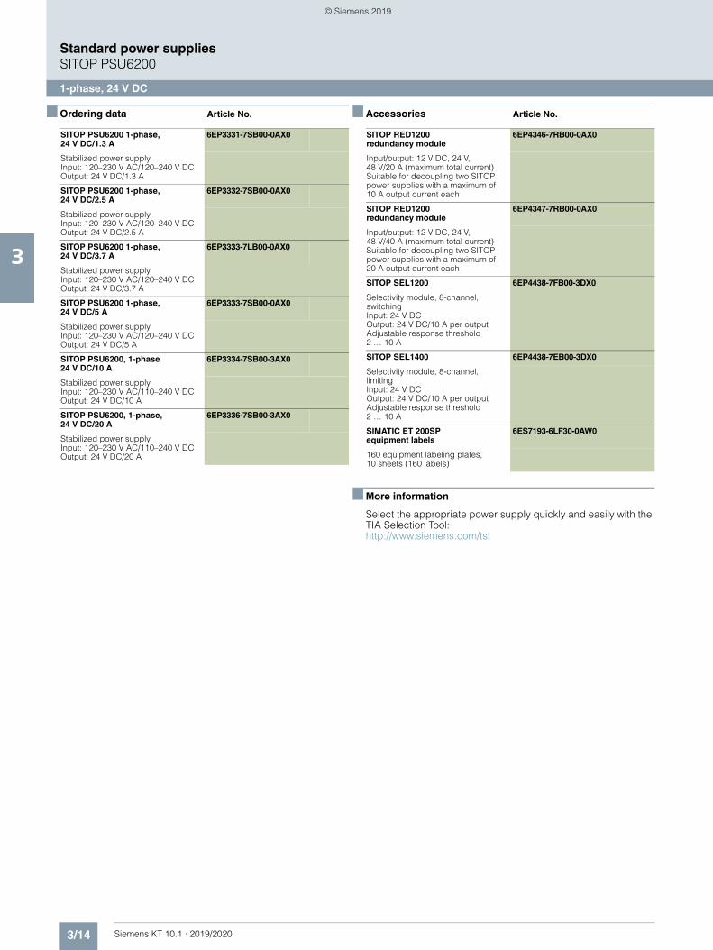
3/14 Siemens KT 10.1 · 2019/2020
3
Standard power suppliesSITOP PSU6200
1-phase, 24 V DC
■ Ordering data Article No. ■ Accessories Article No.
■ More information
Select the appropriate power supply quickly and easily with the TIA Selection Tool:http://www.siemens.com/tst
SITOP PSU6200 1-phase, 24 V DC/1.3 A
6EP3331-7SB00-0AX0
Stabilized power supplyInput: 120–230 V AC/120–240 V DCOutput: 24 V DC/1.3 A
SITOP PSU6200 1-phase, 24 V DC/2.5 A
6EP3332-7SB00-0AX0
Stabilized power supplyInput: 120–230 V AC/120–240 V DCOutput: 24 V DC/2.5 A
SITOP PSU6200 1-phase, 24 V DC/3.7 A
6EP3333-7LB00-0AX0
Stabilized power supplyInput: 120–230 V AC/120–240 V DCOutput: 24 V DC/3.7 A
SITOP PSU6200 1-phase, 24 V DC/5 A
6EP3333-7SB00-0AX0
Stabilized power supplyInput: 120–230 V AC/120–240 V DCOutput: 24 V DC/5 A
SITOP PSU6200, 1-phase24 V DC/10 A
6EP3334-7SB00-3AX0
Stabilized power supplyInput: 120–230 V AC/110–240 V DCOutput: 24 V DC/10 A
SITOP PSU6200, 1-phase, 24 V DC/20 A
6EP3336-7SB00-3AX0
Stabilized power supplyInput: 120–230 V AC/110–240 V DCOutput: 24 V DC/20 A
SITOP RED1200 redundancy module
6EP4346-7RB00-0AX0
Input/output: 12 V DC, 24 V, 48 V/20 A (maximum total current)Suitable for decoupling two SITOP power supplies with a maximum of 10 A output current each
SITOP RED1200 redundancy module
6EP4347-7RB00-0AX0
Input/output: 12 V DC, 24 V, 48 V/40 A (maximum total current)Suitable for decoupling two SITOP power supplies with a maximum of 20 A output current each
SITOP SEL1200 6EP4438-7FB00-3DX0
Selectivity module, 8-channel, switchingInput: 24 V DCOutput: 24 V DC/10 A per outputAdjustable response threshold 2 … 10 A
SITOP SEL1400 6EP4438-7EB00-3DX0
Selectivity module, 8-channel, limitingInput: 24 V DCOutput: 24 V DC/10 A per outputAdjustable response threshold 2 … 10 A
SIMATIC ET 200SP equipment labels
6ES7193-6LF30-0AW0
160 equipment labeling plates, 10 sheets (160 labels)
© Siemens 2019
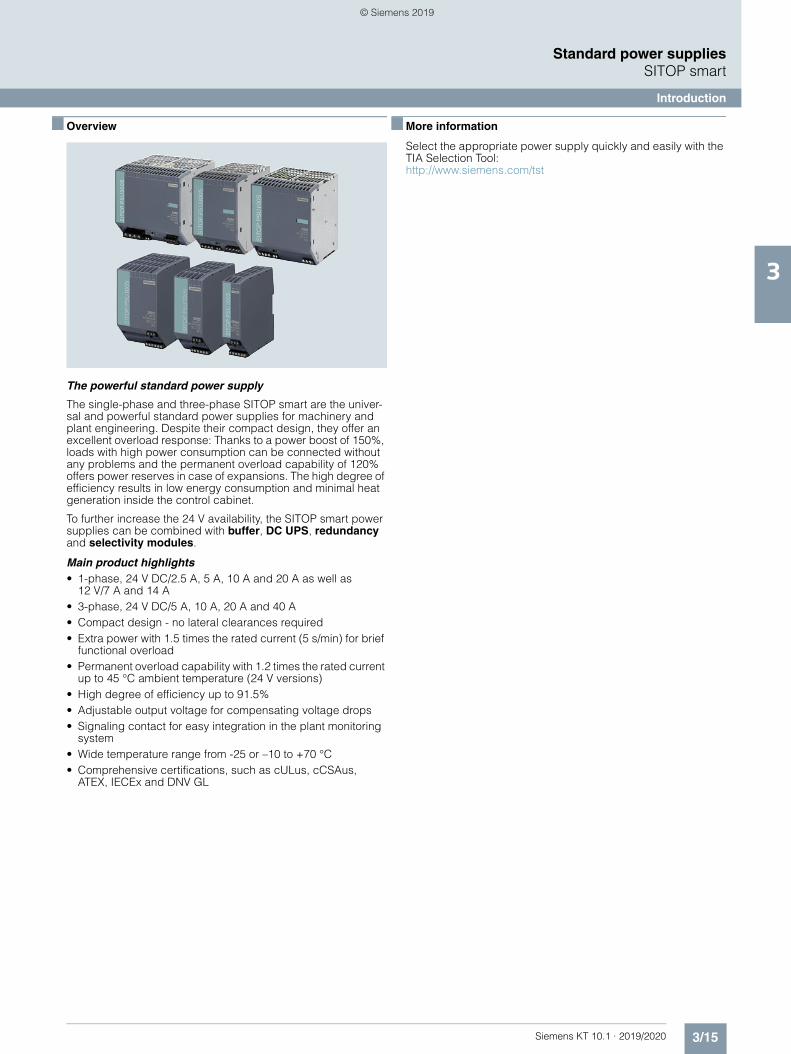
3/15Siemens KT 10.1 · 2019/2020
3
Standard power suppliesSITOP smart
Introduction
■ Overview
The powerful standard power supply
The single-phase and three-phase SITOP smart are the univer-sal and powerful standard power supplies for machinery and plant engineering. Despite their compact design, they offer an excellent overload response: Thanks to a power boost of 150%, loads with high power consumption can be connected without any problems and the permanent overload capability of 120% offers power reserves in case of expansions. The high degree of efficiency results in low energy consumption and minimal heat generation inside the control cabinet.
To further increase the 24 V availability, the SITOP smart power supplies can be combined with buffer, DC UPS, redundancy and selectivity modules.
Main product highlights• 1-phase, 24 V DC/2.5 A, 5 A, 10 A and 20 A as well as
12 V/7 A and 14 A• 3-phase, 24 V DC/5 A, 10 A, 20 A and 40 A• Compact design - no lateral clearances required• Extra power with 1.5 times the rated current (5 s/min) for brief
functional overload• Permanent overload capability with 1.2 times the rated current
up to 45 °C ambient temperature (24 V versions)• High degree of efficiency up to 91.5%• Adjustable output voltage for compensating voltage drops• Signaling contact for easy integration in the plant monitoring
system• Wide temperature range from -25 or –10 to +70 °C• Comprehensive certifications, such as cULus, cCSAus,
ATEX, IECEx and DNV GL
■ More information
Select the appropriate power supply quickly and easily with the TIA Selection Tool:http://www.siemens.com/tst
© Siemens 2019
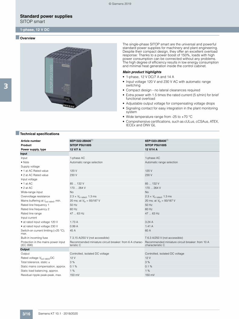
3/16 Siemens KT 10.1 · 2019/2020
3
Standard power suppliesSITOP smart
1-phase, 12 V DC
■ Overview
The single-phase SITOP smart are the universal and powerful standard power supplies for machinery and plant engineering. Despite their compact design, they offer an excellent overload response: Thanks to a power boost of 150%, loads with high power consumption can be connected without any problems. The high degree of efficiency results in low energy consumption and minimal heat generation inside the control cabinet.
Main product highlights• 1-phase, 12 V DC/7 A and 14 A• Input voltage 120 V and 230 V AC with automatic range
switching• Compact design - no lateral clearances required• Extra power with 1.5 times the rated current (5 s/min) for brief
functional overload• Adjustable output voltage for compensating voltage drops• Signaling contact for easy integration in the plant monitoring
system• Wide temperature range from -25 to +70 °C• Comprehensive certifications, such as cULus, cCSAus, ATEX,
IECEx and DNV GL
■ Technical specifications
Article number 6EP1322-2BA001) 6EP1323-2BA001)
Product SITOP PSU100S SITOP PSU100S
Power supply, type 12 V/7 A 12 V/14 A
Input
Input 1-phase AC 1-phase AC
• Note Automatic range selection Automatic range selection
Supply voltage
• 1 at AC Rated value 120 V 120 V
• 2 at AC Rated value 230 V 230 V
Input voltage
• 1 at AC 85 ... 132 V 85 ... 132 V
• 2 at AC 170 ... 264 V 170 ... 264 V
Wide-range input No No
Overvoltage resistance 2.3 × Vin rated, 1.3 ms 2.3 × Vin rated, 1.3 ms
Mains buffering at Iout rated, min. 20 ms; at Vin = 93/187 V 20 ms; at Vin = 93/187 V
Rated line frequency 1 50 Hz 50 Hz
Rated line frequency 2 60 Hz 60 Hz
Rated line range 47 ... 63 Hz 47 ... 63 Hz
Input current
• at rated input voltage 120 V 1.73 A 3.24 A
• at rated input voltage 230 V 0.99 A 1.41 A
Switch-on current limiting (+25 °C), max.
45 A 60 A
Built-in incoming fuse T 3,15 A/250 V (not accessible) T 6.3 A/250 V (not accessible)
Protection in the mains power input (IEC 898)
Recommended miniature circuit breaker: from 6 A charac-teristic C
Recommended miniature circuit breaker: from 10 A characteristic C
Output
Output Controlled, isolated DC voltage Controlled, isolated DC voltage
Rated voltage Vout rated DC 12 V 12 V
Total tolerance, static ± 3 % 3 %
Static mains compensation, approx. 0.1 % 0.1 %
Static load balancing, approx. 1 % 1 %
Residual ripple peak-peak, max. 150 mV 150 mV
© Siemens 2019
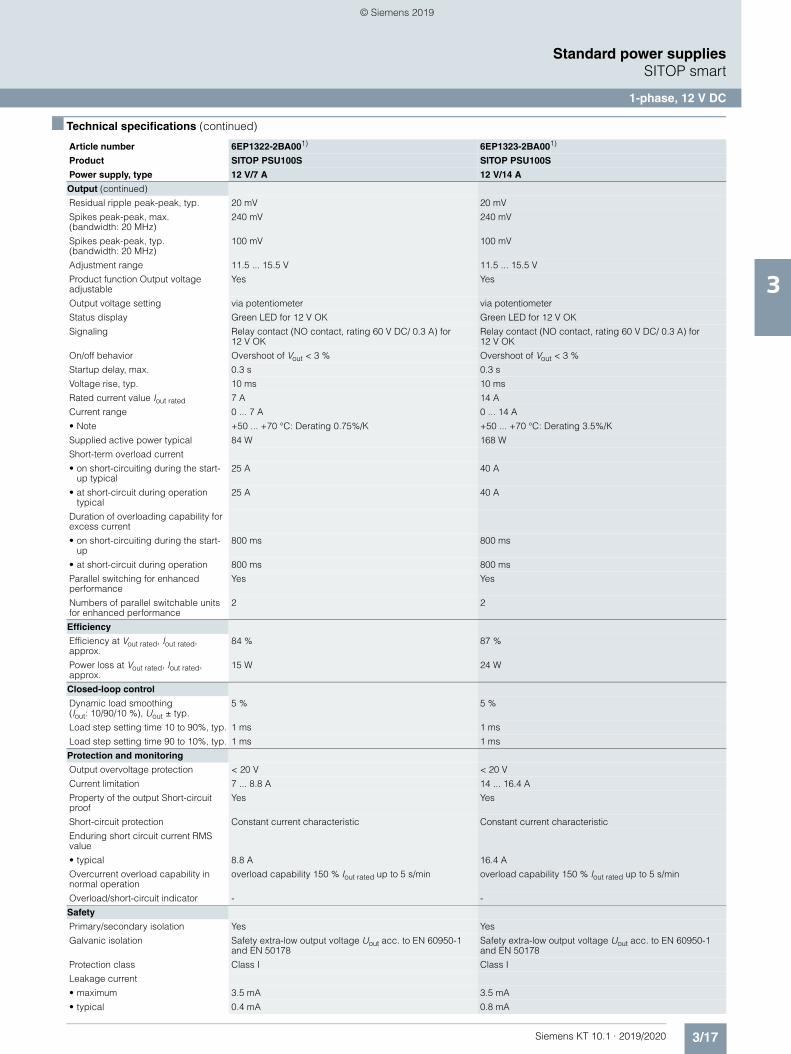
3/17Siemens KT 10.1 · 2019/2020
3
■ Technical specifications (continued)
Standard power suppliesSITOP smart
1-phase, 12 V DC
Output (continued)
Residual ripple peak-peak, typ. 20 mV 20 mV
Spikes peak-peak, max. (bandwidth: 20 MHz)
240 mV 240 mV
Spikes peak-peak, typ.(bandwidth: 20 MHz)
100 mV 100 mV
Adjustment range 11.5 ... 15.5 V 11.5 ... 15.5 V
Product function Output voltage adjustable
Yes Yes
Output voltage setting via potentiometer via potentiometer
Status display Green LED for 12 V OK Green LED for 12 V OK
Signaling Relay contact (NO contact, rating 60 V DC/ 0.3 A) for 12 V OK
Relay contact (NO contact, rating 60 V DC/ 0.3 A) for 12 V OK
On/off behavior Overshoot of Vout < 3 % Overshoot of Vout < 3 %
Startup delay, max. 0.3 s 0.3 s
Voltage rise, typ. 10 ms 10 ms
Rated current value Iout rated 7 A 14 A
Current range 0 ... 7 A 0 ... 14 A
• Note +50 ... +70 °C: Derating 0.75%/K +50 ... +70 °C: Derating 3.5%/K
Supplied active power typical 84 W 168 W
Short-term overload current
• on short-circuiting during the start-up typical
25 A 40 A
• at short-circuit during operation typical
25 A 40 A
Duration of overloading capability for excess current
• on short-circuiting during the start-up
800 ms 800 ms
• at short-circuit during operation 800 ms 800 ms
Parallel switching for enhanced performance
Yes Yes
Numbers of parallel switchable units for enhanced performance
2 2
Efficiency
Efficiency at Vout rated, Iout rated, approx.
84 % 87 %
Power loss at Vout rated, Iout rated, approx.
15 W 24 W
Closed-loop control
Dynamic load smoothing (Iout: 10/90/10 %), Uout ± typ.
5 % 5 %
Load step setting time 10 to 90%, typ. 1 ms 1 ms
Load step setting time 90 to 10%, typ. 1 ms 1 ms
Protection and monitoring
Output overvoltage protection < 20 V < 20 V
Current limitation 7 ... 8.8 A 14 ... 16.4 A
Property of the output Short-circuit proof
Yes Yes
Short-circuit protection Constant current characteristic Constant current characteristic
Enduring short circuit current RMS value
• typical 8.8 A 16.4 A
Overcurrent overload capability in normal operation
overload capability 150 % Iout rated up to 5 s/min overload capability 150 % Iout rated up to 5 s/min
Overload/short-circuit indicator - -
Safety
Primary/secondary isolation Yes Yes
Galvanic isolation Safety extra-low output voltage Uout acc. to EN 60950-1 and EN 50178
Safety extra-low output voltage Uout acc. to EN 60950-1 and EN 50178
Protection class Class I Class I
Leakage current
• maximum 3.5 mA 3.5 mA
• typical 0.4 mA 0.8 mA
Article number 6EP1322-2BA001) 6EP1323-2BA001)
Product SITOP PSU100S SITOP PSU100S
Power supply, type 12 V/7 A 12 V/14 A
© Siemens 2019
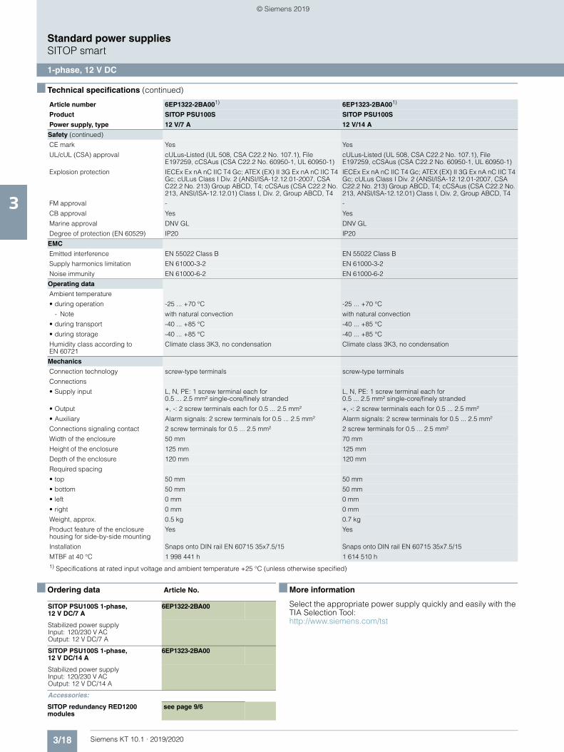
3/18 Siemens KT 10.1 · 2019/2020
3
■ Technical specifications (continued)
Standard power suppliesSITOP smart
1-phase, 12 V DC
■ Ordering data Article No. ■ More information
Select the appropriate power supply quickly and easily with the TIA Selection Tool:http://www.siemens.com/tst
Safety (continued)
CE mark Yes Yes
UL/cUL (CSA) approval cULus-Listed (UL 508, CSA C22.2 No. 107.1), File E197259, cCSAus (CSA C22.2 No. 60950-1, UL 60950-1)
cULus-Listed (UL 508, CSA C22.2 No. 107.1), File E197259, cCSAus (CSA C22.2 No. 60950-1, UL 60950-1)
Explosion protection IECEx Ex nA nC IIC T4 Gc; ATEX (EX) II 3G Ex nA nC IIC T4 Gc; cULus Class I Div. 2 (ANSI/ISA-12.12.01-2007, CSA C22.2 No. 213) Group ABCD, T4; cCSAus (CSA C22.2 No. 213, ANSI/ISA-12.12.01) Class I, Div. 2, Group ABCD, T4
IECEx Ex nA nC IIC T4 Gc; ATEX (EX) II 3G Ex nA nC IIC T4 Gc; cULus Class I Div. 2 (ANSI/ISA-12.12.01-2007, CSA C22.2 No. 213) Group ABCD, T4; cCSAus (CSA C22.2 No. 213, ANSI/ISA-12.12.01) Class I, Div. 2, Group ABCD, T4
FM approval - -
CB approval Yes Yes
Marine approval DNV GL DNV GL
Degree of protection (EN 60529) IP20 IP20
EMC
Emitted interference EN 55022 Class B EN 55022 Class B
Supply harmonics limitation EN 61000-3-2 EN 61000-3-2
Noise immunity EN 61000-6-2 EN 61000-6-2
Operating data
Ambient temperature
• during operation -25 ... +70 °C -25 ... +70 °C
- Note with natural convection with natural convection
• during transport -40 ... +85 °C -40 ... +85 °C
• during storage -40 ... +85 °C -40 ... +85 °C
Humidity class according to EN 60721
Climate class 3K3, no condensation Climate class 3K3, no condensation
Mechanics
Connection technology screw-type terminals screw-type terminals
Connections
• Supply input L, N, PE: 1 screw terminal each for 0.5 ... 2.5 mm² single-core/finely stranded
L, N, PE: 1 screw terminal each for 0.5 ... 2.5 mm² single-core/finely stranded
• Output +, -: 2 screw terminals each for 0.5 ... 2.5 mm² +, -: 2 screw terminals each for 0.5 ... 2.5 mm²
• Auxiliary Alarm signals: 2 screw terminals for 0.5 ... 2.5 mm² Alarm signals: 2 screw terminals for 0.5 ... 2.5 mm²
Connections signaling contact 2 screw terminals for 0.5 ... 2.5 mm² 2 screw terminals for 0.5 ... 2.5 mm²
Width of the enclosure 50 mm 70 mm
Height of the enclosure 125 mm 125 mm
Depth of the enclosure 120 mm 120 mm
Required spacing
• top 50 mm 50 mm
• bottom 50 mm 50 mm
• left 0 mm 0 mm
• right 0 mm 0 mm
Weight, approx. 0.5 kg 0.7 kg
Product feature of the enclosure housing for side-by-side mounting
Yes Yes
Installation Snaps onto DIN rail EN 60715 35x7.5/15 Snaps onto DIN rail EN 60715 35x7.5/15
MTBF at 40 °C 1 998 441 h 1 614 510 h1) Specifications at rated input voltage and ambient temperature +25 °C (unless otherwise specified)
Article number 6EP1322-2BA001) 6EP1323-2BA001)
Product SITOP PSU100S SITOP PSU100S
Power supply, type 12 V/7 A 12 V/14 A
SITOP PSU100S 1-phase, 12 V DC/7 A
6EP1322-2BA00
Stabilized power supplyInput: 120/230 V ACOutput: 12 V DC/7 A
SITOP PSU100S 1-phase, 12 V DC/14 A
6EP1323-2BA00
Stabilized power supplyInput: 120/230 V AC Output: 12 V DC/14 A
Accessories:
SITOP redundancy RED1200 modules
see page 9/6
© Siemens 2019
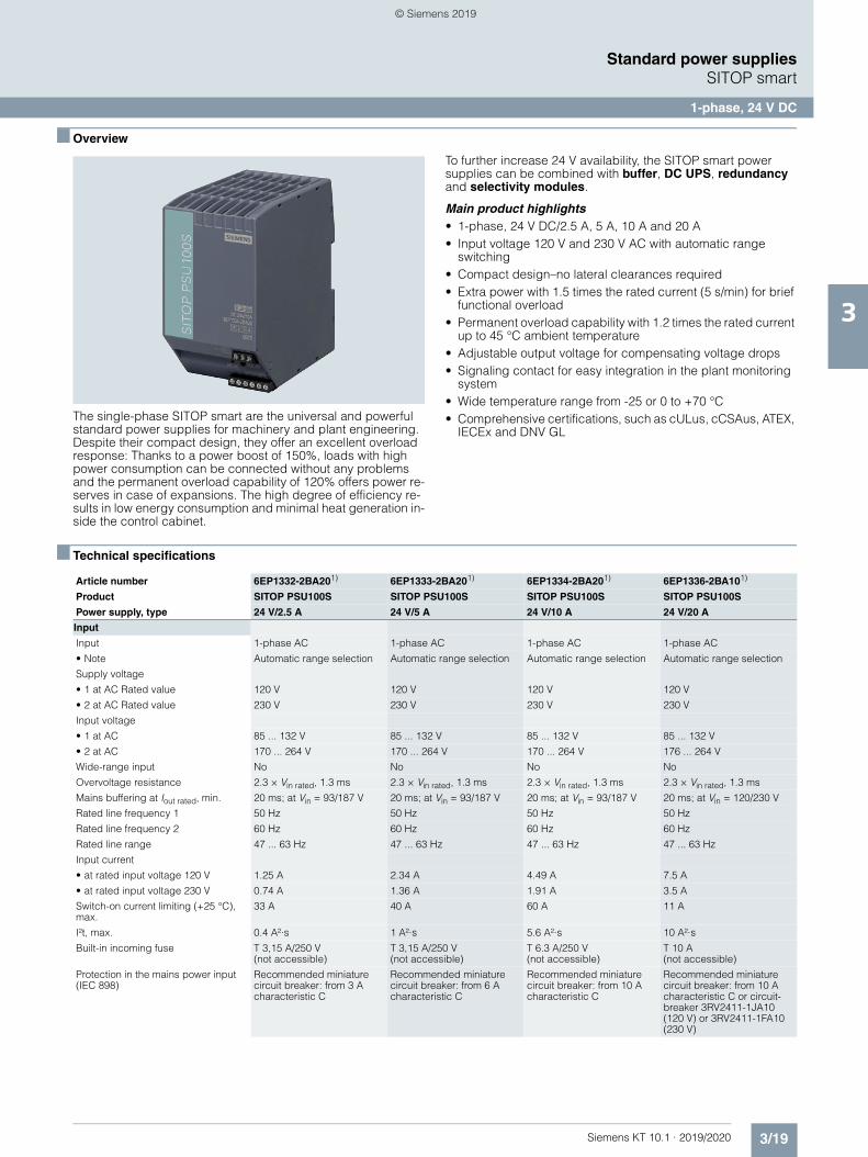
3/19Siemens KT 10.1 · 2019/2020
3
Standard power suppliesSITOP smart
1-phase, 24 V DC
■ Overview
The single-phase SITOP smart are the universal and powerful standard power supplies for machinery and plant engineering. Despite their compact design, they offer an excellent overload response: Thanks to a power boost of 150%, loads with high power consumption can be connected without any problems and the permanent overload capability of 120% offers power re-serves in case of expansions. The high degree of efficiency re-sults in low energy consumption and minimal heat generation in-side the control cabinet.
To further increase 24 V availability, the SITOP smart power supplies can be combined with buffer, DC UPS, redundancy and selectivity modules.
Main product highlights• 1-phase, 24 V DC/2.5 A, 5 A, 10 A and 20 A• Input voltage 120 V and 230 V AC with automatic range
switching• Compact design–no lateral clearances required• Extra power with 1.5 times the rated current (5 s/min) for brief
functional overload• Permanent overload capability with 1.2 times the rated current
up to 45 °C ambient temperature• Adjustable output voltage for compensating voltage drops• Signaling contact for easy integration in the plant monitoring
system• Wide temperature range from -25 or 0 to +70 °C• Comprehensive certifications, such as cULus, cCSAus, ATEX,
IECEx and DNV GL
■ Technical specifications
Article number 6EP1332-2BA201) 6EP1333-2BA201) 6EP1334-2BA201) 6EP1336-2BA101)
Product SITOP PSU100S SITOP PSU100S SITOP PSU100S SITOP PSU100S
Power supply, type 24 V/2.5 A 24 V/5 A 24 V/10 A 24 V/20 A
Input
Input 1-phase AC 1-phase AC 1-phase AC 1-phase AC
• Note Automatic range selection Automatic range selection Automatic range selection Automatic range selection
Supply voltage
• 1 at AC Rated value 120 V 120 V 120 V 120 V
• 2 at AC Rated value 230 V 230 V 230 V 230 V
Input voltage
• 1 at AC 85 ... 132 V 85 ... 132 V 85 ... 132 V 85 ... 132 V
• 2 at AC 170 ... 264 V 170 ... 264 V 170 ... 264 V 176 ... 264 V
Wide-range input No No No No
Overvoltage resistance 2.3 × Vin rated, 1.3 ms 2.3 × Vin rated, 1.3 ms 2.3 × Vin rated, 1.3 ms 2.3 × Vin rated, 1.3 ms
Mains buffering at Iout rated, min. 20 ms; at Vin = 93/187 V 20 ms; at Vin = 93/187 V 20 ms; at Vin = 93/187 V 20 ms; at Vin = 120/230 V
Rated line frequency 1 50 Hz 50 Hz 50 Hz 50 Hz
Rated line frequency 2 60 Hz 60 Hz 60 Hz 60 Hz
Rated line range 47 ... 63 Hz 47 ... 63 Hz 47 ... 63 Hz 47 ... 63 Hz
Input current
• at rated input voltage 120 V 1.25 A 2.34 A 4.49 A 7.5 A
• at rated input voltage 230 V 0.74 A 1.36 A 1.91 A 3.5 A
Switch-on current limiting (+25 °C), max.
33 A 40 A 60 A 11 A
I²t, max. 0.4 A²·s 1 A²·s 5.6 A²·s 10 A²·s
Built-in incoming fuse T 3,15 A/250 V (not accessible)
T 3,15 A/250 V (not accessible)
T 6.3 A/250 V (not accessible)
T 10 A (not accessible)
Protection in the mains power input (IEC 898)
Recommended miniature circuit breaker: from 3 A characteristic C
Recommended miniature circuit breaker: from 6 A characteristic C
Recommended miniature circuit breaker: from 10 A characteristic C
Recommended miniature circuit breaker: from 10 A characteristic C or circuit-breaker 3RV2411-1JA10 (120 V) or 3RV2411-1FA10 (230 V)
© Siemens 2019
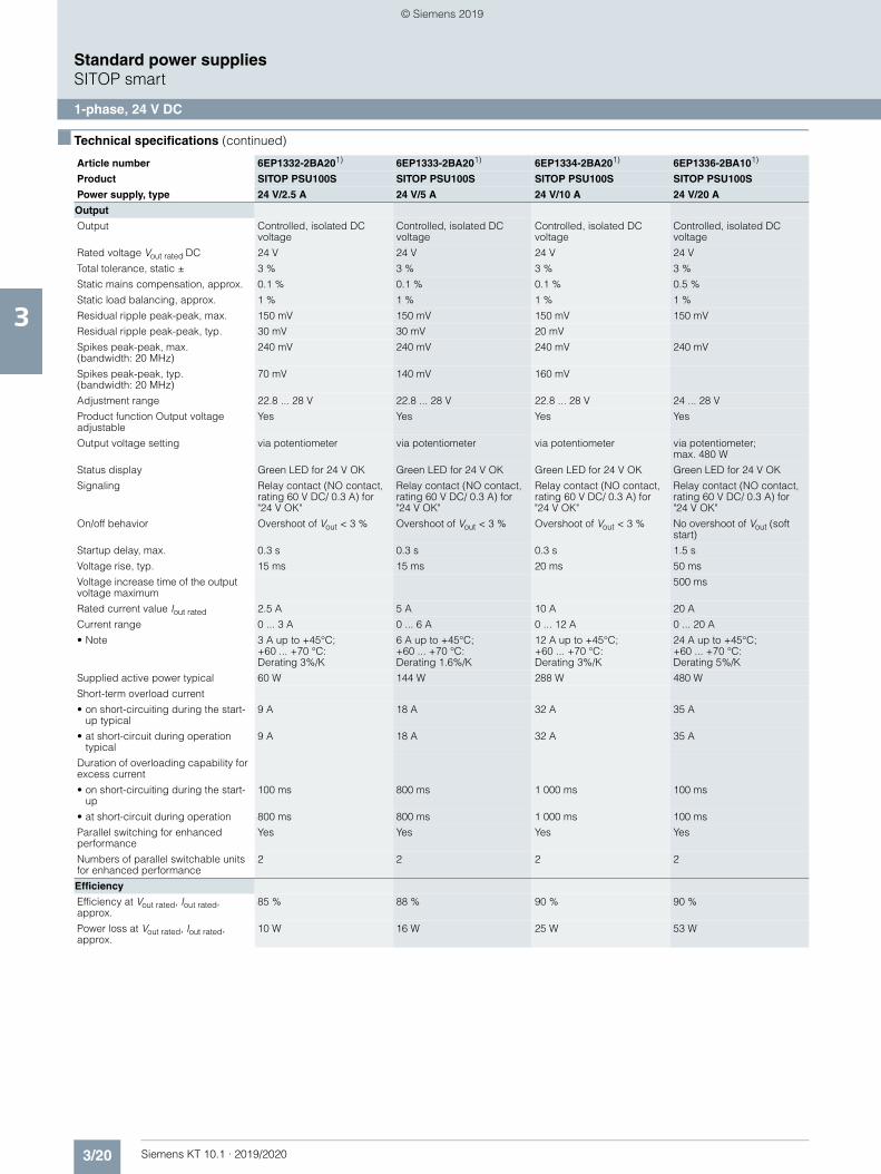
3/20 Siemens KT 10.1 · 2019/2020
3
■ Technical specifications (continued)
Standard power suppliesSITOP smart
1-phase, 24 V DC
Output
Output Controlled, isolated DC voltage
Controlled, isolated DC voltage
Controlled, isolated DC voltage
Controlled, isolated DC voltage
Rated voltage Vout rated DC 24 V 24 V 24 V 24 V
Total tolerance, static ± 3 % 3 % 3 % 3 %
Static mains compensation, approx. 0.1 % 0.1 % 0.1 % 0.5 %
Static load balancing, approx. 1 % 1 % 1 % 1 %
Residual ripple peak-peak, max. 150 mV 150 mV 150 mV 150 mV
Residual ripple peak-peak, typ. 30 mV 30 mV 20 mV
Spikes peak-peak, max. (bandwidth: 20 MHz)
240 mV 240 mV 240 mV 240 mV
Spikes peak-peak, typ. (bandwidth: 20 MHz)
70 mV 140 mV 160 mV
Adjustment range 22.8 ... 28 V 22.8 ... 28 V 22.8 ... 28 V 24 ... 28 V
Product function Output voltage adjustable
Yes Yes Yes Yes
Output voltage setting via potentiometer via potentiometer via potentiometer via potentiometer; max. 480 W
Status display Green LED for 24 V OK Green LED for 24 V OK Green LED for 24 V OK Green LED for 24 V OK
Signaling Relay contact (NO contact, rating 60 V DC/ 0.3 A) for "24 V OK"
Relay contact (NO contact, rating 60 V DC/ 0.3 A) for "24 V OK"
Relay contact (NO contact, rating 60 V DC/ 0.3 A) for "24 V OK"
Relay contact (NO contact, rating 60 V DC/ 0.3 A) for "24 V OK"
On/off behavior Overshoot of Vout < 3 % Overshoot of Vout < 3 % Overshoot of Vout < 3 % No overshoot of Vout (soft start)
Startup delay, max. 0.3 s 0.3 s 0.3 s 1.5 s
Voltage rise, typ. 15 ms 15 ms 20 ms 50 ms
Voltage increase time of the output voltage maximum
500 ms
Rated current value Iout rated 2.5 A 5 A 10 A 20 A
Current range 0 ... 3 A 0 ... 6 A 0 ... 12 A 0 ... 20 A
• Note 3 A up to +45°C; +60 ... +70 °C: Derating 3%/K
6 A up to +45°C; +60 ... +70 °C: Derating 1.6%/K
12 A up to +45°C; +60 ... +70 °C: Derating 3%/K
24 A up to +45°C; +60 ... +70 °C: Derating 5%/K
Supplied active power typical 60 W 144 W 288 W 480 W
Short-term overload current
• on short-circuiting during the start-up typical
9 A 18 A 32 A 35 A
• at short-circuit during operation typical
9 A 18 A 32 A 35 A
Duration of overloading capability for excess current
• on short-circuiting during the start-up
100 ms 800 ms 1 000 ms 100 ms
• at short-circuit during operation 800 ms 800 ms 1 000 ms 100 ms
Parallel switching for enhanced performance
Yes Yes Yes Yes
Numbers of parallel switchable units for enhanced performance
2 2 2 2
Efficiency
Efficiency at Vout rated, Iout rated, approx.
85 % 88 % 90 % 90 %
Power loss at Vout rated, Iout rated, approx.
10 W 16 W 25 W 53 W
Article number 6EP1332-2BA201) 6EP1333-2BA201) 6EP1334-2BA201) 6EP1336-2BA101)
Product SITOP PSU100S SITOP PSU100S SITOP PSU100S SITOP PSU100S
Power supply, type 24 V/2.5 A 24 V/5 A 24 V/10 A 24 V/20 A
© Siemens 2019
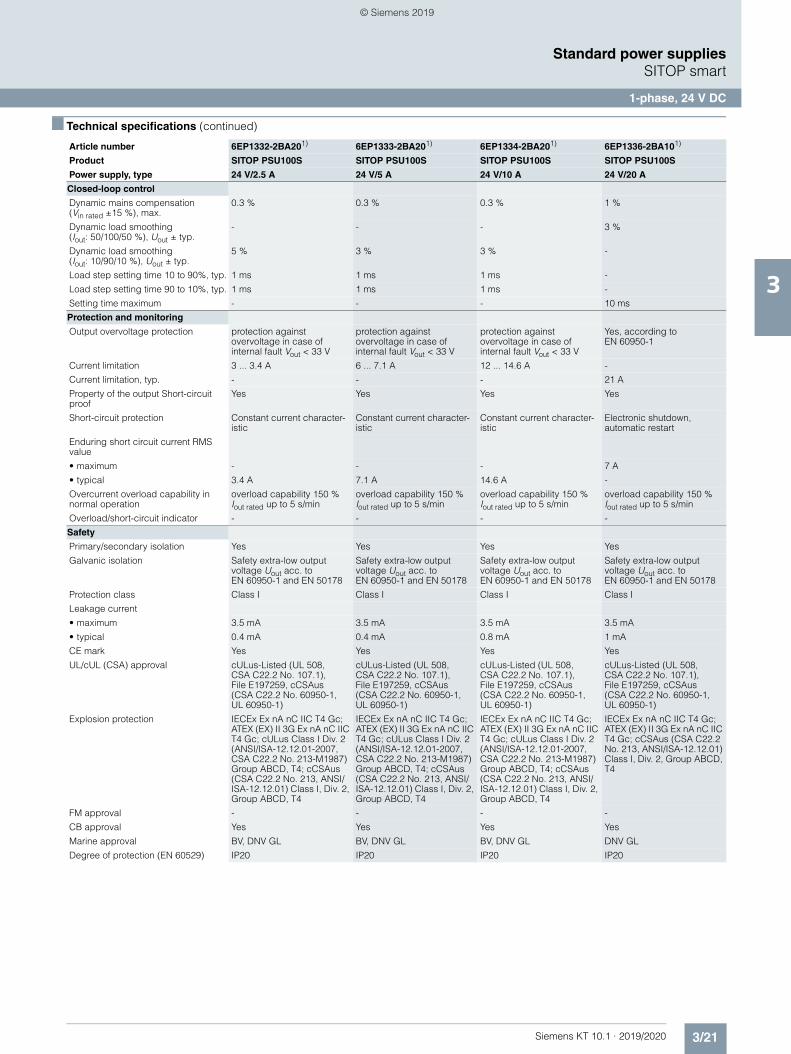
3/21Siemens KT 10.1 · 2019/2020
3
■ Technical specifications (continued)
Standard power suppliesSITOP smart
1-phase, 24 V DC
Closed-loop control
Dynamic mains compensation (Vin rated ±15 %), max.
0.3 % 0.3 % 0.3 % 1 %
Dynamic load smoothing (Iout: 50/100/50 %), Uout ± typ.
- - - 3 %
Dynamic load smoothing (Iout: 10/90/10 %), Uout ± typ.
5 % 3 % 3 % -
Load step setting time 10 to 90%, typ. 1 ms 1 ms 1 ms -
Load step setting time 90 to 10%, typ. 1 ms 1 ms 1 ms -
Setting time maximum - - - 10 ms
Protection and monitoring
Output overvoltage protection protection against overvoltage in case of internal fault Vout < 33 V
protection against overvoltage in case of internal fault Vout < 33 V
protection against overvoltage in case of internal fault Vout < 33 V
Yes, according to EN 60950-1
Current limitation 3 ... 3.4 A 6 ... 7.1 A 12 ... 14.6 A -
Current limitation, typ. - - - 21 A
Property of the output Short-circuit proof
Yes Yes Yes Yes
Short-circuit protection Constant current character-istic
Constant current character-istic
Constant current character-istic
Electronic shutdown, automatic restart
Enduring short circuit current RMS value
• maximum - - - 7 A
• typical 3.4 A 7.1 A 14.6 A -
Overcurrent overload capability in normal operation
overload capability 150 % Iout rated up to 5 s/min
overload capability 150 % Iout rated up to 5 s/min
overload capability 150 % Iout rated up to 5 s/min
overload capability 150 % Iout rated up to 5 s/min
Overload/short-circuit indicator - - - -
Safety
Primary/secondary isolation Yes Yes Yes Yes
Galvanic isolation Safety extra-low output voltage Uout acc. to EN 60950-1 and EN 50178
Safety extra-low output voltage Uout acc. to EN 60950-1 and EN 50178
Safety extra-low output voltage Uout acc. to EN 60950-1 and EN 50178
Safety extra-low output voltage Uout acc. to EN 60950-1 and EN 50178
Protection class Class I Class I Class I Class I
Leakage current
• maximum 3.5 mA 3.5 mA 3.5 mA 3.5 mA
• typical 0.4 mA 0.4 mA 0.8 mA 1 mA
CE mark Yes Yes Yes Yes
UL/cUL (CSA) approval cULus-Listed (UL 508, CSA C22.2 No. 107.1), File E197259, cCSAus (CSA C22.2 No. 60950-1, UL 60950-1)
cULus-Listed (UL 508, CSA C22.2 No. 107.1), File E197259, cCSAus (CSA C22.2 No. 60950-1, UL 60950-1)
cULus-Listed (UL 508, CSA C22.2 No. 107.1), File E197259, cCSAus (CSA C22.2 No. 60950-1, UL 60950-1)
cULus-Listed (UL 508, CSA C22.2 No. 107.1), File E197259, cCSAus (CSA C22.2 No. 60950-1, UL 60950-1)
Explosion protection IECEx Ex nA nC IIC T4 Gc; ATEX (EX) II 3G Ex nA nC IIC T4 Gc; cULus Class I Div. 2 (ANSI/ISA-12.12.01-2007, CSA C22.2 No. 213-M1987) Group ABCD, T4; cCSAus (CSA C22.2 No. 213, ANSI/ISA-12.12.01) Class I, Div. 2, Group ABCD, T4
IECEx Ex nA nC IIC T4 Gc; ATEX (EX) II 3G Ex nA nC IIC T4 Gc; cULus Class I Div. 2 (ANSI/ISA-12.12.01-2007, CSA C22.2 No. 213-M1987) Group ABCD, T4; cCSAus (CSA C22.2 No. 213, ANSI/ISA-12.12.01) Class I, Div. 2, Group ABCD, T4
IECEx Ex nA nC IIC T4 Gc; ATEX (EX) II 3G Ex nA nC IIC T4 Gc; cULus Class I Div. 2 (ANSI/ISA-12.12.01-2007, CSA C22.2 No. 213-M1987) Group ABCD, T4; cCSAus (CSA C22.2 No. 213, ANSI/ISA-12.12.01) Class I, Div. 2, Group ABCD, T4
IECEx Ex nA nC IIC T4 Gc; ATEX (EX) II 3G Ex nA nC IIC T4 Gc; cCSAus (CSA C22.2 No. 213, ANSI/ISA-12.12.01) Class I, Div. 2, Group ABCD, T4
FM approval - - - -
CB approval Yes Yes Yes Yes
Marine approval BV, DNV GL BV, DNV GL BV, DNV GL DNV GL
Degree of protection (EN 60529) IP20 IP20 IP20 IP20
Article number 6EP1332-2BA201) 6EP1333-2BA201) 6EP1334-2BA201) 6EP1336-2BA101)
Product SITOP PSU100S SITOP PSU100S SITOP PSU100S SITOP PSU100S
Power supply, type 24 V/2.5 A 24 V/5 A 24 V/10 A 24 V/20 A
© Siemens 2019
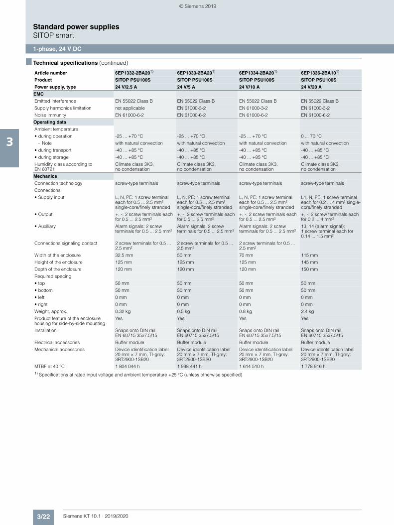
3/22 Siemens KT 10.1 · 2019/2020
3
■ Technical specifications (continued)
Standard power suppliesSITOP smart
1-phase, 24 V DC
EMC
Emitted interference EN 55022 Class B EN 55022 Class B EN 55022 Class B EN 55022 Class B
Supply harmonics limitation not applicable EN 61000-3-2 EN 61000-3-2 EN 61000-3-2
Noise immunity EN 61000-6-2 EN 61000-6-2 EN 61000-6-2 EN 61000-6-2
Operating data
Ambient temperature
• during operation -25 ... +70 °C -25 ... +70 °C -25 ... +70 °C 0 ... 70 °C
- Note with natural convection with natural convection with natural convection with natural convection
• during transport -40 ... +85 °C -40 ... +85 °C -40 ... +85 °C -40 ... +85 °C
• during storage -40 ... +85 °C -40 ... +85 °C -40 ... +85 °C -40 ... +85 °C
Humidity class according to EN 60721
Climate class 3K3, no condensation
Climate class 3K3, no condensation
Climate class 3K3, no condensation
Climate class 3K3, no condensation
Mechanics
Connection technology screw-type terminals screw-type terminals screw-type terminals screw-type terminals
Connections
• Supply input L, N, PE: 1 screw terminal each for 0.5 ... 2.5 mm² single-core/finely stranded
L, N, PE: 1 screw terminal each for 0.5 ... 2.5 mm² single-core/finely stranded
L, N, PE: 1 screw terminal each for 0.5 ... 2.5 mm² single-core/finely stranded
L1, N, PE: 1 screw terminal each for 0.2 ... 4 mm² single-core/finely stranded
• Output +, -: 2 screw terminals each for 0.5 ... 2.5 mm²
+, -: 2 screw terminals each for 0.5 ... 2.5 mm²
+, -: 2 screw terminals each for 0.5 ... 2.5 mm²
+, -: 2 screw terminals each for 0.2 ... 4 mm²
• Auxiliary Alarm signals: 2 screw terminals for 0.5 ... 2.5 mm²
Alarm signals: 2 screw terminals for 0.5 ... 2.5 mm²
Alarm signals: 2 screw terminals for 0.5 ... 2.5 mm²
13, 14 (alarm signal): 1 screw terminal each for 0.14 ... 1.5 mm²
Connections signaling contact 2 screw terminals for 0.5 ... 2.5 mm²
2 screw terminals for 0.5 ... 2.5 mm²
2 screw terminals for 0.5 ... 2.5 mm²
Width of the enclosure 32.5 mm 50 mm 70 mm 115 mm
Height of the enclosure 125 mm 125 mm 125 mm 145 mm
Depth of the enclosure 120 mm 120 mm 120 mm 150 mm
Required spacing
• top 50 mm 50 mm 50 mm 50 mm
• bottom 50 mm 50 mm 50 mm 50 mm
• left 0 mm 0 mm 0 mm 0 mm
• right 0 mm 0 mm 0 mm 0 mm
Weight, approx. 0.32 kg 0.5 kg 0.8 kg 2.4 kg
Product feature of the enclosure housing for side-by-side mounting
Yes Yes Yes Yes
Installation Snaps onto DIN rail EN 60715 35x7.5/15
Snaps onto DIN rail EN 60715 35x7.5/15
Snaps onto DIN rail EN 60715 35x7.5/15
Snaps onto DIN rail EN 60715 35x7.5/15
Electrical accessories Buffer module Buffer module Buffer module Buffer module
Mechanical accessories Device identification label 20 mm × 7 mm, TI-grey: 3RT2900-1SB20
Device identification label 20 mm × 7 mm, TI-grey: 3RT2900-1SB20
Device identification label 20 mm × 7 mm, TI-grey: 3RT2900-1SB20
Device identification label 20 mm × 7 mm, TI-grey: 3RT2900-1SB20
MTBF at 40 °C 1 804 044 h 1 998 441 h 1 614 510 h 1 778 916 h1) Specifications at rated input voltage and ambient temperature +25 °C (unless otherwise specified)
Article number 6EP1332-2BA201) 6EP1333-2BA201) 6EP1334-2BA201) 6EP1336-2BA101)
Product SITOP PSU100S SITOP PSU100S SITOP PSU100S SITOP PSU100S
Power supply, type 24 V/2.5 A 24 V/5 A 24 V/10 A 24 V/20 A
© Siemens 2019
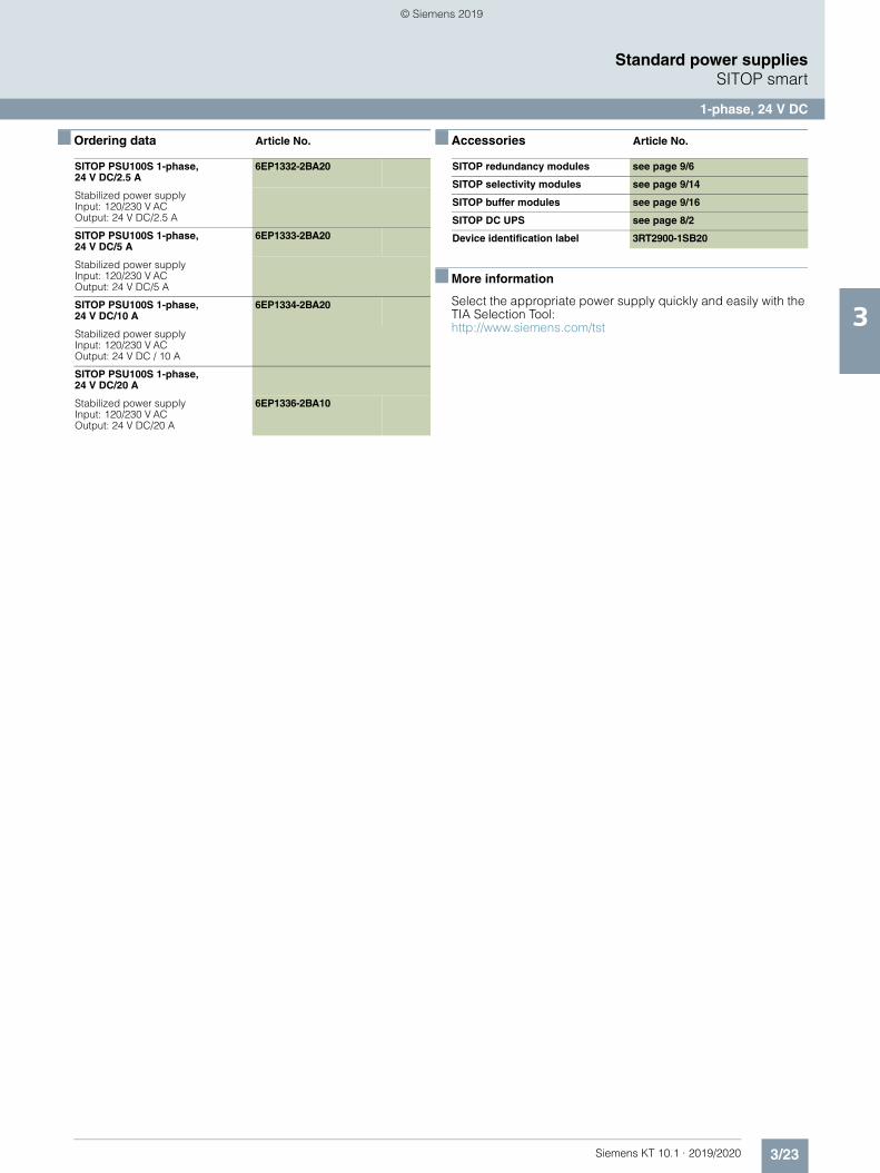
3/23Siemens KT 10.1 · 2019/2020
3
Standard power suppliesSITOP smart
1-phase, 24 V DC
■ Ordering data Article No. ■ Accessories Article No.
■ More information
Select the appropriate power supply quickly and easily with the TIA Selection Tool:http://www.siemens.com/tst
SITOP PSU100S 1-phase, 24 V DC/2.5 A
6EP1332-2BA20
Stabilized power supplyInput: 120/230 V AC Output: 24 V DC/2.5 A
SITOP PSU100S 1-phase, 24 V DC/5 A
6EP1333-2BA20
Stabilized power supplyInput: 120/230 V AC Output: 24 V DC/5 A
SITOP PSU100S 1-phase, 24 V DC/10 A
6EP1334-2BA20
Stabilized power supplyInput: 120/230 V AC Output: 24 V DC / 10 A
SITOP PSU100S 1-phase, 24 V DC/20 A
Stabilized power supplyInput: 120/230 V AC Output: 24 V DC/20 A
6EP1336-2BA10
SITOP redundancy modules see page 9/6
SITOP selectivity modules see page 9/14
SITOP buffer modules see page 9/16
SITOP DC UPS see page 8/2
Device identification label 3RT2900-1SB20
© Siemens 2019
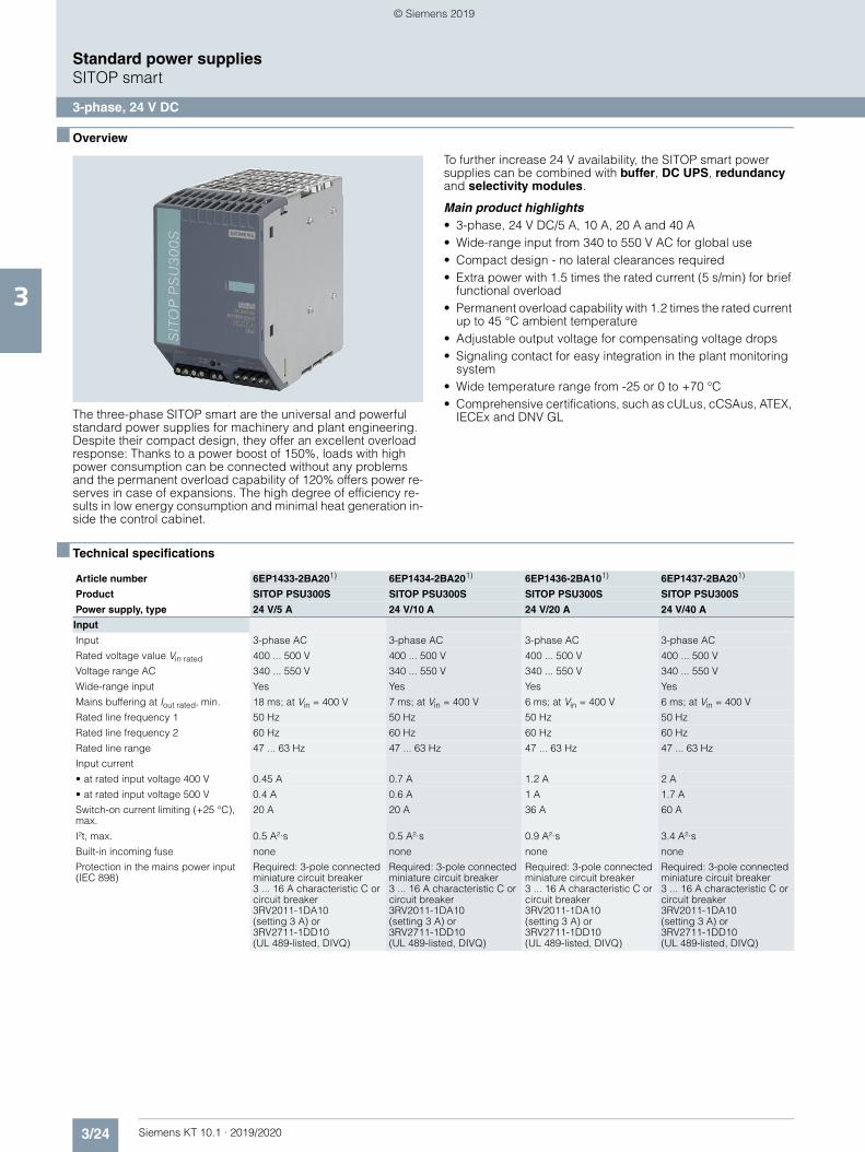
3/24 Siemens KT 10.1 · 2019/2020
3
Standard power suppliesSITOP smart
3-phase, 24 V DC
■ Overview
The three-phase SITOP smart are the universal and powerful standard power supplies for machinery and plant engineering. Despite their compact design, they offer an excellent overload response: Thanks to a power boost of 150%, loads with high power consumption can be connected without any problems and the permanent overload capability of 120% offers power re-serves in case of expansions. The high degree of efficiency re-sults in low energy consumption and minimal heat generation in-side the control cabinet.
To further increase 24 V availability, the SITOP smart power supplies can be combined with buffer, DC UPS, redundancy and selectivity modules.
Main product highlights• 3-phase, 24 V DC/5 A, 10 A, 20 A and 40 A• Wide-range input from 340 to 550 V AC for global use• Compact design - no lateral clearances required• Extra power with 1.5 times the rated current (5 s/min) for brief
functional overload• Permanent overload capability with 1.2 times the rated current
up to 45 °C ambient temperature• Adjustable output voltage for compensating voltage drops• Signaling contact for easy integration in the plant monitoring
system• Wide temperature range from -25 or 0 to +70 °C• Comprehensive certifications, such as cULus, cCSAus, ATEX,
IECEx and DNV GL
■ Technical specifications
Article number 6EP1433-2BA201) 6EP1434-2BA201) 6EP1436-2BA101) 6EP1437-2BA201)
Product SITOP PSU300S SITOP PSU300S SITOP PSU300S SITOP PSU300S
Power supply, type 24 V/5 A 24 V/10 A 24 V/20 A 24 V/40 A
Input
Input 3-phase AC 3-phase AC 3-phase AC 3-phase AC
Rated voltage value Vin rated 400 ... 500 V 400 ... 500 V 400 ... 500 V 400 ... 500 V
Voltage range AC 340 ... 550 V 340 ... 550 V 340 ... 550 V 340 ... 550 V
Wide-range input Yes Yes Yes Yes
Mains buffering at Iout rated, min. 18 ms; at Vin = 400 V 7 ms; at Vin = 400 V 6 ms; at Vin = 400 V 6 ms; at Vin = 400 V
Rated line frequency 1 50 Hz 50 Hz 50 Hz 50 Hz
Rated line frequency 2 60 Hz 60 Hz 60 Hz 60 Hz
Rated line range 47 ... 63 Hz 47 ... 63 Hz 47 ... 63 Hz 47 ... 63 Hz
Input current
• at rated input voltage 400 V 0.45 A 0.7 A 1.2 A 2 A
• at rated input voltage 500 V 0.4 A 0.6 A 1 A 1.7 A
Switch-on current limiting (+25 °C), max.
20 A 20 A 36 A 60 A
I²t, max. 0.5 A²·s 0.5 A²·s 0.9 A²·s 3.4 A²·s
Built-in incoming fuse none none none none
Protection in the mains power input (IEC 898)
Required: 3-pole connected miniature circuit breaker 3 ... 16 A characteristic C or circuit breaker 3RV2011-1DA10 (setting 3 A) or 3RV2711-1DD10 (UL 489-listed, DIVQ)
Required: 3-pole connected miniature circuit breaker 3 ... 16 A characteristic C or circuit breaker 3RV2011-1DA10 (setting 3 A) or 3RV2711-1DD10 (UL 489-listed, DIVQ)
Required: 3-pole connected miniature circuit breaker 3 ... 16 A characteristic C or circuit breaker 3RV2011-1DA10 (setting 3 A) or 3RV2711-1DD10 (UL 489-listed, DIVQ)
Required: 3-pole connected miniature circuit breaker 3 ... 16 A characteristic C or circuit breaker 3RV2011-1DA10 (setting 3 A) or 3RV2711-1DD10 (UL 489-listed, DIVQ)
© Siemens 2019
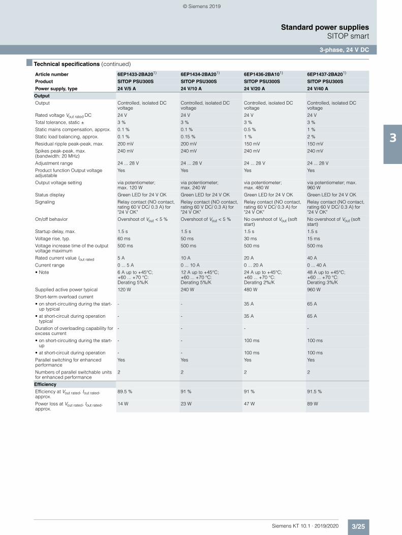
3/25Siemens KT 10.1 · 2019/2020
3
■ Technical specifications (continued)
Standard power suppliesSITOP smart
3-phase, 24 V DC
Output
Output Controlled, isolated DC voltage
Controlled, isolated DC voltage
Controlled, isolated DC voltage
Controlled, isolated DC voltage
Rated voltage Vout rated DC 24 V 24 V 24 V 24 V
Total tolerance, static ± 3 % 3 % 3 % 3 %
Static mains compensation, approx. 0.1 % 0.1 % 0.5 % 1 %
Static load balancing, approx. 0.1 % 0.15 % 1 % 2 %
Residual ripple peak-peak, max. 200 mV 200 mV 150 mV 150 mV
Spikes peak-peak, max. (bandwidth: 20 MHz)
240 mV 240 mV 240 mV 240 mV
Adjustment range 24 ... 28 V 24 ... 28 V 24 ... 28 V 24 ... 28 V
Product function Output voltage adjustable
Yes Yes Yes Yes
Output voltage setting via potentiometer; max. 120 W
via potentiometer; max. 240 W
via potentiometer; max. 480 W
via potentiometer; max. 960 W
Status display Green LED for 24 V OK Green LED for 24 V OK Green LED for 24 V OK Green LED for 24 V OK
Signaling Relay contact (NO contact, rating 60 V DC/ 0.3 A) for "24 V OK"
Relay contact (NO contact, rating 60 V DC/ 0.3 A) for "24 V OK"
Relay contact (NO contact, rating 60 V DC/ 0.3 A) for "24 V OK"
Relay contact (NO contact, rating 60 V DC/ 0.3 A) for "24 V OK"
On/off behavior Overshoot of Vout < 5 % Overshoot of Vout < 5 % No overshoot of Vout (soft start)
No overshoot of Vout (soft start)
Startup delay, max. 1.5 s 1.5 s 1.5 s 1.5 s
Voltage rise, typ. 60 ms 50 ms 30 ms 15 ms
Voltage increase time of the output voltage maximum
500 ms 500 ms 500 ms 500 ms
Rated current value Iout rated 5 A 10 A 20 A 40 A
Current range 0 ... 5 A 0 ... 10 A 0 ... 20 A 0 ... 40 A
• Note 6 A up to +45°C; +60 ... +70 °C: Derating 5%/K
12 A up to +45°C; +60 ... +70 °C: Derating 5%/K
24 A up to +45°C; +60 ... +70 °C: Derating 2%/K
48 A up to +45°C; +60 ... +70 °C: Derating 3%/K
Supplied active power typical 120 W 240 W 480 W 960 W
Short-term overload current
• on short-circuiting during the start-up typical
- - 35 A 65 A
• at short-circuit during operation typical
- - 35 A 65 A
Duration of overloading capability for excess current
- - - -
• on short-circuiting during the start-up
- - 100 ms 100 ms
• at short-circuit during operation - - 100 ms 100 ms
Parallel switching for enhanced performance
Yes Yes Yes Yes
Numbers of parallel switchable units for enhanced performance
2 2 2 2
Efficiency
Efficiency at Vout rated, Iout rated, approx.
89.5 % 91 % 91 % 91.5 %
Power loss at Vout rated, Iout rated, approx.
14 W 23 W 47 W 89 W
Article number 6EP1433-2BA201) 6EP1434-2BA201) 6EP1436-2BA101) 6EP1437-2BA201)
Product SITOP PSU300S SITOP PSU300S SITOP PSU300S SITOP PSU300S
Power supply, type 24 V/5 A 24 V/10 A 24 V/20 A 24 V/40 A
© Siemens 2019
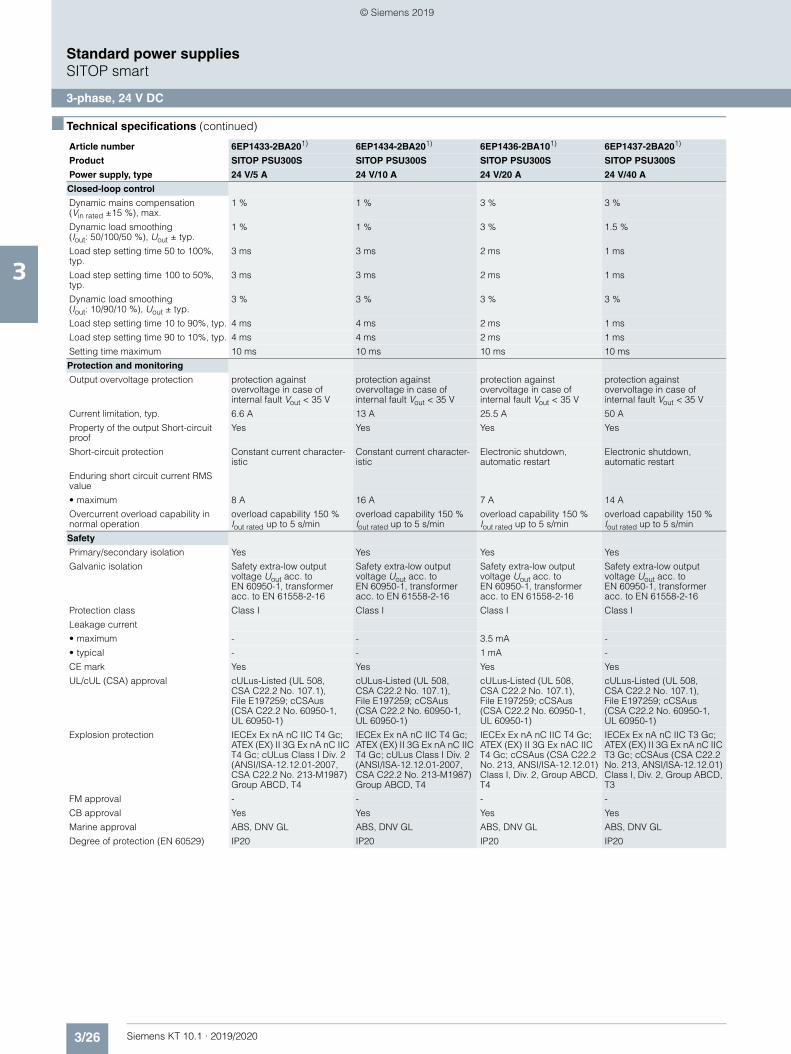
3/26 Siemens KT 10.1 · 2019/2020
3
■ Technical specifications (continued)
Standard power suppliesSITOP smart
3-phase, 24 V DC
Closed-loop control
Dynamic mains compensation (Vin rated ±15 %), max.
1 % 1 % 3 % 3 %
Dynamic load smoothing (Iout: 50/100/50 %), Uout ± typ.
1 % 1 % 3 % 1.5 %
Load step setting time 50 to 100%, typ.
3 ms 3 ms 2 ms 1 ms
Load step setting time 100 to 50%, typ.
3 ms 3 ms 2 ms 1 ms
Dynamic load smoothing (Iout: 10/90/10 %), Uout ± typ.
3 % 3 % 3 % 3 %
Load step setting time 10 to 90%, typ. 4 ms 4 ms 2 ms 1 ms
Load step setting time 90 to 10%, typ. 4 ms 4 ms 2 ms 1 ms
Setting time maximum 10 ms 10 ms 10 ms 10 ms
Protection and monitoring
Output overvoltage protection protection against overvoltage in case of internal fault Vout < 35 V
protection against overvoltage in case of internal fault Vout < 35 V
protection against overvoltage in case of internal fault Vout < 35 V
protection against overvoltage in case of internal fault Vout < 35 V
Current limitation, typ. 6.6 A 13 A 25.5 A 50 A
Property of the output Short-circuit proof
Yes Yes Yes Yes
Short-circuit protection Constant current character-istic
Constant current character-istic
Electronic shutdown, automatic restart
Electronic shutdown, automatic restart
Enduring short circuit current RMS value
• maximum 8 A 16 A 7 A 14 A
Overcurrent overload capability in normal operation
overload capability 150 % Iout rated up to 5 s/min
overload capability 150 % Iout rated up to 5 s/min
overload capability 150 % Iout rated up to 5 s/min
overload capability 150 % Iout rated up to 5 s/min
Safety
Primary/secondary isolation Yes Yes Yes Yes
Galvanic isolation Safety extra-low output voltage Uout acc. to EN 60950-1, transformer acc. to EN 61558-2-16
Safety extra-low output voltage Uout acc. to EN 60950-1, transformer acc. to EN 61558-2-16
Safety extra-low output voltage Uout acc. to EN 60950-1, transformer acc. to EN 61558-2-16
Safety extra-low output voltage Uout acc. to EN 60950-1, transformer acc. to EN 61558-2-16
Protection class Class I Class I Class I Class I
Leakage current
• maximum - - 3.5 mA -
• typical - - 1 mA -
CE mark Yes Yes Yes Yes
UL/cUL (CSA) approval cULus-Listed (UL 508, CSA C22.2 No. 107.1), File E197259; cCSAus (CSA C22.2 No. 60950-1, UL 60950-1)
cULus-Listed (UL 508, CSA C22.2 No. 107.1), File E197259; cCSAus (CSA C22.2 No. 60950-1, UL 60950-1)
cULus-Listed (UL 508, CSA C22.2 No. 107.1), File E197259; cCSAus (CSA C22.2 No. 60950-1, UL 60950-1)
cULus-Listed (UL 508, CSA C22.2 No. 107.1), File E197259; cCSAus (CSA C22.2 No. 60950-1, UL 60950-1)
Explosion protection IECEx Ex nA nC IIC T4 Gc; ATEX (EX) II 3G Ex nA nC IIC T4 Gc; cULus Class I Div. 2 (ANSI/ISA-12.12.01-2007, CSA C22.2 No. 213-M1987) Group ABCD, T4
IECEx Ex nA nC IIC T4 Gc; ATEX (EX) II 3G Ex nA nC IIC T4 Gc; cULus Class I Div. 2 (ANSI/ISA-12.12.01-2007, CSA C22.2 No. 213-M1987) Group ABCD, T4
IECEx Ex nA nC IIC T4 Gc; ATEX (EX) II 3G Ex nAC IIC T4 Gc; cCSAus (CSA C22.2 No. 213, ANSI/ISA-12.12.01) Class I, Div. 2, Group ABCD, T4
IECEx Ex nA nC IIC T3 Gc; ATEX (EX) II 3G Ex nA nC IIC T3 Gc; cCSAus (CSA C22.2 No. 213, ANSI/ISA-12.12.01) Class I, Div. 2, Group ABCD, T3
FM approval - - - -
CB approval Yes Yes Yes Yes
Marine approval ABS, DNV GL ABS, DNV GL ABS, DNV GL ABS, DNV GL
Degree of protection (EN 60529) IP20 IP20 IP20 IP20
Article number 6EP1433-2BA201) 6EP1434-2BA201) 6EP1436-2BA101) 6EP1437-2BA201)
Product SITOP PSU300S SITOP PSU300S SITOP PSU300S SITOP PSU300S
Power supply, type 24 V/5 A 24 V/10 A 24 V/20 A 24 V/40 A
© Siemens 2019
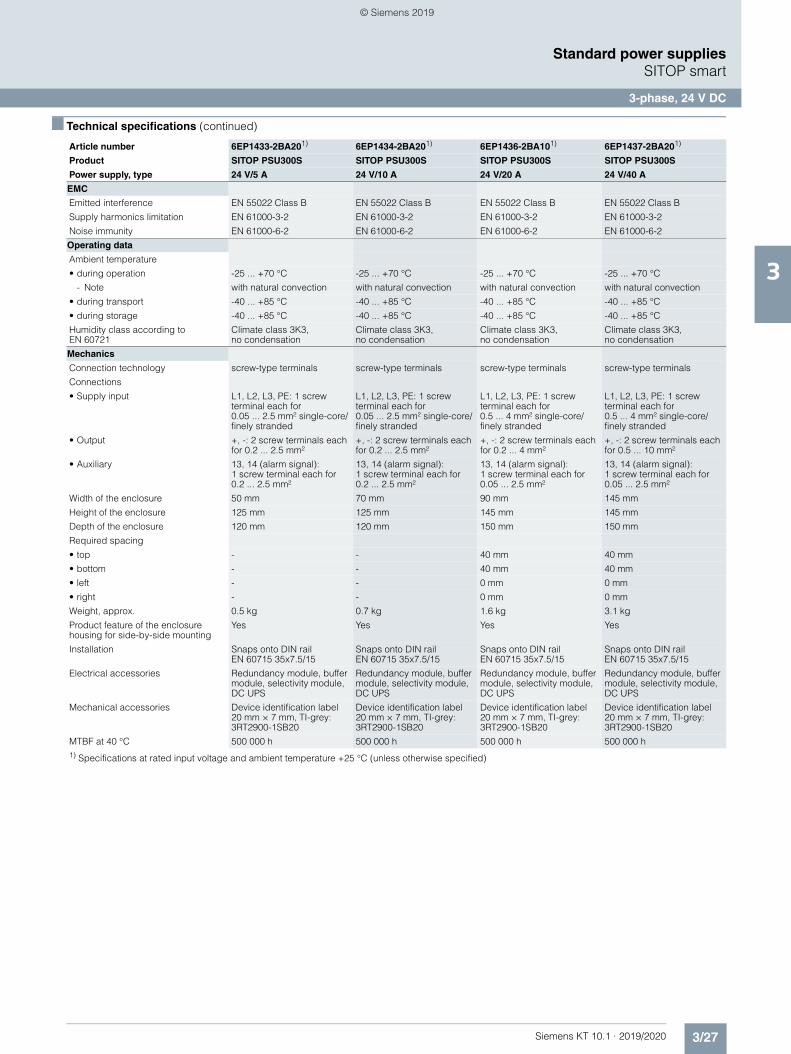
3/27Siemens KT 10.1 · 2019/2020
3
■ Technical specifications (continued)
Standard power suppliesSITOP smart
3-phase, 24 V DC
EMC
Emitted interference EN 55022 Class B EN 55022 Class B EN 55022 Class B EN 55022 Class B
Supply harmonics limitation EN 61000-3-2 EN 61000-3-2 EN 61000-3-2 EN 61000-3-2
Noise immunity EN 61000-6-2 EN 61000-6-2 EN 61000-6-2 EN 61000-6-2
Operating data
Ambient temperature
• during operation -25 ... +70 °C -25 ... +70 °C -25 ... +70 °C -25 ... +70 °C
- Note with natural convection with natural convection with natural convection with natural convection
• during transport -40 ... +85 °C -40 ... +85 °C -40 ... +85 °C -40 ... +85 °C
• during storage -40 ... +85 °C -40 ... +85 °C -40 ... +85 °C -40 ... +85 °C
Humidity class according to EN 60721
Climate class 3K3, no condensation
Climate class 3K3, no condensation
Climate class 3K3, no condensation
Climate class 3K3, no condensation
Mechanics
Connection technology screw-type terminals screw-type terminals screw-type terminals screw-type terminals
Connections
• Supply input L1, L2, L3, PE: 1 screw terminal each for 0.05 ... 2.5 mm² single-core/finely stranded
L1, L2, L3, PE: 1 screw terminal each for 0.05 ... 2.5 mm² single-core/finely stranded
L1, L2, L3, PE: 1 screw terminal each for 0.5 ... 4 mm² single-core/finely stranded
L1, L2, L3, PE: 1 screw terminal each for 0.5 ... 4 mm² single-core/finely stranded
• Output +, -: 2 screw terminals each for 0.2 ... 2.5 mm²
+, -: 2 screw terminals each for 0.2 ... 2.5 mm²
+, -: 2 screw terminals each for 0.2 ... 4 mm²
+, -: 2 screw terminals each for 0.5 ... 10 mm²
• Auxiliary 13, 14 (alarm signal): 1 screw terminal each for 0.2 ... 2.5 mm²
13, 14 (alarm signal): 1 screw terminal each for 0.2 ... 2.5 mm²
13, 14 (alarm signal): 1 screw terminal each for 0.05 ... 2.5 mm²
13, 14 (alarm signal): 1 screw terminal each for 0.05 ... 2.5 mm²
Width of the enclosure 50 mm 70 mm 90 mm 145 mm
Height of the enclosure 125 mm 125 mm 145 mm 145 mm
Depth of the enclosure 120 mm 120 mm 150 mm 150 mm
Required spacing
• top - - 40 mm 40 mm
• bottom - - 40 mm 40 mm
• left - - 0 mm 0 mm
• right - - 0 mm 0 mm
Weight, approx. 0.5 kg 0.7 kg 1.6 kg 3.1 kg
Product feature of the enclosure housing for side-by-side mounting
Yes Yes Yes Yes
Installation Snaps onto DIN rail EN 60715 35x7.5/15
Snaps onto DIN rail EN 60715 35x7.5/15
Snaps onto DIN rail EN 60715 35x7.5/15
Snaps onto DIN rail EN 60715 35x7.5/15
Electrical accessories Redundancy module, buffer module, selectivity module, DC UPS
Redundancy module, buffer module, selectivity module, DC UPS
Redundancy module, buffer module, selectivity module, DC UPS
Redundancy module, buffer module, selectivity module, DC UPS
Mechanical accessories Device identification label 20 mm × 7 mm, TI-grey: 3RT2900-1SB20
Device identification label 20 mm × 7 mm, TI-grey: 3RT2900-1SB20
Device identification label 20 mm × 7 mm, TI-grey: 3RT2900-1SB20
Device identification label 20 mm × 7 mm, TI-grey: 3RT2900-1SB20
MTBF at 40 °C 500 000 h 500 000 h 500 000 h 500 000 h1) Specifications at rated input voltage and ambient temperature +25 °C (unless otherwise specified)
Article number 6EP1433-2BA201) 6EP1434-2BA201) 6EP1436-2BA101) 6EP1437-2BA201)
Product SITOP PSU300S SITOP PSU300S SITOP PSU300S SITOP PSU300S
Power supply, type 24 V/5 A 24 V/10 A 24 V/20 A 24 V/40 A
© Siemens 2019
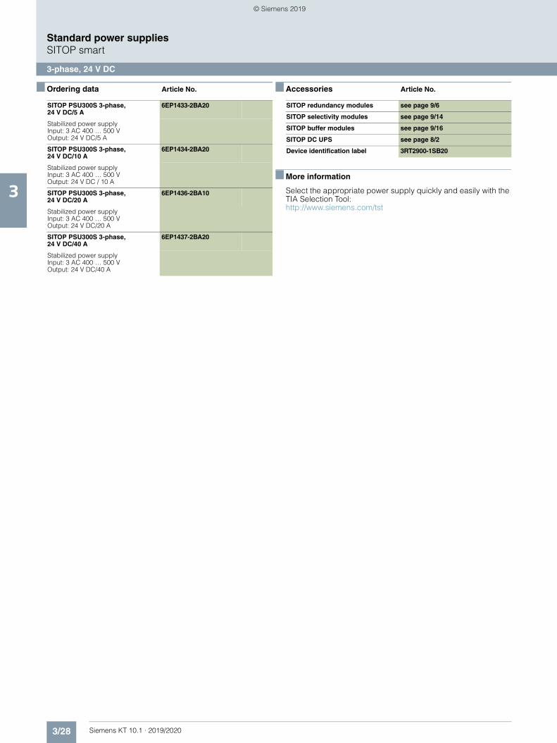
3/28 Siemens KT 10.1 · 2019/2020
3
Standard power suppliesSITOP smart
3-phase, 24 V DC
■ Ordering data Article No. ■ Accessories Article No.
■ More information
Select the appropriate power supply quickly and easily with the TIA Selection Tool:http://www.siemens.com/tst
SITOP PSU300S 3-phase, 24 V DC/5 A
6EP1433-2BA20
Stabilized power supply Input: 3 AC 400 … 500 VOutput: 24 V DC/5 A
SITOP PSU300S 3-phase, 24 V DC/10 A
6EP1434-2BA20
Stabilized power supplyInput: 3 AC 400 … 500 VOutput: 24 V DC / 10 A
SITOP PSU300S 3-phase, 24 V DC/20 A
6EP1436-2BA10
Stabilized power supplyInput: 3 AC 400 … 500 VOutput: 24 V DC/20 A
SITOP PSU300S 3-phase, 24 V DC/40 A
6EP1437-2BA20
Stabilized power supplyInput: 3 AC 400 … 500 VOutput: 24 V DC/40 A
SITOP redundancy modules see page 9/6
SITOP selectivity modules see page 9/14
SITOP buffer modules see page 9/16
SITOP DC UPS see page 8/2
Device identification label 3RT2900-1SB20
© Siemens 2019
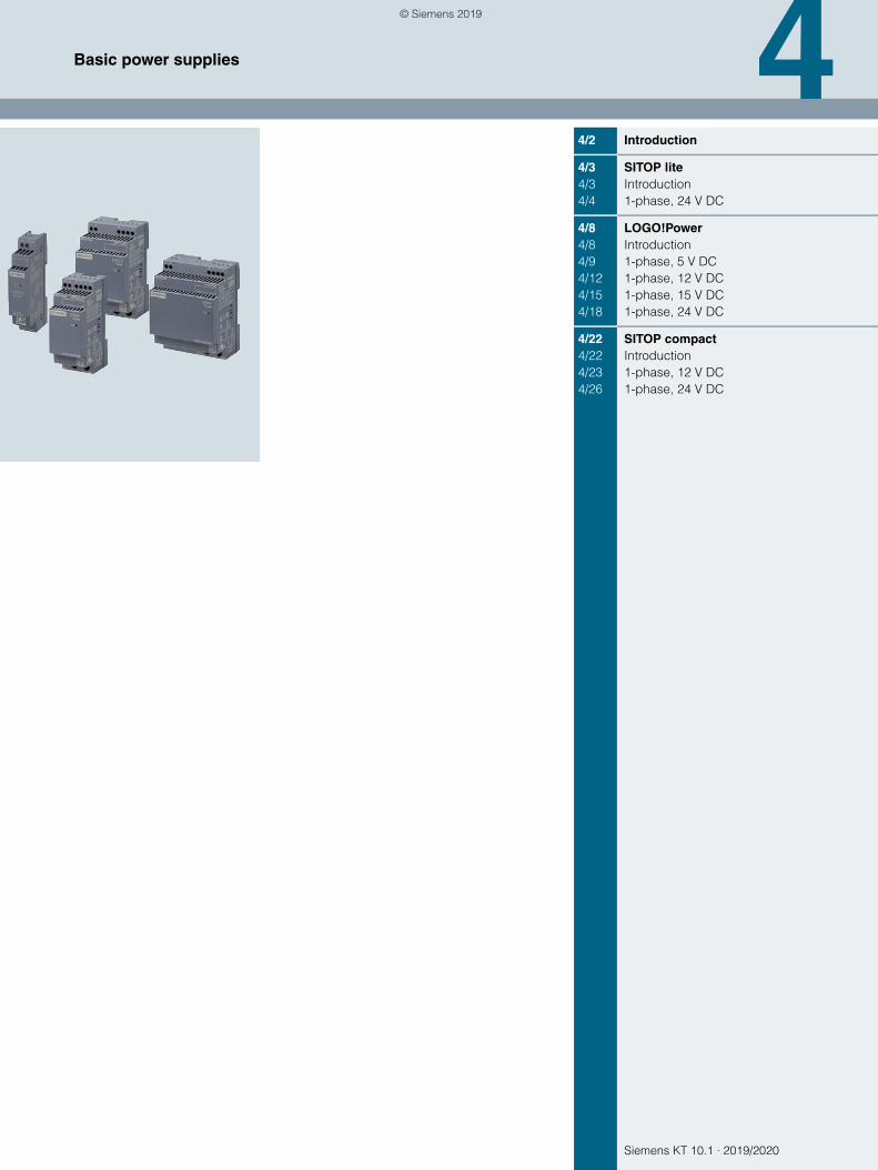
Siemens KT 10.1 · 2019/2020
44/2 Introduction
4/3 SITOP lite4/3 Introduction4/4 1-phase, 24 V DC
4/8 LOGO!Power4/8 Introduction4/9 1-phase, 5 V DC4/12 1-phase, 12 V DC4/15 1-phase, 15 V DC4/18 1-phase, 24 V DC
4/22 SITOP compact4/22 Introduction4/23 1-phase, 12 V DC4/26 1-phase, 24 V DC
Basic power supplies
© Siemens 2019
4/2 Siemens KT 10.1 · 2019/2020
4
Basic power supplies
Introduction
■ Overview
From flat power supplies for distribution boards through cost-effective basic power supplies to slim power supply units for control boxes – SITOP caters to all needs, including in the lower performance range.
LOGO!Power thus offers you mini-power supply units in the LOGO!8 module design. The extremely space-saving SITOP compact devices are ideally suited for distributed applications. And SITOP lite fulfills the main requirements for reliable primary switched-mode regulators at an affordable price.
© Siemens 2019
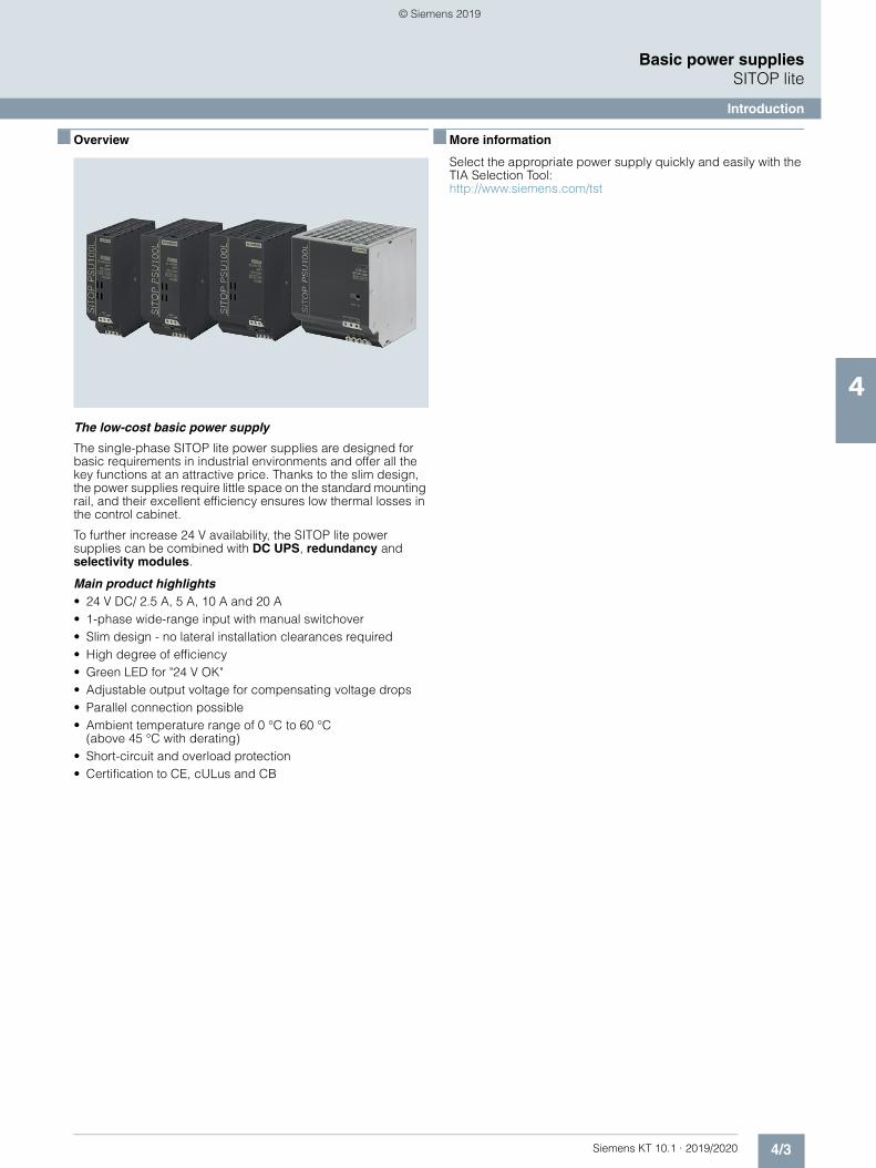
4/3Siemens KT 10.1 · 2019/2020
4
Basic power suppliesSITOP lite
Introduction
■ Overview
The low-cost basic power supply
The single-phase SITOP lite power supplies are designed for basic requirements in industrial environments and offer all the key functions at an attractive price. Thanks to the slim design, the power supplies require little space on the standard mounting rail, and their excellent efficiency ensures low thermal losses in the control cabinet.
To further increase 24 V availability, the SITOP lite power supplies can be combined with DC UPS, redundancy and selectivity modules.
Main product highlights• 24 V DC/ 2.5 A, 5 A, 10 A and 20 A• 1-phase wide-range input with manual switchover• Slim design - no lateral installation clearances required• High degree of efficiency• Green LED for "24 V OK"• Adjustable output voltage for compensating voltage drops• Parallel connection possible• Ambient temperature range of 0 °C to 60 °C
(above 45 °C with derating)• Short-circuit and overload protection• Certification to CE, cULus and CB
■ More information
Select the appropriate power supply quickly and easily with the TIA Selection Tool:http://www.siemens.com/tst
© Siemens 2019
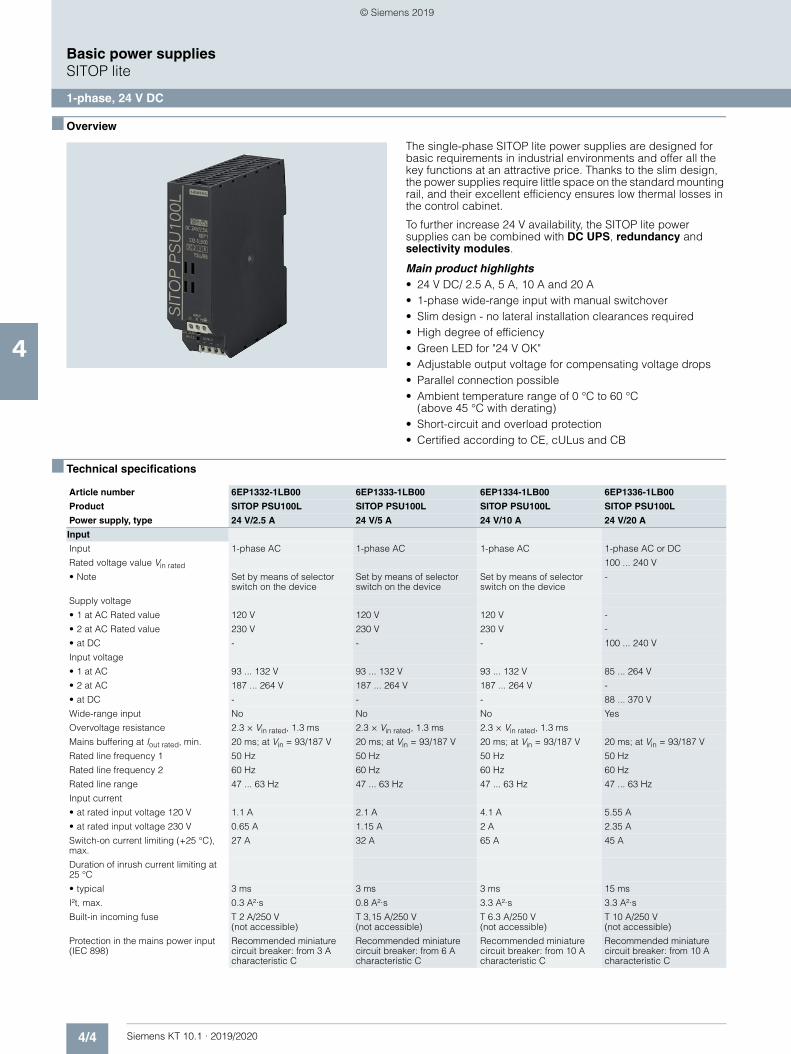
4/4 Siemens KT 10.1 · 2019/2020
4
Basic power suppliesSITOP lite
1-phase, 24 V DC
■ Overview
The single-phase SITOP lite power supplies are designed for basic requirements in industrial environments and offer all the key functions at an attractive price. Thanks to the slim design, the power supplies require little space on the standard mounting rail, and their excellent efficiency ensures low thermal losses in the control cabinet.
To further increase 24 V availability, the SITOP lite power supplies can be combined with DC UPS, redundancy and selectivity modules.
Main product highlights• 24 V DC/ 2.5 A, 5 A, 10 A and 20 A• 1-phase wide-range input with manual switchover• Slim design - no lateral installation clearances required• High degree of efficiency• Green LED for "24 V OK"• Adjustable output voltage for compensating voltage drops• Parallel connection possible• Ambient temperature range of 0 °C to 60 °C
(above 45 °C with derating)• Short-circuit and overload protection• Certified according to CE, cULus and CB
■ Technical specifications
Article number 6EP1332-1LB00 6EP1333-1LB00 6EP1334-1LB00 6EP1336-1LB00
Product SITOP PSU100L SITOP PSU100L SITOP PSU100L SITOP PSU100L
Power supply, type 24 V/2.5 A 24 V/5 A 24 V/10 A 24 V/20 A
Input
Input 1-phase AC 1-phase AC 1-phase AC 1-phase AC or DC
Rated voltage value Vin rated 100 ... 240 V
• Note Set by means of selector switch on the device
Set by means of selector switch on the device
Set by means of selector switch on the device
-
Supply voltage
• 1 at AC Rated value 120 V 120 V 120 V -
• 2 at AC Rated value 230 V 230 V 230 V -
• at DC - - - 100 ... 240 V
Input voltage
• 1 at AC 93 ... 132 V 93 ... 132 V 93 ... 132 V 85 ... 264 V
• 2 at AC 187 ... 264 V 187 ... 264 V 187 ... 264 V -
• at DC - - - 88 ... 370 V
Wide-range input No No No Yes
Overvoltage resistance 2.3 × Vin rated, 1.3 ms 2.3 × Vin rated, 1.3 ms 2.3 × Vin rated, 1.3 ms
Mains buffering at Iout rated, min. 20 ms; at Vin = 93/187 V 20 ms; at Vin = 93/187 V 20 ms; at Vin = 93/187 V 20 ms; at Vin = 93/187 V
Rated line frequency 1 50 Hz 50 Hz 50 Hz 50 Hz
Rated line frequency 2 60 Hz 60 Hz 60 Hz 60 Hz
Rated line range 47 ... 63 Hz 47 ... 63 Hz 47 ... 63 Hz 47 ... 63 Hz
Input current
• at rated input voltage 120 V 1.1 A 2.1 A 4.1 A 5.55 A
• at rated input voltage 230 V 0.65 A 1.15 A 2 A 2.35 A
Switch-on current limiting (+25 °C), max.
27 A 32 A 65 A 45 A
Duration of inrush current limiting at 25 °C
• typical 3 ms 3 ms 3 ms 15 ms
I²t, max. 0.3 A²·s 0.8 A²·s 3.3 A²·s 3.3 A²·s
Built-in incoming fuse T 2 A/250 V (not accessible)
T 3,15 A/250 V (not accessible)
T 6.3 A/250 V (not accessible)
T 10 A/250 V (not accessible)
Protection in the mains power input (IEC 898)
Recommended miniature circuit breaker: from 3 A characteristic C
Recommended miniature circuit breaker: from 6 A characteristic C
Recommended miniature circuit breaker: from 10 A characteristic C
Recommended miniature circuit breaker: from 10 A characteristic C
© Siemens 2019
4/5Siemens KT 10.1 · 2019/2020
4
■ Technical specifications (continued)
Basic power suppliesSITOP lite
1-phase, 24 V DC
Output
Output Controlled, isolated DC voltage
Controlled, isolated DC voltage
Controlled, isolated DC voltage
Controlled, isolated DC voltage
Rated voltage Vout DC 24 V 24 V 24 V 24 V
Total tolerance, static ± 3 % 3 % 3 % 3 %
Static mains compensation, approx. 0.1 % 0.1 % 0.1 % 0.1 %
Static load balancing, approx. 0.5 % 0.5 % 0.5 % 1 %
Residual ripple peak-peak, max. 150 mV 150 mV 150 mV 150 mV
Residual ripple peak-peak, typ. 10 mV 50 mV 50 mV 50 mV
Spikes peak-peak, max. (bandwidth: 20 MHz)
240 mV 240 mV 240 mV 240 mV
Spikes peak-peak, typ. (bandwidth: 20 MHz)
50 mV 150 mV 150 mV 100 mV
Adjustment range 22.8 ... 26.4 V 22.8 ... 26.4 V 22.8 ... 26.4 V 22.8 ... 26.4 V
Product function Output voltage adjustable
Yes Yes Yes Yes
Output voltage setting via potentiometer via potentiometer via potentiometer via potentiometer
Status display Green LED for 24 V OK Green LED for 24 V OK Green LED for 24 V OK Green LED for 24 V OK
On/off behavior Overshoot of Vout approx. 4 %
Overshoot of Vout approx. 4 %
Overshoot of Vout approx. 4 %
No overshoot of Vout (soft start)
Startup delay, max. 1.5 s 1.5 s 1.5 s 1.5 s
Voltage rise, typ. 150 ms 130 ms 170 ms 20 ms
Rated current value Iout rated 2.5 A 5 A 10 A 20 A
Current range 0 ... 2.5 A 0 ... 5 A 0 ... 10 A 0 ... 20 A
• Note +45 ... +60 °C: Derating 2%/K
+45 ... +60 °C: Derating 2%/K
+45 ... +60 °C: Derating 2%/K
+45 ... +70 °C: Derating 2.5%/K
Supplied active power typical 60 W 120 W 240 W 480 W
Parallel switching for enhanced performance
Yes Yes Yes Yes
Numbers of parallel switchable units for enhanced performance
2 2 2 2
Efficiency
Efficiency at Vout rated, Iout rated, approx.
85 % 86 % 89 % 92 %
Power loss at Vout rated, Iout rated, approx.
9 W 17 W 34 W 45 W
Closed-loop control
Dynamic mains compensation (Vin rated ±15 %), max.
0.3 % 0.3 % 0.3 % 0.5 %
Dynamic load smoothing (Iout: 10/90/10 %), Uout ± typ.
2 % 2 % 2 % 3 %
Load step setting time 10 to 90%, typ. 0.5 ms 0.4 ms 0.5 ms 0.7 ms
Load step setting time 90 to 10%, typ. 0.7 ms 0.4 ms 0.7 ms 6 ms
Protection and monitoring
Output overvoltage protection < 33 V < 33 V < 33 V < 33 V
Current limitation, typ. 2.6 A 5.25 A 16 A 24 A
Property of the output Short-circuit proof
Yes Yes Yes Yes
Short-circuit protection Constant current characteristic
Constant current characteristic
Constant current characteristic
Constant current characteristic
Enduring short circuit current RMS value
• typical 4 A 8 A 12.6 A 24 A
Overload/short-circuit indicator - - - -
Article number 6EP1332-1LB00 6EP1333-1LB00 6EP1334-1LB00 6EP1336-1LB00
Product SITOP PSU100L SITOP PSU100L SITOP PSU100L SITOP PSU100L
Power supply, type 24 V/2.5 A 24 V/5 A 24 V/10 A 24 V/20 A
© Siemens 2019
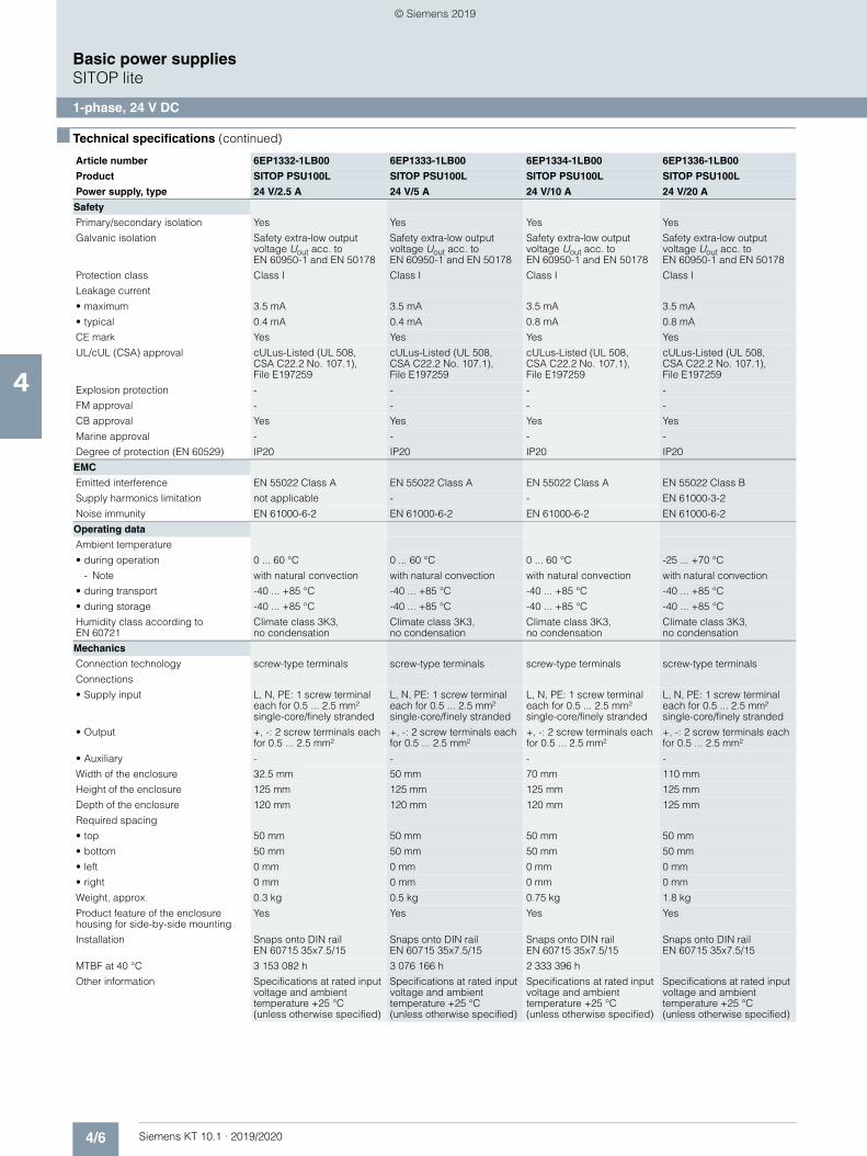
4/6 Siemens KT 10.1 · 2019/2020
4
■ Technical specifications (continued)
Basic power suppliesSITOP lite
1-phase, 24 V DC
Safety
Primary/secondary isolation Yes Yes Yes Yes
Galvanic isolation Safety extra-low output voltage Uout acc. to EN 60950-1 and EN 50178
Safety extra-low output voltage Uout acc. to EN 60950-1 and EN 50178
Safety extra-low output voltage Uout acc. to EN 60950-1 and EN 50178
Safety extra-low output voltage Uout acc. to EN 60950-1 and EN 50178
Protection class Class I Class I Class I Class I
Leakage current
• maximum 3.5 mA 3.5 mA 3.5 mA 3.5 mA
• typical 0.4 mA 0.4 mA 0.8 mA 0.8 mA
CE mark Yes Yes Yes Yes
UL/cUL (CSA) approval cULus-Listed (UL 508, CSA C22.2 No. 107.1), File E197259
cULus-Listed (UL 508, CSA C22.2 No. 107.1), File E197259
cULus-Listed (UL 508, CSA C22.2 No. 107.1), File E197259
cULus-Listed (UL 508, CSA C22.2 No. 107.1), File E197259
Explosion protection - - - -
FM approval - - - -
CB approval Yes Yes Yes Yes
Marine approval - - - -
Degree of protection (EN 60529) IP20 IP20 IP20 IP20
EMC
Emitted interference EN 55022 Class A EN 55022 Class A EN 55022 Class A EN 55022 Class B
Supply harmonics limitation not applicable - - EN 61000-3-2
Noise immunity EN 61000-6-2 EN 61000-6-2 EN 61000-6-2 EN 61000-6-2
Operating data
Ambient temperature
• during operation 0 ... 60 °C 0 ... 60 °C 0 ... 60 °C -25 ... +70 °C
- Note with natural convection with natural convection with natural convection with natural convection
• during transport -40 ... +85 °C -40 ... +85 °C -40 ... +85 °C -40 ... +85 °C
• during storage -40 ... +85 °C -40 ... +85 °C -40 ... +85 °C -40 ... +85 °C
Humidity class according to EN 60721
Climate class 3K3, no condensation
Climate class 3K3, no condensation
Climate class 3K3, no condensation
Climate class 3K3, no condensation
Mechanics
Connection technology screw-type terminals screw-type terminals screw-type terminals screw-type terminals
Connections
• Supply input L, N, PE: 1 screw terminal each for 0.5 ... 2.5 mm² single-core/finely stranded
L, N, PE: 1 screw terminal each for 0.5 ... 2.5 mm² single-core/finely stranded
L, N, PE: 1 screw terminal each for 0.5 ... 2.5 mm² single-core/finely stranded
L, N, PE: 1 screw terminal each for 0.5 ... 2.5 mm² single-core/finely stranded
• Output +, -: 2 screw terminals each for 0.5 ... 2.5 mm²
+, -: 2 screw terminals each for 0.5 ... 2.5 mm²
+, -: 2 screw terminals each for 0.5 ... 2.5 mm²
+, -: 2 screw terminals each for 0.5 ... 2.5 mm²
• Auxiliary - - - -
Width of the enclosure 32.5 mm 50 mm 70 mm 110 mm
Height of the enclosure 125 mm 125 mm 125 mm 125 mm
Depth of the enclosure 120 mm 120 mm 120 mm 125 mm
Required spacing
• top 50 mm 50 mm 50 mm 50 mm
• bottom 50 mm 50 mm 50 mm 50 mm
• left 0 mm 0 mm 0 mm 0 mm
• right 0 mm 0 mm 0 mm 0 mm
Weight, approx. 0.3 kg 0.5 kg 0.75 kg 1.8 kg
Product feature of the enclosure housing for side-by-side mounting
Yes Yes Yes Yes
Installation Snaps onto DIN rail EN 60715 35x7.5/15
Snaps onto DIN rail EN 60715 35x7.5/15
Snaps onto DIN rail EN 60715 35x7.5/15
Snaps onto DIN rail EN 60715 35x7.5/15
MTBF at 40 °C 3 153 082 h 3 076 166 h 2 333 396 h
Other information Specifications at rated input voltage and ambient temperature +25 °C (unless otherwise specified)
Specifications at rated input voltage and ambient temperature +25 °C (unless otherwise specified)
Specifications at rated input voltage and ambient temperature +25 °C (unless otherwise specified)
Specifications at rated input voltage and ambient temperature +25 °C (unless otherwise specified)
Article number 6EP1332-1LB00 6EP1333-1LB00 6EP1334-1LB00 6EP1336-1LB00
Product SITOP PSU100L SITOP PSU100L SITOP PSU100L SITOP PSU100L
Power supply, type 24 V/2.5 A 24 V/5 A 24 V/10 A 24 V/20 A
© Siemens 2019
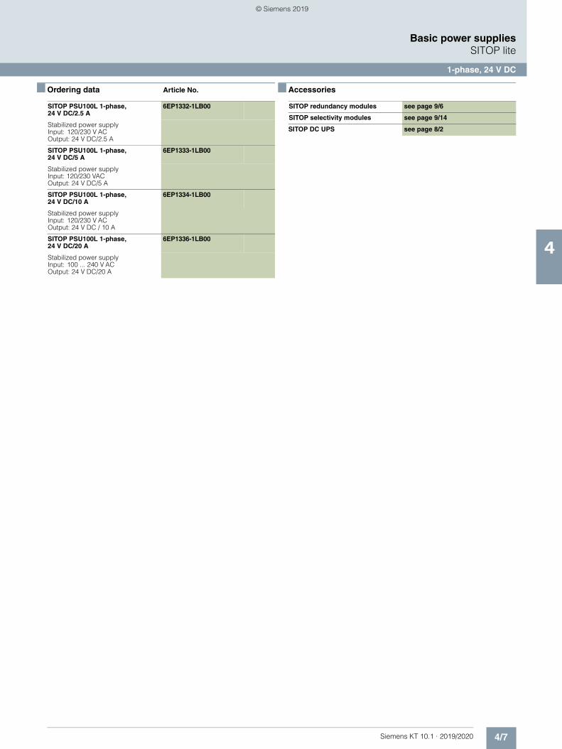
4/7Siemens KT 10.1 · 2019/2020
4
Basic power suppliesSITOP lite
1-phase, 24 V DC
■ Ordering data Article No. ■ Accessories
SITOP PSU100L 1-phase, 24 V DC/2.5 A
6EP1332-1LB00
Stabilized power supplyInput: 120/230 V ACOutput: 24 V DC/2.5 A
SITOP PSU100L 1-phase, 24 V DC/5 A
6EP1333-1LB00
Stabilized power supplyInput: 120/230 VACOutput: 24 V DC/5 A
SITOP PSU100L 1-phase, 24 V DC/10 A
6EP1334-1LB00
Stabilized power supplyInput: 120/230 V ACOutput: 24 V DC / 10 A
SITOP PSU100L 1-phase, 24 V DC/20 A
6EP1336-1LB00
Stabilized power supplyInput: 100 ... 240 V ACOutput: 24 V DC/20 A
SITOP redundancy modules see page 9/6
SITOP selectivity modules see page 9/14
SITOP DC UPS see page 8/2
© Siemens 2019
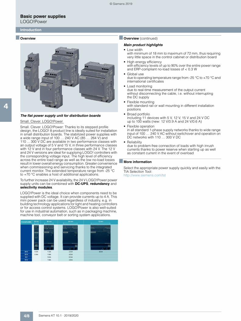
4/8 Siemens KT 10.1 · 2019/2020
4
Basic power suppliesLOGO!Power
Introduction
■ Overview
The flat power supply unit for distribution boards
Small. Clever. LOGO!Power
Small. Clever. LOGO!Power: Thanks to its stepped profile design, the LOGO! 8 product line is ideally suited for installation in small distribution boards. The stabilized power supplies with a wide range input of 100 … 240 V AC (85 … 264 V) and110 ... 300 V DC are available in two performance classes with an output voltage of 5 V and 15 V, in three performance classes with 12 V and in four performance classes with 24 V. The 12 V and 24 V versions are ideal for supplying LOGO! controllers with the corresponding voltage input. The high level of efficiency across the entire load range as well as the low no-load losses result in lower overall energy consumption. Greater convenience when commissioning and servicing thanks to the integrated current monitor. The extended temperature range from -25 °C to +70 °C enables a host of additional applications.
To further increase 24 V availability, the 24 V LOGO!Power power supply units can be combined with DC-UPS, redundancy and selectivity modules.
LOGO!Power is the ideal choice when components need to be supplied with DC voltage. It can provide currents up to 4 A. This mini power pack can be used regardless of industry, e.g. in building technology applications for light and heating controllers or for access control systems. LOGO!Power is also well-suited for use in industrial automation, such as in packaging machine, machine tool, conveyor belt or sorting system applications.
■ Overview (continued)
Main product highlights• Low width
with minimum of 18 mm to maximum of 72 mm, thus requiringvery little space in the control cabinet or distribution board
• High energy efficiencywith efficiency levels of up to 90% over the entire power range and ERP-compliant no-load losses of < 0.3 W
• Global usedue to operating temperature range from -25 °C to +70 °C and international certificates
• Load monitoringdue to real-time measurement of the output currentwithout disconnecting the cable, i.e. without interruptingthe DC supply
• Flexible mountingwith standard rail or wall mounting in different installationpositions
• Broad portfolioincluding 11 devices with 5 V, 12 V, 15 V and 24 V DCup to 100 watts (new: 12 V/0.9 A and 24 V/0.6 A)
• Flexible operationin all standard 1-phase supply networks thanks to wide rangeinput of 100 … 240 V AC without switchover and operation onDC networks with 110 … 300 V DC
• Reliabilitydue to problem-free connection of loads with high inrushcurrents thanks to power reserve when starting up as wellas constant current in the event of overload
■ More information
Select the appropriate power supply quickly and easily with theTIA Selection Tool:http://www.siemens.com/tst
© Siemens 2019
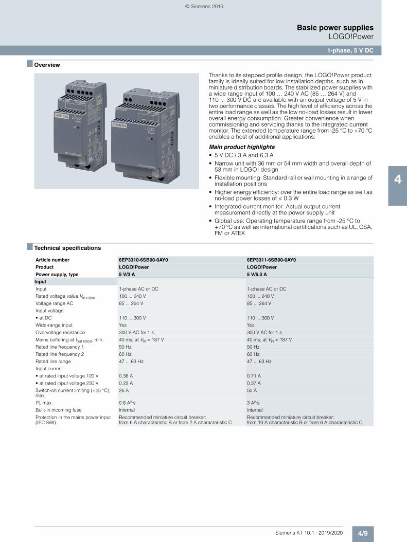
4/9Siemens KT 10.1 · 2019/2020
4
Basic power suppliesLOGO!Power
1-phase, 5 V DC
■ Overview
Thanks to its stepped profile design, the LOGO!Power product family is ideally suited for low installation depths, such as in miniature distribution boards. The stabilized power supplies with a wide range input of 100 … 240 V AC (85 … 264 V) and 110 ... 300 V DC are available with an output voltage of 5 V in two performance classes. The high level of efficiency across the entire load range as well as the low no-load losses result in lower overall energy consumption. Greater convenience when commissioning and servicing thanks to the integrated current monitor. The extended temperature range from -25 °C to +70 °C enables a host of additional applications.
Main product highlights• 5 V DC / 3 A and 6.3 A• Narrow unit with 36 mm or 54 mm width and overall depth of
53 mm in LOGO! design• Flexible mounting: Standard rail or wall mounting in a range of
installation positions• Higher energy efficiency: over the entire load range as well as
no-load power losses of < 0.3 W• Integrated current monitor: Actual output current
measurement directly at the power supply unit• Global use: Operating temperature range from -25 °C to
+70 °C as well as international certifications such as UL, CSA, FM or ATEX
■ Technical specifications
Article number 6EP3310-6SB00-0AY0 6EP3311-6SB00-0AY0
Product LOGO!Power LOGO!Power
Power supply, type 5 V/3 A 5 V/6.3 A
Input
Input 1-phase AC or DC 1-phase AC or DC
Rated voltage value Vin rated 100 ... 240 V 100 ... 240 V
Voltage range AC 85 ... 264 V 85 ... 264 V
Input voltage
• at DC 110 ... 300 V 110 ... 300 V
Wide-range input Yes Yes
Overvoltage resistance 300 V AC for 1 s 300 V AC for 1 s
Mains buffering at Iout rated, min. 40 ms; at Vin = 187 V 40 ms; at Vin = 187 V
Rated line frequency 1 50 Hz 50 Hz
Rated line frequency 2 60 Hz 60 Hz
Rated line range 47 ... 63 Hz 47 ... 63 Hz
Input current
• at rated input voltage 120 V 0.36 A 0.71 A
• at rated input voltage 230 V 0.22 A 0.37 A
Switch-on current limiting (+25 °C), max.
26 A 50 A
I²t, max. 0.8 A²·s 3 A²·s
Built-in incoming fuse internal internal
Protection in the mains power input (IEC 898)
Recommended miniature circuit breaker: from 6 A characteristic B or from 2 A characteristic C
Recommended miniature circuit breaker: from 10 A characteristic B or from 6 A characteristic C
© Siemens 2019

4/10 Siemens KT 10.1 · 2019/2020
4
■ Technical specifications (continued)
Basic power suppliesLOGO!Power
1-phase, 5 V DC
Output
Output Controlled, isolated DC voltage Controlled, isolated DC voltage
Rated voltage Vout rated DC 5 V 5 V
Total tolerance, static ± 3 % 3 %
Static mains compensation, approx. 0.1 % 0.1 %
Static load balancing, approx. 0.1 % 0.1 %
Residual ripple peak-peak, max. 100 mV 100 mV
Residual ripple peak-peak, typ. 30 mV 30 mV
Spikes peak-peak, max. (bandwidth: 20 MHz)
100 mV 100 mV
Spikes peak-peak, typ. (bandwidth: 20 MHz)
50 mV 50 mV
Adjustment range 4.6 ... 5.4 V 4.6 ... 5.4 V
Product function Output voltage adjustable
Yes Yes
Output voltage setting via potentiometer via potentiometer
Status display Green LED for output voltage OK Green LED for output voltage OK
On/off behavior No overshoot of Vout (soft start) No overshoot of Vout (soft start)
Startup delay, max. 0.5 s 0.5 s
Voltage rise, typ. 100 ms 100 ms
Rated current value Iout rated 3 A 6.3 A
Current range 0 ... 3 A 0 ... 6.3 A
• Note +55 ... +70 °C: Derating 2%/K +55 ... +70 °C: Derating 2%/K
Supplied active power typical 15 W 31.5 W
Parallel switching for enhanced performance
Yes Yes
Numbers of parallel switchable units for enhanced performance
2 2
Efficiency
Efficiency at Vout rated, Iout rated, approx.
76 % 80 %
Power loss at Vout rated, Iout rated, approx.
5 W 8 W
Power loss [W] during no-load operation maximum
0.3 W 0.3 W
Closed-loop control
Dynamic mains compensation (Vin rated ±15 %), max.
0.2 % 0.2 %
Dynamic load smoothing (Iout: 10/90/10 %), Uout ± typ.
5 % 7 %
Load step setting time 10 to 90%, typ. 1 ms 1 ms
Load step setting time 90 to 10%, typ. 1 ms 1 ms
Protection and monitoring
Output overvoltage protection Yes, according to EN 60950-1 Yes, according to EN 60950-1
Current limitation, typ. 3.8 A 8.2 A
Property of the output Short-circuit proof
Yes Yes
Short-circuit protection Constant current characteristic Constant current characteristic
Enduring short circuit current RMS value
• maximum 3.8 A 8.2 A
Overcurrent overload capability in normal operation
overload capability 150% Iout rated typ. 200 ms overload capability 150% Iout rated typ. 200 ms
Overload/short-circuit indicator - -
measuring point for output current 50 mV =^ 3 A 50 mV =^ 6.3 A
Overcurrent overload capability when switching on
150% Iout rated typ. 200 ms 150% Iout rated typ. 200 ms
Article number 6EP3310-6SB00-0AY0 6EP3311-6SB00-0AY0
Product LOGO!Power LOGO!Power
Power supply, type 5 V/3 A 5 V/6.3 A
© Siemens 2019
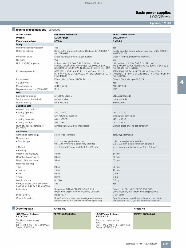
4/11Siemens KT 10.1 · 2019/2020
4
■ Technical specifications (continued)
Basic power suppliesLOGO!Power
1-phase, 5 V DC
■ Ordering data Article No. Article No.
Safety
Primary/secondary isolation Yes Yes
Galvanic isolation Safety extra-low output voltage Uout acc. to EN 60950-1 and EN 50178
Safety extra-low output voltage Uout acc. to EN 60950-1 and EN 50178
Protection class Class II (without protective conductor) Class II (without protective conductor)
CE mark Yes Yes
UL/cUL (CSA) approval cULus-Listed (UL 508, CSA C22.2 No. 107.1), File E197259; cURus-Recognized (UL 60950, CSA C22.2 No. 60950), File E151273, NEC class 2 (acc. to UL 1310)
cULus-listed (UL 508, CSA C22.2 No. 107.1), File E197259; cURus-recognized (UL 60950, CSA C22.2 No. 60950), File E151273
Explosion protection ATEX (EX) II 3G Ex nA IIC T3; cULus Class I Div. 2 (ANSI/ISA-12.12.01, CSA C22.2 No. 213) Group ABCD, T4, File E488866
ATEX (EX) II 3G Ex nA IIC T3; cULus Class I Div. 2 (ANSI/ISA-12.12.01, CSA C22.2 No. 213) Group ABCD, T4, File E488866
FM approval Class I, Div. 2, Group ABCD, T4 Class I, Div. 2, Group ABCD, T4
CB approval Yes Yes
Marine approval ABS, DNV GL ABS, DNV GL
Degree of protection (EN 60529) IP20 IP20
EMC
Emitted interference EN 55022 Class B EN 55022 Class B
Supply harmonics limitation not applicable not applicable
Noise immunity EN 61000-6-2 EN 61000-6-2
Operating data
Ambient temperature
• during operation -25 ... +70 °C -25 ... +70 °C
- Note with natural convection with natural convection
• during transport -40 ... +85 °C -40 ... +85 °C
• during storage -40 ... +85 °C -40 ... +85 °C
Humidity class according to EN 60721
Climate class 3K3, no condensation Climate class 3K3, no condensation
Mechanics
Connection technology screw-type terminals screw-type terminals
Connections
• Supply input L, N: 1 screw terminal each for 0.5 ... 2.5 mm2 single-core/finely stranded
L, N: 1 screw terminal each for 0.5 ... 2.5 mm2 single-core/finely stranded
• Output +, -: 1 screw terminal each for 0.5 ... 2.5 mm² +, -: 1 screw terminal each for 0.5 ... 2.5 mm²
• Auxiliary - -
Width of the enclosure 36 mm 54 mm
Height of the enclosure 90 mm 90 mm
Depth of the enclosure 53 mm 53 mm
Required spacing
• top 20 mm 20 mm
• bottom 20 mm 20 mm
• left 0 mm 0 mm
• right 0 mm 0 mm
Weight, approx. 0.12 kg 0.2 kg
Product feature of the enclosure housing for side-by-side mounting
Yes Yes
Installation Snaps onto DIN rail EN 60715 35x7.5/15, direct mounting in different mounting positions
Snaps onto DIN rail EN 60715 35x7.5/15, direct mounting in different mounting positions
MTBF at 40 °C 2 931 709 h 2 654 280 h
Other information Specifications at rated input voltage and ambient temperature +25 °C (unless otherwise specified)
Specifications at rated input voltage and ambient temperature +25 °C (unless otherwise specified)
Article number 6EP3310-6SB00-0AY0 6EP3311-6SB00-0AY0
Product LOGO!Power LOGO!Power
Power supply, type 5 V/3 A 5 V/6.3 A
LOGO!Power 1-phase, 5 V DC/3 A
6EP3310-6SB00-0AY0
Stabilized power supplyInput: 100 … 240 V AC (110 ... 300 V AC)Output: 5 V DC/3 A
LOGO!Power 1-phase, 5 V DC/6.3 A
6EP3311-6SB00-0AY0
Stabilized power supplyInput: 100 … 240 V AC (110 ... 300 V AC)Output: 5 V DC/6.3 A
© Siemens 2019
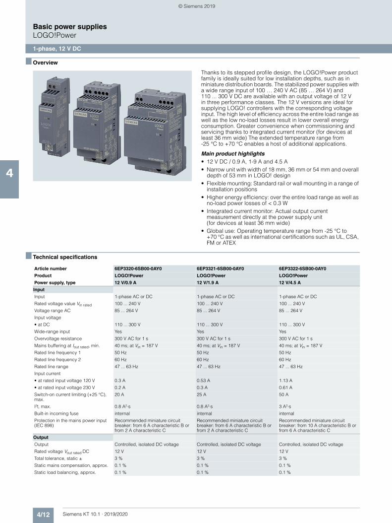
4/12 Siemens KT 10.1 · 2019/2020
4
Basic power suppliesLOGO!Power
1-phase, 12 V DC
■ Overview
Thanks to its stepped profile design, the LOGO!Power product family is ideally suited for low installation depths, such as in miniature distribution boards. The stabilized power supplies with a wide range input of 100 … 240 V AC (85 … 264 V) and 110 ... 300 V DC are available with an output voltage of 12 V in three performance classes. The 12 V versions are ideal for supplying LOGO! controllers with the corresponding voltage input. The high level of efficiency across the entire load range as well as the low no-load losses result in lower overall energy consumption. Greater convenience when commissioning and servicing thanks to integrated current monitor (for devices at least 36 mm wide) The extended temperature range from -25 °C to +70 °C enables a host of additional applications.
Main product highlights• 12 V DC / 0.9 A, 1-9 A and 4.5 A• Narrow unit with width of 18 mm, 36 mm or 54 mm and overall
depth of 53 mm in LOGO! design• Flexible mounting: Standard rail or wall mounting in a range of
installation positions• Higher energy efficiency: over the entire load range as well as
no-load power losses of < 0.3 W• Integrated current monitor: Actual output current
measurement directly at the power supply unit (for devices at least 36 mm wide)
• Global use: Operating temperature range from -25 °C to +70 °C as well as international certifications such as UL, CSA, FM or ATEX
■ Technical specifications
Article number 6EP3320-6SB00-0AY0 6EP3321-6SB00-0AY0 6EP3322-6SB00-0AY0
Product LOGO!Power LOGO!Power LOGO!Power
Power supply, type 12 V/0.9 A 12 V/1.9 A 12 V/4.5 A
Input
Input 1-phase AC or DC 1-phase AC or DC 1-phase AC or DC
Rated voltage value Vin rated 100 ... 240 V 100 ... 240 V 100 ... 240 V
Voltage range AC 85 ... 264 V 85 ... 264 V 85 ... 264 V
Input voltage
• at DC 110 ... 300 V 110 ... 300 V 110 ... 300 V
Wide-range input Yes Yes Yes
Overvoltage resistance 300 V AC for 1 s 300 V AC for 1 s 300 V AC for 1 s
Mains buffering at Iout rated, min. 40 ms; at Vin = 187 V 40 ms; at Vin = 187 V 40 ms; at Vin = 187 V
Rated line frequency 1 50 Hz 50 Hz 50 Hz
Rated line frequency 2 60 Hz 60 Hz 60 Hz
Rated line range 47 ... 63 Hz 47 ... 63 Hz 47 ... 63 Hz
Input current
• at rated input voltage 120 V 0.3 A 0.53 A 1.13 A
• at rated input voltage 230 V 0.2 A 0.3 A 0.61 A
Switch-on current limiting (+25 °C), max.
20 A 25 A 50 A
I²t, max. 0.8 A²·s 0.8 A²·s 3 A²·s
Built-in incoming fuse internal internal internal
Protection in the mains power input (IEC 898)
Recommended miniature circuit breaker: from 6 A characteristic B or from 2 A characteristic C
Recommended miniature circuit breaker: from 6 A characteristic B or from 2 A characteristic C
Recommended miniature circuit breaker: from 10 A characteristic B or from 6 A characteristic C
Output
Output Controlled, isolated DC voltage Controlled, isolated DC voltage Controlled, isolated DC voltage
Rated voltage Vout rated DC 12 V 12 V 12 V
Total tolerance, static ± 3 % 3 % 3 %
Static mains compensation, approx. 0.1 % 0.1 % 0.1 %
Static load balancing, approx. 0.1 % 0.1 % 0.1 %
© Siemens 2019
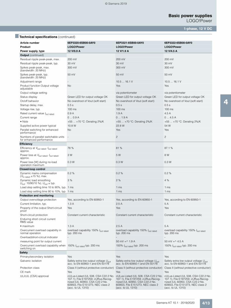
4/13Siemens KT 10.1 · 2019/2020
4
■ Technical specifications (continued)
Basic power suppliesLOGO!Power
1-phase, 12 V DC
Output (continued)
Residual ripple peak-peak, max. 200 mV 200 mV 200 mV
Residual ripple peak-peak, typ. 30 mV 30 mV 30 mV
Spikes peak-peak, max. (bandwidth: 20 MHz)
300 mV 300 mV 300 mV
Spikes peak-peak, typ. (bandwidth: 20 MHz)
50 mV 50 mV 50 mV
Adjustment range - 10.5 ... 16.1 V 10.5 ... 16.1 V
Product function Output voltage adjustable
No Yes Yes
Output voltage setting via potentiometer via potentiometer
Status display Green LED for output voltage OK Green LED for output voltage OK Green LED for output voltage OK
On/off behavior No overshoot of Vout (soft start) No overshoot of Vout (soft start) No overshoot of Vout (soft start)
Startup delay, max. 0.5 s 0.5 s 0.5 s
Voltage rise, typ. 100 ms 100 ms 100 ms
Rated current value Iout rated 0.9 A 1.9 A 4.5 A
Current range 0 ... 0.9 A 0 ... 1.9 A 0 ... 4.5 A
• Note +55 ... +70 °C: Derating 2%/K +55 ... +70 °C: Derating 2%/K +55 ... +70 °C: Derating 2%/K
Supplied active power typical 10.8 W 22.8 W 54 W
Parallel switching for enhanced performance
No Yes Yes
Numbers of parallel switchable units for enhanced performance
- 2 2
Efficiency
Efficiency at Vout rated, Iout rated, approx.
78 % 81 % 87.1 %
Power loss at Vout rated, Iout rated, approx.
3 W 5 W 8 W
Power loss [W] during no-load operation maximum
0.3 W 0.3 W 0.3 W
Closed-loop control
Dynamic mains compensation (Vin rated ±15 %), max.
0.2 % 0.2 % 0.2 %
Dynamic load smoothing (Iout: 10/90/10 %), Uout ± typ.
3 % 2 % 4 %
Load step setting time 10 to 90%, typ. 1 ms 1 ms 1 ms
Load step setting time 90 to 10%, typ. 1 ms 1 ms 1 ms
Protection and monitoring
Output overvoltage protection Yes, according to EN 60950-1 Yes, according to EN 60950-1 Yes, according to EN 60950-1
Current limitation, typ. 1.3 A 2.5 A 5 A
Property of the output Short-circuit proof
Yes Yes Yes
Short-circuit protection Constant current characteristic Constant current characteristic Constant current characteristic
Enduring short circuit current RMS value
• maximum 1.3 A 2.5 A 5 A
Overcurrent overload capability in normal operation
overload capability 150% Iout rated typ. 200 ms
overload capability 150% Iout rated typ. 200 ms
overload capability 150% Iout rated typ. 200 ms
Overload/short-circuit indicator - - -
measuring point for output current 50 mV =^ 1.9 A 50 mV =^ 4.5 A
Overcurrent overload capability when switching on
150% Iout rated typ. 200 ms 150% Iout rated typ. 200 ms 150% Iout rated typ. 200 ms
Safety
Primary/secondary isolation Yes Yes Yes
Galvanic isolation Safety extra-low output voltage Uout acc. to EN 60950-1 and EN 50178
Safety extra-low output voltage Uout acc. to EN 60950-1 and EN 50178
Safety extra-low output voltage Uout acc. to EN 60950-1 and EN 50178
Protection class Class II (without protective conductor) Class II (without protective conductor) Class II (without protective conductor)
CE mark Yes Yes Yes
UL/cUL (CSA) approval cULus-Listed (UL 508, CSA C22.2 No. 107.1), File E197259; cURus-Recog-nized (UL 60950, CSA C22.2 No. 60950), File E151273, NEC class 2 (acc. to UL 1310)
cULus-Listed (UL 508, CSA C22.2 No. 107.1), File E197259; cURus-Recog-nized (UL 60950, CSA C22.2 No. 60950), File E151273, NEC class 2 (acc. to UL 1310)
cULus-Listed (UL 508, CSA C22.2 No. 107.1), File E197259; cURus-Recog-nized (UL 60950, CSA C22.2 No. 60950), File E151273, NEC class 2 (acc. to UL 1310)
Article number 6EP3320-6SB00-0AY0 6EP3321-6SB00-0AY0 6EP3322-6SB00-0AY0
Product LOGO!Power LOGO!Power LOGO!Power
Power supply, type 12 V/0.9 A 12 V/1.9 A 12 V/4.5 A
© Siemens 2019
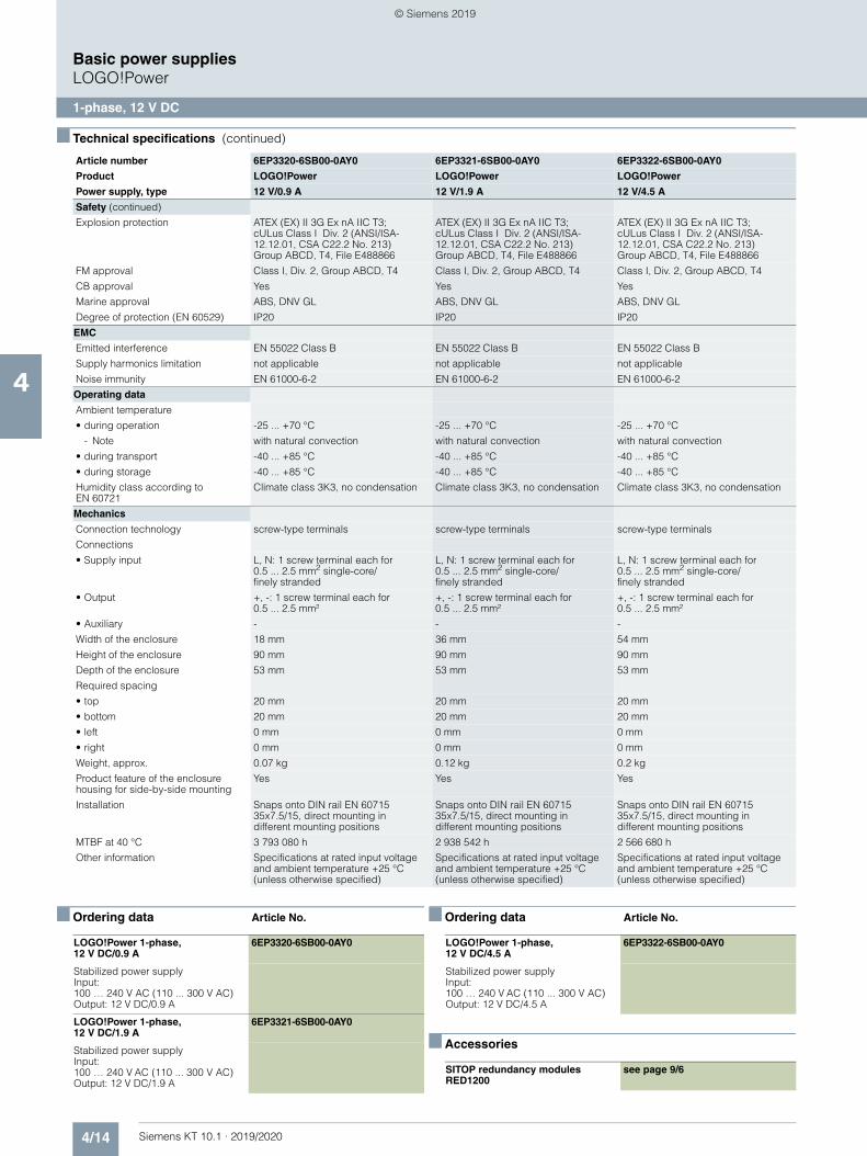
4/14 Siemens KT 10.1 · 2019/2020
4
■ Technical specifications (continued)
Basic power suppliesLOGO!Power
1-phase, 12 V DC
■ Ordering data Article No. ■ Ordering data Article No.
■ Accessories
Safety (continued)
Explosion protection ATEX (EX) II 3G Ex nA IIC T3; cULus Class I Div. 2 (ANSI/ISA-12.12.01, CSA C22.2 No. 213) Group ABCD, T4, File E488866
ATEX (EX) II 3G Ex nA IIC T3; cULus Class I Div. 2 (ANSI/ISA-12.12.01, CSA C22.2 No. 213) Group ABCD, T4, File E488866
ATEX (EX) II 3G Ex nA IIC T3; cULus Class I Div. 2 (ANSI/ISA-12.12.01, CSA C22.2 No. 213) Group ABCD, T4, File E488866
FM approval Class I, Div. 2, Group ABCD, T4 Class I, Div. 2, Group ABCD, T4 Class I, Div. 2, Group ABCD, T4
CB approval Yes Yes Yes
Marine approval ABS, DNV GL ABS, DNV GL ABS, DNV GL
Degree of protection (EN 60529) IP20 IP20 IP20
EMC
Emitted interference EN 55022 Class B EN 55022 Class B EN 55022 Class B
Supply harmonics limitation not applicable not applicable not applicable
Noise immunity EN 61000-6-2 EN 61000-6-2 EN 61000-6-2
Operating data
Ambient temperature
• during operation -25 ... +70 °C -25 ... +70 °C -25 ... +70 °C
- Note with natural convection with natural convection with natural convection
• during transport -40 ... +85 °C -40 ... +85 °C -40 ... +85 °C
• during storage -40 ... +85 °C -40 ... +85 °C -40 ... +85 °C
Humidity class according to EN 60721
Climate class 3K3, no condensation Climate class 3K3, no condensation Climate class 3K3, no condensation
Mechanics
Connection technology screw-type terminals screw-type terminals screw-type terminals
Connections
• Supply input L, N: 1 screw terminal each for 0.5 ... 2.5 mm2 single-core/finely stranded
L, N: 1 screw terminal each for 0.5 ... 2.5 mm2 single-core/finely stranded
L, N: 1 screw terminal each for 0.5 ... 2.5 mm2 single-core/finely stranded
• Output +, -: 1 screw terminal each for 0.5 ... 2.5 mm²
+, -: 1 screw terminal each for 0.5 ... 2.5 mm²
+, -: 1 screw terminal each for 0.5 ... 2.5 mm²
• Auxiliary - - -
Width of the enclosure 18 mm 36 mm 54 mm
Height of the enclosure 90 mm 90 mm 90 mm
Depth of the enclosure 53 mm 53 mm 53 mm
Required spacing
• top 20 mm 20 mm 20 mm
• bottom 20 mm 20 mm 20 mm
• left 0 mm 0 mm 0 mm
• right 0 mm 0 mm 0 mm
Weight, approx. 0.07 kg 0.12 kg 0.2 kg
Product feature of the enclosure housing for side-by-side mounting
Yes Yes Yes
Installation Snaps onto DIN rail EN 60715 35x7.5/15, direct mounting in different mounting positions
Snaps onto DIN rail EN 60715 35x7.5/15, direct mounting in different mounting positions
Snaps onto DIN rail EN 60715 35x7.5/15, direct mounting in different mounting positions
MTBF at 40 °C 3 793 080 h 2 938 542 h 2 566 680 h
Other information Specifications at rated input voltage and ambient temperature +25 °C (unless otherwise specified)
Specifications at rated input voltage and ambient temperature +25 °C (unless otherwise specified)
Specifications at rated input voltage and ambient temperature +25 °C (unless otherwise specified)
Article number 6EP3320-6SB00-0AY0 6EP3321-6SB00-0AY0 6EP3322-6SB00-0AY0
Product LOGO!Power LOGO!Power LOGO!Power
Power supply, type 12 V/0.9 A 12 V/1.9 A 12 V/4.5 A
LOGO!Power 1-phase, 12 V DC/0.9 A
6EP3320-6SB00-0AY0
Stabilized power supplyInput: 100 … 240 V AC (110 ... 300 V AC)Output: 12 V DC/0.9 A
LOGO!Power 1-phase, 12 V DC/1.9 A
6EP3321-6SB00-0AY0
Stabilized power supplyInput: 100 … 240 V AC (110 ... 300 V AC)Output: 12 V DC/1.9 A
LOGO!Power 1-phase, 12 V DC/4.5 A
6EP3322-6SB00-0AY0
Stabilized power supplyInput: 100 … 240 V AC (110 ... 300 V AC)Output: 12 V DC/4.5 A
SITOP redundancy modules RED1200
see page 9/6
© Siemens 2019

4/15Siemens KT 10.1 · 2019/2020
4
Basic power suppliesLOGO!Power
1-phase, 15 V DC
■ Overview
Thanks to its stepped profile design, the LOGO!Power product family is ideally suited for low installation depths, such as in miniature distribution boards. The stabilized power supplies with a wide range input of 100 … 240 V AC (85 … 264 V) and 110 ... 300 V DC are available with an output voltage of 15 V in two performance classes. The high level of efficiency across the entire load range as well as the low no-load losses result in lower overall energy consumption. Greater convenience when commissioning and servicing thanks to the integrated current monitor. The extended temperature range from -25 °C to +70 °C enables a host of additional applications.
Main product highlights• 15 V DC / 1.9 A and 4.0 A• Narrow unit with 36 mm or 54 mm width and overall depth of
53 mm in LOGO! design• Flexible mounting: Standard rail or wall mounting in a range of
installation positions• Higher energy efficiency: over the entire load range as well as
no-load power losses of < 0.3 W• Integrated current monitor: Actual output current
measurement directly at the power supply unit• Global use: Operating temperature range from -25 °C to
+70 °C as well as international certifications such as UL, CSA, FM or ATEX
■ Technical specifications
Article number 6EP3321-6SB10-0AY0 6EP3322-6SB10-0AY0
Product LOGO!Power LOGO!Power
Power supply, type 15 V/1.9 A 15 V/4 A
Input
Input 1-phase AC or DC 1-phase AC or DC
Rated voltage value Vin rated 100 ... 240 V 100 ... 240 V
Voltage range AC 85 ... 264 V 85 ... 264 V
Input voltage
• at DC 110 ... 300 V 110 ... 300 V
Wide-range input Yes Yes
Overvoltage resistance 300 V AC for 1 s 300 V AC for 1 s
Mains buffering at Iout rated, min. 40 ms; at Vin = 187 V 40 ms; at Vin = 187 V
Rated line frequency 1 50 Hz 50 Hz
Rated line frequency 2 60 Hz 60 Hz
Rated line range 47 ... 63 Hz 47 ... 63 Hz
Input current
• at rated input voltage 120 V 0.63 A 1.24 A
• at rated input voltage 230 V 0.33 A 0.68 A
Switch-on current limiting (+25 °C), max.
25 A 55 A
I²t, max. 0.8 A²·s 3 A²·s
Built-in incoming fuse internal internal
Protection in the mains power input (IEC 898)
Recommended miniature circuit breaker: from 6 A characteristic B or from 2 A characteristic C
Recommended miniature circuit breaker: from 10 A characteristic B or from 6 A characteristic C
© Siemens 2019
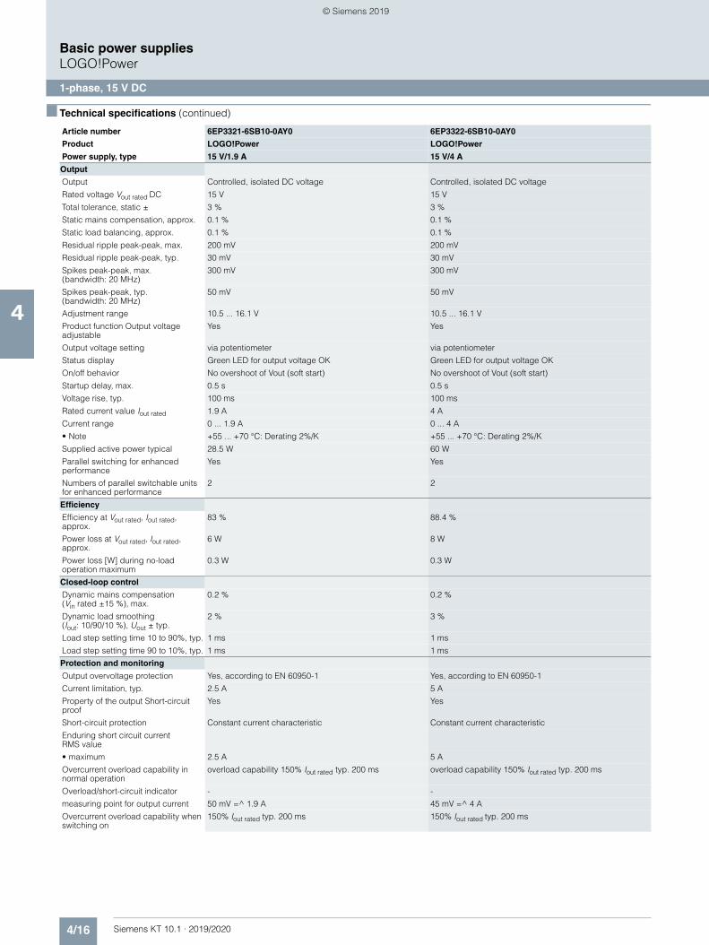
4/16 Siemens KT 10.1 · 2019/2020
4
■ Technical specifications (continued)
Basic power suppliesLOGO!Power
1-phase, 15 V DC
Output
Output Controlled, isolated DC voltage Controlled, isolated DC voltage
Rated voltage Vout rated DC 15 V 15 V
Total tolerance, static ± 3 % 3 %
Static mains compensation, approx. 0.1 % 0.1 %
Static load balancing, approx. 0.1 % 0.1 %
Residual ripple peak-peak, max. 200 mV 200 mV
Residual ripple peak-peak, typ. 30 mV 30 mV
Spikes peak-peak, max. (bandwidth: 20 MHz)
300 mV 300 mV
Spikes peak-peak, typ. (bandwidth: 20 MHz)
50 mV 50 mV
Adjustment range 10.5 ... 16.1 V 10.5 ... 16.1 V
Product function Output voltage adjustable
Yes Yes
Output voltage setting via potentiometer via potentiometer
Status display Green LED for output voltage OK Green LED for output voltage OK
On/off behavior No overshoot of Vout (soft start) No overshoot of Vout (soft start)
Startup delay, max. 0.5 s 0.5 s
Voltage rise, typ. 100 ms 100 ms
Rated current value Iout rated 1.9 A 4 A
Current range 0 ... 1.9 A 0 ... 4 A
• Note +55 ... +70 °C: Derating 2%/K +55 ... +70 °C: Derating 2%/K
Supplied active power typical 28.5 W 60 W
Parallel switching for enhanced performance
Yes Yes
Numbers of parallel switchable units for enhanced performance
2 2
Efficiency
Efficiency at Vout rated, Iout rated, approx.
83 % 88.4 %
Power loss at Vout rated, Iout rated, approx.
6 W 8 W
Power loss [W] during no-load operation maximum
0.3 W 0.3 W
Closed-loop control
Dynamic mains compensation (Vin rated ±15 %), max.
0.2 % 0.2 %
Dynamic load smoothing (Iout: 10/90/10 %), Uout ± typ.
2 % 3 %
Load step setting time 10 to 90%, typ. 1 ms 1 ms
Load step setting time 90 to 10%, typ. 1 ms 1 ms
Protection and monitoring
Output overvoltage protection Yes, according to EN 60950-1 Yes, according to EN 60950-1
Current limitation, typ. 2.5 A 5 A
Property of the output Short-circuit proof
Yes Yes
Short-circuit protection Constant current characteristic Constant current characteristic
Enduring short circuit current RMS value
• maximum 2.5 A 5 A
Overcurrent overload capability in normal operation
overload capability 150% Iout rated typ. 200 ms overload capability 150% Iout rated typ. 200 ms
Overload/short-circuit indicator - -
measuring point for output current 50 mV =^ 1.9 A 45 mV =^ 4 A
Overcurrent overload capability when switching on
150% Iout rated typ. 200 ms 150% Iout rated typ. 200 ms
Article number 6EP3321-6SB10-0AY0 6EP3322-6SB10-0AY0
Product LOGO!Power LOGO!Power
Power supply, type 15 V/1.9 A 15 V/4 A
© Siemens 2019
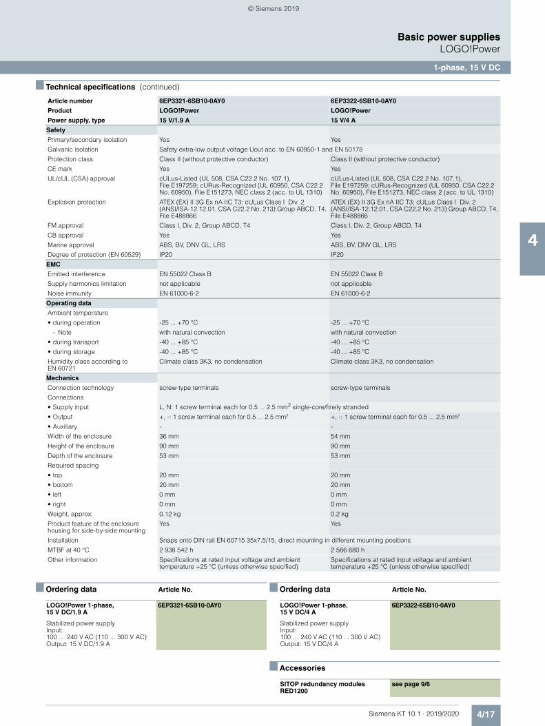
4/17Siemens KT 10.1 · 2019/2020
4
■ Technical specifications (continued)
Basic power suppliesLOGO!Power
1-phase, 15 V DC
■ Ordering data Article No. ■ Ordering data Article No.
■ Accessories
Safety
Primary/secondary isolation Yes Yes
Galvanic isolation Safety extra-low output voltage Uout acc. to EN 60950-1 and EN 50178
Protection class Class II (without protective conductor) Class II (without protective conductor)
CE mark Yes Yes
UL/cUL (CSA) approval cULus-Listed (UL 508, CSA C22.2 No. 107.1), File E197259; cURus-Recognized (UL 60950, CSA C22.2 No. 60950), File E151273, NEC class 2 (acc. to UL 1310)
cULus-Listed (UL 508, CSA C22.2 No. 107.1), File E197259; cURus-Recognized (UL 60950, CSA C22.2 No. 60950), File E151273, NEC class 2 (acc. to UL 1310)
Explosion protection ATEX (EX) II 3G Ex nA IIC T3; cULus Class I Div. 2 (ANSI/ISA-12.12.01, CSA C22.2 No. 213) Group ABCD, T4, File E488866
ATEX (EX) II 3G Ex nA IIC T3; cULus Class I Div. 2 (ANSI/ISA-12.12.01, CSA C22.2 No. 213) Group ABCD, T4, File E488866
FM approval Class I, Div. 2, Group ABCD, T4 Class I, Div. 2, Group ABCD, T4
CB approval Yes Yes
Marine approval ABS, BV, DNV GL, LRS ABS, BV, DNV GL, LRS
Degree of protection (EN 60529) IP20 IP20
EMC
Emitted interference EN 55022 Class B EN 55022 Class B
Supply harmonics limitation not applicable not applicable
Noise immunity EN 61000-6-2 EN 61000-6-2
Operating data
Ambient temperature
• during operation -25 ... +70 °C -25 ... +70 °C
- Note with natural convection with natural convection
• during transport -40 ... +85 °C -40 ... +85 °C
• during storage -40 ... +85 °C -40 ... +85 °C
Humidity class according to EN 60721
Climate class 3K3, no condensation Climate class 3K3, no condensation
Mechanics
Connection technology screw-type terminals screw-type terminals
Connections
• Supply input L, N: 1 screw terminal each for 0.5 ... 2.5 mm2 single-core/finely stranded
• Output +, -: 1 screw terminal each for 0.5 ... 2.5 mm² +, -: 1 screw terminal each for 0.5 ... 2.5 mm²
• Auxiliary - -
Width of the enclosure 36 mm 54 mm
Height of the enclosure 90 mm 90 mm
Depth of the enclosure 53 mm 53 mm
Required spacing
• top 20 mm 20 mm
• bottom 20 mm 20 mm
• left 0 mm 0 mm
• right 0 mm 0 mm
Weight, approx. 0.12 kg 0.2 kg
Product feature of the enclosure housing for side-by-side mounting
Yes Yes
Installation Snaps onto DIN rail EN 60715 35x7.5/15, direct mounting in different mounting positions
MTBF at 40 °C 2 938 542 h 2 566 680 h
Other information Specifications at rated input voltage and ambient temperature +25 °C (unless otherwise specified)
Specifications at rated input voltage and ambient temperature +25 °C (unless otherwise specified)
Article number 6EP3321-6SB10-0AY0 6EP3322-6SB10-0AY0
Product LOGO!Power LOGO!Power
Power supply, type 15 V/1.9 A 15 V/4 A
LOGO!Power 1-phase, 15 V DC/1.9 A
6EP3321-6SB10-0AY0
Stabilized power supplyInput: 100 … 240 V AC (110 ... 300 V AC)Output: 15 V DC/1.9 A
LOGO!Power 1-phase, 15 V DC/4 A
6EP3322-6SB10-0AY0
Stabilized power supplyInput: 100 … 240 V AC (110 ... 300 V AC)Output: 15 V DC/4 A
SITOP redundancy modules RED1200
see page 9/6
© Siemens 2019
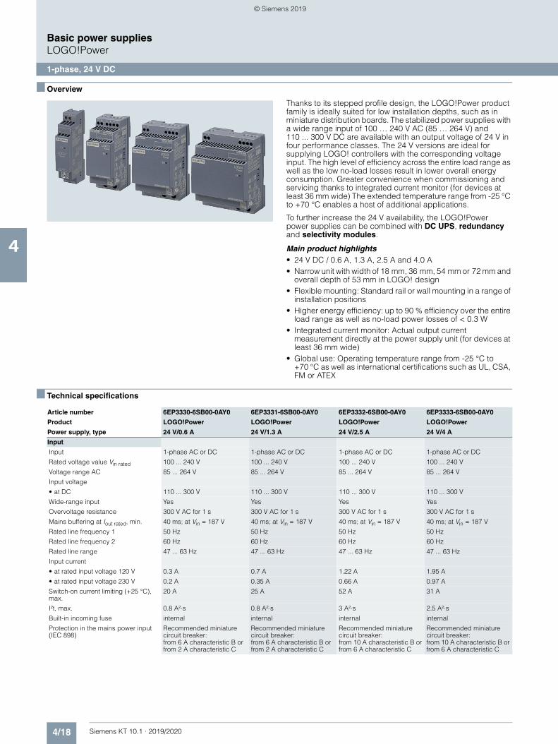
4/18 Siemens KT 10.1 · 2019/2020
4
Basic power suppliesLOGO!Power
1-phase, 24 V DC
■ Overview
Thanks to its stepped profile design, the LOGO!Power product family is ideally suited for low installation depths, such as in miniature distribution boards. The stabilized power supplies with a wide range input of 100 … 240 V AC (85 … 264 V) and 110 ... 300 V DC are available with an output voltage of 24 V in four performance classes. The 24 V versions are ideal for supplying LOGO! controllers with the corresponding voltage input. The high level of efficiency across the entire load range as well as the low no-load losses result in lower overall energy consumption. Greater convenience when commissioning and servicing thanks to integrated current monitor (for devices at least 36 mm wide) The extended temperature range from -25 °C to +70 °C enables a host of additional applications.
To further increase the 24 V availability, the LOGO!Power power supplies can be combined with DC UPS, redundancy and selectivity modules.
Main product highlights• 24 V DC / 0.6 A, 1.3 A, 2.5 A and 4.0 A• Narrow unit with width of 18 mm, 36 mm, 54 mm or 72 mm and
overall depth of 53 mm in LOGO! design• Flexible mounting: Standard rail or wall mounting in a range of
installation positions• Higher energy efficiency: up to 90 % efficiency over the entire
load range as well as no-load power losses of < 0.3 W• Integrated current monitor: Actual output current
measurement directly at the power supply unit (for devices at least 36 mm wide)
• Global use: Operating temperature range from -25 °C to +70 °C as well as international certifications such as UL, CSA, FM or ATEX
■ Technical specifications
Article number 6EP3330-6SB00-0AY0 6EP3331-6SB00-0AY0 6EP3332-6SB00-0AY0 6EP3333-6SB00-0AY0
Product LOGO!Power LOGO!Power LOGO!Power LOGO!Power
Power supply, type 24 V/0.6 A 24 V/1.3 A 24 V/2.5 A 24 V/4 A
Input
Input 1-phase AC or DC 1-phase AC or DC 1-phase AC or DC 1-phase AC or DC
Rated voltage value Vin rated 100 ... 240 V 100 ... 240 V 100 ... 240 V 100 ... 240 V
Voltage range AC 85 ... 264 V 85 ... 264 V 85 ... 264 V 85 ... 264 V
Input voltage
• at DC 110 ... 300 V 110 ... 300 V 110 ... 300 V 110 ... 300 V
Wide-range input Yes Yes Yes Yes
Overvoltage resistance 300 V AC for 1 s 300 V AC for 1 s 300 V AC for 1 s 300 V AC for 1 s
Mains buffering at Iout rated, min. 40 ms; at Vin = 187 V 40 ms; at Vin = 187 V 40 ms; at Vin = 187 V 40 ms; at Vin = 187 V
Rated line frequency 1 50 Hz 50 Hz 50 Hz 50 Hz
Rated line frequency 2 60 Hz 60 Hz 60 Hz 60 Hz
Rated line range 47 ... 63 Hz 47 ... 63 Hz 47 ... 63 Hz 47 ... 63 Hz
Input current
• at rated input voltage 120 V 0.3 A 0.7 A 1.22 A 1.95 A
• at rated input voltage 230 V 0.2 A 0.35 A 0.66 A 0.97 A
Switch-on current limiting (+25 °C), max.
20 A 25 A 52 A 31 A
I²t, max. 0.8 A²·s 0.8 A²·s 3 A²·s 2.5 A²·s
Built-in incoming fuse internal internal internal internal
Protection in the mains power input (IEC 898)
Recommended miniature circuit breaker: from 6 A characteristic B or from 2 A characteristic C
Recommended miniature circuit breaker: from 6 A characteristic B or from 2 A characteristic C
Recommended miniature circuit breaker: from 10 A characteristic B or from 6 A characteristic C
Recommended miniature circuit breaker: from 10 A characteristic B or from 6 A characteristic C
© Siemens 2019
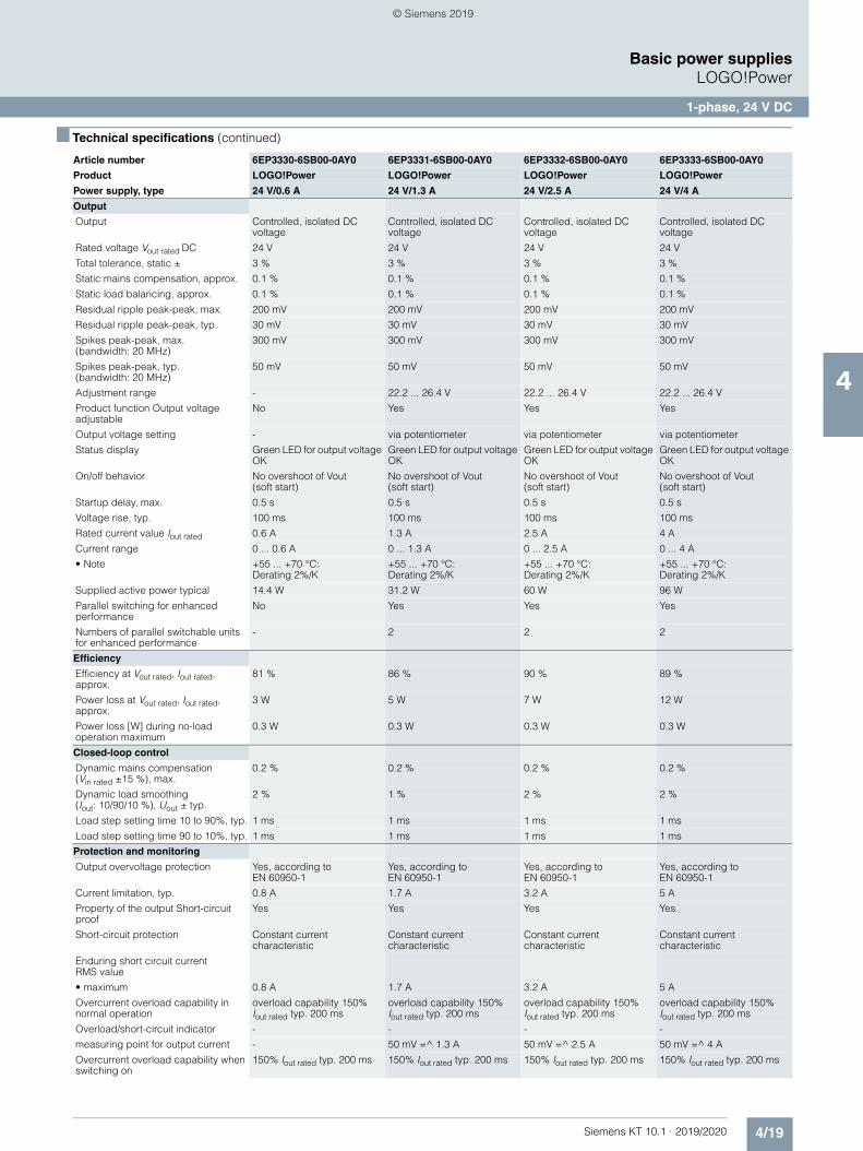
4/19Siemens KT 10.1 · 2019/2020
4
■ Technical specifications (continued)
Basic power suppliesLOGO!Power
1-phase, 24 V DC
Output
Output Controlled, isolated DC voltage
Controlled, isolated DC voltage
Controlled, isolated DC voltage
Controlled, isolated DC voltage
Rated voltage Vout rated DC 24 V 24 V 24 V 24 V
Total tolerance, static ± 3 % 3 % 3 % 3 %
Static mains compensation, approx. 0.1 % 0.1 % 0.1 % 0.1 %
Static load balancing, approx. 0.1 % 0.1 % 0.1 % 0.1 %
Residual ripple peak-peak, max. 200 mV 200 mV 200 mV 200 mV
Residual ripple peak-peak, typ. 30 mV 30 mV 30 mV 30 mV
Spikes peak-peak, max. (bandwidth: 20 MHz)
300 mV 300 mV 300 mV 300 mV
Spikes peak-peak, typ. (bandwidth: 20 MHz)
50 mV 50 mV 50 mV 50 mV
Adjustment range - 22.2 ... 26.4 V 22.2 ... 26.4 V 22.2 ... 26.4 V
Product function Output voltage adjustable
No Yes Yes Yes
Output voltage setting - via potentiometer via potentiometer via potentiometer
Status display Green LED for output voltage OK
Green LED for output voltage OK
Green LED for output voltage OK
Green LED for output voltage OK
On/off behavior No overshoot of Vout (soft start)
No overshoot of Vout (soft start)
No overshoot of Vout (soft start)
No overshoot of Vout (soft start)
Startup delay, max. 0.5 s 0.5 s 0.5 s 0.5 s
Voltage rise, typ. 100 ms 100 ms 100 ms 100 ms
Rated current value Iout rated 0.6 A 1.3 A 2.5 A 4 A
Current range 0 ... 0.6 A 0 ... 1.3 A 0 ... 2.5 A 0 ... 4 A
• Note +55 ... +70 °C: Derating 2%/K
+55 ... +70 °C: Derating 2%/K
+55 ... +70 °C: Derating 2%/K
+55 ... +70 °C: Derating 2%/K
Supplied active power typical 14.4 W 31.2 W 60 W 96 W
Parallel switching for enhanced performance
No Yes Yes Yes
Numbers of parallel switchable units for enhanced performance
- 2 2 2
Efficiency
Efficiency at Vout rated, Iout rated, approx.
81 % 86 % 90 % 89 %
Power loss at Vout rated, Iout rated, approx.
3 W 5 W 7 W 12 W
Power loss [W] during no-load operation maximum
0.3 W 0.3 W 0.3 W 0.3 W
Closed-loop control
Dynamic mains compensation (Vin rated ±15 %), max.
0.2 % 0.2 % 0.2 % 0.2 %
Dynamic load smoothing (Iout: 10/90/10 %), Uout ± typ.
2 % 1 % 2 % 2 %
Load step setting time 10 to 90%, typ. 1 ms 1 ms 1 ms 1 ms
Load step setting time 90 to 10%, typ. 1 ms 1 ms 1 ms 1 ms
Protection and monitoring
Output overvoltage protection Yes, according to EN 60950-1
Yes, according to EN 60950-1
Yes, according to EN 60950-1
Yes, according to EN 60950-1
Current limitation, typ. 0.8 A 1.7 A 3.2 A 5 A
Property of the output Short-circuit proof
Yes Yes Yes Yes
Short-circuit protection Constant current characteristic
Constant current characteristic
Constant current characteristic
Constant current characteristic
Enduring short circuit current RMS value
• maximum 0.8 A 1.7 A 3.2 A 5 A
Overcurrent overload capability in normal operation
overload capability 150% Iout rated typ. 200 ms
overload capability 150% Iout rated typ. 200 ms
overload capability 150% Iout rated typ. 200 ms
overload capability 150% Iout rated typ. 200 ms
Overload/short-circuit indicator - - - -
measuring point for output current - 50 mV =^ 1.3 A 50 mV =^ 2.5 A 50 mV =^ 4 A
Overcurrent overload capability when switching on
150% Iout rated typ. 200 ms 150% Iout rated typ. 200 ms 150% Iout rated typ. 200 ms 150% Iout rated typ. 200 ms
Article number 6EP3330-6SB00-0AY0 6EP3331-6SB00-0AY0 6EP3332-6SB00-0AY0 6EP3333-6SB00-0AY0
Product LOGO!Power LOGO!Power LOGO!Power LOGO!Power
Power supply, type 24 V/0.6 A 24 V/1.3 A 24 V/2.5 A 24 V/4 A
© Siemens 2019
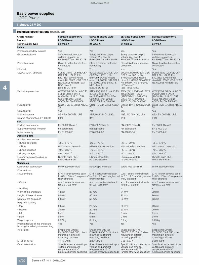
4/20 Siemens KT 10.1 · 2019/2020
4
■ Technical specifications (continued)
Basic power suppliesLOGO!Power
1-phase, 24 V DC
Safety
Primary/secondary isolation Yes Yes Yes Yes
Galvanic isolation Safety extra-low output voltage Uout acc. to EN 60950-1 and EN 50178
Safety extra-low output voltage Uout acc. to EN 60950-1 and EN 50178
Safety extra-low output voltage Uout acc. to EN 60950-1 and EN 50178
Safety extra-low output voltage Uout acc. to EN 60950-1 and EN 50178
Protection class Class II (without protective conductor)
Class II (without protective conductor)
Class II (without protective conductor)
Class II (without protective conductor)
CE mark Yes Yes Yes Yes
UL/cUL (CSA) approval cULus-Listed (UL 508, CSA C22.2 No. 107.1), File E197259; cURus-Recog-nized (UL 60950, CSA C22.2 No. 60950), File E151273, NEC class 2 (acc. to UL 1310)
cULus-Listed (UL 508, CSA C22.2 No. 107.1), File E197259; cURus-Recog-nized (UL 60950, CSA C22.2 No. 60950), File E151273, NEC class 2 (acc. to UL 1310)
cULus-Listed (UL 508, CSA C22.2 No. 107.1), File E197259; cURus-Recog-nized (UL 60950, CSA C22.2 No. 60950), File E151273, NEC class 2 (acc. to UL 1310)
cULus-listed (UL 508, CSA C22.2 No. 107.1), File E197259; cURus-recog-nized (UL 60950, CSA C22.2 No. 60950), File E151273
Explosion protection ATEX (EX) II 3G Ex nA IIC T3; cULus Class I Div. 2 (ANSI/ISA-12.12.01, CSA C22.2 No. 213) Group ABCD, T4, File E488866
ATEX (EX) II 3G Ex nA IIC T3; cULus Class I Div. 2 (ANSI/ISA-12.12.01, CSA C22.2 No. 213) Group ABCD, T4, File E488866
ATEX (EX) II 3G Ex nA IIC T3; cULus Class I Div. 2 (ANSI/ISA-12.12.01, CSA C22.2 No. 213) Group ABCD, T4, File E488866
ATEX (EX) II 3G Ex nA IIC T3; cULus Class I Div. 2 (ANSI/ISA-12.12.01, CSA C22.2 No. 213) Group ABCD, T4, File E488866
FM approval Class I, Div. 2, Group ABCD, T4
Class I, Div. 2, Group ABCD, T4
Class I, Div. 2, Group ABCD, T4
Class I, Div. 2, Group ABCD, T4
CB approval Yes Yes Yes Yes
Marine approval ABS, BV, DNV GL, LRS ABS, BV, DNV GL, LRS ABS, BV, DNV GL, LRS ABS, BV, DNV GL, LRS
Degree of protection (EN 60529) IP20 IP20 IP20 IP20
EMC
Emitted interference EN 55022 Class B EN 55022 Class B EN 55022 Class B EN 55022 Class B
Supply harmonics limitation not applicable not applicable not applicable EN 61000-3-2
Noise immunity EN 61000-6-2 EN 61000-6-2 EN 61000-6-2 EN 61000-6-2
Operating data
Ambient temperature
• during operation -25 ... +70 °C -25 ... +70 °C -25 ... +70 °C -25 ... +70 °C
- Note with natural convection with natural convection with natural convection with natural convection
• during transport -40 ... +85 °C -40 ... +85 °C -40 ... +85 °C -40 ... +85 °C
• during storage -40 ... +85 °C -40 ... +85 °C -40 ... +85 °C -40 ... +85 °C
Humidity class according to EN 60721
Climate class 3K3, no condensation
Climate class 3K3, no condensation
Climate class 3K3, no condensation
Climate class 3K3, no condensation
Mechanics
Connection technology screw-type terminals screw-type terminals screw-type terminals screw-type terminals
Connections
• Supply input L, N: 1 screw terminal each for 0.5 ... 2.5 mm2 single-core/finely stranded
L, N: 1 screw terminal each for 0.5 ... 2.5 mm2 single-core/finely stranded
L, N: 1 screw terminal each for 0.5 ... 2.5 mm2 single-core/finely stranded
L, N: 1 screw terminal each for 0.5 ... 2.5 mm2 single-core/finely stranded
• Output +, -: 1 screw terminal each for 0.5 ... 2.5 mm²
+, -: 1 screw terminal each for 0.5 ... 2.5 mm²
+, -: 1 screw terminal each for 0.5 ... 2.5 mm²
+, -: 1 screw terminal each for 0.5 ... 2.5 mm²
• Auxiliary - - - -
Width of the enclosure 18 mm 36 mm 54 mm 72 mm
Height of the enclosure 90 mm 90 mm 90 mm 90 mm
Depth of the enclosure 53 mm 53 mm 53 mm 53 mm
Required spacing
• top 20 mm 20 mm 20 mm 20 mm
• bottom 20 mm 20 mm 20 mm 20 mm
• left 0 mm 0 mm 0 mm 0 mm
• right 0 mm 0 mm 0 mm 0 mm
Weight, approx. 0.07 kg 0.12 kg 0.2 kg 0.29 kg
Product feature of the enclosure housing for side-by-side mounting
Yes Yes Yes Yes
Installation Snaps onto DIN rail EN 60715 35x7.5/15, direct mounting in different mounting positions
Snaps onto DIN rail EN 60715 35x7.5/15, direct mounting in different mounting positions
Snaps onto DIN rail EN 60715 35x7.5/15, direct mounting in different mounting positions
Snaps onto DIN rail EN 60715 35x7.5/15, direct mounting in different mounting positions
MTBF at 40 °C 4 415 040 h 3 094 996 h 2 864 520 h 2 391 480 h
Other information Specifications at rated input voltage and ambient temperature +25 °C (unless otherwise specified)
Specifications at rated input voltage and ambient temperature +25 °C (unless otherwise specified)
Specifications at rated input voltage and ambient temperature +25 °C (unless otherwise specified)
Specifications at rated input voltage and ambient temperature +25 °C (unless otherwise specified)
Article number 6EP3330-6SB00-0AY0 6EP3331-6SB00-0AY0 6EP3332-6SB00-0AY0 6EP3333-6SB00-0AY0
Product LOGO!Power LOGO!Power LOGO!Power LOGO!Power
Power supply, type 24 V/0.6 A 24 V/1.3 A 24 V/2.5 A 24 V/4 A
© Siemens 2019
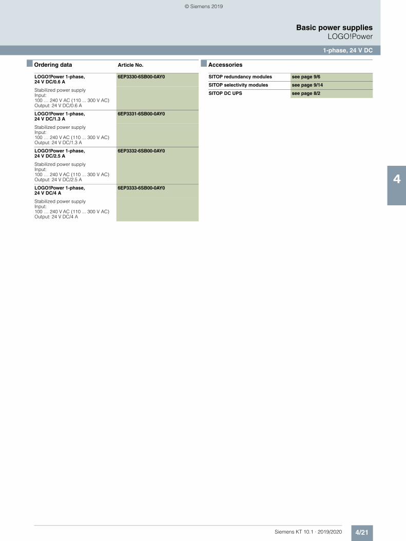
4/21Siemens KT 10.1 · 2019/2020
4
Basic power suppliesLOGO!Power
1-phase, 24 V DC
■ Ordering data Article No. ■ Accessories
LOGO!Power 1-phase, 24 V DC/0.6 A
6EP3330-6SB00-0AY0
Stabilized power supplyInput: 100 … 240 V AC (110 ... 300 V AC)Output: 24 V DC/0.6 A
LOGO!Power 1-phase, 24 V DC/1.3 A
6EP3331-6SB00-0AY0
Stabilized power supplyInput: 100 … 240 V AC (110 ... 300 V AC)Output: 24 V DC/1.3 A
LOGO!Power 1-phase, 24 V DC/2.5 A
6EP3332-6SB00-0AY0
Stabilized power supplyInput: 100 … 240 V AC (110 ... 300 V AC)Output: 24 V DC/2.5 A
LOGO!Power 1-phase, 24 V DC/4 A
6EP3333-6SB00-0AY0
Stabilized power supplyInput: 100 … 240 V AC (110 ... 300 V AC)Output: 24 V DC/4 A
SITOP redundancy modules see page 9/6
SITOP selectivity modules see page 9/14
SITOP DC UPS see page 8/2
© Siemens 2019
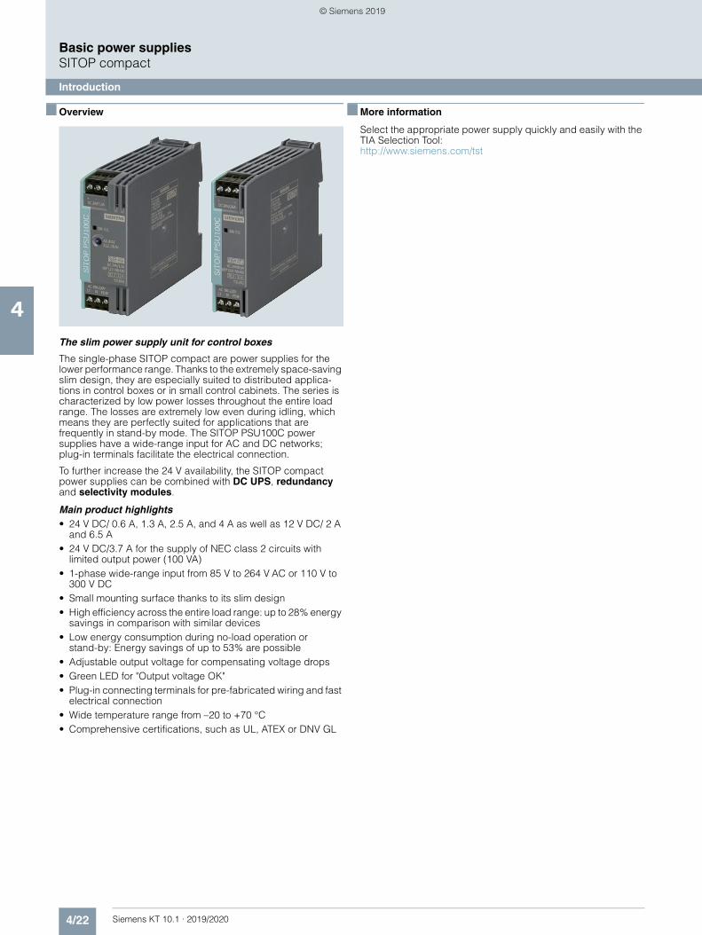
4/22 Siemens KT 10.1 · 2019/2020
4
Basic power suppliesSITOP compact
Introduction
■ Overview
The slim power supply unit for control boxes
The single-phase SITOP compact are power supplies for the lower performance range. Thanks to the extremely space-saving slim design, they are especially suited to distributed applica-tions in control boxes or in small control cabinets. The series is characterized by low power losses throughout the entire load range. The losses are extremely low even during idling, which means they are perfectly suited for applications that are frequently in stand-by mode. The SITOP PSU100C power supplies have a wide-range input for AC and DC networks; plug-in terminals facilitate the electrical connection.
To further increase the 24 V availability, the SITOP compact power supplies can be combined with DC UPS, redundancy and selectivity modules.
Main product highlights• 24 V DC/ 0.6 A, 1.3 A, 2.5 A, and 4 A as well as 12 V DC/ 2 A
and 6.5 A• 24 V DC/3.7 A for the supply of NEC class 2 circuits with
limited output power (100 VA)• 1-phase wide-range input from 85 V to 264 V AC or 110 V to
300 V DC• Small mounting surface thanks to its slim design• High efficiency across the entire load range: up to 28% energy
savings in comparison with similar devices• Low energy consumption during no-load operation or
stand-by: Energy savings of up to 53% are possible• Adjustable output voltage for compensating voltage drops• Green LED for "Output voltage OK"• Plug-in connecting terminals for pre-fabricated wiring and fast
electrical connection• Wide temperature range from –20 to +70 °C• Comprehensive certifications, such as UL, ATEX or DNV GL
■ More information
Select the appropriate power supply quickly and easily with the TIA Selection Tool:http://www.siemens.com/tst
© Siemens 2019
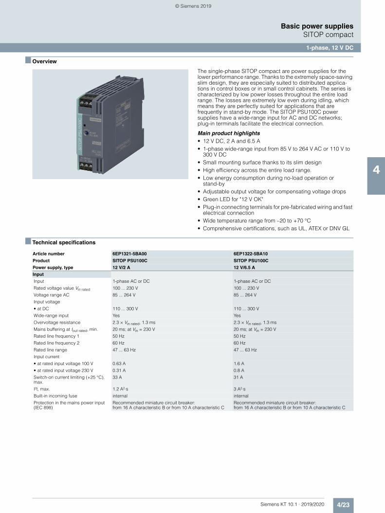
4/23Siemens KT 10.1 · 2019/2020
4
Basic power suppliesSITOP compact
1-phase, 12 V DC
■ Overview
The single-phase SITOP compact are power supplies for the lower performance range. Thanks to the extremely space-saving slim design, they are especially suited to distributed applica-tions in control boxes or in small control cabinets. The series is characterized by low power losses throughout the entire load range. The losses are extremely low even during idling, which means they are perfectly suited for applications that are frequently in stand-by mode. The SITOP PSU100C power supplies have a wide-range input for AC and DC networks; plug-in terminals facilitate the electrical connection.
Main product highlights• 12 V DC, 2 A and 6.5 A• 1-phase wide-range input from 85 V to 264 V AC or 110 V to
300 V DC• Small mounting surface thanks to its slim design• High efficiency across the entire load range.• Low energy consumption during no-load operation or
stand-by• Adjustable output voltage for compensating voltage drops• Green LED for "12 V OK"• Plug-in connecting terminals for pre-fabricated wiring and fast
electrical connection• Wide temperature range from –20 to +70 °C• Comprehensive certifications, such as UL, ATEX or DNV GL
■ Technical specifications
Article number 6EP1321-5BA00 6EP1322-5BA10
Product SITOP PSU100C SITOP PSU100C
Power supply, type 12 V/2 A 12 V/6.5 A
Input
Input 1-phase AC or DC 1-phase AC or DC
Rated voltage value Vin rated 100 ... 230 V 100 ... 230 V
Voltage range AC 85 ... 264 V 85 ... 264 V
Input voltage
• at DC 110 ... 300 V 110 ... 300 V
Wide-range input Yes Yes
Overvoltage resistance 2.3 × Vin rated, 1.3 ms 2.3 × Vin rated, 1.3 ms
Mains buffering at Iout rated, min. 20 ms; at Vin = 230 V 20 ms; at Vin = 230 V
Rated line frequency 1 50 Hz 50 Hz
Rated line frequency 2 60 Hz 60 Hz
Rated line range 47 ... 63 Hz 47 ... 63 Hz
Input current
• at rated input voltage 100 V 0.63 A 1.6 A
• at rated input voltage 230 V 0.31 A 0.8 A
Switch-on current limiting (+25 °C), max.
33 A 31 A
I²t, max. 1.2 A²·s 3 A²·s
Built-in incoming fuse internal internal
Protection in the mains power input (IEC 898)
Recommended miniature circuit breaker: from 16 A characteristic B or from 10 A characteristic C
Recommended miniature circuit breaker: from 16 A characteristic B or from 10 A characteristic C
© Siemens 2019
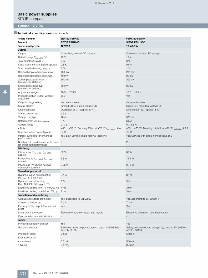
4/24 Siemens KT 10.1 · 2019/2020
4
■ Technical specifications (continued)
Basic power suppliesSITOP compact
1-phase, 12 V DC
Output
Output Controlled, isolated DC voltage Controlled, isolated DC voltage
Rated voltage Vout rated DC 12 V 12 V
Total tolerance, static ± 3 % 3 %
Static mains compensation, approx. 0.5 % 0.5 %
Static load balancing, approx. 1 % 1 %
Residual ripple peak-peak, max. 200 mV 200 mV
Residual ripple peak-peak, typ. 40 mV 80 mV
Spikes peak-peak, max. (bandwidth: 20 MHz)
300 mV 300 mV
Spikes peak-peak, typ. (bandwidth: 20 MHz)
50 mV 80 mV
Adjustment range 10.5 ... 12.9 V 10.5 ... 12.9 V
Product function Output voltage adjustable
Yes Yes
Output voltage setting via potentiometer via potentiometer
Status display Green LED for output voltage OK Green LED for output voltage OK
On/off behavior Overshoot of Vout approx. 5 % Overshoot of Vout approx. 1 %
Startup delay, max. 0.6 s 1 s
Voltage rise, typ. 10 ms 500 ms
Rated current value Iout rated 2 A 6.5 A
Current range 0 ... 2 A 0 ... 6.5 A
• Note +60 ... +70 °C: Derating 2%/K; at +70 °C Iout rated 1.6 A +55 ... +70 °C: Derating 1.6%/K; at +70 °C Iout rated 4.9 A
Supplied active power typical 24 W 78 W
Parallel switching for enhanced performance
Yes; Start-up with single nominal load only Yes; Start-up with single nominal load only
Numbers of parallel switchable units for enhanced performance
2 2
Efficiency
Efficiency at Vout rated, Iout rated, approx.
82 % 86 %
Power loss at Vout rated, Iout rated, approx.
5.8 W 12.5 W
Power loss [W] during no-load operation maximum
0.75 W 0.75 W
Closed-loop control
Dynamic mains compensation (Vin rated ±15 %), max.
0.1 % 0.1 %
Dynamic load smoothing (Iout: 10/90/10 %), Uout ± typ.
3 % 3 %
Load step setting time 10 to 90%, typ. 4 ms 3 ms
Load step setting time 90 to 10%, typ. 3 ms 3 ms
Protection and monitoring
Output overvoltage protection Yes, according to EN 60950-1 Yes, according to EN 60950-1
Current limitation, typ. 2.4 A 7.2 A
Property of the output Short-circuit proof
Yes Yes
Short-circuit protection Electronic shutdown, automatic restart Electronic shutdown, automatic restart
Overload/short-circuit indicator - -
Safety
Primary/secondary isolation Yes Yes
Galvanic isolation Safety extra-low output voltage Uout acc. to EN 60950-1 and EN 50178
Safety extra-low output voltage Uout acc. to EN 60950-1 and EN 50178
Protection class Class I Class I
Leakage current
• maximum 3.5 mA 3.5 mA
• typical 0.4 mA 0.4 mA
Article number 6EP1321-5BA00 6EP1322-5BA10
Product SITOP PSU100C SITOP PSU100C
Power supply, type 12 V/2 A 12 V/6.5 A
© Siemens 2019
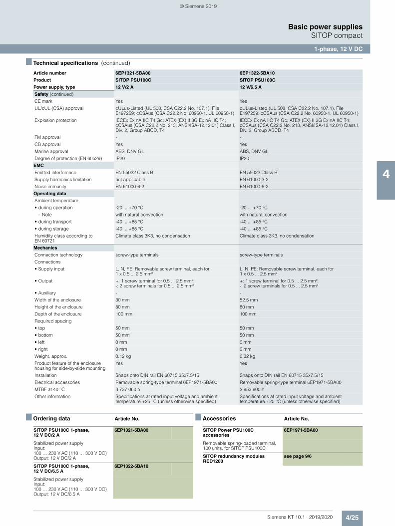
4/25Siemens KT 10.1 · 2019/2020
4
■ Technical specifications (continued)
Basic power suppliesSITOP compact
1-phase, 12 V DC
■ Ordering data Article No. ■ Accessories Article No.
Safety (continued)
CE mark Yes Yes
UL/cUL (CSA) approval cULus-Listed (UL 508, CSA C22.2 No. 107.1), File E197259; cCSAus (CSA C22.2 No. 60950-1, UL 60950-1)
cULus-Listed (UL 508, CSA C22.2 No. 107.1), File E197259; cCSAus (CSA C22.2 No. 60950-1, UL 60950-1)
Explosion protection IECEx Ex nA IIC T4 Gc; ATEX (EX) II 3G Ex nA IIC T4; cCSAus (CSA C22.2 No. 213, ANSI/ISA-12.12.01) Class I, Div. 2, Group ABCD, T4
IECEx Ex nA IIC T4 Gc; ATEX (EX) II 3G Ex nA IIC T4; cCSAus (CSA C22.2 No. 213, ANSI/ISA-12.12.01) Class I, Div. 2, Group ABCD, T4
FM approval - -
CB approval Yes Yes
Marine approval ABS, DNV GL ABS, DNV GL
Degree of protection (EN 60529) IP20 IP20
EMC
Emitted interference EN 55022 Class B EN 55022 Class B
Supply harmonics limitation not applicable EN 61000-3-2
Noise immunity EN 61000-6-2 EN 61000-6-2
Operating data
Ambient temperature
• during operation -20 ... +70 °C -20 ... +70 °C
- Note with natural convection with natural convection
• during transport -40 ... +85 °C -40 ... +85 °C
• during storage -40 ... +85 °C -40 ... +85 °C
Humidity class according to EN 60721
Climate class 3K3, no condensation Climate class 3K3, no condensation
Mechanics
Connection technology screw-type terminals screw-type terminals
Connections
• Supply input L, N, PE: Removable screw terminal, each for 1 x 0.5 ... 2.5 mm²
L, N, PE: Removable screw terminal, each for 1 x 0.5 ... 2.5 mm²
• Output +: 1 screw terminal for 0.5 ... 2.5 mm²; -: 2 screw terminals for 0.5 ... 2.5 mm²
+: 1 screw terminal for 0.5 ... 2.5 mm²;-: 2 screw terminals for 0.5 ... 2.5 mm²
• Auxiliary - -
Width of the enclosure 30 mm 52.5 mm
Height of the enclosure 80 mm 80 mm
Depth of the enclosure 100 mm 100 mm
Required spacing
• top 50 mm 50 mm
• bottom 50 mm 50 mm
• left 0 mm 0 mm
• right 0 mm 0 mm
Weight, approx. 0.12 kg 0.32 kg
Product feature of the enclosure housing for side-by-side mounting
Yes Yes
Installation Snaps onto DIN rail EN 60715 35x7.5/15 Snaps onto DIN rail EN 60715 35x7.5/15
Electrical accessories Removable spring-type terminal 6EP1971-5BA00 Removable spring-type terminal 6EP1971-5BA00
MTBF at 40 °C 3 737 060 h 2 853 800 h
Other information Specifications at rated input voltage and ambient temperature +25 °C (unless otherwise specified)
Specifications at rated input voltage and ambient temperature +25 °C (unless otherwise specified)
Article number 6EP1321-5BA00 6EP1322-5BA10
Product SITOP PSU100C SITOP PSU100C
Power supply, type 12 V/2 A 12 V/6.5 A
SITOP PSU100C 1-phase, 12 V DC/2 A
6EP1321-5BA00
Stabilized power supply Input: 100 … 230 V AC (110 … 300 V DC) Output: 12 V DC/2 A
SITOP PSU100C 1-phase, 12 V DC/6.5 A
6EP1322-5BA10
Stabilized power supplyInput: 100 … 230 V AC (110 … 300 V DC) Output: 12 V DC/6.5 A
SITOP Power PSU100C accessories
6EP1971-5BA00
Removable spring-loaded terminal, 100 units, for SITOP PSU100C
SITOP redundancy modules RED1200
see page 9/6
© Siemens 2019
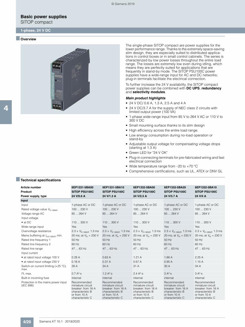
4/26 Siemens KT 10.1 · 2019/2020
4
Basic power suppliesSITOP compact
1-phase, 24 V DC
■ Overview
The single-phase SITOP compact are power supplies for the lower performance range. Thanks to the extremely space-saving slim design, they are especially suited to distributed applica-tions in control boxes or in small control cabinets. The series is characterized by low power losses throughout the entire load range. The losses are extremely low even during idling, which means they are perfectly suited for applications that are frequently in stand-by mode. The SITOP PSU100C power supplies have a wide-range input for AC and DC networks; plug-in terminals facilitate the electrical connection.
To further increase the 24 V availability, the SITOP compact power supplies can be combined with DC UPS, redundancy and selectivity modules.
Main product highlights• 24 V DC/ 0.6 A, 1.3 A, 2.5 A and 4 A• 24 V DC/3.7 A for the supply of NEC class 2 circuits with
limited output power (100 VA)• 1-phase wide-range input from 85 V to 264 V AC or 110 V to
300 V DC• Small mounting surface thanks to its slim design• High efficiency across the entire load range.• Low energy consumption during no-load operation or
stand-by• Adjustable output voltage for compensating voltage drops
(starting at 1.3 A)• Green LED for "24 V OK"• Plug-in connecting terminals for pre-fabricated wiring and fast
electrical connection• Wide temperature range from –20 to +70 °C• Comprehensive certifications, such as UL, ATEX or DNV GL
■ Technical specifications
Article number 6EP1331-5BA00 6EP1331-5BA10 6EP1332-5BA00 6EP1332-5BA20 6EP1332-5BA10
Product SITOP PSU100C SITOP PSU100C SITOP PSU100C SITOP PSU100C SITOP PSU100C
Power supply, type 24 V/0.6 A 24 V/1.3 A 24 V/2.5 A 24 V/3.7 A 24 V/4 A
Input
Input 1-phase AC or DC 1-phase AC or DC 1-phase AC or DC 1-phase AC or DC 1-phase AC or DC
Rated voltage value Vin rated 100 ... 230 V 100 ... 230 V 100 ... 230 V 100 ... 230 V 100 ... 230 V
Voltage range AC 85 ... 264 V 85 ... 264 V 85 ... 264 V 85 ... 264 V 85 ... 264 V
Input voltage
• at DC 110 ... 300 V 110 ... 300 V 110 ... 300 V 110 ... 300 V 110 ... 300 V
Wide-range input Yes Yes Yes Yes Yes
Overvoltage resistance 2.3 × Vin rated, 1.3 ms 2.3 × Vin rated, 1.3 ms 2.3 × Vin rated, 1.3 ms 2.3 × Vin rated, 1.3 ms 2.3 × Vin rated, 1.3 ms
Mains buffering at Iout rated, min. 20 ms; at Vin = 230 V 20 ms; at Vin = 230 V 20 ms; at Vin = 230 V 20 ms; at Vin = 230 V 20 ms; at Vin = 230 V
Rated line frequency 1 50 Hz 50 Hz 50 Hz 50 Hz 50 Hz
Rated line frequency 2 60 Hz 60 Hz 60 Hz 60 Hz 60 Hz
Rated line range 47 ... 63 Hz 47 ... 63 Hz 47 ... 63 Hz 47 ... 63 Hz 47 ... 63 Hz
Input current
• at rated input voltage 100 V 0.28 A 0.63 A 1.21 A 1.88 A 2.25 A
• at rated input voltage 230 V 0.18 A 0.31 A 0.67 A 0.95 A 1.15 A
Switch-on current limiting (+25 °C), max.
28 A 34 A 31 A 30 A 34 A
I²t, max. 0.7 A²·s 1.2 A²·s 2.4 A²·s 3 A²·s 3 A²·s
Built-in incoming fuse internal internal internal internal internal
Protection in the mains power input (IEC 898)
Recommended miniature circuit breaker: from 16 A characteristic B or from 10 A characteristic C
Recommended miniature circuit breaker: from 16 A characteristic B or from 10 A characteristic C
Recommended miniature circuit breaker: from 16 A characteristic B or from 10 A characteristic C
Recommended miniature circuit breaker: from 16 A characteristic B or from 10 A characteristic C
Recommended miniature circuit breaker: from 16 A characteristic B or from 10 A characteristic C
© Siemens 2019
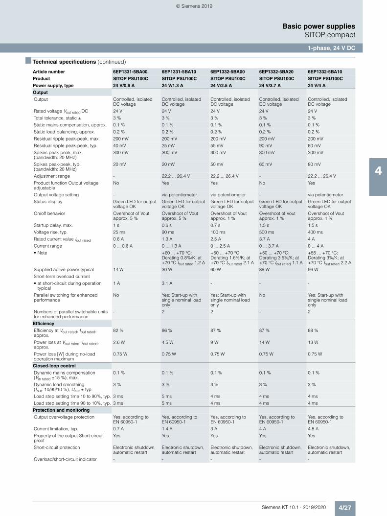
4/27Siemens KT 10.1 · 2019/2020
4
■ Technical specifications (continued)
Basic power suppliesSITOP compact
1-phase, 24 V DC
Output
Output Controlled, isolated DC voltage
Controlled, isolated DC voltage
Controlled, isolated DC voltage
Controlled, isolated DC voltage
Controlled, isolated DC voltage
Rated voltage Vout rated DC 24 V 24 V 24 V 24 V 24 V
Total tolerance, static ± 3 % 3 % 3 % 3 % 3 %
Static mains compensation, approx. 0.1 % 0.1 % 0.1 % 0.1 % 0.1 %
Static load balancing, approx. 0.2 % 0.2 % 0.2 % 0.2 % 0.2 %
Residual ripple peak-peak, max. 200 mV 200 mV 200 mV 200 mV 200 mV
Residual ripple peak-peak, typ. 40 mV 25 mV 55 mV 90 mV 80 mV
Spikes peak-peak, max. (bandwidth: 20 MHz)
300 mV 300 mV 300 mV 300 mV 300 mV
Spikes peak-peak, typ. (bandwidth: 20 MHz)
20 mV 20 mV 50 mV 60 mV 80 mV
Adjustment range - 22.2 ... 26.4 V 22.2 ... 26.4 V - 22.2 ... 26.4 V
Product function Output voltage adjustable
No Yes Yes No Yes
Output voltage setting - via potentiometer via potentiometer - via potentiometer
Status display Green LED for output voltage OK
Green LED for output voltage OK
Green LED for output voltage OK
Green LED for output voltage OK
Green LED for output voltage OK
On/off behavior Overshoot of Vout approx. 5 %
Overshoot of Vout approx. 5 %
Overshoot of Vout approx. 1 %
Overshoot of Vout approx. 1 %
Overshoot of Vout approx. 1 %
Startup delay, max. 1 s 0.6 s 0.7 s 1.5 s 1.5 s
Voltage rise, typ. 25 ms 90 ms 100 ms 500 ms 400 ms
Rated current value Iout rated 0.6 A 1.3 A 2.5 A 3.7 A 4 A
Current range 0 ... 0.6 A 0 ... 1.3 A 0 ... 2.5 A 0 ... 3.7 A 0 ... 4 A
• Note +60 ... +70 °C: Derating 0.8%/K; at +70 °C Iout rated 1.2 A
+60 ... +70 °C: Derating 1.6%/K; at +70 °C Iout rated 2.1 A
+50 ... +70 °C: Derating 3.5%/K; at +70 °C Iout rated 1.1 A
+55 ... +70 °C: Derating 3%/K; at +70 °C Iout rated 2.2 A
Supplied active power typical 14 W 30 W 60 W 89 W 96 W
Short-term overload current
• at short-circuit during operation typical
1 A 3.1 A - - -
Parallel switching for enhanced performance
No Yes; Start-up with single nominal load only
Yes; Start-up with single nominal load only
No Yes; Start-up with single nominal load only
Numbers of parallel switchable units for enhanced performance
- 2 2 - 2
Efficiency
Efficiency at Vout rated, Iout rated, approx.
82 % 86 % 87 % 87 % 88 %
Power loss at Vout rated, Iout rated, approx.
2.6 W 4.5 W 9 W 14 W 13 W
Power loss [W] during no-load operation maximum
0.75 W 0.75 W 0.75 W 0.75 W 0.75 W
Closed-loop control
Dynamic mains compensation (Vin rated ±15 %), max.
0.1 % 0.1 % 0.1 % 0.1 % 0.1 %
Dynamic load smoothing (Iout: 10/90/10 %), Uout ± typ.
3 % 3 % 3 % 3 % 3 %
Load step setting time 10 to 90%, typ. 3 ms 5 ms 4 ms 4 ms 4 ms
Load step setting time 90 to 10%, typ. 3 ms 5 ms 4 ms 4 ms 4 ms
Protection and monitoring
Output overvoltage protection Yes, according to EN 60950-1
Yes, according to EN 60950-1
Yes, according to EN 60950-1
Yes, according to EN 60950-1
Yes, according to EN 60950-1
Current limitation, typ. 0.7 A 1.4 A 3 A 4 A 4.8 A
Property of the output Short-circuit proof
Yes Yes Yes Yes Yes
Short-circuit protection Electronic shutdown, automatic restart
Electronic shutdown, automatic restart
Electronic shutdown, automatic restart
Electronic shutdown, automatic restart
Electronic shutdown, automatic restart
Overload/short-circuit indicator - - - - -
Article number 6EP1331-5BA00 6EP1331-5BA10 6EP1332-5BA00 6EP1332-5BA20 6EP1332-5BA10
Product SITOP PSU100C SITOP PSU100C SITOP PSU100C SITOP PSU100C SITOP PSU100C
Power supply, type 24 V/0.6 A 24 V/1.3 A 24 V/2.5 A 24 V/3.7 A 24 V/4 A
© Siemens 2019
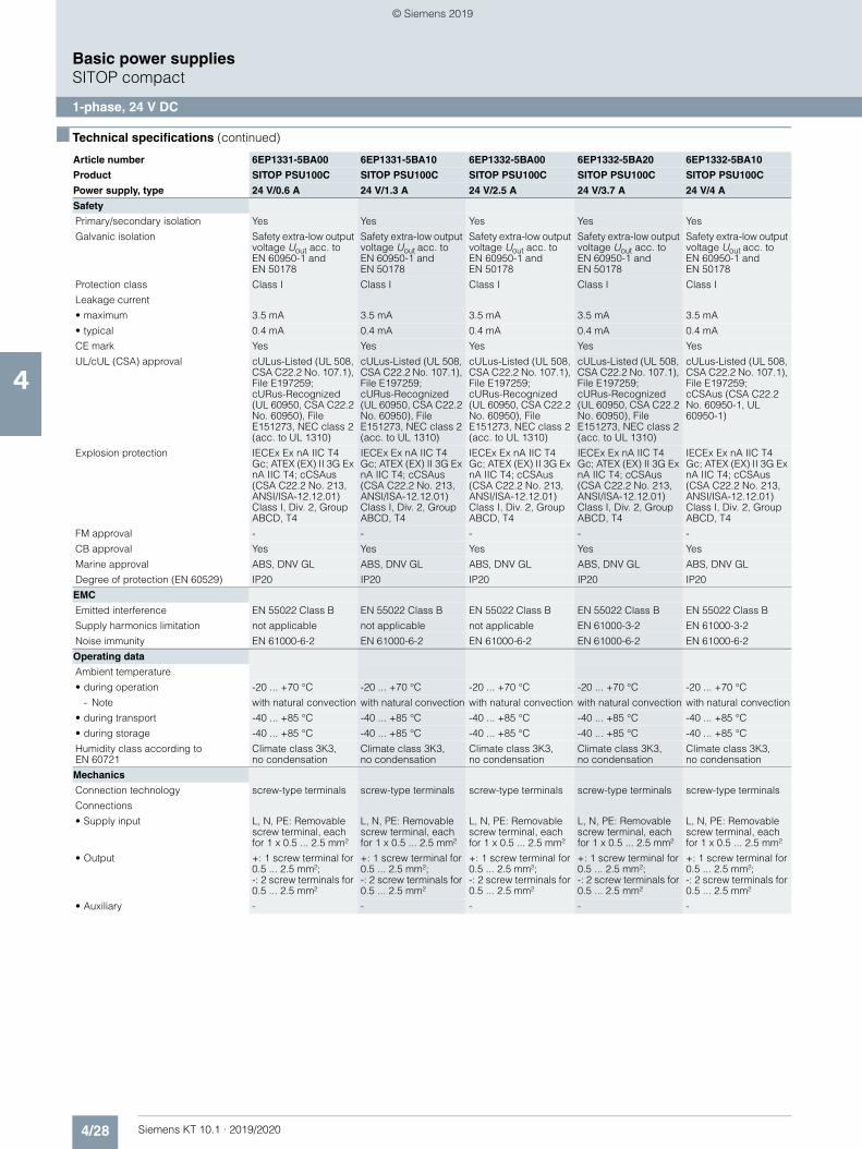
4/28 Siemens KT 10.1 · 2019/2020
4
■ Technical specifications (continued)
Basic power suppliesSITOP compact
1-phase, 24 V DC
Safety
Primary/secondary isolation Yes Yes Yes Yes Yes
Galvanic isolation Safety extra-low output voltage Uout acc. to EN 60950-1 and EN 50178
Safety extra-low output voltage Uout acc. to EN 60950-1 and EN 50178
Safety extra-low output voltage Uout acc. to EN 60950-1 and EN 50178
Safety extra-low output voltage Uout acc. to EN 60950-1 and EN 50178
Safety extra-low output voltage Uout acc. to EN 60950-1 and EN 50178
Protection class Class I Class I Class I Class I Class I
Leakage current
• maximum 3.5 mA 3.5 mA 3.5 mA 3.5 mA 3.5 mA
• typical 0.4 mA 0.4 mA 0.4 mA 0.4 mA 0.4 mA
CE mark Yes Yes Yes Yes Yes
UL/cUL (CSA) approval cULus-Listed (UL 508, CSA C22.2 No. 107.1), File E197259; cURus-Recognized (UL 60950, CSA C22.2 No. 60950), File E151273, NEC class 2 (acc. to UL 1310)
cULus-Listed (UL 508, CSA C22.2 No. 107.1), File E197259; cURus-Recognized (UL 60950, CSA C22.2 No. 60950), File E151273, NEC class 2 (acc. to UL 1310)
cULus-Listed (UL 508, CSA C22.2 No. 107.1), File E197259; cURus-Recognized (UL 60950, CSA C22.2 No. 60950), File E151273, NEC class 2 (acc. to UL 1310)
cULus-Listed (UL 508, CSA C22.2 No. 107.1), File E197259; cURus-Recognized (UL 60950, CSA C22.2 No. 60950), File E151273, NEC class 2 (acc. to UL 1310)
cULus-Listed (UL 508, CSA C22.2 No. 107.1), File E197259; cCSAus (CSA C22.2 No. 60950-1, UL 60950-1)
Explosion protection IECEx Ex nA IIC T4 Gc; ATEX (EX) II 3G Ex nA IIC T4; cCSAus (CSA C22.2 No. 213, ANSI/ISA-12.12.01) Class I, Div. 2, Group ABCD, T4
IECEx Ex nA IIC T4 Gc; ATEX (EX) II 3G Ex nA IIC T4; cCSAus (CSA C22.2 No. 213, ANSI/ISA-12.12.01) Class I, Div. 2, Group ABCD, T4
IECEx Ex nA IIC T4 Gc; ATEX (EX) II 3G Ex nA IIC T4; cCSAus (CSA C22.2 No. 213, ANSI/ISA-12.12.01) Class I, Div. 2, Group ABCD, T4
IECEx Ex nA IIC T4 Gc; ATEX (EX) II 3G Ex nA IIC T4; cCSAus (CSA C22.2 No. 213, ANSI/ISA-12.12.01) Class I, Div. 2, Group ABCD, T4
IECEx Ex nA IIC T4 Gc; ATEX (EX) II 3G Ex nA IIC T4; cCSAus (CSA C22.2 No. 213, ANSI/ISA-12.12.01) Class I, Div. 2, Group ABCD, T4
FM approval - - - - -
CB approval Yes Yes Yes Yes Yes
Marine approval ABS, DNV GL ABS, DNV GL ABS, DNV GL ABS, DNV GL ABS, DNV GL
Degree of protection (EN 60529) IP20 IP20 IP20 IP20 IP20
EMC
Emitted interference EN 55022 Class B EN 55022 Class B EN 55022 Class B EN 55022 Class B EN 55022 Class B
Supply harmonics limitation not applicable not applicable not applicable EN 61000-3-2 EN 61000-3-2
Noise immunity EN 61000-6-2 EN 61000-6-2 EN 61000-6-2 EN 61000-6-2 EN 61000-6-2
Operating data
Ambient temperature
• during operation -20 ... +70 °C -20 ... +70 °C -20 ... +70 °C -20 ... +70 °C -20 ... +70 °C
- Note with natural convection with natural convection with natural convection with natural convection with natural convection
• during transport -40 ... +85 °C -40 ... +85 °C -40 ... +85 °C -40 ... +85 °C -40 ... +85 °C
• during storage -40 ... +85 °C -40 ... +85 °C -40 ... +85 °C -40 ... +85 °C -40 ... +85 °C
Humidity class according to EN 60721
Climate class 3K3, no condensation
Climate class 3K3, no condensation
Climate class 3K3, no condensation
Climate class 3K3, no condensation
Climate class 3K3, no condensation
Mechanics
Connection technology screw-type terminals screw-type terminals screw-type terminals screw-type terminals screw-type terminals
Connections
• Supply input L, N, PE: Removable screw terminal, each for 1 x 0.5 ... 2.5 mm²
L, N, PE: Removable screw terminal, each for 1 x 0.5 ... 2.5 mm²
L, N, PE: Removable screw terminal, each for 1 x 0.5 ... 2.5 mm²
L, N, PE: Removable screw terminal, each for 1 x 0.5 ... 2.5 mm²
L, N, PE: Removable screw terminal, each for 1 x 0.5 ... 2.5 mm²
• Output +: 1 screw terminal for 0.5 ... 2.5 mm²; -: 2 screw terminals for 0.5 ... 2.5 mm²
+: 1 screw terminal for 0.5 ... 2.5 mm²; -: 2 screw terminals for 0.5 ... 2.5 mm²
+: 1 screw terminal for 0.5 ... 2.5 mm²; -: 2 screw terminals for 0.5 ... 2.5 mm²
+: 1 screw terminal for 0.5 ... 2.5 mm²; -: 2 screw terminals for 0.5 ... 2.5 mm²
+: 1 screw terminal for 0.5 ... 2.5 mm²; -: 2 screw terminals for 0.5 ... 2.5 mm²
• Auxiliary - - - - -
Article number 6EP1331-5BA00 6EP1331-5BA10 6EP1332-5BA00 6EP1332-5BA20 6EP1332-5BA10
Product SITOP PSU100C SITOP PSU100C SITOP PSU100C SITOP PSU100C SITOP PSU100C
Power supply, type 24 V/0.6 A 24 V/1.3 A 24 V/2.5 A 24 V/3.7 A 24 V/4 A
© Siemens 2019
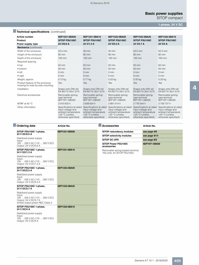
4/29Siemens KT 10.1 · 2019/2020
4
■ Technical specifications (continued)
Basic power suppliesSITOP compact
1-phase, 24 V DC
■ Ordering data Article No. ■ Accessories Article No.
Mechanics (continued)
Width of the enclosure 22.5 mm 30 mm 45 mm 52.5 mm 52.5 mm
Height of the enclosure 80 mm 80 mm 80 mm 80 mm 80 mm
Depth of the enclosure 100 mm 100 mm 100 mm 100 mm 100 mm
Required spacing
• top 50 mm 50 mm 50 mm 50 mm 50 mm
• bottom 50 mm 50 mm 50 mm 50 mm 50 mm
• left 0 mm 0 mm 0 mm 0 mm 0 mm
• right 0 mm 0 mm 0 mm 0 mm 0 mm
Weight, approx. 0.12 kg 0.17 kg 0.22 kg 0.32 kg 0.32 kg
Product feature of the enclosure housing for side-by-side mounting
Yes Yes Yes Yes Yes
Installation Snaps onto DIN rail EN 60715 35x7.5/15
Snaps onto DIN rail EN 60715 35x7.5/15
Snaps onto DIN rail EN 60715 35x7.5/15
Snaps onto DIN rail EN 60715 35x7.5/15
Snaps onto DIN rail EN 60715 35x7.5/15
Electrical accessories Removable spring-type terminal 6EP1971-5BA00
Removable spring-type terminal 6EP1971-5BA00
Removable spring-type terminal 6EP1971-5BA00
Removable spring-type terminal 6EP1971-5BA00
Removable spring-type terminal 6EP1971-5BA00
MTBF at 40 °C 3 910 833 h 3 838 624 h 2 881 014 h 2 776 544 h 2 726 727 h
Other information Specifications at rated input voltage and ambient temperature +25 °C (unless otherwise specified)
Specifications at rated input voltage and ambient temperature +25 °C (unless otherwise specified)
Specifications at rated input voltage and ambient temperature +25 °C (unless otherwise specified)
Specifications at rated input voltage and ambient temperature +25 °C (unless otherwise specified)
Specifications at rated input voltage and ambient temperature +25 °C (unless otherwise specified)
Article number 6EP1331-5BA00 6EP1331-5BA10 6EP1332-5BA00 6EP1332-5BA20 6EP1332-5BA10
Product SITOP PSU100C SITOP PSU100C SITOP PSU100C SITOP PSU100C SITOP PSU100C
Power supply, type 24 V/0.6 A 24 V/1.3 A 24 V/2.5 A 24 V/3.7 A 24 V/4 A
SITOP PSU100C 1-phase, 24 V DC/0.6 A
6EP1331-5BA00
Stabilized power supplyInput: 100 … 230 V AC (110 … 300 V DC) Output: 24 V DC/0.6 A
SITOP PSU100C 1-phase, 24 V DC/1.3 A
6EP1331-5BA10
Stabilized power supplyInput: 100 … 230 V AC (110 … 300 V DC) Output: 24 V DC/1.3 A
SITOP PSU100C 1-phase, 24 V DC/2.5 A
6EP1332-5BA00
Stabilized power supplyInput: 100 … 230 V AC (110 … 300 V DC) Output: 24 V DC/2.5 A
SITOP PSU100C 1-phase, 24 V DC/3.7 A
6EP1332-5BA20
Stabilized power supplyInput: 100 … 230 V AC (110 … 300 V DC) Output: 24 V DC/3.7 Alimited output power NEC Class 2
SITOP PSU100C 1-phase, 24 V DC/4 A
6EP1332-5BA10
Stabilized power supplyInput: 100 … 230 V AC (110 … 300 V DC) Output: 24 V DC/4 A
SITOP redundancy modules see page 9/6
SITOP selectivity modules see page 9/14
SITOP DC UPS see page 8/2
SITOP Power PSU100C accessories
6EP1971-5BA00
Removable spring-loaded terminal, 100 units, for SITOP PSU100C
© Siemens 2019

4/30 Siemens KT 10.1 · 2019/2020
4
Basic power supplies
Notes
© Siemens 2019
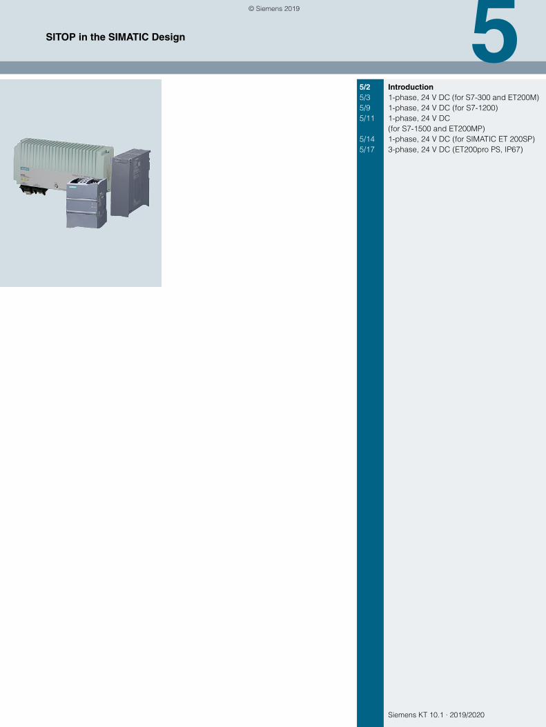
Siemens KT 10.1 · 2019/2020
55/2 Introduction5/3 1-phase, 24 V DC (for S7-300 and ET200M)5/9 1-phase, 24 V DC (for S7-1200)5/11 1-phase, 24 V DC
(for S7-1500 and ET200MP)5/14 1-phase, 24 V DC (for SIMATIC ET 200SP)5/17 3-phase, 24 V DC (ET200pro PS, IP67)
SITOP in the SIMATIC Design
© Siemens 2019
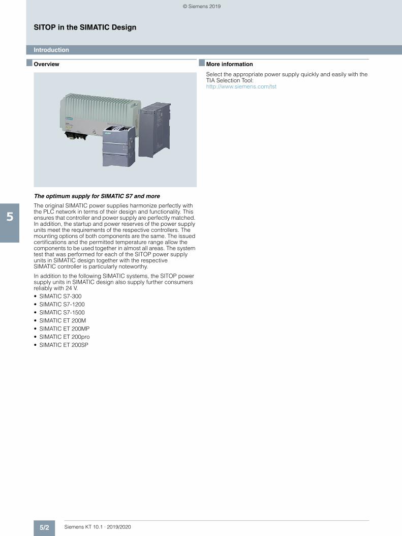
5/2 Siemens KT 10.1 · 2019/2020
5
SITOP in the SIMATIC Design
Introduction
■ Overview
The optimum supply for SIMATIC S7 and more
The original SIMATIC power supplies harmonize perfectly with the PLC network in terms of their design and functionality. This ensures that controller and power supply are perfectly matched. In addition, the startup and power reserves of the power supply units meet the requirements of the respective controllers. The mounting options of both components are the same. The issued certifications and the permitted temperature range allow the components to be used together in almost all areas. The system test that was performed for each of the SITOP power supply units in SIMATIC design together with the respective SIMATIC controller is particularly noteworthy.
In addition to the following SIMATIC systems, the SITOP power supply units in SIMATIC design also supply further consumers reliably with 24 V.• SIMATIC S7-300• SIMATIC S7-1200• SIMATIC S7-1500• SIMATIC ET 200M• SIMATIC ET 200MP• SIMATIC ET 200pro• SIMATIC ET 200SP
■ More information
Select the appropriate power supply quickly and easily with the TIA Selection Tool:http://www.siemens.com/tst
© Siemens 2019
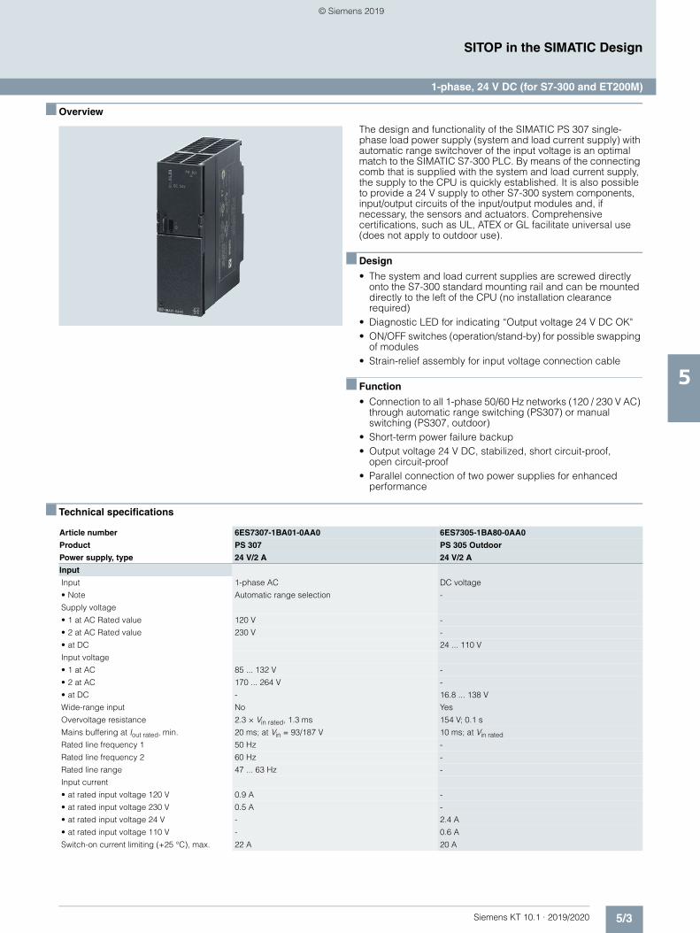
5/3Siemens KT 10.1 · 2019/2020
5
SITOP in the SIMATIC Design
1-phase, 24 V DC (for S7-300 and ET200M)
■ Overview
The design and functionality of the SIMATIC PS 307 single-phase load power supply (system and load current supply) with automatic range switchover of the input voltage is an optimal match to the SIMATIC S7-300 PLC. By means of the connecting comb that is supplied with the system and load current supply, the supply to the CPU is quickly established. It is also possible to provide a 24 V supply to other S7-300 system components, input/output circuits of the input/output modules and, if necessary, the sensors and actuators. Comprehensive certifications, such as UL, ATEX or GL facilitate universal use (does not apply to outdoor use).
■ Design
• The system and load current supplies are screwed directly onto the S7-300 standard mounting rail and can be mounted directly to the left of the CPU (no installation clearance required)
• Diagnostic LED for indicating “Output voltage 24 V DC OK"• ON/OFF switches (operation/stand-by) for possible swapping
of modules• Strain-relief assembly for input voltage connection cable
■ Function
• Connection to all 1-phase 50/60 Hz networks (120 / 230 V AC) through automatic range switching (PS307) or manual switching (PS307, outdoor)
• Short-term power failure backup• Output voltage 24 V DC, stabilized, short circuit-proof,
open circuit-proof• Parallel connection of two power supplies for enhanced
performance
■ Technical specifications
Article number 6ES7307-1BA01-0AA0 6ES7305-1BA80-0AA0
Product PS 307 PS 305 Outdoor
Power supply, type 24 V/2 A 24 V/2 A
Input
Input 1-phase AC DC voltage
• Note Automatic range selection -
Supply voltage
• 1 at AC Rated value 120 V -
• 2 at AC Rated value 230 V -
• at DC 24 ... 110 V
Input voltage
• 1 at AC 85 ... 132 V -
• 2 at AC 170 ... 264 V -
• at DC - 16.8 ... 138 V
Wide-range input No Yes
Overvoltage resistance 2.3 × Vin rated, 1.3 ms 154 V; 0.1 s
Mains buffering at Iout rated, min. 20 ms; at Vin = 93/187 V 10 ms; at Vin rated
Rated line frequency 1 50 Hz -
Rated line frequency 2 60 Hz -
Rated line range 47 ... 63 Hz -
Input current
• at rated input voltage 120 V 0.9 A -
• at rated input voltage 230 V 0.5 A -
• at rated input voltage 24 V - 2.4 A
• at rated input voltage 110 V - 0.6 A
Switch-on current limiting (+25 °C), max. 22 A 20 A
© Siemens 2019
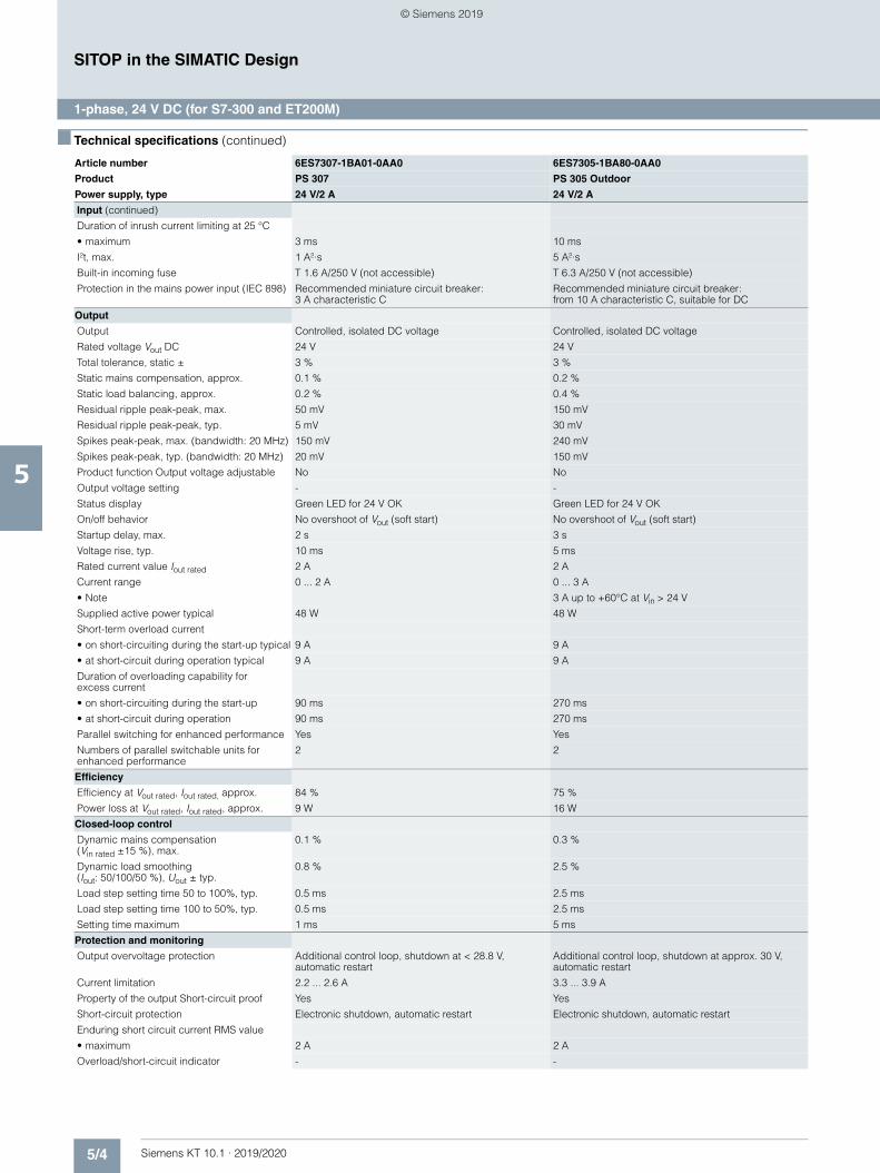
5/4 Siemens KT 10.1 · 2019/2020
5
■ Technical specifications (continued)
SITOP in the SIMATIC Design
1-phase, 24 V DC (for S7-300 and ET200M)
Input (continued)
Duration of inrush current limiting at 25 °C
• maximum 3 ms 10 ms
I²t, max. 1 A²·s 5 A²·s
Built-in incoming fuse T 1.6 A/250 V (not accessible) T 6.3 A/250 V (not accessible)
Protection in the mains power input (IEC 898) Recommended miniature circuit breaker: 3 A characteristic C
Recommended miniature circuit breaker: from 10 A characteristic C, suitable for DC
Output
Output Controlled, isolated DC voltage Controlled, isolated DC voltage
Rated voltage Vout DC 24 V 24 V
Total tolerance, static ± 3 % 3 %
Static mains compensation, approx. 0.1 % 0.2 %
Static load balancing, approx. 0.2 % 0.4 %
Residual ripple peak-peak, max. 50 mV 150 mV
Residual ripple peak-peak, typ. 5 mV 30 mV
Spikes peak-peak, max. (bandwidth: 20 MHz) 150 mV 240 mV
Spikes peak-peak, typ. (bandwidth: 20 MHz) 20 mV 150 mV
Product function Output voltage adjustable No No
Output voltage setting - -
Status display Green LED for 24 V OK Green LED for 24 V OK
On/off behavior No overshoot of Vout (soft start) No overshoot of Vout (soft start)
Startup delay, max. 2 s 3 s
Voltage rise, typ. 10 ms 5 ms
Rated current value Iout rated 2 A 2 A
Current range 0 ... 2 A 0 ... 3 A
• Note 3 A up to +60°C at Vin > 24 V
Supplied active power typical 48 W 48 W
Short-term overload current
• on short-circuiting during the start-up typical 9 A 9 A
• at short-circuit during operation typical 9 A 9 A
Duration of overloading capability for excess current
• on short-circuiting during the start-up 90 ms 270 ms
• at short-circuit during operation 90 ms 270 ms
Parallel switching for enhanced performance Yes Yes
Numbers of parallel switchable units for enhanced performance
2 2
Efficiency
Efficiency at Vout rated, Iout rated, approx. 84 % 75 %
Power loss at Vout rated, Iout rated, approx. 9 W 16 W
Closed-loop control
Dynamic mains compensation (Vin rated ±15 %), max.
0.1 % 0.3 %
Dynamic load smoothing (Iout: 50/100/50 %), Uout ± typ.
0.8 % 2.5 %
Load step setting time 50 to 100%, typ. 0.5 ms 2.5 ms
Load step setting time 100 to 50%, typ. 0.5 ms 2.5 ms
Setting time maximum 1 ms 5 ms
Protection and monitoring
Output overvoltage protection Additional control loop, shutdown at < 28.8 V, automatic restart
Additional control loop, shutdown at approx. 30 V, automatic restart
Current limitation 2.2 ... 2.6 A 3.3 ... 3.9 A
Property of the output Short-circuit proof Yes Yes
Short-circuit protection Electronic shutdown, automatic restart Electronic shutdown, automatic restart
Enduring short circuit current RMS value
• maximum 2 A 2 A
Overload/short-circuit indicator - -
Article number 6ES7307-1BA01-0AA0 6ES7305-1BA80-0AA0
Product PS 307 PS 305 Outdoor
Power supply, type 24 V/2 A 24 V/2 A
© Siemens 2019
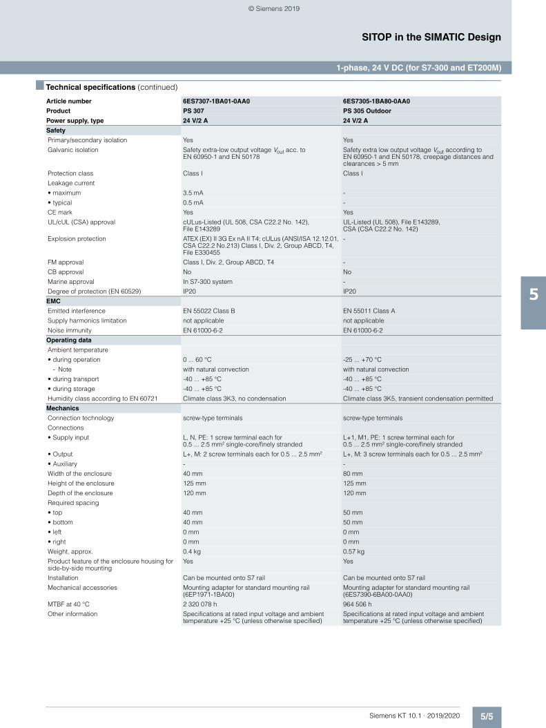
5/5Siemens KT 10.1 · 2019/2020
5
■ Technical specifications (continued)
SITOP in the SIMATIC Design
1-phase, 24 V DC (for S7-300 and ET200M)
Safety
Primary/secondary isolation Yes Yes
Galvanic isolation Safety extra-low output voltage Vout acc. to EN 60950-1 and EN 50178
Safety extra low output voltage Vout according to EN 60950-1 and EN 50178, creepage distances and clearances > 5 mm
Protection class Class I Class I
Leakage current
• maximum 3.5 mA -
• typical 0.5 mA -
CE mark Yes Yes
UL/cUL (CSA) approval cULus-Listed (UL 508, CSA C22.2 No. 142), File E143289
UL-Listed (UL 508), File E143289, CSA (CSA C22.2 No. 142)
Explosion protection ATEX (EX) II 3G Ex nA II T4; cULus (ANSI/ISA 12.12.01, CSA C22.2 No.213) Class I, Div. 2, Group ABCD, T4, File E330455
-
FM approval Class I, Div. 2, Group ABCD, T4 -
CB approval No No
Marine approval In S7-300 system -
Degree of protection (EN 60529) IP20 IP20
EMC
Emitted interference EN 55022 Class B EN 55011 Class A
Supply harmonics limitation not applicable not applicable
Noise immunity EN 61000-6-2 EN 61000-6-2
Operating data
Ambient temperature
• during operation 0 ... 60 °C -25 ... +70 °C
- Note with natural convection with natural convection
• during transport -40 ... +85 °C -40 ... +85 °C
• during storage -40 ... +85 °C -40 ... +85 °C
Humidity class according to EN 60721 Climate class 3K3, no condensation Climate class 3K5, transient condensation permitted
Mechanics
Connection technology screw-type terminals screw-type terminals
Connections
• Supply input L, N, PE: 1 screw terminal each for 0.5 ... 2.5 mm² single-core/finely stranded
L+1, M1, PE: 1 screw terminal each for 0.5 ... 2.5 mm² single-core/finely stranded
• Output L+, M: 2 screw terminals each for 0.5 ... 2.5 mm² L+, M: 3 screw terminals each for 0.5 ... 2.5 mm²
• Auxiliary - -
Width of the enclosure 40 mm 80 mm
Height of the enclosure 125 mm 125 mm
Depth of the enclosure 120 mm 120 mm
Required spacing
• top 40 mm 50 mm
• bottom 40 mm 50 mm
• left 0 mm 0 mm
• right 0 mm 0 mm
Weight, approx. 0.4 kg 0.57 kg
Product feature of the enclosure housing for side-by-side mounting
Yes Yes
Installation Can be mounted onto S7 rail Can be mounted onto S7 rail
Mechanical accessories Mounting adapter for standard mounting rail (6EP1971-1BA00)
Mounting adapter for standard mounting rail (6ES7390-6BA00-0AA0)
MTBF at 40 °C 2 320 078 h 964 506 h
Other information Specifications at rated input voltage and ambient temperature +25 °C (unless otherwise specified)
Specifications at rated input voltage and ambient temperature +25 °C (unless otherwise specified)
Article number 6ES7307-1BA01-0AA0 6ES7305-1BA80-0AA0
Product PS 307 PS 305 Outdoor
Power supply, type 24 V/2 A 24 V/2 A
© Siemens 2019
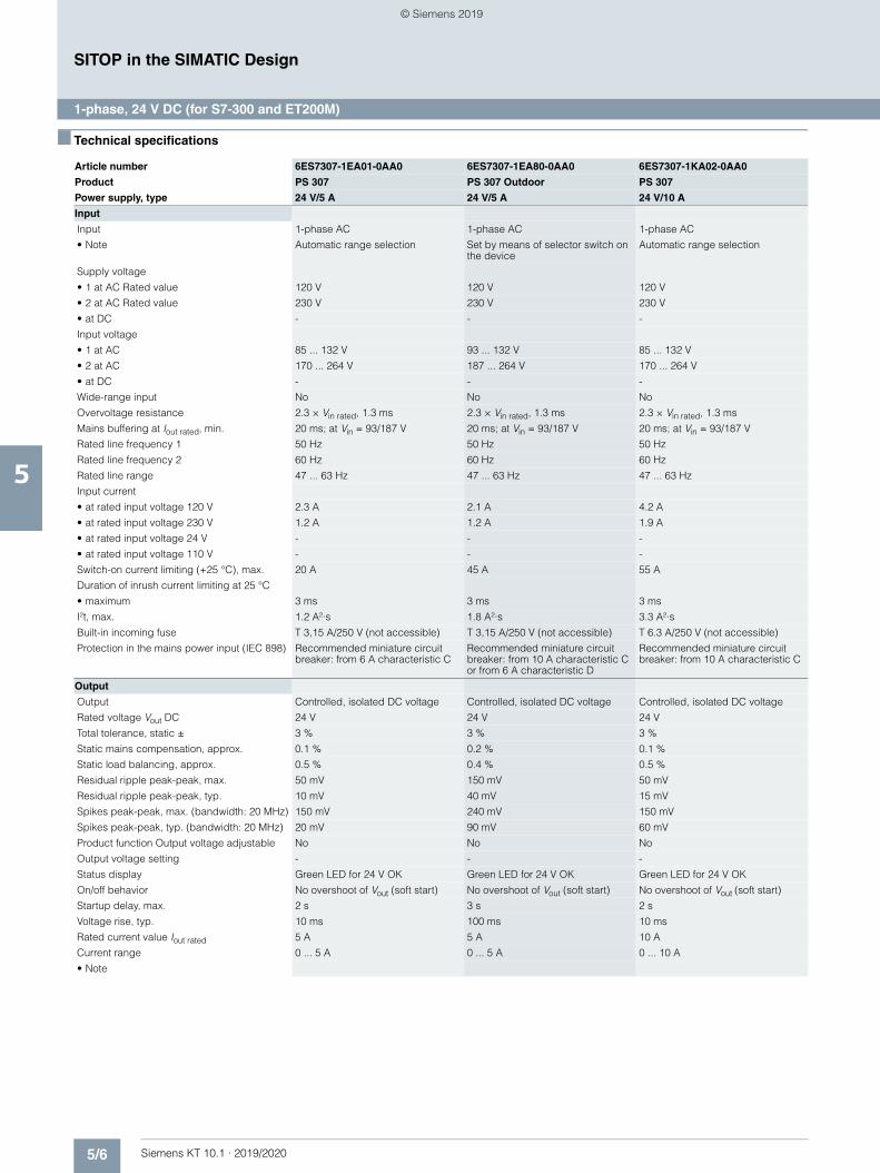
5/6 Siemens KT 10.1 · 2019/2020
5
SITOP in the SIMATIC Design
1-phase, 24 V DC (for S7-300 and ET200M)
■ Technical specifications
Article number 6ES7307-1EA01-0AA0 6ES7307-1EA80-0AA0 6ES7307-1KA02-0AA0
Product PS 307 PS 307 Outdoor PS 307
Power supply, type 24 V/5 A 24 V/5 A 24 V/10 A
Input
Input 1-phase AC 1-phase AC 1-phase AC
• Note Automatic range selection Set by means of selector switch on the device
Automatic range selection
Supply voltage
• 1 at AC Rated value 120 V 120 V 120 V
• 2 at AC Rated value 230 V 230 V 230 V
• at DC - - -
Input voltage
• 1 at AC 85 ... 132 V 93 ... 132 V 85 ... 132 V
• 2 at AC 170 ... 264 V 187 ... 264 V 170 ... 264 V
• at DC - - -
Wide-range input No No No
Overvoltage resistance 2.3 × Vin rated, 1.3 ms 2.3 × Vin rated, 1.3 ms 2.3 × Vin rated, 1.3 ms
Mains buffering at Iout rated, min. 20 ms; at Vin = 93/187 V 20 ms; at Vin = 93/187 V 20 ms; at Vin = 93/187 V
Rated line frequency 1 50 Hz 50 Hz 50 Hz
Rated line frequency 2 60 Hz 60 Hz 60 Hz
Rated line range 47 ... 63 Hz 47 ... 63 Hz 47 ... 63 Hz
Input current
• at rated input voltage 120 V 2.3 A 2.1 A 4.2 A
• at rated input voltage 230 V 1.2 A 1.2 A 1.9 A
• at rated input voltage 24 V - - -
• at rated input voltage 110 V - - -
Switch-on current limiting (+25 °C), max. 20 A 45 A 55 A
Duration of inrush current limiting at 25 °C
• maximum 3 ms 3 ms 3 ms
I²t, max. 1.2 A²·s 1.8 A²·s 3.3 A²·s
Built-in incoming fuse T 3,15 A/250 V (not accessible) T 3,15 A/250 V (not accessible) T 6.3 A/250 V (not accessible)
Protection in the mains power input (IEC 898) Recommended miniature circuit breaker: from 6 A characteristic C
Recommended miniature circuit breaker: from 10 A characteristic C or from 6 A characteristic D
Recommended miniature circuit breaker: from 10 A characteristic C
Output
Output Controlled, isolated DC voltage Controlled, isolated DC voltage Controlled, isolated DC voltage
Rated voltage Vout DC 24 V 24 V 24 V
Total tolerance, static ± 3 % 3 % 3 %
Static mains compensation, approx. 0.1 % 0.2 % 0.1 %
Static load balancing, approx. 0.5 % 0.4 % 0.5 %
Residual ripple peak-peak, max. 50 mV 150 mV 50 mV
Residual ripple peak-peak, typ. 10 mV 40 mV 15 mV
Spikes peak-peak, max. (bandwidth: 20 MHz) 150 mV 240 mV 150 mV
Spikes peak-peak, typ. (bandwidth: 20 MHz) 20 mV 90 mV 60 mV
Product function Output voltage adjustable No No No
Output voltage setting - - -
Status display Green LED for 24 V OK Green LED for 24 V OK Green LED for 24 V OK
On/off behavior No overshoot of Vout (soft start) No overshoot of Vout (soft start) No overshoot of Vout (soft start)
Startup delay, max. 2 s 3 s 2 s
Voltage rise, typ. 10 ms 100 ms 10 ms
Rated current value Iout rated 5 A 5 A 10 A
Current range 0 ... 5 A 0 ... 5 A 0 ... 10 A
• Note
© Siemens 2019
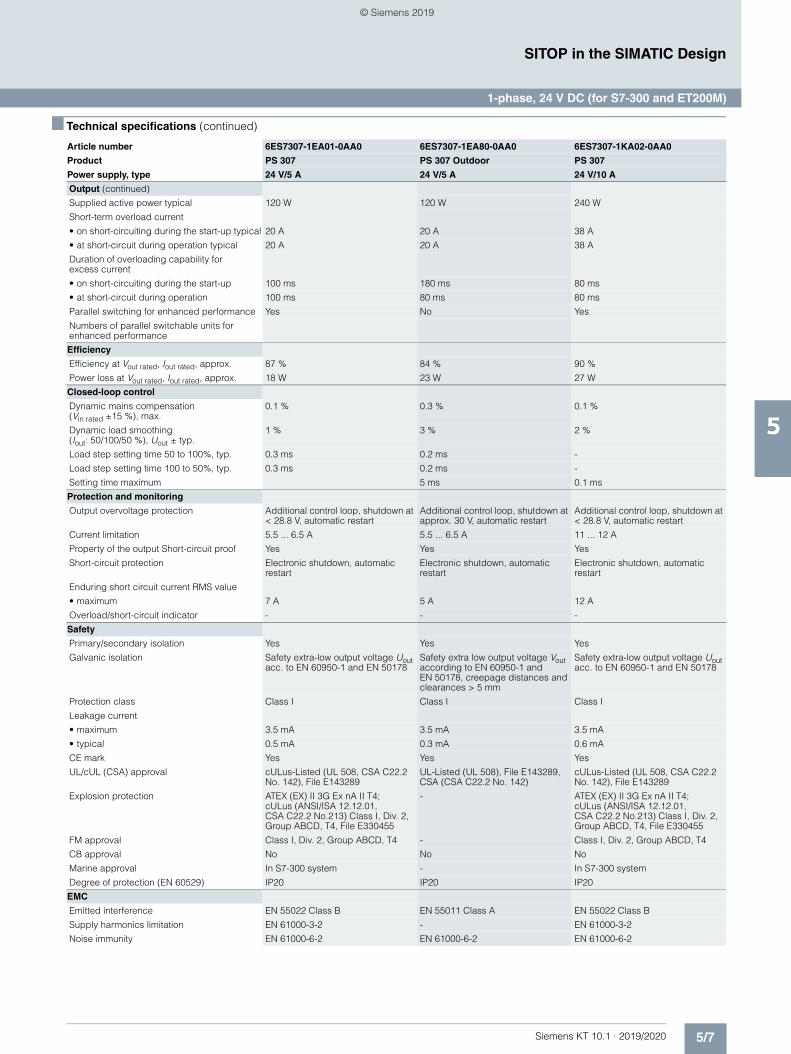
5/7Siemens KT 10.1 · 2019/2020
5
■ Technical specifications (continued)
SITOP in the SIMATIC Design
1-phase, 24 V DC (for S7-300 and ET200M)
Output (continued)
Supplied active power typical 120 W 120 W 240 W
Short-term overload current
• on short-circuiting during the start-up typical 20 A 20 A 38 A
• at short-circuit during operation typical 20 A 20 A 38 A
Duration of overloading capability for excess current
• on short-circuiting during the start-up 100 ms 180 ms 80 ms
• at short-circuit during operation 100 ms 80 ms 80 ms
Parallel switching for enhanced performance Yes No Yes
Numbers of parallel switchable units for enhanced performance
Efficiency
Efficiency at Vout rated, Iout rated, approx. 87 % 84 % 90 %
Power loss at Vout rated, Iout rated, approx. 18 W 23 W 27 W
Closed-loop control
Dynamic mains compensation (Vin rated ±15 %), max.
0.1 % 0.3 % 0.1 %
Dynamic load smoothing (Iout: 50/100/50 %), Uout ± typ.
1 % 3 % 2 %
Load step setting time 50 to 100%, typ. 0.3 ms 0.2 ms -
Load step setting time 100 to 50%, typ. 0.3 ms 0.2 ms -
Setting time maximum 5 ms 0.1 ms
Protection and monitoring
Output overvoltage protection Additional control loop, shutdown at < 28.8 V, automatic restart
Additional control loop, shutdown at approx. 30 V, automatic restart
Additional control loop, shutdown at < 28.8 V, automatic restart
Current limitation 5.5 ... 6.5 A 5.5 ... 6.5 A 11 ... 12 A
Property of the output Short-circuit proof Yes Yes Yes
Short-circuit protection Electronic shutdown, automatic restart
Electronic shutdown, automatic restart
Electronic shutdown, automatic restart
Enduring short circuit current RMS value
• maximum 7 A 5 A 12 A
Overload/short-circuit indicator - - -
Safety
Primary/secondary isolation Yes Yes Yes
Galvanic isolation Safety extra-low output voltage Uout acc. to EN 60950-1 and EN 50178
Safety extra low output voltage Vout according to EN 60950-1 and EN 50178, creepage distances and clearances > 5 mm
Safety extra-low output voltage Uout acc. to EN 60950-1 and EN 50178
Protection class Class I Class I Class I
Leakage current
• maximum 3.5 mA 3.5 mA 3.5 mA
• typical 0.5 mA 0.3 mA 0.6 mA
CE mark Yes Yes Yes
UL/cUL (CSA) approval cULus-Listed (UL 508, CSA C22.2 No. 142), File E143289
UL-Listed (UL 508), File E143289, CSA (CSA C22.2 No. 142)
cULus-Listed (UL 508, CSA C22.2 No. 142), File E143289
Explosion protection ATEX (EX) II 3G Ex nA II T4; cULus (ANSI/ISA 12.12.01, CSA C22.2 No.213) Class I, Div. 2, Group ABCD, T4, File E330455
- ATEX (EX) II 3G Ex nA II T4; cULus (ANSI/ISA 12.12.01, CSA C22.2 No.213) Class I, Div. 2, Group ABCD, T4, File E330455
FM approval Class I, Div. 2, Group ABCD, T4 - Class I, Div. 2, Group ABCD, T4
CB approval No No No
Marine approval In S7-300 system - In S7-300 system
Degree of protection (EN 60529) IP20 IP20 IP20
EMC
Emitted interference EN 55022 Class B EN 55011 Class A EN 55022 Class B
Supply harmonics limitation EN 61000-3-2 - EN 61000-3-2
Noise immunity EN 61000-6-2 EN 61000-6-2 EN 61000-6-2
Article number 6ES7307-1EA01-0AA0 6ES7307-1EA80-0AA0 6ES7307-1KA02-0AA0
Product PS 307 PS 307 Outdoor PS 307
Power supply, type 24 V/5 A 24 V/5 A 24 V/10 A
© Siemens 2019
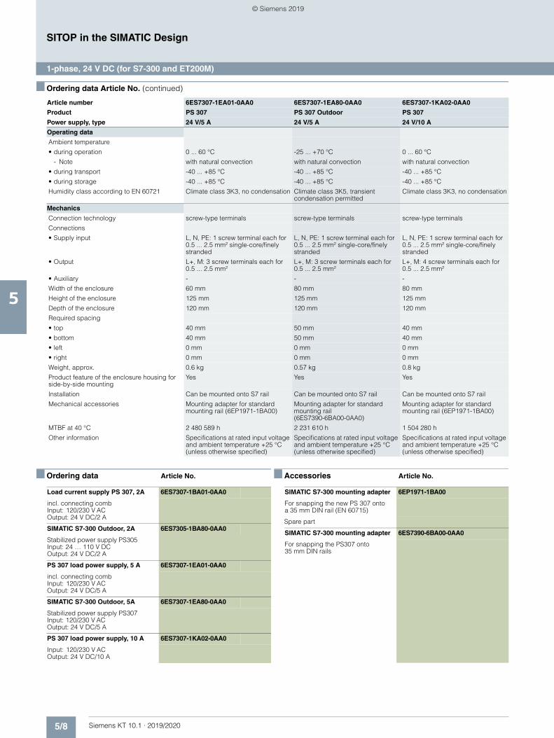
5/8 Siemens KT 10.1 · 2019/2020
5
■ Ordering data Article No. (continued)
SITOP in the SIMATIC Design
1-phase, 24 V DC (for S7-300 and ET200M)
■ Ordering data Article No. ■ Accessories Article No.
Operating data
Ambient temperature
• during operation 0 ... 60 °C -25 ... +70 °C 0 ... 60 °C
- Note with natural convection with natural convection with natural convection
• during transport -40 ... +85 °C -40 ... +85 °C -40 ... +85 °C
• during storage -40 ... +85 °C -40 ... +85 °C -40 ... +85 °C
Humidity class according to EN 60721 Climate class 3K3, no condensation Climate class 3K5, transient condensation permitted
Climate class 3K3, no condensation
Mechanics
Connection technology screw-type terminals screw-type terminals screw-type terminals
Connections
• Supply input L, N, PE: 1 screw terminal each for 0.5 ... 2.5 mm² single-core/finely stranded
L, N, PE: 1 screw terminal each for 0.5 ... 2.5 mm² single-core/finely stranded
L, N, PE: 1 screw terminal each for 0.5 ... 2.5 mm² single-core/finely stranded
• Output L+, M: 3 screw terminals each for 0.5 ... 2.5 mm²
L+, M: 3 screw terminals each for 0.5 ... 2.5 mm²
L+, M: 4 screw terminals each for 0.5 ... 2.5 mm²
• Auxiliary - - -
Width of the enclosure 60 mm 80 mm 80 mm
Height of the enclosure 125 mm 125 mm 125 mm
Depth of the enclosure 120 mm 120 mm 120 mm
Required spacing
• top 40 mm 50 mm 40 mm
• bottom 40 mm 50 mm 40 mm
• left 0 mm 0 mm 0 mm
• right 0 mm 0 mm 0 mm
Weight, approx. 0.6 kg 0.57 kg 0.8 kg
Product feature of the enclosure housing for side-by-side mounting
Yes Yes Yes
Installation Can be mounted onto S7 rail Can be mounted onto S7 rail Can be mounted onto S7 rail
Mechanical accessories Mounting adapter for standard mounting rail (6EP1971-1BA00)
Mounting adapter for standard mounting rail (6ES7390-6BA00-0AA0)
Mounting adapter for standard mounting rail (6EP1971-1BA00)
MTBF at 40 °C 2 480 589 h 2 231 610 h 1 504 280 h
Other information Specifications at rated input voltage and ambient temperature +25 °C (unless otherwise specified)
Specifications at rated input voltage and ambient temperature +25 °C (unless otherwise specified)
Specifications at rated input voltage and ambient temperature +25 °C (unless otherwise specified)
Article number 6ES7307-1EA01-0AA0 6ES7307-1EA80-0AA0 6ES7307-1KA02-0AA0
Product PS 307 PS 307 Outdoor PS 307
Power supply, type 24 V/5 A 24 V/5 A 24 V/10 A
Load current supply PS 307, 2A 6ES7307-1BA01-0AA0
incl. connecting combInput: 120/230 V ACOutput: 24 V DC/2 A
SIMATIC S7-300 Outdoor, 2A 6ES7305-1BA80-0AA0
Stabilized power supply PS305 Input: 24 … 110 V DC Output: 24 V DC/2 A
PS 307 load power supply, 5 A 6ES7307-1EA01-0AA0
incl. connecting combInput: 120/230 V ACOutput: 24 V DC/5 A
SIMATIC S7-300 Outdoor, 5A 6ES7307-1EA80-0AA0
Stabilized power supply PS307 Input: 120/230 V AC Output: 24 V DC/5 A
PS 307 load power supply, 10 A 6ES7307-1KA02-0AA0
Input: 120/230 V ACOutput: 24 V DC/10 A
SIMATIC S7-300 mounting adapter 6EP1971-1BA00
For snapping the new PS 307 onto a 35 mm DIN rail (EN 60715)
Spare part
SIMATIC S7-300 mounting adapter 6ES7390-6BA00-0AA0
For snapping the PS307 onto 35 mm DIN rails
© Siemens 2019
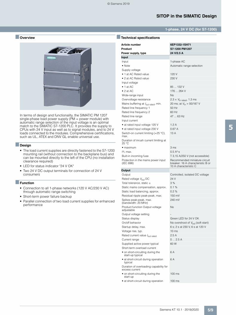
5/9Siemens KT 10.1 · 2019/2020
5
SITOP in the SIMATIC Design
1-phase, 24 V DC (for S7-1200)
■ Overview
In terms of design and functionality, the SIMATIC PM 1207 single-phase load power supply (PM = power module) with automatic range selection of the input voltage is an optimal match to the SIMATIC S7-1200 PLC. It provides the supply to CPUs with 24 V input as well as to signal modules, and to 24 V loads connected to the modules. Comprehensive certifications, such as UL, ATEX and DNV GL enable universal use.
■ Design
• The load current supplies are directly fastened to the S7-1200 mounting rail (without connection to the backplane bus) and can be mounted directly to the left of the CPU (no installation clearance required)
• LED for status indicator "24 V OK"• Two 24 V DC output terminals for connection of 24 V
consumers
■ Function
• Connection to all 1-phase networks (120 V AC/230 V AC) through automatic range switching
• Short-term power failure backup• Parallel connection of two load current supplies for enhanced
performance
■ Technical specifications
Article number 6EP1332-1SH71
Product S7-1200 PM1207
Power supply, type 24 V/2.5 A
Input
Input 1-phase AC
• Note Automatic range selection
Supply voltage
• 1 at AC Rated value 120 V
• 2 at AC Rated value 230 V
Input voltage
• 1 at AC 85 ... 132 V
• 2 at AC 176 ... 264 V
Wide-range input No
Overvoltage resistance 2.3 × Vin rated, 1.3 ms
Mains buffering at Iout rated, min. 20 ms; at Vin = 93/187 V
Rated line frequency 1 50 Hz
Rated line frequency 2 60 Hz
Rated line range 47 ... 63 Hz
Input current
• at rated input voltage 120 V 1.2 A
• at rated input voltage 230 V 0.67 A
Switch-on current limiting (+25 °C), max.
13 A
Duration of inrush current limiting at 25 °C
• maximum 3 ms
I²t, max. 0.5 A²·s
Built-in incoming fuse T 3,15 A/250 V (not accessible)
Protection in the mains power input (IEC 898)
Recommended miniature circuit breaker: 16 A characteristic B or 10 A characteristic C
Output
Output Controlled, isolated DC voltage
Rated voltage Vout DC 24 V
Total tolerance, static ± 3 %
Static mains compensation, approx. 0.1 %
Static load balancing, approx. 0.2 %
Residual ripple peak-peak, max. 150 mV
Spikes peak-peak, max. (bandwidth: 20 MHz)
240 mV
Product function Output voltage adjustable
No
Output voltage setting -
Status display Green LED for 24 V OK
On/off behavior No overshoot of Vout (soft start)
Startup delay, max. 6 s; 2 s at 230 V, 6 s at 120 V
Voltage rise, typ. 10 ms
Rated current value Iout rated 2.5 A
Current range 0 ... 2.5 A
Supplied active power typical 60 W
Short-term overload current
• on short-circuiting during the start-up typical
6 A
• at short-circuit during operation typical
6 A
Duration of overloading capability for excess current
• on short-circuiting during the start-up
100 ms
• at short-circuit during operation 100 ms
© Siemens 2019
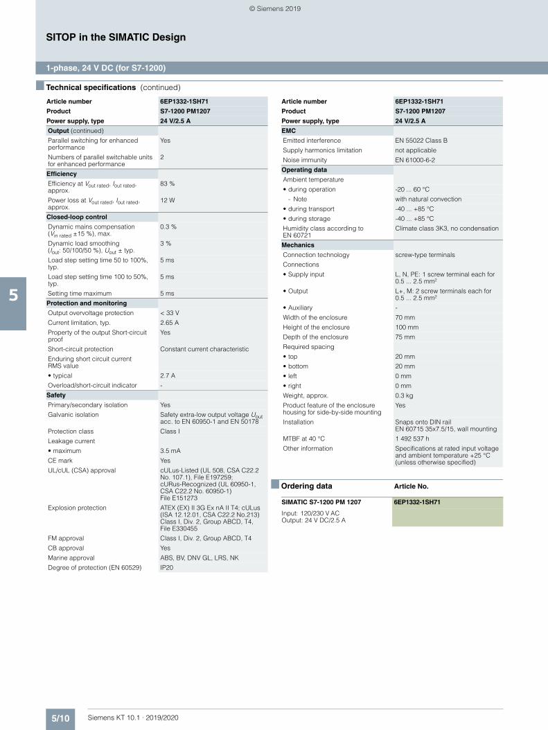
5/10 Siemens KT 10.1 · 2019/2020
5
■ Technical specifications (continued)
SITOP in the SIMATIC Design
1-phase, 24 V DC (for S7-1200)
■ Ordering data Article No.
Output (continued)
Parallel switching for enhanced performance
Yes
Numbers of parallel switchable units for enhanced performance
2
Efficiency
Efficiency at Vout rated, Iout rated, approx.
83 %
Power loss at Vout rated, Iout rated, approx.
12 W
Closed-loop control
Dynamic mains compensation (Vin rated ±15 %), max.
0.3 %
Dynamic load smoothing (Iout: 50/100/50 %), Uout ± typ.
3 %
Load step setting time 50 to 100%, typ.
5 ms
Load step setting time 100 to 50%, typ.
5 ms
Setting time maximum 5 ms
Protection and monitoring
Output overvoltage protection < 33 V
Current limitation, typ. 2.65 A
Property of the output Short-circuit proof
Yes
Short-circuit protection Constant current characteristic
Enduring short circuit current RMS value
• typical 2.7 A
Overload/short-circuit indicator -
Safety
Primary/secondary isolation Yes
Galvanic isolation Safety extra-low output voltage Uout acc. to EN 60950-1 and EN 50178
Protection class Class I
Leakage current
• maximum 3.5 mA
CE mark Yes
UL/cUL (CSA) approval cULus-Listed (UL 508, CSA C22.2 No. 107.1), File E197259; cURus-Recognized (UL 60950-1, CSA C22.2 No. 60950-1) File E151273
Explosion protection ATEX (EX) II 3G Ex nA II T4; cULus (ISA 12.12.01, CSA C22.2 No.213) Class I, Div. 2, Group ABCD, T4, File E330455
FM approval Class I, Div. 2, Group ABCD, T4
CB approval Yes
Marine approval ABS, BV, DNV GL, LRS, NK
Degree of protection (EN 60529) IP20
Article number 6EP1332-1SH71
Product S7-1200 PM1207
Power supply, type 24 V/2.5 A
EMC
Emitted interference EN 55022 Class B
Supply harmonics limitation not applicable
Noise immunity EN 61000-6-2
Operating data
Ambient temperature
• during operation -20 ... 60 °C
- Note with natural convection
• during transport -40 ... +85 °C
• during storage -40 ... +85 °C
Humidity class according to EN 60721
Climate class 3K3, no condensation
Mechanics
Connection technology screw-type terminals
Connections
• Supply input L, N, PE: 1 screw terminal each for 0.5 ... 2.5 mm²
• Output L+, M: 2 screw terminals each for 0.5 ... 2.5 mm²
• Auxiliary -
Width of the enclosure 70 mm
Height of the enclosure 100 mm
Depth of the enclosure 75 mm
Required spacing
• top 20 mm
• bottom 20 mm
• left 0 mm
• right 0 mm
Weight, approx. 0.3 kg
Product feature of the enclosure housing for side-by-side mounting
Yes
Installation Snaps onto DIN rail EN 60715 35x7.5/15, wall mounting
MTBF at 40 °C 1 492 537 h
Other information Specifications at rated input voltage and ambient temperature +25 °C (unless otherwise specified)
SIMATIC S7-1200 PM 1207 6EP1332-1SH71
Input: 120/230 V ACOutput: 24 V DC/2.5 A
Article number 6EP1332-1SH71
Product S7-1200 PM1207
Power supply, type 24 V/2.5 A
© Siemens 2019
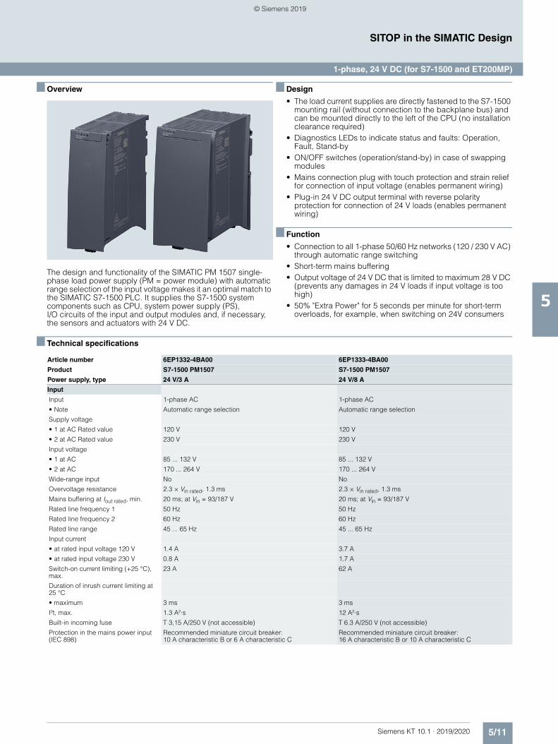
5/11Siemens KT 10.1 · 2019/2020
5
SITOP in the SIMATIC Design
1-phase, 24 V DC (for S7-1500 and ET200MP)
■ Overview
The design and functionality of the SIMATIC PM 1507 single-phase load power supply (PM = power module) with automatic range selection of the input voltage makes it an optimal match to the SIMATIC S7-1500 PLC. It supplies the S7-1500 system components such as CPU, system power supply (PS), I/O circuits of the input and output modules and, if necessary, the sensors and actuators with 24 V DC.
■ Design
• The load current supplies are directly fastened to the S7-1500 mounting rail (without connection to the backplane bus) and can be mounted directly to the left of the CPU (no installation clearance required)
• Diagnostics LEDs to indicate status and faults: Operation, Fault, Stand-by
• ON/OFF switches (operation/stand-by) in case of swapping modules
• Mains connection plug with touch protection and strain relief for connection of input voltage (enables permanent wiring)
• Plug-in 24 V DC output terminal with reverse polarity protection for connection of 24 V loads (enables permanent wiring)
■ Function
• Connection to all 1-phase 50/60 Hz networks (120 / 230 V AC) through automatic range switching
• Short-term mains buffering• Output voltage of 24 V DC that is limited to maximum 28 V DC
(prevents any damages in 24 V loads if input voltage is too high)
• 50% "Extra Power" for 5 seconds per minute for short-term overloads, for example, when switching on 24V consumers
■ Technical specifications
Article number 6EP1332-4BA00 6EP1333-4BA00
Product S7-1500 PM1507 S7-1500 PM1507
Power supply, type 24 V/3 A 24 V/8 A
Input
Input 1-phase AC 1-phase AC
• Note Automatic range selection Automatic range selection
Supply voltage
• 1 at AC Rated value 120 V 120 V
• 2 at AC Rated value 230 V 230 V
Input voltage
• 1 at AC 85 ... 132 V 85 ... 132 V
• 2 at AC 170 ... 264 V 170 ... 264 V
Wide-range input No No
Overvoltage resistance 2.3 × Vin rated, 1.3 ms 2.3 × Vin rated, 1.3 ms
Mains buffering at Iout rated, min. 20 ms; at Vin = 93/187 V 20 ms; at Vin = 93/187 V
Rated line frequency 1 50 Hz 50 Hz
Rated line frequency 2 60 Hz 60 Hz
Rated line range 45 ... 65 Hz 45 ... 65 Hz
Input current
• at rated input voltage 120 V 1.4 A 3.7 A
• at rated input voltage 230 V 0.8 A 1.7 A
Switch-on current limiting (+25 °C), max.
23 A 62 A
Duration of inrush current limiting at 25 °C
• maximum 3 ms 3 ms
I²t, max. 1.3 A²·s 12 A²·s
Built-in incoming fuse T 3,15 A/250 V (not accessible) T 6.3 A/250 V (not accessible)
Protection in the mains power input (IEC 898)
Recommended miniature circuit breaker: 10 A characteristic B or 6 A characteristic C
Recommended miniature circuit breaker: 16 A characteristic B or 10 A characteristic C
© Siemens 2019
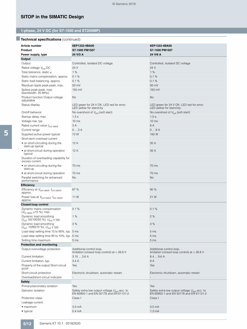
5/12 Siemens KT 10.1 · 2019/2020
5
■ Technical specifications (continued)
SITOP in the SIMATIC Design
1-phase, 24 V DC (for S7-1500 and ET200MP)
Output
Output Controlled, isolated DC voltage Controlled, isolated DC voltage
Rated voltage Vout DC 24 V 24 V
Total tolerance, static ± 1 % 1 %
Static mains compensation, approx. 0.1 % 0.1 %
Static load balancing, approx. 0.1 % 0.1 %
Residual ripple peak-peak, max. 50 mV 50 mV
Spikes peak-peak, max. (bandwidth: 20 MHz)
150 mV 150 mV
Product function Output voltage adjustable
No No
Status display LED green for 24 V OK; LED red for error; LED yellow for stand-by
LED green for 24 V OK; LED red for error; LED yellow for stand-by
On/off behavior No overshoot of Vout (soft start) No overshoot of Vout (soft start)
Startup delay, max. 1.5 s 1.5 s
Voltage rise, typ. 10 ms 10 ms
Rated current value Iout rated 3 A 8 A
Current range 0 ... 3 A 0 ... 8 A
Supplied active power typical 72 W 192 W
Short-term overload current
• on short-circuiting during the start-up typical
12 A 35 A
• at short-circuit during operation typical
12 A 35 A
Duration of overloading capability for excess current
• on short-circuiting during the start-up
70 ms 70 ms
• at short-circuit during operation 70 ms 70 ms
Parallel switching for enhanced performance
No No
Efficiency
Efficiency at Vout rated, Iout rated, approx.
87 % 90 %
Power loss at Vout rated, Iout rated, approx.
11 W 21 W
Closed-loop control
Dynamic mains compensation (Vin rated ±15 %), max.
0.1 % 0.1 %
Dynamic load smoothing (Iout: 50/100/50 %), Uout ± typ.
1 % 2 %
Dynamic load smoothing (Iout: 10/90/10 %), Uout ± typ.
3 % 3 %
Load step setting time 10 to 90%, typ. 5 ms 5 ms
Load step setting time 90 to 10%, typ. 5 ms 5 ms
Setting time maximum 5 ms 5 ms
Protection and monitoring
Output overvoltage protection Additional control loop, limitation (closed loop control) at < 28.8 V
Additional control loop, limitation (closed loop control) at < 28.8 V
Current limitation 3.15 ... 3.6 A 8.4 ... 9.6 A
Current limitation, typ. 3.4 A 9 A
Property of the output Short-circuit proof
Yes Yes
Short-circuit protection Electronic shutdown, automatic restart Electronic shutdown, automatic restart
Overload/short-circuit indicator - -
Safety
Primary/secondary isolation Yes Yes
Galvanic isolation Safety extra-low output voltage Uout acc. to EN 60950-1 and EN 50178 and EN 61131-2
Safety extra-low output voltage Uout acc. to EN 60950-1 and EN 50178 and EN 61131-2
Protection class Class I Class I
Leakage current
• maximum 3.5 mA 3.5 mA
• typical 0.4 mA 1.3 mA
Article number 6EP1332-4BA00 6EP1333-4BA00
Product S7-1500 PM1507 S7-1500 PM1507
Power supply, type 24 V/3 A 24 V/8 A
© Siemens 2019
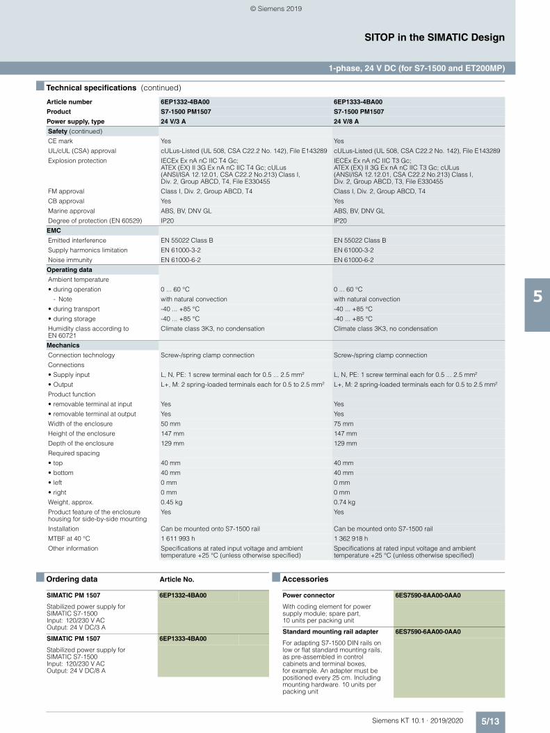
5/13Siemens KT 10.1 · 2019/2020
5
■ Technical specifications (continued)
SITOP in the SIMATIC Design
1-phase, 24 V DC (for S7-1500 and ET200MP)
■ Ordering data Article No. ■ Accessories
Safety (continued)
CE mark Yes Yes
UL/cUL (CSA) approval cULus-Listed (UL 508, CSA C22.2 No. 142), File E143289 cULus-Listed (UL 508, CSA C22.2 No. 142), File E143289
Explosion protection IECEx Ex nA nC IIC T4 Gc;ATEX (EX) II 3G Ex nA nC IIC T4 Gc; cULus (ANSI/ISA 12.12.01, CSA C22.2 No.213) Class I, Div. 2, Group ABCD, T4, File E330455
IECEx Ex nA nC IIC T3 Gc; ATEX (EX) II 3G Ex nA nC IIC T3 Gc; cULus (ANSI/ISA 12.12.01, CSA C22.2 No.213) Class I, Div. 2, Group ABCD, T3, File E330455
FM approval Class I, Div. 2, Group ABCD, T4 Class I, Div. 2, Group ABCD, T4
CB approval Yes Yes
Marine approval ABS, BV, DNV GL ABS, BV, DNV GL
Degree of protection (EN 60529) IP20 IP20
EMC
Emitted interference EN 55022 Class B EN 55022 Class B
Supply harmonics limitation EN 61000-3-2 EN 61000-3-2
Noise immunity EN 61000-6-2 EN 61000-6-2
Operating data
Ambient temperature
• during operation 0 ... 60 °C 0 ... 60 °C
- Note with natural convection with natural convection
• during transport -40 ... +85 °C -40 ... +85 °C
• during storage -40 ... +85 °C -40 ... +85 °C
Humidity class according to EN 60721
Climate class 3K3, no condensation Climate class 3K3, no condensation
Mechanics
Connection technology Screw-/spring clamp connection Screw-/spring clamp connection
Connections
• Supply input L, N, PE: 1 screw terminal each for 0.5 ... 2.5 mm² L, N, PE: 1 screw terminal each for 0.5 ... 2.5 mm²
• Output L+, M: 2 spring-loaded terminals each for 0.5 to 2.5 mm² L+, M: 2 spring-loaded terminals each for 0.5 to 2.5 mm²
Product function
• removable terminal at input Yes Yes
• removable terminal at output Yes Yes
Width of the enclosure 50 mm 75 mm
Height of the enclosure 147 mm 147 mm
Depth of the enclosure 129 mm 129 mm
Required spacing
• top 40 mm 40 mm
• bottom 40 mm 40 mm
• left 0 mm 0 mm
• right 0 mm 0 mm
Weight, approx. 0.45 kg 0.74 kg
Product feature of the enclosure housing for side-by-side mounting
Yes Yes
Installation Can be mounted onto S7-1500 rail Can be mounted onto S7-1500 rail
MTBF at 40 °C 1 611 993 h 1 362 918 h
Other information Specifications at rated input voltage and ambient temperature +25 °C (unless otherwise specified)
Specifications at rated input voltage and ambient temperature +25 °C (unless otherwise specified)
Article number 6EP1332-4BA00 6EP1333-4BA00
Product S7-1500 PM1507 S7-1500 PM1507
Power supply, type 24 V/3 A 24 V/8 A
SIMATIC PM 1507 6EP1332-4BA00
Stabilized power supply for SIMATIC S7-1500Input: 120/230 V ACOutput: 24 V DC/3 A
SIMATIC PM 1507 6EP1333-4BA00
Stabilized power supply for SIMATIC S7-1500Input: 120/230 V ACOutput: 24 V DC/8 A
Power connector 6ES7590-8AA00-0AA0
With coding element for power supply module; spare part, 10 units per packing unit
Standard mounting rail adapter 6ES7590-6AA00-0AA0
For adapting S7-1500 DIN rails on low or flat standard mounting rails, as pre-assembled in control cabinets and terminal boxes, for example. An adapter must be positioned every 25 cm. Including mounting hardware. 10 units per packing unit
© Siemens 2019
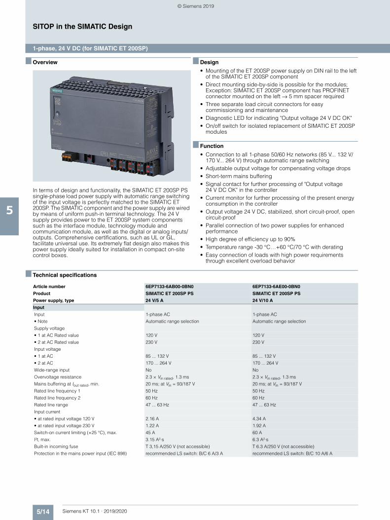
5/14 Siemens KT 10.1 · 2019/2020
5
SITOP in the SIMATIC Design
1-phase, 24 V DC (for SIMATIC ET 200SP)
■ Overview
In terms of design and functionality, the SIMATIC ET 200SP PS single-phase load power supply with automatic range switching of the input voltage is perfectly matched to the SIMATIC ET 200SP. The SIMATIC component and the power supply are wired by means of uniform push-in terminal technology. The 24 V supply provides power to the ET 200SP system components such as the interface module, technology module and communication module, as well as the digital or analog inputs/outputs. Comprehensive certifications, such as UL or GL, facilitate universal use. Its extremely flat design also makes this power supply ideally suited for installation in compact on-site control boxes.
■ Design
• Mounting of the ET 200SP power supply on DIN rail to the left of the SIMATIC ET 200SP component
• Direct mounting side-by-side is possible for the modules; Exception: SIMATIC ET 200SP component has PROFINET connector mounted on the left → 5 mm spacer required
• Three separate load circuit connectors for easy commissioning and maintenance
• Diagnostic LED for indicating "Output voltage 24 V DC OK"• On/off switch for isolated replacement of SIMATIC ET 200SP
modules
■ Function
• Connection to all 1-phase 50/60 Hz networks (85 V... 132 V/170 V... 264 V) through automatic range switching
• Adjustable output voltage for compensating voltage drops• Short-term mains buffering• Signal contact for further processing of "Output voltage
24 V DC OK" in the controller• Current monitor for further processing of the present energy
consumption in the controller• Output voltage 24 V DC, stabilized, short circuit-proof, open
circuit-proof• Parallel connection of two power supplies for enhanced
performance• High degree of efficiency up to 90%• Temperature range -30 °C…+60 °C/70 °C with derating• Easy connection of loads with high power requirements
through excellent overload behavior
■ Technical specifications
Article number 6EP7133-6AB00-0BN0 6EP7133-6AE00-0BN0
Product SIMATIC ET 200SP PS SIMATIC ET 200SP PS
Power supply, type 24 V/5 A 24 V/10 A
Input
Input 1-phase AC 1-phase AC
• Note Automatic range selection Automatic range selection
Supply voltage
• 1 at AC Rated value 120 V 120 V
• 2 at AC Rated value 230 V 230 V
Input voltage
• 1 at AC 85 ... 132 V 85 ... 132 V
• 2 at AC 170 ... 264 V 170 ... 264 V
Wide-range input No No
Overvoltage resistance 2.3 × Vin rated, 1.3 ms 2.3 × Vin rated, 1.3 ms
Mains buffering at Iout rated, min. 20 ms; at Vin = 93/187 V 20 ms; at Vin = 93/187 V
Rated line frequency 1 50 Hz 50 Hz
Rated line frequency 2 60 Hz 60 Hz
Rated line range 47 ... 63 Hz 47 ... 63 Hz
Input current
• at rated input voltage 120 V 2.16 A 4.34 A
• at rated input voltage 230 V 1.22 A 1.92 A
Switch-on current limiting (+25 °C), max. 45 A 60 A
I²t, max. 3.15 A²·s 6.3 A²·s
Built-in incoming fuse T 3,15 A/250 V (not accessible) T 6.3 A/250 V (not accessible)
Protection in the mains power input (IEC 898) recommended LS switch: B/C 6 A/3 A recommended LS switch: B/C 10 A/6 A
© Siemens 2019
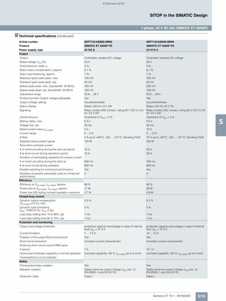
5/15Siemens KT 10.1 · 2019/2020
5
■ Technical specifications (continued)
SITOP in the SIMATIC Design
1-phase, 24 V DC (for SIMATIC ET 200SP)
Output
Output Controlled, isolated DC voltage Controlled, isolated DC voltage
Rated voltage Vout DC 24 V 24 V
Total tolerance, static ± 3 % 3 %
Static mains compensation, approx. 0.1 % 0.1 %
Static load balancing, approx. 1 % 1 %
Residual ripple peak-peak, max. 150 mV 150 mV
Residual ripple peak-peak, typ. 50 mV 50 mV
Spikes peak-peak, max. (bandwidth: 20 MHz) 240 mV 240 mV
Spikes peak-peak, typ. (bandwidth: 20 MHz) 150 mV 150 mV
Adjustment range 22.8 ... 28 V 22.8 ... 28 V
Product function Output voltage adjustable Yes Yes
Output voltage setting via potentiometer via potentiometer
Status display Green LED for 24 V OK Green LED for 24 V OK
Signaling Relay contact (NO contact, rating 60 V DC/ 0.3 A) for "24 V OK"
Relay contact (NO contact, rating 60 V DC/ 0.3 A) for "24 V OK"
On/off behavior Overshoot of Vout < 3 % Overshoot of Vout < 3 %
Startup delay, max. 0.3 s 0.3 s
Voltage rise, typ. 30 ms 30 ms
Rated current value Iout rated 5 A 10 A
Current range 0 ... 6 A 0 ... 12 A
• Note 5 A up to +60°C; +60 ... +70 °C: Derating 3%/K 10 A up to +60°C; +60 ... +70 °C: Derating 3%/K
Supplied active power typical 120 W 240 W
Short-term overload current
• on short-circuiting during the start-up typical 15 A 30 A
• at short-circuit during operation typical 15 A 30 A
Duration of overloading capability for excess current
• on short-circuiting during the start-up 800 ms 750 ms
• at short-circuit during operation 800 ms 800 ms
Parallel switching for enhanced performance Yes Yes
Numbers of parallel switchable units for enhanced performance
2 2
Efficiency
Efficiency at Vout rated, Iout rated, approx. 88 % 90 %
Power loss at Vout rated, Iout rated, approx. 17 W 26 W
Power loss [W] during no-load operation maximum 2.7 W 2.8 W
Closed-loop control
Dynamic mains compensation (Vin rated ±15 %), max.
0.3 % 0.3 %
Dynamic load smoothing (Iout: 10/90/10 %), Uout ± typ.
3 % 3 %
Load step setting time 10 to 90%, typ. 1 ms 1 ms
Load step setting time 90 to 10%, typ. 1 ms 1 ms
Protection and monitoring
Output overvoltage protection protection against overvoltage in case of internal fault Vout < 31.8 V
protection against overvoltage in case of internal fault Vout < 31.8 V
Current limitation 7 ... 7.5 A 14 ... 15 A
Property of the output Short-circuit proof Yes Yes
Short-circuit protection Constant current characteristic Constant current characteristic
Enduring short circuit current RMS value
• typical 7 A 14.1 A
Overcurrent overload capability in normal operation overload capability 150 % Iout rated up to 5 s/min overload capability 150 % Iout rated up to 5 s/min
Overload/short-circuit indicator - -
Safety
Primary/secondary isolation Yes Yes
Galvanic isolation Safety extra-low output voltage Uout acc. to EN 60950-1 and EN 50178
Safety extra-low output voltage Uout acc. to EN 60950-1 and EN 50178
Protection class Class I Class I
Article number 6EP7133-6AB00-0BN0 6EP7133-6AE00-0BN0
Product SIMATIC ET 200SP PS SIMATIC ET 200SP PS
Power supply, type 24 V/5 A 24 V/10 A
© Siemens 2019
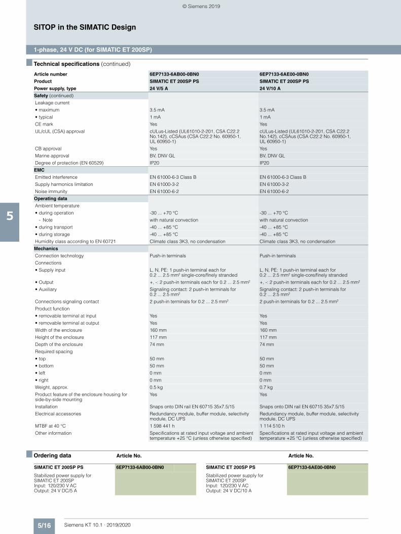
5/16 Siemens KT 10.1 · 2019/2020
5
■ Technical specifications (continued)
SITOP in the SIMATIC Design
1-phase, 24 V DC (for SIMATIC ET 200SP)
■ Ordering data Article No. Article No.
Safety (continued)
Leakage current
• maximum 3.5 mA 3.5 mA
• typical 1 mA 1 mA
CE mark Yes Yes
UL/cUL (CSA) approval cULus-Listed (UL61010-2-201, CSA C22.2 No.142), cCSAus (CSA C22.2 No. 60950-1, UL 60950-1)
cULus-Listed (UL61010-2-201, CSA C22.2 No.142), cCSAus (CSA C22.2 No. 60950-1, UL 60950-1)
CB approval Yes Yes
Marine approval BV, DNV GL BV, DNV GL
Degree of protection (EN 60529) IP20 IP20
EMC
Emitted interference EN 61000-6-3 Class B EN 61000-6-3 Class B
Supply harmonics limitation EN 61000-3-2 EN 61000-3-2
Noise immunity EN 61000-6-2 EN 61000-6-2
Operating data
Ambient temperature
• during operation -30 ... +70 °C -30 ... +70 °C
- Note with natural convection with natural convection
• during transport -40 ... +85 °C -40 ... +85 °C
• during storage -40 ... +85 °C -40 ... +85 °C
Humidity class according to EN 60721 Climate class 3K3, no condensation Climate class 3K3, no condensation
Mechanics
Connection technology Push-in terminals Push-in terminals
Connections
• Supply input L, N, PE: 1 push-in terminal each for 0.2 ... 2.5 mm² single-core/finely stranded
L, N, PE: 1 push-in terminal each for 0.2 ... 2.5 mm² single-core/finely stranded
• Output +, -: 2 push-in terminals each for 0.2 ... 2.5 mm² +, -: 2 push-in terminals each for 0.2 ... 2.5 mm²
• Auxiliary Signaling contact: 2 push-in terminals for 0.2 ... 2.5 mm²
Signaling contact: 2 push-in terminals for 0.2 ... 2.5 mm²
Connections signaling contact 2 push-in terminals for 0.2 ... 2.5 mm² 2 push-in terminals for 0.2 ... 2.5 mm²
Product function
• removable terminal at input Yes Yes
• removable terminal at output Yes Yes
Width of the enclosure 160 mm 160 mm
Height of the enclosure 117 mm 117 mm
Depth of the enclosure 74 mm 74 mm
Required spacing
• top 50 mm 50 mm
• bottom 50 mm 50 mm
• left 0 mm 0 mm
• right 0 mm 0 mm
Weight, approx. 0.5 kg 0.7 kg
Product feature of the enclosure housing for side-by-side mounting
Yes Yes
Installation Snaps onto DIN rail EN 60715 35x7.5/15 Snaps onto DIN rail EN 60715 35x7.5/15
Electrical accessories Redundancy module, buffer module, selectivity module, DC UPS
Redundancy module, buffer module, selectivity module, DC UPS
MTBF at 40 °C 1 598 441 h 1 114 510 h
Other information Specifications at rated input voltage and ambient temperature +25 °C (unless otherwise specified)
Specifications at rated input voltage and ambient temperature +25 °C (unless otherwise specified)
Article number 6EP7133-6AB00-0BN0 6EP7133-6AE00-0BN0
Product SIMATIC ET 200SP PS SIMATIC ET 200SP PS
Power supply, type 24 V/5 A 24 V/10 A
SIMATIC ET 200SP PS 6EP7133-6AB00-0BN0
Stabilized power supply for SIMATIC ET 200SPInput: 120/230 V ACOutput: 24 V DC/5 A
SIMATIC ET 200SP PS 6EP7133-6AE00-0BN0
Stabilized power supply for SIMATIC ET 200SPInput: 120/230 V ACOutput: 24 V DC/10 A
© Siemens 2019
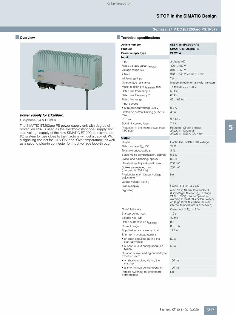
5/17Siemens KT 10.1 · 2019/2020
5
SITOP in the SIMATIC Design
3-phase, 24 V DC (ET200pro PS, IP67)
■ Overview
Power supply for ET200pro:• 3-phase, 24 V DC/8 A
The SIMATIC ET200pro PS power supply unit with degree of protection IP67 is used as the electronics/encoder supply and load voltage supply of the new SIMATIC ET 200pro distributed I/O system for use close to the machine without a cabinet. With a signaling contact for "24 V OK" and "Overtemperature", as well as a second plug-in connector for input voltage loop-through.
■ Technical specifications
Article number 6ES7148-4PC00-0HA0
Product SIMATIC ET200pro PS
Power supply, type 24 V/8 A
Input
Input 3-phase AC
Rated voltage value Vin rated 400 ... 480 V
Voltage range AC 340 ... 550 V
• Note 320 ... 340 V for max. 1 min
Wide-range input Yes
Overvoltage resistance Implemented internally with varistors
Mains buffering at Iout rated, min. 15 ms; at Vin = 400 V
Rated line frequency 1 50 Hz
Rated line frequency 2 60 Hz
Rated line range 45 ... 66 Hz
Input current
• at rated input voltage 400 V 0.5 A
Switch-on current limiting (+25 °C), max.
40 A
I²t, max. 3.5 A²·s
Built-in incoming fuse T 4 A
Protection in the mains power input (IEC 898)
Required: Circuit breaker 3RV2011-1DA10 or 3RV2711-1DD10 (UL 489)
Output
Output Controlled, isolated DC voltage
Rated voltage Vout DC 24 V
Total tolerance, static ± 3 %
Static mains compensation, approx. 0.5 %
Static load balancing, approx. 0.5 %
Residual ripple peak-peak, max. 200 mV
Spikes peak-peak, max. (bandwidth: 20 MHz)
250 mV
Product function Output voltage adjustable
No
Output voltage setting -
Status display Green LED for 24 V OK
Signaling max. 30 V, 10 mA; Power-Good (High-Pegel 1L+ for Vout in range 21.3 ... 29 V); Overtemperature warning at least 30 s before switch-off (high level 1L+ when the max. internal temperature is exceeded)
On/off behavior Overshoot of Vout < 2 %
Startup delay, max. 1.5 s
Voltage rise, typ. 40 ms
Rated current value Iout rated 8 A
Current range 0 ... 8 A
Supplied active power typical 192 W
Short-term overload current
• on short-circuiting during the start-up typical
50 A
• at short-circuit during operation typical
50 A
Duration of overloading capability for excess current
• on short-circuiting during the start-up
100 ms
• at short-circuit during operation 100 ms
Parallel switching for enhanced performance
No
© Siemens 2019
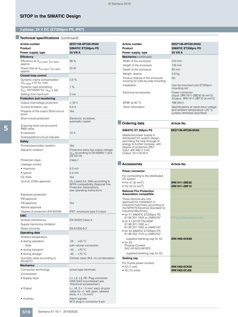
5/18 Siemens KT 10.1 · 2019/2020
5
■ Technical specifications (continued)
SITOP in the SIMATIC Design
3-phase, 24 V DC (ET200pro PS, IP67)
■ Ordering data Article No.
■ Accessories Article No.
Efficiency
Efficiency at Vout rated, Iout rated, approx.
88 %
Power loss at Vout rated, Iout rated, approx.
25 W
Closed-loop control
Dynamic mains compensation (Vin rated ±15 %), max.
0.5 %
Dynamic load smoothing (Iout: 50/100/50 %), Uout ± typ.
1 %
Setting time maximum 2 ms
Protection and monitoring
Output overvoltage protection < 33 V
Current limitation, typ. 9.4 A
Property of the output Short-circuit proof
Yes
Short-circuit protection Electronic shutdown, automatic restart
Enduring short circuit current RMS value
• maximum 10 A
Overload/short-circuit indicator -
Safety
Primary/secondary isolation Yes
Galvanic isolation Protective extra low output voltage Vout according to EN 60950-1 and EN 50178
Protection class Class I
Leakage current
• maximum 3.5 mA
• typical 0.4 mA
CE mark Yes
UL/cUL (CSA) approval UL-Listed (UL 508) according to NFPA compatibility (National Fire Protection Association), see operating instructions
Explosion protection -
FM approval -
CB approval Yes
Marine approval -
Degree of protection (EN 60529) IP67, enclosure type 5 indoor
EMC
Emitted interference EN 55022 Class A
Supply harmonics limitation -
Noise immunity EN 61000-6-2
Operating data
Ambient temperature
• during operation -25 ... +55 °C
- Note with natural convection
• during transport -40 ... +70 °C
• during storage -40 ... +70 °C
Humidity class according to EN 60721
Climate class 3K3, no condensation
Mechanics
Connection technology screw-type terminals
Connections
• Supply input L1, L2, L3, PE: Plug connector HAN Q4/2 (counterpart see "Electrical accessories")
• Output L+, M: 2 x 1.5 mm² each (4-pole cable for +/- with open, labeled ends, 4 x 1.5 mm²)
• Auxiliary Alarm signals: M12 plug-in connector 5-pin
Article number 6ES7148-4PC00-0HA0
Product SIMATIC ET200pro PS
Power supply, type 24 V/8 A
Mechanics (continued)
Width of the enclosure 310 mm
Height of the enclosure 135 mm
Depth of the enclosure 90 mm
Weight, approx. 2.8 kg
Product feature of the enclosure housing for side-by-side mounting
No
Installation Can be mounted onto ET200pro mounting rail
Electrical accessories Power connector (Input: 3RK1911-2BE30 (6 mm²)) (Output: 3RK1911-2BF10 (4 mm²))
MTBF at 40 °C 196 354 h
Other information Specifications at rated input voltage and ambient temperature +25 °C (unless otherwise specified)
SIMATIC ET 200pro PS 6ES7148-4PC00-0HA0
Stabilized power supply in distributed I/O system design, permitting the loop-through of energy to further modules; with degree of protection IP67; Input: 400-480 V 3 ACOutput: 24 V DC/8 A
Power connector
For connecting to the distributed I/O system• For X1 (6 mm2) 3RK1911-2BE30• For X2 (4 mm2) 3RK1911-2BF10
National Fire Protection Association compatible
These devices are only approved for installation in industrial machinery according to the NFPA79 Electrical Standard for Industrial Machinery.• for X1 SIMATIC ET200pro PS
61 88 201 1003.xx (AWG10)* * https://www.harting.com• for X1 SITOP PSU300P
61 88 201 1000.xx / 61 88 201 1002.xx (AWG14)*
• for X2 SIMATIC ET200pro PS 61 88 202 1010.xx (AWG10)*
supplied blanking cap for X2 3RK1902-0CK00• for X3
Phoenix-Contact SAC-5P-M12-M12FS
supplied blanking cap for X3
Sealing cap
For 9-pole power sockets• X2 (1 unit) 3RK1902-0CK00• X2 (10 units) 3RK1902-0CJ00
Article number 6ES7148-4PC00-0HA0
Product SIMATIC ET200pro PS
Power supply, type 24 V/8 A
© Siemens 2019
Siemens KT 10.1 · 2019/2020
66/2 Overview
6/3 SITOP PSU3400
6/10 SITOP PSU400M
6/12 Other DC/DC converters6/12 48–220 V DC/24 V DC/0.375 A6/14 48–110 V DC/24 V DC/2 A6/16 24 V DC/12 V DC/2.5 A6/18 48 V DC/24 V DC/5 A
DC/DC converter
© Siemens 2019
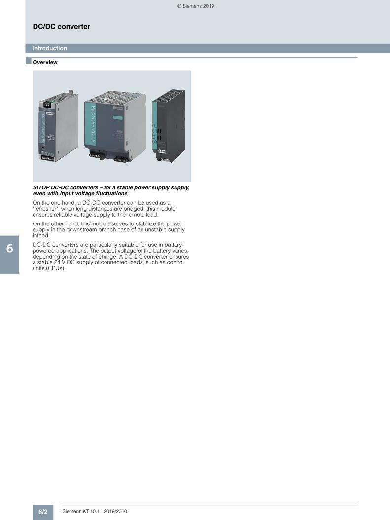
6/2 Siemens KT 10.1 · 2019/2020
6
DC/DC converter
Introduction
■ Overview
SITOP DC-DC converters – for a stable power supply supply, even with input voltage fluctuations
On the one hand, a DC-DC converter can be used as a "refresher": when long distances are bridged, this module ensures reliable voltage supply to the remote load.
On the other hand, this module serves to stabilize the power supply in the downstream branch case of an unstable supply infeed.
DC-DC converters are particularly suitable for use in battery-powered applications. The output voltage of the battery varies, depending on the state of charge. A DC-DC converter ensures a stable 24 V DC supply of connected loads, such as control units (CPUs).
© Siemens 2019
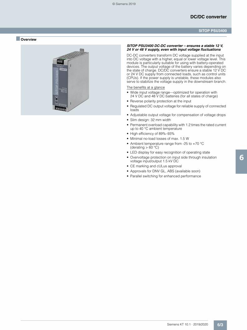
6/3Siemens KT 10.1 · 2019/2020
6
DC/DC converter
SITOP PSU3400
■ Overview
SITOP PSU3400 DC-DC converter – ensures a stable 12 V, 24 V or 48 V supply, even with input voltage fluctuations
DC-DC converters transform DC voltage supplied at the input into DC voltage with a higher, equal or lower voltage level. This module is particularly suitable for using with battery-operated devices. The output voltage of the battery varies depending on the state of charge. DC/DC converters ensure a stable 12 V DC or 24 V DC supply from connected loads, such as control units (CPUs). If the power supply is unstable, these modules also serve to stabilize the voltage supply in the downstream branch.
The benefits at a glance• Wide input voltage range—optimized for operation with
24 V DC and 48 V DC batteries (for all states of charge)• Reverse polarity protection at the input• Regulated DC output voltage for reliable supply of connected
loads• Adjustable output voltage for compensation of voltage drops• Slim design: 32 mm width• Permanent overload capability with 1.2 times the rated current
up to 40 °C ambient temperature• High efficiency of 89%–93%• Minimal no-load losses of max. 1.5 W• Ambient temperature range from -25 to +70 °C
(derating > 60 °C)• LED display for easy recognition of operating state• Overvoltage protection on input side through insulation
voltage input/output 1.5 kV DC• CE marking and cULus approval• Approvals for DNV GL, ABS (available soon) • Parallel switching for enhanced performance
© Siemens 2019
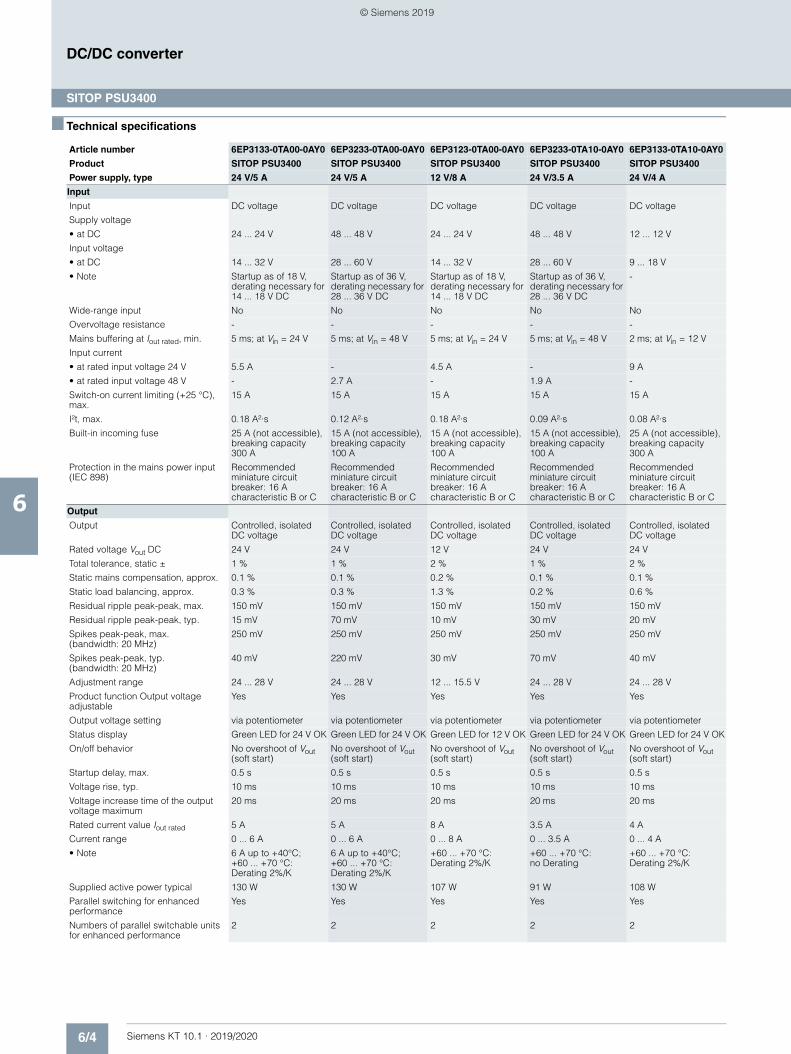
6/4 Siemens KT 10.1 · 2019/2020
6
DC/DC converter
SITOP PSU3400
■ Technical specifications
Article number 6EP3133-0TA00-0AY0 6EP3233-0TA00-0AY0 6EP3123-0TA00-0AY0 6EP3233-0TA10-0AY0 6EP3133-0TA10-0AY0
Product SITOP PSU3400 SITOP PSU3400 SITOP PSU3400 SITOP PSU3400 SITOP PSU3400
Power supply, type 24 V/5 A 24 V/5 A 12 V/8 A 24 V/3.5 A 24 V/4 A
Input
Input DC voltage DC voltage DC voltage DC voltage DC voltage
Supply voltage
• at DC 24 ... 24 V 48 ... 48 V 24 ... 24 V 48 ... 48 V 12 ... 12 V
Input voltage
• at DC 14 ... 32 V 28 ... 60 V 14 ... 32 V 28 ... 60 V 9 ... 18 V
• Note Startup as of 18 V, derating necessary for 14 ... 18 V DC
Startup as of 36 V, derating necessary for 28 ... 36 V DC
Startup as of 18 V, derating necessary for 14 ... 18 V DC
Startup as of 36 V, derating necessary for 28 ... 36 V DC
-
Wide-range input No No No No No
Overvoltage resistance - - - - -
Mains buffering at Iout rated, min. 5 ms; at Vin = 24 V 5 ms; at Vin = 48 V 5 ms; at Vin = 24 V 5 ms; at Vin = 48 V 2 ms; at Vin = 12 V
Input current
• at rated input voltage 24 V 5.5 A - 4.5 A - 9 A
• at rated input voltage 48 V - 2.7 A - 1.9 A -
Switch-on current limiting (+25 °C), max.
15 A 15 A 15 A 15 A 15 A
I²t, max. 0.18 A²·s 0.12 A²·s 0.18 A²·s 0.09 A²·s 0.08 A²·s
Built-in incoming fuse 25 A (not accessible), breaking capacity 300 A
15 A (not accessible), breaking capacity 100 A
15 A (not accessible), breaking capacity 100 A
15 A (not accessible), breaking capacity 100 A
25 A (not accessible), breaking capacity 300 A
Protection in the mains power input (IEC 898)
Recommended miniature circuit breaker: 16 Acharacteristic B or C
Recommended miniature circuit breaker: 16 A characteristic B or C
Recommended miniature circuit breaker: 16 Acharacteristic B or C
Recommended miniature circuit breaker: 16 A characteristic B or C
Recommended miniature circuit breaker: 16 A characteristic B or C
Output
Output Controlled, isolated DC voltage
Controlled, isolated DC voltage
Controlled, isolated DC voltage
Controlled, isolated DC voltage
Controlled, isolated DC voltage
Rated voltage Vout DC 24 V 24 V 12 V 24 V 24 V
Total tolerance, static ± 1 % 1 % 2 % 1 % 2 %
Static mains compensation, approx. 0.1 % 0.1 % 0.2 % 0.1 % 0.1 %
Static load balancing, approx. 0.3 % 0.3 % 1.3 % 0.2 % 0.6 %
Residual ripple peak-peak, max. 150 mV 150 mV 150 mV 150 mV 150 mV
Residual ripple peak-peak, typ. 15 mV 70 mV 10 mV 30 mV 20 mV
Spikes peak-peak, max. (bandwidth: 20 MHz)
250 mV 250 mV 250 mV 250 mV 250 mV
Spikes peak-peak, typ. (bandwidth: 20 MHz)
40 mV 220 mV 30 mV 70 mV 40 mV
Adjustment range 24 ... 28 V 24 ... 28 V 12 ... 15.5 V 24 ... 28 V 24 ... 28 V
Product function Output voltage adjustable
Yes Yes Yes Yes Yes
Output voltage setting via potentiometer via potentiometer via potentiometer via potentiometer via potentiometer
Status display Green LED for 24 V OK Green LED for 24 V OK Green LED for 12 V OK Green LED for 24 V OK Green LED for 24 V OK
On/off behavior No overshoot of Vout (soft start)
No overshoot of Vout (soft start)
No overshoot of Vout (soft start)
No overshoot of Vout (soft start)
No overshoot of Vout (soft start)
Startup delay, max. 0.5 s 0.5 s 0.5 s 0.5 s 0.5 s
Voltage rise, typ. 10 ms 10 ms 10 ms 10 ms 10 ms
Voltage increase time of the output voltage maximum
20 ms 20 ms 20 ms 20 ms 20 ms
Rated current value Iout rated 5 A 5 A 8 A 3.5 A 4 A
Current range 0 ... 6 A 0 ... 6 A 0 ... 8 A 0 ... 3.5 A 0 ... 4 A
• Note 6 A up to +40°C; +60 ... +70 °C: Derating 2%/K
6 A up to +40°C; +60 ... +70 °C: Derating 2%/K
+60 ... +70 °C: Derating 2%/K
+60 ... +70 °C: no Derating
+60 ... +70 °C: Derating 2%/K
Supplied active power typical 130 W 130 W 107 W 91 W 108 W
Parallel switching for enhanced performance
Yes Yes Yes Yes Yes
Numbers of parallel switchable units for enhanced performance
2 2 2 2 2
© Siemens 2019
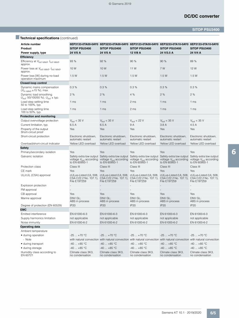
6/5Siemens KT 10.1 · 2019/2020
6
■ Technical specifications (continued)
DC/DC converter
SITOP PSU3400
Efficiency
Efficiency at Vout rated, Iout rated, approx.
93 % 92 % 90 % 90 % 89 %
Power loss at Vout rated, Iout rated, approx.
10 W 10 W 11 W 7 W 12 W
Power loss [W] during no-load operation maximum
1.5 W 1.5 W 1.5 W 1.5 W 1.5 W
Closed-loop control
Dynamic mains compensation(Vin rated ±15 %), max.
0.3 % 0.3 % 0.3 % 0.3 % 0.3 %
Dynamic load smoothing(Iout: 50/100/50 %), Uout ± typ.
2 % 2 % 4 % 2 % 2 %
Load step setting time 50 to 100%, typ.
1 ms 1 ms 2 ms 1 ms 1 ms
Load step setting time 100 to 50%, typ.
1 ms 1 ms 2 ms 1 ms 1 ms
Protection and monitoring
Output overvoltage protection Vout < 35 V Vout < 35 V Vout < 22 V Vout < 35 V Vout < 35 V
Current limitation, typ. 6.5 A 6.5 A 9 A 3.8 A 4.5 A
Property of the output Short-circuit proof
Yes Yes Yes Yes Yes
Short-circuit protection Electronic shutdown, automatic restart
Electronic shutdown, automatic restart
Electronic shutdown, automatic restart
Electronic shutdown, automatic restart
Electronic shutdown, automatic restart
Overload/short-circuit indicator Yellow LED overload Yellow LED overload Yellow LED overload Yellow LED overload Yellow LED overload
Safety
Primary/secondary isolation Yes Yes Yes Yes Yes
Galvanic isolation Safety extra low output voltage Vout according to EN 60950-1
Safety extra low output voltage Vout according to EN 60950-1
Safety extra low output voltage Vout according to EN 60950-1
Safety extra low output voltage Vout according to EN 60950-1
Safety extra low output voltage Vout according to EN 60950-1
Protection class Class III Class III Class III Class III Class III
CE mark Yes Yes Yes Yes Yes
UL/cUL (CSA) approval cULus-Listed (UL 508, CSA C22.2 No. 107.1), File E197259
cULus-Listed (UL 508, CSA C22.2 No. 107.1), File E197259
cULus-Listed (UL 508, CSA C22.2 No. 107.1), File E197259
cULus-Listed (UL 508, CSA C22.2 No. 107.1), File E197259
cULus-Listed (UL 508, CSA C22.2 No. 107.1), File E197259
Explosion protection - - - - -
FM approval - - - - -
CB approval Yes Yes Yes Yes Yes
Marine approval DNV GL; ABS in process
DNV GL;ABS in process
DNV GL; ABS in process
DNV GL; ABS in process
DNV GL; ABS in process
Degree of protection (EN 60529) IP20 IP20 IP20 IP20 IP20
EMC
Emitted interference EN 61000-6-3 EN 61000-6-3 EN 61000-6-3 EN 61000-6-3 EN 61000-6-3
Supply harmonics limitation not applicable not applicable not applicable not applicable not applicable
Noise immunity EN 61000-6-2 EN 61000-6-2 EN 61000-6-2 EN 61000-6-2 EN 61000-6-2
Operating data
Ambient temperature
• during operation -25 ... +70 °C -25 ... +70 °C -25 ... +70 °C -25 ... +70 °C -25 ... +70 °C
- Note with natural convection with natural convection with natural convection with natural convection with natural convection
• during transport -40 ... +85 °C -40 ... +85 °C -40 ... +85 °C -40 ... +85 °C -40 ... +85 °C
• during storage -40 ... +85 °C -40 ... +85 °C -40 ... +85 °C -40 ... +85 °C -40 ... +85 °C
Humidity class according to EN 60721
Climate class 3K3,no condensation
Climate class 3K3,no condensation
Climate class 3K3, no condensation
Climate class 3K3, no condensation
Climate class 3K3, no condensation
Article number 6EP3133-0TA00-0AY0 6EP3233-0TA00-0AY0 6EP3123-0TA00-0AY0 6EP3233-0TA10-0AY0 6EP3133-0TA10-0AY0
Product SITOP PSU3400 SITOP PSU3400 SITOP PSU3400 SITOP PSU3400 SITOP PSU3400
Power supply, type 24 V/5 A 24 V/5 A 12 V/8 A 24 V/3.5 A 24 V/4 A
© Siemens 2019
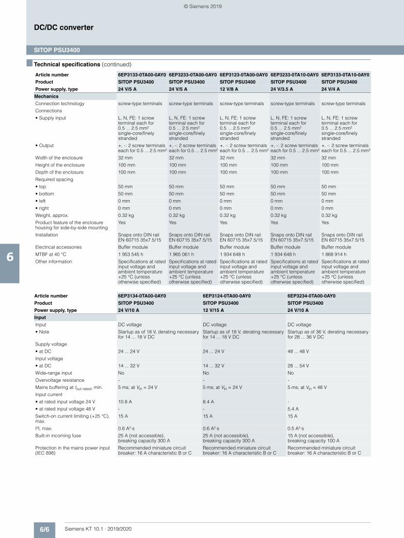
6/6 Siemens KT 10.1 · 2019/2020
6
■ Technical specifications (continued)
DC/DC converter
SITOP PSU3400
Mechanics
Connection technology screw-type terminals screw-type terminals screw-type terminals screw-type terminals screw-type terminals
Connections
• Supply input L, N, FE: 1 screw terminal each for 0.5 ... 2.5 mm²single-core/finely stranded
L, N, FE: 1 screw terminal each for 0.5 ... 2.5 mm² single-core/finely stranded
L, N, FE: 1 screw terminal each for0.5 ... 2.5 mm² single-core/finely stranded
L, N, FE: 1 screw terminal each for0.5 ... 2.5 mm² single-core/finely stranded
L, N, FE: 1 screw terminal each for0.5 ... 2.5 mm² single-core/finely stranded
• Output +, -: 2 screw terminals each for 0.5 ... 2.5 mm²
+, -: 2 screw terminals each for 0.5 ... 2.5 mm²
+, -: 2 screw terminals each for 0.5 ... 2.5 mm²
+, -: 2 screw terminals each for 0.5 ... 2.5 mm²
+, -: 2 screw terminals each for 0.5 ... 2.5 mm²
Width of the enclosure 32 mm 32 mm 32 mm 32 mm 32 mm
Height of the enclosure 100 mm 100 mm 100 mm 100 mm 100 mm
Depth of the enclosure 100 mm 100 mm 100 mm 100 mm 100 mm
Required spacing
• top 50 mm 50 mm 50 mm 50 mm 50 mm
• bottom 50 mm 50 mm 50 mm 50 mm 50 mm
• left 0 mm 0 mm 0 mm 0 mm 0 mm
• right 0 mm 0 mm 0 mm 0 mm 0 mm
Weight, approx. 0.32 kg 0.32 kg 0.32 kg 0.32 kg 0.32 kg
Product feature of the enclosure housing for side-by-side mounting
Yes Yes Yes Yes Yes
Installation Snaps onto DIN rail EN 60715 35x7.5/15
Snaps onto DIN rail EN 60715 35x7.5/15
Snaps onto DIN rail EN 60715 35x7.5/15
Snaps onto DIN rail EN 60715 35x7.5/15
Snaps onto DIN rail EN 60715 35x7.5/15
Electrical accessories Buffer module Buffer module Buffer module Buffer module Buffer module
MTBF at 40 °C 1 953 545 h 1 965 061 h 1 934 648 h 1 934 648 h 1 868 914 h
Other information Specifications at rated input voltage and ambient temperature +25 °C (unless otherwise specified)
Specifications at rated input voltage and ambient temperature +25 °C (unless otherwise specified)
Specifications at rated input voltage and ambient temperature +25 °C (unless otherwise specified)
Specifications at rated input voltage and ambient temperature +25 °C (unless otherwise specified)
Specifications at rated input voltage and ambient temperature +25 °C (unless otherwise specified)
Article number 6EP3134-0TA00-0AY0 6EP3124-0TA00-0AY0 6EP3234-0TA00-0AY0
Product SITOP PSU3400 SITOP PSU3400 SITOP PSU3400
Power supply, type 24 V/10 A 12 V/15 A 24 V/10 A
Input
Input DC voltage DC voltage DC voltage
• Note Startup as of 18 V, derating necessary for 14 ... 18 V DC
Startup as of 18 V, derating necessary for 14 ... 18 V DC
Startup as of 36 V, derating necessary for 28 ... 36 V DC
Supply voltage
• at DC 24 ... 24 V 24 ... 24 V 48 ... 48 V
Input voltage
• at DC 14 ... 32 V 14 ... 32 V 28 ... 54 V
Wide-range input No No No
Overvoltage resistance - - -
Mains buffering at Iout rated, min. 5 ms; at Vin = 24 V 5 ms; at Vin = 24 V 5 ms; at Vin = 48 V
Input current
• at rated input voltage 24 V 10.8 A 8.4 A -
• at rated input voltage 48 V - - 5.4 A
Switch-on current limiting (+25 °C), max.
15 A 15 A 15 A
I²t, max. 0.6 A²·s 0.6 A²·s 0.5 A²·s
Built-in incoming fuse 25 A (not accessible), breaking capacity 300 A
25 A (not accessible), breaking capacity 300 A
15 A (not accessible), breaking capacity 100 A
Protection in the mains power input (IEC 898)
Recommended miniature circuit breaker: 16 A characteristic B or C
Recommended miniature circuit breaker: 16 A characteristic B or C
Recommended miniature circuit breaker: 16 A characteristic B or C
Article number 6EP3133-0TA00-0AY0 6EP3233-0TA00-0AY0 6EP3123-0TA00-0AY0 6EP3233-0TA10-0AY0 6EP3133-0TA10-0AY0
Product SITOP PSU3400 SITOP PSU3400 SITOP PSU3400 SITOP PSU3400 SITOP PSU3400
Power supply, type 24 V/5 A 24 V/5 A 12 V/8 A 24 V/3.5 A 24 V/4 A
© Siemens 2019
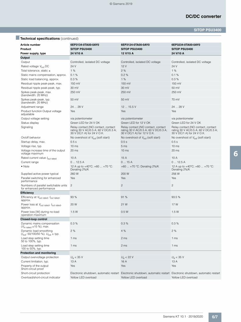
6/7Siemens KT 10.1 · 2019/2020
6
■ Technical specifications (continued)
DC/DC converter
SITOP PSU3400
Output
Output Controlled, isolated DC voltage Controlled, isolated DC voltage Controlled, isolated DC voltage
Rated voltage Vout DC 24 V 12 V 24 V
Total tolerance, static ± 1 % 2 % 1 %
Static mains compensation, approx. 0.1 % 0.2 % 0.1 %
Static load balancing, approx. 0.3 % 1 % 0.3 %
Residual ripple peak-peak, max. 150 mV 150 mV 150 mV
Residual ripple peak-peak, typ. 30 mV 30 mV 50 mV
Spikes peak-peak, max. (bandwidth: 20 MHz)
250 mV 250 mV 250 mV
Spikes peak-peak, typ. (bandwidth: 20 MHz)
50 mV 50 mV 70 mV
Adjustment range 24 ... 28 V 12 ... 15.5 V 24 ... 28 V
Product function Output voltage adjustable
Yes Yes Yes
Output voltage setting via potentiometer via potentiometer via potentiometer
Status display Green LED for 24 V OK Green LED for 12 V OK Green LED for 24 V OK
Signaling Relay contact (NO contact, contact rating 30 V AC/0.5 A; 60 V DC/0.3 A; 30 V DC/1 A) for 24 V O.K.
Relay contact (NO contact, contact rating 30 V AC/0.5 A; 60 V DC/0.3 A; 30 V DC/1 A) for 12 V O.K.
Relay contact (NO contact, contact rating 30 V AC/0.5 A; 60 V DC/0.3 A; 30 V DC/1 A) for 24 V O.K.
On/off behavior No overshoot of Vout (soft start) No overshoot of Vout (soft start) No overshoot of Vout (soft start)
Startup delay, max. 0.5 s 0.5 s 0.5 s
Voltage rise, typ. 10 ms 5 ms 10 ms
Voltage increase time of the output voltage maximum
20 ms 10 ms 20 ms
Rated current value Iout rated 10 A 15 A 10 A
Current range 0 ... 12.5 A 0 ... 15 A 0 ... 12.5 A
• Note 12 A up to +40°C; +60 ... +70 °C: Derating 2%/K
+60 ... +70 °C: Derating 2%/K 12 A up to +40°C; +60 ... +70 °C: Derating 2%/K
Supplied active power typical 260 W 200 W 256 W
Parallel switching for enhanced performance
Yes Yes Yes
Numbers of parallel switchable units for enhanced performance
2 2 2
Efficiency
Efficiency at Vout rated, Iout rated, approx.
93 % 91 % 93.5 %
Power loss at Vout rated, Iout rated, approx.
20 W 21 W 17 W
Power loss [W] during no-load operation maximum
1.5 W 0.5 W 1.5 W
Closed-loop control
Dynamic mains compensation(Vin rated ±15 %), max.
0.3 % 0.3 % 0.3 %
Dynamic load smoothing (Iout: 50/100/50 %), Uout ± typ.
2 % 4 % 2 %
Load step setting time 50 to 100%, typ.
1 ms 2 ms 1 ms
Load step setting time 100 to 50%, typ.
1 ms 2 ms 1 ms
Protection and monitoring
Output overvoltage protection Ua < 35 V Ua < 22 V Ua < 35 V
Current limitation, typ. 13 A 16 A 13 A
Property of the output Short-circuit proof
Yes Yes Yes
Short-circuit protection Electronic shutdown, automatic restart Electronic shutdown, automatic restart Electronic shutdown, automatic restart
Overload/short-circuit indicator Yellow LED overload Yellow LED overload Yellow LED overload
Article number 6EP3134-0TA00-0AY0 6EP3124-0TA00-0AY0 6EP3234-0TA00-0AY0
Product SITOP PSU3400 SITOP PSU3400 SITOP PSU3400
Power supply, type 24 V/10 A 12 V/15 A 24 V/10 A
© Siemens 2019
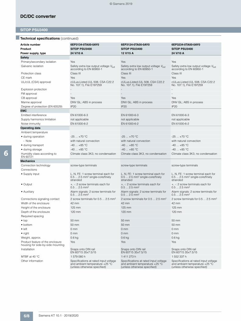
6/8 Siemens KT 10.1 · 2019/2020
6
■ Technical specifications (continued)
DC/DC converter
SITOP PSU3400
Safety
Primary/secondary isolation Yes Yes Yes
Galvanic isolation Safety extra low output voltage Vout according to EN 60950-1
Safety extra low output voltage Vout according to EN 60950-1
Safety extra low output voltage Vout according to EN 60950-1
Protection class Class III Class III Class III
CE mark Yes Yes Yes
UL/cUL (CSA) approval cULus-Listed (UL 508, CSA C22.2 No. 107.1), File E197259
cULus-Listed (UL 508, CSA C22.2No. 107.1), File E197259
cULus-Listed (UL 508, CSA C22.2 No. 107.1), File E197259
Explosion protection - - -
FM approval - - -
CB approval Yes Yes Yes
Marine approval DNV GL; ABS in process DNV GL; ABS in process DNV GL; ABS in process
Degree of protection (EN 60529) IP20 IP20 IP20
EMC
Emitted interference EN 61000-6-3 EN 61000-6-3 EN 61000-6-3
Supply harmonics limitation not applicable not applicable not applicable
Noise immunity EN 61000-6-2 EN 61000-6-2 EN 61000-6-2
Operating data
Ambient temperature
• during operation -25 ... +70 °C -25 ... +70 °C -25 ... +70 °C
- Note with natural convection with natural convection with natural convection
• during transport -40 ... +85 °C -40 ... +85 °C -40 ... +85 °C
• during storage -40 ... +85 °C -40 ... +85 °C -40 ... +85 °C
Humidity class according to EN 60721
Climate class 3K3, no condensation Climate class 3K3, no condensation Climate class 3K3, no condensation
Mechanics
Connection technology screw-type terminals screw-type terminals screw-type terminals
Connections
• Supply input L, N, FE: 1 screw terminal each for 0.5 ... 2.5 mm² single-core/finely stranded
L, N, FE: 1 screw terminal each for0.5 ... 2.5 mm² single-core/finely stranded
L, N, FE: 1 screw terminal each for 0.5 ... 2.5 mm² single-core/finely stranded
• Output +, -: 2 screw terminals each for 0.5 ... 2.5 mm²
+, -: 2 screw terminals each for0.5 ... 2.5 mm²
+, -: 2 screw terminals each for 0.5 ... 2.5 mm²
• Auxiliary Alarm signals: 2 screw terminals for 0.5 ... 2.5 mm²
Alarm signals: 2 screw terminals for0.5 ... 2.5 mm²
Alarm signals: 2 screw terminals for0.5 ... 2.5 mm²
Connections signaling contact 2 screw terminals for 0.5 ... 2.5 mm² 2 screw terminals for 0.5 ... 2.5 mm² 2 screw terminals for 0.5 ... 2.5 mm²
Width of the enclosure 42 mm 42 mm 42 mm
Height of the enclosure 125 mm 125 mm 125 mm
Depth of the enclosure 120 mm 120 mm 120 mm
Required spacing
• top 50 mm 50 mm 50 mm
• bottom 50 mm 50 mm 50 mm
• left 0 mm 0 mm 0 mm
• right 0 mm 0 mm 0 mm
Weight, approx. 0.6 kg 0.6 kg 0.6 kg
Product feature of the enclosure housing for side-by-side mounting
Yes Yes Yes
Installation Snaps onto DIN railEN 60715 35x7.5/15
Snaps onto DIN rail EN 60715 35x7.5/15
Snaps onto DIN rail EN 60715 35x7.5/15
MTBF at 40 °C 1 579 080 h 1 411 273 h 1 552 337 h
Other information Specifications at rated input voltage and ambient temperature +25 °C (unless otherwise specified)
Specifications at rated input voltage and ambient temperature +25 °C (unless otherwise specified)
Specifications at rated input voltage and ambient temperature +25 °C (unless otherwise specified)
Article number 6EP3134-0TA00-0AY0 6EP3124-0TA00-0AY0 6EP3234-0TA00-0AY0
Product SITOP PSU3400 SITOP PSU3400 SITOP PSU3400
Power supply, type 24 V/10 A 12 V/15 A 24 V/10 A
© Siemens 2019
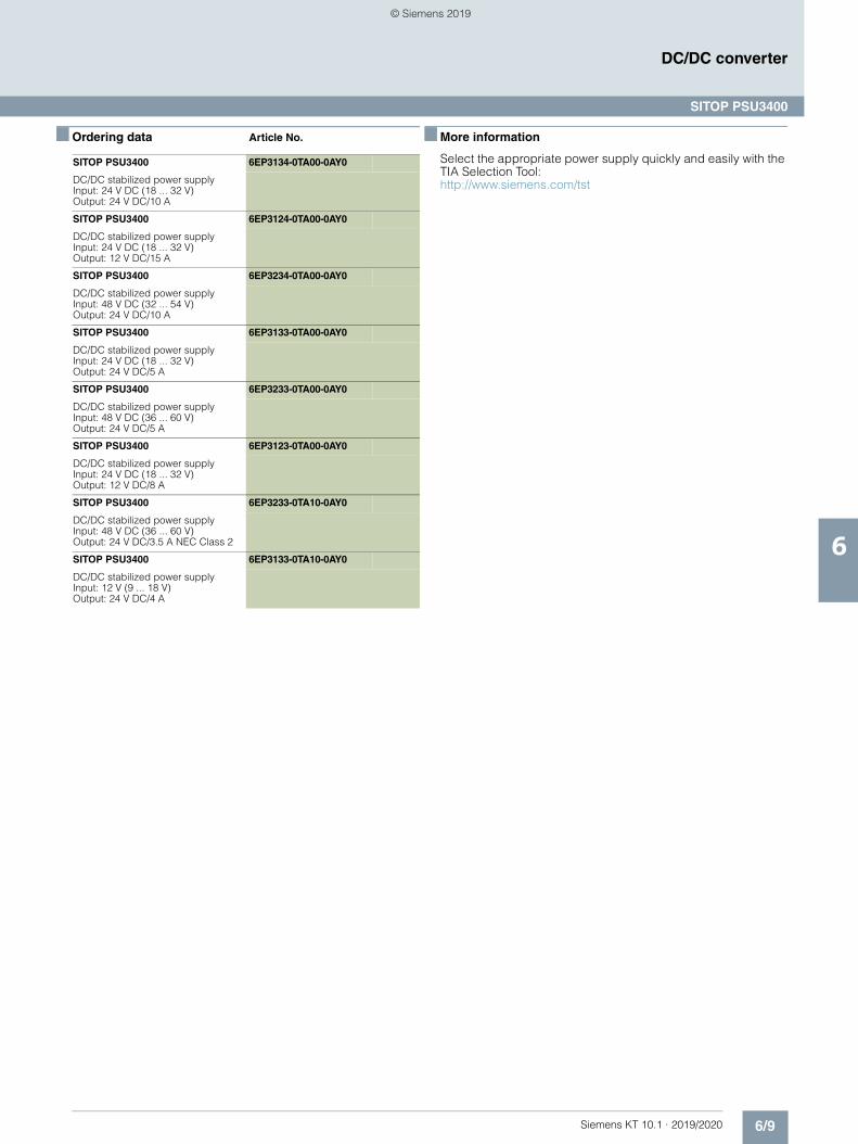
6/9Siemens KT 10.1 · 2019/2020
6
DC/DC converter
SITOP PSU3400
■ Ordering data Article No. ■ More information
Select the appropriate power supply quickly and easily with the TIA Selection Tool:http://www.siemens.com/tst
SITOP PSU3400 6EP3134-0TA00-0AY0
DC/DC stabilized power supply Input: 24 V DC (18 ... 32 V)Output: 24 V DC/10 A
SITOP PSU3400 6EP3124-0TA00-0AY0
DC/DC stabilized power supplyInput: 24 V DC (18 ... 32 V)Output: 12 V DC/15 A
SITOP PSU3400 6EP3234-0TA00-0AY0
DC/DC stabilized power supplyInput: 48 V DC (32 ... 54 V)Output: 24 V DC/10 A
SITOP PSU3400 6EP3133-0TA00-0AY0
DC/DC stabilized power supplyInput: 24 V DC (18 ... 32 V)Output: 24 V DC/5 A
SITOP PSU3400 6EP3233-0TA00-0AY0
DC/DC stabilized power supplyInput: 48 V DC (36 ... 60 V)Output: 24 V DC/5 A
SITOP PSU3400 6EP3123-0TA00-0AY0
DC/DC stabilized power supplyInput: 24 V DC (18 ... 32 V)Output: 12 V DC/8 A
SITOP PSU3400 6EP3233-0TA10-0AY0
DC/DC stabilized power supplyInput: 48 V DC (36 ... 60 V)Output: 24 V DC/3.5 A NEC Class 2
SITOP PSU3400 6EP3133-0TA10-0AY0
DC/DC stabilized power supplyInput: 12 V (9 ... 18 V)Output: 24 V DC/4 A
© Siemens 2019
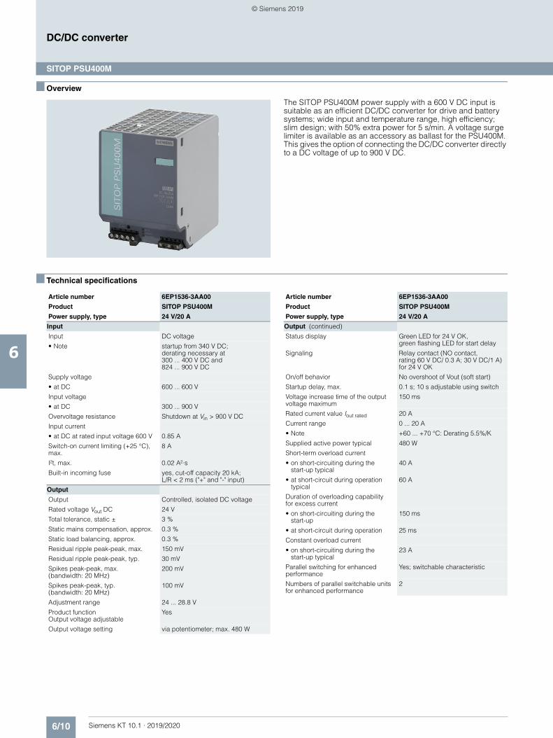
6/10 Siemens KT 10.1 · 2019/2020
6
DC/DC converter
SITOP PSU400M
■ Overview
The SITOP PSU400M power supply with a 600 V DC input is suitable as an efficient DC/DC converter for drive and battery systems; wide input and temperature range, high efficiency;slim design; with 50% extra power for 5 s/min. A voltage surge limiter is available as an accessory as ballast for the PSU400M. This gives the option of connecting the DC/DC converter directly to a DC voltage of up to 900 V DC.
■ Technical specifications
Article number 6EP1536-3AA00
Product SITOP PSU400M
Power supply, type 24 V/20 A
Input
Input DC voltage
• Note startup from 340 V DC; derating necessary at 300 ... 400 V DC and 824 ... 900 V DC
Supply voltage
• at DC 600 ... 600 V
Input voltage
• at DC 300 ... 900 V
Overvoltage resistance Shutdown at Vin > 900 V DC
Input current
• at DC at rated input voltage 600 V 0.85 A
Switch-on current limiting (+25 °C), max.
8 A
I²t, max. 0.02 A²·s
Built-in incoming fuse yes, cut-off capacity 20 kA; L/R < 2 ms ("+" and "-" input)
Output
Output Controlled, isolated DC voltage
Rated voltage Vout DC 24 V
Total tolerance, static ± 3 %
Static mains compensation, approx. 0.3 %
Static load balancing, approx. 0.3 %
Residual ripple peak-peak, max. 150 mV
Residual ripple peak-peak, typ. 30 mV
Spikes peak-peak, max. (bandwidth: 20 MHz)
200 mV
Spikes peak-peak, typ. (bandwidth: 20 MHz)
100 mV
Adjustment range 24 ... 28.8 V
Product function Output voltage adjustable
Yes
Output voltage setting via potentiometer; max. 480 W
Output (continued)
Status display Green LED for 24 V OK, green flashing LED for start delay
Signaling Relay contact (NO contact, rating 60 V DC/ 0.3 A; 30 V DC/1 A) for 24 V OK
On/off behavior No overshoot of Vout (soft start)
Startup delay, max. 0.1 s; 10 s adjustable using switch
Voltage increase time of the output voltage maximum
150 ms
Rated current value Iout rated 20 A
Current range 0 ... 20 A
• Note +60 ... +70 °C: Derating 5.5%/K
Supplied active power typical 480 W
Short-term overload current
• on short-circuiting during thestart-up typical
40 A
• at short-circuit during operation typical
60 A
Duration of overloading capabilityfor excess current
• on short-circuiting during thestart-up
150 ms
• at short-circuit during operation 25 ms
Constant overload current
• on short-circuiting during thestart-up typical
23 A
Parallel switching for enhanced performance
Yes; switchable characteristic
Numbers of parallel switchable units for enhanced performance
2
Article number 6EP1536-3AA00
Product SITOP PSU400M
Power supply, type 24 V/20 A
© Siemens 2019
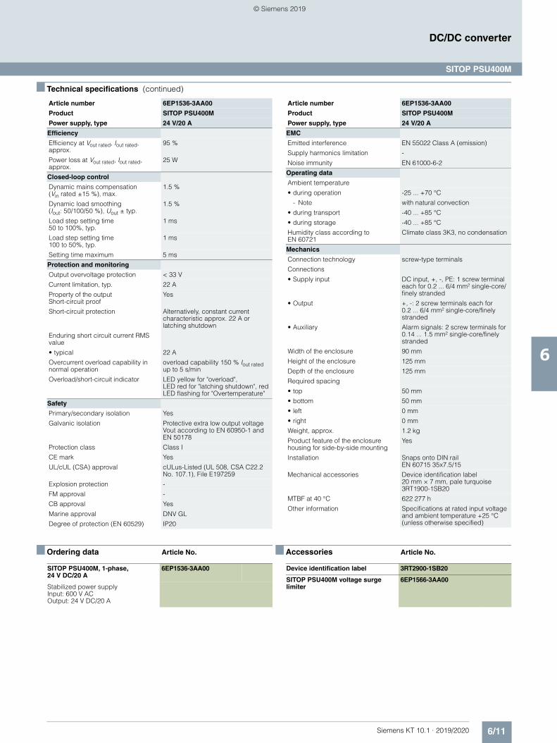
6/11Siemens KT 10.1 · 2019/2020
6
■ Technical specifications (continued)
DC/DC converter
SITOP PSU400M
■ Ordering data Article No. ■ Accessories Article No.
Efficiency
Efficiency at Vout rated, Iout rated, approx.
95 %
Power loss at Vout rated, Iout rated, approx.
25 W
Closed-loop control
Dynamic mains compensation(Vin rated ±15 %), max.
1.5 %
Dynamic load smoothing(Iout: 50/100/50 %), Uout ± typ.
1.5 %
Load step setting time 50 to 100%, typ.
1 ms
Load step setting time 100 to 50%, typ.
1 ms
Setting time maximum 5 ms
Protection and monitoring
Output overvoltage protection < 33 V
Current limitation, typ. 22 A
Property of the output Short-circuit proof
Yes
Short-circuit protection Alternatively, constant current characteristic approx. 22 A or latching shutdown
Enduring short circuit current RMS value
• typical 22 A
Overcurrent overload capability in normal operation
overload capability 150 % Iout rated up to 5 s/min
Overload/short-circuit indicator LED yellow for "overload", LED red for "latching shutdown", red LED flashing for "Overtemperature"
Safety
Primary/secondary isolation Yes
Galvanic isolation Protective extra low output voltage Vout according to EN 60950-1 and EN 50178
Protection class Class I
CE mark Yes
UL/cUL (CSA) approval cULus-Listed (UL 508, CSA C22.2 No. 107.1), File E197259
Explosion protection -
FM approval -
CB approval Yes
Marine approval DNV GL
Degree of protection (EN 60529) IP20
Article number 6EP1536-3AA00
Product SITOP PSU400M
Power supply, type 24 V/20 A
EMC
Emitted interference EN 55022 Class A (emission)
Supply harmonics limitation -
Noise immunity EN 61000-6-2
Operating data
Ambient temperature
• during operation -25 ... +70 °C
- Note with natural convection
• during transport -40 ... +85 °C
• during storage -40 ... +85 °C
Humidity class according to EN 60721
Climate class 3K3, no condensation
Mechanics
Connection technology screw-type terminals
Connections
• Supply input DC input, +, -, PE: 1 screw terminal each for 0.2 ... 6/4 mm² single-core/finely stranded
• Output +, -: 2 screw terminals each for0.2 ... 6/4 mm² single-core/finely stranded
• Auxiliary Alarm signals: 2 screw terminals for 0.14 ... 1.5 mm² single-core/finely stranded
Width of the enclosure 90 mm
Height of the enclosure 125 mm
Depth of the enclosure 125 mm
Required spacing
• top 50 mm
• bottom 50 mm
• left 0 mm
• right 0 mm
Weight, approx. 1.2 kg
Product feature of the enclosure housing for side-by-side mounting
Yes
Installation Snaps onto DIN railEN 60715 35x7.5/15
Mechanical accessories Device identification label 20 mm × 7 mm, pale turquoise 3RT1900-1SB20
MTBF at 40 °C 622 277 h
Other information Specifications at rated input voltage and ambient temperature +25 °C (unless otherwise specified)
Article number 6EP1536-3AA00
Product SITOP PSU400M
Power supply, type 24 V/20 A
SITOP PSU400M, 1-phase, 24 V DC/20 A
6EP1536-3AA00
Stabilized power supplyInput: 600 V ACOutput: 24 V DC/20 A
Device identification label 3RT2900-1SB20
SITOP PSU400M voltage surge limiter
6EP1566-3AA00
© Siemens 2019
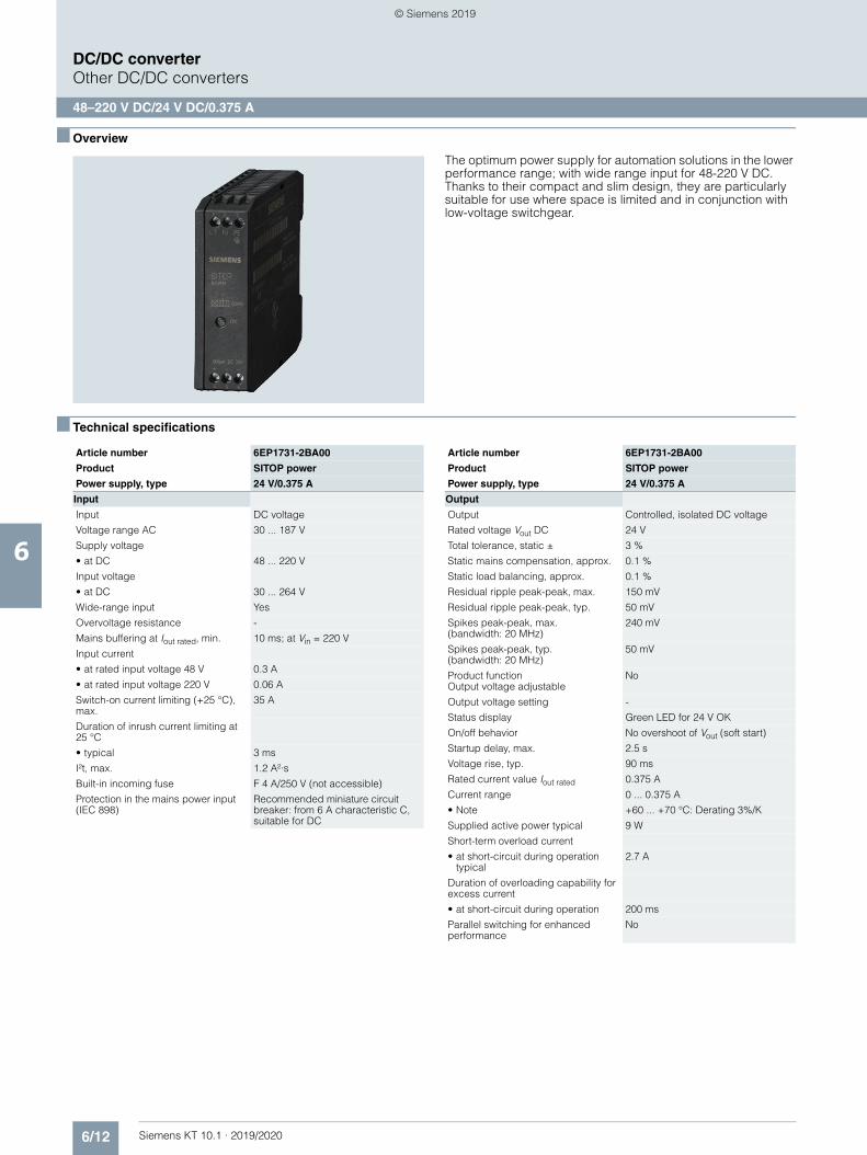
6/12 Siemens KT 10.1 · 2019/2020
6
DC/DC converterOther DC/DC converters
48–220 V DC/24 V DC/0.375 A
■ Overview
The optimum power supply for automation solutions in the lower performance range; with wide range input for 48-220 V DC. Thanks to their compact and slim design, they are particularly suitable for use where space is limited and in conjunction with low-voltage switchgear.
■ Technical specifications
Article number 6EP1731-2BA00
Product SITOP power
Power supply, type 24 V/0.375 A
Input
Input DC voltage
Voltage range AC 30 ... 187 V
Supply voltage
• at DC 48 ... 220 V
Input voltage
• at DC 30 ... 264 V
Wide-range input Yes
Overvoltage resistance -
Mains buffering at Iout rated, min. 10 ms; at Vin = 220 V
Input current
• at rated input voltage 48 V 0.3 A
• at rated input voltage 220 V 0.06 A
Switch-on current limiting (+25 °C), max.
35 A
Duration of inrush current limiting at 25 °C
• typical 3 ms
I²t, max. 1.2 A²·s
Built-in incoming fuse F 4 A/250 V (not accessible)
Protection in the mains power input (IEC 898)
Recommended miniature circuit breaker: from 6 A characteristic C, suitable for DC
Output
Output Controlled, isolated DC voltage
Rated voltage Vout DC 24 V
Total tolerance, static ± 3 %
Static mains compensation, approx. 0.1 %
Static load balancing, approx. 0.1 %
Residual ripple peak-peak, max. 150 mV
Residual ripple peak-peak, typ. 50 mV
Spikes peak-peak, max.(bandwidth: 20 MHz)
240 mV
Spikes peak-peak, typ.(bandwidth: 20 MHz)
50 mV
Product function Output voltage adjustable
No
Output voltage setting -
Status display Green LED for 24 V OK
On/off behavior No overshoot of Vout (soft start)
Startup delay, max. 2.5 s
Voltage rise, typ. 90 ms
Rated current value Iout rated 0.375 A
Current range 0 ... 0.375 A
• Note +60 ... +70 °C: Derating 3%/K
Supplied active power typical 9 W
Short-term overload current
• at short-circuit during operation typical
2.7 A
Duration of overloading capability for excess current
• at short-circuit during operation 200 ms
Parallel switching for enhanced performance
No
Article number 6EP1731-2BA00
Product SITOP power
Power supply, type 24 V/0.375 A
© Siemens 2019
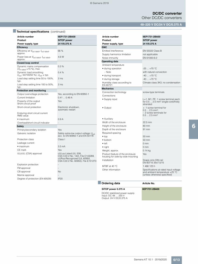
6/13Siemens KT 10.1 · 2019/2020
6
■ Technical specifications (continued)
DC/DC converterOther DC/DC converters
48–220 V DC/24 V DC/0.375 A
■ Ordering data Article No.
Efficiency
Efficiency at Vout rated, Iout rated, approx.
66 %
Power loss at Vout rated, Iout rated, approx.
4.6 W
Closed-loop control
Dynamic mains compensation (Vin rated ±15 %), max.
0.3 %
Dynamic load smoothing (Iout: 50/100/50 %), Uout ± typ.
0.4 %
Load step setting time 50 to 100%, typ.
2 ms
Load step setting time 100 to 50%, typ.
2 ms
Protection and monitoring
Output overvoltage protection Yes, according to EN 60950-1
Current limitation 0.41 ... 0.49 A
Property of the output Short-circuit proof
Yes
Short-circuit protection Electronic shutdown,automatic restart
Enduring short circuit current RMS value
• maximum 0.9 A
Overload/short-circuit indicator -
Safety
Primary/secondary isolation Yes
Galvanic isolation Safety extra-low output voltage Uout acc. to EN 60950-1 and EN 50178
Protection class Class I
Leakage current
• maximum 3.5 mA
CE mark Yes
UL/cUL (CSA) approval cULus-Listed (UL 508, CSA C22.2 No. 142), File E143289, cURus-Recognized (UL 60950, CSA C22.2 No. 60950), File E151273
Explosion protection -
FM approval -
CB approval No
Marine approval -
Degree of protection (EN 60529) IP20
Article number 6EP1731-2BA00
Product SITOP power
Power supply, type 24 V/0.375 A
EMC
Emitted interference EN 55022 Class B
Supply harmonics limitation not applicable
Noise immunity EN 61000-6-2
Operating data
Ambient temperature
• during operation -25 ... +70 °C
- Note with natural convection
• during transport -40 ... +70 °C
• during storage -40 ... +70 °C
Humidity class according to EN 60721
Climate class 3K3, no condensation
Mechanics
Connection technology screw-type terminals
Connections
• Supply input L+1, M1, PE: 1 screw terminal each for 0.5 ... 2.5 mm² single-core/finely stranded
• Output +: 1 screw terminal for 0.5 ... 2.5 mm²; -: 2 screw terminals for 0.5 ... 2.5 mm²
• Auxiliary -
Width of the enclosure 22.5 mm
Height of the enclosure 80 mm
Depth of the enclosure 91 mm
Required spacing
• top 50 mm
• bottom 50 mm
• left 0 mm
• right 0 mm
Weight, approx. 0.14 kg
Product feature of the enclosure housing for side-by-side mounting
Yes
Installation Snaps onto DIN rail EN 60715 35x7.5/15
MTBF at 40 °C 1 466 123 h
Other information Specifications at rated input voltage and ambient temperature +25 °C (unless otherwise specified)
SITOP power 0.375 A 6EP1731-2BA00
DC/DC stabilized power supply Input: DC 48 … 220 V Output: 24 V DC/0.375 A
Article number 6EP1731-2BA00
Product SITOP power
Power supply, type 24 V/0.375 A
© Siemens 2019
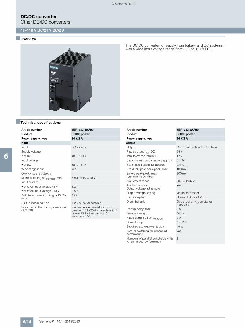
6/14 Siemens KT 10.1 · 2019/2020
6
DC/DC converterOther DC/DC converters
48–110 V DC/24 V DC/2 A
■ Overview
The DC/DC converter for supply from battery and DC systems; with a wide input voltage range from 38 V to 121 V DC.
■ Technical specifications
Article number 6EP1732-0AA00
Product SITOP power
Power supply, type 24 V/2 A
Input
Input DC voltage
Supply voltage
• at DC 48 ... 110 V
Input voltage
• at DC 38 ... 121 V
Wide-range input Yes
Overvoltage resistance -
Mains buffering at Iout rated, min. 5 ms; at Vin = 48 V
Input current
• at rated input voltage 48 V 1.2 A
• at rated input voltage 110 V 0.5 A
Switch-on current limiting (+25 °C), max.
33 A
Built-in incoming fuse T 2.5 A (not accessible)
Protection in the mains power input (IEC 898)
Recommended miniature circuit breaker: 10 to 25 A characteristic B or 6 to 25 A characteristic C, suitable for DC
Output
Output Controlled, isolated DC voltage
Rated voltage Vout DC 24 V
Total tolerance, static ± 1 %
Static mains compensation, approx. 0.1 %
Static load balancing, approx. 0.4 %
Residual ripple peak-peak, max. 100 mV
Spikes peak-peak, max. (bandwidth: 20 MHz)
300 mV
Adjustment range 23.5 ... 26.5 V
Product functionOutput voltage adjustable
Yes
Output voltage setting via potentiometer
Status display Green LED for 24 V OK
On/off behavior Overshoot of Vout on startup max. 25 V
Startup delay, max. 3 s
Voltage rise, typ. 30 ms
Rated current value Iout rated 2 A
Current range 0 ... 2 A
Supplied active power typical 48 W
Parallel switching for enhanced performance
Yes
Numbers of parallel switchable units for enhanced performance
2
Article number 6EP1732-0AA00
Product SITOP power
Power supply, type 24 V/2 A
© Siemens 2019
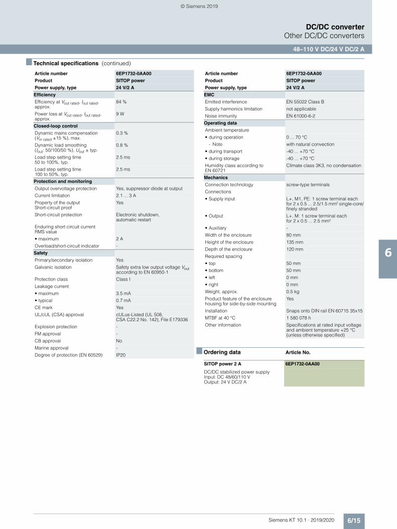
6/15Siemens KT 10.1 · 2019/2020
6
■ Technical specifications (continued)
DC/DC converterOther DC/DC converters
48–110 V DC/24 V DC/2 A
■ Ordering data Article No.
Efficiency
Efficiency at Vout rated, Iout rated, approx.
84 %
Power loss at Vout rated, Iout rated, approx.
9 W
Closed-loop control
Dynamic mains compensation(Vin rated ±15 %), max.
0.3 %
Dynamic load smoothing (Iout: 50/100/50 %), Uout ± typ.
0.8 %
Load step setting time 50 to 100%, typ.
2.5 ms
Load step setting time 100 to 50%, typ.
2.5 ms
Protection and monitoring
Output overvoltage protection Yes, suppressor diode at output
Current limitation 2.1 ... 3 A
Property of the outputShort-circuit proof
Yes
Short-circuit protection Electronic shutdown, automatic restart
Enduring short circuit currentRMS value
• maximum 2 A
Overload/short-circuit indicator -
Safety
Primary/secondary isolation Yes
Galvanic isolation Safety extra low output voltage Vout according to EN 60950-1
Protection class Class I
Leakage current
• maximum 3.5 mA
• typical 0.7 mA
CE mark Yes
UL/cUL (CSA) approval cULus-Listed (UL 508, CSA C22.2 No. 142), File E179336
Explosion protection -
FM approval -
CB approval No
Marine approval -
Degree of protection (EN 60529) IP20
Article number 6EP1732-0AA00
Product SITOP power
Power supply, type 24 V/2 A
EMC
Emitted interference EN 55022 Class B
Supply harmonics limitation not applicable
Noise immunity EN 61000-6-2
Operating data
Ambient temperature
• during operation 0 ... 70 °C
- Note with natural convection
• during transport -40 ... +70 °C
• during storage -40 ... +70 °C
Humidity class according to EN 60721
Climate class 3K3, no condensation
Mechanics
Connection technology screw-type terminals
Connections
• Supply input L+, M1, PE: 1 screw terminal each for 2 x 0.5 ... 2.5/1.5 mm² single-core/finely stranded
• Output L+, M: 1 screw terminal eachfor 2 x 0.5 ... 2.5 mm²
• Auxiliary -
Width of the enclosure 80 mm
Height of the enclosure 135 mm
Depth of the enclosure 120 mm
Required spacing
• top 50 mm
• bottom 50 mm
• left 0 mm
• right 0 mm
Weight, approx. 0.5 kg
Product feature of the enclosure housing for side-by-side mounting
Yes
Installation Snaps onto DIN rail EN 60715 35x15
MTBF at 40 °C 1 580 078 h
Other information Specifications at rated input voltage and ambient temperature +25 °C (unless otherwise specified)
SITOP power 2 A 6EP1732-0AA00
DC/DC stabilized power supply Input: DC 48/60/110 V Output: 24 V DC/2 A
Article number 6EP1732-0AA00
Product SITOP power
Power supply, type 24 V/2 A
© Siemens 2019
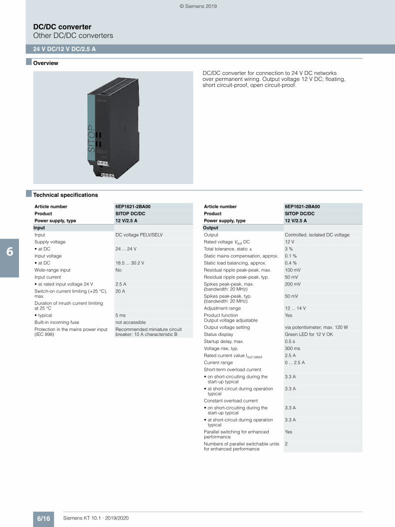
6/16 Siemens KT 10.1 · 2019/2020
6
DC/DC converterOther DC/DC converters
24 V DC/12 V DC/2.5 A
■ Overview
DC/DC converter for connection to 24 V DC networks over permanent wiring. Output voltage 12 V DC; floating,short circuit-proof, open circuit-proof.
■ Technical specifications
Article number 6EP1621-2BA00
Product SITOP DC/DC
Power supply, type 12 V/2.5 A
Input
Input DC voltage PELV/SELV
Supply voltage
• at DC 24 ... 24 V
Input voltage
• at DC 18.5 ... 30.2 V
Wide-range input No
Input current
• at rated input voltage 24 V 2.5 A
Switch-on current limiting (+25 °C), max.
20 A
Duration of inrush current limiting at 25 °C
• typical 5 ms
Built-in incoming fuse not accessible
Protection in the mains power input (IEC 898)
Recommended miniature circuit breaker: 10 A characteristic B
Output
Output Controlled, isolated DC voltage
Rated voltage Vout DC 12 V
Total tolerance, static ± 3 %
Static mains compensation, approx. 0.1 %
Static load balancing, approx. 0.4 %
Residual ripple peak-peak, max. 100 mV
Residual ripple peak-peak, typ. 50 mV
Spikes peak-peak, max.(bandwidth: 20 MHz)
200 mV
Spikes peak-peak, typ.(bandwidth: 20 MHz)
50 mV
Adjustment range 12 ... 14 V
Product functionOutput voltage adjustable
Yes
Output voltage setting via potentiometer; max. 120 W
Status display Green LED for 12 V OK
Startup delay, max. 0.5 s
Voltage rise, typ. 300 ms
Rated current value Iout rated 2.5 A
Current range 0 ... 2.5 A
Short-term overload current
• on short-circuiting during thestart-up typical
3.3 A
• at short-circuit during operation typical
3.3 A
Constant overload current
• on short-circuiting during the start-up typical
3.3 A
• at short-circuit during operation typical
3.3 A
Parallel switching for enhanced performance
Yes
Numbers of parallel switchable units for enhanced performance
2
Article number 6EP1621-2BA00
Product SITOP DC/DC
Power supply, type 12 V/2.5 A
© Siemens 2019
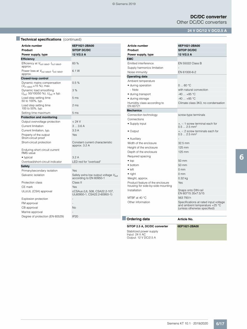
6/17Siemens KT 10.1 · 2019/2020
6
■ Technical specifications (continued)
DC/DC converterOther DC/DC converters
24 V DC/12 V DC/2.5 A
■ Ordering data Article No.
Efficiency
Efficiency at Vout rated, Iout rated, approx.
83 %
Power loss at Vout rated, Iout rated, approx.
6.1 W
Closed-loop control
Dynamic mains compensation (Vin rated ±15 %), max.
0.5 %
Dynamic load smoothing(Iout: 50/100/50 %), Uout ± typ.
3 %
Load step setting time 50 to 100%, typ.
5 ms
Load step setting time 100 to 50%, typ.
2 ms
Setting time maximum 5 ms
Protection and monitoring
Output overvoltage protection < 24 V
Current limitation 3 ... 3.6 A
Current limitation, typ. 3.3 A
Property of the output Short-circuit proof
Yes
Short-circuit protection Constant current characteristic approx. 3.2 A
Enduring short circuit current RMS value
• typical 3.2 A
Overload/short-circuit indicator LED red for "overload"
Safety
Primary/secondary isolation Yes
Galvanic isolation Safety extra low output voltage Vout according to EN 60950-1
Protection class Class II
CE mark Yes
UL/cUL (CSA) approval cCSAus (UL 508, CSA22.2-107, UL60950-1, CSA22.2-60950-1)
Explosion protection -
FM approval -
CB approval No
Marine approval -
Degree of protection (EN 60529) IP20
Article number 6EP1621-2BA00
Product SITOP DC/DC
Power supply, type 12 V/2.5 A
EMC
Emitted interference EN 55022 Class B
Supply harmonics limitation -
Noise immunity EN 61000-6-2
Operating data
Ambient temperature
• during operation 0 ... 60 °C
- Note with natural convection
• during transport -40 ... +85 °C
• during storage -40 ... +85 °C
Humidity class according to EN 60721
Climate class 3K3, no condensation
Mechanics
Connection technology screw-type terminals
Connections
• Supply input +, -: 1 screw terminal each for 0.5 ... 2.5 mm²
• Output +, -: 2 screw terminals each for 0.5 ... 2.5 mm²
• Auxiliary -
Width of the enclosure 32.5 mm
Height of the enclosure 125 mm
Depth of the enclosure 125 mm
Required spacing
• top 50 mm
• bottom 50 mm
• left 0 mm
• right 0 mm
Weight, approx. 0.32 kg
Product feature of the enclosure housing for side-by-side mounting
Yes
Installation Snaps onto DIN rail EN 60715 35x7.5/15
MTBF at 40 °C 563 793 h
Other information Specifications at rated input voltage and ambient temperature +25 °C (unless otherwise specified)
SITOP 2.5 A, DC/DC converter 6EP1621-2BA00
Stabilized power supply Input: 24 V AC Output: 12 V DC/2.5 A
Article number 6EP1621-2BA00
Product SITOP DC/DC
Power supply, type 12 V/2.5 A
© Siemens 2019
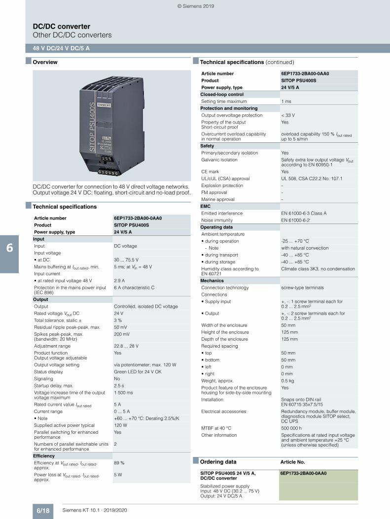
6/18 Siemens KT 10.1 · 2019/2020
6
DC/DC converterOther DC/DC converters
48 V DC/24 V DC/5 A
■ Overview
DC/DC converter for connection to 48 V direct voltage networks. Output voltage 24 V DC; floating, short-circuit and no-load proof.
■ Technical specifications
■ Technical specifications (continued)
■ Ordering data Article No.
Article number 6EP1733-2BA00-0AA0
Product SITOP PSU400S
Power supply, type 24 V/5 A
Input
Input DC voltage
Input voltage
• at DC 30 ... 75.5 V
Mains buffering at Iout rated, min. 5 ms; at Vin = 48 V
Input current
• at rated input voltage 48 V 2.9 A
Protection in the mains power input (IEC 898)
6 A characteristic C
Output
Output Controlled, isolated DC voltage
Rated voltage Vout DC 24 V
Total tolerance, static ± 3 %
Residual ripple peak-peak, max. 50 mV
Spikes peak-peak, max. (bandwidth: 20 MHz)
200 mV
Adjustment range 22.8 ... 28 V
Product function Output voltage adjustable
Yes
Output voltage setting via potentiometer; max. 120 W
Status display Green LED for 24 V OK
Signaling No
Startup delay, max. 2.5 s
Voltage increase time of the output voltage maximum
1 500 ms
Rated current value Iout rated 5 A
Current range 0 ... 5 A
• Note +60 ... +70 °C: Derating 2.5%/K
Supplied active power typical 120 W
Parallel switching for enhanced performance
Yes
Numbers of parallel switchable units for enhanced performance
2
Efficiency
Efficiency at Vout rated, Iout rated, approx.
89 %
Power loss at Vout rated, Iout rated, approx.
5 W
Article number 6EP1733-2BA00-0AA0
Product SITOP PSU400S
Power supply, type 24 V/5 A
Closed-loop control
Setting time maximum 1 ms
Protection and monitoring
Output overvoltage protection < 33 V
Property of the output Short-circuit proof
Yes
Overcurrent overload capabilityin normal operation
overload capability 150 % Iout rated up to 5 s/min
Safety
Primary/secondary isolation Yes
Galvanic isolation Safety extra low output voltage Vout according to EN 60950-1
CE mark Yes
UL/cUL (CSA) approval UL 508, CSA C22.2 No. 107.1
Explosion protection -
FM approval -
Marine approval -
EMC
Emitted interference EN 61000-6-3 Class A
Noise immunity EN 61000-6-2
Operating data
Ambient temperature
• during operation -25 ... +70 °C
- Note with natural convection
• during transport -40 ... +85 °C
• during storage -40 ... +85 °C
Humidity class according to EN 60721
Climate class 3K3, no condensation
Mechanics
Connection technology screw-type terminals
Connections
• Supply input +, -: 1 screw terminal each for0.2 ... 2.5 mm²
• Output +, -: 2 screw terminals each for 0.2 ... 2.5 mm²
Width of the enclosure 50 mm
Height of the enclosure 125 mm
Depth of the enclosure 125 mm
Required spacing
• top 50 mm
• bottom 50 mm
• left 0 mm
• right 0 mm
Weight, approx. 0.5 kg
Product feature of the enclosure housing for side-by-side mounting
Yes
Installation Snaps onto DIN rail EN 60715 35x7.5/15
Electrical accessories Redundancy module, buffer module, diagnostics module SITOP select, DC UPS
MTBF at 40 °C 500 000 h
Other information Specifications at rated input voltage and ambient temperature +25 °C (unless otherwise specified)
SITOP PSU400S 24 V/5 A, DC/DC converter
6EP1733-2BA00-0AA0
Stabilized power supplyInput: 48 V DC (30.2 ... 75 V)Output: 24 V DC/5 A
© Siemens 2019
Siemens KT 10.1 · 2019/2020
77/2 Introduction7/3 Wall mounting7/4 1-phase, 12 V DC (PSU100D)7/7 1-phase, 24 V DC (PSU100D)7/10 High degree of protection7/10 1-phase, 24 V DC (SITOP PSU100P, IP67)7/13 3-phase, 24 V DC (ET200pro PS, IP67)7/16 Battery charging7/16 3-phase, 12 V DC7/18 3-phase, 24 V DC7/21 Medical applications7/22 1-phase, 24 V DC7/24 3-phase, 24 V DC7/26 Alternative output voltages7/26 1-phase, 2 x 15 V DC
(SITOP PSU3600 dual)7/28 1-phase, 3-52 V DC (SITOP PSU3600 flexi)7/30 Special uses7/30 1-phase, 24 V DC7/33 1-phase, 48 V DC (SITOP PSU100E)7/35 3-phase, 24 V DC (SITOP PSU300E)7/37 SIPLUS power supplies7/37 Introduction7/38 Ordering data7/40 AS-Interface power supply units7/40 1-phase / 1-2-phase / DC, AS-i 30 V
(with data decoupling)7/41 1-phase, 30 V DC (without data decoupling)
Special designs, special uses
© Siemens 2019
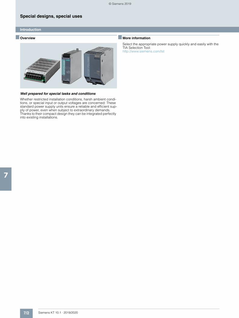
7/2 Siemens KT 10.1 · 2019/2020
7
Special designs, special uses
Introduction
■ Overview
Well prepared for special tasks and conditions
Whether restricted installation conditions, harsh ambient condi-tions, or special input or output voltages are concerned: These standard power supply units ensure a reliable and efficient sup-ply of power, even when subject to extraordinary demands. Thanks to their compact design they can be integrated perfectly into existing installations.
■ More information
Select the appropriate power supply quickly and easily with the TIA Selection Tool:http://www.siemens.com/tst
© Siemens 2019
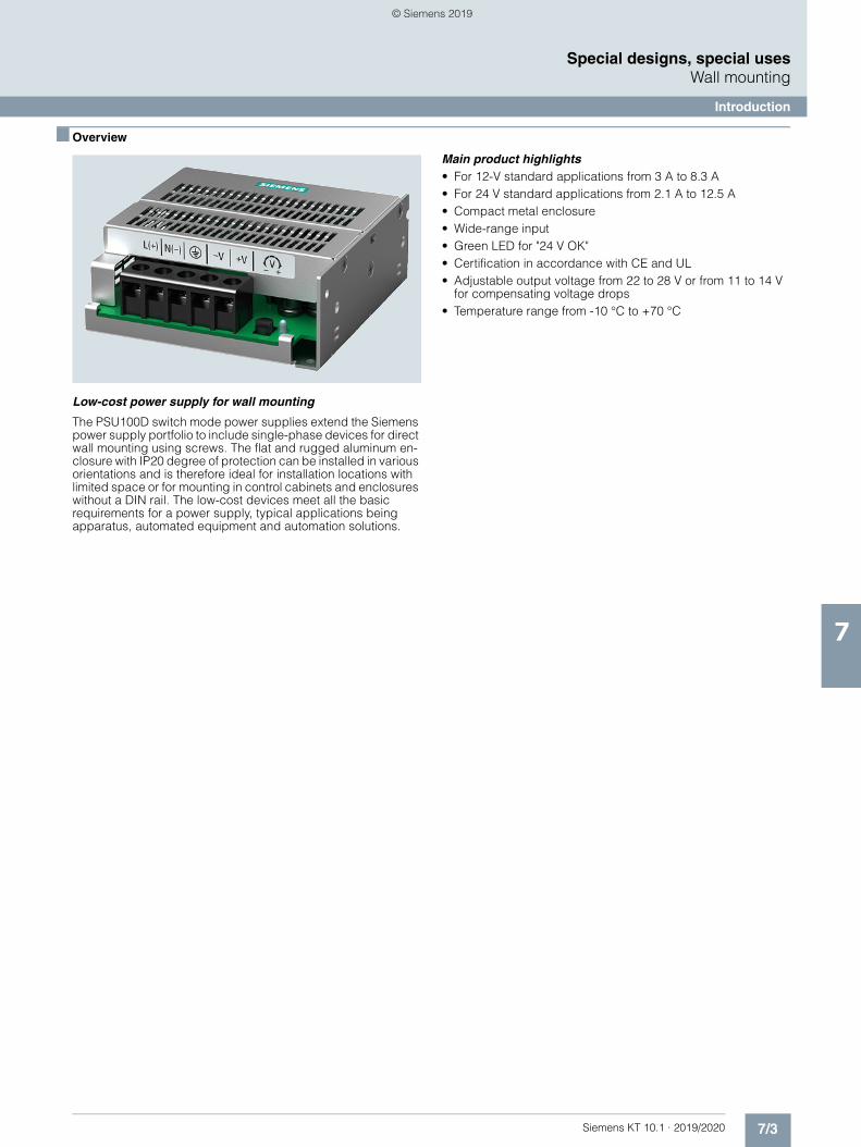
7/3Siemens KT 10.1 · 2019/2020
7
Special designs, special usesWall mounting
Introduction
■ Overview
Low-cost power supply for wall mounting
The PSU100D switch mode power supplies extend the Siemens power supply portfolio to include single-phase devices for direct wall mounting using screws. The flat and rugged aluminum en-closure with IP20 degree of protection can be installed in various orientations and is therefore ideal for installation locations with limited space or for mounting in control cabinets and enclosures without a DIN rail. The low-cost devices meet all the basic requirements for a power supply, typical applications being apparatus, automated equipment and automation solutions.
Main product highlights• For 12-V standard applications from 3 A to 8.3 A• For 24 V standard applications from 2.1 A to 12.5 A• Compact metal enclosure• Wide-range input• Green LED for "24 V OK"• Certification in accordance with CE and UL• Adjustable output voltage from 22 to 28 V or from 11 to 14 V
for compensating voltage drops• Temperature range from -10 °C to +70 °C
© Siemens 2019
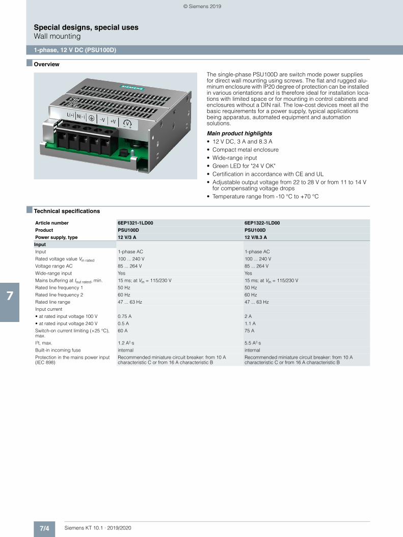
7/4 Siemens KT 10.1 · 2019/2020
7
Special designs, special usesWall mounting
1-phase, 12 V DC (PSU100D)
■ Overview
The single-phase PSU100D are switch mode power supplies for direct wall mounting using screws. The flat and rugged alu-minum enclosure with IP20 degree of protection can be installed in various orientations and is therefore ideal for installation loca-tions with limited space or for mounting in control cabinets and enclosures without a DIN rail. The low-cost devices meet all the basic requirements for a power supply, typical applications being apparatus, automated equipment and automation solutions.
Main product highlights• 12 V DC, 3 A and 8.3 A• Compact metal enclosure• Wide-range input• Green LED for "24 V OK"• Certification in accordance with CE and UL• Adjustable output voltage from 22 to 28 V or from 11 to 14 V
for compensating voltage drops• Temperature range from -10 °C to +70 °C
■ Technical specifications
Article number 6EP1321-1LD00 6EP1322-1LD00
Product PSU100D PSU100D
Power supply, type 12 V/3 A 12 V/8.3 A
Input
Input 1-phase AC 1-phase AC
Rated voltage value Vin rated 100 ... 240 V 100 ... 240 V
Voltage range AC 85 ... 264 V 85 ... 264 V
Wide-range input Yes Yes
Mains buffering at Iout rated, min. 15 ms; at Vin = 115/230 V 15 ms; at Vin = 115/230 V
Rated line frequency 1 50 Hz 50 Hz
Rated line frequency 2 60 Hz 60 Hz
Rated line range 47 ... 63 Hz 47 ... 63 Hz
Input current
• at rated input voltage 100 V 0.75 A 2 A
• at rated input voltage 240 V 0.5 A 1.1 A
Switch-on current limiting (+25 °C), max.
60 A 75 A
I²t, max. 1.2 A²·s 5.5 A²·s
Built-in incoming fuse internal internal
Protection in the mains power input (IEC 898)
Recommended miniature circuit breaker: from 10 A characteristic C or from 16 A characteristic B
Recommended miniature circuit breaker: from 10 A characteristic C or from 16 A characteristic B
© Siemens 2019
7/5Siemens KT 10.1 · 2019/2020
7
■ Technical specifications (continued)
Special designs, special usesWall mounting
1-phase, 12 V DC (PSU100D)
Output
Output Controlled, isolated DC voltage Controlled, isolated DC voltage
Rated voltage Vout DC 12 V 12 V
Total tolerance, static ± 2 % 2 %
Static mains compensation, approx. 0.5 % 0.5 %
Static load balancing, approx. 1 % 1 %
Residual ripple peak-peak, max. 100 mV 100 mV
Spikes peak-peak, max. (bandwidth: 20 MHz)
100 mV 100 mV
Adjustment range 11 ... 14 V 11 ... 14 V
Product function Output voltage adjustable
Yes Yes
Output voltage setting via potentiometer via potentiometer
Status display Green LED for 12 V OK Green LED for 12 V OK
On/off behavior Overshoot of Vout < 2 % Overshoot of Vout < 2 %
Startup delay, max. 2.5 s 1 s
Voltage increase time of the output voltage maximum
30 ms 30 ms
Rated current value Iout rated 3 A 8.3 A
Current range 0 ... 3 A 0 ... 8.3 A
• Note +50 ... +70 °C: Derating 2.5%/K +50 ... +70 °C: Derating 2.5%/K
Supplied active power typical 36 W 100 W
Parallel switching for enhanced performance
Yes Yes
Numbers of parallel switchable units for enhanced performance
2 2
Efficiency
Efficiency at Vout rated, Iout rated, approx.
84 % 84 %
Power loss at Vout rated, Iout rated, approx.
6.5 W 19 W
Closed-loop control
Dynamic mains compensation(Vin rated ±15 %), max.
0.5 % 0.5 %
Dynamic load smoothing(Iout: 50/100/50 %), Uout ± typ.
5 % 5 %
Protection and monitoring
Output overvoltage protection < 17.6 V < 17.6 V
Current limitation, typ. 3.6 A 9.9 A
Property of the output Short-circuit proof
Yes Yes
Short-circuit protection Electronic shutdown, automatic restart Electronic shutdown, automatic restart
Enduring short circuit current RMS value
• typical 6 A 10 A
Overload/short-circuit indicator - -
Safety
Primary/secondary isolation Yes Yes
Galvanic isolation Safety extra low output voltage Vout according to EN 60950-1
Safety extra low output voltage Vout according to EN 60950-1
Protection class Class I Class I
Leakage current
• maximum 3.5 mA 3.5 mA
• typical 1 mA 1 mA
CE mark Yes Yes
UL/cUL (CSA) approval cULus-Listed (UL 508, CSA C22.2 No. 107.1), File E197259; cURus (UL 60950-1, CSA C22.2 No. 60950-1), File E151273
cULus-Listed (UL 508, CSA C22.2 No. 107.1), File E197259; cURus (UL 60950-1, CSA C22.2 No. 60950-1), File E151273
Explosion protection - -
FM approval - -
CB approval Yes Yes
Marine approval - -
Degree of protection (EN 60529) IP20 IP20
Article number 6EP1321-1LD00 6EP1322-1LD00
Product PSU100D PSU100D
Power supply, type 12 V/3 A 12 V/8.3 A
© Siemens 2019
7/6 Siemens KT 10.1 · 2019/2020
7
■ Technical specifications (continued)
Special designs, special usesWall mounting
1-phase, 12 V DC (PSU100D)
■ Ordering data Article No.
EMC
Emitted interference EN 55022 Class B EN 55022 Class B
Supply harmonics limitation not applicable EN 61000-3-2
Noise immunity EN 61000-6-2 EN 61000-6-2
Operating data
Ambient temperature
• during operation -10 ... +70 °C -10 ... +70 °C
- Note with natural convection with natural convection
• during transport -40 ... +85 °C -40 ... +85 °C
• during storage -40 ... +85 °C -40 ... +85 °C
Mechanics
Connection technology screw-type terminals screw-type terminals
Connections
• Supply input L, N, PE: 1 screw terminal each for 0.3 ... 1.3 mm²single-core/finely stranded
L, N, PE: 1 screw terminal each for 0.3 ... 1.3 mm² single-core/finely stranded
• Output +, -: 1 screw terminal each for 0.3 ... 1.3 mm² +, -: 2 screw terminals each for 0.3 ... 1.3 mm²
• Auxiliary - -
Width of the enclosure 97 mm 97 mm
Height of the enclosure 98 mm 158 mm
Depth of the enclosure 38 mm 38 mm
Required spacing
• top 20 mm 20 mm
• bottom 0 mm 0 mm
• left 20 mm 20 mm
• right 20 mm 20 mm
Weight, approx. 0.37 kg 0.57 kg
Installation Wall mounting Wall mounting
Other information Specifications at rated input voltage and ambient temperature +25 °C (unless otherwise specified)
Specifications at rated input voltage and ambient temperature +25 °C (unless otherwise specified)
Article number 6EP1321-1LD00 6EP1322-1LD00
Product PSU100D PSU100D
Power supply, type 12 V/3 A 12 V/8.3 A
PSU100D 1-phase, 12 V DC/3 A 6EP1321-1LD00
Stabilized power supply 35 W,for wall mountingInput: 100 ... 240 V AC Output: 12 V DC/3 A
PSU100D 1-phase, 12 V DC/8.3 A 6EP1322-1LD00
Stabilized power supply 100 W,for wall mountingInput: 100 ... 240 V AC Output: 12 V DC/8.3 A
© Siemens 2019
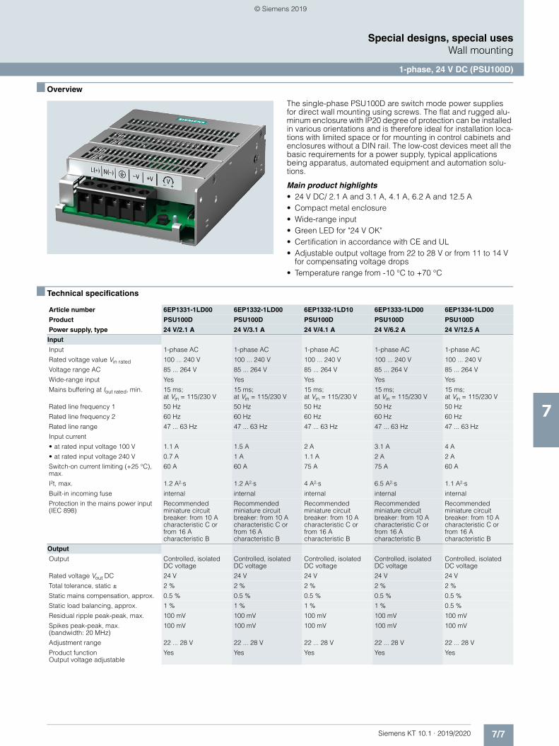
7/7Siemens KT 10.1 · 2019/2020
7
Special designs, special usesWall mounting
1-phase, 24 V DC (PSU100D)
■ Overview
The single-phase PSU100D are switch mode power supplies for direct wall mounting using screws. The flat and rugged alu-minum enclosure with IP20 degree of protection can be installed in various orientations and is therefore ideal for installation loca-tions with limited space or for mounting in control cabinets and enclosures without a DIN rail. The low-cost devices meet all the basic requirements for a power supply, typical applications being apparatus, automated equipment and automation solu-tions.
Main product highlights• 24 V DC/ 2.1 A and 3.1 A, 4.1 A, 6.2 A and 12.5 A• Compact metal enclosure• Wide-range input• Green LED for "24 V OK"• Certification in accordance with CE and UL• Adjustable output voltage from 22 to 28 V or from 11 to 14 V
for compensating voltage drops• Temperature range from -10 °C to +70 °C
■ Technical specifications
Article number 6EP1331-1LD00 6EP1332-1LD00 6EP1332-1LD10 6EP1333-1LD00 6EP1334-1LD00
Product PSU100D PSU100D PSU100D PSU100D PSU100D
Power supply, type 24 V/2.1 A 24 V/3.1 A 24 V/4.1 A 24 V/6.2 A 24 V/12.5 A
Input
Input 1-phase AC 1-phase AC 1-phase AC 1-phase AC 1-phase AC
Rated voltage value Vin rated 100 ... 240 V 100 ... 240 V 100 ... 240 V 100 ... 240 V 100 ... 240 V
Voltage range AC 85 ... 264 V 85 ... 264 V 85 ... 264 V 85 ... 264 V 85 ... 264 V
Wide-range input Yes Yes Yes Yes Yes
Mains buffering at Iout rated, min. 15 ms; at Vin = 115/230 V
15 ms; at Vin = 115/230 V
15 ms; at Vin = 115/230 V
15 ms; at Vin = 115/230 V
15 ms; at Vin = 115/230 V
Rated line frequency 1 50 Hz 50 Hz 50 Hz 50 Hz 50 Hz
Rated line frequency 2 60 Hz 60 Hz 60 Hz 60 Hz 60 Hz
Rated line range 47 ... 63 Hz 47 ... 63 Hz 47 ... 63 Hz 47 ... 63 Hz 47 ... 63 Hz
Input current
• at rated input voltage 100 V 1.1 A 1.5 A 2 A 3.1 A 4 A
• at rated input voltage 240 V 0.7 A 1 A 1.1 A 2 A 2 A
Switch-on current limiting (+25 °C), max.
60 A 60 A 75 A 75 A 60 A
I²t, max. 1.2 A²·s 1.2 A²·s 4 A²·s 6.5 A²·s 1.1 A²·s
Built-in incoming fuse internal internal internal internal internal
Protection in the mains power input (IEC 898)
Recommended miniature circuit breaker: from 10 A characteristic C or from 16 Acharacteristic B
Recommended miniature circuit breaker: from 10 A characteristic C or from 16 Acharacteristic B
Recommended miniature circuit breaker: from 10 A characteristic C or from 16 A characteristic B
Recommended miniature circuit breaker: from 10 A characteristic C or from 16 A characteristic B
Recommended miniature circuit breaker: from 10 A characteristic C or from 16 A characteristic B
Output
Output Controlled, isolated DC voltage
Controlled, isolated DC voltage
Controlled, isolated DC voltage
Controlled, isolated DC voltage
Controlled, isolated DC voltage
Rated voltage Vout DC 24 V 24 V 24 V 24 V 24 V
Total tolerance, static ± 2 % 2 % 2 % 2 % 2 %
Static mains compensation, approx. 0.5 % 0.5 % 0.5 % 0.5 % 0.5 %
Static load balancing, approx. 1 % 1 % 1 % 1 % 0.5 %
Residual ripple peak-peak, max. 100 mV 100 mV 100 mV 100 mV 100 mV
Spikes peak-peak, max.(bandwidth: 20 MHz)
100 mV 100 mV 100 mV 100 mV 100 mV
Adjustment range 22 ... 28 V 22 ... 28 V 22 ... 28 V 22 ... 28 V 22 ... 28 V
Product function Output voltage adjustable
Yes Yes Yes Yes Yes
© Siemens 2019
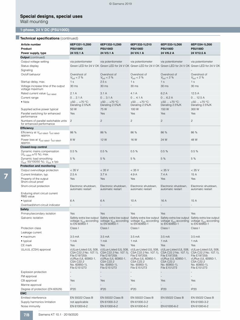
7/8 Siemens KT 10.1 · 2019/2020
7
■ Technical specifications (continued)
Special designs, special usesWall mounting
1-phase, 24 V DC (PSU100D)
Output (continued)
Output voltage setting via potentiometer via potentiometer via potentiometer via potentiometer via potentiometer
Status display Green LED for 24 V OK Green LED for 24 V OK Green LED for 24 V OK Green LED for 24 V OK Green LED for 24 V OK
Signaling -
On/off behavior Overshoot of Vout < 2 %
Overshoot of Vout < 2 %
Overshoot ofVout < 2 %
Overshoot of Vout < 2 %
Overshoot of Vout < 2 %
Startup delay, max. 1 s 2.5 s 1 s 1 s 1 s
Voltage increase time of the output voltage maximum
30 ms 30 ms 30 ms 30 ms 30 ms
Rated current value Iout rated 2.1 A 3.1 A 4.1 A 6.2 A 12.5 A
Current range 0 ... 2.1 A 0 ... 3.1 A 0 ... 4.1 A 0 ... 6.2 A 0 ... 12.5 A
• Note +50 ... +70 °C: Derating 2.5%/K
+50 ... +70 °C: Derating 2.5%/K
+50 ... +70 °C: Derating 2.5%/K
+50 ... +70 °C: Derating 2.5%/K
+50 ... +70 °C: Derating 2.5%/K
Supplied active power typical 50 W 75 W 100 W 150 W 300 W
Parallel switching for enhanced performance
Yes Yes Yes Yes Yes
Numbers of parallel switchable units for enhanced performance
2 2 2 2 2
Efficiency
Efficiency at Vout rated, Iout rated, approx.
86 % 86 % 86 % 86 % 86 %
Power loss at Vout rated, Iout rated, approx.
8 W 12 W 16 W 24 W 48 W
Closed-loop control
Dynamic mains compensation(Vin rated ±15 %), max.
0.5 % 0.5 % 0.5 % 0.5 % 0.5 %
Dynamic load smoothing (Iout: 50/100/50 %), Uout ± typ.
5 % 5 % 5 % 5 % 5 %
Protection and monitoring
Output overvoltage protection < 35 V < 35 V < 35 V < 35 V < 35 V
Current limitation, typ. 2.5 A 3.7 A 4.9 A 7.4 A 15 A
Property of the output Short-circuit proof
Yes Yes Yes Yes Yes
Short-circuit protection Electronic shutdown, automatic restart
Electronic shutdown, automatic restart
Electronic shutdown, automatic restart
Electronic shutdown, automatic restart
Electronic shutdown, automatic restart
Enduring short circuit current RMS value
• typical 6 A 6 A 10 A 16 A 15 A
Overload/short-circuit indicator - - - - -
Safety
Primary/secondary isolation Yes Yes Yes Yes Yes
Galvanic isolation Safety extra low output voltage Vout according to EN 60950-1
Safety extra low output voltage Vout according to EN 60950-1
Safety extra low output voltage Vout according to EN 60950-1
Safety extra low output voltage Vout according to EN 60950-1
Safety extra low output voltage Vout according to EN 60950-1
Protection class Class I Class I Class I Class I Class I
Leakage current
• maximum 3.5 mA 3.5 mA 3.5 mA 3.5 mA 3.5 mA
• typical 1 mA 1 mA 1 mA 1 mA 1 mA
CE mark Yes Yes Yes Yes Yes
UL/cUL (CSA) approval cULus-Listed (UL 508, CSA C22.2 No. 107.1), File E197259; cURus (UL 60950-1, CSA C22.2 No. 60950-1), File E151273
cULus-Listed (UL 508, CSA C22.2 No. 107.1), File E197259; cURus (UL 60950-1, CSA C22.2 No. 60950-1), File E151273
cULus-Listed (UL 508, CSA C22.2 No. 107.1), File E197259;cURus (UL 60950-1, CSA C22.2No. 60950-1),File E151273
cULus-Listed (UL 508, CSA C22.2 No. 107.1), File E197259; cURus (UL 60950-1, CSA C22.2 No. 60950-1),File E151273
cULus-Listed (UL 508, CSA C22.2 No. 107.1), File E197259; cURus (UL 60950-1, CSA C22.2 No. 60950-1),File E151273
Explosion protection - - - - -
FM approval - - - - -
CB approval Yes Yes Yes Yes Yes
Marine approval - - - - -
Degree of protection (EN 60529) IP20 IP20 IP20 IP20 IP20
EMC
Emitted interference EN 55022 Class B EN 55022 Class B EN 55022 Class B EN 55022 Class B EN 55022 Class B
Supply harmonics limitation not applicable EN 61000-3-2 EN 61000-3-2 - EN 61000-3-2
Noise immunity EN 61000-6-2 EN 61000-6-2 EN 61000-6-2 EN 61000-6-2 EN 61000-6-2
Article number 6EP1331-1LD00 6EP1332-1LD00 6EP1332-1LD10 6EP1333-1LD00 6EP1334-1LD00
Product PSU100D PSU100D PSU100D PSU100D PSU100D
Power supply, type 24 V/2.1 A 24 V/3.1 A 24 V/4.1 A 24 V/6.2 A 24 V/12.5 A
© Siemens 2019
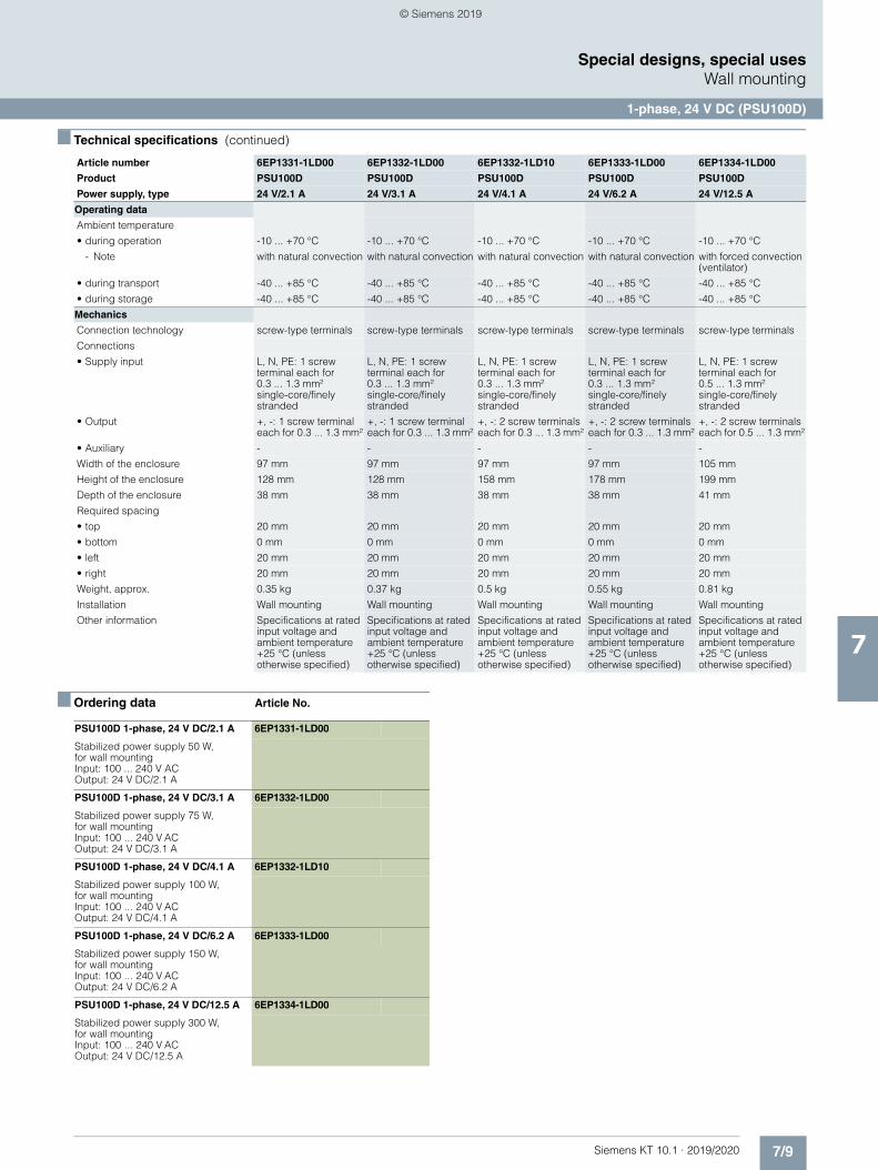
7/9Siemens KT 10.1 · 2019/2020
7
■ Technical specifications (continued)
Special designs, special usesWall mounting
1-phase, 24 V DC (PSU100D)
■ Ordering data Article No.
Operating data
Ambient temperature
• during operation -10 ... +70 °C -10 ... +70 °C -10 ... +70 °C -10 ... +70 °C -10 ... +70 °C
- Note with natural convection with natural convection with natural convection with natural convection with forced convection (ventilator)
• during transport -40 ... +85 °C -40 ... +85 °C -40 ... +85 °C -40 ... +85 °C -40 ... +85 °C
• during storage -40 ... +85 °C -40 ... +85 °C -40 ... +85 °C -40 ... +85 °C -40 ... +85 °C
Mechanics
Connection technology screw-type terminals screw-type terminals screw-type terminals screw-type terminals screw-type terminals
Connections
• Supply input L, N, PE: 1 screw terminal each for0.3 ... 1.3 mm² single-core/finely stranded
L, N, PE: 1 screw terminal each for 0.3 ... 1.3 mm²single-core/finely stranded
L, N, PE: 1 screw terminal each for0.3 ... 1.3 mm² single-core/finely stranded
L, N, PE: 1 screw terminal each for 0.3 ... 1.3 mm²single-core/finely stranded
L, N, PE: 1 screw terminal each for0.5 ... 1.3 mm² single-core/finely stranded
• Output +, -: 1 screw terminal each for 0.3 ... 1.3 mm²
+, -: 1 screw terminal each for 0.3 ... 1.3 mm²
+, -: 2 screw terminals each for 0.3 ... 1.3 mm²
+, -: 2 screw terminals each for 0.3 ... 1.3 mm²
+, -: 2 screw terminals each for 0.5 ... 1.3 mm²
• Auxiliary - - - - -
Width of the enclosure 97 mm 97 mm 97 mm 97 mm 105 mm
Height of the enclosure 128 mm 128 mm 158 mm 178 mm 199 mm
Depth of the enclosure 38 mm 38 mm 38 mm 38 mm 41 mm
Required spacing
• top 20 mm 20 mm 20 mm 20 mm 20 mm
• bottom 0 mm 0 mm 0 mm 0 mm 0 mm
• left 20 mm 20 mm 20 mm 20 mm 20 mm
• right 20 mm 20 mm 20 mm 20 mm 20 mm
Weight, approx. 0.35 kg 0.37 kg 0.5 kg 0.55 kg 0.81 kg
Installation Wall mounting Wall mounting Wall mounting Wall mounting Wall mounting
Other information Specifications at rated input voltage and ambient temperature +25 °C (unless otherwise specified)
Specifications at rated input voltage and ambient temperature +25 °C (unless otherwise specified)
Specifications at rated input voltage and ambient temperature +25 °C (unless otherwise specified)
Specifications at rated input voltage and ambient temperature +25 °C (unless otherwise specified)
Specifications at rated input voltage and ambient temperature +25 °C (unless otherwise specified)
Article number 6EP1331-1LD00 6EP1332-1LD00 6EP1332-1LD10 6EP1333-1LD00 6EP1334-1LD00
Product PSU100D PSU100D PSU100D PSU100D PSU100D
Power supply, type 24 V/2.1 A 24 V/3.1 A 24 V/4.1 A 24 V/6.2 A 24 V/12.5 A
PSU100D 1-phase, 24 V DC/2.1 A 6EP1331-1LD00
Stabilized power supply 50 W,for wall mountingInput: 100 ... 240 V AC Output: 24 V DC/2.1 A
PSU100D 1-phase, 24 V DC/3.1 A 6EP1332-1LD00
Stabilized power supply 75 W,for wall mountingInput: 100 ... 240 V AC Output: 24 V DC/3.1 A
PSU100D 1-phase, 24 V DC/4.1 A 6EP1332-1LD10
Stabilized power supply 100 W, for wall mountingInput: 100 ... 240 V AC Output: 24 V DC/4.1 A
PSU100D 1-phase, 24 V DC/6.2 A 6EP1333-1LD00
Stabilized power supply 150 W,for wall mountingInput: 100 ... 240 V AC Output: 24 V DC/6.2 A
PSU100D 1-phase, 24 V DC/12.5 A 6EP1334-1LD00
Stabilized power supply 300 W, for wall mountingInput: 100 ... 240 V AC Output: 24 V DC/12.5 A
© Siemens 2019
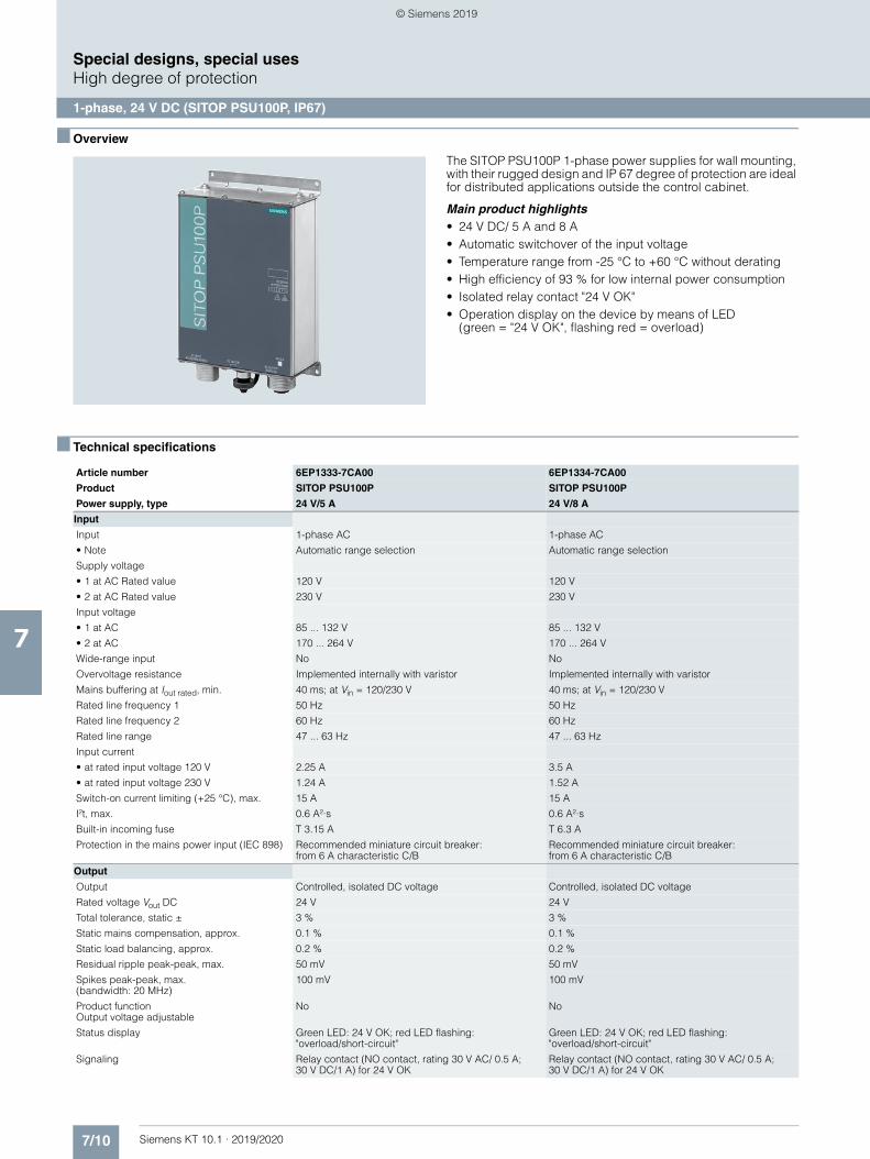
7/10 Siemens KT 10.1 · 2019/2020
7
Special designs, special usesHigh degree of protection
1-phase, 24 V DC (SITOP PSU100P, IP67)
■ Overview
The SITOP PSU100P 1-phase power supplies for wall mounting, with their rugged design and IP 67 degree of protection are ideal for distributed applications outside the control cabinet.
Main product highlights• 24 V DC/ 5 A and 8 A• Automatic switchover of the input voltage• Temperature range from -25 °C to +60 °C without derating• High efficiency of 93 % for low internal power consumption• Isolated relay contact "24 V OK"• Operation display on the device by means of LED
(green = "24 V OK", flashing red = overload)
■ Technical specifications
Article number 6EP1333-7CA00 6EP1334-7CA00
Product SITOP PSU100P SITOP PSU100P
Power supply, type 24 V/5 A 24 V/8 A
Input
Input 1-phase AC 1-phase AC
• Note Automatic range selection Automatic range selection
Supply voltage
• 1 at AC Rated value 120 V 120 V
• 2 at AC Rated value 230 V 230 V
Input voltage
• 1 at AC 85 ... 132 V 85 ... 132 V
• 2 at AC 170 ... 264 V 170 ... 264 V
Wide-range input No No
Overvoltage resistance Implemented internally with varistor Implemented internally with varistor
Mains buffering at Iout rated, min. 40 ms; at Vin = 120/230 V 40 ms; at Vin = 120/230 V
Rated line frequency 1 50 Hz 50 Hz
Rated line frequency 2 60 Hz 60 Hz
Rated line range 47 ... 63 Hz 47 ... 63 Hz
Input current
• at rated input voltage 120 V 2.25 A 3.5 A
• at rated input voltage 230 V 1.24 A 1.52 A
Switch-on current limiting (+25 °C), max. 15 A 15 A
I²t, max. 0.6 A²·s 0.6 A²·s
Built-in incoming fuse T 3.15 A T 6.3 A
Protection in the mains power input (IEC 898) Recommended miniature circuit breaker:from 6 A characteristic C/B
Recommended miniature circuit breaker:from 6 A characteristic C/B
Output
Output Controlled, isolated DC voltage Controlled, isolated DC voltage
Rated voltage Vout DC 24 V 24 V
Total tolerance, static ± 3 % 3 %
Static mains compensation, approx. 0.1 % 0.1 %
Static load balancing, approx. 0.2 % 0.2 %
Residual ripple peak-peak, max. 50 mV 50 mV
Spikes peak-peak, max. (bandwidth: 20 MHz)
100 mV 100 mV
Product functionOutput voltage adjustable
No No
Status display Green LED: 24 V OK; red LED flashing:"overload/short-circuit"
Green LED: 24 V OK; red LED flashing:"overload/short-circuit"
Signaling Relay contact (NO contact, rating 30 V AC/ 0.5 A;30 V DC/1 A) for 24 V OK
Relay contact (NO contact, rating 30 V AC/ 0.5 A; 30 V DC/1 A) for 24 V OK
© Siemens 2019
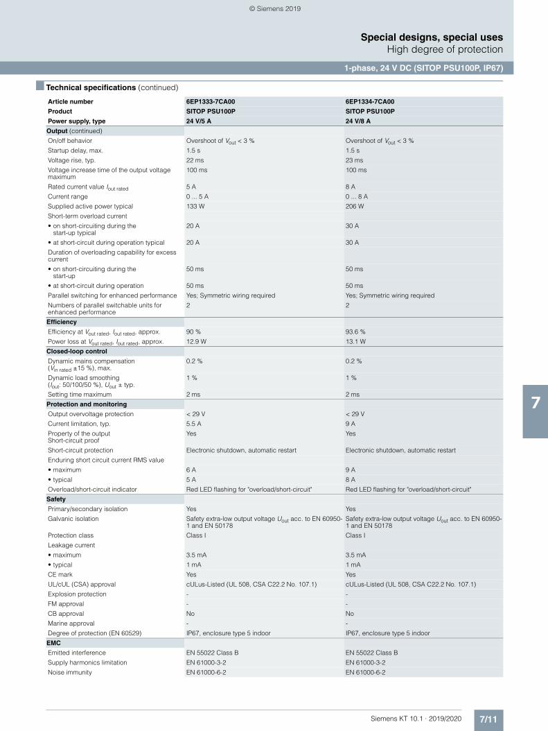
7/11Siemens KT 10.1 · 2019/2020
7
■ Technical specifications (continued)
Special designs, special usesHigh degree of protection
1-phase, 24 V DC (SITOP PSU100P, IP67)
Output (continued)
On/off behavior Overshoot of Vout < 3 % Overshoot of Vout < 3 %
Startup delay, max. 1.5 s 1.5 s
Voltage rise, typ. 22 ms 23 ms
Voltage increase time of the output voltage maximum
100 ms 100 ms
Rated current value Iout rated 5 A 8 A
Current range 0 ... 5 A 0 ... 8 A
Supplied active power typical 133 W 206 W
Short-term overload current
• on short-circuiting during the start-up typical
20 A 30 A
• at short-circuit during operation typical 20 A 30 A
Duration of overloading capability for excess current
• on short-circuiting during the start-up
50 ms 50 ms
• at short-circuit during operation 50 ms 50 ms
Parallel switching for enhanced performance Yes; Symmetric wiring required Yes; Symmetric wiring required
Numbers of parallel switchable units for enhanced performance
2 2
Efficiency
Efficiency at Vout rated, Iout rated, approx. 90 % 93.6 %
Power loss at Vout rated, Iout rated, approx. 12.9 W 13.1 W
Closed-loop control
Dynamic mains compensation(Vin rated ±15 %), max.
0.2 % 0.2 %
Dynamic load smoothing (Iout: 50/100/50 %), Uout ± typ.
1 % 1 %
Setting time maximum 2 ms 2 ms
Protection and monitoring
Output overvoltage protection < 29 V < 29 V
Current limitation, typ. 5.5 A 9 A
Property of the output Short-circuit proof
Yes Yes
Short-circuit protection Electronic shutdown, automatic restart Electronic shutdown, automatic restart
Enduring short circuit current RMS value
• maximum 6 A 9 A
• typical 5 A 8 A
Overload/short-circuit indicator Red LED flashing for "overload/short-circuit" Red LED flashing for "overload/short-circuit"
Safety
Primary/secondary isolation Yes Yes
Galvanic isolation Safety extra-low output voltage Uout acc. to EN 60950-1 and EN 50178
Safety extra-low output voltage Uout acc. to EN 60950-1 and EN 50178
Protection class Class I Class I
Leakage current
• maximum 3.5 mA 3.5 mA
• typical 1 mA 1 mA
CE mark Yes Yes
UL/cUL (CSA) approval cULus-Listed (UL 508, CSA C22.2 No. 107.1) cULus-Listed (UL 508, CSA C22.2 No. 107.1)
Explosion protection - -
FM approval - -
CB approval No No
Marine approval - -
Degree of protection (EN 60529) IP67, enclosure type 5 indoor IP67, enclosure type 5 indoor
EMC
Emitted interference EN 55022 Class B EN 55022 Class B
Supply harmonics limitation EN 61000-3-2 EN 61000-3-2
Noise immunity EN 61000-6-2 EN 61000-6-2
Article number 6EP1333-7CA00 6EP1334-7CA00
Product SITOP PSU100P SITOP PSU100P
Power supply, type 24 V/5 A 24 V/8 A
© Siemens 2019
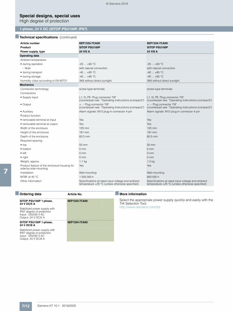
7/12 Siemens KT 10.1 · 2019/2020
7
■ Technical specifications (continued)
Special designs, special usesHigh degree of protection
1-phase, 24 V DC (SITOP PSU100P, IP67)
■ Ordering data Article No. ■ More information
Select the appropriate power supply quickly and easily with the TIA Selection Tool:http://www.siemens.com/tst
Operating data
Ambient temperature
• during operation -25 ... +60 °C -25 ... +60 °C
- Note with natural convection with natural convection
• during transport -40 ... +85 °C -40 ... +85 °C
• during storage -40 ... +85 °C -40 ... +85 °C
Humidity class according to EN 60721 3K6 without direct sunlight 3K6 without direct sunlight
Mechanics
Connection technology screw-type terminals screw-type terminals
Connections
• Supply input L1, N, PE: Plug connector 7/8"(counterpart see "Operating Instructions (compact)")
L1, N, PE: Plug connector 7/8" (counterpart see "Operating Instructions (compact)")
• Output +, -: Plug connector 7/8" (counterpart see "Operating Instructions (compact)")
+, -: Plug connector 7/8"(counterpart see "Operating Instructions (compact)")
• Auxiliary Alarm signals: M12 plug-in connector 4-pin Alarm signals: M12 plug-in connector 4-pin
Product function
• removable terminal at input Yes Yes
• removable terminal at output Yes Yes
Width of the enclosure 120 mm 120 mm
Height of the enclosure 181 mm 181 mm
Depth of the enclosure 60.5 mm 60.5 mm
Required spacing
• top 50 mm 50 mm
• bottom 0 mm 0 mm
• left 0 mm 0 mm
• right 0 mm 0 mm
Weight, approx. 1.1 kg 1.3 kg
Product feature of the enclosure housing for side-by-side mounting
Yes Yes
Installation Wall mounting Wall mounting
MTBF at 40 °C 1 500 000 h 800 000 h
Other information Specifications at rated input voltage and ambient temperature +25 °C (unless otherwise specified)
Specifications at rated input voltage and ambient temperature +25 °C (unless otherwise specified)
Article number 6EP1333-7CA00 6EP1334-7CA00
Product SITOP PSU100P SITOP PSU100P
Power supply, type 24 V/5 A 24 V/8 A
SITOP PSU100P 1-phase, 24 V DC/5 A
6EP1333-7CA00
Stabilized power supply with IP67 degree of protection Input: 120/230 V AC Output: 24 V DC/5 A
SITOP PSU100P 1-phase,24 V DC/8 A
6EP1334-7CA00
Stabilized power supply with IP67 degree of protection Input: 120/230 V AC Output: 24 V DC/8 A
© Siemens 2019
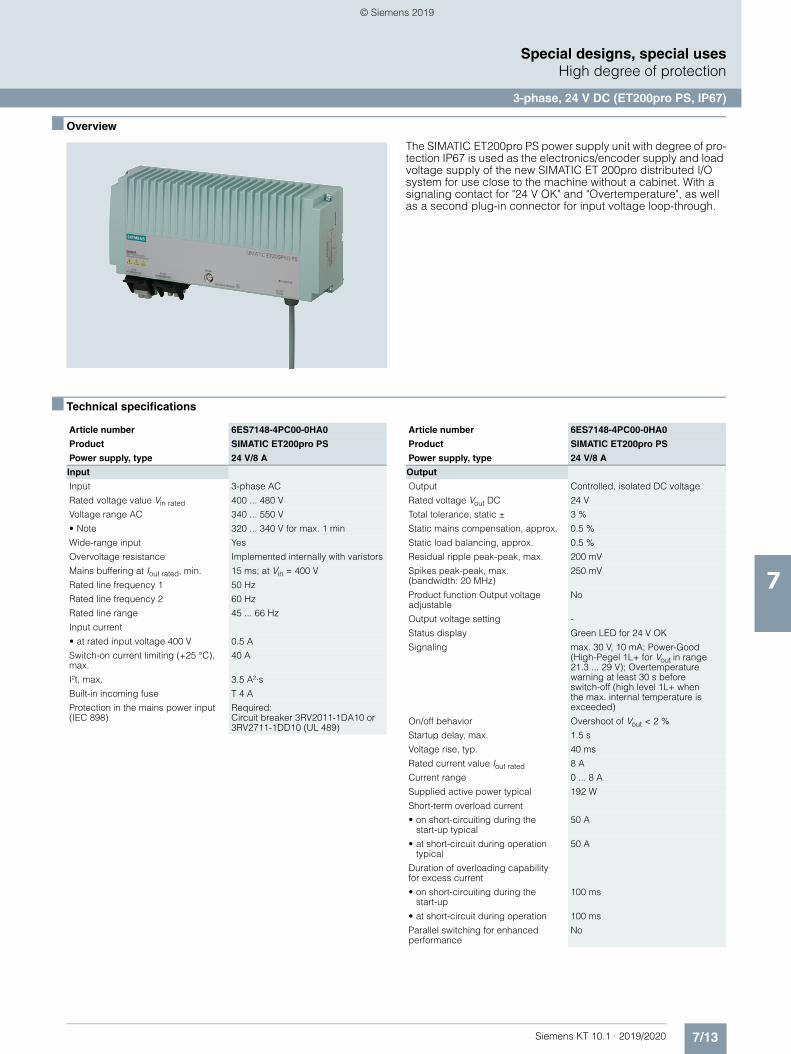
7/13Siemens KT 10.1 · 2019/2020
7
Special designs, special usesHigh degree of protection
3-phase, 24 V DC (ET200pro PS, IP67)
■ Overview
The SIMATIC ET200pro PS power supply unit with degree of pro-tection IP67 is used as the electronics/encoder supply and load voltage supply of the new SIMATIC ET 200pro distributed I/O system for use close to the machine without a cabinet. With a signaling contact for "24 V OK" and "Overtemperature", as well as a second plug-in connector for input voltage loop-through.
■ Technical specifications
Article number 6ES7148-4PC00-0HA0
Product SIMATIC ET200pro PS
Power supply, type 24 V/8 A
Input
Input 3-phase AC
Rated voltage value Vin rated 400 ... 480 V
Voltage range AC 340 ... 550 V
• Note 320 ... 340 V for max. 1 min
Wide-range input Yes
Overvoltage resistance Implemented internally with varistors
Mains buffering at Iout rated, min. 15 ms; at Vin = 400 V
Rated line frequency 1 50 Hz
Rated line frequency 2 60 Hz
Rated line range 45 ... 66 Hz
Input current
• at rated input voltage 400 V 0.5 A
Switch-on current limiting (+25 °C), max.
40 A
I²t, max. 3.5 A²·s
Built-in incoming fuse T 4 A
Protection in the mains power input (IEC 898)
Required:Circuit breaker 3RV2011-1DA10 or 3RV2711-1DD10 (UL 489)
Output
Output Controlled, isolated DC voltage
Rated voltage Vout DC 24 V
Total tolerance, static ± 3 %
Static mains compensation, approx. 0.5 %
Static load balancing, approx. 0.5 %
Residual ripple peak-peak, max. 200 mV
Spikes peak-peak, max.(bandwidth: 20 MHz)
250 mV
Product function Output voltage adjustable
No
Output voltage setting -
Status display Green LED for 24 V OK
Signaling max. 30 V, 10 mA; Power-Good (High-Pegel 1L+ for Vout in range 21.3 ... 29 V); Overtemperature warning at least 30 s before switch-off (high level 1L+ whenthe max. internal temperature is exceeded)
On/off behavior Overshoot of Vout < 2 %
Startup delay, max. 1.5 s
Voltage rise, typ. 40 ms
Rated current value Iout rated 8 A
Current range 0 ... 8 A
Supplied active power typical 192 W
Short-term overload current
• on short-circuiting during thestart-up typical
50 A
• at short-circuit during operation typical
50 A
Duration of overloading capability for excess current
• on short-circuiting during the start-up
100 ms
• at short-circuit during operation 100 ms
Parallel switching for enhanced performance
No
Article number 6ES7148-4PC00-0HA0
Product SIMATIC ET200pro PS
Power supply, type 24 V/8 A
© Siemens 2019
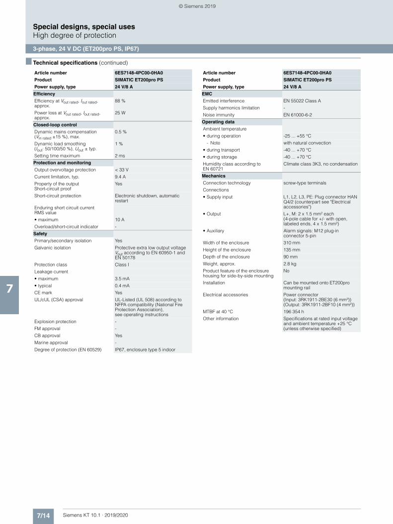
7/14 Siemens KT 10.1 · 2019/2020
7
■ Technical specifications (continued)
Special designs, special usesHigh degree of protection
3-phase, 24 V DC (ET200pro PS, IP67)
Efficiency
Efficiency at Vout rated, Iout rated, approx.
88 %
Power loss at Vout rated, Iout rated, approx.
25 W
Closed-loop control
Dynamic mains compensation(Vin rated ±15 %), max.
0.5 %
Dynamic load smoothing(Iout: 50/100/50 %), Uout ± typ.
1 %
Setting time maximum 2 ms
Protection and monitoring
Output overvoltage protection < 33 V
Current limitation, typ. 9.4 A
Property of the output Short-circuit proof
Yes
Short-circuit protection Electronic shutdown, automatic restart
Enduring short circuit current RMS value
• maximum 10 A
Overload/short-circuit indicator -
Safety
Primary/secondary isolation Yes
Galvanic isolation Protective extra low output voltage Vout according to EN 60950-1 and EN 50178
Protection class Class I
Leakage current
• maximum 3.5 mA
• typical 0.4 mA
CE mark Yes
UL/cUL (CSA) approval UL-Listed (UL 508) according to NFPA compatibility (National Fire Protection Association), see operating instructions
Explosion protection -
FM approval -
CB approval Yes
Marine approval -
Degree of protection (EN 60529) IP67, enclosure type 5 indoor
Article number 6ES7148-4PC00-0HA0
Product SIMATIC ET200pro PS
Power supply, type 24 V/8 A
EMC
Emitted interference EN 55022 Class A
Supply harmonics limitation -
Noise immunity EN 61000-6-2
Operating data
Ambient temperature
• during operation -25 ... +55 °C
- Note with natural convection
• during transport -40 ... +70 °C
• during storage -40 ... +70 °C
Humidity class according to EN 60721
Climate class 3K3, no condensation
Mechanics
Connection technology screw-type terminals
Connections
• Supply input L1, L2, L3, PE: Plug connector HAN Q4/2 (counterpart see "Electrical accessories")
• Output L+, M: 2 x 1.5 mm² each(4-pole cable for +/- with open, labeled ends, 4 x 1.5 mm²)
• Auxiliary Alarm signals: M12 plug-in connector 5-pin
Width of the enclosure 310 mm
Height of the enclosure 135 mm
Depth of the enclosure 90 mm
Weight, approx. 2.8 kg
Product feature of the enclosure housing for side-by-side mounting
No
Installation Can be mounted onto ET200pro mounting rail
Electrical accessories Power connector(Input: 3RK1911-2BE30 (6 mm²)) (Output: 3RK1911-2BF10 (4 mm²))
MTBF at 40 °C 196 354 h
Other information Specifications at rated input voltage and ambient temperature +25 °C (unless otherwise specified)
Article number 6ES7148-4PC00-0HA0
Product SIMATIC ET200pro PS
Power supply, type 24 V/8 A
© Siemens 2019
7/15Siemens KT 10.1 · 2019/2020
7
Special designs, special usesHigh degree of protection
3-phase, 24 V DC (ET200pro PS, IP67)
■ Ordering data Article No. ■ Accessories Article No.
SIMATIC ET 200pro PS 6ES7148-4PC00-0HA0
Stabilized power supply in distributed I/O system design, permitting the loop-through of energy to further modules; with degree of protection IP67; Input: 400-480 V 3 ACOutput: 24 V DC/8 A
Power connector
For connecting to the distributed I/O system• For X1 (6 mm2) 3RK1911-2BE30• For X2 (4 mm2) 3RK1911-2BF10
National Fire Protection Association compatible
These devices are only approved for installation in industrial machinery according to the NFPA79 Electrical Standard for Industrial Machinery.• for X1 SIMATIC ET200pro PS
61 88 201 1003.xx (AWG10)* * http://www.harting.com• for X1 SITOP PSU300P
61 88 201 1000.xx / 61 88 201 1002.xx (AWG14)*
• for X2 SIMATIC ET200pro PS 61 88 202 1010.xx (AWG10)*
supplied blanking cap for X2 3RK1902-0CK00• for X3
Phoenix-ContactSAC-5P-M12-M12FS
supplied blanking cap for X3
Sealing cap
For 9-pole power sockets• X2 (1 unit) 3RK1902-0CK00• X2 (10 units) 3RK1902-0CJ00
© Siemens 2019
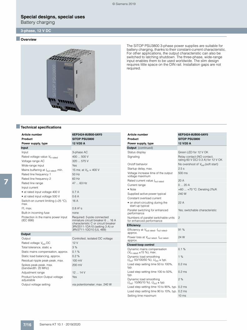
7/16 Siemens KT 10.1 · 2019/2020
7
Special designs, special usesBattery charging
3-phase, 12 V DC
■ Overview
The SITOP PSU3800 3-phase power supplies are suitable for battery charging, thanks to their constant-current characteristic. For other applications, the output characteristic can also be switched to latching shutdown. The three-phase, wide-range input enables them to be used worldwide. The slim design requires little space on the DIN rail. Installation gaps are not required.
■ Technical specifications
Article number 6EP3424-8UB00-0AY0
Product SITOP PSU3800
Power supply, type 12 V/20 A
Input
Input 3-phase AC
Rated voltage value Vin rated 400 ... 500 V
Voltage range AC 320 ... 575 V
Wide-range input Yes
Mains buffering at Iout rated, min. 15 ms; at Vin = 400 V
Rated line frequency 1 50 Hz
Rated line frequency 2 60 Hz
Rated line range 47 ... 63 Hz
Input current
• at rated input voltage 400 V 0.7 A
• at rated input voltage 500 V 0.6 A
Switch-on current limiting (+25 °C), max.
16 A
I²t, max. 0.8 A²·s
Built-in incoming fuse none
Protection in the mains power input (IEC 898)
Required: 3-pole connected miniature circuit breaker 6 ... 16 A characteristic C or circuit breaker 3RV2011-1DA10 (setting 3 A) or 3RV2711-1DD10 (UL 489)
Output
Output Controlled, isolated DC voltage
Rated voltage Vout DC 12 V
Total tolerance, static ± 3 %
Static mains compensation, approx. 0.1 %
Static load balancing, approx. 0.2 %
Residual ripple peak-peak, max. 100 mV
Spikes peak-peak, max.(bandwidth: 20 MHz)
200 mV
Adjustment range 12 ... 14 V
Product function Output voltage adjustable
Yes
Output voltage setting via potentiometer; max. 240 W
Output (continued)
Status display Green LED for 12 V OK
Signaling Relay contact (NO contact,rating 60 V DC/ 0.3 A) for 12 V OK
On/off behavior No overshoot of Vout (soft start)
Startup delay, max. 2.5 s
Voltage increase time of the output voltage maximum
500 ms
Rated current value Iout rated 20 A
Current range 0 ... 20 A
• Note +60 ... +70 °C: Derating 2%/K
Supplied active power typical 240 W
Constant overload current
• on short-circuiting during the start-up typical
22 A
Parallel switching for enhanced performance
Yes; switchable characteristic
Numbers of parallel switchable units for enhanced performance
2
Efficiency
Efficiency at Vout rated, Iout rated, approx.
91 %
Power loss at Vout rated, Iout rated, approx.
24 W
Closed-loop control
Dynamic mains compensation(Vin rated ±15 %), max.
0.1 %
Dynamic load smoothing (Iout: 50/100/50 %), Uout ± typ.
1 %
Load step setting time 50 to 100%, typ.
0.2 ms
Load step setting time 100 to 50%, typ.
0.2 ms
Dynamic load smoothing (Iout: 10/90/10 %), Uout ± typ.
2 %
Load step setting time 10 to 90%, typ. 0.2 ms
Load step setting time 90 to 10%, typ. 0.2 ms
Setting time maximum 10 ms
Article number 6EP3424-8UB00-0AY0
Product SITOP PSU3800
Power supply, type 12 V/20 A
© Siemens 2019
7/17Siemens KT 10.1 · 2019/2020
7
■ Technical specifications (continued)
Special designs, special usesBattery charging
3-phase, 12 V DC
■ Ordering data Article No.
■ Accessories Article No.
Protection and monitoring
Output overvoltage protection < 18 V
Current limitation, typ. 22 A
Property of the output Short-circuit proof
Yes
Short-circuit protection Alternatively, constant current characteristic approx. 22 A or latching shutdown
Enduring short circuit current RMS value
• typical 22 A
Overload/short-circuit indicator LED yellow for "overload", LED red for "latching shutdown"
Safety
Primary/secondary isolation Yes
Galvanic isolation Safety extra low output voltage Vout according to EN 60950-1
Protection class Class I
Leakage current
• maximum 3.5 mA
• typical 0.9 mA
CE mark Yes
UL/cUL (CSA) approval cULus-Listed (UL 508, CSA C22.2 No. 107.1), File E197259
Explosion protection IECEx Ex nA nC IIC T4 Gc; ATEX (EX) II 3G Ex nA nC IIC T4; cCSAus (CSA C22.2 No. 213, ANSI/ISA-12.12.01) Class I, Div. 2, Group ABCD, T4
FM approval -
CB approval Yes
Marine approval ABS, DNV GL
Degree of protection (EN 60529) IP20
EMC
Emitted interference EN 55022 Class B
Supply harmonics limitation EN 61000-3-2
Noise immunity EN 61000-6-2
Operating data
Ambient temperature
• during operation -25 ... +70 °C
- Note with natural convection
• during transport -40 ... +85 °C
• during storage -40 ... +85 °C
Humidity class according to EN 60721
Climate class 3K3, no condensation
Article number 6EP3424-8UB00-0AY0
Product SITOP PSU3800
Power supply, type 12 V/20 A
Mechanics
Connection technology screw-type terminals
Connections
• Supply input L1, L2, L3, PE: 1 screw terminal each for 0.2 ... 4 mm² single-core/finely stranded
• Output +, -: 2 screw terminals each for 0.2 ... 4 mm²
• Auxiliary 13, 14 (alarm signal): 1 screw terminal each for 0.14 ... 1.5 mm²;15, 16 (Remote): 1 screw terminal each for 0.14 ... 1.5 mm²
Width of the enclosure 70 mm
Height of the enclosure 125 mm
Depth of the enclosure 125 mm
Required spacing
• top 50 mm
• bottom 50 mm
• left 0 mm
• right 0 mm
Weight, approx. 1.2 kg
Product feature of the enclosure housing for side-by-side mounting
Yes
Installation Snaps onto DIN rail EN 60715 35x7.5/15
Mechanical accessories Device identification label 20 mm × 7 mm, pale turquoise 3RT1900-1SB20
Other information Specifications at rated input voltage and ambient temperature +25 °C (unless otherwise specified)
SITOP PSU3800, 3-phase,12 V DC/20 A
6EP3424-8UB00-0AY0
Stabilized power supply Input: 400 … 500 V 3 ACOutput: 12 V DC/20 A
Device identification label 3RT2900-1SB20
Article number 6EP3424-8UB00-0AY0
Product SITOP PSU3800
Power supply, type 12 V/20 A
© Siemens 2019
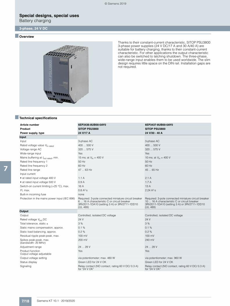
7/18 Siemens KT 10.1 · 2019/2020
7
Special designs, special usesBattery charging
3-phase, 24 V DC
■ Overview
Thanks to their constant-current characteristic, SITOP PSU3800 3-phase power supplies (24 V DC/17 A and 30 A/40 A) are suitable for battery charging, thanks to their constant-current characteristic. For other applications the output characteristic can also be switched to latching shutdown. The three-phase, wide-range input enables them to be used worldwide. The slim design requires little space on the DIN rail. Installation gaps are not required.
■ Technical specifications
Article number 6EP3436-8UB00-0AY0 6EP3437-8UB00-0AY0
Product SITOP PSU3800 SITOP PSU3800
Power supply, type 24 V/17 A 24 V/30 - 40 A
Input
Input 3-phase AC 3-phase AC
Rated voltage value Vin rated 400 ... 500 V 400 ... 500 V
Voltage range AC 320 ... 575 V 320 ... 575 V
Wide-range input Yes Yes
Mains buffering at Iout rated, min. 15 ms; at Vin = 400 V 10 ms; at Vin = 400 V
Rated line frequency 1 50 Hz 50 Hz
Rated line frequency 2 60 Hz 60 Hz
Rated line range 47 ... 63 Hz 45 ... 65 Hz
Input current
• at rated input voltage 400 V 1.1 A 2.1 A
• at rated input voltage 500 V 0.9 A 1.7 A
Switch-on current limiting (+25 °C), max. 16 A 13 A
I²t, max. 0.8 A²·s 2.24 A²·s
Built-in incoming fuse none
Protection in the mains power input (IEC 898) Required: 3-pole connected miniature circuit breaker6 ... 16 A characteristic C or circuit breaker 3RV2011-1DA10 (setting 3 A) or 3RV2711-1DD10 (UL 489)
Required: 3-pole connected miniature circuit breaker 10 ... 16 A characteristic C or circuit breaker 3RV2011-1DA10 (setting 3 A) or 3RV2711-1DD10 (UL 489)
Output
Output Controlled, isolated DC voltage Controlled, isolated DC voltage
Rated voltage Vout DC 24 V 24 V
Total tolerance, static ± 3 % 3 %
Static mains compensation, approx. 0.1 % 0.1 %
Static load balancing, approx. 0.2 % 0.2 %
Residual ripple peak-peak, max. 100 mV 100 mV
Spikes peak-peak, max. (bandwidth: 20 MHz)
200 mV 240 mV
Adjustment range 24 ... 28 V 24 ... 28 V
Product function Output voltage adjustable
Yes Yes
Output voltage setting via potentiometer; max. 480 W via potentiometer; max. 960 W
Status display Green LED for 24 V OK Green LED for 24 V OK
Signaling Relay contact (NO contact, rating 60 V DC/ 0.3 A) for "24 V OK"
Relay contact (NO contact, rating 60 V DC/ 0.3 A)for "24 V OK"
© Siemens 2019
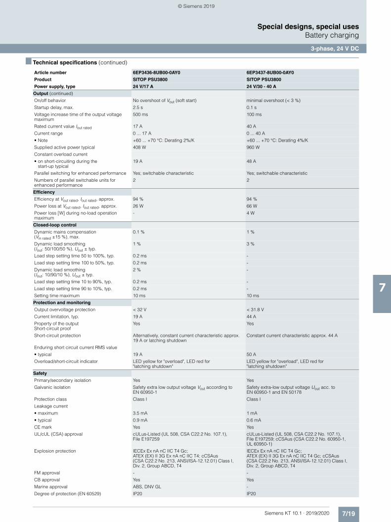
7/19Siemens KT 10.1 · 2019/2020
7
■ Technical specifications (continued)
Special designs, special usesBattery charging
3-phase, 24 V DC
Output (continued)
On/off behavior No overshoot of Vout (soft start) minimal overshoot (< 3 %)
Startup delay, max. 2.5 s 0.1 s
Voltage increase time of the output voltage maximum
500 ms 100 ms
Rated current value Iout rated 17 A 40 A
Current range 0 ... 17 A 0 ... 40 A
• Note +60 ... +70 °C: Derating 2%/K +60 ... +70 °C: Derating 4%/K
Supplied active power typical 408 W 960 W
Constant overload current
• on short-circuiting during thestart-up typical
19 A 48 A
Parallel switching for enhanced performance Yes; switchable characteristic Yes; switchable characteristic
Numbers of parallel switchable units for enhanced performance
2 2
Efficiency
Efficiency at Vout rated, Iout rated, approx. 94 % 94 %
Power loss at Vout rated, Iout rated, approx. 26 W 66 W
Power loss [W] during no-load operation maximum
- 4 W
Closed-loop control
Dynamic mains compensation(Vin rated ±15 %), max.
0.1 % 1 %
Dynamic load smoothing(Iout: 50/100/50 %), Uout ± typ.
1 % 3 %
Load step setting time 50 to 100%, typ. 0.2 ms -
Load step setting time 100 to 50%, typ. 0.2 ms -
Dynamic load smoothing(Iout: 10/90/10 %), Uout ± typ.
2 % -
Load step setting time 10 to 90%, typ. 0.2 ms -
Load step setting time 90 to 10%, typ. 0.2 ms -
Setting time maximum 10 ms 10 ms
Protection and monitoring
Output overvoltage protection < 32 V < 31.8 V
Current limitation, typ. 19 A 44 A
Property of the output Short-circuit proof
Yes Yes
Short-circuit protection Alternatively, constant current characteristic approx. 19 A or latching shutdown
Constant current characteristic approx. 44 A
Enduring short circuit current RMS value
• typical 19 A 50 A
Overload/short-circuit indicator LED yellow for "overload", LED red for "latching shutdown"
LED yellow for "overload", LED red for "latching shutdown"
Safety
Primary/secondary isolation Yes Yes
Galvanic isolation Safety extra low output voltage Vout according to EN 60950-1
Safety extra-low output voltage Uout acc. to EN 60950-1 and EN 50178
Protection class Class I Class I
Leakage current
• maximum 3.5 mA 1 mA
• typical 0.9 mA 0.6 mA
CE mark Yes Yes
UL/cUL (CSA) approval cULus-Listed (UL 508, CSA C22.2 No. 107.1), File E197259
cULus-Listed (UL 508, CSA C22.2 No. 107.1),File E197259; cCSAus (CSA C22.2 No. 60950-1, UL 60950-1)
Explosion protection IECEx Ex nA nC IIC T4 Gc; ATEX (EX) II 3G Ex nA nC IIC T4; cCSAus (CSA C22.2 No. 213, ANSI/ISA-12.12.01) Class I, Div. 2, Group ABCD, T4
IECEx Ex nA nC IIC T4 Gc; ATEX (EX) II 3G Ex nA nC IIC T4 Gc; cCSAus (CSA C22.2 No. 213, ANSI/ISA-12.12.01) Class I, Div. 2, Group ABCD, T4
FM approval - -
CB approval Yes Yes
Marine approval ABS, DNV GL -
Degree of protection (EN 60529) IP20 IP20
Article number 6EP3436-8UB00-0AY0 6EP3437-8UB00-0AY0
Product SITOP PSU3800 SITOP PSU3800
Power supply, type 24 V/17 A 24 V/30 - 40 A
© Siemens 2019
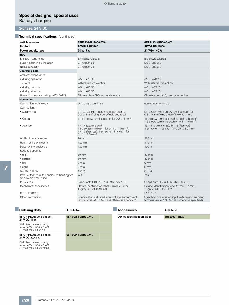
7/20 Siemens KT 10.1 · 2019/2020
7
■ Technical specifications (continued)
Special designs, special usesBattery charging
3-phase, 24 V DC
■ Ordering data Article No. ■ Accessories Article No.
EMC
Emitted interference EN 55022 Class B EN 55022 Class B
Supply harmonics limitation EN 61000-3-2 EN 61000-3-2
Noise immunity EN 61000-6-2 EN 61000-6-2
Operating data
Ambient temperature
• during operation -25 ... +70 °C -25 ... +70 °C
- Note with natural convection With natural convection
• during transport -40 ... +85 °C -40 ... +85 °C
• during storage -40 ... +85 °C -40 ... +85 °C
Humidity class according to EN 60721 Climate class 3K3, no condensation Climate class 3K3, no condensation
Mechanics
Connection technology screw-type terminals screw-type terminals
Connections
• Supply input L1, L2, L3, PE: 1 screw terminal each for 0.2 ... 4 mm² single-core/finely stranded
L1, L2, L3, PE: 1 screw terminal each for 0.5 ... 4 mm² single-core/finely stranded
• Output +, -: 2 screw terminals each for 0.2 ... 4 mm² +: 2 screw terminals each for 0.5 ... 16 mm²; -: 3 screw terminals each for 0.5 ... 16 mm²
• Auxiliary 13, 14 (alarm signal): 1 screw terminal each for 0.14 ... 1.5 mm²; 15, 16 (Remote): 1 screw terminal each for 0.14 ... 1.5 mm²
13, 14 (alarm signal), 15, 16 (Remote):1 screw terminal each for 0.05 ... 2.5 mm²
Width of the enclosure 70 mm 135 mm
Height of the enclosure 125 mm 145 mm
Depth of the enclosure 125 mm 150 mm
Required spacing
• top 50 mm 40 mm
• bottom 50 mm 40 mm
• left 0 mm 0 mm
• right 0 mm 0 mm
Weight, approx. 1.2 kg 3.3 kg
Product feature of the enclosure housing for side-by-side mounting
Yes Yes
Installation Snaps onto DIN rail EN 60715 35x7.5/15 Snaps onto DIN rail EN 60715 35x15
Mechanical accessories Device identification label 20 mm × 7 mm,TI-grey 3RT2900-1SB20
Device identification label 20 mm × 7 mm,TI-grey 3RT2900-1SB20
MTBF at 40 °C 517 015 h
Other information Specifications at rated input voltage and ambient temperature +25 °C (unless otherwise specified)
Specifications at rated input voltage and ambient temperature +25 °C (unless otherwise specified)
Article number 6EP3436-8UB00-0AY0 6EP3437-8UB00-0AY0
Product SITOP PSU3800 SITOP PSU3800
Power supply, type 24 V/17 A 24 V/30 - 40 A
SITOP PSU3800 3-phase, 24 V DC/17 A
6EP3436-8UB00-0AY0
Stabilized power supplyInput: 400 ... 500 V 3 ACOutput: 24 V DC/17 A
SITOP PSU3800 3-phase, 24 V DC/30/40 A
6EP3437-8UB00-0AY0
Stabilized power supplyInput: 400 ... 500 V 3 ACOutput: 24 V DC/30/40 A
Device identification label 3RT2900-1SB20
© Siemens 2019
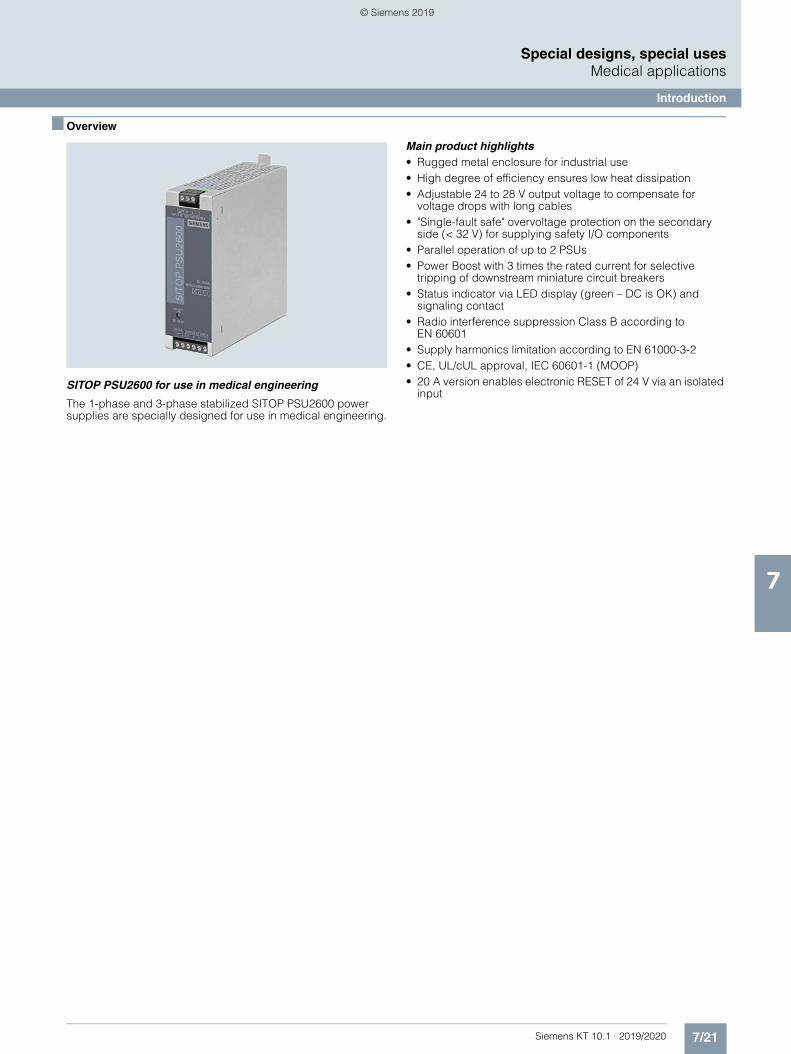
7/21Siemens KT 10.1 · 2019/2020
7
Special designs, special usesMedical applications
Introduction
■ Overview
SITOP PSU2600 for use in medical engineering
The 1-phase and 3-phase stabilized SITOP PSU2600 power supplies are specially designed for use in medical engineering.
Main product highlights• Rugged metal enclosure for industrial use• High degree of efficiency ensures low heat dissipation• Adjustable 24 to 28 V output voltage to compensate for
voltage drops with long cables• "Single-fault safe" overvoltage protection on the secondary
side (< 32 V) for supplying safety I/O components • Parallel operation of up to 2 PSUs• Power Boost with 3 times the rated current for selective
tripping of downstream miniature circuit breakers• Status indicator via LED display (green – DC is OK) and
signaling contact • Radio interference suppression Class B according to
EN 60601• Supply harmonics limitation according to EN 61000-3-2• CE, UL/cUL approval, IEC 60601-1 (MOOP)• 20 A version enables electronic RESET of 24 V via an isolated
input
© Siemens 2019
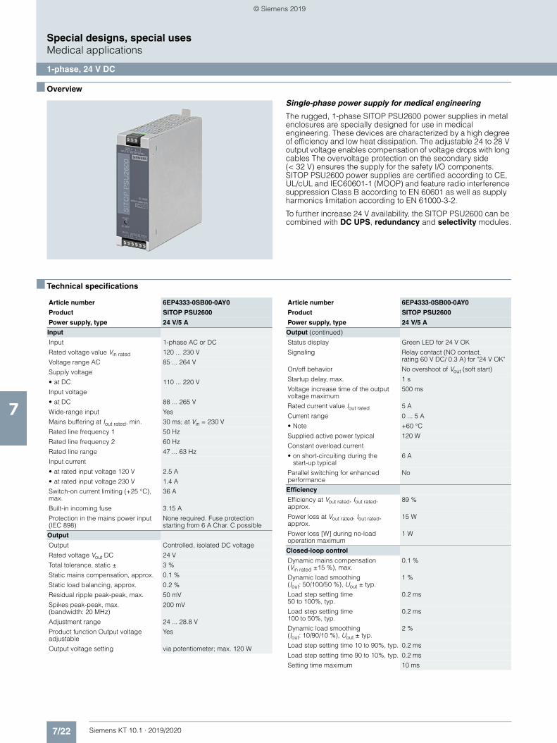
7/22 Siemens KT 10.1 · 2019/2020
7
Special designs, special usesMedical applications
1-phase, 24 V DC
■ Overview
Single-phase power supply for medical engineering
The rugged, 1-phase SITOP PSU2600 power supplies in metal enclosures are specially designed for use in medical engineering. These devices are characterized by a high degree of efficiency and low heat dissipation. The adjustable 24 to 28 V output voltage enables compensation of voltage drops with long cables The overvoltage protection on the secondary side (< 32 V) ensures the supply for the safety I/O components. SITOP PSU2600 power supplies are certified according to CE, UL/cUL and IEC60601-1 (MOOP) and feature radio interference suppression Class B according to EN 60601 as well as supply harmonics limitation according to EN 61000-3-2.
To further increase 24 V availability, the SITOP PSU2600 can be combined with DC UPS, redundancy and selectivity modules.
■ Technical specifications
Article number 6EP4333-0SB00-0AY0
Product SITOP PSU2600
Power supply, type 24 V/5 A
Input
Input 1-phase AC or DC
Rated voltage value Vin rated 120 ... 230 V
Voltage range AC 85 ... 264 V
Supply voltage
• at DC 110 ... 220 V
Input voltage
• at DC 88 ... 265 V
Wide-range input Yes
Mains buffering at Iout rated, min. 30 ms; at Vin = 230 V
Rated line frequency 1 50 Hz
Rated line frequency 2 60 Hz
Rated line range 47 ... 63 Hz
Input current
• at rated input voltage 120 V 2.5 A
• at rated input voltage 230 V 1.4 A
Switch-on current limiting (+25 °C), max.
36 A
Built-in incoming fuse 3.15 A
Protection in the mains power input (IEC 898)
None required. Fuse protection starting from 6 A Char. C possible
Output
Output Controlled, isolated DC voltage
Rated voltage Vout DC 24 V
Total tolerance, static ± 3 %
Static mains compensation, approx. 0.1 %
Static load balancing, approx. 0.2 %
Residual ripple peak-peak, max. 50 mV
Spikes peak-peak, max. (bandwidth: 20 MHz)
200 mV
Adjustment range 24 ... 28.8 V
Product function Output voltage adjustable
Yes
Output voltage setting via potentiometer; max. 120 W
Output (continued)
Status display Green LED for 24 V OK
Signaling Relay contact (NO contact,rating 60 V DC/ 0.3 A) for "24 V OK"
On/off behavior No overshoot of Vout (soft start)
Startup delay, max. 1 s
Voltage increase time of the output voltage maximum
500 ms
Rated current value Iout rated 5 A
Current range 0 ... 5 A
• Note +60 °C
Supplied active power typical 120 W
Constant overload current
• on short-circuiting during thestart-up typical
6 A
Parallel switching for enhanced performance
No
Efficiency
Efficiency at Vout rated, Iout rated, approx.
89 %
Power loss at Vout rated, Iout rated, approx.
15 W
Power loss [W] during no-load operation maximum
1 W
Closed-loop control
Dynamic mains compensation(Vin rated ±15 %), max.
0.1 %
Dynamic load smoothing (Iout: 50/100/50 %), Uout ± typ.
1 %
Load step setting time 50 to 100%, typ.
0.2 ms
Load step setting time 100 to 50%, typ.
0.2 ms
Dynamic load smoothing(Iout: 10/90/10 %), Uout ± typ.
2 %
Load step setting time 10 to 90%, typ. 0.2 ms
Load step setting time 90 to 10%, typ. 0.2 ms
Setting time maximum 10 ms
Article number 6EP4333-0SB00-0AY0
Product SITOP PSU2600
Power supply, type 24 V/5 A
© Siemens 2019
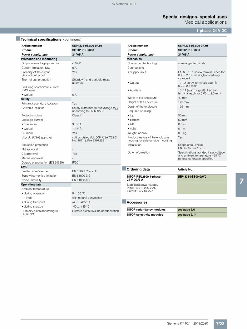
7/23Siemens KT 10.1 · 2019/2020
7
■ Technical specifications (continued)
Special designs, special usesMedical applications
1-phase, 24 V DC
■ Ordering data Article No.
■ Accessories
Protection and monitoring
Output overvoltage protection < 32 V
Current limitation, typ. 6 A
Property of the outputShort-circuit proof
Yes
Short-circuit protection Shutdown and periodic restart attempts
Enduring short circuit currentRMS value
• typical 6 A
Safety
Primary/secondary isolation Yes
Galvanic isolation Safety extra low output voltage Vout according to EN 60950-1
Protection class Class I
Leakage current
• maximum 3.5 mA
• typical 1.1 mA
CE mark Yes
UL/cUL (CSA) approval cULus-Listed (UL 508, CSA C22.2 No. 107.1), File E197259
Explosion protection -
FM approval -
CB approval Yes
Marine approval -
Degree of protection (EN 60529) IP20
EMC
Emitted interference EN 55022 Class B
Supply harmonics limitation EN 61000-3-2
Noise immunity EN 61000-6-2
Operating data
Ambient temperature
• during operation 0 ... 60 °C
- Note with natural convection
• during transport -40 ... +85 °C
• during storage -40 ... +85 °C
Humidity class according to EN 60721
Climate class 3K3, no condensation
Article number 6EP4333-0SB00-0AY0
Product SITOP PSU2600
Power supply, type 24 V/5 A
Mechanics
Connection technology screw-type terminals
Connections
• Supply input L1, N, PE: 1 screw terminal each for 0.2 ... 2.5 mm² single-core/finely stranded
• Output +, -: 2 screw terminals each for0.2 ... 2.5 mm²
• Auxiliary 13, 14 (alarm signal): 1 screw terminal each for 0.05 ... 2.5 mm²
Width of the enclosure 42 mm
Height of the enclosure 125 mm
Depth of the enclosure 125 mm
Required spacing
• top 50 mm
• bottom 50 mm
• left 0 mm
• right 0 mm
Weight, approx. 0.6 kg
Product feature of the enclosure housing for side-by-side mounting
Yes
Installation Snaps onto DIN railEN 60715 35x7.5/15
Other information Specifications at rated input voltage and ambient temperature +25 °C (unless otherwise specified)
SITOP PSU2600 1-phase, 24 V DC/5 A
6EP4333-0SB00-0AY0
Stabilized power supply Input: 120 ... 230 V AC Output: 24 V DC/5 A
SITOP redundancy modules see page 9/6
SITOP selectivity modules see page 9/14
Article number 6EP4333-0SB00-0AY0
Product SITOP PSU2600
Power supply, type 24 V/5 A
© Siemens 2019
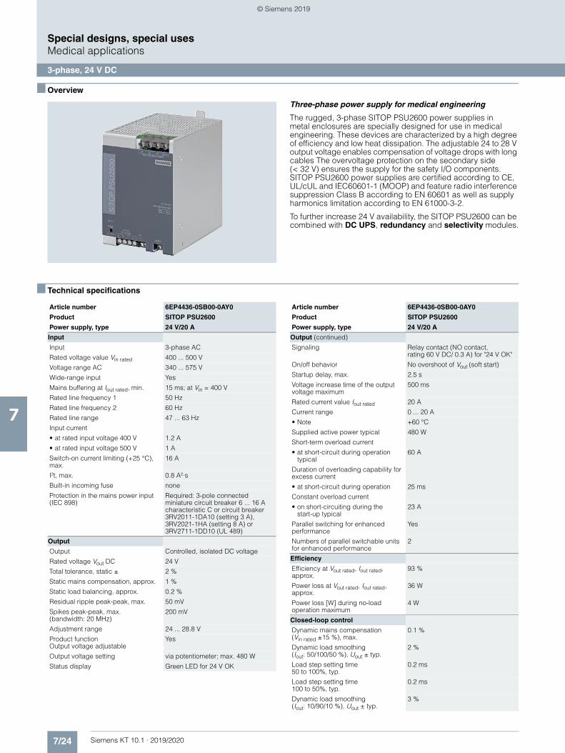
7/24 Siemens KT 10.1 · 2019/2020
7
Special designs, special usesMedical applications
3-phase, 24 V DC
■ Overview
Three-phase power supply for medical engineering
The rugged, 3-phase SITOP PSU2600 power supplies in metal enclosures are specially designed for use in medical engineering. These devices are characterized by a high degree of efficiency and low heat dissipation. The adjustable 24 to 28 V output voltage enables compensation of voltage drops with long cables The overvoltage protection on the secondary side (< 32 V) ensures the supply for the safety I/O components. SITOP PSU2600 power supplies are certified according to CE, UL/cUL and IEC60601-1 (MOOP) and feature radio interference suppression Class B according to EN 60601 as well as supply harmonics limitation according to EN 61000-3-2.
To further increase 24 V availability, the SITOP PSU2600 can be combined with DC UPS, redundancy and selectivity modules.
■ Technical specifications
Article number 6EP4436-0SB00-0AY0
Product SITOP PSU2600
Power supply, type 24 V/20 A
Input
Input 3-phase AC
Rated voltage value Vin rated 400 ... 500 V
Voltage range AC 340 ... 575 V
Wide-range input Yes
Mains buffering at Iout rated, min. 15 ms; at Vin = 400 V
Rated line frequency 1 50 Hz
Rated line frequency 2 60 Hz
Rated line range 47 ... 63 Hz
Input current
• at rated input voltage 400 V 1.2 A
• at rated input voltage 500 V 1 A
Switch-on current limiting (+25 °C), max.
16 A
I²t, max. 0.8 A²·s
Built-in incoming fuse none
Protection in the mains power input (IEC 898)
Required: 3-pole connected miniature circuit breaker 6 ... 16 A characteristic C or circuit breaker 3RV2011-1DA10 (setting 3 A), 3RV2021-1HA (setting 8 A) or 3RV2711-1DD10 (UL 489)
Output
Output Controlled, isolated DC voltage
Rated voltage Vout DC 24 V
Total tolerance, static ± 2 %
Static mains compensation, approx. 1 %
Static load balancing, approx. 0.2 %
Residual ripple peak-peak, max. 50 mV
Spikes peak-peak, max. (bandwidth: 20 MHz)
200 mV
Adjustment range 24 ... 28.8 V
Product function Output voltage adjustable
Yes
Output voltage setting via potentiometer; max. 480 W
Status display Green LED for 24 V OK
Output (continued)
Signaling Relay contact (NO contact, rating 60 V DC/ 0.3 A) for "24 V OK"
On/off behavior No overshoot of Vout (soft start)
Startup delay, max. 2.5 s
Voltage increase time of the output voltage maximum
500 ms
Rated current value Iout rated 20 A
Current range 0 ... 20 A
• Note +60 °C
Supplied active power typical 480 W
Short-term overload current
• at short-circuit during operation typical
60 A
Duration of overloading capability for excess current
• at short-circuit during operation 25 ms
Constant overload current
• on short-circuiting during the start-up typical
23 A
Parallel switching for enhanced performance
Yes
Numbers of parallel switchable units for enhanced performance
2
Efficiency
Efficiency at Vout rated, Iout rated, approx.
93 %
Power loss at Vout rated, Iout rated, approx.
36 W
Power loss [W] during no-load operation maximum
4 W
Closed-loop control
Dynamic mains compensation (Vin rated ±15 %), max.
0.1 %
Dynamic load smoothing(Iout: 50/100/50 %), Uout ± typ.
2 %
Load step setting time 50 to 100%, typ.
0.2 ms
Load step setting time 100 to 50%, typ.
0.2 ms
Dynamic load smoothing(Iout: 10/90/10 %), Uout ± typ.
3 %
Article number 6EP4436-0SB00-0AY0
Product SITOP PSU2600
Power supply, type 24 V/20 A
© Siemens 2019
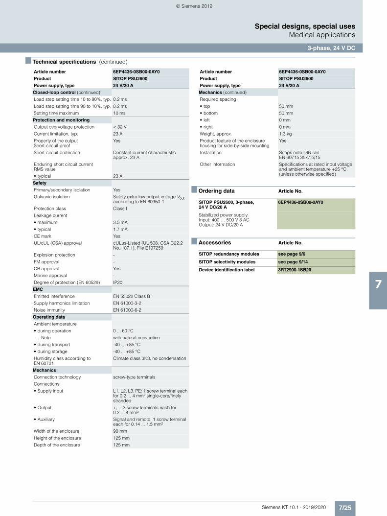
7/25Siemens KT 10.1 · 2019/2020
7
■ Technical specifications (continued)
Special designs, special usesMedical applications
3-phase, 24 V DC
■ Ordering data Article No.
■ Accessories Article No.
Closed-loop control (continued)
Load step setting time 10 to 90%, typ. 0.2 ms
Load step setting time 90 to 10%, typ. 0.2 ms
Setting time maximum 10 ms
Protection and monitoring
Output overvoltage protection < 32 V
Current limitation, typ. 23 A
Property of the outputShort-circuit proof
Yes
Short-circuit protection Constant current characteristic approx. 23 A
Enduring short circuit current RMS value
• typical 23 A
Safety
Primary/secondary isolation Yes
Galvanic isolation Safety extra low output voltage Vout according to EN 60950-1
Protection class Class I
Leakage current
• maximum 3.5 mA
• typical 1.7 mA
CE mark Yes
UL/cUL (CSA) approval cULus-Listed (UL 508, CSA C22.2 No. 107.1), File E197259
Explosion protection -
FM approval -
CB approval Yes
Marine approval -
Degree of protection (EN 60529) IP20
EMC
Emitted interference EN 55022 Class B
Supply harmonics limitation EN 61000-3-2
Noise immunity EN 61000-6-2
Operating data
Ambient temperature
• during operation 0 ... 60 °C
- Note with natural convection
• during transport -40 ... +85 °C
• during storage -40 ... +85 °C
Humidity class according to EN 60721
Climate class 3K3, no condensation
Mechanics
Connection technology screw-type terminals
Connections
• Supply input L1, L2, L3, PE: 1 screw terminal each for 0.2 ... 4 mm² single-core/finely stranded
• Output +, -: 2 screw terminals each for0.2 ... 4 mm²
• Auxiliary Signal and remote: 1 screw terminal each for 0.14 ... 1.5 mm²
Width of the enclosure 90 mm
Height of the enclosure 125 mm
Depth of the enclosure 125 mm
Article number 6EP4436-0SB00-0AY0
Product SITOP PSU2600
Power supply, type 24 V/20 A
Mechanics (continued)
Required spacing
• top 50 mm
• bottom 50 mm
• left 0 mm
• right 0 mm
Weight, approx. 1.3 kg
Product feature of the enclosure housing for side-by-side mounting
Yes
Installation Snaps onto DIN railEN 60715 35x7.5/15
Other information Specifications at rated input voltage and ambient temperature +25 °C (unless otherwise specified)
SITOP PSU2600, 3-phase, 24 V DC/20 A
6EP4436-0SB00-0AY0
Stabilized power supply Input: 400 … 500 V 3 ACOutput: 24 V DC/20 A
SITOP redundancy modules see page 9/6
SITOP selectivity modules see page 9/14
Device identification label 3RT2900-1SB20
Article number 6EP4436-0SB00-0AY0
Product SITOP PSU2600
Power supply, type 24 V/20 A
© Siemens 2019
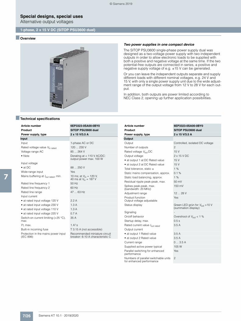
7/26 Siemens KT 10.1 · 2019/2020
7
Special designs, special usesAlternative output voltages
1-phase, 2 x 15 V DC (SITOP PSU3600 dual)
■ Overview
Two power supplies in one compact device
The SITOP PSU3600 single-phase power supply dual was designed as a two-voltage power supply with two independent outputs in order to allow electronic loads to be supplied with both a positive and negative voltage at the same time. If the two potential-free outputs are connected in series, a positive and negative supply voltage of e.g. ±15 V can be generated.
Or you can leave the independent outputs separate and supply different loads with different nominal voltages, e.g. 24 V and 15 V, with only a single power supply unit due to the wide adjust-ment range of the output voltage from 12 V to 28 V for each out-put.
In addition, both outputs are power limited according to NEC Class 2, opening up further application possibilities.
■ Technical specifications
Article number 6EP3323-0SA00-0BY0
Product SITOP PSU3600 dual
Power supply, type 2 x 15 V/3.5 A
Input
Input 1-phase AC or DC
Rated voltage value Vin rated 120 ... 230 V
Voltage range AC 85 ... 264 V
• Note Derating at < 110 V AC/DC: output power max. 100 W
Input voltage
• at DC 88 ... 250 V
Wide-range input Yes
Mains buffering at Iout rated, min. 10 ms; at Vin = 120 V,40 ms at Vin = 187 V
Rated line frequency 1 50 Hz
Rated line frequency 2 60 Hz
Rated line range 47 ... 63 Hz
Input current
• at rated input voltage 120 V 2.2 A
• at rated input voltage 230 V 1.3 A
• at rated input voltage 110 V 1.3 A
• at rated input voltage 220 V 0.7 A
Switch-on current limiting (+25 °C), max.
35 A
I²t, max. 1 A²·s
Built-in incoming fuse T 3.15 A (not accessible)
Protection in the mains power input (IEC 898)
Recommended miniature circuit breaker: 6-10 A characteristic C
Output
Output Controlled, isolated DC voltage
Number of outputs 2
Rated voltage Vout DC 15 V
Output voltage 2 x 15 V DC
• at output 1 at DC Rated value 15 V
• at output 2 at DC Rated value 15 V
Total tolerance, static ± 1 %
Static mains compensation, approx. 0.1 %
Static load balancing, approx. 1 %
Residual ripple peak-peak, max. 50 mV
Spikes peak-peak, max.(bandwidth: 20 MHz)
150 mV
Adjustment range 12 ... 28 V
Product function Output voltage adjustable
Yes
Status display Green LED grün for Vout >10 V (summation display)
Signaling -
On/off behavior Overshoot of Vout < 1 %
Startup delay, max. 0.5 s
Rated current value Iout rated 3.5 A
Output current
• at output 1 Rated value 3.5 A
• at output 2 Rated value 3.5 A
Current range 0 ... 3.5 A
Supplied active power typical 105 W
Parallel switching for enhanced performance
Yes
Numbers of parallel switchable units for enhanced performance
2
Article number 6EP3323-0SA00-0BY0
Product SITOP PSU3600 dual
Power supply, type 2 x 15 V/3.5 A
© Siemens 2019
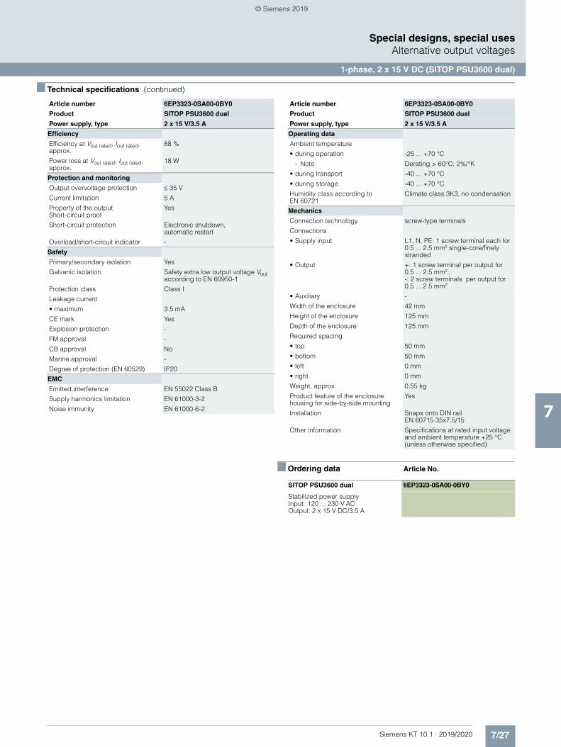
7/27Siemens KT 10.1 · 2019/2020
7
■ Technical specifications (continued)
Special designs, special usesAlternative output voltages
1-phase, 2 x 15 V DC (SITOP PSU3600 dual)
■ Ordering data Article No.
Efficiency
Efficiency at Vout rated, Iout rated, approx.
88 %
Power loss at Vout rated, Iout rated, approx.
18 W
Protection and monitoring
Output overvoltage protection ≤ 35 V
Current limitation 5 A
Property of the output Short-circuit proof
Yes
Short-circuit protection Electronic shutdown,automatic restart
Overload/short-circuit indicator -
Safety
Primary/secondary isolation Yes
Galvanic isolation Safety extra low output voltage Vout according to EN 60950-1
Protection class Class I
Leakage current
• maximum 3.5 mA
CE mark Yes
Explosion protection -
FM approval -
CB approval No
Marine approval -
Degree of protection (EN 60529) IP20
EMC
Emitted interference EN 55022 Class B
Supply harmonics limitation EN 61000-3-2
Noise immunity EN 61000-6-2
Article number 6EP3323-0SA00-0BY0
Product SITOP PSU3600 dual
Power supply, type 2 x 15 V/3.5 A
Operating data
Ambient temperature
• during operation -25 ... +70 °C
- Note Derating > 60°C: 2%/°K
• during transport -40 ... +70 °C
• during storage -40 ... +70 °C
Humidity class according to EN 60721
Climate class 3K3, no condensation
Mechanics
Connection technology screw-type terminals
Connections
• Supply input L1, N, PE: 1 screw terminal each for 0.5 ... 2.5 mm² single-core/finely stranded
• Output +: 1 screw terminal per output for 0.5 ... 2.5 mm²; -: 2 screw terminals per output for 0.5 ... 2.5 mm²
• Auxiliary -
Width of the enclosure 42 mm
Height of the enclosure 125 mm
Depth of the enclosure 125 mm
Required spacing
• top 50 mm
• bottom 50 mm
• left 0 mm
• right 0 mm
Weight, approx. 0.55 kg
Product feature of the enclosure housing for side-by-side mounting
Yes
Installation Snaps onto DIN railEN 60715 35x7.5/15
Other information Specifications at rated input voltage and ambient temperature +25 °C (unless otherwise specified)
SITOP PSU3600 dual 6EP3323-0SA00-0BY0
Stabilized power supplyInput: 120 ... 230 V ACOutput: 2 x 15 V DC/3.5 A
Article number 6EP3323-0SA00-0BY0
Product SITOP PSU3600 dual
Power supply, type 2 x 15 V/3.5 A
© Siemens 2019
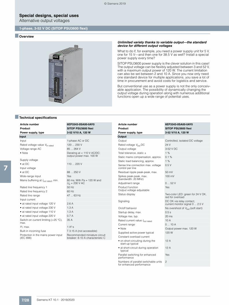
7/28 Siemens KT 10.1 · 2019/2020
7
Special designs, special usesAlternative output voltages
1-phase, 3-52 V DC (SITOP PSU3600 flexi)
■ Overview
Unlimited variety thanks to variable output—the standard device for different output voltages
What to do if, for example, you need a power supply unit for 5 V, one for 15 V—and then one for 38.5 V as well? Install a special power supply every time?
SITOP PSU3600 power supply is the clever solution in this case! The output voltage can be flexibly adjusted between 3 and 52 V, with a maximum output power of 120 W. The current limitation can also be set between 2 and 10 A. Since you now only need one standard device for multiple applications, you save a lot of time in procurement and avoid costs for logistics and service.
But conventional use as a power supply is not the only conceiv-able application. The possibility of dynamically changing the output voltage during operation along with numerous additional functions open up a wide range of potential uses.
■ Technical specifications
Article number 6EP3343-0SA00-0AY0
Product SITOP PSU3600 flexi
Power supply, type 3-52 V/10 A, 120 W
Input
Input 1-phase AC or DC
Rated voltage value Vin rated 120 ... 230 V
Voltage range AC 85 ... 264 V
• Note Derating at < 110 V AC/DC: output power max. 100 W
Supply voltage
• at DC 110 ... 220 V
Input voltage
• at DC 88 ... 250 V
Wide-range input Yes
Mains buffering at Iout rated, min. 80 ms; With Pa = 120 W and Ue = 230 V AC
Rated line frequency 1 50 Hz
Rated line frequency 2 60 Hz
Rated line range 47 ... 63 Hz
Input current
• at rated input voltage 120 V 2.6 A
• at rated input voltage 230 V 1.3 A
• at rated input voltage 110 V 1.3 A
• at rated input voltage 220 V 0.7 A
Switch-on current limiting (+25 °C), max.
35 A
I²t, max. 1 A²·s
Built-in incoming fuse T 3.15 A (not accessible)
Protection in the mains power input (IEC 898)
Recommended miniature circuit breaker: 6-10 A characteristic C
Output
Output Controlled, isolated DC voltage
Rated voltage Vout DC 24 V
Output voltage 3-52 V DC
Total tolerance, static ± 1 %
Static mains compensation, approx. 0.1 %
Static load balancing, approx. 1 %
Sense line connection max. voltage control per line
0.5 V
Residual ripple peak-peak, max. 50 mV
Spikes peak-peak, max. (bandwidth: 20 MHz)
100 mV
Adjustment range 0 ... 52 V
Product functionOutput voltage adjustable
Yes
Status display Two-color LED: green for 24 V OK, red for overload
Signaling DC OK via relay contact, current monitor signal 0 ... 2.5 V
On/off behavior No overshoot of Vout (soft start)
Startup delay, max. 0.5 s
Voltage rise, typ. 20 ms
Rated current value Iout rated 10 A
Current range 0 ... 10 A
• Note Output power max. 120 W
Supplied active power typical 120 W
Constant overload current
• on short-circuiting during thestart-up typical
12 A
• at short-circuit during operation typical
12 A
Parallel switching for enhanced performance
Yes
Numbers of parallel switchable units for enhanced performance
2
Article number 6EP3343-0SA00-0AY0
Product SITOP PSU3600 flexi
Power supply, type 3-52 V/10 A, 120 W
© Siemens 2019
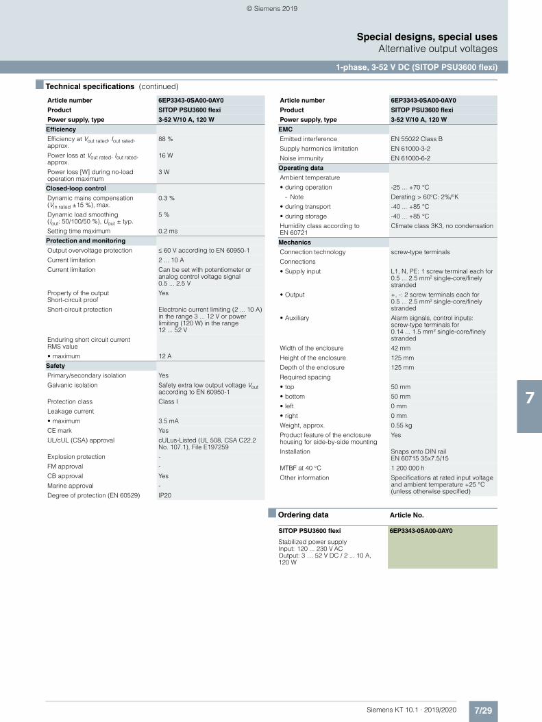
7/29Siemens KT 10.1 · 2019/2020
7
■ Technical specifications (continued)
Special designs, special usesAlternative output voltages
1-phase, 3-52 V DC (SITOP PSU3600 flexi)
■ Ordering data Article No.
Efficiency
Efficiency at Vout rated, Iout rated, approx.
88 %
Power loss at Vout rated, Iout rated, approx.
16 W
Power loss [W] during no-load operation maximum
3 W
Closed-loop control
Dynamic mains compensation (Vin rated ±15 %), max.
0.3 %
Dynamic load smoothing(Iout: 50/100/50 %), Uout ± typ.
5 %
Setting time maximum 0.2 ms
Protection and monitoring
Output overvoltage protection ≤ 60 V according to EN 60950-1
Current limitation 2 ... 10 A
Current limitation Can be set with potentiometer or analog control voltage signal0.5 ... 2.5 V
Property of the outputShort-circuit proof
Yes
Short-circuit protection Electronic current limiting (2 ... 10 A) in the range 3 ... 12 V or power limiting (120 W) in the range 12 ... 52 V
Enduring short circuit currentRMS value
• maximum 12 A
Safety
Primary/secondary isolation Yes
Galvanic isolation Safety extra low output voltage Vout according to EN 60950-1
Protection class Class I
Leakage current
• maximum 3.5 mA
CE mark Yes
UL/cUL (CSA) approval cULus-Listed (UL 508, CSA C22.2 No. 107.1), File E197259
Explosion protection -
FM approval -
CB approval Yes
Marine approval -
Degree of protection (EN 60529) IP20
Article number 6EP3343-0SA00-0AY0
Product SITOP PSU3600 flexi
Power supply, type 3-52 V/10 A, 120 W
EMC
Emitted interference EN 55022 Class B
Supply harmonics limitation EN 61000-3-2
Noise immunity EN 61000-6-2
Operating data
Ambient temperature
• during operation -25 ... +70 °C
- Note Derating > 60°C: 2%/°K
• during transport -40 ... +85 °C
• during storage -40 ... +85 °C
Humidity class according to EN 60721
Climate class 3K3, no condensation
Mechanics
Connection technology screw-type terminals
Connections
• Supply input L1, N, PE: 1 screw terminal each for 0.5 ... 2.5 mm² single-core/finely stranded
• Output +, -: 2 screw terminals each for 0.5 ... 2.5 mm² single-core/finely stranded
• Auxiliary Alarm signals, control inputs:screw-type terminals for0.14 ... 1.5 mm² single-core/finely stranded
Width of the enclosure 42 mm
Height of the enclosure 125 mm
Depth of the enclosure 125 mm
Required spacing
• top 50 mm
• bottom 50 mm
• left 0 mm
• right 0 mm
Weight, approx. 0.55 kg
Product feature of the enclosure housing for side-by-side mounting
Yes
Installation Snaps onto DIN rail EN 60715 35x7.5/15
MTBF at 40 °C 1 200 000 h
Other information Specifications at rated input voltage and ambient temperature +25 °C (unless otherwise specified)
SITOP PSU3600 flexi 6EP3343-0SA00-0AY0
Stabilized power supplyInput: 120 ... 230 V ACOutput: 3 … 52 V DC / 2 ... 10 A, 120 W
Article number 6EP3343-0SA00-0AY0
Product SITOP PSU3600 flexi
Power supply, type 3-52 V/10 A, 120 W
© Siemens 2019
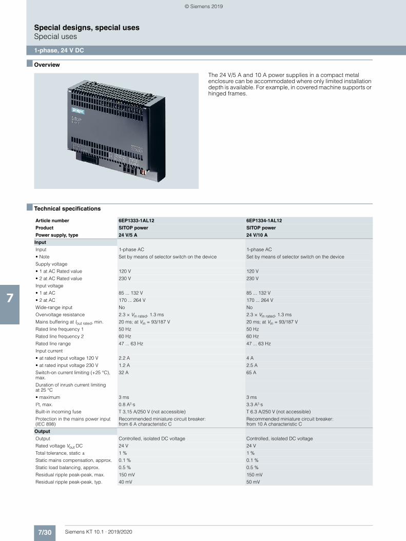
7/30 Siemens KT 10.1 · 2019/2020
7
Special designs, special usesSpecial uses
1-phase, 24 V DC
■ Overview
The 24 V/5 A and 10 A power supplies in a compact metal enclosure can be accommodated where only limited installation depth is available. For example, in covered machine supports or hinged frames.
■ Technical specifications
Article number 6EP1333-1AL12 6EP1334-1AL12
Product SITOP power SITOP power
Power supply, type 24 V/5 A 24 V/10 A
Input
Input 1-phase AC 1-phase AC
• Note Set by means of selector switch on the device Set by means of selector switch on the device
Supply voltage
• 1 at AC Rated value 120 V 120 V
• 2 at AC Rated value 230 V 230 V
Input voltage
• 1 at AC 85 ... 132 V 85 ... 132 V
• 2 at AC 170 ... 264 V 170 ... 264 V
Wide-range input No No
Overvoltage resistance 2.3 × Vin rated, 1.3 ms 2.3 × Vin rated, 1.3 ms
Mains buffering at Iout rated, min. 20 ms; at Vin = 93/187 V 20 ms; at Vin = 93/187 V
Rated line frequency 1 50 Hz 50 Hz
Rated line frequency 2 60 Hz 60 Hz
Rated line range 47 ... 63 Hz 47 ... 63 Hz
Input current
• at rated input voltage 120 V 2.2 A 4 A
• at rated input voltage 230 V 1.2 A 2.5 A
Switch-on current limiting (+25 °C), max.
32 A 65 A
Duration of inrush current limiting at 25 °C
• maximum 3 ms 3 ms
I²t, max. 0.8 A²·s 3.3 A²·s
Built-in incoming fuse T 3,15 A/250 V (not accessible) T 6.3 A/250 V (not accessible)
Protection in the mains power input (IEC 898)
Recommended miniature circuit breaker:from 6 A characteristic C
Recommended miniature circuit breaker:from 10 A characteristic C
Output
Output Controlled, isolated DC voltage Controlled, isolated DC voltage
Rated voltage Vout DC 24 V 24 V
Total tolerance, static ± 1 % 1 %
Static mains compensation, approx. 0.1 % 0.1 %
Static load balancing, approx. 0.5 % 0.5 %
Residual ripple peak-peak, max. 150 mV 150 mV
Residual ripple peak-peak, typ. 40 mV 50 mV
© Siemens 2019
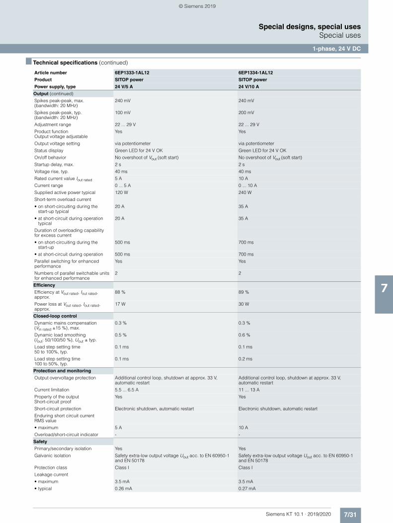
7/31Siemens KT 10.1 · 2019/2020
7
■ Technical specifications (continued)
Special designs, special usesSpecial uses
1-phase, 24 V DC
Output (continued)
Spikes peak-peak, max. (bandwidth: 20 MHz)
240 mV 240 mV
Spikes peak-peak, typ.(bandwidth: 20 MHz)
100 mV 200 mV
Adjustment range 22 ... 29 V 22 ... 29 V
Product functionOutput voltage adjustable
Yes Yes
Output voltage setting via potentiometer via potentiometer
Status display Green LED for 24 V OK Green LED for 24 V OK
On/off behavior No overshoot of Vout (soft start) No overshoot of Vout (soft start)
Startup delay, max. 2 s 2 s
Voltage rise, typ. 40 ms 40 ms
Rated current value Iout rated 5 A 10 A
Current range 0 ... 5 A 0 ... 10 A
Supplied active power typical 120 W 240 W
Short-term overload current
• on short-circuiting during thestart-up typical
20 A 35 A
• at short-circuit during operation typical
20 A 35 A
Duration of overloading capabilityfor excess current
• on short-circuiting during the start-up
500 ms 700 ms
• at short-circuit during operation 500 ms 700 ms
Parallel switching for enhanced performance
Yes Yes
Numbers of parallel switchable units for enhanced performance
2 2
Efficiency
Efficiency at Vout rated, Iout rated, approx.
88 % 89 %
Power loss at Vout rated, Iout rated, approx.
17 W 30 W
Closed-loop control
Dynamic mains compensation(Vin rated ±15 %), max.
0.3 % 0.3 %
Dynamic load smoothing (Iout: 50/100/50 %), Uout ± typ.
0.5 % 0.6 %
Load step setting time 50 to 100%, typ.
0.1 ms 0.1 ms
Load step setting time 100 to 50%, typ.
0.1 ms 0.2 ms
Protection and monitoring
Output overvoltage protection Additional control loop, shutdown at approx. 33 V, automatic restart
Additional control loop, shutdown at approx. 33 V, automatic restart
Current limitation 5.5 ... 6.5 A 11 ... 13 A
Property of the output Short-circuit proof
Yes Yes
Short-circuit protection Electronic shutdown, automatic restart Electronic shutdown, automatic restart
Enduring short circuit currentRMS value
• maximum 5 A 10 A
Overload/short-circuit indicator - -
Safety
Primary/secondary isolation Yes Yes
Galvanic isolation Safety extra-low output voltage Uout acc. to EN 60950-1 and EN 50178
Safety extra-low output voltage Uout acc. to EN 60950-1 and EN 50178
Protection class Class I Class I
Leakage current
• maximum 3.5 mA 3.5 mA
• typical 0.26 mA 0.27 mA
Article number 6EP1333-1AL12 6EP1334-1AL12
Product SITOP power SITOP power
Power supply, type 24 V/5 A 24 V/10 A
© Siemens 2019
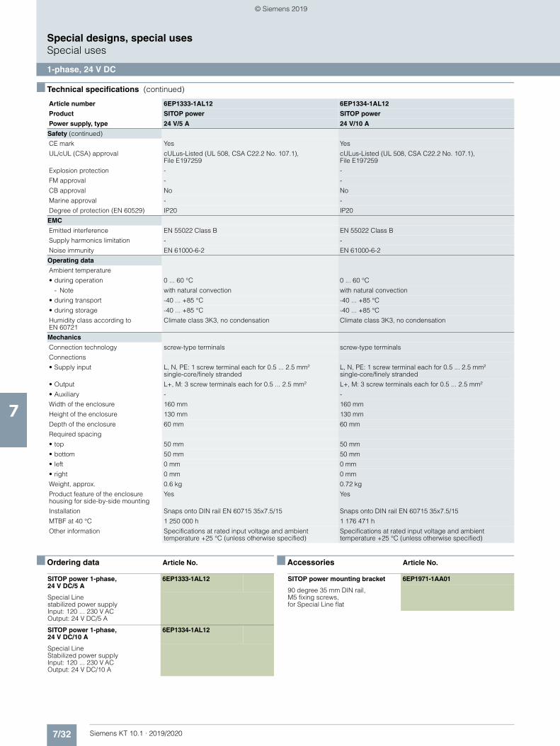
7/32 Siemens KT 10.1 · 2019/2020
7
■ Technical specifications (continued)
Special designs, special usesSpecial uses
1-phase, 24 V DC
■ Ordering data Article No. ■ Accessories Article No.
Safety (continued)
CE mark Yes Yes
UL/cUL (CSA) approval cULus-Listed (UL 508, CSA C22.2 No. 107.1), File E197259
cULus-Listed (UL 508, CSA C22.2 No. 107.1), File E197259
Explosion protection - -
FM approval - -
CB approval No No
Marine approval - -
Degree of protection (EN 60529) IP20 IP20
EMC
Emitted interference EN 55022 Class B EN 55022 Class B
Supply harmonics limitation - -
Noise immunity EN 61000-6-2 EN 61000-6-2
Operating data
Ambient temperature
• during operation 0 ... 60 °C 0 ... 60 °C
- Note with natural convection with natural convection
• during transport -40 ... +85 °C -40 ... +85 °C
• during storage -40 ... +85 °C -40 ... +85 °C
Humidity class according toEN 60721
Climate class 3K3, no condensation Climate class 3K3, no condensation
Mechanics
Connection technology screw-type terminals screw-type terminals
Connections
• Supply input L, N, PE: 1 screw terminal each for 0.5 ... 2.5 mm² single-core/finely stranded
L, N, PE: 1 screw terminal each for 0.5 ... 2.5 mm²single-core/finely stranded
• Output L+, M: 3 screw terminals each for 0.5 ... 2.5 mm² L+, M: 3 screw terminals each for 0.5 ... 2.5 mm²
• Auxiliary - -
Width of the enclosure 160 mm 160 mm
Height of the enclosure 130 mm 130 mm
Depth of the enclosure 60 mm 60 mm
Required spacing
• top 50 mm 50 mm
• bottom 50 mm 50 mm
• left 0 mm 0 mm
• right 0 mm 0 mm
Weight, approx. 0.6 kg 0.72 kg
Product feature of the enclosure housing for side-by-side mounting
Yes Yes
Installation Snaps onto DIN rail EN 60715 35x7.5/15 Snaps onto DIN rail EN 60715 35x7.5/15
MTBF at 40 °C 1 250 000 h 1 176 471 h
Other information Specifications at rated input voltage and ambient temperature +25 °C (unless otherwise specified)
Specifications at rated input voltage and ambient temperature +25 °C (unless otherwise specified)
Article number 6EP1333-1AL12 6EP1334-1AL12
Product SITOP power SITOP power
Power supply, type 24 V/5 A 24 V/10 A
SITOP power 1-phase, 24 V DC/5 A
6EP1333-1AL12
Special Line stabilized power supply Input: 120 ... 230 V AC Output: 24 V DC/5 A
SITOP power 1-phase, 24 V DC/10 A
6EP1334-1AL12
Special Line Stabilized power supply Input: 120 ... 230 V AC Output: 24 V DC/10 A
SITOP power mounting bracket 6EP1971-1AA01
90 degree 35 mm DIN rail, M5 fixing screws, for Special Line flat
© Siemens 2019
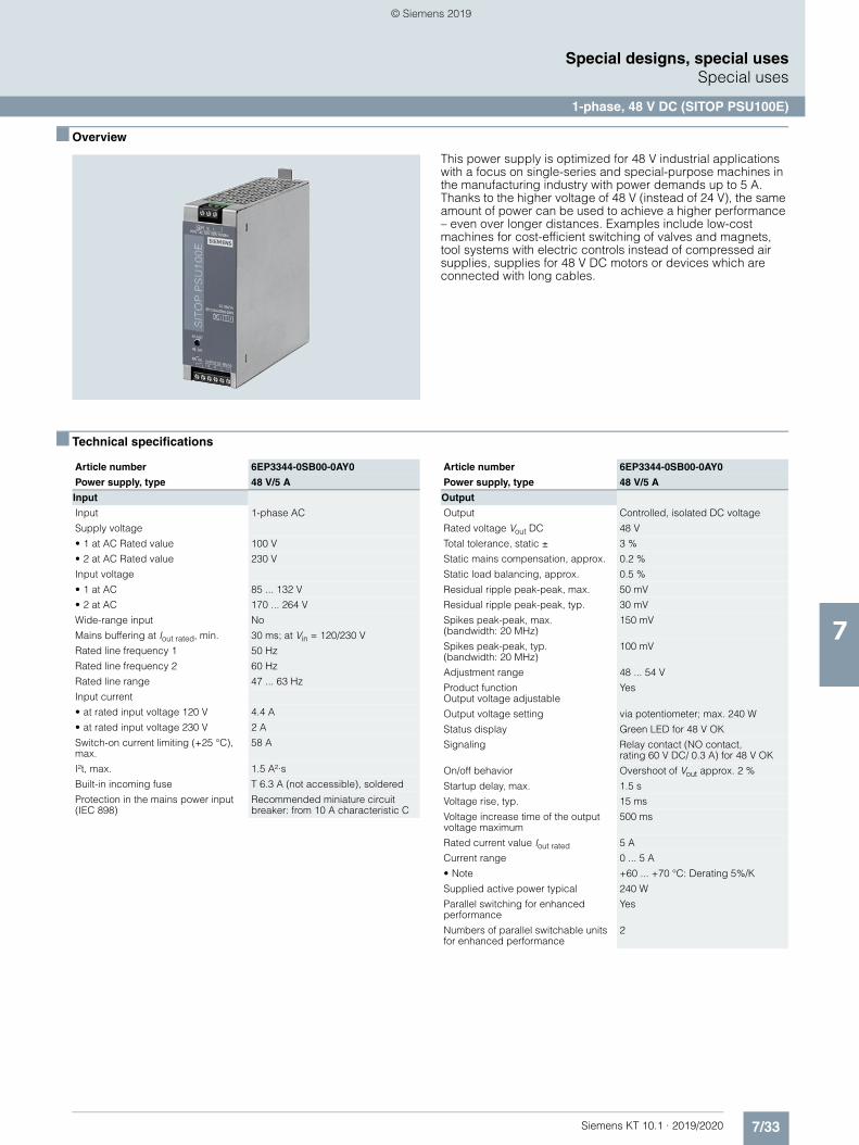
7/33Siemens KT 10.1 · 2019/2020
7
Special designs, special usesSpecial uses
1-phase, 48 V DC (SITOP PSU100E)
■ Overview
This power supply is optimized for 48 V industrial applications with a focus on single-series and special-purpose machines in the manufacturing industry with power demands up to 5 A. Thanks to the higher voltage of 48 V (instead of 24 V), the same amount of power can be used to achieve a higher performance – even over longer distances. Examples include low-cost machines for cost-efficient switching of valves and magnets, tool systems with electric controls instead of compressed air supplies, supplies for 48 V DC motors or devices which are connected with long cables.
■ Technical specifications
Article number 6EP3344-0SB00-0AY0
Power supply, type 48 V/5 A
Input
Input 1-phase AC
Supply voltage
• 1 at AC Rated value 100 V
• 2 at AC Rated value 230 V
Input voltage
• 1 at AC 85 ... 132 V
• 2 at AC 170 ... 264 V
Wide-range input No
Mains buffering at Iout rated, min. 30 ms; at Vin = 120/230 V
Rated line frequency 1 50 Hz
Rated line frequency 2 60 Hz
Rated line range 47 ... 63 Hz
Input current
• at rated input voltage 120 V 4.4 A
• at rated input voltage 230 V 2 A
Switch-on current limiting (+25 °C), max.
58 A
I²t, max. 1.5 A²·s
Built-in incoming fuse T 6.3 A (not accessible), soldered
Protection in the mains power input (IEC 898)
Recommended miniature circuit breaker: from 10 A characteristic C
Output
Output Controlled, isolated DC voltage
Rated voltage Vout DC 48 V
Total tolerance, static ± 3 %
Static mains compensation, approx. 0.2 %
Static load balancing, approx. 0.5 %
Residual ripple peak-peak, max. 50 mV
Residual ripple peak-peak, typ. 30 mV
Spikes peak-peak, max.(bandwidth: 20 MHz)
150 mV
Spikes peak-peak, typ. (bandwidth: 20 MHz)
100 mV
Adjustment range 48 ... 54 V
Product function Output voltage adjustable
Yes
Output voltage setting via potentiometer; max. 240 W
Status display Green LED for 48 V OK
Signaling Relay contact (NO contact,rating 60 V DC/ 0.3 A) for 48 V OK
On/off behavior Overshoot of Vout approx. 2 %
Startup delay, max. 1.5 s
Voltage rise, typ. 15 ms
Voltage increase time of the output voltage maximum
500 ms
Rated current value Iout rated 5 A
Current range 0 ... 5 A
• Note +60 ... +70 °C: Derating 5%/K
Supplied active power typical 240 W
Parallel switching for enhanced performance
Yes
Numbers of parallel switchable units for enhanced performance
2
Article number 6EP3344-0SB00-0AY0
Power supply, type 48 V/5 A
© Siemens 2019
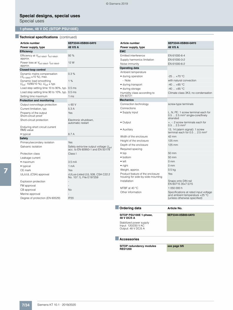
7/34 Siemens KT 10.1 · 2019/2020
7
■ Technical specifications (continued)
Special designs, special usesSpecial uses
1-phase, 48 V DC (SITOP PSU100E)
■ Ordering data Article No.
■ Accessories
Efficiency
Efficiency at Vout rated, Iout rated, approx.
92 %
Power loss at Vout rated, Iout rated, approx.
12 W
Closed-loop control
Dynamic mains compensation(Vin rated ±15 %), max.
0.3 %
Dynamic load smoothing(Iout: 10/90/10 %), Uout ± typ.
1 %
Load step setting time 10 to 90%, typ. 0.5 ms
Load step setting time 90 to 10%, typ. 0.5 ms
Setting time maximum 1 ms
Protection and monitoring
Output overvoltage protection < 60 V
Current limitation, typ. 5.3 A
Property of the output Short-circuit proof
Yes
Short-circuit protection Electronic shutdown,automatic restart
Enduring short circuit currentRMS value
• typical 8.7 A
Safety
Primary/secondary isolation Yes
Galvanic isolation Safety extra-low output voltage Uout acc. to EN 60950-1 and EN 50178
Protection class Class I
Leakage current
• maximum 3.5 mA
• typical 1 mA
CE mark Yes
UL/cUL (CSA) approval cULus-Listed (UL 508, CSA C22.2 No. 107.1), File E197259
Explosion protection -
FM approval -
CB approval No
Marine approval -
Degree of protection (EN 60529) IP20
Article number 6EP3344-0SB00-0AY0
Power supply, type 48 V/5 A
EMC
Emitted interference EN 61000-6-4
Supply harmonics limitation EN 61000-3-2
Noise immunity EN 61000-6-2
Operating data
Ambient temperature
• during operation -25 ... +70 °C
- Note with natural convection
• during transport -40 ... +85 °C
• during storage -40 ... +85 °C
Humidity class according to EN 60721
Climate class 3K3, no condensation
Mechanics
Connection technology screw-type terminals
Connections
• Supply input L, N, PE: 1 screw terminal each for 0.5 ... 2.5 mm² single-core/finely stranded
• Output +, -: 2 screw terminals each for 0.5 ... 2.5 mm²
• Auxiliary 13, 14 (alarm signal): 1 screw terminal each for 0.5 ... 2.5 mm²
Width of the enclosure 42 mm
Height of the enclosure 125 mm
Depth of the enclosure 125 mm
Required spacing
• top 50 mm
• bottom 50 mm
• left 0 mm
• right 0 mm
Weight, approx. 0.5 kg
Product feature of the enclosure housing for side-by-side mounting
Yes
Installation Snaps onto DIN railEN 60715 35x7.5/15
MTBF at 40 °C 1 050 000 h
Other information Specifications at rated input voltage and ambient temperature +25 °C (unless otherwise specified)
SITOP PSU100E 1-phase, 48 V DC/5 A
6EP3344-0SB00-0AY0
Stabilized power supplyInput: 120/230 V ACOutput: 48 V DC/5 A
SITOP redundancy modules RED1200
see page 9/6
Article number 6EP3344-0SB00-0AY0
Power supply, type 48 V/5 A
© Siemens 2019
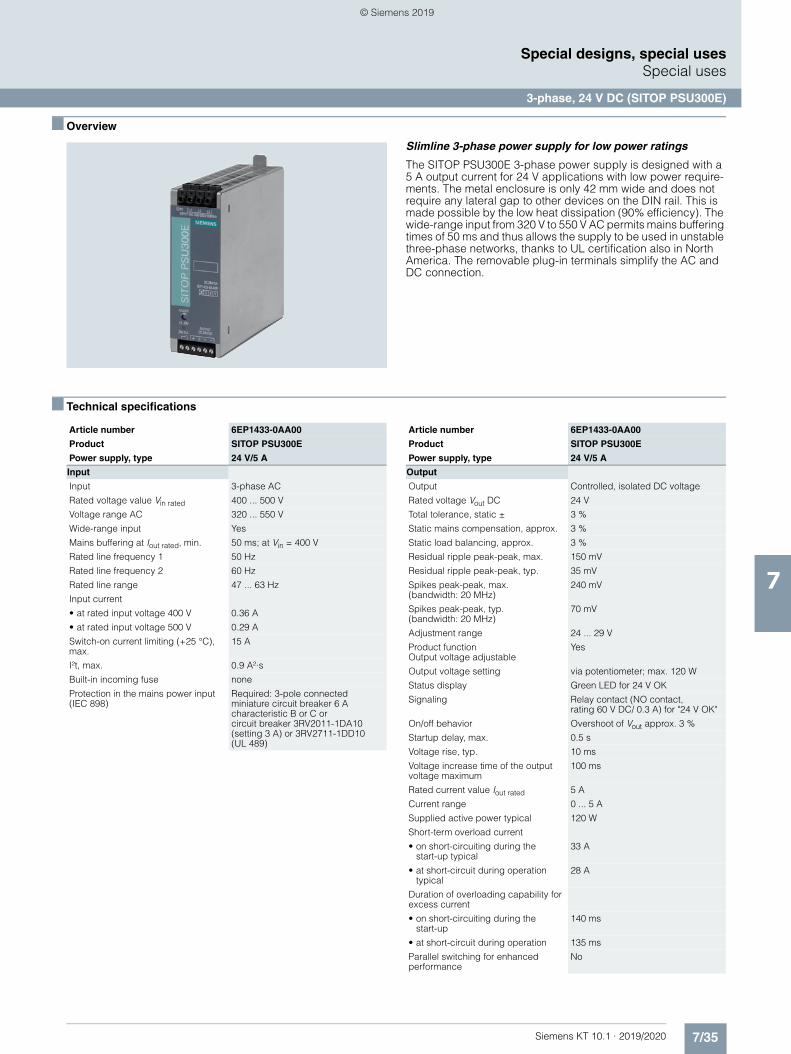
7/35Siemens KT 10.1 · 2019/2020
7
Special designs, special usesSpecial uses
3-phase, 24 V DC (SITOP PSU300E)
■ Overview
Slimline 3-phase power supply for low power ratings
The SITOP PSU300E 3-phase power supply is designed with a 5 A output current for 24 V applications with low power require-ments. The metal enclosure is only 42 mm wide and does not require any lateral gap to other devices on the DIN rail. This is made possible by the low heat dissipation (90% efficiency). The wide-range input from 320 V to 550 V AC permits mains buffering times of 50 ms and thus allows the supply to be used in unstable three-phase networks, thanks to UL certification also in North America. The removable plug-in terminals simplify the AC and DC connection.
■ Technical specifications
Article number 6EP1433-0AA00
Product SITOP PSU300E
Power supply, type 24 V/5 A
Input
Input 3-phase AC
Rated voltage value Vin rated 400 ... 500 V
Voltage range AC 320 ... 550 V
Wide-range input Yes
Mains buffering at Iout rated, min. 50 ms; at Vin = 400 V
Rated line frequency 1 50 Hz
Rated line frequency 2 60 Hz
Rated line range 47 ... 63 Hz
Input current
• at rated input voltage 400 V 0.36 A
• at rated input voltage 500 V 0.29 A
Switch-on current limiting (+25 °C), max.
15 A
I²t, max. 0.9 A²·s
Built-in incoming fuse none
Protection in the mains power input (IEC 898)
Required: 3-pole connected miniature circuit breaker 6 Acharacteristic B or C orcircuit breaker 3RV2011-1DA10 (setting 3 A) or 3RV2711-1DD10(UL 489)
Output
Output Controlled, isolated DC voltage
Rated voltage Vout DC 24 V
Total tolerance, static ± 3 %
Static mains compensation, approx. 3 %
Static load balancing, approx. 3 %
Residual ripple peak-peak, max. 150 mV
Residual ripple peak-peak, typ. 35 mV
Spikes peak-peak, max.(bandwidth: 20 MHz)
240 mV
Spikes peak-peak, typ. (bandwidth: 20 MHz)
70 mV
Adjustment range 24 ... 29 V
Product functionOutput voltage adjustable
Yes
Output voltage setting via potentiometer; max. 120 W
Status display Green LED for 24 V OK
Signaling Relay contact (NO contact,rating 60 V DC/ 0.3 A) for "24 V OK"
On/off behavior Overshoot of Vout approx. 3 %
Startup delay, max. 0.5 s
Voltage rise, typ. 10 ms
Voltage increase time of the output voltage maximum
100 ms
Rated current value Iout rated 5 A
Current range 0 ... 5 A
Supplied active power typical 120 W
Short-term overload current
• on short-circuiting during thestart-up typical
33 A
• at short-circuit during operation typical
28 A
Duration of overloading capability for excess current
• on short-circuiting during the start-up
140 ms
• at short-circuit during operation 135 ms
Parallel switching for enhanced performance
No
Article number 6EP1433-0AA00
Product SITOP PSU300E
Power supply, type 24 V/5 A
© Siemens 2019
7/36 Siemens KT 10.1 · 2019/2020
7
■ Technical specifications (continued)
Special designs, special usesSpecial uses
3-phase, 24 V DC (SITOP PSU300E)
■ Ordering data Article No.
■ Accessories
Efficiency
Efficiency at Vout rated, Iout rated, approx.
90 %
Power loss at Vout rated, Iout rated, approx.
13 W
Closed-loop control
Dynamic mains compensation(Vin rated ±15 %), max.
3 %
Dynamic load smoothing (Iout: 50/100/50 %), Uout ± typ.
5 %
Load step setting time 50 to 100%, typ.
1 ms
Load step setting time 100 to 50%, typ.
1 ms
Dynamic load smoothing (Iout: 10/90/10 %), Uout ± typ.
1 %
Load step setting time 10 to 90%, typ. 1 ms
Load step setting time 90 to 10%, typ. 1 ms
Setting time maximum 30 ms
Protection and monitoring
Output overvoltage protection Yes, according to EN 60950-1
Current limitation, typ. 11 A
Property of the output Short-circuit proof
Yes
Short-circuit protection Electronic shutdown,automatic restart
Enduring short circuit currentRMS value
• maximum 7.5 A
Safety
Primary/secondary isolation Yes
Galvanic isolation Safety extra-low output voltage Uout acc. to EN 60950-1 and EN 50178
Protection class Class I
CE mark Yes
UL/cUL (CSA) approval cULus-Listed (UL 508, CSA C22.2 No. 107.1), File E197259
Explosion protection -
FM approval -
CB approval No
Marine approval -
Degree of protection (EN 60529) IP20
Article number 6EP1433-0AA00
Product SITOP PSU300E
Power supply, type 24 V/5 A
EMC
Emitted interference EN 55022 Class A
Supply harmonics limitation EN 61000-3-2
Noise immunity EN 61000-6-2
Operating data
Ambient temperature
• during operation 0 ... 60 °C
- Note with natural convection
• during transport -40 ... +85 °C
• during storage -40 ... +85 °C
Humidity class according to EN 60721
Climate class 3K3, no condensation
Mechanics
Connection technology screw-type terminals
Connections
• Supply input L1, L2, L3, PE: Removable screw terminal for 0.5 ... 2.5 mm²single-core/finely stranded
• Output +, -: 2 screw terminals each for0.5 ... 2.5 mm²
• Auxiliary 13, 14 (alarm signal): 1 screw terminal each for 0.5 ... 2.5 mm²
Product function
• removable terminal at input Yes
• removable terminal at output Yes
Width of the enclosure 42 mm
Height of the enclosure 125 mm
Depth of the enclosure 125 mm
Required spacing
• top 50 mm
• bottom 50 mm
• left 0 mm
• right 0 mm
Weight, approx. 0.6 kg
Product feature of the enclosure housing for side-by-side mounting
Yes
Installation Snaps onto DIN rail EN 60715 35x7.5/15
MTBF at 40 °C 2 389 441 h
Other information Specifications at rated input voltage and ambient temperature +25 °C (unless otherwise specified)
SITOP PSU300E 3-phase,24 V/5 A DC
6EP1433-0AA00
Stabilized power supply Input: 400 ... 500 V 3 AC Output: 24 V DC/5 A
SITOP redundancy modules see page 9/6
SITOP selectivity modules see page 9/14
Article number 6EP1433-0AA00
Product SITOP PSU300E
Power supply, type 24 V/5 A
© Siemens 2019
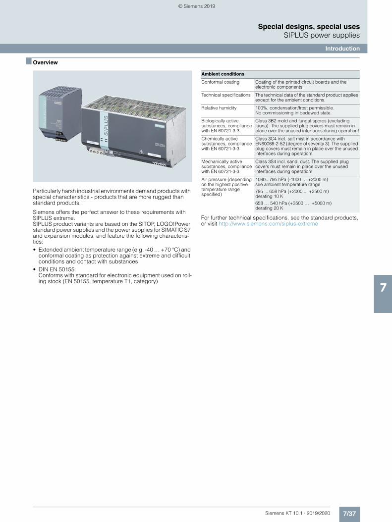
7/37Siemens KT 10.1 · 2019/2020
7
Special designs, special usesSIPLUS power supplies
Introduction
■ Overview
Particularly harsh industrial environments demand products with special characteristics - products that are more rugged than standard products.
Siemens offers the perfect answer to these requirements with SIPLUS extreme. SIPLUS product variants are based on the SITOP, LOGO!Power standard power supplies and the power supplies for SIMATIC S7 and expansion modules, and feature the following characteris-tics:• Extended ambient temperature range (e.g. -40 … +70 °C) and
conformal coating as protection against extreme and difficult conditions and contact with substances
• DIN EN 50155:Conforms with standard for electronic equipment used on roll-ing stock (EN 50155, temperature T1, category)
For further technical specifications, see the standard products, or visit http://www.siemens.com/siplus-extreme
Ambient conditions
Conformal coating Coating of the printed circuit boards and the electronic components
Technical specifications The technical data of the standard product applies except for the ambient conditions.
Relative humidity 100%, condensation/frost permissible. No commissioning in bedewed state.
Biologically active substances, compliance with EN 60721-3-3
Class 3B2 mold and fungal spores (excluding fauna). The supplied plug covers must remain in place over the unused interfaces during operation!
Chemically active substances, compliance with EN 60721-3-3
Class 3C4 incl. salt mist in accordance with EN60068-2-52 (degree of severity 3). The supplied plug covers must remain in place over the unused interfaces during operation!
Mechanically active substances, compliance with EN 60721-3-3
Class 3S4 incl. sand, dust. The supplied plug covers must remain in place over the unused interfaces during operation!
Air pressure (depending on the highest positive temperature range specified)
1080...795 hPa (-1000 … +2000 m) see ambient temperature range
795 ... 658 hPa (+2000 ... +3500 m)derating 10 K
658 … 540 hPa (+3500 … +5000 m) derating 20 K
© Siemens 2019
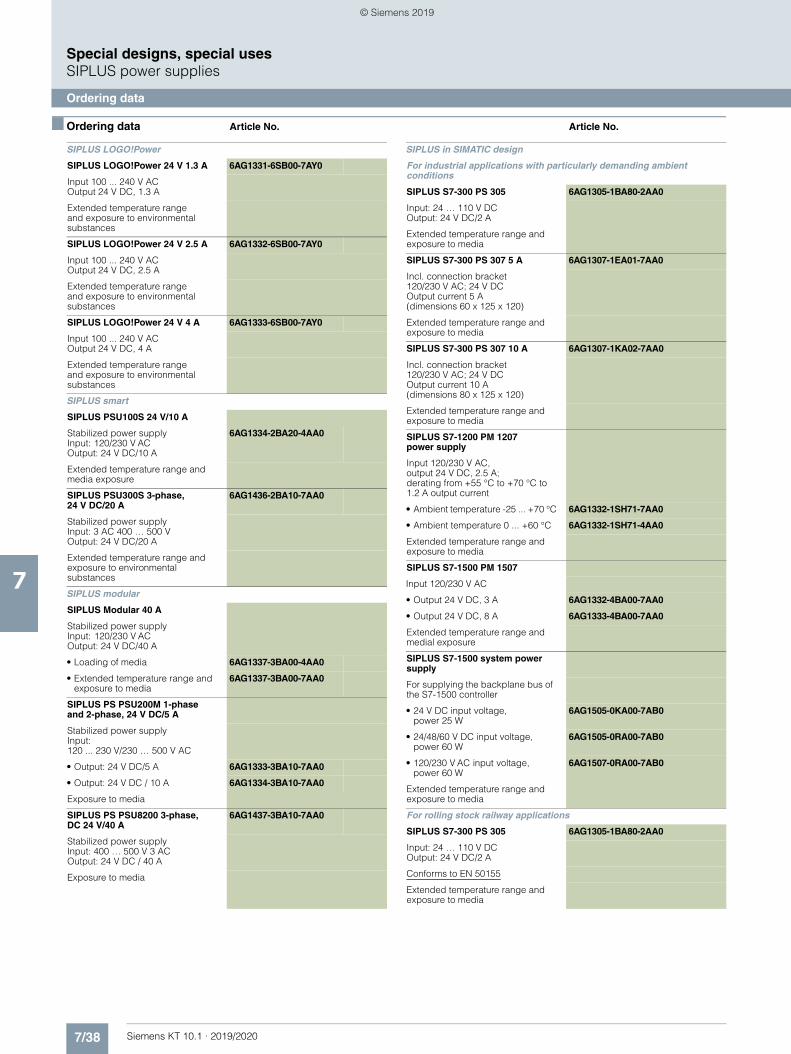
7/38 Siemens KT 10.1 · 2019/2020
7
Special designs, special usesSIPLUS power supplies
Ordering data
■ Ordering data Article No. Article No.
SIPLUS LOGO!Power
SIPLUS LOGO!Power 24 V 1.3 A 6AG1331-6SB00-7AY0
Input 100 ... 240 V ACOutput 24 V DC, 1.3 A
Extended temperature range and exposure to environmental substances
SIPLUS LOGO!Power 24 V 2.5 A 6AG1332-6SB00-7AY0
Input 100 ... 240 V ACOutput 24 V DC, 2.5 A
Extended temperature rangeand exposure to environmental substances
SIPLUS LOGO!Power 24 V 4 A 6AG1333-6SB00-7AY0
Input 100 ... 240 V ACOutput 24 V DC, 4 A
Extended temperature range and exposure to environmental substances
SIPLUS smart
SIPLUS PSU100S 24 V/10 A
Stabilized power supply Input: 120/230 V AC Output: 24 V DC/10 A
6AG1334-2BA20-4AA0
Extended temperature range and media exposure
SIPLUS PSU300S 3-phase, 24 V DC/20 A
6AG1436-2BA10-7AA0
Stabilized power supplyInput: 3 AC 400 … 500 VOutput: 24 V DC/20 A
Extended temperature range and exposure to environmental substances
SIPLUS modular
SIPLUS Modular 40 A
Stabilized power supplyInput: 120/230 V ACOutput: 24 V DC/40 A
• Loading of media 6AG1337-3BA00-4AA0
• Extended temperature range and exposure to media
6AG1337-3BA00-7AA0
SIPLUS PS PSU200M 1-phase and 2-phase, 24 V DC/5 A
Stabilized power supply Input: 120 ... 230 V/230 … 500 V AC
• Output: 24 V DC/5 A 6AG1333-3BA10-7AA0
• Output: 24 V DC / 10 A 6AG1334-3BA10-7AA0
Exposure to media
SIPLUS PS PSU8200 3-phase,DC 24 V/40 A
6AG1437-3BA10-7AA0
Stabilized power supplyInput: 400 … 500 V 3 ACOutput: 24 V DC / 40 A
Exposure to media
SIPLUS in SIMATIC design
For industrial applications with particularly demanding ambient conditions
SIPLUS S7-300 PS 305 6AG1305-1BA80-2AA0
Input: 24 … 110 V DC Output: 24 V DC/2 A
Extended temperature range and exposure to media
SIPLUS S7-300 PS 307 5 A 6AG1307-1EA01-7AA0
Incl. connection bracket120/230 V AC; 24 V DCOutput current 5 A (dimensions 60 x 125 x 120)
Extended temperature range and exposure to media
SIPLUS S7-300 PS 307 10 A 6AG1307-1KA02-7AA0
Incl. connection bracket120/230 V AC; 24 V DCOutput current 10 A(dimensions 80 x 125 x 120)
Extended temperature range and exposure to media
SIPLUS S7-1200 PM 1207 power supply
Input 120/230 V AC, output 24 V DC, 2.5 A;derating from +55 °C to +70 °C to 1.2 A output current
• Ambient temperature -25 ... +70 °C 6AG1332-1SH71-7AA0
• Ambient temperature 0 ... +60 °C 6AG1332-1SH71-4AA0
Extended temperature range and exposure to media
SIPLUS S7-1500 PM 1507
Input 120/230 V AC
• Output 24 V DC, 3 A 6AG1332-4BA00-7AA0
• Output 24 V DC, 8 A 6AG1333-4BA00-7AA0
Extended temperature range and medial exposure
SIPLUS S7-1500 system power supply
For supplying the backplane bus of the S7-1500 controller
• 24 V DC input voltage, power 25 W
6AG1505-0KA00-7AB0
• 24/48/60 V DC input voltage, power 60 W
6AG1505-0RA00-7AB0
• 120/230 V AC input voltage, power 60 W
6AG1507-0RA00-7AB0
Extended temperature range and exposure to media
For rolling stock railway applications
SIPLUS S7-300 PS 305 6AG1305-1BA80-2AA0
Input: 24 … 110 V DC Output: 24 V DC/2 A
Conforms to EN 50155
Extended temperature range and exposure to media
© Siemens 2019
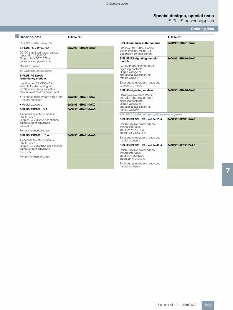
7/39Siemens KT 10.1 · 2019/2020
7
■ Ordering data Article No. Article No.
Special designs, special usesSIPLUS power supplies
Ordering data
SIPLUS DC/DC converter
SIPLUS PS 24V/0.375A 6AG1931-2BA00-3AA0
DC/DC stabilized power supply Input: 48 … 220 V DCOutput: 24 V DC/0.375 A condensation permissible
Medial exposure
SIPLUS add-on modules
SIPLUS PS E202U redundancy module
Input/output: 24 V DC/40 A suitable for decoupling twoSITOP power supplies with amaximum of 20 A output current
• Extended temperature range and medial exposure
6AG1961-3BA21-7AX0
• Medial exposure 6AG1961-3BA21-4AX0
SIPLUS PSE200U 3 A 6AG1961-2BA31-7AA0
4-channel selectivity module Input: 24 V AC Output: 24 V DC/3A per channel output current adjustable 0.5 ... 3 A
For environmental stress
SIPLUS PSE200U 10 A 6AG1961-2BA41-7AA0
4-channel selectivity module Input: 24 V AC Output: 24 V DC/10 A per channel output current adjustable3 ... 10 A
For environmental stress
SIPLUS modular buffer module 6AG1961-3BA01-7AA0
For 6AG1 961-3BA01-7AA0; buffer time 100 ms to 10 s, dependent on load current
SIPLUS PS signaling module modular
6AG1961-3BA10-7AA0
For 6AG1XXX-3BA00 -XXXXsignaling contacts: Output voltage ok, operational availability ok, remote ON/OFF
Extended temperature range and exposure to media
SIPLUS signaling module 6AG1961-3BA10-6AA0
Hard gold-plated contacts; for 6AG1XXX-3BA00 -XXXXsignaling contacts: Output voltage ok, operational availability ok, remote ON/OFF
SIPLUS DC UPS, uninterruptible power supplies
SIPLUS PS DC UPS module 15 A 6AG1931-2EC21-2AA0
Uninterruptible power supply without interface;input: 24 V DC/16 A, output: 24 V DC/15 A
Extended temperature range and medial exposure
SIPLUS PS DC UPS module 40 A 6AG1931-2FC21-7AA0
Uninterruptible power supply without interface; input 24 V DC/43 A, output 24 V DC/40 A
Extended temperature range and medial exposure
© Siemens 2019
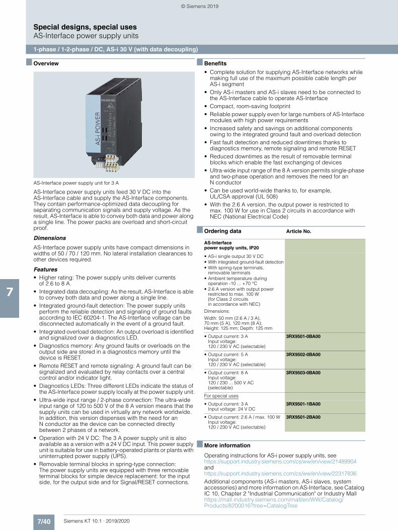
7/40 Siemens KT 10.1 · 2019/2020
7
Special designs, special usesAS-Interface power supply units
1-phase / 1-2-phase / DC, AS-i 30 V (with data decoupling)
■ Overview
AS-Interface power supply unit for 3 A
AS-Interface power supply units feed 30 V DC into the AS-Interface cable and supply the AS-Interface components. They contain performance-optimized data decoupling for separating communication signals and supply voltage. As the result, AS-Interface is able to convey both data and power along a single line. The power packs are overload and short-circuit proof.
Dimensions
AS-Interface power supply units have compact dimensions in widths of 50 / 70 / 120 mm. No lateral installation clearances to other devices required.
Features• Higher rating: The power supply units deliver currents
of 2.6 to 8 A.• Integrated data decoupling: As the result, AS-Interface is able
to convey both data and power along a single line.• Integrated ground-fault detection: The power supply units
perform the reliable detection and signaling of ground faults according to IEC 60204-1. The AS-Interface voltage can be disconnected automatically in the event of a ground fault.
• Integrated overload detection: An output overload is identified and signalized over a diagnostics LED.
• Diagnostics memory: Any ground faults or overloads on the output side are stored in a diagnostics memory until the device is RESET.
• Remote RESET and remote signaling: A ground fault can be signalized and evaluated by relay contacts over a central control and/or indicator light.
• Diagnostics LEDs: Three different LEDs indicate the status of the AS-Interface power supply locally at the power supply unit.
• Ultra-wide input range / 2-phase connection: The ultra-wide input range of 120 to 500 V of the 8 A version means that the supply units can be used in virtually any network worldwide. In addition, this version dispenses with the need for an N conductor as the device can be connected directly between 2 phases of a network.
• Operation with 24 V DC: The 3 A power supply unit is also available as a version with a 24 V DC input. This power supply unit is suitable for use in battery-operated plants or plants with uninterrupted power supply (UPS).
• Removable terminal blocks in spring-type connection: The power supply units are equipped with three removable terminal blocks for simple device replacement: for the input side, for the output side and for Signal/RESET connections.
■ Benefits
• Complete solution for supplying AS-Interface networks while making full use of the maximum possible cable length per AS-i segment
• Only AS-i masters and AS-i slaves need to be connected to the AS-Interface cable to operate AS-Interface
• Compact, room-saving footprint• Reliable power supply even for large numbers of AS-Interface
modules with high power requirements• Increased safety and savings on additional components
owing to the integrated ground fault and overload detection• Fast fault detection and reduced downtimes thanks to
diagnostics memory, remote signaling and remote RESET• Reduced downtimes as the result of removable terminal
blocks which enable the fast exchanging of devices• Ultra-wide input range of the 8 A version permits single-phase
and two-phase operation and removes the need for an N conductor
• Can be used world-wide thanks to, for example,UL/CSA approval (UL 508)
• With the 2.6 A version, the output power is restricted tomax. 100 W for use in Class 2 circuits in accordance withNEC (National Electrical Code)
■ Ordering data Article No.
■ More information
Operating instructions for AS-i power supply units, seehttps://support.industry.siemens.com/cs/ww/en/view/21489904 and https://support.industry.siemens.com/cs/ww/en/view/22317836Additional components (AS-i masters, AS-i slaves, system accessories) and more information on AS-Interface, see Catalog IC 10, Chapter 2 "Industrial Communication" or Industry Mall https://mall.industry.siemens.com/mall/en/WW/Catalog/Products/8200016?tree=CatalogTree
AS-Interface power supply units, IP20
• AS-i single output 30 V DC• With integrated ground-fault detection• With spring-type terminals,
removable terminals• Ambient temperature during
operation -10 ... +70 °C• 2.6 A version with output power
restricted to max. 100 W (for Class 2 circuits in accordance with NEC)
Dimensions:
Width: 50 mm (2.6 A / 3 A), 70 mm (5 A), 120 mm (8 A); Height: 125 mm; Depth: 125 mm
• Output current: 3 AInput voltage:120 / 230 V AC (selectable)
3RX9501-0BA00
• Output current: 5 AInput voltage:120 / 230 V AC (selectable)
3RX9502-0BA00
• Output current: 8 AInput voltage:120 / 230 ... 500 V AC(selectable)
3RX9503-0BA00
For special uses
• Output current: 3 AInput voltage: 24 V DC
3RX9501-1BA00
• Output current: 2.6 A / max. 100 WInput voltage:120 / 230 V AC (selectable)
3RX9501-2BA00
© Siemens 2019
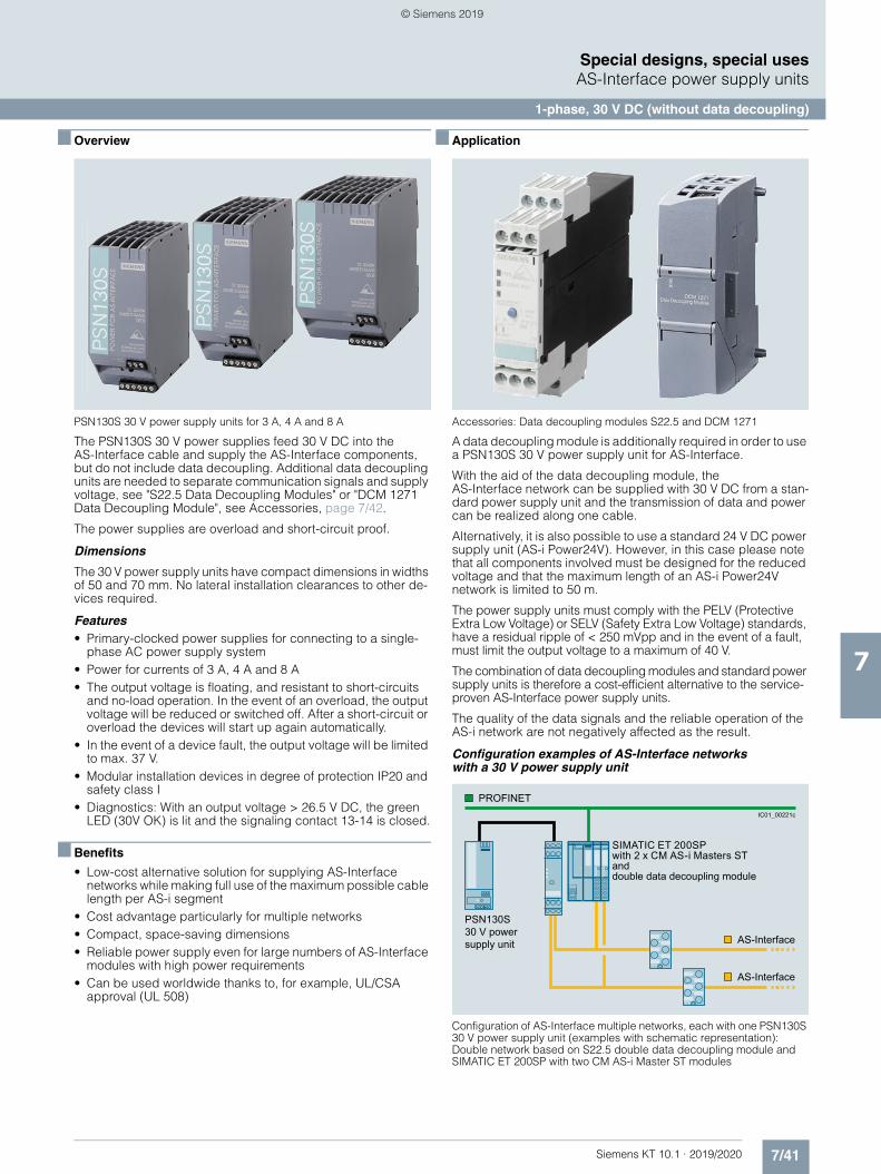
7/41Siemens KT 10.1 · 2019/2020
7
Special designs, special usesAS-Interface power supply units
1-phase, 30 V DC (without data decoupling)
■ Overview
PSN130S 30 V power supply units for 3 A, 4 A and 8 A
The PSN130S 30 V power supplies feed 30 V DC into the AS-Interface cable and supply the AS-Interface components, but do not include data decoupling. Additional data decoupling units are needed to separate communication signals and supply voltage, see "S22.5 Data Decoupling Modules" or "DCM 1271 Data Decoupling Module", see Accessories, page 7/42.
The power supplies are overload and short-circuit proof.
Dimensions
The 30 V power supply units have compact dimensions in widths of 50 and 70 mm. No lateral installation clearances to other de-vices required.
Features• Primary-clocked power supplies for connecting to a single-
phase AC power supply system• Power for currents of 3 A, 4 A and 8 A• The output voltage is floating, and resistant to short-circuits
and no-load operation. In the event of an overload, the output voltage will be reduced or switched off. After a short-circuit or overload the devices will start up again automatically.
• In the event of a device fault, the output voltage will be limited to max. 37 V.
• Modular installation devices in degree of protection IP20 and safety class I
• Diagnostics: With an output voltage > 26.5 V DC, the green LED (30V OK) is lit and the signaling contact 13-14 is closed.
■ Benefits
• Low-cost alternative solution for supplying AS-Interface networks while making full use of the maximum possible cable length per AS-i segment
• Cost advantage particularly for multiple networks• Compact, space-saving dimensions• Reliable power supply even for large numbers of AS-Interface
modules with high power requirements• Can be used worldwide thanks to, for example, UL/CSA
approval (UL 508)
■ Application
Accessories: Data decoupling modules S22.5 and DCM 1271
A data decoupling module is additionally required in order to use a PSN130S 30 V power supply unit for AS-Interface.
With the aid of the data decoupling module, the AS-Interface network can be supplied with 30 V DC from a stan-dard power supply unit and the transmission of data and power can be realized along one cable.
Alternatively, it is also possible to use a standard 24 V DC power supply unit (AS-i Power24V). However, in this case please note that all components involved must be designed for the reduced voltage and that the maximum length of an AS-i Power24V network is limited to 50 m.
The power supply units must comply with the PELV (Protective Extra Low Voltage) or SELV (Safety Extra Low Voltage) standards, have a residual ripple of < 250 mVpp and in the event of a fault, must limit the output voltage to a maximum of 40 V.
The combination of data decoupling modules and standard power supply units is therefore a cost-efficient alternative to the service-proven AS-Interface power supply units.
The quality of the data signals and the reliable operation of the AS-i network are not negatively affected as the result.
Configuration examples of AS-Interface networks with a 30 V power supply unit
Configuration of AS-Interface multiple networks, each with one PSN130S 30 V power supply unit (examples with schematic representation):Double network based on S22.5 double data decoupling module and SIMATIC ET 200SP with two CM AS-i Master ST modules
and double data decoupling module
PSN130S30 V power supply unit
SIMATIC ET 200SPwith 2 x CM AS-i Masters ST
AS-Interface
PROFINET
AS-Interface
IC01_00221c
© Siemens 2019
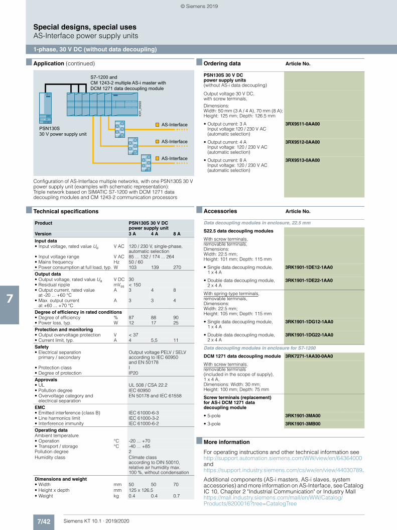
7/42 Siemens KT 10.1 · 2019/2020
7
■ Application (continued)
Special designs, special usesAS-Interface power supply units
1-phase, 30 V DC (without data decoupling)
Configuration of AS-Interface multiple networks, with one PSN130S 30 V power supply unit (examples with schematic representation):Triple network based on SIMATIC S7-1200 with DCM 1271 data decoupling modules and CM 1243-2 communication processors
■ Technical specifications
Product PSN130S 30 V DC power supply unit
Version 3 A 4 A 8 A
Input data• Input voltage, rated value Ue V AC 120 / 230 V, single-phase,
automatic selection • Input voltage range V AC 85 ... 132 / 174 ... 264• Mains frequency Hz 50 / 60 • Power consumption at full load, typ. W 103 139 270Output data• Output voltage, rated value Ua V DC 30• Residual ripple mVss < 150 • Output current, rated value
at -20 ... +60 °CA 3 4 8
• Max. output current at +60 ... +70 °C
A 3 3 4
Degree of efficiency in rated conditions• Degree of efficiency % 87 88 90• Power loss, typ. W 12 17 25Protection and monitoring• Output overvoltage protection V < 37• Current limit, typ. A 4 5,5 11Safety• Electrical separation
primary / secondaryOutput voltage PELV / SELV according to IEC 60950 and EN 50178
• Protection class I• Degree of protection IP20Approvals• UL UL 508 / CSA 22.2• Pollution degree IEC 60950• Overvoltage category and
electrical separation EN 50178 and IEC 61558
EMC• Emitted interference (class B) IEC 61000-6-3• Line harmonics limit IEC 61000-3-2• Interference immunity IEC 61000-6-2Operating dataAmbient temperature• Operation °C -20 ... +70• Transport / storage °C -40 ... +85Pollution degree 2Humidity class Climate class
according to DIN 50010, relative air humidity max. 100 %, without condensation
Dimensions and weight• Width mm 50 50 70• Height x depth mm 125 x 126.5• Weight kg 0.4 0.4 0.7
S7-1200 and CM 1243-2 multiple AS-i master with DCM 1271 data decoupling module
PSN130S30 V power supply unit
AS-Interface
AS-Interface
AS-Interface
IC01
_002
22
■ Ordering data Article No.
■ Accessories Article No.
■ More information
For operating instructions and other technical information see http://support.automation.siemens.com/WW/view/en/64364000 and https://support.industry.siemens.com/cs/ww/en/view/44030789.
Additional components (AS-i masters, AS-i slaves, system accessories) and more information on AS-Interface, see Catalog IC 10, Chapter 2 "Industrial Communication" or Industry Mallhttps://mall.industry.siemens.com/mall/en/WW/Catalog/Products/8200016?tree=CatalogTree
PSN130S 30 V DC power supply units (without AS-i data decoupling)
Output voltage 30 V DC, with screw terminals,
Dimensions: Width: 50 mm (3 A / 4 A), 70 mm (8 A); Height: 125 mm; Depth: 126.5 mm
• Output current: 3 AInput voltage:120 / 230 V AC (automatic selection)
3RX9511-0AA00
• Output current: 4 AInput voltage: 120 / 230 V AC (automatic selection)
3RX9512-0AA00
• Output current: 8 AInput voltage: 120 / 230 V AC (automatic selection)
3RX9513-0AA00
Data decoupling modules in enclosure, 22.5 mm
S22.5 data decoupling modules
With screw terminals, removable terminals, Dimensions: Width: 22.5 mm;Height: 101 mm; Depth: 115 mm
• Single data decoupling module, 1 x 4 A
3RK1901-1DE12-1AA0
• Double data decoupling module, 2 x 4 A
3RK1901-1DE22-1AA0
With spring-type terminals, removable terminals, Dimensions: Width: 22.5 mm;Height: 105 mm; Depth: 115 mm
• Single data decoupling module, 1 x 4 A
3RK1901-1DG12-1AA0
• Double data decoupling module, 2 x 4 A
3RK1901-1DG22-1AA0
Data decoupling modules in enclosure for S7-1200
DCM 1271 data decoupling module 3RK7271-1AA30-0AA0
With screw terminals, removable terminals(included in the scope of supply), 1 x 4 A, Dimensions: Width: 30 mm; Height: 100 mm; Depth: 75 mm
Screw terminals (replacement) for AS-i DCM 1271 data decoupling module
• 5-pole 3RK1901-3MA00
• 3-pole 3RK1901-3MB00
© Siemens 2019
Siemens KT 10.1 · 2019/2020
88/2 Introduction
8/3 DC UPS with capacitors
8/10 DC UPS with battery modules8/10 SITOP UPS1600 DC UPS modules8/18 SITOP UPS1100 battery modules8/22 SITOP DC UPS8/28 DC UPS battery modules
SITOP DC UPS uninterruptible power supplies
© Siemens 2019
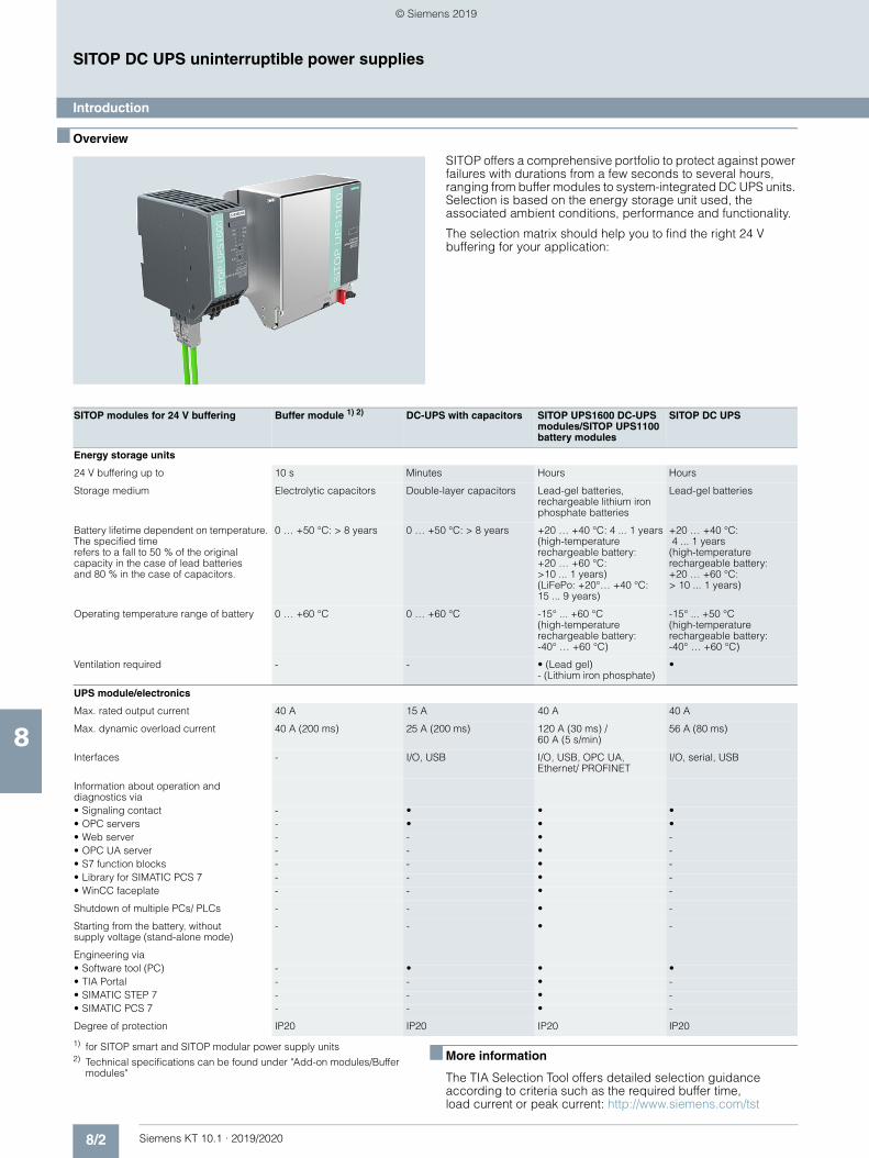
8/2 Siemens KT 10.1 · 2019/2020
8
SITOP DC UPS uninterruptible power supplies
Introduction
■ Overview
SITOP offers a comprehensive portfolio to protect against power failures with durations from a few seconds to several hours, ranging from buffer modules to system-integrated DC UPS units. Selection is based on the energy storage unit used, the associated ambient conditions, performance and functionality.
The selection matrix should help you to find the right 24 V buffering for your application:
1) for SITOP smart and SITOP modular power supply units2) Technical specifications can be found under "Add-on modules/Buffer
modules"
■ More information
The TIA Selection Tool offers detailed selection guidance according to criteria such as the required buffer time, load current or peak current: http://www.siemens.com/tst
SITOP modules for 24 V buffering Buffer module 1) 2) DC-UPS with capacitors SITOP UPS1600 DC-UPS modules/SITOP UPS1100 battery modules
SITOP DC UPS
Energy storage units
24 V buffering up to 10 s Minutes Hours Hours
Storage medium Electrolytic capacitors Double-layer capacitors Lead-gel batteries, rechargeable lithium iron phosphate batteries
Lead-gel batteries
Battery lifetime dependent on temperature. The specified time refers to a fall to 50 % of the original capacity in the case of lead batteries and 80 % in the case of capacitors.
0 … +50 °C: > 8 years 0 … +50 °C: > 8 years +20 … +40 °C: 4 ... 1 years(high-temperature rechargeable battery:+20 … +60 °C: >10 ... 1 years)(LiFePo: +20°… +40 °C: 15 ... 9 years)
+20 … +40 °C: 4 ... 1 years(high-temperature rechargeable battery:+20 … +60 °C: > 10 ... 1 years)
Operating temperature range of battery 0 … +60 °C 0 … +60 °C -15° ... +60 °C(high-temperature rechargeable battery:-40° … +60 °C)
-15° ... +50 °C(high-temperature rechargeable battery:-40° … +60 °C)
Ventilation required - - • (Lead gel)- (Lithium iron phosphate)
•
UPS module/electronics
Max. rated output current 40 A 15 A 40 A 40 A
Max. dynamic overload current 40 A (200 ms) 25 A (200 ms) 120 A (30 ms) /60 A (5 s/min)
56 A (80 ms)
Interfaces - I/O, USB I/O, USB, OPC UA,Ethernet/ PROFINET
I/O, serial, USB
Information about operation and diagnostics via• Signaling contact - • • •• OPC servers - • • •• Web server - - • -• OPC UA server - - • -• S7 function blocks - - • -• Library for SIMATIC PCS 7 - - • -• WinCC faceplate - - • -
Shutdown of multiple PCs/ PLCs - - • -
Starting from the battery, without supply voltage (stand-alone mode)
- - • -
Engineering via• Software tool (PC) - • • •• TIA Portal - - • -• SIMATIC STEP 7 - - • -• SIMATIC PCS 7 - - • -
Degree of protection IP20 IP20 IP20 IP20
© Siemens 2019
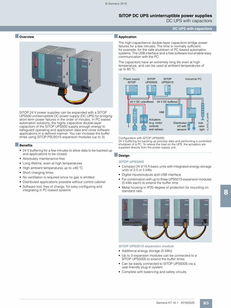
8/3Siemens KT 10.1 · 2019/2020
8
SITOP DC UPS uninterruptible power suppliesDC UPS with capacitors
DC UPS with capacitors
■ Overview
SITOP 24 V power supplies can be expanded with a SITOP UPS500 uninterruptible DC power supply (DC UPS) for bridging short-term power failures in the order of minutes. In PC-based automation solutions, the highly capacitive double-layer capacitors of the SITOP UPS500 supply enough energy to safeguard operating and application data and close software applications in a defined manner. You can increase the buffer times using SITOP PSU501S expansion modules (up to 3).
■ Benefits
• 24 V buffering for a few minutes to allow data to be backed up and applications to be closed.
• Absolutely maintenance-free • Long lifetime, even at high temperatures• High ambient temperatures up to +60 °C• Short charging times• No ventilation is required since no gas is emitted• Distributed applications possible without control cabinet• Software tool, free of charge, for easy configuring and
integrating in PC-based systems
■ Application
The high-capacitance double-layer capacitors bridge power failures for a few minutes. The time is normally sufficient, for example, for the safe shutdown of PC-based automation systems. The USB interface and a free software tool enable easy communication with the PC.
The capacitors have an extremely long life even at high temperature, and can be used at ambient temperatures of up to 60 °C.
Configuration with SITOP UPS500S: 24 V buffering for backing up process data and performing a controlled shutdown of a PC. To relieve the load on the UPS, the actuators are supplied directly from the power supply unit.
■ Design
SITOP UPS500S• Compact 24 V/15 A basic units with integrated energy storage
units of 2.5 or 5 kWs• Digital inputs/outputs and USB interface• For combination with up to three UPS501S expansion modules
(5 kWs each) to extend the buffer time• Metal housing in IP20 degree of protection for mounting on
standard rails
SITOP UPS501S expansion module• Additional energy storage (5 kWs)• Up to 3 expansion modules can be connected to a
SITOP UPS500S to extend the buffer times• Can be easily connected to SITOP UPS500S via a
user-friendly plug-in system• Complete with balancing and safety circuits
Actuators(e.g. motor controlsand valves)
Indi-catorlight
Distributed I/O with sensors
24 V DC unbuffered 24 V DC buffered
Industrial PCPower supplySITOP
SITOP UPS501S
SITOP UPS500S
G_K
T01_
XX
_007
58
HMI
© Siemens 2019
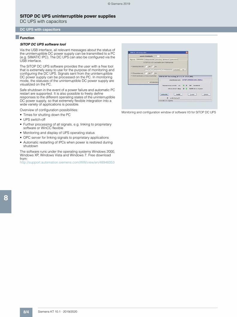
8/4 Siemens KT 10.1 · 2019/2020
8
SITOP DC UPS uninterruptible power suppliesDC UPS with capacitors
DC UPS with capacitors
■ Function
SITOP DC UPS software tool
Via the USB interface, all relevant messages about the status of the uninterruptible DC power supply can be transmitted to a PC (e.g. SIMATIC IPC). The DC UPS can also be configured via the USB interface.
The SITOP DC UPS software provides the user with a free tool that is extremely easy to use for the purpose of monitoring and configuring the DC UPS. Signals sent from the uninterruptible DC power supply can be processed on the PC. In monitoring mode, the statuses of the uninterruptible DC power supply are visualized on the PC.
Safe shutdown in the event of a power failure and automatic PC restart are supported. It is also possible to freely define responses to the different operating states of the uninterruptible DC power supply, so that extremely flexible integration into a wide variety of applications is possible.
Overview of configuration possibilities:• Times for shutting down the PC• UPS switch-off• Further processing of all signals, e.g. linking to proprietary
software or WinCC flexible• Monitoring and display of UPS operating status• OPC server for linking signals to proprietary applications• Automatic restarting of IPCs when power is restored during
shutdown
The software runs under the operating systems Windows 2000, Windows XP, Windows Vista and Windows 7. Free download from:http://support.automation.siemens.com/WW/view/en/48946053
Monitoring and configuration window of software V3 for SITOP DC UPS
© Siemens 2019
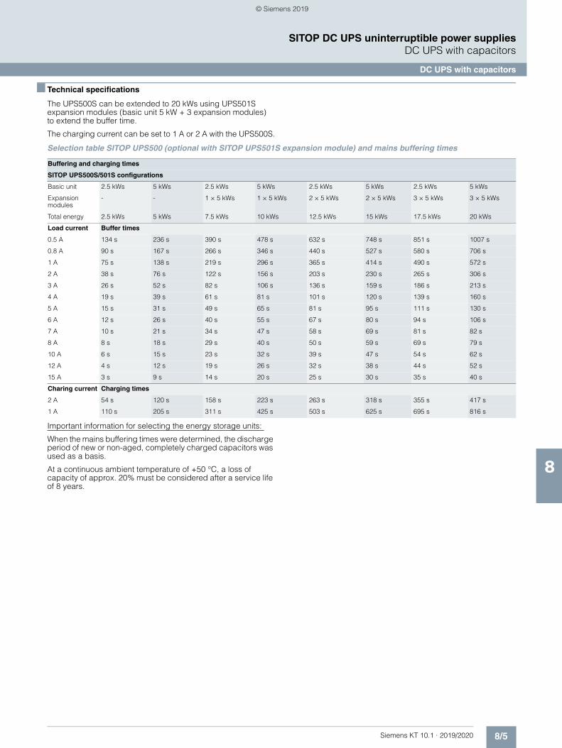
8/5Siemens KT 10.1 · 2019/2020
8
SITOP DC UPS uninterruptible power suppliesDC UPS with capacitors
DC UPS with capacitors
■ Technical specifications
The UPS500S can be extended to 20 kWs using UPS501S expansion modules (basic unit 5 kW + 3 expansion modules) to extend the buffer time.
The charging current can be set to 1 A or 2 A with the UPS500S.
Selection table SITOP UPS500 (optional with SITOP UPS501S expansion module) and mains buffering times
Important information for selecting the energy storage units:
When the mains buffering times were determined, the discharge period of new or non-aged, completely charged capacitors was used as a basis.
At a continuous ambient temperature of +50 °C, a loss of capacity of approx. 20% must be considered after a service life of 8 years.
Buffering and charging times
SITOP UPS500S/501S configurations
Basic unit 2.5 kWs 5 kWs 2.5 kWs 5 kWs 2.5 kWs 5 kWs 2.5 kWs 5 kWs
Expansion modules
- - 1 × 5 kWs 1 × 5 kWs 2 × 5 kWs 2 × 5 kWs 3 × 5 kWs 3 × 5 kWs
Total energy 2.5 kWs 5 kWs 7.5 kWs 10 kWs 12.5 kWs 15 kWs 17.5 kWs 20 kWs
Load current Buffer times
0.5 A 134 s 236 s 390 s 478 s 632 s 748 s 851 s 1007 s
0.8 A 90 s 167 s 266 s 346 s 440 s 527 s 580 s 706 s
1 A 75 s 138 s 219 s 296 s 365 s 414 s 490 s 572 s
2 A 38 s 76 s 122 s 156 s 203 s 230 s 265 s 306 s
3 A 26 s 52 s 82 s 106 s 136 s 159 s 186 s 213 s
4 A 19 s 39 s 61 s 81 s 101 s 120 s 139 s 160 s
5 A 15 s 31 s 49 s 65 s 81 s 95 s 111 s 130 s
6 A 12 s 26 s 40 s 55 s 67 s 80 s 94 s 106 s
7 A 10 s 21 s 34 s 47 s 58 s 69 s 81 s 82 s
8 A 8 s 18 s 29 s 40 s 50 s 59 s 69 s 79 s
10 A 6 s 15 s 23 s 32 s 39 s 47 s 54 s 62 s
12 A 4 s 12 s 19 s 26 s 32 s 38 s 44 s 52 s
15 A 3 s 9 s 14 s 20 s 25 s 30 s 35 s 40 s
Charing current Charging times
2 A 54 s 120 s 158 s 223 s 263 s 318 s 355 s 417 s
1 A 110 s 205 s 311 s 425 s 503 s 625 s 695 s 816 s
© Siemens 2019
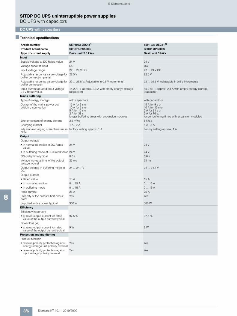
8/6 Siemens KT 10.1 · 2019/2020
8
SITOP DC UPS uninterruptible power suppliesDC UPS with capacitors
DC UPS with capacitors
■ Technical specifications
Article number 6EP1933-2EC411) 6EP1933-2EC511)
Product brand name SITOP UPS500S SITOP UPS500S
Type of current supply Basic unit 2.5 kWs Basic unit 5 kWs
Input
Supply voltage at DC Rated value 24 V 24 V
Voltage curve at input DC DC
input voltage range 22 ... 29 V DC 22 ... 29 V DC
Adjustable response value voltage for buffer connection preset
22.5 V 22.5 V
Adjustable response value voltage for buffer connection
22 ... 25.5 V; Adjustable in 0.5 V increments 22 ... 25.5 V; Adjustable in 0.5 V increments
Input current at rated input voltage 24 V Rated value
15.2 A; + approx. 2.3 A with empty energy storage (capacitor)
15.2 A; + approx. 2.3 A with empty energy storage (capacitor)
Mains buffering
Type of energy storage with capacitors with capacitors
Design of the mains power cut bridging-connection
15 A for 3 s or 10 A for 6 s or 5 A for 15 s or 2 A for 38 s; longer buffering times with expansion modules
15 A for 9 s or 10 A for 15 s or 5 A for 31 s or 2 A for 76 s; longer buffering times with expansion modules
Energy content of energy storage 2.5 kW.s 5 kW.s
Charging current 1 A - 2 A 1 A - 2 A
adjustable charging current maximum Note
factory setting approx. 1 A factory setting approx. 1 A
Output
Output voltage
• in normal operation at DC Rated value
24 V 24 V
• in buffering mode at DC Rated value 24 V 24 V
ON-delay time typical 0.6 s 0.6 s
Voltage increase time of the output voltage typical
25 ms 25 ms
Output voltage in buffering mode at DC
24 ... 24.7 V 24 ... 24.7 V
Output current
• Rated value 15 A 15 A
• in normal operation 0 ... 15 A 0 ... 15 A
• in buffering mode 0 ... 15 A 0 ... 15 A
Peak current 25 A 25 A
Property of the output Short-circuit proof
Yes Yes
Supplied active power typical 360 W 360 W
Efficiency
Efficiency in percent
• at rated output current for rated value of the output current typical
97.5 % 97.5 %
Power loss [W]
• at rated output current for rated value of the output current typical
9 W 9 W
Protection and monitoring
Product function
• reverse polarity protection against energy storage unit polarity reversal
Yes Yes
• reverse polarity protection against input voltage polarity reversal
Yes Yes
© Siemens 2019
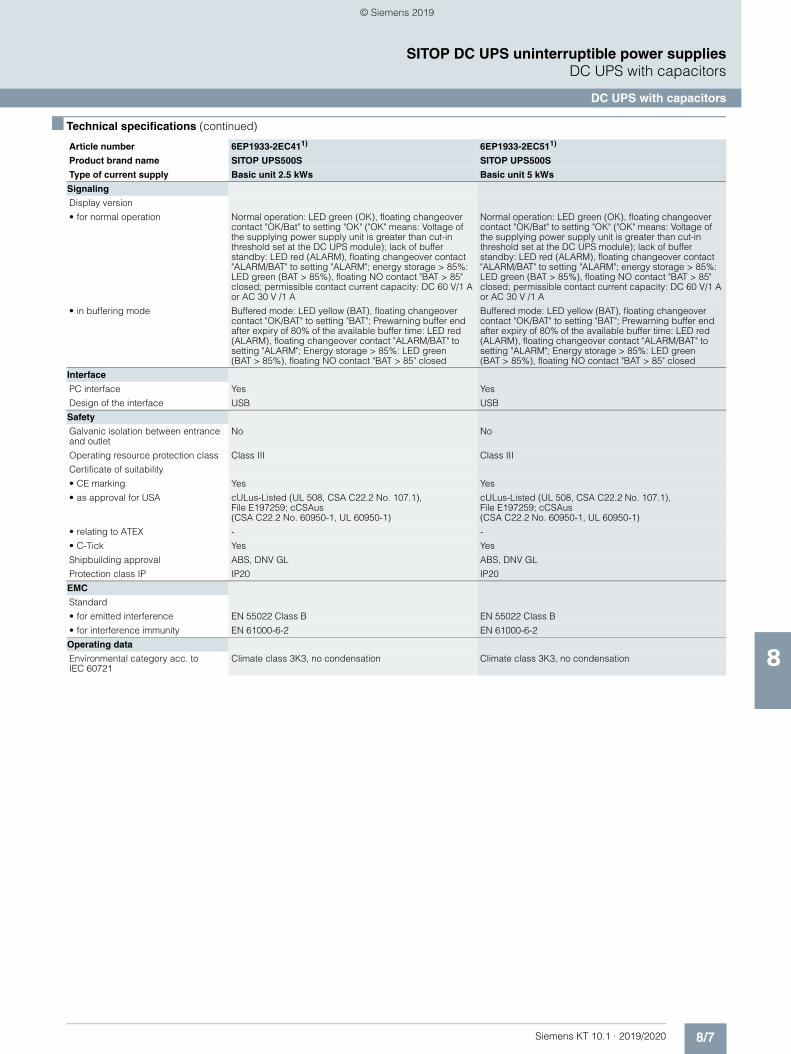
8/7Siemens KT 10.1 · 2019/2020
8
■ Technical specifications (continued)
SITOP DC UPS uninterruptible power suppliesDC UPS with capacitors
DC UPS with capacitors
Signaling
Display version
• for normal operation Normal operation: LED green (OK), floating changeover contact "OK/Bat" to setting "OK" ("OK" means: Voltage of the supplying power supply unit is greater than cut-in threshold set at the DC UPS module); lack of buffer standby: LED red (ALARM), floating changeover contact "ALARM/BAT" to setting "ALARM"; energy storage > 85%: LED green (BAT > 85%), floating NO contact "BAT > 85" closed; permissible contact current capacity: DC 60 V/1 A or AC 30 V /1 A
Normal operation: LED green (OK), floating changeover contact "OK/Bat" to setting "OK" ("OK" means: Voltage of the supplying power supply unit is greater than cut-in threshold set at the DC UPS module); lack of buffer standby: LED red (ALARM), floating changeover contact "ALARM/BAT" to setting "ALARM"; energy storage > 85%: LED green (BAT > 85%), floating NO contact "BAT > 85" closed; permissible contact current capacity: DC 60 V/1 A or AC 30 V /1 A
• in buffering mode Buffered mode: LED yellow (BAT), floating changeover contact "OK/BAT" to setting "BAT"; Prewarning buffer end after expiry of 80% of the available buffer time: LED red (ALARM), floating changeover contact "ALARM/BAT" to setting "ALARM"; Energy storage > 85%: LED green (BAT > 85%), floating NO contact "BAT > 85" closed
Buffered mode: LED yellow (BAT), floating changeover contact "OK/BAT" to setting "BAT"; Prewarning buffer end after expiry of 80% of the available buffer time: LED red (ALARM), floating changeover contact "ALARM/BAT" to setting "ALARM"; Energy storage > 85%: LED green (BAT > 85%), floating NO contact "BAT > 85" closed
Interface
PC interface Yes Yes
Design of the interface USB USB
Safety
Galvanic isolation between entrance and outlet
No No
Operating resource protection class Class III Class III
Certificate of suitability
• CE marking Yes Yes
• as approval for USA cULus-Listed (UL 508, CSA C22.2 No. 107.1), File E197259; cCSAus (CSA C22.2 No. 60950-1, UL 60950-1)
cULus-Listed (UL 508, CSA C22.2 No. 107.1), File E197259; cCSAus (CSA C22.2 No. 60950-1, UL 60950-1)
• relating to ATEX - -
• C-Tick Yes Yes
Shipbuilding approval ABS, DNV GL ABS, DNV GL
Protection class IP IP20 IP20
EMC
Standard
• for emitted interference EN 55022 Class B EN 55022 Class B
• for interference immunity EN 61000-6-2 EN 61000-6-2
Operating data
Environmental category acc. to IEC 60721
Climate class 3K3, no condensation Climate class 3K3, no condensation
Article number 6EP1933-2EC411) 6EP1933-2EC511)
Product brand name SITOP UPS500S SITOP UPS500S
Type of current supply Basic unit 2.5 kWs Basic unit 5 kWs
© Siemens 2019
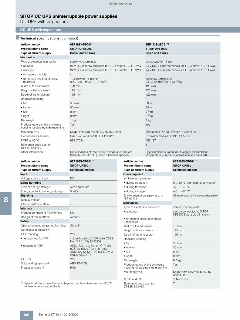
8/8 Siemens KT 10.1 · 2019/2020
8
■ Technical specifications (continued)
SITOP DC UPS uninterruptible power suppliesDC UPS with capacitors
DC UPS with capacitors
Mechanics
Type of electrical connection screw-type terminals screw-type terminals
• at input 24 V DC: 2 screw terminals for 1 ... 4 mm²/17 ... 11 AWG 24 V DC: 2 screw terminals for 1 ... 4 mm²/17 ... 11 AWG
• at output 24 V DC: 4 screw terminals for 1 ... 4 mm²/17 ... 11 AWG 24 V DC: 4 screw terminals for 1 ... 4 mm²/17 ... 11 AWG
• for battery module - -
• for control circuit and status message
10 screw terminals for 0.5 ... 2.5 mm²/20 ... 13 AWG
10 screw terminals for 0.5 ... 2.5 mm²/20 ... 13 AWG
Width of the enclosure 120 mm 120 mm
Height of the enclosure 125 mm 125 mm
Depth of the enclosure 125 mm 125 mm
Required spacing
• top 50 mm 50 mm
• bottom 50 mm 50 mm
• left 0 mm 0 mm
• right 0 mm 0 mm
Net weight 1 kg 1 kg
Product feature of the enclosure housing for side-by-side mounting
Yes Yes
Mounting type Snaps onto DIN rail EN 60715 35x7.5/15 Snaps onto DIN rail EN 60715 35x7.5/15
Electrical accessories Extension module SITOP UPS501S Extension module SITOP UPS501S
MTBF at 40 °C 638 570 h 459 137 h
Reference code acc. to DIN EN 81346-2
T T
Other information Specifications at rated input voltage and ambient temperature +25 °C (unless otherwise specified)
Specifications at rated input voltage and ambient temperature +25 °C (unless otherwise specified)
Article number 6EP1933-2EC411) 6EP1933-2EC511)
Product brand name SITOP UPS500S SITOP UPS500S
Type of current supply Basic unit 2.5 kWs Basic unit 5 kWs
Article number 6EP1935-5PG011)
Product brand name SITOP UPS501
Type of current supply Extension module
Input
Voltage curve at input DC
Mains buffering
Type of energy storage with capacitors
Energy content of energy storage 5 kW.s
Signaling
Display version
• for normal operation -
Interface
Product component PC interface No
Design of the interface without
Safety
Operating resource protection class Class III
Certificate of suitability
• CE marking Yes
• as approval for USA cULus-Listed (UL 508, CSA C22.2 No. 107.1), File E197259
• relating to ATEX ATEX (EX) II 3G Ex nA IIC T4 Gc; cCSAus (CSA C22.2 No. 213, ANSI/ISA-12.12.01) Class I, Div. 2, Group ABCD, T4
• C-Tick Yes
Shipbuilding approval ABS, DNV GL
Protection class IP IP20
1) Specifications at rated input voltage and ambient temperature +25 °C (unless otherwise specified)
Operating data
Ambient temperature
• during operation 0 ... 60 °C; with natural convection
• during transport -40 ... +70 °C
• during storage -40 ... +70 °C
Environmental category acc. to IEC 60721
Climate class 3K3, no condensation
Mechanics
Type of electrical connection screw-type terminals
• at output can be connected to SITOP UPS500S via a plug-in system
• for control circuit and status message
-
Width of the enclosure 70 mm
Height of the enclosure 125 mm
Depth of the enclosure 125 mm
Required spacing
• top 50 mm
• bottom 50 mm
• left 0 mm
• right 0 mm
Net weight 0.7 kg
Product feature of the enclosure housing for side-by-side mounting
Yes
Mounting type Snaps onto DIN rail EN 60715 35x7.5/15
MTBF at 40 °C 7 142 857 h
Reference code acc. to DIN EN 81346-2
T
Article number 6EP1935-5PG011)
Product brand name SITOP UPS501
Type of current supply Extension module
© Siemens 2019
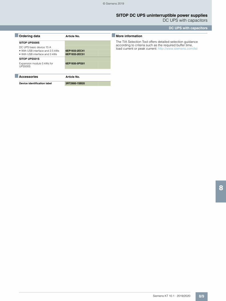
8/9Siemens KT 10.1 · 2019/2020
8
SITOP DC UPS uninterruptible power suppliesDC UPS with capacitors
DC UPS with capacitors
■ Ordering data Article No.
■ Accessories Article No.
■ More information
The TIA Selection Tool offers detailed selection guidance according to criteria such as the required buffer time, load current or peak current: http://www.siemens.com/tst
SITOP UPS500S
DC UPS basic device 15 A • With USB interface and 2.5 kWs 6EP1933-2EC41• With USB interface and 5 kWs 6EP1933-2EC51
SITOP UPS501S
Expansion module 5 kWs for UPS500S
6EP1935-5PG01
Device identification label 3RT2900-1SB20
© Siemens 2019
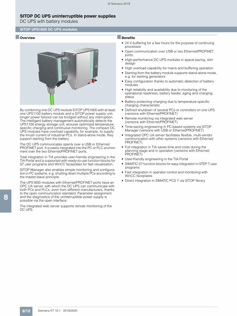
8/10 Siemens KT 10.1 · 2019/2020
8
SITOP DC UPS uninterruptible power suppliesDC UPS with battery modules
SITOP UPS1600 DC UPS modules
■ Overview
By combining one DC UPS module SITOP UPS1600 with at least one UPS1100 battery module and a SITOP power supply unit, longer power failures can be bridged without any interruption. The intelligent battery management automatically detects the UPS1100 energy storage unit, ensures optimized temperature-specific charging and continuous monitoring. The compact DC UPS modules have overload capability, for example, to supply the inrush current of industrial PCs. In stand-alone mode, they support starting from the battery.
The DC UPS communicates openly over a USB or Ethernet/PROFINET port. It is easily integrated into the PC or PLC environ-ment over the two Ethernet/PROFINET ports.
Total integration in TIA provides user-friendly engineering in the TIA Portal and is supported with ready-to-use function blocks for S7 user programs and WinCC faceplates for fast visualization.
SITOP Manager also enables simple monitoring and configura-tion in PC systems, e.g. shutting down multiple PCs according to the master-slave principle.
The UPS1600 modules with Ethernet/PROFINET ports have an OPC UA server, with which the DC UPS can communicate with both PCs and PLCs, even from different manufacturers, thanks to the open communication standard. Parameter assignment and the diagnostics of the uninterruptible power supply is possible via the open interface.
The integrated web server supports remote monitoring of the DC UPS.
■ Benefits
• 24 V buffering for a few hours for the purpose of continuing processes
• Open communication over USB or two Ethernet/PROFINET ports
• High-performance DC UPS modules in space-saving, slim design
• High overload capability for mains and buffering operation• Starting from the battery module supports stand-alone mode,
e.g. for starting generators• Easy configuration thanks to automatic detection of battery
modules• High reliability and availability due to monitoring of the
operational readiness, battery feeder, aging and charging status
• Battery protecting charging due to temperature-specific charging characteristic
• Defined shutdown of several PCs or controllers on one UPS (versions with Ethernet/PROFINET)
• Remote monitoring via integrated web server (versions with Ethernet/PROFINET)
• Time-saving engineering in PC-based systems via SITOP Manager (versions with USB or Ethernet/PROFINET)
• Integrated OPC UA server facilitates flexible, multi-vendor communication with other systems (versions with Ethernet/PROFINET)
• Full integration in TIA saves time and costs during the planning stage and in operation (versions with Ethernet/PROFINET)
• User-friendly engineering in the TIA Portal• SIMATIC S7 function blocks for easy integration in STEP 7 user
programs • Fast integration in operator control and monitoring with
WinCC faceplates• Direct integration in SIMATIC PCS 7 via SITOP library
© Siemens 2019
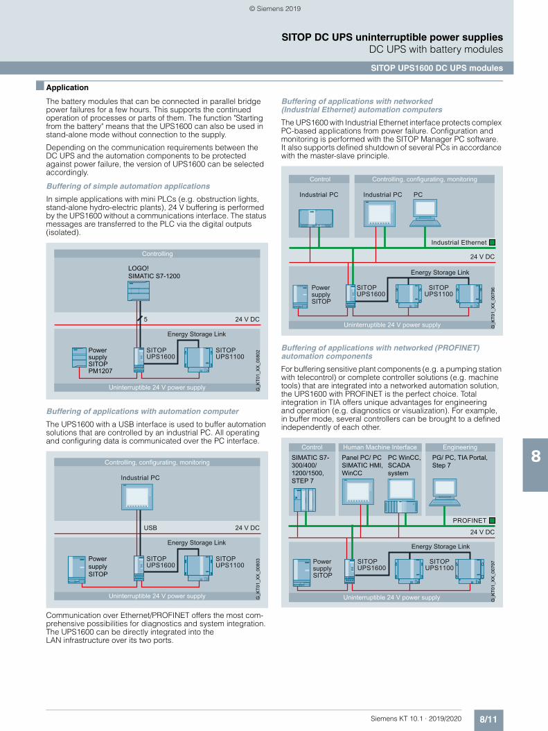
8/11Siemens KT 10.1 · 2019/2020
8
SITOP DC UPS uninterruptible power suppliesDC UPS with battery modules
SITOP UPS1600 DC UPS modules
■ Application
The battery modules that can be connected in parallel bridge power failures for a few hours. This supports the continued operation of processes or parts of them. The function "Starting from the battery" means that the UPS1600 can also be used in stand-alone mode without connection to the supply.
Depending on the communication requirements between the DC UPS and the automation components to be protected against power failure, the version of UPS1600 can be selected accordingly.
Buffering of simple automation applications
In simple applications with mini PLCs (e.g. obstruction lights, stand-alone hydro-electric plants), 24 V buffering is performed by the UPS1600 without a communications interface. The status messages are transferred to the PLC via the digital outputs (isolated).
Buffering of applications with automation computer
The UPS1600 with a USB interface is used to buffer automation solutions that are controlled by an industrial PC. All operating and configuring data is communicated over the PC interface.
Communication over Ethernet/PROFINET offers the most com-prehensive possibilities for diagnostics and system integration. The UPS1600 can be directly integrated into the LAN infrastructure over its two ports.
Buffering of applications with networked (Industrial Ethernet) automation computers
The UPS1600 with Industrial Ethernet interface protects complex PC-based applications from power failure. Configuration and monitoring is performed with the SITOP Manager PC software. It also supports defined shutdown of several PCs in accordance with the master-slave principle.
Buffering of applications with networked (PROFINET) automation components
For buffering sensitive plant components (e.g. a pumping station with telecontrol) or complete controller solutions (e.g. machine tools) that are integrated into a networked automation solution, the UPS1600 with PROFINET is the perfect choice. Total integration in TIA offers unique advantages for engineering and operation (e.g. diagnostics or visualization). For example, in buffer mode, several controllers can be brought to a defined independently of each other.
Controlling
Uninterruptible 24 V power supply
24 V DC
Power supplySITOP PM1207
G_K
T01_
XX
_008
02SITOPUPS1600
SITOPUPS1100
Energy Storage Link
LOGO!SIMATIC S7-1200
5
Controlling, configurating, monitoring
Uninterruptible 24 V power supply
Industrial PC
24 V DC
Power supplySITOP
G_K
T01_
XX
_008
03SITOPUPS1600
SITOPUPS1100
Energy Storage Link
USB
Controlling, configurating, monitoring
Uninterruptible 24 V power supply
Control
Industrial PC Industrial PC
24 V DC
Power supplySITOP
Industrial Ethernet
G_K
T01_
XX
_007
96 SITOP
UPS1600SITOP
UPS1100
PC
Energy Storage Link
Uninterruptible 24 V power supply
Human Machine InterfaceControl
Power supplySITOP
24 V DC
PROFINET
SITOPUPS1600
SITOPUPS1100
G_K
T01_
XX
_007
97
EngineeringSIMATIC S7-300/400/1200/1500, STEP 7
Panel PC/ PC SIMATIC HMI, WinCC
PC WinCC, SCADAsystem
PG/ PC, TIA Portal,Step 7
Energy Storage Link
© Siemens 2019
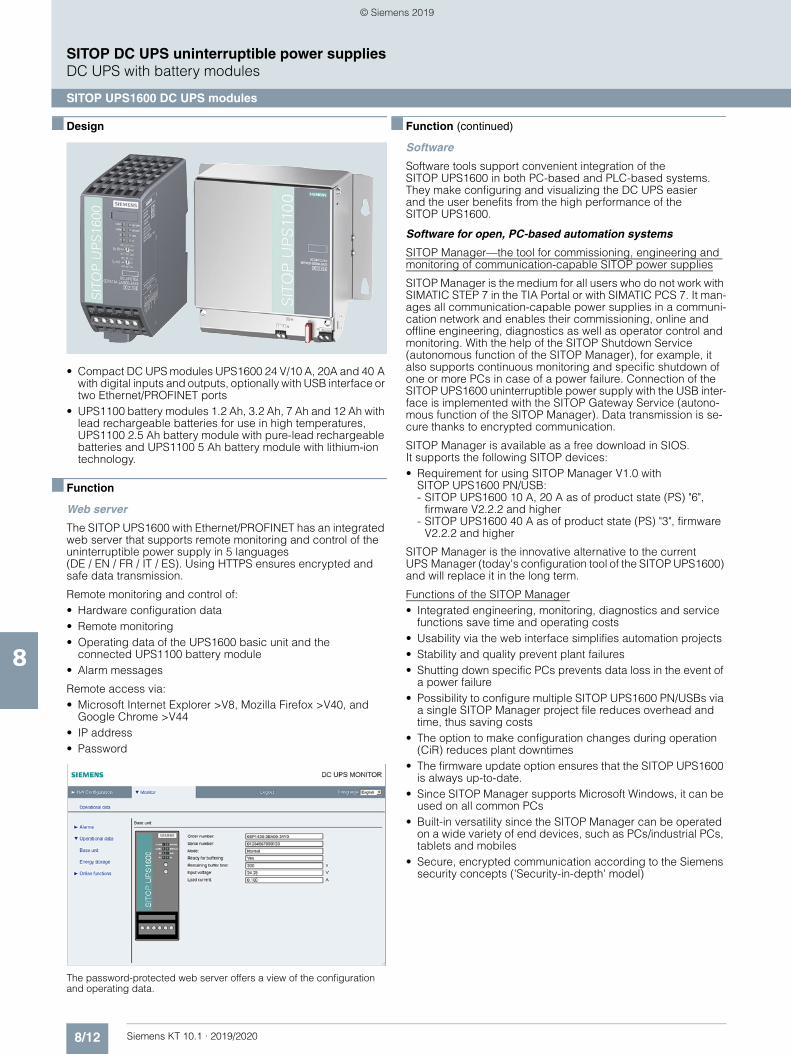
8/12 Siemens KT 10.1 · 2019/2020
8
SITOP DC UPS uninterruptible power suppliesDC UPS with battery modules
SITOP UPS1600 DC UPS modules
■ Design
• Compact DC UPS modules UPS1600 24 V/10 A, 20A and 40 A with digital inputs and outputs, optionally with USB interface or two Ethernet/PROFINET ports
• UPS1100 battery modules 1.2 Ah, 3.2 Ah, 7 Ah and 12 Ah with lead rechargeable batteries for use in high temperatures, UPS1100 2.5 Ah battery module with pure-lead rechargeable batteries and UPS1100 5 Ah battery module with lithium-ion technology.
■ Function
Web server
The SITOP UPS1600 with Ethernet/PROFINET has an integrated web server that supports remote monitoring and control of the uninterruptible power supply in 5 languages (DE / EN / FR / IT / ES). Using HTTPS ensures encrypted and safe data transmission.
Remote monitoring and control of:• Hardware configuration data• Remote monitoring• Operating data of the UPS1600 basic unit and the
connected UPS1100 battery module• Alarm messages
Remote access via:• Microsoft Internet Explorer >V8, Mozilla Firefox >V40, and
Google Chrome >V44• IP address• Password
The password-protected web server offers a view of the configuration and operating data.
■ Function (continued)
Software
Software tools support convenient integration of the SITOP UPS1600 in both PC-based and PLC-based systems. They make configuring and visualizing the DC UPS easier and the user benefits from the high performance of the SITOP UPS1600.
Software for open, PC-based automation systems
SITOP Manager—the tool for commissioning, engineering and monitoring of communication-capable SITOP power supplies
SITOP Manager is the medium for all users who do not work with SIMATIC STEP 7 in the TIA Portal or with SIMATIC PCS 7. It man-ages all communication-capable power supplies in a communi-cation network and enables their commissioning, online and offline engineering, diagnostics as well as operator control and monitoring. With the help of the SITOP Shutdown Service (autonomous function of the SITOP Manager), for example, it also supports continuous monitoring and specific shutdown of one or more PCs in case of a power failure. Connection of the SITOP UPS1600 uninterruptible power supply with the USB inter-face is implemented with the SITOP Gateway Service (autono-mous function of the SITOP Manager). Data transmission is se-cure thanks to encrypted communication.
SITOP Manager is available as a free download in SIOS. It supports the following SITOP devices:• Requirement for using SITOP Manager V1.0 with
SITOP UPS1600 PN/USB:- SITOP UPS1600 10 A, 20 A as of product state (PS) "6",
firmware V2.2.2 and higher- SITOP UPS1600 40 A as of product state (PS) "3", firmware
V2.2.2 and higher
SITOP Manager is the innovative alternative to the current UPS Manager (today's configuration tool of the SITOP UPS1600) and will replace it in the long term.
Functions of the SITOP Manager• Integrated engineering, monitoring, diagnostics and service
functions save time and operating costs• Usability via the web interface simplifies automation projects• Stability and quality prevent plant failures• Shutting down specific PCs prevents data loss in the event of
a power failure• Possibility to configure multiple SITOP UPS1600 PN/USBs via
a single SITOP Manager project file reduces overhead and time, thus saving costs
• The option to make configuration changes during operation (CiR) reduces plant downtimes
• The firmware update option ensures that the SITOP UPS1600 is always up-to-date.
• Since SITOP Manager supports Microsoft Windows, it can be used on all common PCs
• Built-in versatility since the SITOP Manager can be operated on a wide variety of end devices, such as PCs/industrial PCs, tablets and mobiles
• Secure, encrypted communication according to the Siemens security concepts ('Security-in-depth' model)
© Siemens 2019
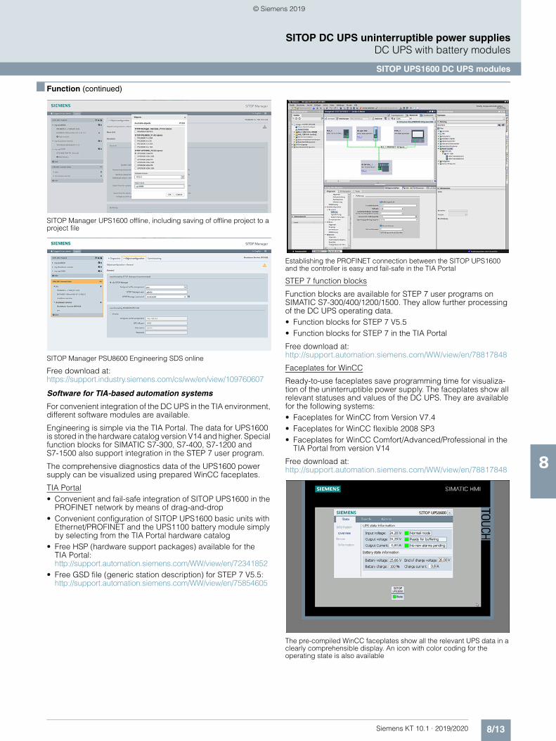
8/13Siemens KT 10.1 · 2019/2020
8
SITOP DC UPS uninterruptible power suppliesDC UPS with battery modules
SITOP UPS1600 DC UPS modules
■ Function (continued)
SITOP Manager UPS1600 offline, including saving of offline project to a project file
SITOP Manager PSU8600 Engineering SDS online
Free download at:https://support.industry.siemens.com/cs/ww/en/view/109760607
Software for TIA-based automation systems
For convenient integration of the DC UPS in the TIA environment, different software modules are available.
Engineering is simple via the TIA Portal. The data for UPS1600 is stored in the hardware catalog version V14 and higher. Special function blocks for SIMATIC S7-300, S7-400, S7-1200 and S7-1500 also support integration in the STEP 7 user program.
The comprehensive diagnostics data of the UPS1600 power supply can be visualized using prepared WinCC faceplates.
TIA Portal• Convenient and fail-safe integration of SITOP UPS1600 in the
PROFINET network by means of drag-and-drop • Convenient configuration of SITOP UPS1600 basic units with
Ethernet/PROFINET and the UPS1100 battery module simply by selecting from the TIA Portal hardware catalog
• Free HSP (hardware support packages) available for the TIA Portal:http://support.automation.siemens.com/WW/view/en/72341852
• Free GSD file (generic station description) for STEP 7 V5.5:http://support.automation.siemens.com/WW/view/en/75854605
Establishing the PROFINET connection between the SITOP UPS1600 and the controller is easy and fail-safe in the TIA Portal
STEP 7 function blocks
Function blocks are available for STEP 7 user programs on SIMATIC S7-300/400/1200/1500. They allow further processing of the DC UPS operating data. • Function blocks for STEP 7 V5.5• Function blocks for STEP 7 in the TIA Portal
Free download at:http://support.automation.siemens.com/WW/view/en/78817848
Faceplates for WinCC
Ready-to-use faceplates save programming time for visualiza-tion of the uninterruptible power supply. The faceplates show all relevant statuses and values of the DC UPS. They are available for the following systems: • Faceplates for WinCC from Version V7.4• Faceplates for WinCC flexible 2008 SP3• Faceplates for WinCC Comfort/Advanced/Professional in the
TIA Portal from version V14
Free download at:http://support.automation.siemens.com/WW/view/en/78817848
The pre-compiled WinCC faceplates show all the relevant UPS data in a clearly comprehensible display. An icon with color coding for the operating state is also available
© Siemens 2019
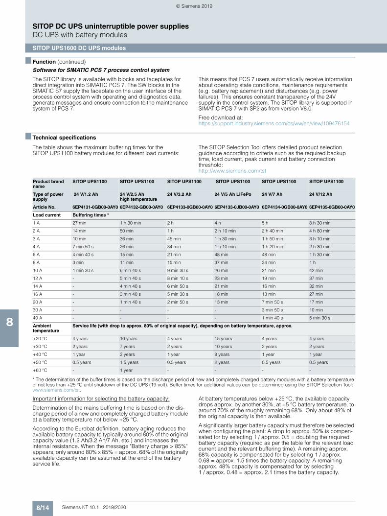
8/14 Siemens KT 10.1 · 2019/2020
8
■ Function (continued)
SITOP DC UPS uninterruptible power suppliesDC UPS with battery modules
SITOP UPS1600 DC UPS modules
Software for SIMATIC PCS 7 process control system
The SITOP library is available with blocks and faceplates for direct integration into SIMATIC PCS 7. The SW blocks in the SIMATIC S7 supply the faceplate on the user interface of the process control system with operating and diagnostics data, generate messages and ensure connection to the maintenance system of PCS 7.
This means that PCS 7 users automatically receive information about operating state conditions, maintenance requirements (e.g. battery replacement) and disturbances (e.g. power failures). This ensures constant transparency of the 24V supply in the control system. The SITOP library is supported in SIMATIC PCS 7 with SP2 as from version V8.0.
Free download at:https://support.industry.siemens.com/cs/ww/en/view/109476154
■ Technical specifications
The table shows the maximum buffering times for the SITOP UPS1100 battery modules for different load currents:
The SITOP Selection Tool offers detailed product selection guidance according to criteria such as the required backup time, load current, peak current and battery connection threshold: http://www.siemens.com/tst
* The determination of the buffer times is based on the discharge period of new and completely charged battery modules with a battery temperature of not less than +25 °C until shutdown of the DC UPS (19 volt). Buffer times for additional values can be determined using the SITOP Selection Tool: www.siemens.com/tst.
Important information for selecting the battery capacity:
Determination of the mains buffering time is based on the dis-charge period of a new and completely charged battery module at a battery temperature not below +25 °C.
According to the Eurobat definition, battery aging reduces the available battery capacity to typically around 80% of the original capacity value (1.2 Ah/3.2 Ah/7 Ah, etc.) and increases the internal resistance. When the message "Battery charge > 85%" appears, only around 80% x 85% = approx. 68% of the originally available capacity can be assumed at the end of the battery service life.
At battery temperatures below +25 °C, the available capacity drops approx. by another 30%, at +5 °C battery temperature, to around 70% of the roughly remaining 68%. Only about 48% of the original capacity is then available.
A significantly larger battery capacity must therefore be selected when configuring the plant: A drop to approx. 50% is compen-sated for by selecting 1 / approx. 0.5 = doubling the required battery capacity (required as per the table for the relevant load current and the relevant buffering time). A remaining approx. 68% capacity is compensated for by selecting 1 / approx. 0.68 = approx. 1.5 times the battery capacity. A remaining approx. 48% capacity is compensated for by selecting 1 / approx. 0.48 = approx. 2.1 times the battery capacity.
Product brand name
SITOP UPS1100 SITOP UPS1100 SITOP UPS1100 SITOP UPS1100 SITOP UPS1100 SITOP UPS1100
Type of power supply
24 V/1.2 Ah 24 V/2.5 Ah high temperature
24 V/3.2 Ah 24 V/5 Ah LiFePo 24 V/7 Ah 24 V/12 Ah
Article No. 6EP4131-0GB00-0AY0 6EP4132-GB00-0AY0 6EP4133-0GB00-0AY0 6EP4133-0JB00-0AY0 6EP4134-0GB00-0AY0 6EP4135-0GB00-0AY0
Load current Buffering times *
1 A 27 min 1 h 30 min 2 h 4 h 5 h 8 h 30 min
2 A 14 min 50 min 1 h 2 h 10 min 2 h 40 min 4 h 80 min
3 A 10 min 36 min 45 min 1 h 30 min 1 h 50 min 3 h 10 min
4 A 7 min 50 s 26 min 34 min 1 h 10 min 1 h 20 min 2 h 30 min
6 A 4 min 40 s 15 min 21 min 48 min 48 min 1 h 30 min
8 A 3 min 11 min 15 min 37 min 34 min 1 h
10 A 1 min 30 s 6 min 40 s 9 min 30 s 26 min 21 min 42 min
12 A - 5 min 40 s 8 min 10 s 23 min 19 min 37 min
14 A - 4 min 40 s 6 min 50 s 21 min 16 min 32 min
16 A - 3 min 40 s 5 min 30 s 18 min 13 min 27 min
20 A - 1 min 40 s 2 min 50 s 13 min 7 min 50 s 17 min
30 A - - - - 3 min 50 s 10 min
40 A - - - - 1 min 40 s 5 min 30 s
Ambient temperature
Service life (with drop to approx. 80% of original capacity), depending on battery temperature, approx.
+20 °C 4 years 10 years 4 years 15 years 4 years 4 years
+30 °C 2 years 7 years 2 years 10 years 2 years 2 years
+40 °C 1 year 3 years 1 year 9 years 1 year 1 year
+50 °C 0.5 years 1.5 years 0.5 years 2 years 0.5 years 0.5 years
+60 °C - 1 year - - - -
© Siemens 2019
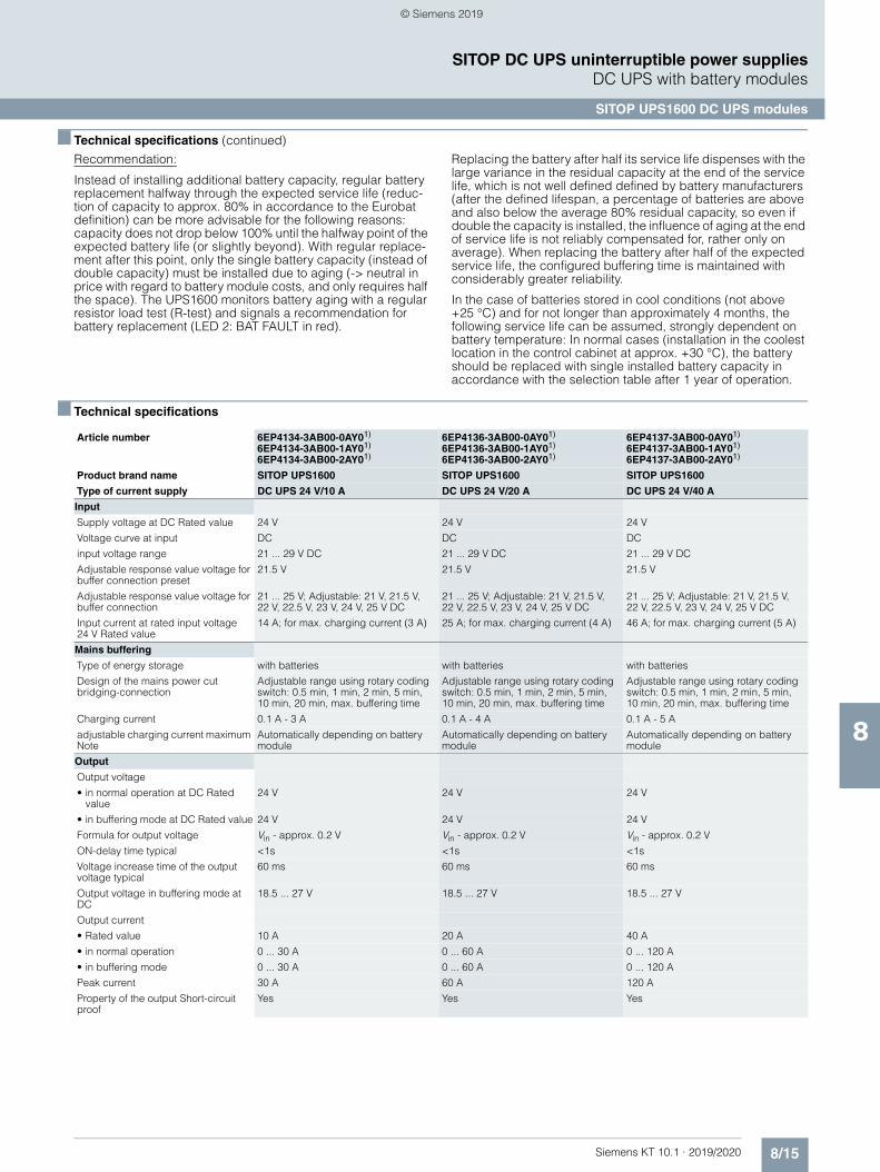
8/15Siemens KT 10.1 · 2019/2020
8
■ Technical specifications (continued)
SITOP DC UPS uninterruptible power suppliesDC UPS with battery modules
SITOP UPS1600 DC UPS modules
Recommendation:
Instead of installing additional battery capacity, regular battery replacement halfway through the expected service life (reduc-tion of capacity to approx. 80% in accordance to the Eurobat definition) can be more advisable for the following reasons: capacity does not drop below 100% until the halfway point of the expected battery life (or slightly beyond). With regular replace-ment after this point, only the single battery capacity (instead of double capacity) must be installed due to aging (-> neutral in price with regard to battery module costs, and only requires half the space). The UPS1600 monitors battery aging with a regular resistor load test (R-test) and signals a recommendation for battery replacement (LED 2: BAT FAULT in red).
Replacing the battery after half its service life dispenses with the large variance in the residual capacity at the end of the service life, which is not well defined defined by battery manufacturers (after the defined lifespan, a percentage of batteries are above and also below the average 80% residual capacity, so even if double the capacity is installed, the influence of aging at the end of service life is not reliably compensated for, rather only on average). When replacing the battery after half of the expected service life, the configured buffering time is maintained with considerably greater reliability.
In the case of batteries stored in cool conditions (not above +25 °C) and for not longer than approximately 4 months, the following service life can be assumed, strongly dependent on battery temperature: In normal cases (installation in the coolest location in the control cabinet at approx. +30 °C), the battery should be replaced with single installed battery capacity in accordance with the selection table after 1 year of operation.
■ Technical specifications
Article number 6EP4134-3AB00-0AY01)
6EP4134-3AB00-1AY01)
6EP4134-3AB00-2AY01)
6EP4136-3AB00-0AY01)
6EP4136-3AB00-1AY01)
6EP4136-3AB00-2AY01)
6EP4137-3AB00-0AY01)
6EP4137-3AB00-1AY01)
6EP4137-3AB00-2AY01)
Product brand name SITOP UPS1600 SITOP UPS1600 SITOP UPS1600
Type of current supply DC UPS 24 V/10 A DC UPS 24 V/20 A DC UPS 24 V/40 A
Input
Supply voltage at DC Rated value 24 V 24 V 24 V
Voltage curve at input DC DC DC
input voltage range 21 ... 29 V DC 21 ... 29 V DC 21 ... 29 V DC
Adjustable response value voltage for buffer connection preset
21.5 V 21.5 V 21.5 V
Adjustable response value voltage for buffer connection
21 ... 25 V; Adjustable: 21 V, 21.5 V, 22 V, 22.5 V, 23 V, 24 V, 25 V DC
21 ... 25 V; Adjustable: 21 V, 21.5 V, 22 V, 22.5 V, 23 V, 24 V, 25 V DC
21 ... 25 V; Adjustable: 21 V, 21.5 V, 22 V, 22.5 V, 23 V, 24 V, 25 V DC
Input current at rated input voltage 24 V Rated value
14 A; for max. charging current (3 A) 25 A; for max. charging current (4 A) 46 A; for max. charging current (5 A)
Mains buffering
Type of energy storage with batteries with batteries with batteries
Design of the mains power cut bridging-connection
Adjustable range using rotary coding switch: 0.5 min, 1 min, 2 min, 5 min, 10 min, 20 min, max. buffering time
Adjustable range using rotary coding switch: 0.5 min, 1 min, 2 min, 5 min, 10 min, 20 min, max. buffering time
Adjustable range using rotary coding switch: 0.5 min, 1 min, 2 min, 5 min, 10 min, 20 min, max. buffering time
Charging current 0.1 A - 3 A 0.1 A - 4 A 0.1 A - 5 A
adjustable charging current maximum Note
Automatically depending on battery module
Automatically depending on battery module
Automatically depending on battery module
Output
Output voltage
• in normal operation at DC Rated value
24 V 24 V 24 V
• in buffering mode at DC Rated value 24 V 24 V 24 V
Formula for output voltage Vin - approx. 0.2 V Vin - approx. 0.2 V Vin - approx. 0.2 V
ON-delay time typical <1s <1s <1s
Voltage increase time of the output voltage typical
60 ms 60 ms 60 ms
Output voltage in buffering mode at DC
18.5 ... 27 V 18.5 ... 27 V 18.5 ... 27 V
Output current
• Rated value 10 A 20 A 40 A
• in normal operation 0 ... 30 A 0 ... 60 A 0 ... 120 A
• in buffering mode 0 ... 30 A 0 ... 60 A 0 ... 120 A
Peak current 30 A 60 A 120 A
Property of the output Short-circuit proof
Yes Yes Yes
© Siemens 2019
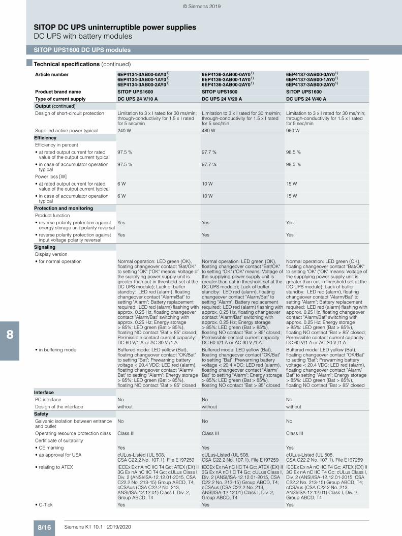
8/16 Siemens KT 10.1 · 2019/2020
8
■ Technical specifications (continued)
SITOP DC UPS uninterruptible power suppliesDC UPS with battery modules
SITOP UPS1600 DC UPS modules
Output (continued)
Design of short-circuit protection Limitation to 3 x I rated for 30 ms/min; through-conductivity for 1.5 x I rated for 5 sec/min
Limitation to 3 x I rated for 30 ms/min; through-conductivity for 1.5 x I rated for 5 sec/min
Limitation to 3 x I rated for 30 ms/min; through-conductivity for 1.5 x I rated for 5 sec/min
Supplied active power typical 240 W 480 W 960 W
Efficiency
Efficiency in percent
• at rated output current for rated value of the output current typical
97.5 % 97.7 % 98.5 %
• in case of accumulator operation typical
97.5 % 97.7 % 98.5 %
Power loss [W]
• at rated output current for rated value of the output current typical
6 W 10 W 15 W
• in case of accumulator operation typical
6 W 10 W 15 W
Protection and monitoring
Product function
• reverse polarity protection against energy storage unit polarity reversal
Yes Yes Yes
• reverse polarity protection against input voltage polarity reversal
Yes Yes Yes
Signaling
Display version
• for normal operation Normal operation: LED green (OK), floating changeover contact "Bat/OK" to setting "OK" ("OK" means: Voltage of the supplying power supply unit is greater than cut-in threshold set at the DC UPS module); Lack of buffer standby: LED red (alarm), floating changeover contact "Alarm/Bat" to setting "Alarm"; Battery replacement required: LED red (alarm) flashing with approx. 0.25 Hz, floating changeover contact "Alarm/Bat" switching with approx. 0.25 Hz; Energy storage > 85%: LED green (Bat > 85%), floating NO contact "Bat > 85" closed; Permissible contact current capacity: DC 60 V/1 A or AC 30 V /1 A
Normal operation: LED green (OK), floating changeover contact "Bat/OK" to setting "OK" ("OK" means: Voltage of the supplying power supply unit is greater than cut-in threshold set at the DC UPS module); Lack of buffer standby: LED red (alarm), floating changeover contact "Alarm/Bat" to setting "Alarm"; Battery replacement required: LED red (alarm) flashing with approx. 0.25 Hz, floating changeover contact "Alarm/Bat" switching with approx. 0.25 Hz; Energy storage > 85%: LED green (Bat > 85%), floating NO contact "Bat > 85" closed; Permissible contact current capacity: DC 60 V/1 A or AC 30 V /1 A
Normal operation: LED green (OK), floating changeover contact "Bat/OK" to setting "OK" ("OK" means: Voltage of the supplying power supply unit is greater than cut-in threshold set at the DC UPS module); Lack of buffer standby: LED red (alarm), floating changeover contact "Alarm/Bat" to setting "Alarm"; Battery replacement required: LED red (alarm) flashing with approx. 0.25 Hz, floating changeover contact "Alarm/Bat" switching with approx. 0.25 Hz; Energy storage > 85%: LED green (Bat > 85%), floating NO contact "Bat > 85" closed; Permissible contact current capacity: DC 60 V/1 A or AC 30 V /1 A
• in buffering mode Buffered mode: LED yellow (Bat), floating changeover contact "OK/Bat" to setting "Bat"; Prewarning battery voltage < 20.4 VDC: LED red (alarm), floating changeover contact "Alarm/Bat" to setting "Alarm"; Energy storage > 85%: LED green (Bat > 85%), floating NO contact "Bat > 85" closed
Buffered mode: LED yellow (Bat), floating changeover contact "OK/Bat" to setting "Bat"; Prewarning battery voltage < 20.4 VDC: LED red (alarm), floating changeover contact "Alarm/Bat" to setting "Alarm"; Energy storage > 85%: LED green (Bat > 85%), floating NO contact "Bat > 85" closed
Buffered mode: LED yellow (Bat), floating changeover contact "OK/Bat" to setting "Bat"; Prewarning battery voltage < 20.4 VDC: LED red (alarm), floating changeover contact "Alarm/Bat" to setting "Alarm"; Energy storage > 85%: LED green (Bat > 85%), floating NO contact "Bat > 85" closed
Interface
PC interface No No No
Design of the interface without without without
Safety
Galvanic isolation between entrance and outlet
No No No
Operating resource protection class Class III Class III Class III
Certificate of suitability
• CE marking Yes Yes Yes
• as approval for USA cULus-Listed (UL 508, CSA C22.2 No. 107.1), File E197259
cULus-Listed (UL 508, CSA C22.2 No. 107.1), File E197259
cULus-Listed (UL 508, CSA C22.2 No. 107.1), File E197259
• relating to ATEX IECEx Ex nA nC IIC T4 Gc; ATEX (EX) II 3G Ex nA nC IIC T4 Gc; cULus Class I, Div. 2 (ANSI/ISA-12.12.01-2015, CSA C22.2 No. 213-15) Group ABCD, T4; cCSAus (CSA C22.2 No. 213, ANSI/ISA-12.12.01) Class I, Div. 2, Group ABCD, T4
IECEx Ex nA nC IIC T4 Gc; ATEX (EX) II 3G Ex nA nC IIC T4 Gc; cULus Class I, Div. 2 (ANSI/ISA-12.12.01-2015, CSA C22.2 No. 213-15) Group ABCD, T4; cCSAus (CSA C22.2 No. 213,ANSI/ISA-12.12.01) Class I, Div. 2, Group ABCD, T4
IECEx Ex nA nC IIC T4 Gc; ATEX (EX) II 3G Ex nA nC IIC T4 Gc; cULus Class I, Div. 2 (ANSI/ISA-12.12.01-2015, CSA C22.2 No. 213-15) Group ABCD, T4; cCSAus (CSA C22.2 No. 213, ANSI/ISA-12.12.01) Class I, Div. 2, Group ABCD, T4
• C-Tick Yes Yes Yes
Article number 6EP4134-3AB00-0AY01)
6EP4134-3AB00-1AY01)
6EP4134-3AB00-2AY01)
6EP4136-3AB00-0AY01)
6EP4136-3AB00-1AY01)
6EP4136-3AB00-2AY01)
6EP4137-3AB00-0AY01)
6EP4137-3AB00-1AY01)
6EP4137-3AB00-2AY01)
Product brand name SITOP UPS1600 SITOP UPS1600 SITOP UPS1600
Type of current supply DC UPS 24 V/10 A DC UPS 24 V/20 A DC UPS 24 V/40 A
© Siemens 2019
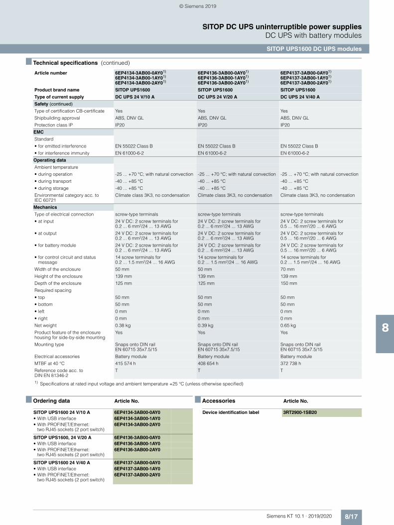
8/17Siemens KT 10.1 · 2019/2020
8
■ Technical specifications (continued)
SITOP DC UPS uninterruptible power suppliesDC UPS with battery modules
SITOP UPS1600 DC UPS modules
■ Ordering data Article No. ■ Accessories Article No.
Safety (continued)
Type of certification CB-certificate Yes Yes Yes
Shipbuilding approval ABS, DNV GL ABS, DNV GL ABS, DNV GL
Protection class IP IP20 IP20 IP20
EMC
Standard
• for emitted interference EN 55022 Class B EN 55022 Class B EN 55022 Class B
• for interference immunity EN 61000-6-2 EN 61000-6-2 EN 61000-6-2
Operating data
Ambient temperature
• during operation -25 ... +70 °C; with natural convection -25 ... +70 °C; with natural convection -25 ... +70 °C; with natural convection
• during transport -40 ... +85 °C -40 ... +85 °C -40 ... +85 °C
• during storage -40 ... +85 °C -40 ... +85 °C -40 ... +85 °C
Environmental category acc. to IEC 60721
Climate class 3K3, no condensation Climate class 3K3, no condensation Climate class 3K3, no condensation
Mechanics
Type of electrical connection screw-type terminals screw-type terminals screw-type terminals
• at input 24 V DC: 2 screw terminals for 0.2 ... 6 mm²/24 ... 13 AWG
24 V DC: 2 screw terminals for 0.2 ... 6 mm²/24 ... 13 AWG
24 V DC: 2 screw terminals for 0.5 ... 16 mm²/20 ... 6 AWG
• at output 24 V DC: 2 screw terminals for 0.2 ... 6 mm²/24 ... 13 AWG
24 V DC: 2 screw terminals for 0.2 ... 6 mm²/24 ... 13 AWG
24 V DC: 2 screw terminals for 0.5 ... 16 mm²/20 ... 6 AWG
• for battery module 24 V DC: 2 screw terminals for 0.2 ... 6 mm²/24 ... 13 AWG
24 V DC: 2 screw terminals for 0.2 ... 6 mm²/24 ... 13 AWG
24 V DC: 2 screw terminals for 0.5 ... 16 mm²/20 ... 6 AWG
• for control circuit and status message
14 screw terminals for 0.2 ... 1.5 mm²/24 ... 16 AWG
14 screw terminals for 0.2 ... 1.5 mm²/24 ... 16 AWG
14 screw terminals for 0.2 ... 1.5 mm²/24 ... 16 AWG
Width of the enclosure 50 mm 50 mm 70 mm
Height of the enclosure 139 mm 139 mm 139 mm
Depth of the enclosure 125 mm 125 mm 150 mm
Required spacing
• top 50 mm 50 mm 50 mm
• bottom 50 mm 50 mm 50 mm
• left 0 mm 0 mm 0 mm
• right 0 mm 0 mm 0 mm
Net weight 0.38 kg 0.39 kg 0.65 kg
Product feature of the enclosure housing for side-by-side mounting
Yes Yes Yes
Mounting type Snaps onto DIN rail EN 60715 35x7.5/15
Snaps onto DIN rail EN 60715 35x7.5/15
Snaps onto DIN rail EN 60715 35x7.5/15
Electrical accessories Battery module Battery module Battery module
MTBF at 40 °C 415 574 h 408 654 h 372 738 h
Reference code acc. to DIN EN 81346-2
T T T
1) Specifications at rated input voltage and ambient temperature +25 °C (unless otherwise specified)
Article number 6EP4134-3AB00-0AY01)
6EP4134-3AB00-1AY01)
6EP4134-3AB00-2AY01)
6EP4136-3AB00-0AY01)
6EP4136-3AB00-1AY01)
6EP4136-3AB00-2AY01)
6EP4137-3AB00-0AY01)
6EP4137-3AB00-1AY01)
6EP4137-3AB00-2AY01)
Product brand name SITOP UPS1600 SITOP UPS1600 SITOP UPS1600
Type of current supply DC UPS 24 V/10 A DC UPS 24 V/20 A DC UPS 24 V/40 A
SITOP UPS1600 24 V/10 A 6EP4134-3AB00-0AY0• With USB interface 6EP4134-3AB00-1AY0• With PROFINET/Ethernet:
two RJ45 sockets (2 port switch)6EP4134-3AB00-2AY0
SITOP UPS1600, 24 V/20 A 6EP4136-3AB00-0AY0• With USB interface 6EP4136-3AB00-1AY0• With PROFINET/Ethernet:
two RJ45 sockets (2 port switch)6EP4136-3AB00-2AY0
SITOP UPS1600 24 V/40 A 6EP4137-3AB00-0AY0• With USB interface 6EP4137-3AB00-1AY0• With PROFINET/Ethernet:
two RJ45 sockets (2 port switch)6EP4137-3AB00-2AY0
Device identification label 3RT2900-1SB20
© Siemens 2019
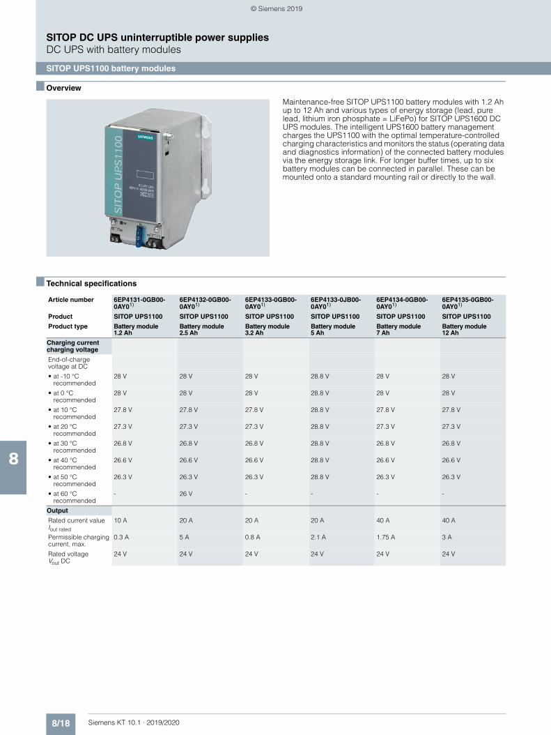
8/18 Siemens KT 10.1 · 2019/2020
8
SITOP DC UPS uninterruptible power suppliesDC UPS with battery modules
SITOP UPS1100 battery modules
■ Overview
Maintenance-free SITOP UPS1100 battery modules with 1.2 Ah up to 12 Ah and various types of energy storage (lead, pure lead, lithium iron phosphate = LiFePo) for SITOP UPS1600 DC UPS modules. The intelligent UPS1600 battery management charges the UPS1100 with the optimal temperature-controlled charging characteristics and monitors the status (operating data and diagnostics information) of the connected battery modules via the energy storage link. For longer buffer times, up to six battery modules can be connected in parallel. These can be mounted onto a standard mounting rail or directly to the wall.
■ Technical specifications
Article number 6EP4131-0GB00-0AY01)
6EP4132-0GB00-0AY01)
6EP4133-0GB00-0AY01)
6EP4133-0JB00-0AY01)
6EP4134-0GB00-0AY01)
6EP4135-0GB00-0AY01)
Product SITOP UPS1100 SITOP UPS1100 SITOP UPS1100 SITOP UPS1100 SITOP UPS1100 SITOP UPS1100
Product type Battery module 1.2 Ah
Battery module 2.5 Ah
Battery module 3.2 Ah
Battery module 5 Ah
Battery module 7 Ah
Battery module 12 Ah
Charging current charging voltage
End-of-charge voltage at DC
• at -10 °C recommended
28 V 28 V 28 V 28.8 V 28 V 28 V
• at 0 °C recommended
28 V 28 V 28 V 28.8 V 28 V 28 V
• at 10 °C recommended
27.8 V 27.8 V 27.8 V 28.8 V 27.8 V 27.8 V
• at 20 °C recommended
27.3 V 27.3 V 27.3 V 28.8 V 27.3 V 27.3 V
• at 30 °C recommended
26.8 V 26.8 V 26.8 V 28.8 V 26.8 V 26.8 V
• at 40 °C recommended
26.6 V 26.6 V 26.6 V 28.8 V 26.6 V 26.6 V
• at 50 °C recommended
26.3 V 26.3 V 26.3 V 28.8 V 26.3 V 26.3 V
• at 60 °C recommended
- 26 V - - - -
Output
Rated current value Iout rated
10 A 20 A 20 A 20 A 40 A 40 A
Permissible charging current, max.
0.3 A 5 A 0.8 A 2.1 A 1.75 A 3 A
Rated voltage Vout DC
24 V 24 V 24 V 24 V 24 V 24 V
© Siemens 2019
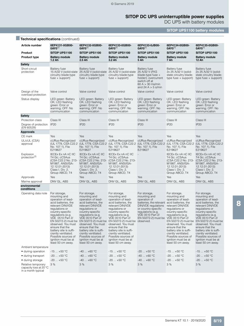
8/19Siemens KT 10.1 · 2019/2020
8
■ Technical specifications (continued)
SITOP DC UPS uninterruptible power suppliesDC UPS with battery modules
SITOP UPS1100 battery modules
Safety
Short-circuit protection
Battery fuse 15 A/32 V (solid-state circuitry blade-type fuse + support)
Battery fuse 25 A/32 V (solid-state circuitry blade-type fuse + support)
Battery fuse 25 A/32 V (solid-state circuitry blade-type fuse + support)
Battery fuse 25 A/32 V (FKS blade-type fuse + holder); overcurrent switch-off at 60 A > 30 ms/min and 24 A > 5 s/min
Battery fuse 2x 25 A/32 V (solid-state circuitry blade-type fuse + support)
Battery fuse 2x 25 A/32 V (solid-state circuitry blade-type fuse + support)
Design of the overload protection
Valve control Valve control Valve control Valve control Valve control Valve control
Status display LED green: Battery OK; LED flashing green: Error or warning; OFF: No communication
LED green: Battery OK; LED flashing green: Error or warning; OFF: No communication
LED green: Battery OK; LED flashing green: Error or warning; OFF: No communication
LED green: Battery OK; LED flashing green: Error or warning; OFF: No communication
LED green: Battery OK; LED flashing green: Error or warning; OFF: No communication
LED green: Battery OK; LED flashing green: Error or warning; OFF: No communication
Safety
Protection class Class III Class III Class III Class III Class III Class III
Degree of protection (EN 60529)
IP20 IP20 IP20 IP20 IP20 IP20
Approvals
CE mark Yes Yes Yes Yes Yes Yes
UL/cUL (CSA) approval
cURus-Recognized (UL 1778, CSA C22.2 No. 107.1), File E219627
cURus-Recognized (UL 1778, CSA C22.2 No. 107.1), File E219627
cURus-Recognized (UL 1778, CSA C22.2 No. 107.1), File E219627
cURus-Recognized (UL 1778, CSA C22.2 No. 107.1), File E219627
cURus-Recognized (UL 1778, CSA C22.2 No. 107.1), File E219627
cURus-Recognized (UL 1778, CSA C22.2 No. 107.1), File E219627
Explosion protection2)
IECEx Ex nA nC IIC T4 Gc; cCSAus (CSA C22.2 No. 213-M1987, ANSI/ISA-12.12.01-2013) Class I, Div. 2, Group ABCD, T4
IECEx Ex nA nC IIC T4 Gc; cCSAus (CSA C22.2 No. 213-M1987, ANSI/ISA-12.12.01-2013) Class I, Div. 2, Group ABCD, T4
IECEx Ex nA nC IIC T4 Gc; cCSAus (CSA C22.2 No. 213-M1987, ANSI/ISA-12.12.01-2013) Class I, Div. 2, Group ABCD, T4
- IECEx Ex nA nC IIC T4 Gc; cCSAus (CSA C22.2 No. 213-M1987, ANSI/ISA-12.12.01-2013) Class I, Div. 2, Group ABCD, T4
IECEx Ex nA nC IIC T4 Gc; cCSAus (CSA C22.2 No. 213-M1987, ANSI/ISA-12.12.01-2013) Class I, Div. 2, Group ABCD, T4
Approvals Yes Yes Yes Yes Yes Yes
Marine approval DNV GL, ABS DNV GL, ABS DNV GL, ABS DNV GL, ABS DNV GL, ABS DNV GL, ABS
environmental conditions
Operating data note For storage, mounting and operation of lead-acid batteries, the relevant DIN/VDE regulations or country-specific regulations (e.g. VDE 0510 Part 2/EN 50272-2) must be observed. You must ensure that the battery site is suffi-ciently ventilated. Possible sources of ignition must be at least 50 cm away.
For storage, mounting and operation of lead-acid batteries, the relevant DIN/VDE regulations or country-specific regulations (e.g. VDE 0510 Part 2/EN 50272-2) must be observed. You must ensure that the battery site is suffi-ciently ventilated. Possible sources of ignition must be at least 50 cm away.
For storage, mounting and operation of lead-acid batteries, the relevant DIN/VDE regulations or country-specific regulations (e.g. VDE 0510 Part 2/EN 50272-2) must be observed. You must ensure that the battery site is suffi-ciently ventilated. Possible sources of ignition must be at least 50 cm away.
For storage, mounting and operation of batteries, the relevant DIN/VDE regulations or country-specific regulations (e.g. VDE 0510 Part 2/EN 50272-2) must be observed.
For storage, mounting and operation of lead-acid batteries, the relevant DIN/VDE regulations or country-specific regulations (e.g. VDE 0510 Part 2/EN 50272-2) must be observed. You must ensure that the battery site is suffi-ciently ventilated. Possible sources of ignition must be at least 50 cm away.
For storage, mounting and operation of lead-acid batteries, the relevant DIN/VDE regulations or country-specific regulations (e.g. VDE 0510 Part 2/EN 50272-2) must be observed. You must ensure that the battery site is suffi-ciently ventilated. Possible sources of ignition must be at least 50 cm away.
Ambient temperature
• during operation -15 ... +50 °C -40 ... +60 °C -15 ... +50 °C -20 ... +50 °C -15 ... +50 °C -15 ... +50 °C
• during transport -20 ... +50 °C -40 ... +60 °C -20 ... +50 °C -40 ... +60 °C -20 ... +50 °C -20 ... +50 °C
• during storage -20 ... +50 °C -40 ... +60 °C -20 ... +50 °C -40 ... +60 °C -20 ... +50 °C -20 ... +50 °C
Relative temporary capacity loss at 20 °C in a month typical
3 % 3 % 3 % 3 % 3 % 3 %
Article number 6EP4131-0GB00-0AY01)
6EP4132-0GB00-0AY01)
6EP4133-0GB00-0AY01)
6EP4133-0JB00-0AY01)
6EP4134-0GB00-0AY01)
6EP4135-0GB00-0AY01)
Product SITOP UPS1100 SITOP UPS1100 SITOP UPS1100 SITOP UPS1100 SITOP UPS1100 SITOP UPS1100
Product type Battery module 1.2 Ah
Battery module 2.5 Ah
Battery module 3.2 Ah
Battery module 5 Ah
Battery module 7 Ah
Battery module 12 Ah
© Siemens 2019
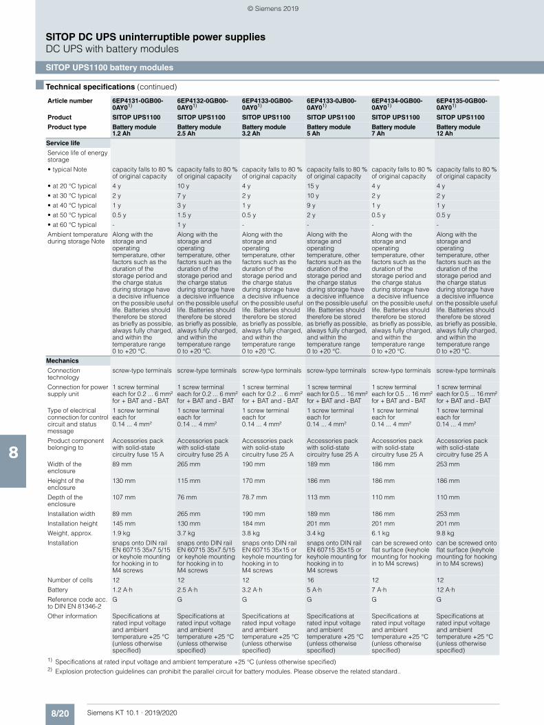
8/20 Siemens KT 10.1 · 2019/2020
8
■ Technical specifications (continued)
SITOP DC UPS uninterruptible power suppliesDC UPS with battery modules
SITOP UPS1100 battery modules
Service life
Service life of energy storage
• typical Note capacity falls to 80 % of original capacity
capacity falls to 80 % of original capacity
capacity falls to 80 % of original capacity
capacity falls to 80 % of original capacity
capacity falls to 80 % of original capacity
capacity falls to 80 % of original capacity
• at 20 °C typical 4 y 10 y 4 y 15 y 4 y 4 y
• at 30 °C typical 2 y 7 y 2 y 10 y 2 y 2 y
• at 40 °C typical 1 y 3 y 1 y 9 y 1 y 1 y
• at 50 °C typical 0.5 y 1.5 y 0.5 y 2 y 0.5 y 0.5 y
• at 60 °C typical - 1 y - - - -
Ambient temperature during storage Note
Along with the storage and operating temperature, other factors such as the duration of the storage period and the charge status during storage have a decisive influence on the possible useful life. Batteries should therefore be stored as briefly as possible, always fully charged, and within the temperature range 0 to +20 °C.
Along with the storage and operating temperature, other factors such as the duration of the storage period and the charge status during storage have a decisive influence on the possible useful life. Batteries should therefore be stored as briefly as possible, always fully charged, and within the temperature range 0 to +20 °C.
Along with the storage and operating temperature, other factors such as the duration of the storage period and the charge status during storage have a decisive influence on the possible useful life. Batteries should therefore be stored as briefly as possible, always fully charged, and within the temperature range 0 to +20 °C.
Along with the storage and operating temperature, other factors such as the duration of the storage period and the charge status during storage have a decisive influence on the possible useful life. Batteries should therefore be stored as briefly as possible, always fully charged, and within the temperature range 0 to +20 °C.
Along with the storage and operating temperature, other factors such as the duration of the storage period and the charge status during storage have a decisive influence on the possible useful life. Batteries should therefore be stored as briefly as possible, always fully charged, and within the temperature range 0 to +20 °C.
Along with the storage and operating temperature, other factors such as the duration of the storage period and the charge status during storage have a decisive influence on the possible useful life. Batteries should therefore be stored as briefly as possible, always fully charged, and within the temperature range 0 to +20 °C.
Mechanics
Connection technology
screw-type terminals screw-type terminals screw-type terminals screw-type terminals screw-type terminals screw-type terminals
Connection for power supply unit
1 screw terminal each for 0.2 ... 6 mm² for + BAT and - BAT
1 screw terminal each for 0.2 ... 6 mm² for + BAT and - BAT
1 screw terminal each for 0.2 ... 6 mm² for + BAT and - BAT
1 screw terminal each for 0.5 ... 16 mm² for + BAT and - BAT
1 screw terminal each for 0.5 ... 16 mm² for + BAT and - BAT
1 screw terminal each for 0.5 ... 16 mm² for + BAT and - BAT
Type of electrical connection for control circuit and status message
1 screw terminal each for 0.14 ... 4 mm²
1 screw terminal each for 0.14 ... 4 mm²
1 screw terminal each for 0.14 ... 4 mm²
1 screw terminal each for 0.14 ... 4 mm²
1 screw terminal each for 0.14 ... 4 mm²
1 screw terminal each for 0.14 ... 4 mm²
Product component belonging to
Accessories pack with solid-state circuitry fuse 15 A
Accessories pack with solid-state circuitry fuse 25 A
Accessories pack with solid-state circuitry fuse 25 A
Accessories pack with solid-state circuitry fuse 25 A
Accessories pack with solid-state circuitry fuse 25 A
Accessories pack with solid-state circuitry fuse 25 A
Width of the enclosure
89 mm 265 mm 190 mm 189 mm 186 mm 253 mm
Height of the enclosure
130 mm 115 mm 170 mm 186 mm 186 mm 186 mm
Depth of the enclosure
107 mm 76 mm 78.7 mm 113 mm 110 mm 110 mm
Installation width 89 mm 265 mm 190 mm 189 mm 186 mm 253 mm
Installation height 145 mm 130 mm 184 mm 201 mm 201 mm 201 mm
Weight, approx. 1.9 kg 3.7 kg 3.8 kg 3.4 kg 6.1 kg 9.8 kg
Installation snaps onto DIN rail EN 60715 35x7.5/15 or keyhole mounting for hooking in to M4 screws
snaps onto DIN rail EN 60715 35x7.5/15 or keyhole mounting for hooking in to M4 screws
snaps onto DIN rail EN 60715 35x15 or keyhole mounting for hooking in to M4 screws
snaps onto DIN rail EN 60715 35x15 or keyhole mounting for hooking in to M4 screws
can be screwed onto flat surface (keyhole mounting for hooking in to M4 screws)
can be screwed onto flat surface (keyhole mounting for hooking in to M4 screws)
Number of cells 12 12 12 16 12 12
Battery 1.2 A·h 2.5 A·h 3.2 A·h 5 A·h 7 A·h 12 A·h
Reference code acc. to DIN EN 81346-2
G G G G G G
Other information Specifications at rated input voltage and ambient temperature +25 °C (unless otherwise specified)
Specifications at rated input voltage and ambient temperature +25 °C (unless otherwise specified)
Specifications at rated input voltage and ambient temperature +25 °C (unless otherwise specified)
Specifications at rated input voltage and ambient temperature +25 °C (unless otherwise specified)
Specifications at rated input voltage and ambient temperature +25 °C (unless otherwise specified)
Specifications at rated input voltage and ambient temperature +25 °C (unless otherwise specified)
1) Specifications at rated input voltage and ambient temperature +25 °C (unless otherwise specified)2) Explosion protection guidelines can prohibit the parallel circuit for battery modules. Please observe the related standard..
Article number 6EP4131-0GB00-0AY01)
6EP4132-0GB00-0AY01)
6EP4133-0GB00-0AY01)
6EP4133-0JB00-0AY01)
6EP4134-0GB00-0AY01)
6EP4135-0GB00-0AY01)
Product SITOP UPS1100 SITOP UPS1100 SITOP UPS1100 SITOP UPS1100 SITOP UPS1100 SITOP UPS1100
Product type Battery module 1.2 Ah
Battery module 2.5 Ah
Battery module 3.2 Ah
Battery module 5 Ah
Battery module 7 Ah
Battery module 12 Ah
© Siemens 2019
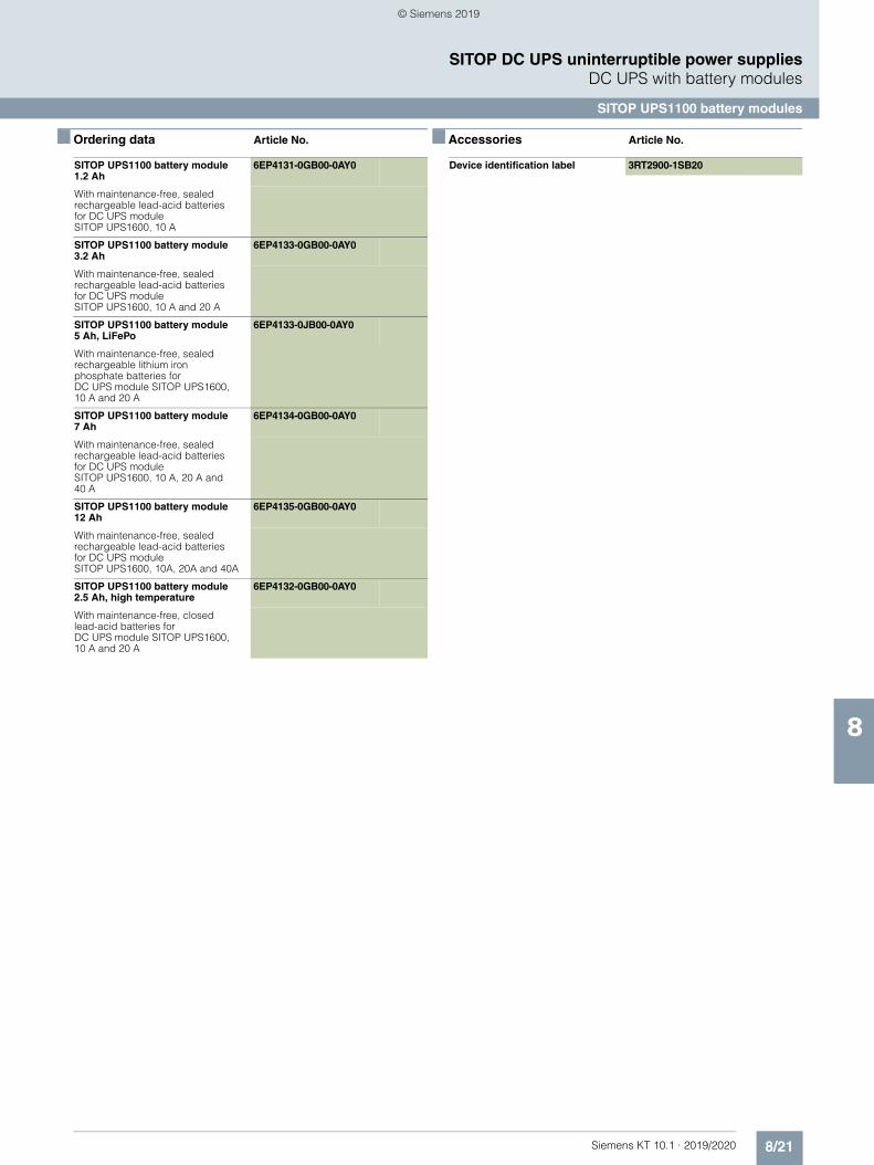
8/21Siemens KT 10.1 · 2019/2020
8
SITOP DC UPS uninterruptible power suppliesDC UPS with battery modules
SITOP UPS1100 battery modules
■ Ordering data Article No. ■ Accessories Article No.
SITOP UPS1100 battery module 1.2 Ah
6EP4131-0GB00-0AY0
With maintenance-free, sealed rechargeable lead-acid batteries for DC UPS module SITOP UPS1600, 10 A
SITOP UPS1100 battery module 3.2 Ah
6EP4133-0GB00-0AY0
With maintenance-free, sealed rechargeable lead-acid batteries for DC UPS module SITOP UPS1600, 10 A and 20 A
SITOP UPS1100 battery module 5 Ah, LiFePo
6EP4133-0JB00-0AY0
With maintenance-free, sealed rechargeable lithium iron phosphate batteries for DC UPS module SITOP UPS1600, 10 A and 20 A
SITOP UPS1100 battery module 7 Ah
6EP4134-0GB00-0AY0
With maintenance-free, sealed rechargeable lead-acid batteries for DC UPS module SITOP UPS1600, 10 A, 20 A and 40 A
SITOP UPS1100 battery module 12 Ah
6EP4135-0GB00-0AY0
With maintenance-free, sealed rechargeable lead-acid batteries for DC UPS module SITOP UPS1600, 10A, 20A and 40A
SITOP UPS1100 battery module 2.5 Ah, high temperature
6EP4132-0GB00-0AY0
With maintenance-free, closed lead-acid batteries for DC UPS module SITOP UPS1600, 10 A and 20 A
Device identification label 3RT2900-1SB20
© Siemens 2019
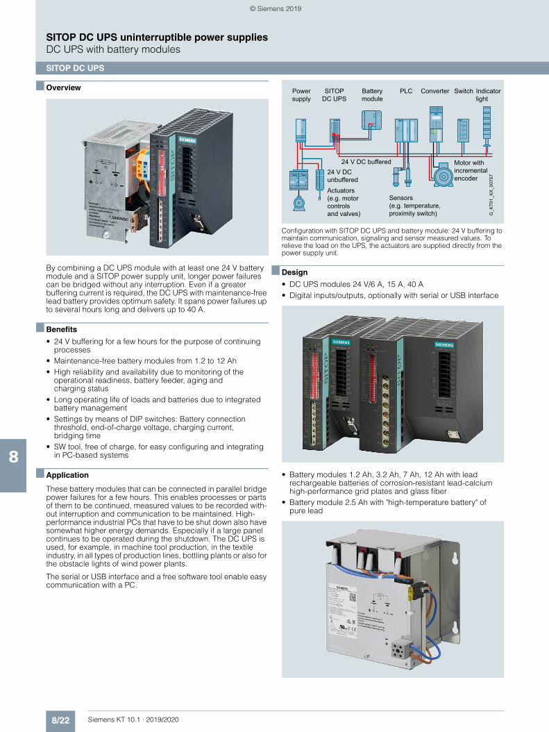
8/22 Siemens KT 10.1 · 2019/2020
8
SITOP DC UPS uninterruptible power suppliesDC UPS with battery modules
SITOP DC UPS
■ Overview
By combining a DC UPS module with at least one 24 V battery module and a SITOP power supply unit, longer power failures can be bridged without any interruption. Even if a greater buffering current is required, the DC UPS with maintenance-free lead battery provides optimum safety. It spans power failures up to several hours long and delivers up to 40 A.
■ Benefits
• 24 V buffering for a few hours for the purpose of continuing processes
• Maintenance-free battery modules from 1.2 to 12 Ah• High reliability and availability due to monitoring of the
operational readiness, battery feeder, aging and charging status
• Long operating life of loads and batteries due to integrated battery management
• Settings by means of DIP switches: Battery connection threshold, end-of-charge voltage, charging current, bridging time
• SW tool, free of charge, for easy configuring and integrating in PC-based systems
■ Application
These battery modules that can be connected in parallel bridge power failures for a few hours. This enables processes or parts of them to be continued, measured values to be recorded with-out interruption and communication to be maintained. High-performance industrial PCs that have to be shut down also have somewhat higher energy demands. Especially if a large panel continues to be operated during the shutdown. The DC UPS is used, for example, in machine tool production, in the textile industry, in all types of production lines, bottling plants or also for the obstacle lights of wind power plants.
The serial or USB interface and a free software tool enable easy communication with a PC.
Configuration with SITOP DC UPS and battery module: 24 V buffering to maintain communication, signaling and sensor measured values. To relieve the load on the UPS, the actuators are supplied directly from the power supply unit.
■ Design
• DC UPS modules 24 V/6 A, 15 A, 40 A• Digital inputs/outputs, optionally with serial or USB interface
• Battery modules 1.2 Ah, 3.2 Ah, 7 Ah, 12 Ah with lead rechargeable batteries of corrosion-resistant lead-calcium high-performance grid plates and glass fiber
• Battery module 2.5 Ah with "high-temperature battery" of pure lead
24 V DCunbuffered
Actuators(e.g. motor controlsand valves)
24 V DC buffered Motor with incrementalencoder
Indicatorlight
Sensors(e.g. temperature,proximity switch)
Power
supplySwitchPLC Converter Battery
module SITOP
DC UPS
G_K
T01_
XX
_007
57
© Siemens 2019
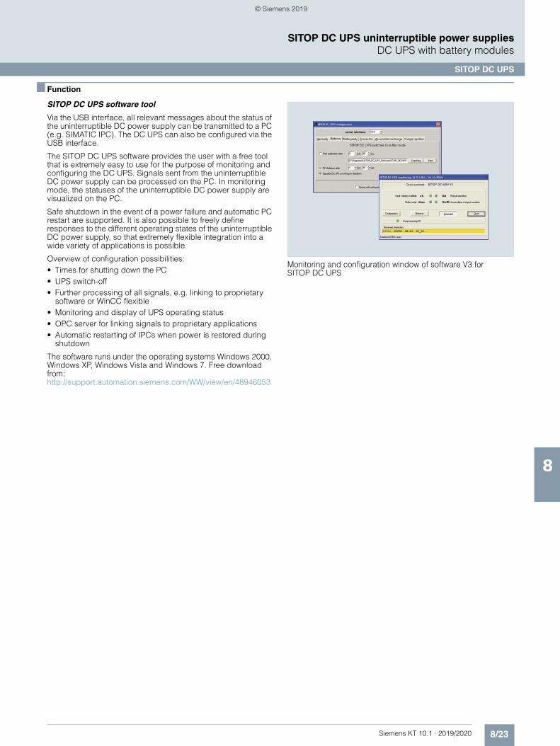
8/23Siemens KT 10.1 · 2019/2020
8
SITOP DC UPS uninterruptible power suppliesDC UPS with battery modules
SITOP DC UPS
■ Function
SITOP DC UPS software tool
Via the USB interface, all relevant messages about the status of the uninterruptible DC power supply can be transmitted to a PC (e.g. SIMATIC IPC). The DC UPS can also be configured via the USB interface.
The SITOP DC UPS software provides the user with a free tool that is extremely easy to use for the purpose of monitoring and configuring the DC UPS. Signals sent from the uninterruptible DC power supply can be processed on the PC. In monitoring mode, the statuses of the uninterruptible DC power supply are visualized on the PC.
Safe shutdown in the event of a power failure and automatic PC restart are supported. It is also possible to freely define responses to the different operating states of the uninterruptible DC power supply, so that extremely flexible integration into a wide variety of applications is possible.
Overview of configuration possibilities:• Times for shutting down the PC• UPS switch-off• Further processing of all signals, e.g. linking to proprietary
software or WinCC flexible• Monitoring and display of UPS operating status• OPC server for linking signals to proprietary applications• Automatic restarting of IPCs when power is restored during
shutdown
The software runs under the operating systems Windows 2000, Windows XP, Windows Vista and Windows 7. Free download from:http://support.automation.siemens.com/WW/view/en/48946053
Monitoring and configuration window of software V3 for SITOP DC UPS
© Siemens 2019
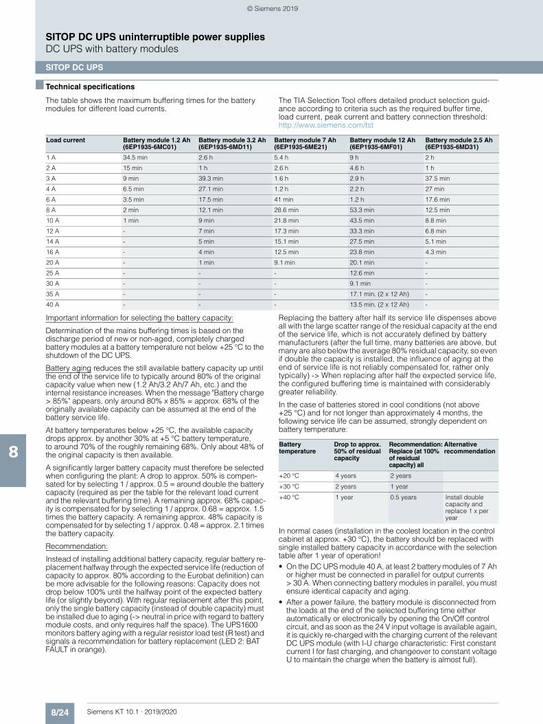
8/24 Siemens KT 10.1 · 2019/2020
8
SITOP DC UPS uninterruptible power suppliesDC UPS with battery modules
SITOP DC UPS
■ Technical specifications
The table shows the maximum buffering times for the battery modules for different load currents.
The TIA Selection Tool offers detailed product selection guid-ance according to criteria such as the required buffer time, load current, peak current and battery connection threshold:http://www.siemens.com/tst
Important information for selecting the battery capacity:
Determination of the mains buffering times is based on the discharge period of new or non-aged, completely charged battery modules at a battery temperature not below +25 °C to the shutdown of the DC UPS.
Battery aging reduces the still available battery capacity up until the end of the service life to typically around 80% of the original capacity value when new (1.2 Ah/3.2 Ah/7 Ah, etc.) and the internal resistance increases. When the message "Battery charge > 85%" appears, only around 80% x 85% = approx. 68% of the originally available capacity can be assumed at the end of the battery service life.
At battery temperatures below +25 °C, the available capacity drops approx. by another 30% at +5 °C battery temperature, to around 70% of the roughly remaining 68%. Only about 48% of the original capacity is then available.
A significantly larger battery capacity must therefore be selected when configuring the plant: A drop to approx. 50% is compen-sated for by selecting 1 / approx. 0.5 = around double the battery capacity (required as per the table for the relevant load current and the relevant buffering time). A remaining approx. 68% capac-ity is compensated for by selecting 1 / approx. 0.68 = approx. 1.5 times the battery capacity. A remaining approx. 48% capacity is compensated for by selecting 1 / approx. 0.48 = approx. 2.1 times the battery capacity.
Recommendation:
Instead of installing additional battery capacity, regular battery re-placement halfway through the expected service life (reduction of capacity to approx. 80% according to the Eurobat definition) can be more advisable for the following reasons: Capacity does not drop below 100% until the halfway point of the expected battery life (or slightly beyond). With regular replacement after this point, only the single battery capacity (instead of double capacity) must be installed due to aging (-> neutral in price with regard to battery module costs, and only requires half the space). The UPS1600 monitors battery aging with a regular resistor load test (R test) and signals a recommendation for battery replacement (LED 2: BAT FAULT in orange).
Replacing the battery after half its service life dispenses above all with the large scatter range of the residual capacity at the end of the service life, which is not accurately defined by battery manufacturers (after the full time, many batteries are above, but many are also below the average 80% residual capacity, so even if double the capacity is installed, the influence of aging at the end of service life is not reliably compensated for, rather only typically) -> When replacing after half the expected service life, the configured buffering time is maintained with considerably greater reliability.
In the case of batteries stored in cool conditions (not above +25 °C) and for not longer than approximately 4 months, the following service life can be assumed, strongly dependent on battery temperature:
In normal cases (installation in the coolest location in the control cabinet at approx. +30 °C), the battery should be replaced with single installed battery capacity in accordance with the selection table after 1 year of operation!• On the DC UPS module 40 A, at least 2 battery modules of 7 Ah
or higher must be connected in parallel for output currents > 30 A. When connecting battery modules in parallel, you must ensure identical capacity and aging.
• After a power failure, the battery module is disconnected from the loads at the end of the selected buffering time either automatically or electronically by opening the On/Off control circuit, and as soon as the 24 V input voltage is available again, it is quickly re-charged with the charging current of the relevant DC UPS module (with I-U charge characteristic: First constant current I for fast charging, and changeover to constant voltage U to maintain the charge when the battery is almost full).
Load current Battery module 1.2 Ah(6EP1935-6MC01)
Battery module 3.2 Ah(6EP1935-6MD11)
Battery module 7 Ah(6EP1935-6ME21)
Battery module 12 Ah (6EP1935-6MF01)
Battery module 2.5 Ah(6EP1935-6MD31)
1 A 34.5 min 2.6 h 5.4 h 9 h 2 h
2 A 15 min 1 h 2.6 h 4.6 h 1 h
3 A 9 min 39.3 min 1.6 h 2.9 h 37.5 min
4 A 6.5 min 27.1 min 1.2 h 2.2 h 27 min
6 A 3.5 min 17.5 min 41 min 1.2 h 17.6 min
8 A 2 min 12.1 min 28.6 min 53.3 min 12.5 min
10 A 1 min 9 min 21.8 min 43.5 min 8.8 min
12 A - 7 min 17.3 min 33.3 min 6.8 min
14 A - 5 min 15.1 min 27.5 min 5.1 min
16 A - 4 min 12.5 min 23.8 min 4.3 min
20 A - 1 min 9.1 min 20.1 min -
25 A - - - 12.6 min -
30 A - - - 9.1 min -
35 A - - - 17.1 min. (2 x 12 Ah) -
40 A - - - 13.5 min. (2 x 12 Ah) -
Battery temperature
Drop to approx. 50% of residual capacity
Recommendation: Replace (at 100% of residual capacity) all
Alternative recommendation
+20 °C 4 years 2 years
+30 °C 2 years 1 year
+40 °C 1 year 0.5 years Install double capacity and replace 1 x per year
© Siemens 2019
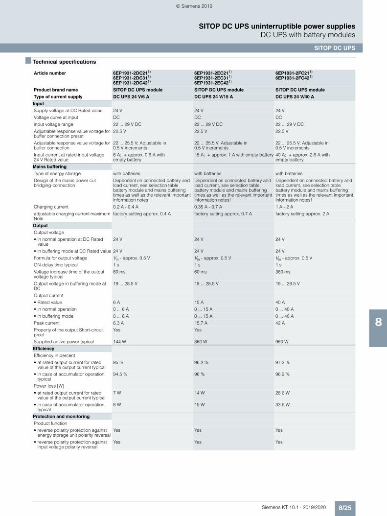
8/25Siemens KT 10.1 · 2019/2020
8
SITOP DC UPS uninterruptible power suppliesDC UPS with battery modules
SITOP DC UPS
■ Technical specifications
Article number 6EP1931-2DC211)
6EP1931-2DC311)
6EP1931-2DC421)
6EP1931-2EC211)
6EP1931-2EC311)
6EP1931-2EC421)
6EP1931-2FC211)
6EP1931-2FC421)
Product brand name SITOP DC UPS module SITOP DC UPS module SITOP DC UPS module
Type of current supply DC UPS 24 V/6 A DC UPS 24 V/15 A DC UPS 24 V/40 A
Input
Supply voltage at DC Rated value 24 V 24 V 24 V
Voltage curve at input DC DC DC
input voltage range 22 ... 29 V DC 22 ... 29 V DC 22 ... 29 V DC
Adjustable response value voltage for buffer connection preset
22.5 V 22.5 V 22.5 V
Adjustable response value voltage for buffer connection
22 ... 25.5 V; Adjustable in 0.5 V increments
22 ... 25.5 V; Adjustable in 0.5 V increments
22 ... 25.5 V; Adjustable in 0.5 V increments
Input current at rated input voltage 24 V Rated value
6 A; + approx. 0.6 A with empty battery
15 A; + approx. 1 A with empty battery 40 A; + approx. 2.6 A with empty battery
Mains buffering
Type of energy storage with batteries with batteries with batteries
Design of the mains power cut bridging-connection
Dependent on connected battery and load current, see selection table battery module and mains buffering times as well as the relevant important information notes!
Dependent on connected battery and load current, see selection table battery module and mains buffering times as well as the relevant important information notes!
Dependent on connected battery and load current, see selection table battery module and mains buffering times as well as the relevant important information notes!
Charging current 0.2 A - 0.4 A 0.35 A - 0.7 A 1 A - 2 A
adjustable charging current maximum Note
factory setting approx. 0.4 A factory setting approx. 0.7 A factory setting approx. 2 A
Output
Output voltage
• in normal operation at DC Rated value
24 V 24 V 24 V
• in buffering mode at DC Rated value 24 V 24 V 24 V
Formula for output voltage Vin - approx. 0.5 V Vin - approx. 0.5 V Vin - approx. 0.5 V
ON-delay time typical 1 s 1 s 1 s
Voltage increase time of the output voltage typical
60 ms 60 ms 360 ms
Output voltage in buffering mode at DC
19 ... 28.5 V 19 ... 28.5 V 19 ... 28.5 V
Output current
• Rated value 6 A 15 A 40 A
• in normal operation 0 ... 6 A 0 ... 15 A 0 ... 40 A
• in buffering mode 0 ... 6 A 0 ... 15 A 0 ... 40 A
Peak current 6.3 A 15.7 A 42 A
Property of the output Short-circuit proof
Yes Yes
Supplied active power typical 144 W 360 W 960 W
Efficiency
Efficiency in percent
• at rated output current for rated value of the output current typical
95 % 96.2 % 97.2 %
• in case of accumulator operation typical
94.5 % 96 % 96.9 %
Power loss [W]
• at rated output current for rated value of the output current typical
7 W 14 W 28.6 W
• in case of accumulator operation typical
8 W 15 W 33.6 W
Protection and monitoring
Product function
• reverse polarity protection against energy storage unit polarity reversal
Yes Yes Yes
• reverse polarity protection against input voltage polarity reversal
Yes Yes Yes
© Siemens 2019
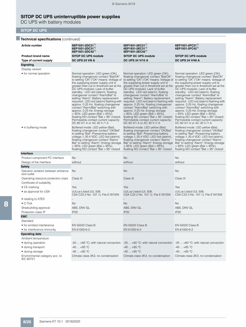
8/26 Siemens KT 10.1 · 2019/2020
8
■ Technical specifications (continued)
SITOP DC UPS uninterruptible power suppliesDC UPS with battery modules
SITOP DC UPS
Signaling
Display version
• for normal operation Normal operation: LED green (OK), floating changeover contact "Bat/OK" to setting "OK" ("OK" means: Voltage of the supplying power supply unit is greater than cut-in threshold set at the DC UPS module); Lack of buffer standby: LED red (alarm), floating changeover contact "Alarm/Bat" to setting "Alarm"; Battery replacement required: LED red (alarm) flashing with approx. 0.25 Hz, floating changeover contact "Alarm/Bat" switching with approx. 0.25 Hz; Energy storage > 85%: LED green (Bat > 85%), floating NO contact "Bat > 85" closed; Permissible contact current capacity: DC 60 V/1 A or AC 30 V /1 A
Normal operation: LED green (OK), floating changeover contact "Bat/OK" to setting "OK" ("OK" means: Voltage of the supplying power supply unit is greater than cut-in threshold set at the DC UPS module); Lack of buffer standby: LED red (alarm), floating changeover contact "Alarm/Bat" to setting "Alarm"; Battery replacement required: LED red (alarm) flashing with approx. 0.25 Hz, floating changeover contact "Alarm/Bat" switching with approx. 0.25 Hz; Energy storage > 85%: LED green (Bat > 85%), floating NO contact "Bat > 85" closed; Permissible contact current capacity: DC 60 V/1 A or AC 30 V /1 A
Normal operation: LED green (OK), floating changeover contact "Bat/OK" to setting "OK" ("OK" means: Voltage of the supplying power supply unit is greater than cut-in threshold set at the DC UPS module); Lack of buffer standby: LED red (alarm), floating changeover contact "Alarm/Bat" to setting "Alarm"; Battery replacement required: LED red (alarm) flashing with approx. 0.25 Hz, floating changeover contact "Alarm/Bat" switching with approx. 0.25 Hz; Energy storage > 85%: LED green (Bat > 85%), floating NO contact "Bat > 85" closed; Permissible contact current capacity: DC 60 V/1 A or AC 30 V /1 A
• in buffering mode Buffered mode: LED yellow (Bat), floating changeover contact "OK/Bat" to setting "Bat"; Prewarning battery voltage < 20.4 VDC: LED red (alarm), floating changeover contact "Alarm/Bat" to setting "Alarm"; Energy storage > 85%: LED green (Bat > 85%), floating NO contact "Bat > 85" closed
Buffered mode: LED yellow (Bat), floating changeover contact "OK/Bat" to setting "Bat"; Prewarning battery voltage < 20.4 VDC: LED red (alarm), floating changeover contact "Alarm/Bat" to setting "Alarm"; Energy storage > 85%: LED green (Bat > 85%), floating NO contact "Bat > 85" closed
Buffered mode: LED yellow (Bat), floating changeover contact "OK/Bat" to setting "Bat"; Prewarning battery voltage < 20.4 VDC: LED red (alarm), floating changeover contact "Alarm/Bat" to setting "Alarm"; Energy storage > 85%: LED green (Bat > 85%), floating NO contact "Bat > 85" closed
Interface
Product component PC interface No No No
Design of the interface without without without
Safety
Galvanic isolation between entrance and outlet
No No No
Operating resource protection class Class III Class III Class III
Certificate of suitability
• CE marking Yes Yes Yes
• as approval for USA cULus-Listed (UL 508, CSA C22.2 No. 107.1), File E197259
cULus-Listed (UL 508, CSA C22.2 No. 107.1), File E197259
cULus-Listed (UL 508, CSA C22.2 No. 107.1), File E197259
• relating to ATEX - - -
• C-Tick No No No
Shipbuilding approval ABS, DNV GL ABS, DNV GL ABS, DNV GL
Protection class IP IP20 IP20 IP20
EMC
Standard
• for emitted interference EN 55022 Class B EN 55022 Class B EN 55022 Class B
• for interference immunity EN 61000-6-2 EN 61000-6-2 EN 61000-6-2
Operating data
Ambient temperature
• during operation -25 ... +60 °C; with natural convection -25 ... +60 °C; with natural convection -25 ... +60 °C; with natural convection
• during transport -40 ... +85 °C -40 ... +85 °C -40 ... +85 °C
• during storage -40 ... +85 °C -40 ... +85 °C -40 ... +85 °C
Environmental category acc. to IEC 60721
Climate class 3K3, no condensation Climate class 3K3, no condensation Climate class 3K3, no condensation
Article number 6EP1931-2DC211)
6EP1931-2DC311)
6EP1931-2DC421)
6EP1931-2EC211)
6EP1931-2EC311)
6EP1931-2EC421)
6EP1931-2FC211)
6EP1931-2FC421)
Product brand name SITOP DC UPS module SITOP DC UPS module SITOP DC UPS module
Type of current supply DC UPS 24 V/6 A DC UPS 24 V/15 A DC UPS 24 V/40 A
© Siemens 2019
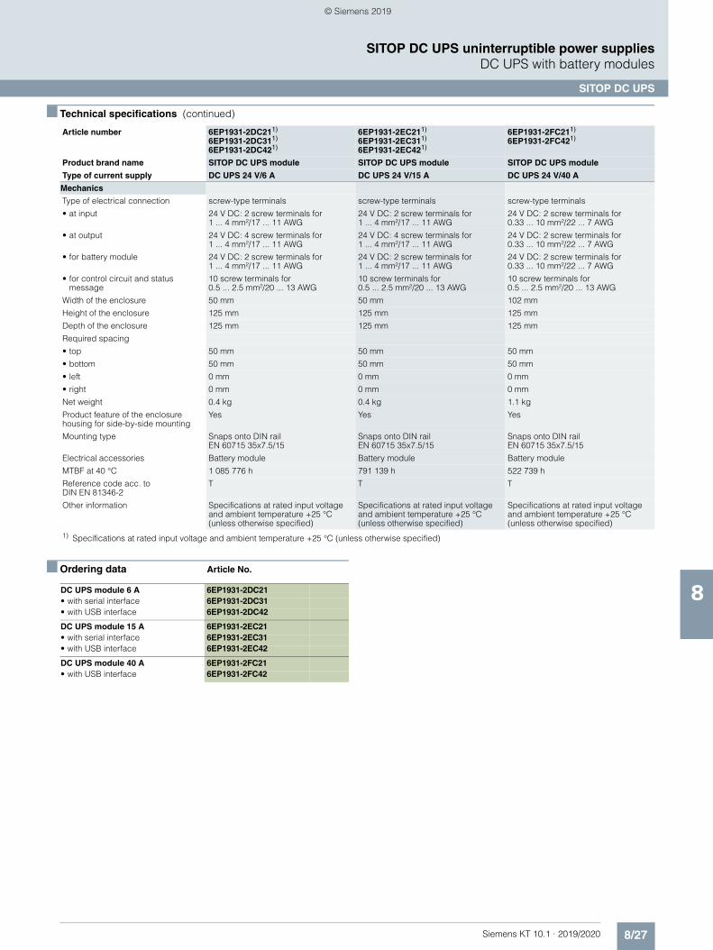
8/27Siemens KT 10.1 · 2019/2020
8
■ Technical specifications (continued)
SITOP DC UPS uninterruptible power suppliesDC UPS with battery modules
SITOP DC UPS
■ Ordering data Article No.
Mechanics
Type of electrical connection screw-type terminals screw-type terminals screw-type terminals
• at input 24 V DC: 2 screw terminals for 1 ... 4 mm²/17 ... 11 AWG
24 V DC: 2 screw terminals for 1 ... 4 mm²/17 ... 11 AWG
24 V DC: 2 screw terminals for 0.33 ... 10 mm²/22 ... 7 AWG
• at output 24 V DC: 4 screw terminals for 1 ... 4 mm²/17 ... 11 AWG
24 V DC: 4 screw terminals for 1 ... 4 mm²/17 ... 11 AWG
24 V DC: 2 screw terminals for 0.33 ... 10 mm²/22 ... 7 AWG
• for battery module 24 V DC: 2 screw terminals for 1 ... 4 mm²/17 ... 11 AWG
24 V DC: 2 screw terminals for 1 ... 4 mm²/17 ... 11 AWG
24 V DC: 2 screw terminals for 0.33 ... 10 mm²/22 ... 7 AWG
• for control circuit and status message
10 screw terminals for 0.5 ... 2.5 mm²/20 ... 13 AWG
10 screw terminals for 0.5 ... 2.5 mm²/20 ... 13 AWG
10 screw terminals for 0.5 ... 2.5 mm²/20 ... 13 AWG
Width of the enclosure 50 mm 50 mm 102 mm
Height of the enclosure 125 mm 125 mm 125 mm
Depth of the enclosure 125 mm 125 mm 125 mm
Required spacing
• top 50 mm 50 mm 50 mm
• bottom 50 mm 50 mm 50 mm
• left 0 mm 0 mm 0 mm
• right 0 mm 0 mm 0 mm
Net weight 0.4 kg 0.4 kg 1.1 kg
Product feature of the enclosure housing for side-by-side mounting
Yes Yes Yes
Mounting type Snaps onto DIN rail EN 60715 35x7.5/15
Snaps onto DIN rail EN 60715 35x7.5/15
Snaps onto DIN rail EN 60715 35x7.5/15
Electrical accessories Battery module Battery module Battery module
MTBF at 40 °C 1 085 776 h 791 139 h 522 739 h
Reference code acc. to DIN EN 81346-2
T T T
Other information Specifications at rated input voltage and ambient temperature +25 °C (unless otherwise specified)
Specifications at rated input voltage and ambient temperature +25 °C (unless otherwise specified)
Specifications at rated input voltage and ambient temperature +25 °C (unless otherwise specified)
1) Specifications at rated input voltage and ambient temperature +25 °C (unless otherwise specified)
Article number 6EP1931-2DC211)
6EP1931-2DC311)
6EP1931-2DC421)
6EP1931-2EC211)
6EP1931-2EC311)
6EP1931-2EC421)
6EP1931-2FC211)
6EP1931-2FC421)
Product brand name SITOP DC UPS module SITOP DC UPS module SITOP DC UPS module
Type of current supply DC UPS 24 V/6 A DC UPS 24 V/15 A DC UPS 24 V/40 A
DC UPS module 6 A 6EP1931-2DC21• with serial interface 6EP1931-2DC31• with USB interface 6EP1931-2DC42
DC UPS module 15 A 6EP1931-2EC21• with serial interface 6EP1931-2EC31• with USB interface 6EP1931-2EC42
DC UPS module 40 A 6EP1931-2FC21• with USB interface 6EP1931-2FC42
© Siemens 2019
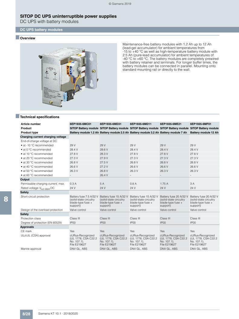
8/28 Siemens KT 10.1 · 2019/2020
8
SITOP DC UPS uninterruptible power suppliesDC UPS with battery modules
DC UPS battery modules
■ Overview
Maintenance-free battery modules with 1.2 Ah up to 12 Ah (lead-gel accumulator) for ambient temperatures from -15 to +40 °C as well as high-temperature battery module with 2.5 Ah (pure-lead accumulator) for ambient temperatures of -40 °C to +60 °C. The battery modules are completely prewired with battery retainer and terminals. For longer buffer times, the battery modules can be connected in parallel. Mounting onto standard mounting rail or directly to the wall.
■ Technical specifications
Article number 6EP1935-6MC01 6EP1935-6MD31 6EP1935-6MD11 6EP1935-6ME21 6EP1935-6MF01
Product SITOP Battery module SITOP Battery module SITOP Battery module SITOP Battery module SITOP Battery module
Product type Battery module 1.2 Ah Battery module 2.5 Ah Battery module 3.2 Ah Battery module 7 Ah Battery module 12 Ah
Charging current charging voltage
End-of-charge voltage at DC
• at -10 °C recommended 29 V 29 V 29 V 29 V 29 V
• at 0 °C recommended 28.4 V 28.6 V 28.4 V 28.4 V 28.4 V
• at 10 °C recommended 27.8 V 28.3 V 27.8 V 27.8 V 27.8 V
• at 20 °C recommended 27.3 V 27.9 V 27.3 V 27.3 V 27.3 V
• at 30 °C recommended 26.8 V 27.5 V 26.8 V 26.8 V 26.8 V
• at 40 °C recommended 26.6 V 27.2 V 26.6 V 26.6 V 26.6 V
• at 50 °C recommended 26.3 V 26.8 V 26.3 V 26.3 V 26.3 V
• at 60 °C recommended - 26.4 V - - -
Output
Permissible charging current, max. 0.3 A 5 A 0.8 A 1.75 A 3 A
Rated voltage Vout rated DC 24 V 24 V 24 V 24 V 24 V
Safety
Short-circuit protection Battery fuse 7.5 A/32 V (solid-state circuitry blade-type fuse + support)
Battery fuse 15 A/32 V (solid-state circuitry blade-type fuse + support)
Battery fuse 15 A/32 V (solid-state circuitry blade-type fuse + support)
Battery fuse 20 A/32 V (solid-state circuitry blade-type fuse + support)
Battery fuse 20 A/32 V (solid-state circuitry blade-type fuse + support)
Design of the overload protection Valve control Valve control Valve control Valve control Valve control
Safety
Protection class Class III Class III Class III Class III Class III
Degree of protection (EN 60529) IP00 IP00 IP00 IP00 IP00
Approvals
CE mark Yes Yes Yes Yes Yes
UL/cUL (CSA) approval cURus-Recognized (UL 1778, CSA C22.2 No. 107.1), File E219627
cURus-Recognized (UL 1778, CSA C22.2 No. 107.1), File E219627
cURus-Recognized (UL 1778, CSA C22.2 No. 107.1), File E219627
cURus-Recognized (UL 1778, CSA C22.2 No. 107.1), File E219627
cURus-Recognized (UL 1778, CSA C22.2 No. 107.1), File E219627
Marine approval DNV GL, ABS DNV GL, ABS DNV GL, ABS DNV GL, ABS DNV GL, ABS
© Siemens 2019
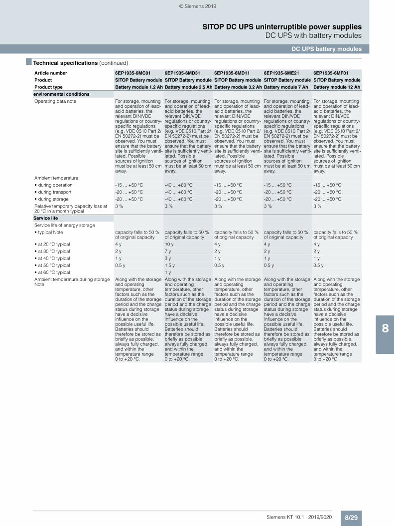
8/29Siemens KT 10.1 · 2019/2020
8
■ Technical specifications (continued)
SITOP DC UPS uninterruptible power suppliesDC UPS with battery modules
DC UPS battery modules
environmental conditions
Operating data note For storage, mounting and operation of lead-acid batteries, the relevant DIN/VDE regulations or country-specific regulations (e.g. VDE 0510 Part 2/EN 50272-2) must be observed. You must ensure that the battery site is sufficiently venti-lated. Possible sources of ignition must be at least 50 cm away.
For storage, mounting and operation of lead-acid batteries, the relevant DIN/VDE regulations or country-specific regulations (e.g. VDE 0510 Part 2/EN 50272-2) must be observed. You must ensure that the battery site is sufficiently venti-lated. Possible sources of ignition must be at least 50 cm away.
For storage, mounting and operation of lead-acid batteries, the relevant DIN/VDE regulations or country-specific regulations (e.g. VDE 0510 Part 2/EN 50272-2) must be observed. You must ensure that the battery site is sufficiently venti-lated. Possible sources of ignition must be at least 50 cm away.
For storage, mounting and operation of lead-acid batteries, the relevant DIN/VDE regulations or country-specific regulations (e.g. VDE 0510 Part 2/EN 50272-2) must be observed. You must ensure that the battery site is sufficiently venti-lated. Possible sources of ignition must be at least 50 cm away.
For storage, mounting and operation of lead-acid batteries, the relevant DIN/VDE regulations or country-specific regulations (e.g. VDE 0510 Part 2/EN 50272-2) must be observed. You must ensure that the battery site is sufficiently venti-lated. Possible sources of ignition must be at least 50 cm away.
Ambient temperature
• during operation -15 ... +50 °C -40 ... +60 °C -15 ... +50 °C -15 ... +50 °C -15 ... +50 °C
• during transport -20 ... +50 °C -40 ... +60 °C -20 ... +50 °C -20 ... +50 °C -20 ... +50 °C
• during storage -20 ... +50 °C -40 ... +60 °C -20 ... +50 °C -20 ... +50 °C -20 ... +50 °C
Relative temporary capacity loss at 20 °C in a month typical
3 % 3 % 3 % 3 % 3 %
Service life
Service life of energy storage
• typical Note capacity falls to 50 % of original capacity
capacity falls to 50 % of original capacity
capacity falls to 50 % of original capacity
capacity falls to 50 % of original capacity
capacity falls to 50 % of original capacity
• at 20 °C typical 4 y 10 y 4 y 4 y 4 y
• at 30 °C typical 2 y 7 y 2 y 2 y 2 y
• at 40 °C typical 1 y 3 y 1 y 1 y 1 y
• at 50 °C typical 0.5 y 1.5 y 0.5 y 0.5 y 0.5 y
• at 60 °C typical 1 y
Ambient temperature during storage Note
Along with the storage and operating temperature, other factors such as the duration of the storage period and the charge status during storage have a decisive influence on the possible useful life. Batteries should therefore be stored as briefly as possible, always fully charged, and within the temperature range 0 to +20 °C.
Along with the storage and operating temperature, other factors such as the duration of the storage period and the charge status during storage have a decisive influence on the possible useful life. Batteries should therefore be stored as briefly as possible, always fully charged, and within the temperature range 0 to +20 °C.
Along with the storage and operating temperature, other factors such as the duration of the storage period and the charge status during storage have a decisive influence on the possible useful life. Batteries should therefore be stored as briefly as possible, always fully charged, and within the temperature range 0 to +20 °C.
Along with the storage and operating temperature, other factors such as the duration of the storage period and the charge status during storage have a decisive influence on the possible useful life. Batteries should therefore be stored as briefly as possible, always fully charged, and within the temperature range 0 to +20 °C.
Along with the storage and operating temperature, other factors such as the duration of the storage period and the charge status during storage have a decisive influence on the possible useful life. Batteries should therefore be stored as briefly as possible, always fully charged, and within the temperature range 0 to +20 °C.
Article number 6EP1935-6MC01 6EP1935-6MD31 6EP1935-6MD11 6EP1935-6ME21 6EP1935-6MF01
Product SITOP Battery module SITOP Battery module SITOP Battery module SITOP Battery module SITOP Battery module
Product type Battery module 1.2 Ah Battery module 2.5 Ah Battery module 3.2 Ah Battery module 7 Ah Battery module 12 Ah
© Siemens 2019
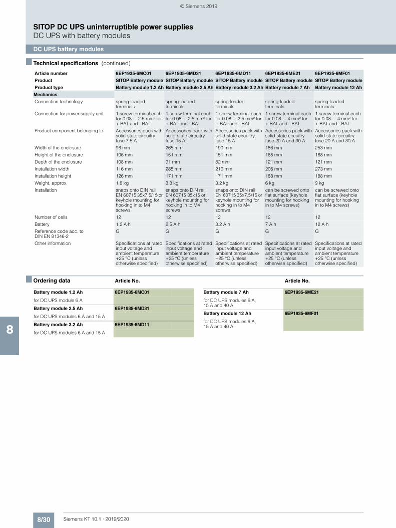
8/30 Siemens KT 10.1 · 2019/2020
8
■ Technical specifications (continued)
SITOP DC UPS uninterruptible power suppliesDC UPS with battery modules
DC UPS battery modules
■ Ordering data Article No. Article No.
Mechanics
Connection technology spring-loaded terminals
spring-loaded terminals
spring-loaded terminals
spring-loaded terminals
spring-loaded terminals
Connection for power supply unit 1 screw terminal each for 0.08 ... 2.5 mm² for + BAT and - BAT
1 screw terminal each for 0.08 ... 2.5 mm² for + BAT and - BAT
1 screw terminal each for 0.08 ... 2.5 mm² for + BAT and - BAT
1 screw terminal each for 0.08 ... 4 mm² for + BAT and - BAT
1 screw terminal each for 0.08 ... 4 mm² for + BAT and - BAT
Product component belonging to Accessories pack with solid-state circuitry fuse 7.5 A
Accessories pack with solid-state circuitry fuse 15 A
Accessories pack with solid-state circuitry fuse 15 A
Accessories pack with solid-state circuitry fuse 20 A and 30 A
Accessories pack with solid-state circuitry fuse 20 A and 30 A
Width of the enclosure 96 mm 265 mm 190 mm 186 mm 253 mm
Height of the enclosure 106 mm 151 mm 151 mm 168 mm 168 mm
Depth of the enclosure 108 mm 91 mm 82 mm 121 mm 121 mm
Installation width 116 mm 285 mm 210 mm 206 mm 273 mm
Installation height 126 mm 171 mm 171 mm 188 mm 188 mm
Weight, approx. 1.8 kg 3.8 kg 3.2 kg 6 kg 9 kg
Installation snaps onto DIN rail EN 60715 35x7.5/15 or keyhole mounting for hooking in to M4 screws
snaps onto DIN rail EN 60715 35x15 or keyhole mounting for hooking in to M4 screws
snaps onto DIN rail EN 60715 35x7.5/15 or keyhole mounting for hooking in to M4 screws
can be screwed onto flat surface (keyhole mounting for hooking in to M4 screws)
can be screwed onto flat surface (keyhole mounting for hooking in to M4 screws)
Number of cells 12 12 12 12 12
Battery 1.2 A·h 2.5 A·h 3.2 A·h 7 A·h 12 A·h
Reference code acc. to DIN EN 81346-2
G G G G G
Other information Specifications at rated input voltage and ambient temperature +25 °C (unless otherwise specified)
Specifications at rated input voltage and ambient temperature +25 °C (unless otherwise specified)
Specifications at rated input voltage and ambient temperature +25 °C (unless otherwise specified)
Specifications at rated input voltage and ambient temperature +25 °C (unless otherwise specified)
Specifications at rated input voltage and ambient temperature +25 °C (unless otherwise specified)
Article number 6EP1935-6MC01 6EP1935-6MD31 6EP1935-6MD11 6EP1935-6ME21 6EP1935-6MF01
Product SITOP Battery module SITOP Battery module SITOP Battery module SITOP Battery module SITOP Battery module
Product type Battery module 1.2 Ah Battery module 2.5 Ah Battery module 3.2 Ah Battery module 7 Ah Battery module 12 Ah
Battery module 1.2 Ah 6EP1935-6MC01
for DC UPS module 6 A
Battery module 2.5 Ah 6EP1935-6MD31
for DC UPS modules 6 A and 15 A
Battery module 3.2 Ah 6EP1935-6MD11
for DC UPS modules 6 A and 15 A
Battery module 7 Ah 6EP1935-6ME21
for DC UPS modules 6 A, 15 A and 40 A
Battery module 12 Ah 6EP1935-6MF01
for DC UPS modules 6 A, 15 A and 40 A
© Siemens 2019

Siemens KT 10.1 · 2019/2020
99/2 Introduction9/3 Redundancy module9/7 Selectivity module9/15 Buffer module9/17 Inrush current limiter
Add-on modules
© Siemens 2019
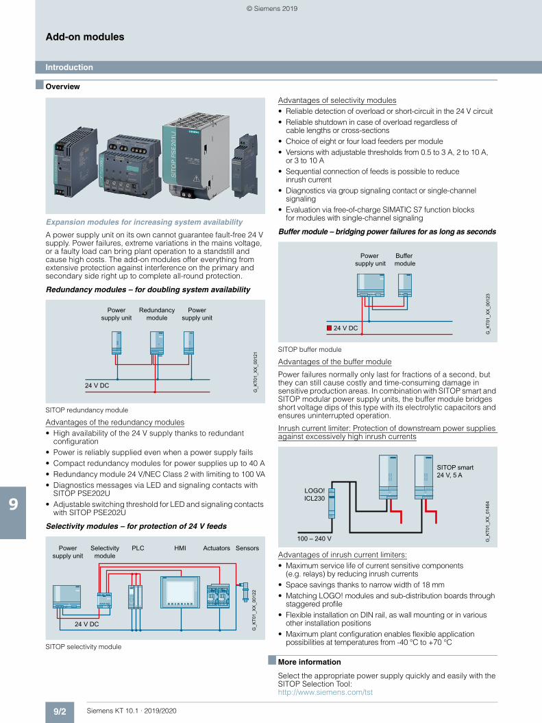
9/2 Siemens KT 10.1 · 2019/2020
9
Add-on modules
Introduction
■ Overview
Expansion modules for increasing system availability
A power supply unit on its own cannot guarantee fault-free 24 V supply. Power failures, extreme variations in the mains voltage, or a faulty load can bring plant operation to a standstill and cause high costs. The add-on modules offer everything from extensive protection against interference on the primary and secondary side right up to complete all-round protection.
Redundancy modules – for doubling system availability
SITOP redundancy module
Advantages of the redundancy modules• High availability of the 24 V supply thanks to redundant
configuration• Power is reliably supplied even when a power supply fails• Compact redundancy modules for power supplies up to 40 A• Redundancy module 24 V/NEC Class 2 with limiting to 100 VA• Diagnostics messages via LED and signaling contacts with
SITOP PSE202U• Adjustable switching threshold for LED and signaling contacts
with SITOP PSE202U
Selectivity modules – for protection of 24 V feeds
SITOP selectivity module
Advantages of selectivity modules• Reliable detection of overload or short-circuit in the 24 V circuit• Reliable shutdown in case of overload regardless of
cable lengths or cross-sections• Choice of eight or four load feeders per module• Versions with adjustable thresholds from 0.5 to 3 A, 2 to 10 A,
or 3 to 10 A• Sequential connection of feeds is possible to reduce
inrush current• Diagnostics via group signaling contact or single-channel
signaling• Evaluation via free-of-charge SIMATIC S7 function blocks
for modules with single-channel signaling
Buffer module – bridging power failures for as long as seconds
SITOP buffer module
Advantages of the buffer module
Power failures normally only last for fractions of a second, but they can still cause costly and time-consuming damage in sensitive production areas. In combination with SITOP smart and SITOP modular power supply units, the buffer module bridges short voltage dips of this type with its electrolytic capacitors and ensures uninterrupted operation.
Inrush current limiter: Protection of downstream power supplies against excessively high inrush currents
Advantages of inrush current limiters:• Maximum service life of current sensitive components
(e.g. relays) by reducing inrush currents• Space savings thanks to narrow width of 18 mm• Matching LOGO! modules and sub-distribution boards through
staggered profile• Flexible installation on DIN rail, as wall mounting or in various
other installation positions• Maximum plant configuration enables flexible application
possibilities at temperatures from -40 °C to +70 °C
■ More information
Select the appropriate power supply quickly and easily with the SITOP Selection Tool:http://www.siemens.com/tst
Power supply unit
Redundancy module
Power supply unit
24 V DC
G_K
T01_
XX
_001
21
Power supply unit
Selectivity module
Actuators Sensors
24 V DC
G_K
T01_
XX
_001
22
HMIPLC
Power supply unit
Buffer module
24 V DC
G_K
T01_
XX
_001
23
SITOP smart 24 V, 5 A
G_K
T01_
XX
_014
64
100 – 240 V
LOGO! ICL230
© Siemens 2019
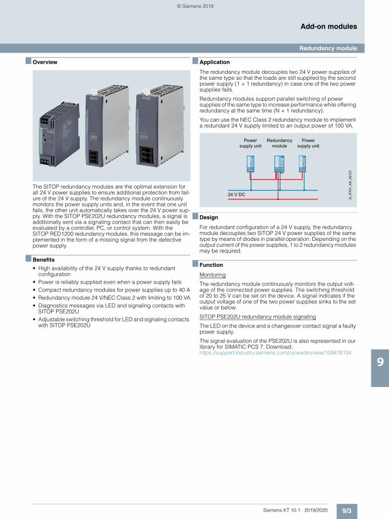
9/3Siemens KT 10.1 · 2019/2020
9
Add-on modules
Redundancy module
■ Overview
The SITOP redundancy modules are the optimal extension for all 24 V power supplies to ensure additional protection from fail-ure of the 24 V supply. The redundancy module continuously monitors the power supply units and, in the event that one unit fails, the other unit automatically takes over the 24 V power sup-ply. With the SITOP PSE202U redundancy modules, a signal is additionally sent via a signaling contact that can then easily be evaluated by a controller, PC, or control system. With the SITOP RED1200 redundancy modules, this message can be im-plemented in the form of a missing signal from the defective power supply.
■ Benefits
• High availability of the 24 V supply thanks to redundant configuration
• Power is reliably supplied even when a power supply fails• Compact redundancy modules for power supplies up to 40 A• Redundancy module 24 V/NEC Class 2 with limiting to 100 VA• Diagnostics messages via LED and signaling contacts with
SITOP PSE202U• Adjustable switching threshold for LED and signaling contacts
with SITOP PSE202U
■ Application
The redundancy module decouples two 24 V power supplies of the same type so that the loads are still supplied by the second power supply (1 + 1 redundancy) in case one of the two power supplies fails.
Redundancy modules support parallel switching of power supplies of the same type to increase performance while offering redundancy at the same time (N + 1 redundancy).
You can use the NEC Class 2 redundancy module to implement a redundant 24 V supply limited to an output power of 100 VA.
■ Design
For redundant configuration of a 24 V supply, the redundancy module decouples two SITOP 24 V power supplies of the same type by means of diodes in parallel operation. Depending on the output current of the power supplies, 1 to 2 redundancy modules may be required.
■ Function
Monitoring
The redundancy module continuously monitors the output volt-age of the connected power supplies. The switching threshold of 20 to 25 V can be set on the device. A signal indicates if the output voltage of one of the two power supplies sinks to the set value or below.
SITOP PSE202U redundancy module signaling
The LED on the device and a changeover contact signal a faulty power supply.
The signal evaluation of the PSE202U is also represented in our library for SIMATIC PCS 7. Download: https://support.industry.siemens.com/cs/ww/en/view/109476154
Power supply unit
Redundancy module
Power supply unit
24 V DC
G_K
T01_
XX
_001
21
© Siemens 2019
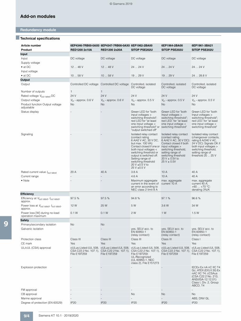
9/4 Siemens KT 10.1 · 2019/2020
9
Add-on modules
Redundancy module
■ Technical specifications
Article number 6EP4346-7RB00-0AX0 6EP4347-7RB00-0AX0 6EP1962-2BA00 6EP1964-2BA00 6EP1961-3BA21
Product RED1200 2x10A RED1200 2x20A SITOP PSE202U SITOP PSE202U SITOP PSE202U
Input
Input DC voltage DC voltage DC voltage DC voltage DC voltage
Supply voltage
• at DC 12 ... 48 V 12 ... 48 V 24 ... 24 V 24 ... 24 V 24 ... 24 V
Input voltage
• at DC 10 ... 58 V 10 ... 58 V 19 ... 29 V 19 ... 29 V 24 ... 28.8 V
Output
Output Controlled DC voltage Controlled DC voltage Controlled, isolated DC voltage
Controlled, isolated DC voltage
Controlled, isolated DC voltage
Number of outputs 1 1
Rated voltage Vout rated DC 24 V 24 V 24 V 24 V 24 V
Output voltage Vin - approx. 0.6 V Vin - approx. 0.6 V Vin - approx. 0.5 V Vin - approx. 0.5 V Vin - approx. 0.5 V
Product function Output voltage adjustable
No No No No No
Status display - - Green LED for "both input voltages > switching threshold"; red LED for "at least one input voltage < switching threshold" or "output switched off"
Green LED for "both Input voltages > switching threshold"; red LED: for "at least one input voltage < switching threshold"
Green LED for "both Input voltages > switching threshold"; red LED: for "at least one input voltage < switching threshold"
Signaling - - Isolated relay contact (contact rating 6 A/42 V AC, 30 V DC, but max. 100 VA): Contact closed if one or both input voltages < switching threshold or output is switched off. Setting range of switching threshold 20 V ±0.5 V to 25 V ±0.5 V
Isolated relay contact (contact rating 6 A/42 V AC, 30 V DC): Contact closed if both input voltages > switching threshold, setting range of switching threshold 20 V ± 0.5V to 25 V ± 0.5V
Isolated relay contact (changeover contacts, rating 8 A/240 V AC, 24 V DC): Signals OK if both input voltages > switching threshold, setting range of threshold 20 ... 25 V
Rated current value Iout rated 20 A 40 A 3.8 A 10 A 40 A
Current range - - 4.6 A 10 A 40 A
• Note - - Maximum aggregate current in the event of an error according to NEC class 2 limit 8 A
max. aggregate current 10 A
max. aggregate current 40 A; +60 ... +70 °C: derating 3%/K
Efficiency
Efficiency at Vout rated, Iout rated, approx.
97.5 % 97.5 % 94.8 % 97.1 % 96.6 %
Power loss at Vout rated, Iout rated, approx.
12 W 25 W 5 W 3.6 W 34 W
Power loss [W] during no-load operation maximum
0.1 W 0.1 W 2 W 1 W 1.5 W
Safety
Primary/secondary isolation No No
Galvanic isolation - - yes, SELV acc. toEN 60950-1 (relay contact)
yes, SELV acc. to EN 60950-1 (relay contact)
yes, SELV acc. to EN 60950-1 (relay contact)
Protection class Class III Class III Class III Class III Class I
CE mark Yes Yes Yes Yes Yes
UL/cUL (CSA) approval cULus-Listed (UL 508, CSA C22.2 No. 107.1), File E197259
cULus-Listed (UL 508, CSA C22.2 No. 107.1), File E197259
cULus-Listed (UL 508, CSA C22.2 No. 107.1), File E197259; UL-Recognized (UL 60950-1, NEC class 2), File E151273
cULus-Listed (UL 508, CSA C22.2 No. 107.1), File E197259
cULus-Listed (UL 508, CSA C22.2 No. 107.1), File E197259
Explosion protection - - - - IECEx Ex nA nC IIC T4 Gc; ATEX (EX) II 3G Ex nAC IIC T4; cCSAus (CSA C22.2 No. 213, ANSI/ISA-12.12.01) Class I, Div. 2, Group ABCD, T4
FM approval - - - - -
CB approval - - No No No
Marine approval - - - - ABS, DNV GL
Degree of protection (EN 60529) IP20 IP20 IP20 IP20 IP20
© Siemens 2019
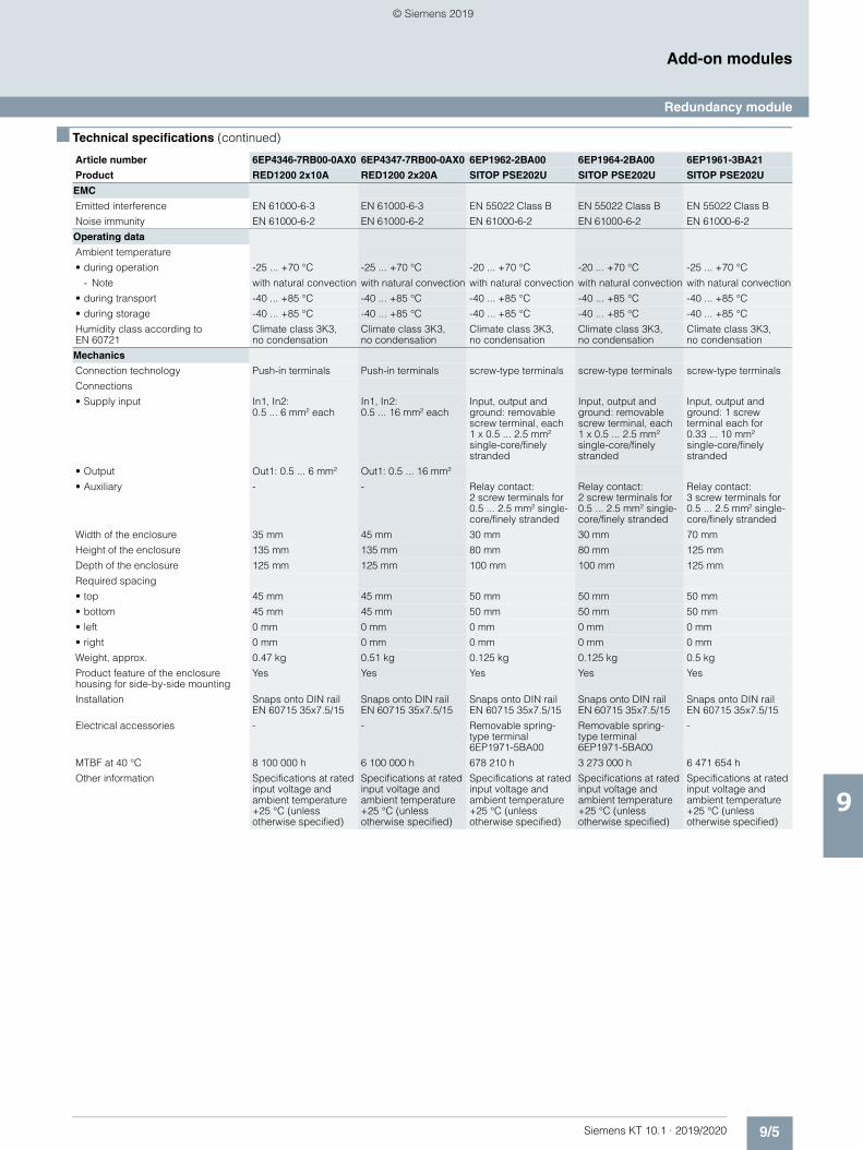
9/5Siemens KT 10.1 · 2019/2020
9
■ Technical specifications (continued)
Add-on modules
Redundancy module
EMC
Emitted interference EN 61000-6-3 EN 61000-6-3 EN 55022 Class B EN 55022 Class B EN 55022 Class B
Noise immunity EN 61000-6-2 EN 61000-6-2 EN 61000-6-2 EN 61000-6-2 EN 61000-6-2
Operating data
Ambient temperature
• during operation -25 ... +70 °C -25 ... +70 °C -20 ... +70 °C -20 ... +70 °C -25 ... +70 °C
- Note with natural convection with natural convection with natural convection with natural convection with natural convection
• during transport -40 ... +85 °C -40 ... +85 °C -40 ... +85 °C -40 ... +85 °C -40 ... +85 °C
• during storage -40 ... +85 °C -40 ... +85 °C -40 ... +85 °C -40 ... +85 °C -40 ... +85 °C
Humidity class according to EN 60721
Climate class 3K3, no condensation
Climate class 3K3, no condensation
Climate class 3K3, no condensation
Climate class 3K3, no condensation
Climate class 3K3, no condensation
Mechanics
Connection technology Push-in terminals Push-in terminals screw-type terminals screw-type terminals screw-type terminals
Connections
• Supply input In1, In2: 0.5 ... 6 mm² each
In1, In2: 0.5 ... 16 mm² each
Input, output and ground: removable screw terminal, each 1 x 0.5 ... 2.5 mm² single-core/finely stranded
Input, output and ground: removable screw terminal, each 1 x 0.5 ... 2.5 mm² single-core/finely stranded
Input, output and ground: 1 screw terminal each for 0.33 ... 10 mm² single-core/finely stranded
• Output Out1: 0.5 ... 6 mm² Out1: 0.5 ... 16 mm²
• Auxiliary - - Relay contact: 2 screw terminals for 0.5 ... 2.5 mm² single-core/finely stranded
Relay contact: 2 screw terminals for 0.5 ... 2.5 mm² single-core/finely stranded
Relay contact: 3 screw terminals for 0.5 ... 2.5 mm² single-core/finely stranded
Width of the enclosure 35 mm 45 mm 30 mm 30 mm 70 mm
Height of the enclosure 135 mm 135 mm 80 mm 80 mm 125 mm
Depth of the enclosure 125 mm 125 mm 100 mm 100 mm 125 mm
Required spacing
• top 45 mm 45 mm 50 mm 50 mm 50 mm
• bottom 45 mm 45 mm 50 mm 50 mm 50 mm
• left 0 mm 0 mm 0 mm 0 mm 0 mm
• right 0 mm 0 mm 0 mm 0 mm 0 mm
Weight, approx. 0.47 kg 0.51 kg 0.125 kg 0.125 kg 0.5 kg
Product feature of the enclosure housing for side-by-side mounting
Yes Yes Yes Yes Yes
Installation Snaps onto DIN rail EN 60715 35x7.5/15
Snaps onto DIN rail EN 60715 35x7.5/15
Snaps onto DIN rail EN 60715 35x7.5/15
Snaps onto DIN rail EN 60715 35x7.5/15
Snaps onto DIN rail EN 60715 35x7.5/15
Electrical accessories - - Removable spring-type terminal 6EP1971-5BA00
Removable spring-type terminal 6EP1971-5BA00
-
MTBF at 40 °C 8 100 000 h 6 100 000 h 678 210 h 3 273 000 h 6 471 654 h
Other information Specifications at rated input voltage and ambient temperature +25 °C (unless otherwise specified)
Specifications at rated input voltage and ambient temperature +25 °C (unless otherwise specified)
Specifications at rated input voltage and ambient temperature +25 °C (unless otherwise specified)
Specifications at rated input voltage and ambient temperature +25 °C (unless otherwise specified)
Specifications at rated input voltage and ambient temperature +25 °C (unless otherwise specified)
Article number 6EP4346-7RB00-0AX0 6EP4347-7RB00-0AX0 6EP1962-2BA00 6EP1964-2BA00 6EP1961-3BA21
Product RED1200 2x10A RED1200 2x20A SITOP PSE202U SITOP PSE202U SITOP PSE202U
© Siemens 2019
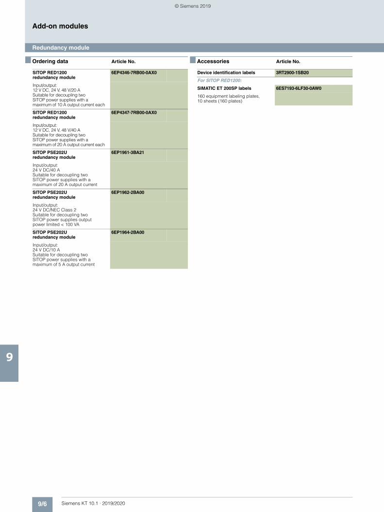
9/6 Siemens KT 10.1 · 2019/2020
9
Add-on modules
Redundancy module
■ Ordering data Article No. ■ Accessories Article No.
SITOP RED1200 redundancy module
6EP4346-7RB00-0AX0
Input/output: 12 V DC, 24 V, 48 V/20 ASuitable for decoupling two SITOP power supplies with a maximum of 10 A output current each
SITOP RED1200 redundancy module
6EP4347-7RB00-0AX0
Input/output: 12 V DC, 24 V, 48 V/40 ASuitable for decoupling two SITOP power supplies with a maximum of 20 A output current each
SITOP PSE202U redundancy module
6EP1961-3BA21
Input/output: 24 V DC/40 ASuitable for decoupling two SITOP power supplies with a maximum of 20 A output current
SITOP PSE202U redundancy module
6EP1962-2BA00
Input/output: 24 V DC/NEC Class 2Suitable for decoupling two SITOP power supplies output power limited < 100 VA
SITOP PSE202U redundancy module
6EP1964-2BA00
Input/output: 24 V DC/10 ASuitable for decoupling two SITOP power supplies with a maximum of 5 A output current
Device identification labels 3RT2900-1SB20
For SITOP RED1200:
SIMATIC ET 200SP labels 6ES7193-6LF30-0AW0
160 equipment labeling plates, 10 sheets (160 plates)
© Siemens 2019
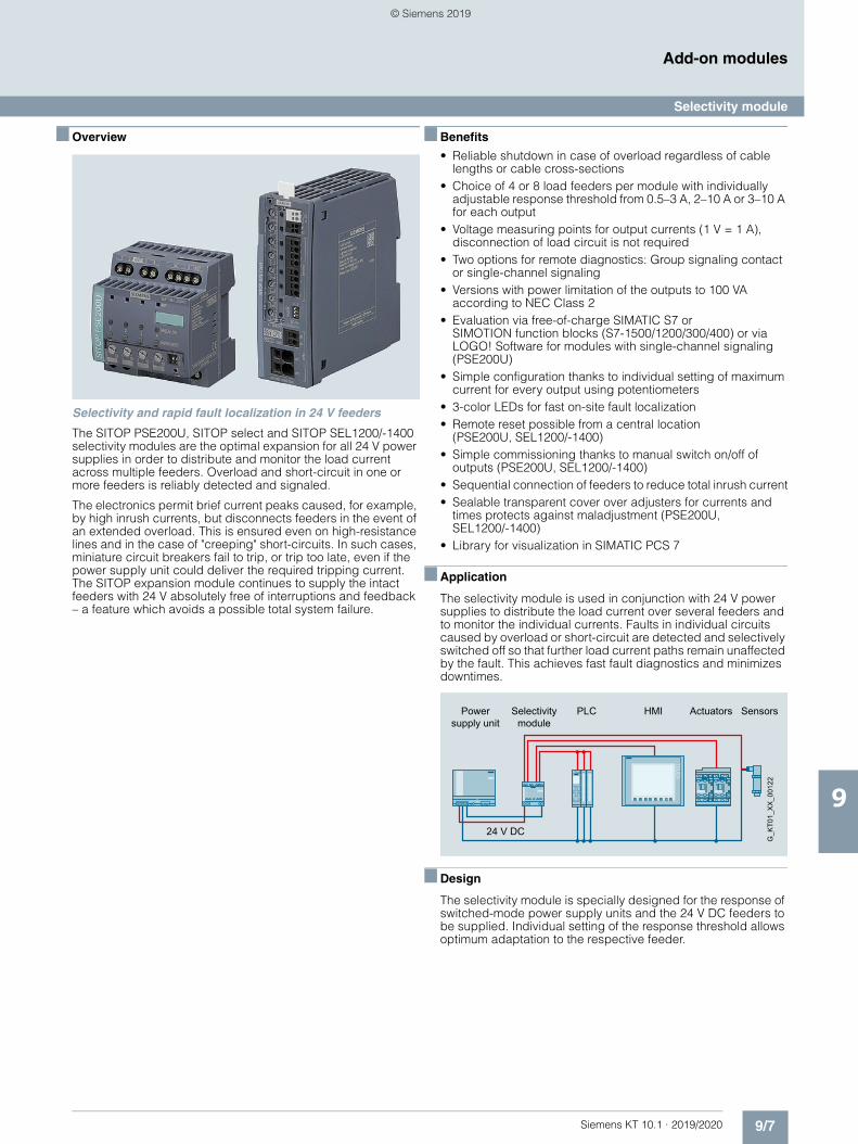
9/7Siemens KT 10.1 · 2019/2020
9
Add-on modules
Selectivity module
■ Overview
Selectivity and rapid fault localization in 24 V feeders
The SITOP PSE200U, SITOP select and SITOP SEL1200/-1400 selectivity modules are the optimal expansion for all 24 V power supplies in order to distribute and monitor the load current across multiple feeders. Overload and short-circuit in one or more feeders is reliably detected and signaled.
The electronics permit brief current peaks caused, for example, by high inrush currents, but disconnects feeders in the event of an extended overload. This is ensured even on high-resistance lines and in the case of "creeping" short-circuits. In such cases, miniature circuit breakers fail to trip, or trip too late, even if the power supply unit could deliver the required tripping current. The SITOP expansion module continues to supply the intact feeders with 24 V absolutely free of interruptions and feedback – a feature which avoids a possible total system failure.
■ Benefits
• Reliable shutdown in case of overload regardless of cable lengths or cable cross-sections
• Choice of 4 or 8 load feeders per module with individually adjustable response threshold from 0.5–3 A, 2–10 A or 3–10 A for each output
• Voltage measuring points for output currents (1 V = 1 A), disconnection of load circuit is not required
• Two options for remote diagnostics: Group signaling contact or single-channel signaling
• Versions with power limitation of the outputs to 100 VA according to NEC Class 2
• Evaluation via free-of-charge SIMATIC S7 or SIMOTION function blocks (S7-1500/1200/300/400) or via LOGO! Software for modules with single-channel signaling (PSE200U)
• Simple configuration thanks to individual setting of maximum current for every output using potentiometers
• 3-color LEDs for fast on-site fault localization• Remote reset possible from a central location
(PSE200U, SEL1200/-1400)• Simple commissioning thanks to manual switch on/off of
outputs (PSE200U, SEL1200/-1400)• Sequential connection of feeders to reduce total inrush current• Sealable transparent cover over adjusters for currents and
times protects against maladjustment (PSE200U, SEL1200/-1400)
• Library for visualization in SIMATIC PCS 7
■ Application
The selectivity module is used in conjunction with 24 V power supplies to distribute the load current over several feeders and to monitor the individual currents. Faults in individual circuits caused by overload or short-circuit are detected and selectively switched off so that further load current paths remain unaffected by the fault. This achieves fast fault diagnostics and minimizes downtimes.
■ Design
The selectivity module is specially designed for the response of switched-mode power supply units and the 24 V DC feeders to be supplied. Individual setting of the response threshold allows optimum adaptation to the respective feeder.
Power supply unit
Selectivity module
Actuators Sensors
24 V DC
G_K
T01_
XX
_001
22
HMIPLC
© Siemens 2019
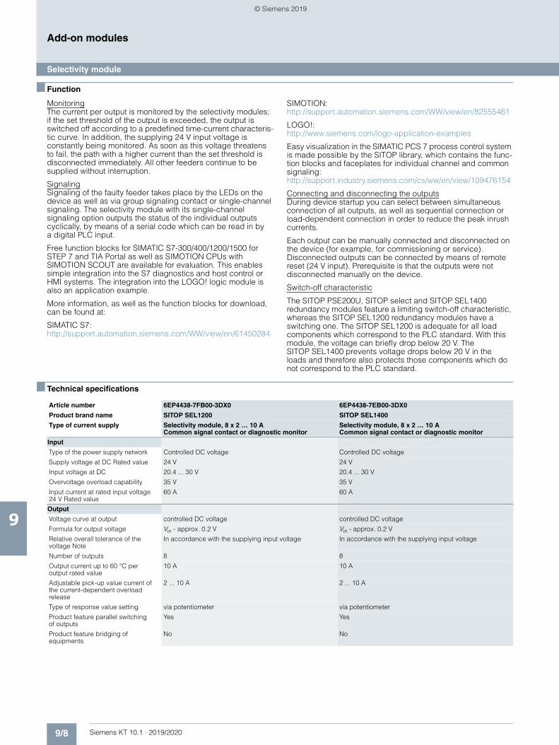
9/8 Siemens KT 10.1 · 2019/2020
9
Add-on modules
Selectivity module
■ Function
MonitoringThe current per output is monitored by the selectivity modules; if the set threshold of the output is exceeded, the output is switched off according to a predefined time-current characteris-tic curve. In addition, the supplying 24 V input voltage is constantly being monitored. As soon as this voltage threatens to fail, the path with a higher current than the set threshold is disconnected immediately. All other feeders continue to be supplied without interruption.
SignalingSignaling of the faulty feeder takes place by the LEDs on the device as well as via group signaling contact or single-channel signaling. The selectivity module with its single-channel signaling option outputs the status of the individual outputs cyclically, by means of a serial code which can be read in by a digital PLC input.
Free function blocks for SIMATIC S7-300/400/1200/1500 for STEP 7 and TIA Portal as well as SIMOTION CPUs with SIMOTION SCOUT are available for evaluation. This enables simple integration into the S7 diagnostics and host control or HMI systems. The integration into the LOGO! logic module is also an application example.
More information, as well as the function blocks for download, can be found at:
SIMATIC S7:http://support.automation.siemens.com/WW/view/en/61450284
SIMOTION:http://support.automation.siemens.com/WW/view/en/82555461
LOGO!: http://www.siemens.com/logo-application-examples
Easy visualization in the SIMATIC PCS 7 process control system is made possible by the SITOP library, which contains the func-tion blocks and faceplates for individual channel and common signaling: http://support.industry.siemens.com/cs/ww/en/view/109476154
Connecting and disconnecting the outputsDuring device startup you can select between simultaneous connection of all outputs, as well as sequential connection or load-dependent connection in order to reduce the peak inrush currents.
Each output can be manually connected and disconnected on the device (for example, for commissioning or service). Disconnected outputs can be connected by means of remote reset (24 V input). Prerequisite is that the outputs were not disconnected manually on the device.
Switch-off characteristic
The SITOP PSE200U, SITOP select and SITOP SEL1400 redundancy modules feature a limiting switch-off characteristic, whereas the SITOP SEL1200 redundancy modules have a switching one. The SITOP SEL1200 is adequate for all load components which correspond to the PLC standard. With this module, the voltage can briefly drop below 20 V. The SITOP SEL1400 prevents voltage drops below 20 V in the loads and therefore also protects those components which do not correspond to the PLC standard.
■ Technical specifications
Article number 6EP4438-7FB00-3DX0 6EP4438-7EB00-3DX0
Product brand name SITOP SEL1200 SITOP SEL1400
Type of current supply Selectivity module, 8 x 2 … 10 ACommon signal contact or diagnostic monitor
Selectivity module, 8 x 2 … 10 ACommon signal contact or diagnostic monitor
Input
Type of the power supply network Controlled DC voltage Controlled DC voltage
Supply voltage at DC Rated value 24 V 24 V
Input voltage at DC 20.4 ... 30 V 20.4 ... 30 V
Overvoltage overload capability 35 V 35 V
Input current at rated input voltage 24 V Rated value
60 A 60 A
Output
Voltage curve at output controlled DC voltage controlled DC voltage
Formula for output voltage Vin - approx. 0.2 V Vin - approx. 0.2 V
Relative overall tolerance of the voltage Note
In accordance with the supplying input voltage In accordance with the supplying input voltage
Number of outputs 8 8
Output current up to 60 °C per output rated value
10 A 10 A
Adjustable pick-up value current of the current-dependent overload release
2 ... 10 A 2 ... 10 A
Type of response value setting via potentiometer via potentiometer
Product feature parallel switching of outputs
Yes Yes
Product feature bridging of equipments
No No
© Siemens 2019

9/9Siemens KT 10.1 · 2019/2020
9
■ Technical specifications (continued)
Add-on modules
Selectivity module
Efficiency
Efficiency in percent 98 % 98 %
Power loss [W] at rated output current for rated value of the output current typical
18 W 18 W
Switch-off characteristic per output
Switching characteristic
• of the excess current Iout = 1.0 ...1.5 x set value, switch-off after approx. 5 s Iout = 1.0 ...1.5 x set value, switch-off after approx. 5 s
• of the current limitation Iout = 1.5 x set value, switch-off after typ. 1 s Iout = 1.5 x set value, switch-off after typ. 100 ms
• of the immediate switch-off Iout > set value and Vin < 20 V, switch-off after approx. 8 ms Iout > set value and Vin < 20 V, switch-off after approx. 0.5 ms
Design of the reset device/resetting mechanism
via sensor per output via sensor per output
Remote reset function Non-electrically isolated 24 V input (signal level "high" at > 15 V)
Non-electrically isolated 24 V input (signal level "high" at > 15 V)
Protection and monitoring
Display version for normal operation Three-color LED per output: green LED for "Output switched through"; yellow LED for "Output switched off manually"; red LED for "Output switched off due to overcurrent"
Three-color LED per output: green LED for "Output switched through"; yellow LED for "Output switched off manually"; red LED for "Output switched off due to overcurrent"
Safety
Galvanic isolation between input and output at switch-off
No No
Operating resource protection class Class III Class III
Certificate of suitability
• CE marking Yes Yes
• as approval for USA UL-Recognized (UL 2367) File E328600; cULus-Listed (UL 508, CSA C22.2 No. 107.1) File E197259
UL-Recognized (UL 2367) File E328600; cULus-Listed (UL 508, CSA C22.2 No. 107.1) File E197259
Standard for safety according to EN 60950-1 and EN 50178 according to EN 60950-1 and EN 50178
Protection class IP IP20 IP20
EMC
Standard
• for emitted interference EN 61000-6-3 EN 61000-6-3
• for interference immunity EN 61000-6-2 EN 61000-6-2
Operating data
Ambient temperature
• during operation -25 ... +60 °C -25 ... +60 °C
- Note with natural convection with natural convection
• during transport -40 ... +85 °C -40 ... +85 °C
• during storage -40 ... +85 °C -40 ... +85 °C
Environmental category acc. to IEC 60721
Climate class 3K3, no condensation Climate class 3K3, no condensation
Mechanics
Width of the enclosure 45 mm 45 mm
Height of the enclosure 135 mm 135 mm
Depth of the enclosure 125 mm 125 mm
Installation width 45 mm 45 mm
Mounting height 225 mm 225 mm
Net weight 0.3 kg 0.4 kg
Mounting type Snaps onto DIN rail EN 60715 35x7.5/15 Snaps onto DIN rail EN 60715 35x7.5/15
MTBF at 40 °C 925 000 h 363 000 h
Other information Specifications at rated input voltage and ambient temperature +25 °C (unless otherwise specified)
Specifications at rated input voltage and ambient temperature +25 °C (unless otherwise specified)
Article number 6EP4438-7FB00-3DX0 6EP4438-7EB00-3DX0
Product brand name SITOP SEL1200 SITOP SEL1400
Type of current supply Selectivity module, 8 x 2 … 10 ACommon signal contact or diagnostic monitor
Selectivity module, 8 x 2 … 10 ACommon signal contact or diagnostic monitor
© Siemens 2019
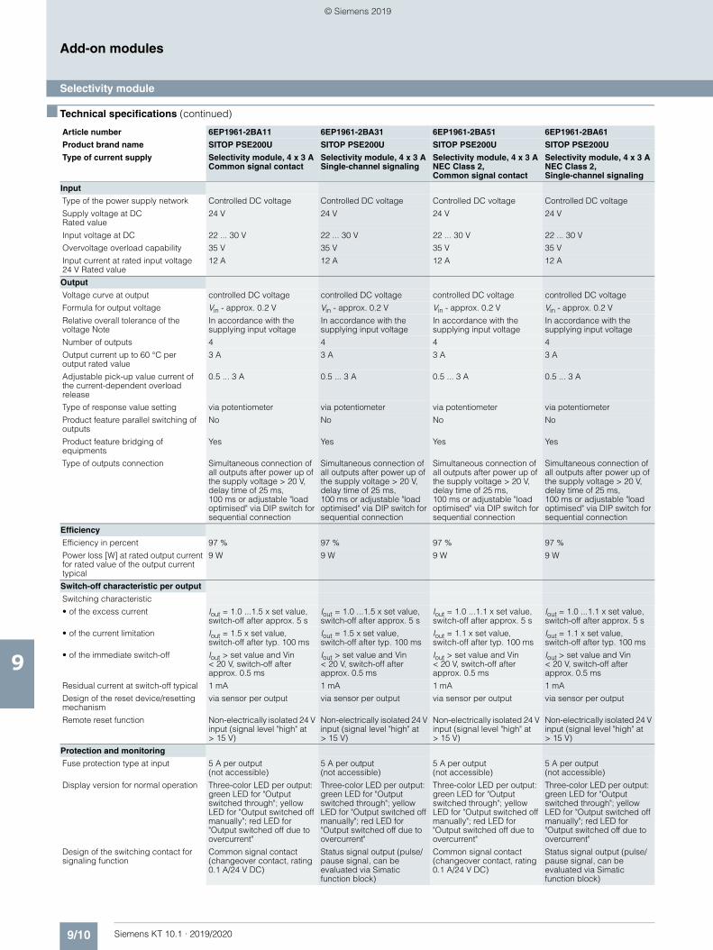
9/10 Siemens KT 10.1 · 2019/2020
9
■ Technical specifications (continued)
Add-on modules
Selectivity module
Article number 6EP1961-2BA11 6EP1961-2BA31 6EP1961-2BA51 6EP1961-2BA61
Product brand name SITOP PSE200U SITOP PSE200U SITOP PSE200U SITOP PSE200U
Type of current supply Selectivity module, 4 x 3 A Common signal contact
Selectivity module, 4 x 3 A Single-channel signaling
Selectivity module, 4 x 3 A NEC Class 2, Common signal contact
Selectivity module, 4 x 3 A NEC Class 2, Single-channel signaling
Input
Type of the power supply network Controlled DC voltage Controlled DC voltage Controlled DC voltage Controlled DC voltage
Supply voltage at DC Rated value
24 V 24 V 24 V 24 V
Input voltage at DC 22 ... 30 V 22 ... 30 V 22 ... 30 V 22 ... 30 V
Overvoltage overload capability 35 V 35 V 35 V 35 V
Input current at rated input voltage 24 V Rated value
12 A 12 A 12 A 12 A
Output
Voltage curve at output controlled DC voltage controlled DC voltage controlled DC voltage controlled DC voltage
Formula for output voltage Vin - approx. 0.2 V Vin - approx. 0.2 V Vin - approx. 0.2 V Vin - approx. 0.2 V
Relative overall tolerance of the voltage Note
In accordance with the supplying input voltage
In accordance with the supplying input voltage
In accordance with the supplying input voltage
In accordance with the supplying input voltage
Number of outputs 4 4 4 4
Output current up to 60 °C per output rated value
3 A 3 A 3 A 3 A
Adjustable pick-up value current of the current-dependent overload release
0.5 ... 3 A 0.5 ... 3 A 0.5 ... 3 A 0.5 ... 3 A
Type of response value setting via potentiometer via potentiometer via potentiometer via potentiometer
Product feature parallel switching of outputs
No No No No
Product feature bridging of equipments
Yes Yes Yes Yes
Type of outputs connection Simultaneous connection of all outputs after power up of the supply voltage > 20 V, delay time of 25 ms, 100 ms or adjustable "load optimised" via DIP switch for sequential connection
Simultaneous connection of all outputs after power up of the supply voltage > 20 V, delay time of 25 ms, 100 ms or adjustable "load optimised" via DIP switch for sequential connection
Simultaneous connection of all outputs after power up of the supply voltage > 20 V, delay time of 25 ms, 100 ms or adjustable "load optimised" via DIP switch for sequential connection
Simultaneous connection of all outputs after power up of the supply voltage > 20 V, delay time of 25 ms, 100 ms or adjustable "load optimised" via DIP switch for sequential connection
Efficiency
Efficiency in percent 97 % 97 % 97 % 97 %
Power loss [W] at rated output current for rated value of the output current typical
9 W 9 W 9 W 9 W
Switch-off characteristic per output
Switching characteristic
• of the excess current Iout = 1.0 ...1.5 x set value, switch-off after approx. 5 s
Iout = 1.0 ...1.5 x set value, switch-off after approx. 5 s
Iout = 1.0 ...1.1 x set value, switch-off after approx. 5 s
Iout = 1.0 ...1.1 x set value, switch-off after approx. 5 s
• of the current limitation Iout = 1.5 x set value, switch-off after typ. 100 ms
Iout = 1.5 x set value, switch-off after typ. 100 ms
Iout = 1.1 x set value, switch-off after typ. 100 ms
Iout = 1.1 x set value, switch-off after typ. 100 ms
• of the immediate switch-off Iout > set value and Vin < 20 V, switch-off after approx. 0.5 ms
Iout > set value and Vin < 20 V, switch-off after approx. 0.5 ms
Iout > set value and Vin < 20 V, switch-off after approx. 0.5 ms
Iout > set value and Vin < 20 V, switch-off after approx. 0.5 ms
Residual current at switch-off typical 1 mA 1 mA 1 mA 1 mA
Design of the reset device/resetting mechanism
via sensor per output via sensor per output via sensor per output via sensor per output
Remote reset function Non-electrically isolated 24 V input (signal level "high" at > 15 V)
Non-electrically isolated 24 V input (signal level "high" at > 15 V)
Non-electrically isolated 24 V input (signal level "high" at > 15 V)
Non-electrically isolated 24 V input (signal level "high" at > 15 V)
Protection and monitoring
Fuse protection type at input 5 A per output (not accessible)
5 A per output (not accessible)
5 A per output (not accessible)
5 A per output (not accessible)
Display version for normal operation Three-color LED per output: green LED for "Output switched through"; yellow LED for "Output switched off manually"; red LED for "Output switched off due to overcurrent"
Three-color LED per output: green LED for "Output switched through"; yellow LED for "Output switched off manually"; red LED for "Output switched off due to overcurrent"
Three-color LED per output: green LED for "Output switched through"; yellow LED for "Output switched off manually"; red LED for "Output switched off due to overcurrent"
Three-color LED per output: green LED for "Output switched through"; yellow LED for "Output switched off manually"; red LED for "Output switched off due to overcurrent"
Design of the switching contact for signaling function
Common signal contact (changeover contact, rating 0.1 A/24 V DC)
Status signal output (pulse/pause signal, can be evaluated via Simatic function block)
Common signal contact (changeover contact, rating 0.1 A/24 V DC)
Status signal output (pulse/pause signal, can be evaluated via Simatic function block)
© Siemens 2019
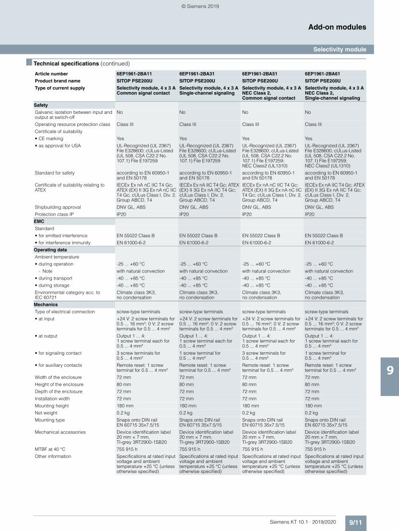
9/11Siemens KT 10.1 · 2019/2020
9
■ Technical specifications (continued)
Add-on modules
Selectivity module
Safety
Galvanic isolation between input and output at switch-off
No No No No
Operating resource protection class Class III Class III Class III Class III
Certificate of suitability
• CE marking Yes Yes Yes Yes
• as approval for USA UL-Recognized (UL 2367) File E328600; cULus-Listed (UL 508, CSA C22.2 No. 107.1) File E197259
UL-Recognized (UL 2367) File E328600; cULus-Listed (UL 508, CSA C22.2 No. 107.1) File E197259
UL-Recognized (UL 2367) File E328600; cULus-Listed (UL 508, CSA C22.2 No. 107.1) File E197259; NEC Class2 (UL1310)
UL-Recognized (UL 2367) File E328600; cULus-Listed (UL 508, CSA C22.2 No. 107.1) File E197259; NEC Class2 (UL1310)
Standard for safety according to EN 60950-1 and EN 50178
according to EN 60950-1 and EN 50178
according to EN 60950-1 and EN 50178
according to EN 60950-1 and EN 50178
Certificate of suitability relating to ATEX
IECEx Ex nA nC IIC T4 Gc; ATEX (EX) II 3G Ex nA nC IIC T4 Gc; cULus Class I, Div. 2, Group ABCD, T4
IECEx Ex nA IIC T4 Gc; ATEX (EX) II 3G Ex nA IIC T4 Gc; cULus Class I, Div. 2, Group ABCD, T4
IECEx Ex nA nC IIC T4 Gc; ATEX (EX) II 3G Ex nA nC IIC T4 Gc; cULus Class I, Div. 2, Group ABCD, T4
IECEx Ex nA IIC T4 Gc; ATEX (EX) II 3G Ex nA IIC T4 Gc; cULus Class I, Div. 2, Group ABCD, T4
Shipbuilding approval DNV GL, ABS DNV GL, ABS DNV GL, ABS DNV GL, ABS
Protection class IP IP20 IP20 IP20 IP20
EMC
Standard
• for emitted interference EN 55022 Class B EN 55022 Class B EN 55022 Class B EN 55022 Class B
• for interference immunity EN 61000-6-2 EN 61000-6-2 EN 61000-6-2 EN 61000-6-2
Operating data
Ambient temperature
• during operation -25 ... +60 °C -25 ... +60 °C -25 ... +60 °C -25 ... +60 °C
- Note with natural convection with natural convection with natural convection with natural convection
• during transport -40 ... +85 °C -40 ... +85 °C -40 ... +85 °C -40 ... +85 °C
• during storage -40 ... +85 °C -40 ... +85 °C -40 ... +85 °C -40 ... +85 °C
Environmental category acc. to IEC 60721
Climate class 3K3, no condensation
Climate class 3K3, no condensation
Climate class 3K3, no condensation
Climate class 3K3, no condensation
Mechanics
Type of electrical connection screw-type terminals screw-type terminals screw-type terminals screw-type terminals
• at input +24 V: 2 screw terminals for 0.5 ... 16 mm²; 0 V: 2 screw terminals for 0.5 ... 4 mm²
+24 V: 2 screw terminals for 0.5 ... 16 mm²; 0 V: 2 screw terminals for 0.5 ... 4 mm²
+24 V: 2 screw terminals for 0.5 ... 16 mm²; 0 V: 2 screw terminals for 0.5 ... 4 mm²
+24 V: 2 screw terminals for 0.5 ... 16 mm²; 0 V: 2 screw terminals for 0.5 ... 4 mm²
• at output Output 1 ... 4: 1 screw terminal each for 0.5 ... 4 mm²
Output 1 ... 4: 1 screw terminal each for 0.5 ... 4 mm²
Output 1 ... 4: 1 screw terminal each for 0.5 ... 4 mm²
Output 1 ... 4: 1 screw terminal each for 0.5 ... 4 mm²
• for signaling contact 3 screw terminals for 0.5 ... 4 mm²
1 screw terminal for 0.5 ... 4 mm²
3 screw terminals for 0.5 ... 4 mm²
1 screw terminal for 0.5 ... 4 mm²
• for auxiliary contacts Remote reset: 1 screw terminal for 0.5 ... 4 mm²
Remote reset: 1 screw terminal for 0.5 ... 4 mm²
Remote reset: 1 screw terminal for 0.5 ... 4 mm²
Remote reset: 1 screw terminal for 0.5 ... 4 mm²
Width of the enclosure 72 mm 72 mm 72 mm 72 mm
Height of the enclosure 80 mm 80 mm 80 mm 80 mm
Depth of the enclosure 72 mm 72 mm 72 mm 72 mm
Installation width 72 mm 72 mm 72 mm 72 mm
Mounting height 180 mm 180 mm 180 mm 180 mm
Net weight 0.2 kg 0.2 kg 0.2 kg 0.2 kg
Mounting type Snaps onto DIN rail EN 60715 35x7.5/15
Snaps onto DIN rail EN 60715 35x7.5/15
Snaps onto DIN rail EN 60715 35x7.5/15
Snaps onto DIN rail EN 60715 35x7.5/15
Mechanical accessories Device identification label 20 mm × 7 mm, TI-grey 3RT2900-1SB20
Device identification label 20 mm × 7 mm, TI-grey 3RT2900-1SB20
Device identification label 20 mm × 7 mm, TI-grey 3RT2900-1SB20
Device identification label 20 mm × 7 mm, TI-grey 3RT2900-1SB20
MTBF at 40 °C 755 915 h 755 915 h 755 915 h 755 915 h
Other information Specifications at rated input voltage and ambient temperature +25 °C (unless otherwise specified)
Specifications at rated input voltage and ambient temperature +25 °C (unless otherwise specified)
Specifications at rated input voltage and ambient temperature +25 °C (unless otherwise specified)
Specifications at rated input voltage and ambient temperature +25 °C (unless otherwise specified)
Article number 6EP1961-2BA11 6EP1961-2BA31 6EP1961-2BA51 6EP1961-2BA61
Product brand name SITOP PSE200U SITOP PSE200U SITOP PSE200U SITOP PSE200U
Type of current supply Selectivity module, 4 x 3 A Common signal contact
Selectivity module, 4 x 3 A Single-channel signaling
Selectivity module, 4 x 3 A NEC Class 2, Common signal contact
Selectivity module, 4 x 3 A NEC Class 2, Single-channel signaling
© Siemens 2019
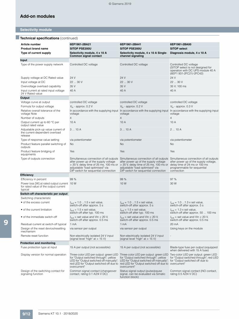
9/12 Siemens KT 10.1 · 2019/2020
9
■ Technical specifications (continued)
Add-on modules
Selectivity module
Article number 6EP1961-2BA21 6EP1961-2BA41 6EP1961-2BA00
Product brand name SITOP PSE200U SITOP PSE200U SITOP select
Type of current supply Selectivity module, 4 x 10 A Common signal contact
Selectivity module, 4 x 10 A Single-channel signaling
Diagnosis module, 4 x 10 A
Input
Type of the power supply network Controlled DC voltage Controlled DC voltage Controlled DC voltage (SITOP select is not designed for operation with DC UPS module 40 A (6EP1 931-2FC21/-2FC42)
Supply voltage at DC Rated value 24 V 24 V 24 V
Input voltage at DC 22 ... 30 V 22 ... 30 V 22 ... 30 V
Overvoltage overload capability 35 V 35 V 35 V; 100 ms
Input current at rated input voltage 24 V Rated value
40 A 40 A 40 A
Output
Voltage curve at output controlled DC voltage controlled DC voltage controlled DC voltage
Formula for output voltage Vin - approx. 0.2 V Vin - approx. 0.2 V Vin - approx. 0.3 V
Relative overall tolerance of the voltage Note
In accordance with the supplying input voltage
In accordance with the supplying input voltage
In accordance with the supplying input voltage
Number of outputs 4 4 4
Output current up to 60 °C per output rated value
10 A 10 A 10 A
Adjustable pick-up value current of the current-dependent overload release
3 ... 10 A 3 ... 10 A 2 ... 10 A
Type of response value setting via potentiometer via potentiometer via potentiometer
Product feature parallel switching of outputs
No No No
Product feature bridging of equipments
Yes Yes Yes
Type of outputs connection Simultaneous connection of all outputs after power up of the supply voltage > 20 V, delay time of 25 ms, 100 ms or adjustable "load optimised" via DIP switch for sequential connection
Simultaneous connection of all outputs after power up of the supply voltage > 20 V, delay time of 25 ms, 100 ms or adjustable "load optimised" via DIP switch for sequential connection
Simultaneous connection of all outputs after power up of the supply voltage, delay time of 24 ms or 100 ms programmable for sequential connection
Efficiency
Efficiency in percent 99 % 99 % 97 %
Power loss [W] at rated output current for rated value of the output current typical
10 W 10 W 30 W
Switch-off characteristic per output
Switching characteristic
• of the excess current Iout = 1.0 ...1.5 x set value, switch-off after approx. 5 s
Iout = 1.0 ...1.5 x set value, switch-off after approx. 5 s
Iout = 1.0 ...1.3 x set value, switch-off after approx. 5 s
• of the current limitation Iout = 1.5 x set value, switch-off after typ. 100 ms
Iout = 1.5 x set value, switch-off after typ. 100 ms
Iout = 1.3 x set value, switch-off after approx. 50 ... 100 ms
• of the immediate switch-off Iout > set value and Vin < 20 V, switch-off after approx. 0.5 ms
Iout > set value and Vin < 20 V, switch-off after approx. 0.5 ms
Iout > set value and Vin < 20 V, switch-off after approx. 0.5 ms
Residual current at switch-off typical 1 mA 1 mA 20 mA
Design of the reset device/resetting mechanism
via sensor per output via sensor per output Using keys on the module
Remote reset function Non-electrically isolated 24 V input (signal level "high" at > 15 V)
Non-electrically isolated 24 V input (signal level "high" at > 15 V)
-
Protection and monitoring
Fuse protection type at input 15 A per output (not accessible) 15 A per output (not accessible) Blade-type fuse per output (equipped when delivered with 15 A fuse)
Display version for normal operation Three-color LED per output: green LED for "Output switched through"; yellow LED for "Output switched off manually"; red LED for "Output switched off due to overcurrent"
Three-color LED per output: green LED for "Output switched through"; yellow LED for "Output switched off manually"; red LED for "Output switched off due to overcurrent"
Two-color LED per output: green LED for "Output switched through"; red LED for "Output switched off due to overcurrent"
Design of the switching contact for signaling function
Common signal contact (changeover contact, rating 0.1 A/24 V DC)
Status signal output (pulse/pause signal, can be evaluated via Simatic function block)
Common signal contact (NO contact, rating 0.5 A/24 V DC)
© Siemens 2019
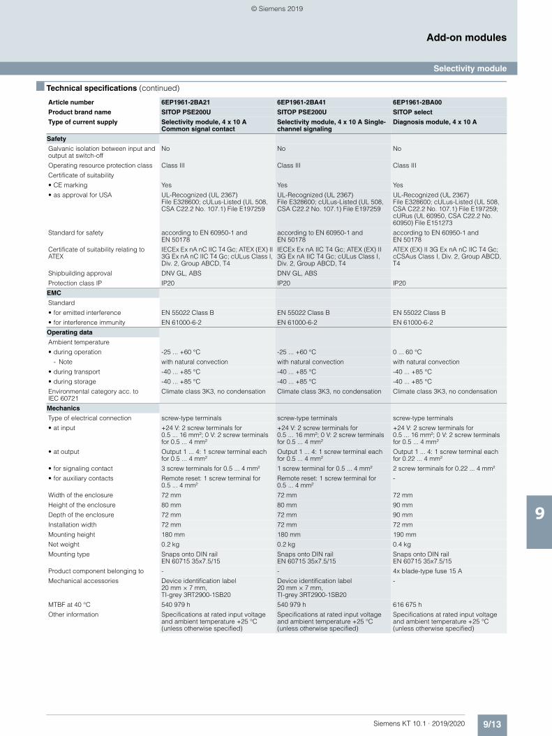
9/13Siemens KT 10.1 · 2019/2020
9
■ Technical specifications (continued)
Add-on modules
Selectivity module
Safety
Galvanic isolation between input and output at switch-off
No No No
Operating resource protection class Class III Class III Class III
Certificate of suitability
• CE marking Yes Yes Yes
• as approval for USA UL-Recognized (UL 2367) File E328600; cULus-Listed (UL 508, CSA C22.2 No. 107.1) File E197259
UL-Recognized (UL 2367) File E328600; cULus-Listed (UL 508, CSA C22.2 No. 107.1) File E197259
UL-Recognized (UL 2367) File E328600; cULus-Listed (UL 508, CSA C22.2 No. 107.1) File E197259; cURus (UL 60950, CSA C22.2 No. 60950) File E151273
Standard for safety according to EN 60950-1 and EN 50178
according to EN 60950-1 and EN 50178
according to EN 60950-1 and EN 50178
Certificate of suitability relating to ATEX
IECEx Ex nA nC IIC T4 Gc; ATEX (EX) II 3G Ex nA nC IIC T4 Gc; cULus Class I, Div. 2, Group ABCD, T4
IECEx Ex nA IIC T4 Gc; ATEX (EX) II 3G Ex nA IIC T4 Gc; cULus Class I, Div. 2, Group ABCD, T4
ATEX (EX) II 3G Ex nA nC IIC T4 Gc; cCSAus Class I, Div. 2, Group ABCD, T4
Shipbuilding approval DNV GL, ABS DNV GL, ABS
Protection class IP IP20 IP20 IP20
EMC
Standard
• for emitted interference EN 55022 Class B EN 55022 Class B EN 55022 Class B
• for interference immunity EN 61000-6-2 EN 61000-6-2 EN 61000-6-2
Operating data
Ambient temperature
• during operation -25 ... +60 °C -25 ... +60 °C 0 ... 60 °C
- Note with natural convection with natural convection with natural convection
• during transport -40 ... +85 °C -40 ... +85 °C -40 ... +85 °C
• during storage -40 ... +85 °C -40 ... +85 °C -40 ... +85 °C
Environmental category acc. to IEC 60721
Climate class 3K3, no condensation Climate class 3K3, no condensation Climate class 3K3, no condensation
Mechanics
Type of electrical connection screw-type terminals screw-type terminals screw-type terminals
• at input +24 V: 2 screw terminals for 0.5 ... 16 mm²; 0 V: 2 screw terminals for 0.5 ... 4 mm²
+24 V: 2 screw terminals for 0.5 ... 16 mm²; 0 V: 2 screw terminals for 0.5 ... 4 mm²
+24 V: 2 screw terminals for 0.5 ... 16 mm²; 0 V: 2 screw terminals for 0.5 ... 4 mm²
• at output Output 1 ... 4: 1 screw terminal each for 0.5 ... 4 mm²
Output 1 ... 4: 1 screw terminal each for 0.5 ... 4 mm²
Output 1 ... 4: 1 screw terminal each for 0.22 ... 4 mm²
• for signaling contact 3 screw terminals for 0.5 ... 4 mm² 1 screw terminal for 0.5 ... 4 mm² 2 screw terminals for 0.22 ... 4 mm²
• for auxiliary contacts Remote reset: 1 screw terminal for 0.5 ... 4 mm²
Remote reset: 1 screw terminal for 0.5 ... 4 mm²
-
Width of the enclosure 72 mm 72 mm 72 mm
Height of the enclosure 80 mm 80 mm 90 mm
Depth of the enclosure 72 mm 72 mm 90 mm
Installation width 72 mm 72 mm 72 mm
Mounting height 180 mm 180 mm 190 mm
Net weight 0.2 kg 0.2 kg 0.4 kg
Mounting type Snaps onto DIN rail EN 60715 35x7.5/15
Snaps onto DIN rail EN 60715 35x7.5/15
Snaps onto DIN rail EN 60715 35x7.5/15
Product component belonging to - - 4x blade-type fuse 15 A
Mechanical accessories Device identification label 20 mm × 7 mm, TI-grey 3RT2900-1SB20
Device identification label 20 mm × 7 mm, TI-grey 3RT2900-1SB20
-
MTBF at 40 °C 540 979 h 540 979 h 616 675 h
Other information Specifications at rated input voltage and ambient temperature +25 °C (unless otherwise specified)
Specifications at rated input voltage and ambient temperature +25 °C (unless otherwise specified)
Specifications at rated input voltage and ambient temperature +25 °C (unless otherwise specified)
Article number 6EP1961-2BA21 6EP1961-2BA41 6EP1961-2BA00
Product brand name SITOP PSE200U SITOP PSE200U SITOP select
Type of current supply Selectivity module, 4 x 10 A Common signal contact
Selectivity module, 4 x 10 A Single-channel signaling
Diagnosis module, 4 x 10 A
© Siemens 2019
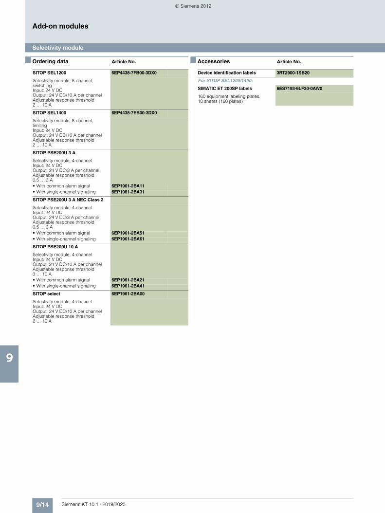
9/14 Siemens KT 10.1 · 2019/2020
9
Add-on modules
Selectivity module
■ Ordering data Article No. ■ Accessories Article No.
SITOP SEL1200 6EP4438-7FB00-3DX0
Selectivity module, 8-channel, switchingInput: 24 V DCOutput: 24 V DC/10 A per channelAdjustable response threshold 2 … 10 A
SITOP SEL1400 6EP4438-7EB00-3DX0
Selectivity module, 8-channel, limitingInput: 24 V DCOutput: 24 V DC/10 A per channelAdjustable response threshold 2 … 10 A
SITOP PSE200U 3 A
Selectivity module, 4-channelInput: 24 V DCOutput: 24 V DC/3 A per channel Adjustable response threshold 0.5 … 3 A• With common alarm signal 6EP1961-2BA11• With single-channel signaling 6EP1961-2BA31
SITOP PSE200U 3 A NEC Class 2
Selectivity module, 4-channelInput: 24 V DCOutput: 24 V DC/3 A per channelAdjustable response threshold 0.5 … 3 A• With common alarm signal 6EP1961-2BA51• With single-channel signaling 6EP1961-2BA61
SITOP PSE200U 10 A
Selectivity module, 4-channelInput: 24 V DCOutput: 24 V DC/10 A per channel Adjustable response threshold 3 … 10 A• With common alarm signal 6EP1961-2BA21• With single-channel signaling 6EP1961-2BA41
SITOP select 6EP1961-2BA00
Selectivity module, 4-channelInput: 24 V DCOutput: 24 V DC/10 A per channel Adjustable response threshold 2 … 10 A
Device identification labels 3RT2900-1SB20
For SITOP SEL1200/1400:
SIMATIC ET 200SP labels 6ES7193-6LF30-0AW0
160 equipment labeling plates, 10 sheets (160 plates)
© Siemens 2019
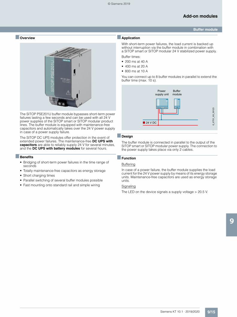
9/15Siemens KT 10.1 · 2019/2020
9
Add-on modules
Buffer module
■ Overview
The SITOP PSE201U buffer module bypasses short-term power failures lasting a few seconds and can be used with all 24 V power supplies of the SITOP smart or SITOP modular product lines. The buffer module is equipped with maintenance-free capacitors and automatically takes over the 24 V power supply in case of a power supply failure.
The SITOP DC UPS modules offer protection in the event of extended power failures. The maintenance-free DC UPS with capacitors are able to reliably supply 24 V for several minutes, and the DC UPS with battery modules for several hours.
■ Benefits
• Bridging of short-term power failures in the time range of seconds
• Totally maintenance-free capacitors as energy storage• Short charging times• Parallel switching of several buffer modules possible• Fast mounting onto standard rail and simple wiring
■ Application
With short-term power failures, the load current is backed up without interruption via the buffer module in combination with a SITOP smart or SITOP modular 24 V stabilized power supply.
Buffer times:• 200 ms at 40 A• 400 ms at 20 A• 800 ms at 10 A
You can connect up to 8 buffer modules in parallel to extend the buffer time (max. 10 s).
■ Design
The buffer module is connected in parallel to the output of the SITOP smart or SITOP modular power supply. The connection to the power supply takes place via only 2 cables.
■ Function
Buffering
In case of a power failure, the buffer module supplies the load current for the 24 V power supply by means of its energy storage units. Maintenance-free capacitors are used as energy storage units.
Signaling
The LED on the device signals a supply voltage > 20.5 V.
Power supply unit
Buffer module
24 V DC
G_K
T01_
XX
_001
23
© Siemens 2019
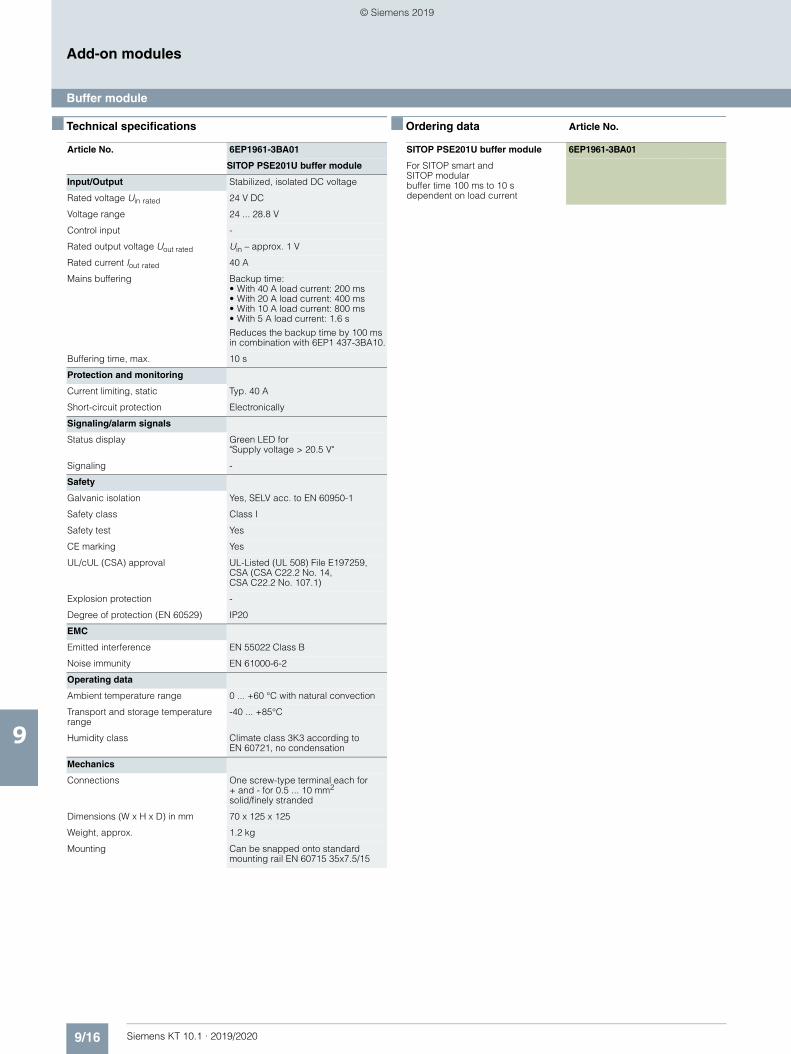
9/16 Siemens KT 10.1 · 2019/2020
9
Add-on modules
Buffer module
■ Technical specifications ■ Ordering data Article No.
Article No. 6EP1961-3BA01
SITOP PSE201U buffer module
Input/Output Stabilized, isolated DC voltage
Rated voltage Uin rated 24 V DC
Voltage range 24 ... 28.8 V
Control input -
Rated output voltage Uout rated Uin – approx. 1 V
Rated current Iout rated 40 A
Mains buffering Backup time:• With 40 A load current: 200 ms• With 20 A load current: 400 ms• With 10 A load current: 800 ms• With 5 A load current: 1.6 s
Reduces the backup time by 100 ms in combination with 6EP1 437-3BA10.
Buffering time, max. 10 s
Protection and monitoring
Current limiting, static Typ. 40 A
Short-circuit protection Electronically
Signaling/alarm signals
Status display Green LED for "Supply voltage > 20.5 V"
Signaling -
Safety
Galvanic isolation Yes, SELV acc. to EN 60950-1
Safety class Class I
Safety test Yes
CE marking Yes
UL/cUL (CSA) approval UL-Listed (UL 508) File E197259, CSA (CSA C22.2 No. 14, CSA C22.2 No. 107.1)
Explosion protection -
Degree of protection (EN 60529) IP20
EMC
Emitted interference EN 55022 Class B
Noise immunity EN 61000-6-2
Operating data
Ambient temperature range 0 ... +60 °C with natural convection
Transport and storage temperature range
-40 ... +85°C
Humidity class Climate class 3K3 according to EN 60721, no condensation
Mechanics
Connections One screw-type terminal each for + and - for 0.5 ... 10 mm2
solid/finely stranded
Dimensions (W x H x D) in mm 70 x 125 x 125
Weight, approx. 1.2 kg
Mounting Can be snapped onto standard mounting rail EN 60715 35x7.5/15
SITOP PSE201U buffer module 6EP1961-3BA01
For SITOP smart and SITOP modularbuffer time 100 ms to 10 s dependent on load current
© Siemens 2019
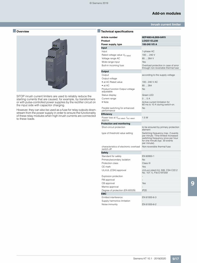
9/17Siemens KT 10.1 · 2019/2020
9
Add-on modules
Inrush current limiter
■ Overview
SITOP inrush current limiters are used to reliably reduce the starting currents that are caused, for example, by transformers or with pulse-controlled power supplies by the rectifier circuit on the input side with capacitor charging.
However, they can also be used as a fuse for relay outputs down-stream from the power supply in order to ensure the functionality of these relay modules when high inrush currents are connected to these loads.
■ Technical specifications
Article number 6EP4683-6LB00-0AY0
Product LOGO! ICL230
Power supply, type 100-240 V/5 A
Input
Input 1-phase AC
Rated voltage value Vin rated 100 ... 240 V
Voltage range AC 85 ... 264 V
Wide-range input Yes
Built-in incoming fuse Overload protection in case of error through non-reversible thermal fuse
Output
Output according to the supply voltage
Output voltage
• at AC Rated value 100 - 240 V AC
• at AC 85 ... 264
Product function Output voltage adjustable
No
Status display Green LED
Current range 0 ... 5 A
• Note Active current limitation for 60 ms to 10 A during switch-on.
Parallel switching for enhanced performance
No
Efficiency
Power loss at Vout rated, Iout rated, approx.
1.5 W
Protection and monitoring
Short-circuit protection to be ensured by primary protection element
type of threshold value setting Switching frequency max. 2 events per minute. Time-limited increased switching frequency once per hour for one minute (typ. 30 events per minute).
characteristics of electronic overload switch-off
Non-reversible thermal fuse
Safety
Standard for safety EN 60950-1
Primary/secondary isolation No
Protection class Class III
CE mark Yes
UL/cUL (CSA) approval cULus-Listed (UL 508, CSA C22.2 No. 107.1), File E197259
Explosion protection -
FM approval -
CB approval Yes
Marine approval -
Degree of protection (EN 60529) IP20
EMC
Emitted interference EN 61000-6-3
Supply harmonics limitation -
Noise immunity EN 61000-6-2
© Siemens 2019
9/18 Siemens KT 10.1 · 2019/2020
9
■ Technical specifications (continued)
Add-on modules
Inrush current limiter
Operating data
Ambient temperature
• during operation -40 ... +70 °C
- Note with natural convection
• during transport -40 ... +85 °C
• during storage -40 ... +85 °C
Humidity class according to EN 60721
Climate class 3K3, no condensation
Mechanics
Connection technology screw-type terminals
Connections
• Supply input L, N: 1 screw terminal each for 0.5 ... 2.5 mm2 single-core/finely stranded
• Output +, -: 1 screw terminal each for 0.5 ... 2.5 mm²
Width of the enclosure 18 mm
Height of the enclosure 90 mm
Depth of the enclosure 53 mm
Required spacing
• top 20 mm
• bottom 20 mm
• left 0 mm
• right 0 mm
Weight, approx. 0.14 kg
Product feature of the enclosure housing for side-by-side mounting
Yes
Installation Snaps onto DIN rail EN 60715 35x7.5/15
Other information Specifications at rated input voltage and ambient temperature +25 °C (unless otherwise specified)
Article number 6EP4683-6LB00-0AY0
Product LOGO! ICL230
Power supply, type 100-240 V/5 A
■ Ordering data Article No.
SITOP making current limiter 6EP1967-2AA00
Ballast for SITOP power supplies Input: 100 … 480 V AC, 10 A maxOutput: 100 … 480 V AC, 10 A max
LOGO! ICL230 inrush current limiter
6EP4683-6LB00-0AY0
Ballast for SITOP power suppliesInput: 100 … 240 V AC, 5 A maxOutput: 100 … 240 V AC, 5 A max
© Siemens 2019
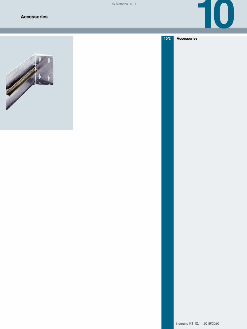
Siemens KT 10.1 · 2019/2020
1010/2 Accessories
Accessories
© Siemens 2019
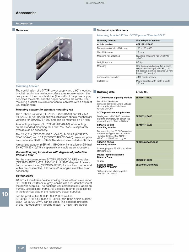
10/2 Siemens KT 10.1 · 2019/2020
10
Accessories
Accessories
■ Overview
Mounting bracket
The combination of a SITOP power supply and a 90° mounting bracket results in a minimum surface area requirement on the rear panel of the control cabinet (the width of the power supply becomes the depth, and the depth becomes the width). The mounting bracket is suitable for control cabinets with a depth of 320 mm or more.
Mounting adapter for standard mounting rail
The 1-phase 24 V/2 A (6ES7305-1BA80-0AA0) and 24 V/5 A (6ES7307-1EA80-0AA0) power supplies are special mechanical versions for SIMATIC S7-300 and can be mounted on S7 rails.
A mounting adapter (6ES7390-6BA00-0AA0) for mounting on the standard mounting rail EN 60715 35x15 is separately available as an accessory.
The 24 V/ 2 A (6ES7307-1BA01-0AA0), 24 V/ 5 A (6ES7307-1EA01-0AA0) and 10 A (6ES7307-1KA02-0AA0) power supplies are variants for SIMATIC S7-300 and can be mounted on S7 rails.
A mounting adapter (6EP1971-1BA00) for installation on DIN rail EN 60715 35×15/7.5 is separately available as an accessory.
Connection plug for devices with degrees of protection IP65 and IP67
For the maintenance-free SITOP UPS500P DC UPS modules (6EP1933-2NC01, 6EP1933-2NC11) in IP65 degree of protec-tion, a connector set (6EP1975-2ES00) for input and output and with a pre-assembled USB cable (2 m long) is available as an accessory.
Device labels
20 mm x 7 mm blank device labeling plates with article number 3RT2900-1SB20 (titanium gray) can be used for identification of the power supplies. The package unit comprises 340 labels on frames, 20 labels per frame. For usability, refer to "Accessories" in the technical data of the respective power supplies.
For the product line SITOP PSU6200 as well as SITOP SEL1200/-1400 and SITOP RED1200 the article number 6ES7193-6LF30-0AW0 can be used. The package unit com-prises 160 equipment labeling plates, 10 mats (160 labels).
■ Technical specifications
Mounting bracket 90° for SITOP power Standard 24 V
■ Ordering data Article No.
Mounting bracket For a depth of 320 mm
Article number 6EP1971-2BA00
Dimensions (W x H x D) in mm 100 x 150 x 320
Sheet thickness 1.5 mm
Mounting rail, attached Standard mounting rail EN 60715 35x15
Weight, approx. 0.9 kg
Mounting Can be screwed onto a flat surface (keyhole mounting for hooking onto M6 screws, drill hole distance 90 mm height, 50 mm side)
Accessories, included 4 M6 combi screws
Suitable for Power supplies with width of up to 280 mm
SITOP modular signaling module 6EP1961-3BA10
For 6EP1XXX-3BA00 signaling contacts: Output voltage ok, operational availability ok, remote ON/OFF
SITOP power mounting bracket
90 degrees, with 35x15 mm stan-dard mounting rail, for power sup-plies with width of up to 280 mm
6EP1971-2BA00
SIMATIC S7-300 mounting adapter
6EP1971-1BA00
For snapping the PS 307 onto stan-dard mounting rail 35x15/7.5 mm suitable for 6ES7307-1BA01*, -1EA01*, -1KA02* and higher
SIMATIC S7-300 mounting adapter
6ES7390-6BA00-0AA0
for snapping the PS307 onto 35 mm standard rails
Device identification label 20 mm x 7 mm
Ti gray 3RT2900-1SB20
Labeling plates SIMATIC ET 200SP
6ES7193-6LF30-0AW0
160 equipment labeling plates, 10 mats (160 labels)
© Siemens 2019
Siemens KT 10.1 · 2019/2020
1111/2 Power supplies general11/5 Supply systems data, line-side connection11/8 Possible mains disturbances and
their causes11/9 Installation guidelines, mounting areas and
fixing options11/10 Parallel connection11/11 Series connection to increase the voltage11/12 Battery charging with SITOP11/13 Fusing of the output circuit 24 V DC,
selectivity11/18 Standards and approvals11/19 Certificates
Technical information and configuration
© Siemens 2019
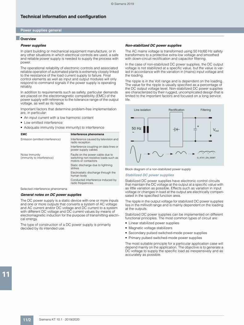
11/2 Siemens KT 10.1 · 2019/2020
11
Technical information and configuration
Power supplies general
■ Overview
Power supplies
In plant building or mechanical equipment manufacture, or in any other situations in which electrical controls are used, a safe and reliable power supply is needed to supply the process with power.
The operational reliability of electronic controls and associated reliable operation of automated plants is extremely closely linked to the resistance of the load current supply to failure. Final control elements as well as input and output modules will only respond to command signals if the power supply is operating reliably.
In addition to requirements such as safety, particular demands are placed on the electromagnetic compatibility (EMC) of the power supply with reference to the tolerance range of the output voltage, as well as its ripple.
Important factors that determine problem-free implementation are, in particular:• An input current with a low harmonic content• Low emitted interference• Adequate immunity (noise immunity) to interference
Selected interference phenomena
General notes on DC power supplies
The DC power supply is a static device with one or more inputs and one or more outputs that converts a system of AC voltage and AC current and/or DC voltage and DC current to a system with different DC voltage and DC current values by means of electromagnetic induction for the purpose of transmitting electri-cal energy.
The type of construction of a DC power supply is primarily decided by its intended use.
Non-stabilized DC power supplies
The AC mains voltage is transformed using 50 Hz/60 Hz safety transformers to a protective extra-low voltage and smoothed with down-circuit rectification and capacitor filtering.
In the case of non-stabilized DC power supplies, the DC output voltage is not stabilized at a specific value, but the value is var-ied in accordance with the variation in (mains) input voltage and the loading.
The ripple is in the Volt range and is dependent on the loading. The value for the ripple is usually specified as a percentage of the DC output voltage level. Non-stabilized DC power supplies are characterized by their rugged, uncomplicated design that is limited to the important factors and focused on a long service life.
Block diagram of a non-stabilized power supply
Stabilized DC power supplies
Stabilized DC power supplies have electronic control circuits that maintain the DC voltage at the output at a specific value with as little variation as possible. Effects such as variation in input voltage or changes in load at the output are electrically compen-sated in the specified function area.
The ripple in the output voltage for stabilized DC power supplies lies in the millivolt range and is mainly dependent on the loading at the outputs.
Stabilized DC power supplies can be implemented on different functional principles. The most common types of circuit are:• Linear stabilized power supplies• Magnetic voltage stabilizers• Secondary pulsed switched-mode power supplies• Primary pulsed switched-mode power supplies
The most suitable principle for a particular application case will depend mainly on the application. The objective is to generate a DC voltage to supply the specific load as inexpensively and as accurately as possible.
EMC Interference phenomena
Emission (emitted interference) Interference caused by television and radio reception
Interference coupling on data lines or power supply cables
Noise immunity (immunity to interference)
Faults on the power cable due to switching non-resistive loads such as motors or contactors
Static discharge due to lightning strikes
Electrostatic discharge through the human body
Conducted interference induced by radio frequencies
������
�
������������ �� ���� ���� ��������
��
���������������
© Siemens 2019
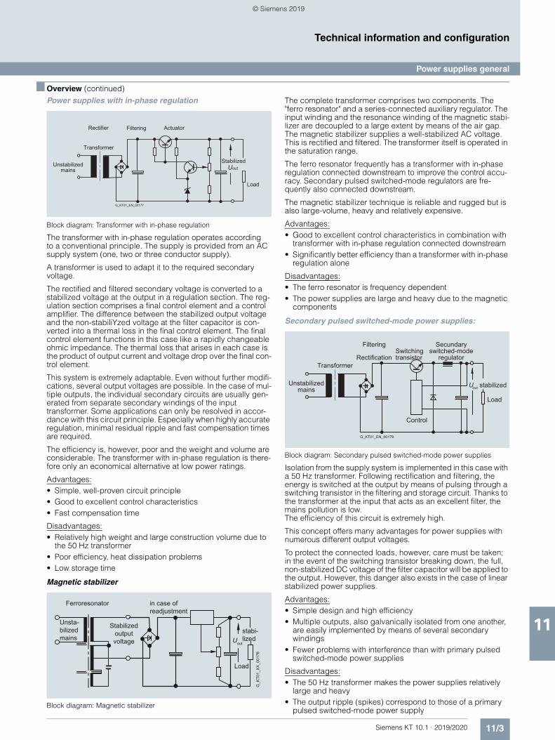
11/3Siemens KT 10.1 · 2019/2020
11
■ Overview (continued)
Technical information and configuration
Power supplies general
Power supplies with in-phase regulation
Block diagram: Transformer with in-phase regulation
The transformer with in-phase regulation operates according to a conventional principle. The supply is provided from an AC supply system (one, two or three conductor supply).
A transformer is used to adapt it to the required secondary voltage.
The rectified and filtered secondary voltage is converted to a stabilized voltage at the output in a regulation section. The reg-ulation section comprises a final control element and a control amplifier. The difference between the stabilized output voltage and the non-stabiliYzed voltage at the filter capacitor is con-verted into a thermal loss in the final control element. The final control element functions in this case like a rapidly changeable ohmic impedance. The thermal loss that arises in each case is the product of output current and voltage drop over the final con-trol element.
This system is extremely adaptable. Even without further modifi-cations, several output voltages are possible. In the case of mul-tiple outputs, the individual secondary circuits are usually gen-erated from separate secondary windings of the input transformer. Some applications can only be resolved in accor-dance with this circuit principle. Especially when highly accurate regulation, minimal residual ripple and fast compensation times are required.
The efficiency is, however, poor and the weight and volume are considerable. The transformer with in-phase regulation is there-fore only an economical alternative at low power ratings.
Advantages:• Simple, well-proven circuit principle• Good to excellent control characteristics• Fast compensation time
Disadvantages:• Relatively high weight and large construction volume due to
the 50 Hz transformer• Poor efficiency, heat dissipation problems• Low storage time
Magnetic stabilizer
Block diagram: Magnetic stabilizer
The complete transformer comprises two components. The "ferro resonator" and a series-connected auxiliary regulator. The input winding and the resonance winding of the magnetic stabi-lizer are decoupled to a large extent by means of the air gap. The magnetic stabilizer supplies a well-stabilized AC voltage. This is rectified and filtered. The transformer itself is operated in the saturation range.
The ferro resonator frequently has a transformer with in-phase regulation connected downstream to improve the control accu-racy. Secondary pulsed switched-mode regulators are fre-quently also connected downstream.
The magnetic stabilizer technique is reliable and rugged but is also large-volume, heavy and relatively expensive.
Advantages:• Good to excellent control characteristics in combination with
transformer with in-phase regulation connected downstream• Significantly better efficiency than a transformer with in-phase
regulation alone
Disadvantages:• The ferro resonator is frequency dependent• The power supplies are large and heavy due to the magnetic
components
Secondary pulsed switched-mode power supplies:
Block diagram: Secondary pulsed switched-mode power supplies
Isolation from the supply system is implemented in this case with a 50 Hz transformer. Following rectification and filtering, the energy is switched at the output by means of pulsing through a switching transistor in the filtering and storage circuit. Thanks to the transformer at the input that acts as an excellent filter, the mains pollution is low. The efficiency of this circuit is extremely high.
This concept offers many advantages for power supplies with numerous different output voltages.
To protect the connected loads, however, care must be taken; in the event of the switching transistor breaking down, the full, non-stabilized DC voltage of the filter capacitor will be applied to the output. However, this danger also exists in the case of linear stabilized power supplies.
Advantages:• Simple design and high efficiency• Multiple outputs, also galvanically isolated from one another,
are easily implemented by means of several secondary windings
• Fewer problems with interference than with primary pulsed switched-mode power supplies
Disadvantages:• The 50 Hz transformer makes the power supplies relatively
large and heavy• The output ripple (spikes) correspond to those of a primary
pulsed switched-mode power supply
Rectifier Filtering
UoutUnstabilized mains
Stabilized
Load
Transformer
G_KT01_EN_00177
Actuator
Ferroresonator in case of readjustment
Uout
stabi-lized
Stabilized output voltage
Unsta-bilizedmains
Load
G_K
T01_
XX
_001
78
Secundaryswitched-mode
regulatorSwitchingtransistor
Transformer
Filtering
Rectification
Unstabilizedmains
U out
Load
stabilized
G_KT01_EN_00179
Control
© Siemens 2019
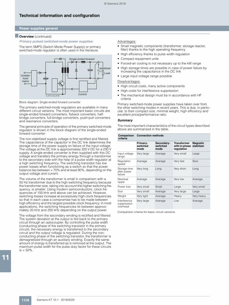
11/4 Siemens KT 10.1 · 2019/2020
11
■ Overview (continued)
Technical information and configuration
Power supplies general
Primary pulsed switched-mode power supplies:
The term SMPS (Switch Mode Power Supply) or primary switched-mode regulator is often used in the literature.
Block diagram: Single-ended forward converter
The primary switched-mode regulators are available in many different circuit versions. The most important basic circuits are single-ended forward converters, flyback converters, half-bridge converters, full-bridge converters, push-pull converters and resonance converters.
The general principle of operation of the primary switched-mode regulator is shown in the block diagram of the single-ended forward converter:
The non-stabilized supply voltage is first rectified and filtered. The capacitance of the capacitor in the DC link determines the storage time of the power supply on failure of the input voltage. The voltage at the DC link is approximately 320 V DC for a 230 V supply. A single-ended converter is then supplied with this DC voltage and transfers the primary energy through a transformer to the secondary side with the help of a pulse width regulator at a high switching frequency. The switching transistor has low power losses when functioning as a switch so that the power balance lies between > 70% and at least 90%, depending on the output voltage and current.
The volume of the transformer is small in comparison with a 50 Hz transformer due to the high switching frequency because the transformer size, taking into account the higher switching fre-quency, is smaller. Using modern semiconductors, clock fre-quencies of 100 kHz and above can be achieved. However, switching losses increase at excessively high clock frequencies so that in each case a compromise has to be made between high efficiency and the largest possible clock frequency. In most applications, the switching frequencies lie between approxi-mately 20 kHz and 250 kHz depending on the output power.
The voltage from the secondary winding is rectified and filtered. The system deviation at the output is fed back to the primary circuit through an optocoupler. By controlling the pulse width (conducting phase of the switching transistor in the primary circuit), the necessary energy is transferred to the secondary circuit and the output voltage is regulated. During the non-conducting phase of the switching transistor, the transformer is demagnetized through an auxiliary winding. Exactly the same amount of energy is transferred as is removed at the output. The maximum pulse width for the pulse duty factor for these circuits is < 50%.
Advantages:• Small magnetic components (transformer, storage reactor,
filter) thanks to the high operating frequency• High efficiency thanks to pulse width regulation• Compact equipment units• Forced-air cooling is not necessary up to the kW range• High storage times are possible in case of power failure by
increasing the capacitance in the DC link• Large input voltage range possible
Disadvantages:• High circuit costs, many active components• High costs for interference suppression• The mechanical design must be in accordance with HF
criteria
Primary switched-mode power supplies have taken over from the other switching modes in recent years. This is due, in partic-ular, to their compact size, minimal weight, high efficiency and excellent price/performance ratio.
Summary
The most important characteristics of the circuit types described above are summarized in the table.
Comparison criteria for basic circuit versions
Control
Unstabi-lized
mains
Single-ended-forward
Load
stabilizedUOUT
G_KT01_EN_00180
Comparison criteria
Connection methods
Primary-switched mode
Secondary-switched mode
Transformer with in-phase regulation
Magnetic stabilizer
Input voltage range
Very large Average Very small Large
Regulation speed
Average Average Very fast Slow
Storage time after power failure
Very long Long Very short Long
Residual ripple
Average Average Very low Average
Power loss Very small Small Large Very small
Size Very small Average Very large Large
Weight Very light Average Heavy Very heavy
Interference suppression overhead
Very large Average Low Average
© Siemens 2019
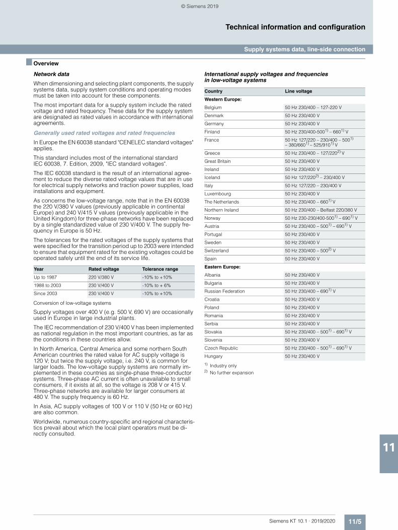
11/5Siemens KT 10.1 · 2019/2020
11
Technical information and configuration
Supply systems data, line-side connection
■ Overview
Network data
When dimensioning and selecting plant components, the supply systems data, supply system conditions and operating modes must be taken into account for these components.
The most important data for a supply system include the rated voltage and rated frequency. These data for the supply system are designated as rated values in accordance with international agreements.
Generally used rated voltages and rated frequencies
In Europe the EN 60038 standard "CENELEC standard voltages" applies.
This standard includes most of the international standard IEC 60038, 7. Edition, 2009, "IEC standard voltages".
The IEC 60038 standard is the result of an international agree-ment to reduce the diverse rated voltage values that are in use for electrical supply networks and traction power supplies, load installations and equipment.
As concerns the low-voltage range, note that in the EN 60038 the 220 V/380 V values (previously applicable in continental Europe) and 240 V/415 V values (previously applicable in the United Kingdom) for three-phase networks have been replaced by a single standardized value of 230 V/400 V. The supply fre-quency in Europe is 50 Hz.
The tolerances for the rated voltages of the supply systems that were specified for the transition period up to 2003 were intended to ensure that equipment rated for the existing voltages could be operated safely until the end of its service life.
Conversion of low-voltage systems
Supply voltages over 400 V (e.g. 500 V, 690 V) are occasionally used in Europe in large industrial plants.
The IEC recommendation of 230 V/400 V has been implemented as national regulation in the most important countries, as far as the conditions in these countries allow.
In North America, Central America and some northern South American countries the rated value for AC supply voltage is 120 V; but twice the supply voltage, i.e. 240 V, is common for larger loads. The low-voltage supply systems are normally im-plemented in these countries as single-phase three-conductor systems. Three-phase AC current is often unavailable to small consumers, if it exists at all, so the voltage is 208 V or 415 V. Three-phase networks are available for larger consumers at 480 V. The supply frequency is 60 Hz.
In Asia, AC supply voltages of 100 V or 110 V (50 Hz or 60 Hz) are also common.
Worldwide, numerous country-specific and regional characteris-tics prevail about which the local plant operators must be di-rectly consulted.
International supply voltages and frequencies in low-voltage systems
1) Industry only 2) No further expansion
Year Rated voltage Tolerance range
Up to 1987 220 V/380 V -10% to +10%
1988 to 2003 230 V/400 V -10% to + 6%
Since 2003 230 V/400 V -10% to +10%
Country Line voltage
Western Europe:
Belgium 50 Hz 230/400 – 127-220 V
Denmark 50 Hz 230/400 V
Germany 50 Hz 230/400 V
Finland 50 Hz 230/400-5001) – 6601) V
France 50 Hz 127/220 – 230/400 – 5001)
– 380/6601) – 525/9101) V
Greece 50 Hz 230/400 – 127/2202) V
Great Britain 50 Hz 230/400 V
Ireland 50 Hz 230/400 V
Iceland 50 Hz 127/2202) – 230/400 V
Italy 50 Hz 127/220 – 230/400 V
Luxembourg 50 Hz 230/400 V
The Netherlands 50 Hz 230/400 – 6601) V
Northern Ireland 50 Hz 230/400 – Belfast 220/380 V
Norway 50 Hz 230-230/400-5001) – 6901) V
Austria 50 Hz 230/400 – 5001) – 6901) V
Portugal 50 Hz 230/400 V
Sweden 50 Hz 230/400 V
Switzerland 50 Hz 230/400 – 5002) V
Spain 50 Hz 230/400 V
Eastern Europe:
Albania 50 Hz 230/400 V
Bulgaria 50 Hz 230/400 V
Russian Federation 50 Hz 230/400 – 6901) V
Croatia 50 Hz 230/400 V
Poland 50 Hz 230/400 V
Romania 50 Hz 230/400 V
Serbia 50 Hz 230/400 V
Slovakia 50 Hz 230/400 – 5001) – 6901) V
Slovenia 50 Hz 230/400 V
Czech Republic 50 Hz 230/400 – 5001) – 6901) V
Hungary 50 Hz 230/400 V
© Siemens 2019
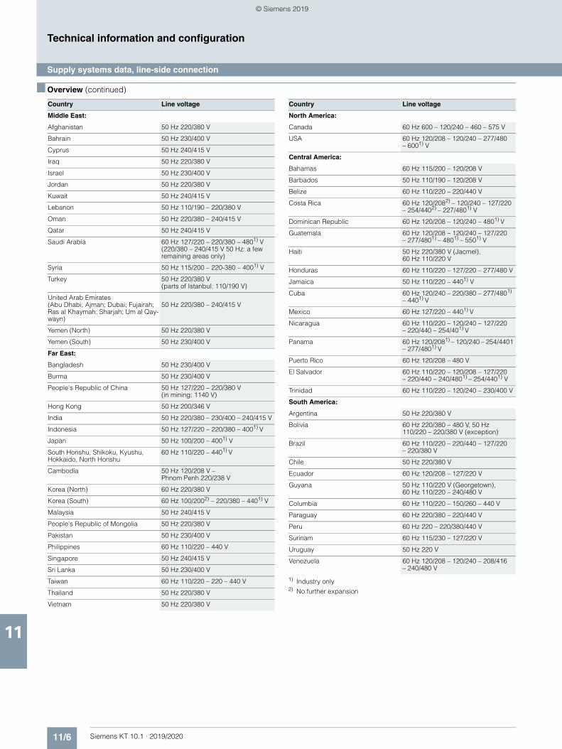
11/6 Siemens KT 10.1 · 2019/2020
11
■ Overview (continued)
Technical information and configuration
Supply systems data, line-side connection
1) Industry only 2) No further expansion
Country Line voltage
Middle East:
Afghanistan 50 Hz 220/380 V
Bahrain 50 Hz 230/400 V
Cyprus 50 Hz 240/415 V
Iraq 50 Hz 220/380 V
Israel 50 Hz 230/400 V
Jordan 50 Hz 220/380 V
Kuwait 50 Hz 240/415 V
Lebanon 50 Hz 110/190 – 220/380 V
Oman 50 Hz 220/380 – 240/415 V
Qatar 50 Hz 240/415 V
Saudi Arabia 60 Hz 127/220 – 220/380 – 4801) V (220/380 – 240/415 V 50 Hz: a few remaining areas only)
Syria 50 Hz 115/200 – 220-380 – 4001) V
Turkey 50 Hz 220/380 V (parts of Istanbul: 110/190 V)
United Arab Emirates(Abu Dhabi; Ajman; Dubai; Fujairah;Ras al Khaymah; Sharjah; Um al Qay-wayn)
50 Hz 220/380 – 240/415 V
Yemen (North) 50 Hz 220/380 V
Yemen (South) 50 Hz 230/400 V
Far East:
Bangladesh 50 Hz 230/400 V
Burma 50 Hz 230/400 V
People's Republic of China 50 Hz 127/220 – 220/380 V (in mining: 1140 V)
Hong Kong 50 Hz 200/346 V
India 50 Hz 220/380 – 230/400 – 240/415 V
Indonesia 50 Hz 127/220 – 220/380 – 4001) V
Japan 50 Hz 100/200 – 4001) V
South Honshu, Shikoku, Kyushu, Hokkaido, North Honshu
60 Hz 110/220 – 4401) V
Cambodia 50 Hz 120/208 V – Phnom Penh 220/238 V
Korea (North) 60 Hz 220/380 V
Korea (South) 60 Hz 100/2002) – 220/380 – 4401) V
Malaysia 50 Hz 240/415 V
People's Republic of Mongolia 50 Hz 220/380 V
Pakistan 50 Hz 230/400 V
Philippines 60 Hz 110/220 – 440 V
Singapore 50 Hz 240/415 V
Sri Lanka 50 Hz 230/400 V
Taiwan 60 Hz 110/220 – 220 – 440 V
Thailand 50 Hz 220/380 V
Vietnam 50 Hz 220/380 V
Country Line voltage
North America:
Canada 60 Hz 600 – 120/240 – 460 – 575 V
USA 60 Hz 120/208 – 120/240 – 277/480– 6001) V
Central America:
Bahamas 60 Hz 115/200 – 120/208 V
Barbados 50 Hz 110/190 – 120/208 V
Belize 60 Hz 110/220 – 220/440 V
Costa Rica 60 Hz 120/2082) – 120/240 – 127/220 – 254/4402) – 227/4801) V
Dominican Republic 60 Hz 120/208 – 120/240 – 4801) V
Guatemala 60 Hz 120/208 – 120/240 – 127/220– 277/4801) – 4801) – 5501) V
Haiti 50 Hz 220/380 V (Jacmel), 60 Hz 110/220 V
Honduras 60 Hz 110/220 – 127/220 – 277/480 V
Jamaica 50 Hz 110/220 – 4401) V
Cuba 60 Hz 120/240 – 220/380 – 277/4801)
– 4401) V
Mexico 60 Hz 127/220 – 4401) V
Nicaragua 60 Hz 110/220 – 120/240 – 127/220 – 220/440 – 254/401) V
Panama 60 Hz 120/2081) – 120/240 – 254/4401 – 277/4801) V
Puerto Rico 60 Hz 120/208 – 480 V
El Salvador 60 Hz 110/220 – 120/208 – 127/220 – 220/440 – 240/4801) – 254/4401) V
Trinidad 60 Hz 110/220 – 120/240 – 230/400 V
South America:
Argentina 50 Hz 220/380 V
Bolivia 60 Hz 220/380 – 480 V, 50 Hz 110/220 – 220/380 V (exception)
Brazil 60 Hz 110/220 – 220/440 – 127/220 – 220/380 V
Chile 50 Hz 220/380 V
Ecuador 60 Hz 120/208 – 127/220 V
Guyana 50 Hz 110/220 V (Georgetown), 60 Hz 110/220 – 240/480 V
Columbia 60 Hz 110/220 – 150/260 – 440 V
Paraguay 60 Hz 220/380 – 220/440 V
Peru 60 Hz 220 – 220/380/440 V
Surinam 60 Hz 115/230 – 127/220 V
Uruguay 50 Hz 220 V
Venezuela 60 Hz 120/208 – 120/240 – 208/416 – 240/480 V
© Siemens 2019
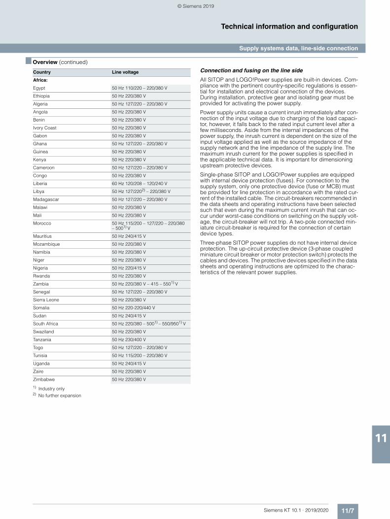
11/7Siemens KT 10.1 · 2019/2020
11
■ Overview (continued)
Technical information and configuration
Supply systems data, line-side connection
1) Industry only 2) No further expansion
Connection and fusing on the line side
All SITOP and LOGO!Power supplies are built-in devices. Com-pliance with the pertinent country-specific regulations is essen-tial for installation and electrical connection of the devices. During installation, protective gear and isolating gear must be provided for activating the power supply.
Power supply units cause a current inrush immediately after con-nection of the input voltage due to charging of the load capaci-tor, however, it falls back to the rated input current level after a few milliseconds. Aside from the internal impedances of the power supply, the inrush current is dependent on the size of the input voltage applied as well as the source impedance of the supply network and the line impedance of the supply line. The maximum inrush current for the power supplies is specified in the applicable technical data. It is important for dimensioning upstream protective devices.
Single-phase SITOP and LOGO!Power supplies are equipped with internal device protection (fuses). For connection to the supply system, only one protective device (fuse or MCB) must be provided for line protection in accordance with the rated cur-rent of the installed cable. The circuit-breakers recommended in the data sheets and operating instructions have been selected such that even during the maximum current inrush that can oc-cur under worst-case conditions on switching on the supply volt-age, the circuit-breaker will not trip. A two-pole connected min-iature circuit-breaker is required for the connection of certain device types.
Three-phase SITOP power supplies do not have internal device protection. The up-circuit protective device (3-phase coupled miniature circuit breaker or motor protection switch) protects the cables and devices. The protective devices specified in the data sheets and operating instructions are optimized to the charac-teristics of the relevant power supplies.
Country Line voltage
Africa:
Egypt 50 Hz 110/220 – 220/380 V
Ethiopia 50 Hz 220/380 V
Algeria 50 Hz 127/220 – 220/380 V
Angola 50 Hz 220/380 V
Benin 50 Hz 220/380 V
Ivory Coast 50 Hz 220/380 V
Gabon 50 Hz 220/380 V
Ghana 50 Hz 127/220 – 220/380 V
Guinea 50 Hz 220/380 V
Kenya 50 Hz 220/380 V
Cameroon 50 Hz 127/220 – 220/380 V
Congo 50 Hz 220/380 V
Liberia 60 Hz 120/208 – 120/240 V
Libya 50 Hz 127/2202) – 220/380 V
Madagascar 50 Hz 127/220 – 220/380 V
Malawi 50 Hz 220/380 V
Mali 50 Hz 220/380 V
Morocco 50 Hz 115/200 – 127/220 – 220/380 – 5001) V
Mauritius 50 Hz 240/415 V
Mozambique 50 Hz 220/380 V
Namibia 50 Hz 220/380 V
Niger 50 Hz 220/380 V
Nigeria 50 Hz 220/415 V
Rwanda 50 Hz 220/380 V
Zambia 50 Hz 220/380 V – 415 – 5501) V
Senegal 50 Hz 127/220 – 220/380 V
Sierra Leone 50 Hz 220/380 V
Somalia 50 Hz 220-220/440 V
Sudan 50 Hz 240/415 V
South Africa 50 Hz 220/380 – 5001) – 550/9501) V
Swaziland 50 Hz 220/380 V
Tanzania 50 Hz 230/400 V
Togo 50 Hz 127/220 – 220/380 V
Tunisia 50 Hz 115/200 – 220/380 V
Uganda 50 Hz 240/415 V
Zaire 50 Hz 220/380 V
Zimbabwe 50 Hz 220/380 V
© Siemens 2019
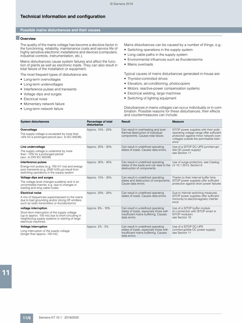
11/8 Siemens KT 10.1 · 2019/2020
11
Technical information and configuration
Possible mains disturbances and their causes
■ Overview
The quality of the mains voltage has become a decisive factor in the functioning, reliability, maintenance costs and service life of highly sensitive electronic installations and devices (computers, industrial controls, instrumentation, etc.).
Mains disturbances cause system failures and affect the func-tion of plants as well as electronic loads. They can also result in total failure of the installation or equipment.
The most frequent types of disturbance are:• Long-term overvoltages• Long-term undervoltages• Interference pulses and transients• Voltage dips and surges• Electrical noise• Momentary network failure• Long-term network failure
Mains disturbances can be caused by a number of things, e.g.:• Switching operations in the supply system• Long cable paths in the supply system• Environmental influences such as thunderstorms• Mains overloads
Typical causes of mains disturbances generated in-house are:• Thyristor-controlled drives• Elevators, air-conditioning, photocopiers• Motors, reactive-power compensation systems• Electrical welding, large machines• Switching of lighting equipment
Disturbances in mains voltages can occur individually or in com-bination. Possible reasons for these disturbances, their effects and countermeasures can include:
System disturbances Percentage of total disturbance
Result Measure
Overvoltage
The supply voltage is exceeded by more than +6% for a prolonged period (acc. to IEC 60038)
Approx. 15% - 20% Can result in overheating and even thermal destruction of individual components. Causes total failure.
SITOP power supplies with their wide operating voltage range offer sufficient protection against minor network over-voltages outside the permissible toler-ance
Line undervoltage
The supply voltage is undershot by more than –10% for a prolonged period (acc. to DIN IEC 60038)
Approx. 20% - 30% Can result in undefined operating states of loads. Causes data errors.
Use of a SITOP DC-UPS (uninterrupt-ible DC power supply)see Section 11
Interference pulses
Energy-rich pulses (e.g. 700 V/1 ms) and energy-poor transients (e.g. 2500 V/20 µs) result from switching operations in the supply system
Approx. 30% - 35% Can result in undefined operating states of the loads and can lead to the destruction of components.
Use of surge protectors, see Catalog LV 10.1 2013, Section 6
Voltage dips and surges
The voltage level changes suddenly and in an uncontrolled manner, e.g. due to changes in loading and long cable routes
Approx. 15% - 30% Can result in undefined operating states and destruction of components. Cause data errors.
Thanks to their internal buffer time, SITOP power supplies offer sufficient protection against short power failures
Electrical noise
A mix of frequencies superimposed on the mains due to bad grounding and/or strong HF emitters such as radio transmitters or thunderstorms
Approx. 20% - 35% Can result in undefined operating states of loads. Causes data errors.
Due to internal switching measures, SITOP power supplies offer sufficient immunity to electromagnetic interfer-ence
voltage interruption
Short-term interruption of the supply voltage (up to approx. 100 ms) due to short-circuiting in neighboring supply systems or starting of large electrical machines.
Approx. 8% - 10% Can result in undefined operating states of loads, especially those with insufficient mains buffering. Causes data errors.
Use of a SITOP buffer module (in connection with SITOP smart or SITOP modular) see Section 10
Voltage interruption
Long interruption of the supply voltage (longer than approx. 100 ms)
Approx. 2% - 5% Can result in undefined operating states of loads, especially those with insufficient mains buffering. Causes data errors.
Use of a SITOP DC-UPS (uninterruptible DC power supply)see Section 11
© Siemens 2019
11/9Siemens KT 10.1 · 2019/2020
11
Technical information and configuration
Installation guidelines, mounting areas and fixing options
■ Overview
Installation guidelines
SITOP und LOGO!Power power supplies are mostly built-in devices. They must be mounted vertically so that the supply air can enter the ventilation slots at the bottom of the devices and leave through the upper part of the devices. The minimum clear-ances specified in the relevant product documentation (operat-ing instructions, device manuals) for the top and bottom of the devices must be observed to ensure free air convection. Side clearance is not required.
The option of mounting on standard mounting rails, wall mount-ing or mounting in non-vertical positions with the appropriate derating is specified in the respective device manuals.
Everything for project planning
Comprehensive information is available for mechanical and electrical engineering, for example, 3D data, circuit diagram macros, device manuals, product data sheets and certificates. The information is available for download via the CAx Download Manager.
Further information is available on the Internet at
http://www.siemens.com/cax
© Siemens 2019
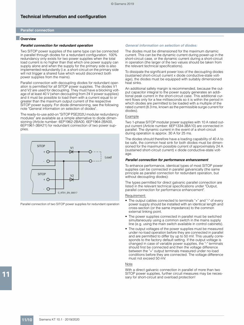
11/10 Siemens KT 10.1 · 2019/2020
11
Technical information and configuration
Parallel connection
■ Overview
Parallel connection for redundant operation
Two SITOP power supplies of the same type can be connected in parallel through diodes for a redundant configuration. 100% redundancy only exists for two power supplies when the total load current is no higher than that which one power supply can supply alone and when the supply for the primary side is also implemented redundantly (i.e. a short-circuit on the primary side will not trigger a shared fuse which would disconnect both power supplies from the mains).
Parallel connection with decoupling diodes for redundant oper-ation is permitted for all SITOP power supplies. The diodes V1 and V2 are used for decoupling. They must have a blocking volt-age of at least 40 V (when decoupling from 24 V power supplies) and it must be possible to load them with a current equal to or greater than the maximum output current of the respective SITOP power supply. For diode dimensioning, see the following note "General information on selection of diodes".
The ready-to-use add-on "SITOP PSE202U modular redundancy modules" are available as a simple alternative to diode dimen-sioning (Article number: 6EP1962-2BA00, 6EP1964-2BA00, 6EP1961-3BA21) for redundant connection of two power sup-plies.
Parallel connection of two SITOP power supplies for redundant operation
General information on selection of diodes:
The diodes must be dimensioned for the maximum dynamic current. This can be the dynamic current during power-up in the short-circuit case, or the dynamic current during a short-circuit in operation (the larger of the two values should be taken from the relevant technical specifications).
To dissipate the significant power loss of the decoupling diodes (sustained short-circuit current x diode conductive-state volt-age), the diodes must be equipped with suitably dimensioned heat sinks.
An additional safety margin is recommended, because the out-put capacitor integral to the power supply generates an addi-tional peak current in the short-circuit case. This additional cur-rent flows only for a few milliseconds so it is within the period in which diodes are permitted to be loaded with a multiple of the rated current (8.3 ms, known as the permissible surge current for diodes).
Example
Two 1-phase SITOP modular power supplies with 10 A rated out-put current (Article number: 6EP1334-3BA10) are connected in parallel. The dynamic current in the event of a short-circuit during operation is approx. 30 A for 25 ms.
The diodes should therefore have a loading capability of 40 A to be safe, the common heat sink for both diodes must be dimen-sioned for the maximum possible current of approximately 24 A (sustained short-circuit current) x diode conductive-state volt-age.
Parallel connection for performance enhancement
To enhance performance, identical types of most SITOP power supplies can be connected in parallel galvanically (the same principle as parallel connection for redundant operation, but without decoupling diodes):
The types permitted for direct galvanic parallel connection are listed in the relevant technical specifications under "Output, parallel connection for performance enhancement".
Requirement:• The output cables connected to terminals "+" and "-" of every
power supply should be installed with an identical length and cross-section (or the same impedance) to the common external linking point.
• The power supplies connected in parallel must be switched simultaneously using a common switch in the mains supply line (e.g. using the main switch available in control cabinets).
• The output voltages of the power supplies must be measured under no-load operation before they are connected in parallel and are permitted to differ by up to 50 mV. This usually corre-sponds to the factory default setting. If the output voltage is changed in case of variable power supplies, the "-" terminals should first be connected and then the voltage difference between the "+" output terminals measured under no-load conditions before they are connected. The voltage difference must not exceed 50 mV.
Note
With a direct galvanic connection in parallel of more than two SITOP power supplies, further circuit measures may be neces-sary for short-circuit and overload protection!
SITOP
+
-
SITOP
+
-
V1
V2
Load
G_KT01_EN_00017
© Siemens 2019
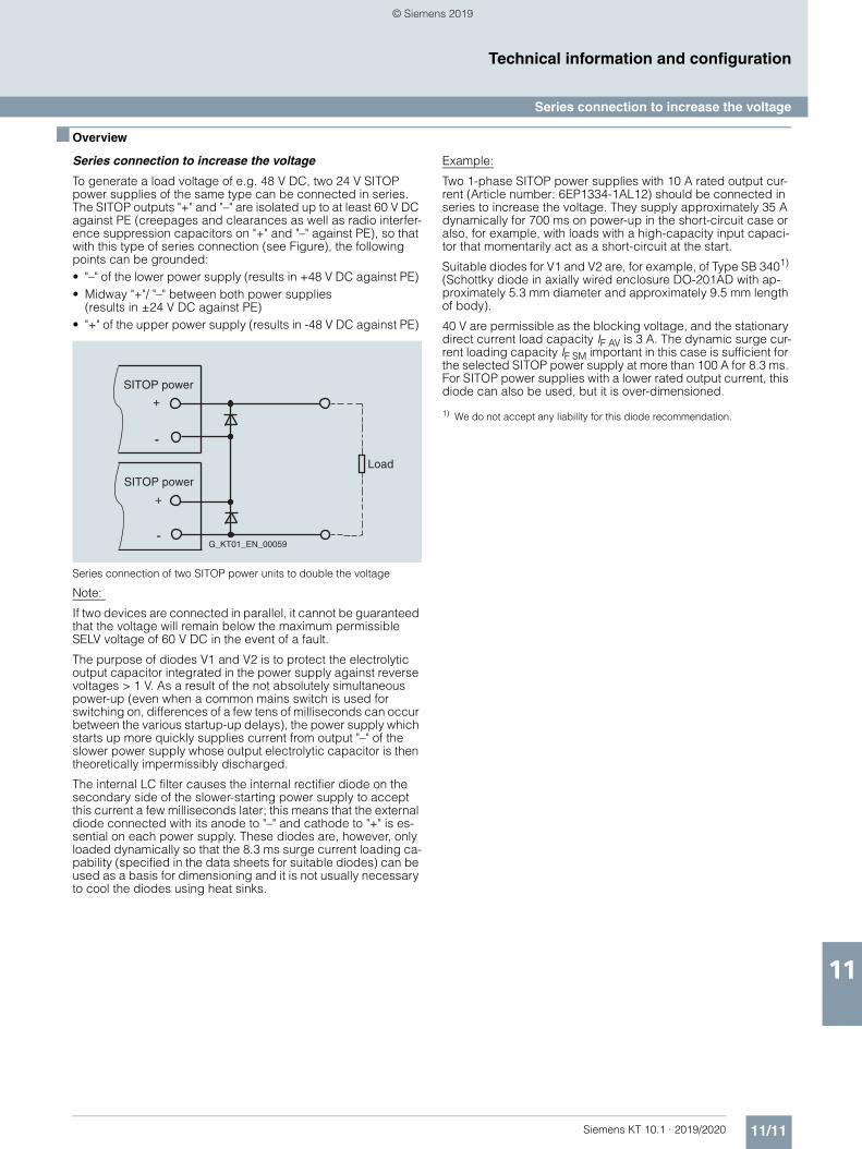
11/11Siemens KT 10.1 · 2019/2020
11
Technical information and configuration
Series connection to increase the voltage
■ Overview
Series connection to increase the voltage
To generate a load voltage of e.g. 48 V DC, two 24 V SITOP power supplies of the same type can be connected in series. The SITOP outputs "+" and "–" are isolated up to at least 60 V DC against PE (creepages and clearances as well as radio interfer-ence suppression capacitors on "+" and "–" against PE), so that with this type of series connection (see Figure), the following points can be grounded:• "–" of the lower power supply (results in +48 V DC against PE) • Midway "+"/ "–" between both power supplies
(results in ±24 V DC against PE) • "+" of the upper power supply (results in -48 V DC against PE)
Series connection of two SITOP power units to double the voltage
Note:
If two devices are connected in parallel, it cannot be guaranteed that the voltage will remain below the maximum permissible SELV voltage of 60 V DC in the event of a fault.
The purpose of diodes V1 and V2 is to protect the electrolytic output capacitor integrated in the power supply against reverse voltages > 1 V. As a result of the not absolutely simultaneous power-up (even when a common mains switch is used for switching on, differences of a few tens of milliseconds can occur between the various startup-up delays), the power supply which starts up more quickly supplies current from output "–" of the slower power supply whose output electrolytic capacitor is then theoretically impermissibly discharged.
The internal LC filter causes the internal rectifier diode on the secondary side of the slower-starting power supply to accept this current a few milliseconds later; this means that the external diode connected with its anode to "–" and cathode to "+" is es-sential on each power supply. These diodes are, however, only loaded dynamically so that the 8.3 ms surge current loading ca-pability (specified in the data sheets for suitable diodes) can be used as a basis for dimensioning and it is not usually necessary to cool the diodes using heat sinks.
Example:
Two 1-phase SITOP power supplies with 10 A rated output cur-rent (Article number: 6EP1334-1AL12) should be connected in series to increase the voltage. They supply approximately 35 A dynamically for 700 ms on power-up in the short-circuit case or also, for example, with loads with a high-capacity input capaci-tor that momentarily act as a short-circuit at the start.
Suitable diodes for V1 and V2 are, for example, of Type SB 3401) (Schottky diode in axially wired enclosure DO-201AD with ap-proximately 5.3 mm diameter and approximately 9.5 mm length of body).
40 V are permissible as the blocking voltage, and the stationary direct current load capacity IF AV is 3 A. The dynamic surge cur-rent loading capacity IF SM important in this case is sufficient for the selected SITOP power supply at more than 100 A for 8.3 ms. For SITOP power supplies with a lower rated output current, this diode can also be used, but it is over-dimensioned.
1) We do not accept any liability for this diode recommendation.
SITOP power
+
-
SITOP power
+
-G_KT01_EN_00059
Load
© Siemens 2019
11/12 Siemens KT 10.1 · 2019/2020
11
Technical information and configuration
Battery charging with SITOP
■ Overview
Battery charging with SITOP power supplies
The SITOP PSU3800 12 V/20 A (Article No. 6EP3424-8UB00-0AY0), 24 V/17 A (Article No. 6EP3436-8UB99-0AY0) and 24 V/40 A (Article No. 6EP3437-8UB00-0AY0) power supplies are suitable for charging lead rechargeable batteries. For a U-I characteristic curve set to parallel operation, the battery to be charged is charged with a constant current until approximately 95% of the set SITOP output voltage is reached. The charging current is then continuously re-duced from 1.2 x rated current at 95% of the set voltage to ap-proximately 0 A or the self-discharge current of the battery at 100% of the set output voltage, i.e. the resistance characteristic in this range.
As reverse voltage and reverse polarity protection, we recom-mend that a diode suitable for at least 1.2 x the rated current of the power supply with a blocking voltage of at least 40 V is con-nected in series with the "+" output (anode connected to "+" out-put of the SITOP PSU3800 and cathode connected to positive pole of the battery).
The output voltage of the power supply must be set at no-load to the end-of-charging voltage plus the voltage drop at the diode. For an end-of-charging voltage of e.g. 27.0 V DC (usual at 20 °C to 30 °C battery temperature; specifications of the battery man-ufacturer must be observed!) and 0.8 V voltage drop at the di-ode, the power supply must be set to 27.8 V during no-load op-eration.
General note for using SITOP power supplies as a battery-charging unit
When using SITOP as a battery charging unit, VDE 0510 or rele-vant national regulations must be observed, and adequate ven-tilation of the battery location provided. SITOP power supplies are designed as built-in units, and touch protection should there-fore be provided by installation in an appropriate housing.
The value recommended by the battery manufacturer must be set as the end-of-charge voltage (depending on the battery tem-perature). An ideal temperature for the lead-acid battery is be-tween +20 °C to +30 °C and the recommended end-of-charge voltage in this case is usually about 27 V.
© Siemens 2019
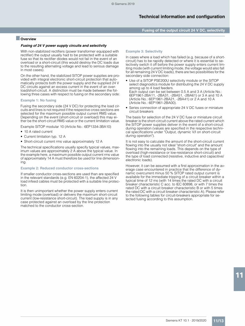
11/13Siemens KT 10.1 · 2019/2020
11
Technical information and configuration
Fusing of the output circuit 24 V DC, selectivity
■ Overview
Fusing of 24 V power supply circuits and selectivity
With non-stabilized rectifiers (power transformer equipped with rectifier) the output usually had to be protected with a suitable fuse so that its rectifier diodes would not fail in the event of an overload or a short-circuit (this would destroy the DC loads due to the resulting alternating voltage and lead to serious damage in most cases).
On the other hand, the stabilized SITOP power supplies are pro-vided with integral electronic short-circuit protection that auto-matically protects both the power supply and the supplied 24 V DC circuits against an excess current in the event of an over-load/short-circuit. A distinction must be made between the fol-lowing three cases with respect to fusing on the secondary side:
Example 1: No fusing
Fusing the secondary side (24 V DC) for protecting the load cir-cuits and lines is not required if the respective cross-sections are selected for the maximum possible output current RMS value. Depending on the event (short-circuit or overload) this may ei-ther be the short-circuit RMS value or the current limitation value.
Example SITOP modular 10 (Article No.: 6EP1334-3BA10) • 10 A rated current• Current limitation typ. 12 A • Short-circuit current rms value approximately 12 A
The technical specifications usually specify typical values, max-imum values are approximately 2 A above the typical value. In the example here, a maximum possible output current rms value of approximately 14 A must therefore be used for line dimension-ing.
Example 2: Reduced conductor cross-sections
If smaller conductor cross-sections are used than are specified in the relevant standards (e.g. EN 60204-1), the affected 24 V load infeed cables must be protected with a suitable line protec-tion.
It is then unimportant whether the power supply enters current limiting mode (overload) or delivers the maximum short-circuit current (low-resistance short-circuit). The load supply is in any case protected against an overload by the line protection matched to the conductor cross-section.
Example 3: Selectivity
In cases where a load which has failed (e.g. because of a short-circuit) has to be rapidly detected or where it is essential to se-lectively switch it off before the power supply enters current lim-iting mode (with current limiting mode, the voltage would also fall for all remaining 24 V DC loads), there are two possibilities for the secondary side connection:• Use of a SITOP PSE200U selectivity module or the SITOP
select diagnostics module for distributing the 24 V DC supply among up to 4 load feeders.Each output can be set between 0.5 A and 3 A (Article No.: 6EP1961-2BA11, -2BA31, -2BA51, -2BA61) or 3 A and 10 A (Article No.: 6EP1961-2BA21, -2BA41) or 2 A and 10 A (Article No.: 6EP1961-2BA00).
• Series connection of appropriate 24 V DC fuses or miniature circuit breakers
The basis for selection of the 24 V DC fuse or miniature circuit breaker is the short-circuit current above the rated current which the SITOP power supplies deliver in the event of a short-circuit during operation (values are specified in the respective techni-cal specifications under "Output, dynamic V/I on short-circuit during operation").
It is not easy to calculate the amount of the short-circuit current flowing into the usually not ideal "short-circuit" and the amount flowing into the remaining loads. This depends on the type of overload (high-resistance or low-resistance short-circuit) and the type of load connected (resistive, inductive and capacitive/electronic loads).
However, it can be assumed with a first approximation in the av-erage case encountered in practice that the difference of dy-namic overcurrent minus 50 % SITOP rated output current is available for the immediate tripping of a circuit breaker within a typical time of 12 ms (with 14 times the rated DC with a circuit breaker characteristic C acc. to IEC 60898, or with 7 times the rated DC with a circuit breaker characteristic B or with 5 times the rated DC with a circuit breaker characteristic A). Please refer to the following tables for circuit-breakers appropriate for se-lected fusing according to this assumption.
© Siemens 2019
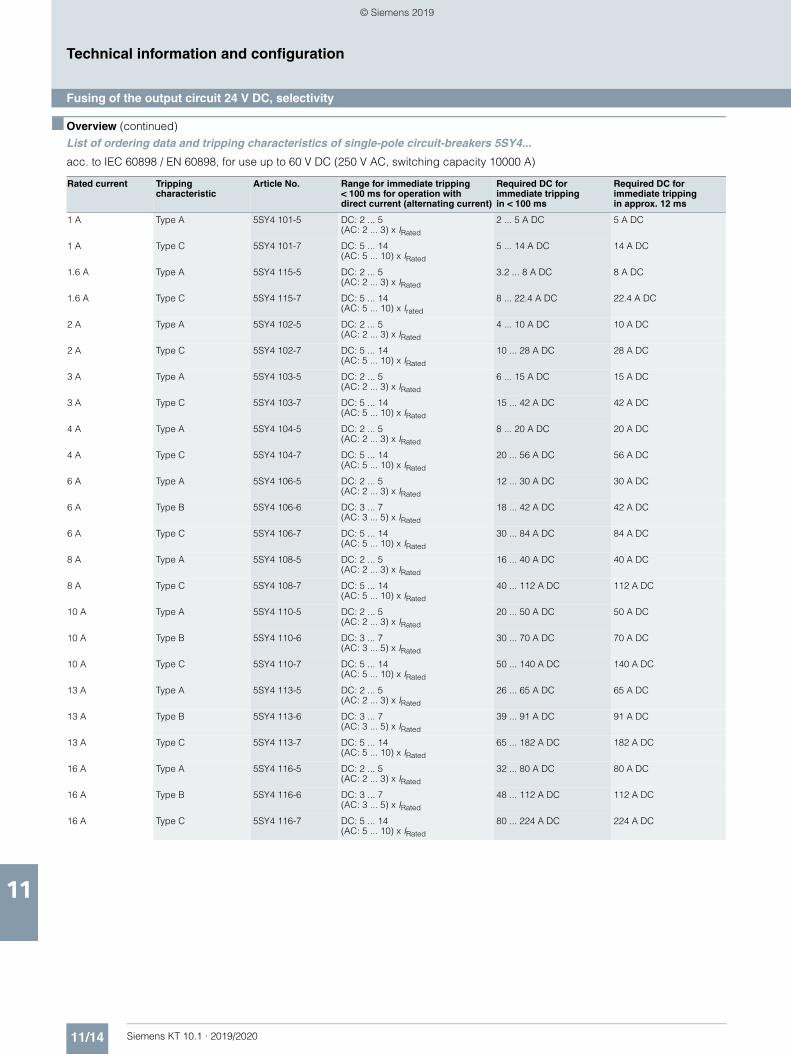
11/14 Siemens KT 10.1 · 2019/2020
11
■ Overview (continued)
Technical information and configuration
Fusing of the output circuit 24 V DC, selectivity
List of ordering data and tripping characteristics of single-pole circuit-breakers 5SY4...
acc. to IEC 60898 / EN 60898, for use up to 60 V DC (250 V AC, switching capacity 10000 A)
Rated current Tripping characteristic
Article No. Range for immediate tripping < 100 ms for operation with direct current (alternating current)
Required DC for immediate tripping in < 100 ms
Required DC for immediate trippingin approx. 12 ms
1 A Type A 5SY4 101-5 DC: 2 ... 5 (AC: 2 ... 3) x IRated
2 ... 5 A DC 5 A DC
1 A Type C 5SY4 101-7 DC: 5 ... 14 (AC: 5 ... 10) x IRated
5 ... 14 A DC 14 A DC
1.6 A Type A 5SY4 115-5 DC: 2 ... 5 (AC: 2 ... 3) x IRated
3.2 ... 8 A DC 8 A DC
1.6 A Type C 5SY4 115-7 DC: 5 ... 14 (AC: 5 ... 10) x Irated
8 ... 22.4 A DC 22.4 A DC
2 A Type A 5SY4 102-5 DC: 2 ... 5 (AC: 2 ... 3) x IRated
4 ... 10 A DC 10 A DC
2 A Type C 5SY4 102-7 DC: 5 ... 14 (AC: 5 ... 10) x IRated
10 ... 28 A DC 28 A DC
3 A Type A 5SY4 103-5 DC: 2 ... 5(AC: 2 ... 3) x IRated
6 ... 15 A DC 15 A DC
3 A Type C 5SY4 103-7 DC: 5 ... 14 (AC: 5 ... 10) x IRated
15 ... 42 A DC 42 A DC
4 A Type A 5SY4 104-5 DC: 2 ... 5 (AC: 2 ... 3) x IRated
8 ... 20 A DC 20 A DC
4 A Type C 5SY4 104-7 DC: 5 ... 14 (AC: 5 ... 10) x IRated
20 ... 56 A DC 56 A DC
6 A Type A 5SY4 106-5 DC: 2 ... 5 (AC: 2 ... 3) x IRated
12 ... 30 A DC 30 A DC
6 A Type B 5SY4 106-6 DC: 3 ... 7 (AC: 3 ... 5) x IRated
18 ... 42 A DC 42 A DC
6 A Type C 5SY4 106-7 DC: 5 ... 14 (AC: 5 ... 10) x IRated
30 ... 84 A DC 84 A DC
8 A Type A 5SY4 108-5 DC: 2 ... 5 (AC: 2 ... 3) x IRated
16 ... 40 A DC 40 A DC
8 A Type C 5SY4 108-7 DC: 5 ... 14 (AC: 5 ... 10) x IRated
40 ... 112 A DC 112 A DC
10 A Type A 5SY4 110-5 DC: 2 ... 5 (AC: 2 ... 3) x IRated
20 ... 50 A DC 50 A DC
10 A Type B 5SY4 110-6 DC: 3 ... 7 (AC: 3 ... 5) x IRated
30 ... 70 A DC 70 A DC
10 A Type C 5SY4 110-7 DC: 5 ... 14 (AC: 5 ... 10) x IRated
50 ... 140 A DC 140 A DC
13 A Type A 5SY4 113-5 DC: 2 ... 5 (AC: 2 ... 3) x IRated
26 ... 65 A DC 65 A DC
13 A Type B 5SY4 113-6 DC: 3 ... 7 (AC: 3 ... 5) x IRated
39 ... 91 A DC 91 A DC
13 A Type C 5SY4 113-7 DC: 5 ... 14 (AC: 5 ... 10) x IRated
65 ... 182 A DC 182 A DC
16 A Type A 5SY4 116-5 DC: 2 ... 5 (AC: 2 ... 3) x IRated
32 ... 80 A DC 80 A DC
16 A Type B 5SY4 116-6 DC: 3 ... 7 (AC: 3 ... 5) x IRated
48 ... 112 A DC 112 A DC
16 A Type C 5SY4 116-7 DC: 5 ... 14 (AC: 5 ... 10) x IRated
80 ... 224 A DC 224 A DC
© Siemens 2019
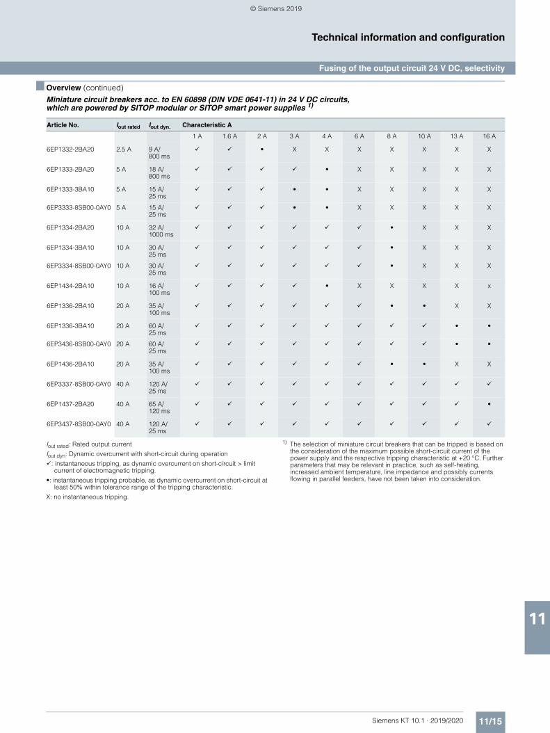
11/15Siemens KT 10.1 · 2019/2020
11
■ Overview (continued)
Technical information and configuration
Fusing of the output circuit 24 V DC, selectivity
Miniature circuit breakers acc. to EN 60898 (DIN VDE 0641-11) in 24 V DC circuits, which are powered by SITOP modular or SITOP smart power supplies 1)
Iout rated: Rated output current
Iout dyn: Dynamic overcurrent with short-circuit during operation
: instantaneous tripping, as dynamic overcurrent on short-circuit > limit current of electromagnetic tripping.
•: instantaneous tripping probable, as dynamic overcurrent on short-circuit at least 50% within tolerance range of the tripping characteristic.
X: no instantaneous tripping.
1) The selection of miniature circuit breakers that can be tripped is based on the consideration of the maximum possible short-circuit current of the power supply and the respective tripping characteristic at +20 °C. Further parameters that may be relevant in practice, such as self-heating, increased ambient temperature, line impedance and possibly currents flowing in parallel feeders, have not been taken into consideration.
Article No. Iout rated Iout dyn. Characteristic A
1 A 1.6 A 2 A 3 A 4 A 6 A 8 A 10 A 13 A 16 A
6EP1332-2BA20 2.5 A 9 A/800 ms
• X X X X X X X
6EP1333-2BA20 5 A 18 A/800 ms
• X X X X X
6EP1333-3BA10 5 A 15 A/25 ms
• • X X X X X
6EP3333-8SB00-0AY0 5 A 15 A/25 ms
• • X X X X X
6EP1334-2BA20 10 A 32 A/1000 ms
• X X X
6EP1334-3BA10 10 A 30 A/25 ms
• X X X
6EP3334-8SB00-0AY0 10 A 30 A/25 ms
• X X X
6EP1434-2BA10 10 A 16 A/100 ms
• X X X X x
6EP1336-2BA10 20 A 35 A/100 ms
• • X X
6EP1336-3BA10 20 A 60 A/25 ms
• •
6EP3436-8SB00-0AY0 20 A 60 A/25 ms
• •
6EP1436-2BA10 20 A 35 A/100 ms
• • X X
6EP3337-8SB00-0AY0 40 A 120 A/25 ms
6EP1437-2BA20 40 A 65 A/120 ms
•
6EP3437-8SB00-0AY0 40 A 120 A/25 ms
© Siemens 2019
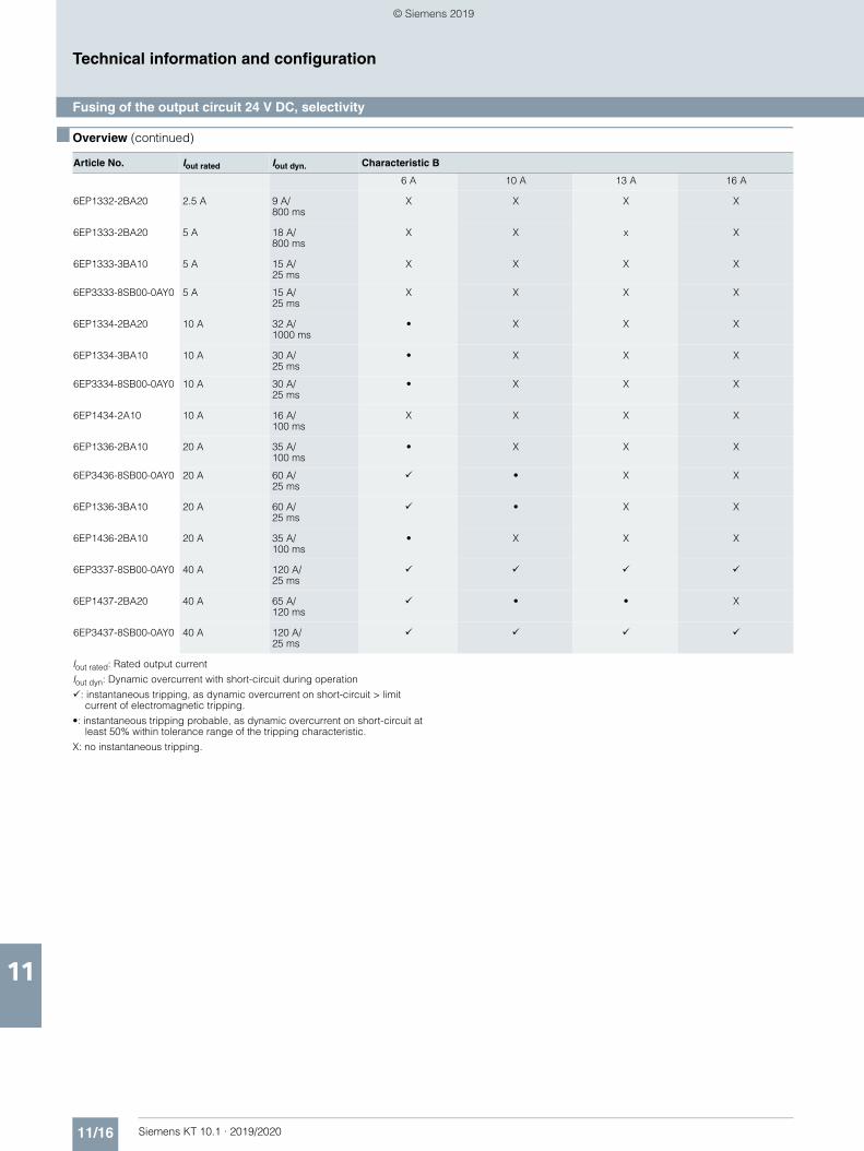
11/16 Siemens KT 10.1 · 2019/2020
11
■ Overview (continued)
Technical information and configuration
Fusing of the output circuit 24 V DC, selectivity
Iout rated: Rated output current
Iout dyn: Dynamic overcurrent with short-circuit during operation
: instantaneous tripping, as dynamic overcurrent on short-circuit > limit current of electromagnetic tripping.
•: instantaneous tripping probable, as dynamic overcurrent on short-circuit at least 50% within tolerance range of the tripping characteristic.
X: no instantaneous tripping.
Article No. Iout rated Iout dyn. Characteristic B
6 A 10 A 13 A 16 A
6EP1332-2BA20 2.5 A 9 A/800 ms
X X X X
6EP1333-2BA20 5 A 18 A/800 ms
X X x X
6EP1333-3BA10 5 A 15 A/25 ms
X X X X
6EP3333-8SB00-0AY0 5 A 15 A/25 ms
X X X X
6EP1334-2BA20 10 A 32 A/1000 ms
• X X X
6EP1334-3BA10 10 A 30 A/25 ms
• X X X
6EP3334-8SB00-0AY0 10 A 30 A/25 ms
• X X X
6EP1434-2A10 10 A 16 A/100 ms
X X X X
6EP1336-2BA10 20 A 35 A/100 ms
• X X X
6EP3436-8SB00-0AY0 20 A 60 A/25 ms
• X X
6EP1336-3BA10 20 A 60 A/25 ms
• X X
6EP1436-2BA10 20 A 35 A/100 ms
• X X X
6EP3337-8SB00-0AY0 40 A 120 A/25 ms
6EP1437-2BA20 40 A 65 A/120 ms
• • X
6EP3437-8SB00-0AY0 40 A 120 A/25 ms
© Siemens 2019
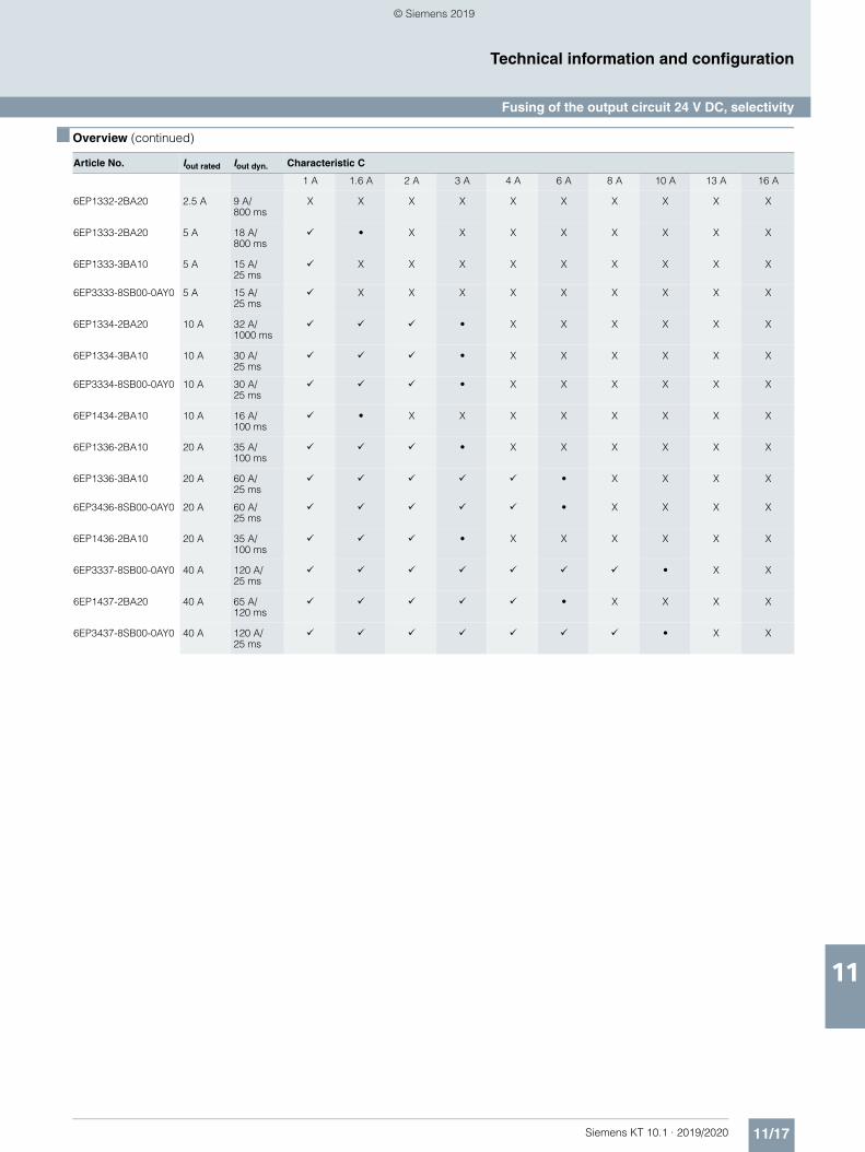
11/17Siemens KT 10.1 · 2019/2020
11
■ Overview (continued)
Technical information and configuration
Fusing of the output circuit 24 V DC, selectivity
Article No. Iout rated Iout dyn. Characteristic C
1 A 1.6 A 2 A 3 A 4 A 6 A 8 A 10 A 13 A 16 A
6EP1332-2BA20 2.5 A 9 A/800 ms
X X X X X X X X X X
6EP1333-2BA20 5 A 18 A/800 ms
• X X X X X X X X
6EP1333-3BA10 5 A 15 A/25 ms
X X X X X X X X X
6EP3333-8SB00-0AY0 5 A 15 A/25 ms
X X X X X X X X X
6EP1334-2BA20 10 A 32 A/1000 ms
• X X X X X X
6EP1334-3BA10 10 A 30 A/25 ms
• X X X X X X
6EP3334-8SB00-0AY0 10 A 30 A/25 ms
• X X X X X X
6EP1434-2BA10 10 A 16 A/100 ms
• X X X X X X X X
6EP1336-2BA10 20 A 35 A/100 ms
• X X X X X X
6EP1336-3BA10 20 A 60 A/25 ms
• X X X X
6EP3436-8SB00-0AY0 20 A 60 A/25 ms
• X X X X
6EP1436-2BA10 20 A 35 A/100 ms
• X X X X X X
6EP3337-8SB00-0AY0 40 A 120 A/25 ms
• X X
6EP1437-2BA20 40 A 65 A/120 ms
• X X X X
6EP3437-8SB00-0AY0 40 A 120 A/25 ms
• X X
© Siemens 2019
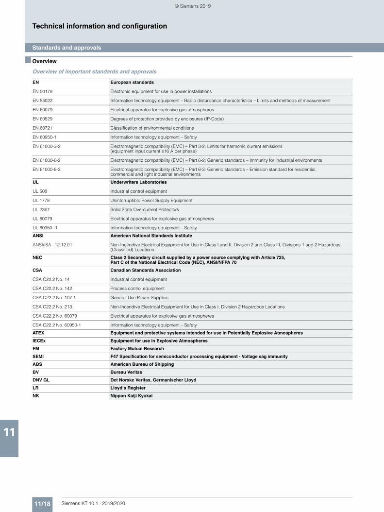
11/18 Siemens KT 10.1 · 2019/2020
11
Technical information and configuration
Standards and approvals
■ Overview
Overview of important standards and approvals
EN European standards
EN 50178 Electronic equipment for use in power installations
EN 55022 Information technology equipment – Radio disturbance characteristics – Limits and methods of measurement
EN 60079 Electrical apparatus for explosive gas atmospheres
EN 60529 Degrees of protection provided by enclosures (IP-Code)
EN 60721 Classification of environmental conditions
EN 60950-1 Information technology equipment – Safety
EN 61000-3-2 Electromagnetic compatibility (EMC) – Part 3-2: Limits for harmonic current emissions (equipment input current ≤16 A per phase)
EN 61000-6-2 Electromagnetic compatibility (EMC) – Part 6-2: Generic standards – Immunity for industrial environments
EN 61000-6-3 Electromagnetic compatibility (EMC) – Part 6-3: Generic standards – Emission standard for residential, commercial and light industrial environments
UL Underwriters Laboratories
UL 508 Industrial control equipment
UL 1778 Uninterruptible Power Supply Equipment
UL 2367 Solid State Overcurrent Protectors
UL 60079 Electrical apparatus for explosive gas atmospheres
UL 60950 -1 Information technology equipment – Safety
ANSI American National Standards Institute
ANSI/ISA –12.12.01 Non-Incendive Electrical Equipment for Use in Class I and II, Division 2 and Class III, Divisions 1 and 2 Hazardous (Classified) Locations
NEC Class 2 Secondary circuit supplied by a power source complying with Article 725,Part C of the National Electrical Code (NEC), ANSI/NFPA 70
CSA Canadian Standards Association
CSA C22.2 No. 14 Industrial control equipment
CSA C22.2 No. 142 Process control equipment
CSA C22.2 No. 107.1 General Use Power Supplies
CSA C22.2 No. 213 Non-Incendive Electrical Equipment for Use in Class I, Division 2 Hazardous Locations
CSA C22.2 No. 60079 Electrical apparatus for explosive gas atmospheres
CSA C22.2 No. 60950-1 Information technology equipment – Safety
ATEX Equipment and protective systems intended for use in Potentially Explosive Atmospheres
IECEx Equipment for use in Explosive Atmospheres
FM Factory Mutual Research
SEMI F47 Specification for semiconductor processing equipment - Voltage sag immunity
ABS American Bureau of Shipping
BV Bureau Veritas
DNV GL Det Norske Veritas, Germanischer Lloyd
LR Lloyd‘s Register
NK Nippon Kaiji Kyokai
© Siemens 2019
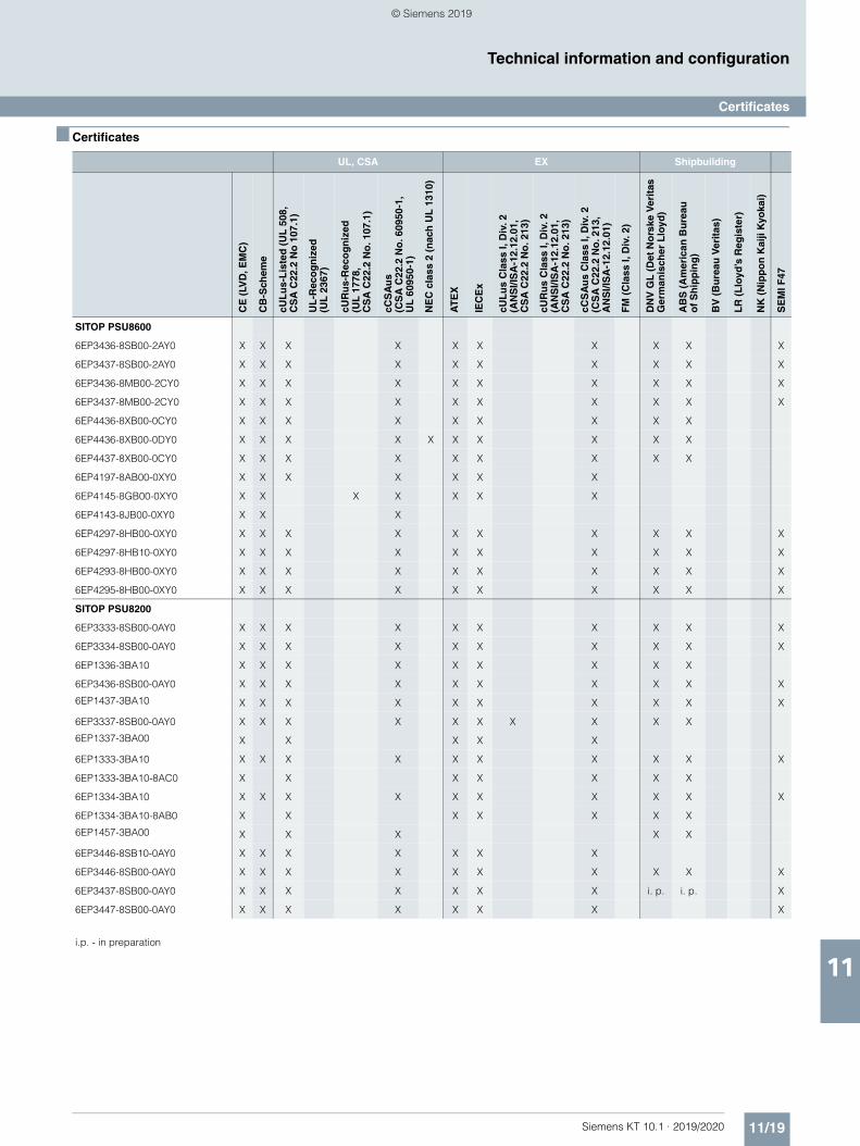
11/19Siemens KT 10.1 · 2019/2020
11
Technical information and configuration
Certificates
■ Certificates
UL, CSA EX Shipbuilding
CE
(LV
D, E
MC
)
CB
-Sch
eme
cUL
us-
Lis
ted
(U
L 5
08,
CS
A C
22.2
No
107
.1)
UL
-Rec
og
niz
ed
(UL
236
7)
cUR
us-
Rec
og
niz
ed
(UL
177
8,
CS
A C
22.2
No
. 107
.1)
cCS
Au
s (C
SA
C22
.2 N
o. 6
0950
-1,
UL
609
50-1
)
NE
C c
lass
2 (
nac
h U
L 1
310)
AT
EX
IEC
Ex
cUL
us
Cla
ss I,
Div
. 2
(AN
SI/I
SA
-12.
12.0
1,
CS
A C
22.2
No
. 213
)
cUR
us
Cla
ss I,
Div
. 2(A
NS
I/IS
A-1
2.12
.01,
CS
A C
22.2
No
. 213
)
cCS
Au
s C
lass
I, D
iv. 2
(C
SA
C22
.2 N
o. 2
13,
AN
SI/I
SA
-12.
12.0
1)
FM
(C
lass
I, D
iv. 2
)
DN
V G
L (
Det
No
rske
Ver
itas
G
erm
anis
cher
Llo
yd)
AB
S (
Am
eric
an B
ure
au
of
Sh
ipp
ing
)
BV
(B
ure
au V
erit
as)
LR
(L
loyd
’s R
egis
ter)
NK
(N
ipp
on
Kai
ji K
yoka
i)
SE
MI F
47
SITOP PSU8600
6EP3436-8SB00-2AY0 X X X X X X X X X X
6EP3437-8SB00-2AY0 X X X X X X X X X X
6EP3436-8MB00-2CY0 X X X X X X X X X X
6EP3437-8MB00-2CY0 X X X X X X X X X X
6EP4436-8XB00-0CY0 X X X X X X X X X
6EP4436-8XB00-0DY0 X X X X X X X X X X
6EP4437-8XB00-0CY0 X X X X X X X X X
6EP4197-8AB00-0XY0 X X X X X X X
6EP4145-8GB00-0XY0 X X X X X X X
6EP4143-8JB00-0XY0 X X X
6EP4297-8HB00-0XY0 X X X X X X X X X X
6EP4297-8HB10-0XY0 X X X X X X X X X X
6EP4293-8HB00-0XY0 X X X X X X X X X X
6EP4295-8HB00-0XY0 X X X X X X X X X X
SITOP PSU8200
6EP3333-8SB00-0AY0 X X X X X X X X X X
6EP3334-8SB00-0AY0 X X X X X X X X X X
6EP1336-3BA10 X X X X X X X X X
6EP3436-8SB00-0AY0 X X X X X X X X X X
6EP1437-3BA10 X X X X X X X X X X
6EP3337-8SB00-0AY0 X X X X X X X X X X
6EP1337-3BA00 X X X X X
6EP1333-3BA10 X X X X X X X X X X
6EP1333-3BA10-8AC0 X X X X X X X
6EP1334-3BA10 X X X X X X X X X X
6EP1334-3BA10-8AB0 X X X X X X X
6EP1457-3BA00 X X X X X
6EP3446-8SB10-0AY0 X X X X X X X
6EP3446-8SB00-0AY0 X X X X X X X X X X
6EP3437-8SB00-0AY0 X X X X X X X i. p. i. p. X
6EP3447-8SB00-0AY0 X X X X X X X X
i.p. - in preparation
© Siemens 2019
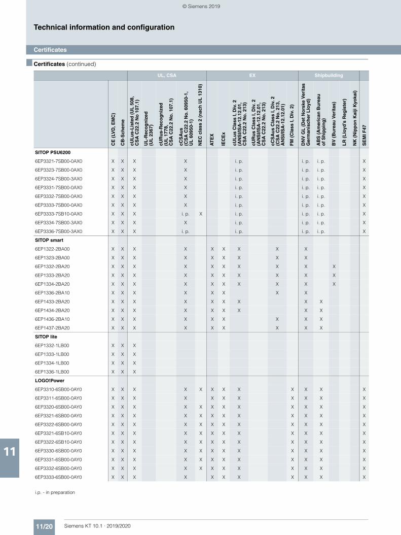
11/20 Siemens KT 10.1 · 2019/2020
11
■ Certificates (continued)
Technical information and configuration
Certificates
SITOP PSU6200
6EP3321-7SB00-0AX0 X X X X i. p. i. p. i. p. X
6EP3323-7SB00-0AX0 X X X X i. p. i. p. i. p. X
6EP3324-7SB00-3AX0 X X X X i. p. i. p. i. p. X
6EP3331-7SB00-0AX0 X X X X i. p. i. p. i. p. X
6EP3332-7SB00-0AX0 X X X X i. p. i. p. i. p. X
6EP3333-7SB00-0AX0 X X X X i. p. i. p. i. p. X
6EP3333-7SB10-0AX0 X X X i. p. X i. p. i. p. i. p. X
6EP3334-7SB00-3AX0 X X X X i. p. i. p. i. p. X
6EP3336-7SB00-3AX0 X X X i. p. i. p. i. p. i. p. X
SITOP smart
6EP1322-2BA00 X X X X X X X X X
6EP1323-2BA00 X X X X X X X X X
6EP1332-2BA20 X X X X X X X X X X
6EP1333-2BA20 X X X X X X X X X X
6EP1334-2BA20 X X X X X X X X X X
6EP1336-2BA10 X X X X X X X X
6EP1433-2BA20 X X X X X X X X X
6EP1434-2BA20 X X X X X X X X X
6EP1436-2BA10 X X X X X X X X X
6EP1437-2BA20 X X X X X X X X X
SITOP lite
6EP1332-1LB00 X X X
6EP1333-1LB00 X X X
6EP1334-1LB00 X X X
6EP1336-1LB00 X X X
LOGO!Power
6EP3310-6SB00-0AY0 X X X X X X X X X X X X
6EP3311-6SB00-0AY0 X X X X X X X X X X X
6EP3320-6SB00-0AY0 X X X X X X X X X X X X
6EP3321-6SB00-0AY0 X X X X X X X X X X X X
6EP3322-6SB00-0AY0 X X X X X X X X X X X X
6EP3321-6SB10-0AY0 X X X X X X X X X X X X
6EP3322-6SB10-0AY0 X X X X X X X X X X X X
6EP3330-6SB00-0AY0 X X X X X X X X X X X X
6EP3331-6SB00-0AY0 X X X X X X X X X X X X
6EP3332-6SB00-0AY0 X X X X X X X X X X X X
6EP3333-6SB00-0AY0 X X X X X X X X X X X
i.p. - in preparation
UL, CSA EX Shipbuilding
CE
(LV
D, E
MC
)
CB
-Sch
eme
cUL
us-
Lis
ted
(U
L 5
08,
CS
A C
22.2
No
107
.1)
UL
-Rec
og
niz
ed
(UL
236
7)
cUR
us-
Rec
og
niz
ed
(UL
177
8,
CS
A C
22.2
No
. 107
.1)
cCS
Au
s (C
SA
C22
.2 N
o. 6
0950
-1,
UL
609
50-1
)
NE
C c
lass
2 (
nac
h U
L 1
310)
AT
EX
IEC
Ex
cUL
us
Cla
ss I,
Div
. 2
(AN
SI/I
SA
-12.
12.0
1,
CS
A C
22.2
No
. 213
)
cUR
us
Cla
ss I,
Div
. 2(A
NS
I/IS
A-1
2.12
.01,
CS
A C
22.2
No
. 213
)
cCS
Au
s C
lass
I, D
iv. 2
(C
SA
C22
.2 N
o. 2
13,
AN
SI/I
SA
-12.
12.0
1)
FM
(C
lass
I, D
iv. 2
)
DN
V G
L (
Det
No
rske
Ver
itas
G
erm
anis
cher
Llo
yd)
AB
S (
Am
eric
an B
ure
au
of
Sh
ipp
ing
)
BV
(B
ure
au V
erit
as)
LR
(L
loyd
’s R
egis
ter)
NK
(N
ipp
on
Kai
ji K
yoka
i)
SE
MI F
47
© Siemens 2019
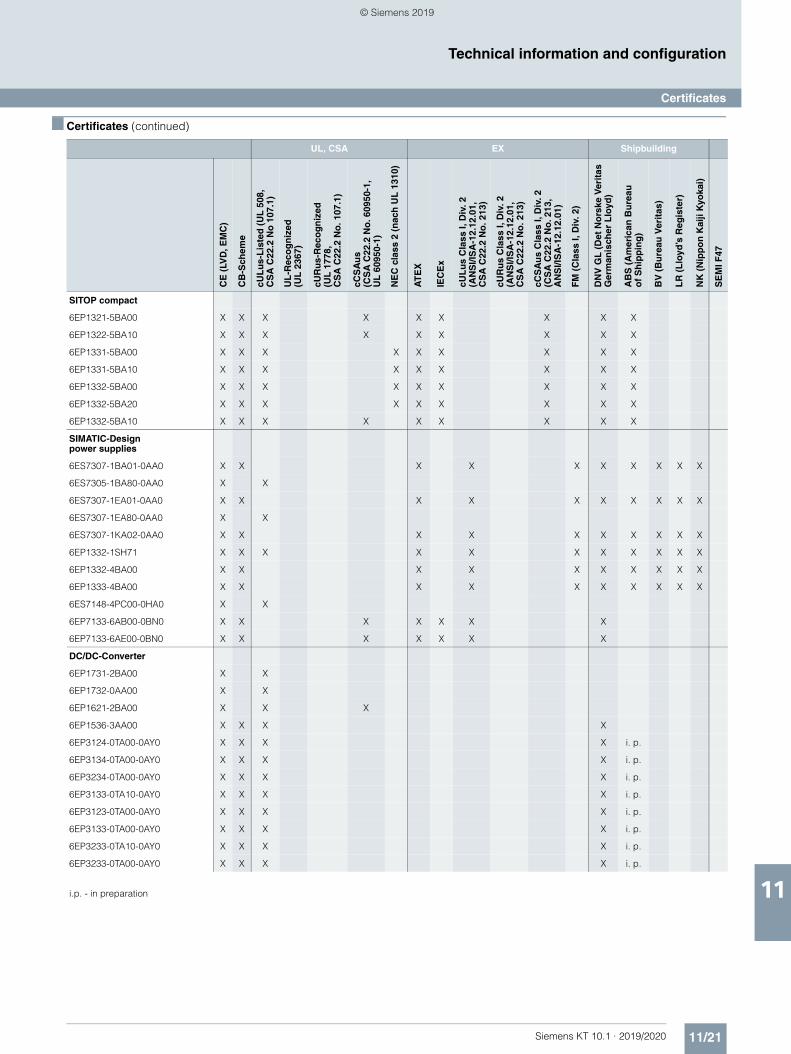
11/21Siemens KT 10.1 · 2019/2020
11
■ Certificates (continued)
Technical information and configuration
Certificates
SITOP compact
6EP1321-5BA00 X X X X X X X X X
6EP1322-5BA10 X X X X X X X X X
6EP1331-5BA00 X X X X X X X X X
6EP1331-5BA10 X X X X X X X X X
6EP1332-5BA00 X X X X X X X X X
6EP1332-5BA20 X X X X X X X X X
6EP1332-5BA10 X X X X X X X X X
SIMATIC-Design power supplies
6ES7307-1BA01-0AA0 X X X X X X X X X X
6ES7305-1BA80-0AA0 X X
6ES7307-1EA01-0AA0 X X X X X X X X X X
6ES7307-1EA80-0AA0 X X
6ES7307-1KA02-0AA0 X X X X X X X X X X
6EP1332-1SH71 X X X X X X X X X X X
6EP1332-4BA00 X X X X X X X X X X
6EP1333-4BA00 X X X X X X X X X X
6ES7148-4PC00-0HA0 X X
6EP7133-6AB00-0BN0 X X X X X X X
6EP7133-6AE00-0BN0 X X X X X X X
DC/DC-Converter
6EP1731-2BA00 X X
6EP1732-0AA00 X X
6EP1621-2BA00 X X X
6EP1536-3AA00 X X X X
6EP3124-0TA00-0AY0 X X X X i. p.
6EP3134-0TA00-0AY0 X X X X i. p.
6EP3234-0TA00-0AY0 X X X X i. p.
6EP3133-0TA10-0AY0 X X X X i. p.
6EP3123-0TA00-0AY0 X X X X i. p.
6EP3133-0TA00-0AY0 X X X X i. p.
6EP3233-0TA10-0AY0 X X X X i. p.
6EP3233-0TA00-0AY0 X X X X i. p.
i.p. - in preparation
UL, CSA EX Shipbuilding
CE
(LV
D, E
MC
)
CB
-Sch
eme
cUL
us-
Lis
ted
(U
L 5
08,
CS
A C
22.2
No
107
.1)
UL
-Rec
og
niz
ed
(UL
236
7)
cUR
us-
Rec
og
niz
ed
(UL
177
8,
CS
A C
22.2
No
. 107
.1)
cCS
Au
s (C
SA
C22
.2 N
o. 6
0950
-1,
UL
609
50-1
)
NE
C c
lass
2 (
nac
h U
L 1
310)
AT
EX
IEC
Ex
cUL
us
Cla
ss I,
Div
. 2
(AN
SI/I
SA
-12.
12.0
1,
CS
A C
22.2
No
. 213
)
cUR
us
Cla
ss I,
Div
. 2(A
NS
I/IS
A-1
2.12
.01,
CS
A C
22.2
No
. 213
)
cCS
Au
s C
lass
I, D
iv. 2
(C
SA
C22
.2 N
o. 2
13,
AN
SI/I
SA
-12.
12.0
1)
FM
(C
lass
I, D
iv. 2
)
DN
V G
L (
Det
No
rske
Ver
itas
G
erm
anis
cher
Llo
yd)
AB
S (
Am
eric
an B
ure
au
of
Sh
ipp
ing
)
BV
(B
ure
au V
erit
as)
LR
(L
loyd
’s R
egis
ter)
NK
(N
ipp
on
Kai
ji K
yoka
i)
SE
MI F
47
© Siemens 2019
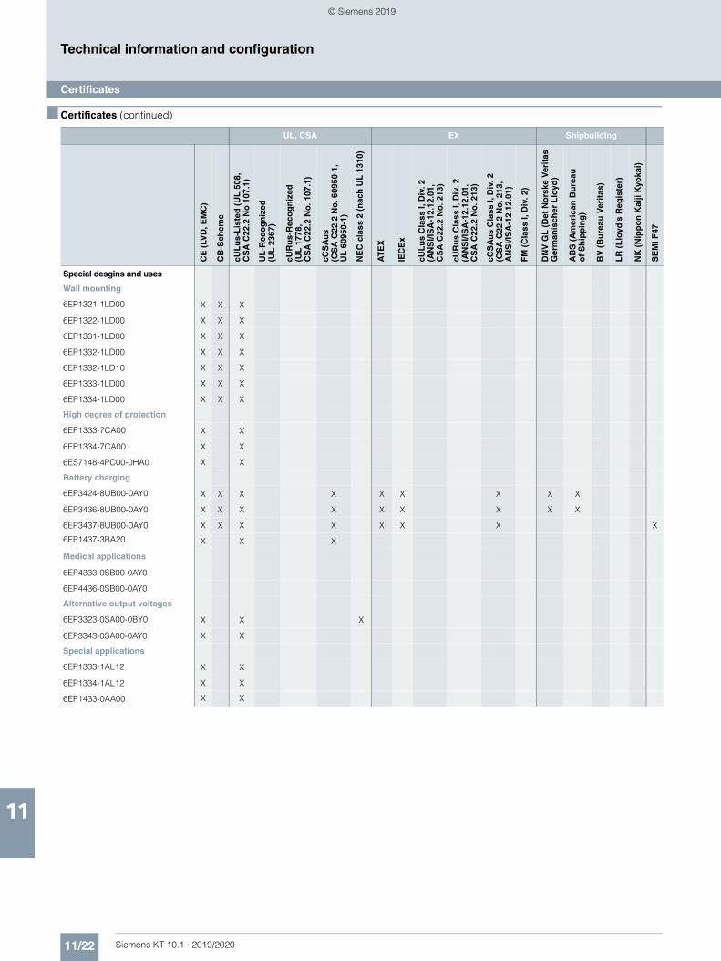
11/22 Siemens KT 10.1 · 2019/2020
11
■ Certificates (continued)
Technical information and configuration
Certificates
Special desgins and uses
Wall mounting
6EP1321-1LD00 X X X
6EP1322-1LD00 X X X
6EP1331-1LD00 X X X
6EP1332-1LD00 X X X
6EP1332-1LD10 X X X
6EP1333-1LD00 X X X
6EP1334-1LD00 X X X
High degree of protection
6EP1333-7CA00 X X
6EP1334-7CA00 X X
6ES7148-4PC00-0HA0 X X
Battery charging
6EP3424-8UB00-0AY0 X X X X X X X X X
6EP3436-8UB00-0AY0 X X X X X X X X X
6EP3437-8UB00-0AY0 X X X X X X X X
6EP1437-3BA20 X X X
Medical applications
6EP4333-0SB00-0AY0
6EP4436-0SB00-0AY0
Alternative output voltages
6EP3323-0SA00-0BY0 X X X
6EP3343-0SA00-0AY0 X X
Special applications
6EP1333-1AL12 X X
6EP1334-1AL12 X X
6EP1433-0AA00 X X
UL, CSA EX Shipbuilding
CE
(LV
D, E
MC
)
CB
-Sch
eme
cUL
us-
Lis
ted
(U
L 5
08,
CS
A C
22.2
No
107
.1)
UL
-Rec
og
niz
ed
(UL
236
7)
cUR
us-
Rec
og
niz
ed
(UL
177
8,
CS
A C
22.2
No
. 107
.1)
cCS
Au
s (C
SA
C22
.2 N
o. 6
0950
-1,
UL
609
50-1
)
NE
C c
lass
2 (
nac
h U
L 1
310)
AT
EX
IEC
Ex
cUL
us
Cla
ss I,
Div
. 2
(AN
SI/I
SA
-12.
12.0
1,
CS
A C
22.2
No
. 213
)
cUR
us
Cla
ss I,
Div
. 2(A
NS
I/IS
A-1
2.12
.01,
CS
A C
22.2
No
. 213
)
cCS
Au
s C
lass
I, D
iv. 2
(C
SA
C22
.2 N
o. 2
13,
AN
SI/I
SA
-12.
12.0
1)
FM
(C
lass
I, D
iv. 2
)
DN
V G
L (
Det
No
rske
Ver
itas
G
erm
anis
cher
Llo
yd)
AB
S (
Am
eric
an B
ure
au
of
Sh
ipp
ing
)
BV
(B
ure
au V
erit
as)
LR
(L
loyd
’s R
egis
ter)
NK
(N
ipp
on
Kai
ji K
yoka
i)
SE
MI F
47
© Siemens 2019
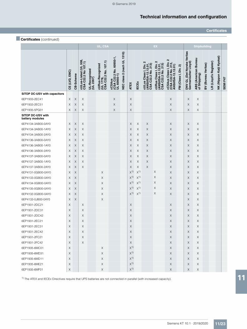
11/23Siemens KT 10.1 · 2019/2020
11
■ Certificates (continued)
Technical information and configuration
Certificates
SITOP DC-USV with capacitors
6EP1933-2EC41 X X X X X X X X
6EP1933-2EC51 X X X X X X X X
6EP1935-5PG01 X X X X X X X X
SITOP DC-USV with battery modules
6EP4134-3AB00-0AY0 X X X X X X X X X
6EP4134-3AB00-1AY0 X X X X X X X X X
6EP4134-3AB00-2AY0 X X X X X X X X X
6EP4136-3AB00-0AY0 X X X X X X X X X
6EP4136-3AB00-1AY0 X X X X X X X X X
6EP4136-3AB00-2AY0 X X X X X X X X X
6EP4137-3AB00-0AY0 X X X X X X X X X
6EP4137-3AB00-1AY0 X X X X X X X X X
6EP4137-3AB00-2AY0 X X X X X X X X X
6EP4131-0GB00-0AY0 X X X X1) X1) X X X X
6EP4133-0GB00-0AY0 X X X X1) X1) X X X X
6EP4134-0GB00-0AY0 X X X X1) X1) X X X X
6EP4135-0GB00-0AY0 X X X X1) X1) X X X X
6EP4132-0GB00-0AY0 X X X X1) X1) X X X X
6EP4133-0JB00-0AY0 X X X X X
6EP1931-2DC21 X X X X X X
6EP1931-2DC31 X X X X X X
6EP1931-2DC42 X X X X X X
6EP1931-2EC21 X X X X X X
6EP1931-2EC31 X X X X X X
6EP1931-2EC42 X X X X X X
6EP1931-2FC21 X X X X X X
6EP1931-2FC42 X X X X X X
6EP1935-6MC01 X X X1) X X X
6EP1935-6MD31 X X X1) X X X
6EP1935-6MD11 X X X1) X X X
6EP1935-6ME21 X X X1) X X X
6EP1935-6MF01 X X X1) X X X
1) The ATEX and IECEx Directives require that UPS batteries are not connected in parallel (with increased capacity).
UL, CSA EX Shipbuilding
CE
(LV
D, E
MC
)
CB
-Sch
eme
cUL
us-
Lis
ted
(U
L 5
08,
CS
A C
22.2
No
107
.1)
UL
-Rec
og
niz
ed
(UL
236
7)
cUR
us-
Rec
og
niz
ed
(UL
177
8,
CS
A C
22.2
No
. 107
.1)
cCS
Au
s (C
SA
C22
.2 N
o. 6
0950
-1,
UL
609
50-1
)
NE
C c
lass
2 (
nac
h U
L 1
310)
AT
EX
IEC
Ex
cUL
us
Cla
ss I,
Div
. 2
(AN
SI/I
SA
-12.
12.0
1,
CS
A C
22.2
No
. 213
)
cUR
us
Cla
ss I,
Div
. 2(A
NS
I/IS
A-1
2.12
.01,
CS
A C
22.2
No
. 213
)
cCS
Au
s C
lass
I, D
iv. 2
(C
SA
C22
.2 N
o. 2
13,
AN
SI/I
SA
-12.
12.0
1)
FM
(C
lass
I, D
iv. 2
)
DN
V G
L (
Det
No
rske
Ver
itas
G
erm
anis
cher
Llo
yd)
AB
S (
Am
eric
an B
ure
au
of
Sh
ipp
ing
)
BV
(B
ure
au V
erit
as)
LR
(L
loyd
’s R
egis
ter)
NK
(N
ipp
on
Kai
ji K
yoka
i)
SE
MI F
47
© Siemens 2019
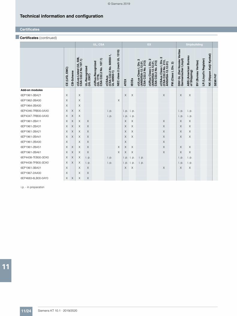
11/24 Siemens KT 10.1 · 2019/2020
11
■ Certificates (continued)
Technical information and configuration
Certificates
Add-on modules
6EP1961-3BA21 X X X X X X X
6EP1962-2BA00 X X X
6EP1964-2BA00 X X
6EP4346-7RB00-0AX0 X X X i. p. i. p. i. p. i. p. i. p.
6EP4347-7RB00-0AX0 X X X i. p. i. p. i. p. i. p. i. p.
6EP1961-2BA11 X X X X X X X X X
6EP1961-2BA31 X X X X X X X X X
6EP1961-2BA21 X X X X X X X X X
6EP1961-2BA41 X X X X X X X X X
6EP1961-2BA00 X X X X X
6EP1961-2BA51 X X X X X X X X X X
6EP1961-2BA61 X X X X X X X X X X
6EP4438-7EB00-3DX0 X X X i. p. i. p. i. p. i. p. i. p. i. p. i. p.
6EP4438-7FB00-3DX0 X X X i. p. i. p. i. p. i. p. i. p. i. p. i. p.
6EP1961-3BA01 X X X X X X X X
6EP1967-2AA00 X X X
6EP4683-6LB00-0AY0 X X X X
i.p. - in preparation
UL, CSA EX Shipbuilding
CE
(LV
D, E
MC
)
CB
-Sch
eme
cUL
us-
Lis
ted
(U
L 5
08,
CS
A C
22.2
No
107
.1)
UL
-Rec
og
niz
ed
(UL
236
7)
cUR
us-
Rec
og
niz
ed
(UL
177
8,
CS
A C
22.2
No
. 107
.1)
cCS
Au
s (C
SA
C22
.2 N
o. 6
0950
-1,
UL
609
50-1
)
NE
C c
lass
2 (
nac
h U
L 1
310)
AT
EX
IEC
Ex
cUL
us
Cla
ss I,
Div
. 2
(AN
SI/I
SA
-12.
12.0
1,
CS
A C
22.2
No
. 213
)
cUR
us
Cla
ss I,
Div
. 2(A
NS
I/IS
A-1
2.12
.01,
CS
A C
22.2
No
. 213
)
cCS
Au
s C
lass
I, D
iv. 2
(C
SA
C22
.2 N
o. 2
13,
AN
SI/I
SA
-12.
12.0
1)
FM
(C
lass
I, D
iv. 2
)
DN
V G
L (
Det
No
rske
Ver
itas
G
erm
anis
cher
Llo
yd)
AB
S (
Am
eric
an B
ure
au
of
Sh
ipp
ing
)
BV
(B
ure
au V
erit
as)
LR
(L
loyd
’s R
egis
ter)
NK
(N
ipp
on
Kai
ji K
yoka
i)
SE
MI F
47
© Siemens 2019

Siemens KT 10.1 · 2019/2020
1212/2 SITRAIN – Digital Industry Academy
12/3 Partners at Siemens12/4 Siemens Partner Program
12/5 Siemens Automation Cooperates with Education (SCE)
12/5 Teaching made easy - Comprehensive support on the way to Industry 4.0
12/8 Industry Services12/9 Industry Services – Portfolio overview12/11 Online Support
12/12 Conditions of sale and delivery
Appendix
© Siemens 2019

12/2 Siemens KT 10.1 · 2019/2020
AppendixSITRAIN – Digital Industry Academy
12
Time for learning
Today’s demands on our knowledge are every bit as diverse and dynamic as our profession itself. We keep learning more and longer – for our work, for our career and for ourselves. Advancing digitalization entails new topics and is also changing the way we absorb and process knowledge. SITRAIN – Digital Industry Academy offers the right source of knowledge here, which we can use anytime in just the way we need it. The time for learning is now.
Knowledge for every need
With its three areas – SITRAIN open, SITRAIN access and SITRAIN personal – SITRAIN offers you an all-encompassing range of options for an ongoing expansion of your knowledge and skills, suited for every type of learner. And SITRAIN uses advancing digitalization to continuously expand content and offer new training methods.
SITRAIN – Digital Industry Academy Customer Support Germany
Tel.: +49 911 895-7575E-Mail: [email protected]
Knowledge you can always find
SITRAIN open bundles useful information, worthwhile data and up-to-date expert knowledge about Siemens products for industry. Search it anytime, find anything – and always the right stuff.
Knowledge that gets you ahead
SITRAIN access is learning in the digital age. It offers you individualized ways to build your knowledge and access to exclusive digital training courses. Take advantage of sustainable learning success with a wide range of learning methods. Improve your skills – whether working in groups with others, or by yourself. Whenever, wherever and however you need to.
Knowledge you can experience
We all want to learn from the best. And SITRAIN personal’s training courses let you benefit from our well-practiced trainers’ expert knowledge, along with direct access to our training equipment. That’s the best way to convey knowledge – whether at your company or in our training classrooms.
Findyour localoffer here
SITRAIN – Digital Industry Academy
www.siemens.com/sitrain• SITRAIN open:
www.siemens.com/sitrain-open• SITRAIN access:
www.siemens.com/sitrain-access• SITRAIN personal:
www.siemens.com/sitrain-personal
© Siemens 2019
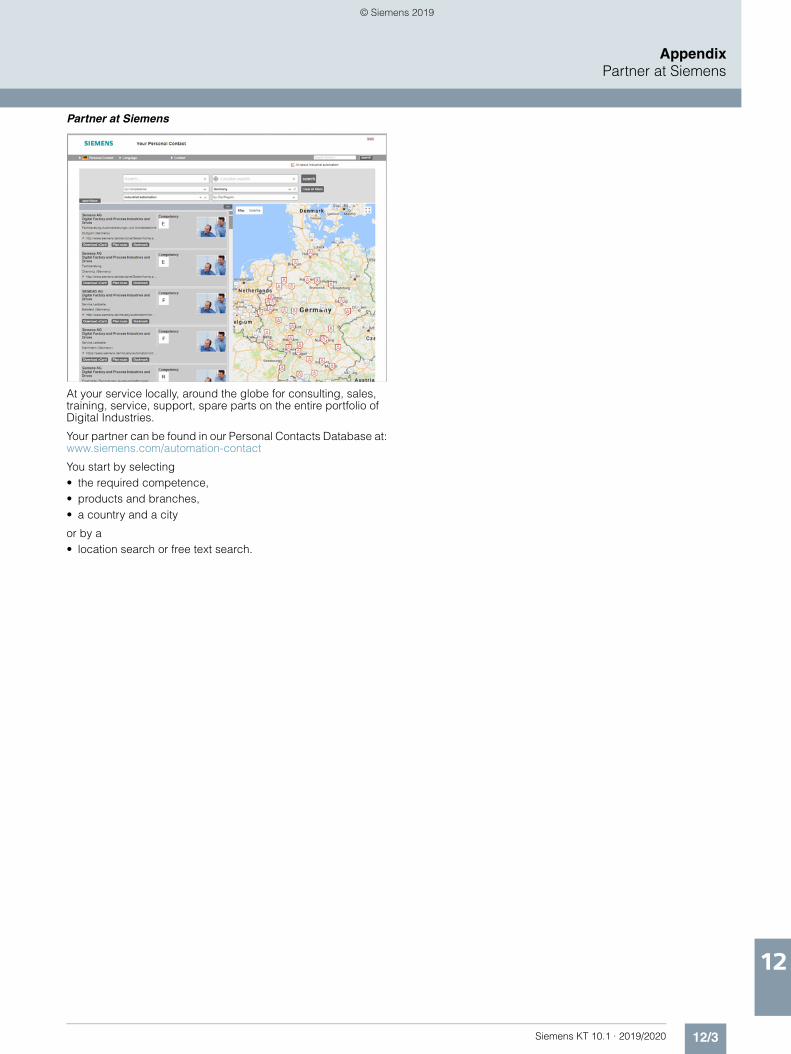
12/3Siemens KT 10.1 · 2019/2020
AppendixPartner at Siemens
12
Partner at Siemens
At your service locally, around the globe for consulting, sales, training, service, support, spare parts on the entire portfolio of Digital Industries.
Your partner can be found in our Personal Contacts Database at:www.siemens.com/automation-contact
You start by selecting • the required competence, • products and branches, • a country and a city
or by a• location search or free text search.
© Siemens 2019

12/4 Siemens KT 10.1 · 2019/2020
AppendixPartner at Siemens
Siemens Partner Program
■ Overview
Siemens Solution and Approved Partner – Partners for your success
Highest competence in automation and drive technology
Siemens works closely together with selected partner compa-nies around the world in order to ensure that customer require-ments for all aspects of automation and drives are fulfilled as best as possible − wherever you are, and whatever the time.
We place great value on our customers acting in accordance with the same ideals which characterize Siemens as a whole: Competence, professionalism and quality. That is why continu-ous development through qualification and certification mea-sures in line with global standards is a central aspect of our Partner Program. This means that with our partners, you benefit from the same high quality standards all over the world. The partner emblem is the symbol for tried and tested quality.
The partner network for industry
The Siemens Partner Program offers you expertise and experience close at hand.
Within our global network, we distinguish between Solution Partners and Approved Partners. We currently work with more than 1,500 Solution Partners around the world. Our network of over 150 Approved Partners continues to grow. In more than 80 countries worldwide
Siemens Solution Partner – Automation Drives
At present we are working with more than 1,500 Solution Partners worldwide. They are characterized by extensive application, system and sector knowledge, as well as proven project experience, and are able to implement future-proof tailored solutions of the highest quality, based on our product and system portfolio.
Siemens Approved Partner – Value Added Reseller
With their detailed technical knowledge, Siemens Approved Partners – Value Added Resellers offer a combination of products and services that range from specialist technologies and customized modifications to the provision of high-quality system and product packages. They also provide qualified technical support and assistance.
Siemens Approved Partner – Industry Services
Siemens Approved Partner – Industry Services put their unique expertise entirely at the service of enhancing your productivity and can be instrumental in ensuring the availability of your plants.
Partner Finder
The ideal partner for your task is just a mouse click away!
In the Siemens global Solution Partner program, customers are certain to find the optimum partner for their specific require-ments – with no great effort. The Partner Finder is basically a comprehensive database that showcases the profiles of all our partners.
Easy selection: Set filters in the search screen form according to the criteria that are relevant to you. You can also directly enter the name of an existing partner.
Skills at a glance: Gain a quick insight into the specific competencies of any par-ticular partner with the reference reports.
Direct contact option: Use our electronic query form:
www.siemens.com/partnerfinder
Additional information of the Siemens Parners for industry is available online at:
www.siemens.com/partnerprogram
© Siemens 2019
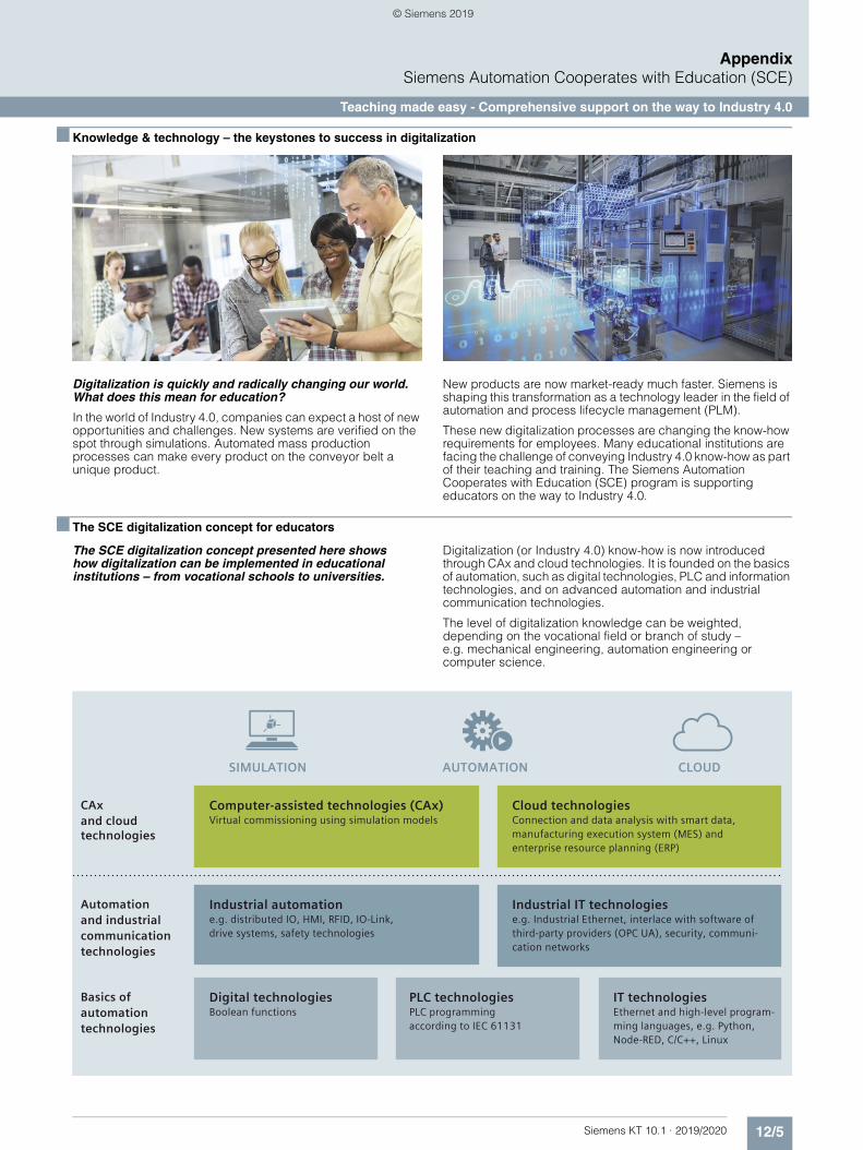
12/5Siemens KT 10.1 · 2019/2020
AppendixSiemens Automation Cooperates with Education (SCE)
Teaching made easy - Comprehensive support on the way to Industry 4.0
■ Knowledge & technology – the keystones to success in digitalization
Digitalization is quickly and radically changing our world. What does this mean for education?
In the world of Industry 4.0, companies can expect a host of new opportunities and challenges. New systems are verified on the spot through simulations. Automated mass production processes can make every product on the conveyor belt a unique product.
New products are now market-ready much faster. Siemens is shaping this transformation as a technology leader in the field of automation and process lifecycle management (PLM).
These new digitalization processes are changing the know-how requirements for employees. Many educational institutions are facing the challenge of conveying Industry 4.0 know-how as part of their teaching and training. The Siemens Automation Cooperates with Education (SCE) program is supporting educators on the way to Industry 4.0.
■ The SCE digitalization concept for educators
The SCE digitalization concept presented here shows how digitalization can be implemented in educational institutions – from vocational schools to universities.
Digitalization (or Industry 4.0) know-how is now introduced through CAx and cloud technologies. It is founded on the basics of automation, such as digital technologies, PLC and information technologies, and on advanced automation and industrial communication technologies.
The level of digitalization knowledge can be weighted, depending on the vocational field or branch of study – e.g. mechanical engineering, automation engineering or computer science.
© Siemens 2019
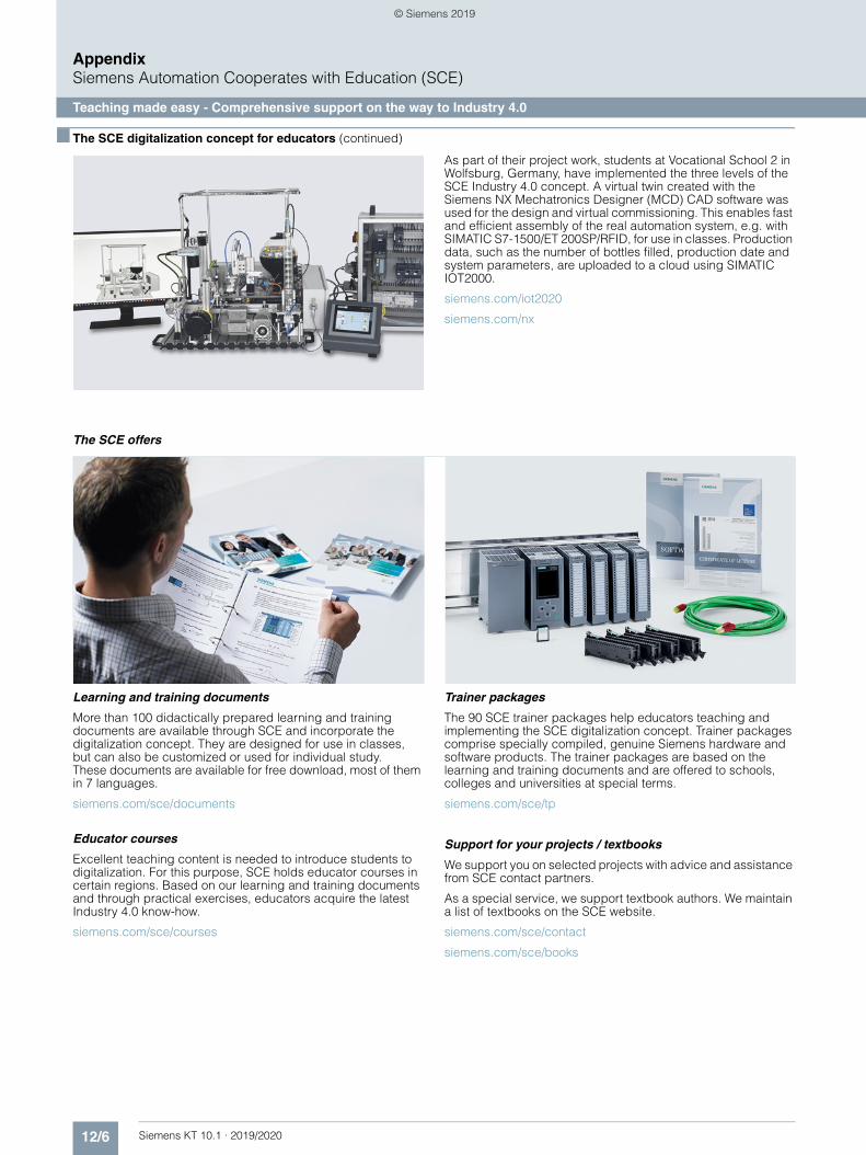
12/6 Siemens KT 10.1 · 2019/2020
AppendixSiemens Automation Cooperates with Education (SCE)
Teaching made easy - Comprehensive support on the way to Industry 4.0
■ The SCE digitalization concept for educators (continued)
As part of their project work, students at Vocational School 2 in Wolfsburg, Germany, have implemented the three levels of the SCE Industry 4.0 concept. A virtual twin created with the Siemens NX Mechatronics Designer (MCD) CAD software was used for the design and virtual commissioning. This enables fast and efficient assembly of the real automation system, e.g. with SIMATIC S7-1500/ET 200SP/RFID, for use in classes. Production data, such as the number of bottles filled, production date and system parameters, are uploaded to a cloud using SIMATIC IOT2000.
siemens.com/iot2020
siemens.com/nx
The SCE offers
Learning and training documents
More than 100 didactically prepared learning and training documents are available through SCE and incorporate the digitalization concept. They are designed for use in classes, but can also be customized or used for individual study. These documents are available for free download, most of them in 7 languages.
siemens.com/sce/documents
Educator courses
Excellent teaching content is needed to introduce students to digitalization. For this purpose, SCE holds educator courses in certain regions. Based on our learning and training documents and through practical exercises, educators acquire the latest Industry 4.0 know-how.
siemens.com/sce/courses
Trainer packages
The 90 SCE trainer packages help educators teaching and implementing the SCE digitalization concept. Trainer packages comprise specially compiled, genuine Siemens hardware and software products. The trainer packages are based on the learning and training documents and are offered to schools, colleges and universities at special terms.
siemens.com/sce/tp
Support for your projects / textbooks
We support you on selected projects with advice and assistance from SCE contact partners.
As a special service, we support textbook authors. We maintain a list of textbooks on the SCE website.
siemens.com/sce/contact
siemens.com/sce/books
© Siemens 2019

12/7Siemens KT 10.1 · 2019/2020
AppendixSiemens Automation Cooperates with Education (SCE)
Teaching made easy - Comprehensive support on the way to Industry 4.0
■ Partnerships for proliferation of Industry 4.0 in education
Partnership with WorldSkills
As a technology powerhouse, we support vocational training of students around the world. Since 2010, we have partnered with WorldSkills as a Global Industry Partner in order to amplify this cause.
WorldSkills is an international organization whose mission is to raise the profile and recognition of skilled people, and show how important vocational skills are in achieving economic growth and personal success. Every two years, WorldSkills hosts the world championships of skills.
Siemens provides the competitors with automation products, such as SIMATIC S7-1500 and LOGO!, for the disciplines: indus-trial control, electrical installations, Polymechanics/Automation and manufacturing technology.
The next international skill competitions are scheduled for Kazan/Russia, in 2019 and Shanghai/China, in 2021. Additionally, we support selected continental and regional competitions.
siemens.com/worldskills
Partnerships with educators
We provide support to educators and educational organizations in the form of one-on-one advice through SCE contact partners and Siemens experts as well as long-term cooperation.
siemens.com/sce/contact
Partnerships with producers of learning systems
For practical training in classrooms and labs, numerous producers of learning systems offer a wide range of complete didactic solutions based on SCE trainer packages.
siemens.com/sce/partner
■ Information portal
To facilitate your teaching assignment and/or for selfstudy, we offer educators and students a comprehensive SCE information portal. At this portal you have quick access to all SCE offers, e.g. learning and training documents including projects, Getting Started information, videos, manuals, trial software and newsletters.
siemens.com/sce
© Siemens 2019
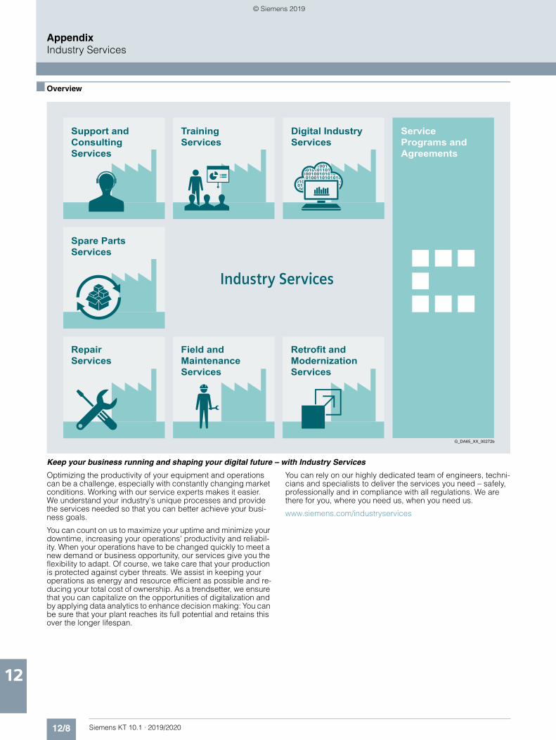
12/8 Siemens KT 10.1 · 2019/2020
AppendixIndustry Services
12
■ Overview
Keep your business running and shaping your digital future – with Industry Services
Optimizing the productivity of your equipment and operations can be a challenge, especially with constantly changing market conditions. Working with our service experts makes it easier. We understand your industry's unique processes and provide the services needed so that you can better achieve your busi-ness goals.
You can count on us to maximize your uptime and minimize your downtime, increasing your operations' productivity and reliabil-ity. When your operations have to be changed quickly to meet a new demand or business opportunity, our services give you the flexibility to adapt. Of course, we take care that your production is protected against cyber threats. We assist in keeping your operations as energy and resource efficient as possible and re-ducing your total cost of ownership. As a trendsetter, we ensure that you can capitalize on the opportunities of digitalization and by applying data analytics to enhance decision making: You can be sure that your plant reaches its full potential and retains this over the longer lifespan.
You can rely on our highly dedicated team of engineers, techni-cians and specialists to deliver the services you need – safely, professionally and in compliance with all regulations. We are there for you, where you need us, when you need us.
www.siemens.com/industryservices
TrainingServices
ServicePrograms andAgreements
Retrofit andModernizationServices
G_DA65_XX_00272b
RepairServices
Field andMaintenanceServices
Spare PartsServices
Digital IndustryServices
Support andConsultingServices
© Siemens 2019
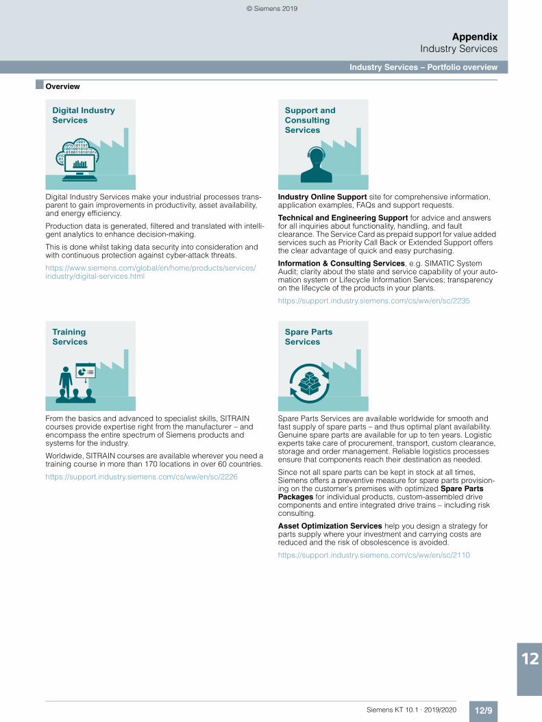
12/9Siemens KT 10.1 · 2019/2020
AppendixIndustry Services
Industry Services – Portfolio overview
12
■ Overview
Digital Industry Services make your industrial processes trans-parent to gain improvements in productivity, asset availability, and energy efficiency.
Production data is generated, filtered and translated with intelli-gent analytics to enhance decision-making.
This is done whilst taking data security into consideration and with continuous protection against cyber-attack threats.
https://www.siemens.com/global/en/home/products/services/industry/digital-services.html
From the basics and advanced to specialist skills, SITRAIN courses provide expertise right from the manufacturer – and encompass the entire spectrum of Siemens products and systems for the industry.
Worldwide, SITRAIN courses are available wherever you need a training course in more than 170 locations in over 60 countries.
https://support.industry.siemens.com/cs/ww/en/sc/2226
Industry Online Support site for comprehensive information, application examples, FAQs and support requests.
Technical and Engineering Support for advice and answers for all inquiries about functionality, handling, and fault clearance. The Service Card as prepaid support for value added services such as Priority Call Back or Extended Support offers the clear advantage of quick and easy purchasing.
Information & Consulting Services, e.g. SIMATIC System Audit; clarity about the state and service capability of your auto-mation system or Lifecycle Information Services; transparency on the lifecycle of the products in your plants.
https://support.industry.siemens.com/cs/ww/en/sc/2235
Spare Parts Services are available worldwide for smooth and fast supply of spare parts – and thus optimal plant availability. Genuine spare parts are available for up to ten years. Logistic experts take care of procurement, transport, custom clearance, storage and order management. Reliable logistics processes ensure that components reach their destination as needed.
Since not all spare parts can be kept in stock at all times, Siemens offers a preventive measure for spare parts provision-ing on the customer's premises with optimized Spare Parts Packages for individual products, custom-assembled drive components and entire integrated drive trains – including risk consulting.
Asset Optimization Services help you design a strategy for parts supply where your investment and carrying costs are reduced and the risk of obsolescence is avoided.
https://support.industry.siemens.com/cs/ww/en/sc/2110
Digital IndustryServices
TrainingServices
Support andConsultingServices
Spare PartsServices
© Siemens 2019
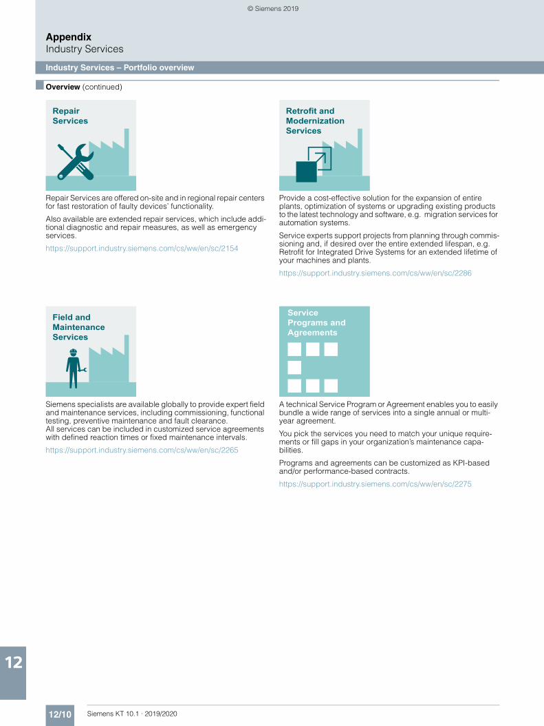
12/10 Siemens KT 10.1 · 2019/2020
AppendixIndustry Services
Industry Services – Portfolio overview
12
■ Overview (continued)
Repair Services are offered on-site and in regional repair centers for fast restoration of faulty devices’ functionality.
Also available are extended repair services, which include addi-tional diagnostic and repair measures, as well as emergency services.
https://support.industry.siemens.com/cs/ww/en/sc/2154
Siemens specialists are available globally to provide expert field and maintenance services, including commissioning, functional testing, preventive maintenance and fault clearance. All services can be included in customized service agreements with defined reaction times or fixed maintenance intervals.
https://support.industry.siemens.com/cs/ww/en/sc/2265
Provide a cost-effective solution for the expansion of entire plants, optimization of systems or upgrading existing products to the latest technology and software, e.g. migration services for automation systems.
Service experts support projects from planning through commis-sioning and, if desired over the entire extended lifespan, e.g. Retrofit for Integrated Drive Systems for an extended lifetime of your machines and plants.
https://support.industry.siemens.com/cs/ww/en/sc/2286
A technical Service Program or Agreement enables you to easily bundle a wide range of services into a single annual or multi-year agreement.
You pick the services you need to match your unique require-ments or fill gaps in your organization’s maintenance capa-bilities.
Programs and agreements can be customized as KPI-based and/or performance-based contracts.
https://support.industry.siemens.com/cs/ww/en/sc/2275
RepairServices
Field andMaintenanceServices
Retrofit andModernizationServices
ServicePrograms andAgreements
© Siemens 2019

12/11Siemens KT 10.1 · 2019/2020
AppendixIndustry Services
Online Support
12
■ Overview
Siemens Industry and Online Support with some 1.7 million visi-tors per month is one of the most popular web services provided by Siemens. It is the central access point for comprehensive technical know-how about products, systems and services for automation and drives applications as well as for process industries.
In connection with the challenges and opportunities related to digitalization you can look forward to continued support with innovative offerings.
Online Support – fast, intuitive, whenever you want, wherever you need
Online Support for Siemens Industry Products
Exchange information and experience with other users and experts
Forum
Videos, documentation, manuals, updates, product notes, compatibility tool, certificates, planning data such as dimensional drawings, product data, 3D models
Technical information
Information about industrial products, programming and configuration as well as application examples
FAQ / Application examples
App
support.industry.siemens.com
Web
Scan the QR code for information on our Online Support app.
© Siemens 2019
12/12 Siemens KT 10.1 · 2019/2020
AppendixConditions of sale and delivery
■ 1. General Provisions
By using this catalog you can purchase products (hardware, software and services) described therein from Siemens Aktien-gesellschaft subject to the following Terms and Conditions of Sale and Delivery (hereinafter referred to as "T&C"). Please note that the scope, the quality and the conditions for supplies and services, including software products, by any Siemens entity having a registered office outside Germany, shall be subject exclusively to the General Terms and Conditions of the respective Siemens entity. The following T&C apply exclusively for orders placed with Siemens Aktiengesellschaft, Germany.
1.1 For customers with a seat or registered office in GermanyFor customers with a seat or registered office in Germany, the following terms and conditions apply subordinate to T&C:• for products, which include specific terms and conditions in
the description text, these specific terms and conditions shall apply and subordinate thereto,
• for installation work the "General Conditions for Erection Works − Germany"1) ("Allgemeine Montagebedingungen − Deutschland" (currently only available in German)) and/or
• for stand-alone software products and software products forming a part of a product or project, the "General License Conditions for Software Products for Automation and Drives for Customers with a Seat or registered Office in Germany"1) and/or
• for consulting services the "General Terms and Conditions for Consulting Services of the Division DF − Germany"1) and/or
• for other supplies and/or services the "General Conditions for the Supply of Products and Services of the Electrical and Electronics Industry"1). In case such supplies and/or services should contain Open Source Software, the conditions of which shall prevail over the "General Conditions for the Supply of Products and Services of the Electrical and Electronics Industry"1), a notice will be contained in the scope of delivery in which the applicable conditions for Open Source Software are specified. This shall apply mutatis mutandis for notices referring to other third party software components.
1.2 For customers with a seat or registered office outside GermanyFor customers with a seat or registered office outside Germany, the following terms and conditions apply subordinate to T&C:• for products, which include specific terms and conditions in
the description text, these specific terms and conditions shall apply and subordinate thereto,
• for services the "International Terms & Conditions for Services"1) supplemented by "Software Licensing Conditions"1) and/or
• for consulting services the "General Terms and Conditions for Consulting Services of the Division DF − Germany"1) and/or
• for other supplies of hard- and software the "International Terms & Conditions for Products"1) supplemented by "Software Licensing Conditions"1)
1.3 For customers with master or framework agreementTo the extent our supplies and/or services offered are covered by an existing master or framework agreement, the terms and conditions of that agreement shall apply instead of T&C.
■ 2. Prices
The prices are in € (Euro) ex point of delivery, exclusive of packaging.The sales tax (value added tax) is not included in the prices. It shall be charged separately at the respective rate according to the applicable statutory legal regulations.Prices are subject to change without prior notice. We will charge the prices valid at the time of delivery.To compensate for variations in the price of raw materials (e.g. silver, copper, aluminum, lead, gold, dysprosium and neodym), surcharges are calculated on a daily basis using the so-called metal factor for products containing these raw materials. A surcharge for the respective raw material is calculated as a supplement to the price of a product if the basic official price of the raw material in question is exceeded.The metal factor of a product indicates the basic official price (for those raw materials concerned) as of which the surcharges on the price of the product are applied, and with what method of calculation. An exact explanation of the metal factor can be downloaded at:www.siemens.com/automation/salesmaterial-as/catalog/en/terms_of_trade_en.pdfTo calculate the surcharge (except in the cases of dysprosium and neodym), the official price from the day prior to that on which the order was received or the release order was effected is used.To calculate the surcharge applicable to dysprosium and neodym ("rare earths"), the corresponding three-month basic average price in the quarter prior to that in which the order was received or the release order was effected is used with a one-month buffer (details on the calculation can be found in the explanation of the metal factor).
■ 3. Additional Terms and Conditions
The dimensions are in mm. In Germany, according to the German law on units in measuring technology, data in inches apply only to devices for export.Illustrations are not binding.Insofar as there are no remarks on the individual pages of this catalog – especially with regard to data, dimensions and weights given – these are subject to change without prior notice.
1) The text of the Terms and Conditions of Siemens AG can be downloaded atwww.siemens.com/automation/salesmaterial-as/catalog/en/terms_of_trade_en.pdf
© Siemens 2019
12/13Siemens KT 10.1 · 2019/2020
AppendixConditions of sale and delivery
■ 4. Export Regulations
We shall not be obligated to fulfill any agreement if such fulfillment is prevented by any impediments arising out of national or international foreign trade or customs requirements or any embargoes and/or other sanctions.Export may be subject to license. We shall indicate in the delivery details whether licenses are required under German, European and US export lists.Our products are controlled by the U.S. Government (when labeled with "ECCN" unequal "N") and authorized for export only to the country of ultimate destination for use by the ultimate consignee or end-user(s) herein identified. They may not be resold, transferred, or otherwise disposed of, to any other country or to any person other than the authorized ultimate consignee or end-user(s), either in their original form or after being incorporated into other items, without first obtaining approval from the U.S. Government or as otherwise authorized by U.S. law and regulations. The export indications can be viewed in advance in the description of the respective goods on the Industry Mall, our online catalog system. Only the export labels "AL" and "ECCN" indicated on order confirmations, delivery notes and invoices are authoritative.Products labeled with "AL" unequal "N" are subject to European / national export authorization. Products without label, with label "AL:N" / "ECCN:N", or label "AL:9X9999" / "ECCN: 9X9999" may require authorization from responsible authorities depending on the final end-use, or the destination.
If you transfer goods (hardware and/or software and/or technology as well as corresponding documentation, regardless of the mode of provision) delivered by us or works and services (including all kinds of technical support) performed by us to a third party worldwide, you must comply with all applicable na-tional and international (re-)export control regulations.If required for the purpose of conducting export control checks, you (upon request by us) shall promptly provide us with all infor-mation pertaining to the particular end customer, final dispo-sition and intended use of goods delivered by us respectively works and services provided by us, as well as to any export control restrictions existing in this relation.The products listed in this catalog may be subject to European/German and/or US export regulations. Any export requiring approval is therefore subject to authorization by the relevant authorities.Errors excepted and subject to change without prior notice.
© Siemens 2019
12/14 Siemens KT 10.1 · 2019/2020
Appendix
Notes
© Siemens 2019
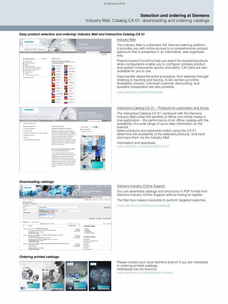
Selection and ordering at SiemensIndustry Mall, Catalog CA 01, downloading and ordering catalogs
Easy product selection and ordering: Industry Mall and Interactive Catalog CA 01
Industry Mall
The Industry Mall is a Siemens AG Internet ordering platform. It provides you with online access to a comprehensive product spectrum that is presented in an informative, well-organized way.
Powerful search functions help you select the required products, while configurators enable you to configure complex product and system components quickly and easily. CAx data are also available for you to use.
Data transfer allows the entire procedure, from selection through ordering to tracking and tracing, to be carried out online. Availability checks, individual customer discounting, and quotation preparation are also possible.
www.siemens.com/industrymall
Interactive Catalog CA 01 – Products for automation and drives
The Interactive Catalog CA 01 combined with the Siemens Industry Mall unites the benefits of offline and online media in one application – the performance of an offline catalog with the availability of a wide range of up-to-date information on the Internet. Select products and assemble orders using the CA 01, determine the availability of the selected products, and track and trace them via the Industry Mall.
Information and download: www.siemens.com/automation/ca01
Downloading catalogsSiemens Industry Online Support
You can download catalogs and brochures in PDF format from Siemens Industry Online Support without having to register.
The filter box makes it possible to perform targeted searches.
www.siemens.com/industry-catalogs
Ordering printed catalogs
Please contact your local Siemens branch if you are interested in ordering printed catalogs. Addresses can be found at www.siemens.com/automation-contact
© Siemens 2019
www.siemens.com/automation
Security informationSiemens provides products and solutions with industrial security functions that support the secure operation of plants, systems, machines and networks.
In order to protect plants, systems, machines and networks against cyber threats, it is necessary to implement – and continuously maintain – a holistic, state-of-the-art industrial security concept. Siemens’ products and solutions constitute one element of such a concept.
Customers are responsible for preventing unauthorized access to their plants, systems, machines and networks. Such systems, machines and components should only be connected to an enterprise network or the internet if and to the extent such a connection is necessary and only when appropriate security measures (e.g. firewalls and/or network segmentation) are in place.
For additional information on industrial security measures that may be implemented, please visithttps://www.siemens.com/industrialsecurity.
Siemens’ products and solutions undergo continuous development to make them more secure. Siemens strongly recommends that product updates are applied as soon as they are available and that the latest product versions are used. Use of product versions that are no longer supported, and failure to apply the latest updates may increase cus-tomer’s exposure to cyber threats.
To stay informed about product updates, subscribe to the Siemens Industrial Security RSS Feed under https://www.siemens.com/industrialsecurity.
Digital IndustriesProcess AutomationÖstliche Rheinbrückenstr. 5076187 Karlsruhe, Germany
Published bySiemens
PDF (E86060-D4001-A510-D8)KG 0719 276 En© Siemens 2019
Availability and technical specifications are subject to change without notice. The information provided in this catalog contains merely general descriptions or characteristics of performance which in case of actual use do not always apply as described or which may change as a result of further development of the products. An obligation to provide the respective characteristics shall only exist if expressly agreed in the terms of contract.
All product designations may be trademarks or product names of Siemens AG or supplier companies whose use by third parties for their own purposes could violate the rights of the owners.
© Siemens 2019


