Embed Size (px)
Citation preview
flender.com
FLENDER COUPLINGS CATALOG FLE 10.1 EDITION 2022 EN
TORSIONALLY RIGID COUPLINGSZAPEX, N-ARPEX AND ARPEX

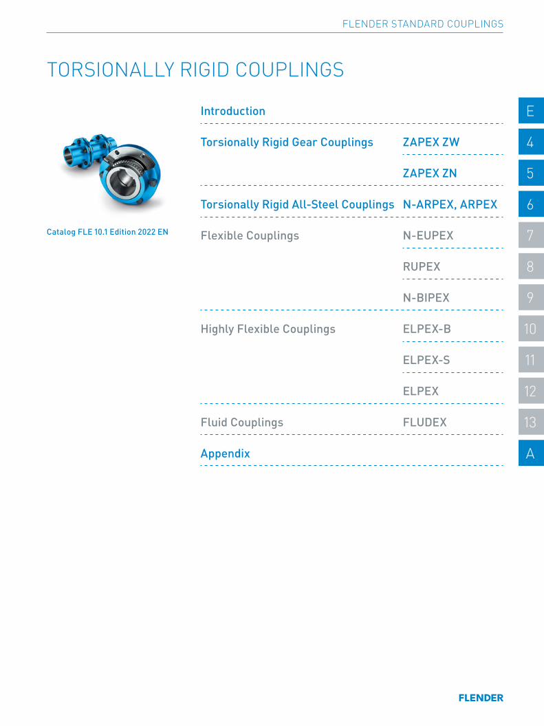
TORSIONALLY RIGID COUPLINGS
Catalog FLE 10.1 Edition 2022 EN
Introduction E E
Torsionally Rigid Gear Couplings ZAPEX ZW 4 4
ZAPEX ZN 5 5
Torsionally Rigid All-Steel Couplings N-ARPEX, ARPEX 6 6
Flexible Couplings N-EUPEX 7 7
RUPEX 8 8
N-BIPEX 9 9
Highly Flexible Couplings ELPEX-B 10 10
ELPEX-S 11 11
ELPEX 12 12
Fluid Couplings FLUDEX 13 13
Appendix A A
FLENDER STANDARD COUPLINGS
E/2
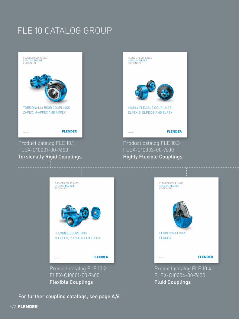
FLE 10 CATALOG GROUP
INTRODUCTION
Product catalog FLE 10.1 FLEX-C10001-00-7600 Torsionally Rigid Couplings
Product catalog FLE 10.2 FLEX-C10001-00-7600 Flexible Couplings
Product catalog FLE 10.3 FLEX-C10003-00-7600 Highly Flexible Couplings
Product catalog FLE 10.4 FLEX-C10004-00-7600 Fluid Couplings
flender.com
FLENDER COUPLINGS CATALOG FLE 10.1 EDITION EN
TORSIONALLY RIGID COUPLINGSZAPEX, N-ARPEX AND ARPEX
flender.com
FLENDER COUPLINGS CATALOG FLE 10.3 EDITION EN
HIGHLY FLEXIBLE COUPLINGSELPEX-B, ELPEX-S AND ELPEX
flender.com
FLENDER COUPLINGS CATALOG FLE 10.2 EDITION EN
FLEXIBLE COUPLINGSN-EUPEX, RUPEX AND N-BIPEX
flender.com
FLENDER COUPLINGS CATALOG FLE 10.4 EDITION EN
FLUID COUPLINGSFLUDEX
For further coupling catalogs, see page A/6
E/3
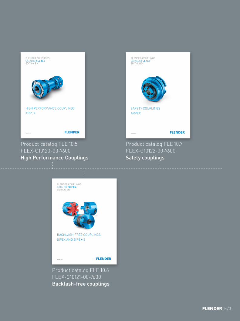
Product catalog FLE 10.5 FLEX-C10120-00-7600 High Performance Couplings
Product catalog FLE 10.6 FLEX-C10121-00-7600 Backlash-free couplings
Product catalog FLE 10.7 FLEX-C10122-00-7600 Safety couplings
flender.com
FLENDER COUPLINGS CATALOG FLE 10.5 EDITION EN
HIGH PERFORMANCE COUPLINGSARPEX
flender.com
FLENDER-COUPLINGS CATALOG FLE 10.7 EDITION EN
SAFETY COUPLINGSARPEX
flender.com
FLENDER COUPLINGS CATALOG FLE 10.6 EDITION EN
BACKLASH-FREE COUPLINGSSIPEX AND BIPEX-S
The mechanical drive train comprises individual units such as motor, gear unit and driven machine. The coupling connects these component assemblies. As well as the transmission of rotary motion and torque, other requirements may be made of the coupling.
• Compensation for shaft misalignment with low restorative forces
• Control of characteristic angular vibration frequency and damping
• Interruption or limitation of torque• Noise insulation, electrical insulation
Couplings are frequently chosen after the machines to be connected have already been selected. Thanks to a large number of different coupling assembly options, speci-fied marginal conditions for clearance and connection geometry can be met from the standard range. The coup-ling also performs secondary functions, e.g. providing a brake disk or brake drum for operating or blocking brakes, devices to record speed or the attachment of sprockets or pulleys.
Couplings are divided into two main groups, couplings and clutches. Clutches interrupt or limited the transmissible torque. The engaging and disengaging forces on externally operated clutches are introduced via a mechanically, electrically, hydraulically or pneumatically operating mechanism. Overload, centrifugal or freewheel clutches draw their engaging energy from the transmitted output.
Rigid couplings, designed as clamp, flanged or mechanism couplings, connect machines which must not undergo any shaft misalignment. Hydrodynamic couplings, often also called fluid or Föttinger couplings, are used as starting couplings in drives with high mass moments of inertia of the driven machine. In drive technology very often flexible, positive couplings, which may be designed to be torsionally rigid, torsionally flexible or highly flexible, are used.
Torsionally rigid couplings are designed to be rigid in a peripheral direction and flexible in radial and axial direc-tions. The angle of rotation and torque are conducted through the coupling without a phase shift.
Torsionally flexible couplings have resilient elements usually manufactured from elastomer materials. Using an elastomer material with a suitable ShoreA hardness provides the most advantageous torsional stiffness and damping for the application. Shaft misalignment causes the resilient elements to deform.
Highly flexible couplings have large-volume (elastomer) resilient elements of low stiffness. The angle of rota-tion and torque are conducted through the coupling with a considerable phase shift.
INTRODUCTION
E/4
FLENDER STANDARD COUPLINGS | INTRODUCTION
E E
4 4
5 5
6 6
7 7
8 8
9 9
10 10
11 11
12 12
13 13
A A
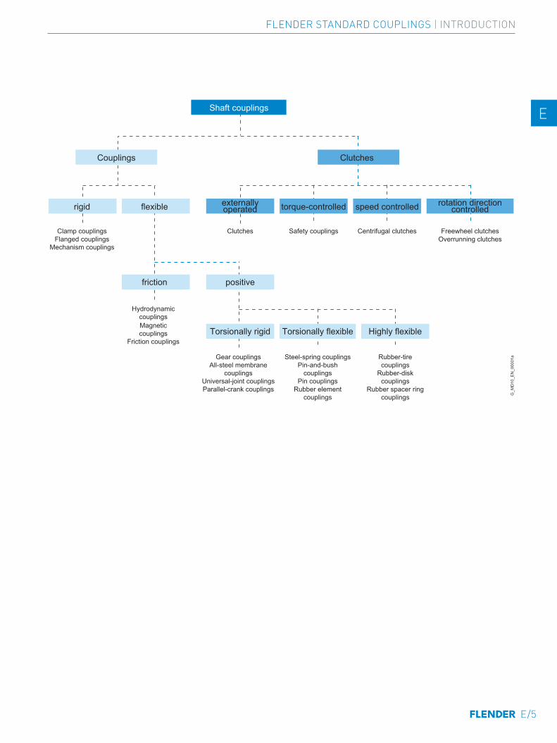
Shaft couplings
Couplings Clutches
rigid flexible
friction positive
Clamp couplingsFlanged couplings
Mechanism couplings
HydrodynamiccouplingsMagneticcouplings
Friction couplings
Clutches
externallyoperated
rotation directioncontrolled
Safety couplings
torque-controlled
Centrifugal clutches
speed controlled
Freewheel clutchesOverrunning clutches
Torsionally rigid Torsionally flexible Highly flexible
Gear couplingsAll-steel membrane
couplingsUniversal-joint couplingsParallel-crank couplings
Steel-spring couplingsPin-and-bush
couplingsPin couplings
Rubber elementcouplings
Rubber-tirecouplings
Rubber-diskcouplings
Rubber spacer ringcouplings G
_MD
10_E
N_0
0001
a
E/5
FLENDER STANDARD COUPLINGS | INTRODUCTION
E E
4 4
5 5
6 6
7 7
8 8
9 9
10 10
11 11
12 12
13 13
A A
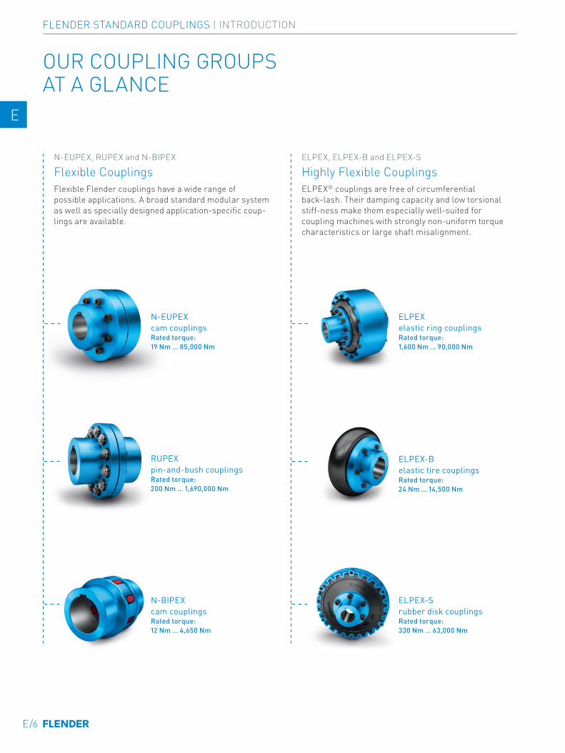
OUR COUPLING GROUPS AT A GLANCE
N-EUPEX, RUPEX and N-BIPEX
Flexible CouplingsFlexible Flender couplings have a wide range of possible applications. A broad standard modular system as well as specially designed application-specific coup-lings are available.
ELPEX, ELPEX-B and ELPEX-S
Highly Flexible CouplingsELPEX® couplings are free of circumferential back-lash. Their damping capacity and low torsional stiff-ness make them especially well-suited for coupling machines with strongly non-uniform torque characteristics or large shaft misalignment.
N-EUPEX cam couplingsRated torque: 19 Nm … 85,000 Nm
ELPEX elastic ring couplingsRated torque: 1,600 Nm … 90,000 Nm
ELPEX-B elastic tire couplingsRated torque: 24 Nm … 14,500 Nm
N-BIPEX cam couplingsRated torque: 12 Nm … 4,650 Nm
ELPEX-S rubber disk couplingsRated torque: 330 Nm … 63,000 Nm
RUPEX pin-and-bush couplingsRated torque: 200 Nm … 1,690,000 Nm
E/6
FLENDER STANDARD COUPLINGS | INTRODUCTION
E E
4 4
5 5
6 6
7 7
8 8
9 9
10 10
11 11
12 12
13 13
A A
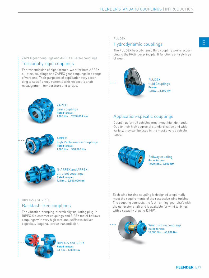
FLUDEX
Hydrodynamic couplingsThe FLUDEX hydrodynamic fluid coupling works accor-ding to the Föttinger principle. It functions entirely free of wear.
FLUDEX fluid CouplingsPower: 1.2 kW … 2,500 kW
Application-specific couplingsCouplings for rail vehicles must meet high demands. Due to their high degree of standardization and wide variety, they can be used in the most diverse vehicle types.
Each wind turbine coupling is designed to optimally meet the requirements of the respective wind turbine. The coupling connects the fast-running gear shaft with the generator shaft and is available for wind turbines with a capacity of up to 12 MW.
Wind turbine couplingsRated torque: 10,000 Nm … 60,000 Nm
Railway couplingRated torque: 1,000 Nm … 9,500 Nm
ZAPEX gear couplings and ARPEX all-steel couplings
Torsionally rigid couplingsFor transmission of high torques, we offer both ARPEX all-steel couplings and ZAPEX gear couplings in a range of versions. Their purposes of application vary accor-ding to specific requirements with respect to shaft misalignment, temperature and torque.
BIPEX-S and SIPEX
Backlash-free couplingsThe vibration-damping, electrically insulating plug-in BIPEX-S elastomer couplings and SIPEX metal bellows couplings with very high torsional stiffness deliver especially isogonal torque transmission.
N-ARPEX and ARPEX all-steel couplingsRated torque: 92 Nm … 2,000,000 Nm
ZAPEX gear couplingsRated torque: 1,300 Nm … 7,200,000 Nm
ARPEX high Performance CouplingsRated torque: 1,000 Nm … 588,500 Nm
BIPEX-S and SIPEXRated torque: 0.1 Nm … 5,000 Nm
E/7
FLENDER STANDARD COUPLINGS | INTRODUCTION
E E
4 4
5 5
6 6
7 7
8 8
9 9
10 10
11 11
12 12
13 13
A A

E/8
TECHNICAL INFORMATION AND COUPLING SELECTION
Technical Information E/10
Shaft misalignment E/10Balancing E/11Shaft-hub connections E/13Standards E/14Key to symbols E/15
Selection of the coupling series E/16
Typical coupling solutions for different example applications E/17
Selection of the coupling size E/18
Coupling load in continuous operation E/18Coupling load at maximum and overload conditions E/19Coupling load due to dynamic torque load E/19Checking the maximum speed E/20Checking permitted shaft misalignment E/20Checking bore diameter, mounting geometry and coupling design E/20Coupling behavior under overload conditions E/20Checking shaft-hub connection E/20Checking low temperature and chemically aggressive environment E/20
Features of the standard type E/21
E/9
FLENDER STANDARD COUPLINGS | INTRODUCTION
E E
4 4
5 5
6 6
7 7
8 8
9 9
10 10
11 11
12 12
13 13
A A

Shaft misalignment
Shaft misalignment is the result of displacement during assembly and operation and, where machines const-ructed with two radial bearings each are rigidly coupled, will cause high loads being placed on the bearings. Elastic deformation of base frame, foundation and machine housing will lead to shaft misalignment which cannot be prevented, even by precise alignment.
Furthermore, because individual components of the drive train heat up differently during operation, heat expansion of the machine housings causes shaft misalignment. Poorly aligned drives are often the cause of seal, rolling bearing or coupling failure. Alignment should be carried out by specialist personnel in accordance with operating instructions.
TECHNICAL INFORMATION
Depending on the direction of the effective shaft misalignment a distinction is made between:
Single-joint couplings
Couplings with flexible elements mainly made of elas-tomer materials. Shaft misalignment results in deforma-tion of the elastomer elements. The elastomer elements can absorb shaft misalignment as deformations in an axial, radial and angular direction. The degree of permissible misalignment depends on the coupling size, the speed and the type of elastomer element. Single-joint couplings do not require an adapter and are therefore short versions.
Example:In the case of a RUPEX RWN 198 coupling with an outer diameter of 198 mm and a speed of 1500 rpm, the permitted radial misalignment is ΔKr = 0.3 mm.
Kr
G_M
D10
_XX
_000
14
Couplings can be categorized into one of the following groups:
Axial misalignment Radial misalignment Angular misalignment
Two-joint couplings
Two-joint couplings are always designed with an adapter. The two joint levels are able to absorb axial and angular misalignment. Radial misalignment occurs via the gap between the two joint levels and the angular displace-ment of the joint levels. The permitted angular misalign-ment per joint level is frequently about 0.5°. The permitted shaft misalignment of the coupling can be adjusted via the length of the adapter. If there are more than two joint levels, it is not possible to define the position of the coupling parts relative to the axis of rotation. (The less frequently used parallel-crank couplings are an exception).
Example:N-ARPEX ARN-6 NEN 217-6 with a shaft distance of 140 mm with a permitted radial misalignment of ΔKr = 2.2 mm (angle per joint level 1.0°).
E/10
FLENDER STANDARD COUPLINGS | INTRODUCTION
E E
4 4
5 5
6 6
7 7
8 8
9 9
10 10
11 11
12 12
13 13
A A
Balancing
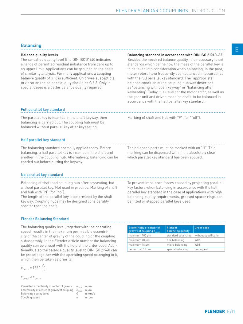
Balance quality levelsThe so-called quality level G to DIN ISO 21940 indicates a range of permitted residual imbalance from zero up to an upper limit. Applications can be grouped on the basis of similarity analysis. For many applications a coupling balance quality of G 16 is sufficient. On drives susceptible to vibration the balance quality should be G 6.3. Only in special cases is a better balance quality required.
Balancing standard in accordance with DIN ISO 21940-32Besides the required balance quality, it is necessary to set standards which define how the mass of the parallel key is to be taken into consideration when balancing. In the past, motor rotors have frequently been balanced in accordance with the full parallel key standard. The "appropriate" balance condition of the coupling hub was described as "balancing with open keyway" or "balancing after key seating". Today it is usual for the motor rotor, as well as the gear unit and driven machine shaft, to be balanced in accordance with the half parallel key standard.
Full parallel key standard
The parallel key is inserted in the shaft keyway, then balancing is carried out. The coupling hub must be balanced without parallel key after keyseating.
Marking of shaft and hub with "F" (for "full").
Half parallel key standard
The balancing standard normally applied today. Before balancing, a half parallel key is inserted in the shaft and another in the coupling hub. Alternatively, balancing can be carried out before cutting the keyway.
The balanced parts must be marked with an "H". This marking can be dispensed with if it is absolutely clear which parallel key standard has been applied.
No parallel key standard
Balancing of shaft and coupling hub after keyseating, but without parallel key. Not used in practice. Marking of shaft and hub with "N" (for "no"). The length of the parallel key is determined by the shaft keyway. Coupling hubs may be designed considerably shorter than the shaft.
To prevent imbalance forces caused by projecting parallel key factors when balancing in accordance with the half parallel key standard in the case of applications with high balancing quality requirements, grooved spacer rings can be fitted or stepped parallel keys used.
Flender Balancing Standard
The balancing quality level, together with the operating speed, results in the maximum permissible eccentri-city of the center of gravity of the coupling or the coupling subassembly. In the Flender article number the balancing quality can be preset with the help of the order code. Addi-tionally, also the balance quality level to DIN ISO 21940 can be preset together with the operating speed belonging to it, which then be taken as priority.
eperm = 9550⋅―
ecoupl ≤ eperm
Gn
Permitted eccentricity of center of gravity eperm in µm Eccentricity of center of gravity of coupling ecoupl in µm Balancing quality level G in mm/s Coupling speed n in rpm
Eccentricity of center of gravity of coupling ecoupl
Flender balancing quality
Order code
maximum 100 μm standard balancing without specificationmaximum 40 μm fine balancing W02maximum 16 μm micro-balancing W03better than 16 μm special balancing on request
E/11
FLENDER STANDARD COUPLINGS | INTRODUCTION
E E
4 4
5 5
6 6
7 7
8 8
9 9
10 10
11 11
12 12
13 13
A A
TECHNICAL INFORMATION
G 1
G 4
G 10G 16G 25G 40
102
10
1
2
468
2
468
2
468
103
102 42 6 8 2 4 6 8103 104
G 1.6G 2.5
G 6.3
G_M
D10
_EN
_000
07a
Ecce
ntric
ity o
f cen
ter o
f gra
vity
epe
rm. i
n µm
Coupling speed in rpm
On request
Micro-balancing
Fine balancing
Standard balancing
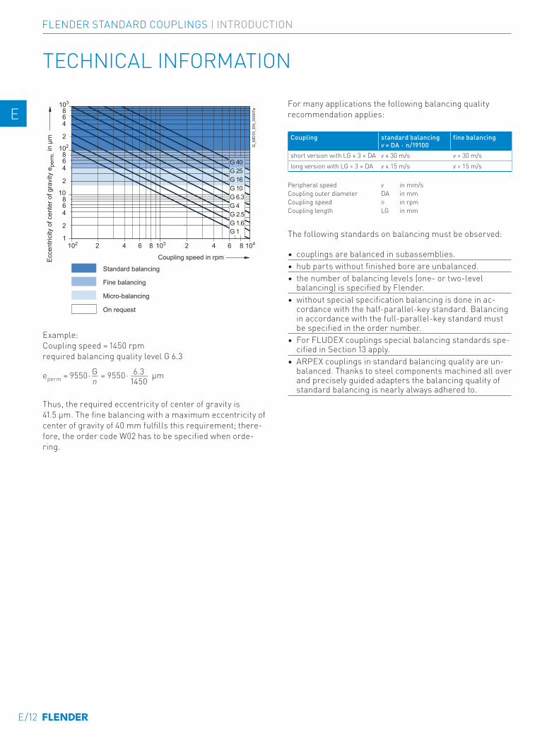
Example:Coupling speed = 1450 rpmrequired balancing quality level G 6.3
eperm = 9550⋅― = 9550⋅― µmG 6.3n 1450
Thus, the required eccentricity of center of gravity is 41.5 μm. The fine balancing with a maximum eccentricity of center of gravity of 40 mm fulfills this requirement; there-fore, the order code W02 has to be specified when orde-ring.
For many applications the following balancing quality recommendation applies:
Coupling standard balancing fine balancingν = DA ⋅ n/19100
short version with LG ≤ 3 × DA ν ≤ 30 m/s ν > 30 m/slong version with LG > 3 × DA ν ≤ 15 m/s ν > 15 m/s
Peripheral speed ν in mm/s Coupling outer diameter DA in mm Coupling speed n in rpm
Coupling length LG in mm
The following standards on balancing must be observed:
• couplings are balanced in subassemblies.• hub parts without finished bore are unbalanced.• the number of balancing levels (one- or two-level
balancing) is specified by Flender.• without special specification balancing is done in ac-
cordance with the half-parallel-key standard. Balancing in accordance with the full-parallel-key standard must be specified in the order number.
• For FLUDEX couplings special balancing standards spe-cified in Section 13 apply.
• ARPEX couplings in standard balancing quality are un-balanced. Thanks to steel components machined all over and precisely guided adapters the balancing quality of standard balancing is nearly always adhered to.
E/12
FLENDER STANDARD COUPLINGS | INTRODUCTION
E E
4 4
5 5
6 6
7 7
8 8
9 9
10 10
11 11
12 12
13 13
A A
Shaft-hub connections
The bore and the shaft-hub connection of the coupling are determined by the design of the machine shaft. In the case of IEC standard motors, the shaft diameters and parallel key connections are specified in accordance with DIN EN 50347. For diesel motors, the flywheel connections are frequently specified in accordance with SAE J620d or DIN 6288. Besides the very widely used connection of shaft and hub with parallel keys to DIN 6885 and cylindrically bored hubs, couplings with Taper clamping bushes, clam-ping sets, shrink-fit connections and splines to DIN 5480 are common.
The form stability of the shaft/hub connection can only be demonstrated when shaft dimensions and details of the connection are available. The coupling torques specified in the tables of power ratings of the coupling series do not apply to the shaft-hub connection unrestrictedly.
In the case of the shaft-hub connection with parallel key, the coupling hub must be axially secured, e.g. with a set screw or end washer. The parallel key must be secured against axial displacement in the machine shaft.
All Flender couplings with a finished bore and parallel keyway are designed with a set screw. Exceptions are some couplings of the FLUDEX series, in which end washers are used. During assembly, Taper clamping bushes are frictionally connected to the machine shaft.
E/13
FLENDER STANDARD COUPLINGS | INTRODUCTION
E E
4 4
5 5
6 6
7 7
8 8
9 9
10 10
11 11
12 12
13 13
A A
TECHNICAL INFORMATION
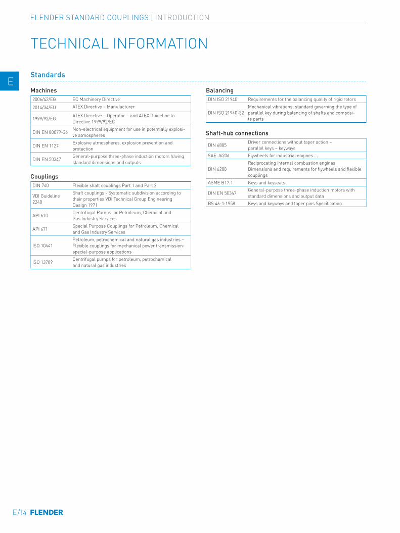
Standards
Machines2006/42/EG EC Machinery Directive
2014/34/EU ATEX Directive – Manufacturer
1999/92/EG ATEX Directive – Operator – and ATEX Guideline to Directive 1999/92/EC
DIN EN 80079-36 Non-electrical equipment for use in potentially explosi-ve atmospheres
DIN EN 1127 Explosive atmospheres, explosion prevention and protection
DIN EN 50347 General-purpose three-phase induction motors having standard dimensions and outputs
CouplingsDIN 740 Flexible shaft couplings Part 1 and Part 2
VDI Guideline 2240
Shaft couplings - Systematic subdivision according to their properties VDI Technical Group Engineering Design 1971
API 610 Centrifugal Pumps for Petroleum, Chemical and Gas Industry Services
API 671 Special Purpose Couplings for Petroleum, Chemical and Gas Industry Services
ISO 10441Petroleum, petrochemical and natural gas industries – Flexible couplings for mechanical power transmission-special-purpose applications
ISO 13709 Centrifugal pumps for petroleum, petrochemical and natural gas industries
BalancingDIN ISO 21940 Requirements for the balancing quality of rigid rotors
DIN ISO 21940-32Mechanical vibrations; standard governing the type of parallel key during balancing of shafts and composi-te parts
Shaft-hub connections
DIN 6885 Driver connections without taper action – parallel keys – keyways
SAE J620d Flywheels for industrial engines ...
DIN 6288Reciprocating internal combustion engines Dimensions and requirements for flywheels and flexible couplings
ASME B17.1 Keys and keyseats
DIN EN 50347 General-purpose three-phase induction motors with standard dimensions and output data
BS 46-1:1958 Keys and keyways and taper pins Specification
E/14
FLENDER STANDARD COUPLINGS | INTRODUCTION
E E
4 4
5 5
6 6
7 7
8 8
9 9
10 10
11 11
12 12
13 13
A A
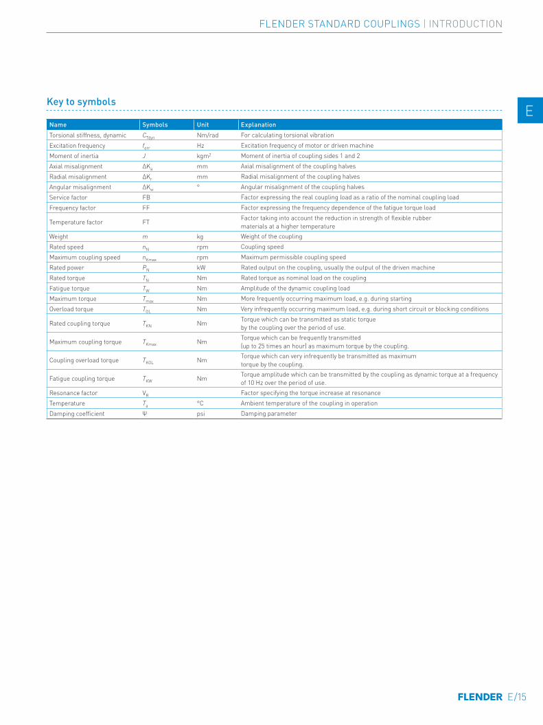
Key to symbols
Name Symbols Unit Explanation Torsional stiffness, dynamic CTdyn Nm/rad For calculating torsional vibrationExcitation frequency ferr Hz Excitation frequency of motor or driven machine Moment of inertia J kgm2 Moment of inertia of coupling sides 1 and 2 Axial misalignment ∆Ka mm Axial misalignment of the coupling halves Radial misalignment ∆Kr mm Radial misalignment of the coupling halvesAngular misalignment ∆Kw ° Angular misalignment of the coupling halvesService factor FB Factor expressing the real coupling load as a ratio of the nominal coupling loadFrequency factor FF Factor expressing the frequency dependence of the fatigue torque load
Temperature factor FT Factor taking into account the reduction in strength of flexible rubber materials at a higher temperature
Weight m kg Weight of the couplingRated speed nN rpm Coupling speedMaximum coupling speed nKmax rpm Maximum permissible coupling speed Rated power PN kW Rated output on the coupling, usually the output of the driven machine Rated torque TN Nm Rated torque as nominal load on the couplingFatigue torque TW Nm Amplitude of the dynamic coupling loadMaximum torque Tmax Nm More frequently occurring maximum load, e.g. during startingOverload torque TOL Nm Very infrequently occurring maximum load, e.g. during short circuit or blocking conditions
Rated coupling torque TKN Nm Torque which can be transmitted as static torque by the coupling over the period of use.
Maximum coupling torque TKmax Nm Torque which can be frequently transmitted (up to 25 times an hour) as maximum torque by the coupling.
Coupling overload torque TKOL Nm Torque which can very infrequently be transmitted as maximum torque by the coupling.
Fatigue coupling torque TKW Nm Torque amplitude which can be transmitted by the coupling as dynamic torque at a frequency of 10 Hz over the period of use.
Resonance factor VR Factor specifying the torque increase at resonanceTemperature Ta °C Ambient temperature of the coupling in operationDamping coefficient Ψ psi Damping parameter
E/15
FLENDER STANDARD COUPLINGS | INTRODUCTION
E E
4 4
5 5
6 6
7 7
8 8
9 9
10 10
11 11
12 12
13 13
A A
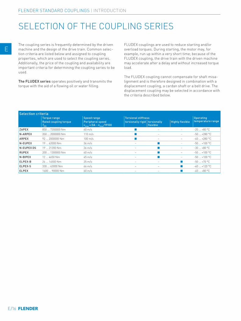
The coupling series is frequently determined by the driven machine and the design of the drive train. Common selec-tion criteria are listed below and assigned to coupling properties, which are used to select the coupling series. Additionally, the price of the coupling and availability are important criteria for determining the coupling series to be used.
The FLUDEX series operates positively and transmits the torque with the aid of a flowing oil or water filling.
SELECTION OF THE COUPLING SERIES
FLUDEX couplings are used to reduce starting and/or overload torques. During starting, the motor may, for example, run up within a very short time; because of the FLUDEX coupling, the drive train with the driven machine may accelerate after a delay and without increased torque load.
The FLUDEX coupling cannot compensate for shaft misa-lignment and is therefore designed in combination with a displacement coupling, a cardan shaft or a belt drive. The displacement coupling may be selected in accordance with the criteria described below.
Selection criteriaTorque range Speed range Torsional stiffness Operating
temperature rangeRated coupling torque TKN
Peripheral speed vmax = DA ⋅ nmax/19100
torsionally rigid torsionally flexible
Highly flexible
ZAPEX 850 ... 7200000 Nm 60 m/s ■ – – -20 ... +80 °CN-ARPEX 350 ... 2000000 Nm 110 m/s ■ – – -50 ... +280 °CARPEX 92 ... 2000000 Nm 100 m/s ■ – – -40 ... +280 °CN-EUPEX 19 ... 62000 Nm 36 m/s – ■ – -50 ... +100 °CN-EUPEX DS 19 ... 21200 Nm 36 m/s – ■ – -30 ... +80 °CRUPEX 200 ... 1300000 Nm 60 m/s – ■ – -50 ... +100 °CN-BIPEX 12 ... 4650 Nm 45 m/s – ■ – -50 ... +100 °CELPEX-B 24 ... 14500 Nm 35 m/s – – ■ -50 ... +70 °CELPEX-S 330 ... 63000 Nm 66 m/s – – ■ -40 ... +120 °CELPEX 1600 ... 90000 Nm 60 m/s – – ■ -40 ... +80 °C
E/16
FLENDER STANDARD COUPLINGS | INTRODUCTION
E E
4 4
5 5
6 6
7 7
8 8
9 9
10 10
11 11
12 12
13 13
A A
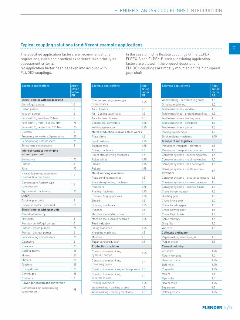
Typical coupling solutions for different example applications
The specified application factors are recommendations; regulations, rules and practical experience take priority as assessment criteria.No application factor need be taken into account with FLUDEX couplings.
In the case of highly flexible couplings of the ELPEX, ELPEX-S and ELPEX-B series, deviating application factors are stated in the product descriptions.FLUDEX couplings are mostly mounted on the high-speed gear shaft.
Example applications Appli-cation factor FB
Electric motor without gear unitCentrifugal pumps 1.0Piston pumps 1.5Vacuum pumps 1.5Fans with TN less than 75 Nm 1.5Fans with TN from 75 to 750 Nm 1.75Fans with TN larger than 750 Nm 1.75Blowers 1.5Frequency converters / generators 1.25Reciprocating compressors 1.75Screw-type compressors 1.5
Internal-combustion engine without gear unit
Generators 1.75Pumps 1.5Fans 1.75
Hydraulic pumps, excavators, construction machines 1.5
Compressors / screw-type compressors 1.5
Agricultural machinery 1.75Other Turbine gear units 1.5Hydraulic motor - gear unit 1.25Electric motor with gear unit Chemical industryExtruders 1.5Pumps - centrifugal pumps 1.0Pumps - piston pumps 1.75Pumps - plunger pumps 1.5Reciprocating compressors 1.75Calenders 1.5Kneaders 1.75Cooling drums 1.25Mixers 1.25Stirrers 1.25Toasters 1.25Drying drums 1.25Centrifuges 1.25Crushers 1.5Power generation and conversion
Compressed air, reciprocating compressors 1.75
Example applications Appli-cation factor FB
Compressed air, screw-type compressors 1.25
Air - Blowers 1.5Air - Cooling tower fans 1.5Air - Turbine blowers 1.5Generators, converters 1.25Welding generators 1.25Metal production, iron and steel worksPlate tilters 1.5Ingot pushers 1.75Slabbing mill 1.75Coiling machines 1.5Roller straightening machines 1.5Roller tables 1.75Shears 1.75Rollers 1.75Metal working machinesPlate bending machines 1.5Plate straightening machines 1.5Hammers 1.75Planing machines 1.75 Presses, forging presses 1.75Shears 1.5Grinding machines 1.25 Punches 1.5Machine tools: Main drives 1.5Machine tools: Auxiliary drives 1.25Food industryFilling machines 1.25Kneading machines 1.5Mashers 1.5Sugar cane production 1.5Production machines
Construction machines, hydraulic pumps 1.25
Construction machines, traversing gears 1.5
Construction machines, suction pumps 1.5
Construction machines, concrete mixers 1.5
Printing machines 1.25 Woodworking - barking drums 1.5Woodworking - planing machines 1.5
Example applications Appli-cation factor FB
Woodworking - reciprocating saws 1.5Grinding machines 1.5Textile machines - winders 1.5 Textile machines - printing machines 1.5 Textile machines - tanning vats 1.5 Textile machines - shredders 1.5 Textile machines - looms 1.5Packaging machines 1.5Brick molding machines 1.75 Transport and logisticsPassenger transport - elevators 1.5 Passenger transport - escalators 1.5 Conveyor systems - bucket elevators 1.5 Conveyor systems - hauling winches 1.5 Conveyor systems - belt conveyors 1.5
Conveyor systems - endless-chain conveyors 1.5
Conveyor systems - circular conveyors 1.5Conveyor systems - screw conveyors 1.5 Conveyor systems - inclined hoists 1.5Crane traversing gear 1.5Hoisting gear 1.5 Crane lifting gear 2.0Crane traveling gear 1.5Crane slewing gear 1.5 Crane fly jib hoists 1.5Cable railways 1.5 Drag lifts 1.5 Winches 1.5 Cellulose and paperPaper-making machines, all 1.5 Pulper drives 1.5 Cement industryCrushers 1.75 Rotary furnaces 1.5 Hammer mills 1.75 Ball mills 1.75 Pug mills 1.75 Mixers 1.5Pipe mills 1.5Beater mills 1.75Separators 1.5 Roller presses 1.75
E/17
FLENDER STANDARD COUPLINGS | INTRODUCTION
E E
4 4
5 5
6 6
7 7
8 8
9 9
10 10
11 11
12 12
13 13
A A
SELECTION OF THE COUPLING SIZE
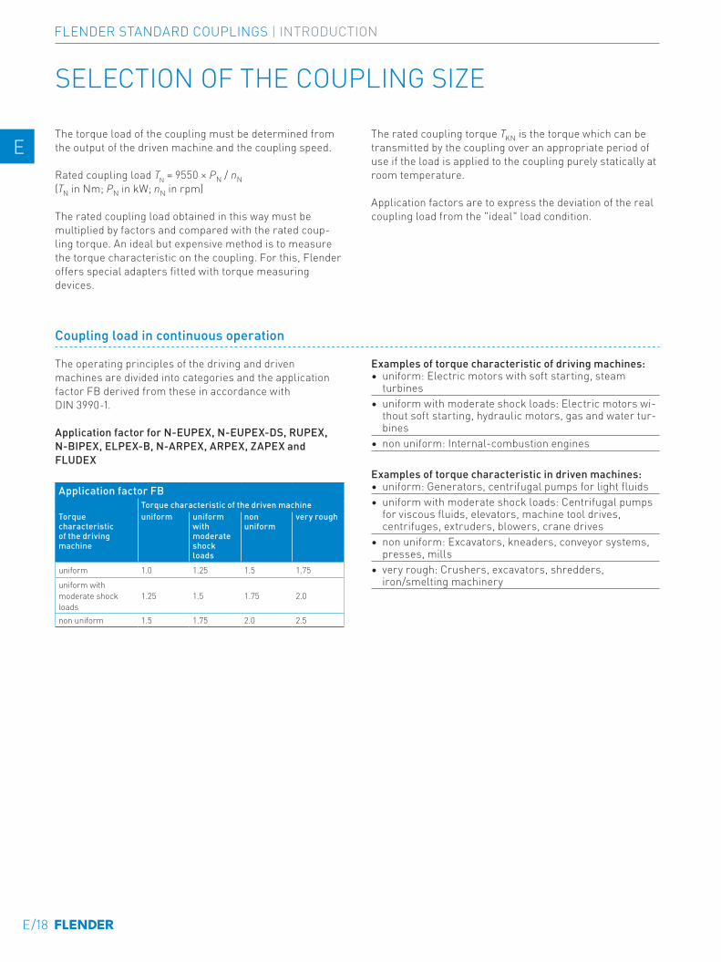
The torque load of the coupling must be determined from the output of the driven machine and the coupling speed.
Rated coupling load TN = 9550 × PN / nN(TN in Nm; PN in kW; nN in rpm)
The rated coupling load obtained in this way must be multiplied by factors and compared with the rated coup-ling torque. An ideal but expensive method is to measure the torque characteristic on the coupling. For this, Flender offers special adapters fitted with torque measuring devices.
The rated coupling torque TKN is the torque which can be transmitted by the coupling over an appropriate period of use if the load is applied to the coupling purely statically at room temperature.
Application factors are to express the deviation of the real coupling load from the "ideal" load condition.
Coupling load in continuous operation
The operating principles of the driving and driven machines are divided into categories and the application factor FB derived from these in accordance with DIN 3990-1.
Application factor for N-EUPEX, N-EUPEX-DS, RUPEX, N-BIPEX, ELPEX-B, N-ARPEX, ARPEX, ZAPEX and FLUDEX
Application factor FBTorque characteristic of the driven machine
Torque characteristic of t he driving machine
uniform uniform with moderate shock loads
non uniform
very rough
uniform 1.0 1.25 1.5 1.75
uniform with moderate shock loads
1.25 1.5 1.75 2.0
non uniform 1.5 1.75 2.0 2.5
Examples of torque characteristic of driving machines:• uniform: Electric motors with soft starting, steam
turbines• uniform with moderate shock loads: Electric motors wi-
thout soft starting, hydraulic motors, gas and water tur-bines
• non uniform: Internal-combustion engines
Examples of torque characteristic in driven machines:• uniform: Generators, centrifugal pumps for light fluids• uniform with moderate shock loads: Centrifugal pumps
for viscous fluids, elevators, machine tool drives, centrifuges, extruders, blowers, crane drives
• non uniform: Excavators, kneaders, conveyor systems, presses, mills
• very rough: Crushers, excavators, shredders, iron/smelting machinery
E/18
FLENDER STANDARD COUPLINGS | INTRODUCTION
E E
4 4
5 5
6 6
7 7
8 8
9 9
10 10
11 11
12 12
13 13
A A
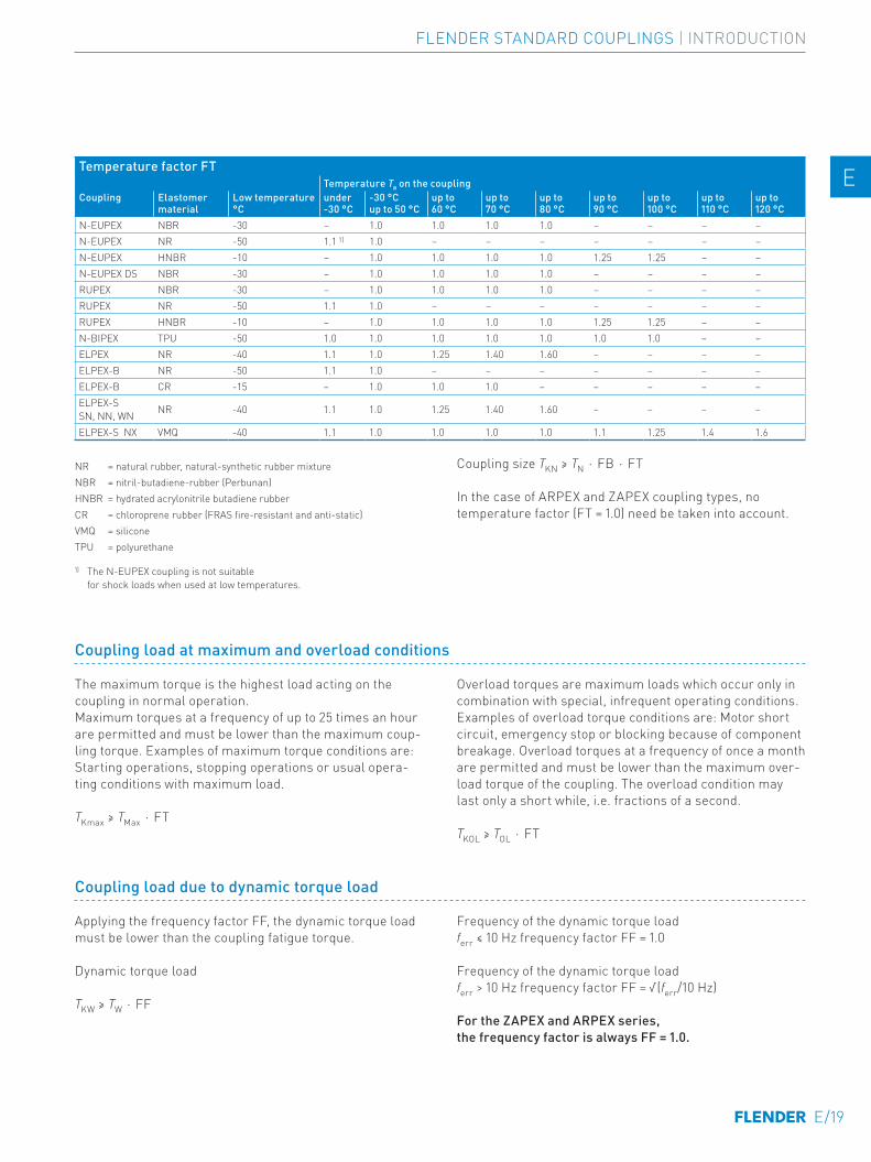
NR = natural rubber, natural-synthetic rubber mixtureNBR = nitril-butadiene-rubber (Perbunan)HNBR = hydrated acrylonitrile butadiene rubberCR = chloroprene rubber (FRAS fire-resistant and anti-static)VMQ = siliconeTPU = polyurethane
Coupling size TKN ≥ TN ⋅ FB ⋅ FT
In the case of ARPEX and ZAPEX coupling types, no temperature factor (FT = 1.0) need be taken into account.
Temperature factor FTTemperature Ta on the coupling
Coupling Elastomer material
Low t emperature °C
under -30 °C
-30 °C up to 50 °C
up to 60 °C
up to 70 °C
up to 80 °C
up to 90 °C
up to 100 °C
up to 110 °C
up to 120 °C
N-EUPEX NBR -30 – 1.0 1.0 1.0 1.0 – – – –N-EUPEX NR -50 1.1 1) 1.0 – – – – – – –N-EUPEX HNBR -10 – 1.0 1.0 1.0 1.0 1.25 1.25 – –N-EUPEX DS NBR -30 – 1.0 1.0 1.0 1.0 – – – –RUPEX NBR -30 – 1.0 1.0 1.0 1.0 – – – –RUPEX NR -50 1.1 1.0 – – – – – – –RUPEX HNBR -10 – 1.0 1.0 1.0 1.0 1.25 1.25 – –N-BIPEX TPU -50 1.0 1.0 1.0 1.0 1.0 1.0 1.0 – –ELPEX NR -40 1.1 1.0 1.25 1.40 1.60 – – – –ELPEX-B NR -50 1.1 1.0 – – – – – – –ELPEX-B CR -15 – 1.0 1.0 1.0 – – – – –ELPEX-S SN, NN, WN NR -40 1.1 1.0 1.25 1.40 1.60 – – – –
ELPEX-S NX VMQ -40 1.1 1.0 1.0 1.0 1.0 1.1 1.25 1.4 1.6
1) The N-EUPEX coupling is not suitable for shock loads when used at low temperatures.
Coupling load at maximum and overload conditions
The maximum torque is the highest load acting on the coupling in normal operation. Maximum torques at a frequency of up to 25 times an hour are permitted and must be lower than the maximum coup-ling torque. Examples of maximum torque conditions are: Starting operations, stopping operations or usual opera-ting conditions with maximum load.
TKmax ≥ TMax ⋅ FT
Overload torques are maximum loads which occur only in combination with special, infrequent operating conditions. Examples of overload torque conditions are: Motor short circuit, emergency stop or blocking because of component breakage. Overload torques at a frequency of once a month are permitted and must be lower than the maximum over-load torque of the coupling. The overload condition may last only a short while, i.e. fractions of a second.
TKOL ≥ TOL ⋅ FT
Coupling load due to dynamic torque load
Applying the frequency factor FF, the dynamic torque load must be lower than the coupling fatigue torque.
Dynamic torque load
TKW ≥ TW ⋅ FF
Frequency of the dynamic torque load ferr ≤ 10 Hz frequency factor FF = 1.0
Frequency of the dynamic torque load ferr > 10 Hz frequency factor FF = √(ferr/10 Hz)
For the ZAPEX and ARPEX series, the frequency factor is always FF = 1.0.
E/19
FLENDER STANDARD COUPLINGS | INTRODUCTION
E E
4 4
5 5
6 6
7 7
8 8
9 9
10 10
11 11
12 12
13 13
A A
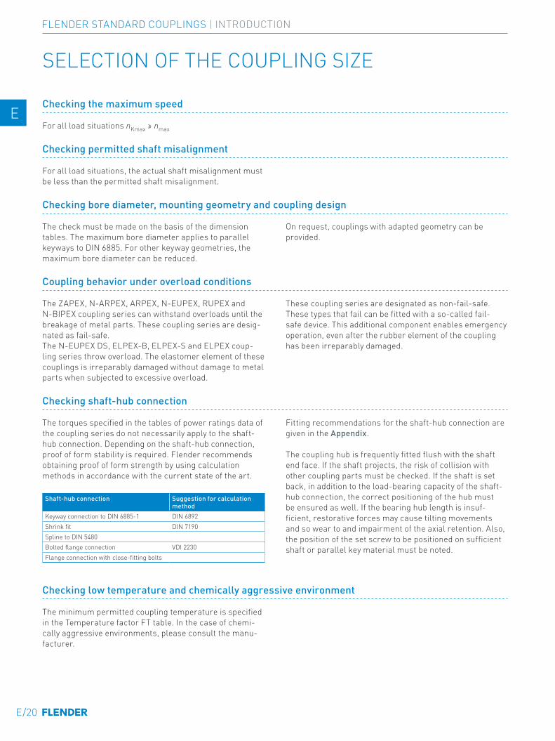
Checking the maximum speed
For all load situations nKmax ≥ nmax
Checking permitted shaft misalignment
For all load situations, the actual shaft misalignment must be less than the permitted shaft misalignment.
Checking bore diameter, mounting geometry and coupling design
The check must be made on the basis of the dimension tables. The maximum bore diameter applies to parallel keyways to DIN 6885. For other keyway geometries, the maximum bore diameter can be reduced.
On request, couplings with adapted geometry can be provided.
Coupling behavior under overload conditions
The ZAPEX, N-ARPEX, ARPEX, N-EUPEX, RUPEX and N-BIPEX coupling series can withstand overloads until the breakage of metal parts. These coupling series are desig-nated as fail-safe.The N-EUPEX DS, ELPEX-B, ELPEX-S and ELPEX coup-ling series throw overload. The elastomer element of these couplings is irreparably damaged without damage to metal parts when subjected to excessive overload.
These coupling series are designated as non-fail-safe. These types that fail can be fitted with a so-called fail-safe device. This additional component enables emergency operation, even after the rubber element of the coupling has been irreparably damaged.
Checking shaft-hub connection
The torques specified in the tables of power ratings data of the coupling series do not necessarily apply to the shaft-hub connection. Depending on the shaft-hub connection, proof of form stability is required. Flender recommends obtaining proof of form strength by using calculation methods in accordance with the current state of the art.
Shaft-hub connection Suggestion for calculation method
Keyway connection to DIN 6885-1 DIN 6892Shrink fit DIN 7190Spline to DIN 5480Bolted flange connection VDI 2230Flange connection with close-fitting bolts
Fitting recommendations for the shaft-hub connection are given in the Appendix.
The coupling hub is frequently fitted flush with the shaft end face. If the shaft projects, the risk of collision with other coupling parts must be checked. If the shaft is set back, in addition to the load-bearing capacity of the shaft-hub connection, the correct positioning of the hub must be ensured as well. If the bearing hub length is insuf-ficient, restorative forces may cause tilting movements and so wear to and impairment of the axial retention. Also, the position of the set screw to be positioned on sufficient shaft or parallel key material must be noted.
Checking low temperature and chemically aggressive environment
The minimum permitted coupling temperature is specified in the Temperature factor FT table. In the case of chemi-cally aggressive environments, please consult the manu-facturer.
SELECTION OF THE COUPLING SIZE
E/20
FLENDER STANDARD COUPLINGS | INTRODUCTION
E E
4 4
5 5
6 6
7 7
8 8
9 9
10 10
11 11
12 12
13 13
A A
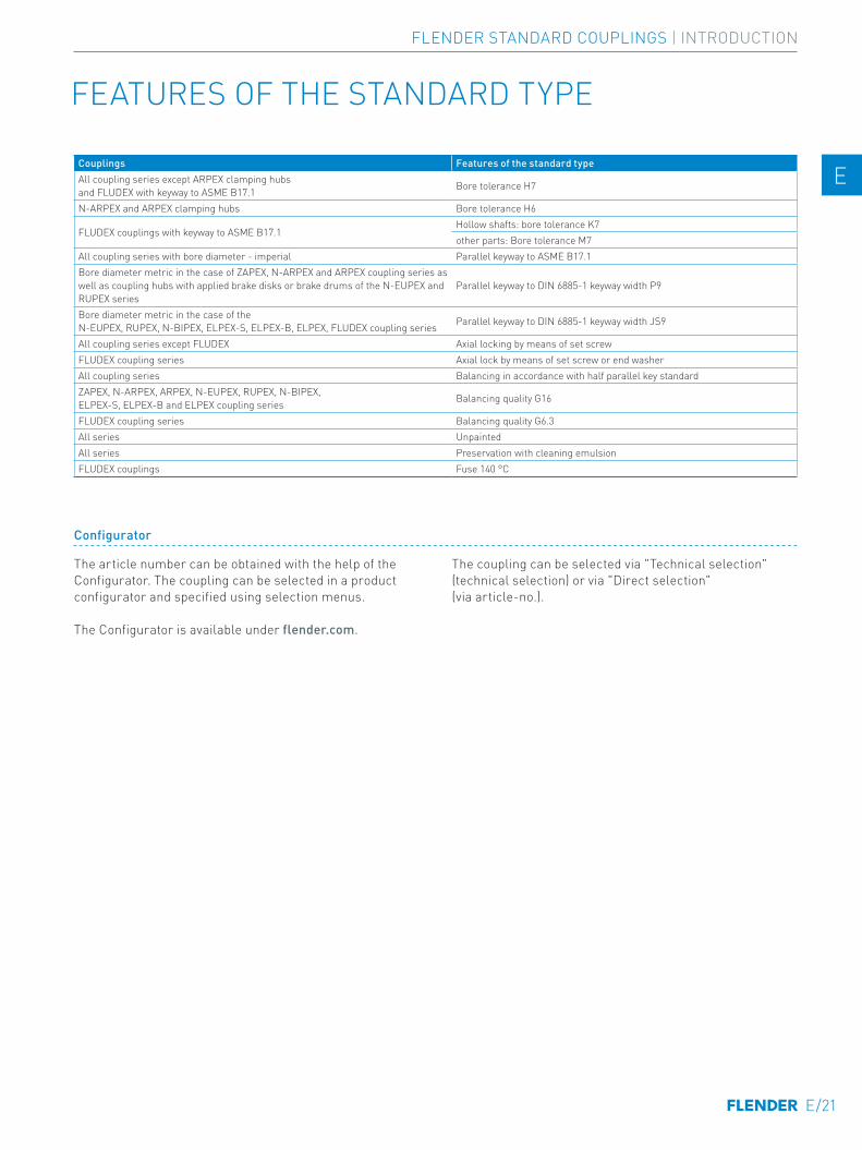
Configurator
The article number can be obtained with the help of the Configurator. The coupling can be selected in a product configurator and specified using selection menus.
The Configurator is available under flender.com.
The coupling can be selected via "Technical selection" (technical selection) or via "Direct selection" (via article-no.).
Couplings Features of the standard typeAll coupling series except ARPEX clamping hubs and FLUDEX with keyway to ASME B17.1 Bore tolerance H7
N-ARPEX and ARPEX clamping hubs Bore tolerance H6
FLUDEX couplings with keyway to ASME B17.1Hollow shafts: bore tolerance K7other parts: Bore tolerance M7
All coupling series with bore diameter - imperial Parallel keyway to ASME B17.1Bore diameter metric in the case of ZAPEX, N-ARPEX and ARPEX coupling series as well as coupling hubs with applied brake disks or brake drums of the N-EUPEX and RUPEX series
Parallel keyway to DIN 6885-1 keyway width P9
Bore diameter metric in the case of the N-EUPEX, RUPEX, N-BIPEX, ELPEX-S, ELPEX-B, ELPEX, FLUDEX coupling series Parallel keyway to DIN 6885-1 keyway width JS9
All coupling series except FLUDEX Axial locking by means of set screwFLUDEX coupling series Axial lock by means of set screw or end washerAll coupling series Balancing in accordance with half parallel key standardZAPEX, N-ARPEX, ARPEX, N-EUPEX, RUPEX, N-BIPEX, ELPEX-S, ELPEX-B and ELPEX coupling series Balancing quality G16
FLUDEX coupling series Balancing quality G6.3All series UnpaintedAll series Preservation with cleaning emulsionFLUDEX couplings Fuse 140 °C
FEATURES OF THE STANDARD TYPE
E/21
FLENDER STANDARD COUPLINGS | INTRODUCTION
E E
4 4
5 5
6 6
7 7
8 8
9 9
10 10
11 11
12 12
13 13
A A

E/22
TORSIONALLY RIGID GEAR COUPLINGS ZAPEX ZW SERIES
ZAPEX ZW
01-Einzelschilder-03-2020.indd 3 09.03.20 14:00
General 4/3Benefits 4/3Application 4/3Design and configurations 4/4Function 4/4Technical specifications 4/5
Type ZWN 4/6
Type ZZS 4/8
Type ZZW 4/10
Type ZWH 4/12
Type ZWBT 4/13
Type ZWBG 4/14
Type ZWB 4/15
Type ZWTR 4/16
Type ZBR 4/17
Type ZWS 4/18
Type ZWNV 4/19
Type ZWSE 4/20
Customized hub design 4/21
Spare and wear parts 4/23
4/1
TORSIONALLY RIGID GEAR COUPLINGS | ZAPEX ZW SERIES
E E
4 4
5 5
6 6
7 7
8 8
9 9
10 10
11 11
12 12
13 13
A A

4/2
TORSIONALLY RIGID GEAR COUPLINGS | ZAPEX ZW SERIES
E E
4 4
5 5
6 6
7 7
8 8
9 9
10 10
11 11
12 12
13 13
A A
GENERAL
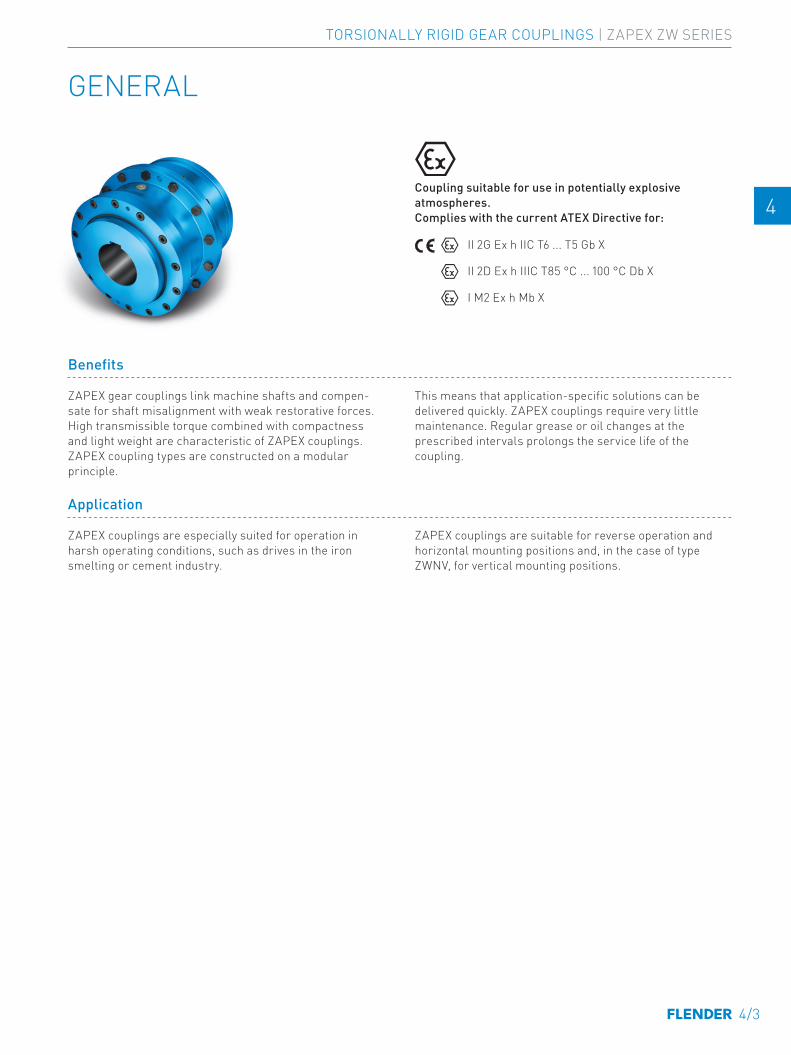
Coupling suitable for use in potentially explosive atmospheres. Complies with the current ATEX Directive for:
II 2G Ex h IIC T6 ... T5 Gb X
II 2D Ex h IIIC T85 °C ... 100 °C Db X
I M2 Ex h Mb X
Benefits
ZAPEX gear couplings link machine shafts and compen-sate for shaft misalignment with weak restorative forces. High transmissible torque combined with compactness and light weight are characteristic of ZAPEX couplings. ZAPEX coupling types are constructed on a modular principle.
This means that application-specific solutions can be delivered quickly. ZAPEX couplings require very little maintenance. Regular grease or oil changes at the prescribed intervals prolongs the service life of the coupling.
Application
ZAPEX couplings are especially suited for operation in harsh operating conditions, such as drives in the iron smelting or cement industry.
ZAPEX couplings are suitable for reverse operation and horizontal mounting positions and, in the case of type ZWNV, for vertical mounting positions.
4/3
TORSIONALLY RIGID GEAR COUPLINGS | ZAPEX ZW SERIES
E E
4 4
5 5
6 6
7 7
8 8
9 9
10 10
11 11
12 12
13 13
A A
GENERAL
Design and configurations
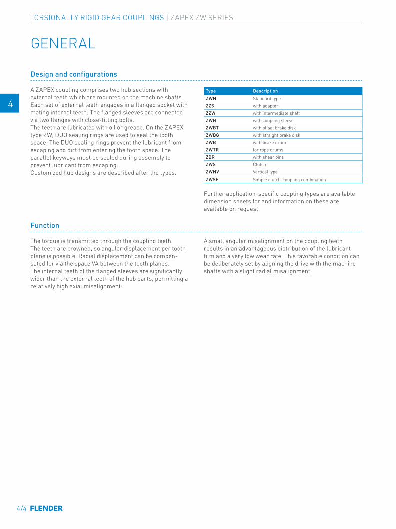
A ZAPEX coupling comprises two hub sections with external teeth which are mounted on the machine shafts. Each set of external teeth engages in a flanged socket with mating internal teeth. The flanged sleeves are connected via two flanges with close-fitting bolts. The teeth are lubricated with oil or grease. On the ZAPEX type ZW, DUO sealing rings are used to seal the tooth space. The DUO sealing rings prevent the lubricant from escaping and dirt from entering the tooth space. The parallel keyways must be sealed during assembly to prevent lubricant from escaping.Customized hub designs are described after the types.
Type DescriptionZWN Standard typeZZS with adapterZZW with intermediate shaftZWH with coupling sleeveZWBT with offset brake diskZWBG with straight brake diskZWB with brake drumZWTR for rope drumsZBR with shear pinsZWS ClutchZWNV Vertical typeZWSE Simple clutch-coupling combination
Further application-specific coupling types are available; dimension sheets for and information on these are available on request.
Function
The torque is transmitted through the coupling teeth. The teeth are crowned, so angular displacement per tooth plane is possible. Radial displacement can be compen-sated for via the space VA between the tooth planes. The internal teeth of the flanged sleeves are significantly wider than the external teeth of the hub parts, permitting a relatively high axial misalignment.
A small angular misalignment on the coupling teeth results in an advantageous distribution of the lubricant film and a very low wear rate. This favorable condition can be deliberately set by aligning the drive with the machine shafts with a slight radial misalignment.
4/4
TORSIONALLY RIGID GEAR COUPLINGS | ZAPEX ZW SERIES
E E
4 4
5 5
6 6
7 7
8 8
9 9
10 10
11 11
12 12
13 13
A A
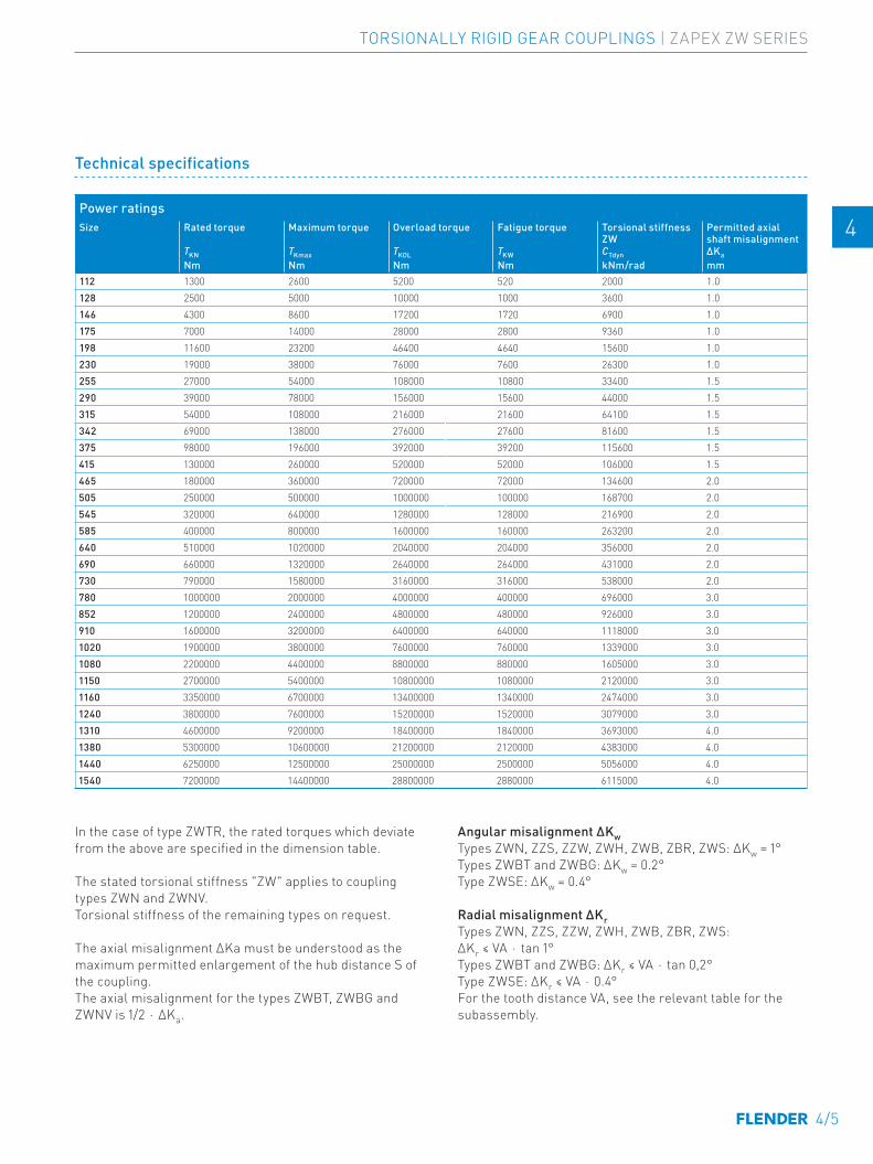
Power ratingsSize Rated torque Maximum torque Overload torque Fatigue torque Torsional stiffness
ZWPermitted axial shaft misalignment
TKN TKmax TKOL TKW CTdyn ∆KaNm Nm Nm Nm kNm/rad mm
112 1300 2600 5200 520 2000 1.0128 2500 5000 10000 1000 3600 1.0146 4300 8600 17200 1720 6900 1.0175 7000 14000 28000 2800 9360 1.0198 11600 23200 46400 4640 15600 1.0230 19000 38000 76000 7600 26300 1.0255 27000 54000 108000 10800 33400 1.5290 39000 78000 156000 15600 44000 1.5315 54000 108000 216000 21600 64100 1.5342 69000 138000 276000 27600 81600 1.5375 98000 196000 392000 39200 115600 1.5415 130000 260000 520000 52000 106000 1.5465 180000 360000 720000 72000 134600 2.0505 250000 500000 1000000 100000 168700 2.0545 320000 640000 1280000 128000 216900 2.0585 400000 800000 1600000 160000 263200 2.0640 510000 1020000 2040000 204000 356000 2.0690 660000 1320000 2640000 264000 431000 2.0730 790000 1580000 3160000 316000 538000 2.0780 1000000 2000000 4000000 400000 696000 3.0852 1200000 2400000 4800000 480000 926000 3.0910 1600000 3200000 6400000 640000 1118000 3.01020 1900000 3800000 7600000 760000 1339000 3.01080 2200000 4400000 8800000 880000 1605000 3.01150 2700000 5400000 10800000 1080000 2120000 3.01160 3350000 6700000 13400000 1340000 2474000 3.01240 3800000 7600000 15200000 1520000 3079000 3.01310 4600000 9200000 18400000 1840000 3693000 4.01380 5300000 10600000 21200000 2120000 4383000 4.01440 6250000 12500000 25000000 2500000 5056000 4.01540 7200000 14400000 28800000 2880000 6115000 4.0
In the case of type ZWTR, the rated torques which deviate from the above are specified in the dimension table.
The stated torsional stiffness "ZW" applies to coupling types ZWN and ZWNV. Torsional stiffness of the remaining types on request.
The axial misalignment ΔKa must be understood as the maximum permitted enlargement of the hub distance S of the coupling.The axial misalignment for the types ZWBT, ZWBG and ZWNV is 1/2 ⋅ ∆Ka.
Angular misalignment ΔKwTypes ZWN, ZZS, ZZW, ZWH, ZWB, ZBR, ZWS: ∆Kw = 1°Types ZWBT and ZWBG: ∆Kw = 0.2°Type ZWSE: ∆Kw = 0.4°
Radial misalignment ΔKrTypes ZWN, ZZS, ZZW, ZWH, ZWB, ZBR, ZWS: ∆Kr ≤ VA ⋅ tan 1°Types ZWBT and ZWBG: ∆Kr ≤ VA ⋅ tan 0,2°Type ZWSE: ∆Kr ≤ VA ⋅ 0.4°For the tooth distance VA, see the relevant table for the subassembly.
Technical specifications
4/5
TORSIONALLY RIGID GEAR COUPLINGS | ZAPEX ZW SERIES
E E
4 4
5 5
6 6
7 7
8 8
9 9
10 10
11 11
12 12
13 13
A A

TYPE ZWN
Variant B
Variant AB
Variant A
Part 2Part 1
Part 2Part 1
Part 2Part 1
Part 2Part 1
G_MD10_EN_00043a
J2J1
S3
S2
S1
ØD
1
ØD
D2
P
ØQ
ØD
2
VA
S1NL2NL1
ØD
AØ
DD
1
ØN
D1
ØN
D2
Size Rated torque
Maxi-mum speed
Dimensions in mm Mass moment of inertia
↗ Article no. 1)
Weight
TKN nKmax D1, D2 Keyway DIN 6885-1
DA ND1/ ND2
NL1/ NL2
DD1/ DD2
S1 S2 S3 VA Q P J1/J2 Type m
Nm rpm min. max. kgm2 A B AB kg112 1300 9400 0 49 143 65 50 110 6 - - 56 50 35 0.007 2LC0300-0AA 2LC0300-0AB 2LC0300-0AC 5.8 -0AA0128 2500 8300 0 61 157 80 60 128 6 13 20 73 65 45 0.014 2LC0300-1AA 2LC0300-1AB 2LC0300-1AC 7.9 -0AA0146 4300 7300 0 72 177 95 75 146 6 13 20 88 75 45 0.021 2LC0300-2AA 2LC0300-2AB 2LC0300-2AC 11.5 -0AA0175 7000 6400 0 85 215 112 90 175 8 14 20 104 85 50 0.049 2LC0300-3AA 2LC0300-3AB 2LC0300-3AC 19 -0AA0198 11600 5500 0 100 237 135 100 198 8 19 30 119 110 50 0.086 2LC0300-4AA 2LC0300-4AB 2LC0300-4AC 26.5 -0AA0230 19000 4700 0 120 265 160 110 230 8 20 32 130 135 50 0.16 2LC0300-5AA 2LC0300-5AB 2LC0300-5AC 37 -0AA0255 27000 4100 0 140 294 185 125 255 10 25 40 150 160 50 0.26 2LC0300-6AA 2LC0300-6AB 2LC0300-6AC 49 -0AA0290 39000 3700 70 160 330 210 140 290 10 30 50 170 180 60 0.51 2LC0300-7AA 2LC0300-7AB 2LC0300-7AC 72 -0AA0315 54000 3300 80 175 366 230 160 315 10 30 50 190 200 60 0.81 2LC0300-8AA 2LC0300-8AB 2LC0300-8AC 99 -0AA0342 69000 3000 90 195 392 255 180 340 12 42 72 222 225 60 1.2 2LC0301-0AA 2LC0301-0AB 2LC0301-0AC 125 -0AA0375 98000 2700 100 220 430 290 200 375 12 42 72 242 260 60 2 2LC0301-1AA 2LC0301-1AB 2LC0301-1AC 170 -0AA0415 130000 2500 120 240 478 320 220 415 12 74 136 294 285 80 3.1 2LC0301-2AA 2LC0301-2AB 2LC0301-2AC 225 -0AA0465 180000 2200 140 270 528 360 240 465 16 96 176 336 325 80 5.2 2LC0301-3AA 2LC0301-3AB 2LC0301-3AC 300 -0AA0505 250000 2000 160 300 568 400 260 505 16 106 196 366 365 80 7.7 2LC0301-4AA 2LC0301-4AB 2LC0301-4AC 380 -0AA0545 320000 1800 180 330 620 440 280 545 16 126 236 406 405 80 12 2LC0301-5AA 2LC0301-5AB 2LC0301-5AC 490 -0AA0585 400000 1700 210 360 660 480 310 585 20 150 280 460 445 80 17 2LC0301-6AA 2LC0301-6AB 2LC0301-6AC 620 -0AA0
640 510000 1600 230 360 738 480 330 640 20 149 278 479 445 90 25 2LC0301-7AA 2LC0301-7AB 2LC0301-7AC 780 -0AA0>360 390 520 475 27 800
690 660000 1450 250 390 788 520 350 690 20 166 312 516 475 90 35 2LC0301-8AA 2LC0301-8AB 2LC0301-8AC 950 -0AA0>390 420 560 515 38 980
730 790000 1350 275 420 834 560 380 730 20 180 340 560 515 90 48 2LC0302-0AA 2LC0302-0AB 2LC0302-0AC 1150 -0AA0>420 450 600 555 52 1200
Configurable variants 1)
• ØD1 Without finished bore With finished bore
• ØD2 Without finished bore With finished bore
1) To identify complete item numbers specifying the available finish boring options and – if necessary – further order options, please use our configurators on flender.com.↗ For online configuration on flender.com, click on the item no.
4/6
TORSIONALLY RIGID GEAR COUPLINGS | ZAPEX ZW SERIES
E E
4 4
5 5
6 6
7 7
8 8
9 9
10 10
11 11
12 12
13 13
A A
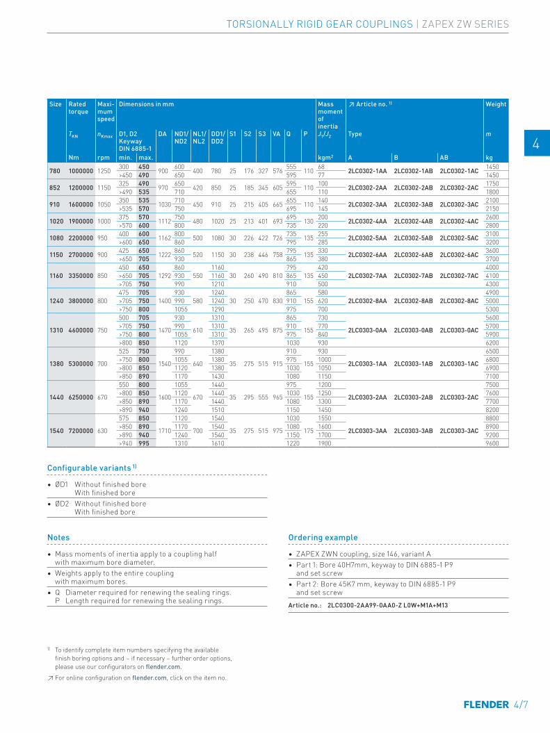
Notes
• Mass moments of inertia apply to a coupling half with maximum bore diameter.
• Weights apply to the entire coupling with maximum bores.
• Q Diameter required for renewing the sealing rings. P Length required for renewing the sealing rings.
Ordering example
• ZAPEX ZWN coupling, size 146, variant A • Part 1: Bore 40H7mm, keyway to DIN 6885-1 P9
and set screw• Part 2: Bore 45K7 mm, keyway to DIN 6885-1 P9
and set screw Article no.: 2LC0300-2AA99-0AA0-Z L0W+M1A+M13
Size Rated torque
Maxi-mum speed
Dimensions in mm Mass moment of inertia
↗ Article no. 1)
Weight
TKN nKmax D1, D2 Keyway DIN 6885-1
DA ND1/ ND2
NL1/ NL2
DD1/ DD2
S1 S2 S3 VA Q P J1/J2 Type m
Nm rpm min. max. kgm2 A B AB kg
780 1000000 1250 300 450 900 600 400 780 25 176 327 576 555 110 68 2LC0302-1AA 2LC0302-1AB 2LC0302-1AC 1450 -0AA0>450 490 650 595 77 1450
852 1200000 1150 325 490 970 650 420 850 25 185 345 605 595 110 100 2LC0302-2AA 2LC0302-2AB 2LC0302-2AC 1750 -0AA0>490 535 710 655 110 1800
910 1600000 1050 350 535 1030 710 450 910 25 215 405 665 655 110 140 2LC0302-3AA 2LC0302-3AB 2LC0302-3AC 2100 -0AA0>535 570 750 695 145 2150
1020 1900000 1000 375 570 1112 750 480 1020 25 213 401 693 695 130 200 2LC0302-4AA 2LC0302-4AB 2LC0302-4AC 2600 -0AA0>570 600 800 735 220 2800
1080 2200000 950 400 600 1162 800 500 1080 30 226 422 726 735 135 255 2LC0302-5AA 2LC0302-5AB 2LC0302-5AC 3100 -0AA0>600 650 860 795 285 3200
1150 2700000 900 425 650 1222 860 520 1150 30 238 446 758 795 135 330 2LC0302-6AA 2LC0302-6AB 2LC0302-6AC 3600 -0AA0>650 705 930 865 380 3700
1160 3350000 850450 650
1292860
5501160
30 260 490 810795
135420
2LC0302-7AA 2LC0302-7AB 2LC0302-7AC4000
-0AA0>650 705 930 1160 865 450 4100>705 750 990 1210 910 500 4300
1240 3800000 800475 705
1400930
5801240
30 250 470 830865
155580
2LC0302-8AA 2LC0302-8AB 2LC0302-8AC4900
-0AA0>705 750 990 1240 910 620 5000>750 800 1055 1290 975 700 5300
1310 4600000 750
500 705
1470
930
610
1310
35 265 495 875
865
155
730
2LC0303-0AA 2LC0303-0AB 2LC0303-0AC
5600
-0AA0>705 750 990 1310 910 770 5700>750 800 1055 1310 975 840 5900>800 850 1120 1370 1030 930 6200
1380 5300000 700
525 750
1540
990
640
1380
35 275 515 915
910
155
930
2LC0303-1AA 2LC0303-1AB 2LC0303-1AC
6500
-0AA0>750 800 1055 1380 975 1000 6800>800 850 1120 1380 1030 1050 6900>850 890 1170 1430 1080 1150 7100
1440 6250000 670
550 800
1600
1055
670
1440
35 295 555 965
975
155
1200
2LC0303-2AA 2LC0303-2AB 2LC0303-2AC
7500
-0AA0>800 850 1120 1440 1030 1250 7600>850 890 1170 1440 1080 1300 7700>890 940 1240 1510 1150 1450 8200
1540 7200000 630
575 850
1710
1120
700
1540
35 275 515 975
1030
175
1550
2LC0303-3AA 2LC0303-3AB 2LC0303-3AC
8800
-0AA0>850 890 1170 1540 1080 1600 8900>890 940 1240 1540 1150 1700 9200>940 995 1310 1610 1220 1900 9600
Configurable variants 1)
• ØD1 Without finished bore With finished bore
• ØD2 Without finished bore With finished bore
1) To identify complete item numbers specifying the available finish boring options and – if necessary – further order options, please use our configurators on flender.com.↗ For online configuration on flender.com, click on the item no.
4/7
TORSIONALLY RIGID GEAR COUPLINGS | ZAPEX ZW SERIES
E E
4 4
5 5
6 6
7 7
8 8
9 9
10 10
11 11
12 12
13 13
A A
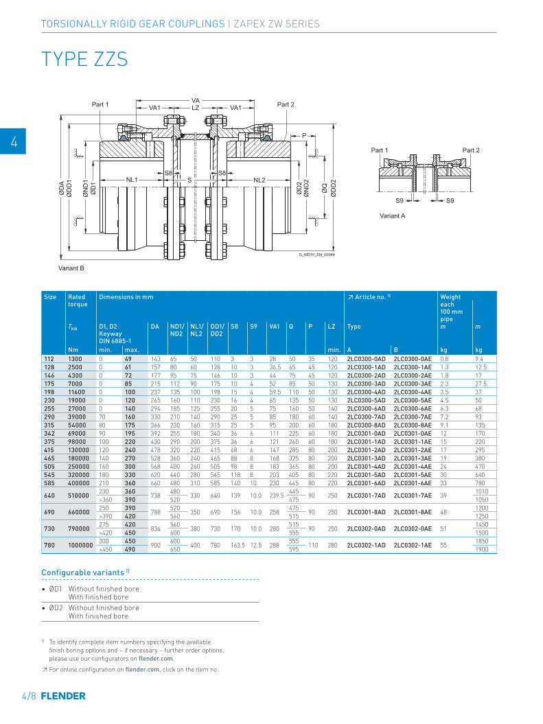
Variant B
Variant A
Part 2Part 1
Part 2Part 1
G_MD10_EN_00044
S9
ØD
2
ØD
D2
ØQ
ØN
D2
S9
ØD
1
VA1LZVA1VA
S8 S8S NL2NL1
ØD
AØ
DD
1
ØN
D1
P
TYPE ZZS
Size Rated torque
Dimensions in mm ↗ Article no. 1) Weighteach 100 mm pipe
TKN D1, D2 Keyway DIN 6885-1
DA ND1/ ND2
NL1/ NL2
DD1/ DD2
S8 S9 VA1 Q P LZ Type m m
Nm min. max. min. A B kg kg112 1300 0 49 143 65 50 110 3 3 28 50 35 120 2LC0300-0AD 2LC0300-0AE 0.8 9.4 -0AZ0128 2500 0 61 157 80 60 128 10 3 36.5 65 45 120 2LC0300-1AD 2LC0300-1AE 1.3 12.5 -0AZ0146 4300 0 72 177 95 75 146 10 3 44 75 45 120 2LC0300-2AD 2LC0300-2AE 1.8 17 -0AZ0175 7000 0 85 215 112 90 175 10 4 52 85 50 130 2LC0300-3AD 2LC0300-3AE 2.3 27.5 -0AZ0198 11600 0 100 237 135 100 198 15 4 59.5 110 50 130 2LC0300-4AD 2LC0300-4AE 3.5 37 -0AZ0230 19000 0 120 265 160 110 230 16 4 65 135 50 130 2LC0300-5AD 2LC0300-5AE 4.5 50 -0AZ0255 27000 0 140 294 185 125 255 20 5 75 160 50 140 2LC0300-6AD 2LC0300-6AE 6.3 68 -0AZ0290 39000 70 160 330 210 140 290 25 5 85 180 60 140 2LC0300-7AD 2LC0300-7AE 7.2 93 -0AZ0315 54000 80 175 366 230 160 315 25 5 95 200 60 180 2LC0300-8AD 2LC0300-8AE 9.1 135 -0AZ0342 69000 90 195 392 255 180 340 36 6 111 225 60 180 2LC0301-0AD 2LC0301-0AE 12 170 -0AZ0375 98000 100 220 430 290 200 375 36 6 121 260 60 180 2LC0301-1AD 2LC0301-1AE 15 220 -0AZ0415 130000 120 240 478 320 220 415 68 6 147 285 80 200 2LC0301-2AD 2LC0301-2AE 17 295 -0AZ0465 180000 140 270 528 360 240 465 88 8 168 325 80 200 2LC0301-3AD 2LC0301-3AE 19 380 -0AZ0505 250000 160 300 568 400 260 505 98 8 183 365 80 200 2LC0301-4AD 2LC0301-4AE 24 470 -0AZ0545 320000 180 330 620 440 280 545 118 8 203 405 80 220 2LC0301-5AD 2LC0301-5AE 30 640 -0AZ0585 400000 210 360 660 480 310 585 140 10 230 445 80 220 2LC0301-6AD 2LC0301-6AE 33 780 -0AZ0
640 510000 230 360 738 480 330 640 139 10.0 239.5 445 90 250 2LC0301-7AD 2LC0301-7AE 39 1010 -0AZ0>360 390 520 475 1050
690 660000 250 390 788 520 350 690 156 10.0 258 475 90 250 2LC0301-8AD 2LC0301-8AE 48 1200 -0AZ0>390 420 560 515 1250
730 790000 275 420 834 560 380 730 170 10.0 280 515 90 250 2LC0302-0AD 2LC0302-0AE 51 1450 -0AZ0>420 450 600 555 1500
780 1000000 300 450 900 600 400 780 163.5 12.5 288 555 110 280 2LC0302-1AD 2LC0302-1AE 55 1850 -0AZ0>450 490 650 595 1900
1) To identify complete item numbers specifying the available finish boring options and – if necessary – further order options, please use our configurators on flender.com.↗ For online configuration on flender.com, click on the item no.
Configurable variants 1)
• ØD1 Without finished bore With finished bore
• ØD2 Without finished bore With finished bore
4/8
TORSIONALLY RIGID GEAR COUPLINGS | ZAPEX ZW SERIES
E E
4 4
5 5
6 6
7 7
8 8
9 9
10 10
11 11
12 12
13 13
A A
Size Rated torque
Dimensions in mm ↗ Article no. 1) Weighteach 100 mm pipe
TKN D1, D2 Keyway DIN 6885-1
DA ND1/ ND2
NL1/ NL2
DD1/ DD2
S8 S9 VA1 Q P LZ Type m m
Nm min. max. min. A B kg kg112 1300 0 49 143 65 50 110 3 3 28 50 35 120 2LC0300-0AD 2LC0300-0AE 0.8 9.4 -0AZ0128 2500 0 61 157 80 60 128 10 3 36.5 65 45 120 2LC0300-1AD 2LC0300-1AE 1.3 12.5 -0AZ0146 4300 0 72 177 95 75 146 10 3 44 75 45 120 2LC0300-2AD 2LC0300-2AE 1.8 17 -0AZ0175 7000 0 85 215 112 90 175 10 4 52 85 50 130 2LC0300-3AD 2LC0300-3AE 2.3 27.5 -0AZ0198 11600 0 100 237 135 100 198 15 4 59.5 110 50 130 2LC0300-4AD 2LC0300-4AE 3.5 37 -0AZ0230 19000 0 120 265 160 110 230 16 4 65 135 50 130 2LC0300-5AD 2LC0300-5AE 4.5 50 -0AZ0255 27000 0 140 294 185 125 255 20 5 75 160 50 140 2LC0300-6AD 2LC0300-6AE 6.3 68 -0AZ0290 39000 70 160 330 210 140 290 25 5 85 180 60 140 2LC0300-7AD 2LC0300-7AE 7.2 93 -0AZ0315 54000 80 175 366 230 160 315 25 5 95 200 60 180 2LC0300-8AD 2LC0300-8AE 9.1 135 -0AZ0342 69000 90 195 392 255 180 340 36 6 111 225 60 180 2LC0301-0AD 2LC0301-0AE 12 170 -0AZ0375 98000 100 220 430 290 200 375 36 6 121 260 60 180 2LC0301-1AD 2LC0301-1AE 15 220 -0AZ0415 130000 120 240 478 320 220 415 68 6 147 285 80 200 2LC0301-2AD 2LC0301-2AE 17 295 -0AZ0465 180000 140 270 528 360 240 465 88 8 168 325 80 200 2LC0301-3AD 2LC0301-3AE 19 380 -0AZ0505 250000 160 300 568 400 260 505 98 8 183 365 80 200 2LC0301-4AD 2LC0301-4AE 24 470 -0AZ0545 320000 180 330 620 440 280 545 118 8 203 405 80 220 2LC0301-5AD 2LC0301-5AE 30 640 -0AZ0585 400000 210 360 660 480 310 585 140 10 230 445 80 220 2LC0301-6AD 2LC0301-6AE 33 780 -0AZ0
640 510000 230 360 738 480 330 640 139 10.0 239.5 445 90 250 2LC0301-7AD 2LC0301-7AE 39 1010 -0AZ0>360 390 520 475 1050
690 660000 250 390 788 520 350 690 156 10.0 258 475 90 250 2LC0301-8AD 2LC0301-8AE 48 1200 -0AZ0>390 420 560 515 1250
730 790000 275 420 834 560 380 730 170 10.0 280 515 90 250 2LC0302-0AD 2LC0302-0AE 51 1450 -0AZ0>420 450 600 555 1500
780 1000000 300 450 900 600 400 780 163.5 12.5 288 555 110 280 2LC0302-1AD 2LC0302-1AE 55 1850 -0AZ0>450 490 650 595 1900
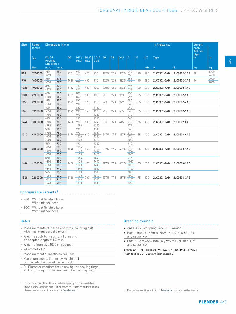
Size Rated torque
Dimensions in mm ↗ Article no. 1) Weighteach 100 mm pipe
TKN D1, D2 Keyway DIN 6885-1
DA ND1/ ND2
NL1/ NL2
DD1/ DD2
S8 S9 VA1 Q P LZ Type m m
Nm min. max. min. A B kg kg
852 1200000 325 490 970 650 420 850 172.5 12.5 302.5 595 110 280 2LC0302-2AD 2LC0302-2AE 68 2300 -0AZ0>490 535 710 655 2400
910 1600000 350 535 1030 710 450 910 202.5 12.5 332.5 655 110 280 2LC0302-3AD 2LC0302-3AE 94 2800 -0AZ0>535 570 750 695 2850
1020 1900000 375 570 1112 750 480 1020 200.5 12.5 346.5 695 130 380 2LC0302-4AD 2LC0302-4AE -0AZ0>570 600 800 735
1080 2200000 400 600 1162 800 500 1080 211 15.0 363 735 135 380 2LC0302-5AD 2LC0302-5AE -0AZ0>600 650 860 795
1150 2700000 425 650 1222 860 520 1150 223 15.0 379 795 135 380 2LC0302-6AD 2LC0302-6AE -0AZ0>650 705 930 865
1160 3350000450 650
1292860
5501160
245 15.0 405795
135 380 2LC0302-7AD 2LC0302-7AE -0AZ0>650 705 930 1160 865>705 750 990 1210 910
1240 3800000475 705
1400930
5801240
235 15.0 415865
155 400 2LC0302-8AD 2LC0302-8AE -0AZ0>705 750 990 1240 910>750 800 1055 1290 975
1310 4600000
500 705
1470
930
610
1310
247.5 17.5 437.5
865
155 400 2LC0303-0AD 2LC0303-0AE -0AZ0>705 750 990 1310 910>750 800 1055 1310 975>800 850 1120 1370 1030
1380 5300000
525 750
1540
990
640
1380
257.5 17.5 457.5
910
155 400 2LC0303-1AD 2LC0303-1AE -0AZ0>750 800 1055 1380 975>800 850 1120 1380 1030>850 890 1170 1430 1080
1440 6250000
550 800
1600
1055
670
1440
277.5 17.5 482.5
975
155 400 2LC0303-2AD 2LC0303-2AE -0AZ0>800 850 1120 1440 1030>850 890 1170 1440 1080>890 940 1240 1510 1150
1540 7200000
575 850
1710
1120
700
1540
257.5 17.5 487.5
1030
175 600 2LC0303-3AD 2LC0303-3AE -0AZ0>850 890 1170 1540 1080>890 940 1240 1540 1150>940 995 1310 1610 1220
Notes
• Mass moments of inertia apply to a coupling half with maximum bore diameter.
• Weights apply to maximum bores and an adapter length of LZ min.
• Weights from size 1020 on request. • VA = 2⋅VA1 + LZ• Mass moment of inertia on request.• Maximum speed, limited by weight and
critical adapter speed, on request.• Q Diameter required for renewing the sealing rings.
P Length required for renewing the sealing rings.
Ordering example
• ZAPEX ZZS coupling, size 146, variant B • Part 1: Bore 40H7mm, keyway to DIN 6885-1 P9
and set screw• Part 2: Bore 45K7 mm, keyway to DIN 6885-1 P9
and set screw Article no.: 2LC0300-2AE99-0AZ0-Z L0W+M1A+Q0Y+M13Plain text to Q0Y: 250 mm (dimension S)
1) To identify complete item numbers specifying the available finish boring options and – if necessary – further order options, please use our configurators on flender.com. ↗ For online configuration on flender.com, click on the item no.
Configurable variants 1)
• ØD1 Without finished bore With finished bore
• ØD2 Without finished bore With finished bore
4/9
TORSIONALLY RIGID GEAR COUPLINGS | ZAPEX ZW SERIES
E E
4 4
5 5
6 6
7 7
8 8
9 9
10 10
11 11
12 12
13 13
A A
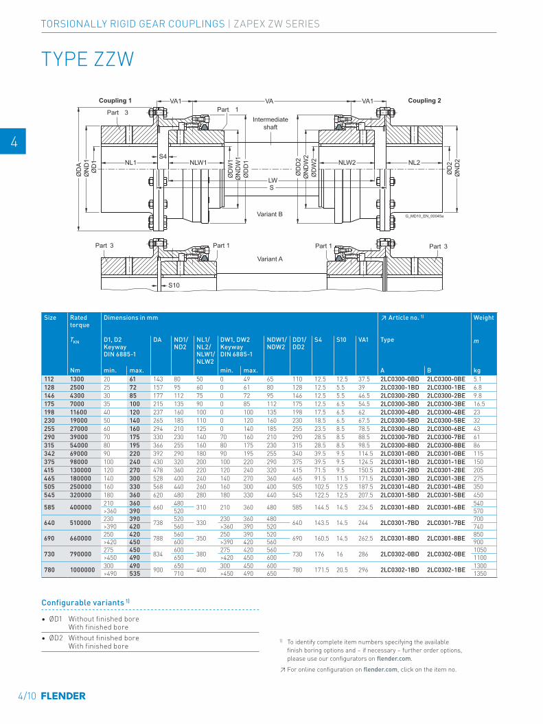
Coupling 1 Coupling 2
Intermediate shaft
Part 1 Part 3Part 3 Part 1
Variant A
Variant B G_MD10_EN_00045a
Part 3 Part 1
S10
ØD
2
ØD
W2
SLW
ØD
D2
ØN
D2
ØN
DW
2
VA1
NL2NLW2
ØD
1
ØD
W1
ØD
A
ØD
D1
ØN
D1
ØN
DW
1
VAVA1
S4NL1 NLW1
TYPE ZZW
Size Rated torque
Dimensions in mm ↗ Article no. 1) Weight
TKN D1, D2 Keyway DIN 6885-1
DA ND1/ ND2
NL1/ NL2/ NLW1/ NLW2
DW1, DW2 Keyway DIN 6885-1
NDW1/ NDW2
DD1/ DD2
S4 S10 VA1 Type m
Nm min. max. min. max. A B kg112 1300 20 61 143 80 50 0 49 65 110 12.5 12.5 37.5 2LC0300-0BD 2LC0300-0BE 5.1 -0AA0128 2500 25 72 157 95 60 0 61 80 128 12.5 5.5 39 2LC0300-1BD 2LC0300-1BE 6.8 -0AA0146 4300 30 85 177 112 75 0 72 95 146 12.5 5.5 46.5 2LC0300-2BD 2LC0300-2BE 9.8 -0AA0175 7000 35 100 215 135 90 0 85 112 175 12.5 6.5 54.5 2LC0300-3BD 2LC0300-3BE 16.5 -0AA0198 11600 40 120 237 160 100 0 100 135 198 17.5 6.5 62 2LC0300-4BD 2LC0300-4BE 23 -0AA0230 19000 50 140 265 185 110 0 120 160 230 18.5 6.5 67.5 2LC0300-5BD 2LC0300-5BE 32 -0AA0255 27000 60 160 294 210 125 0 140 185 255 23.5 8.5 78.5 2LC0300-6BD 2LC0300-6BE 43 -0AA0290 39000 70 175 330 230 140 70 160 210 290 28.5 8.5 88.5 2LC0300-7BD 2LC0300-7BE 61 -0AA0315 54000 80 195 366 255 160 80 175 230 315 28.5 8.5 98.5 2LC0300-8BD 2LC0300-8BE 86 -0AA0342 69000 90 220 392 290 180 90 195 255 340 39.5 9.5 114.5 2LC0301-0BD 2LC0301-0BE 115 -0AA0375 98000 100 240 430 320 200 100 220 290 375 39.5 9.5 124.5 2LC0301-1BD 2LC0301-1BE 150 -0AA0415 130000 120 270 478 360 220 120 240 320 415 71.5 9.5 150.5 2LC0301-2BD 2LC0301-2BE 205 -0AA0465 180000 140 300 528 400 240 140 270 360 465 91.5 11.5 171.5 2LC0301-3BD 2LC0301-3BE 275 -0AA0505 250000 160 330 568 440 260 160 300 400 505 102.5 12.5 187.5 2LC0301-4BD 2LC0301-4BE 350 -0AA0545 320000 180 360 620 480 280 180 330 440 545 122.5 12.5 207.5 2LC0301-5BD 2LC0301-5BE 450 -0AA0
585 400000 210 360 660 480 310 210 360 480 585 144.5 14.5 234.5 2LC0301-6BD 2LC0301-6BE 540 -0AA0>360 390 520 570
640 510000 230 390 738 520 330 230 360 480 640 143.5 14.5 244 2LC0301-7BD 2LC0301-7BE 700 -0AA0>390 420 560 >360 390 520 740
690 660000 250 420 788 560 350 250 390 520 690 160.5 14.5 262.5 2LC0301-8BD 2LC0301-8BE 850 -0AA0>420 450 600 >390 420 560 900
730 790000 275 450 834 600 380 275 420 560 730 176 16 286 2LC0302-0BD 2LC0302-0BE 1050 -0AA0>450 490 650 >420 450 600 1100
780 1000000 300 490 900 650 400 300 450 600 780 171.5 20.5 296 2LC0302-1BD 2LC0302-1BE 1300 -0AA0>490 535 710 >450 490 650 1350
1) To identify complete item numbers specifying the available finish boring options and – if necessary – further order options, please use our configurators on flender.com.↗ For online configuration on flender.com, click on the item no.
Configurable variants 1)
• ØD1 Without finished bore With finished bore
• ØD2 Without finished bore With finished bore
4/10
TORSIONALLY RIGID GEAR COUPLINGS | ZAPEX ZW SERIES
E E
4 4
5 5
6 6
7 7
8 8
9 9
10 10
11 11
12 12
13 13
A A
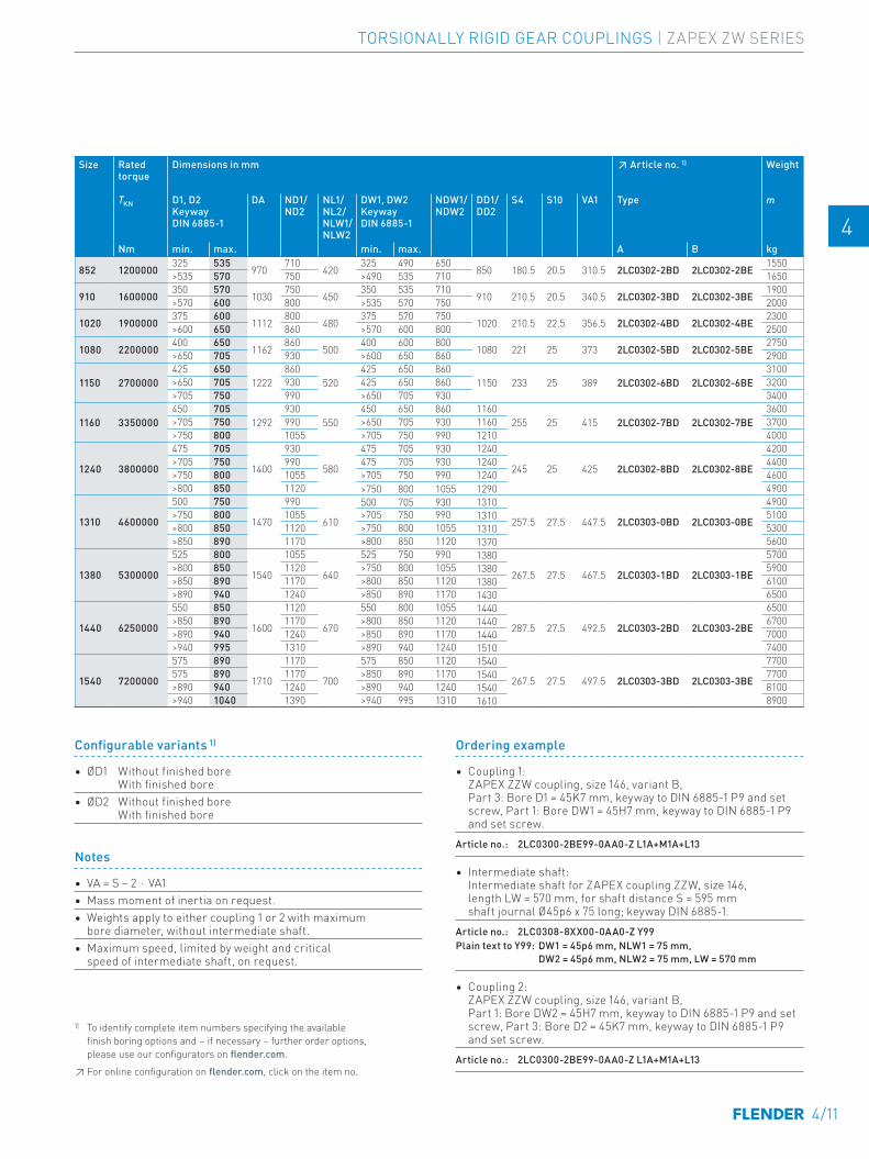
Ordering example
• Coupling 1: ZAPEX ZZW coupling, size 146, variant B, Part 3: Bore D1 = 45K7 mm, keyway to DIN 6885-1 P9 and set screw, Part 1: Bore DW1 = 45H7 mm, keyway to DIN 6885-1 P9 and set screw.
Article no.: 2LC0300-2BE99-0AA0-Z L1A+M1A+L13
• Intermediate shaft: Intermediate shaft for ZAPEX coupling ZZW, size 146, length LW = 570 mm, for shaft distance S = 595 mm shaft journal Ø45p6 x 75 long; keyway DIN 6885-1.
Article no.: 2LC0308-8XX00-0AA0-Z Y99Plain text to Y99: DW1 = 45p6 mm, NLW1 = 75 mm, DW2 = 45p6 mm, NLW2 = 75 mm, LW = 570 mm
• Coupling 2: ZAPEX ZZW coupling, size 146, variant B, Part 1: Bore DW2 = 45H7 mm, keyway to DIN 6885-1 P9 and set screw, Part 3: Bore D2 = 45K7 mm, keyway to DIN 6885-1 P9 and set screw.
Article no.: 2LC0300-2BE99-0AA0-Z L1A+M1A+L13
Size Rated torque
Dimensions in mm ↗ Article no. 1) Weight
TKN D1, D2 Keyway DIN 6885-1
DA ND1/ ND2
NL1/ NL2/ NLW1/ NLW2
DW1, DW2 Keyway DIN 6885-1
NDW1/ NDW2
DD1/ DD2
S4 S10 VA1 Type m
Nm min. max. min. max. A B kg
852 1200000325 535
970710
420325 490 650
850 180.5 20.5 310.5 2LC0302-2BD 2LC0302-2BE1550
-0AA0>535 570 750 >490 535 710 1650
910 1600000350 570
1030750
450350 535 710
910 210.5 20.5 340.5 2LC0302-3BD 2LC0302-3BE1900
-0AA0>570 600 800 >535 570 750 2000
1020 1900000375 600
1112800
480375 570 750
1020 210.5 22.5 356.5 2LC0302-4BD 2LC0302-4BE2300
-0AA0>600 650 860 >570 600 800 2500
1080 2200000400 650
1162860
500400 600 800
1080 221 25 373 2LC0302-5BD 2LC0302-5BE2750
-0AA0>650 705 930 >600 650 860 2900
1150 2700000425 650
1222860
520425 650 860
1150 233 25 389 2LC0302-6BD 2LC0302-6BE3100
-0AA0>650 705 930 425 650 860 3200>705 750 990 >650 705 930 3400
1160 3350000450 705
1292930
550450 650 860 1160
255 25 415 2LC0302-7BD 2LC0302-7BE3600
-0AA0>705 750 990 >650 705 930 1160 3700>750 800 1055 >705 750 990 1210 4000
1240 3800000
475 705
1400
930
580
475 705 930 1240
245 25 425 2LC0302-8BD 2LC0302-8BE
4200
-0AA0>705 750 990 475 705 930 1240 4400>750 800 1055 >705 750 990 1240 4600>800 850 1120 >750 800 1055 1290 4900
1310 4600000
500 750
1470
990
610
500 705 930 1310
257.5 27.5 447.5 2LC0303-0BD 2LC0303-0BE
4900
-0AA0>750 800 1055 >705 750 990 1310 5100>800 850 1120 >750 800 1055 1310 5300>850 890 1170 >800 850 1120 1370 5600
1380 5300000
525 800
1540
1055
640
525 750 990 1380
267.5 27.5 467.5 2LC0303-1BD 2LC0303-1BE
5700
-0AA0>800 850 1120 >750 800 1055 1380 5900>850 890 1170 >800 850 1120 1380 6100>890 940 1240 >850 890 1170 1430 6500
1440 6250000
550 850
1600
1120
670
550 800 1055 1440
287.5 27.5 492.5 2LC0303-2BD 2LC0303-2BE
6500
-0AA0>850 890 1170 >800 850 1120 1440 6700>890 940 1240 >850 890 1170 1440 7000>940 995 1310 >890 940 1240 1510 7400
1540 7200000
575 890
1710
1170
700
575 850 1120 1540
267.5 27.5 497.5 2LC0303-3BD 2LC0303-3BE
7700
-0AA0575 890 1170 >850 890 1170 1540 7700>890 940 1240 >890 940 1240 1540 8100>940 1040 1390 >940 995 1310 1610 8900
Notes
• VA = S − 2 ⋅ VA1• Mass moment of inertia on request.• Weights apply to either coupling 1 or 2 with maximum
bore diameter, without intermediate shaft.• Maximum speed, limited by weight and critical
speed of intermediate shaft, on request.
1) To identify complete item numbers specifying the available finish boring options and – if necessary – further order options, please use our configurators on flender.com.↗ For online configuration on flender.com, click on the item no.
Configurable variants 1)
• ØD1 Without finished bore With finished bore
• ØD2 Without finished bore With finished bore
4/11
TORSIONALLY RIGID GEAR COUPLINGS | ZAPEX ZW SERIES
E E
4 4
5 5
6 6
7 7
8 8
9 9
10 10
11 11
12 12
13 13
A A
Part 1 Part 2
G_MD10_EN_00047a
J2J1VA
S1NL2NL1
ØD
1
ØD
D1
ØN
D1
ØD
2
ØD
D2
ØQ
ØN
D2
P
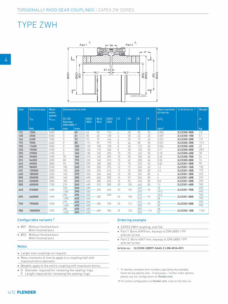
TYPE ZWH
Size Rated torque
Maxi-mum speed
Dimensions in mm Mass moment of inertia
↗ Article no. 1) Weight
TKN nKmax D1, D2 Keyway DIN 6885-1
ND1/ ND2
NL1/ NL2
DD1/ DD2
S1 VA Q P J1/J2 m
Nm rpm min. max. kgm2 kg112 1300 9400 0 49 65 50 110 6 28 50 35 0.003 2LC0300-0BB 3.5 -0AA0128 2500 8300 0 61 80 60 128 6 30 65 45 0.007 2LC0300-1BB 5.1 -0AA0146 4300 7300 0 72 95 75 146 6 33 75 45 0.012 2LC0300-2BB 7.8 -0AA0175 7000 6400 0 85 112 90 175 8 46 85 50 0.031 2LC0300-3BB 13.5 -0AA0198 11600 5500 0 100 135 100 198 8 48 110 50 0.056 2LC0300-4BB 20 -0AA0230 19000 4700 0 120 160 110 230 8 50 135 50 0.11 2LC0300-5BB 28.5 -0AA0255 27000 4100 0 140 185 125 255 10 55 160 50 0.18 2LC0300-6BB 38 -0AA0290 39000 3700 70 160 210 140 290 10 58 180 60 0.35 2LC0300-7BB 56 -0AA0315 54000 3300 80 175 230 160 315 10 62 200 60 0.55 2LC0300-8BB 74 -0AA0342 69000 3000 90 195 255 180 340 12 70 225 60 0.82 2LC0301-0BB 95 -0AA0375 98000 2700 100 220 290 200 375 12 72 260 60 1.3 2LC0301-1BB 130 -0AA0415 130000 2500 120 240 320 220 415 12 76 285 80 2.3 2LC0301-2BB 175 -0AA0465 180000 2200 140 270 360 240 465 16 90 325 80 4 2LC0301-3BB 245 -0AA0505 250000 2000 160 300 400 260 505 16 92 365 80 6 2LC0301-4BB 310 -0AA0545 320000 1800 180 330 440 280 545 16 96 405 80 8.8 2LC0301-5BB 390 -0AA0585 400000 1700 210 360 480 310 585 20 102 445 80 13 2LC0301-6BB 500 -0AA0
640 510000 1600 230 360 480 330 640 20 105 445 90 18 2LC0301-7BB620
-0AA0>360 390 520 475 19.5 650
690 660000 1450 250 390 520 350 690 20 108 475 90 25.5 2LC0301-8BB760
-0AA0>390 420 560 515 28 790
730 790000 1350 275 420 560 380 730 20 112 515 90 35 2LC0302-0BB920
-0AA0>420 450 600 555 39 950
780 1000000 1250 300 450 600 400 780 25 120 555 110 48 2LC0302-1BB 1150 -0AA0>450 490 650 595 57
Notes
• Larger size couplings on request.• Mass moments of inertia apply to a coupling half with
maximum bore diameter.• Weights apply to the entire coupling with maximum bores.• Q Diameter required for renewing the sealing rings.
P Length required for renewing the sealing rings.
Ordering example
• ZAPEX ZWH coupling, size 146 • Part 1: Bore 40H7mm, keyway to DIN 6885-1 P9
and set screw• Part 2: Bore 45K7 mm, keyway to DIN 6885-1 P9
and set screw Article no.: 2LC0300-2BB99-0AA0-Z L0W+M1A+M13
Configurable variants 1)
• ØD1 Without finished bore With finished bore
• ØD2 Without finished bore With finished bore
1) To identify complete item numbers specifying the available finish boring options and – if necessary – further order options, please use our configurators on flender.com.↗ For online configuration on flender.com, click on the item no.
4/12
TORSIONALLY RIGID GEAR COUPLINGS | ZAPEX ZW SERIES
E E
4 4
5 5
6 6
7 7
8 8
9 9
10 10
11 11
12 12
13 13
A A
Size Rated torque
Maxi-mum speed
Dimensions in mm Mass moment of inertia
↗ Article no. 1) Weight
TKN nKmax D1, D2 Keyway DIN 6885-1
ND1/ ND2
NL1/ NL2
DD1/ DD2
S1 VA Q P J1/J2 m
Nm rpm min. max. kgm2 kg112 1300 9400 0 49 65 50 110 6 28 50 35 0.003 2LC0300-0BB 3.5 -0AA0128 2500 8300 0 61 80 60 128 6 30 65 45 0.007 2LC0300-1BB 5.1 -0AA0146 4300 7300 0 72 95 75 146 6 33 75 45 0.012 2LC0300-2BB 7.8 -0AA0175 7000 6400 0 85 112 90 175 8 46 85 50 0.031 2LC0300-3BB 13.5 -0AA0198 11600 5500 0 100 135 100 198 8 48 110 50 0.056 2LC0300-4BB 20 -0AA0230 19000 4700 0 120 160 110 230 8 50 135 50 0.11 2LC0300-5BB 28.5 -0AA0255 27000 4100 0 140 185 125 255 10 55 160 50 0.18 2LC0300-6BB 38 -0AA0290 39000 3700 70 160 210 140 290 10 58 180 60 0.35 2LC0300-7BB 56 -0AA0315 54000 3300 80 175 230 160 315 10 62 200 60 0.55 2LC0300-8BB 74 -0AA0342 69000 3000 90 195 255 180 340 12 70 225 60 0.82 2LC0301-0BB 95 -0AA0375 98000 2700 100 220 290 200 375 12 72 260 60 1.3 2LC0301-1BB 130 -0AA0415 130000 2500 120 240 320 220 415 12 76 285 80 2.3 2LC0301-2BB 175 -0AA0465 180000 2200 140 270 360 240 465 16 90 325 80 4 2LC0301-3BB 245 -0AA0505 250000 2000 160 300 400 260 505 16 92 365 80 6 2LC0301-4BB 310 -0AA0545 320000 1800 180 330 440 280 545 16 96 405 80 8.8 2LC0301-5BB 390 -0AA0585 400000 1700 210 360 480 310 585 20 102 445 80 13 2LC0301-6BB 500 -0AA0
640 510000 1600 230 360 480 330 640 20 105 445 90 18 2LC0301-7BB620
-0AA0>360 390 520 475 19.5 650
690 660000 1450 250 390 520 350 690 20 108 475 90 25.5 2LC0301-8BB760
-0AA0>390 420 560 515 28 790
730 790000 1350 275 420 560 380 730 20 112 515 90 35 2LC0302-0BB920
-0AA0>420 450 600 555 39 950
780 1000000 1250 300 450 600 400 780 25 120 555 110 48 2LC0302-1BB 1150 -0AA0>450 490 650 595 57
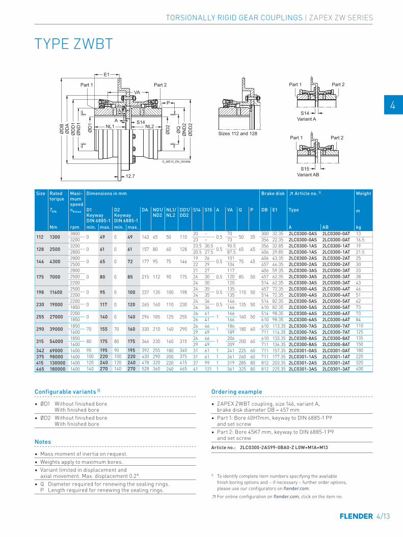
TYPE ZWBT
12.7 Variant AB
Variant A
Part 2Part 1
Part 2Part 1Part 1
Sizes 112 and 128
Part 2
G_MD10_EN_00048b
S15
S14
E1
ØD
1
ØD
BØ
DA
ØD
D1
ØN
D1
VA
A
A
S14NL2NL1
ØD
2
ØD
D2
ØQ
ØN
D2
P
Size Rated torque
Maxi-mum speed
Dimensions in mm Brake disk ↗ Article no. 1) Weight
TKN nKmax D1 Keyway DIN 6885-1
D2 Keyway DIN 6885-1
DA ND1/ ND2
NL1/ NL2
DD1/ DD2
S14 S15 A VA Q P DB E1 Type m
Nm rpm min. max. min. max. A AB kg
112 13003800
0 49 0 49 143 65 50 11020 –
0.570
50 35300 32.35 2LC0300-0AS 2LC0300-0AT 13 -0AA0
3200 23 – 73 356 22.35 2LC0300-0AS 2LC0300-0AT 16.5 -0BA0
128 25003200
0 61 0 61 157 80 60 12823.5 30.5
0.590.5
65 45356 32.85 2LC0300-1AS 2LC0300-1AT 19 -0AA0
2800 20.5 27.5 87.5 406 29.85 2LC0300-1AS 2LC0300-1AT 21.5 -0BA0
146 43002800
0 65 0 72 177 95 75 14619 26
0.5101
75 45406 43.35 2LC0300-2AS 2LC0300-2AT 25 -0AA0
2500 22 29 104 457 46.35 2LC0300-2AS 2LC0300-2AT 30 -0BA0
175 70002800
0 80 0 85 215 112 90 17521 27
0.5117
85 50406 59.35 2LC0300-3AS 2LC0300-3AT 33 -0AA0
2500 24 30 120 457 62.35 2LC0300-3AS 2LC0300-3AT 38 -0BA02200 24 30 120 514 62.35 2LC0300-3AS 2LC0300-3AT 43 -0CA0
198 116002500
0 95 0 100 237 135 100 19824 35
0.5135
110 50457 72.35 2LC0300-4AS 2LC0300-4AT 46 -0AA0
2200 24 35 135 514 72.35 2LC0300-4AS 2LC0300-4AT 51 -0BA0
230 190002200
0 117 0 120 265 160 110 23024 36
0.5146
135 50514 82.35 2LC0300-5AS 2LC0300-5AT 62 -0AA0
1850 24 36 146 610 82.35 2LC0300-5AS 2LC0300-5AT 73 -0BA0
255 270002200
0 140 0 140 294 185 125 25526 41
1166
160 50514 98.35 2LC0300-6AS 2LC0300-6AT 73 -0AA0
1850 26 41 166 610 98.35 2LC0300-6AS 2LC0300-6AT 84 -0BA0
290 39000 1850 70 155 70 160 330 210 140 290 26 46 1 186 180 60 610 113.35 2LC0300-7AS 2LC0300-7AT 110 -0AA01600 29 49 189 711 116.35 2LC0300-7AS 2LC0300-7AT 125 -0BA0
315 54000 1850 80 175 80 175 366 230 160 315 26 46 1 206 200 60 610 133.35 2LC0300-8AS 2LC0300-8AT 135 -0AA01600 29 49 209 711 136.35 2LC0300-8AS 2LC0300-8AT 150 -0BA0
342 69000 1600 90 195 90 195 392 255 180 340 31 61 1 241 225 60 711 157.35 2LC0301-0AS 2LC0301-0AT 180 -0AA0375 98000 1600 100 220 100 220 430 290 200 375 31 61 1 261 260 60 711 177.35 2LC0301-1AS 2LC0301-1AT 220 -0AA0415 130000 1400 120 240 120 240 478 320 220 415 37 99 1 319 285 80 812 203.35 2LC0301-2AS 2LC0301-2AT 320 -0AA0465 180000 1400 140 270 140 270 528 360 240 465 41 121 1 361 325 80 812 225.35 2LC0301-3AS 2LC0301-3AT 400 -0AA0
Notes
• Mass moment of inertia on request.• Weights apply to maximum bores.• Variant limited in displacement and
axial movement. Max. displacement 0.2°.• Q Diameter required for renewing the sealing rings.
P Length required for renewing the sealing rings.
Ordering example
• ZAPEX ZWBT coupling, size 146, variant A, brake disk diameter DB = 457 mm
• Part 1: Bore 40H7mm, keyway to DIN 6885-1 P9 and set screw
• Part 2: Bore 45K7 mm, keyway to DIN 6885-1 P9 and set screw
Article no.: 2LC0300-2AS99-0BA0-Z L0W+M1A+M13
Configurable variants 1)
• ØD1 Without finished bore With finished bore
• ØD2 Without finished bore With finished bore
1) To identify complete item numbers specifying the available finish boring options and – if necessary – further order options, please use our configurators on flender.com.↗ For online configuration on flender.com, click on the item no.
4/13
TORSIONALLY RIGID GEAR COUPLINGS | ZAPEX ZW SERIES
E E
4 4
5 5
6 6
7 7
8 8
9 9
10 10
11 11
12 12
13 13
A A
12.7
Part 2Part 1
Part 2Part 1
Variant AB
Variant A
Part 1
Sizes 112 and 128
Part 2
G_MD10_EN_00049a
S15
S14
E3Ø
D1
ØD
BØ
DA
ØD
D1
ØN
D1
VA
A
A
S14NL2NL1
ØD
2
ØD
D2
ØQ
ØN
D2
P
TYPE ZWBG
Size Rated torque
Maxi-mum speed
Dimensions in mm Brake disk ↗ Article no. 1) Weight
TKN nKmax D1 Keyway DIN 6885-1
D2 Keyway DIN 6885-1
DA ND1/ ND2
NL1/ NL2
DD1/ DD2
S14 S15 A VA Q P DB E3 Type m
Nm rpm min. max. min. max. A AB kg
112 1300 3800 0 49 0 49 143 65 50 110 19 – 0.5 69 50 35 300 59.5 2LC0300-0AU 2LC0300-0AV 13 -0AA03200 22 – 72 356 61 2LC0300-0AU 2LC0300-0AV 16 -0BA0
128 2500 3200 0 61 0 61 157 80 60 128 22 29 0.5 89 65 45 356 71 2LC0300-1AU 2LC0300-1AV 18 -0AA02800 19 26 86 406 69.5 2LC0300-1AU 2LC0300-1AV 20.5 -0BA0
146 4300 2800 0 65 0 72 177 95 75 146 19 26 0.5 101 75 45 406 84.5 2LC0300-2AU 2LC0300-2AV 24 -0AA02500 22 29 104 457 86 2LC0300-2AU 2LC0300-2AV 28.5 -0BA0
175 70002800
0 80 0 85 215 112 90 17521 27
0.5117
85 50406 100.5 2LC0300-3AU 2LC0300-3AV 31 -0AA0
2500 24 30 120 457 102 2LC0300-3AU 2LC0300-3AV 35 -0BA02200 24 30 120 514 102 2LC0300-3AU 2LC0300-3AV 40 -0CA0
198 11600 2500 0 95 0 100 237 135 100 198 24 35 0.5 135 110 50 457 112 2LC0300-4AU 2LC0300-4AV 43 -0AA02200 24 35 135 514 112 2LC0300-4AU 2LC0300-4AV 47 -0BA0
230 19000 2200 0 117 0 120 265 160 110 230 24 36 0.5 146 135 50 514 122 2LC0300-5AU 2LC0300-5AV 58 -0AA01850 24 36 146 610 122 2LC0300-5AU 2LC0300-5AV 66 -0BA0
255 27000 2200 0 140 0 140 294 185 125 255 26 41 1 166 160 50 514 138 2LC0300-6AU 2LC0300-6AV 69 -0AA01850 26 41 166 610 138 2LC0300-6AU 2LC0300-6AV 77 -0BA0
290 39000 1850 70 155 70 160 330 210 140 290 26 46 1 186 180 60 610 153 2LC0300-7AU 2LC0300-7AV 100 -0AA01600 29 49 189 711 154.5 2LC0300-7AU 2LC0300-7AV 110 -0BA0
315 54000 1850 80 175 80 175 366 230 160 315 26 46 1 206 200 60 610 173 2LC0300-8AU 2LC0300-8AV 130 -0AA01600 29 49 209 711 174.5 2LC0300-8AU 2LC0300-8AV 140 -0BA0
342 69000 1600 90 195 90 195 392 255 180 340 31 61 1 241 225 60 711 195.5 2LC0301-0AU 2LC0301-0AV 165 -0AA0375 98000 1600 100 220 100 220 430 290 200 375 31 61 1 261 260 60 711 215.5 2LC0301-1AU 2LC0301-1AV 205 -0AA0415 130000 1400 120 240 120 240 478 320 220 415 37 99 1 319 285 80 812 238.5 2LC0301-2AU 2LC0301-2AV 280 -0AA0465 180000 1400 140 270 140 270 528 360 240 465 41 121 1 361 325 80 812 260.5 2LC0301-3AU 2LC0301-3AV 360 -0AA0
Notes
• Mass moment of inertia on request.• Weights apply to maximum bores.• Variant limited in displacement and
axial movement. Max. displacement 0.2°.• Modified brake disk dimensions on request• Q Diameter required for renewing the sealing rings.
P Length required for renewing the sealing rings.
Ordering example
• ZAPEX ZWBG coupling, size 146, variant A, brake disk diameter DB = 457 mm
• Part 1: Bore 40H7mm, keyway to DIN 6885-1 P9 and set screw
• Part 2: Bore 45K7 mm, keyway to DIN 6885-1 P9 and set screw
Article no.: 2LC0300-2AU99-0BA0-Z L0W+M1A+M13
1) To identify complete item numbers specifying the available finish boring options and – if necessary – further order options, please use our configurators on flender.com.↗ For online configuration on flender.com, click on the item no.
Configurable variants 1)
• ØD1 Without finished bore With finished bore
• ØD2 Without finished bore With finished bore
4/14
TORSIONALLY RIGID GEAR COUPLINGS | ZAPEX ZW SERIES
E E
4 4
5 5
6 6
7 7
8 8
9 9
10 10
11 11
12 12
13 13
A A
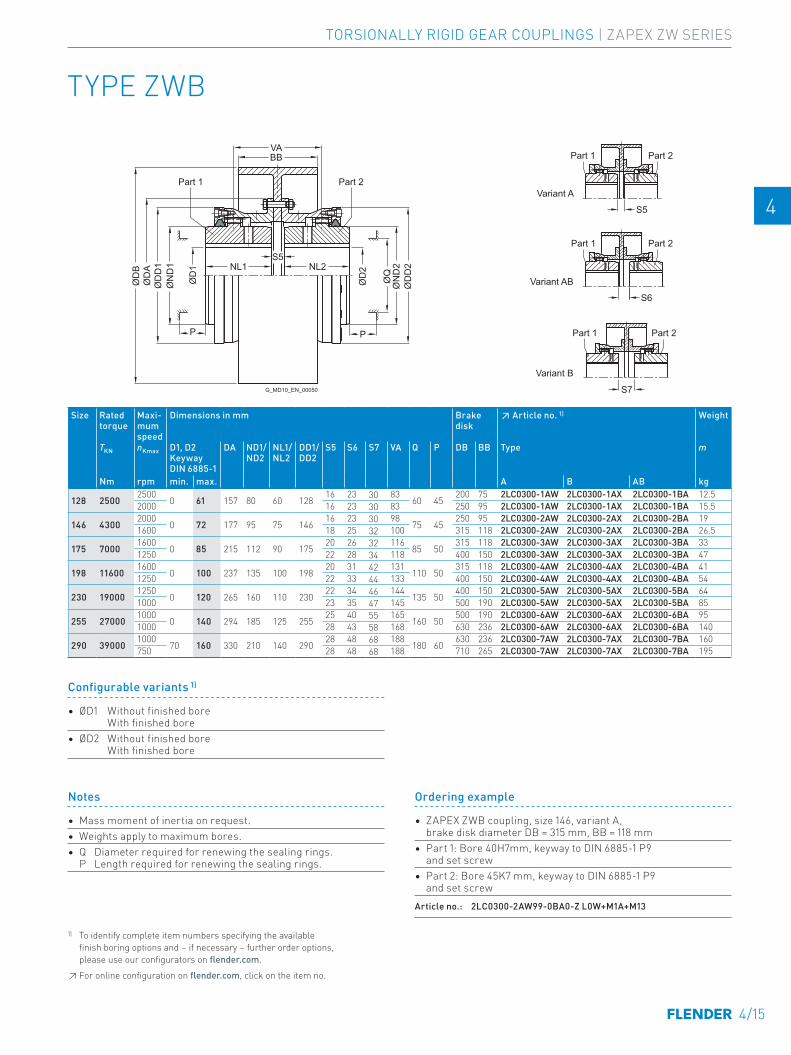
TYPE ZWB
Part 2
G_MD10_EN_00050
Part 1 Part 2
Part 1 Part 2
Part 1
Part 1 Part 2
Variant B
Variant AB
Variant A
S5
S6
S7
S5NL1
ØD
D1
ØD
D2
ØQ
ØD
2
ØN
D2NL2
PP
ØD
BØ
DA
VABB
ØD
1
ØN
D1
Size Rated torque
Maxi-mum speed
Dimensions in mm Brake disk
↗ Article no. 1) Weight
TKN nKmax D1, D2 Keyway DIN 6885-1
DA ND1/ ND2
NL1/ NL2
DD1/ DD2
S5 S6 S7 VA Q P DB BB Type m
Nm rpm min. max. A B AB kg
128 25002500
0 61 157 80 60 12816 23 30 83
60 45200 75 2LC0300-1AW 2LC0300-1AX 2LC0300-1BA 12.5 -0AA0
2000 16 23 30 83 250 95 2LC0300-1AW 2LC0300-1AX 2LC0300-1BA 15.5 -0BA0
146 43002000
0 72 177 95 75 14616 23 30 98
75 45250 95 2LC0300-2AW 2LC0300-2AX 2LC0300-2BA 19 -0AA0
1600 18 25 32 100 315 118 2LC0300-2AW 2LC0300-2AX 2LC0300-2BA 26.5 -0BA0
175 70001600
0 85 215 112 90 17520 26 32 116
85 50315 118 2LC0300-3AW 2LC0300-3AX 2LC0300-3BA 33 -0AA0
1250 22 28 34 118 400 150 2LC0300-3AW 2LC0300-3AX 2LC0300-3BA 47 -0BA0
198 116001600
0 100 237 135 100 19820 31 42 131
110 50315 118 2LC0300-4AW 2LC0300-4AX 2LC0300-4BA 41 -0AA0
1250 22 33 44 133 400 150 2LC0300-4AW 2LC0300-4AX 2LC0300-4BA 54 -0BA0
230 190001250
0 120 265 160 110 23022 34 46 144
135 50400 150 2LC0300-5AW 2LC0300-5AX 2LC0300-5BA 64 -0AA0
1000 23 35 47 145 500 190 2LC0300-5AW 2LC0300-5AX 2LC0300-5BA 85 -0BA0
255 270001000
0 140 294 185 125 25525 40 55 165
160 50500 190 2LC0300-6AW 2LC0300-6AX 2LC0300-6BA 95 -0AA0
1000 28 43 58 168 630 236 2LC0300-6AW 2LC0300-6AX 2LC0300-6BA 140 -0BA0
290 390001000
70 160 330 210 140 29028 48 68 188
180 60630 236 2LC0300-7AW 2LC0300-7AX 2LC0300-7BA 160 -0AA0
750 28 48 68 188 710 265 2LC0300-7AW 2LC0300-7AX 2LC0300-7BA 195 -0BA0
Notes
• Mass moment of inertia on request.• Weights apply to maximum bores.• Q Diameter required for renewing the sealing rings.
P Length required for renewing the sealing rings.
Ordering example
• ZAPEX ZWB coupling, size 146, variant A, brake disk diameter DB = 315 mm, BB = 118 mm
• Part 1: Bore 40H7mm, keyway to DIN 6885-1 P9 and set screw
• Part 2: Bore 45K7 mm, keyway to DIN 6885-1 P9 and set screw
Article no.: 2LC0300-2AW99-0BA0-Z L0W+M1A+M13
1) To identify complete item numbers specifying the available finish boring options and – if necessary – further order options, please use our configurators on flender.com.↗ For online configuration on flender.com, click on the item no.
Configurable variants 1)
• ØD1 Without finished bore With finished bore
• ØD2 Without finished bore With finished bore
4/15
TORSIONALLY RIGID GEAR COUPLINGS | ZAPEX ZW SERIES
E E
4 4
5 5
6 6
7 7
8 8
9 9
10 10
11 11
12 12
13 13
A A
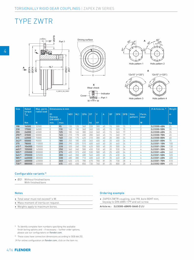
Part 1
Hole pattern 1
Hole pattern 4Hole pattern 3
Hole pattern 2
Wear check
Driving surface
G_MD10_EN_00051
Part 1
IndicatorCover
12x10° (=120°)V
BF ØD
FBA
NL1
ØD
FAØ
DFK
ØD
1
W W
ØD
7Ø
ND
1
30°
60°40°
40°20°
10°
12x10° (=120°)
30°X
X
AA
A30°
30°
10°
30°
TYPE ZWTR
Size Rated torque
Max. perm. radial load
Dimensions in mm ↗ Article no. 1) Weight
TKN D1 Keyway DIN 6885-1
ND1 NL1 DFA D7 V A BF DFK DFB Hole pattern
Perm. wear
m
Nm N min. max. h6 h9 W kg198 14500 32500 0 95 135 125 340 220 300 45 15 300 15 1 2 2LC0300-4BN 25 0-0AA0230 17500 36500 0 110 160 130 360 240 320 45 15 320 15 1 2 2LC0300-5BN 30 0-0AA0255 24000 45500 0 125 185 145 380 260 340 45 15 340 19 1 2 2LC0300-6BN 35 0-0AA0290 2) 31500 50000 0 145 210 170 400 280 360 45 15 360 19 1 3 2LC0300-7BN 45 0-0AA0315 42000 70000 0 160 230 175 420 310 380 60 20 380 24 1 3 2LC0300-8BN 60 0-0AA0342 2) 55000 90000 0 180 255 185 450 340 400 60 20 400 24 1 3 2LC0301-0BN 70 0-0AA0375 78000 110000 0 200 290 220 510 400 460 60 20 460 24 1 3 2LC0301-1BN 100 0-0AA0415 2) 104000 150000 0 220 320 240 550 420 500 60 20 500 24 1 3 2LC0301-2BN 130 0-0AA0465 2) 155000 165000 0 250 360 260 580 450 530 60 20 530 24 2 4 2LC0301-3BN 160 0-0AA0505 2) 235000 200000 0 275 400 315 650 530 580 65 25 600 24 2 4 2LC0301-4BN 240 0-0AA0545 2) 390000 325000 0 300 440 350 680 560 600 65 25 630 24 3 4 2LC0301-5BN 320 0-0AA0585 2) 460000 380000 0 330 480 380 710 600 640 81 35 660 28 4 4 2LC0301-6BN 400 0-0AA0640 2) 600000 420000 0 360 520 410 780 670 700 81 35 730 28 4 4 2LC0301-7BN 510 0-0AA0730 2) 880000 500000 0 415 600 450 850 730 760 81 35 800 28 4 5 2LC0302-0BN 690 0-0AA0
Notes
• Total wear must not exceed 1 x W.• Mass moment of inertia on request.• Weights apply to maximum bores.
Ordering example
• ZAPEX ZWTR coupling, size 198, bore 80H7 mm, keyway to DIN 6885-1 P9 and set screw.
Article no.: 2LC0300-4BN90-0AA0-Z L1J
Configurable variants 1)
• ØD1 Without finished bore With finished bore
1) To identify complete item numbers specifying the available finish boring options and – if necessary – further order options, please use our configurators on flender.com.2) These sizes have connection dimensions according to SEB 666 212.↗ For online configuration on flender.com, click on the item no.
4/16
TORSIONALLY RIGID GEAR COUPLINGS | ZAPEX ZW SERIES
E E
4 4
5 5
6 6
7 7
8 8
9 9
10 10
11 11
12 12
13 13
A A
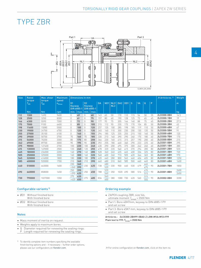
TYPE ZBR
Part 3Part 1
G_MD10_EN_00052
VA
S NL2
P
NL1
ØD
1
ØD
2
ØD
AØ
DD
1
ØQ
ØN
D1
ØD
A2
Size Rated torque
Max. shear torque
Maximum speed
Dimensions in mm ↗ Article no. 1) Weight
TKN TBR nKmax D1 Keyway DIN 6885-1
D2 Keyway DIN 6885-1
DA ND1 NL1/ NL2
DA2 DD1 S VA Q P m
Nm Nm rpm min. max. min. max. kg112 1300 1690 9400 0 49 0 60 143 65 50 170 110 115 56 50 35 2LC0300-0BH 14.5 -0AA0128 2500 3250 8300 0 61 0 75 157 80 60 190 128 125 73 65 45 2LC0300-1BH 19 -0AA0146 4300 5590 7300 0 72 0 90 177 95 75 205 146 140 88 75 45 2LC0300-2BH 27.5 -0AA0175 7000 9100 6400 0 85 0 105 215 112 90 235 175 170 104 85 50 2LC0300-3BH 43 -0AA0198 11600 15080 5500 0 100 0 120 237 135 100 285 198 185 119 110 50 2LC0300-4BH 67 -0AA0230 19000 24700 4700 0 120 0 135 265 160 110 300 230 200 130 135 50 2LC0300-5BH 91 -0AA0255 27000 35100 4100 0 140 0 155 294 185 125 335 255 215 150 160 50 2LC0300-6BH 120 -0AA0290 39000 50700 3700 70 160 70 185 330 210 140 390 290 240 170 180 60 2LC0300-7BH 170 -0AA0315 54000 70200 3300 80 175 80 200 366 230 160 415 315 257 190 200 60 2LC0300-8BH 215 -0AA0342 69000 89700 3000 90 195 90 235 392 255 180 460 340 290 222 225 60 2LC0301-0BH 295 -0AA0375 98000 127400 2700 100 220 100 240 430 290 200 495 375 300 242 260 60 2LC0301-1BH 380 -0AA0415 130000 169000 2500 120 240 120 255 478 320 220 540 415 370 294 285 80 2LC0301-2BH 520 -0AA0465 180000 234000 2200 140 270 140 285 528 360 240 635 465 400 336 325 80 2LC0301-3BH 720 -0AA0505 250000 325000 2000 160 300 160 320 568 400 260 710 505 420 366 365 80 2LC0301-4BH 970 -0AA0545 320000 416000 1800 180 330 180 370 620 440 280 800 545 460 406 405 80 2LC0301-5BH 1250 -0AA0585 400000 520000 1700 210 360 210 390 660 480 310 860 585 500 460 445 80 2LC0301-6BH 1600 -0AA0
640 510000 663000 1600230 360
230 425 738480
330 900 640 530 479 445 90 2LC0301-7BH 1850 -0AA0>360 390 520 475
690 660000 858000 1450250 390
250 450 788520
350 1020 690 580 516 475 90 2LC0301-8BH2600
-0AA0>390 420 560 515 2650
730 790000 1027000 1350275 420
275 485 834560
380 1080 730 620 560 515 90 2LC0302-0BH 3200 -0AA0>420 450 600 555
Notes
• Mass moment of inertia on request.• Weights apply to maximum bores.• Q Diameter required for renewing the sealing rings.
P Length required for renewing the sealing rings.
Ordering example
• ZAPEX coupling ZBR, size 146, ultimate moment Tbreak = 3500 Nm
• Part 1: Bore 40H7mm, keyway to DIN 6885-1 P9 and set screw
• Part 3: Bore 45K7 mm, keyway to DIN 6885-1 P9 and set screw
Article no.: 2LC0300-2BH99-0BA0-Z L0W+M1A+M13+Y99Plain text to Y99: Tbreak = 3500 Nm
Configurable variants 1)
• ØD1 Without finished bore With finished bore
• ØD2 Without finished bore With finished bore
1) To identify complete item numbers specifying the available finish boring options and – if necessary – further order options, please use our configurators on flender.com. ↗ For online configuration on flender.com, click on the item no.
4/17
TORSIONALLY RIGID GEAR COUPLINGS | ZAPEX ZW SERIES
E E
4 4
5 5
6 6
7 7
8 8
9 9
10 10
11 11
12 12
13 13
A A
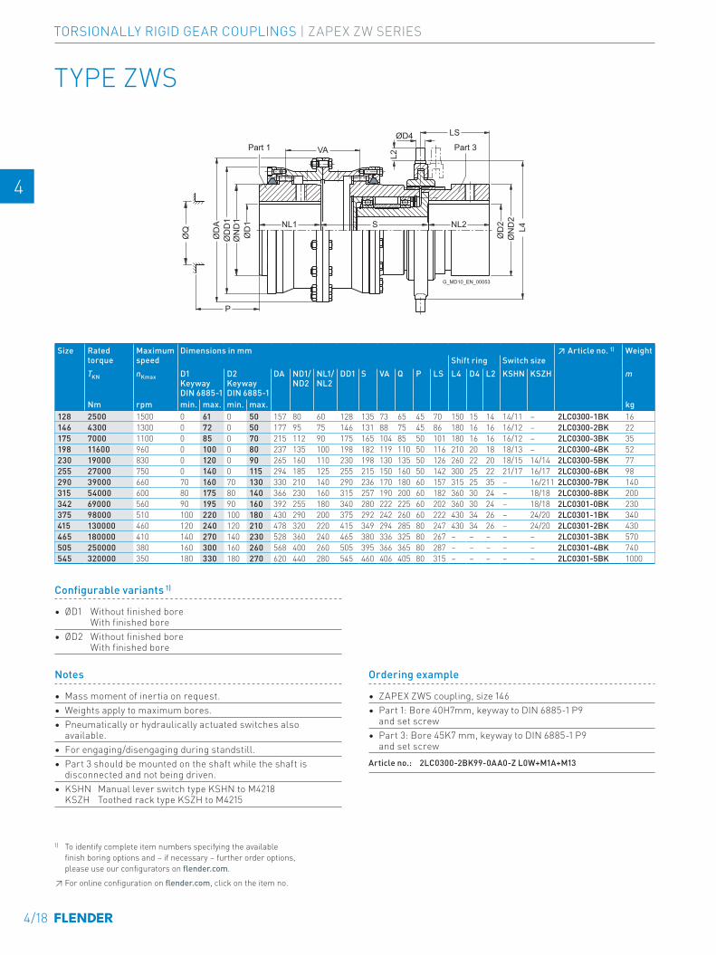
Part 3Part 1
G_MD10_EN_00053
ØQ SNL1
P
VA
LS
NL2
ØD
1
ØD4
L2
ØD
2
ØD
AØ
DD
1Ø
ND
1
L4Ø
ND
2
TYPE ZWS
Ordering example
• ZAPEX ZWS coupling, size 146• Part 1: Bore 40H7mm, keyway to DIN 6885-1 P9
and set screw• Part 3: Bore 45K7 mm, keyway to DIN 6885-1 P9
and set screw Article no.: 2LC0300-2BK99-0AA0-Z L0W+M1A+M13
Size Rated torque
Maximum speed
Dimensions in mm ↗ Article no. 1) WeightShift ring Switch size
TKN nKmax D1 Keyway DIN 6885-1
D2 Keyway DIN 6885-1
DA ND1/ND2
NL1/ NL2
DD1 S VA Q P LS L4 D4 L2 KSHN KSZH m
Nm rpm min. max. min. max. kg128 2500 1500 0 61 0 50 157 80 60 128 135 73 65 45 70 150 15 14 14/11 – 2LC0300-1BK 16 -0AA0146 4300 1300 0 72 0 50 177 95 75 146 131 88 75 45 86 180 16 16 16/12 – 2LC0300-2BK 22 -0AA0175 7000 1100 0 85 0 70 215 112 90 175 165 104 85 50 101 180 16 16 16/12 – 2LC0300-3BK 35 -0AA0198 11600 960 0 100 0 80 237 135 100 198 182 119 110 50 116 210 20 18 18/13 – 2LC0300-4BK 52 -0AA0230 19000 830 0 120 0 90 265 160 110 230 198 130 135 50 126 260 22 20 18/15 14/14 2LC0300-5BK 77 -0AA0255 27000 750 0 140 0 115 294 185 125 255 215 150 160 50 142 300 25 22 21/17 16/17 2LC0300-6BK 98 -0AA0290 39000 660 70 160 70 130 330 210 140 290 236 170 180 60 157 315 25 35 – 16/211 2LC0300-7BK 140 -0AA0315 54000 600 80 175 80 140 366 230 160 315 257 190 200 60 182 360 30 24 – 18/18 2LC0300-8BK 200 -0AA0342 69000 560 90 195 90 160 392 255 180 340 280 222 225 60 202 360 30 24 – 18/18 2LC0301-0BK 230 -0AA0375 98000 510 100 220 100 180 430 290 200 375 292 242 260 60 222 430 34 26 – 24/20 2LC0301-1BK 340 -0AA0415 130000 460 120 240 120 210 478 320 220 415 349 294 285 80 247 430 34 26 – 24/20 2LC0301-2BK 430 -0AA0465 180000 410 140 270 140 230 528 360 240 465 380 336 325 80 267 – – – – – 2LC0301-3BK 570 -0AA0505 250000 380 160 300 160 260 568 400 260 505 395 366 365 80 287 – – – – – 2LC0301-4BK 740 -0AA0545 320000 350 180 330 180 270 620 440 280 545 460 406 405 80 315 – – – – – 2LC0301-5BK 1000 -0AA0
Notes
• Mass moment of inertia on request.• Weights apply to maximum bores. • Pneumatically or hydraulically actuated switches also
available.• For engaging/disengaging during standstill.• Part 3 should be mounted on the shaft while the shaft is
disconnected and not being driven.• KSHN Manual lever switch type KSHN to M4218
KSZH Toothed rack type KSZH to M4215
Configurable variants 1)
• ØD1 Without finished bore With finished bore
• ØD2 Without finished bore With finished bore
1) To identify complete item numbers specifying the available finish boring options and – if necessary – further order options, please use our configurators on flender.com.↗ For online configuration on flender.com, click on the item no.
4/18
TORSIONALLY RIGID GEAR COUPLINGS | ZAPEX ZW SERIES
E E
4 4
5 5
6 6
7 7
8 8
9 9
10 10
11 11
12 12
13 13
A A
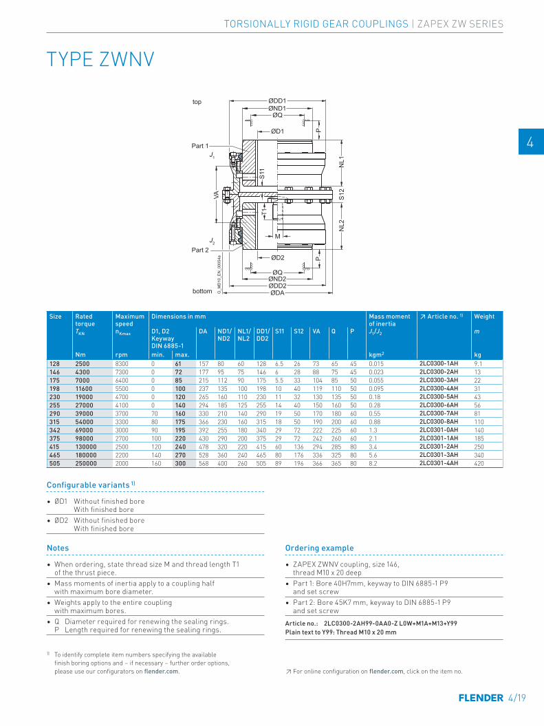
TYPE ZWNV
bottom
top
Part 1
Part 2
G_M
D10
_EN
_000
54a
J1
J2
ØD2
ØD1
ØDAØDD2
ØDD1
ØND2
ØND1
ØQ
ØQ
PP
NL2
S12
NL1
M
T1S1
1
VA
Ordering example
• ZAPEX ZWNV coupling, size 146, thread M10 x 20 deep
• Part 1: Bore 40H7mm, keyway to DIN 6885-1 P9 and set screw
• Part 2: Bore 45K7 mm, keyway to DIN 6885-1 P9 and set screw
Article no.: 2LC0300-2AH99-0AA0-Z L0W+M1A+M13+Y99Plain text to Y99: Thread M10 x 20 mm
Size Rated torque
Maximum speed
Dimensions in mm Mass moment of inertia
↗ Article no. 1) Weight
TKN nKmax
D1, D2 Keyway DIN 6885-1
DA ND1/ ND2
NL1/ NL2
DD1/ DD2
S11 S12 VA Q P J1/J2 m
Nm rpm min. max. kgm2 kg128 2500 8300 0 61 157 80 60 128 6.5 26 73 65 45 0.015 2LC0300-1AH 9.1 -0AA0146 4300 7300 0 72 177 95 75 146 6 28 88 75 45 0.023 2LC0300-2AH 13 -0AA0175 7000 6400 0 85 215 112 90 175 5.5 33 104 85 50 0.055 2LC0300-3AH 22 -0AA0198 11600 5500 0 100 237 135 100 198 10 40 119 110 50 0.095 2LC0300-4AH 31 -0AA0230 19000 4700 0 120 265 160 110 230 11 32 130 135 50 0.18 2LC0300-5AH 43 -0AA0255 27000 4100 0 140 294 185 125 255 14 40 150 160 50 0.28 2LC0300-6AH 56 -0AA0290 39000 3700 70 160 330 210 140 290 19 50 170 180 60 0.55 2LC0300-7AH 81 -0AA0315 54000 3300 80 175 366 230 160 315 18 50 190 200 60 0.88 2LC0300-8AH 110 -0AA0342 69000 3000 90 195 392 255 180 340 29 72 222 225 60 1.3 2LC0301-0AH 140 -0AA0375 98000 2700 100 220 430 290 200 375 29 72 242 260 60 2.1 2LC0301-1AH 185 -0AA0415 130000 2500 120 240 478 320 220 415 60 136 294 285 80 3.4 2LC0301-2AH 250 -0AA0465 180000 2200 140 270 528 360 240 465 80 176 336 325 80 5.6 2LC0301-3AH 340 -0AA0505 250000 2000 160 300 568 400 260 505 89 196 366 365 80 8.2 2LC0301-4AH 420 -0AA0
Notes
• When ordering, state thread size M and thread length T1 of the thrust piece.
• Mass moments of inertia apply to a coupling half with maximum bore diameter.
• Weights apply to the entire coupling with maximum bores.
• Q Diameter required for renewing the sealing rings. P Length required for renewing the sealing rings.
Configurable variants 1)
• ØD1 Without finished bore With finished bore
• ØD2 Without finished bore With finished bore
1) To identify complete item numbers specifying the available finish boring options and – if necessary – further order options, please use our configurators on flender.com. ↗ For online configuration on flender.com, click on the item no.
4/19
TORSIONALLY RIGID GEAR COUPLINGS | ZAPEX ZW SERIES
E E
4 4
5 5
6 6
7 7
8 8
9 9
10 10
11 11
12 12
13 13
A A
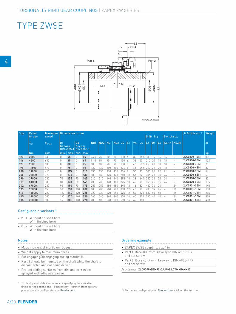
Part 2Part 1
G_MD10_EN_00055a
S1NL2NL1
LS
VA
ØD4
L2
ØD
2
ØD
1
L4ØD
D
ØN
D2
ØN
D1
TYPE ZWSE
Size Rated torque
Maximum speed
Dimensions in mm ↗ Article no. 1) WeightShift ring Switch size
TKN nKmax D1 Keyway DIN 6885-1
D2 Keyway DIN 6885-1
ND1 ND2 NL1 NL2 DD S1 VA LS L4 D4 L2 KSHN KSZH m
Nm rpm min. max. min. max. kg128 2500 730 0 55 0 55 76.5 75 60 60 130 6 30 36.5 180 16 16 16 – 2LC0300-1BM 8.8 -0AA0146 4300 630 0 69 0 65 91.5 90 75 75 150 6 33 50 210 20 18 18 – 2LC0300-2BM 13.5 -0AA0175 7000 530 0 80 0 75 108 105 90 90 180 8 46 56.5 250 20 30 18 – 2LC0300-3BM 23 -0AA0198 11600 470 0 95 0 95 130 130 100 100 204 8 48 64.5 260 22 20 18 – 2LC0300-4BM 32 -0AA0230 19000 410 0 115 0 110 155 155 110 110 236 8 50 73 300 25 22 21 – 2LC0300-5BM 44 -0AA0255 27000 370 0 135 0 130 180 180 125 125 260 10 55 82 355 25 35 24 – 2LC0300-6BM 63 -0AA0290 39000 330 70 155 70 145 210 210 140 140 295 10 38 64.5 355 25 35 24 – 2LC0300-7BM 82 -0AA0315 54000 300 80 170 80 165 230 230 160 160 325 10 42 76 355 25 35 24 – 2LC0300-8BM 105 -0AA0342 69000 280 90 190 90 175 255 255 180 180 345 12 46 82 430 34 26 – 24 2LC0301-0BM 145 -0AA0375 98000 250 100 210 100 200 280 280 200 200 378 12 48 90 430 34 26 – 24 2LC0301-1BM 180 -0AA0415 130000 220 120 240 120 225 320 320 220 240 425 12 52 120 580 40 40 – 24 2LC0301-2BM 295 -0AA0465 180000 200 140 270 140 250 360 360 240 260 470 16 60 150 580 40 40 – 24 2LC0301-3BM 350 -0AA0505 250000 180 160 300 160 270 400 400 260 280 510 16 62 161 – – – – 24 2LC0301-4BM 400 -0AA0
Ordering example
• ZAPEX ZWSE coupling, size 146 • Part 1: Bore 40H7mm, keyway to DIN 6885-1 P9
and set screw,• Part 2: Bore 45K7 mm, keyway to DIN 6885-1 P9
and set screw. Article no.: 2LC0300-2BM99-0AA0-Z L0W+M1A+M13
Notes
• Mass moment of inertia on request.• Weights apply to maximum bores. • For engaging/disengaging during standstill.• Part 2 should be mounted on the shaft while the shaft is
disconnected and not being driven.• Protect sliding surfaces from dirt and corrosion;
sprayed with adhesive grease.
1) To identify complete item numbers specifying the available finish boring options and – if necessary – further order options, please use our configurators on flender.com.
Configurable variants 1)
• ØD1 Without finished bore With finished bore
• ØD2 Without finished bore With finished bore
↗ For online configuration on flender.com, click on the item no.
4/20
TORSIONALLY RIGID GEAR COUPLINGS | ZAPEX ZW SERIES
E E
4 4
5 5
6 6
7 7
8 8
9 9
10 10
11 11
12 12
13 13
A A
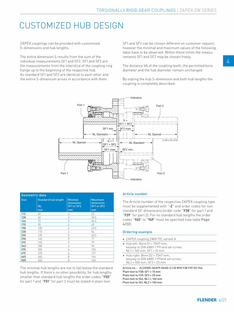
CUSTOMIZED HUB DESIGN
G_MD10_EN_00184
Part 2Part 1
Part 2Part 1
Interstice
Interstice
NL SpecialNL Standard
NL Special
S =SF1 + SF2
S =SF1 + SF2
SF1 min. SF2 max.
SF1 max. SF2 min.
NL Standard
ZAPEX couplings can be provided with customized S-dimensions and hub lengths.
The entire dimension S results from the sum of the individual measurements SF1 and SF2. SF1 and SF2 are the measurements from the interstice of the coupling ring flange up to the beginning of the respective hub. As standard SF1 and SF2 are identical to each other and the entire S-dimension arises in accordance with them.
SF1 and SF2 can be chosen different on customer request, however the minimal and maximum values of the following table have to be observed. Within these limits the measu-rements SF1 and SF2 may be chosen freely.
The distance VA of the coupling teeth, the permitted bore diameter and the hub diameter remain unchanged.
By stating the hub S-dimension and both hub lengths the coupling is completely described.
Geometric dataSize Standard hub length Minimal
dimensionMaximum dimension
NL SF1 or SF2 SF1 or SF2mm mm mm
112 50 3 23128 60 3 30.5146 75 3 36.5175 90 4 43198 100 4 49.5230 110 4 54255 125 5 62.5290 140 5 71315 160 5 79342 180 6 94375 200 6 103415 220 6 127465 240 8 146505 260 8 160
The minimal hub lengths are not to fall below the standard hub lengths. If there‘s no other possibility, for hub lengths smaller than standard hub lengths the order codes "Y50" for part 1 and "Y51" for part 2 must be stated in plain text.
Article number
The Article number of the respective ZAPEX coupling type must be supplemented with "-Z" and order codes for non standard SF-dimensions (order code "Y38" for part 1 and "Y39" for part 2). For no standard hub lengths the order codes "Y40" to "Y49" must be specified (see table Page 4/22).
Ordering example
• ZAPEX coupling ZWN 175, variant A• Hub left: Bore D1 = 70H7 mm,
keyway to DIN 6885-1 P9 and set screw; NL1 = 160 mm; SF1 = 10 mm
• Hub right: Bore D2 = 75H7 mm, keyway to DIN 6885-1 P9and set screw; NL2 = 100 mm; SF2 = 25 mm
Article no.: 2LC0300-3AA99-0AA0-Z L1G M1H Y38 Y39 Y41 Y46Plain text to Y38: SF1 = 10 mm Plain text to Y39: SF2 = 25 mm Plain text to Y46: NL1 = 160 mm Plain text to Y41: NL2 = 100 mm
4/21
TORSIONALLY RIGID GEAR COUPLINGS | ZAPEX ZW SERIES
E E
4 4
5 5
6 6
7 7
8 8
9 9
10 10
11 11
12 12
13 13
A A
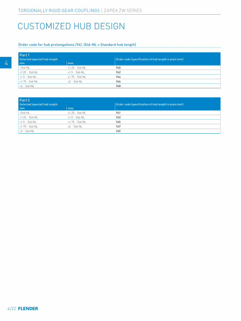
CUSTOMIZED HUB DESIGN
Order code for hub prolongations (Y4). (Std-NL = Standard hub length)
Part 1Selected (special) hub length Order code (specification of hub length in plain text)min. max.>Std-NL ≤1.25 ⋅ Std-NL Y40>1.25 ⋅ Std-NL ≤1.5 ⋅ Std-NL Y42>1.5 ⋅ Std-NL ≤1.75 ⋅ Std-NL Y44>1.75 ⋅ Std-NL ≤2 ⋅ Std-NL Y46>2 ⋅ Std-NL Y48
Part 2Selected (special) hub length Order code (specification of hub length in plain text)min. max.>Std-NL ≤1.25 ⋅ Std-NL Y41>1.25 ⋅ Std-NL ≤1.5 ⋅ Std-NL Y43>1.5 ⋅ Std-NL ≤1.75 ⋅ Std-NL Y45>1.75 ⋅ Std-NL ≤2 ⋅ Std-NL Y47>2 ⋅ Std-NL Y49
4/22
TORSIONALLY RIGID GEAR COUPLINGS | ZAPEX ZW SERIES
E E
4 4
5 5
6 6
7 7
8 8
9 9
10 10
11 11
12 12
13 13
A A
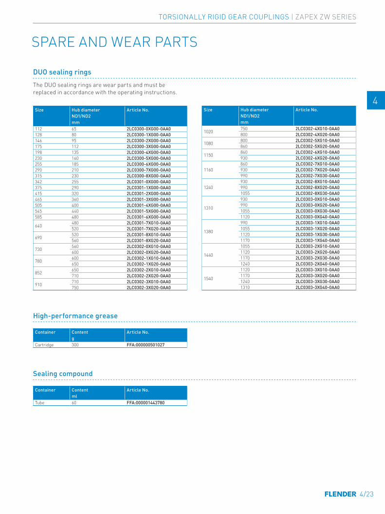
SPARE AND WEAR PARTS
DUO sealing rings
Size Hub diameter Article No.ND1/ND2mm
112 65 2LC0300-0XG00-0AA0128 80 2LC0300-1XG00-0AA0146 95 2LC0300-2XG00-0AA0175 112 2LC0300-3XG00-0AA0198 135 2LC0300-4XG00-0AA0230 160 2LC0300-5XG00-0AA0255 185 2LC0300-6XG00-0AA0290 210 2LC0300-7XG00-0AA0315 230 2LC0300-8XG00-0AA0342 255 2LC0301-0XG00-0AA0375 290 2LC0301-1XG00-0AA0415 320 2LC0301-2XG00-0AA0465 360 2LC0301-3XG00-0AA0505 400 2LC0301-4XG00-0AA0545 440 2LC0301-5XG00-0AA0585 480 2LC0301-6XG00-0AA0
640 480 2LC0301-7XG10-0AA0520 2LC0301-7XG20-0AA0
690 520 2LC0301-8XG10-0AA0560 2LC0301-8XG20-0AA0
730 560 2LC0302-0XG10-0AA0600 2LC0302-0XG20-0AA0
780 600 2LC0302-1XG10-0AA0650 2LC0302-1XG20-0AA0
852 650 2LC0302-2XG10-0AA0710 2LC0302-2XG20-0AA0
910 710 2LC0302-3XG10-0AA0750 2LC0302-3XG20-0AA0
The DUO sealing rings are wear parts and must be replaced in accordance with the operating instructions.
Size Hub diameter Article No.ND1/ND2mm
1020 750 2LC0302-4XG10-0AA0800 2LC0302-4XG20-0AA0
1080 800 2LC0302-5XG10-0AA0860 2LC0302-5XG20-0AA0
1150 860 2LC0302-6XG10-0AA0930 2LC0302-6XG20-0AA0
1160860 2LC0302-7XG10-0AA0930 2LC0302-7XG20-0AA0990 2LC0302-7XG30-0AA0
1240930 2LC0302-8XG10-0AA0990 2LC0302-8XG20-0AA01055 2LC0302-8XG30-0AA0
1310
930 2LC0303-0XG10-0AA0990 2LC0303-0XG20-0AA01055 2LC0303-0XG30-0AA01120 2LC0303-0XG40-0AA0
1380
990 2LC0303-1XG10-0AA01055 2LC0303-1XG20-0AA01120 2LC0303-1XG30-0AA01170 2LC0303-1XG40-0AA0
1440
1055 2LC0303-2XG10-0AA01120 2LC0303-2XG20-0AA01170 2LC0303-2XG30-0AA01240 2LC0303-2XG40-0AA0
1540
1120 2LC0303-3XG10-0AA01170 2LC0303-3XG20-0AA01240 2LC0303-3XG30-0AA01310 2LC0303-3XG40-0AA0
High-performance grease
Container Content Article No.g
Cartridge 300 FFA:000000501027
Sealing compound
Container Content Article No.ml
Tube 60 FFA:000001443780
4/23
TORSIONALLY RIGID GEAR COUPLINGS | ZAPEX ZW SERIES
E E
4 4
5 5
6 6
7 7
8 8
9 9
10 10
11 11
12 12
13 13
A A

4/24
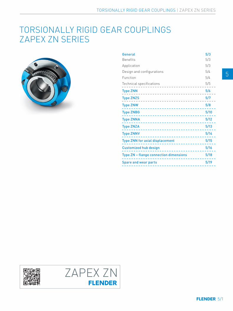
TORSIONALLY RIGID GEAR COUPLINGS ZAPEX ZN SERIES
ZAPEX ZN
01-Einzelschilder-03-2020.indd 2 09.03.20 14:00
General 5/3Benefits 5/3Application 5/3Design and configurations 5/4Function 5/4Technical specifications 5/5
Type ZNN 5/6
Type ZNZS 5/7
Type ZNW 5/8
Type ZNBG 5/10
Type ZNNA 5/12
Type ZNZA 5/13
Type ZNNV 5/14
Type ZNN for axial displacement 5/15
Customized hub design 5/16
Type ZN – flange connection dimensions 5/18
Spare and wear parts 5/19
TORSIONALLY RIGID GEAR COUPLINGS | ZAPEX ZN SERIES
5/1
E E
4 4
5 5
6 6
7 7
8 8
9 9
10 10
11 11
12 12
13 13
A A

5/2
TORSIONALLY RIGID GEAR COUPLINGS | ZAPEX ZN SERIES
E E
4 4
5 5
6 6
7 7
8 8
9 9
10 10
11 11
12 12
13 13
A A
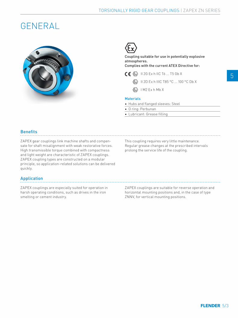
GENERAL
Coupling suitable for use in potentially explosive atmospheres. Complies with the current ATEX Directive for:
II 2G Ex h IIC T6 ... T5 Gb X
II 2D Ex h IIIC T85 °C ... 100 °C Db X
I M2 Ex h Mb X
Materials• Hubs and flanged sleeves: Steel• O ring: Perbunan• Lubricant: Grease filling
Benefits
ZAPEX gear couplings link machine shafts and compen-sate for shaft misalignment with weak restorative forces. High transmissible torque combined with compactness and light weight are characteristic of ZAPEX couplings. ZAPEX coupling types are constructed on a modular principle, so application-related solutions can be delivered quickly.
This coupling requires very little maintenance. Regular grease changes at the prescribed intervals prolong the service life of the coupling.
Application
ZAPEX couplings are especially suited for operation in harsh operating conditions, such as drives in the iron smelting or cement industry.
ZAPEX couplings are suitable for reverse operation and horizontal mounting positions and, in the case of type ZNNV, for vertical mounting positions.
TORSIONALLY RIGID GEAR COUPLINGS | ZAPEX ZN SERIES
5/3
E E
4 4
5 5
6 6
7 7
8 8
9 9
10 10
11 11
12 12
13 13
A A
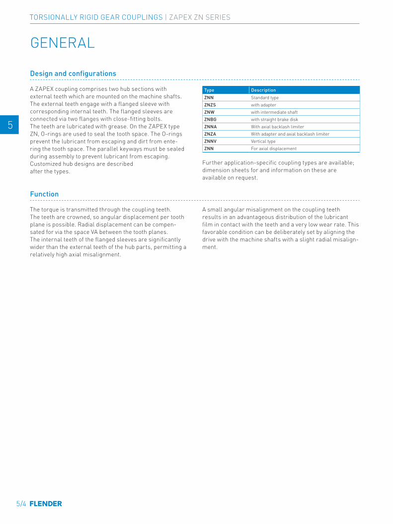
GENERAL
Design and configurations
A ZAPEX coupling comprises two hub sections with external teeth which are mounted on the machine shafts. The external teeth engage with a flanged sleeve with corresponding internal teeth. The flanged sleeves are connected via two flanges with close-fitting bolts.The teeth are lubricated with grease. On the ZAPEX type ZN, O-rings are used to seal the tooth space. The O-rings prevent the lubricant from escaping and dirt from ente-ring the tooth space. The parallel keyways must be sealed during assembly to prevent lubricant from escaping.Customized hub designs are described after the types.
Type DescriptionZNN Standard typeZNZS with adapterZNW with intermediate shaftZNBG with straight brake diskZNNA With axial backlash limiterZNZA With adapter and axial backlash limiterZNNV Vertical typeZNN For axial displacement
Further application-specific coupling types are available; dimension sheets for and information on these are available on request.
Function
The torque is transmitted through the coupling teeth. The teeth are crowned, so angular displacement per tooth plane is possible. Radial displacement can be compen-sated for via the space VA between the tooth planes. The internal teeth of the flanged sleeves are significantly wider than the external teeth of the hub parts, permitting a relatively high axial misalignment.
A small angular misalignment on the coupling teeth results in an advantageous distribution of the lubricant film in contact with the teeth and a very low wear rate. This favorable condition can be deliberately set by aligning the drive with the machine shafts with a slight radial misalign-ment.
5/4
TORSIONALLY RIGID GEAR COUPLINGS | ZAPEX ZN SERIES
E E
4 4
5 5
6 6
7 7
8 8
9 9
10 10
11 11
12 12
13 13
A A
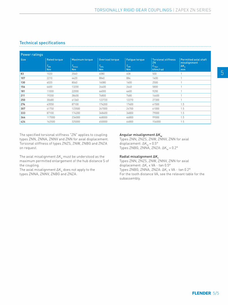
Power ratingsSize Rated torque Maximum torque Overload torque Fatigue torque Torsional stiffness
ZNPermitted axial shaft misalignment
TKN TKmax TKOL TKW CTdyn ∆KaNm Nm Nm Nm kNm/rad mm
83 1020 2040 4080 408 500 1107 2210 4420 8840 884 1400 1130 4020 8040 16080 1600 2500 1156 6600 13200 26400 2640 5800 1181 11000 22000 44000 4400 9200 1211 19200 38400 76800 7680 16600 1250 30680 61360 122720 12270 27300 1274 43550 87100 174200 17400 41500 1.5307 61750 123500 247000 24700 61000 1.5333 87100 174200 348400 34800 79000 1.5364 117000 234000 468000 46800 99000 1.5424 162500 325000 650000 64800 156000 1.5
The specified torsional stiffness "ZN" applies to coupling types ZNN, ZNNA, ZNNV and ZNN for axial displacement.Torsional stiffness of types ZNZS, ZNW, ZNBG and ZNZA on request.
The axial misalignment ΔKa must be understood as the maximum permitted enlargement of the hub distance S of the coupling.The axial misalignment ΔKa does not apply to the types ZNNA, ZNNV, ZNBG and ZNZA.
Angular misalignment ΔKwTypes ZNN, ZNZS, ZNW, ZNNV, ZNN for axial displacement: ∆Kw = 0.5°Types ZNBG, ZNNA, ZNZA: ∆Kw = 0.2°
Radial misalignment ΔKrTypes ZNN, ZNZS, ZNW, ZNNV, ZNN for axial displacement: ∆Kr ≤ VA ⋅ tan 0.5°Types ZNBG, ZNNA, ZNZA: ∆Kr ≤ VA ⋅ tan 0.2°For the tooth distance VA, see the relevant table for the subassembly.
Technical specifications
TORSIONALLY RIGID GEAR COUPLINGS | ZAPEX ZN SERIES
5/5
E E
4 4
5 5
6 6
7 7
8 8
9 9
10 10
11 11
12 12
13 13
A A
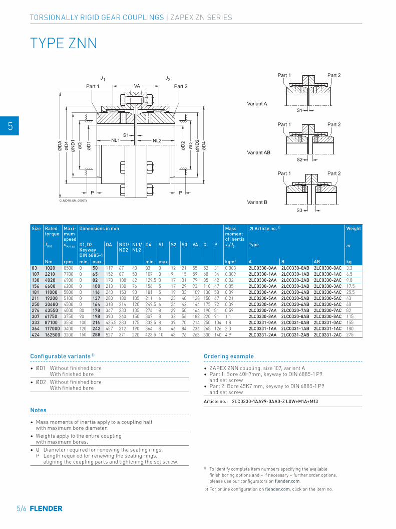
VA
PP
ØN
D1
ØD
4
ØN
D2
ØD
4
ØD
A
ØD
1
ØD
2
ØQ
ØQ
NL1 NL2S1
S1
S2
S3
J1 J2
G_MD10_EN_00057a
Part 1 Part 2
Part 1
Part 1
Part 1
Variant A
Variant AB
Variant B
Part 2
Part 2
Part 2
TYPE ZNN
Size Rated torque
Maxi-mum speed
Dimensions in mm Mass moment of inertia
↗ Article no. 1) Weight
TKN nKmax D1, D2 Keyway DIN 6885-1
DA ND1/ ND2
NL1/ NL2
D4 S1 S2 S3 VA Q P J1/J2 Type m
Nm rpm min. max. min. max. kgm2 A B AB kg83 1020 8500 0 50 117 67 43 83 3 12 21 55 52 31 0.003 2LC0330-0AA 2LC0330-0AB 2LC0330-0AC 3.2 -0AA0107 2210 7700 0 65 152 87 50 107 3 9 15 59 68 34 0.009 2LC0330-1AA 2LC0330-1AB 2LC0330-1AC 6.5 -0AA0130 4020 6900 0 82 178 108 62 129.5 3 17 31 79 85 42 0.02 2LC0330-2AA 2LC0330-2AB 2LC0330-2AC 9.8 -0AA0156 6600 6200 0 100 213 130 76 156 5 17 29 93 110 47 0.05 2LC0330-3AA 2LC0330-3AB 2LC0330-3AC 17.5 -0AA0181 11000 5800 0 116 240 153 90 181 5 19 33 109 130 58 0.09 2LC0330-4AA 2LC0330-4AB 2LC0330-4AC 25.5 -0AA0211 19200 5100 0 137 280 180 105 211 6 23 40 128 150 67 0.21 2LC0330-5AA 2LC0330-5AB 2LC0330-5AC 43 -0AA0250 30680 4500 0 164 318 214 120 249.5 6 24 42 144 175 72 0.39 2LC0330-6AA 2LC0330-6AB 2LC0330-6AC 60 -0AA0274 43550 4000 80 178 347 233 135 274 8 29 50 164 190 81 0.59 2LC0330-7AA 2LC0330-7AB 2LC0330-7AC 82 -0AA0307 61750 3750 90 198 390 260 150 307 8 32 56 182 220 91 1.1 2LC0330-8AA 2LC0330-8AB 2LC0330-8AC 115 -0AA0333 87100 3550 100 216 425.5 283 175 332.5 8 39 70 214 250 104 1.8 2LC0331-0AA 2LC0331-0AB 2LC0331-0AC 155 -0AA0364 117000 3400 120 242 457 312 190 364 8 46 84 236 265 126 2.3 2LC0331-1AA 2LC0331-1AB 2LC0331-1AC 180 -0AA0424 162500 3200 150 288 527 371 220 423.5 10 43 76 263 300 140 4.9 2LC0331-2AA 2LC0331-2AB 2LC0331-2AC 275 -0AA0
Notes
• Mass moments of inertia apply to a coupling half with maximum bore diameter.
• Weights apply to the entire coupling with maximum bores.
• Q Diameter required for renewing the sealing rings. P Length required for renewing the sealing rings, aligning the coupling parts and tightening the set screw.
Ordering example
• ZAPEX ZNN coupling, size 107, variant A• Part 1: Bore 40H7mm, keyway to DIN 6885-1 P9
and set screw• Part 2: Bore 45K7 mm, keyway to DIN 6885-1 P9
and set screwArticle no.: 2LC0330-1AA99-0AA0-Z L0W+M1A+M13
Configurable variants 1)
• ØD1 Without finished bore With finished bore
• ØD2 Without finished bore With finished bore
1) To identify complete item numbers specifying the available finish boring options and – if necessary – further order options, please use our configurators on flender.com.↗ For online configuration on flender.com, click on the item no.
5/6
TORSIONALLY RIGID GEAR COUPLINGS | ZAPEX ZN SERIES
E E
4 4
5 5
6 6
7 7
8 8
9 9
10 10
11 11
12 12
13 13
A A
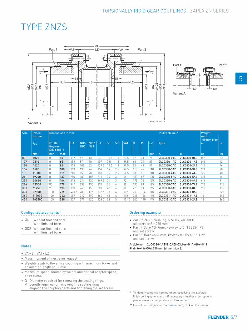
Notes
• VA = 2 ⋅ VA1 + LZ • Mass moment of inertia on request.• Weights apply to the entire coupling with maximum bores and
an adapter length of LZ min.• Maximum speed, limited by weight and critical adapter speed,
on request.• Q Diameter required for renewing the sealing rings.
P Length required for renewing the sealing rings, aligning the coupling parts and tightening the set screw.
Ordering example
• ZAPEX ZNZS coupling, size 107, variant B, adapter for S = 250 mm
• Part 1: Bore 40H7mm, keyway to DIN 6885-1 P9 and set screw
• Part 2: Bore 45K7 mm, keyway to DIN 6885-1 P9 and set screw
Article no.: 2LC0330-1AE99-0AZ0-Z L0W+M1A+Q0Y+M13Plain text to Q0Y: 250 mm (dimension S)
TYPE ZNZS
VAVA1 LZ VA1
ØD
1
ØD
2
ØQ
ØQ
ØN
D1
ØD
4Ø
DA
NL1 NL2SS8 S8
P P
ØN
D2
ØD
4Ø
DA
S9 S9
Part 1 Part 2
Part 1 Part 2
Variant A
Variant BG_MD10_EN_00058a
Size Rated torque
Dimensions in mm ↗ Article no. 1) Weighteach 100 mm pipe
TKN D1, D2 Keyway DIN 6885-1
DA ND1/ ND2
NL1/ NL2
D4 S8 S9 VA1 Q P LZ Type m m
Nm min. max. min. A B kg kg83 1020 0 50 117 67 43 83 10.5 1.5 27.5 52 31 75 2LC0330-0AD 2LC0330-0AE 0.9 5.5 -0AZ0107 2210 0 65 152 87 50 107 7.5 1.5 29.5 68 34 85 2LC0330-1AD 2LC0330-1AE 0.8 12 -0AZ0130 4020 0 82 178 108 62 129.5 15.5 1.5 39.5 85 42 95 2LC0330-2AD 2LC0330-2AE 1.2 16 -0AZ0156 6600 0 100 213 130 76 156 14.5 2.5 46.5 110 47 110 2LC0330-3AD 2LC0330-3AE 2.3 28 -0AZ0181 11000 0 116 240 153 90 181 16.5 2.5 54.5 130 58 110 2LC0330-4AD 2LC0330-4AE 3.5 40 -0AZ0211 19200 0 137 280 180 105 211 20 3 64 150 67 125 2LC0330-5AD 2LC0330-5AE 4.5 64 -0AZ0250 30680 0 164 318 214 120 249.5 21 3 72 175 72 125 2LC0330-6AD 2LC0330-6AE 6.3 91 -0AZ0274 43550 80 178 347 233 135 274 25 4 82 190 81 125 2LC0330-7AD 2LC0330-7AE 7.2 115 -0AZ0307 61750 90 198 390 260 150 307 28 4 91 220 91 145 2LC0330-8AD 2LC0330-8AE 9.1 175 -0AZ0333 87100 100 216 425.5 283 175 332.5 35 4 107 250 104 145 2LC0331-0AD 2LC0331-0AE 12 220 -0AZ0364 117000 120 242 457 312 190 364 42 4 118 265 126 145 2LC0331-1AD 2LC0331-1AE 15 245 -0AZ0424 162500 150 288 527 371 220 423.5 38 5 131.5 300 140 145 2LC0331-2AD 2LC0331-2AE 16 360 -0AZ0
Configurable variants 1)
• ØD1 Without finished bore With finished bore
• ØD2 Without finished bore With finished bore
1) To identify complete item numbers specifying the available finish boring options and – if necessary – further order options, please use our configurators on flender.com.↗ For online configuration on flender.com, click on the item no.
TORSIONALLY RIGID GEAR COUPLINGS | ZAPEX ZN SERIES
5/7
E E
4 4
5 5
6 6
7 7
8 8
9 9
10 10
11 11
12 12
13 13
A A
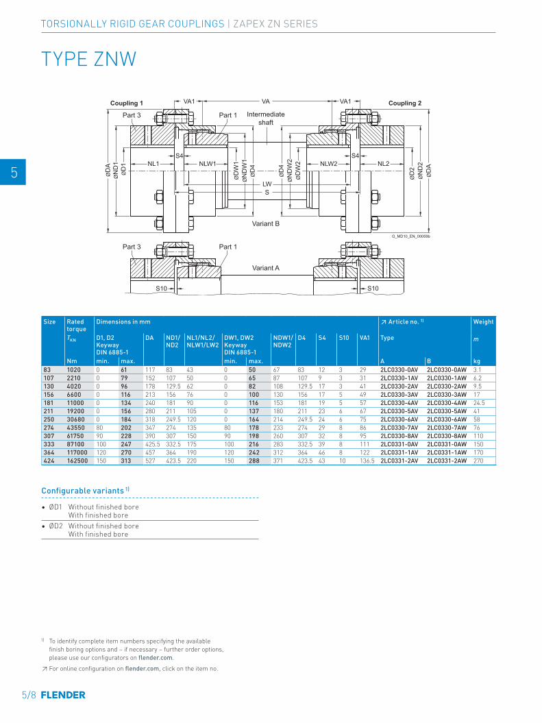
ØD
2Ø
ND
2Ø
DA
ØD
1Ø
ND
1 NLW1NL1S4 S4
LWS
NLW2 NL2
ØD
A
ØD
W1
ØD
W2
ØN
DW
1Ø
D4
ØN
DW
2Ø
D4
VA1 VA1VA
S10 S10
Coupling 1
Intermediate shaft
Part 1Part 3
Part 1Part 3
Variant B
Variant A
Coupling 2
G_MD10_EN_00059b
TYPE ZNW
Size Rated torque
Dimensions in mm ↗ Article no. 1) Weight
TKN D1, D2 Keyway DIN 6885-1
DA ND1/ ND2
NL1/NL2/ NLW1/LW2
DW1, DW2 Keyway DIN 6885-1
NDW1/ NDW2
D4 S4 S10 VA1 Type m
Nm min. max. min. max. A B kg83 1020 0 61 117 83 43 0 50 67 83 12 3 29 2LC0330-0AV 2LC0330-0AW 3.1 -0AA0107 2210 0 79 152 107 50 0 65 87 107 9 3 31 2LC0330-1AV 2LC0330-1AW 6.2 -0AA0130 4020 0 96 178 129.5 62 0 82 108 129.5 17 3 41 2LC0330-2AV 2LC0330-2AW 9.5 -0AA0156 6600 0 116 213 156 76 0 100 130 156 17 5 49 2LC0330-3AV 2LC0330-3AW 17 -0AA0181 11000 0 134 240 181 90 0 116 153 181 19 5 57 2LC0330-4AV 2LC0330-4AW 24.5 -0AA0211 19200 0 156 280 211 105 0 137 180 211 23 6 67 2LC0330-5AV 2LC0330-5AW 41 -0AA0250 30680 0 184 318 249.5 120 0 164 214 249.5 24 6 75 2LC0330-6AV 2LC0330-6AW 58 -0AA0274 43550 80 202 347 274 135 80 178 233 274 29 8 86 2LC0330-7AV 2LC0330-7AW 76 -0AA0307 61750 90 228 390 307 150 90 198 260 307 32 8 95 2LC0330-8AV 2LC0330-8AW 110 -0AA0333 87100 100 247 425.5 332.5 175 100 216 283 332.5 39 8 111 2LC0331-0AV 2LC0331-0AW 150 -0AA0364 117000 120 270 457 364 190 120 242 312 364 46 8 122 2LC0331-1AV 2LC0331-1AW 170 -0AA0424 162500 150 313 527 423.5 220 150 288 371 423.5 43 10 136.5 2LC0331-2AV 2LC0331-2AW 270 -0AA0
Configurable variants 1)
• ØD1 Without finished bore With finished bore
• ØD2 Without finished bore With finished bore
1) To identify complete item numbers specifying the available finish boring options and – if necessary – further order options, please use our configurators on flender.com.↗ For online configuration on flender.com, click on the item no.
5/8
TORSIONALLY RIGID GEAR COUPLINGS | ZAPEX ZN SERIES
E E
4 4
5 5
6 6
7 7
8 8
9 9
10 10
11 11
12 12
13 13
A A
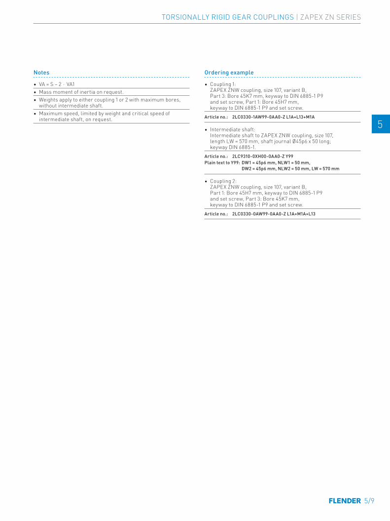
Size Rated torque
Dimensions in mm ↗ Article no. 1) Weight
TKN D1, D2 Keyway DIN 6885-1
DA ND1/ ND2
NL1/NL2/ NLW1/LW2
DW1, DW2 Keyway DIN 6885-1
NDW1/ NDW2
D4 S4 S10 VA1 Type m
Nm min. max. min. max. A B kg83 1020 0 61 117 83 43 0 50 67 83 12 3 29 2LC0330-0AV 2LC0330-0AW 3.1 -0AA0107 2210 0 79 152 107 50 0 65 87 107 9 3 31 2LC0330-1AV 2LC0330-1AW 6.2 -0AA0130 4020 0 96 178 129.5 62 0 82 108 129.5 17 3 41 2LC0330-2AV 2LC0330-2AW 9.5 -0AA0156 6600 0 116 213 156 76 0 100 130 156 17 5 49 2LC0330-3AV 2LC0330-3AW 17 -0AA0181 11000 0 134 240 181 90 0 116 153 181 19 5 57 2LC0330-4AV 2LC0330-4AW 24.5 -0AA0211 19200 0 156 280 211 105 0 137 180 211 23 6 67 2LC0330-5AV 2LC0330-5AW 41 -0AA0250 30680 0 184 318 249.5 120 0 164 214 249.5 24 6 75 2LC0330-6AV 2LC0330-6AW 58 -0AA0274 43550 80 202 347 274 135 80 178 233 274 29 8 86 2LC0330-7AV 2LC0330-7AW 76 -0AA0307 61750 90 228 390 307 150 90 198 260 307 32 8 95 2LC0330-8AV 2LC0330-8AW 110 -0AA0333 87100 100 247 425.5 332.5 175 100 216 283 332.5 39 8 111 2LC0331-0AV 2LC0331-0AW 150 -0AA0364 117000 120 270 457 364 190 120 242 312 364 46 8 122 2LC0331-1AV 2LC0331-1AW 170 -0AA0424 162500 150 313 527 423.5 220 150 288 371 423.5 43 10 136.5 2LC0331-2AV 2LC0331-2AW 270 -0AA0
Ordering example
• Coupling 1: ZAPEX ZNW coupling, size 107, variant B, Part 3: Bore 45K7 mm, keyway to DIN 6885-1 P9 and set screw, Part 1: Bore 45H7 mm, keyway to DIN 6885-1 P9 and set screw.
Article no.: 2LC0330-1AW99-0AA0-Z L1A+L13+M1A
• Intermediate shaft: Intermediate shaft to ZAPEX ZNW coupling, size 107, length LW = 570 mm, shaft journal Ø45p6 x 50 long; keyway DIN 6885-1.
Article no.: 2LC9310-0XH00-0AA0-Z Y99Plain text to Y99: DW1 = 45p6 mm, NLW1 = 50 mm, DW2 = 45p6 mm, NLW2 = 50 mm, LW = 570 mm
• Coupling 2: ZAPEX ZNW coupling, size 107, variant B, Part 1: Bore 45H7 mm, keyway to DIN 6885-1 P9 and set screw, Part 3: Bore 45K7 mm, keyway to DIN 6885-1 P9 and set screw.
Article no.: 2LC0330-0AW99-0AA0-Z L1A+M1A+L13
Notes
• VA = S − 2 ⋅ VA1• Mass moment of inertia on request.• Weights apply to either coupling 1 or 2 with maximum bores,
without intermediate shaft.• Maximum speed, limited by weight and critical speed of
intermediate shaft, on request.
TORSIONALLY RIGID GEAR COUPLINGS | ZAPEX ZN SERIES
5/9
E E
4 4
5 5
6 6
7 7
8 8
9 9
10 10
11 11
12 12
13 13
A A
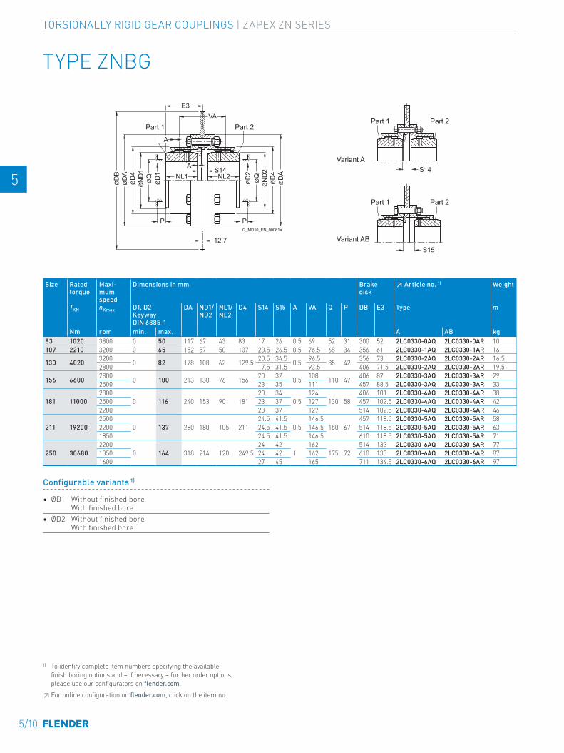
TYPE ZNBG
ØD
1Ø
QØ
ND
1Ø
D4
ØD
AØ
DB
ØQ
ØD
2
ØN
D2
ØD
4Ø
DA
E3VA
A S14NL1 NL2
P P
A
S14
S15
Variant A
Variant ABG_MD10_EN_00061a
Part 1 Part 2Part 1 Part 2
Part 1 Part 2
12.7
Size Rated torque
Maxi-mum speed
Dimensions in mm Brake disk
↗ Article no. 1) Weight
TKN nKmax D1, D2 Keyway DIN 6885-1
DA ND1/ ND2
NL1/ NL2
D4 S14 S15 A VA Q P DB E3 Type m
Nm rpm min. max. A AB kg83 1020 3800 0 50 117 67 43 83 17 26 0.5 69 52 31 300 52 2LC0330-0AQ 2LC0330-0AR 10 -0AA0107 2210 3200 0 65 152 87 50 107 20.5 26.5 0.5 76.5 68 34 356 61 2LC0330-1AQ 2LC0330-1AR 16 -0AA0
130 4020 3200 0 82 178 108 62 129.5 20.5 34.5 0.5 96.5 85 42 356 73 2LC0330-2AQ 2LC0330-2AR 16.5 -0AA02800 17.5 31.5 93.5 406 71.5 2LC0330-2AQ 2LC0330-2AR 19.5 -0BA0
156 6600 2800 0 100 213 130 76 156 20 32 0.5 108 110 47 406 87 2LC0330-3AQ 2LC0330-3AR 29 -0AA02500 23 35 111 457 88.5 2LC0330-3AQ 2LC0330-3AR 33 -0BA0
181 110002800
0 116 240 153 90 18120 34
0.5124
130 58406 101 2LC0330-4AQ 2LC0330-4AR 38 -0AA0
2500 23 37 127 457 102.5 2LC0330-4AQ 2LC0330-4AR 42 -0BA02200 23 37 127 514 102.5 2LC0330-4AQ 2LC0330-4AR 46 -0CA0
211 192002500
0 137 280 180 105 21124.5 41.5
0.5146.5
150 67457 118.5 2LC0330-5AQ 2LC0330-5AR 58 -0AA0
2200 24.5 41.5 146.5 514 118.5 2LC0330-5AQ 2LC0330-5AR 63 -0BA01850 24.5 41.5 146.5 610 118.5 2LC0330-5AQ 2LC0330-5AR 71 -0CA0
250 306802200
0 164 318 214 120 249.524 42
1162
175 72514 133 2LC0330-6AQ 2LC0330-6AR 77 -0AA0
1850 24 42 162 610 133 2LC0330-6AQ 2LC0330-6AR 87 -0BA01600 27 45 165 711 134.5 2LC0330-6AQ 2LC0330-6AR 97 -0CA0
Configurable variants 1)
• ØD1 Without finished bore With finished bore
• ØD2 Without finished bore With finished bore
1) To identify complete item numbers specifying the available finish boring options and – if necessary – further order options, please use our configurators on flender.com.↗ For online configuration on flender.com, click on the item no.
5/10
TORSIONALLY RIGID GEAR COUPLINGS | ZAPEX ZN SERIES
E E
4 4
5 5
6 6
7 7
8 8
9 9
10 10
11 11
12 12
13 13
A A
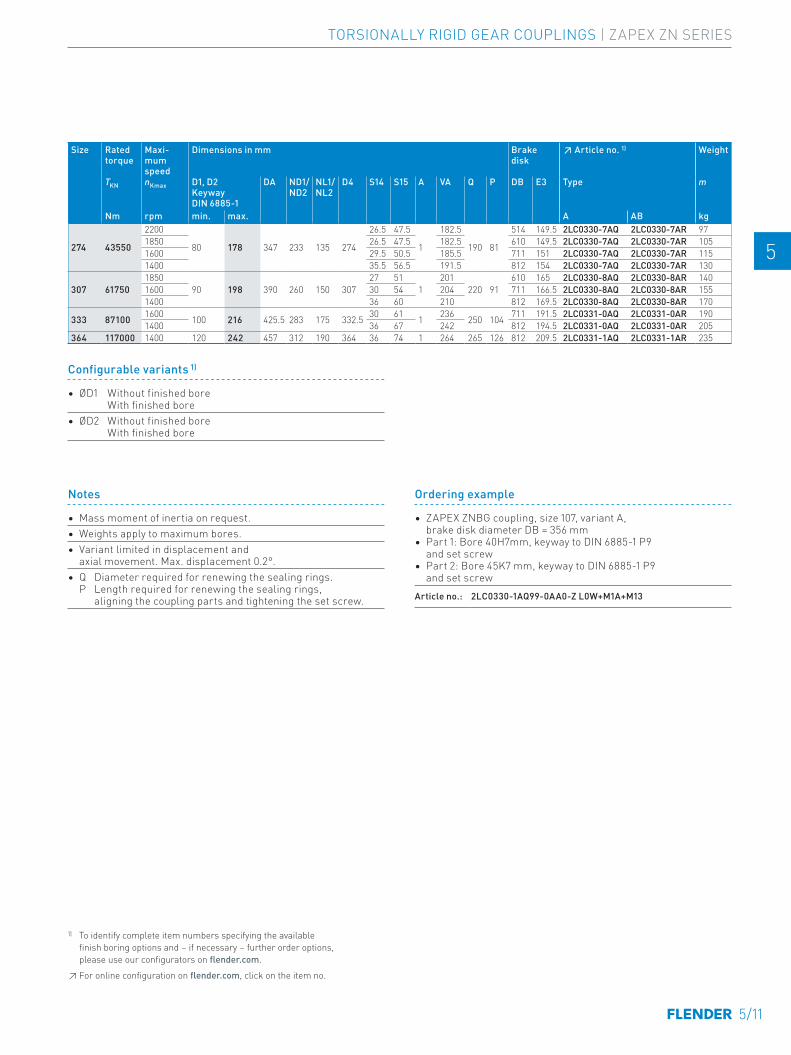
Size Rated torque
Maxi-mum speed
Dimensions in mm Brake disk
↗ Article no. 1) Weight
TKN nKmax D1, D2 Keyway DIN 6885-1
DA ND1/ ND2
NL1/ NL2
D4 S14 S15 A VA Q P DB E3 Type m
Nm rpm min. max. A AB kg
274 43550
2200
80 178 347 233 135 274
26.5 47.5
1
182.5
190 81
514 149.5 2LC0330-7AQ 2LC0330-7AR 97 -0AA01850 26.5 47.5 182.5 610 149.5 2LC0330-7AQ 2LC0330-7AR 105 -0BA01600 29.5 50.5 185.5 711 151 2LC0330-7AQ 2LC0330-7AR 115 -0CA01400 35.5 56.5 191.5 812 154 2LC0330-7AQ 2LC0330-7AR 130 -0DA0
307 617501850
90 198 390 260 150 30727 51
1201
220 91610 165 2LC0330-8AQ 2LC0330-8AR 140 -0AA0
1600 30 54 204 711 166.5 2LC0330-8AQ 2LC0330-8AR 155 -0BA01400 36 60 210 812 169.5 2LC0330-8AQ 2LC0330-8AR 170 -0CA0
333 87100 1600 100 216 425.5 283 175 332.5 30 61 1 236 250 104 711 191.5 2LC0331-0AQ 2LC0331-0AR 190 -0AA01400 36 67 242 812 194.5 2LC0331-0AQ 2LC0331-0AR 205 -0BA0
364 117000 1400 120 242 457 312 190 364 36 74 1 264 265 126 812 209.5 2LC0331-1AQ 2LC0331-1AR 235 -0AA0
Notes
• Mass moment of inertia on request.• Weights apply to maximum bores.• Variant limited in displacement and
axial movement. Max. displacement 0.2°.• Q Diameter required for renewing the sealing rings.
P Length required for renewing the sealing rings, aligning the coupling parts and tightening the set screw.
Ordering example
• ZAPEX ZNBG coupling, size 107, variant A, brake disk diameter DB = 356 mm
• Part 1: Bore 40H7mm, keyway to DIN 6885-1 P9 and set screw
• Part 2: Bore 45K7 mm, keyway to DIN 6885-1 P9 and set screw
Article no.: 2LC0330-1AQ99-0AA0-Z L0W+M1A+M13
Size Rated torque
Maxi-mum speed
Dimensions in mm Brake disk
↗ Article no. 1) Weight
TKN nKmax D1, D2 Keyway DIN 6885-1
DA ND1/ ND2
NL1/ NL2
D4 S14 S15 A VA Q P DB E3 Type m
Nm rpm min. max. A AB kg83 1020 3800 0 50 117 67 43 83 17 26 0.5 69 52 31 300 52 2LC0330-0AQ 2LC0330-0AR 10 -0AA0107 2210 3200 0 65 152 87 50 107 20.5 26.5 0.5 76.5 68 34 356 61 2LC0330-1AQ 2LC0330-1AR 16 -0AA0
130 4020 3200 0 82 178 108 62 129.5 20.5 34.5 0.5 96.5 85 42 356 73 2LC0330-2AQ 2LC0330-2AR 16.5 -0AA02800 17.5 31.5 93.5 406 71.5 2LC0330-2AQ 2LC0330-2AR 19.5 -0BA0
156 6600 2800 0 100 213 130 76 156 20 32 0.5 108 110 47 406 87 2LC0330-3AQ 2LC0330-3AR 29 -0AA02500 23 35 111 457 88.5 2LC0330-3AQ 2LC0330-3AR 33 -0BA0
181 110002800
0 116 240 153 90 18120 34
0.5124
130 58406 101 2LC0330-4AQ 2LC0330-4AR 38 -0AA0
2500 23 37 127 457 102.5 2LC0330-4AQ 2LC0330-4AR 42 -0BA02200 23 37 127 514 102.5 2LC0330-4AQ 2LC0330-4AR 46 -0CA0
211 192002500
0 137 280 180 105 21124.5 41.5
0.5146.5
150 67457 118.5 2LC0330-5AQ 2LC0330-5AR 58 -0AA0
2200 24.5 41.5 146.5 514 118.5 2LC0330-5AQ 2LC0330-5AR 63 -0BA01850 24.5 41.5 146.5 610 118.5 2LC0330-5AQ 2LC0330-5AR 71 -0CA0
250 306802200
0 164 318 214 120 249.524 42
1162
175 72514 133 2LC0330-6AQ 2LC0330-6AR 77 -0AA0
1850 24 42 162 610 133 2LC0330-6AQ 2LC0330-6AR 87 -0BA01600 27 45 165 711 134.5 2LC0330-6AQ 2LC0330-6AR 97 -0CA0
Configurable variants 1)
• ØD1 Without finished bore With finished bore
• ØD2 Without finished bore With finished bore
1) To identify complete item numbers specifying the available finish boring options and – if necessary – further order options, please use our configurators on flender.com.↗ For online configuration on flender.com, click on the item no.
TORSIONALLY RIGID GEAR COUPLINGS | ZAPEX ZN SERIES
5/11
E E
4 4
5 5
6 6
7 7
8 8
9 9
10 10
11 11
12 12
13 13
A A
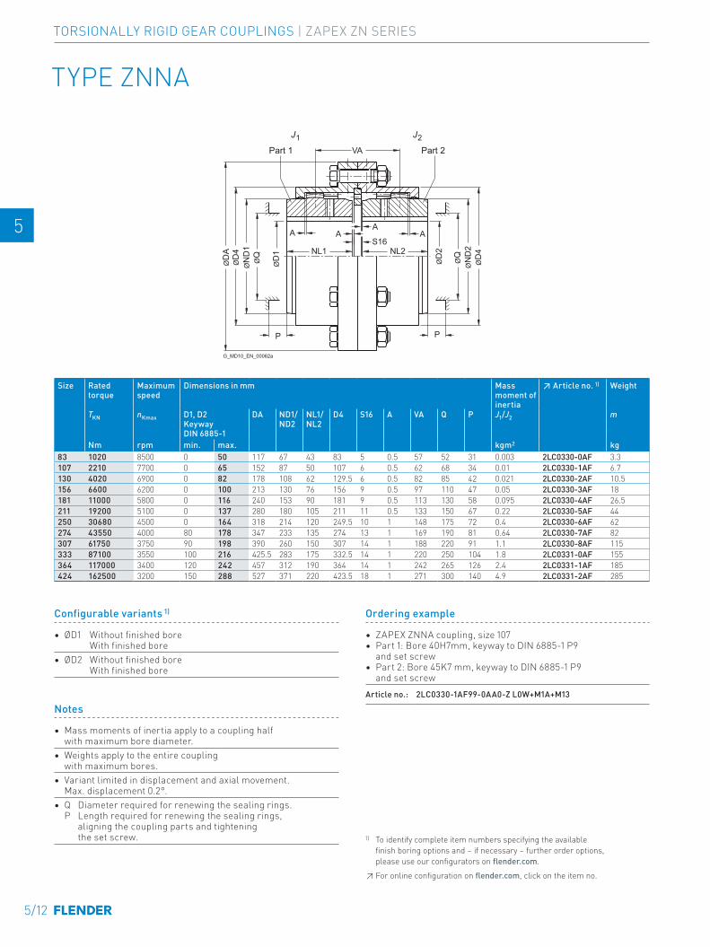
TYPE ZNNA
NL1 NL2S16
AA
AA
VA
ØN
D1
ØD
4Ø
DA
ØD
4
ØD
1
ØQ
ØD
2
ØQ
ØN
D2
PP
J1 J2
G_MD10_EN_00062a
Part 2Part 1
Size Rated torque
Maximum speed
Dimensions in mm Mass moment of inertia
↗ Article no. 1) Weight
TKN nKmax D1, D2 Keyway DIN 6885-1
DA ND1/ ND2
NL1/ NL2
D4 S16 A VA Q P J1/J2 m
Nm rpm min. max. kgm2 kg83 1020 8500 0 50 117 67 43 83 5 0.5 57 52 31 0.003 2LC0330-0AF 3.3 -0AA0107 2210 7700 0 65 152 87 50 107 6 0.5 62 68 34 0.01 2LC0330-1AF 6.7 -0AA0130 4020 6900 0 82 178 108 62 129.5 6 0.5 82 85 42 0.021 2LC0330-2AF 10.5 -0AA0156 6600 6200 0 100 213 130 76 156 9 0.5 97 110 47 0.05 2LC0330-3AF 18 -0AA0181 11000 5800 0 116 240 153 90 181 9 0.5 113 130 58 0.095 2LC0330-4AF 26.5 -0AA0211 19200 5100 0 137 280 180 105 211 11 0.5 133 150 67 0.22 2LC0330-5AF 44 -0AA0250 30680 4500 0 164 318 214 120 249.5 10 1 148 175 72 0.4 2LC0330-6AF 62 -0AA0274 43550 4000 80 178 347 233 135 274 13 1 169 190 81 0.64 2LC0330-7AF 82 -0AA0307 61750 3750 90 198 390 260 150 307 14 1 188 220 91 1.1 2LC0330-8AF 115 -0AA0333 87100 3550 100 216 425.5 283 175 332.5 14 1 220 250 104 1.8 2LC0331-0AF 155 -0AA0364 117000 3400 120 242 457 312 190 364 14 1 242 265 126 2.4 2LC0331-1AF 185 -0AA0424 162500 3200 150 288 527 371 220 423.5 18 1 271 300 140 4.9 2LC0331-2AF 285 -0AA0
Notes
• Mass moments of inertia apply to a coupling half with maximum bore diameter.
• Weights apply to the entire coupling with maximum bores.
• Variant limited in displacement and axial movement. Max. displacement 0.2°.
• Q Diameter required for renewing the sealing rings. P Length required for renewing the sealing rings, aligning the coupling parts and tightening the set screw.
Ordering example
• ZAPEX ZNNA coupling, size 107 • Part 1: Bore 40H7mm, keyway to DIN 6885-1 P9
and set screw• Part 2: Bore 45K7 mm, keyway to DIN 6885-1 P9
and set screw Article no.: 2LC0330-1AF99-0AA0-Z L0W+M1A+M13
Configurable variants 1)
• ØD1 Without finished bore With finished bore
• ØD2 Without finished bore With finished bore
1) To identify complete item numbers specifying the available finish boring options and – if necessary – further order options, please use our configurators on flender.com.↗ For online configuration on flender.com, click on the item no.
5/12
TORSIONALLY RIGID GEAR COUPLINGS | ZAPEX ZN SERIES
E E
4 4
5 5
6 6
7 7
8 8
9 9
10 10
11 11
12 12
13 13
A A
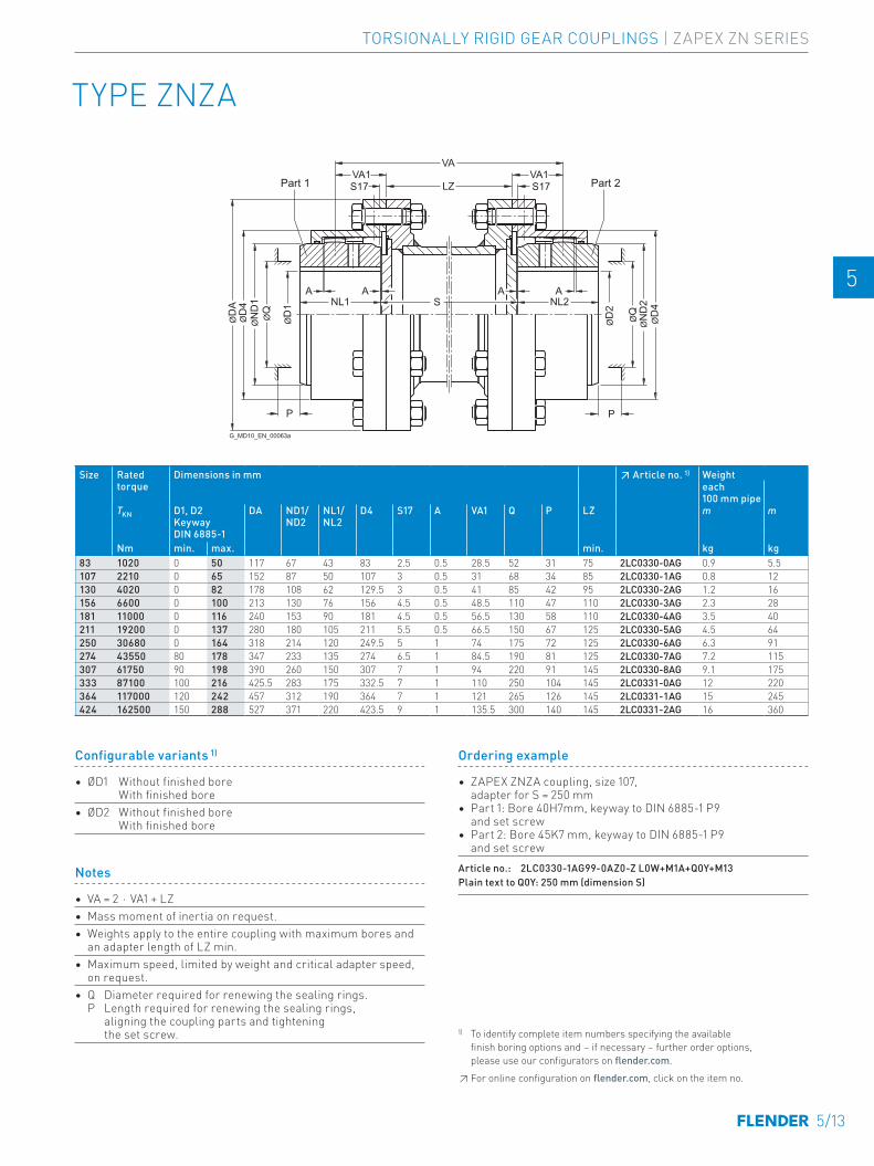
TYPE ZNZA
VAVA1
S17S17 LZVA1
PP
ØN
D1
ØD
4Ø
DA
ØD
1
ØQ
NL1 NL2SA AA A
ØD
4
ØD
2
ØQ
ØN
D2
G_MD10_EN_00063a
Part 1 Part 2
Size Rated torque
Dimensions in mm ↗ Article no. 1) Weighteach 100 mm pipe
TKN D1, D2 Keyway DIN 6885-1
DA ND1/ ND2
NL1/ NL2
D4 S17 A VA1 Q P LZ m m
Nm min. max. min. kg kg83 1020 0 50 117 67 43 83 2.5 0.5 28.5 52 31 75 2LC0330-0AG 0.9 5.5 -0AZ0107 2210 0 65 152 87 50 107 3 0.5 31 68 34 85 2LC0330-1AG 0.8 12 -0AZ0130 4020 0 82 178 108 62 129.5 3 0.5 41 85 42 95 2LC0330-2AG 1.2 16 -0AZ0156 6600 0 100 213 130 76 156 4.5 0.5 48.5 110 47 110 2LC0330-3AG 2.3 28 -0AZ0181 11000 0 116 240 153 90 181 4.5 0.5 56.5 130 58 110 2LC0330-4AG 3.5 40 -0AZ0211 19200 0 137 280 180 105 211 5.5 0.5 66.5 150 67 125 2LC0330-5AG 4.5 64 -0AZ0250 30680 0 164 318 214 120 249.5 5 1 74 175 72 125 2LC0330-6AG 6.3 91 -0AZ0274 43550 80 178 347 233 135 274 6.5 1 84.5 190 81 125 2LC0330-7AG 7.2 115 -0AZ0307 61750 90 198 390 260 150 307 7 1 94 220 91 145 2LC0330-8AG 9.1 175 -0AZ0333 87100 100 216 425.5 283 175 332.5 7 1 110 250 104 145 2LC0331-0AG 12 220 -0AZ0364 117000 120 242 457 312 190 364 7 1 121 265 126 145 2LC0331-1AG 15 245 -0AZ0424 162500 150 288 527 371 220 423.5 9 1 135.5 300 140 145 2LC0331-2AG 16 360 -0AZ0
Notes
• VA = 2 ⋅ VA1 + LZ• Mass moment of inertia on request.• Weights apply to the entire coupling with maximum bores and
an adapter length of LZ min.• Maximum speed, limited by weight and critical adapter speed,
on request.• Q Diameter required for renewing the sealing rings.
P Length required for renewing the sealing rings, aligning the coupling parts and tightening the set screw.
Ordering example
• ZAPEX ZNZA coupling, size 107, adapter for S = 250 mm
• Part 1: Bore 40H7mm, keyway to DIN 6885-1 P9 and set screw
• Part 2: Bore 45K7 mm, keyway to DIN 6885-1 P9 and set screw
Article no.: 2LC0330-1AG99-0AZ0-Z L0W+M1A+Q0Y+M13Plain text to Q0Y: 250 mm (dimension S)
1) To identify complete item numbers specifying the available finish boring options and – if necessary – further order options, please use our configurators on flender.com.↗ For online configuration on flender.com, click on the item no.
Configurable variants 1)
• ØD1 Without finished bore With finished bore
• ØD2 Without finished bore With finished bore
TORSIONALLY RIGID GEAR COUPLINGS | ZAPEX ZN SERIES
5/13
E E
4 4
5 5
6 6
7 7
8 8
9 9
10 10
11 11
12 12
13 13
A A
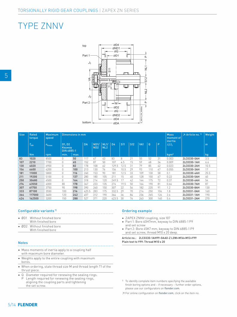
G_M
D10
_EN
_000
64a
Part 2
Part 1
top
bottom
ØQ
ØQ
ØND1ØD4
ØND2
ØDAØD4
ØD1
ØD2
NL1
S12
NL2
PP
VA
M
J1
J2
S11
T1
TYPE ZNNV
Size Rated torque
Maximum speed
Dimensions in mm Mass moment of inertia
↗ Article no. 1) Weight
TKN nKmax D1, D2 Keyway DIN 6885-1
DA ND1/ ND2
NL1/ NL2
D4 S11 S12 VA1 Q P J1/J2 m
Nm rpm min. max. kgm2 kg83 1020 8500 0 50 117 67 43 83 8 21 55 52 31 0.003 2LC0330-0AH 3.5 -0AA0107 2210 7700 0 65 152 87 50 107 4.5 15 59 68 34 0.009 2LC0330-1AH 6.6 -0AA0130 4020 6900 0 82 178 108 62 129.5 12.5 31 79 85 42 0.023 2LC0330-2AH 10.5 -0AA0156 6600 6200 0 100 213 130 76 156 10.5 29 93 110 47 0.055 2LC0330-3AH 17 -0AA0181 11000 5800 0 116 240 153 90 181 12.5 33 109 130 58 0.1 2LC0330-4AH 25.5 -0AA0211 19200 5100 0 137 280 180 105 211 15 40 128 150 67 0.22 2LC0330-5AH 40 -0AA0250 30680 4500 0 164 318 214 120 249.5 17 42 144 175 72 0.37 2LC0330-6AH 54 -0AA0274 43550 4000 80 178 347 233 135 274 19.5 50 164 190 81 0.64 2LC0330-7AH 87 -0AA0307 61750 3750 90 198 390 260 150 307 22 56 182 220 91 1.2 2LC0330-8AH 130 -0AA0333 87100 3550 100 216 425.5 283 175 332.5 29 70 214 250 104 1.8 2LC0331-0AH 160 -0AA0364 117000 3400 120 242 457 312 190 364 36 84 236 265 126 2.6 2LC0331-1AH 190 -0AA0424 162500 3200 150 288 527 371 220 423.5 30 76 263 300 140 5.4 2LC0331-2AH 270 -0AA0
Notes
• Mass moments of inertia apply to a coupling half with maximum bore diameter.
• Weights apply to the entire coupling with maximum bores.
• When ordering, state thread size M and thread length T1 of the thrust piece.
• Q Diameter required for renewing the sealing rings. P Length required for renewing the sealing rings, aligning the coupling parts and tightening the set screw.
Ordering example
• ZAPEX ZNNV coupling, size 107• Part 1: Bore 40H7mm, keyway to DIN 6885-1 P9
and set screw• Part 2: Bore 45K7 mm, keyway to DIN 6885-1 P9
and set screw, thread M10 x 20 deep.Article no.: 2LC0330-1AH99-0AA0-Z L0W+M1A+M13+Y99Plain text to Y99: Thread M10 x 20
Configurable variants 1)
• ØD1 Without finished bore With finished bore
• ØD2 Without finished bore With finished bore
1) To identify complete item numbers specifying the available finish boring options and – if necessary – further order options, please use our configurators on flender.com.↗ For online configuration on flender.com, click on the item no.
5/14
TORSIONALLY RIGID GEAR COUPLINGS | ZAPEX ZN SERIES
E E
4 4
5 5
6 6
7 7
8 8
9 9
10 10
11 11
12 12
13 13
A A
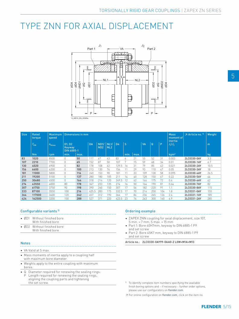
TYPE ZNN FOR AXIAL DISPLACEMENT
NL1 NL2S
VA
PP
ØN
D1
ØD
4Ø
DA
ØD
1
ØQ
ØN
D2
ØD
4
ØD
2Ø
Q
J1 J2
G_MD10_EN_00065a
Part 1 Part 2
Size Rated torque
Maximum speed
Dimensions in mm Mass moment of inertia
↗ Article no. 1) Weight
TKN nKmax D1, D2 Keyway DIN 6885-1
DA ND1/ ND2
NL1/ NL2
D4 S VA Q P J1/J2 m
Nm rpm min. max. min. max. kgm2 kg83 1020 8500 0 50 117 67 43 83 6 21 55 52 31 0.003 2LC0330-0AY 3.3 -0AA0107 2210 7700 0 65 152 87 50 107 7 15 59 68 34 0.01 2LC0330-1AY 6.7 -0AA0130 4020 6900 0 82 178 108 62 129.5 16 31 79 85 42 0.021 2LC0330-2AY 10.5 -0AA0156 6600 6200 0 100 213 130 76 156 11 29 93 110 47 0.05 2LC0330-3AY 18 -0AA0181 11000 5800 0 116 240 153 90 181 11 33 109 130 58 0.095 2LC0330-4AY 26.5 -0AA0211 19200 5100 0 137 280 180 105 211 14 40 128 150 67 0.22 2LC0330-5AY 44 -0AA0250 30680 4500 0 164 318 214 120 249.5 12 42 144 175 72 0.4 2LC0330-6AY 62 -0AA0274 43550 4000 80 178 347 233 135 274 16 50 164 190 81 0.64 2LC0330-7AY 82 -0AA0307 61750 3750 90 198 390 260 150 307 17 56 182 220 91 1.1 2LC0330-8AY 115 -0AA0333 87100 3550 100 216 425.5 283 175 332.5 17 70 214 250 104 1.8 2LC0331-0AY 155 -0AA0364 117000 3400 120 242 457 312 190 364 17 84 236 265 126 2.4 2LC0331-1AY 185 -0AA0424 162500 3200 150 288 527 371 220 423.5 23 76 263 300 140 4.9 2LC0331-2AY 285 -0AA0
Notes
• VA Valid at S max.• Mass moments of inertia apply to a coupling half
with maximum bore diameter.• Weights apply to the entire coupling with maximum
bores.• Q Diameter required for renewing the sealing rings.
P Length required for renewing the sealing rings, aligning the coupling parts and tightening the set screw.
Ordering example
• ZAPEX ZNN coupling for axial displacement, size 107, S min. = 7 mm, S max. = 15 mm
• Part 1: Bore 40H7mm, keyway to DIN 6885-1 P9 and set screw
• Part 2: Bore 45K7 mm, keyway to DIN 6885-1 P9 and set screw
Article no.: 2LC0330-0AY99-0AA0-Z L0W+M1A+M13
Configurable variants 1)
• ØD1 Without finished bore With finished bore
• ØD2 Without finished bore With finished bore
1) To identify complete item numbers specifying the available finish boring options and – if necessary – further order options, please use our configurators on flender.com.↗ For online configuration on flender.com, click on the item no.
TORSIONALLY RIGID GEAR COUPLINGS | ZAPEX ZN SERIES
5/15
E E
4 4
5 5
6 6
7 7
8 8
9 9
10 10
11 11
12 12
13 13
A A
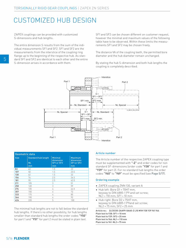
CUSTOMIZED HUB DESIGN
Part 2
G_MD10_EN_00183
Part 1
Part 2Part 1
Interstice
Interstice
S =SF1 + SF2
S =SF1 + SF2
SF2 max.SF1 min.
SF2 min.SF1 max.
NL Special
NL Special
NL Standard
NL Standard
ZAPEX couplings can be provided with customized S-dimensions and hub lengths.
The entire dimension S results from the sum of the indi-vidual measurements SF1 and SF2. SF1 and SF2 are the measurements from the interstice of the coupling ring flange up to the beginning of the respective hub. As stan-dard SF1 and SF2 are identical to each other and the entire S-dimension arises in accordance with them.
SF1 and SF2 can be chosen different on customer request, however the minimal and maximum values of the following table have to be observed. Within these limits the measu-rements SF1 and SF2 may be chosen freely.
The distance VA of the coupling teeth, the permitted bore diameter and the hub diameter remain unchanged.
By stating the hub S-dimension and both hub lengths the coupling is completely described.
Geometric dataSize Standard hub length Minimal
dimensionMaximum dimension
NL SF1 or SF2 SF1 or SF2mm mm mm
83 43 1.5 22107 50 1.5 23.5130 62 1.5 32156 76 2.5 36.5181 90 2.5 43.5211 105 3 51250 120 3 59274 135 4 64.5307 150 4 72333 175 4 85364 190 4 92424 220 5 100
The minimal hub lengths are not to fall below the standard hub lengths. If there‘s no other possibility, for hub lengths smaller than standard hub lengths the order codes "Y50" for part 1 and "Y51" for part 2 must be stated in plain text.
Article number
The Article number of the respective ZAPEX coupling type must be supplemented with "-Z" and order codes for non standard SF-dimensions (order code "Y38" for part 1 and "Y39" for part 2). For no standard hub lengths the order codes "Y40" to "Y49" must be specified (see Page 5/17).
Ordering example
• ZAPEX coupling ZNN 130, variant A• Hub left: Bore D1 = 70H7 mm,
keyway to DIN 6885-1 P9 and set screw; NL1 = 110 mm; SF1 = 10 mm
• Hub right: Bore D2 = 75H7 mm, keyway to DIN 6885-1 P9and set screw; NL2 = 75 mm; SF2 = 25 mm
Article no.: 2LC0330-2AA99-0AA0-Z L1G M1H Y38 Y39 Y41 Y46Plain text to Y38: SF1 = 10 mm Plain text to Y39: SF2 = 25 mm Plain text to Y46: NL1 = 110 mm Plain text to Y41: NL2 = 75 mm
5/16
TORSIONALLY RIGID GEAR COUPLINGS | ZAPEX ZN SERIES
E E
4 4
5 5
6 6
7 7
8 8
9 9
10 10
11 11
12 12
13 13
A A
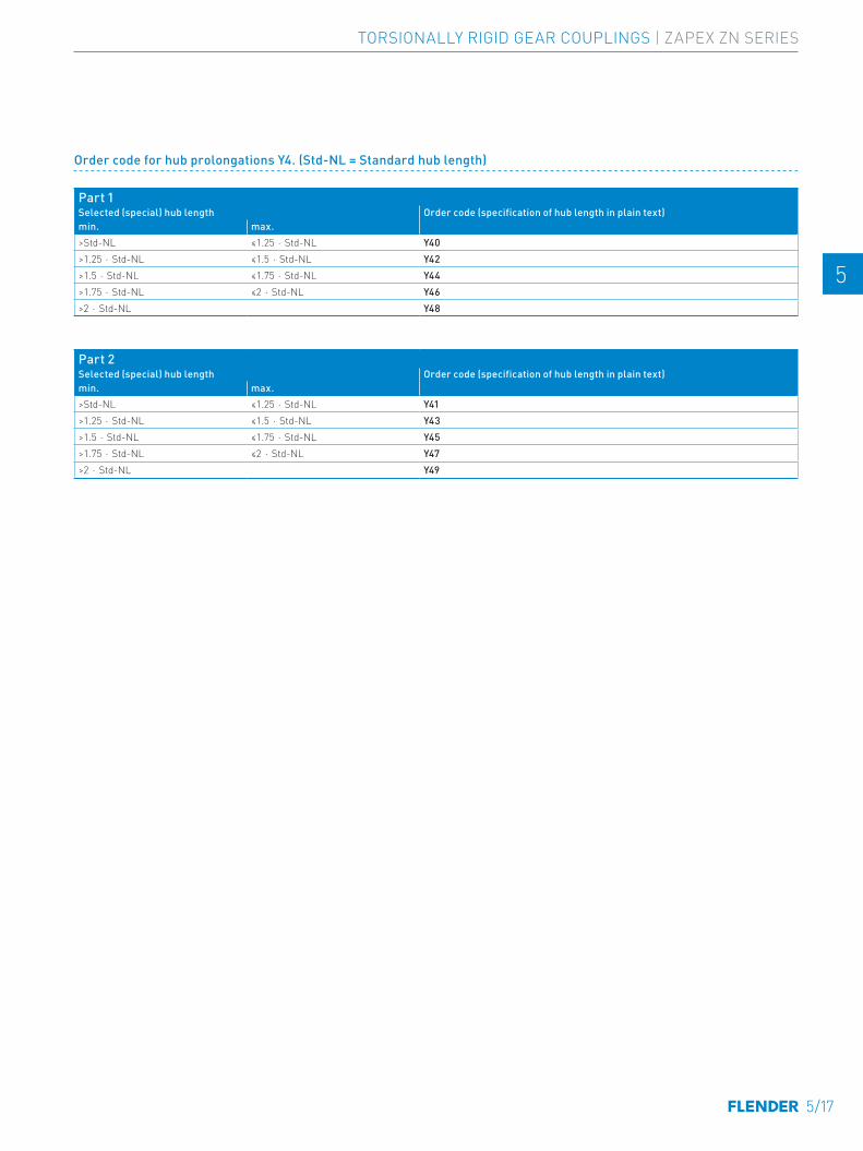
Order code for hub prolongations Y4. (Std-NL = Standard hub length)
Part 1Selected (special) hub length Order code (specification of hub length in plain text)min. max.>Std-NL ≤1.25 ⋅ Std-NL Y40>1.25 ⋅ Std-NL ≤1.5 ⋅ Std-NL Y42>1.5 ⋅ Std-NL ≤1.75 ⋅ Std-NL Y44>1.75 ⋅ Std-NL ≤2 ⋅ Std-NL Y46>2 ⋅ Std-NL Y48
Part 2Selected (special) hub length Order code (specification of hub length in plain text)min. max.>Std-NL ≤1.25 ⋅ Std-NL Y41>1.25 ⋅ Std-NL ≤1.5 ⋅ Std-NL Y43>1.5 ⋅ Std-NL ≤1.75 ⋅ Std-NL Y45>1.75 ⋅ Std-NL ≤2 ⋅ Std-NL Y47>2 ⋅ Std-NL Y49
TORSIONALLY RIGID GEAR COUPLINGS | ZAPEX ZN SERIES
5/17
E E
4 4
5 5
6 6
7 7
8 8
9 9
10 10
11 11
12 12
13 13
A A
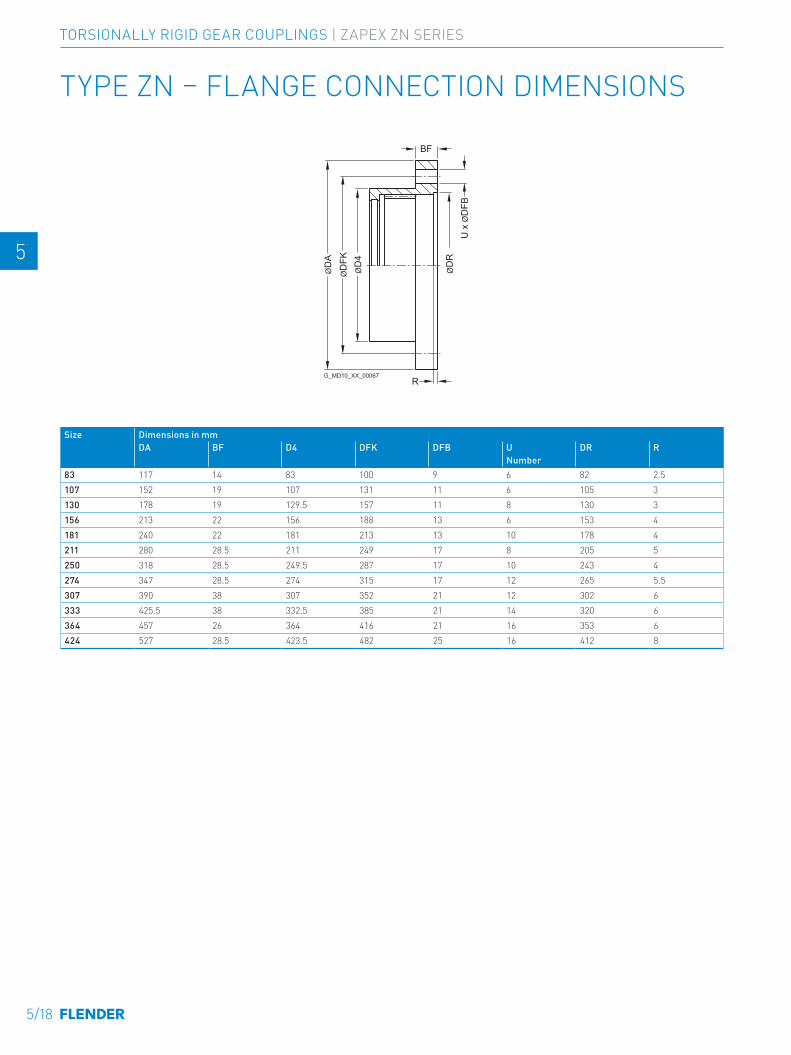
G_MD10_XX_00067R
ØD
A
ØD
4
BF
U x
ØD
FBØ
DR
ØD
FK
TYPE ZN – FLANGE CONNECTION DIMENSIONS
Size Dimensions in mmDA BF D4 DFK DFB U DR R
Number83 117 14 83 100 9 6 82 2.5107 152 19 107 131 11 6 105 3130 178 19 129.5 157 11 8 130 3156 213 22 156 188 13 6 153 4181 240 22 181 213 13 10 178 4211 280 28.5 211 249 17 8 205 5250 318 28.5 249.5 287 17 10 243 4274 347 28.5 274 315 17 12 265 5.5307 390 38 307 352 21 12 302 6333 425.5 38 332.5 385 21 14 320 6364 457 26 364 416 21 16 353 6424 527 28.5 423.5 482 25 16 412 8
5/18
TORSIONALLY RIGID GEAR COUPLINGS | ZAPEX ZN SERIES
E E
4 4
5 5
6 6
7 7
8 8
9 9
10 10
11 11
12 12
13 13
A A
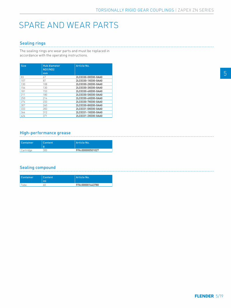
SPARE AND WEAR PARTS
Sealing rings
Size Hub diameter Article No.ND1/ND2mm
83 67 2LC0330-0XE00-0AA0107 87 2LC0330-1XE00-0AA0130 108 2LC0330-2XE00-0AA0156 130 2LC0330-3XE00-0AA0181 153 2LC0330-4XE00-0AA0211 180 2LC0330-5XE00-0AA0250 214 2LC0330-6XE00-0AA0274 233 2LC0330-7XE00-0AA0307 260 2LC0330-8XE00-0AA0333 283 2LC0331-0XE00-0AA0364 312 2LC0331-1XE00-0AA0424 371 2LC0331-2XE00-0AA0
The sealing rings are wear parts and must be replaced in accordance with the operating instructions.
High-performance grease
Container Content Article No.g
Cartridge 300 FFA:000000501027
Sealing compound
Container Content Article No.ml
Tube 60 FFA:000001443780
TORSIONALLY RIGID GEAR COUPLINGS | ZAPEX ZN SERIES
5/19
E E
4 4
5 5
6 6
7 7
8 8
9 9
10 10
11 11
12 12
13 13
A A

5/20
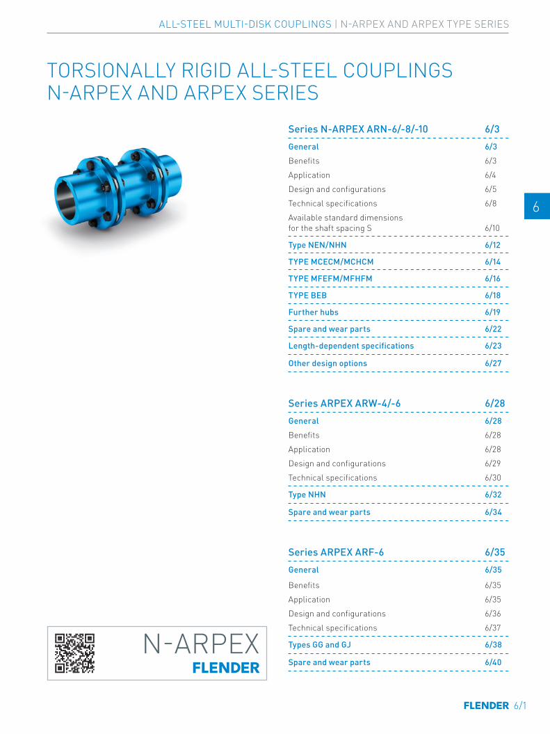
E E
4 4
5 5
6 6
7 7
8 8
9 9
10 10
11 11
12 12
13 13
A A
TORSIONALLY RIGID ALL-STEEL COUPLINGS N-ARPEX AND ARPEX SERIES
N-ARPEX
01-Einzelschilder-03-2020.indd 1 09.03.20 14:00
N-ARPEX
01-Einzelschilder-03-2020.indd 1 09.03.20 14:00
Series N-ARPEX ARN-6/-8/-10 6/3General 6/3Benefits 6/3Application 6/4Design and configurations 6/5Technical specifications 6/8Available standard dimensions for the shaft spacing S 6/10
Type NEN/NHN 6/12
TYPE MCECM/MCHCM 6/14
TYPE MFEFM/MFHFM 6/16
TYPE BEB 6/18
Further hubs 6/19
Spare and wear parts 6/22
Length-dependent specifications 6/23
Other design options 6/27
Series ARPEX ARW-4/-6 6/28General 6/28Benefits 6/28Application 6/28Design and configurations 6/29Technical specifications 6/30
Type NHN 6/32
Spare and wear parts 6/34
Series ARPEX ARF-6 6/35General 6/35
Benefits 6/35Application 6/35Design and configurations 6/36Technical specifications 6/37
Types GG and GJ 6/38
Spare and wear parts 6/40
6/1
ALL-STEEL MULTI-DISK COUPLINGS | N-ARPEX AND ARPEX TYPE SERIES

E E
4 4
5 5
6 6
7 7
8 8
9 9
10 10
11 11
12 12
13 13
A A
6/2
ALL-STEEL MULTI-DISK COUPLINGS | N-ARPEX AND ARPEX TYPE SERIES
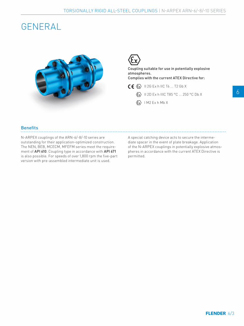
E E
4 4
5 5
6 6
7 7
8 8
9 9
10 10
11 11
12 12
13 13
A A
GENERAL
Benefits
N-ARPEX couplings of the ARN-6/-8/-10 series are outstanding for their application-optimized construction. The NEN, BEB, MCECM, MFEFM series meet the require-ment of API 610. Coupling type in accordance with API 671 is also possible. For speeds of over 1,800 rpm the five-part version with pre-assembled intermediate unit is used.
A special catching device acts to secure the interme-diate spacer in the event of plate breakage. Application of the N-ARPEX couplings in potentially explosive atmos-pheres in accordance with the current ATEX Directive is permitted.
Coupling suitable for use in potentially explosive atmospheres. Complies with the current ATEX Directive for:
II 2G Ex h IIC T6 ... T2 Gb X
II 2D Ex h IIIC T85 °C ... 250 °C Db X
I M2 Ex h Mb X
SERIES N-ARPEX ARN-6/-8/-10
6/3
TORSIONALLY RIGID ALL-STEEL COUPLINGS | N-ARPEX ARN-6/-8/-10 SERIES
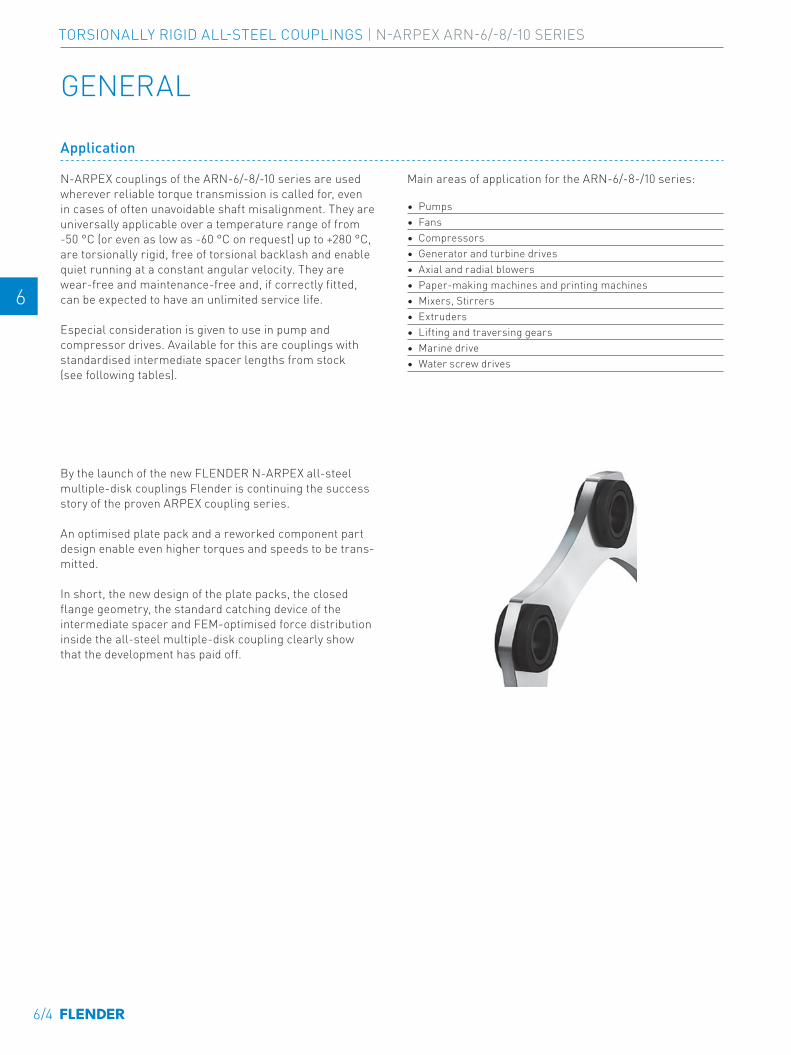
E E
4 4
5 5
6 6
7 7
8 8
9 9
10 10
11 11
12 12
13 13
A A
GENERAL
Application
N-ARPEX couplings of the ARN-6/-8/-10 series are used wherever reliable torque transmission is called for, even in cases of often unavoidable shaft misalignment. They are universally applicable over a temperature range of from -50 °C (or even as low as -60 °C on request) up to +280 °C, are torsionally rigid, free of torsional backlash and enable quiet running at a constant angular velocity. They are wear-free and maintenance-free and, if correctly fitted, can be expected to have an unlimited service life.
Especial consideration is given to use in pump and compressor drives. Available for this are couplings with standardised intermediate spacer lengths from stock (see following tables).
Main areas of application for the ARN-6/-8-/10 series:
• Pumps• Fans• Compressors• Generator and turbine drives• Axial and radial blowers• Paper-making machines and printing machines• Mixers, Stirrers• Extruders• Lifting and traversing gears• Marine drive• Water screw drives
By the launch of the new FLENDER N-ARPEX all-steel multiple-disk couplings Flender is continuing the success story of the proven ARPEX coupling series.
An optimised plate pack and a reworked component part design enable even higher torques and speeds to be trans-mitted.
In short, the new design of the plate packs, the closed flange geometry, the standard catching device of the intermediate spacer and FEM-optimised force distribution inside the all-steel multiple-disk coupling clearly show that the development has paid off.
6/4
TORSIONALLY RIGID ALL-STEEL COUPLINGS | N-ARPEX ARN-6/-8/-10 SERIES
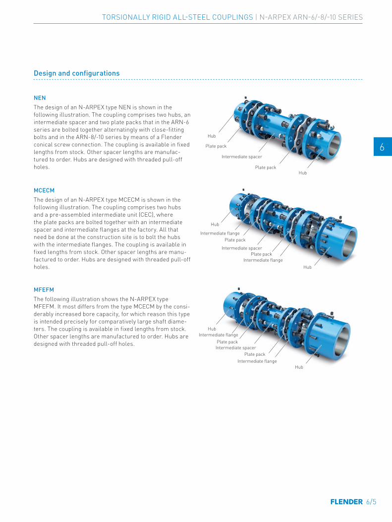
E E
4 4
5 5
6 6
7 7
8 8
9 9
10 10
11 11
12 12
13 13
A A
Design and configurations
NENThe design of an N-ARPEX type NEN is shown in the following illustration. The coupling comprises two hubs, an intermediate spacer and two plate packs that in the ARN-6 series are bolted together alternatingly with close-fitting bolts and in the ARN-8/-10 series by means of a Flender conical screw connection. The coupling is available in fixed lengths from stock. Other spacer lengths are manufac-tured to order. Hubs are designed with threaded pull-off holes.
MCECMThe design of an N-ARPEX type MCECM is shown in the following illustration. The coupling comprises two hubs and a pre-assembled intermediate unit (CEC), where the plate packs are bolted together with an intermediate spacer and intermediate flanges at the factory. All that need be done at the construction site is to bolt the hubs with the intermediate flanges. The coupling is available in fixed lengths from stock. Other spacer lengths are manu-factured to order. Hubs are designed with threaded pull-off holes.
MFEFMThe following illustration shows the N-ARPEX type MFEFM. It most differs from the type MCECM by the consi-derably increased bore capacity, for which reason this type is intended precisely for comparatively large shaft diame-ters. The coupling is available in fixed lengths from stock. Other spacer lengths are manufactured to order. Hubs are designed with threaded pull-off holes.
Intermediate spacer
Plate pack
Hub
Hub
Plate pack
Intermediate spacer
Intermediate flange
Hub
Hub
Plate pack
Plate pack
Intermediate flange
Intermediate spacer
Intermediate flange
Hub
Hub
Plate pack
Plate pack
Intermediate flange
6/5
TORSIONALLY RIGID ALL-STEEL COUPLINGS | N-ARPEX ARN-6/-8/-10 SERIES
E E
4 4
5 5
6 6
7 7
8 8
9 9
10 10
11 11
12 12
13 13
A A
GENERAL
Type Series DescriptionARN-6 ARN-8 ARN-10
NEN ■ ■ ■ Variant with intermediate spacer machined on all sides, length variableBEB ■ – – Variant with intermediate spacer machined on all sidesMCECM ■ ■ –
Variant with preassembled intermediate unit and intermediate spacer machined on all sides, length variableMFEFM ■ ■ ■NHN ■ ■ ■ Version with variable spacer tube – specially for greater shaft distances (up to 6,500 mm)MCHCM ■ ■ – Version with pre-assembled intermediate unit and with variable spacer tube –
specially for greater shaft distances (up to 6,500 mm)MFHFM ■ ■ ■
Variants of the N-ARPEX coupling, ARN-6/-8/-10 series
The coupling parts of the N-ARPEX ARN-6/-8/-10 series with the exception of the H spacers have been machined on all sides. The H spacers are delivered with unmachined, primed spacer tube.
Dimension sheets and 3D models of the standard types as well as application-related coupling types are available from the DTK selection module at flender.com.
6/6
TORSIONALLY RIGID ALL-STEEL COUPLINGS | N-ARPEX ARN-6/-8/-10 SERIES
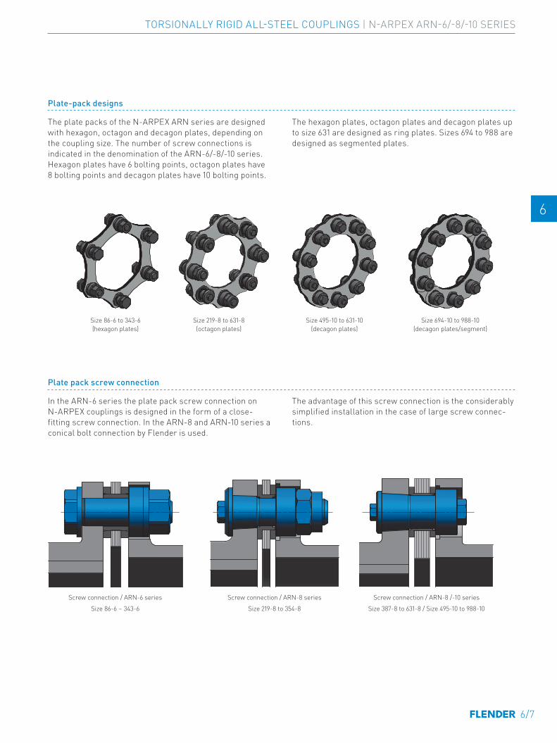
E E
4 4
5 5
6 6
7 7
8 8
9 9
10 10
11 11
12 12
13 13
A A
Plate pack screw connection
In the ARN-6 series the plate pack screw connection on N-ARPEX couplings is designed in the form of a close-fitting screw connection. In the ARN-8 and ARN-10 series a conical bolt connection by Flender is used.
The advantage of this screw connection is the considerably simplified installation in the case of large screw connec-tions.
Screw connection / ARN-6 seriesSize 86-6 – 343-6
Screw connection / ARN-8 seriesSize 219-8 to 354-8
Screw connection / ARN-8 /-10 series Size 387-8 to 631-8 / Size 495-10 to 988-10
Size 86-6 to 343-6 (hexagon plates)
Size 219-8 to 631-8 (octagon plates)
Size 495-10 to 631-10 (decagon plates)
Size 694-10 to 988-10 (decagon plates/segment)
Plate-pack designs
The plate packs of the N-ARPEX ARN series are designed with hexagon, octagon and decagon plates, depending on the coupling size. The number of screw connections is indicated in the denomination of the ARN-6/-8/-10 series. Hexagon plates have 6 bolting points, octagon plates have 8 bolting points and decagon plates have 10 bolting points.
The hexagon plates, octagon plates and decagon plates up to size 631 are designed as ring plates. Sizes 694 to 988 are designed as segmented plates.
6/7
TORSIONALLY RIGID ALL-STEEL COUPLINGS | N-ARPEX ARN-6/-8/-10 SERIES

E E
4 4
5 5
6 6
7 7
8 8
9 9
10 10
11 11
12 12
13 13
A A
Notes
• The permitted shaft misalignments ΔKa, ΔKr and ΔKw are maximum values and must not occur at the same time (see table on page 6/9).
• The maximum permissible radial misalignment depends on the shaft distance S. It can be determined for the stated types by using the following formulas: NEN/NHN: ΔKr = (S - S1) ⋅ tan(ΔKw) BEB, MCECM/ MCHCM and MFEFM/ MFHFM: ΔKr = (LZ + S1) ⋅ tan(ΔKw)
• TKmax is permitted five times per hour. • Length-related values like torsional stiffness,
total weight and mass moment of inertia are listed in the tables on pages 6/23 to 6/25.
• The torsional stiffness of the plate packs relates to the nominal range of the coupling. For determination of torsional stiffness for a specific operating point outside the nominal range Flender must be consulted.
Technical specifications
Power ratings, NEN/NHN, BEB, MCECM/MCHCM and MFEFM/MFHFM seriesSize Type Rated
torqueMaxi-mum torque
Overload torque
Fatigue torque Maxi-mum speed
Maximum permitted shaft misalignment (The permissible radial misalignment ΔKr depends on the total length of the coupling)
Torsional stiffness for a plate pack
DA TKN TKmax TKOL TKw0 TKw = TKw0 ⋅ (1 - TN/TKN) nKmax ±ΔKa ±ΔKw CTdynTN = 0%TKN 25%TKN 50%TKN 75%TKN
mm kNm kNm kNm kNm kNm kNm kNm rpm mm MNm/rad86-6
6-Bolt
0.35 0.7 0.875 0.175 0.131 0.088 0.044 24000 1.2
1.0 °
0.132103-6 0.5 1 1.25 0.25 0.188 0.125 0.063 20000 1.4 0.206122-6 0.95 1.9 2.375 0.475 0.356 0.238 0.119 17000 2 0.463133-6 1.25 2.5 3.125 0.625 0.469 0.313 0.156 15000 2.2 0.608159-6 2.1 4.2 5.25 1.05 0.788 0.525 0.263 13000 2.6 0.986174-6 2.5 5 6.25 1.25 0.938 0.625 0.313 12000 3 1.19184-6 3.8 7.6 9.5 1.9 1.425 0.95 0.475 11000 3.2 1.83203-6 5 10 12.5 2.5 1.875 1.25 0.625 10000 3.4 2.59217-6 6.2 12.4 15.5 3.1 2.325 1.55 0.775 9500 3.4 3.28251-6 10.5 21 26.25 5.25 3.938 2.625 1.313 8000 4.1 4.71268-6 13.8 27.6 34.5 6.9 5.175 3.45 1.725 7500 4.2 5.63291-6 18.2 36.4 45.5 9.1 6.825 4.55 2.275 7000 4.6 8.27318-6 23 46 57.5 11.5 8.625 5.75 2.875 6500 5 10.94343-6 28 56 70 14 10.5 7 3.5 6000 5.3 12.15219-8
8-Bolt
10 20 25 5 3.75 2.5 1.25 9500 1.7
0.4 °
6.31241-8 15 30 37 7.5 5.625 3.75 1.875 8700 1.9 7.64262-8 20 40 50 10 7.5 5 2.5 8000 2.1 9.09285-8 27 54 67 13.5 10.125 6.75 3.375 7300 2.2 11.9302-8 35 70 87 17.5 13.125 8.75 4.375 6900 2.4 16.2321-8 43 86 107 21.5 16.125 10.75 5.375 6500 2.5 21.9354-8 56 112 140 28 21 14 7 5900 3 29.1387-8 72 144 180 36 27 18 9 5400 3.3 40411-8 93 186 232 46.5 34.875 23.25 11.625 5100 3.4 46.9447-8 122 244 305 61 45.75 30.5 15.25 4600 2.5 60.3495-8 160 320 400 80 60 40 20 4200 3 76.9546-8 212 424 530 106 79.5 53 26.5 3800 3.4 100587-8 270 540 675 135 101.25 67.5 33.75 3500 3.6 116631-8 350 700 875 175 131.25 87.5 43.75 3300 3.8 138495-10
10-Bolt
200 350 450 80 60 40 20 4200 2
0.3 °
150546-10 270 473 608 108 81 54 27 3800 2.3 194587-10 352 616 792 140.8 105.6 70.4 35.2 3500 2.4 236631-10 450 788 1013 180 135 90 45 3300 2.5 274694-10 630 1103 1418 252 189 126 63 3000 2.7
0.2 °
405734-10 760 1330 1710 304 228 152 76 2800 2.8 501790-10 950 1663 2138 380 285 190 95 2600 3 632887-10 1400 2450 3150 560 420 280 140 2300 3.5 858988-10 2000 3500 4500 800 600 400 200 2100 3.9 1163
GENERAL
6/8
TORSIONALLY RIGID ALL-STEEL COUPLINGS | N-ARPEX ARN-6/-8/-10 SERIES

E E
4 4
5 5
6 6
7 7
8 8
9 9
10 10
11 11
12 12
13 13
A A
Permitted shaft misalignments, types NEN/NHN, BEB, MCECM/MCHCM and MFEFM/MFHFM
The permitted shaft misalignments ΔKa, ΔKr and ΔKw are maximum values and must not occur at the same time. The specified axial misalignments apply to the complete coupling. The permissible angular misalignments have been specified per coupling joint. As all N-ARPEX types are designed to be double-jointed, there is a direct interrelation between radial and angular misalignment.
NEN/NHN: ΔKr = (S - S1) ⋅ tan(ΔKw)BEB, MCECM/MCHCM and MFEFM/MFHFM: ΔKr = (LZ + S1) ⋅ tan(ΔKw)
To determine the permissible misalignment, values must, if necessary, be converted.
Size Permitted angular misalignment ±ΔKw
0.0 ° 0.1 ° 0.2 ° 0.3 ° 0.4 ° 0.5 ° 0.6 ° 0.7 ° 0.8 ° 0.9 ° 1.0 °DA Permitted axial misalignment ±ΔKa in mm86-6 1.2 1.1 1 0.8 0.7 0.6 0.5 0.4 0.2 0.1 0103-6 1.4 1.3 1.1 1 0.8 0.7 0.6 0.4 0.3 0.1 0122-6 2 1.8 1.6 1.4 1.2 1 0.8 0.6 0.4 0.2 0133-6 2.2 2 1.8 1.5 1.3 1.1 0.9 0.7 0.4 0.2 0159-6 2.6 2.3 2.1 1.8 1.6 1.3 1 0.8 0.5 0.3 0174-6 3 2.7 2.4 2.1 1.8 1.5 1.2 0.9 0.6 0.3 0184-6 3.2 2.9 2.6 2.2 1.9 1.6 1.3 1 0.6 0.3 0203-6 3.4 3.1 2.7 2.4 2 1.7 1.4 1 0.7 0.3 0217-6 3.4 3.1 2.7 2.4 2 1.7 1.4 1 0.7 0.3 0251-6 4.1 3.7 3.3 2.9 2.5 2.1 1.6 1.2 0.8 0.4 0268-6 4.2 3.8 3.4 2.9 2.5 2.1 1.7 1.3 0.8 0.4 0291-6 4.6 4.1 3.7 3.2 2.8 2.3 1.8 1.4 0.9 0.5 0318-6 5 4.5 4 3.5 3 2.5 2 1.5 1 0.5 0343-6 5.3 4.8 4.2 3.7 3.2 2.7 2.1 1.6 1.1 0.5 0219-8 1.7 1.28 0.85 0.43 0 - - - - - -241-8 1.9 1.43 0.95 0.48 0 - - - - - -262-8 2.1 1.58 1.05 0.53 0 - - - - - -285-8 2.2 1.65 1.1 0.55 0 - - - - - -302-8 2.4 1.8 1.2 0.6 0 - - - - - -321-8 2.5 1.88 1.25 0.63 0 - - - - - -354-8 3 2.25 1.5 0.75 0 - - - - - -387-8 3.3 2.48 1.65 0.83 0 - - - - - -411-8 3.4 2.55 1.7 0.85 0 - - - - - -447-8 2.5 1.88 1.25 0.63 0 - - - - - -495-8 3 2.25 1.5 0.75 0 - - - - - -546-8 3.4 2.55 1.7 0.85 0 - - - - - -587-8 3.6 2.7 1.8 0.9 0 - - - - - -631-8 3.8 2.85 1.9 0.95 0 - - - - - -495-10 2 1.33 0.67 0 - - - - - - -546-10 2.3 1.53 0.77 0 - - - - - - -587-10 2.4 1.6 0.8 0 - - - - - - -631-10 2.5 1.67 0.83 0 - - - - - - -694-10 2.7 1.35 0 - - - - - - - -734-10 2.8 1.4 0 - - - - - - - -790-10 3 1.5 0 - - - - - - - -887-10 3.5 1.75 0 - - - - - - - -988-10 3.9 1.95 0 - - - - - - - -
6/9
TORSIONALLY RIGID ALL-STEEL COUPLINGS | N-ARPEX ARN-6/-8/-10 SERIES
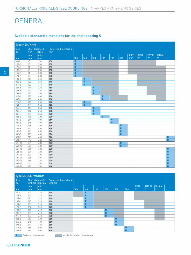
E E
4 4
5 5
6 6
7 7
8 8
9 9
10 10
11 11
12 12
13 13
A A
Type MCECM/MCHCMSize Shaft distance S Preferred dimension VDA MCECM MCHCM MCECM
min. min. (127) (177.8) (228.6)mm mm mm 100 140 180 200 250 300 5" 7" 9" -86-6 100 340 140 ■103-6 100 340 140 ■122-6 111 340 140 ■133-6 113 340 140 ■159-6 131 340 140 ■174-6 132 340 140 ■184-6 179 410 200 ■203-6 180 410 200 ■217-6 183 410 200 ■251-6 219 420 250 ■268-6 245 420 250 ■291-6 247 420 250 ■318-6 289 500 300 ■343-6 290 500 300 ■
Type NEN/NHNSize Shaft distance S Preferred dimension VDA NEN NHN NEN
min. min. (88.9) (127) (177.8) (228.6)mm mm mm 100 140 180 200 250 300 3.5" 5" 7" 9" -86-6 60 300 100 ■103-6 60 300 100 ■122-6 71 300 100 ■133-6 73 300 100 ■159-6 91 300 100 ■174-6 92 300 100 ■184-6 119 350 140 ■203-6 120 350 140 ■217-6 123 350 140 ■251-6 149 350 180 ■268-6 175 350 180 ■291-6 177 350 180 ■318-6 189 400 200 ■343-6 190 400 200 ■219-8 129 350 140 ■241-8 135 350 140 ■262-8 145 350 180 ■285-8 162 350 180 ■302-8 179 350 180 ■321-8 196 400 200 ■354-8 214 400 250 ■387-8 246 400 250 ■411-8 256 400 300 ■447-8 270 400 300 ■495-8 281 600 300 ■546-8 299 600 300 ■587-8 315 600 320 ■631-8 334 600 340 ■495-10 281 600 300 ■546-10 299 600 300 ■587-10 315 600 320 ■631-10 334 600 340 ■694-10 400 600 400 ■734-10 436 600 440 ■790-10 466 750 470 ■887-10 543 750 550 ■988-10 617 750 620 ■
GENERAL
Available standard dimensions for the shaft spacing S
■ Preferred dimensions Available standard dimensions
6/10
TORSIONALLY RIGID ALL-STEEL COUPLINGS | N-ARPEX ARN-6/-8/-10 SERIES
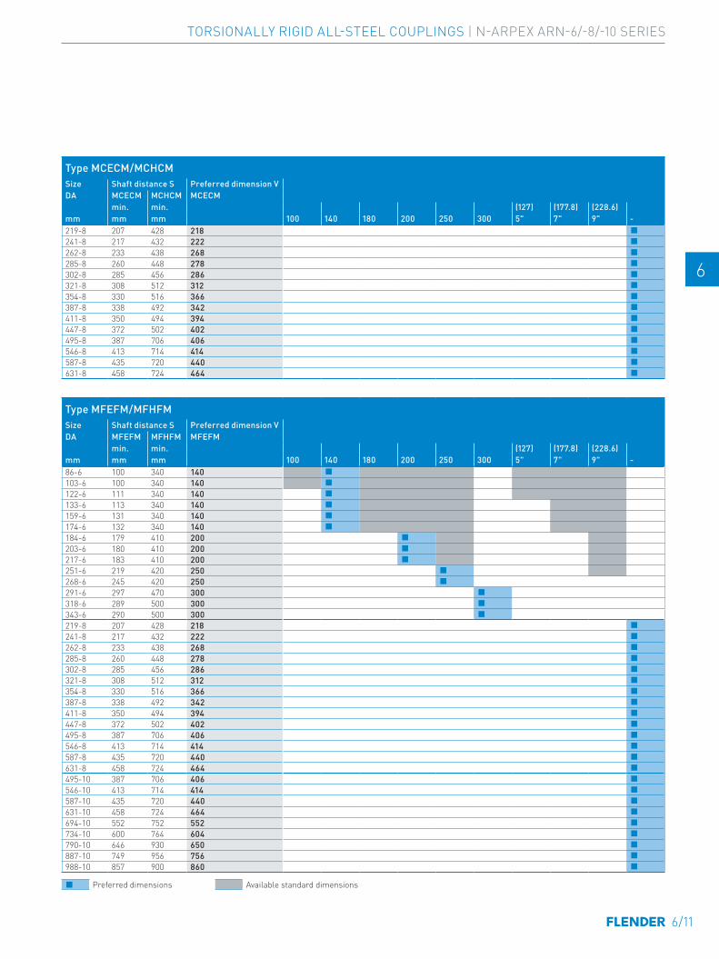
E E
4 4
5 5
6 6
7 7
8 8
9 9
10 10
11 11
12 12
13 13
A A
Type MFEFM/MFHFMSize Shaft distance S Preferred dimension VDA MFEFM MFHFM MFEFM
min. min. (127) (177.8) (228.6)mm mm mm 100 140 180 200 250 300 5" 7" 9" -86-6 100 340 140 ■103-6 100 340 140 ■122-6 111 340 140 ■133-6 113 340 140 ■159-6 131 340 140 ■174-6 132 340 140 ■184-6 179 410 200 ■203-6 180 410 200 ■217-6 183 410 200 ■251-6 219 420 250 ■268-6 245 420 250 ■291-6 297 470 300 ■318-6 289 500 300 ■343-6 290 500 300 ■219-8 207 428 218 ■241-8 217 432 222 ■262-8 233 438 268 ■285-8 260 448 278 ■302-8 285 456 286 ■321-8 308 512 312 ■354-8 330 516 366 ■387-8 338 492 342 ■411-8 350 494 394 ■447-8 372 502 402 ■495-8 387 706 406 ■546-8 413 714 414 ■587-8 435 720 440 ■631-8 458 724 464 ■495-10 387 706 406 ■546-10 413 714 414 ■587-10 435 720 440 ■631-10 458 724 464 ■694-10 552 752 552 ■734-10 600 764 604 ■790-10 646 930 650 ■887-10 749 956 756 ■988-10 857 900 860 ■
Type MCECM/MCHCMSize Shaft distance S Preferred dimension VDA MCECM MCHCM MCECM
min. min. (127) (177.8) (228.6)mm mm mm 100 140 180 200 250 300 5" 7" 9" -219-8 207 428 218 ■241-8 217 432 222 ■262-8 233 438 268 ■285-8 260 448 278 ■302-8 285 456 286 ■321-8 308 512 312 ■354-8 330 516 366 ■387-8 338 492 342 ■411-8 350 494 394 ■447-8 372 502 402 ■495-8 387 706 406 ■546-8 413 714 414 ■587-8 435 720 440 ■631-8 458 724 464 ■
■ Preferred dimensions Available standard dimensions
6/11
TORSIONALLY RIGID ALL-STEEL COUPLINGS | N-ARPEX ARN-6/-8/-10 SERIES
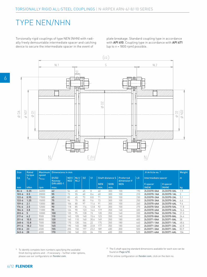
E E
4 4
5 5
6 6
7 7
8 8
9 9
10 10
11 11
12 12
13 13
A A
TYPE NEN/NHN
Torsionally rigid couplings of type NEN (NHN) with radi-ally freely demountable intermediate spacer and catching device to secure the intermediate spacer in the event of
plate breakage. Standard coupling type in accordance with API 610. Coupling type in accordance with API 671 (up to n = 1800 rpm) possible.
Size Rated torque
Maximum speed
Dimensions in mm ↗ Article no. 1) Weight
DA TKN nKmax D1/D2 Keyway DIN 6885-1
ND1/ND2
NL1/NL2
DZ S1 Shaft distance S Preferred dimension V
LG Intermediate spacer m
NEN NHN NEN E spacer H spacermm kNm rpm max. min. min. (NEN) (NHN) kg86-6 0.35 24000 42 56 45 45 8 60 300 100 190 2LC0370-0AA 2LC0370-0AL 1.9 -0A.0103-6 0.5 20000 55 73 55 60 8.4 60 300 100 210 2LC0370-1AA 2LC0370-1AL 3 -0A.0122-6 0.95 17000 65 85 65 73 8.8 71 300 100 230 2LC0370-2AA 2LC0370-2AL 5.1 -0A.0133-6 1.25 15000 75 96 75 85 9.6 73 300 100 250 2LC0370-3AA 2LC0370-3AL 6.4 -0A.0159-6 2.1 13000 80 104 80 97 11.6 91 300 100 260 2LC0370-4AA 2LC0370-4AL 9.6 -0A.0174-6 2.5 12000 90 118 85 116 12.8 92 300 100 270 2LC0370-5AA 2LC0370-5AL 11.8 -0A.0184-6 3.8 11000 95 124 90 123 14.6 119 350 140 320 2LC0370-6AA 2LC0370-6AL 16.4 -0A.0203-6 5 10000 100 135 95 128 15 120 350 140 330 2LC0370-7AA 2LC0370-7AL 21.3 -0A.0217-6 6.2 9500 110 143 105 140 15.4 123 350 140 350 2LC0370-8AA 2LC0370-8AL 24.4 -0A.0251-6 10.5 8000 120 160 110 160 20.6 149 350 180 400 2LC0371-0AA 2LC0371-0AL 38 -0A.0268-6 13.8 7500 130 170 130 166 22 175 350 180 440 2LC0371-1AA 2LC0371-1AL 48.6 -0A.0291-6 18.2 7000 145 190 140 188 22.8 177 350 180 460 2LC0371-2AA 2LC0371-2AL 62.8 -0A.0318-6 23 6500 155 205 150 197 23.2 189 400 200 500 2LC0371-3AA 2LC0371-3AL 83.9 -0A.0343-6 28 6000 170 230 160 223 24 190 400 200 520 2LC0371-4AA 2LC0371-4AL 104 -0A.0
1) To identify complete item numbers specifying the available finish boring options and – if necessary – further order options, please use our configurators on flender.com.
2) The S shaft spacing standard dimensions available for each size can be found on Page 6/10. ↗ For online configuration on flender.com, click on the item no.
6/12
TORSIONALLY RIGID ALL-STEEL COUPLINGS | N-ARPEX ARN-6/-8/-10 SERIES
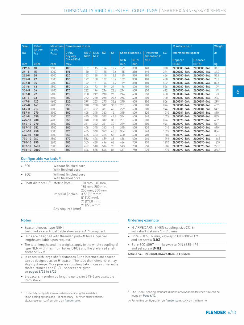
E E
4 4
5 5
6 6
7 7
8 8
9 9
10 10
11 11
12 12
13 13
A A
Size Rated torque
Maximum speed
Dimensions in mm ↗ Article no. 1) Weight
DA TKN nKmax D1/D2 Keyway DIN 6885-1
ND1/ND2
NL1/NL2
DZ S1 Shaft distance S Preferred dimension V
LG Intermediate spacer m
NEN NHN NEN E spacer H spacermm kNm rpm max. min. min. (NEN) (NHN) kg219-8 10 9500 100 137 115 124 12.2 129 350 140 370 2LC0380-0AA 2LC0380-0AL 31.9 -0A.0241-8 15 8700 110 150 127 135 12.6 135 350 140 394 2LC0380-1AA 2LC0380-1AL 41.3 -0A.0262-8 20 8000 120 163 138 148 13.8 145 350 180 456 2LC0380-2AA 2LC0380-2AL 53.8 -0A.0285-8 27 7300 130 177 150 162 15.2 162 350 180 480 2LC0380-3AA 2LC0380-3AL 70.8 -0A.0302-8 35 6900 140 192 161 174 17.2 179 350 180 502 2LC0380-4AA 2LC0380-4AL 89.4 -0A.0321-8 43 6500 150 206 173 189 21 196 400 200 546 2LC0380-5AA 2LC0380-5AL 109 -0A.0354-8 56 5900 170 232 196 216 23.6 214 400 250 642 2LC0380-6AA 2LC0380-6AL 149 -0A.0387-8 72 5400 190 258 219 240 26 246 400 250 688 2LC0380-7AA 2LC0380-7AL 193 -0A.0411-8 93 5100 200 272 230 250 29.6 256 400 300 760 2LC0380-8AA 2LC0380-8AL 236 -0A.0447-8 122 4600 220 299 253 275 32.6 270 400 300 806 2LC0381-0AA 2LC0381-0AL 299 -0A.0495-8 160 4200 250 340 288 312 33.8 281 600 300 876 2LC0381-1AA 2LC0381-1AL 402 -0A.0546-8 212 3800 280 381 322 351 40 299 600 300 944 2LC0381-2AA 2LC0381-2AL 547 -0A.0587-8 270 3500 300 408 345 363 45 315 600 320 1010 2LC0381-3AA 2LC0381-3AL 690 -0A.0631-8 350 3300 320 435 368 399 48.8 334 600 340 1076 2LC0381-4AA 2LC0381-4AL 835 -0A.0495-10 200 4200 250 340 288 312 33.8 281 600 300 876 2LC0390-0AA 2LC0390-0AL 402 -0A.0546-10 270 3800 280 381 322 351 40 299 600 300 944 2LC0390-1AA 2LC0390-1AL 547 -0A.0587-10 352 3500 300 408 345 363 45 315 600 320 1010 2LC0390-2AA 2LC0390-2AL 690 -0A.0631-10 450 3300 320 435 368 399 48.8 334 600 340 1076 2LC0390-3AA 2LC0390-3AL 834 -0A.0694-10 630 3000 350 485 403 435 58 400 600 400 1206 2LC0390-4AA 2LC0390-4AL 1213 -0A.0734-10 760 2800 370 512 426 459 63 436 600 440 1292 2LC0390-5AA 2LC0390-5AL 1463 -0A.0790-10 950 2600 400 555 460 496 66 466 750 470 1390 2LC0390-6AA 2LC0390-6AL 1837 -0A.0887-10 1400 2300 450 627 518 546 78 543 750 550 1586 2LC0390-7AA 2LC0390-7AL 2713 -0A.0988-10 2000 2100 500 696 575 596 86 617 750 620 1770 2LC0390-8AA 2LC0390-8AL 3868 -0A.0
Configurable variants 1)
• ØD1 Without finished bore With finished bore
• ØD2 Without finished bore With finished bore
• Shaft distance S 2) Metric (mm): 100 mm, 140 mm, 180 mm, 200 mm, 250 mm, 300 mm Imperial (inches): 3.5" (88.9 mm), 5" (127 mm), 7" (177.8 mm), 9" (228.6 mm) Any required (mm)
Notes
• Spacer sleeves (type NEN) designed as electrical cable sleeves are API compliant.
• Hubs are designed with threaded pull-off holes. Special lengths available upon request.
• The total lengths and the weights apply to the whole coupling of type NEN with maximum bores D1/D2 and the preferred shaft distance S = V.
• In cases with large shaft distances S the intermediate spacer can be designed as an H-spacer. The tube diameters here may slightly diverge. More precise coupling data in cases of variable shaft distances and E- / H-spacers are given on pages 6/23 to 6/25.
• E-spacers in preferred lengths up to size 343-6 are available from stock.
Ordering example
• N-ARPEX ARN-6 NEN coupling, size 217-6, with shaft distance S = 140 mm
• Bore ØD1 50H7 mm, keyway to DIN 6885-1 P9 and set screw (L1C)
• Bore ØD2 60H7 mm, keyway to DIN 6885-1 P9 and set screw (M1E)
Article no.: 2LC0370-8AA99-0AB0-Z L1C+M1E
Size Rated torque
Maximum speed
Dimensions in mm ↗ Article no. 1) Weight
DA TKN nKmax D1/D2 Keyway DIN 6885-1
ND1/ND2
NL1/NL2
DZ S1 Shaft distance S Preferred dimension V
LG Intermediate spacer m
NEN NHN NEN E spacer H spacermm kNm rpm max. min. min. (NEN) (NHN) kg86-6 0.35 24000 42 56 45 45 8 60 300 100 190 2LC0370-0AA 2LC0370-0AL 1.9 -0A.0103-6 0.5 20000 55 73 55 60 8.4 60 300 100 210 2LC0370-1AA 2LC0370-1AL 3 -0A.0122-6 0.95 17000 65 85 65 73 8.8 71 300 100 230 2LC0370-2AA 2LC0370-2AL 5.1 -0A.0133-6 1.25 15000 75 96 75 85 9.6 73 300 100 250 2LC0370-3AA 2LC0370-3AL 6.4 -0A.0159-6 2.1 13000 80 104 80 97 11.6 91 300 100 260 2LC0370-4AA 2LC0370-4AL 9.6 -0A.0174-6 2.5 12000 90 118 85 116 12.8 92 300 100 270 2LC0370-5AA 2LC0370-5AL 11.8 -0A.0184-6 3.8 11000 95 124 90 123 14.6 119 350 140 320 2LC0370-6AA 2LC0370-6AL 16.4 -0A.0203-6 5 10000 100 135 95 128 15 120 350 140 330 2LC0370-7AA 2LC0370-7AL 21.3 -0A.0217-6 6.2 9500 110 143 105 140 15.4 123 350 140 350 2LC0370-8AA 2LC0370-8AL 24.4 -0A.0251-6 10.5 8000 120 160 110 160 20.6 149 350 180 400 2LC0371-0AA 2LC0371-0AL 38 -0A.0268-6 13.8 7500 130 170 130 166 22 175 350 180 440 2LC0371-1AA 2LC0371-1AL 48.6 -0A.0291-6 18.2 7000 145 190 140 188 22.8 177 350 180 460 2LC0371-2AA 2LC0371-2AL 62.8 -0A.0318-6 23 6500 155 205 150 197 23.2 189 400 200 500 2LC0371-3AA 2LC0371-3AL 83.9 -0A.0343-6 28 6000 170 230 160 223 24 190 400 200 520 2LC0371-4AA 2LC0371-4AL 104 -0A.0
1) To identify complete item numbers specifying the available finish boring options and – if necessary – further order options, please use our configurators on flender.com.
2) The S shaft spacing standard dimensions available for each size can be found on Page 6/10. ↗ For online configuration on flender.com, click on the item no.
6/13
TORSIONALLY RIGID ALL-STEEL COUPLINGS | N-ARPEX ARN-6/-8/-10 SERIES
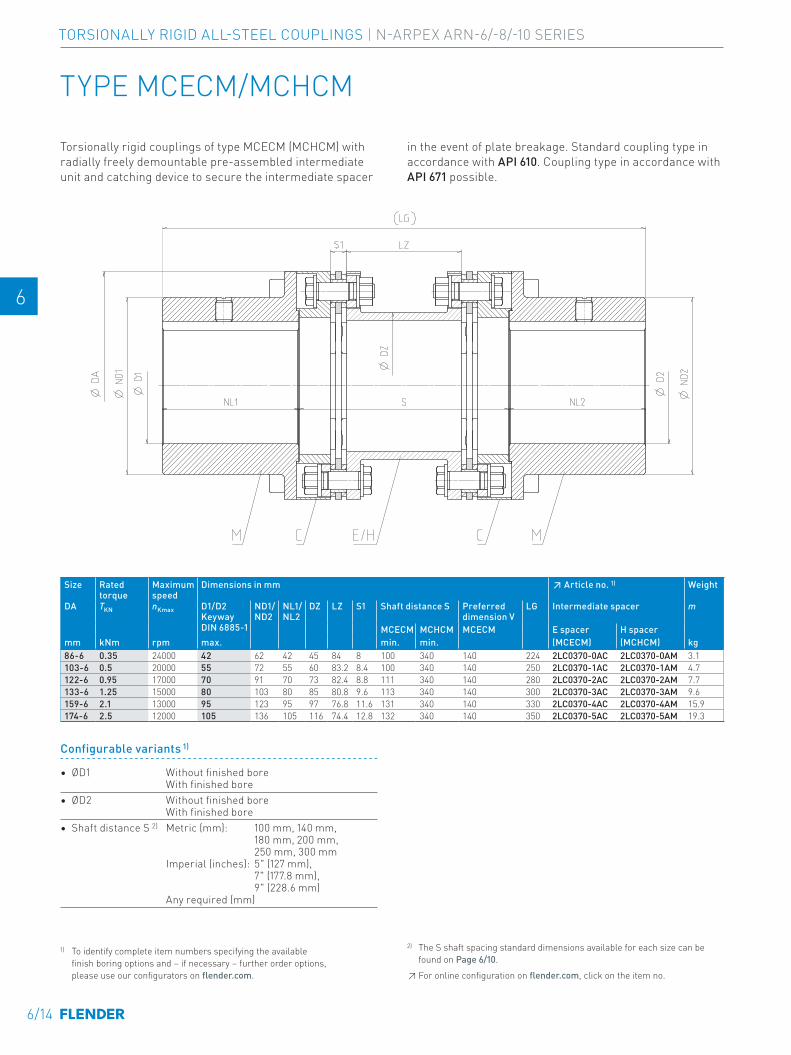
E E
4 4
5 5
6 6
7 7
8 8
9 9
10 10
11 11
12 12
13 13
A A
TYPE MCECM/MCHCM
Torsionally rigid couplings of type MCECM (MCHCM) with radially freely demountable pre-assembled intermediate unit and catching device to secure the intermediate spacer
in the event of plate breakage. Standard coupling type in accordance with API 610. Coupling type in accordance with API 671 possible.
Size Rated torque
Maximum speed
Dimensions in mm ↗ Article no. 1) Weight
DA TKN nKmax D1/D2 Keyway DIN 6885-1
ND1/ND2
NL1/NL2
DZ LZ S1 Shaft distance S Preferred dimension V
LG Intermediate spacer m
MCECM MCHCM MCECM E spacer H spacermm kNm rpm max. min. min. (MCECM) (MCHCM) kg86-6 0.35 24000 42 62 42 45 84 8 100 340 140 224 2LC0370-0AC 2LC0370-0AM 3.1 -0A.0103-6 0.5 20000 55 72 55 60 83.2 8.4 100 340 140 250 2LC0370-1AC 2LC0370-1AM 4.7 -0A.0122-6 0.95 17000 70 91 70 73 82.4 8.8 111 340 140 280 2LC0370-2AC 2LC0370-2AM 7.7 -0A.0133-6 1.25 15000 80 103 80 85 80.8 9.6 113 340 140 300 2LC0370-3AC 2LC0370-3AM 9.6 -0A.0159-6 2.1 13000 95 123 95 97 76.8 11.6 131 340 140 330 2LC0370-4AC 2LC0370-4AM 15.9 -0A.0174-6 2.5 12000 105 136 105 116 74.4 12.8 132 340 140 350 2LC0370-5AC 2LC0370-5AM 19.3 -0A.0
Configurable variants 1)
• ØD1 Without finished bore With finished bore
• ØD2 Without finished bore With finished bore
• Shaft distance S 2) Metric (mm): 100 mm, 140 mm, 180 mm, 200 mm, 250 mm, 300 mm Imperial (inches): 5" (127 mm), 7" (177.8 mm), 9" (228.6 mm) Any required (mm)
1) To identify complete item numbers specifying the available finish boring options and – if necessary – further order options, please use our configurators on flender.com.
2) The S shaft spacing standard dimensions available for each size can be found on Page 6/10. ↗ For online configuration on flender.com, click on the item no.
6/14
TORSIONALLY RIGID ALL-STEEL COUPLINGS | N-ARPEX ARN-6/-8/-10 SERIES
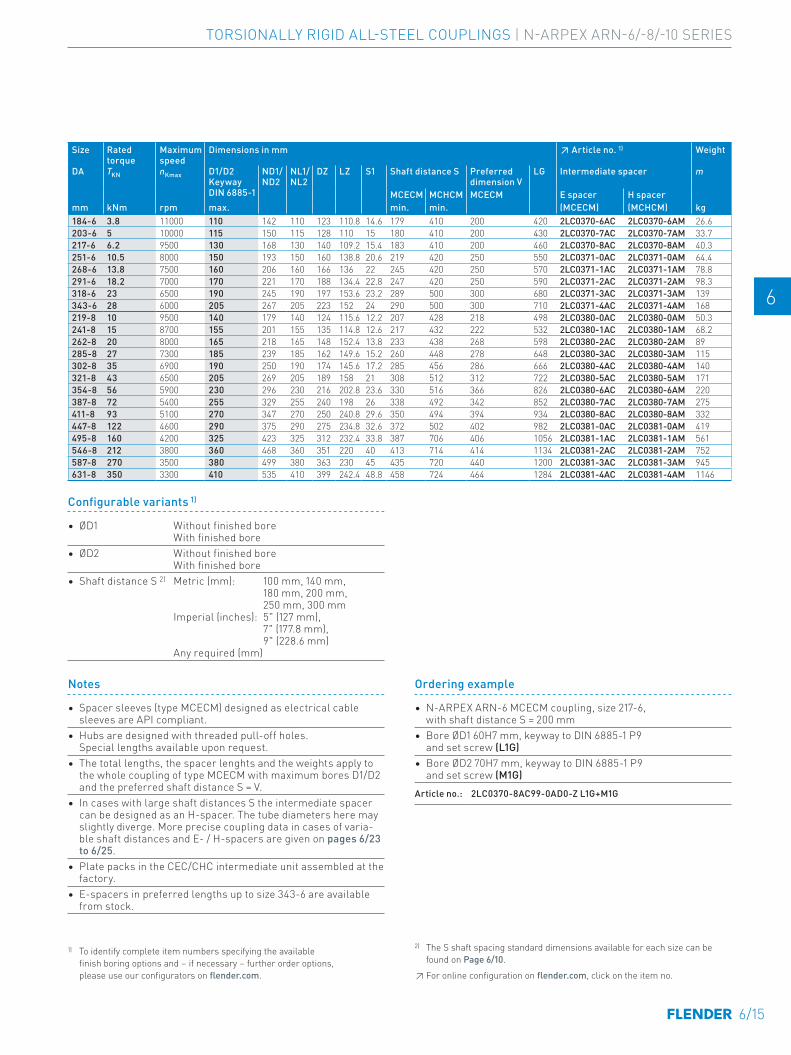
E E
4 4
5 5
6 6
7 7
8 8
9 9
10 10
11 11
12 12
13 13
A A
Size Rated torque
Maximum speed
Dimensions in mm ↗ Article no. 1) Weight
DA TKN nKmax D1/D2 Keyway DIN 6885-1
ND1/ND2
NL1/NL2
DZ LZ S1 Shaft distance S Preferred dimension V
LG Intermediate spacer m
MCECM MCHCM MCECM E spacer H spacermm kNm rpm max. min. min. (MCECM) (MCHCM) kg184-6 3.8 11000 110 142 110 123 110.8 14.6 179 410 200 420 2LC0370-6AC 2LC0370-6AM 26.6 -0A.0203-6 5 10000 115 150 115 128 110 15 180 410 200 430 2LC0370-7AC 2LC0370-7AM 33.7 -0A.0217-6 6.2 9500 130 168 130 140 109.2 15.4 183 410 200 460 2LC0370-8AC 2LC0370-8AM 40.3 -0A.0251-6 10.5 8000 150 193 150 160 138.8 20.6 219 420 250 550 2LC0371-0AC 2LC0371-0AM 64.4 -0A.0268-6 13.8 7500 160 206 160 166 136 22 245 420 250 570 2LC0371-1AC 2LC0371-1AM 78.8 -0A.0291-6 18.2 7000 170 221 170 188 134.4 22.8 247 420 250 590 2LC0371-2AC 2LC0371-2AM 98.3 -0A.0318-6 23 6500 190 245 190 197 153.6 23.2 289 500 300 680 2LC0371-3AC 2LC0371-3AM 139 -0A.0343-6 28 6000 205 267 205 223 152 24 290 500 300 710 2LC0371-4AC 2LC0371-4AM 168 -0A.0219-8 10 9500 140 179 140 124 115.6 12.2 207 428 218 498 2LC0380-0AC 2LC0380-0AM 50.3 -0A.0241-8 15 8700 155 201 155 135 114.8 12.6 217 432 222 532 2LC0380-1AC 2LC0380-1AM 68.2 -0A.0262-8 20 8000 165 218 165 148 152.4 13.8 233 438 268 598 2LC0380-2AC 2LC0380-2AM 89 -0A.0285-8 27 7300 185 239 185 162 149.6 15.2 260 448 278 648 2LC0380-3AC 2LC0380-3AM 115 -0A.0302-8 35 6900 190 250 190 174 145.6 17.2 285 456 286 666 2LC0380-4AC 2LC0380-4AM 140 -0A.0321-8 43 6500 205 269 205 189 158 21 308 512 312 722 2LC0380-5AC 2LC0380-5AM 171 -0A.0354-8 56 5900 230 296 230 216 202.8 23.6 330 516 366 826 2LC0380-6AC 2LC0380-6AM 220 -0A.0387-8 72 5400 255 329 255 240 198 26 338 492 342 852 2LC0380-7AC 2LC0380-7AM 275 -0A.0411-8 93 5100 270 347 270 250 240.8 29.6 350 494 394 934 2LC0380-8AC 2LC0380-8AM 332 -0A.0447-8 122 4600 290 375 290 275 234.8 32.6 372 502 402 982 2LC0381-0AC 2LC0381-0AM 419 -0A.0495-8 160 4200 325 423 325 312 232.4 33.8 387 706 406 1056 2LC0381-1AC 2LC0381-1AM 561 -0A.0546-8 212 3800 360 468 360 351 220 40 413 714 414 1134 2LC0381-2AC 2LC0381-2AM 752 -0A.0587-8 270 3500 380 499 380 363 230 45 435 720 440 1200 2LC0381-3AC 2LC0381-3AM 945 -0A.0631-8 350 3300 410 535 410 399 242.4 48.8 458 724 464 1284 2LC0381-4AC 2LC0381-4AM 1146 -0A.0
Size Rated torque
Maximum speed
Dimensions in mm ↗ Article no. 1) Weight
DA TKN nKmax D1/D2 Keyway DIN 6885-1
ND1/ND2
NL1/NL2
DZ LZ S1 Shaft distance S Preferred dimension V
LG Intermediate spacer m
MCECM MCHCM MCECM E spacer H spacermm kNm rpm max. min. min. (MCECM) (MCHCM) kg86-6 0.35 24000 42 62 42 45 84 8 100 340 140 224 2LC0370-0AC 2LC0370-0AM 3.1 -0A.0103-6 0.5 20000 55 72 55 60 83.2 8.4 100 340 140 250 2LC0370-1AC 2LC0370-1AM 4.7 -0A.0122-6 0.95 17000 70 91 70 73 82.4 8.8 111 340 140 280 2LC0370-2AC 2LC0370-2AM 7.7 -0A.0133-6 1.25 15000 80 103 80 85 80.8 9.6 113 340 140 300 2LC0370-3AC 2LC0370-3AM 9.6 -0A.0159-6 2.1 13000 95 123 95 97 76.8 11.6 131 340 140 330 2LC0370-4AC 2LC0370-4AM 15.9 -0A.0174-6 2.5 12000 105 136 105 116 74.4 12.8 132 340 140 350 2LC0370-5AC 2LC0370-5AM 19.3 -0A.0
Notes
• Spacer sleeves (type MCECM) designed as electrical cable sleeves are API compliant.
• Hubs are designed with threaded pull-off holes. Special lengths available upon request.
• The total lengths, the spacer lenghts and the weights apply to the whole coupling of type MCECM with maximum bores D1/D2 and the preferred shaft distance S = V.
• In cases with large shaft distances S the intermediate spacer can be designed as an H-spacer. The tube diameters here may slightly diverge. More precise coupling data in cases of varia-ble shaft distances and E- / H-spacers are given on pages 6/23 to 6/25.
• Plate packs in the CEC/CHC intermediate unit assembled at the factory.
• E-spacers in preferred lengths up to size 343-6 are available from stock.
Ordering example
• N-ARPEX ARN-6 MCECM coupling, size 217-6, with shaft distance S = 200 mm
• Bore ØD1 60H7 mm, keyway to DIN 6885-1 P9 and set screw (L1G)
• Bore ØD2 70H7 mm, keyway to DIN 6885-1 P9 and set screw (M1G)
Article no.: 2LC0370-8AC99-0AD0-Z L1G+M1G
Configurable variants 1)
• ØD1 Without finished bore With finished bore
• ØD2 Without finished bore With finished bore
• Shaft distance S 2) Metric (mm): 100 mm, 140 mm, 180 mm, 200 mm, 250 mm, 300 mm Imperial (inches): 5" (127 mm), 7" (177.8 mm), 9" (228.6 mm) Any required (mm)
1) To identify complete item numbers specifying the available finish boring options and – if necessary – further order options, please use our configurators on flender.com.
2) The S shaft spacing standard dimensions available for each size can be found on Page 6/10. ↗ For online configuration on flender.com, click on the item no.
6/15
TORSIONALLY RIGID ALL-STEEL COUPLINGS | N-ARPEX ARN-6/-8/-10 SERIES
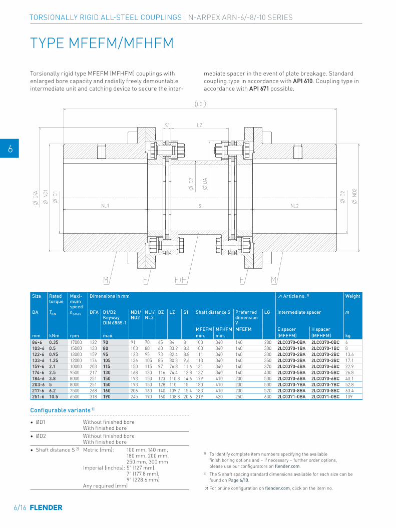
E E
4 4
5 5
6 6
7 7
8 8
9 9
10 10
11 11
12 12
13 13
A A
TYPE MFEFM/MFHFM
Torsionally rigid type MFEFM (MFHFM) couplings with enlarged bore capacity and radially freely demountable intermediate unit and catching device to secure the inter-
mediate spacer in the event of plate breakage. Standard coupling type in accordance with API 610. Coupling type in accordance with API 671 possible.
Size Rated torque
Maxi-mum speed
Dimensions in mm ↗ Article no. 1) Weight
DA TKN nKmax DFA D1/D2 Keyway DIN 6885-1
ND1/ND2
NL1/NL2
DZ LZ S1 Shaft distance S Preferred dimension V
LG Intermediate spacer m
MFEFM MFHFM MFEFM E spacer H spacermm kNm rpm max. min. min. (MFEFM) (MFHFM) kg86-6 0.35 17000 122 70 91 70 45 84 8 100 340 140 280 2LC0370-0BA 2LC0370-0BC 6 -0A.0103-6 0.5 15000 133 80 103 80 60 83.2 8.4 100 340 140 300 2LC0370-1BA 2LC0370-1BC 8 -0A.0122-6 0.95 13000 159 95 123 95 73 82.4 8.8 111 340 140 330 2LC0370-2BA 2LC0370-2BC 13.6 -0A.0133-6 1.25 12000 174 105 136 105 85 80.8 9.6 113 340 140 350 2LC0370-3BA 2LC0370-3BC 17.1 -0A.0159-6 2.1 10000 203 115 150 115 97 76.8 11.6 131 340 140 370 2LC0370-4BA 2LC0370-4BC 22.9 -0A.0174-6 2.5 9500 217 130 168 130 116 74.4 12.8 132 340 140 400 2LC0370-5BA 2LC0370-5BC 26.8 -0A.0184-6 3.8 8000 251 150 193 150 123 110.8 14.6 179 410 200 500 2LC0370-6BA 2LC0370-6BC 40.1 -0A.0203-6 5 8000 251 150 193 150 128 110 15 180 410 200 500 2LC0370-7BA 2LC0370-7BC 52.8 -0A.0217-6 6.2 7500 268 160 206 160 140 109.2 15.4 183 410 200 520 2LC0370-8BA 2LC0370-8BC 63.4 -0A.0251-6 10.5 6500 318 190 245 190 160 138.8 20.6 219 420 250 630 2LC0371-0BA 2LC0371-0BC 109 -0A.0
Configurable variants 1)
• ØD1 Without finished bore With finished bore
• ØD2 Without finished bore With finished bore
• Shaft distance S 2) Metric (mm): 100 mm, 140 mm, 180 mm, 200 mm, 250 mm, 300 mm Imperial (inches): 5" (127 mm), 7" (177.8 mm), 9" (228.6 mm) Any required (mm)
1) To identify complete item numbers specifying the available finish boring options and – if necessary – further order options, please use our configurators on flender.com.2) The S shaft spacing standard dimensions available for each size can be found on Page 6/10. ↗ For online configuration on flender.com, click on the item no.
6/16
TORSIONALLY RIGID ALL-STEEL COUPLINGS | N-ARPEX ARN-6/-8/-10 SERIES
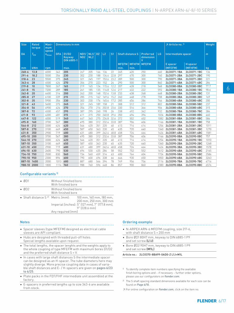
E E
4 4
5 5
6 6
7 7
8 8
9 9
10 10
11 11
12 12
13 13
A A
Size Rated torque
Maxi-mum speed
Dimensions in mm ↗ Article no. 1) Weight
DA TKN nKmax DFA D1/D2 Keyway DIN 6885-1
ND1/ND2
NL1/NL2
DZ LZ S1 Shaft distance S Preferred dimension V
LG Intermediate spacer m
MFEFM MFHFM MFEFM E spacer H spacermm kNm rpm max. min. min. (MFEFM) (MFHFM) kg268-6 13.8 6000 343 205 267 205 166 136 22 245 420 250 660 2LC0371-1BA 2LC0371-1BC 136 -0A.0291-6 18.2 5500 356 230 302 230 188 134.4 22.8 297 470 300 760 2LC0371-2BA 2LC0371-2BC 190 -0A.0318-6 23 5500 375 245 321 245 197 153.6 23.2 289 500 300 790 2LC0371-3BA 2LC0371-3BC 221 -0A.0343-6 28 4500 424 270 354 270 223 152 24 290 500 300 840 2LC0371-4BA 2LC0371-4BC 284 -0A.0219-8 10 7800 267 165 219 165 124 115.6 12.2 207 428 218 548 2LC0380-0BA 2LC0380-0BC 77.7 -0A.0241-8 15 7200 289 185 241 185 135 114.8 12.6 217 432 222 592 2LC0380-1BA 2LC0380-1BC 98.6 -0A.0262-8 20 6600 314 200 262 200 148 152.4 13.8 233 438 268 668 2LC0380-2BA 2LC0380-2BC 131 -0A.0285-8 27 6100 339 215 285 215 162 149.6 15.2 260 448 278 708 2LC0380-3BA 2LC0380-3BC 169 -0A.0302-8 35 5900 356 230 302 230 174 145.6 17.2 285 456 286 746 2LC0380-4BA 2LC0380-4BC 200 -0A.0321-8 43 5600 375 245 321 245 189 158 21 308 512 312 802 2LC0380-5BA 2LC0380-5BC 237 -0A.0354-8 56 4900 424 270 354 270 216 202.8 23.6 330 516 366 906 2LC0380-6BA 2LC0380-6BC 315 -0A.0387-8 72 4500 457 295 387 295 240 198 26 338 492 342 932 2LC0380-7BA 2LC0380-7BC 384 -0A.0411-8 93 4300 481 315 411 315 250 240.8 29.6 350 494 394 1024 2LC0380-8BA 2LC0380-8BC 460 -0A.0447-8 122 4000 519 340 447 340 275 234.8 32.6 372 502 402 1082 2LC0381-0BA 2LC0381-0BC 586 -0A.0495-8 160 3700 567 380 495 380 312 232.4 33.8 387 706 406 1166 2LC0381-1BA 2LC0381-1BC 758 -0A.0546-8 212 3300 624 420 546 420 351 220 40 413 714 414 1254 2LC0381-2BA 2LC0381-2BC 1011 -0A.0587-8 270 3100 669 450 587 450 363 230 45 435 720 440 1340 2LC0381-3BA 2LC0381-3BC 1270 -0A.0631-8 350 2900 719 480 631 480 399 242.4 48.8 458 724 464 1424 2LC0381-4BA 2LC0381-4BC 1581 -0A.0495-10 200 3700 567 380 495 380 312 232.4 33.8 387 706 406 1166 2LC0390-0BA 2LC0390-0BC 757 -0A.0546-10 270 3300 624 420 546 420 351 220 40 413 714 414 1254 2LC0390-1BA 2LC0390-1BC 1010 -0A.0587-10 350 3100 669 450 587 450 363 230 45 435 720 440 1340 2LC0390-2BA 2LC0390-2BC 1268 -0A.0631-10 450 2900 719 480 631 480 399 242.4 48.8 458 724 464 1424 2LC0390-3BA 2LC0390-3BC 1578 -0A.0694-10 630 2600 790 530 694 530 435 284 58 552 752 552 1612 2LC0390-4BA 2LC0390-4BC 2165 -0A.0734-10 750 2500 830 560 734 560 459 314 63 600 764 604 1724 2LC0390-5BA 2LC0390-5BC 2586 -0A.0790-10 950 2300 896 600 790 600 496 338 66 646 930 650 1850 2LC0390-6BA 2LC0390-6BC 3263 -0A.0887-10 1400 2000 1013 680 887 680 546 394 78 749 956 756 2116 2LC0390-7BA 2LC0390-7BC 4716 -0A.0988-10 2000 1800 1114 760 988 760 596 448 86 857 900 860 2380 2LC0390-8BA 2LC0390-8BC 6574 -0A.0
Notes
• Spacer sleeves (type MFEFM) designed as electrical cable sleeves are API compliant.
• Hubs are designed with threaded pull-off holes. Special lengths available upon request.
• The total lengths, the spacer lenghts and the weights apply to the whole coupling of type MFEFM with maximum bores D1/D2 and the preferred shaft distance S = V.
• In cases with large shaft distances S the intermediate spacer can be designed as an H-spacer. The tube diameters here may slightly diverge. More precise coupling data in cases of varia-ble shaft distances and E- / H-spacers are given on pages 6/23 to 6/25.
• Plate packs in the FEF/FHF intermediate unit assembled at the factory.
• E-spacers in preferred lengths up to size 343-6 are available from stock.
Ordering example
• N-ARPEX ARN-6 MFEFM coupling, size 217-6, with shaft distance S = 200 mm
• Bore ØD1 80H7 mm, keyway to DIN 6885-1 P9 and set screw (L1J)
• Bore ØD2 90H7 mm, keyway to DIN 6885-1 P9 and set screw (M1L)
Article no.: 2LC0370-8BA99-0AD0-Z L1J+M1L
Configurable variants 1)
• ØD1 Without finished bore With finished bore
• ØD2 Without finished bore With finished bore
• Shaft distance S 2) Metric (mm): 100 mm, 140 mm, 180 mm, 200 mm, 250 mm, 300 mm Imperial (inches): 5" (127 mm), 7" (177.8 mm), 9" (228.6 mm) Any required (mm)
1) To identify complete item numbers specifying the available finish boring options and – if necessary – further order options, please use our configurators on flender.com.2) The S shaft spacing standard dimensions available for each size can be found on Page 6/10. ↗ For online configuration on flender.com, click on the item no.
6/17
TORSIONALLY RIGID ALL-STEEL COUPLINGS | N-ARPEX ARN-6/-8/-10 SERIES
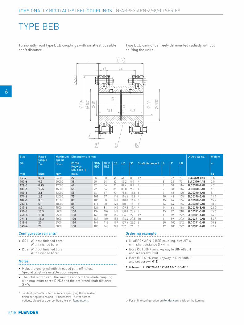
E E
4 4
5 5
6 6
7 7
8 8
9 9
10 10
11 11
12 12
13 13
A A
TYPE BEB
Size Rated torque
Maximum speed
Dimensions in mm ↗ Article no. 1) Weight
DA TKN nKmax D1/D2 Keyway DIN 6885-1
ND1/ND2
NL1/NL2
DZ LZ S1 Shaft distance S A P LG m
mm kNm rpm max. kg86-6 0.35 24000 22 35 30 45 44 8 12 8 32 72 SLC0370-0AB 1.5 -0AA0103-6 0.5 20000 38 50 34 60 43.2 8.4 4 8 32 72 SLC0370-1AB 2.0 -0AA0122-6 0.95 17000 48 62 56 73 82.4 8.8 4 8 38 116 2LC0370-2AB 4.2 -0AA0133-6 1.25 15000 55 72 56 85 80.8 9.6 4 7 38 116 2LC0370-3AB 5.1 -0AA0159-6 2.1 13000 65 84 57 97 76.8 11.6 6 9 48 120 2LC0370-4AB 8.1 -0AA0174-6 2.5 12000 75 102 77 116 114.4 12.8 4 10 48 158 2LC0370-5AB 11.4 -0AA0184-6 3.8 11000 80 106 80 123 110.8 14.6 6 15 64 166 2LC0370-6AB 15.2 -0AA0203-6 5 10000 85 111 80 128 110 15 6 14 64 166 2LC0370-7AB 18.2 -0AA0217-6 6.2 9500 90 124 81 140 109.2 15.4 4 14 66 166 2LC0370-8AB 22.0 -0AA0251-6 10.5 8000 100 137 102 160 138.8 20.6 6 15 77 210 2LC0371-0AB 35.6 -0AA0268-6 13.8 7500 108 143 105 166 136 22 12 11 89 222 2LC0371-1AB 44.8 -0AA0291-6 18.2 7000 120 162 106 188 134.4 22.8 10 11 89 222 2LC0371-2AB 56.7 -0AA0318-6 23 6500 130 164 118 197 153.6 23.2 6 20 100 242 2LC0371-3AB 70.2 -0AA0343-6 28 6000 150 186 143 223 202 24 6 19 100 292 2LC0371-4AB 87.7 -0AA0
Torsionally rigid type BEB couplings with smallest possible shaft distance.
Type BEB cannot be freely demounted radially without shifting the units.
Notes
• Hubs are designed with threaded pull-off holes. Special lengths available upon request.
• The total lengths and the weights apply to the whole coupling with maximum bores D1/D2 and the preferred shaft distance S = V.
Ordering example
• N-ARPEX ARN-6 BEB coupling, size 217-6, with shaft distance S = 4 mm
• Bore ØD1 50H7 mm, keyway to DIN 6885-1 and set screw (L1C)
• Bore ØD2 60H7 mm, keyway to DIN 6885-1 and set screw (M1E)
Article no.: 2LC0370-8AB99-0AA0-Z L1C+M1E
Configurable variants 1)
• ØD1 Without finished bore With finished bore
• ØD2 Without finished bore With finished bore
1) To identify complete item numbers specifying the available finish boring options and – if necessary – further order options, please use our configurators on flender.com. ↗ For online configuration on flender.com, click on the item no.
6/18
TORSIONALLY RIGID ALL-STEEL COUPLINGS | N-ARPEX ARN-6/-8/-10 SERIES
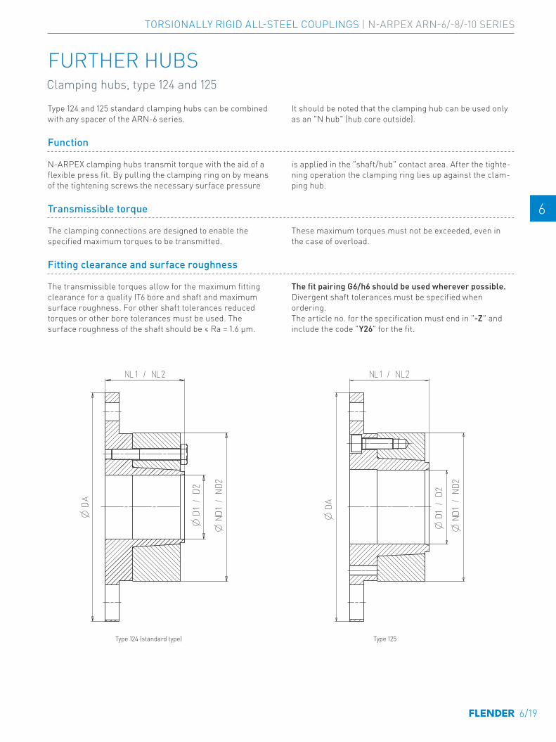
E E
4 4
5 5
6 6
7 7
8 8
9 9
10 10
11 11
12 12
13 13
A A
FURTHER HUBSClamping hubs, type 124 and 125
Type 124 (standard type) Type 125
Type 124 and 125 standard clamping hubs can be combined with any spacer of the ARN-6 series.
It should be noted that the clamping hub can be used only as an "N hub" (hub core outside).
Function
N-ARPEX clamping hubs transmit torque with the aid of a flexible press fit. By pulling the clamping ring on by means of the tightening screws the necessary surface pressure
is applied in the "shaft/hub" contact area. After the tighte-ning operation the clamping ring lies up against the clam-ping hub.
Transmissible torque
The clamping connections are designed to enable the specified maximum torques to be transmitted.
These maximum torques must not be exceeded, even in the case of overload.
Fitting clearance and surface roughness
The transmissible torques allow for the maximum fitting clearance for a quality IT6 bore and shaft and maximum surface roughness. For other shaft tolerances reduced torques or other bore tolerances must be used. The surface roughness of the shaft should be ≤ Ra = 1.6 μm.
The fit pairing G6/h6 should be used wherever possible.Divergent shaft tolerances must be specified when ordering. The article no. for the specification must end in "-Z" and include the code "Y26" for the fit.
6/19
TORSIONALLY RIGID ALL-STEEL COUPLINGS | N-ARPEX ARN-6/-8/-10 SERIES
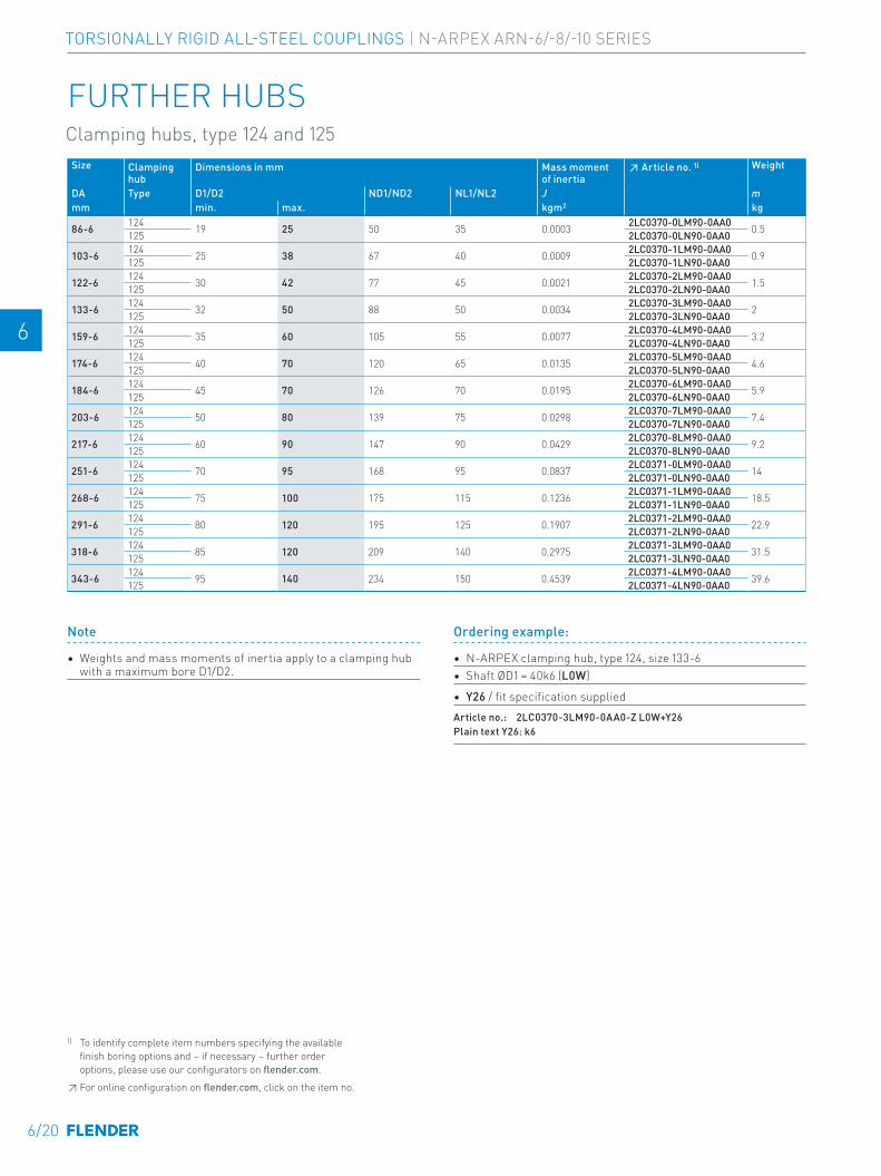
E E
4 4
5 5
6 6
7 7
8 8
9 9
10 10
11 11
12 12
13 13
A A
Note
• Weights and mass moments of inertia apply to a clamping hub with a maximum bore D1/D2.
Size Clamping hub
Dimensions in mm Mass moment of inertia
↗ Article no. 1) Weight
DA Type D1/D2 ND1/ND2 NL1/NL2 J mmm min. max. kgm2 kg
86-6 124 19 25 50 35 0.0003 2LC0370-0LM90-0AA0 0.5125 2LC0370-0LN90-0AA0
103-6 124 25 38 67 40 0.0009 2LC0370-1LM90-0AA0 0.9125 2LC0370-1LN90-0AA0
122-6 124 30 42 77 45 0.0021 2LC0370-2LM90-0AA0 1.5125 2LC0370-2LN90-0AA0
133-6 124 32 50 88 50 0.0034 2LC0370-3LM90-0AA0 2125 2LC0370-3LN90-0AA0
159-6 124 35 60 105 55 0.0077 2LC0370-4LM90-0AA0 3.2125 2LC0370-4LN90-0AA0
174-6 124 40 70 120 65 0.0135 2LC0370-5LM90-0AA0 4.6125 2LC0370-5LN90-0AA0
184-6 124 45 70 126 70 0.0195 2LC0370-6LM90-0AA0 5.9125 2LC0370-6LN90-0AA0
203-6 124 50 80 139 75 0.0298 2LC0370-7LM90-0AA0 7.4125 2LC0370-7LN90-0AA0
217-6 124 60 90 147 90 0.0429 2LC0370-8LM90-0AA0 9.2125 2LC0370-8LN90-0AA0
251-6 124 70 95 168 95 0.0837 2LC0371-0LM90-0AA0 14125 2LC0371-0LN90-0AA0
268-6 124 75 100 175 115 0.1236 2LC0371-1LM90-0AA0 18.5125 2LC0371-1LN90-0AA0
291-6 124 80 120 195 125 0.1907 2LC0371-2LM90-0AA0 22.9125 2LC0371-2LN90-0AA0
318-6 124 85 120 209 140 0.2975 2LC0371-3LM90-0AA0 31.5125 2LC0371-3LN90-0AA0
343-6 124 95 140 234 150 0.4539 2LC0371-4LM90-0AA0 39.6125 2LC0371-4LN90-0AA0
Ordering example:
• N-ARPEX clamping hub, type 124, size 133-6• Shaft ØD1 = 40k6 (L0W)
• Y26 / fit specification suppliedArticle no.: 2LC0370-3LM90-0AA0-Z L0W+Y26Plain text Y26: k6
FURTHER HUBSClamping hubs, type 124 and 125
1) To identify complete item numbers specifying the available finish boring options and – if necessary – further order options, please use our configurators on flender.com.↗ For online configuration on flender.com, click on the item no.
6/20
TORSIONALLY RIGID ALL-STEEL COUPLINGS | N-ARPEX ARN-6/-8/-10 SERIES
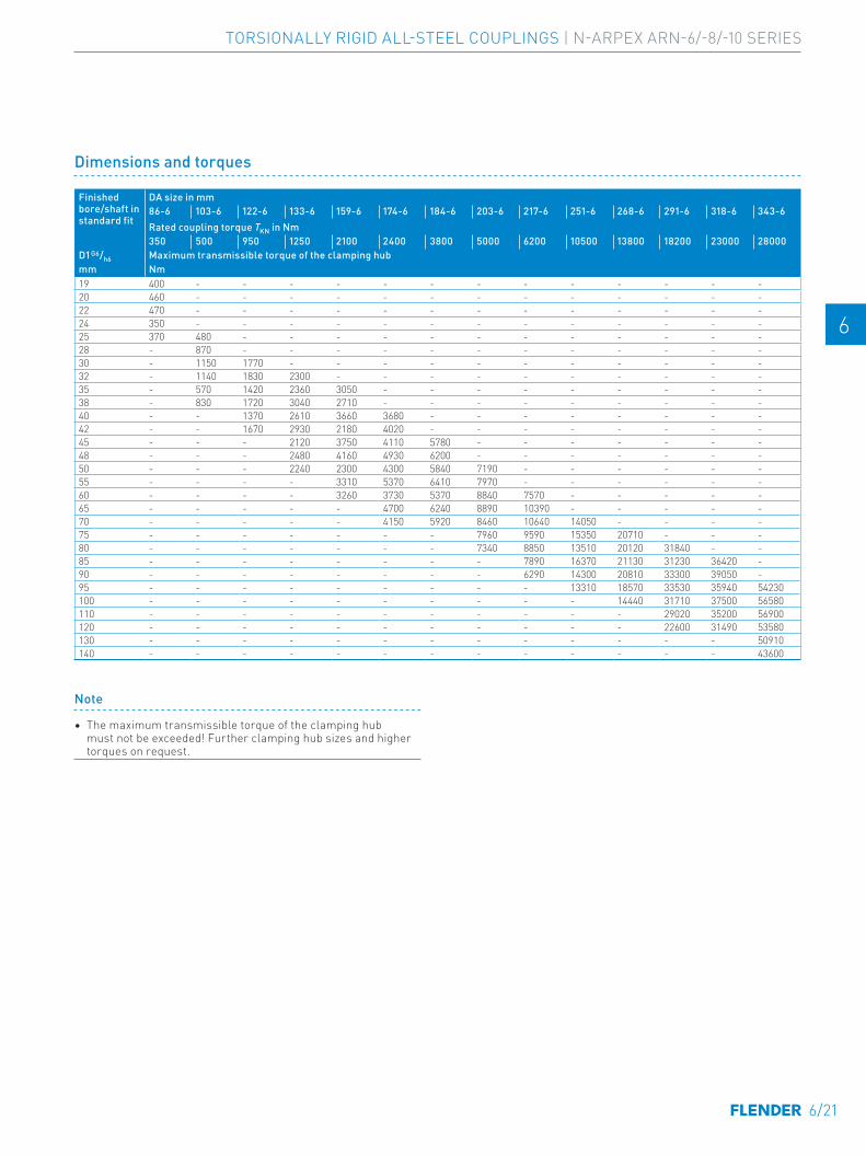
E E
4 4
5 5
6 6
7 7
8 8
9 9
10 10
11 11
12 12
13 13
A A
Dimensions and torques
Finished bore/shaft in standard fit
DA size in mm86-6 103-6 122-6 133-6 159-6 174-6 184-6 203-6 217-6 251-6 268-6 291-6 318-6 343-6Rated coupling torque TKN in Nm350 500 950 1250 2100 2400 3800 5000 6200 10500 13800 18200 23000 28000
D1 G6/h6 Maximum transmissible torque of the clamping hubmm Nm19 400 - - - - - - - - - - - - -20 460 - - - - - - - - - - - - -22 470 - - - - - - - - - - - - -24 350 - - - - - - - - - - - - -25 370 480 - - - - - - - - - - - -28 - 870 - - - - - - - - - - - -30 - 1150 1770 - - - - - - - - - - -32 - 1140 1830 2300 - - - - - - - - - -35 - 570 1420 2360 3050 - - - - - - - - -38 - 830 1720 3040 2710 - - - - - - - - -40 - - 1370 2610 3660 3680 - - - - - - - -42 - - 1670 2930 2180 4020 - - - - - - - -45 - - - 2120 3750 4110 5780 - - - - - - -48 - - - 2480 4160 4930 6200 - - - - - - -50 - - - 2240 2300 4300 5840 7190 - - - - - -55 - - - - 3310 5370 6410 7970 - - - - - -60 - - - - 3260 3730 5370 8840 7570 - - - - -65 - - - - - 4700 6240 8890 10390 - - - - -70 - - - - - 4150 5920 8460 10640 14050 - - - -75 - - - - - - - 7960 9590 15350 20710 - - -80 - - - - - - - 7340 8850 13510 20120 31840 - -85 - - - - - - - - 7890 16370 21130 31230 36420 -90 - - - - - - - - 6290 14300 20810 33300 39050 -95 - - - - - - - - - 13310 18570 33530 35940 54230100 - - - - - - - - - - 14440 31710 37500 56580110 - - - - - - - - - - - 29020 35200 56900120 - - - - - - - - - - - 22600 31490 53580130 - - - - - - - - - - - - - 50910140 - - - - - - - - - - - - - 43600
Note
• The maximum transmissible torque of the clamping hub must not be exceeded! Further clamping hub sizes and higher torques on request.
6/21
TORSIONALLY RIGID ALL-STEEL COUPLINGS | N-ARPEX ARN-6/-8/-10 SERIES
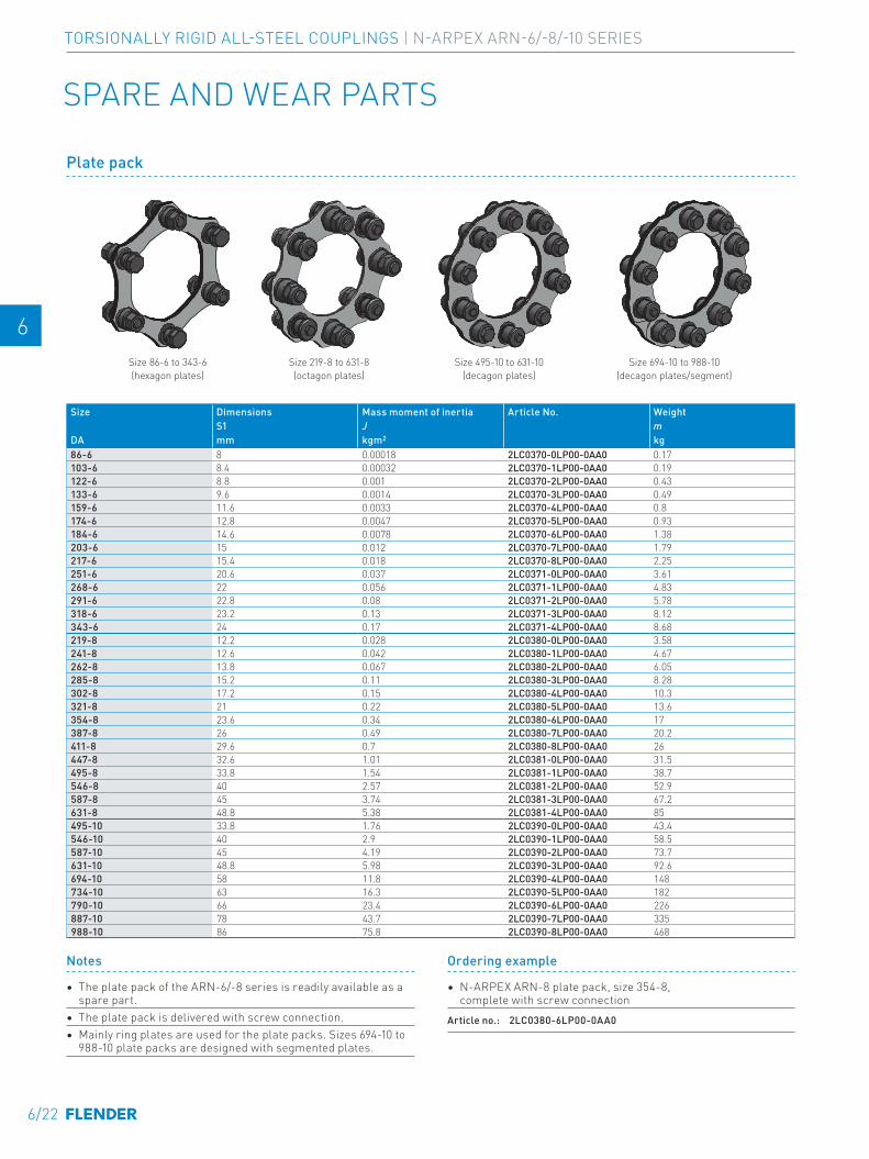
E E
4 4
5 5
6 6
7 7
8 8
9 9
10 10
11 11
12 12
13 13
A A
SPARE AND WEAR PARTS
Plate pack
Size 86-6 to 343-6 (hexagon plates)
Size 219-8 to 631-8 (octagon plates)
Size 495-10 to 631-10 (decagon plates)
Size 694-10 to 988-10 (decagon plates/segment)
Size Dimensions Mass moment of inertia Article No. WeightS1 J m
DA mm kgm2 kg86-6 8 0.00018 2LC0370-0LP00-0AA0 0.17103-6 8.4 0.00032 2LC0370-1LP00-0AA0 0.19122-6 8.8 0.001 2LC0370-2LP00-0AA0 0.43133-6 9.6 0.0014 2LC0370-3LP00-0AA0 0.49159-6 11.6 0.0033 2LC0370-4LP00-0AA0 0.8174-6 12.8 0.0047 2LC0370-5LP00-0AA0 0.93184-6 14.6 0.0078 2LC0370-6LP00-0AA0 1.38203-6 15 0.012 2LC0370-7LP00-0AA0 1.79217-6 15.4 0.018 2LC0370-8LP00-0AA0 2.25251-6 20.6 0.037 2LC0371-0LP00-0AA0 3.61268-6 22 0.056 2LC0371-1LP00-0AA0 4.83291-6 22.8 0.08 2LC0371-2LP00-0AA0 5.78318-6 23.2 0.13 2LC0371-3LP00-0AA0 8.12343-6 24 0.17 2LC0371-4LP00-0AA0 8.68219-8 12.2 0.028 2LC0380-0LP00-0AA0 3.58241-8 12.6 0.042 2LC0380-1LP00-0AA0 4.67262-8 13.8 0.067 2LC0380-2LP00-0AA0 6.05285-8 15.2 0.11 2LC0380-3LP00-0AA0 8.28302-8 17.2 0.15 2LC0380-4LP00-0AA0 10.3321-8 21 0.22 2LC0380-5LP00-0AA0 13.6354-8 23.6 0.34 2LC0380-6LP00-0AA0 17387-8 26 0.49 2LC0380-7LP00-0AA0 20.2411-8 29.6 0.7 2LC0380-8LP00-0AA0 26447-8 32.6 1.01 2LC0381-0LP00-0AA0 31.5495-8 33.8 1.54 2LC0381-1LP00-0AA0 38.7546-8 40 2.57 2LC0381-2LP00-0AA0 52.9587-8 45 3.74 2LC0381-3LP00-0AA0 67.2631-8 48.8 5.38 2LC0381-4LP00-0AA0 85495-10 33.8 1.76 2LC0390-0LP00-0AA0 43.4546-10 40 2.9 2LC0390-1LP00-0AA0 58.5587-10 45 4.19 2LC0390-2LP00-0AA0 73.7631-10 48.8 5.98 2LC0390-3LP00-0AA0 92.6694-10 58 11.8 2LC0390-4LP00-0AA0 148734-10 63 16.3 2LC0390-5LP00-0AA0 182790-10 66 23.4 2LC0390-6LP00-0AA0 226887-10 78 43.7 2LC0390-7LP00-0AA0 335988-10 86 75.8 2LC0390-8LP00-0AA0 468
Notes
• The plate pack of the ARN-6/-8 series is readily available as a spare part.
• The plate pack is delivered with screw connection.• Mainly ring plates are used for the plate packs. Sizes 694-10 to
988-10 plate packs are designed with segmented plates.
Ordering example
• N-ARPEX ARN-8 plate pack, size 354-8, complete with screw connection
Article no.: 2LC0380-6LP00-0AA0
6/22
TORSIONALLY RIGID ALL-STEEL COUPLINGS | N-ARPEX ARN-6/-8/-10 SERIES
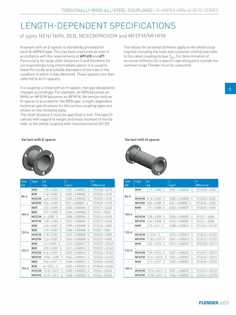
E E
4 4
5 5
6 6
7 7
8 8
9 9
10 10
11 11
12 12
13 13
A A
A variant with an E-spacer is standardly provided for each N-ARPEX type. This has been machined all over in accordance with the requirements of API 610 and 671. Particularly for large shaft distances S and therefore for correspondingly long intermediate spacer it is usual to leave the inside and outside diameters of the tube in the condition in which it was delivered. These spacers are then referred to as H-spacers.
If a coupling is fitted with an H-spacer, the type designation changes accordingly. For example, an NEN becomes an NHN, an MFEFM becomes an MFHFN. No version with an H-spacer is provided for the BEB type. Length-dependent technical specifications for the various coupling types are shown on the following table.The shaft distance S must be specified in mm. The specifi-cations with regard to weight and mass moment of inertia refer to the whole coupling with maximum bores D1/ D2.
The values for torsional stiffness apply to the whole coup-ling (not including the hubs and customer shafts) and refer to the rated coupling torque TKN. For determination of torsional stiffness for a specific operating point outside the nominal range Flender must be consulted.
Variant with E spacer
Size Type m J CDA kg kgm2 MNm/rad
86-6
NEN 1.55 + 0.003 ⋅ S 0.001 + 0.000002 ⋅ S 1/(1/0,08 + S/15)BEB 1.42 + 0.003 ⋅ S 0.001 + 0.000002 ⋅ S 1/(1/0,06 + S/15)MCECM 2.64 + 0.003 ⋅ S 0.003 + 0.000002 ⋅ S 1/(1/0,09 + S/15)MFEFM 5.54 + 0.003 ⋅ S 0.01 + 0.000002 ⋅ S 1/(1/0,09 + S/15)
103-6
NEN 2.52 + 0.005 ⋅ S 0.004 + 0.000004 ⋅ S 1/(1/0,11 + S/42)BEB 2.01 + 0.005 ⋅ S 0.003 + 0.000004 ⋅ S 1/(1/0,1 + S/42)MCECM 4 + 0.005 ⋅ S 0.006 + 0.000004 ⋅ S 1/(1/0,12 + S/42)MFEFM 7.28 + 0.005 ⋅ S 0.017 + 0.000004 ⋅ S 1/(1/0,12 + S/42)
122-6
NEN 4.39 + 0.007 ⋅ S 0.009 + 0.000008 ⋅ S 1/(1/0,26 + S/82)BEB 4.19 + 0.007 ⋅ S 0.008 + 0.000008 ⋅ S 1/(1/0,2 + S/82)MCECM 6.78 + 0.007 ⋅ S 0.015 + 0.000008 ⋅ S 1/(1/0,29 + S/82)MFEFM 12.6 + 0.007 ⋅ S 0.042 + 0.000008 ⋅ S 1/(1/0,29 + S/82)
133-6
NEN 5.5 + 0.009 ⋅ S 0.013 + 0.000014 ⋅ S 1/(1/0,33 + S/142)BEB 5.09 + 0.009 ⋅ S 0.011 + 0.000014 ⋅ S 1/(1/0,27 + S/142)MCECM 8.44 + 0.009 ⋅ S 0.023 + 0.000014 ⋅ S 1/(1/0,36 + S/142)MFEFM 15.86 + 0.009 ⋅ S 0.064 + 0.000014 ⋅ S 1/(1/0,36 + S/142)
159-6
NEN 8.54 + 0.011 ⋅ S 0.028 + 0.000023 ⋅ S 1/(1/0,54 + S/234)BEB 8 + 0.011 ⋅ S 0.026 + 0.000023 ⋅ S 1/(1/0,45 + S/234)MCECM 14.35 + 0.011 ⋅ S 0.055 + 0.000023 ⋅ S 1/(1/0,6 + S/234)MFEFM 21.37 + 0.011 ⋅ S 0.068 + 0.000023 ⋅ S 1/(1/0,6 + S/234)
Variant with H spacer
Size Type m J CDA kg kgm2 MNm/rad
86-6
NHN 1.11 + 0.005 ⋅ S 0.001 + 0.000003 ⋅ S 1/(1/0,05 + S/25)- - - -MCHCM 2.13 + 0.005 ⋅ S 0.003 + 0.000003 ⋅ S 1/(1/0,06 + S/25)MFHFM 5.03 + 0.005 ⋅ S 0.01 + 0.000003 ⋅ S 1/(1/0,06 + S/25)
103-6
NHN 1.91 + 0.008 ⋅ S 0.003 + 0.000007 ⋅ S 1/(1/0,09 + S/68)- - - -MCHCM 3.28 + 0.008 ⋅ S 0.006 + 0.000007 ⋅ S 1/(1/0,1 + S/68)MFHFM 6.56 + 0.008 ⋅ S 0.016 + 0.000007 ⋅ S 1/(1/0,1 + S/68)
122-6
NHN 3.72 + 0.01 ⋅ S 0.008 + 0.000012 ⋅ S 1/(1/0,21 + S/122)- - - -MCHCM 6 + 0.01 ⋅ S 0.014 + 0.000012 ⋅ S 1/(1/0,22 + S/122)MFHFM 11.82 + 0.01 ⋅ S 0.041 + 0.000012 ⋅ S 1/(1/0,22 + S/122)
133-6
NHN 4.52 + 0.013 ⋅ S 0.012 + 0.000022 ⋅ S 1/(1/0,28 + S/221)- - - -MCHCM 7.29 + 0.013 ⋅ S 0.021 + 0.000022 ⋅ S 1/(1/0,29 + S/221)MFHFM 14.71 + 0.013 ⋅ S 0.062 + 0.000022 ⋅ S 1/(1/0,29 + S/221)
159-6
NHN 7.17 + 0.017 ⋅ S 0.025 + 0.000037 ⋅ S 1/(1/0,45 + S/373)- - - -MCHCM 12.76 + 0.017 ⋅ S 0.051 + 0.000037 ⋅ S 1/(1/0,47 + S/373)MFHFM 19.78 + 0.017 ⋅ S 0.064 + 0.000037 ⋅ S 1/(1/0,47 + S/373)
LENGTH-DEPENDENT SPECIFICATIONS of types NEN/ NHN, BEB, MCECM/MCHCM and MFEFM/MFHFM
6/23
TORSIONALLY RIGID ALL-STEEL COUPLINGS | N-ARPEX ARN-6/-8/-10 SERIES
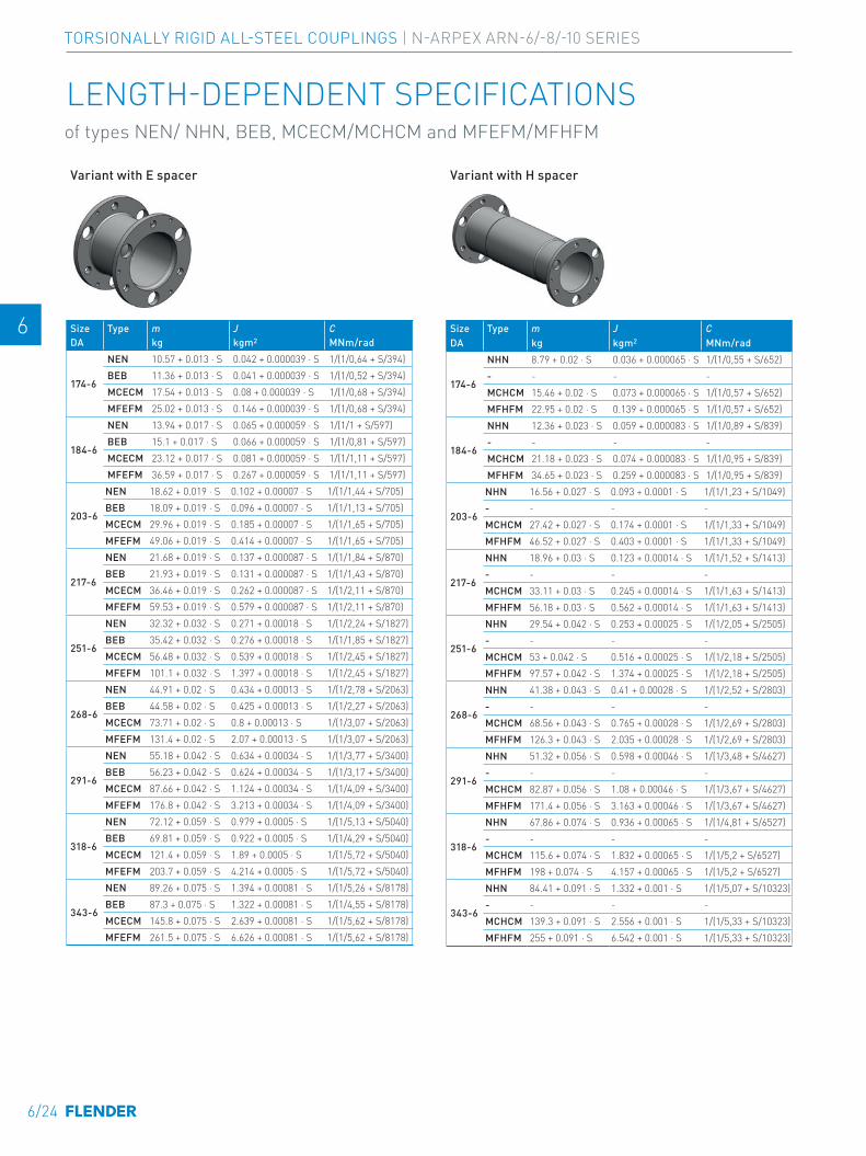
E E
4 4
5 5
6 6
7 7
8 8
9 9
10 10
11 11
12 12
13 13
A A
Variant with E spacer
Size Type m J CDA kg kgm2 MNm/rad
174-6
NEN 10.57 + 0.013 ⋅ S 0.042 + 0.000039 ⋅ S 1/(1/0,64 + S/394)BEB 11.36 + 0.013 ⋅ S 0.041 + 0.000039 ⋅ S 1/(1/0,52 + S/394)MCECM 17.54 + 0.013 ⋅ S 0.08 + 0.000039 ⋅ S 1/(1/0,68 + S/394)MFEFM 25.02 + 0.013 ⋅ S 0.146 + 0.000039 ⋅ S 1/(1/0,68 + S/394)
184-6
NEN 13.94 + 0.017 ⋅ S 0.065 + 0.000059 ⋅ S 1/(1/1 + S/597)BEB 15.1 + 0.017 ⋅ S 0.066 + 0.000059 ⋅ S 1/(1/0,81 + S/597)MCECM 23.12 + 0.017 ⋅ S 0.081 + 0.000059 ⋅ S 1/(1/1,11 + S/597)MFEFM 36.59 + 0.017 ⋅ S 0.267 + 0.000059 ⋅ S 1/(1/1,11 + S/597)
203-6
NEN 18.62 + 0.019 ⋅ S 0.102 + 0.00007 ⋅ S 1/(1/1,44 + S/705)BEB 18.09 + 0.019 ⋅ S 0.096 + 0.00007 ⋅ S 1/(1/1,13 + S/705)MCECM 29.96 + 0.019 ⋅ S 0.185 + 0.00007 ⋅ S 1/(1/1,65 + S/705)MFEFM 49.06 + 0.019 ⋅ S 0.414 + 0.00007 ⋅ S 1/(1/1,65 + S/705)
217-6
NEN 21.68 + 0.019 ⋅ S 0.137 + 0.000087 ⋅ S 1/(1/1,84 + S/870)BEB 21.93 + 0.019 ⋅ S 0.131 + 0.000087 ⋅ S 1/(1/1,43 + S/870)MCECM 36.46 + 0.019 ⋅ S 0.262 + 0.000087 ⋅ S 1/(1/2,11 + S/870)MFEFM 59.53 + 0.019 ⋅ S 0.579 + 0.000087 ⋅ S 1/(1/2,11 + S/870)
251-6
NEN 32.32 + 0.032 ⋅ S 0.271 + 0.00018 ⋅ S 1/(1/2,24 + S/1827)BEB 35.42 + 0.032 ⋅ S 0.276 + 0.00018 ⋅ S 1/(1/1,85 + S/1827)MCECM 56.48 + 0.032 ⋅ S 0.539 + 0.00018 ⋅ S 1/(1/2,45 + S/1827)MFEFM 101.1 + 0.032 ⋅ S 1.397 + 0.00018 ⋅ S 1/(1/2,45 + S/1827)
268-6
NEN 44.91 + 0.02 ⋅ S 0.434 + 0.00013 ⋅ S 1/(1/2,78 + S/2063)BEB 44.58 + 0.02 ⋅ S 0.425 + 0.00013 ⋅ S 1/(1/2,27 + S/2063)MCECM 73.71 + 0.02 ⋅ S 0.8 + 0.00013 ⋅ S 1/(1/3,07 + S/2063)MFEFM 131.4 + 0.02 ⋅ S 2.07 + 0.00013 ⋅ S 1/(1/3,07 + S/2063)
291-6
NEN 55.18 + 0.042 ⋅ S 0.634 + 0.00034 ⋅ S 1/(1/3,77 + S/3400)BEB 56.23 + 0.042 ⋅ S 0.624 + 0.00034 ⋅ S 1/(1/3,17 + S/3400)MCECM 87.66 + 0.042 ⋅ S 1.124 + 0.00034 ⋅ S 1/(1/4,09 + S/3400)MFEFM 176.8 + 0.042 ⋅ S 3.213 + 0.00034 ⋅ S 1/(1/4,09 + S/3400)
318-6
NEN 72.12 + 0.059 ⋅ S 0.979 + 0.0005 ⋅ S 1/(1/5,13 + S/5040)BEB 69.81 + 0.059 ⋅ S 0.922 + 0.0005 ⋅ S 1/(1/4,29 + S/5040)MCECM 121.4 + 0.059 ⋅ S 1.89 + 0.0005 ⋅ S 1/(1/5,72 + S/5040)MFEFM 203.7 + 0.059 ⋅ S 4.214 + 0.0005 ⋅ S 1/(1/5,72 + S/5040)
343-6
NEN 89.26 + 0.075 ⋅ S 1.394 + 0.00081 ⋅ S 1/(1/5,26 + S/8178)BEB 87.3 + 0.075 ⋅ S 1.322 + 0.00081 ⋅ S 1/(1/4,55 + S/8178)MCECM 145.8 + 0.075 ⋅ S 2.639 + 0.00081 ⋅ S 1/(1/5,62 + S/8178)MFEFM 261.5 + 0.075 ⋅ S 6.626 + 0.00081 ⋅ S 1/(1/5,62 + S/8178)
Variant with H spacer
Size Type m J CDA kg kgm2 MNm/rad
174-6
NHN 8.79 + 0.02 ⋅ S 0.036 + 0.000065 ⋅ S 1/(1/0,55 + S/652)- - - -MCHCM 15.46 + 0.02 ⋅ S 0.073 + 0.000065 ⋅ S 1/(1/0,57 + S/652)MFHFM 22.95 + 0.02 ⋅ S 0.139 + 0.000065 ⋅ S 1/(1/0,57 + S/652)
184-6
NHN 12.36 + 0.023 ⋅ S 0.059 + 0.000083 ⋅ S 1/(1/0,89 + S/839)- - - -MCHCM 21.18 + 0.023 ⋅ S 0.074 + 0.000083 ⋅ S 1/(1/0,95 + S/839)MFHFM 34.65 + 0.023 ⋅ S 0.259 + 0.000083 ⋅ S 1/(1/0,95 + S/839)
203-6
NHN 16.56 + 0.027 ⋅ S 0.093 + 0.0001 ⋅ S 1/(1/1,23 + S/1049)- - - -MCHCM 27.42 + 0.027 ⋅ S 0.174 + 0.0001 ⋅ S 1/(1/1,33 + S/1049)MFHFM 46.52 + 0.027 ⋅ S 0.403 + 0.0001 ⋅ S 1/(1/1,33 + S/1049)
217-6
NHN 18.96 + 0.03 ⋅ S 0.123 + 0.00014 ⋅ S 1/(1/1,52 + S/1413)- - - -MCHCM 33.11 + 0.03 ⋅ S 0.245 + 0.00014 ⋅ S 1/(1/1,63 + S/1413)MFHFM 56.18 + 0.03 ⋅ S 0.562 + 0.00014 ⋅ S 1/(1/1,63 + S/1413)
251-6
NHN 29.54 + 0.042 ⋅ S 0.253 + 0.00025 ⋅ S 1/(1/2,05 + S/2505)- - - -MCHCM 53 + 0.042 ⋅ S 0.516 + 0.00025 ⋅ S 1/(1/2,18 + S/2505)MFHFM 97.57 + 0.042 ⋅ S 1.374 + 0.00025 ⋅ S 1/(1/2,18 + S/2505)
268-6
NHN 41.38 + 0.043 ⋅ S 0.41 + 0.00028 ⋅ S 1/(1/2,52 + S/2803)- - - -MCHCM 68.56 + 0.043 ⋅ S 0.765 + 0.00028 ⋅ S 1/(1/2,69 + S/2803)MFHFM 126.3 + 0.043 ⋅ S 2.035 + 0.00028 ⋅ S 1/(1/2,69 + S/2803)
291-6
NHN 51.32 + 0.056 ⋅ S 0.598 + 0.00046 ⋅ S 1/(1/3,48 + S/4627)- - - -MCHCM 82.87 + 0.056 ⋅ S 1.08 + 0.00046 ⋅ S 1/(1/3,67 + S/4627)MFHFM 171.4 + 0.056 ⋅ S 3.163 + 0.00046 ⋅ S 1/(1/3,67 + S/4627)
318-6
NHN 67.86 + 0.074 ⋅ S 0.936 + 0.00065 ⋅ S 1/(1/4,81 + S/6527)- - - -MCHCM 115.6 + 0.074 ⋅ S 1.832 + 0.00065 ⋅ S 1/(1/5,2 + S/6527)MFHFM 198 + 0.074 ⋅ S 4.157 + 0.00065 ⋅ S 1/(1/5,2 + S/6527)
343-6
NHN 84.41 + 0.091 ⋅ S 1.332 + 0.001 ⋅ S 1/(1/5,07 + S/10323)- - - -MCHCM 139.3 + 0.091 ⋅ S 2.556 + 0.001 ⋅ S 1/(1/5,33 + S/10323)MFHFM 255 + 0.091 ⋅ S 6.542 + 0.001 ⋅ S 1/(1/5,33 + S/10323)
LENGTH-DEPENDENT SPECIFICATIONS of types NEN/ NHN, BEB, MCECM/MCHCM and MFEFM/MFHFM
6/24
TORSIONALLY RIGID ALL-STEEL COUPLINGS | N-ARPEX ARN-6/-8/-10 SERIES
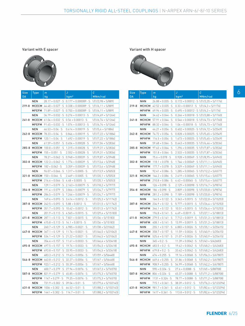
E E
4 4
5 5
6 6
7 7
8 8
9 9
10 10
11 11
12 12
13 13
A A
Variant with E spacer
Size Type m J CDA kg kgm2 MNm/rad
219-8NEN 28.17 + 0.027 ⋅ S 0.177 + 0.000089 ⋅ S 1/(1/3,98 + S/889)MCECM 44.48 + 0.027 ⋅ S 0.338 + 0.000089 ⋅ S 1/(1/6,11 + S/889)MFEFM 71.89 + 0.027 ⋅ S 0.703 + 0.000089 ⋅ S 1/(1/6,11 + S/889)
241-8NEN 36.79 + 0.032 ⋅ S 0.276 + 0.00013 ⋅ S 1/(1/4,69 + S/1264)MCECM 61.04 + 0.032 ⋅ S 0.56 + 0.00013 ⋅ S 1/(1/6,74 + S/1264)MFEFM 91.45 + 0.032 ⋅ S 1.074 + 0.00013 ⋅ S 1/(1/6,74 + S/1264)
262-8NEN 46.53 + 0.04 ⋅ S 0.414 + 0.00019 ⋅ S 1/(1/5,4 + S/1884)MCECM 78.23 + 0.04 ⋅ S 0.846 + 0.00019 ⋅ S 1/(1/7,22 + S/1884)MFEFM 120.1 + 0.04 ⋅ S 1.692 + 0.00019 ⋅ S 1/(1/7,22 + S/1884)
285-8NEN 61.59 + 0.051 ⋅ S 0.656 + 0.00028 ⋅ S 1/(1/7,04 + S/2836)MCECM 100.8 + 0.051 ⋅ S 1.315 + 0.00028 ⋅ S 1/(1/9,31 + S/2836)MFEFM 155 + 0.051 ⋅ S 2.552 + 0.00028 ⋅ S 1/(1/9,31 + S/2836)
302-8NEN 78.21 + 0.062 ⋅ S 0.948 + 0.00039 ⋅ S 1/(1/9,87 + S/3948)MCECM 122.3 + 0.062 ⋅ S 1.774 + 0.00039 ⋅ S 1/(1/13,4 + S/3948)MFEFM 182 + 0.062 ⋅ S 3.359 + 0.00039 ⋅ S 1/(1/13,4 + S/3948)
321-8NEN 96.07 + 0.066 ⋅ S 1.317 + 0.0005 ⋅ S 1/(1/13,9 + S/5053)MCECM 150 + 0.066 ⋅ S 2.469 + 0.0005 ⋅ S 1/(1/20,1 + S/5053)MFEFM 216.6 + 0.066 ⋅ S 4.48 + 0.0005 ⋅ S 1/(1/20,1 + S/5053)
354-8NEN 129.1 + 0.079 ⋅ S 2.163 + 0.00079 ⋅ S 1/(1/18,2 + S/7977)MCECM 191.4 + 0.079 ⋅ S 3.866 + 0.00079 ⋅ S 1/(1/24,7 + S/7977)MFEFM 286.5 + 0.079 ⋅ S 7.246 + 0.00079 ⋅ S 1/(1/24,7 + S/7977)
387-8NEN 169.6 + 0.093 ⋅ S 3.414 + 0.0012 ⋅ S 1/(1/25,3 + S/11742)MCECM 242.5 + 0.093 ⋅ S 5.88 + 0.0012 ⋅ S 1/(1/31,5 + S/11742)MFEFM 351.7 + 0.093 ⋅ S 10.62 + 0.0012 ⋅ S 1/(1/31,5 + S/11742)
411-8NEN 201.9 + 0.113 ⋅ S 4.565 + 0.0015 ⋅ S 1/(1/29,4 + S/15183)MCECM 287.1 + 0.113 ⋅ S 7.821 + 0.0015 ⋅ S 1/(1/36 + S/15183)MFEFM 415.8 + 0.113 ⋅ S 14.1 + 0.0015 ⋅ S 1/(1/36 + S/15183)
447-8NEN 260.7 + 0.129 ⋅ S 6.985 + 0.0021 ⋅ S 1/(1/38 + S/21062)MCECM 367.1 + 0.129 ⋅ S 11.74 + 0.0021 ⋅ S 1/(1/46,5 + S/21062)MFEFM 534.1 + 0.129 ⋅ S 21.22 + 0.0021 ⋅ S 1/(1/46,5 + S/21062)
495-8NEN 354.4 + 0.157 ⋅ S 11.61 + 0.0033 ⋅ S 1/(1/46,4 + S/33418)MCECM 497.5 + 0.157 ⋅ S 19.74 + 0.0033 ⋅ S 1/(1/54,5 + S/33418)MFEFM 693.8 + 0.157 ⋅ S 33.95 + 0.0033 ⋅ S 1/(1/54,5 + S/33418)
546-8NEN 483.3 + 0.212 ⋅ S 19.43 + 0.0056 ⋅ S 1/(1/59 + S/56448)MCECM 663.8 + 0.212 ⋅ S 32.27 + 0.0056 ⋅ S 1/(1/67 + S/56448)MFEFM 923.1 + 0.212 ⋅ S 55.39 + 0.0056 ⋅ S 1/(1/67 + S/56448)
587-8NEN 600.7 + 0.279 ⋅ S 27.94 + 0.0076 ⋅ S 1/(1/67,3 + S/76570)MCECM 821.9 + 0.279 ⋅ S 45.85 + 0.0076 ⋅ S 1/(1/75,3 + S/76570)MFEFM 1147 + 0.279 ⋅ S 79.25 + 0.0076 ⋅ S 1/(1/75,3 + S/76570)
631-8NEN 731.9 + 0.302 ⋅ S 39.04 + 0.01 ⋅ S 1/(1/79,6 + S/102143)MCECM 1006 + 0.302 ⋅ S 64.52 + 0.01 ⋅ S 1/(1/88,2 + S/102143)MFEFM 1441 + 0.302 ⋅ S 114.7 + 0.01 ⋅ S 1/(1/88,2 + S/102143)
Variant with H spacer
Size Type m J CDA kg kgm2 MNm/rad
219-8NHN 26.88 + 0.035 ⋅ S 0.172 + 0.00012 ⋅ S 1/(1/3,35 + S/1176)MCHCM 42.52 + 0.035 ⋅ S 0.33 + 0.00012 ⋅ S 1/(1/4,3 + S/1176)MFHFM 69.94 + 0.035 ⋅ S 0.695 + 0.00012 ⋅ S 1/(1/4,3 + S/1176)
241-8NHN 34.62 + 0.044 ⋅ S 0.266 + 0.00018 ⋅ S 1/(1/3,88 + S/1760)MCHCM 57.91 + 0.044 ⋅ S 0.546 + 0.00018 ⋅ S 1/(1/4,73 + S/1760)MFHFM 88.32 + 0.044 ⋅ S 1.06 + 0.00018 ⋅ S 1/(1/4,73 + S/1760)
262-8NHN 44.21 + 0.054 ⋅ S 0.402 + 0.00025 ⋅ S 1/(1/4,72 + S/2549)MCHCM 74.72 + 0.054 ⋅ S 0.828 + 0.00025 ⋅ S 1/(1/5,65 + S/2549)MFHFM 116.5 + 0.054 ⋅ S 1.673 + 0.00025 ⋅ S 1/(1/5,65 + S/2549)
285-8NHN 59.68 + 0.064 ⋅ S 0.643 + 0.00035 ⋅ S 1/(1/6,46 + S/3534)MCHCM 97.63 + 0.064 ⋅ S 1.296 + 0.00035 ⋅ S 1/(1/7,87 + S/3534)MFHFM 151.8 + 0.064 ⋅ S 2.533 + 0.00035 ⋅ S 1/(1/7,87 + S/3534)
302-8NHN 75.6 + 0.078 ⋅ S 0.928 + 0.00049 ⋅ S 1/(1/8,95 + S/4945)MCHCM 118.1 + 0.078 ⋅ S 1.744 + 0.00049 ⋅ S 1/(1/11,1 + S/4945)MFHFM 177.7 + 0.078 ⋅ S 3.329 + 0.00049 ⋅ S 1/(1/11,1 + S/4945)
321-8NHN 92.41 + 0.086 ⋅ S 1.285 + 0.00065 ⋅ S 1/(1/12,2 + S/6577)MCHCM 144.2 + 0.086 ⋅ S 2.419 + 0.00065 ⋅ S 1/(1/15,4 + S/6577)MFHFM 210.8 + 0.086 ⋅ S 4.43 + 0.00065 ⋅ S 1/(1/15,4 + S/6577)
354-8NHN 126 + 0.098 ⋅ S 2.129 + 0.00098 ⋅ S 1/(1/16,7 + S/9874)MCHCM 186 + 0.098 ⋅ S 3.809 + 0.00098 ⋅ S 1/(1/20,8 + S/9874)MFHFM 281.2 + 0.098 ⋅ S 7.189 + 0.00098 ⋅ S 1/(1/20,8 + S/9874)
387-8NHN 164.5 + 0.122 ⋅ S 3.343 + 0.0015 ⋅ S 1/(1/22,8 + S/15253)MCHCM 234.9 + 0.122 ⋅ S 5.777 + 0.0015 ⋅ S 1/(1/26,4 + S/15253)MFHFM 344.1 + 0.122 ⋅ S 10.51 + 0.0015 ⋅ S 1/(1/26,4 + S/15253)
411-8NHN 196.8 + 0.141 ⋅ S 4.49 + 0.0019 ⋅ S 1/(1/27,1 + S/18813)MCHCM 279.5 + 0.141 ⋅ S 7.712 + 0.0019 ⋅ S 1/(1/31,3 + S/18813)MFHFM 408.1 + 0.141 ⋅ S 13.99 + 0.0019 ⋅ S 1/(1/31,3 + S/18813)
447-8NHN 255.1 + 0.157 ⋅ S 6.883 + 0.0026 ⋅ S 1/(1/35,1 + S/25615)MCHCM 358.7 + 0.157 ⋅ S 11.59 + 0.0026 ⋅ S 1/(1/40,9 + S/25615)MFHFM 525.6 + 0.157 ⋅ S 21.07 + 0.0026 ⋅ S 1/(1/40,9 + S/25615)
495-8NHN 345 + 0.2 ⋅ S 11.39 + 0.0042 ⋅ S 1/(1/43 + S/42683)MCHCM 483.5 + 0.2 ⋅ S 19.42 + 0.0042 ⋅ S 1/(1/48,2 + S/42683)MFHFM 679.8 + 0.2 ⋅ S 33.62 + 0.0042 ⋅ S 1/(1/48,2 + S/42683)
546-8NHN 474 + 0.255 ⋅ S 19.16 + 0.0068 ⋅ S 1/(1/56,3 + S/67807)MCHCM 649.6 + 0.255 ⋅ S 31.86 + 0.0068 ⋅ S 1/(1/62,2 + S/67807)MFHFM 908.9 + 0.255 ⋅ S 54.99 + 0.0068 ⋅ S 1/(1/62,2 + S/67807)
587-8NHN 590 + 0.324 ⋅ S 27.6 + 0.0088 ⋅ S 1/(1/65 + S/88708)MCHCM 806 + 0.324 ⋅ S 45.37 + 0.0088 ⋅ S 1/(1/71,2 + S/88708)MFHFM 1131 + 0.324 ⋅ S 78.77 + 0.0088 ⋅ S 1/(1/71,2 + S/88708)
631-8NHN 715.1 + 0.361 ⋅ S 38.39 + 0.012 ⋅ S 1/(1/76,3 + S/123294)MCHCM 981.7 + 0.361 ⋅ S 63.61 + 0.012 ⋅ S 1/(1/82,6 + S/123294)MFHFM 1417 + 0.361 ⋅ S 113.8 + 0.012 ⋅ S 1/(1/82,6 + S/123294)
6/25
TORSIONALLY RIGID ALL-STEEL COUPLINGS | N-ARPEX ARN-6/-8/-10 SERIES
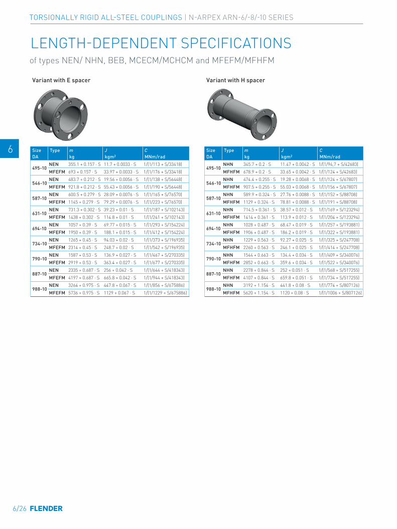
E E
4 4
5 5
6 6
7 7
8 8
9 9
10 10
11 11
12 12
13 13
A A
Variant with E spacer
Size Type m J CDA kg kgm2 MNm/rad
495-10NEN 355.1 + 0.157 ⋅ S 11.7 + 0.0033 ⋅ S 1/(1/113 + S/33418)MFEFM 693 + 0.157 ⋅ S 33.97 + 0.0033 ⋅ S 1/(1/176 + S/33418)
546-10NEN 483.7 + 0.212 ⋅ S 19.56 + 0.0056 ⋅ S 1/(1/138 + S/56448)MFEFM 921.8 + 0.212 ⋅ S 55.43 + 0.0056 ⋅ S 1/(1/190 + S/56448)
587-10NEN 600.5 + 0.279 ⋅ S 28.09 + 0.0076 ⋅ S 1/(1/165 + S/76570)MFEFM 1145 + 0.279 ⋅ S 79.29 + 0.0076 ⋅ S 1/(1/223 + S/76570)
631-10NEN 731.3 + 0.302 ⋅ S 39.23 + 0.01 ⋅ S 1/(1/187 + S/102143)MFEFM 1438 + 0.302 ⋅ S 114.8 + 0.01 ⋅ S 1/(1/241 + S/102143)
694-10NEN 1057 + 0.39 ⋅ S 69.77 + 0.015 ⋅ S 1/(1/293 + S/154224)MFEFM 1950 + 0.39 ⋅ S 188.1 + 0.015 ⋅ S 1/(1/412 + S/154224)
734-10NEN 1265 + 0.45 ⋅ S 94.03 + 0.02 ⋅ S 1/(1/373 + S/196935)MFEFM 2314 + 0.45 ⋅ S 248.7 + 0.02 ⋅ S 1/(1/542 + S/196935)
790-10NEN 1587 + 0.53 ⋅ S 136.9 + 0.027 ⋅ S 1/(1/467 + S/270335)MFEFM 2919 + 0.53 ⋅ S 363.4 + 0.027 ⋅ S 1/(1/677 + S/270335)
887-10NEN 2335 + 0.687 ⋅ S 256 + 0.042 ⋅ S 1/(1/644 + S/418343)MFEFM 4197 + 0.687 ⋅ S 665.8 + 0.042 ⋅ S 1/(1/944 + S/418343)
988-10NEN 3264 + 0.975 ⋅ S 447.8 + 0.067 ⋅ S 1/(1/856 + S/675886)MFEFM 5736 + 0.975 ⋅ S 1129 + 0.067 ⋅ S 1/(1/1229 + S/675886)
Variant with H spacer
Size Type m J CDA kg kgm2 MNm/rad
495-10NHN 345.7 + 0.2 ⋅ S 11.47 + 0.0042 ⋅ S 1/(1/94,7 + S/42683)MFHFM 678.9 + 0.2 ⋅ S 33.65 + 0.0042 ⋅ S 1/(1/124 + S/42683)
546-10NHN 474.4 + 0.255 ⋅ S 19.28 + 0.0068 ⋅ S 1/(1/124 + S/67807)MFHFM 907.5 + 0.255 ⋅ S 55.03 + 0.0068 ⋅ S 1/(1/156 + S/67807)
587-10NHN 589.9 + 0.324 ⋅ S 27.76 + 0.0088 ⋅ S 1/(1/152 + S/88708)MFHFM 1129 + 0.324 ⋅ S 78.81 + 0.0088 ⋅ S 1/(1/191 + S/88708)
631-10NHN 714.5 + 0.361 ⋅ S 38.57 + 0.012 ⋅ S 1/(1/169 + S/123294)MFHFM 1414 + 0.361 ⋅ S 113.9 + 0.012 ⋅ S 1/(1/204 + S/123294)
694-10NHN 1028 + 0.487 ⋅ S 68.47 + 0.019 ⋅ S 1/(1/257 + S/193881)MFHFM 1906 + 0.487 ⋅ S 186.2 + 0.019 ⋅ S 1/(1/322 + S/193881)
734-10NHN 1229 + 0.563 ⋅ S 92.27 + 0.025 ⋅ S 1/(1/325 + S/247708)MFHFM 2260 + 0.563 ⋅ S 246.1 + 0.025 ⋅ S 1/(1/414 + S/247708)
790-10NHN 1544 + 0.663 ⋅ S 134.4 + 0.034 ⋅ S 1/(1/409 + S/340076)MFHFM 2852 + 0.663 ⋅ S 359.6 + 0.034 ⋅ S 1/(1/522 + S/340076)
887-10NHN 2278 + 0.844 ⋅ S 252 + 0.051 ⋅ S 1/(1/568 + S/517255)MFHFM 4107 + 0.844 ⋅ S 659.8 + 0.051 ⋅ S 1/(1/734 + S/517255)
988-10NHN 3192 + 1.154 ⋅ S 441.8 + 0.08 ⋅ S 1/(1/774 + S/807126)MFHFM 5620 + 1.154 ⋅ S 1120 + 0.08 ⋅ S 1/(1/1006 + S/807126)
LENGTH-DEPENDENT SPECIFICATIONS of types NEN/ NHN, BEB, MCECM/MCHCM and MFEFM/MFHFM
6/26
TORSIONALLY RIGID ALL-STEEL COUPLINGS | N-ARPEX ARN-6/-8/-10 SERIES
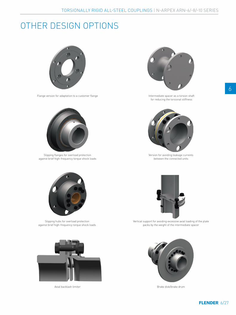
E E
4 4
5 5
6 6
7 7
8 8
9 9
10 10
11 11
12 12
13 13
A A
OTHER DESIGN OPTIONS
Flange version for adaptation to a customer flange
Slipping flanges for overload protection against brief high-frequency torque shock loads
Slipping hubs for overload protection against brief high-frequency torque shock loads
Axial backlash limiter
Intermediate spacer as a torsion shaft for reducing the torsional stiffness
Version for avoiding leakage currents between the connected units
Vertical support for avoiding excessive axial loading of the plate packs by the weight of the intermediate spacer
Brake disk/brake drum
6/27
TORSIONALLY RIGID ALL-STEEL COUPLINGS | N-ARPEX ARN-6/-8/-10 SERIES
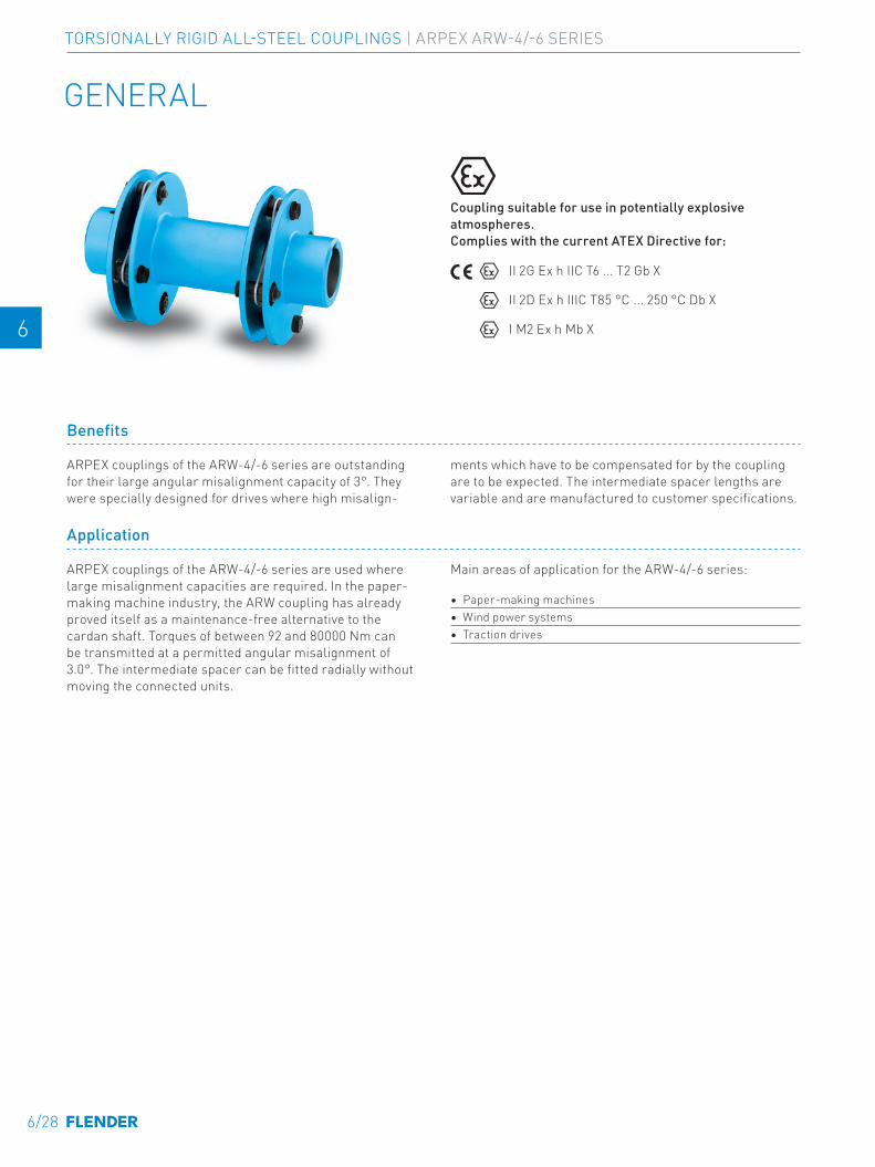
E E
4 4
5 5
6 6
7 7
8 8
9 9
10 10
11 11
12 12
13 13
A A
GENERAL
Coupling suitable for use in potentially explosive atmospheres. Complies with the current ATEX Directive for:
II 2G Ex h IIC T6 ... T2 Gb X
II 2D Ex h IIIC T85 °C ... 250 °C Db X
I M2 Ex h Mb X
Benefits
ARPEX couplings of the ARW-4/-6 series are outstanding for their large angular misalignment capacity of 3°. They were specially designed for drives where high misalign-
ments which have to be compensated for by the coupling are to be expected. The intermediate spacer lengths are variable and are manufactured to customer specifications.
Application
ARPEX couplings of the ARW-4/-6 series are used where large misalignment capacities are required. In the paper-making machine industry, the ARW coupling has already proved itself as a maintenance-free alternative to the cardan shaft. Torques of between 92 and 80000 Nm can be transmitted at a permitted angular misalignment of 3.0°. The intermediate spacer can be fitted radially without moving the connected units.
Main areas of application for the ARW-4/-6 series:
• Paper-making machines• Wind power systems• Traction drives
SERIES ARPEX ARW-4/-6
6/28
TORSIONALLY RIGID ALL-STEEL COUPLINGS | ARPEX ARW-4/-6 SERIES
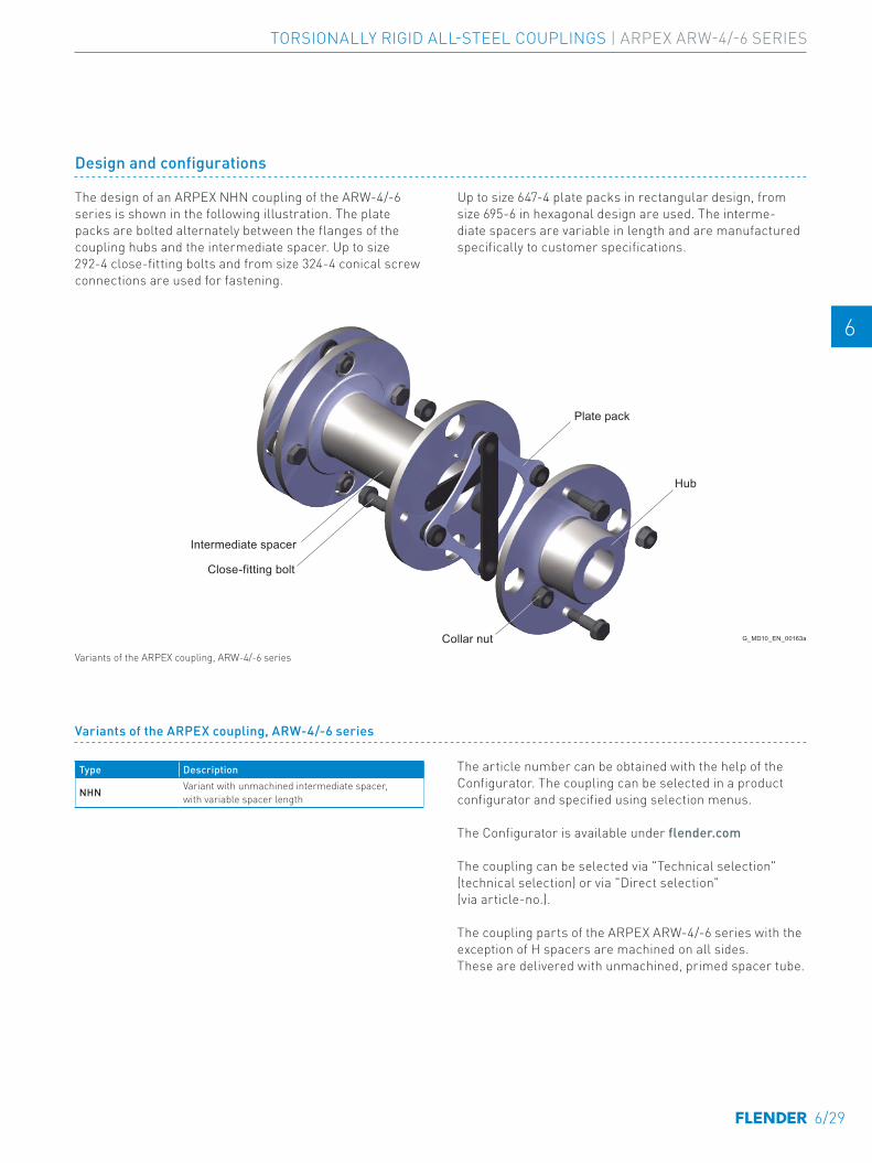
E E
4 4
5 5
6 6
7 7
8 8
9 9
10 10
11 11
12 12
13 13
A A
Design and configurations
The design of an ARPEX NHN coupling of the ARW-4/-6 series is shown in the following illustration. The plate packs are bolted alternately between the flanges of the coupling hubs and the intermediate spacer. Up to size 292-4 close-fitting bolts and from size 324-4 conical screw connections are used for fastening.
Up to size 647-4 plate packs in rectangular design, from size 695-6 in hexagonal design are used. The interme-diate spacers are variable in length and are manufactured specifically to customer specifications.
Hub
Intermediate spacer
Close-fitting bolt
Plate pack
G_MD10_EN_00163aCollar nut
Variants of the ARPEX coupling, ARW-4/-6 series
Type Description
NHN Variant with unmachined intermediate spacer, with variable spacer length
The article number can be obtained with the help of the Configurator. The coupling can be selected in a product configurator and specified using selection menus.
The Configurator is available under flender.com
The coupling can be selected via "Technical selection" (technical selection) or via "Direct selection" (via article-no.).
The coupling parts of the ARPEX ARW-4/-6 series with the exception of H spacers are machined on all sides. These are delivered with unmachined, primed spacer tube.
Variants of the ARPEX coupling, ARW-4/-6 series
6/29
TORSIONALLY RIGID ALL-STEEL COUPLINGS | ARPEX ARW-4/-6 SERIES
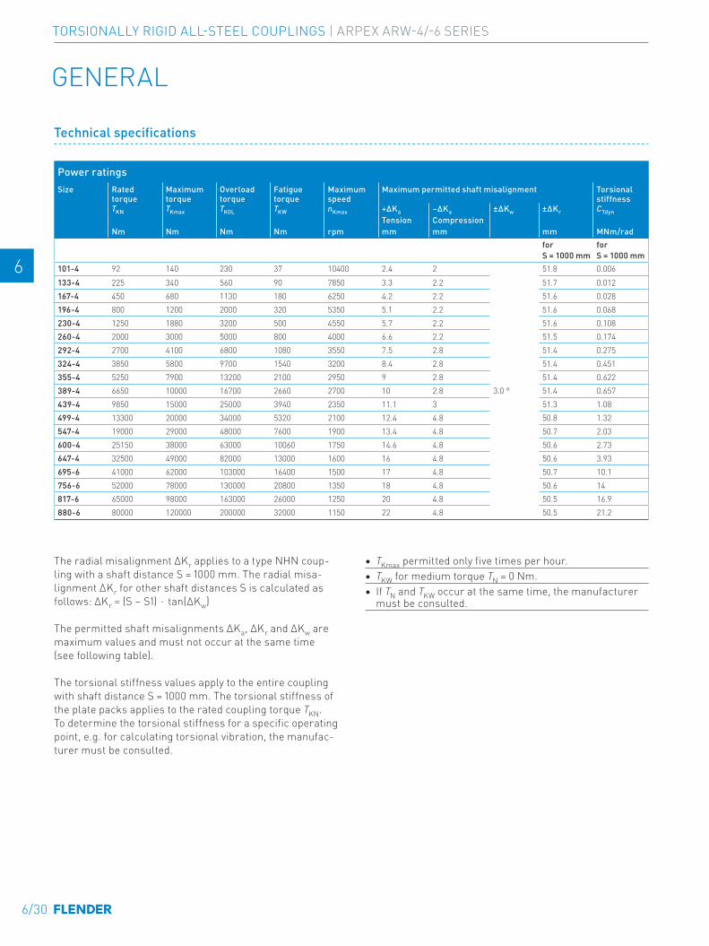
E E
4 4
5 5
6 6
7 7
8 8
9 9
10 10
11 11
12 12
13 13
A A
Technical specifications
Power ratingsSize Rated
torque Maximum torque
Overload torque
Fatigue torque
Maximum speed
Maximum permitted shaft misalignment Torsional stiffness
TKN TKmax TKOL TKW nKmax +∆Ka –∆Ka ±∆Kw ±∆Kr CTdynTension Compression
Nm Nm Nm Nm rpm mm mm mm MNm/radfor S = 1000 mm
for S = 1000 mm
101-4 92 140 230 37 10400 2.4 2
3.0 °
51.8 0.006133-4 225 340 560 90 7850 3.3 2.2 51.7 0.012167-4 450 680 1130 180 6250 4.2 2.2 51.6 0.028196-4 800 1200 2000 320 5350 5.1 2.2 51.6 0.068230-4 1250 1880 3200 500 4550 5.7 2.2 51.6 0.108260-4 2000 3000 5000 800 4000 6.6 2.2 51.5 0.174292-4 2700 4100 6800 1080 3550 7.5 2.8 51.4 0.275324-4 3850 5800 9700 1540 3200 8.4 2.8 51.4 0.451355-4 5250 7900 13200 2100 2950 9 2.8 51.4 0.622389-4 6650 10000 16700 2660 2700 10 2.8 51.4 0.657439-4 9850 15000 25000 3940 2350 11.1 3 51.3 1.08499-4 13300 20000 34000 5320 2100 12.4 4.8 50.8 1.32547-4 19000 29000 48000 7600 1900 13.4 4.8 50.7 2.03600-4 25150 38000 63000 10060 1750 14.6 4.8 50.6 2.73647-4 32500 49000 82000 13000 1600 16 4.8 50.6 3.93695-6 41000 62000 103000 16400 1500 17 4.8 50.7 10.1756-6 52000 78000 130000 20800 1350 18 4.8 50.6 14817-6 65000 98000 163000 26000 1250 20 4.8 50.5 16.9880-6 80000 120000 200000 32000 1150 22 4.8 50.5 21.2
The radial misalignment ΔKr applies to a type NHN coup-ling with a shaft distance S = 1000 mm. The radial misa-lignment ΔKr for other shaft distances S is calculated as follows: ∆Kr = (S – S1) ⋅ tan(∆Kw)
The permitted shaft misalignments ΔKa, ΔKr and ΔKw are maximum values and must not occur at the same time (see following table).
The torsional stiffness values apply to the entire coupling with shaft distance S = 1000 mm. The torsional stiffness of the plate packs applies to the rated coupling torque TKN. To determine the torsional stiffness for a specific operating point, e.g. for calculating torsional vibration, the manufac-turer must be consulted.
• TKmax permitted only five times per hour.• TKW for medium torque TN = 0 Nm. • If TN and TKW occur at the same time, the manufacturer
must be consulted.
GENERAL
6/30
TORSIONALLY RIGID ALL-STEEL COUPLINGS | ARPEX ARW-4/-6 SERIES
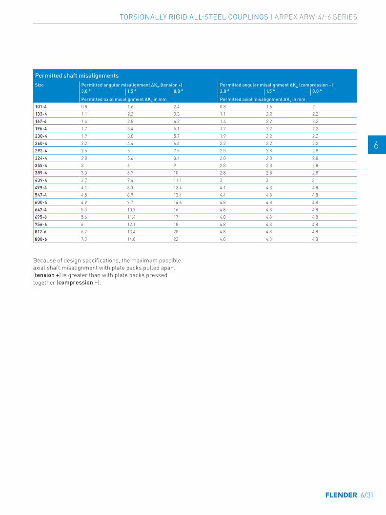
E E
4 4
5 5
6 6
7 7
8 8
9 9
10 10
11 11
12 12
13 13
A A
Permitted shaft misalignmentsSize Permitted angular misalignment ΔKw (tension +) Permitted angular misalignment ΔKw (compression –)
3.0 ° 1.5 ° 0.0 ° 3.0 ° 1.5 ° 0.0 °
Permitted axial misalignment ΔKa in mm Permitted axial misalignment ΔKa in mm101-4 0.8 1.6 2.4 0.8 1.6 2133-4 1.1 2.2 3.3 1.1 2.2 2.2167-4 1.4 2.8 4.2 1.4 2.2 2.2196-4 1.7 3.4 5.1 1.7 2.2 2.2230-4 1.9 3.8 5.7 1.9 2.2 2.2260-4 2.2 4.4 6.6 2.2 2.2 2.2292-4 2.5 5 7.5 2.5 2.8 2.8324-4 2.8 5.6 8.4 2.8 2.8 2.8355-4 3 6 9 2.8 2.8 2.8389-4 3.3 6.7 10 2.8 2.8 2.8439-4 3.7 7.4 11.1 3 3 3499-4 4.1 8.3 12.4 4.1 4.8 4.8547-4 4.5 8.9 13.4 4.4 4.8 4.8600-4 4.9 9.7 14.6 4.8 4.8 4.8647-4 5.3 10.7 16 4.8 4.8 4.8695-6 5.6 11.4 17 4.8 4.8 4.8756-6 6 12.1 18 4.8 4.8 4.8817-6 6.7 13.4 20 4.8 4.8 4.8880-6 7.3 14.8 22 4.8 4.8 4.8
Because of design specifications, the maximum possible axial shaft misalignment with plate packs pulled apart (tension +) is greater than with plate packs pressed together (compression –).
6/31
TORSIONALLY RIGID ALL-STEEL COUPLINGS | ARPEX ARW-4/-6 SERIES

E E
4 4
5 5
6 6
7 7
8 8
9 9
10 10
11 11
12 12
13 13
A A
TYPE NHN
Size Rated torque
Maximum speed
Dimensions in mm Mass moment of inertia
↗ Article no. 1) Weight
DA TKN nKmax D1, D2 Keyway DIN 6885
ND1/ND2
DZ SZ NL1/NL2
S1 LZ Shaft dis-tance S
J m
mm Nm rpm max. kgm2 kg101-4 92 10400 32 45 45 2.9 32 11 43 65 0.002 2LC0530-0AD 1.5 -0AZ0133-4 225 7850 45 60 48 2.9 45 13 59 85 0.008 2LC0530-1AD 3.9 -0AZ0167-4 450 6250 50 70 64 4 50 15 70 100 0.022 2LC0530-2AD 7.1 -0AZ0196-4 800 5350 60 80 89 4 60 16 83 115 0.056 2LC0530-3AD 12.1 -0AZ0230-4 1250 4550 75 100 102 5 75 16 83 115 0.109 2LC0530-4AD 17.9 -0AZ0260-4 2000 4000 90 120 133 5 90 17 96 130 0.189 2LC0530-5AD 24.6 -0AZ0292-4 2700 3550 100 130 152 5 100 19 92 130 0.359 2LC0530-6AD 35.1 -0AZ0324-4 3850 3200 110 145 168 6.3 110 20 120 160 0.52 2LC0530-7AD 43.7 -0AZ0355-4 5250 2950 120 160 178 7.1 120 20 125 165 0.856 2LC0530-8AD 59.8 -0AZ0389-4 6650 2700 130 175 194 7.1 130 20 130 170 1.09 2LC0531-0AD 68.9 -0AZ0439-4 9850 2350 150 200 219 7.1 150 22 166 210 2.23 2LC0531-1AD 106 -0AZ0499-4 13300 2100 165 220 245 7.1 165 30 170 230 3.81 2LC0531-2AD 142 -0AZ0547-4 19000 1900 190 250 299 8.8 190 32 176 240 6.24 2LC0531-3AD 191 -0AZ0600-4 25150 1750 205 275 324 8.8 205 34 182 250 10.2 2LC0531-4AD 257 -0AZ0647-4 32500 1600 225 300 343 10 225 35 220 290 16.5 2LC0531-5AD 348 -0AZ0695-6 41000 1500 240 325 368 10 240 33 224 290 23.7 2LC0540-0AD 441 -0AZ0756-6 52000 1350 255 340 394 12.5 255 34 232 300 33.2 2LC0540-1AD 525 -0AZ0817-6 65000 1250 270 360 406 12.5 270 36 238 310 49.1 2LC0540-2AD 659 -0AZ0880-6 80000 1150 300 400 419 12.5 300 37 256 330 72.8 2LC0540-3AD 849 -0AZ0
G_MD10_XX_00164a
NL2LZSNL1
S1
ØN
D2
ØD
2
ØD
A
ØN
D1
ØD
1
SZØ
DZ
NHN
Torsionally rigid type NHN coupling with high angular misalignment capacity up to 3° and radially freely dismountable intermediate spacer and variable shaft distance S.
Configurable variants 1)
• ØD1 Without finished bore With finished bore
• ØD2 Without finished bore With finished bore
1) To identify complete item numbers specifying the available finish boring options and – if necessary – further order options, please use our configurators on flender.com.↗ For online configuration on flender.com, click on the item no.
6/32
TORSIONALLY RIGID ALL-STEEL COUPLINGS | ARPEX ARW-4/-6 SERIES
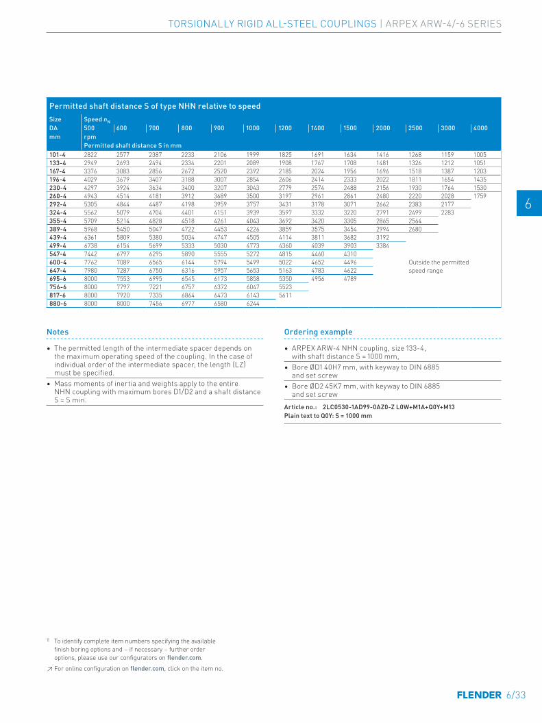
E E
4 4
5 5
6 6
7 7
8 8
9 9
10 10
11 11
12 12
13 13
A A
1) To identify complete item numbers specifying the available finish boring options and – if necessary – further order options, please use our configurators on flender.com.↗ For online configuration on flender.com, click on the item no.
Ordering example
• ARPEX ARW-4 NHN coupling, size 133-4, with shaft distance S = 1000 mm,
• Bore ØD1 40H7 mm, with keyway to DIN 6885 and set screw
• Bore ØD2 45K7 mm, with keyway to DIN 6885 and set screw
Article no.: 2LC0530-1AD99-0AZ0-Z L0W+M1A+Q0Y+M13Plain text to Q0Y: S = 1000 mm
Permitted shaft distance S of type NHN relative to speedSize Speed nNDA 500 600 700 800 900 1000 1200 1400 1500 2000 2500 3000 4000mm rpm
Permitted shaft distance S in mm101-4 2822 2577 2387 2233 2106 1999 1825 1691 1634 1416 1268 1159 1005133-4 2949 2693 2494 2334 2201 2089 1908 1767 1708 1481 1326 1212 1051167-4 3376 3083 2856 2672 2520 2392 2185 2024 1956 1696 1518 1387 1203196-4 4029 3679 3407 3188 3007 2854 2606 2414 2333 2022 1811 1654 1435230-4 4297 3924 3634 3400 3207 3043 2779 2574 2488 2156 1930 1764 1530260-4 4943 4514 4181 3912 3689 3500 3197 2961 2861 2480 2220 2028 1759292-4 5305 4844 4487 4198 3959 3757 3431 3178 3071 2662 2383 2177324-4 5562 5079 4704 4401 4151 3939 3597 3332 3220 2791 2499 2283355-4 5709 5214 4828 4518 4261 4043 3692 3420 3305 2865 2564389-4 5968 5450 5047 4722 4453 4226 3859 3575 3454 2994 2680439-4 6361 5809 5380 5034 4747 4505 4114 3811 3682 3192499-4 6738 6154 5699 5333 5030 4773 4360 4039 3903 3384547-4 7442 6797 6295 5890 5555 5272 4815 4460 4310600-4 7762 7089 6565 6144 5794 5499 5022 4652 4496 Outside the permitted
speed range647-4 7980 7287 6750 6316 5957 5653 5163 4783 4622695-6 8000 7553 6995 6545 6173 5858 5350 4956 4789756-6 8000 7797 7221 6757 6372 6047 5523817-6 8000 7920 7335 6864 6473 6143 5611880-6 8000 8000 7456 6977 6580 6244
Notes
• The permitted length of the intermediate spacer depends on the maximum operating speed of the coupling. In the case of individual order of the intermediate spacer, the length (LZ) must be specified.
• Mass moments of inertia and weights apply to the entire NHN coupling with maximum bores D1/D2 and a shaft distance S = S min.
6/33
TORSIONALLY RIGID ALL-STEEL COUPLINGS | ARPEX ARW-4/-6 SERIES
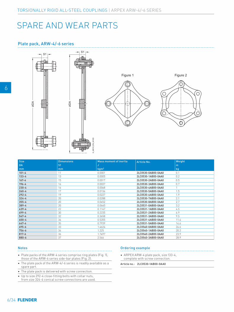
E E
4 4
5 5
6 6
7 7
8 8
9 9
10 10
11 11
12 12
13 13
A A
SPARE AND WEAR PARTS
Size Dimensions Mass moment of inertia Article No. WeightDA S1 J mmm mm kgm2 kg101-4 11 0.0001 2LC0530-0AB00-0AA0 0.1133-4 13 0.0005 2LC0530-1AB00-0AA0 0.2167-4 15 0.0017 2LC0530-2AB00-0AA0 0.5196-4 16 0.0037 2LC0530-3AB00-0AA0 0.7230-4 16 0.0068 2LC0530-4AB00-0AA0 1260-4 17 0.0136 2LC0530-5AB00-0AA0 1.5292-4 19 0.0227 2LC0530-6AB00-0AA0 1.9324-4 20 0.0288 2LC0530-7AB00-0AA0 2.1355-4 20 0.0452 2LC0530-8AB00-0AA0 2.7389-4 20 0.0645 2LC0531-0AB00-0AA0 3.2439-4 22 0.1147 2LC0531-1AB00-0AA0 4.5499-4 30 0.2235 2LC0531-2AB00-0AA0 6.9547-4 32 0.3658 2LC0531-3AB00-0AA0 9.5600-4 34 0.5355 2LC0531-4AB00-0AA0 11.4647-4 35 0.7939 2LC0531-5AB00-0AA0 14.6695-6 33 1.4624 2LC0540-0AB00-0AA0 24.6756-6 34 1.225 2LC0540-1AB00-0AA0 20.2817-6 36 1.7497 2LC0540-2AB00-0AA0 23.9880-6 37 2.546 2LC0540-3AB00-0AA0 28.9
Notes
• Plate packs of the ARW-4 series comprise ring plates (Fig. 1), those of the ARW-6 series side-bar plates (Fig. 2).
• The plate pack of the ARW-4/-6 series is readily available as a spare part.
• The plate pack is delivered with screw connection.• Up to size 292-4 close-fitting bolts with collar nuts,
from size 324-4 conical screw connections are used.
Ordering example
• ARPEX ARW-4 plate pack, size 133-4, complete with screw connection.
Article no.: 2LC0530-1AB00-0AA0
S1S1
ØD
A
ØD
A
G_M
D10
_EN
_001
65
Figure 1 Figure 2
Plate pack, ARW-4/-6 series
6/34
TORSIONALLY RIGID ALL-STEEL COUPLINGS | ARPEX ARW-4/-6 SERIES
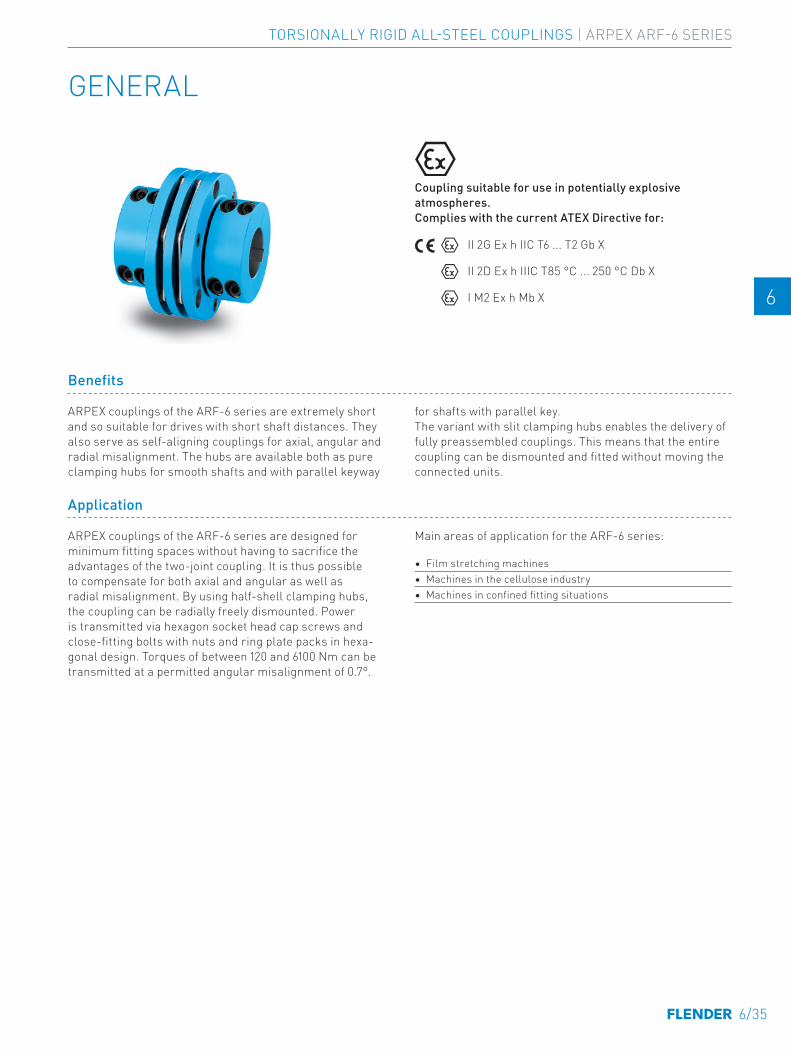
E E
4 4
5 5
6 6
7 7
8 8
9 9
10 10
11 11
12 12
13 13
A A
GENERAL
Benefits
ARPEX couplings of the ARF-6 series are extremely short and so suitable for drives with short shaft distances. They also serve as self-aligning couplings for axial, angular and radial misalignment. The hubs are available both as pure clamping hubs for smooth shafts and with parallel keyway
for shafts with parallel key. The variant with slit clamping hubs enables the delivery of fully preassembled couplings. This means that the entire coupling can be dismounted and fitted without moving the connected units.
Application
ARPEX couplings of the ARF-6 series are designed for minimum fitting spaces without having to sacrifice the advantages of the two-joint coupling. It is thus possible to compensate for both axial and angular as well as radial misalignment. By using half-shell clamping hubs, the coupling can be radially freely dismounted. Power is transmitted via hexagon socket head cap screws and close-fitting bolts with nuts and ring plate packs in hexa-gonal design. Torques of between 120 and 6100 Nm can be transmitted at a permitted angular misalignment of 0.7°.
Main areas of application for the ARF-6 series:
• Film stretching machines• Machines in the cellulose industry• Machines in confined fitting situations
Coupling suitable for use in potentially explosive atmospheres. Complies with the current ATEX Directive for:
II 2G Ex h IIC T6 ... T2 Gb X
II 2D Ex h IIIC T85 °C ... 250 °C Db X
I M2 Ex h Mb X
SERIES ARPEX ARF-6
6/35
TORSIONALLY RIGID ALL-STEEL COUPLINGS | ARPEX ARF-6 SERIES
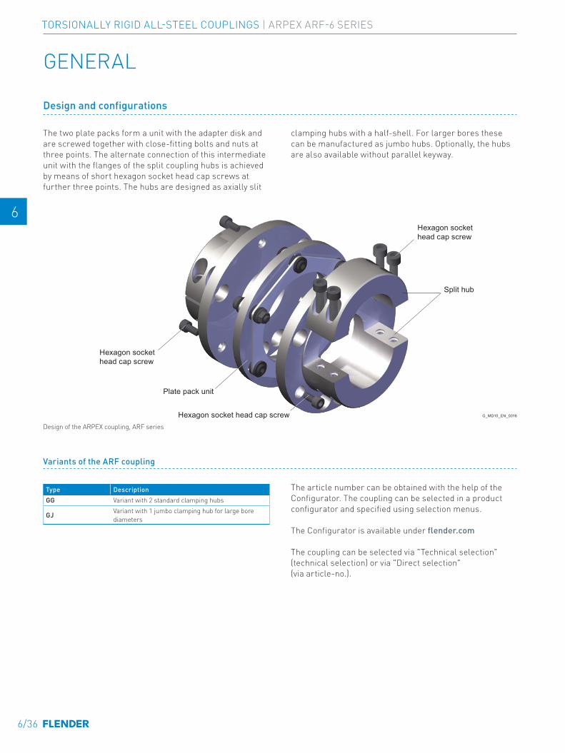
E E
4 4
5 5
6 6
7 7
8 8
9 9
10 10
11 11
12 12
13 13
A A
Split hub
Plate pack unit
G_MD10_EN_00166a
Hexagon sockethead cap screw
Hexagon sockethead cap screw
Hexagon socket head cap screw
Design and configurations
The two plate packs form a unit with the adapter disk and are screwed together with close-fitting bolts and nuts at three points. The alternate connection of this intermediate unit with the flanges of the split coupling hubs is achieved by means of short hexagon socket head cap screws at further three points. The hubs are designed as axially slit
clamping hubs with a half-shell. For larger bores these can be manufactured as jumbo hubs. Optionally, the hubs are also available without parallel keyway.
Variants of the ARF coupling
Type DescriptionGG Variant with 2 standard clamping hubs
GJ Variant with 1 jumbo clamping hub for large bore diameters
The article number can be obtained with the help of the Configurator. The coupling can be selected in a product configurator and specified using selection menus.
The Configurator is available under flender.com
The coupling can be selected via "Technical selection" (technical selection) or via "Direct selection" (via article-no.).
Design of the ARPEX coupling, ARF series
GENERAL
6/36
TORSIONALLY RIGID ALL-STEEL COUPLINGS | ARPEX ARF-6 SERIES

E E
4 4
5 5
6 6
7 7
8 8
9 9
10 10
11 11
12 12
13 13
A A
Technical specifications
Power ratings, types GG and GJSize Rated torque Maximum
torque Overload torque
Fatigue torque
Maximum speed
Maximum permitted shaft misalignment Torsional stiffness
TKN TKmax TKOL TKW nKmax ±∆Ka ±∆Kw ±∆Kr CT
Nm Nm Nm Nm rpm mm mm MNm/rad84-6 120 220 330 55 12500 1.1
0.7 °
0.16 0.07111-6 190 350 520 90 9450 1.8 0.16 0.13132-6 350 650 950 160 7950 2.02 0.2 0.2147-6 500 900 1350 230 7100 2.4 0.2 0.28171-6 900 1700 2450 400 6100 2.74 0.24 0.57182-6 1450 2600 4000 650 5750 2.86 0.29 0.66202-6 2150 3900 5800 980 5200 3.06 0.29 0.77218-6 3200 5800 8700 1450 4800 3.14 0.37 1.25252-6 4500 8100 12000 2000 4150 3.7 0.45 1.55267-6 6100 11000 16500 2800 3900 3.84 0.46 1.8
The permitted shaft misalignments ΔKa, ΔKr and ΔKw are maximum values and must not occur at the same time (see following table).
• TKmax permitted only five times per hour.• TKW for medium torque TN = 0 Nm. • If TN and TKW occur at the same time, the manufacturer
must be consulted.
The values for torsional stiffness apply to the complete coupling. The torsional stiffness of the plate packs applies to the rated coupling torque TKN. To determine the torsional stiffness for a specific operating point, e.g. for calculating torsional vibration, the manufacturer must be consulted.
Permitted shaft misalignmentsSize Permitted angular misalignment ±ΔKw
0.0 ° 0.1 ° 0.2 ° 0.3 ° 0.4 ° 0.5 ° 0.6 ° 0.7 °Permitted axial misalignment ±ΔKa in mm
84-6 1.1 0.94 0.79 0.63 0.47 0.31 0.16 0111-6 1.8 1.54 1.29 1.03 0.77 0.51 0.26 0132-6 2.02 1.73 1.44 1.15 0.87 0.58 0.29 0147-6 2.4 2.06 1.71 1.37 1.03 0.69 0.34 0171-6 2.74 2.35 1.96 1.57 1.17 0.78 0.39 0182-6 2.86 2.45 2.04 1.63 1.23 0.82 0.41 0202-6 3.06 2.62 2.19 1.75 1.31 0.87 0.44 0218-6 3.14 2.69 2.24 1.79 1.35 0.9 0.45 0252-6 3.7 3.17 2.64 2.11 1.59 1.06 0.53 0267-6 3.84 3.29 2.74 2.19 1.65 1.1 0.55 0
6/37
TORSIONALLY RIGID ALL-STEEL COUPLINGS | ARPEX ARF-6 SERIES
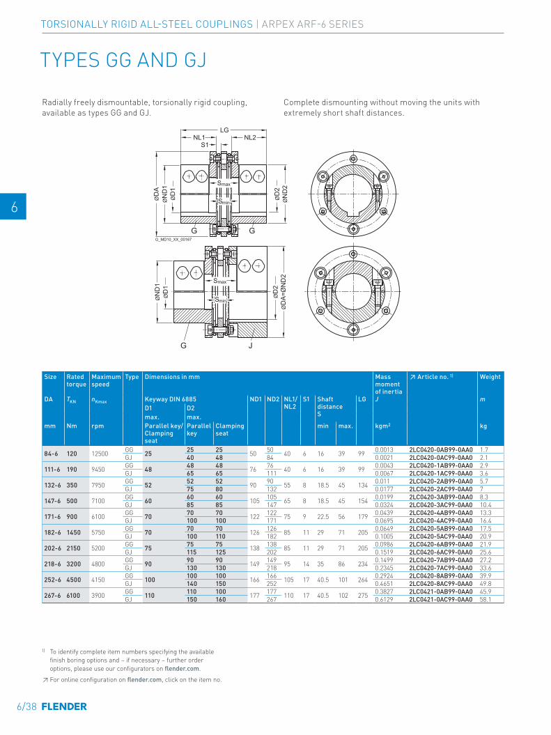
E E
4 4
5 5
6 6
7 7
8 8
9 9
10 10
11 11
12 12
13 13
A A
TYPES GG AND GJ
Size Rated torque
Maximum speed
Type Dimensions in mm Mass moment of inertia
↗ Article no. 1) Weight
DA TKN nKmax Keyway DIN 6885 ND1 ND2 NL1/NL2
S1 Shaft distance S
LG J mD1 D2max. max.
mm Nm rpm Parallel key/Clamping seat
Parallel key
Clamping seat
min max. kgm2 kg
84-6 120 12500 GG 25 25 25 50 50 40 6 16 39 99 0.0013 2LC0420-0AB99-0AA0 1.7GJ 40 48 84 0.0021 2LC0420-0AC99-0AA0 2.1
111-6 190 9450 GG 48 48 48 76 76 40 6 16 39 99 0.0043 2LC0420-1AB99-0AA0 2.9GJ 65 65 111 0.0067 2LC0420-1AC99-0AA0 3.6
132-6 350 7950 GG 52 52 52 90 90 55 8 18.5 45 134 0.011 2LC0420-2AB99-0AA0 5.7GJ 75 80 132 0.0177 2LC0420-2AC99-0AA0 7
147-6 500 7100 GG 60 60 60 105 105 65 8 18.5 45 154 0.0199 2LC0420-3AB99-0AA0 8.3GJ 85 85 147 0.0324 2LC0420-3AC99-0AA0 10.4
171-6 900 6100 GG 70 70 70 122 122 75 9 22.5 56 179 0.0439 2LC0420-4AB99-0AA0 13.3GJ 100 100 171 0.0695 2LC0420-4AC99-0AA0 16.4
182-6 1450 5750 GG 70 70 70 126 126 85 11 29 71 205 0.0649 2LC0420-5AB99-0AA0 17.5GJ 100 110 182 0.1005 2LC0420-5AC99-0AA0 20.9
202-6 2150 5200 GG 75 75 75 138 138 85 11 29 71 205 0.0986 2LC0420-6AB99-0AA0 21.9GJ 115 125 202 0.1519 2LC0420-6AC99-0AA0 25.6
218-6 3200 4800 GG 90 90 90 149 149 95 14 35 86 234 0.1499 2LC0420-7AB99-0AA0 27.2GJ 130 130 218 0.2345 2LC0420-7AC99-0AA0 33.6
252-6 4500 4150 GG 100 100 100 166 166 105 17 40.5 101 264 0.2924 2LC0420-8AB99-0AA0 39.9GJ 140 150 252 0.4651 2LC0420-8AC99-0AA0 49.8
267-6 6100 3900 GG 110 110 100 177 177 110 17 40.5 102 275 0.3827 2LC0421-0AB99-0AA0 45.9GJ 150 160 267 0.6129 2LC0421-0AC99-0AA0 58.1
G_MD10_XX_00167
S1
Smax
Smin
NL1LG
NL2
ØD
A
ØN
D2
ØD
2Smax
SminØN
D1
ØD
1
ØD
A=Ø
ND
2Ø
D2
G G
G J
ØN
D1
ØD
1
Radially freely dismountable, torsionally rigid coupling, available as types GG and GJ.
Complete dismounting without moving the units with extremely short shaft distances.
1) To identify complete item numbers specifying the available finish boring options and – if necessary – further order options, please use our configurators on flender.com.↗ For online configuration on flender.com, click on the item no.
6/38
TORSIONALLY RIGID ALL-STEEL COUPLINGS | ARPEX ARF-6 SERIES
E E
4 4
5 5
6 6
7 7
8 8
9 9
10 10
11 11
12 12
13 13
A A
Notes
• The shaft tolerance must be specified in the order. To specify, "-Z" must be added to the article no. and the order codes "Y26" and "Y27" with plain text specification of the shaft tolerance for D1 and D2 must be added as well.
• Jumbo hubs for larger shaft diameters. G and J hubs in split clamping hub variant. The hub variant with keyway rates as standard. Optionally, the shaft/hub connection can be implemented without keyway as a pure clamping seat. For specification of plate pack, see Page 6/40.
• Weights and mass moments of inertia apply to the entire coupling with maximum bores D1/D2.
Ordering example
• ARPEX ARF-6 GG coupling, size 132-6• for shaft diameter ØD1 45h6 mm, without keyway • for shaft diameter ØD2 50k6 mm,
with keyway to DIN 6885-1, keyway width P9.Article no.: 2LC0420-2AB99-0AA0-Z L1A+M1C+L45+Y26+Y27Plain text to Y26: h6 Plain text to Y27: k6
1) To identify complete item numbers specifying the available finish boring options and – if necessary – further order options, please use our configurators on flender.com.↗ For online configuration on flender.com, click on the item no.
6/39
TORSIONALLY RIGID ALL-STEEL COUPLINGS | ARPEX ARF-6 SERIES
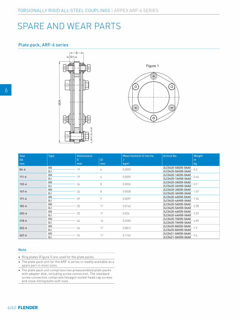
E E
4 4
5 5
6 6
7 7
8 8
9 9
10 10
11 11
12 12
13 13
A A
Note
• Ring plates (Figure 1) are used for the plate packs.• The plate pack unit for the ARF-6 series is readily available as a
spare part in most sizes. • The plate pack unit comprises two preassembled plate packs
with adapter disk, including screw connection. The standard screw connection comprises hexagon socket head cap screws and close-fitting bolts with nuts.
Size Type Dimensions Mass moment of inertia Article No. WeightDA S S1 J mmm mm mm kgm2 kg
84-6 GG 19 6 0.0003 2LC0420-0AE00-0AA0 0.3GJ 2LC0420-0AH00-0AA0
111-6 GG 19 6 0.0009 2LC0420-1AE00-0AA0 0.46GJ 2LC0420-1AH00-0AA0
132-6 GG 24 8 0.0026 2LC0420-2AE00-0AA0 0.9GJ 2LC0420-2AH00-0AA0
147-6 GG 24 8 0.0038 2LC0420-3AE00-0AA0 1.07GJ 2LC0420-3AH00-0AA0
171-6 GG 29 9 0.0097 2LC0420-4AE00-0AA0 1.96GJ 2LC0420-4AH00-0AA0
182-6 GG 35 11 0.0143 2LC0420-5AE00-0AA0 2.58GJ 2LC0420-5AH00-0AA0
202-6 GG 35 11 0.024 2LC0420-6AE00-0AA0 3.53GJ 2LC0420-6AH00-0AA0
218-6 GG 44 14 0.0383 2LC0420-7AE00-0AA0 4.89GJ 2LC0420-7AH00-0AA0
252-6 GG 54 17 0.0812 2LC0420-8AE00-0AA0 7.9GJ 2LC0420-8AH00-0AA0
267-6 GG 55 17 0.1152 2LC0421-0AE00-0AA0 9.6GJ 2LC0421-0AH00-0AA0
SPARE AND WEAR PARTS
S1S
ØD
A
G_M
D10
_EN
_001
68
Figure 1
Plate pack, ARF-6 series
6/40
TORSIONALLY RIGID ALL-STEEL COUPLINGS | ARPEX ARF-6 SERIES

E E
4 4
5 5
6 6
7 7
8 8
9 9
10 10
11 11
12 12
13 13
A A
6/41
TORSIONALLY RIGID ALL-STEEL COUPLINGS | ARPEX ARF-6 SERIES

6/42
APPENDIX
Fits A/2Fitting recommendations A/2Deviation table to DIN ISO 286 A/2Cylindrical shaft ends, extract from DIN 748 Part 1 (long) A/3Central holes according to DIN 332 Part 2 A/3
Parallel key connections to DIN 6885-1 A/4
Related catalogs A/6
Suitable gear solutions A/9
A/1
E E
4 4
5 5
6 6
7 7
8 8
9 9
10 10
11 11
12 12
13 13
A A
APPENDIX | FLENDER STANDARD COUPLINGS
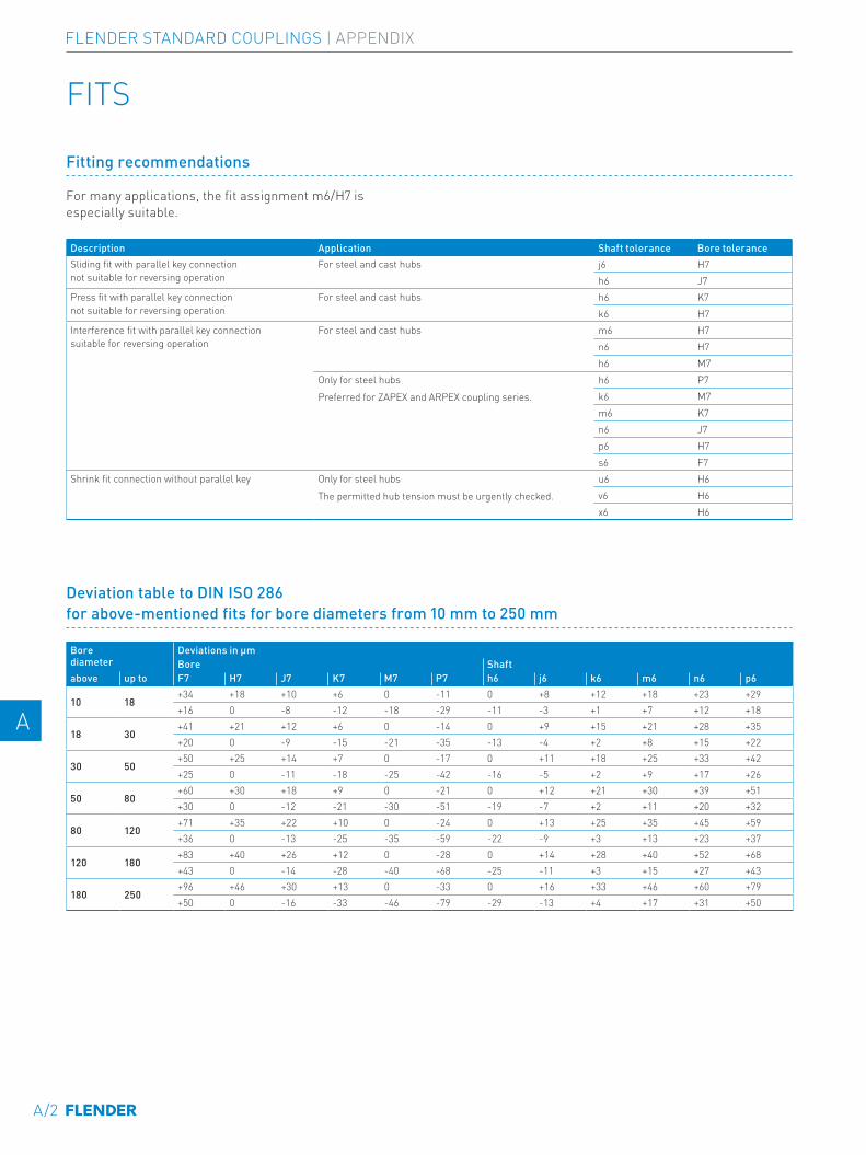
FITS
Fitting recommendations
For many applications, the fit assignment m6/H7 is especially suitable.
Description Application Shaft tolerance Bore toleranceSliding fit with parallel key connection not suitable for reversing operation
For steel and cast hubs j6 H7h6 J7
Press fit with parallel key connection not suitable for reversing operation
For steel and cast hubs h6 K7k6 H7
Interference fit with parallel key connection suitable for reversing operation
For steel and cast hubs m6 H7n6 H7h6 M7
Only for steel hubsPreferred for ZAPEX and ARPEX coupling series.
h6 P7k6 M7m6 K7n6 J7p6 H7s6 F7
Shrink fit connection without parallel key Only for steel hubsThe permitted hub tension must be urgently checked.
u6 H6v6 H6x6 H6
Deviation table to DIN ISO 286 for above-mentioned fits for bore diameters from 10 mm to 250 mm
Bore diameter
Deviations in µmBore Shaft
above up to F7 H7 J7 K7 M7 P7 h6 j6 k6 m6 n6 p6
10 18+34 +18 +10 +6 0 -11 0 +8 +12 +18 +23 +29+16 0 -8 -12 -18 -29 -11 -3 +1 +7 +12 +18
18 30+41 +21 +12 +6 0 -14 0 +9 +15 +21 +28 +35+20 0 -9 -15 -21 -35 -13 -4 +2 +8 +15 +22
30 50+50 +25 +14 +7 0 -17 0 +11 +18 +25 +33 +42+25 0 -11 -18 -25 -42 -16 -5 +2 +9 +17 +26
50 80+60 +30 +18 +9 0 -21 0 +12 +21 +30 +39 +51+30 0 -12 -21 -30 -51 -19 -7 +2 +11 +20 +32
80 120+71 +35 +22 +10 0 -24 0 +13 +25 +35 +45 +59+36 0 -13 -25 -35 -59 -22 -9 +3 +13 +23 +37
120 180+83 +40 +26 +12 0 -28 0 +14 +28 +40 +52 +68+43 0 -14 -28 -40 -68 -25 -11 +3 +15 +27 +43
180 250+96 +46 +30 +13 0 -33 0 +16 +33 +46 +60 +79+50 0 -16 -33 -46 -79 -29 -13 +4 +17 +31 +50
A/2
E E
4 4
5 5
6 6
7 7
8 8
9 9
10 10
11 11
12 12
13 13
A A
FLENDER STANDARD COUPLINGS | APPENDIX
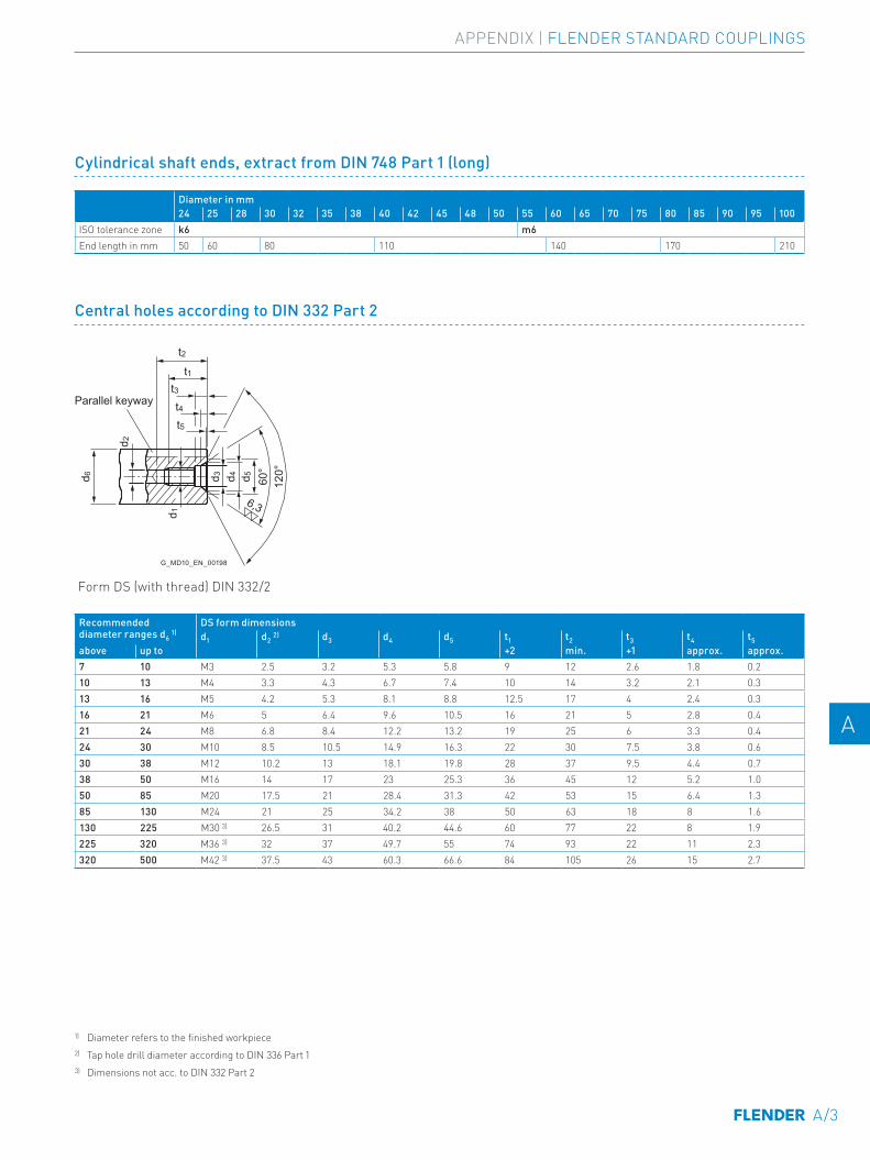
Cylindrical shaft ends, extract from DIN 748 Part 1 (long)
Diameter in mm24 25 28 30 32 35 38 40 42 45 48 50 55 60 65 70 75 80 85 90 95 100
ISO tolerance zone k6 m6End length in mm 50 60 80 110 140 170 210
Central holes according to DIN 332 Part 2
Parallel keyway
G_MD10_EN_00198
t2
d 6
d 2
d 3 d 4 d 5 60°
6,3
120°
d 1
t1t3t4t5
Form DS (with thread) DIN 332/2
Recommended diameter ranges d6 1)
DS form dimensionsd1 d2 2) d3 d4 d5 t1 t2 t3 t4 t5
above up to +2 min. +1 approx. approx. 7 10 M3 2.5 3.2 5.3 5.8 9 12 2.6 1.8 0.210 13 M4 3.3 4.3 6.7 7.4 10 14 3.2 2.1 0.313 16 M5 4.2 5.3 8.1 8.8 12.5 17 4 2.4 0.316 21 M6 5 6.4 9.6 10.5 16 21 5 2.8 0.421 24 M8 6.8 8.4 12.2 13.2 19 25 6 3.3 0.424 30 M10 8.5 10.5 14.9 16.3 22 30 7.5 3.8 0.630 38 M12 10.2 13 18.1 19.8 28 37 9.5 4.4 0.738 50 M16 14 17 23 25.3 36 45 12 5.2 1.050 85 M20 17.5 21 28.4 31.3 42 53 15 6.4 1.385 130 M24 21 25 34.2 38 50 63 18 8 1.6130 225 M30 3) 26.5 31 40.2 44.6 60 77 22 8 1.9225 320 M36 3) 32 37 49.7 55 74 93 22 11 2.3320 500 M42 3) 37.5 43 60.3 66.6 84 105 26 15 2.7
1) Diameter refers to the finished workpiece2) Tap hole drill diameter according to DIN 336 Part 13) Dimensions not acc. to DIN 332 Part 2
A/3
E E
4 4
5 5
6 6
7 7
8 8
9 9
10 10
11 11
12 12
13 13
A A
APPENDIX | FLENDER STANDARD COUPLINGS
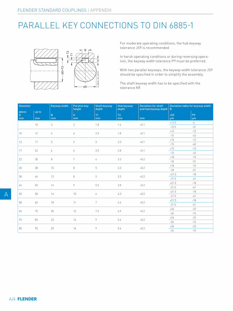
PARALLEL KEY CONNECTIONS TO DIN 6885-1
ØD
+T2
T1
H
T2
ØD
B
G_M
D10
_XX
_001
72
For moderate operating conditions, the hub keyway tolerance JS9 is recommended.
In harsh operating conditions or during reversing opera-tion, the keyway width tolerance P9 must be preferred.
With two parallel keyways, the keyway width tolerance JS9 should be specified in order to simplify the assembly. The shaft keyway width has to be specified with the tolerance N9.
Diameter Keyway width Parallel key height
Shaft keyway depth
Hub keyway depth
Deviation for shaft and hub keyway depth
Deviation table for keyway width B
above up toD B H T1 T2 JS9 P9mm mm mm mm mm mm mm µm µm
10 3 3 1.8 1.4 +0.1+12.5 -6-12.5 -31
10 12 4 4 2.5 1.8 +0.1+15 -12-15 -42
12 17 5 5 3 2.3 +0.1+15 -12-15 -42
17 22 6 6 3.5 2.8 +0.1+15 -12-15 -42
22 30 8 7 4 3.3 +0.2+18 -15-18 -51
30 38 10 8 5 3.3 +0.2+18 -15-18 -51
38 44 12 8 5 3.3 +0.2+21.5 -18-21.5 -61
44 50 14 9 5.5 3.8 +0.2+21.5 -18-21.5 -61
50 58 16 10 6 4.3 +0.2+21.5 -18-21.5 -61
58 65 18 11 7 4.4 +0.2+21.5 -18-21.5 -61
65 75 20 12 7.5 4.9 +0.2+26 -22-26 -74
75 85 22 14 9 5.4 +0.2+26 -22-26 -74
85 95 25 14 9 5.4 +0.2+26 -22-26 -74
A/4
E E
4 4
5 5
6 6
7 7
8 8
9 9
10 10
11 11
12 12
13 13
A A
FLENDER STANDARD COUPLINGS | APPENDIX
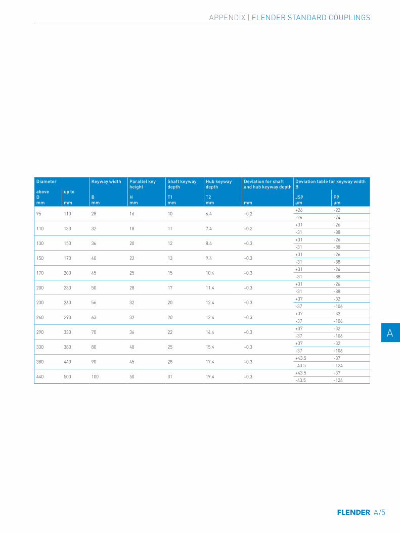
Diameter Keyway width Parallel key height
Shaft keyway depth
Hub keyway depth
Deviation for shaft and hub keyway depth
Deviation table for keyway width B
above up toD B H T1 T2 JS9 P9mm mm mm mm mm mm mm µm µm
95 110 28 16 10 6.4 +0.2+26 -22-26 -74
110 130 32 18 11 7.4 +0.2+31 -26-31 -88
130 150 36 20 12 8.4 +0.3+31 -26-31 -88
150 170 40 22 13 9.4 +0.3+31 -26-31 -88
170 200 45 25 15 10.4 +0.3+31 -26-31 -88
200 230 50 28 17 11.4 +0.3+31 -26-31 -88
230 260 56 32 20 12.4 +0.3+37 -32-37 -106
260 290 63 32 20 12.4 +0.3+37 -32-37 -106
290 330 70 36 22 14.4 +0.3+37 -32-37 -106
330 380 80 40 25 15.4 +0.3+37 -32-37 -106
380 440 90 45 28 17.4 +0.3+43.5 -37-43.5 -124
440 500 100 50 31 19.4 +0.3+43.5 -37-43.5 -124
A/5
E E
4 4
5 5
6 6
7 7
8 8
9 9
10 10
11 11
12 12
13 13
A A
APPENDIX | FLENDER STANDARD COUPLINGS
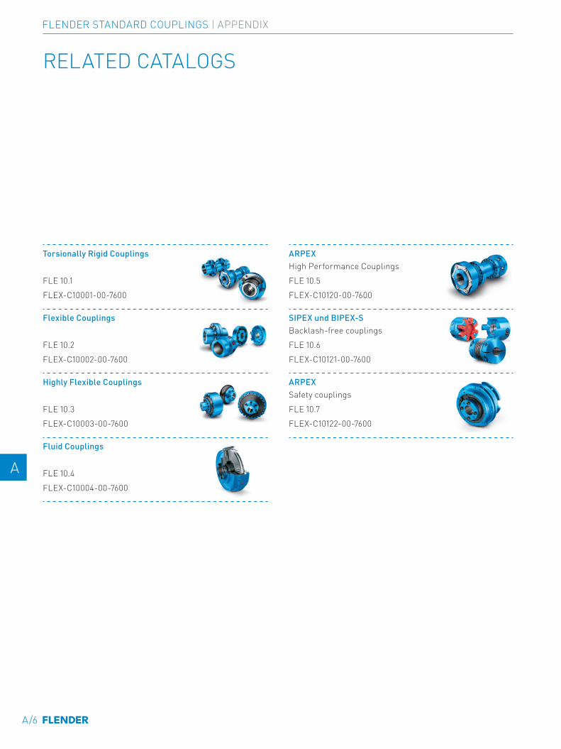
RELATED CATALOGS
Torsionally Rigid Couplings
FLE 10.1FLEX-C10001-00-7600
ARPEX High Performance CouplingsFLE 10.5FLEX-C10120-00-7600
Flexible Couplings
FLE 10.2FLEX-C10002-00-7600
SIPEX und BIPEX-S Backlash-free couplingsFLE 10.6FLEX-C10121-00-7600
Highly Flexible Couplings
FLE 10.3FLEX-C10003-00-7600
ARPEX Safety couplingsFLE 10.7FLEX-C10122-00-7600
Fluid Couplings
FLE 10.4FLEX-C10004-00-7600
A/6
E E
4 4
5 5
6 6
7 7
8 8
9 9
10 10
11 11
12 12
13 13
A A
FLENDER STANDARD COUPLINGS | APPENDIX
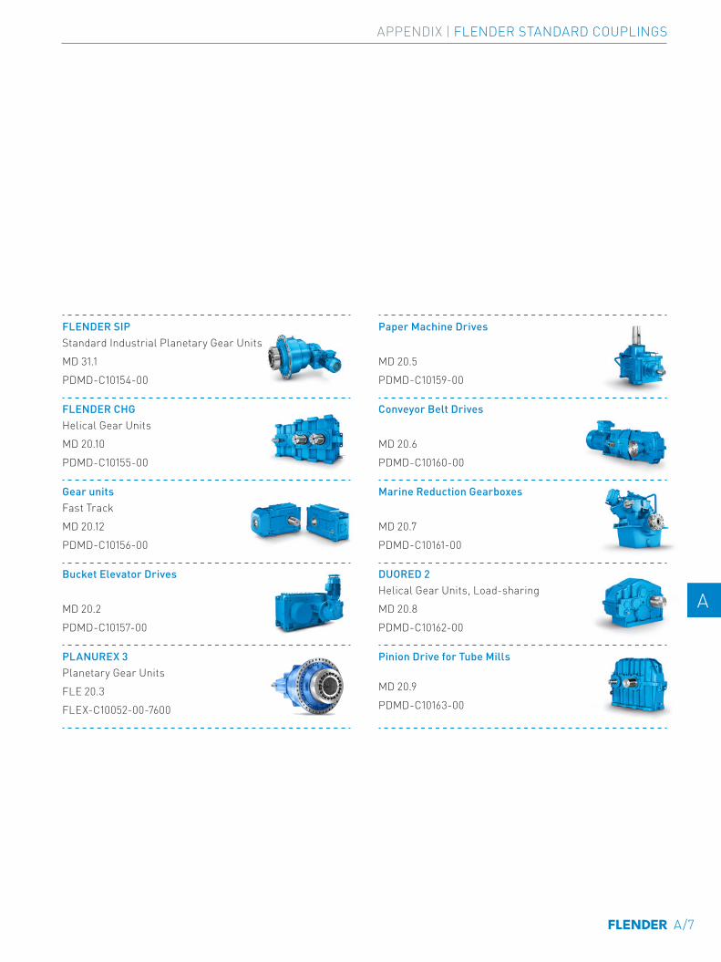
FLENDER SIP Standard Industrial Planetary Gear UnitsMD 31.1PDMD-C10154-00
Paper Machine Drives
MD 20.5PDMD-C10159-00
FLENDER CHG Helical Gear UnitsMD 20.10PDMD-C10155-00
Conveyor Belt Drives
MD 20.6PDMD-C10160-00
Gear units Fast TrackMD 20.12PDMD-C10156-00
Marine Reduction Gearboxes
MD 20.7PDMD-C10161-00
Bucket Elevator Drives
MD 20.2PDMD-C10157-00
DUORED 2 Helical Gear Units, Load-sharingMD 20.8PDMD-C10162-00
PLANUREX 3 Planetary Gear UnitsFLE 20.3FLEX-C10052-00-7600
Pinion Drive for Tube Mills
MD 20.9PDMD-C10163-00
A/7
E E
4 4
5 5
6 6
7 7
8 8
9 9
10 10
11 11
12 12
13 13
A A
APPENDIX | FLENDER STANDARD COUPLINGS
A/8
THE RIGHT GEAR UNIT SOLUTION FOR ANY REQUIREMENTWe provide helical and planetary gear units made up of standard modules or as a complete application solution.
Helical and planetary gear units from Flender are modern drive solutions that satisfy the most varying and extreme demands, day after day and year after year. For decades, plant operators have been achieving high system reliability and low lifecycle costs in every conceivable industry with our helical gear units.
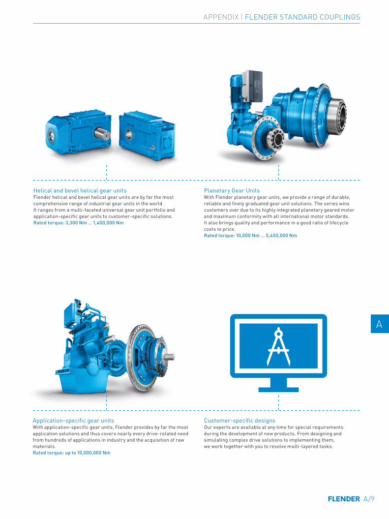
Planetary Gear UnitsWith Flender planetary gear units, we provide a range of durable, reliable and finely graduated gear unit solutions. The series wins customers over due to its highly integrated planetary geared motor and maximum conformity with all international motor standards. It also brings quality and performance in a good ratio of lifecycle costs to price.Rated torque: 10,000 Nm … 5,450,000 Nm
Helical and bevel helical gear unitsFlender helical and bevel helical gear units are by far the most comprehensive range of industrial gear units in the world. It ranges from a multi-faceted universal gear unit portfolio and application-specific gear units to customer-specific solutions. Rated torque: 3,300 Nm … 1,400,000 Nm
Application-specific gear unitsWith application-specific gear units, Flender provides by far the most application solutions and thus covers nearly every drive-related need from hundreds of applications in industry and the acquisition of raw materials.Rated torque: up to 10,000,000 Nm
Customer-specific designsOur experts are available at any time for special requirements during the development of new products. From designing and simulating complex drive solutions to implementing them, we work together with you to resolve multi-layered tasks.
SUITABLE GEAR SOLUTIONS
A/9
E E
4 4
5 5
6 6
7 7
8 8
9 9
10 10
11 11
12 12
13 13
A A
APPENDIX | FLENDER STANDARD COUPLINGS

A/10

FLENDER COUPLINGS CATALOG FLE 10.1 EDITION 2022 EN
Flender GmbHAlfred-Flender-Straße 7746395 BocholtGermany
Article no.: FLEX-C10001-00-7600
Subject to changes and errors. The information given in this product catalog includes descriptions and performance features that in specific applications do not always apply in the form described or may change through further-development of the products.The desired performance features are binding only if they are expressly agreed on conclusion of contract. Subject to availability for delivery and to technical changes.flender.com


