Embed Size (px)
Citation preview

Theo Heijnen Consumer Care
Subject: Power Supply DELTA date September 2011

CONFIDENTIAL Consumer Care, Reference 2
Overview
Supplier: Delta Article Id Description Remarks
2722 171 90337 MOD PSL 32 DPS-93BP A B Blockbuster - 32PFL66X6H/T/M/K / 2722 171 90338 MOD PSL 42 DPS-139AP A B Sundance - 42PFL74X6/H/T/M/K /
2722 171 90339 MOD PSL 47 DPS-186FP A B Infinity - 42/47PFL7XX6 / Infinity - 42PDL7906H/T/M/K
2722 171 90311 MOD PSU DPS-300AP-59 A B 58PFL9955H/D & 9956H/T
8204 001 56651 MOD PSL DPS-318AP B 46PFL9706H/T/M/K & 52PFL9606H/T/M/K
CONFIDENTIAL Consumer Care, Reference 3
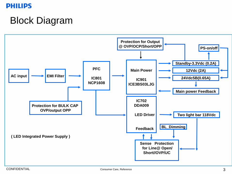
Block Diagram
AC input
PFC
IC801 NCP1608
Standby-3.3Vdc (0.2A)
12Vdc (2A)
24Vdc5B(0.65A)
IC702 DDA009
LED Driver
Feedback
Sense Protection for Line@ Open/ Short//OVP/UC
EMI Filter Main Power
IC901
ICE3BS03LJG
Protection for Output @ OVP/OCP/Short/OPP
Protection for BULK CAP OVP/output OPP
Main power Feedback
PS-on/off
BL_Dimming ( LED Integrated Power Supply )
Two light bar 118Vdc
CONFIDENTIAL Consumer Care, Reference 4
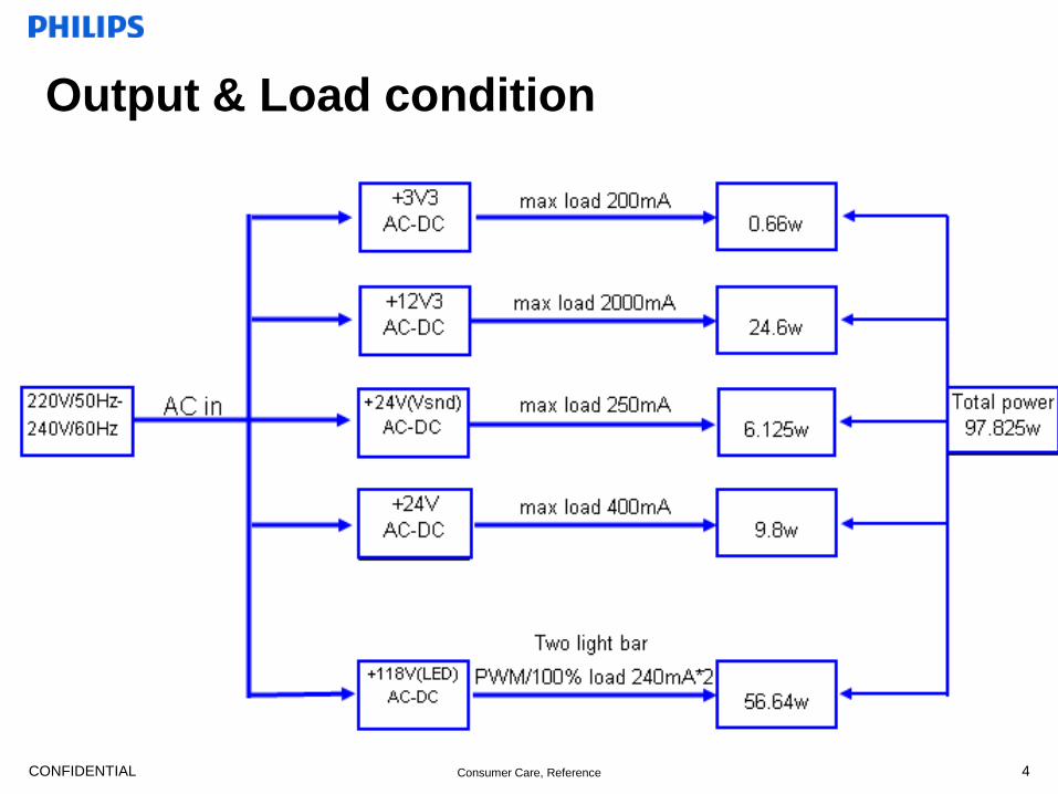
Output & Load condition

CONFIDENTIAL Consumer Care, Reference
Schematics_1/2
5

CONFIDENTIAL Consumer Care, Reference
Schematics_2/2
6
CONFIDENTIAL Consumer Care, Reference 7
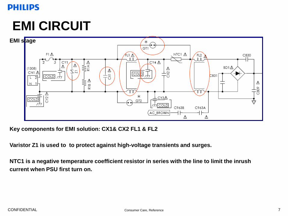
EMI CIRCUIT
Key components for EMI solution: CX1& CX2 FL1 & FL2 Varistor Z1 is used to to protect against high-voltage transients and surges. NTC1 is a negative temperature coefficient resistor in series with the line to limit the inrush current when PSU first turn on.
EMI stage
CONFIDENTIAL Consumer Care, Reference 8
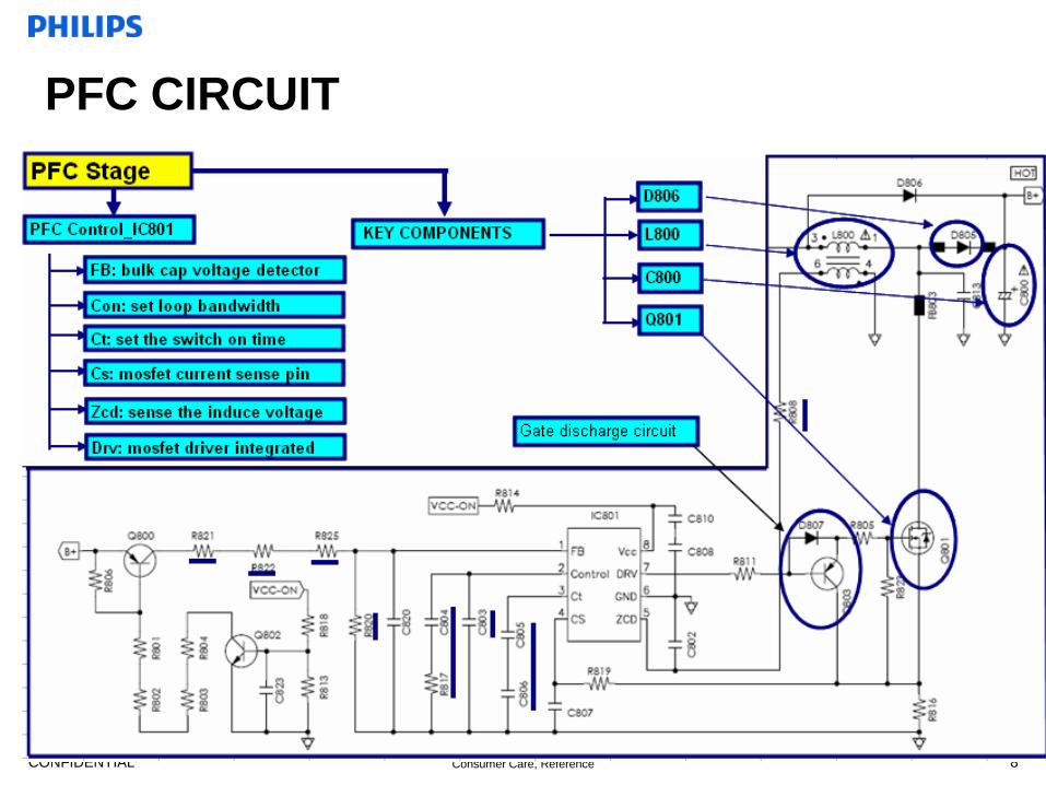
PFC CIRCUIT

CONFIDENTIAL Consumer Care, Reference
FLYBACK CIRCUIT_1/2
9

CONFIDENTIAL Consumer Care, Reference
FLYBACK CIRCUIT_2/2
10

CONFIDENTIAL Consumer Care, Reference
FLYBACK CIRCUIT_2/2
11
• Notes: IC902 is used to set the AC Brown In/Out point and discharge time. The trigger point is 1.28v for Brown/In and 1.16V for Brown out.

CONFIDENTIAL Consumer Care, Reference
DC_output F/B Circuit
12
Vout_3.3V≒Vref*(R917+R912+R913)/R913
Vout_12V≒Vref*(R958+R918+R913)/R913+VF_D922
CONFIDENTIAL Consumer Care, Reference
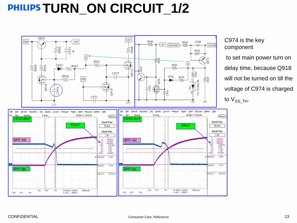
TURN_ON CIRCUIT_1/2
13
C974 is the key component
to set main power turn on
delay time, because Q918
will not be turned on till the
voltage of C974 is charged
to VGS_TH.
CONFIDENTIAL Consumer Care, Reference
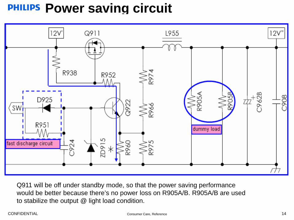
Power saving circuit
14
Q911 will be off under standby mode, so that the power saving performance would be better because there’s no power loss on R905A/B. R905A/B are used to stabilize the output @ light load condition.
CONFIDENTIAL Consumer Care, Reference
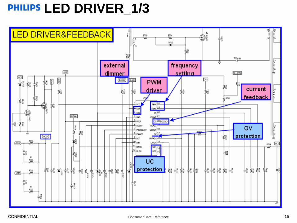
LED DRIVER_1/3
15
CONFIDENTIAL Consumer Care, Reference
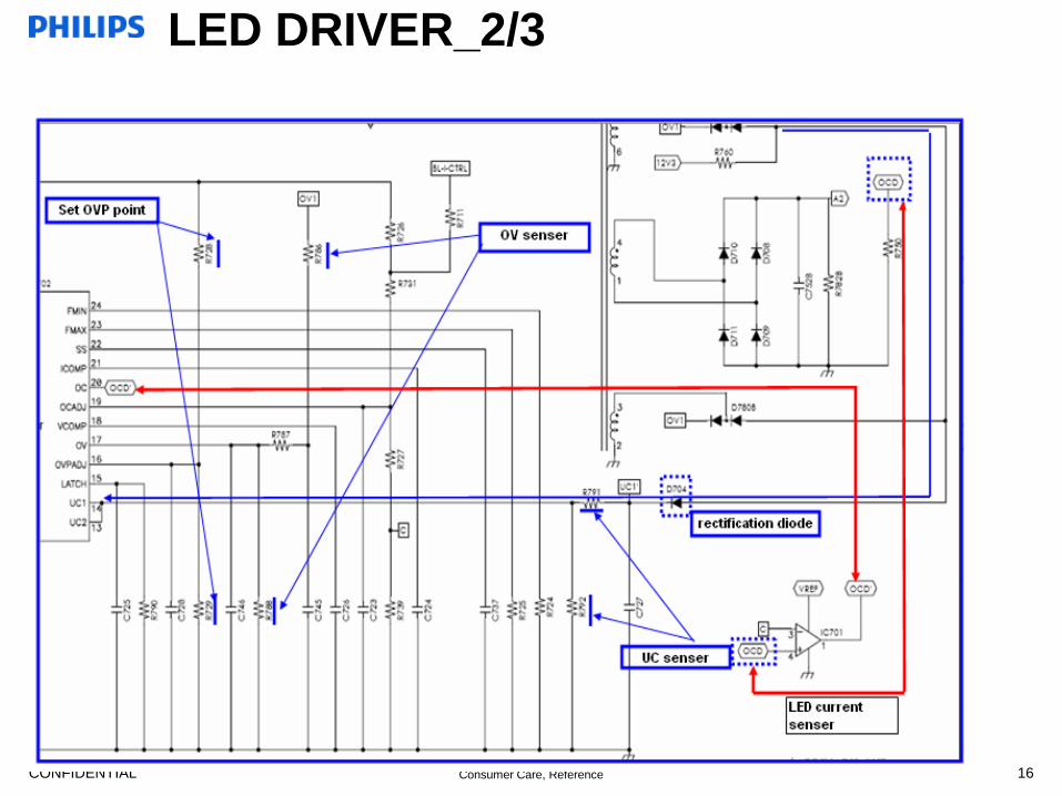
LED DRIVER_2/3
16
CONFIDENTIAL Consumer Care, Reference 17
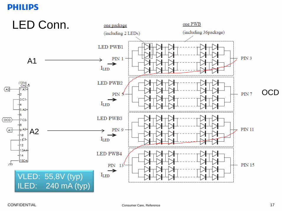
LED Conn.
A1
A2
OCD
VLED: 55,8V (typ) ILED: 240 mA (typ)

CONFIDENTIAL Consumer Care, Reference
LED DRIVER_3/3
18

CONFIDENTIAL Consumer Care, Reference 19
Notes 1. Visual inspection should be the first step you do once received a defect.
That’s to check components missing/burnt or mechanical damage issues.
2. The second step is, check key components by using digital multimeter. Locations show as below: F1/BD1/R945/Q901/Q701A/B……
3. If there’s no abnormal found, then we can power up the PSU to check Standby output, enable STANDBY to check main output and BL-ON to check LED
4. Check L800/T901/IC3 if no 3.3Vsb signal
5. If 12v/24v stays low after main power on, check Bulk voltage and IC901, including voltage of VCC/FB, waveforms of Gate/CS pins.
6. As for LED stage, mostly the problem will be founded had relationship with protection such as OC/OV/UC/Brown out, and it’s easy to be confirmed by disabling the protection one by one.
7. Never forget that the PSU (Bulk capacitor) must be discharged after power off
CONFIDENTIAL Consumer Care, Reference
20
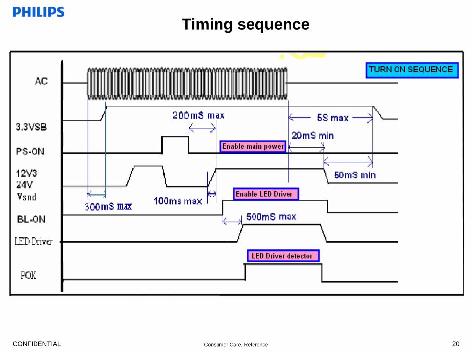
Timing sequence
CONFIDENTIAL Consumer Care, Reference
Fault finding circuit instruction_1/9
21
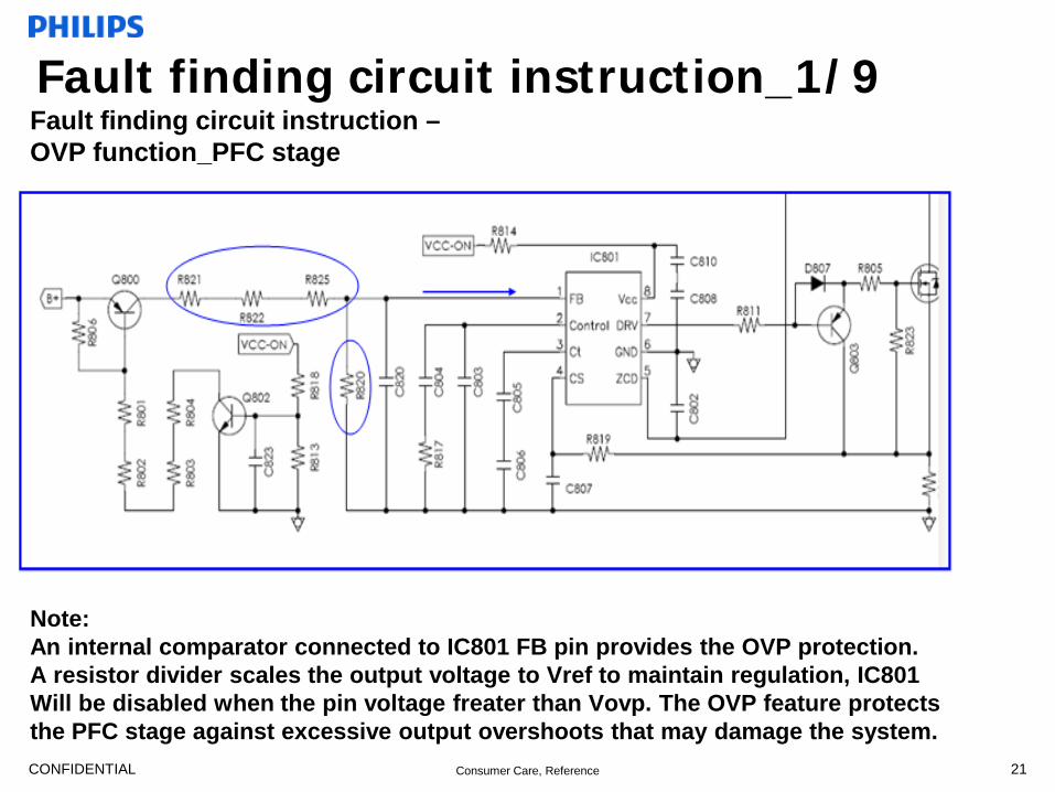
Fault finding circuit instruction – OVP function_PFC stage
Note: An internal comparator connected to IC801 FB pin provides the OVP protection. A resistor divider scales the output voltage to Vref to maintain regulation, IC801 Will be disabled when the pin voltage freater than Vovp. The OVP feature protects the PFC stage against excessive output overshoots that may damage the system.

CONFIDENTIAL Consumer Care, Reference
Fault finding circuit instruction_2/9
22
Fault finding circuit instruction – OVP function_Flyback stage
Note: The voltage from the auxiliary winding will be applied to IC901 pin 1 after a time delay, there’s an internal Zero-Crossing detector used for switch-on determination. By comparing the voltage Vzc with an internal preset threshold which is about 3.7V, the output over voltage detection is realized.
Ovp section

CONFIDENTIAL Consumer Care, Reference
Fault finding circuit instruction_3/9
23
Fault finding circuit instruction – OVP function_ LED driver
Note: IC702 pin17 is the feedback for the voltage amplifier, connected to the output voltage sense resistor divider(R786/787/788. This signal is compared to an internal 4V voltage amplifier reference to limit output voltage in an over voltage condition or LED string open condition.
CONFIDENTIAL Consumer Care, Reference
Fault finding circuit instruction_4/9
24
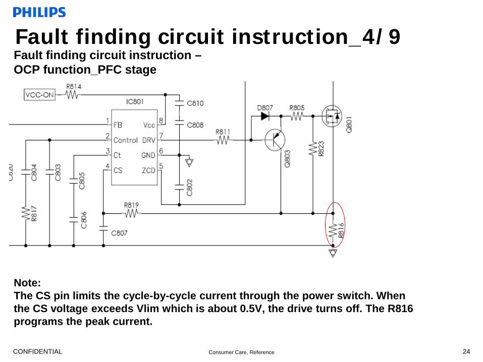
Fault finding circuit instruction – OCP function_PFC stage
Note: The CS pin limits the cycle-by-cycle current through the power switch. When the CS voltage exceeds Vlim which is about 0.5V, the drive turns off. The R816 programs the peak current.

CONFIDENTIAL Consumer Care, Reference
Fault finding circuit instruction_5/9
25
Fault finding circuit instruction – OCP function_ FLYBACK stage
Note: The CS pin limits the cycle-by-cycle current through the power switch.
When the CS voltage exceeds Vlim which is about 1V, the drive turns off. The R903 programs the peak current.

CONFIDENTIAL Consumer Care, Reference
Fault finding circuit instruction_6/9
26
Fault finding circuit instruction – OCP function_ LED driver
Note: Output Current sense Imput monitors the LED current. As for the feedback input
for the current amplifer, OC pin is connected to the transformer. This signal is compared to the current reference by the current amplifier to regulate the LED current, the regulation range is limited by the internal clamp (0.7V~2.8V)
CONFIDENTIAL Consumer Care, Reference
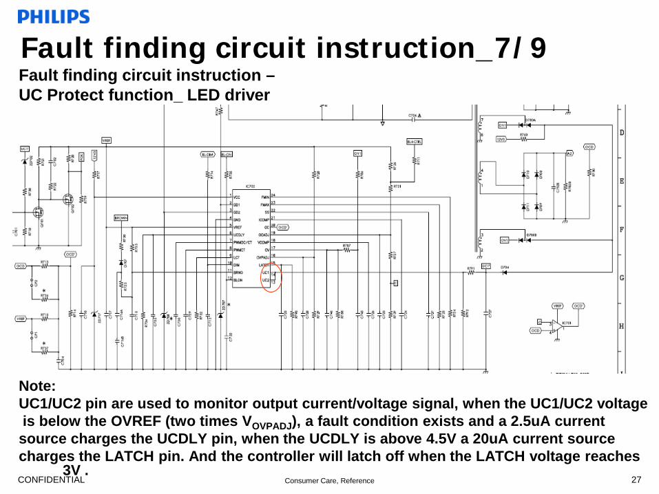
Fault finding circuit instruction_7/9
27
Fault finding circuit instruction – UC Protect function_ LED driver
Note: UC1/UC2 pin are used to monitor output current/voltage signal, when the UC1/UC2 voltage is below the OVREF (two times VOVPADJ), a fault condition exists and a 2.5uA current source charges the UCDLY pin, when the UCDLY is above 4.5V a 20uA current source charges the LATCH pin. And the controller will latch off when the LATCH voltage reaches
3V .
CONFIDENTIAL Consumer Care, Reference
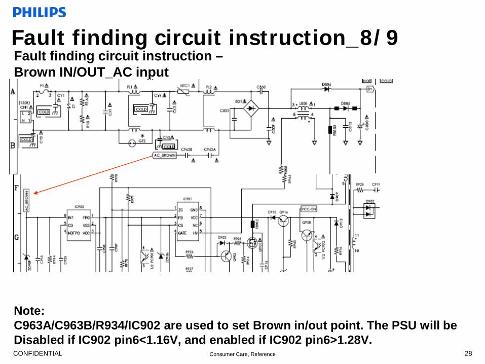
Fault finding circuit instruction_8/9
28
Fault finding circuit instruction – Brown IN/OUT_AC input
Note: C963A/C963B/R934/IC902 are used to set Brown in/out point. The PSU will be Disabled if IC902 pin6<1.16V, and enabled if IC902 pin6>1.28V.
CONFIDENTIAL Consumer Care, Reference
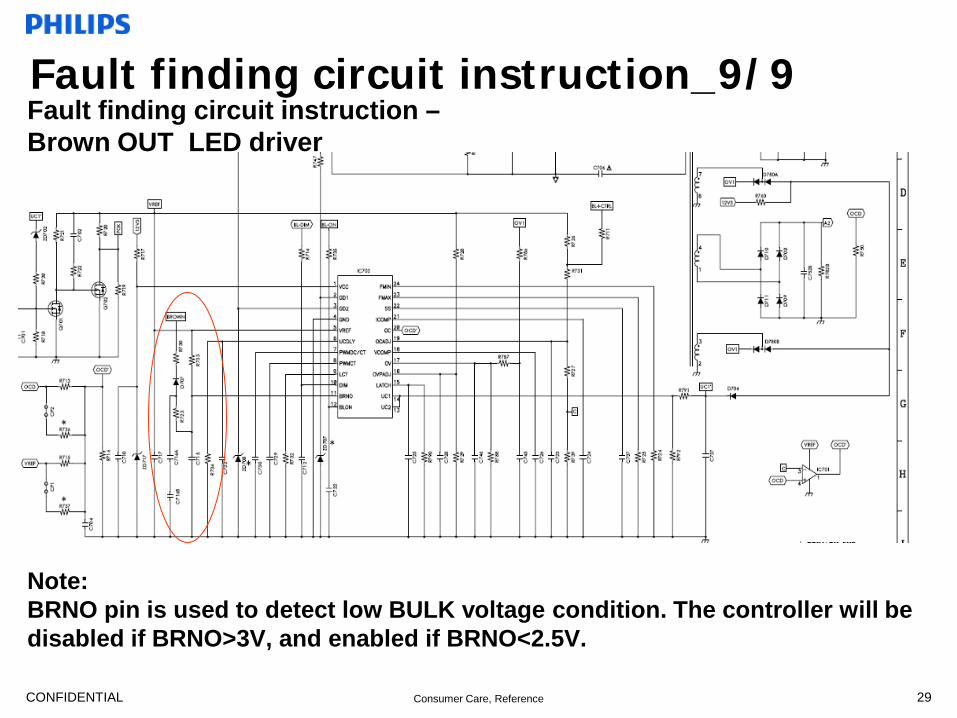
Fault finding circuit instruction_9/9
29
Fault finding circuit instruction – Brown OUT_LED driver
Note: BRNO pin is used to detect low BULK voltage condition. The controller will be disabled if BRNO>3V, and enabled if BRNO<2.5V.
CONFIDENTIAL Consumer Care, Reference
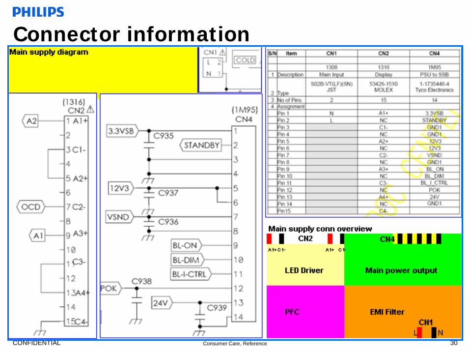
Connector information
30

CONFIDENTIAL Consumer Care, Reference
PSU Fault condition & Fall-off sumary
31

CONFIDENTIAL Consumer Care, Reference
PSU Fault condition & Fall-off
sumary


