Embed Size (px)
Citation preview

Compliant
GPIBCANUSB APGLAN
Chroma 62000D programmable bidirectional DC power supplies provide both power source and load characteristics. These two quadrant power supplies allow power from the DUT to be converted back to the utility grid and so are ideal for testing renewable energy power systems such as PV, storage, and EV inverters as well as a wide range of bidirectional power conditioning system (PCS) and may also be used as a battery simulator. 62000D has applications in testing power components in electric vehicles as well as bidirectional on-board chargers (BOBC), bidirectional DC converters, and DC-AC motor drivers and can perform power conversion tests of Li-ion batteries in both charge and discharge directions.
To illustrate the 62000D unique capabilities, t r a d i t i o n a l D C p o w e r s u p p l i e s n e e d protection diodes to prevent Back EMF during motor testing does not damage the source. However, the 62000D bidirectional DC power supplies can drive the motor and also efficiently regenerate EMF to the grid, thereby avoiding the need for blocking diodes while saving space, energy, and configuration. In addition, the fast cross-quadrant bandwidth of the 62000D provides a transient response time of less than 1.5ms (-90% to +90%).
62000D bidirectional DC supplies include 9 different models with industry-leading power density at 18kW in 3U of vertical rack space. Model range from 6kW to 18kW, output current ratings up to ±540A, and voltage ratings up to 1800VDC. The master/slave feature allows for up to 10 models to be paralleled easily and safely up to 180kW.
62000D s e r i e s i s e q u i p p e d w i t h 100 programmable user settings through the unit's List Mode. The fast response time fills many testing needs, including the LV123 and LV148 standards required for new energy vehicle components. When combined with the Chroma Softpanel, the user can conduct the complex tests with simple clicks of the mouse.
62000D family of power supplies can easily be used in any region of the world due to its wide input range of 200-480 Vac and an active PFC low-current harmonic feed to grid, reducing power consumption, power system configuration, and ambient temperature changes under high-power testing. Control options include digital USB, LAN, CANbus, GPIB as well as analog APG interfaces.
BIDIRECTIONAL DC POWER SUPPLY MODEL 62000D SERIES
MODEL 62000D SERIES
KEY FEATURES■ Voltage rating : 0~100V/600V/1200V/1800V■ Current rating : 0~540A■ Power rating : 6kW/12kW/18kW■ Two-quadrant operation: source and load functions■ High power density: 18kW in 3U■ Easy master/slave parallel & series *1 operation up to 540kW■ Wide range of voltage & current combinations in constant power■ Auto sequencing programming■ Voltage & current slew rate control■ High speed transient response <1.5ms■ Low output noise and ripple■ Intuitive and user-friendly touch control screen■ Standard USB/LAN/APG interfaces, optional CAN/GPIB interfaces■ 3-phase 4-wire universal AC power: 200~480 Vac■ Solar array simulation function (optional)
*1: 100V/600V models support series operation. 1200V/1800V models support parallel operation up to 540kW.
APPLICATIONS■ Charge/discharge testing and life cycle testing, including BOBC, DC-DC conversion, and PCS■ Motor driver testing■ Pre-compliant with LV123 and LV148 standards on electrical car components testing■ Used as battery simulation source for microgrid applications■ Suitable for 1500V string PV inverter testing
LV148LV123<1.5ms 1800V/40A 0.1%+0.1%18kW/3U2 in 1
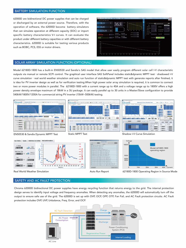
Chroma's 62000D has a bidirectional switch-mode power supply design that offers two-quadrant operation with positive current/positive
voltage as well as negative current/positive voltage, enabling both DC power supply output and regenerative DC load. The absorbed energy
feeds back to the grid with a conversion efficiency up to 93% and can operate in constant voltage, constant current, and constant power
modes. Compared to traditional power supply and load, the 62000D two-in-one bidirectional DC power supply saves space, reduces energy
loss and heat dissipation, and is easier to wire and configure.
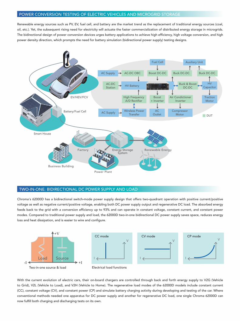
Renewable energy sources such as PV, EV, fuel cell, and battery are the market trend as the replacement of traditional energy sources (coal,
oil, etc.). Yet, the subsequent rising need for electricity will actuate the faster commercialization of distributed energy storage in microgrids.
The bidirectional design of power conversion devices urges battery applications to achieve high efficiency, high voltage conversion, and high
power density direction, which prompts the need for battery simulation (bidirectional power supply) testing designs.
With the current evolution of electric cars, their on-board chargers are controlled through back and forth energy supply to V2G (Vehicle
to Grid), V2L (Vehicle to Load), and V2H (Vehicle to Home). The regenerative load modes of the 62000D models include constant current
(CC), constant voltage (CV), and constant power (CP) and simulate battery charging activity during developing and testing of the car. Where
conventional methods needed one apparatus for DC power supply and another for regenerative DC load, one single Chroma 62000D can
now fulfill both charging and discharging tests on its own.
Two-in-one source & load Electrical load functions
TWO-IN-ONE: BIDIRECTIONAL DC POWER SUPPLY AND LOAD
POWER CONVERSION TESTING OF ELECTRIC VEHICLES AND MICROGRID STORAGE
EV/HEV/FCV
Battery/Fuel Cell
Smart House
Energy StorageSystem
AC-DCStation
HV Battery
Fuel Cell
ACOutlet
AC Supply
AC Supply
DUT
AC-DC OBC
Auxiliary Unit
Boost DC-DC Buck DC-DC Buck DC-DC
Wireless PowerTransfer
CompressorMotor
High FrequencyA/D Rectifier
HVCapacitor
TractionMotor
Boost+ Inverter
Buck & BoostDC-DC
Air CondictionerInverter
Business Building
Factory
Power Plant
Renewable Energy
+I-I
+V
SourceLoad
V
I
V V
I I
CC mode CV mode CP mode

Bidirectional on-board charger testing configuration
A power conditioning system (PCS) serves to realize bidirectional power conversion between the battery system and the grid with the
terminal battery voltage of the newest devices reaching up to 1500V and having a charge/discharge function, active power control, reactive
power regulation, and off-grid switch. A common issue for users is how to prepare an actual high voltage battery for testing the charge/
discharge transition (with a standard <100ms) performance of this PCS and it is impossible to use R&D verification and manufacture with fast
reproducibility, controllability, and safety. The high voltage 62180D-1800 (1800V/40A/18kW) model can be connected in parallel to reach
540kW/1800V/1200A, so replacing the real battery simulation as power supply or regenerative power load to carry out this charge/discharge
transition with a seamless switch.
HIGH VOLTAGE 1800V PCS TESTING
BidirectionalDC Power Supply
substitute
BidirectionalOBC
Charging mode
Discharging mode(V2H, V2L, V2G)
18kW in 3U
18kW in 3UDC Power Supply
18kW in 20UAir-cooling DC Load
√ Energy recycling
√ Easy to wire and configure
√ Space saving
√ Transient response
test CC/CV
18kW BidirectionalDC Power Supply
HV Battery Simulator
Measurement Device RLC Load
DUT (PCS)Grid Simulator
Chroma 62000D allows seamless current conversion between the two quadrants of supply and electrical load without changing the output
characteristics or causing damage. To use this in many bidirectional DC-DC and DC-AC battery charge/discharge tests requires very fast
charge/discharge conversion. To increase this transient responsiveness, the 62000D bidirectional DC power supply has a high speed transient
response time of less than 1.5ms (-90% to +90%) and gives stable voltage output.
HIGH TRANSIENT RESPONSE <1.5ms
• Continued on next page ➟

Along with the global energy efficiency and carbon emission reduction trends, the car industry have established technical development
standards for new energy vehicles, which define tests for a variety of electric vehicles. The LV123 guidelines specify the vehicle’s electrical
characteristics and safety of high-voltage components, whereas the LV148 standard covers tests for electric and electronic components in
48V electrical system motor vehicles. Chroma 62000D has a high-speed CV dynamic response slope that can be controlled up to 180V/ms,
which is applicable to the electrical characteristics tests of many vehicle guidelines. When combined with the Chroma Softpanel, the user can
even conduct the tests at the push of a button.
TESTING STANDARDS LV123 AND LV 148
LV123• Range of unlimited operating capability
• Range of upper limited operating capability
• Range of lower limited operating capability
• Range of highly limited operating capability
LV148• Long-term overvoltage
• Transient pulse in the lower operating range
• Recuperation
• Slow reduction and slow increase of supply voltage
• Reset behavior
• Operation in the upper range with functional restrictions
• Operation in the lower range with functional restrictions
• Overvoltage range
To test the acceleration and braking of the motor
driver under driving conditions, the conversion
between the battery and power components
will encounter supply and recharge of electrical
energy. The very fast transient response of the
62000D two quadrants can simulate the battery
and convert according to the actual needs of the
motor, offering stable voltage and allowing current
recharge during braking.
Start-stop system motor driver test application
Simulation of actual driving conditions
functions as battery pack
Battery Simulator GUI
Motor
Motor Driver
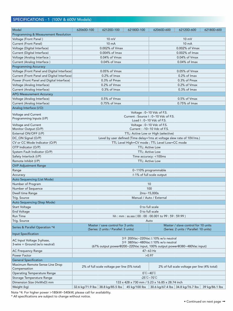
BATTERY SIMULATION FUNCTION
62000D are bidirectional DC power supplies that can be charged
or discharged by an external power source. Therefore, with the
operation of software, the 62000D become battery simulators
that can simulate operation at different capacity (SOC) or import
specific battery characteristics V-I curves. It can evaluate the
product under different battery capacities or with different battery
characteristics. 62000D is suitable for testing various products
such as BOBC, PCS, ESS or motor drivers.
Model 62180D-1800 has a built-in EN50530 and Sandia's SAS model that allow user easily program different solar cell I-V characteristic
outputs via manual or remote SCPI control. The graphical user interface SAS SoftPanel includes static&dynamic MPPT test、shadowed I-V
curve simulation、real world weather simulation and auto run function of static&dynamic MPPT test with generate reports after finished, it
is idea for PV inverter design as well as for verification testing.When high power solar array simulation is required, it is common to connect
two or more power modules in parallel. The 62180D-1800 with a current range up to 40A and a voltage range up to 1800V offers a high
power density envelope maximum of 18kW in a 3U package. It can easily parallel up to 30 units in a Master/Slave configuration to provide
540kW/1800V/1200A for commercial string PV inverter (15kW~500kW) testing.
SOLAR ARRAY SIMULATION FUNCTION (OPTIONAL)
Voltage
Current
Model 62180D-1800operating region
450V600V
900V
1800V
0 10A 20A 30A 40A
EN50530 & Sandia Dynamic MPPT Test Static MPPT Test Shadow I-V Curve Simulation
Real World Weather Simulation Auto Run Report 62180D-1800 Operating Region in Source Mode
SAFETY AND AC FAULT PROTECTION
Chroma 62000D bidirectional DC power supplies have energy recycling function that returns energy to the grid. The internal protection
design serves to identify input voltage and frequency anomalies. When detecting any anomalies, the 62000D will automatically turn off the
output to ensure safe use of the grid. The 62000D is set up with OVP, OCP, OPP, OTP, Fan Fail, and AC Fault protection circuits. AC Fault
protection includes OVP, UVP, Unbalance, Freq. Error, and OCP.
Power ConditioningSystem (PCS)
AC Line
Discharge
Charge
Regenerative Power
AC PowerConsumption
AC Fault Detection
Internal Loading

62180D-600 operating region Others
+600V
+500V
+150V
+18kWCP Curve
-18kWCP Curve
Voltage
Current+120A-120A +90A-90A +30A-30A 0
Chroma 62000D bidirectional DC power supply is equipped with an active PFC >0.97 for low energy consumption and high conversion
efficiency. Moreover, to fit the universal AC power input range, the 62000D series has a very wide input power range of three-phase 200Vac
to 220Vac and 380Vac to 480Vac inputs. The user can buy one single device without having to configure it for use in other areas.
UNIVERSAL AC POWER RANGE 200~480VAC
Chroma's 62000D bidirectional DC power supplies include four auto-operating ranges. The 62180D-600
has an 18kW/600V/120A output and operates flexibly in various combinations as the figure below shows.
Compared with the three output ranges of competitors, the 62000D can give much greater current at
low voltage. This offers an even wider coverage of low voltage/high current and high voltage/low current
DUTs that other DC power supplies can test. When used into a standard ATE system or on a laboratory
table, one 62000D can replace multiple DC power supplies to significantly save space and costs.
When testing high power 10kW~180kW conversion components (e.g. PCS, ESS, Charger, Inverter),
users need to consider small volume, light weight, utilization rate, flexible assembly and disassembly for
operation of various power systems, and influence of R&D during system failure and maintenance. The
62000D Series has a smart master/slave control mode that can connect 2 to 10 devices, enabling fast and
simple series/parallel operation for use by R&D, QC, and at the production line. In this mode, the master
scales values and downloads data to slave units so programming is as simple as using a single unit, and
the digital current sharing is highly stable and without noise interference.
Master/slave parallel operation up to 180kW
* Call for availability
FOUR AUTO-OPERATING RANGES
Chroma provides high power system solut ion from 54kW-
540kW/1800V/1200A system integration services, this power system
has multiple safety protections (AC Breaker circuit breaker includes
overcurrent protection, leakage current detection protection,
emergency stop button device, input AC over Voltage, under voltage,
OFP, UFP, system over temperature, fan failure, etc.) is suitable for
long-term testing and use in R&D and production lines.
HIGH POWER SYSTEM INTEGRATION

Chroma 62000D has a next generation human-machine control
interface with an intuitive and user-friendly touch screen. Operation
of the apparatus is as easy as using a smartphone, with its intelligent
and convenient user interface; through icons on the touch screen, the
user can complete any voltage/current settings and measurements,
program sequence control settings, preview output waveforms, etc.
The 62000D series can be operated from the front panel controls or from available softpanel. This user friendly software includes all functions
of the 62000D series and is easy to understand and operate. The 62000D can be controlled via GPIB, USB and Ethernet interfaces for remote
control and automated testing applications.
List Mode
Automotive Test Standard
Fixed Mode
Battery Simulator
Step Mode
Fuel Cell
USER-FRIENDLY INTUITIVE CONTROL INTERFACE
SOFTPANEL
Control interface
Chroma 62000D supports various remote interfaces, enabling the user to control the PC through the standard USB and LAN or optional
GPIB interfaces. Moreover, the optional CAN interface as frequently used in the automobile industry is compliant with the CAN2.0 A 11-bit
and CAN2.0 B 29-bit identifiers and has a V/I/P cycle time of up to 10ms.
REMOTE INTERFACES

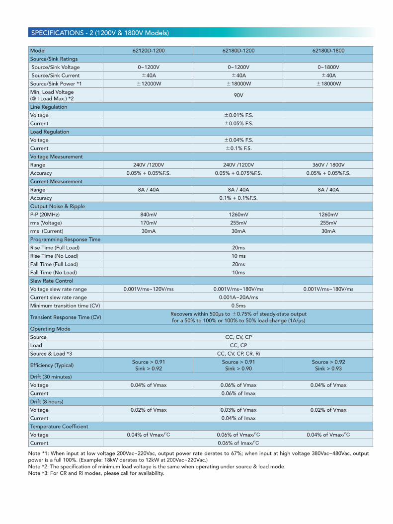
SPECIFICATIONSSPECIFICATIONS - 1 (100V & 600V Models)
Model 62060D-100 62120D-100 62180D-100 62060D-600 62120D-600 62180D-600
Source/Sink Ratings
Source/Sink Voltage 0~100V 0~600V
Source/Sink Current ±180A ±360A ±540A ±40A ±80A ±120A
Source/Sink Power *1 ±6000W ±12000W ±18000W ±6000W ±12000W ±18000W
Min. Load Voltage(@ I Load Max.) *2
5V 30V
Line Regulation
Voltage ±0.01% F.S.
Current ±0.05% F.S.
Load Regulation
Voltage ±0.02% F.S.
Current ±0.1% F.S.
Voltage Measurement
Range 20V / 100V 120V / 600V
Accuracy 0.05% + 0.05%F.S.
Current Measurement
Range 36A / 180A 72A / 360A 108A / 540A 8A / 40A 16A / 80A 24A / 120A
Accuracy 0.1% + 0.1%F.S.
Output Noise & Ripple
P-P (20MHz) 150 mV 420mV
rms (Voltage) 25 mV 85mV
rms (Current) 150mA 300mA 450mA 30mA 60mA 90mA
Programming Response Time
Rise Time (Full Load) 10 ms 20ms
Rise Time (No Load) 10 ms 10 ms
Fall Time (Full Load) 10 ms 20ms
Fall Time (No Load) 10 ms 10 ms
Slew Rate Control
Voltage slew rate range 0.001V/ms~ 10V/ms 0.001V/ms~60V/ms
Current slew rate range0.001A~10A/ms
0.001A~20A/ms
0.001A~30A/ms
0.001A~20A/ms
0.001A~40A/ms
0.001A~60A/ms
Minimum transition time (CV) 0.5ms 0.5ms
Transient Response Time (CV)Recovers within 500µs to ±0.75% of steady-state output for a 50% to 100%
or 100% to 50% load change (1A/µs)
Operating Mode
Source CC, CV, CP
Load CC, CP
Source & Load *3 CC, CV, CP, CR, Ri
Efficiency (Typical)Source > 0.91
Sink > 0.90Source > 0.91
Sink > 0.90Source > 0.92
Sink > 0.90Source > 0.91
Sink > 0.92Source > 0.92
Sink > 0.93Source > 0.92
Sink > 0.93
Drift (30 minutes)
Voltage 0.04% of Vmax 0.04% of Vmax
Current 0.06% of Imax 0.06% of Imax
Drift (8 hours)
Voltage 0.02% of Vmax 0.02% of Vmax
Current 0.04% of Imax 0.04% of Imax
Temperature Coefficient
Voltage 0.04% of Vmax/℃ 0.04% of Vmax/℃
Current 0.06% of Imax/℃ 0.06% of Imax/℃
Note *1: When input at low voltage 200Vac~220Vac, output power rate derates to 67%; when input at high voltage 380Vac~480Vac, output power is a full 100%. (Example: 18kW derates to 12kW at 200Vac~220Vac.)Note *2: The specification of minimum load voltage is the same when operating under source & load mode.Note *3: For CR and Ri modes, please call for availability.
SPECIFICATIONS - 1 (100V & 600V Models)
Note *4: For higher power >180kW~540kW, please call for availability.* All specifications are subject to change without notice.
• Continued on next page ➟
Model 62060D-100 62120D-100 62180D-100 62060D-600 62120D-600 62180D-600Programming & Measurement ResolutionVoltage (Front Panel ) 10 mV 10 mVCurrent (Front Panel) 10 mA 10 mAVoltage (Digital Interface) 0.002% of Vmax 0.002% of VmaxCurrent (Digital Interface) 0.004% of Imax 0.002% of ImaxVoltage (Analog Interface ) 0.04% of Vmax 0.04% of VmaxCurrent (Analog Interface ) 0.04% of Imax 0.04% of ImaxProgramming AccuracyVoltage (Front Panel and Digital Interface) 0.05% of Vmax 0.05% of VmaxCurrent (Front Panel and Digital Interface) 0.2% of Imax 0.2% of ImaxPower (Front Panel and Digital Interface) 0.3% of Pmax 0.3% of PmaxVoltage (Analog Interface) 0.2% of Vmax 0.2% of VmaxCurrent (Analog Interface) 0.3% of Imax 0.3% of ImaxAPG Measurement AccuracyVoltage (Analog Interface) 0.5% of Vmax 0.5% of VmaxCurrent (Analog Interface) 0.75% of Imax 0.75% of ImaxAnalog Interface (I/O)
Voltage and CurrentProgramming Inputs (I/P)
Voltage : 0~10 Vdc of F.S. Current : Source I : 0~10 Vdc of F.S.
Load I : 0~10 Vdc of F.S.Voltage and CurrentMonitor Output (O/P)
Voltage : 0~10 Vdc of F.S. Current : -10~10 Vdc of F.S.
External ON/OFF (I/P) TTL: Active Low or High (selective)DC_ON Signal (O/P) Level by user defined (Time delay=1ms at voltage slew rate of 10V/ms.)CV or CC Mode Indicator (O/P) TTL Level High=CV mode ; TTL Level Low=CC modeOTP Indicator (O/P) TTL: Active LowSystem Fault Indicator (O/P) TTL: Active LowSafety Interlock (I/P) Time accuracy: <100msRemote Inhibit (I/P) TTL: Active LowOVP Adjustment RangeRange 0~110% programmableAccuracy ±1% of full scale output Auto Sequencing (List Mode)Number of Program 10Number of Sequence 100Dwell time Range 2ms~15,000sTrig. Source Manual / Auto / ExternalAuto Sequencing (Step Mode)Start Voltage 0 to full scaleEnd Voltage 0 to full scaleRun Time hh : mm : ss.sss ( 00 : 00 : 00.001 to 99 : 59 : 59.99 )Trig. Source Auto
Series & Parallel Operation *4Master / save control for 3 units(Series: 2 units / Parallel: 3 units)
Master / slave control for 10 units(Series: 2 units / Parallel: 10 units)
Input Specification
AC Input Voltage 3-phase, 3-wire + Ground (w/o neutral)
3Φ 200Vac~220Vac±10% w/o neutral3Φ 380Vac~480Vac±10% w/o neutral
(67% output power@200~220Vac input, 100% output power@380~480Vac input)AC Frequency Range 47~63 HzPower Factor >0.97General SpecificationMaximum Remote Sense Line Drop Compensation
2% of full scale voltage per line (5% total) 2% of full scale voltage per line (4% total)
Operating Temperature Range 0℃~40℃Storage Temperature Range -25℃~70℃Dimension Size (HxWxD) mm 133 x 428 x 730 mm / 5.23 x 16.85 x 28.74 inchWeight (kg) 32.6 kg/71.9 lbs 38.8 kg/85.5 lbs 45 kg/100 lbs 30.6 kg/67.4 lbs 34.8 kg/76.7 lbs 39 kg/86.1 lbs
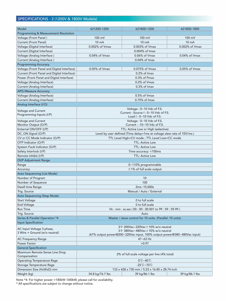
SPECIFICATIONSSPECIFICATIONS - 2 (1200V & 1800V Models)
Model 62120D-1200 62180D-1200 62180D-1800
Source/Sink Ratings
Source/Sink Voltage 0~1200V 0~1200V 0~1800V
Source/Sink Current ±40A ±40A ±40A
Source/Sink Power *1 ±12000W ±18000W ±18000W
Min. Load Voltage(@ I Load Max.) *2
90V
Line Regulation
Voltage ±0.01% F.S.
Current ±0.05% F.S.
Load Regulation
Voltage ±0.04% F.S.
Current ±0.1% F.S.
Voltage Measurement
Range 240V /1200V 240V /1200V 360V / 1800V
Accuracy 0.05% + 0.05%F.S. 0.05% + 0.075%F.S. 0.05% + 0.05%F.S.
Current Measurement
Range 8A / 40A 8A / 40A 8A / 40A
Accuracy 0.1% + 0.1%F.S.
Output Noise & Ripple
P-P (20MHz) 840mV 1260mV 1260mV
rms (Voltage) 170mV 255mV 255mV
rms (Current) 30mA 30mA 30mA
Programming Response Time
Rise Time (Full Load) 20ms
Rise Time (No Load) 10 ms
Fall Time (Full Load) 20ms
Fall Time (No Load) 10ms
Slew Rate Control
Voltage slew rate range 0.001V/ms~120V/ms 0.001V/ms~180V/ms 0.001V/ms~180V/ms
Current slew rate range 0.001A~20A/ms
Minimum transition time (CV) 0.5ms
Transient Response Time (CV)Recovers within 500µs to ±0.75% of steady-state outputfor a 50% to 100% or 100% to 50% load change (1A/µs)
Operating Mode
Source CC, CV, CP
Load CC, CP
Source & Load *3 CC, CV, CP, CR, Ri
Efficiency (Typical)Source > 0.91
Sink > 0.92Source > 0.91
Sink > 0.90Source > 0.92
Sink > 0.93
Drift (30 minutes)
Voltage 0.04% of Vmax 0.06% of Vmax 0.04% of Vmax
Current 0.06% of Imax
Drift (8 hours)
Voltage 0.02% of Vmax 0.03% of Vmax 0.02% of Vmax
Current 0.04% of Imax
Temperature Coefficient
Voltage 0.04% of Vmax/℃ 0.06% of Vmax/℃ 0.04% of Vmax/℃
Current 0.06% of Imax/℃
Note *1: When input at low voltage 200Vac~220Vac, output power rate derates to 67%; when input at high voltage 380Vac~480Vac, output power is a full 100%. (Example: 18kW derates to 12kW at 200Vac~220Vac.)Note *2: The specification of minimum load voltage is the same when operating under source & load mode.Note *3: For CR and Ri modes, please call for availability.
SPECIFICATIONS - 2 (1200V & 1800V Models)
Note *4: For higher power >180kW~540kW, please call for availability.* All specifications are subject to change without notice.
Model 62120D-1200 62180D-1200 62180D-1800Programming & Measurement ResolutionVoltage (Front Panel ) 100 mV 100 mV 100 mVCurrent (Front Panel) 10 mA 10 mA 10 mAVoltage (Digital Interface) 0.002% of Vmax 0.003% of Vmax 0.002% of VmaxCurrent (Digital Interface) 0.004% of ImaxVoltage (Analog Interface ) 0.04% of Vmax 0.06% of Vmax 0.04% of VmaxCurrent (Analog Interface ) 0.04% of ImaxProgramming AccuracyVoltage (Front Panel and Digital Interface) 0.05% of Vmax 0.075% of Vmax 0.05% of VmaxCurrent (Front Panel and Digital Interface) 0.2% of ImaxPower (Front Panel and Digital Interface) 0.3% of PmaxVoltage (Analog Interface) 0.2% of VmaxCurrent (Analog Interface) 0.3% of ImaxAPG Measure AccuracyVoltage (Analog Interface) 0.5% of VmaxCurrent (Analog Interface) 0.75% of ImaxAnalog Interface (I/O)
Voltage and CurrentProgramming Inputs (I/P)
Voltage : 0~10 Vdc of F.S. Current : Source I : 0~10 Vdc of F.S.
Load I : 0~10 Vdc of F.S.Voltage and CurrentMonitor Output (O/P)
Voltage : 0~10 Vdc of F.S. Current : -10~10 Vdc of F.S.
External ON/OFF (I/P) TTL: Active Low or High (selective)DC_ON Signal (O/P) Level by user defined (Time delay=1ms at voltage slew rate of 10V/ms.)CV or CC Mode Indicator (O/P) TTL Level High=CV mode ; TTL Level Low=CC modeOTP Indicator (O/P) TTL: Active LowSystem Fault Indicator (O/P) TTL: Active LowSafety Interlock (I/P) Time accuracy: <100msRemote Inhibit (I/P) TTL: Active LowOVP Adjustment RangeRange 0~110% programmableAccuracy ±1% of full scale output Auto Sequencing (List Mode)Number of Program 10Number of Sequence 100Dwell time Range 2ms~15,000sTrig. Source Manual / Auto / ExternalAuto Sequencing (Step Mode)Start Voltage 0 to full scaleEnd Voltage 0 to full scaleRun Time hh : mm : ss.sss ( 00 : 00 : 00.001 to 99 : 59 : 59.99 )Trig. Source AutoSeries & Parallel Operation *4 Master / slave control for 10 units. (Parallel: 10 units)Input Specification
AC Input Voltage 3 phase, 3 Wire + Ground (w/o neutral)
3Φ 200Vac~220Vac±10% w/o neutral3Φ 380Vac~480Vac±10% w/o neutral
(67% output power@200~220Vac input, 100% output power@380~480Vac input)AC Frequency Range 47~63 HzPower Factor >0.97General SpecificationMaximum Remote Sense Line Drop Compensation
2% of full scale voltage per line (4% total)
Operating Temperature Rage 0℃~40℃Storage Temperature Rage -25℃~70℃Dimension Size (HxWxD) mm 133 x 428 x 730 mm / 5.23 x 16.85 x 28.74 inchWeight (kg) 34.8 kg/76.7 lbs 39 kg/86.1 lbs 39 kg/86.1 lbs

iOS Android
Get more product & global distributor information in Chroma ATE APP
Search Keyword
62000D
62000D Series : Programmable Bidirectional DC Power Supply62060D-100 : Programmable Bidirectional DC Power Supply 100V/180A/6kW62120D-100 : Programmable Bidirectional DC Power Supply 100V/360A/12kW62180D-100 : Programmable Bidirectional DC Power Supply 100V/540A/18kW62060D-600 : Programmable Bidirectional DC Power Supply 600V/40A/6kW62120D-600 : Programmable Bidirectional DC Power Supply 600V/80A/12kW62180D-600 : Programmable Bidirectional DC Power Supply 600V/120A/18kW62120D-1200 : Programmable Bidirectional DC Power Supply 1200V/40A/12kW62180D-1200 : Programmable Bidirectional DC Power Supply 1200V/40A/18kW62180D-1800 : Programmable Bidirectional DC Power Supply 1800V/40A/18kWA620039 : GPIB InterfaceA620045 : CAN InterfaceA620046 : 62000D SoftpanelB620003: Optional Solar Array Simulation Function for model 62180D-1800 (Factory installation)
* Call for availability
*
ORDERING INFORMATION
62000D-EN-202109-1000
JAPANCHROMA JAPANCORP.888 Nippa-cho, Kouhoku-ku,Yokohama-shi,Kanagawa,223-0057 JapanT +81-45-542-1118F [email protected]
U.S.A.CHROMA SYSTEMS SOLUTIONS, INC.19772 Pauling, Foothill Ranch, CA 92610 T +1-949-600-6400F [email protected]
EUROPE CHROMA ATE EUROPE B.V. Morsestraat 32, 6716 AHEde, The NetherlandsT +31-318-648282F [email protected]
CHROMA GERMANY GMBHSüdtiroler Str. 9, 86165,Augsburg, GermanyT +49-821-790967-0F [email protected]
CHINACHROMA ELECTRONICS (SHENZHEN) CO., LTD.8F, No.4, Nanyou TianAn Industrial Estate,Shenzhen, ChinaT +86-755-2664-4598F +86-755-2641-9620 [email protected]
SOUTHEAST ASIAQUANTEL PTE LTD.(A company of Chroma Group)25 Kallang Avenue #05-02 Singapore 339416T +65-6745-3200F [email protected]
HEADQUARTERSCHROMA ATE INC.88 Wenmao Rd.,Guishan Dist.,Taoyuan City333001, TaiwanT +886-3-327-9999F [email protected]
KOREACHROMA ATEKOREA BRANCH3F RichtogetherCenter, 14,Pangyoyeok-ro 192, Bundang-gu,Seongnam-si,Gyeonggi-do13524, KoreaT +82-31-781-1025F [email protected]
PANEL DESCRIPTION
1 3 4
6
2 5
7 8 9 10 11 12 13
1. POWER Switch 2. TFT Control Interface Displays: measurements, setup, control, and status 3. USB HOST (not yet supported) Programming: program fetching, data downloading, firmware updates, etc. 4. Pushable Rotary Switch Rotate to edit screen and set values; after configuration, push to confirm input 5. OUTPUT ON Key Press the ON key: light indicates Output ON, dark indicates Output OFF
6. GPIB & CAN Interfaces Shared Slot (choose one) 7. Analog Programming Interface For analog level to program and monitor output voltage & current 8. DC Output Terminal 9. Remote Sense Terminal10. Current Sharing Terminal Connect the cable to slave unit11. USB Interface (standard)12. LAN Interface (standard)13. AC Input Terminal


