Embed Size (px)
Citation preview

1
SENIOR DESIGN PROJECT REPORT
Automated Power Supply Test Unit
Submitted To
Professor Cooney
Professor Weissbach
Professor Lin
Electrical Engineering Technology Program
Engineering Technology Department
By
K. Mitchell Brauns
Yazed Alanazi
05/01/2020
2
EXECUTIVE SUMMARY
This project will be completed by the request of Professor Cooney. The goal of this
senior design project is to create an automated power supply test unit. This
automated power supply test unit is needed to reduce the time to test students’
power supply projects. This report will cover the design process and testing process
in depth. A replica of the project should easily be made using this documentation.
The zero-crossing detector, triac control circuit, DC measurement circuit, and ripple
voltage measurement circuit are all thoroughly documented. The full code for the
Arduino Due and Nano is also included. Test results are shown for each step of the
testing process. Overall, the project was a success. Small improvements could be
made and will be covered in the recommendation portion.
3
Contents EXECUTIVE SUMMARY ................................................................................................................................................................................. 2
Definitions ............................................................................................................................................................................................... 4
Version History ........................................................................................................................................................................................ 4
Introduction ............................................................................................................................................................................................ 5
Project Scope .......................................................................................................................................................................................... 5
Out of Scope ........................................................................................................................................................................................... 5
Related Projects ...................................................................................................................................................................................... 5
Assumptions............................................................................................................................................................................................ 5
Process Overview .................................................................................................................................................................................... 6
Requirements .......................................................................................................................................................................................... 6
User Roles and Responsibilities ............................................................................................................................................................... 7
System Wide Design Options .................................................................................................................................................................. 8
Microcontroller Selection and Reasoning ............................................................................................................................................... 8
AC Voltage Controller Options ................................................................................................................................................................ 8
AC Voltage Controller Selection Reasoning ............................................................................................................................................. 8
Data Transfer Selection and Reasoning................................................................................................................................................... 9
Display Options ....................................................................................................................................................................................... 9
Display Selection and Reasoning ............................................................................................................................................................. 9
Cooling Selection and Reasoning .......................................................................................................................................................... 10
Hardware Block Diagram ...................................................................................................................................................................... 10
Software flowchart overview. ............................................................................................................................................................... 11
Interface Design .................................................................................................................................................................................... 12
Detailed Hardware Design – DC Measurement Circuit ......................................................................................................................... 13
Ripple Measurement Circuit ................................................................................................................................................................. 13
Zero Crossing Detection Circuit ............................................................................................................................................................. 14
AC Voltage Control Circuit ..................................................................................................................................................................... 15
Input / Output Table ............................................................................................................................................................................. 16
Software Flowchart – High Level ........................................................................................................................................................... 17
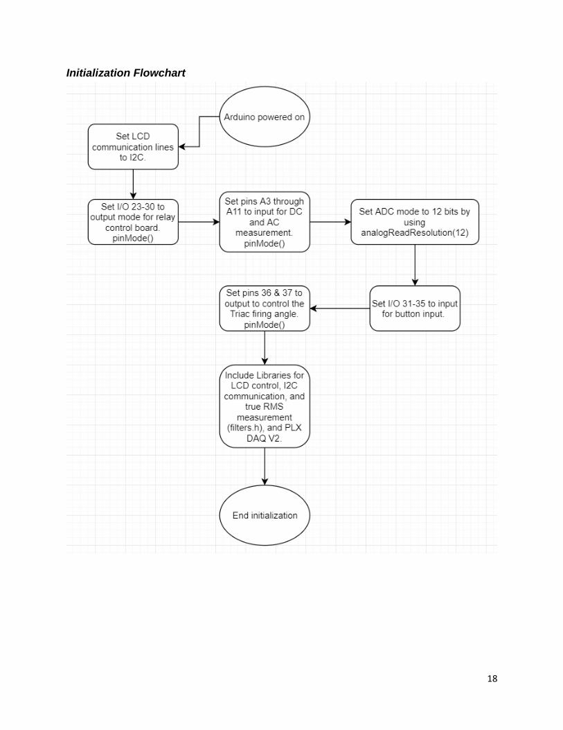
Initialization Flowchart .......................................................................................................................................................................... 18
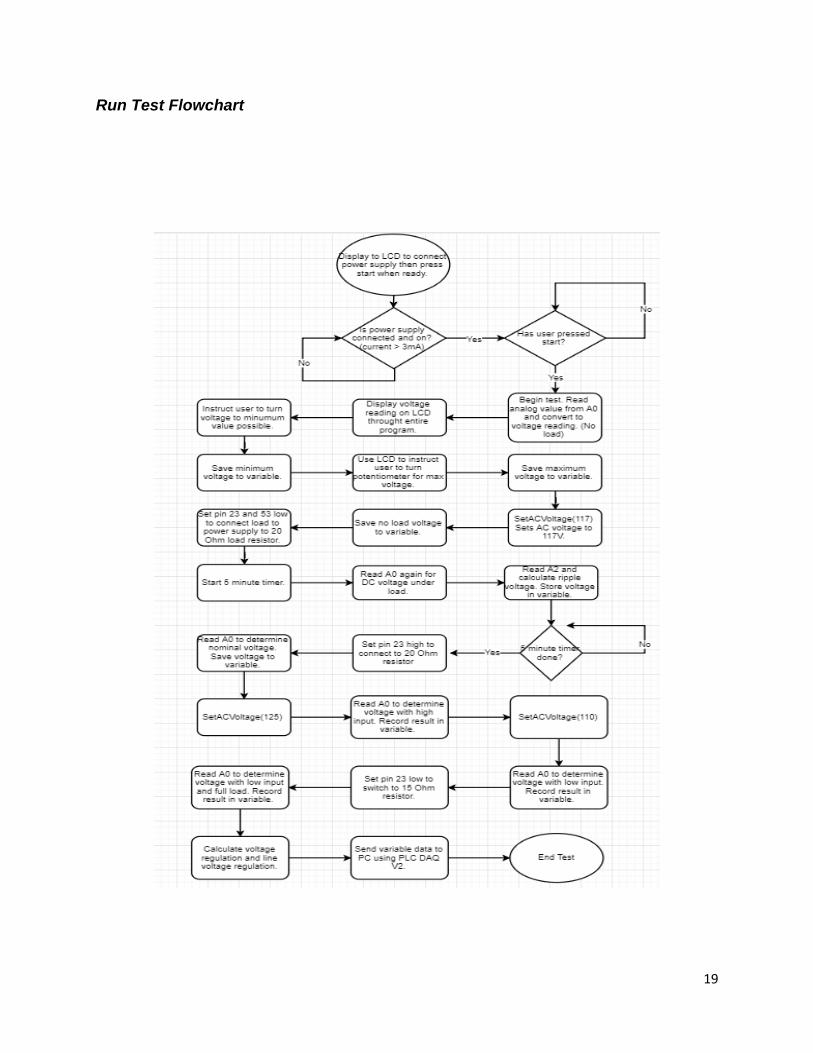
Run Test Flowchart ............................................................................................................................................................................... 19
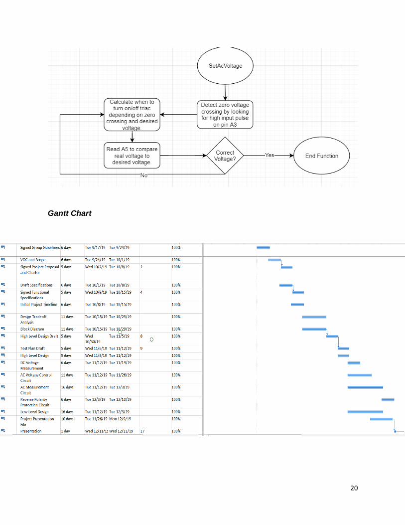
Gantt Chart ........................................................................................................................................................................................... 20
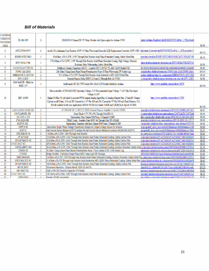
Bill of Materials ..................................................................................................................................................................................... 21
Code for Due ......................................................................................................................................................................................... 22
Code for Nano ....................................................................................................................................................................................... 45
Test Results ........................................................................................................................................................................................... 48
Final Product Pictures ........................................................................................................................................................................... 52
Recommendations ................................................................................................................................................................................ 52
References ............................................................................................................................................................................................ 53
Document Approval .............................................................................................................................................................................. 54
4
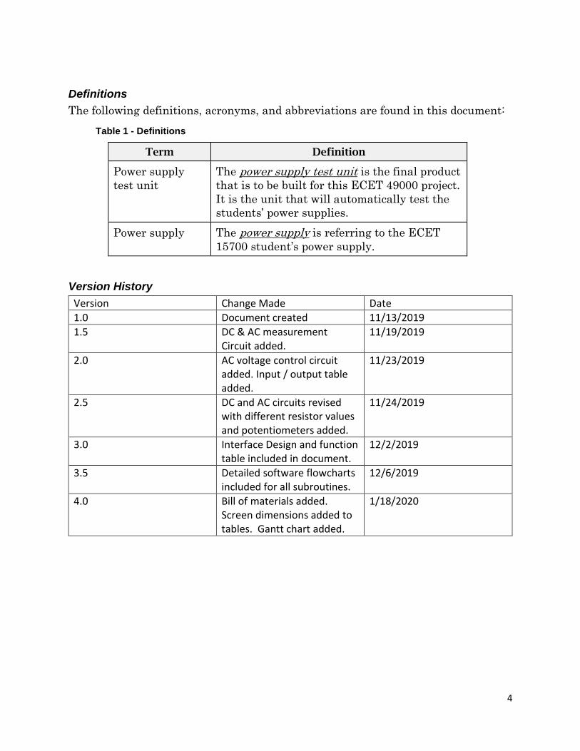
Definitions
The following definitions, acronyms, and abbreviations are found in this document:
Table 1 - Definitions
Term Definition
Power supply
test unit
The power supply test unit is the final product
that is to be built for this ECET 49000 project.
It is the unit that will automatically test the
students’ power supplies.
Power supply The power supply is referring to the ECET
15700 student’s power supply.
Version History
Version Change Made Date
1.0 Document created 11/13/2019
1.5 DC & AC measurement Circuit added.
11/19/2019
2.0 AC voltage control circuit added. Input / output table added.
11/23/2019
2.5 DC and AC circuits revised with different resistor values and potentiometers added.
11/24/2019
3.0 Interface Design and function table included in document.
12/2/2019
3.5 Detailed software flowcharts included for all subroutines.
12/6/2019
4.0 Bill of materials added. Screen dimensions added to tables. Gantt chart added.
1/18/2020
5
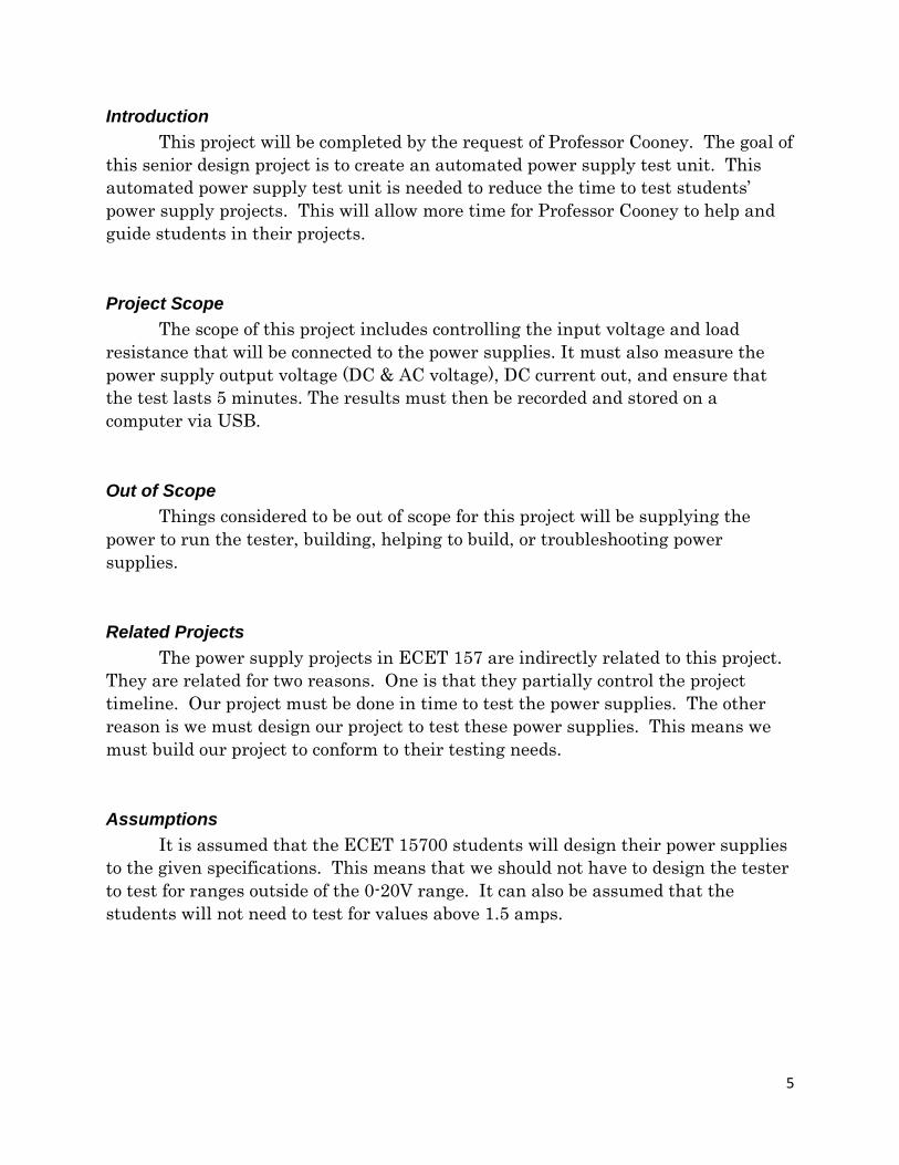
Introduction
This project will be completed by the request of Professor Cooney. The goal of
this senior design project is to create an automated power supply test unit. This
automated power supply test unit is needed to reduce the time to test students’
power supply projects. This will allow more time for Professor Cooney to help and
guide students in their projects.
Project Scope
The scope of this project includes controlling the input voltage and load
resistance that will be connected to the power supplies. It must also measure the
power supply output voltage (DC & AC voltage), DC current out, and ensure that
the test lasts 5 minutes. The results must then be recorded and stored on a
computer via USB.
Out of Scope
Things considered to be out of scope for this project will be supplying the
power to run the tester, building, helping to build, or troubleshooting power
supplies.
Related Projects
The power supply projects in ECET 157 are indirectly related to this project.
They are related for two reasons. One is that they partially control the project
timeline. Our project must be done in time to test the power supplies. The other
reason is we must design our project to test these power supplies. This means we
must build our project to conform to their testing needs.
Assumptions
It is assumed that the ECET 15700 students will design their power supplies
to the given specifications. This means that we should not have to design the tester
to test for ranges outside of the 0-20V range. It can also be assumed that the
students will not need to test for values above 1.5 amps.
6
Process Overview
(Current System)
The current system for testing the power supplies involves the professor
manually testing all aspects of the system. This process involves several time-
consuming steps. The first step is to set up the testing equipment, including the
oscilloscope, DMM, load resistors, variac, and any data recording equipment. The
professor must then connect the student’s power supply to the testing equipment.
After all equipment is set up and connected together, the professor must manually
run the test. The testing process is started by running the power supply on the 15-
ohm load and recording the AC ripple voltage, the DC voltage, and the DC current.
This data must be recorded onto the data sheet manually. The professor must time
the test for 5 minutes to ensure that the power supply does not fail. The power
supply must also be tested with a lower AC input voltage, which is controlled by the
variac. This is a time-consuming process that must be streamlined through
automation.
(New Process)
The new process will automate as many of the steps as possible. The goal is
to have the AC and DC voltage automatically measured, the loads automatically
switched, and all data recorded without the input of a user. Doing this should save
the instructor time.
Requirements
Customer Requirements
The power supply test unit must control the input voltage and load resistance
that will be connected to the power supplies. It must also measure the power supply
output voltage (DC & AC voltage), DC current out, and ensure that the test lasts 5
minutes. The results must then be recorded and stored on a computer via USB.
Engineering Specifications
1. Unit power supply test unit should test power supply at 1 amp.
2. The power supply test unit must test the power supply for exactly 5 minutes.
3. The AC input voltage must be varied automatically from 125 to 110 V RMS.
4. The power supply test unit output voltage must be within 1V rms of the
specified output.
5. The power supply test unit must be accurate to 100mV when measuring DC
voltage.
7
6. The power supply test unit must be accurate to 0.5mV when measuring AC
ripple voltage.
7. Reverse polarity protection should be included for the power supply test unit
to protect from the student connecting their power supply backwards.
8. User interface screen for instructions and status. Must display items at or
above the size of 1cm.
9. USB connection to computer with autosave function to a pre-determined file.
Must complete the data transfer in under two minutes.
10. The AC voltage measurement must cover the 1mV-3V range.
11. The power supply test unit must be able to run for a continuous time of 2
hours minimum.
12. The power supply test unit must be able to dissipate a minimum of 15 watts
continuously for 2 hours.
13. The power supply test unit must be able to measure DC voltage within the 0-
20V range.
14. The power supply test unit must have a built-in safety margin for the DC
voltage it is measuring. The test unit should be able to safely handle up to a
50V DC input.
Hardware
Inputs: DC Voltage, AC voltage
Outputs: AC voltage (line voltage), USB out to computer
User Roles and Responsibilities
• The user must set up the power supply test unit. This includes plugging in
the USB to the computer, opening the corresponding program, and plugging
the tester into the provided wall outlet.
• The user must also connect the power supply that is to be tested to the test
unit. This consists of connecting the positive and negative terminals to the
corresponding locations.
• The power supply voltage out must also be manually controlled by the user.
There will be an indication screen showing when to change the voltage, and
to what level it should be changed.
8
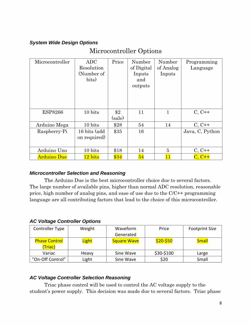
System Wide Design Options
Microcontroller Options
Microcontroller ADC
Resolution
(Number of
bits)
Price Number
of Digital
Inputs
and
outputs
Number
of Analog
Inputs
Programming
Language
ESP8266 10 bits $2
(sale)
11 1 C, C++
Arduino Mega 10 bits $28 54 14 C, C++
Raspberry-Pi 16 bits (add
on required)
$35 16 Java, C, Python
Arduino Uno 10 bits $18 14 5 C, C++
Arduino Due 12 bits $34 54 11 C, C++
Microcontroller Selection and Reasoning
The Arduino Due is the best microcontroller choice due to several factors.
The large number of available pins, higher than normal ADC resolution, reasonable
price, high number of analog pins, and ease of use due to the C/C++ programming
language are all contributing factors that lead to the choice of this microcontroller.
AC Voltage Controller Options
Controller Type Weight Waveform Generated
Price Footprint Size
Phase Control (Triac)
Light Square Wave $20-$50 Small
Variac Heavy Sine Wave $30-$100 Large
“On-Off Control” Light Sine Wave $20 Small
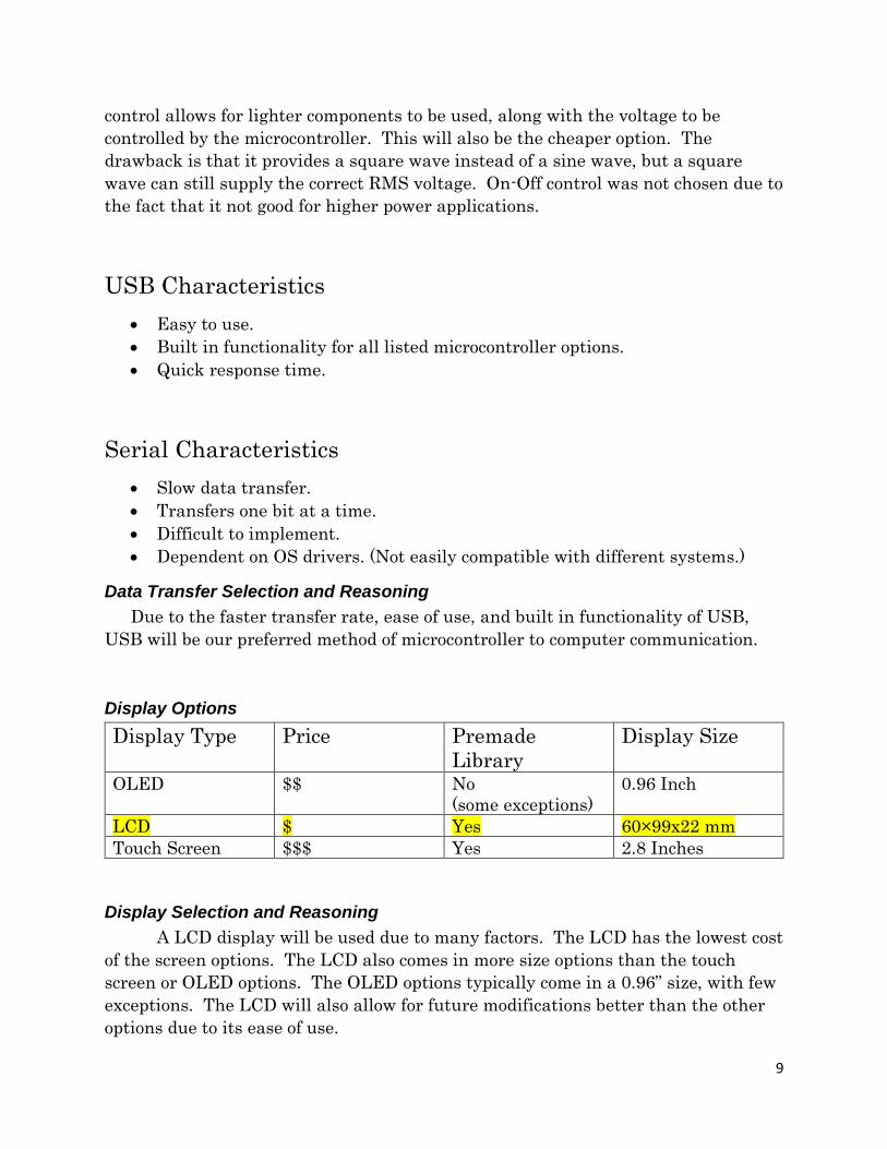
AC Voltage Controller Selection Reasoning
Triac phase control will be used to control the AC voltage supply to the
student’s power supply. This decision was made due to several factors. Triac phase
9
control allows for lighter components to be used, along with the voltage to be
controlled by the microcontroller. This will also be the cheaper option. The
drawback is that it provides a square wave instead of a sine wave, but a square
wave can still supply the correct RMS voltage. On-Off control was not chosen due to
the fact that it not good for higher power applications.
USB Characteristics
• Easy to use.
• Built in functionality for all listed microcontroller options.
• Quick response time.
Serial Characteristics
• Slow data transfer.
• Transfers one bit at a time.
• Difficult to implement.
• Dependent on OS drivers. (Not easily compatible with different systems.)
Data Transfer Selection and Reasoning
Due to the faster transfer rate, ease of use, and built in functionality of USB,
USB will be our preferred method of microcontroller to computer communication.
Display Options
Display Type Price Premade
Library
Display Size
OLED $$ No
(some exceptions)
0.96 Inch
LCD $ Yes 60×99x22 mm
Touch Screen $$$ Yes 2.8 Inches
Display Selection and Reasoning
A LCD display will be used due to many factors. The LCD has the lowest cost
of the screen options. The LCD also comes in more size options than the touch
screen or OLED options. The OLED options typically come in a 0.96” size, with few
exceptions. The LCD will also allow for future modifications better than the other
options due to its ease of use.
10
Cooling Selection and Reasoning
A fan will be used due to the heat produced in a constricted space. The power
supply test unit must dissipate 15 watts. This heat would most likely be too much
for passive cooling to handle. We will confirm or reject this decision depending on
the thermo analysis results.
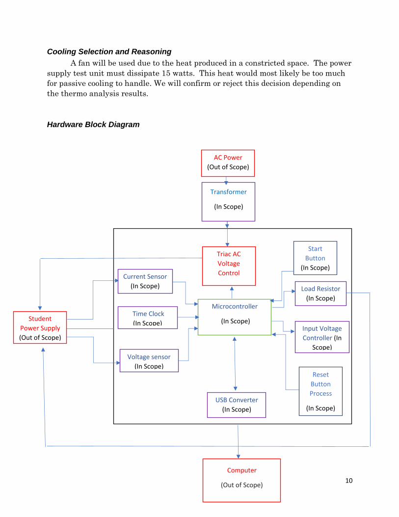
Hardware Block Diagram
AC Power
(Out of Scope)
Student
Power Supply
(Out of Scope)
Microcontroller
(In Scope)
Current Sensor
(In Scope)
Time Clock
(In Scope)
Voltage sensor
(In Scope)
Load Resistor
(In Scope)
Input Voltage
Controller (In
Scope)
Computer
(Out of Scope)
USB Converter
(In Scope)
Reset
Button
Process
(In Scope)
Start
Button
(In Scope)
Triac AC
Voltage
Control
Transformer
(In Scope)
11
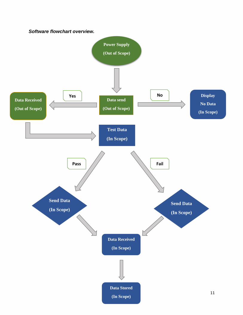
Software flowchart overview.
Power Supply
(Out of Scope)
Data send
(Out of Scope)
No Yes Data Received
(Out of Scope)
Display
No Data
(In Scope)
Test Data
(In Scope)
Send Data
(In Scope)
Send Data
(In Scope)
Fail Pass
Data Received
(In Scope)
Data Stored
(In Scope)
12
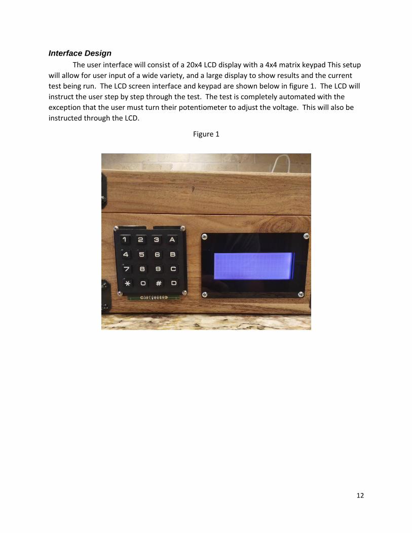
Interface Design
The user interface will consist of a 20x4 LCD display with a 4x4 matrix keypad This setup
will allow for user input of a wide variety, and a large display to show results and the current
test being run. The LCD screen interface and keypad are shown below in figure 1. The LCD will
instruct the user step by step through the test. The test is completely automated with the
exception that the user must turn their potentiometer to adjust the voltage. This will also be
instructed through the LCD.
Figure 1
13
Detailed Hardware Design – DC Measurement Circuit
There are four main circuits used in this project. They consist of a DC measurement, AC
measurement, Triac, and zero crossing detection circuit. The DC measurement circuit is
designed to take up to a 50V DC input and reduce it down to a 3V input. This is done to ensure
that the Arduino has over voltage protection. The resistors were chosen by using the formula
Vout = (Vin*R2)/(R1+R2). Vin was set to 50V and the desired output was 3V. There were many
resistor options to give this output, but a 51.1k in series and a 10k and 5k in parallel were
chosen due to the availability and pricing of these resistors. The circuit uses a relay to switch
between the measurement circuit with the load and without the load. This allows for the
power supply test unit to determine the voltage difference when a load is applied. Calibration
of this circuit is done in the code when needed.
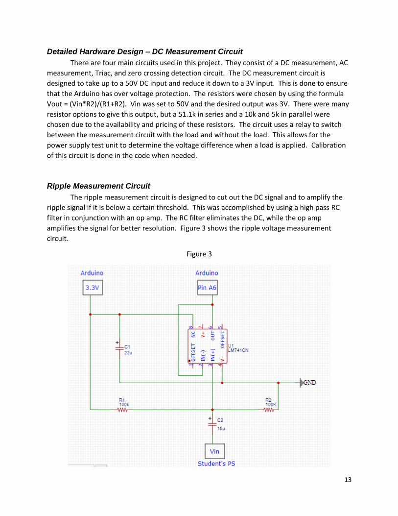
Ripple Measurement Circuit
The ripple measurement circuit is designed to cut out the DC signal and to amplify the
ripple signal if it is below a certain threshold. This was accomplished by using a high pass RC
filter in conjunction with an op amp. The RC filter eliminates the DC, while the op amp
amplifies the signal for better resolution. Figure 3 shows the ripple voltage measurement
circuit.
Figure 3
14
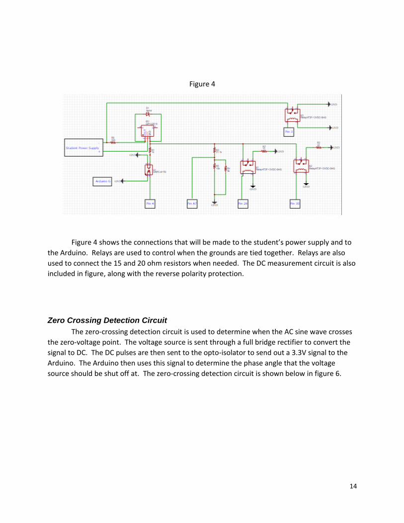
Figure 4
Figure 4 shows the connections that will be made to the student’s power supply and to
the Arduino. Relays are used to control when the grounds are tied together. Relays are also
used to connect the 15 and 20 ohm resistors when needed. The DC measurement circuit is also
included in figure, along with the reverse polarity protection.
Zero Crossing Detection Circuit
The zero-crossing detection circuit is used to determine when the AC sine wave crosses
the zero-voltage point. The voltage source is sent through a full bridge rectifier to convert the
signal to DC. The DC pulses are then sent to the opto-isolator to send out a 3.3V signal to the
Arduino. The Arduino then uses this signal to determine the phase angle that the voltage
source should be shut off at. The zero-crossing detection circuit is shown below in figure 6.
15
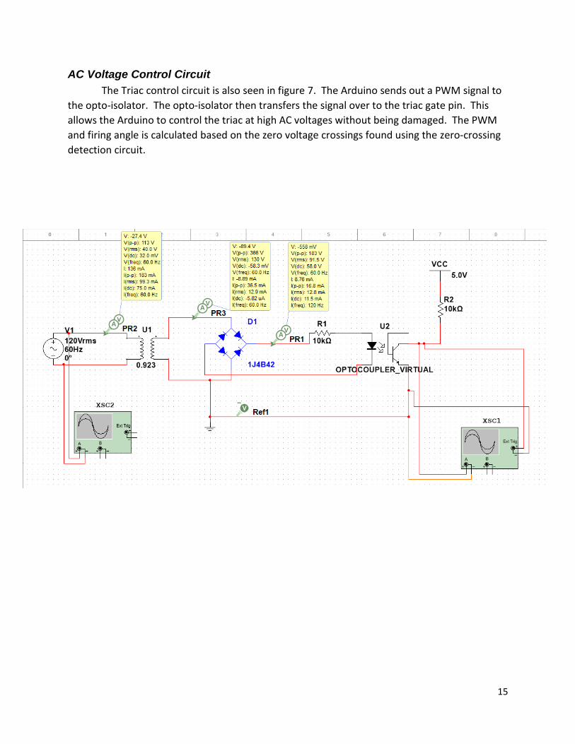
AC Voltage Control Circuit
The Triac control circuit is also seen in figure 7. The Arduino sends out a PWM signal to
the opto-isolator. The opto-isolator then transfers the signal over to the triac gate pin. This
allows the Arduino to control the triac at high AC voltages without being damaged. The PWM
and firing angle is calculated based on the zero voltage crossings found using the zero-crossing
detection circuit.
16
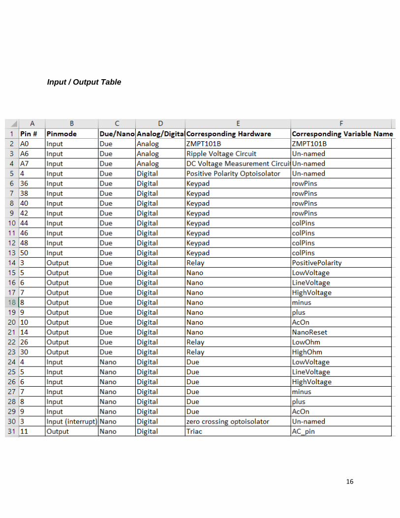
Input / Output Table
17
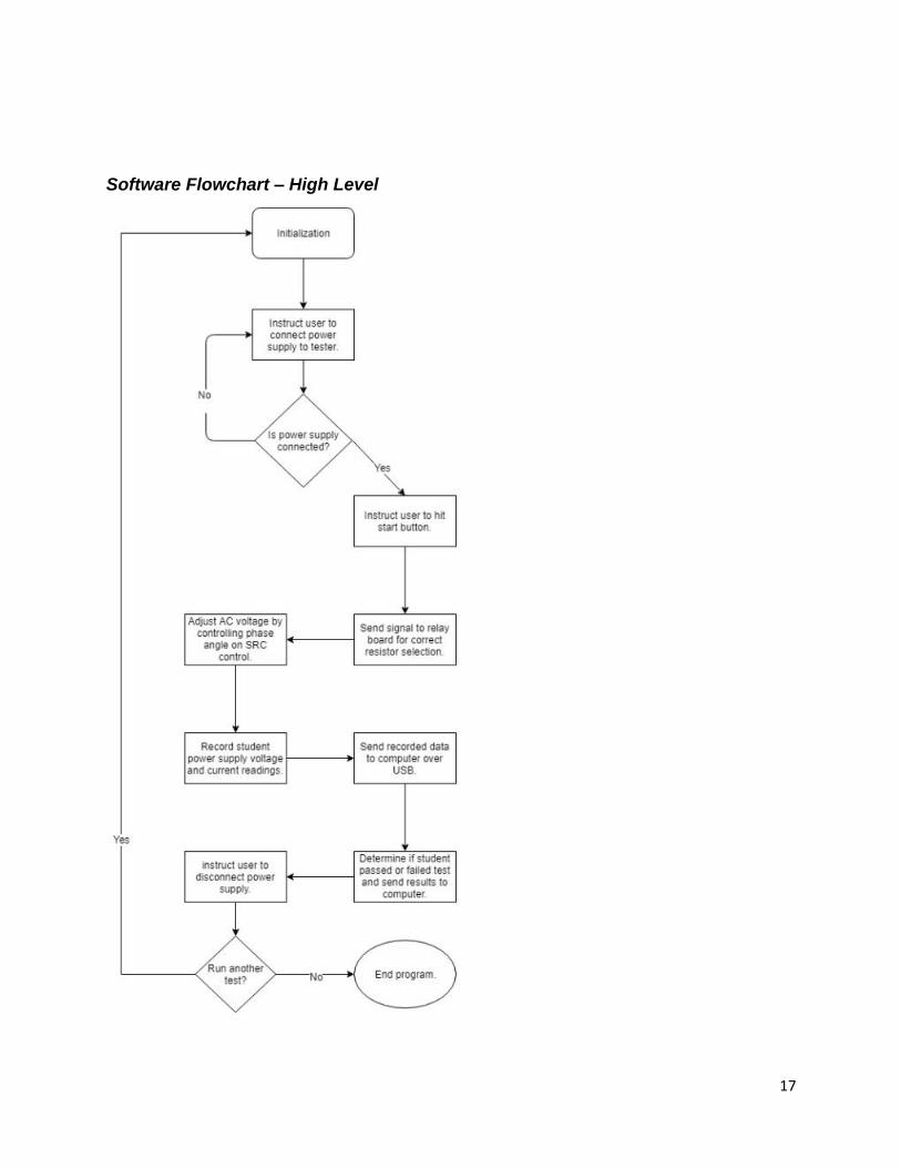
Software Flowchart – High Level
18
Initialization Flowchart
19
Run Test Flowchart
20
Gantt Chart
21
Bill of Materials
22
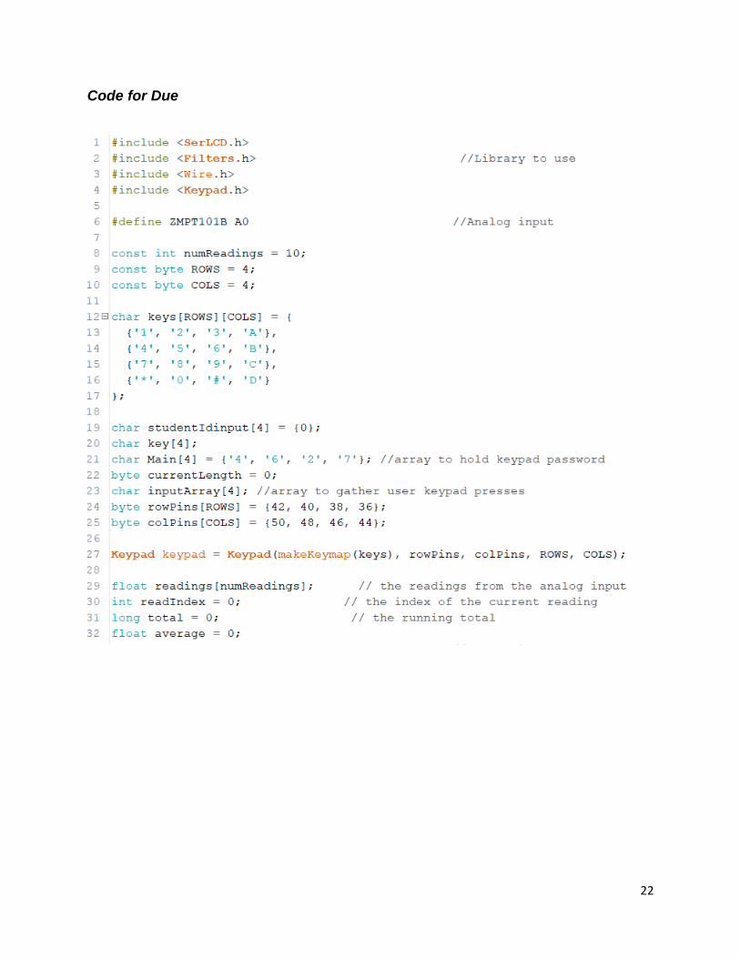
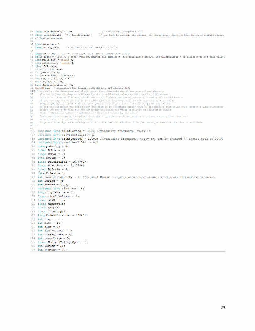
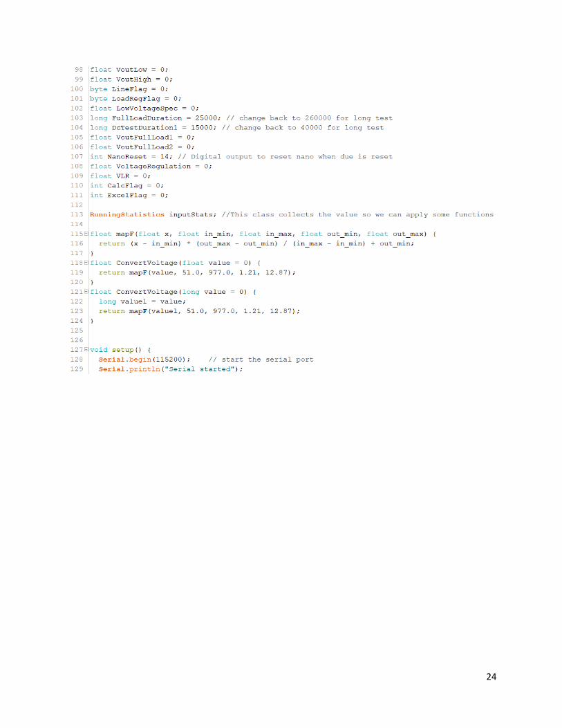
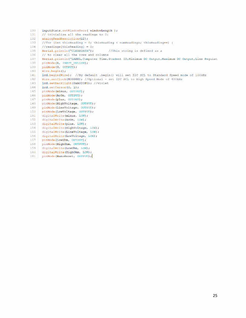
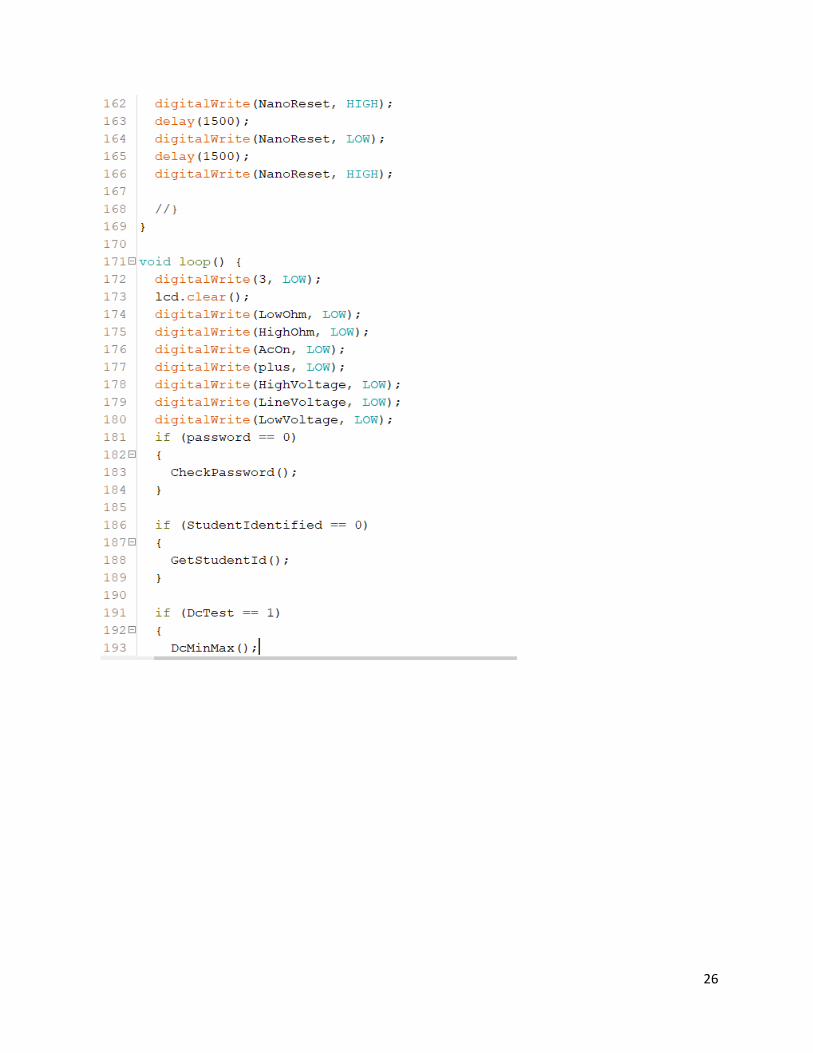
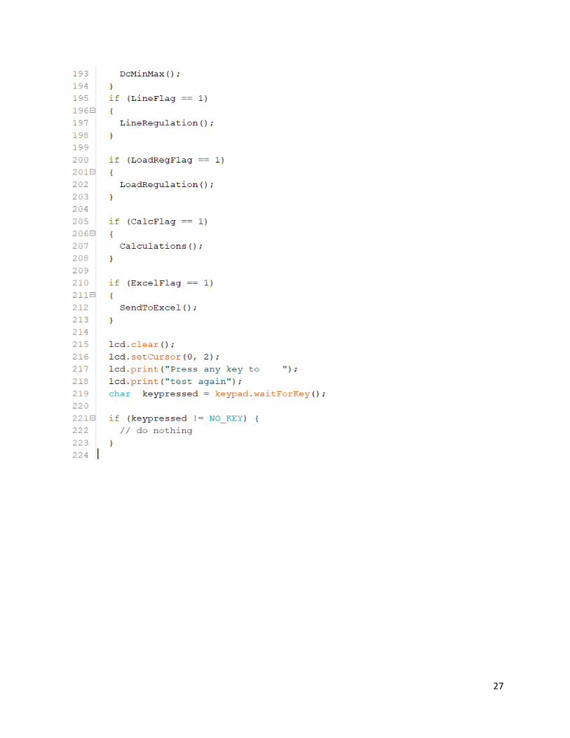
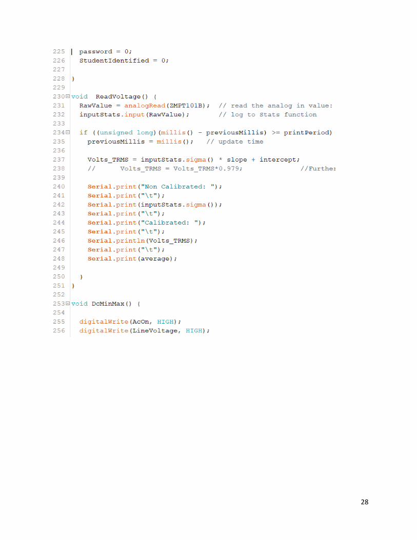
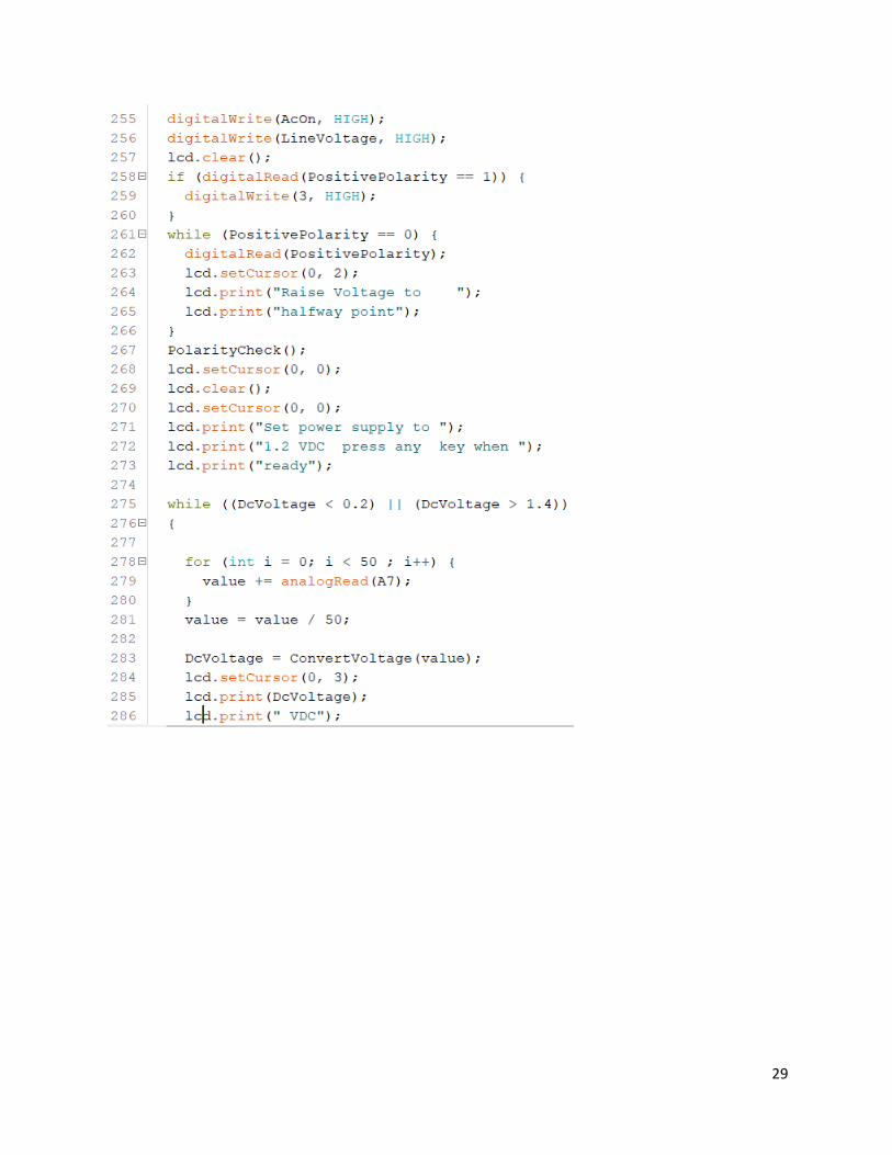
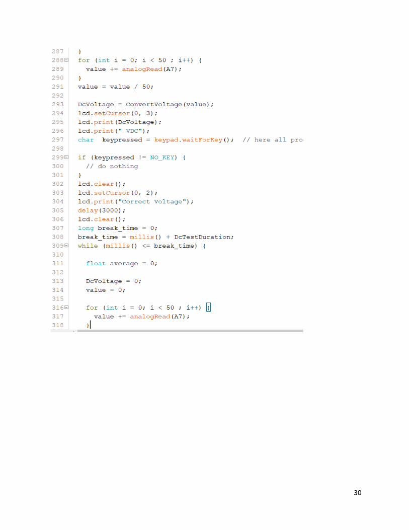
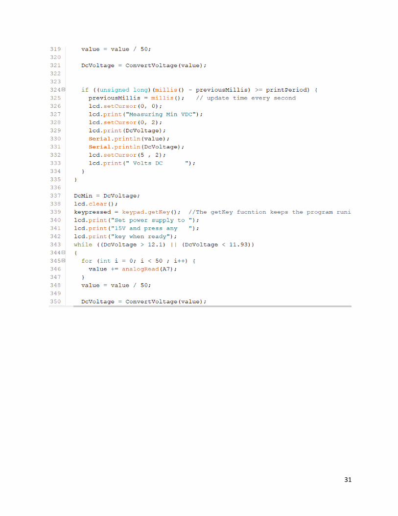
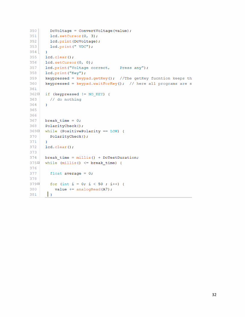
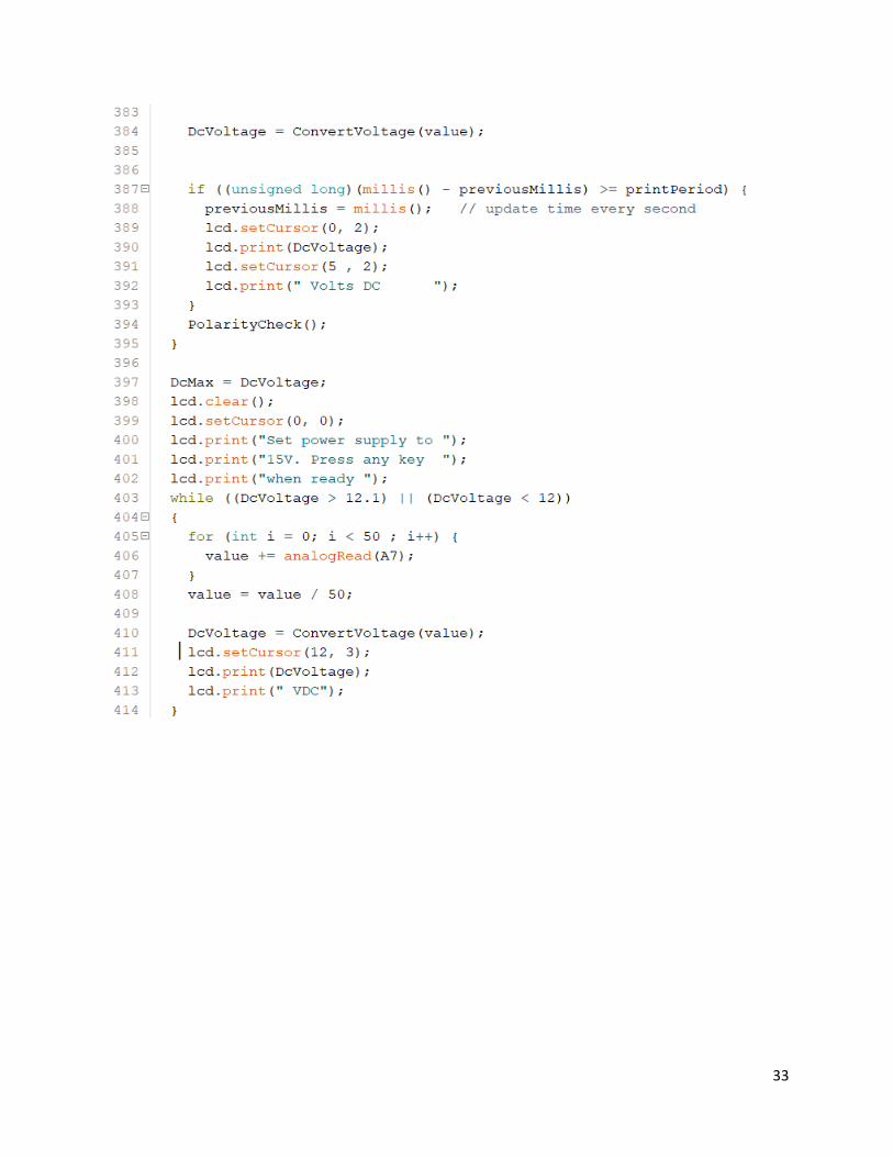
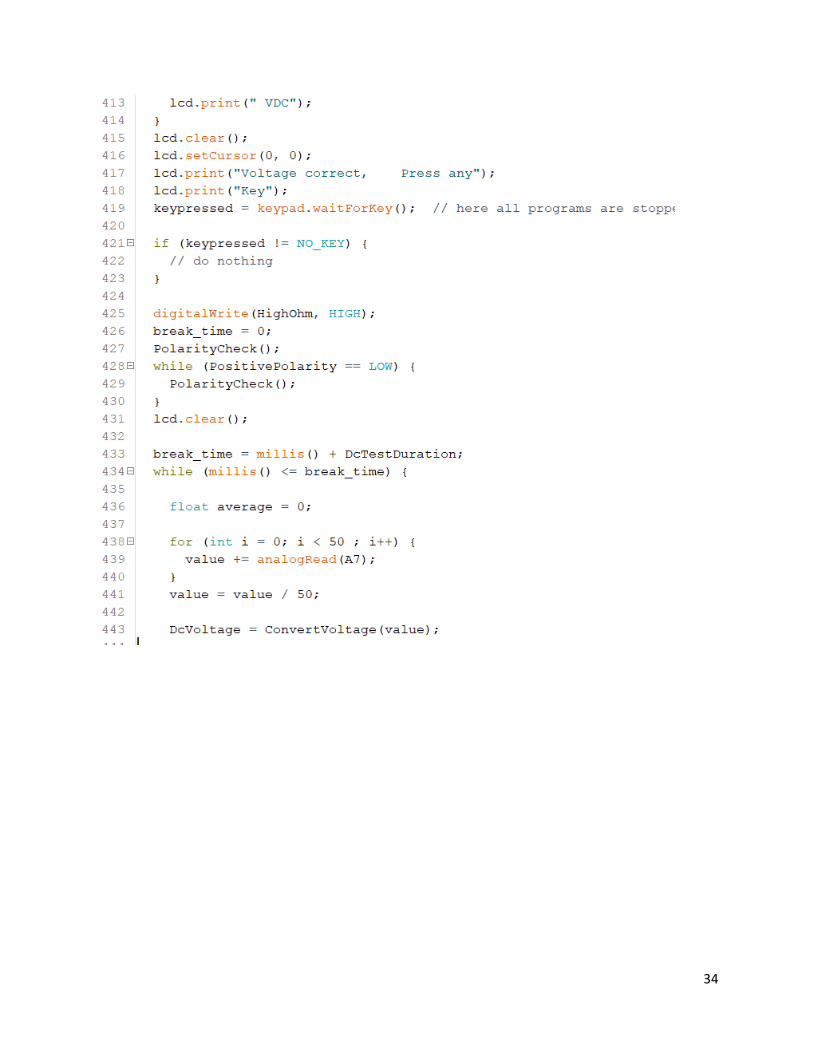
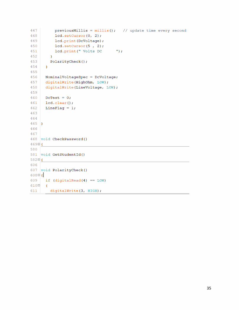
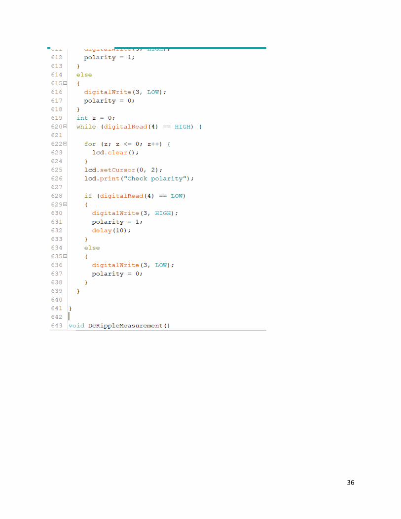
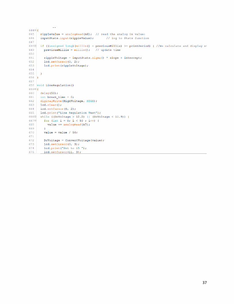
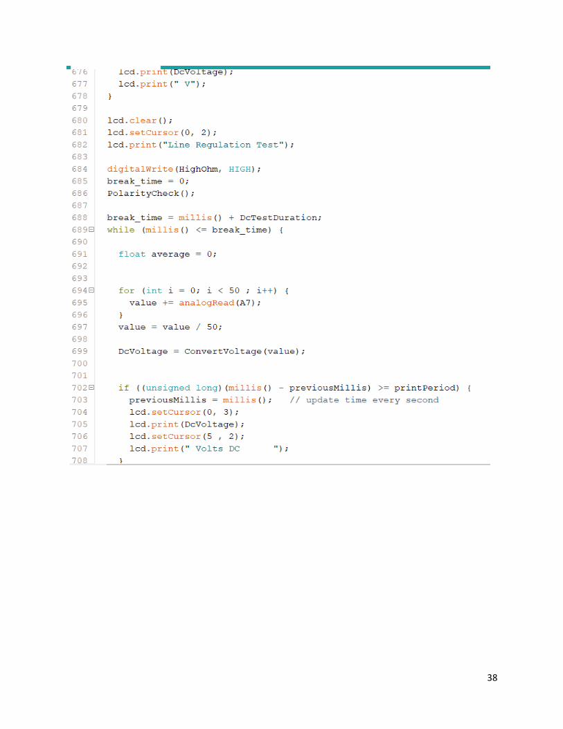
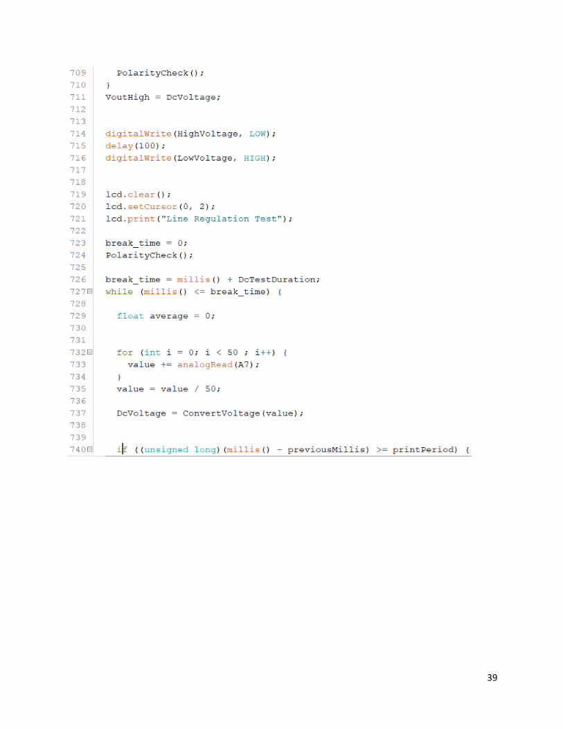
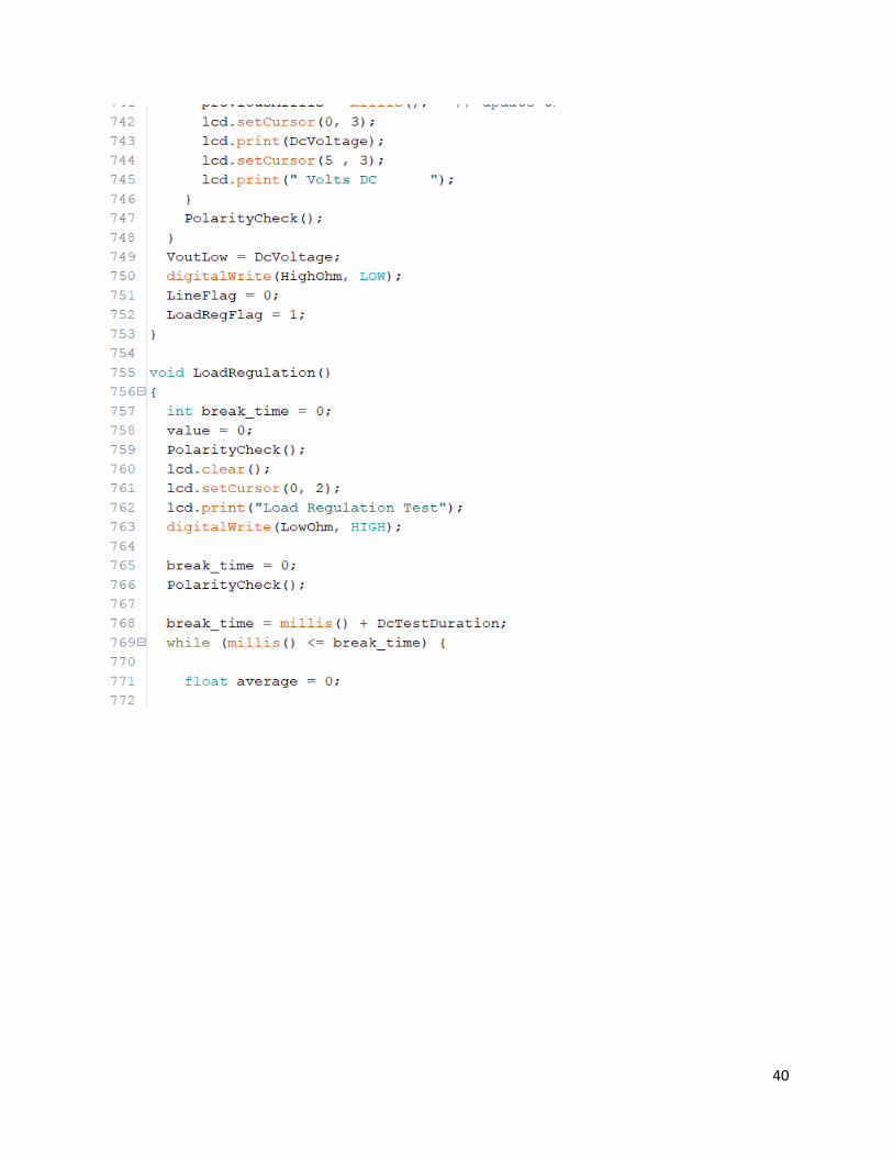
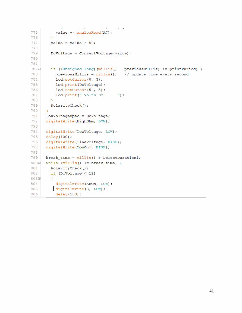
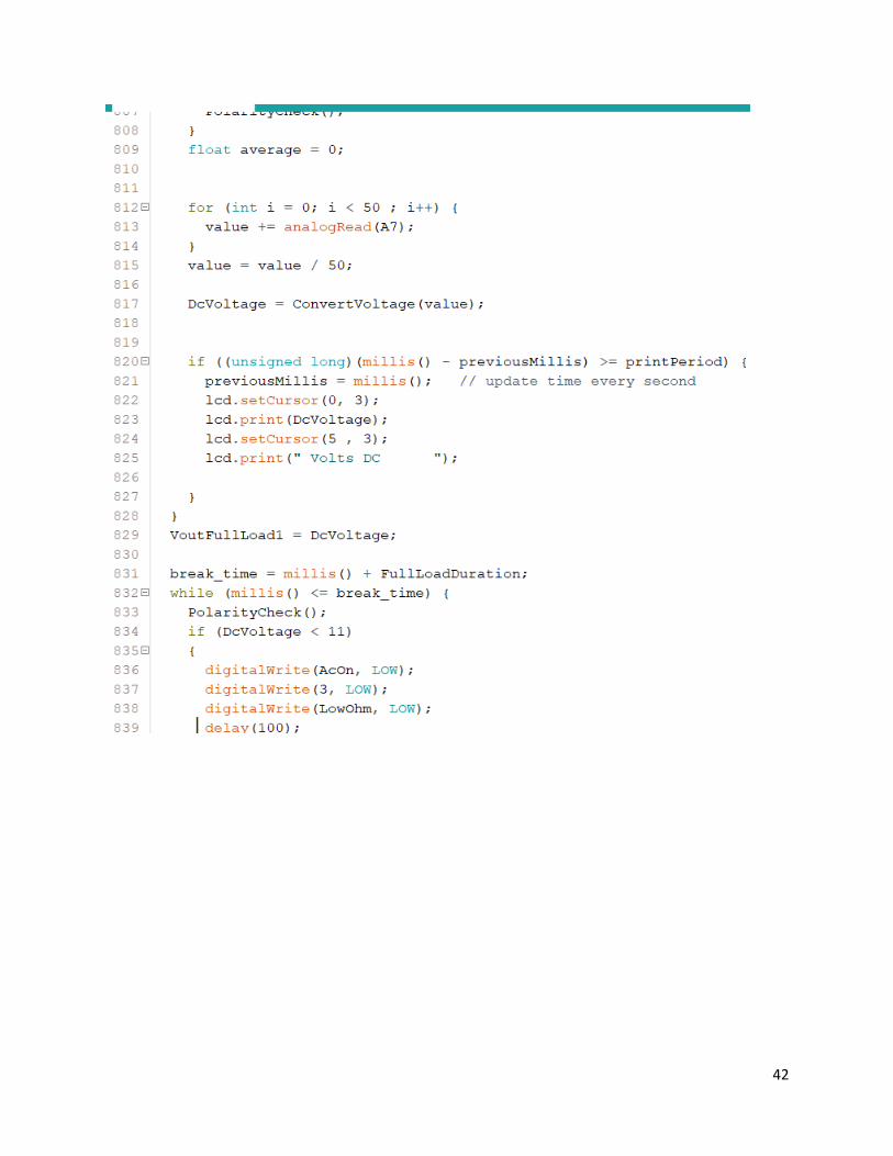
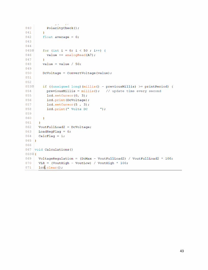
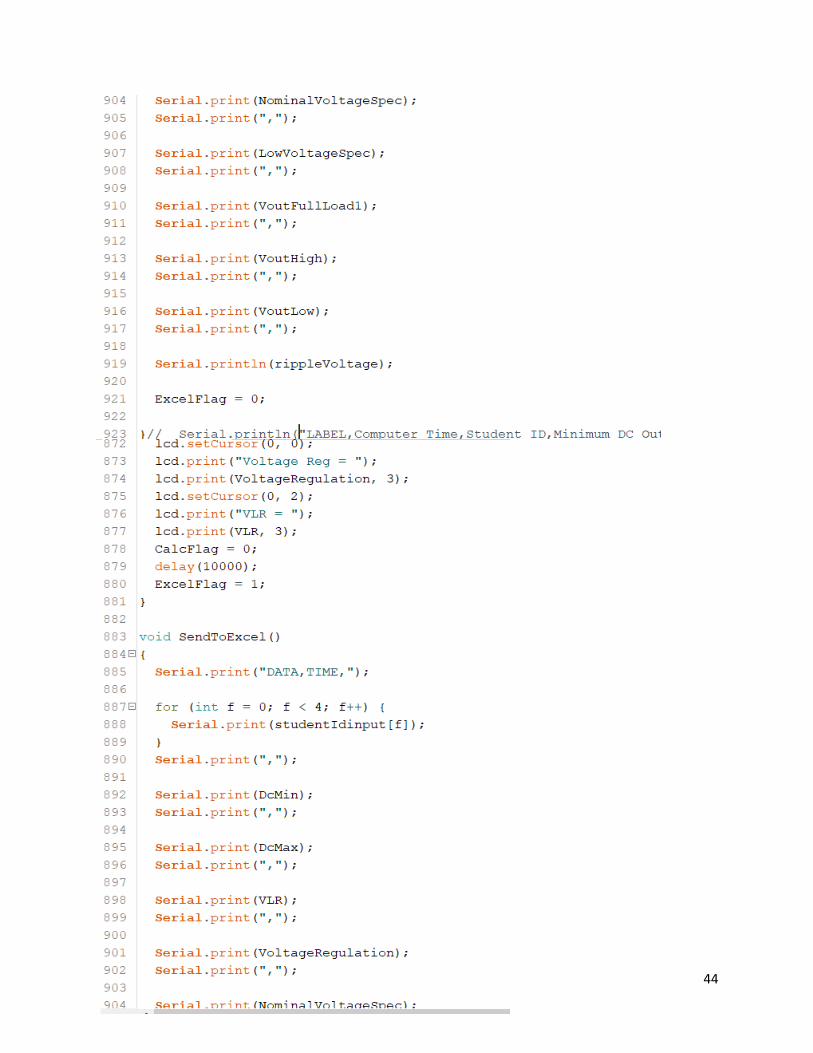
Code for Due
23
24
25
26
27
28
29
30
31
32
33
34
35
36
37
38
39
40
41
42
43
44
45
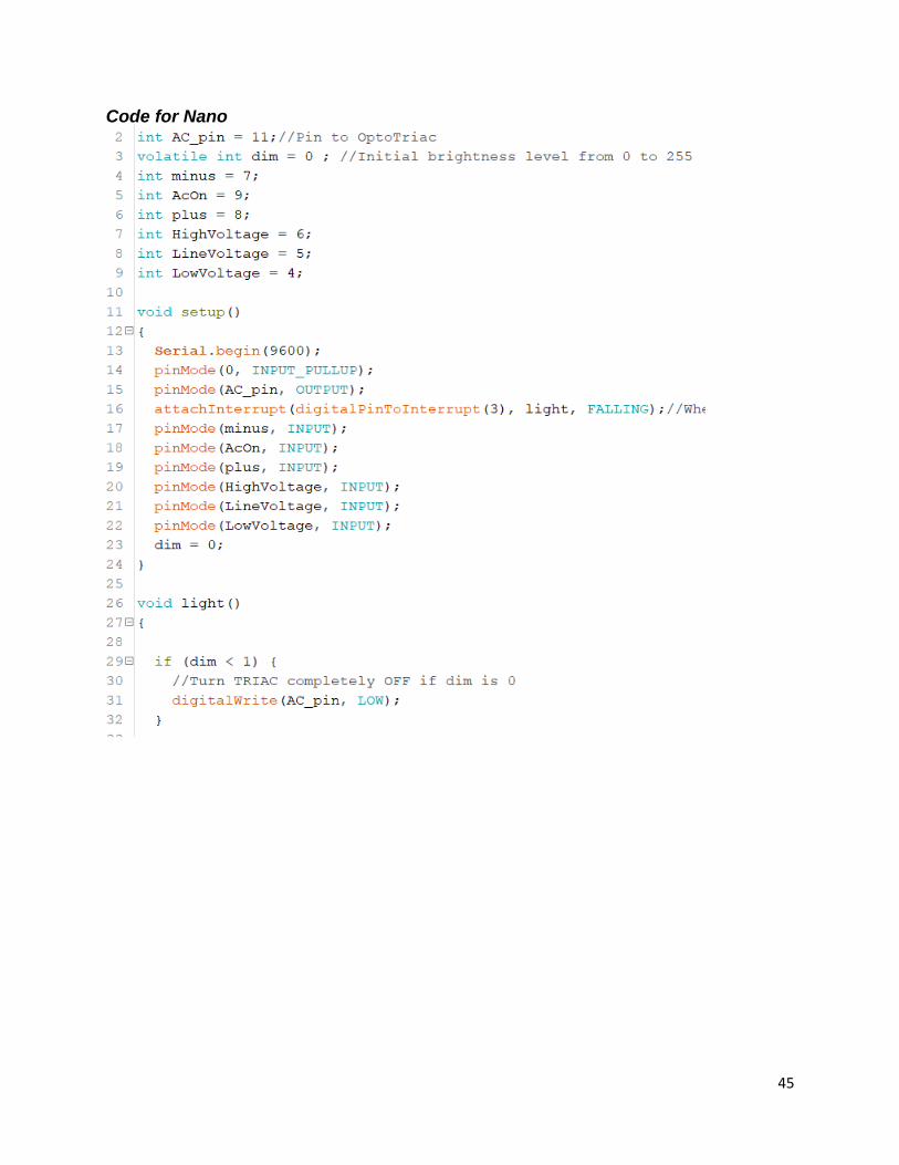
Code for Nano
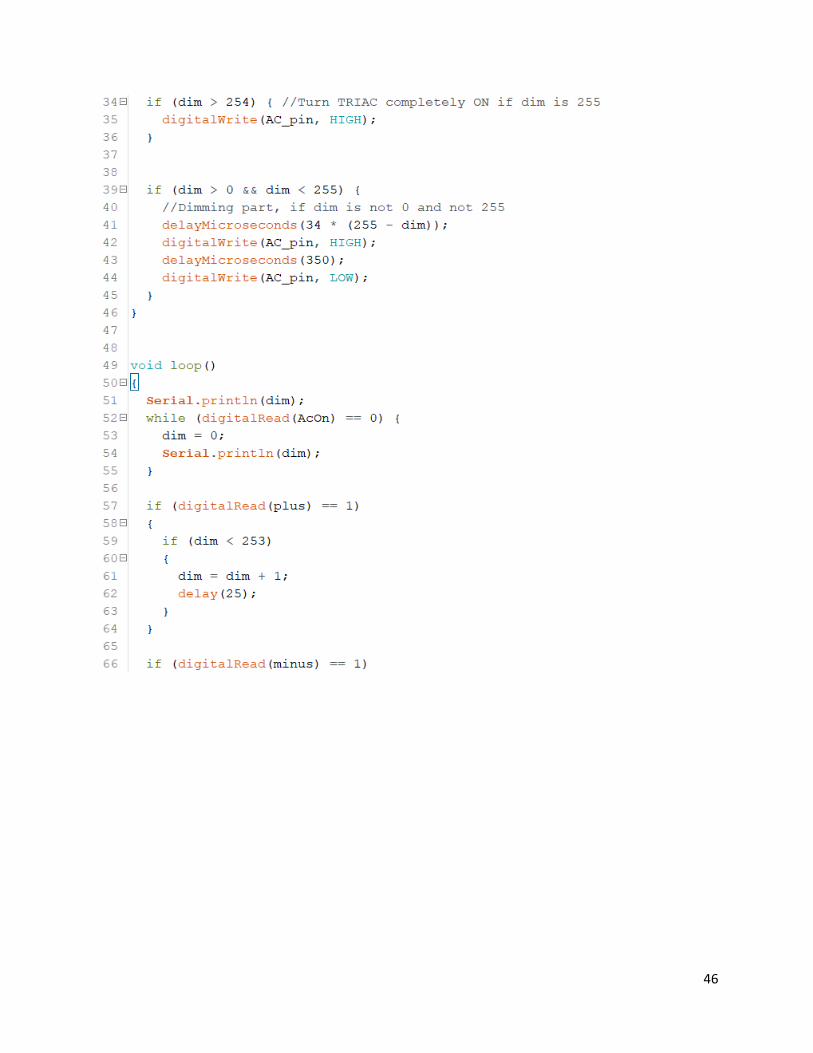
46
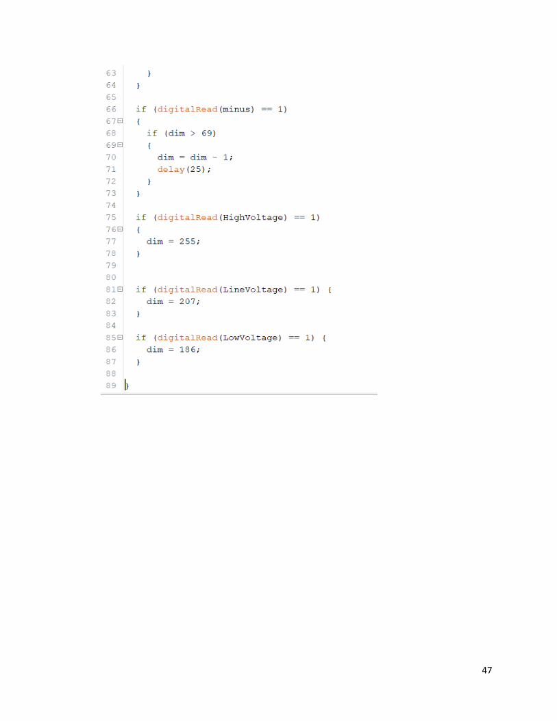
47
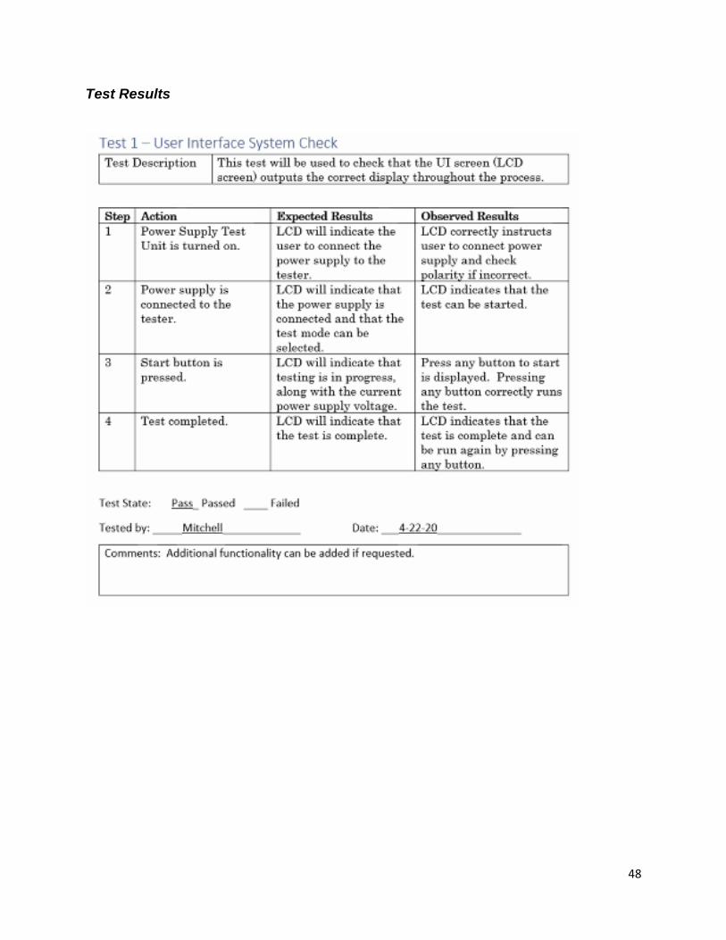
48
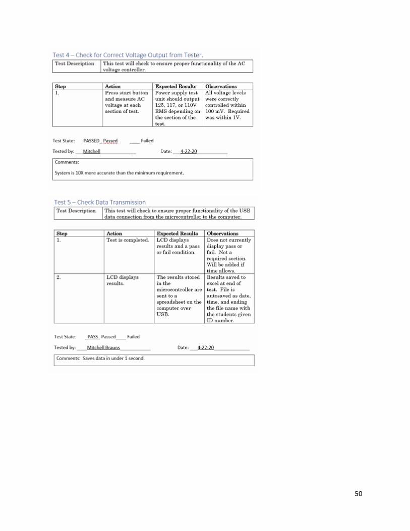
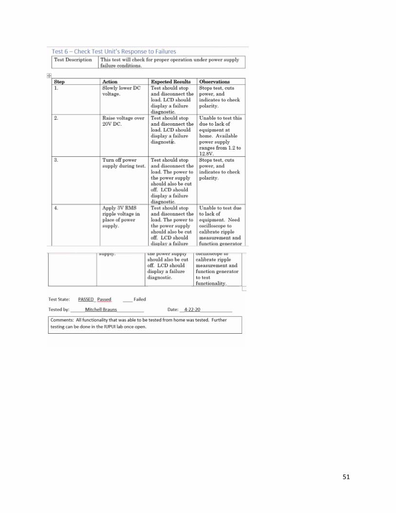
Test Results
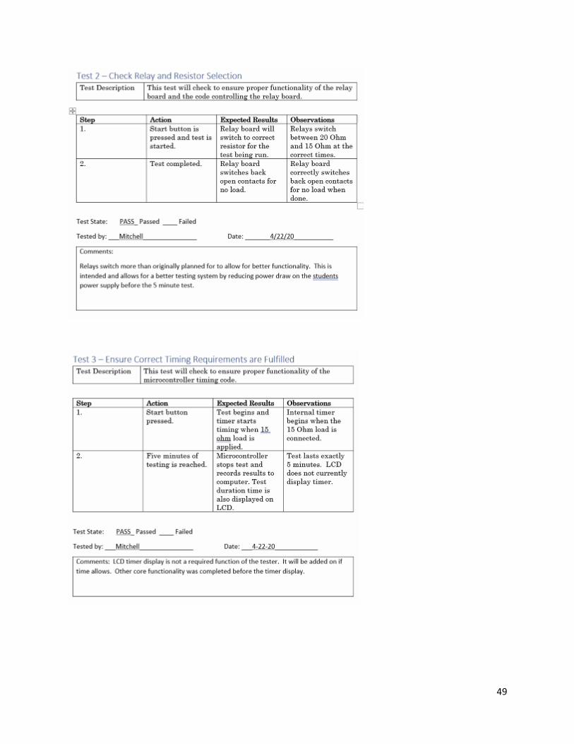
49
50
51
52
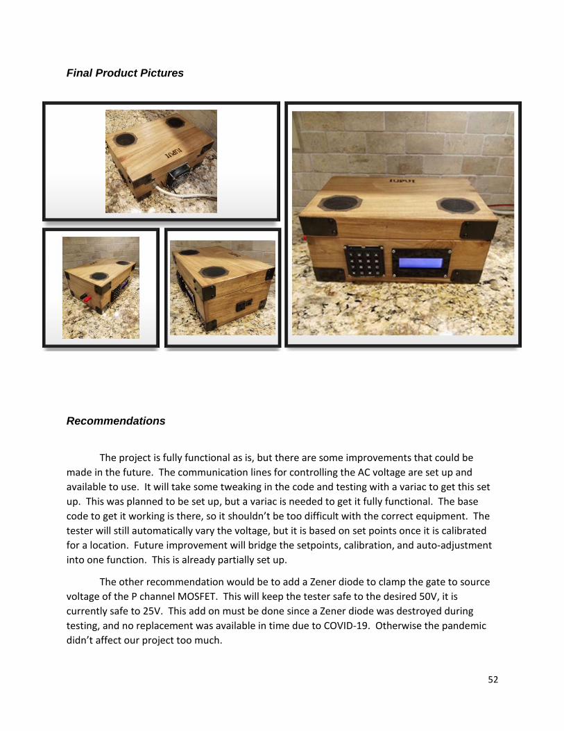
Final Product Pictures
Recommendations
The project is fully functional as is, but there are some improvements that could be
made in the future. The communication lines for controlling the AC voltage are set up and
available to use. It will take some tweaking in the code and testing with a variac to get this set
up. This was planned to be set up, but a variac is needed to get it fully functional. The base
code to get it working is there, so it shouldn’t be too difficult with the correct equipment. The
tester will still automatically vary the voltage, but it is based on set points once it is calibrated
for a location. Future improvement will bridge the setpoints, calibration, and auto-adjustment
into one function. This is already partially set up.
The other recommendation would be to add a Zener diode to clamp the gate to source
voltage of the P channel MOSFET. This will keep the tester safe to the desired 50V, it is
currently safe to 25V. This add on must be done since a Zener diode was destroyed during
testing, and no replacement was available in time due to COVID-19. Otherwise the pandemic
didn’t affect our project too much.
53
References
Kumar, P. (2019, July 12). Arduino Based AC Voltage Control using Zero Voltage Crossing Detection.
Retrieved from https://www.engineersgarage.com/contributions/arduino-based-ac-voltage-
control-using-zero-voltage-crossing-detection/.
Measure Any AC Voltage Up to 250V. (n.d.). Retrieved from
https://create.arduino.cc/projecthub/SurtrTech/measure-any-ac-voltage-up-to-250v-1af7bd.
Reverse Polarity Protection. (2018, August 27). Retrieved December 2, 2019, from
https://circuitdigest.com/electronic-circuits/reverse-polarity-protection-circuit-diagram.
Abubakar, I., Khalid, S. N., & Shareef, H. (2017, February). CALIBRATION OF ZMPT101B VOLTAGE
SENSOR MODULE USING POLYNOMIAL REGRESSION FOR ACCURATE LOAD MONITORING .
Retrieved from
http://www.arpnjournals.org/jeas/research_papers/rp_2017/jeas_0217_5728.pdf
Shahbaaz. (1968, January 1). Retrieved from
https://www.extendoffice.com/documents/excel/4620-excel-autosave-after-entry.html
(2018, August 27). Retrieved from https://circuitdigest.com/electronic-circuits/reverse-polarity-
protection-circuit-diagram
54
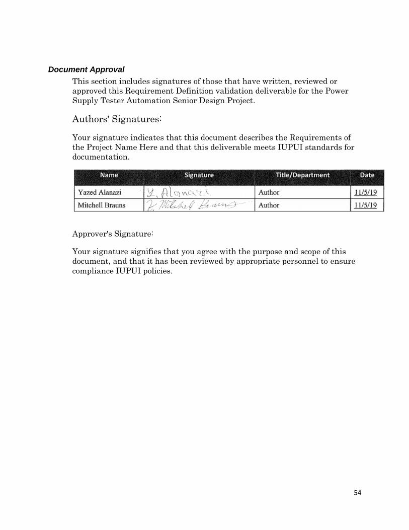
Document Approval
This section includes signatures of those that have written, reviewed or
approved this Requirement Definition validation deliverable for the Power
Supply Tester Automation Senior Design Project.
Authors' Signatures:
Your signature indicates that this document describes the Requirements of
the Project Name Here and that this deliverable meets IUPUI standards for
documentation.
Approver's Signature:
Your signature signifies that you agree with the purpose and scope of this
document, and that it has been reviewed by appropriate personnel to ensure
compliance IUPUI policies.


