Embed Size (px)
Citation preview
Revision Date: 04/11
Power Supply
Introduction . . . . . . . . . . . . . . . . . . . . . . . . . . . . . . . . . . . . . . . . . . . . . . . . . .3
Power Supply Components . . . . . . . . . . . . . . . . . . . . . . . . . . . . . . . . . . . .4Battery . . . . . . . . . . . . . . . . . . . . . . . . . . . . . . . . . . . . . . . . . . . . . . . . . . . . . . . .4
General Battery Information . . . . . . . . . . . . . . . . . . . . . . . . . . . . . . . . . . .4Battery Aging . . . . . . . . . . . . . . . . . . . . . . . . . . . . . . . . . . . . . . . . . . . . . . . .4
AGM Battery . . . . . . . . . . . . . . . . . . . . . . . . . . . . . . . . . . . . . . . . . . . . . . . . . . .5Mode of Operation . . . . . . . . . . . . . . . . . . . . . . . . . . . . . . . . . . . . . . . . . . .6Special Features . . . . . . . . . . . . . . . . . . . . . . . . . . . . . . . . . . . . . . . . . . . . .6Housing . . . . . . . . . . . . . . . . . . . . . . . . . . . . . . . . . . . . . . . . . . . . . . . . . . . . .6Installation Locations . . . . . . . . . . . . . . . . . . . . . . . . . . . . . . . . . . . . . . . . .6Battery Replacement . . . . . . . . . . . . . . . . . . . . . . . . . . . . . . . . . . . . . . . . .6
Alternator . . . . . . . . . . . . . . . . . . . . . . . . . . . . . . . . . . . . . . . . . . . . . . . . . . . . . .6Battery Cables . . . . . . . . . . . . . . . . . . . . . . . . . . . . . . . . . . . . . . . . . . . . . . . . .7
Aluminum Ribbon Cable . . . . . . . . . . . . . . . . . . . . . . . . . . . . . . . . . . . . .10Battery Cable Monitoring . . . . . . . . . . . . . . . . . . . . . . . . . . . . . . . . . . . .10
Battery Safety Terminal . . . . . . . . . . . . . . . . . . . . . . . . . . . . . . . . . . . . . . . . .12Cable Disconnection Sequence . . . . . . . . . . . . . . . . . . . . . . . . . . . . . .13
Intelligent Battery Sensor (IBS) . . . . . . . . . . . . . . . . . . . . . . . . . . . . . . . . . .14Power Distribution Boxes . . . . . . . . . . . . . . . . . . . . . . . . . . . . . . . . . . . . . . .16
Power Distribution Box in Engine Compartment . . . . . . . . . . . . . . . .17Junction Box . . . . . . . . . . . . . . . . . . . . . . . . . . . . . . . . . . . . . . . . . . . . . . .18Front Fuse Carrier and Junction Box Electronics . . . . . . . . . . . . . . . .19Internal Plug Connection . . . . . . . . . . . . . . . . . . . . . . . . . . . . . . . . . . . .20
Front Fuse Carrier . . . . . . . . . . . . . . . . . . . . . . . . . . . . . . . . . . . . . . . . . . . .21Soldered Relay . . . . . . . . . . . . . . . . . . . . . . . . . . . . . . . . . . . . . . . . . . . . .22Direct Contacting . . . . . . . . . . . . . . . . . . . . . . . . . . . . . . . . . . . . . . . . . . .23
Rear Fuse Carrier in the Luggage Compartment . . . . . . . . . . . . . . . . . .24Distribution Box on the Battery . . . . . . . . . . . . . . . . . . . . . . . . . . . . . . . . .25Terminals . . . . . . . . . . . . . . . . . . . . . . . . . . . . . . . . . . . . . . . . . . . . . . . . . . . . .27
Terminal 30 . . . . . . . . . . . . . . . . . . . . . . . . . . . . . . . . . . . . . . . . . . . . . . . .29Terminal R . . . . . . . . . . . . . . . . . . . . . . . . . . . . . . . . . . . . . . . . . . . . . . . . .29Terminal 15 . . . . . . . . . . . . . . . . . . . . . . . . . . . . . . . . . . . . . . . . . . . . . . . .29Terminal 31 . . . . . . . . . . . . . . . . . . . . . . . . . . . . . . . . . . . . . . . . . . . . . . . .29Ground Points . . . . . . . . . . . . . . . . . . . . . . . . . . . . . . . . . . . . . . . . . . . . . .30
Vehicles with Reduced-weight Aluminum Front End (GRAV) . .32
Subject Page
Table of Contents
Initial Print Date: 07/10
Power Supply
Model: All
Production: All
After completion of this module you will be able to:
• Understand overall voltage supply layout
• Locate voltage supply components
• Locate fuse boxes
• Understand IBS operation
• Understand BST operation
• Describe terminal control in BMW vehicles
• Diagnose voltage supply faults
2Power Supply
Introduction
3Power Supply
The power supply is a combination of hardware and software that ensures the necessarypower for all the vehicle systems.
Essentially it can be divided into two major functions:
• Energy management
• Power management
The energy management system ensures that sufficient starter motor current is alwaysavailable and monitors the vehicle even when the engine is off. Energy managementincludes all the components in the vehicle that generate, store and consume energy.The data for the energy management is distributed across a number of control modules.
Power management is a subsystem of the energy management. The power manage-ment is run from the engine control module Digital Engine Electronics or Digital DieselElectronics (DME or DDE). While the vehicle is being driven, the power managementregulates the power output of the alternator as well as the battery charging.
For more information regarding Energy and Power management refer to the PowerManagement section of this training material.
The following are the basic components that make up the power supply system:
- Battery
- Alternator
- Battery cables
- Battery safety sensor
- Intelligent battery sensor
- Distribution box
- Junction Box Electronics
- Car Access System
- Digital Engine Electronics or Digital Diesel Electronics
- Multiple Restraint System
- Bit-serial data interface
- Relay box
Battery
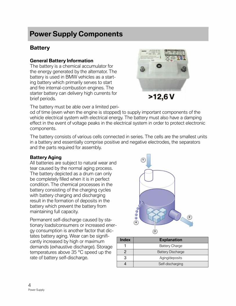
General Battery InformationThe battery is a chemical accumulator forthe energy generated by the alternator. Thebattery is used in BMW vehicles as a start-ing battery which primarily serves to startand fire internal-combustion engines. Thestarter battery can delivery high currents forbrief periods.
The battery must be able over a limited peri-od of time (even when the engine is stopped) to supply important components of thevehicle electrical system with electrical energy. The battery must also have a dampingeffect in the event of voltage peaks in the electrical system in order to protect electroniccomponents.
The battery consists of various cells connected in series. The cells are the smallest unitsin a battery and essentially comprise positive and negative electrodes, the separatorsand the parts required for assembly.
Battery AgingAll batteries are subject to natural wear andtear caused by the normal aging process.The battery depicted as a drum can onlybe completely filled when it is in perfectcondition. The chemical processes in thebattery consisting of the charging cycleswith battery charging and dischargingresult in the formation of deposits in thebattery which prevent the battery frommaintaining full capacity.
Permanent self-discharge caused by sta-tionary loads/consumers or increased ener-gy consumption is another factor that dic-tates battery aging. Wear can be signifi-cantly increased by high or maximumdemands (exhaustive discharge). Storagetemperatures above 35 °C speed up therate of battery self-discharge.
Power Supply Components
4Power Supply
Index Explanation
1 Battery Charge
2 Battery Discharge
3 Aging/deposits
4 Self-discharging
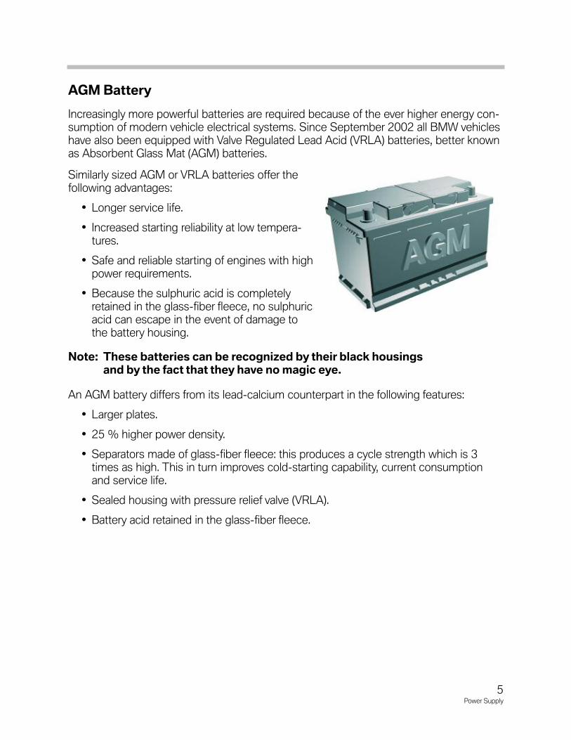
AGM Battery
Increasingly more powerful batteries are required because of the ever higher energy con-sumption of modern vehicle electrical systems. Since September 2002 all BMW vehicleshave also been equipped with Valve Regulated Lead Acid (VRLA) batteries, better knownas Absorbent Glass Mat (AGM) batteries.
Similarly sized AGM or VRLA batteries offer thefollowing advantages:
• Longer service life.
• Increased starting reliability at low tempera-tures.
• Safe and reliable starting of engines with highpower requirements.
• Because the sulphuric acid is completelyretained in the glass-fiber fleece, no sulphuricacid can escape in the event of damage tothe battery housing.
Note: These batteries can be recognized by their black housingsand by the fact that they have no magic eye.
An AGM battery differs from its lead-calcium counterpart in the following features:
• Larger plates.
• 25 % higher power density.
• Separators made of glass-fiber fleece: this produces a cycle strength which is 3times as high. This in turn improves cold-starting capability, current consumptionand service life.
• Sealed housing with pressure relief valve (VRLA).
• Battery acid retained in the glass-fiber fleece.
5Power Supply
Mode of OperationThe AGM battery differs from conventional batteries in its environmentally compatibleand substance-maintaining performance during charging. When vehicle batteries arecharged, the two gases oxygen and hydrogen are released.
• In a conventional, wet lead-calcium battery, the oxygen and hydrogen are dissipatedto atmosphere.
• In an AGM battery, these two gases are converted back into water. The oxygenwhich is created during charging at the positive electrode passes through the per-meable glass-fiber fleece to the negative electrode, where it reacts with the hydro-gen ions in the electrolyte to form water.
In this way, no gases escape and electrolyte is not lost.
Special FeaturesIn the event of an excessive build-up of gas, i.e. excessive pressure increase (20 to 200mbar), the pressure relief valve blows off gas without allowing atmospheric oxygen toenter. Hence the designation VRLA.
HousingAGM batteries must not be opened under any circumstances as the entry of atmosphericoxygen would cause the batteries to lose their chemical balance and render them inoper-ational.
Installation LocationsAGM batteries on account of their high spatial temperature differences must not beinstalled in the engine compartment. This would significantly reduce their service life.
Battery ReplacementA lead-calcium battery can always be replaced with an AGM battery provided the installa-tion conditions conform to the specifications for AGM batteries. The use of an AGM bat-tery does not require any changes to be made to the vehicle electrical system.
Alternator
With the engine running, the alternator generates a variable charge voltage for batterycharging. The variable charge voltage is influenced by the power management dependingon the temperature and current.
6Power Supply
Battery Cables
Depending on the vehicle the battery cables can be located in the vehicle interior or onthe outside (under the floorpan). Depending on the model and equipment specification,the starter cable may also be equipped with a monitoring lead.
Some vehicles may be fitted with several battery cables. The starter cable is typicallyrouted via the jump-start terminal point to the starter and the alternator.
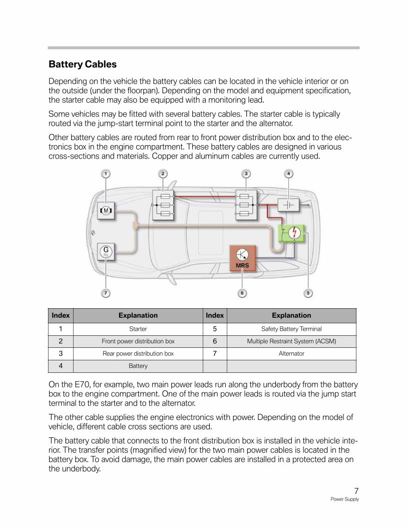
Other battery cables are routed from rear to front power distribution box and to the elec-tronics box in the engine compartment. These battery cables are designed in variouscross-sections and materials. Copper and aluminum cables are currently used.
On the E70, for example, two main power leads run along the underbody from the batterybox to the engine compartment. One of the main power leads is routed via the jump startterminal to the starter and to the alternator.
The other cable supplies the engine electronics with power. Depending on the model ofvehicle, different cable cross sections are used.
The battery cable that connects to the front distribution box is installed in the vehicle inte-rior. The transfer points (magnified view) for the two main power cables is located in thebattery box. To avoid damage, the main power cables are installed in a protected area onthe underbody.
Index Explanation Index Explanation
1 Starter 5 Safety Battery Terminal
2 Front power distribution box 6 Multiple Restraint System (ACSM)
3 Rear power distribution box 7 Alternator
4 Battery
7Power Supply
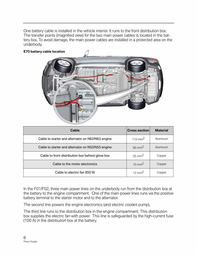
One battery cable is installed in the vehicle interior. It runs to the front distribution box.The transfer points (magnified view) for the two main power cables is located in the bat-tery box. To avoid damage, the main power cables are installed in a protected area on theunderbody.
In the F01/F02, three main power lines on the underbody run from the distribution box atthe battery to the engine compartment. One of the main power lines runs via the positivebattery terminal to the starter motor and to the alternator.
The second line powers the engine electronics (and electric coolant pump).
The third line runs to the distribution box in the engine compartment. This distributionbox supplies the electric fan with power. This line is safeguarded by the high-current fuse(100 A) in the distribution box at the battery.
Cable Cross section Material
Cable to starter and alternator on N62/N63 engine 110 mm2 Aluminum
Cable to starter and alternator on N52/N55 engine 90 mm2 Aluminum
Cable to front distribution box behind glove box 35 mm2 Copper
Cable to the motor electronics 10 mm2 Copper
Cable to electric fan 850 W 12 mm2 Copper
8Power Supply
E70 battery cable location
9Power Supply
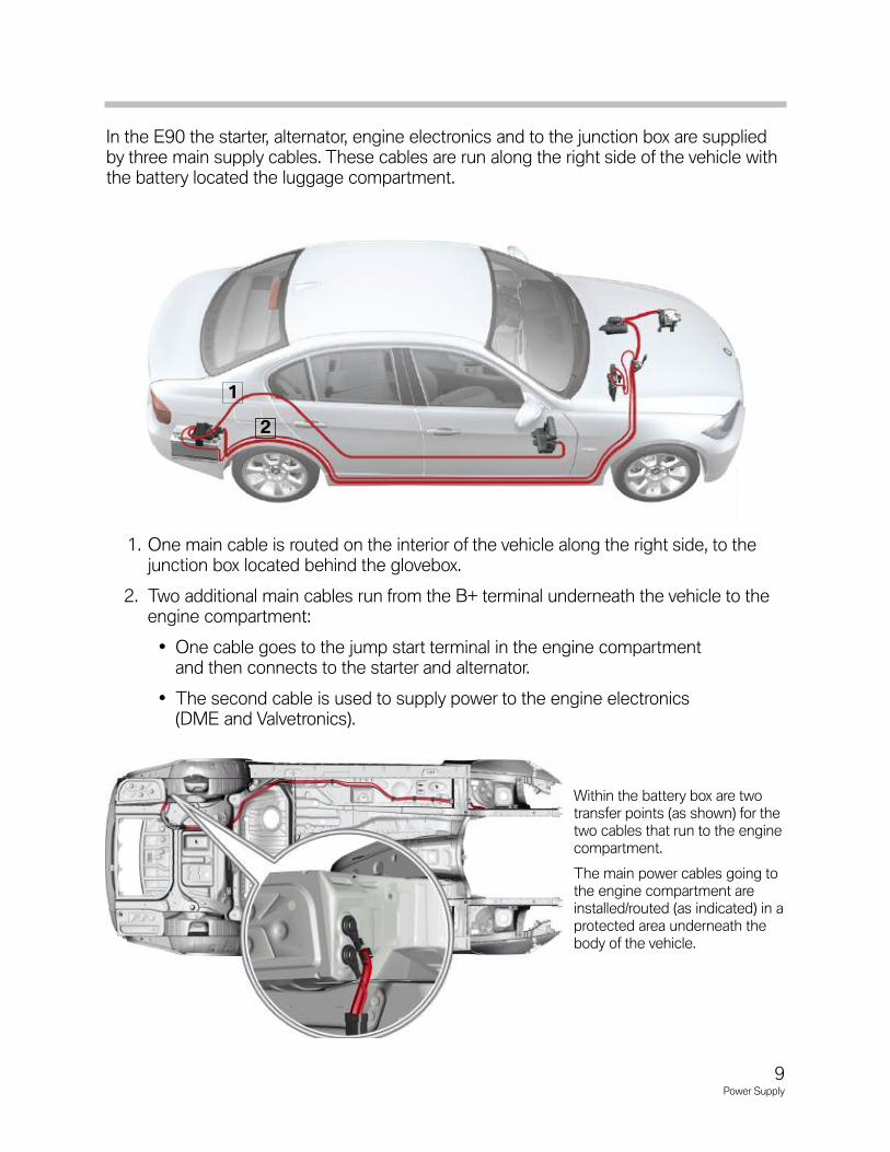
In the E90 the starter, alternator, engine electronics and to the junction box are suppliedby three main supply cables. These cables are run along the right side of the vehicle withthe battery located the luggage compartment.
1. One main cable is routed on the interior of the vehicle along the right side, to thejunction box located behind the glovebox.
2. Two additional main cables run from the B+ terminal underneath the vehicle to theengine compartment:
• One cable goes to the jump start terminal in the engine compartmentand then connects to the starter and alternator.
• The second cable is used to supply power to the engine electronics(DME and Valvetronics).
Within the battery box are twotransfer points (as shown) for thetwo cables that run to the enginecompartment.
The main power cables going tothe engine compartment areinstalled/routed (as indicated) in aprotected area underneath thebody of the vehicle.
1
2
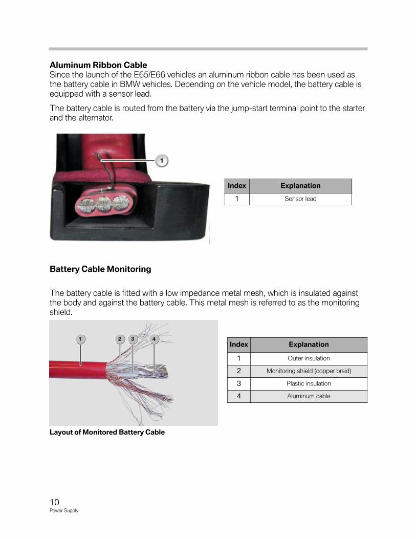
Aluminum Ribbon CableSince the launch of the E65/E66 vehicles an aluminum ribbon cable has been used asthe battery cable in BMW vehicles. Depending on the vehicle model, the battery cable isequipped with a sensor lead.
The battery cable is routed from the battery via the jump-start terminal point to the starterand the alternator.
Battery Cable Monitoring
The battery cable is fitted with a low impedance metal mesh, which is insulated againstthe body and against the battery cable. This metal mesh is referred to as the monitoringshield.
Index Explanation
1 Sensor lead
Index Explanation
1 Outer insulation
2 Monitoring shield (copper braid)
3 Plastic insulation
4 Aluminum cable
Layout of Monitored Battery Cable
10Power Supply
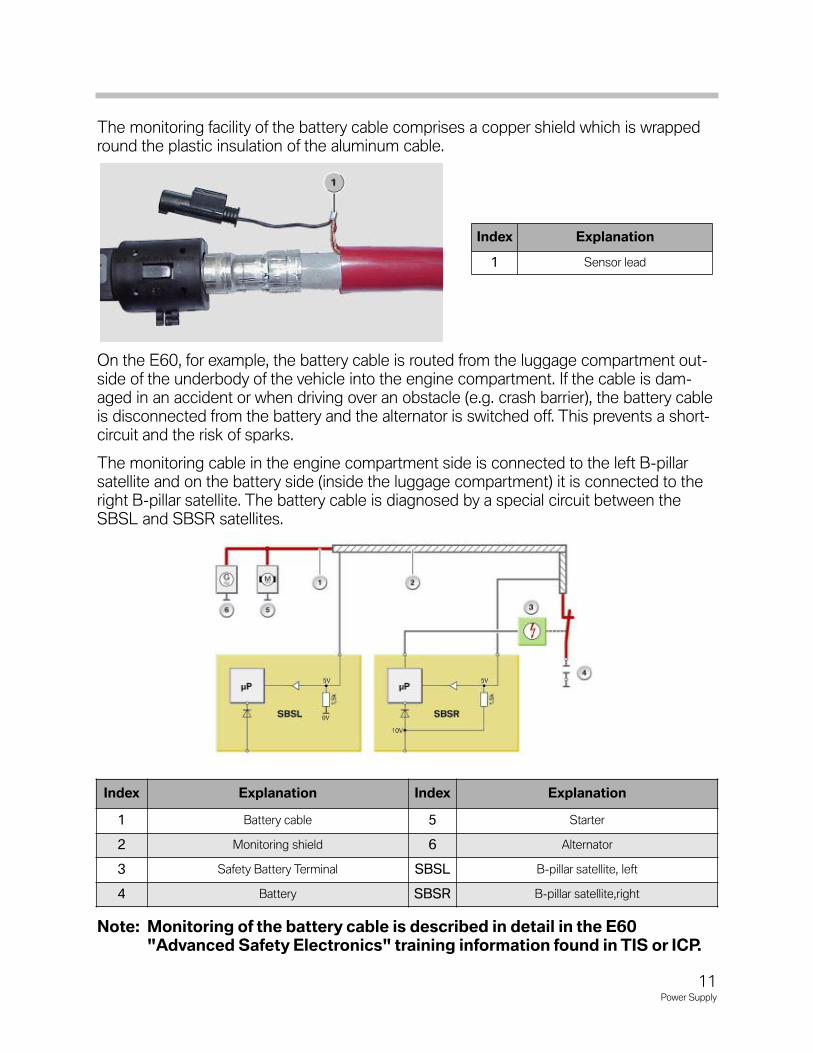
The monitoring facility of the battery cable comprises a copper shield which is wrappedround the plastic insulation of the aluminum cable.
On the E60, for example, the battery cable is routed from the luggage compartment out-side of the underbody of the vehicle into the engine compartment. If the cable is dam-aged in an accident or when driving over an obstacle (e.g. crash barrier), the battery cableis disconnected from the battery and the alternator is switched off. This prevents a short-circuit and the risk of sparks.
The monitoring cable in the engine compartment side is connected to the left B-pillarsatellite and on the battery side (inside the luggage compartment) it is connected to theright B-pillar satellite. The battery cable is diagnosed by a special circuit between theSBSL and SBSR satellites.
Note: Monitoring of the battery cable is described in detail in the E60"Advanced Safety Electronics" training information found in TIS or ICP.
Index Explanation
1 Sensor lead
Index Explanation Index Explanation
1 Battery cable 5 Starter
2 Monitoring shield 6 Alternator
3 Safety Battery Terminal SBSL B-pillar satellite, left
4 Battery SBSR B-pillar satellite,right
11Power Supply
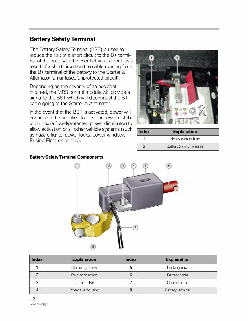
Battery Safety Terminal
The Battery Safety Terminal (BST) is used toreduce the risk of a short circuit to the B+ termi-nal of the battery in the event of an accident, as aresult of a short circuit on the cable running fromthe B+ terminal of the battery to the Starter &Alternator (an unfused/unprotected circuit).
Depending on the severity of an accidentincurred, the MRS control module will provide asignal to the BST which will disconnect the B+cable going to the Starter & Alternator.
In the event that the BST is activated, power willcontinue to be supplied to the rear power distrib-ution box (a fused/protected power distributor) toallow activation of all other vehicle systems (suchas hazard lights, power locks, power windows,Engine Electronics etc.).
Index Explanation
1 Heavy current fuse
2 Battery Safety Terminal
Index Explanation Index Explanation
1 Clamping screw 5 Locking pawl
2 Plug connection 6 Battery cable
3 Terminal B+ 7 Control cable
4 Protective housing 8 Battery terminal
12Power Supply
Battery Safety Terminal Components
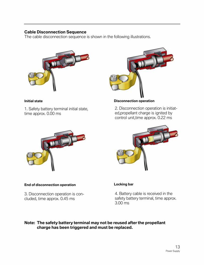
Cable Disconnection SequenceThe cable disconnection sequence is shown in the following illustrations.
Note: The safety battery terminal may not be reused after the propellantcharge has been triggered and must be replaced.
1. Safety battery terminal initial state,time approx. 0.00 ms
2. Disconnection operation is initiat-ed,propellant charge is ignited bycontrol unit,time approx. 0.22 ms
3. Disconnection operation is con-cluded, time approx. 0.45 ms
4. Battery cable is received in thesafety battery terminal, time approx.3.00 ms
Initial state Disconnection operation
End of disconnection operation Locking bar
13Power Supply
Because the battery cables are divided up in the rear distribution box, the rest of the vehi-cle electrical system remains operational when the safety battery terminal is triggered aslong as none of the main fuses disconnect the circuit as the result of a short circuit. Thisensures that all the important functions, such as e.g. hazard warning flashers, telephone,remain operational.
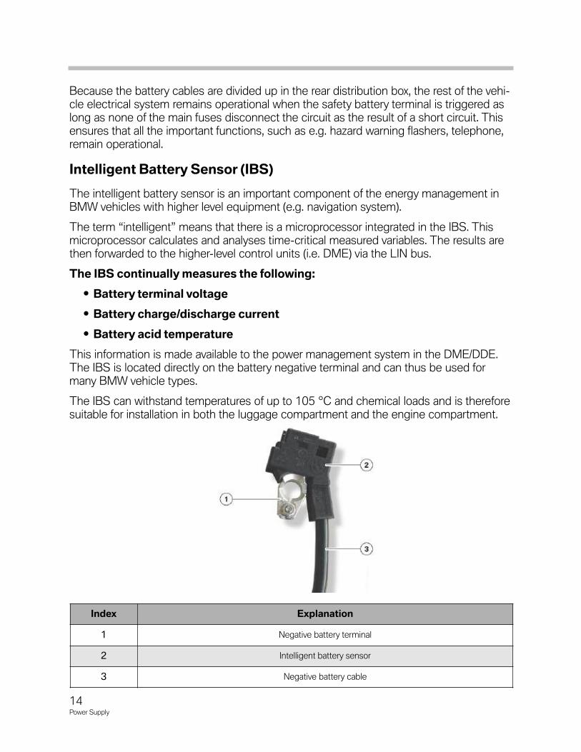
Intelligent Battery Sensor (IBS)
The intelligent battery sensor is an important component of the energy management inBMW vehicles with higher level equipment (e.g. navigation system).
The term “intelligent” means that there is a microprocessor integrated in the IBS. Thismicroprocessor calculates and analyses time-critical measured variables. The results arethen forwarded to the higher-level control units (i.e. DME) via the LIN bus.
The IBS continually measures the following:
• Battery terminal voltage
• Battery charge/discharge current
• Battery acid temperature
This information is made available to the power management system in the DME/DDE.The IBS is located directly on the battery negative terminal and can thus be used formany BMW vehicle types.
The IBS can withstand temperatures of up to 105 °C and chemical loads and is thereforesuitable for installation in both the luggage compartment and the engine compartment.
Index Explanation
1 Negative battery terminal
2 Intelligent battery sensor
3 Negative battery cable
14Power Supply

15Power Supply
The intelligent battery sensor (IBS) is used to determine precisely the "state of charge"(SoC) and the "state of health" (SoH) of the battery.
The IBS consists of mechanical, hardware and software elements. The mechanical partconsists of the battery terminal with ground cable for the negative terminal.
The functions of the mechanical section are:
• Providing electrical contact of the vehicle body with the negative terminal.
• Accommodating the sensor element for current measurement.
• Accommodating the hardware.
• Providing sufficient thermal contact between the temperature sensor of thehardware and the battery negative terminal.
• Providing protection for the sensitive electronic components.
• The battery terminal is the ground connection for the IBS.
The enhanced intelligent battery sensor as of F10 enables better detection of the batterycondition by:
• Detection of defective battery cells.
• Calculation of the remaining battery capacity.
Each total discharge results in a loss of battery capacity: The longer the battery remains completely discharged, the greater theloss of battery capacity.The batteries installed at BMW can withstand several short total dis-charges or up to two long total discharges, however, when they arefully recharged with a constant charging voltage of 14.8 V after thetotal discharge.
For all models before F10, we should use the Midtronics tester, NOT aVAT40 or equivalent. For F10 and later vehicles, a battery test is builtinto the vehicle (through the IBS), and is accessed using ISTA.
Note: A battery may only be replaced on F10 when identified as faulty usingISTA (the test plan returns a Diagnostic Code for the replacement)
Note: For further information regarding the IBS (intelligent battery sensor)refer to the Energy Management with Micro-power Module in the PowerManagement section of this training material.
Power Distribution Boxes
The fuses and relays are spread over different power distribution boxes in BMW vehicles.Some examples of possible installation locations are depicted in this chapter.
The distribution boxes can be incorporated in the luggage compartment, in the enginecompartment and behind the glovebox. Even a combination of all three installation loca-tions is possible, such as e.g. E65/E66.
In the E7x and F0x vehicles, there are two separate distribution boxes. The front distribu-tion box is near the glove box and the rear distribution box is on the right-hand side of theluggage compartment.
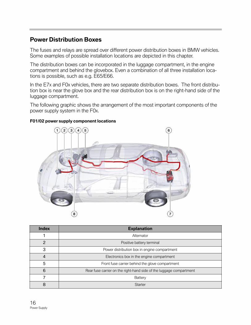
The following graphic shows the arrangement of the most important components of thepower supply system in the F0x.
Index Explanation
1 Alternator
2 Positive battery terminal
3 Power distribution box in engine compartment
4 Electronics box in the engine compartment
5 Front fuse carrier behind the glove compartment
6 Rear fuse carrier on the right-hand side of the luggage compartment
7 Battery
8 Starter
F01/02 power supply component locations
16Power Supply
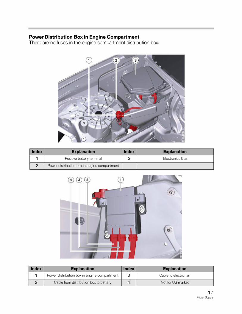
Power Distribution Box in Engine CompartmentThere are no fuses in the engine compartment distribution box.
Index Explanation Index Explanation
1 Power distribution box in engine compartment 3 Cable to electric fan
2 Cable from distribution box to battery 4 Not for US market
Index Explanation Index Explanation
1 Positive battery terminal 3 Electronics Box
2 Power distribution box in engine compartment
17Power Supply
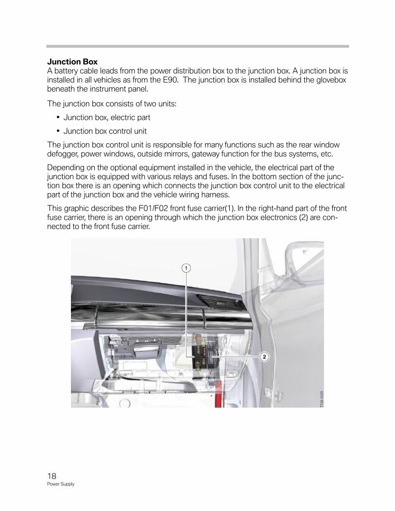
Junction BoxA battery cable leads from the power distribution box to the junction box. A junction box isinstalled in all vehicles as from the E90. The junction box is installed behind the gloveboxbeneath the instrument panel.
The junction box consists of two units:
• Junction box, electric part
• Junction box control unit
The junction box control unit is responsible for many functions such as the rear windowdefogger, power windows, outside mirrors, gateway function for the bus systems, etc.
Depending on the optional equipment installed in the vehicle, the electrical part of thejunction box is equipped with various relays and fuses. In the bottom section of the junc-tion box there is an opening which connects the junction box control unit to the electricalpart of the junction box and the vehicle wiring harness.
This graphic describes the F01/F02 front fuse carrier(1). In the right-hand part of the frontfuse carrier, there is an opening through which the junction box electronics (2) are con-nected to the front fuse carrier.
18Power Supply
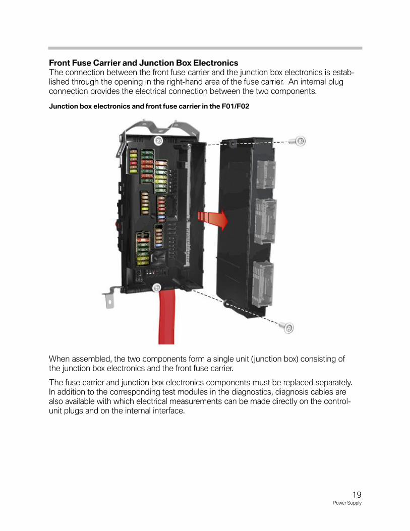
Front Fuse Carrier and Junction Box ElectronicsThe connection between the front fuse carrier and the junction box electronics is estab-lished through the opening in the right-hand area of the fuse carrier. An internal plugconnection provides the electrical connection between the two components.
When assembled, the two components form a single unit ( junction box) consisting ofthe junction box electronics and the front fuse carrier.
The fuse carrier and junction box electronics components must be replaced separately. In addition to the corresponding test modules in the diagnostics, diagnosis cables arealso available with which electrical measurements can be made directly on the control-unit plugs and on the internal interface.
Junction box electronics and front fuse carrier in the F01/F02
19Power Supply
Internal Plug Connection
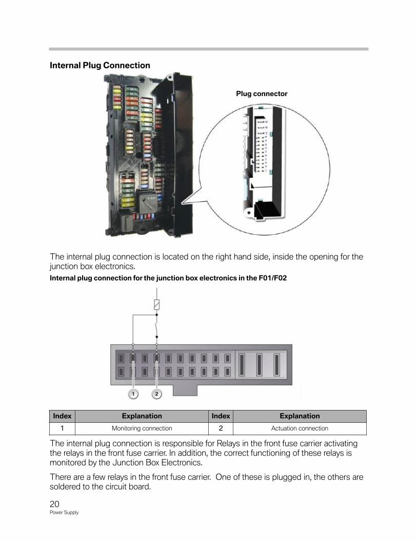
The internal plug connection is located on the right hand side, inside the opening for thejunction box electronics.
The internal plug connection is responsible for Relays in the front fuse carrier activatingthe relays in the front fuse carrier. In addition, the correct functioning of these relays ismonitored by the Junction Box Electronics.
There are a few relays in the front fuse carrier. One of these is plugged in, the others aresoldered to the circuit board.
Plug connector
Internal plug connection for the junction box electronics in the F01/F02
Index Explanation Index Explanation
1 Monitoring connection 2 Actuation connection
20Power Supply
Front Fuse Carrier
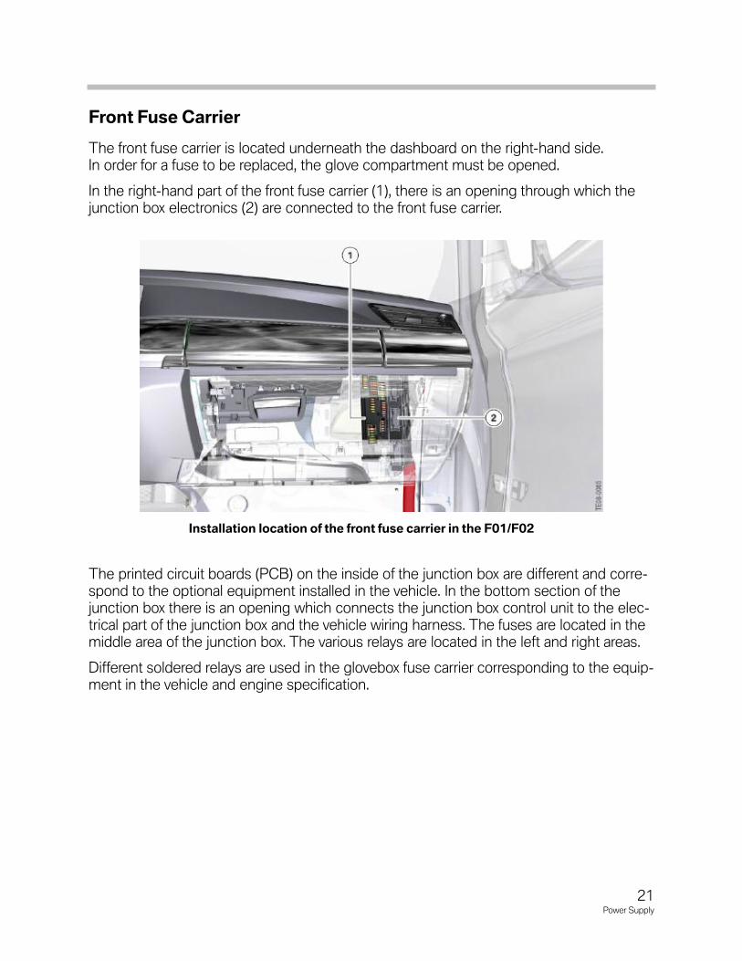
The front fuse carrier is located underneath the dashboard on the right-hand side. In order for a fuse to be replaced, the glove compartment must be opened.
In the right-hand part of the front fuse carrier (1), there is an opening through which thejunction box electronics (2) are connected to the front fuse carrier.
The printed circuit boards (PCB) on the inside of the junction box are different and corre-spond to the optional equipment installed in the vehicle. In the bottom section of thejunction box there is an opening which connects the junction box control unit to the elec-trical part of the junction box and the vehicle wiring harness. The fuses are located in themiddle area of the junction box. The various relays are located in the left and right areas.
Different soldered relays are used in the glovebox fuse carrier corresponding to the equip-ment in the vehicle and engine specification.
Installation location of the front fuse carrier in the F01/F02
21Power Supply
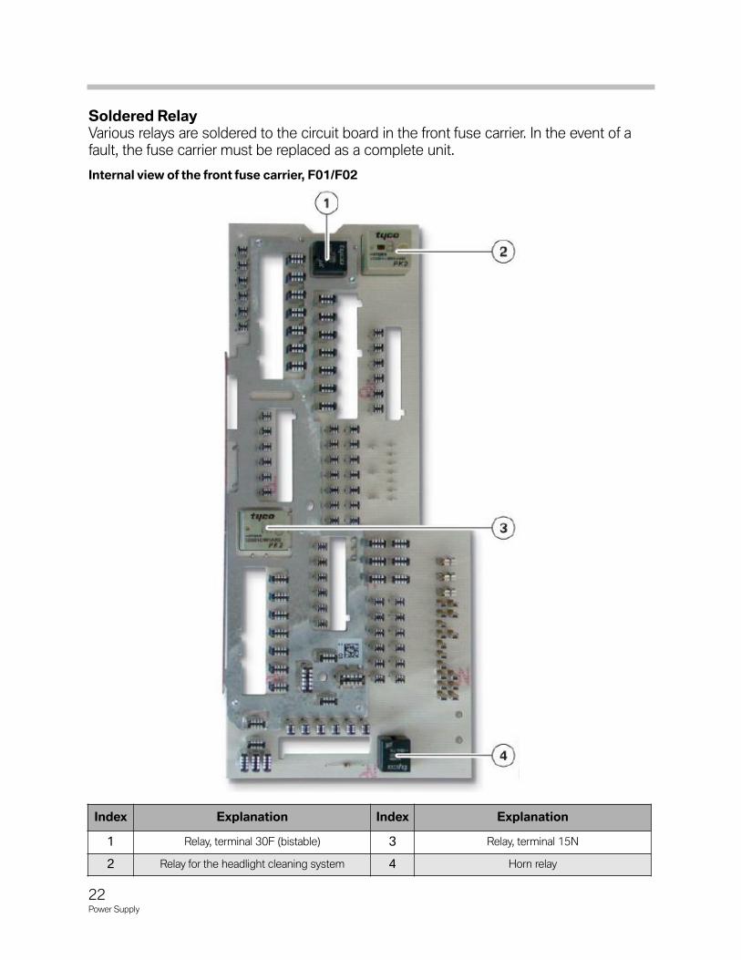
Soldered Relay Various relays are soldered to the circuit board in the front fuse carrier. In the event of afault, the fuse carrier must be replaced as a complete unit.
Index Explanation Index Explanation
1 Relay, terminal 30F (bistable) 3 Relay, terminal 15N
2 Relay for the headlight cleaning system 4 Horn relay
Internal view of the front fuse carrier, F01/F02
22Power Supply
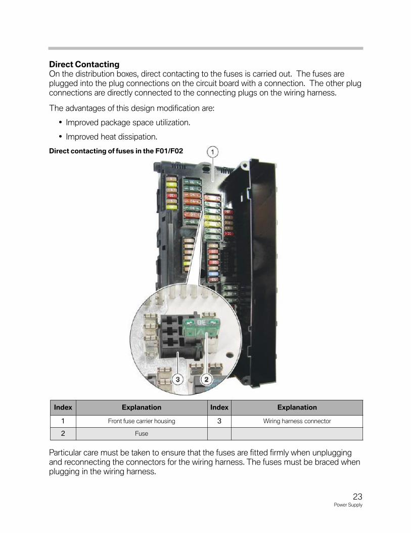
Direct Contacting On the distribution boxes, direct contacting to the fuses is carried out. The fuses areplugged into the plug connections on the circuit board with a connection. The other plugconnections are directly connected to the connecting plugs on the wiring harness.
The advantages of this design modification are:
• Improved package space utilization.
• Improved heat dissipation.
Particular care must be taken to ensure that the fuses are fitted firmly when unpluggingand reconnecting the connectors for the wiring harness. The fuses must be braced whenplugging in the wiring harness.
Index Explanation Index Explanation
1 Front fuse carrier housing 3 Wiring harness connector
2 Fuse
Direct contacting of fuses in the F01/F02
23Power Supply
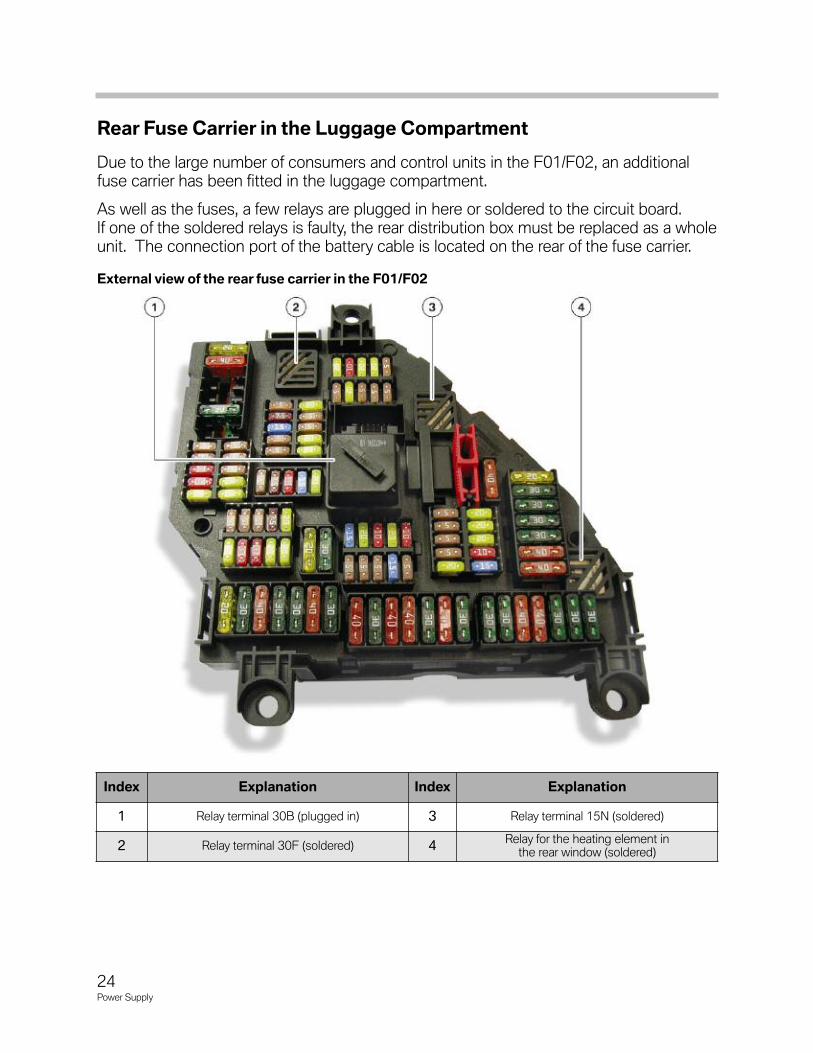
Rear Fuse Carrier in the Luggage Compartment
Due to the large number of consumers and control units in the F01/F02, an additionalfuse carrier has been fitted in the luggage compartment.
As well as the fuses, a few relays are plugged in here or soldered to the circuit board. If one of the soldered relays is faulty, the rear distribution box must be replaced as a wholeunit. The connection port of the battery cable is located on the rear of the fuse carrier.
Index Explanation Index Explanation
1 Relay terminal 30B (plugged in) 3 Relay terminal 15N (soldered)
2 Relay terminal 30F (soldered) 4Relay for the heating element in
the rear window (soldered)
External view of the rear fuse carrier in the F01/F02
24Power Supply
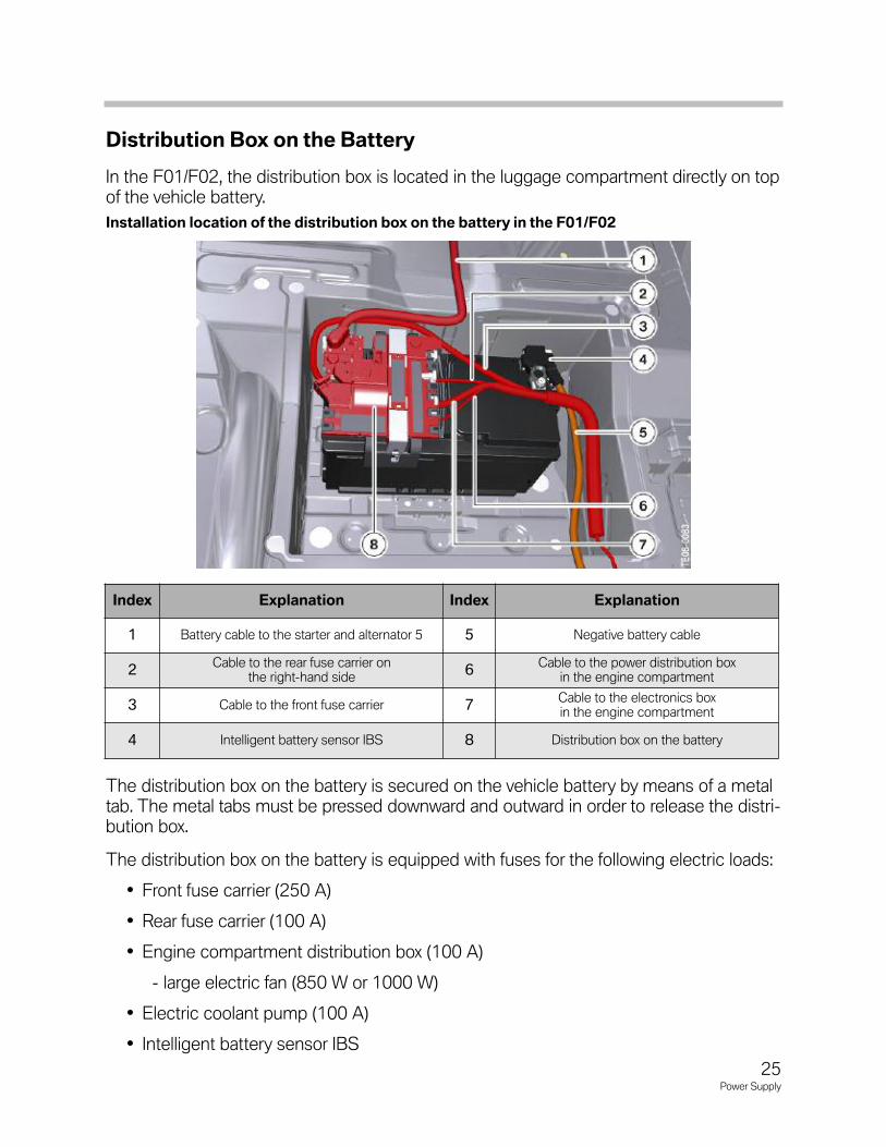
Distribution Box on the Battery
In the F01/F02, the distribution box is located in the luggage compartment directly on topof the vehicle battery.
The distribution box on the battery is secured on the vehicle battery by means of a metaltab. The metal tabs must be pressed downward and outward in order to release the distri-bution box.
The distribution box on the battery is equipped with fuses for the following electric loads:
• Front fuse carrier (250 A)
• Rear fuse carrier (100 A)
• Engine compartment distribution box (100 A)
- large electric fan (850 W or 1000 W)
• Electric coolant pump (100 A)
• Intelligent battery sensor IBS
Installation location of the distribution box on the battery in the F01/F02
Index Explanation Index Explanation
1 Battery cable to the starter and alternator 5 5 Negative battery cable
2Cable to the rear fuse carrier on
the right-hand side 6
Cable to the power distribution boxin the engine compartment
3 Cable to the front fuse carrier 7Cable to the electronics boxin the engine compartment
4 Intelligent battery sensor IBS 8 Distribution box on the battery
25Power Supply
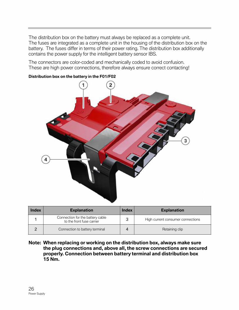
The distribution box on the battery must always be replaced as a complete unit. The fuses are integrated as a complete unit in the housing of the distribution box on thebattery. The fuses differ in terms of their power rating. The distribution box additionallycontains the power supply for the intelligent battery sensor IBS.
The connectors are color-coded and mechanically coded to avoid confusion.These are high power connections, therefore always ensure correct contacting!
Note: When replacing or working on the distribution box, always make surethe plug connections and, above all, the screw connections are securedproperly. Connection between battery terminal and distribution box15 Nm.
Index Explanation Index Explanation
1Connection for the battery cable
to the front fuse carrier3 High current consumer connections
2 Connection to battery terminal 4 Retaining clip
Distribution box on the battery in the F01/F02
26Power Supply
Terminals
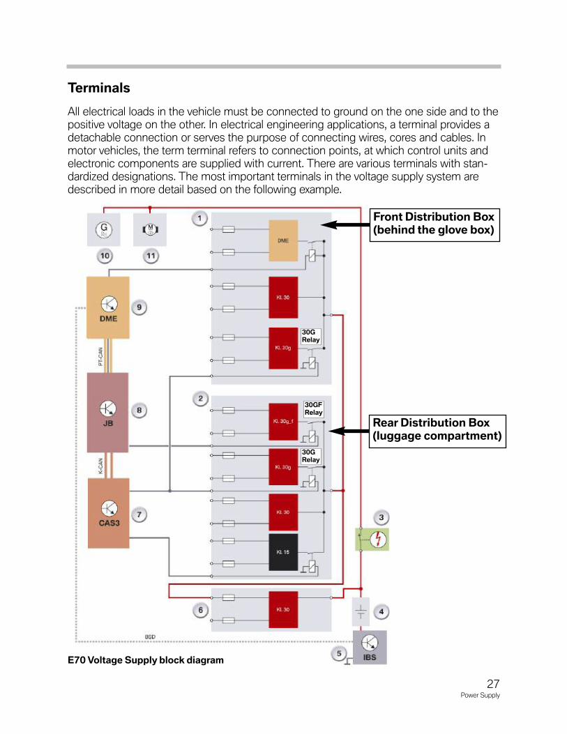
All electrical loads in the vehicle must be connected to ground on the one side and to thepositive voltage on the other. In electrical engineering applications, a terminal provides adetachable connection or serves the purpose of connecting wires, cores and cables. Inmotor vehicles, the term terminal refers to connection points, at which control units andelectronic components are supplied with current. There are various terminals with stan-dardized designations. The most important terminals in the voltage supply system aredescribed in more detail based on the following example.
E70 Voltage Supply block diagram
30GRelay
30GFRelay
30GRelay
27Power Supply
Rear Distribution Box(luggage compartment)
Front Distribution Box(behind the glove box)
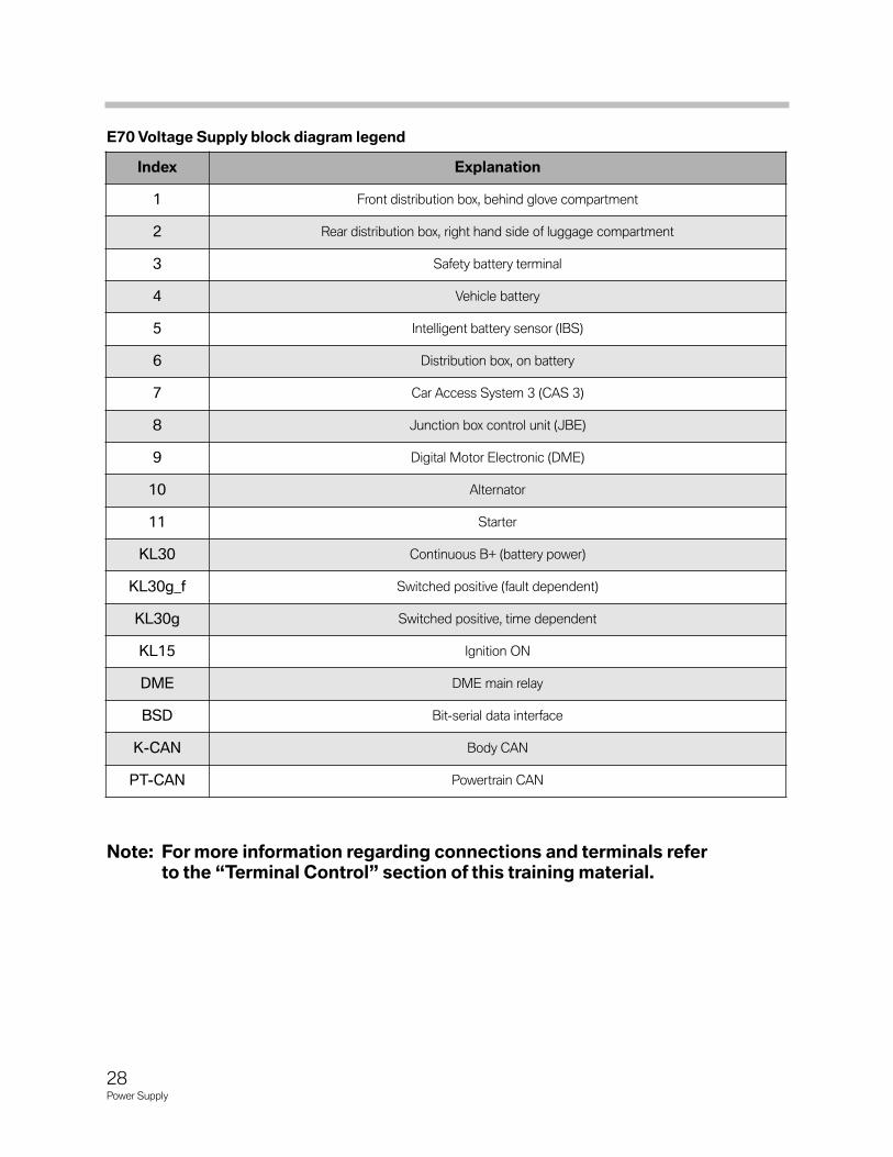
Index Explanation
1 Front distribution box, behind glove compartment
2 Rear distribution box, right hand side of luggage compartment
3 Safety battery terminal
4 Vehicle battery
5 Intelligent battery sensor (IBS)
6 Distribution box, on battery
7 Car Access System 3 (CAS 3)
8 Junction box control unit (JBE)
9 Digital Motor Electronic (DME)
10 Alternator
11 Starter
KL30 Continuous B+ (battery power)
KL30g_f Switched positive (fault dependent)
KL30g Switched positive, time dependent
KL15 Ignition ON
DME DME main relay
BSD Bit-serial data interface
K-CAN Body CAN
PT-CAN Powertrain CAN
28Power Supply
Note: For more information regarding connections and terminals referto the “Terminal Control” section of this training material.
E70 Voltage Supply block diagram legend
Terminal 30All electrical loads in a vehicle are permanently connected to ground via the negative ter-minal of the vehicle battery. Some of the electric loads in the vehicle are also permanentlyconnected to the positive terminal of the vehicle battery. This current circuit is interruptedonly by switches or relays.
The terminal in the vehicle's electrical system, at which battery voltage is permanentlyapplied is referred to as terminal 30 (also known as B+ or continuous positive). With thebattery installed and connected, electrical power is made available on this branch of thewiring harness when the ignition is turned off and the ignition key removed. Terminal 30powers the control units and assemblies which must remain operative even when thevehicle is shut down or which only require electrical energy in order to maintain data.The switch for the hazard warning light system, for example, is powered via terminal 30.
Terminal RA proportion of the electric loads is connected to the positive terminal of the battery onlyafter inserting the ignition key in the ignition lock and turning it to the first notch position,thus applying the electric loads with current. In this case, the ignition lock acts as aswitch. The terminal is designated terminal R.
Example: If connected via terminal 30 (continuous positive), a car radio can be operatedeven when the ignition key is removed. If, on the other hand, it is connected via terminalR, it can be operated only when terminal R is switched on. In addition to the radio, thecontrol unit for the safety system (MRS, ACSM) also receives its voltage via this terminal.
Terminal 15Terminal 15 (also switched positive, ignition positive) is activated when the ignition key isturned to the second notch position. Further control units and electrical componentsreceive their voltage supply via terminal 15.
For example, the air conditioning system and parking aid (PDC) are switched on viaterminal15. Terminal R and terminal 15 are controlled by the CAS control unit.
Terminal 31Because every current consumer is incorporated in a circuit, it requires the necessaryearth/ground connection in addition to the B+ power supply. The connection to the bat-tery negative terminal is established via a separate ground lead and the body panel.This connection is also known as terminal 31 (ground).
Because the number of electrical systems and loads has increased, it would cause con-siderable problems to screw every ground connection directly to the body.
For this reason, BMW vehicles have central ground points with screwed-on strip connec-tors for accommodating as many ground leads as required.
29Power Supply
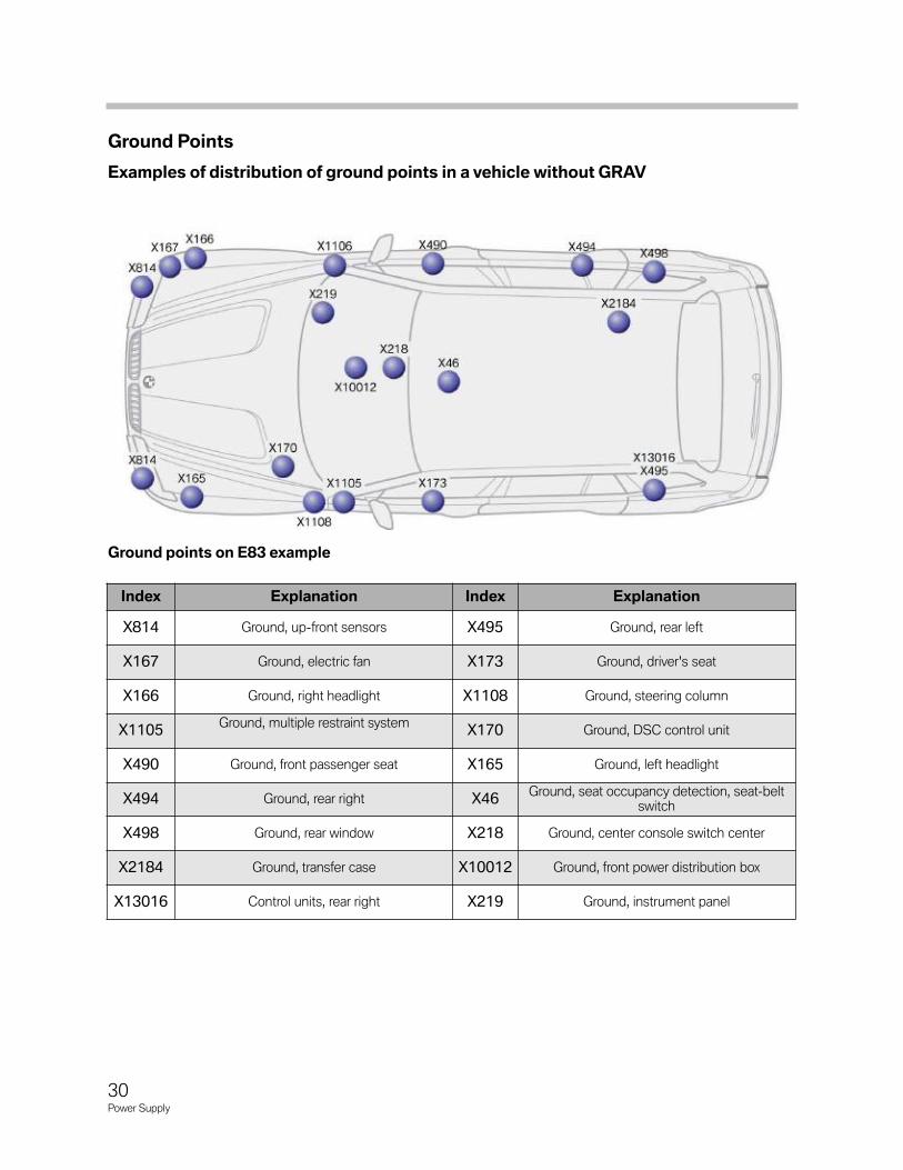
Ground Points
Examples of distribution of ground points in a vehicle without GRAV
Index Explanation Index Explanation
X814 Ground, up-front sensors X495 Ground, rear left
X167 Ground, electric fan X173 Ground, driver's seat
X166 Ground, right headlight X1108 Ground, steering column
X1105 Ground, multiple restraint system
X170 Ground, DSC control unit
X490 Ground, front passenger seat X165 Ground, left headlight
X494 Ground, rear right X46 Ground, seat occupancy detection, seat-belt
switch
X498 Ground, rear window X218 Ground, center console switch center
X2184 Ground, transfer case X10012 Ground, front power distribution box
X13016 Control units, rear right X219 Ground, instrument panel
Ground points on E83 example
30Power Supply
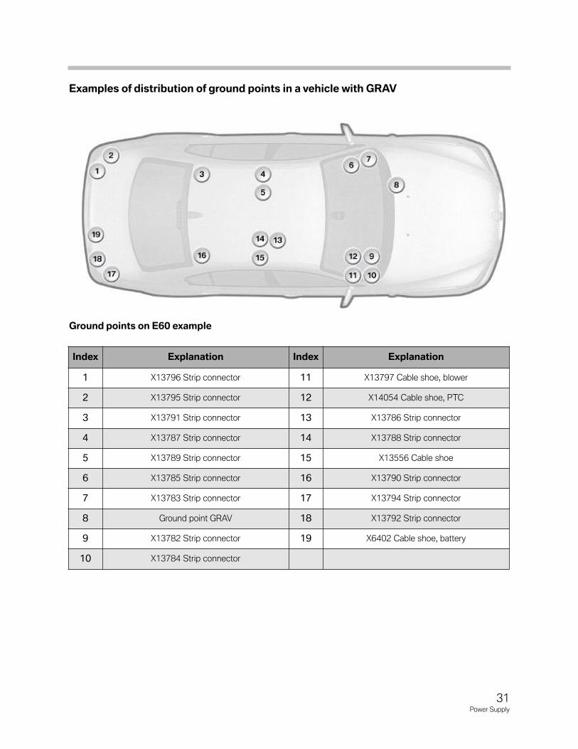
Examples of distribution of ground points in a vehicle with GRAV
Index Explanation Index Explanation
1 X13796 Strip connector 11 X13797 Cable shoe, blower
2 X13795 Strip connector 12 X14054 Cable shoe, PTC
3 X13791 Strip connector 13 X13786 Strip connector
4 X13787 Strip connector 14 X13788 Strip connector
5 X13789 Strip connector 15 X13556 Cable shoe
6 X13785 Strip connector 16 X13790 Strip connector
7 X13783 Strip connector 17 X13794 Strip connector
8 Ground point GRAV 18 X13792 Strip connector
9 X13782 Strip connector 19 X6402 Cable shoe, battery
10 X13784 Strip connector
31Power Supply
Ground points on E60 example
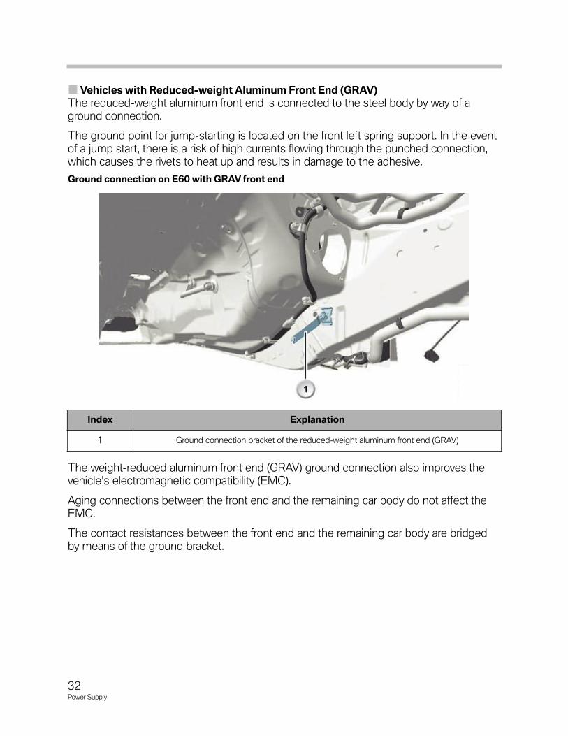
Vehicles with Reduced-weight Aluminum Front End (GRAV)
The reduced-weight aluminum front end is connected to the steel body by way of aground connection.
The ground point for jump-starting is located on the front left spring support. In the eventof a jump start, there is a risk of high currents flowing through the punched connection,which causes the rivets to heat up and results in damage to the adhesive.
The weight-reduced aluminum front end (GRAV) ground connection also improves thevehicle's electromagnetic compatibility (EMC).
Aging connections between the front end and the remaining car body do not affect theEMC.
The contact resistances between the front end and the remaining car body are bridgedby means of the ground bracket.
Index Explanation
1 Ground connection bracket of the reduced-weight aluminum front end (GRAV)
32Power Supply
Ground connection on E60 with GRAV front end


