Embed Size (px)
Citation preview
UNIT-4: POWER SUPPLY
UNIT STRUCTURE
4.1 Learning Objectives
4.2 Introduction
4.3 Power Supply
4.3.1 Linear Power Supply
4.3.2 Switch Mode Power Supply (SMPS)
4.4 Parts of the Power Supply
4.4.1 Power Conversion Circuitry
4.4.2 Power Supply Fan
4.4.3 Power Supply Fuse
4.4.4 Power Supply Form Factor
4.4.5 ATX Power Supply Specification
4.4.6 Power Supply Output
4.4.7 Power Supply Troubleshooting
4.5 Un-interrupted Power Supply (UPS)
4.5.1 On-line UPS
4.5.2 Line Interactive UPS
4.5.3 Off-line UPS
4.6 Installation of UPS (Hardware & Software)
4.7 Let Us Sum Up
4.8 Further Readings
4.9 Answers To Check Your Progress
4.10 Possible Questions
4.1 LEARNING OBJECTIVES
After going through this unit you will be able to:
• Describe about the Power Supply and their classifications.
• Identify the Linear Power Supply.
• Describe about the SMPS.
• Explain about UPS, its Types and Installation.
Elements of Computer Hardware 61
Unit'4 _ Power Supply
4.2 INTRODUCTION
In the previous unit you have learnt about basic concepts of motherboard
and its component. From that we realize that power supply is required in
all the stages and sections of the motherboard. Power supply is required
for all the electronic and electrical component, storage drives etc. In this
unit we are going to discuss about the power supply.
Power is supplied to your computer in two stages. In the first stage the
power is conveyed to the PC through the UPS from the electrical utility of
your wall. In the second stage, the internal power supply transforms the
standard household electricity into the forms that your computer needs.
We will discuss this type of power supply for the use of PC. This power
supply is essential for the functioning of every devices in your computer. If
it has a problem or is of low quality, you may experience many difficulties.
So, for the proper functioning of the devices a good quality, high efficiency
with stability having proper cooling system is required.
A high quality power supply with sufficient capacity to meet the demandsof your computer will provide years of stability to your PC. It contains a
main fan that controls the flow of air for cooling the electronic components.
The capacity of the power supply is one factor that will determine the ability
to add new drives to the system.
4.3 POWER SUPPLY
Power Supply Unit (PSU) is a device that transfers electric ppwer from asource to a load using electronic circuits. A typical application of power
supplies is to convert utility's AC input voltage into regulated DC voltage(s)required for electronic equipments, motherboard and drives etc. Depending
on the mode of operation of power semiconductors, PSU can be linear or
switching (SMPS).
g2 Elements of Computer Hardware
Power Supply Unit-4
4.3.1 Linear Power Supply
The main application of power supplies is to convert utility's AC input
voltage into regulated DC voltage(s) required for electronic
equipments. Conventional power supplies usages one step down
transformer, rectifier (it may be half wave, full wave or bridge), a filter
and sometimes a regulated section. Such type of power supply is
called Linear Power Supply; because of the output voltage or current
is linear or continuous in nature.
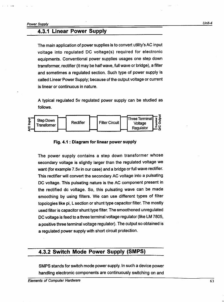
A typical regulated 5v regulated power supply can be studied as
follows.
Q.
Filter CircuitStep DownTransformer
RectifierThree Terminal
VoltageRegulator
Fig. 4.1 : Diagram for linear power supply
The power supply contains a step down transformer whose
secondary voltage is slightly larger than the regulated voltage we
want (for example 7.5v in our case) and a bridge or full wave rectifier.
This rectifier will convert the secondary AC voltage into a pulsating
DC voltage. This pulsating nature is the AC component present in
the rectified dc voltage. So, this pulsating wave can be made
smoothing by using filters. We can use different types of filter
topologies like pi, L section or shunt type capacitor filter. The mostly
used filter is capacitor shunt type filter. The smoothened unregulated
DC voltage is feed to a three terminal voltage regulator (like LM 7805,
a positive three terminal voltage regulator). The output so obtained is
a regulated power supply with short circuit protection.
4.3.2 Switch Mode Power Supply (SMPS)
SMPS stands for switch mode power supply. In such a device power
handling electronic components are continuously switching on and
Elements of Computer Hardware 63
Unit-4 Power Supply
off with high frequency in order to provide the transfer of electric
power via energy storage components (inductors and capacitors).
iBy varying duty cycle, frequency or a relative phase of these
transitions average value of output voltage or current is controlled.
The frequency range of an SMPS varies from 20 kHz to several MHz.
The main advahtage of the switch mode power sup(!)ly is that it is far
more efficient than a linear design.
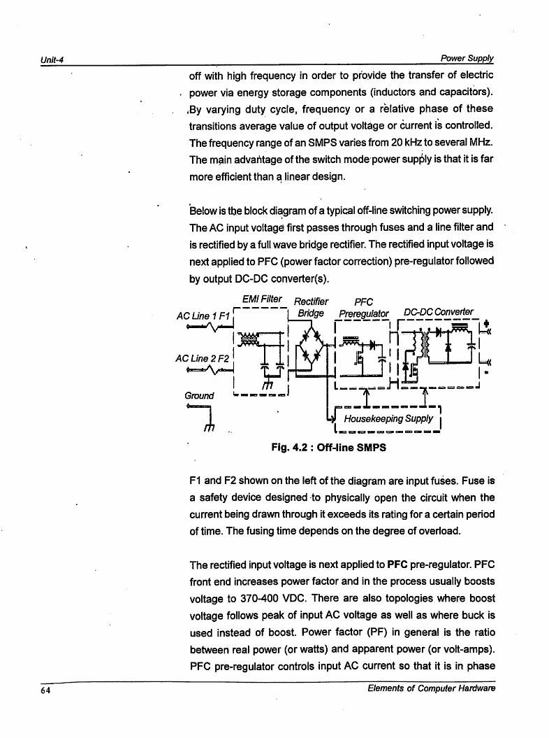
Below is the block diagram of a typical off-line switching power supply.
The AC input voltagd first passes through fuses and a line filter and
is rectified by a full wave bridge rectifier. The rectified input voltage is
next applied to PFO (power factor correction) pre-regulator followed
by output DC-DC converter(s).
EMI Filter Rectifier PFO
ACLine1Fl\t I
AC Line 2 F2
LJ
Ground
I Bridge Preregulator DC-DC Converter
i 1^ Housekeeping Supply |
Fig. 4.2 : Off-line SMPS
F1 and F2 shown on the left of the diagram are input fuses. Fuse is
a safety device designed to physically open the circuit when the
current being drawn through it exceeds its rating for a certain period
of time. The fusing time depends on the degree of overload.
The rectified input voltage is next applied to RFC pre-regulator. PFC
front end increases power factor and in the process usually boosts
voltage to 370-400 VDC. There are also topologies where boost
voltage follows peak of input AC voltage as well as where buck is
used instead of boost. Power factor (PF) in general is the ratio
between real power (or watts) and apparent power (or volt-amps).
PFC pre-regulator controls input AC current so that it is in phase
64 Elements of Computer Hardware
Power Supply Unit-4
with mains AC voltage and its waveform repeats the input voltage
waveform. Without this, the input current would be delivered to the
SMPS in short high peak pulses, which have a high harmonic content.
The current harmonics do not deliver any power to the load, but cause
additional heating in the wiring and distribution equipment. They also
reduce the maximum power that can be taken from a standard wall
outlet, since circuit breakers are rated by current rather then by power.
There are various regulations that limit the input current harmoniccontent, such as EN61000-3-2 (for equipment connected to public
low voltage distribution systems) or DO-160 (for airborne equipment).
To meet these harmonics requirements power factor correction
techniques are used: a PSU with high PF draws nearly sinusoidal
current from input (assuming sinusoidal input voltage), which results
in low harmonic content. Currently there are no mandatory
international standards that specifically regulate the power factor of
electronic equipment, but there are various industry standards as
well as voluntary incentive programs. For example, 80 PLUS and
Energy Star programs require computer PSU demonstrate PF>0.9
at rated load. Power factor as well as current harmonics can be
measured with commercially available power meters or special AC
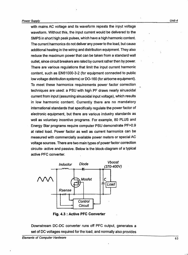
voltage sources. There are two main types of power factor correction
circuits- active and passive. Below is the block-diagram of a typical
active PFC converter.
Vboost
(370-400V)Inductor Diode
AAA Mosfet
Rsense
Load
Control
Circuit
Fig. 4.3 : Active PFC Converter
Downstream DC-DC converter runs off PFC output, generates a
set of DC voltages required for the load, and normally also provides
Elements of Computer Hardware 65
Unit-4 Power Supply
input-to-output isolation. There is a number of topologies utilized in a
DC-DC converter. In isolated off-line SMPS the most popular are full
bridge, half-bridge, forward and fly back. Most low-voltage non-
isolated DC-DC converters use buck regulators (single or interleaved
multi-phase). There is a large variety of regulator ICs suitable for
each of these topologies. The selection of right topology and controller
depends on specific requirements for the power supply (including
cost and time factors) and personal experience of the designer.
Efficiency of PSU is the ratio between output power (Pout) and input
power (Pin):
Efficiency = Pout/Pin.
To measure Pin you would need a true wattmeter: since any power
supply has power factor <1, you cannot just multiply input volts and
ampere. A typical commercially available power meter usually
displays both Pin and power factor. To measure you will need a
volt meter and ammeter. Finally, housekeeping supply provides bias
for all control circuitry and may also provide a separate stand-by
voltage (SBV) which remains active even when the PSU is shut down
for any reason. In today's computer power supplies a 5VDC SBV is
a standard feature.
LET US KNOW
The main disadvantage of the switch mode power supply is that it
generates high frequency signals within it as part of jhe conversion
process, which can radiate out of the unit and cause interference
to other electronic devices(inside or outside of the PC). For this
reason PC Power supplies are enclosed in a metal box for
shielding.
66 Elements of Computer Hardware
Power Supply Unit-4
CHECK YOUR PROGRESS-1
1. What is the main application of a linear power supply?
2. What do you mean by SMPS?
4.4 PARTS OF THE POWER SUPPLY (SMPS)
Power supply takes a look at the various parts that comprises the power
supply both inside and outside the box. The exact contents of any supply
vary depending on both the design and form factor. But most of them have
the same general size and components.
4.4.1 Power Conversion Circuitry
The heart of the power supply is usually a circuit board with various
electrical components on it, mounted inside the metal box of the
power supply. All the cables going in and out of the power supply go
to the circuit, including those of the remote switch, if any. This circuitry
is responsible for the conversion of AC to DC within the power supply.
This also manages the other power supply functions. In newer
supplies many of the features of the power supply are combined into
special integrated circuits to reduce space requirements and reducing
the manufacturing costs "also. The circuitry inside the case of the
power supply relies on the power supply fan for ventilation and cooling.
Elements of Computer Hardware67
Power Supply
JR ACTIVITY
1. Collect a power supply, open it and identify the various
components.
2. Find out the various sections of the power supply.
4.4.2 Power Supply Fan
Power supply fan is one of the most important parts of the PSU.
Since the earliest PCs, the power supply fan has been the primary
cooling source for the entire PC. Today's PC, of course, incorporated
additional cooling device, but the power supply fan remains an
important factor in the overall cooling. The power supply fan is
probably the only component that can be replaced by an end user.
4.4.3 Power Supply Fuse
Power supply comes with their own integrated fuse. The fuse is
designed to protect the circuits in the power supply from damage
should an over-current situation arise.
4.4.4 Power Supply Form Factor
As with cases, the primary characteristic of a power supply is its
form factor, which specifies dimensions and mounting hole locations,
which in tum determine which case form factor(s) the power supply
fits. Form factor also specifies the type of motherboard power
connectors the power supply provides, which in tum determines the
type(s) of motherboards the power supply supports. Table 1 lists
compatibility of power supplies with cases.
68 Elements of Computer Hardware
Power SupplyUnit-4
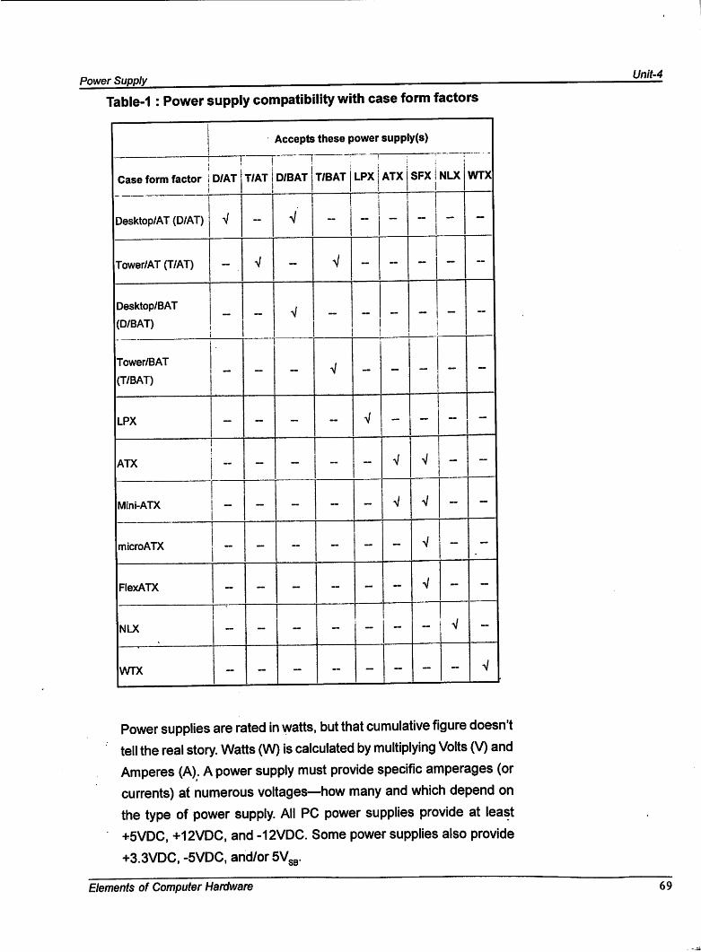
Table-1 : Power supply compatibility with case form factors
Accepts these power supply(s)
Case form factor 1
1
D/AT
j
T/AT j!
D/BAT jT/BAT LPX ATxj
X11.
OC
NLX WTX
Desktop/AT (D/AT) V - v'
1
Tower/AT (T/AT) - V
Desktop/BAT
(D/BAT)-
j
Tower/BAT
(T/BAT)- - >/ -
- -
LPX - - ~ V -
11
-
ATX - ~ - ~ V
1
V j - -
Mini-ATX - - - ~ - V V - ~
microATX - ~ ~ ~ - V - -
FlexATX - ~ - ~ -- V - -
NLX ~ - - - ~ - - ~
WTX ~ - ~ ~ - - ~ ~ V
Power supplies are rated In watts, but that cumulative figure doesn't
tell the real story. Watts (W) is calculated by multiplying Volts (V) andAmperes (A). A power supply must provide specific amperages (orcurrents) at numerous voltages—how many and which depend on
the type of power supply. All PC power supplies provide at least
+5VDC, +12VDC, and -12VDC. Some power supplies also provide
+3.3VDC, -5VDG, and/or SVgg.
Elements of Computer Hardware 69
Power Supply
Another important aspect of voltage—one that varies greatly between
power supplies—is regulation, which specifies how tightly voltages
are controlled. For example, a memory module that expects +3.3V
may work at +3.2V or +3.4V, but will probably not work at +3.1 V or
+3.5V. Regulation may be specified as a maximum percentage
variation or as a maximum variation in absolute voltage.
No standards body produced a formal specification for all aspects of
the AT power supply or its BAT and IPX variants. However, the ATX
power supply—along with its variants, the NLX and SFX power
supplies—is completely defined in a group of documents.
4.4.5 ATX/ATX12V Power Supply Specifications
ATX Specification Version 2.1 and associated documents define the
ATX voltage rails and tolerances shown in Table 2. An ATX 2.1-
compliant power supply must provide these voltages at these
tolerances or better. High-quality power supplies provide tighter
tolerances, sometimes much tighter, such as 1% across all positive
voltages. Cheap power supplies often do not meet the required
tolerances for one or more voltages, and are therefore technically
not ATX power supplies. However, they look like ATX power supplies,
quack like ATX power supplies, and are sold as ATX power supplies.
Avoid any power supply that does not meet the following standard,
^min ^max calculatod valuos, provided for the convenience ofthose testing power supplies with a DMM.
The ATX/ATX12V Power Supply Design Guide Version 1.2 defines
two distinct types of power supply, the ATX power supply and the
ATX12V power supply. An ATX12V power supply is a superset of an
ATX power supply, and is backward-compatible with an ATX unit.
ATX power supplies support motherboards that use +5VDC or
+3.3VDC voltage regulator modules (VRMs). ATX12V power supplies
support motherboards that use +5VDC, +3.3VDC, or+12VDC VRMs.
The sole advantage of ATX relative to ATX12V is that ATX power
10 Elements of Computer Hardware
Power Supply Unit-4
supplies cost a bit less to produce, but that advantage is sufficient to
ensure that the standard ATX power supply definition will be
maintained in parallel with ATX12V. Standard ATX power supplies will
continue to be produced for use in high-volume, low-end applications.
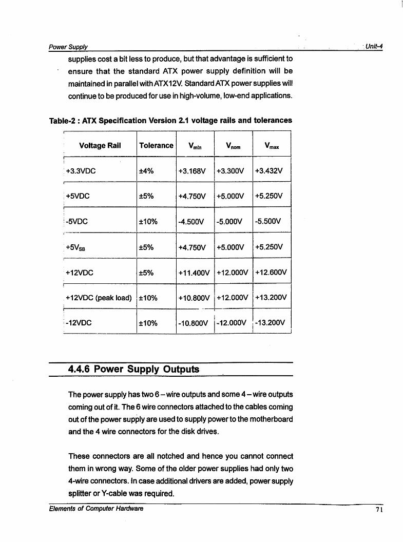
Table-2 : ATX Specification Version 2.1 voltage rails and tolerances\
Voltage Rail Tolerance Vmin Vnom Vmax
I
+3.3VDC ±4% +3.168V +3.300V +3.432V
1
+5VDC ±5% +4.750V +5.000V +5.250V
1
i-5VDC ±10% -4.500V -5.000V -5.500V
+5Vsb ±5% +4.750V +5.000V +5.250V
+12VDC ±5% +11.400V +12.000V +12.600V
!
+12VDC (peak load) ±10% +10.800V +12.000V +13.200V
1
;-12VDC ±10% -10.800V -12.000V -13.200V
4.4.6 Power Supply Outputs
The power supply has two 6 - wire outputs and some 4 - wire outputs
coming out of it. The 6 wire connectors attached to the cables coming
out of the power supply are used to supply power to the motherboard
and the 4 wire connectors for the disk drives.
These connectors are all notched and hence you cannot connect
them in wrong way. Some of the older power supplies had only two
4-wire connectors, in case additional drivers are added, power supply
splitter or Y-cable was required.
Elements of Computer Hardware 71
Unit-4 Power Supply
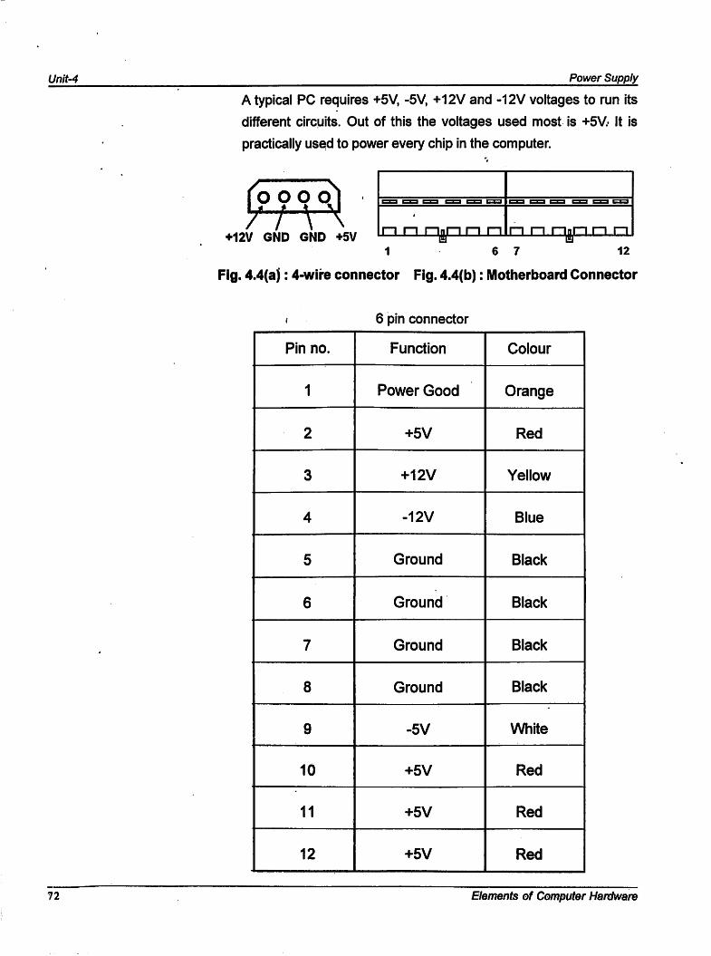
Atypical PC requires +5V, -5V, +12V and -12V voltages to run its
different circuits. Out of this the voltages used most is +5V.- It is
practically used to power every chip in the computer.
f O O Q
+12V GND GND +5V
1 6 7 12
Fig. 4.4(a): 4-wlre connector Fig. 4.4(b): Motherboard Connector
n n n n r-i n nun
6 pin connector
Pin no. Function Colour
1 Power Good Orange
2 +5V Red
3 +12V Yellow
4 -12V Blue
5 Ground Black
6 Ground Black
7 Ground Black
8 Ground Black
9 -5V White
10 +5V Red
11 +5V Red
12 +5V Red
72 Elements of Computer Hardware
Power Supply Unit-4
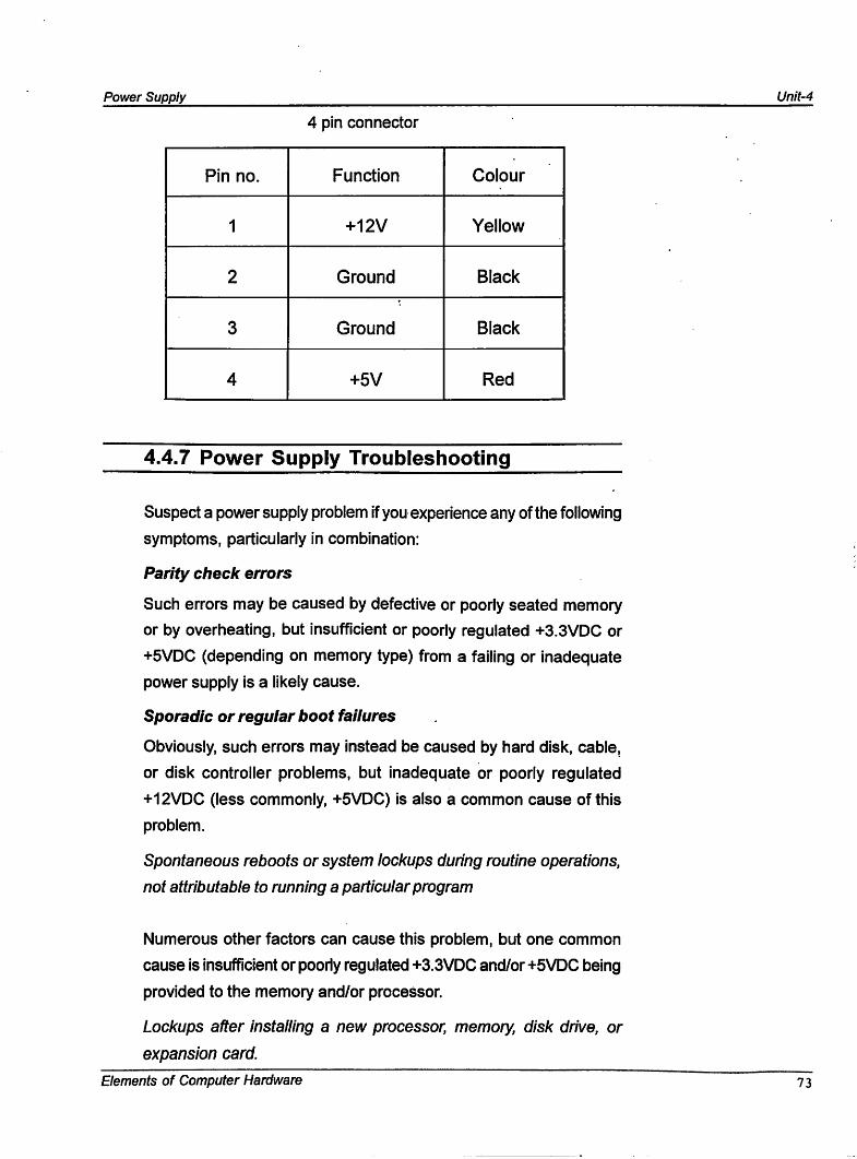
4 pin connector
Pin no. Function Colour
1 +12V Yellow
2 Ground Black
3 Ground Black
4 +5V Red
4.4.7 Power Supply Troubleshooting
Suspect a power supply problem If you experience any of the following
symptoms, particularly In combination:
Parity check errors
Such errors may be caused by defective or poorly seated memory
or by overheating, but Insufficient or poorly regulated +3.3VDC or
+5VDC (depending on memory type) from a falling or Inadequate
power supply Is a likely cause.
Sporadic or regular boot failures
Obviously, such errors may Instead be caused by hard disk, cable,
or disk controller problems, but Inadequate or poorly regulated
+12VDC (less commonly, +5VDC) Is also a common cause of this
problem.
Spontaneous reboots or system lockups during routine operations,
not attributable to running a particular program
Numerous other factors can cause this problem, but one common
cause Is Insufficient or poorly regulated +3.3VDC and/or +5VDC being
provided to the memory and/or processor.
Lockups after installing a new processor, memory, disk drive, or
expansion card.
Elements of Computer Hardware 73
Unit-4 Power Supply
Driver issues and resource conflicts aside, this problem commonly
occurs when new components overload a marginal power supply.
This is particularly likely to occur if you make dramatic changes to
the system, such as replacing a slow CPU with a fast, high-current
CPU; if you expand memory significantly—e.g., from 128 MB to 512
MB; if you add a high-current expansion card such as a fast AGP
video card or internal modem; or if you add a high-current drive such
as a high-performance SCSI hard disk or a CD burner to the system.
Note that the power supplies provided with commercial systems,
particularly inexpensive ones, often have very little reserve.
Failure to function with a Wake-on-LAN (WOL) motherboard
The motherboard and power supply may both be operating properly
but be incompatible. Many early ATX power supplies (and some
current models) provide 100 mA or less of +5Vsg. Although that output
met the ATX 2.01 requirements, WOL motherboards require +5V3g
of at least 720 mA.
Slow disk performance
Although this may seem an odd symptom to be related to power
supply problems, inadequate voltage and current can cause disk
retries on both reads and writes. The error correction circuitry built
into hard disks and controllers means that this problem often (usually)
goes undiagnosed. People often say to us something like, "I replaced
the power supply as you suggested, and now my hard disk seems a
lot faster. Is that possible?" Yes, it is.
LET US KNOW
A very common source of problems is using a noncompliant ATX-
like power supply. We say "ATX-like" because many power
supplies that fit ATX cases are not ATX-compliant. Motherboards
vary in their tolerance for voltages that are slightly out of spec,
and a marginal power supply that works fine with one motherboard
may not work with another, even of the same model.
74 Elements of Computer Hardware
Power Supply Unit-4
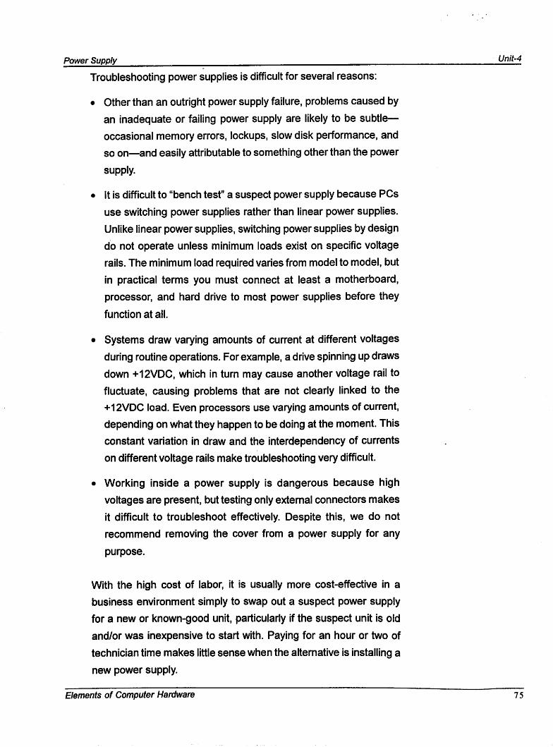
Troubleshooting power supplies is difficult for several reasons;
• Other than an outright power supply failure, problems caused by
an inadequate or failing power supply are likely to be subtle—
occasional memory errors, lockups, slow disk performance, and
so on—and easily attributable to something other than the power
supply.
• It is difficult to "bench test" a suspect power supply because PCs
use switching power supplies rather than linear power supplies.
Unlike linear power supplies, switching power supplies by design
do not operate unless minimum loads exist on specific voltage
rails. The minimum load required varies from model to model, but
in practical terms you must connect at least a motherboard,
processor, and hard drive to most power supplies before they
function at all.
• Systems draw varying amounts of current at different voltages
during routine operations. For example, a drive spinning up draws
down +12VDC, which in turn may cause another voltage rail to
fluctuate, causing problems that are not clearly linked to the
+12VDC load. Even processors use varying amounts of current,
depending on what they happen to be doing at the moment. This
constant variation in draw and the interdependency of currents
on different voltage rails make troubleshooting very difficult.
• Working inside a power supply is dangerous because high
voltages are present, but testing only extemal connectors makes
it difficult to troubleshoot effectively. Despite this, we do not
recommend removing the cover from a power supply for any
purpose.
With the high cost of labor, it is usually more cost-effective in a
business environment simply to swap out a suspect power supply
for a new or known-good unit, particularly if the suspect unit is old
and/or was inexpensive to start with. Paying for an hour or two of
technician time makes little sense when the alternative is installing a
new power supply.
Elements of Computer Hardware 7 5
Unit-4 Power Supply
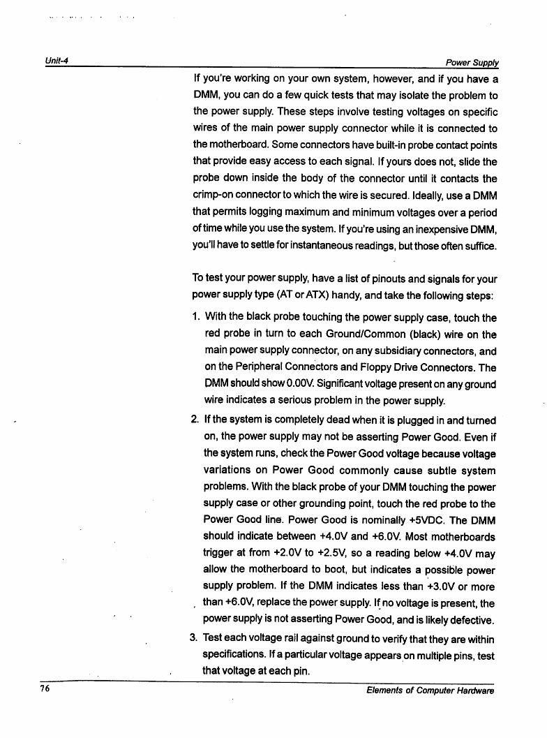
If you're working on your own system, however, and If you have a
DMM, you can do a few quick tests that may isolate the problem to
the power supply. These steps involve testing voltages on specific
wires of the main power supply connector while it is connected to
the motherboard. Some connectors have built-in probe contact points
that provide easy access to each signal. If yours does not, slide the
probe down inside the body of the connector until it contacts the
crimp-on connector to which the wire is secured. Ideally, use a DMM
that permits logging maximum and minimum voltages over a period
of time while you use the system. If you're using an inexpensive DMM,
you'll have to settle for instantaneous readings, but those often suffice.
To test your power supply, have a list of pinouts and signals for your
power supply type (AT or ATX) handy, and take the following steps:
1. With the black probe touching the power supply case, touch the
red probe in turn to each Ground/Common (black) wire on the
main power supply connector, on any subsidiary connectors, and
on the Peripheral Connectors and Floppy Drive Connectors. The
DMM should show O.OOV. Significant voltage present on any ground
wire indicates a serious problem in the power supply.
2. If the system is completely dead when it is plugged in and turned
on, the power supply may not be asserting Power Good. Even if
the system runs, check the Power Good voltage because voltage
variations on Power Good commonly cause subtle system
problems. With the black probe of your DMM touching the power
supply case or other grounding point, touch the red probe to the
Power Good line. Power Good is nominally +5VDC. The DMM
should indicate between +4.0V and +6.0V. Most motherboards
trigger at from +2.0V to +2.5V, so a reading below +4.0V may
allow the motherboard to boot, but indicates a possible power
supply problem. If the DMM indicates less than +3.0V or more
than +6.0V, replace the power supply. If no voltage is present, the
power supply is not asserting Power Good, and is likely defective.
3. Test each voltage rail against ground to verify that they are within
specifications. If a particular voltage appears on multiple pins, test
that voltage at each pin.
7 6 Elements of Computer Hardware
Power Supply Unit-4
4. For each Peripheral Connector and Floppy Drive Connector, test
each of the two voltages present against ground. That is, touch
the red probe to +12V (yellow wire), and then touch the black
probe to the adjacent ground pin (black wire). The DMM should
read +12V within tolerance. Then touch the red probe to +5V (red
wire) and the black probe to the adjacent ground pin. The DMM
should read +5V within tolerance. Finally, touch each probe to
one of the ground pins. The DMM should read O.OOV or something
very near it.
If any of these tests fails, a defective or overloaded power supply is
the most likely cause. In that event, replacing the power supply is
usually the best choice. We have never attempted to repair a power
supply ourselves, and do not recommend doing so. If the power supply
is under warranty—good units often have three- to five-year
warranties—call the vendor for an RMA number and ask if they are
willing to cross-ship a replacement unit. If the power supply is not
under warranty but is an expensive (high-wattage or redundant) and
relatively new unit, contact the vendor about having it repaired. Some
vendors quote a fixed price, while others charge time and materials.
Be wary of the latter.
CHECK YOUR PROGRESS-2
1. Fill in the Blanks
(i) is one of the most important parts of the PSU.
(ii) Power supplies are rated in
(iii) The Power Supply has
(iv) Atypical PC requires
to outputs.
and voltages to run its different circuits.
Elements of Computer Hardware 77
Unit-4 Power Supply
4.5 UNINTERRUPTED POWER SUPPLY
There really is a difference between an uninterruptable power supply (UPS)
and a standby power supply (SPS), but common usage now designates a
unit properly termed an SPS as a UPS. We call a unit of either sort a
backup power supply (BPS), which neatly sidesteps the terminology
problem.
A BPS comprises a battery and some supporting circuitry, and is designed
to supply power to your PC for a short period if the utility power fails. This
temporary reprieve allows you to save your work and shut down the PC in
an orderly fashion. BPSs differ in the quality of the power they supply, how
much power they can supply, and for how long they can supply it. BPSs
also condition the utility power to protect equipment against spikes, surges,
drops, brownouts, and electrical noise.
Most electric utilities supply consistent, well-regulated power. But as that
power moves from the generating plant through the distribution grid to you,
the power company gradually loses control of Its quality. A good BPS
protects against all of the following power problems:
Blackout
A blackout \s a sudden, complete loss of voltage, which may be accidental
(a tree falling on a power line) or intentional (the power company shedding
load during a power emergency). Blackouts are the reason most people
consider buying a BPS, but they are the least-common power problem.
Blackouts of very short duration, called drops, occur frequently and often
pass unnoticed. Drops may be so short that the lights may not flicker.
High-quality PC power supplies have enough inertia to continue supplying
power to the PC during short drops. Lower-quality PC power supplies have
much shorter hold-up times, so even very short drops may cause the PC
to lock up. In fact, this is one of the most common causes of PC lockups,
and installing a BPS eliminates them.
78 Elements of Computer Hardware
Power Supply Unit-4
Brownout
A brownout is a significant reduction in voltage lasting from seconds to
days. Short brownouts, called sags, are usually caused by a sudden load
on the line, such as a high-amperage motor being turned on. Longer
brownouts may be caused by the utility intentionally reducing voltage in
response to demands heavier than they can meet. Utilities supply a nominal
standard voltage, which in the U.S. normally ranges from 108V to 125V,
with 110 to 115V most common. During a brownout, voltage may drop
from nominal to 90V or less. Brownouts can damage equipment because
as voltage drops, equipment draws more current to compensate, which
increases heat production.
Surge
During a surge, delivered voltage is substantially (20% to 100%) higher
than nominal. Surges may last from a fraction of a second to several
seconds, and often result when a heavy load is suddenly removed from
the circuit. Surges are relatively common, and all but the most extreme
are relatively benign. Despite claims made by the manufacturers of so-
called "surge protectors," most equipment takes normal surges in stride. A
good BPS does, however, prevent them from reaching the equipment in
the first place.
Spike
A spike, also called a transient, is an extreme overvoltage of very short
duration. Spikes originate from various sources, including voltages induced
by remote lightning strikes, transformer failures, and no brushless motors
turning on and off. Although spikes may carry 50,000 V or more, most are
of such short duration (milliseconds or less) that they deliver very little
electrical energy. PC power supplies themselves protect against most
spikes. A good PC power supply smothers typical short spikes of up to
5,000 V without affecting system operation. Spikes of higher voltage or
longer duration are stopped by a good BPS. The worst spikes, those that
result from a direct "bolt on copper" lighting strike nearby, cannot be stopped
by any power protection equipment.
Elements of Computer Hardware 79
Unit-4 ^ Power Supply
Most people don't realize that damage from electrical problems, particularly
spikes, is incremental and cumulative. That is, a computer may absorb a
severe spike and continue to operate normally. But that spike may have
caused invisible damage to the chips, down almost at the quantum level.
Computer chips, including memory and CPUs, typically use 12 V or less.
A spike at even 10,000 times that voltage may simply lock up the system
with no other obvious effects or apparent damage, but leave the system
teetering on the edge. A subsequent spike, even a small one, may be the
straw that breaks the camel's back. Little Spike finishes the job that Big
Spike started, causing the system to fail for no apparent reason. A good
BPS prevents such problems.
All BPSs have three common elements; a battery, which stores electrical
energy against power failures; an inverter, which converts DC voltage
supplied by the battery to the AC voltage required by the load; and charging
circuitry, which converts AC mains power to the DC voltage required to
charge the battery. IEEE recognizes three categories of BPS, which it terms
UPS:
4.5.1 ON LINE UPS
An on-line UPS (often called a true UPS to differentiate it from an
SPS) connects the load directly to the inverter, which converts DC
voltage supplied by the battery to standard AC voltage. The charging
circuitry charges the battery constantly while the UPS is operating,
and the equipment always runs from battery power supplied by the
inverter. On-line UPSs are not often used on PCs because they cost
substantially more than SPSs, described later in this list. An on-line
UPS has two advantages. Because the PC runs on battery power all
the time, there is no switch-over time, and no switch to fail. Also,
because the PC does not connect to mains power, it is effectively
isolated from AC line problems. Against this, an on-line UPS has
three drawbacks. Foremost is cost, which may be 50% to 100%
higher than an equivalent SPS. Also, because the system runs from
80 Elements of Computer Hardware
Power Supply Unit-4
battery constantly, UPS batteries typically require replacement more
frequently than SPS batteries, and UPS batteries are not cheap.
Finally, UPS efficiencies are relatively low. An SPS runs at nearly
100% efficiency during normal operations, and at lower efficiency
only during power failures. A UPS runs its inverter all the time. That
results in efficiency as low as 70%, which translates to higher electric
bills. This is of little concern to most home and office PC users, but
is a major issue for data centers. An on-line UPS may also be called
a dual-conversion on-line UPS, to differentiate it from a line-interactive
UPS, described next.
4.5.2 LINE-INTERACTIVE UPS
A iine-interactive UPS also called a single-conversion on-line UPS
differs from an on-line UPS in that the load normally runs primarily
from utility power as long as that power is available. Rather than
convert utility power to DC, use it to charge the battery, and then
reconvert it to AC for the load (the "dual-conversion" part), a line-
interactive UPS feeds utility power directly to the load under normal
conditions. Minor variations in utility power are smoothed out by the
inverter using battery power. The defining characteristics of a line-
interactive UPS are that the inverter runs at all times, and that the
load is always dynamically shared between inverter and utility power.
During routine operation, utility power may support 99% of the load
and the inverter only 1%. During a brownout, the inverter may support
10% or more of the load. Only during a blackout does the inverter
assume 100% of the load. A true line-interactive UPS has no switch
over time because the inverter and utility power dynamically share
the load at all times, so a power failure simply means that the inverter
instantaneously assumes 100% of the load. Although line-interactive
units do not isolate the load from the AC line to the extent that an on
line UPS does, they are quite good at maintaining clean, steady AC
to the load. Line-interactive UPSs are common in data centers, but
uncommon in the PC environment.
Elements of Computer Hardware 81
Unit-4 Power Supply
4.5.3 OFF LINE UPS
Any BPS used with a PC (or even a server) nowadays Is almost
certainly an off-line power supply, sometimes called a standby power
supply (SPS). BPS marketers dislike "standby" and downright hate
"off-line," so off-line power supplies are always described as
"uninterruptable" power supplies, which they are not. The defining
characteristics of an SPS are that it has a switch and that the inverter
is not always running. During normal operation the switch routes
utility power directly to the load. When utility power fails, that switch
quickly disconnects the load from the utility power and reconnects it
to the inverter, which continues to power the equipment from battery.
SPSs are less expensive than on-line and line-interactive units
because they can use a relatively inexpensive inverter, one rated for
low duty cycle and short run time.
Unlike on-line and line-interactive units, SPSs do not condition or
regenerate incoming AC before supplying it to the load. Instead, they
pass utility AC power through a passive filter similar to an ordinary
surge suppressor, which means that SPSs do not provide power as
clean as that provided by on-line and line-interactive units. In theory,
SPSs have another drawback relative to on-line and line-interactive
units. Actual switching time may be considerably longer than nominal
under extended low-voltage conditions and with partially depleted
batteries. Because the hold-up time of a PC power supply decreases
under marginal low-voltage conditions, in theory an SPS may require
longer to switch than the hold-up time of the PC power supply, resulting
in a system crash. In practice, good SPSs have typical switching
times of 2 to 4 ms and maximum switching times of 10 ms or less,
and good PC power supplies have hold-up times of 20 ms or longer
at nominal voltage and 15 ms or longer during sustained marginal
under-voltage conditions, which means this is seldom a problem.
Several SPS variants exist:
Standard SPS
A standard SPS has only two modes—^full utility power or full battery
power. As long as utility power is within threshold voltage limits (which
82 Elements of Computer Hardware
Power Supply Unit-4
can be set on many units), the SPS simply passes utility power to
the equipment. When utility power dips beneath threshold, the SPS
. transfers the load from using 100% utility power to using 100% battery
power. Some standard SPSs also transfer to battery when utility
voltage exceeds an upper threshold. That means that the SPS
switches to battery every time a surge, sag, or brownout occurs,
which may be quite frequently. This all-or-nothing approach cycles
the battery frequently, which reduces battery life. More Important,
frequent alarms for minor power problems cause many people to
turn off the alarm, which may delay recognition of an actual outage
so long that the battery runs down and work Is lost. Most entry-level
SPS models are standard SPSs. The American Power Conversion
(APC) Back-UPS series, for example, are standard SPSs.
Line-boost SPS
A line-boost SPS adds line-boost mode to the two modes of the
standard SPS. Unlike llne-lnteractlve units, which use battery power
to raise AC output voltage to nominal, line-boost units simply have
an extra transformer tap, which they use to Increase output voltage
by a fixed percentage (typically, 12% to 15%) when Input voltage falls
below threshold. For example, when AC Input falls to 10OVAC, a llne-
lnteractlve unit uses battery power to raise It 15V to 115VAC nominal.
For 95VAC Input, the llne-lnteractlve unit raises It 20V to 115VAC
nominal. For 100VAC Input, a line-boost unit uses the extra tap to
raise output voltage by the fixed percentage (we'll assume 12%),
yielding 112VAC output. For 95VAC Input, the line-boost unit raises It
by the same fixed percentage. In this case to 106.4VAC. That means
that output voltage follows Input voltage for line-boost units, with the
resulting transients and current surges on the load side as the Inverter
kicks In and out. Most midrange and high-end PC SPS models are
line-boost SPSs. The APC Back-UPS Pro and Smart-UPS series,
for example, are line-boost SPSs.
Ferro-resonant SPS
A ferro-resonant SPS uses a ferro-resonant transformer rather than
the tap-change transformer used by a line-boost unit. Its sole
advantage relative to a line-boost unit Is that It provides some power
Elements of Computer Hardware 83
Unit-4 Power Supply
conditioning instead of allowing output voltage to vary with input
Voltage. Against that, ferro-respnant units have several serious
drawbacks. First, as a high output-impedance source, ferro-resonant
units are inherently unstable with some loads, including the power-
factor-corrected (RFC) power supplies that are relatively common
in PCs. Second, a ferro-resonant unit can introduce severe oscillation
Into output voltage even when input voltage is relatively clean and
stable. Most important, although ferro-resonant units are often
claimed to have zero transfer time, their actual transfer time can be
greater than 25 ms, which is larger than the hold-up time of nearly
any PC power supply. We believe Ferro-resonant units are a poor
choice for use with PCs.
CHECK YOUR PROGRESS-3
1. What is Black out?
2. What is a ON LINE UPS?
3. What are the common elements of Backup Power Supply?
4. Answer True or False :
i) Off-line power supply is also called Standby Power Supply.
ii) On-line power supply is less expensive than off-line power.
iii) Short brownouts calledsurge are usually caused by a sudden
load oh the line.
iv) A standard SPS has only two modes.
^4 MiiBments of Computer Hardware
Power Supply Unit-4
4.6 INSTALLATION OF UPS (H/W
Volt-Ampere (VA) rating
The VA rating of a BPS specifies the maximum power the UPS can supply,
and is determined by the capacity of the inverter. VA rating is the product of
nominal AC output voltage and the maximum amperage rating of the
inverter. For example, Barbara's 120VAPC Back-UPS Pro 650 can supply
about 5.4A (650VA/120V). Connecting a load greater than the amperage
rating of the inverter overloads the inverter and soon destroys it unless the
BPS has current-limiting circuitry. Watts equal VA only for 100% resistive
loads (e.g., a light bulb). If the load includes capacitive or inductive
components, as do PC power supplies, the draw in VA is equal to Wattage
divided by the Power Factor {PF) of the load. Most PC power supplies
have Power Factors of 0.65 to 0.7. For example, Robert's APC Smart-
UPS 1000 is rated at 1000VA but only 670 Watts, which means that APC
assumes a PF of 0.67 when rating wattage for this unit.
Run time
The run time of a BPS is determined by many factors, including battery
type and condition, Amp-hour capacity, and state of charge; ambient
temperature; inverter efficiency; and percentage load. Of those, percentage
load is most variable. The number of Amp-hours a battery can supply
depends on how many amps you draw from it, which means the relationship
between load and run time is not linear. For example, our APC Back-UPS
600 can supply 600VA for five minutes, but can supply 300VA (half the load)
for 22 minutes (4.4 times longer). Doubling load cuts run time by much
more than half; halving load extends run time by much more than twice.
LET US KNOW
Many people believe VA rating and run time are somehow related.There is no such relationship, except that units with larger VA
ratings typically also have a larger battery, which provides longer
run time for a given load, both because the battery itself is larger
and because the unit is supplying fewer amps than its rated
maximum. It is, however, quite possible to build a BPS with a very
high VA rating and a tiny battery or vice versa.
Elements of Computer Hardware 85
Unit-4 Power Supply
Output waveform
Utility AC voltage is nominally a pure sine waveform, which is what power
supplies and other equipment are designed to use. The output waveform
generated by BPSs varies. In order of increasing desirability (and price),
output waveforms include: square wave, sawtooth wave, and modified
square wave (often somewhat deceptively called near sine wave, stepped
approximation to sine wave, modified sine wave, or stepped sine wave—
marketers are desperate to get the word "sine" in there, especially for units
that don't deserve it). The cheapest units generate square wave output,
which is essentially bipolar DC voltage with near zero rise-time and fall-
time, which allows it to masquerade as AC. Midrange units normally provide
pseudo-sine wave output, which may be anything from a very close
approximation to a sine wave to something not much better than an
unmodified square wave. The output waveform is determined by the inverter.
The inverter is the most expensive component of a BPS. Better inverters—
those that generate a sine wave or a close approximation—are more
expensive, so the quality of the output waveform generally correlates closely
to unit price. Astonishingly, we once saw specifications for a no-name BPS
that listed output waveform as "pure square wave," presumably intending
to confound buyers with "pure" (a Good Thing) and "square wave" (a Bad
Thing).
Before you buy a
replacement batteryfrom the UPS maker,
check Graybar, W. W.
Grainger, and similar
industrial supply
vendors. You may beable to find identical
replacement batteries
for half or less the
price charged by theUPS maker.
LET US KNOW
We have heard reports of fires caused by connecting a surge
suppressor between the BPS and the PC. Although we have not
been able to verify the reports, it makes sense that feeding square
wave power to a surge suppressor designed to accept sine wave
input could cause it to overheat. On the other hand, there is nothing
wrong with using a surge suppressor between the BPS and the
wall receptacle. In fact, we recommend it, both to provide increased
protection against spikes reaching the PC and to protect the BPS
itself.
86 Elements of Computer Hardware
Power Supply Unit-4
Battery replacement method
Although it sounds trivial, battery replacement method is one of the most
important characteristics of a BPS. Batteries must be replaced periodically,
perhaps as often as annually if you have frequent long power outages.
Better units have user-replaceable batteries. Lesser units must be retumed
to the factory for servicing. It's both much less expensive and much more
convenient to be able to replace batteries yourself.
Warranty
The length of warranty is a reasonably good indicator of the quality of
the unit. Better units have a two-year parts and labor warranty,
although the battery is usually excluded. Lesser units often carry a
one-year warranty, and we have seen many of them fail not long
past that time. The cheapest units may carry only a 90-day warranty.
Configuration options
Inexpensive BPSs may provide few or no configuration options. They
may, for example, be permanently set to transfer to battery if the
input voltage drops below 102VAC or rises above 130VAC. Better
BPSs offer flexible options for setting such things as transfer voltage
thresholds, warning type (audible, visual, email and/or pager
notification, etc.), delay before warning, warning duration, and so on.
Status indicators
Inexpensive units provide few status indicators, typically only an LED
that illuminates when the unit is operating on battery. Better units
provide detailed LED or LCD status displays to indicate such things
as load percentage, battery charge status, overload conditions, and
battery replacement required.
Overload protection
All units include some form of overload protection. Less-expensive
units often use a fuse, and may need to be returned to the factory if
that fuse blows. Better units use a circuit breaker that can be reset
by pressing a button.
Elements of Computer Hardware 87
' Power Supply
Receptacle configuration
Most units include two types of receptacle, often differentiated by
color. The first sort are backed up by the battery; the second sort are
surge-protected only, and are useful for connecting items (such as
laser printers) that you want surge-protected but do not want to run
from the UPS. Also note that units vary greatly in how many
receptacles they provide and how convenient they are to use.
Inexpensive units mount a few receptacles on the back panel. Better
units provide additional receptacles, and arrange them—either by
spacing or by making the receptacle a female connector on a short
extension cord—so that connecting a power brick or oversize plug
does not block other receptacles.
Manageability
There are two aspects to BPS manageability:
Automatic shutdown
All but entry-level BPS units include a network interface port. By
connecting that port to a serial port on the computer—^which
usually requires a nonstandard cable—and running automatic
shutdown software supplied with the OS or the BPS, you canallow the BPS to shut down the computer in an orderly manner
during a power failure before battery power runs out. If your
computer runs unattended, automatic shutdown is a valuable
feature. Some BPS models support automatic shutdown via a
USB link. If yours does, make sure the unit also supports serial
connection, or it will be unusable with Windows NT 4 and other
OSs that don't support USB. Note that if you share one BPS among
computers, you will be able to shut down only one of them
automatically unless you purchase expensive hardware designed
to distribute the automatic shutdown signal to multiple computers.
SNMP manageability
Simple Network Management Protocol (SNMP) can be used to
centralize monitoring and control of a large network. In that
88 Elements of Computer Hardware
Power Supply Unit-4
environment, having SNMP-capable BPSs is important, but in
typical home-office and smallbusiness environments, SNMP
support is a nonissue. Inexpensive BPSs do not support SNMP.
Midrange and high-end SPSs may include it as a standard or
optional feature. If SNMP is an issue for you, make sure that the
BPS manufacturer supplies an MIB that is usable by your
management package. If you don't know what an MIB is, don't
worry about it.
Here are some BPS characteristics that are promoted by marketers
but are largely meaningless:
Operating system certification
This item is pertinent only if you use shutdown software, either that
bundled with the OS or that provided by the BPS manufacturer. The
shutdown software provided with a modern OS recognizes most
common BPS models, and can usually be configured to support
oddball requirements from off-brand BPSs. Most people use the
automatic shutdown software bundled with the BPS, as it is usually
more functional and supports specific features of the BPS model. In
that case, the only thing that matters is that it runs on your OS, which
it is likely to do unless you're running something relatively uncommon
such as OS/2. Linux support, formerly rare, is now common. OS
certification should be at most a checklist item.
Switching time
Typical BPSs have nominal switching times of 2 to 4ms. Under
adverse conditions, such as an extended period of low-voltage,
partially discharged batteries, and so on, transfer time can be longer.
A typical BPS might list worst-case transfer time of 8 ms, which
should be within the hold-time of any decent power supply, even
operating under adverse conditions. Shorter is obviously better here,
but don't give nominal switching time too much weight.
Elements of Computer Hardware 89
Unit-4 Power Supply
Connected equipment warranty
Most BPS makers include a connected equipment warranty. In theory,
if your equipment suffers damage attributable to a fault in the BPS,
the BPS Company pays to repair or replace it. That sounds good,
but the truth is that few people ever collect on such warranties. There
are so many exclusions and limitations, including the fact that the
coverage is often subrogated to your home or business insurance,
that such warranties are all sizzle and no steak.
CHECK YOUR PROGRESS-4
1. What determines the capacity of an inverter or a UPS?
4.7 LET US SUM UP
Power supply unit (PSU) is a device that transfers electric power
from a source to a load using electronic circuits.
In SMPS power handling electronic components are continuously
switching on and off with high frequency in order to provide the transfer
of electric power via energy storage components
The primary characteristic of a power supply is its form factor.
The VA rating of a BPS specifies the maximum power the UPS can
supply, and is determined by the capacity of the inverter.
The run time of a BPS is determined by many factors, including
battery type and condition. Amp-hour capacity, and state of charge;
ambient temperature; inverter efficiency; and percentage load.
90 Elements of Computer Hardware
Power Supply Uhit-4
4.8 FURTHER READINGS
• Fundamentals of Computer Hardware -Mandeep S. Bhatia
(Khanna Book Publishing co(p) Ltd, Delhi)
• Learning PC Hardware -Ramesh Bangia (Khanna Book Pubiishing
CO. pvt Ltd)
4^ 4.9 ANSWERS TO CHECK YOUR PROGRESS
CHECK YOUR PROGRESS 1
1. The main application of power supplies is to convert utility's AC input
voltage into regulated DC voltage(s) required for electronic
equipments.
2. Switch Mode Power supply
CHECK YOUR PROGRESS-2
(i) Power supply fan (ii) Watts
(ill) 4, 6 (iv) +5V, -5V, +12V, -12V
CHECK YOUR PROGRESS-3
1. A blackout is a sudden, complete loss of voltage, which may be
accidental (a tree falling on a power line) or intentional (the power
company shedding load during a power emergency).
2. An on-line UPS (often called a true UPS to differentiate it from an
SPS) connects the load directly to the inverter, which converts DC
voltage supplied by the battery to standard AC voltage.
3. All BPS have three common elements- a battery, an inverter and
charging circuitry.
4. i) True, ii) False, ill) False, iv) True.
CHECK YOUR PROGRESS-4
1. The VA rating of a BPS specifies the maximum power the UPS can
supply, and is determined by the capacity of the inverter.
Elements of Computer Hardware 9 j
Unit-4 Power Supply
Pll^ 4.10 POSSIBLE QUESTIONS
1. What do you understand by a power supply? Describe in short about
its different types.
2. Mention the major parts of a SMPS. Describe in short about them.
3. Write a short note on UPS.
4. What is the difference between ON LINE UPS and OFF line UPS?
5. Write in short about-
a. VA rating b. RunTime c. Output Waveform.
5. Describe the Battery replacement method.
92 ■ Elements of Computer Hardware