Embed Size (px)
Citation preview
www.r4t.me
TECHNICAL PROPOSAL
BUS – BAR PROTECTION RELAY PANELS Case Study
"اقل الطاقة الكهربائيةوحدات حماية ن"
اإلمارات العربية المتحدة –أبو ظبي ٤١٨٤٩. ب.ص): م.م.ذ(شركة روافد للتكنولوجيا
العراق -البصرة /عشار ١٦٦٠. ب.ص
Prepared by Rawafid for Technology (R4T) L.L.C. PO Box 41849, Abu Dhabi – UAE
10-03-2010

"اقل الطاقة الكهربائيةوحدات حماية ن"
في توزيع الطاقة الكهربائية هو عبارة عن لوح سميك من النحاس (bus-bar)ناقل الطاقة الكهربائية ويكون حجم الناقل مهما في . اح مفاتيح التوزيع في المحطات الفرعبةولأو األلمنيوم يوصل الكهرباء أل
وناقل الطاقة عالي األهمية بشكل غير منظور في . يمكن تمريره بأمانالذي لتيار لعلى الحد األتحديد المنظومة ويكون نادر التسبب في األعطال إال أنه في حالة حدوث عطل فإن ذلك يسبب عطل كامل في
. رتبطة به وذلك يجعل األهتمام بحماية الناقل واجبا عالي األهميةالمنظومة الم
من أجل قطع الدورة (ومستوى األعطال المتعلقة بناقل الطاقة يجعل مستوى أجهزة حمايتها أقل من وزمن إستجابة أجهزة حماية الناقل المقبولة هو . أن تكون سريعة اإلستجابة بالضرورة) الكهربائية
إلى ٢٠يكون ذلك الزمن بحدود وفي القاطعات السريعة ). مل ثانية ١٠٠٠الثانية تساوي (ة ينمل ثا ١٠٠ومن أجل تقصير إنقطاع الكهرباء إلى الجهة المستخدمة لها فإن على نظام الحماية تحديد . مل ثانية ٣٠
من موقع العطل وقطع المسارات الخاصة بها فقط مع مراعاة أن يكون ذلك بالقدر األدنى المقبولومن أجل ذلك يجب أن يميز نظام الحماية بشكل دقيق وصحيح وسريع ايضا مناطق العطل . القاطعات
. وأثرها
ويجب أن تكون عقد اإلتصال لعدة دوائر قدرة عالية األمان والحماية طالما إن قطع الطاقة عن ناقلها وهذا بدوره يجلب ى أحتمالته وعليه يجب أن يكون القطع في أدن. يؤدي إلى توسع في تقطعات التجهيز
وفي هذا . إلنتباه إلى اإلهتزازات العرضية التي يمكن تجاوزهااموضوع توازن الطاقة وإستمرارها والمقترح الذي هو وضع حلول لحالة حقيقية تقدم روافد للتكنولوجيا التقنيات الالزمة لحماية ناقل طاقة
للمزيد يرجى اإلتصال بشركة روافد و. م محوسببمواصفات معينة بإستخدام إجهزة ألكترونية ونظا . للتكنولوجيا
موقع األلكترونيال تصفح: روافد للتكنولوجيااألخرى لشركة لإلطالع على المقترحات
Email: [email protected]

TABLE OF CONTENTS
1. Introduction
2. Technology Background
3. Objectives
4. End Customer Requirements 4.1 General Description 4,2 Method of Operation 4.3 Description of Bus Bar Protection Relay Panel 4.4 Notes
5. Design Principles
6. Basics of Differential Algorithm Calculations
7. Features & Benefits of Bus-bar Protection
8. High and Low Differential Protection Systems
9. System Components and Bill of Materials
10. Product Technical Details
11. Bill of Quantity
12. Conclusion
_
Technical Proposal Page 4 of 21 Bus-bar Protection Panels
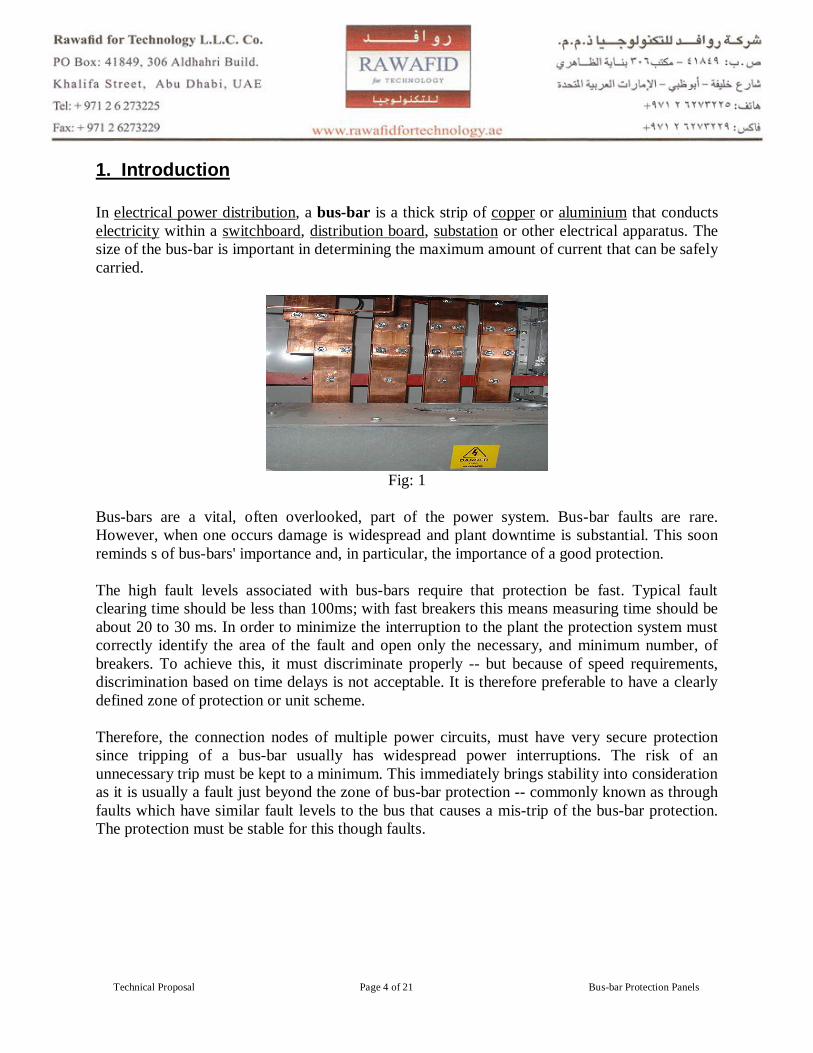
1. Introduction In electrical power distribution, a bus-bar is a thick strip of copper or aluminium that conducts electricity within a switchboard, distribution board, substation or other electrical apparatus. The size of the bus-bar is important in determining the maximum amount of current that can be safely carried.
Fig: 1
Bus-bars are a vital, often overlooked, part of the power system. Bus-bar faults are rare. However, when one occurs damage is widespread and plant downtime is substantial. This soon reminds s of bus-bars' importance and, in particular, the importance of a good protection. The high fault levels associated with bus-bars require that protection be fast. Typical fault clearing time should be less than 100ms; with fast breakers this means measuring time should be about 20 to 30 ms. In order to minimize the interruption to the plant the protection system must correctly identify the area of the fault and open only the necessary, and minimum number, of breakers. To achieve this, it must discriminate properly -- but because of speed requirements, discrimination based on time delays is not acceptable. It is therefore preferable to have a clearly defined zone of protection or unit scheme. Therefore, the connection nodes of multiple power circuits, must have very secure protection since tripping of a bus-bar usually has widespread power interruptions. The risk of an unnecessary trip must be kept to a minimum. This immediately brings stability into consideration as it is usually a fault just beyond the zone of bus-bar protection -- commonly known as through faults which have similar fault levels to the bus that causes a mis-trip of the bus-bar protection. The protection must be stable for this though faults.
_
Technical Proposal Page 5 of 21 Bus-bar Protection Panels
2. Technology Background Today, electric power companies and authorities worldwide, driven by regulations and increased competition, have changed the way they operate. Power plants and lines are becoming loaded up to thermal and stability limits. Existing power plants are expected to operate to and beyond the end of their original design life. Corrective event-based repair replaces preventive maintenance. Considering these changes, power system protection and control face new technical and economic challenges. Modern secondary systems play an important role in satisfying the above requirements for lower investment and operational cost without compromising system reliability. To assure power system integrity during fault conditions, one of the most important requirements is reliable performance of power system bus-bar relay protection. This requirement is further emphasized by the fact that an incorrect operation of busbar protection will result in loss of all connected lines, power transformers, and generators, which may lead to a power system blackout. Reliable performance of the busbar protection system must be preserved for both In-Zone and Out-Zone faults. This is a challenging task since high fault currents may exist at the substation making it difficult, or even impossible, to avoid saturation of conventional iron-core Current Transformers (CT). Most busbar protection systems operate on a differential principle by comparing input and output currents. If a CT saturates, then a false differential current will be derived by the relay. Busbar protection schemes implemented in modern digital multifunction relays are designed to tolerate substantial CT saturation, while providing high-speed operation for In-Zone faults (dependability). Relays are designed to reliably operate in the presence of distorted waveforms, or prior to CT saturation (time-to-saturation). High-speed busbar protection operation is required since bus faults may result in large fault currents endangering the entire substation due to the high dynamic forces and thermal stresses experienced. For external Out-Zone faults (security), the protection scheme must remain stable for all types of fault for the time needed to clear the fault. Manufacturers use different algorithms to achieve relay stability during CT saturation. While both security and dependability are important requirements for busbar protection, the preference is always given to security.
3. Objectives The main requirements for busbar protection include: Security - probability of an unwanted protection operation for through faults. Dependability - probability that the protection will not operate for a fault on the bus.
_
Technical Proposal Page 6 of 21 Bus-bar Protection Panels
Speed – high-speed operation is needed to limit equipment damage, and to preserve system transient stability. Sensitivity - to detect and clear high resistive faults. Selectivity - to minimize the power outage and to ensure continued operation of the healthy parts of the power system. All these requirements are interrelated; therefore, it is not possible to satisfy one without affecting the other. The design solution should meet the requirements that correspond to the importance of the substation within the network and the layout of the substation.
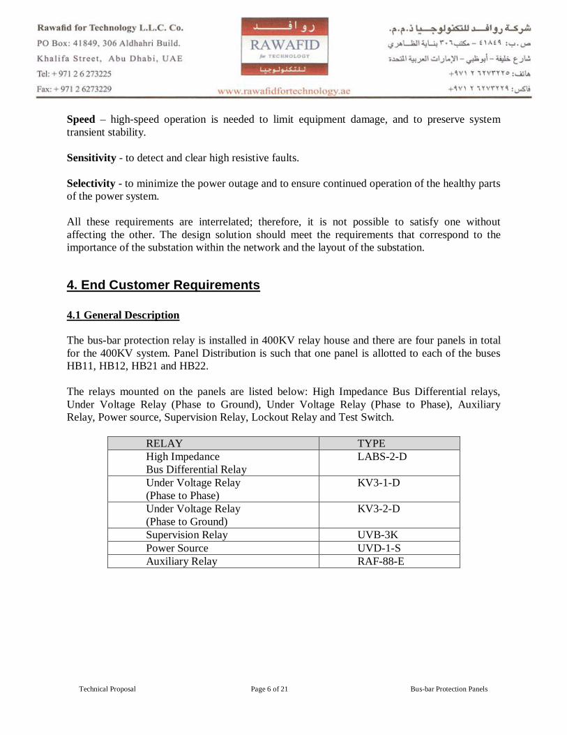
4. End Customer Requirements 4.1 General Description The bus-bar protection relay is installed in 400KV relay house and there are four panels in total for the 400KV system. Panel Distribution is such that one panel is allotted to each of the buses HB11, HB12, HB21 and HB22. The relays mounted on the panels are listed below: High Impedance Bus Differential relays, Under Voltage Relay (Phase to Ground), Under Voltage Relay (Phase to Phase), Auxiliary Relay, Power source, Supervision Relay, Lockout Relay and Test Switch.
RELAY TYPE High Impedance Bus Differential Relay
LABS-2-D
Under Voltage Relay (Phase to Phase)
KV3-1-D
Under Voltage Relay (Phase to Ground)
KV3-2-D
Supervision Relay UVB-3K Power Source UVD-1-S Auxiliary Relay RAF-88-E

_
Technical Proposal Page 7 of 21 Bus-bar Protection Panels
4,2 Method of Operation
Switch on DC 110V and AC 220V power supplies and close NFB mounted in the panel for
the distribution board. Operation of the bus-bar protection relay gives rise to the response in the form of the lock out
relays operation sending trip signal to the circuit breaker. Trip signal from the bus protective relay can be locked by opening the test switch. The test
switch is installed in the trip circuit for individual circuit breakers. Daily routine inspection should be carried out by patrolling around the equipment.
4.3 Description of Bus Bar Protection Relay Panel Differential protection relay to protect two bus bar 400KV separated by Bus TIE C.B. Each Bus-bar connected to two C.B rating 175V Under Voltage Relay Phase to Phase: Rating 110V Under voltage Relay Phase to Ground: 63.5V Voltage Control DC 110V All CT Ratio 2000/1 PT Ratio Phase to Phase 400KV/110V PT Ratio Phase to Ground 400KV/63.5V The relay must be computerized type & supplied with Laptop computer for software, with all
connections between Laptop computer & protection relay Training two engineers & two technical for software program & protection in the Country of
Origin. 4.4 Notes Range of Diff. Relay: (25-50-……175)V Range of Under Voltage Relay (Phase to Phase): (60 – 65 - ….90)V Set (85V) Range of Under Voltage Relay (Phase to Ground): (30 – 35 - ..50)V Set (50V)
_
Technical Proposal Page 8 of 21 Bus-bar Protection Panels
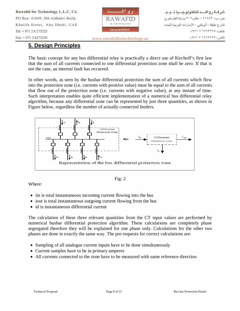
5. Design Principles The basic concept for any bus differential relay is practically a direct use of Kirchoff’s first law that the sum of all currents connected to one differential protection zone shall be zero. If that is not the case, an internal fault has occurred. In other words, as seen by the busbar differential protection the sum of all currents which flow into the protection zone (i.e. currents with positive value) must be equal to the sum of all currents that flow out of the protection zone (i.e. currents with negative value), at any instant of time. Such interpretation enables quite efficient implementation of a numerical bus differential relay algorithm, because any differential zone can be represented by just three quantities, as shown in Figure below, regardless the number of actually connected feeders.
Fig: 2
Where: iin is total instantaneous incoming current flowing into the bus iout is total instantaneous outgoing current flowing from the bus id is instantaneous differential current
The calculation of these three relevant quantities from the CT input values are performed by numerical busbar differential protection algorithm. These calculations are completely phase segregated therefore they will be explained for one phase only. Calculations for the other two phases are done in exactly the same way. The pre-requests for correct calculations are: Sampling of all analogue current inputs have to be done simultaneously Current samples have to be in primary amperes All currents connected to the zone have to be measured with same reference direction
_
Technical Proposal Page 9 of 21 Bus-bar Protection Panels
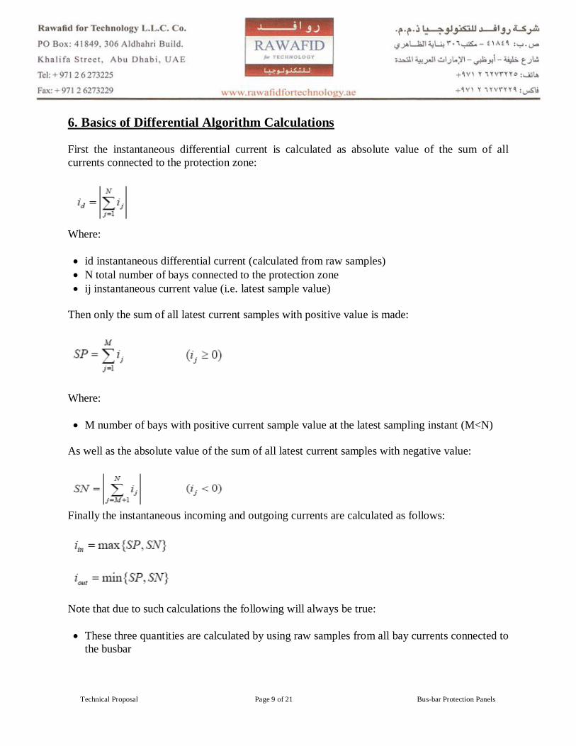
6. Basics of Differential Algorithm Calculations First the instantaneous differential current is calculated as absolute value of the sum of all currents connected to the protection zone:
Where: id instantaneous differential current (calculated from raw samples) N total number of bays connected to the protection zone ij instantaneous current value (i.e. latest sample value)
Then only the sum of all latest current samples with positive value is made:
Where: M number of bays with positive current sample value at the latest sampling instant (M<N)
As well as the absolute value of the sum of all latest current samples with negative value:
Finally the instantaneous incoming and outgoing currents are calculated as follows:
Note that due to such calculations the following will always be true: These three quantities are calculated by using raw samples from all bay currents connected to
the busbar
_
Technical Proposal Page 10 of 21 Bus-bar Protection Panels
These three quantities (i.e. iin, iout and id) will be of a “DC” nature in time (i.e. these three quantities can only have a positive numerical value). This means that the instantaneous incoming and outgoing currents during normal load condition looks like as the output of the full wave rectifier;
iin is always bigger than or equal to iout; During normal through load conditions the total instantaneous incoming current will be equal
to the total instantaneous outgoing current and differential current is negligible; and Any differential protection zone can be represented as shown in Figure 2, regardless the
number of the bays connected to the bus The instantaneous quantities are constantly changing in time; therefore RMS values of the incoming, outgoing and differential currents (i.e. IIN, IOUT and ID respectively) as well as they rate of change are used in the algorithm as well. These quantities are calculated over last power system cycle by using numerical integration. Only the formula for IIN will be presented here (the other two RMS quantities are calculated by using the same principle)
Where T is the length of one fundamental power system cycle
When all six values (i.e. iin, iout, id, IIN, IOUT and ID) are calculated, they are passed further to the differential protection and algorithm for further processing.
7. Features & Benefits of Bus-bar Protection
1- Protection: Differential and directional current elements provide increased security and fast fault detection. Reduce protection costs with built-in breaker failure protection.
2- Flexibility: Eliminate complex wiring by using CT ratios that differ by up to a factor of 10:1. Take advantage of the same CTs for differential protection, metering, backup relaying, and other functions.
3- Automation and Control: Reduce project costs and simplify interconnect wiring using multiple communications protocols and ports. Configurable operator controls

_
Technical Proposal Page 11 of 21 Bus-bar Protection Panels
4- Monitoring and Metering: Provide accurate, timely monitoring and metering of busbar, feeder, and substation signals. Terminal currents, breaker and disconnect positions, station dc voltage levels, and three phase voltage are continuously monitored and updated.
8. High and Low Differential Protection Systems Two main designs used for high voltage busbar protection are high impedance and low impedance differential protection systems. High impedance differential protection systems have been in use for over 50 years. The protection system consists of CTs whose secondary windings are connected in parallel and to one high impedance voltage relay. High impedance protection responds to a voltage across the relay. All CTs must be well-matched, have equal ratios, and have low secondary leakage impedance. The major disadvantage is the need for dedicated CT cores. When used for re-configurable buses, the switching of CT secondary currents may affect the performance of the protection and increase the cost. In addition, this solution requires voltage limiting varistors. New microprocessor-based high impedance relays operate on the same principle as traditional designs. However, they also provide functions such as sequence of events, disturbance recording, and communication. Low impedance differential protection systems employ digital relays. The CT inputs are connected to individual channels. The relay derives differential signals by executing protection algorithms. These solutions allow the use of CTs with different ratios since CT matching is performed inside the relay. The same CT core can be used by different protection relays. In addition to the operating quantity, low impedance differential protection systems derive a stabilizing quantity and apply a percent (biased) characteristic in order to ensure the stability of the scheme. Modern relays, in addition to the percentage characteristic, typically have implemented sophisticated algorithms to cope with severe CT saturation. Some relays are designed to make decisions before the CT saturates. For modern digital busbar protection schemes, a time-to-saturation of 2–3 ms can be sufficient to stabilize the protection in case of external faults; requiring small over-dimensioning factors of the CT. Typical operating times are one cycle or less. The proposed solution here is using high impedance differential protection systems. 9. System Components and Bill of Materials One set: PEME Make Relay Panels, 750mmx750mmx2300mm, floor mounted sheet steel cubicles as detailed below and supplied with auxiliary items like thermostat controlled heater, door limit switch, illumination lamp, diodes for lamp test, power socket, MCB for AC/DC circuits, C.T neutral earth test links, terminals with 10% spare, earth bar, internal identification labels etc.

_
Technical Proposal Page 12 of 21 Bus-bar Protection Panels
One Set: Circuit labels suitably engraved Ten: Test Terminal block for Bus Bar Protection and CT Shorting Relay Twelve: High Burden trip relays Two: B/B DC supply supervision relay Five: B/B protection In/Out selector switch for Five Zones Lockable type Five: Indicating lamp for B/B protection Out of service One: Selector switch for B/B D.C. supply In/Out selection lockable type One: Indicating lamp for DC supply out One: Push button for lamp test One set: Selector switch for Heater Off/On selection One set: Indicating lamp for Heater On indication One Set: Trip isolation links for above. Set of: MCB/links, aux. Terminals with 10% spare One set: Keys for door lock Five: High Impedance Bus Bar Protection Relay Five: CT Shorting Relay Five: 3 Ph Metrosils Fifteen: Resistors
_
Technical Proposal Page 13 of 21 Bus-bar Protection Panels
10. Product Technical Details
Numerical High Impedance Protection
Fig: 3
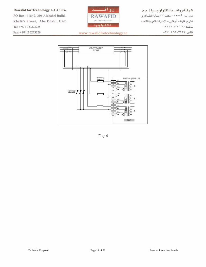
A three phase relay providing high-speed, high impedance phase segregated current differential protection and phase segregated open circuit monitoring of the current transformer secondary circuits (CT supervision). Outputs from the differential and CT supervision elements operate when their input current exceeds their individual current settings. The programmed time delays, LEDs and output contacts are initiated. All output contacts are fully programmable to any relay function listed in the output relay menu. Output relays can be configured as self reset or hand/electrically reset. The overall differential protection uses the high impedance circulating current principle; a single line diagram of such a scheme is shown in fig. 3.
_
Technical Proposal Page 14 of 21 Bus-bar Protection Panels
Fig: 4
_
Technical Proposal Page 15 of 21 Bus-bar Protection Panels
CT Shorting Relay
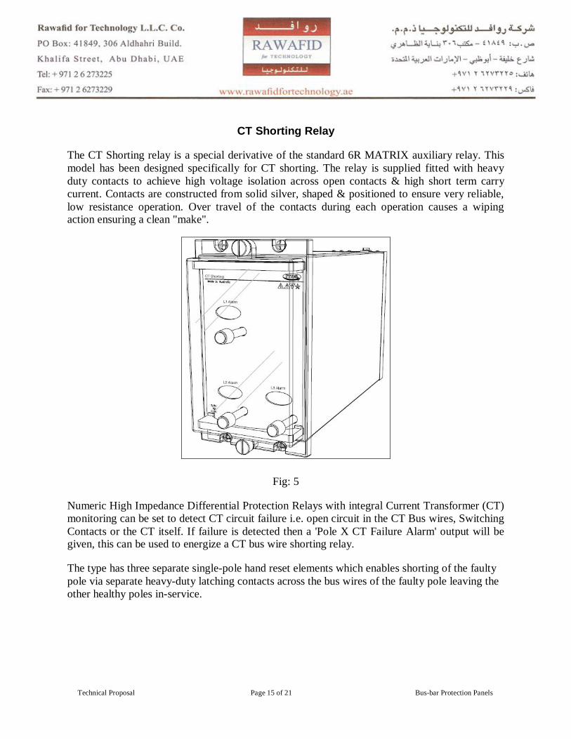
The CT Shorting relay is a special derivative of the standard 6R MATRIX auxiliary relay. This model has been designed specifically for CT shorting. The relay is supplied fitted with heavy duty contacts to achieve high voltage isolation across open contacts & high short term carry current. Contacts are constructed from solid silver, shaped & positioned to ensure very reliable, low resistance operation. Over travel of the contacts during each operation causes a wiping action ensuring a clean "make".
Fig: 5
Numeric High Impedance Differential Protection Relays with integral Current Transformer (CT) monitoring can be set to detect CT circuit failure i.e. open circuit in the CT Bus wires, Switching Contacts or the CT itself. If failure is detected then a 'Pole X CT Failure Alarm' output will be given, this can be used to energize a CT bus wire shorting relay.
The type has three separate single-pole hand reset elements which enables shorting of the faulty pole via separate heavy-duty latching contacts across the bus wires of the faulty pole leaving the other healthy poles in-service.
_
Technical Proposal Page 16 of 21 Bus-bar Protection Panels
DC Supply Supervision
Fig: 6
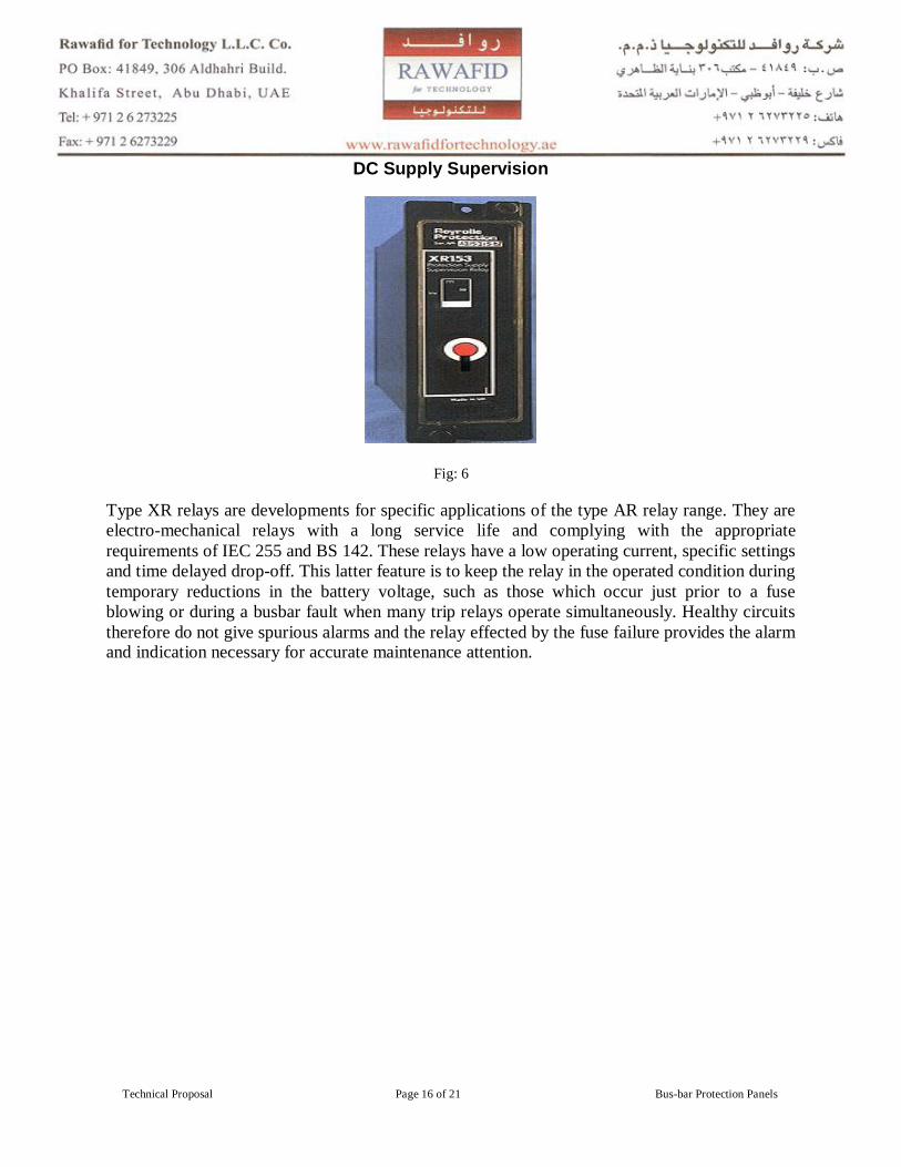
Type XR relays are developments for specific applications of the type AR relay range. They are electro-mechanical relays with a long service life and complying with the appropriate requirements of IEC 255 and BS 142. These relays have a low operating current, specific settings and time delayed drop-off. This latter feature is to keep the relay in the operated condition during temporary reductions in the battery voltage, such as those which occur just prior to a fuse blowing or during a busbar fault when many trip relays operate simultaneously. Healthy circuits therefore do not give spurious alarms and the relay effected by the fuse failure provides the alarm and indication necessary for accurate maintenance attention.
_
Technical Proposal Page 17 of 21 Bus-bar Protection Panels
Test Block
Fig: 7
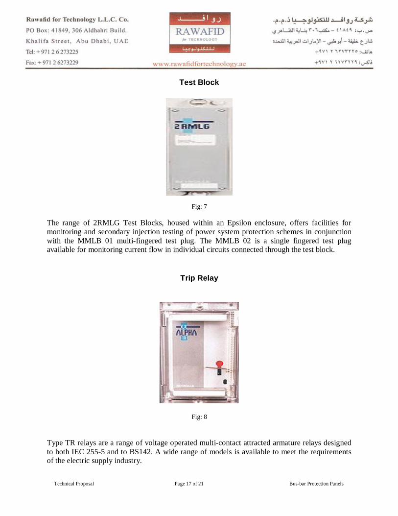
The range of 2RMLG Test Blocks, housed within an Epsilon enclosure, offers facilities for monitoring and secondary injection testing of power system protection schemes in conjunction with the MMLB 01 multi-fingered test plug. The MMLB 02 is a single fingered test plug available for monitoring current flow in individual circuits connected through the test block.
Trip Relay
Fig: 8
Type TR relays are a range of voltage operated multi-contact attracted armature relays designed to both IEC 255-5 and to BS142. A wide range of models is available to meet the requirements of the electric supply industry.
_
Technical Proposal Page 18 of 21 Bus-bar Protection Panels
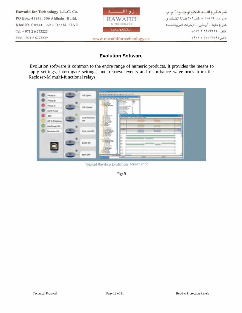
Evolution Software
Evolution software is common to the entire range of numeric products. It provides the means to apply settings, interrogate settings, and retrieve events and disturbance waveforms from the Recloser-M multi-functional relays.
Fig: 9
_
Technical Proposal Page 19 of 21 Bus-bar Protection Panels
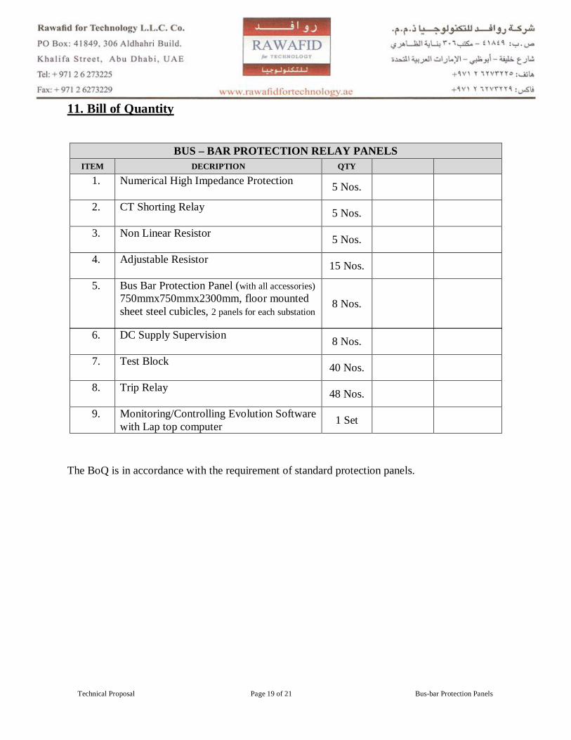
11. Bill of Quantity
The BoQ is in accordance with the requirement of standard protection panels.
BUS – BAR PROTECTION RELAY PANELS ITEM DECRIPTION QTY
1. Numerical High Impedance Protection 5 Nos.
2. CT Shorting Relay 5 Nos.
3. Non Linear Resistor 5 Nos.
4. Adjustable Resistor 15 Nos.
5. Bus Bar Protection Panel (with all accessories) 750mmx750mmx2300mm, floor mounted sheet steel cubicles, 2 panels for each substation
8 Nos.
6. DC Supply Supervision 8 Nos.
7. Test Block 40 Nos.
8. Trip Relay 48 Nos.
9. Monitoring/Controlling Evolution Software with Lap top computer 1 Set
_
Technical Proposal Page 20 of 21 Bus-bar Protection Panels
12. Conclusion Bus-bar protection applications should have good security since an unwanted operation might have severe consequences. The unwanted operation of the bus differential relay will have the similar effect as simultaneous faults on all power system elements connected to the bus. On the other hand, the relay has to be dependable as well. Failure to operate or even slow operation of the differential relay, in case of an actual internal fault, can have fatal consequences. Human injuries, power system blackout, transient instability or considerable damage to the surrounding substation equipment and the close-by generators are some of the possible outcomes. These two main requirements are contradictory to each other in nature.
_________________
_________ ____
For other R4T Technical Proposals: Browse the web site
_
Technical Proposal Page 21 of 21 Bus-bar Protection Panels
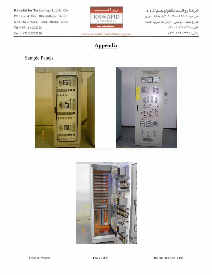
Appendix
Sample Panels