Embed Size (px)
Citation preview
Abu Hamad – Karima Road Project MD & VOYANTS
24
REPUBLIC OF SUDAN
MINISTRY OF ROADS & BRIDGES
NATIONAL HIGHWAY AUTHORITY
CONSULTANCY SERVICES FOR DETAILED
ENGINEERING DESIGN STUDY
FOR
ABU HAMAD – KARIMA ROAD
TECHNICAL PROPOSAL
Prepared By
Dr. Magdi Zumrawi
University of Khartoum
July 2010
Abu Hamad – Karima Road Project MD & VOYANTS
1
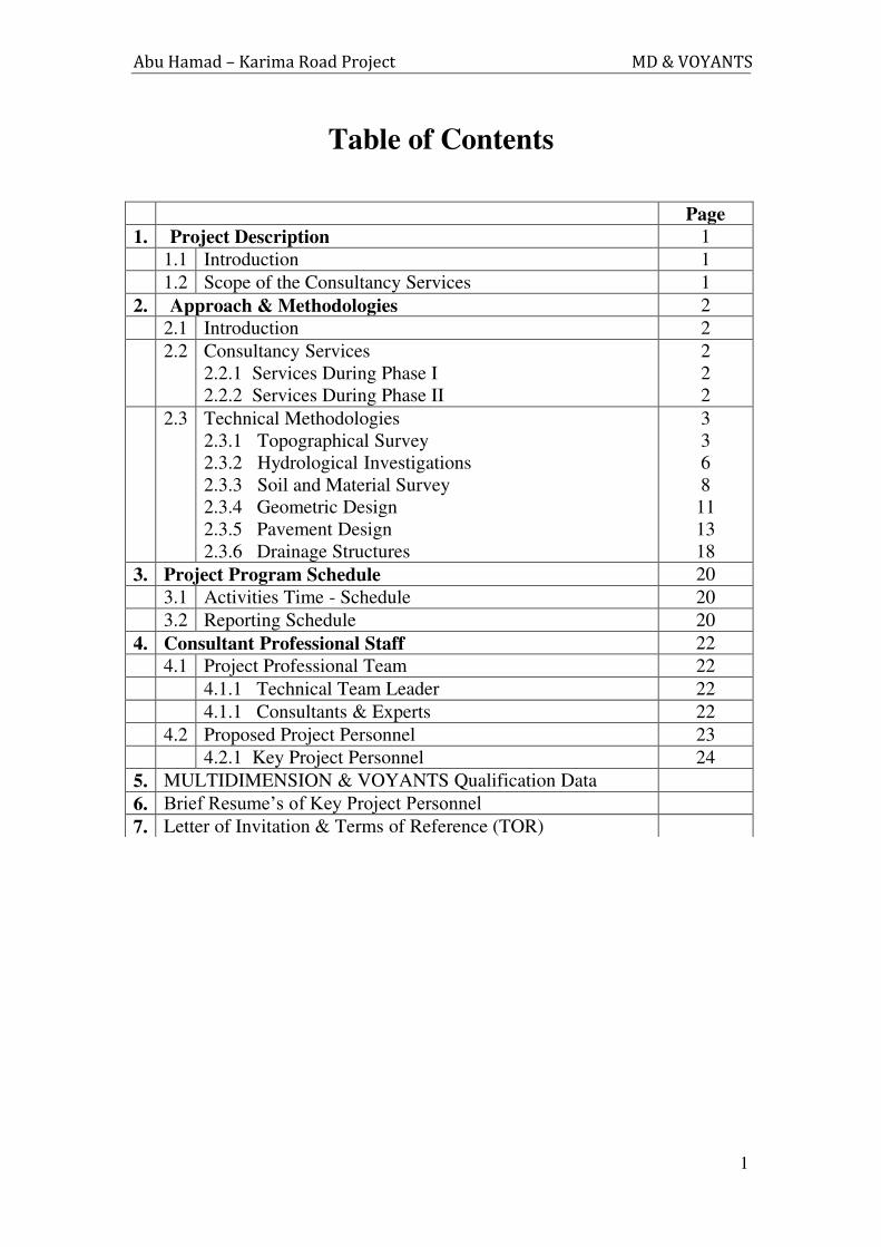
Table of Contents
Page
1. Project Description 1
1.1 Introduction 1
1.2 Scope of the Consultancy Services 1
2. Approach & Methodologies 2
2.1 Introduction 2
2.2
Consultancy Services
2.2.1 Services During Phase I
2.2.2 Services During Phase II
2
2
2
2.3 Technical Methodologies
2.3.1 Topographical Survey
2.3.2 Hydrological Investigations
2.3.3 Soil and Material Survey
2.3.4 Geometric Design
2.3.5 Pavement Design
2.3.6 Drainage Structures
3
3
6
8
11
13
18
3. Project Program Schedule 20
3.1 Activities Time - Schedule 20
3.2 Reporting Schedule 20
4. Consultant Professional Staff 22
4.1 Project Professional Team 22
4.1.1 Technical Team Leader 22
4.1.1 Consultants & Experts 22
4.2 Proposed Project Personnel 23
4.2.1 Key Project Personnel 24
5. MULTIDIMENSION & VOYANTS Qualification Data
6. Brief Resume’s of Key Project Personnel
7. Letter of Invitation & Terms of Reference (TOR)
Abu Hamad – Karima Road Project MD & VOYANTS
2
1. Project Description
1.1 Introduction
Sudan Government, represented by the National Highway Authority (NHA) as a
regulatory body, intends to build a road of Abu Hamad - Karima in River Nile &
North States. The total length of this road is about 230 km. The area of this Project is
very rich of agricultural production.
The Consultant visited the proposed site in order to acquaint his team with the actual
site conditions, regarding the Project size, general soil conditions and existing
infrastructure of utility services and roads.
1.2 Scope of the Consultancy Services
The Project calls for the provision of Consultancy Services covering the feasibility and
detailed engineering studies.
The Consultant is required to prepare and submit to the Client the Design and
Construction Documents for the Project.
The Consultancy Services, required for this Project, consist of two distinct Phases,
namely:
1- Phase I: Feasibility study
To determine the technical feasibility, social and environmental impacts
and the economic viability of constructing a road between Abu Hamad
and Karima towns.
2- Phase II: Detailed Engineering Design
To undertake detailed engineering design of the selected road alignment
and preparation of bidding documents for construction purposes.
Abu Hamad – Karima Road Project MD & VOYANTS
3
2. Approach & Methodologies
2.1 Introduction
The Consultancy Services required for this Project, will be provided by Multi
Dimension for Engineering Consultancy (MD). Our approach to this Project is based
on dividing the task into two sequential phases, Phases I & II. The approach, to be
used for each phase, will now be presented in some detail hereinafter.
2.2 Consultancy Services
2.2.1 Services during Phase I
The feasibility study will cover the following items for this road project: -
- Investigation of alternative alignment
- Climate, geology and vegetation study.
- Mapping and Aerial Photography
- Hydrology and drainage Investigation.
- Preliminary soil investigation.
- Preliminary design (geometric and pavement design).
- Environmental and social impact assessments.
- Economic evaluation.
During this phase, the Consultant will submit inception report and interim
report.
2.2.2 Services during Phase II
Based on the results of the feasibility study carried out in Phase I, the detailed
engineering design will be carried out as outlined below:-
- Topographical Survey
- Survey of water courses
- Hydrological and geological surveys
- Soils and materials survey
- Geometric design
- Pavement design
- Bidding documents for construction
Abu Hamad – Karima Road Project MD & VOYANTS
4
2.3 Technical Methodologies
2.3.1 Topographical Survey:
2.3.1.1 Introduction:
The procedure to carry on the topographical surveys is shown in the following
sections.
2.3.1.2 The selection of the best route alignment:
First to choose the best route alignment we will first review the Google earth image
and find the best area for the route. This will reduce cost and time. Then the
preliminary road area will be proposed. After that and using the preliminary proposal
data the site will be visited to check the route and to adopt the final road area. After
adopting the final road area the field survey will start.
(During this step we suggest that representative of the Roads and Bridge
Corporation to be attending and to approve the proposed road area on site)
2.3.1.3 The field Survey:
i. The installation of bench marks: 46 benchmark will be installed as follows:
- (one benchmark at every 5km.)
- Additional benchmark will be installed at the start of road, middle of road and at the
end of the road.
The proposed benchmark will be established by inserting a 15 mm diameter inserted
in the ground, with a 30 cm section above the ground covered with a cube of concrete
(30x30x30 cm).
ii. The Reduced level of benchmarks:
In order to get an accurate reduced level for the benchmarks their reduced levels will
be obtained using spirit leveling (using automatic levels). A double leveling
procedure will be carried out to check the miss closure (error of observation). The
maximum accepted miss closure (e) will be computed according to the formulae;
e = 10 √ k mm. which is quoted for the accuracy of engineers levels in BS5606.
Where k is the length of circuit in Km.
- The circuit will be computed and adjusted to obtain the optimum reduced levels for
the benchmarks.
Abu Hamad – Karima Road Project MD & VOYANTS
5
iii. Reading cross section/levels of the ground and offset levels:
- Using the established Benchmarks as a reference the following observations will be
carried out using GPS Real Time observation techniques:
- Cross – Sections /levels of the ground will be observed at 50m. intervals and at
abrupt changes of the ground along the entire length of the road and locations of
alignment. The width of the offset levels will be read according to the site conditions
iv. Detailed Surveys:
A detailed survey will be also carried out to obtain the coordinates and dimensions of
the existing utilities and land uses in the road area using GPS Real Time techniques.
Also satellite images (such as Google earth) or any other available images will be also
reviewed to help in surveying the utilities and land uses. Mixing the two data (field
observation data and satellite images) will help in better assessment of the existing
utilities and structures within the road right of way.
2.3.1.4 Office activities (Data Processing and Computations):
-The field data obtained will be processed using Trimble Business center soft ware,
and Excel soft ware.
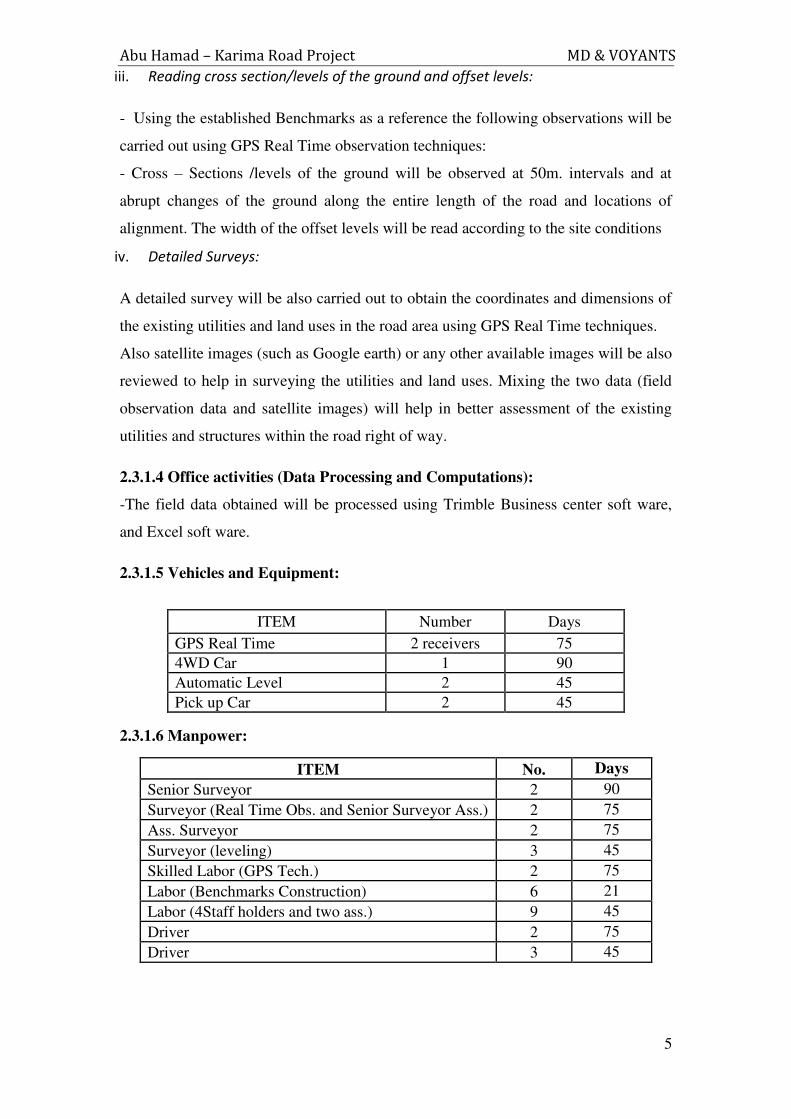
2.3.1.5 Vehicles and Equipment:
ITEM Number Days
GPS Real Time 2 receivers 75
4WD Car 1 90
Automatic Level 2 45
Pick up Car 2 45
2.3.1.6 Manpower:
ITEM No. Days
Senior Surveyor 2 90
Surveyor (Real Time Obs. and Senior Surveyor Ass.) 2 75
Ass. Surveyor 2 75
Surveyor (leveling) 3 45
Skilled Labor (GPS Tech.) 2 75
Labor (Benchmarks Construction) 6 21
Labor (4Staff holders and two ass.) 9 45
Driver 2 75
Driver 3 45

Abu Hamad – Karima Road Project MD & VOYANTS
6
2.3.1.7 Work Plan:
The topographical survey services will be executed as follows:
1- Satellite image review and preliminary route alignment proposal – will be
completed in five days.
1 A field visit to check the route alignment - To be completed in 7 days
2- Benchmark installation which will start after the end of the reconnaissance survey
and will be completed in 21 days.
3 – Benchmarks Leveling. The benchmark leveling will start after three days from the
start of benchmarks installation. Three leveling teams will carry on the leveling using
automatic spirit levels. The leveling will be completed in 45 days.
3- The topographical survey and detailed survey. This activity will start after 7 days
from the start of the Benchmarks leveling. The activity will be completed in 75 days.
4- Data processing and computations of coordinates and elevations. This activity will
start 7 days after the end of benchmarks leveling and will be completed 5 days after
the end of the topographical survey activity. But every 10 km. completed will be
submitted immediately for the geometric design purposes.
The total time needed to complete the above activities is 90 days.
Abu Hamad – Karima Road Project MD & VOYANTS
7
2.3.2 Hydrological Investigations
2.3.2.1 Study Objective
The main objective of this investigation is to prepare an effective hydrologic and
hydraulic design of the road drainage system. Information to be gathered on the
hydrology of the study region, Wadis intersecting the road, their hydrologic and
hydraulic characteristics will be used to calculate the most important design parameter
which is the peak discharge. Accordingly, the type and size of the drainage structure
will be determined.
The methodology to be adopted will involve the following steps
2.3.2.2 Review of previous studies
Previous studies on road design or similar water related studies in the area will be
gathered and all the relevant information will be extracted and entered a database for
the study.
2.3.2.3 Field investigations through site visits
A number of site visits will be made along the road route. Types of soil, vegetation,
Wadi cross sections, water marks, catchment characteristics and all factors that
influence runoff and water levels will be noted. Existing drainage structures will also
be surveyed and interviews of officials and local inhabitants will be made regarding
flooding history of the significant Wadi and other related issues..
2.3.2.4 Data collection
This will include collection of topographic maps, drainage maps, and satellite
imageries as well as collection of rainfall data for relevant rainfall stations.
2.3.2.5 Collection and analysis of rainfall data
Rainfall data for the rainfall stations in the study area will be collected from the Sudan
meteorological department. The data will be screened and checked for consistency
and any missing data will be filled using appropriate techniques. Frequency analysis
will then be performed to develop the Intensity-Duration Frequency Curves (IDF).
Abu Hamad – Karima Road Project MD & VOYANTS
8
2.3.2.6 Hydrologic analysis for estimating design discharges
The discharges of Wadis will be estimated using the rational model .This method is
most commonly used method where the catchment areas and other information are
available. According to the rational model, the peak discharge Qp is given by:
Qp = C.A.I / 3.6
Where C = runoff coefficient depending as the type of soil and vegetation cover.
A = Catchment area (Km2) determined from satellite data
I = Design rainfall intensity(mm/h) during the time of concentration
The maximum runoff rate in a Catchment is reached when all parts of the watershed
are contributing to the outflow. This happens when the time of concentration, the time
after which the runoff rate equals the excess rainfall rate, is reached.
2.3.2.7 Design of drainage structures
Using the Rational method the peak discharge for the appropriate return period
(normally 50 years) will be estimated with catchment areas of Wadis being obtained
from satellite imageries or alternatively from Google Earth. Alternative models will
also be applied to estimate design discharges such as the Manning formula.
Once the design discharge is estimated then the appropriate type of culvert will be
recommended. The following possibilities will be considered
Pipe culverts
Box culverts
Bridges
Guidelines for locating the culverts during execution will be given.
2.3.2.8 Design of Protection Works
For erosion control and protection of drainage structures and road embankment, the
concept of incipient motion will be used for rock rip rapping. The critical shear
equation will be used to determine the rock sizes
2.3.2.9 Study period
3 months including:
Site visits
Data collection and cost
Design and reporting
Abu Hamad – Karima Road Project MD & VOYANTS
9
2.3.3 Soil and Material Survey
2.3.5.1 Scope of Work
The soil and materials survey will include the following:
Field work will comprise of excavating pit-holes for the natural subgrade beside the
roadway alignment. Soil investigation will be carried out for the bridges and Irish
crossing at khors and valleys.
Soil survey of the locally occurring construction materials is essential to indicate their
quality, locations and to estimate the quantities available at each site. Accordingly
borrow pits will be excavated at certain locations in the road site.
Laboratory tests will be carried out on representative samples taken from the borrow
pits.
Possible problems arising from the use of proposed materials in the area under study
will be assessed, quantified and appropriate counter measures will be recommended.
2.3.5.2 Field Work
i. Excavating Pits
The field investigation will start with excavating pit-holes in the area of the road sites.
The pit-holes generally will be excavated at intervals not more than two kilometer
length of the roadway or if there is any variation in the soil, to cover most of the
natural subgrade areas. For the locally occurring construction materials some borrow
pits will be excavated in certain locations in the area under study. The locations of
these borrow pits will be decided after the site investigation. The pit-holes and borrow
pits will be excavated to a depth not less than 1.5 m and each pit of one meter by one
meter cross sectional area.
Disturbed soils samples will be taken from these pits to represent the roads' subgrade
soils and the local construction materials to be used. These soil samples were kept in
plastic bags, labeled and transported to the Laboratory for visual inspection and
testing.
ii. Soil Investigation
Subsoil exploration is to be carried out at the locations of the existing or proposed
bridges and Irish crossing at khors and valleys. At these sites certain numbers of
Abu Hamad – Karima Road Project MD & VOYANTS
10
boreholes are to be drilled to satisfactory depths and field tests are performed if
required.
2.3.5.3 Laboratory Testing
The Laboratory investigation is comprised of performing some tests on disturbed soil
samples that are taken from the roads site. The testing procedures will be followed are
in general conformance with those recommended in BS 1377 and ASTM. The
laboratory tests will be performed included the following:-
I. Soil Tests
The soil tests include: Sieve analysis, Atterberg limits, modified compaction and
Soaked CBR. These tests to be performed for the pit-holes at intervals of about 2000
meter (115 sections) and 30 borrow pits for the locally occurring construction
materials. In the locations of the bridges and Irish crossing almost 5 locations where
two boreholes of 10 to 15 meter depth will be drilled, the soil gradation and limits
tests are curried out at one interval of the boreholes while the shear and consolidation
tests are performed for specified soil layers.
i. Concrete Tests
For concrete: Compressive strength of concrete cubes, Mix design.
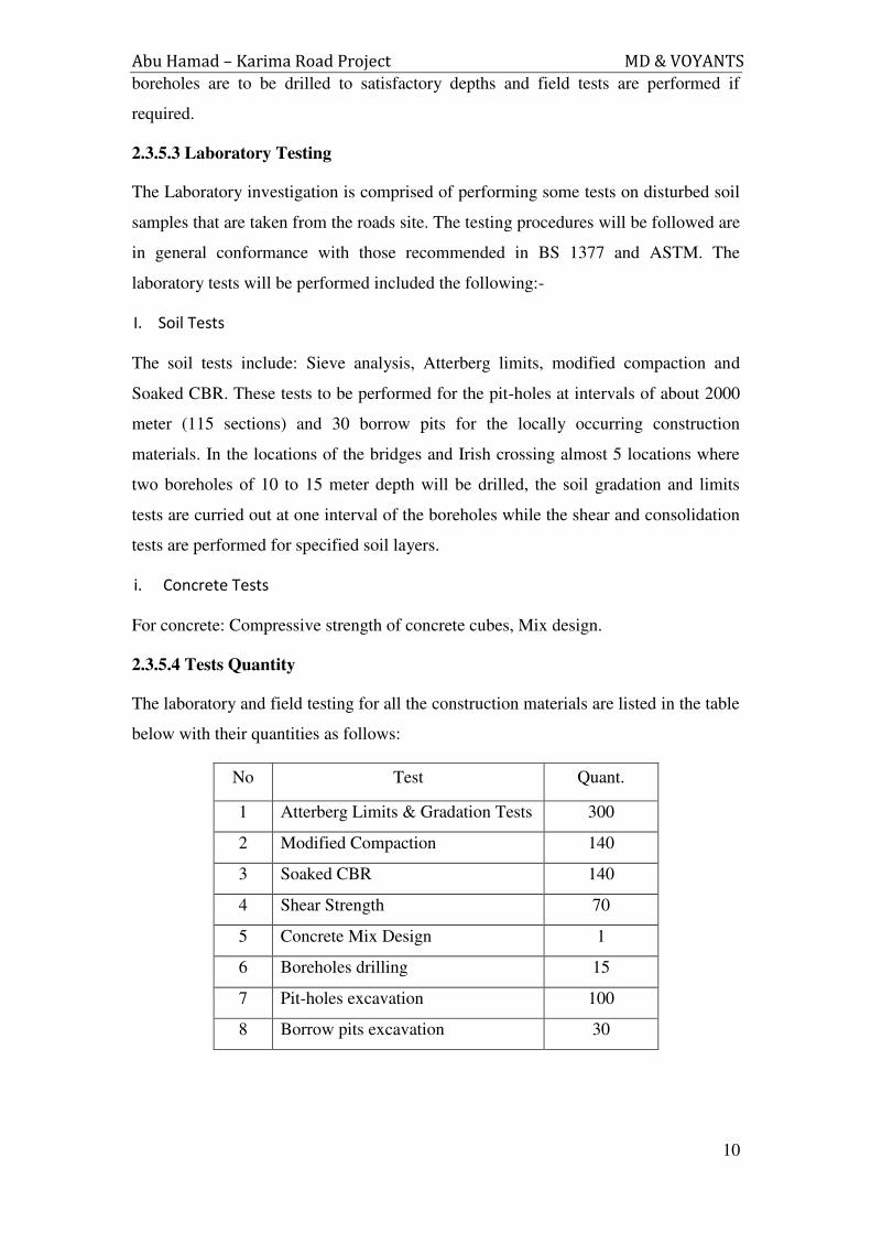
2.3.5.4 Tests Quantity
The laboratory and field testing for all the construction materials are listed in the table
below with their quantities as follows:
No Test Quant.
1 Atterberg Limits & Gradation Tests 300
2 Modified Compaction 140
3 Soaked CBR 140
4 Shear Strength 70
5 Concrete Mix Design 1
6 Boreholes drilling 15
7 Pit-holes excavation 100
8 Borrow pits excavation 30

Abu Hamad – Karima Road Project MD & VOYANTS
11
2.3.5.5 Technical Staff
The technical staff required to carry the laboratory and field testing for this project for
a period about five months as follows:
Senior Material Engineer
Three Junior engineer
Six Technicians
9 skilled & 5 unskilled labours
two drivers
No Staff Number of Months
1 Senior Material Engineer 8
2 Three Junior engineer 6
3 Six Technicians 6
4 9 Skilled labours 5
5 5 Unskilled labours 5
6 two drivers 8
Abu Hamad – Karima Road Project MD & VOYANTS
12
2.3.4 Geometric Design
Geometric design is the process whereby the layout of the road in the terrain is
designed to meet the needs of the road users. The principal geometric features are the
road cross-section and horizontal and vertical alignment. The use of geometric design
standards fulfills three inter-related objectives. Firstly, standards are intended to
provide minimum levels of safety and comfort for drivers by the provision of
adequate sight distances, coefficients of friction and road space for vehicle
maneuvers; secondly, they provide the framework for economic design; and, thirdly,
they ensure a consistency of alignment. The design standards adopted must take into
account the environmental road conditions, traffic characteristics, and driver behavior.
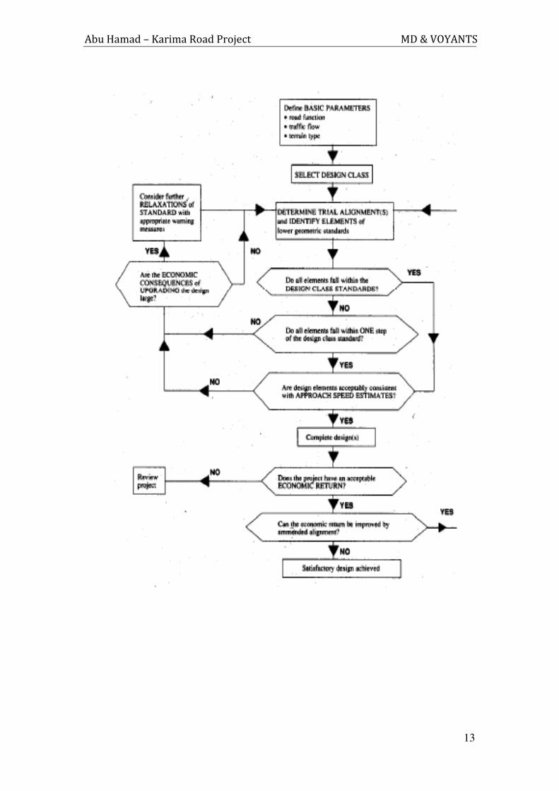
Based on traffic, axle load, roads safety audit review and according to TOR
requirements the data will be fed into the design software (Land Desk top 2009) to
select the suitable design elements those comply with design speed of 120 km/h. The
check will be automatically based on AASHTO 2001 Geometric Design Policy after
the assignment of some design elements. The design process will be according to the
following flow chart.
Generally the design criteria considered during design and alignment of the road will
be:
Right of way and Road way features.
Vehicular characteristics.
Traffic pattern.
Number of lanes, widths and shoulder type and width.
Design speed.
Maximum and minimum grade.
Maximum superelevation.
Sight distances
Vertical and horizontal curves characteristics.
Normal crown of surface
Abu Hamad – Karima Road Project MD & VOYANTS
13
Abu Hamad – Karima Road Project MD & VOYANTS
14
2.3.5 Pavement Design
2.3.5.1 Introduction
The pavement design process will be through the following steps:
Estimation of Equivalent Standard Ale Loads (ESAL).
Determination of design subgrade strength value (CBR).
Interpolation of data and different studies and revision of the determined
thickness from economical point of view.
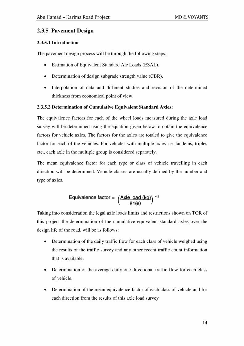
2.3.5.2 Determination of Cumulative Equivalent Standard Axles:
The equivalence factors for each of the wheel loads measured during the axle load
survey will be determined using the equation given below to obtain the equivalence
factors for vehicle axles. The factors for the axles are totaled to give the equivalence
factor for each of the vehicles. For vehicles with multiple axles i e. tandems, triples
etc., each axle in the multiple group is considered separately.
The mean equivalence factor for each type or class of vehicle travelling in each
direction will be determined. Vehicle classes are usually defined by the number and
type of axles.
Taking into consideration the legal axle loads limits and restrictions shown on TOR of
this project the determination of the cumulative equivalent standard axles over the
design life of the road, will be as follows:
Determination of the daily traffic flow for each class of vehicle weighed using
the results of the traffic survey and any other recent traffic count information
that is available.
Determination of the average daily one-directional traffic flow for each class
of vehicle.
Determination of the mean equivalence factor of each class of vehicle and for
each direction from the results of this axle load survey
Abu Hamad – Karima Road Project MD & VOYANTS
15
The products of the cumulative one-directional traffic flows for each class of
vehicle over the design life of the road and the mean equivalence factor for
that class should then be calculated and added together to give the cumulative
equivalent standard axle loading for each direction. The higher of the two
directional values will be used for design.
The estimated ESAL determined from the axle and traffic surveys will be
increased by the amount of the ESAL estimated to be diverted from other
roads to this highway and the converted traffic from other modes of transports
in addition to the expected generated traffic expected from the industrial and
land use development.
Then the estimated traffic ESAL in millions will be increased by the
appropriate traffic growth factors from assigned opening year up to the design
life (20 years).
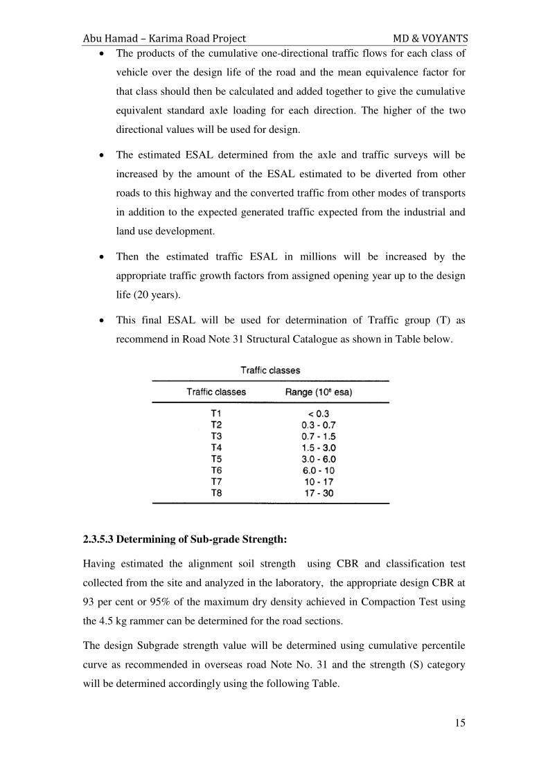
This final ESAL will be used for determination of Traffic group (T) as
recommend in Road Note 31 Structural Catalogue as shown in Table below.
2.3.5.3 Determining of Sub-grade Strength:
Having estimated the alignment soil strength using CBR and classification test
collected from the site and analyzed in the laboratory, the appropriate design CBR at
93 per cent or 95% of the maximum dry density achieved in Compaction Test using
the 4.5 kg rammer can be determined for the road sections.
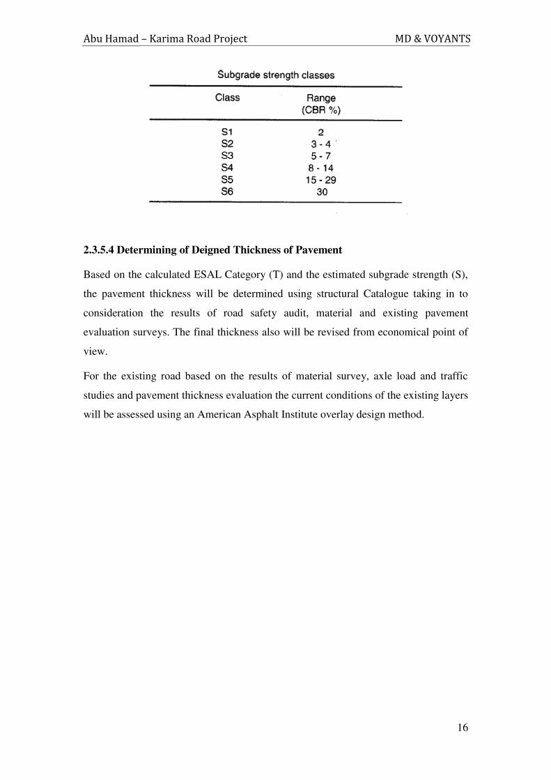
The design Subgrade strength value will be determined using cumulative percentile
curve as recommended in overseas road Note No. 31 and the strength (S) category
will be determined accordingly using the following Table.
Abu Hamad – Karima Road Project MD & VOYANTS
16
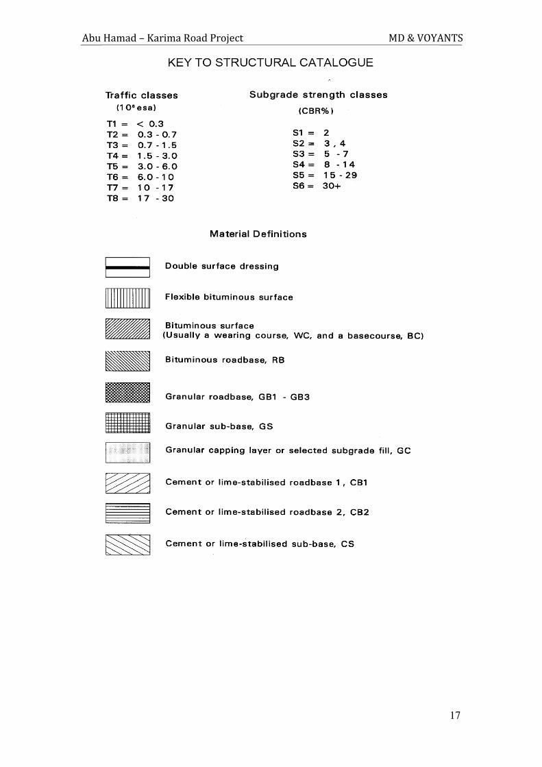
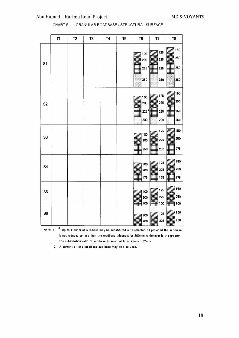
2.3.5.4 Determining of Deigned Thickness of Pavement
Based on the calculated ESAL Category (T) and the estimated subgrade strength (S),
the pavement thickness will be determined using structural Catalogue taking in to
consideration the results of road safety audit, material and existing pavement
evaluation surveys. The final thickness also will be revised from economical point of
view.
For the existing road based on the results of material survey, axle load and traffic
studies and pavement thickness evaluation the current conditions of the existing layers
will be assessed using an American Asphalt Institute overlay design method.
Abu Hamad – Karima Road Project MD & VOYANTS
17
Abu Hamad – Karima Road Project MD & VOYANTS
18
Abu Hamad – Karima Road Project MD & VOYANTS
19
2.3.6 Drainage Structures:
2.3.6.1 Introduction:
The consultant will review existing drainage structures and decide upon their
structural integrity and suitability for the new design. From topographic and
hydrological data, structural system is to be designed and constructed to facilitate
passage of khors (streams) or drains under the road embankment. The consultant,
jointly with the hydrological expert will decide upon the most suitable hydrological
structures required for the chosen alignment.
2.3.6.2 Methodology:
A) Site Visit and Field Inspection.
A site visit by the consultant is a must to determine on site information, such as:
Structural conditions of the existing structures (Bridges, culverts & Irish
crossings)
Visual inspection of existing bridges.
Topographical features.
Catchment area characteristics.
Khor (channel or stream) characteristics.
High-water information
B) Design of Drainage Structures:
I. Culverts:
Depending on the amount of storm-water, reinforced concrete pipe or culverts
of single, double or multiple cells may be required.
These culverts will be designed to resist all expected loading from earthwork,
water pressure and superimposed loads.
Detailed design calculations will be carried out including design of wing walls
and aprons.
Erosion protection work will be considered and fully described.
Abu Hamad – Karima Road Project MD & VOYANTS
20
Recent international codes of practice will be adopted and this includes BS
8110, BS 5400, ACI, EC2 & AASHTO specifications.
II. Bridges:
The land topography or amount of storm water may require the provision of
other structural systems at certain places on the road routes.
These structural systems may be small span bridges of single or multiple
spans.
Detailed design calculations for different bridge elements will be prepared.
The latest specifications of BS 8110, BS 5400, ACI, EC2 & AASHO are to be
followed in the design of the drainage structures.
III. Extra Activities:
The following extra activities will be included in the final report:
Design of adequate foundation based on soil investigation data.
Design and description of erosion protection systems at any bridge or culverts
site in collaboration with the hydrological consultant.
Preparation of tenders detailed drawings.
Preparation of technical specifications and bill of quantities.
IV. Standards & Specifications:
Design Methodologies: The methodologies to be employed for the design of
drainage structures and erosion protection will conform to latest
internationally accepted standards and specifications; this includes BS 8110,
BS 5400, ACI, EC2 & AASHTO where appropriate.
Earthquake-resistant Design: Earthquake resistant-design will be taken into
consideration in the Design of bridges and culverts.
Abu Hamad – Karima Road Project MD & VOYANTS
21
2.3 Project Program Schedule
2.3.1 Activities Time - Schedule
The time-Schedule of activities, presented in Table (1) below, represents a realistic
time-schedule related to the size of the Project. However, the actual time needed, for
phase I, will depend on the feasibility studies actual volume of work required for this
project. The actual time of Phase II will be depending on the feasibility studies to
proceed for the detailed engineering design.
The program specifying the Activity – Time Schedule and the distribution of
Consultants Personnel per Activity are presented in Table (2) & (3).
2.3.2 Reporting Schedule
The required following reports will be submitted according to the schedule shown in
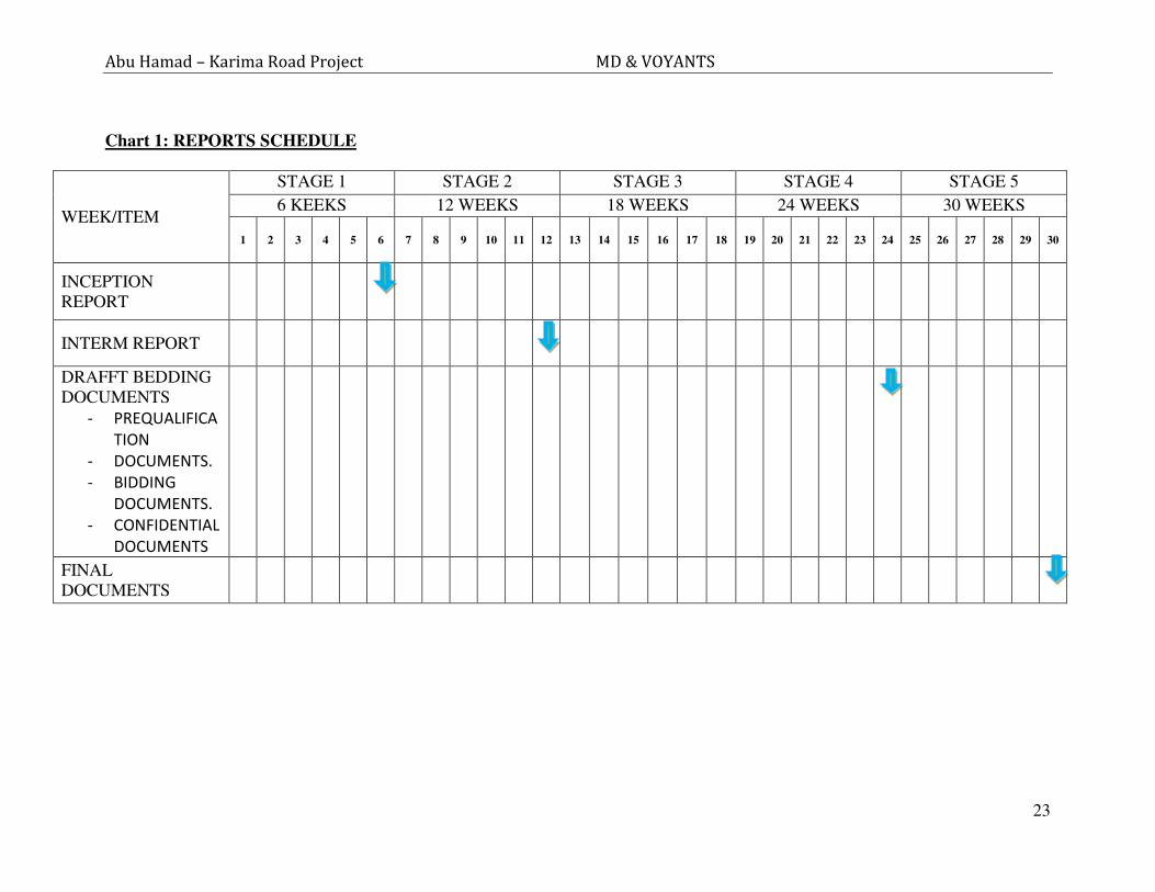
chart 1 below, the reports shall include:
1. Inception Report: will be submitted within (6) weeks from the commencing date,
it will include the outcomes of route alignment and the summary of other
conducted activities and recommendations.
2. Interim Report: it will be submitted within (12) weeks from the commencement
date, describing the completed services, works in progress proposed
recommendations.
3. Draft bidding Documents: upon competition of this stage three copies of the
following documents will be submitted within 24 weeks from the commencement
date:
a. Prequalification Document for Contractor
b. Bidding Documents: including instructions to bidders, condition of contracts
based on FIDIC 1999, Technical specifications, bills of quantities, drawing
(plan-profile, structures details and others) and forms of bids and guarantees.
c. Confidential Reports including Road Auditing, design, material and cost and
time estimates reports.
d. Final Documents: within (30) weeks from the commencement of works we will
submit eight copies of revised documents to the client.

Abu Hamad – Karima Road Project MD & VOYANTS
22
Abu Hamad – Karima Road Project MD & VOYANTS
23
Chart 1: REPORTS SCHEDULE
WEEK/ITEM
STAGE 1 STAGE 2 STAGE 3 STAGE 4 STAGE 5
6 KEEKS 12 WEEKS 18 WEEKS 24 WEEKS 30 WEEKS
1 2 3 4 5 6 7 8 9 10 11 12 13 14 15 16 17 18 19 20 21 22 23 24 25 26 27 28 29 30
INCEPTION
REPORT
INTERM REPORT
DRAFFT BEDDING
DOCUMENTS
- PREQUALIFICA
TION
- DOCUMENTS.
- BIDDING
DOCUMENTS.
- CONFIDENTIAL
DOCUMENTS
FINAL
DOCUMENTS
Abu Hamad – Karima Road Project MD & VOYANTS
24
4. Consultant Professional Staff
To carry out the two phases of the project, the Consultant shall set up a technical and
non-technical Staff.
The Services shall be carried out by the personnel specified herein, for the respective
periods of time indicated therein. The Consultant shall not withdraw and/or replace any
person, specifically named herein, without the prior written consent of the Client. Where
the Consultant replaces any of his personnel, before the completion of the Services, any
additional cost of such replacement shall be borne by the Consultant.
MD & VOYANTS will provide logistics technical support services and other necessary
resources and systems to allow their staff to operate effectively.
4.1 Project Professional Team
4.1.1 Technical Team Leader
A competent technical team leader will manage the consultancy team on the feasibility
studies and the detailed engineering design. The Consultant Head-Office shall provide all
necessary back-up services required by the team leader. Such back-up will include the
services of consultants, specialists, and other Head-Office Experts, for specific periods.
Basically, the team leader shall be responsible for ensuring that the studies and design
progress is within approved time-schedule.
4.1.2 Consultants & Experts
These are the experts and specialists who participated in the previous phases of the
Project. This group will carry out the feasibility studies and the detailed engineering
design. The consultants and experts will be involved in this project include:-
1) Hydrologist Expert
2) Senior Transport Economist
3) Soil & Material Expert
4) Surveyor Expert
5) Senior Surveyor Engineer
Abu Hamad – Karima Road Project MD & VOYANTS
26
6) Structural Expert
7) Senior Structural Engineer
8) Senior environmental Specialist
9) Contract/ Claims Expert
4.2 Proposed Project Personnel
The man-power required (Number, Specialization, Effective Time of Involvement
and position in the Project) is indicated in Tables (2) and (3). The minimum number
of personnel, compatible with the scope of services specified in the TOR, has been
considered in our Proposal.
MD & VOYANTS Key Project Personnel, proposed for this Project, [Phase I
(Feasibility Study) and Phase II (Detailed Engineering Design)] are listed in Tables
(2) and (3), respectively. The proposed Consultants and Experts have a great deal of
experience and expertise in the entire range of consultancy services and activities
required for this Project.
Abu Hamad – Karima Road Project MD & VOYANTS
26
4.2.1 Key Project Personnel
1. Technical Team Leader (TTL) : Dr. Magdi Mohamed Eltayeb Zumrawi (MD)
2. Eng. Highway Expert : Eng. Ramakant Dwivedi (VOYANTS)
3. Structural Expert (Bridges): Dr. Abdalla Khogali (MD)
4. Soil & Material Expert: Eng. Soubhik Sadhu (VOYANTS)
5. Contract/Claims Expert: B. K. Banati (VOYANTS)
6. Hydrologist Expert: Eng. Elsidig Omer A/Gadir (MD)
7. Surveying Consultant: Eng. Mohamoud Abd Elrahim Abd Elgiom (MD)


