Embed Size (px)
Citation preview
SP25M user's guideDocument part number: H-1000-5104-08-A
SP25M user's guide
www.renishaw.com
Issued 06 2022 1

General information© 2005 ‐ 2022 Renishaw plc. All rights reserved.
ORIGINAL LANGUAGE VERSION
This document may not be copied or reproduced in whole or in part, or transferred to any other media or language by any means, without the
prior written permission of Renishaw.
Disclaimer
WHILE CONSIDERABLE EFFORT WAS MADE TO VERIFY THE ACCURACY OF THIS DOCUMENT AT PUBLICATION, ALL WARRANTIES,
CONDITIONS, REPRESENTATIONS AND LIABILITY, HOWSOEVER ARISING, ARE EXCLUDED TO THE EXTENT PERMITTED BY LAW.
RENISHAW RESERVES THE RIGHT TO MAKE CHANGES TO THIS DOCUMENT AND TO THE EQUIPMENT, AND/OR SOFTWARE AND THE
SPECIFICATION DESCRIBED HEREIN WITHOUT OBLIGATION TO PROVIDE NOTICE OF SUCH CHANGES.
Trade marks
RENISHAW®, the probe symbol and REVO® are registered trade marks of Renishaw plc.
Renishaw product names, designations and the mark ‘apply innovation' are trade marks of Renishaw plc or its subsidiaries.
Other brand, product or company names are trade marks of their respective owners.
WEEE
The use of this symbol on Renishaw products and / or accompanying documentation indicates that the product should not be mixed with
general household waste upon disposal. It is the responsibility of the end user to dispose of this product at a designated collection point for
waste electrical and electronic equipment (WEEE) to enable reuse or recycling. Correct disposal of this product will help to save valuable
resources and prevent potential negative effects on the environment. For more information, please contact your local waste disposal service
or Renishaw distributor.
Warranty
Unless you and Renishaw have agreed and signed a separate written agreement, the equipment and/or software are sold subject to the
Renishaw Standard Terms and Conditions supplied with such equipment and/or software, or available on request from your local Renishaw
office.
Renishaw warrants its equipment and software for a limited period (as set out in the Standard Terms and Conditions), provided that they are
installed and used exactly as defined in associated Renishaw documentation. You should consult these Standard Terms and Conditions to find
out the full details of your warranty.
Equipment and/or software purchased by you from a third-party supplier is subject to separate terms and conditions supplied with such
equipment and/or software. You should contact your third-party supplier for details.
SP25M user's guide
www.renishaw.com
Issued 06 2022 2
Care of equipment
Renishaw probes and associated systems are precision tools used for obtaining precise measurements and must therefore be treated with
care.
Changes to Renishaw products
Renishaw reserves the right to improve, change or modify its hardware or software without incurring any obligations to make changes to
Renishaw equipment previously sold.
Company registration details
Renishaw plc. Registered in England and Wales. Company no: 1106260. Registered office: New Mills, Wotton-under-Edge, Gloucestershire,
GL12 8JR, UK.
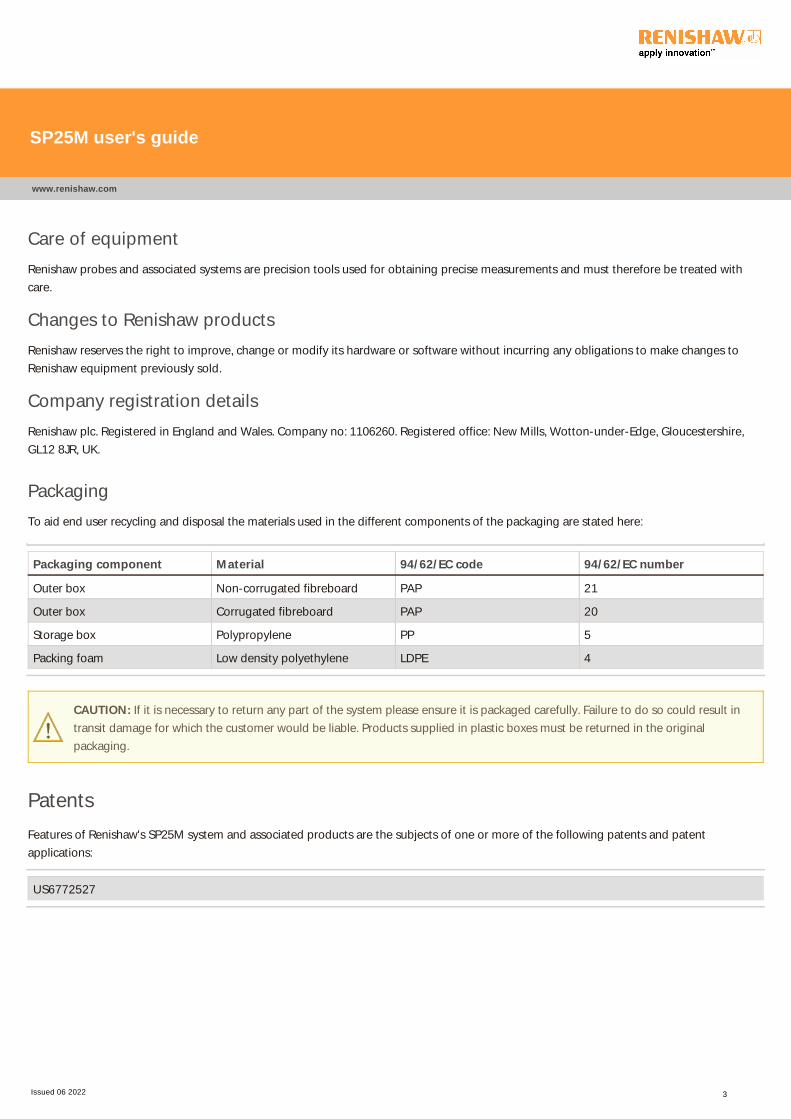
Packaging
To aid end user recycling and disposal the materials used in the different components of the packaging are stated here:
Packaging component Material 94/62/EC code 94/62/EC number
Outer box Non-corrugated fibreboard PAP 21
Outer box Corrugated fibreboard PAP 20
Storage box Polypropylene PP 5
Packing foam Low density polyethylene LDPE 4
CAUTION: If it is necessary to return any part of the system please ensure it is packaged carefully. Failure to do so could result in
transit damage for which the customer would be liable. Products supplied in plastic boxes must be returned in the original
packaging.
Patents
Features of Renishaw's SP25M system and associated products are the subjects of one or more of the following patents and patent
applications:
US6772527
SP25M user's guide
www.renishaw.com
Issued 06 2022 3

Product compliance
EU declaration of conformity
Contact Renishaw plc or visit www.renishaw.com/EUCMM for the full EU declaration.
UK declaration of conformity
Contact Renishaw plc or visit www.renishaw.com/UKCMM for the full UK declaration.
EMC conformity
This equipment must be installed and used in accordance with this installation guide. This product is intended for industrial use only and
should not be used in a residential area or connected to a low voltage power supply network which supplies buildings used for residential
purposes.
FCC (USA only)
Information to user (47 CFR 15.105)
This equipment has been tested and found to comply with the limits for a Class A digital device, pursuant to Part 15 of the FCC rules. These
limits are designed to provide reasonable protection against harmful interference when the equipment is operated in a commercial
environment. This equipment generates, uses, and can radiate radio frequency energy and, if not installed and used in accordance with the
instruction manual, may cause harmful interference to radio communications. Operation of this equipment in a residential area is likely to
cause harmful interference, in which case you will be required to correct the interference at your own expense.
Information to user (47 CFR 15.21)
The user is cautioned that any changes or modifications not expressly approved by Renishaw plc or authorised representative could void the
user's authority to operate the equipment.
Equipment label (47 CFR 15.19)
This device complies with part 15 of the FCC Rules. Operation is subject to the following two conditions:
1. This device may not cause harmful interference.
2. This device must accept any interference received, including interference that may cause undesired operation.
SP25M user's guide
www.renishaw.com
Issued 06 2022 4

ICES-001 (Canada only)
This ISM device complies with Canadian ICES-001(A) / NMB-001(A).
Cet appareil ISM est conforme à la norme ICES‐001﴾A﴿ / NMB‐001﴾A﴿ du Canada.
REACH regulation
Information required by Article 33﴾1﴿ of Regulation ﴾EC﴿ No. 1907/2006 ﴾“REACH”﴿ relating to products containing substances of very highconcern (SVHCs) is available at:
www.renishaw.com/REACH
China RoHS
Contact Renishaw plc or visit www.renishaw.com/ChinaRoHSCMM for the full China RoHS tabulation.
SP25M user's guide
www.renishaw.com
Issued 06 2022 5

International safety instructions
BG ‐ ПРЕДУПРЕЖДЕНИЕМоля, обърнете на приложение 1 и прочетете инструкциите за безопасност на вашия собствен език, преди за разопаковате имонтирате този продукт.
CZ ‐ VÝSTRAHAPřed rozbalením a instalací tohoto výrobku si přečtěte bezpečnostní pokyny ve vlastním jazyce uvedené v příloze 1.
DA - ADVARSEL
Læs sikkerhedsinstrukserne i Appendix 1 FØR udpakning og installation af dette produkt.
DE - WARNHINWEIS
Bevor Sie dieses Produkt auspacken und installieren, konsultieren Sie bitte Anhang 1 und lesen Sie die Sicherheitshinweise in Ihrer Sprache.
EL ‐ ΠΡΟΕΙΔΟΠΟΙΗΣΗΓυρίστε στο Κεφάλαιο 1 και διαβάστε τις οδηγίες ασφαλείας στη δική σας γλώσσα προτού ανοίξετε αυτό το προϊόν για να τοεγκαταστήσετε.
EN - WARNING
Before unpacking and installing this product, please consult Appendix 1 and read the safety instructions in your language.
ES - ADVERTENCIA
Consulte el apéndice 1 y lea las instrucciones de seguridad en su idioma antes de desempaquetar e instalar este producto.
ET - HOIATUS
Palun vaadake 1. lisa ning lugege enne selle toote lahtipakkimist ja paigaldamist ohutusjuhend läbi.
FI - VAROITUKSIA
Lue liitteessä 1 olevat omalla kielelläsi kirjoitetut turvaohjeet ennen tämän tuotteen pakkauksen avaamista ja asentamista.
FR - AVERTISSEMENT
Consulter l'annexe 1 et les instructions de sécurité dans votre propre langue avant de déballer et d'installer ce produit.
SP25M user's guide
www.renishaw.com
Issued 06 2022 6

GA - RABHADH
Téigh chuig aguisín 1 agus déan na treoracha sábháilteachta a léamh i do theanga féin le do thoil sula ndéantar an táirge seo a dhíphacáilagus a shuiteáil.
HR - NAPOMENA
Prije nego što proizvod izvadite iz ambalaže i ugradite ga, otvorite Prilog 1 i pročitajte sigurnosne upute na svom jeziku.
HU – FIGYELMEZTETÉSA termék kicsomagolása és telepítése előtt olvassa el az 1. számú függelékben található, az Ön anyanyelvén hozzáférhető biztonságiutasításokat.
IT - AVVISO
Prima di aprire ed installare questo prodotto, leggere le istruzioni di sicurezza nella vostra lingua riportate nell'Appendice 1.
JA ‐ 警告
この製品を箱から取り出し設置する前に、付録 1 に記載された安全性に関する注意書きをお読みください。
LT – ĮSPĖJIMASPrieš išpakuodami ir įdiegdami produktą, turite grįžti prie 1 priedo ir perskaityti nurodymus dėl saugos savo kalba.
LV – BRĪDINĀJUMSPirms šī izstrādājuma izsaiņošanas un uzstādīšanas izskatiet 1. pielikumā sniegtās drošības instrukcijas savā valodā.
MT - TWISSIJA
Jekk jogħġbok mur f'appendiċi 1 u aqra l‐istruzzjonijiet tas‐sigurtà fil‐lingwa tiegħek qabel ma toħroġ dan il‐prodott mill‐ippakkjar utinstallah.
NL - WAARSCHUWING
Ga naar appendix 1 en lees de veiligheidsinstructies in uw eigen taal, voordat u dit product uitpakt en installeert.
PL ‐ OSTRZEŻENIEPrzed rozpakowaniem i zainstalowaniem tego produktu prosimy o zapoznanie się z Dodatkiem 1 i przeczytanie zaleceń dotyczącychbezpieczeństwa w danym języku.
PT ‐ ADVERTÊNCIAVocê deve retornar ao Anexo 1 e ler as instruções de segurança em seu idioma antes de desembalar e instalar este produto.
SP25M user's guide
www.renishaw.com
Issued 06 2022 7
RO - AVERTISMENT
Înainte de a desface ambalajul şi a instala acest produs, vă rugăm să căutaţi Anexa 1 şi să citiţi cu atenţie instrucţiunile de siguranță, în limbaromână.
SK ‐ VÝSTRAHAPred rozbalením a inštaláciou tohto produktu si pozrite prílohu 1 a prečítajte si bezpečnostné pokyny vo vašom jazyku.
SL - OPOZORILO
Preden izdelek vzamete iz embalaže in ga vgradite, odprite Prilogo 1 in preberite varnostna navodila v svojem jeziku.
SV - VARNING
Gå till bilaga 1 och läs säkerhetsinstruktionerna på ditt eget språk innan du packar upp och installerar denna produkt.
TW ‐ 警告
在拆開和安裝本產品之前,請翻頁至附錄 1 閱讀母語的安全指示。
中文 — 警告
在拆包和安装本产品之前,请翻到附录1,阅读中文版安全说明。
SP25M user's guide
www.renishaw.com
Issued 06 2022 8
General safety recommendations
CAUTION: Before unpacking and installing the SP25M probe system, the user should carefully read the safety instructions below
and ensure that they are followed at all times by all operators using the probe system. Use of controls or adjustments, or
performance of procedures other than those specified herein may result in hazardous infra red radiation exposure.
Operators must be trained in the use and application of the SP25M probe system and accompanying products, in the context of the
machine it is fitted to, before being allowed to operate that machine.
NOTE: References are made below to features indicated [†] [‡] [♦] on the illustrations shown below. Please ensure that you clearlyunderstand all safety instructions. Familiarisation with the SP25M system components, as shown in the following sections is
recommended:
System components overview
Schematic diagram of probe system components
Schematic diagram of FCR25 flexible change rack
Schematic diagram of FCR25 TC flexible change rack
The SP25M probe system has mechanical overtravel protection provided in the probe +Z axis, by a fixed bumpstop. The machine
control system must therefore be able to stop the motion of the machine, in this axis of the probe, before the bumpstop is reached.
If this is not the case, the user must wear eye protection during operation in case of stylus breakage.
Care should be taken to ensure that the optical windows ﴾indicated [♦]﴿, located on both body and module, do not become damaged as theyare made of glass and could cause injury.
CAUTION: Permanent magnets are used in some components of the SP25M system and associated products. It is important to
keep them away from items which may be affected by magnetic fields, e.g. data storage systems, pacemakers and watches etc.
SP25M user's guide
www.renishaw.com
Issued 06 2022 9

LED safety
The SP25M body contains embedded high power LED sources ﴾indicated [†]﴿ which emit invisible infra‐red radiation. These sources areexposed when an SM25-# or TM25-20 module is not attached.
Removing the module breaks two sets of interlock switch contacts ﴾indicated [‡]﴿ to automatically switch off the LED power and assure usersafety.
At suitable intervals, the interlock contacts should be inspected and checked to ensure that they are clean and free from airborne
contamination such as dust, debris or swarf. In unlikely circumstances, such contamination could cause a short circuit of the pins and thus
increase the risk of sending power to the LEDs, without a module being attached. Never connect conducting objects to, or between, the
contacts. Follow the cleaning instructions in the Maintenance section.
Before inspecting, always remove the SP25M body from the probe head.
In the event of serious damage to, or a rupture of, any part of the SP25M body or scanning module outer casing, IMMEDIATELY disconnect
power source, remove and do not attempt to re-use the parts, and contact your supplier for advice.
Safety illustrations
These diagrams show features, indicated [†] [‡] [♦] which are referred to within these safety recommendations.
SP25M probe body
End view showing kinematic joint to module
SP25M kinematic joint to module
SM25 scanning modules
End view showing kinematic joint to body
SP25M kinematic joint to body
SP25M user's guide
www.renishaw.com
Issued 06 2022 10

Introduction
NOTE: Before unpacking and installing the SP25M probe system, please read the safety information and ensure that they are
followed at all times during system installation and operation.
This document is intended to provide help and guidance during initial installation, integration and subsequent use of the of the SP25M probe
system. It is assumed that the system will be installed on a coordinate measuring machine using a controller system that has had full SP25M
system integration in the form of a dedicated Renishaw controller or an AC3 (ISA bus) analogue interface PC card.
SP25M is a compact and versatile probe system that provides both scanning capability for form measurement or reverse engineering and
touch-trigger probing for geometric size and position measurement.
The SP25M system provides highly accurate scanning measurement with stylus lengths from 20 mm to 400 mm as well as full TP20 touch-
trigger probe module compatibility to suit a range of applications.
The SP25M system uses the Renishaw autojoint to enable repeatable mounting to the PH10M PLUS, PH10MQ PLUS and PH6M probe heads.
Multiwired extension bar mounting of the SP25M system is also possible to extend the reach and enable more access to part features.
The range of SM25 scanning modules are designed to cover specific stylus length ranges whilst maintaining excellent accuracy performance.
The system can be readily expanded to further increase the scanning range, allow TP20 touch-trigger measurement or utilise an automatic
changer system.
SP25M user's guide
www.renishaw.com
Issued 06 2022 11

Design principles of the SP25M systemThe SP25M design features an optical transducer sensor system which is located within the SP25M probe body. The design also features a
spring pivoting motion system which is located within the SM25 scanning modules.
Two infrared light emitting diodes (IREDs) mounted in the SP25M probe body project invisible infrared beams on to two mirrors mounted on
the pivoting motion structure within the SM25 scanning module. The mirrors reflect the beam back to the SP25M probe body where their
change in position is detected by two position sensitive devices (PSDs) when the stylus is deflected. The PSDs provide signal outputs in the
three probe axes; P, Q and R.
NOTE: The SP25M probe system does not have a fixed rate, gain or resolution and the P, Q and R probe axis outputs are non-linear
and non-orthogonal. These outputs are converted to X, Y and Z signals by the calibration routine. Renishaw offer support and
advice on scanning calibration algorithms suited to SP25M.
The SM25 scanning modules are designed to provide an optimised level of accuracy and contact force over a specified stylus range. This
minimises the reduction in performance seen in other types of scanning probes as the stylus length increases.
SP25M user's guide
www.renishaw.com
Issued 06 2022 12

System components overview
System overview
The modular design of the SP25M system enables the flexibility for optimum configuration by the user. Please refer to the schematic
diagrams showing the SP25M system components in the SP25M installation section of this document.
SP25M probe body
The SP25M probe body houses the optical transducer system and attaches to PH10M PLUS, PH10MQ PLUS or PH6M using a Renishaw
autojoint connection.
SM25 scanning modules
There are five scanning modules in the SM25 range which enable accurate scanning measurements at different stylus lengths. SM25-1,
SM25-2, SM25-3 and SM25-4 are recommended for use with linear stylus arrangements and SM25-5 is recommended for use with non-
linear and star stylus arrangements.
SH25 stylus holders
The range of SH25 stylus holders enable accurate scanning measurements with effective stylus lengths ranging from 20 mm to 400 mm.
SH25-1, SH25-2, SH25-3 and SH25-4 are recommended for use with linear stylus arrangements. SH25-2A, SH25-3A, SH25-4A and SH25-5
are recommended for use with non-linear and star stylus arrangements.
TM25-20 adaptor module
For rapid touch-trigger measurement, the TM25-20 adaptor module may be used which provides full compatibility with the whole range of
TP20 touch-trigger probe modules.
SP25M user's guide
www.renishaw.com
Issued 06 2022 13

FCR25 flexible change rack
Automated and repeatable changing of the SM25 scanning modules, SH25 stylus holders and TM25-20 is possible with FCR25. This triple
port system is designed for mounting on the Renishaw MRS rail system.
FCR25-L3 and FCR25-L6 leg mounted flexible change racks
These variants of the FCR25 flexible change rack and designed to be mounted to the bed of the CMM with the integrated leg assembly.
FCR25 TC change rack
The FCR25 TC provides automated and repeatable changing of SM25 scanning modules whilst keeping the ports at the same operating
temperature as the SP25M probe body. This ensures that there is no difference in temperature between the SP25M probe body and the SM25
scanning modules eliminating thermal variation and providing optimum metrology.
AC3 analogue interface PCB card
An ISA bus card to enable integration of the SP25M system with a CMM manufacturer's own controller.
SP25M user's guide
www.renishaw.com
Issued 06 2022 14
Probe system components
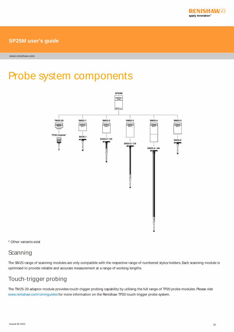
* Other variants exist
Scanning
The SM25 range of scanning modules are only compatible with the respective range of numbered stylus holders. Each scanning module is
optimised to provide reliable and accurate measurement at a range of working lengths.
Touch-trigger probing
The TM25-20 adaptor module provides touch-trigger probing capability by utilising the full range of TP20 probe modules. Please visit
www.renishaw.com/cmmguides for more information on the Renishaw TP20 touch-trigger probe system.
SP25M user's guide
www.renishaw.com
Issued 06 2022 15
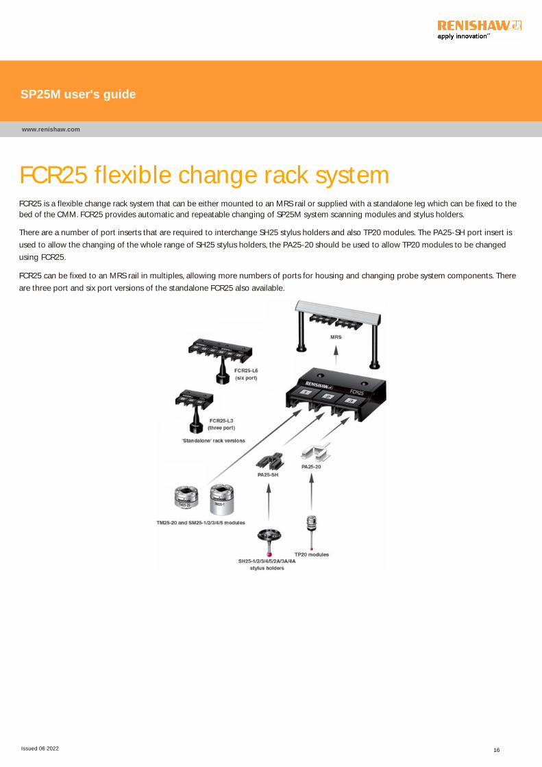
FCR25 flexible change rack systemFCR25 is a flexible change rack system that can be either mounted to an MRS rail or supplied with a standalone leg which can be fixed to the
bed of the CMM. FCR25 provides automatic and repeatable changing of SP25M system scanning modules and stylus holders.
There are a number of port inserts that are required to interchange SH25 stylus holders and also TP20 modules. The PA25-SH port insert is
used to allow the changing of the whole range of SH25 stylus holders, the PA25-20 should be used to allow TP20 modules to be changed
using FCR25.
FCR25 can be fixed to an MRS rail in multiples, allowing more numbers of ports for housing and changing probe system components. There
are three port and six port versions of the standalone FCR25 also available.
SP25M user's guide
www.renishaw.com
Issued 06 2022 16

FCR25 TC temperature controlled flexible
change rackFCR25 TC is similar in function to the standard FCR25, the main difference being that temperature compensation is provided to optimise
scanning module metrology performance.
No port inserts are compatible with FCR25 TC which means that only the SM25 scanning module components of the SP25M system can be
changed using this rack.
FCR25 TC can be mounted directly to an MRS rail, there is also a three port standalone version that can be fixed directly to the bed on the
CMM.
SP25M user's guide
www.renishaw.com
Issued 06 2022 17
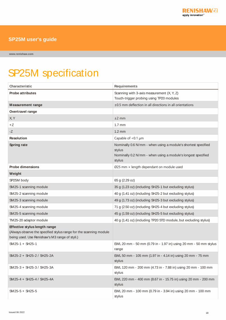
SP25M specificationCharacteristic Requirements
Probe attributes Scanning with 3-axis measurement (X, Y, Z)
Touch-trigger probing using TP20 modules
Measurement range ±0.5 mm deflection in all directions in all orientations
Overtravel range
X, Y ±2 mm
+Z 1.7 mm
-Z 1.2 mm
Resolution Capable of <0.1 μm
Spring rate Nominally 0.6 N/mm - when using a module's shortest specified
stylus
Nominally 0.2 N/mm - when using a module's longest specified
stylus
Probe dimensions Ø25 mm × length dependant on module used
Weight
SP25M body 65 g (2.29 oz)
SM25-1 scanning module 35 g (1.23 oz) (including SH25-1 but excluding stylus)
SM25-2 scanning module 40 g (1.41 oz) (including SH25-2 but excluding stylus)
SM25-3 scanning module 49 g (1.73 oz) (including SH25-3 but excluding stylus)
SM25-4 scanning module 71 g (2.50 oz) (including SH25-4 but excluding stylus)
SM25-5 scanning module 45 g (1.59 oz) (including SH25-5 but excluding stylus)
TM25-20 adaptor module 40 g (1.41 oz) (including TP20 STD module, but excluding stylus)
Effective stylus length range
(Always observe the specified stylus range for the scanning module
being used. Use Renishaw's M3 range of styli.)
SM25-1 + SH25-1 EWL 20 mm - 50 mm (0.79 in - 1.97 in) using 20 mm - 50 mm stylus
range
SM25-2 + SH25-2 / SH25-2A EWL 50 mm - 105 mm (1.97 in - 4.14 in) using 20 mm - 75 mm
stylus
SM25-3 + SH25-3 / SH25-3A EWL 120 mm - 200 mm (4.73 in - 7.88 in) using 20 mm - 100 mm
stylus
SM25-4 + SH25-4 / SH25-4A EWL 220 mm - 400 mm (8.67 in - 15.75 in) using 20 mm - 200 mm
stylus
SM25-5 + SH25-5 EWL 20 mm - 100 mm (0.79 in - 3.94 in) using 20 mm - 100 mm
stylus
SP25M user's guide
www.renishaw.com
Issued 06 2022 18
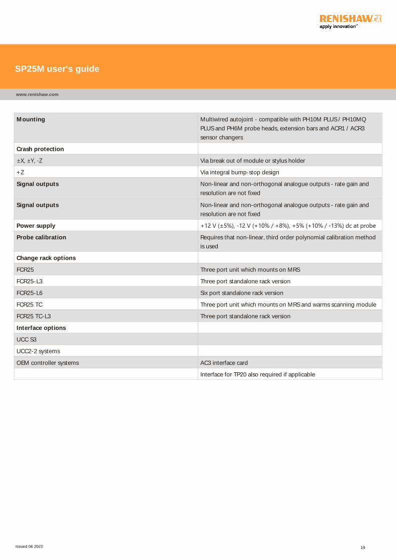
Mounting Multiwired autojoint - compatible with PH10M PLUS / PH10MQ
PLUS and PH6M probe heads, extension bars and ACR1 / ACR3
sensor changers
Crash protection
±X, ±Y, ‐Z Via break out of module or stylus holder
+Z Via integral bump-stop design
Signal outputs Non-linear and non-orthogonal analogue outputs - rate gain and
resolution are not fixed
Signal outputs Non-linear and non-orthogonal analogue outputs - rate gain and
resolution are not fixed
Power supply +12 V ﴾±5%﴿, ‐12 V ﴾+10% / +8%﴿, +5% ﴾+10% / ‐13%﴿ dc at probe
Probe calibration Requires that non-linear, third order polynomial calibration method
is used
Change rack options
FCR25 Three port unit which mounts on MRS
FCR25-L3 Three port standalone rack version
FCR25-L6 Six port standalone rack version
FCR25 TC Three port unit which mounts on MRS and warms scanning module
FCR25 TC-L3 Three port standalone rack version
Interface options
UCC S3
UCC2-2 systems
OEM controller systems AC3 interface card
Interface for TP20 also required if applicable
SP25M user's guide
www.renishaw.com
Issued 06 2022 19
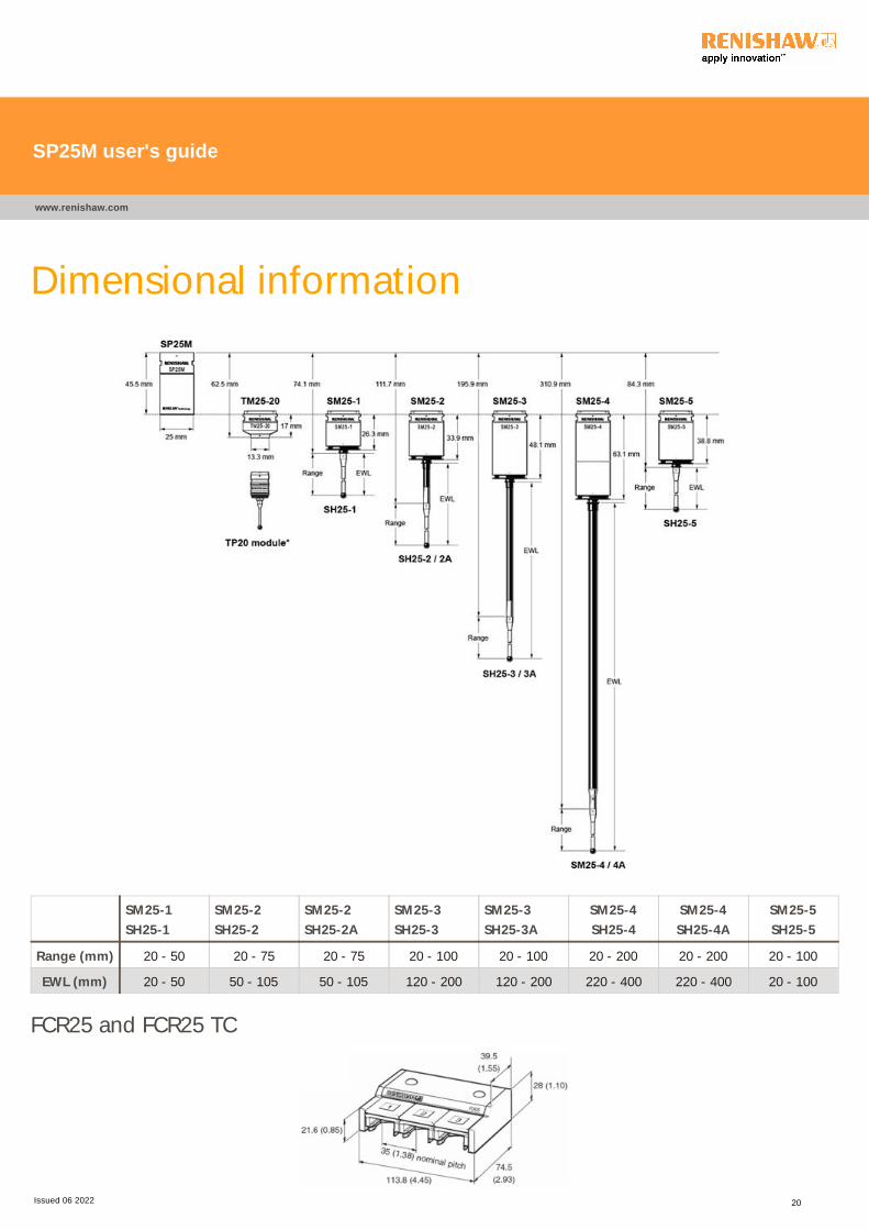
Dimensional information
SM25-1
SH25-1
SM25-2
SH25-2
SM25-2
SH25-2A
SM25-3
SH25-3
SM25-3
SH25-3A
SM25-4
SH25-4
SM25-4
SH25-4A
SM25-5
SH25-5
Range (mm) 20 - 50 20 - 75 20 - 75 20 - 100 20 - 100 20 - 200 20 - 200 20 - 100
EWL (mm) 20 - 50 50 - 105 50 - 105 120 - 200 120 - 200 220 - 400 220 - 400 20 - 100
FCR25 and FCR25 TC
SP25M user's guide
www.renishaw.com
Issued 06 2022 20
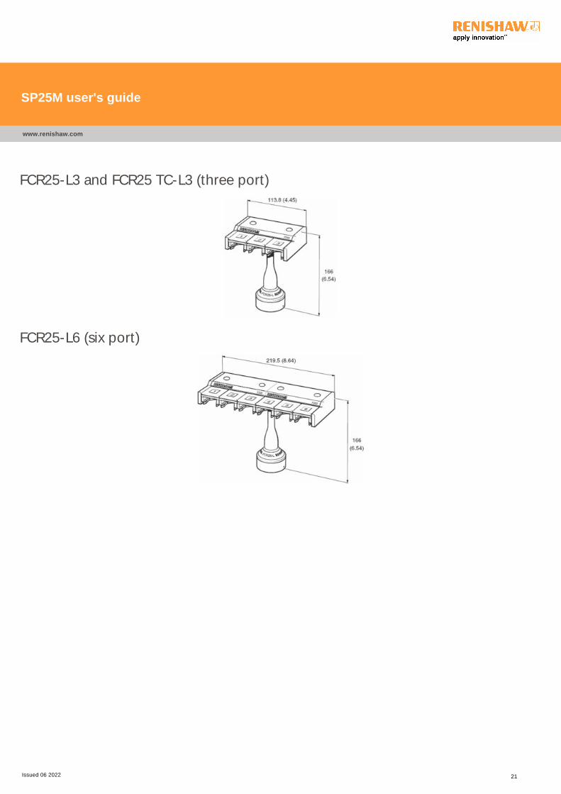
FCR25-L3 and FCR25 TC-L3 (three port)
FCR25-L6 (six port)
SP25M user's guide
www.renishaw.com
Issued 06 2022 21
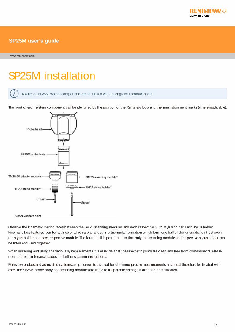
SP25M installation
NOTE: All SP25M system components are identified with an engraved product name.
The front of each system component can be identified by the position of the Renishaw logo and the small alignment marks (where applicable).
Observe the kinematic mating faces between the SM25 scanning modules and each respective SH25 stylus holder. Each stylus holder
kinematic face features four balls, three of which are arranged in a triangular formation which form one half of the kinematic joint between
the stylus holder and each respective module. The fourth ball is positioned so that only the scanning module and respective stylus holder can
be fitted and used together.
When installing and using the various system elements it is essential that the kinematic joints are clean and free from contaminants. Please
refer to the maintenance pages for further cleaning instructions.
Renishaw probes and associated systems are precision tools used for obtaining precise measurements and must therefore be treated with
care. The SP25M probe body and scanning modules are liable to irreparable damage if dropped or mistreated.
SP25M user's guide
www.renishaw.com
Issued 06 2022 22
Attaching the SP25M probe body to the
probe head
NOTE: To ensure optimum metrology performance it is recommended that following any probe change (either manual or
automatic), the probe head is unlocked and locked.
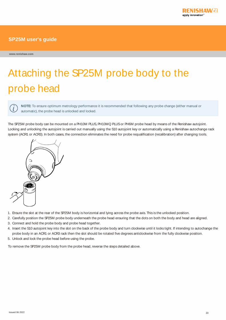
The SP25M probe body can be mounted on a PH10M PLUS, PH10MQ PLUS or PH6M probe head by means of the Renishaw autojoint.
Locking and unlocking the autojoint is carried out manually using the S10 autojoint key or automatically using a Renishaw autochange rack
system (ACR1 or ACR3). In both cases, the connection eliminates the need for probe requalification (recalibration) after changing tools.
1. Ensure the slot at the rear of the SP25M body is horizontal and lying across the probe axis. This is the unlocked position.
2. Carefully position the SP25M probe body underneath the probe head ensuring that the dots on both the body and head are aligned.
3. Connect and hold the probe body and probe head together.
4. Insert the S10 autojoint key into the slot on the back of the probe body and turn clockwise until it locks tight. If intending to autochange the
probe body in an ACR1 or ACR3 rack then the slot should be rotated five degrees anticlockwise from the fully clockwise position.
5. Unlock and lock the probe head before using the probe.
To remove the SP25M probe body from the probe head, reverse the steps detailed above.
SP25M user's guide
www.renishaw.com
Issued 06 2022 23
Attaching an SM25 or TM25-20 module to the
SP25M probe body
NOTE: To ensure optimum metrology performance it is recommended that following any probe change (either manual or
automatic), the probe head is unlocked and locked.
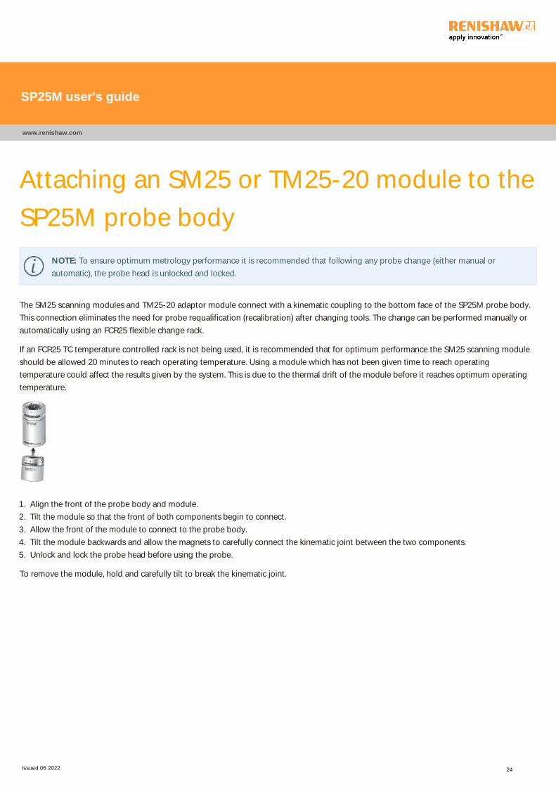
The SM25 scanning modules and TM25-20 adaptor module connect with a kinematic coupling to the bottom face of the SP25M probe body.
This connection eliminates the need for probe requalification (recalibration) after changing tools. The change can be performed manually or
automatically using an FCR25 flexible change rack.
If an FCR25 TC temperature controlled rack is not being used, it is recommended that for optimum performance the SM25 scanning module
should be allowed 20 minutes to reach operating temperature. Using a module which has not been given time to reach operating
temperature could affect the results given by the system. This is due to the thermal drift of the module before it reaches optimum operating
temperature.
1. Align the front of the probe body and module.
2. Tilt the module so that the front of both components begin to connect.
3. Allow the front of the module to connect to the probe body.
4. Tilt the module backwards and allow the magnets to carefully connect the kinematic joint between the two components.
5. Unlock and lock the probe head before using the probe.
To remove the module, hold and carefully tilt to break the kinematic joint.
SP25M user's guide
www.renishaw.com
Issued 06 2022 24

Attaching an SH25 stylus holder to an SM25
scanning moduleThe range of SH25 stylus holders have a kinematic coupling that connects to each respective SM25 scanning module. This connection
eliminates the need for probe requalification (recalibration) after changing tools. The change can be performed manually or automatically
using an FCR25 flexible change rack (highly recommended for optimum performance).
Each stylus holder is only compatible with its respective scanning module. Incorrect combinations are prevented by the unique position of the
orientation ball in the stylus holder kinematic joint. All SH25 stylus holders use the Renishaw M3 range of styli.
Manually attaching an SH25 stylus holder to an SM25 scanning module
1. Align the front of the stylus holder and probe module.
2. Slowly connect the stylus holder to the bottom of the probe module. Allow the magnets to carefully connect the kinematic joint between
the stylus holder and module.
3. Gently rotate the stylus holder to ensure a correct connection.
To remove the stylus holder, hold and carefully tilt to break the kinematic joint.
Attaching a stylus to a stylus holder
1. Ensure the stylus holder is not attached to the probe module.
2. Always stay within the recommended stylus capability range for each stylus holder.
3. Avoid touching the kinematic face of the stylus holder.
4. When tightening the stylus ensure that the correct M3 stylus tool is used.
SP25M user's guide
www.renishaw.com
Issued 06 2022 25
Attaching a TP20 module to the TM25-20
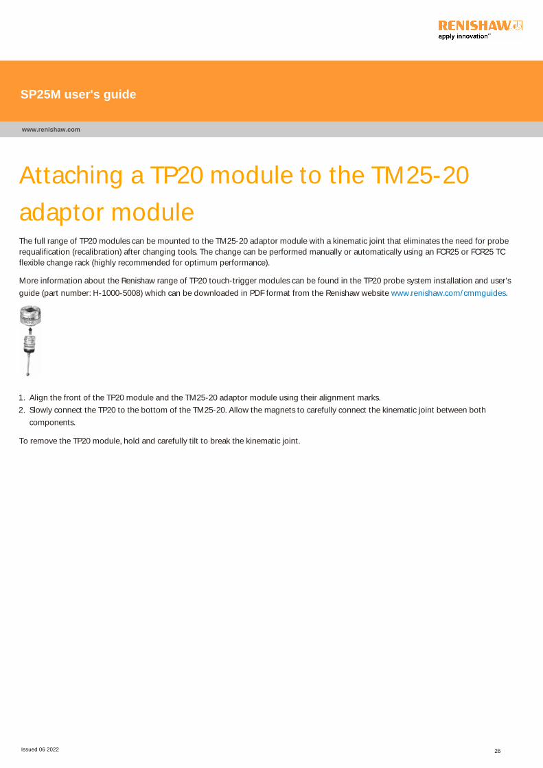
adaptor moduleThe full range of TP20 modules can be mounted to the TM25-20 adaptor module with a kinematic joint that eliminates the need for probe
requalification (recalibration) after changing tools. The change can be performed manually or automatically using an FCR25 or FCR25 TC
flexible change rack (highly recommended for optimum performance).
More information about the Renishaw range of TP20 touch-trigger modules can be found in the TP20 probe system installation and user's
guide (part number: H-1000-5008) which can be downloaded in PDF format from the Renishaw website www.renishaw.com/cmmguides.
1. Align the front of the TP20 module and the TM25-20 adaptor module using their alignment marks.
2. Slowly connect the TP20 to the bottom of the TM25-20. Allow the magnets to carefully connect the kinematic joint between both
components.
To remove the TP20 module, hold and carefully tilt to break the kinematic joint.
SP25M user's guide
www.renishaw.com
Issued 06 2022 26

FCR25 flexible change rackThe FCR25 flexible change rack is a triple port unit that provides unmatched flexibility when rapid and automatic tool changing is required.
FCR25 is a passive rack design meaning no electrical connection is required. During a change cycle, it is still necessary however to inhibit
probe signals.
NOTE: Renishaw strongly recommends the use of FCR25 to ensure optimum performance when changing elements of the SP25M
probe system.
FCR25 racks can be mounted in multiples along a Renishaw MRS rail which enables rack port configurations in multiples of three. Any port in
an FCR25 rack can be used to change all of the following system elements:
The whole range of SM25 scanning modules
The TM25-20 adaptor module
The whole range of SH25 stylus holders (using a PA25-SH port adaptor insert)
The whole range of TP20 modules (using a PA25-20 port adaptor insert)
FCR25 TC temperature controlled flexible change rack
The FCR25 TC flexible change rack is a triple port unit that provides unmatched flexibility when rapid and automatic tool changing is required.
The FCR25 TC rack is powered by a standard 24 V mains supply that is supplied with the unit.
The integrated temperature control functionality heats the rack ports to elevate any housed modules to the same temperature as a powered
SP25M probe. Although FCR25 TC is a powered rack, it is still necessary to inhibit probe signals during a change cycle.
NOTE: Renishaw strongly recommends the use of FCR25 TC to ensure optimum performance when changing the scanning
modules of an SP25M system. To change any other components of the SP25M system, a standard FCR25 should be used.
In installations where ultimate accuracy is required, it is recommended that the system is left in a powered state.
FCR25 TC racks can be mounted in multiples along a Renishaw MRS rail in conjunction with standard FCR25 units which enable rack port
configurations in multiples of three. FCR25 TC can only be used for scanning modules. FCR25 should be used for all other system elements.
SP25M user's guide
www.renishaw.com
Issued 06 2022 27

General FCR25 and FCR25 TC installation
informationThe information is this document that describes the mounting and aligning of the FCR25 and FCR25 TC racks assumes that the MRS rail is
positioned along the X-axis of the CMM with the probe head positioned at A0 B0 during a change routine. If the MRS2 rack is mounted along
the Y-axis of the CMM, it will be necessary to transpose all references to axis, motion and orientation.
It is also assumed that the MRS rail has been correctly installed on the CMM as defined in the MRS installation and user's guide which can be
downloaded in PDF format from the Renishaw website www.renishaw.com/cmmguides.
When two or more FCR25 racks are used together, it is possible to remove the adjoining plastic end caps to enable an unbroken line of ports.
Carefully remove the end caps to reveal a series of machined lug features. These are used to align the adjoining FCR25 racks. This is not
possible with FCR25 TC racks.
SP25M user's guide
www.renishaw.com
Issued 06 2022 28
Mounting an FCR25 and FCR25 TC to an MRS
rail system
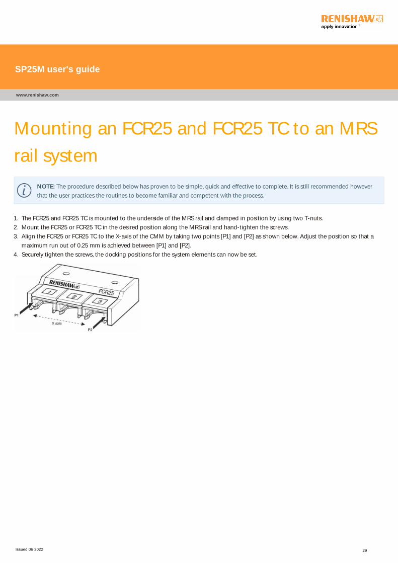
NOTE: The procedure described below has proven to be simple, quick and effective to complete. It is still recommended however
that the user practices the routines to become familiar and competent with the process.
1. The FCR25 and FCR25 TC is mounted to the underside of the MRS rail and clamped in position by using two T-nuts.
2. Mount the FCR25 or FCR25 TC in the desired position along the MRS rail and hand-tighten the screws.
3. Align the FCR25 or FCR25 TC to the X-axis of the CMM by taking two points [P1] and [P2] as shown below. Adjust the position so that a
maximum run out of 0.25 mm is achieved between [P1] and [P2].
4. Securely tighten the screws, the docking positions for the system elements can now be set.
SP25M user's guide
www.renishaw.com
Issued 06 2022 29
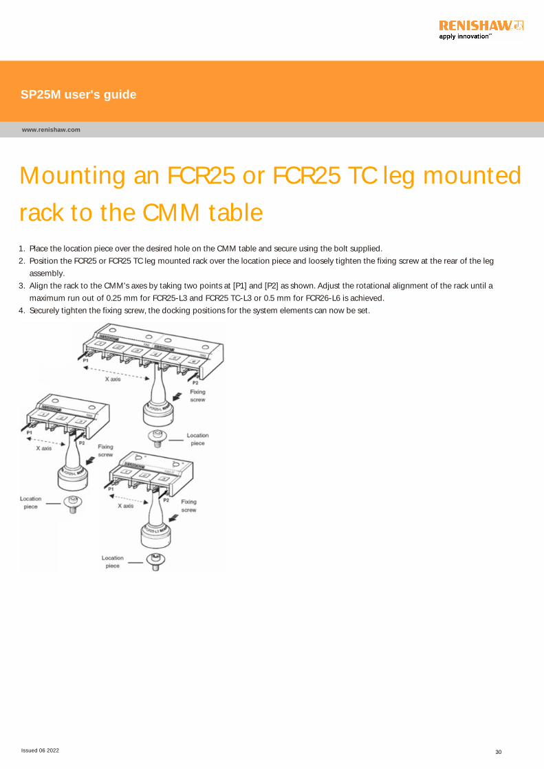
Mounting an FCR25 or FCR25 TC leg mounted
rack to the CMM table1. Place the location piece over the desired hole on the CMM table and secure using the bolt supplied.
2. Position the FCR25 or FCR25 TC leg mounted rack over the location piece and loosely tighten the fixing screw at the rear of the leg
assembly.
3. Align the rack to the CMM's axes by taking two points at [P1] and [P2] as shown. Adjust the rotational alignment of the rack until a
maximum run out of 0.25 mm for FCR25-L3 and FCR25 TC-L3 or 0.5 mm for FCR26-L6 is achieved.
4. Securely tighten the fixing screw, the docking positions for the system elements can now be set.
SP25M user's guide
www.renishaw.com
Issued 06 2022 30
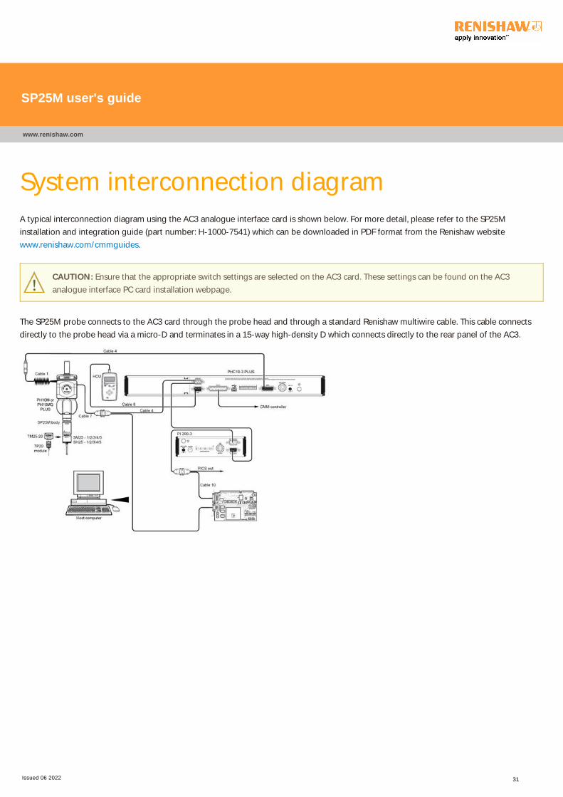
System interconnection diagramA typical interconnection diagram using the AC3 analogue interface card is shown below. For more detail, please refer to the SP25M
installation and integration guide (part number: H-1000-7541) which can be downloaded in PDF format from the Renishaw website
www.renishaw.com/cmmguides.
CAUTION: Ensure that the appropriate switch settings are selected on the AC3 card. These settings can be found on the AC3
analogue interface PC card installation webpage.
The SP25M probe connects to the AC3 card through the probe head and through a standard Renishaw multiwire cable. This cable connects
directly to the probe head via a micro-D and terminates in a 15-way high-density D which connects directly to the rear panel of the AC3.
SP25M user's guide
www.renishaw.com
Issued 06 2022 31
SP25M calibrationThe SP25M probe requires calibration before it can give accurate positional data.
NOTE: As the analogue outputs from SP25M are non-linear and non-orthogonal, a third order polymer non-linear calibration
method should always be used for optimum accuracy.
At the nominal free stylus position the probe outputs will not be zero. These zero offsets are determined and saved as part of the non-linear
calibration.
For maximum probe performance in scanning mode, Renishaw recommends that the SP25M is qualified (calibrated) using a third order,
polynominal, non-linear calibration method using two different deflections such as 0.2 mm and 0.5 mm. It is very important that during
scanning operation the CMM controller maintains a deflection that is less than the higher of these qualification deflections.
SP25M user's guide
www.renishaw.com
Issued 06 2022 32
SP25M operation
Modes of operation
The SP25M is an analogue output measurement probe and may be used in a variety of ways. Principally, these will be either as a single point
measurement probe or as a profile measurement / digitising probe.
Scanning mode
SP25M can be used as a continuous deflection analogue contact scanning probe for profile measurement or for surface digitising purposes. In
this case the CMM controller must respond to the deflections of the probe in real time to maintain surface contact.
Touch-trigger mode
SP25M can be used as a traditional touch-trigger probe using all seven modules in the TP20 probe range. Operating characteristics and
instructions are given in the TP20 system installation and user's guide (Renishaw part number: H-1000-5008) which can be downloaded in
PDF format from the Renishaw website www.renishaw.com/cmmguides.
Reorientation
The SP25M probe may be used in different orientations when mounted on a Renishaw PH10M PLUS or PH10MQ PLUS motorised head. The
design has been optimised to ensure the working range of the probe can be achieved in all orientations.
SP25M user's guide
www.renishaw.com
Issued 06 2022 33
SP25M technical terms
Return to zero
The probe has a nominal absolute centre position where the functions of stylus configuration and probe orientation cause it to rest. Because
of small amounts of internal friction, when the probe is displaced from this zero point, the stylus will not return to exactly the same point on
the scale and the axis deflection readings will show a different value.
This characteristic of probe performance is called RETURN TO ZERO and is a feature of all analogue probes and is not a source of error as the
scale system continues to monitor position. Rather, it is merely a factor which must be taken into account when designing control software for
using the probe. It can be given a value which represents the diameter of a sphere around the nominal zero position within which the probe
will return to reset after any displacement.
SP25M has a return to zero value of less than 5 microns after a deflection of 0.5 mm ﴾typically 1 µm﴿. It is important to take this into accountas it affects the minimum amount of deflection necessary before the stylus is considered to be in contact with the surface. Because the stylus
can return to a value other than the nominal zero, the CMM must recognise the fact that the range of rest positions of the stylus must not
cause machine motion, as the stylus is not necessarily in contact with a surface even though it is ‘deflected'.
Minimum probe deflection
The CMM controller should set a parameter for minimum probe deflection, above the return to zero value. The stylus should only be
considered to be in contact with a surface while the deflection exceeds this threshold.
Maximum probe deflection
A spherical operating range of ±0.5 mm ﴾±0.02 in﴿ deflection in all direction s in all oreintations is guaranteed provided that the styluscarrying recommendations are adhered to. The mechanical travel of the scanning module is greater than the transducer operating range. If
this range is exceed the axis signals (P, Q, R) become invalid.
Probe over range signal
This signal is asserted by the probe to indicate that the transducer operating range has been exceeded. The CMM controller must then take
appropriate recovery action.
SP25M user's guide
www.renishaw.com
Issued 06 2022 34
Using the FCR25 and FCR25 TCIt is assumed that the FCR25 and or the FCR25 TC has been installed on the MRS rack system as described in the 'Mounting an FCR25 and
FCR25 TC to an MRS rail system' pages of this document.
It is also assumed that all SP25M system components have been set up as described in the installation pages of this document. Please refer to
the installation pages for clarification of the various datum positions used in this document.
NOTE: It is necessary to inhibit the probe signal through software during the change routine.
SP25M user's guide
www.renishaw.com
Issued 06 2022 35
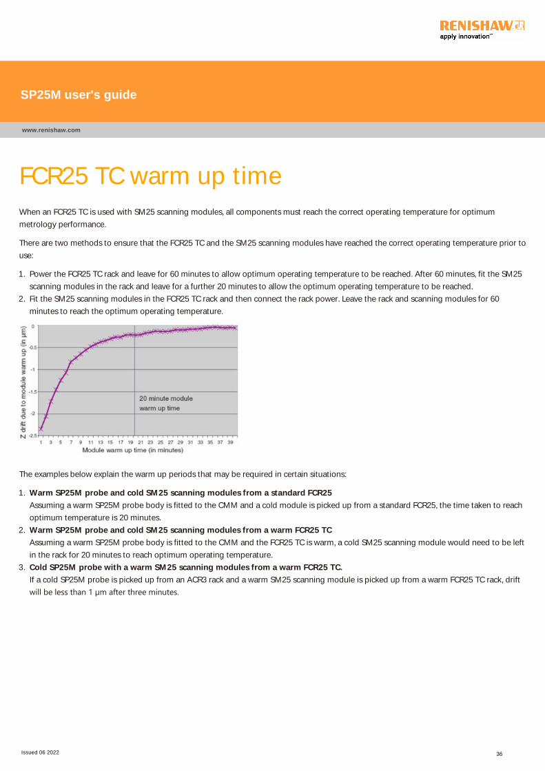
FCR25 TC warm up timeWhen an FCR25 TC is used with SM25 scanning modules, all components must reach the correct operating temperature for optimum
metrology performance.
There are two methods to ensure that the FCR25 TC and the SM25 scanning modules have reached the correct operating temperature prior to
use:
1. Power the FCR25 TC rack and leave for 60 minutes to allow optimum operating temperature to be reached. After 60 minutes, fit the SM25
scanning modules in the rack and leave for a further 20 minutes to allow the optimum operating temperature to be reached.
2. Fit the SM25 scanning modules in the FCR25 TC rack and then connect the rack power. Leave the rack and scanning modules for 60
minutes to reach the optimum operating temperature.
The examples below explain the warm up periods that may be required in certain situations:
1. Warm SP25M probe and cold SM25 scanning modules from a standard FCR25
Assuming a warm SP25M probe body is fitted to the CMM and a cold module is picked up from a standard FCR25, the time taken to reach
optimum temperature is 20 minutes.
2. Warm SP25M probe and cold SM25 scanning modules from a warm FCR25 TC
Assuming a warm SP25M probe body is fitted to the CMM and the FCR25 TC is warm, a cold SM25 scanning module would need to be left
in the rack for 20 minutes to reach optimum operating temperature.
3. Cold SP25M probe with a warm SM25 scanning modules from a warm FCR25 TC.
If a cold SP25M probe is picked up from an ACR3 rack and a warm SM25 scanning module is picked up from a warm FCR25 TC rack, drift
will be less than 1 µm after three minutes.
SP25M user's guide
www.renishaw.com
Issued 06 2022 36
Establishing a docking position for SM25 and
TM25-20 modulesThis section describes how to manually position the probe body and module to define the module docking position of the desired port. This
process requires very fine movements under CMM joystick control and care must be taken to avoid any collisions of the probe body, module
and port.
Eye protection should be work during this procedure and a good level of lighting is recommended to ensure no collisions occur. This
procedure is the same when using the FCR25 or the FCR25 TC rack.
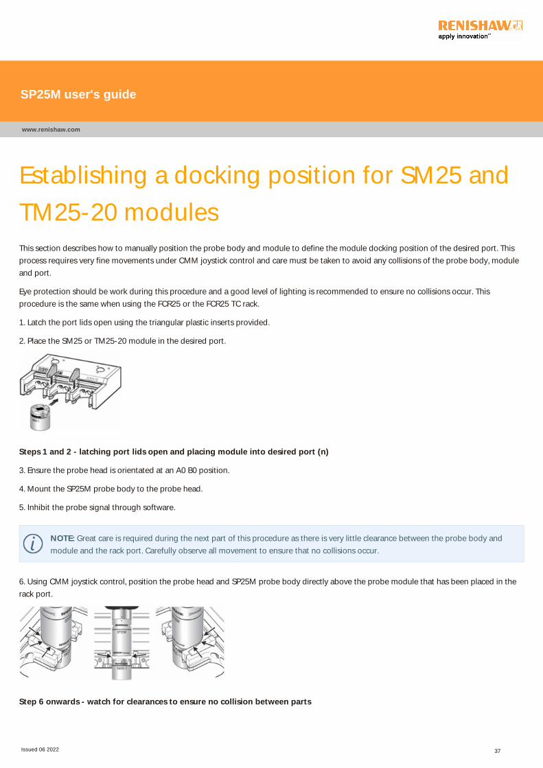
1. Latch the port lids open using the triangular plastic inserts provided.
2. Place the SM25 or TM25-20 module in the desired port.
Steps 1 and 2 - latching port lids open and placing module into desired port (n)
3. Ensure the probe head is orientated at an A0 B0 position.
4. Mount the SP25M probe body to the probe head.
5. Inhibit the probe signal through software.
NOTE: Great care is required during the next part of this procedure as there is very little clearance between the probe body and
module and the rack port. Carefully observe all movement to ensure that no collisions occur.
6. Using CMM joystick control, position the probe head and SP25M probe body directly above the probe module that has been placed in the
rack port.
Step 6 onwards - watch for clearances to ensure no collision between parts
SP25M user's guide
www.renishaw.com
Issued 06 2022 37

7. Slowly lower the probe body towards the probe module ensuring that the XY position of the probe body does not collide with the port.
Step 6 and 7 - moving to approximate XY position then refining to ensure good alignment between body and module
8. Continue to lower the probe body towards the probe module until the magnetic attraction between the kinematic joint makes the module
move towards the probe body. The module should move slightly towards the kinematic joint of the probe body without tilting (indicating
good XY alignment). If any tilting occurs when the module moves towards the probe body (indicating poor XY alignment) then the probe head
and body should be repositioned and the process should be repeated.
Step 8 - slowly move body downward in Z axis until module jumps straight upwards due to magnetic attraction
9. Slowly lower the probe body on to the module, stop any movement when the LED on the probe head illuminates. This indicates that an
electrical connection is made.
Step 9 - slowly move body downward in Z axis - STOP immediately when the probe head LED is lit
SP25M user's guide
www.renishaw.com
Issued 06 2022 38

Step 9 - slowly move body downward in Z axis - STOP immediately when the probe head LED is lit
10. Offset the CMM using a DCC movement of 0.75 mm in a –Z direction at a speed of 5 mm/s.
11. Create a datum coordinate system for the module docking position of the port at the following position: [dat_MOD_port(n)].
12. Slowly move the connected probe head, body and module assembly in a –Y direction clear of the port.
13. Remove the module and place back in the port.
14. Enable the probe signal through software (probe signal now armed).
15. Repeat steps 2 to 13 above for all other modules required.
SP25M user's guide
www.renishaw.com
Issued 06 2022 39

Establishing a docking position for SH25
stylus holdersThis section describes how to establish the docking position for the SH25 stylus holder. The docking position is defined by taking a series of
measurements using the stylus holder setting piece (SHSP). The SHSP is a dummy stylus holder with a short cylindrical stem of a qualified
length and diameter. This provides known constant values to accurately calculate the port docking position.
Eye protection should be work during this procedure and a good level of lighting is recommended to ensure no collisions occur.
It is necessary to turn off tip radius compensation when taking points using the SHSP because it is not calibrated. However, a suitable tip
qualification (calibration) should be applied as detailed below.
Before taking points using the SHSP, a probe tip qualification should be applied that has previously been defined for a suitable configuration
of SM25 scanning modules, SH25 stylus holder and stylus length. This configuration should be the shortest length possible, for example
SM25-1, SH25-1 and a 21 mm stylus. In instances where SM25-3, SH25-3 and a 21 mm stylus is the only configuration available, it is
recommended that the approach speed when taking points is restricted to 3 mm/s or less.
If using a threshold deflection method to measure points, the threshold deflection should be set to 0.050 mm.
CAUTION: Failure to follow the above recommendations could lead to severe damage of the SM25 scanning module when taking
points with the SHSP.
1. Latch the port lids open using the triangular plastic inserts provided
2. The desired port should be fitted with a PA25-SH port adapter insert. Orientate the PA25-SH as shown in the image below. Slide the port
adapter into the port ensuring that the side lugs of the adapter locate in the slots at either side of the port. Push the PA25-SH port adapter in
to the port until it clips securely in to the port. Check that the adapter is fitted correctly and that there is no misalignment.
Steps 1 and 2 - latching port lids open and placing PA25-SH into desired port(n)
SP25M user's guide
www.renishaw.com
Issued 06 2022 40
3. Ensure the probe head is orientated at an A0 B0 position.
4. Inhibit the probe signal through software.
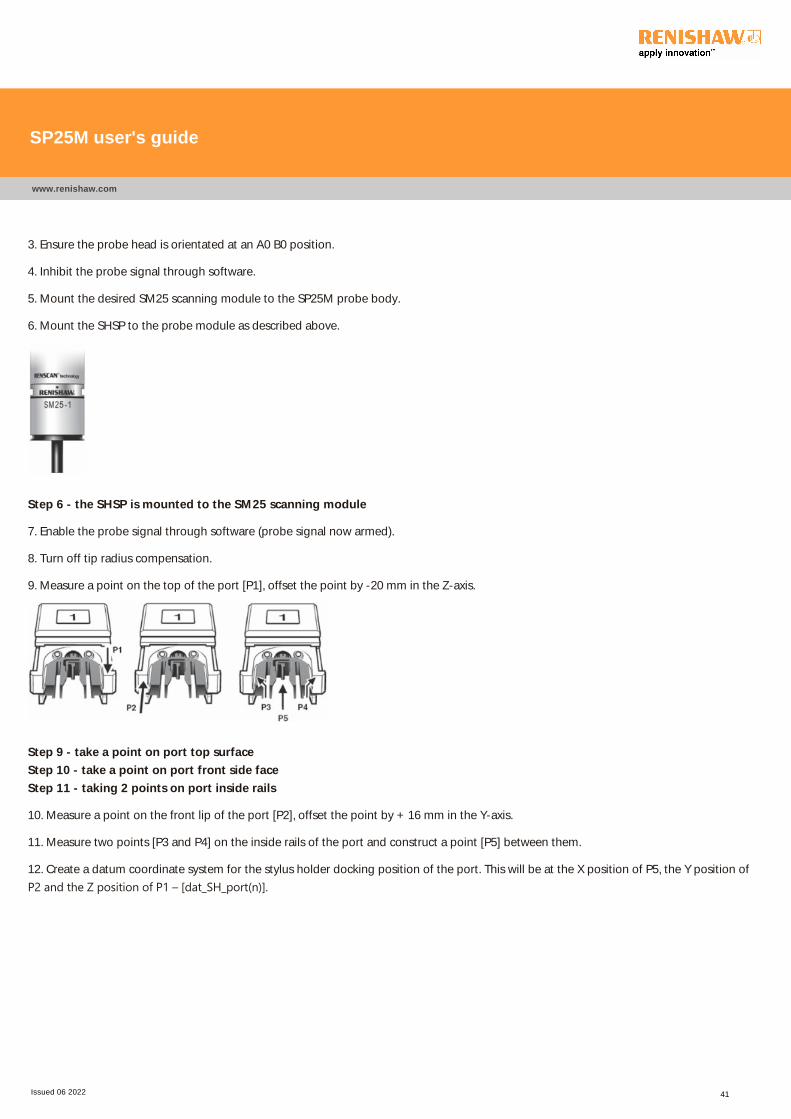
5. Mount the desired SM25 scanning module to the SP25M probe body.
6. Mount the SHSP to the probe module as described above.
Step 6 - the SHSP is mounted to the SM25 scanning module
7. Enable the probe signal through software (probe signal now armed).
8. Turn off tip radius compensation.
9. Measure a point on the top of the port [P1], offset the point by -20 mm in the Z-axis.
Step 9 - take a point on port top surface
Step 10 - take a point on port front side face
Step 11 - taking 2 points on port inside rails
10. Measure a point on the front lip of the port [P2], offset the point by + 16 mm in the Y-axis.
11. Measure two points [P3 and P4] on the inside rails of the port and construct a point [P5] between them.
12. Create a datum coordinate system for the stylus holder docking position of the port. This will be at the X position of P5, the Y position of
P2 and the Z position of P1 – [dat_SH_port﴾n﴿].
SP25M user's guide
www.renishaw.com
Issued 06 2022 41

Establishing a docking position for TP20
modulesThis section describes how to establish the docking position for the combination of a TM25-20, a TP20 module and a stylus.
1. Latch the port lids open using the triangular plastic inserts provided
2. The desired port should be fitted with a PA25-20 port adapter insert. Orientate the PA25-20 as shown in the image below. Slide the port
adapter into the port ensuring that the side lugs of the adapter locate in the slots at either side of the port. Push the PA25-20 port adapter in
to the port and use a 2.5 mm hex key to tighten. Check that the adapter is fitted correctly and that there is no misalignment.
Steps 1 and 2 - latching port lids open and placing PA25-20 into desired port(n)
3. Ensure the probe head is orientated at an A0 B0 position.
4. Inhibit the probe signal through software.
5. Mount the desired combination of TM25-20, TP20 module and stylus to the probe body.
6. Enable the probe signal through software (probe signal now armed).
7. Qualify (calibrate) the stylus tip on the reference sphere.
SP25M user's guide
www.renishaw.com
Issued 06 2022 42

8. Measure four points on the top surface of the PA25-20 to create a plane [PLN1]. Translate this plane to the Z-axis and offset this plane by [Z
- length of stylus - 21.25 mm] and set the Z-axis origin to this plane.
Step 8 - take four points on top of PA25-20
Step 9 - take two points on front side faces of PA25-20
Step 10 - take two points on port inside rails of PA25-20
9. Measure two points [P1 and P2] on the front faces of the PA25-20. Construct a line [L1] between these points, rotate this line to the X-axis,
offset the line by [Y + 8.75 mm] and origin the Y-axis position of the line.
10. Measure two points [P3 and P4] on the inside rails of each side of the PA25-20. Construct a point [P5] between them.
11. Create a datum coordinate system [dat_TP20_port(n)] for the TP20 module docking position of the port. This will be at the position of [P5],
the Y position of [L1] and the Z position of [PLN1].
12. Repeat steps 1 to 13 above for all other module combinations required.
SP25M user's guide
www.renishaw.com
Issued 06 2022 43

Pick up routines
Pick up routine - SM25 scanning modules and TM25-20 adaptor module
Move description X -axis (mm)* Y-axis (mm)* Z-axis (mm)*
Clearance position [dat_MOD_port(n)] [dat_MOD_port(n)] - 30 mm [dat_MOD_port(n)] + 8 mm
Enter port no change [dat_MOD_port(n)] no change
Towards module no change no change [dat_MOD_port(n)] + 3 mm
Attach module(s) no change no change [dat_MOD_port(n)]
Exit port no change [dat_MOD_port(n)] - 30 mm no change
NOTE: To ensure optimum metrology performance it is recommended that following any module change the probe head is
unlocked and then relocked.
Pick up routine - SH25 stylus holders
Move description X-axis (mm)* Y-axis (mm)* Z-axis (mm)*
Clearance position [dat_SH_port(n)] [dat_SH_port(n)] - 30 mm [dat_SH_port(n)] + 8 mm
Enter port no change [dat_SH_port(n)] no change
Towards stylus holder(s) no change [dat_SH_port(n)] [dat_SH_port(n)] + 3 mm
Attach stylus holder(s) no change [dat_SH_port(n)] [dat_SH_port(n)]
Exit port no change [dat_MOD_port(n)] - 30 mm no change
Pick up routine - TP20 module
Move description X-axis (mm)* Y-axis (mm)* Z-axis (mm)*
Clearance position [dat_TP20_port(n)] [dat_TP20_port(n)] - 30 mm ** [dat_TP20_port(n)] + 6 mm
Enter port no change [dat_TP20_port(n)] no change
Towards TP20 module no change [dat_TP20_port(n)] **[dat_MOD_port(n)] + 3 mm
Attach TP20 module(s) no change [dat_TP20_port(n)] **[dat_MOD_port(n)]
Exit port no change [dat_TP20_port(n)] - 30 mm no change
* Coordinates assume aligned with Y-axis as per FCR25 mounting instructions
** Calculate nominal 'Z' docking position according to the stylus length used (see calculation formula in section Establishing the docking
position for SH25 stylus holders).
SP25M user's guide
www.renishaw.com
Issued 06 2022 44
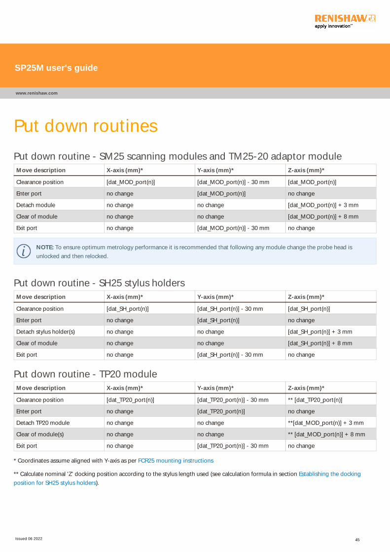
Put down routines
Put down routine - SM25 scanning modules and TM25-20 adaptor module
Move description X-axis (mm)* Y-axis (mm)* Z-axis (mm)*
Clearance position [dat_MOD_port(n)] [dat_MOD_port(n)] - 30 mm [dat_MOD_port(n)]
Enter port no change [dat_MOD_port(n)] no change
Detach module no change no change [dat_MOD_port(n)] + 3 mm
Clear of module no change no change [dat_MOD_port(n)] + 8 mm
Exit port no change [dat_MOD_port(n)] - 30 mm no change
NOTE: To ensure optimum metrology performance it is recommended that following any module change the probe head is
unlocked and then relocked.
Put down routine - SH25 stylus holders
Move description X-axis (mm)* Y-axis (mm)* Z-axis (mm)*
Clearance position [dat_SH_port(n)] [dat_SH_port(n)] - 30 mm [dat_SH_port(n)]
Enter port no change [dat_SH_port(n)] no change
Detach stylus holder(s) no change no change [dat_SH_port(n)] + 3 mm
Clear of module no change no change [dat_SH_port(n)] + 8 mm
Exit port no change [dat_SH_port(n)] - 30 mm no change
Put down routine - TP20 module
Move description X-axis (mm)* Y-axis (mm)* Z-axis (mm)*
Clearance position [dat_TP20_port(n)] [dat_TP20_port(n)] - 30 mm ** [dat_TP20_port(n)]
Enter port no change [dat_TP20_port(n)] no change
Detach TP20 module no change no change **[dat_MOD_port(n)] + 3 mm
Clear of module(s) no change no change ** [dat_MOD_port(n)] + 8 mm
Exit port no change [dat_TP20_port(n)] - 30 mm no change
* Coordinates assume aligned with Y-axis as per FCR25 mounting instructions
** Calculate nominal 'Z' docking position according to the stylus length used (see calculation formula in section Establishing the docking
position for SH25 stylus holders).
SP25M user's guide
www.renishaw.com
Issued 06 2022 45
Speed of motion during a change routine
NOTE: When obtaining or returning an SM25 scanning module, a TM25-20 adaptor module or an SH25 stylus holder, the motion
speed over the 3 mm distance where the kinematic joint is made and broken should be restricted to a maximum of 5 mm/s.
All other moves may be made at up to a maximum of 30 mm/s.
SP25M user's guide
www.renishaw.com
Issued 06 2022 46

SP25M straight stylus carrying capability and
performance guidelinesSP25M gives exceptional scanning performance over the entire range of stylus lengths. This is achieved by using a dedicated set of scanning
modules, SM25-1, SM25-2, SM25-3, SM25-4 and SM25-5. Each module is optimised to carry a specific stylus range whilst maintaining a low
contact force band and maximised sensor performance.
This design approach has enabled SP25M to successfully counter the loss of scanning system performance traditionally encountered as stylus
length increases. It is therefore important to adhere to the stylus carrying recommendations given.
Use of the Renishaw range of M3 styli and accessories is recommended. This range includes several longer styli with carbon fibre stems for
exceptional performance as well as kits specifically suited to each of the scanning modules.
SP25M user's guide
www.renishaw.com
Issued 06 2022 47
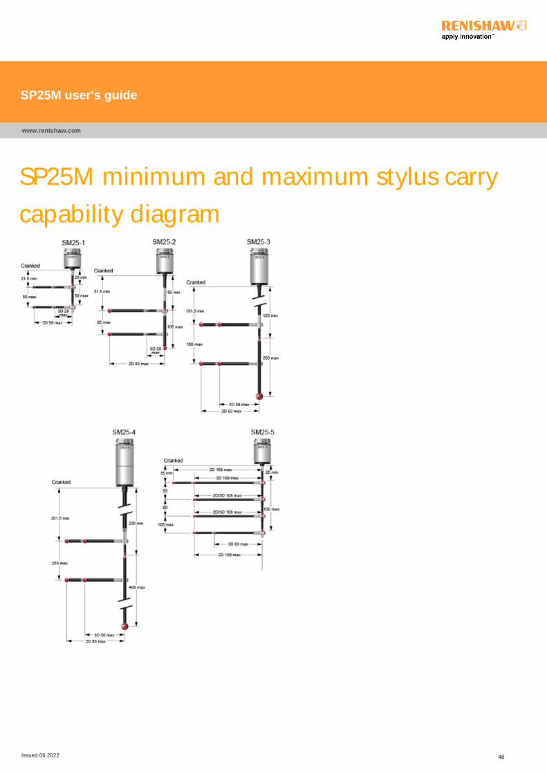
SP25M minimum and maximum stylus carry
capability diagram
SP25M user's guide
www.renishaw.com
Issued 06 2022 48
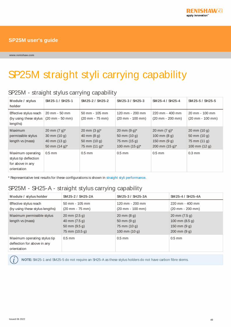
SP25M straight styli carrying capability
SP25M - straight stylus carrying capability
Module / stylus
holder
SM25-1 / SH25-1 SM25-2 / SH25-2 SM25-3 / SH25-3 SM25-4 / SH25-4 SM25-5 / SH25-5
Effective stylus reach
(by using these stylus
lengths)
20 mm - 50 mm
(20 mm - 50 mm)
50 mm - 105 mm
(20 mm - 75 mm)
120 mm - 200 mm
(20 mm - 100 mm)
220 mm - 400 mm
(20 mm - 200 mm)
20 mm - 100 mm
(20 mm - 100 mm)
Maximum
permissible stylus
length vs (mass)
20 mm (7 g)*
30 mm (10 g)
40 mm (13 g)
50 mm (14 g)*
20 mm (3 g)*
40 mm (8 g)
50 mm (10 g)
75 mm (11 g)*
20 mm (9 g)*
50 mm (10 g)
75 mm (15 g)
100 mm (15 g)*
20 mm (7 g)*
100 mm (8 g)
150 mm (9 g)
200 mm (15 g)*
20 mm (10 g)
50 mm (10 g)
75 mm (11 g)
100 mm (12 g)
Maximum operating
stylus tip deflection
for above in any
orientation
0.5 mm 0.5 mm 0.5 mm 0.5 mm 0.3 mm
* Representative test results for these configurations is shown in straight styli performance.
SP25M - SH25-A - straight stylus carrying capability
Module / stylus holder SM25-2 / SH25-2A SM25-3 / SH25-3A SM25-4 / SH25-4A
Effective stylus reach
(by using these stylus lengths)
50 mm - 105 mm
(20 mm - 75 mm)
120 mm - 200 mm
(20 mm - 100 mm)
220 mm - 400 mm
(20 mm - 200 mm)
Maximum permissible stylus
length vs (mass)
20 mm (2.5 g)
40 mm (7.5 g)
50 mm (9.5 g)
75 mm (10.5 g)
20 mm (8 g)
50 mm (9 g)
75 mm (10 g)
100 mm (10 g)
20 mm (7.5 g)
100 mm (8.5 g)
150 mm (9 g)
200 mm (9 g)
Maximum operating stylus tip
deflection for above in any
orientation
0.5 mm 0.5 mm 0.5 mm
NOTE: SM25-1 and SM25-5 do not require an SH25-A as these stylus holders do not have carbon fibre stems.
SP25M user's guide
www.renishaw.com
Issued 06 2022 49

SP25M cranked stylus carrying capability for
typical stylus combinationsAs well as straight styli, SP25M has the ability to carry cranked styli when using the standard range of SM25 scanning modules. For optimum
metrology and when larger offsets are required, it is recommended that the SH25-3A, SH25-4A and SH25-5A modules are used.
For SH25-1, SH25-2 and SH25-2A it is mandatory that a 20 mm or longer stylus extension is used between the SH25 stylus holder and the
crank centre to give the correct crank down distance from the stylus holder to the crank centre.
When using SH25-3, SH25-4, SH25-3A and SH25-4A, the crank centre may either be mounted directly to the stylus holder or to a stylus
extension between the stylus holder and the crank centre.
For SM25-1, SM25-2, SM25-3 and SM25-4, a straight downward pointing stylus can be added to the crank centre to continue the projection
down from the stylus holder. This is providing that the maximum overall stylus length and mass does not exceed the recommended limits for
the particular module being used.
For 3D scanning with SM25-1 and SM25-2, the maximum crank out distance is 28 mm and is measured from the cranked (non straight)
stylus tip to the centre of the crank centre. For 3D scanning with SM25-3 and SM25-4, the maximum crank out distance is 58 mm.
Multiple cranked styli may be used providing the overall mass of the crank centre and stylus does not exceed the recommended limits for the
particular module being used.
Please refer to the Renishaw stylus catalogue for the full range of cranked and star stylus configurations available. It is recommended that a
one piece star stylus is used whenever possible to minimise the mass of the assembly. Greater flexibility is offered however by configuring a
crank centre with one or more cranked styli.
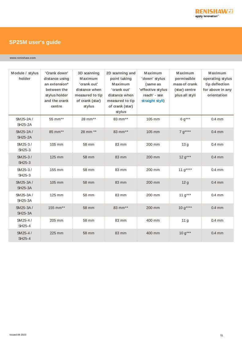
Module / stylus
holder
'Crank down'
distance using
an extension*
between the
stylus holder
and the crank
centre
3D scanning
Maximum
'crank out'
distance when
measured to tip
of crank (star)
stylus
2D scanning and
point taking
Maximum
'crank out'
distance when
measured to tip
of crank (star)
stylus
Maximum
'down' stylus
(same as
'effective stylus
reach' - see
straight styli)
Maximum
permissible
mass of crank
(star) centre
plus all styli
Maximum
operating stylus
tip deflection
for above in any
orientation
SM25-1 /
SH25-1
25 mm** 28 mm** 58 mm** 50 mm 9 g*** 0.4 mm
SM25-1 /
SH25-1
55 mm** 28 mm** 58 mm** 50 mm 9 g**** 0.4 mm
SM25-2 /
SH25-2
55 mm 28 mm 83 mm 105 mm 6 g*** 0.4 mm
SM25-2 /
SH25-2
85 mm 28 mm 83 mm 105 mm 7 g**** 0.4 mm
SP25M user's guide
www.renishaw.com
Issued 06 2022 50
Module / stylus
holder
'Crank down'
distance using
an extension*
between the
stylus holder
and the crank
centre
3D scanning
Maximum
'crank out'
distance when
measured to tip
of crank (star)
stylus
2D scanning and
point taking
Maximum
'crank out'
distance when
measured to tip
of crank (star)
stylus
Maximum
'down' stylus
(same as
'effective stylus
reach' - see
straight styli)
Maximum
permissible
mass of crank
(star) centre
plus all styli
Maximum
operating stylus
tip deflection
for above in any
orientation
SM25-2A /
SH25-2A
55 mm** 28 mm** 83 mm** 105 mm 6 g*** 0.4 mm
SM25-2A /
SH25-2A
85 mm** 28 mm ** 83 mm** 105 mm 7 g**** 0.4 mm
SM25-3 /
SH25-3
105 mm 58 mm 83 mm 200 mm 13 g 0.4 mm
SM25-3 /
SH25-3
125 mm 58 mm 83 mm 200 mm 12 g*** 0.4 mm
SM25-3 /
SH25-3
155 mm 58 mm 83 mm 200 mm 11 g**** 0.4 mm
SM25-3A /
SH25-3A
105 mm 58 mm 83 mm 200 mm 12 g 0.4 mm
SM25-3A /
SH25-3A
125 mm 58 mm 83 mm 200 mm 11 g*** 0.4 mm
SM25-3A /
SH25-3A
155 mm** 58 mm 83 mm** 200 mm 10 g**** 0.4 mm
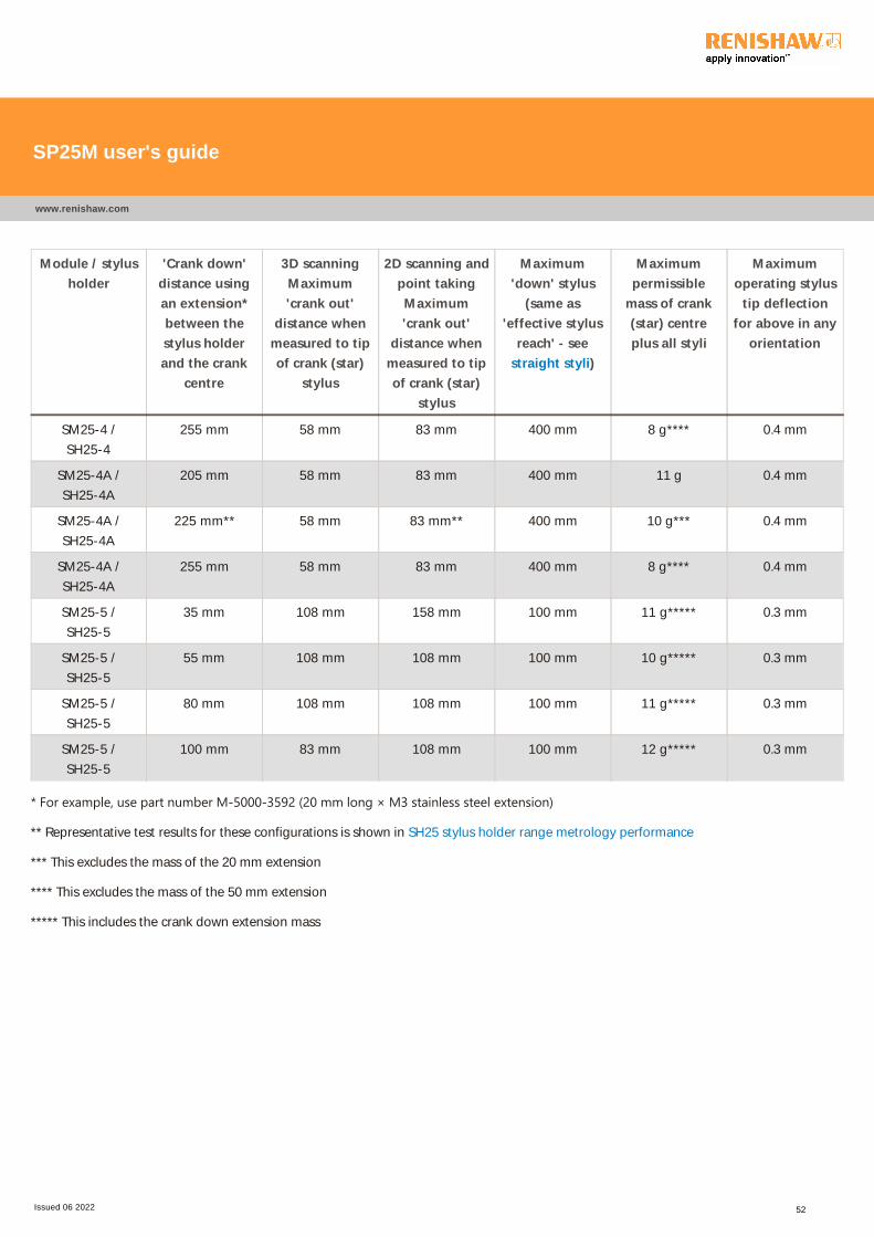
SM25-4 /
SH25-4
205 mm 58 mm 83 mm 400 mm 11 g 0.4 mm
SM25-4 /
SH25-4
225 mm 58 mm 83 mm 400 mm 10 g*** 0.4 mm
SP25M user's guide
www.renishaw.com
Issued 06 2022 51
Module / stylus
holder
'Crank down'
distance using
an extension*
between the
stylus holder
and the crank
centre
3D scanning
Maximum
'crank out'
distance when
measured to tip
of crank (star)
stylus
2D scanning and
point taking
Maximum
'crank out'
distance when
measured to tip
of crank (star)
stylus
Maximum
'down' stylus
(same as
'effective stylus
reach' - see
straight styli)
Maximum
permissible
mass of crank
(star) centre
plus all styli
Maximum
operating stylus
tip deflection
for above in any
orientation
SM25-4 /
SH25-4
255 mm 58 mm 83 mm 400 mm 8 g**** 0.4 mm
SM25-4A /
SH25-4A
205 mm 58 mm 83 mm 400 mm 11 g 0.4 mm
SM25-4A /
SH25-4A
225 mm** 58 mm 83 mm** 400 mm 10 g*** 0.4 mm
SM25-4A /
SH25-4A
255 mm 58 mm 83 mm 400 mm 8 g**** 0.4 mm
SM25-5 /
SH25-5
35 mm 108 mm 158 mm 100 mm 11 g***** 0.3 mm
SM25-5 /
SH25-5
55 mm 108 mm 108 mm 100 mm 10 g***** 0.3 mm
SM25-5 /
SH25-5
80 mm 108 mm 108 mm 100 mm 11 g***** 0.3 mm
SM25-5 /
SH25-5
100 mm 83 mm 108 mm 100 mm 12 g***** 0.3 mm
* For example, use part number M‐5000‐3592 ﴾20 mm long × M3 stainless steel extension﴿
** Representative test results for these configurations is shown in SH25 stylus holder range metrology performance
*** This excludes the mass of the 20 mm extension
**** This excludes the mass of the 50 mm extension
***** This includes the crank down extension mass
SP25M user's guide
www.renishaw.com
Issued 06 2022 52
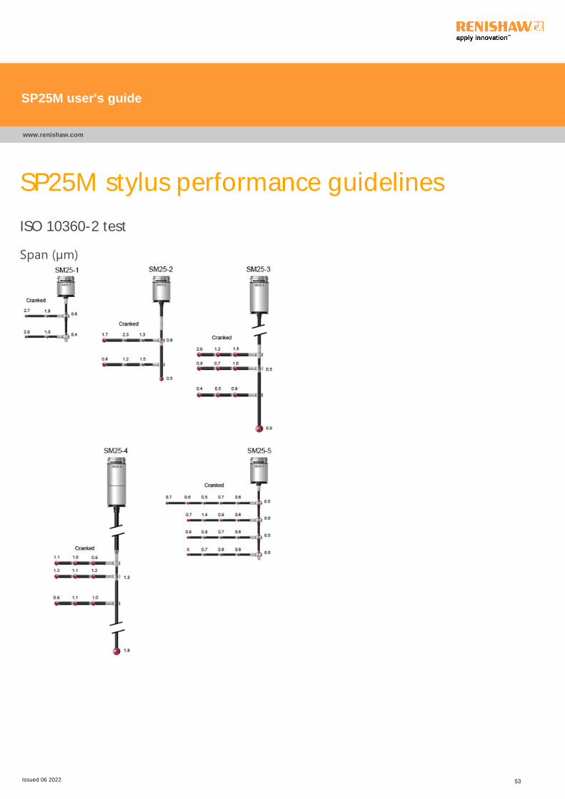
SP25M stylus performance guidelines
ISO 10360-2 test
Span ﴾µm﴿
SP25M user's guide
www.renishaw.com
Issued 06 2022 53
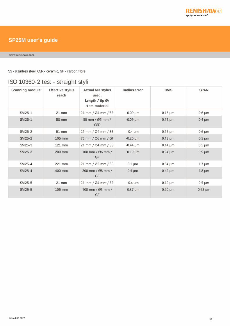
SS - stainless steel, CER - ceramic, GF - carbon fibre
ISO 10360-2 test - straight styli
Scanning module Effective stylus
reach
Actual M3 stylus
used:
Length / tip Ø/stem material
Radius error RMS SPAN
SM25-1 21 mm 21 mm / Ø4 mm / SS ‐0.09 µm 0.15 µm 0.6 µm
SM25-1 50 mm 50 mm / Ø5 mm /CER
‐0.09 µm 0.11 µm 0.4 µm
SM25-2 51 mm 21 mm / Ø4 mm / SS ‐0.4 µm 0.15 µm 0.6 µm
SM25-2 105 mm 75 mm / Ø6 mm / GF ‐0.26 µm 0.13 µm 0.5 µm
SM25-3 121 mm 21 mm / Ø4 mm / SS ‐0.44 µm 0.14 µm 0.5 µm
SM25-3 200 mm 100 mm / Ø6 mm /GF
‐0.19 µm 0.24 µm 0.9 µm
SM25-4 221 mm 21 mm / Ø5 mm / SS 0.1 µm 0.34 µm 1.3 µm
SM25-4 400 mm 200 mm / Ø8 mm /GF
0.4 µm 0.42 µm 1.8 µm
SM25-5 21 mm 21 mm / Ø4 mm / SS ‐0.4 µm 0.12 µm 0.5 µm
SM25-5 105 mm 100 mm / Ø5 mm /CF
‐0.37 µm 0.20 µm 0.68 µm
SP25M user's guide
www.renishaw.com
Issued 06 2022 54
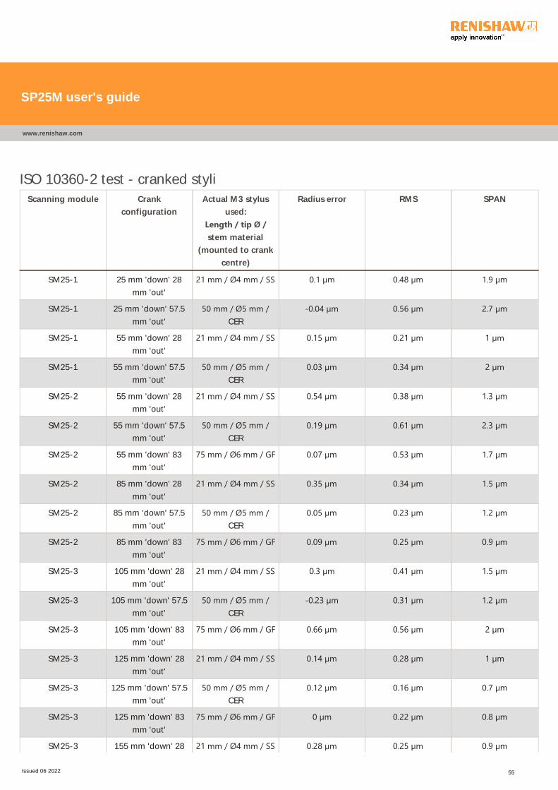
ISO 10360-2 test - cranked styli
Scanning module Crank
configuration
Actual M3 stylus
used:
Length / tip Ø /stem material
(mounted to crank
centre)
Radius error RMS SPAN
SM25-1 25 mm 'down' 28
mm 'out'
21 mm / Ø4 mm / SS 0.1 µm 0.48 µm 1.9 µm
SM25-1 25 mm 'down' 57.5
mm 'out'
50 mm / Ø5 mm /CER
‐0.04 µm 0.56 µm 2.7 µm
SM25-1 55 mm 'down' 28
mm 'out'
21 mm / Ø4 mm / SS 0.15 µm 0.21 µm 1 µm
SM25-1 55 mm 'down' 57.5
mm 'out'
50 mm / Ø5 mm /CER
0.03 µm 0.34 µm 2 µm
SM25-2 55 mm 'down' 28
mm 'out'
21 mm / Ø4 mm / SS 0.54 µm 0.38 µm 1.3 µm
SM25-2 55 mm 'down' 57.5
mm 'out'
50 mm / Ø5 mm /CER
0.19 µm 0.61 µm 2.3 µm
SM25-2 55 mm 'down' 83
mm 'out'
75 mm / Ø6 mm / GF 0.07 µm 0.53 µm 1.7 µm
SM25-2 85 mm 'down' 28
mm 'out'
21 mm / Ø4 mm / SS 0.35 µm 0.34 µm 1.5 µm
SM25-2 85 mm 'down' 57.5
mm 'out'
50 mm / Ø5 mm /CER
0.05 µm 0.23 µm 1.2 µm
SM25-2 85 mm 'down' 83
mm 'out'
75 mm / Ø6 mm / GF 0.09 µm 0.25 µm 0.9 µm
SM25-3 105 mm 'down' 28
mm 'out'
21 mm / Ø4 mm / SS 0.3 µm 0.41 µm 1.5 µm
SM25-3 105 mm 'down' 57.5
mm 'out'
50 mm / Ø5 mm /CER
‐0.23 µm 0.31 µm 1.2 µm
SM25-3 105 mm 'down' 83
mm 'out'
75 mm / Ø6 mm / GF 0.66 µm 0.56 µm 2 µm
SM25-3 125 mm 'down' 28
mm 'out'
21 mm / Ø4 mm / SS 0.14 µm 0.28 µm 1 µm
SM25-3 125 mm 'down' 57.5
mm 'out'
50 mm / Ø5 mm /CER
0.12 µm 0.16 µm 0.7 µm
SM25-3 125 mm 'down' 83
mm 'out'
75 mm / Ø6 mm / GF 0 µm 0.22 µm 0.8 µm
SM25-3 155 mm 'down' 28 21 mm / Ø4 mm / SS 0.28 µm 0.25 µm 0.9 µm
SP25M user's guide
www.renishaw.com
Issued 06 2022 55

mm 'out'
SM25-3 155 mm 'down' 57.5
mm 'out'
50 mm / Ø5 mm /CER
0.06 µm 0.15 µm 0.5 µm
SM25-3 155 mm 'down' 83
mm 'out'
75 mm / Ø6 mm / GF 0.04 µm 0.1 µm 0.4 µm
SM25-4 205 mm 'down' 28
mm 'out'
21 mm / Ø4 mm / SS 0.01 µm 0.24 µm 0.9 µm
SM25-4 205 mm 'down' 57.5
mm 'out'
50 mm / Ø5 mm /CER
0.19 µm 0.21 µm 1 µm
SM25-4 205 mm 'down' 83
mm 'out'
75 mm / Ø6 mm / GF ‐0.11 µm 0.28 µm 1.1 µm
SM25-4 225 mm 'down' 28
mm 'out'
21 mm / Ø4 mm / SS 0.01 µm 0.21 µm 1.2 µm
SM25-4 225 mm 'down' 57.5
mm 'out'
50 mm / Ø5 mm /CER
0.18 µm 0.29 µm 1.1 µm
SM25-4 225 mm 'down' 83
mm 'out'
75 mm / Ø6 mm / GF 0.05 µm 0.3 µm 1.3 µm
SM25-4 255 mm 'down' 28
mm 'out'
21 mm / Ø4 mm / SS ‐0.07 µm 0.25 µm 1 µm
SM25-4 255 mm 'down' 57.5
mm 'out'
50 mm / Ø5 mm /CER
0.1 µm 0.34 µm 1.1 µm
SM25-4 255 mm 'down' 83
mm 'out'
75 mm / Ø6 mm / GF ‐0.1 µm 0.21 µm 0.9 µm
SP25M user's guide
www.renishaw.com
Issued 06 2022 56

Test setup criteria
Test site Renishaw UK
Styli used Renishaw's M3 stylus range
CMM specification U3 = 0.48 µm + L / 1000
CMM controller Renishaw's UCC2
Probe calibration Renishaw's third order polynomial calibration method
Data filter used Harmonic simple cut off order = 60 UPR (undulations per revolution)
Artefacts used Ø25 mm ﴾nom﴿ calibration sphere ﴾for the ISO 10360 Part 2 / Part 4tests)
Ø50 mm ﴾nom﴿ ring gauge ﴾for the ring gauge scan tests﴿
Scanning speed 5 mm/s (for the ISO 10360 Part 4 and ring gauge scan tests)
Touch speed 5 mm/s (for the ISO 10360 Part 2 tests)
Back off speed 1 mm/s (for the ISO 10360 Part 2 tests)
Bi-directional scans The effect of probe misalignment and contact friction will result in
radius changes with scanning direction if a suitable calibration
procedure is not used.
Mechanical hysteresis within a probe mechanism is best
demonstrated by a bi-directional scan.
Therefore, Renishaw have decided to take the high integrity
approach of quoting ring gauge metrology using bi-directional scan
data to demonstrate the performance of the Renishaw probe and
calibration method.
SP25M user's guide
www.renishaw.com
Issued 06 2022 57
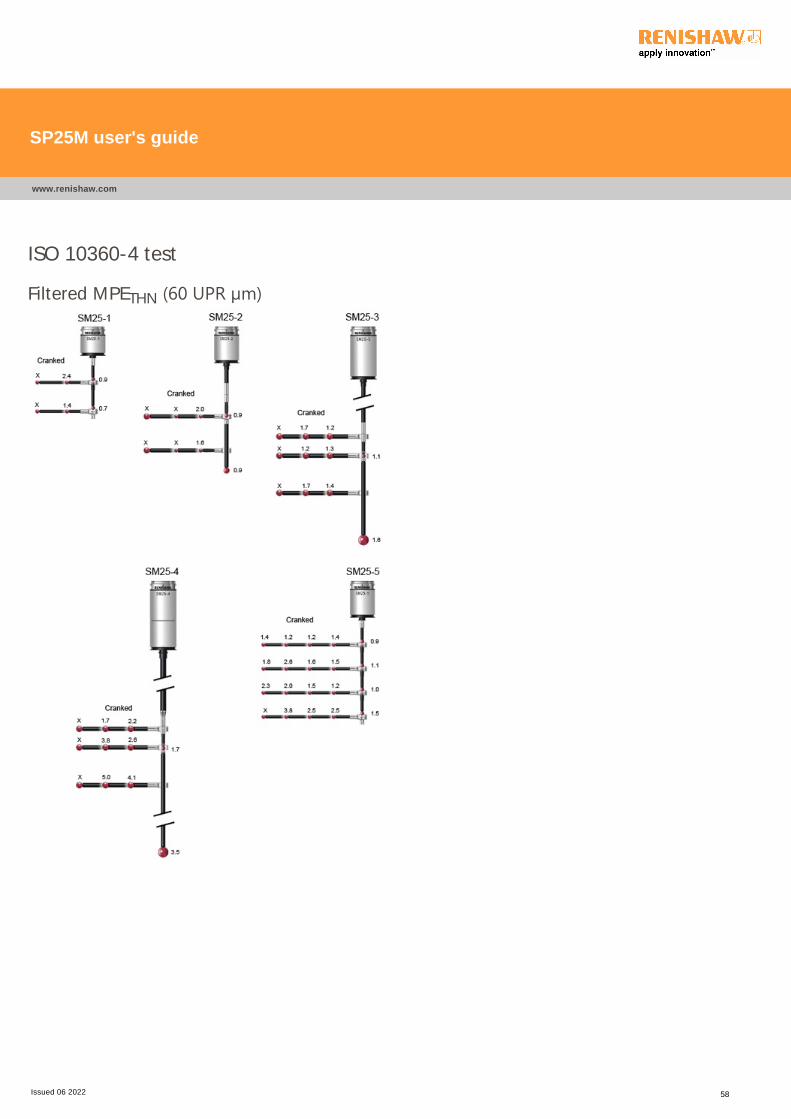
ISO 10360-4 test
Filtered MPETHN ﴾60 UPR µm﴿
SP25M user's guide
www.renishaw.com
Issued 06 2022 58
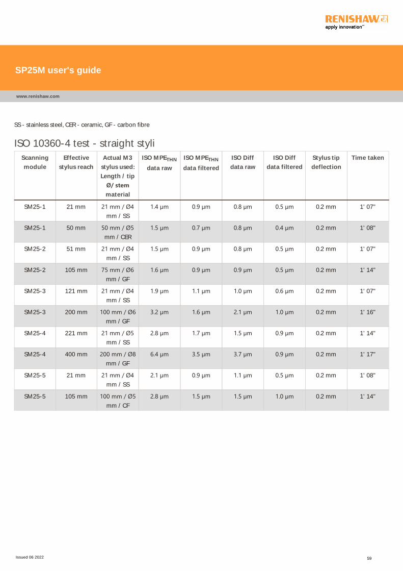
SS - stainless steel, CER - ceramic, GF - carbon fibre
ISO 10360-4 test - straight styli
Scanning
module
Effective
stylus reach
Actual M3
stylus used:
Length / tip
Ø/ stemmaterial
ISO MPETHN
data raw
ISO MPETHN
data filtered
ISO Diff
data raw
ISO Diff
data filtered
Stylus tip
deflection
Time taken
SM25-1 21 mm 21 mm / Ø4mm / SS
1.4 µm 0.9 µm 0.8 µm 0.5 µm 0.2 mm 1' 07"
SM25-1 50 mm 50 mm / Ø5mm / CER
1.5 µm 0.7 µm 0.8 µm 0.4 µm 0.2 mm 1' 08"
SM25-2 51 mm 21 mm / Ø4mm / SS
1.5 µm 0.9 µm 0.8 µm 0.5 µm 0.2 mm 1' 07"
SM25-2 105 mm 75 mm / Ø6mm / GF
1.6 µm 0.9 µm 0.9 µm 0.5 µm 0.2 mm 1' 14"
SM25-3 121 mm 21 mm / Ø4mm / SS
1.9 µm 1.1 µm 1.0 µm 0.6 µm 0.2 mm 1' 07"
SM25-3 200 mm 100 mm / Ø6mm / GF
3.2 µm 1.6 µm 2.1 µm 1.0 µm 0.2 mm 1' 16"
SM25-4 221 mm 21 mm / Ø5mm / SS
2.8 µm 1.7 µm 1.5 µm 0.9 µm 0.2 mm 1' 14"
SM25-4 400 mm 200 mm / Ø8mm / GF
6.4 µm 3.5 µm 3.7 µm 0.9 µm 0.2 mm 1' 17"
SM25-5 21 mm 21 mm / Ø4mm / SS
2.1 µm 0.9 µm 1.1 µm 0.5 µm 0.2 mm 1' 08"
SM25-5 105 mm 100 mm / Ø5mm / CF
2.8 µm 1.5 µm 1.5 µm 1.0 µm 0.2 mm 1' 14"
SP25M user's guide
www.renishaw.com
Issued 06 2022 59
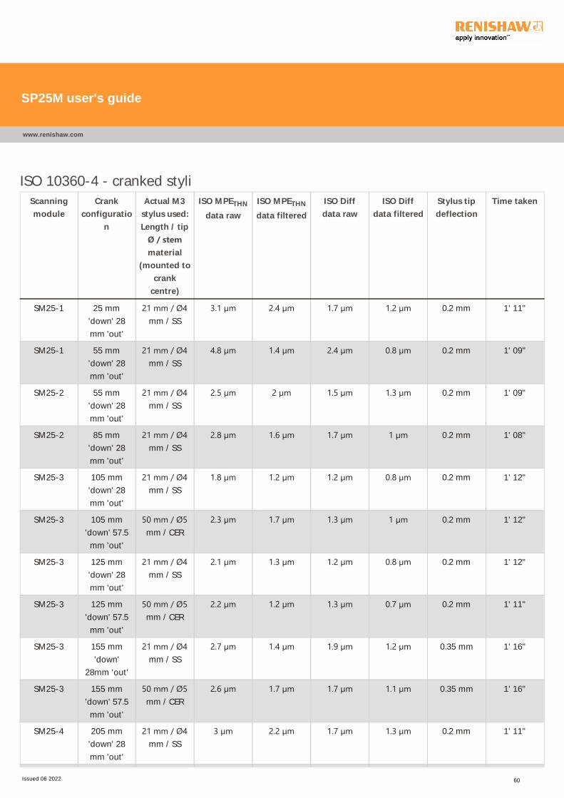
ISO 10360-4 - cranked styli
Scanning
module
Crank
configuratio
n
Actual M3
stylus used:
Length / tip
Ø / stemmaterial
(mounted to
crank
centre)
ISO MPETHN
data raw
ISO MPETHN
data filtered
ISO Diff
data raw
ISO Diff
data filtered
Stylus tip
deflection
Time taken
SM25-1 25 mm
'down' 28
mm 'out'
21 mm / Ø4mm / SS
3.1 µm 2.4 µm 1.7 µm 1.2 µm 0.2 mm 1' 11"
SM25-1 55 mm
'down' 28
mm 'out'
21 mm / Ø4mm / SS
4.8 µm 1.4 µm 2.4 µm 0.8 µm 0.2 mm 1' 09"
SM25-2 55 mm
'down' 28
mm 'out'
21 mm / Ø4mm / SS
2.5 µm 2 µm 1.5 µm 1.3 µm 0.2 mm 1' 09"
SM25-2 85 mm
'down' 28
mm 'out'
21 mm / Ø4mm / SS
2.8 µm 1.6 µm 1.7 µm 1 µm 0.2 mm 1' 08"
SM25-3 105 mm
'down' 28
mm 'out'
21 mm / Ø4mm / SS
1.8 µm 1.2 µm 1.2 µm 0.8 µm 0.2 mm 1' 12"
SM25-3 105 mm
'down' 57.5
mm 'out'
50 mm / Ø5mm / CER
2.3 µm 1.7 µm 1.3 µm 1 µm 0.2 mm 1' 12"
SM25-3 125 mm
'down' 28
mm 'out'
21 mm / Ø4mm / SS
2.1 µm 1.3 µm 1.2 µm 0.8 µm 0.2 mm 1' 12"
SM25-3 125 mm
'down' 57.5
mm 'out'
50 mm / Ø5mm / CER
2.2 µm 1.2 µm 1.3 µm 0.7 µm 0.2 mm 1' 11"
SM25-3 155 mm
'down'
28mm 'out'
21 mm / Ø4mm / SS
2.7 µm 1.4 µm 1.9 µm 1.2 µm 0.35 mm 1' 16"
SM25-3 155 mm
'down' 57.5
mm 'out'
50 mm / Ø5mm / CER
2.6 µm 1.7 µm 1.7 µm 1.1 µm 0.35 mm 1' 16"
SM25-4 205 mm
'down' 28
mm 'out'
21 mm / Ø4mm / SS
3 µm 2.2 µm 1.7 µm 1.3 µm 0.2 mm 1' 11"
SP25M user's guide
www.renishaw.com
Issued 06 2022 60
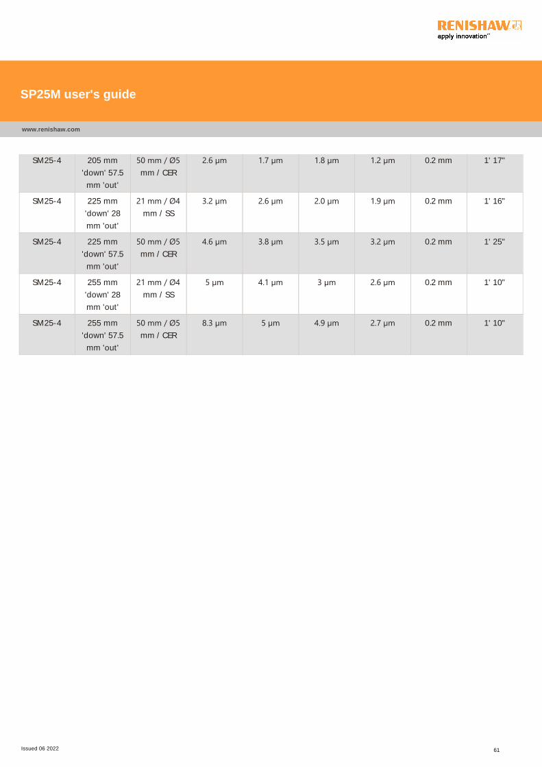
SM25-4 205 mm
'down' 57.5
mm 'out'
50 mm / Ø5mm / CER
2.6 µm 1.7 µm 1.8 µm 1.2 µm 0.2 mm 1' 17"
SM25-4 225 mm
'down' 28
mm 'out'
21 mm / Ø4mm / SS
3.2 µm 2.6 µm 2.0 µm 1.9 µm 0.2 mm 1' 16"
SM25-4 225 mm
'down' 57.5
mm 'out'
50 mm / Ø5mm / CER
4.6 µm 3.8 µm 3.5 µm 3.2 µm 0.2 mm 1' 25"
SM25-4 255 mm
'down' 28
mm 'out'
21 mm / Ø4mm / SS
5 µm 4.1 µm 3 µm 2.6 µm 0.2 mm 1' 10"
SM25-4 255 mm
'down' 57.5
mm 'out'
50 mm / Ø5mm / CER
8.3 µm 5 µm 4.9 µm 2.7 µm 0.2 mm 1' 10"
SP25M user's guide
www.renishaw.com
Issued 06 2022 61
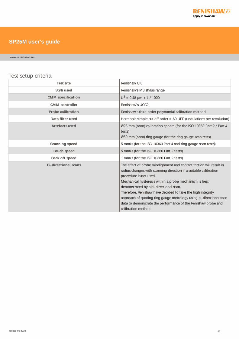
Test setup criteria
Test site Renishaw UK
Styli used Renishaw's M3 stylus range
CMM specification U3 = 0.48 µm + L / 1000
CMM controller Renishaw's UCC2
Probe calibration Renishaw's third order polynomial calibration method
Data filter used Harmonic simple cut off order = 60 UPR (undulations per revolution)
Artefacts used Ø25 mm ﴾nom﴿ calibration sphere ﴾for the ISO 10360 Part 2 / Part 4tests)
Ø50 mm ﴾nom﴿ ring gauge ﴾for the ring gauge scan tests﴿
Scanning speed 5 mm/s (for the ISO 10360 Part 4 and ring gauge scan tests)
Touch speed 5 mm/s (for the ISO 10360 Part 2 tests)
Back off speed 1 mm/s (for the ISO 10360 Part 2 tests)
Bi-directional scans The effect of probe misalignment and contact friction will result in
radius changes with scanning direction if a suitable calibration
procedure is not used.
Mechanical hysteresis within a probe mechanism is best
demonstrated by a bi-directional scan.
Therefore, Renishaw have decided to take the high integrity
approach of quoting ring gauge metrology using bi-directional scan
data to demonstrate the performance of the Renishaw probe and
calibration method.
SP25M user's guide
www.renishaw.com
Issued 06 2022 62
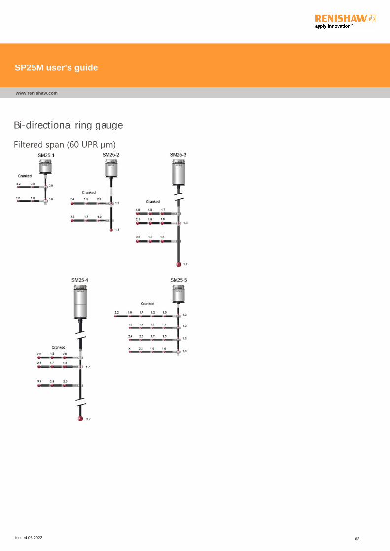
Bi-directional ring gauge
Filtered span ﴾60 UPR µm﴿
SP25M user's guide
www.renishaw.com
Issued 06 2022 63

SS - stainless steel, CER - ceramic, GF - carbon fibre
Bi-directional ring gauge scan test - straight styli
Scanning
module
Effective
stylus reach
Actual M3
stylus used:
Length / tip
Ø/ stemmaterial
RMS data
raw
RMS data
filtered
SPAN data
raw
SPAN data
filtered
Stylus tip
deflection
Raw data
pts
SM25-1 21 mm 21 mm / Ø4mm / SS
0.23 µm 0.19 µm 1.5 µm 0.9 µm 0.35 mm 2857
SM25-1 50 mm 50 mm / Ø5mm / CER
0.24 µm 0.17 µm 1.5 µm 0.9 µm 0.2 mm 2794
SM25-2 51 mm 21 mm / Ø4mm / SS
0.24 µm 0.21 µm 1.6 µm 1.2 µm 0.2 mm 2858
SM25-2 105 mm 75 mm / Ø6mm / GF
0.24 µm 0.18 µm 2.0 µm 1.1 µm 0.2 mm 2609
SM25-3 121 mm 21 mm / Ø4mm / SS
0.38 µm 0.20 µm 2.2 µm 1.3 µm 0.2 mm 2857
SM25-3 200 mm 100 mm / Ø6mm / GF
0.38 µm 0.27 µm 4.1 µm 1.7 µm 0.2 mm 2484
SM25-4 221 mm 21 mm / Ø5mm / SS
0.40 µm 0.30 µm 3.0 µm 1.7 µm 0.2 mm 2462
SM25-4 400 mm 200 mm / Ø8mm / GF
0.80 µm 0.50 µm 5.7 µm 2.7 µm 0.2 mm 2388
SM25-5 21 mm 21 mm / Ø4mm / SS
0.21 µm 0.18 µm 2.1 µm 1.0 µm 0.2 mm 2831
SM25-5 105 mm 100 mm / Ø5mm / CF
0.48 µm 0.28 µm 4.2 µm 1.6 µm 0.2 mm 2643
SP25M user's guide
www.renishaw.com
Issued 06 2022 64
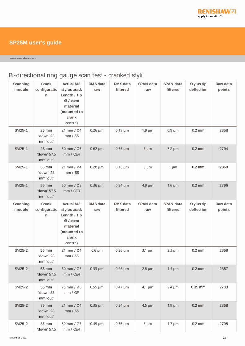
Bi-directional ring gauge scan test - cranked styli
Scanning
module
Crank
configuratio
n
Actual M3
stylus used:
Length / tip
Ø / stemmaterial
(mounted to
crank
centre)
RMS data
raw
RMS data
filtered
SPAN data
raw
SPAN data
filtered
Stylus tip
deflection
Raw data
points
SM25-1 25 mm
'down' 28
mm 'out'
21 mm / Ø4mm / SS
0.26 µm 0.19 µm 1.9 µm 0.9 µm 0.2 mm 2858
SM25-1 25 mm
'down' 57.5
mm 'out'
50 mm / Ø5mm / CER
0.62 µm 0.56 µm 6 µm 3.2 µm 0.2 mm 2794
SM25-1 55 mm
'down' 28
mm 'out'
21 mm / Ø4mm / SS
0.28 µm 0.16 µm 3 µm 1 µm 0.2 mm 2868
SM25-1 55 mm
'down' 57.5
mm 'out'
50 mm / Ø5mm / CER
0.36 µm 0.24 µm 4.9 µm 1.6 µm 0.2 mm 2796
Scanning
module
Crank
configuratio
n
Actual M3
stylus used:
Length / tip
Ø / stemmaterial
(mounted to
crank
centre)
RMS data
raw
RMS data
filtered
SPAN data
raw
SPAN data
filtered
Stylus tip
deflection
Raw data
points
SM25-2 55 mm
'down' 28
mm 'out'
21 mm / Ø4mm / SS
0.6 µm 0.56 µm 3.1 µm 2.3 µm 0.2 mm 2858
SM25-2 55 mm
'down' 57.5
mm 'out'
50 mm / Ø5mm / CER
0.33 µm 0.26 µm 2.8 µm 1.5 µm 0.2 mm 2857
SM25-2 55 mm
'down' 83
mm 'out'
75 mm / Ø6mm / GF
0.55 µm 0.47 µm 4.1 µm 2.4 µm 0.35 mm 2733
SM25-2 85 mm
'down' 28
mm 'out'
21 mm / Ø4mm / SS
0.35 µm 0.24 µm 4.5 µm 1.9 µm 0.2 mm 2858
SM25-2 85 mm
'down' 57.5
50 mm / Ø5mm / CER
0.45 µm 0.36 µm 3 µm 1.7 µm 0.2 mm 2795
SP25M user's guide
www.renishaw.com
Issued 06 2022 65

mm 'out'
SM25-2 85 mm
'down' 83
mm 'out'
75 mm / Ø6mm / GF
0.75 µm 0.6 µm 6.1 µm 3.6 µm 0.2 mm 2734
SM25-3 105 mm
'down' 28
mm 'out'
21 mm / Ø4mm / SS
0.4 µm 0.35 µm 2.3 µm 1.7 µm 0.2 mm 2858
SM25-3 105 mm
'down' 57.5
mm 'out'
50 mm / Ø5mm / CER
0.44 µm 0.38 µm 2.7 µm 1.8 µm 0.2 mm 2858
SM25-3 105 mm
'down' 83
mm 'out'
75 mm / Ø6mm / GF
0.42 µm 0.36 µm 3 µm 1.8 µm 0.2 mm 2733
SM25-3 125 mm
'down' 28
mm 'out'
21 mm / Ø4mm / SS
0.47 µm 0.42 µm 2.7 µm 1.8 µm 0.2 mm 2856
SM25-3 125 mm
'down' 57.5
mm 'out'
50 mm / Ø5mm / CER
0.47 µm 0.35 µm 2.7 µm 1.8 µm 0.2 mm 2856
SM25-3 125 mm
'down' 83
mm 'out'
75 mm / Ø6mm / GF
0.55 µm 0.46 µm 3.5 µm 2.1 µm 0.35 mm 2732
SM25-3 155 mm
'down' 28
mm 'out'
21 mm / Ø4mm / SS
0.38 µm 0.31 µm 2.6 µm 1.5 µm 0.2 mm 2858
SM25-3 155 mm
'down' 57.5
mm 'out'
50 mm / Ø5mm / CER
0.37 µm 0.27 µm 2.9 µm 1.3 µm 0.2 mm 2858
SM25-3 155 mm
'down' 83
mm 'out'
75 mm / Ø6mm / GF
1.01 µm 0.69 µm 11.8 µm 3.5 µm 0.2 mm 2734
SP25M user's guide
www.renishaw.com
Issued 06 2022 66

Scanning
module
Crank
configuratio
n
Actual M3
stylus used:
Length / tip
Ø / stemmaterial
(mounted to
crank
centre)
RMS data
raw
RMS data
filtered
SPAN data
raw
SPAN data
filtered
Stylus tip
deflection
Raw data
points
SM25-4 205 mm
'down' 28
mm 'out'
21 mm / Ø4mm / SS
0.45 µm 0.38 µm 2.6 µm 2 µm 0.2 mm 1439
SM25-4 205 mm
'down' 57.5
mm 'out'
50 mm / Ø5mm / CER
0.38 µm 0.26 µm 2.5 µm 1.5 µm 0.2 mm 1440
SM25-4 205 mm
'down' 83
mm 'out'
75 mm / Ø6mm / GF
0.51 µm 0.34 µm 4.2 µm 2.2 µm 0.2 mm 1376
SM25-4 225 mm
'down' 28
mm 'out'
21 mm / Ø4mm / SS
0.41 µm 0.32 µm 2.7 µm 1.8 µm 0.2 mm 1438
SM25-4 225 mm
'down' 57.5
mm 'out'
50 mm / Ø5mm / CER
0.42 µm 0.3 µm 2.6 µm 2.7 µm 0.2 mm 1438
SM25-4 225 mm
'down' 83
mm 'out'
75 mm / Ø6mm / GF
0.65 µm 0.48 µm 5.1 µm 2.4 µm 0.35 mm 2731
SM25-4 255 mm
'down' 28
mm 'out'
21 mm / Ø4mm / SS
0.67 µm 0.59 µm 3.6 µm 2.5 µm 0.2 mm 2858
SM25-4 255 mm
'down' 57.5
mm 'out'
50 mm / Ø5mm / CER
0.69 µm 0.55 µm 5.9 µm 2.8 µm 0.2 mm 2794
SM25-4 255 mm
'down' 83
mm 'out'
75 mm / Ø6mm / GF
0.99 µm 0.75 µm 8.5 µm 3.9 µm 0.2 mm 2730
SP25M user's guide
www.renishaw.com
Issued 06 2022 67

Test setup criteria
Test site Renishaw UK
Styli used Renishaw's M3 stylus range
CMM specification U3 = 0.48 µm + L / 1000
CMM controller Renishaw's UCC2
Probe calibration Renishaw's third order polynomial calibration method
Data filter used Harmonic simple cut off order = 60 UPR (undulations per revolution)
Artefacts used Ø25 mm ﴾nom﴿ calibration sphere ﴾for the ISO 10360 Part 2 / Part 4tests)
Ø50 mm ﴾nom﴿ ring gauge ﴾for the ring gauge scan tests﴿
Scanning speed 5 mm/s (for the ISO 10360 Part 4 and ring gauge scan tests)
Touch speed 5 mm/s (for the ISO 10360 Part 2 tests)
Back off speed 1 mm/s (for the ISO 10360 Part 2 tests)
Bi-directional scans The effect of probe misalignment and contact friction will result in
radius changes with scanning direction if a suitable calibration
procedure is not used.
Mechanical hysteresis within a probe mechanism is best
demonstrated by a bi-directional scan.
Therefore, Renishaw have decided to take the high integrity
approach of quoting ring gauge metrology using bi-directional scan
data to demonstrate the performance of the Renishaw probe and
calibration method.
SP25M user's guide
www.renishaw.com
Issued 06 2022 68

SH25 stylus holder range metrology
performanceSH25-2A, SH25-3A and SH25-4A have distinct metrology advantages over SH25-2, SH25-3 and SH25-4 for any stylus arrangements where
the stylus holder is subjected to torsional load when using components like cranked styli or knuckle joints.
The standard range of SH25 stylus holders still have an advantage over the -A range of stylus holders when straight styli arrangements are
required.
The following tables compare typical metrology performance with the standard and -A range of SH25 stylus holders for both straight and
cranked stylus configurations.
SH25-2 against SH25-2A - bi-directional ring gauge scan test
Straight stylus perfromance - effective stylus reach 51 mm:
Stylus holder SPAN data raw SPAN data filtered Stylus tip deflection
SH25-2 1.6 µm 1.2 µm 0.2 mm
SH25-2A 1.5 µm 1.1 µm 0.2 mm
Cranked stylus performance - crank down distance 55 mm, crank out distance 83 mm:
Stylus holder SPAN data raw SPAN data filtered Stylus tip deflection
SH25-2 14.9 µm 5.9 µm 0.35 mm
SH25-2A 4.1 µm 2.4 µm 0.35 mm
SH25-3 against SH25-3A - bi-directional ring gauge scan test
Straight stylus perfromance - effective stylus reach 121 mm:
Stylus holder SPAN data raw SPAN data filtered Stylus tip deflection
SH25-3 2.2 µm 1.3 µm 0.2 mm
SH25-3A 2.5 µm 1.7 µm 0.2 mm
Cranked stylus performance - crank down distance 125 mm, crank out distance 83 mm:
Stylus holder SPAN data raw SPAN data filtered Stylus tip deflection
SH25-3 11.8 µm 8.2 µm 0.35 mm
SH25-3A 3.5 µm 2.1 µm 0.35 mm
SP25M user's guide
www.renishaw.com
Issued 06 2022 69
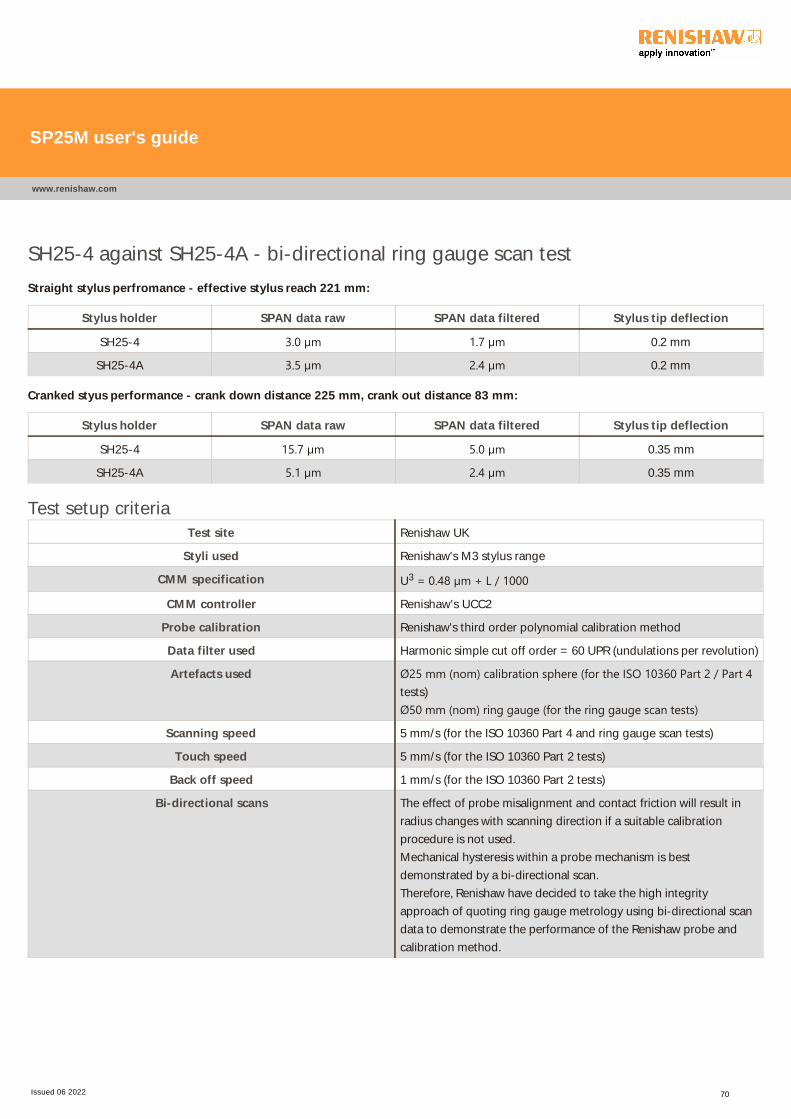
SH25-4 against SH25-4A - bi-directional ring gauge scan test
Straight stylus perfromance - effective stylus reach 221 mm:
Stylus holder SPAN data raw SPAN data filtered Stylus tip deflection
SH25-4 3.0 µm 1.7 µm 0.2 mm
SH25-4A 3.5 µm 2.4 µm 0.2 mm
Cranked styus performance - crank down distance 225 mm, crank out distance 83 mm:
Stylus holder SPAN data raw SPAN data filtered Stylus tip deflection
SH25-4 15.7 µm 5.0 µm 0.35 mm
SH25-4A 5.1 µm 2.4 µm 0.35 mm
Test setup criteria
Test site Renishaw UK
Styli used Renishaw's M3 stylus range
CMM specification U3 = 0.48 µm + L / 1000
CMM controller Renishaw's UCC2
Probe calibration Renishaw's third order polynomial calibration method
Data filter used Harmonic simple cut off order = 60 UPR (undulations per revolution)
Artefacts used Ø25 mm ﴾nom﴿ calibration sphere ﴾for the ISO 10360 Part 2 / Part 4tests)
Ø50 mm ﴾nom﴿ ring gauge ﴾for the ring gauge scan tests﴿
Scanning speed 5 mm/s (for the ISO 10360 Part 4 and ring gauge scan tests)
Touch speed 5 mm/s (for the ISO 10360 Part 2 tests)
Back off speed 1 mm/s (for the ISO 10360 Part 2 tests)
Bi-directional scans The effect of probe misalignment and contact friction will result in
radius changes with scanning direction if a suitable calibration
procedure is not used.
Mechanical hysteresis within a probe mechanism is best
demonstrated by a bi-directional scan.
Therefore, Renishaw have decided to take the high integrity
approach of quoting ring gauge metrology using bi-directional scan
data to demonstrate the performance of the Renishaw probe and
calibration method.
SP25M user's guide
www.renishaw.com
Issued 06 2022 70
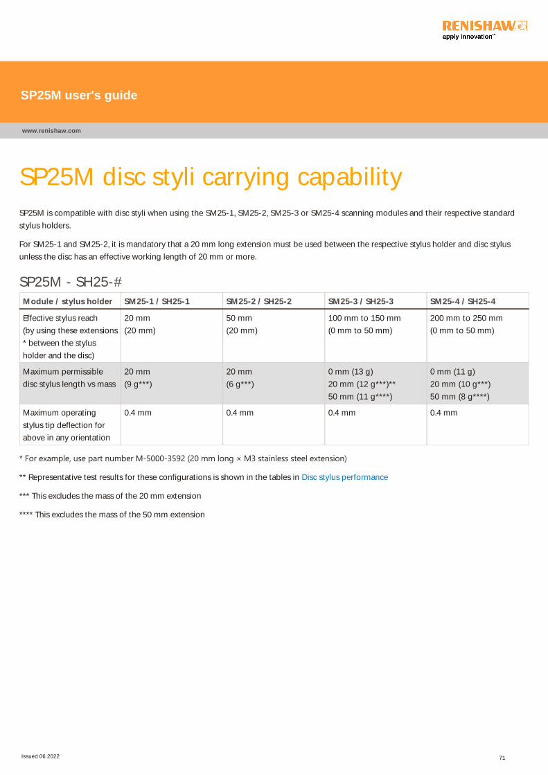
SP25M disc styli carrying capabilitySP25M is compatible with disc styli when using the SM25-1, SM25-2, SM25-3 or SM25-4 scanning modules and their respective standard
stylus holders.
For SM25-1 and SM25-2, it is mandatory that a 20 mm long extension must be used between the respective stylus holder and disc stylus
unless the disc has an effective working length of 20 mm or more.
SP25M - SH25-#
Module / stylus holder SM25-1 / SH25-1 SM25-2 / SH25-2 SM25-3 / SH25-3 SM25-4 / SH25-4
Effective stylus reach
(by using these extensions
* between the stylus
holder and the disc)
20 mm
(20 mm)
50 mm
(20 mm)
100 mm to 150 mm
(0 mm to 50 mm)
200 mm to 250 mm
(0 mm to 50 mm)
Maximum permissible
disc stylus length vs mass
20 mm
(9 g***)
20 mm
(6 g***)
0 mm (13 g)
20 mm (12 g***)**
50 mm (11 g****)
0 mm (11 g)
20 mm (10 g***)
50 mm (8 g****)
Maximum operating
stylus tip deflection for
above in any orientation
0.4 mm 0.4 mm 0.4 mm 0.4 mm
* For example, use part number M‐5000‐3592 ﴾20 mm long × M3 stainless steel extension﴿
** Representative test results for these configurations is shown in the tables in Disc stylus performance
*** This excludes the mass of the 20 mm extension
**** This excludes the mass of the 50 mm extension
SP25M user's guide
www.renishaw.com
Issued 06 2022 71
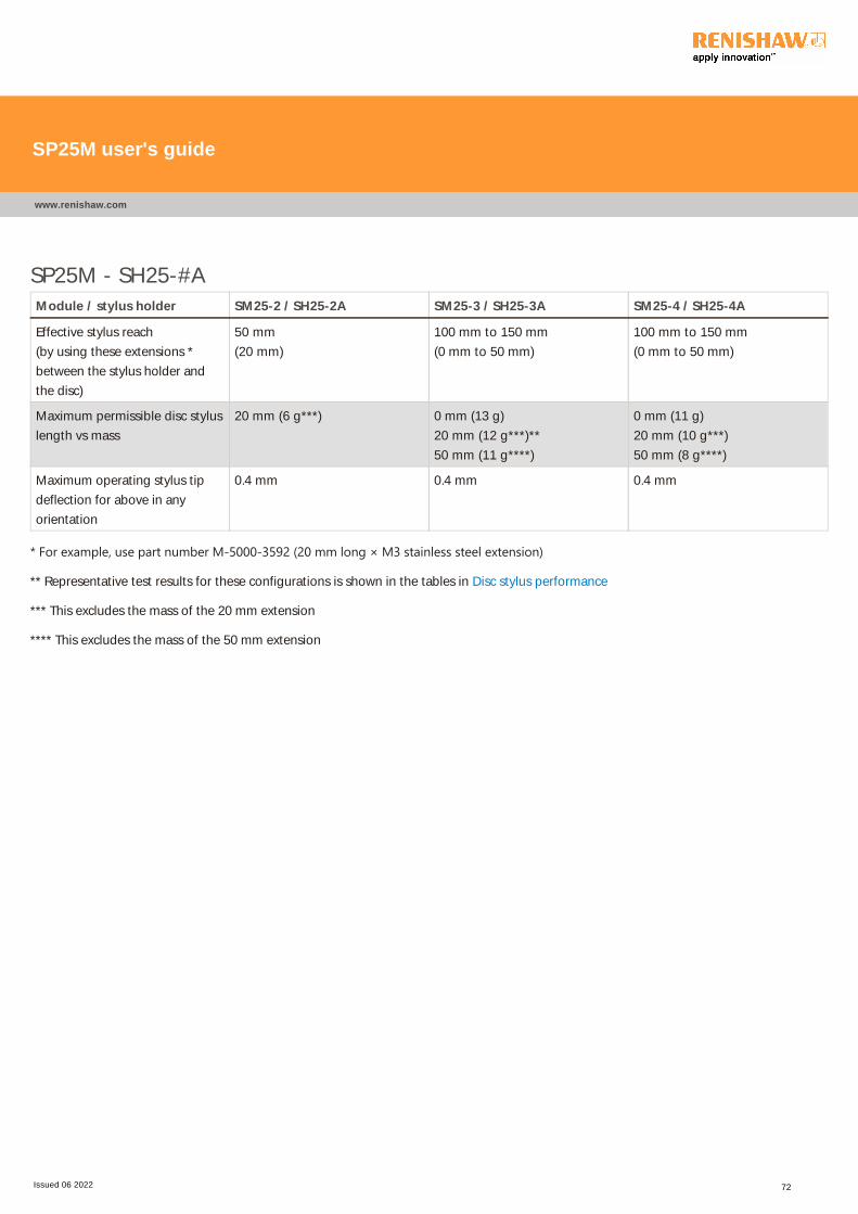
SP25M - SH25-#A
Module / stylus holder SM25-2 / SH25-2A SM25-3 / SH25-3A SM25-4 / SH25-4A
Effective stylus reach
(by using these extensions *
between the stylus holder and
the disc)
50 mm
(20 mm)
100 mm to 150 mm
(0 mm to 50 mm)
100 mm to 150 mm
(0 mm to 50 mm)
Maximum permissible disc stylus
length vs mass
20 mm (6 g***) 0 mm (13 g)
20 mm (12 g***)**
50 mm (11 g****)
0 mm (11 g)
20 mm (10 g***)
50 mm (8 g****)
Maximum operating stylus tip
deflection for above in any
orientation
0.4 mm 0.4 mm 0.4 mm
* For example, use part number M‐5000‐3592 ﴾20 mm long × M3 stainless steel extension﴿
** Representative test results for these configurations is shown in the tables in Disc stylus performance
*** This excludes the mass of the 20 mm extension
**** This excludes the mass of the 50 mm extension
SP25M user's guide
www.renishaw.com
Issued 06 2022 72
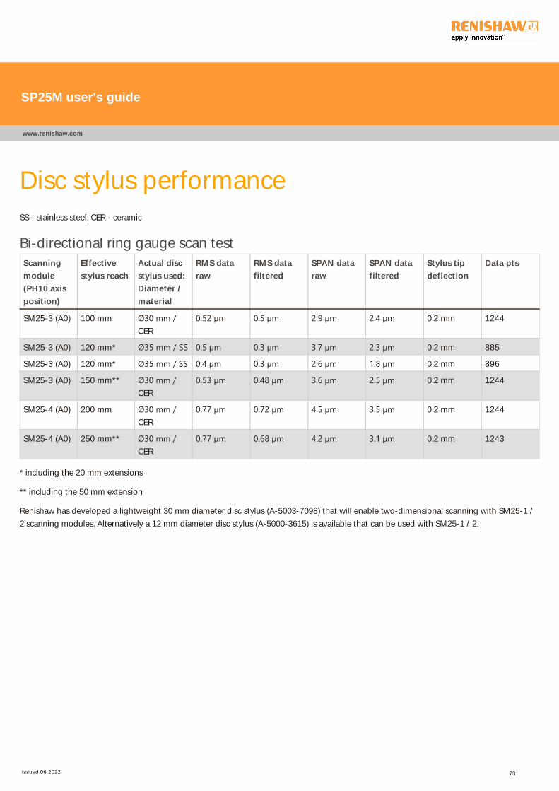
Disc stylus performanceSS - stainless steel, CER - ceramic
Bi-directional ring gauge scan test
Scanning
module
(PH10 axis
position)
Effective
stylus reach
Actual disc
stylus used:
Diameter /
material
RMS data
raw
RMS data
filtered
SPAN data
raw
SPAN data
filtered
Stylus tip
deflection
Data pts
SM25-3 (A0) 100 mm Ø30 mm /CER
0.52 µm 0.5 µm 2.9 µm 2.4 µm 0.2 mm 1244
SM25-3 (A0) 120 mm* Ø35 mm / SS 0.5 µm 0.3 µm 3.7 µm 2.3 µm 0.2 mm 885
SM25-3 (A0) 120 mm* Ø35 mm / SS 0.4 µm 0.3 µm 2.6 µm 1.8 µm 0.2 mm 896
SM25-3 (A0) 150 mm** Ø30 mm /CER
0.53 µm 0.48 µm 3.6 µm 2.5 µm 0.2 mm 1244
SM25-4 (A0) 200 mm Ø30 mm /CER
0.77 µm 0.72 µm 4.5 µm 3.5 µm 0.2 mm 1244
SM25-4 (A0) 250 mm** Ø30 mm /CER
0.77 µm 0.68 µm 4.2 µm 3.1 µm 0.2 mm 1243
* including the 20 mm extensions
** including the 50 mm extension
Renishaw has developed a lightweight 30 mm diameter disc stylus (A-5003-7098) that will enable two-dimensional scanning with SM25-1 /
2 scanning modules. Alternatively a 12 mm diameter disc stylus (A-5000-3615) is available that can be used with SM25-1 / 2.
SP25M user's guide
www.renishaw.com
Issued 06 2022 73
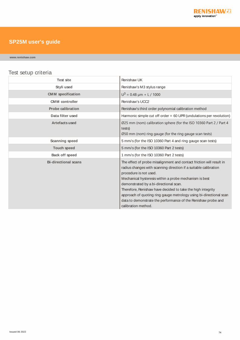
Test setup criteria
Test site Renishaw UK
Styli used Renishaw's M3 stylus range
CMM specification U3 = 0.48 µm + L / 1000
CMM controller Renishaw's UCC2
Probe calibration Renishaw's third order polynomial calibration method
Data filter used Harmonic simple cut off order = 60 UPR (undulations per revolution)
Artefacts used Ø25 mm ﴾nom﴿ calibration sphere ﴾for the ISO 10360 Part 2 / Part 4tests)
Ø50 mm ﴾nom﴿ ring gauge ﴾for the ring gauge scan tests﴿
Scanning speed 5 mm/s (for the ISO 10360 Part 4 and ring gauge scan tests)
Touch speed 5 mm/s (for the ISO 10360 Part 2 tests)
Back off speed 1 mm/s (for the ISO 10360 Part 2 tests)
Bi-directional scans The effect of probe misalignment and contact friction will result in
radius changes with scanning direction if a suitable calibration
procedure is not used.
Mechanical hysteresis within a probe mechanism is best
demonstrated by a bi-directional scan.
Therefore, Renishaw have decided to take the high integrity
approach of quoting ring gauge metrology using bi-directional scan
data to demonstrate the performance of the Renishaw probe and
calibration method.
SP25M user's guide
www.renishaw.com
Issued 06 2022 74
ExtensionsThe SP25M can be used with the PEM25 (25 mm), PEM1 (50 mm) and PEM2 (100 mm) autojoint to autojoint extension bars to extend the
effective probe reach.
CAUTION: SP25M cannot be used with the PEM3 (200 mm).
SP25M user's guide
www.renishaw.com
Issued 06 2022 75
SP25M maintenanceThe SP25M probe, SM25 scanning modules and SH25 stylus holders have no user serviceable parts. In the event of a problem, contact your
local Renishaw supplier for assistance.
Following the simple maintenance procedures below will help to prolong the operation life and continued high performance of the system.
The user should determine the frequency of inspection and maintenance according to the conditions of use.
CAUTION: Always adhere to the general safety recommendations in this document. Failure to do so could adversely affect the
performance of the probe system and / or lead to personal injury.
SP25M probe system components
The external surfaces of all system components should be cleaned with a soft, lint free cloth. All parts must always be kept dry.
The kinematic coupling mechanisms incorporated throughout the system have a precision ball and V-groove seating, electrical contacts and
permanent magnets. It is recommended that all these features are cleaned before first use and then at intervals after 500 tool changes.
A cleaning kit for the above components is available from your local Renishaw supplier (part number: A-1085-0016). With clean hands, tear
off a small amount of yellow tack, shape in to a ball and press on to each feature in turn to remove debris.
The optical windows that feature as part of the probe and module assemblies should be carefully cleaned using the yellow tack supplied in the
cleaning kit (part number: A-1085-0016). The optical windows are made of glass and should be cleaned with care to avoid damage or
personal injury.
All probe system components that are not being used and are not stored in the rack should be kept in their original transportation packaging
boxes.
FCR25 and FCR25 TC flexible change racks
The ports, lids and outer surfaces of the FCR25 racks should be periodically cleaned using a soft, lint free cloth to prevent the contamination of
the probe system components. A port replacement kit is available if required (FCR25: A-5036-0049, FCR25 TC: A-2237-0050).
Styli
Stylus balls, threads and mating faces should be cleaned using a proprietary cleaning cloth or solvent. Stylus balls should be regularly
inspected for damage or pick-up of component material.
SP25M user's guide
www.renishaw.com
Issued 06 2022 76

SP25M appendix 1 - International safety
recommendations
SP25M user's guide
www.renishaw.com
Issued 06 2022 77
BG ‐ Общи препоръки по безопасностВНИМАНИЕ: Преди разопаковане и монтиране на пробниковата система SP25M, потребителят трябва внимателно дапрочете инструкциите по безопасност по‐долу и да гарантира, че те ще се спазват през цялото време от всички оператори,използващи пробниковата система. Употребата на органи за управление или настройка, или изпълнението на процедури,различни от тук посочените, може да доведе до експозиция на опасно инфрачервено излъчване.Операторите трябва да са обучени в употребата и прилагането на пробниковата системата SP25M и придружаващите япродукти, към които се монтира машината преди да могат да работят с тази машина.
ЗАБЕЛЕЖКА: По‐долу са направени препратки към функции, които са обозначени с [†] [‡] [♦] в следващите илюстрации.Моля, уверете се че ясно разбирате всички съвети за безопасност. Препоръчва се запозване с компонентите на систематаSP25M по показания в следващите раздели начин:
Преглед на компонентите на систематаСхема на компонентите на пробниковата системаСхема на гъвкавата за смяна стойка FCR25Схема на гъвкавата за смяна стойка FCR25 TC
Пробниковата система SP25M има механична защита от излизане извън работния ход, осигурена по ос +Z в пробника отнеподвижен краен изключвател с буфер. Тогава контролната система на машината ще трябва да може да спре нейнотодвижение, в тази ос на пробника, преди да бъде достигнат ограничителя. Ако това не е така, потребителят трябва да носипредпазни средства за очите по време на работа в случай на счупване на острието.
Трябва да се внимава, за да се гарантира, че оптичните прозорци ﴾обозначени с [♦]﴿, разположени както на тялото, така и на модула,не се повреждат, тъй като те са изработени от стъкло и могат да предизвикат травма.
ВНИМАНИЕ: В някои компоненти на системата SP25M и свързаните с нея продукти са използвани постоянни магнити.Важно е те да се пазят от елементи, които биха могли да бъдат засегнати от магнитни полета, напр. – системи зазапаметяване на данни, водачи, часовници и др.
SP25M user's guide
www.renishaw.com
Issued 06 2022 78
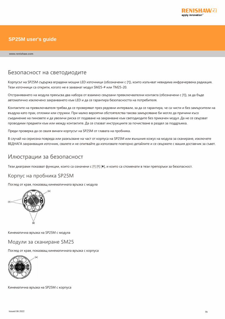
Безопасност на светодиодитеКорпусът на SP25M съдържа вградени мощни LED източници ﴾обозначени с [†]﴿, които излъчват невидима инфрачервена радиация.Тези източници са открити, когато не е захванат модул SM25‐# или TM25‐20.
Отстраняването на модула прекъсва два набора от взаимно свързани превключвателни контакта ﴾обозначени с [‡]﴿, за да бъдеавтоматично изключено захранването към LED и да се гарантира безопасността на потребителя.
Контактите на превключвателя трябва да се проверяват през редовни интервали, за да се гарантира, че са чисти и без замърсители навъздуха като прах, отломки или стружки. При малко вероятни обстоятелства такова замърсяване би могло да причини късосъединение на пиновете и да увеличи риска от подаване на захранване към светодиодите без прикачен модул. Да не се свързватпроводими предмети към или между контактите. Да се спазват инструкциите за почистване в раздел за поддръжка.
Преди проверка да се сваля винаги корпусът на SP25M от главата на пробника.
В случай на сериозна повреда или разкъсване на част от корпуса на SP25M или външния кожух на модула за сканиране, изключетеВЕДНАГА захранващия източник, свалете и не опитвайте да използвате повторно детайлите и се свържете с вашия доставчик за съвет.
Илюстрации за безопасностТези диаграми показват функции, които са означени с [†] [‡] [♦], и които са споменати в тези препоръки за безопасност.
Корпус на пробника SP25MПоглед от края, показващ кинематичната връзка с модула
Кинематична връзка на SP25M с модула
Модули за сканиране SM25Поглед от края, показващ кинематичната връзка с корпуса
Кинематична връзка на SP25M с корпуса
SP25M user's guide
www.renishaw.com
Issued 06 2022 79
CZ ‐ Obecná bezpečnostní doporučeníUPOZORNĚNÍ: Před vybalením a instalací skenovacího systému SP25M by si měl uživatel pozorně přečíst níže uvedenébezpečnostní pokyny a zajistit, aby je všechny osoby používající skenovací systém neustále dodržovaly. Při použití jiných ovládacíchprvků či jiných nastavení nebo při provádění jiných postupů než těch, které jsou zde uvedeny, můžete být vystaveni nebezpečnémuinfračervenému záření.Než bude moci obsluha začít pracovat se strojem, ke kterému je připojen skenovací systém SP25M, je nutné, aby byla vyškolena voblasti používání tohoto systému a doplňujících produktů v souvislosti s daným strojem.
POZNÁMKA: Odkazy v následujícím textu se vztahují k prvkům označeným značkami [†] [‡] [♦] na obrázcích dole. Ujistěte se, ževšem bezpečnostním pokynům zcela rozumíte. Doporučujeme seznámit se se součástmi systému SP25M, které jsou znázorněny vtěchto částech:
Přehled součástí systémuSchéma součástí snímacího systémuSchéma flexibilního výměníku FCR25Schéma flexibilního výměníku FCR25 TC
Snímací systém SP25M obsahuje mechanickou ochranu před nadměrným zdvihem, která je v ose +Z tvořena pevnou zarážkou.Řídicí systém stroje proto musí být schopen před dosažením zarážky zastavit svůj pohyb ve směru osy sondy. V opačném případěmusí uživatel během provozu používat ochranu zraku pro případ zlomení doteku.
Pozornost by měla být věnována také tomu, zda nejsou poškozena optická okénka ﴾označena značkou [♦]﴿ umístěná na hlavní části i namodulu. Tato okénka jsou vyrobena ze skla a mohla by být příčinou zranění.
UPOZORNĚNÍ: V některých součástech systému SP25M a přidružených produktů jsou použity permanentní magnety. Je nutné jeuchovávat mimo dosah předmětů, na které by mohlo nepříznivě působit magnetické pole, jako jsou například systémy proukládání dat, kardiostimulátory, hodinky atd.
SP25M user's guide
www.renishaw.com
Issued 06 2022 80

LED kontrolka
V tělese SP25M jsou integrovány zdroje LED s vysokou intenzitou ﴾označené značkou [†]﴿, které vysílají neviditelné infračervené záření. Tytozdroje jsou odkryty v případě, že není připojen modul SM25‐# nebo modul TM25‐20.
Při odebrání modulu dojde k přerušení dvou sad ochranných kontaktů vypínače ﴾označeny značkou [‡]﴿ a tím k automatickému odpojenínapájení zařízení LED a zajištění bezpečnosti uživatelů.
Pravidelnou prohlídkou a kontrolou ochranných kontaktů by mělo být zjištěno, zda jsou čisté a zda neobsahují vzduchem přenášené nečistoty,jako je například prach nebo třísky odletující při obrábění. Za určitých, málo pravděpodobných okolností by takové znečištění mohlo mezikolíky způsobit zkrat a tím by došlo ke zvýšení rizika, že bude zařízení LED napájeno, i když nebude připojen žádný modul. Ke kontaktůmnikdy nepřipojujte vodivé předměty. Postupujte podle návodu na čištění v kapitole o údržbě.
Před kontrolou vždy demontujte tělo SP25M ze snímací hlavice.
V případě poškození nebo natržení jakékoliv části vnějšího obalu tělesa SP25M nebo skenovacího modulu, OKAMŽITĚ odpojte napájecí zdroj,poškozený díl demontujte a zajistěte, že nebude dále používán. Dále kontaktujte vašeho dodavatele.
Obrázky týkající se bezpečnostiTato schématická znázornění ukazují prvky, označené [†] [‡] [♦], na které jsou uvedeny odkazy v těchto bezpečnostních doporučeních.
Těleso sondy SP25MPohled na koncovou část znázorňující kinematický spoj s modulem
Kinematický spoj s modulem systému SP25M
Skenovací moduly SP25MPohled na koncovou část znázorňující kinematický spoj s tělesem
Kinematický spoj s tělesem systému SP25M
SP25M user's guide
www.renishaw.com
Issued 06 2022 81
DA - Generelle sikkerhedsanbefalinger
FORSIGTIG! Før udpakning og installation af SP25M‐probesystemet skal brugeren omhyggeligt læse nedenståendesikkerhedsinstruktioner og sørge for, at de altid bliver fulgt af alle, der betjener probesystemet. Brug af kontrolenheder,justeringsenheder eller ydelsesprocedurer ud over dem, som er angivet heri, kan bevirke, at man udsættes for farlig infrarødstråling.Operatørerne skal være uddannet i brugen og anvendelsen af SP25M‐probesystemet og de medfølgende produkter i forbindelsenmed den maskine, det er monteret på, før de får tilladelse til at betjene maskinen.
BEMÆRK: Nedenfor henvises der til funktioner, der er angivet med [†] [‡] [♦] på illustrationerne nedenfor. Sørg for, at du forståralle sikkerhedsinstruktionerne fuldstændigt. Det anbefales at gøre sig bekendt med SP25M‐systemkomponenterne som vist iafsnittene:
Oversigt over systemkomponenter
Skematisk diagram over probesystemets komponenter
Skematisk diagram over FCR25 fleksibelt rack
Skematisk diagram over FCR25 TC fleksibelt rack
SP25M‐probesystemet er forsynet med mekanisk beskyttelse mod at bevæge sig for langt i form af et fast endestop i probens +Z‐akseretning. Maskinens kontrolsystem skal derfor være i stand til at stoppe maskinens bevægelse, i denne akseretning for proben,før endestoppet nås. Hvis dette ikke er tilfældet, skal brugeren være iført beskyttelsesbriller under betjeningen i tilfælde af, at stylusknækker.
Pas på, at de optiske vinduer ﴾angivet med [♦]﴿, der findes både i enheden og modulet, ikke bliver beskadigede, da de er fremstillet af glas ogkan forårsage kvæstelser.
FORSIGTIG! Der anvendes permanente magneter i visse komponenter i SP25M‐systemet og de tilhørende produkter. Det er vigtigtat holde dem på afstand af komponenter, der kan påvirkes af magnetiske felter, f.eks. datalagringssystemer, pacemakere, ure osv.
SP25M user's guide
www.renishaw.com
Issued 06 2022 82
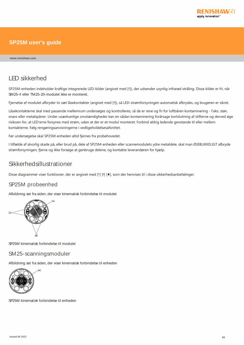
LED sikkerhed
SP25M‐enheden indeholder kraftige integrerede LED‐kilder ﴾angivet med [†]﴿, der udsender usynlig infrarød stråling. Disse kilder er fri, nårSM25-# eller TM25-20-modulet ikke er monteret.
Fjernelse af modulet afbryder to sæt låsekontakter ﴾angivet med [‡]﴿, så LED‐strømforsyningen automatisk afbrydes, og brugeren er sikret.
Låsekontakterne skal med passende mellemrum undersøges og kontrolleres, så de er rene og fri for luftbåren kontaminering ‐ f.eks. støv,snavs eller metalspåner. Under usædvanlige omstændigheder kan en sådan kontaminering forårsage kortslutning af stifterne og derved øgerisikoen for, at LED'erne forsynes med strøm, uden at der er et modul monteret. Forbind aldrig ledende genstande til eller mellemkontakterne. Følg rengøringsanvisningerne i vedligeholdelsesafsnittet.
Før undersøgelse skal SP25M‐enheden altid fjernes fra probehovedet.
I tilfælde af alvorlig skade på, eller brud på, dele af SP25M‐enheden eller scannemodulets ydre metaldele, skal man ØJEBLIKKELIGT afbrydestrømforsyningen, fjerne og ikke forsøge at genbruge delene, og kontakte leverandøren for hjælp.
Sikkerhedsillustrationer
Disse diagrammer viser funktioner, der er angivet med [†] [‡] [♦], som der henvises til i disse sikkerhedsanbefalinger.
SP25M probeenhed
Afbildning set fra siden, der viser kinematisk forbindelse til modulet
SP25M kinematisk forbindelse til modulet
SM25-scanningsmoduler
Afbildning set fra siden, der viser kinematisk forbindelse til enheden
SP25M kinematisk forbindelse til enheden
SP25M user's guide
www.renishaw.com
Issued 06 2022 83
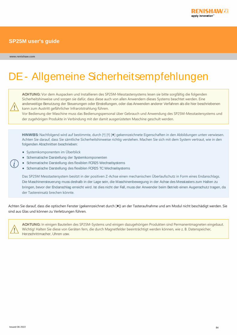
DE - Allgemeine Sicherheitsempfehlungen
ACHTUNG: Vor dem Auspacken und Installieren des SP25M‐Messtastersystems lesen sie bitte sorgfältig die folgendenSicherheitshinweise und sorgen sie dafür, dass diese auch von allen Anwendern dieses Systems beachtet werden. Eineanderweitige Benutzung der Steuerungen oder Einstellungen, oder das Anwenden anderer Verfahren als die hier beschriebenen
kann zum Austritt gefährlicher Infrarotstrahlung führen.Vor Bedienung der Maschine muss das Bedienungspersonal über Gebrauch und Anwendung des SP25M‐Messtastersystems undder zugehörigen Produkte in Verbindung mit der damit ausgerüsteten Maschine geschult werden.
HINWEIS: Nachfolgend wird auf bestimmte, durch [†] [‡] [♦] gekennzeichnete Eigenschaften in den Abbildungen unten verwiesen.Achten Sie darauf, dass Sie sämtliche Sicherheitshinweise richtig verstehen. Machen Sie sich mit dem System vertraut, wie in denfolgenden Abschnitten beschrieben:
Systemkomponenten im ÜberblickSchematische Darstellung der Systemkomponenten
Schematische Darstellung des flexiblen FCR25 Wechselsystems
Schematische Darstellung des flexiblen FCR25 TC Wechselsystems
Das SP25M Messtastersystem besitzt in der positiven Z‐Achse einen mechanischen Überlaufschutz in Form eines Endanschlags.Die Maschinensteuerung muss deshalb in der Lage sein, die Maschinenbewegung in der Achse des Messtasters zum Halten zu
bringen, bevor der Endanschlag erreicht wird. Ist dies nicht der Fall, muss der Anwender beim Betrieb einen Augenschutz tragen, da
der Tastereinsatz brechen könnte.
Achten Sie darauf, dass die optischen Fenster ﴾gekennzeichnet durch [♦]﴿ an der Tasteraufnahme und am Modul nicht beschädigt werden. Siesind aus Glas und können zu Verletzungen führen.
ACHTUNG: In einigen Bauteilen des SP25M‐Systems und einigen dazugehörigen Produkten sind Permanentmagneten eingebaut.Wichtig! Halten Sie diese von Geräten fern, die durch Magnetfelder beeinträchtigt werden können, wie z. B. Datenspeicher,Herzschrittmacher, Uhren usw.
SP25M user's guide
www.renishaw.com
Issued 06 2022 84

LED Sicherheit
Im Sensorgehäuse des SP25M‐Systems befinden sich eingeschlossene Hochleistungs‐LEDs ﴾gekennzeichnet durch [†]﴿, welche unsichtbaresInfrarotlicht ausstrahlen. Die Strahlen können austreten, wenn Modul SM25‐# oder Modul TM25‐20 nicht montiert sind.
Beim Entfernen des Moduls werden zwei Verriegelungskontakte ﴾gekennzeichnet durch [‡]﴿ unterbrochen. Die LED‐Stromversorgung wirdhierdurch automatisch abgeschaltet, der Anwender wird geschützt.
In geeigneten Zeitabständen sollten die Verriegelungskontakte überprüft werden. Stellen Sie sicher, dass diese sauber und frei von Staub,Spänen und sonstigen Verunreinigungen sind. Wenn auch unwahrscheinlich, so kann eine solche Verschmutzung zu einem Kurzschluss anden Stiften führen. Dies erhöht das Risiko, dass Strom zu den LEDs fließt, obwohl kein Modul befestigt ist. Bringen Sie niemals leitendeGegenstände an oder zwischen die Kontakte. Beachten Sie die Anweisungen für die Reinigung im Abschnitt „Instandhaltung“.
Vor einer Inspektion immer den SP25M vom Tastkopf entfernen.
Im Falle einer größeren Beschädigung oder Bruch eines Gehäuseteils des SP25M oder des Gehäuses des Scan‐Modules muss SOFORT dieStromzufuhr unterbrochen und der beschädigte Messtaster entfernt werden. Bitten Sie Ihren Lieferanten um Unterstützung; versuchen Sienicht Teile wiederzuverwenden.
Sicherheitsmerkmale
Auf die durch [†] [‡] [♦] gekennzeichneten Merkmale wird in diesen Sicherheitshinweisen verwiesen.
SP25M Tasteraufnahme
Kinematische Verbindungsfläche zum Modul ﴾Draufsicht﴿
SP25M kinematische Verbindungsfläche zum Modul
SM25 Scanmodule
Kinematische Verbindungsfläche zur Tasteraufnahme ﴾Draufsicht﴿
SP25M kinematische Verbindungsfläche zur Tasteraufnahme
SP25M user's guide
www.renishaw.com
Issued 06 2022 85
EL ‐ Γενικές συστάσεις ασφάλειαςΠΡΟΣΟΧΗ: Πριν από την αποσυσκευασία και εγκατάσταση του συστήματος αισθητήρα SP25M, ο χρήστης πρέπει να διαβάσειπροσεκτικά τις οδηγίες ασφάλειας που ακολουθούν και να διασφαλίσει ότι θα εφαρμόζονται πάντοτε από όλους τους χειριστέςτου συστήματος. Η χρήση χειριστηρίων ή ρυθμίσεων, καθώς και η εκτέλεση διαδικασιών διαφορετικών από αυτές πουκαθορίζονται στο παρόν μπορεί να προκαλέσει έκθεση σε επικίνδυνη υπέρυθρη ακτινοβολία.Οι χειριστές πρέπει να είναι εκπαιδευμένοι στη χρήση και εφαρμογή του συστήματος αισθητήρα SP25M και των συνοδευτικώνπροϊόντων, σε σχέση με το μηχάνημα στο οποίο τοποθετείται, για να τους επιτραπεί να χρησιμοποιήσουν το συγκεκριμένομηχάνημα.
ΣΗΜΕΙΩΣΗ: Γίνονται αναφορές κατωτέρω σε χαρακτηριστικά που δηλώνονται ως [†] [‡] [♦] στις απεικονιζόμενες παρακάτωεικόνες. Παρακαλούμε να βεβαιωθείτε ότι κατανοείτε σαφώς όλες τις οδηγίες ασφάλειας. Συστήνεται η εξοικείωση με ταστοιχεία του συστήματος SP25M, όπως φαίνεται στα ακόλουθα αποσπάσματα:
Επισκόπηση μερών του συστήματοςΣχηματικό διάγραμμα των μερών του συστήματος αισθητήραΣχηματικό διάγραμμα του εύκαμπτου πλαισίου στήριξης αλλαγής FCR25Σχηματικό διάγραμμα του εύκαμπτου πλαισίου στήριξης αλλαγής FCR25 TC
Το σύστημα αισθητήρα SP25M διαθέτει μηχανική προστασία υπέρβασης διαδρομής η οποία παρέχεται στον άξονα +Z τουαισθητήρα, από έναν σταθερό αποσβεστήρα κρούσεων. Το σύστημα ελέγχου του μηχανήματος πρέπει επομένως να είναι σεθέση να διακόπτει την κίνηση της μηχανής, στο συγκεκριμένο άξονα του αισθητήρα, πριν από την προσέγγιση στοναποσβεστήρα κρούσεων. Σε διαφορετική περίπτωση, ο χρήστης πρέπει να φοράει συσκευή προστασίας των ματιών ότανχειρίζεται το μηχάνημα για την περίπτωση θραύσης του επαφέα.
Πρέπει να φροντίσετε ώστε να εξασφαλιστεί ότι τα οπτικά παράθυρα ﴾αναφέρονται ως [♦]﴿, τα οποία βρίσκονται στο σώμα και στηνυπομονάδα, δεν πρόκειται να πάθουν ζημιά επειδή είναι κατασκευασμένα από γυαλί και μπορεί να προκαλέσουν τραυματισμό.
ΠΡΟΣΟΧΗ: Σε ορισμένα εξαρτήματα του συστήματος SP25M και των σχετικών προϊόντων χρησιμοποιούνται μόνιμοιμαγνήτες. Είναι σημαντικό να κρατάτε τους μαγνήτες μακριά από στοιχεία που μπορεί να επηρεαστούν από μαγνητικά πεδία,π.χ. συστήματα αποθήκευσης δεδομένων, βηματοδότες, ρολόγια, κ.λπ.
SP25M user's guide
www.renishaw.com
Issued 06 2022 86
Ασφάλεια με LEDΤο σώμα του SP25M περιέχει ενσωματωμένες πηγές LED υψηλής ισχύος ﴾δηλώνονται με το σύμβολο [†]﴿ οι οποίες εκπέμπουν αόρατηυπέρυθρη ακτινοβολία. Οι πηγές αυτές είναι εκτεθειμένες όταν δεν είναι τοποθετημένη μια υπομονάδα SM25‐# ή TM25‐20.
Η αφαίρεση της υπομονάδας απομακρύνει δύο ομάδες επαφών διακοπτών ασφαλείας ﴾δηλώνονται με [‡]﴿ ώστε να διακόπτεταιαυτόματα η τροφοδότηση ισχύος στις φωτοδιόδους LED και να διασφαλίζεται η ασφάλεια του χρήστη.
Σε κατάλληλα χρονικά διαστήματα, οι επαφές των διακοπτών ασφαλείας πρέπει να επιθεωρούνται και να ελέγχονται ώστε ναεξασφαλίζεται ότι είναι καθαρές και χωρίς αερομεταφερόμενους ρύπους, όπως σκόνη, θραύσματα ή ρινίσματα. Σε σπάνιες περιπτώσεις,αυτού του είδους η ρύπανση μπορεί να προκαλέσει βραχυκύκλωμα στους ακροδέκτες και να αυξήσει με αυτόν τον τρόπο τον κίνδυνο νατροφοδοτούνται οι φωτοδίοδοι LED με ισχύ, χωρίς να έχει τοποθετηθεί κάποια υπομονάδα. Μη συνδέετε ποτέ αντικείμενα που είναικαλοί αγωγοί του ηλεκτρικού ρεύματος στις, ή ανάμεσα στις, επαφές. Ακολουθήστε τις οδηγίες καθαρισμού που δίνονται στην ενότηταΣυντήρηση.
Πριν από την επιθεώρηση, να αφαιρείτε πάντοτε το σώμα του SP25M από την κεφαλή του αισθητήρα.
Σε περίπτωση σοβαρής ζημιάς ή θραύσης οποιουδήποτε τμήματος του σώματος του SP25M ή του εξωτερικού περιβλήματος της μονάδαςσάρωσης, αποσυνδέστε ΑΜΕΣΑ την παροχή ρεύματος, αφαιρέστε και μην προσπαθήσετε να ξαναχρησιμοποιήσετε τα κομμάτια, καιεπικοινωνήστε με τον προμηθευτή σας για οδηγίες.
SP25M user's guide
www.renishaw.com
Issued 06 2022 87
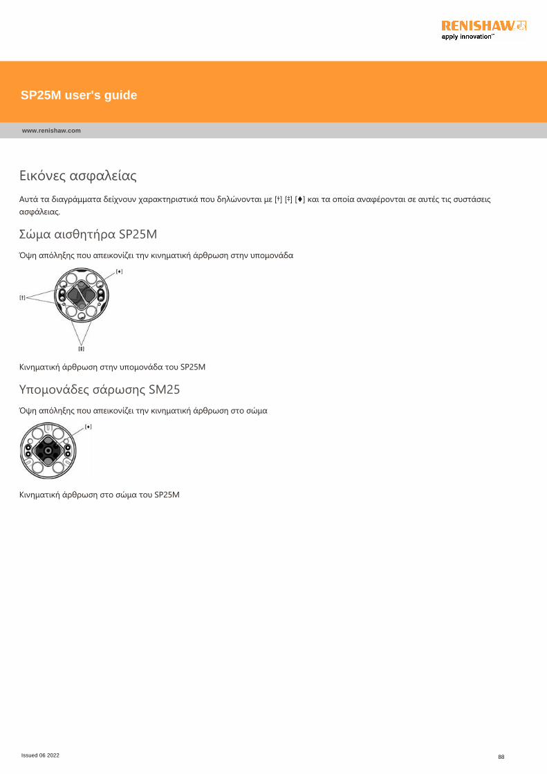
Εικόνες ασφαλείαςΑυτά τα διαγράμματα δείχνουν χαρακτηριστικά που δηλώνονται με [†] [‡] [♦] και τα οποία αναφέρονται σε αυτές τις συστάσειςασφάλειας.
Σώμα αισθητήρα SP25MΌψη απόληξης που απεικονίζει την κινηματική άρθρωση στην υπομονάδα
Κινηματική άρθρωση στην υπομονάδα του SP25M
Υπομονάδες σάρωσης SM25Όψη απόληξης που απεικονίζει την κινηματική άρθρωση στο σώμα
Κινηματική άρθρωση στο σώμα του SP25M
SP25M user's guide
www.renishaw.com
Issued 06 2022 88
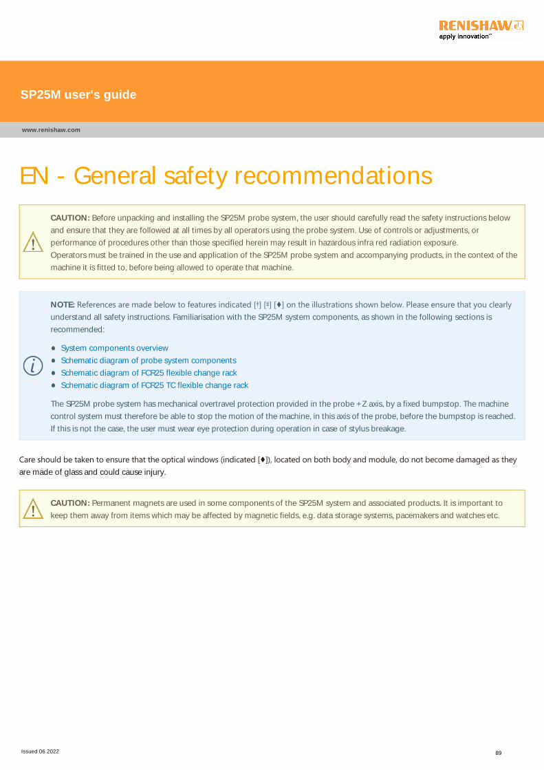
EN - General safety recommendations
CAUTION: Before unpacking and installing the SP25M probe system, the user should carefully read the safety instructions below
and ensure that they are followed at all times by all operators using the probe system. Use of controls or adjustments, or
performance of procedures other than those specified herein may result in hazardous infra red radiation exposure.
Operators must be trained in the use and application of the SP25M probe system and accompanying products, in the context of the
machine it is fitted to, before being allowed to operate that machine.
NOTE: References are made below to features indicated [†] [‡] [♦] on the illustrations shown below. Please ensure that you clearlyunderstand all safety instructions. Familiarisation with the SP25M system components, as shown in the following sections is
recommended:
System components overview
Schematic diagram of probe system components
Schematic diagram of FCR25 flexible change rack
Schematic diagram of FCR25 TC flexible change rack
The SP25M probe system has mechanical overtravel protection provided in the probe +Z axis, by a fixed bumpstop. The machine
control system must therefore be able to stop the motion of the machine, in this axis of the probe, before the bumpstop is reached.
If this is not the case, the user must wear eye protection during operation in case of stylus breakage.
Care should be taken to ensure that the optical windows ﴾indicated [♦]﴿, located on both body and module, do not become damaged as theyare made of glass and could cause injury.
CAUTION: Permanent magnets are used in some components of the SP25M system and associated products. It is important to
keep them away from items which may be affected by magnetic fields, e.g. data storage systems, pacemakers and watches etc.
SP25M user's guide
www.renishaw.com
Issued 06 2022 89

LED safety
The SP25M body contains embedded high power LED sources ﴾indicated [†]﴿ which emit invisible infra‐red radiation. These sources areexposed when an SM25-# or TM25-20 module is not attached.
Removing the module breaks two sets of interlock switch contacts ﴾indicated [‡]﴿ to automatically switch off the LED power and assure usersafety.
At suitable intervals, the interlock contacts should be inspected and checked to ensure that they are clean and free from airborne
contamination such as dust, debris or swarf. In unlikely circumstances, such contamination could cause a short circuit of the pins and thus
increase the risk of sending power to the LEDs, without a module being attached. Never connect conducting objects to, or between, the
contacts. Follow the cleaning instructions in the Maintenance section.
Before inspecting, always remove the SP25M body from the probe head.
In the event of serious damage to, or a rupture of, any part of the SP25M body or scanning module outer casing, IMMEDIATELY disconnect
power source, remove and do not attempt to re-use the parts, and contact your supplier for advice.
Safety illustrations
These diagrams show features, indicated [†] [‡] [♦] which are referred to within these safety recommendations.
SP25M probe body
End view showing kinematic joint to module
SP25M kinematic joint to module
SM25 scanning modules
End view showing kinematic joint to body
SP25M kinematic joint to body
SP25M user's guide
www.renishaw.com
Issued 06 2022 90
ES - Recomendaciones generales de
seguridad
PRECAUCIÓN: Antes de desempaquetar e instalar el sistema de sonda SP25M, lea atentamente las instrucciones de seguridad
siguientes y asegúrese de que son cumplidas en todo momento por los operarios del sistema de sonda. El uso de controles oajustes, o la realización de procedimientos no especificados en este documento puede provocar exposiciones a radiacionesinfrarrojas peligrosas.
Los operadores deben recibir formación sobre el uso y la aplicación del sistema de sonda SP25M y sus accesorios, en el contextoen el que se ajusta la máquina, antes de poder utilizarla.
NOTA: Las referencias a las características se indican con [†] [‡] [♦] en las ilustraciones siguientes. Lea atentamente todas lasinstrucciones de seguridad hasta que no tenga ninguna duda. Se recomienda familiarizarse con los componentes del sistema
SP25M, mostrados en las secciones:
Descripción general de los componentes del sistemaDiagrama esquemático de los componentes del sistema de sondaDiagrama esquemático del cambiador flexible de FCR25Diagrama esquemático del cambiador flexible de FCR25 TC
El sistema de sonda SP25M tiene una protección de sobrerrecorrido mecánica en el eje +Z de la sonda compuesto de un punto deparada fijo. Por lo tanto, el sistema de control de la máquina deberá ser capaz de detener el movimiento de ésta en este eje de lasonda antes de alcanzar el punto de parada fija. Si esto no ocurre, el usuario deberá utilizar gafas de protección para manipular unaposible rotura del palpador.
Debe prestarse atención para evitar daños en las ventanas ópticas ﴾marcadas [♦]﴿, situadas en el cuerpo y en el módulo, ya que es de cristal ypodría provocar lesiones.
PRECAUCIÓN: Algunos componentes del sistema SP25M y sus accesorios utilizan imanes permanentes. Es muy importante
mantenerlos alejados de otros elementos que puedan verse afectados por los campos magnéticos, por ejemplo, sistemas dealmacenamiento de datos, marcapasos, relojes, etc.
SP25M user's guide
www.renishaw.com
Issued 06 2022 91
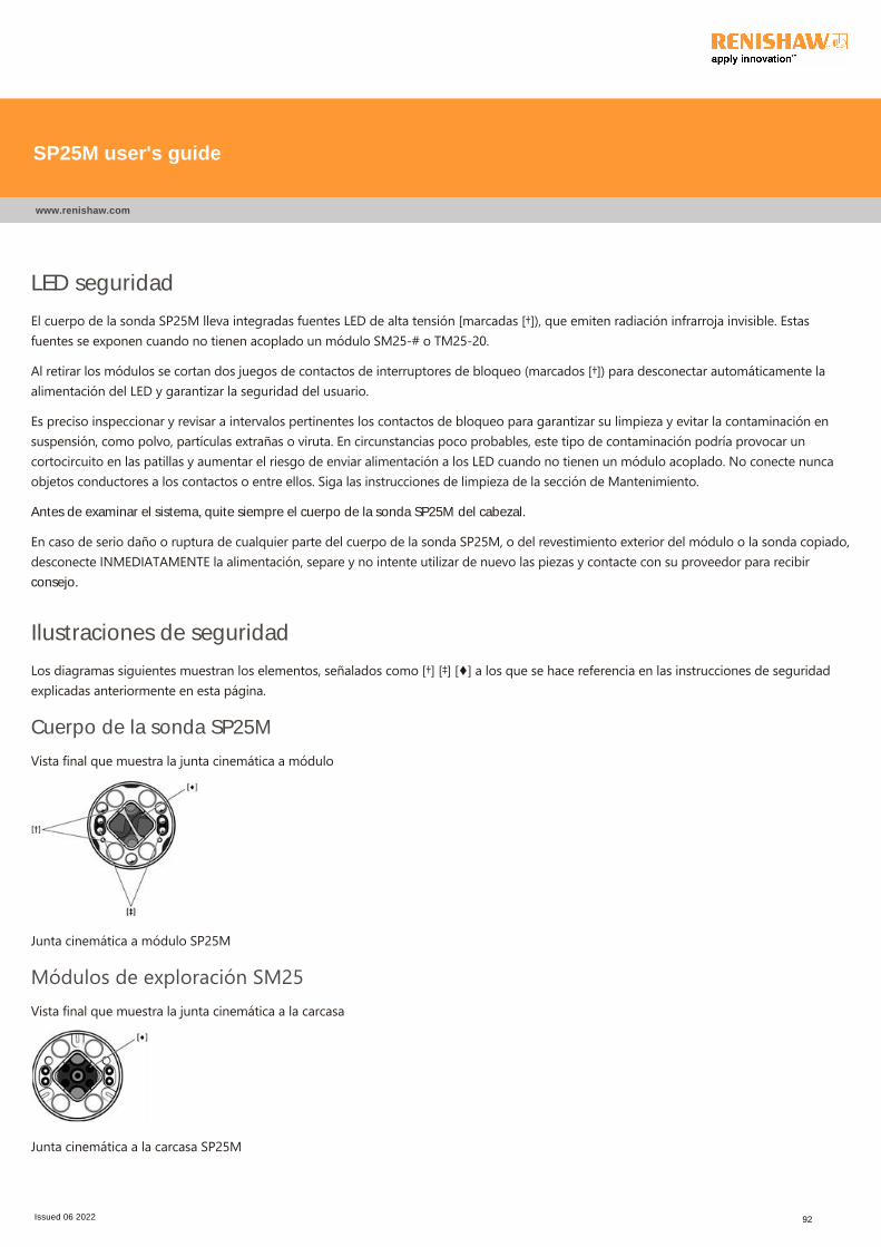
LED seguridad
El cuerpo de la sonda SP25M lleva integradas fuentes LED de alta tensión [marcadas [†]﴿, que emiten radiación infrarroja invisible. Estasfuentes se exponen cuando no tienen acoplado un módulo SM25‐# o TM25‐20.
Al retirar los módulos se cortan dos juegos de contactos de interruptores de bloqueo ﴾marcados [†]﴿ para desconectar automáticamente laalimentación del LED y garantizar la seguridad del usuario.
Es preciso inspeccionar y revisar a intervalos pertinentes los contactos de bloqueo para garantizar su limpieza y evitar la contaminación ensuspensión, como polvo, partículas extrañas o viruta. En circunstancias poco probables, este tipo de contaminación podría provocar uncortocircuito en las patillas y aumentar el riesgo de enviar alimentación a los LED cuando no tienen un módulo acoplado. No conecte nuncaobjetos conductores a los contactos o entre ellos. Siga las instrucciones de limpieza de la sección de Mantenimiento.
Antes de examinar el sistema, quite siempre el cuerpo de la sonda SP25M del cabezal.
En caso de serio daño o ruptura de cualquier parte del cuerpo de la sonda SP25M, o del revestimiento exterior del módulo o la sonda copiado,desconecte INMEDIATAMENTE la alimentación, separe y no intente utilizar de nuevo las piezas y contacte con su proveedor para recibirconsejo.
Ilustraciones de seguridad
Los diagramas siguientes muestran los elementos, señalados como [†] [‡] [♦] a los que se hace referencia en las instrucciones de seguridadexplicadas anteriormente en esta página.
Cuerpo de la sonda SP25M
Vista final que muestra la junta cinemática a módulo
Junta cinemática a módulo SP25M
Módulos de exploración SM25Vista final que muestra la junta cinemática a la carcasa
Junta cinemática a la carcasa SP25M
SP25M user's guide
www.renishaw.com
Issued 06 2022 92
ET ‐ Üldised ohutusjuhisedETTEVAATUST! Enne SP25M‐sondisüsteemi lahtipakkimist ja paigaldamist peab kasutaja lugema hoolikalt alltoodudohutussuuniseid ning tagama, et kõik operaatorid järgiksid neid sondisüsteemi kasutamisel. Juhtimis‐ või reguleerimisseadmetekasutamine või selles dokumendis mitte loetletud protseduuride tegemine võib põhjustada ohtlikku infrapunakiirgust.Operaatorid peavad saama SP25M‐sondisüsteemi ning sellega kaasnevate toodete kasutamise ja rakendamise koolituse enne, kuitohivad asuda tööle masinaga, kuhu vastav süsteem on paigaldatud.
MÄRKUS. Viited on märgitud alljärgnevatel piltidel näidatud tähistusega [†] [‡] [♦] tunnusjoonte alla. Palun veenduge, etmõistaksite selgelt kõiki ohutussuuniseid. Soovitav on tutvuda järgnevates jaotistes näidatud SP25M‐süsteemi komponentidega.
Süsteemi komponentide ülevaadeSondisüsteemi komponentide põhimõtteskeemFCR25 muudetava raami põhimõtteskeemFCR25 TC muudetava raami põhimõtteskeem
SP25M‐sondisüsteemil on sondi +Z‐teljel fikseeritud otsatõkkena mehaaniline järeljooksukaitse. Seega peaks masinakontrollsüsteem suutma enne otsatõkkeni jõudmist peatada masina liikumise sondi teljel enne otsatõkkeni jõudmist. Kui see polenii, siis peavad kasutajal olema töö ajal silmakaitsmed juhuks, kui nõel peaks murduma.
Tuleb hoolikalt jälgida, et nii korpusel kui ka moodulil asuvad optilised aknad ﴾näidatud [♦]﴿ ei saaks viga, kuna need on klaasist ja võivadpõhjustada vigastusi.
ETTEVAATUST! SP25M‐süsteemi ja sellega seotud toodete mõnel komponendil kasutatakse püsimagneteid. Need tuleb hoidaeemal detailidest, mida võib mõjutada magnetväli, nt andmesalvestussüsteemid, südamestimulaatorid, kellad jne.
SP25M user's guide
www.renishaw.com
Issued 06 2022 93
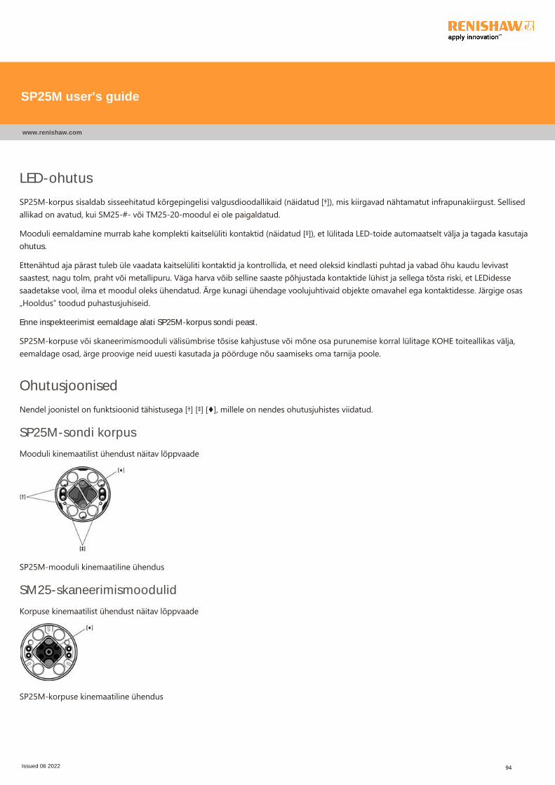
LED-ohutus
SP25M‐korpus sisaldab sisseehitatud kõrgepingelisi valgusdioodallikaid ﴾näidatud [†]﴿, mis kiirgavad nähtamatut infrapunakiirgust. Sellisedallikad on avatud, kui SM25‐#‐ või TM25‐20‐moodul ei ole paigaldatud.
Mooduli eemaldamine murrab kahe komplekti kaitselüliti kontaktid ﴾näidatud [‡]﴿, et lülitada LED‐toide automaatselt välja ja tagada kasutajaohutus.
Ettenähtud aja pärast tuleb üle vaadata kaitselüliti kontaktid ja kontrollida, et need oleksid kindlasti puhtad ja vabad õhu kaudu levivastsaastest, nagu tolm, praht või metallipuru. Väga harva võib selline saaste põhjustada kontaktide lühist ja sellega tõsta riski, et LEDidessesaadetakse vool, ilma et moodul oleks ühendatud. Ärge kunagi ühendage voolujuhtivaid objekte omavahel ega kontaktidesse. Järgige osas„Hooldus” toodud puhastusjuhiseid.
Enne inspekteerimist eemaldage alati SP25M-korpus sondi peast.
SP25M‐korpuse või skaneerimismooduli välisümbrise tõsise kahjustuse või mõne osa purunemise korral lülitage KOHE toiteallikas välja,eemaldage osad, ärge proovige neid uuesti kasutada ja pöörduge nõu saamiseks oma tarnija poole.
Ohutusjoonised
Nendel joonistel on funktsioonid tähistusega [†] [‡] [♦], millele on nendes ohutusjuhistes viidatud.
SP25M-sondi korpus
Mooduli kinemaatilist ühendust näitav lõppvaade
SP25M‐mooduli kinemaatiline ühendus
SM25-skaneerimismoodulid
Korpuse kinemaatilist ühendust näitav lõppvaade
SP25M‐korpuse kinemaatiline ühendus
SP25M user's guide
www.renishaw.com
Issued 06 2022 94
FI - Yleiset turvallisuussuositukset
VAROITUS: Ennen SP25M‐luotausjärjestelmän paketin avaamista ja laitteen asennusta käyttäjän tulee lukea turvallisuusohjeethuolellisesti ja varmistua siitä, että kaikki testausjärjestelmää käyttävät henkilöt noudattavat niitä aina. Sellaisten säätöjen jaasetusten teko tai sellaisten menetelmien käyttö, joita ei tässä mainita, saattaa johtaa vahingolliseen altistumiseeninfrapunasäteilylle.Ennenkuin käyttäjien sallitaan käyttää laitetta, heidän tulee olla koulutettuja käyttämään ja soveltamaan SP25M‐kuvaluotausjärjestelmää ja siihen liittyviä tuotteita.
HUOMAA: Viittaukset kuviin merkitään symboleilla [†] [‡] [♦] alla olevissa kuvissa. Varmista, että ymmärrät selvästi kaikkiturvallisuusohjeet. Suosittelemme tutustumista kappaleissa esitettyihin SP25M‐järjestelmän komponentteihin:
Järjestelmän komponenttien yleiskuvausAnturijärjestelmän komponenttien kaaviokuvaJoustavan vaihtokehikon FCR25 kaaviokuva
Joustavan vaihtokehikon FCR25 TC kaaviokuva
SP25M‐anturijärjestelmässä on +Z‐akselin mekaaninen liikerajan suojaus, joka on kiinteä pysäytysvaste. Koneenohjausjärjestelmän on tämän vuoksi kyettävä pysäyttämään koneen liike tässä anturin akselisuunnassa, ennen kuin vastesaavutetaan. Jos tämä ei ole mahdollista, käyttäjän tulee pitää silmäsuojusta kärjen hajoamisen varalta.
Käyttäjän tulee huolehtia siitä, ettei sekä rungossa että moduulissa sijaitseva optinen ikkuna ﴾merkitty [♦]﴿ vahingoitu, sillä se on valmistettulasista ja voi aiheuttaa tapaturman.
VAROITUS: SP25M‐järjestelmän ja siihen liittyvien tuotteiden joissain komponenteissa käytetään kestomagneetteja. On tärkeää,ettei kestomagneettien lähelle viedä tuotteita, jotka saattavat reagoida magneettikenttiin, kuten esim. tiedontallennusvälineitä,tahdistimia, kelloja jne.
SP25M user's guide
www.renishaw.com
Issued 06 2022 95
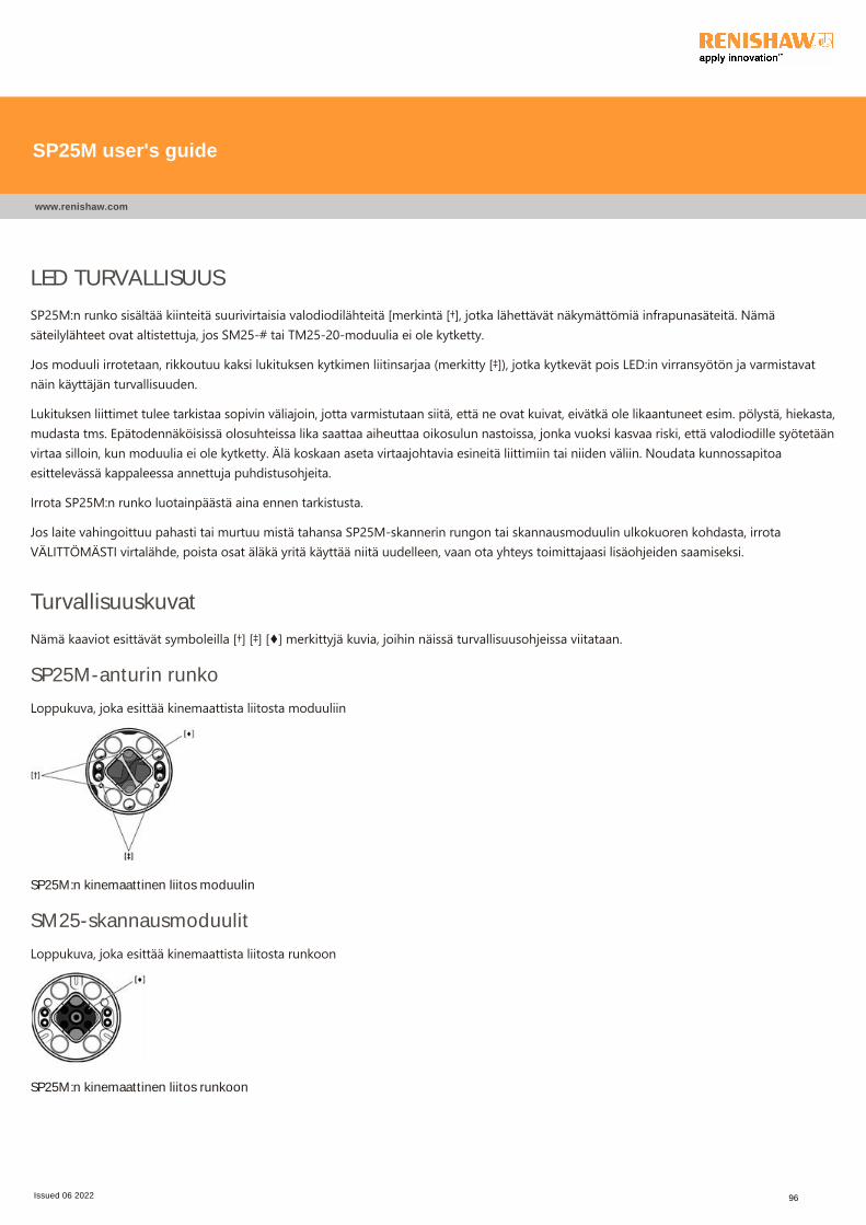
LED TURVALLISUUS
SP25M:n runko sisältää kiinteitä suurivirtaisia valodiodilähteitä [merkintä [†], jotka lähettävät näkymättömiä infrapunasäteitä. Nämäsäteilylähteet ovat altistettuja, jos SM25‐# tai TM25‐20‐moduulia ei ole kytketty.
Jos moduuli irrotetaan, rikkoutuu kaksi lukituksen kytkimen liitinsarjaa ﴾merkitty [‡]﴿, jotka kytkevät pois LED:in virransyötön ja varmistavatnäin käyttäjän turvallisuuden.
Lukituksen liittimet tulee tarkistaa sopivin väliajoin, jotta varmistutaan siitä, että ne ovat kuivat, eivätkä ole likaantuneet esim. pölystä, hiekasta,mudasta tms. Epätodennäköisissä olosuhteissa lika saattaa aiheuttaa oikosulun nastoissa, jonka vuoksi kasvaa riski, että valodiodille syötetäänvirtaa silloin, kun moduulia ei ole kytketty. Älä koskaan aseta virtaajohtavia esineitä liittimiin tai niiden väliin. Noudata kunnossapitoaesittelevässä kappaleessa annettuja puhdistusohjeita.
Irrota SP25M:n runko luotainpäästä aina ennen tarkistusta.
Jos laite vahingoittuu pahasti tai murtuu mistä tahansa SP25M‐skannerin rungon tai skannausmoduulin ulkokuoren kohdasta, irrotaVÄLITTÖMÄSTI virtalähde, poista osat äläkä yritä käyttää niitä uudelleen, vaan ota yhteys toimittajaasi lisäohjeiden saamiseksi.
Turvallisuuskuvat
Nämä kaaviot esittävät symboleilla [†] [‡] [♦] merkittyjä kuvia, joihin näissä turvallisuusohjeissa viitataan.
SP25M-anturin runko
Loppukuva, joka esittää kinemaattista liitosta moduuliin
SP25M:n kinemaattinen liitos moduulin
SM25-skannausmoduulit
Loppukuva, joka esittää kinemaattista liitosta runkoon
SP25M:n kinemaattinen liitos runkoon
SP25M user's guide
www.renishaw.com
Issued 06 2022 96
FR ‐ Recommandations générales de sécuritéATTENTION : Avant de déballer et d'installer le système de palpeur SP25M, l'utilisateur doit lire attentivement les instructions desécurité suivantes et faire en sorte qu'elles soient respectées en permanence par tous les opérateurs de ce système. L'utilisation decommandes ou de réglages ou la réalisation de procédures autres que ceux spécifiés dans ce document peut entraîner uneexposition dangereuse à des rayonnements infrarouges.Les opérateurs doivent être formés à l'usage et aux applications du système de palpeur SP25M et aux produits qui l'accompagnentet ce, dans le contexte de la machine sur laquelle ce système est installé avant d'être autorisés à utiliser cette machine.
REMARQUE : Le texte ci‐après fait référence à des éléments indiqués par [†] [‡] [♦] sur les illustrations qui suivent. Assurez‐vousd'avoir clairement compris toutes les instructions de sécurité. Nous vous recommandons de vous familiariser avec les composantsdu système SP25M, illustrés dans les sections :
Présentation des composants du systèmeSchéma des composants du système de palpageSchéma du système automatique de rack changeur FCR25Schéma du système automatique de rack changeur FCR25 TC
Le système de palpeur SP25M est doté d'une protection mécanique ﴾butée de choc﴿ contre les dépassements de course sur l'axe +Zdu palpeur. Le système de commande de la machine doit donc pouvoir stopper le mouvement de la machine sur cet axe du palpeuravant d'atteindre la butée de choc. Dans le cas contraire, l'utilisateur devra porter des lunettes de protection pendant lefonctionnement en cas de rupture du stylet.
Évitez toute détérioration de la fenêtre optique [signalée par le symbole [♦], située à la fois sur le corps et sur le module. Cette fenêtre est enverre et peut entraîner des blessures.
ATTENTION : Des aimants permanents sont utilisés dans certains composants du système SP25M et ses produits associés. Il fautimpérativement les tenir à distance des objets susceptibles d'être affectés par les champs magnétiques tels que les systèmes destockage de données, stimulateurs cardiaques, montres‐bracelets, etc.
SP25M user's guide
www.renishaw.com
Issued 06 2022 97
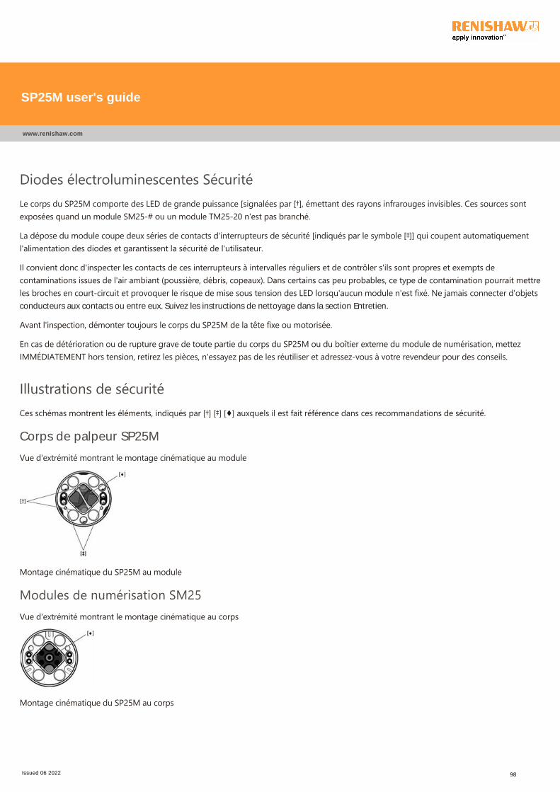
Diodes électroluminescentes SécuritéLe corps du SP25M comporte des LED de grande puissance [signalées par [†], émettant des rayons infrarouges invisibles. Ces sources sontexposées quand un module SM25‐# ou un module TM25‐20 n'est pas branché.
La dépose du module coupe deux séries de contacts d'interrupteurs de sécurité [indiqués par le symbole [‡]] qui coupent automatiquementl'alimentation des diodes et garantissent la sécurité de l'utilisateur.
Il convient donc d'inspecter les contacts de ces interrupteurs à intervalles réguliers et de contrôler s'ils sont propres et exempts decontaminations issues de l'air ambiant ﴾poussière, débris, copeaux﴿. Dans certains cas peu probables, ce type de contamination pourrait mettreles broches en court‐circuit et provoquer le risque de mise sous tension des LED lorsqu'aucun module n'est fixé. Ne jamais connecter d'objetsconducteurs aux contacts ou entre eux. Suivez les instructions de nettoyage dans la section Entretien.
Avant l'inspection, démonter toujours le corps du SP25M de la tête fixe ou motorisée.
En cas de détérioration ou de rupture grave de toute partie du corps du SP25M ou du boîtier externe du module de numérisation, mettezIMMÉDIATEMENT hors tension, retirez les pièces, n'essayez pas de les réutiliser et adressez‐vous à votre revendeur pour des conseils.
Illustrations de sécuritéCes schémas montrent les éléments, indiqués par [†] [‡] [♦] auxquels il est fait référence dans ces recommandations de sécurité.
Corps de palpeur SP25M
Vue d'extrémité montrant le montage cinématique au module
Montage cinématique du SP25M au module
Modules de numérisation SM25Vue d'extrémité montrant le montage cinématique au corps
Montage cinématique du SP25M au corps
SP25M user's guide
www.renishaw.com
Issued 06 2022 98
GA ‐ Moltaí ginearálta sábháilteachtaRABHADH: Ba chóir don úsáideoir na treoracha sábháilteachta thíos a léamh go cúramach sula ndéantar an córas tóireadóraSP25M a dhíphacáil agus a shuiteáil, agus a chinntiú go leanann gach oibreoir a úsáideann an córas tóireadóra i gcónaí iad. Is feidirnochtadh radaíochta infridhearg guaisí a tharlú de dheasca rialtáin a úsáid nó ceartú, nó feidhmiú nósanna imeachta seachas nacinn a shonraítear istigh anseo.Ní mór oibreoirí a chur faoi oiliúint maidir le húsáid agus le feidhmiú chórais tóireadóra SP25M agus na táirgí a ghabhann leis, igcomhthéacs an innill ar a bhfuil sé feistithe, sula gceadaítear dóibh an t‐inneall a úsáid.
NÓTA: Déantar tagairtí thíos do ghnéithe a léirítear mar [†] [‡] [♦] sna léaráidí thíos. Cinntigh, le do thoil, go dtuigeann tú gachtreoir shábháilteachta ina n‐iomláine. Moltar bheith eolach ar chomhbhaill an chórais SP25M, mar a léirítear sna codanna seo aleanas:
Forbhreathnú ar chomhbhaill an chóraisLéaráid scéimreach ar chomhbhall an chórais tóireadóraLéaráid scéimreach ar raca athraithe solúbtha FCR25Léaráid scéimreach ar raca athraithe solúbtha FCR25 TC
Tá cosaint mheicniúil ar fhorthaistil sa chóras tóireadóra SP25M atá ar fáil in ais +Z an tóireadóra, le stop tuairte daingean. Ní mórdo rialchóras an innill a bheith in ann stop a chur le gluaiseacht an innill, in ais seo an tóireadóra, sula ndéanfar an stop tuairte abhaint amach. Murab amhlaidh an scéal, caithfidh an t‐úsáideoir cosaint súl a chaitheamh agus an gléas á oibriú aige/aici ar eaglago mbrisfeadh an stíleas.
Ní mór aire a thabhairt lena chinntiú nach ndéantar aon damáiste do na fuinneoga optúla ﴾a léirítear mar [♦]﴿, atá ar an gcabhail agus ar anmodúl araon, óir tá siad déanta de ghloine agus d'fhéadfaidís gortú a dhéanamh.
RABHADH: Tá buanmhaighnéid i gcuid de chomhpháirteanna an chórais SP25M agus sna táirgí a théann leis. Tá sé tábhachtachiad a choinneáil amach ó earraí mar chórais stórála sonraí, séadairí, uaireadóirí agus araile a d'fheadfadh réimsí maighnéadachadul i gcion orthu.
SP25M user's guide
www.renishaw.com
Issued 06 2022 99
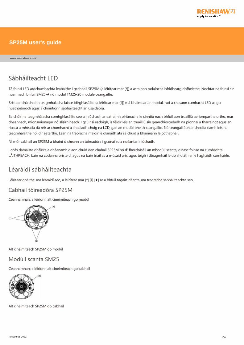
Sábháilteacht LEDTá foinsí LED ardchumhachta leabaithe i gcabhail SP25M ﴾a léirítear mar [†]﴿ a astaíonn radaíocht infridhearg dofheicthe. Nochtar na foinsí sinnuair nach bhfuil SM25‐# nó modúl TM25‐20 module ceangailte.
Bristear dhá shraith teagmhálacha laisce idirghlasáilte ﴾a léirítear mar [‡]﴿ má bhaintear an modúl, rud a chasann cumhacht LED as gohuathoibríoch agus a chinntíonn sábháilteacht an úsáideora.
Ba chóir na teagmhálacha comhghlasáilte seo a iniúchadh ar eatraimh oiriúnacha le cinntiú nach bhfuil aon truailliú aeriompartha orthu, mardheannach, mionsmionagar nó slisirníneach. I gcúinsí éadóigh, is féidir leis an truailliú sin gearrchiorcadadh na pionnaí a tharraingt agus anriosca a mhéadú dá réir ar chumhacht a sheoladh chuig na LCD, gan an modúl bheith ceangailte. Ná ceangail ábhair sheolta riamh leis nateagmhálaithe nó idir eatarthu. Lean na treoracha maidir le glanadh atá sa chuid a bhaineann le cothabháil.
Ní mór cabhail an SP25M a bhaint ó cheann an tóireadóra i gcónaí sula ndéantar iniúchadh.
I gcás damáiste dháiríre a dhéanamh d'aon chuid den chabail SP25M nó d' fhorchásáil an mhodúil scanta, dínasc foinse na cumhachtaLÁITHREACH, bain na codanna briste di agus ná bain triail as a n‐úsáid arís, agus téigh i dteagmháil le do sholáthraí le haghaidh comhairle.
Léaráidí sábháilteachtaLéirítear gnéithe sna léaráidí seo, a léirítear mar [†] [‡] [♦] ar a bhfuil tagairt déanta sna treoracha sábháilteachta seo.
Cabhail tóireadóra SP25MCeannamharc a léiríonn alt cinéimiteach go modúl
Alt cinéimiteach SP25M go modúl
Modúil scanta SM25Ceannamharc a léiríonn alt cinéimiteach go cabhail
Alt cinéimiteach SP25M go cabhail
SP25M user's guide
www.renishaw.com
Issued 06 2022 100
HR - UPOZORENJE
OPREZ: Prije raspakiravanja i instaliranja sustava sonde SP25M, korisnik mora pažljivo pročitati donje sigurnosne upute i osiguratida ih cijelo vrijeme poštuju svi rukovatelji koji koriste sustav sonde. Korištenje kontrola ili podešavanja, ili karakteristike postupakadrugačije od ovdje navedenih, može prouzročiti izlaganje opasnom infracrvenom zračenju.Rukovatelji moraju biti obučeni za korištenje i primjenu sustava sonde SP25M i pripadajućih proizvoda, u kontekstu stroja koji jenjima opremljen, prije nego što dobiju dopuštenje rada na stroju.
NAPOMENA: Reference se nalaze ispod za značajke označene s [†] [‡] [♦] na donjem crtežu. Uvjerite se da dobro razumijete svesigurnosne upute. Preporučuje se upoznavanje s komponentama sustava SP25M, kako je prikazano u sljedećim poglavljima:
Pregled komponenti sustava
Shematski dijagram komponenti sustava sonde
Shematski dijagram FCR25 okvira za fleksibilnu promjenu
Shematski dijagram FCR25 TC stalka za fleksibilnu promjenu
Sustav sonde SP25M ima mehaničku zaštitu od prekomjernog hoda danu u osi +Z, putem fiksnog graničnika. Upravljački sustavstroja zato mora moći zaustaviti kretanje stroja, u ovoj osi sonde, prije dosezanja graničnika. Ako se to ne dogodi, korisnik moranositi zaštitu za oči tijekom rada za slučaj lomljenja igle.
Potrebno je paziti kako se optički prozori ﴾označeni s [♦]﴿, koji se nalaze na korpusu i na modulu, ne bi oštetili, jer su načinjeni od stakla imogu prouzročiti ozljede.
OPREZ: U nekim komponentama sustava SP25M i pridruženih proizvoda koriste se trajni magneti. Važno je držati ih podalje odpredmeta koji mogu biti zahvaćeni magnetskim poljima, npr. sustavi pohrane podataka, elektrostimulatori srca, satovi itd.
SP25M user's guide
www.renishaw.com
Issued 06 2022 101
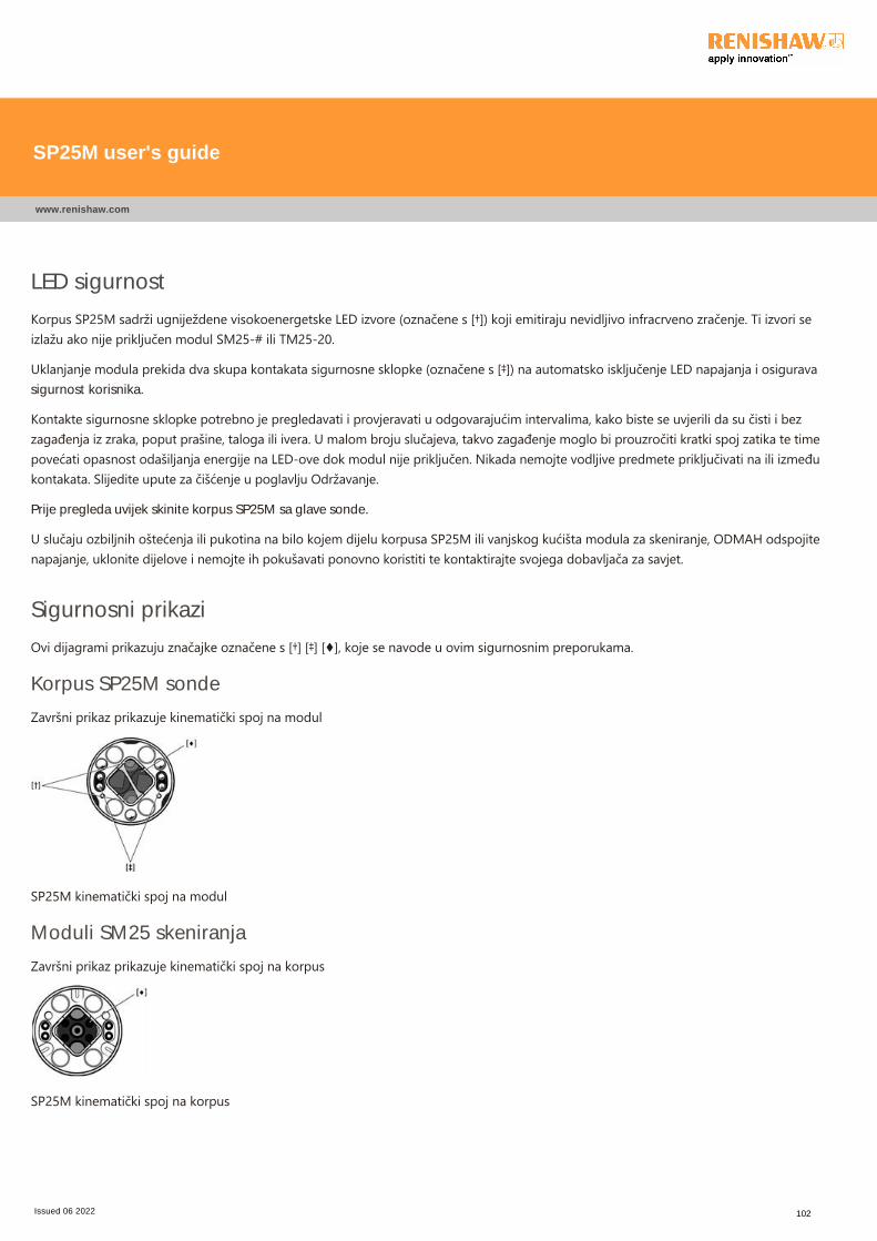
LED sigurnost
Korpus SP25M sadrži ugniježdene visokoenergetske LED izvore ﴾označene s [†]﴿ koji emitiraju nevidljivo infracrveno zračenje. Ti izvori seizlažu ako nije priključen modul SM25‐# ili TM25‐20.
Uklanjanje modula prekida dva skupa kontakata sigurnosne sklopke ﴾označene s [‡]﴿ na automatsko isključenje LED napajanja i osiguravasigurnost korisnika.
Kontakte sigurnosne sklopke potrebno je pregledavati i provjeravati u odgovarajućim intervalima, kako biste se uvjerili da su čisti i bezzagađenja iz zraka, poput prašine, taloga ili ivera. U malom broju slučajeva, takvo zagađenje moglo bi prouzročiti kratki spoj zatika te timepovećati opasnost odašiljanja energije na LED‐ove dok modul nije priključen. Nikada nemojte vodljive predmete priključivati na ili izmeđukontakata. Slijedite upute za čišćenje u poglavlju Održavanje.
Prije pregleda uvijek skinite korpus SP25M sa glave sonde.
U slučaju ozbiljnih oštećenja ili pukotina na bilo kojem dijelu korpusa SP25M ili vanjskog kućišta modula za skeniranje, ODMAH odspojitenapajanje, uklonite dijelove i nemojte ih pokušavati ponovno koristiti te kontaktirajte svojega dobavljača za savjet.
Sigurnosni prikazi
Ovi dijagrami prikazuju značajke označene s [†] [‡] [♦], koje se navode u ovim sigurnosnim preporukama.
Korpus SP25M sonde
Završni prikaz prikazuje kinematički spoj na modul
SP25M kinematički spoj na modul
Moduli SM25 skeniranja
Završni prikaz prikazuje kinematički spoj na korpus
SP25M kinematički spoj na korpus
SP25M user's guide
www.renishaw.com
Issued 06 2022 102
HU ‐ Általános biztonsági javaslatokFIGYELMEZTETÉS: Az SP25M mérőrendszer kicsomagolása és telepítése előtt a felhasználónak figyelmesen el kell olvasnia azalábbi biztonsági utasításokat, és gondoskodnia kell arról, hogy azokat a mérőrendszer minden kezelője, mindig betartsa. Az ittleírtaktól eltérő vezérlőszervek, beállítások vagy módszerek alkalmazása esetén a felhasználót veszélyes infravörös sugárzás érheti.A kezelőknek még azt megelőzően képzésben kell részesülniük az SP25M mérőrendszer és a kapcsolódó termékek használata ésalkalmazása terén, mielőtt engedélyezik számukra a gép kezelését. A képzés során az érintett termékek használatát azon a gépenkell elsajátítani, amelyre azokat felszerelik.
MEGJEGYZÉS: Az alábbi utalások a lentebb látható ábrákon [†] [‡] [♦] szimbólummal jelölt részekre vonatkoznak. Kérjük,győződjön meg arról, hogy minden biztonsági utasítást világosan megértett. Azt javasoljuk, hogy ismerkedjen meg az SP25Mrendszer összetevőivel; a kapcsolódó tudnivalók a következő fejezetekben olvashatók:
A rendszer összetevőinek áttekintéseA mérőfejes rendszer összetevőinek sematikus ábrájaAz FCR25 flexibilis csereállvány sematikus ábrájaAz FCR25 TC flexibilis csereállvány sematikus ábrája
Az SP25M mérőfejes rendszer mechanikus túlfutásvédelemmel rendelkezik a mérőfej +Z tengelyén, amit egy rögzített ütközőbiztosít. A gépet vezérlő rendszernek ezért le kell tudnia állítani a gép mozgását a mérőfej említett tengelyén, mielőtt az elérné azütközőt. Amennyiben ez nem teljesül, a felhasználónak szemvédő eszközt kell viselnie a gép kezelése közben arra az esetre, ha atapintószár esetleg eltörne.
Ügyelni kell arra, hogy a készülék házán és a modulon található optikai ablakok ﴾amelyeket az ábrán [♦] jelöl﴿ ne sérülhessenek meg, mivelezek üvegből készültek, és törés esetén sérülést okozhatnak.
FIGYELMEZTETÉS: Az SP25M rendszer és a kapcsolódó termékek egyes alkatrészeiben állandó mágnesek találhatók. Ezeket távolkell tartani olyan tárgyaktól, amelyeket a mágneses mezők károsíthatnak, pl. adattároló rendszerek, szívritmus‐szabályozók,karórák stb.
SP25M user's guide
www.renishaw.com
Issued 06 2022 103
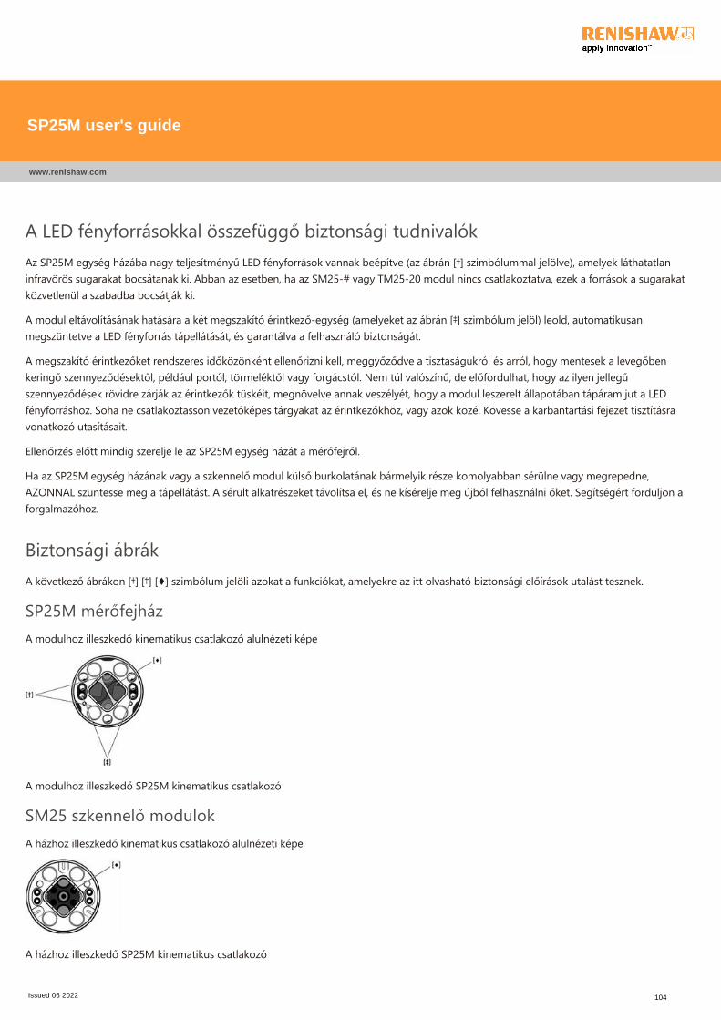
A LED fényforrásokkal összefüggő biztonsági tudnivalókAz SP25M egység házába nagy teljesítményű LED fényforrások vannak beépítve ﴾az ábrán [†] szimbólummal jelölve﴿, amelyek láthatatlaninfravörös sugarakat bocsátanak ki. Abban az esetben, ha az SM25‐# vagy TM25‐20 modul nincs csatlakoztatva, ezek a források a sugarakatközvetlenül a szabadba bocsátják ki.
A modul eltávolításának hatására a két megszakító érintkező‐egység ﴾amelyeket az ábrán [‡] szimbólum jelöl﴿ leold, automatikusanmegszüntetve a LED fényforrás tápellátását, és garantálva a felhasználó biztonságát.
A megszakító érintkezőket rendszeres időközönként ellenőrizni kell, meggyőződve a tisztaságukról és arról, hogy mentesek a levegőbenkeringő szennyeződésektől, például portól, törmeléktől vagy forgácstól. Nem túl valószínű, de előfordulhat, hogy az ilyen jellegűszennyeződések rövidre zárják az érintkezők tüskéit, megnövelve annak veszélyét, hogy a modul leszerelt állapotában tápáram jut a LEDfényforráshoz. Soha ne csatlakoztasson vezetőképes tárgyakat az érintkezőkhöz, vagy azok közé. Kövesse a karbantartási fejezet tisztításravonatkozó utasításait.
Ellenőrzés előtt mindig szerelje le az SP25M egység házát a mérőfejről.
Ha az SP25M egység házának vagy a szkennelő modul külső burkolatának bármelyik része komolyabban sérülne vagy megrepedne,AZONNAL szüntesse meg a tápellátást. A sérült alkatrészeket távolítsa el, és ne kísérelje meg újból felhasználni őket. Segítségért forduljon aforgalmazóhoz.
Biztonsági ábrákA következő ábrákon [†] [‡] [♦] szimbólum jelöli azokat a funkciókat, amelyekre az itt olvasható biztonsági előírások utalást tesznek.
SP25M mérőfejházA modulhoz illeszkedő kinematikus csatlakozó alulnézeti képe
A modulhoz illeszkedő SP25M kinematikus csatlakozó
SM25 szkennelő modulokA házhoz illeszkedő kinematikus csatlakozó alulnézeti képe
A házhoz illeszkedő SP25M kinematikus csatlakozó
SP25M user's guide
www.renishaw.com
Issued 06 2022 104
IT - Raccomandazioni generali di sicurezza
ATTENZIONE: Prima di estrarre il sistema sonda SP25M dall'imballo e iniziare l'installazione, leggere attentamente le istruzioni
riportate di seguito e controllare che vengano sempre rispettate da tutti gli operatori che utilizzano il sistema sonda. L'uso di
comandi e regolazioni o l'esecuzione di procedure di natura diversa da quelle qui specificate potrebbero provocare un'esposizione
a radiazioni infrarossi nocive.
Prima di attivare una macchina che include il sistema SP25M, gli operatori devono essere addestrati all'uso del sistema e dei
prodotti accessori nel contesto in cui essi vengono utilizzati.
NOTA: Di seguito vengono riportati riferimenti a funzioni indicate con [†] [‡] [♦] nelle figure di seguito. Leggere con estremaattenzione tutte le istruzioni di sicurezza. Si consiglia di acquisire familiarità con tutti i componenti del sistema SP25M, mostratinelle sezioni di seguito:
Panoramica dei componenti del sistema
Diagramma schematico dei componenti del sistema
Diagramma schematico del rack di cambio flessibile FCR25
Diagramma schematico del rack di cambio flessibile FCR25 TC
Il sistema sonda SP25M dispone di un sistema meccanico di protezione di oltrecorsa lungo l'asse Z+ della sonda costituito da un
punto fisso di arresto. Il sistema di controllo delle macchina deve essere quindi in grado di fermare il movimento macchina lungo la
direzione di tale asse della sonda prima che venga raggiunto il fine corsa meccanico. In caso contrario, l'utente dovrà indossareocchiali protettivi durante l'utilizzo della macchina, per prevenire rischi in caso di rottura dello stilo.
Fare attenzione che le finestre ottiche ﴾indicate con [♦]﴿,posizionate sul corpo e sul modulo, non subiscano danni. Le finestre sono di vetro e incaso di rottura potrebbero provocare lesioni alle persone.
ATTENZIONE: Alcuni componenti del sistema SP25M e di prodotti associati includono magneti. Non avvicinare prodotti che
possano essere influenzati da campi magnetici come ad esempio, sistemi di immagazzinamento dati, orologi, pacemaker e così via.
SP25M user's guide
www.renishaw.com
Issued 06 2022 105
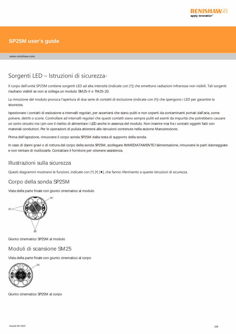
Sorgenti LED – Istruzioni di sicurezza‐Il corpo dell'unità SP25M contiene sorgenti LED ad alta intensità ﴾indicate con [†]﴿ che emettono radiazioni infrarosse non visibili. Tali sorgentirisultano visibili se non si collega un modulo SM25-# o TM25-20.
La rimozione del modulo provoca l'apertura di due serie di contatti di esclusione ﴾indicate con [‡]﴿ che spengono i LED per garantire lasicurezza.
Ispezionare i contatti di esclusione a intervalli regolari, per accertarsi che siano puliti e non coperti da contaminanti portati dall'aria, come
polvere, detriti o scorie. Controllare ad intervalli regolari che questi contatti siano sempre puliti ed esenti da impurità che potrebbero causareun corto circuito tra i pin con il rischio di alimentare i LED anche in assenza del modulo. Non inserire mai fra i contatti oggetti fatti con
materiali conduttori. Per le operazioni di pulizia attenersi alle istruzioni contenute nella sezione Manutenzione.
Prima dell'ispezione, rimuovere il corpo sonda SP25M dalla testa di supporto della sonda.
In caso di danni gravi o di rottura del corpo della sonda SP25M, scollegare IMMEDIATAMENTE l'alimentazione, rimuovere le parti danneggiate
e non tentare di riutilizzarle. Contattare il fornitore per ottenere assistenza.
Illustrazioni sulla sicurezza
Questi diagrammi mostrano le funzioni, indicate con [†] [‡] [♦], che fanno riferimento a queste istruzioni di sicurezza.
Corpo della sonda SP25M
Vista della parte finale con giunto cinematico al modulo
Giunto cinematico SP25M al modulo
Moduli di scansione SM25
Vista della parte finale con giunto cinematico al corpo
Giunto cinematico SP25M al corpo
SP25M user's guide
www.renishaw.com
Issued 06 2022 106
JA ‐ 安全性に関する一般的な推奨事項
警告:SP25M プローブシステムの梱包を解いてインストールを始める前に、次の安全性に関する注意事項をよく読み、これらの事項を遵守してプ
ローブシステムを使用してください。 ここに記載した以外の方法で制御や調整を行ったり、異なる手順を実行した場合、有害な赤外線放射を浴び
る可能性があります。
SP25Mプローブシステムおよびその付属製品を使用する場合、オペレーターは機械の操作を始める前に、実際に取り付けられている機械を使って、
その使用方法や安全性等について適切なトレーニングを受けてください。
注意:以下に示されたイラストに記されている [†] [‡] [♦] に関しては、下記をご参照下さい。 すべての安全性に関する注意事項を明確に理解しし
てください。 次のセクションに示した図を参照のうえ、SP25M システムの構成を把握しておくことをお勧めします。
システム構成部品の概観
プローブシステムの構成図
FCR25 フレキシブルチェンジラックの構成図
FCR25 TC フレキシブルチェンジラックの構成図
SP25M プローブシステムにおける +Z 軸のオーバートラベル保護機構は、固定式のバンプストップ構造となっています。 安全のため、機械制御によ
りプローブのバンプストップに到達する前に動きを停止するようにしてください。 このような対策をしてない場合は、スタイラスが破損した時の安全を確
保するため、必ず保護眼鏡を着用してください。
本体とモジュールにある光学装置用のウィンドウ([♦]で表示)はガラスでできています。破損すると怪我をする危険があるため注意して作業してください。
警告:SP25Mシステムと関連製品の一部コンポーネントには、永久磁石が使用されています。 データ格納システム、ペースメーカー、時計など、磁
界の影響をうけるものは近づけないでください。
SP25M user's guide
www.renishaw.com
Issued 06 2022 107
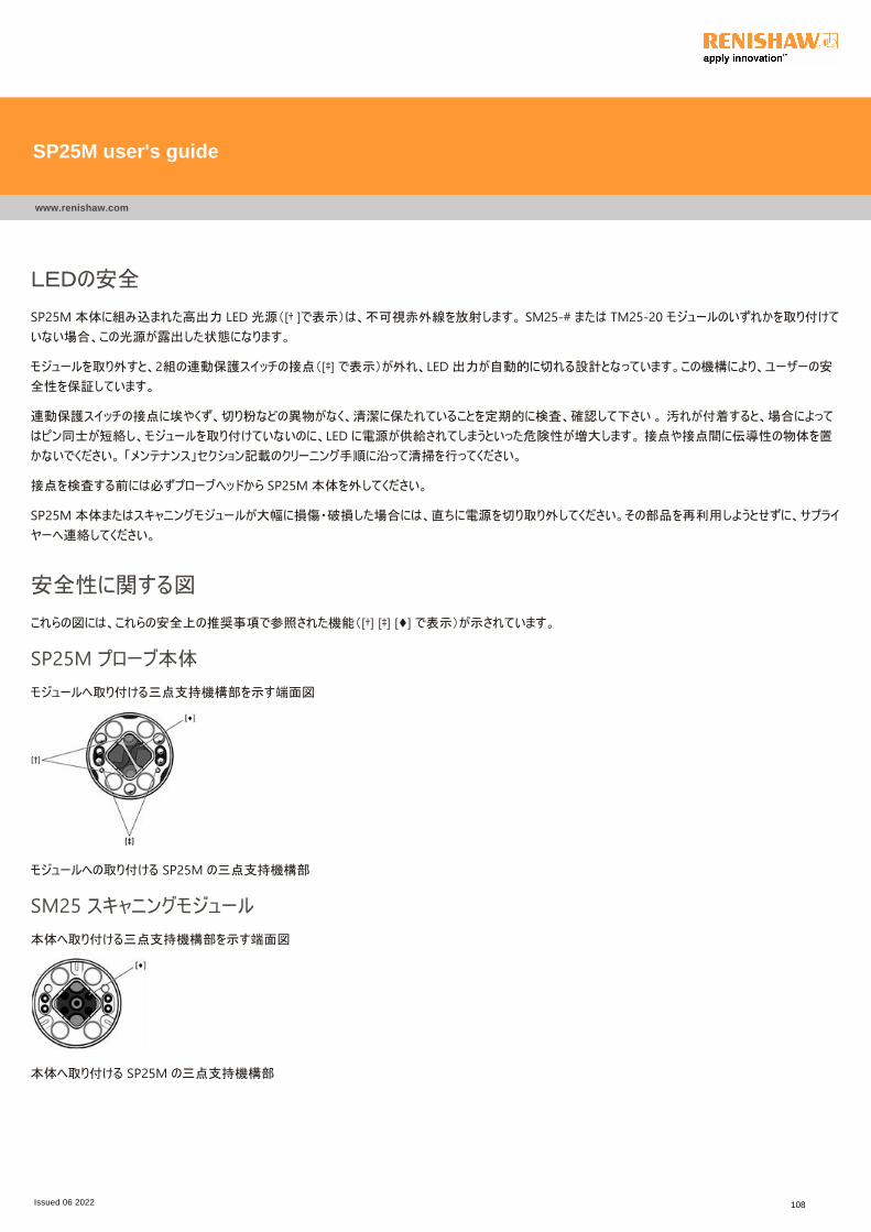
LEDの安全
SP25M 本体に組み込まれた高出力 LED 光源([† ]で表示)は、不可視赤外線を放射します。 SM25‐# または TM25‐20 モジュールのいずれかを取り付けて
いない場合、この光源が露出した状態になります。
モジュールを取り外すと、2組の連動保護スイッチの接点([‡] で表示)が外れ、LED 出力が自動的に切れる設計となっています。この機構により、ユーザーの安
全性を保証しています。
連動保護スイッチの接点に埃やくず、切り粉などの異物がなく、清潔に保たれていることを定期的に検査、確認して下さい 。 汚れが付着すると、場合によって
はピン同士が短絡し、モジュールを取り付けていないのに、LED に電源が供給されてしまうといった危険性が増大します。 接点や接点間に伝導性の物体を置
かないでください。 「メンテナンス」セクション記載のクリーニング手順に沿って清掃を行ってください。
接点を検査する前には必ずプローブヘッドから SP25M 本体を外してください。
SP25M 本体またはスキャニングモジュールが大幅に損傷・破損した場合には、直ちに電源を切り取り外してください。その部品を再利用しようとせずに、サプライ
ヤーへ連絡してください。
安全性に関する図
これらの図には、これらの安全上の推奨事項で参照された機能([†] [‡] [♦] で表示)が示されています。
SP25M プローブ本体
モジュールへ取り付ける三点支持機構部を示す端面図
モジュールへの取り付ける SP25M の三点支持機構部
SM25 スキャニングモジュール
本体へ取り付ける三点支持機構部を示す端面図
本体へ取り付ける SP25M の三点支持機構部
SP25M user's guide
www.renishaw.com
Issued 06 2022 108
LT - Bendrosios saugumo rekomendacijos
ATSARGIAI: Prieð iðpakuodami ir montuodami zondavimo sistemą SP25M, atidžiai perskaitykite saugos nurodymus ir jų laikykitėskaskart naudodami zondavimo sistemą. Naudojant valdiklius, nuostatas arba procedūras kitaip nei nurodyta šioje instrukcijoje,galima patirti pavojingą infraraudonųjų spindulių apšvitą.Prieš leidžiant naudoti įrenginį, į kurį įmontuojama zondavimo sistema SP25M ir kiti su šia sistema naudojami produktai,operatoriai turi būti iðmokyti juo dirbti.
PASTABA: toliau esanèiose iliustracijose pateikiamos nuorodos á funkcijas, paþymëtas [†] [‡] [♦]. Įsitikinkite, ar aiškiai supratotevisus saugos nurodymus. Rekomenduojama susipažinti su sistemos SP25M dalimis, nurodytomis šiuose skyriuose:
Sistemos dalių apžvalgaZondavimo sistemos dalių schemaLankstaus keitimo stovo FCR25 schema
Lankstaus keitimo stovo FCR25 TC schema
Zondavimo sistema SP25M zondo +Z ašyje turi mechaninę per didelės eigos apsaugą, kurios funkciją atlieka stacionari atrama.Todėl įrenginio valdymo sistema turi sugebėti sustabdyti įrenginio judesį zondo ašimi prieš pasiekiant atramą. Jeigu taip nėra,dirbdamas naudotojas privalo užsidėti apsauginius akinius, kad jie apsaugotų lūžus adatai.
Reikia saugotis, kad optiniai langeliai ﴾pažymėti [♦]﴿, įtaisyti korpuse ir modulyje, nebūtų sudaužyti, nes jie stikliniai ir gali sužeisti.
ATSARGIAI: Kai kuriose sistemos SP25M dalyse ir su ja naudojamuose įtaisuose yra nuolatinių magnetų. Todėl svarbu arti jųnelaikyti prietaisų, kuriuos gali paveikti magnetinis laukas, pavyzdžiui, duomenų atmintinių.
SP25M user's guide
www.renishaw.com
Issued 06 2022 109
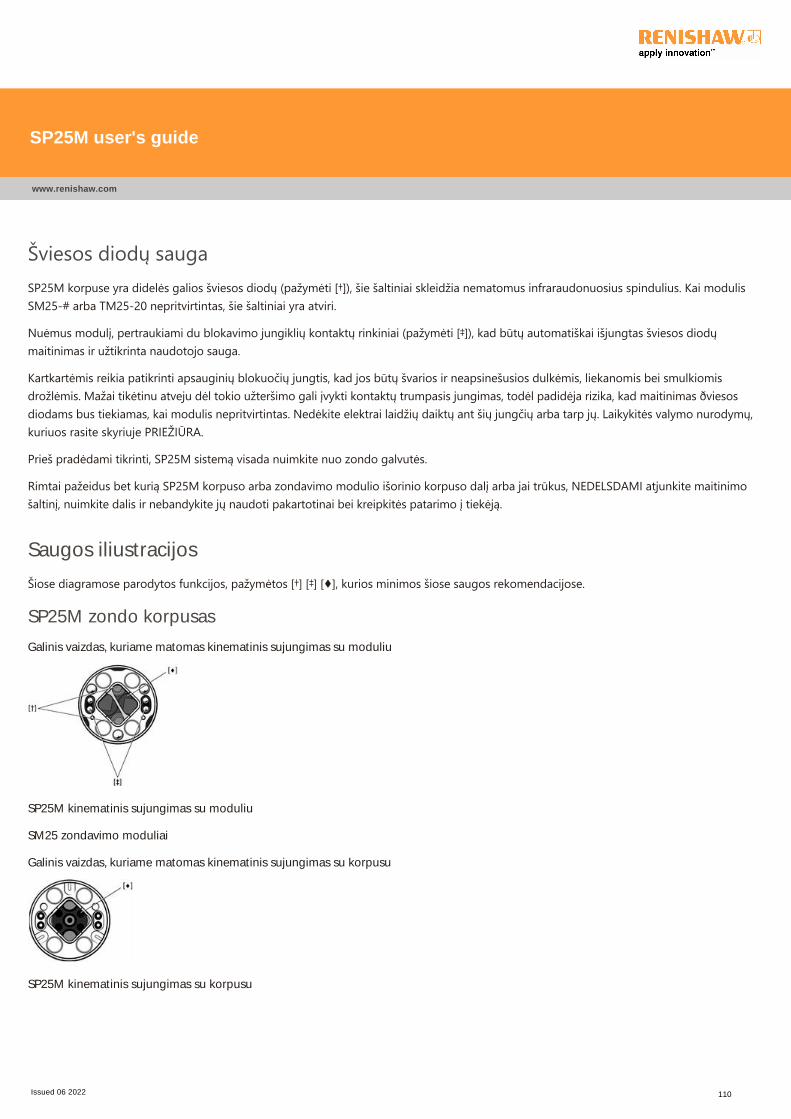
Šviesos diodų saugaSP25M korpuse yra didelės galios šviesos diodų ﴾pažymėti [†]﴿, šie šaltiniai skleidžia nematomus infraraudonuosius spindulius. Kai modulisSM25‐# arba TM25‐20 nepritvirtintas, šie šaltiniai yra atviri.
Nuėmus modulį, pertraukiami du blokavimo jungiklių kontaktų rinkiniai ﴾pažymėti [‡]﴿, kad būtų automatiškai išjungtas šviesos diodųmaitinimas ir užtikrinta naudotojo sauga.
Kartkartėmis reikia patikrinti apsauginių blokuočių jungtis, kad jos būtų švarios ir neapsinešusios dulkėmis, liekanomis bei smulkiomisdrožlėmis. Mažai tikėtinu atveju dėl tokio užteršimo gali įvykti kontaktų trumpasis jungimas, todėl padidėja rizika, kad maitinimas ðviesosdiodams bus tiekiamas, kai modulis nepritvirtintas. Nedėkite elektrai laidžių daiktų ant šių jungčių arba tarp jų. Laikykitės valymo nurodymų,kuriuos rasite skyriuje PRIEŽIŪRA.
Prieš pradėdami tikrinti, SP25M sistemą visada nuimkite nuo zondo galvutės.
Rimtai pažeidus bet kurią SP25M korpuso arba zondavimo modulio išorinio korpuso dalį arba jai trūkus, NEDELSDAMI atjunkite maitinimošaltinį, nuimkite dalis ir nebandykite jų naudoti pakartotinai bei kreipkitės patarimo į tiekėją.
Saugos iliustracijos
Šiose diagramose parodytos funkcijos, pažymėtos [†] [‡] [♦], kurios minimos šiose saugos rekomendacijose.
SP25M zondo korpusas
Galinis vaizdas, kuriame matomas kinematinis sujungimas su moduliu
SP25M kinematinis sujungimas su moduliu
SM25 zondavimo moduliai
Galinis vaizdas, kuriame matomas kinematinis sujungimas su korpusu
SP25M kinematinis sujungimas su korpusu
SP25M user's guide
www.renishaw.com
Issued 06 2022 110
LV ‐ Vispārīgi ieteikumi par drošībuUZMANĪBU! Pirms „SP25M” zondes sistēmas izsaiņošanas un uzstādīšanas lietotājam ir uzmanīgi jāizlasa drošības instrukcijas unjāpārliecinās, vai visi zondes sistēmas operatori tās vienmēr ievēro. Lietojot noteikumos nenorādītas kontrolierīces vai aprīkojumuun veicot neatļautas darbības, var rasties bīstams infrasarkanais starojums.Pirms ierīces izmantošanas operatori ir jāapmāca atbilstoši un pareizi lietot ar iekārtu savienoto „SP25M” zondes sistēmu unaprīkojumu.
PIEZĪME: Turpmāk attēlos atsauces ir apzīmētas ar [†] [‡] [♦]. Pārliecinieties, vai skaidri saprotat visas drošības instrukcijas.Ieteicams iepazīties ar „SP25M” sistēmas sastāvdaļām, kā norādīts tālāk redzamajās nodaļās.
Sistēmas sastāvdaļu pārskatsShematisks zondes sistēmas sastāvdaļu attēlojumsShematisks „FCR25” lokāmās pamatnes attēlojumsShematisks „FCR25 TC” lokāmās pamatnes attēlojums
„SP25M” zondes sistēma ir aprīkota ar mehānisku novirzīšanās aizsardzību uz zondes +Z ass ar fiksētu gala aizturi. Iekārtaskontroles sistēmai jāspēj apturēt iekārtas kustība zondes asī pirms gala aiztura sasniegšanas. Darba laikā lietotājam jāvalkā acuaizsargi, lai izvairītos no savainojumiem, adatai lūztot.
Nedrīkst pieļaut, ka korpusa un moduļa optiskie logi ﴾apzīmēti ar [♦]﴿ tiek bojāti, – tie ir izgatavoti no stikla un var savainot.
UZMANĪBU! Noteiktās „SP25M” sistēmas un tās aprīkojuma sastāvdaļās ir iestrādāti pastāvīgi magnēti. Svarīgi tos turēt atstatusno tādiem priekšmetiem, kurus var ietekmēt magnētiskais lauks, piem., datu glabāšanas sistēmām, elektrokardiostimulatoriem,pulksteņiem utt.
SP25M user's guide
www.renishaw.com
Issued 06 2022 111
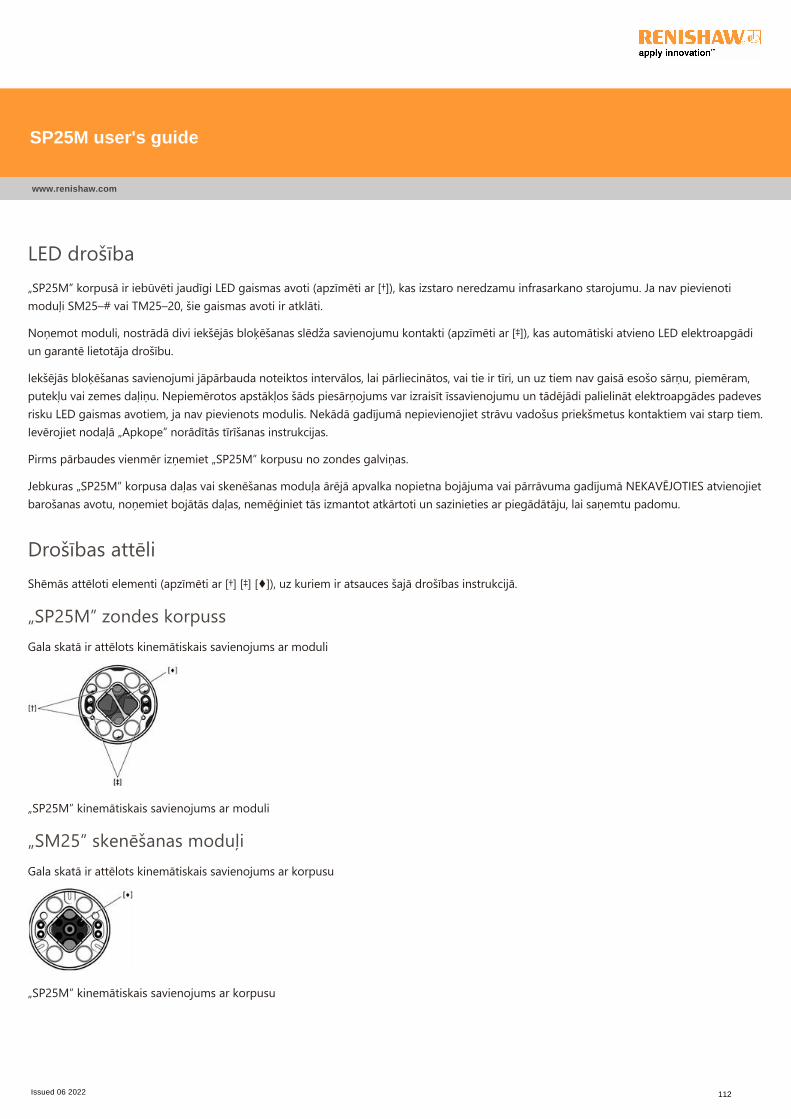
LED drošība„SP25M” korpusā ir iebūvēti jaudīgi LED gaismas avoti ﴾apzīmēti ar [†]﴿, kas izstaro neredzamu infrasarkano starojumu. Ja nav pievienotimoduļi SM25–# vai TM25–20, šie gaismas avoti ir atklāti.
Noņemot moduli, nostrādā divi iekšējās bloķēšanas slēdža savienojumu kontakti ﴾apzīmēti ar [‡]﴿, kas automātiski atvieno LED elektroapgādiun garantē lietotāja drošību.
Iekšējās bloķēšanas savienojumi jāpārbauda noteiktos intervālos, lai pārliecinātos, vai tie ir tīri, un uz tiem nav gaisā esošo sārņu, piemēram,putekļu vai zemes daļiņu. Nepiemērotos apstākļos šāds piesārņojums var izraisīt īssavienojumu un tādējādi palielināt elektroapgādes padevesrisku LED gaismas avotiem, ja nav pievienots modulis. Nekādā gadījumā nepievienojiet strāvu vadošus priekšmetus kontaktiem vai starp tiem.Ievērojiet nodaļā „Apkope” norādītās tīrīšanas instrukcijas.
Pirms pārbaudes vienmēr izņemiet „SP25M” korpusu no zondes galviņas.
Jebkuras „SP25M” korpusa daļas vai skenēšanas moduļa ārējā apvalka nopietna bojājuma vai pārrāvuma gadījumā NEKAVĒJOTIES atvienojietbarošanas avotu, noņemiet bojātās daļas, nemēģiniet tās izmantot atkārtoti un sazinieties ar piegādātāju, lai saņemtu padomu.
Drošības attēliShēmās attēloti elementi ﴾apzīmēti ar [†] [‡] [♦]﴿, uz kuriem ir atsauces šajā drošības instrukcijā.
„SP25M” zondes korpussGala skatā ir attēlots kinemātiskais savienojums ar moduli
„SP25M” kinemātiskais savienojums ar moduli
„SM25” skenēšanas moduļiGala skatā ir attēlots kinemātiskais savienojums ar korpusu
„SP25M” kinemātiskais savienojums ar korpusu
SP25M user's guide
www.renishaw.com
Issued 06 2022 112
MT ‐ Rakkomandazzjonijiet ġenerali dwar is‐sigurtà
ATTENZJONI: Qabel ma joħroġ mill‐ippakkjar u jinstalla s‐sistema tas‐sonda SP25M, l‐utent għandu jaqra bl‐attenzjoni l‐istruzzjonijiet dwar is‐sigurtà hawn taħt u jiżgura li jkunu segwiti f'kull ħin mill‐operaturi kollha li jużaw is‐sistema tas‐sonda. L‐użuta' kontrolli jew aġġustamenti, jew it‐twettiq ta' proċeduri ħlief dawk speċifikati hawnhekk, jistgħu jirriżultaw f'espożizzjoniperikoluża għal radjazzjoni infra‐red.L‐operaturi għandhom jiġu mħarrġa fl‐użu u fl‐applikazzjoni tas‐sistema tas‐sonda SP25M u tal‐prodotti li jiġu magħha, fil‐kuntesttal‐magna li tkun iffittjata magħha, qabel ma jitħallew iħaddmu dik il‐magna.
NOTA: Ir‐referenzi hawn taħt jirreferu għal karatteristiċi indikati [†] [‡] [♦] fuq l‐istampi murija hawn taħt. Jekk jogħġbok aċċertaruħek li tifhem b'mod ċar l‐istruzzjonijiet kollha dwar is‐sigurtà. Hu rakkomandat li wieħed ikun familjari mal‐komponenti tas‐sistema SP25M, kif muri fis‐sezzjonijiet li ġejjin.
Deskrizzjoni fil-qosor tal-komponenti tas-sistema
Dijagramma skematika tal-komponenti tas-sistema tas-sonda
Dijagramma skematika tal-FCR25 flexible change rack
Dijagramma skematika tal-FCR25 TC flexible change rack
Is‐sistema tas‐sonda SP25M għandha protezzjoni overtravel mekkanika pprovduta fl‐assi +Z tas‐sonda, permezz ta' bumpstopfissa. Għalhekk, is‐sistema tal‐kontroll tal‐magna trid tkun kapaċi twaqqaf il‐moviment tal‐magna, f'din l‐assi tas‐sonda, qabel matintlaħaq il‐bumpstop. Jekk dan mhuwiex il‐każ, l‐utent għandu jilbes protezzjoni għall‐għajnejn matul it‐tħaddim fil‐każ ta' ksurtal-istylus.
Għandu jkun kawtela biex jiġi żgurat li l‐optical windows ﴾indikati b'[♦]﴿, li jinsabu kemm fuq il‐body kif ukoll fuq il‐modulu, ma ssirilhomxħsara għax huma tal‐ħġieġ u jistgħu jikkawżaw korriment.
ATTENZJONI: Kalamiti permanenti jintużaw f'xi partijiet tas‐sistema SP25M u prodotti assoċjati magħha. Hu importanti liżżommhom 'il bogħod minn oġġetti li jistgħu jiġu affettwati minn kampijiet manjetiċi, eż. sistemi ta' ħażna tad‐dejta, pacemakers uarloġġi, eċċ.
SP25M user's guide
www.renishaw.com
Issued 06 2022 113
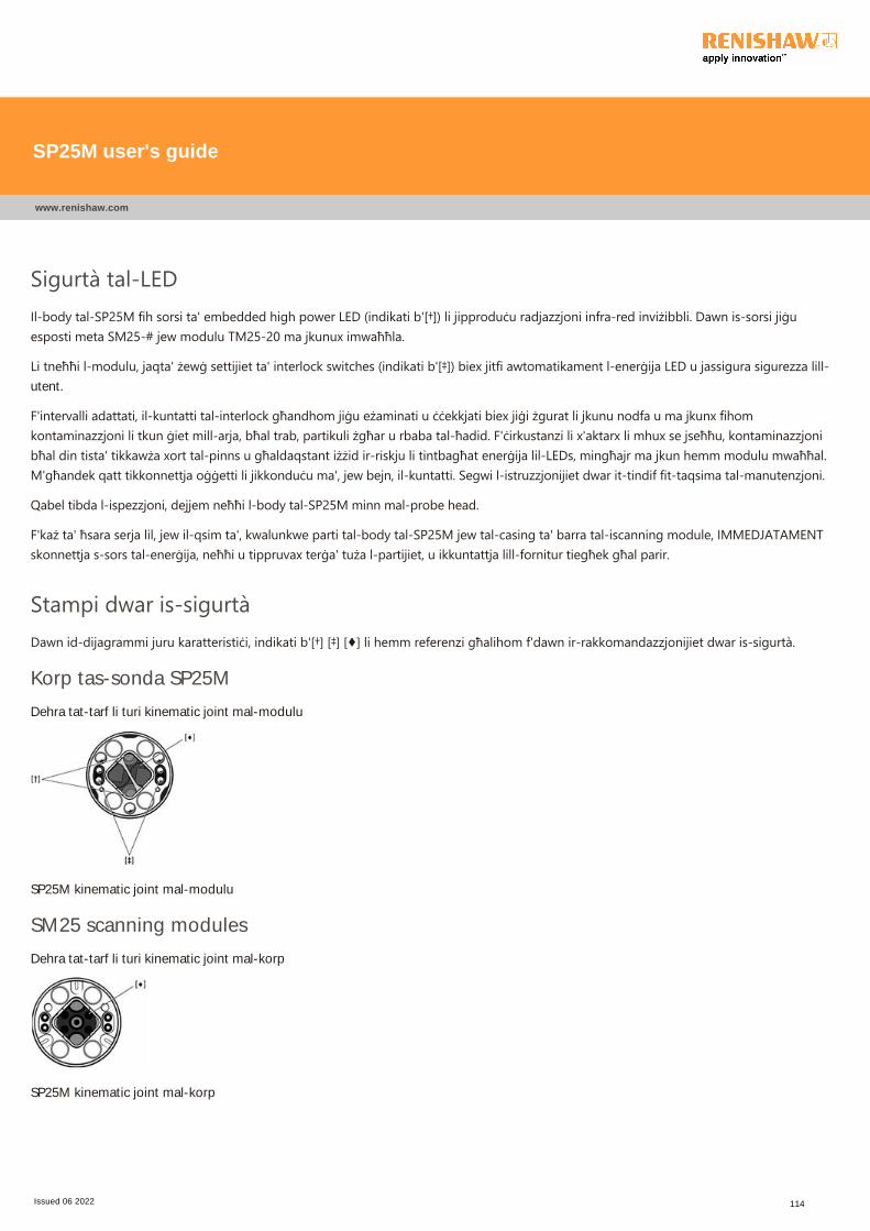
Sigurtà tal‐LEDIl‐body tal‐SP25M fih sorsi ta' embedded high power LED ﴾indikati b'[†]﴿ li jipproduċu radjazzjoni infra‐red inviżibbli. Dawn is‐sorsi jiġuesposti meta SM25‐# jew modulu TM25‐20 ma jkunux imwaħħla.
Li tneħħi l‐modulu, jaqta' żewġ settijiet ta' interlock switches ﴾indikati b'[‡]﴿ biex jitfi awtomatikament l‐enerġija LED u jassigura sigurezza lill‐utent.
F'intervalli adattati, il‐kuntatti tal‐interlock għandhom jiġu eżaminati u ċċekkjati biex jiġi żgurat li jkunu nodfa u ma jkunx fihomkontaminazzjoni li tkun ġiet mill‐arja, bħal trab, partikuli żgħar u rbaba tal‐ħadid. F'ċirkustanzi li x'aktarx li mhux se jseħħu, kontaminazzjonibħal din tista' tikkawża xort tal‐pinns u għaldaqstant iżżid ir‐riskju li tintbagħat enerġija lil‐LEDs, mingħajr ma jkun hemm modulu mwaħħal.M'għandek qatt tikkonnettja oġġetti li jikkonduċu ma', jew bejn, il‐kuntatti. Segwi l‐istruzzjonijiet dwar it‐tindif fit‐taqsima tal‐manutenzjoni.
Qabel tibda l‐ispezzjoni, dejjem neħħi l‐body tal‐SP25M minn mal‐probe head.
F'każ ta' ħsara serja lil, jew il‐qsim ta', kwalunkwe parti tal‐body tal‐SP25M jew tal‐casing ta' barra tal‐iscanning module, IMMEDJATAMENTskonnettja s‐sors tal‐enerġija, neħħi u tippruvax terġa' tuża l‐partijiet, u ikkuntattja lill‐fornitur tiegħek għal parir.
Stampi dwar is‐sigurtàDawn id‐dijagrammi juru karatteristiċi, indikati b'[†] [‡] [♦] li hemm referenzi għalihom f'dawn ir‐rakkomandazzjonijiet dwar is‐sigurtà.
Korp tas-sonda SP25M
Dehra tat-tarf li turi kinematic joint mal-modulu
SP25M kinematic joint mal-modulu
SM25 scanning modules
Dehra tat-tarf li turi kinematic joint mal-korp
SP25M kinematic joint mal-korp
SP25M user's guide
www.renishaw.com
Issued 06 2022 114
NL - Algemene veiligheidsaanbevelingen
WAARSCHUWING: Lees voor het uitpakken en installeren van het SP25M tastersysteem eerst de hieronder vermelde
veiligheidsinstructies en zorg ervoor dat deze te allen tijde door alle gebruikers van het tastersysteem worden opgevolgd. Het
gebruik van andere bedieningsapparatuur, hulpstukken of uitvoeringsprocedures dan hierin vermeld kan leiden tot blootstelling
aan gevaarlijke infraroodstraling.
Gebruikers moeten, voordat de machine wordt gebruikt, worden opgeleid in het gebruik en de toepassing van het SP25M
tastersysteem en de daarbij behorende producten in samenhang met de machine waarop het systeem is aangesloten.
OPMERKING: Hieronder wordt verwezen naar de tekens [†], [‡] en [♦] in de onderstaande afbeeldingen. Zorg ervoor dat u alleveiligheidsinstructies helder begrijpt. Maakt u zich vertrouwd met de SP25M systeemcomponenten, die te zien zijn in de volgende
doorsnedes:
Overzicht systeemcomponenten
Schematische weergave van componenten tastersysteem
Schematische weergave van flexibel wisselrek FCR25
Schematische weergave van flexibel wisselrek FCR25 TC
Het SP25M tastersysteem heeft een mechanische overtravelbescherming in de tasters +Z-as, bestaande uit een vaste eindaanslag.
Het besturingssysteem van de machine moet daarom de machinebeweging langs deze tasteras kunnen stopzetten voordat de
eindaanslag wordt bereikt. Als dit niet zo is, dan moet de gebruiker tijdens het werk een veiligheidsbril dragen voor het geval de
stylus breekt.
Zorg ervoor dat de optische vensters ﴾aangegeven met [♦]﴿ op zowel het tasterhuis als de module niet beschadigd raken, aangezien ze vanglas zijn en dan letsel kunnen veroorzaken.
WAARSCHUWING: Er worden in enkele componenten van het SP25M systeem en de daarbij behorende producten permanente
magneten gebruikt. Het is belangrijk om deze weg te houden van voorwerpen die gevoelig zijn voor magnetische velden, zoals
gegevensopslagsystemen, pacemakers, horloges enz.
SP25M user's guide
www.renishaw.com
Issued 06 2022 115
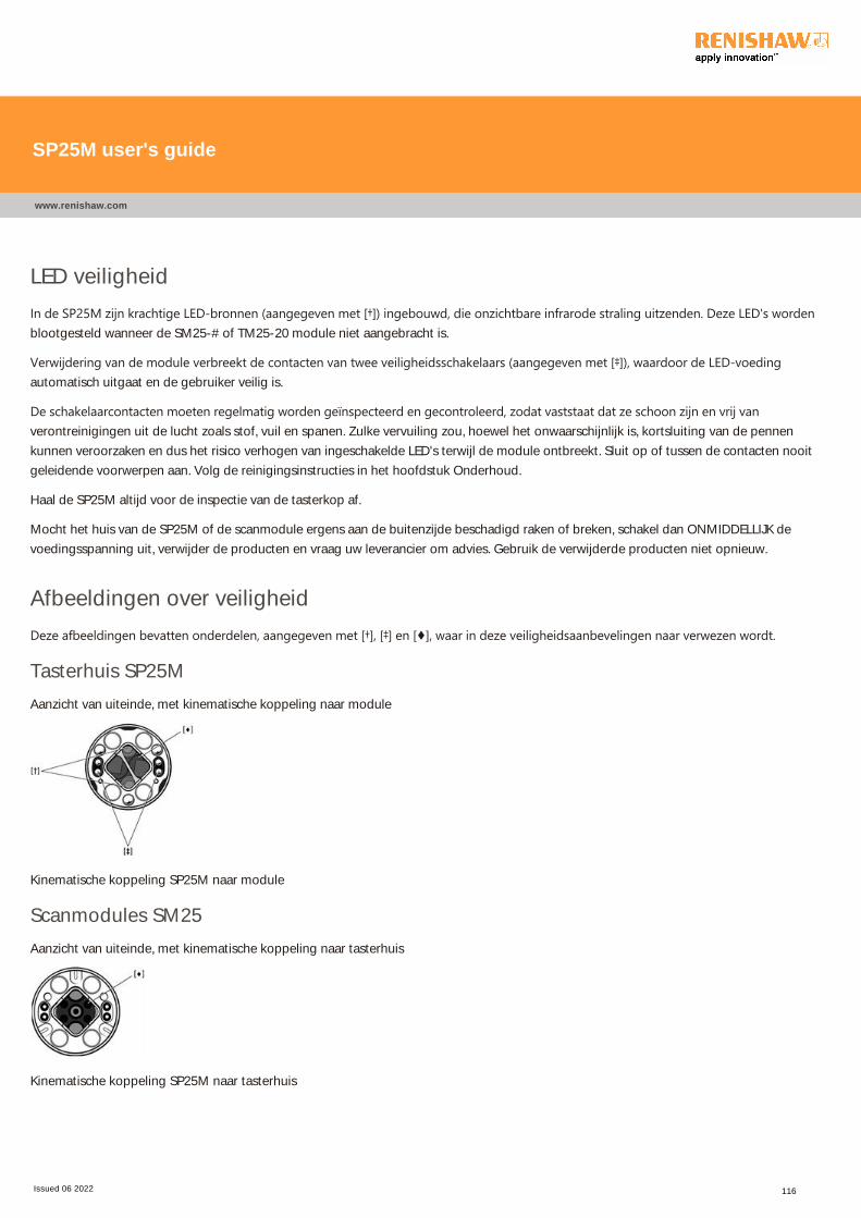
LED veiligheid
In de SP25M zijn krachtige LED‐bronnen ﴾aangegeven met [†]﴿ ingebouwd, die onzichtbare infrarode straling uitzenden. Deze LED's wordenblootgesteld wanneer de SM25-# of TM25-20 module niet aangebracht is.
Verwijdering van de module verbreekt de contacten van twee veiligheidsschakelaars ﴾aangegeven met [‡]﴿, waardoor de LED‐voedingautomatisch uitgaat en de gebruiker veilig is.
De schakelaarcontacten moeten regelmatig worden geïnspecteerd en gecontroleerd, zodat vaststaat dat ze schoon zijn en vrij vanverontreinigingen uit de lucht zoals stof, vuil en spanen. Zulke vervuiling zou, hoewel het onwaarschijnlijk is, kortsluiting van de pennen
kunnen veroorzaken en dus het risico verhogen van ingeschakelde LED's terwijl de module ontbreekt. Sluit op of tussen de contacten nooit
geleidende voorwerpen aan. Volg de reinigingsinstructies in het hoofdstuk Onderhoud.
Haal de SP25M altijd voor de inspectie van de tasterkop af.
Mocht het huis van de SP25M of de scanmodule ergens aan de buitenzijde beschadigd raken of breken, schakel dan ONMIDDELLIJK de
voedingsspanning uit, verwijder de producten en vraag uw leverancier om advies. Gebruik de verwijderde producten niet opnieuw.
Afbeeldingen over veiligheid
Deze afbeeldingen bevatten onderdelen, aangegeven met [†], [‡] en [♦], waar in deze veiligheidsaanbevelingen naar verwezen wordt.
Tasterhuis SP25M
Aanzicht van uiteinde, met kinematische koppeling naar module
Kinematische koppeling SP25M naar module
Scanmodules SM25
Aanzicht van uiteinde, met kinematische koppeling naar tasterhuis
Kinematische koppeling SP25M naar tasterhuis
SP25M user's guide
www.renishaw.com
Issued 06 2022 116
PL ‐ Ogólne zalecenia dotyczącebezpieczeństwa
PRZESTROGA: Przed rozpakowaniem i zainstalowaniem systemu sondy SP25M użytkownik powinien zapoznać się dokładnie zponiższymi instrukcjami dotyczącymi bezpieczeństwa oraz zapewnić stałe przestrzeganie tych instrukcji przez wszystkichoperatorów korzystających z systemu pomiarowego. Skutkiem adiustacji lub regulacji, bądź wykonywania procedur innych niżprzedstawione poniżej, może być narażenie na działanie niebezpiecznego promieniowania podczerwieni.Operatorzy, przed dopuszczeniem ich do obsługi maszyny współrzędnościowej, muszą być przeszkoleni w używaniu izastosowaniu systemu SP25M oraz elementów pomocniczych.
UWAGA:W tekście powołano się na elementy oznaczone symbolami [†] [‡] [♦] jak przedstawiono na poniższych ilustracjach. Należyzadbać o dokładne zrozumienie wszystkich zaleceń dotyczących bezpieczeństwa. Zalecane jest zapoznanie się z częściamiskładowymi systemu SP25M, jak przedstawiono w następujących sekcjach:
Przegląd elementów składowych systemuSchemat części składowych sondySchemat elastycznego systemu zasobnika FCR25
Schemat elastycznego systemu zasobnika FCR25 TC
System sondy SP25M jest wyposażony w mechaniczne zabezpieczenie nadmiernego wychylenia trzpienia, działające w osi +Zsondy, w postaci zderzaka krańcowego zamocowanego w ustalonym położeniu. Dlatego też system sterujący obrabiarki musizapewniać zatrzymanie ruchu obrabiarki w tej osi zanim zostanie osiągnięty zderzak krańcowy. Jeżeli tak nie jest, użytkownik musipodczas eksploatacji maszyny współrzędnościowej zakładać osłonę oczu na wypadek złamania końcówki czujnikowej.
Należy uważać, aby nie dopuścić do uszkodzenia okienek optycznych ﴾oznaczonych [♦]﴿, umieszczonych zarówno na korpusie, jak i namoduLe, ponieważ są one wykonane ze szkła i mogłyby spowodować obrażenia.
PRZESTROGA: W niektrych czesciach skladowych systemu SP25M i produktw pomocniczych sa stosowane magnesy trwale.
Wazne jest, aby utrzymywac je z dala od takich elementw, na ktre moga niekorzystnie oddzialywac pola magnetyczne, np. systemy
przechowywania danych, stymulatory serca, zegarki itp.
SP25M user's guide
www.renishaw.com
Issued 06 2022 117

Bezpieczeństwo posługiwania się diodą LEDKorpus SP25M zawiera wbudowane źródła elektroluminescencyjne o dużej mocy ﴾oznaczone [†]﴿, które emitują niewidzialne promieniowaniepodczerwone. Źródła te są odsłonięte, gdy nie jest zamontowany moduł SM25‐# ani TM25‐20.
Wymontowanie tego modułu powoduje rozwarcie dwóch zespołów styków przełącznika blokady ﴾oznakowanie [‡]﴿ w celu automatycznegowyłączenia zasilania diod i zagwarantowania bezpieczeństwa użytkowników.
W stosownych odstępach czasu należy dokonywać przeglądu i kontroli styków blokady w celu upewnienia się, czy są czyste i wolne odzanieczyszczeń zawartych w powietrzu, takich jak kurz, pył lub opiłki. W mało prawdopodobnych okolicznościach takie zanieczyszczeniamogłyby spowodować zwarcie końcówek styków i w ten sposób podnieść ryzyko podania zasilania do diod świecących bez zamontowaniamodułu. Nigdy nie wolno przyłączać do styków, lub pomiędzy nimi, żadnych przedmiotów przewodzących prąd elektryczny. Postępowaćzgodnie z zaleceniami rozdziału Konserwacja dotyczącymi czyszczenia.
Przed przystąpieniem do przeglądu należy zawsze zdejmować korpus SP25M z głowicy sondy.
W przypadku poważnego uszkodzenia lub pęknięcia jakiejkolwiek części obudowy SP25M, bądź obudowy zewnętrznej Modułu Skanującego,należy natychmiast odłączyć źródło zasilania, usunąć i nie próbować ponownie użyć zdemontowanych części, następnie niezwłocznieskontaktować się z dostawcą.
Ilustracje związane z bezpieczeństwemZnajdujące się poniżej diagramy przedstawiają elementy oznaczone symbolami [†] [‡] [♦], do których odniesiono się w niniejszych instrukcjachbezpieczeństwa.
Korpus sondy SP25M
Widok z końca pokazujący złącze kinematyczne modułu
Kinematyczne złącze modułu SP25M
Moduły skanujące SM25Widok z końca pokazujący kinematyczne złącze korpusu
Kinematyczne złącze korpusu SP25M
SP25M user's guide
www.renishaw.com
Issued 06 2022 118
PT ‐ Recomendaçőes gerais de segurançaATENÇÃO : Antes de desembalar e instalar o apalpador SP25M, o usuário deve ler com todo o cuidado as instruções de segurançaabaixo e certificar-se de que sempre sejam obedecidas por todos os operadores que utilizarem o sistema. O uso de controles ou
ajustes ou a execução de procedimentos diferentes daqueles aqui especificados podem resultar em exposição perigosa à radiaçãoinfravermelha.
É necessário que os operadores estejam treinados no uso e na aplicação do apalpador SP25M, dos produtos que o acompanham ena máquina onde o mesmo estiver instalado, antes de serem autorizados a operá‐lo.
NOTA: O texto a seguir contém referências sobre características indicadas por [†] [‡] [♦] nas figuras mostradas abaixo. Certifique‐seque todas as instruções de segurança foram compreendidas. É recomendável familiarizar‐se com os componentes do sistemaSP25M mostrados nas seções a seguir:
Visão geral dos componentes do sistemaDiagrama dos componentes do sistema de apalpador
Diagrama do magazine de troca flexível FCR25Diagrama do magazine de troca flexível FCR25 TC
O apalpador SP25M possui uma proteção mecânica de fim de curso, através de um limitador fixo no eixo +Z do apalpador.Portanto, o sistema de comando da máquina deve ser capaz de parar seu movimento neste eixo do apalpador, antes de atingir olimitador. Caso isso não seja possível, o usuário deverá utilizar óculos de proteção durante a operação, para o caso de quebra daponta.
Deve ser assegurado que as janelas ópticas ﴾indicadas como [♦]﴿, localizadas no corpo e no módulo, não sejam danificadas, pois são feitas devidro e podem causar lesões.
ATENÇÃO : Alguns componentes do sistema SP25M e de produtos associados fazem uso de ímãs permanentes. É importantemanter estes imăs afastados de quaisquer objetos que possam ser afetados por campos magnéticos, como sistemas dearmazenamento de dados, marca‐passos, relógios, etc.
SP25M user's guide
www.renishaw.com
Issued 06 2022 119
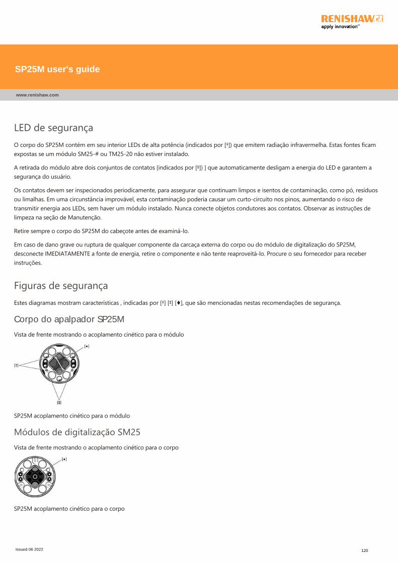
LED de segurançaO corpo do SP25M contém em seu interior LEDs de alta potência ﴾indicados por [†]﴿ que emitem radiação infravermelha. Estas fontes ficamexpostas se um módulo SM25‐# ou TM25‐20 não estiver instalado.
A retirada do módulo abre dois conjuntos de contatos [indicados por [‡]﴿ ] que automaticamente desligam a energia do LED e garantem asegurança do usuário.
Os contatos devem ser inspecionados periodicamente, para assegurar que continuam limpos e isentos de contaminação, como pó, resíduosou limalhas. Em uma circunstância improvável, esta contaminação poderia causar um curto‐circuito nos pinos, aumentando o risco detransmitir energia aos LEDs, sem haver um módulo instalado. Nunca conecte objetos condutores aos contatos. Observar as instruções delimpeza na seção de Manutenção.
Retire sempre o corpo do SP25M do cabeçote antes de examiná‐lo.
Em caso de dano grave ou ruptura de qualquer componente da carcaça externa do corpo ou do módulo de digitalização do SP25M,desconecte IMEDIATAMENTE a fonte de energia, retire o componente e não tente reaproveitá‐lo. Procure o seu fornecedor para receberinstruções.
Figuras de segurançaEstes diagramas mostram características , indicadas por [†] [‡] [♦], que são mencionadas nestas recomendações de segurança.
Corpo do apalpador SP25M
Vista de frente mostrando o acoplamento cinético para o módulo
SP25M acoplamento cinético para o módulo
Módulos de digitalização SM25Vista de frente mostrando o acoplamento cinético para o corpo
SP25M acoplamento cinético para o corpo
SP25M user's guide
www.renishaw.com
Issued 06 2022 120
RO ‐ Recomandări generale de protecţiamuncii
ATENŢIE: Inainte de a despacheta si instala sistemul SP25M, utilizatorul trebuie sa citeasca cu atentie instructiunile de securitate de
mai jos si sa se asigure ca ele vor fi respectate de toti operatorii ce folosesc sistemul. Utilizarea de operatii, proceduri sau reglaje,
altele decat cele specificate in prezenta instructiune, poate duce la expunere periculoasa la radiatii infrarosii.
Operatorii trebuiesc instruiti pentru utilizarea sistemului SP25M si a a produselor asociate, in contextul echiparii masinii, inainte de
a li se permite operarea acesteia.
NOTĂ: Mai jos se fac referiri la elementele indicate [†] [‡] [♦] pe ilustratii. Mai jos se fac referiri la elementele indicate pe ilustratii.Se recomanda familiarizarea cu componentele sistemului SP25 M dupa cum este prezentat mai jos:
Prezentarea componentelor sistemului
Schema bloc a componentelor sistemului
Schema bloc a schimbatorului de scule flexibil FCR25
Schema bloc a schimbatorului de scule flexibil FCR25 TC
Sistemul SP25M dispune de o protectie mecanica de suprasarcina pe axa +Z a probei, printr-un tampon fix. Sistemul de control al
masinii trebuie sa fie capabil sa opreasca miscarea acesteia pe directia axei +Z, inainte ca tamponul sa fie atins. Dacă acest lucru nueste posibil, operatorul trebuie să poarte ochelari de protecţie care să îl protejeze în cazul spargerii palpatorului propriu‐zis.
Trebuie să vă asigurați că ferestrele optice ﴾indicate [♦]﴿, situate atât pe corp cât și pe modul, nu sunt deteriorate deoarece sunt făcute dinsticlă și ar putea cauza răniri.
ATENŢIE: In unele componente ale sistemului SP25M sunt folositi magneti permanenti. Este recomandata pastrarea distantei fata
de acestia a dispozitivelor care pot fi afectate de camp magnetic cum ar fi: sisteme de stocare de date, pacemakere, ceasuri etc.
SP25M user's guide
www.renishaw.com
Issued 06 2022 121
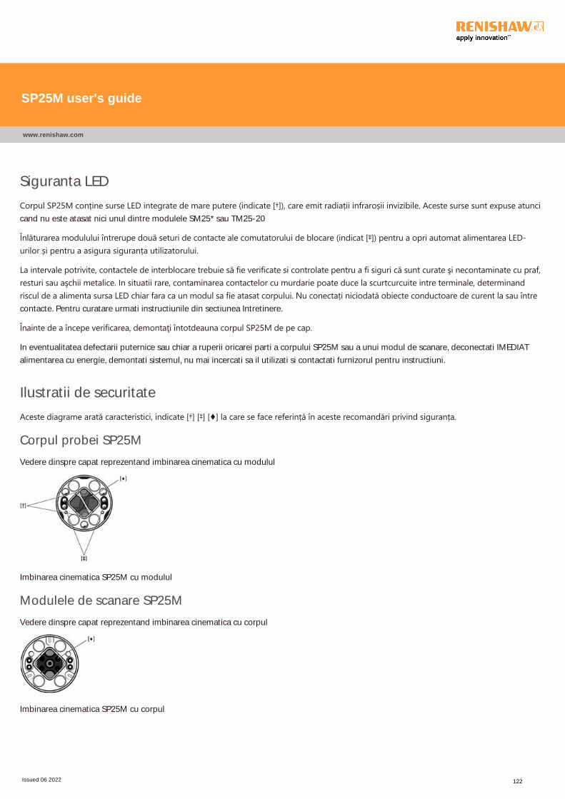
Siguranta LED
Corpul SP25M conține surse LED integrate de mare putere ﴾indicate [†]﴿, care emit radiații infraroșii invizibile. Aceste surse sunt expuse atuncicand nu este atasat nici unul dintre modulele SM25* sau TM25-20
Înlăturarea modulului întrerupe două seturi de contacte ale comutatorului de blocare ﴾indicat [‡]﴿ pentru a opri automat alimentarea LED‐urilor și pentru a asigura siguranța utilizatorului.
La intervale potrivite, contactele de interblocare trebuie să fie verificate si controlate pentru a fi siguri că sunt curate şi necontaminate cu praf,resturi sau aşchii metalice. In situatii rare, contaminarea contactelor cu murdarie poate duce la scurtcurcuite intre terminale, determinandriscul de a alimenta sursa LED chiar fara ca un modul sa fie atasat corpului. Nu conectați niciodată obiecte conductoare de curent la sau întrecontacte. Pentru curatare urmati instructiunile din sectiunea Intretinere.
Înainte de a începe verificarea, demontaţi întotdeauna corpul SP25M de pe cap.
In eventualitatea defectarii puternice sau chiar a ruperii oricarei parti a corpului SP25M sau a unui modul de scanare, deconectati IMEDIAT
alimentarea cu energie, demontati sistemul, nu mai incercati sa il utilizati si contactati furnizorul pentru instructiuni.
Ilustratii de securitate
Aceste diagrame arată caracteristici, indicate [†] [‡] [♦] la care se face referință în aceste recomandări privind siguranța.
Corpul probei SP25M
Vedere dinspre capat reprezentand imbinarea cinematica cu modulul
Imbinarea cinematica SP25M cu modulul
Modulele de scanare SP25M
Vedere dinspre capat reprezentand imbinarea cinematica cu corpul
Imbinarea cinematica SP25M cu corpul
SP25M user's guide
www.renishaw.com
Issued 06 2022 122

SK ‐ Všeobecné bezpečnostné odporúčaniaUPOZORNENIE: Pred vybalením a nainštalovaním snímacieho systému SP25M si používateľ musí dôkladne prečítať bezpečnostnépokyny uvedené nižšie a zaručiť ich neustále dodržiavanie všetkými pracovníkmi obsluhujúcimi snímací systém. Používanieovládacích prvkov, nastavovanie alebo vykonávanie iných postupov, než sú uvedené v tomto dokumente, môže viesť k nebezpečnejexpozícii infračerveným žiarením.Obsluha musí byť predtým, než sa jej umožní ovládanie príslušného stroja, vyškolená v používaní a aplikácii snímacieho systémuSP25M a príslušných produktov v kontexte stroja, do ktorého sa montuje.
POZNÁMKA: Nižšie sa odkazuje na funkcie označené ikonou [†] [‡] [♦] na obrázkoch uvedených nižšie. Všetkým bezpečnostnýmpokynom musíte dobre porozumieť. Odporúčame oboznámiť sa s komponentmi systému SP25M, ktoré sú vyobrazené vnasledujúcich sekciách.
Prehľad systémových komponentovSchematický diagram komponentov snímacieho systémuSchematický diagram flexibilnej výmennej konzoly FCR25Schematický diagram flexibilnej výmennej konzoly FCR25 TC
Snímací systém SP25M obsahuje mechanickú ochranu pred prekročením krajnej polohy, ktorú tvorí pevný koncový doraz v osi +Zsondy. Systém ovládania stroja musí byť preto schopný zastaviť pohyb stroja v smere tejto osi sondy ešte pred dosiahnutímkoncového dorazu. V opačnom prípade musí užívateľ nosiť počas prevádzky ochranu očí pre prípad prasknutia snímacieho hrotu.
Musí sa dávať pozor, aby nedošlo k poškodeniu optických okienok ﴾označených ikonou [♦]﴿, ktoré sú umiestnené na tele hlavice aj module,pretože sú vyrobené zo skla a mohli by spôsobiť poranenie.
UPOZORNENIE: V niektorých súčastiach systému SP25M a sprievodných produktoch sa používajú permanentné magnety. Jedôležité udržiavať ich mimo predmetov, ktoré môžu byť ovplyvnené magnetickými poľami, ako sú napríklad systémy na ukladanieúdajov, kardiostimulátory, hodinky a podobne.
SP25M user's guide
www.renishaw.com
Issued 06 2022 123
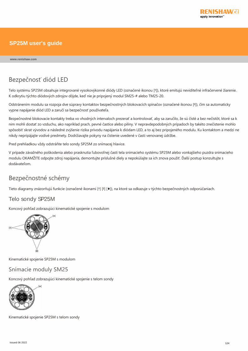
Bezpečnosť diód LEDTelo systému SP25M obsahuje integrované vysokovýkonné diódy LED ﴾označené ikonou [†]﴿, ktoré emitujú neviditeľné infračervené žiarenie.K odkrytiu týchto diódových zdrojov dôjde, keď nie je pripojený modul SM25‐# alebo TM25‐20.
Odstránením modulu sa rozpoja dve súpravy kontaktov bezpečnostných blokovacích spínačov ﴾označené ikonou [‡]﴿, čím sa automatickyvypne napájanie diód LED a zaručí sa bezpečnosť používateľa.
Bezpečnostné blokovacie kontakty treba vo vhodných intervaloch prezerať a kontrolovať, aby sa zaručilo, že sú čisté a bez nečistôt, ktoré sa knim mohli dostať zo vzduchu, ako napríklad prach, pevné častice alebo piliny. V nepravdepodobných prípadoch by takéto znečistenie mohlospôsobiť skrat vývodov a následné zvýšenie rizika prívodu napájania k diódam LED, a to aj bez pripojeného modulu. Ku kontaktom a medzi nenikdy nepripájajte vodivé predmety. Dodržiavajte pokyny na čistenie uvedené v časti venovanej údržbe.
Pred prehliadkou vždy odstráňte telo sondy SP25M zo snímacej hlavice.
V prípade závažného poškodenia alebo prasknutia ľubovoľnej časti tela snímacieho systému SP25M alebo vonkajšieho puzdra snímaciehomodulu OKAMŽITE odpojte zdroj napájania, demontujte príslušné diely a nepokúšajte sa ich znova použiť. Ďalší postup konzultujte sdodávateľom.
Bezpečnostné schémyTieto diagramy znázorňujú funkcie ﴾označené ikonami [†] [‡] [♦]﴿, na ktoré sa odkazuje v týchto bezpečnostných odporúčaniach.
Telo sondy SP25M
Koncový pohľad zobrazujúci kinematické spojenie s modulom
Kinematické spojenie SP25M s modulom
Snímacie moduly SM25Koncový pohľad zobrazujúci kinematické spojenie s telom sondy
Kinematické spojenie SP25M s telom sondy
SP25M user's guide
www.renishaw.com
Issued 06 2022 124
SL ‐ Splošna varnostna priporočilaPOZOR: Uporabnik mora pred jemanjem iz embalaže in montažo merilnega sistema SP25M skrbno prebrati spodnja varnostnanavodila ter poskrbeti, da jih bodo dosledno upoštevali vsi operaterji, ki bodo imeli opravka z merilnim sistemom. Uporaba ukazov,nastavitev ali postopkov, ki odstopajo od tukaj opisanih, lahko povzroči izpostavitev nevarnemu infrardečemu sevanju.Preden začnejo upravljati s strojem, morajo operaterji opraviti usposabljanje za uporabo merilnega sistema SP25M inspremljajočih izdelkov v kontekstu stroja, na katerem je sistem nameščen.
OPOMBA: V besedilu so navedene pozicije s spodnjih ilustracij, ki so označene z [†] [‡] [♦]. Poskrbite, da boste pred uporabo jasnorazumeli vsa varnostna navodila. Priporočamo vam, da se seznanite s komponentami sistema SP25M, ki so opisane v naslednjihpoglavjih:
Pregled komponent sistema
Shematski prikaz komponent merilnega sistema
Shematski prikaz sistema za fleksibilno menjavo modulov FCR25
Shematski prikaz sistema za fleksibilno menjavo modulov FCR25 TC
Merilni sistem SP25M ima mehansko zaščito pred predolgim hodom po osi glave +Z ﴾fiksni prislon﴿. Krmilni sistem stroja morazaustaviti gibanje stroja po tej osi glave še preden je dosežen končni položaj. V nasprotnem primeru mora operater med delomuporabljati zaščito za oči, ki ga bo zavarovala v primeru loma tipala.
Pazite, da se ne razbije optično okno na telesu in na modulu [označeno z [♦]], ker je izdelano iz stekla in se lahko poškodujete.
POZOR: V nekaterih komponentah sistema SP25M in spremljajočih izdelkih so trajni magneti. Pazite, da take komponente nepridejo v bližino predmetov, na katere lahko vplivajo magnetna polja; to so npr. sistemi za shranjevanje podatkov, srčnispodbujevalniki, ure itd.
SP25M user's guide
www.renishaw.com
Issued 06 2022 125
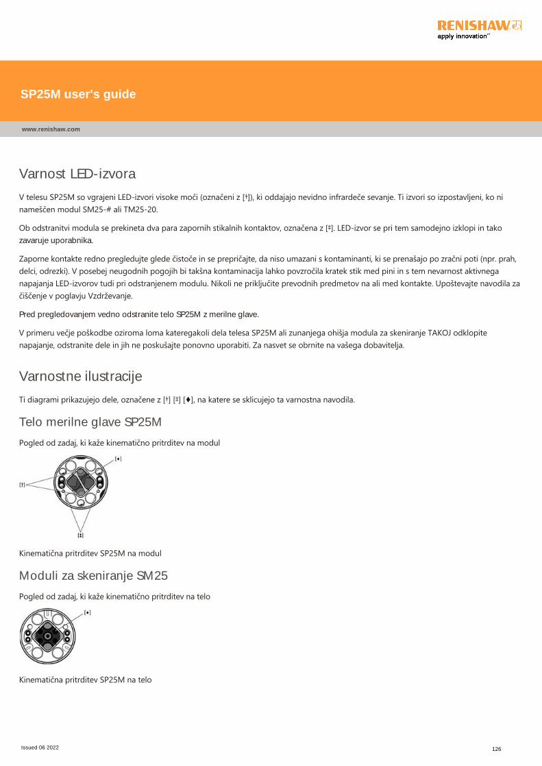
Varnost LED-izvora
V telesu SP25M so vgrajeni LED‐izvori visoke moči ﴾označeni z [†]﴿, ki oddajajo nevidno infrardeče sevanje. Ti izvori so izpostavljeni, ko ninameščen modul SM25‐# ali TM25‐20.
Ob odstranitvi modula se prekineta dva para zapornih stikalnih kontaktov, označena z [‡]. LED‐izvor se pri tem samodejno izklopi in takozavaruje uporabnika.
Zaporne kontakte redno pregledujte glede čistoče in se prepričajte, da niso umazani s kontaminanti, ki se prenašajo po zračni poti ﴾npr. prah,delci, odrezki﴿. V posebej neugodnih pogojih bi takšna kontaminacija lahko povzročila kratek stik med pini in s tem nevarnost aktivneganapajanja LED‐izvorov tudi pri odstranjenem modulu. Nikoli ne priključite prevodnih predmetov na ali med kontakte. Upoštevajte navodila začiščenje v poglavju Vzdrževanje.
Pred pregledovanjem vedno odstranite telo SP25M z merilne glave.
V primeru večje poškodbe oziroma loma kateregakoli dela telesa SP25M ali zunanjega ohišja modula za skeniranje TAKOJ odklopitenapajanje, odstranite dele in jih ne poskušajte ponovno uporabiti. Za nasvet se obrnite na vašega dobavitelja.
Varnostne ilustracije
Ti diagrami prikazujejo dele, označene z [†] [‡] [♦], na katere se sklicujejo ta varnostna navodila.
Telo merilne glave SP25M
Pogled od zadaj, ki kaže kinematično pritrditev na modul
Kinematična pritrditev SP25M na modul
Moduli za skeniranje SM25
Pogled od zadaj, ki kaže kinematično pritrditev na telo
Kinematična pritrditev SP25M na telo
SP25M user's guide
www.renishaw.com
Issued 06 2022 126
SV ‐ Allmänna säkerhetsrekommendationerVAR FÖRSIKTIG: Innan probsystem SP25M packas upp och installeras, bör du läsa nedanstående säkerhetsföreskrifter noggrant,och se till att de alltid följs av alla operatörer som använder probsystemet. Om inställningarna ändras, eller om man vidtar andraåtgärder än de som anges i dessa instruktioner, kan det leda till att man utsätter sig för farlig infraröd strålning.Operatörerna måste övas i hur man använder och sätter upp probsystem SP25M och tillhörande produkter, i anslutning till denmaskin där den är monterad, innan de tillåts köra maskinen.
OBS: I illustrationerna nedan återfinns referenser till olika funktioner som indikeras med [†] [‡] [♦]. Se till att du förstår allasäkerhetsföreskrifter utan problem. Vi rekommenderar att du bekantar dig med komponenterna i SP25M‐systemet, så som detvisas i följande avsnitt:
Översikt över systemets komponenterSchematisk översikt över probsystemets komponenterSchematisk översikt över FCR25 flexibelt växlingsrackSchematisk översikt över FCR25 TC flexibelt växlingsrack
Probsystemet SP25M har ett mekaniskt skydd mot överrörelse i +Z‐riktningen i form av ett fast ändstopp. Maskinens styrsystemmåste därför kunna stoppa rörelsen i denna riktning innan proben kommer till ändstoppet. Om detta inte är möjligt, måsteoperatören använda skyddsglasögon under driften, för den händelse att mätspetsen bryts av.
Var försiktig så att de optiska fönstren ﴾märkta [♦]﴿, som finns på huset och modulen, inte skadas, eftersom de är gjorda av glas och kanorsaka personskador.
VAR FÖRSIKTIG: Permanentmagneter används i vissa komponenter i system SP25M och tillhörande produkter. Det är viktigt atthålla avstånd mellan dessa och sådant som kan skadas av magnetfält, t.ex. datalagringsenheter, pacemakers, klockor m.m.
SP25M user's guide
www.renishaw.com
Issued 06 2022 127
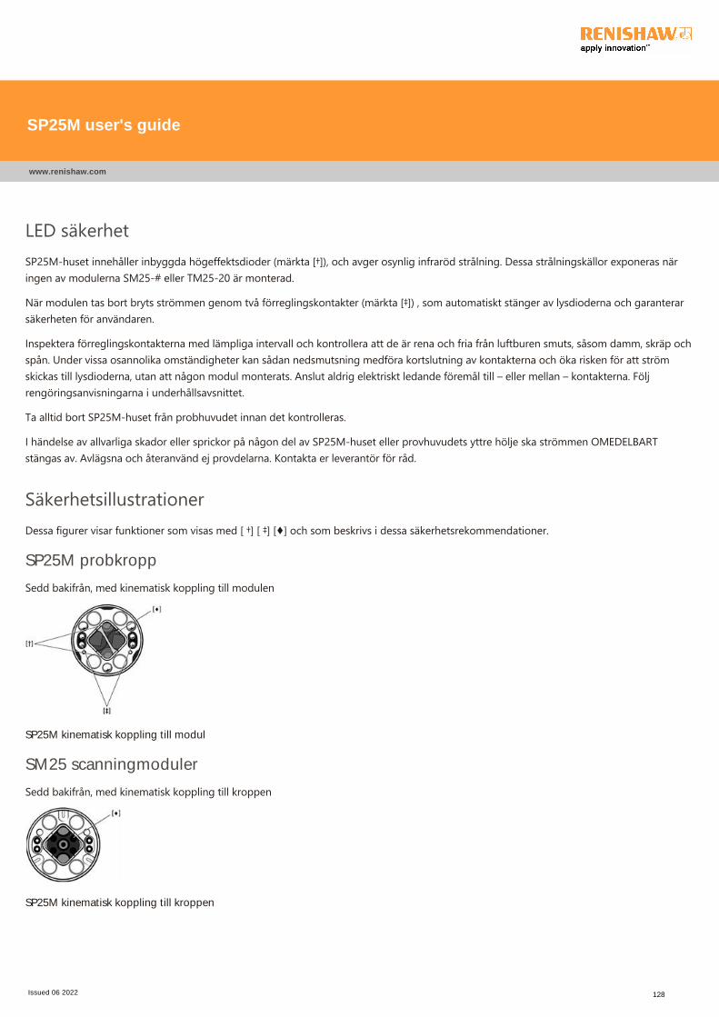
LED säkerhetSP25M‐huset innehåller inbyggda högeffektsdioder ﴾märkta [†]﴿, och avger osynlig infraröd strålning. Dessa strålningskällor exponeras näringen av modulerna SM25‐# eller TM25‐20 är monterad.
När modulen tas bort bryts strömmen genom två förreglingskontakter ﴾märkta [‡]﴿ , som automatiskt stänger av lysdioderna och garanterarsäkerheten för användaren.
Inspektera förreglingskontakterna med lämpliga intervall och kontrollera att de är rena och fria från luftburen smuts, såsom damm, skräp ochspån. Under vissa osannolika omständigheter kan sådan nedsmutsning medföra kortslutning av kontakterna och öka risken för att strömskickas till lysdioderna, utan att någon modul monterats. Anslut aldrig elektriskt ledande föremål till – eller mellan – kontakterna. Följrengöringsanvisningarna i underhållsavsnittet.
Ta alltid bort SP25M‐huset från probhuvudet innan det kontrolleras.
I händelse av allvarliga skador eller sprickor på någon del av SP25M‐huset eller provhuvudets yttre hölje ska strömmen OMEDELBARTstängas av. Avlägsna och återanvänd ej provdelarna. Kontakta er leverantör för råd.
SäkerhetsillustrationerDessa figurer visar funktioner som visas med [ †] [ ‡] [♦] och som beskrivs i dessa säkerhetsrekommendationer.
SP25M probkropp
Sedd bakifrån, med kinematisk koppling till modulen
SP25M kinematisk koppling till modul
SM25 scanningmoduler
Sedd bakifrån, med kinematisk koppling till kroppen
SP25M kinematisk koppling till kroppen
SP25M user's guide
www.renishaw.com
Issued 06 2022 128
TW ‐ 般安全建議
注意:在拆開包裝和安裝SP25M測頭系統之前,使用者應詳細閱讀該下方的安全指示,並保證使用測頭系統的所有操作者隨時都能
確實遵守這些安全指示. 在使用控制元件或調整元件或者操作時,若不按照本文所述的步驟進行,可能受到有害的紅外線輻射的照
射。
操作者必須接受有關在機器適合之背景中使用與應用SP25M測頭系統及其相應產品的培訓,然後才能獲准操作機器.
備註:下圖所示 [†] [‡] [♦] 符號的功能其參考說明如下。 請確保您明確瞭解所有安全指示. 建議您熟悉下列章節中所示的 SP25M 系統組件。
系統組件概述
測頭系統組件示意圖
FCR25靈活更換架示意圖
FCR25 TC靈活更換架示意圖
SP25M測頭系統由一個固定緩衝塊在測頭+Z軸中提供機械過行程保護。 因此,加工機控制系統必須能夠在接觸緩衝塊之前在測頭
的此軸停止加工機的運動. 否則,使用者必須在作業期間配戴護目鏡,以防探針破損。
主體和模組上的光學視窗(以 [♦] 表示)係由玻璃製成,務必小心確保其不受損壞,否則可能會造成傷害。
注意: 在某些SP25M系統的組件及其關聯產品中使用了永久磁體. 請特別注意盡量使可能受到磁場影響的物體遠離裝置,諸如資料
儲存系統、心臟起搏器和手錶等等。
SP25M user's guide
www.renishaw.com
Issued 06 2022 129
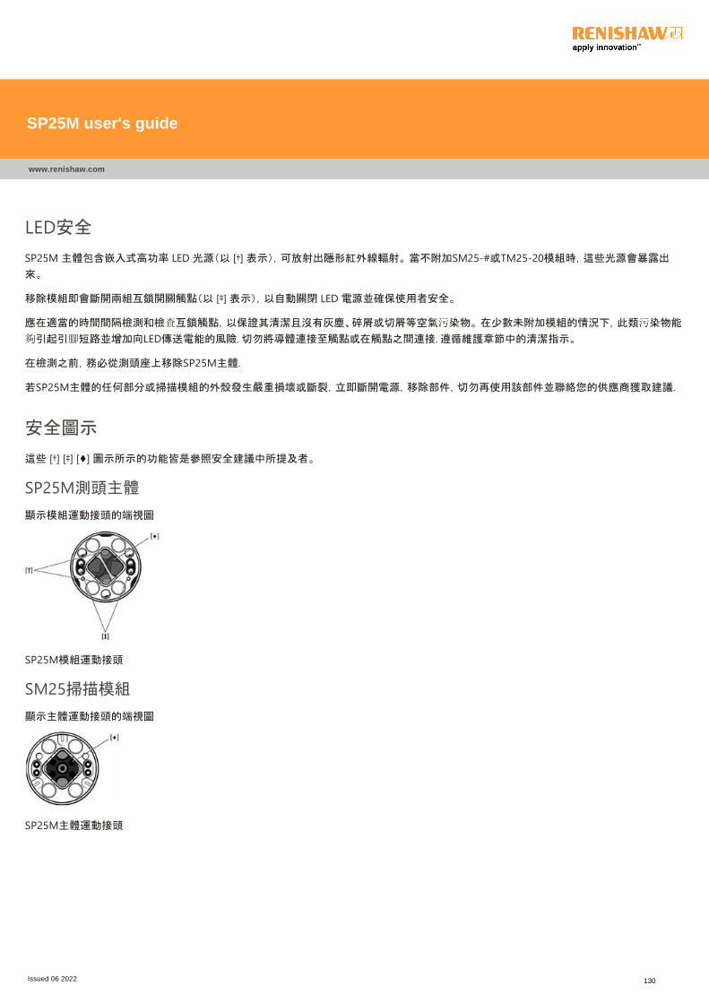
LED安全
SP25M 主體包含嵌入式高功率 LED 光源(以 [†] 表示),可放射出隱形紅外線輻射。 當不附加SM25‐#或TM25‐20模組時,這些光源會暴露出
來。
移除模組即會斷開兩組互鎖開關觸點(以 [‡] 表示),以自動關閉 LED 電源並確保使用者安全。
應在適當的時間間隔檢測和檢查互鎖觸點,以保證其清潔且沒有灰塵、碎屑或切屑等空氣污染物。 在少數未附加模組的情況下,此類污染物能
夠引起引腳短路並增加向LED傳送電能的風險. 切勿將導體連接至觸點或在觸點之間連接. 遵循維護章節中的清潔指示。
在檢測之前,務必從測頭座上移除SP25M主體.
若SP25M主體的任何部分或掃描模組的外殼發生嚴重損壞或斷裂,立即斷開電源,移除部件,切勿再使用該部件並聯絡您的供應商獲取建議.
安全圖示
這些 [†] [‡] [♦] 圖示所示的功能皆是參照安全建議中所提及者。
SP25M測頭主體
顯示模組運動接頭的端視圖
SP25M模組運動接頭
SM25掃描模組
顯示主體運動接頭的端視圖
SP25M主體運動接頭
SP25M user's guide
www.renishaw.com
Issued 06 2022 130
ZH ‐ 般安全建议
小心:在拆包和安装SP25M测头系统之前,用户应仔细阅读下述安全说明,并确保使用测头系统的所有操作人员都能始终遵守这些
说明。 在使用控制元件或调整元件或者进行操作时,若不按照本文所述的步骤进行,可能会受到有害的红外线辐射的照射。
操作人员必须在配装测头的机器环境下接受SP25M测头系统及其随附产品的使用及应用培训,然后才能获准操作机器。
注:此处涉及的部分在如下镜组中由[†][‡][♦]表示。 请确保您明确了解所有安全说明。 建议您熟悉下列章节中所示的SP25M系统组件:
系统组件概述
测头系统组件示意图
FCR25自动交换架示意图
FCR25 TC自动交换架示意图
SP25M测头系统由一个固定缓冲块在测头+Z轴上提供机械越程保护。 因此,机器控制系统必须能够在接触缓冲块之前,就在测头
的这个轴上停止机器的运动。 否则,用户在操作过程中必须配戴护目镜,以防测针破损。
小心确保测头本体和模块上的光学窗口(如[♦]所示)不会被损坏,因为它们是用玻璃制成的,如果损坏,可能会造成人身伤害。
小心:在某些SP25M系统的组件及其相关产品中使用了永久磁体。 请特别注意,尽量使可能受到磁场影响的物体远离装置,诸如数
据存储系统、心脏起搏器和手表等。
SP25M user's guide
www.renishaw.com
Issued 06 2022 131
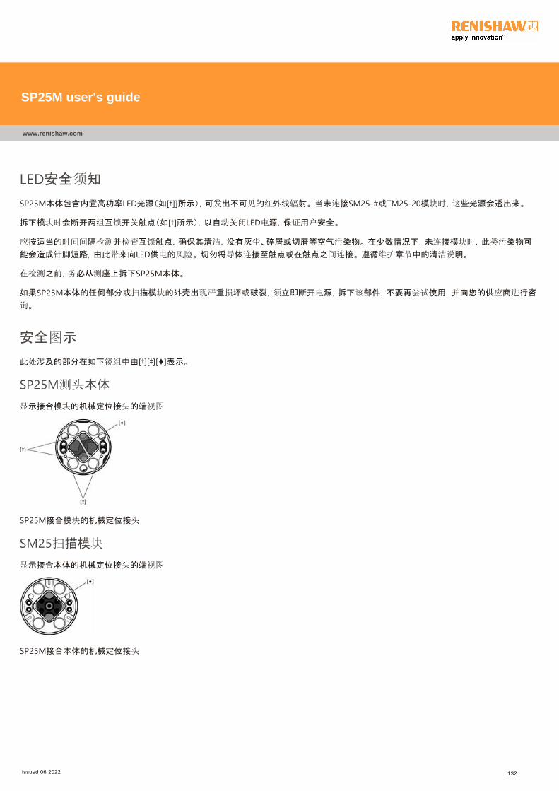
LED安全须知
SP25M本体包含内置高功率LED光源(如[†]]所示),可发出不可见的红外线辐射。 当未连接SM25‐#或TM25‐20模块时,这些光源会透出来。
拆下模块时会断开两组互锁开关触点(如[‡]所示),以自动关闭LED电源,保证用户安全。
应按适当的时间间隔检测并检查互锁触点,确保其清洁,没有灰尘、碎屑或切屑等空气污染物。 在少数情况下,未连接模块时,此类污染物可
能会造成针脚短路,由此带来向LED供电的风险。 切勿将导体连接至触点或在触点之间连接。 遵循维护章节中的清洁说明。
在检测之前,务必从测座上拆下SP25M本体。
如果SP25M本体的任何部分或扫描模块的外壳出现严重损坏或破裂,须立即断开电源,拆下该部件,不要再尝试使用,并向您的供应商进行咨
询。
安全图示
此处涉及的部分在如下镜组中由[†][‡][♦]表示。
SP25M测头本体
显示接合模块的机械定位接头的端视图
SP25M接合模块的机械定位接头
SM25扫描模块
显示接合本体的机械定位接头的端视图
SP25M接合本体的机械定位接头
SP25M user's guide
www.renishaw.com
Issued 06 2022 132

For worldwide contact details,please visit our main website at
www.renishaw.com/contact
Renishaw plc
New Mills, Wotton-under-Edge
Gloucestershire, GL12 8JR
United Kingdom
T +44 (0)1453 524524
F +44 (0)1453 524901
www.renishaw.com/cmmsupport
Issued 06 2022