Embed Size (px)
Citation preview
User's GuideSLAU607–December 2014
RF430FRL152HEVM User's Guide
This document is a description of the RF430FRL152HEVM product that is designed to fully explore all ofthe capabilities that the RF430FRL152H part offers. To more easily experiment with all of the features ofthe part and the firmware that is in the ROM, a PC application is available, and its use is also describedhere, including software and driver installation.
The family of RF430RL15xH devices includes the RF430FRL152H, RF430FRL153H, and RF430FRL154Hvariants.
Contents1 Introduction ................................................................................................................... 22 Hardware Description ....................................................................................................... 53 GUI Introduction.............................................................................................................. 84 Overview ...................................................................................................................... 95 Setup of Demo System .................................................................................................... 196 RF430FRL152HEVM Schematics........................................................................................ 267 References .................................................................................................................. 30
List of Figures
1 RF430FRL152HEVM........................................................................................................ 32 TRF7970AEVM .............................................................................................................. 33 Sensor Hub BoosterPack ................................................................................................... 44 RF430FRL152HEVM Block Diagram ..................................................................................... 55 RF430FRL152HEVM Hardware ........................................................................................... 66 PC Application................................................................................................................ 87 Setup Tab..................................................................................................................... 98 Demo Tab ................................................................................................................... 109 General Device Configuration Tab ....................................................................................... 1110 Sensor Configuration Tab ................................................................................................. 1411 Alarm Control Tab.......................................................................................................... 1512 Sensor Threshold Configuration.......................................................................................... 1713 View Sensor Data Tab..................................................................................................... 1814 BoosterPack Configuration................................................................................................ 1915 Position the EVMs.......................................................................................................... 2116 Custom Sensor Configuration Tab ...................................................................................... 2317 Custom General Device Configuration .................................................................................. 2418 Custom View Data ......................................................................................................... 2519 MCU Section Schematic .................................................................................................. 2620 I2C or SPI Translators Section Schematic .............................................................................. 2721 JTAG Section Schematic.................................................................................................. 2822 Power Section Schematic ................................................................................................. 29
MSP430 is a trademark of Texas Instruments.All other trademarks are the property of their respective owners.
1SLAU607–December 2014 RF430FRL152HEVM User's GuideSubmit Documentation Feedback
Copyright © 2014, Texas Instruments Incorporated

Introduction www.ti.com
1 IntroductionThe RF430FRL152HEVM, including the user software, is a complete evaluation platform to evaluate thekey features of the of the RF430FRL15xH devices:• Passive communication and sensor measurement using ISO/IEC 15693• Can program user code to FRAM memory through JTAG• Collect sensor measurements over I2C using the Sensor Hub BoosterPack (BOOSTXL-SENSHUB)• Can develop drivers for custom digital sensors• Interfaces with the PC GUI application to fully experiment with application functionality
1.1 OverviewTo start evaluating the RF430FRL152H device, an RF430FRL152HEVM is available. This evaluationboard allows you to experiment with all of the capabilities of the low-voltage (1.5-V) dynamic tag with anMSP430™ core.
Because this dynamic tag uses ISO/IEC 15693 (NFC-capable) passive communication, it needs anISO/IEC 15693 reader/writer to explore its full capabilities. TI recommends that you use either aTRF7970AEVM in conjunction with a PC application or a custom NFC/RFID-capable handset.
Features and benefits of the RF430FRL152H MCU include:• ISO/IEC 15693 RF interface• Low-voltage MSP430 MCU (L092 based)• Nonvolatile low-power FRAM memory (2kB)• Sigma-delta 14-bit analog-to-digital converter• Single-cell battery (1.5-V) operation• Can run batteryless from RF scavenged energy provided by NFC/RFID reader• Supports temperature measurement using a thermistor• Single-chip solution for a contact-less sensor
The RF430FRL152HEVM is a development platform to evaluate the capabilities of the RF430FRL15xHdevices and allows experimenting with all the features of the RF430FRL152H.• Integrated PCB antenna• Power over RF, battery, or USB• Onboard thermistor and reference resistor for temperature measurement• Onboard light sensor• NFC/RFID ISO 15693 communication with NFC/RFID enabled reader/writer or smart phone• Connector to enable compatibility with TI LaunchPads and BoosterPacks• JTAG header for connection of MSP430-FET Emulation tool for programming
2 RF430FRL152HEVM User's Guide SLAU607–December 2014Submit Documentation Feedback
Copyright © 2014, Texas Instruments Incorporated
www.ti.com Introduction
1.2 What is Included• RF430FRL152HEVM (see Figure 1 below)• USB cable• Quick start guide
1.2.1 RF430FRL152HEVMFigure 1 shows a photograph of the RF430FRL152HEVM.
Figure 1. RF430FRL152HEVM
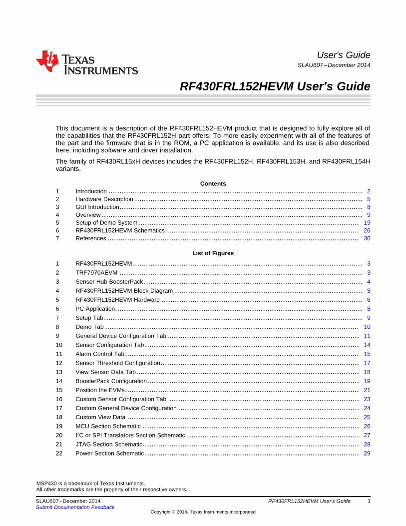
1.3 Required Additional EquipmentOptional recommended equipment:• PC running Windows operating system to run the GUI for the TRF7970AEVM• TRF7970AEVM for NFC/RFID communication with the RF430FRL152HEVM (TRF7970AEVM)
1.3.1 TRF7970AEVMFigure 2 shows a photograph of the TRF7970AEVM. If the TRF7970AEVM was purchased around thesame time as the RF430FRL152HEVM no code updates will be necessary. If there are communicationissues with the RF430FRL152HEVM, make sure that the TRF7970AEVM is programmed with the latestfirmware. The latest firmware for the TRF7970AEVM can be found here.
Figure 2. TRF7970AEVM
3SLAU607–December 2014 RF430FRL152HEVM User's GuideSubmit Documentation Feedback
Copyright © 2014, Texas Instruments Incorporated
Introduction www.ti.com
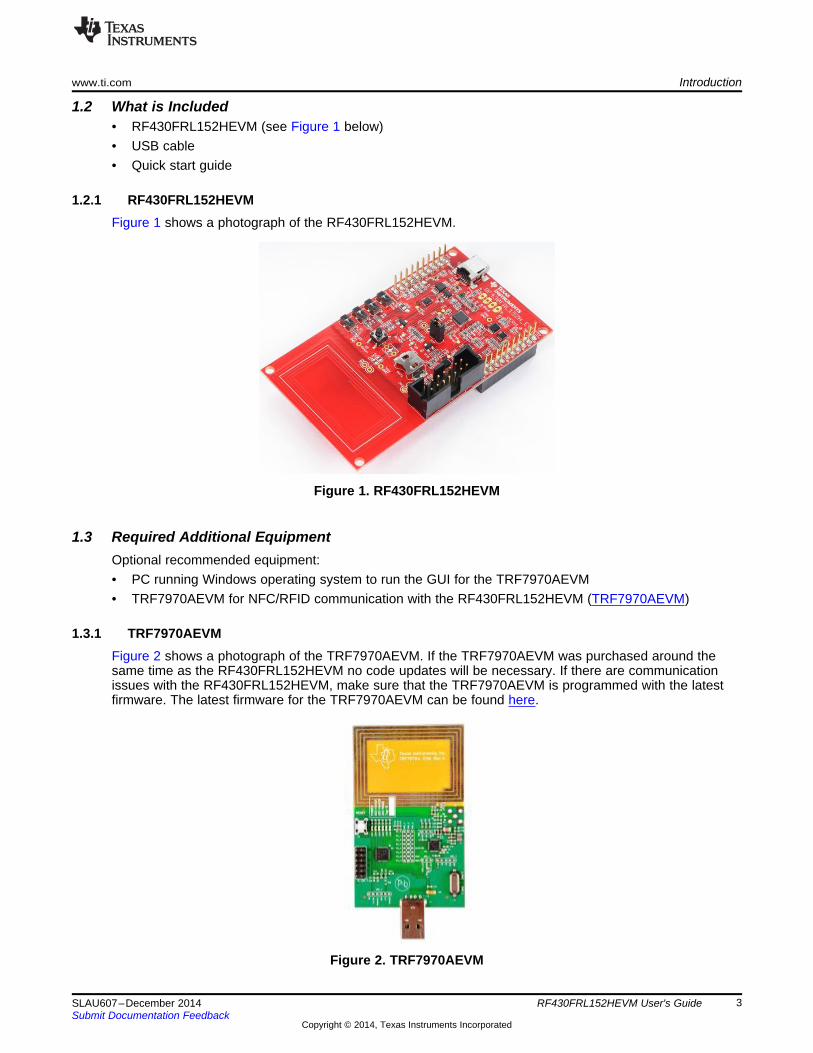
1.4 Recommended Additional EquipmentOptional recommended equipment:• SensorHub Booster Pack – connection of digital sensors (BOOSTXL-SENSHUB)• MSP430 FET Tool for code development / debugging and programming the device over JTAG (MSP-
FET)
1.4.1 Sensor Hub BoosterPackFigure 3 shows a photograph of the Sensor Hub BoosterPack.
Figure 3. Sensor Hub BoosterPack
1.5 Installation of the Software and DriversThe most recent PC GUI and user's guide are available at www.ti.com/tool/RF430FRL152HEVM .
To install the PC GUI:1. Download the RF430FRL152HEVM-1.1.2-windows-installer.exe file to the PC.2. Run the executable and follow the prompts to install the software.3. To run the application click on the Start menu, All Programs, then the Texas Instruments folder, then
the "RF430FRL152HEVM Application" and finally the "RF430FRL152H GUI Interface" program.
The USB drivers for the TRF7970AEVM are available from this link:http://www.silabs.com/products/mcu/pages/USBtoUARTbridgeVCPdrivers.aspx
4 RF430FRL152HEVM User's Guide SLAU607–December 2014Submit Documentation Feedback
Copyright © 2014, Texas Instruments Incorporated
RF430FRL152H
ANT 1
ANT 2RF
P1
.4/T
CK
P1
.5/T
DI
P1
.6/T
DO
P1
.7/T
MS
1.5 VJTAG Level
Translators
3.3 V FET Tool
Programmer
Connector
'E��������^0_
s��^t�^1_
^D/^_�(S3)
^�1_�(S4)
^�0_(S5)
SVSS
ADC0
VDDSW
ADC2
ADC1
Thermistor
Reference Resistor
Light Sensor
3.3V
MOSFET INT
5 V3.3 V
POWER LED
ALARM
LED
Power
Chooser
Power From
MSP-FET
1.5-V LDO
^������Ç_
^^µ��oÇ_VDDB
VDDB
P1.2/SPI_CLK
P1.1/MISO/SCL
P1.0/MOSI/SDA
P1.3/SPI_CS
0
Level
Translator
Level
Translator
SV9 SV10
1
2
3
4
5
6
7
8
9
10
POWER_3V3
RF430_RST
INT_3V3
BPACK_CLK
BPACK_CS
1
2
3
4
5
6
7
8
9
10
GND
BPACK_SDA
BPACK_SCL
BPACK_CSBPACK_CLK
BPACK_SDABPACK_SCL
INT_3V3LaunchPad BoosterPack
Headerss��^t�^1_
s��^t�^1_
'E��������^0_
'E��������^0_
USB
Mini
Connector
3.3-V LDO
RE
SE
T
VDDSW
Jumper
SV7
S6
www.ti.com Hardware Description
2 Hardware Description
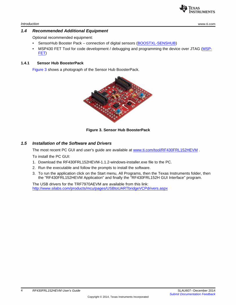
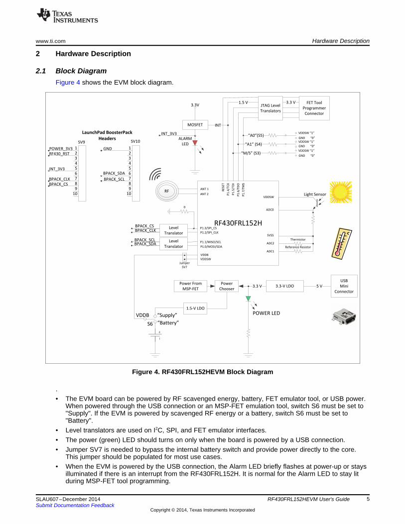
2.1 Block DiagramFigure 4 shows the EVM block diagram.
Figure 4. RF430FRL152HEVM Block Diagram
.• The EVM board can be powered by RF scavenged energy, battery, FET emulator tool, or USB power.
When powered through the USB connection or an MSP-FET emulation tool, switch S6 must be set to"Supply". If the EVM is powered by scavenged RF energy or a battery, switch S6 must be set to"Battery".
• Level translators are used on I2C, SPI, and FET emulator interfaces.• The power (green) LED should turns on only when the board is powered by a USB connection.• Jumper SV7 is needed to bypass the internal battery switch and provide power directly to the core.
This jumper should be populated for most use cases.• When the EVM is powered by the USB connection, the Alarm LED briefly flashes at power-up or stays
illuminated if there is an interrupt from the RF430FRL152H. It is normal for the Alarm LED to stay litduring MSP-FET tool programming.
5SLAU607–December 2014 RF430FRL152HEVM User's GuideSubmit Documentation Feedback
Copyright © 2014, Texas Instruments Incorporated
Hardware Description www.ti.com
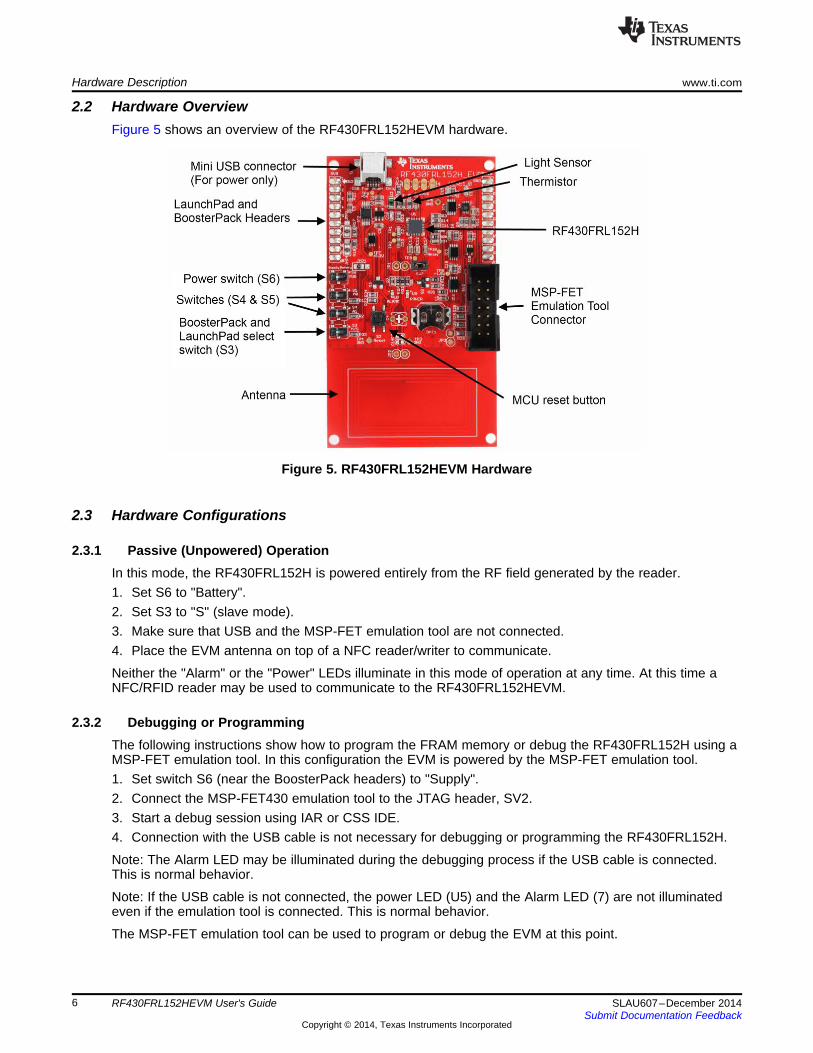
2.2 Hardware OverviewFigure 5 shows an overview of the RF430FRL152HEVM hardware.
Figure 5. RF430FRL152HEVM Hardware
2.3 Hardware Configurations
2.3.1 Passive (Unpowered) OperationIn this mode, the RF430FRL152H is powered entirely from the RF field generated by the reader.1. Set S6 to "Battery".2. Set S3 to "S" (slave mode).3. Make sure that USB and the MSP-FET emulation tool are not connected.4. Place the EVM antenna on top of a NFC reader/writer to communicate.
Neither the "Alarm" or the "Power" LEDs illuminate in this mode of operation at any time. At this time aNFC/RFID reader may be used to communicate to the RF430FRL152HEVM.
2.3.2 Debugging or ProgrammingThe following instructions show how to program the FRAM memory or debug the RF430FRL152H using aMSP-FET emulation tool. In this configuration the EVM is powered by the MSP-FET emulation tool.1. Set switch S6 (near the BoosterPack headers) to "Supply".2. Connect the MSP-FET430 emulation tool to the JTAG header, SV2.3. Start a debug session using IAR or CSS IDE.4. Connection with the USB cable is not necessary for debugging or programming the RF430FRL152H.
Note: The Alarm LED may be illuminated during the debugging process if the USB cable is connected.This is normal behavior.
Note: If the USB cable is not connected, the power LED (U5) and the Alarm LED (7) are not illuminatedeven if the emulation tool is connected. This is normal behavior.
The MSP-FET emulation tool can be used to program or debug the EVM at this point.
6 RF430FRL152HEVM User's Guide SLAU607–December 2014Submit Documentation Feedback
Copyright © 2014, Texas Instruments Incorporated
www.ti.com Hardware Description
2.3.3 Using a BoosterPack or Digital SensorsAn example of this use case is using the Sensor Hub BoosterPack. In this configuration the EVM ispowered by the USB connection.1. Set switch S6 (near the BoosterPack headers) to "Supply".2. Set switch S3 to "M" (master mode).3. Attach the BoosterPack on top of the EVM, making sure it is in the correct orientation (pin 1 on the
EVM matches pin 1 on the BoosterPack headers).4. Connect the USB cable to either the BoosterPack or the RF430FRL152HEVM.
Note: When the USB cable is attached, the power LED (U5) stays illuminated. The Alarm LED (U7) shouldmomentarily illuminate and then turn off.
Now the TRF7970AEVM can be used to communicate to the part and initiate samples of the varioussensors.
2.3.4 Using a Host ControllerIn this mode, the host LaunchPad is connected underneath the RF430FRL152HEVM. Make sure theorientations match.1. Set switch S6 (near the BoosterPack headers) to "Supply" setting.2. Set S3 to "S" (slave mode).3. For a host that uses I2C, S5 and S4 determine the two least significant bits of the I2C slave address for
the RF430FRL152H. For most cases, set these switches to the "0" positions.4. For a host that uses SPI, S5 and S4 determine the SPI mode. For most cases, set these switches to
the "0" positions.5. Set S5 or S4 to desired setting at this time.6. Connect the LaunchPad and the EVM together.7. Power either the LaunchPad or the EVM by connecting either to a USB cable.
Note: When the USB cable is attached, the power LED (U5) stay illuminated. The Alarm LED (U7) shouldmomentarily illuminate and then turn off.
2.3.5 Powering the EVM Using a Battery1. Insert an SR66 1.5-V battery into the battery holder (BAT1).2. Note: The first time that a battery is inserted, the batter holder may be tight. Carefully holding the board
with a flat object, firmly slide in the battery. Make sure that the positive side of the battery is facing thepositive (or top) side of the battery holder.
3. Set S6 to "Battery".4. If the battery switch is open (the battery switch is inside the RF430FRL152H), SV7 needs to have a
jumper to power the part. If the battery switch is closed, then SV7 does not need a jumper to power theRF430FRL152H.
Note: In this mode, the alarm and power LEDs are not illuminated. The device is still powered andoperational.
Note: Also if S5, S4, or S3 positions are changed after powering the EVM, a reset is required for thechanged settings to take effect. This can be done through the PC GUI or by pressing the reset switch(S2).
Note: If a battery is installed and another configuration (for example, debugging or using a BoosterPack) isrequired, set switch S6 to "Supply" to disconnect the battery and not drain it.
7SLAU607–December 2014 RF430FRL152HEVM User's GuideSubmit Documentation Feedback
Copyright © 2014, Texas Instruments Incorporated

GUI Introduction www.ti.com
3 GUI IntroductionFigure 6 shows the Setup tab.
Figure 6. PC Application
Table 1. GUI Tabs
Name Contents and FunctionsSetup This tab explains how to configure the system.
Using an RF430FRL152HEVM, this tab allows automatic setup, measurement, and display ofDemo Mode the thermistor and light sensor's measurements with one click of a button.This tab contains controls that allow starting the sampling process, choosing the sensors to beGeneral Device Configuration used, and selecting the sampling frequency, among other options.
Sensor Configuration This tab contains settings for the ADC for each analog sensor and also advanced settings.Alarm Control This tab contains settings for enabling and disabling the alarm settings.Sensor Threshold Configuration This tab contains settings for alarm thresholds for each sensor.View Sensor Data After a sampling process has completed, this tab allows the user to view the logged data.
8 RF430FRL152HEVM User's Guide SLAU607–December 2014Submit Documentation Feedback
Copyright © 2014, Texas Instruments Incorporated
www.ti.com Overview
4 OverviewThis section describes the meaning of each of the options on each tab. Remember, checking an optiondoes not immediately cause that option to be set. It is only set after a "Write" button click is performed.Any changes that have occurred on the part, like new status, will not be visible until a "Read" button clickhas been done.
4.1 Typical SequenceIn a typical sequence (for example, to do a thermistor measurement) follow these steps. These steps aremore fully described in the RF430FRL15xH Firmware User's Guide (SLAU603).1. Configure the thermistor measurement parameters:
(a) Select the thermistor sensor.(b) Set how many times it needs to be sampled.(c) If sampled more than one time, select the delay between the samples.(d) Select the ADC configuration (resolution, PGA setting, and type of filter).These settings are written to the virtual registers in the FRAM memory using RF communication.
2. Write the start bit in the control register to start the sampling process.3. There is a delay while the sampling process is being performed.4. After sampling is complete, the requested measurements are stored into the log memory, typically
FRAM (after the virtual registers).
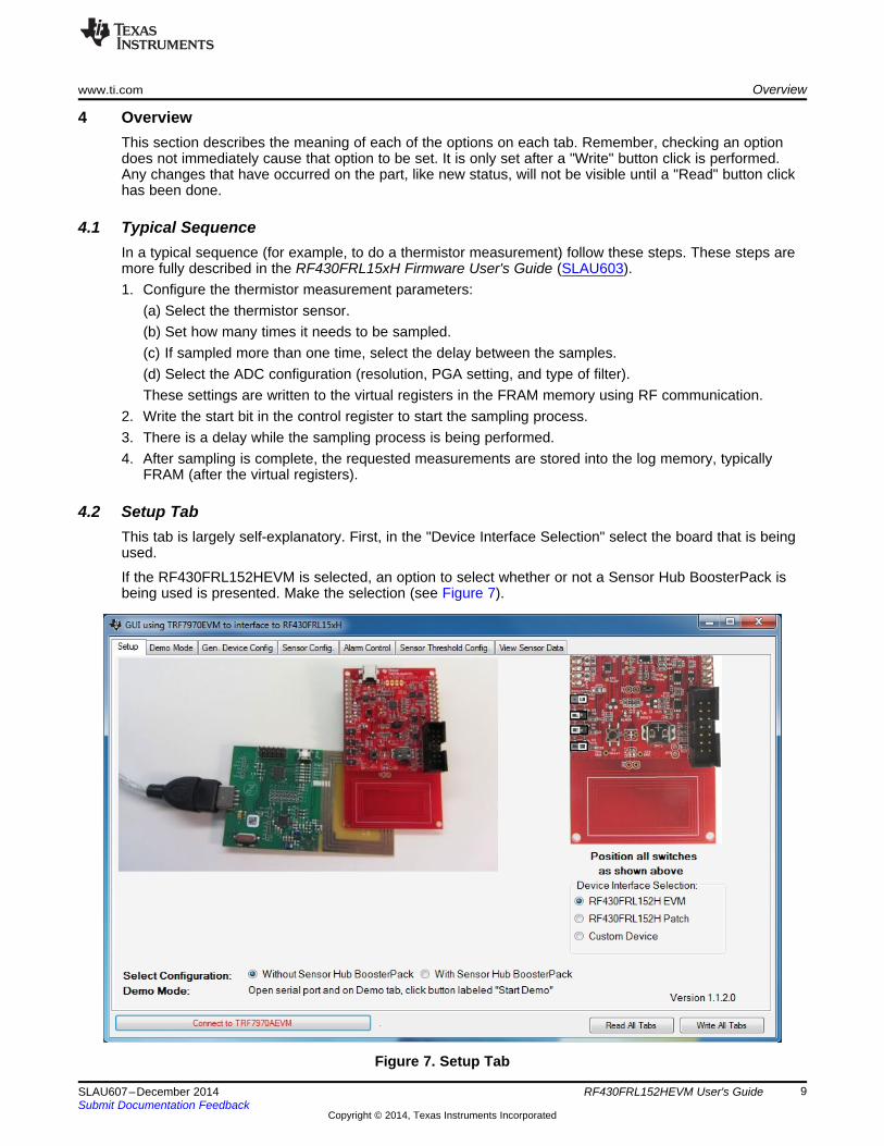
4.2 Setup TabThis tab is largely self-explanatory. First, in the "Device Interface Selection" select the board that is beingused.
If the RF430FRL152HEVM is selected, an option to select whether or not a Sensor Hub BoosterPack isbeing used is presented. Make the selection (see Figure 7).
Figure 7. Setup Tab
9SLAU607–December 2014 RF430FRL152HEVM User's GuideSubmit Documentation Feedback
Copyright © 2014, Texas Instruments Incorporated
Overview www.ti.com
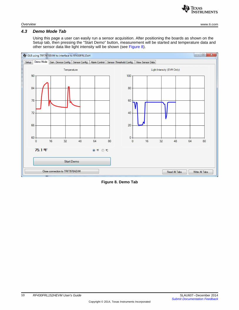
4.3 Demo Mode TabUsing this page a user can easily run a sensor acquisition. After positioning the boards as shown on theSetup tab, then pressing the "Start Demo" button, measurement will be started and temperature data andother sensor data like light intensity will be shown (see Figure 8).
Figure 8. Demo Tab
10 RF430FRL152HEVM User's Guide SLAU607–December 2014Submit Documentation Feedback
Copyright © 2014, Texas Instruments Incorporated

www.ti.com Overview
4.4 General Device Configuration TabFigure 9 shows the "Gen. Device Config" tab.
Figure 9. General Device Configuration Tab
1. Start Sampling ProcessSetting this bit causes the application ROM code to start the sampling process of all the sensors thatwere selected, based on all of the configurations.
2. LPM3 and LPM4Selects which power mode is used when the device enters idle mode.
3. Control Battery Switch and Close Battery SwitchControls the state of the battery switch on the device. To change the state, check "Control BatterySwitch" and then to close the battery switch, check "Close Battery Switch". Otherwise, leave itunchecked, and the battery switch is set to open. The "Control Battery Switch" option is reset after thecommand is executed by the application ROM code.
4. ISO 15693 Send DataAllows sending of raw ISO/IEC 15693 commands. Disabled in the current version of the GUI.
5. Control Interrupt and Set InterruptControls the state of the external interrupt on the device. To change the state, check "ControlInterrupt", and then to set the interrupt, check "Set Interrupt". Otherwise, leave it unchecked, and theinterrupt and the associated flags are cleared. The "Control Interrupt" option is reset after thecommand is executed by the application ROM code. To generate an external interrupt manually withthe GUI, more settings must be done using the "External Interrupt Control"
6. ResetCauses a PUC (a reset) to be generated on the device. The connection is maintained.
7. Status Register
11SLAU607–December 2014 RF430FRL152HEVM User's GuideSubmit Documentation Feedback
Copyright © 2014, Texas Instruments Incorporated

Overview www.ti.com
This group box displays any interrupt or status that have occurred on the device.Reset all status flags on next write resets all status to idle mode after the tab write.
8. Sensor Control RegisterAllows the selection of any sensor to be sampled. Selection of one or multiple sensors is possible.
9. Reference / ADC1 SensorAnalog Input. If "Using Thermistor", check 11. This causes the input to be configured for an externalreference resistor measurement. Otherwise, it can function as a standalone generic analog sensor(ADC1).
10. Thermistor / ADC2 SensorAnalog Input. If "Using Thermister", check 11. This causes the input to be configured for an externalthermistor measurement. Otherwise, it can function as a standalone generic analog sensor (ADC2).
11. Using ThermistorIf using a thermistor, this option must be selected for the application ROM code to properly set up themeasurement.
12. ADC0 / Light SensorWhen using a RF430FRL152HEVM, this is an option to sample the light sensor. Otherwise, it is ageneric analog sensor (ADC0).
13. Internal Temperature SensorAllows sampling of the internal temperature sensor on the part.
14. Digital Sensor 1If using the RF430FRL152HEVM together with the Sensor Hub BoosterPack, this samples the SHT21temperature sensor. Otherwise, it is an option to sample a generic digital sensor.
15. Digital Sensor 2If using the RF430FRL152HEVM together with the Sensor Hub BoosterPack, this samples the SHT21humidity sensor. Otherwise, it is an option to sample a generic digital sensor.
16. Digital Sensor 3If using the RF430FRL152HEVM together with the Sensor Hub BoosterPack, this option samples theISL29023 light sensor. Otherwise, it is an option to sample a generic digital sensor.
17. Number of Passes RegisterOne pass is sampling all of the selected sensors one time.
18. Averaging RegisterAny value higher than 1 causes that many samples to be averaged into one result. Averaging mode inthe "Alarm Control" tab selects the type of averaging used per sensor.
19. Frequency RegisterSelects the delay to be made in between each of the sampling passes. Note this delay must not beless than the time to complete sampling all of the sensors one time. If it is less, then a "collision"occurs.
20. More RegistersThis advanced section is not required in most cases. However, it is described below.Gating option to enable the external GPIO interrupt.
21. Interrupt Assert LevelThe level to be driven or pulled to if there is an interrupt
22. Interrupt Drive StateDetermines if the device drives an interrupt or is high impedance (user must provide the appropriatepullup or pulldown resistor).
23. Bus Test Mode EnableAllows access to protected memory using an I2C or SPI host.
12 RF430FRL152HEVM User's Guide SLAU607–December 2014Submit Documentation Feedback
Copyright © 2014, Texas Instruments Incorporated
www.ti.com Overview
24. Check For Unexpected ResetIf this option is selected, and an unexpected reset occurs, the reset code is logged at the end of thelogging memory.
25. Disconnect Battery At Sampling EndWhen the sampling process has been completed, this option causes the ROM code to open the batteryswitch.
26. End of Sampling External Interrupt EnableWhen the sampling process has completed, this option causes an external interrupt to be generated.
27. Voltage Levels AlertWhen these are set, it indicates that the voltage levels have gone too low on a particular rail at somepoint. Not self clearing.
28. BIP8 ControlError detection for I2C or SPI protocol
29. Infinite SamplingSamples until the "Start Sampling Process" option is unchecked.
30. Enable WatchdogEnables the watchdog during a sampling process.
31. RAM Storage EnableWrites sampling results into RAM memory instead of FRAM.
32. Read only this tabReads Gen. Device Config and populates the results on this tab.
33. Write only this tabWrites Gen. Device Config with all of the settings on this tab.
34. Read All TabsReads all of the information on all of the tabs from the virtual FRAM registers in the device using RFand populates the fields in the tabs.
35. Write All TabsWrites all of the information to the virtual FRAM registers in the device over RF from all of the settings.
NOTE: Settings made on the following tabs do not take effect until a "Write only this tab" or "WriteAll Tabs" button is clicked:Gen. Device Config.Sensor Config.Alarm ControlSensor Threshold Config.
Likewise, the settings on these tabs are not updated until a "Read only this tab" or "Read AllTabs" button is clicked.
13SLAU607–December 2014 RF430FRL152HEVM User's GuideSubmit Documentation Feedback
Copyright © 2014, Texas Instruments Incorporated
Overview www.ti.com
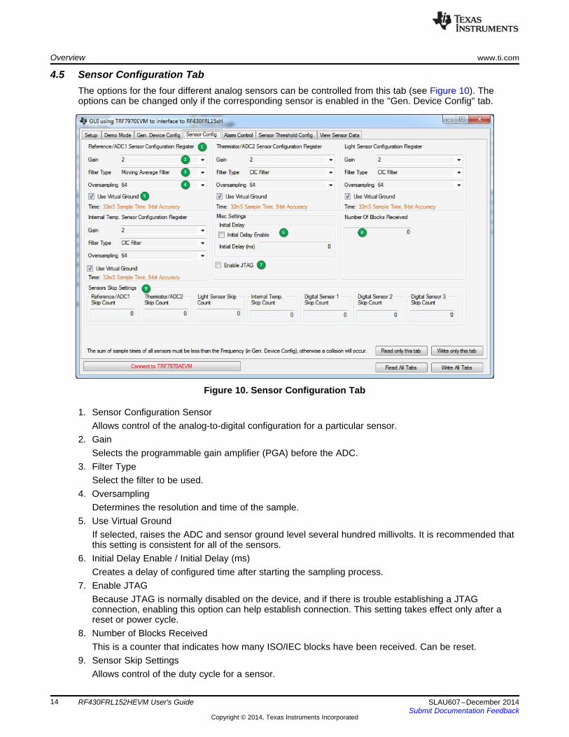
4.5 Sensor Configuration TabThe options for the four different analog sensors can be controlled from this tab (see Figure 10). Theoptions can be changed only if the corresponding sensor is enabled in the "Gen. Device Config" tab.
Figure 10. Sensor Configuration Tab
1. Sensor Configuration SensorAllows control of the analog-to-digital configuration for a particular sensor.
2. GainSelects the programmable gain amplifier (PGA) before the ADC.
3. Filter TypeSelect the filter to be used.
4. OversamplingDetermines the resolution and time of the sample.
5. Use Virtual GroundIf selected, raises the ADC and sensor ground level several hundred millivolts. It is recommended thatthis setting is consistent for all of the sensors.
6. Initial Delay Enable / Initial Delay (ms)Creates a delay of configured time after starting the sampling process.
7. Enable JTAGBecause JTAG is normally disabled on the device, and if there is trouble establishing a JTAGconnection, enabling this option can help establish connection. This setting takes effect only after areset or power cycle.
8. Number of Blocks ReceivedThis is a counter that indicates how many ISO/IEC blocks have been received. Can be reset.
9. Sensor Skip SettingsAllows control of the duty cycle for a sensor.
14 RF430FRL152HEVM User's Guide SLAU607–December 2014Submit Documentation Feedback
Copyright © 2014, Texas Instruments Incorporated
www.ti.com Overview
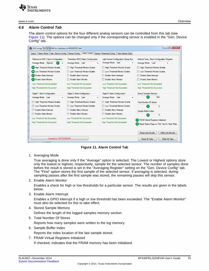
4.6 Alarm Control TabThe alarm control options for the four different analog sensors can be controlled from this tab (seeFigure 11). The options can be changed only if the corresponding sensor is enabled in the "Gen. DeviceConfig" tab.
Figure 11. Alarm Control Tab
1. Averaging ModeTrue averaging is done only if the "Average" option is selected. The Lowest or Highest options storeonly the lowest or highest, respectively, sample for the selected sensor. The number of samples donebefore the result is stored is set in the "Averaging Register" setting on the "Gen. Device Config" tab.The "First" option stores the first sample of the selected sensor. If averaging is selected, duringsampling passes after the first sample was stored, the remaining passes will skip this sensor.
2. Enable Alarm MonitorEnables a check for high or low thresholds for a particular sensor. The results are given in the labelsbelow.
3. Enable Alarm InterruptEnables a GPIO interrupt if a high or low threshold has been exceeded. The "Enable Alarm Monitor"must also be selected for this to take effect.
4. Stored Sample MemoryDefines the length of the logged samples memory section.
5. Total Number Of StoresReports how many samples were written to the log memory.
6. Sample Buffer IndexReports the index location of the last sample stored.
7. FRAM Virtual Registers InitializedIf checked, indicates that the FRAM memory has been initialized.
15SLAU607–December 2014 RF430FRL152HEVM User's GuideSubmit Documentation Feedback
Copyright © 2014, Texas Instruments Incorporated
Overview www.ti.com
8. Reset Status Flags on This Tab On Next WriteResets all of the flags on this tab the next time the "Write" button is clicked.
9. High Threshold Monitor EnableEnables monitoring of that particular sensor for a sample value that exceeds or is equal to thethreshold value set in "Sensor Threshold Config." tab. If the sample meets that condition, the status forthat sensor (in the same group box) changes to indicate that condition.
10. Low Threshold Monitor EnableEnables monitoring of that particular sensor for a sample value for that is less than or equal to thethreshold value set in "Sensor Threshold Config." tab. If the sample meets that condition, the status forthat sensor (in the same group box) changes to indicate that condition.
16 RF430FRL152HEVM User's Guide SLAU607–December 2014Submit Documentation Feedback
Copyright © 2014, Texas Instruments Incorporated
www.ti.com Overview
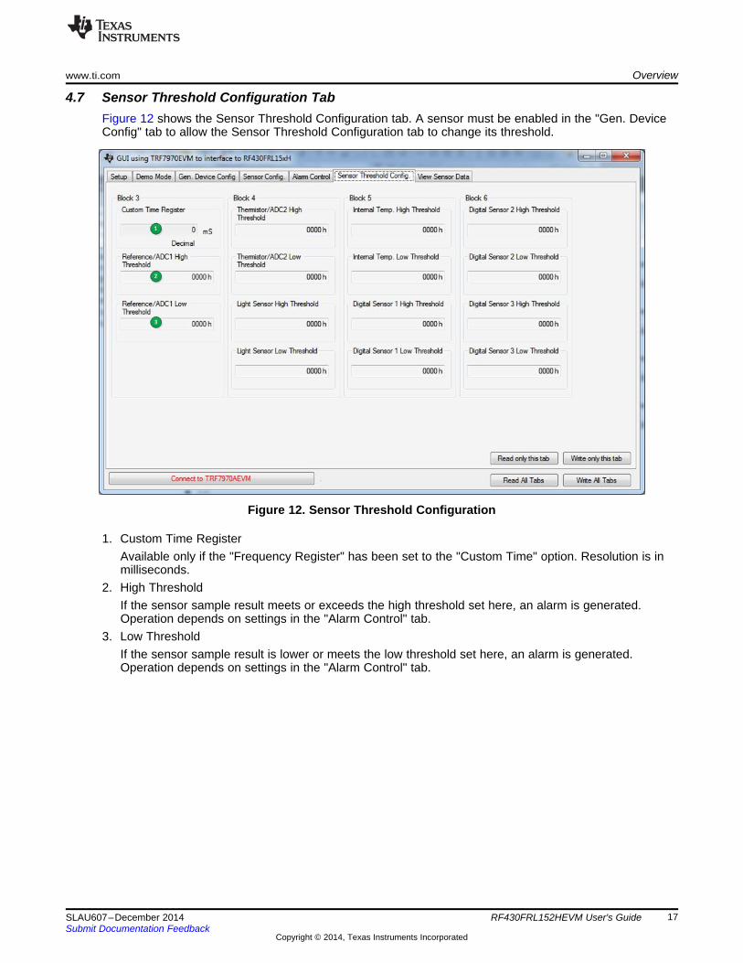
4.7 Sensor Threshold Configuration TabFigure 12 shows the Sensor Threshold Configuration tab. A sensor must be enabled in the "Gen. DeviceConfig" tab to allow the Sensor Threshold Configuration tab to change its threshold.
Figure 12. Sensor Threshold Configuration
1. Custom Time RegisterAvailable only if the "Frequency Register" has been set to the "Custom Time" option. Resolution is inmilliseconds.
2. High ThresholdIf the sensor sample result meets or exceeds the high threshold set here, an alarm is generated.Operation depends on settings in the "Alarm Control" tab.
3. Low ThresholdIf the sensor sample result is lower or meets the low threshold set here, an alarm is generated.Operation depends on settings in the "Alarm Control" tab.
17SLAU607–December 2014 RF430FRL152HEVM User's GuideSubmit Documentation Feedback
Copyright © 2014, Texas Instruments Incorporated
Overview www.ti.com
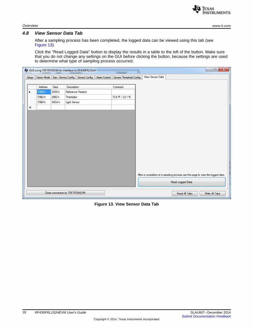
4.8 View Sensor Data TabAfter a sampling process has been completed, the logged data can be viewed using this tab (seeFigure 13).
Click the "Read Logged Data" button to display the results in a table to the left of the button. Make surethat you do not change any settings on the GUI before clicking the button, because the settings are usedto determine what type of sampling process occurred.
Figure 13. View Sensor Data Tab
18 RF430FRL152HEVM User's Guide SLAU607–December 2014Submit Documentation Feedback
Copyright © 2014, Texas Instruments Incorporated

www.ti.com Setup of Demo System
5 Setup of Demo SystemThe following sections describe how to setup a demo with and without the Sensor Hub BoosterPack, andalso for custom configuring and operation of the device.
5.1 Set up the RF430FRL152HEVM With Sensor Hub Demo Using the PCThis section describes how to setup and run the Sensor Hub BoosterPack demo. With this setup, theRF430FRL152HEVM samples over I2C three different sensors on the SensorHub BoosterPack. They aretemperature and humidity (SHT21) and a light sensor (ISL29023). After collecting the samples, the data istransmitted over RF to the TRF7970AEVM which reports them to the PC application. Finally the resultsare plotted on the graphs.1. Connect the TRF7970AEVM to the PC with a USB cable.2. On the RF430FRL152HEVM, use a pencil or pen to position the switches as shown in Table 2
Table 2. Switch Positions For Sensor Hub Operation
Switch ID Position CommentS6 Supply This will source power from the USB cableS5 0 Does not matter what state this switch is inS4 0 Does not matter what state this switch is inS3 M Device starts in I2C/SPI master mode
3. Attach the Sensor Hub BoosterPack on top of the RF430FRL152HEVM. Make sure that the orientationis correct (see Figure 14).
4. Connect the RF430FRL152HEVM to the PC using the provided USB cable. Note that this USBconnection is only for the power supply, and no data is passed through it.
5. Position the RF430FRL152HEVM antenna on the antenna portion of the TRF7970AEVM as shown inFigure 14. It is recommended to have an insulator between the two antennas or to hold them at adistance from each other to prevent any short circuits.
Figure 14. BoosterPack Configuration
6. Open the RF430FRL15xH GUI Interface application by going to the Start menu→All Programs→TexasInstruments→RF430FRL152H GUI .
7. Click the "Connect to TRF7970AEVM" button on the bottom of the window.8. A few seconds after you click the "Connect" button, the label next to the button should show
"Connected to TRF7970AEVM on COMx". If this is not shown, then a connection has not been made.
19SLAU607–December 2014 RF430FRL152HEVM User's GuideSubmit Documentation Feedback
Copyright © 2014, Texas Instruments Incorporated
Setup of Demo System www.ti.com
In this case, disconnect the TRF7970AEVM and reconnect it, then restart at step 1. If this still does notsolve the problem, make sure that the TRF7970AEVM has the latest firmware downloaded from theTRF7970AEVM tool folder.
9. In the "Setup Tab", select the "With Sensor Hub BoosterPack" and "RF430FRL152HEVM" options onthe Device Interface Selection.
10. Select the "Demo Mode" tab.11. Click the "Start Sensor Hub Demo" button.12. The GUI starts to plot the temperature and light intensity samples on the graphs.
(a) To plot these values, the PC GUI configures the RF430FRL152HEVM through the TRF7970AEVMto take three different samples from the Sensor Hub BoosterPack. The RF430FRL152HEVMalready has the drivers loaded into the FRAM to enable the measurements to be made.
(b) When the samples are complete, the PC GUI reads the result from FRAM of theRF430FRL152HEVM through the TRF7970AEVM and plots it on the graphs in the PC GUI.
13. To change the measurements, you can place your hand over the light sensor or heat the thermistor(U5).
20 RF430FRL152HEVM User's Guide SLAU607–December 2014Submit Documentation Feedback
Copyright © 2014, Texas Instruments Incorporated

www.ti.com Setup of Demo System
5.2 Set up the RF430FRL152HEVM Demo Using the PCThis section describes how to setup and run the sensor demo. With this setup, the RF430FRL152HEVMsamples, using the onboard ADC, two external sensors, the thermistor and the light sensor. Aftercollecting the samples, the data is transmitted over RF to the TRF7970AEVM which reports them to thePC application. Finally the results are plotted on the graphs. In this demo the RF430FRL152HEVM is runcompletely wireless, with no power or data connections.1. Connect the TRF7970AEVM to the PC with a USB cable.2. On the RF430FRL152HEVM, use a pen or pencil to set the mini-switches as shown in Table 3.
Table 3. Switch Positions For Passive Operation
Switch ID Position CommentS6 Battery There is no need for a battery to be presentS5 0 Does not matter what state this switch is inS4 0 Does not matter what state this switch is inS3 S Device starts in I2C/SPI slave mode
3. The RF430FRL152HEVM should not be connected to a USB cable for this demo. If it isconnected, set switch S6 to the "Supply" position. The rest of the steps are the same.Note: If EnergyTrace technology is used, a USB cable should not be used and the EVM must bepowered from the MSP-FET tool.
4. Position the RF430FRL152HEVM antenna on the antenna portion of the TRF7970AEVM as shown inFigure 15. It is recommended to have an insulator between the two antennas or to hold them at adistance from each other to prevent any short circuits.
Figure 15. Position the EVMs
5. Open the RF430FRL15xH GUI Interface application by going to the Start menu→All Programs→TexasInstruments→RF430FRL152H GUI .
6. Press the "Connect to TRF7970AEVM" button on the bottom of the window.7. A few seconds after you click the "Connect" button, the label next to the button should show
"Connected to TRF7970AEVM on COMx".If this is not displayed, then a connection has not been made. In this case, disconnect theTRF7970AEVM and reconnect it, then restart at step 1. If this still does not solve the problem, makesure that the TRF7970AEVM has the latest firmware downloaded from the TRF7970AEVM tool folder.
8. In the "Setup Tab" select the "Without Sensor Hub BoosterPack" and "RF430FRL152HEVM" options.9. Go to the "Demo Mode" tab.10. Click the "Start Demo" button.11. The GUI starts to plot the temperature and light intensity samples on the graphs.
(a) To plot these values, the PC GUI configures the RF430FRL152HEVM through the TRF7970AEVMto take two different samples from the analog thermistor and light sensors.
(b) When the samples are complete, the PC GUI reads the result from FRAM of the
21SLAU607–December 2014 RF430FRL152HEVM User's GuideSubmit Documentation Feedback
Copyright © 2014, Texas Instruments Incorporated

Setup of Demo System www.ti.com
RF430FRL152HEVM through the TRF7970AEVM and plots it on the graphs in the PC GUI.12. To change the measurements, you can place your hand over the light sensor or press the thermistor
with a finger to affect the temperature result. The light sensor and the thermistor locations on the EVMare shown in Section 2.The thermistor temperature measurement may not reach the true skin temperature, because some ofthe heat dissipates into the EVM.The light sensor reading value does not increase in the presence of extra light (for example, if youshine a flashlight on it), because of design reasons with the light sensor selected for this EVM.However, the light sensor shows a change for reduced light. Note that the light sensor on the SensorHub BoosterPack does not have this same limitation.
22 RF430FRL152HEVM User's Guide SLAU607–December 2014Submit Documentation Feedback
Copyright © 2014, Texas Instruments Incorporated
www.ti.com Setup of Demo System
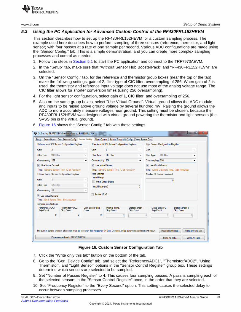
5.3 Using the PC Application for Advanced Custom Control of the RF430FRL152HEVMThis section describes how to set up the RF430FRL152HEVM for a custom sampling process. Theexample used here describes how to perform sampling of three sensors (reference, thermistor, and lightsensor) with four passes at a rate of one sample per second. Various ADC configurations are made usingthe "Sensor Config." tab. This is a simple demonstration, and you can create more complex samplingprocesses and control as needed.1. Follow the steps in Section 5.1 to start the PC application and connect to the TRF7970AEVM.2. In the "Setup" tab, make sure that "Without Sensor Hub BoosterPack" and "RF430FRL152HEVM" are
selected.3. On the "Sensor Config." tab, for the reference and thermistor group boxes (near the top of the tab),
make the following settings: gain of 2, filter type of CIC filter, oversampling of 256. When gain of 2 isused, the thermistor and reference input voltage does not use most of the analog voltage range. TheCIC filter allows for shorter conversion times (using 256 oversampling).
4. For the light sensor configuration, select gain of 1, CIC filter, and oversampling of 256.5. Also on the same group boxes, select "Use Virtual Ground". Virtual ground allows the ADC module
and inputs to be raised above ground voltage by several hundred mV. Raising the ground allows theADC to more accurately measure voltages near ground. This setting must be chosen, because theRF430FRL152HEVM was designed with virtual ground powering the thermistor and light sensors (theSVSS pin is the virtual ground).
6. Figure 16 shows the "Sensor Config." tab with these settings.
Figure 16. Custom Sensor Configuration Tab
7. Click the "Write only this tab" button on the bottom of the tab.8. Go to the "Gen. Device Config" tab, and select the "Reference/ADC1", "Thermistor/ADC2", "Using
Thermistor", and "Light Sensor" options in the "Sensor Control Register" group box. These settingsdetermine which sensors are selected to be sampled.
9. Set "Number of Passes Register" to 4. This causes four sampling passes. A pass is sampling each ofthe selected sensors in the "Sensor Control Register" once, in the order that they are selected.
10. Set "Frequency Register" to the "Every Second" option. This setting causes the selected delay tooccur between sampling processes.
23SLAU607–December 2014 RF430FRL152HEVM User's GuideSubmit Documentation Feedback
Copyright © 2014, Texas Instruments Incorporated

Setup of Demo System www.ti.com
11. Check "Start Sampling Process".12. Figure 17 shows the "Gen. Device Config" tab with these settings.
Figure 17. Custom General Device Configuration
13. Click the "Write only this tab" button.14. The sampling process starts. You can click the "Read only this tab" button to check on the status of
the sampling process. While the RF430FRL152H is still sampling, the "Status Register" displays thetext "Sampling in Progress".
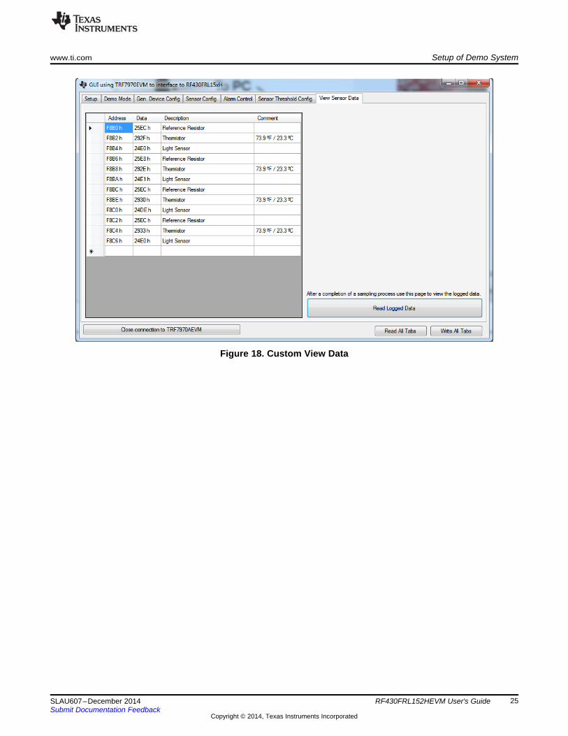
15. Continue to click the "Read only this tab" button until the "Status Register" displays the text "DataAvailable". The sampling process should take three seconds to complete.
16. When data is available, go to the "View Sensor Data" tab and click the "Read Logged Data" button.The GUI reads the logged data from the EVM and displays it (see Figure 18). This logged data is notdesigned to be human-readable. However, one use case of this function is to show the correlation andorder of data to the sensor that took that data. In the logged data memory, the sensor that took thatsample is not given and must be determined based on the configuration of the settings. However, theGUI shows which sensor is sampled and the expected order.
24 RF430FRL152HEVM User's Guide SLAU607–December 2014Submit Documentation Feedback
Copyright © 2014, Texas Instruments Incorporated
www.ti.com Setup of Demo System
Figure 18. Custom View Data
25SLAU607–December 2014 RF430FRL152HEVM User's GuideSubmit Documentation Feedback
Copyright © 2014, Texas Instruments Incorporated
RF430FRL152HEVM Schematics www.ti.com
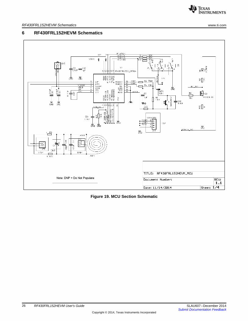
6 RF430FRL152HEVM Schematics
Figure 19. MCU Section Schematic
26 RF430FRL152HEVM User's Guide SLAU607–December 2014Submit Documentation Feedback
Copyright © 2014, Texas Instruments Incorporated
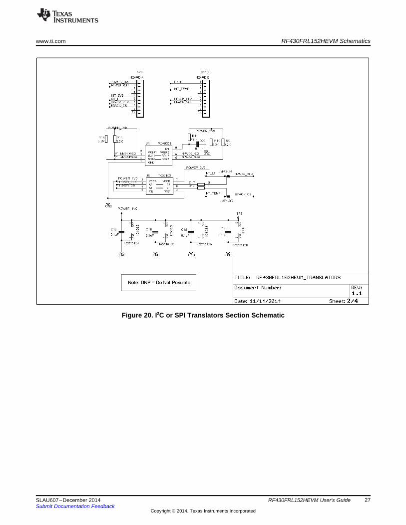
www.ti.com RF430FRL152HEVM Schematics
Figure 20. I2C or SPI Translators Section Schematic
27SLAU607–December 2014 RF430FRL152HEVM User's GuideSubmit Documentation Feedback
Copyright © 2014, Texas Instruments Incorporated

RF430FRL152HEVM Schematics www.ti.com
Figure 21. JTAG Section Schematic
28 RF430FRL152HEVM User's Guide SLAU607–December 2014Submit Documentation Feedback
Copyright © 2014, Texas Instruments Incorporated
www.ti.com RF430FRL152HEVM Schematics
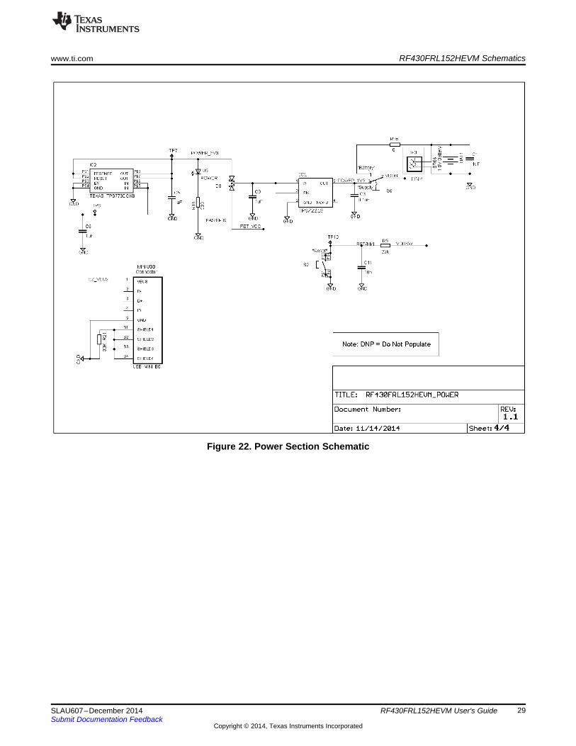
Figure 22. Power Section Schematic
29SLAU607–December 2014 RF430FRL152HEVM User's GuideSubmit Documentation Feedback
Copyright © 2014, Texas Instruments Incorporated
References www.ti.com
7 ReferencesThe primary sources of RF430FRL15xH information are:
RF430FRL152H Evaluation Module (www.ti.com/tool/rf430frl152hevm)
Sensor Hub BoosterPack (www.ti.com/tool/boostxl-senshub)
TRF7970A Evaluation Module (www.ti.com/tool/trf7970aevm)
Near Field Communications Overview (www.ti.com/nfc)
Low-Power Microcontrollers Overview (www.ti.com/msp430)
30 RF430FRL152HEVM User's Guide SLAU607–December 2014Submit Documentation Feedback
Copyright © 2014, Texas Instruments Incorporated
IMPORTANT NOTICE
Texas Instruments Incorporated and its subsidiaries (TI) reserve the right to make corrections, enhancements, improvements and otherchanges to its semiconductor products and services per JESD46, latest issue, and to discontinue any product or service per JESD48, latestissue. Buyers should obtain the latest relevant information before placing orders and should verify that such information is current andcomplete. All semiconductor products (also referred to herein as “components”) are sold subject to TI’s terms and conditions of salesupplied at the time of order acknowledgment.TI warrants performance of its components to the specifications applicable at the time of sale, in accordance with the warranty in TI’s termsand conditions of sale of semiconductor products. Testing and other quality control techniques are used to the extent TI deems necessaryto support this warranty. Except where mandated by applicable law, testing of all parameters of each component is not necessarilyperformed.TI assumes no liability for applications assistance or the design of Buyers’ products. Buyers are responsible for their products andapplications using TI components. To minimize the risks associated with Buyers’ products and applications, Buyers should provideadequate design and operating safeguards.TI does not warrant or represent that any license, either express or implied, is granted under any patent right, copyright, mask work right, orother intellectual property right relating to any combination, machine, or process in which TI components or services are used. Informationpublished by TI regarding third-party products or services does not constitute a license to use such products or services or a warranty orendorsement thereof. Use of such information may require a license from a third party under the patents or other intellectual property of thethird party, or a license from TI under the patents or other intellectual property of TI.Reproduction of significant portions of TI information in TI data books or data sheets is permissible only if reproduction is without alterationand is accompanied by all associated warranties, conditions, limitations, and notices. TI is not responsible or liable for such altereddocumentation. Information of third parties may be subject to additional restrictions.Resale of TI components or services with statements different from or beyond the parameters stated by TI for that component or servicevoids all express and any implied warranties for the associated TI component or service and is an unfair and deceptive business practice.TI is not responsible or liable for any such statements.Buyer acknowledges and agrees that it is solely responsible for compliance with all legal, regulatory and safety-related requirementsconcerning its products, and any use of TI components in its applications, notwithstanding any applications-related information or supportthat may be provided by TI. Buyer represents and agrees that it has all the necessary expertise to create and implement safeguards whichanticipate dangerous consequences of failures, monitor failures and their consequences, lessen the likelihood of failures that might causeharm and take appropriate remedial actions. Buyer will fully indemnify TI and its representatives against any damages arising out of the useof any TI components in safety-critical applications.In some cases, TI components may be promoted specifically to facilitate safety-related applications. With such components, TI’s goal is tohelp enable customers to design and create their own end-product solutions that meet applicable functional safety standards andrequirements. Nonetheless, such components are subject to these terms.No TI components are authorized for use in FDA Class III (or similar life-critical medical equipment) unless authorized officers of the partieshave executed a special agreement specifically governing such use.Only those TI components which TI has specifically designated as military grade or “enhanced plastic” are designed and intended for use inmilitary/aerospace applications or environments. Buyer acknowledges and agrees that any military or aerospace use of TI componentswhich have not been so designated is solely at the Buyer's risk, and that Buyer is solely responsible for compliance with all legal andregulatory requirements in connection with such use.TI has specifically designated certain components as meeting ISO/TS16949 requirements, mainly for automotive use. In any case of use ofnon-designated products, TI will not be responsible for any failure to meet ISO/TS16949.
Products ApplicationsAudio www.ti.com/audio Automotive and Transportation www.ti.com/automotiveAmplifiers amplifier.ti.com Communications and Telecom www.ti.com/communicationsData Converters dataconverter.ti.com Computers and Peripherals www.ti.com/computersDLP® Products www.dlp.com Consumer Electronics www.ti.com/consumer-appsDSP dsp.ti.com Energy and Lighting www.ti.com/energyClocks and Timers www.ti.com/clocks Industrial www.ti.com/industrialInterface interface.ti.com Medical www.ti.com/medicalLogic logic.ti.com Security www.ti.com/securityPower Mgmt power.ti.com Space, Avionics and Defense www.ti.com/space-avionics-defenseMicrocontrollers microcontroller.ti.com Video and Imaging www.ti.com/videoRFID www.ti-rfid.comOMAP Applications Processors www.ti.com/omap TI E2E Community e2e.ti.comWireless Connectivity www.ti.com/wirelessconnectivity
Mailing Address: Texas Instruments, Post Office Box 655303, Dallas, Texas 75265Copyright © 2014, Texas Instruments Incorporated