Embed Size (px)
Citation preview

Advant Controller 31Software manual
1SBC006099R1101A-09/00
AC31GRAFProgramming Software

Information in this document is subject to change without notice and does not represent acommitment on the part of ABB. The software, which includes information contained in anydatabases, described in this document is furnished under a license agreement or nondisclosureagreement and may be used or copied only in accordance with the terms of that agreement. Itis against the law to copy the software except as specifically allowed in the license ornondisclosure agreement. No part of this manual may be reproduced in any form or by anymeans, electronic or mechanical, including photocopying and recording, for any purposewithout the express written permission of ABB.
© 1997 CJ International. All rights reserved.
MS-DOS is a registered trademark of Microsoft Corporation.Windows is a registered trademark of Microsoft Corporation.Windows NT is a registered trademark of Microsoft Corporation.
All other brand or product names are trademarks or registered trademarks of their respectiveholders.
General table of contents
ABB Control Page i 1SBC006099R1001 10/00
General table of contents
A USER’S GUIDE
1 Getting started ...........................................................................................................A-32 Using the project manager........................................................................................A-43 Making a modular project......................................................................................A-114 Using editors ............................................................................................................A-155 Editor common tools ...............................................................................................A-486 Control panel ...........................................................................................................A-627 User’s library ...........................................................................................................A-75
B LANGUAGE REFERENCE
1 Project architecture................................................................................................... B-32 Variables .................................................................................................................... B-63 FBD language............................................................................................................. B-74 LD and Quick LD languages.................................................................................. B-105 SFC language ........................................................................................................... B-206 IL language .............................................................................................................. B-31
C FUNCTION BLOCK DESCRIPTION
1 Libraries.....................................................................................................................C-22 Basic operators/functions .........................................................................................C-83 Program control functions......................................................................................C-694 CS31 functions.........................................................................................................C-855 Communication functions.....................................................................................C-1196 Regulation functions .............................................................................................C-1577 Format conversion functions................................................................................C-1778 Standard double word functions .........................................................................C-2039 High order functions .............................................................................................C-21910 Memory access functions......................................................................................C-29511 Special Functions ..................................................................................................C-32012 Historical values....................................................................................................C-32513 Runtimes ................................................................................................................C-328
Lexicon
ABB Control Page ii 1SBC006099R1001 10/00
LEXICON
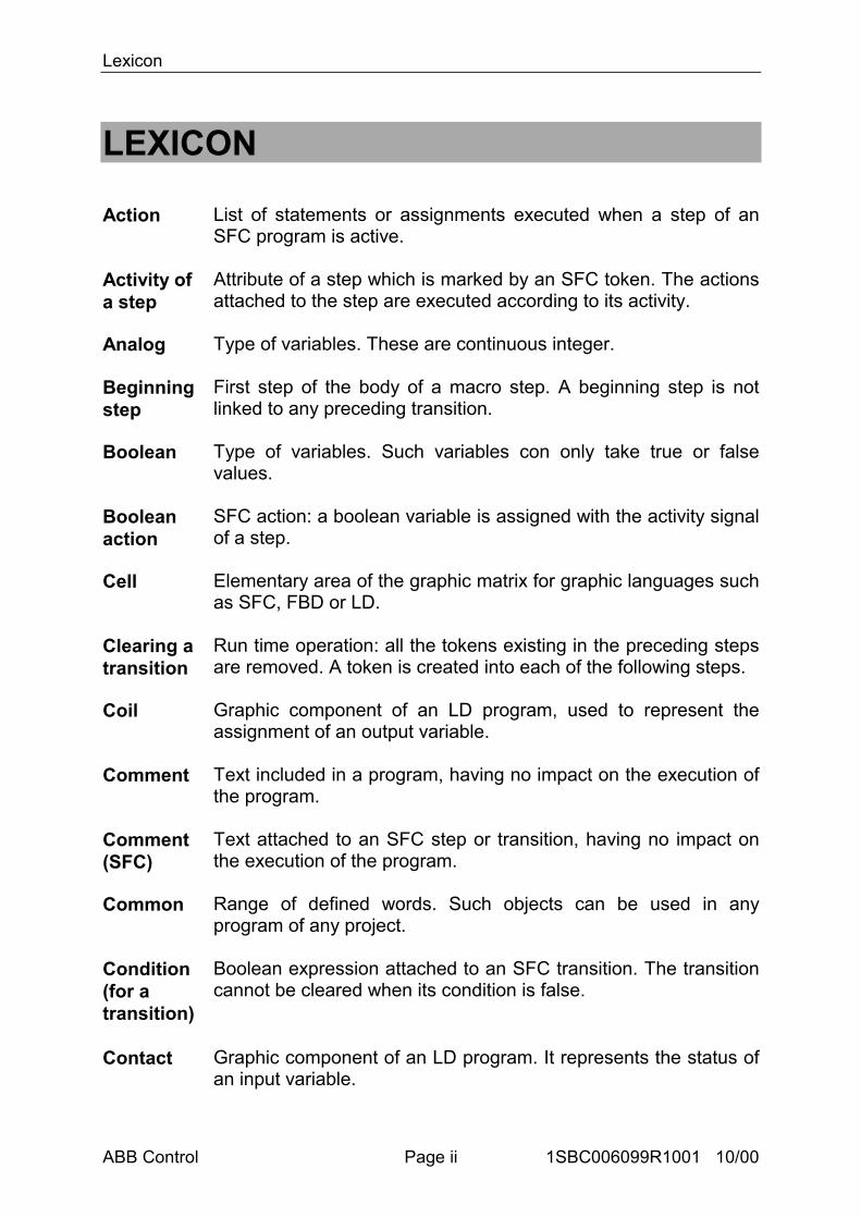
Action List of statements or assignments executed when a step of anSFC program is active.
Activity ofa step
Attribute of a step which is marked by an SFC token. The actionsattached to the step are executed according to its activity.
Analog Type of variables. These are continuous integer.
Beginningstep
First step of the body of a macro step. A beginning step is notlinked to any preceding transition.
Boolean Type of variables. Such variables con only take true or falsevalues.
Booleanaction
SFC action: a boolean variable is assigned with the activity signalof a step.
Cell Elementary area of the graphic matrix for graphic languages suchas SFC, FBD or LD.
Clearing atransition
Run time operation: all the tokens existing in the preceding stepsare removed. A token is created into each of the following steps.
Coil Graphic component of an LD program, used to represent theassignment of an output variable.
Comment Text included in a program, having no impact on the execution ofthe program.
Comment(SFC)
Text attached to an SFC step or transition, having no impact onthe execution of the program.
Common Range of defined words. Such objects can be used in anyprogram of any project.
Condition(for atransition)
Boolean expression attached to an SFC transition. The transitioncannot be cleared when its condition is false.
Contact Graphic component of an LD program. It represents the status ofan input variable.
Lexicon
ABB Control Page iii 1SBC006099R1001 10/00
Crossreferences
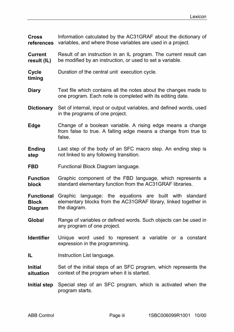
Information calculated by the AC31GRAF about the dictionary ofvariables, and where those variables are used in a project.
Currentresult (IL)
Result of an instruction in an IL program. The current result canbe modified by an instruction, or used to set a variable.
Cycletiming
Duration of the central unit execution cycle.
Diary Text file which contains all the notes about the changes made toone program. Each note is completed with its editing date.
Dictionary Set of internal, input or output variables, and defined words, usedin the programs of one project.
Edge Change of a boolean variable. A rising edge means a changefrom false to true. A falling edge means a change from true tofalse.
Endingstep
Last step of the body of an SFC macro step. An ending step isnot linked to any following transition.
FBD Functional Block Diagram language.
Functionblock
Graphic component of the FBD language, which represents astandard elementary function from the AC31GRAF libraries.
FunctionalBlockDiagram
Graphic language: the equations are built with standardelementary blocks from the AC31GRAF library, linked together inthe diagram.
Global Range of variables or defined words. Such objects can be used inany program of one project.
Identifier Unique word used to represent a variable or a constantexpression in the programming.
IL Instruction List language.
Initialsituation
Set of the initial steps of an SFC program, which represents thecontext of the program when it is started.
Initial step Special step of an SFC program, which is activated when theprogram starts.
Lexicon
ABB Control Page iv 1SBC006099R1001 10/00
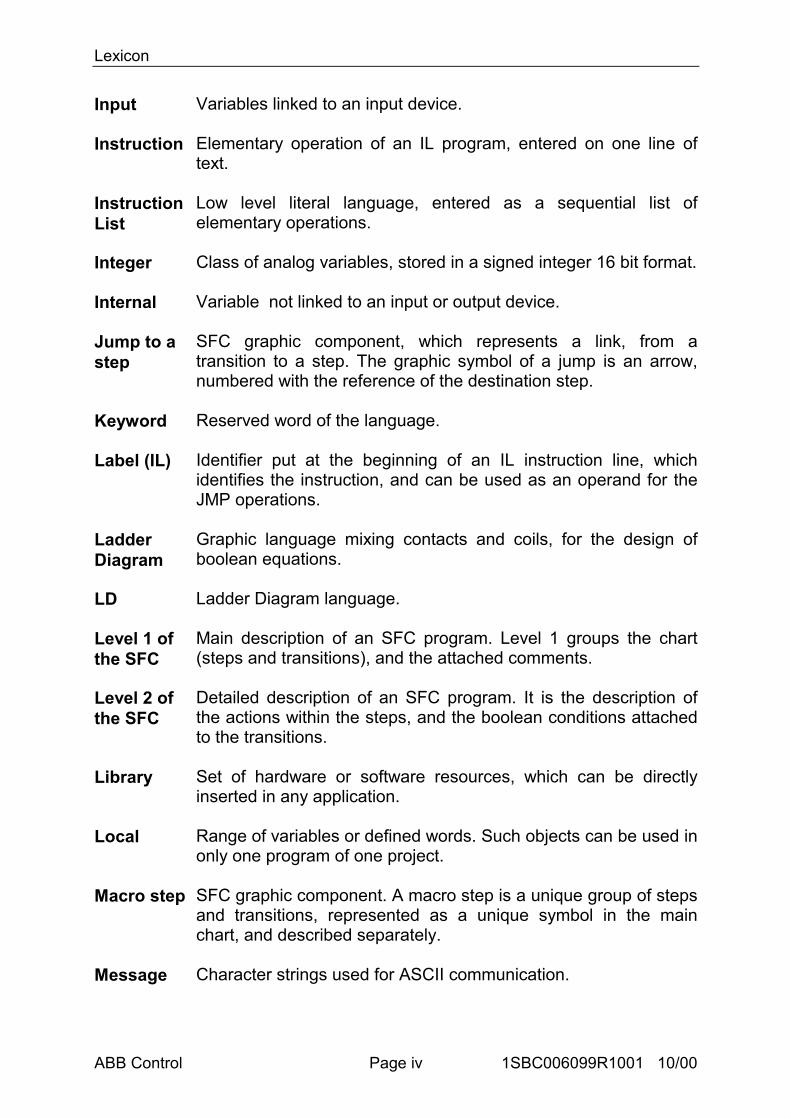
Input Variables linked to an input device.
Instruction Elementary operation of an IL program, entered on one line oftext.
InstructionList
Low level literal language, entered as a sequential list ofelementary operations.
Integer Class of analog variables, stored in a signed integer 16 bit format.
Internal Variable not linked to an input or output device.
Jump to astep
SFC graphic component, which represents a link, from atransition to a step. The graphic symbol of a jump is an arrow,numbered with the reference of the destination step.
Keyword Reserved word of the language.
Label (IL) Identifier put at the beginning of an IL instruction line, whichidentifies the instruction, and can be used as an operand for theJMP operations.
LadderDiagram
Graphic language mixing contacts and coils, for the design ofboolean equations.
LD Ladder Diagram language.
Level 1 ofthe SFC
Main description of an SFC program. Level 1 groups the chart(steps and transitions), and the attached comments.
Level 2 ofthe SFC
Detailed description of an SFC program. It is the description ofthe actions within the steps, and the boolean conditions attachedto the transitions.
Library Set of hardware or software resources, which can be directlyinserted in any application.
Local Range of variables or defined words. Such objects can be used inonly one program of one project.
Macro step SFC graphic component. A macro step is a unique group of stepsand transitions, represented as a unique symbol in the mainchart, and described separately.
Message Character strings used for ASCII communication.
Lexicon
ABB Control Page v 1SBC006099R1001 10/00
Modbus Master-Slave protocol. The CS31 central unit can be a Modbusslave for the link with an external system (such as supervisorysystems) in a complete architecture.
Modifier(IL)
Single character put at the end of an IL operation keyword, whichmodifies the meaning of the operation.
Non-storedaction
SFC action: it is a list of statements, executed at each central unitcycle, when the corresponding step is active.
Operand(IL)
Variable or constant expression processed by an elementary ILinstruction.
Operation(IL)
Basic instruction of the IL language. An operation is generallyassociated to an operand in an instruction.
Output Variables linked to an output device.
Power rail Main left and right vertical rails at the extremities of an ladderdiagram.
Program Basic programming unit in a project. A program is described withone language, and is placed in the hierarchy architecture of theproject in case of modular project.
Project Programming area, which groups all the information (programs,variables, ...).
Pulseaction
SFC action: it is a list of statements executed only once when thecorresponding step is activated.
Referencenumber(SFC)
Decimal number (from 1 to 65535) which identifies an SFC stepor transition in an SFC program.
Register(IL)
Current result of an IL sequence.
Separator Special character (or group of characters) used to separate theidentifiers in a literal language. A separator may represent anoperation.
SequentialFunctionChart
Graphic language: the process is described as a set of steps,linked by transitions. Actions are attached to the steps.Transitions are detailed as boolean conditions.
Lexicon
ABB Control Page vi 1SBC006099R1001 10/00
Sequentialsection
Group of the programs of a project. The execution of thoseprograms follows the dynamic rules of the SFC language.
SFC Sequential Function Chart language.
Step Basic graphic component of the SFC language. A step representsa steady situation of the process, and is drawn as a square. Astep is referenced by a number. The activity of a step is used tocontrol the execution of the corresponding actions.
Sub-program
Program written with any language excepted SFC, and called byanother program, called its owner program.
Token(SFC)
Graphical marker used to show the active steps of an SFCprogram.
Toolbox Small child window of an graphic editing tool window, whichgroups the main buttons for the selection of the graphiccomponents.
Transition Basic graphic SFC component. A transition represents thecondition between different SFC steps. A transition is referencedby a number. A boolean condition is attached to each transition.
Validity ofatransition
Attribute of a transition. A transition is validated when all thepreceding steps are actives.
Variable Unique representation of elementary data which is processed inthe programs of project.

User's guide
ABB Control 1SBC006099R1001 10/00
A User’s guide

User’s guide
ABB Control 1SBC006099R1001 10/00
User's guide
ABB Control Page A-1 1SBC006099R1001 10/00
A USER’S GUIDE
1 Getting started...........................................................................................................A-32 Using the project manager .......................................................................................A-4
2.1 Project manager description ..................................................................................A-42.2 Printing a project document...................................................................................A-7
3 Making a modular project .....................................................................................A-114 Using editors............................................................................................................A-15
4.1 Using the FBD/LD editor ....................................................................................A-154.1.1 Basics of the FBD/LD languages ..................................................................A-154.1.2 Entering a FBD diagram ...............................................................................A-174.1.3 Working on an existing diagram...................................................................A-194.1.4 Display options .............................................................................................A-214.1.5 Other AC31GRAF tools ...............................................................................A-224.1.6 Style and modification tracking ....................................................................A-23
4.2 Using the SFC editor ...........................................................................................A-264.2.1 SFC language main topics.............................................................................A-264.2.2 Entering SFC chart........................................................................................A-284.2.3 Working on an existing SFC chart................................................................A-304.2.4 Entering the level 2 programming.................................................................A-314.2.5 Selecting a variable from list ........................................................................A-354.2.6 Using the SFC gallery ...................................................................................A-36
4.3 Using the Quick LD editor ..................................................................................A-374.3.1 Basics of the LD language ............................................................................A-374.3.2 Entering a LD diagram..................................................................................A-394.3.3 Working on an existing diagram...................................................................A-424.3.4 Display options .............................................................................................A-434.3.5 Calling other AC31GRAF tools....................................................................A-434.3.6 Selecting a variable from list ........................................................................A-44
4.4 Using the IL editor...............................................................................................A-454.4.1 File commands ..............................................................................................A-454.4.2 Editing commands ........................................................................................A-464.4.3 Options..........................................................................................................A-474.4.4 Selecting a variable from list ........................................................................A-47
5 Editor common tools...............................................................................................A-485.1 Declaring variables ..............................................................................................A-48
5.1.1 Using the variable list in declaration mode...................................................A-485.1.2 Using the variable list in selection mode ......................................................A-49
5.2 Cross References .................................................................................................A-535.3 Build the application............................................................................................A-555.4 Creating graphics .................................................................................................A-56
5.4.1 Drawing chart................................................................................................A-565.4.2 Object description .........................................................................................A-585.4.3 Commands of the "File" menu......................................................................A-605.4.4 Options..........................................................................................................A-60
6 Control panel...........................................................................................................A-626.1 Using the control panel........................................................................................A-626.2 Time diagrams .....................................................................................................A-666.3 On line list ...........................................................................................................A-68
User's guide
ABB Control Page A-2 1SBC006099R1001 10/00
6.4 Status / Diagnosis ................................................................................................A-716.5 Configuration.......................................................................................................A-72
7 User’s library...........................................................................................................A-757.1 User’s function ....................................................................................................A-757.2 Variables for a user’s function.............................................................................A-767.3 Compiling a user’s function ................................................................................A-76
User's guide
ABB Control Page A-3 1SBC006099R1001 10/00
1 Getting started
This chapter covers the installation of the AC31GRAF workbench. It also includes ashort example of an AC31GRAF application, giving the user a brief outline of its mainfeatures and enabling the immediate use of AC31GRAF.
Installing AC31GRAF
This chapter covers the installation of the AC31GRAF Workbench and how to set upthe computer for application development.
Hardware and software requirements
The AC31GRAF Workbench can be installed on any computer meeting the minimumqualifications for Windows Version 3.1. However, the following hardware isrecommended for application development:
• A personal computer using an 80486 or higher microprocessor• 8 megabytes of conventional and extended memory• One 3.5-inch (1.44 megabyte) disk drive• One hard disk with at least 20 megabytes of available space• A graphic VGA or SVGA adapter and compatible monitor• A mouse (required for graphic development tools)• A parallel LPT1 port
Before installing the AC31GRAF workbench, one of the following software shouldalready be included on the system:
• Windows Version 3.1 running in 386 enhanced mode• Windows 95• Windows NT Version 3.51 or 4.00
Using the installation program
The AC31GRAF Workbench is installed by using SETUP. This program copies theAC31GRAF software from the AC31GRAF disks onto the user's hard disk.
SETUP is a Windows program.To install AC31GRAF, the following steps must be performed:
• Insert Disk 1 into the appropriate drive• From Program Manager, select the "SETUP.EXE" to start the installation.
User's guide
ABB Control Page A-4 1SBC006099R1001 10/00
2 Using the project manager
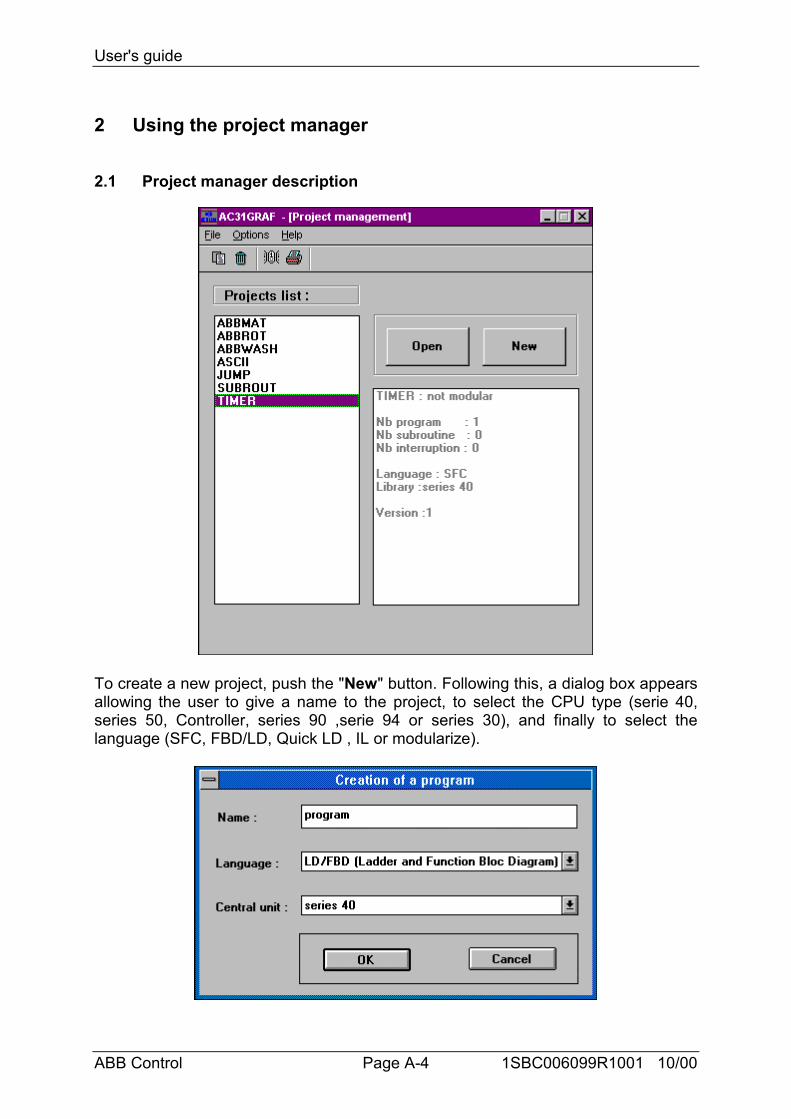
2.1 Project manager description
To create a new project, push the "New" button. Following this, a dialog box appearsallowing the user to give a name to the project, to select the CPU type (serie 40,series 50, Controller, series 90 ,serie 94 or series 30), and finally to select thelanguage (SFC, FBD/LD, Quick LD , IL or modularize).

User's guide
ABB Control Page A-5 1SBC006099R1001 10/00
The new project name must conform to the following rules :
- the name cannot exceed 8 characters- the first character must be a letter- the following characters can be letters or digits.
It is possible to take the modularize choice instead of a specific language in order tobuild a modular project. If the project is not modular, the editor of the selectedlanguage is opened and the program has the name «main» by default.On the other hand, if the project is created as modularize, the Program managementwindow is opened in order to create programs.
Editing the project descriptor
The ”File / Project descriptor” command is used to edit the project text descriptor.This document fully identifies the project from the others on the project list. Theproject descriptor can also be used to record any remarks during the project lifetime.
The History of modifications
AC31GRAF stores any information relative to a component of a project in a historyfile. Each modification is identified in the history by a title, a date and a time. There isone history file for each project.The “File / History” command allows the user to view or print the history ofmodifications for the selected project. The user can select one or more items in themain list, and press the following buttons:
OK...................................... closes the window.Print................................... sends the contents of the list to the printer.Selected ............................ removes the selected items from the list.Erase /All........................... clears the complete list.Search/Find ...................... find a pattern in the list.
Make a project document
The “File / Print” command allows the user to build and print a complete documentabout the selected project. This document can group any component (program,variable, parameters...) of the selected project.See description at the chapter «Printing a project document»
Using the library management
The “File / Library” command launches the user library manager.
Renaming a project
The “File / Rename” command allows the user to change the name of a selectedproject.
Copying project
User's guide
ABB Control Page A-6 1SBC006099R1001 10/00
The “File / Copy” command allows the user to copy all the contents of the selectedproject in the same CPU or to another one. When the user enters the name of thecopy, according to the rules of above, he is able to choose the CPU.
Deleting a project
The “File / Delete” command deletes the entire contents of the selected project.
Modularizing a project
The “File / Modularize” command allows the user to edit the Program managementwindow in order to create other programs, subroutines or interruptions.
Closing an application
The “File / Exit” command closes the application.
Uploading an application
The “Options / Upload application” command allows the user to upload the code ofa CPU. First, the user creates a new project and next, he has to select the time outvalue and the COM port he wants to use, then the Control panel window is editingand displays a default choice of the program start and a program end of the uploadaddress that the user can change.
Finally, the code is uploaded and the original project edited.The uploaded project consists of a main program and, if any, of subroutines andinterruption programs. The IL editor is necessary to read the code of these differentprograms.All the variables used in the uploaded project are recorded in the global variables file.
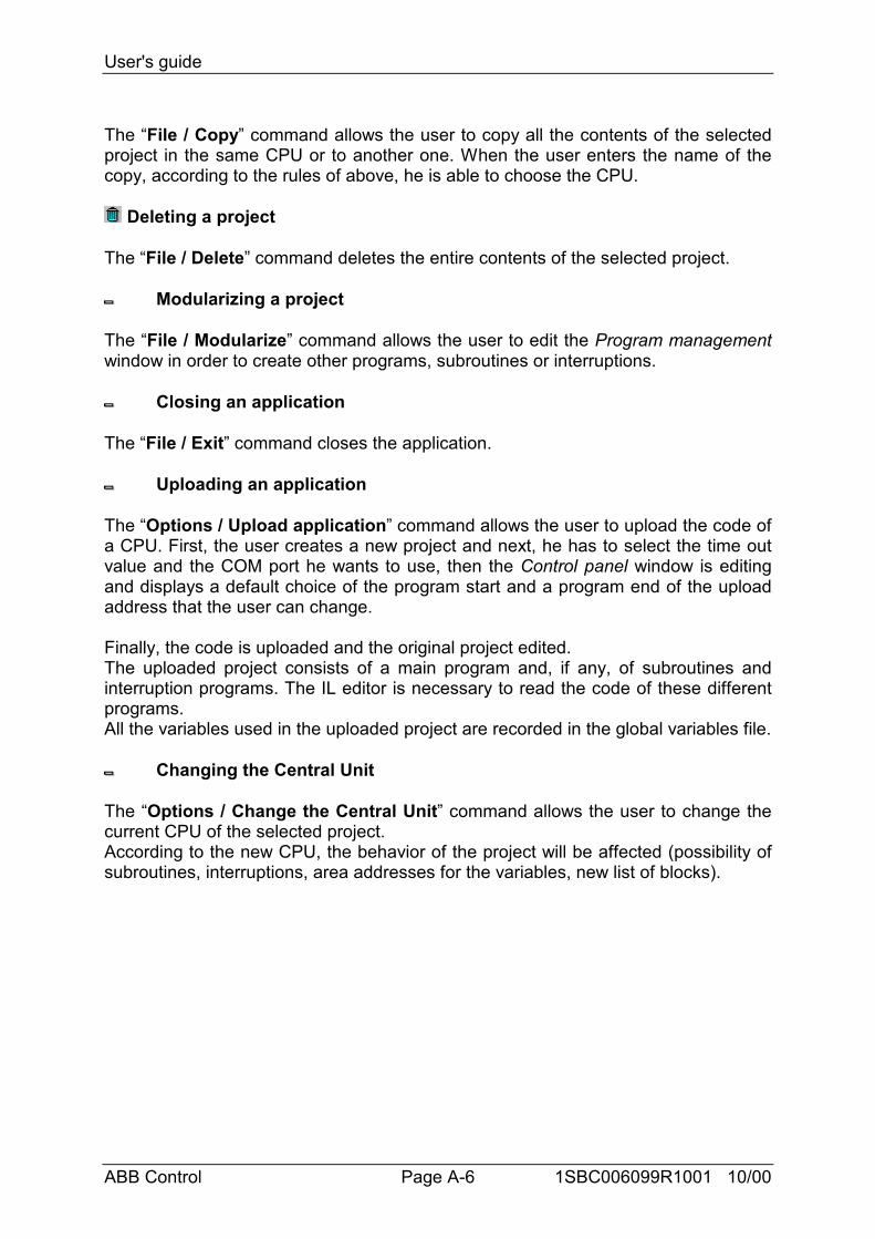
Changing the Central Unit
The “Options / Change the Central Unit” command allows the user to change thecurrent CPU of the selected project.According to the new CPU, the behavior of the project will be affected (possibility ofsubroutines, interruptions, area addresses for the variables, new list of blocks).
User's guide
ABB Control Page A-7 1SBC006099R1001 10/00
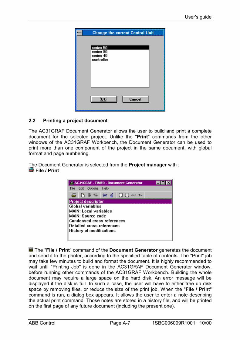
2.2 Printing a project document
The AC31GRAF Document Generator allows the user to build and print a completedocument for the selected project. Unlike the "Print" commands from the otherwindows of the AC31GRAF Workbench, the Document Generator can be used toprint more than one component of the project in the same document, with globalformat and page numbering.
The Document Generator is selected from the Project manager with : File / Print
The "File / Print" command of the Document Generator generates the documentand send it to the printer, according to the specified table of contents. The "Print" jobmay take few minutes to build and format the document. It is highly recommended towait until "Printing Job" is done in the AC31GRAF Document Generator window,before running other commands of the AC31GRAF Workbench. Building the wholedocument may require a large space on the hard disk. An error message will bedisplayed if the disk is full. In such a case, the user will have to either free up diskspace by removing files, or reduce the size of the print job. When the "File / Print"command is run, a dialog box appears. It allows the user to enter a note describingthe actual print command. Those notes are stored in a history file, and will be printedon the first page of any future document (including the present one).
User's guide
ABB Control Page A-8 1SBC006099R1001 10/00
The commands of the "Edit" menu are used to define the elements of the projectthat must be inserted in the document. A choice of commands allow the user to usea default table (with all the components of the project), build a specific table (withonly some components) or move items in the table and modify it. Any informationabout the project may be inserted in the project document. No information fromanother project or from AC31GRAF libraries may appear in this document.
Inserting a new item
When the "Edit / Insert" command is run, the "Add item" dialog box appears. Itallows the user to insert items (components of the project) into the table of contents.
For an item relative to a program, use the "Program" combo box to select a programname. Press the "Add" button to insert the selected item to the table of contents.The same item can appear only once in the table.
Clearing table
The "Edit / Clear" command resets the table of contents, so that it can be totallyrebuilt using single item insertion.
Default table
The "Edit / Default list" command defines a standard table of contents for thedocument, which includes all the components of the project. The standard tableconsists of:
• Project descriptor• Global variables• MAIN: Local variables• MAIN: Source code• Condensed cross references• Detailed cross references• History of modifications
Cut and paste
The "Edit / Cut" and "Edit / Paste" commands move items in the list, in order tocustomize the order of the table. The Document Generator allows multiple selectionso that a group of items may be cut and pasted.
The commands of the "Options" menu are used to define and customize the formatof the generated document.
Page format
User's guide
ABB Control Page A-9 1SBC006099R1001 10/00
The "Options / Page format" command is used to define the main parametersoperated by the Document Generator when formatting a page. The followingparameters can be specified:
• Left margin: (1 or 2 centimeters, or no margin)• Page border: When this option is selected, a border is drawn around any printedpage.
Page title
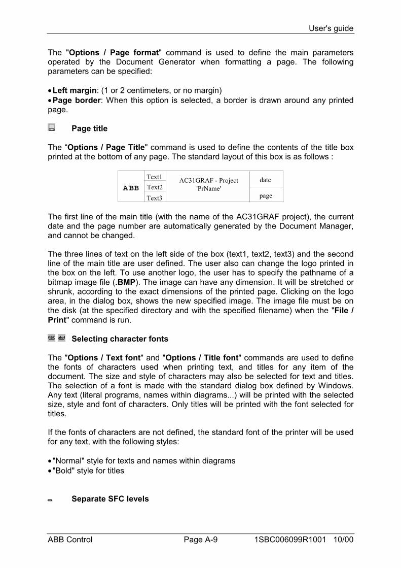
The “Options / Page Title" command is used to define the contents of the title boxprinted at the bottom of any page. The standard layout of this box is as follows :
AC31GRAF - Project'PrName'
date
page
Text1Text2Text3
ABB
The first line of the main title (with the name of the AC31GRAF project), the currentdate and the page number are automatically generated by the Document Manager,and cannot be changed.
The three lines of text on the left side of the box (text1, text2, text3) and the secondline of the main title are user defined. The user also can change the logo printed inthe box on the left. To use another logo, the user has to specify the pathname of abitmap image file (.BMP). The image can have any dimension. It will be stretched orshrunk, according to the exact dimensions of the printed page. Clicking on the logoarea, in the dialog box, shows the new specified image. The image file must be onthe disk (at the specified directory and with the specified filename) when the "File /Print" command is run.
Selecting character fonts
The "Options / Text font" and "Options / Title font" commands are used to definethe fonts of characters used when printing text, and titles for any item of thedocument. The size and style of characters may also be selected for text and titles.The selection of a font is made with the standard dialog box defined by Windows.Any text (literal programs, names within diagrams...) will be printed with the selectedsize, style and font of characters. Only titles will be printed with the font selected fortitles.
If the fonts of characters are not defined, the standard font of the printer will be usedfor any text, with the following styles:
• "Normal" style for texts and names within diagrams• "Bold" style for titles
Separate SFC levels
User's guide
ABB Control Page A-10 1SBC006099R1001 10/00
The "Options / Separate SFC levels" option directs the system to print, for eachSFC program, first the level 1 of the SFC (chart and comments), and then the level 2programming. When this option is not checked, levels 1 and 2 appear together onthe same printout.
User's guide
ABB Control Page A-11 1SBC006099R1001 10/00
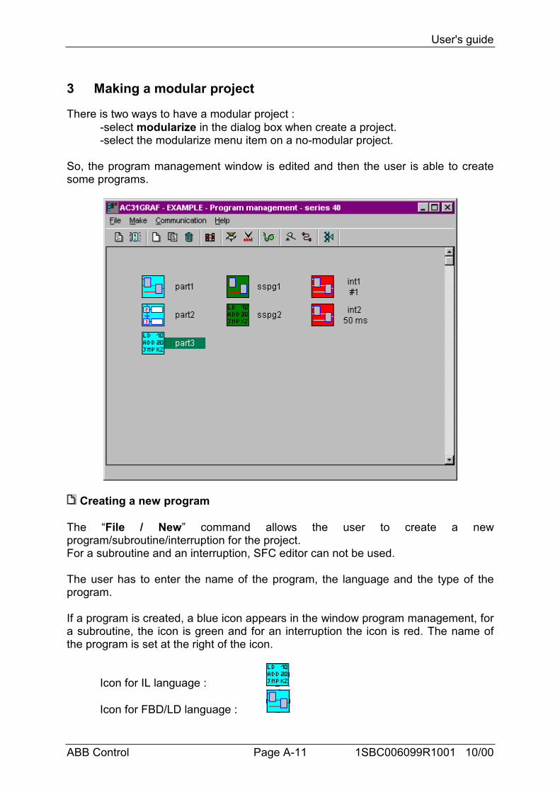
3 Making a modular project
There is two ways to have a modular project :-select modularize in the dialog box when create a project.-select the modularize menu item on a no-modular project.
So, the program management window is edited and then the user is able to createsome programs.
Creating a new program
The “File / New” command allows the user to create a newprogram/subroutine/interruption for the project.For a subroutine and an interruption, SFC editor can not be used.
The user has to enter the name of the program, the language and the type of theprogram.
If a program is created, a blue icon appears in the window program management, fora subroutine, the icon is green and for an interruption the icon is red. The name ofthe program is set at the right of the icon.
Icon for IL language :
Icon for FBD/LD language :
User's guide
ABB Control Page A-12 1SBC006099R1001 10/00
Icon for SFC language :
Icon for Quick LD language:
A project can contains only three interruption programs : two hard interruptions and asoft one.For a interruption program, the name contains the type of the interruption (#1 or #2for a hard interruption, and the cycle time for the soft interruption).
Some CPU do not support subroutine and interruption program, they are : serie 30 ,serie 90 and serie 94.
The Subroutines and interruption tasks are called in the main program (Il or FBDlanguage) with directly their name as a function block or a format parameter.
Editing a program
The “File / Edit” command displays the editor of the selected program. It has thesame result as the button open.
Editing the variables list
The “File / Variable list” command allows to edit the list of variable window.The global variables and the local variables of the current program are shown.
Editing a diary file
The “File / Program descriptor” command allows the user to start editing the diaryfile of the current edited project program. This is a text file which contains all thenotes about the modifications made to the program during its time life.
Setting an interruption program
The “File / Parameters” command allows the user to change the cycle time of thesoft interruption of the project.
Renaming a program
The “File / Rename” command allows the user to change the name of the selectedprogram.The new program name must conform to the following rules :
- the name cannot exceed 8 characters- the first character must be a letter- the following characters can be letters or digits.
Deleting a program
User's guide
ABB Control Page A-13 1SBC006099R1001 10/00
The “File / Delete” command deletes the selected program/subroutine/interruptionfrom the current application.
Copying a program
The “File / Copy” command allows the user to copy the selected program to thesame project, so the user has to give a name for the copy and then nothing happensfor the variables.Furthermore, the user can copy the selected program to an other project. First, thereis a detection of conflict name, and then the program is added to those of the targetproject. There is a detection on variables conflict.Each variable not used in the target project will be added to the global variables fileof this project.
Closing the program manager
The “File / Exit” command closes the program management window.
Making a graphic
The “Make / Graphics” command runs the graphic editor. This tool allows the user todefine graphic images that will be refreshed during debug, based on the state of theapplication variables. The images are built with standard windows bitmap (.BMP) andicon (.ICO) files. This requires additional graphic editing tools, such as PaintBrush,to create bitmaps and icon files.
Building the application code
The “Make / Code generation” command starts the project code generation.Before generating the code, any program that is still not verified is checked to detectthe syntax errors.
Verifying a program
The “Make / Verify” command allows the user to verify the syntax of the programcurrently selected. When a program is verified, with no error detected, it is not re-verified during the code generation.
Running the cross reference editor
The “Make / Cross references” command allows the user to calculate, view or printthe cross references of the project. The cross references show the user all theoccurrences of each variable in the source code of the programs, in the entireproject. This function is very useful to detect an access to a variable or any globalsource, or to the list all the occurrences of a global variable in the source code.
Running the communication
The “Communication / Run communication” command opens the communicationmain window, and closes the program management.
User's guide
ABB Control Page A-14 1SBC006099R1001 10/00
This open is then re-opened in debug mode as soon as the communication isestablished between the debugger and the target application.
Setting the communication parameters
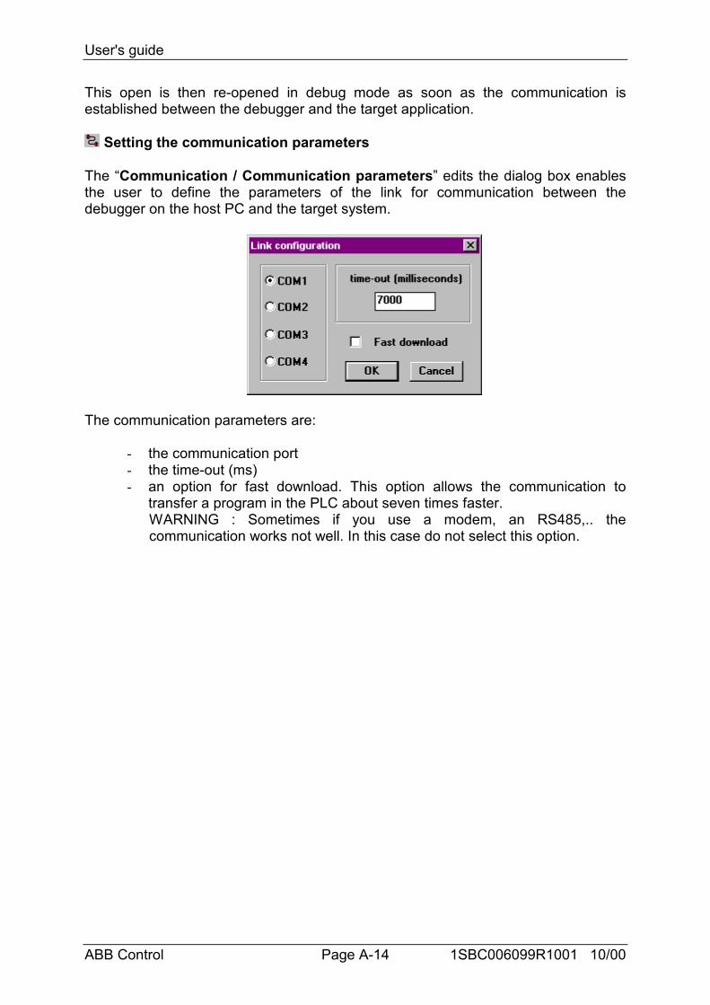
The “Communication / Communication parameters” edits the dialog box enablesthe user to define the parameters of the link for communication between thedebugger on the host PC and the target system.
The communication parameters are:
- the communication port- the time-out (ms)- an option for fast download. This option allows the communication to
transfer a program in the PLC about seven times faster.WARNING : Sometimes if you use a modem, an RS485,.. thecommunication works not well. In this case do not select this option.
User's guide
ABB Control Page A-15 1SBC006099R1001 10/00
4 Using editors
4.1 Using the FBD/LD editor
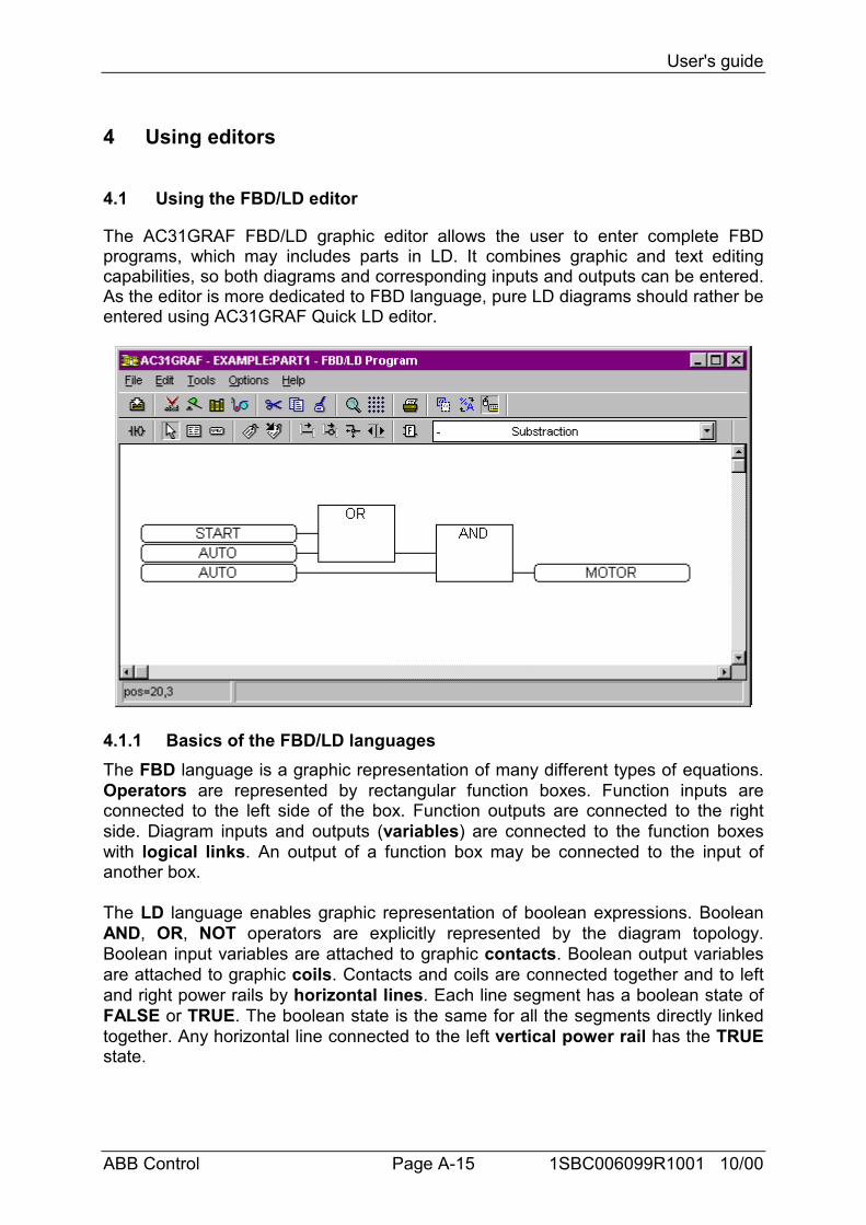
The AC31GRAF FBD/LD graphic editor allows the user to enter complete FBDprograms, which may includes parts in LD. It combines graphic and text editingcapabilities, so both diagrams and corresponding inputs and outputs can be entered.As the editor is more dedicated to FBD language, pure LD diagrams should rather beentered using AC31GRAF Quick LD editor.
4.1.1 Basics of the FBD/LD languagesThe FBD language is a graphic representation of many different types of equations.Operators are represented by rectangular function boxes. Function inputs areconnected to the left side of the box. Function outputs are connected to the rightside. Diagram inputs and outputs (variables) are connected to the function boxeswith logical links. An output of a function box may be connected to the input ofanother box.
The LD language enables graphic representation of boolean expressions. BooleanAND, OR, NOT operators are explicitly represented by the diagram topology.Boolean input variables are attached to graphic contacts. Boolean output variablesare attached to graphic coils. Contacts and coils are connected together and to leftand right power rails by horizontal lines. Each line segment has a boolean state ofFALSE or TRUE. The boolean state is the same for all the segments directly linkedtogether. Any horizontal line connected to the left vertical power rail has the TRUEstate.
User's guide
ABB Control Page A-16 1SBC006099R1001 10/00
LD and FBD diagrams are always interpreted from the left to the right, and from thetop to the bottom. Refer to the AC31GRAF Manual Part B for more details about LDand FBD languages. These are the basic graphic components of the LD and FBDlanguages, such as supported by the FBD/LD editor:
Left power rail
Rungs must be connected on the left to a left power rail, which represents the initial"TRUE" state. AC31GRAF FBD editor also allows to connect any boolean symbol toa left power rail.
Right power rail
Coils may be connected on the right to a right power rail. This is an optional featurewhen using the AC31GRAF FBD/LD editor. If a coil is not connected on the right, itincludes a right power rail in its own drawing.
LD vertical "OR" connection
LD vertical connection accepts several connections on the left and severalconnections on the right. Each connection on the right is equal to the ORcombination of the connections on the left.
Contacts
A contact modifies the boolean data flow, according to the state of a booleanvariable. The name of the variable is displayed upon the contact symbol. Thefollowing types of contacts are supported by AC31GRAF FBD/LD editor:
...................................... direct contact
...................................... negated contact
...................................... contact with positive (rising) edge detection
...................................... contact with negative (falling) edge detection
Coils
A coil represents an action. It must be connected on the left to a boolean symbolsuch as a contact. The name of the variable is displayed upon the coil symbol. Thefollowing types of coils are supported by AC31GRAF FBD/LD editor:
...................................... direct coil
...................................... negated coil
...................................... "set" action coil
...................................... "reset" action coil
Function blocks
User's guide
ABB Control Page A-17 1SBC006099R1001 10/00
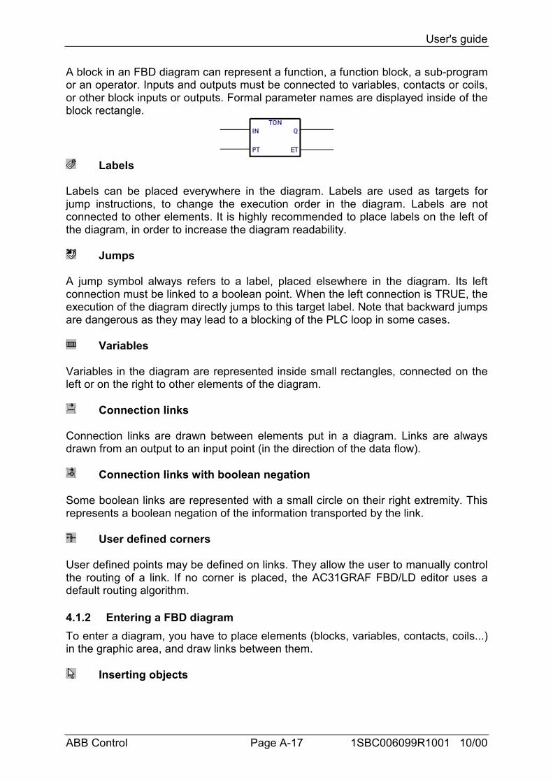
A block in an FBD diagram can represent a function, a function block, a sub-programor an operator. Inputs and outputs must be connected to variables, contacts or coils,or other block inputs or outputs. Formal parameter names are displayed inside of theblock rectangle.
Labels
Labels can be placed everywhere in the diagram. Labels are used as targets forjump instructions, to change the execution order in the diagram. Labels are notconnected to other elements. It is highly recommended to place labels on the left ofthe diagram, in order to increase the diagram readability.
Jumps
A jump symbol always refers to a label, placed elsewhere in the diagram. Its leftconnection must be linked to a boolean point. When the left connection is TRUE, theexecution of the diagram directly jumps to this target label. Note that backward jumpsare dangerous as they may lead to a blocking of the PLC loop in some cases.
Variables
Variables in the diagram are represented inside small rectangles, connected on theleft or on the right to other elements of the diagram.
Connection links
Connection links are drawn between elements put in a diagram. Links are alwaysdrawn from an output to an input point (in the direction of the data flow).
Connection links with boolean negation
Some boolean links are represented with a small circle on their right extremity. Thisrepresents a boolean negation of the information transported by the link.
User defined corners
User defined points may be defined on links. They allow the user to manually controlthe routing of a link. If no corner is placed, the AC31GRAF FBD/LD editor uses adefault routing algorithm.
4.1.2 Entering a FBD diagramTo enter a diagram, you have to place elements (blocks, variables, contacts, coils...)in the graphic area, and draw links between them.
Inserting objects
User's guide
ABB Control Page A-18 1SBC006099R1001 10/00
To insert an object in a diagram, select the corresponding button in the toolbar andclick in the graphic area, where you want to insert it.
Selecting objects
Selecting graphic objects is needed for most of the editing commands. TheAC31GRAF LD/FBD graphic editor enables the selection of one or more existingobjects in the diagram area. To select objects, the "select" (button with an arrow)choice must be checked in the editor toolbar. To select one object, the user only hasto click on its symbol. To select a list of objects, drag the mouse in the diagram andselect a rectangle area. All the graphic objects that intersect the selection rectangleare marked as "selected". A selected object is drawn with little black squares aroundits graphic symbol. By making a new selection, all previously selected objects areunselected. To remove the existing selection, simply click with the mouse on anempty area, outside of the rectangle which borders the selected objects.
Inserting comments
Comments may be inserted anywhere in the diagram. Comments have no influenceon the program execution. They allow a higher readability of the diagram. To insert acomment block, select this button in the toolbar, and drag the mouse to select therectangle area where comment must be drawn. Then enter the text of the comment.No special leading or trailing characters such as "(*" and "*)" are needed whenentering the text of a comment block. A comment block may be resized by draggingthe corners of its border when it is selected.
Moving objects
To move objects in the diagram, you have to select them, and drag the mouse tomove the selected area in the diagram. To move connected objects, the user simplyhas to move the graphic symbols put on the diagram. The AC31GRAF LD/FBDeditor will automatically redraw the connection lines between the objects that weremoved, based on their new location.
Drawing links
Select one of these buttons in the toolbar to draw a link between connection points ofexisting elements. If you draw a link from a connection point to an empty location inthe diagram, it is automatically terminated by a user defined corner, so that you cancontinue drawing another segment.
Changing link drawing
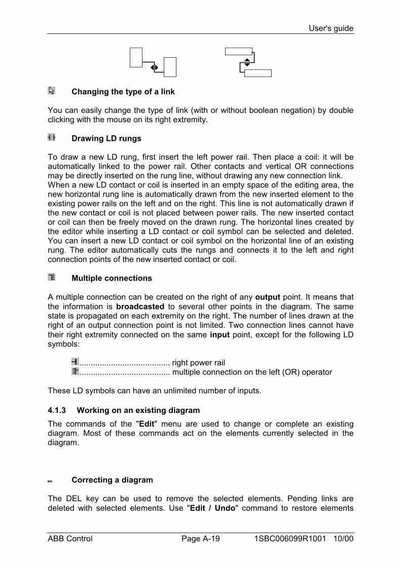
The "Tools / Move line" command is used when a link is selected in the diagram tochange its automatic routing. This command has no effect when the link isconnected to a user defined corner. When a link is drawn as three segments, thiscommand changes the position of the second segment. Below are examples:
User's guide
ABB Control Page A-19 1SBC006099R1001 10/00
Changing the type of a link
You can easily change the type of link (with or without boolean negation) by doubleclicking with the mouse on its right extremity.
Drawing LD rungs
To draw a new LD rung, first insert the left power rail. Then place a coil: it will beautomatically linked to the power rail. Other contacts and vertical OR connectionsmay be directly inserted on the rung line, without drawing any new connection link.When a new LD contact or coil is inserted in an empty space of the editing area, thenew horizontal rung line is automatically drawn from the new inserted element to theexisting power rails on the left and on the right. This line is not automatically drawn ifthe new contact or coil is not placed between power rails. The new inserted contactor coil can then be freely moved on the drawn rung. The horizontal lines created bythe editor while inserting a LD contact or coil symbol can be selected and deleted.You can insert a new LD contact or coil symbol on the horizontal line of an existingrung. The editor automatically cuts the rungs and connects it to the left and rightconnection points of the new inserted contact or coil.
Multiple connections
A multiple connection can be created on the right of any output point. It means thatthe information is broadcasted to several other points in the diagram. The samestate is propagated on each extremity on the right. The number of lines drawn at theright of an output connection point is not limited. Two connection lines cannot havetheir right extremity connected on the same input point, except for the following LDsymbols:
........................................ right power rail
........................................ multiple connection on the left (OR) operator
These LD symbols can have an unlimited number of inputs.
4.1.3 Working on an existing diagramThe commands of the "Edit" menu are used to change or complete an existingdiagram. Most of these commands act on the elements currently selected in thediagram.
Correcting a diagram
The DEL key can be used to remove the selected elements. Pending links aredeleted with selected elements. Use "Edit / Undo" command to restore elements
User's guide
ABB Control Page A-20 1SBC006099R1001 10/00
after a DEL command. The DEL command can also be applied to a group ofelements selected in the diagram. The "Cut", "Copy", "Paste" commands of the"Edit" menu are used to move or copy selected elements.
Find and replace
The "Edit / Find" and "Edit / Replace" menu commands are used to find andreplace texts in the diagram. Only complete names can be found. Research acts oncontacts, coils, block names, variables and labels. It cannot be used to find a stringin a comment text. The Replace command cannot be used to change the name of ablock. The research can be made upward or downward, starting at the currentselection position. It "loops" when the limits of the diagram are reached.
Displaying the execution order
When an FBD diagram includes backward loops, the execution order cannot followthe single left to right / top to bottom method. In order to avoid confusion, use the"Tools / Show execution order" command or press Control + F1 keys to displaythe execution order that will be used at compiling time. Tags numbered from 1 to Nare displayed close to symbols that lead to an action (coils, set variables andfunction blocks).
Entering symbols and texts
Double click with the mouse on an element to enter the associated symbol or text.This applies to variables, contacts and coils, comment texts and labels. When usedon a contact or coil, this also allows to change its type (direct, negated...).If the "Auto input" mode is checked in the "Options" menu, the variable symbolmust be entered immediately each time a new contact or coil is inserted.The symbol must always be entered immediately when a variable or label is inserted.
If the “Manual keyboard input” mode is selected in the “Options” menu, thevariable name is directly catch in a field. Enter the new text and hit Enter to validate,or Esc to give up. The field used for this mode can not be closed with the mouse.When you enter the variable name and you hit Enter, if the variable does not alreadyexists, the variable list is opened to complete the variable definition.When you click on the button to call the variable list, if the variable already exists, thevariable list will be opened on this variable.
Selecting function block type
Double click with the mouse on a block is used to change its type. The block type isselected from the list of available operators, functions and function blocks. This
Variable name Button to call thevariable list
User's guide
ABB Control Page A-21 1SBC006099R1001 10/00
command also allows to change the number of input points in the case of acommutative operator (e.g. AND, OR, ADD, MUL...).
Getting free space
When you press the right button of the mouse in the FBD drawing area, a popupmenu is displayed. It contains the following commands that can be used to insert orremove free space at the location of the mouse cursor:
Insert rows........................ This command inserts horizontal free space,made of 4 rows according to the grid step, startingat the position of the mouse cursor where popupmenu is open.
Delete rows....................... This command removes unused horizontal space(rows) starting at the position of the mouse cursorwhere popup menu is open. This commandcannot be used to remove FBD elements.
When popup menu is open, a gray line in the FBD drawing area indicates whereempty space will be inserted or removed.
4.1.4 Displaying optionsThe commands of the "Options" menu are used to customize the drawing of theFBD diagram on the screen.
Layout customization
The "Options / Layout" command opens a dialog box where are grouped all theparameters and options concerning the editor workspace and the drawing of thegraphic diagram. Use the check boxes in the "Workspace" groupbox to display orhide editor toolbars and status bar. Options of the "Document" groupbox allows youto show or hide points of the editing grid, and to enable/disable the use of colors forthe drawing.
Switching name and address
The “Options / Name/address” command switches the symbol of a variable by hisaddress and vice versa.
Selecting LD toolbar
The “Options / LD toolbar” command selects the LD toolbar.
Selecting FBD toolbar
User's guide
ABB Control Page A-22 1SBC006099R1001 10/00
The “Options / FBD toolbar” command selects the FBD toolbar.
Auto input variable list manager
The “Options / Auto input” command edit the variable list manager when a variableis put.
Manual keyboard input
The “Options / Manual keyboard input” command allows the user to enter directlythe symbol of the variable.
Setting the communication parameters
The “Options / Link configuration” command allows the user to modify thecommunication parameters.
Zoom
Options of the "Zoom" groupbox allows you to select a main zoom ratio. You canalso use the "zoom" button in the editor toolbar to swap between default zoom ratios.
4.1.5 Other AC31GRAF tools
Verifying (compiling) the program
The "File / Verify" command runs the AC31GRAF code generator to verify theprogramming syntax of the currently edited program. In case of SFC language, bothlevel 1 and 2 are checked.
Running debugger
The "File / PLC communication” command runs the AC31GRAF graphic debuggerreal connected mode, and re-opens the edited FBD/LD program in debug mode.Used in debug mode, no modification can be entered in the program.
Editing the variable list
The "File / Variable list" command is used to edit the list of variables for the currentapplication and the current program.
Making a Graphic
The “File / Graphics” command runs the graphic editor. This tool allows the user todefine graphic images that will be refreshed during debug, based on the state of theapplication variables. The images are built with standard windows bitmap (.BMP) and
User's guide
ABB Control Page A-23 1SBC006099R1001 10/00
icon (.ICO) files. This requires additional graphic editing tools, such as PaintBrush,to create bitmaps and icon files.
Printing the program
The "File / Print" command outputs the edited program on a printer. This commandproduces a draft listing of the program. More detailed information is given when theproject document generator is used.
Selecting a variable from the variables list
When editing a text program the "Edit / Insert variable" allows the selection of adeclared variable name to be inserted at the current position of the caret. Whenediting LD or FBD programs, variable selection is required for the description ofcontacts coils, block I/O parameters or FBD variable boxes. In both cases, the"Select" dialog box is open to select a declared variable.
To select a variable, click on its name in the list. Its name and comment are thendisplayed on the top of the list. Then press the "OK" button to confirm its selection. Itis also possible to directly enter a variable name in the edit control without using thelist.
For the graphicals programs (SFC, FBD and Quick LD) the "Edition / Copy drawing(metafile)" copy an image of a program in metafile form into the Window clipboard.So, it can be copied in others applications. For the SFC programs, only theinformation of the level 1 are copied into the image (graph, references andcomments).
4.1.6 Style and modification tracking
The AC31GRAF LD/FBD editor enables you to assign a graphic style to anycomponent of a LD/FBD diagram. A style is mainly defined as a special diagramcolouring. But AC31GRAF also used styles to enable modification tracking indiagram for version control purpose.
Note that styles are not visible during simulation or on-line debug, as colours (redand blue) are used in that mode to highlight TRUE / FALSE states of spied variables.
Predefined style
The following styles are pre-defined:
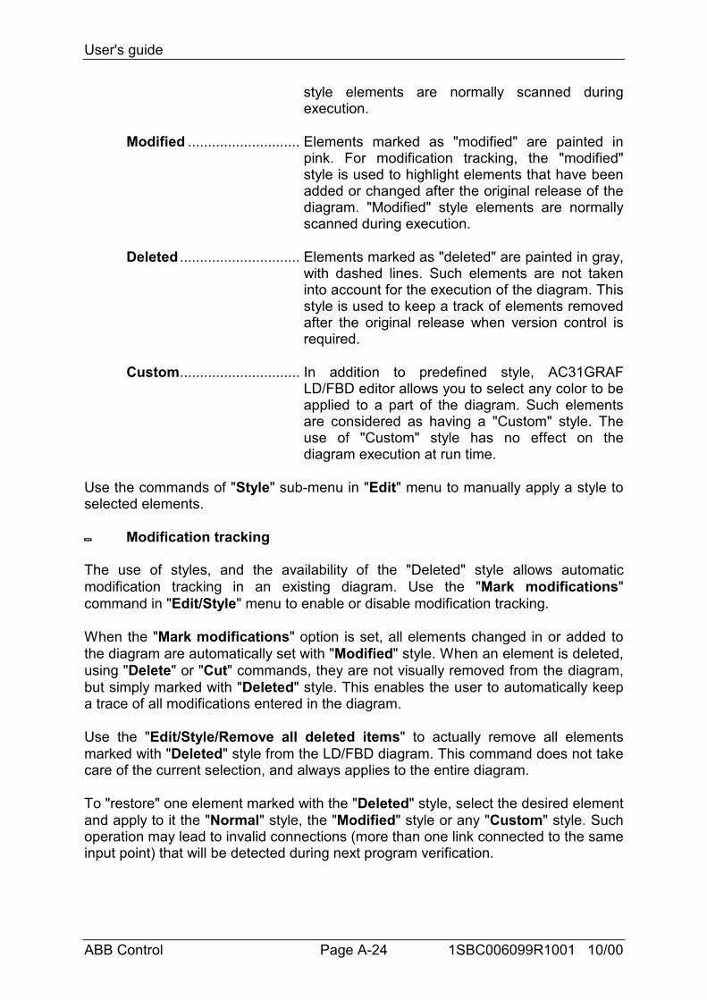
Normal............................... Default drawing (black). For modification tracking,"normal" style indicates that elements having thatstyle are part of the original diagram. "Normal"
User's guide
ABB Control Page A-24 1SBC006099R1001 10/00
style elements are normally scanned duringexecution.
Modified ............................ Elements marked as "modified" are painted inpink. For modification tracking, the "modified"style is used to highlight elements that have beenadded or changed after the original release of thediagram. "Modified" style elements are normallyscanned during execution.
Deleted .............................. Elements marked as "deleted" are painted in gray,with dashed lines. Such elements are not takeninto account for the execution of the diagram. Thisstyle is used to keep a track of elements removedafter the original release when version control isrequired.
Custom.............................. In addition to predefined style, AC31GRAFLD/FBD editor allows you to select any color to beapplied to a part of the diagram. Such elementsare considered as having a "Custom" style. Theuse of "Custom" style has no effect on thediagram execution at run time.
Use the commands of "Style" sub-menu in "Edit" menu to manually apply a style toselected elements.
Modification tracking
The use of styles, and the availability of the "Deleted" style allows automaticmodification tracking in an existing diagram. Use the "Mark modifications"command in "Edit/Style" menu to enable or disable modification tracking.
When the "Mark modifications" option is set, all elements changed in or added tothe diagram are automatically set with "Modified" style. When an element is deleted,using "Delete" or "Cut" commands, they are not visually removed from the diagram,but simply marked with "Deleted" style. This enables the user to automatically keepa trace of all modifications entered in the diagram.
Use the "Edit/Style/Remove all deleted items" to actually remove all elementsmarked with "Deleted" style from the LD/FBD diagram. This command does not takecare of the current selection, and always applies to the entire diagram.
To "restore" one element marked with the "Deleted" style, select the desired elementand apply to it the "Normal" style, the "Modified" style or any "Custom" style. Suchoperation may lead to invalid connections (more than one link connected to the sameinput point) that will be detected during next program verification.

User's guide
ABB Control Page A-25 1SBC006099R1001 10/00
For graphic programs (SFC, FBD), you can also use the "Edit / Copy drawing"command to copy in the clipboard the drawing of the chart in metafile format, so thatit can be pasted in other applications such as word processors. For SFC programs,only the level 1 information (chart, numbering and level 1 comments) appears on thecopied metafile.
User's guide
ABB Control Page A-26 1SBC006099R1001 10/00
4.2 Using the SFC editor
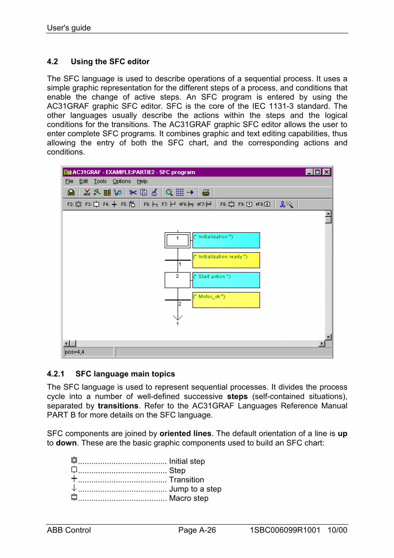
The SFC language is used to describe operations of a sequential process. It uses asimple graphic representation for the different steps of a process, and conditions thatenable the change of active steps. An SFC program is entered by using theAC31GRAF graphic SFC editor. SFC is the core of the IEC 1131-3 standard. Theother languages usually describe the actions within the steps and the logicalconditions for the transitions. The AC31GRAF graphic SFC editor allows the user toenter complete SFC programs. It combines graphic and text editing capabilities, thusallowing the entry of both the SFC chart, and the corresponding actions andconditions.
4.2.1 SFC language main topicsThe SFC language is used to represent sequential processes. It divides the processcycle into a number of well-defined successive steps (self-contained situations),separated by transitions. Refer to the AC31GRAF Languages Reference ManualPART B for more details on the SFC language.
SFC components are joined by oriented lines. The default orientation of a line is upto down. These are the basic graphic components used to build an SFC chart:
........................................ Initial step
........................................ Step
........................................ Transition
........................................ Jump to a step
........................................ Macro step
User's guide
ABB Control Page A-27 1SBC006099R1001 10/00
........................................ Macro beginning step
........................................ Macro ending step
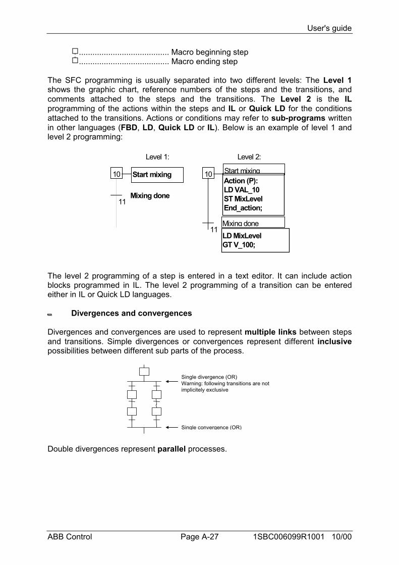
The SFC programming is usually separated into two different levels: The Level 1shows the graphic chart, reference numbers of the steps and the transitions, andcomments attached to the steps and the transitions. The Level 2 is the ILprogramming of the actions within the steps and IL or Quick LD for the conditionsattached to the transitions. Actions or conditions may refer to sub-programs writtenin other languages (FBD, LD, Quick LD or IL). Below is an example of level 1 andlevel 2 programming:
10 Start mixing
Mixing done11
10 Start mixing
Mixing done11
LD MixLevelGT V_100;
Action (P):LD VAL_10ST MixLevelEnd_action;
Level 1: Level 2:
The level 2 programming of a step is entered in a text editor. It can include actionblocks programmed in IL. The level 2 programming of a transition can be enteredeither in IL or Quick LD languages.
Divergences and convergences
Divergences and convergences are used to represent multiple links between stepsand transitions. Simple divergences or convergences represent different inclusivepossibilities between different sub parts of the process.
Single divergence (OR)Warning: following transitions are notimplicitely exclusive
Single convergence (OR)
Double divergences represent parallel processes.
User's guide
ABB Control Page A-28 1SBC006099R1001 10/00
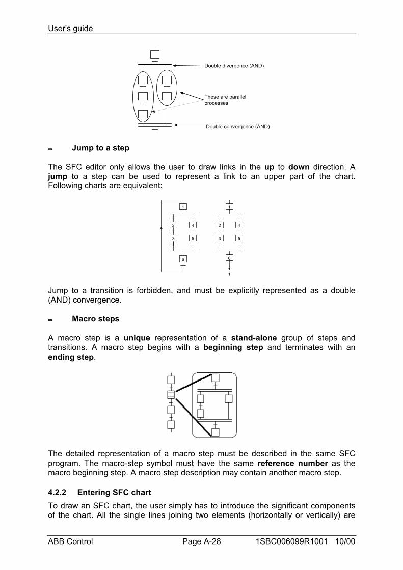
Double divergence (AND)
Double convergence (AND)
These are parallelprocesses
Jump to a step
The SFC editor only allows the user to draw links in the up to down direction. Ajump to a step can be used to represent a link to an upper part of the chart.Following charts are equivalent:
1
2
3
4
5
1
2
3
4
5
1
66
Jump to a transition is forbidden, and must be explicitly represented as a double(AND) convergence.
Macro steps
A macro step is a unique representation of a stand-alone group of steps andtransitions. A macro step begins with a beginning step and terminates with anending step.
The detailed representation of a macro step must be described in the same SFCprogram. The macro-step symbol must have the same reference number as themacro beginning step. A macro step description may contain another macro step.
4.2.2 Entering SFC chartTo draw an SFC chart, the user simply has to introduce the significant componentsof the chart. All the single lines joining two elements (horizontally or vertically) are
User's guide
ABB Control Page A-29 1SBC006099R1001 10/00
drawn automatically by the SFC editor. To place an SFC component on the chart,the user has to move the selection to appropriate location and select the type of thecomponent in the editor toolbar. The symbol is inserted at the current position. Thefollowing keyboard sequences can also be used:
.................................... Insert an initial step
.................................... Insert a single step
.................................... Insert a transition
.................................... Insert a jump to a step ............................ Insert an OR divergence or convergence / Add
branches ............................ Insert an AND divergence or convergence / Add
branches.................................... Insert a macro step ............................ Insert begin or end step for the body of a macro
step
(The " " symbol indicates a combination with SHIFT key)
The editing grid shows matrix cells. An editor option allows the user to show orhide the grid during chart input. The grid is very useful for initial layout of SFC chart,or selecting sub-parts of the chart. Use the "Options / Layout" command to displayor hide the grid.
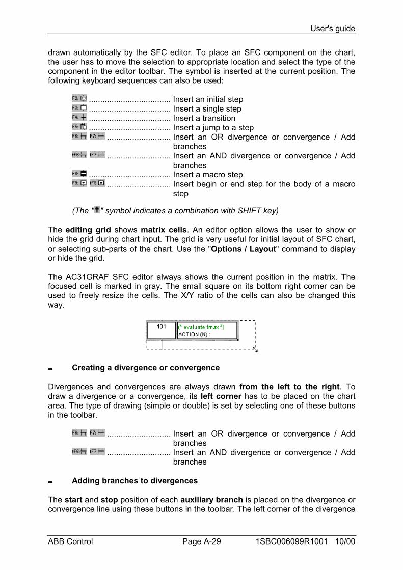
The AC31GRAF SFC editor always shows the current position in the matrix. Thefocused cell is marked in gray. The small square on its bottom right corner can beused to freely resize the cells. The X/Y ratio of the cells can also be changed thisway.
Creating a divergence or convergence
Divergences and convergences are always drawn from the left to the right. Todraw a divergence or a convergence, its left corner has to be placed on the chartarea. The type of drawing (simple or double) is set by selecting one of these buttonsin the toolbar.
............................ Insert an OR divergence or convergence / Addbranches
............................ Insert an AND divergence or convergence / Addbranches
Adding branches to divergences
The start and stop position of each auxiliary branch is placed on the divergence orconvergence line using these buttons in the toolbar. The left corner of the divergence
User's guide
ABB Control Page A-30 1SBC006099R1001 10/00
or convergence must be present before inserting new branches. The right cornershave the same style (simple or double) as the main left corner. Right corners cannotbe placed if the main left corner has not been added.
............................ Insert an OR divergence or convergence / Addbranches
............................ Insert an AND divergence or convergence / Addbranches
Inserting a macro step
This button is used to insert a macro step in the main chart. The body of the macrostep must be entered elsewhere in the same SFC program.
Body of a macro step
Macro steps must be described in the same SFC program as the main chart. Amacro step must start with a beginning step and stop with an ending step. Thesub-chart described as the macro implementation must be self-contained. Themacro beginning step must have the same reference as the macro-step symbol ofthe main branch.
4.2.3 Working on an existing SFC chartYou can use either the mouse or keyboards arrows to select a rectangle area in thechart. The whole selected area is marked in gray. The commands of the "Edit" menucan then used:
Cut / copy / delete / paste commands
The following commands are available from the "Edit" menu when the "arrow"button is selected in the editor toolbar:
Cut ..................................... Move selected rectangle from the screen to theSFC clipboard
Copy .................................. Copy selected rectangle from the screen to theSFC clipboard
Delete ................................ Clear (delete) selected rectanglePaste ................................. Insert contents SFC clipboard at the current
position
The "Edit / Paste" copies SFC clipboard to the screen. Copy / Paste commandswork on both SFC chart and step/transition level 2 programming. It is also possible tocopy a chart in a program and paste it in another SFC program. Elements areinserted before the currently selected position.
Move elements
User's guide
ABB Control Page A-31 1SBC006099R1001 10/00
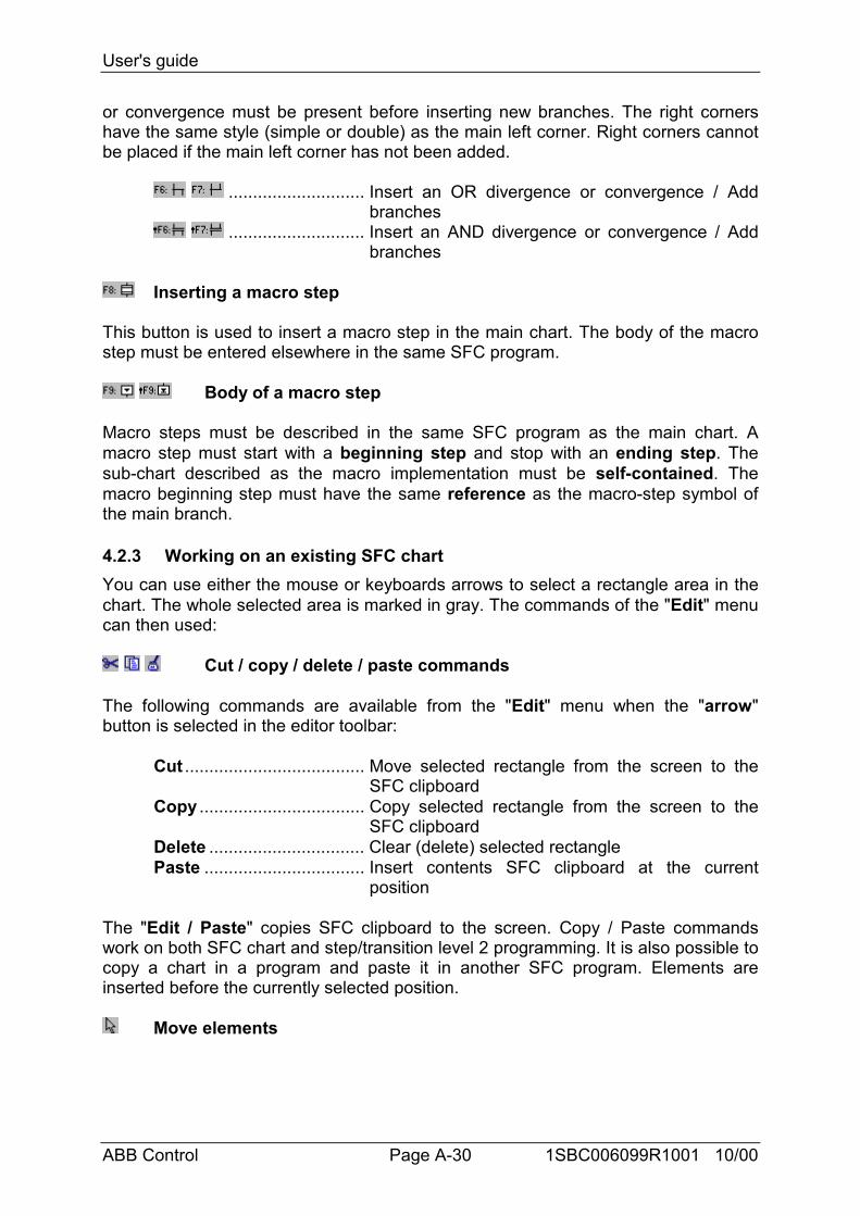
When SFC elements are selected in the SFC chart, you can move them to anotherlocation of the chart by dragging the selection with the mouse. While you drag theselection, the initial location of selected elements is hatched.
The destination area for moved elements must be empty. No insertion is possiblewhile moving SFC symbols.
Renumbering steps and transitions
Each step or transition is identified by a logical number in the SFC chart. The "Edit /Renumber" command allows the user to automatically set up numerically sequentialreference numbers for any of the steps and the transitions of the currently editedSFC program. When a step number is changed, all the jumps to this step areautomatically updated with the new reference number. (this also applies to macrosteps and beginning steps)
Direct access to a step or transition
The "Edit / Go to" command allows the user to access an existing step or transition.The scrolling position is automatically adapted so that the step or transition is visible.
Find and replace texts
The "Edit / Find Replace" command can be used to find or replace text strings in thecomplete program (all steps and transitions). The Find/Replace dialog box is used toenter a searched text and directly open the level 2 programming section where textoccurs.
4.2.4 Entering the level 2 programmingTo enter the Level 2 text, the user must double click on the step or transition symbol.The level 2 programming is displayed on the right of the SFC window. Theseparation line between SFC chart and level 2 programming can be freely moved.
You can open one or two level 2 areas at the same time. The following commandsare available from keyboard, mouse or the "Edit" menu:
Keyboard Mouse "Edit" menuOpen in last default window Enter Double Click Edit level 2Open in separate window Ctrl+Enter Ctrl + DoubleClick Edit Level 2 in separate window
User's guide
ABB Control Page A-32 1SBC006099R1001 10/00
When two level 2 windows are visible, the separation between them can be freelymoved. The button on the right of the level 2 title bar is used to close a level 2window.
The language for Level 2 programming is IL (Instruction List) or Quick LD. Anindependent window is opened to enter the level 2 programming. You can openseveral level 2 windows at the same time.
When working on a level 2 programming window, you can still access the commandsof the "Edit" menu in the main window to work on the active level 2 text or diagram.
The “Options / Refresh” can be used at any time when level 2 windows are open torefresh the main SFC chart with modified level 2 programs.
Inserting a variable name
When programming in text language, press this button to select a variable declaredin the list of variables and insert its name at the current position of the caret.
P Inserting a Pulse action block in step
When programming the level 2 of a step, press this button to insert the template of aPulse action block at the current position of the caret. Below is the format of a Pulseaction block:
Action (P) :IL statement;...
End_Action;
Pulse actions are instructions which are executed only once when the step becomesactive. Refer to the AC31GRAF language reference for further details on SFCprogramming.
Inserting a Non stored action block in step
When programming the level 2 of a step, press this button to insert the template of aNon stored action block at the current position of the caret. Below is the format of aNon stored action block:
Action (N) :IL statement;...
End_Action;
User's guide
ABB Control Page A-33 1SBC006099R1001 10/00
Non stored actions are instructions which are executed on every PLC cycle when thestep is active. Refer to the AC31GRAF language reference for further details on SFCprogramming.
New P0 and P1 action qualifiers
AC31GRAF supports new P0 and P1 action qualifiers. When programming the level2 of a step, press these buttons to insert the template of a P0 or P1 action block atthe current position of the caret. Below is the format of such blocks:
Action (P0) : Action (P1) :IL statement; IL statement;... ...
End_Action; End_Action;
P1 actions are instructions which are executed only once when the step becomesactive (same as Pulse). P0 actions are instructions which are executed only oncewhen the step becomes inactive. Refer to the AC31GRAF language reference forfurther details on SFC programming.
Boolean actions
Other text semantics are available to directly act on a boolean variable according tothe step activity. Such actions consist of attaching the step activity signal to aninternal or output boolean variable. This is the syntax of the basic boolean actions:
var (N); ............................... assigns the step activity signal to the variablevar; ..................................... same effect (N attribute is optional)/ var; ................................... assigns the negation of the step activity signal to
the variable
example :%O62.00 (N); ..................... assigns the step activity signal to the output
%O62.00%O62.00; ........................... same effect (N attribute is optional)/ %M00.00; assigns the negation of the step activity signal to
the variable %M00.00
Other features are available to set or reset a boolean variable, when the stepbecomes active. This is the syntax of set and reset boolean actions:
var (S);.........sets the variable to TRUE when the step activity signal becomes TRUEvar (R); ............................... resets the variable to FALSE when the step
activity signal becomes TRUE
example%O62.00 (S); ..................... sets %O62.00 to TRUE when the step activity
signal becomes TRUE%M00.00 (R);..................... resets %M00.00 to FALSE when the step activity
signal becomes TRUE
User's guide
ABB Control Page A-34 1SBC006099R1001 10/00
Transitions written in IL
The level 2 of a transition is a boolean expression. To program it in IL language, justenter the boolean condition according to the IL syntax. Optionally, a semi colon maybe added at the end of the expression.
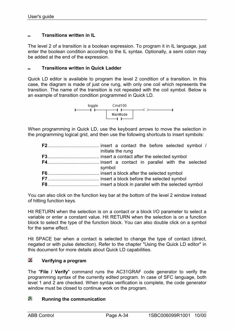
Transitions written in Quick Ladder
Quick LD editor is available to program the level 2 condition of a transition. In thiscase, the diagram is made of just one rung, with only one coil which represents thetransition. The name of the transition is not repeated with the coil symbol. Below isan example of transition condition programmed in Quick LD.
When programming in Quick LD, use the keyboard arrows to move the selection inthe programming logical grid, and then use the following shortcuts to insert symbols:
F2....................................... insert a contact the before selected symbol /initiate the rung
F3....................................... insert a contact after the selected symbolF4....................................... insert a contact in parallel with the selected
symbolF6....................................... insert a block after the selected symbolF7....................................... insert a block before the selected symbolF8....................................... insert a block in parallel with the selected symbol
You can also click on the function key bar at the bottom of the level 2 window insteadof hitting function keys.
Hit RETURN when the selection is on a contact or a block I/O parameter to select avariable or enter a constant value. Hit RETURN when the selection is on a functionblock to select the type of the function block. You can also double click on a symbolfor the same effect.
Hit SPACE bar when a contact is selected to change the type of contact (direct,negated or with pulse detection). Refer to the chapter "Using the Quick LD editor" inthis document for more details about Quick LD capabilities.
Verifying a program
The "File / Verify" command runs the AC31GRAF code generator to verify theprogramming syntax of the currently edited program. In case of SFC language, bothlevel 1 and 2 are checked. When syntax verification is complete, the code generatorwindow must be closed to continue work on the program.
Running the communication
User's guide
ABB Control Page A-35 1SBC006099R1001 10/00
The "File / PLC communication" command runs the AC31GRAF graphic debuggerin connected mode, and re-opens the edited SFC program in debug mode. Used indebug mode, no modification can be entered in the program.
Editing variable list
The "File / Variable list" command is used to edit the list of variables for the currentapplication and the current program.
Making a graphic
This "File / Graphics" command runs the graphic editor. This tool allows the user todefine graphic images that will be refreshed during debug, based on the state of theapplication variables. The images are built with standard windows bitmap (.BMP) andicon (.ICO) files. This requires additional graphic editing tools, such as PaintBrush,to create bitmaps and icon files.
Printing the program
The "File / Print" command outputs the edited program on printer. This commandproduces a draft listing of the program. More detailed information is given when theproject document generator is used.
For graphic programs (SFC, FBD), you can also use the "Edit / Copy drawing"command to copy in the clipboard the drawing of the chart in metafile format, so thatit can be pasted in other applications such as word processors. For SFC programs,only the level 1 information (chart, numbering and level 1 comments) appears on thecopied metafile.
4.2.5 Selecting a variable from listWhen editing a text program (IL) the "Edit / Insert variable" allows the
selection of a declared variable name to be inserted at the current position of thecaret. When editing LD or FBD programs, variable selection is required for thedescription of contacts coils, block I/O parameters or FBD variable boxes. In bothcases, the "Select" dialog box is opened to select a declared variable.
To select a variable, click on its name in the list. Its name and comment are thendisplayed on the different fields. Then press the "OK" button to confirm its selection.It is also possible to enter a variable name with a double click on the selected line inthe list, or enter manually its symbol without using the list.
4.2.6 Commands of the "Tools" menuThe following commands are available in the Tools menu. They are used to displayinformation in a small text list at the bottom of the SFC window:
Find in steps and transitions find occurrences of a text in all steps and transitionsand list them in the output window
Hide output window close the output list window
User's guide
ABB Control Page A-36 1SBC006099R1001 10/00
When error messages or occurrences are displayed in the output window, doubleclick on a line to directly open the level 2 programming window at the correspondinglocation.
4.2.7 Using the SFC galleryThe AC31GRAF SFC editor manages an SFC gallery: it is a collection of SFCstructures that can be inserted in any SFC chart. Elements of the SFC gallery canoptionally embed the level 2 programming of steps and transitions. Use the followingcommands of the "Tools" menu:
Copy to SFC gallery ......... copy selected elements to SFC galleryPaste from SFC gallery.... paste an SFC gallery element at the current
location
When copying to SFC gallery (i.e. creating a new SFC gallery element), you canoptionally ask to embed level 2 programming of selected SFC symbols.
User's guide
ABB Control Page A-37 1SBC006099R1001 10/00
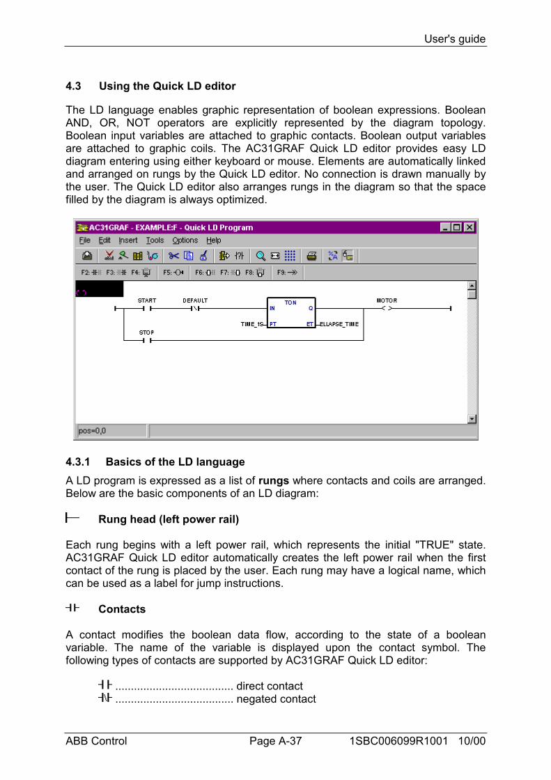
4.3 Using the Quick LD editor
The LD language enables graphic representation of boolean expressions. BooleanAND, OR, NOT operators are explicitly represented by the diagram topology.Boolean input variables are attached to graphic contacts. Boolean output variablesare attached to graphic coils. The AC31GRAF Quick LD editor provides easy LDdiagram entering using either keyboard or mouse. Elements are automatically linkedand arranged on rungs by the Quick LD editor. No connection is drawn manually bythe user. The Quick LD editor also arranges rungs in the diagram so that the spacefilled by the diagram is always optimized.
4.3.1 Basics of the LD languageA LD program is expressed as a list of rungs where contacts and coils are arranged.Below are the basic components of an LD diagram:
Rung head (left power rail)
Each rung begins with a left power rail, which represents the initial "TRUE" state.AC31GRAF Quick LD editor automatically creates the left power rail when the firstcontact of the rung is placed by the user. Each rung may have a logical name, whichcan be used as a label for jump instructions.
Contacts
A contact modifies the boolean data flow, according to the state of a booleanvariable. The name of the variable is displayed upon the contact symbol. Thefollowing types of contacts are supported by AC31GRAF Quick LD editor:
...................................... direct contact
...................................... negated contact
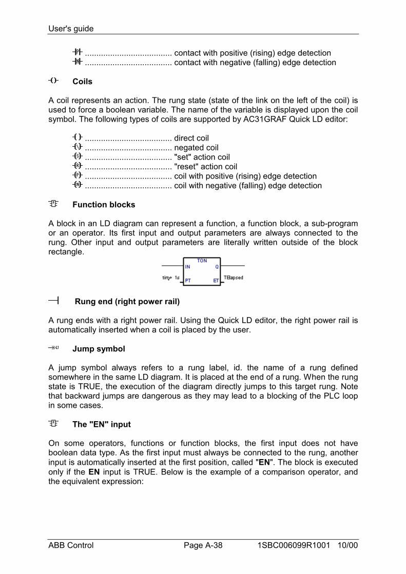
User's guide
ABB Control Page A-38 1SBC006099R1001 10/00
...................................... contact with positive (rising) edge detection
...................................... contact with negative (falling) edge detection
Coils
A coil represents an action. The rung state (state of the link on the left of the coil) isused to force a boolean variable. The name of the variable is displayed upon the coilsymbol. The following types of coils are supported by AC31GRAF Quick LD editor:
...................................... direct coil
...................................... negated coil
...................................... "set" action coil
...................................... "reset" action coil
...................................... coil with positive (rising) edge detection
...................................... coil with negative (falling) edge detection
Function blocks
A block in an LD diagram can represent a function, a function block, a sub-programor an operator. Its first input and output parameters are always connected to therung. Other input and output parameters are literally written outside of the blockrectangle.
Rung end (right power rail)
A rung ends with a right power rail. Using the Quick LD editor, the right power rail isautomatically inserted when a coil is placed by the user.
Jump symbol
A jump symbol always refers to a rung label, id. the name of a rung definedsomewhere in the same LD diagram. It is placed at the end of a rung. When the rungstate is TRUE, the execution of the diagram directly jumps to this target rung. Notethat backward jumps are dangerous as they may lead to a blocking of the PLC loopin some cases.
The "EN" input
On some operators, functions or function blocks, the first input does not haveboolean data type. As the first input must always be connected to the rung, anotherinput is automatically inserted at the first position, called "EN". The block is executedonly if the EN input is TRUE. Below is the example of a comparison operator, andthe equivalent expression:
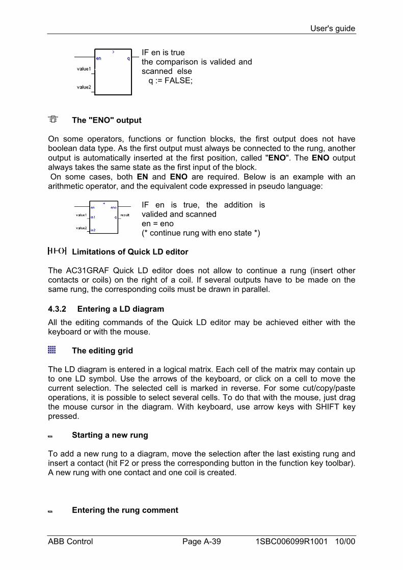
User's guide
ABB Control Page A-39 1SBC006099R1001 10/00
IF en is truethe comparison is valided andscanned else q := FALSE;
The "ENO" output
On some operators, functions or function blocks, the first output does not haveboolean data type. As the first output must always be connected to the rung, anotheroutput is automatically inserted at the first position, called "ENO". The ENO outputalways takes the same state as the first input of the block. On some cases, both EN and ENO are required. Below is an example with anarithmetic operator, and the equivalent code expressed in pseudo language:
IF en is true, the addition isvalided and scanneden = eno(* continue rung with eno state *)
Limitations of Quick LD editor
The AC31GRAF Quick LD editor does not allow to continue a rung (insert othercontacts or coils) on the right of a coil. If several outputs have to be made on thesame rung, the corresponding coils must be drawn in parallel.
4.3.2 Entering a LD diagramAll the editing commands of the Quick LD editor may be achieved either with thekeyboard or with the mouse.
The editing grid
The LD diagram is entered in a logical matrix. Each cell of the matrix may contain upto one LD symbol. Use the arrows of the keyboard, or click on a cell to move thecurrent selection. The selected cell is marked in reverse. For some cut/copy/pasteoperations, it is possible to select several cells. To do that with the mouse, just dragthe mouse cursor in the diagram. With keyboard, use arrow keys with SHIFT keypressed.
Starting a new rung
To add a new rung to a diagram, move the selection after the last existing rung andinsert a contact (hit F2 or press the corresponding button in the function key toolbar).A new rung with one contact and one coil is created.
Entering the rung comment
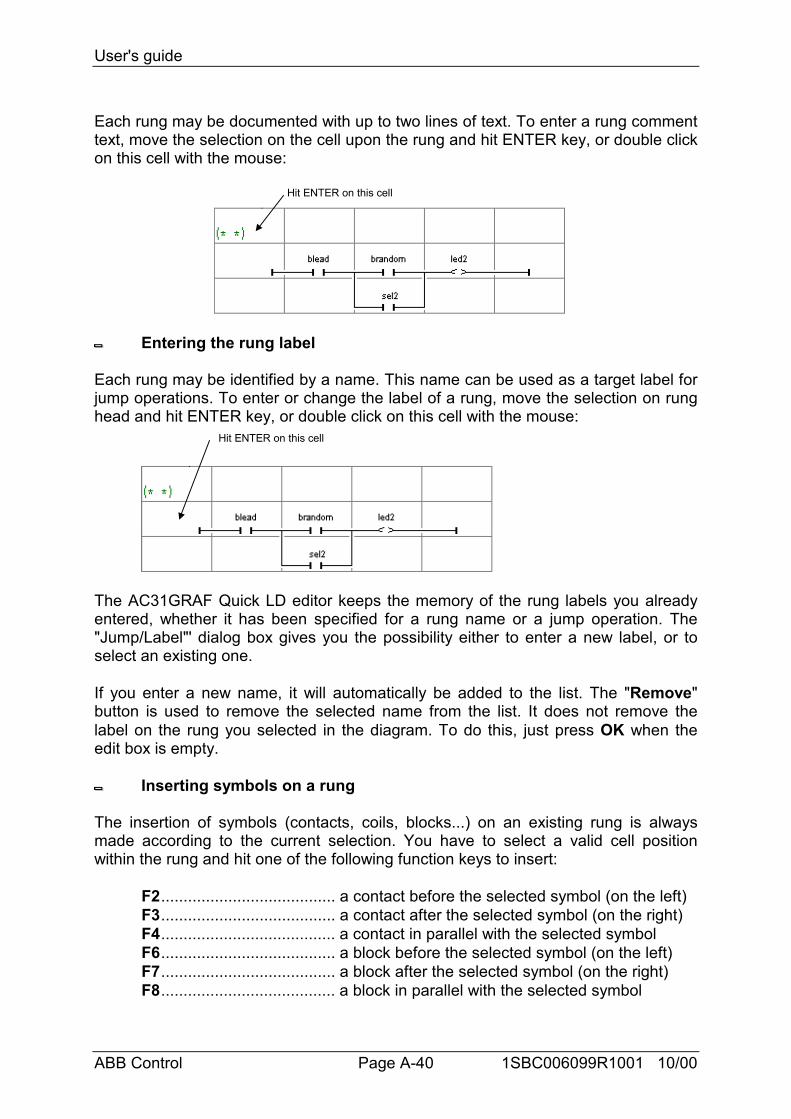
User's guide
ABB Control Page A-40 1SBC006099R1001 10/00
Each rung may be documented with up to two lines of text. To enter a rung commenttext, move the selection on the cell upon the rung and hit ENTER key, or double clickon this cell with the mouse:
Hit ENTER on this cell
Entering the rung label
Each rung may be identified by a name. This name can be used as a target label forjump operations. To enter or change the label of a rung, move the selection on runghead and hit ENTER key, or double click on this cell with the mouse:
Hit ENTER on this cell
The AC31GRAF Quick LD editor keeps the memory of the rung labels you alreadyentered, whether it has been specified for a rung name or a jump operation. The"Jump/Label"' dialog box gives you the possibility either to enter a new label, or toselect an existing one.
If you enter a new name, it will automatically be added to the list. The "Remove"button is used to remove the selected name from the list. It does not remove thelabel on the rung you selected in the diagram. To do this, just press OK when theedit box is empty.
Inserting symbols on a rung
The insertion of symbols (contacts, coils, blocks...) on an existing rung is alwaysmade according to the current selection. You have to select a valid cell positionwithin the rung and hit one of the following function keys to insert:
F2....................................... a contact before the selected symbol (on the left)F3....................................... a contact after the selected symbol (on the right)F4....................................... a contact in parallel with the selected symbolF6....................................... a block before the selected symbol (on the left)F7....................................... a block after the selected symbol (on the right)F8....................................... a block in parallel with the selected symbol
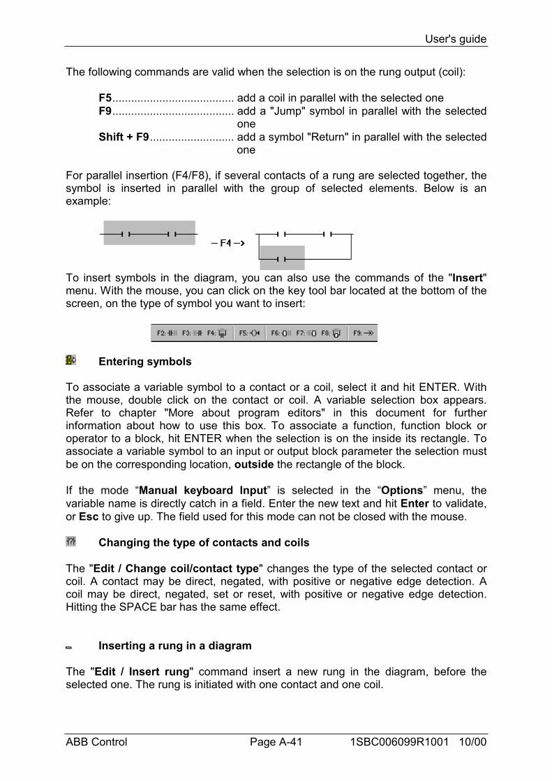
User's guide
ABB Control Page A-41 1SBC006099R1001 10/00
The following commands are valid when the selection is on the rung output (coil):
F5....................................... add a coil in parallel with the selected oneF9....................................... add a "Jump" symbol in parallel with the selected
oneShift + F9........................... add a symbol "Return" in parallel with the selected
one
For parallel insertion (F4/F8), if several contacts of a rung are selected together, thesymbol is inserted in parallel with the group of selected elements. Below is anexample:
To insert symbols in the diagram, you can also use the commands of the "Insert"menu. With the mouse, you can click on the key tool bar located at the bottom of thescreen, on the type of symbol you want to insert:
Entering symbols
To associate a variable symbol to a contact or a coil, select it and hit ENTER. Withthe mouse, double click on the contact or coil. A variable selection box appears.Refer to chapter "More about program editors" in this document for furtherinformation about how to use this box. To associate a function, function block oroperator to a block, hit ENTER when the selection is on the inside its rectangle. Toassociate a variable symbol to an input or output block parameter the selection mustbe on the corresponding location, outside the rectangle of the block.
If the mode “Manual keyboard Input” is selected in the “Options” menu, thevariable name is directly catch in a field. Enter the new text and hit Enter to validate,or Esc to give up. The field used for this mode can not be closed with the mouse.
Changing the type of contacts and coils
The "Edit / Change coil/contact type" changes the type of the selected contact orcoil. A contact may be direct, negated, with positive or negative edge detection. Acoil may be direct, negated, set or reset, with positive or negative edge detection.Hitting the SPACE bar has the same effect.
Inserting a rung in a diagram
The "Edit / Insert rung" command insert a new rung in the diagram, before theselected one. The rung is initiated with one contact and one coil.
User's guide
ABB Control Page A-42 1SBC006099R1001 10/00
4.3.3 Working on an existing diagramThe commands of the "Edit" menu are used to change or complete an existingdiagram. Most of these commands act on the elements currently selected in thediagram.
Correcting a diagram
The DEL key can be used to remove the selected elements. It is not possible toremove a coils, a jump or return symbol when it is the only output of a rung. Use"Edit / Undo" command to restore elements after a DEL command. The DELcommand can also be applied to a group of elements selected in the diagram. TheDEL command can be used when selection is on the rung comment text to reset it.The DEL command, used when the selection is on the rung head, remove the entirerung.
Copying symbols
The "Cut", "Copy", "Paste" commands of the "Edit" menu are used to move or copyselected elements. These commands do not act on rung comments. The "Edit /Paste special" command gives you the choice to insert the pasted elements:• before the selected element (on the left)• after the selected element (on the right)• in parallel with the selected element
Managing entire rungs
All editing commands (delete, copy, cut...) act on the entire rung if the selection is onthe rung header (left power rail). This provides an easy way to arrange rungs in thediagram, just by moving the selection in the first column. It is also possible to extendthe selection vertically so that it includes several rung headers. In this case editioncommands may be applied to a list of entire rungs.
Find and replace
The "Edit / Find" and "Edit / Replace" menu commands are used to find andreplace texts in the diagram. Only complete names can be found. Search acts oncontacts, coils, block names, block parameters and run labels. It cannot be used tofind a string in a rung comment. The Replace command cannot be used to changethe type of a block. The research can be made upward or downward, starting atposition of the current selection. It "loops" when the limits of the diagram arereached. The following shortcuts are also available for quick research of variablenames:
ALT + F2 finds the next element with the same variable name as the elementcurrently selected. This feature can also be applied to function blocks and runglabels.
User's guide
ABB Control Page A-43 1SBC006099R1001 10/00
ALT + F5 finds the next coil with the same variable name as the element currentlyselected. This feature is mainly used in debug mode, to quickly find out the rungswhich forces a suspicious variable.
4.3.4 Display optionsThe commands of the "Options" menu are used to customize the drawing of the LDdiagram on the screen, and to hide or display some types of information.
Rung comments
Use the "Options / Rung comments" command to hide or display the rungcomments in the whole diagram. Hiding the rung comments can be required to havea more condensed view on a huge diagram, as each comment consumes one row inthe editing matrix. This option does not affect the contents of the existing rungcomments, and can be swapped at any time.
Switching name and address
Each variable, when associated to a contact, a coil or a block I/O parameter isidentified by its symbolic name. When using the menu "Options / Name/address"the symbol appears to replace the address or vice-versa
Rawing options
The "Options / Layout" command opens a dialog box where are grouped all theparameters and options concerning the editor workspace and the drawing of thegraphic LD diagram.
Use the check boxes in the "Workspace" groupbox to display or hide editor tool bar,status bar and function key toolbar. Options of the "Document" groupbox allows youto show or hide points of the editing grid, and to enable/disable the use of colors forthe drawing.
Options of the "Zoom" groupbox allows you to select a main zoom ratio. Youcan also use the "zoom" button in the editor toolbar to swap between default zoomratios.
You can also customize the X/Y aspect ratio of cells in the editing grid. Thislast option can be used to reduce the default cell width, if you commonly use shortnames for variables. You can also use the "width" button in the editor toolbar tochange the X/Y aspect ratio without entering the Layout dialog box.
4.3.5 Calling other AC31GRAF tools
Verifying a program
The "File / Verify" command runs the AC31GRAF code generator to verify theprogramming syntax of the currently edited program. In case of SFC language, bothlevel 1 and 2 are checked. When syntax verification is complete, the code generator

User's guide
ABB Control Page A-44 1SBC006099R1001 10/00
window must be closed to continue work on the program. If there is only oneprogram in the application (the edited one) the application code is generated if nosyntax error is detected. The "Options / Compiling options" command is used toset compiling and optimizing parameters. Refer to chapter "Using the codegenerator" in this document for further information about compiling and codegeneration.
Running debugger
The "File / PLC Communication" commands run the AC31GRAF graphic debuggerin real connected mode, and re-opens the edited program in debug mode. Used indebug mode, no modification can be entered in the program.
Editing the variable list
The "File / Variable list" command is used to edit the variable list of variables for thecurrent application and the current program. It also contains the entry points to editthe user defined words. The local declarations or defined words relate to thecurrently edited program.
Printing the program
The "File / Print" command outputs the edited program on printer. This commandproduces a draft listing of the program. More detailed information is given when theproject document generator is used.
For graphic programs (SFC, FBD and Quick LD) You can also use the "Edit / Copydrawing" command to copy in the clipboard the drawing of the chart in metafileformat, so that it can be pasted in other applications such as word processors. ForSFC programs, only the level 1 information (chart, numbering and level 1 comments)appear on the copied metafile.
4.3.6 Selecting a variable from variable list When editing LD or FBD programs, variable selection is required for the
description of contacts coils, block I/O parameters or FBD variable boxes. In bothcases, the "Select" dialog box is open to select a declared variable.
To select a variable, click on its name in the list. Its name and comment are thendisplayed on the top of the list. Then press the "OK" button to confirm its selection. Itis also possible to directly enter a variable name in the edit control without using thelist.
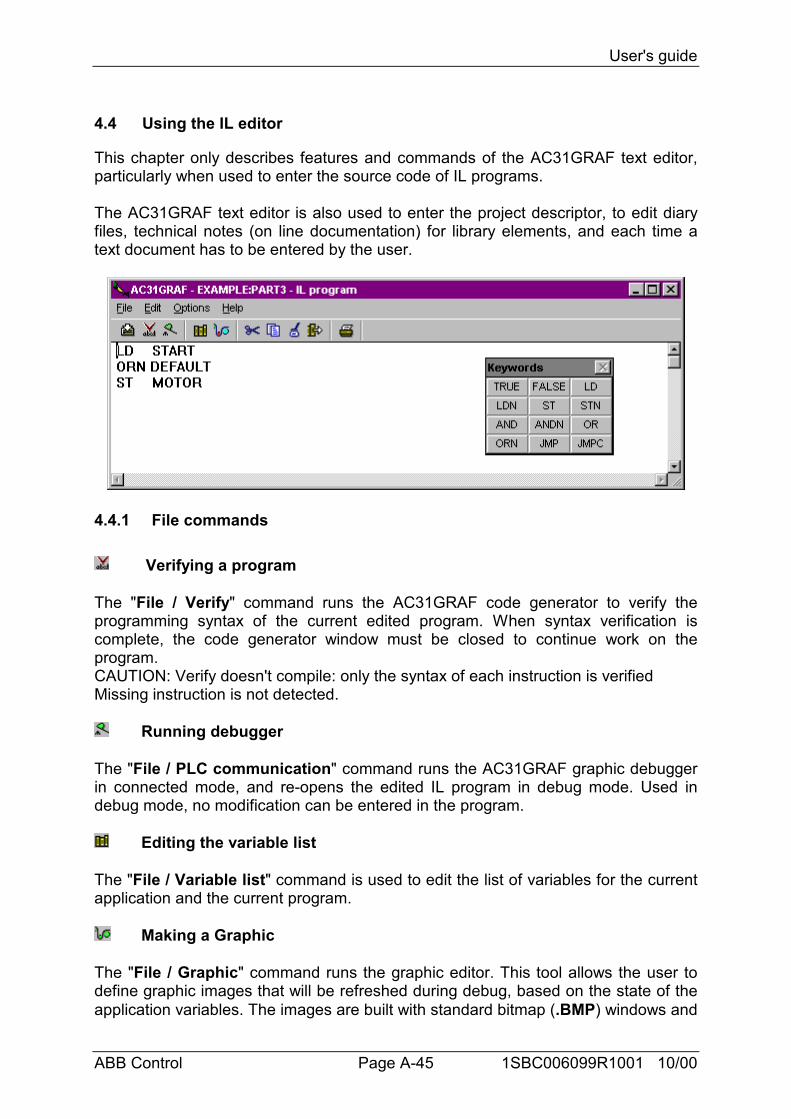
User's guide
ABB Control Page A-45 1SBC006099R1001 10/00
4.4 Using the IL editor
This chapter only describes features and commands of the AC31GRAF text editor,particularly when used to enter the source code of IL programs.
The AC31GRAF text editor is also used to enter the project descriptor, to edit diaryfiles, technical notes (on line documentation) for library elements, and each time atext document has to be entered by the user.
4.4.1 File commands
Verifying a program
The "File / Verify" command runs the AC31GRAF code generator to verify theprogramming syntax of the current edited program. When syntax verification iscomplete, the code generator window must be closed to continue work on theprogram.CAUTION: Verify doesn't compile: only the syntax of each instruction is verifiedMissing instruction is not detected.
Running debugger
The "File / PLC communication" command runs the AC31GRAF graphic debuggerin connected mode, and re-opens the edited IL program in debug mode. Used indebug mode, no modification can be entered in the program.
Editing the variable list
The "File / Variable list" command is used to edit the list of variables for the currentapplication and the current program.
Making a Graphic
The "File / Graphic" command runs the graphic editor. This tool allows the user todefine graphic images that will be refreshed during debug, based on the state of theapplication variables. The images are built with standard bitmap (.BMP) windows and
User's guide
ABB Control Page A-46 1SBC006099R1001 10/00
icon (.ICO) files. This requires additional graphic editing tools, such as PaintBrush,to create bitmaps and icon files.
Printing the program
The "File / Print" command outputs the edited program on a printer. This commandproduces a draft listing of the program. More detailed information is given when theproject document generator is used.
4.4.2 Editing commandsThe commands of the "Edit" menu are used to work on the edited text. Most of thesecommands act on the characters currently selected in the diagram, or perform anaction at the current location of the caret.
Cut, paste, and copy
The DEL key can be used to remove the selected text. Use "Edit / Undo" commandto restore elements after a DEL command. The "Cut", "Copy", "Paste" commands ofthe "Edit" menu are used to move or copy text in the program, or to insert pieces oftexts copied in the clipboard by other applications.
Find and replace
The "Edit / Find" and "Edit / Replace" menu commands are used to find andreplace texts in the program. Any character string can be found. Research can beperformed upward or backward, starting at the current location of the caret. It doesnot "loops" when the limits of the program are reached.
Go to line
The "Edit / Go to line" command is used to move the caret to a specific line number.This can be very useful to have access to a line with an error detected by theAC31GRAF compiler in an IL program, and referenced by a line number.
Inserting a variable
Use the "Edit / Insert variable" command to insert at the caret position the symbolof a variable or object declared in the list of variables. Symbol is selected through thecommon variable selection box described in chapter "More about program editors" inthis document.
Inserting a file
The "Edit / Insert file" command inserts the whole contents of a file at the currentlocation of the caret. Note that only pure ASCII text files can be handled by thiscommand.
User's guide
ABB Control Page A-47 1SBC006099R1001 10/00
4.4.3 OptionsThe commands of the "Options" menu are used to display or hide editor toolbars,and select the character font. The selected character font will be used for any textediting in all AC31GRAF Workbench.
When used to enter the source code of an IL program, the "Options / Showkeywords" command is used to show or hide a toolbox that groups the mostcommon keywords of IL language. Click on a button in the toolbar to insert thecorresponding keyword or operator at the current location of the caret.
4.4.4 Selecting a variable from listWhen editing a text program (IL) the "Edit / Insert variable" allows the
selection of a declared variable name to be inserted at the current position of thecaret. When editing LD or FBD programs, variable selection is required for thedescription of contacts coils, block I/O parameters or FBD variable boxes. In bothcases, the "Select" dialog box is open to select a declared variable.
To select a variable, click on its name in the list. Its name and comment are thendisplayed on the different fields. Then press the "OK" button to confirm its selection.It is also possible to enter a variable name with a double click on the selected line inthe list, or enter manually its symbol without using the list.
Instruction List, or IL is a low level language. It is highly effective for smallerapplications or for optimizing parts of an application. Instructions always relate to thecurrent result (or IL register). The operator indicates the operation that must bemade between the current value and the operand. The result of the operation isstored again in the current result.
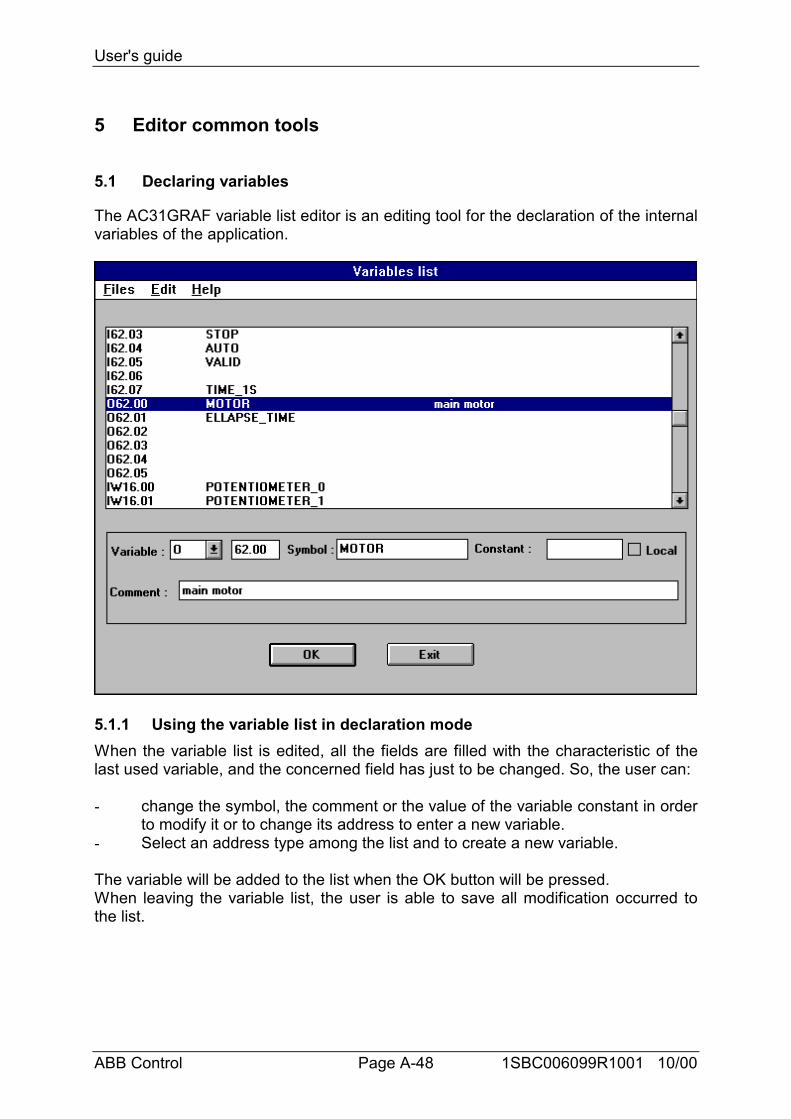
User's guide
ABB Control Page A-48 1SBC006099R1001 10/00
5 Editor common tools
5.1 Declaring variables
The AC31GRAF variable list editor is an editing tool for the declaration of the internalvariables of the application.
5.1.1 Using the variable list in declaration modeWhen the variable list is edited, all the fields are filled with the characteristic of thelast used variable, and the concerned field has just to be changed. So, the user can:
- change the symbol, the comment or the value of the variable constant in orderto modify it or to change its address to enter a new variable.
- Select an address type among the list and to create a new variable.
The variable will be added to the list when the OK button will be pressed.When leaving the variable list, the user is able to save all modification occurred tothe list.
User's guide
ABB Control Page A-49 1SBC006099R1001 10/00
5.1.2 Using the variable list in selection modeWhen the variable list is edited, by default, the last selected variable is highlighted inthe list. The user can:- modify the fields of this variable in order to create an other- double-click on the variable in the list to take it- click on the variable in the list and to press OK to take it.
The variable will be added to the list.
Fast way to enter a variable:(for the select and declare mode)
When the list of variables is edited, the cursor is set on the variable type field.The user can enter manually the type he wants without using the mouse and with the‘tab’ key, he can reach the next field in order to complete the address…Finally, hepress OK to enter the variable in the list.
Format of the variable list fileEach variable is described on one line of text. It is not possible to insert an emptyline.Here is the exact format of the different variable records.
<type>→ <address>→<symbol>→<comment>↵<type>→ <address>→ → <comment>↵<type>→ <address>→<symbol>↵<type>→ <address>↵
type.................................... Variable type ( ex : I,O, IW, …..).address ............................. Variable address (ex: 62.01).symbol .............................. Variable symbol (ex : MOTOR). If it is a constant,
add “=<constant_value>” (ex : MOTOR=1)Comment .......................... Variable comment (ex : Motor command).→→→→ ....................................... Tabulation.↵......................................... Carriage return.
What you have to know on the variable creation:
• AddressFor TXT, # and #H type, there is no address.For I, O, A, E, IW, OW, EW and AW type, the address format is : “cc.cc” or “cc,cc”where c is a digit. For the other type, the address format is “ccc.cc” or “ccc,cc”.For more information, to range for one type, select the type choose “Edit / Rangeon”.The maximum size for an address is 6 characters.You can not have twice the same address.You can not create a variable outside of its declaration area (see “ Edit / Range on”).
• Symbol
User's guide
ABB Control Page A-50 1SBC006099R1001 10/00
The first character must be a letter (“a”-“z” or “A”-“Z”). The next characters must besome letters or digits.A symbol must not begin by ‘GT”, “GS” or “LG”.The words BVARTMP, SFC_EVOL and BVARTMP2 are reserved and are forbiddenfor symbol.The maximum size for a symbol is 16 characters.You can not have twice the same symbol.
• ConstantA constant type is : K, KW and KD. For these types, the field “constant” must befilled.The value of a constant KW is between –32768 and 32767.The value of a constant KD is between –2147483648 and 2147483647The value of a constant K is 0 or 1.The maximum size for a constant is 11 characters.
• CommentThe maximum size for a comment is 100 characters.
• Variable scopeA “local” variable is a variable visible only in a program, a sub-routine or a interruptprogram.A “global” variable is visible in an application. If a variable has no symbol, it isconsidered as a global variable for the application.
For the user library:
For the P, PW, PD, Q, QW, QD type, an address and a symbol are necessary.For types I, IW, O, OW, S: no symbol, just an address.For the M, MW, MD, KW, KD, just a symbol is necessary.
Saving the variable list
The command “FiIe / Save” allows to save the state of the variable list.
Making the cross references
The command “File / Cross references” runs the cross reference tool.
Importing a variable list
The command “File / Import” allows to select a variable file on the disk and add allthe variables on the bottom of the list. The source file can have a PC33 file format, inthis case, the checkbox "PC33 format" must be selected.If an address is already used in the project, a message is displayed to inform theuser and the variable is not set in the list, the same thing happens when a variable isnot inside the range value.If the file is in an 907PC331 format, it is set in the new one.
Exporting a variable list
User's guide
ABB Control Page A-51 1SBC006099R1001 10/00
The command “File / Import” allows to select variables in the list, record them in afile on a selected directory. (the file extension is ".dcl")
Cut variables
The command “Edit / Cut” erases the selected line(s) in the list and record it in theclipboard.
Copying variables
The command “Edit / Copy” records the selected line(s) in the list in the clipboard.
Paste variables
The command “Edit / Paste” writes the contain of the clipboard in the variable list.
Inserting an empty line
The command “Edit / Insert” inserts an empty line above the selected one.
Removing a symbol
The command “Edit / Remove symbol” removes the symbol of the selectedvariable.
Removing a comment
The command “Edit / Remove comment” removes the comment of the selectedvariable.
Searching an address
The command “Edit / Search” allows to search a defined address and highlight theline where the variable is found.
Sorting the variable list
The command “Edit / Sort” allows to set the list in the alphabetic order on thevariable addresses (I, IW, K, KW,…). If you save the sorted list and you open againthe variable list editor, the variables will be sorted in the alphabetic order. But theglobal variables will be displayed in first and the local variables after.
Authorized values area
The command “Edit / Range on type” allows to show the authorized values area fora selected type. Before to use this command, select a variable in the list with thecorrect type ( for example the variable “O 62.00” to see the authorized values area ofthe type “O”).
User's guide
ABB Control Page A-52 1SBC006099R1001 10/00
Creating a variables area
The command ‘’Edit / Variables area” runs a dialog box containing the currentaddress type and allowing to select an area of addresses. When clicking on the OKbutton, all the variables are added to the bottom of the list. If an address is alreadyused in the project, a message is displayed to inform the user and the variable is notset in the list, the same thing happens when a variable is not inside the range value.
Ex:
If a user selects the M type and the following area:from: 2.3to: 2.6
the new addresses added to the list are:M 002.03M 002.04M 002.05M 002.06
User's guide
ABB Control Page A-53 1SBC006099R1001 10/00
5.2 Cross References
The AC31GRAF includes a cross-reference editor which provides user with a totalview of the declared variables in the project programs, and where they are used. Theaim of a cross reference is to list all the variables declared in the project, and tolocalize at the source of each program the parts of source code where thosevariables are used. The cross references are very useful for a global view of onevariable life cycle. They help to localize side effects, and to reduce the time tounderstand the project during the maintenance. The cross references may also beused for a global view of the complete list of variables of a project, so unusedvariables are easily found and the complexity of the project measured.
From the variable list editor, the command “File / Cross references” runs the Crossreference editor.
The list on the left shows the declared objects of the project (programs, variables anddefined words), and the library elements (functions and function blocks) referencedin the project. The list on the right shows the occurrences in the programs of theobject currently selected in the first list.
Object type selection
Because a project can group a huge number of declared objects, the combo box inthe editor toolbar is used to select the type of objects which must be listed in thewindow. This allows the user to have access to selected information.
Each time the cross references are re-calculated, the selection is reset to "Allobjects" in order to present the complete list.
Re-calculating cross references
The "File / Re-calculate" command can be used at any time to update the crossreferences according to the modifications entered in other AC31GRAF editingwindows.
Exporting cross references
The "File / Export" command is used to write the complete listing of the crossreferences in an ASCII text file. This file can then be opened with other applicationssuch as Windows NotePad or word processors.
Searching an object
The "Edit / Search" command allows the user to directly select an variable in theeditor list. The searched variable cannot be found if it is not actually listed (whenusing a selected display). It is recommended to activate the "All" selection in thetoolbar before searching for a variable.
User's guide
ABB Control Page A-54 1SBC006099R1001 10/00
Opening a program
The list on the right contains the occurrences of the selected object in the sourcefiles and I/O connection of the open project. The "Edit / Open program" commandenables the user to directly open a program where the object appears. It is alsopossible to double click the mouse on an occurrence (in the occurrence list) to openthe corresponding program.
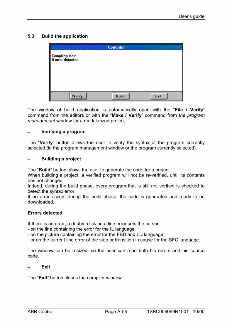
User's guide
ABB Control Page A-55 1SBC006099R1001 10/00
5.3 Build the application
The window of build application is automatically open with the “File / Verify”command from the editors or with the “Make / Verify” command from the programmanagement window for a modularized project.
Verifying a program
The “Verify” button allows the user to verify the syntax of the program currentlyselected (in the program management window or the program currently selected).
Building a project
The “Build” button allows the user to generate the code for a project.When building a project, a verified program will not be re-verified, until its contentshas not changed.Indeed, during the build phase, every program that is still not verified is checked todetect the syntax error.If no error occurs during the build phase, the code is generated and ready to bedownloaded.
Errors detected
If there is an error, a double-click on a line error sets the cursor- on the line containing the error for the IL language- on the picture containing the error for the FBD and LD language- or on the current line error of the step or transition in cause for the SFC language.
The window can be resized, so the user can read both his errors and his sourcecode.
Exit
The “Exit” button closes the compiler window.
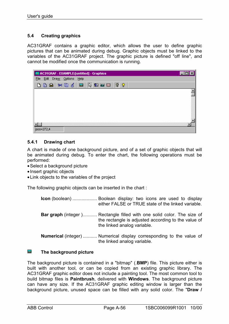
User's guide
ABB Control Page A-56 1SBC006099R1001 10/00
5.4 Creating graphics
AC31GRAF contains a graphic editor, which allows the user to define graphicpictures that can be animated during debug. Graphic objects must be linked to thevariables of the AC31GRAF project. The graphic picture is defined "off line", andcannot be modified once the communication is running.
5.4.1 Drawing chartA chart is made of one background picture, and of a set of graphic objects that willbe animated during debug. To enter the chart, the following operations must beperformed:• Select a background picture• Insert graphic objects• Link objects to the variables of the project
The following graphic objects can be inserted in the chart :
Icon (boolean) ................... Boolean display: two icons are used to displayeither FALSE or TRUE state of the linked variable.
Bar graph (integer )........... Rectangle filled with one solid color. The size ofthe rectangle is adjusted according to the value ofthe linked analog variable.
Numerical (integer) ........... Numerical display corresponding to the value ofthe linked analog variable.
The background picture
The background picture is contained in a "bitmap" (.BMP) file. This picture either isbuilt with another tool, or can be copied from an existing graphic library. TheAC31GRAF graphic editor does not include a painting tool. The most common tool tobuild bitmap files is Paintbrush, delivered with Windows. The background picturecan have any size. If the AC31GRAF graphic editing window is larger than thebackground picture, unused space can be filled with any solid color. The "Draw /
User's guide
ABB Control Page A-57 1SBC006099R1001 10/00
Background picture" command is used to select the bitmap file and also to select asolid color for empty space. The bitmap file must exist before it is inserted in thechart. Press the "Browse" button of the dialog box to select an existing pathname onthe disk. A background color can be selected to fill unused space, if the selectedbitmap is smaller than the editing window.
Note: Bitmaps consume a large amount of memory. It is highly recommended tocorrectly size the picture, and limit the unused space inside the bitmap rectangle.
Icons
Icons used to display boolean objects are stored in standard icon files (.ICO). Theseare 32x32 pixel/16 color pictures, which can use the "transparent" color. Any iconeditor can be used to create .ICO files.
Bar graph and numerical displays
"Bar graph" and "numerical" objects can be linked to analog (or integer) variables.The sizing direction of "bar graph" objects can be to the left, to the right, to the top orto the bottom. Any variable of the AC31GRAF project (global or local to oneprogram) can be linked to a graphic object.
Inserting objects
To insert a graphic object in the chart, the following operations have to be performed:• Select the type of object in the editor toolbar or in the "Draw" menu• Click at the insert position in the graphic area• Enter the definition of the objectAnalog "bar graph" and "numerical" objects have a variable size. To insert such anobject, the user has to define the boundary of the rectangle, by dragging the mousein the drawing area. The following buttons of the editor toolbar are used to select atype of graphic object:
........................................ Selection mode (no object can be inserted)
........................................ Insert boolean icon
........................................ Insert analog bar graph
........................................ Insert analog numerical field
Selecting objects
Selecting graphic objects is needed for most of the editing commands. TheAC31GRAF graphic editor enables the selection of one or more existing objects inthe chart area. To select objects, the "select" (button with an arrow) choice must bechecked in the editor toolbar. You can run the "Draw / Select" command or hit theESCAPE key to set the selection mode. To select one object, the user simply has toclick on its symbol. To select a list of objects, drag the mouse in the drawing area toselect a rectangle area. All the graphic objects that intersect the selection rectangleare marked as "selected". A selected object is drawn with little black squares aroundits graphic symbol.
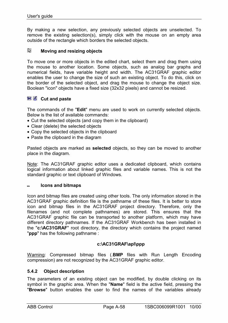
User's guide
ABB Control Page A-58 1SBC006099R1001 10/00
By making a new selection, any previously selected objects are unselected. Toremove the existing selection(s), simply click with the mouse on an empty areaoutside of the rectangle which borders the selected objects.
Moving and resizing objects
To move one or more objects in the edited chart, select them and drag them usingthe mouse to another location. Some objects, such as analog bar graphs andnumerical fields, have variable height and width. The AC31GRAF graphic editorenables the user to change the size of such an existing object. To do this, click onthe border of the selected object, and drag the mouse to change the object size.Boolean "icon" objects have a fixed size (32x32 pixels) and cannot be resized.
Cut and paste
The commands of the "Edit" menu are used to work on currently selected objects.Below is the list of available commands:• Cut the selected objects (and copy them in the clipboard)• Clear (delete) the selected objects• Copy the selected objects in the clipboard• Paste the clipboard in the diagram
Pasted objects are marked as selected objects, so they can be moved to anotherplace in the diagram.
Note: The AC31GRAF graphic editor uses a dedicated clipboard, which containslogical information about linked graphic files and variable names. This is not thestandard graphic or text clipboard of Windows.
Icons and bitmaps
Icon and bitmap files are created using other tools. The only information stored in theAC31GRAF graphic definition file is the pathname of these files. It is better to storeicon and bitmap files in the AC31GRAF project directory. Therefore, only thefilenames (and not complete pathnames) are stored. This ensures that theAC31GRAF graphic file can be transported to another platform, which may havedifferent directory pathnames. If the AC31GRAF Workbench has been installed inthe "c:\AC31GRAF" root directory, the directory which contains the project named"ppp" has the following pathname :
c:\AC31GRAF\apl\ppp
Warning: Compressed bitmap files (.BMP files with Run Length Encodingcompression) are not recognized by the AC31GRAF graphic editor.
5.4.2 Object descriptionThe parameters of an existing object can be modified, by double clicking on itssymbol in the graphic area. When the "Name" field is the active field, pressing the"Browse" button enables the user to find the names of the variables already
User's guide
ABB Control Page A-59 1SBC006099R1001 10/00
declared in the list of variables. When an "Icon file" field is the active field (for aboolean icon), pressing the "Browse" button enables the user to find the pathnameof any of the existing icon files.
Below is the list of fields that must be entered when defining a boolean "icon"object:
Name ................................. Name of the AC31GRAF boolean variable linkedto the graphic object.
"False" icon file ................ Pathname of the icon (.ICO) file used to displaythe False" state of the linked boolean variable.
"True" icon file ................. Pathname of the icon (.ICO) file used to displaythe "True" state of the linked boolean variable.
Default value..................... Value used to display the object before it is firstrefreshed by the debugger.
Command variable ........... If this option is checked, the user can modify thevalue of the linked variable during debug bydouble clicking on the corresponding graphicsymbol.
Below is the list of fields that must be entered when defining an analog "bargraph" object:
Name ................................. Name of the AC31GRAF analog variable linked tothe graphic object.
Range – minimum ............ Indicates the minimum value that can bedisplayed. If the value is less than this limit, thebar graph is not displayed.
Range – maximum ........... Indicates the maximum value that can bedisplayed. If the value is greater or equal to thislimit, the bar graph rectangle is completely filled.
Default value..................... Value used to display the object before it is firstrefreshed by the debugger.
Direction ........................... Indicates the growing direction of the filled part ofthe bounded rectangle. When the variable valueincreases, the filled rectangle must grow to theleft, to the right, to the top or to the bottom.
Color.................................. Color used to draw the filled part of the movingbar.
Command variable ........... If this option is checked, the user can modify thevalue of the linked variable during debug bydouble clicking on the corresponding graphicsymbol.
Below is the list of fields that must be entered when defining an analog"numerical" object:
Name ................................. Name of the ABB AC31GRAF analog variablelinked to the graphic object.

User's guide
ABB Control Page A-60 1SBC006099R1001 10/00
Format............................... Indicates whether the value is displayed as aninteger or real value. The decimal part of adisplayed real value is truncated if the "integer"format is selected.
Justification...................... Indicates how the text (numerical value) must bejustified (left, right or center) in the boundedrectangle.
Default value..................... Value used to display the object before it isrefreshed by the debugger.
Command variable ........... If this option is checked, the user can modify thevalue of the linked variable during debug bydouble clicking on the corresponding graphicsymbol.
5.4.3 Commands of the "File" menuThe "File" menu contains the commands which allow the user to manage thecomplete chart as a file.
The "File / New" command starts the editing of a new graphic chart. Thenumber of charts defined for a project is not limited by AC31GRAF. Before editingthe new chart, the previously opened chart is closed. The AC31GRAF graphic editingwindow cannot be used to edit several charts at once. However, multiple AC31GRAFgraphic editing windows can be opened simultaneously with each used to edit adifferent chart.
The "File / Open" command allows the user to close the currently edited chartand to start editing another chart of the current project. The new selected chartreplaces the current one in the editing window. When selecting the new chart, the"Delete" button can be used to delete an existing chart, in order to clean up theproject directory. Icon and bitmap files referenced in a chart are not erased when thechart is deleted.
The "File / Save" command stores the currently edited chart on the disk. If thechart is a new untitled document, the user must give it a name before saving it.Naming a chart must conform to the following rules:• The length of the name cannot exceed 8 characters• The first character must be a letter• The following ones must be letters, digits or underscore characters• Naming is case insensitiveThe "File / Save as" command allows the user to store the currently edited chartunder another name.
5.4.4 OptionsThe "Options" menu contains the graphic editing options for displaying the toolbar,cursor coordinates, or selecting the state of displayed boolean objects.
The "Options / View false state" and "Options / View true state" commandsare used to select the state (false or true) of the displayed boolean "icon" objects. Byselecting one of these options, the user can simulate the state of the inserted

User's guide
ABB Control Page A-61 1SBC006099R1001 10/00
boolean objects, in order to display either "false" state or "true" state icons. Thesecommands apply to all inserted objects. Object states cannot be changedindividually.
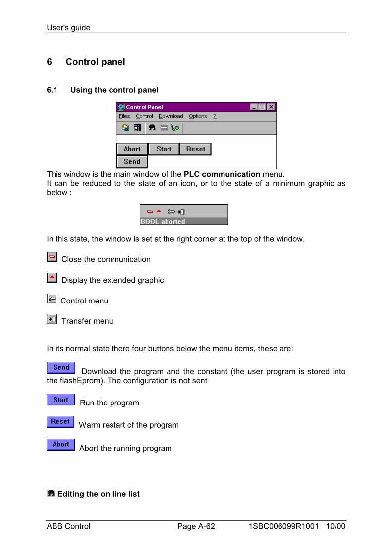
User's guide
ABB Control Page A-62 1SBC006099R1001 10/00
6 Control panel
6.1 Using the control panel
This window is the main window of the PLC communication menu.It can be reduced to the state of an icon, or to the state of a minimum graphic asbelow :
In this state, the window is set at the right corner at the top of the window.
Close the communication
Display the extended graphic
Control menu
Transfer menu
In its normal state there four buttons below the menu items, these are:
Download the program and the constant (the user program is stored intothe flashEprom). The configuration is not sent
Run the program
Warm restart of the program
Abort the running program
Editing the on line list
User's guide
ABB Control Page A-63 1SBC006099R1001 10/00
The “File / On line List” edits the on-line list window. For further information see the“On line list” chapter.
Making time diagrams
The “File / Time diagrams” command runs the time diagram tool. This tool allowsthe user to watch time diagrams corresponding to the changes in the lists ofvariables.
Making a graphic
The "File / Graphics" command runs the graphic editor. This tool allows the user todefine graphic images that will be refreshed during debug, based on the state of theapplication variables. The images are built with standard windows bitmap (.BMP) andicon (.ICO) files. This requires additional graphic editing tools, such as PaintBrush,to create bitmaps and icon files.
Displaying the central unit status
The “File / Status” command edits the status window. This windows display someinformation about the central unit. For further information see the “Status / diagnosis”chapter.
Configuration
The “File / Configuration” command edits the configuration window. This windowallows the user to accede to central unit parameters. For further information see the“Configuration” chapter.
Aborting a PLC program
The command “Control / Abort PLC program” aborts the program in the centralunit. It is no longer running, when launching this command.
Starting a PLC program
The command “Control / Start PLC program” runs the program in central unit.
Restarting a PLC program
The command “Control / Reset (Warm) of central unit program” restarts theprogram in its current state in the central unit.
Cold-restarting a PLC program
The command “Control / Cold restart of central unit program” restarts theprogram in its initial state (memory and configuration are initialized) in the centralunit.
Delete PROM
User's guide
ABB Control Page A-64 1SBC006099R1001 10/00
The command “Control / Delete PROM” deletes the program on the FlashEPROM.
Save PROM contents
The command “Control / Save PROM contents” cancels the flashEPROM of thecentral unit.
Reactivating a former program
The command “Control / Reactivate program” reactivates the former program.
Erasing PROM contents
The command “Control / Erase PROM contents” fills the central unit programmemory with NOP instructions.
Optimizing a PLC program
The command “Control / Optimize program on PLC” suppresses the NOPinstructions.
Sending a program
The command “Control / Send program” downloads the program (prog.ABB) intothe central unit.
Sending constants
The command “Control / Send constants” sends the constants of theapplication.(not the system constants) into the central unit.
Sending all
The command “Control / Send all” downloads the program (prog.ABB) and theconstants of the application, except the system constants into the central unit.
Download / Send system constants
The command “Control / Send system constants” sends the system constants (It isalso be done from the configurator editor) into the central unit.
Minimizing the window
The option “Options / Minimize window” takes the shape as described on the top.
Window always visible
If the option “Options / Always on top” is selected, the window is always above allother windows.On the next selection of this menu item, the window no longer on this state.

User's guide
ABB Control Page A-65 1SBC006099R1001 10/00
Editing the historic of the errors
The command option “Options / Error list” edits the historic of the errors occurredwith the date and the time.
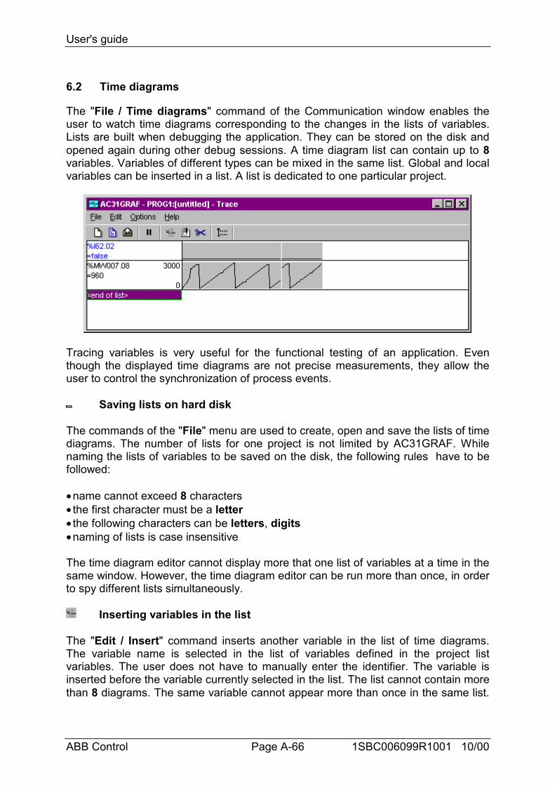
User's guide
ABB Control Page A-66 1SBC006099R1001 10/00
6.2 Time diagrams
The "File / Time diagrams" command of the Communication window enables theuser to watch time diagrams corresponding to the changes in the lists of variables.Lists are built when debugging the application. They can be stored on the disk andopened again during other debug sessions. A time diagram list can contain up to 8variables. Variables of different types can be mixed in the same list. Global and localvariables can be inserted in a list. A list is dedicated to one particular project.
Tracing variables is very useful for the functional testing of an application. Eventhough the displayed time diagrams are not precise measurements, they allow theuser to control the synchronization of process events.
Saving lists on hard disk
The commands of the "File" menu are used to create, open and save the lists of timediagrams. The number of lists for one project is not limited by AC31GRAF. Whilenaming the lists of variables to be saved on the disk, the following rules have to befollowed:
• name cannot exceed 8 characters• the first character must be a letter• the following characters can be letters, digits• naming of lists is case insensitive
The time diagram editor cannot display more that one list of variables at a time in thesame window. However, the time diagram editor can be run more than once, in orderto spy different lists simultaneously.
Inserting variables in the list
The "Edit / Insert" command inserts another variable in the list of time diagrams.The variable name is selected in the list of variables defined in the project listvariables. The user does not have to manually enter the identifier. The variable isinserted before the variable currently selected in the list. The list cannot contain morethan 8 diagrams. The same variable cannot appear more than once in the same list.
User's guide
ABB Control Page A-67 1SBC006099R1001 10/00
If the project is modular, the user can choose the program for the local variables hewants to see.
Changing the selected variable
The "Edit / Modify" command replaces the selected variable by another variable.You can also use the "Cut" command to remove the selected variable from the list.
Diagram scaling
The "Edit / Set scale" command sets up the minimum and maximum values for thetiming diagram of the selected variable. This command has no effect if the selecteddiagram shows a boolean variable.
Setting refresh duration
The "Options / Cyclic refresh duration" command enables the user to change thetime scale of the timing diagrams. The time scale is defined by entering the cyclicrefresh duration, which is the time elapsed between two consecutive points of atiming diagram.
Pause and resume
Another possibility is to pause the cyclic diagram refresh. The ESCAPE key can alsobe used to pause or restart refreshing diagrams.
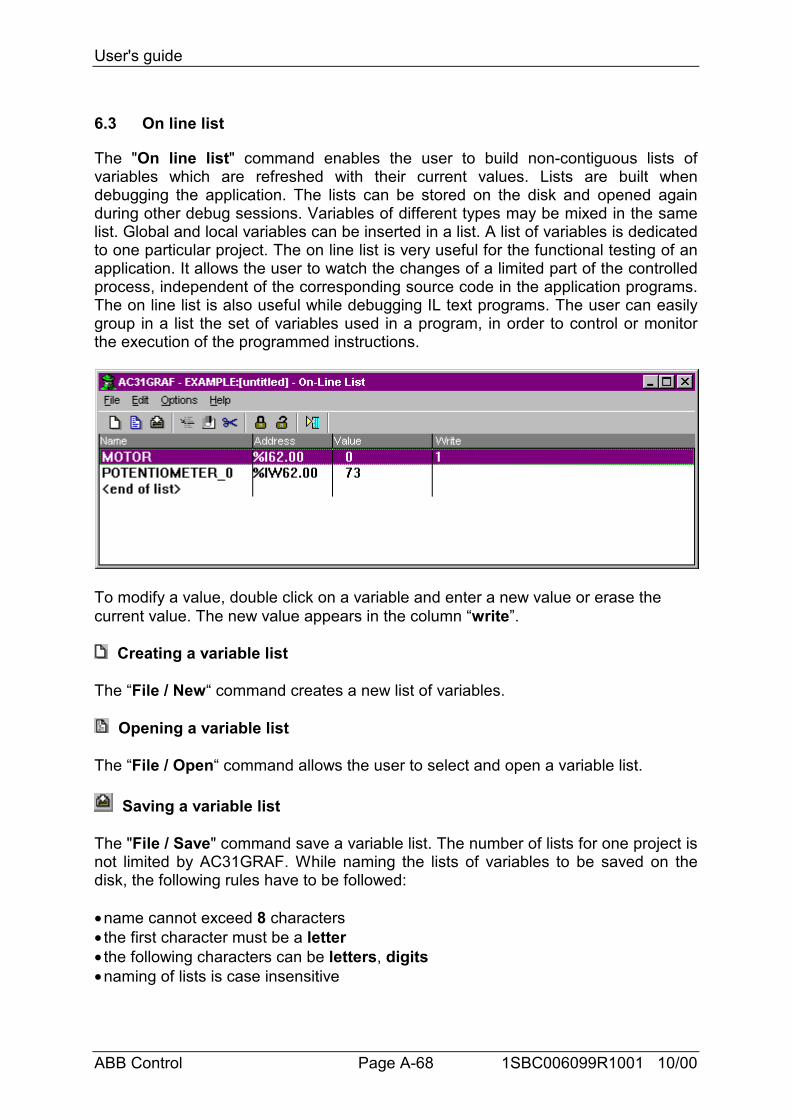
User's guide
ABB Control Page A-68 1SBC006099R1001 10/00
6.3 On line list
The "On line list" command enables the user to build non-contiguous lists ofvariables which are refreshed with their current values. Lists are built whendebugging the application. The lists can be stored on the disk and opened againduring other debug sessions. Variables of different types may be mixed in the samelist. Global and local variables can be inserted in a list. A list of variables is dedicatedto one particular project. The on line list is very useful for the functional testing of anapplication. It allows the user to watch the changes of a limited part of the controlledprocess, independent of the corresponding source code in the application programs.The on line list is also useful while debugging IL text programs. The user can easilygroup in a list the set of variables used in a program, in order to control or monitorthe execution of the programmed instructions.
To modify a value, double click on a variable and enter a new value or erase thecurrent value. The new value appears in the column “write”.
Creating a variable list
The “File / New“ command creates a new list of variables.
Opening a variable list
The “File / Open“ command allows the user to select and open a variable list.
Saving a variable list
The "File / Save" command save a variable list. The number of lists for one project isnot limited by AC31GRAF. While naming the lists of variables to be saved on thedisk, the following rules have to be followed:
• name cannot exceed 8 characters• the first character must be a letter• the following characters can be letters, digits• naming of lists is case insensitive
User's guide
ABB Control Page A-69 1SBC006099R1001 10/00
The list editor cannot display more that one list of variables at a time in the samewindow. However, the list editor can be run more than once, in order to spy differentlists simultaneously.
Inserting a variable
The “Edit / Insert” command inserts another variable in the list. The variable name isselected in the list of the global variables and local variables of the selected program.This way the user does not have to manually enter the identifier. The variable isinserted before the variable currently selected in the list. The same variable cannotappear more than once in the same list.If the variable has no symbol, the address appears in the column name and columnaddress, on the other hand if the variable is defined with a symbol, this latter isadded in the column name.
Modifying a variable
The “Edit / Modify” command replaces the selected variable by another variable.You can also use the " Edit / Cut" command to remove the selected variable fromthe list.
Cut a variable
The “Edit / Modify” command deletes the current selected line.
Sending new values
The “Edit / Send new values” command allows to download to the central unit thenew value entered in the column “write” to the selected variable.
Resetting new values
The “Edit / Reset new values” command erases the column “write”.
Locking a selected variable
The “Edit / Lock selected variable” command is similar to the send command, butthe variable is locked.Only for the input/output variables.
Unlocking selected variable
After having selected the “Edit / Unlock selected variable” command, the selectedvariable stops to be locked.Only for the input/output variables.
Adding list of locked variables

User's guide
ABB Control Page A-70 1SBC006099R1001 10/00
The “Edit / Get list of locked variables” adds the list of locked variables to thecurrent list in the central unit.
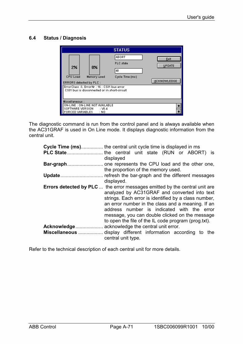
User's guide
ABB Control Page A-71 1SBC006099R1001 10/00
6.4 Status / Diagnosis
The diagnostic command is run from the control panel and is always available whenthe AC31GRAF is used in On Line mode. It displays diagnostic information from thecentral unit.
Cycle Time (ms)................ the central unit cycle time is displayed in msPLC State .......................... the central unit state (RUN or ABORT) is
displayedBar-graph.......................... one represents the CPU load and the other one,
the proportion of the memory used.Update............................... refresh the bar-graph and the different messages
displayed.Errors detected by PLC ... the error messages emitted by the central unit are
analyzed by AC31GRAF and converted into textstrings. Each error is identified by a class number,an error number in the class and a meaning. If anaddress number is indicated with the errormessage, you can double clicked on the messageto open the file of the IL code program (prog.txt).
Acknowledge .................... acknowledge the central unit error.Miscellaneous .................. display different information according to the
central unit type.
Refer to the technical description of each central unit for more details.
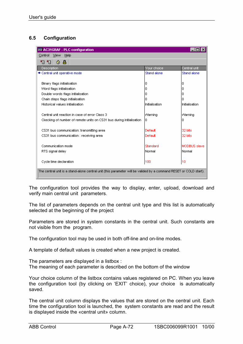
User's guide
ABB Control Page A-72 1SBC006099R1001 10/00
6.5 Configuration
The configuration tool provides the way to display, enter, upload, download andverify main central unit parameters.
The list of parameters depends on the central unit type and this list is automaticallyselected at the beginning of the project
Parameters are stored in system constants in the central unit. Such constants arenot visible from the program.
The configuration tool may be used in both off-line and on-line modes.
A template of default values is created when a new project is created.
The parameters are displayed in a listbox :The meaning of each parameter is described on the bottom of the window
Your choice column of the listbox contains values registered on PC. When you leavethe configuration tool (by clicking on ‘EXIT’ choice), your choice is automaticallysaved.
The central unit column displays the values that are stored on the central unit. Eachtime the configuration tool is launched, the system constants are read and the resultis displayed inside the «central unit» column.
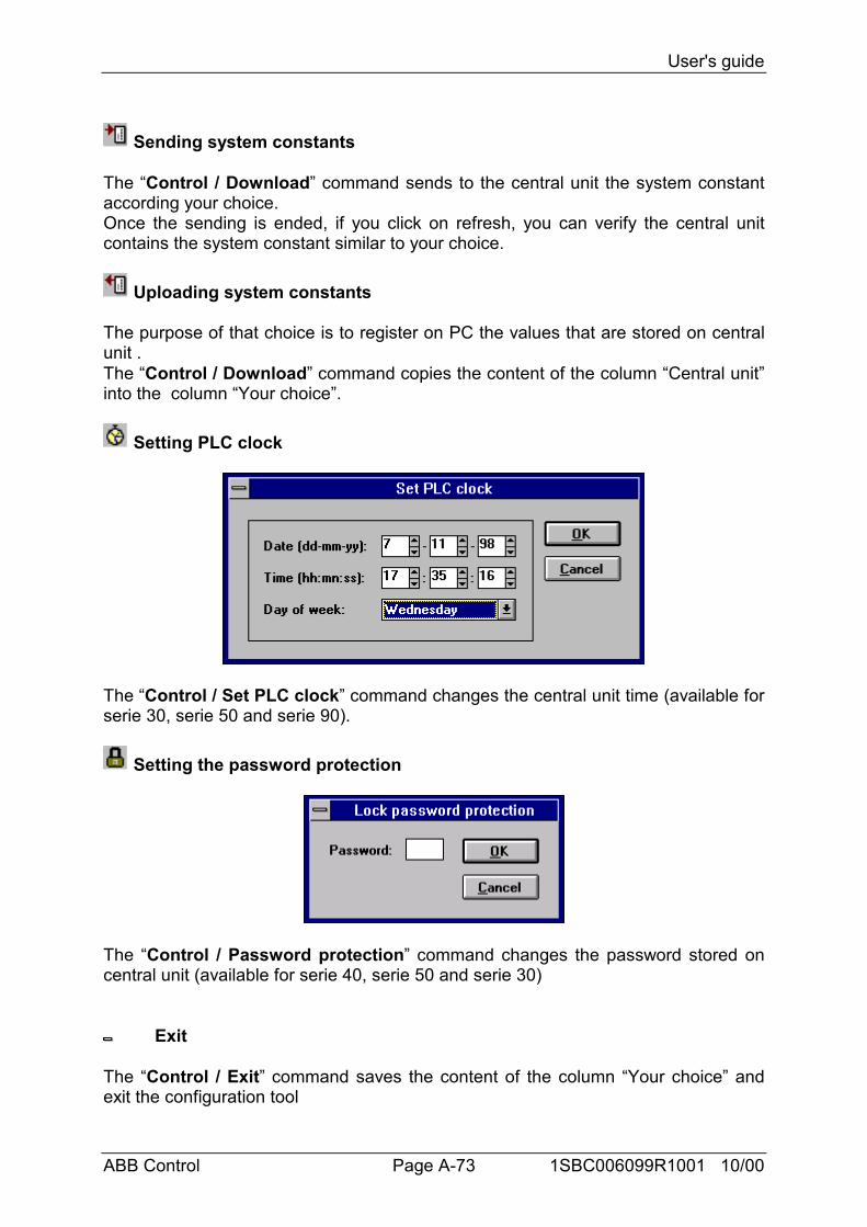
User's guide
ABB Control Page A-73 1SBC006099R1001 10/00
Sending system constants
The “Control / Download” command sends to the central unit the system constantaccording your choice.Once the sending is ended, if you click on refresh, you can verify the central unitcontains the system constant similar to your choice.
Uploading system constants
The purpose of that choice is to register on PC the values that are stored on centralunit .The “Control / Download” command copies the content of the column “Central unit”into the column “Your choice”.
Setting PLC clock
The “Control / Set PLC clock” command changes the central unit time (available forserie 30, serie 50 and serie 90).
Setting the password protection
The “Control / Password protection” command changes the password stored oncentral unit (available for serie 40, serie 50 and serie 30)
Exit
The “Control / Exit” command saves the content of the column “Your choice” andexit the configuration tool
User's guide
ABB Control Page A-74 1SBC006099R1001 10/00
Showing ToolBar
The “View / Show ToolBar” command displays or removes the toolbar inside theconfiguration tool.
Showing title bar
The “View / Show title bar” command displays or removes the listbox title bar
Showing status bar
The “View / Show status bar” command displays or removes the status bar, at thebottom of the window.
Refreshing the constants
The “View / Reads” command reads again the system constants on the central unit,and display the result by refreshing the column “Central unit”.
Refer to the technical description of each central unit for more details.
Automatic launche of editors in debug mode
The following commands have to be set for a direct use of the debug mode
- To start one project in debug modeC:\AC31GRAF\EXE\CORIDA7.EXE -D=PROJECT_NAME
-To start one project in debug mode with GRAF1 graphicC:\AC31GRAF\EXE\CORIDA7.EXE -D=PROJECT_NAME -G=GRAF1-To start one project in debug mode with GRAF1, GRAF2 graphicsC:\AC31GRAF\EXE\CORIDA7.EXE -D=PROJECT_NAME -G=GRAF1
-G=GRAF2-To start one project in debug mode with LIST1 list of variables
C:\AC31GRAF\EXE\CORIDA7.EXE -D=PROJECT_NAME -L=LIST1-To start one project in debug mode with GRAF1, GRAF2 graphics, and LIST1
list of variablesC:\AC31GRAF\EXE\CORIDA7.EXE -D=PROJECT_NAME -G=GRAF1
-G=GRAF2 -L=LIST1-To start one project in debug mode with TIME1 chronogram
C:\AC31GRAF\EXE\CORIDA7.EXE -D=PROJECT_NAME -T=TIME1
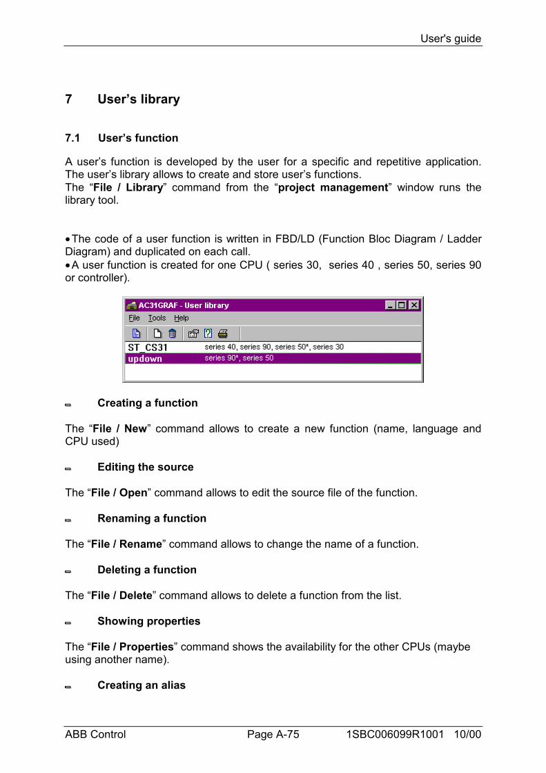
User's guide
ABB Control Page A-75 1SBC006099R1001 10/00
7 User’s library
7.1 User’s function
A user’s function is developed by the user for a specific and repetitive application.The user’s library allows to create and store user’s functions.The “File / Library” command from the “project management” window runs thelibrary tool.
• The code of a user function is written in FBD/LD (Function Bloc Diagram / LadderDiagram) and duplicated on each call.• A user function is created for one CPU ( series 30, series 40 , series 50, series 90or controller).
Creating a function
The “File / New” command allows to create a new function (name, language andCPU used)
Editing the source
The “File / Open” command allows to edit the source file of the function.
Renaming a function
The “File / Rename” command allows to change the name of a function.
Deleting a function
The “File / Delete” command allows to delete a function from the list.
Showing properties
The “File / Properties” command shows the availability for the other CPUs (maybeusing another name).
Creating an alias
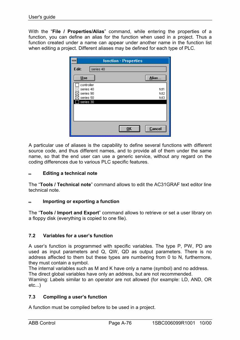
User's guide
ABB Control Page A-76 1SBC006099R1001 10/00
With the “File / Properties/Alias” command, while entering the properties of afunction, you can define an alias for the function when used in a project. Thus afunction created under a name can appear under another name in the function listwhen editing a project. Different aliases may be defined for each type of PLC.
A particular use of aliases is the capability to define several functions with differentsource code, and thus different names, and to provide all of them under the samename, so that the end user can use a generic service, without any regard on thecoding differences due to various PLC specific features.
Editing a technical note
The “Tools / Technical note” command allows to edit the AC31GRAF text editor linetechnical note.
Importing or exporting a function
The “Tools / Import and Export” command allows to retrieve or set a user library ona floppy disk (everything is copied to one file).
7.2 Variables for a user’s function
A user’s function is programmed with specific variables. The type P, PW, PD areused as input parameters and Q, QW, QD as output parameters. There is noaddress affected to them but these types are numbering from 0 to N, furthermore,they must contain a symbol.The internal variables such as M and K have only a name (symbol) and no address.The direct global variables have only an address, but are not recommended.Warning: Labels similar to an operator are not allowed (for example: LD, AND, ORetc...)
7.3 Compiling a user’s function
A function must be compiled before to be used in a project.
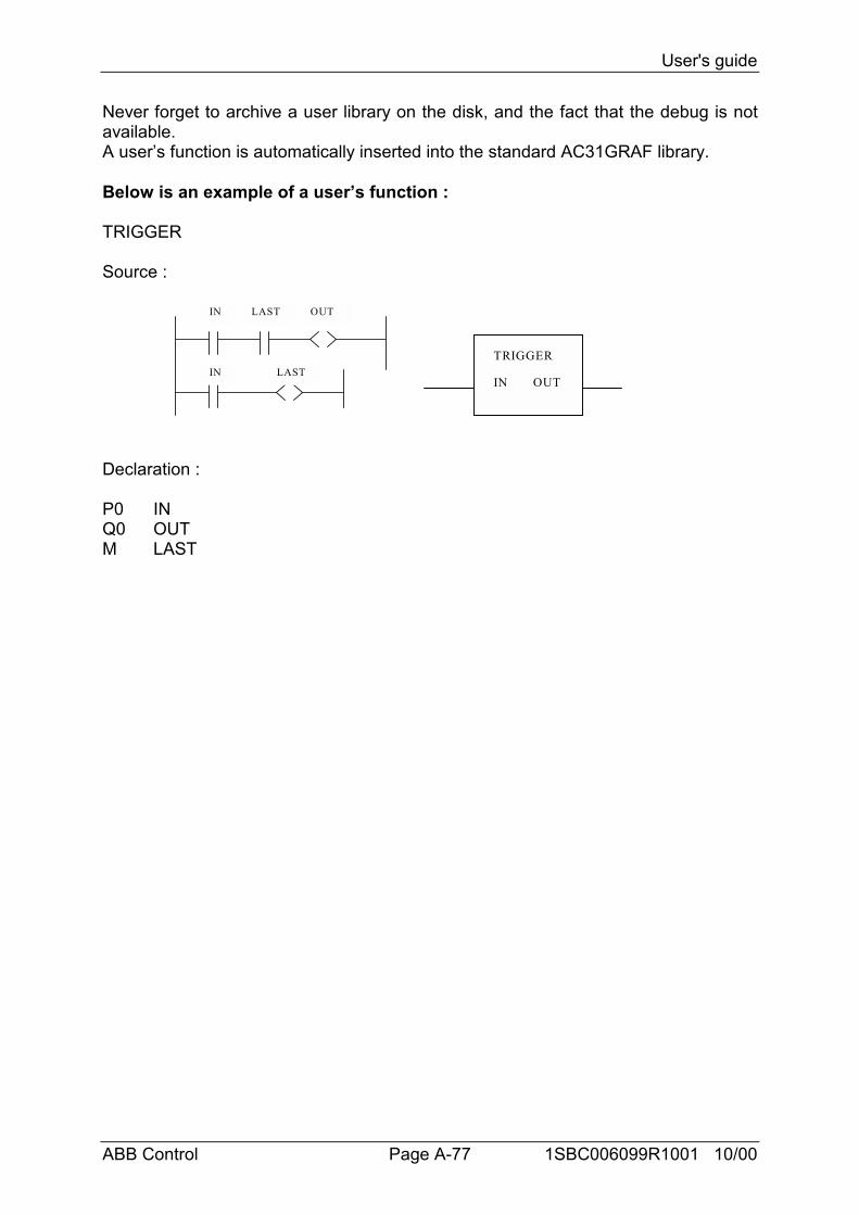
User's guide
ABB Control Page A-77 1SBC006099R1001 10/00
Never forget to archive a user library on the disk, and the fact that the debug is notavailable.A user’s function is automatically inserted into the standard AC31GRAF library.
Below is an example of a user’s function :
TRIGGER
Source :
IN LAST OUT
IN LASTTRIGGER
IN OUT
Declaration :
P0 INQ0 OUTM LAST
Language reference
ABB Control 1SBC006099R1001 10/00
B Language reference

Language reference
ABB Control 1SBC006099R1001 10/00

Language reference
ABB Control Page B-1 1SBC006099R1001 10/00
B LANGUAGE REFERENCE
1 Project architecture................................................................................................... B-31.1 Programs................................................................................................................ B-31.2 Modular architecture.............................................................................................. B-31.3 No-modular architecture........................................................................................ B-5
2 Variables .................................................................................................................... B-62.1 Variables are sorted according to their type. ......................................................... B-62.2 Variables are sorted according to their range ........................................................ B-6
3 FBD language............................................................................................................. B-73.1 FBD diagram main format..................................................................................... B-73.2 Jumps and labels.................................................................................................... B-83.3 Boolean negation ................................................................................................... B-93.4 Calling function or function blocks from the FBD................................................ B-9
4 LD and Quick LD languages.................................................................................. B-104.1 Power rails and connection lines ......................................................................... B-104.2 Multiple connection............................................................................................. B-114.3 Basic LD contacts and coils................................................................................. B-12
4.3.1 Direct contact ................................................................................................ B-124.3.2 Inverted contact............................................................................................. B-134.3.3 Contact with rising edge detection................................................................ B-134.3.4 Contact with falling edge detection .............................................................. B-134.3.5 Direct coil...................................................................................................... B-144.3.6 Inverted coil .................................................................................................. B-154.3.7 SET coil ........................................................................................................ B-154.3.8 RESET coil ................................................................................................... B-164.3.9 Coil with rising edge detection ..................................................................... B-16
4.4 Jumps and labels.................................................................................................. B-174.5 Blocks in LD........................................................................................................ B-18
4.5.1 The "EN" input.............................................................................................. B-184.5.2 The "ENO" output......................................................................................... B-194.5.3 Using both "EN" and "ENO" ........................................................................ B-19
5 SFC language ........................................................................................................... B-205.1 SFC chart main format ........................................................................................ B-205.2 SFC basic components......................................................................................... B-20
5.2.1 Steps and initial steps.................................................................................... B-205.2.2 Transitions..................................................................................................... B-215.2.3 Oriented links................................................................................................ B-215.2.4 Jump to a step................................................................................................ B-22
5.3 Divergences and convergences............................................................................ B-225.3.1 Single divergences ........................................................................................ B-225.3.2 Double divergences....................................................................................... B-23
5.4 Macro steps.......................................................................................................... B-245.5 Actions within the steps....................................................................................... B-25
5.5.1 Boolean actions ............................................................................................. B-265.5.2 Pulse actions.................................................................................................. B-265.5.3 Non-stored actions ........................................................................................ B-275.5.4 Calling function and function blocks from an action.................................... B-27
Language reference
ABB Control Page B-2 1SBC006099R1001 10/00
5.5.5 IL convention ................................................................................................ B-285.5.6 Activation duration of a step......................................................................... B-28
5.6 Conditions attached to transitions........................................................................ B-295.6.1 LD convention............................................................................................... B-295.6.2 IL convention ................................................................................................ B-29
5.7 SFC dynamic rules............................................................................................... B-306 IL language .............................................................................................................. B-31
6.1 IL main syntax ..................................................................................................... B-316.1.1 Labels ............................................................................................................ B-316.1.2 Operator modifiers ........................................................................................ B-31
6.2 IL operators.......................................................................................................... B-326.2.1 LD operator ................................................................................................... B-336.2.2 ST operator.................................................................................................... B-336.2.3 S operator ...................................................................................................... B-336.2.4 R operator...................................................................................................... B-346.2.5 JMP operator................................................................................................. B-346.2.6 Calling sub-programs and interruptions........................................................ B-356.2.7 Calling function blocks: CAL, !BA 0 operator............................................. B-35
6.3 Main differences between IEC IL and ABB IL ................................................... B-36
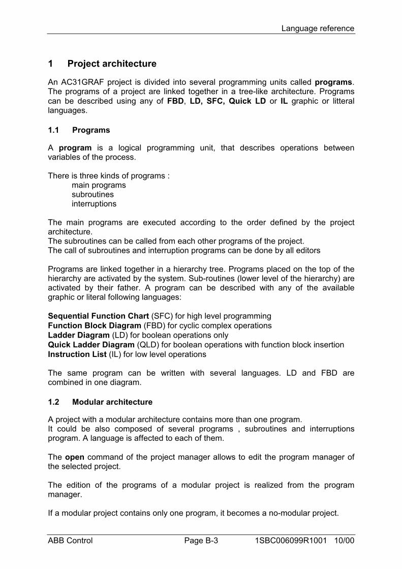
Language reference
ABB Control Page B-3 1SBC006099R1001 10/00
1 Project architecture
An AC31GRAF project is divided into several programming units called programs.The programs of a project are linked together in a tree-like architecture. Programscan be described using any of FBD, LD, SFC, Quick LD or IL graphic or litterallanguages.
1.1 Programs
A program is a logical programming unit, that describes operations betweenvariables of the process.
There is three kinds of programs :main programssubroutinesinterruptions
The main programs are executed according to the order defined by the projectarchitecture.The subroutines can be called from each other programs of the project.The call of subroutines and interruption programs can be done by all editors
Programs are linked together in a hierarchy tree. Programs placed on the top of thehierarchy are activated by the system. Sub-routines (lower level of the hierarchy) areactivated by their father. A program can be described with any of the availablegraphic or literal following languages:
Sequential Function Chart (SFC) for high level programmingFunction Block Diagram (FBD) for cyclic complex operationsLadder Diagram (LD) for boolean operations onlyQuick Ladder Diagram (QLD) for boolean operations with function block insertionInstruction List (IL) for low level operations
The same program can be written with several languages. LD and FBD arecombined in one diagram.
1.2 Modular architecture
A project with a modular architecture contains more than one program.It could be also composed of several programs , subroutines and interruptionsprogram. A language is affected to each of them.
The open command of the project manager allows to edit the program manager ofthe selected project.
The edition of the programs of a modular project is realized from the programmanager.
If a modular project contains only one program, it becomes a no-modular project.
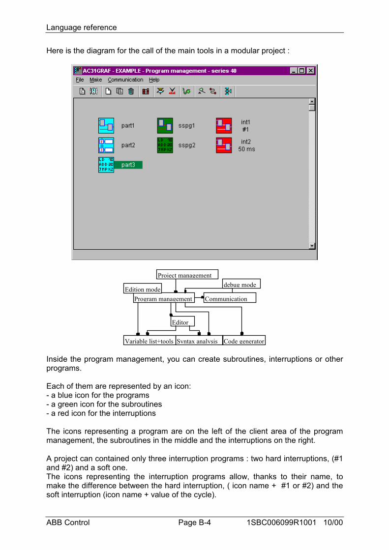
Language reference
ABB Control Page B-4 1SBC006099R1001 10/00
Here is the diagram for the call of the main tools in a modular project :
Project management
Program management
Editor
Communication
Variable list+tools Syntax analysis Code generator
debug modeEdition mode
Inside the program management, you can create subroutines, interruptions or otherprograms.
Each of them are represented by an icon:- a blue icon for the programs- a green icon for the subroutines- a red icon for the interruptions
The icons representing a program are on the left of the client area of the programmanagement, the subroutines in the middle and the interruptions on the right.
A project can contained only three interruption programs : two hard interruptions, (#1and #2) and a soft one.The icons representing the interruption programs allow, thanks to their name, tomake the difference between the hard interruption, ( icon name + #1 or #2) and thesoft interruption (icon name + value of the cycle).
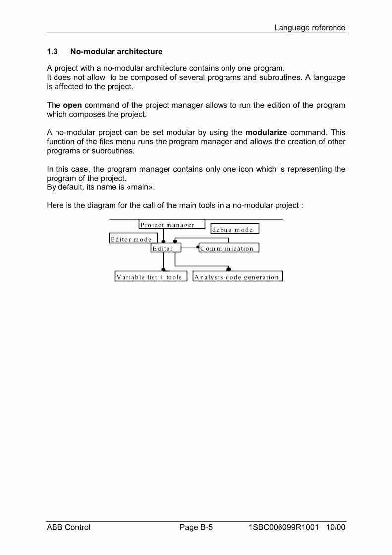
Language reference
ABB Control Page B-5 1SBC006099R1001 10/00
1.3 No-modular architecture
A project with a no-modular architecture contains only one program.It does not allow to be composed of several programs and subroutines. A languageis affected to the project.
The open command of the project manager allows to run the edition of the programwhich composes the project.
A no-modular project can be set modular by using the modularize command. Thisfunction of the files menu runs the program manager and allows the creation of otherprograms or subroutines.
In this case, the program manager contains only one icon which is representing theprogram of the project.By default, its name is «main».
Here is the diagram for the call of the main tools in a no-modular project :
d eb u g m o d eP ro jec t m an ag er
E d ito r C o m m u n ica tio n
V ariab le list + to o ls A n a ly sis-co d e g en era tio n
E d ito r m o d e
Language reference
ABB Control Page B-6 1SBC006099R1001 10/00
2 Variables
2.1 Variables are sorted according to their type.
These are basic types of variables :
BOOLEAN ......................... true/false binary valuesWORD................................ analog valuesDOUBLEWORD ................ double word valuesCONSTANT ....................... binary, analog, double word valuesTEXT.................................. string characters
Binary variable type I Binary inputO Binary outputS Binary stepK Binary constantM Binary flag
Word variable type IW Analog inputOW Analog outputKW Analog constantMW Analog flag
Double word variable type KD Double word constantMD Double word flag
Text variable TXT Input string
Direct constant # Value in decimal#H Value in hexadecimal
2.2 Variables are sorted according to their range
GLOBAL ............................ the variable can be used by all programs of aproject
LOCAL............................... the variable can be used by only one program
Two variables can have the same symbol, but they have to be local in two differentfiles.A global variable can not have the same symbol as a local variable file.A variable defined without a symbol is global.
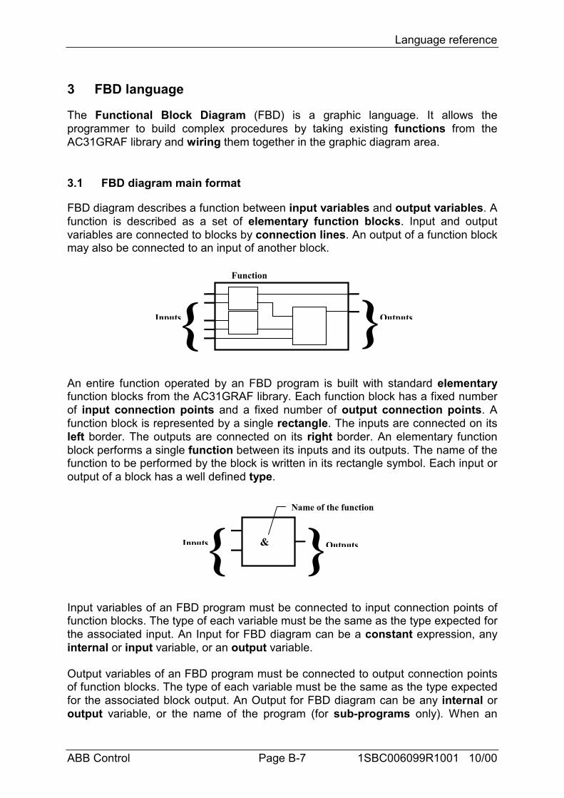
Language reference
ABB Control Page B-7 1SBC006099R1001 10/00
3 FBD language
The Functional Block Diagram (FBD) is a graphic language. It allows theprogrammer to build complex procedures by taking existing functions from theAC31GRAF library and wiring them together in the graphic diagram area.
3.1 FBD diagram main format
FBD diagram describes a function between input variables and output variables. Afunction is described as a set of elementary function blocks. Input and outputvariables are connected to blocks by connection lines. An output of a function blockmay also be connected to an input of another block.
{ }Function
Inputs Outputs
An entire function operated by an FBD program is built with standard elementaryfunction blocks from the AC31GRAF library. Each function block has a fixed numberof input connection points and a fixed number of output connection points. Afunction block is represented by a single rectangle. The inputs are connected on itsleft border. The outputs are connected on its right border. An elementary functionblock performs a single function between its inputs and its outputs. The name of thefunction to be performed by the block is written in its rectangle symbol. Each input oroutput of a block has a well defined type.
{ }Inputs Outputs&
Name of the function
Input variables of an FBD program must be connected to input connection points offunction blocks. The type of each variable must be the same as the type expected forthe associated input. An Input for FBD diagram can be a constant expression, anyinternal or input variable, or an output variable.
Output variables of an FBD program must be connected to output connection pointsof function blocks. The type of each variable must be the same as the type expectedfor the associated block output. An Output for FBD diagram can be any internal oroutput variable, or the name of the program (for sub-programs only). When an
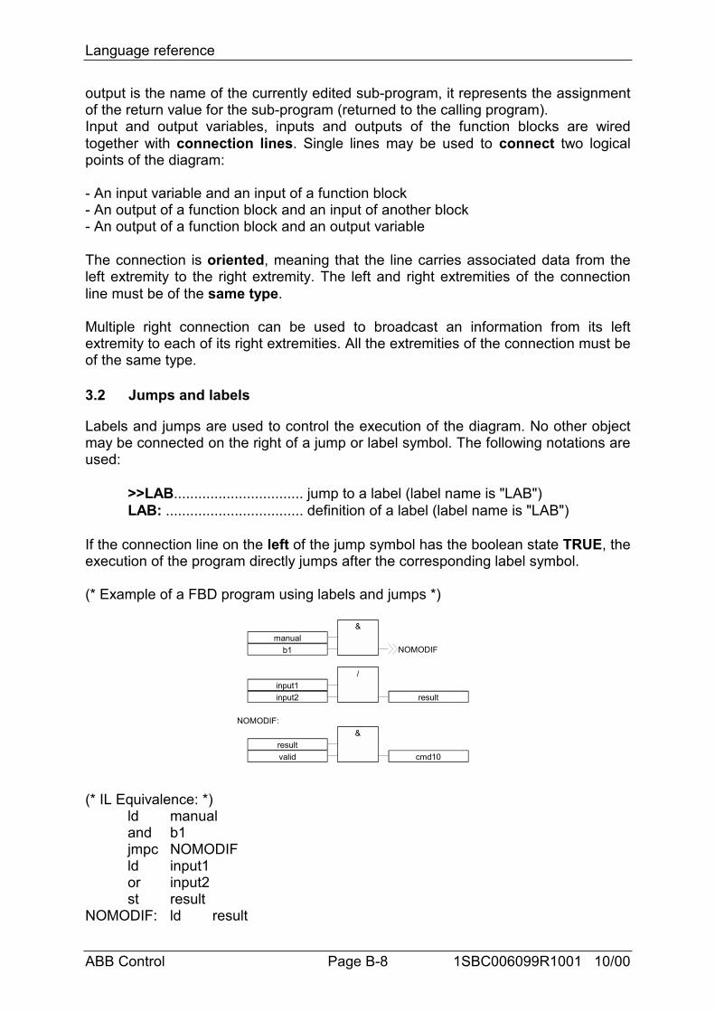
Language reference
ABB Control Page B-8 1SBC006099R1001 10/00
output is the name of the currently edited sub-program, it represents the assignmentof the return value for the sub-program (returned to the calling program).Input and output variables, inputs and outputs of the function blocks are wiredtogether with connection lines. Single lines may be used to connect two logicalpoints of the diagram:
- An input variable and an input of a function block- An output of a function block and an input of another block- An output of a function block and an output variable
The connection is oriented, meaning that the line carries associated data from theleft extremity to the right extremity. The left and right extremities of the connectionline must be of the same type.
Multiple right connection can be used to broadcast an information from its leftextremity to each of its right extremities. All the extremities of the connection must beof the same type.
3.2 Jumps and labels
Labels and jumps are used to control the execution of the diagram. No other objectmay be connected on the right of a jump or label symbol. The following notations areused:
>>LAB................................ jump to a label (label name is "LAB")LAB: .................................. definition of a label (label name is "LAB")
If the connection line on the left of the jump symbol has the boolean state TRUE, theexecution of the program directly jumps after the corresponding label symbol.
(* Example of a FBD program using labels and jumps *)
manualb1
&
NOMODIF
input1input2 result
NOMODIF:
resultvalid cmd10
/
&
(* IL Equivalence: *)ld manualand b1jmpc NOMODIFld input1or input2st result
NOMODIF: ld result
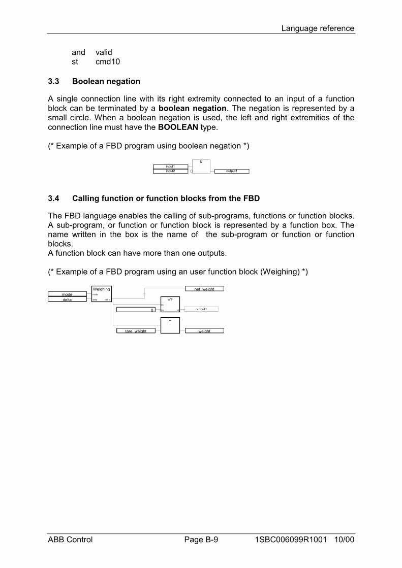
Language reference
ABB Control Page B-9 1SBC006099R1001 10/00
and validst cmd10
3.3 Boolean negation
A single connection line with its right extremity connected to an input of a functionblock can be terminated by a boolean negation. The negation is represented by asmall circle. When a boolean negation is used, the left and right extremities of theconnection line must have the BOOLEAN type.
(* Example of a FBD program using boolean negation *)
input1input2 output1
&
3.4 Calling function or function blocks from the FBD
The FBD language enables the calling of sub-programs, functions or function blocks.A sub-program, or function or function block is represented by a function box. Thename written in the box is the name of the sub-program or function or functionblocks.A function block can have more than one outputs.
(* Example of a FBD program using an user function block (Weighing) *)
Weighingmode
delta net_w
modedelta
net_weight
=?IN1
IN2 Q0
+
tare_weight weight
output1
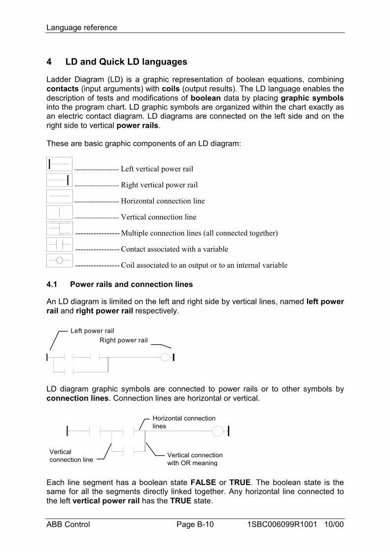
Language reference
ABB Control Page B-10 1SBC006099R1001 10/00
4 LD and Quick LD languages
Ladder Diagram (LD) is a graphic representation of boolean equations, combiningcontacts (input arguments) with coils (output results). The LD language enables thedescription of tests and modifications of boolean data by placing graphic symbolsinto the program chart. LD graphic symbols are organized within the chart exactly asan electric contact diagram. LD diagrams are connected on the left side and on theright side to vertical power rails.
These are basic graphic components of an LD diagram:
--------------------- Left vertical power rail
--------------------- Right vertical power rail
--------------------- Horizontal connection line
--------------------- Vertical connection line
----------------- Multiple connection lines (all connected together)
----------------- Contact associated with a variable
----------------- Coil associated to an output or to an internal variable
4.1 Power rails and connection lines
An LD diagram is limited on the left and right side by vertical lines, named left powerrail and right power rail respectively.
Right power railLeft power rail
LD diagram graphic symbols are connected to power rails or to other symbols byconnection lines. Connection lines are horizontal or vertical.
Horizontal connectionlines
Vertical connectionwith OR meaning
Verticalconnection line
Each line segment has a boolean state FALSE or TRUE. The boolean state is thesame for all the segments directly linked together. Any horizontal line connected tothe left vertical power rail has the TRUE state.
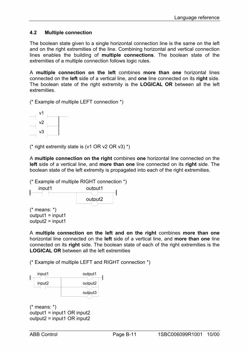
Language reference
ABB Control Page B-11 1SBC006099R1001 10/00
4.2 Multiple connection
The boolean state given to a single horizontal connection line is the same on the leftand on the right extremities of the line. Combining horizontal and vertical connectionlines enables the building of multiple connections. The boolean state of theextremities of a multiple connection follows logic rules.
A multiple connection on the left combines more than one horizontal linesconnected on the left side of a vertical line, and one line connected on its right side.The boolean state of the right extremity is the LOGICAL OR between all the leftextremities.
(* Example of multiple LEFT connection *)
v1
v2
v3
(* right extremity state is (v1 OR v2 OR v3) *)
A multiple connection on the right combines one horizontal line connected on theleft side of a vertical line, and more than one line connected on its right side. Theboolean state of the left extremity is propagated into each of the right extremities.
(* Example of multiple RIGHT connection *)input1 output1
output2
(* means: *)output1 = input1output2 = input1
A multiple connection on the left and on the right combines more than onehorizontal line connected on the left side of a vertical line, and more than one lineconnected on its right side. The boolean state of each of the right extremities is theLOGICAL OR between all the left extremities
(* Example of multiple LEFT and RIGHT connection *)
input1
input2
output1
output2
output3
(* means: *)output1 = input1 OR input2output2 = input1 OR input2
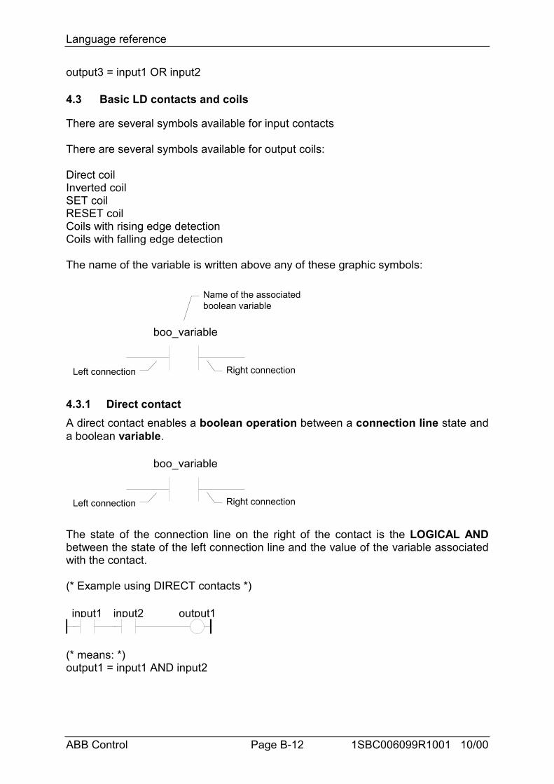
Language reference
ABB Control Page B-12 1SBC006099R1001 10/00
output3 = input1 OR input2
4.3 Basic LD contacts and coils
There are several symbols available for input contacts
There are several symbols available for output coils:
Direct coilInverted coilSET coilRESET coilCoils with rising edge detectionCoils with falling edge detection
The name of the variable is written above any of these graphic symbols:
boo_variable
Name of the associatedboolean variable
Left connection Right connection
4.3.1 Direct contactA direct contact enables a boolean operation between a connection line state anda boolean variable.
boo_variable
Left connection Right connection
The state of the connection line on the right of the contact is the LOGICAL ANDbetween the state of the left connection line and the value of the variable associatedwith the contact.
(* Example using DIRECT contacts *)
input1 input2 output1
(* means: *)output1 = input1 AND input2
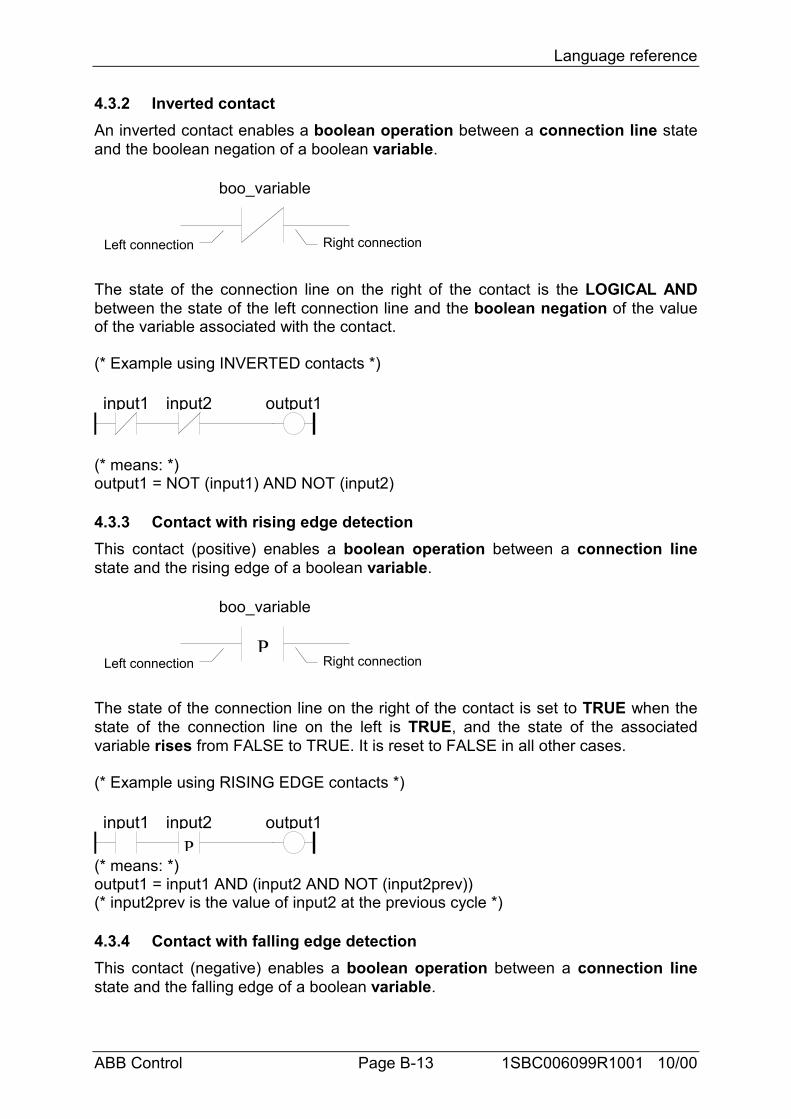
Language reference
ABB Control Page B-13 1SBC006099R1001 10/00
4.3.2 Inverted contactAn inverted contact enables a boolean operation between a connection line stateand the boolean negation of a boolean variable.
boo_variable
Left connection Right connection
The state of the connection line on the right of the contact is the LOGICAL ANDbetween the state of the left connection line and the boolean negation of the valueof the variable associated with the contact.
(* Example using INVERTED contacts *)
input1 input2 output1
(* means: *)output1 = NOT (input1) AND NOT (input2)
4.3.3 Contact with rising edge detectionThis contact (positive) enables a boolean operation between a connection linestate and the rising edge of a boolean variable.
boo_variable
Left connection Right connectionP
The state of the connection line on the right of the contact is set to TRUE when thestate of the connection line on the left is TRUE, and the state of the associatedvariable rises from FALSE to TRUE. It is reset to FALSE in all other cases.
(* Example using RISING EDGE contacts *)
input1 input2 output1P
(* means: *)output1 = input1 AND (input2 AND NOT (input2prev))(* input2prev is the value of input2 at the previous cycle *)
4.3.4 Contact with falling edge detectionThis contact (negative) enables a boolean operation between a connection linestate and the falling edge of a boolean variable.
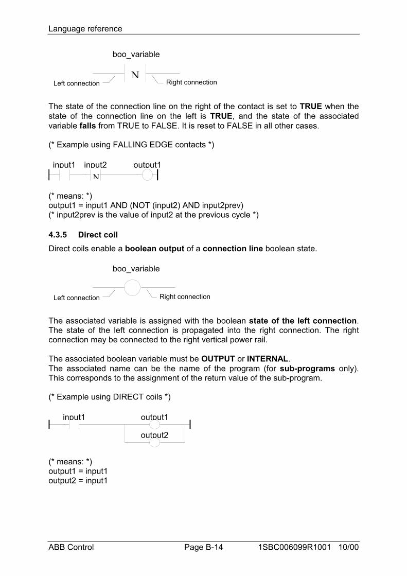
Language reference
ABB Control Page B-14 1SBC006099R1001 10/00
boo_variable
Left connection Right connectionN
The state of the connection line on the right of the contact is set to TRUE when thestate of the connection line on the left is TRUE, and the state of the associatedvariable falls from TRUE to FALSE. It is reset to FALSE in all other cases.
(* Example using FALLING EDGE contacts *)
input1 input2 output1N
(* means: *)output1 = input1 AND (NOT (input2) AND input2prev)(* input2prev is the value of input2 at the previous cycle *)
4.3.5 Direct coilDirect coils enable a boolean output of a connection line boolean state.
boo_variable
Left connection Right connection
The associated variable is assigned with the boolean state of the left connection.The state of the left connection is propagated into the right connection. The rightconnection may be connected to the right vertical power rail.
The associated boolean variable must be OUTPUT or INTERNAL.The associated name can be the name of the program (for sub-programs only).This corresponds to the assignment of the return value of the sub-program.
(* Example using DIRECT coils *)
input1 output1
output2
(* means: *)output1 = input1output2 = input1
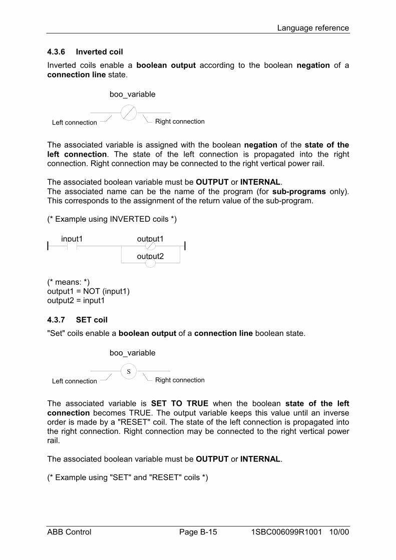
Language reference
ABB Control Page B-15 1SBC006099R1001 10/00
4.3.6 Inverted coilInverted coils enable a boolean output according to the boolean negation of aconnection line state.
boo_variable
Left connection Right connection
The associated variable is assigned with the boolean negation of the state of theleft connection. The state of the left connection is propagated into the rightconnection. Right connection may be connected to the right vertical power rail.
The associated boolean variable must be OUTPUT or INTERNAL.The associated name can be the name of the program (for sub-programs only).This corresponds to the assignment of the return value of the sub-program.
(* Example using INVERTED coils *)
input1 output1
output2
(* means: *)output1 = NOT (input1)output2 = input1
4.3.7 SET coil"Set" coils enable a boolean output of a connection line boolean state.
boo_variable
Left connection Right connectionS
The associated variable is SET TO TRUE when the boolean state of the leftconnection becomes TRUE. The output variable keeps this value until an inverseorder is made by a "RESET" coil. The state of the left connection is propagated intothe right connection. Right connection may be connected to the right vertical powerrail.
The associated boolean variable must be OUTPUT or INTERNAL.
(* Example using "SET" and "RESET" coils *)
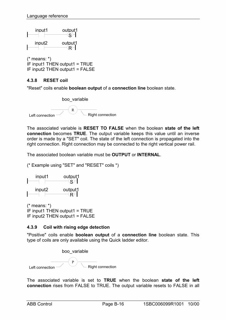
Language reference
ABB Control Page B-16 1SBC006099R1001 10/00
input1
input2
output1S
output1R
(* means: *)IF input1 THEN output1 = TRUEIF input2 THEN output1 = FALSE
4.3.8 RESET coil"Reset" coils enable boolean output of a connection line boolean state.
boo_variable
Left connection Right connectionR
The associated variable is RESET TO FALSE when the boolean state of the leftconnection becomes TRUE. The output variable keeps this value until an inverseorder is made by a "SET" coil. The state of the left connection is propagated into theright connection. Right connection may be connected to the right vertical power rail.
The associated boolean variable must be OUTPUT or INTERNAL.
(* Example using "SET" and "RESET" coils *)
input1
input2
output1S
output1R
(* means: *)IF input1 THEN output1 = TRUEIF input2 THEN output1 = FALSE
4.3.9 Coil with rising edge detection"Positive" coils enable boolean output of a connection line boolean state. Thistype of coils are only available using the Quick ladder editor.
boo_variable
Left connection Right connectionP
The associated variable is set to TRUE when the boolean state of the leftconnection rises from FALSE to TRUE. The output variable resets to FALSE in all
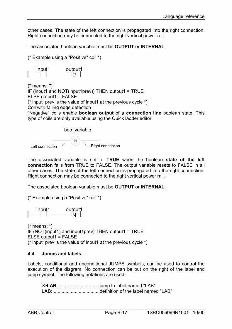
Language reference
ABB Control Page B-17 1SBC006099R1001 10/00
other cases. The state of the left connection is propagated into the right connection.Right connection may be connected to the right vertical power rail.
The associated boolean variable must be OUTPUT or INTERNAL.
(* Example using a "Positive" coil *)
input1 output1P
(* means: *)IF (input1 and NOT(input1prev)) THEN output1 = TRUEELSE output1 = FALSE(* input1prev is the value of input1 at the previous cycle *)Coil with falling edge detection"Negative" coils enable boolean output of a connection line boolean state. Thistype of coils are only available using the Quick ladder editor.
boo_variable
Left connection Right connectionN
The associated variable is set to TRUE when the boolean state of the leftconnection falls from TRUE to FALSE. The output variable resets to FALSE in allother cases. The state of the left connection is propagated into the right connection.Right connection may be connected to the right vertical power rail.
The associated boolean variable must be OUTPUT or INTERNAL.
(* Example using a "Positive" coil *)
input1 output1N
(* means: *)IF (NOT(input1) and input1prev) THEN output1 = TRUEELSE output1 = FALSE(* input1prev is the value of input1 at the previous cycle *)
4.4 Jumps and labels
Labels, conditional and unconditional JUMPS symbols, can be used to control theexecution of the diagram. No connection can be put on the right of the label andjump symbol. The following notations are used:
>>LAB................................ jump to label named "LAB"LAB: .................................. definition of the label named "LAB"
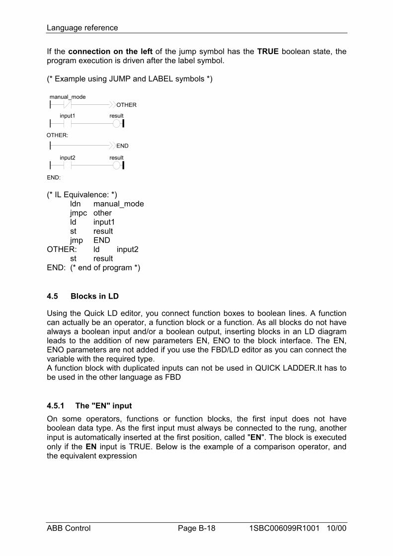
Language reference
ABB Control Page B-18 1SBC006099R1001 10/00
If the connection on the left of the jump symbol has the TRUE boolean state, theprogram execution is driven after the label symbol.
(* Example using JUMP and LABEL symbols *)
manual_mode
input1 result
OTHER
OTHER:
input2 result
END
END:
(* IL Equivalence: *)ldn manual_modejmpc otherld input1st resultjmp END
OTHER: ld input2st result
END: (* end of program *)
4.5 Blocks in LD
Using the Quick LD editor, you connect function boxes to boolean lines. A functioncan actually be an operator, a function block or a function. As all blocks do not havealways a boolean input and/or a boolean output, inserting blocks in an LD diagramleads to the addition of new parameters EN, ENO to the block interface. The EN,ENO parameters are not added if you use the FBD/LD editor as you can connect thevariable with the required type.A function block with duplicated inputs can not be used in QUICK LADDER.It has tobe used in the other language as FBD
4.5.1 The "EN" inputOn some operators, functions or function blocks, the first input does not haveboolean data type. As the first input must always be connected to the rung, anotherinput is automatically inserted at the first position, called "EN". The block is executedonly if the EN input is TRUE. Below is the example of a comparison operator, andthe equivalent expression
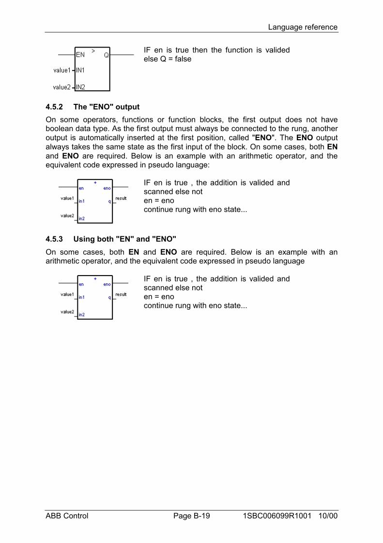
Language reference
ABB Control Page B-19 1SBC006099R1001 10/00
IF en is true then the function is validedelse Q = false
4.5.2 The "ENO" outputOn some operators, functions or function blocks, the first output does not haveboolean data type. As the first output must always be connected to the rung, anotheroutput is automatically inserted at the first position, called "ENO". The ENO outputalways takes the same state as the first input of the block. On some cases, both ENand ENO are required. Below is an example with an arithmetic operator, and theequivalent code expressed in pseudo language:
IF en is true , the addition is valided andscanned else noten = enocontinue rung with eno state...
4.5.3 Using both "EN" and "ENO"On some cases, both EN and ENO are required. Below is an example with anarithmetic operator, and the equivalent code expressed in pseudo language
IF en is true , the addition is valided andscanned else noten = enocontinue rung with eno state...
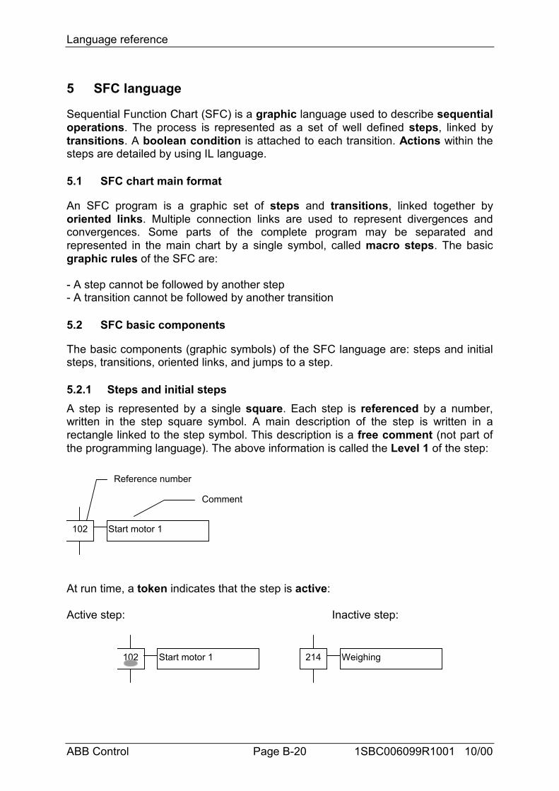
Language reference
ABB Control Page B-20 1SBC006099R1001 10/00
5 SFC language
Sequential Function Chart (SFC) is a graphic language used to describe sequentialoperations. The process is represented as a set of well defined steps, linked bytransitions. A boolean condition is attached to each transition. Actions within thesteps are detailed by using IL language.
5.1 SFC chart main format
An SFC program is a graphic set of steps and transitions, linked together byoriented links. Multiple connection links are used to represent divergences andconvergences. Some parts of the complete program may be separated andrepresented in the main chart by a single symbol, called macro steps. The basicgraphic rules of the SFC are:
- A step cannot be followed by another step- A transition cannot be followed by another transition
5.2 SFC basic components
The basic components (graphic symbols) of the SFC language are: steps and initialsteps, transitions, oriented links, and jumps to a step.
5.2.1 Steps and initial stepsA step is represented by a single square. Each step is referenced by a number,written in the step square symbol. A main description of the step is written in arectangle linked to the step symbol. This description is a free comment (not part ofthe programming language). The above information is called the Level 1 of the step:
102 Start motor 1
Reference number
Comment
At run time, a token indicates that the step is active:
Active step: Inactive step:
102 Start motor 1 214 Weighing
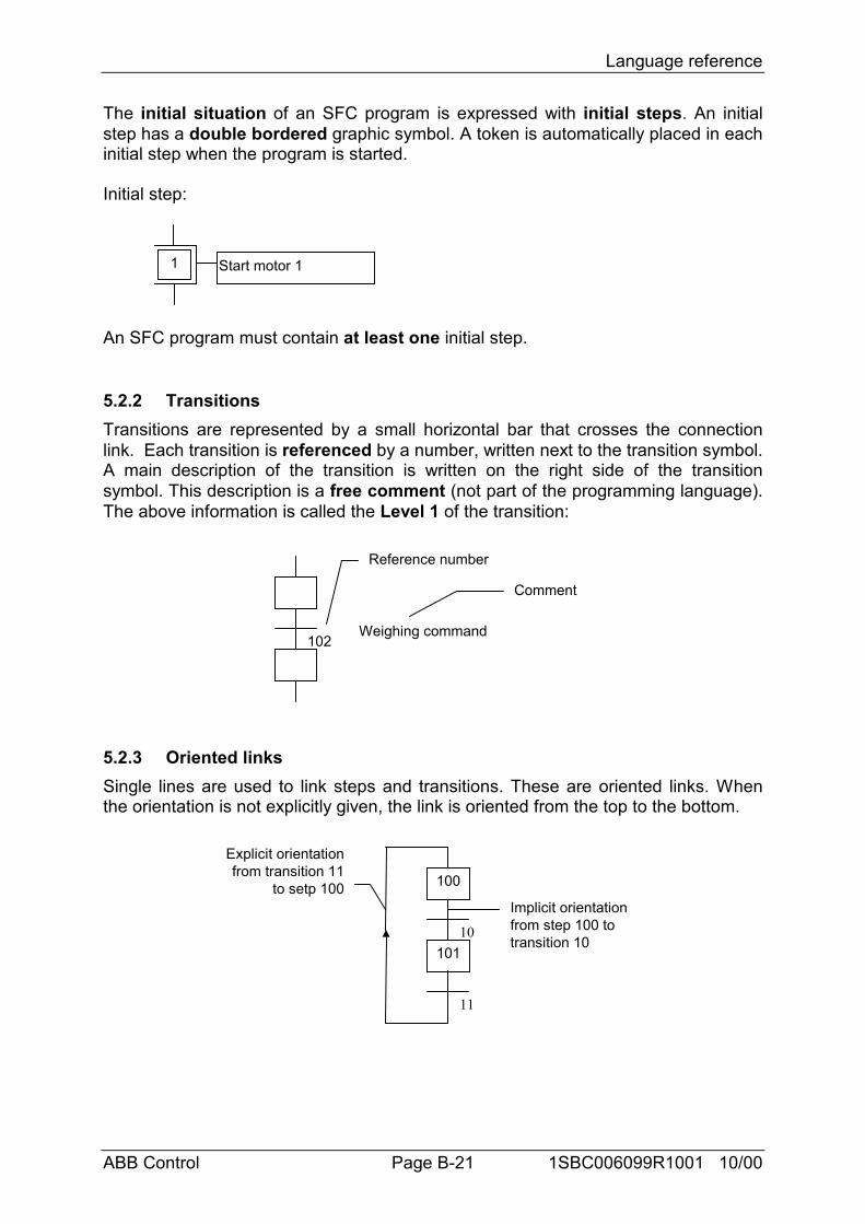
Language reference
ABB Control Page B-21 1SBC006099R1001 10/00
The initial situation of an SFC program is expressed with initial steps. An initialstep has a double bordered graphic symbol. A token is automatically placed in eachinitial step when the program is started.
Initial step:
Start motor 11
An SFC program must contain at least one initial step.
5.2.2 TransitionsTransitions are represented by a small horizontal bar that crosses the connectionlink. Each transition is referenced by a number, written next to the transition symbol.A main description of the transition is written on the right side of the transitionsymbol. This description is a free comment (not part of the programming language).The above information is called the Level 1 of the transition:
Weighing command
Reference number
Comment
102
5.2.3 Oriented linksSingle lines are used to link steps and transitions. These are oriented links. Whenthe orientation is not explicitly given, the link is oriented from the top to the bottom.
100
Explicit orientationfrom transition 11
to setp 100Implicit orientationfrom step 100 totransition 10
10110
11
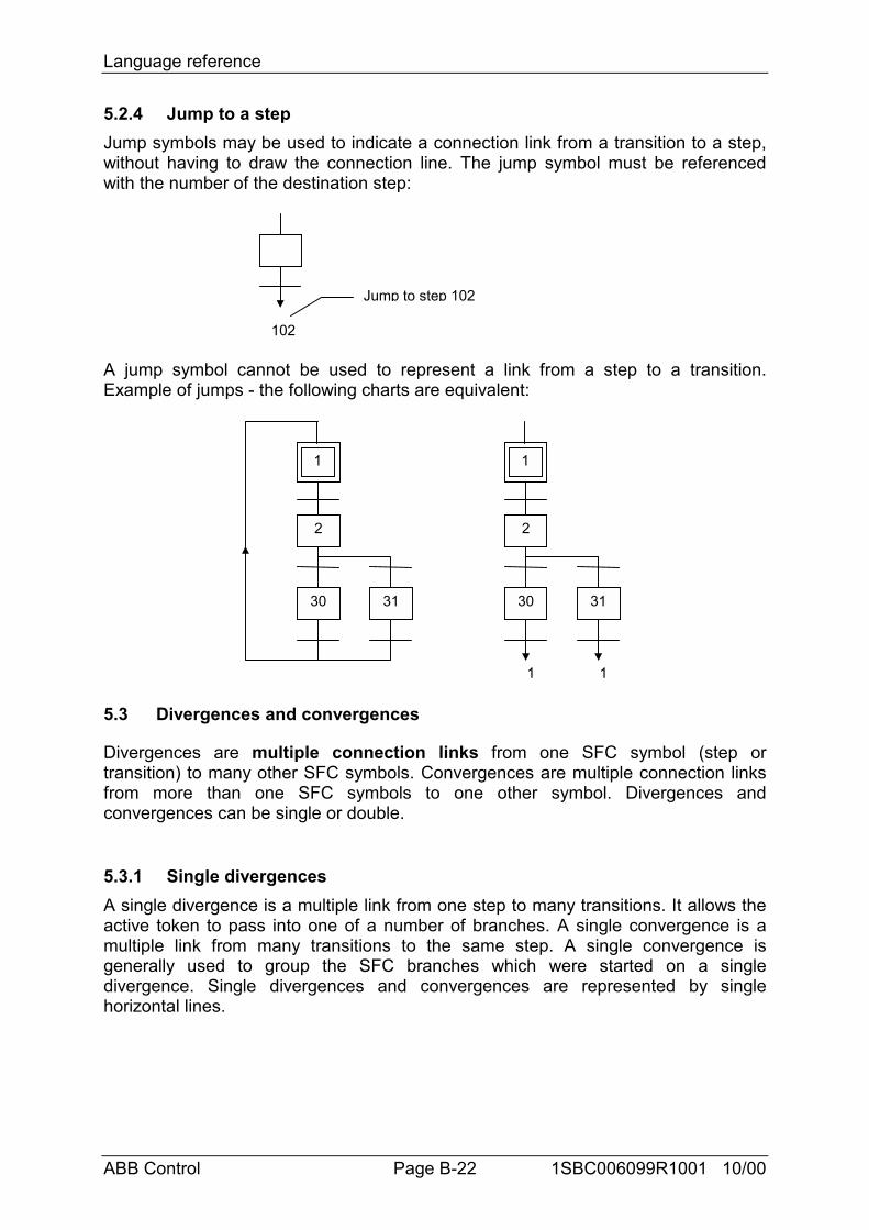
Language reference
ABB Control Page B-22 1SBC006099R1001 10/00
5.2.4 Jump to a stepJump symbols may be used to indicate a connection link from a transition to a step,without having to draw the connection line. The jump symbol must be referencedwith the number of the destination step:
Jump to step 102
102
A jump symbol cannot be used to represent a link from a step to a transition.Example of jumps - the following charts are equivalent:
1
2
30 31
1
1
2
30 31
1
5.3 Divergences and convergences
Divergences are multiple connection links from one SFC symbol (step ortransition) to many other SFC symbols. Convergences are multiple connection linksfrom more than one SFC symbols to one other symbol. Divergences andconvergences can be single or double.
5.3.1 Single divergencesA single divergence is a multiple link from one step to many transitions. It allows theactive token to pass into one of a number of branches. A single convergence is amultiple link from many transitions to the same step. A single convergence isgenerally used to group the SFC branches which were started on a singledivergence. Single divergences and convergences are represented by singlehorizontal lines.
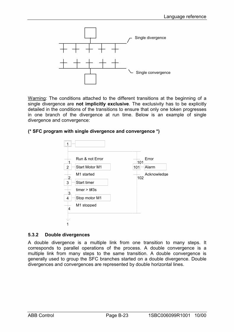
Language reference
ABB Control Page B-23 1SBC006099R1001 10/00
Single divergence
Single convergence
Warning: The conditions attached to the different transitions at the beginning of asingle divergence are not implicitly exclusive. The exclusivity has to be explicitlydetailed in the conditions of the transitions to ensure that only one token progressesin one branch of the divergence at run time. Below is an example of singledivergence and convergence:
(* SFC program with single divergence and convergence *)
1 Initialize
1Run & not Error
101Error
2 Start Motor M1 101 Alarm
2M1 started
102Acknowledge
3 Start timer
3timer > t#3s
4 Stop motor M1
4M1 stopped
1
5.3.2 Double divergencesA double divergence is a multiple link from one transition to many steps. Itcorresponds to parallel operations of the process. A double convergence is amultiple link from many steps to the same transition. A double convergence isgenerally used to group the SFC branches started on a double divergence. Doubledivergences and convergences are represented by double horizontal lines.
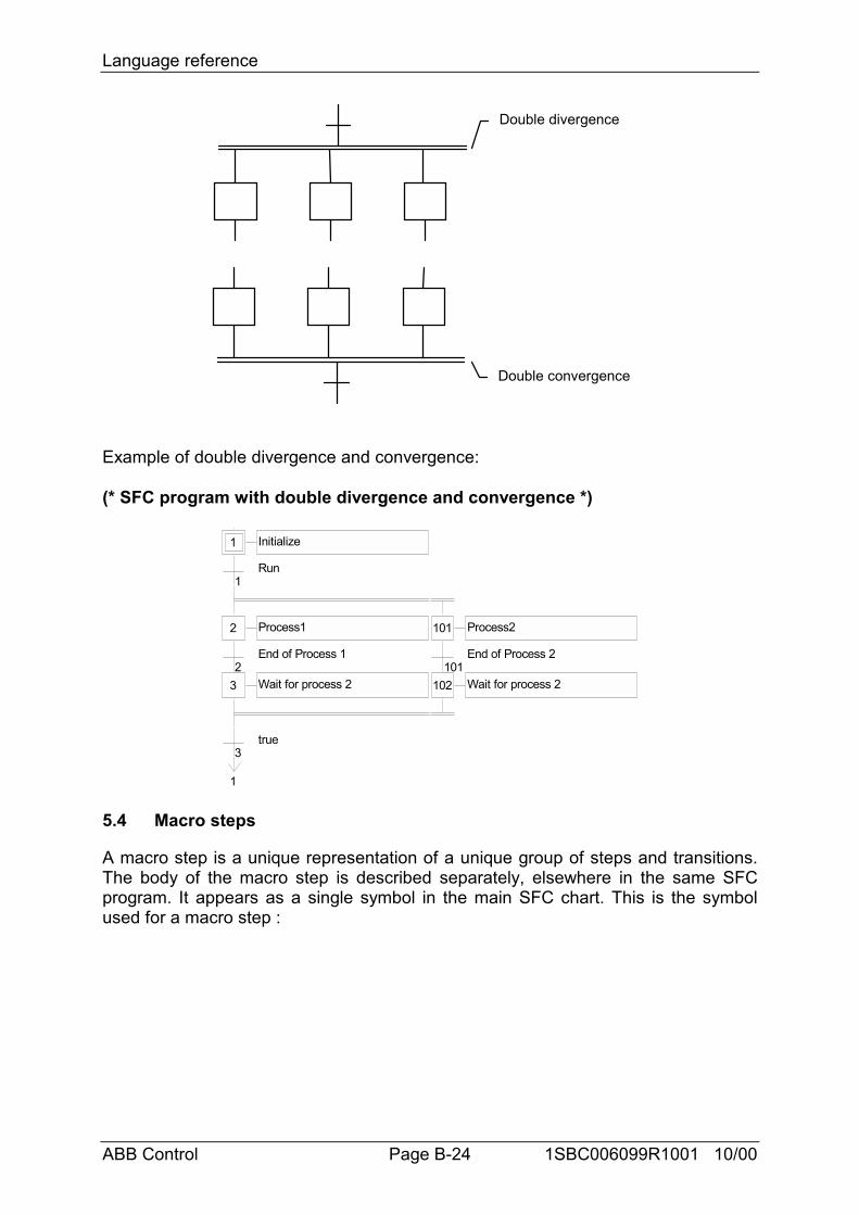
Language reference
ABB Control Page B-24 1SBC006099R1001 10/00
Double divergence
Double convergence
Example of double divergence and convergence:
(* SFC program with double divergence and convergence *)
1 Initialize
1Run
2 Process1 101 Process2
2End of Process 1
101End of Process 2
3 Wait for process 2 102 Wait for process 2
3true
1
5.4 Macro steps
A macro step is a unique representation of a unique group of steps and transitions.The body of the macro step is described separately, elsewhere in the same SFCprogram. It appears as a single symbol in the main SFC chart. This is the symbolused for a macro step :
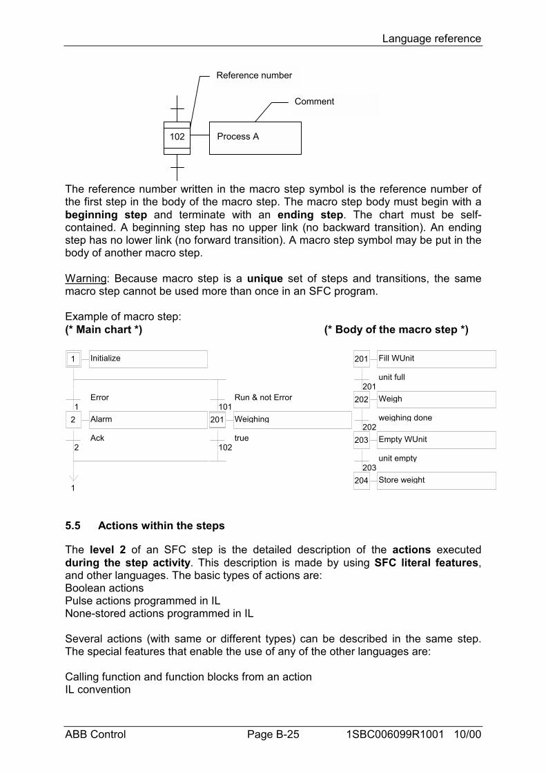
Language reference
ABB Control Page B-25 1SBC006099R1001 10/00
102 Process A
Reference number
Comment
The reference number written in the macro step symbol is the reference number ofthe first step in the body of the macro step. The macro step body must begin with abeginning step and terminate with an ending step. The chart must be self-contained. A beginning step has no upper link (no backward transition). An endingstep has no lower link (no forward transition). A macro step symbol may be put in thebody of another macro step.
Warning: Because macro step is a unique set of steps and transitions, the samemacro step cannot be used more than once in an SFC program.
Example of macro step:(* Main chart *) (* Body of the macro step *)
1 Initialize 201 Fill WUnit
201unit full
1Error
101Run & not Error 202 Weigh
2 Alarm 201 Weighing202
weighing done
2Ack
102true 203 Empty WUnit
203unit empty
1204 Store weight
5.5 Actions within the steps
The level 2 of an SFC step is the detailed description of the actions executedduring the step activity. This description is made by using SFC literal features,and other languages. The basic types of actions are:Boolean actionsPulse actions programmed in ILNone-stored actions programmed in IL
Several actions (with same or different types) can be described in the same step.The special features that enable the use of any of the other languages are:
Calling function and function blocks from an actionIL convention
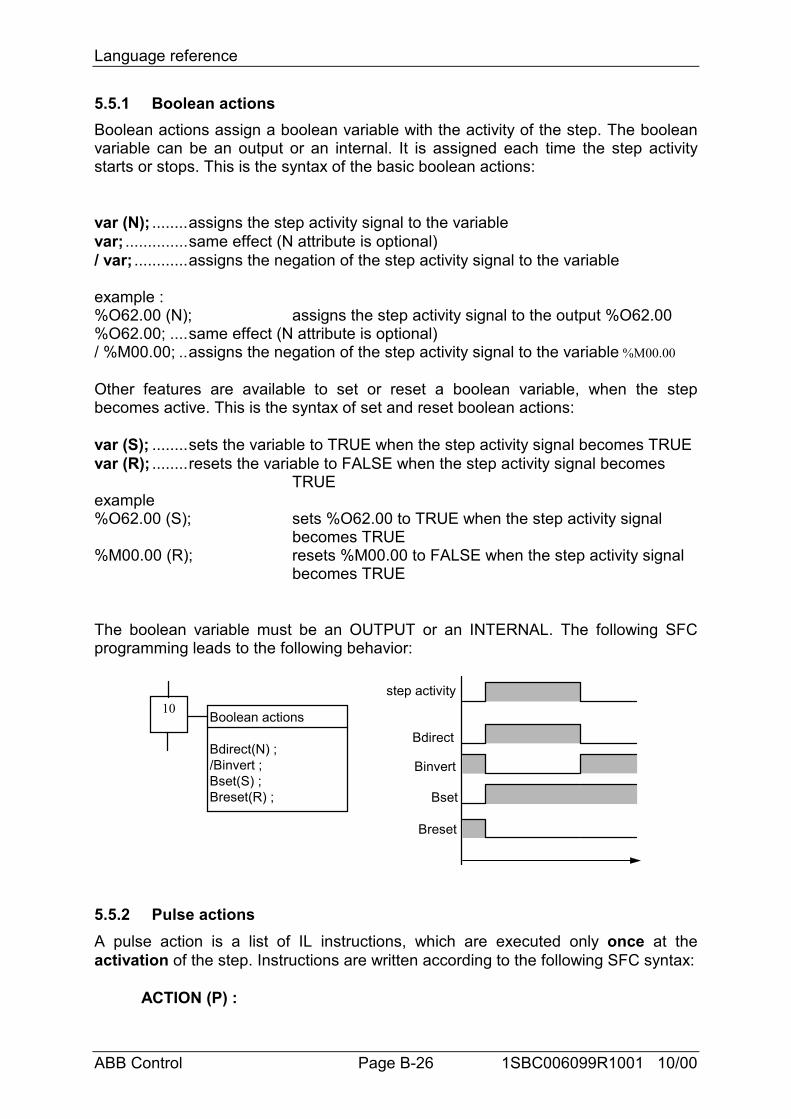
Language reference
ABB Control Page B-26 1SBC006099R1001 10/00
5.5.1 Boolean actionsBoolean actions assign a boolean variable with the activity of the step. The booleanvariable can be an output or an internal. It is assigned each time the step activitystarts or stops. This is the syntax of the basic boolean actions:
var (N); ........assigns the step activity signal to the variablevar; ..............same effect (N attribute is optional)/ var; ............assigns the negation of the step activity signal to the variable
example :%O62.00 (N); assigns the step activity signal to the output %O62.00%O62.00; ....same effect (N attribute is optional)/ %M00.00; ..assigns the negation of the step activity signal to the variable %M00.00
Other features are available to set or reset a boolean variable, when the stepbecomes active. This is the syntax of set and reset boolean actions:
var (S); ........sets the variable to TRUE when the step activity signal becomes TRUEvar (R); ........resets the variable to FALSE when the step activity signal becomes
TRUEexample%O62.00 (S); sets %O62.00 to TRUE when the step activity signal
becomes TRUE%M00.00 (R); resets %M00.00 to FALSE when the step activity signal
becomes TRUE
The boolean variable must be an OUTPUT or an INTERNAL. The following SFCprogramming leads to the following behavior:
Boolean actions
Bdirect(N) ;/Binvert ;Bset(S) ;Breset(R) ;
10step activity
Bdirect
Binvert
Bset
Breset
5.5.2 Pulse actionsA pulse action is a list of IL instructions, which are executed only once at theactivation of the step. Instructions are written according to the following SFC syntax:
ACTION (P) :
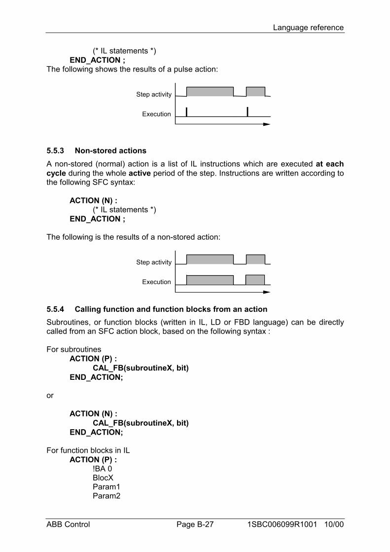
Language reference
ABB Control Page B-27 1SBC006099R1001 10/00
(* IL statements *)END_ACTION ;
The following shows the results of a pulse action:
Step activity
Execution
5.5.3 Non-stored actionsA non-stored (normal) action is a list of IL instructions which are executed at eachcycle during the whole active period of the step. Instructions are written according tothe following SFC syntax:
ACTION (N) :(* IL statements *)
END_ACTION ;
The following is the results of a non-stored action:
Step activity
Execution
5.5.4 Calling function and function blocks from an actionSubroutines, or function blocks (written in IL, LD or FBD language) can be directlycalled from an SFC action block, based on the following syntax :
For subroutinesACTION (P) :
CAL_FB(subroutineX, bit)END_ACTION;
or
ACTION (N) :CAL_FB(subroutineX, bit)
END_ACTION;
For function blocks in ILACTION (P) :
!BA 0BlocXParam1Param2
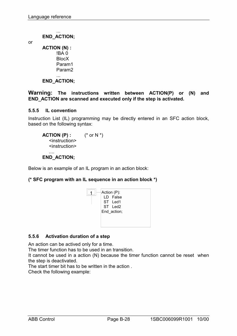
Language reference
ABB Control Page B-28 1SBC006099R1001 10/00
...END_ACTION;
orACTION (N) :
!BA 0BlocXParam1Param2...
END_ACTION;
Warning: The instructions written between ACTION(P) or (N) andEND_ACTION are scanned and executed only if the step is activated.
5.5.5 IL conventionInstruction List (IL) programming may be directly entered in an SFC action block,based on the following syntax:
ACTION (P) : (* or N *) <instruction> <instruction> ....END_ACTION;
Below is an example of an IL program in an action block:
(* SFC program with an IL sequence in an action block *)
1 Action (P): LD False ST Led1 ST Led2End_action;
5.5.6 Activation duration of a stepAn action can be actived only for a time.The timer function has to be used in an transition.It cannot be used in a action (N) because the timer function cannot be reset whenthe step is deactivated.The start timer bit has to be written in the action .Check the following example:
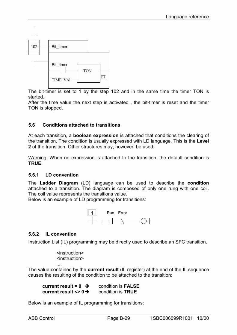
Language reference
ABB Control Page B-29 1SBC006099R1001 10/00
102 Bit_timer;
Bit_timerTON
TIME_VAlET
The bit-timer is set to 1 by the step 102 and in the same time the timer TON isstarted.After the time value the next step is activated , the bit-timer is reset and the timerTON is stopped.
5.6 Conditions attached to transitions
At each transition, a boolean expression is attached that conditions the clearing ofthe transition. The condition is usually expressed with LD language. This is the Level2 of the transition. Other structures may, however, be used:
Warning: When no expression is attached to the transition, the default condition isTRUE.
5.6.1 LD conventionThe Ladder Diagram (LD) language can be used to describe the conditionattached to a transition. The diagram is composed of only one rung with one coil.The coil value represents the transitions value.Below is an example of LD programming for transitions:
1 Run Error
5.6.2 IL conventionInstruction List (IL) programming may be directly used to describe an SFC transition.
<instruction><instruction>....
The value contained by the current result (IL register) at the end of the IL sequencecauses the resulting of the condition to be attached to the transition:
current result = 0 ! condition is FALSEcurrent result <> 0! condition is TRUE
Below is an example of IL programming for transitions:
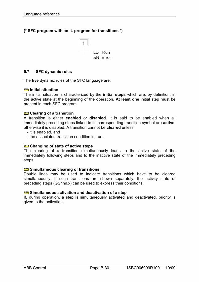
Language reference
ABB Control Page B-30 1SBC006099R1001 10/00
(* SFC program with an IL program for transitions *)
1 LD Run &N Error
5.7 SFC dynamic rules
The five dynamic rules of the SFC language are:
Initial situationThe initial situation is characterized by the initial steps which are, by definition, inthe active state at the beginning of the operation. At least one initial step must bepresent in each SFC program.
Clearing of a transitionA transition is either enabled or disabled. It is said to be enabled when allimmediately preceding steps linked to its corresponding transition symbol are active,otherwise it is disabled. A transition cannot be cleared unless: - it is enabled, and - the associated transition condition is true.
Changing of state of active stepsThe clearing of a transition simultaneously leads to the active state of theimmediately following steps and to the inactive state of the immediately precedingsteps.
Simultaneous clearing of transitionsDouble lines may be used to indicate transitions which have to be clearedsimultaneously. If such transitions are shown separately, the activity state ofpreceding steps (GSnnn.x) can be used to express their conditions.
Simultaneous activation and deactivation of a stepIf, during operation, a step is simultaneously activated and deactivated, priority isgiven to the activation.
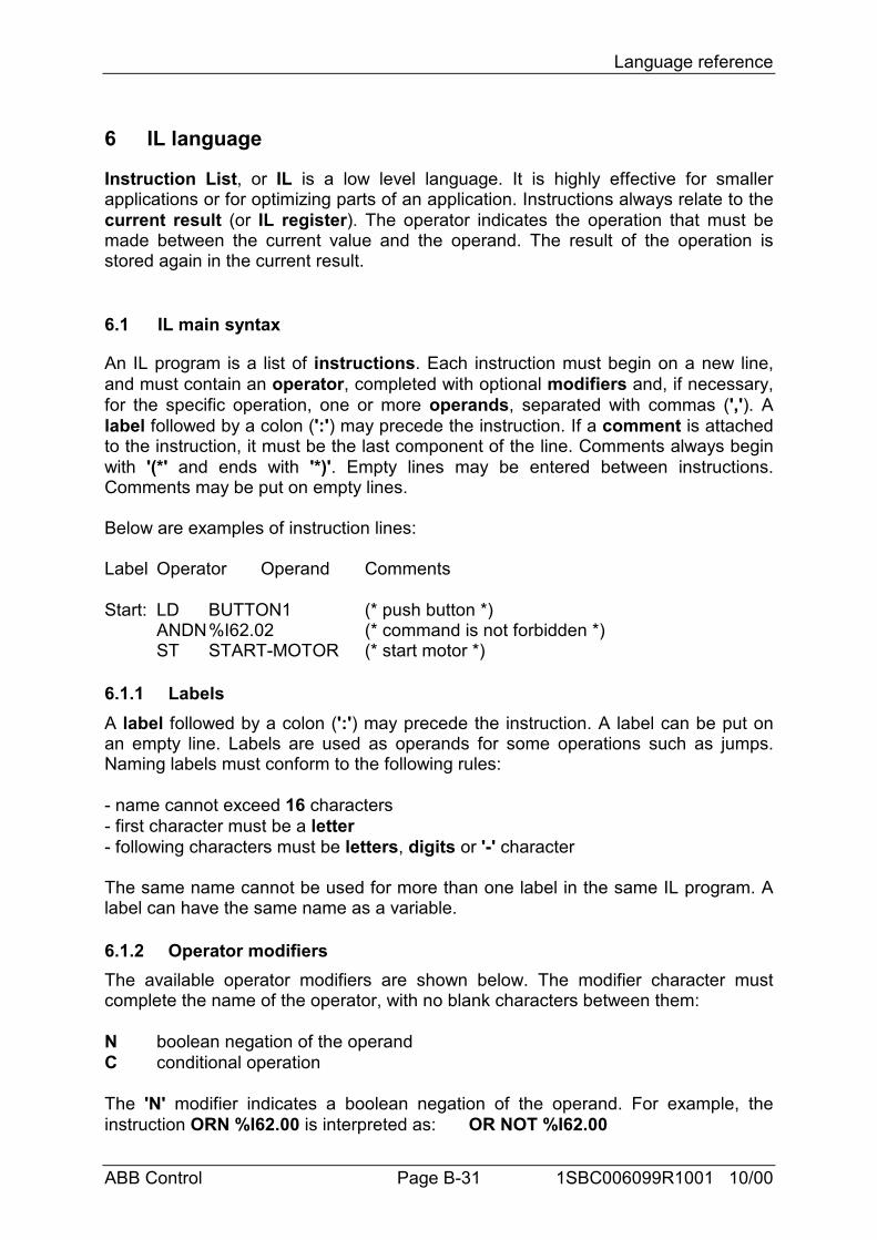
Language reference
ABB Control Page B-31 1SBC006099R1001 10/00
6 IL language
Instruction List, or IL is a low level language. It is highly effective for smallerapplications or for optimizing parts of an application. Instructions always relate to thecurrent result (or IL register). The operator indicates the operation that must bemade between the current value and the operand. The result of the operation isstored again in the current result.
6.1 IL main syntax
An IL program is a list of instructions. Each instruction must begin on a new line,and must contain an operator, completed with optional modifiers and, if necessary,for the specific operation, one or more operands, separated with commas (','). Alabel followed by a colon (':') may precede the instruction. If a comment is attachedto the instruction, it must be the last component of the line. Comments always beginwith '(*' and ends with '*)'. Empty lines may be entered between instructions.Comments may be put on empty lines.
Below are examples of instruction lines:
Label Operator Operand Comments
Start: LD BUTTON1 (* push button *)ANDN%I62.02 (* command is not forbidden *)ST START-MOTOR (* start motor *)
6.1.1 LabelsA label followed by a colon (':') may precede the instruction. A label can be put onan empty line. Labels are used as operands for some operations such as jumps.Naming labels must conform to the following rules:
- name cannot exceed 16 characters- first character must be a letter- following characters must be letters, digits or '-' character
The same name cannot be used for more than one label in the same IL program. Alabel can have the same name as a variable.
6.1.2 Operator modifiersThe available operator modifiers are shown below. The modifier character mustcomplete the name of the operator, with no blank characters between them:
N boolean negation of the operandC conditional operation
The 'N' modifier indicates a boolean negation of the operand. For example, theinstruction ORN %I62.00 is interpreted as: OR NOT %I62.00
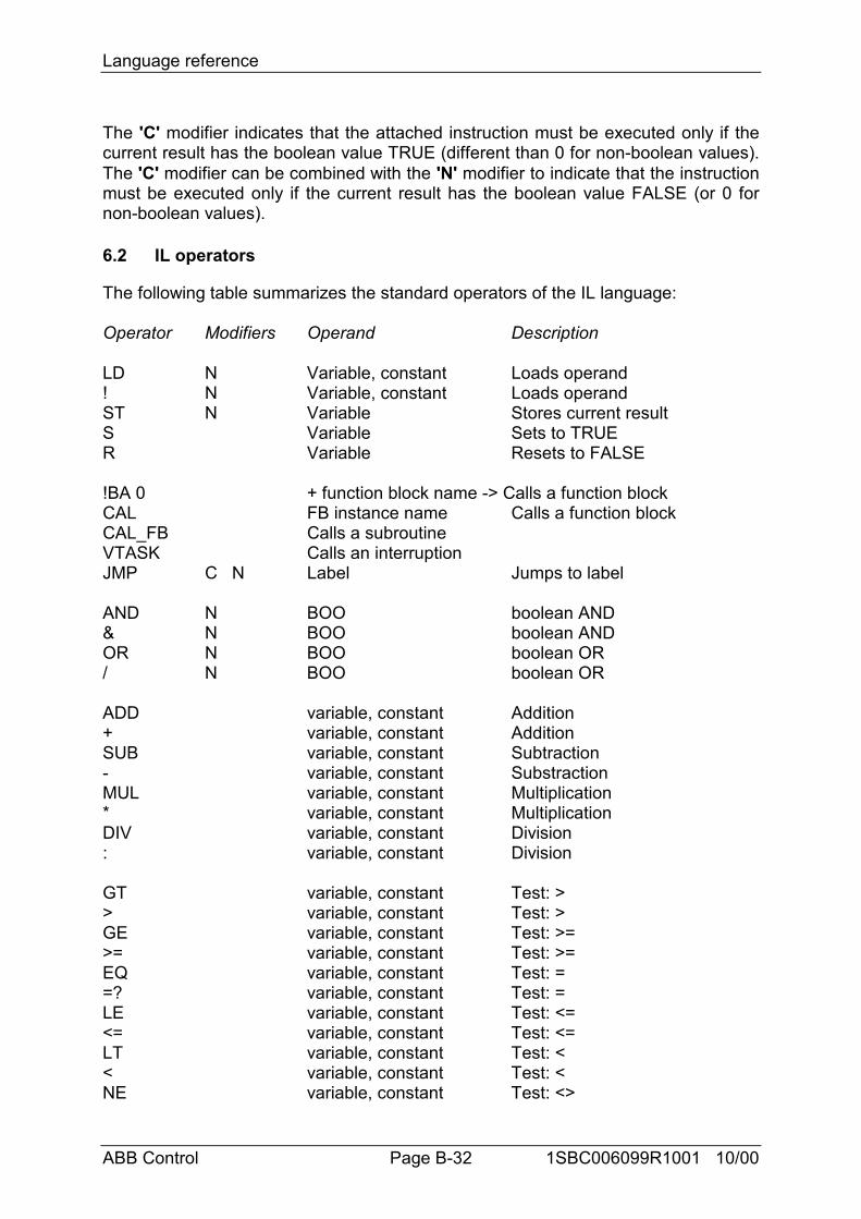
Language reference
ABB Control Page B-32 1SBC006099R1001 10/00
The 'C' modifier indicates that the attached instruction must be executed only if thecurrent result has the boolean value TRUE (different than 0 for non-boolean values).The 'C' modifier can be combined with the 'N' modifier to indicate that the instructionmust be executed only if the current result has the boolean value FALSE (or 0 fornon-boolean values).
6.2 IL operators
The following table summarizes the standard operators of the IL language:
Operator Modifiers Operand Description
LD N Variable, constant Loads operand! N Variable, constant Loads operandST N Variable Stores current resultS Variable Sets to TRUER Variable Resets to FALSE
!BA 0 + function block name -> Calls a function blockCAL FB instance name Calls a function blockCAL_FB Calls a subroutineVTASK Calls an interruptionJMP C N Label Jumps to label
AND N BOO boolean AND& N BOO boolean ANDOR N BOO boolean OR/ N BOO boolean OR
ADD variable, constant Addition+ variable, constant AdditionSUB variable, constant Subtraction- variable, constant SubstractionMUL variable, constant Multiplication* variable, constant MultiplicationDIV variable, constant Division: variable, constant Division
GT variable, constant Test: >> variable, constant Test: >GE variable, constant Test: >=>= variable, constant Test: >=EQ variable, constant Test: ==? variable, constant Test: =LE variable, constant Test: <=<= variable, constant Test: <=LT variable, constant Test: << variable, constant Test: <NE variable, constant Test: <>
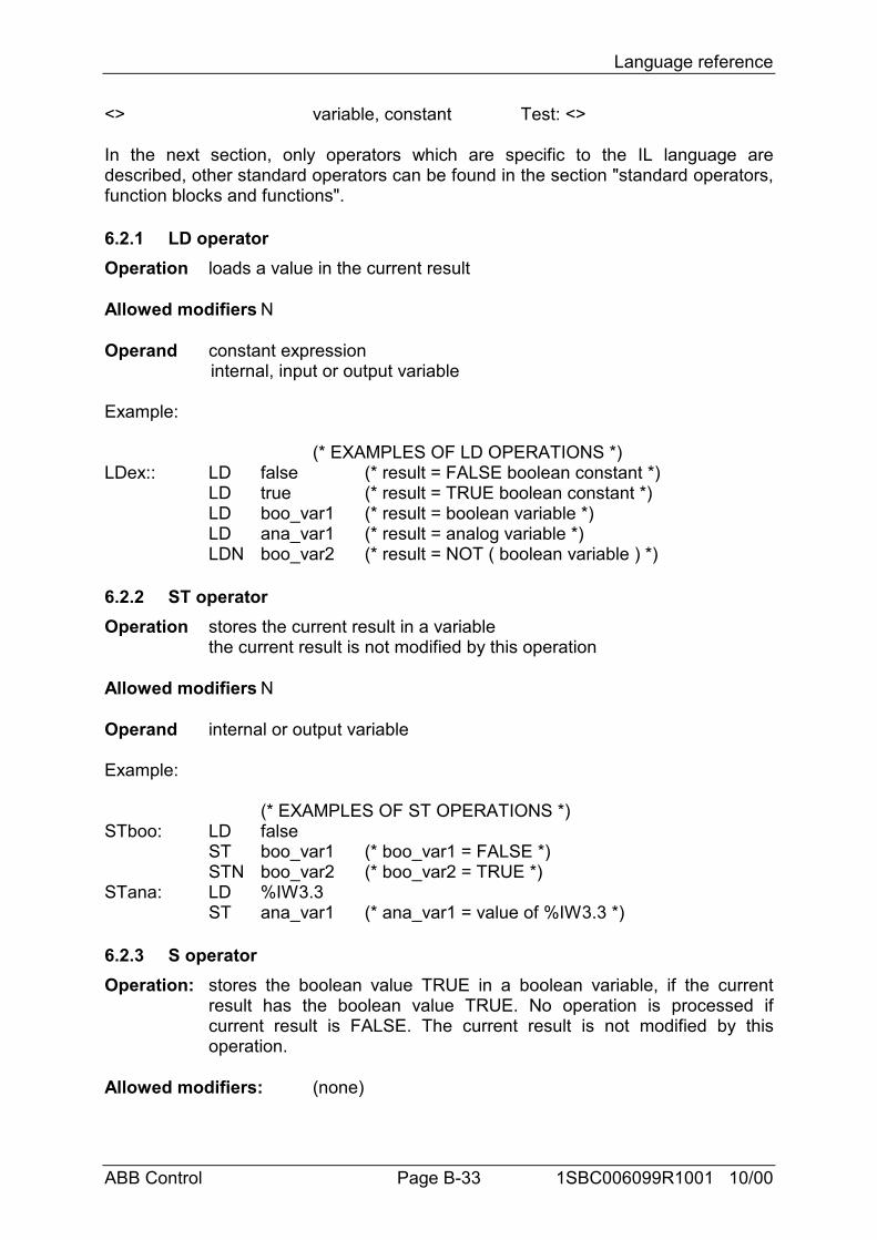
Language reference
ABB Control Page B-33 1SBC006099R1001 10/00
<> variable, constant Test: <>
In the next section, only operators which are specific to the IL language aredescribed, other standard operators can be found in the section "standard operators,function blocks and functions".
6.2.1 LD operatorOperation loads a value in the current result
Allowed modifiers N
Operand constant expressioninternal, input or output variable
Example:
(* EXAMPLES OF LD OPERATIONS *)LDex:: LD false (* result = FALSE boolean constant *)
LD true (* result = TRUE boolean constant *)LD boo_var1 (* result = boolean variable *)LD ana_var1 (* result = analog variable *)LDN boo_var2 (* result = NOT ( boolean variable ) *)
6.2.2 ST operatorOperation stores the current result in a variable
the current result is not modified by this operation
Allowed modifiers N
Operand internal or output variable
Example:
(* EXAMPLES OF ST OPERATIONS *)STboo: LD false
ST boo_var1 (* boo_var1 = FALSE *)STN boo_var2 (* boo_var2 = TRUE *)
STana: LD %IW3.3ST ana_var1 (* ana_var1 = value of %IW3.3 *)
6.2.3 S operatorOperation: stores the boolean value TRUE in a boolean variable, if the current
result has the boolean value TRUE. No operation is processed ifcurrent result is FALSE. The current result is not modified by thisoperation.
Allowed modifiers: (none)
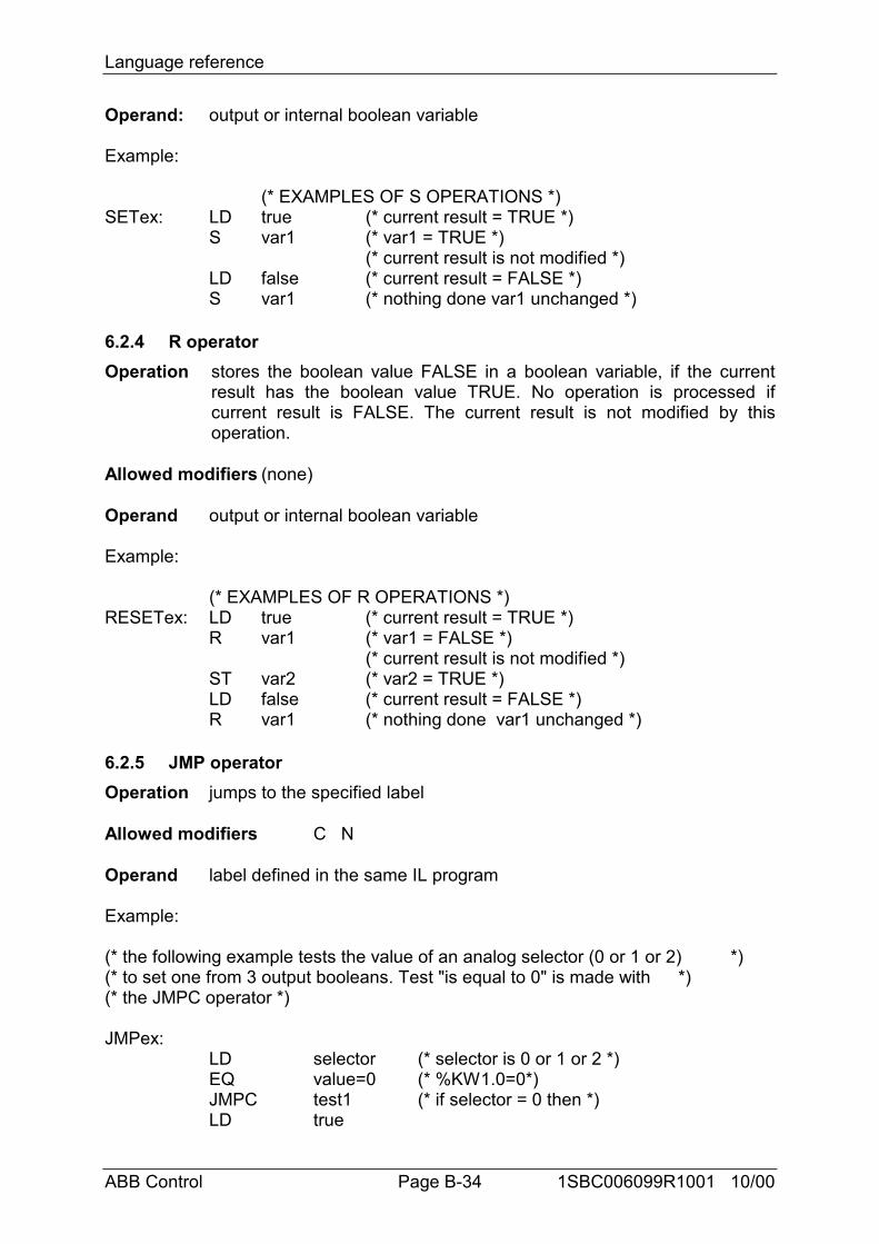
Language reference
ABB Control Page B-34 1SBC006099R1001 10/00
Operand: output or internal boolean variable
Example:
(* EXAMPLES OF S OPERATIONS *)SETex: LD true (* current result = TRUE *)
S var1 (* var1 = TRUE *)(* current result is not modified *)
LD false (* current result = FALSE *)S var1 (* nothing done var1 unchanged *)
6.2.4 R operatorOperation stores the boolean value FALSE in a boolean variable, if the current
result has the boolean value TRUE. No operation is processed ifcurrent result is FALSE. The current result is not modified by thisoperation.
Allowed modifiers (none)
Operand output or internal boolean variable
Example:
(* EXAMPLES OF R OPERATIONS *)RESETex: LD true (* current result = TRUE *)
R var1 (* var1 = FALSE *)(* current result is not modified *)
ST var2 (* var2 = TRUE *)LD false (* current result = FALSE *)R var1 (* nothing done var1 unchanged *)
6.2.5 JMP operatorOperation jumps to the specified label
Allowed modifiers C N
Operand label defined in the same IL program
Example:
(* the following example tests the value of an analog selector (0 or 1 or 2) *)(* to set one from 3 output booleans. Test "is equal to 0" is made with *)(* the JMPC operator *)
JMPex:LD selector (* selector is 0 or 1 or 2 *)EQ value=0 (* %KW1.0=0*)JMPC test1 (* if selector = 0 then *)LD true
Language reference
ABB Control Page B-35 1SBC006099R1001 10/00
ST bo0 (* bo0 = true *)JMP JMPend (* end of the program *)
test1:LD selectorEQ value=1 (* %KW1.1=1 *)JMPC test2 (* if selector = 1 then *)LD trueST bo1 (* bo1 = true *)JMP JMPend (* end of the program *)
test2:LD true (* last possibility *)ST bo2 (* bo2 = true *)
JMPend: (* end of the IL program *)
6.2.6 Calling sub-programs and interruptionsA sub-program is called from the IL language, using its name as an operator.
Operation executes a sub-program
Allowed modifiers (none)
Operand The first calling parameter must be the name of the subroutineThe following one, separated by a coma, is the call bit of thesubroutine.
Example:
CAL_FB(sub1,%I2.2) (* call the subroutine named sub1 *)
An interruption is called from the IL language, using its name as an operator.
Operation executes an interruption
Allowed modifiers (none)
Operand The first calling parameter must be the name of the interruptionThe following one, separated by a coma, is the call bit of theinterruption.
Example:
VTASK(int, %I2.2) (* call the hard interruption named int *)
6.2.7 Calling function blocks: CAL, !BA 0 operatorOperation calls a function block
CAL has to be used for blocks not extended.
Allowed modifiers None
Language reference
ABB Control Page B-36 1SBC006099R1001 10/00
Operand Name of the function block instance.Output parameters are known if used.
Example1:
(* Calling function block TON*)
CAL TON ( IN, PT, ET, Q)
is equivalent to :
!BA0TONINPTETQ
example 2:
(* Calling function block CTUH *)CALCTUH(#1,%I62.00,%I62.01,%MW2.0,%I62.02,%I62.03,%I62.04,%O62.00,%OW62.01,%OW62.02)
is equivalent to :
!BA 0CTUH#1%I62.00%I62.01%MW2.0%I62.02%I62.03%I62.04%O62.00%OW62.01%OW62.02
6.3 Main differences between IEC IL and ABB IL
With IL ABB, an instruction list must be followed by an operator ST:
LD %I62.01AND %I62.02ST %M2.0
Language reference
ABB Control Page B-37 1SBC006099R1001 10/00
In order to use the accumulator %M2.0, we have to load it:
LD %I62.01AND %I62.02ST %M2.0LD %M2.0OR %M3.0…
With IL IEC, there no need to load the accumulator (the current result), so we canwrite:
LD %I62.01AND %I62.02ST %M2.2OR %I62.03…
Call of subroutines, interruptions and function blocs:
Function blocs:The following syntax is just used for IL ABB in order to call function blocs!BA 0CTUH…
but it is possible to use the IL IEC as follow:
CAL CTUH(…)
Subroutines and interruption:To call a subroutine:CAL_FBand an interruption:VTASK
This syntax is specific to the IL ABB

Function block description
ABB Control 1SBC006099R1001 10/00
Function block description
ABB Control 1SBC006099R1001 10/00
C Function block description

Function block description
ABB Control 1SBC006099R1001 10/00
Function block description
ABB Control Page C-1 1SBC006099R1001 10/00
C FUNCTION BLOCK DESCRIPTION
1 Libraries.....................................................................................................................C-22 Basic operators/functions .........................................................................................C-8
2.1 Binary functions..................................................................................................... C-82.2 Timer functions.................................................................................................... C-172.3 Counter functions ................................................................................................ C-342.4 Comparison functions, word................................................................................ C-402.5 Arithmetic functions, word.................................................................................. C-492.6 Logical functions, word ....................................................................................... C-61
3 Program control functions......................................................................................C-694 CS31 functions.........................................................................................................C-855 Communication functions.....................................................................................C-1196 Regulation functions .............................................................................................C-1577 Format conversion functions................................................................................C-1778 Standard double word functions .........................................................................C-203
8.1 Comparison functions, double word.................................................................. C-2038.2 Arithmetic functions, double word.................................................................... C-2068.3 Logical functions, double word ......................................................................... C-215
9 High order functions .............................................................................................C-21910 Memory access functions......................................................................................C-29511 Special Functions ..................................................................................................C-32012 Historical values....................................................................................................C-325
12.1 Definition........................................................................................................... C-32512.2 Historical value table ......................................................................................... C-326
13 Runtimes ................................................................................................................C-32813.1 Definition........................................................................................................... C-32813.2 Runtime table (time in µs) ................................................................................. C-328
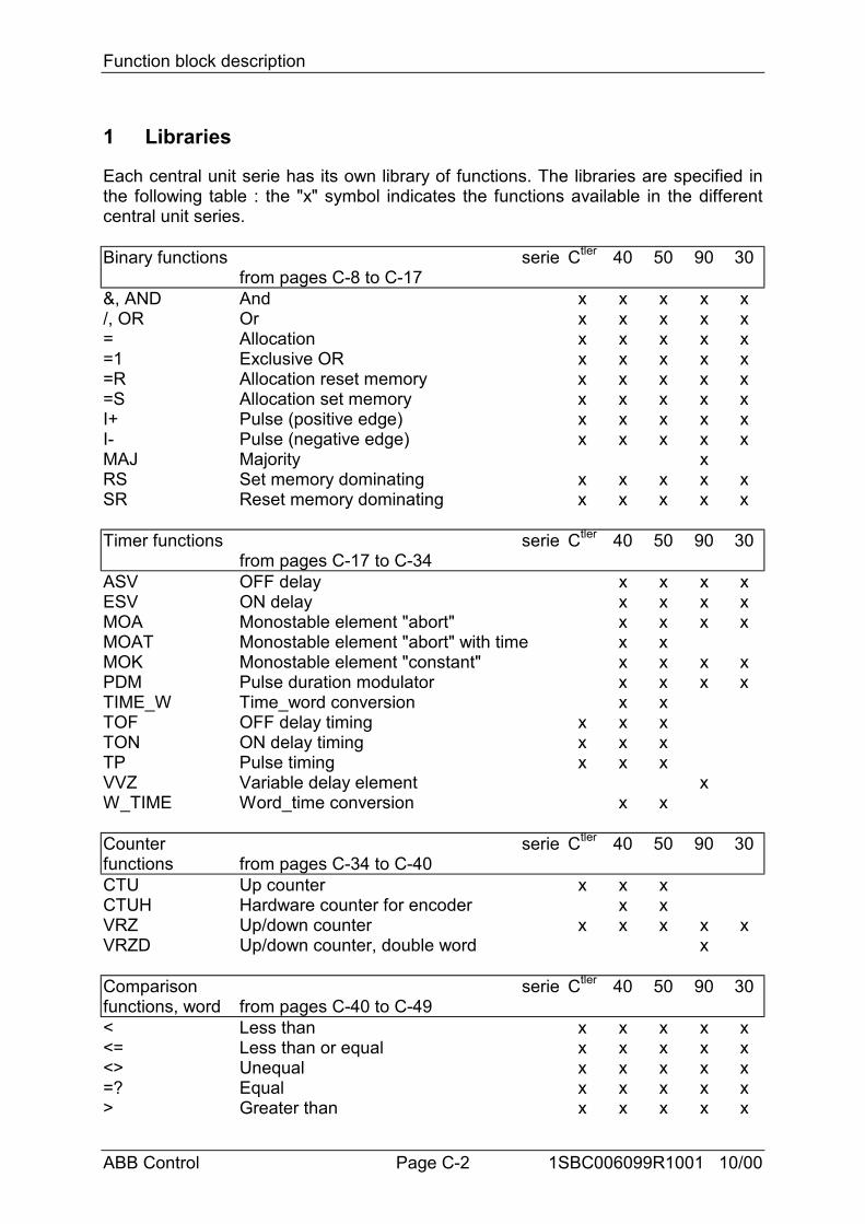
Function block description
ABB Control Page C-2 1SBC006099R1001 10/00
1 Libraries
Each central unit serie has its own library of functions. The libraries are specified inthe following table : the "x" symbol indicates the functions available in the differentcentral unit series.
Binary functions seriefrom pages C-8 to C-17
Ctler 40 50 90 30
&, AND And x x x x x/, OR Or x x x x x= Allocation x x x x x=1 Exclusive OR x x x x x=R Allocation reset memory x x x x x=S Allocation set memory x x x x xI+ Pulse (positive edge) x x x x xI- Pulse (negative edge) x x x x xMAJ Majority xRS Set memory dominating x x x x xSR Reset memory dominating x x x x x
Timer functions seriefrom pages C-17 to C-34
Ctler 40 50 90 30
ASV OFF delay x x x xESV ON delay x x x xMOA Monostable element "abort" x x x xMOAT Monostable element "abort" with time x xMOK Monostable element "constant" x x x xPDM Pulse duration modulator x x x xTIME_W Time_word conversion x xTOF OFF delay timing x x xTON ON delay timing x x xTP Pulse timing x x xVVZ Variable delay element xW_TIME Word_time conversion x x
Counterfunctions
seriefrom pages C-34 to C-40
Ctler 40 50 90 30
CTU Up counter x x xCTUH Hardware counter for encoder x xVRZ Up/down counter x x x x xVRZD Up/down counter, double word x
Comparisonfunctions, word
seriefrom pages C-40 to C-49
Ctler 40 50 90 30
< Less than x x x x x<= Less than or equal x x x x x<> Unequal x x x x x=? Equal x x x x x> Greater than x x x x x
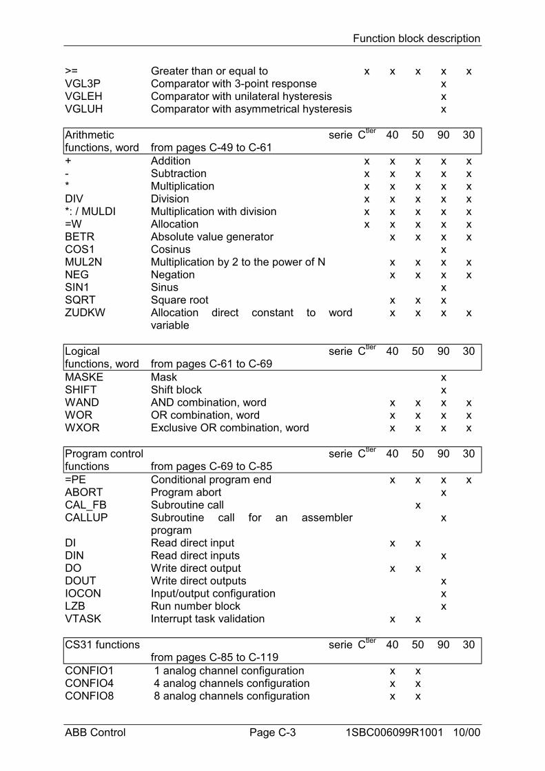
Function block description
ABB Control Page C-3 1SBC006099R1001 10/00
>= Greater than or equal to x x x x xVGL3P Comparator with 3-point response xVGLEH Comparator with unilateral hysteresis xVGLUH Comparator with asymmetrical hysteresis x
Arithmeticfunctions, word
seriefrom pages C-49 to C-61
Ctler 40 50 90 30
+ Addition x x x x x- Subtraction x x x x x* Multiplication x x x x xDIV Division x x x x x*: / MULDI Multiplication with division x x x x x=W Allocation x x x x xBETR Absolute value generator x x x xCOS1 Cosinus xMUL2N Multiplication by 2 to the power of N x x x xNEG Negation x x x xSIN1 Sinus xSQRT Square root x x xZUDKW Allocation direct constant to word
variablex x x x
Logicalfunctions, word
seriefrom pages C-61 to C-69
Ctler 40 50 90 30
MASKE Mask xSHIFT Shift block xWAND AND combination, word x x x xWOR OR combination, word x x x xWXOR Exclusive OR combination, word x x x x
Program controlfunctions
seriefrom pages C-69 to C-85
Ctler 40 50 90 30
=PE Conditional program end x x x xABORT Program abort xCAL_FB Subroutine call xCALLUP Subroutine call for an assembler
programx
DI Read direct input x xDIN Read direct inputs xDO Write direct output x xDOUT Write direct outputs xIOCON Input/output configuration xLZB Run number block xVTASK Interrupt task validation x x
CS31 functions seriefrom pages C-85 to C-119
Ctler 40 50 90 30
CONFIO1 1 analog channel configuration x xCONFIO4 4 analog channels configuration x xCONFIO8 8 analog channels configuration x x
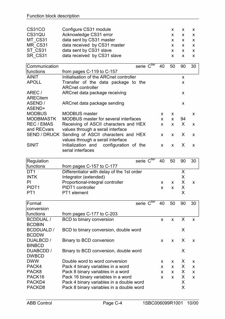
Function block description
ABB Control Page C-4 1SBC006099R1001 10/00
CS31CO Configure CS31 module x x xCS31QU Acknowledge CS31 error x x xMT_CS31 data sent by CS31 master x x xMR_CS31 data received by CS31 master x x xST_CS31 data sent by CS31 slave x x xSR_CS31 data received by CS31 slave x x x
Communicationfunctions
seriefrom pages C-119 to C-157
Ctler 40 50 90 30
AINIT Initialisation of the ARCnet controller xAPOLL Transfer of the data package to the
ARCnet controllerx
AREC /ARECitem
ARCnet data package receiving x
ASEND /ASEND+
ARCnet data package sending x
MODBUS MODBUS master x x xMODBMASTK MODBUS master for several interfaces x x 94REC / EMASand RECvars
Receiving of ASCII characters and HEXvalues through a serail interface
x x X x
SEND / DRUCK Sending of ASCII characters and HEXvalues through a serail interface
x x X x
SINIT Initialization and configuration of theserial interfaces
x x X x
Regulationfunctions
seriefrom pages C-157 to C-177
Ctler 40 50 90 30
DT1 Differentiator with delay of the 1st order XINTK Integrator (extended) XPI Proportional-integral controller x x X xPIDT1 PIDT1 controller x x XPT1 PT1 element X
Formatconversionfunctions
serie
from pages C-177 to C-203
Ctler 40 50 90 30
BCDDUAL /BCDBIN
BCD to binary conversion x x X x
BCDDUALD /BCDDW
BCD to binary conversion, double word X
DUALBCD /BINBCD
Binary to BCD conversion x x X x
DUABCDD /DWBCD
Binary to BCD conversion, double word X
DWW Double word to word conversion x x X xPACK4 Pack 4 binary variables in a word x x X xPACK8 Pack 8 binary variables in a word x x X xPACK16 Pack 16 binary variables in a word x x X xPACKD4 Pack 4 binary variables in a double word XPACKD8 Pack 8 binary variables in a double word X
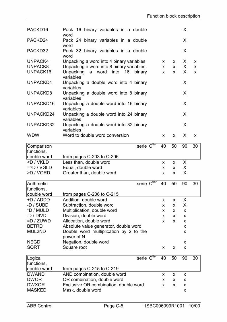
Function block description
ABB Control Page C-5 1SBC006099R1001 10/00
PACKD16 Pack 16 binary variables in a doubleword
X
PACKD24 Pack 24 binary variables in a doubleword
X
PACKD32 Pack 32 binary variables in a doubleword
X
UNPACK4 Unpacking a word into 4 binary variables x x X xUNPACK8 Unpacking a word into 8 binary variables x x X xUNPACK16 Unpacking a word into 16 binary
variablesx x X x
UNPACKD4 Unpacking a double word into 4 binaryvariables
X
UNPACKD8 Unpacking a double word into 8 binaryvariables
X
UNPACKD16 Unpacking a double word into 16 binaryvariables
X
UNPACKD24 Unpacking a double word into 24 binaryvariables
X
UNPACKD32 Unpacking a double word into 32 binaryvariables
X
WDW Word to double word conversion x x X x
Comparisonfunctions,double word
serie
from pages C-203 to C-206
Ctler 40 50 90 30
<D / VKLD Less than, double word x x X=?D / VGLD Equal, double word x x X>D / VGRD Greater than, double word x x X
Arithmeticfunctions,double word
serie
from pages C-206 to C-215
Ctler 40 50 90 30
+D / ADDD Addition, double word x x X-D / SUBD Subtraction, double word x x X*D / MULD Multiplication, double word x x x:D / DIVD Division, double word x x x=D / ZUWD Allocation, double word x x xBETRD Absolute value generator, double word xMUL2ND Double word multiplication by 2 to the
power of Nx
NEGD Negation, double word xSQRT Square root x x x
Logicalfunctions,double word
serie
from pages C-215 to C-219
Ctler 40 50 90 30
DWAND AND combination, double word x x xDWOR OR combination, double word x x xDWXOR Exclusive OR combination, double word x x xMASKED Mask, double word x
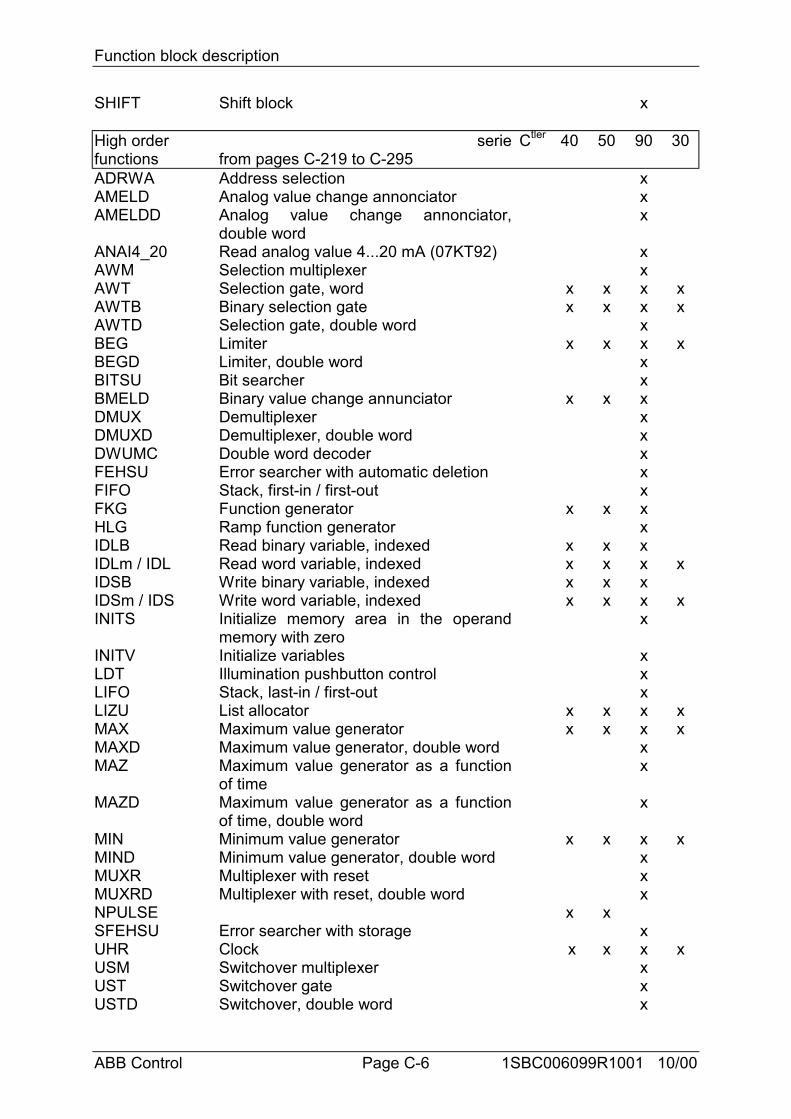
Function block description
ABB Control Page C-6 1SBC006099R1001 10/00
SHIFT Shift block x
High orderfunctions
seriefrom pages C-219 to C-295
Ctler 40 50 90 30
ADRWA Address selection xAMELD Analog value change annonciator xAMELDD Analog value change annonciator,
double wordx
ANAI4_20 Read analog value 4...20 mA (07KT92) xAWM Selection multiplexer xAWT Selection gate, word x x x xAWTB Binary selection gate x x x xAWTD Selection gate, double word xBEG Limiter x x x xBEGD Limiter, double word xBITSU Bit searcher xBMELD Binary value change annunciator x x xDMUX Demultiplexer xDMUXD Demultiplexer, double word xDWUMC Double word decoder xFEHSU Error searcher with automatic deletion xFIFO Stack, first-in / first-out xFKG Function generator x x xHLG Ramp function generator xIDLB Read binary variable, indexed x x xIDLm / IDL Read word variable, indexed x x x xIDSB Write binary variable, indexed x x xIDSm / IDS Write word variable, indexed x x x xINITS Initialize memory area in the operand
memory with zerox
INITV Initialize variables xLDT Illumination pushbutton control xLIFO Stack, last-in / first-out xLIZU List allocator x x x xMAX Maximum value generator x x x xMAXD Maximum value generator, double word xMAZ Maximum value generator as a function
of timex
MAZD Maximum value generator as a functionof time, double word
x
MIN Minimum value generator x x x xMIND Minimum value generator, double word xMUXR Multiplexer with reset xMUXRD Multiplexer with reset, double word xNPULSE x xSFEHSU Error searcher with storage xUHR Clock x x x xUSM Switchover multiplexer xUST Switchover gate xUSTD Switchover, double word x
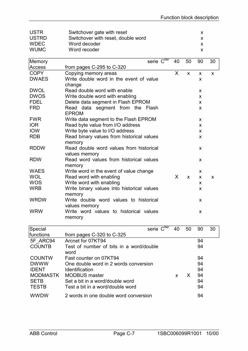
Function block description
ABB Control Page C-7 1SBC006099R1001 10/00
USTR Switchover gate with reset xUSTRD Switchover with reset, double word xWDEC Word decoder xWUMC Word recoder x
MemoryAccess
seriefrom pages C-295 to C-320
Ctler 40 50 90 30
COPY Copying memory areas X x x xDWAES Write double word in the event of value
changex
DWOL Read double word with enable xDWOS Write double word with enabling xFDEL Delete data segment in Flash EPROM xFRD Read data segment from the Flash
EPROMx
FWR Write data segment to the Flash EPROM xIOR Read byte value from I/O address xIOW Write byte value to I/O address xRDB Read binary values from historical values
memoryx
RDDW Read double word values from historicalvalues memory
x
RDW Read word values from historical valuesmemory
x
WAES Write word in the event of value change xWOL Read word with enabling X x x xWOS Write word with enabling xWRB Write binary values into historical values
memoryx
WRDW Write double word values to historicalvalues memory
x
WRW Write word values to historical valuesmemory
x
Specialfunctions
seriefrom pages C-320 to C-325
Ctler 40 50 90 30
5F_ARC94 Arcnet for 07KT94 94COUNTB Test of number of bits in a word/double
word94
COUNTW Fast counter on 07KT94 94DWWW One double word in 2 words conversion 94IDENT Identification 94MODMASTK MODBUS master x X 94SETB Set a bit in a word/double word 94TESTB Test a bit in a word/double word 94
WWDW 2 words in one double word conversion 94
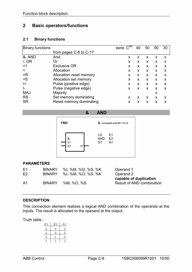
Function block description
ABB Control Page C-8 1SBC006099R1001 10/00
2 Basic operators/functions
2.1 Binary functions
Binary functions seriefrom pages C-8 to C-17
Ctler 40 50 90 30
&, AND And x x x x x/, OR Or x x x x x=1 Exclusive OR x x x x x= Allocation x x x x x=R Allocation reset memory x x x x x=S Allocation set memory x x x x xI+ Pulse (positive edge) x x x x xI- Pulse (negative edge) x x x x xMAJ Majority xRS Set memory dominating x x x x xSR Reset memory dominating x x x x x
& AND
LDANDST
E1E2A1
FBD IL (compatible with IEC 1131-3)
&E1E2 A1
PARAMETERSE1 BINARY %I, %M, %O, %S, %K Operand 1E2 BINARY %I, %M, %O, %S, %K Operand 2
capable of duplicationA1 BINARY %M, %O, %S Result of AND combination
DESCRIPTIONThis connection element realizes a logical AND combination of the operands at theinputs. The result is allocated to the operand at the output.
Truth table :E1
0101
E2
0011
A1
0001
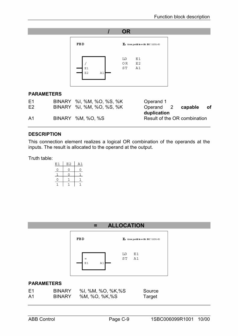
Function block description
ABB Control Page C-9 1SBC006099R1001 10/00
/ OR
FBD IL (com patible with IEC 1131-3)
/E1
E2 A1
LDO RST
E1E2A1
PARAMETERSE1 BINARY %I, %M, %O, %S, %K Operand 1E2 BINARY %I, %M, %O, %S, %K Operand 2 capable of
duplicationA1 BINARY %M, %O, %S Result of the OR combination
DESCRIPTIONThis connection element realizes a logical OR combination of the operands at theinputs. The result is allocated to the operand at the output.
Truth table:E1
0101
E2
0011
A1
0111
= ALLOCATION
FBD IL (com patible with IEC 1131-3)
=E1 A1
LDST
E1A1
PARAMETERSE1 BINARY %I, %M, %O, %K,%S SourceA1 BINARY %M, %O, %K,%S Target
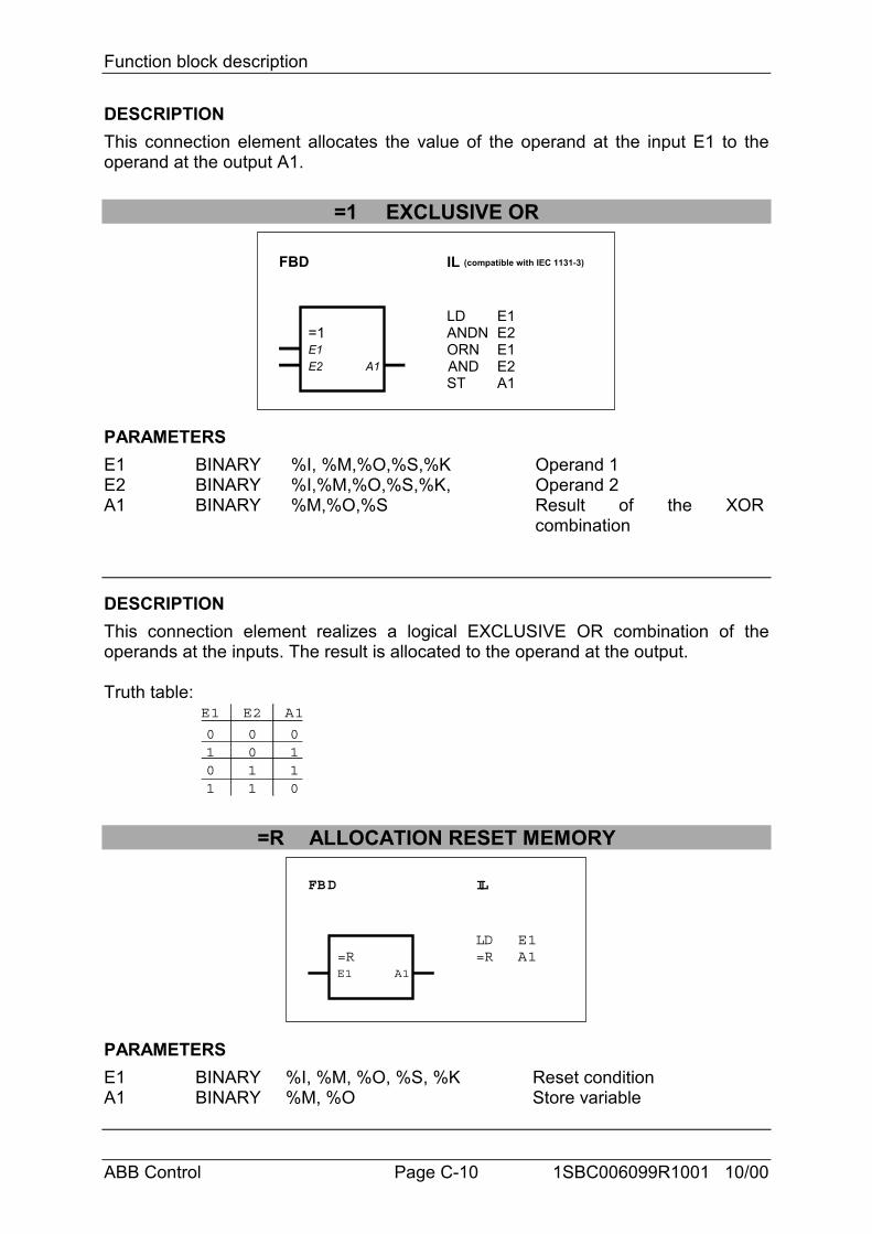
Function block description
ABB Control Page C-10 1SBC006099R1001 10/00
DESCRIPTIONThis connection element allocates the value of the operand at the input E1 to theoperand at the output A1.
=1 EXCLUSIVE OR
FBD IL (compatible with IEC 1131-3)
=1E1E2 A1
LDANDNORNANDST
E1E2E1E2A1
PARAMETERSE1 BINARY %I, %M,%O,%S,%K Operand 1E2 BINARY %I,%M,%O,%S,%K, Operand 2A1 BINARY %M,%O,%S Result of the XOR
combination
DESCRIPTIONThis connection element realizes a logical EXCLUSIVE OR combination of theoperands at the inputs. The result is allocated to the operand at the output.
Truth table:E1
0101
E2
0011
A1
0110
=R ALLOCATION RESET MEMORY
FBD IL
=RE1 A1
LD=R
E1A1
PARAMETERSE1 BINARY %I, %M, %O, %S, %K Reset conditionA1 BINARY %M, %O Store variable
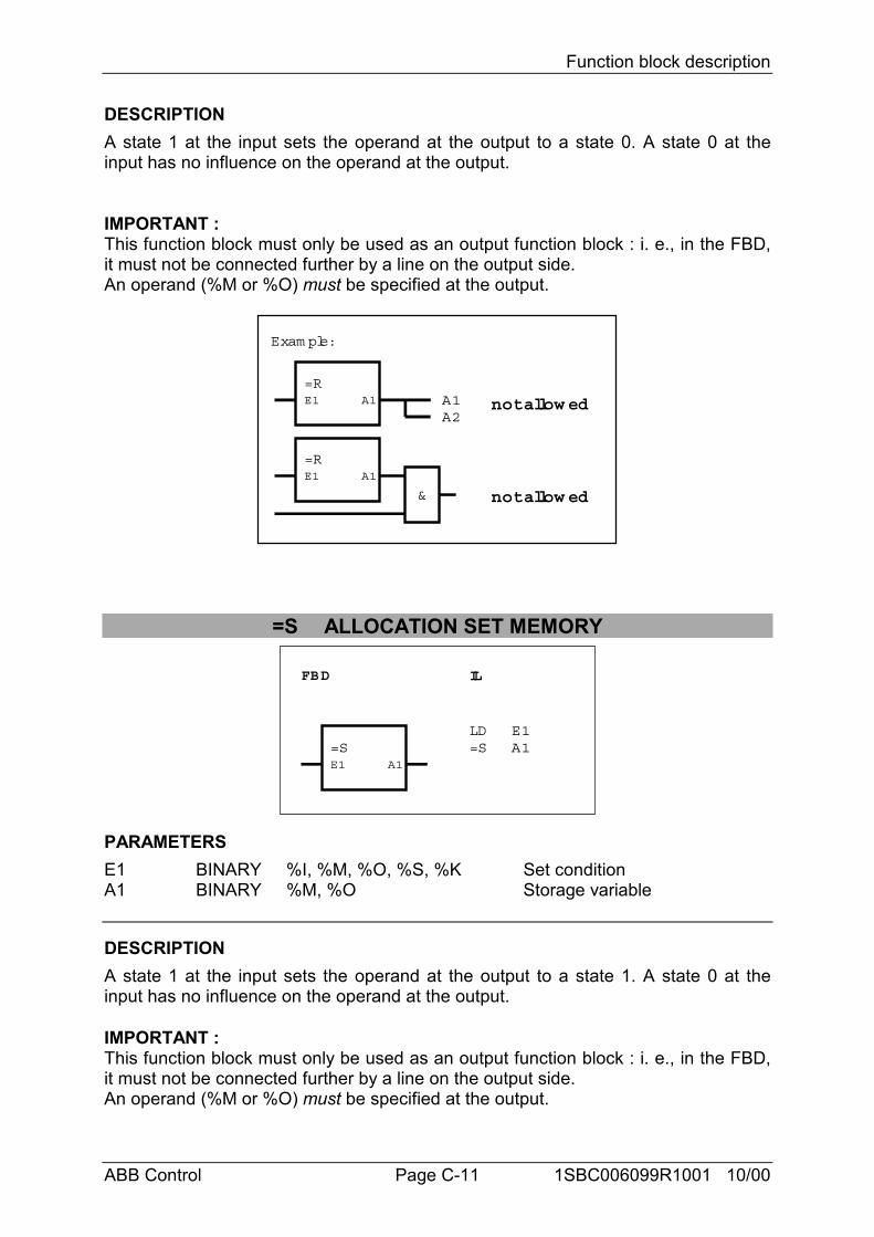
Function block description
ABB Control Page C-11 1SBC006099R1001 10/00
DESCRIPTIONA state 1 at the input sets the operand at the output to a state 0. A state 0 at theinput has no influence on the operand at the output.
IMPORTANT :This function block must only be used as an output function block : i. e., in the FBD,it must not be connected further by a line on the output side.An operand (%M or %O) must be specified at the output.
Exam ple:
=RE1 A1 A1
A2
=RE1 A1
&
not allowed
not allowed
=S ALLOCATION SET MEMORY
FBD IL
=SE1 A1
LD=S
E1A1
PARAMETERSE1 BINARY %I, %M, %O, %S, %K Set conditionA1 BINARY %M, %O Storage variable
DESCRIPTIONA state 1 at the input sets the operand at the output to a state 1. A state 0 at theinput has no influence on the operand at the output.
IMPORTANT :This function block must only be used as an output function block : i. e., in the FBD,it must not be connected further by a line on the output side.An operand (%M or %O) must be specified at the output.
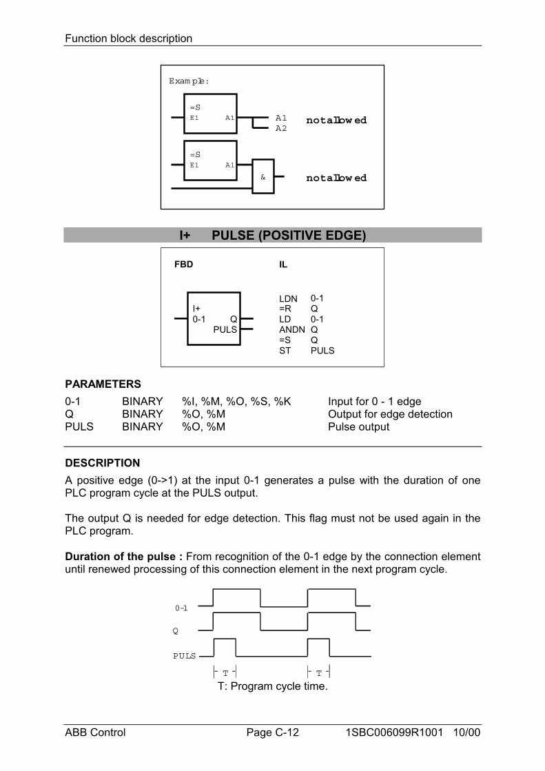
Function block description
ABB Control Page C-12 1SBC006099R1001 10/00
Exam ple:
=SE1 A1 A1
A2
=SE1 A1
&
not allowed
not allowed
I+ PULSE (POSITIVE EDGE)
FBD IL
I+0-1 Q
PULS
LDN=RLDANDN=SST
0-1Q0-1QQPULS
PARAMETERS0-1 BINARY %I, %M, %O, %S, %K Input for 0 - 1 edgeQ BINARY %O, %M Output for edge detectionPULS BINARY %O, %M Pulse output
DESCRIPTIONA positive edge (0->1) at the input 0-1 generates a pulse with the duration of onePLC program cycle at the PULS output.
The output Q is needed for edge detection. This flag must not be used again in thePLC program.
Duration of the pulse : From recognition of the 0-1 edge by the connection elementuntil renewed processing of this connection element in the next program cycle.
0-1
Q
PULS
T T
T: Program cycle time.
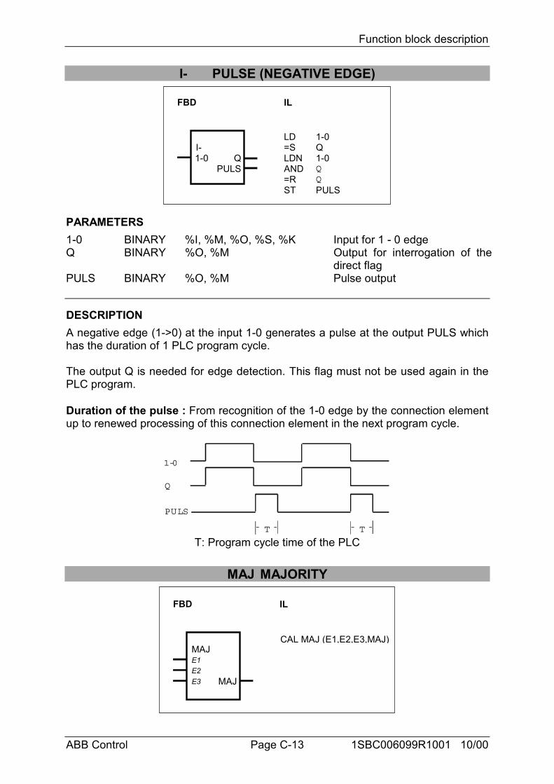
Function block description
ABB Control Page C-13 1SBC006099R1001 10/00
I- PULSE (NEGATIVE EDGE)
FBD IL
I-1-0 Q
PULS
LD=SLDNAND=RST
1-0Q1-0QQPULS
PARAMETERS1-0 BINARY %I, %M, %O, %S, %K Input for 1 - 0 edgeQ BINARY %O, %M Output for interrogation of the
direct flagPULS BINARY %O, %M Pulse output
DESCRIPTIONA negative edge (1->0) at the input 1-0 generates a pulse at the output PULS whichhas the duration of 1 PLC program cycle.
The output Q is needed for edge detection. This flag must not be used again in thePLC program.
Duration of the pulse : From recognition of the 1-0 edge by the connection elementup to renewed processing of this connection element in the next program cycle.
1-0
Q
PULS
T T
T: Program cycle time of the PLC
MAJ MAJORITY
FBD IL
MAJE1E2E3 MAJ
CAL MAJ (E1,E2,E3,MAJ)
Function block description
ABB Control Page C-14 1SBC006099R1001 10/00
PARAMETERSE1 BINARY %I, %M, %O, %S, %K Operand 1E2 BINARY %I, %M, %O, %S, %K Operand 2E3 BINARY %I, %M, %O, %S, %K Operand 3MAJ BINARY %M, %O Result
DESCRIPTIONThis connection element realizes a MAJORITY element.
If at least 2 of the 3 binary operands at the inputs E1, E2 and E3 have the state 1,then the state 1 is allocated to the binary operand at the output MAJ.
If it is not the case, the state 0 is allocated to the binary operand at the output MAJ.
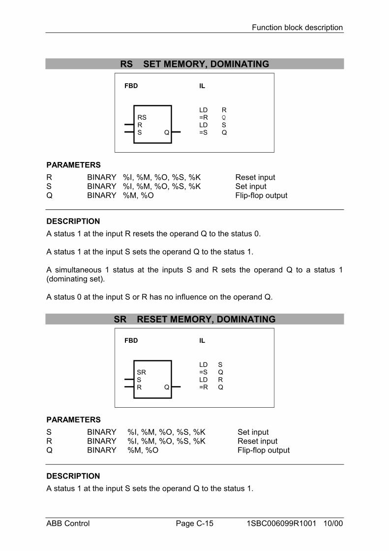
Function block description
ABB Control Page C-15 1SBC006099R1001 10/00
RS SET MEMORY, DOMINATING
FBD IL
RSRS Q
LD=RLD=S
RQSQ
PARAMETERSR BINARY %I, %M, %O, %S, %K Reset inputS BINARY %I, %M, %O, %S, %K Set inputQ BINARY %M, %O Flip-flop output
DESCRIPTIONA status 1 at the input R resets the operand Q to the status 0.
A status 1 at the input S sets the operand Q to the status 1.
A simultaneous 1 status at the inputs S and R sets the operand Q to a status 1(dominating set).
A status 0 at the input S or R has no influence on the operand Q.
SR RESET MEMORY, DOMINATING
FBD IL
SRSR Q
LD=SLD=R
SQRQ
PARAMETERSS BINARY %I, %M, %O, %S, %K Set inputR BINARY %I, %M, %O, %S, %K Reset inputQ BINARY %M, %O Flip-flop output
DESCRIPTIONA status 1 at the input S sets the operand Q to the status 1.
Function block description
ABB Control Page C-16 1SBC006099R1001 10/00
A status 1 at the input R resets the operand Q to the status 0.
A simultaneous 1 status at the inputs S and R resets the operand to a status 0(dominating reset).
A status 0 at the input S or R has no influence on the operand Q.
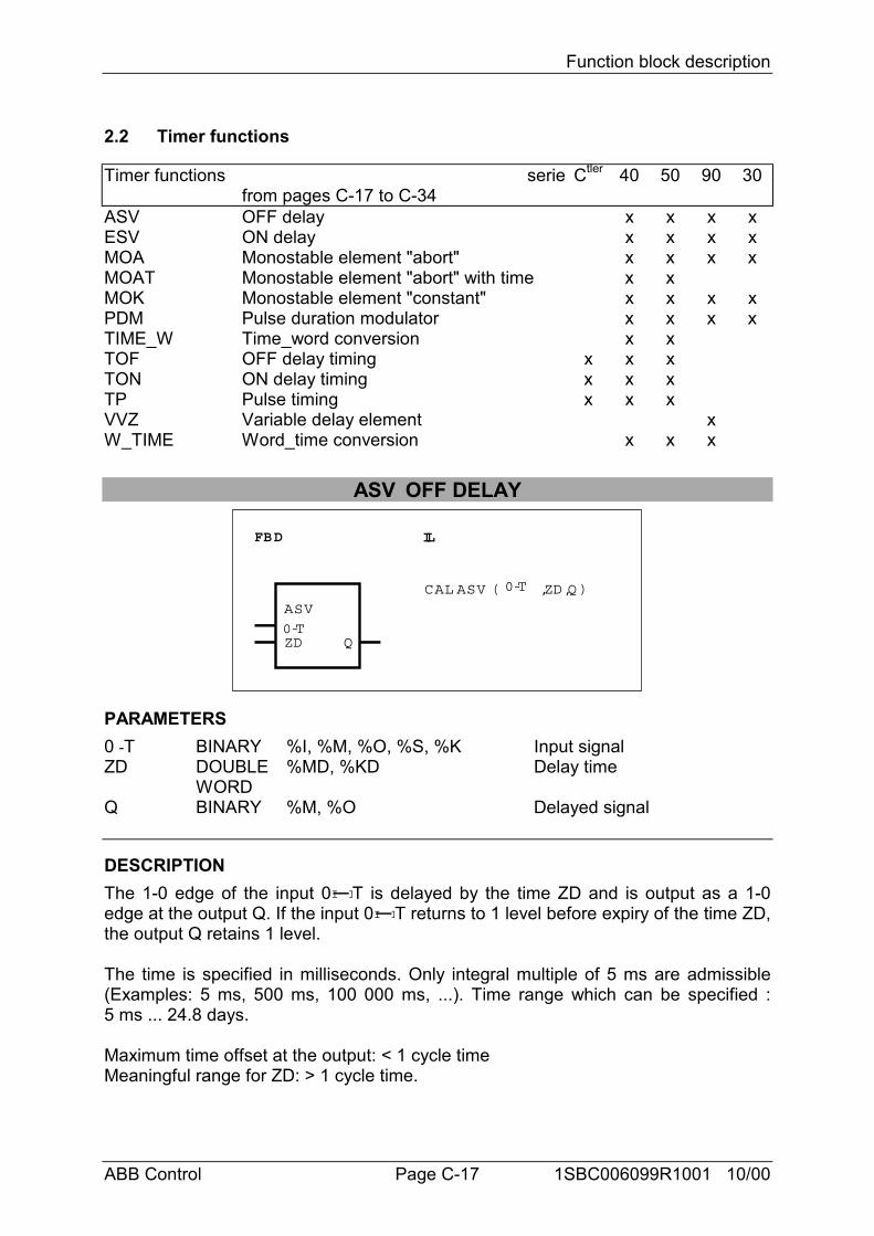
Function block description
ABB Control Page C-17 1SBC006099R1001 10/00
2.2 Timer functions
Timer functions seriefrom pages C-17 to C-34
Ctler 40 50 90 30
ASV OFF delay x x x xESV ON delay x x x xMOA Monostable element "abort" x x x xMOAT Monostable element "abort" with time x xMOK Monostable element "constant" x x x xPDM Pulse duration modulator x x x xTIME_W Time_word conversion x xTOF OFF delay timing x x xTON ON delay timing x x xTP Pulse timing x x xVVZ Variable delay element xW_TIME Word_time conversion x x x
ASV OFF DELAY
FBD IL
ASV
ZD
CAL ASV ( ,ZD,Q )
0-TQ
0-T
PARAMETERS0 -T BINARY %I, %M, %O, %S, %K Input signalZD DOUBLE
WORD%MD, %KD Delay time
Q BINARY %M, %O Delayed signal
DESCRIPTIONThe 1-0 edge of the input 0I IT is delayed by the time ZD and is output as a 1-0edge at the output Q. If the input 0I IT returns to 1 level before expiry of the time ZD,the output Q retains 1 level.
The time is specified in milliseconds. Only integral multiple of 5 ms are admissible(Examples: 5 ms, 500 ms, 100 000 ms, ...). Time range which can be specified :5 ms ... 24.8 days.
Maximum time offset at the output: < 1 cycle timeMeaningful range for ZD: > 1 cycle time.
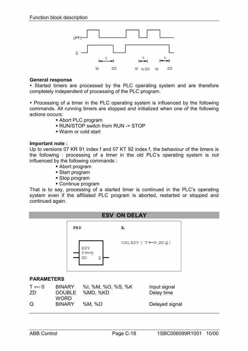
Function block description
ABB Control Page C-18 1SBC006099R1001 10/00
Qt
ZD
t t
ZD
0 T
t<ZDt0 t0 t0
General response" Started timers are processed by the PLC operating system and are thereforecompletely independent of processing of the PLC program.
" Processing of a timer in the PLC operating system is influenced by the followingcommands. All running timers are stopped and initialized when one of the followingactions occurs:
# Abort PLC program# RUN/STOP switch from RUN -> STOP# Warm or cold start
Important note :Up to versions 07 KR 91 index f and 07 KT 92 index f, the behaviour of the timers isthe following : processing of a timer in the old PLC’s operating system is notinfluenced by the following commands :
# Abort program# Start program# Stop program# Continue program
That is to say, processing of a started timer is continued in the PLC’s operatingsystem even if the affiliated PLC program is aborted, restarted or stopped andcontinued again.
ESV ON DELAY
FBD IL
ESV
ZD
CAL ESV ( ,ZD,Q )
T 0I I
Q
T 0I I
PARAMETERST I I 0 BINARY %I, %M, %O, %S, %K Input signalZD DOUBLE
WORD%MD, %KD Delay time
Q BINARY %M, %O Delayed signal
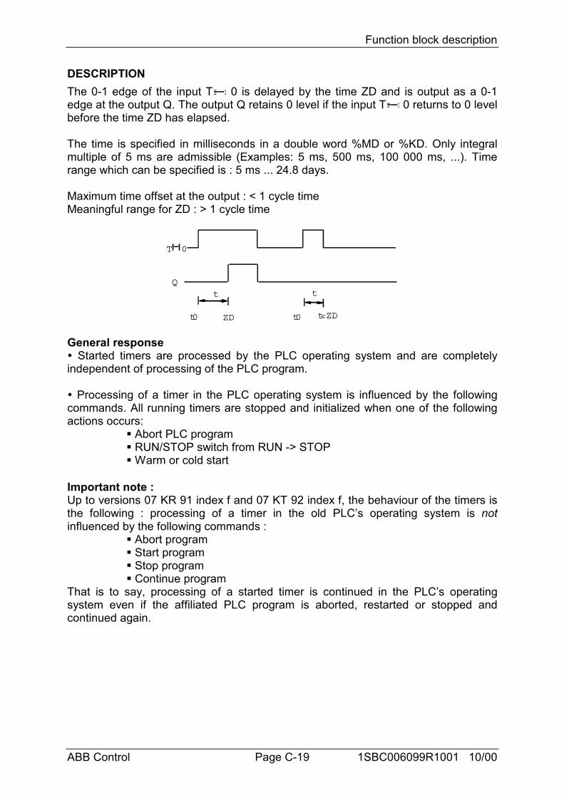
Function block description
ABB Control Page C-19 1SBC006099R1001 10/00
DESCRIPTIONThe 0-1 edge of the input TI I 0 is delayed by the time ZD and is output as a 0-1edge at the output Q. The output Q retains 0 level if the input TI I 0 returns to 0 levelbefore the time ZD has elapsed.
The time is specified in milliseconds in a double word %MD or %KD. Only integralmultiple of 5 ms are admissible (Examples: 5 ms, 500 ms, 100 000 ms, ...). Timerange which can be specified is : 5 ms ... 24.8 days.
Maximum time offset at the output : < 1 cycle timeMeaningful range for ZD : > 1 cycle time
Qt
ZD
t
T 0
t0 t0 t<ZD
General response" Started timers are processed by the PLC operating system and are completelyindependent of processing of the PLC program.
" Processing of a timer in the PLC operating system is influenced by the followingcommands. All running timers are stopped and initialized when one of the followingactions occurs:
# Abort PLC program# RUN/STOP switch from RUN -> STOP# Warm or cold start
Important note :Up to versions 07 KR 91 index f and 07 KT 92 index f, the behaviour of the timers isthe following : processing of a timer in the old PLC’s operating system is notinfluenced by the following commands :
# Abort program# Start program# Stop program# Continue program
That is to say, processing of a started timer is continued in the PLC’s operatingsystem even if the affiliated PLC program is aborted, restarted or stopped andcontinued again.
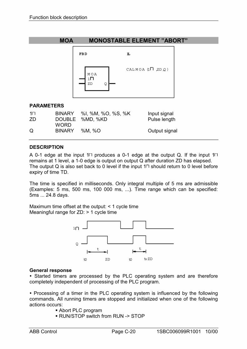
Function block description
ABB Control Page C-20 1SBC006099R1001 10/00
MOA MONOSTABLE ELEMENT ”ABORT”
FBD IL
M O A1ZD
CAL M O A (1 ,ZD,Q )
Q
PARAMETERS1 BINARY %I, %M, %O, %S, %K Input signalZD DOUBLE
WORD%MD, %KD Pulse length
Q BINARY %M, %O Output signal
DESCRIPTIONA 0-1 edge at the input 1 produces a 0-1 edge at the output Q. If the input 1remains at 1 level, a 1-0 edge is output on output Q after duration ZD has elapsed.The output Q is also set back to 0 level if the input 1 should return to 0 level beforeexpiry of time TD.
The time is specified in milliseconds. Only integral multiple of 5 ms are admissible(Examples: 5 ms, 500 ms, 100 000 ms, ...). Time range which can be specified:5ms ... 24.8 days.
Maximum time offset at the output: < 1 cycle timeMeaningful range for ZD: > 1 cycle time
Qt
ZD
t
1
t0 t0 t<ZD
General response" Started timers are processed by the PLC operating system and are thereforecompletely independent of processing of the PLC program.
" Processing of a timer in the PLC operating system is influenced by the followingcommands. All running timers are stopped and initialized when one of the followingactions occurs:
# Abort PLC program# RUN/STOP switch from RUN -> STOP
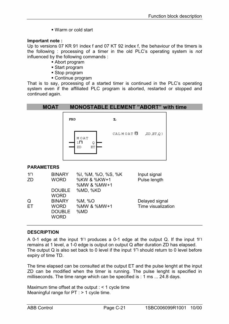
Function block description
ABB Control Page C-21 1SBC006099R1001 10/00
# Warm or cold start
Important note :Up to versions 07 KR 91 index f and 07 KT 92 index f, the behaviour of the timers isthe following : processing of a timer in the old PLC’s operating system is notinfluenced by the following commands :
# Abort program# Start program# Stop program# Continue program
That is to say, processing of a started timer is continued in the PLC’s operatingsystem even if the affiliated PLC program is aborted, restarted or stopped andcontinued again.
MOAT MONOSTABLE ELEMENT ”ABORT” with time
FBD IL
M OAT1ZD
CAL M OAT (1 ,ZD,ET,Q )
QET
PARAMETERS1 BINARY %I, %M, %O, %S, %K Input signalZD WORD
DOUBLEWORD
%KW & %KW+1%MW & %MW+1%MD, %KD
Pulse length
Q BINARY %M, %O Delayed signalET WORD
DOUBLEWORD
%MW & %MW+1%MD
Time visualization
DESCRIPTIONA 0-1 edge at the input 1 produces a 0-1 edge at the output Q. If the input 1remains at 1 level, a 1-0 edge is output on output Q after duration ZD has elapsed.The output Q is also set back to 0 level if the input 1 should return to 0 level beforeexpiry of time TD.
The time elapsed can be consulted at the output ET and the pulse lenght at the inputZD can be modified when the timer is running. The pulse lenght is specified inmilliseconds. The time range which can be specified is : 1 ms ... 24.8 days.
Maximum time offset at the output : < 1 cycle timeMeaningful range for PT : > 1 cycle time.
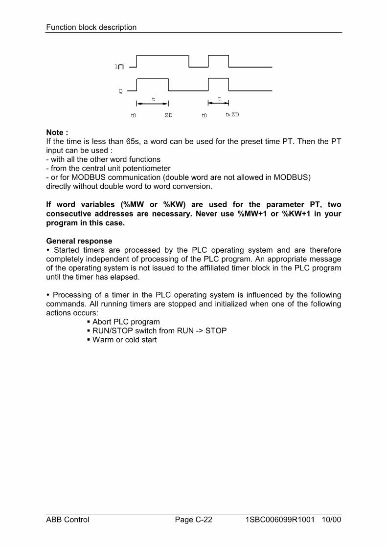
Function block description
ABB Control Page C-22 1SBC006099R1001 10/00
Qt
ZD
t
1
t0 t0 t<ZD
Note :If the time is less than 65s, a word can be used for the preset time PT. Then the PTinput can be used :- with all the other word functions- from the central unit potentiometer- or for MODBUS communication (double word are not allowed in MODBUS)directly without double word to word conversion.
If word variables (%MW or %KW) are used for the parameter PT, twoconsecutive addresses are necessary. Never use %MW+1 or %KW+1 in yourprogram in this case.
General response" Started timers are processed by the PLC operating system and are thereforecompletely independent of processing of the PLC program. An appropriate messageof the operating system is not issued to the affiliated timer block in the PLC programuntil the timer has elapsed.
" Processing of a timer in the PLC operating system is influenced by the followingcommands. All running timers are stopped and initialized when one of the followingactions occurs:
# Abort PLC program# RUN/STOP switch from RUN -> STOP# Warm or cold start
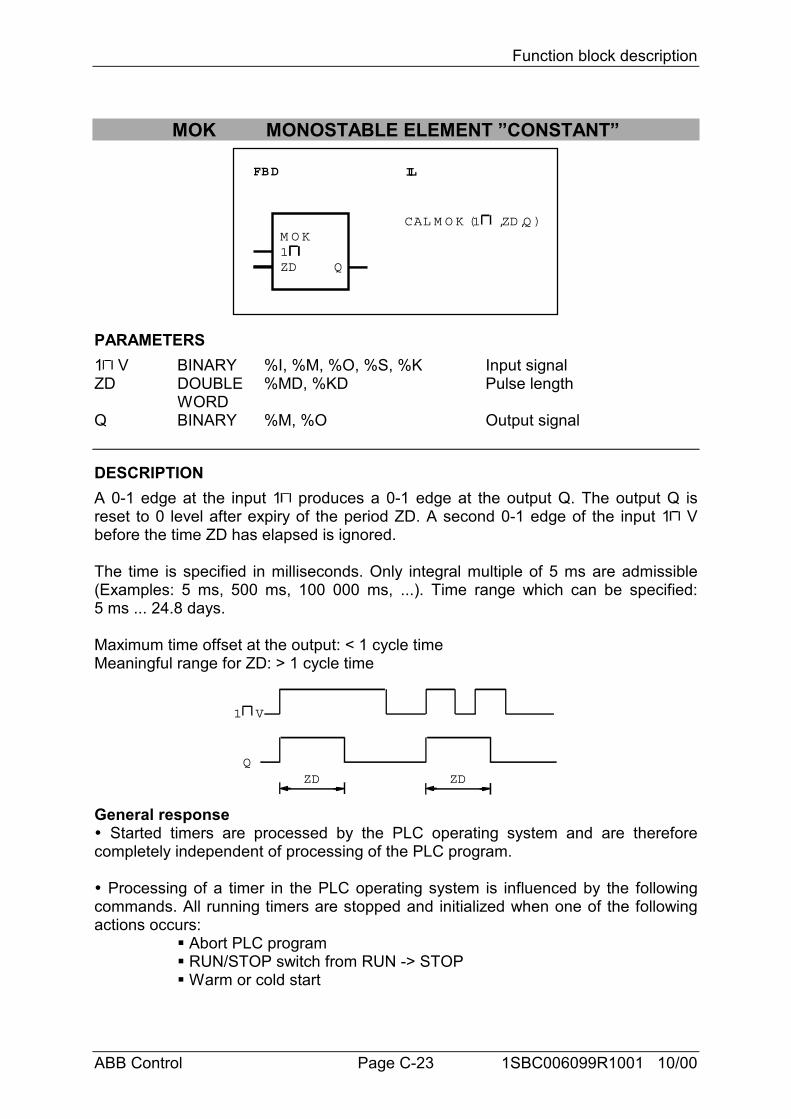
Function block description
ABB Control Page C-23 1SBC006099R1001 10/00
MOK MONOSTABLE ELEMENT ”CONSTANT”
FBD IL
M O K1ZD
CAL M O K (1 ,ZD,Q )
Q
PARAMETERS1 V BINARY %I, %M, %O, %S, %K Input signalZD DOUBLE
WORD%MD, %KD Pulse length
Q BINARY %M, %O Output signal
DESCRIPTIONA 0-1 edge at the input 1 produces a 0-1 edge at the output Q. The output Q isreset to 0 level after expiry of the period ZD. A second 0-1 edge of the input 1 Vbefore the time ZD has elapsed is ignored.
The time is specified in milliseconds. Only integral multiple of 5 ms are admissible(Examples: 5 ms, 500 ms, 100 000 ms, ...). Time range which can be specified:5 ms ... 24.8 days.
Maximum time offset at the output: < 1 cycle timeMeaningful range for ZD: > 1 cycle time
QZD
1 V
ZD
General response" Started timers are processed by the PLC operating system and are thereforecompletely independent of processing of the PLC program.
" Processing of a timer in the PLC operating system is influenced by the followingcommands. All running timers are stopped and initialized when one of the followingactions occurs:
# Abort PLC program# RUN/STOP switch from RUN -> STOP# Warm or cold start
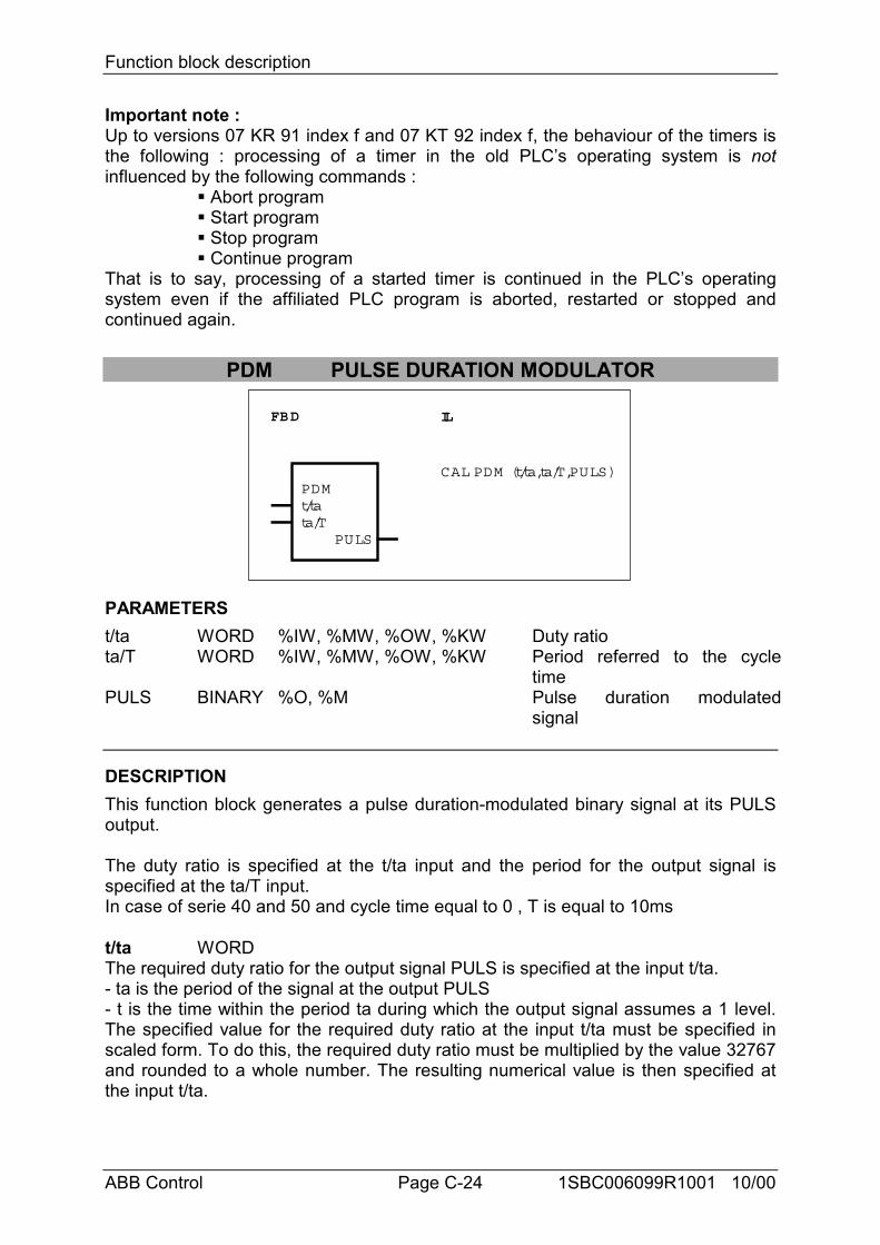
Function block description
ABB Control Page C-24 1SBC006099R1001 10/00
Important note :Up to versions 07 KR 91 index f and 07 KT 92 index f, the behaviour of the timers isthe following : processing of a timer in the old PLC’s operating system is notinfluenced by the following commands :
# Abort program# Start program# Stop program# Continue program
That is to say, processing of a started timer is continued in the PLC’s operatingsystem even if the affiliated PLC program is aborted, restarted or stopped andcontinued again.
PDM PULSE DURATION MODULATOR
FBD IL
PDMt/tata/T
PULS
CAL PDM (t/ta,ta/T,PULS)
PARAMETERSt/ta WORD %IW, %MW, %OW, %KW Duty ratiota/T WORD %IW, %MW, %OW, %KW Period referred to the cycle
timePULS BINARY %O, %M Pulse duration modulated
signal
DESCRIPTIONThis function block generates a pulse duration-modulated binary signal at its PULSoutput.
The duty ratio is specified at the t/ta input and the period for the output signal isspecified at the ta/T input.In case of serie 40 and 50 and cycle time equal to 0 , T is equal to 10ms
t/ta WORDThe required duty ratio for the output signal PULS is specified at the input t/ta.- ta is the period of the signal at the output PULS- t is the time within the period ta during which the output signal assumes a 1 level.The specified value for the required duty ratio at the input t/ta must be specified inscaled form. To do this, the required duty ratio must be multiplied by the value 32767and rounded to a whole number. The resulting numerical value is then specified atthe input t/ta.
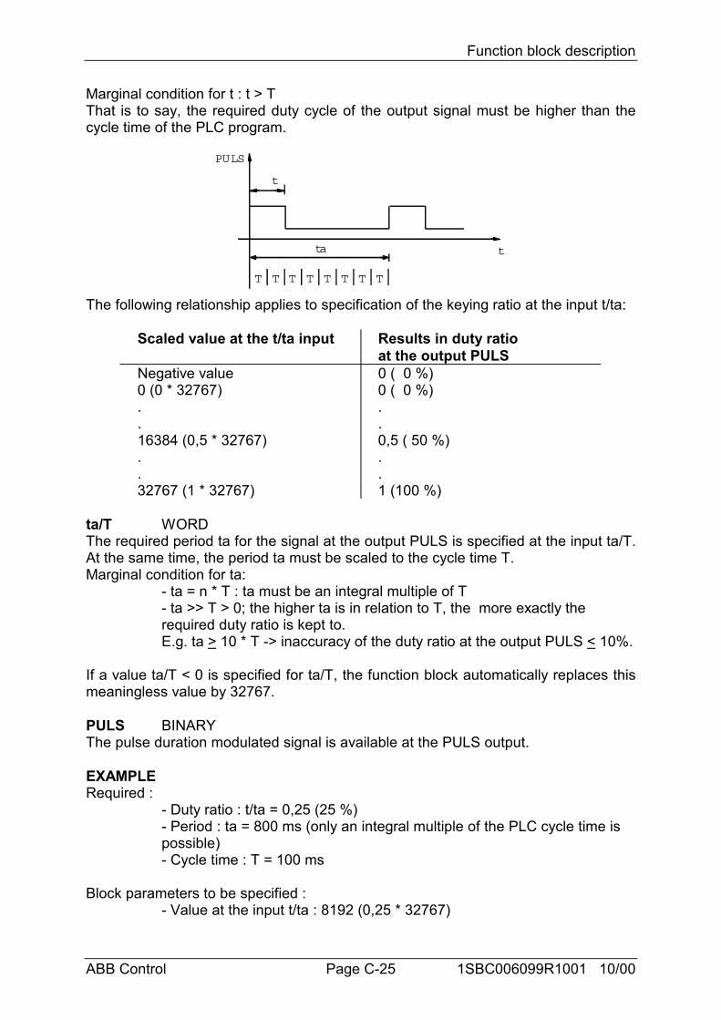
Function block description
ABB Control Page C-25 1SBC006099R1001 10/00
Marginal condition for t : t > TThat is to say, the required duty cycle of the output signal must be higher than thecycle time of the PLC program.
ta
t
PULS
t
T T T T T T T T
The following relationship applies to specification of the keying ratio at the input t/ta:
Scaled value at the t/ta input Results in duty ratioat the output PULS
Negative value 0 ( 0 %)0 (0 * 32767) 0 ( 0 %). .. .16384 (0,5 * 32767) 0,5 ( 50 %). .. .32767 (1 * 32767) 1 (100 %)
ta/T WORDThe required period ta for the signal at the output PULS is specified at the input ta/T.At the same time, the period ta must be scaled to the cycle time T.Marginal condition for ta:
- ta = n * T : ta must be an integral multiple of T- ta >> T > 0; the higher ta is in relation to T, the more exactly the required duty ratio is kept to.E.g. ta > 10 * T -> inaccuracy of the duty ratio at the output PULS < 10%.
If a value ta/T < 0 is specified for ta/T, the function block automatically replaces thismeaningless value by 32767.
PULS BINARYThe pulse duration modulated signal is available at the PULS output.
EXAMPLERequired :
- Duty ratio : t/ta = 0,25 (25 %)- Period : ta = 800 ms (only an integral multiple of the PLC cycle time is possible)- Cycle time : T = 100 ms
Block parameters to be specified :- Value at the input t/ta : 8192 (0,25 * 32767)
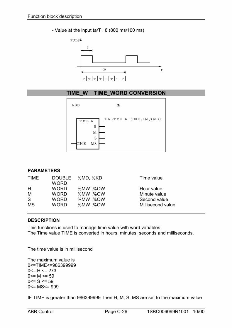
Function block description
ABB Control Page C-26 1SBC006099R1001 10/00
- Value at the input ta/T : 8 (800 ms/100 ms)
ta
t
PULS
t
T T T T T T T T
TIME_W TIME_WORD CONVERSION
FBD IL
TIM E_W
TIM E
CAL TIM E_W (TIM E,H,M ,S,M S)
H
MS
MS
PARAMETERSTIME DOUBLE
WORD%MD, %KD Time value
H WORD %MW ,%OW Hour valueM WORD %MW ,%OW Minute valueS WORD %MW ,%OW Second valueMS WORD %MW ,%OW Millisecond value
DESCRIPTIONThis functions is used to manage time value with word variablesThe Time value TIME is converted in hours, minutes, seconds and milliseconds.
The time value is in millisecond
The maximum value is0<=TIME<=9863999990<= H <= 2730<= M <= 590<= S <= 590<= MS<= 999
IF TIME is greater than 986399999 then H, M, S, MS are set to the maximum value
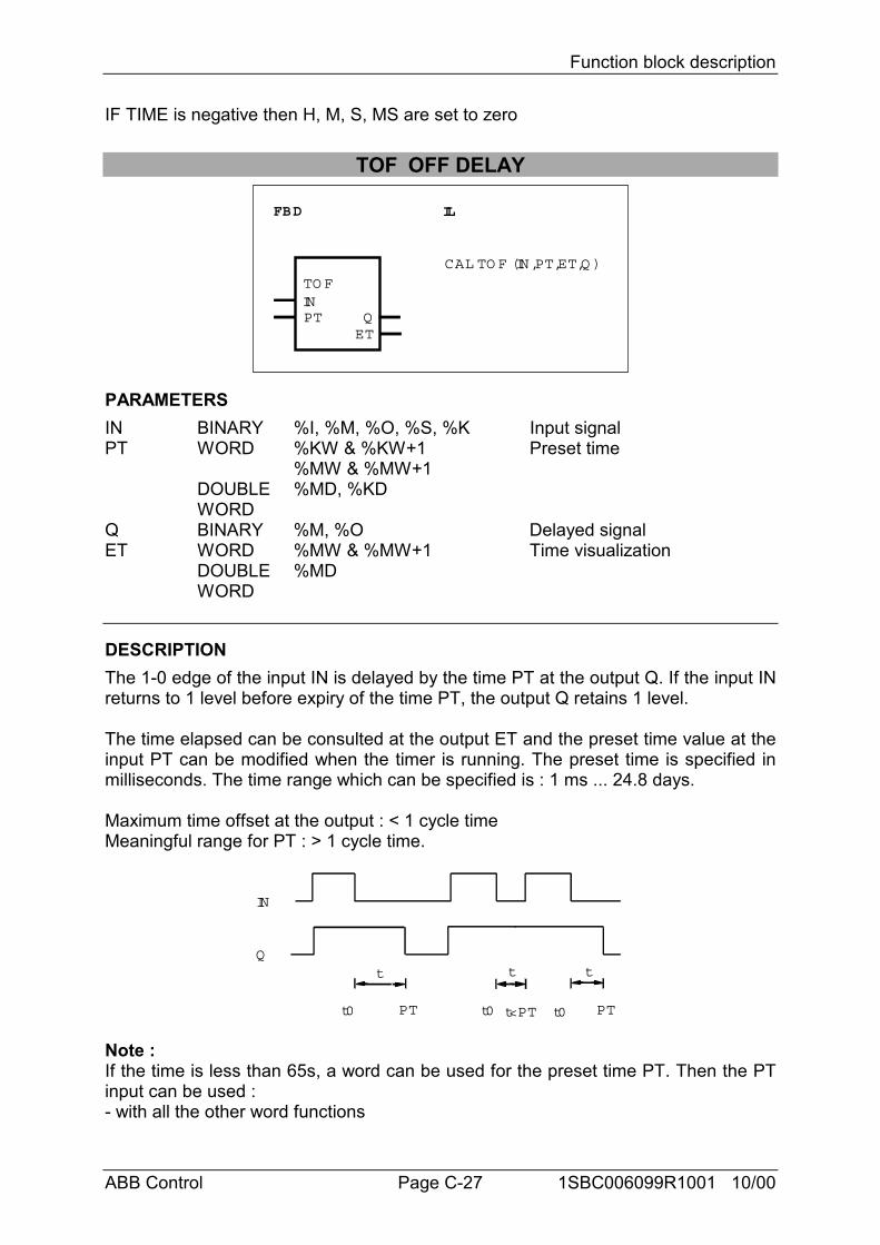
Function block description
ABB Control Page C-27 1SBC006099R1001 10/00
IF TIME is negative then H, M, S, MS are set to zero
TOF OFF DELAY
FBD IL
TO F
PT
CAL TO F (IN,PT,ET,Q )
INQET
PARAMETERSIN BINARY %I, %M, %O, %S, %K Input signalPT WORD
DOUBLEWORD
%KW & %KW+1%MW & %MW+1%MD, %KD
Preset time
Q BINARY %M, %O Delayed signalET WORD
DOUBLEWORD
%MW & %MW+1%MD
Time visualization
DESCRIPTIONThe 1-0 edge of the input IN is delayed by the time PT at the output Q. If the input INreturns to 1 level before expiry of the time PT, the output Q retains 1 level.
The time elapsed can be consulted at the output ET and the preset time value at theinput PT can be modified when the timer is running. The preset time is specified inmilliseconds. The time range which can be specified is : 1 ms ... 24.8 days.
Maximum time offset at the output : < 1 cycle timeMeaningful range for PT : > 1 cycle time.
Qt
PT
t t
PT
IN
t<PTt0 t0 t0
Note :If the time is less than 65s, a word can be used for the preset time PT. Then the PTinput can be used :- with all the other word functions
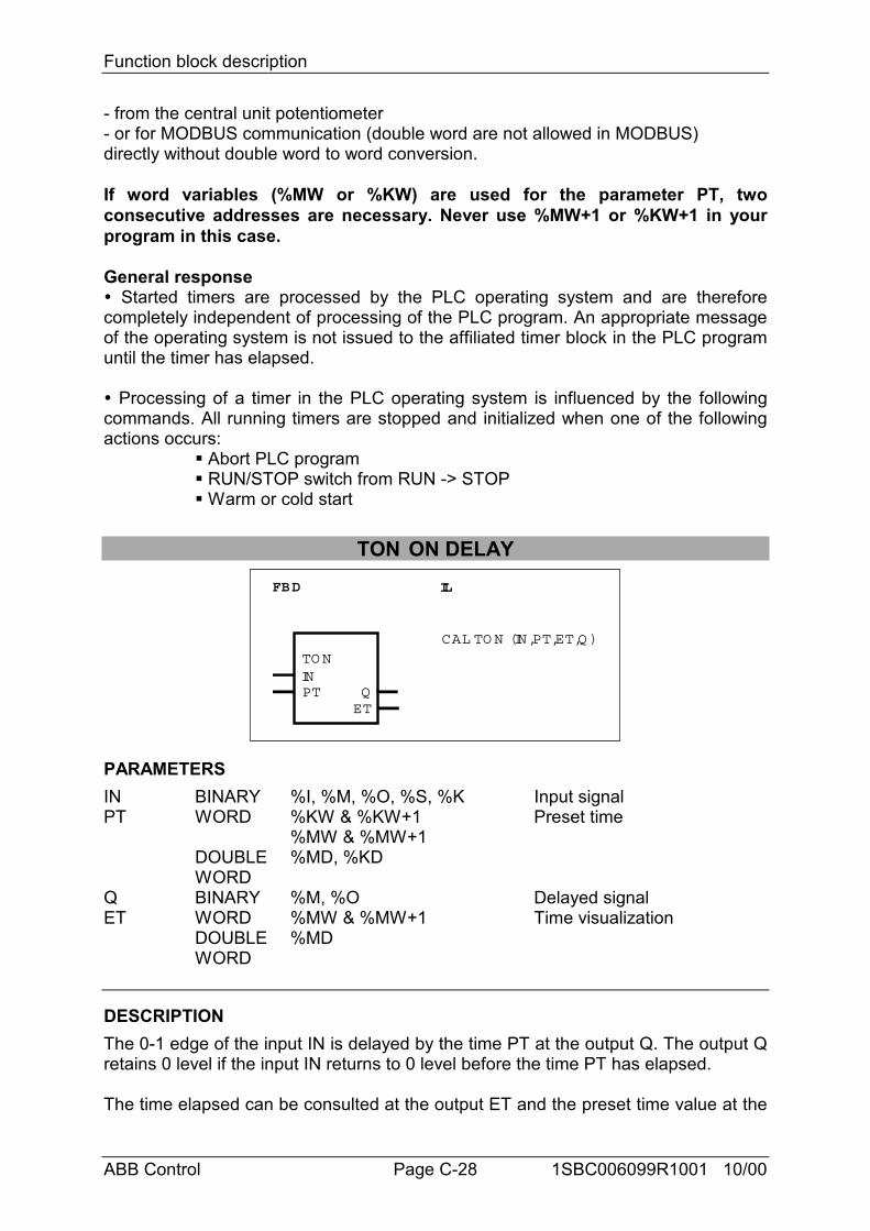
Function block description
ABB Control Page C-28 1SBC006099R1001 10/00
- from the central unit potentiometer- or for MODBUS communication (double word are not allowed in MODBUS)directly without double word to word conversion.
If word variables (%MW or %KW) are used for the parameter PT, twoconsecutive addresses are necessary. Never use %MW+1 or %KW+1 in yourprogram in this case.
General response" Started timers are processed by the PLC operating system and are thereforecompletely independent of processing of the PLC program. An appropriate messageof the operating system is not issued to the affiliated timer block in the PLC programuntil the timer has elapsed.
" Processing of a timer in the PLC operating system is influenced by the followingcommands. All running timers are stopped and initialized when one of the followingactions occurs:
# Abort PLC program# RUN/STOP switch from RUN -> STOP# Warm or cold start
TON ON DELAYFBD IL
TO N
PT
CAL TO N (IN,PT,ET,Q )
INQET
PARAMETERSIN BINARY %I, %M, %O, %S, %K Input signalPT WORD
DOUBLEWORD
%KW & %KW+1%MW & %MW+1%MD, %KD
Preset time
Q BINARY %M, %O Delayed signalET WORD
DOUBLEWORD
%MW & %MW+1%MD
Time visualization
DESCRIPTIONThe 0-1 edge of the input IN is delayed by the time PT at the output Q. The output Qretains 0 level if the input IN returns to 0 level before the time PT has elapsed.
The time elapsed can be consulted at the output ET and the preset time value at the
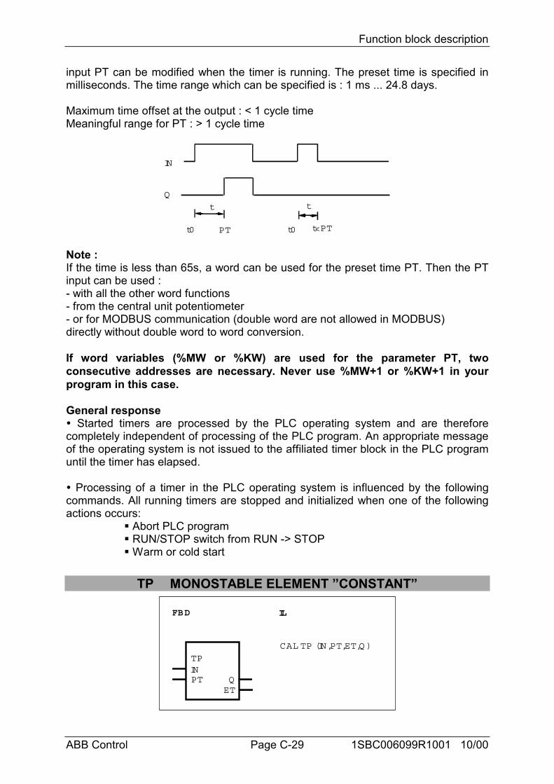
Function block description
ABB Control Page C-29 1SBC006099R1001 10/00
input PT can be modified when the timer is running. The preset time is specified inmilliseconds. The time range which can be specified is : 1 ms ... 24.8 days.
Maximum time offset at the output : < 1 cycle timeMeaningful range for PT : > 1 cycle time
Q
t
PT
t
t0 t0 t<PT
IN
Note :If the time is less than 65s, a word can be used for the preset time PT. Then the PTinput can be used :- with all the other word functions- from the central unit potentiometer- or for MODBUS communication (double word are not allowed in MODBUS)directly without double word to word conversion.
If word variables (%MW or %KW) are used for the parameter PT, twoconsecutive addresses are necessary. Never use %MW+1 or %KW+1 in yourprogram in this case.
General response" Started timers are processed by the PLC operating system and are thereforecompletely independent of processing of the PLC program. An appropriate messageof the operating system is not issued to the affiliated timer block in the PLC programuntil the timer has elapsed.
" Processing of a timer in the PLC operating system is influenced by the followingcommands. All running timers are stopped and initialized when one of the followingactions occurs:
# Abort PLC program# RUN/STOP switch from RUN -> STOP# Warm or cold start
TP MONOSTABLE ELEMENT ”CONSTANT”
FBD IL
TP
PT
CAL TP (IN,PT,ET,Q )
INQET
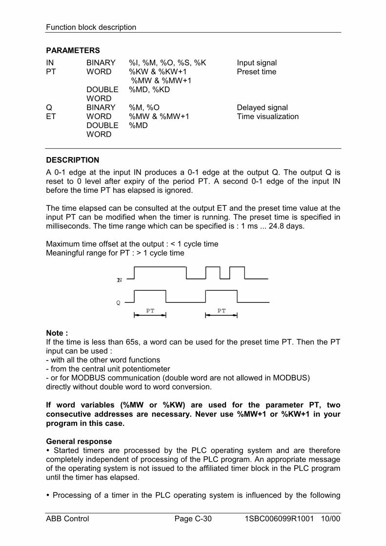
Function block description
ABB Control Page C-30 1SBC006099R1001 10/00
PARAMETERSIN BINARY %I, %M, %O, %S, %K Input signalPT WORD
DOUBLEWORD
%KW & %KW+1 %MW & %MW+1%MD, %KD
Preset time
Q BINARY %M, %O Delayed signalET WORD
DOUBLEWORD
%MW & %MW+1%MD
Time visualization
DESCRIPTIONA 0-1 edge at the input IN produces a 0-1 edge at the output Q. The output Q isreset to 0 level after expiry of the period PT. A second 0-1 edge of the input INbefore the time PT has elapsed is ignored.
The time elapsed can be consulted at the output ET and the preset time value at theinput PT can be modified when the timer is running. The preset time is specified inmilliseconds. The time range which can be specified is : 1 ms ... 24.8 days.
Maximum time offset at the output : < 1 cycle timeMeaningful range for PT : > 1 cycle time
QPT
IN
PT
Note :If the time is less than 65s, a word can be used for the preset time PT. Then the PTinput can be used :- with all the other word functions- from the central unit potentiometer- or for MODBUS communication (double word are not allowed in MODBUS)directly without double word to word conversion.
If word variables (%MW or %KW) are used for the parameter PT, twoconsecutive addresses are necessary. Never use %MW+1 or %KW+1 in yourprogram in this case.
General response" Started timers are processed by the PLC operating system and are thereforecompletely independent of processing of the PLC program. An appropriate messageof the operating system is not issued to the affiliated timer block in the PLC programuntil the timer has elapsed.
" Processing of a timer in the PLC operating system is influenced by the following
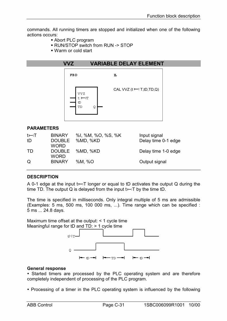
Function block description
ABB Control Page C-31 1SBC006099R1001 10/00
commands. All running timers are stopped and initialized when one of the followingactions occurs:
# Abort PLC program# RUN/STOP switch from RUN -> STOP# Warm or cold start
VVZ VARIABLE DELAY ELEMENT
FBD IL
VVZttDTD Q
CAL VVZ (t T,tD,TD,Q)
I IT
I I
PARAMETERStI IT BINARY %I, %M, %O, %S, %K Input signaltD DOUBLE
WORD%MD, %KD Delay time 0-1 edge
TD DOUBLEWORD
%MD, %KD Delay time 1-0 edge
Q BINARY %M, %O Output signal
DESCRIPTIONA 0-1 edge at the input tI IT longer or equal to tD activates the output Q during thetime TD. The output Q is delayed from the input tI IT by the time tD.
The time is specified in milliseconds. Only integral multiple of 5 ms are admissible(Examples: 5 ms, 500 ms, 100 000 ms, ...). Time range which can be specified :5 ms ... 24.8 days.
Maximum time offset at the output: < 1 cycle timeMeaningful range for tD and TD: > 1 cycle time
Q
tD
t T
TD tD
General response" Started timers are processed by the PLC operating system and are thereforecompletely independent of processing of the PLC program.
" Processing of a timer in the PLC operating system is influenced by the following
Function block description
ABB Control Page C-32 1SBC006099R1001 10/00
commands. All running timers are stopped and initialized when one of the followingactions occurs:
# Abort PLC program# RUN/STOP switch from RUN -> STOP# Warm or cold start
Important note :Up to versions 07 KR 91 index f and 07 KT 92 index f, the behaviour of the timers isthe following : processing of a timer in the old PLC’s operating system is notinfluenced by the following commands :
# Abort program# Start program# Stop program# Continue program
That is to say, processing of a started timer is continued in the PLC’s operatingsystem even if the affiliated PLC program is aborted, restarted or stopped andcontinued again.
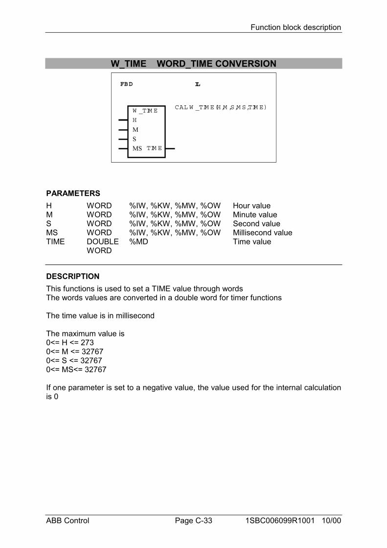
Function block description
ABB Control Page C-33 1SBC006099R1001 10/00
W_TIME WORD_TIME CONVERSION
FBD IL
W _TIM E
TIM E
CAL W _TIM E(H,M ,S,M S,TIM E)
H
MSMS
PARAMETERSH WORD %IW, %KW, %MW, %OW Hour valueM WORD %IW, %KW, %MW, %OW Minute valueS WORD %IW, %KW, %MW, %OW Second valueMS WORD %IW, %KW, %MW, %OW Millisecond valueTIME DOUBLE
WORD%MD Time value
DESCRIPTIONThis functions is used to set a TIME value through wordsThe words values are converted in a double word for timer functions
The time value is in millisecond
The maximum value is0<= H <= 2730<= M <= 327670<= S <= 327670<= MS<= 32767
If one parameter is set to a negative value, the value used for the internal calculationis 0
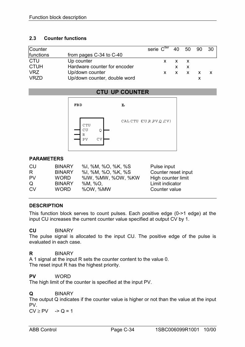
Function block description
ABB Control Page C-34 1SBC006099R1001 10/00
2.3 Counter functions
Counterfunctions
seriefrom pages C-34 to C-40
Ctler 40 50 90 30
CTU Up counter x x xCTUH Hardware counter for encoder x xVRZ Up/down counter x x x x xVRZD Up/down counter, double word x
CTU UP COUNTER
FBD IL
CTUCURPV
CAL CTU (CU,R,PV,Q ,CV)
CV
Q
PARAMETERSCU BINARY %I, %M, %O, %K, %S Pulse inputR BINARY %I, %M, %O, %K, %S Counter reset inputPV WORD %IW, %MW, %OW, %KW High counter limitQ BINARY %M, %O, Limit indicatorCV WORD %OW, %MW Counter value
DESCRIPTIONThis function block serves to count pulses. Each positive edge (0->1 edge) at theinput CU increases the current counter value specified at output CV by 1.
CU BINARYThe pulse signal is allocated to the input CU. The positive edge of the pulse isevaluated in each case.
R BINARYA 1 signal at the input R sets the counter content to the value 0.The reset input R has the highest priority.
PV WORDThe high limit of the counter is specified at the input PV.
Q BINARYThe output Q indicates if the counter value is higher or not than the value at the inputPV.CV ≥ PV -> Q = 1
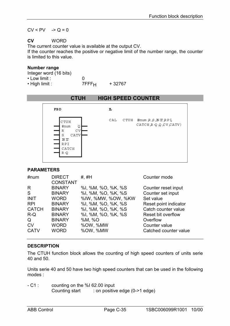
Function block description
ABB Control Page C-35 1SBC006099R1001 10/00
CV < PV -> Q = 0
CV WORDThe current counter value is available at the output CV.If the counter reaches the positive or negative limit of the number range, the counteris limited to this value.
Number rangeInteger word (16 bits)• Low limit : 0• High limit : 7FFFH + 32767
CTUH HIGH SPEED COUNTER
#numRSINITRPICATCH
CTUH
R-Q
QCV
CATV
FBD IL
CAL CTUH (#num ,R,S,INIT,RPI,CATCH,R-Q ,Q ,CV,CATV)
PARAMETERS#num DIRECT
CONSTANT#, #H Counter mode
R BINARY %I, %M, %O, %K, %S Counter reset inputS BINARY %I, %M, %O, %K, %S Counter set inputINIT WORD %IW, %MW, %OW, %KW Set valueRPI BINARY %I, %M, %O, %K, %S Reset point indicatorCATCH BINARY %I, %M, %O, %K, %S Catch counter valueR-Q BINARY %I, %M, %O, %K, %S Reset bit overflowQ BINARY %M, %O OverflowCV WORD %OW, %MW Counter valueCATV WORD %OW, %MW Catched counter value
DESCRIPTIONThe CTUH function block allows the counting of high speed counters of units serie40 and 50.
Units serie 40 and 50 have two high speed counters that can be used in the followingmodes :
- C1 : counting on the %I 62.00 inputCounting start : on positive edge (0->1 edge)
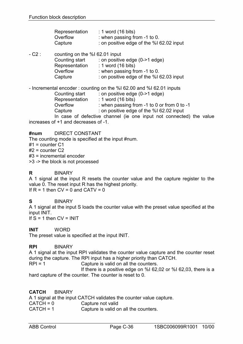
Function block description
ABB Control Page C-36 1SBC006099R1001 10/00
Representation : 1 word (16 bits)Overflow : when passing from -1 to 0.Capture : on positive edge of the %I 62.02 input
- C2 : counting on the %I 62.01 inputCounting start : on positive edge (0->1 edge)Representation : 1 word (16 bits)Overflow : when passing from -1 to 0.Capture : on positive edge of the %I 62.03 input
- Incremental encoder : counting on the %I 62.00 and %I 62.01 inputsCounting start : on positive edge (0->1 edge)Representation : 1 word (16 bits)Overflow : when passing from -1 to 0 or from 0 to -1Capture : on positive edge of the %I 62.02 inputIn case of defective channel (ie one input not connected) the value
increases of +1 and decreases of -1.
#num DIRECT CONSTANTThe counting mode is specified at the input #num.#1 = counter C1#2 = counter C2#3 = incremental encoder>3 -> the block is not processed
R BINARYA 1 signal at the input R resets the counter value and the capture register to thevalue 0. The reset input R has the highest priority.If R = 1 then CV = 0 and CATV = 0
S BINARYA 1 signal at the input S loads the counter value with the preset value specified at theinput INIT.If S = 1 then CV = INIT
INIT WORDThe preset value is specified at the input INIT.
RPI BINARYA 1 signal at the input RPI validates the counter value capture and the counter resetduring the capture. The RPI input has a higher priority than CATCH.RPI = 1 Capture is valid on all the counters.
If there is a positive edge on %I 62,02 or %I 62,03, there is ahard capture of the counter. The counter is reset to 0.
CATCH BINARYA 1 signal at the input CATCH validates the counter value capture.CATCH = 0 Capture not validCATCH = 1 Capture is valid on all the counters.
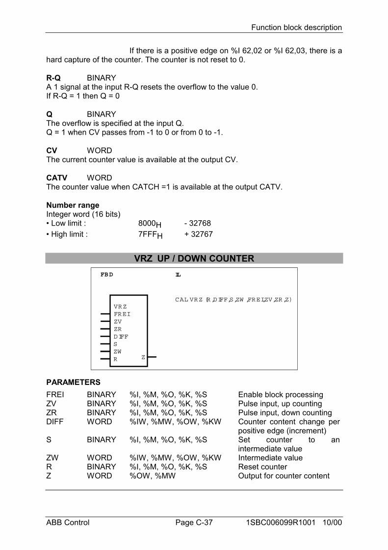
Function block description
ABB Control Page C-37 1SBC006099R1001 10/00
If there is a positive edge on %I 62,02 or %I 62,03, there is ahard capture of the counter. The counter is not reset to 0.
R-Q BINARYA 1 signal at the input R-Q resets the overflow to the value 0.If R-Q = 1 then Q = 0
Q BINARYThe overflow is specified at the input Q.Q = 1 when CV passes from -1 to 0 or from 0 to -1.
CV WORDThe current counter value is available at the output CV.
CATV WORDThe counter value when CATCH =1 is available at the output CATV.
Number rangeInteger word (16 bits)• Low limit : 8000H - 32768• High limit : 7FFFH + 32767
VRZ UP / DOWN COUNTERFBD IL
VRZFREIZVZRDIFF
CAL VRZ (R,DIFF,S,ZW ,FREI,ZV,ZR,Z)
SZWR Z
PARAMETERSFREI BINARY %I, %M, %O, %K, %S Enable block processingZV BINARY %I, %M, %O, %K, %S Pulse input, up countingZR BINARY %I, %M, %O, %K, %S Pulse input, down countingDIFF WORD %IW, %MW, %OW, %KW Counter content change per
positive edge (increment)S BINARY %I, %M, %O, %K, %S Set counter to an
intermediate valueZW WORD %IW, %MW, %OW, %KW Intermediate valueR BINARY %I, %M, %O, %K, %S Reset counterZ WORD %OW, %MW Output for counter content
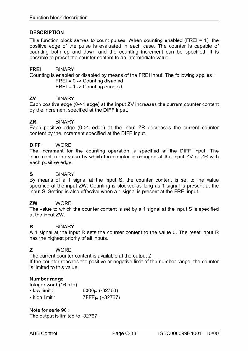
Function block description
ABB Control Page C-38 1SBC006099R1001 10/00
DESCRIPTIONThis function block serves to count pulses. When counting enabled (FREI = 1), thepositive edge of the pulse is evaluated in each case. The counter is capable ofcounting both up and down and the counting increment can be specified. It ispossible to preset the counter content to an intermediate value.
FREI BINARYCounting is enabled or disabled by means of the FREI input. The following applies :
FREI = 0 -> Counting disabledFREI = 1 -> Counting enabled
ZV BINARYEach positive edge (0->1 edge) at the input ZV increases the current counter contentby the increment specified at the DIFF input.
ZR BINARYEach positive edge (0->1 edge) at the input ZR decreases the current countercontent by the increment specified at the DIFF input.
DIFF WORDThe increment for the counting operation is specified at the DIFF input. Theincrement is the value by which the counter is changed at the input ZV or ZR witheach positive edge.
S BINARYBy means of a 1 signal at the input S, the counter content is set to the valuespecified at the input ZW. Counting is blocked as long as 1 signal is present at theinput S. Setting is also effective when a 1 signal is present at the FREI input.
ZW WORDThe value to which the counter content is set by a 1 signal at the input S is specifiedat the input ZW.
R BINARYA 1 signal at the input R sets the counter content to the value 0. The reset input Rhas the highest priority of all inputs.
Z WORDThe current counter content is available at the output Z.If the counter reaches the positive or negative limit of the number range, the counteris limited to this value.
Number rangeInteger word (16 bits)• low limit : 8000H (-32768)• high limit : 7FFFH (+32767)
Note for serie 90 :The output is limited to -32767.
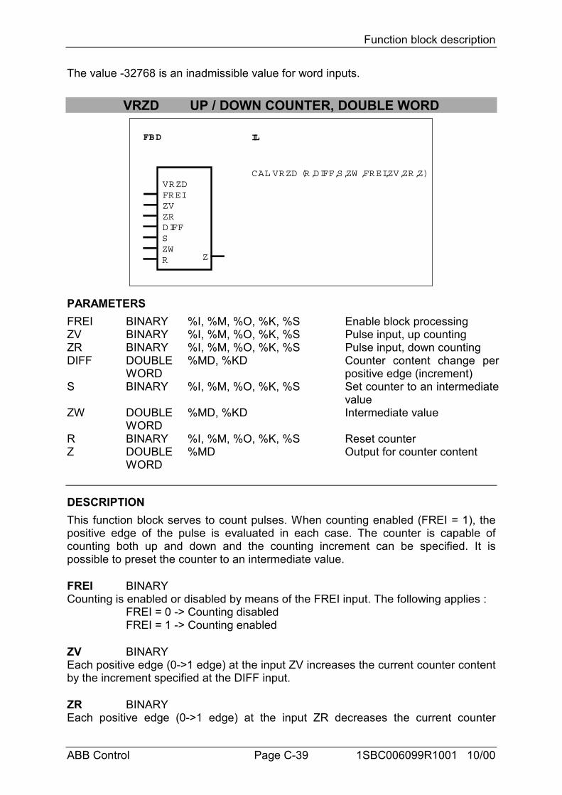
Function block description
ABB Control Page C-39 1SBC006099R1001 10/00
The value -32768 is an inadmissible value for word inputs.
VRZD UP / DOWN COUNTER, DOUBLE WORD
FBD IL
VRZDFREIZVZRDIFF
CAL VRZD (R,DIFF,S,ZW ,FREI,ZV,ZR,Z)
SZWR Z
PARAMETERSFREI BINARY %I, %M, %O, %K, %S Enable block processingZV BINARY %I, %M, %O, %K, %S Pulse input, up countingZR BINARY %I, %M, %O, %K, %S Pulse input, down countingDIFF DOUBLE
WORD%MD, %KD Counter content change per
positive edge (increment)S BINARY %I, %M, %O, %K, %S Set counter to an intermediate
valueZW DOUBLE
WORD%MD, %KD Intermediate value
R BINARY %I, %M, %O, %K, %S Reset counterZ DOUBLE
WORD%MD Output for counter content
DESCRIPTIONThis function block serves to count pulses. When counting enabled (FREI = 1), thepositive edge of the pulse is evaluated in each case. The counter is capable ofcounting both up and down and the counting increment can be specified. It ispossible to preset the counter to an intermediate value.
FREI BINARYCounting is enabled or disabled by means of the FREI input. The following applies :
FREI = 0 -> Counting disabledFREI = 1 -> Counting enabled
ZV BINARYEach positive edge (0->1 edge) at the input ZV increases the current counter contentby the increment specified at the DIFF input.
ZR BINARYEach positive edge (0->1 edge) at the input ZR decreases the current counter
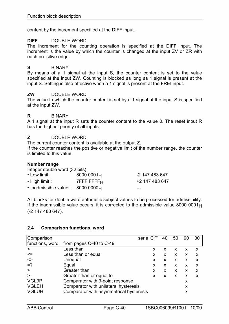
Function block description
ABB Control Page C-40 1SBC006099R1001 10/00
content by the increment specified at the DIFF input.
DIFF DOUBLE WORDThe increment for the counting operation is specified at the DIFF input. Theincrement is the value by which the counter is changed at the input ZV or ZR witheach po–sitive edge.
S BINARYBy means of a 1 signal at the input S, the counter content is set to the valuespecified at the input ZW. Counting is blocked as long as 1 signal is present at theinput S. Setting is also effective when a 1 signal is present at the FREI input.
ZW DOUBLE WORDThe value to which the counter content is set by a 1 signal at the input S is specifiedat the input ZW.
R BINARYA 1 signal at the input R sets the counter content to the value 0. The reset input Rhas the highest priority of all inputs.
Z DOUBLE WORDThe current counter content is available at the output Z.If the counter reaches the positive or negative limit of the number range, the counteris limited to this value.
Number rangeInteger double word (32 bits)• Low limit : 8000 0001H -2 147 483 647• High limit : 7FFF FFFFH +2 147 483 647• Inadmissible value : 8000 0000H ---
All blocks for double word arithmetic subject values to be processed for admissibility.If the inadmissible value occurs, it is corrected to the admissible value 8000 0001H(-2 147 483 647).
2.4 Comparison functions, word
Comparisonfunctions, word
seriefrom pages C-40 to C-49
Ctler 40 50 90 30
< Less than x x x x x<= Less than or equal x x x x x<> Unequal x x x x x=? Equal x x x x x> Greater than x x x x x>= Greater than or equal to x x x x xVGL3P Comparator with 3-point response xVGLEH Comparator with unilateral hysteresis xVGLUH Comparator with asymmetrical hysteresis x
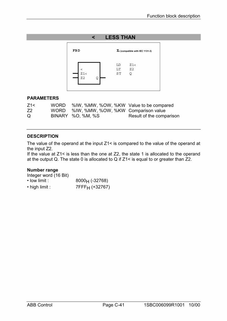
Function block description
ABB Control Page C-41 1SBC006099R1001 10/00
< LESS THAN
FBD IL (compatible with IEC 1131-3)
<Z1<Z2 Q
LDLTST
Z1<Z2Q
PARAMETERSZ1< WORD %IW, %MW, %OW, %KW Value to be comparedZ2 WORD %IW, %MW, %OW, %KW Comparison valueQ BINARY %O, %M, %S Result of the comparison
DESCRIPTIONThe value of the operand at the input Z1< is compared to the value of the operand atthe input Z2.If the value at Z1< is less than the one at Z2, the state 1 is allocated to the operandat the output Q. The state 0 is allocated to Q if Z1< is equal to or greater than Z2.
Number rangeInteger word (16 Bit)• low limit : 8000H (-32768)• high limit : 7FFFH (+32767)
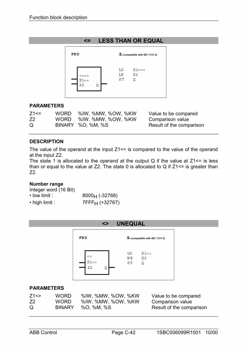
Function block description
ABB Control Page C-42 1SBC006099R1001 10/00
<= LESS THAN OR EQUAL
FBD IL (compatible with IEC 1131-3)
<=<=Z1<=Z2 Q
LDLEST
Z1<==Z2Q
PARAMETERSZ1<= WORD %IW, %MW, %OW, %KW Value to be comparedZ2 WORD %IW, %MW, %OW, %KW Comparison valueQ BINARY %O, %M, %S Result of the comparison
DESCRIPTIONThe value of the operand at the input Z1<= is compared to the value of the operandat the input Z2.The state 1 is allocated to the operand at the output Q if the value at Z1<= is lessthan or equal to the value at Z2. The state 0 is allocated to Q if Z1<= is greater thanZ2.
Number rangeInteger word (16 Bit)• low limit : 8000H (-32768)• high limit : 7FFFH (+32767)
<> UNEQUAL
FBD IL (compatible with IEC 1131-3)
<>
Z1<>
Z2 Q
LDNEST
Z1<>Z2Q
PARAMETERSZ1<> WORD %IW, %MW, %OW, %KW Value to be comparedZ2 WORD %IW, %MW, %OW, %KW Comparison valueQ BINARY %O, %M, %S Result of the comparison
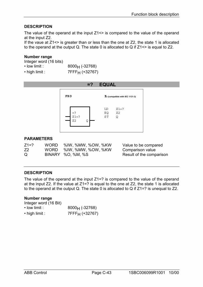
Function block description
ABB Control Page C-43 1SBC006099R1001 10/00
DESCRIPTIONThe value of the operand at the input Z1<> is compared to the value of the operandat the input Z2.If the vaue at Z1<> is greater than or less than the one at Z2, the state 1 is allocatedto the operand at the output Q. The state 0 is allocated to Q if Z1<> is equal to Z2.
Number rangeInteger word (16 bits)• low limit : 8000H (-32768)• high limit : 7FFFH (+32767)
=? EQUAL
FBD IL (compatible with IEC 1131-3)
=?Z1=?Z2 Q
LDEQST
Z1=?Z2Q
PARAMETERSZ1=? WORD %IW, %MW, %OW, %KW Value to be comparedZ2 WORD %IW, %MW, %OW, %KW Comparison valueQ BINARY %O, %M, %S Result of the comparison
DESCRIPTIONThe value of the operand at the input Z1=? is compared to the value of the operandat the input Z2. If the value at Z1=? is equal to the one at Z2, the state 1 is allocatedto the operand at the output Q. The state 0 is allocated to Q if Z1=? is unequal to Z2.
Number rangeInteger word (16 Bit)• low limit : 8000H (-32768)• high limit : 7FFFH (+32767)
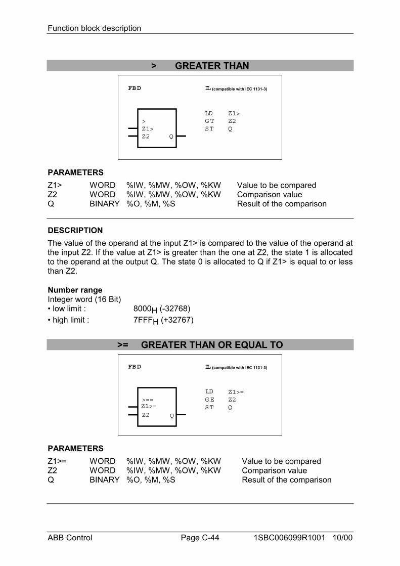
Function block description
ABB Control Page C-44 1SBC006099R1001 10/00
> GREATER THAN
FBD IL (compatible with IEC 1131-3)
>Z1>Z2 Q
LDG TST
Z1>Z2Q
PARAMETERSZ1> WORD %IW, %MW, %OW, %KW Value to be comparedZ2 WORD %IW, %MW, %OW, %KW Comparison valueQ BINARY %O, %M, %S Result of the comparison
DESCRIPTIONThe value of the operand at the input Z1> is compared to the value of the operand atthe input Z2. If the value at Z1> is greater than the one at Z2, the state 1 is allocatedto the operand at the output Q. The state 0 is allocated to Q if Z1> is equal to or lessthan Z2.
Number rangeInteger word (16 Bit)• low limit : 8000H (-32768)• high limit : 7FFFH (+32767)
>= GREATER THAN OR EQUAL TO
FBD IL (compatible with IEC 1131-3)
>==Z1>=
Z2 Q
LDG EST
Z1>=Z2Q
PARAMETERSZ1>= WORD %IW, %MW, %OW, %KW Value to be comparedZ2 WORD %IW, %MW, %OW, %KW Comparison valueQ BINARY %O, %M, %S Result of the comparison
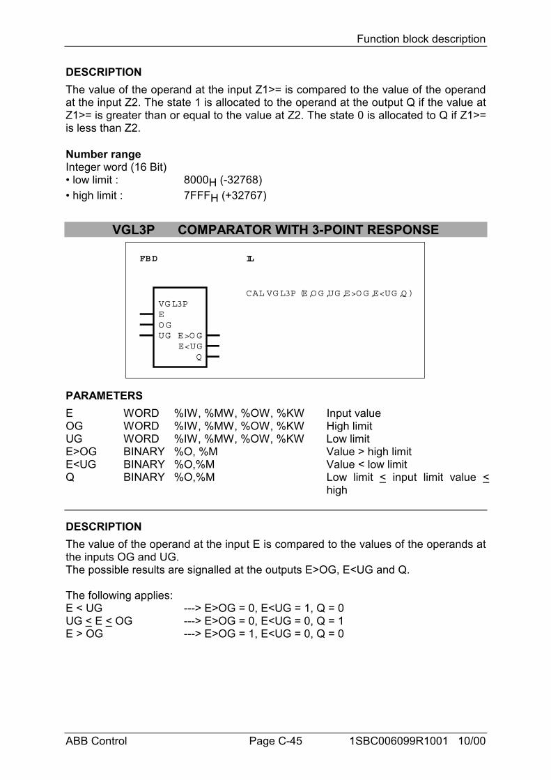
Function block description
ABB Control Page C-45 1SBC006099R1001 10/00
DESCRIPTIONThe value of the operand at the input Z1>= is compared to the value of the operandat the input Z2. The state 1 is allocated to the operand at the output Q if the value atZ1>= is greater than or equal to the value at Z2. The state 0 is allocated to Q if Z1>=is less than Z2.
Number rangeInteger word (16 Bit)• low limit : 8000H (-32768)• high limit : 7FFFH (+32767)
VGL3P COMPARATOR WITH 3-POINT RESPONSE
FBD IL
VG L3PEO GUG
E<UGE>O G
CAL VG L3P (E,O G ,UG ,E>O G ,E<UG ,Q )
Q
PARAMETERSE WORD %IW, %MW, %OW, %KW Input valueOG WORD %IW, %MW, %OW, %KW High limitUG WORD %IW, %MW, %OW, %KW Low limitE>OG BINARY %O, %M Value > high limitE<UG BINARY %O,%M Value < low limitQ BINARY %O,%M Low limit < input limit value <
high
DESCRIPTIONThe value of the operand at the input E is compared to the values of the operands atthe inputs OG and UG.The possible results are signalled at the outputs E>OG, E<UG and Q.
The following applies:E < UG ---> E>OG = 0, E<UG = 1, Q = 0UG < E < OG ---> E>OG = 0, E<UG = 0, Q = 1E > OG ---> E>OG = 1, E<UG = 0, Q = 0
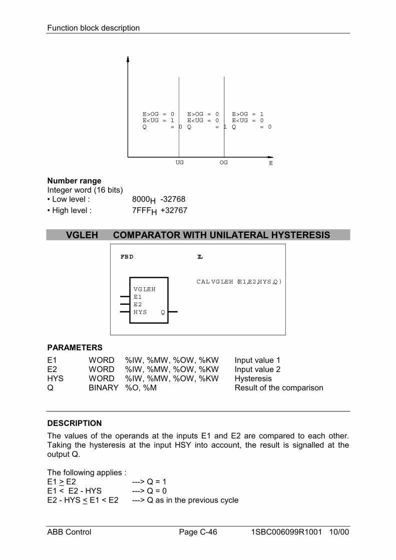
Function block description
ABB Control Page C-46 1SBC006099R1001 10/00
E>OG = 0E<UG = 1Q = 0
E>OG = 0E<UG = 0Q = 1
E>OG = 1E<UG = 0Q = 0
UG OG E
Number rangeInteger word (16 bits)• Low level : 8000H -32768• High level : 7FFFH +32767
VGLEH COMPARATOR WITH UNILATERAL HYSTERESIS
FBD IL
VG LEHE1E2HYS Q
CAL VG LEH (E1,E2,HYS,Q )
PARAMETERSE1 WORD %IW, %MW, %OW, %KW Input value 1E2 WORD %IW, %MW, %OW, %KW Input value 2HYS WORD %IW, %MW, %OW, %KW HysteresisQ BINARY %O, %M Result of the comparison
DESCRIPTIONThe values of the operands at the inputs E1 and E2 are compared to each other.Taking the hysteresis at the input HSY into account, the result is signalled at theoutput Q.
The following applies :E1 > E2 ---> Q = 1E1 < E2 - HYS ---> Q = 0E2 - HYS < E1 < E2 ---> Q as in the previous cycle
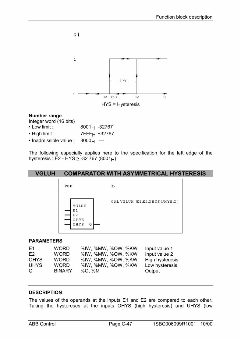
Function block description
ABB Control Page C-47 1SBC006099R1001 10/00
E2-HYS E2 E1
1
Q
1
0
HYS
HYS = Hysteresis
Number rangeInteger word (16 bits)• Low limit : 8001H -32767• High limit : 7FFFH +32767• Inadmissible value : 8000H ---
The following especially applies here to the specification for the left edge of thehysteresis : E2 - HYS > -32 767 (8001H)
VGLUH COMPARATOR WITH ASYMMETRICAL HYSTERESIS
FBD IL
VG LUHE1E2O HYSUHYS
CAL VG LUH (E1,E2,O HYS,UHYS,Q )
Q
PARAMETERSE1 WORD %IW, %MW, %OW, %KW Input value 1E2 WORD %IW, %MW, %OW, %KW Input value 2OHYS WORD %IW, %MW, %OW, %KW High hysteresisUHYS WORD %IW, %MW, %OW, %KW Low hysteresisQ BINARY %O, %M Output
DESCRIPTIONThe values of the operands at the inputs E1 and E2 are compared to each other.Taking the hystereses at the inputs OHYS (high hysteresis) and UHYS (low
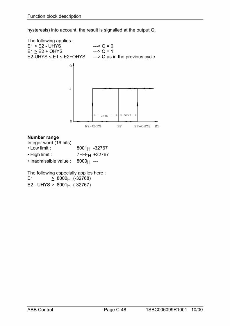
Function block description
ABB Control Page C-48 1SBC006099R1001 10/00
hysteresis) into account, the result is signalled at the output Q.
The following applies :E1 < E2 - UHYS ---> Q = 0E1 > E2 + OHYS ---> Q = 1E2-UHYS < E1 < E2+OHYS ---> Q as in the previous cycle
E2-UHYS E2 E1
1
E2+OHYS
Q
UHYS OHYS
0
Number rangeInteger word (16 bits)• Low limit : 8001H -32767• High limit : 7FFFH +32767• Inadmissible value : 8000H ---
The following especially applies here :E1 > 8000H (-32768)E2 - UHYS > 8001H (-32767)
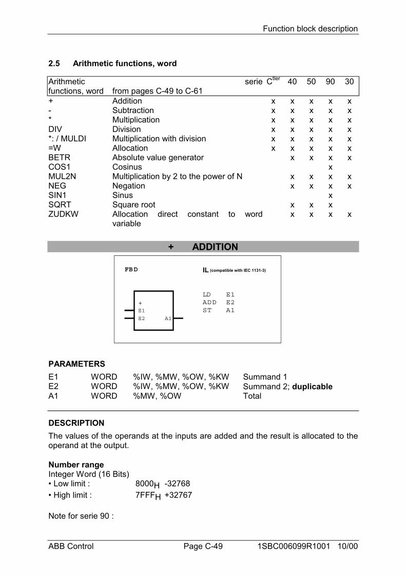
Function block description
ABB Control Page C-49 1SBC006099R1001 10/00
2.5 Arithmetic functions, word
Arithmeticfunctions, word
seriefrom pages C-49 to C-61
Ctler 40 50 90 30
+ Addition x x x x x- Subtraction x x x x x* Multiplication x x x x xDIV Division x x x x x*: / MULDI Multiplication with division x x x x x=W Allocation x x x x xBETR Absolute value generator x x x xCOS1 Cosinus xMUL2N Multiplication by 2 to the power of N x x x xNEG Negation x x x xSIN1 Sinus xSQRT Square root x x xZUDKW Allocation direct constant to word
variablex x x x
+ ADDITION
FBD IL (compatible with IEC 1131-3)
+E1
E2 A1
LDADDST
E1E2A1
PARAMETERSE1 WORD %IW, %MW, %OW, %KW Summand 1E2 WORD %IW, %MW, %OW, %KW Summand 2; duplicableA1 WORD %MW, %OW Total
DESCRIPTIONThe values of the operands at the inputs are added and the result is allocated to theoperand at the output.
Number rangeInteger Word (16 Bits)• Low limit : 8000H -32768• High limit : 7FFFH +32767
Note for serie 90 :
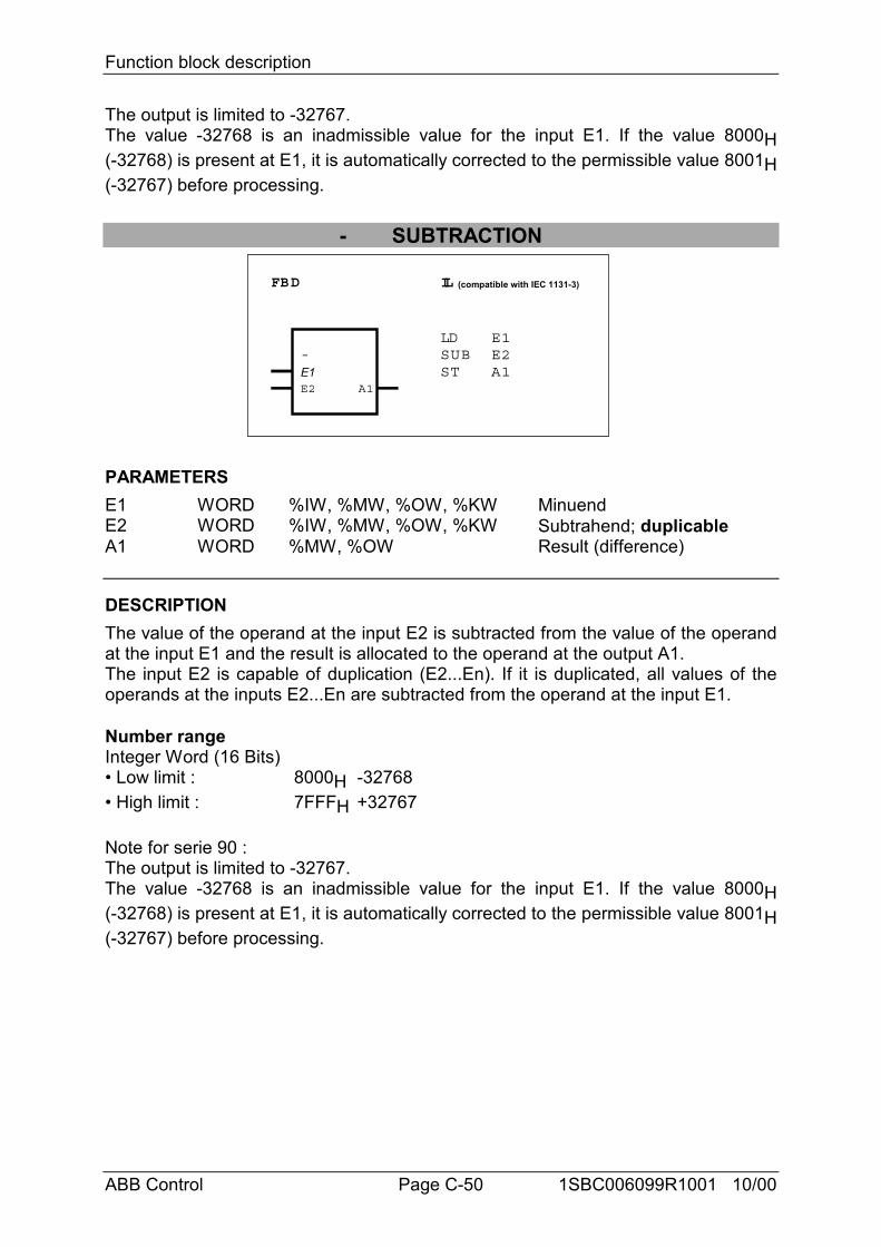
Function block description
ABB Control Page C-50 1SBC006099R1001 10/00
The output is limited to -32767.The value -32768 is an inadmissible value for the input E1. If the value 8000H(-32768) is present at E1, it is automatically corrected to the permissible value 8001H(-32767) before processing.
- SUBTRACTION
FBD IL (compatible with IEC 1131-3)
-E1E2 A1
LDSUBST
E1E2A1
PARAMETERSE1 WORD %IW, %MW, %OW, %KW MinuendE2 WORD %IW, %MW, %OW, %KW Subtrahend; duplicableA1 WORD %MW, %OW Result (difference)
DESCRIPTIONThe value of the operand at the input E2 is subtracted from the value of the operandat the input E1 and the result is allocated to the operand at the output A1.The input E2 is capable of duplication (E2...En). If it is duplicated, all values of theoperands at the inputs E2...En are subtracted from the operand at the input E1.
Number rangeInteger Word (16 Bits)• Low limit : 8000H -32768• High limit : 7FFFH +32767
Note for serie 90 :The output is limited to -32767.The value -32768 is an inadmissible value for the input E1. If the value 8000H(-32768) is present at E1, it is automatically corrected to the permissible value 8001H(-32767) before processing.
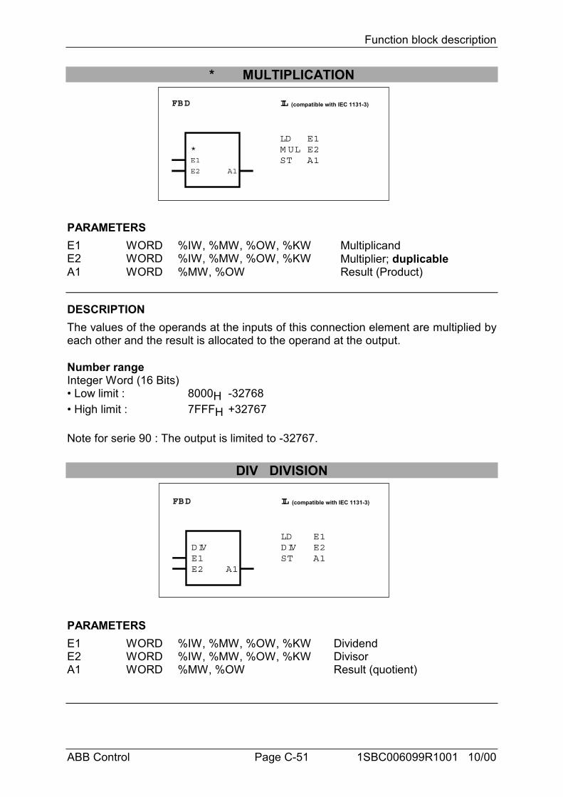
Function block description
ABB Control Page C-51 1SBC006099R1001 10/00
* MULTIPLICATION
FBD IL (compatible with IEC 1131-3)
*E1
E2 A1
LDM ULST
E1E2A1
PARAMETERSE1 WORD %IW, %MW, %OW, %KW MultiplicandE2 WORD %IW, %MW, %OW, %KW Multiplier; duplicableA1 WORD %MW, %OW Result (Product)
DESCRIPTIONThe values of the operands at the inputs of this connection element are multiplied byeach other and the result is allocated to the operand at the output.
Number rangeInteger Word (16 Bits)• Low limit : 8000H -32768• High limit : 7FFFH +32767
Note for serie 90 : The output is limited to -32767.
DIV DIVISION
FBD IL (compatible with IEC 1131-3)
DIVE1E2 A1
LDDIVST
E1E2A1
PARAMETERSE1 WORD %IW, %MW, %OW, %KW DividendE2 WORD %IW, %MW, %OW, %KW DivisorA1 WORD %MW, %OW Result (quotient)
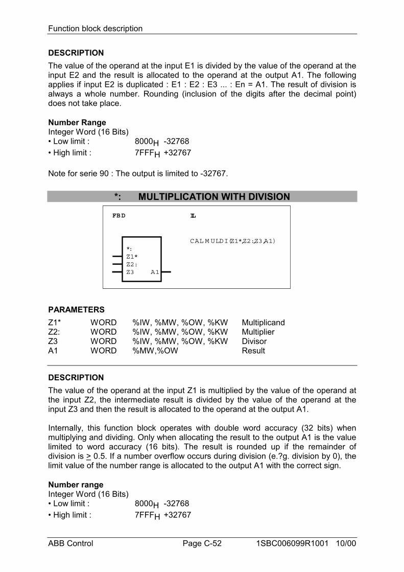
Function block description
ABB Control Page C-52 1SBC006099R1001 10/00
DESCRIPTIONThe value of the operand at the input E1 is divided by the value of the operand at theinput E2 and the result is allocated to the operand at the output A1. The followingapplies if input E2 is duplicated : E1 : E2 : E3 ... : En = A1. The result of division isalways a whole number. Rounding (inclusion of the digits after the decimal point)does not take place.
Number RangeInteger Word (16 Bits)• Low limit : 8000H -32768• High limit : 7FFFH +32767
Note for serie 90 : The output is limited to -32767.
*: MULTIPLICATION WITH DIVISION
FBD IL
*:Z1*Z2:Z3 A1
CAL M ULDI (Z1*,Z2:,Z3,A1)
PARAMETERSZ1* WORD %IW, %MW, %OW, %KW MultiplicandZ2: WORD %IW, %MW, %OW, %KW MultiplierZ3 WORD %IW, %MW, %OW, %KW DivisorA1 WORD %MW,%OW Result
DESCRIPTIONThe value of the operand at the input Z1 is multiplied by the value of the operand atthe input Z2, the intermediate result is divided by the value of the operand at theinput Z3 and then the result is allocated to the operand at the output A1.
Internally, this function block operates with double word accuracy (32 bits) whenmultiplying and dividing. Only when allocating the result to the output A1 is the valuelimited to word accuracy (16 bits). The result is rounded up if the remainder ofdivision is > 0.5. If a number overflow occurs during division (e.?g. division by 0), thelimit value of the number range is allocated to the output A1 with the correct sign.
Number rangeInteger Word (16 Bits)• Low limit : 8000H -32768• High limit : 7FFFH +32767
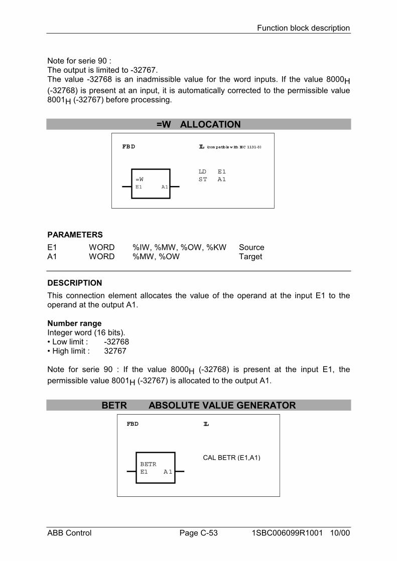
Function block description
ABB Control Page C-53 1SBC006099R1001 10/00
Note for serie 90 :The output is limited to -32767.The value -32768 is an inadmissible value for the word inputs. If the value 8000H(-32768) is present at an input, it is automatically corrected to the permissible value8001H (-32767) before processing.
=W ALLOCATION
FBD IL (com patible with IEC 1131-3)
=WE1 A1
LDST
E1A1
PARAMETERSE1 WORD %IW, %MW, %OW, %KW SourceA1 WORD %MW, %OW Target
DESCRIPTIONThis connection element allocates the value of the operand at the input E1 to theoperand at the output A1.
Number rangeInteger word (16 bits).• Low limit : -32768• High limit : 32767
Note for serie 90 : If the value 8000H (-32768) is present at the input E1, thepermissible value 8001H (-32767) is allocated to the output A1.
BETR ABSOLUTE VALUE GENERATOR
FBD IL
BETRE1 A1
CAL BETR (E1,A1)
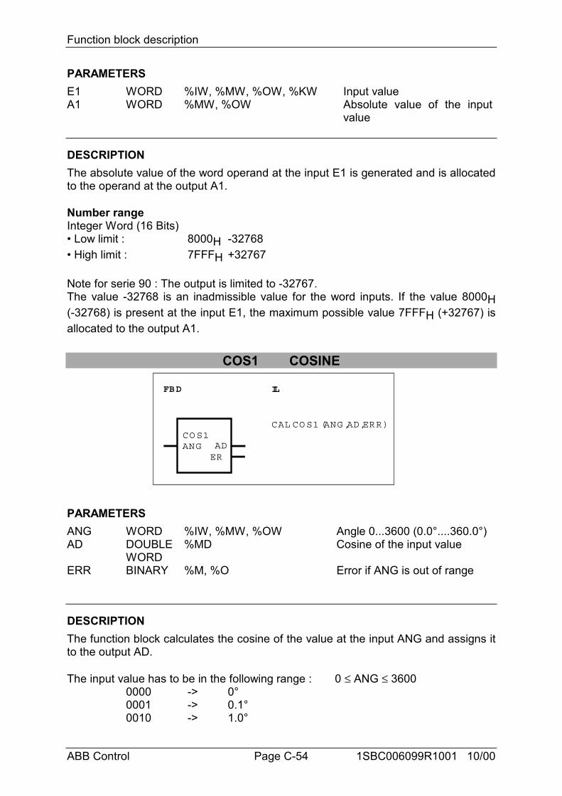
Function block description
ABB Control Page C-54 1SBC006099R1001 10/00
PARAMETERSE1 WORD %IW, %MW, %OW, %KW Input valueA1 WORD %MW, %OW Absolute value of the input
value
DESCRIPTIONThe absolute value of the word operand at the input E1 is generated and is allocatedto the operand at the output A1.
Number rangeInteger Word (16 Bits)• Low limit : 8000H -32768• High limit : 7FFFH +32767
Note for serie 90 : The output is limited to -32767.The value -32768 is an inadmissible value for the word inputs. If the value 8000H(-32768) is present at the input E1, the maximum possible value 7FFFH (+32767) isallocated to the output A1.
COS1 COSINE
FBD IL
CO S1ANG AD
ER
CAL CO S1 (ANG ,AD,ERR)
PARAMETERSANG WORD %IW, %MW, %OW Angle 0...3600 (0.0°....360.0°)AD DOUBLE
WORD%MD Cosine of the input value
ERR BINARY %M, %O Error if ANG is out of range
DESCRIPTIONThe function block calculates the cosine of the value at the input ANG and assigns itto the output AD.
The input value has to be in the following range : 0 ≤ ANG ≤ 36000000 -> 0°0001 -> 0.1°0010 -> 1.0°
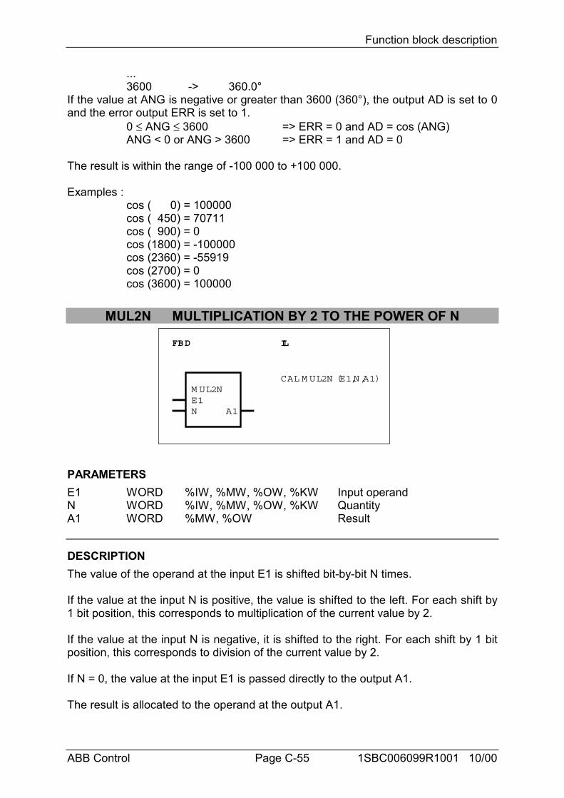
Function block description
ABB Control Page C-55 1SBC006099R1001 10/00
...3600 -> 360.0°
If the value at ANG is negative or greater than 3600 (360°), the output AD is set to 0and the error output ERR is set to 1.
0 ≤ ANG ≤ 3600 => ERR = 0 and AD = cos (ANG)ANG < 0 or ANG > 3600 => ERR = 1 and AD = 0
The result is within the range of -100 000 to +100 000.
Examples :cos ( 0) = 100000cos ( 450) = 70711cos ( 900) = 0cos (1800) = -100000cos (2360) = -55919cos (2700) = 0cos (3600) = 100000
MUL2N MULTIPLICATION BY 2 TO THE POWER OF N
FBD IL
M UL2NE1N A1
CAL M UL2N (E1,N,A1)
PARAMETERSE1 WORD %IW, %MW, %OW, %KW Input operandN WORD %IW, %MW, %OW, %KW QuantityA1 WORD %MW, %OW Result
DESCRIPTIONThe value of the operand at the input E1 is shifted bit-by-bit N times.
If the value at the input N is positive, the value is shifted to the left. For each shift by1 bit position, this corresponds to multiplication of the current value by 2.
If the value at the input N is negative, it is shifted to the right. For each shift by 1 bitposition, this corresponds to division of the current value by 2.
If N = 0, the value at the input E1 is passed directly to the output A1.
The result is allocated to the operand at the output A1.
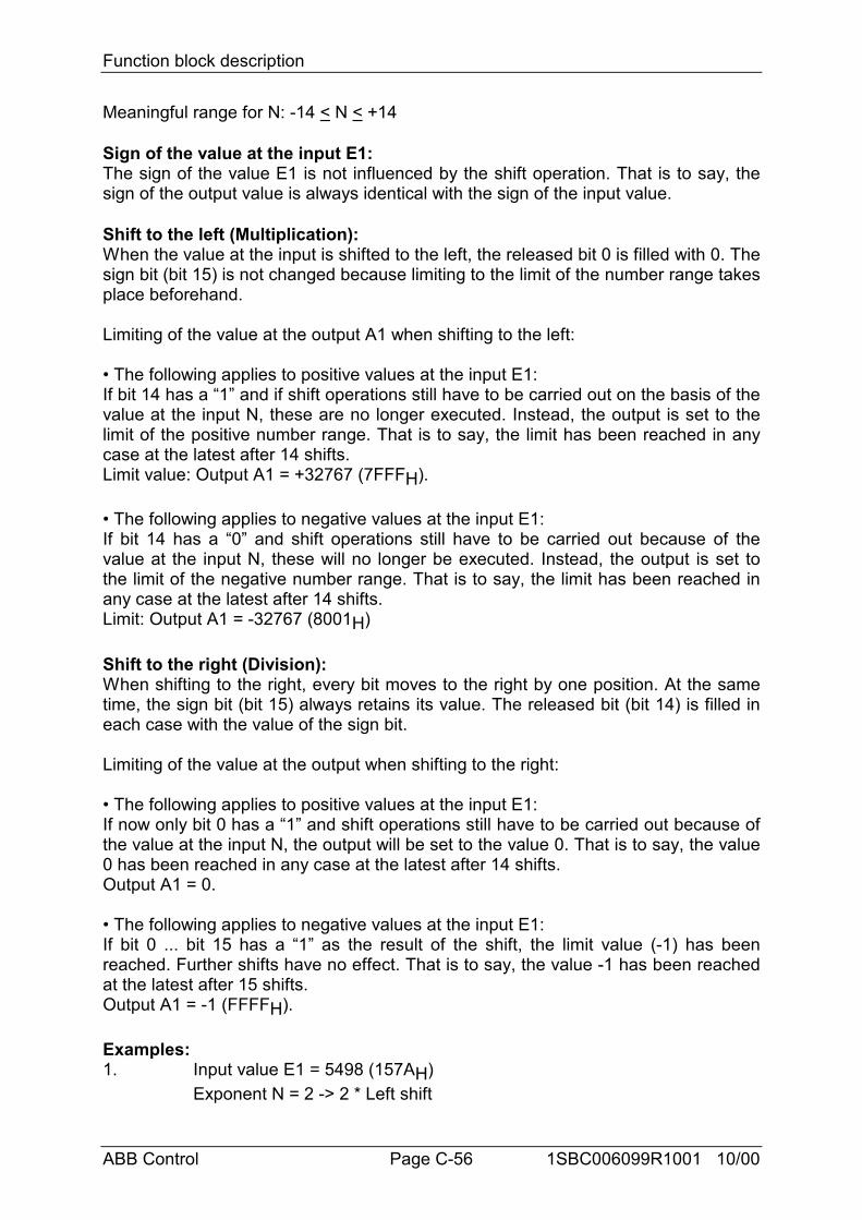
Function block description
ABB Control Page C-56 1SBC006099R1001 10/00
Meaningful range for N: -14 < N < +14
Sign of the value at the input E1:The sign of the value E1 is not influenced by the shift operation. That is to say, thesign of the output value is always identical with the sign of the input value.
Shift to the left (Multiplication):When the value at the input is shifted to the left, the released bit 0 is filled with 0. Thesign bit (bit 15) is not changed because limiting to the limit of the number range takesplace beforehand.
Limiting of the value at the output A1 when shifting to the left:
• The following applies to positive values at the input E1:If bit 14 has a “1” and if shift operations still have to be carried out on the basis of thevalue at the input N, these are no longer executed. Instead, the output is set to thelimit of the positive number range. That is to say, the limit has been reached in anycase at the latest after 14 shifts.Limit value: Output A1 = +32767 (7FFFH).
• The following applies to negative values at the input E1:If bit 14 has a “0” and shift operations still have to be carried out because of thevalue at the input N, these will no longer be executed. Instead, the output is set tothe limit of the negative number range. That is to say, the limit has been reached inany case at the latest after 14 shifts.Limit: Output A1 = -32767 (8001H)
Shift to the right (Division):When shifting to the right, every bit moves to the right by one position. At the sametime, the sign bit (bit 15) always retains its value. The released bit (bit 14) is filled ineach case with the value of the sign bit.
Limiting of the value at the output when shifting to the right:
• The following applies to positive values at the input E1:If now only bit 0 has a “1” and shift operations still have to be carried out because ofthe value at the input N, the output will be set to the value 0. That is to say, the value0 has been reached in any case at the latest after 14 shifts.Output A1 = 0.
• The following applies to negative values at the input E1:If bit 0 ... bit 15 has a “1” as the result of the shift, the limit value (-1) has beenreached. Further shifts have no effect. That is to say, the value -1 has been reachedat the latest after 15 shifts.Output A1 = -1 (FFFFH).
Examples:1. Input value E1 = 5498 (157AH)
Exponent N = 2 -> 2 * Left shift
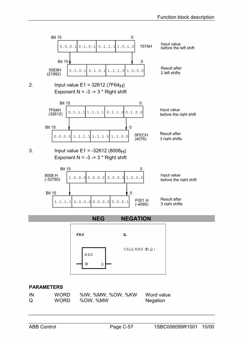
Function block description
ABB Control Page C-57 1SBC006099R1001 10/00
0.0.0.1 0.1.0.1 0.1.1.1 1.0.1.0
0.1.0.1 0.1.0.1 1.1.1.0 1.0.0.0
Bit 15 0
Bit 15 0
157AH Input value
Result after2 left shifts55E8H
(21992)
before the left shift
2. Input value E1 = 32612 (7F64H)Exponent N = -3 -> 3 * Right shift
0.1.1.1 1.1.1.1 0.1.1.0 0.1.0.0
0.0.0.0 1.1.1.1 1.1.1.0 1.1.0.0
Bit 15 0
Bit 15 0
Input valuebefore the right shift
3 right shiftsResult after
7F64H(32612)
0FECH(4076)
3. Input value E1 = -32612 (8008H)Exponent N = -3 -> 3 * Right shift
1.0.0.0 0.0.0.0 0.0.0.0 1.0.0.0
1.1.1.1 0.0.0.0 0.0.0.0 0.0.0.1
Bit 15 0
Bit 15 0
Input valuebefore the right shift
Result after3 right shifts
8008 H(-32760)
F001 H(-4095)
NEG NEGATION
FBD IL
NEG
IN
CALL NEG (IN,Q )
Q
PARAMETERSIN WORD %IW, %MW, %OW, %KW Word valueQ WORD %OW, %MW Negation
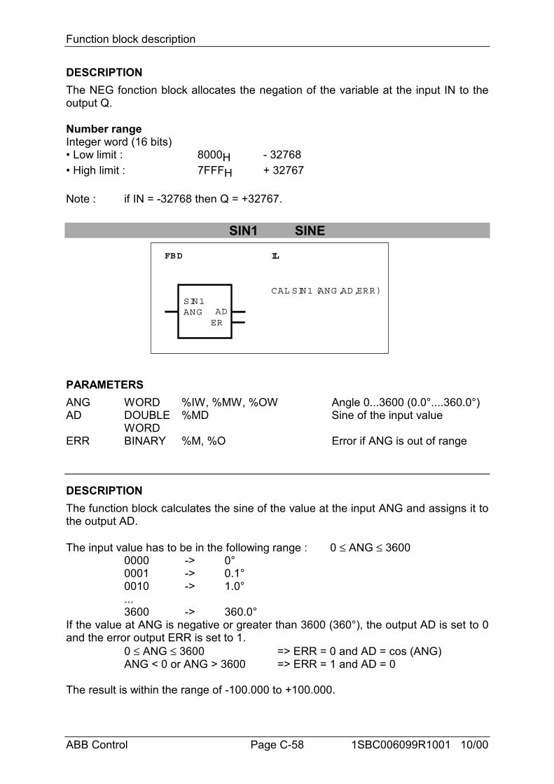
Function block description
ABB Control Page C-58 1SBC006099R1001 10/00
DESCRIPTIONThe NEG fonction block allocates the negation of the variable at the input IN to theoutput Q.
Number rangeInteger word (16 bits)• Low limit : 8000H - 32768• High limit : 7FFFH + 32767
Note : if IN = -32768 then Q = +32767.
SIN1 SINE
FBD IL
SIN1ANG AD
ER
CAL SIN1 (ANG ,AD,ERR)
PARAMETERSANG WORD %IW, %MW, %OW Angle 0...3600 (0.0°....360.0°)AD DOUBLE
WORD%MD Sine of the input value
ERR BINARY %M, %O Error if ANG is out of range
DESCRIPTIONThe function block calculates the sine of the value at the input ANG and assigns it tothe output AD.
The input value has to be in the following range : 0 ≤ ANG ≤ 36000000 -> 0°0001 -> 0.1°0010 -> 1.0°...3600 -> 360.0°
If the value at ANG is negative or greater than 3600 (360°), the output AD is set to 0and the error output ERR is set to 1.
0 ≤ ANG ≤ 3600 => ERR = 0 and AD = cos (ANG)ANG < 0 or ANG > 3600 => ERR = 1 and AD = 0
The result is within the range of -100.000 to +100.000.
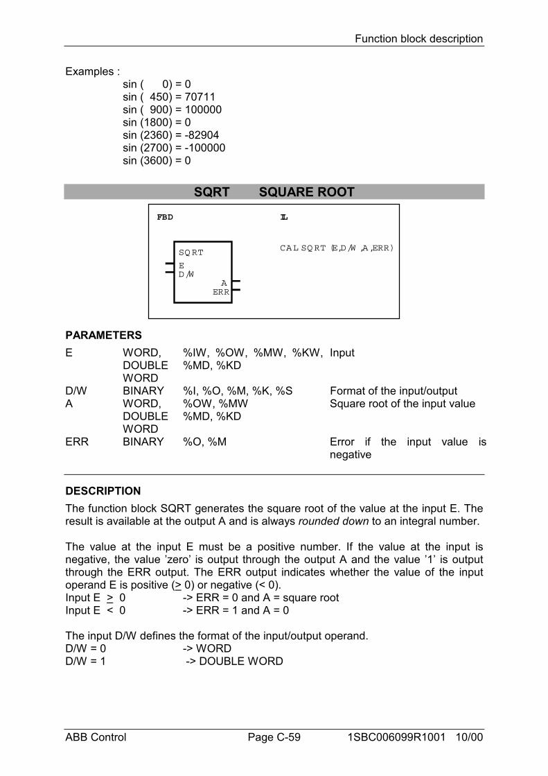
Function block description
ABB Control Page C-59 1SBC006099R1001 10/00
Examples :sin ( 0) = 0sin ( 450) = 70711sin ( 900) = 100000sin (1800) = 0sin (2360) = -82904sin (2700) = -100000sin (3600) = 0
SQRT SQUARE ROOT
E
ERR
D/WA
SQ RT
FBD IL
CAL SQ RT (E,D/W ,A,ERR)
PARAMETERSE WORD,
DOUBLEWORD
%IW, %OW, %MW, %KW,%MD, %KD
Input
D/W BINARY %I, %O, %M, %K, %S Format of the input/outputA WORD,
DOUBLEWORD
%OW, %MW%MD, %KD
Square root of the input value
ERR BINARY %O, %M Error if the input value isnegative
DESCRIPTIONThe function block SQRT generates the square root of the value at the input E. Theresult is available at the output A and is always rounded down to an integral number.
The value at the input E must be a positive number. If the value at the input isnegative, the value ’zero’ is output through the output A and the value ’1’ is outputthrough the ERR output. The ERR output indicates whether the value of the inputoperand E is positive (> 0) or negative (< 0).Input E > 0 -> ERR = 0 and A = square rootInput E < 0 -> ERR = 1 and A = 0
The input D/W defines the format of the input/output operand.D/W = 0 -> WORDD/W = 1 -> DOUBLE WORD
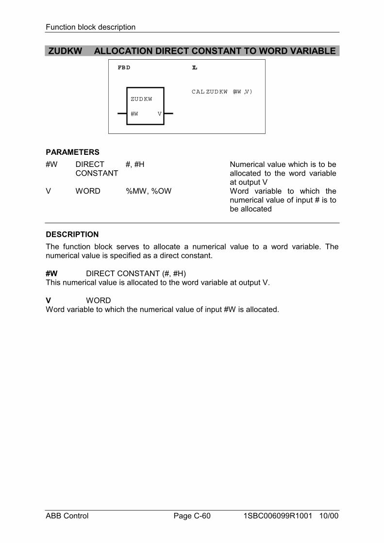
Function block description
ABB Control Page C-60 1SBC006099R1001 10/00
ZUDKW ALLOCATION DIRECT CONSTANT TO WORD VARIABLEFBD IL
ZUDKW
#W V
CAL ZUDKW (#W ,V)
PARAMETERS#W DIRECT
CONSTANT#, #H Numerical value which is to be
allocated to the word variableat output V
V WORD %MW, %OW Word variable to which thenumerical value of input # is tobe allocated
DESCRIPTIONThe function block serves to allocate a numerical value to a word variable. Thenumerical value is specified as a direct constant.
#W DIRECT CONSTANT (#, #H)This numerical value is allocated to the word variable at output V.
V WORDWord variable to which the numerical value of input #W is allocated.
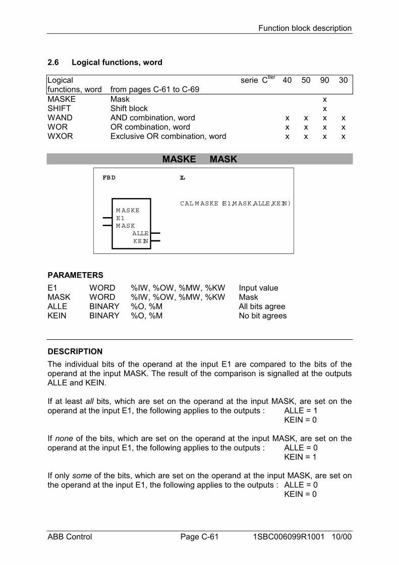
Function block description
ABB Control Page C-61 1SBC006099R1001 10/00
2.6 Logical functions, word
Logicalfunctions, word
seriefrom pages C-61 to C-69
Ctler 40 50 90 30
MASKE Mask xSHIFT Shift block xWAND AND combination, word x x x xWOR OR combination, word x x x xWXOR Exclusive OR combination, word x x x x
MASKE MASK
FBD IL
M ASKEE1M ASK
KEINALLE
CAL M ASKE (E1,M ASK,ALLE,KEIN)
PARAMETERSE1 WORD %IW, %OW, %MW, %KW Input valueMASK WORD %IW, %OW, %MW, %KW MaskALLE BINARY %O, %M All bits agreeKEIN BINARY %O, %M No bit agrees
DESCRIPTIONThe individual bits of the operand at the input E1 are compared to the bits of theoperand at the input MASK. The result of the comparison is signalled at the outputsALLE and KEIN.
If at least all bits, which are set on the operand at the input MASK, are set on theoperand at the input E1, the following applies to the outputs : ALLE = 1
KEIN = 0
If none of the bits, which are set on the operand at the input MASK, are set on theoperand at the input E1, the following applies to the outputs : ALLE = 0
KEIN = 1
If only some of the bits, which are set on the operand at the input MASK, are set onthe operand at the input E1, the following applies to the outputs : ALLE = 0
KEIN = 0

Function block description
ABB Control Page C-62 1SBC006099R1001 10/00
E1 X1111XX11XXXX11X
00XXXXX0XXX0XXXX
1X1X1XXX10XXXX10
MASK 0111100110000110
1100000100010000
0010100011000011
ALLE = 1KEIN = 0
::
Example
E1MASK
ALLEKEIN
::
E1MASK
ALLEKEIN
::
= 0= 1
= 0= 0
X: These bits may have any value (don't care)
SHIFT SHIFT BLOCK
FBD IL
SHIFT
ED/WANZLKSRO T
CY_AA
CAL SHIFT (E,D/W ,ANZ,LKS,RO T,RO TC,SLO G ,SARI,CY E,CY A,A)
RO TCSLO GSARICY_E
PARAMETERSE WORD,
DOUBLEWORD
%IW, %OW, %MW, %KW,%KD, %MD
Operand to be shifted Word ordouble word
D/W BINARY %I, %O, %M, %K, %S Format selection (W or DW)ANZ WORD %IW, %OW, %MW, %KW Number of bit positions to be
shiftedLKS BINARY %I, %O, %M, %K, %S Shift direction, left or rightROT BINARY %I, %O, %M, %K, %S Shift-Art: ROTATEROTC BINARY %I, %O, %M, %K, %S Shift-Art: ROTATE by the
CARRY FLAGSLOG BINARY %I, %O, %M, %K, %S SHIFT type: LOGICAL SHIFTSARI BINARY %I, %O, %M, %K, %S SHIFT type: ARITHMETIC
SHIFTCY_E BINARY %I, %O, %M, %K, %S Initial value for the CARRY
FLAG in the case of shift typeROTC
CY_A BINARY %O, %M Status of the CARRY FLAGafter the shift
A WORD,DOUBLEWORD
%OW, %MW, %MD Result of the shift
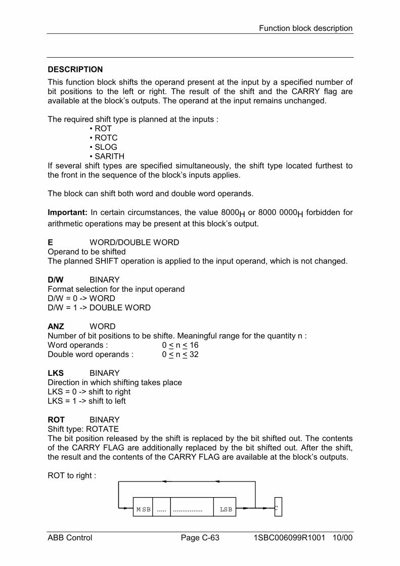
Function block description
ABB Control Page C-63 1SBC006099R1001 10/00
DESCRIPTIONThis function block shifts the operand present at the input by a specified number ofbit positions to the left or right. The result of the shift and the CARRY flag areavailable at the block’s outputs. The operand at the input remains unchanged.
The required shift type is planned at the inputs :• ROT• ROTC• SLOG• SARITH
If several shift types are specified simultaneously, the shift type located furthest tothe front in the sequence of the block’s inputs applies.
The block can shift both word and double word operands.
Important: In certain circumstances, the value 8000H or 8000 0000H forbidden forarithmetic operations may be present at this block’s output.
E WORD/DOUBLE WORDOperand to be shiftedThe planned SHIFT operation is applied to the input operand, which is not changed.
D/W BINARYFormat selection for the input operandD/W = 0 -> WORDD/W = 1 -> DOUBLE WORD
ANZ WORDNumber of bit positions to be shifte. Meaningful range for the quantity n :Word operands : 0 < n < 16Double word operands : 0 < n < 32
LKS BINARYDirection in which shifting takes placeLKS = 0 -> shift to rightLKS = 1 -> shift to left
ROT BINARYShift type: ROTATEThe bit position released by the shift is replaced by the bit shifted out. The contentsof the CARRY FLAG are additionally replaced by the bit shifted out. After the shift,the result and the contents of the CARRY FLAG are available at the block’s outputs.
ROT to right :
M SB LSB..... ................ C
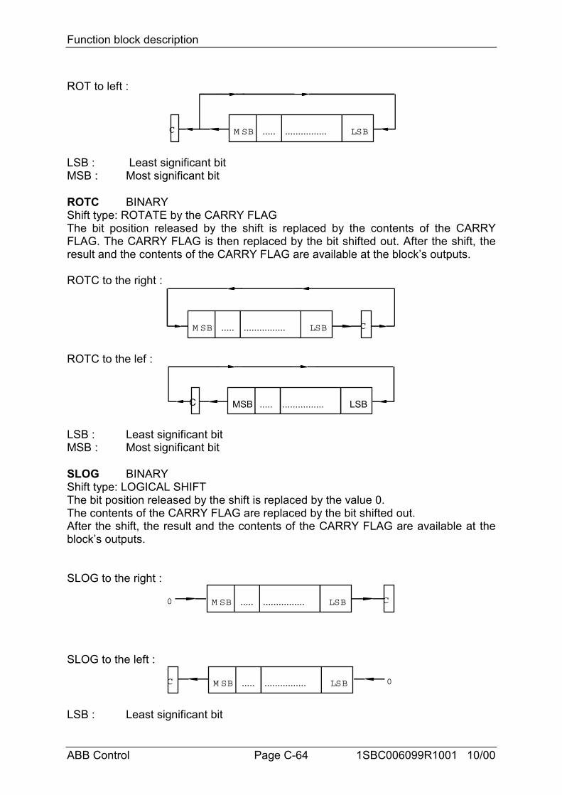
Function block description
ABB Control Page C-64 1SBC006099R1001 10/00
ROT to left :
M SB LSB..... ................C
LSB : Least significant bitMSB : Most significant bit
ROTC BINARYShift type: ROTATE by the CARRY FLAGThe bit position released by the shift is replaced by the contents of the CARRYFLAG. The CARRY FLAG is then replaced by the bit shifted out. After the shift, theresult and the contents of the CARRY FLAG are available at the block’s outputs.
ROTC to the right :
M SB LSB..... ................ C
ROTC to the lef :
MSB LSB..... ................C
LSB : Least significant bitMSB : Most significant bit
SLOG BINARYShift type: LOGICAL SHIFTThe bit position released by the shift is replaced by the value 0.The contents of the CARRY FLAG are replaced by the bit shifted out.After the shift, the result and the contents of the CARRY FLAG are available at theblock’s outputs.
SLOG to the right :
M SB LSB..... ................ C0
SLOG to the left :
M SB LSB..... ................C 0
LSB : Least significant bit
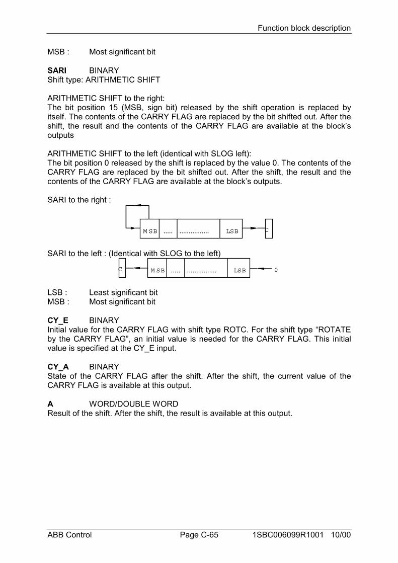
Function block description
ABB Control Page C-65 1SBC006099R1001 10/00
MSB : Most significant bit
SARI BINARYShift type: ARITHMETIC SHIFT
ARITHMETIC SHIFT to the right:The bit position 15 (MSB, sign bit) released by the shift operation is replaced byitself. The contents of the CARRY FLAG are replaced by the bit shifted out. After theshift, the result and the contents of the CARRY FLAG are available at the block’soutputs
ARITHMETIC SHIFT to the left (identical with SLOG left):The bit position 0 released by the shift is replaced by the value 0. The contents of theCARRY FLAG are replaced by the bit shifted out. After the shift, the result and thecontents of the CARRY FLAG are available at the block’s outputs.
SARI to the right :
M SB LSB..... ................ C
SARI to the left : (Identical with SLOG to the left)
M SB LSB..... ................C 0
LSB : Least significant bitMSB : Most significant bit
CY_E BINARYInitial value for the CARRY FLAG with shift type ROTC. For the shift type “ROTATEby the CARRY FLAG”, an initial value is needed for the CARRY FLAG. This initialvalue is specified at the CY_E input.
CY_A BINARYState of the CARRY FLAG after the shift. After the shift, the current value of theCARRY FLAG is available at this output.
A WORD/DOUBLE WORDResult of the shift. After the shift, the result is available at this output.
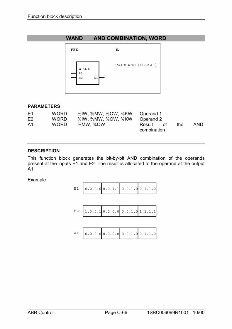
Function block description
ABB Control Page C-66 1SBC006099R1001 10/00
WAND AND COMBINATION, WORD
FBD IL
W ANDE1
E2 A1
CAL W AND (E1,E2,A1)
PARAMETERSE1 WORD %IW, %MW, %OW, %KW Operand 1E2 WORD %IW, %MW, %OW, %KW Operand 2A1 WORD %MW, %OW Result of the AND
combination
DESCRIPTIONThis function block generates the bit-by-bit AND combination of the operandspresent at the inputs E1 and E2. The result is allocated to the operand at the outputA1.
Example :
0.0.0.0 0.0.1.1 0.0.1.0 0.1.1.0
1.0.0.1 0.0.0.0 0.0.1.0 1.1.1.1
0.0.0.0 0.0.0.0 0.0.1.0 0.1.1.0
E1
E2
A1
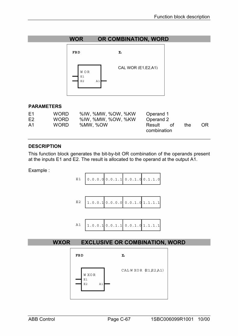
Function block description
ABB Control Page C-67 1SBC006099R1001 10/00
WOR OR COMBINATION, WORD
FBD IL
W O RE1
E2 A1
CAL WOR (E1,E2,A1)
PARAMETERSE1 WORD %IW, %MW, %OW, %KW Operand 1E2 WORD %IW, %MW, %OW, %KW Operand 2A1 WORD %MW, %OW Result of the OR
combination
DESCRIPTIONThis function block generates the bit-by-bit OR combination of the operands presentat the inputs E1 and E2. The result is allocated to the operand at the output A1.
Example :
0.0.0.0 0.0.1.1 0.0.1.0 0.1.1.0
1.0.0.1 0.0.0.0 0.0.1.0 1.1.1.1
1.0.0.1 0.0.1.1 0.0.1.0 1.1.1.1
E1
E2
A1
WXOR EXCLUSIVE OR COMBINATION, WORD
FBD IL
W XO RE1
E2 A1
CAL W XO R (E1,E2,A1)
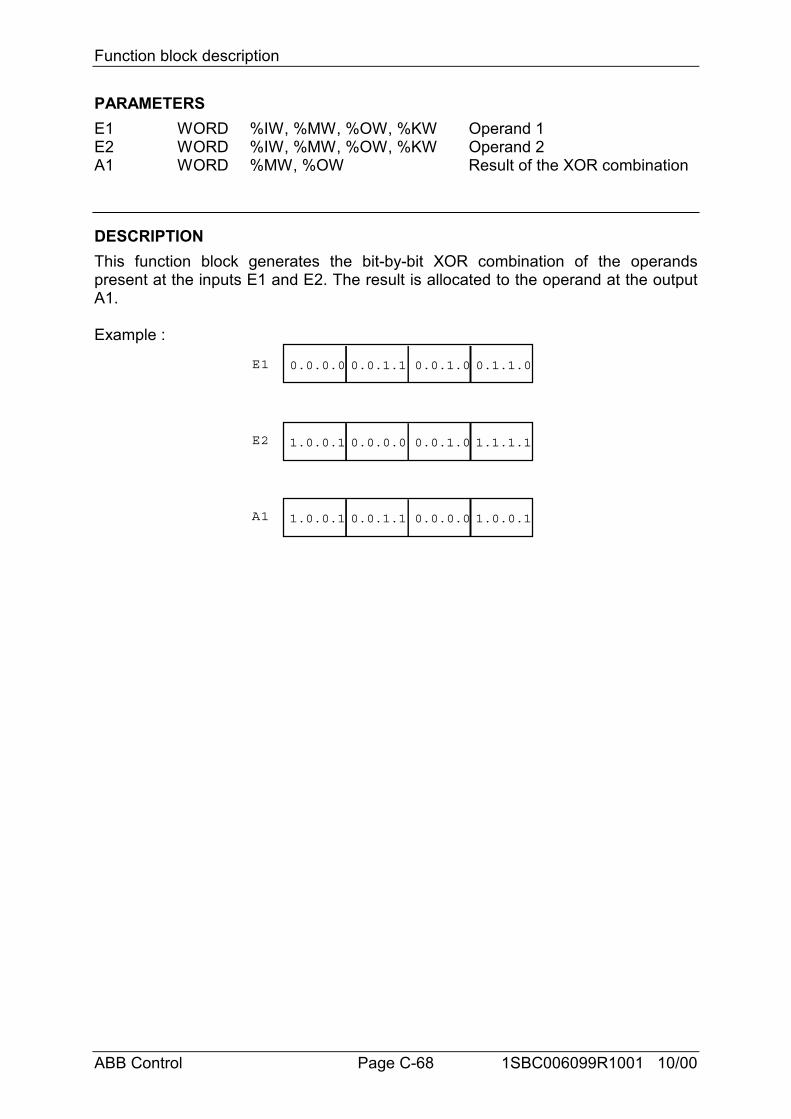
Function block description
ABB Control Page C-68 1SBC006099R1001 10/00
PARAMETERSE1 WORD %IW, %MW, %OW, %KW Operand 1E2 WORD %IW, %MW, %OW, %KW Operand 2A1 WORD %MW, %OW Result of the XOR combination
DESCRIPTIONThis function block generates the bit-by-bit XOR combination of the operandspresent at the inputs E1 and E2. The result is allocated to the operand at the outputA1.
Example :
0.0.0.0 0.0.1.1 0.0.1.0 0.1.1.0
1.0.0.1 0.0.0.0 0.0.1.0 1.1.1.1
1.0.0.1 0.0.1.1 0.0.0.0 1.0.0.1
E1
E2
A1
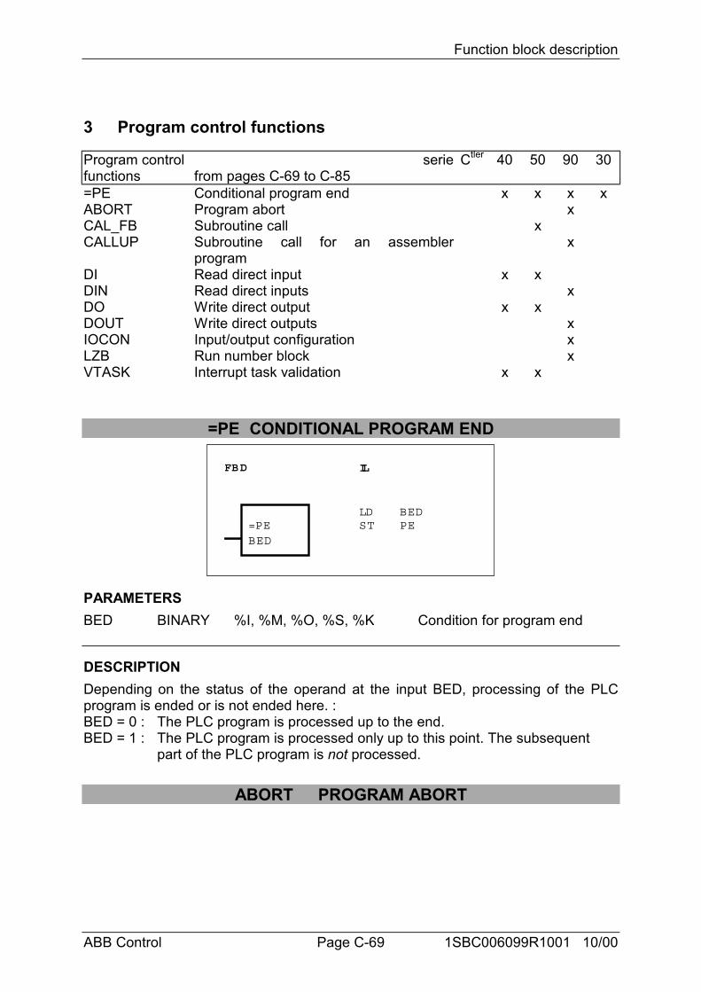
Function block description
ABB Control Page C-69 1SBC006099R1001 10/00
3 Program control functions
Program controlfunctions
seriefrom pages C-69 to C-85
Ctler 40 50 90 30
=PE Conditional program end x x x xABORT Program abort xCAL_FB Subroutine call xCALLUP Subroutine call for an assembler
programx
DI Read direct input x xDIN Read direct inputs xDO Write direct output x xDOUT Write direct outputs xIOCON Input/output configuration xLZB Run number block xVTASK Interrupt task validation x x
=PE CONDITIONAL PROGRAM END
FBD IL
=PEBED
LDST
BEDPE
PARAMETERSBED BINARY %I, %M, %O, %S, %K Condition for program end
DESCRIPTIONDepending on the status of the operand at the input BED, processing of the PLCprogram is ended or is not ended here. :BED = 0 : The PLC program is processed up to the end.BED = 1 : The PLC program is processed only up to this point. The subsequent
part of the PLC program is not processed.
ABORT PROGRAM ABORT
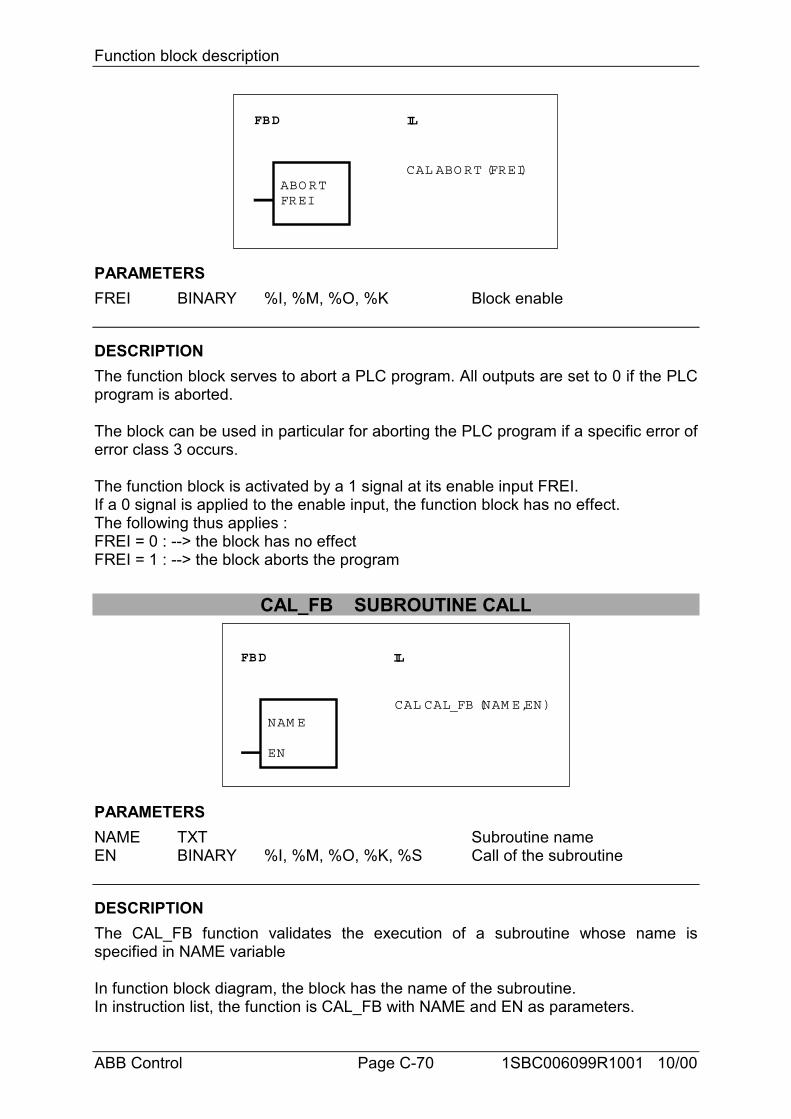
Function block description
ABB Control Page C-70 1SBC006099R1001 10/00
FBD IL
ABO RTFREI
CAL ABO RT (FREI)
PARAMETERSFREI BINARY %I, %M, %O, %K Block enable
DESCRIPTIONThe function block serves to abort a PLC program. All outputs are set to 0 if the PLCprogram is aborted.
The block can be used in particular for aborting the PLC program if a specific error oferror class 3 occurs.
The function block is activated by a 1 signal at its enable input FREI.If a 0 signal is applied to the enable input, the function block has no effect.The following thus applies :FREI = 0 : --> the block has no effectFREI = 1 : --> the block aborts the program
CAL_FB SUBROUTINE CALL
FBD IL
NAM E
EN
CAL CAL_FB (NAM E,EN)
PARAMETERSNAME TXT Subroutine nameEN BINARY %I, %M, %O, %K, %S Call of the subroutine
DESCRIPTIONThe CAL_FB function validates the execution of a subroutine whose name isspecified in NAME variable
In function block diagram, the block has the name of the subroutine.In instruction list, the function is CAL_FB with NAME and EN as parameters.
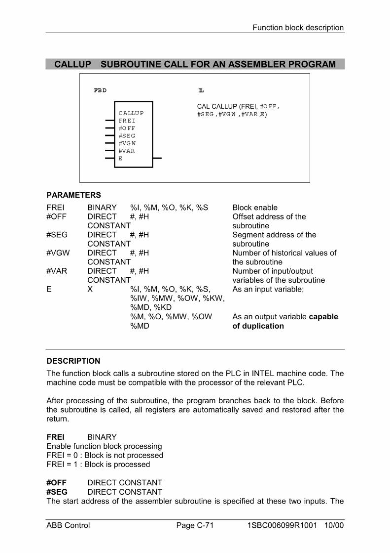
Function block description
ABB Control Page C-71 1SBC006099R1001 10/00
CALLUP SUBROUTINE CALL FOR AN ASSEMBLER PROGRAM
FBD IL
CALLUPFREI#O FF#SEG#VG W#VARE
CAL CALLUP (FREI, #O FF,#SEG , #VG W , #VAR,E)
PARAMETERSFREI BINARY %I, %M, %O, %K, %S Block enable#OFF DIRECT #, #H Offset address of the
CONSTANT subroutine#SEG DIRECT #, #H Segment address of the
CONSTANT subroutine#VGW DIRECT #, #H Number of historical values of
CONSTANT the subroutine#VAR DIRECT #, #H Number of input/output
CONSTANT variables of the subroutineE X %I, %M, %O, %K, %S, As an input variable;
%IW, %MW, %OW, %KW,%MD, %KD%M, %O, %MW, %OW As an output variable capable %MD of duplication
DESCRIPTIONThe function block calls a subroutine stored on the PLC in INTEL machine code. Themachine code must be compatible with the processor of the relevant PLC.
After processing of the subroutine, the program branches back to the block. Beforethe subroutine is called, all registers are automatically saved and restored after thereturn.
FREI BINARYEnable function block processingFREI = 0 : Block is not processedFREI = 1 : Block is processed
#OFF DIRECT CONSTANT#SEG DIRECT CONSTANTThe start address of the assembler subroutine is specified at these two inputs. The
Function block description
ABB Control Page C-72 1SBC006099R1001 10/00
start address consists of an offset and a segment address. The offset and segmentaddresses are specified as direct constants.
If the value “0” is specified as the segment address, the block expects the subroutineto have been stored in the user program memory. The offset address thenrepresents the byte spacing between start of user program and start of subroutine.The subroutine is automatically saved as well when saving the PLC program onEPROM or flash EPROM.
#VGW DIRECT CONSTANTThe number of historical values used in the subroutine is specified at the input#VGW. This is specified as a direct constant.
#VAR DIRECT CONSTANTThe total number of input and output variables of the subroutine is specified at theinput #VAR. Therefore, this is the total of all E1...En and A1...An. This is specified asa direct constant.
E BINARY, WORD, DOUBLE WORDThe input E is capable of duplication (E1...Em).The input variables for the subroutine are specified at the inputs E1...Em. Thesubroutine performs “reading” access to these variables. When the subroutineaccesses these variables, the assembler programmer must pay attention to thedefined data format. Direct constants (value transfer) are not allowed at the inputsE1...Em.The output variables for the subroutine are specified at the outputs Em+1...En. Thesubroutine performs “writing” access to these variables, i.e. values calculated in thesubroutine are provided to the main program with the aid of the output variablesEm+1...En. The assembler programmer must pay attention to the defined dataformat when accessing these variables.
Application notes
Store subroutineThe best possibility to store the subroutine is to store it in the user program memory(after PE). The subroutine can be loaded e. g. with a HEX file loader or the PLCmonitor.If the value “0” is specified as the segment address, the block expects the subroutineto have been stored in the user program memory. The offset address thenrepresents the byte spacing between start of user program and start of subroutine.The subroutine is automatically saved as well when saving the PLC program onEPROM or flash EPROM.
Loading the subroutineThe subroutine can be loaded into the PLC via the serial interface COM2 withmonitor command “Read INTEL-HEX-FILE”. (See Description of the monitorfunctions, command “R”). This can be done only in connection with PLCs which havetwo serial interfaces (e. g. 07 KT 92).
Subroutine creation
Function block description
ABB Control Page C-73 1SBC006099R1001 10/00
1. RegisterWhen creating the subroutine, use can be made of the following registers to suitrequirements :
AX, BX, CX, DX, BP
The following registers are intended for access to variables :
DS, ES, DI, SI
However, these registers can also be changed because they are corrected againafter execution of the subroutine in the CALLUP block.
2. Start addressSubroutine’s start address must be specified at the #OFF and #SEG inputs in thecall of the block. The offset and segment are each specified as direct constants.
3. Access to input and output variablesAccess to the variables is by way of the pointers ES:SI and DS:BX.When the subroutine is entered, the pointer to the address of the first variable in thecall of the block is located in (ES:SI) and the pointer to the address of the secondvariable is located in (ES:SI+2) etc. Access to the contents of these variables is thenby means of DS:BX
Example 1 :The values of the first two word variables in the block call are to be fetched to theregisters AX and CX.MOV BX,ES:[SI] ;Fetch address for 1st variable and store in BXMOV AX,DS:[BX] ;fetch value to AXMOV BX,ES:[SI+2] ;fetch address for second variable and store in BXMOV CX,DS:[BX] ;fetch value to CX
Example 2 :The value of the first two binary variables in the call of the block are to be fetched tothe registers AL and CL.MOV BX,ES:[SI] ;Fetch address for 1st variable and store in BXMOV AL,DS:[BX] ;Fetch value to ALMOV BX,ES:[SI+2] ;Fetch address for second variable and store in BXMOV CL,DS:[BX] ;Fetch value to CLBinary variables occupy a whole byte. This byte may only have 0 or 1 as its contents.
4. Access to historical values/RAMIf RAM space is needed in the subroutine for intermediate values, use can be madeof the historical values memory.
The intermediate values are retained and are again available in the next programcycle for further processing. For each call of the subroutine, its own memorylocations are available in the historical values memory. If a subroutine is called threetimes, for instance, in total 3 times as many historical values are occupied in thehistorical values memory as are specified in the call. The number of memory words
Function block description
ABB Control Page C-74 1SBC006099R1001 10/00
used (1 word = 16 bits) in the historical values memory must be specified as a directconstant in the call of the block. If too many historical values are occupied, the PLCissues an error message when the command PA (program editing) is used or whenthe program is started.
The historical values are addressed by way of the pointers DS:DIIn doing so, DS:DI points to the first available historical value when entering thesubroutine.
Example :The value fetched to register AX in point 3. is to be compared to the first word in thehistorical values memory.CMP AX,DS :[DI] ;Compare value to historical value
5. The stack has a depth of 40 words. In this way, up to 40 PUSH commands can beexecuted successively.
6. Return from the subroutineThe return is achieved by means of RET FAR (8086 machine code : CB). RET FARis generated by the 8086 assembler by virtue of the fact that the subroutine isdeclared as PROC FAR.
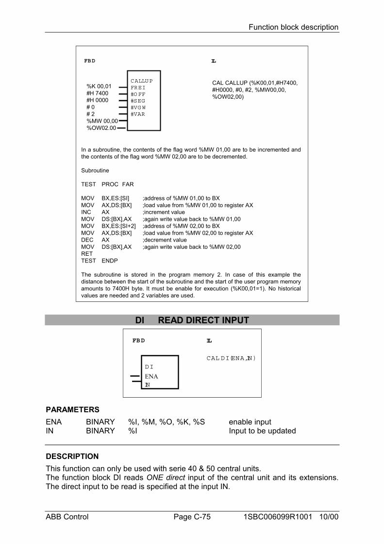
Function block description
ABB Control Page C-75 1SBC006099R1001 10/00
FBD IL
CALLUPFREI#O FF#SEG#VG W#VAR
In a subroutine, the contents of the flag word %MW 01,00 are to be incremented andthe contents of the flag word %MW 02,00 are to be decremented.
Subroutine
TEST PROC FAR
MOV BX,ES:[SI] ;address of %MW 01,00 to BXMOV AX,DS:[BX] ;load value from %MW 01,00 to register AXINC AX ;increment valueMOV DS:[BX],AX ;again write value back to %MW 01,00MOV BX,ES:[SI+2] ;address of %MW 02,00 to BXMOV AX,DS:[BX] ;load value from %MW 02,00 to register AXDEC AX ;decrement valueMOV DS:[BX],AX ;again write value back to %MW 02,00RETTEST ENDP
The subroutine is stored in the program memory 2. In case of this example thedistance between the start of the subroutine and the start of the user program memoryamounts to 7400H byte. It must be enable for execution (%K00,01=1). No historicalvalues are needed and 2 variables are used.
%K 00,01#H 7400#H 0000# 0# 2%MW 00,00%OW02.00
CAL CALLUP (%K00,01,#H7400,#H0000, #0, #2, %MW00,00,%OW02,00)
DI READ DIRECT INPUT
FBD IL
DI
IN
CAL DI (ENA,IN)
ENA
PARAMETERSENA BINARY %I, %M, %O, %K, %S enable inputIN BINARY %I Input to be updated
DESCRIPTIONThis function can only be used with serie 40 & 50 central units.The function block DI reads ONE direct input of the central unit and its extensions.The direct input to be read is specified at the input IN.
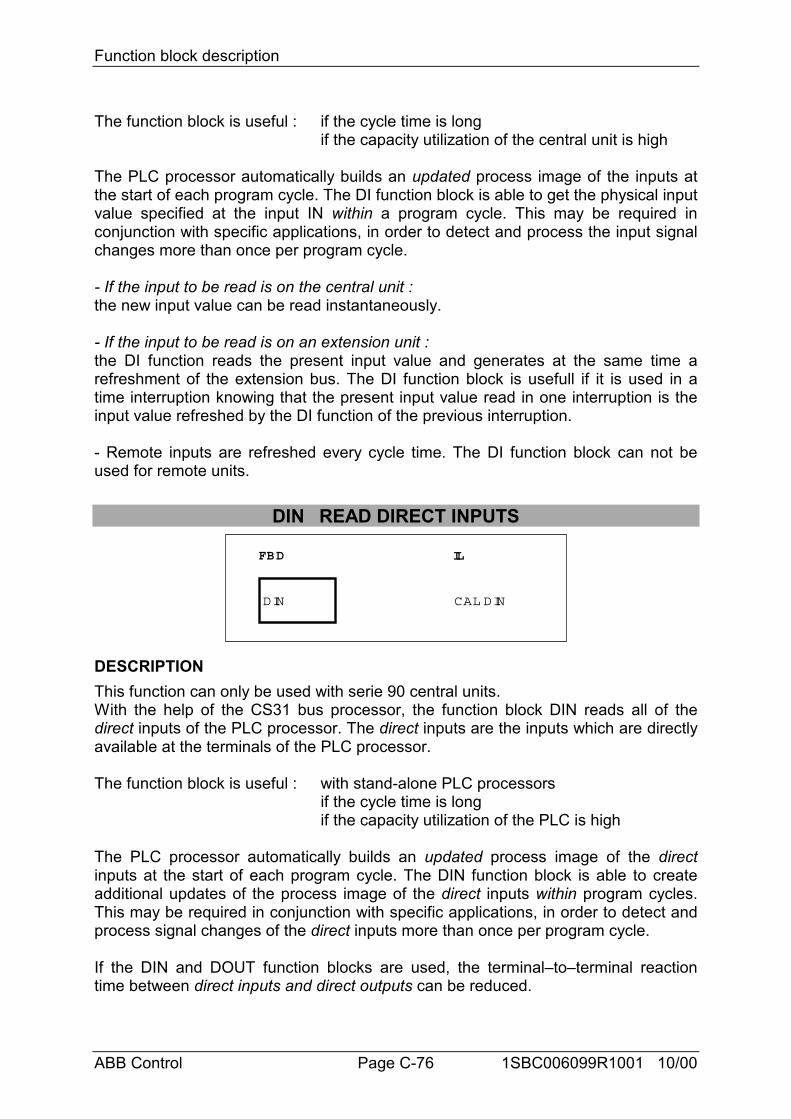
Function block description
ABB Control Page C-76 1SBC006099R1001 10/00
The function block is useful : if the cycle time is longif the capacity utilization of the central unit is high
The PLC processor automatically builds an updated process image of the inputs atthe start of each program cycle. The DI function block is able to get the physical inputvalue specified at the input IN within a program cycle. This may be required inconjunction with specific applications, in order to detect and process the input signalchanges more than once per program cycle.
- If the input to be read is on the central unit :the new input value can be read instantaneously.
- If the input to be read is on an extension unit :the DI function reads the present input value and generates at the same time arefreshment of the extension bus. The DI function block is usefull if it is used in atime interruption knowing that the present input value read in one interruption is theinput value refreshed by the DI function of the previous interruption.
- Remote inputs are refreshed every cycle time. The DI function block can not beused for remote units.
DIN READ DIRECT INPUTS
FBD IL
CAL DINDIN
DESCRIPTIONThis function can only be used with serie 90 central units.With the help of the CS31 bus processor, the function block DIN reads all of thedirect inputs of the PLC processor. The direct inputs are the inputs which are directlyavailable at the terminals of the PLC processor.
The function block is useful : with stand-alone PLC processorsif the cycle time is longif the capacity utilization of the PLC is high
The PLC processor automatically builds an updated process image of the directinputs at the start of each program cycle. The DIN function block is able to createadditional updates of the process image of the direct inputs within program cycles.This may be required in conjunction with specific applications, in order to detect andprocess signal changes of the direct inputs more than once per program cycle.
If the DIN and DOUT function blocks are used, the terminal–to–terminal reactiontime between direct inputs and direct outputs can be reduced.
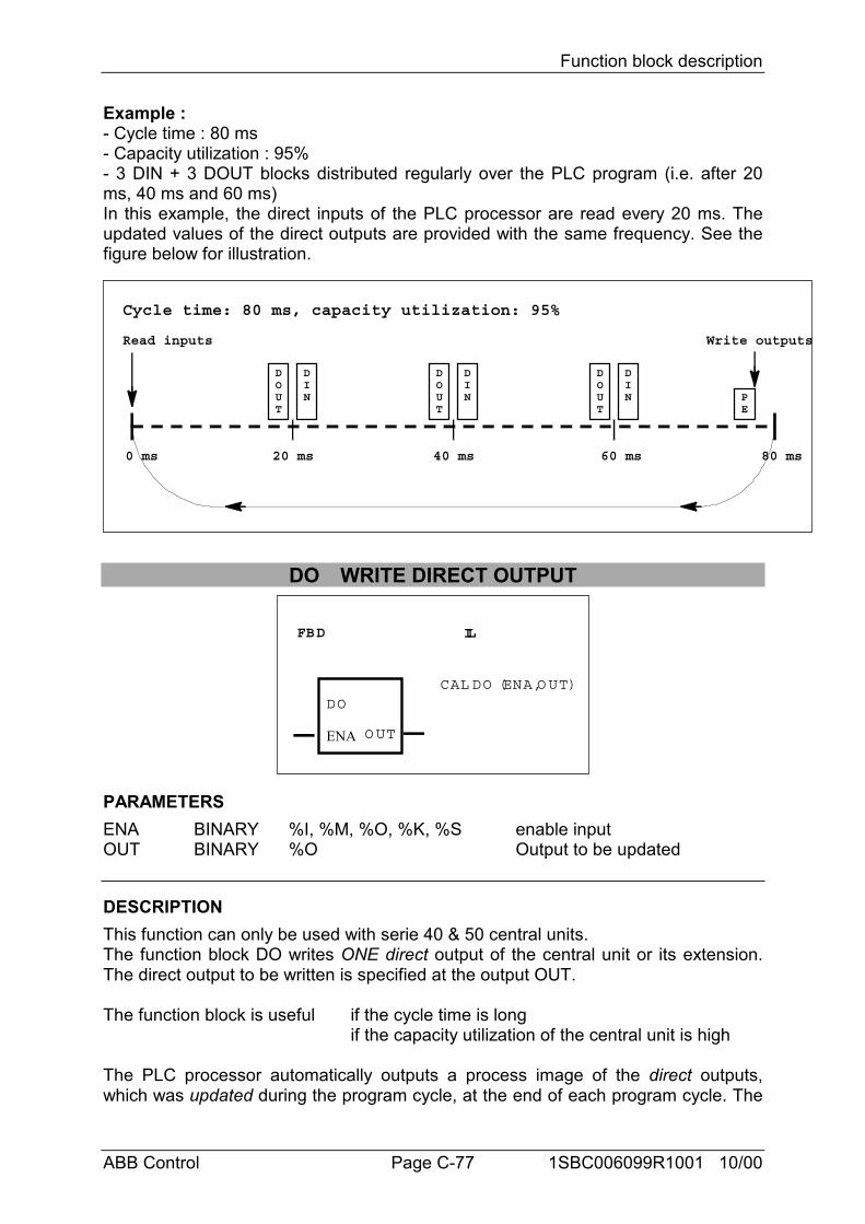
Function block description
ABB Control Page C-77 1SBC006099R1001 10/00
Example :- Cycle time : 80 ms- Capacity utilization : 95%- 3 DIN + 3 DOUT blocks distributed regularly over the PLC program (i.e. after 20ms, 40 ms and 60 ms)In this example, the direct inputs of the PLC processor are read every 20 ms. Theupdated values of the direct outputs are provided with the same frequency. See thefigure below for illustration.
Cycle time: 80 ms, capacity utilization: 95%
0 ms 20 ms 40 ms 60 ms 80 ms
Read inputs Write outputs
DIN
DOUT
DIN
DOUT
DIN
DOUT
PE
DO WRITE DIRECT OUTPUT
FBD IL
DO
O UT
CAL DO (ENA,O UT)
ENA
PARAMETERSENA BINARY %I, %M, %O, %K, %S enable inputOUT BINARY %O Output to be updated
DESCRIPTIONThis function can only be used with serie 40 & 50 central units.The function block DO writes ONE direct output of the central unit or its extension.The direct output to be written is specified at the output OUT.
The function block is useful if the cycle time is longif the capacity utilization of the central unit is high
The PLC processor automatically outputs a process image of the direct outputs,which was updated during the program cycle, at the end of each program cycle. The
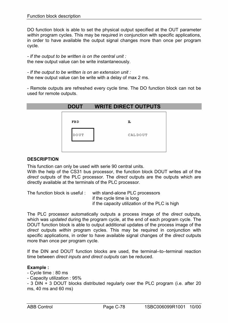
Function block description
ABB Control Page C-78 1SBC006099R1001 10/00
DO function block is able to set the physical output specified at the OUT parameterwithin program cycles. This may be required in conjunction with specific applications,in order to have available the output signal changes more than once per programcycle.
- If the output to be written is on the central unit :the new output value can be write instantaneously.
- If the output to be written is on an extension unit :the new output value can be write with a delay of max 2 ms.
- Remote outputs are refreshed every cycle time. The DO function block can not beused for remote outputs.
DOUT WRITE DIRECT OUTPUTS
FBD IL
CAL DO UTDO UT
DESCRIPTIONThis function can only be used with serie 90 central units.With the help of the CS31 bus processor, the function block DOUT writes all of thedirect outputs of the PLC processor. The direct outputs are the outputs which aredirectly available at the terminals of the PLC processor.
The function block is useful : with stand-alone PLC processorsif the cycle time is longif the capacity utilization of the PLC is high
The PLC processor automatically outputs a process image of the direct outputs,which was updated during the program cycle, at the end of each program cycle. TheDOUT function block is able to output additional updates of the process image of thedirect outputs within program cycles. This may be required in conjunction withspecific applications, in order to have available signal changes of the direct outputsmore than once per program cycle.
If the DIN and DOUT function blocks are used, the terminal–to–terminal reactiontime between direct inputs and direct outputs can be reduced.
Example :- Cycle time : 80 ms- Capacity utilization : 95%- 3 DIN + 3 DOUT blocks distributed regularly over the PLC program (i.e. after 20ms, 40 ms and 60 ms)
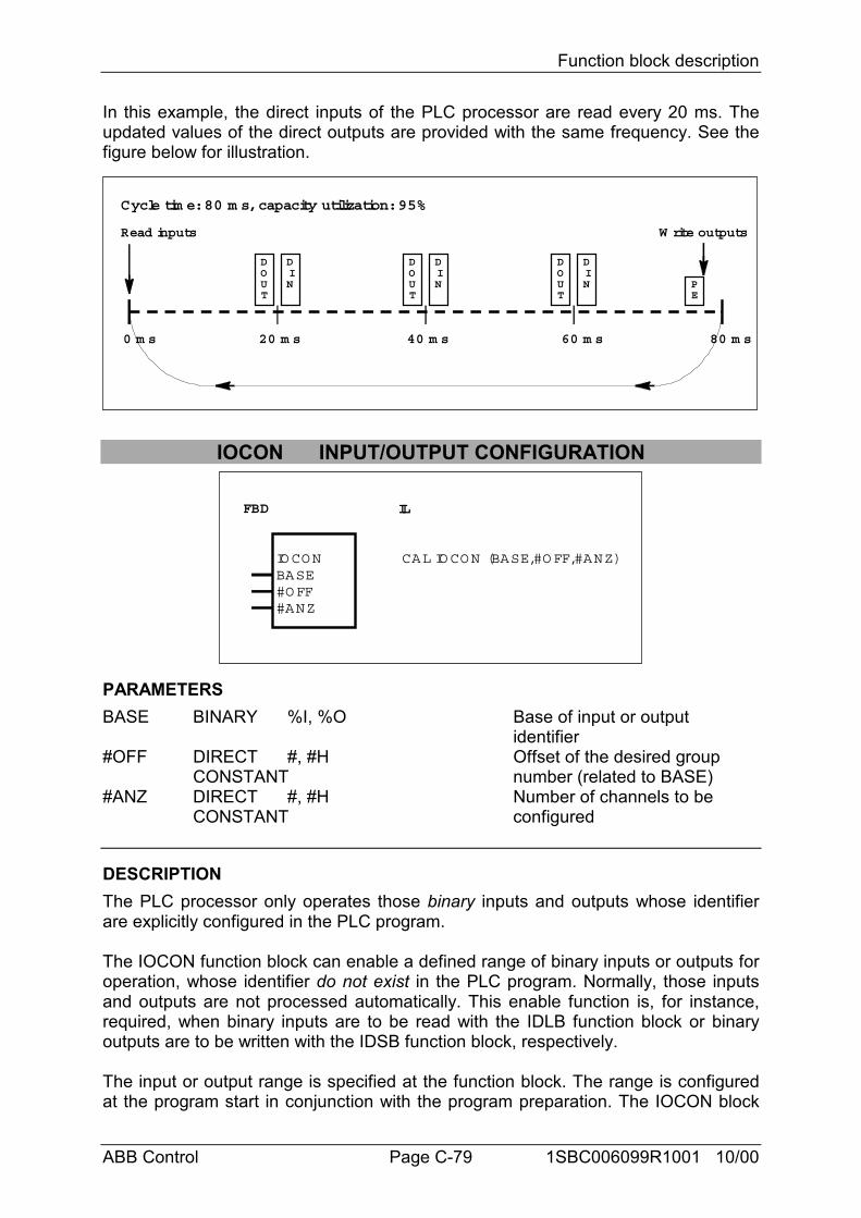
Function block description
ABB Control Page C-79 1SBC006099R1001 10/00
In this example, the direct inputs of the PLC processor are read every 20 ms. Theupdated values of the direct outputs are provided with the same frequency. See thefigure below for illustration.
Cycle tim e: 80 m s, capacity utilization: 95%
0 m s 20 m s 40 m s 60 m s 80 m s
Read inputs W rite outputs
DIN
DOUT
DIN
DOUT
DIN
DOUT
PE
IOCON INPUT/OUTPUT CONFIGURATION
FBD IL
CAL IOCON (BASE,#OFF,#ANZ)IOCONBASE#OFF#ANZ
PARAMETERSBASE BINARY %I, %O Base of input or output
identifier#OFF DIRECT #, #H Offset of the desired group
CONSTANT number (related to BASE)#ANZ DIRECT #, #H Number of channels to be
CONSTANT configured
DESCRIPTIONThe PLC processor only operates those binary inputs and outputs whose identifierare explicitly configured in the PLC program.
The IOCON function block can enable a defined range of binary inputs or outputs foroperation, whose identifier do not exist in the PLC program. Normally, those inputsand outputs are not processed automatically. This enable function is, for instance,required, when binary inputs are to be read with the IDLB function block or binaryoutputs are to be written with the IDSB function block, respectively.
The input or output range is specified at the function block. The range is configuredat the program start in conjunction with the program preparation. The IOCON block
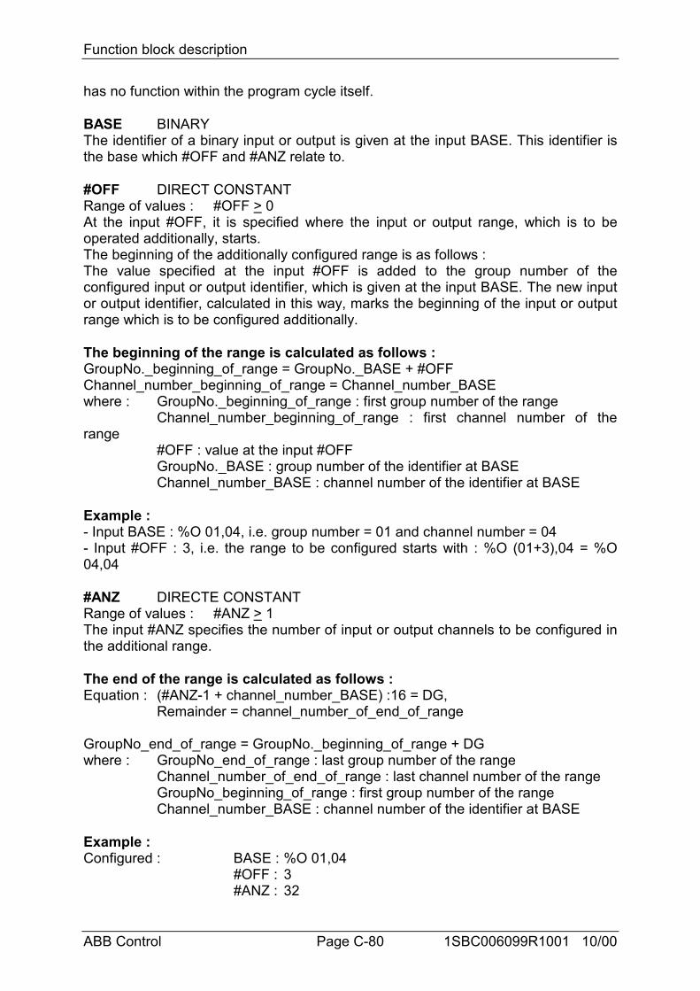
Function block description
ABB Control Page C-80 1SBC006099R1001 10/00
has no function within the program cycle itself.
BASE BINARYThe identifier of a binary input or output is given at the input BASE. This identifier isthe base which #OFF and #ANZ relate to.
#OFF DIRECT CONSTANTRange of values : #OFF > 0At the input #OFF, it is specified where the input or output range, which is to beoperated additionally, starts.The beginning of the additionally configured range is as follows :The value specified at the input #OFF is added to the group number of theconfigured input or output identifier, which is given at the input BASE. The new inputor output identifier, calculated in this way, marks the beginning of the input or outputrange which is to be configured additionally.
The beginning of the range is calculated as follows :GroupNo._beginning_of_range = GroupNo._BASE + #OFFChannel_number_beginning_of_range = Channel_number_BASEwhere : GroupNo._beginning_of_range : first group number of the range
Channel_number_beginning_of_range : first channel number of therange
#OFF : value at the input #OFFGroupNo._BASE : group number of the identifier at BASEChannel_number_BASE : channel number of the identifier at BASE
Example :- Input BASE : %O 01,04, i.e. group number = 01 and channel number = 04- Input #OFF : 3, i.e. the range to be configured starts with : %O (01+3),04 = %O04,04
#ANZ DIRECTE CONSTANTRange of values : #ANZ > 1The input #ANZ specifies the number of input or output channels to be configured inthe additional range.
The end of the range is calculated as follows :Equation : (#ANZ-1 + channel_number_BASE) :16 = DG,
Remainder = channel_number_of_end_of_range
GroupNo_end_of_range = GroupNo._beginning_of_range + DGwhere : GroupNo_end_of_range : last group number of the range
Channel_number_of_end_of_range : last channel number of the rangeGroupNo_beginning_of_range : first group number of the rangeChannel_number_BASE : channel number of the identifier at BASE
Example :Configured : BASE : %O 01,04
#OFF : 3#ANZ : 32
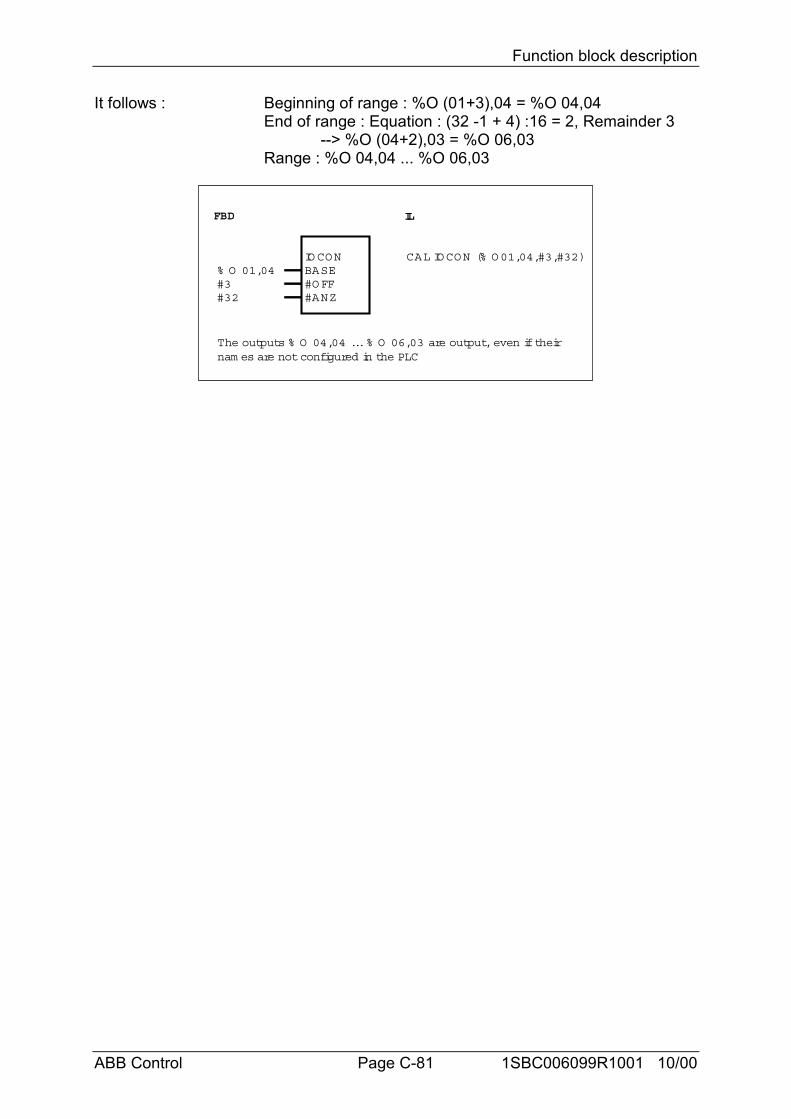
Function block description
ABB Control Page C-81 1SBC006099R1001 10/00
It follows : Beginning of range : %O (01+3),04 = %O 04,04End of range : Equation : (32 -1 + 4) :16 = 2, Remainder 3
--> %O (04+2),03 = %O 06,03Range : %O 04,04 ... %O 06,03
FBD IL
CAL IOCON (% O01,04,#3,#32)% O 01,04#3#32
IOCONBASE#OFF#ANZ
The outputs % O 04,04 ... % O 06,03 are output, even if theirnam es are not configured in the PLC
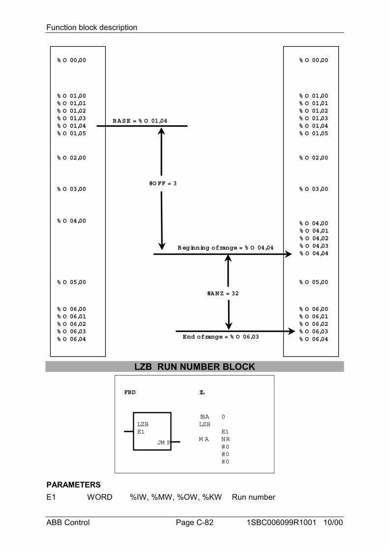
Function block description
ABB Control Page C-82 1SBC006099R1001 10/00
% O 01,00% O 01,01% O 01,02
% O 02,00
% O 03,00
% O 01,03% O 01,04% O 01,05
% O 04,00
% O 05,00
% O 06,00% O 06,01% O 06,02% O 06,03% O 06,04
% O 00,00
% O 01,00% O 01,01% O 01,02
% O 02,00
% O 03,00
% O 01,03% O 01,04% O 01,05
% O 04,00
% O 05,00
% O 06,00% O 06,01% O 06,02% O 06,03% O 06,04
% O 00,00
#O FF = 3
% O 04,01% O 04,02% O 04,03% O 04,04
Beginning of range = % O 04,04
End of range = % O 06,03
#ANZ = 32
BASE = % O 01,04
LZB RUN NUMBER BLOCK
FBD IL
LZB!BALZB
M A
0
E1NR#0#0#0
E1
JM P
PARAMETERSE1 WORD %IW, %MW, %OW, %KW Run number
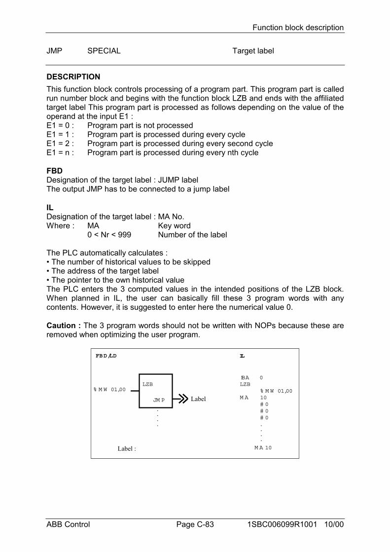
Function block description
ABB Control Page C-83 1SBC006099R1001 10/00
JMP SPECIAL Target label
DESCRIPTIONThis function block controls processing of a program part. This program part is calledrun number block and begins with the function block LZB and ends with the affiliatedtarget label This program part is processed as follows depending on the value of theoperand at the input E1 :E1 = 0 : Program part is not processedE1 = 1 : Program part is processed during every cycleE1 = 2 : Program part is processed during every second cycleE1 = n : Program part is processed during every nth cycle
FBDDesignation of the target label : JUMP labelThe output JMP has to be connected to a jump label
ILDesignation of the target label : MA No.Where : MA Key word
0 < Nr < 999 Number of the label
The PLC automatically calculates :• The number of historical values to be skipped• The address of the target label• The pointer to the own historical valueThe PLC enters the 3 computed values in the intended positions of the LZB block.When planned in IL, the user can basically fill these 3 program words with anycontents. However, it is suggested to enter here the numerical value 0.
Caution : The 3 program words should not be written with NOPs because these areremoved when optimizing the user program.
FBD/LD IL
LZB
JM P
!BALZB
M A% M W 01,0010# 0# 0# 0
% M W 01,00
0
.
.
.
.
.
.
.
.
M A 10
Label
Label :
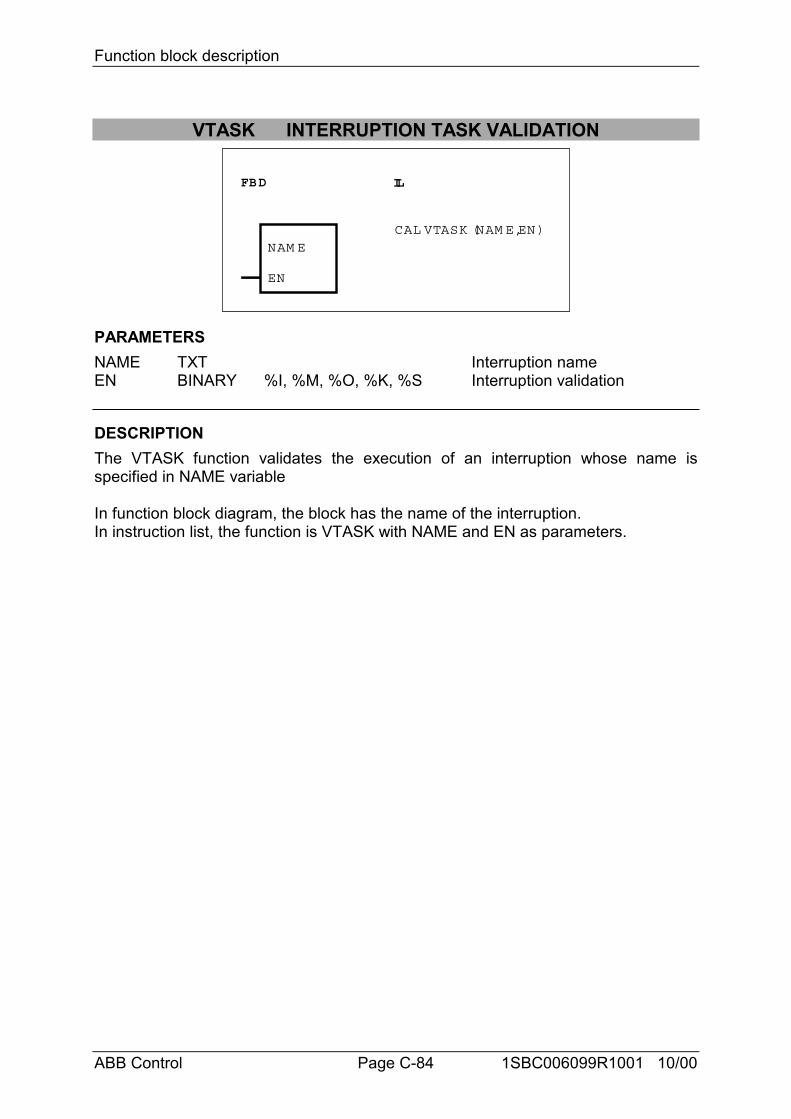
Function block description
ABB Control Page C-84 1SBC006099R1001 10/00
VTASK INTERRUPTION TASK VALIDATION
FBD IL
NAM E
EN
CAL VTASK (NAM E,EN)
PARAMETERSNAME TXT Interruption nameEN BINARY %I, %M, %O, %K, %S Interruption validation
DESCRIPTIONThe VTASK function validates the execution of an interruption whose name isspecified in NAME variable
In function block diagram, the block has the name of the interruption.In instruction list, the function is VTASK with NAME and EN as parameters.
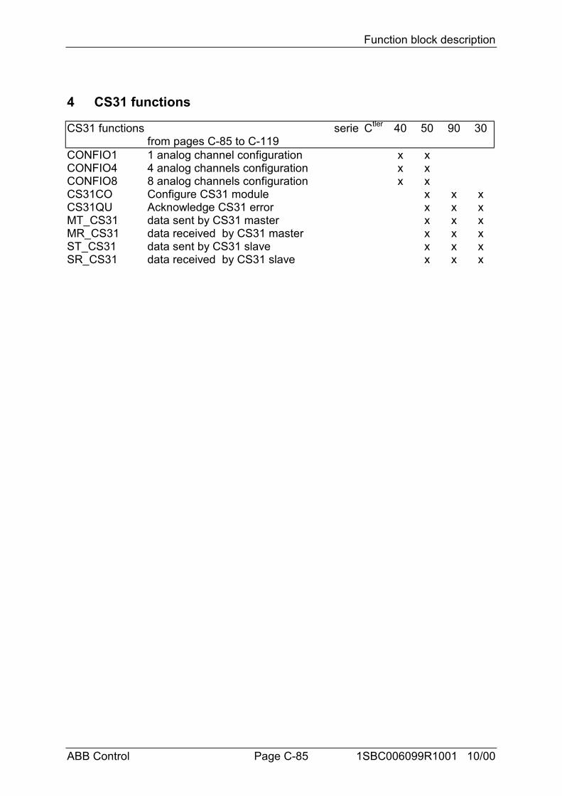
Function block description
ABB Control Page C-85 1SBC006099R1001 10/00
4 CS31 functions
CS31 functions seriefrom pages C-85 to C-119
Ctler 40 50 90 30
CONFIO1 1 analog channel configuration x xCONFIO4 4 analog channels configuration x xCONFIO8 8 analog channels configuration x xCS31CO Configure CS31 module x x xCS31QU Acknowledge CS31 error x x xMT_CS31 data sent by CS31 master x x xMR_CS31 data received by CS31 master x x xST_CS31 data sent by CS31 slave x x xSR_CS31 data received by CS31 slave x x x
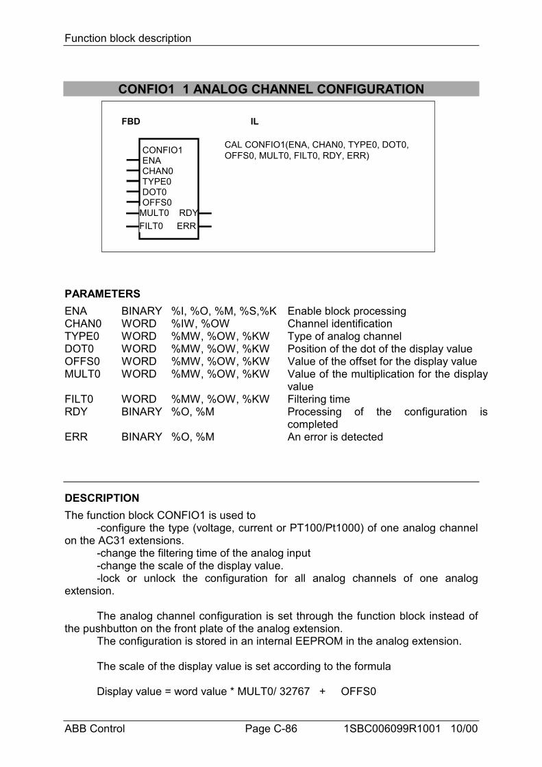
Function block description
ABB Control Page C-86 1SBC006099R1001 10/00
CONFIO1 1 ANALOG CHANNEL CONFIGURATION
FBD IL
CONFIO1ENACHAN0TYPE0DOT0OFFS0
RDYERR
CAL CONFIO1(ENA, CHAN0, TYPE0, DOT0,OFFS0, MULT0, FILT0, RDY, ERR)
MULT0FILT0
PARAMETERSENA BINARY %I, %O, %M, %S,%K Enable block processingCHAN0 WORD %IW, %OW Channel identificationTYPE0 WORD %MW, %OW, %KW Type of analog channelDOT0 WORD %MW, %OW, %KW Position of the dot of the display valueOFFS0 WORD %MW, %OW, %KW Value of the offset for the display valueMULT0 WORD %MW, %OW, %KW Value of the multiplication for the display
valueFILT0 WORD %MW, %OW, %KW Filtering timeRDY BINARY %O, %M Processing of the configuration is
completedERR BINARY %O, %M An error is detected
DESCRIPTIONThe function block CONFIO1 is used to
-configure the type (voltage, current or PT100/Pt1000) of one analog channelon the AC31 extensions.
-change the filtering time of the analog input-change the scale of the display value.-lock or unlock the configuration for all analog channels of one analog
extension.
The analog channel configuration is set through the function block instead ofthe pushbutton on the front plate of the analog extension.
The configuration is stored in an internal EEPROM in the analog extension.
The scale of the display value is set according to the formula
Display value = word value * MULT0/ 32767 + OFFS0
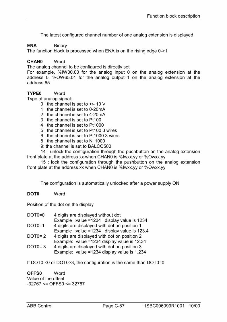
Function block description
ABB Control Page C-87 1SBC006099R1001 10/00
The latest configured channel number of one analog extension is displayed
ENA BinaryThe function block is processed when ENA is on the rising edge 0->1
CHAN0 WordThe analog channel to be configured is directly setFor example, %IW00.00 for the analog input 0 on the analog extension at theaddress 0, %OW65.01 for the analog output 1 on the analog extension at theaddress 65
TYPE0 WordType of analog signal:
0 : the channel is set to +/- 10 V1 : the channel is set to 0-20mA2 : the channel is set to 4-20mA3 : the channel is set to Pt1004 : the channel is set to Pt10005 : the channel is set to Pt100 3 wires6 : the channel is set to Pt1000 3 wires8 : the channel is set to Ni 10009: the channel is set to BALCO50014 : unlock the configuration through the pushbutton on the analog extension
front plate at the address xx when CHAN0 is %Iwxx.yy or %Owxx.yy15 : lock the configuration through the pushbutton on the analog extension
front plate at the address xx when CHAN0 is %Iwxx.yy or %Owxx.yy
The configuration is automatically unlocked after a power supply ON
DOT0 Word
Position of the dot on the display
DOT0=0 4 digits are displayed without dotExample :value =1234 display value is 1234
DOT0=1 4 digits are displayed with dot on position 1Example :value =1234 display value is 123.4
DOT0= 2 4 digits are displayed with dot on position 2Example: value =1234 display value is 12.34
DOT0= 3 4 digits are displayed with dot on position 3Example: value =1234 display value is 1.234
If DOT0 <0 or DOT0>3, the configuration is the same than DOT0=0
OFFS0 WordValue of the offset-32767 <= OFFS0 <= 32767
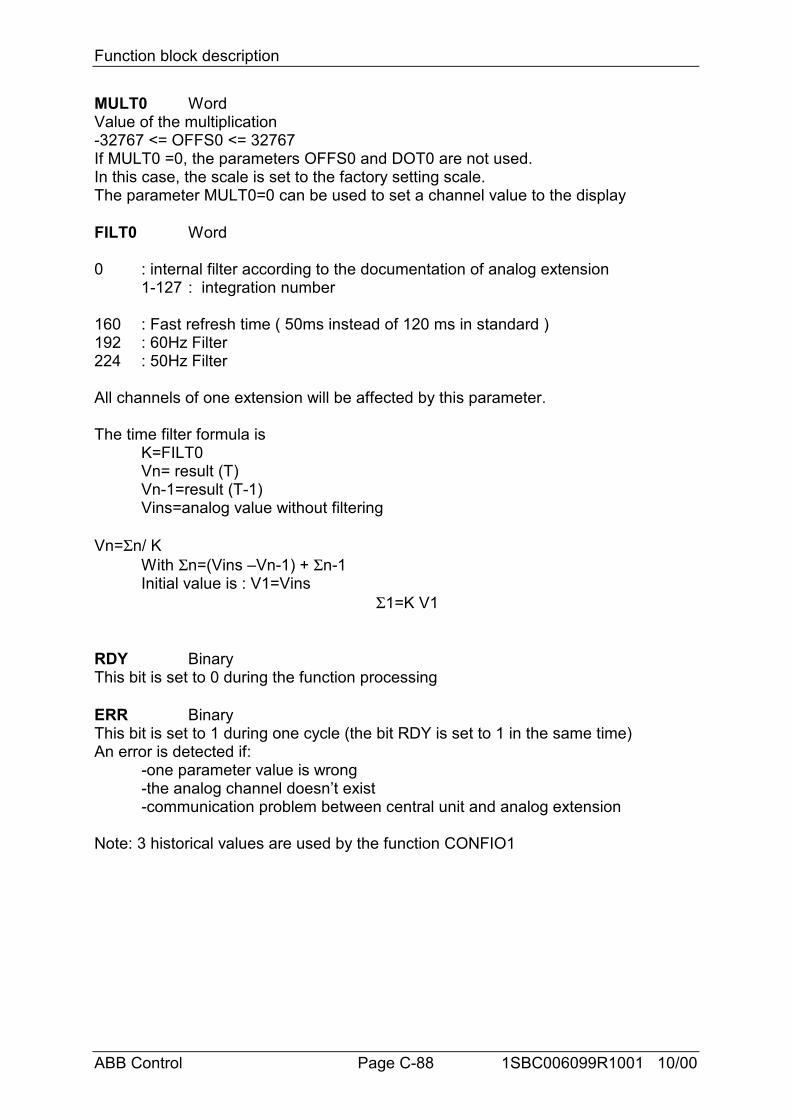
Function block description
ABB Control Page C-88 1SBC006099R1001 10/00
MULT0 WordValue of the multiplication-32767 <= OFFS0 <= 32767If MULT0 =0, the parameters OFFS0 and DOT0 are not used.In this case, the scale is set to the factory setting scale.The parameter MULT0=0 can be used to set a channel value to the display
FILT0 Word
0 : internal filter according to the documentation of analog extension1-127 : integration number
160 : Fast refresh time ( 50ms instead of 120 ms in standard )192 : 60Hz Filter224 : 50Hz Filter
All channels of one extension will be affected by this parameter.
The time filter formula isK=FILT0Vn= result (T)Vn-1=result (T-1)Vins=analog value without filtering
Vn=Σn/ KWith Σn=(Vins –Vn-1) + Σn-1Initial value is : V1=Vins
Σ1=K V1
RDY BinaryThis bit is set to 0 during the function processing
ERR BinaryThis bit is set to 1 during one cycle (the bit RDY is set to 1 in the same time)An error is detected if:
-one parameter value is wrong-the analog channel doesn’t exist-communication problem between central unit and analog extension
Note: 3 historical values are used by the function CONFIO1
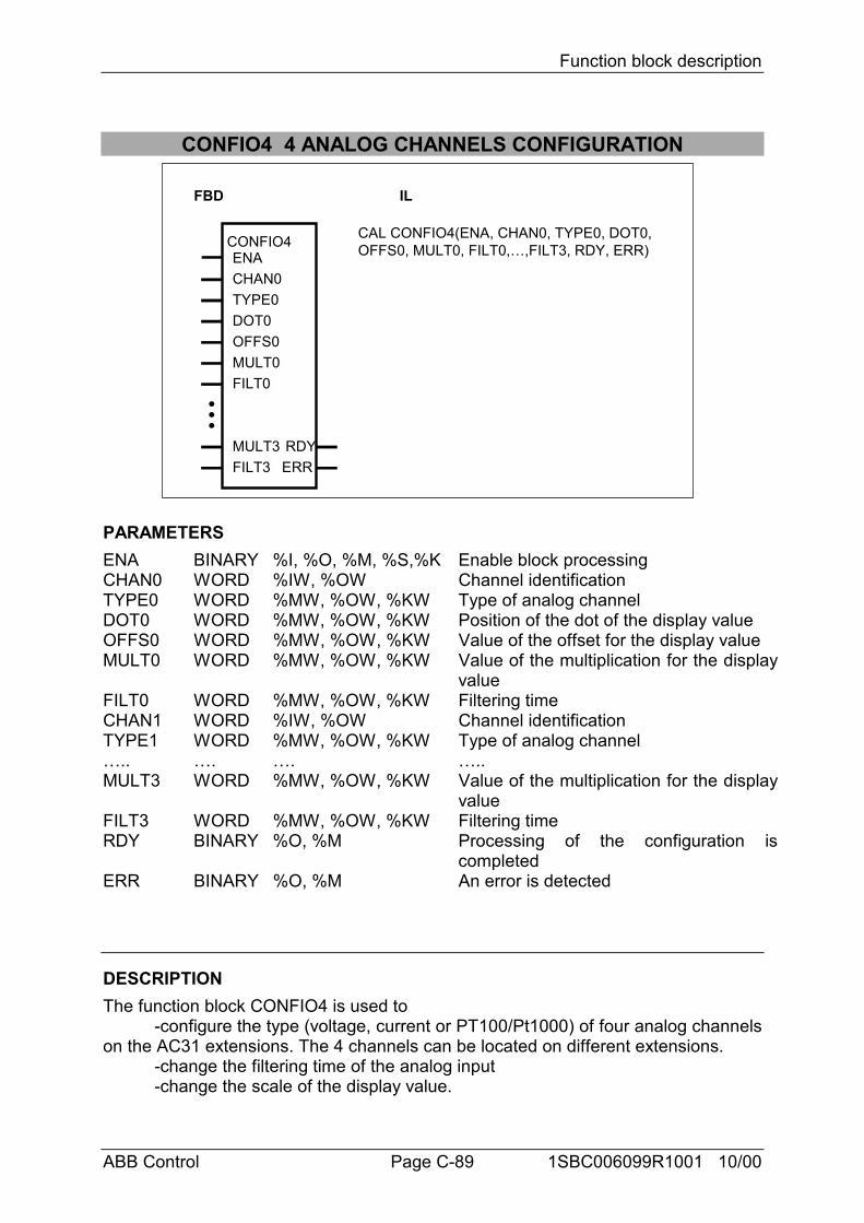
Function block description
ABB Control Page C-89 1SBC006099R1001 10/00
CONFIO4 4 ANALOG CHANNELS CONFIGURATION
FBD IL
CONFIO4ENACHAN0TYPE0DOT0OFFS0
RDYERR
CAL CONFIO4(ENA, CHAN0, TYPE0, DOT0,OFFS0, MULT0, FILT0,…,FILT3, RDY, ERR)
MULT0FILT0
MULT3FILT3
PARAMETERSENA BINARY %I, %O, %M, %S,%K Enable block processingCHAN0 WORD %IW, %OW Channel identificationTYPE0 WORD %MW, %OW, %KW Type of analog channelDOT0 WORD %MW, %OW, %KW Position of the dot of the display valueOFFS0 WORD %MW, %OW, %KW Value of the offset for the display valueMULT0 WORD %MW, %OW, %KW Value of the multiplication for the display
valueFILT0 WORD %MW, %OW, %KW Filtering timeCHAN1 WORD %IW, %OW Channel identificationTYPE1 WORD %MW, %OW, %KW Type of analog channel….. …. …. …..MULT3 WORD %MW, %OW, %KW Value of the multiplication for the display
valueFILT3 WORD %MW, %OW, %KW Filtering timeRDY BINARY %O, %M Processing of the configuration is
completedERR BINARY %O, %M An error is detected
DESCRIPTIONThe function block CONFIO4 is used to
-configure the type (voltage, current or PT100/Pt1000) of four analog channelson the AC31 extensions. The 4 channels can be located on different extensions.
-change the filtering time of the analog input-change the scale of the display value.

Function block description
ABB Control Page C-90 1SBC006099R1001 10/00
-lock or unlock the configuration for all analog channels of one analogextension.
The analog channel configuration is set through the function block instead ofthe pushbutton on the front plate of the analog extension.
The configuration is stored in an internal EEPROM in the analog extension.
The scale of the display value is set according to the formula
Display value = word value * MULT0/ 32767 + OFFS0
The latest configured channel number of one analog extension is displayed
ENA BinaryThe function block is processed when ENA is on the rising edge 0->1
CHAN0 WordThe analog channel to be configured is directly setFor example, %IW00.00 for the analog input 0 on the analog extension at theaddress 0, %OW65.01 for the analog output 1 on the analog extension at theaddress 65
TYPE0 WordType of analog signal:
0 : the channel is set to +/- 10 V1 : the channel is set to 0-20mA2 : the channel is set to 4-20mA3 : the channel is set to Pt1004 : the channel is set to Pt10005 : the channel is set to Pt100 3 wires6 : the channel is set to Pt1000 3 wires8 : the channel is set to Ni 10009: the channel is set to BALCO50014 : unlock the configuration through the pushbutton on the analog extension
front plate at the address xx when CHAN0 is %Iwxx.yy or %Owxx.yy15 : lock the configuration through the pushbutton on the analog extension
front plate at the address xx when CHAN0 is %Iwxx.yy or %Owxx.yy
The configuration is automatically unlocked after a power supply ON
DOT0 Word
Position of the dot on the display
DOT0=0 4 digits are displayed without dotExample :value =1234 display value is 1234
DOT0=1 4 digits are displayed with dot on position 1Example :value =1234 display value is 123.4
DOT0= 2 4 digits are displayed with dot on position 2
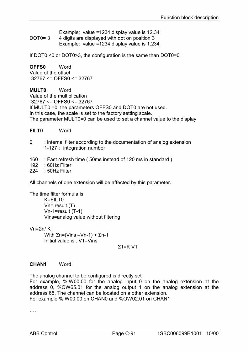
Function block description
ABB Control Page C-91 1SBC006099R1001 10/00
Example: value =1234 display value is 12.34DOT0= 3 4 digits are displayed with dot on position 3
Example: value =1234 display value is 1.234
If DOT0 <0 or DOT0>3, the configuration is the same than DOT0=0
OFFS0 WordValue of the offset-32767 <= OFFS0 <= 32767
MULT0 WordValue of the multiplication-32767 <= OFFS0 <= 32767If MULT0 =0, the parameters OFFS0 and DOT0 are not used.In this case, the scale is set to the factory setting scale.The parameter MULT0=0 can be used to set a channel value to the display
FILT0 Word
0 : internal filter according to the documentation of analog extension1-127 : integration number
160 : Fast refresh time ( 50ms instead of 120 ms in standard )192 : 60Hz Filter224 : 50Hz Filter
All channels of one extension will be affected by this parameter.
The time filter formula isK=FILT0Vn= result (T)Vn-1=result (T-1)Vins=analog value without filtering
Vn=Σn/ KWith Σn=(Vins –Vn-1) + Σn-1Initial value is : V1=Vins
Σ1=K V1
CHAN1 Word
The analog channel to be configured is directly setFor example, %IW00.00 for the analog input 0 on the analog extension at theaddress 0, %OW65.01 for the analog output 1 on the analog extension at theaddress 65. The channel can be located on a other extension.For example %IW00.00 on CHAN0 and %OW02.01 on CHAN1
….

Function block description
ABB Control Page C-92 1SBC006099R1001 10/00
RDY BinaryThis bit is set to 0 during the function processing
ERR BinaryThis bit is set to 1 during one cycle (the bit RDY is set to 1 in the same time)An error is detected if:
-one parameter value is wrong-the analog channel doesn’t exist-communication problem between central unit and analog extension.
Note: 3 historical values are used by the function CONFIO4
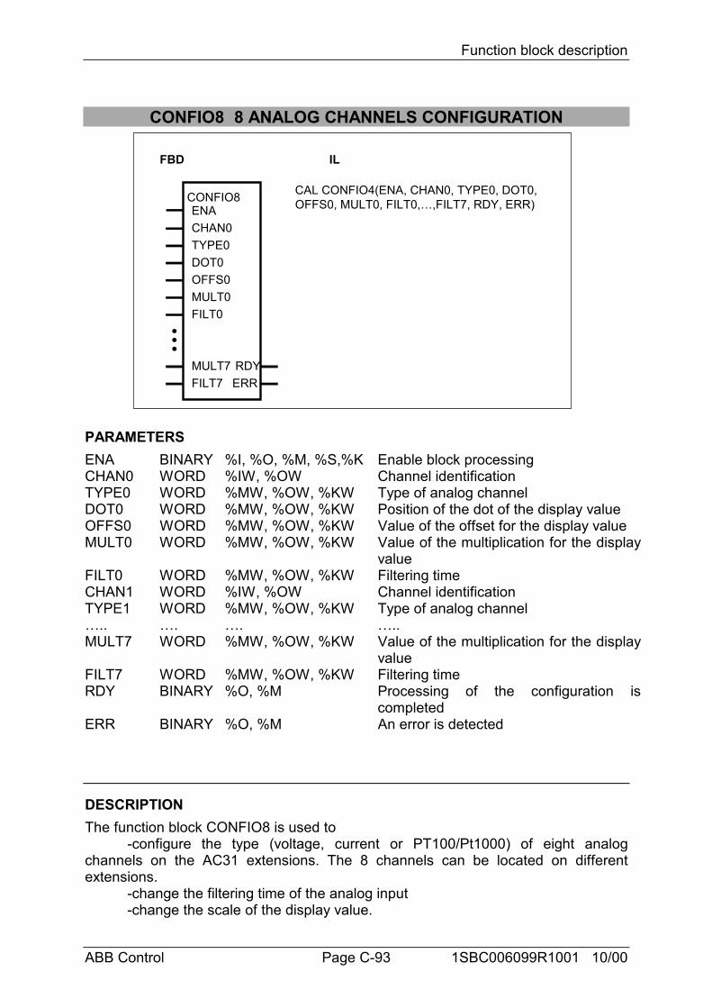
Function block description
ABB Control Page C-93 1SBC006099R1001 10/00
CONFIO8 8 ANALOG CHANNELS CONFIGURATION
FBD IL
CONFIO8ENACHAN0TYPE0DOT0OFFS0
RDYERR
CAL CONFIO4(ENA, CHAN0, TYPE0, DOT0,OFFS0, MULT0, FILT0,…,FILT7, RDY, ERR)
MULT0FILT0
MULT7FILT7
PARAMETERSENA BINARY %I, %O, %M, %S,%K Enable block processingCHAN0 WORD %IW, %OW Channel identificationTYPE0 WORD %MW, %OW, %KW Type of analog channelDOT0 WORD %MW, %OW, %KW Position of the dot of the display valueOFFS0 WORD %MW, %OW, %KW Value of the offset for the display valueMULT0 WORD %MW, %OW, %KW Value of the multiplication for the display
valueFILT0 WORD %MW, %OW, %KW Filtering timeCHAN1 WORD %IW, %OW Channel identificationTYPE1 WORD %MW, %OW, %KW Type of analog channel….. …. …. …..MULT7 WORD %MW, %OW, %KW Value of the multiplication for the display
valueFILT7 WORD %MW, %OW, %KW Filtering timeRDY BINARY %O, %M Processing of the configuration is
completedERR BINARY %O, %M An error is detected
DESCRIPTIONThe function block CONFIO8 is used to
-configure the type (voltage, current or PT100/Pt1000) of eight analogchannels on the AC31 extensions. The 8 channels can be located on differentextensions.
-change the filtering time of the analog input-change the scale of the display value.
Function block description
ABB Control Page C-94 1SBC006099R1001 10/00
-lock or unlock the configuration for all analog channels of one analogextension.
The analog channel configuration is set through the function block instead ofthe pushbutton on the front plate of the analog extension.
The configuration is stored in an internal EEPROM in the analog extension.
The scale of the display value is set according to the formula
Display value = word value * MULT0/ 32767 + OFFS0
The latest configured channel number of one analog extension is displayed
ENA BinaryThe function block is processed when ENA is on the rising edge 0->1
CHAN0 WordThe analog channel to be configured is directly setFor example, %IW00.00 for the analog input 0 on the analog extension at theaddress 0, %OW65.01 for the analog output 1 on the analog extension at theaddress 65
TYPE0 WordType of analog signal:
0 : the channel is set to +/- 10 V1 : the channel is set to 0-20mA2 : the channel is set to 4-20mA3 : the channel is set to Pt1004 : the channel is set to Pt10005 : the channel is set to Pt100 3 wires6 : the channel is set to Pt1000 3 wires8 : the channel is set to Ni 10009: the channel is set to BALCO50014 : unlock the configuration through the pushbutton on the analog extension
front plate at the address xx when CHAN0 is %Iwxx.yy or %Owxx.yy15 : lock the configuration through the pushbutton on the analog extension
front plate at the address xx when CHAN0 is %Iwxx.yy or %Owxx.yy
The configuration is automatically unlocked after a power supply ON
DOT0 Word
Position of the dot on the display
DOT0=0 4 digits are displayed without dotExample :value =1234 display value is 1234
DOT0=1 4 digits are displayed with dot on position 1Example :value =1234 display value is 123.4
DOT0= 2 4 digits are displayed with dot on position 2

Function block description
ABB Control Page C-95 1SBC006099R1001 10/00
Example: value =1234 display value is 12.34DOT0= 3 4 digits are displayed with dot on position 3
Example: value =1234 display value is 1.234
If DOT0 <0 or DOT0>3, the configuration is the same than DOT0=0
OFFS0 WordValue of the offset-32767 <= OFFS0 <= 32767
MULT0 WordValue of the multiplication-32767 <= OFFS0 <= 32767If MULT0 =0, the parameters OFFS0 and DOT0 are not used.In this case, the scale is set to the factory setting scale.The parameter MULT0=0 can be used to set a channel value to the display
FILT0 Word
0 : internal filter according to the documentation of analog extension1-127 : integration number
160 : Fast refresh time ( 50ms instead of 120 ms in standard )192 : 60Hz Filter224 : 50Hz Filter
All channels of one extension will be affected by this parameter.
The time filter formula isK=FILT0Vn= result (T)Vn-1=result (T-1)Vins=analog value without filtering
Vn=Σn/ KWith Σn=(Vins –Vn-1) + Σn-1Initial value is : V1=Vins
Σ1=K V1
CHAN1 Word
The analog channel to be configured is directly setFor example, %IW00.00 for the analog input 0 on the analog extension at theaddress 0, %OW65.01 for the analog output 1 on the analog extension at theaddress 65. The channel can be located on a other extension.For example %IW00.00 on CHAN0 and %OW02.01 on CHAN1
….
RDY Binary
Function block description
ABB Control Page C-96 1SBC006099R1001 10/00
This bit is set to 0 during the function processing
ERR BinaryThis bit is set to 1 during one cycle (the bit RDY is set to 1 in the same time)An error is detected if:
-one parameter value is wrong-the analog channel doesn’t exist-communication problem between central unit and analog extension.
Note: 3 historical values are used by the function CONFIO8
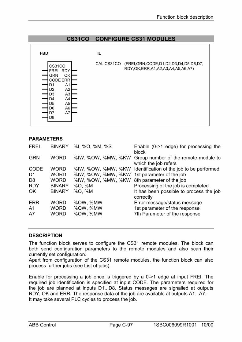
Function block description
ABB Control Page C-97 1SBC006099R1001 10/00
CS31CO CONFIGURE CS31 MODULES
FBD IL
CS31COFREIGRNCODED1D2
A3A4
A1A2
A5A6
D3D4D5D6D7D8
ERR
RDYOK
A7
CAL CS31CO (FREI,GRN,CODE,D1,D2,D3,D4,D5,D6,D7,RDY,OK,ERR,A1,A2,A3,A4,A5,A6,A7)
PARAMETERSFREI BINARY %I, %O, %M, %S Enable (0->1 edge) for processing the
blockGRN WORD %IW, %OW, %MW, %KW Group number of the remote module to
which the job refersCODE WORD %IW, %OW, %MW, %KW Identification of the job to be performedD1 WORD %IW, %OW, %MW, %KW 1st parameter of the jobD8 WORD %IW, %OW, %MW, %KW 8th parameter of the jobRDY BINARY %O, %M Processing of the job is completedOK BINARY %O, %M It has been possible to process the job
correctlyERR WORD %OW, %MW Error message/status messageA1 WORD %OW, %MW 1st parameter of the responseA7 WORD %OW, %MW 7th Parameter of the response
DESCRIPTIONThe function block serves to configure the CS31 remote modules. The block canboth send configuration parameters to the remote modules and also scan theircurrently set configuration.Apart from configuration of the CS31 remote modules, the function block can alsoprocess further jobs (see List of jobs).
Enable for processing a job once is triggered by a 0->1 edge at input FREI. Therequired job identification is specified at input CODE. The parameters required forthe job are planned at inputs D1...D8. Status messages are signalled at outputsRDY, OK and ERR. The response data of the job are available at outputs A1...A7.It may take several PLC cycles to process the job.
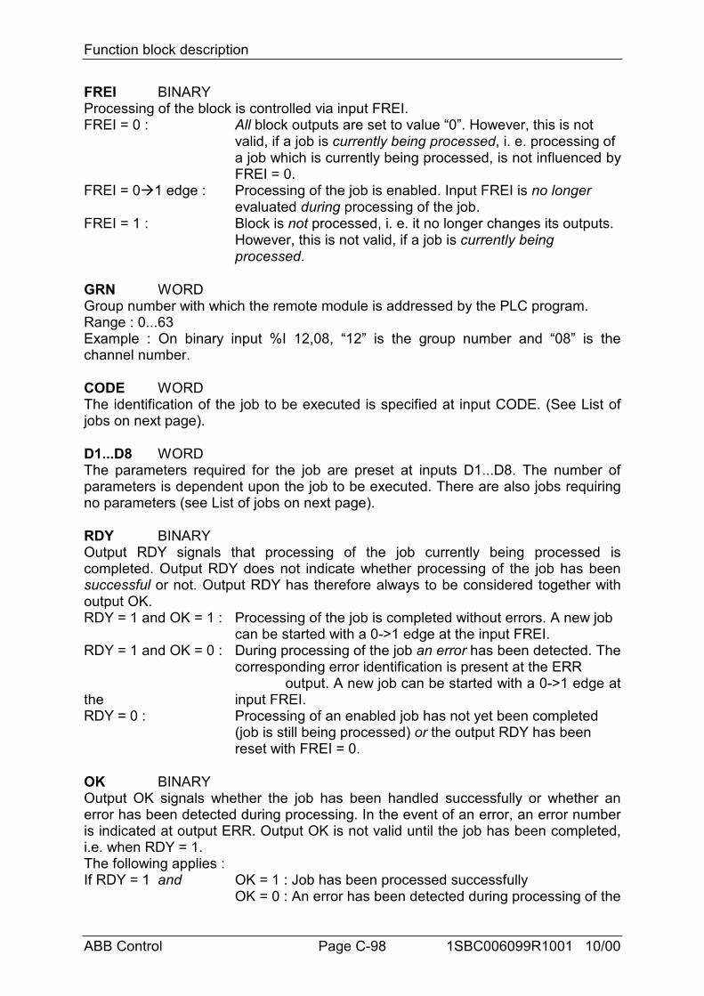
Function block description
ABB Control Page C-98 1SBC006099R1001 10/00
FREI BINARYProcessing of the block is controlled via input FREI.FREI = 0 : All block outputs are set to value “0”. However, this is not
valid, if a job is currently being processed, i. e. processing of a job which is currently being processed, is not influenced byFREI = 0.
FREI = 0$1 edge : Processing of the job is enabled. Input FREI is no longerevaluated during processing of the job.
FREI = 1 : Block is not processed, i. e. it no longer changes its outputs. However, this is not valid, if a job is currently being processed.
GRN WORDGroup number with which the remote module is addressed by the PLC program.Range : 0...63Example : On binary input %I 12,08, “12” is the group number and “08” is thechannel number.
CODE WORDThe identification of the job to be executed is specified at input CODE. (See List ofjobs on next page).
D1...D8 WORDThe parameters required for the job are preset at inputs D1...D8. The number ofparameters is dependent upon the job to be executed. There are also jobs requiringno parameters (see List of jobs on next page).
RDY BINARYOutput RDY signals that processing of the job currently being processed iscompleted. Output RDY does not indicate whether processing of the job has beensuccessful or not. Output RDY has therefore always to be considered together withoutput OK.RDY = 1 and OK = 1 : Processing of the job is completed without errors. A new job
can be started with a 0->1 edge at the input FREI.RDY = 1 and OK = 0 : During processing of the job an error has been detected. The
corresponding error identification is present at the ERR output. A new job can be started with a 0->1 edge at
the input FREI.RDY = 0 : Processing of an enabled job has not yet been completed
(job is still being processed) or the output RDY has been reset with FREI = 0.
OK BINARYOutput OK signals whether the job has been handled successfully or whether anerror has been detected during processing. In the event of an error, an error numberis indicated at output ERR. Output OK is not valid until the job has been completed,i.e. when RDY = 1.The following applies :If RDY = 1 and OK = 1 : Job has been processed successfully
OK = 0 : An error has been detected during processing of the
Function block description
ABB Control Page C-99 1SBC006099R1001 10/00
job.
ERR WORDStatus and error identifications are output at output ERR. The status identificationsare output during processing of a job in order to signal in what stage of processingthe job currently is. After enabling a job, status identifications are signalled only foras long as RDY = 0.The error identifications are output after completion of the job processing if an errorhas occurred. Error identifications are thus not signalled until RDY = 1 and OK = 0.
Error identificationsERR = 1 : An illegal job identification has been specified at input CODE.ERR = 2 : Incorrect parameters have been specified at inputs D1...D8 (e.g. a group
number for which there is no remote module on the CS31 bus).ERR = 3 The addressed CS31 remote module does not accept the job.
Status identificationsERR = 8 : The function block is waiting since a job of another user is currently being
processed.ERR = 10 : The job has been sent to the addressee and the block is waiting for its
response.
A1...A7 WORDAfter completion of job processing, the response is available at outputs A1...A7. Thenumber of response parameters depends upon the job performed (see List of jobs).
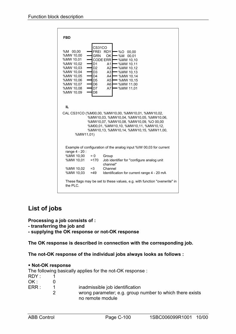
Function block description
ABB Control Page C-100 1SBC006099R1001 10/00
FBD
IL
CS31COFREIGRNCODED1D2
ERRA1
RDYOK
A2A3
Example of configuration of the analog input %IW 00,03 for currentrange 4 - 20 :%MW 10,00 = 0 Group%MW 10,01 =170 Job identifier for "configure analog unit
channel"%MW 10,02 =3 Channel%MW 10,03 =49 Identification for current range 4 - 20 mA
These flags may be set to these values, e.g. with function "overwrite" inthe PLC.
D3D4D5D6D7
%MW 10,02%MW 10,03
%MW 10,01%MW 10,00%M 00,00
%MW 10,07%MW 10,08
%MW 10,06%MW 10,05%MW 10,04
%MW 10,09 D8
A4A5A6A7
%O 00,00%M 00,01%MW 10,10%MW 10,11%MW 10,12%MW 10,13%MW 10,14%MW 10,15%MW 11,00%MW 11,01
CAL CS31CO (%M00,00, %MW10,00, %MW10,01, %MW10,02,%MW10,03, %MW10,04, %MW10,05, %MW10,06,%MW10,07, %MW10,08, %MW10,09, %O 00,00%M00,01, %MW10,10, %MW10,11, %MW10,12,%MW10,13, %MW10,14, %MW10,15, %MW11,00,
%MW11,01)
List of jobs
Processing a job consists of :- transferring the job and- supplying the OK response or not-OK response
The OK response is described in connection with the corresponding job.
The not-OK response of the individual jobs always looks as follows :
# Not-OK responseThe following basically applies for the not-OK response :RDY : 1OK : 0ERR : 1 inadmissible job identification
2 wrong parameter; e.g. group number to which there exists no remote module
Function block description
ABB Control Page C-101 1SBC006099R1001 10/00
3 remote module does not accept jobA1 ... A7 : 0
% Updating of the maximum number of remote modules detectedInput word %IW 07,15 contains, amongst other things, the maximum number ofremote modules detected in the past. The actual number of remote modules whichexist at the moment may be less. This command is used to update this value. Themodules which exist are counted and the value is stored. The user can scan thisvalue in the PLC program. It is located in input word %IW 07,15, bits 8...15.
# jobGRN : 255 (Master PLC with bus)CODE : 132D1 ... D8 : not used# OK responseRDY : 1OK : 1A1 ... A7 : 0
% Scanning the open-circuit monitoring of an input to establish whether it isactivated or deactivated# jobGRN : group number 0 ... 63CODE : 32D1 : channel numberD2 ... D8 : not used# OK responseRDY : 1OK : 1A1 : 47 open-circuit monitoring ON
32 open-circuit monitoring OFFA2 ... A7 : 0
% Scanning the open-circuit monitoring of an output to establish whether it isactivated or deactivated# jobGRN : group number 0 ... 63CODE : 33D1 : channel numberD2 ... D8 : not used# OK responseRDY : 1OK : 1A1 : 47 open-circuit monitoring ON
32 open-circuit monitoring OFFA2 ... A7 : 0
% Deactivating or activating open-circuit monitoring of an input# jobGRN : group number 0 ... 63
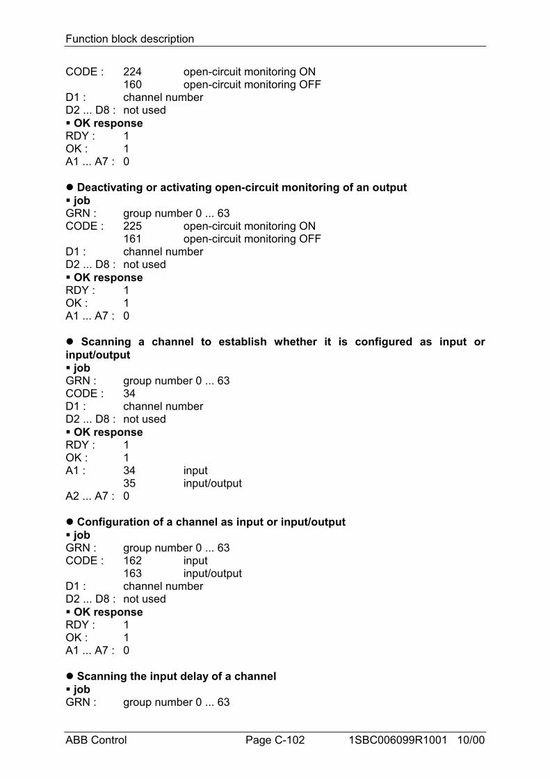
Function block description
ABB Control Page C-102 1SBC006099R1001 10/00
CODE : 224 open-circuit monitoring ON160 open-circuit monitoring OFF
D1 : channel numberD2 ... D8 : not used# OK responseRDY : 1OK : 1A1 ... A7 : 0
% Deactivating or activating open-circuit monitoring of an output# jobGRN : group number 0 ... 63CODE : 225 open-circuit monitoring ON
161 open-circuit monitoring OFFD1 : channel numberD2 ... D8 : not used# OK responseRDY : 1OK : 1A1 ... A7 : 0
% Scanning a channel to establish whether it is configured as input orinput/output# jobGRN : group number 0 ... 63CODE : 34D1 : channel numberD2 ... D8 : not used# OK responseRDY : 1OK : 1A1 : 34 input
35 input/outputA2 ... A7 : 0
% Configuration of a channel as input or input/output# jobGRN : group number 0 ... 63CODE : 162 input
163 input/outputD1 : channel numberD2 ... D8 : not used# OK responseRDY : 1OK : 1A1 ... A7 : 0
% Scanning the input delay of a channel# jobGRN : group number 0 ... 63
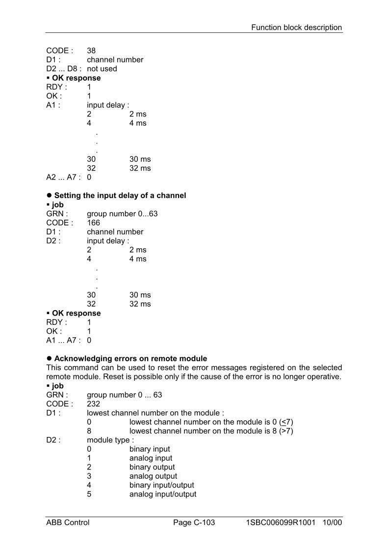
Function block description
ABB Control Page C-103 1SBC006099R1001 10/00
CODE : 38D1 : channel numberD2 ... D8 : not used# OK responseRDY : 1OK : 1A1 : input delay :
2 2 ms4 4 ms . . .30 30 ms32 32 ms
A2 ... A7 : 0
% Setting the input delay of a channel# jobGRN : group number 0...63CODE : 166D1 : channel numberD2 : input delay :
2 2 ms4 4 ms . . .30 30 ms32 32 ms
# OK responseRDY : 1OK : 1A1 ... A7 : 0
% Acknowledging errors on remote moduleThis command can be used to reset the error messages registered on the selectedremote module. Reset is possible only if the cause of the error is no longer operative.# jobGRN : group number 0 ... 63CODE : 232D1 : lowest channel number on the module :
0 lowest channel number on the module is 0 (<7)8 lowest channel number on the module is 8 (>7)
D2 : module type :0 binary input1 analog input2 binary output3 analog output4 binary input/output5 analog input/output
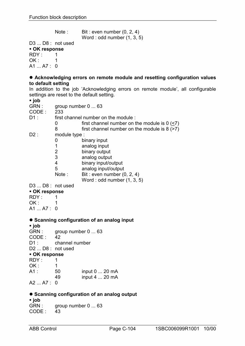
Function block description
ABB Control Page C-104 1SBC006099R1001 10/00
Note : Bit : even number (0, 2, 4)Word : odd number (1, 3, 5)
D3 ... D8 : not used# OK responseRDY : 1OK : 1A1 ... A7 : 0
% Acknowledging errors on remote module and resetting configuration valuesto default settingIn addition to the job ’Acknowledging errors on remote module’, all configurablesettings are reset to the default setting.# jobGRN : group number 0 ... 63CODE : 233D1 : first channel number on the module :
0 first channel number on the module is 0 (<7)8 first channel number on the module is 8 (>7)
D2 : module type :0 binary input1 analog input2 binary output3 analog output4 binary input/output5 analog input/outputNote : Bit : even number (0, 2, 4)
Word : odd number (1, 3, 5)D3 ... D8 : not used# OK responseRDY : 1OK : 1A1 ... A7 : 0
% Scanning configuration of an analog input# jobGRN : group number 0 ... 63CODE : 42D1 : channel numberD2 ... D8 : not used# OK responseRDY : 1OK : 1A1 : 50 input 0 ... 20 mA
49 input 4 ... 20 mAA2 ... A7 : 0
% Scanning configuration of an analog output# jobGRN : group number 0 ... 63CODE : 43
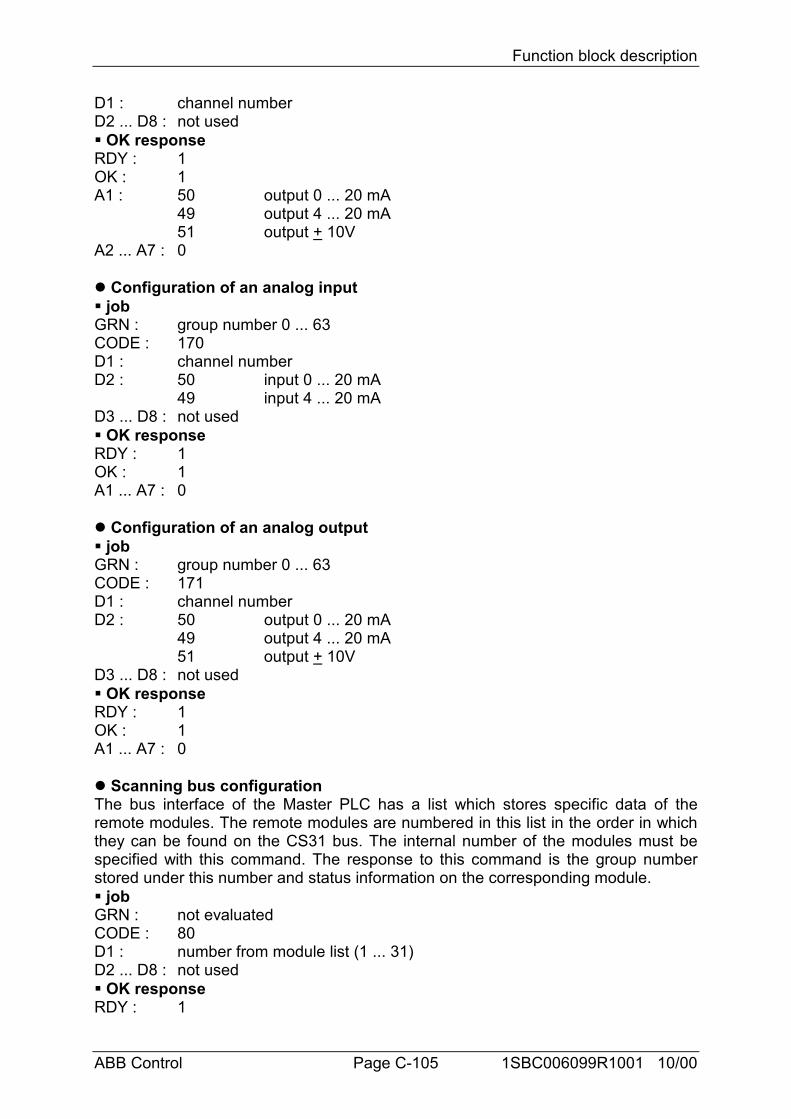
Function block description
ABB Control Page C-105 1SBC006099R1001 10/00
D1 : channel numberD2 ... D8 : not used# OK responseRDY : 1OK : 1A1 : 50 output 0 ... 20 mA
49 output 4 ... 20 mA51 output + 10V
A2 ... A7 : 0
% Configuration of an analog input# jobGRN : group number 0 ... 63CODE : 170D1 : channel numberD2 : 50 input 0 ... 20 mA
49 input 4 ... 20 mAD3 ... D8 : not used# OK responseRDY : 1OK : 1A1 ... A7 : 0
% Configuration of an analog output# jobGRN : group number 0 ... 63CODE : 171D1 : channel numberD2 : 50 output 0 ... 20 mA
49 output 4 ... 20 mA51 output + 10V
D3 ... D8 : not used# OK responseRDY : 1OK : 1A1 ... A7 : 0
% Scanning bus configurationThe bus interface of the Master PLC has a list which stores specific data of theremote modules. The remote modules are numbered in this list in the order in whichthey can be found on the CS31 bus. The internal number of the modules must bespecified with this command. The response to this command is the group numberstored under this number and status information on the corresponding module.# jobGRN : not evaluatedCODE : 80D1 : number from module list (1 ... 31)D2 ... D8 : not used# OK responseRDY : 1
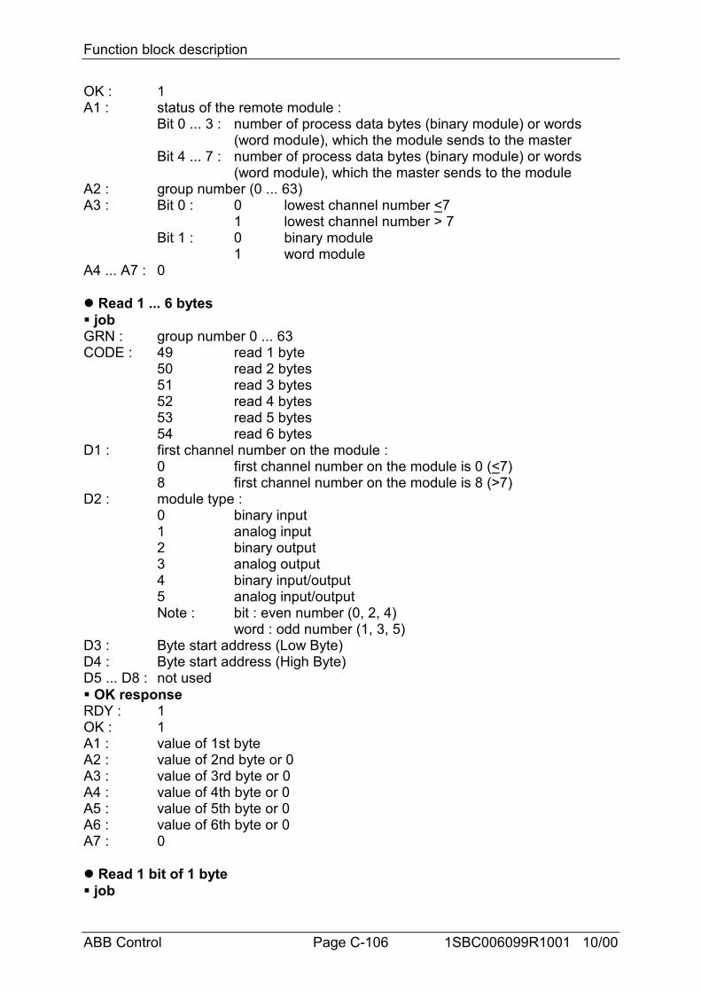
Function block description
ABB Control Page C-106 1SBC006099R1001 10/00
OK : 1A1 : status of the remote module :
Bit 0 ... 3 : number of process data bytes (binary module) or words (word module), which the module sends to the master
Bit 4 ... 7 : number of process data bytes (binary module) or words (word module), which the master sends to the module
A2 : group number (0 ... 63)A3 : Bit 0 : 0 lowest channel number <7
1 lowest channel number > 7Bit 1 : 0 binary module
1 word moduleA4 ... A7 : 0
% Read 1 ... 6 bytes# jobGRN : group number 0 ... 63CODE : 49 read 1 byte
50 read 2 bytes51 read 3 bytes52 read 4 bytes53 read 5 bytes54 read 6 bytes
D1 : first channel number on the module :0 first channel number on the module is 0 (<7)8 first channel number on the module is 8 (>7)
D2 : module type :0 binary input1 analog input2 binary output3 analog output4 binary input/output5 analog input/outputNote : bit : even number (0, 2, 4)
word : odd number (1, 3, 5)D3 : Byte start address (Low Byte)D4 : Byte start address (High Byte)D5 ... D8 : not used# OK responseRDY : 1OK : 1A1 : value of 1st byteA2 : value of 2nd byte or 0A3 : value of 3rd byte or 0A4 : value of 4th byte or 0A5 : value of 5th byte or 0A6 : value of 6th byte or 0A7 : 0
% Read 1 bit of 1 byte# job
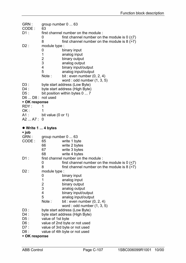
Function block description
ABB Control Page C-107 1SBC006099R1001 10/00
GRN : group number 0 ... 63CODE : 63D1 : first channel number on the module :
0 first channel number on the module is 0 (<7)8 first channel number on the module is 8 (>7)
D2 : module type :0 binary input1 analog input2 binary output3 analog output4 binary input/output5 analog input/outputNote : bit : even number (0, 2, 4)
word : odd number (1, 3, 5)D3 : byte start address (Low Byte)D4 : byte start address (High Byte)D5 : bit position within bytes 0 ... 7D6 ... D8 : not used# OK responseRDY : 1OK : 1A1 : bit value (0 or 1)A2 ... A7 : 0
% Write 1 ... 4 bytes# jobGRN : group number 0 ... 63CODE : 65 write 1 byte
66 write 2 bytes67 write 3 bytes68 write 4 bytes
D1 : first channel number on the module :0 first channel number on the module is 0 (<7)8 first channel number on the module is 8 (>7)
D2 : module type :0 binary input1 analog input2 binary output3 analog output4 binary input/output5 analog input/outputNote : bit : even number (0, 2, 4)
word : odd number (1, 3, 5)D3 : byte start address (Low Byte)D4 : byte start address (High Byte)D5 : value of 1st byteD6 : value of 2nd byte or not usedD7 : value of 3rd byte or not usedD8 : value of 4th byte or not used# OK response
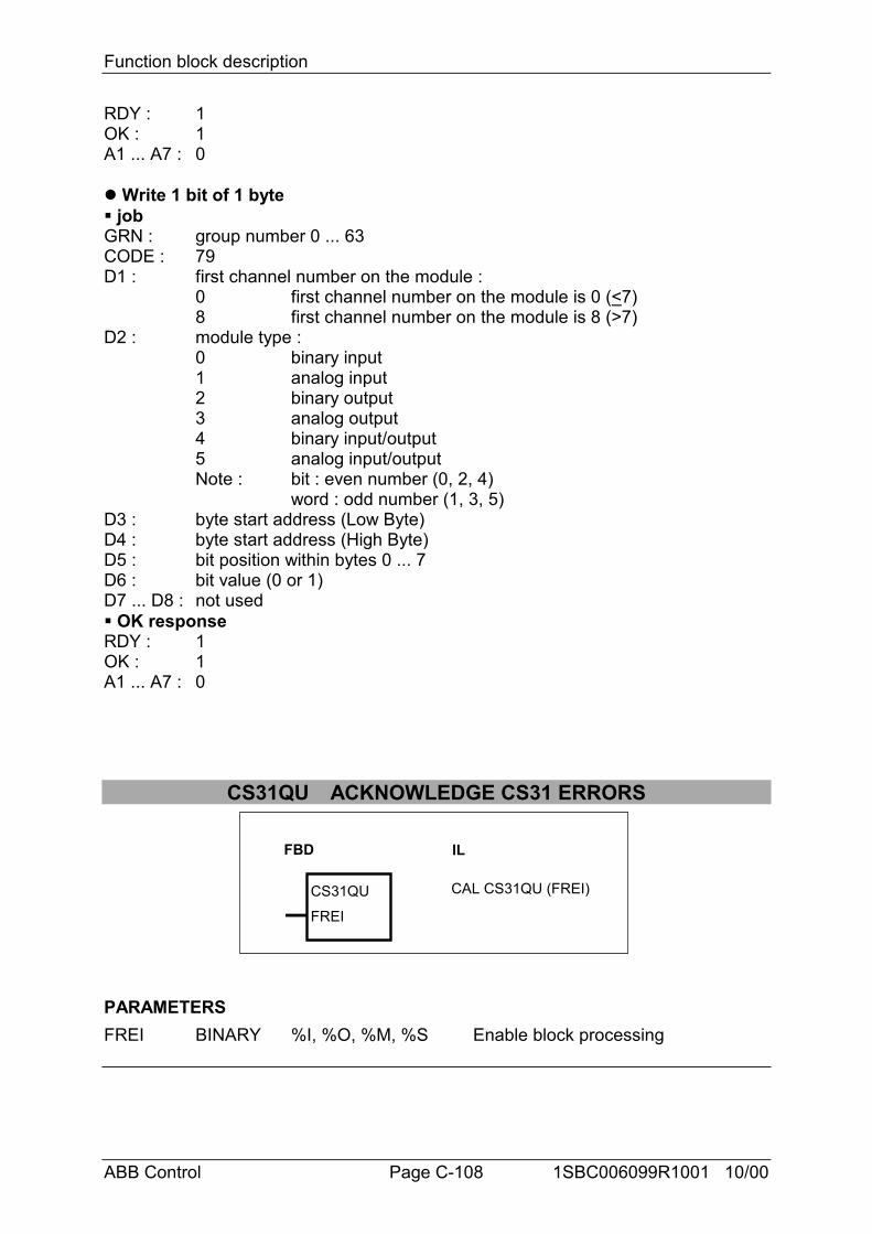
Function block description
ABB Control Page C-108 1SBC006099R1001 10/00
RDY : 1OK : 1A1 ... A7 : 0
% Write 1 bit of 1 byte# jobGRN : group number 0 ... 63CODE : 79D1 : first channel number on the module :
0 first channel number on the module is 0 (<7)8 first channel number on the module is 8 (>7)
D2 : module type :0 binary input1 analog input2 binary output3 analog output4 binary input/output5 analog input/outputNote : bit : even number (0, 2, 4)
word : odd number (1, 3, 5)D3 : byte start address (Low Byte)D4 : byte start address (High Byte)D5 : bit position within bytes 0 ... 7D6 : bit value (0 or 1)D7 ... D8 : not used# OK responseRDY : 1OK : 1A1 ... A7 : 0
CS31QU ACKNOWLEDGE CS31 ERRORS
FBD IL
CS31QU
FREI
CAL CS31QU (FREI)
PARAMETERSFREI BINARY %I, %O, %M, %S Enable block processing
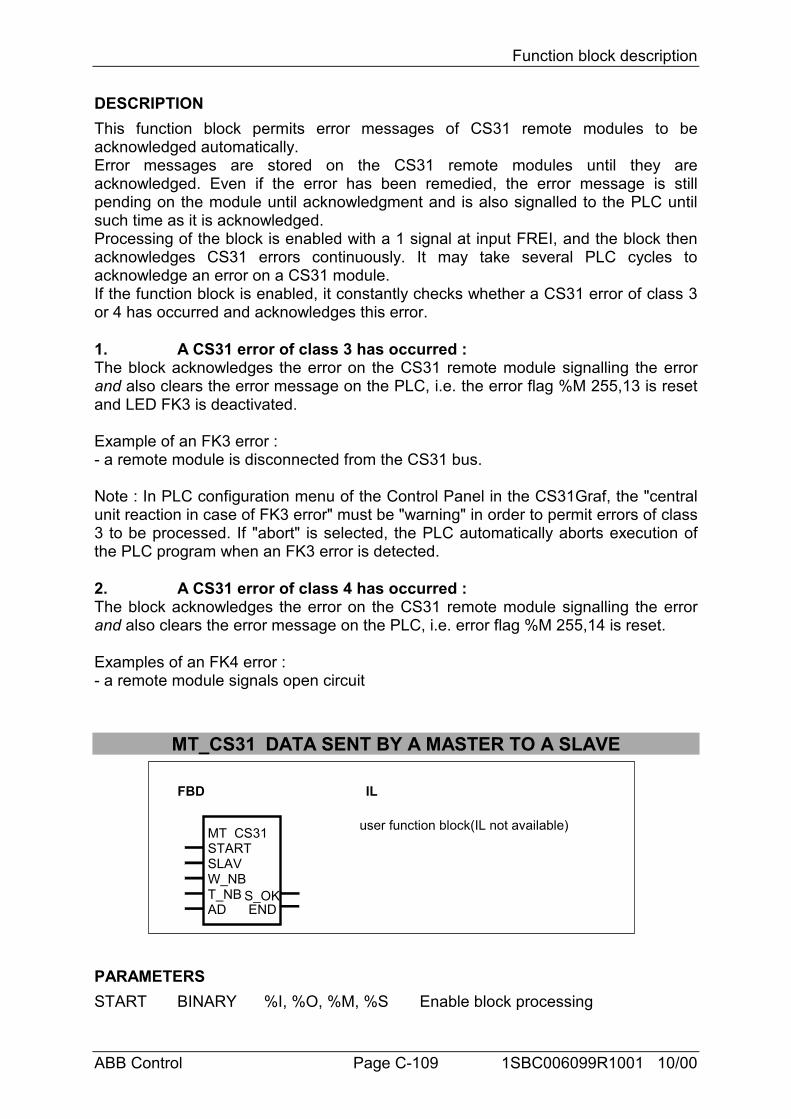
Function block description
ABB Control Page C-109 1SBC006099R1001 10/00
DESCRIPTIONThis function block permits error messages of CS31 remote modules to beacknowledged automatically.Error messages are stored on the CS31 remote modules until they areacknowledged. Even if the error has been remedied, the error message is stillpending on the module until acknowledgment and is also signalled to the PLC untilsuch time as it is acknowledged.Processing of the block is enabled with a 1 signal at input FREI, and the block thenacknowledges CS31 errors continuously. It may take several PLC cycles toacknowledge an error on a CS31 module.If the function block is enabled, it constantly checks whether a CS31 error of class 3or 4 has occurred and acknowledges this error.
1. A CS31 error of class 3 has occurred :The block acknowledges the error on the CS31 remote module signalling the errorand also clears the error message on the PLC, i.e. the error flag %M 255,13 is resetand LED FK3 is deactivated.
Example of an FK3 error :- a remote module is disconnected from the CS31 bus.
Note : In PLC configuration menu of the Control Panel in the CS31Graf, the "centralunit reaction in case of FK3 error" must be "warning" in order to permit errors of class3 to be processed. If "abort" is selected, the PLC automatically aborts execution ofthe PLC program when an FK3 error is detected.
2. A CS31 error of class 4 has occurred :The block acknowledges the error on the CS31 remote module signalling the errorand also clears the error message on the PLC, i.e. error flag %M 255,14 is reset.
Examples of an FK4 error :- a remote module signals open circuit
MT_CS31 DATA SENT BY A MASTER TO A SLAVE
FBD IL
MT CS31STARTSLAVW_NBT_NBAD
S_OKEND
user function block(IL not available)
PARAMETERSSTART BINARY %I, %O, %M, %S Enable block processing
Function block description
ABB Control Page C-110 1SBC006099R1001 10/00
SLAV WORD %MW, %OW, %KW Slave number of the slave CPUW_NB WORD %MW, %OW, %KW Word number to exchange per sendingT_NB WORD %MW, %OW, %KW Total word number to transmitAD WORD %MW, %OW, %KW First variable address of the data areaS_OK BINARY %O, %M Slave CPU is ready to receive dataEND BINARY %O, %M Data area has been transmitted
DESCRIPTIONThe function block MT_CS31 in the master has to be used with the function blockSR_CS31 in the slave; and MR_CS31 in the master with ST_CS31 in the slave.
These function blocks allow to exchange a data area between a master central unitand a slave central unit on the CS31 bus, with the possibility to keep a quick datatransfer between the master and the slave.The transmission or receiving has to be configured in the slave central unit as followsSize of the transmitting and sending area on CS31 bus for slave central unit.: 8words
A maximum of 7 words are allowed to exchange in one direction per sending. The8th word is reserved for the handshake.Only the address of the 1st variable of the data area has to be given.Words are then automatically transfered 7 by 7 (or 6 by 6,...) from the data area toOW xx,01 to OW xx,07 (or OW xx,01 to OW xx,06;...)OW xx,00 is always reserved for the handshake to send; and IW xx,07 for thehandshake to be received.When words are sent 6 by 6 (or 5 by 5,...), OW xx,07 (and OW xx,06;...) staysavailable for a quick data transfer between the master and the slave.(xx = the slave number of the slave central unit : 0 ≤ xx ≤ 61 for a 50 serie and 0 ≤ xx ≤ 5 for a 90 serie).
START BinaryThe transfert is started. The data area is trasmitted only one time .A new transmit is possible when END=1
SLAV Word(For the function blocks in the master only)Slave number of the slave central unitThe value is : 0 ≤ SLAV ≤ 61 for 50 serie and 0 ≤ SLAV ≤ 5 for 90 & 30serie
W_NB WordNumber of words to transmit or receive per sendingThe value is : 1 ≤ W_NB ≤ 7The value has to be the same than the W_NB of the corresponding function blockusedin the other central unit.
Function block description
ABB Control Page C-111 1SBC006099R1001 10/00
ex : if W_NB=6 in the master then W_NB=6 in the slave.In the master, OW xx,01 to OW xx,06 are used for the transmission of words.OW xx,00 and IW xx,07 are reserved for the handshake.OW xx,07 is free and available for direct control of the slave I/O for example.
T_NB Word(For a transmission only)Total word number to transmitThe value has to be a multiple of W_NB : T_NB = n * W_NB
Note : n has to be chosen not to exceed addresses allowed in the central unitselected.
AD WordAddress of the first variable of the data area. Only the offset address is requested.
The Segment is 0 for 30 & 50 serie and 30C2H for a 90 serieA 90 serie with 8 kinstructions memory can not use this function block.The segment (30C2H) has to be modified in the code with the user library.
Please refer to the CPU respective documentation to find the hexadecimal addresseof variable,.
S_OK BinaryThis bit is set by the slave.It can be used to start a new transmit of data area
END BinaryThis bit is set when the data area is completly transmitted to the slave CPU.This bit is reset when START=0. Information that the slave has received this bit isnecessary to start again the transfer. The bit S_OK can be use (it can be managedby the slave).
______________________________________________________________________
CAUTION
The data are sent every three cycle times between the master and the slave.
The value of W_NB in the slave has to be the same than W_NB in the master.
T_NB = n * W_NBPay attention not to exceed addresses allowed in the central unit selected.The data area has to be chosen without any reserved area.
OW xx,00 to OW xx,07 and IW xx,00 to IW xx,07 are used following the functionblock used and the value of W_NB.
The data exchange is an exchange of words or double words. In the case of the 30serie & 50 serie , the data area can be a bit area.
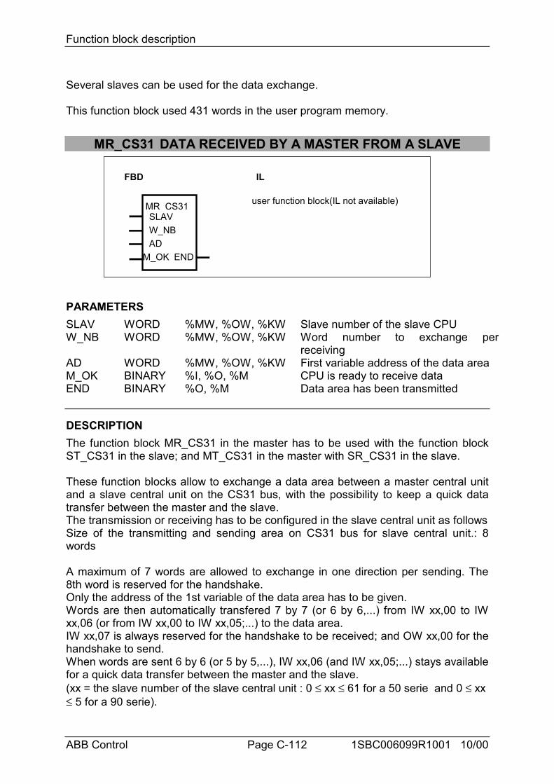
Function block description
ABB Control Page C-112 1SBC006099R1001 10/00
Several slaves can be used for the data exchange.
This function block used 431 words in the user program memory.
MR_CS31 DATA RECEIVED BY A MASTER FROM A SLAVE
FBD IL
MR CS31SLAVW_NBAD
M_OK END
user function block(IL not available)
PARAMETERSSLAV WORD %MW, %OW, %KW Slave number of the slave CPUW_NB WORD %MW, %OW, %KW Word number to exchange per
receivingAD WORD %MW, %OW, %KW First variable address of the data areaM_OK BINARY %I, %O, %M CPU is ready to receive dataEND BINARY %O, %M Data area has been transmitted
DESCRIPTIONThe function block MR_CS31 in the master has to be used with the function blockST_CS31 in the slave; and MT_CS31 in the master with SR_CS31 in the slave.
These function blocks allow to exchange a data area between a master central unitand a slave central unit on the CS31 bus, with the possibility to keep a quick datatransfer between the master and the slave.The transmission or receiving has to be configured in the slave central unit as followsSize of the transmitting and sending area on CS31 bus for slave central unit.: 8words
A maximum of 7 words are allowed to exchange in one direction per sending. The8th word is reserved for the handshake.Only the address of the 1st variable of the data area has to be given.Words are then automatically transfered 7 by 7 (or 6 by 6,...) from IW xx,00 to IWxx,06 (or from IW xx,00 to IW xx,05;...) to the data area.IW xx,07 is always reserved for the handshake to be received; and OW xx,00 for thehandshake to send.When words are sent 6 by 6 (or 5 by 5,...), IW xx,06 (and IW xx,05;...) stays availablefor a quick data transfer between the master and the slave.(xx = the slave number of the slave central unit : 0 ≤ xx ≤ 61 for a 50 serie and 0 ≤ xx ≤ 5 for a 90 serie).
Function block description
ABB Control Page C-113 1SBC006099R1001 10/00
SLAV Word(For the function blocks in the master only)Slave number of the slave central unitThe value is : 0 ≤ SLAV ≤ 61 for 50 serie and 0 ≤ SLAV ≤ 5 for 30 1 90series
W_NB WordNumber of words to transmit or receive per sendingThe value is : 1 ≤ W_NB ≤ 7The value has to be the same than the W_NB of the corresponding function blockusedin the other central unit.
ex : if W_NB=6 in the master then W_NB=6 in the slave.In the master, OW xx,01 to OW xx,06 are used for the transmission of words.OW xx,00 and IW xx,07 are reserved for the handshake.OW xx,07 is free and available for direct control of the slave I/O for example.
AD WordAddress of the first variable of the data area. Only the offset address is requested.
The Segment is 0 for 30 & 50 series and 30C2H for a 90 serieA 90 serie with 8 kinstructions memory can not use this function block.The segment (30C2H) has to be modified in the code with the user library.
Please refer to the CPU respective documentation to find the hexadecimal addresseof variable,.
M_OK BinaryThis bit is set when the master central unit is ready to receive data area from theCPU slave.It can be used by the slave CPU to start a new transmit of data area
END BinaryThis bit is set when the data area is completly transmitted from the slave CPU.This bit is reset by the slave CPU______________________________________________________________________
CAUTION
The data are sent every three cycle times between the master and the slave.
The value of W_NB in the master has to be the same than W_NB in the slave.
OW xx,00 to OW xx,07 and IW xx,00 to IW xx,07 are used following the functionblock used and the value of W_NB.
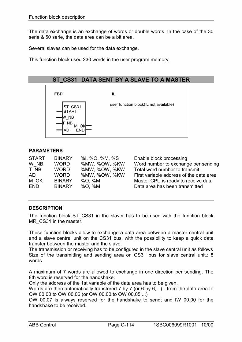
Function block description
ABB Control Page C-114 1SBC006099R1001 10/00
The data exchange is an exchange of words or double words. In the case of the 30serie & 50 serie, the data area can be a bit area.
Several slaves can be used for the data exchange.
This function block used 230 words in the user program memory.
ST_CS31 DATA SENT BY A SLAVE TO A MASTER
FBD IL
ST CS31START
W_NBT_NB
ADM_OKEND
user function block(IL not available)
PARAMETERSSTART BINARY %I, %O, %M, %S Enable block processingW_NB WORD %MW, %OW, %KW Word number to exchange per sendingT_NB WORD %MW, %OW, %KW Total word number to transmitAD WORD %MW, %OW, %KW First variable address of the data areaM_OK BINARY %O, %M Master CPU is ready to receive dataEND BINARY %O, %M Data area has been transmitted
DESCRIPTIONThe function block ST_CS31 in the slaver has to be used with the function blockMR_CS31 in the master.
These function blocks allow to exchange a data area between a master central unitand a slave central unit on the CS31 bus, with the possibility to keep a quick datatransfer between the master and the slave.The transmission or receiving has to be configured in the slave central unit as followsSize of the transmitting and sending area on CS31 bus for slave central unit.: 8words
A maximum of 7 words are allowed to exchange in one direction per sending. The8th word is reserved for the handshake.Only the address of the 1st variable of the data area has to be given.Words are then automatically transfered 7 by 7 (or 6 by 6,...) - from the data area toOW 00,00 to OW 00,06 (or OW 00,00 to OW 00,05;...)OW 00,07 is always reserved for the handshake to send; and IW 00,00 for thehandshake to be received.
Function block description
ABB Control Page C-115 1SBC006099R1001 10/00
When words are sent 6 by 6 (or 5 by 5,...), OW 00,06 (and OW 00,05;...) staysavailable for a quick data transfer between the master and the slave.
START BinaryThe transfert is started. The data area is trasmitted only one time .A new transmit is possible when END=1
W_NB WordNumber of words to transmit or receive per sendingThe value is : 1 ≤ W_NB ≤ 7The value has to be the same than the W_NB of the corresponding function blockused in the other central unit.
ex : if W_NB=6 in the master then W_NB=6 in the slave.In the master, OW xx,01 to OW xx,06 are used for the transmission of words.OW xx,00 and IW xx,07 are reserved for the handshake.OW xx,07 is free and available for direct control of the slave I/O for example.
T_NB Word(For a transmission only)Total word number to transmitThe value has to be a multiple of W_NB : T_NB = n * W_NB
Note : n has to be chosen not to exceed addresses allowed in the central unitselected.
AD WordAddress of the first variable of the data area. Only the offset address is requested.
The Segment is 0 for 30 & 50 serie and 30C2H for a 90 serieA 90 serie with 8 kinstructions memory can not use this function block.The segment (30C2H) has to be modified in the code with the user library.
Please refer to the CPU respective documentation to find the hexadecimal addresseof variable,.
M_OK BinaryThis bit is set by the master.It can be used to start a new transmit of data area
END BinaryThis bit is set when the data area is completly transmitted to the master CPU.This bit is reset when START=0. Information that the master has received this bit isnecessary to start again the transfer. The bit M_OK can be use (it can be managedby the master).
______________________________________________________________________
CAUTION
Function block description
ABB Control Page C-116 1SBC006099R1001 10/00
The data are sent every three cycle times between the master and the slave.
The value of W_NB in the slave has to be the same than W_NB in the master.
T_NB = n * W_NBPay attention not to exceed addresses allowed in the central unit selected.The data area has to be chosen without any reserved area.
OW xx,00 to OW xx,07 and IW xx,00 to IW xx,07 are used following the functionblock used and the value of W_NB.
The data exchange is an exchange of words or double words. In the case of the 30serie & 50 serie , the data area can be a bit area.
Several slaves can be used for the data exchange.
This function block used 431 words in the user program memory
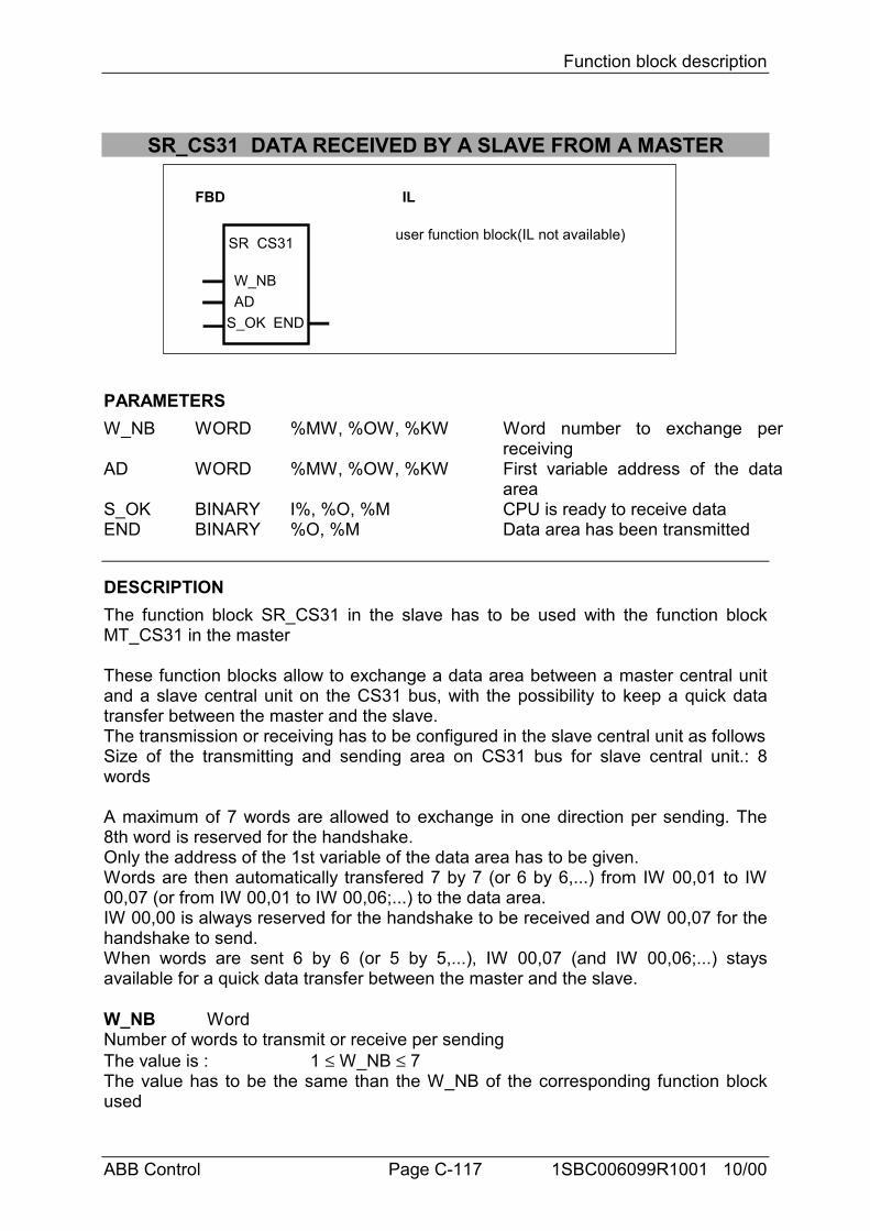
Function block description
ABB Control Page C-117 1SBC006099R1001 10/00
SR_CS31 DATA RECEIVED BY A SLAVE FROM A MASTER
FBD IL
SR CS31
W_NBAD
S_OK END
user function block(IL not available)
PARAMETERSW_NB WORD %MW, %OW, %KW Word number to exchange per
receivingAD WORD %MW, %OW, %KW First variable address of the data
areaS_OK BINARY I%, %O, %M CPU is ready to receive dataEND BINARY %O, %M Data area has been transmitted
DESCRIPTIONThe function block SR_CS31 in the slave has to be used with the function blockMT_CS31 in the master
These function blocks allow to exchange a data area between a master central unitand a slave central unit on the CS31 bus, with the possibility to keep a quick datatransfer between the master and the slave.The transmission or receiving has to be configured in the slave central unit as followsSize of the transmitting and sending area on CS31 bus for slave central unit.: 8words
A maximum of 7 words are allowed to exchange in one direction per sending. The8th word is reserved for the handshake.Only the address of the 1st variable of the data area has to be given.Words are then automatically transfered 7 by 7 (or 6 by 6,...) from IW 00,01 to IW00,07 (or from IW 00,01 to IW 00,06;...) to the data area.IW 00,00 is always reserved for the handshake to be received and OW 00,07 for thehandshake to send.When words are sent 6 by 6 (or 5 by 5,...), IW 00,07 (and IW 00,06;...) staysavailable for a quick data transfer between the master and the slave.
W_NB WordNumber of words to transmit or receive per sendingThe value is : 1 ≤ W_NB ≤ 7The value has to be the same than the W_NB of the corresponding function blockused
Function block description
ABB Control Page C-118 1SBC006099R1001 10/00
in the other central unit.
ex : if W_NB=6 in the master then W_NB=6 in the slave.In the master, OW xx,01 to OW xx,06 are used for the transmission of words.OW xx,00 and IW xx,07 are reserved for the handshake.OW xx,07 is free and available for direct control of the slave I/O for example.
AD WordAddress of the first variable of the data area. Only the offset address is requested.
The Segment is 0 for 30 & 50 series and 30C2H for a 90 serieA 90 serie with 8 kinstructions memory can not use this function block.The segment (30C2H) has to be modified in the code with the user library.
Please refer to the CPU respective documentation to find the hexadecimal addresseof variable,.
S_OK BinaryThis bit is set when the slave central unit is ready to receive data area from the CPUmaster.It can be used by the master CPU to start a new transmit of data area
END BinaryThis bit is set when the data area is completly transmitted from the master CPU.This bit is reset by the master CPU______________________________________________________________________
CAUTION
The data are sent every three cycle times between the master and the slave.
The value of W_NB in the master has to be the same than W_NB in the slave.
OW xx,00 to OW xx,07 and IW xx,00 to IW xx,07 are used following the functionblock used and the value of W_NB.
The data exchange is an exchange of words or double words. In the case of the 30serie & 50 serie, the data area can be a bit area.
Several slaves can be used for the data exchange.
This function block used 431 words in the user program memory.
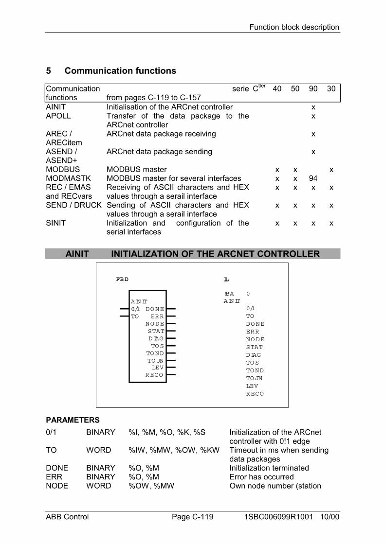
Function block description
ABB Control Page C-119 1SBC006099R1001 10/00
5 Communication functions
Communicationfunctions
seriefrom pages C-119 to C-157
Ctler 40 50 90 30
AINIT Initialisation of the ARCnet controller xAPOLL Transfer of the data package to the
ARCnet controllerx
AREC /ARECitem
ARCnet data package receiving x
ASEND /ASEND+
ARCnet data package sending x
MODBUS MODBUS master x x xMODMASTK MODBUS master for several interfaces x x 94REC / EMASand RECvars
Receiving of ASCII characters and HEXvalues through a serail interface
x x x x
SEND / DRUCK Sending of ASCII characters and HEXvalues through a serail interface
x x x x
SINIT Initialization and configuration of theserial interfaces
x x x x
AINIT INITIALIZATION OF THE ARCNET CONTROLLER
FBD IL
!BAAINIT
0
0/1TODO NEERRNO DESTATDIAGTO STO NDTO JNLEVRECO
AINIT0/1TO
STAT
DO NEERR
NO DE
TO JN
DIAGTO S
TO ND
RECOLEV
PARAMETERS0/1 BINARY %I, %M, %O, %K, %S Initialization of the ARCnet
controller with 0!1 edgeTO WORD %IW, %MW, %OW, %KW Timeout in ms when sending
data packagesDONE BINARY %O, %M Initialization terminatedERR BINARY %O, %M Error has occurredNODE WORD %OW, %MW Own node number (station
Function block description
ABB Control Page C-120 1SBC006099R1001 10/00
address)STAT WORD %OW, %MW Status register of the ARCnet
controllerDIAG WORD %OW, %MW Diagnosis register of the
ARCnet controllerTOS BINARY %O, %M Timeout has occurred during
send operationTOND WORD %OW, %MW Node number of lost data
package after timeoutTOJN WORD %OW, %MW Job number of lost data
package after timeoutLEV WORD %OW, %MW Level of the send bufferRECO BINARY %O, %M Network reconfiguration is
running (after loss of token)
The outputs STAT, DIAG, TOS, TOND, TOJN, LEV and RECO are updated after asuccessful initialization with each block call.
DESCRIPTIONARCnet communication function block.
The function block AINIT initializes the ARCnet controller in the following way :- Interrupt after reception of a data package- Only short packages (a short package = 256 bytes)- Data packages to all stations (broadcasts)
Important note :If a PLC is used with an ARCnet interface, a certain section of the PLC TURBOprogram memory No. 2 is reserved for ARCnet.If programs with more than 2 k instructions are executed, the system–dependentcapacity utilization can possibly be increased by reason of the reduced TURBOmemory No. 2 when changes are made to a running program.
There are no problems if- the capacity utilization is less than 80 % before making changes to a runningprogram or if- the program length is less than 2 k instructions.
0/1 BINARYA 0-1 edge at the input 0/1 causes a single initialization of the ARCnet controller. Aslong as the initialization has not been terminated (DONE = 0), a new 0-1 edge at theinput 0/1 is ignored.
TO WORDThe timeout waiting time for sending data packages is specified in ms at the inputTO. If a data package cannot be sent within this period, the sending operation of thisdata package is aborted and the package is lost. The output TOS indicates the lossof the package.
Function block description
ABB Control Page C-121 1SBC006099R1001 10/00
DONE BINARYThe output DONE indicates that the initialization has been terminated. This outputhas always to be considered together with the output ERR.The following applies :DONE = 1 and ERR = 0 : The initialization has been terminated.
No error has occurred.DONE = 1 and ERR = 1 : An error has occurred during initialization.
The ARCnet controller has not responded within a period of 100 ms.
ERR BINARYThe output ERR indicates that the ARCnet controller has not responded after aninitialization command within a period of 100 ms. This output has always to beconsidered together with the output DONE.If an error has occurred, the following applies :DONE = 1 and ERR = 1.
NODE WORDThe output NODE indicates the node number (station address) of its own after asuccessful initialization.
STAT WORDThe output STAT indicates the content of the status register of the ARCnet controllerafter a successful initialization.
DIAG WORDThe output DIAG indicates the content of the diagnosis register of the ARCnetcontroller after a successful initialization.
TOS BINARYThe output TOS indicates that the sending of a data package was not feasible withinthe timeout period (input TO) and that the data package is lost. Both the nodenumber and the job number of the lost data package are available at the outputsTOND and TOJN, respectively.
TOND WORDThe output TOND indicates the node number of the lost data package after thetimeout period has elapsed.
TOJN WORDThe output TOJN indicates the job number of the lost data package after the timeoutperiod has elapsed.
LEV WORDThe output LEV indicates the level of the sending buffer after a successfulinitialization.
RECO BINARYThe output RECO indicates that the network is reconfiguring itself (RECO = 1) after aloss of token. The transition from RECO = 1 to 0 means that the reconfiguring
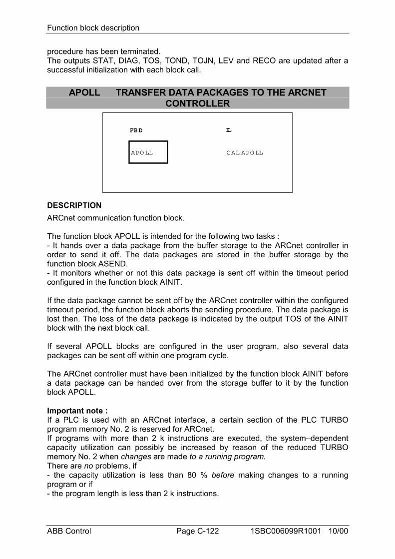
Function block description
ABB Control Page C-122 1SBC006099R1001 10/00
procedure has been terminated.The outputs STAT, DIAG, TOS, TOND, TOJN, LEV and RECO are updated after asuccessful initialization with each block call.
APOLL TRANSFER DATA PACKAGES TO THE ARCNETCONTROLLER
FBD IL
CAL APO LLAPO LL
DESCRIPTIONARCnet communication function block.
The function block APOLL is intended for the following two tasks :- It hands over a data package from the buffer storage to the ARCnet controller inorder to send it off. The data packages are stored in the buffer storage by thefunction block ASEND.- It monitors whether or not this data package is sent off within the timeout periodconfigured in the function block AINIT.
If the data package cannot be sent off by the ARCnet controller within the configuredtimeout period, the function block aborts the sending procedure. The data package islost then. The loss of the data package is indicated by the output TOS of the AINITblock with the next block call.
If several APOLL blocks are configured in the user program, also several datapackages can be sent off within one program cycle.
The ARCnet controller must have been initialized by the function block AINIT beforea data package can be handed over from the storage buffer to it by the functionblock APOLL.
Important note :If a PLC is used with an ARCnet interface, a certain section of the PLC TURBOprogram memory No. 2 is reserved for ARCnet.If programs with more than 2 k instructions are executed, the system–dependentcapacity utilization can possibly be increased by reason of the reduced TURBOmemory No. 2 when changes are made to a running program.There are no problems, if- the capacity utilization is less than 80 % before making changes to a runningprogram or if- the program length is less than 2 k instructions.
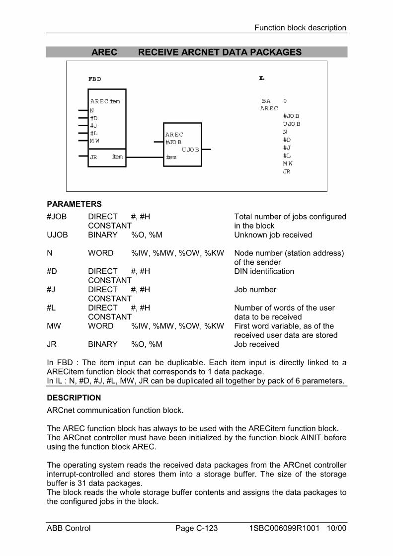
Function block description
ABB Control Page C-123 1SBC006099R1001 10/00
AREC RECEIVE ARCNET DATA PACKAGES
FBD IL
!BAAREC
0
#JO BUJO BN#D#J#LM WJR
AREC#JO B
itemUJO B
ARECitem
N#D#J#LM W
JR item
PARAMETERS#JOB DIRECT #, #H Total number of jobs configured
CONSTANT in the blockUJOB BINARY %O, %M Unknown job received
N WORD %IW, %MW, %OW, %KW Node number (station address) of the sender
#D DIRECT #, #H DIN identificationCONSTANT
#J DIRECT #, #H Job numberCONSTANT
#L DIRECT #, #H Number of words of the userCONSTANT data to be received
MW WORD %IW, %MW, %OW, %KW First word variable, as of the received user data are stored
JR BINARY %O, %M Job received
In FBD : The item input can be duplicable. Each item input is directly linked to aARECitem function block that corresponds to 1 data package.In IL : N, #D, #J, #L, MW, JR can be duplicated all together by pack of 6 parameters.
DESCRIPTIONARCnet communication function block.
The AREC function block has always to be used with the ARECitem function block.The ARCnet controller must have been initialized by the function block AINIT beforeusing the function block AREC.
The operating system reads the received data packages from the ARCnet controllerinterrupt-controlled and stores them into a storage buffer. The size of the storagebuffer is 31 data packages.The block reads the whole storage buffer contents and assigns the data packages tothe configured jobs in the block.
Function block description
ABB Control Page C-124 1SBC006099R1001 10/00
With the same job the receiver gets user data which belong together logically. Forunmistakable identification of a job the following parameters are necessary :
Node number of the sender,DIN identification andJob number.
The parameter values of the received data packages are compared to the parametervalues of the configured jobs. If both values are equal, the user data of the datapackage beginning from the word variable MW are stored continuously and theoutput JR is set to 1. If several data packages are equal, the function block onlyevaluates that data package which has been received last (the latest data package).If no data package from the storage buffer can be assigned to a configured job, theoutput belonging to this configured job is set to 0 (JR = 0).The output UJOB indicates that a data package existing in the storage buffer couldnot be assigned to a job.A user program must not contain more than one block call of AREC.
Important note :If a PLC is used with an ARCnet interface, a certain section of the PLC TURBOprogram memory No. 2 is reserved for ARCnet.If programs with more than 2 k instructions are executed, the system–dependentcapacity utilization can possibly be increased by reason of the reduced TURBOmemory No. 2 when changes are made to a running program.There are no problems, if - the capacity utilization is less than 80 % before
making changes to a running program or if- the program length is less than 2 k instructions.
#JOB DIRECT CONSTANTThe total number of jobs configured in this function block is assigned to the input#JOB.The following is valid : 1 < #JOB
UJOB BINARYOutput UJOB indicates that a data package was stored in the storage buffer whichcould not be assigned to any job.The following applies :UJOB = 1 : unknown job receivedUJOB = 0 : no unknown job received
N WORDThe node number (station address) of the sender is specified for the configured jobat input N.The following is valid : 0 < N0...Nn-1 < 255
#D DIRECT CONSTANTThe DIN identification is specified for the configured job at input #D.The following is valid : 0 < #D < 127not allowed : 111 (6FH)
#J DIRECT CONSTANT
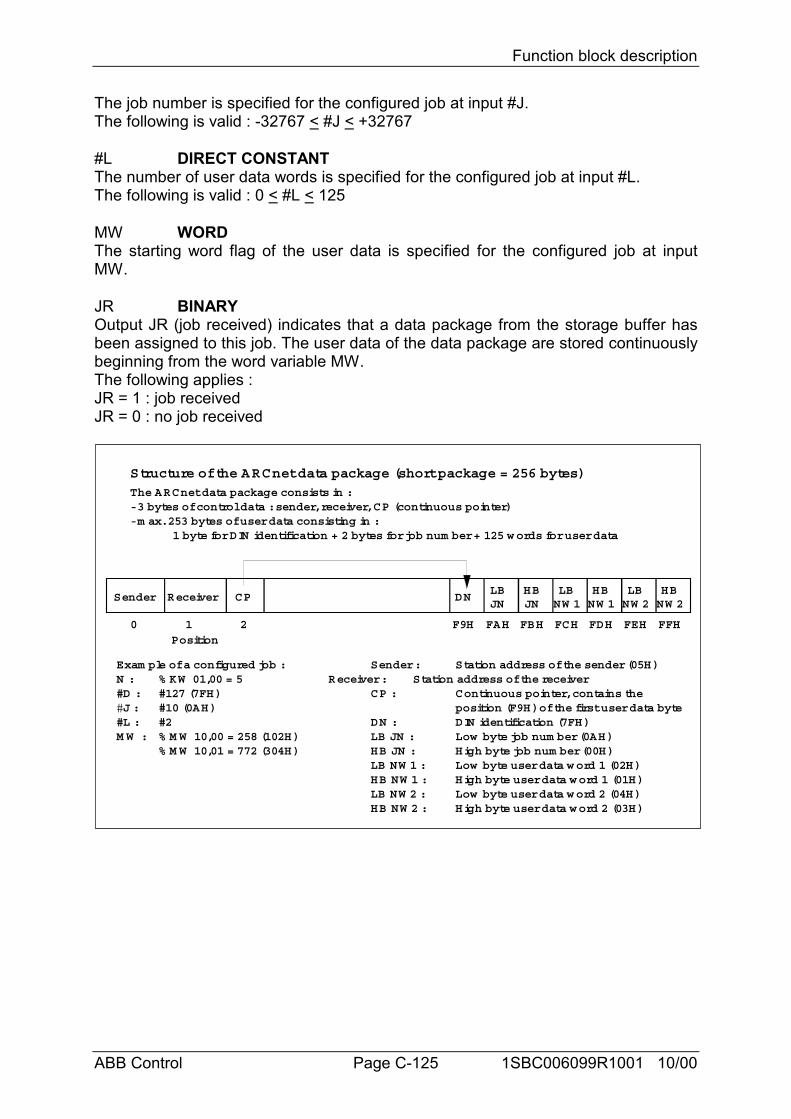
Function block description
ABB Control Page C-125 1SBC006099R1001 10/00
The job number is specified for the configured job at input #J.The following is valid : -32767 < #J < +32767
#L DIRECT CONSTANTThe number of user data words is specified for the configured job at input #L.The following is valid : 0 < #L < 125
MW WORDThe starting word flag of the user data is specified for the configured job at inputMW.
JR BINARYOutput JR (job received) indicates that a data package from the storage buffer hasbeen assigned to this job. The user data of the data package are stored continuouslybeginning from the word variable MW.The following applies :JR = 1 : job receivedJR = 0 : no job received
Sender Receiver CP
0 1 2 FFHFEHFDHFCHFBHFAHF9H
DNLB HB
JNJNLB LBHB HBNW 1 NW 1 NW 2 NW 2
Structure of the ARCnet data package (short package = 256 bytes)The ARCnet data package consists in :- 3 bytes of control data : sender, receiver, CP (continuous pointer)- m ax. 253 bytes of user data consisting in :
1 byte for DIN identification + 2 bytes for job num ber + 125 w ords for user data
Position
Exam ple of a configured job : Sender : Station address of the sender (05H)N : % KW 01,00 = 5 Receiver : Station address of the receiver#D : #127 (7FH) CP : Continuous pointer, contains the#J : #10 (0AH) position (F9H) of the first user data byte#L : #2 DN : DIN identification (7FH)M W : % M W 10,00 = 258 (102H) LB JN : Low byte job num ber (0AH)
% M W 10,01 = 772 (304H) HB JN : High byte job num ber (00H)LB NW 1 : Low byte user data w ord 1 (02H)HB NW 1 : High byte user data word 1 (01H)LB NW 2 : Low byte user data w ord 2 (04H)HB NW 2 : High byte user data word 2 (03H)
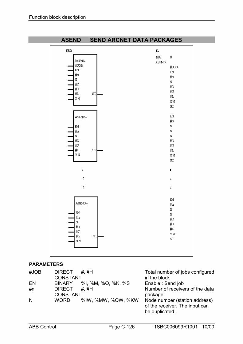
Function block description
ABB Control Page C-126 1SBC006099R1001 10/00
ASEND SEND ARCNET DATA PACKAGES
ASEND#JOBEN#n
!BA 0ASEND
#JOBEN#nN#D#J#LMWST
EN#nNNN#D#J#LMWST
EN#nNN#D#J#LMWST
N#D#J#LMW
ST
ASEND+
EN#nN#D#J#LMW
ST
ASEND+
EN#nN#D#J#LMW
ST
:
:
:
FBD IL
:
:
:
PARAMETERS#JOB DIRECT #, #H Total number of jobs configured
CONSTANT in the blockEN BINARY %I, %M, %O, %K, %S Enable : Send job#n DIRECT #, #H Number of receivers of the data
CONSTANT packageN WORD %IW, %MW, %OW, %KW Node number (station address)
of the receiver. The input can be duplicated.
Function block description
ABB Control Page C-127 1SBC006099R1001 10/00
#D DIRECT #, #H DIN identificationCONSTANT
#J DIRECT #, #H Job numberCONSTANT
#L DIRECT #, #H Number of user data words toCONSTANT be sent
MW WORD %IW, %MW, %OW, %KW First word variable of the user data words
ST BINARY %O, %M Job has been stored in the storage buffer
The inputs EN, #n, N, #D, #J, #L and MW and the output ST are the parameters,that define a job. These parameters therefore appear both in the ASEND block andin the ASEND+ extension block.
DESCRIPTIONARCnet communication function block.
The ASEND function block is intended for sending off jobs (data packages) via theARCnet network. The configured jobs are stored in a buffer storage. From here, theyare transferred to the ARCnet controller for sending off. The transport from the bufferstorage to the ARCnet controller is managed by the APOLL function block. Thetransport is also carried out by the operating system in the idle period between twoPLC cycles.The maximum size of the storage buffer is 31 data packages.The output ST indicates that the configured job has been stored in the storagebuffer.
Important noteA user program must not contain more than one block call of ASEND. If more thanone job have to be sent off, the ASEND block must be extended by the ASEND+block. For each further job, one ASEND+ must be configured in the FBD directlyfollowing ASEND.ASEND+ is only an extension block for ASEND, but not autonomous. For thatreason, all used ASEND+ blocks must be configured directly following an ASENDblock or then following each other. Under no circumstances may other CEs beinserted between ASEND and ASEND+ or ASEND+ and a following ASEND+respectively.For the same reason, the output ST may not be connected by a line with another CE.A variable must always be defined at the output ST.ASEND+ blocks only exist in FBD. During the translation, the ASEND block and allthe following ASEND+ are combined into one ASEND-IL function block.The ARCnet controller must have been initialized by the function block AINIT beforedata packages can be stored in the storage buffer by the function block ASEND.
Important note :If a PLC is used with an ARCnet interface, a certain section of the PLC TURBOprogram memory No. 2 is reserved for ARCnet.If programs with more than 2 k instructions are executed, the system–dependent
Function block description
ABB Control Page C-128 1SBC006099R1001 10/00
capacity utilization can possibly be increased by reason of the reduced TURBOmemory No. 2 when changes are made to a running program.There are no problems, if - the capacity utilization is less than 80 % before
making changes to a running program or if- the program length is less than 2 k instructions.
#JOB DIRECT CONSTANTThe total number of jobs configured in the ASEND and ASEND+ function blocks isspecified at the input #JOB.The following is valid : 1 < #JOB
EN BINARYDependent on the enable input EN, the configured job is stored as a data package inthe storage buffer and sent off then.The following applies :EN = 0 : The configured job is not stored in the storage buffer and
thus not sent off.EN = 0-1 edge : The configured job is stored as a data package in the
storage buffer and sent off then.EN = 1 : The configured job is stored in the storage buffer and sent
off, only if the user data of the job have changed.
#n DIRECT CONSTANTThe number of receivers for the configured job is specified at the input #n. The nodenumbers of the receivers are configured at the inputs N, where : 1 < #n < 15
N WORDIf the same job has to be sent to several receivers, the node numbers (stationaddresses) of the receivers are defined at the inputs N.N0 : Node number = 0 :If the node number is ”0” at the input N0, the job is sent to all stations (Broadcast).N1...Nn-1 : Node number = 0 :If the node number is ”0” at the inputs N1...Nn-1, no broadcast is sent.If one of the receivers is not able to receive data, the data package is lost for thisreceiver.The following applies : 0 < N < 255
#D DIRECT CONSTANTThe DIN identification is specified for the configured job at input #D. The value 111(6FH) is not allowed here, because it is reserved for programming and testtelegrams.The following applies : 0 < #D < 127 not allowed : 111 (6FH)
#J DIRECT CONSTANTThe job number is specified for the configured job at input #J.The following applies : -32767 < #J < +32767
#L DIRECT CONSTANTThe number of user data words is specified for the configured job at input #L.The following applies : 0 < #L < 125
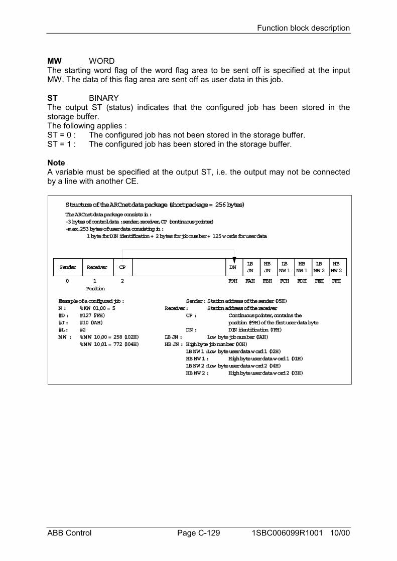
Function block description
ABB Control Page C-129 1SBC006099R1001 10/00
MW WORDThe starting word flag of the word flag area to be sent off is specified at the inputMW. The data of this flag area are sent off as user data in this job.
ST BINARYThe output ST (status) indicates that the configured job has been stored in thestorage buffer.The following applies :ST = 0 : The configured job has not been stored in the storage buffer.ST = 1 : The configured job has been stored in the storage buffer.
NoteA variable must be specified at the output ST, i.e. the output may not be connectedby a line with another CE.
Sender Receiver CP
0 1 2 FFHFEHFDHFCHFBHFAHF9H
DNLB HB
JNJNLB LBHB HBNW1 NW1 NW2 NW2
Structure of the ARCnet data package (short package = 256 bytes)
The ARCnet data package consists in :- 3 bytes of control data : sender, receiver, CP (continuous pointer)- max. 253 bytes of user data consisting in :
1 byte for DIN identification + 2 bytes for job number + 125 words for user data
Position
Example of a configured job : Sender :Station address of the sender (05H)N : %KW 01,00 = 5 Receiver : Station address of the receiver#D : #127 (7FH) CP : Continuous pointer, contains the#J : #10 (0AH) position (F9H) of the first user data byte#L : #2 DN : DIN identification (7FH)MW : %MW 10,00 = 258 (102H) LB JN : Low byte job number (0AH)
%MW 10,01 = 772 (304H) HB JN : High byte job number (00H)LB NW1 :Low byte user data word 1 (02H)HB NW1 : High byte user data word 1 (01H)LB NW2 :Low byte user data word 2 (04H)HB NW2 : High byte user data word 2 (03H)
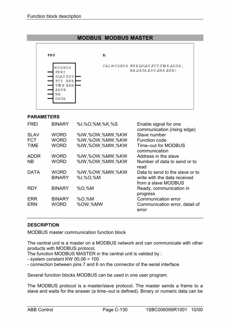
Function block description
ABB Control Page C-130 1SBC006099R1001 10/00
MODBUS MODBUS MASTER
FREISLAVFCTTIM EADDRNB
RDYERRERN
M O DBUS
DATA
FBD IL
CAL M O DBUS (FREI,SLAV,FCT,TIM E,ADDR,NB,DATA,RDY,ERR,ERN)
PARAMETERSFREI BINARY %I,%O,%M,%K,%S Enable signal for one
communication (rising edge)SLAV WORD %IW,%OW,%MW,%KW Slave numberFCT WORD %IW,%OW,%MW,%KW Function codeTIME WORD %IW,%OW,%MW,%KW Time–out for MODBUS
communicationADDR WORD %IW,%OW,%MW,%KW Address in the slaveNB WORD %IW,%OW,%MW,%KW Number of data to send or to
readDATA WORD %IW,%OW,%MW,%KW Data to send to the slave or to
BINARY %I,%O,%M write with the data received from a slave MODBUS
RDY BINARY %O,%M Ready, communication in progress
ERR BINARY %O,%M Communication errorERN WORD %OW,%MW Communication error, detail of
error
DESCRIPTIONMODBUS master communication function block
The central unit is a master on a MODBUS network and can communicate with otherproducts with MODBUS protocol.The function MODBUS MASTER in the central unit is valided by :- system constant KW 00,06 = 100- connection between pins 7 and 6 on the connector of the serial interface
Several function blocks MODBUS can be used in one user program.
The MODBUS protocol is a master/slave protocol. The master sends a frame to aslave and waits for the answer (a time–out is defined). Binary or numeric data can be
Function block description
ABB Control Page C-131 1SBC006099R1001 10/00
read or written in a slave.
The area of data in the master is chosen by the address of the first variable. The sizeof area is necessary for sending or receiving. Reading or writing data are doneautomatically from these areas.
FREI BINARYA rising edge at the FREI input leads to an output of a request to a slave MODBUS,provided that the block is ready to do this (RDY = 1).If a rising edge appears at the FREI input although the RDY output is equal to 0, i.e.the block is not ready for a new MODBUS communication, the rising edge will beignored. Therefore, no new MODBUS communication can be started as long as theRDY output is 0.
SLAV WORDAddress of the slave which receives the request.Value : 0 < ADDR < 255In case of address 0 (ADDR = 0), all slaves on the MODBUS network will read theframe.
FCT WORDThe function depends on the type of parameters and if it is reading or writing.Value : 1 (01H): reading n bits
2 (02H): reading n bits3 (03H): reading n words4 (04H): reading n words5 (05H): writing one bit6 (06H): writing one word7 (07H): fast reading of 8 bits8 (08H): Diagnosis/initialization15 (0FH): writing n bits16 (10H): writing n words
The other function codes are not supported by by the central units 30serie, 40 serieand 50 serie. In case of a wrong function code, an error 1 is generated in the wordERN.
TIME WORDTime–out for the communication (maximum time for an answer of the slaveMODBUS).The value is given in milliseconds.Cycle time (KD 00,00) < TIME < 32767In case of a time–out, the output ERN provides the value of 9.
ADDR WORDAddress of data in the slave memory to read or write.
NB WORDNumber of data to read or write in the slave.This number defines also the size of the data area in the master to send to the slaveor to receive from the slave.
Function block description
ABB Control Page C-132 1SBC006099R1001 10/00
DATA WORD, BINARYDATA defines the first variable of the data area in the master. The size of this areadepends on the NB parameter.Different cases are possible according to the function code and the operand :Reading : ADDR DATA result
word word idembit bit idembit word same as the function block PACKword bit The first bit of the word is ranged in the first bit of the
group number.Example : data = M 00,07 : The first bit of the read word will be written in M 00,00.
Writing : ADDR DATA resultword word idembit bit idembit word same as the function block PACKword bit same as the function block UNPACK
RDY BINARYThe output RDY (ready) indicates whether a MODBUS communication is in progressor not. As long as a communication is in progress, the output RDY is equal to 0. Thefunction block can only be used if RDY = 1.
ERR BINARYThe output ERR indicates an error occurred during communication. The word outputERN indicates the details of the error.If ERR = 1 -> error,
ERR = 0 -> no error or communication in progress.The error is clear after one cycle time.
ERN WORDDetails of error :
0 : no error 1 : unknown function code 2 : address error 3 : data error 9 : time–out10 : checksum error
The error is clear after one cycle time.
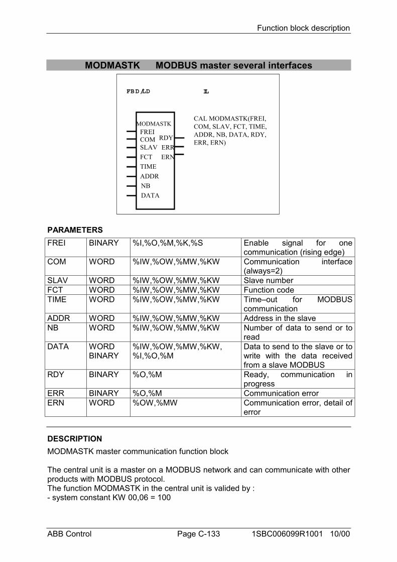
Function block description
ABB Control Page C-133 1SBC006099R1001 10/00
MODMASTK MODBUS master several interfaces
FBD/LD IL
MODMASTKFREICOM
ERRRDY
ERN
CAL MODMASTK(FREI,COM, SLAV, FCT, TIME,ADDR, NB, DATA, RDY,ERR, ERN)
SLAVFCTTIMEADDRNBDATA
PARAMETERSFREI BINARY %I,%O,%M,%K,%S Enable signal for one
communication (rising edge)COM WORD %IW,%OW,%MW,%KW Communication interface
(always=2)SLAV WORD %IW,%OW,%MW,%KW Slave numberFCT WORD %IW,%OW,%MW,%KW Function codeTIME WORD %IW,%OW,%MW,%KW Time–out for MODBUS
communicationADDR WORD %IW,%OW,%MW,%KW Address in the slaveNB WORD %IW,%OW,%MW,%KW Number of data to send or to
readDATA WORD
BINARY%IW,%OW,%MW,%KW,%I,%O,%M
Data to send to the slave or towrite with the data receivedfrom a slave MODBUS
RDY BINARY %O,%M Ready, communication inprogress
ERR BINARY %O,%M Communication errorERN WORD %OW,%MW Communication error, detail of
error
DESCRIPTIONMODMASTK master communication function block
The central unit is a master on a MODBUS network and can communicate with otherproducts with MODBUS protocol.The function MODMASTK in the central unit is valided by :- system constant KW 00,06 = 100
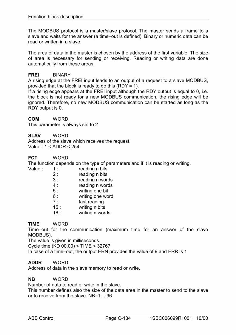
Function block description
ABB Control Page C-134 1SBC006099R1001 10/00
The MODBUS protocol is a master/slave protocol. The master sends a frame to aslave and waits for the answer (a time–out is defined). Binary or numeric data can beread or written in a slave.
The area of data in the master is chosen by the address of the first variable. The sizeof area is necessary for sending or receiving. Reading or writing data are doneautomatically from these areas.
FREI BINARYA rising edge at the FREI input leads to an output of a request to a slave MODBUS,provided that the block is ready to do this (RDY = 1).If a rising edge appears at the FREI input although the RDY output is equal to 0, i.e.the block is not ready for a new MODBUS communication, the rising edge will beignored. Therefore, no new MODBUS communication can be started as long as theRDY output is 0.
COM WORDThis parameter is always set to 2
SLAV WORDAddress of the slave which receives the request.Value : 1 < ADDR < 254
FCT WORDThe function depends on the type of parameters and if it is reading or writing.Value : 1 : reading n bits
2 : reading n bits3 : reading n words4 : reading n words5 : writing one bit6 : writing one word7 : fast reading15 : writing n bits16 : writing n words
TIME WORDTime–out for the communication (maximum time for an answer of the slaveMODBUS).The value is given in milliseconds.Cycle time (KD 00,00) < TIME < 32767In case of a time–out, the output ERN provides the value of 9.and ERR is 1
ADDR WORDAddress of data in the slave memory to read or write.
NB WORDNumber of data to read or write in the slave.This number defines also the size of the data area in the master to send to the slaveor to receive from the slave. NB=1….96
Function block description
ABB Control Page C-135 1SBC006099R1001 10/00
DATA WORD, BINARYDATA defines the first variable of the data area in the master. The size of this areadepends on the NB parameter.
RDY BINARYThe output RDY (ready) indicates whether a MODBUS communication is in progressor not. As long as a communication is in progress, the output RDY is equal to 0. Thefunction block can only be used if RDY = 1.
ERR BINARYThe output ERR indicates an error occurred during communication. The word outputERN indicates the details of the error.If ERR = 1 -> error,
ERR = 0 -> no error or communication in progress.The error is clear after one cycle time.
ERN WORDDetails of error :
0 : no error 1 : unknown function code 2 : address error 3 : data error 9 : time–out10 : checksum error
The error is clear after one cycle time.
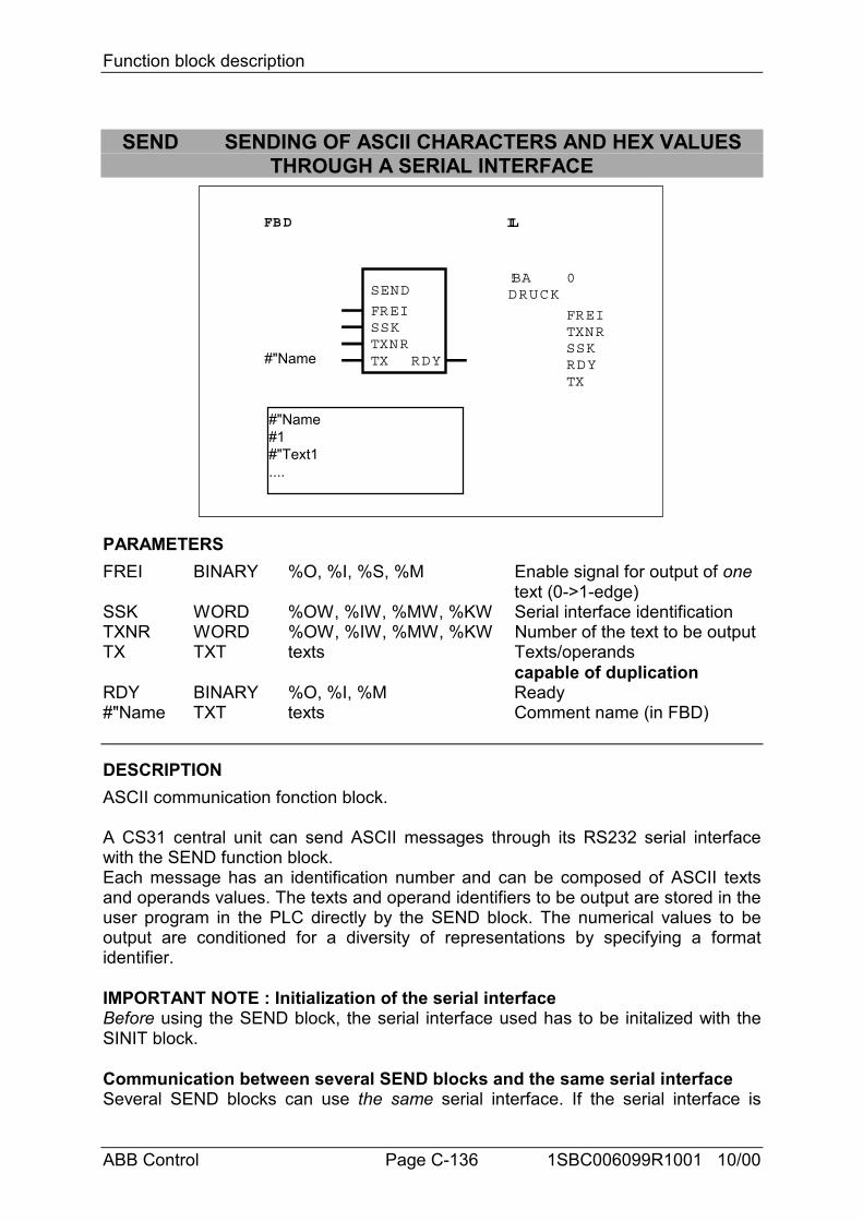
Function block description
ABB Control Page C-136 1SBC006099R1001 10/00
SEND SENDING OF ASCII CHARACTERS AND HEX VALUESTHROUGH A SERIAL INTERFACE
FBD IL
SEND
FREISSKTXNRTX RDY
!BADRUCK
0
FREITXNRSSK
TXRDY#"Name
#"Name#1#"Text1....
PARAMETERSFREI BINARY %O, %I, %S, %M Enable signal for output of one
text (0->1-edge)SSK WORD %OW, %IW, %MW, %KW Serial interface identificationTXNR WORD %OW, %IW, %MW, %KW Number of the text to be outputTX TXT texts Texts/operands
capable of duplicationRDY BINARY %O, %I, %M Ready#"Name TXT texts Comment name (in FBD)
DESCRIPTIONASCII communication fonction block.
A CS31 central unit can send ASCII messages through its RS232 serial interfacewith the SEND function block.Each message has an identification number and can be composed of ASCII textsand operands values. The texts and operand identifiers to be output are stored in theuser program in the PLC directly by the SEND block. The numerical values to beoutput are conditioned for a diversity of representations by specifying a formatidentifier.
IMPORTANT NOTE : Initialization of the serial interfaceBefore using the SEND block, the serial interface used has to be initalized with theSINIT block.
Communication between several SEND blocks and the same serial interfaceSeveral SEND blocks can use the same serial interface. If the serial interface is
Function block description
ABB Control Page C-137 1SBC006099R1001 10/00
engaged by one of the SEND blocks, the other SEND blocks automatically wait untilit is free again. The priority access to the serial interface when several SEND blockssimultaneously have access to the same interface, corresponds to the sequence inwhich the SEND blocks are called in the user program : the first SEND block locatedat the beginning of the user program is given access first. The processing sequencemust be planned by an appropriate mutual interlocking of the SEND blocks.
Communication by a SEND and REC block with the same serial interfaceA SEND block and a REC block (receiving of ASCII messages) can use the sameserial interface without any special precaution.
FREI BINARYIf the block is ready (RDY = 1) and a 0 -> 1 edge appears at the FREI input, the textidentified at the input TXNR is sent through the serial interface specified at the SSKinput.
If a 0 -> 1 edge appears at the FREI input although the RDY output is equal to 0 (i.e.the block is not ready yet for a new transfer), the 0 -> 1 edge is ignored. Therefore,no new text transfer is started as long as the RDY signal is 0.
SSK WORDCentral units can have one or two RS232 serial interface. The number of theinterface through which the text is to be output is specified at the SSK input :
SSK = 1 for COM1SSK = 2 for COM2
TXNR WORDThe number of the text to be output is specified at the TXNR input : 1≤ TXNR ≤ 99
The number of the text to be output must be present at the TXNR input until theblock indicates the end of text transfer with a 1 signal at its RDY output.
RDY BINARYIn the program cycle in which the block is called for the first time, and during the timewhen a text is output, RDY is equal to 0. As long as RDY is equal to 0, no new textoutput can be activated and all 0 -> 1 edge present at the FREI input are ignored andlost.
After the first call of the block or after termination of a text output, RDY is equal to 1and the block is ready again for output of a new text.
FREI RDY TXNR SSK MEANING0/1 edge 1 2 1 The text with the number 2 is
output through interface 10/1 edge 0 2 1 0/1 edge is ignored because
the block is not readyno 0/1 edge x x x No output of a new text
=> The RDY signal can be used for example at the FREI input to activate a new texttransfer.
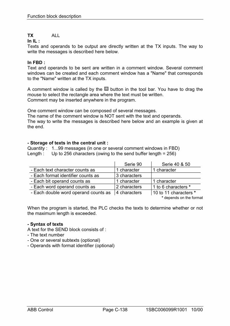
Function block description
ABB Control Page C-138 1SBC006099R1001 10/00
TX ALLIn IL :Texts and operands to be output are directly written at the TX inputs. The way towrite the messages is described here below.
In FBD :Text and operands to be sent are written in a comment window. Several commentwindows can be created and each comment window has a "Name" that correspondsto the "Name" written at the TX inputs.
A comment window is called by the button in the tool bar. You have to drag themouse to select the rectangle area where the text must be written.Comment may be inserted anywhere in the program.
One comment window can be composed of several messages.The name of the comment window is NOT sent with the text and operands.The way to write the messages is described here below and an example is given atthe end.
- Storage of texts in the central unit :Quantity : 1...99 messages (in one or several comment windows in FBD)Length : Up to 256 characters (owing to the send buffer length = 256)
Serie 90 Serie 40 & 50- Each text character counts as 1 character 1 character- Each format identifier counts as 3 characters- Each bit operand counts as 1 character 1 character- Each word operand counts as 2 characters 1 to 6 characters *- Each double word operand counts as 4 characters 10 to 11 characters *
* depends on the format
When the program is started, the PLC checks the texts to determine whether or notthe maximum length is exceeded.
- Syntax of textsA text for the SEND block consists of :- The text number- One or several subtexts (optional)- Operands with format identifier (optional)
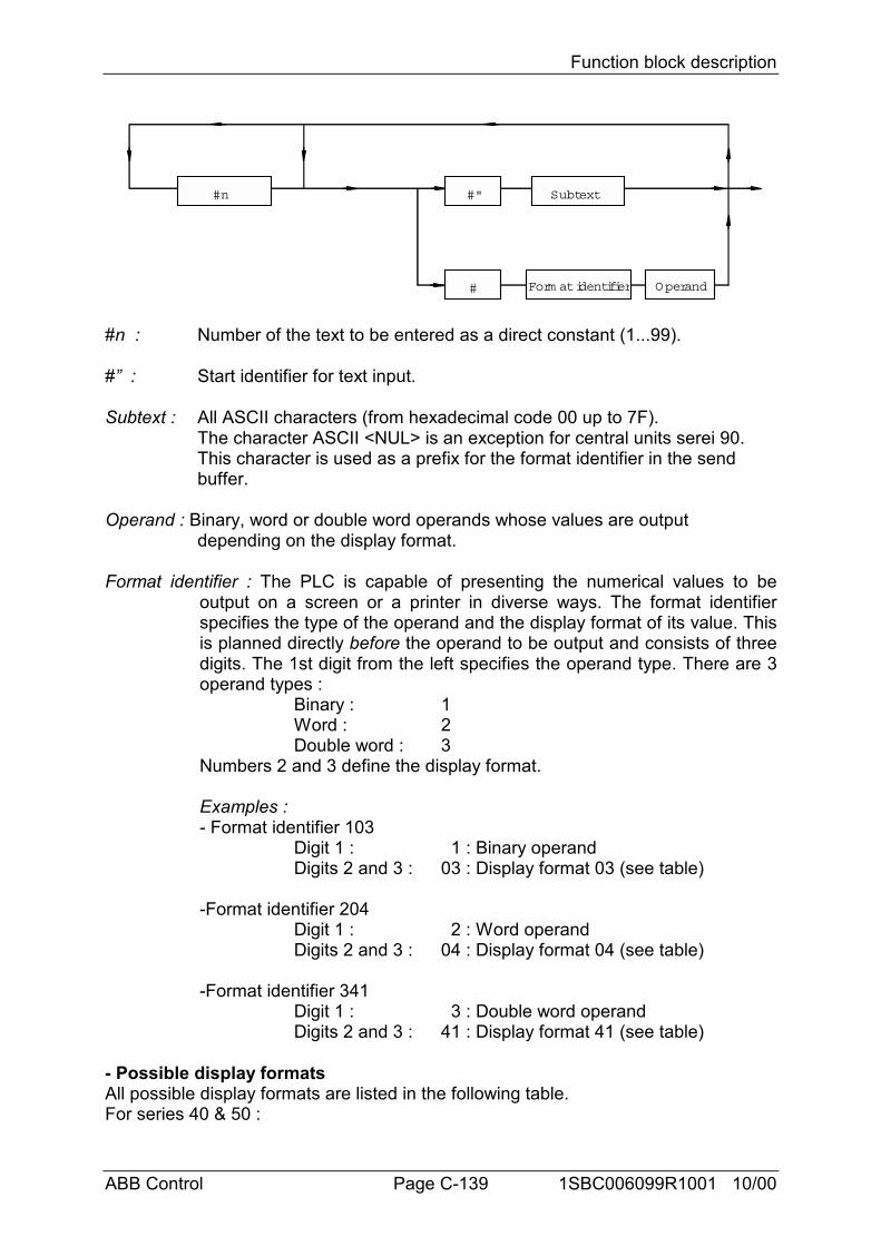
Function block description
ABB Control Page C-139 1SBC006099R1001 10/00
#n #" Subtext
# Form at identifier Operand
#n : Number of the text to be entered as a direct constant (1...99).
#” : Start identifier for text input.
Subtext : All ASCII characters (from hexadecimal code 00 up to 7F).The character ASCII <NUL> is an exception for central units serei 90. This character is used as a prefix for the format identifier in the send buffer.
Operand : Binary, word or double word operands whose values are output depending on the display format.
Format identifier : The PLC is capable of presenting the numerical values to beoutput on a screen or a printer in diverse ways. The format identifierspecifies the type of the operand and the display format of its value. Thisis planned directly before the operand to be output and consists of threedigits. The 1st digit from the left specifies the operand type. There are 3operand types :
Binary : 1Word : 2Double word : 3
Numbers 2 and 3 define the display format.
Examples :- Format identifier 103
Digit 1 : 1 : Binary operandDigits 2 and 3 : 03 : Display format 03 (see table)
-Format identifier 204Digit 1 : 2 : Word operandDigits 2 and 3 : 04 : Display format 04 (see table)
-Format identifier 341Digit 1 : 3 : Double word operandDigits 2 and 3 : 41 : Display format 41 (see table)
- Possible display formatsAll possible display formats are listed in the following table.For series 40 & 50 :
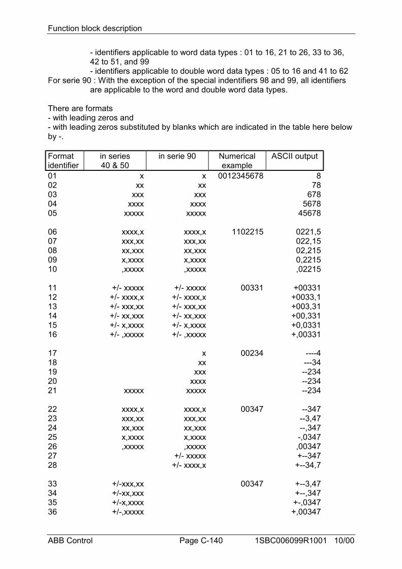
Function block description
ABB Control Page C-140 1SBC006099R1001 10/00
- identifiers applicable to word data types : 01 to 16, 21 to 26, 33 to 36, 42 to 51, and 99- identifiers applicable to double word data types : 05 to 16 and 41 to 62
For serie 90 : With the exception of the special indentifiers 98 and 99, all identifiers are applicable to the word and double word data types.
There are formats- with leading zeros and- with leading zeros substituted by blanks which are indicated in the table here belowby -.
Formatidentifier
in series40 & 50
in serie 90 Numericalexample
ASCII output
01 x x 0012345678 802 xx xx 7803 xxx xxx 67804 xxxx xxxx 567805 xxxxx xxxxx 45678
06 xxxx,x xxxx,x 1102215 0221,507 xxx,xx xxx,xx 022,1508 xx,xxx xx,xxx 02,21509 x,xxxx x,xxxx 0,221510 ,xxxxx ,xxxxx ,02215
11 +/- xxxxx +/- xxxxx 00331 +0033112 +/- xxxx,x +/- xxxx,x +0033,113 +/- xxx,xx +/- xxx,xx +003,3114 +/- xx,xxx +/- xx,xxx +00,33115 +/- x,xxxx +/- x,xxxx +0,033116 +/- ,xxxxx +/- ,xxxxx +,00331
17 x 00234 ----418 xx ---3419 xxx --23420 xxxx --23421 xxxxx xxxxx --234
22 xxxx,x xxxx,x 00347 --34723 xxx,xx xxx,xx --3,4724 xx,xxx xx,xxx --,34725 x,xxxx x,xxxx -,034726 ,xxxxx ,xxxxx ,0034727 +/- xxxxx +--34728 +/- xxxx,x +--34,7
33 +/-xxx,xx 00347 +--3,4734 +/-xx,xxx +--,34735 +/-x,xxxx +-,034736 +/-,xxxxx +,00347
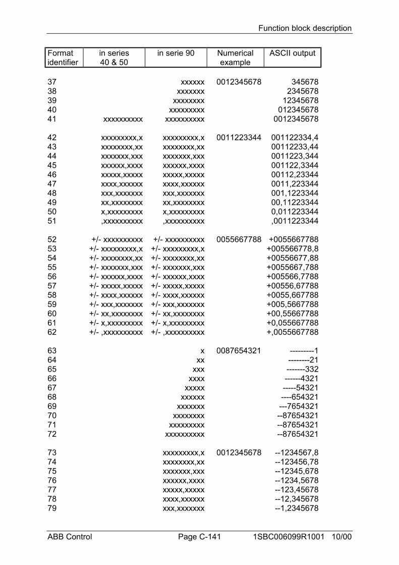
Function block description
ABB Control Page C-141 1SBC006099R1001 10/00
Formatidentifier
in series40 & 50
in serie 90 Numericalexample
ASCII output
37 xxxxxx 0012345678 34567838 xxxxxxx 234567839 xxxxxxxx 1234567840 xxxxxxxxx 01234567841 xxxxxxxxxx xxxxxxxxxx 0012345678
42 xxxxxxxxx,x xxxxxxxxx,x 0011223344 001122334,443 xxxxxxxx,xx xxxxxxxx,xx 00112233,4444 xxxxxxx,xxx xxxxxxx,xxx 0011223,34445 xxxxxx,xxxx xxxxxx,xxxx 001122,334446 xxxxx,xxxxx xxxxx,xxxxx 00112,2334447 xxxx,xxxxxx xxxx,xxxxxx 0011,22334448 xxx,xxxxxxx xxx,xxxxxxx 001,122334449 xx,xxxxxxxx xx,xxxxxxxx 00,1122334450 x,xxxxxxxxx x,xxxxxxxxx 0,01122334451 ,xxxxxxxxxx ,xxxxxxxxxx ,0011223344
52 +/- xxxxxxxxxx +/- xxxxxxxxxx 0055667788 +005566778853 +/- xxxxxxxxx,x +/- xxxxxxxxx,x +005566778,854 +/- xxxxxxxx,xx +/- xxxxxxxx,xx +00556677,8855 +/- xxxxxxx,xxx +/- xxxxxxx,xxx +0055667,78856 +/- xxxxxx,xxxx +/- xxxxxx,xxxx +005566,778857 +/- xxxxx,xxxxx +/- xxxxx,xxxxx +00556,6778858 +/- xxxx,xxxxxx +/- xxxx,xxxxxx +0055,66778859 +/- xxx,xxxxxxx +/- xxx,xxxxxxx +005,566778860 +/- xx,xxxxxxxx +/- xx,xxxxxxxx +00,5566778861 +/- x,xxxxxxxxx +/- x,xxxxxxxxx +0,05566778862 +/- ,xxxxxxxxxx +/- ,xxxxxxxxxx +,0055667788
63 x 0087654321 ---------164 xx --------2165 xxx -------33266 xxxx ------432167 xxxxx -----5432168 xxxxxx ----65432169 xxxxxxx ---765432170 xxxxxxxx --8765432171 xxxxxxxxx --8765432172 xxxxxxxxxx --87654321
73 xxxxxxxxx,x 0012345678 --1234567,874 xxxxxxxx,xx --123456,7875 xxxxxxx,xxx --12345,67876 xxxxxx,xxxx --1234,567877 xxxxx,xxxxx --123,4567878 xxxx,xxxxxx --12,34567879 xxx,xxxxxxx --1,2345678
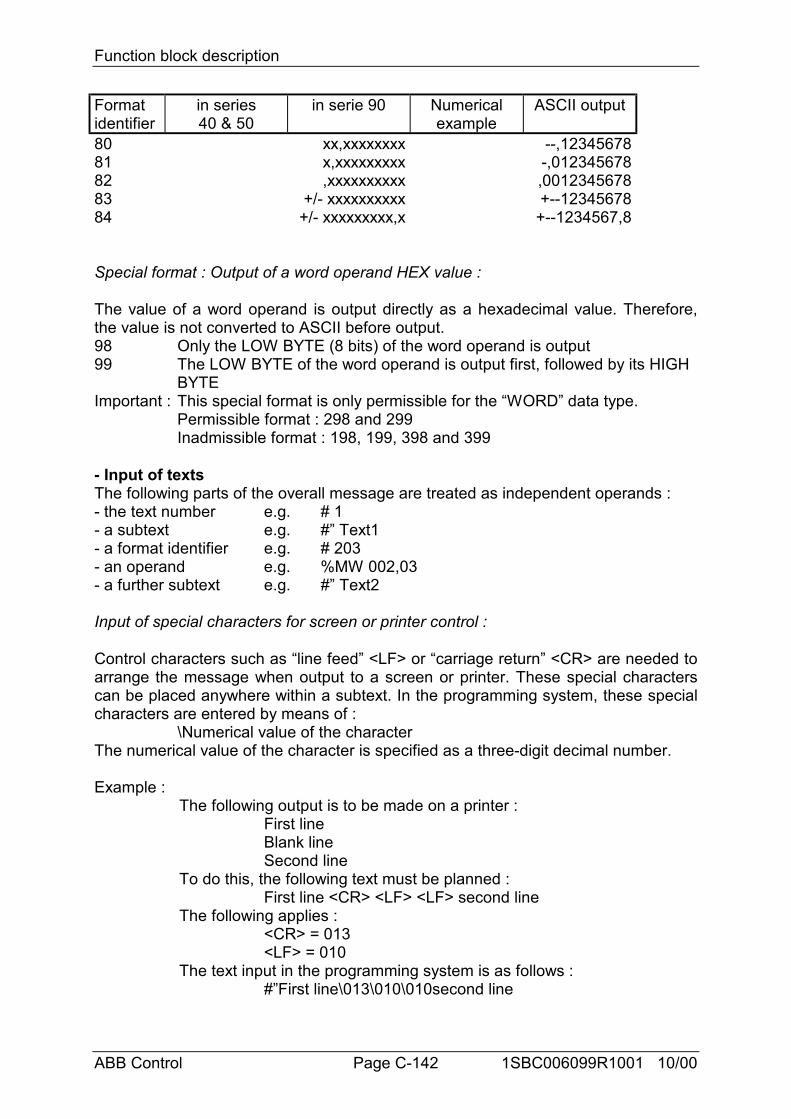
Function block description
ABB Control Page C-142 1SBC006099R1001 10/00
Formatidentifier
in series40 & 50
in serie 90 Numericalexample
ASCII output
80 xx,xxxxxxxx --,1234567881 x,xxxxxxxxx -,01234567882 ,xxxxxxxxxx ,001234567883 +/- xxxxxxxxxx +--1234567884 +/- xxxxxxxxx,x +--1234567,8
Special format : Output of a word operand HEX value :
The value of a word operand is output directly as a hexadecimal value. Therefore,the value is not converted to ASCII before output.98 Only the LOW BYTE (8 bits) of the word operand is output99 The LOW BYTE of the word operand is output first, followed by its HIGH
BYTEImportant : This special format is only permissible for the “WORD” data type.
Permissible format : 298 and 299Inadmissible format : 198, 199, 398 and 399
- Input of textsThe following parts of the overall message are treated as independent operands :- the text number e.g. # 1- a subtext e.g. #” Text1- a format identifier e.g. # 203- an operand e.g. %MW 002,03- a further subtext e.g. #” Text2
Input of special characters for screen or printer control :
Control characters such as “line feed” <LF> or “carriage return” <CR> are needed toarrange the message when output to a screen or printer. These special characterscan be placed anywhere within a subtext. In the programming system, these specialcharacters are entered by means of :
\Numerical value of the characterThe numerical value of the character is specified as a three-digit decimal number.
Example :The following output is to be made on a printer :
First lineBlank lineSecond line
To do this, the following text must be planned :First line <CR> <LF> <LF> second line
The following applies :<CR> = 013<LF> = 010
The text input in the programming system is as follows :#”First line\013\010\010second line
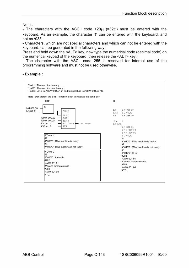
Function block description
ABB Control Page C-143 1SBC006099R1001 10/00
Notes :- The characters with the ASCII code >20H (=32D) must be entered with thekeyboard. As an example, the character ”!” can be entered with the keyboard, andnot as \033.- Characters, which are not special characters and which can not be entered with thekeyboard, can be generated in the following way :Press and hold down the <ALT> key, now type the numerical code (decimal code) onthe numerical keypad of the keyboard, then release the <ALT> key.- The character with the ASCII code 255 is reserved for internal use of theprogramming software and must not be used otherwise.
- Example :
FBD IL
LD % M 000,00AND % O 00,00ST % M 238,00
!BA 0DRUCK
% M 238,00% M W 000,00% M W 000,01% O 00,00#1#"\010\013The machine is ready.#2#"\010\013The machine is not ready.#3#"\010\013It is#202%MW 001,01#"m and temperature is#203%MW 001,00#"°C.
% O 00,00
SEND
FREISSKTXNRTX0TX1
RDY
Text 1 : The machine is ready.Text 2 : The machine is not ready.Text 3 : Level is (%MW 001,01)m and temperature is (%MW 001,00)°C.
Note : Don’t forget the SINIT function block to initialize the serial port
%MW 000,00%MW 000,01#"Com. 1#"Com. 2
%M 000,00%O 00,00
#"Com. 1#1#"\010\013The machine is ready.#2#"\010\013The machine is not ready.
#"Com. 2#3#"\010\013Level is#202%MW 001,01#"m and temperature is#203%MW 001,00#"°C.
&
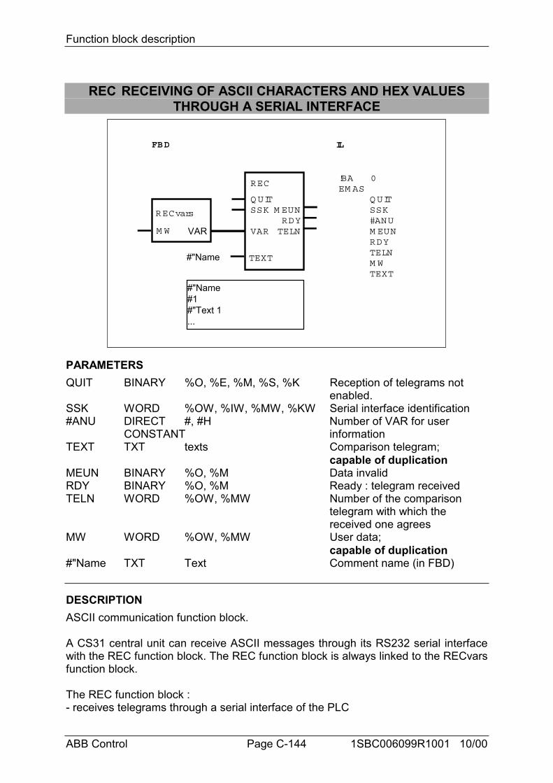
Function block description
ABB Control Page C-144 1SBC006099R1001 10/00
REC RECEIVING OF ASCII CHARACTERS AND HEX VALUESTHROUGH A SERIAL INTERFACE
FBD IL
!BAEM AS
0REC
Q UITSSK
VAR
TEXT
RDYTELN
M EUNQ UITSSK#ANUM EUN
M WTEXT
RDYTELN
RECvars
M W VAR
#"Name#1#"Text 1...
#"Name
PARAMETERSQUIT BINARY %O, %E, %M, %S, %K Reception of telegrams not
enabled.SSK WORD %OW, %IW, %MW, %KW Serial interface identification#ANU DIRECT #, #H Number of VAR for user
CONSTANT informationTEXT TXT texts Comparison telegram;
capable of duplicationMEUN BINARY %O, %M Data invalidRDY BINARY %O, %M Ready : telegram receivedTELN WORD %OW, %MW Number of the comparison
telegram with which the received one agrees
MW WORD %OW, %MW User data;capable of duplication
#"Name TXT Text Comment name (in FBD)
DESCRIPTIONASCII communication function block.
A CS31 central unit can receive ASCII messages through its RS232 serial interfacewith the REC function block. The REC function block is always linked to the RECvarsfunction block.
The REC function block :- receives telegrams through a serial interface of the PLC
Function block description
ABB Control Page C-145 1SBC006099R1001 10/00
- compares these telegrams to comparison telegrams stored in the user program- and, if these agree, provides the user data of the telegram received at the block’soutputs.
The received telegrams are fetched from the serial interface by an interface driverand are provided in a BUFFER for further processing by REC. The driver recognizesthe end of the telegram by the end of telegram character. This end of telegramcharacter is planned in the SINIT block.
IMPORTANT NOTE : Initialization of the serial interfaceBefore using the REC block, the serial interface used has to be initalized with theSINIT block.
Communication between several REC blocks and the same serial interface- REC blocks of a user program which access the same serial interface must beinterlocked so that only ever one REC block is active. If this is not done, telegramsmay be processed by the wrong REC and declared invalid.- If both user program 1 and also user program 2 contain REC blocks which accessthe same serial interface, they must be interlocked so that only ever one REC blockis active. If this is not done, telegrams may be processed by the wrong REC anddeclared invalid.A telegram loss can be avoided by interlocking of the REC blocks. Interlocking mustbe planned so that only the REC block is enabled for which the telegram arrivingthrough the interface is intended.
Communication by an REC block and a SEND block with the same serialinterfaceAn REC and a SEND block can use the same serial interface without specialprecautions having to be taken.
QUIT BINARYThe input QUIT controls reception of telegrams and also serves the purpose ofacknowledgement in the event of an error occurring.QUIT = 0 : Reception of telegrams enabled.QUIT = 1 : Reception of telegrams not enabled. Acknowledgment after
reception of an invalid telegram.If agreement with none of the stored comparison telegrams is ascertained oncomparison of a received telegram, the REC automatically assumes the “error” state.In this case, REC no longer processes any new telegrams until the error isacknowledged with a 1 signal at the input QUIT and reception of telegrams isenabled again (next cycle) with a 0 signal at the input QUIT.
SSK WORDThe number of the interface through which the block receives its telegrams isspecified at the SSK input (interface identifier).The following applies :COM1 : number = 1COM2 : number = 2
#ANU DIRECT CONSTANT
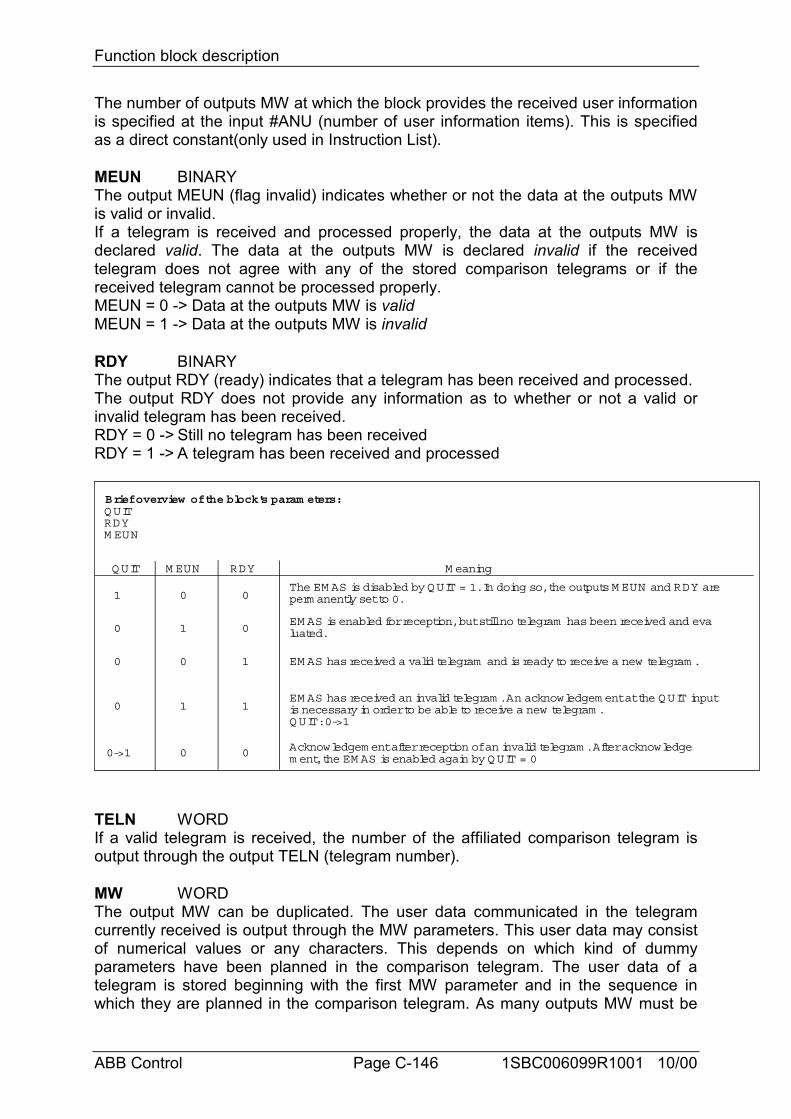
Function block description
ABB Control Page C-146 1SBC006099R1001 10/00
The number of outputs MW at which the block provides the received user informationis specified at the input #ANU (number of user information items). This is specifiedas a direct constant(only used in Instruction List).
MEUN BINARYThe output MEUN (flag invalid) indicates whether or not the data at the outputs MWis valid or invalid.If a telegram is received and processed properly, the data at the outputs MW isdeclared valid. The data at the outputs MW is declared invalid if the receivedtelegram does not agree with any of the stored comparison telegrams or if thereceived telegram cannot be processed properly.MEUN = 0 -> Data at the outputs MW is validMEUN = 1 -> Data at the outputs MW is invalid
RDY BINARYThe output RDY (ready) indicates that a telegram has been received and processed.The output RDY does not provide any information as to whether or not a valid orinvalid telegram has been received.RDY = 0 -> Still no telegram has been receivedRDY = 1 -> A telegram has been received and processed
QUIT M EUN RDY M eaning
The EM AS is disabled by QUIT = 1. In doing so, the outputs M EUN and RDY areperm anently set to 0.
EM AS is enabled for reception, but still no telegram has been received and evaluated.
EM AS has received a valid telegram and is ready to receive a new telegram .
EM AS has received an invalid telegram . An acknowledgem ent at the QUIT inputis necessary in order to be able to receive a new telegram .QUIT: 0->1
Acknowledgem ent after reception of an invalid telegram . After acknowledgem ent, the EM AS is enabled again by QUIT = 0
1 0 0
0
1
1
00
1
0
0
0
0
1
0->1
Brief overview of the block's param eters:QUITRDYM EUN
TELN WORDIf a valid telegram is received, the number of the affiliated comparison telegram isoutput through the output TELN (telegram number).
MW WORDThe output MW can be duplicated. The user data communicated in the telegramcurrently received is output through the MW parameters. This user data may consistof numerical values or any characters. This depends on which kind of dummyparameters have been planned in the comparison telegram. The user data of atelegram is stored beginning with the first MW parameter and in the sequence inwhich they are planned in the comparison telegram. As many outputs MW must be
Function block description
ABB Control Page C-147 1SBC006099R1001 10/00
provided as are sufficient for the telegram with the most user data.
TEXT ALLIn IL :The comparison telegrams to be stored in the PLC program are specified at theinputs TEXT. The block is capable of processing from 1 to 99 telegrams. Onetelegram occupies 2 inputs, each telegram number being specified at one input andthe actual telegram text being specified at the next one. The exact syntax andhandling of the comparison telegrams are described here below.
In FBD :Text and operands to be stored are written in a comment window. Several commentwindows can be created and each comment window has a "Name" that correspondsto the "Name" written at the TX inputs.
A comment window is called by the button in the tool bar. You have to drag themouse to select the rectangle area where the text must be written.Comment may be inserted anywhere in the program.
One comment window can be composed of several messages.The name of the comment window is NOT stored with the text and operands.The way to write the messages is described here below and an example is given atthe end.
DETAILED DESCRIPTION OF COMPARISON TELEGRAMS1...99 comparison telegrams are stored directly after the REC block.
The comparison telegrams serve to identify- the current telegrams received- and the user data contained in the telegrams received
Each stored comparison telegram has a telegram number to identify it and maycomprise up to 255 characters.
The comparison telegrams consist of :- ASCII characters serving only to identify the telegram received,- Dummy parameters for the user information to be received and to be outputthrough the block’s outputs.As regards the dummy parameters for the user information, REC function blockdistinguishes between dummy parameters for digits and dummy parameters forcharacters.Dummy parameter for digits : # (1 # per digit)Dummy param. for characters : * (1 * per character/byte)
Dummy parameter for digits :For each dummy digit parameter (#) of the comparison telegram, REC expectsprecisely one ASCII coded decimal digit in the telegram to be received. Up to 5dummy digits constitute one dummy parameter group. Such a group of dummy digitsrepresents the numerical value of a decimal number comprising up to 5 digits.No dummy parameter is specified for the decimal number’s sign because REC takes
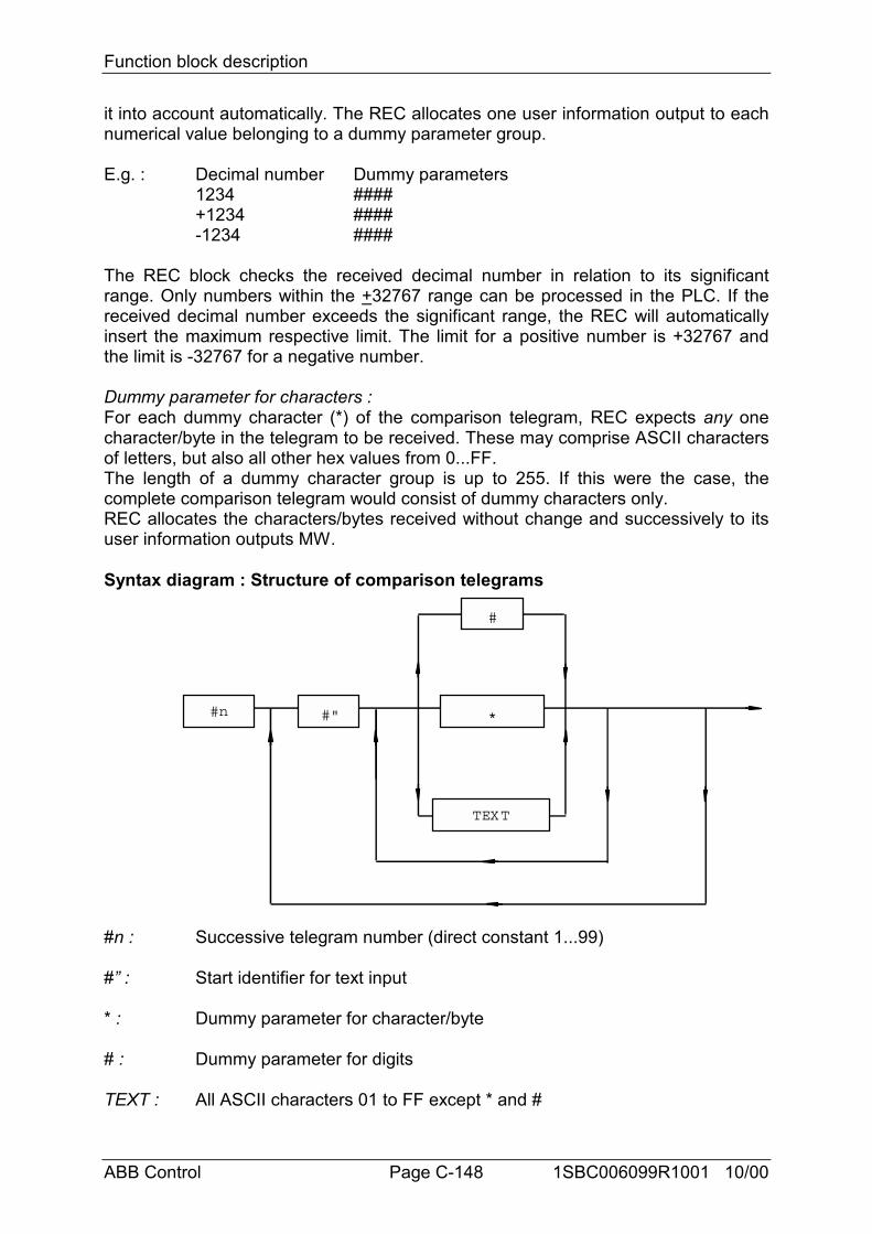
Function block description
ABB Control Page C-148 1SBC006099R1001 10/00
it into account automatically. The REC allocates one user information output to eachnumerical value belonging to a dummy parameter group.
E.g. : Decimal number Dummy parameters1234 ####+1234 ####-1234 ####
The REC block checks the received decimal number in relation to its significantrange. Only numbers within the +32767 range can be processed in the PLC. If thereceived decimal number exceeds the significant range, the REC will automaticallyinsert the maximum respective limit. The limit for a positive number is +32767 andthe limit is -32767 for a negative number.
Dummy parameter for characters :For each dummy character (*) of the comparison telegram, REC expects any onecharacter/byte in the telegram to be received. These may comprise ASCII charactersof letters, but also all other hex values from 0...FF.The length of a dummy character group is up to 255. If this were the case, thecomplete comparison telegram would consist of dummy characters only.REC allocates the characters/bytes received without change and successively to itsuser information outputs MW.
Syntax diagram : Structure of comparison telegrams
#n #" *
#
TEXT
#n : Successive telegram number (direct constant 1...99)
#” : Start identifier for text input
* : Dummy parameter for character/byte
# : Dummy parameter for digits
TEXT : All ASCII characters 01 to FF except * and #
Function block description
ABB Control Page C-149 1SBC006099R1001 10/00
Input of comparison telegrams- Each comparison telegram consists of :
the telegram numberthe telegram text
The telegram number and the telegram text are two separate operands. This is whythe telegram number and the telegram text occupy separate inputs in the FBDsymbol of the REC block. Therefore, two inputs are needed for one comparisontelegram.
Example :First TEXT Input : #1 (No. of the first comparison telegram)Second TEXT Input : #”PRINT### IDENTIFIER**** (Text of the first comparison
telegram)
- Apart from the ASCII characters for * and #, all ASCII characters are possible in thetelegram text.
- When entering special ASCII characters such as “start of line” <CR>, the followingmust be observed : special characters are entered by :
\Numerical value of the characterThe character’s numerical value is specified as a three-digit decimal number.
Example :The following telegram text is to be compared : Temperature <CR> boiler 1The following applies : <CR> = 013The text input in the programming system is as follows :
#”temperature\013boiler 1
Note :- The characters with the ASCII code >20H or >32D must be entered with thekeyboard. As an example, the character ”!” must be entered with the keyboard, andnot as \033.- Characters, which are no special characters and which also could not be enteredwith the keyboard, can be generated in the following way :Press and hold down the <ALT> key, now type the numerical code (decimal code) onthe numeric keypad of the keyboard, then release the <ALT> key.- The character with the ASCII code 255 is reserved for internal use of theprogramming software and must not be used otherwise.
Function block description
ABB Control Page C-150 1SBC006099R1001 10/00
RECEIVING / PROCESSING TELEGRAMSReceiving telegrams are controlled by the QUIT input which also acknowledgetransmission errors.
The REC compares character by character a received telegram to the comparisontelegrams stored. In doing so, agreement between the dummy parameters in thecomparison telegram and the affiliated current characters in the received telegram ischecked.
Important : For REC, the telegram end identifier indicates the end of the telegram tobe received. This is why the telegram end identifier must not occur within a telegram.This also applies to user characters received on the basis of a dummy parameter (#or *).
AgreementIf the REC ascertains agreement between the received telegram and one of itscomparison telegrams, the following applies to the outputs :MEUN = 0, because it has been possible to receive and process the telegram
properlyRDY = 1, because a telegram has been received and processedTELN = Number of the relevant comparison telegramMW = Current user data from the telegram received
The coherent digits defined by a dummy digit group in the comparison telegram areread out of the received telegram, are combined in one numerical value and this isoutput to one word operand (user information output). Text characters marked bydummy text characters (*) in the comparison text are read out of the receivedtelegram and each single character/byte is output without change to a word operand(user information output).
The user information is allocated to the outputs MW in the same sequence as theuser information occurs in the currently received telegram (see also examples).
The maximum number of user information word operands to be output is specified atthe input #ANU. The maximum number results from the telegram with the most userinformation word operands to be reserved (up to 256 word operands, in which casethe telegram would consist of user information only).
Special case :If more user information is planned in a comparison telegram than user informationoutputs are available on the block, i.e. specified at the input #ANU, the received userdata is output through the user information outputs until the end of the outputs hasbeen reached. The remaining user data received will not be output.
The following applies in this error case :MEUN = 1, because it has not been possible to process the telegram properlyRDY = 1, because a telegram has been received and processedTELN = Text No. of the relevant comparison telegramMW = The part of the current user data from the received telegram for which
the number of planned user information outputs suffices.
Function block description
ABB Control Page C-151 1SBC006099R1001 10/00
No agreementThe received telegram agrees with none of the stored comparison telegrams.The following then applies to the outputs :MEUN = 1, because the received telegram is invalidRDY = 1, because a telegram has been received and processing of it has been
terminatedThe REC is now in the “ERROR” state. In this case, REC does not process any newtelegram until the error is acknowledged with a 1 signal at the QUIT input and thereception of telegrams is enabled again (next cycle) with a 0 signal at the QUIT input.
Acknowledgement of the errorSet QUIT = 1 and then, in the next cycle QUIT = 0.After reception of telegrams has been enabled, it may happen that still no telegram isavailable for reception or that a telegram has not yet been received and evaluatedcompletely. In this case, the outputs are set as follows• MEUN = 1 and• RDY = 0until a telegram has been received and processed completely.
EXAMPLE OF A COMPARISON TELEGRAMS
Text 1 : RO104Text 2 : DO##”#”##
Special case : terminate text input and restartIf the text character (”) is used and a dummy parameter for digits(#) follows this text character, the input must be terminated after thetext character (”). A subsequent text or dummy parameter beginswith the input identifier of a new text input (#”).
Text 3 : CO##****Text 4 : *****###**
Note : The texts designated TEXT1, TEXT2 and TEXT3 in the example arepermanently planned texts which REC doesn’t output to user information outputs.They serve exclusively to identify an arriving telegram.Any sequence of texts and dummy parameters for characters and digits is possible.
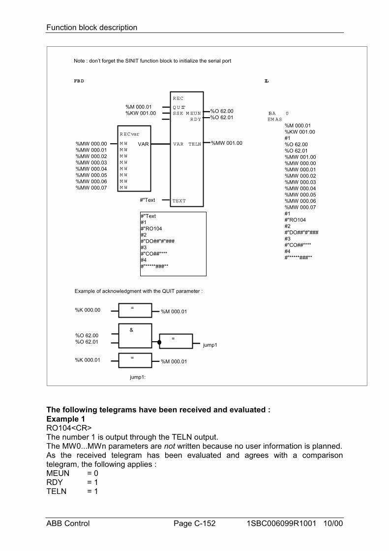
Function block description
ABB Control Page C-152 1SBC006099R1001 10/00
FBD IL
VAR
TEXT
TELN
REC
Q UITSSK
RDYM EUN !BA
EM AS0
%M 000.01%KW 001.00#1%O 62.00%O 62.01%MW 001.00%MW 000.00%MW 000.01%MW 000.02%MW 000.03%MW 000.04%MW 000.05%MW 000.06%MW 000.07#1#"RO104#2#"DO##"#"####3#"CO##****#4#"*****###**
RECvar
M WM WM WM WM WM WM WM W
VAR
#"Text#1#"RO104#2#"DO##"#"####3#"CO##****#4#"*****###**
#"Text
Note : don’t forget the SINIT function block to initialize the serial port
%M 000.01%KW 001.00
%MW 000.00%MW 000.01%MW 000.02%MW 000.03%MW 000.04%MW 000.05%MW 000.06%MW 000.07
%O 62.00%O 62.01
%MW 001.00
Example of acknowledgment with the QUIT parameter :
&
jump1:
=%O 62.00%O 62.01
=%K 000.00 %M 000.01
jump1
=%K 000.01 %M 000.01
The following telegrams have been received and evaluated :Example 1RO104<CR>The number 1 is output through the TELN output.The MW0...MWn parameters are not written because no user information is planned.As the received telegram has been evaluated and agrees with a comparisontelegram, the following applies :MEUN = 0RDY = 1TELN = 1
Function block description
ABB Control Page C-153 1SBC006099R1001 10/00
Example 2DO+12”457”<CR>The number 2 is output through the TELN output.The value 12 is present at the MW0 parameter as the contents of a word flag.The value 457 is present at the MW1 parameter as the contents of a word flag.As the received telegram has been evaluated and agrees with a comparisontelegram, the following applies :MEUN = 0RDY = 1TELN = 2MW0 = 12MW1 = 457
Example 3CO-11AUTO<CR>The number 3 is output through the TELN output.-11 is present at the MW0 parameter as the contents of a word flag.41H (A in ASCII) is present at the MW1 parameter as the contents of a word flag.55H (U in ASCII) is present at the MW2 parameter as the contents of a word flag.54H (T in ASCII) is present at the MW3 parameter as the contents of a word flag.4FH (O in ASCII) is present at the MW4 parameter as the contents of a word flag.As the received telegram has been evaluated and agrees with a comparisontelegram, the following applies :MEUN = 0RDY = 1TELN = 3MW0 = -11MW1 = AMW2 = UMW3 = TMW4 = O
Example 4TEMPO120KM<CR>The number 4 is output through the TELN output.54H (T in ASCII) is present at the MW0 parameter as the contents of a word flag.45H (E in ASCII) is present at the MW1 parameter as the contents of a word flag.4DH (M in ASCII) is present at the MW2 parameter as the contents of a word flag.50H (P in ASCII) is present at the MW3 parameter as the contents of a word flag.4FH (O in ASCII) is present at the MW4 parameter as the contents of a word flag.The value 120 is present at the MW5 parameter as the contents of a word flag.4BH (K in ASCII) is present at the MW6 parameter as the contents of a word flag.4DH (M in ASCII) is present at the MW7 parameter as the contents of a word flag.As the received telegram has been evaluated and agrees with a comparisontelegram, the following applies :MEUN = 0RDY = 1
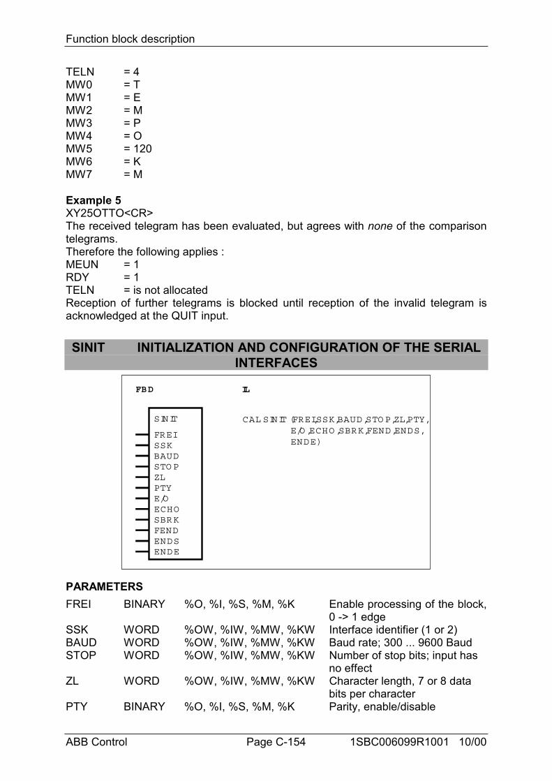
Function block description
ABB Control Page C-154 1SBC006099R1001 10/00
TELN = 4MW0 = TMW1 = EMW2 = MMW3 = PMW4 = OMW5 = 120MW6 = KMW7 = M
Example 5XY25OTTO<CR>The received telegram has been evaluated, but agrees with none of the comparisontelegrams.Therefore the following applies :MEUN = 1RDY = 1TELN = is not allocatedReception of further telegrams is blocked until reception of the invalid telegram isacknowledged at the QUIT input.
SINIT INITIALIZATION AND CONFIGURATION OF THE SERIALINTERFACES
FBD IL
SINIT
FREISSKBAUDSTO P
CAL SINIT (FREI,SSK,BAUD,STO P,ZL,PTY, E/O ,ECHO ,SBRK,FEND,ENDS, ENDE)
ZLPTYE/OECHOSBRKFENDENDSENDE
PARAMETERSFREI BINARY %O, %I, %S, %M, %K Enable processing of the block,
0 -> 1 edgeSSK WORD %OW, %IW, %MW, %KW Interface identifier (1 or 2)BAUD WORD %OW, %IW, %MW, %KW Baud rate; 300 ... 9600 BaudSTOP WORD %OW, %IW, %MW, %KW Number of stop bits; input has
no effectZL WORD %OW, %IW, %MW, %KW Character length, 7 or 8 data
bits per characterPTY BINARY %O, %I, %S, %M, %K Parity, enable/disable
Function block description
ABB Control Page C-155 1SBC006099R1001 10/00
E/O BINARY %O, %I, %S, %M, %K Parity even/oddECHO BINARY %O, %I, %S, %M, %K Echo, on/offSBRK BINARY %O, %I, %S, %M, %K Send break characterFEND BINARY %O, %I, %S, %M, %K Enable end of text character for
transmitting directionENDS WORD %OW, %IW, %MW, %KW End of text character for
transmitting directionENDE WORD %OW, %IW, %MW, %KW End of text character for
receiving direction
DESCRIPTIONSerial interface initialization function block.
The serial interface COM1 is available to the user. In case of 07 KT 92 and07 KT 93, COM2 is additionally available. These interfaces can be operated by thePLC program (e.g. with the DRUCK and EMAS blocks).
Before using one of these interfaces, the interface must be initialized. The functionblock SINIT is available for this purpose.
The function block SINIT is processed once with every 0 -> 1 edge at the FREI input.It initializes the serial interface specified at the SSK input (COM1, COM2).
FREI BINARYThe block is run through once when a 0->1 edge is specified at the FREI input. Asthe result of this, the serial interface whose number is specified at the SSK input isinitialized and the interface is then operable.
SSK WORDThe number of the interface to be initialized is specified at the input SSK.The following applies :COM1 : number = 1COM2 : number = 2
BAUD WORDThe value for the baud rate is specified at the BAUD input.Baudrate : 300 ... 9600 Baud
STOP WORDThe number of stop bits is set to 1 and can not be modified. The value for thenumber of stop bits specified at the input STOP has no significance.
ZL WORDThe input ZL specifies the required character length. The character length signifiesthe number of data bits per character.7 or 8 data bits per character are possible.
PTY BINARYThe input PTY specifies whether a character is transferred with or without a parity bit.
Function block description
ABB Control Page C-156 1SBC006099R1001 10/00
PTY = 0 -> Transfer without parity bitPTY = 1 -> Transfer with parity bit
E/O BINARYThe input E/O specifies whether an even or odd parity bit is required.E/O = 0 -> Odd parity bitE/O = 1 -> Even parity bit
ECHO BINARYThe input ECHO specifies whether the characters received through the applicableinterface are to be reflected (echoed) by the PLC. In this way, the sender of acharacter, for example, can determine whether or not it has arrived correctly in thePLC.ECHO = 0 -> No echo, character is not reflectedECHO = 1 -> Echo, character is reflected
SBRK BINARYThe state of the transmit line TxD can be influenced at the input SBRK (send breakcharacter).SBRK = 0 -> Normal state of the transmit line TxD for transfer of charactersSBRK = 1 -> Transmit line TxD set to “0”
FEND BINARYThe input FEND specifies whether or not the end of text character planned at inputENDS is output at the same time (enable end character).FEND = 0 -> End of text character in transmitting direction is not outputFEND = 1 -> End of text character in transmitting direction is output
ENDS WORDA freely selectable end of text character for the transmitting direction can bespecified at the ENDS input. This end character is then appended automatically toevery text (telegram) which the DRUCK block sends to the outside world through theserial interface. However, a precondition is that input FEND is enabled.The end of text character is specified as a numeric value.
Example : 3 or 03H signifies <ETX> 4 or 04H signifies <EOT>13 or 0DH signifies <CR>10 or OAH signifies <LF>32 or 20H signifies <SP>
...
ENDE WORDA freely selectable end of text character for the receiving direction can be specified atthe ENDE input. When a telegram is received through the serial interface, the PLCrecognizes the end of the telegram by virtue of this end character. The end characteris specified in the same way as in the case of the ENDS input.
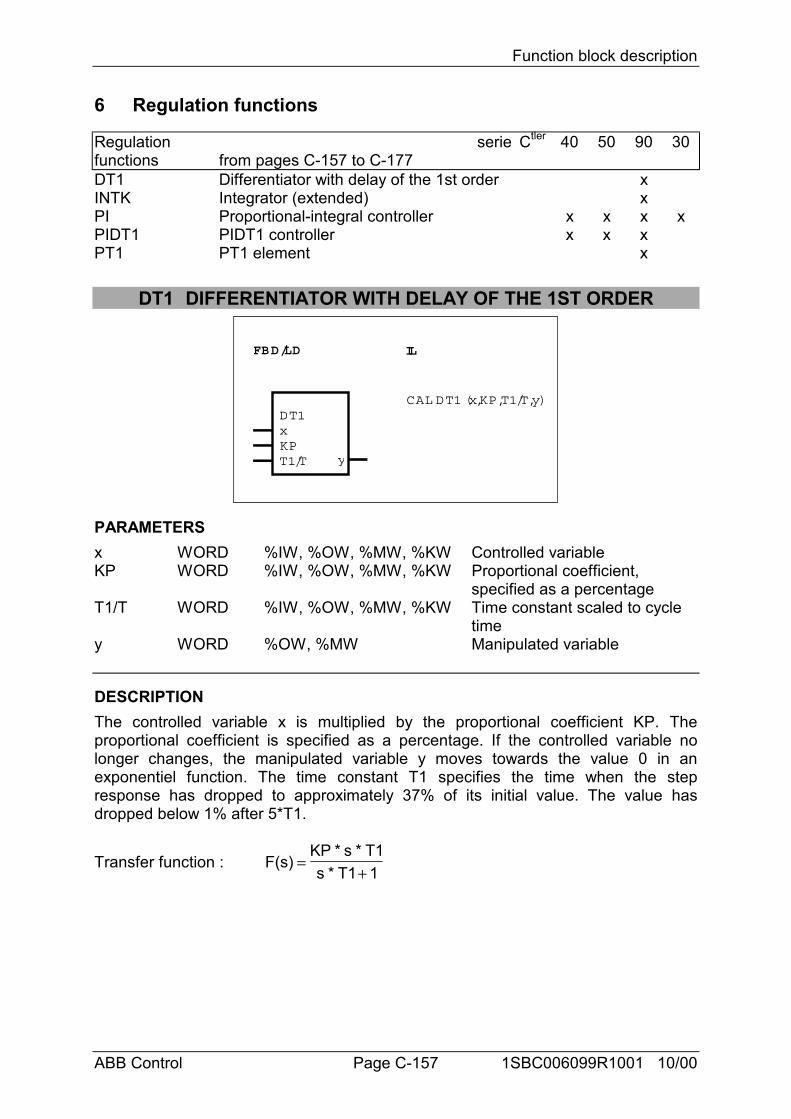
Function block description
ABB Control Page C-157 1SBC006099R1001 10/00
6 Regulation functions
Regulationfunctions
seriefrom pages C-157 to C-177
Ctler 40 50 90 30
DT1 Differentiator with delay of the 1st order xINTK Integrator (extended) xPI Proportional-integral controller x x x xPIDT1 PIDT1 controller x x xPT1 PT1 element x
DT1 DIFFERENTIATOR WITH DELAY OF THE 1ST ORDER
FBD/LD IL
DT1xKPT1/T y
CAL DT1 (x,KP,T1/T,y)
PARAMETERSx WORD %IW, %OW, %MW, %KW Controlled variableKP WORD %IW, %OW, %MW, %KW Proportional coefficient,
specified as a percentageT1/T WORD %IW, %OW, %MW, %KW Time constant scaled to cycle
timey WORD %OW, %MW Manipulated variable
DESCRIPTIONThe controlled variable x is multiplied by the proportional coefficient KP. Theproportional coefficient is specified as a percentage. If the controlled variable nolonger changes, the manipulated variable y moves towards the value 0 in anexponentiel function. The time constant T1 specifies the time when the stepresponse has dropped to approximately 37% of its initial value. The value hasdropped below 1% after 5*T1.
Transfer function : F(s)KP * s * T1s * T1 1
=+
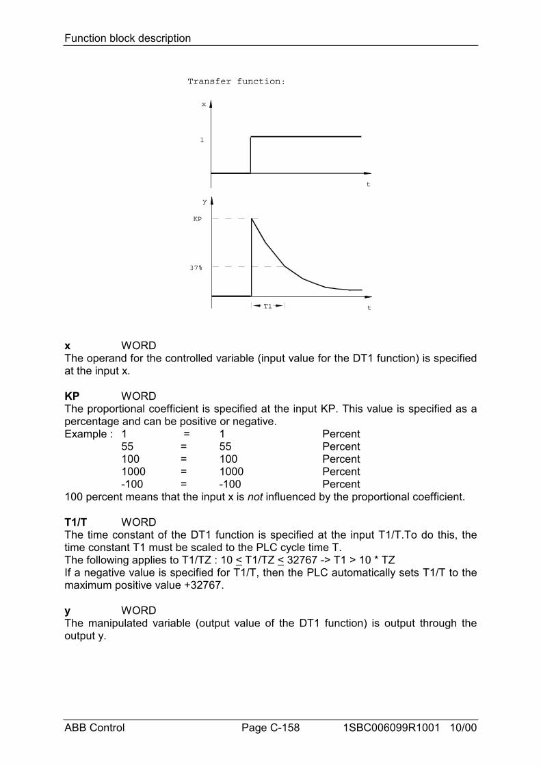
Function block description
ABB Control Page C-158 1SBC006099R1001 10/00
x
t
1
y
t
KP
37%
T1
Transfer function:
x WORDThe operand for the controlled variable (input value for the DT1 function) is specifiedat the input x.
KP WORDThe proportional coefficient is specified at the input KP. This value is specified as apercentage and can be positive or negative.Example : 1 = 1 Percent
55 = 55 Percent100 = 100 Percent1000 = 1000 Percent-100 = -100 Percent
100 percent means that the input x is not influenced by the proportional coefficient.
T1/T WORDThe time constant of the DT1 function is specified at the input T1/T.To do this, thetime constant T1 must be scaled to the PLC cycle time T.The following applies to T1/TZ : 10 < T1/TZ < 32767 -> T1 > 10 * TZIf a negative value is specified for T1/T, then the PLC automatically sets T1/T to themaximum positive value +32767.
y WORDThe manipulated variable (output value of the DT1 function) is output through theoutput y.
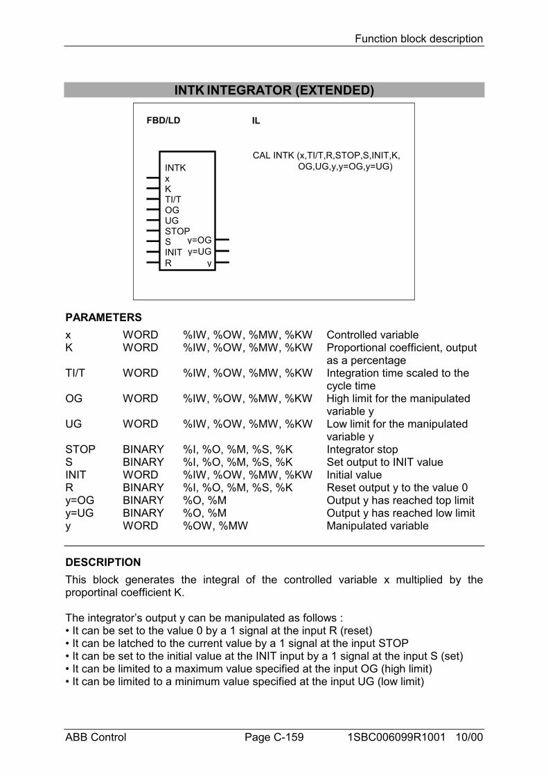
Function block description
ABB Control Page C-159 1SBC006099R1001 10/00
INTK INTEGRATOR (EXTENDED)
FBD/LD IL
CAL INTK (x,TI/T,R,STOP,S,INIT,K, OG,UG,y,y=OG,y=UG)INTK
xKTI/TOGUGSTOPSINITR y
y=UGy=OG
PARAMETERSx WORD %IW, %OW, %MW, %KW Controlled variableK WORD %IW, %OW, %MW, %KW Proportional coefficient, output
as a percentageTI/T WORD %IW, %OW, %MW, %KW Integration time scaled to the
cycle timeOG WORD %IW, %OW, %MW, %KW High limit for the manipulated
variable yUG WORD %IW, %OW, %MW, %KW Low limit for the manipulated
variable ySTOP BINARY %I, %O, %M, %S, %K Integrator stopS BINARY %I, %O, %M, %S, %K Set output to INIT valueINIT WORD %IW, %OW, %MW, %KW Initial valueR BINARY %I, %O, %M, %S, %K Reset output y to the value 0y=OG BINARY %O, %M Output y has reached top limity=UG BINARY %O, %M Output y has reached low limity WORD %OW, %MW Manipulated variable
DESCRIPTIONThis block generates the integral of the controlled variable x multiplied by theproportinal coefficient K.
The integrator’s output y can be manipulated as follows :• It can be set to the value 0 by a 1 signal at the input R (reset)• It can be latched to the current value by a 1 signal at the input STOP• It can be set to the initial value at the INIT input by a 1 signal at the input S (set)• It can be limited to a maximum value specified at the input OG (high limit)• It can be limited to a minimum value specified at the input UG (low limit)
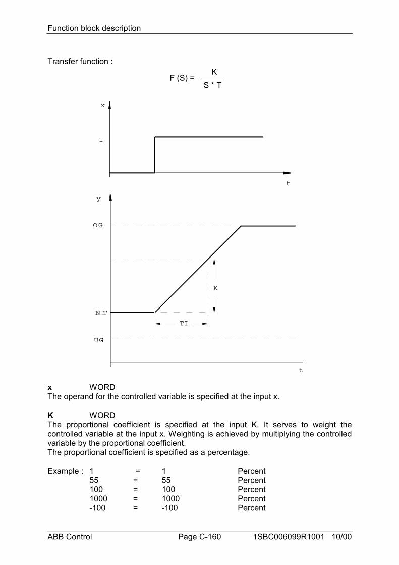
Function block description
ABB Control Page C-160 1SBC006099R1001 10/00
Transfer function :
F (S) =K
S * T
x
t
1
y
OG
t
INIT
TI
UG
K
x WORDThe operand for the controlled variable is specified at the input x.
K WORDThe proportional coefficient is specified at the input K. It serves to weight thecontrolled variable at the input x. Weighting is achieved by multiplying the controlledvariable by the proportional coefficient.The proportional coefficient is specified as a percentage.
Example : 1 = 1 Percent55 = 55 Percent100 = 100 Percent1000 = 1000 Percent-100 = -100 Percent
Function block description
ABB Control Page C-161 1SBC006099R1001 10/00
• 1 percent means that the block multiplies the value at input x by the factor 0.01• 100 percent means that the block multiplies the value at input x by the factor 1• 1000 percent means that the block multiplies the value at input x by the factor 10
TI/T WORDThe integration time is specified at the input TI/T. It must be scaled to the cycle time.During the time TI the output y of the integrator changes by the value K * x.Value range : 0 < TI/T < 328• If values which are beyond the admissible value range are specified, the PLC usesthe value 328.• A large integration time (TI) can be achieved by choosing a great cycle time, too. Ifthe block is used within a run number block, the cycle time of the run number block isvalid for block INTK and not the cycle time (%KD 0,0) of the PLC program.
OG WORDThe manipulated variable y can be limited to a value range. The high limit for themanipulated variable y is specified at the input OG.
UG WORDThe manipulated variable y can be limited to a value range. The low limit for themanipulated variable y is specified at the input UG.
STOP BINARY *)Integration can be stopped with the STOP input.STOP = 0 -> integration is not stoppedSTOP = 1 -> integration is stopped, i.e. the output y no longer changes.
S BINARY *)By means of the input S, the manipulated variable y can be set to the initial valuespecified at the input INIT. Integration then again begins as from the initial value.S = 0 -> No settingS = 1 -> Output y is set to the specified initial value
INIT WORDThe initial value to which the output y must be set when required is specified at theinput INIT.
R BINARY *)With the input R, the output y can be reset to the value 0. Integration then againbegins as from the value 0.
*) Priority sequence for the inputs STOP, S and R : R Highest prioritySTOPS Lowest priority
y=OG BINARYWhether the value at the output y has reached the specified top limit is signalled atthe output y=OG. Integration is stopped automatically when the limit is reached. y=OG = 0 -> y has not reached the limity=OG = 1 -> y has reached the limit
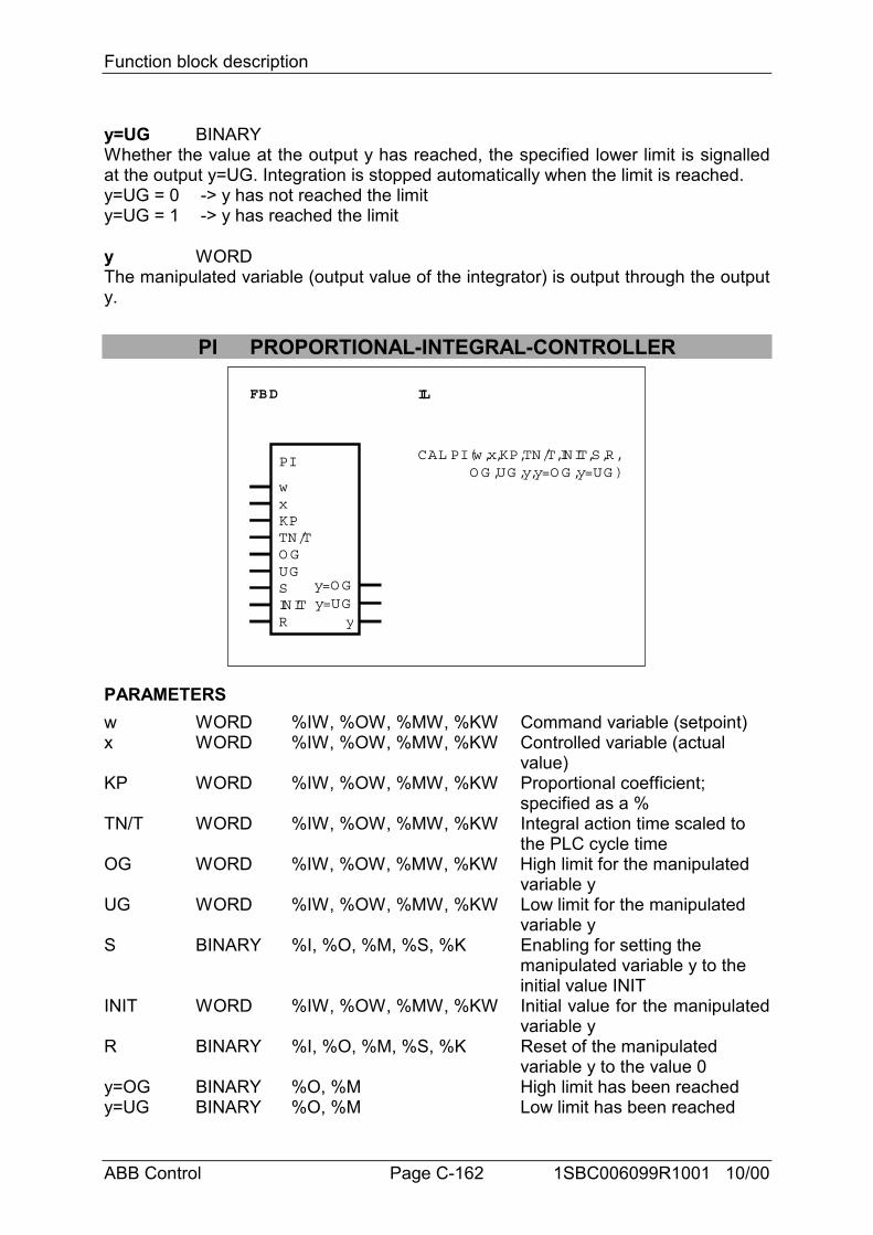
Function block description
ABB Control Page C-162 1SBC006099R1001 10/00
y=UG BINARYWhether the value at the output y has reached, the specified lower limit is signalledat the output y=UG. Integration is stopped automatically when the limit is reached.y=UG = 0 -> y has not reached the limity=UG = 1 -> y has reached the limit
y WORDThe manipulated variable (output value of the integrator) is output through the outputy.
PI PROPORTIONAL-INTEGRAL-CONTROLLER
FBD IL
CAL PI (w,x,KP,TN/T,INIT,S,R,O G ,UG ,y,y=O G ,y=UG )
PI
wxKPTN/TO GUGSINITR y
y=UGy=O G
PARAMETERSw WORD %IW, %OW, %MW, %KW Command variable (setpoint)x WORD %IW, %OW, %MW, %KW Controlled variable (actual
value)KP WORD %IW, %OW, %MW, %KW Proportional coefficient;
specified as a %TN/T WORD %IW, %OW, %MW, %KW Integral action time scaled to
the PLC cycle timeOG WORD %IW, %OW, %MW, %KW High limit for the manipulated
variable yUG WORD %IW, %OW, %MW, %KW Low limit for the manipulated
variable yS BINARY %I, %O, %M, %S, %K Enabling for setting the
manipulated variable y to the initial value INIT
INIT WORD %IW, %OW, %MW, %KW Initial value for the manipulatedvariable y
R BINARY %I, %O, %M, %S, %K Reset of the manipulated variable y to the value 0
y=OG BINARY %O, %M High limit has been reachedy=UG BINARY %O, %M Low limit has been reached
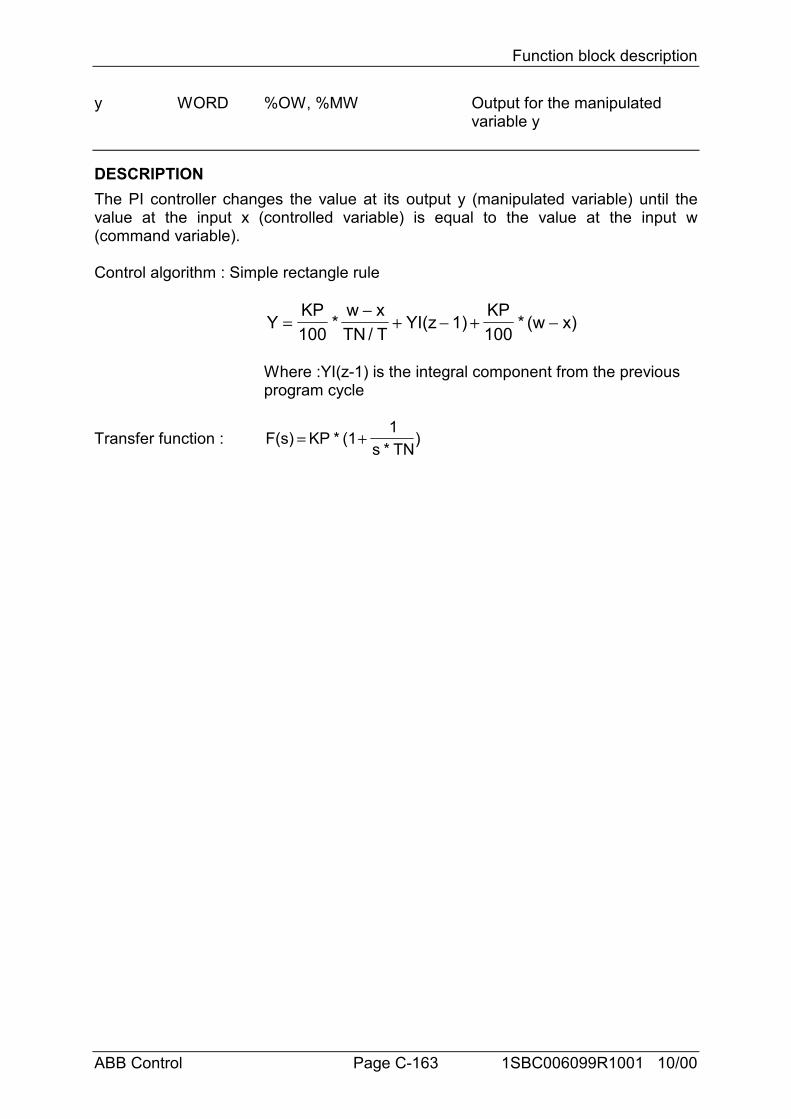
Function block description
ABB Control Page C-163 1SBC006099R1001 10/00
y WORD %OW, %MW Output for the manipulated variable y
DESCRIPTIONThe PI controller changes the value at its output y (manipulated variable) until thevalue at the input x (controlled variable) is equal to the value at the input w(command variable).
Control algorithm : Simple rectangle rule
YKP100
*w xTN / T
YI(z 1)KP100
* (w x)=−
+ − + −
Where :YI(z-1) is the integral component from the previous program cycle
Transfer function : F(s) KP * (11
s * TN)= +
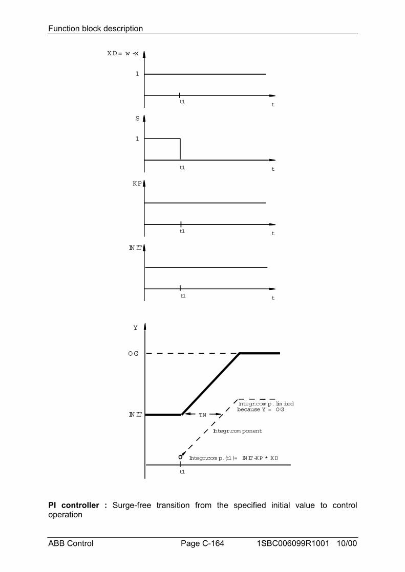
Function block description
ABB Control Page C-164 1SBC006099R1001 10/00
XD= w -x
t
1
Y
OG
INIT TN
S
t
1
KP
t
INIT
t
Integr.com p.(t1)= INIT-KP * XD
Integr.com ponent
t1
t1
t1
t1
t1
Integr.com p. lim itedbecause Y = OG
PI controller : Surge-free transition from the specified initial value to controloperation
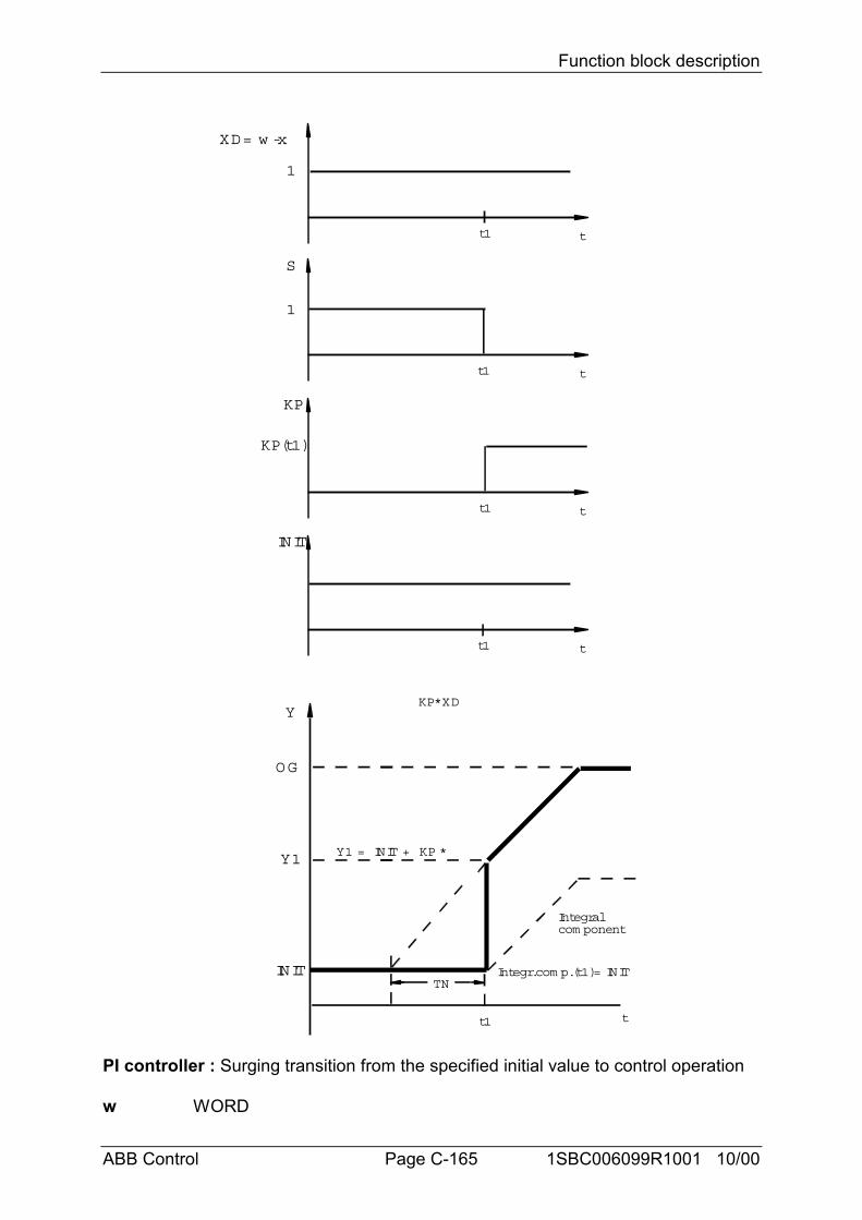
Function block description
ABB Control Page C-165 1SBC006099R1001 10/00
XD= w -x
t
1
Y
OG
t
INITTN
S
t
1
KP
t
KP(t1)
INIT
t
t1
Y1 Y1 = INIT + KP *
KP*XD
t1
t1
t1
t1
Integr.com p.(t1)= INIT
Integralcom ponent
PI controller : Surging transition from the specified initial value to control operation
w WORD
Function block description
ABB Control Page C-166 1SBC006099R1001 10/00
The command variable (setpoint) is specified at the input w.
x WORDThe controlled variable (actual value) is specified at the input x.
KP WORDThe proportional coefficient is specified at the input KP. This value is specified as apercentage and may be positive or negative.Example : 1 = 1 Percent
55 = 55 Percent100 = 100 Percent1000 = 1000 Percent-500 = -500 Percent
• 1 percent means that the block multiplies the system deviation by the factor 0.01(see also control algoritm)• 100 percent means that the block multiplies the system deviation by the factor 1(see also control algoritm)• 1000 percent means that the block multiplies the system deviation by the factor 10(see also control algoritm)Generally, proportional coefficients of more than 1000% are not meaningful in controlsystems.
TN/T WORDThe integral action time TN is scaled to the PLC cycle time T and is specified at theinput TN/T.Value range : 0 < TN/T < 328• If values which are beyond the admissible value range are specified, the PLC usesthe value 328.• A large integral action time TN can be achieved by choosing a great cycle time T,too. If the block is used within a run number block, the cycle time of the run numberblock is valid for block PI and not the cycle time (%KD 0,0) of the PLC program.
Limiting the manipulated variable yOG WORDUG WORDThe output y (manipulated variable) of the controller can be limited- To a maximum value by specifying a limit at the input OG (high limit);- To a minimum value by specifying a limit at the input UG (low limit)The high and low limits also apply to the controller’s internal I component. That is tosay, the I component can only assume values between the high and low limits. If themanipulated variable y reaches one of the two limits, the controller’s I component isno longer altered. This prevents the I component from running amock in the event oflimiting of the controller output y, assuming meaningless values from the point ofview of control and, in certain circumstances, not returning to the operating rangeuntil after a very long time. This response of a controller is also referred to as a“special anti-reset windup measure”.
Setting and resetting the controllerS BINARYINIT WORD
Function block description
ABB Control Page C-167 1SBC006099R1001 10/00
R BINARYSetting the controller to an initial value- The output y of the controller is set to the initial value specified at the INIT input bymeans of a 1 signal at the input S (set).- A 1 signal at the input R (reset) is equivalent to specifying the initial value 0 (seeabove).
Surge-free setting/resetting- The output y of the controller is set to the initial value specified at the input INIT bymeans of a 1 signal at the binary input S (set).- A 1 signal at the input R (reset) is equivalent to specifying the initial value 0.
In doing so, adjustment to the initial value takes place internally in the controller. Thisadjustment is a shift of the controller output from the momentary value to therequired initial value. Now, the controller continues operating from this initial valueprecisely as it would have done at the old operating point before the shift, i.e. withoutsurges. The controller’s I component is defined so that the sum of the P componentand the I component just results in the initial value.
Advantage of surge-free operation :- Control as from the new initial value is devoid of surges.
Disadvantage of surge-free operation :- The following equation applies : I_component = INIT - P_componentIn certain circumstances, the I component is set to high values and may take verylong before this “wrong” I component from the point of view of control is dissipatedagain.
Surging setting/resetting- The output y of the controller is set to the initial value specified at the INIT input bymeans of a 1 signal at the input S (set).- A 1 signal at the input R (reset) is equivalent to specifying the initial value 0.
In the event of surging setting or resetting of the controller the I component is setequal to the initial value. To do this, the P component must be suppressed duringsetting.Where : I component = INITSurging setting to an initial value is achieved by the following measure during setting:- Specifying the value 0 at the input KP.This measure renders the P component inactive. The controller output y assumesthe initial value during the set cycle.
The P component is enabled again after the set cycle. From the initial value, thecontroller output y jumps according to the P component of the controller.
Advantage of surging setting :- The I component is not set to “wrong” values from the point of view of control.
Disadvantage of surging setting :- No freedom from surging
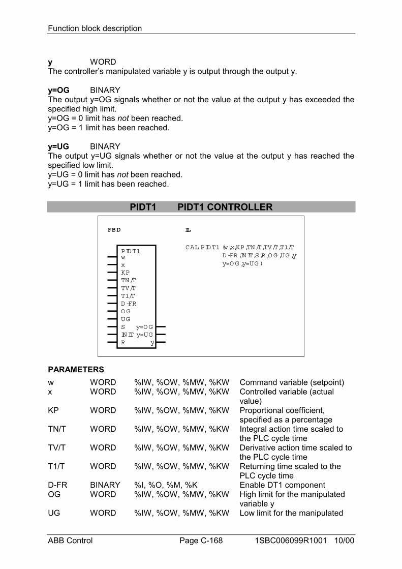
Function block description
ABB Control Page C-168 1SBC006099R1001 10/00
y WORDThe controller’s manipulated variable y is output through the output y.
y=OG BINARYThe output y=OG signals whether or not the value at the output y has exceeded thespecified high limit.y=OG = 0 limit has not been reached.y=OG = 1 limit has been reached.
y=UG BINARYThe output y=UG signals whether or not the value at the output y has reached thespecified low limit.y=UG = 0 limit has not been reached.y=UG = 1 limit has been reached.
PIDT1 PIDT1 CONTROLLER
FBD IL
D-FRO GUGSINITR y
y=O Gy=UG
CAL PIDT1 (w,x,KP,TN/T,TV/T,T1/T D-FR,INIT,S,R,O G ,UG ,y y=O G ,y=UG )x
KPTN/TTV/TT1/T
wPIDT1
PARAMETERSw WORD %IW, %OW, %MW, %KW Command variable (setpoint)x WORD %IW, %OW, %MW, %KW Controlled variable (actual
value)KP WORD %IW, %OW, %MW, %KW Proportional coefficient,
specified as a percentageTN/T WORD %IW, %OW, %MW, %KW Integral action time scaled to
the PLC cycle timeTV/T WORD %IW, %OW, %MW, %KW Derivative action time scaled to
the PLC cycle timeT1/T WORD %IW, %OW, %MW, %KW Returning time scaled to the
PLC cycle timeD-FR BINARY %I, %O, %M, %K Enable DT1 componentOG WORD %IW, %OW, %MW, %KW High limit for the manipulated
variable yUG WORD %IW, %OW, %MW, %KW Low limit for the manipulated
Function block description
ABB Control Page C-169 1SBC006099R1001 10/00
variable yS BINARY %I, %O, %M, %S, %K Enable for setting to initial
value INITINIT WORD %IW, %OW, %MW, %KW Initial value for the manipulated
variable yR BINARY %I, %O, %M, %S, %K Reset the manipulated variable
y to the value 0y=OG BINARY %O, %M High value has been reachedy=UG BINARY %O, %M Low value has been reachedy WORD %OW, %MW Output for manipulated variable
y
DESCRIPTIONThe PI controller changes its output y (manipulated variable) until the input x(controlled variable) is equal to the input w (command variable).
Transfer function : F(s) KP * (11
s * TNs * TV
1 (s * T1))= + +
+
Control algorithm : simple rectangle rule :
( ) ( ) ( ) ( )( )yKP*XD
100KP100
*XD
TN/ TZYI z 1
T1/ TZ1 T1/ TZ
* YDT1z 11
T1/ TZ*TVTZ
*KP100
* XD XD z 1= + + − ++
− + − −
where :YI(z-1) : integral portion from the previous program cycleYDT1(z-1) : differential portion from the previous program cycleXD(z-1) : control system difference from the previous program cycle
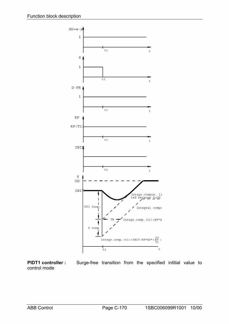
Function block description
ABB Control Page C-170 1SBC006099R1001 10/00
t
t
t
t
t
t
Integr.comp.(t1)+KP*X
Integral compoDT1 Comp.
P Comp
TN
Integr.comp.(t1)=INIT-KP*XD*(1+TV__T1
)
t1
t1
t1
t1
t1
t1
Integr.compon. lited because Y=OG
XD=w-x
S
1
D-FR
1
INIT
KP
KP(T1)
YOG
INIT
1
PIDT1 controller : Surge-free transition from the specified intitial value tocontrol mode
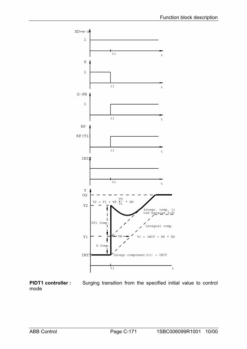
Function block description
ABB Control Page C-171 1SBC006099R1001 10/00
t
t
t
t
t
Y1 = INIT + KP * XD
t
Y2 = Y1 + KP *TV__T1
* XD
t1
Integral comp.DT1 Comp.
P Comp.
TN
t1
t1
t1
Integr.component(t1) = INIT
t1
t1
Integr. comp. lited because Y=OG
XD=w-x
1
YOG
INIT
S
1
D-FR
1
INIT
Y1
KP
KP(T1)
Y2
PIDT1 controller : Surging transition from the specified initial value to controlmode
Function block description
ABB Control Page C-172 1SBC006099R1001 10/00
w WORDThe command variable (setpoint) is specified at the input w.
x WORDThe controlled variable (actual value) is specified at the input x.
KP WORDThe proportional coefficient is specified at the input KP. This value is specified as apercentage and may be positive or negative.Example : 1 = 1 Percent
55 = 55 Percent100 = 100 Percent1000 = 1000 Percent-500 = -500 Percent
• 1 percent means that the block multiplies the system deviation by the factor 0.01(see also control algoritm)• 100 percent means that the block multiplies the system deviation by the factor 1(see also control algoritm)• 1000 percent means that the block multiplies the system deviation by the factor 10(see also control algoritm)Generally, proportional coefficients of more than 1000% are not meaningful in controlsystems.
TN/T WORDThe integral action time TN is scaled to the PLC cycle time T and is specified at theinput TN/T.Value range : 0 < TN/T < 328• If values which are beyond the admissible value range are specified, the PLC usesthe value 328.• A large integral action time TN can be achieved by choosing a great cycle time T,too. If the block is used within a run number block, the cycle time of the run numberblock is valid for block PIDT1 and not the cycle time (%KD 0,0) of the PLC program.
TV/T WORDThe derivative action time TV is scaled to the PLC cycle time T and is specified atthe input TV/T(0 < TV/T < 32767).
T1/T WORDThe returning time T1 is scaled to the PLC cycle time T and is specified at the inputT1/T(0 < T1/T < 32767). The returning time is the time in which the DT1 componenthas decreased to approximately 37% of its initial value.Inadmissible time parameters :Every time value is set to the maximum positive value 32767 if the time value at theinput is erroneously specified as less than or equal to “0”.
D-FR WORDThe DT1 component of the controller can be connected or deactivated by means ofthe D-FR input.D-FR = 0 The DT1 component is deactivated -> pure PI controllerD-FR = 1 The DT1 component is connected -> PIDT1 controller
Function block description
ABB Control Page C-173 1SBC006099R1001 10/00
In the following cases, from the control point of view it is often disturbing and notmeaningful for the DT1 component to be active :- During activations- In the event of large system deviations- When setting the controller to a specified initial value- When resetting the controller to the value 0
The command and controlled variables can be compared outside of the controller.Depending on this comparison, the DT1 component can be activated or deactivatedspecifically by way of the D-FR input.
For example, activation can be restricted to ensuring that the system deviation iswithin a required bandwidth. That is to say, the DT1 component is only active if thecontrolled variable fluctuates around the setpoint within a specific bandwidth. TheDT1 component is deactivated if the controlled variable leaves this tolerance band.
Limiting the maniulated variable yOG WORDUG WORDThe output y (manipulated variable) of the controller can be limited- To a maximum value by specifying a limit at the input OG (high limit);- To a minimum value by specifying a limit at the input UG (low limit)The high and low limits also apply to the controller’s internal I component. That is tosay, the I component can only assume values between the high and low limits. If themanipulated variable y reaches one of the two limits, the controller’s I component isno longer altered.
This prevents the I component from running amock in the event of limiting of thecontroller output y, assuming meaningless values from the point of view of controland, in certain circumstances, not returning to the operating range until after a verylong time. This response of a controller is also referred to as a “special anti-resetwindup measure (ARW)”.
Setting and resetting the controllerS BINARYINIT WORDR BINARYSetting the controller to an initial value- The output y of the controller is set to the initial value specified at the INIT input bymeans of a 1 signal at the input S (set).- A 1 signal at the input R (reset) is equivalent to specifying the initial value 0 (seeabove).
Surge-free setting/resetting- The output y of the controller is set to the initial value specified at the input INIT bymeans of a 1 signal at the binary input S (set).- A 1 signal at the input R (reset) is equivalent to specifying the initial value 0.In doing so, adjustment to the initial value takes place internally in the controller. Thisadjustment is a shift of the controller output from the momentary value to the
Function block description
ABB Control Page C-174 1SBC006099R1001 10/00
required initial value. Now, the controller continues operating from this initial valueprecisely as it would have done at the old operating point before the shift, i.e. withoutsurges. The controller’s I component is defined so that the sum of the P component,I component and DT1 component just results in the initial value.
Advantage of surge-free operation :- Control as from the new initial value is devoid of surges.
Disadvantage of surge-free operation :- The following equation applies :
I component = INIT - P component - DT1 componentIn certain circumstances, the I component is set to high values and may take verylong before this “wrong” I component from the point of view of control is dissipatedagain.
Surging setting/resetting- The output y of the controller is set to the initial value specified at the INIT input bymeans of a 1 signal at the input S (set).- A 1 signal at the input R (reset) is equivalent to specifying the initial value 0.- In the event of surging setting or resetting of the controller, the I component is setequal to the initial value. To do this, the P and DT1 components must be suppressedduring setting.Where : I component = INIT
Surging setting to an initial value is achieved by the following measures duringsetting :- Deactivation of the DT1 component via the D-FR control input and- Specifying the value 0 at the input KP.These measures render the P component and the DT1 component inactive duringsetting of the controller.The controller output assumes the initial value during the set cycle.The P and DT1 components are enabled again after the set cycle. From the initialvalue, the controller output y jumps according to the P and DT1 components of thecontroller.
Advantage of surging setting :- The I component is not set to “wrong” values from the point of view of control.
Disadvantage of surging setting :- No freedom from surging
y WORDThe controller’s manipulated variable y is output through the output y.
y=OG BINARYThe output y=OG signals whether or not the value at the output y has reached thespecified high limit.y=OG = 0 limit has not been reached.y=OG = 1 limit has been reached.
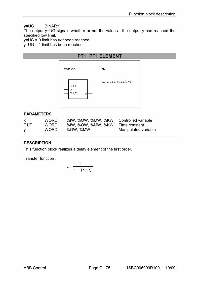
Function block description
ABB Control Page C-175 1SBC006099R1001 10/00
y=UG BINARYThe output y=UG signals whether or not the value at the output y has reached thespecified low limit.y=UG = 0 limit has not been reached.y=UG = 1 limit has been reached.
PT1 PT1 ELEMENT
FBD/LD IL
PT1xT1/T y
CAL PT1 (x,T1/T,y)
PARAMETERSx WORD %IW, %OW, %MW, %KW Controlled variableT1/T WORD %IW, %OW, %MW, %KW Time constanty WORD %OW, %MW Manipulated variable
DESCRIPTIONThis function block realizes a delay element of the first order.
Transfer function :
F =1
1 + T1 * S
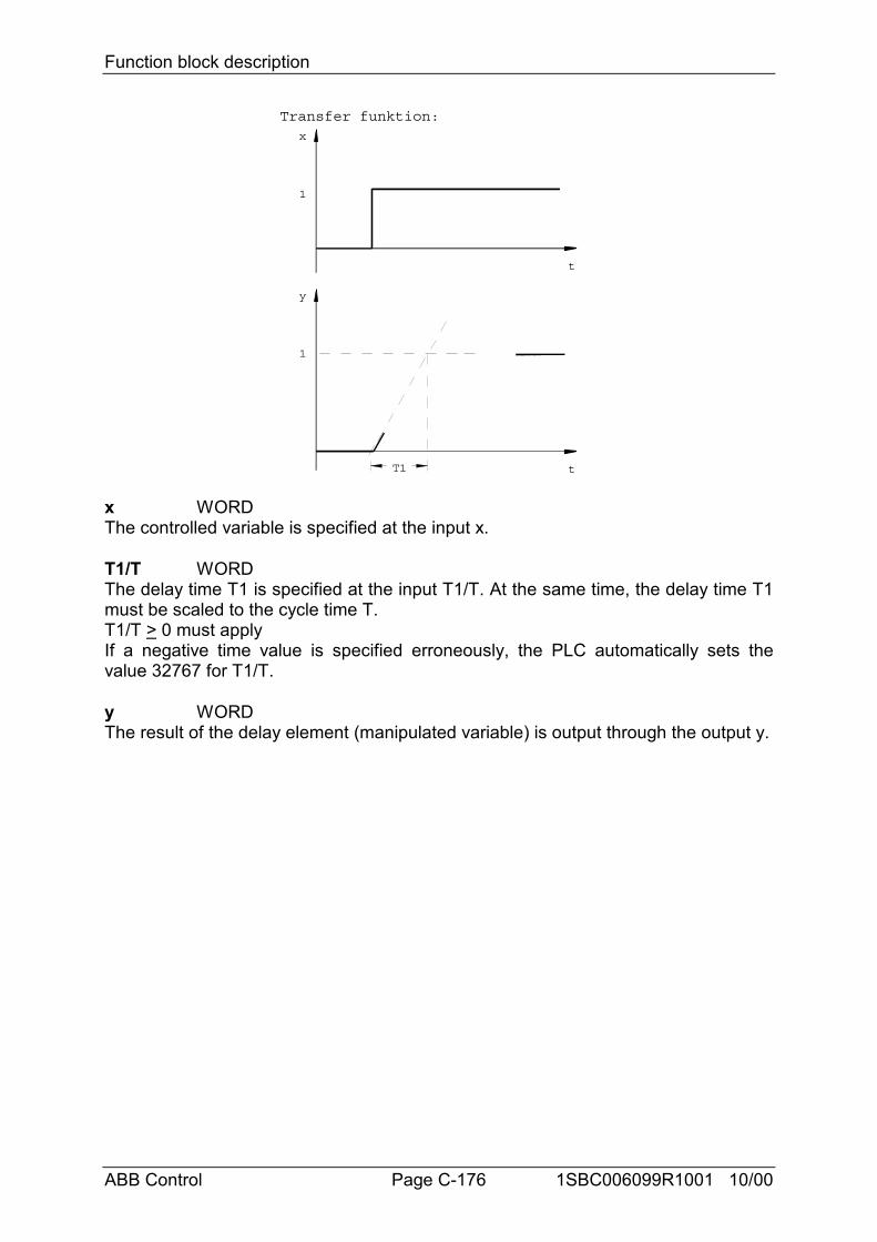
Function block description
ABB Control Page C-176 1SBC006099R1001 10/00
x
t
1
y
t
1
T1
Transfer funktion:
x WORDThe controlled variable is specified at the input x.
T1/T WORDThe delay time T1 is specified at the input T1/T. At the same time, the delay time T1must be scaled to the cycle time T.T1/T > 0 must applyIf a negative time value is specified erroneously, the PLC automatically sets thevalue 32767 for T1/T.
y WORDThe result of the delay element (manipulated variable) is output through the output y.
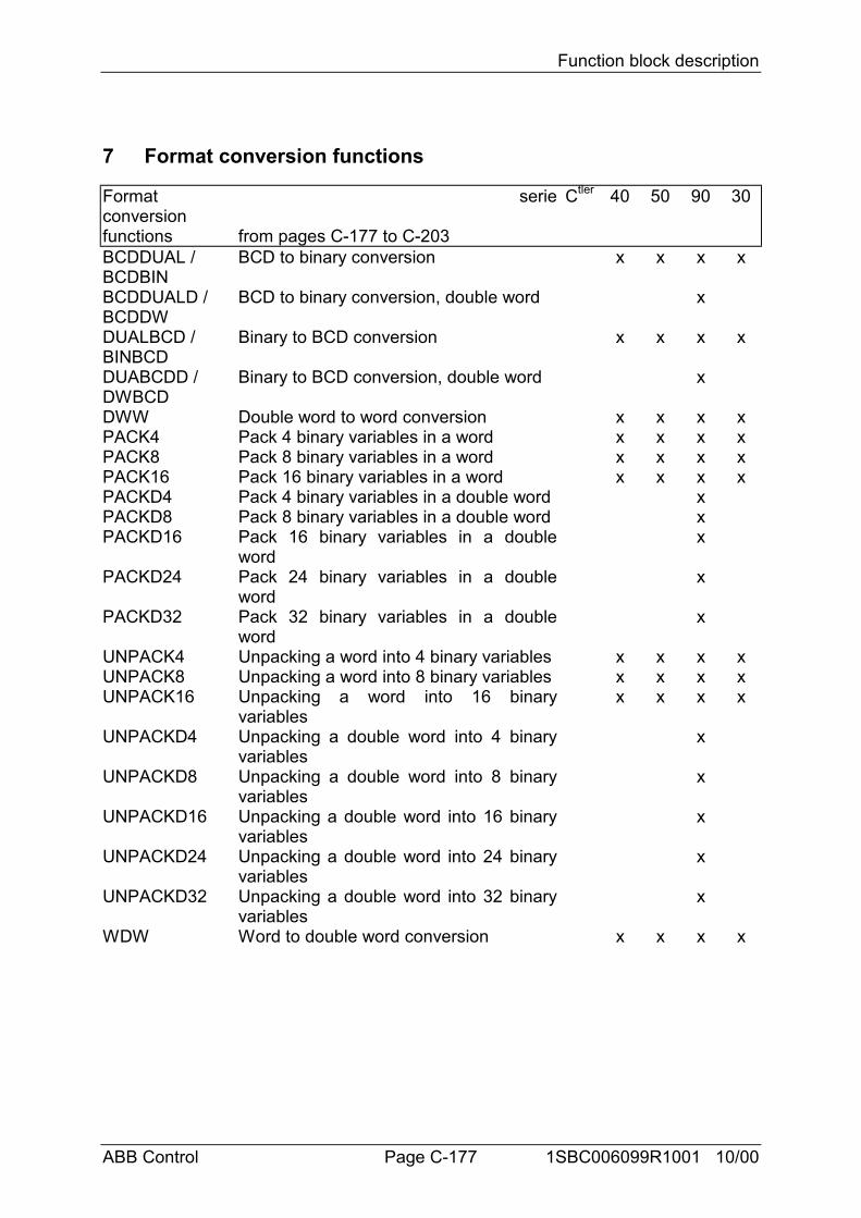
Function block description
ABB Control Page C-177 1SBC006099R1001 10/00
7 Format conversion functions
Formatconversionfunctions
serie
from pages C-177 to C-203
Ctler 40 50 90 30
BCDDUAL /BCDBIN
BCD to binary conversion x x x x
BCDDUALD /BCDDW
BCD to binary conversion, double word x
DUALBCD /BINBCD
Binary to BCD conversion x x x x
DUABCDD /DWBCD
Binary to BCD conversion, double word x
DWW Double word to word conversion x x x xPACK4 Pack 4 binary variables in a word x x x xPACK8 Pack 8 binary variables in a word x x x xPACK16 Pack 16 binary variables in a word x x x xPACKD4 Pack 4 binary variables in a double word xPACKD8 Pack 8 binary variables in a double word xPACKD16 Pack 16 binary variables in a double
wordx
PACKD24 Pack 24 binary variables in a doubleword
x
PACKD32 Pack 32 binary variables in a doubleword
x
UNPACK4 Unpacking a word into 4 binary variables x x x xUNPACK8 Unpacking a word into 8 binary variables x x x xUNPACK16 Unpacking a word into 16 binary
variablesx x x x
UNPACKD4 Unpacking a double word into 4 binaryvariables
x
UNPACKD8 Unpacking a double word into 8 binaryvariables
x
UNPACKD16 Unpacking a double word into 16 binaryvariables
x
UNPACKD24 Unpacking a double word into 24 binaryvariables
x
UNPACKD32 Unpacking a double word into 32 binaryvariables
x
WDW Word to double word conversion x x x x
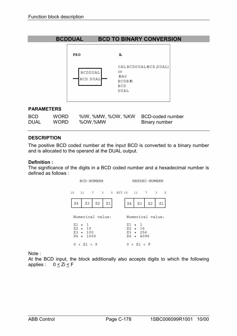
Function block description
ABB Control Page C-178 1SBC006099R1001 10/00
BCDDUAL BCD TO BINARY CONVERSION
FBD IL
BCDDUAL
CAL BCDDUAL(BCD,DUAL)or!BA0BCDBINBCDDUAL
BCD DUAL
PARAMETERSBCD WORD %IW, %MW, %OW, %KW BCD-coded numberDUAL WORD %OW,%MW Binary number
DESCRIPTIONThe positive BCD coded number at the input BCD is converted to a binary numberand is allocated to the operand at the DUAL output.
Definition :The significance of the digits in a BCD coded number and a hexadecimal number isdefined as follows :
BCD-NUMBER HEXDEC-NUMBER
Z4 Z3 Z2 Z1 Z4 Z3 Z2 Z1
15 11 7 3 0 BIT 15 11 7 3 0
Numerical value:
Z1Z2Z3Z4
Numerical value:
Z1Z2Z3Z4
1101001000
1162564096
****
****
0 < Zi < 9 0 < Zi < F
Note :At the BCD input, the block additionally also accepts digits to which the followingapplies : 0 < Zi < F
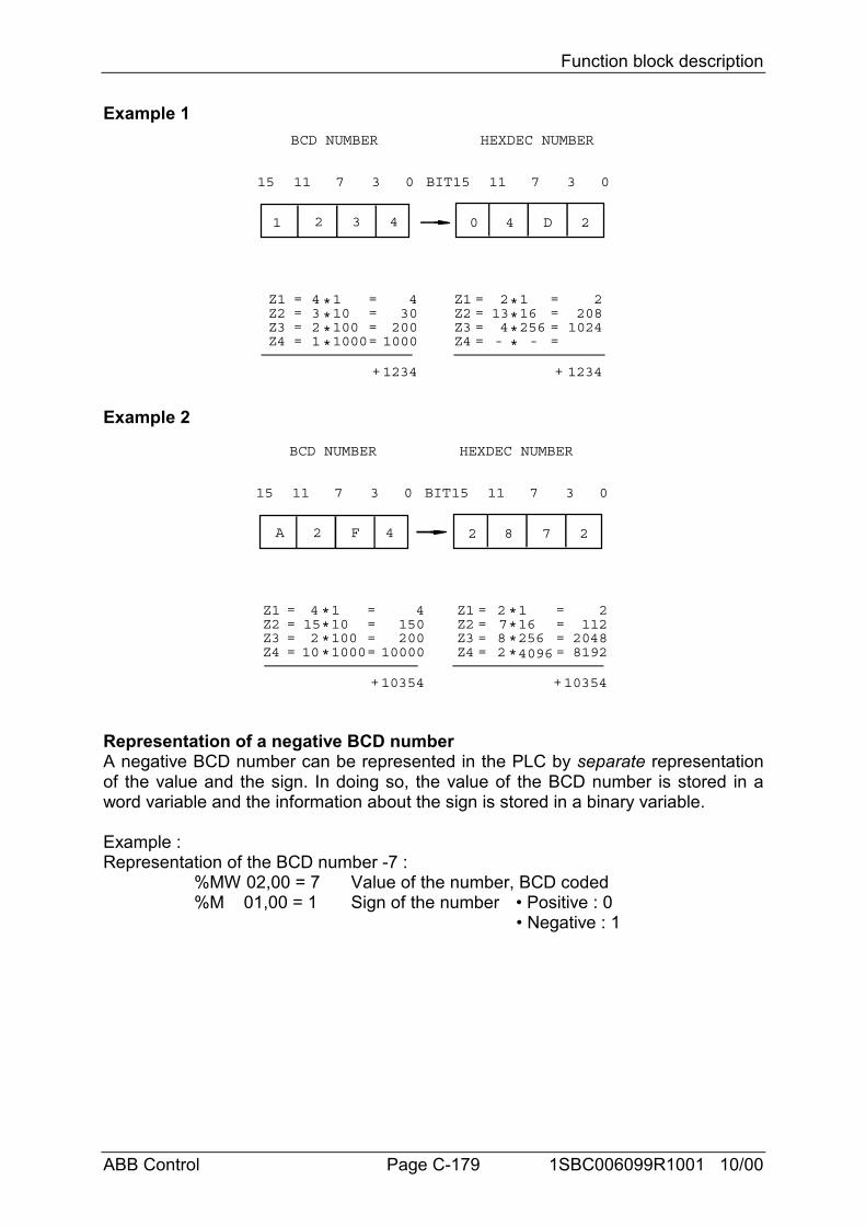
Function block description
ABB Control Page C-179 1SBC006099R1001 10/00
Example 1BCD NUMBER HEXDEC NUMBER
1 2 3 4 0 4 D 2
15 11 7 3 0 BIT15 11 7 3 0
Z1Z2Z3Z4
Z1Z2Z3Z4
1101001000
116256
====
430
2001000
1234+ 1234+
====
22081024
--
4321
====
====
2134
****
****
Example 2
BCD NUMBER HEXDEC NUMBER
A 2 F 4 2 8 7 2
15 11 7 3 0 BIT15 11 7 3 0
10354+ 10354+
Z1Z2Z3Z4
Z1Z2Z3Z4
1101001000
116256
====
4150200
10000
====
2112
2048
415210
====
====
2782 4096 8192
****
****
Representation of a negative BCD numberA negative BCD number can be represented in the PLC by separate representationof the value and the sign. In doing so, the value of the BCD number is stored in aword variable and the information about the sign is stored in a binary variable.
Example :Representation of the BCD number -7 :
%MW 02,00 = 7 Value of the number, BCD coded%M 01,00 = 1 Sign of the number • Positive : 0
• Negative : 1
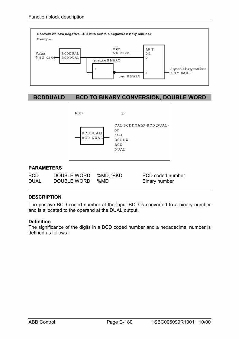
Function block description
ABB Control Page C-180 1SBC006099R1001 10/00
BCDDUALBCD DUAL
Value% M W 02,00
=
AW T0/10
1 % M W 02,01
Sign% M 01,00
Signed binary num ber
positive BINARY
neg. BINARY
Exam ple:
Conversion of a negative BCD num ber to a negative binary num ber
BCDDUALD BCD TO BINARY CONVERSION, DOUBLE WORD
FBD IL
BCDDUALD
CAL BCDDUALD(BCD,DUAL)or!BA0BCDDWBCDDUAL
BCD DUAL
PARAMETERSBCD DOUBLE WORD %MD, %KD BCD coded numberDUAL DOUBLE WORD %MD Binary number
DESCRIPTIONThe positive BCD coded number at the input BCD is converted to a binary numberand is allocated to the operand at the DUAL output.
DefinitionThe significance of the digits in a BCD coded number and a hexadecimal number isdefined as follows :
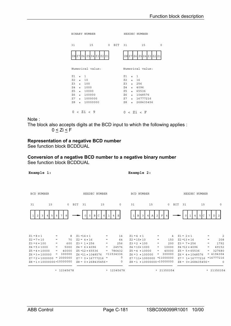
Function block description
ABB Control Page C-181 1SBC006099R1001 10/00
BINARY NUMBER HEXDEC NUMBER
31 15 0 BIT 31 15 0
Numerical value:
Z1Z2Z3Z4
Numerical value:
Z1Z2Z3Z4
1101001000
1162564096
****
****
Z5Z6Z7Z8
****
10000100000100000010000000
Z5Z6Z7Z8
****
65536104857616777216268435456
Z8 Z7 Z6 Z5 Z4 Z3 Z2 Z1 Z8 Z7 Z6 Z5 Z4 Z3 Z2 Z1
0 < Zi < 9 0 < Zi < F
Note :The block also accepts digits at the BCD input to which the following applies :
0 < Zi < F
Representation of a negative BCD numberSee function block BCDDUAL
Conversion of a negative BCD number to a negative binary numberSee function block BCDDUAL
BCD NUMBER HEXDEC NUMBER
Z1Z2Z3Z4
1101001000
====
8
12345678+ 12345678+
8 ====
****
31 15 0 BIT 31 15 0
1 2 3 4 5 6 7 8 0 0 B C 6 1 4 E
Z5Z6Z7Z8
====
7654321
****
10000100000100000010000000
===
=
70600
500040000
3000002000000
10000000
Z1Z2Z3Z4
1162564096
====
1414 ====
****
Z5Z6Z7Z8
====
416
1211
****
65536104857616777216268435456
===
=
64256
24576786432
11534336
BCD NUMBER HEXDEC NUMBER
Z1Z2Z3Z4
1101001000
====
4
21350354+ 21350354+
4 ====
****
31 15 0 BIT 31 15 0
1 B 3 4 A 2 F 4 0 1 4 5 C 7 D 2
Z5Z6Z7Z8
====
1521043111
****
10000100000100000010000000
===
=
150200
1000040000300000
1100000010000000
Z1Z2Z3Z4
1162564096
====
22 ====
****
Z5Z6Z7Z8
====
137
1254****
65536104857616777216268435456
===
=
208179249152
3276804194304
1 16777216
Example 1: Example 2:
00 0 0
0
0
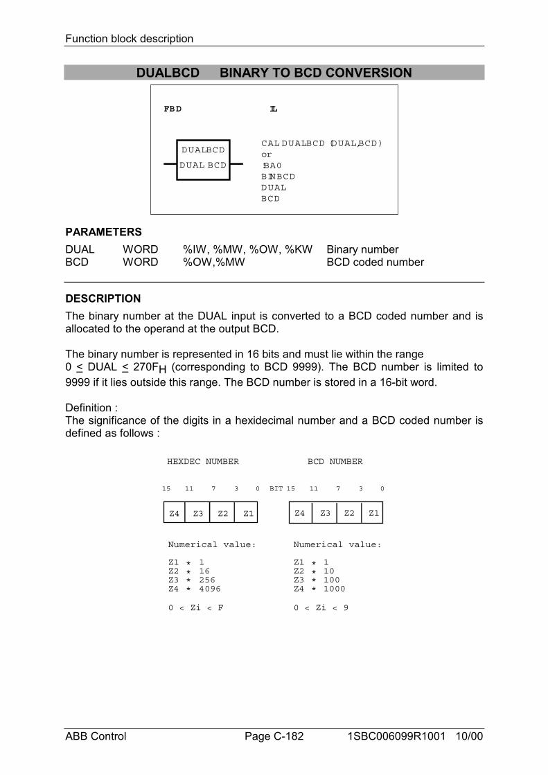
Function block description
ABB Control Page C-182 1SBC006099R1001 10/00
DUALBCD BINARY TO BCD CONVERSION
FBD IL
DUALBCDCAL DUALBCD (DUAL,BCD)or!BA0BINBCDDUALBCD
DUAL BCD
PARAMETERSDUAL WORD %IW, %MW, %OW, %KW Binary numberBCD WORD %OW,%MW BCD coded number
DESCRIPTIONThe binary number at the DUAL input is converted to a BCD coded number and isallocated to the operand at the output BCD.
The binary number is represented in 16 bits and must lie within the range0 < DUAL < 270FH (corresponding to BCD 9999). The BCD number is limited to9999 if it lies outside this range. The BCD number is stored in a 16-bit word.
Definition :The significance of the digits in a hexidecimal number and a BCD coded number isdefined as follows :
BCD NUMBERHEXDEC NUMBER
Z4 Z3 Z2 Z1Z4 Z3 Z2 Z1
15 11 7 3 0BIT15 11 7 3 0
Numerical value:
Z1Z2Z3Z4
Numerical value:
Z1Z2Z3Z4
1101001000
1162564096
****
****
0 < Zi < F 0 < Zi < 9
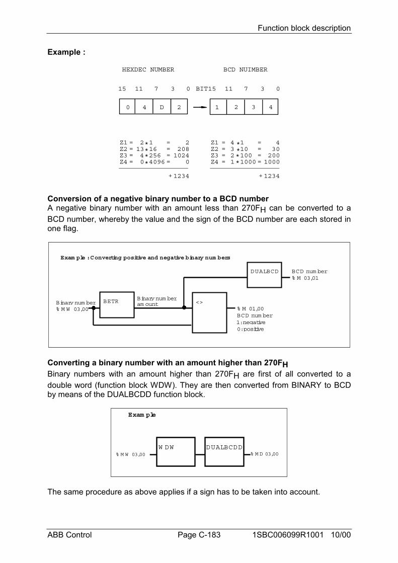
Function block description
ABB Control Page C-183 1SBC006099R1001 10/00
Example :
BCD NUIMBERHEXDEC NUMBER
1 2 3 40 4 D 2
15 11 7 3 0BIT15 11 7 3 0
Z1Z2Z3Z4
Z1Z2Z3Z4
1101001000
116256
====
430200
1000
1234+ 1234+
====
22081024
0
4321
====
====
2134
***
***
* *4096 0
Conversion of a negative binary number to a BCD numberA negative binary number with an amount less than 270FH can be converted to aBCD number, whereby the value and the sign of the BCD number are each stored inone flag.
Exam ple : Converting positive and negative binary num bers
BETRBinary num ber% M W 03,00
Binary num ber<>
DUALBCD% M 03,01BCD num ber
% M 01,00
1: negative0: positive
BCD num ber
am ount
Converting a binary number with an amount higher than 270FHBinary numbers with an amount higher than 270FH are first of all converted to adouble word (function block WDW). They are then converted from BINARY to BCDby means of the DUALBCDD function block.
Exam ple
W DW DUALBCDD% M W 03,00 % M D 03,00
The same procedure as above applies if a sign has to be taken into account.
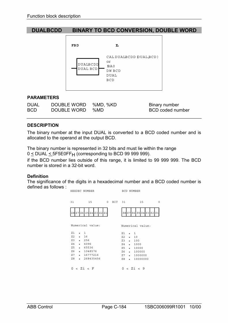
Function block description
ABB Control Page C-184 1SBC006099R1001 10/00
DUALBCDD BINARY TO BCD CONVERSION, DOUBLE WORD
FBD IL
DUALBCDD
CAL DUALBCDD(DUAL,BCD)or!BA0DW BCDDUALBCD
DUAL BCD
PARAMETERSDUAL DOUBLE WORD %MD, %KD Binary numberBCD DOUBLE WORD %MD BCD coded number
DESCRIPTIONThe binary number at the input DUAL is converted to a BCD coded number and isallocated to the operand at the output BCD.
The binary number is represented in 32 bits and must lie within the range0 < DUAL < 5F5E0FFH (corresponding to BCD 99 999 999).if the BCD number lies outside of this range, it is limited to 99 999 999. The BCDnumber is stored in a 32-bit word.
DefinitionThe significance of the digits in a hexadecimal number and a BCD coded number isdefined as follows :
BCD NUMBERHEXDEC NUMBER
31 15 0 BIT 31 15 0
Numerical value:
Z1Z2Z3Z4
Numerical value:
Z1Z2Z3Z4
1101001000
1162564096
****
****
Z5Z6Z7Z8
****
10000100000100000010000000
Z5Z6Z7Z8
****
65536104857616777216268435456
Z8 Z7 Z6 Z5 Z4 Z3 Z2 Z1 Z8 Z7 Z6 Z5 Z4 Z3 Z2 Z1
0 < Zi < F 0 < Zi < 9
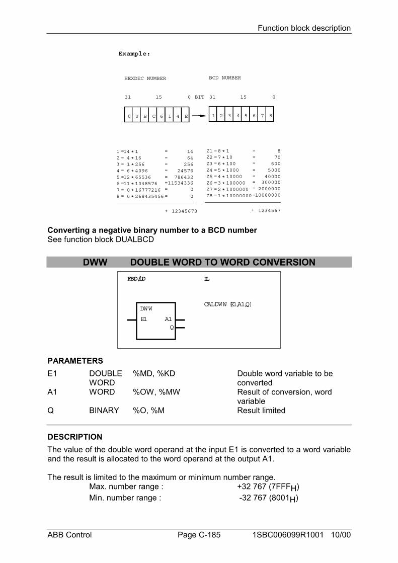
Function block description
ABB Control Page C-185 1SBC006099R1001 10/00
BCD NUMBERHEXDEC NUMBER
Z1Z2Z3Z4
1101001000
====
8
12345678+ 12345678+
8 ====
****
31 15 0BIT31 15 0
1 2 3 4 5 6 7 80 0 B C 6 1 4 E
Z5Z6Z7Z8
====
7654321
****
10000100000100000010000000
====
70600
500040000
3000002000000
10000000
1234
1162564096
====
1414 ====
****
5678
====
416
1211
****
65536104857616777216268435456
====
64256
24576786432
11534336
Example:
00
00
Converting a negative binary number to a BCD numberSee function block DUALBCD
DWW DOUBLE WORD TO WORD CONVERSIONFBD/LD IL
DWW
Q
CAL DWW (E1,A1,Q)
E1 A1
PARAMETERSE1 DOUBLE %MD, %KD Double word variable to be
WORD convertedA1 WORD %OW, %MW Result of conversion, word
variableQ BINARY %O, %M Result limited
DESCRIPTIONThe value of the double word operand at the input E1 is converted to a word variableand the result is allocated to the word operand at the output A1.
The result is limited to the maximum or minimum number range.Max. number range : +32 767 (7FFFH)Min. number range : -32 767 (8001H)
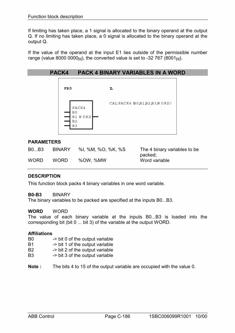
Function block description
ABB Control Page C-186 1SBC006099R1001 10/00
If limiting has taken place, a 1 signal is allocated to the binary operand at the outputQ. If no limiting has taken place, a 0 signal is allocated to the binary operand at theoutput Q.
If the value of the operand at the input E1 lies outside of the permissible numberrange (value 8000 0000H), the converted value is set to -32 767 (8001H).
PACK4 PACK 4 BINARY VARIABLES IN A WORD
FBD IL
PACK4B0B1 W O RD
CAL PACK4 (B0,B1,B2,B3,W O RD)
B2B3
PARAMETERSB0...B3 BINARY %I, %M, %O, %K, %S The 4 binary variables to be
packed;WORD WORD %OW, %MW Word variable
DESCRIPTIONThis function block packs 4 binary variables in one word variable.
B0-B3 BINARYThe binary variables to be packed are specified at the inputs B0...B3.
WORD WORDThe value of each binary variable at the inputs B0...B3 is loaded into thecorresponding bit (bit 0 ... bit 3) of the variable at the output WORD.
AffiliationsB0 -> bit 0 of the output variableB1 -> bit 1 of the output variableB2 -> bit 2 of the output variableB3 -> bit 3 of the output variable
Note : The bits 4 to 15 of the output variable are occupied with the value 0.
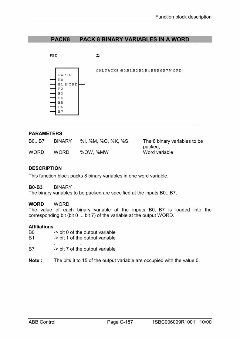
Function block description
ABB Control Page C-187 1SBC006099R1001 10/00
PACK8 PACK 8 BINARY VARIABLES IN A WORD
FBD IL
PACK8
W O RD
CAL PACK8 (B0,B1,B2,B3,B4,B5,B6,B7,W O RD)
B0B1B2B3B4B5B6B7
PARAMETERSB0...B7 BINARY %I, %M, %O, %K, %S The 8 binary variables to be
packed;WORD WORD %OW, %MW Word variable
DESCRIPTIONThis function block packs 8 binary variables in one word variable.
B0-B3 BINARYThe binary variables to be packed are specified at the inputs B0...B7.
WORD WORDThe value of each binary variable at the inputs B0...B7 is loaded into thecorresponding bit (bit 0 ... bit 7) of the variable at the output WORD.
AffiliationsB0 -> bit 0 of the output variableB1 -> bit 1 of the output variable. . . .B7 -> bit 7 of the output variable
Note : The bits 8 to 15 of the output variable are occupied with the value 0.
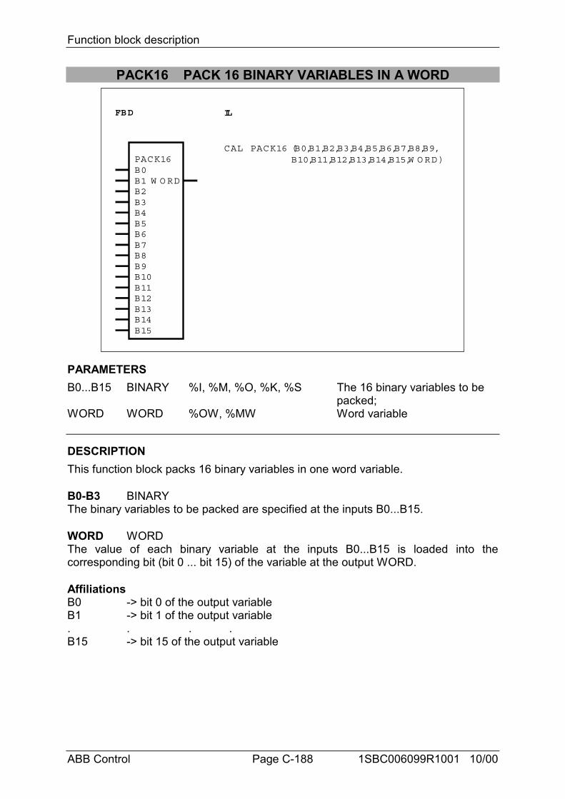
Function block description
ABB Control Page C-188 1SBC006099R1001 10/00
PACK16 PACK 16 BINARY VARIABLES IN A WORD
FBD IL
PACK16
W O RD
CAL PACK16 (B0,B1,B2,B3,B4,B5,B6,B7,B8,B9,B10,B11,B12,B13,B14,B15,W O RD)
B0B1B2B3B4B5B6B7B8B9B10B11B12B13B14B15
PARAMETERSB0...B15 BINARY %I, %M, %O, %K, %S The 16 binary variables to be
packed;WORD WORD %OW, %MW Word variable
DESCRIPTIONThis function block packs 16 binary variables in one word variable.
B0-B3 BINARYThe binary variables to be packed are specified at the inputs B0...B15.
WORD WORDThe value of each binary variable at the inputs B0...B15 is loaded into thecorresponding bit (bit 0 ... bit 15) of the variable at the output WORD.
AffiliationsB0 -> bit 0 of the output variableB1 -> bit 1 of the output variable. . . .B15 -> bit 15 of the output variable
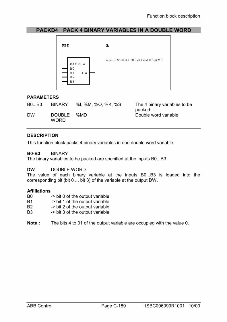
Function block description
ABB Control Page C-189 1SBC006099R1001 10/00
PACKD4 PACK 4 BINARY VARIABLES IN A DOUBLE WORD
FBD IL
PACKD4B0B1 DW
CAL PACKD4 (B0,B1,B2,B3,DW )
B2B3
PARAMETERSB0...B3 BINARY %I, %M, %O, %K, %S The 4 binary variables to be
packed;DW DOUBLE %MD Double word variable
WORD
DESCRIPTIONThis function block packs 4 binary variables in one double word variable.
B0-B3 BINARYThe binary variables to be packed are specified at the inputs B0...B3.
DW DOUBLE WORDThe value of each binary variable at the inputs B0...B3 is loaded into thecorresponding bit (bit 0 ... bit 3) of the variable at the output DW.
AffiliationsB0 -> bit 0 of the output variableB1 -> bit 1 of the output variableB2 -> bit 2 of the output variableB3 -> bit 3 of the output variable
Note : The bits 4 to 31 of the output variable are occupied with the value 0.
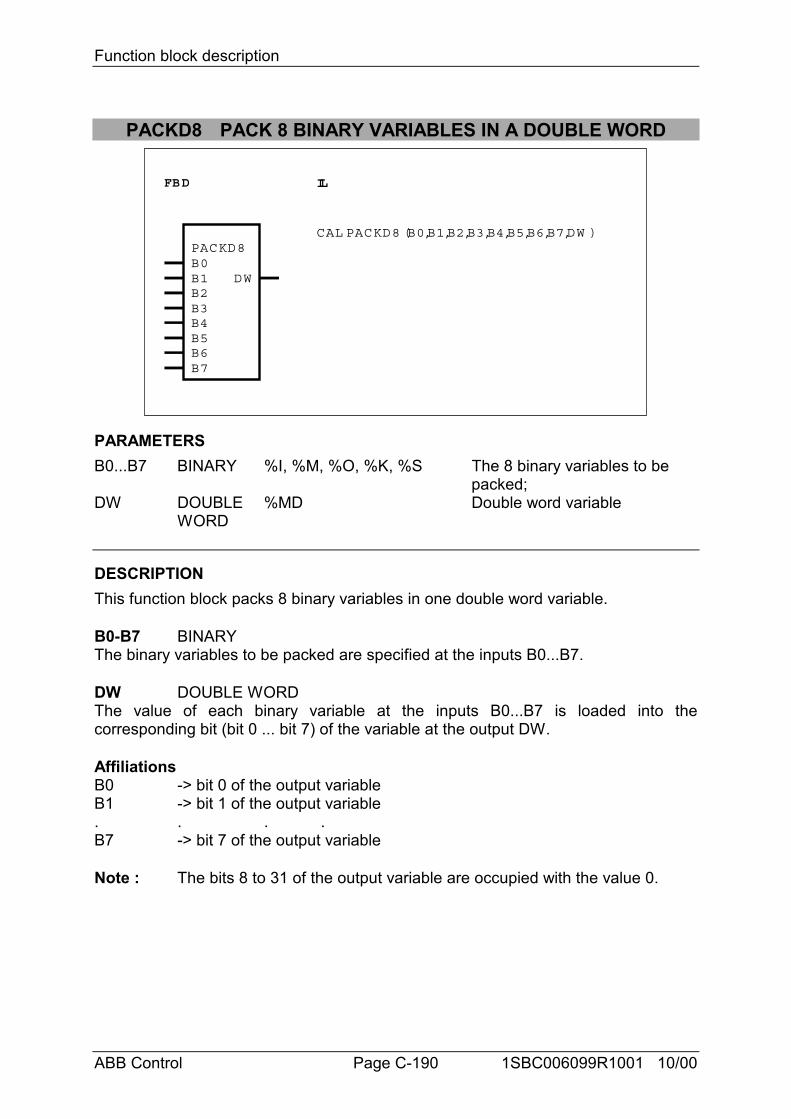
Function block description
ABB Control Page C-190 1SBC006099R1001 10/00
PACKD8 PACK 8 BINARY VARIABLES IN A DOUBLE WORD
FBD IL
PACKD8
DW
CAL PACKD8 (B0,B1,B2,B3,B4,B5,B6,B7,DW )
B0B1B2B3B4B5B6B7
PARAMETERSB0...B7 BINARY %I, %M, %O, %K, %S The 8 binary variables to be
packed;DW DOUBLE %MD Double word variable
WORD
DESCRIPTIONThis function block packs 8 binary variables in one double word variable.
B0-B7 BINARYThe binary variables to be packed are specified at the inputs B0...B7.
DW DOUBLE WORDThe value of each binary variable at the inputs B0...B7 is loaded into thecorresponding bit (bit 0 ... bit 7) of the variable at the output DW.
AffiliationsB0 -> bit 0 of the output variableB1 -> bit 1 of the output variable. . . .B7 -> bit 7 of the output variable
Note : The bits 8 to 31 of the output variable are occupied with the value 0.
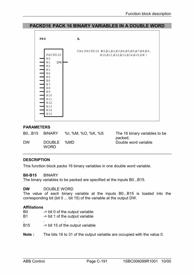
Function block description
ABB Control Page C-191 1SBC006099R1001 10/00
PACKD16 PACK 16 BINARY VARIABLES IN A DOUBLE WORD
FBD IL
PACKD16
DW
CAL PACKD16 (B0,B1,B2,B3,B4,B5,B6,B7,B8,B9,B10,B11,B12,B13,B14,B15,DW )
B0B1B2B3B4B5B6B7B8B9B10B11B12B13B14B15
PARAMETERSB0...B15 BINARY %I, %M, %O, %K, %S The 16 binary variables to be
packed;DW DOUBLE %MD Double word variable
WORD
DESCRIPTIONThis function block packs 16 binary variables in one double word variable.
B0-B15 BINARYThe binary variables to be packed are specified at the inputs B0...B15.
DW DOUBLE WORDThe value of each binary variable at the inputs B0...B15 is loaded into thecorresponding bit (bit 0 ... bit 15) of the variable at the output DW.
AffiliationsB0 -> bit 0 of the output variableB1 -> bit 1 of the output variable. . . .B15 -> bit 15 of the output variable
Note : The bits 16 to 31 of the output variable are occupied with the value 0.
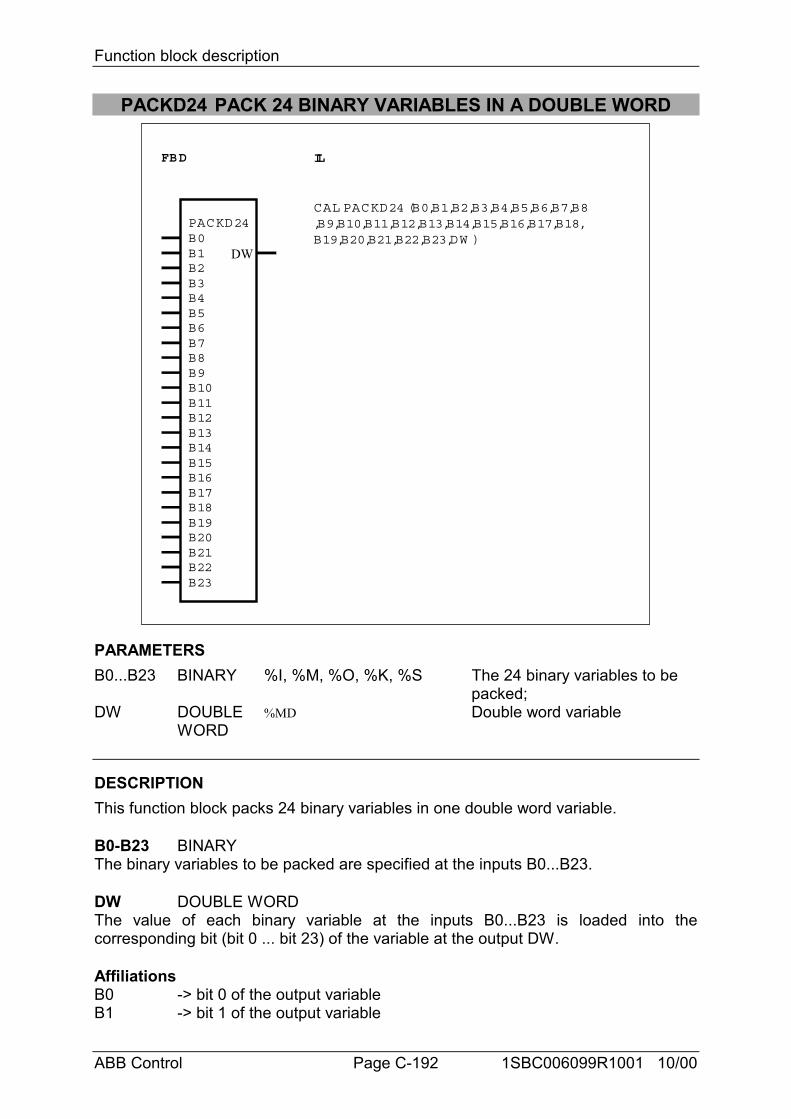
Function block description
ABB Control Page C-192 1SBC006099R1001 10/00
PACKD24 PACK 24 BINARY VARIABLES IN A DOUBLE WORD
FBD IL
PACKD24
DW
CAL PACKD24 (B0,B1,B2,B3,B4,B5,B6,B7,B8,B9,B10,B11,B12,B13,B14,B15,B16,B17,B18,B19,B20,B21,B22,B23,DW )B0
B1B2B3B4B5B6B7B8B9B10B11B12B13B14B15B16B17B18B19B20B21B22B23
PARAMETERSB0...B23 BINARY %I, %M, %O, %K, %S The 24 binary variables to be
packed;DW DOUBLE %MD Double word variable
WORD
DESCRIPTIONThis function block packs 24 binary variables in one double word variable.
B0-B23 BINARYThe binary variables to be packed are specified at the inputs B0...B23.
DW DOUBLE WORDThe value of each binary variable at the inputs B0...B23 is loaded into thecorresponding bit (bit 0 ... bit 23) of the variable at the output DW.
AffiliationsB0 -> bit 0 of the output variableB1 -> bit 1 of the output variable
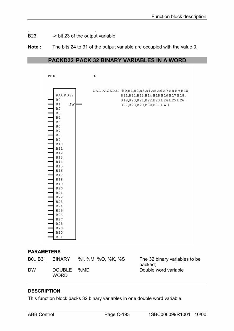
Function block description
ABB Control Page C-193 1SBC006099R1001 10/00
. . . .B23 -> bit 23 of the output variable
Note : The bits 24 to 31 of the output variable are occupied with the value 0.
PACKD32 PACK 32 BINARY VARIABLES IN A WORD
FBD IL
PACKD32
DW
CAL PACKD32 (B0,B1,B2,B3,B4,B5,B6,B7,B8,B9,B10,B11,B12,B13,B14,B15,B16,B17,B18,B19,B20,B21,B22,B23,B24,B25,B26,B27,B28,B29,B30,B31,DW )
B0B1B2B3B4B5B6B7B8B9B10B11B12B13B14B15B16B17B18B19B20B21B22B23B24B25B26B27B28B29B30B31
PARAMETERSB0...B31 BINARY %I, %M, %O, %K, %S The 32 binary variables to be
packed;DW DOUBLE %MD Double word variable
WORD
DESCRIPTIONThis function block packs 32 binary variables in one double word variable.
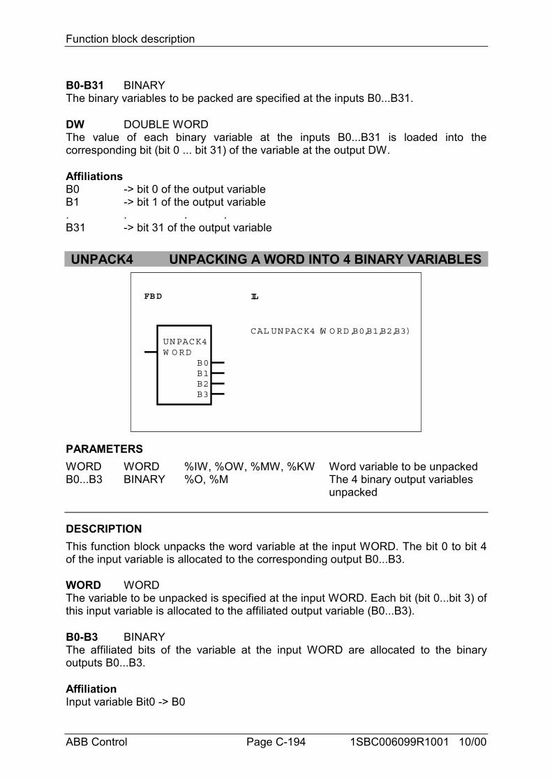
Function block description
ABB Control Page C-194 1SBC006099R1001 10/00
B0-B31 BINARYThe binary variables to be packed are specified at the inputs B0...B31.
DW DOUBLE WORDThe value of each binary variable at the inputs B0...B31 is loaded into thecorresponding bit (bit 0 ... bit 31) of the variable at the output DW.
AffiliationsB0 -> bit 0 of the output variableB1 -> bit 1 of the output variable. . . .B31 -> bit 31 of the output variable
UNPACK4 UNPACKING A WORD INTO 4 BINARY VARIABLES
FBD IL
UNPACK4W O RD
B0
CAL UNPACK4 (W O RD,B0,B1,B2,B3)
B1B2B3
PARAMETERSWORD WORD %IW, %OW, %MW, %KW Word variable to be unpackedB0...B3 BINARY %O, %M The 4 binary output variables
unpacked
DESCRIPTIONThis function block unpacks the word variable at the input WORD. The bit 0 to bit 4of the input variable is allocated to the corresponding output B0...B3.
WORD WORDThe variable to be unpacked is specified at the input WORD. Each bit (bit 0...bit 3) ofthis input variable is allocated to the affiliated output variable (B0...B3).
B0-B3 BINARYThe affiliated bits of the variable at the input WORD are allocated to the binaryoutputs B0...B3.
AffiliationInput variable Bit0 -> B0
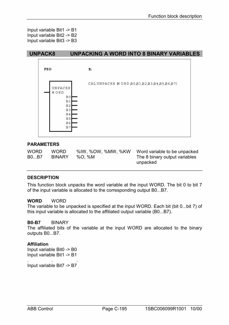
Function block description
ABB Control Page C-195 1SBC006099R1001 10/00
Input variable Bit1 -> B1Input variable Bit2 -> B2Input variable Bit3 -> B3
UNPACK8 UNPACKING A WORD INTO 8 BINARY VARIABLES
FBD IL
UNPACK8W O RD
CAL UNPACK8 (W O RD,B0,B1,B2,B3,B4,B5,B6,B7)
B0B1B2B3B4B5B6B7
PARAMETERSWORD WORD %IW, %OW, %MW, %KW Word variable to be unpackedB0...B7 BINARY %O, %M The 8 binary output variables
unpacked
DESCRIPTIONThis function block unpacks the word variable at the input WORD. The bit 0 to bit 7of the input variable is allocated to the corresponding output B0...B7.
WORD WORDThe variable to be unpacked is specified at the input WORD. Each bit (bit 0...bit 7) ofthis input variable is allocated to the affiliated output variable (B0...B7).
B0-B7 BINARYThe affiliated bits of the variable at the input WORD are allocated to the binaryoutputs B0...B7.
AffiliationInput variable Bit0 -> B0Input variable Bit1 -> B1. . .Input variable Bit7 -> B7
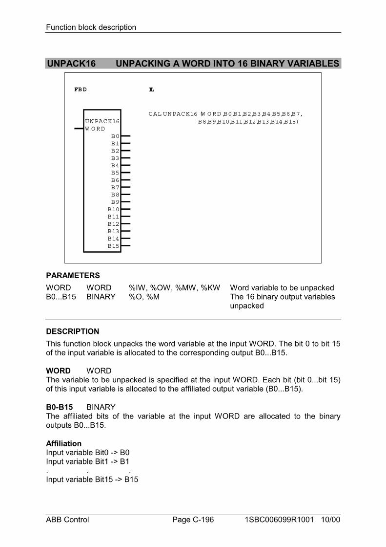
Function block description
ABB Control Page C-196 1SBC006099R1001 10/00
UNPACK16 UNPACKING A WORD INTO 16 BINARY VARIABLES
FBD IL
UNPACK16W O RD
CAL UNPACK16 (W O RD,B0,B1,B2,B3,B4,B5,B6,B7, B8,B9,B10,B11,B12,B13,B14,B15)
B0B1B2B3B4B5B6B7B8B9B10B11B12B13B14B15
PARAMETERSWORD WORD %IW, %OW, %MW, %KW Word variable to be unpackedB0...B15 BINARY %O, %M The 16 binary output variables
unpacked
DESCRIPTIONThis function block unpacks the word variable at the input WORD. The bit 0 to bit 15of the input variable is allocated to the corresponding output B0...B15.
WORD WORDThe variable to be unpacked is specified at the input WORD. Each bit (bit 0...bit 15)of this input variable is allocated to the affiliated output variable (B0...B15).
B0-B15 BINARYThe affiliated bits of the variable at the input WORD are allocated to the binaryoutputs B0...B15.
AffiliationInput variable Bit0 -> B0Input variable Bit1 -> B1. . .Input variable Bit15 -> B15
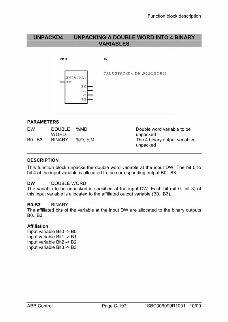
Function block description
ABB Control Page C-197 1SBC006099R1001 10/00
UNPACKD4 UNPACKING A DOUBLE WORD INTO 4 BINARYVARIABLES
FBD IL
UNPACKD4DW
B0
CAL UNPACKD4 (DW ,B0,B1,B2,B3)
B1B2B3
PARAMETERSDW DOUBLE %MD Double word variable to be
WORD unpackedB0...B3 BINARY %O, %M The 4 binary output variables
unpacked
DESCRIPTIONThis function block unpacks the double word variable at the input DW. The bit 0 tobit 4 of the input variable is allocated to the corresponding output B0...B3.
DW DOUBLE WORDThe variable to be unpacked is specified at the input DW. Each bit (bit 0...bit 3) ofthis input variable is allocated to the affiliated output variable (B0...B3).
B0-B3 BINARYThe affiliated bits of the variable at the input DW are allocated to the binary outputsB0...B3.
AffiliationInput variable Bit0 -> B0Input variable Bit1 -> B1Input variable Bit2 -> B2Input variable Bit3 -> B3
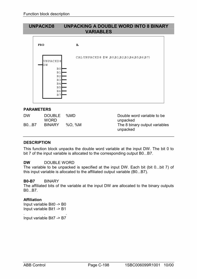
Function block description
ABB Control Page C-198 1SBC006099R1001 10/00
UNPACKD8 UNPACKING A DOUBLE WORD INTO 8 BINARYVARIABLES
FBD IL
UNPACKD8DW
CAL UNPACKD8 (DW ,B0,B1,B2,B3,B4,B5,B6,B7)
B0B1B2B3B4B5B6B7
PARAMETERSDW DOUBLE %MD Double word variable to be
WORD unpackedB0...B7 BINARY %O, %M The 8 binary output variables
unpacked
DESCRIPTIONThis function block unpacks the double word variable at the input DW. The bit 0 tobit 7 of the input variable is allocated to the corresponding output B0...B7.
DW DOUBLE WORDThe variable to be unpacked is specified at the input DW. Each bit (bit 0...bit 7) ofthis input variable is allocated to the affiliated output variable (B0...B7).
B0-B7 BINARYThe affiliated bits of the variable at the input DW are allocated to the binary outputsB0...B7.
AffiliationInput variable Bit0 -> B0Input variable Bit1 -> B1. . .Input variable Bit7 -> B7
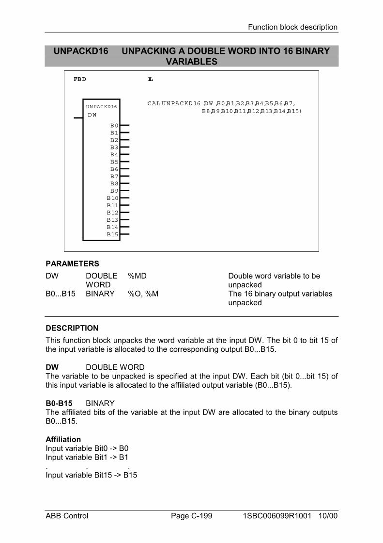
Function block description
ABB Control Page C-199 1SBC006099R1001 10/00
UNPACKD16 UNPACKING A DOUBLE WORD INTO 16 BINARYVARIABLES
FBD IL
UNPACKD16
DW
CAL UNPACKD16 (DW ,B0,B1,B2,B3,B4,B5,B6,B7, B8,B9,B10,B11,B12,B13,B14,B15)
B0B1B2B3B4B5B6B7B8B9B10B11B12B13B14B15
PARAMETERSDW DOUBLE %MD Double word variable to be
WORD unpackedB0...B15 BINARY %O, %M The 16 binary output variables
unpacked
DESCRIPTIONThis function block unpacks the word variable at the input DW. The bit 0 to bit 15 ofthe input variable is allocated to the corresponding output B0...B15.
DW DOUBLE WORDThe variable to be unpacked is specified at the input DW. Each bit (bit 0...bit 15) ofthis input variable is allocated to the affiliated output variable (B0...B15).
B0-B15 BINARYThe affiliated bits of the variable at the input DW are allocated to the binary outputsB0...B15.
AffiliationInput variable Bit0 -> B0Input variable Bit1 -> B1. . .Input variable Bit15 -> B15
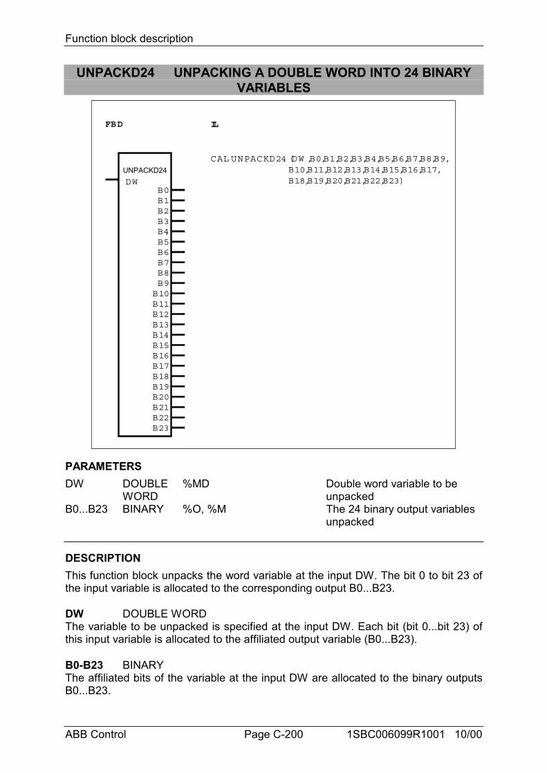
Function block description
ABB Control Page C-200 1SBC006099R1001 10/00
UNPACKD24 UNPACKING A DOUBLE WORD INTO 24 BINARYVARIABLES
FBD IL
UNPACKD24 DW
CAL UNPACKD24 (DW ,B0,B1,B2,B3,B4,B5,B6,B7,B8,B9, B10,B11,B12,B13,B14,B15,B16,B17, B18,B19,B20,B21,B22,B23)
B0B1B2B3B4B5B6B7B8B9B10B11B12B13B14B15B16B17B18B19B20B21B22B23
PARAMETERSDW DOUBLE %MD Double word variable to be
WORD unpackedB0...B23 BINARY %O, %M The 24 binary output variables
unpacked
DESCRIPTIONThis function block unpacks the word variable at the input DW. The bit 0 to bit 23 ofthe input variable is allocated to the corresponding output B0...B23.
DW DOUBLE WORDThe variable to be unpacked is specified at the input DW. Each bit (bit 0...bit 23) ofthis input variable is allocated to the affiliated output variable (B0...B23).
B0-B23 BINARYThe affiliated bits of the variable at the input DW are allocated to the binary outputsB0...B23.
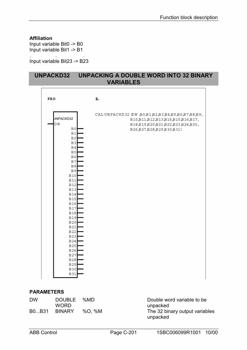
Function block description
ABB Control Page C-201 1SBC006099R1001 10/00
AffiliationInput variable Bit0 -> B0Input variable Bit1 -> B1. . .Input variable Bit23 -> B23
UNPACKD32 UNPACKING A DOUBLE WORD INTO 32 BINARYVARIABLES
FBD IL
UNPACKD32 DW
CAL UNPACKD32 (DW ,B0,B1,B2,B3,B4,B5,B6,B7,B8,B9, B10,B11,B12,B13,B14,B15,B16,B17, B18,B19,B20,B21,B22,B23,B24,B25, B26,B27,B28,B29,B30,B31)B0
B1B2B3B4B5B6B7B8B9B10B11B12B13B14B15B16B17B18B19B20B21B22B23B24B25B26B27B28B29B30B31
PARAMETERSDW DOUBLE %MD Double word variable to be
WORD unpackedB0...B31 BINARY %O, %M The 32 binary output variables
unpacked
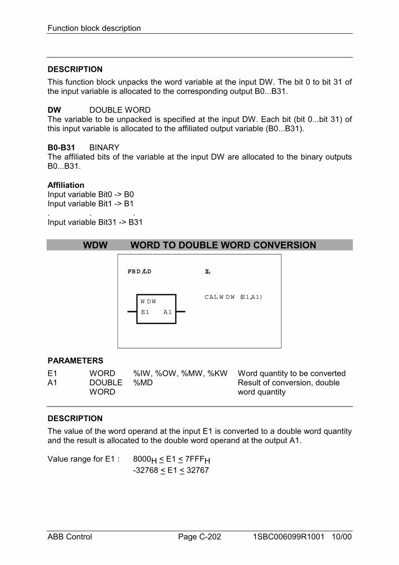
Function block description
ABB Control Page C-202 1SBC006099R1001 10/00
DESCRIPTIONThis function block unpacks the word variable at the input DW. The bit 0 to bit 31 ofthe input variable is allocated to the corresponding output B0...B31.
DW DOUBLE WORDThe variable to be unpacked is specified at the input DW. Each bit (bit 0...bit 31) ofthis input variable is allocated to the affiliated output variable (B0...B31).
B0-B31 BINARYThe affiliated bits of the variable at the input DW are allocated to the binary outputsB0...B31.
AffiliationInput variable Bit0 -> B0Input variable Bit1 -> B1. . .Input variable Bit31 -> B31
WDW WORD TO DOUBLE WORD CONVERSION
FBD/LD IL
W DWCAL W DW (E1,A1)
E1 A1
PARAMETERSE1 WORD %IW, %OW, %MW, %KW Word quantity to be convertedA1 DOUBLE %MD Result of conversion, double
WORD word quantity
DESCRIPTIONThe value of the word operand at the input E1 is converted to a double word quantityand the result is allocated to the double word operand at the output A1.
Value range for E1 : 8000H < E1 < 7FFFH-32768 < E1 < 32767
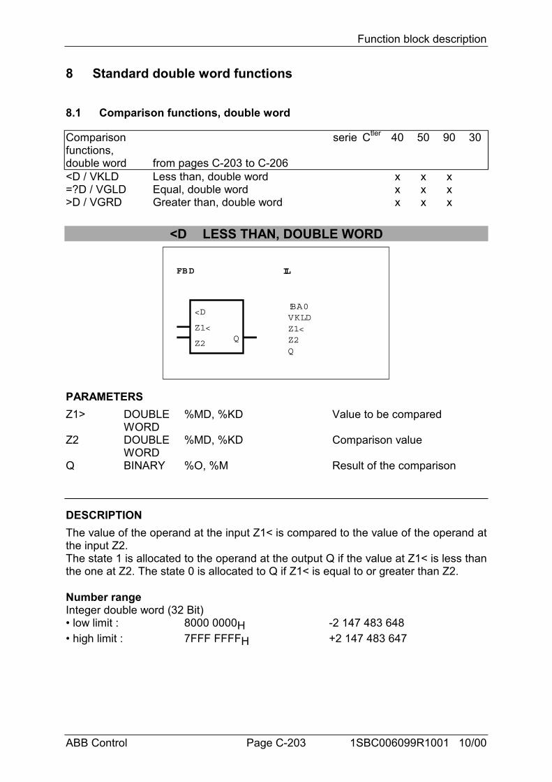
Function block description
ABB Control Page C-203 1SBC006099R1001 10/00
8 Standard double word functions
8.1 Comparison functions, double word
Comparisonfunctions,double word
serie
from pages C-203 to C-206
Ctler 40 50 90 30
<D / VKLD Less than, double word x x x=?D / VGLD Equal, double word x x x>D / VGRD Greater than, double word x x x
<D LESS THAN, DOUBLE WORD
FBD IL
<D
Z1<
Z2Q
!BA0VKLDZ1<Z2Q
PARAMETERSZ1> DOUBLE
WORD%MD, %KD Value to be compared
Z2 DOUBLEWORD
%MD, %KD Comparison value
Q BINARY %O, %M Result of the comparison
DESCRIPTIONThe value of the operand at the input Z1< is compared to the value of the operand atthe input Z2.The state 1 is allocated to the operand at the output Q if the value at Z1< is less thanthe one at Z2. The state 0 is allocated to Q if Z1< is equal to or greater than Z2.
Number rangeInteger double word (32 Bit)• low limit : 8000 0000H -2 147 483 648• high limit : 7FFF FFFFH +2 147 483 647
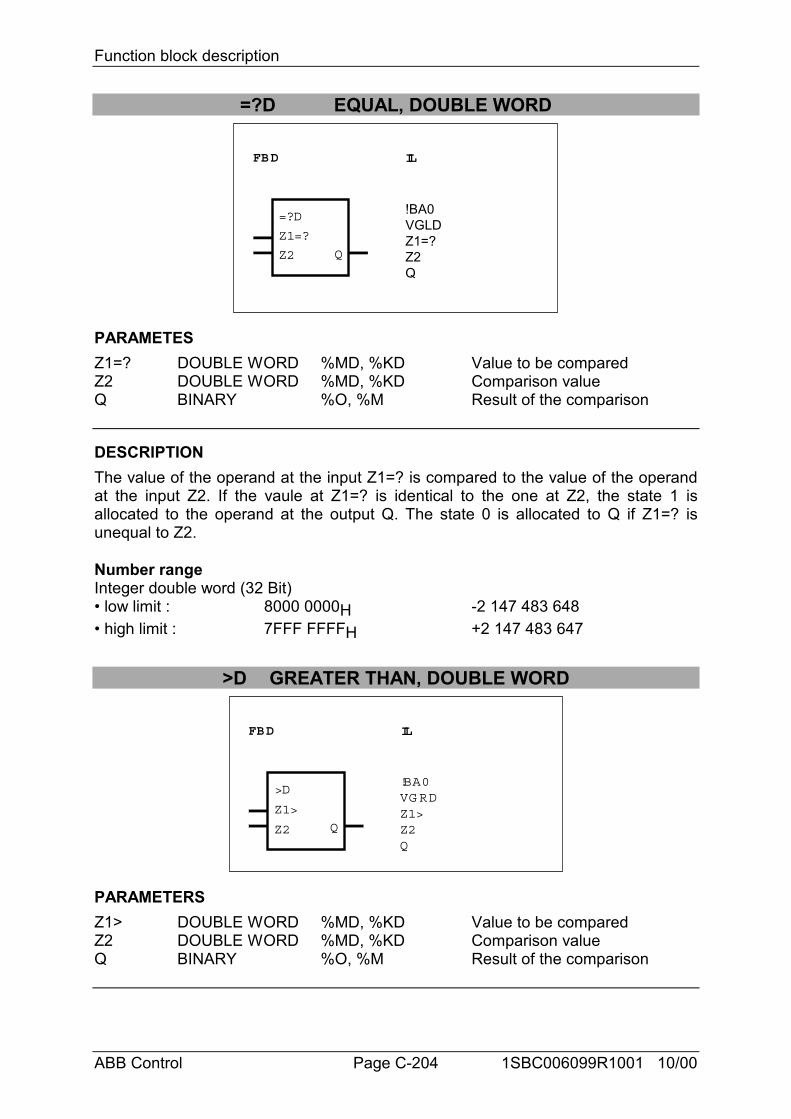
Function block description
ABB Control Page C-204 1SBC006099R1001 10/00
=?D EQUAL, DOUBLE WORD
FBD IL
=?D
Z1=?
Z2 Q
!BA0VGLDZ1=?Z2Q
PARAMETESZ1=? DOUBLE WORD %MD, %KD Value to be comparedZ2 DOUBLE WORD %MD, %KD Comparison valueQ BINARY %O, %M Result of the comparison
DESCRIPTIONThe value of the operand at the input Z1=? is compared to the value of the operandat the input Z2. If the vaule at Z1=? is identical to the one at Z2, the state 1 isallocated to the operand at the output Q. The state 0 is allocated to Q if Z1=? isunequal to Z2.
Number rangeInteger double word (32 Bit)• low limit : 8000 0000H -2 147 483 648• high limit : 7FFF FFFFH +2 147 483 647
>D GREATER THAN, DOUBLE WORD
FBD IL
>D
Z1>
Z2 Q
!BA0VG RDZ1>Z2Q
PARAMETERSZ1> DOUBLE WORD %MD, %KD Value to be comparedZ2 DOUBLE WORD %MD, %KD Comparison valueQ BINARY %O, %M Result of the comparison
Function block description
ABB Control Page C-205 1SBC006099R1001 10/00
DESCRIPTIONThe value of the operand at the input Z1> is compared to the value of the operand atthe input Z2.The state 1 is allocated to the operand at the output Q if the value at Z1> is greaterthan the one at Z2. The state 0 is allocated to Q if Z1> is equal to or less than Z2.
Number rangeInteger double word (32 Bit)• low limit : 8000 0000H -2 147 483 648• high limit : 7FFF FFFFH +2 147 483 647
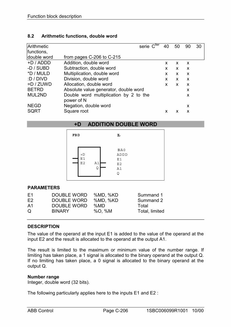
Function block description
ABB Control Page C-206 1SBC006099R1001 10/00
8.2 Arithmetic functions, double word
Arithmeticfunctions,double word
serie
from pages C-206 to C-215
Ctler 40 50 90 30
+D / ADDD Addition, double word x x x-D / SUBD Subtraction, double word x x x*D / MULD Multiplication, double word x x x:D / DIVD Division, double word x x x=D / ZUWD Allocation, double word x x xBETRD Absolute value generator, double word xMUL2ND Double word multiplication by 2 to the
power of Nx
NEGD Negation, double word xSQRT Square root x x x
+D ADDITION DOUBLE WORD
FBD IL
+DE1E2 A1
Q
!BA0ADDDE1E2A1Q
PARAMETERSE1 DOUBLE WORD %MD, %KD Summand 1E2 DOUBLE WORD %MD, %KD Summand 2A1 DOUBLE WORD %MD TotalQ BINARY %O, %M Total, limited
DESCRIPTIONThe value of the operand at the input E1 is added to the value of the operand at theinput E2 and the result is allocated to the operand at the output A1.
The result is limited to the maximum or minimum value of the number range. Iflimiting has taken place, a 1 signal is allocated to the binary operand at the output Q.If no limiting has taken place, a 0 signal is allocated to the binary operand at theoutput Q.
Number rangeInteger, double word (32 bits).
The following particularly applies here to the inputs E1 and E2 :
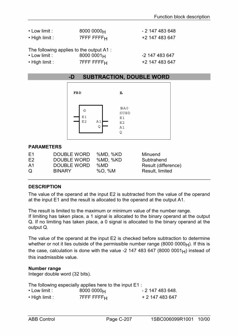
Function block description
ABB Control Page C-207 1SBC006099R1001 10/00
• Low limit : 8000 0000H - 2 147 483 648• High limit : 7FFF FFFFH +2 147 483 647
The following applies to the output A1 :• Low limit : 8000 0001H -2 147 483 647• High limit : 7FFF FFFFH +2 147 483 647
-D SUBTRACTION, DOUBLE WORD
FBD IL
-D
E1E2 A1
Q
!BA0SUBDE1E2A1Q
PARAMETERSE1 DOUBLE WORD %MD, %KD MinuendE2 DOUBLE WORD %MD, %KD SubtrahendA1 DOUBLE WORD %MD Result (difference)Q BINARY %O, %M Result, limited
DESCRIPTIONThe value of the operand at the input E2 is subtracted from the value of the operandat the input E1 and the result is allocated to the operand at the output A1.
The result is limited to the maximum or minimum value of the number range.If limiting has taken place, a 1 signal is allocated to the binary operand at the outputQ. If no limiting has taken place, a 0 signal is allocated to the binary operand at theoutput Q.
The value of the operand at the input E2 is checked before subtraction to determinewhether or not it lies outside of the permissible number range (8000 0000H). If this isthe case, calculation is done with the value -2 147 483 647 (8000 0001H) instead ofthis inadmissible value.
Number rangeInteger double word (32 bits).
The following especially applies here to the input E1 :• Low limit : 8000 0000H - 2 147 483 648.• High limit : 7FFF FFFFH + 2 147 483 647
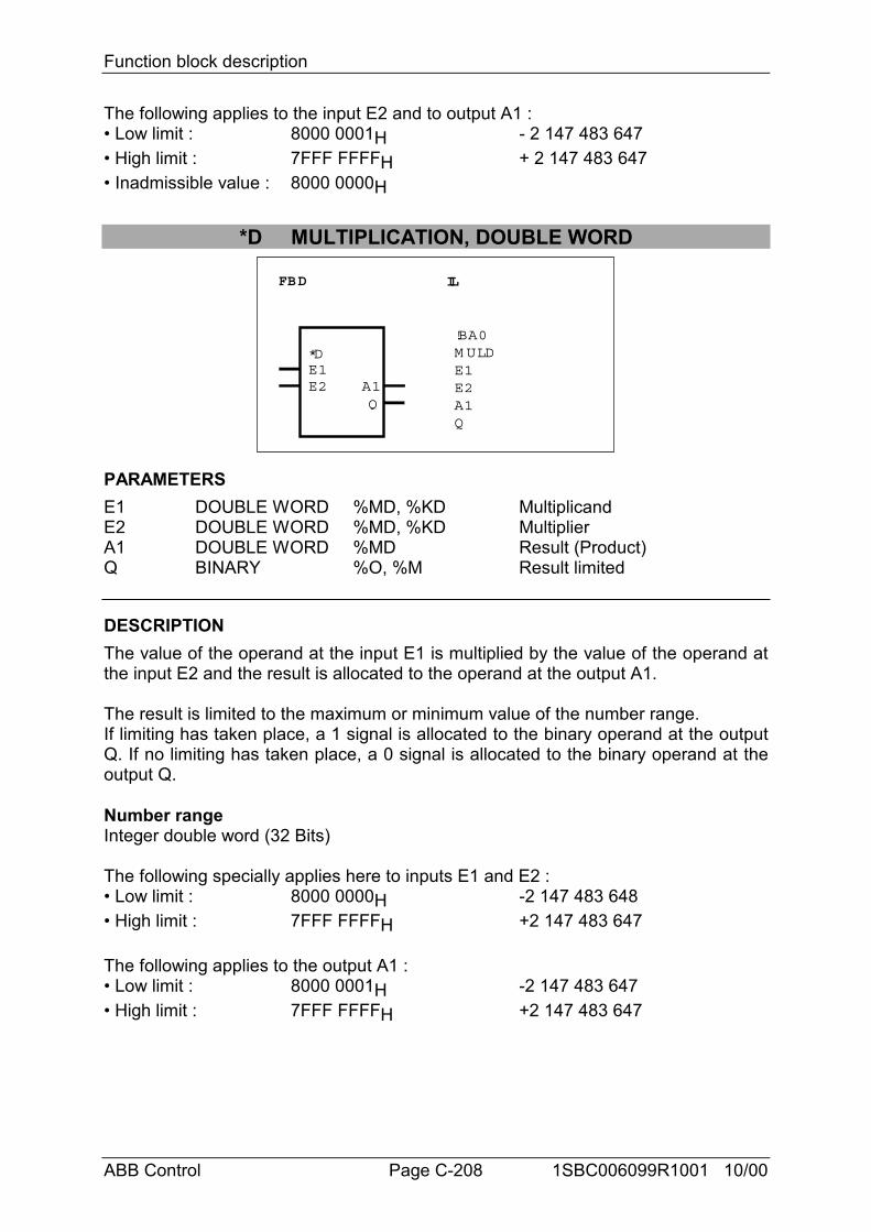
Function block description
ABB Control Page C-208 1SBC006099R1001 10/00
The following applies to the input E2 and to output A1 :• Low limit : 8000 0001H - 2 147 483 647• High limit : 7FFF FFFFH + 2 147 483 647• Inadmissible value : 8000 0000H
*D MULTIPLICATION, DOUBLE WORD
FBD IL
*DE1E2 A1
Q
!BA0M ULDE1E2A1Q
PARAMETERSE1 DOUBLE WORD %MD, %KD MultiplicandE2 DOUBLE WORD %MD, %KD MultiplierA1 DOUBLE WORD %MD Result (Product)Q BINARY %O, %M Result limited
DESCRIPTIONThe value of the operand at the input E1 is multiplied by the value of the operand atthe input E2 and the result is allocated to the operand at the output A1.
The result is limited to the maximum or minimum value of the number range.If limiting has taken place, a 1 signal is allocated to the binary operand at the outputQ. If no limiting has taken place, a 0 signal is allocated to the binary operand at theoutput Q.
Number rangeInteger double word (32 Bits)
The following specially applies here to inputs E1 and E2 :• Low limit : 8000 0000H -2 147 483 648• High limit : 7FFF FFFFH +2 147 483 647
The following applies to the output A1 :• Low limit : 8000 0001H -2 147 483 647• High limit : 7FFF FFFFH +2 147 483 647
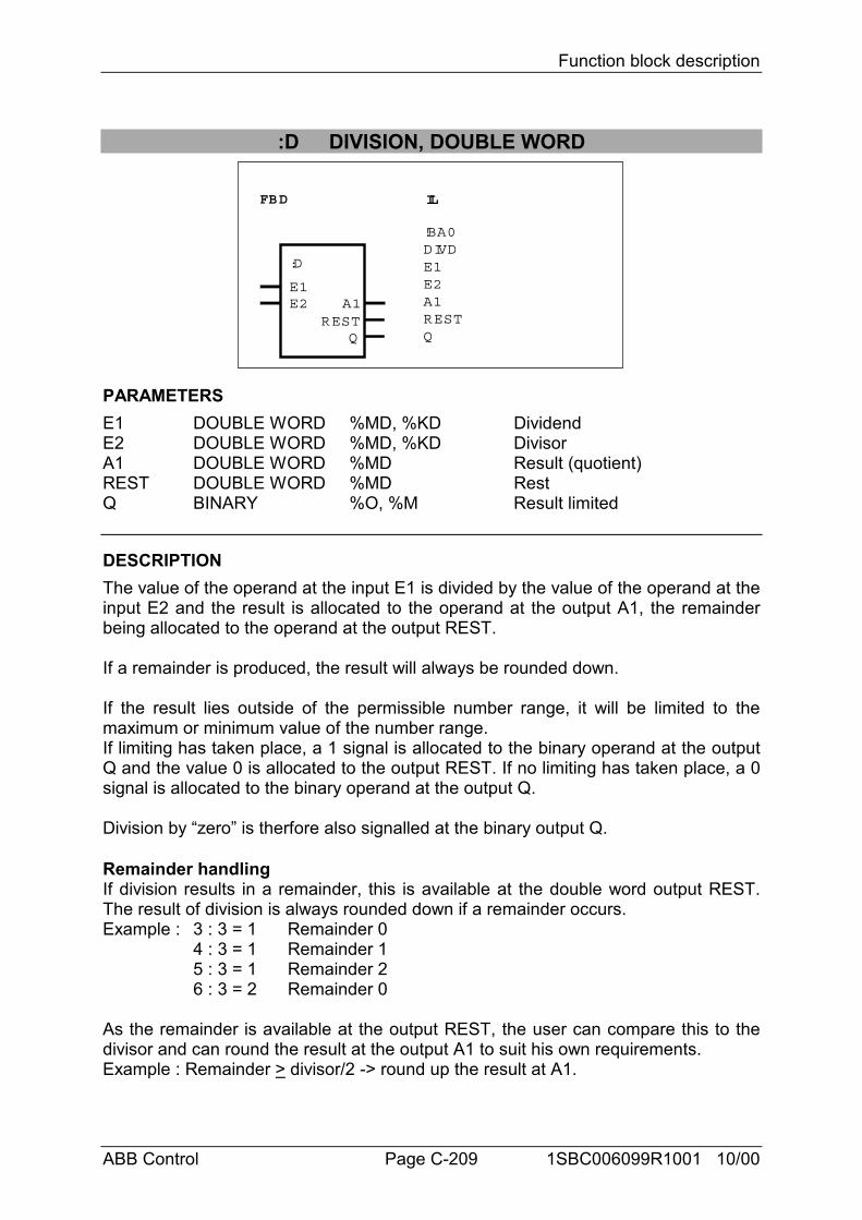
Function block description
ABB Control Page C-209 1SBC006099R1001 10/00
:D DIVISION, DOUBLE WORD
FBD IL
:D
E1E2
Q
A1REST
!BA0DIVDE1E2A1RESTQ
PARAMETERSE1 DOUBLE WORD %MD, %KD DividendE2 DOUBLE WORD %MD, %KD DivisorA1 DOUBLE WORD %MD Result (quotient)REST DOUBLE WORD %MD RestQ BINARY %O, %M Result limited
DESCRIPTIONThe value of the operand at the input E1 is divided by the value of the operand at theinput E2 and the result is allocated to the operand at the output A1, the remainderbeing allocated to the operand at the output REST.
If a remainder is produced, the result will always be rounded down.
If the result lies outside of the permissible number range, it will be limited to themaximum or minimum value of the number range.If limiting has taken place, a 1 signal is allocated to the binary operand at the outputQ and the value 0 is allocated to the output REST. If no limiting has taken place, a 0signal is allocated to the binary operand at the output Q.
Division by “zero” is therfore also signalled at the binary output Q.
Remainder handlingIf division results in a remainder, this is available at the double word output REST.The result of division is always rounded down if a remainder occurs.Example : 3 : 3 = 1 Remainder 0
4 : 3 = 1 Remainder 15 : 3 = 1 Remainder 26 : 3 = 2 Remainder 0
As the remainder is available at the output REST, the user can compare this to thedivisor and can round the result at the output A1 to suit his own requirements.Example : Remainder > divisor/2 -> round up the result at A1.
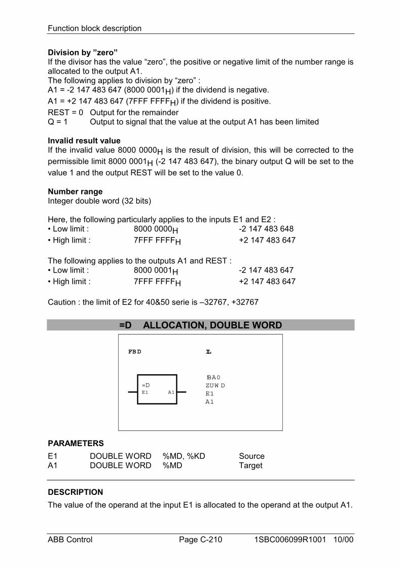
Function block description
ABB Control Page C-210 1SBC006099R1001 10/00
Division by ”zero”If the divisor has the value “zero”, the positive or negative limit of the number range isallocated to the output A1.The following applies to division by “zero” :A1 = -2 147 483 647 (8000 0001H) if the dividend is negative.A1 = +2 147 483 647 (7FFF FFFFH) if the dividend is positive.REST = 0 Output for the remainderQ = 1 Output to signal that the value at the output A1 has been limited
Invalid result valueIf the invalid value 8000 0000H is the result of division, this will be corrected to thepermissible limit 8000 0001H (-2 147 483 647), the binary output Q will be set to thevalue 1 and the output REST will be set to the value 0.
Number rangeInteger double word (32 bits)
Here, the following particularly applies to the inputs E1 and E2 :• Low limit : 8000 0000H -2 147 483 648• High limit : 7FFF FFFFH +2 147 483 647
The following applies to the outputs A1 and REST :• Low limit : 8000 0001H -2 147 483 647• High limit : 7FFF FFFFH +2 147 483 647
Caution : the limit of E2 for 40&50 serie is –32767, +32767
=D ALLOCATION, DOUBLE WORD
FBD IL
=DE1 A1
!BA0ZUW DE1A1
PARAMETERSE1 DOUBLE WORD %MD, %KD SourceA1 DOUBLE WORD %MD Target
DESCRIPTIONThe value of the operand at the input E1 is allocated to the operand at the output A1.
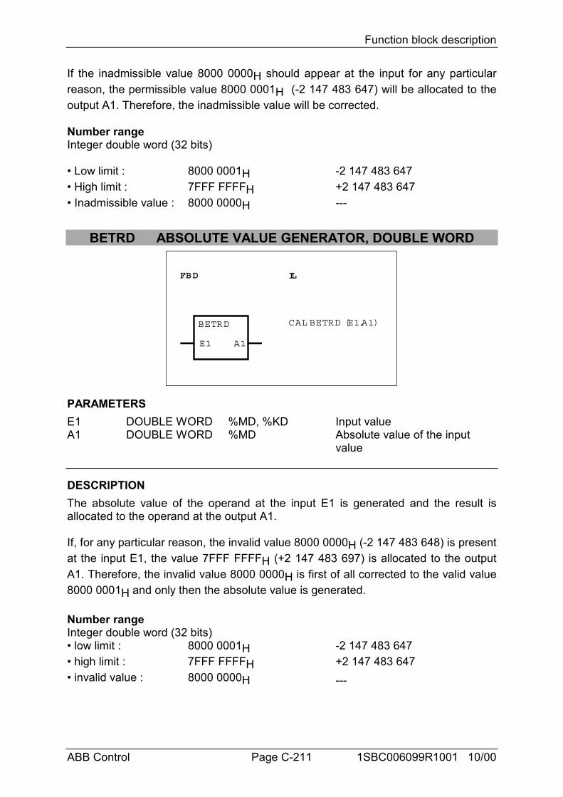
Function block description
ABB Control Page C-211 1SBC006099R1001 10/00
If the inadmissible value 8000 0000H should appear at the input for any particularreason, the permissible value 8000 0001H (-2 147 483 647) will be allocated to theoutput A1. Therefore, the inadmissible value will be corrected.
Number rangeInteger double word (32 bits)
• Low limit : 8000 0001H -2 147 483 647• High limit : 7FFF FFFFH +2 147 483 647• Inadmissible value : 8000 0000H ---
BETRD ABSOLUTE VALUE GENERATOR, DOUBLE WORD
FBD IL
BETRD
E1 A1
CAL BETRD (E1,A1)
PARAMETERSE1 DOUBLE WORD %MD, %KD Input valueA1 DOUBLE WORD %MD Absolute value of the input
value
DESCRIPTIONThe absolute value of the operand at the input E1 is generated and the result isallocated to the operand at the output A1.
If, for any particular reason, the invalid value 8000 0000H (-2 147 483 648) is presentat the input E1, the value 7FFF FFFFH (+2 147 483 697) is allocated to the outputA1. Therefore, the invalid value 8000 0000H is first of all corrected to the valid value8000 0001H and only then the absolute value is generated.
Number rangeInteger double word (32 bits)• low limit : 8000 0001H -2 147 483 647• high limit : 7FFF FFFFH +2 147 483 647• invalid value : 8000 0000H ---
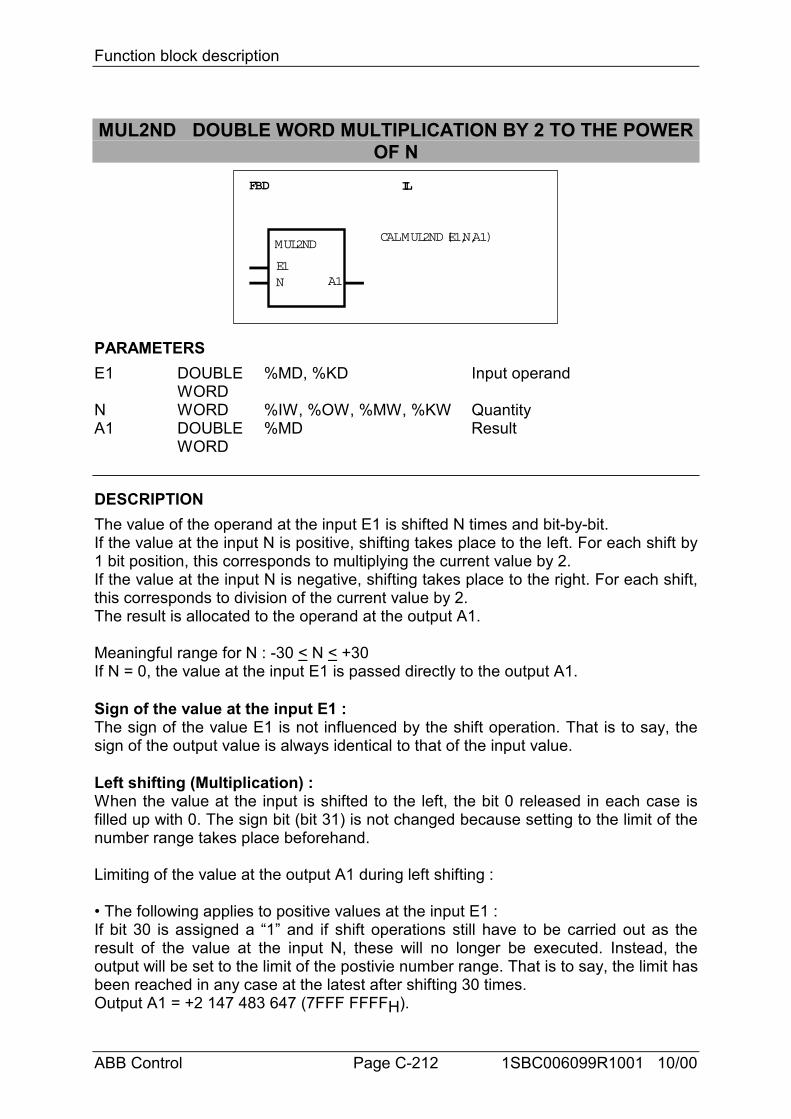
Function block description
ABB Control Page C-212 1SBC006099R1001 10/00
MUL2ND DOUBLE WORD MULTIPLICATION BY 2 TO THE POWEROF N
FBD IL
MUL2ND
E1N A1
CAL MUL2ND (E1,N,A1)
PARAMETERSE1 DOUBLE %MD, %KD Input operand
WORDN WORD %IW, %OW, %MW, %KW QuantityA1 DOUBLE %MD Result
WORD
DESCRIPTIONThe value of the operand at the input E1 is shifted N times and bit-by-bit.If the value at the input N is positive, shifting takes place to the left. For each shift by1 bit position, this corresponds to multiplying the current value by 2.If the value at the input N is negative, shifting takes place to the right. For each shift,this corresponds to division of the current value by 2.The result is allocated to the operand at the output A1.
Meaningful range for N : -30 < N < +30If N = 0, the value at the input E1 is passed directly to the output A1.
Sign of the value at the input E1 :The sign of the value E1 is not influenced by the shift operation. That is to say, thesign of the output value is always identical to that of the input value.
Left shifting (Multiplication) :When the value at the input is shifted to the left, the bit 0 released in each case isfilled up with 0. The sign bit (bit 31) is not changed because setting to the limit of thenumber range takes place beforehand.
Limiting of the value at the output A1 during left shifting :
• The following applies to positive values at the input E1 :If bit 30 is assigned a “1” and if shift operations still have to be carried out as theresult of the value at the input N, these will no longer be executed. Instead, theoutput will be set to the limit of the postivie number range. That is to say, the limit hasbeen reached in any case at the latest after shifting 30 times.Output A1 = +2 147 483 647 (7FFF FFFFH).
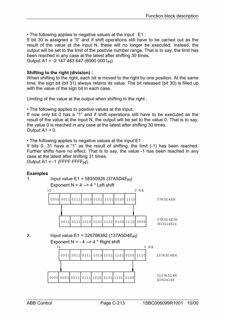
Function block description
ABB Control Page C-213 1SBC006099R1001 10/00
• The following applies to negative values at the input E1 :If bit 30 is assigned a “0” and if shift operations still have to be carried out as theresult of the value at the input N, these will no longer be executed. Instead, theoutput will be set to the limit of the postivie number range. That is to say, the limit hasbeen reached in any case at the latest after shifting 30 times.Output A1 = -2 147 483 647 (8000 0001H).
Shifting to the right (division) :When shifting to the right, each bit is moved to the right by one position. At the sametime, the sign bit (bit 31) always retains its value. The bit released (bit 30) is filled upwith the value of the sign bit in each case.
Limiting of the value at the output when shifting to the right :
• The following applies to positive values at the input :If now only bit 0 has a “1” and if shift operations still have to be executed as theresult of the value at the input N, the output will be set to the value 0. That is to say,the value 0 is reached in any case at the latest after shifting 30 times.Output A1 = 0.
• The following applies to negative values at the input E1 :If bits 0...31 have a “1” as the result of shifting, the limit (-1) has been reached.Further shifts have no effect. That is to say, the value -1 has been reached in anycase at the latest after shifting 31 times.Output A1 = -1 (FFFF FFFFH).
Examples1. Input value E1 = 58350926 (37A5D4EH)
Exponent N = 4 --> 4 * Left shift
0011
31 0 Bit
37A5D4EH
37A5D4E0H(933614816
0111 1010 0101 1101 0100 1110 0000
0000 0011 0111 1010 0101 1101 0100 1110
2. Input value E1 = 326786382 (137A5D4EH)Exponent N = - 4 --> 4 * Right shift
0000
31 0 Bit
137A5D4EH
0137A5D4H(20424148
0001 0011 0111 1010 0101 1101 0100
0001 0011 0111 1010 0101 1101 0100 1110
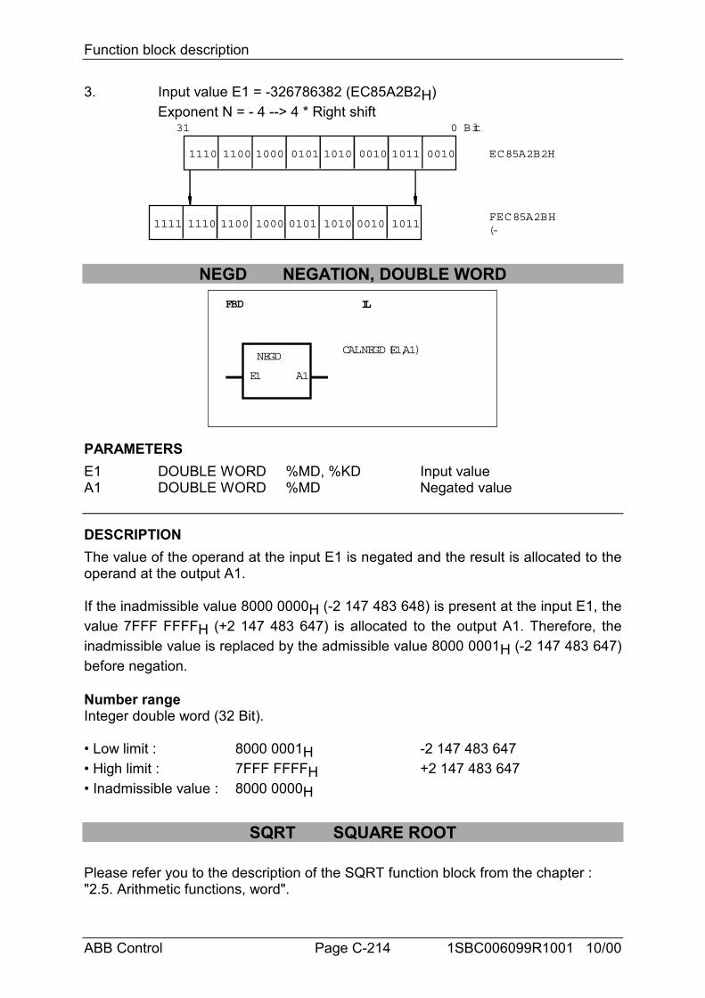
Function block description
ABB Control Page C-214 1SBC006099R1001 10/00
3. Input value E1 = -326786382 (EC85A2B2H)Exponent N = - 4 --> 4 * Right shift
1111
31 0 Bit
EC85A2B2H
FEC85A2BH(-
1110 1100 1000 0101 1010 0010 1011
1110 1100 1000 0101 1010 0010 1011 0010
NEGD NEGATION, DOUBLE WORDFBD IL
NEGD
E1 A1
CAL NEGD (E1,A1)
PARAMETERSE1 DOUBLE WORD %MD, %KD Input valueA1 DOUBLE WORD %MD Negated value
DESCRIPTIONThe value of the operand at the input E1 is negated and the result is allocated to theoperand at the output A1.
If the inadmissible value 8000 0000H (-2 147 483 648) is present at the input E1, thevalue 7FFF FFFFH (+2 147 483 647) is allocated to the output A1. Therefore, theinadmissible value is replaced by the admissible value 8000 0001H (-2 147 483 647)before negation.
Number rangeInteger double word (32 Bit).
• Low limit : 8000 0001H -2 147 483 647• High limit : 7FFF FFFFH +2 147 483 647• Inadmissible value : 8000 0000H
SQRT SQUARE ROOT
Please refer you to the description of the SQRT function block from the chapter :"2.5. Arithmetic functions, word".
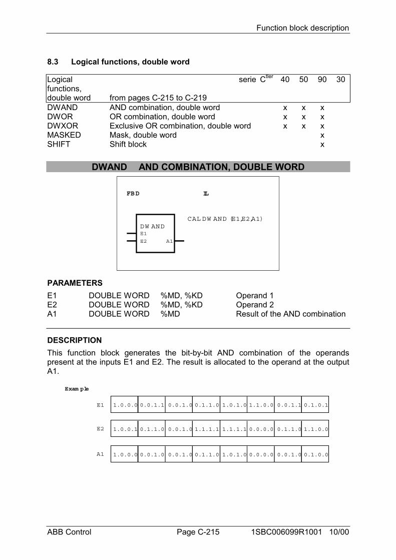
Function block description
ABB Control Page C-215 1SBC006099R1001 10/00
8.3 Logical functions, double word
Logicalfunctions,double word
serie
from pages C-215 to C-219
Ctler 40 50 90 30
DWAND AND combination, double word x x xDWOR OR combination, double word x x xDWXOR Exclusive OR combination, double word x x xMASKED Mask, double word xSHIFT Shift block x
DWAND AND COMBINATION, DOUBLE WORD
FBD IL
DW ANDE1
E2 A1
CAL DW AND (E1,E2,A1)
PARAMETERSE1 DOUBLE WORD %MD, %KD Operand 1E2 DOUBLE WORD %MD, %KD Operand 2A1 DOUBLE WORD %MD Result of the AND combination
DESCRIPTIONThis function block generates the bit-by-bit AND combination of the operandspresent at the inputs E1 and E2. The result is allocated to the operand at the outputA1.
1.0.0.0 0.0.1.1 0.0.1.0 0.1.1.0
1.0.0.1 0.1.1.0 0.0.1.0 1.1.1.1
1.0.0.0 0.0.1.0 0.0.1.0 0.1.1.0
E1
E2
A1
1.0.1.0 1.1.0.0 0.0.1.1 0.1.0.1
1.1.1.1 0.0.0.0 0.1.1.0 1.1.0.0
1.0.1.0 0.0.0.0 0.0.1.0 0.1.0.0
Exam ple
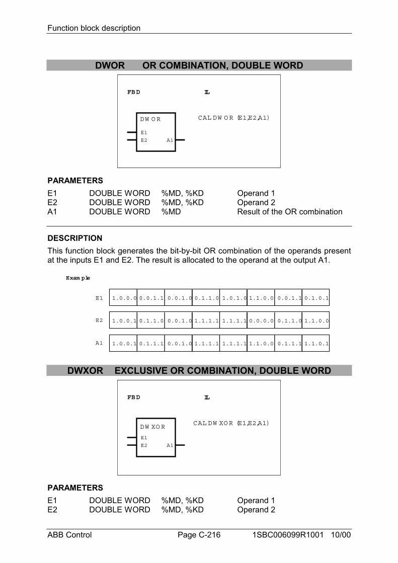
Function block description
ABB Control Page C-216 1SBC006099R1001 10/00
DWOR OR COMBINATION, DOUBLE WORD
FBD IL
DW O R
E1
E2 A1
CAL DW O R (E1,E2,A1)
PARAMETERSE1 DOUBLE WORD %MD, %KD Operand 1E2 DOUBLE WORD %MD, %KD Operand 2A1 DOUBLE WORD %MD Result of the OR combination
DESCRIPTIONThis function block generates the bit-by-bit OR combination of the operands presentat the inputs E1 and E2. The result is allocated to the operand at the output A1.
1.0.0.0 0.0.1.1 0.0.1.0 0.1.1.0
1.0.0.1 0.1.1.0 0.0.1.0 1.1.1.1
1.0.0.1 0.1.1.1 0.0.1.0 1.1.1.1
E1
E2
A1
1.0.1.0 1.1.0.0 0.0.1.1 0.1.0.1
1.1.1.1 0.0.0.0 0.1.1.0 1.1.0.0
1.1.1.1 1.1.0.0 0.1.1.1 1.1.0.1
Exam ple
DWXOR EXCLUSIVE OR COMBINATION, DOUBLE WORD
FBD IL
DW XO R
E1
E2 A1
CAL DW XO R (E1,E2,A1)
PARAMETERSE1 DOUBLE WORD %MD, %KD Operand 1E2 DOUBLE WORD %MD, %KD Operand 2
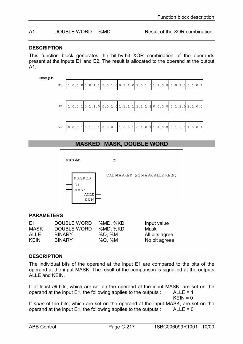
Function block description
ABB Control Page C-217 1SBC006099R1001 10/00
A1 DOUBLE WORD %MD Result of the XOR combination
DESCRIPTIONThis function block generates the bit-by-bit XOR combination of the operandspresent at the inputs E1 and E2. The result is allocated to the operand at the outputA1.
1.0.0.0 0.0.1.1 0.0.1.0 0.1.1.0
1.0.0.1 0.1.1.0 0.0.1.0 1.1.1.1
0.0.0.1 0.1.0.1 0.0.0.0 1.0.0.1
E1
E2
A1
1.0.1.0 1.1.0.0 0.0.1.1 0.1.0.1
1.1.1.1 0.0.0.0 0.1.1.0 1.1.0.0
0.1.0.1 1.1.0.0 0.1.0.1 1.0.0.1
Exam ple
MASKED MASK, DOUBLE WORD
FBD/LD IL
M ASKED
E1M ASK
KEINALLE
CAL M ASKED (E1,M ASK,ALLE,KEIN)
PARAMETERSE1 DOUBLE WORD %MD, %KD Input valueMASK DOUBLE WORD %MD, %KD MaskALLE BINARY %O, %M All bits agreeKEIN BINARY %O, %M No bit agrees
DESCRIPTIONThe individual bits of the operand at the input E1 are compared to the bits of theoperand at the input MASK. The result of the comparison is signalled at the outputsALLE and KEIN.
If at least all bits, which are set on the operand at the input MASK, are set on theoperand at the input E1, the following applies to the outputs : ALLE = 1
KEIN = 0If none of the bits, which are set on the operand at the input MASK, are set on theoperand at the input E1, the following applies to the outputs : ALLE = 0
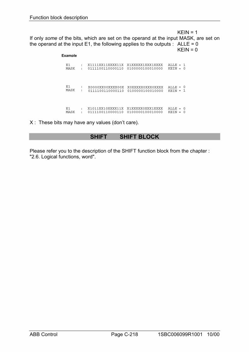
Function block description
ABB Control Page C-218 1SBC006099R1001 10/00
KEIN = 1If only some of the bits, which are set on the operand at the input MASK, are set onthe operand at the input E1, the following applies to the outputs : ALLE = 0
KEIN = 0
E1 X1111XX11XXXX11X
X0000XX00XXXX00X
X1011XX10XXXX11X
MASK 0111100110000110
0111100110000110
0111100110000110
ALLE = 1KEIN = 0
::
Example
E1MASK
ALLEKEIN
::
E1MASK
ALLEKEIN
::
= 0= 1
= 0= 0
X1XXXXX1XXX1XXXX0100000100010000
X0XXXXX0XXX0XXXX0100000100010000
X1XXXXX0XXX1XXXX0100000100010000
X : These bits may have any values (don’t care).
SHIFT SHIFT BLOCK
Please refer you to the description of the SHIFT function block from the chapter :"2.6. Logical functions, word".
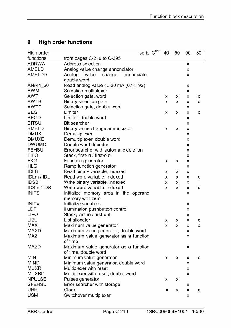
Function block description
ABB Control Page C-219 1SBC006099R1001 10/00
9 High order functions
High orderfunctions
seriefrom pages C-219 to C-295
Ctler 40 50 90 30
ADRWA Address selection xAMELD Analog value change annonciator xAMELDD Analog value change annonciator,
double wordx
ANAI4_20 Read analog value 4...20 mA (07KT92) xAWM Selection multiplexer xAWT Selection gate, word x x x xAWTB Binary selection gate x x x xAWTD Selection gate, double word xBEG Limiter x x x xBEGD Limiter, double word xBITSU Bit searcher xBMELD Binary value change annunciator x x xDMUX Demultiplexer xDMUXD Demultiplexer, double word xDWUMC Double word decoder xFEHSU Error searcher with automatic deletion xFIFO Stack, first-in / first-out xFKG Function generator x x xHLG Ramp function generator xIDLB Read binary variable, indexed x x xIDLm / IDL Read word variable, indexed x x x xIDSB Write binary variable, indexed x x xIDSm / IDS Write word variable, indexed x x x xINITS Initialize memory area in the operand
memory with zerox
INITV Initialize variables xLDT Illumination pushbutton control xLIFO Stack, last-in / first-out xLIZU List allocator x x x xMAX Maximum value generator x x x xMAXD Maximum value generator, double word xMAZ Maximum value generator as a function
of timex
MAZD Maximum value generator as a functionof time, double word
x
MIN Minimum value generator x x x xMIND Minimum value generator, double word xMUXR Multiplexer with reset xMUXRD Multiplexer with reset, double word xNPULSE Pulses generator x xSFEHSU Error searcher with storage xUHR Clock x x x xUSM Switchover multiplexer x
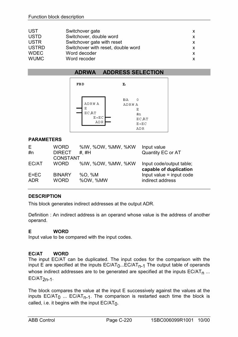
Function block description
ABB Control Page C-220 1SBC006099R1001 10/00
UST Switchover gate xUSTD Switchover, double word xUSTR Switchover gate with reset xUSTRD Switchover with reset, double word xWDEC Word decoder xWUMC Word recoder x
ADRWA ADDRESS SELECTION
FBD IL
ADRW AEEC/AT
ADRE=EC
!BA 0 ADRW A
E#nEC/ATE=ECADR
PARAMETERSE WORD %IW, %OW, %MW, %KW Input value#n DIRECT #, #H Quantity EC or AT
CONSTANTEC/AT WORD %IW, %OW, %MW, %KW Input code/output table;
capable of duplicationE=EC BINARY %O, %M Input value = input codeADR WORD %OW, %MW indirect address
DESCRIPTIONThis block generates indirect addresses at the output ADR.
Definition : An indirect address is an operand whose value is the address of anotheroperand.
E WORDInput value to be compared with the input codes.
EC/AT WORDThe input EC/AT can be duplicated. The input codes for the comparison with theinput E are specified at the inputs EC/AT0...EC/ATn-1 The output table of operandswhose indirect addresses are to be generated are specified at the inputs EC/ATn ...EC/AT2n-1.
The block compares the value at the input E successively against the values at theinputs EC/AT0 ... EC/ATn-1. The comparison is restarted each time the block iscalled, i.e. it begins with the input EC/AT0.
Function block description
ABB Control Page C-221 1SBC006099R1001 10/00
If the value at the input E agrees with one of the values at the inputsEC/AT0...EC/ATn-1:- The output E=EC is set to 1 (hit),- The allocated operand is selected from the inputs EC/ATn ... EC/AT2n-1
If the value at the input E does not agree with one of the values at the inputsEC/AT0...EC/ATn-1:- The output E=EC is set to 0 (no hit)- no operand is selected from the output table EC/ATn ... EC/AT2n-1 and accordinglyno indirect address is generated either.
Convention for allocation between EC/AT0...EC/ATn-1 and EC/ATn ... EC/AT2n-1:EC/AT0 -> EC/ATnEC/AT1 -> EC/ATn+1. .EC/ATn-1 -> EC/AT2n-1
#n DIRECT CONSTANTOnly used in IL. The number of input codes EC/AT0...EC/ATn-1 is specified at theinput #n. It is specified as a direct constant.
Example: EC/AT0, ..., EC/AT5 are planned-> input codes = EC/AT0, ..., EC/AT2 and output table = EC/AT0, ..., EC/AT5-> #n = 3.
E=EC BINARYThe output E=EC indicates whether or not the value at the input E agrees with one ofthe values at the inputs EC/AT0...EC/ATn-1.E=EC = 0 -> No agreementE=EC = 1 -> The value at the input E agrees with one of the values at the
inputs EC/AT0...EC/ATn-1.
ADR WORDThe operand specified at the ADR output is the indirect address of the operandselected from the output table EC/ATn ... EC/AT2n-1. The address of the operandselected from the output table is therefore allocating as a value to the operandspecified at the ADR output.If no agreement between the input E and the inputs EC/AT0...EC/ATn-1 isdetermined during comparison, no value is allocated to the ADR output. In that case,the ADR output is not updated.
Reading/writing operands indirectlyThe function blocks AWM or USM use the indirect address generated by the blockADRWA in order to read or write the operand selected with the block ADRWA.Therefore, the block ADRWA and the block AWM or USM is needed to read or writeoperands indirectly. To do this, the operands to be read or written are listed at the
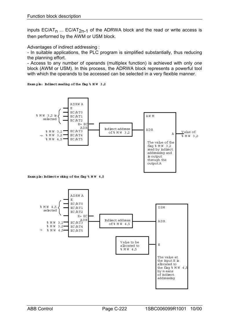
Function block description
ABB Control Page C-222 1SBC006099R1001 10/00
inputs EC/ATn ... EC/AT2n-1 of the ADRWA block and the read or write access isthen performed by the AWM or USM block.
Advantages of indirect addressing :- In suitable applications, the PLC program is simplified substantially, thus reducingthe planning effort.- Access to any number of operands (multiplex function) is achieved with only oneblock (AWM or USM). In this process, the ADRWA block represents a powerful toolwith which the operands to be accessed can be selected in a very flexible manner.
ADRW AEEC/AT0EC/AT1EC/AT2
ADRE= EC
Exam ple: Indirect reading of the flag % M W 3,2
EC/AT3EC/AT4EC/AT5
AW M
Indirect addressof % M W 3,2
ADRA
% M W 3,2 isselected
The value of theflag % M W 3,2read by indirectaddressing andis outputthrough theoutput A
ADRW AEEC/AT0EC/AT1EC/AT2
ADRE= EC
EC/AT3EC/AT4EC/AT5
USM
ADRIndirect addressof % M W 4,5
% M W 4,5selected
Exam ple: Indirect w riting of the flag % M W 4,5
% M W 3,1% M W 3,2% M W 4,5
% M W 3,1% M W 3,2% M W 4,5
EValue to beallocated to% M W 4,5
The value atthe input E isallocated tothe flag % M W 4,5by m eansof indirectaddressing
->Value of% M W 3,2
->
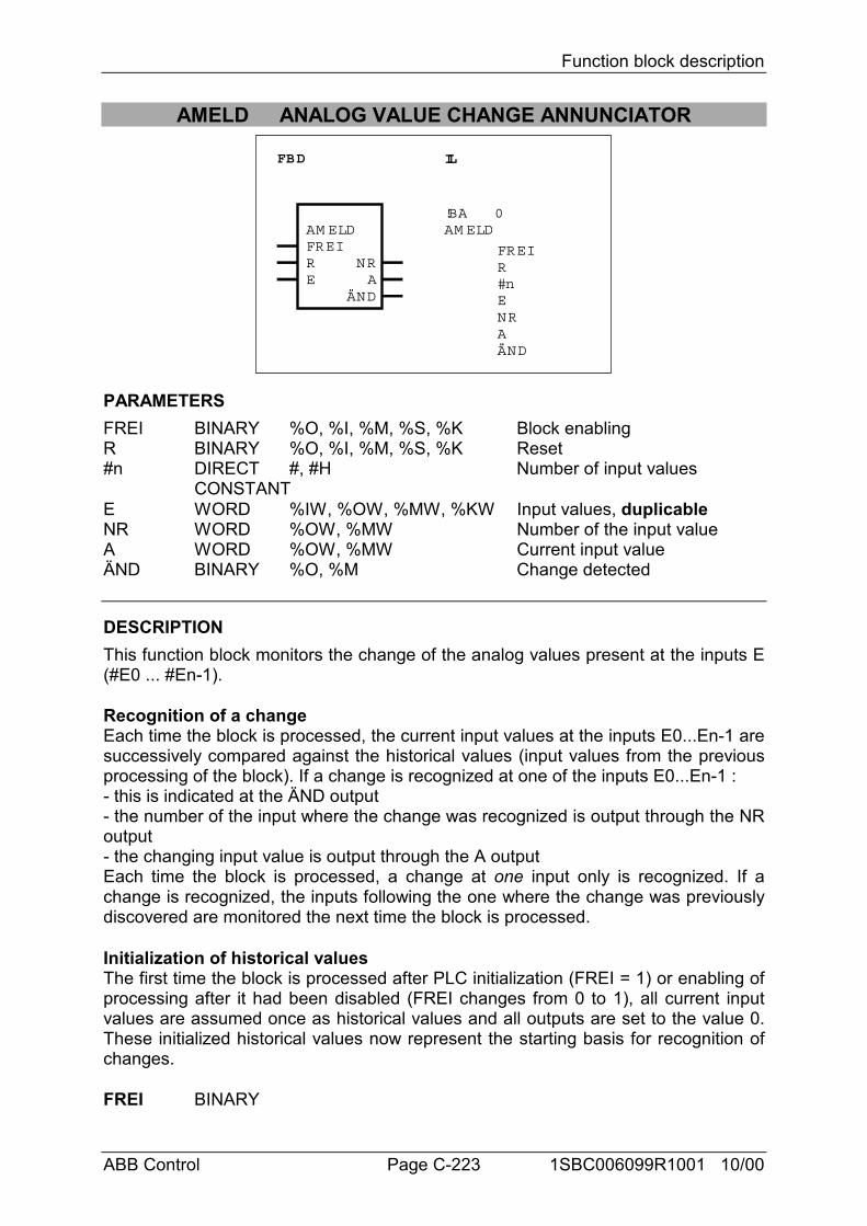
Function block description
ABB Control Page C-223 1SBC006099R1001 10/00
AMELD ANALOG VALUE CHANGE ANNUNCIATOR
FBD IL
AM ELDFREIRE
ÄND
NRA
!BAAM ELD
0
FREIR#nE
ÄND
NRA
PARAMETERSFREI BINARY %O, %I, %M, %S, %K Block enablingR BINARY %O, %I, %M, %S, %K Reset#n DIRECT #, #H Number of input values
CONSTANTE WORD %IW, %OW, %MW, %KW Input values, duplicableNR WORD %OW, %MW Number of the input valueA WORD %OW, %MW Current input valueÄND BINARY %O, %M Change detected
DESCRIPTIONThis function block monitors the change of the analog values present at the inputs E(#E0 ... #En-1).
Recognition of a changeEach time the block is processed, the current input values at the inputs E0...En-1 aresuccessively compared against the historical values (input values from the previousprocessing of the block). If a change is recognized at one of the inputs E0...En-1 :- this is indicated at the ÄND output- the number of the input where the change was recognized is output through the NRoutput- the changing input value is output through the A outputEach time the block is processed, a change at one input only is recognized. If achange is recognized, the inputs following the one where the change was previouslydiscovered are monitored the next time the block is processed.
Initialization of historical valuesThe first time the block is processed after PLC initialization (FREI = 1) or enabling ofprocessing after it had been disabled (FREI changes from 0 to 1), all current inputvalues are assumed once as historical values and all outputs are set to the value 0.These initialized historical values now represent the starting basis for recognition ofchanges.
FREI BINARY
Function block description
ABB Control Page C-224 1SBC006099R1001 10/00
Processing of the block is enabled with the FREI input.FREI = 0 -> Block is not processedFREI = 1 -> Processing of the block is enabledIf FREI = 0, the outputs of the block are also no longer updated.
R BINARYThe block can be reset with the R input.R = 0 -> No resetR = 1 -> Reset of the blockReset signifies :- Adoption of the current values at the inputs E0...En-1 as historical values.- All outputs are set to the value 0
#n DIRECT CONSTANTONLY in IL languageThe number of values to be monitored at the inputs E0...En-1 is specified at the input#n. The number is specified as a direct constant.Range for #n : 1 < #n < 127
E WORDThe input E can be duplicated (E0...En-1).The operands to be monitored for a change are specified at the inputs E.
NR WORDThe serial number of the input E0...En-1 where a change has been discovered isoutput through the output NR.If no output change is discovered during processing of the block, the number of theinput changing last is still output through the output NR.The following affiliations apply :Change discovered at E0 -> NR = 0Change discovered at E1 -> NR = 1Change discovered at En-1 -> NR = n-1
A WORDIf a change is discovered at one of the inputs E0...En-1, the changing input value isallocated to the output A.If no change is discovered at the inputs E0...En-1 during processing of the block, thevalue of the input changing last is still output through the output A.
ÄND BINARYThe output ÄND indicates whether or not a change has been discovered at theinputs E0...En-1.ÄND = 0 -> No change discoveredÄND = 1 -> Change discovered
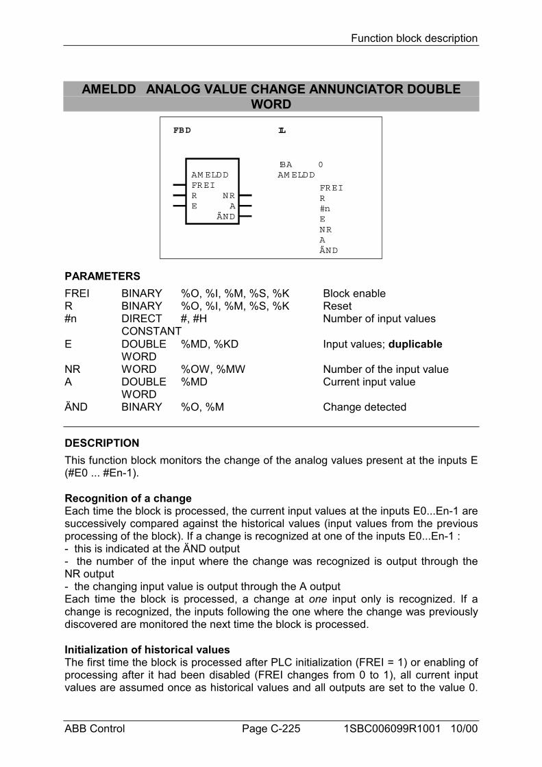
Function block description
ABB Control Page C-225 1SBC006099R1001 10/00
AMELDD ANALOG VALUE CHANGE ANNUNCIATOR DOUBLEWORD
FBD IL
AM ELDDFREIRE
ÄND
NRA
!BAAM ELDD
0
FREIR#nE
ÄND
NRA
PARAMETERSFREI BINARY %O, %I, %M, %S, %K Block enableR BINARY %O, %I, %M, %S, %K Reset#n DIRECT #, #H Number of input values
CONSTANTE DOUBLE %MD, %KD Input values; duplicable
WORDNR WORD %OW, %MW Number of the input valueA DOUBLE %MD Current input value
WORDÄND BINARY %O, %M Change detected
DESCRIPTIONThis function block monitors the change of the analog values present at the inputs E(#E0 ... #En-1).
Recognition of a changeEach time the block is processed, the current input values at the inputs E0...En-1 aresuccessively compared against the historical values (input values from the previousprocessing of the block). If a change is recognized at one of the inputs E0...En-1 :- this is indicated at the ÄND output- the number of the input where the change was recognized is output through theNR output- the changing input value is output through the A outputEach time the block is processed, a change at one input only is recognized. If achange is recognized, the inputs following the one where the change was previouslydiscovered are monitored the next time the block is processed.
Initialization of historical valuesThe first time the block is processed after PLC initialization (FREI = 1) or enabling ofprocessing after it had been disabled (FREI changes from 0 to 1), all current inputvalues are assumed once as historical values and all outputs are set to the value 0.
Function block description
ABB Control Page C-226 1SBC006099R1001 10/00
These initialized historical values now represent the starting basis for re–cognition ofchanges.
FREI BINARYProcessing of the block is enabled with the FREI input.FREI = 0 -> Block is not processedFREI = 1 -> Processing of the block is enabledIf FREI = 0, the outputs of the block are also no longer updated.
R BINARYThe block can be reset with the R input.R = 0 -> No resetR = 1 -> Reset of the blockReset signifies :- Adoption of the current values at the inputs E0...En-1 as historical values.- All outputs are set to the value 0.
#n DIRECT CONSTANTONLY used in IL languageThe number of values to be monitored at the inputs E0...En-1 are specified at input#n. Range for #n : 1 < #n < #63
E DOUBLE WORDThe input E can be duplicated (E0...En-1).The operands to be monitored for a change are specified at the inputs E0...En-1.
NR WORDThe serial number of the input E0...En-1 where a change has been discovered isoutput through the output NR.If no change is discovered during processing of the block the number of the inputchanging last is still output through the output NR.The following affiliations apply :Change discovered at E0 -> NR = 0Change discovered at E1 -> NR = 1Change discovered at En-1 -> NR = n-1
A DOUBLE WORDIf a change is discovered at one of the inputs E0...En-1, the changing input value isallocated to the output A.If no change is discovered at the inputs E0...En-1 during processing of the block, thevalue of the input changing last is still output through the output A.
ÄND BINARYThe output ÄND indicates whether or not a change has been discovered at theinputs E0...En-1.ÄND = 0 -> No change discoveredÄND = 1 -> Change discovered
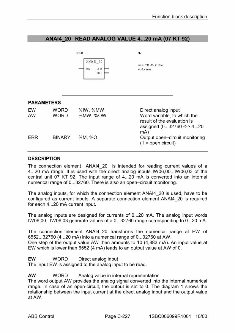
Function block description
ABB Control Page C-227 1SBC006099R1001 10/00
ANAI4_20 READ ANALOG VALUE 4...20 mA (07 KT 92)
see CE-IL in the
FBD IL
ANAI4_20
EW AWERR
software
PARAMETERSEW WORD %IW, %MW Direct analog inputAW WORD %MW, %OW Word variable, to which the
result of the evaluation is assigned (0...32760 <-> 4...20 mA)
ERR BINARY %M, %O Output open–circuit monitoring (1 = open circuit)
DESCRIPTIONThe connection element ANAI4_20 is intended for reading current values of a4...20 mA range. It is used with the direct analog inputs IW06,00...IW06,03 of thecentral unit 07 KT 92. The input range of 4...20 mA is converted into an internalnumerical range of 0...32760. There is also an open–circuit monitoring.
The analog inputs, for which the connection element ANAI4_20 is used, have to beconfigured as current inputs. A separate connection element ANAI4_20 is requiredfor each 4...20 mA current input.
The analog inputs are designed for currents of 0...20 mA. The analog input wordsIW06,00...IW06,03 generate values of a 0...32760 range corresponding to 0...20 mA.
The connection element ANAI4_20 transforms the numerical range at EW of6552...32760 (4...20 mA) into a numerical range of 0...32760 at AW.One step of the output value AW then amounts to 10 (4,883 mA). An input value atEW which is lower than 6552 (4 mA) leads to an output value at AW of 0.
EW WORD Direct analog inputThe input EW is assigned to the analog input to be read.
AW WORD Analog value in internal representationThe word output AW provides the analog signal converted into the internal numericalrange. In case of an open-circuit, the output is set to 0. The diagram 1 shows therelationship between the input current at the direct analog input and the output valueat AW.
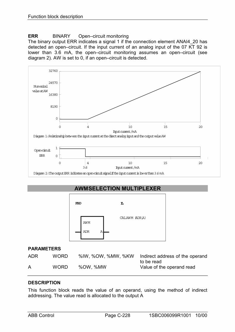
Function block description
ABB Control Page C-228 1SBC006099R1001 10/00
ERR BINARY Open–circuit monitoringThe binary output ERR indicates a signal 1 if the connection element ANAI4_20 hasdetected an open–circuit. If the input current of an analog input of the 07 KT 92 islower than 3.6 mA, the open–circuit monitoring assumes an open–circuit (seediagram 2). AW is set to 0, if an open–circuit is detected.
0 4 10 15 20Input current / mA
0
32760
24570
16380
8190
Numericalvalue at AW
0
1Open-circuit
ERR
3.6
0 4 10 15 20Input current / mA
Diagram 1: Relationship between the input current at the direct analog input and the output value AW
Diagram 2: The output ERR indicates an open-circuit signal if the input current is lower than 3.6 mA
AWMSELECTION MULTIPLEXER
FBD IL
AWM
ADR A
CAL AWM (ADR,A)
PARAMETERSADR WORD %IW, %OW, %MW, %KW Indirect address of the operand
to be readA WORD %OW, %MW Value of the operand read
DESCRIPTIONThis function block reads the value of an operand, using the method of indirectaddressing. The value read is allocated to the output A
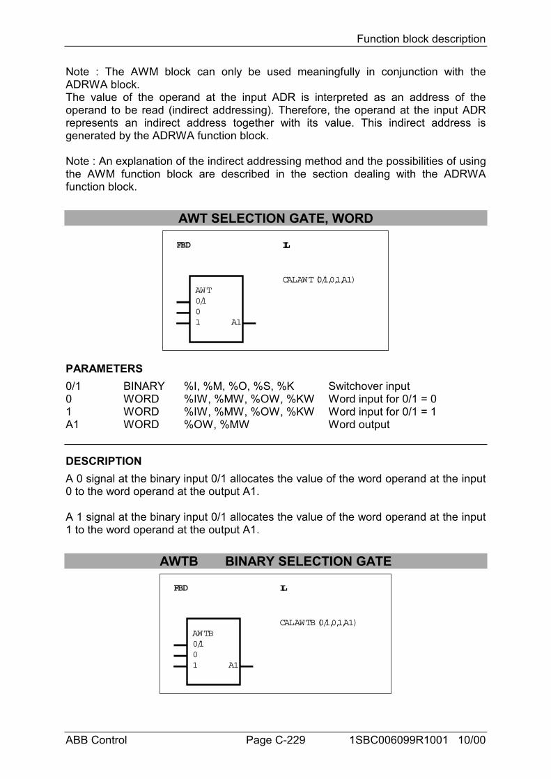
Function block description
ABB Control Page C-229 1SBC006099R1001 10/00
Note : The AWM block can only be used meaningfully in conjunction with theADRWA block.The value of the operand at the input ADR is interpreted as an address of theoperand to be read (indirect addressing). Therefore, the operand at the input ADRrepresents an indirect address together with its value. This indirect address isgenerated by the ADRWA function block.
Note : An explanation of the indirect addressing method and the possibilities of usingthe AWM function block are described in the section dealing with the ADRWAfunction block.
AWT SELECTION GATE, WORD
FBD IL
AWT0/101 A1
CAL AWT (0/1,0,1,A1)
PARAMETERS0/1 BINARY %I, %M, %O, %S, %K Switchover input0 WORD %IW, %MW, %OW, %KW Word input for 0/1 = 01 WORD %IW, %MW, %OW, %KW Word input for 0/1 = 1A1 WORD %OW, %MW Word output
DESCRIPTIONA 0 signal at the binary input 0/1 allocates the value of the word operand at the input0 to the word operand at the output A1.
A 1 signal at the binary input 0/1 allocates the value of the word operand at the input1 to the word operand at the output A1.
AWTB BINARY SELECTION GATE
FBD IL
AWTB0/101 A1
CAL AWTB (0/1,0,1,A1)
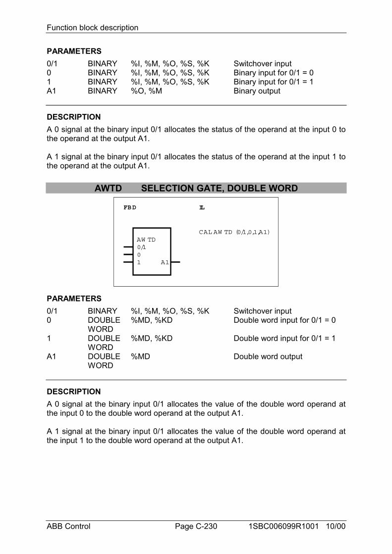
Function block description
ABB Control Page C-230 1SBC006099R1001 10/00
PARAMETERS0/1 BINARY %I, %M, %O, %S, %K Switchover input0 BINARY %I, %M, %O, %S, %K Binary input for 0/1 = 01 BINARY %I, %M, %O, %S, %K Binary input for 0/1 = 1A1 BINARY %O, %M Binary output
DESCRIPTIONA 0 signal at the binary input 0/1 allocates the status of the operand at the input 0 tothe operand at the output A1.
A 1 signal at the binary input 0/1 allocates the status of the operand at the input 1 tothe operand at the output A1.
AWTD SELECTION GATE, DOUBLE WORD
FBD IL
AW TD0/101 A1
CAL AW TD (0/1,0,1,A1)
PARAMETERS0/1 BINARY %I, %M, %O, %S, %K Switchover input0 DOUBLE %MD, %KD Double word input for 0/1 = 0
WORD1 DOUBLE %MD, %KD Double word input for 0/1 = 1
WORDA1 DOUBLE %MD Double word output
WORD
DESCRIPTIONA 0 signal at the binary input 0/1 allocates the value of the double word operand atthe input 0 to the double word operand at the output A1.
A 1 signal at the binary input 0/1 allocates the value of the double word operand atthe input 1 to the double word operand at the output A1.
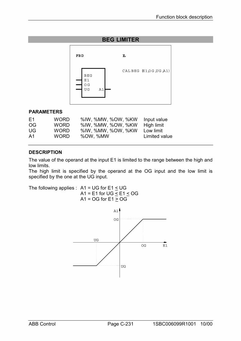
Function block description
ABB Control Page C-231 1SBC006099R1001 10/00
BEG LIMITER
FBD IL
BEGE1O GUG A1
CAL BEG (E1,O G ,UG ,A1)
PARAMETERSE1 WORD %IW, %MW, %OW, %KW Input valueOG WORD %IW, %MW, %OW, %KW High limitUG WORD %IW, %MW, %OW, %KW Low limitA1 WORD %OW, %MW Limited value
DESCRIPTIONThe value of the operand at the input E1 is limited to the range between the high andlow limits.The high limit is specified by the operand at the OG input and the low limit isspecified by the one at the UG input.
The following applies : A1 = UG for E1 < UGA1 = E1 for UG < E1 < OGA1 = OG for E1 > OG
A1
E1
OG
UG
OG
UG
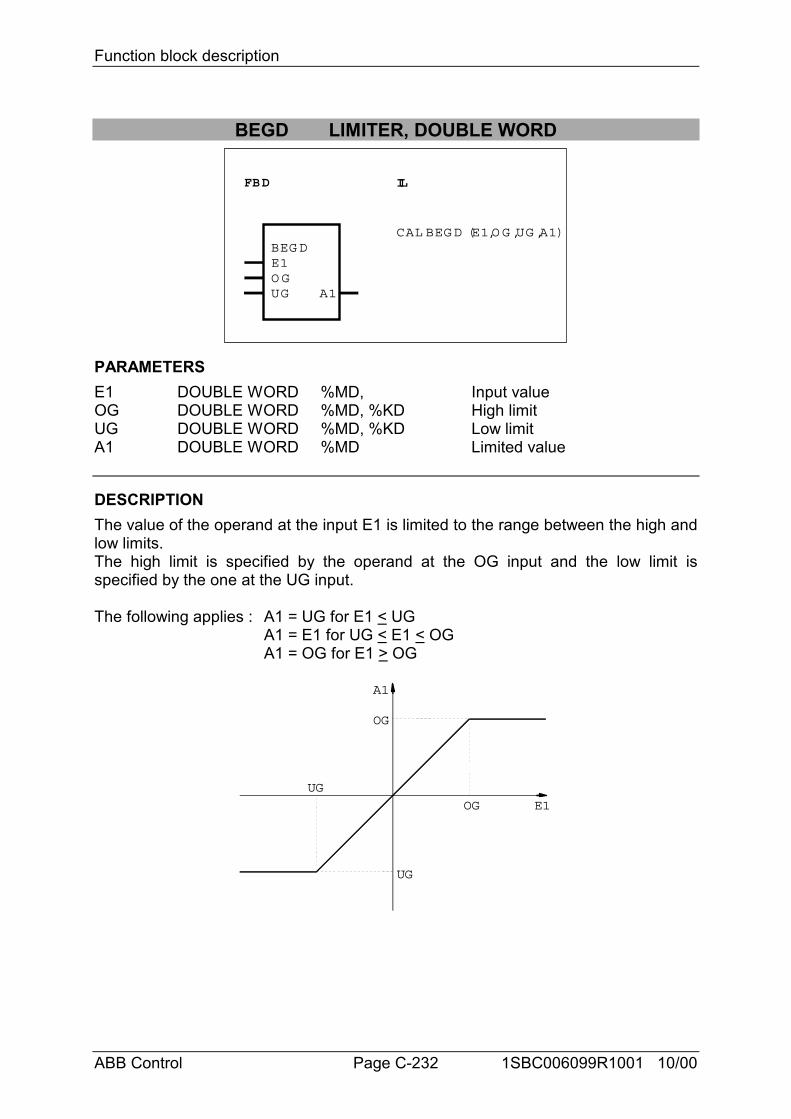
Function block description
ABB Control Page C-232 1SBC006099R1001 10/00
BEGD LIMITER, DOUBLE WORD
FBD IL
BEG DE1O GUG A1
CAL BEG D (E1,O G ,UG ,A1)
PARAMETERSE1 DOUBLE WORD %MD, Input valueOG DOUBLE WORD %MD, %KD High limitUG DOUBLE WORD %MD, %KD Low limitA1 DOUBLE WORD %MD Limited value
DESCRIPTIONThe value of the operand at the input E1 is limited to the range between the high andlow limits.The high limit is specified by the operand at the OG input and the low limit isspecified by the one at the UG input.
The following applies : A1 = UG for E1 < UGA1 = E1 for UG < E1 < OGA1 = OG for E1 > OG
A1
E1
OG
UG
OG
UG
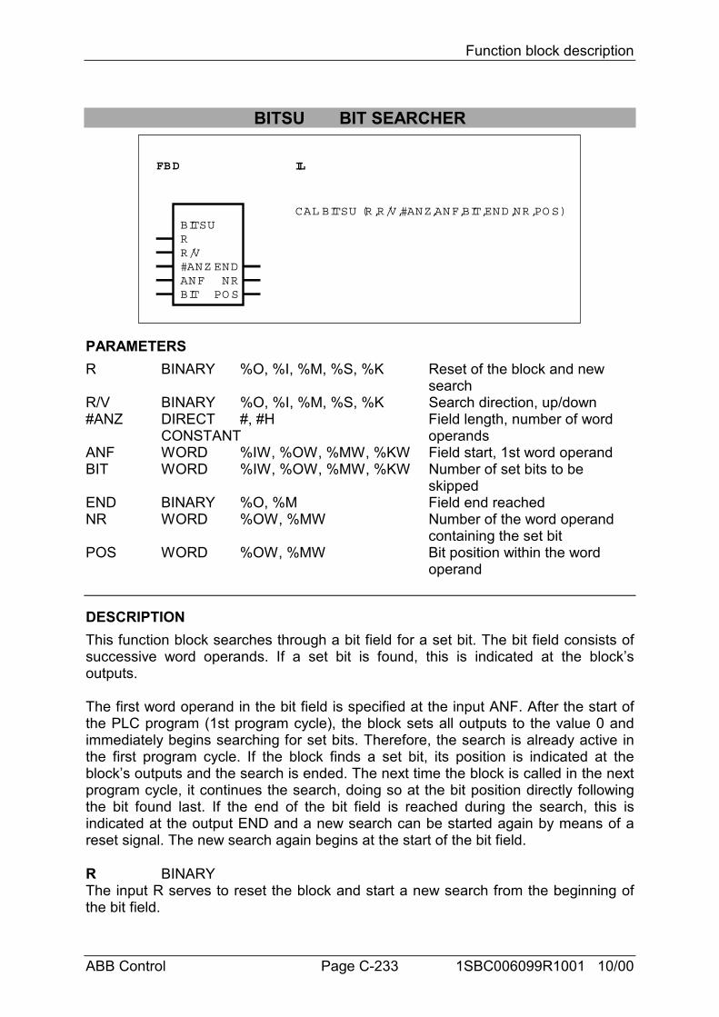
Function block description
ABB Control Page C-233 1SBC006099R1001 10/00
BITSU BIT SEARCHER
FBD IL
BITSURR/V#ANZANFBIT
NRPO S
END
CAL BITSU (R,R/V,#ANZ,ANF,BIT,END,NR,PO S)
PARAMETERSR BINARY %O, %I, %M, %S, %K Reset of the block and new
searchR/V BINARY %O, %I, %M, %S, %K Search direction, up/down#ANZ DIRECT #, #H Field length, number of word
CONSTANT operandsANF WORD %IW, %OW, %MW, %KW Field start, 1st word operandBIT WORD %IW, %OW, %MW, %KW Number of set bits to be
skippedEND BINARY %O, %M Field end reachedNR WORD %OW, %MW Number of the word operand
containing the set bitPOS WORD %OW, %MW Bit position within the word
operand
DESCRIPTIONThis function block searches through a bit field for a set bit. The bit field consists ofsuccessive word operands. If a set bit is found, this is indicated at the block’soutputs.
The first word operand in the bit field is specified at the input ANF. After the start ofthe PLC program (1st program cycle), the block sets all outputs to the value 0 andimmediately begins searching for set bits. Therefore, the search is already active inthe first program cycle. If the block finds a set bit, its position is indicated at theblock’s outputs and the search is ended. The next time the block is called in the nextprogram cycle, it continues the search, doing so at the bit position directly followingthe bit found last. If the end of the bit field is reached during the search, this isindicated at the output END and a new search can be started again by means of areset signal. The new search again begins at the start of the bit field.
R BINARYThe input R serves to reset the block and start a new search from the beginning ofthe bit field.
Function block description
ABB Control Page C-234 1SBC006099R1001 10/00
R = 0 -> No resetR = 1 -> Reset is triggeredA 1 signal at the input R resets all of the block’s outputs to the value 0 and results inimmediate starting of a new search from the beginning of the bit field. Therefore, thenew search begins in the same processing cycle in which the block’s outputs arereset. The search within the reset cycle ends either at the first set bit or, if no bit isset, at the end of the field. The next time the block is called, the reset input must beset to 0 so that the block will be able to continue searching through the bit field forset bits. The reset input is dominant with respect to the other inputs.
R/V BINARYThe searching direction is specified at the input R/V.R/V = 0 -> Search down : The start of the bit field within the meaning of the search is
identical with the physical start of the bit field.R/V = 1 -> Search up : The start of the bit field within the meaning of the search is
identical with the physical end of the bit field.
#ANZ DIRECT CONSTANTThe number of word operands in which the bit field consists is specified at the input#ANZ. This is specified as a direct constant.
ANF WORDThe word operand with which the bit field physically begins is specified at the inputANF. The entire bit field consists in the operand at the input ANF and in thesubsequent operands corresponding to the operand numbering. The total number ofword operands is specified at the input #ANZ.
BIT WORDThe way in which the function block is to indicate the bits set in the bit field isspecified at the input BIT.BIT = 1 -> Each set bit in the bit field is indicated at the outputs NR and POS.BIT = 2 -> The first set bit in the bit field is indicated and then only every second set
bit of the other set bits in the bit field is indicated.BIT = 3 -> The first set bit in the bit field is indicated and then only every third set
bit of the other set bits in the bit field is indicated.BIT = n -> The first set bit in the bit field is indicated and then only every n-th set
bit of the other set bits in the bit field is indicated.
- Special function : BIT = 0- If the block finds a set bit, in the next program cycle the search is not automaticallycontinued at the subsequent bit position. The search is interrupted at this point untilthe bit found has assumed the significance 0. During interruption of the search, theposition of the bit found last continues to be indicated at the outputs. If the bit foundlast assumes the value 0, the search is continued at the next bit position. If a furtherbit is set in the selected search direction, this bit’s position is indicated and thesearch is interrupted again. If no more bits are set in the search direction, theposition of the bit found last is indicated. The output END is set to 1.- If no bits are set after a reset, the block runs through the bit field up to its end andstops there. The output END is set to one. The outputs NR and POS are set to 0.- If bits are set after a reset, the block indicates the first set bit in the search direction
Function block description
ABB Control Page C-235 1SBC006099R1001 10/00
and stops at this bit.
END BINARYWhether or not the end of the bit field has been reached during the search isindicated at the END output.END = 0 -> End of the bit field not reachedEND = 1 -> End of the bit field reachedSearch down : The end of the bit field is defined by bit position 15 in the last wordoperand of the physical bit field.Search up :The end of the bit field is defined by bit position 15 in the first wordoperand of the physical bit field.If the bit is set at the last bit position of the field and it is found and indicated during asearch, the output END is not yet set to the value 1. This is not done until the nextprocessing cycle of the block. Therefore, the prerequisite for setting the output ENDis that no set bit has been found during the current search.
NR, POS WORDIf the block finds a set bit in the planned bit field, its position is indicated at theoutputs NR and POS.Meanings :NR : Current number of the word operand in which the set bit has been found.POS : Position of the set bit within the word operand.
Current number of the word operandNR = 0 -> 1st word operand of the bit fieldNR = 1 -> 2nd word operand of the bit field. . .. . .NR = n-1 -> nth word operand of the bit field
The word operands are numbered in the sense of the search.Therefore, the following applies to down searching :First word operand -> first word operand of the physical bit fieldLast word operand -> last word operand of the physical bit field
Therefore, the following applies to up searching :First word operand -> last word operand of the physical bit fieldLast word operand -> first word operand of the physical bit field
Position of the set bit within the word operandNumbering within a word operand is from 0...15. At the same time, position 0corresponds to the least significant bit and position 15 to the most significant bitwithin the word operand.If the end of the field is reached during a search without a set bit having been found,the position of the bit found last continues to be output through the output NR andthe output POS. This takes place until a new search is compelled from the start ofthe bit field by a reset at the input R.If no bits are set at all within the entire bit field, the outputs assume the followingvalues at the end of the first search : END = 1
NR = 0
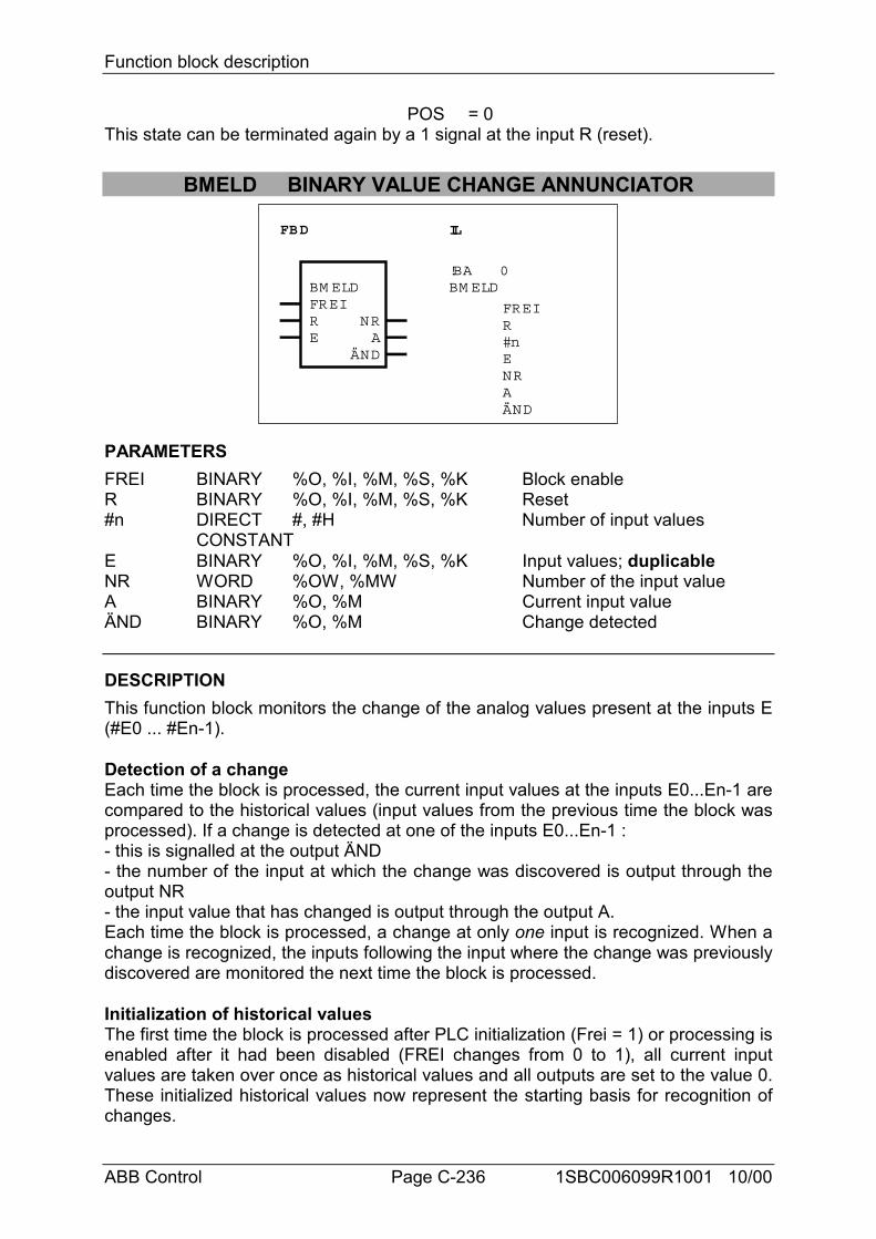
Function block description
ABB Control Page C-236 1SBC006099R1001 10/00
POS = 0This state can be terminated again by a 1 signal at the input R (reset).
BMELD BINARY VALUE CHANGE ANNUNCIATOR
FBD IL
BM ELDFREIRE
ÄND
NRA
!BABM ELD
0
FREIR#nE
ÄND
NRA
PARAMETERSFREI BINARY %O, %I, %M, %S, %K Block enableR BINARY %O, %I, %M, %S, %K Reset#n DIRECT #, #H Number of input values
CONSTANTE BINARY %O, %I, %M, %S, %K Input values; duplicableNR WORD %OW, %MW Number of the input valueA BINARY %O, %M Current input valueÄND BINARY %O, %M Change detected
DESCRIPTIONThis function block monitors the change of the analog values present at the inputs E(#E0 ... #En-1).
Detection of a changeEach time the block is processed, the current input values at the inputs E0...En-1 arecompared to the historical values (input values from the previous time the block wasprocessed). If a change is detected at one of the inputs E0...En-1 :- this is signalled at the output ÄND- the number of the input at which the change was discovered is output through theoutput NR- the input value that has changed is output through the output A.Each time the block is processed, a change at only one input is recognized. When achange is recognized, the inputs following the input where the change was previouslydiscovered are monitored the next time the block is processed.
Initialization of historical valuesThe first time the block is processed after PLC initialization (Frei = 1) or processing isenabled after it had been disabled (FREI changes from 0 to 1), all current inputvalues are taken over once as historical values and all outputs are set to the value 0.These initialized historical values now represent the starting basis for recognition ofchanges.
Function block description
ABB Control Page C-237 1SBC006099R1001 10/00
FREI BINARYProcessing of the block is enabled with the FREI input.FREI = 0 -> Block is not processedFREI = 1 -> Processing of the block is enabledIf FREI = 0, the block’s outputs are also no longer updated.
R BINARYThe block can be reset with the R input.R = 0 -> No resetR = 1 -> Reset of the blockReset signifies :- Adoption of the current values at the inputs E0...En-1 as historical values.- All outputs are set to the value 0.
#n DIRECT CONSTANTONLY used in IL languageThe number of values to be monitored at the inputs E0...En-1 are specified at the #ninput. This is specified as a direct constant.Range for #n : < #n < 127
E BINARYThe input E is capable of duplication (E0...En-1).The operands to be monitored for a change are specified at the inputs E0...En-1.
NR WORDThe serial number of the input E0...En-1 where a change has been discovered isoutput through the output NR.If no change is discovered during processing of the block, the number of the inputthat changed last continues to be output through the output NR.The following affiliations apply :Change discovered at E0 -> NR = 0Change discovered at E1 -> NR = 1Change discovered at En-1 -> NR = n-1
A BINARYIf a change is discovered at one of the inputs E0...En-1, the input value that haschanged is allocated to the output A.If no change is discovered at the inputs E0...En-1 during processing of the block, thevalue of the input that has changed last continues to be output through the output A.
ÄND BINARYThe output ÄND indicates whether or not a change has been discovered at theinputs E0...En-1.ÄND = 0 -> No change discoveredÄND = 1 -> Change discovered
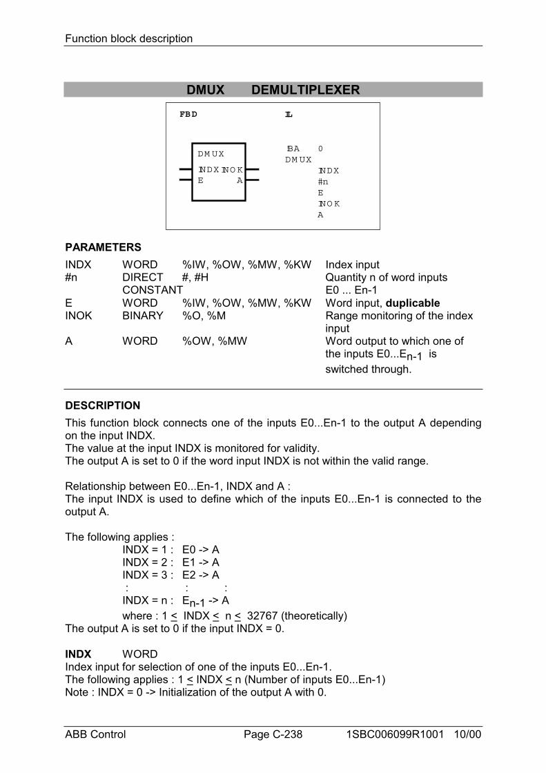
Function block description
ABB Control Page C-238 1SBC006099R1001 10/00
DMUX DEMULTIPLEXERFBD IL
!BA 0DM UX
INDX#nEINO KA
DM UX
INDXE
INO KA
PARAMETERSINDX WORD %IW, %OW, %MW, %KW Index input#n DIRECT #, #H Quantity n of word inputs
CONSTANT E0 ... En-1E WORD %IW, %OW, %MW, %KW Word input, duplicableINOK BINARY %O, %M Range monitoring of the index
inputA WORD %OW, %MW Word output to which one of
the inputs E0...En-1 is switched through.
DESCRIPTIONThis function block connects one of the inputs E0...En-1 to the output A dependingon the input INDX.The value at the input INDX is monitored for validity.The output A is set to 0 if the word input INDX is not within the valid range.
Relationship between E0...En-1, INDX and A :The input INDX is used to define which of the inputs E0...En-1 is connected to theoutput A.
The following applies :INDX = 1 : E0 -> AINDX = 2 : E1 -> AINDX = 3 : E2 -> A : : :INDX = n : En-1 -> Awhere : 1 < INDX < n < 32767 (theoretically)
The output A is set to 0 if the input INDX = 0.
INDX WORDIndex input for selection of one of the inputs E0...En-1.The following applies : 1 < INDX < n (Number of inputs E0...En-1)Note : INDX = 0 -> Initialization of the output A with 0.
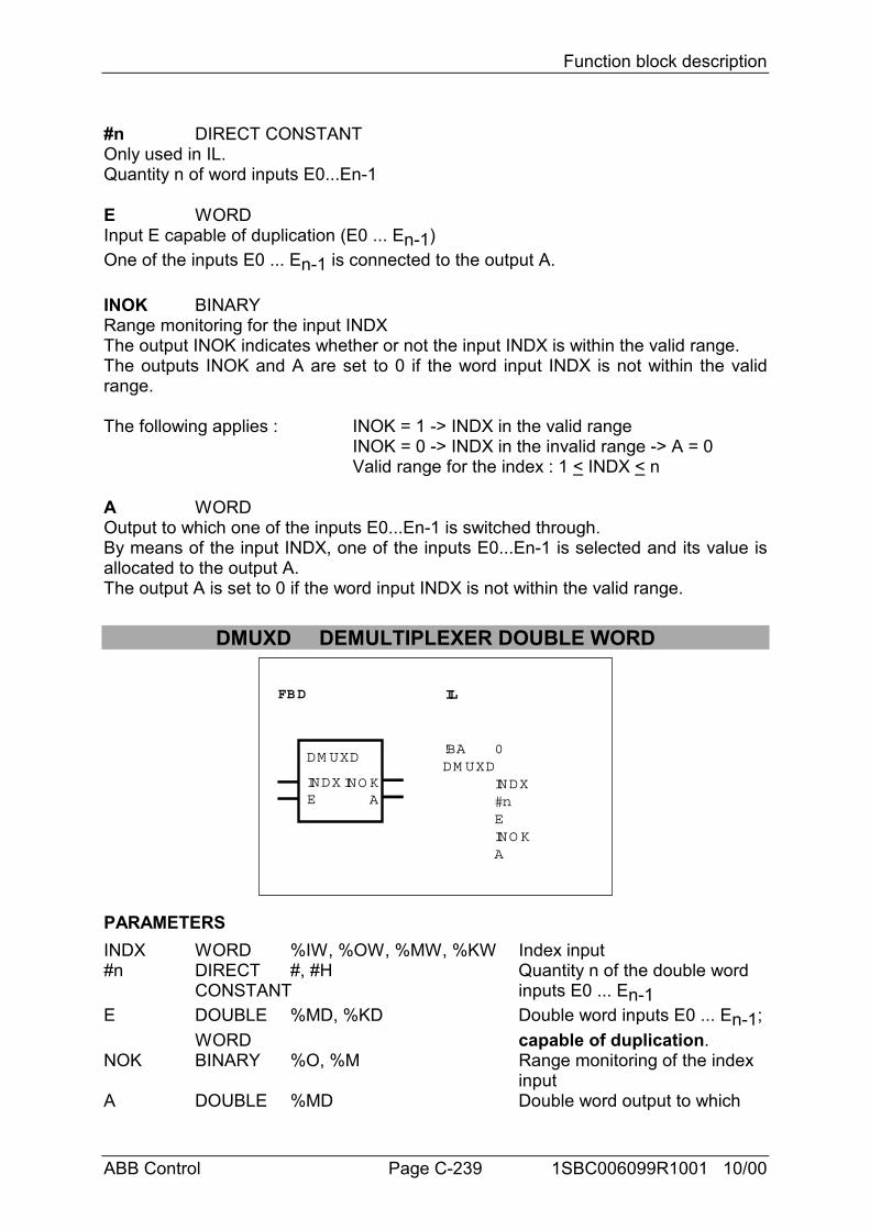
Function block description
ABB Control Page C-239 1SBC006099R1001 10/00
#n DIRECT CONSTANTOnly used in IL.Quantity n of word inputs E0...En-1
E WORDInput E capable of duplication (E0 ... En-1)One of the inputs E0 ... En-1 is connected to the output A.
INOK BINARYRange monitoring for the input INDXThe output INOK indicates whether or not the input INDX is within the valid range.The outputs INOK and A are set to 0 if the word input INDX is not within the validrange.
The following applies : INOK = 1 -> INDX in the valid rangeINOK = 0 -> INDX in the invalid range -> A = 0Valid range for the index : 1 < INDX < n
A WORDOutput to which one of the inputs E0...En-1 is switched through.By means of the input INDX, one of the inputs E0...En-1 is selected and its value isallocated to the output A.The output A is set to 0 if the word input INDX is not within the valid range.
DMUXD DEMULTIPLEXER DOUBLE WORD
FBD IL
!BA 0DM UXD
INDX#nEINO KA
DM UXD
INDXE A
INO K
PARAMETERSINDX WORD %IW, %OW, %MW, %KW Index input#n DIRECT #, #H Quantity n of the double word
CONSTANT inputs E0 ... En-1E DOUBLE %MD, %KD Double word inputs E0 ... En-1;
WORD capable of duplication.NOK BINARY %O, %M Range monitoring of the index
inputA DOUBLE %MD Double word output to which
Function block description
ABB Control Page C-240 1SBC006099R1001 10/00
WORD one of the inputs E0 ... En-1 is switched through.
DESCRIPTIONThis function block connects one of the inputs E0...En-1 to the output A dependingon the input INDX.The value at the input INDX is checked for validity. The output A is set to 0 if theword input INDX is not within the valid range.
Relationship between E0 ... En-1, INDX and A :The input INDX is used to define which of the inputs E0 ... En-1 is connected to theoutput A.
The following applies :
INDX = 1 : E0 -> AINDX = 2 : E1 -> AINDX = 3 : E2 -> A : : : :INDX = n : En-1 -> Awhere : 1 < INDX < n < 32767 (theoretically)
Note : The output A is is set to 0 if the input INDX = 0.
INDX WORDIndex input for selection of one of the inputs E0 ... En-1.The following applies : 1 < INDX < n (number of inputs E0 ... En-1)Note : INDX = 0 -> Initialization of the output A with 0.
#n DIRECT CONSTANTOnly used in IL.Quantity n of double word inputs E0 ... En-1.
E DOUBLE WORDInput E capable of duplication (E0 ... En-1)One of the n inputs E0 ... En-1 is connected to the output A.
INOK BINARYRange monitoring for the input INDXThe output INOK indicates whether or not the input INDX is within the valid range.The outputs INOK and A are set to 0 if the word input INDX is not within the validrange.
The following applies : INOK = 1 -> INDX within the valid rangeINOK = 0 -> INDX in the invalid range -> A = 0Valid range for the index : 1 < INDX < n
A DOUBLE WORD
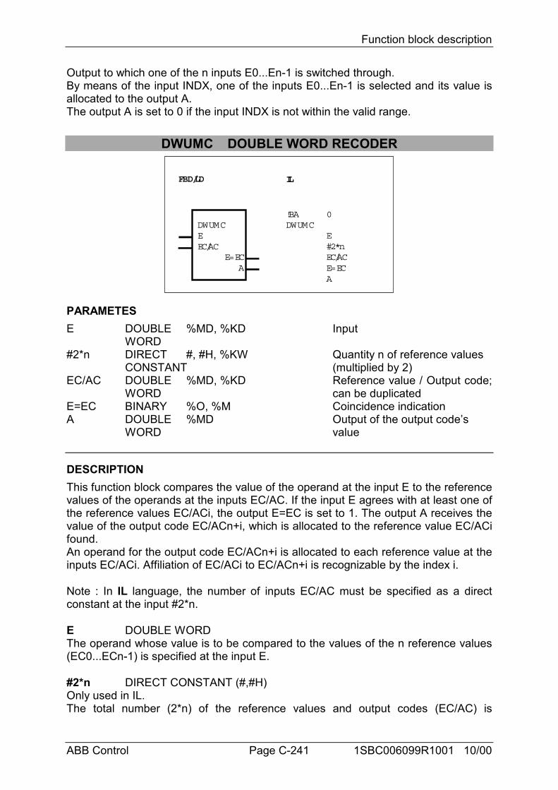
Function block description
ABB Control Page C-241 1SBC006099R1001 10/00
Output to which one of the n inputs E0...En-1 is switched through.By means of the input INDX, one of the inputs E0...En-1 is selected and its value isallocated to the output A.The output A is set to 0 if the input INDX is not within the valid range.
DWUMC DOUBLE WORD RECODER
FBD/LD IL
DWUMCEEC/AC
AE=EC
!BADWUMC
0
E#2*nEC/ACE=ECA
PARAMETESE DOUBLE %MD, %KD Input
WORD#2*n DIRECT #, #H, %KW Quantity n of reference values
CONSTANT (multiplied by 2)EC/AC DOUBLE %MD, %KD Reference value / Output code;
WORD can be duplicatedE=EC BINARY %O, %M Coincidence indicationA DOUBLE %MD Output of the output code’s
WORD value
DESCRIPTIONThis function block compares the value of the operand at the input E to the referencevalues of the operands at the inputs EC/AC. If the input E agrees with at least one ofthe reference values EC/ACi, the output E=EC is set to 1. The output A receives thevalue of the output code EC/ACn+i, which is allocated to the reference value EC/ACifound.An operand for the output code EC/ACn+i is allocated to each reference value at theinputs EC/ACi. Affiliation of EC/ACi to EC/ACn+i is recognizable by the index i.
Note : In IL language, the number of inputs EC/AC must be specified as a directconstant at the input #2*n.
E DOUBLE WORDThe operand whose value is to be compared to the values of the n reference values(EC0...ECn-1) is specified at the input E.
#2*n DIRECT CONSTANT (#,#H)Only used in IL.The total number (2*n) of the reference values and output codes (EC/AC) is
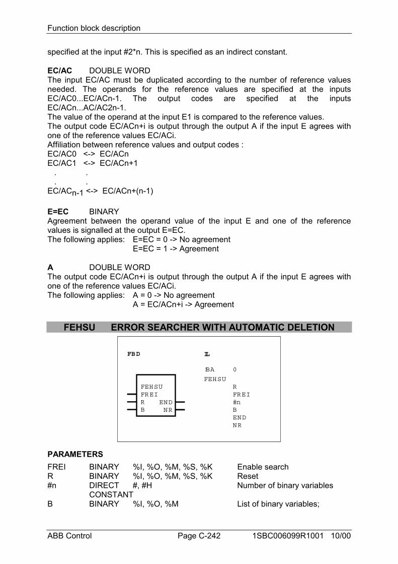
Function block description
ABB Control Page C-242 1SBC006099R1001 10/00
specified at the input #2*n. This is specified as an indirect constant.
EC/AC DOUBLE WORDThe input EC/AC must be duplicated according to the number of reference valuesneeded. The operands for the reference values are specified at the inputsEC/AC0...EC/ACn-1. The output codes are specified at the inputsEC/ACn...AC/AC2n-1.The value of the operand at the input E1 is compared to the reference values.The output code EC/ACn+i is output through the output A if the input E agrees withone of the reference values EC/ACi.Affiliation between reference values and output codes :EC/AC0 <-> EC/ACnEC/AC1 <-> EC/ACn+1 . . . .EC/ACn-1 <-> EC/ACn+(n-1)
E=EC BINARYAgreement between the operand value of the input E and one of the referencevalues is signalled at the output E=EC.The following applies: E=EC = 0 -> No agreement
E=EC = 1 -> Agreement
A DOUBLE WORDThe output code EC/ACn+i is output through the output A if the input E agrees withone of the reference values EC/ACi.The following applies: A = 0 -> No agreement
A = EC/ACn+i -> Agreement
FEHSU ERROR SEARCHER WITH AUTOMATIC DELETION
FBD IL
FEHSUFREIRB
FEHSU
!BA 0
NREND
RFREI#nB
NREND
PARAMETERSFREI BINARY %I, %O, %M, %S, %K Enable searchR BINARY %I, %O, %M, %S, %K Reset#n DIRECT #, #H Number of binary variables
CONSTANTB BINARY %I, %O, %M List of binary variables;
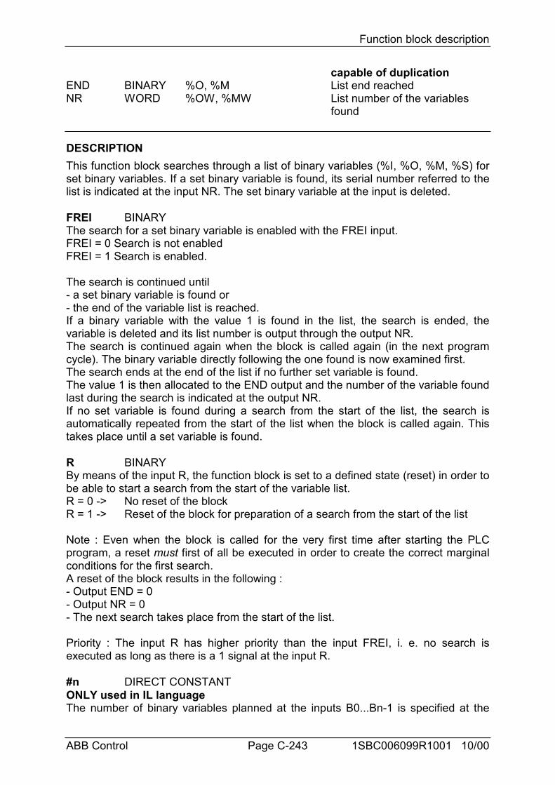
Function block description
ABB Control Page C-243 1SBC006099R1001 10/00
capable of duplicationEND BINARY %O, %M List end reachedNR WORD %OW, %MW List number of the variables
found
DESCRIPTIONThis function block searches through a list of binary variables (%I, %O, %M, %S) forset binary variables. If a set binary variable is found, its serial number referred to thelist is indicated at the input NR. The set binary variable at the input is deleted.
FREI BINARYThe search for a set binary variable is enabled with the FREI input.FREI = 0 Search is not enabledFREI = 1 Search is enabled.
The search is continued until- a set binary variable is found or- the end of the variable list is reached.If a binary variable with the value 1 is found in the list, the search is ended, thevariable is deleted and its list number is output through the output NR.The search is continued again when the block is called again (in the next programcycle). The binary variable directly following the one found is now examined first.The search ends at the end of the list if no further set variable is found.The value 1 is then allocated to the END output and the number of the variable foundlast during the search is indicated at the output NR.If no set variable is found during a search from the start of the list, the search isautomatically repeated from the start of the list when the block is called again. Thistakes place until a set variable is found.
R BINARYBy means of the input R, the function block is set to a defined state (reset) in order tobe able to start a search from the start of the variable list.R = 0 -> No reset of the blockR = 1 -> Reset of the block for preparation of a search from the start of the list
Note : Even when the block is called for the very first time after starting the PLCprogram, a reset must first of all be executed in order to create the correct marginalconditions for the first search.A reset of the block results in the following :- Output END = 0- Output NR = 0- The next search takes place from the start of the list.
Priority : The input R has higher priority than the input FREI, i. e. no search isexecuted as long as there is a 1 signal at the input R.
#n DIRECT CONSTANTONLY used in IL languageThe number of binary variables planned at the inputs B0...Bn-1 is specified at the
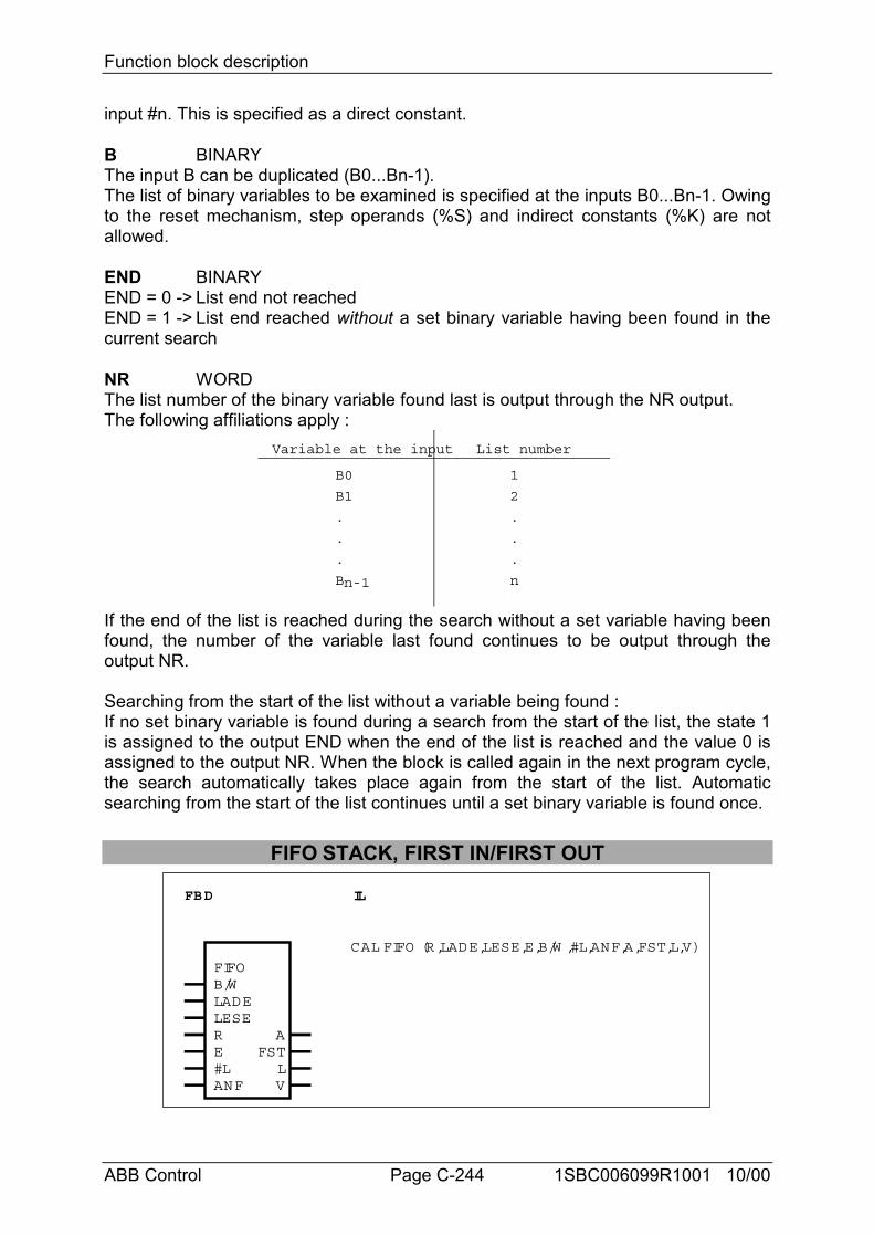
Function block description
ABB Control Page C-244 1SBC006099R1001 10/00
input #n. This is specified as a direct constant.
B BINARYThe input B can be duplicated (B0...Bn-1).The list of binary variables to be examined is specified at the inputs B0...Bn-1. Owingto the reset mechanism, step operands (%S) and indirect constants (%K) are notallowed.
END BINARYEND = 0 -> List end not reachedEND = 1 -> List end reached without a set binary variable having been found in thecurrent search
NR WORDThe list number of the binary variable found last is output through the NR output.The following affiliations apply :
Variable at the input List number
B0
B1
.
.
.
Bn-1
1
2
.
.
.
n
If the end of the list is reached during the search without a set variable having beenfound, the number of the variable last found continues to be output through theoutput NR.
Searching from the start of the list without a variable being found :If no set binary variable is found during a search from the start of the list, the state 1is assigned to the output END when the end of the list is reached and the value 0 isassigned to the output NR. When the block is called again in the next program cycle,the search automatically takes place again from the start of the list. Automaticsearching from the start of the list continues until a set binary variable is found once.
FIFO STACK, FIRST IN/FIRST OUT
FBD IL
FIFOB/WLADELESERE
AFST
LV
CAL FIFO (R,LADE,LESE,E,B/W ,#L,ANF,A,FST,L,V)
#LANF
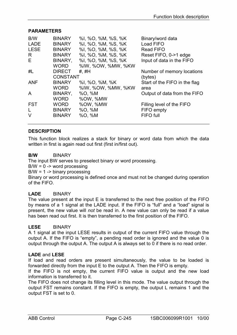
Function block description
ABB Control Page C-245 1SBC006099R1001 10/00
PARAMETERSB/W BINARY %I, %O, %M, %S, %K Binary/word dataLADE BINARY %I, %O, %M, %S, %K Load FIFOLESE BINARY %I, %O, %M, %S, %K Read FIFOR BINARY %I, %O, %M, %S, %K Reset FIFO, 0->1 edgeE BINARY, %I, %O, %M, %S, %K Input of data in the FIFO
WORD %IW, %OW, %MW, %KW#L DIRECT #, #H Number of memory locations
CONSTANT (bytes)ANF BINARY %I, %O, %M, %K Start of the FIFO in the flag
WORD %IW, %OW, %MW, %KW areaA BINARY, %O, %M Output of data from the FIFO
WORD %OW, %MWFST WORD %OW, %MW Filling level of the FIFOL BINARY %O, %M FIFO emptyV BINARY %O, %M FIFO full
DESCRIPTIONThis function block realizes a stack for binary or word data from which the datawritten in first is again read out first (first in/first out).
B/W BINARYThe input BW serves to preselect binary or word processing.B/W = 0 -> word processingB/W = 1 -> binary processingBinary or word processing is defined once and must not be changed during operationof the FIFO.
LADE BINARYThe value present at the input E is transferred to the next free position of the FIFOby means of a 1 signal at the LADE input. If the FIFO is “full” and a “load” signal ispresent, the new value will not be read in. A new value can only be read if a valuehas been read out first. It is then transferred to the first position of the FIFO.
LESE BINARYA 1 signal at the input LESE results in output of the current FIFO value through theoutput A. If the FIFO is “empty”, a pending read order is ignored and the value 0 isoutput through the output A. The output A is always set to 0 if there is no read order.
LADE and LESEIf load and read orders are present simultaneously, the value to be loaded isforwarded directly from the input E to the output A. Then the FIFO is empty.If the FIFO is not empty, the current FIFO value is output and the new loadinformation is transferred to it.The FIFO does not change its filling level in this mode. The value output through theoutput FST remains constant. If the FIFO is empty, the output L remains 1 and theoutput FST is set to 0.
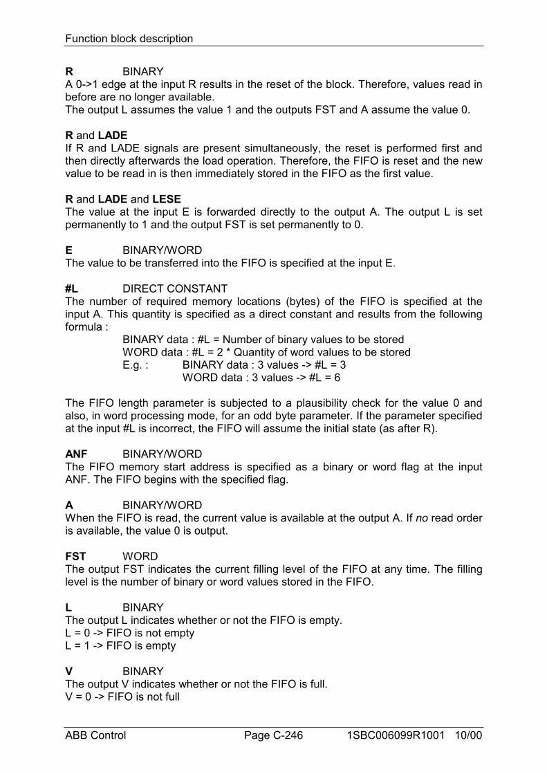
Function block description
ABB Control Page C-246 1SBC006099R1001 10/00
R BINARYA 0->1 edge at the input R results in the reset of the block. Therefore, values read inbefore are no longer available.The output L assumes the value 1 and the outputs FST and A assume the value 0.
R and LADEIf R and LADE signals are present simultaneously, the reset is performed first andthen directly afterwards the load operation. Therefore, the FIFO is reset and the newvalue to be read in is then immediately stored in the FIFO as the first value.
R and LADE and LESEThe value at the input E is forwarded directly to the output A. The output L is setpermanently to 1 and the output FST is set permanently to 0.
E BINARY/WORDThe value to be transferred into the FIFO is specified at the input E.
#L DIRECT CONSTANTThe number of required memory locations (bytes) of the FIFO is specified at theinput A. This quantity is specified as a direct constant and results from the followingformula :
BINARY data : #L = Number of binary values to be storedWORD data : #L = 2 * Quantity of word values to be storedE.g. : BINARY data : 3 values -> #L = 3
WORD data : 3 values -> #L = 6
The FIFO length parameter is subjected to a plausibility check for the value 0 andalso, in word processing mode, for an odd byte parameter. If the parameter specifiedat the input #L is incorrect, the FIFO will assume the initial state (as after R).
ANF BINARY/WORDThe FIFO memory start address is specified as a binary or word flag at the inputANF. The FIFO begins with the specified flag.
A BINARY/WORDWhen the FIFO is read, the current value is available at the output A. If no read orderis available, the value 0 is output.
FST WORDThe output FST indicates the current filling level of the FIFO at any time. The fillinglevel is the number of binary or word values stored in the FIFO.
L BINARYThe output L indicates whether or not the FIFO is empty.L = 0 -> FIFO is not emptyL = 1 -> FIFO is empty
V BINARYThe output V indicates whether or not the FIFO is full.V = 0 -> FIFO is not full
Function block description
ABB Control Page C-247 1SBC006099R1001 10/00
V = 1 -> FIFO is fullNo more values can be read in if the FIFO is full. A value can only be read in once avalue has been read out. This then takes place as from the start of the FIFO.
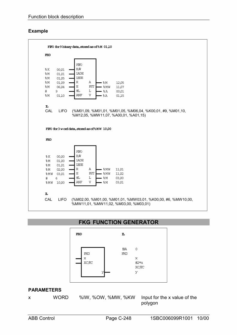
Function block description
ABB Control Page C-248 1SBC006099R1001 10/00
Example
FBD
IL
FIFOB/WLADELESERE#LANF
AFSTLV
%K
#%M
%M%M%M
%M
00,0101,0101,0501,0906,04901,10
00,01
12,0511,07
01,15
%M%MW%A%A
FIFO for 9 binary data, stored as of %M 01,10
FBD
FIFOB/WLADELESERE#LANF
AFSTLV
FIFO for 3 word data, stored as of %MW 10,00
%K
#%MW
%M%M%M
%MW
00,0001,0001,0102,0003,01610,00
03,00
11,0111,02
03,01
%MW%MW%M%M
IL
CAL LIFO (%M01,09, %M01,01, %M01,05, %M06,04, %K00,01, #9, %M01,10,%M12,05, %MW11,07, %A00,01, %A01,15)
CAL LIFO (%M02,00, %M01,00, %M01,01, %MW03,01, %K00,00, #6, %MW10,00,%MW11,01, %MW11,02, %M03,00, %M03,01)
FKG FUNCTION GENERATOR
FBD IL
FKGxXC/YC
y
!BAFKG
0
x#2*nXC/YCy
PARAMETERSx WORD %IW, %OW, %MW, %KW Input for the x value of the
polygon
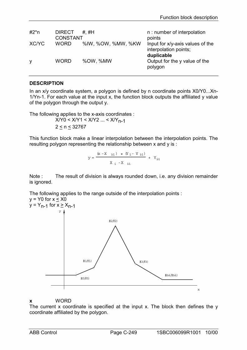
Function block description
ABB Control Page C-249 1SBC006099R1001 10/00
#2*n DIRECT #, #H n : number of interpolationCONSTANT points
XC/YC WORD %IW, %OW, %MW, %KW Input for x/y-axis values of the interpolation points;duplicable
y WORD %OW, %MW Output for the y value of the polygon
DESCRIPTIONIn an x/y coordinate system, a polygon is defined by n coordinate points X0/Y0...Xn-1/Yn-1. For each value at the input x, the function block outputs the affiliated y valueof the polygon through the output y.
The following applies to the x-axis coordinates :X/Y0 < X/Y1 < X/Y2 ... < X/Yn-12 < n < 32767
This function block make a linear interpolation between the interpolation points. Theresulting polygon representing the relationship between x and y is :
(x - X i-1 * (Y - Y )
X - X
i-1
i-1i
y = + Yi-1) i
Note : The result of division is always rounded down, i.e. any division remainderis ignored.
The following applies to the range outside of the interpolation points :y = Y0 for x < X0y = Yn-1 for x > Xn-1
y
x
(X0/Y0)
(X1/Y1)
(X2/Y2)
(X3/Y3)
(Xn-1/Yn-1)
x WORDThe current x coordinate is specified at the input x. The block then defines the ycoordinate affiliated by the polygon.
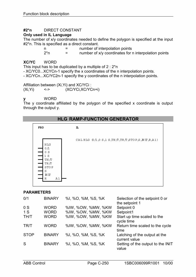
Function block description
ABB Control Page C-250 1SBC006099R1001 10/00
#2*n DIRECT CONSTANTOnly used in IL LanguageThe number of x/y coordinates needed to define the polygon is specified at the input#2*n. This is specified as a direct constant.
n = number of interpolation points2*n = number of x/y coordinates for n interpolation points
XC/YC WORDThis input has to be duplicated by a multiple of 2 : 2*n- XC/YC0...XCYCn-1 specify the x coordinates of the n interpolation points.- XC/YCn...XC/YC2n-1 specify the y coordinates of the n interpolation points.
Affiliation between (Xi,Yi) and XC/YCi :(Xi,Yi) <-> (XC/YCi,XC/YCn+i)
y WORDThe y coordinate affiliated by the polygon of the specified x coordinate is outputthrough the output y.
HLG RAMP-FUNCTION GENERATORFBD IL
CAL HLG (0/1,0 S,1 S,TH/T,TR/T,STOP,S,INIT,R,A1)
HLG0/10 S1 STH/TTR/TSTOPSINITR A1
PARAMETERS0/1 BINARY %I, %O, %M, %S, %K Selection of the setpoint 0 or
the setpoint 10 S WORD %IW, %OW, %MW, %KW Setpoint 01 S WORD %IW, %OW, %MW, %KW Setpoint1TH/T WORD %IW, %OW, %MW, %KW Start up time scaled to the
cycle timeTR/T WORD %IW, %OW, %MW, %KW Return time scaled to the cycle
timeSTOP BINARY %I, %O, %M, %S, %K Latching of the output at the
current valueS BINARY %I, %O, %M, %S, %K Setting of the output to the INIT
value
Function block description
ABB Control Page C-251 1SBC006099R1001 10/00
INIT WORD %IW, %OW, %MW, %KW INIT value to which the output can be set
R BINARY %I, %O, %M, %S, %K Reset of the output to the value0
A1 WORD %MW, %OW Output
DESCRIPTIONThe ramp-function generator serves to provide ramp-shaped adaption of the currentactual value at the output to a specified setpoint.
The value at the output of the HLG is adapted linearly from the current actual valueto the specified setpoint with the slope y’. In doing so, the value at the outputprecisely runs through the amount of the setpoint during the time TH or TR. If thevalue at the output of the HLG has reached the setpoint, it no longer changes unlessa new setpoint is specified.
The slope y’ of the ramp results from the specified time TH (start up time) or TR(return time) and the amount of the setpoint :
Slope y' =Setpoint am ount
TH or TR
The slope is - positive if setpoint > actual value- negative if setpoint < actual value- 0 if setpoint = 0
Therefore, the specified setpoint has two functions :- its amount defines the slope of the ramp together with the specified time TH or TR;- it represents the value to which the current actual value must be adapted in a rampshape.
The user may specify the start up time TH and the return time TR separately. Thedirection of the slope is defined on the basis of the setpoint. The direction of theslope then defines whether or not the running time TH or TR is used.Slope y’ positive -> TH, i.e. the ramp runs upwards.Slope y’ negative -> TR, i.e. the ramp runs downwards.
The start up time TH and the return time TR must be scaled to the program cycletime TZ, i.e. the following must be specified at the corresponding inputs of the block :- Start up time : TH/TZ- Return time : TR/TZThe times are specified in milliseconds.The following applies to the time constants TH or TR : 0 < TH < 32767
0 < TR < 32767
Two setpoints can be planned (0 S and 1 S), whereby one of these setpoints isselected by the binary input 0/1 (setpoint selection). The setpoints may assume thefollowing values : -32767 < setpoint < +32767
At any time, the output of the ramp-function generator can be
Function block description
ABB Control Page C-252 1SBC006099R1001 10/00
- stopped at the current value- set to an initial value- reset (output = 0)The STOP input has the highest priority and the R input has the lowest.
The values at the inputs of the HLG can be altered at any time in the user program.In this way, any (non-linear) adaptation to the setpoint can be realized on the basis ofthe linear adaptation of the actual value.
ImportantSetpoint = 0 means that the slope of the ramp is also 0, i.e. the current actual valuedoes not change. If it is intended to switch from an actual value unequal to 0 to anactual value of 0, a setpoint unequal to 0 must be specified and the output of theramp-function generator must be limited to 0 by a subsequent limiter. (Oninterpolation, the rounding transitions are based on calculation of integral numbersonly).
0/1 BINARYOne of the two setpoints is selected with the input 0/1.0/1 = 0 -> setpoint 0 S0/1 = 1 -> setpoint 1 S
0 S WORDThe setpoint 0 is specified at the input 0 S.
1 S WORDThe setpoint 1 is specified at the input 1 S.
TH/T WORDThe startup time is specified at the input TH/T. At the same time, the start up time THmust be scaled to the cycle time T.
TR/T WORDThe start up time is specified at the input TH/T. At the same time, the start up timeTH must be scaled to the cycle time T.
STOP BINARYThe output can be latched to the current value by means of the STOP input.STOP = 0 -> Output not latchedSTOP = 1 -> Output is latchedThe STOP input has higher priority than the inputs S and R.
S BINARYWith the input S, the output can be set to the initial value specified at the input INIT.S = 0 -> Output is not set to initial value.S = 1 -> Output is set to initial value.
INIT WORDThe initial value to which the output is to be set if required is specified at the inputINIT.
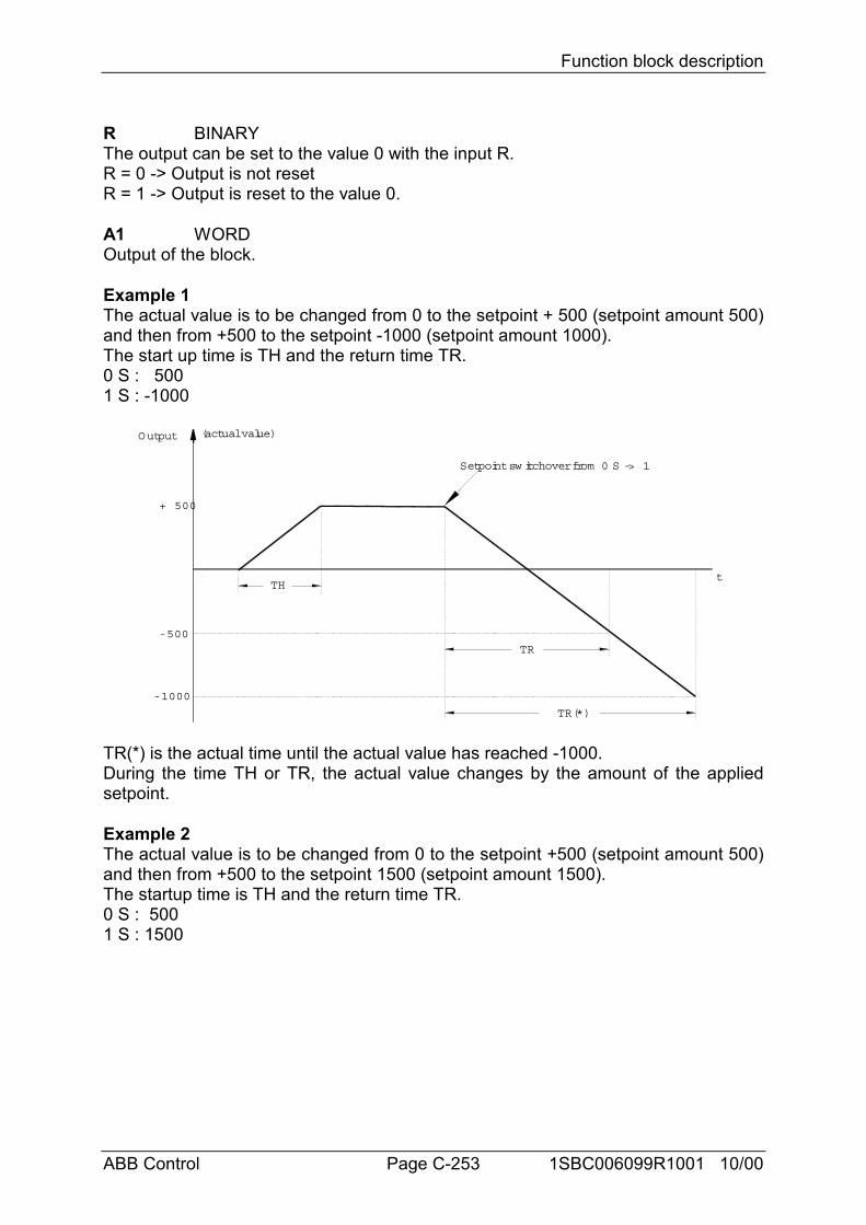
Function block description
ABB Control Page C-253 1SBC006099R1001 10/00
R BINARYThe output can be set to the value 0 with the input R.R = 0 -> Output is not resetR = 1 -> Output is reset to the value 0.
A1 WORDOutput of the block.
Example 1The actual value is to be changed from 0 to the setpoint + 500 (setpoint amount 500)and then from +500 to the setpoint -1000 (setpoint amount 1000).The start up time is TH and the return time TR.0 S : 5001 S : -1000
+ 500
t
(actual value)
- 500
- 1000
TH
TR
TR(*)
Setpoint sw itchover from 0 S -> 1
Output
TR(*) is the actual time until the actual value has reached -1000.During the time TH or TR, the actual value changes by the amount of the appliedsetpoint.
Example 2The actual value is to be changed from 0 to the setpoint +500 (setpoint amount 500)and then from +500 to the setpoint 1500 (setpoint amount 1500).The startup time is TH and the return time TR.0 S : 5001 S : 1500
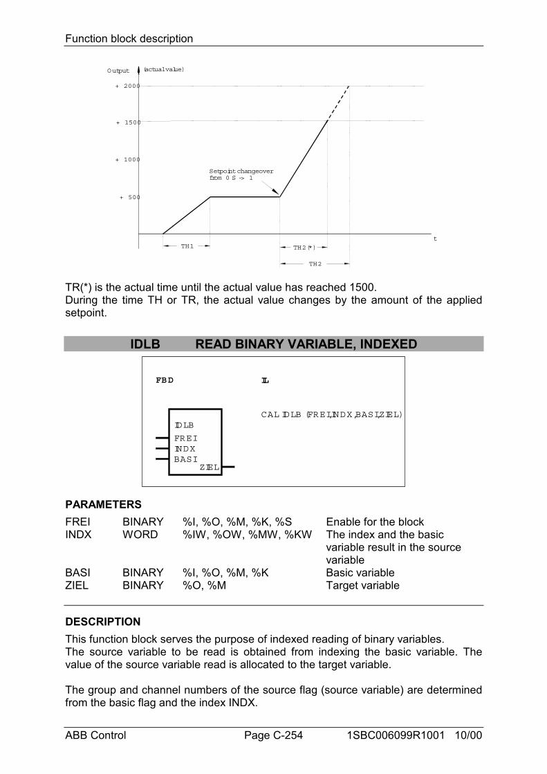
Function block description
ABB Control Page C-254 1SBC006099R1001 10/00
+ 1500
t
(actual value)
+ 500
+ 1000
TH1 TH2(*)
TH2
+ 2000
Setpoint changeoverfrom 0 S -> 1
Output
TR(*) is the actual time until the actual value has reached 1500.During the time TH or TR, the actual value changes by the amount of the appliedsetpoint.
IDLB READ BINARY VARIABLE, INDEXED
FBD IL
IDLB
FREIINDXBASI
ZIEL
CAL IDLB (FREI,INDX,BASI,ZIEL)
PARAMETERSFREI BINARY %I, %O, %M, %K, %S Enable for the blockINDX WORD %IW, %OW, %MW, %KW The index and the basic
variable result in the source variable
BASI BINARY %I, %O, %M, %K Basic variableZIEL BINARY %O, %M Target variable
DESCRIPTIONThis function block serves the purpose of indexed reading of binary variables.The source variable to be read is obtained from indexing the basic variable. Thevalue of the source variable read is allocated to the target variable.
The group and channel numbers of the source flag (source variable) are determinedfrom the basic flag and the index INDX.
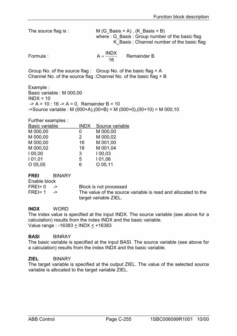
Function block description
ABB Control Page C-255 1SBC006099R1001 10/00
The source flag is : M (G_Basis + A) , (K_Basis + B)where : G_Basis : Group number of the basic flag K_Basis : Channel number of the basic flag
Formula : A INDX16
= Remainder B
Group No. of the source flag : Group No. of the basic flag + AChannel No. of the source flag :Channel No. of the basic flag + B
Example :Basic variable : M 000,00INDX = 10 -> A = 10 : 16 -> A = 0, Remainder B = 10->Source variable : M (000+A),(00+B) = M (000+0),(00+10) = M 000,10
Further examples :Basic variable INDX Source variableM 000,00 0 M 000,00M 000,00 2 M 000,02M 000,00 16 M 001,00M 000,02 18 M 001,04I 00,00 3 I 00,03I 01,01 5 I 01,06O 05,05 6 O 05,11
FREI BINARYEnable blockFREI= 0 -> Block is not processedFREI= 1 -> The value of the source variable is read and allocated to the
target variable ZIEL.
INDX WORDThe index value is specified at the input INDX. The source variable (see above for acalculation) results from the index INDX and the basic variable.Value range : -16383 < INDX < +16383
BASI BINRAYThe basic variable is specified at the input BASI. The source variable (see above fora calculation) results from the index INDX and the basic variable.
ZIEL BINARYThe target variable is specified at the output ZIEL. The value of the selected sourcevariable is allocated to the target variable ZIEL.
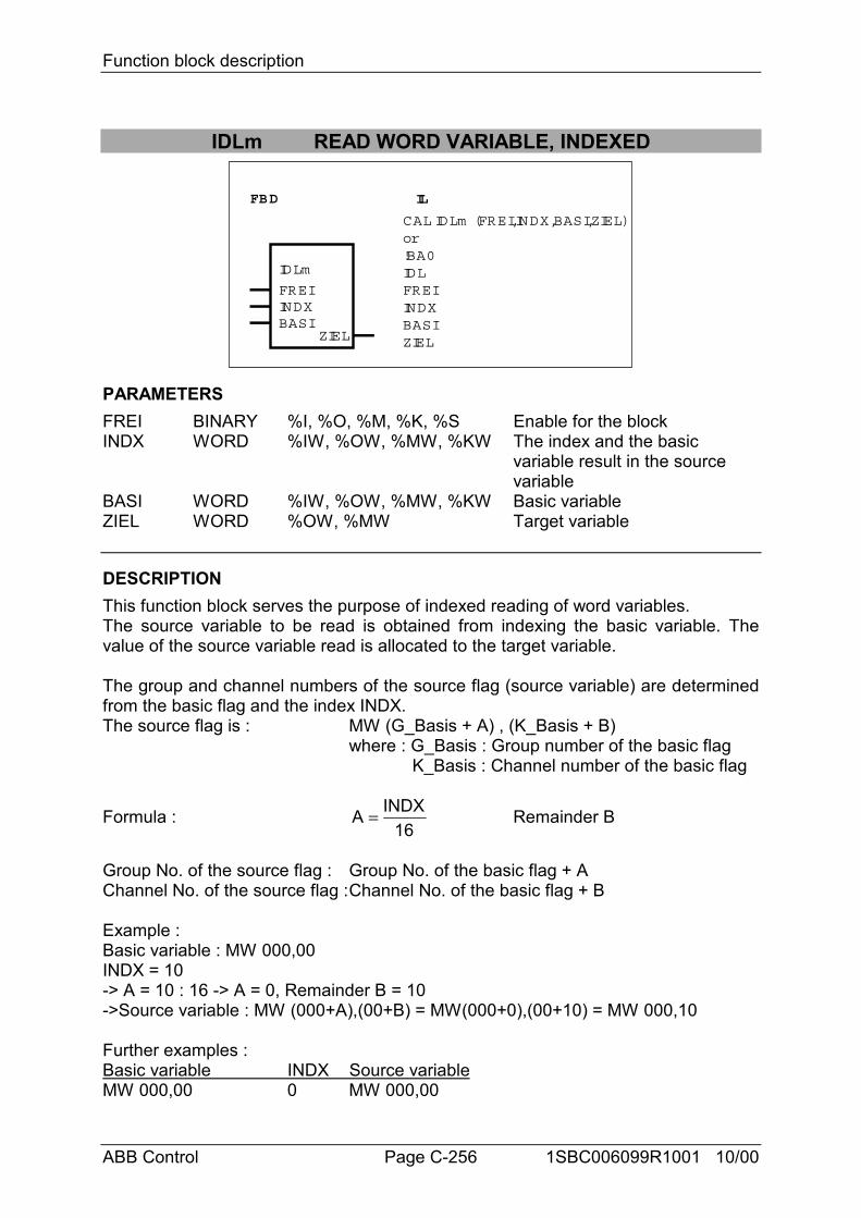
Function block description
ABB Control Page C-256 1SBC006099R1001 10/00
IDLm READ WORD VARIABLE, INDEXED
FBD IL
IDLm
FREIINDXBASI
ZIEL
CAL IDLm (FREI,INDX,BASI,ZIEL)or!BA0IDLFREIINDXBASIZIEL
PARAMETERSFREI BINARY %I, %O, %M, %K, %S Enable for the blockINDX WORD %IW, %OW, %MW, %KW The index and the basic
variable result in the source variable
BASI WORD %IW, %OW, %MW, %KW Basic variableZIEL WORD %OW, %MW Target variable
DESCRIPTIONThis function block serves the purpose of indexed reading of word variables.The source variable to be read is obtained from indexing the basic variable. Thevalue of the source variable read is allocated to the target variable.
The group and channel numbers of the source flag (source variable) are determinedfrom the basic flag and the index INDX.The source flag is : MW (G_Basis + A) , (K_Basis + B)
where : G_Basis : Group number of the basic flag K_Basis : Channel number of the basic flag
Formula : A INDX16
= Remainder B
Group No. of the source flag : Group No. of the basic flag + AChannel No. of the source flag :Channel No. of the basic flag + B
Example :Basic variable : MW 000,00INDX = 10-> A = 10 : 16 -> A = 0, Remainder B = 10->Source variable : MW (000+A),(00+B) = MW(000+0),(00+10) = MW 000,10
Further examples :Basic variable INDX Source variableMW 000,00 0 MW 000,00
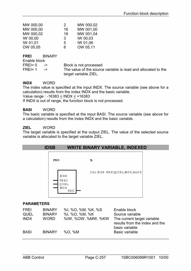
Function block description
ABB Control Page C-257 1SBC006099R1001 10/00
MW 000,00 2 MW 000,02MW 000,00 16 MW 001,00MW 000,02 18 MW 001,04IW 00,00 3 IW 00,03IW 01,01 5 IW 01,06OW 05,05 6 OW 05,11
FREI BINARYEnable blockFREI= 0 -> Block is not processedFREI= 1 -> The value of the source variable is read and allocated to the
target variable ZIEL.
INDX WORDThe index value is specified at the input INDX. The source variable (see above for acalculation) results from the index INDX and the basic variable.Value range : -16383 < INDX < +16383If INDX is out of range, the function block is not processed.
BASI WORDThe basic variable is specified at the input BASI. The source variable (see above fora calculation) results from the index INDX and the basic variable.
ZIEL WORDThe target variable is specified at the output ZIEL. The value of the selected sourcevariable is allocated to the target variable ZIEL.
IDSB WRITE BINARY VARIABLE, INDEXED
FBD IL
IDSB
FREIQ UELINDX
BASI
CAL IDSB (FREI,Q UEL,INDX,BASI)
PARAMETERSFREI BINARY %I, %O, %M, %K, %S Enable blockQUEL BINARY %I, %O, %M, %K Source variableINDX WORD %IW, %OW, %MW, %KW The current target variable
results from the index and the basic variable
BASI BINARY %O, %M Basic variable
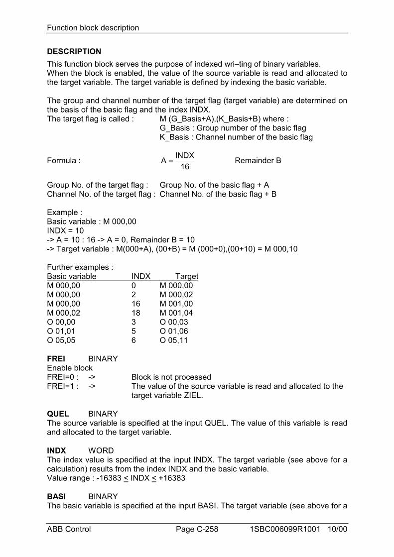
Function block description
ABB Control Page C-258 1SBC006099R1001 10/00
DESCRIPTIONThis function block serves the purpose of indexed wri–ting of binary variables.When the block is enabled, the value of the source variable is read and allocated tothe target variable. The target variable is defined by indexing the basic variable.
The group and channel number of the target flag (target variable) are determined onthe basis of the basic flag and the index INDX.The target flag is called : M (G_Basis+A),(K_Basis+B) where :
G_Basis : Group number of the basic flagK_Basis : Channel number of the basic flag
Formula : A INDX16
= Remainder B
Group No. of the target flag : Group No. of the basic flag + AChannel No. of the target flag : Channel No. of the basic flag + B
Example :Basic variable : M 000,00INDX = 10-> A = 10 : 16 -> A = 0, Remainder B = 10-> Target variable : M(000+A), (00+B) = M (000+0),(00+10) = M 000,10
Further examples :Basic variable INDX TargetM 000,00 0 M 000,00M 000,00 2 M 000,02M 000,00 16 M 001,00M 000,02 18 M 001,04O 00,00 3 O 00,03O 01,01 5 O 01,06O 05,05 6 O 05,11
FREI BINARYEnable blockFREI=0 : -> Block is not processedFREI=1 : -> The value of the source variable is read and allocated to the
target variable ZIEL.
QUEL BINARYThe source variable is specified at the input QUEL. The value of this variable is readand allocated to the target variable.
INDX WORDThe index value is specified at the input INDX. The target variable (see above for acalculation) results from the index INDX and the basic variable.Value range : -16383 < INDX < +16383
BASI BINARYThe basic variable is specified at the input BASI. The target variable (see above for a
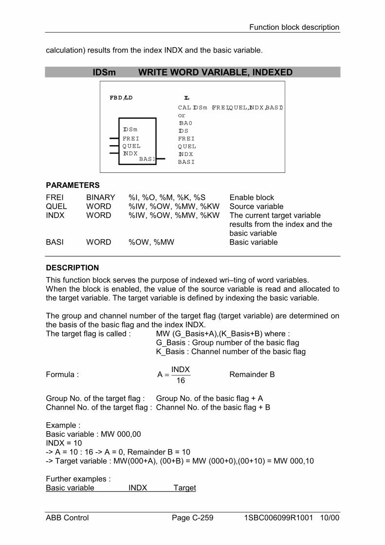
Function block description
ABB Control Page C-259 1SBC006099R1001 10/00
calculation) results from the index INDX and the basic variable.
IDSm WRITE WORD VARIABLE, INDEXED
FBD/LD IL
IDSm
FREIQ UELINDX
BASI
CAL IDSm (FREI,Q UEL,INDX,BASI)or!BA0IDSFREIQ UELINDXBASI
PARAMETERSFREI BINARY %I, %O, %M, %K, %S Enable blockQUEL WORD %IW, %OW, %MW, %KW Source variableINDX WORD %IW, %OW, %MW, %KW The current target variable
results from the index and the basic variable
BASI WORD %OW, %MW Basic variable
DESCRIPTIONThis function block serves the purpose of indexed wri–ting of word variables.When the block is enabled, the value of the source variable is read and allocated tothe target variable. The target variable is defined by indexing the basic variable.
The group and channel number of the target flag (target variable) are determined onthe basis of the basic flag and the index INDX.The target flag is called : MW (G_Basis+A),(K_Basis+B) where :
G_Basis : Group number of the basic flagK_Basis : Channel number of the basic flag
Formula : A INDX16
= Remainder B
Group No. of the target flag : Group No. of the basic flag + AChannel No. of the target flag : Channel No. of the basic flag + B
Example :Basic variable : MW 000,00INDX = 10-> A = 10 : 16 -> A = 0, Remainder B = 10-> Target variable : MW(000+A), (00+B) = MW (000+0),(00+10) = MW 000,10
Further examples :Basic variable INDX Target
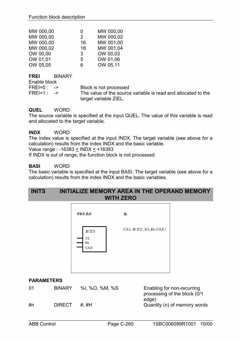
Function block description
ABB Control Page C-260 1SBC006099R1001 10/00
MW 000,00 0 MW 000,00MW 000,00 2 MW 000,02MW 000,00 16 MW 001,00MW 000,02 18 MW 001,04OW 00,00 3 OW 00,03OW 01,01 5 OW 01,06OW 05,05 6 OW 05,11
FREI BINARYEnable blockFREI=0 : -> Block is not processedFREI=1 : -> The value of the source variable is read and allocated to the
target variable ZIEL.
QUEL WORDThe source variable is specified at the input QUEL. The value of this variable is readand allocated to the target variable.
INDX WORDThe index value is specified at the input INDX. The target variable (see above for acalculation) results from the index INDX and the basic variable.Value range : -16383 < INDX < +16383If INDX is out of range, the function block is not processed.
BASI WORDThe basic variable is specified at the input BASI. The target variable (see above for acalculation) results from the index INDX and the basic variables.
INITS INITIALIZE MEMORY AREA IN THE OPERAND MEMORYWITH ZERO
FBD/LD IL
INITS
01
VAR
CAL INITS (01,#n,VAR)
#n
PARAMETERS01 BINARY %I, %O, %M, %S Enabling for non-recurring
processing of the block (0/1 edge)
#n DIRECT #, #H Quantity (n) of memory words
Function block description
ABB Control Page C-261 1SBC006099R1001 10/00
CONSTANT to be initializedVAR BINARY, %I, %O, %M, %K, %S, The n memory words specified
WORD, %IW, %AM, %MW, %KW, at the input #n are initialized as DOUBLE %MD, %KD from this variable.WORD
DESCRIPTIONThis function block serves the purpose of word-by-word initialization of memoryareas in the operand memory with the value 0.
The block is run through precisely once in the event of a 0/1 edge at the input 01. Indoing so, n memory words are initialized with the value 0 as from the variablespecified at the input VAR. The variable specified at this input can be a BINARY,WORD or DOUBLE WORD operand.The following must be observed :BINARY operand : Occupies 1 BYTE in the operand memory.WORD operand : Occupies 1 WORD in the operand memory.DOUBLE WORD operand : Occupies 2 WORDS in the operand memory.
0-1 BINARYBlock enable.The block is run through precisely once when a 0/1 edge appears at this input.
#n DIRECT CONSTANTQuantity (n) of memory words to be initialized specified as a DIRECT CONSTANT.Value range : 0 < n < 65535No initialization is realized if the value 0 is specified.
VAR BINARY, WORD, DOUBLE WORDn memory words are initialized with the value 0 as from this variable (inclusive).
Example
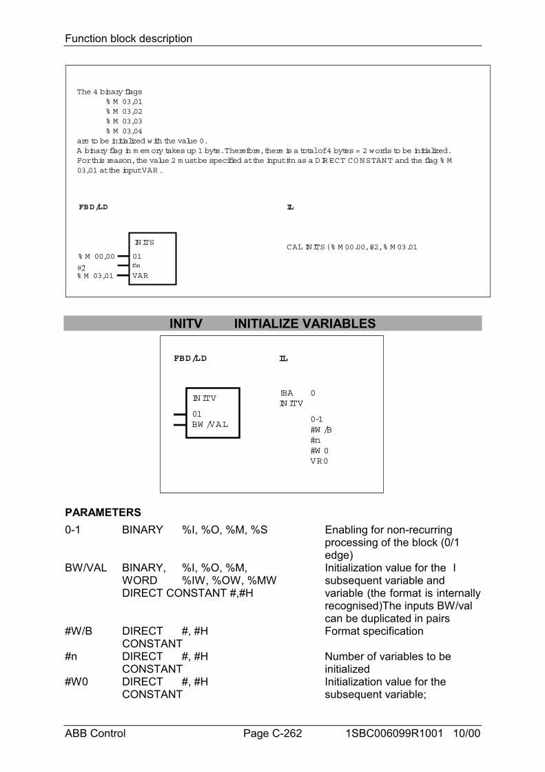
Function block description
ABB Control Page C-262 1SBC006099R1001 10/00
FBD/LD IL
CAL INITS( % M 00.00, #2, % M 03.01
% M 03,01
% M 00,00
INITS
01
VAR
The 4 binary flags% M 03,01% M 03,02% M 03,03% M 03,04
are to be initialized with the value 0.A binary flag in m em ory takes up 1 byte. Therefore, there is a total of 4 bytes = 2 words to be initialized.For this reason, the value 2 m ust be specified at the input #n as a DIRECT CO NSTANT and the flag % M03,01 at the input VAR.
#n#2
INITV INITIALIZE VARIABLES
FBD/LD IL
INITV
01BW /VAL
!BAINITV
0
0-1#W /B#n#W 0VR0
PARAMETERS0-1 BINARY %I, %O, %M, %S Enabling for non-recurring
processing of the block (0/1 edge)
BW/VAL BINARY, %I, %O, %M, Initialization value for the IWORD %IW, %OW, %MW subsequent variable and DIRECT CONSTANT #,#H variable (the format is internally
recognised)The inputs BW/val can be duplicated in pairs
#W/B DIRECT #, #H Format specificationCONSTANT
#n DIRECT #, #H Number of variables to beCONSTANT initialized
#W0 DIRECT #, #H Initialization value for the CONSTANT subsequent variable;
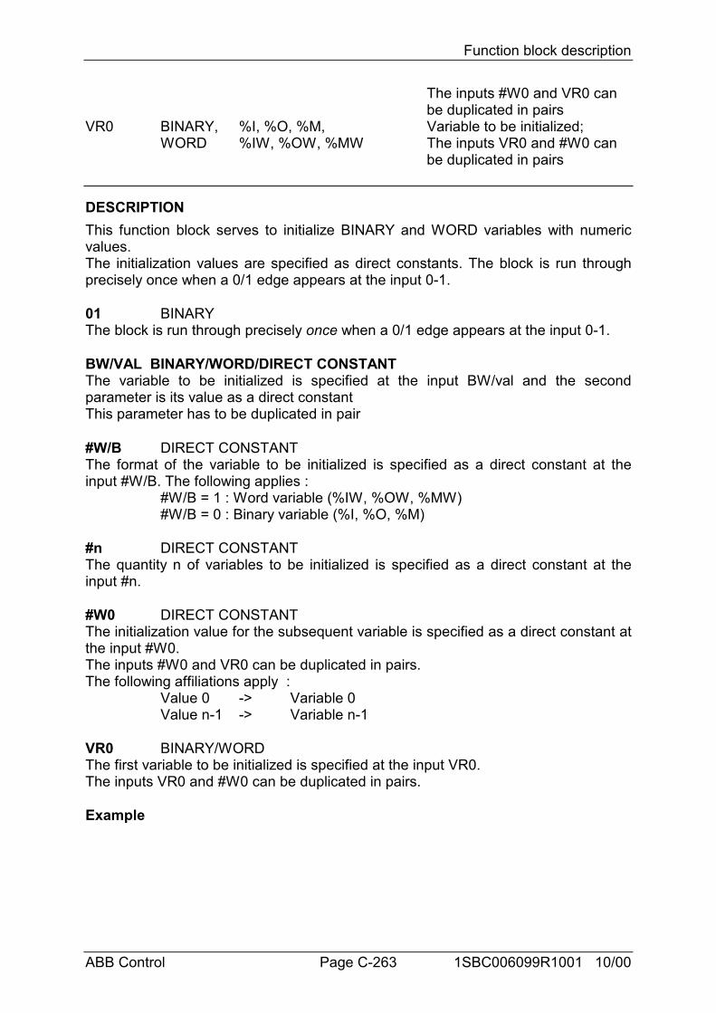
Function block description
ABB Control Page C-263 1SBC006099R1001 10/00
The inputs #W0 and VR0 can be duplicated in pairs
VR0 BINARY, %I, %O, %M, Variable to be initialized;WORD %IW, %OW, %MW The inputs VR0 and #W0 can
be duplicated in pairs
DESCRIPTIONThis function block serves to initialize BINARY and WORD variables with numericvalues.The initialization values are specified as direct constants. The block is run throughprecisely once when a 0/1 edge appears at the input 0-1.
01 BINARYThe block is run through precisely once when a 0/1 edge appears at the input 0-1.
BW/VAL BINARY/WORD/DIRECT CONSTANTThe variable to be initialized is specified at the input BW/val and the secondparameter is its value as a direct constantThis parameter has to be duplicated in pair
#W/B DIRECT CONSTANTThe format of the variable to be initialized is specified as a direct constant at theinput #W/B. The following applies :
#W/B = 1 : Word variable (%IW, %OW, %MW)#W/B = 0 : Binary variable (%I, %O, %M)
#n DIRECT CONSTANTThe quantity n of variables to be initialized is specified as a direct constant at theinput #n.
#W0 DIRECT CONSTANTThe initialization value for the subsequent variable is specified as a direct constant atthe input #W0.The inputs #W0 and VR0 can be duplicated in pairs.The following affiliations apply :
Value 0 -> Variable 0Value n-1 -> Variable n-1
VR0 BINARY/WORDThe first variable to be initialized is specified at the input VR0.The inputs VR0 and #W0 can be duplicated in pairs.
Example
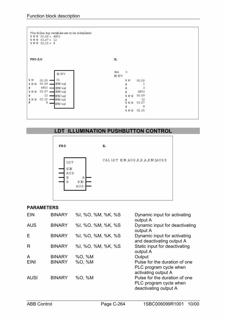
Function block description
ABB Control Page C-264 1SBC006099R1001 10/00
FBD/LD IL
!BAINITV
0INITV
01
% M W#% M W
#% M W% M
#
1202.15
00.0000.09485303.07
8
#% M W#
##% M
% M W#% M W
00.0912
00.0013
4853
03.078
02.15
The following variables are to be initialized:% M W 00,09 = 4853% M W 03,07 = 12% M W 02,15 = 8
BW/val
BW/valBW/val
BW/valBW/valBW/val
LDT ILLUMINATION PUSHBUTTON CONTROL
FBD IL
LDT
EINAUSER EINI
AUSI
A
CAL LDT (EIN,AUS,E,R,A,EINI,AUSI)
PARAMETERSEIN BINARY %I, %O, %M, %K, %S Dynamic input for activating
output AAUS BINARY %I, %O, %M, %K, %S Dynamic input for deactivating
output AE BINARY %I, %O, %M, %K, %S Dynamic input for activating
and deactivating output AR BINARY %I, %O, %M, %K, %S Static input for deactivating
output AA BINARY %O, %M OutputEINI BINARY %O, %M Pulse for the duration of one
PLC program cycle when activating output A
AUSI BINARY %O, %M Pulse for the duration of one PLC program cycle when deactivating output A
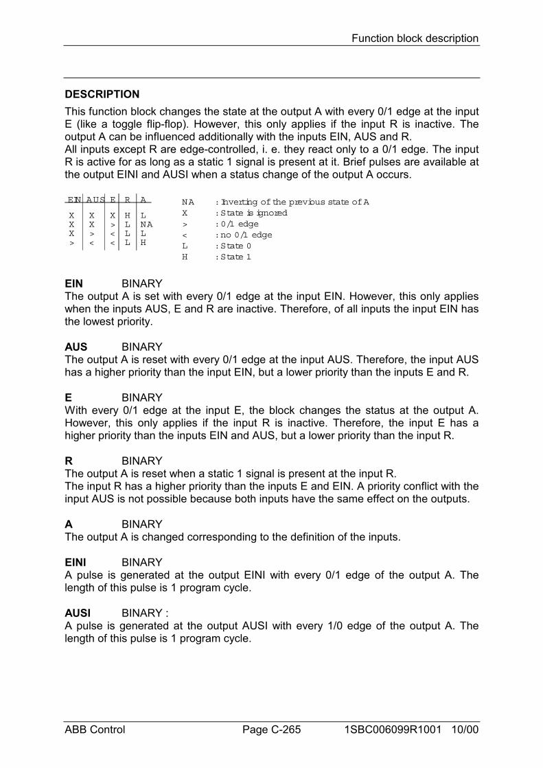
Function block description
ABB Control Page C-265 1SBC006099R1001 10/00
DESCRIPTIONThis function block changes the state at the output A with every 0/1 edge at the inputE (like a toggle flip-flop). However, this only applies if the input R is inactive. Theoutput A can be influenced additionally with the inputs EIN, AUS and R.All inputs except R are edge-controlled, i. e. they react only to a 0/1 edge. The inputR is active for as long as a static 1 signal is present at it. Brief pulses are available atthe output EINI and AUSI when a status change of the output A occurs.
XXX>
XX><
X><<
HLLL
LNALH
NA : Inverting of the previous state of AX : State is ignored> : 0/1 edge< : no 0/1 edgeL : State 0H : State 1
EIN AUS E R A
EIN BINARYThe output A is set with every 0/1 edge at the input EIN. However, this only applieswhen the inputs AUS, E and R are inactive. Therefore, of all inputs the input EIN hasthe lowest priority.
AUS BINARYThe output A is reset with every 0/1 edge at the input AUS. Therefore, the input AUShas a higher priority than the input EIN, but a lower priority than the inputs E and R.
E BINARYWith every 0/1 edge at the input E, the block changes the status at the output A.However, this only applies if the input R is inactive. Therefore, the input E has ahigher priority than the inputs EIN and AUS, but a lower priority than the input R.
R BINARYThe output A is reset when a static 1 signal is present at the input R.The input R has a higher priority than the inputs E and EIN. A priority conflict with theinput AUS is not possible because both inputs have the same effect on the outputs.
A BINARYThe output A is changed corresponding to the definition of the inputs.
EINI BINARYA pulse is generated at the output EINI with every 0/1 edge of the output A. Thelength of this pulse is 1 program cycle.
AUSI BINARY :A pulse is generated at the output AUSI with every 1/0 edge of the output A. Thelength of this pulse is 1 program cycle.
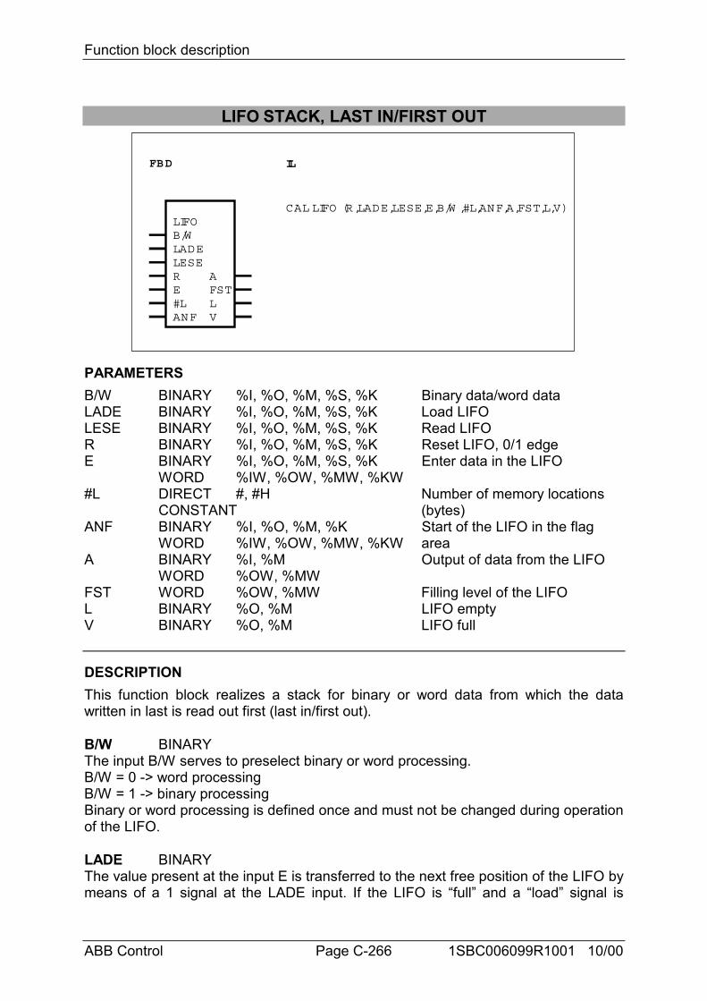
Function block description
ABB Control Page C-266 1SBC006099R1001 10/00
LIFO STACK, LAST IN/FIRST OUT
FBD IL
LIFOB/WLADELESERE
AFSTLV
CAL LIFO (R,LADE,LESE,E,B/W ,#L,ANF,A,FST,L,V)
#LANF
PARAMETERSB/W BINARY %I, %O, %M, %S, %K Binary data/word dataLADE BINARY %I, %O, %M, %S, %K Load LIFOLESE BINARY %I, %O, %M, %S, %K Read LIFOR BINARY %I, %O, %M, %S, %K Reset LIFO, 0/1 edgeE BINARY %I, %O, %M, %S, %K Enter data in the LIFO
WORD %IW, %OW, %MW, %KW#L DIRECT #, #H Number of memory locations
CONSTANT (bytes)ANF BINARY %I, %O, %M, %K Start of the LIFO in the flag
WORD %IW, %OW, %MW, %KW areaA BINARY %I, %M Output of data from the LIFO
WORD %OW, %MWFST WORD %OW, %MW Filling level of the LIFOL BINARY %O, %M LIFO emptyV BINARY %O, %M LIFO full
DESCRIPTIONThis function block realizes a stack for binary or word data from which the datawritten in last is read out first (last in/first out).
B/W BINARYThe input B/W serves to preselect binary or word processing.B/W = 0 -> word processingB/W = 1 -> binary processingBinary or word processing is defined once and must not be changed during operationof the LIFO.
LADE BINARYThe value present at the input E is transferred to the next free position of the LIFO bymeans of a 1 signal at the LADE input. If the LIFO is “full” and a “load” signal is
Function block description
ABB Control Page C-267 1SBC006099R1001 10/00
present, the new value will not be read in. A new value can only be read in if a valuehas been read out first. It is then transferred to the first position of the LIFO.
LESE BINARYA 1 signal at the input LESE results in output of the current LIFO value through theoutput A. If the LIFO is “empty”, a pending read order is ignored and the value 0 isoutput through the output A. The output A is always set to 0 if there is no read order.
LADE and LESEIf load and read orders are present simultaneously, the value to be loaded isforwarded directly from the input E to the output A. At the same time, the LIFO doesnot store the value. The LIFO does not change its filling level in this mode. The valueoutput through the output FST remains constant. If the LIFO is empty, the output Lremains 1 and the output FST is set to 0.
R BINARYA 0->1 edge at the input R results in the reset of the block. Therefore, values read inbefore are no longer available. The output L assumes the value 1 and the outputsFST and A assume the value 0.
R and LADEIf R and LADE signals are present simultaneously, the reset is performed first andthen directly afterwards the load operation. Therefore, the LIFO is reset and the newvalue to be read in is then immediately stored in the LIFO as the first value.
R and LADE and LESEThe value at the input E is forwarded directly to the output A. The output L is setpermanently to 1 and the output FST is set permanently to 0.
E BINARY/WORDThe value to be transferred into the LIFO is specified at the input E.
#L DIRECT CONSTANTThe number of required memory locations (bytes) of the LIFO is specified at theinput #L. This quantity is specified as a direct constant and results from the followingformula :
BINARY data : #L = Number of binary values to be storedWORD data : #L = 2 * Quantity of word values to be storedE.g. : BINARY data : 3 values -> #L = 3
WORD data : 3 values -> #L = 6
The LIFO length parameter is subjected to a plausibility check for the value 0 andalso, in word processing mode, for an odd byte parameter. If the parameter specifiedat the input #L is incorrect, the LIFO will assume the initial state (as after R).
ANF BINARY/WORDThe LIFO memory start address is specified as a binary or word flag at the inputANF. The LIFO begins with the specified flag.
A BINARY/WORD
Function block description
ABB Control Page C-268 1SBC006099R1001 10/00
When the LIFO is read, the current value is available at the output A. If no read orderis available, the value 0 is output.
FST WORDThe output FST indicates the current filling level of the LIFO at any time. The fillinglevel is the number of binary or word values stored in the LIFO.
L BINARYThe output L indicates whether or not the LIFO is empty.L = 0 -> LIFO is not emptyL = 1 -> LIFO is empty
V BINARYThe output V indicates whether or not the LIFO is full.V = 0 -> LIFO is not fullV = 1 -> LIFO is fullNo more values can be read in if the LIFO is full. A value can only be read in againonce a value has been read out. This then takes place as from the start of the LIFO.
Example
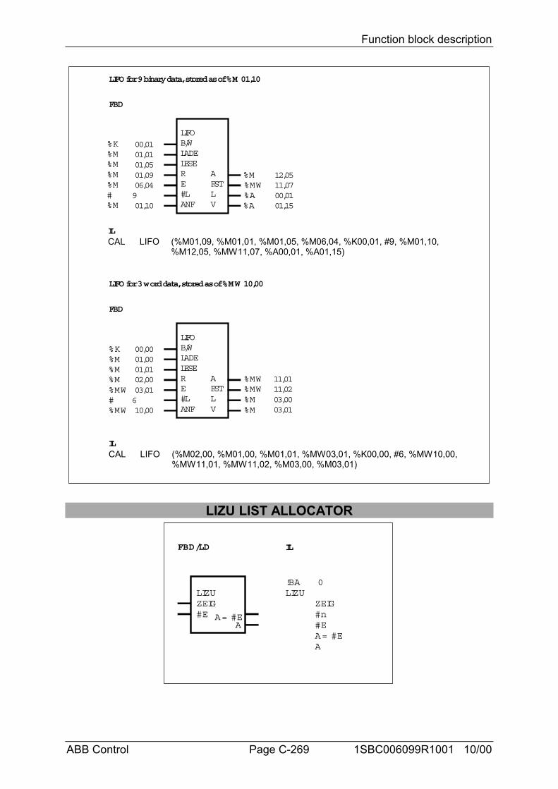
Function block description
ABB Control Page C-269 1SBC006099R1001 10/00
FBD
IL
LIFOB/WLADELESERE#LANF
AFSTLV
%K
#%M
%M%M%M
%M
00,0101,0101,0501,0906,04901,10
00,01
12,0511,07
01,15
%M%MW%A%A
LIFO for 9 binary data, stored as of %M 01,10
FBD
LIFOB/WLADELESERE#LANF
AFSTLV
LIFO for 3 word data, stored as of %MW 10,00
%K
#%MW
%M%M%M
%MW
00,0001,0001,0102,0003,01610,00
03,00
11,0111,02
03,01
%MW%MW%M%M
IL
CAL LIFO (%M01,09, %M01,01, %M01,05, %M06,04, %K00,01, #9, %M01,10,%M12,05, %MW11,07, %A00,01, %A01,15)
CAL LIFO (%M02,00, %M01,00, %M01,01, %MW03,01, %K00,00, #6, %MW10,00,%MW11,01, %MW11,02, %M03,00, %M03,01)
LIZU LIST ALLOCATOR
FBD/LD IL
LIZUZEIG#E
AA= #E
!BALIZU
0
ZEIG#n#E
AA= #E
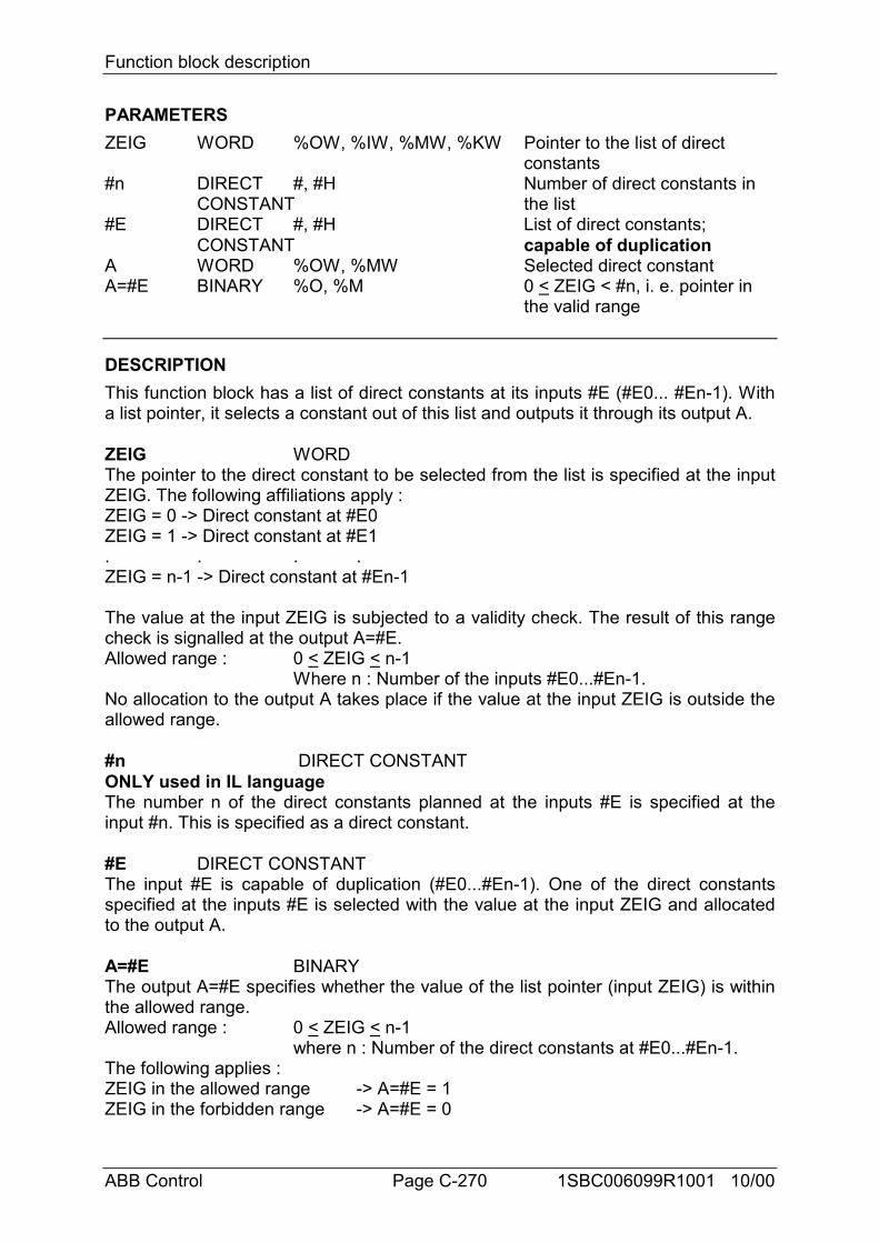
Function block description
ABB Control Page C-270 1SBC006099R1001 10/00
PARAMETERSZEIG WORD %OW, %IW, %MW, %KW Pointer to the list of direct
constants#n DIRECT #, #H Number of direct constants in
CONSTANT the list#E DIRECT #, #H List of direct constants;
CONSTANT capable of duplicationA WORD %OW, %MW Selected direct constantA=#E BINARY %O, %M 0 < ZEIG < #n, i. e. pointer in
the valid range
DESCRIPTIONThis function block has a list of direct constants at its inputs #E (#E0... #En-1). Witha list pointer, it selects a constant out of this list and outputs it through its output A.
ZEIG WORDThe pointer to the direct constant to be selected from the list is specified at the inputZEIG. The following affiliations apply :ZEIG = 0 -> Direct constant at #E0ZEIG = 1 -> Direct constant at #E1. . . .ZEIG = n-1 -> Direct constant at #En-1
The value at the input ZEIG is subjected to a validity check. The result of this rangecheck is signalled at the output A=#E.Allowed range : 0 < ZEIG < n-1
Where n : Number of the inputs #E0...#En-1.No allocation to the output A takes place if the value at the input ZEIG is outside theallowed range.
#n DIRECT CONSTANTONLY used in IL languageThe number n of the direct constants planned at the inputs #E is specified at theinput #n. This is specified as a direct constant.
#E DIRECT CONSTANTThe input #E is capable of duplication (#E0...#En-1). One of the direct constantsspecified at the inputs #E is selected with the value at the input ZEIG and allocatedto the output A.
A=#E BINARYThe output A=#E specifies whether the value of the list pointer (input ZEIG) is withinthe allowed range.Allowed range : 0 < ZEIG < n-1
where n : Number of the direct constants at #E0...#En-1.The following applies :ZEIG in the allowed range -> A=#E = 1ZEIG in the forbidden range -> A=#E = 0
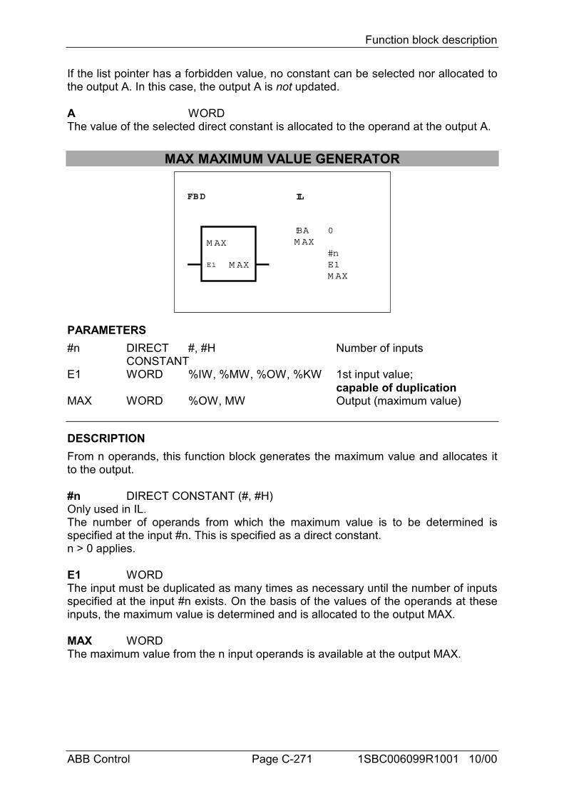
Function block description
ABB Control Page C-271 1SBC006099R1001 10/00
If the list pointer has a forbidden value, no constant can be selected nor allocated tothe output A. In this case, the output A is not updated.
A WORDThe value of the selected direct constant is allocated to the operand at the output A.
MAX MAXIMUM VALUE GENERATOR
FBD IL
!BA 0M AX
#nE1M AX
M AX
E1 M AX
PARAMETERS#n DIRECT #, #H Number of inputs
CONSTANTE1 WORD %IW, %MW, %OW, %KW 1st input value;
capable of duplicationMAX WORD %OW, MW Output (maximum value)
DESCRIPTIONFrom n operands, this function block generates the maximum value and allocates itto the output.
#n DIRECT CONSTANT (#, #H)Only used in IL.The number of operands from which the maximum value is to be determined isspecified at the input #n. This is specified as a direct constant.n > 0 applies.
E1 WORDThe input must be duplicated as many times as necessary until the number of inputsspecified at the input #n exists. On the basis of the values of the operands at theseinputs, the maximum value is determined and is allocated to the output MAX.
MAX WORDThe maximum value from the n input operands is available at the output MAX.
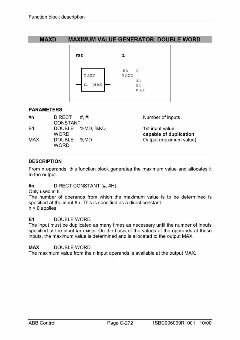
Function block description
ABB Control Page C-272 1SBC006099R1001 10/00
MAXD MAXIMUM VALUE GENERATOR, DOUBLE WORD
FBD IL
!BA 0M AXD
#nE1M AX
M AXD
E1 M AX
PARAMETERS#n DIRECT #, #H Number of inputs
CONSTANTE1 DOUBLE %MD, %KD 1st input value;
WORD capable of duplicationMAX DOUBLE %MD Output (maximum value)
WORD
DESCRIPTIONFrom n operands, this function block generates the maximum value and allocates itto the output.
#n DIRECT CONSTANT (#, #H)Only used in IL.The number of operands from which the maximum value is to be determined isspecified at the input #n. This is specified as a direct constant.n > 0 applies.
E1 DOUBLE WORDThe input must be duplicated as many times as necessary until the number of inputsspecified at the input #n exists. On the basis of the values of the operands at theseinputs, the maximum value is determined and is allocated to the output MAX.
MAX DOUBLE WORDThe maximum value from the n input operands is available at the output MAX.
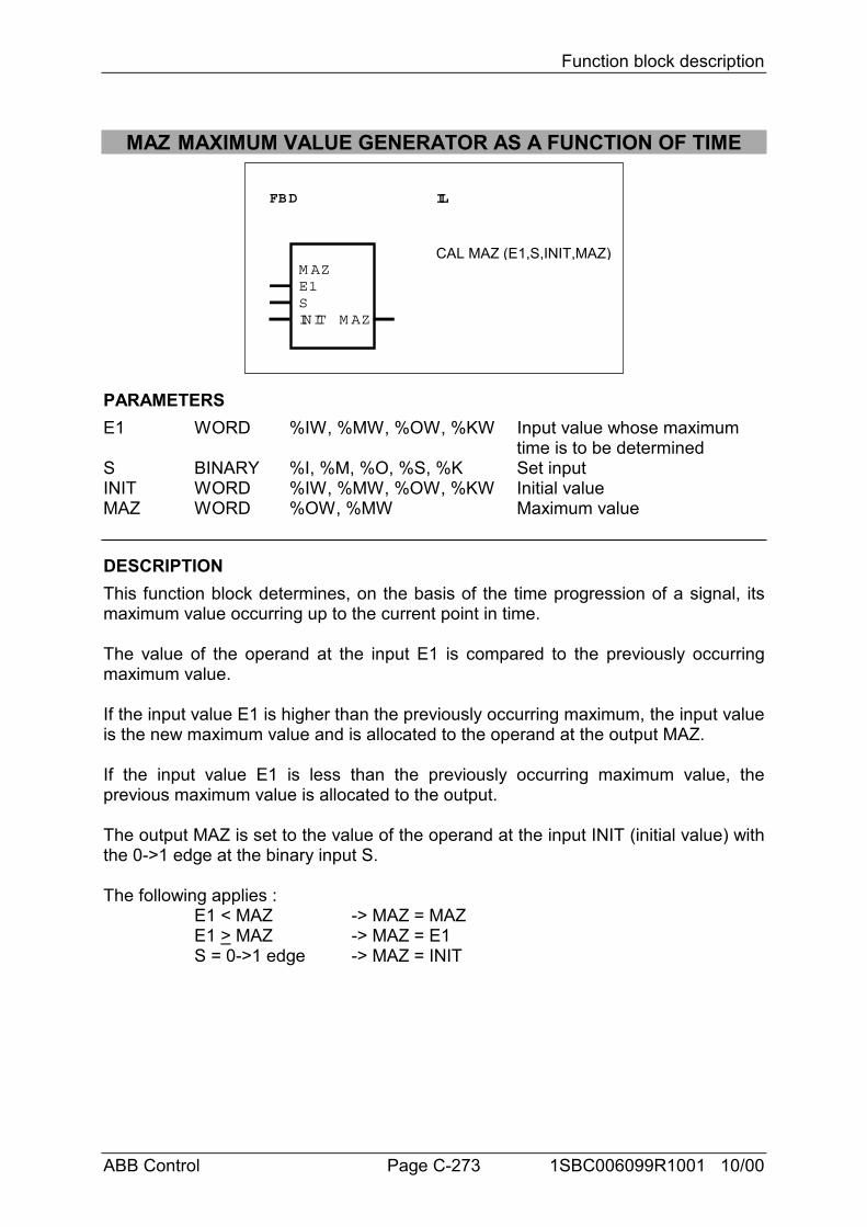
Function block description
ABB Control Page C-273 1SBC006099R1001 10/00
MAZ MAXIMUM VALUE GENERATOR AS A FUNCTION OF TIME
FBD IL
M AZE1SINIT M AZ
CAL MAZ (E1,S,INIT,MAZ)
PARAMETERSE1 WORD %IW, %MW, %OW, %KW Input value whose maximum
time is to be determinedS BINARY %I, %M, %O, %S, %K Set inputINIT WORD %IW, %MW, %OW, %KW Initial valueMAZ WORD %OW, %MW Maximum value
DESCRIPTIONThis function block determines, on the basis of the time progression of a signal, itsmaximum value occurring up to the current point in time.
The value of the operand at the input E1 is compared to the previously occurringmaximum value.
If the input value E1 is higher than the previously occurring maximum, the input valueis the new maximum value and is allocated to the operand at the output MAZ.
If the input value E1 is less than the previously occurring maximum value, theprevious maximum value is allocated to the output.
The output MAZ is set to the value of the operand at the input INIT (initial value) withthe 0->1 edge at the binary input S.
The following applies :E1 < MAZ -> MAZ = MAZE1 > MAZ -> MAZ = E1S = 0->1 edge -> MAZ = INIT
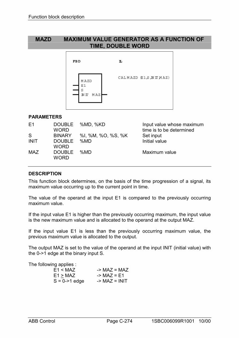
Function block description
ABB Control Page C-274 1SBC006099R1001 10/00
MAZD MAXIMUM VALUE GENERATOR AS A FUNCTION OFTIME, DOUBLE WORD
FBD IL
M AZDE1SINIT M AZ
CAL M AZD (E1,S,INIT,M AZ)
PARAMETERSE1 DOUBLE %MD, %KD Input value whose maximum
WORD time is to be determinedS BINARY %I, %M, %O, %S, %K Set inputINIT DOUBLE %MD Initial value
WORDMAZ DOUBLE %MD Maximum value
WORD
DESCRIPTIONThis function block determines, on the basis of the time progression of a signal, itsmaximum value occurring up to the current point in time.
The value of the operand at the input E1 is compared to the previously occurringmaximum value.
If the input value E1 is higher than the previously occurring maximum, the input valueis the new maximum value and is allocated to the operand at the output MAZ.
If the input value E1 is less than the previously occurring maximum value, theprevious maximum value is allocated to the output.
The output MAZ is set to the value of the operand at the input INIT (initial value) withthe 0->1 edge at the binary input S.
The following applies :E1 < MAZ -> MAZ = MAZE1 > MAZ -> MAZ = E1S = 0->1 edge -> MAZ = INIT
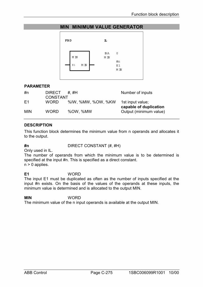
Function block description
ABB Control Page C-275 1SBC006099R1001 10/00
MIN MINIMUM VALUE GENERATOR
FBD IL
!BA 0M IN
#nE1M IN
M IN
E1 M IN
PARAMETER#n DIRECT #, #H Number of inputs
CONSTANTE1 WORD %IW, %MW, %OW, %KW 1st input value;
capable of duplicationMIN WORD %OW, %MW Output (minimum value)
DESCRIPTIONThis function block determines the minimum value from n operands and allocates itto the output.
#n DIRECT CONSTANT (#, #H)Only used in IL.The number of operands from which the minimum value is to be determined isspecified at the input #n. This is specified as a direct constant.n > 0 applies.
E1 WORDThe input E1 must be duplicated as often as the number of inputs specified at theinput #n exists. On the basis of the values of the operands at these inputs, theminimum value is determined and is allocated to the output MIN.
MIN WORDThe minimum value of the n input operands is available at the output MIN.
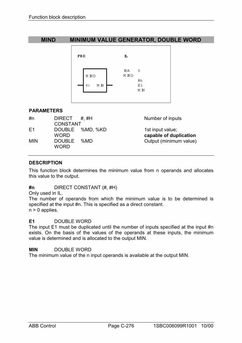
Function block description
ABB Control Page C-276 1SBC006099R1001 10/00
MIND MINIMUM VALUE GENERATOR, DOUBLE WORD
FBD IL
!BA 0M IND
#nE1M IN
M IND
E1 M IN
PARAMETERS#n DIRECT #, #H Number of inputs
CONSTANTE1 DOUBLE %MD, %KD 1st input value;
WORD capable of duplicationMIN DOUBLE %MD Output (minimum value)
WORD
DESCRIPTIONThis function block determines the minimum value from n operands and allocatesthis value to the output.
#n DIRECT CONSTANT (#, #H)Only used in IL.The number of operands from which the minimum value is to be determined isspecified at the input #n. This is specified as a direct constant.n > 0 applies.
E1 DOUBLE WORDThe input E1 must be duplicated until the number of inputs specified at the input #nexists. On the basis of the values of the operands at these inputs, the minimumvalue is determined and is allocated to the output MIN.
MIN DOUBLE WORDThe minimum value of the n input operands is available at the output MIN.
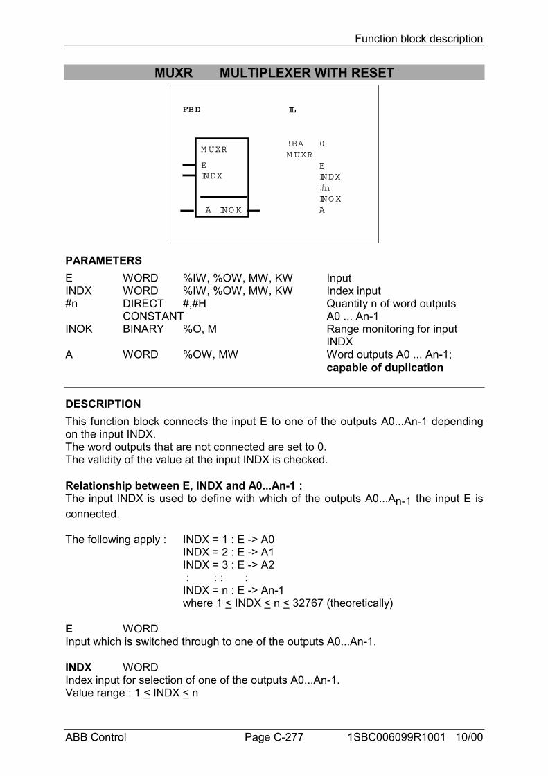
Function block description
ABB Control Page C-277 1SBC006099R1001 10/00
MUXR MULTIPLEXER WITH RESET
FBD IL
M UXR
EINDX
! BA 0M UXR
EINDX#nINO XAA INO K
PARAMETERSE WORD %IW, %OW, MW, KW InputINDX WORD %IW, %OW, MW, KW Index input#n DIRECT #,#H Quantity n of word outputs
CONSTANT A0 ... An-1INOK BINARY %O, M Range monitoring for input
INDXA WORD %OW, MW Word outputs A0 ... An-1;
capable of duplication
DESCRIPTIONThis function block connects the input E to one of the outputs A0...An-1 dependingon the input INDX.The word outputs that are not connected are set to 0.The validity of the value at the input INDX is checked.
Relationship between E, INDX and A0...An-1 :The input INDX is used to define with which of the outputs A0...An-1 the input E isconnected.
The following apply : INDX = 1 : E -> A0INDX = 2 : E -> A1INDX = 3 : E -> A2 : : : :INDX = n : E -> An-1where 1 < INDX < n < 32767 (theoretically)
E WORDInput which is switched through to one of the outputs A0...An-1.
INDX WORDIndex input for selection of one of the outputs A0...An-1.Value range : 1 < INDX < n
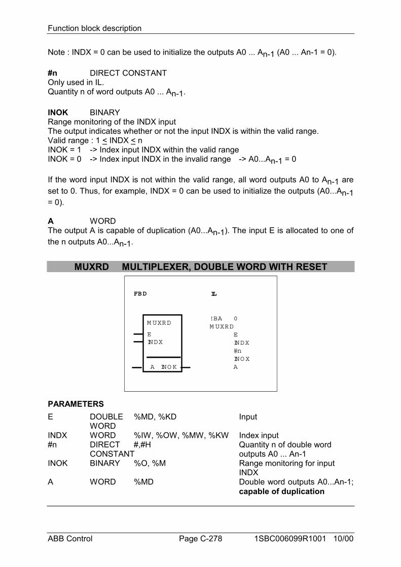
Function block description
ABB Control Page C-278 1SBC006099R1001 10/00
Note : INDX = 0 can be used to initialize the outputs A0 ... An-1 (A0 ... An-1 = 0).
#n DIRECT CONSTANTOnly used in IL.Quantity n of word outputs A0 ... An-1.
INOK BINARYRange monitoring of the INDX inputThe output indicates whether or not the input INDX is within the valid range.Valid range : 1 < INDX < nINOK = 1 -> Index input INDX within the valid rangeINOK = 0 -> Index input INDX in the invalid range -> A0...An-1 = 0
If the word input INDX is not within the valid range, all word outputs A0 to An-1 areset to 0. Thus, for example, INDX = 0 can be used to initialize the outputs (A0...An-1= 0).
A WORDThe output A is capable of duplication (A0...An-1). The input E is allocated to one ofthe n outputs A0...An-1.
MUXRD MULTIPLEXER, DOUBLE WORD WITH RESET
FBD IL
M UXRD
EINDX
! BA 0M UXRD
EINDX#nINO XAA INO K
PARAMETERSE DOUBLE %MD, %KD Input
WORDINDX WORD %IW, %OW, %MW, %KW Index input#n DIRECT #,#H Quantity n of double word
CONSTANT outputs A0 ... An-1INOK BINARY %O, %M Range monitoring for input
INDXA WORD %MD Double word outputs A0...An-1;
capable of duplication
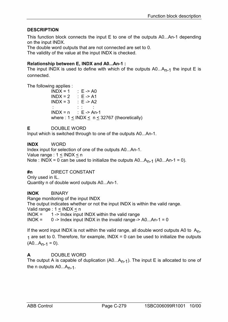
Function block description
ABB Control Page C-279 1SBC006099R1001 10/00
DESCRIPTIONThis function block connects the input E to one of the outputs A0...An-1 dependingon the input INDX.The double word outputs that are not connected are set to 0.The validity of the value at the input INDX is checked.
Relationship between E, INDX and A0...An-1 :The input INDX is used to define with which of the outputs A0...An-1 the input E isconnected.
The following applies :INDX = 1 : E -> A0INDX = 2 : E -> A1INDX = 3 : E -> A2 : : : :INDX = n : E -> An-1where : 1 < INDX < n < 32767 (theoretically)
E DOUBLE WORDInput which is switched through to one of the outputs A0...An-1.
INDX WORDIndex input for selection of one of the outputs A0...An-1.Value range : 1 < INDX < nNote : INDX = 0 can be used to initialize the outputs A0...An-1 (A0...An-1 = 0).
#n DIRECT CONSTANTOnly used in IL.Quantity n of double word outputs A0...An-1.
INOK BINARYRange monitoring of the input INDXThe output indicates whether or not the input INDX is within the valid range.Valid range : 1 < INDX < nINOK = 1 -> Index input INDX within the valid rangeINOK = 0 -> Index input INDX in the invalid range -> A0...An-1 = 0
If the word input INDX is not within the valid range, all double word outputs A0 to An-1 are set to 0. Therefore, for example, INDX = 0 can be used to initialize the outputs(A0...An-1 = 0).
A DOUBLE WORDThe output A is capable of duplication (A0...An-1). The input E is allocated to one ofthe n outputs A0...An-1.
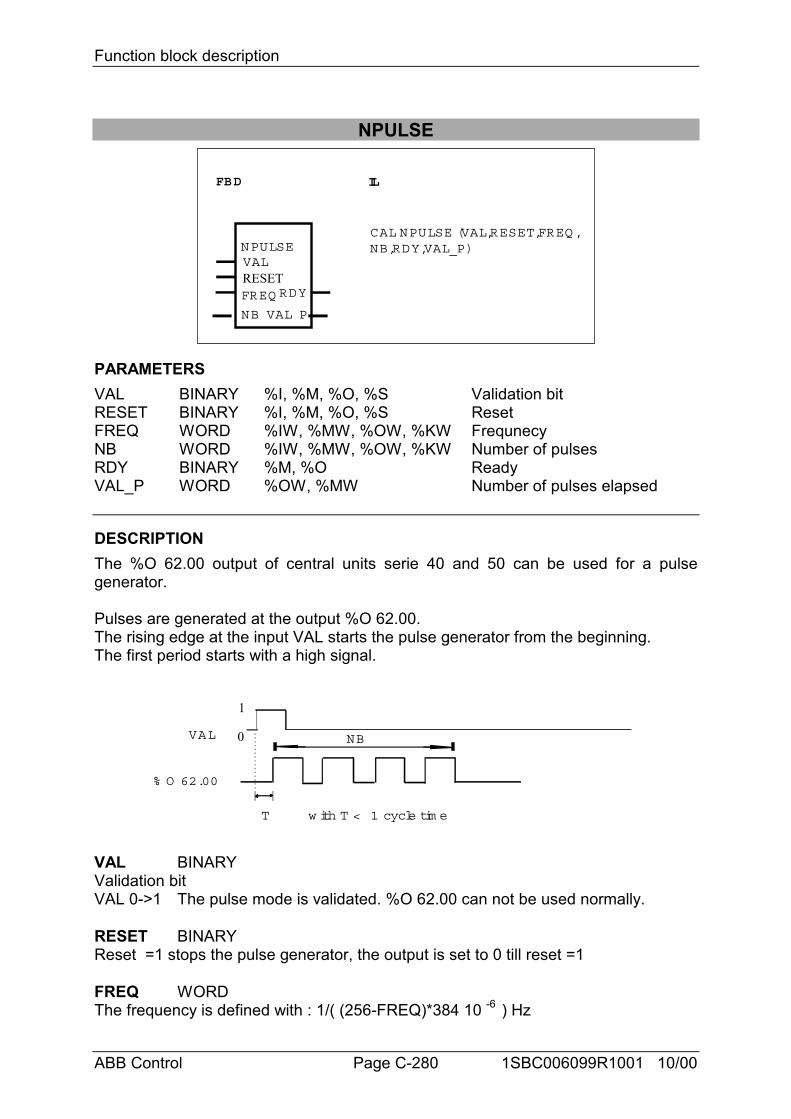
Function block description
ABB Control Page C-280 1SBC006099R1001 10/00
NPULSE
FBD IL
NPULSEVAL
FREQ
NB
CAL NPULSE (VAL,RESET,FREQ ,NB,RDY,VAL_P)
VAL_P
RDYRESET
PARAMETERSVAL BINARY %I, %M, %O, %S Validation bitRESET BINARY %I, %M, %O, %S ResetFREQ WORD %IW, %MW, %OW, %KW FrequnecyNB WORD %IW, %MW, %OW, %KW Number of pulsesRDY BINARY %M, %O ReadyVAL_P WORD %OW, %MW Number of pulses elapsed
DESCRIPTIONThe %O 62.00 output of central units serie 40 and 50 can be used for a pulsegenerator.
Pulses are generated at the output %O 62.00.The rising edge at the input VAL starts the pulse generator from the beginning.The first period starts with a high signal.
% O 62.00
NBVAL
T w ith T < 1 cycle tim e
0
1
VAL BINARYValidation bitVAL 0->1 The pulse mode is validated. %O 62.00 can not be used normally.
RESET BINARYReset =1 stops the pulse generator, the output is set to 0 till reset =1
FREQ WORDThe frequency is defined with : 1/( (256-FREQ)*384 10 -6 ) Hz
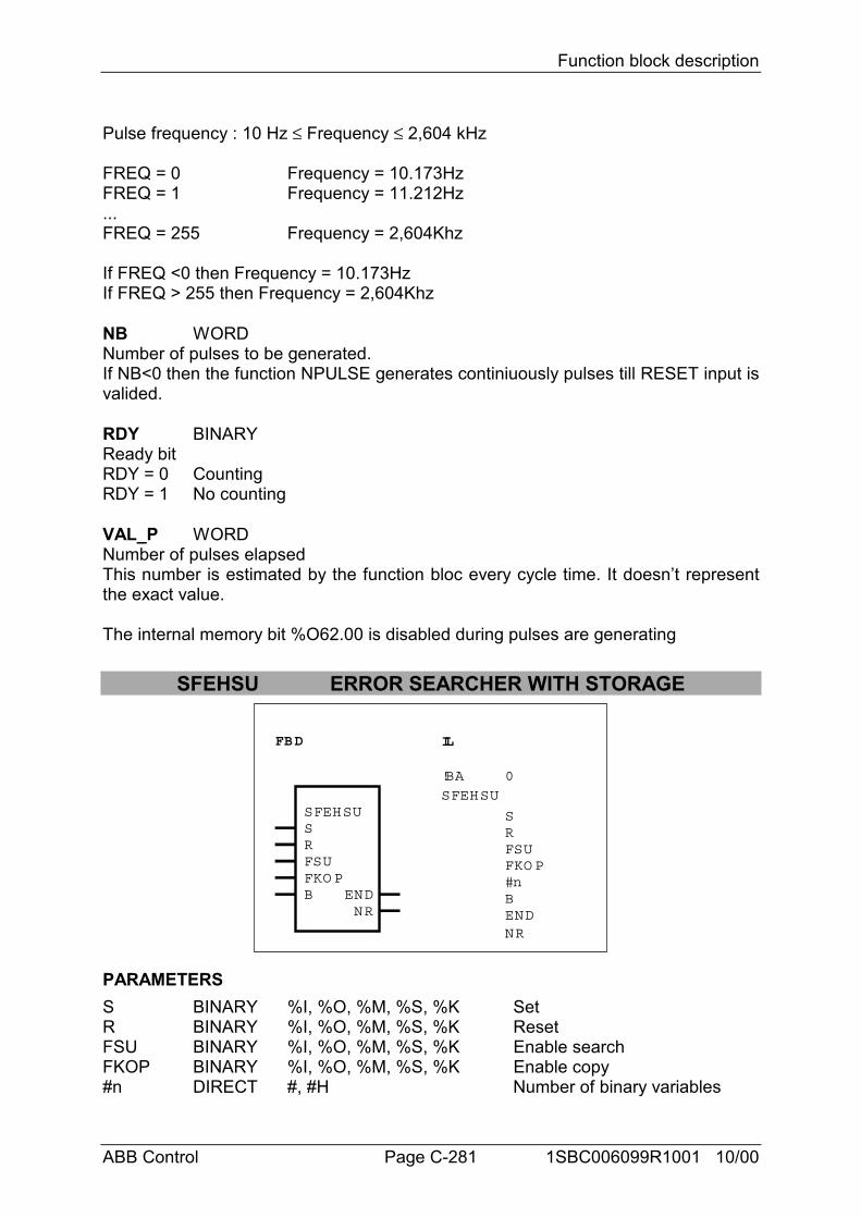
Function block description
ABB Control Page C-281 1SBC006099R1001 10/00
Pulse frequency : 10 Hz ≤ Frequency ≤ 2,604 kHz
FREQ = 0 Frequency = 10.173HzFREQ = 1 Frequency = 11.212Hz...FREQ = 255 Frequency = 2,604Khz
If FREQ <0 then Frequency = 10.173HzIf FREQ > 255 then Frequency = 2,604Khz
NB WORDNumber of pulses to be generated.If NB<0 then the function NPULSE generates continiuously pulses till RESET input isvalided.
RDY BINARYReady bitRDY = 0 CountingRDY = 1 No counting
VAL_P WORDNumber of pulses elapsedThis number is estimated by the function bloc every cycle time. It doesn’t representthe exact value.
The internal memory bit %O62.00 is disabled during pulses are generating
SFEHSU ERROR SEARCHER WITH STORAGE
FBD IL
ENDNR
SFEHSUSFEHSUSRFSUFKO PB
SRFSUFKO P#nBENDNR
!BA 0
PARAMETERSS BINARY %I, %O, %M, %S, %K SetR BINARY %I, %O, %M, %S, %K ResetFSU BINARY %I, %O, %M, %S, %K Enable searchFKOP BINARY %I, %O, %M, %S, %K Enable copy#n DIRECT #, #H Number of binary variables
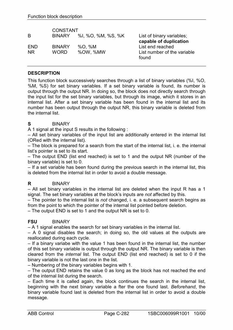
Function block description
ABB Control Page C-282 1SBC006099R1001 10/00
CONSTANTB BINARY %I, %O, %M, %S, %K List of binary variables;
capable of duplicationEND BINARY %O, %M List end reachedNR WORD %OW, %MW List number of the variable
found
DESCRIPTIONThis function block successively searches through a list of binary variables (%I, %O,%M, %S) for set binary variables. If a set binary variable is found, its number isoutput through the output NR. In doing so, the block does not directly search throughthe input list for the set binary variables, but through its image, which it stores in aninternal list. After a set binary variable has been found in the internal list and itsnumber has been output through the output NR, this binary variable is deleted fromthe internal list.
S BINARYA 1 signal at the input S results in the following :– All set binary variables of the input list are additionally entered in the internal list(ORed with the internal list).– The block is prepared for a search from the start of the internal list, i. e. the internallist’s pointer is set to its start.– The output END (list end reached) is set to 1 and the output NR (number of thebinary variable) is set to 0.– If a set variable has been found during the previous search in the internal list, thisis deleted from the internal list in order to avoid a double message.
R BINARY– All set binary variables in the internal list are deleted when the input R has a 1signal. The set binary variables at the block’s inputs are not affected by this.– The pointer to the internal list is not changed, i. e. a subsequent search begins asfrom the point to which the pointer of the internal list pointed before deletion.– The output END is set to 1 and the output NR is set to 0.
FSU BINARY– A 1 signal enables the search for set binary variables in the internal list.– A 0 signal disables the search; in doing so, the old values at the outputs arereallocated during each cycle.– If a binary variabe with the value 1 has been found in the internal list, the numberof this set binary variable is output through the output NR. The binary variable is thencleared from the internal list. The output END (list end reached) is set to 0 if thebinary variable is not the last one in the list.– Numbering of the binary variables begins with 1.– The output END retains the value 0 as long as the block has not reached the endof the internal list during the search.– Each time it is called again, the block continues the search in the internal list,beginning with the next binary variable a fter the one found last. Beforehand, thebinary variable found last is deleted from the internal list in order to avoid a doublemessage.
Function block description
ABB Control Page C-283 1SBC006099R1001 10/00
– The following applies if the end of the internal list is reached during the search : • the output END (list end reached) is set to 1. • the number of the binary variable found last in the internal list is output through theoutput NR. • each further time the block is called, the internal list is searched through as fromthe point of the binary variable found last. The search ends when a set binaryvariable is found or when the end of the list is reached.- If the last binary variable of the list is set and has been found during the search, thesearch stops there until a new search from the start of the internal list is prepared bymeans of the input S.– If no set binary variable has been found during the course of a search from thestart of the list, the output END (list end reached) is set to 1 and the output NR(number) retains the value 0. Each time the block is called again, the whole list isalways searched through until a binary variable assumes the value 1 and is found.
FKOP BINARYWhen the input FKOP has a 1 signal, all set binary variables of the input list areadditionally entered in the internal list. At the same time, the binary variables alreadyset in the internal list are retained. Updating is realized by “ORing” of the input listwith the internal list.Restart when searching after updatingUpdating of the internal list has no influence on the next search. The search beginsprecisely at the point in the internal list where it would also have been begun if noupdating had taken place.
#n DIRECT CONSTANTONLY used in IL languageThe number of binary variables planned at the inputs B0...Bn-1 is specified at theinput #n. This is specified as a direct constant.Important : The quantity at the input #n must be an integral multiple of 16. Dummyoperands may also be planned (e.g. %K0,0 is specified at all inputs not needed) inorder to keep to this stipulation.
B BINARYThe input B is capable of duplication (B0...Bn-1). The binary variables to beexamined are specified at the inputs B0...Bn-1. The number of variables must alwaysbe an integral multiple of 16. To achieve this, assign %K0,0 = 0 to inputs Bi that arenot needed.
END BINARYWhether or not the end of the list has been reached during the search is signalled atthe output END.END = 0 -> List end not reachedEND = 1 -> List end reachedIf the last variable of the list is set and has been found during the search just carriedout, its number is output through the output NR and the value 1 is additionallyallocated to the output END.
NR WORDThe list number of the variable found last is output through the output NR. The
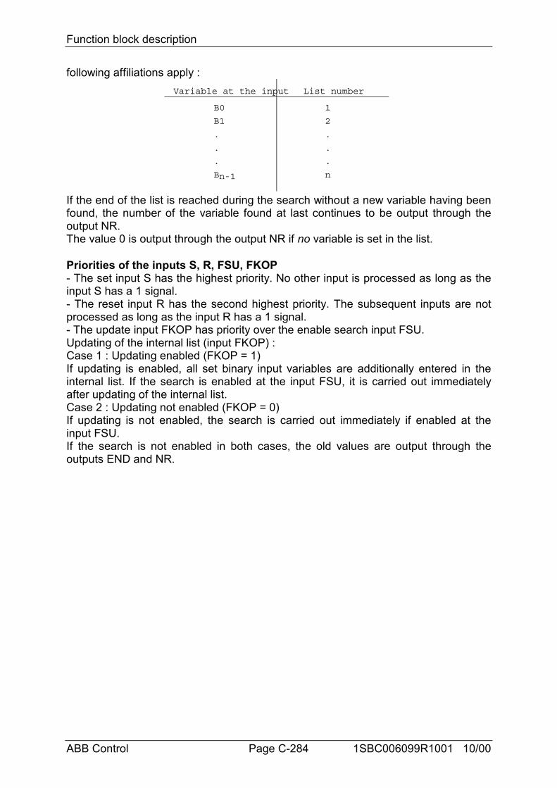
Function block description
ABB Control Page C-284 1SBC006099R1001 10/00
following affiliations apply :Variable at the input List number
B0
B1
.
.
.
Bn-1
1
2
.
.
.
n
If the end of the list is reached during the search without a new variable having beenfound, the number of the variable found at last continues to be output through theoutput NR.The value 0 is output through the output NR if no variable is set in the list.
Priorities of the inputs S, R, FSU, FKOP- The set input S has the highest priority. No other input is processed as long as theinput S has a 1 signal.- The reset input R has the second highest priority. The subsequent inputs are notprocessed as long as the input R has a 1 signal.- The update input FKOP has priority over the enable search input FSU.Updating of the internal list (input FKOP) :Case 1 : Updating enabled (FKOP = 1)If updating is enabled, all set binary input variables are additionally entered in theinternal list. If the search is enabled at the input FSU, it is carried out immediatelyafter updating of the internal list.Case 2 : Updating not enabled (FKOP = 0)If updating is not enabled, the search is carried out immediately if enabled at theinput FSU.If the search is not enabled in both cases, the old values are output through theoutputs END and NR.
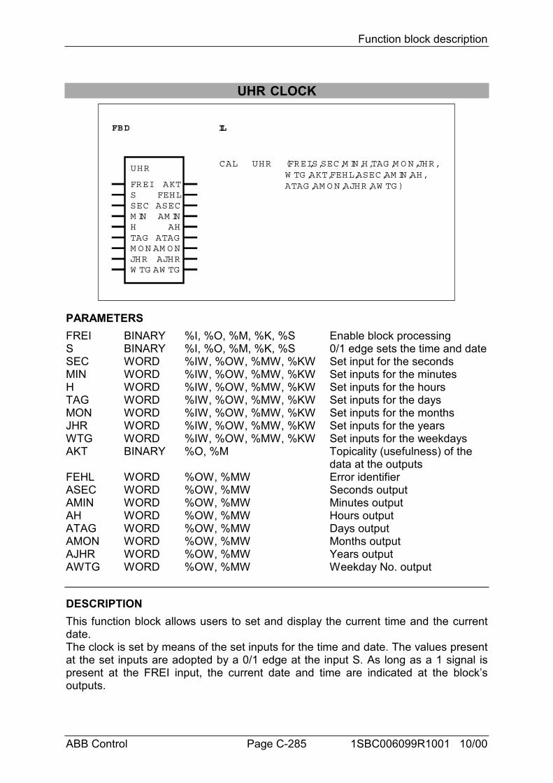
Function block description
ABB Control Page C-285 1SBC006099R1001 10/00
UHR CLOCK
FBD IL
UHR
FREISSECM INH
AM INAH
AKTFEHLASEC
CAL UHR (FREI,S,SEC,M IN,H,TAG ,M O N,JHR,W TG ,AKT,FEHL,ASEC,AM IN,AH,ATAG ,AM O N,AJHR,AW TG )
TAGM O NJHRW TG
AJHRAW TG
ATAGAM O N
PARAMETERSFREI BINARY %I, %O, %M, %K, %S Enable block processingS BINARY %I, %O, %M, %K, %S 0/1 edge sets the time and dateSEC WORD %IW, %OW, %MW, %KW Set input for the secondsMIN WORD %IW, %OW, %MW, %KW Set inputs for the minutesH WORD %IW, %OW, %MW, %KW Set inputs for the hoursTAG WORD %IW, %OW, %MW, %KW Set inputs for the daysMON WORD %IW, %OW, %MW, %KW Set inputs for the monthsJHR WORD %IW, %OW, %MW, %KW Set inputs for the yearsWTG WORD %IW, %OW, %MW, %KW Set inputs for the weekdaysAKT BINARY %O, %M Topicality (usefulness) of the
data at the outputsFEHL WORD %OW, %MW Error identifierASEC WORD %OW, %MW Seconds outputAMIN WORD %OW, %MW Minutes outputAH WORD %OW, %MW Hours outputATAG WORD %OW, %MW Days outputAMON WORD %OW, %MW Months outputAJHR WORD %OW, %MW Years outputAWTG WORD %OW, %MW Weekday No. output
DESCRIPTIONThis function block allows users to set and display the current time and the currentdate.The clock is set by means of the set inputs for the time and date. The values presentat the set inputs are adopted by a 0/1 edge at the input S. As long as a 1 signal ispresent at the FREI input, the current date and time are indicated at the block’soutputs.
Function block description
ABB Control Page C-286 1SBC006099R1001 10/00
FREI BINARYBlock enableFREI = 0 : The block is not processed. The AKT and FEHL outputs are set to 0. Thetime and date outputs are no longer changed by the block.FREI = 1 : Block is processed
S BINARYSet inputs for date and timeIn the event of a 0/1 edge at the input S, the clock is set to the values present at thetime and date inputs. During the setting, the time and date at the block’s output areinvalid (output AKT = 0).If the specified set values are inadmissible, the AKT output is set to 0 and an errormessage appears at the FEHL output. The values present at the time and dateoutputs are invalid in this case. The clock has to be set again.
SEC WORDSet input for the seconds.Value range : 0...59.
MIN WORDSet input for the minutes.Value range : 0...59.
H WORDSet input for the hours.
The clock operates in 24 hour mode, i.e. it changes from 23 :59 :59 h to 0 :0 :0 h.Value range : 0...23.
TAG WORDSet input for the days (which day of the month)
Note for 07 KR 31:The clock knows the number of days depending on the months and leap years. Forthe clock, a leap year exists when the year number is an integral multiple of 4. Themaximum value for the days (28, 29, 30, 31) depends on the month.Value range : 1...28, 29, 30, 31.
MON WORDSet input for the month.Value range : 1...12.
JHR WORDSet input for the years.The clock only indicates the years and decades.Value range : 0...99.
WTG WORDSet input for the number of the weekday.Value range : 1...7.
Function block description
ABB Control Page C-287 1SBC006099R1001 10/00
Example :The clock is set on Friday, 01.07.88. If the value 6 is entered for the week daynumber, Friday is now the 6th day of the week and Sunday is defined as the 1st dayof the week.
AKT BINARYIndication of the topicality (usefulness) of the outputs.AKT is 1 if :- The date and time outputs were updated in the current cycle;- The values at the outputs are consistent, i.e. none of the values at the date or timeoutputs has changed during updating. They all originate from the same clock pulse;- The clock was set correctly;
AKT = 1 -> FEHL = 0 : Date/time are valid.AKT = 0 -> FEHL > 0 : Date/time are invalid.
The reason why is displayed at the output FEHL as error identifier.
FEHL WORDIn the event of an error, the relevant error identifier is available at the output FEHL.
Meanings of the error identifiers :- No error has occurred :
FEHL = 0 : No error has occurred or FREI = 0,i.e. block disabled- Error when setting the clock :
FEHL = 1 : 0 < SEC < 59 has not been obeyedFEHL = 2 : 0 < MIN < 59 has not been obeyedFEHL = 3 : 0 < H < 23 has not been obeyedFEHL = 4 : 1 < TAG < 28, 29, 30, 31 (depending on the month, not tested in 07 KR 31) has not been obeyedFEHL = 5 : 1 < MON < 12 has not been obeyedFEHL = 6 : 0 < JHR < 99 has not been obeyedFEHL = 7 : 1 < WTG < 7 has not been obeyed
The following errors are not used in the 07 KR 31 :FEHL = 8 : The transmission mailbox is currently occupied by another user. The block waits till the mailbox is free and thereafter sets date/time.FEHL = 9 : Date/time at the outputs are invalid.FEHL = 10 :Date/time are currently being set; this may take several PLC cycles.FEHL = 11 :Setting was not successful, please repeat (unknown request code).FEHL = 12 :Setting was not successful, please repeat (invalid mail parameter).FEHL = 13 :Setting was not successful, please repeat (request code cannot be excecuted).
- Error when displaying date and time :FEHL = 9 : Date/time at the outputs are invalid.
Outputs for date and timeThe outputs are updated whenever a 1 signal is present at the FREI input and the
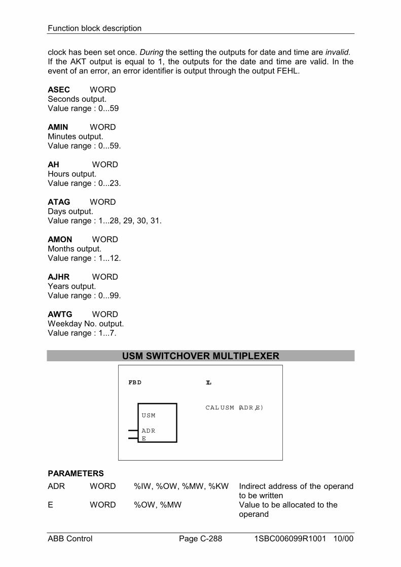
Function block description
ABB Control Page C-288 1SBC006099R1001 10/00
clock has been set once. During the setting the outputs for date and time are invalid.If the AKT output is equal to 1, the outputs for the date and time are valid. In theevent of an error, an error identifier is output through the output FEHL.
ASEC WORDSeconds output.Value range : 0...59
AMIN WORDMinutes output.Value range : 0...59.
AH WORDHours output.Value range : 0...23.
ATAG WORDDays output.Value range : 1...28, 29, 30, 31.
AMON WORDMonths output.Value range : 1...12.
AJHR WORDYears output.Value range : 0...99.
AWTG WORDWeekday No. output.Value range : 1...7.
USM SWITCHOVER MULTIPLEXER
FBD IL
USM
ADRE
CAL USM (ADR,E)
PARAMETERSADR WORD %IW, %OW, %MW, %KW Indirect address of the operand
to be writtenE WORD %OW, %MW Value to be allocated to the
operand
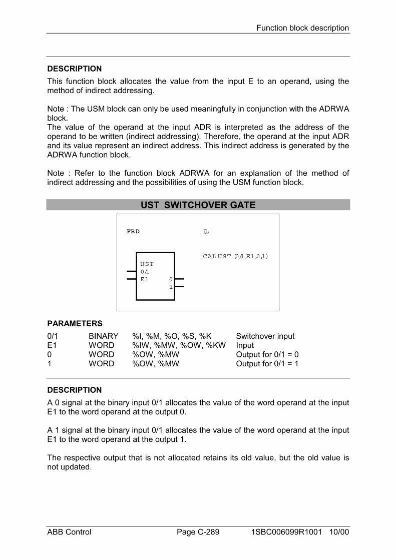
Function block description
ABB Control Page C-289 1SBC006099R1001 10/00
DESCRIPTIONThis function block allocates the value from the input E to an operand, using themethod of indirect addressing.
Note : The USM block can only be used meaningfully in conjunction with the ADRWAblock.The value of the operand at the input ADR is interpreted as the address of theoperand to be written (indirect addressing). Therefore, the operand at the input ADRand its value represent an indirect address. This indirect address is generated by theADRWA function block.
Note : Refer to the function block ADRWA for an explanation of the method ofindirect addressing and the possibilities of using the USM function block.
UST SWITCHOVER GATE
FBD IL
UST0/1E1
1
CAL UST (0/1,E1,0,1)
0
PARAMETERS0/1 BINARY %I, %M, %O, %S, %K Switchover inputE1 WORD %IW, %MW, %OW, %KW Input0 WORD %OW, %MW Output for 0/1 = 01 WORD %OW, %MW Output for 0/1 = 1
DESCRIPTIONA 0 signal at the binary input 0/1 allocates the value of the word operand at the inputE1 to the word operand at the output 0.
A 1 signal at the binary input 0/1 allocates the value of the word operand at the inputE1 to the word operand at the output 1.
The respective output that is not allocated retains its old value, but the old value isnot updated.
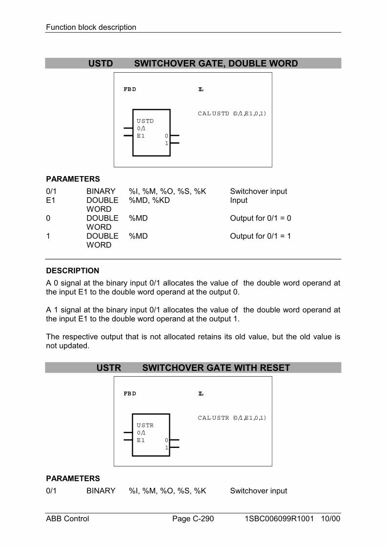
Function block description
ABB Control Page C-290 1SBC006099R1001 10/00
USTD SWITCHOVER GATE, DOUBLE WORD
FBD IL
USTD0/1E1
1
CAL USTD (0/1,E1,0,1)
0
PARAMETERS0/1 BINARY %I, %M, %O, %S, %K Switchover inputE1 DOUBLE %MD, %KD Input
WORD0 DOUBLE %MD Output for 0/1 = 0
WORD1 DOUBLE %MD Output for 0/1 = 1
WORD
DESCRIPTIONA 0 signal at the binary input 0/1 allocates the value of the double word operand atthe input E1 to the double word operand at the output 0.
A 1 signal at the binary input 0/1 allocates the value of the double word operand atthe input E1 to the double word operand at the output 1.
The respective output that is not allocated retains its old value, but the old value isnot updated.
USTR SWITCHOVER GATE WITH RESET
FBD IL
USTR0/1E1
1
CAL USTR (0/1,E1,0,1)
0
PARAMETERS0/1 BINARY %I, %M, %O, %S, %K Switchover input
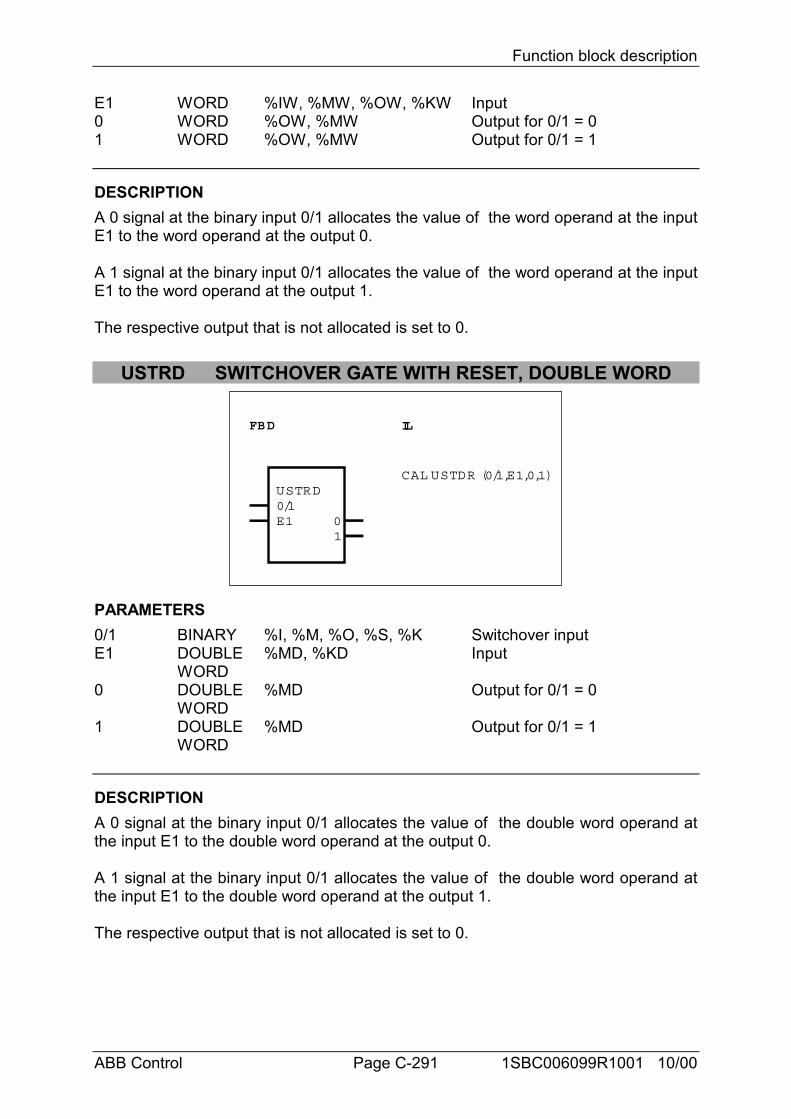
Function block description
ABB Control Page C-291 1SBC006099R1001 10/00
E1 WORD %IW, %MW, %OW, %KW Input0 WORD %OW, %MW Output for 0/1 = 01 WORD %OW, %MW Output for 0/1 = 1
DESCRIPTIONA 0 signal at the binary input 0/1 allocates the value of the word operand at the inputE1 to the word operand at the output 0.
A 1 signal at the binary input 0/1 allocates the value of the word operand at the inputE1 to the word operand at the output 1.
The respective output that is not allocated is set to 0.
USTRD SWITCHOVER GATE WITH RESET, DOUBLE WORD
FBD IL
USTRD0/1E1
1
CAL USTDR (0/1,E1,0,1)
0
PARAMETERS0/1 BINARY %I, %M, %O, %S, %K Switchover inputE1 DOUBLE %MD, %KD Input
WORD0 DOUBLE %MD Output for 0/1 = 0
WORD1 DOUBLE %MD Output for 0/1 = 1
WORD
DESCRIPTIONA 0 signal at the binary input 0/1 allocates the value of the double word operand atthe input E1 to the double word operand at the output 0.
A 1 signal at the binary input 0/1 allocates the value of the double word operand atthe input E1 to the double word operand at the output 1.
The respective output that is not allocated is set to 0.
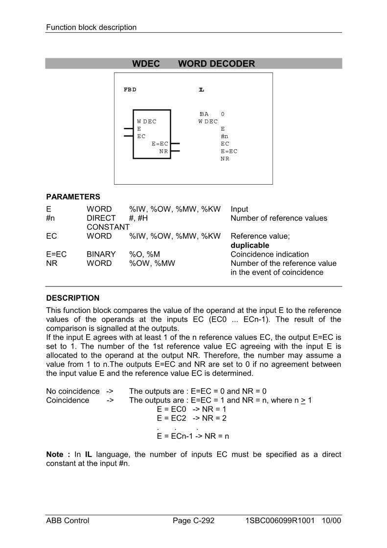
Function block description
ABB Control Page C-292 1SBC006099R1001 10/00
WDEC WORD DECODER
FBD IL
W DECEEC
NRE=EC
!BAW DEC
0
E#nECE=ECNR
PARAMETERSE WORD %IW, %OW, %MW, %KW Input#n DIRECT #, #H Number of reference values
CONSTANTEC WORD %IW, %OW, %MW, %KW Reference value;
duplicableE=EC BINARY %O, %M Coincidence indicationNR WORD %OW, %MW Number of the reference value
in the event of coincidence
DESCRIPTIONThis function block compares the value of the operand at the input E to the referencevalues of the operands at the inputs EC (EC0 ... ECn-1). The result of thecomparison is signalled at the outputs.If the input E agrees with at least 1 of the n reference values EC, the output E=EC isset to 1. The number of the 1st reference value EC agreeing with the input E isallocated to the operand at the output NR. Therefore, the number may assume avalue from 1 to n.The outputs E=EC and NR are set to 0 if no agreement betweenthe input value E and the reference value EC is determined.
No coincidence -> The outputs are : E=EC = 0 and NR = 0Coincidence -> The outputs are : E=EC = 1 and NR = n, where n > 1
E = EC0 -> NR = 1E = EC2 -> NR = 2. . .E = ECn-1 -> NR = n
Note : In IL language, the number of inputs EC must be specified as a directconstant at the input #n.
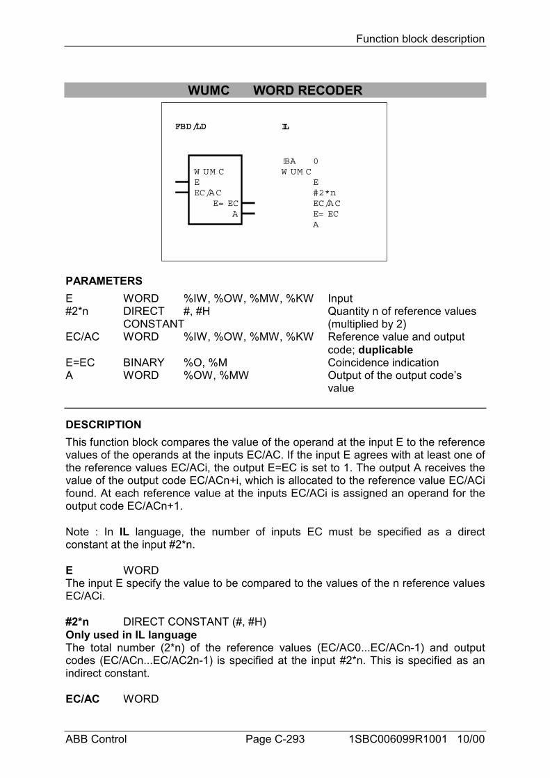
Function block description
ABB Control Page C-293 1SBC006099R1001 10/00
WUMC WORD RECODER
FBD/LD IL
W UM CEEC/AC
AE= EC
!BAW UM C
0
E#2*nEC/ACE= ECA
PARAMETERSE WORD %IW, %OW, %MW, %KW Input#2*n DIRECT #, #H Quantity n of reference values
CONSTANT (multiplied by 2)EC/AC WORD %IW, %OW, %MW, %KW Reference value and output
code; duplicableE=EC BINARY %O, %M Coincidence indicationA WORD %OW, %MW Output of the output code’s
value
DESCRIPTIONThis function block compares the value of the operand at the input E to the referencevalues of the operands at the inputs EC/AC. If the input E agrees with at least one ofthe reference values EC/ACi, the output E=EC is set to 1. The output A receives thevalue of the output code EC/ACn+i, which is allocated to the reference value EC/ACifound. At each reference value at the inputs EC/ACi is assigned an operand for theoutput code EC/ACn+1.
Note : In IL language, the number of inputs EC must be specified as a directconstant at the input #2*n.
E WORDThe input E specify the value to be compared to the values of the n reference valuesEC/ACi.
#2*n DIRECT CONSTANT (#, #H)Only used in IL languageThe total number (2*n) of the reference values (EC/AC0...EC/ACn-1) and outputcodes (EC/ACn...EC/AC2n-1) is specified at the input #2*n. This is specified as anindirect constant.
EC/AC WORD
Function block description
ABB Control Page C-294 1SBC006099R1001 10/00
The input EC/AC must be duplicated according to the required number of referencevalues. The operands for the reference values are specified at the inputsEC/AC0...EC/ACn-1. The value of the operand at the input E is compared to thereference values. The output codes are specified at the inputs EC/ACn...EC/AC2n-1.The output code EC/ACi+n is output through the output A if the input E agrees withone of the reference values EC/ACi.Affiliations between the reference values and output codes :EC/AC0 <-> EC/ACnEC/AC1 <-> EC/ACn+1 . . . .EC/ACn-1 <-> EC/ACn+(n-1)
E=EC BINARYAgreement between the operand value of the input E and one of the referencevalues is signalled at the output E=EC.The following applies : E=EC = 0 -> No coincidence
E=EC = 1 -> Coincidence
A WORDThe output code EC/ACn+i is output through the output A if the input E agrees withone of the reference values EC/ACi.The following applies : A = 0 -> No coincidence
A = EC/ACn+i -> Coincidence
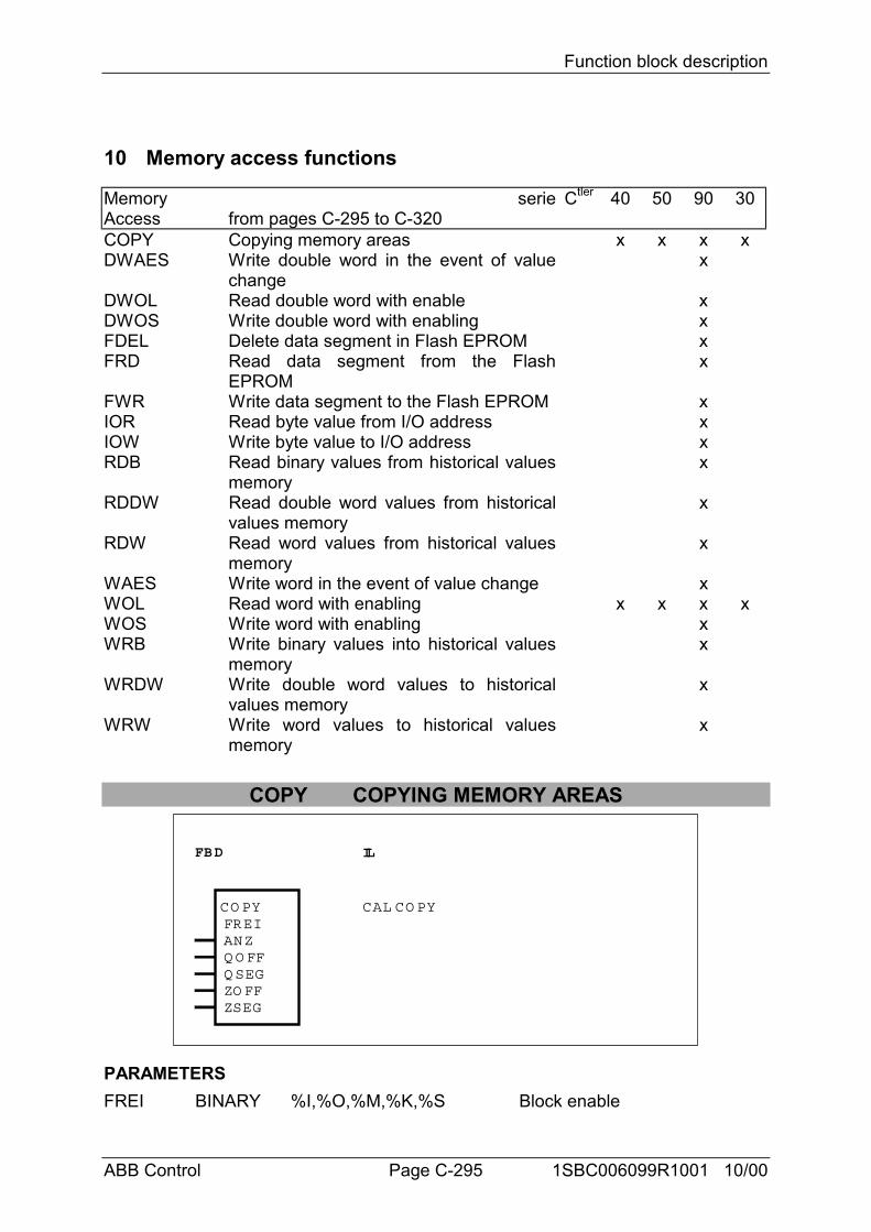
Function block description
ABB Control Page C-295 1SBC006099R1001 10/00
10 Memory access functions
MemoryAccess
seriefrom pages C-295 to C-320
Ctler 40 50 90 30
COPY Copying memory areas x x x xDWAES Write double word in the event of value
changex
DWOL Read double word with enable xDWOS Write double word with enabling xFDEL Delete data segment in Flash EPROM xFRD Read data segment from the Flash
EPROMx
FWR Write data segment to the Flash EPROM xIOR Read byte value from I/O address xIOW Write byte value to I/O address xRDB Read binary values from historical values
memoryx
RDDW Read double word values from historicalvalues memory
x
RDW Read word values from historical valuesmemory
x
WAES Write word in the event of value change xWOL Read word with enabling x x x xWOS Write word with enabling xWRB Write binary values into historical values
memoryx
WRDW Write double word values to historicalvalues memory
x
WRW Write word values to historical valuesmemory
x
COPY COPYING MEMORY AREAS
FBD IL
FREIANZQ O FFQ SEGZO FFZSEG
CAL CO PYCO PY
PARAMETERSFREI BINARY %I,%O,%M,%K,%S Block enable
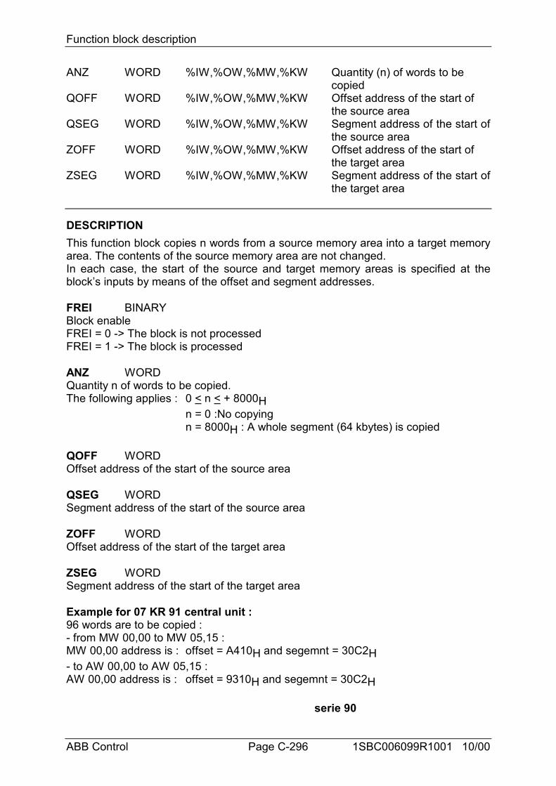
Function block description
ABB Control Page C-296 1SBC006099R1001 10/00
ANZ WORD %IW,%OW,%MW,%KW Quantity (n) of words to be copied
QOFF WORD %IW,%OW,%MW,%KW Offset address of the start of the source area
QSEG WORD %IW,%OW,%MW,%KW Segment address of the start ofthe source area
ZOFF WORD %IW,%OW,%MW,%KW Offset address of the start of the target area
ZSEG WORD %IW,%OW,%MW,%KW Segment address of the start ofthe target area
DESCRIPTIONThis function block copies n words from a source memory area into a target memoryarea. The contents of the source memory area are not changed.In each case, the start of the source and target memory areas is specified at theblock’s inputs by means of the offset and segment addresses.
FREI BINARYBlock enableFREI = 0 -> The block is not processedFREI = 1 -> The block is processed
ANZ WORDQuantity n of words to be copied.The following applies : 0 < n < + 8000H
n = 0 :No copyingn = 8000H : A whole segment (64 kbytes) is copied
QOFF WORDOffset address of the start of the source area
QSEG WORDSegment address of the start of the source area
ZOFF WORDOffset address of the start of the target area
ZSEG WORDSegment address of the start of the target area
Example for 07 KR 91 central unit :96 words are to be copied :- from MW 00,00 to MW 05,15 :MW 00,00 address is : offset = A410H and segemnt = 30C2H- to AW 00,00 to AW 05,15 :AW 00,00 address is : offset = 9310H and segemnt = 30C2H
serie 90
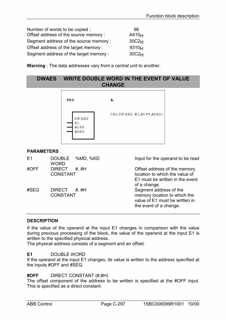
Function block description
ABB Control Page C-297 1SBC006099R1001 10/00
Number of words to be copied : 96Offset address of the source memory : A410HSegment address of the source memory : 30C2HOffset address of the target memory : 9310HSegment address of the target memory : 30C2H
Warning : The data addresses vary from a central unit to another.
DWAES WRITE DOUBLE WORD IN THE EVENT OF VALUECHANGE
FBD IL
DW AESE1#O FF#SEG
CAL DW AES (E1,#O FF,#SEG )
PARAMETERSE1 DOUBLE %MD, %KD Input for the operand to be read
WORD#OFF DIRECT #, #H Offset address of the memory
CONSTANT location to which the value of E1 must be written in the event of a change.
#SEG DIRECT #, #H Segment address of theCONSTANT memory location to which the
value of E1 must be written in the event of a change.
DESCRIPTIONIf the value of the operand at the input E1 changes in comparison with the valueduring previous processing of the block, the value of the operand at the input E1 iswritten to the specified physical address.The physical address consists of a segment and an offset.
E1 DOUBLE WORDIf the operand at the input E1 changes, its value is written to the address specified atthe inputs #OFF and #SEG.
#OFF DIRECT CONSTANT (#,#H)The offset component of the address to be written is specified at the #OFF input.This is specified as a direct constant.
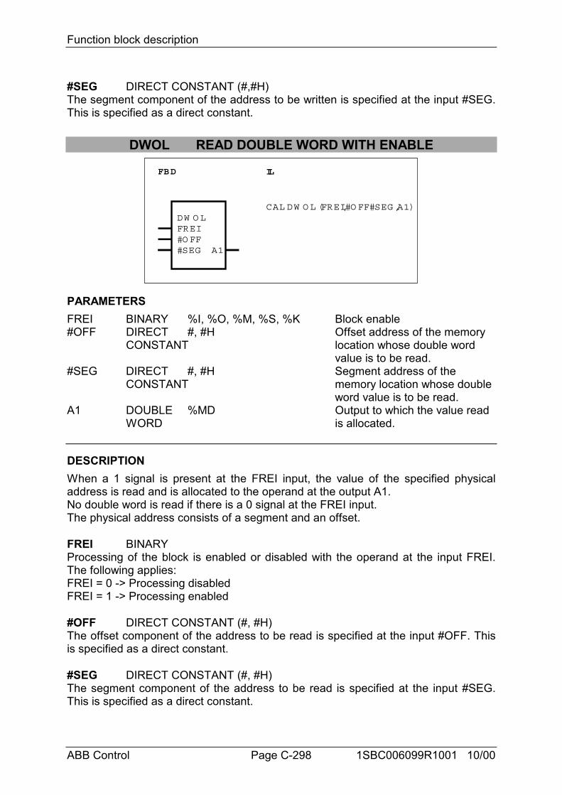
Function block description
ABB Control Page C-298 1SBC006099R1001 10/00
#SEG DIRECT CONSTANT (#,#H)The segment component of the address to be written is specified at the input #SEG.This is specified as a direct constant.
DWOL READ DOUBLE WORD WITH ENABLE
FBD IL
DW O LFREI#O FF#SEG A1
CAL DW O L (FREI,#O FF#SEG ,A1)
PARAMETERSFREI BINARY %I, %O, %M, %S, %K Block enable#OFF DIRECT #, #H Offset address of the memory
CONSTANT location whose double word value is to be read.
#SEG DIRECT #, #H Segment address of theCONSTANT memory location whose double
word value is to be read.A1 DOUBLE %MD Output to which the value read
WORD is allocated.
DESCRIPTIONWhen a 1 signal is present at the FREI input, the value of the specified physicaladdress is read and is allocated to the operand at the output A1.No double word is read if there is a 0 signal at the FREI input.The physical address consists of a segment and an offset.
FREI BINARYProcessing of the block is enabled or disabled with the operand at the input FREI.The following applies:FREI = 0 -> Processing disabledFREI = 1 -> Processing enabled
#OFF DIRECT CONSTANT (#, #H)The offset component of the address to be read is specified at the input #OFF. Thisis specified as a direct constant.
#SEG DIRECT CONSTANT (#, #H)The segment component of the address to be read is specified at the input #SEG.This is specified as a direct constant.
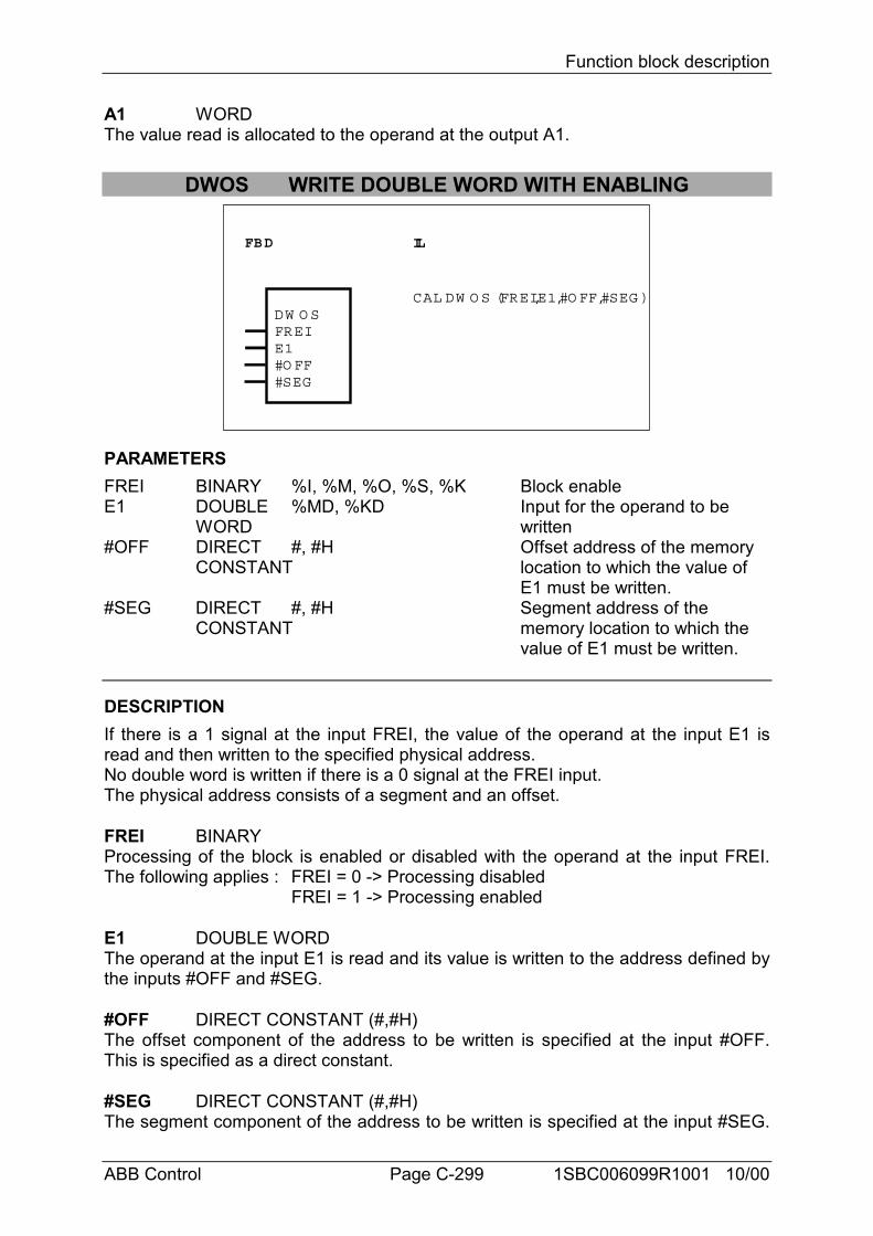
Function block description
ABB Control Page C-299 1SBC006099R1001 10/00
A1 WORDThe value read is allocated to the operand at the output A1.
DWOS WRITE DOUBLE WORD WITH ENABLING
FBD IL
DW O SFREIE1#O FF#SEG
CAL DW O S (FREI,E1,#O FF,#SEG )
PARAMETERSFREI BINARY %I, %M, %O, %S, %K Block enableE1 DOUBLE %MD, %KD Input for the operand to be
WORD written#OFF DIRECT #, #H Offset address of the memory
CONSTANT location to which the value of E1 must be written.
#SEG DIRECT #, #H Segment address of theCONSTANT memory location to which the
value of E1 must be written.
DESCRIPTIONIf there is a 1 signal at the input FREI, the value of the operand at the input E1 isread and then written to the specified physical address.No double word is written if there is a 0 signal at the FREI input.The physical address consists of a segment and an offset.
FREI BINARYProcessing of the block is enabled or disabled with the operand at the input FREI.The following applies : FREI = 0 -> Processing disabled
FREI = 1 -> Processing enabled
E1 DOUBLE WORDThe operand at the input E1 is read and its value is written to the address defined bythe inputs #OFF and #SEG.
#OFF DIRECT CONSTANT (#,#H)The offset component of the address to be written is specified at the input #OFF.This is specified as a direct constant.
#SEG DIRECT CONSTANT (#,#H)The segment component of the address to be written is specified at the input #SEG.
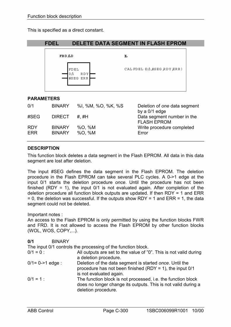
Function block description
ABB Control Page C-300 1SBC006099R1001 10/00
This is specified as a direct constant.
FDEL DELETE DATA SEGMENT IN FLASH EPROM
FBD/LD IL
CAL FDEL (0/1,#SEG ,RDY,ERR)FDEL0/1#SEG
RDYERR
PARAMETERS0/1 BINARY %I, %M, %O, %K, %S Deletion of one data segment
by a 0/1 edge#SEG DIRECT #, #H Data segment number in the
FLASH EPROMRDY BINARY %O, %M Write procedure completedERR BINARY %O, %M Error
DESCRIPTIONThis function block deletes a data segment in the Flash EPROM. All data in this datasegment are lost after deletion.
The input #SEG defines the data segment in the Flash EPROM. The deletionprocedure in the Flash EPROM can take several PLC cycles. A 0->1 edge at theinput 0/1 starts the deletion procedure once. Until the procedure has not beenfinished (RDY = 1), the input 0/1 is not evaluated again. After completion of thedeletion procedure all function block outputs are updated. If then RDY = 1 and ERR= 0, the deletion was successful. If the outputs show RDY = 1 and ERR = 1, the datasegment could not be deleted.
Important notes :An access to the Flash EPROM is only permitted by using the function blocks FWRand FRD. It is not allowed to access the Flash EPROM by other function blocks(WOL, WOS, COPY,...).
0/1 BINARYThe input 0/1 controls the processing of the function block.0/1 = 0 : All outputs are set to the value of ”0”. This is not valid during
a deletion procedure.0/1= 0->1 edge : Deletion of the data segment is started once. Until the
procedure has not been finished (RDY = 1), the input 0/1 is not evaluated again.
0/1 = 1 : The function block is not processed, i.e. the function block does no longer change its outputs. This is not valid during a deletion procedure.
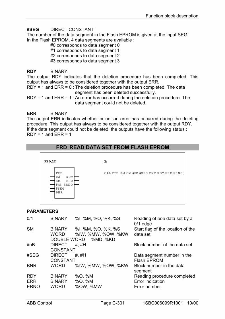
Function block description
ABB Control Page C-301 1SBC006099R1001 10/00
#SEG DIRECT CONSTANTThe number of the data segment in the Flash EPROM is given at the input SEG.In the Flash EPROM, 4 data segments are available :
#0 corresponds to data segment 0#1 corresponds to data segment 1#2 corresponds to data segment 2#3 corresponds to data segment 3
RDY BINARYThe output RDY indicates that the deletion procedure has been completed. Thisoutput has always to be considered together with the output ERR.RDY = 1 and ERR = 0 : The deletion procedure has been completed. The data
segment has been deleted successfully.RDY = 1 and ERR = 1 : An error has occurred during the deletion procedure. The
data segment could not be deleted.
ERR BINARYThe output ERR indicates whether or not an error has occurred during the deletingprocedure. This output has always to be considered together with the output RDY.If the data segment could not be deleted, the outputs have the following status :RDY = 1 and ERR = 1
FRD READ DATA SET FROM FLASH EPROM
FBD/LD IL
CAL FRD (0/1,SM ,#nB,#SEG ,BNR,RDY,ERR,ERNO )FRD0/1SM#nB
RDYERR
ERNO#SEGBNR
PARAMETERS0/1 BINARY %I, %M, %O, %K, %S Reading of one data set by a
0/1 edgeSM BINARY %I, %M, %O, %K, %S Start flag of the location of the
WORD %IW, %MW, %OW, %KW data setDOUBLE WORD %MD, %KD
#nB DIRECT #, #H Block number of the data setCONSTANT
#SEG DIRECT #, #H Data segment number in the CONSTANT Flash EPROM
BNR WORD %IW, %MW, %OW, %KW Block number in the data segment
RDY BINARY %O, %M Reading procedure completedERR BINARY %O, %M Error indicationERNO WORD %OW, %MW Error number
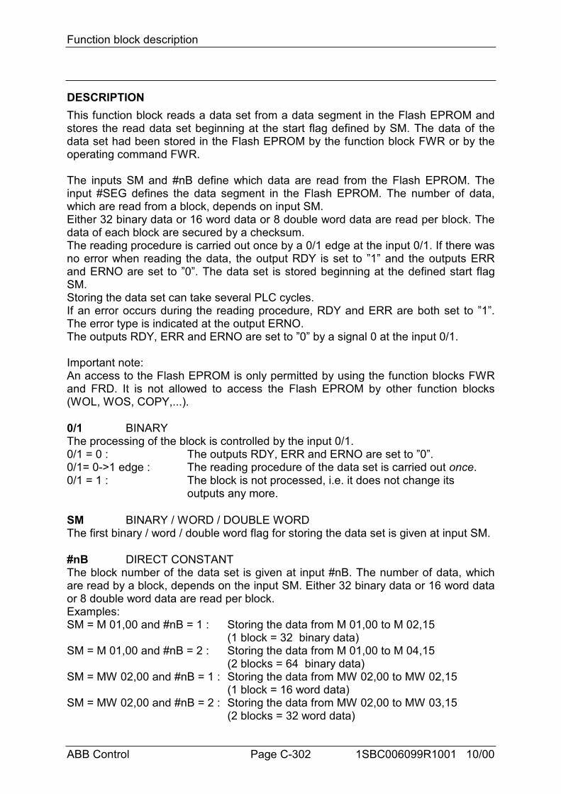
Function block description
ABB Control Page C-302 1SBC006099R1001 10/00
DESCRIPTIONThis function block reads a data set from a data segment in the Flash EPROM andstores the read data set beginning at the start flag defined by SM. The data of thedata set had been stored in the Flash EPROM by the function block FWR or by theoperating command FWR.
The inputs SM and #nB define which data are read from the Flash EPROM. Theinput #SEG defines the data segment in the Flash EPROM. The number of data,which are read from a block, depends on input SM.Either 32 binary data or 16 word data or 8 double word data are read per block. Thedata of each block are secured by a checksum.The reading procedure is carried out once by a 0/1 edge at the input 0/1. If there wasno error when reading the data, the output RDY is set to ”1” and the outputs ERRand ERNO are set to ”0”. The data set is stored beginning at the defined start flagSM.Storing the data set can take several PLC cycles.If an error occurs during the reading procedure, RDY and ERR are both set to ”1”.The error type is indicated at the output ERNO.The outputs RDY, ERR and ERNO are set to ”0” by a signal 0 at the input 0/1.
Important note:An access to the Flash EPROM is only permitted by using the function blocks FWRand FRD. It is not allowed to access the Flash EPROM by other function blocks(WOL, WOS, COPY,...).
0/1 BINARYThe processing of the block is controlled by the input 0/1.0/1 = 0 : The outputs RDY, ERR and ERNO are set to ”0”.0/1= 0->1 edge : The reading procedure of the data set is carried out once.0/1 = 1 : The block is not processed, i.e. it does not change its
outputs any more.
SM BINARY / WORD / DOUBLE WORDThe first binary / word / double word flag for storing the data set is given at input SM.
#nB DIRECT CONSTANTThe block number of the data set is given at input #nB. The number of data, whichare read by a block, depends on the input SM. Either 32 binary data or 16 word dataor 8 double word data are read per block.Examples:SM = M 01,00 and #nB = 1 : Storing the data from M 01,00 to M 02,15
(1 block = 32 binary data)SM = M 01,00 and #nB = 2 : Storing the data from M 01,00 to M 04,15
(2 blocks = 64 binary data)SM = MW 02,00 and #nB = 1 : Storing the data from MW 02,00 to MW 02,15
(1 block = 16 word data)SM = MW 02,00 and #nB = 2 : Storing the data from MW 02,00 to MW 03,15
(2 blocks = 32 word data)
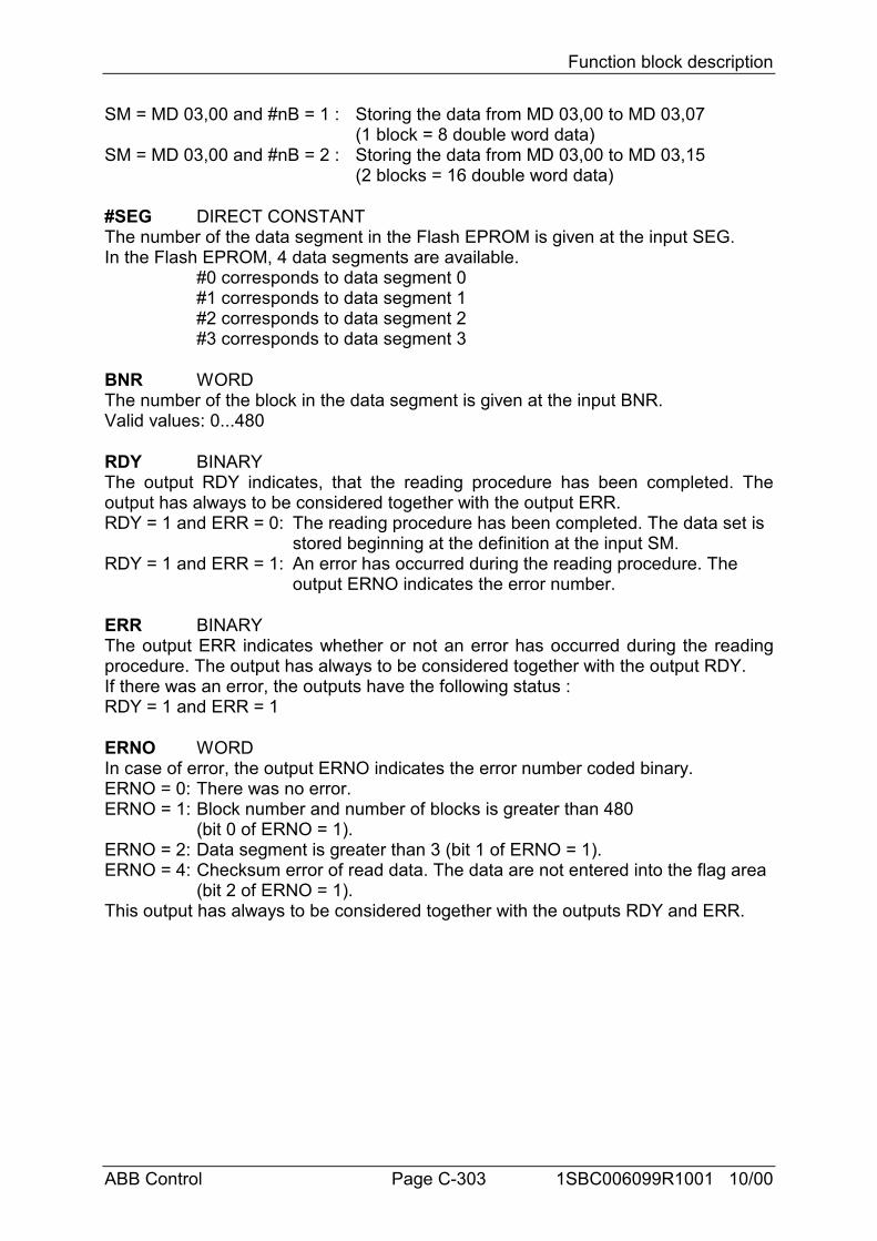
Function block description
ABB Control Page C-303 1SBC006099R1001 10/00
SM = MD 03,00 and #nB = 1 : Storing the data from MD 03,00 to MD 03,07(1 block = 8 double word data)
SM = MD 03,00 and #nB = 2 : Storing the data from MD 03,00 to MD 03,15(2 blocks = 16 double word data)
#SEG DIRECT CONSTANTThe number of the data segment in the Flash EPROM is given at the input SEG.In the Flash EPROM, 4 data segments are available.
#0 corresponds to data segment 0#1 corresponds to data segment 1#2 corresponds to data segment 2#3 corresponds to data segment 3
BNR WORDThe number of the block in the data segment is given at the input BNR.Valid values: 0...480
RDY BINARYThe output RDY indicates, that the reading procedure has been completed. Theoutput has always to be considered together with the output ERR.RDY = 1 and ERR = 0: The reading procedure has been completed. The data set is
stored beginning at the definition at the input SM.RDY = 1 and ERR = 1: An error has occurred during the reading procedure. The
output ERNO indicates the error number.
ERR BINARYThe output ERR indicates whether or not an error has occurred during the readingprocedure. The output has always to be considered together with the output RDY.If there was an error, the outputs have the following status :RDY = 1 and ERR = 1
ERNO WORDIn case of error, the output ERNO indicates the error number coded binary.ERNO = 0: There was no error.ERNO = 1: Block number and number of blocks is greater than 480
(bit 0 of ERNO = 1).ERNO = 2: Data segment is greater than 3 (bit 1 of ERNO = 1).ERNO = 4: Checksum error of read data. The data are not entered into the flag area
(bit 2 of ERNO = 1).This output has always to be considered together with the outputs RDY and ERR.
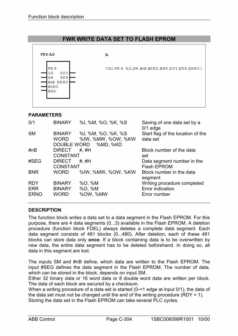
Function block description
ABB Control Page C-304 1SBC006099R1001 10/00
FWR WRITE DATA SET TO FLASH EPROM
FBD/LD IL
CAL FW R (0/1,SM ,#nB,#SEG ,BNR,RDY,ERR,ERNO )FW R0/1SM#nB
RDYERR
ERNO#SEGBNR
PARAMETERS0/1 BINARY %I, %M, %O, %K, %S Saving of one data set by a
0/1 edgeSM BINARY %I, %M, %O, %K, %S Start flag of the location of the
WORD %IW, %MW, %OW, %KW data setDOUBLE WORD %MD, %KD
#nB DIRECT #, #H Block number of the dataCONSTANT set
#SEG DIRECT #, #H Data segment number in the CONSTANT Flash EPROM
BNR WORD %IW, %MW, %OW, %KW Block number in the data segment
RDY BINARY %O, %M Writing procedure completedERR BINARY %O, %M Error indicationERNO WORD %OW, %MW Error number
DESCRIPTIONThe function block writes a data set to a data segment in the Flash EPROM. For thispurpose, there are 4 data segments (0...3) available in the Flash EPROM. A deletionprocedure (function block FDEL) always deletes a complete data segment. Eachdata segment consists of 481 blocks (0...480). After deletion, each of these 481blocks can store data only once. If a block containing data is to be overwritten bynew data, the entire data segment has to be deleted beforehand. In doing so, alldata in this segment are lost.
The inputs SM and #nB define, which data are written to the Flash EPROM. Theinput #SEG defines the data segment in the Flash EPROM. The number of data,which can be stored in the block, depends on input SM.Either 32 binary data or 16 word data or 8 double word data are written per block.The data of each block are secured by a checksum.When a writing procedure of a data set is started (0->1 edge at input 0/1), the data ofthe data set must not be changed until the end of the writing procedure (RDY = 1).Storing the data set in the Flash EPROM can take several PLC cycles.
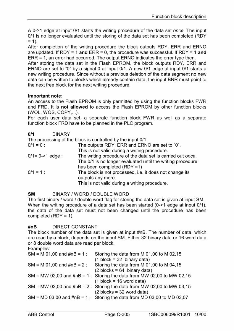
Function block description
ABB Control Page C-305 1SBC006099R1001 10/00
A 0->1 edge at input 0/1 starts the writing procedure of the data set once. The input0/1 is no longer evaluated until the storing of the data set has been completed (RDY= 1).After completion of the writing procedure the block outputs RDY, ERR and ERNOare updated. If RDY = 1 and ERR = 0, the procedure was successful. If RDY = 1 andERR = 1, an error had occurred. The output ERNO indicates the error type then.After storing the data set in the Flash EPROM, the block outputs RDY, ERR andERNO are set to ”0” by a signal 0 at input 0/1. A new 0/1 edge at input 0/1 starts anew writing procedure. Since without a previous deletion of the data segment no newdata can be written to blocks which already contain data, the input BNR must point tothe next free block for the next writing procedure.
Important note:An access to the Flash EPROM is only permitted by using the function blocks FWRand FRD. It is not allowed to access the Flash EPROM by other function blocks(WOL, WOS, COPY,...).For each user data set, a separate function block FWR as well as a separatefunction block FRD have to be planned in the PLC program.
0/1 BINARYThe processing of the block is controlled by the input 0/1.0/1 = 0 : The outputs RDY, ERR and ERNO are set to ”0”.
This is not valid during a writing procedure.0/1= 0->1 edge : The writing procedure of the data set is carried out once.
The 0/1 is no longer evaluated until the writing procedure has been completed (RDY =1)
0/1 = 1 : The block is not processed, i.e. it does not change its outputs any more.This is not valid during a writing procedure.
SM BINARY / WORD / DOUBLE WORDThe first binary / word / double word flag for storing the data set is given at input SM.When the writing procedure of a data set has been started (0->1 edge at input 0/1),the data of the data set must not been changed until the procedure has beencompleted (RDY = 1).
#nB DIRECT CONSTANTThe block number of the data set is given at input #nB. The number of data, whichare read by a block, depends on the input SM. Either 32 binary data or 16 word dataor 8 double word data are read per block.Examples:SM = M 01,00 and #nB = 1 : Storing the data from M 01,00 to M 02,15
(1 block = 32 binary data)SM = M 01,00 and #nB = 2 : Storing the data from M 01,00 to M 04,15
(2 blocks = 64 binary data)SM = MW 02,00 and #nB = 1 : Storing the data from MW 02,00 to MW 02,15
(1 block = 16 word data)SM = MW 02,00 and #nB = 2 : Storing the data from MW 02,00 to MW 03,15
(2 blocks = 32 word data)SM = MD 03,00 and #nB = 1 : Storing the data from MD 03,00 to MD 03,07
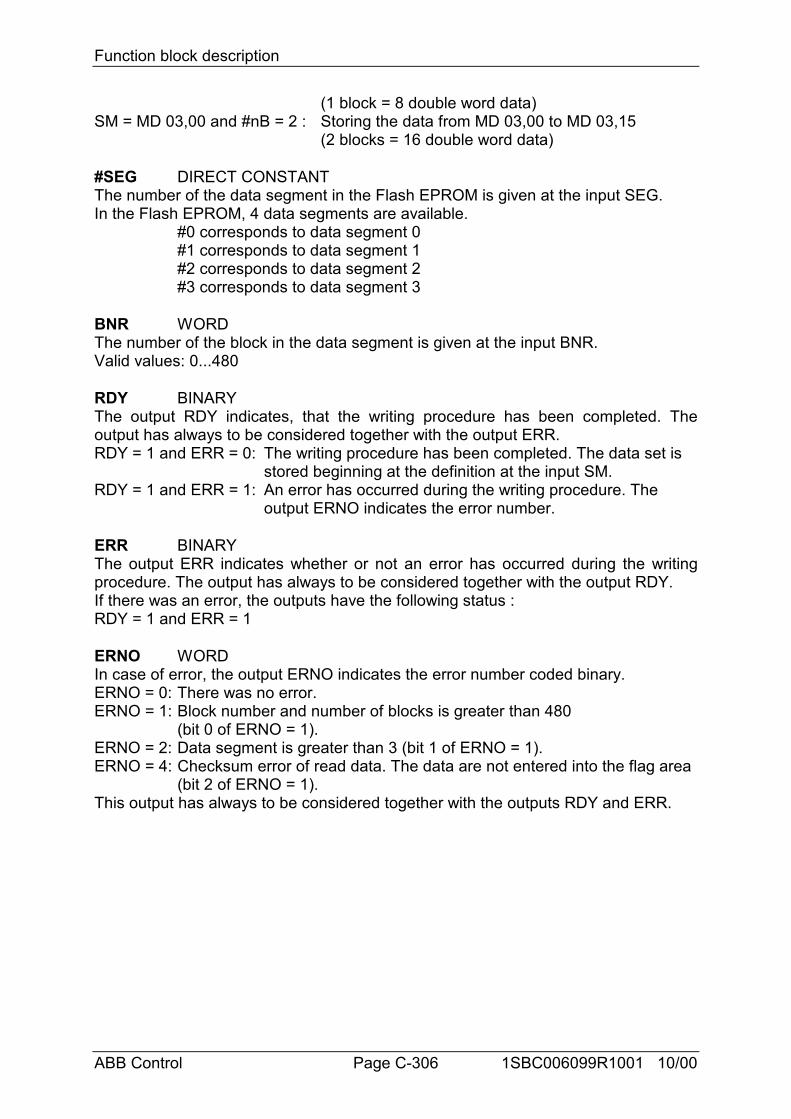
Function block description
ABB Control Page C-306 1SBC006099R1001 10/00
(1 block = 8 double word data)SM = MD 03,00 and #nB = 2 : Storing the data from MD 03,00 to MD 03,15
(2 blocks = 16 double word data)
#SEG DIRECT CONSTANTThe number of the data segment in the Flash EPROM is given at the input SEG.In the Flash EPROM, 4 data segments are available.
#0 corresponds to data segment 0#1 corresponds to data segment 1#2 corresponds to data segment 2#3 corresponds to data segment 3
BNR WORDThe number of the block in the data segment is given at the input BNR.Valid values: 0...480
RDY BINARYThe output RDY indicates, that the writing procedure has been completed. Theoutput has always to be considered together with the output ERR.RDY = 1 and ERR = 0: The writing procedure has been completed. The data set is
stored beginning at the definition at the input SM.RDY = 1 and ERR = 1: An error has occurred during the writing procedure. The
output ERNO indicates the error number.
ERR BINARYThe output ERR indicates whether or not an error has occurred during the writingprocedure. The output has always to be considered together with the output RDY.If there was an error, the outputs have the following status :RDY = 1 and ERR = 1
ERNO WORDIn case of error, the output ERNO indicates the error number coded binary.ERNO = 0: There was no error.ERNO = 1: Block number and number of blocks is greater than 480
(bit 0 of ERNO = 1).ERNO = 2: Data segment is greater than 3 (bit 1 of ERNO = 1).ERNO = 4: Checksum error of read data. The data are not entered into the flag area
(bit 2 of ERNO = 1).This output has always to be considered together with the outputs RDY and ERR.
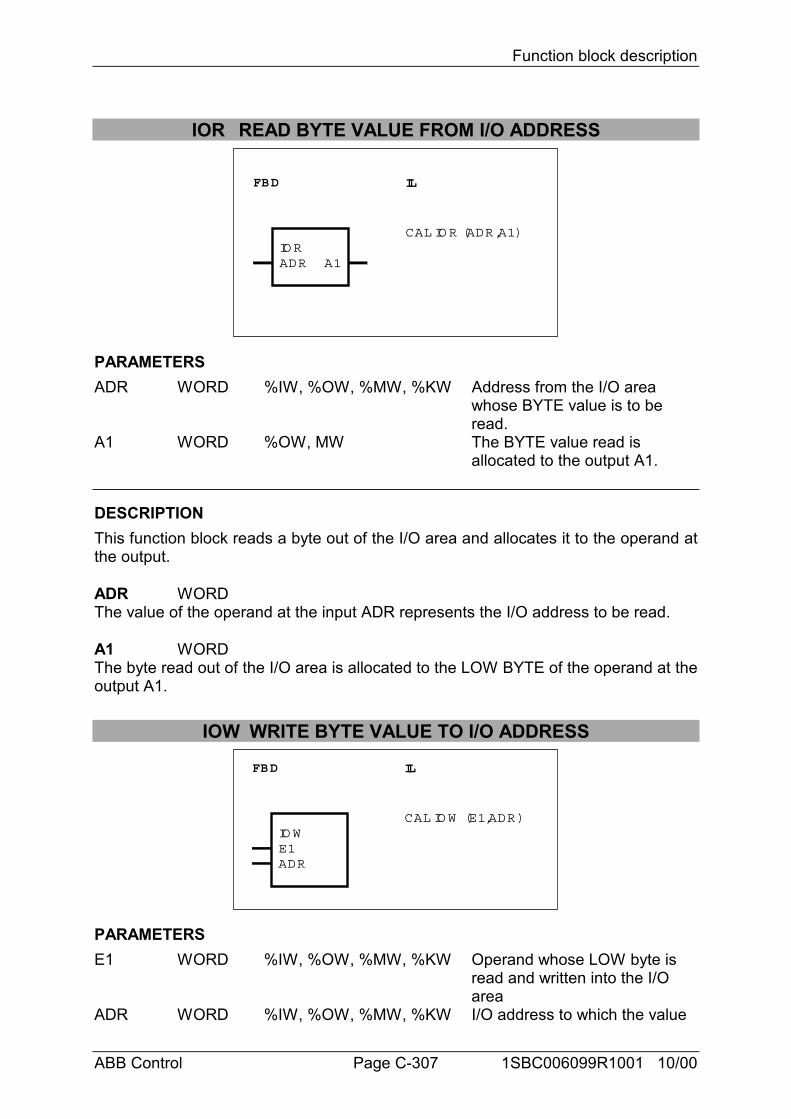
Function block description
ABB Control Page C-307 1SBC006099R1001 10/00
IOR READ BYTE VALUE FROM I/O ADDRESS
FBD IL
IO RCAL IO R (ADR,A1)
ADR A1
PARAMETERSADR WORD %IW, %OW, %MW, %KW Address from the I/O area
whose BYTE value is to be read.
A1 WORD %OW, MW The BYTE value read is allocated to the output A1.
DESCRIPTIONThis function block reads a byte out of the I/O area and allocates it to the operand atthe output.
ADR WORDThe value of the operand at the input ADR represents the I/O address to be read.
A1 WORDThe byte read out of the I/O area is allocated to the LOW BYTE of the operand at theoutput A1.
IOW WRITE BYTE VALUE TO I/O ADDRESS
FBD IL
IO W
ADR
CAL IO W (E1,ADR)
E1
PARAMETERSE1 WORD %IW, %OW, %MW, %KW Operand whose LOW byte is
read and written into the I/O area
ADR WORD %IW, %OW, %MW, %KW I/O address to which the value
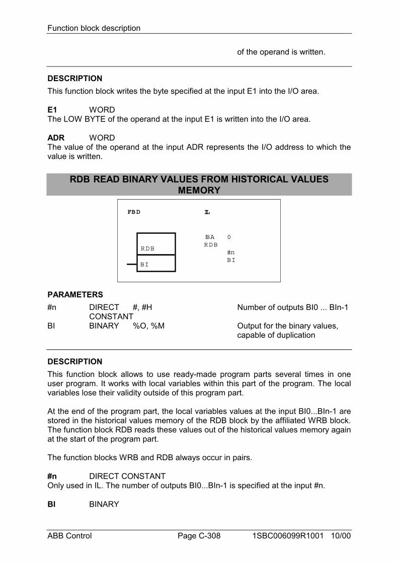
Function block description
ABB Control Page C-308 1SBC006099R1001 10/00
of the operand is written.
DESCRIPTIONThis function block writes the byte specified at the input E1 into the I/O area.
E1 WORDThe LOW BYTE of the operand at the input E1 is written into the I/O area.
ADR WORDThe value of the operand at the input ADR represents the I/O address to which thevalue is written.
RDB READ BINARY VALUES FROM HISTORICAL VALUESMEMORY
FBD IL
RDB
BI
!BARDB
0
#nBI
PARAMETERS#n DIRECT #, #H Number of outputs BI0 ... BIn-1
CONSTANTBI BINARY %O, %M Output for the binary values,
capable of duplication
DESCRIPTIONThis function block allows to use ready-made program parts several times in oneuser program. It works with local variables within this part of the program. The localvariables lose their validity outside of this program part.
At the end of the program part, the local variables values at the input BI0...BIn-1 arestored in the historical values memory of the RDB block by the affiliated WRB block.The function block RDB reads these values out of the historical values memory againat the start of the program part.
The function blocks WRB and RDB always occur in pairs.
#n DIRECT CONSTANTOnly used in IL. The number of outputs BI0...BIn-1 is specified at the input #n.
BI BINARY
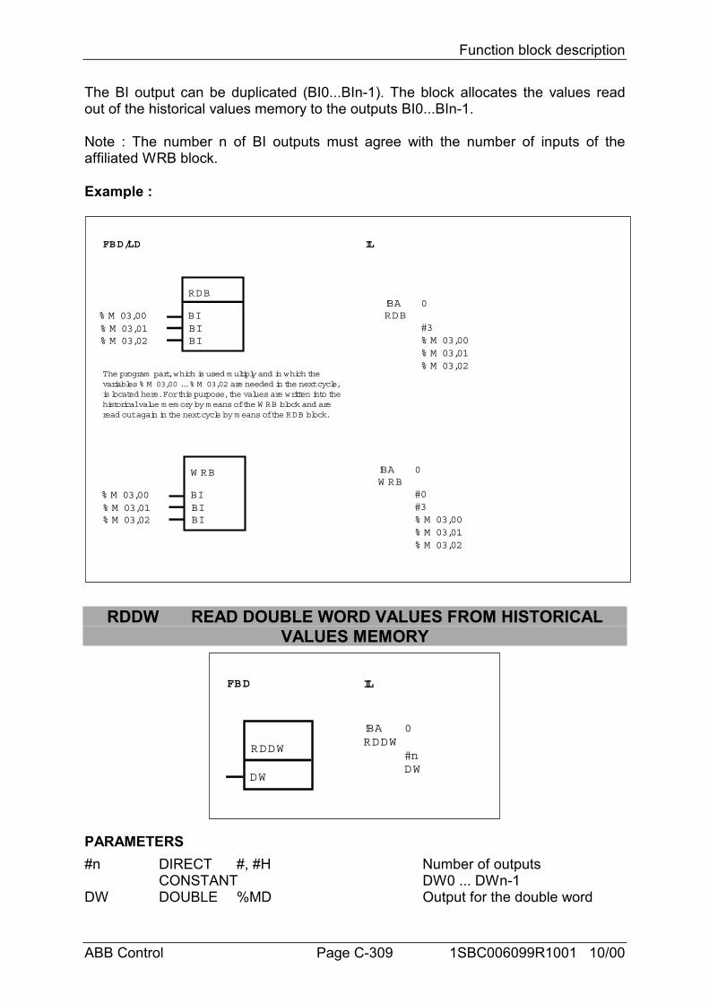
Function block description
ABB Control Page C-309 1SBC006099R1001 10/00
The BI output can be duplicated (BI0...BIn-1). The block allocates the values readout of the historical values memory to the outputs BI0...BIn-1.
Note : The number n of BI outputs must agree with the number of inputs of theaffiliated WRB block.
Example :
FBD/LD IL
!BAW RB
0
#0#3% M 03,00% M 03,01% M 03,02
The program part, which is used m ultiply and in which thevariables % M 03,00 ... % M 03,02 are needed in the next cycle,is located here. For this purpose, the values are written into thehistorical value m em ory by m eans of the W RB block and areread out again in the next cycle by m eans of the RDB block.
RDB
BIBIBI
% M 03,00% M 03,01% M 03,02
W RB
BIBIBI
% M 03,00% M 03,01% M 03,02
!BARDB
0
#3% M 03,00% M 03,01% M 03,02
RDDW READ DOUBLE WORD VALUES FROM HISTORICALVALUES MEMORY
FBD IL
RDDW
DW
!BARDDW
0
#nDW
PARAMETERS#n DIRECT #, #H Number of outputs
CONSTANT DW0 ... DWn-1DW DOUBLE %MD Output for the double word
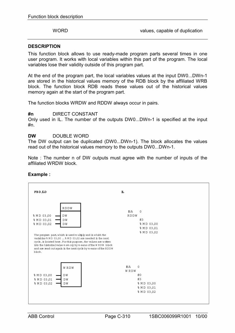
Function block description
ABB Control Page C-310 1SBC006099R1001 10/00
WORD values, capable of duplication
DESCRIPTIONThis function block allows to use ready-made program parts several times in oneuser program. It works with local variables within this part of the program. The localvariables lose their validity outside of this program part.
At the end of the program part, the local variables values at the input DW0...DWn-1are stored in the historical values memory of the RDB block by the affiliated WRBblock. The function block RDB reads these values out of the historical valuesmemory again at the start of the program part.
The function blocks WRDW and RDDW always occur in pairs.
#n DIRECT CONSTANTOnly used in IL. The number of the outputs DW0...DWn-1 is specified at the input#n.
DW DOUBLE WORDThe DW output can be duplicated (DW0...DWn-1). The block allocates the valuesread out of the historical values memory to the outputs DW0...DWn-1.
Note : The number n of DW outputs must agree with the number of inputs of theaffiliated WRDW block.
Example :
FBD/LD IL
!BAW RDW
0
#0#3% M D 03,00% M D 03,01% M D 03,02
The program part, which is used m ultiply and in which thevariables % M D 03,00 ... % M D 03,02 are needed in the nextcycle, is located here. For this purpose, the values are writteninto the historical value m em ory by m eans of the W RDW blockand are read out again in the next cycle by m eans of the RDDWblock.
RDDW
DWDWDW
% M D 03,00% M D 03,01% M D 03,02
W RDW
DWDWDW
% M D 03,00% M D 03,01% M D 03,02
!BARDDW
0
#3% M D 03,00% M D 03,01% M D 03,02
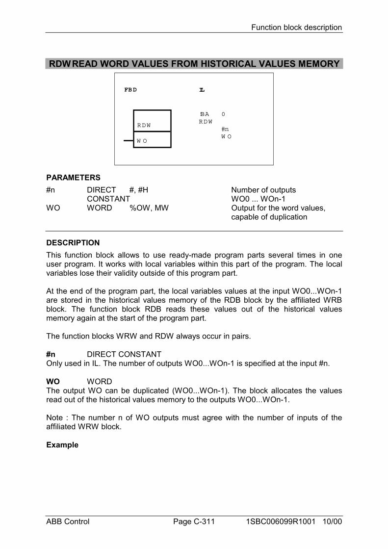
Function block description
ABB Control Page C-311 1SBC006099R1001 10/00
RDWREAD WORD VALUES FROM HISTORICAL VALUES MEMORY
FBD IL
RDW
W O
!BARDW
0
#nW O
PARAMETERS#n DIRECT #, #H Number of outputs
CONSTANT WO0 ... WOn-1WO WORD %OW, MW Output for the word values,
capable of duplication
DESCRIPTIONThis function block allows to use ready-made program parts several times in oneuser program. It works with local variables within this part of the program. The localvariables lose their validity outside of this program part.
At the end of the program part, the local variables values at the input WO0...WOn-1are stored in the historical values memory of the RDB block by the affiliated WRBblock. The function block RDB reads these values out of the historical valuesmemory again at the start of the program part.
The function blocks WRW and RDW always occur in pairs.
#n DIRECT CONSTANTOnly used in IL. The number of outputs WO0...WOn-1 is specified at the input #n.
WO WORDThe output WO can be duplicated (WO0...WOn-1). The block allocates the valuesread out of the historical values memory to the outputs WO0...WOn-1.
Note : The number n of WO outputs must agree with the number of inputs of theaffiliated WRW block.
Example
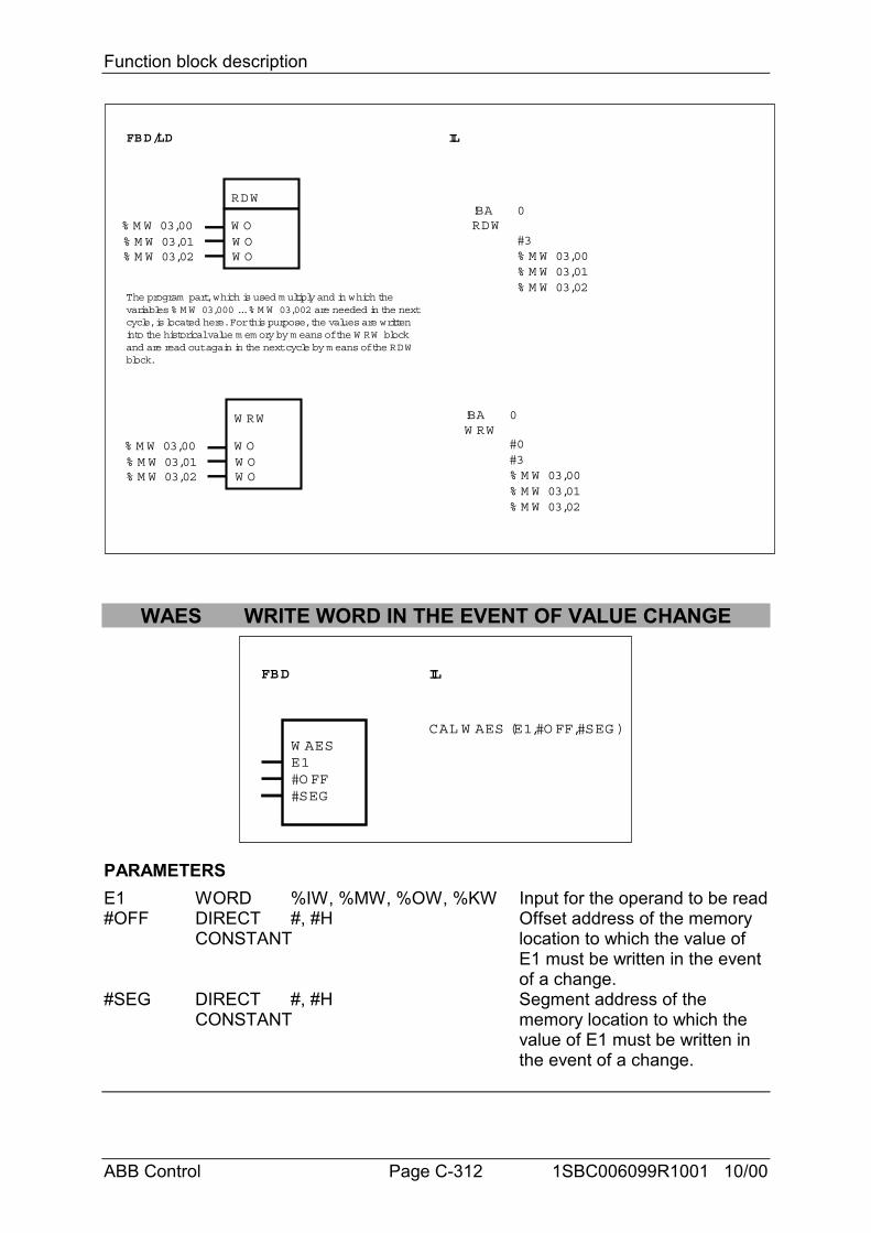
Function block description
ABB Control Page C-312 1SBC006099R1001 10/00
FBD/LD IL
!BAW RW
0
#0#3% M W 03,00% M W 03,01% M W 03,02
The program part, which is used m ultiply and in which thevariables % M W 03,000 ... % M W 03,002 are needed in the nextcycle, is located here. For this purpose, the values are writteninto the historical value m em ory by m eans of the W RW blockand are read out again in the next cycle by m eans of the RDWblock.
RDW
W OW OW O
% M W 03,00% M W 03,01% M W 03,02
W RW
W OW OW O
% M W 03,00% M W 03,01% M W 03,02
!BARDW
0
#3% M W 03,00% M W 03,01% M W 03,02
WAES WRITE WORD IN THE EVENT OF VALUE CHANGE
FBD IL
W AESE1#O FF#SEG
CAL W AES (E1,#O FF,#SEG )
PARAMETERSE1 WORD %IW, %MW, %OW, %KW Input for the operand to be read#OFF DIRECT #, #H Offset address of the memory
CONSTANT location to which the value of E1 must be written in the event of a change.
#SEG DIRECT #, #H Segment address of theCONSTANT memory location to which the
value of E1 must be written in the event of a change.
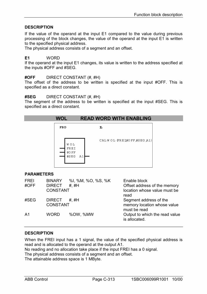
Function block description
ABB Control Page C-313 1SBC006099R1001 10/00
DESCRIPTIONIf the value of the operand at the input E1 compared to the value during previousprocessing of the block changes, the value of the operand at the input E1 is writtento the specified physical address.The physical address consists of a segment and an offset.
E1 WORDIf the operand at the input E1 changes, its value is written to the address specified atthe inputs #OFF and #SEG.
#OFF DIRECT CONSTANT (#, #H)The offset of the address to be written is specified at the input #OFF. This isspecified as a direct constant.
#SEG DIRECT CONSTANT (#, #H)The segment of the address to be written is specified at the input #SEG. This isspecified as a direct constant.
WOL READ WORD WITH ENABLINGFBD IL
W O LFREI#O FF#SEG A1
CAL W O L (FREI,#O FF,#SEG ,A1)
PARAMETERSFREI BINARY %I, %M, %O, %S, %K Enable block#OFF DIRECT #, #H Offset address of the memory
CONSTANT location whose value must be read
#SEG DIRECT #, #H Segment address of theCONSTANT memory location whose value
must be readA1 WORD %OW, %MW Output to which the read value
is allocated.
DESCRIPTIONWhen the FREI input has a 1 signal, the value of the specified physical address isread and is allocated to the operand at the output A1.No reading and no allocation take place if the input FREI has a 0 signal.The physical address consists of a segment and an offset.The attainable address space is 1 MByte.
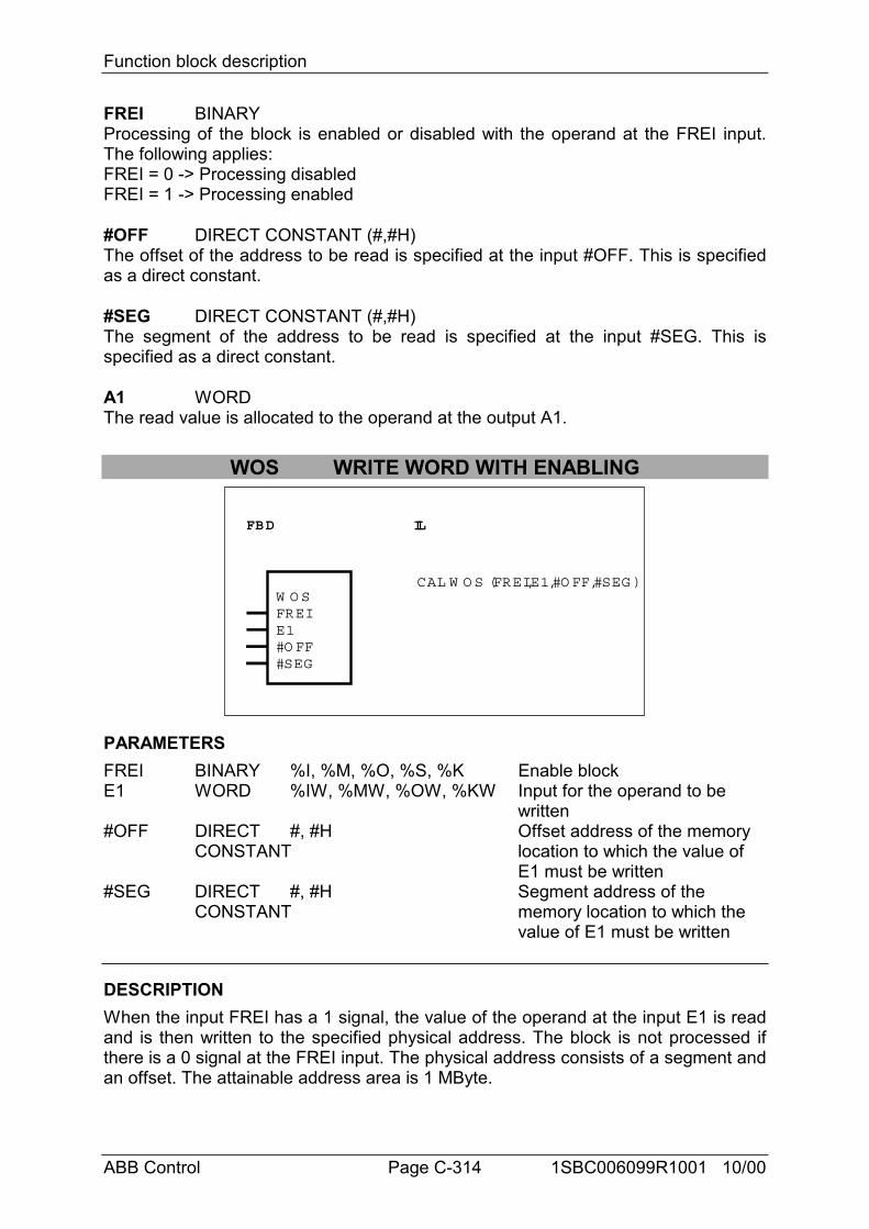
Function block description
ABB Control Page C-314 1SBC006099R1001 10/00
FREI BINARYProcessing of the block is enabled or disabled with the operand at the FREI input.The following applies:FREI = 0 -> Processing disabledFREI = 1 -> Processing enabled
#OFF DIRECT CONSTANT (#,#H)The offset of the address to be read is specified at the input #OFF. This is specifiedas a direct constant.
#SEG DIRECT CONSTANT (#,#H)The segment of the address to be read is specified at the input #SEG. This isspecified as a direct constant.
A1 WORDThe read value is allocated to the operand at the output A1.
WOS WRITE WORD WITH ENABLING
FBD IL
W O SFREIE1#O FF#SEG
CAL W O S (FREI,E1,#O FF,#SEG )
PARAMETERSFREI BINARY %I, %M, %O, %S, %K Enable blockE1 WORD %IW, %MW, %OW, %KW Input for the operand to be
written#OFF DIRECT #, #H Offset address of the memory
CONSTANT location to which the value of E1 must be written
#SEG DIRECT #, #H Segment address of theCONSTANT memory location to which the
value of E1 must be written
DESCRIPTIONWhen the input FREI has a 1 signal, the value of the operand at the input E1 is readand is then written to the specified physical address. The block is not processed ifthere is a 0 signal at the FREI input. The physical address consists of a segment andan offset. The attainable address area is 1 MByte.
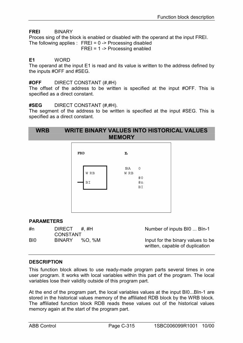
Function block description
ABB Control Page C-315 1SBC006099R1001 10/00
FREI BINARYProces sing of the block is enabled or disabled with the operand at the input FREI.The following applies : FREI = 0 -> Processing disabled
FREI = 1 -> Processing enabled
E1 WORDThe operand at the input E1 is read and its value is written to the address defined bythe inputs #OFF and #SEG.
#OFF DIRECT CONSTANT (#,#H)The offset of the address to be written is specified at the input #OFF. This isspecified as a direct constant.
#SEG DIRECT CONSTANT (#,#H).The segment of the address to be written is specified at the input #SEG. This isspecified as a direct constant.
WRB WRITE BINARY VALUES INTO HISTORICAL VALUESMEMORY
FBD IL
W RB
BI
!BAW RB
0
#0#nBI
PARAMETERS#n DIRECT #, #H Number of inputs BI0 ... BIn-1
CONSTANTBI0 BINARY %O, %M Input for the binary values to be
written, capable of duplication
DESCRIPTIONThis function block allows to use ready-made program parts several times in oneuser program. It works with local variables within this part of the program. The localvariables lose their validity outside of this program part.
At the end of the program part, the local variables values at the input BI0...BIn-1 arestored in the historical values memory of the affiliated RDB block by the WRB block.The affiliated function block RDB reads these values out of the historical valuesmemory again at the start of the program part.
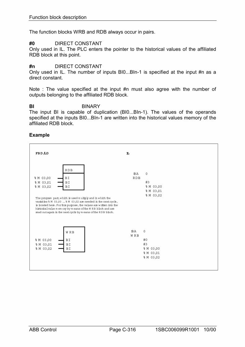
Function block description
ABB Control Page C-316 1SBC006099R1001 10/00
The function blocks WRB and RDB always occur in pairs.
#0 DIRECT CONSTANTOnly used in IL. The PLC enters the pointer to the historical values of the affiliatedRDB block at this point.
#n DIRECT CONSTANTOnly used in IL. The number of inputs BI0...BIn-1 is specified at the input #n as adirect constant.
Note : The value specified at the input #n must also agree with the number ofoutputs belonging to the affiliated RDB block.
BI BINARYThe input BI is capable of duplication (BI0...BIn-1). The values of the operandsspecified at the inputs BI0...BIn-1 are written into the historical values memory of theaffiliated RDB block.
Example
FBD/LD IL
!BAW RB
0
#0#3% M 03,00% M 03,01% M 03,02
The program part, which is used m ultiply and in which thevariables % M 03,00 ... % M 03,02 are needed in the next cycle,is located here. For this purpose, the values are written into thehistorical value m em ory by m eans of the W RB block and areread out again in the next cycle by m eans of the RDB block.
RDB
BIBIBI
% M 03,00% M 03,01% M 03,02
W RB
BIBIBI
% M 03,00% M 03,01% M 03,02
!BARDB
0
#3% M 03,00% M 03,01% M 03,02
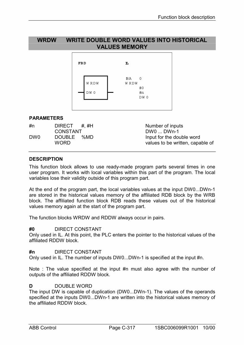
Function block description
ABB Control Page C-317 1SBC006099R1001 10/00
WRDW WRITE DOUBLE WORD VALUES INTO HISTORICALVALUES MEMORY
FBD IL
W RDW
DW 0
!BAW RDW
0
#0#nDW 0
PARAMETERS#n DIRECT #, #H Number of inputs
CONSTANT DW0 ... DWn-1DW0 DOUBLE %MD Input for the double word
WORD values to be written, capable of
DESCRIPTIONThis function block allows to use ready-made program parts several times in oneuser program. It works with local variables within this part of the program. The localvariables lose their validity outside of this program part.
At the end of the program part, the local variables values at the input DW0...DWn-1are stored in the historical values memory of the affiliated RDB block by the WRBblock. The affiliated function block RDB reads these values out of the historicalvalues memory again at the start of the program part.
The function blocks WRDW and RDDW always occur in pairs.
#0 DIRECT CONSTANTOnly used in IL. At this point, the PLC enters the pointer to the historical values of theaffiliated RDDW block.
#n DIRECT CONSTANTOnly used in IL. The number of inputs DW0...DWn-1 is specified at the input #n.
Note : The value specified at the input #n must also agree with the number ofoutputs of the affiliated RDDW block.
D DOUBLE WORDThe input DW is capable of duplication (DW0...DWn-1). The values of the operandsspecified at the inputs DW0...DWn-1 are written into the historical values memory ofthe affiliated RDDW block.
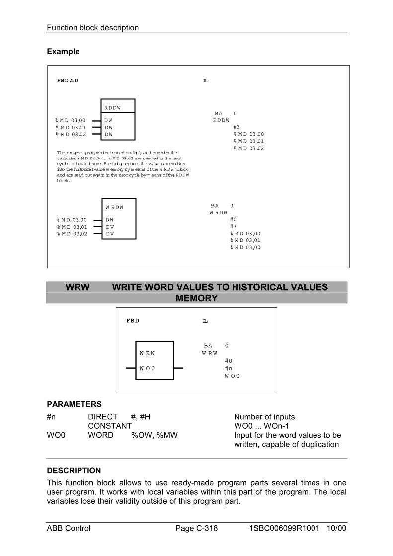
Function block description
ABB Control Page C-318 1SBC006099R1001 10/00
Example
FBD/LD IL
!BAW RDW
0
#0#3% M D 03,00% M D 03,01% M D 03,02
The program part, which is used m ultiply and in which thevariables % M D 03,00 ... % M D 03,02 are needed in the nextcycle, is located here. For this purpose, the values are writteninto the historical value m em ory by m eans of the W RDW blockand are read out again in the next cycle by m eans of the RDDWblock.
RDDW
DWDWDW
% M D 03,00% M D 03,01% M D 03,02
W RDW
DWDWDW
% M D 03,00% M D 03,01% M D 03,02
!BARDDW
0
#3% M D 03,00% M D 03,01% M D 03,02
WRW WRITE WORD VALUES TO HISTORICAL VALUESMEMORY
FBD IL
W RW
W O 0
!BAW RW
0
#0#nW O 0
PARAMETERS#n DIRECT #, #H Number of inputs
CONSTANT WO0 ... WOn-1WO0 WORD %OW, %MW Input for the word values to be
written, capable of duplication
DESCRIPTIONThis function block allows to use ready-made program parts several times in oneuser program. It works with local variables within this part of the program. The localvariables lose their validity outside of this program part.
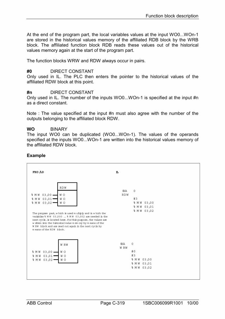
Function block description
ABB Control Page C-319 1SBC006099R1001 10/00
At the end of the program part, the local variables values at the input WO0...WOn-1are stored in the historical values memory of the affiliated RDB block by the WRBblock. The affiliated function block RDB reads these values out of the historicalvalues memory again at the start of the program part.
The function blocks WRW and RDW always occur in pairs.
#0 DIRECT CONSTANTOnly used in IL. The PLC then enters the pointer to the historical values of theaffiliated RDW block at this point.
#n DIRECT CONSTANTOnly used in IL. The number of the inputs WO0...WOn-1 is specified at the input #nas a direct constant.
Note : The value specified at the input #n must also agree with the number of theoutputs belonging to the affiliated block RDW.
WO BINARYThe input WO0 can be duplicated (WO0...WOn-1). The values of the operandsspecified at the inputs WO0...WOn-1 are written into the historical values memory ofthe affiliated RDW block.
Example
FBD/LD IL
!BAW RW
0
#0#3% M W 03,00% M W 03,01% M W 03,02
The program part, w hich is used m ultiply and in w hich thevariables % M W 03,000 ... % M W 03,002 are needed in thenext cycle, is located here. For this purpose, the values arew ritten into the historical value m em ory by m eans of theW RW block and are read out again in the next cycle bym eans of the RDW block.
RDW
W OW OW O
% M W 03,00% M W 03,01% M W 03,02
W RW
W OW OW O
% M W 03,00% M W 03,01% M W 03,02
!BARDW
0
#3% M W 03,00% M W 03,01% M W 03,02
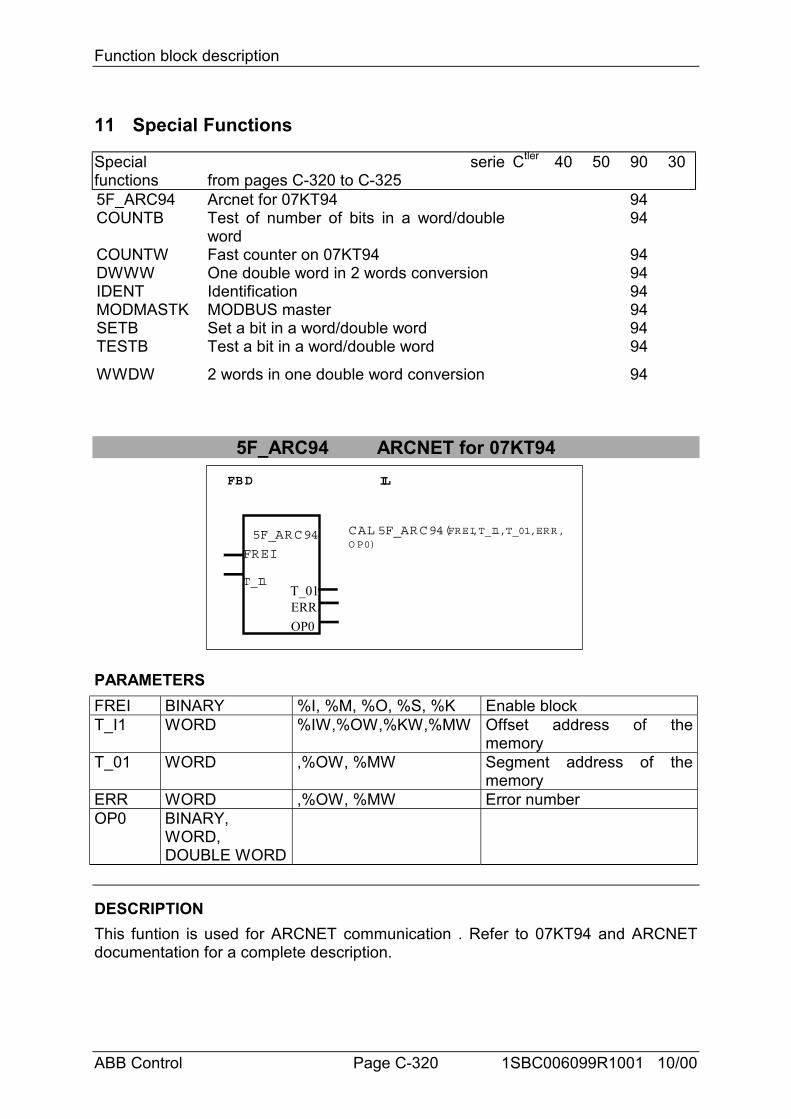
Function block description
ABB Control Page C-320 1SBC006099R1001 10/00
11 Special Functions
Specialfunctions
seriefrom pages C-320 to C-325
Ctler 40 50 90 30
5F_ARC94 Arcnet for 07KT94 94COUNTB Test of number of bits in a word/double
word94
COUNTW Fast counter on 07KT94 94DWWW One double word in 2 words conversion 94IDENT Identification 94MODMASTK MODBUS master 94SETB Set a bit in a word/double word 94TESTB Test a bit in a word/double word 94
WWDW 2 words in one double word conversion 94
5F_ARC94 ARCNET for 07KT94FBD IL
5F_ARC94
FREI
T_I1T_01
CAL 5F_ARC94(FREI, T_I1, T_01, ERR,OP0)
ERROP0
PARAMETERSFREI BINARY %I, %M, %O, %S, %K Enable blockT_I1 WORD %IW,%OW,%KW,%MW Offset address of the
memoryT_01 WORD ,%OW, %MW Segment address of the
memoryERR WORD ,%OW, %MW Error numberOP0 BINARY,
WORD,DOUBLE WORD
DESCRIPTIONThis funtion is used for ARCNET communication . Refer to 07KT94 and ARCNETdocumentation for a complete description.
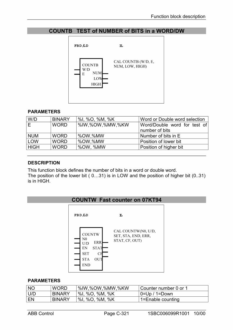
Function block description
ABB Control Page C-321 1SBC006099R1001 10/00
COUNTB TEST of NUMBER of BITS in a WORD/DW
FBD/LD IL
COUNTBW/DE
LOWNUM
HIGH
CAL COUNTB (W/D, E,NUM, LOW, HIGH)
PARAMETERSW/D BINARY %I, %O, %M, %K Word or Double word selectionE WORD %IW,%OW,%MW,%KW Word/Double word for test of
number of bitsNUM WORD %OW,%MW Number of bits in ELOW WORD %OW,%MW Position of lower bitHIGH WORD %OW, %MW Position of higher bit
DESCRIPTIONThis function block defines the number of bits in a word or double word.The position of the lower bit ( 0…31) is in LOW and the position of higher bit (0..31)is in HIGH.
COUNTW Fast counter on 07KT94
FBD/LD IL
COUNTWN0U/D
STATERR
CF
CAL COUNTW(N0, U/D,SET, STA, END, ERR,STAT, CF, OUT)
ENSETSTAEND
OUT
PARAMETERSNO WORD %IW,%OW,%MW,%KW Counter number 0 or 1U/D BINARY %I, %O, %M, %K 0=Up / 1=DownEN BINARY %I, %O, %M, %K 1=Enable counting
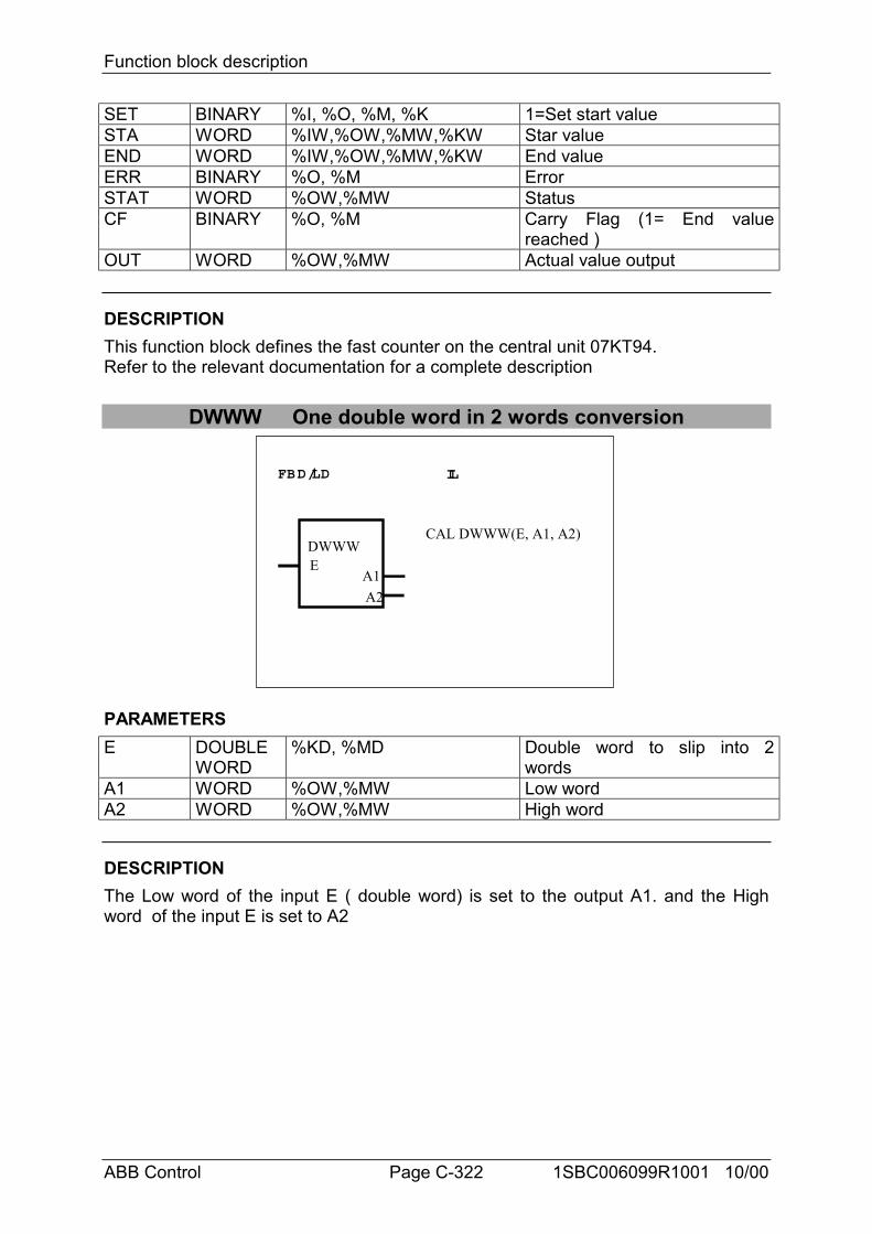
Function block description
ABB Control Page C-322 1SBC006099R1001 10/00
SET BINARY %I, %O, %M, %K 1=Set start valueSTA WORD %IW,%OW,%MW,%KW Star valueEND WORD %IW,%OW,%MW,%KW End valueERR BINARY %O, %M ErrorSTAT WORD %OW,%MW StatusCF BINARY %O, %M Carry Flag (1= End value
reached )OUT WORD %OW,%MW Actual value output
DESCRIPTIONThis function block defines the fast counter on the central unit 07KT94.Refer to the relevant documentation for a complete description
DWWW One double word in 2 words conversion
FBD/LD IL
DWWWE
A2A1
CAL DWWW(E, A1, A2)
PARAMETERSE DOUBLE
WORD%KD, %MD Double word to slip into 2
wordsA1 WORD %OW,%MW Low wordA2 WORD %OW,%MW High word
DESCRIPTIONThe Low word of the input E ( double word) is set to the output A1. and the Highword of the input E is set to A2
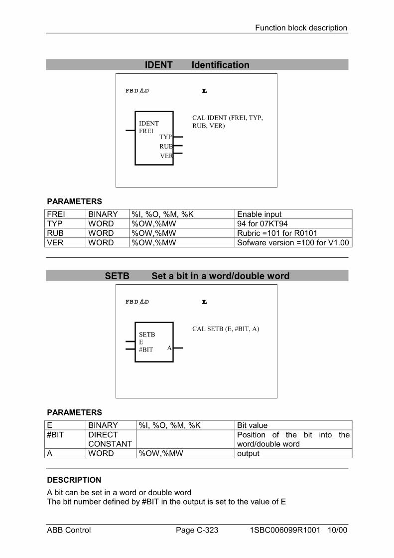
Function block description
ABB Control Page C-323 1SBC006099R1001 10/00
IDENT Identification
FBD/LD IL
IDENTFREI
RUBTYP
VER
CAL IDENT (FREI, TYP,RUB, VER)
PARAMETERSFREI BINARY %I, %O, %M, %K Enable inputTYP WORD %OW,%MW 94 for 07KT94RUB WORD %OW,%MW Rubric =101 for R0101VER WORD %OW,%MW Sofware version =100 for V1.00
SETB Set a bit in a word/double word
FBD/LD IL
SETBE#BIT A
CAL SETB (E, #BIT, A)
PARAMETERSE BINARY %I, %O, %M, %K Bit value#BIT DIRECT
CONSTANTPosition of the bit into theword/double word
A WORD %OW,%MW output
DESCRIPTIONA bit can be set in a word or double wordThe bit number defined by #BIT in the output is set to the value of E
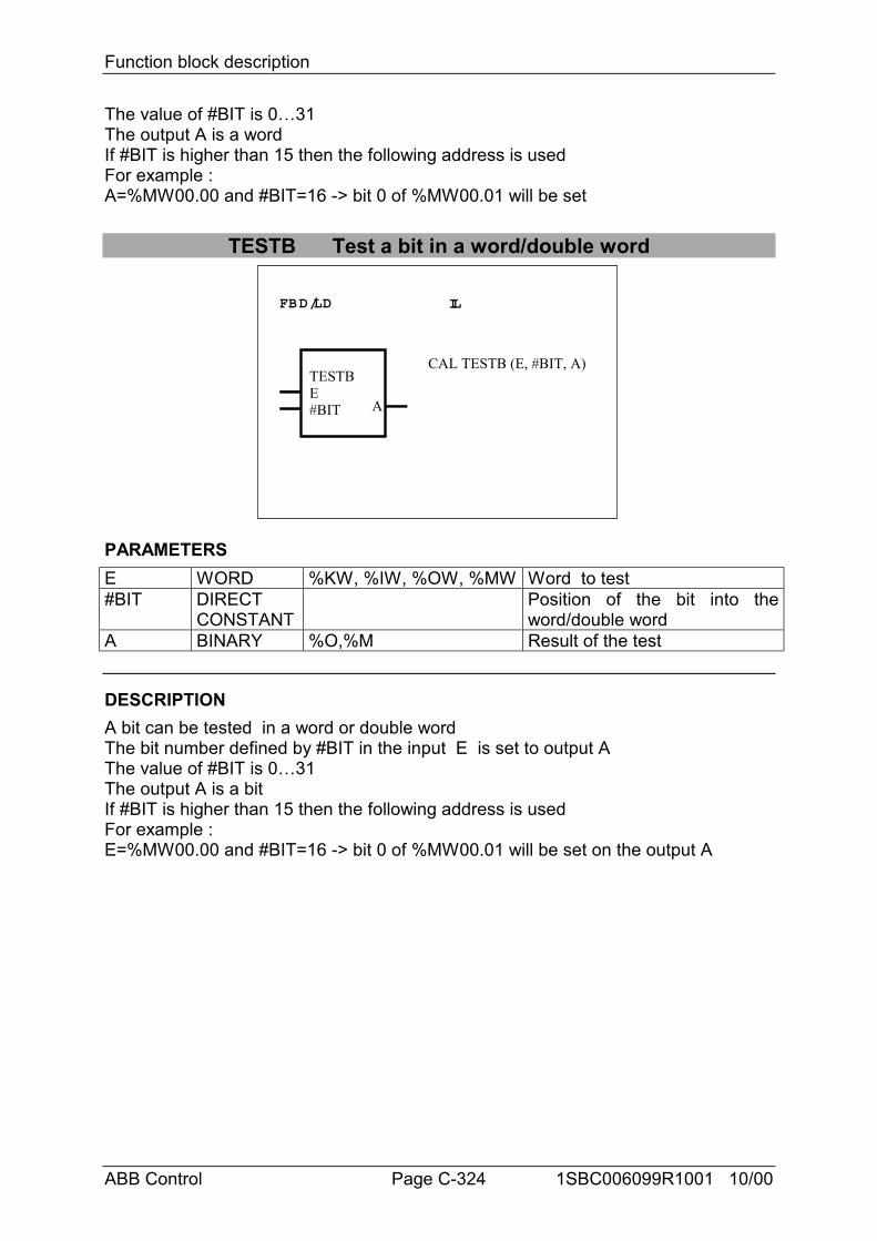
Function block description
ABB Control Page C-324 1SBC006099R1001 10/00
The value of #BIT is 0…31The output A is a wordIf #BIT is higher than 15 then the following address is usedFor example :A=%MW00.00 and #BIT=16 -> bit 0 of %MW00.01 will be set
TESTB Test a bit in a word/double word
FBD/LD IL
TESTBE#BIT A
CAL TESTB (E, #BIT, A)
PARAMETERSE WORD %KW, %IW, %OW, %MW Word to test#BIT DIRECT
CONSTANTPosition of the bit into theword/double word
A BINARY %O,%M Result of the test
DESCRIPTIONA bit can be tested in a word or double wordThe bit number defined by #BIT in the input E is set to output AThe value of #BIT is 0…31The output A is a bitIf #BIT is higher than 15 then the following address is usedFor example :E=%MW00.00 and #BIT=16 -> bit 0 of %MW00.01 will be set on the output A
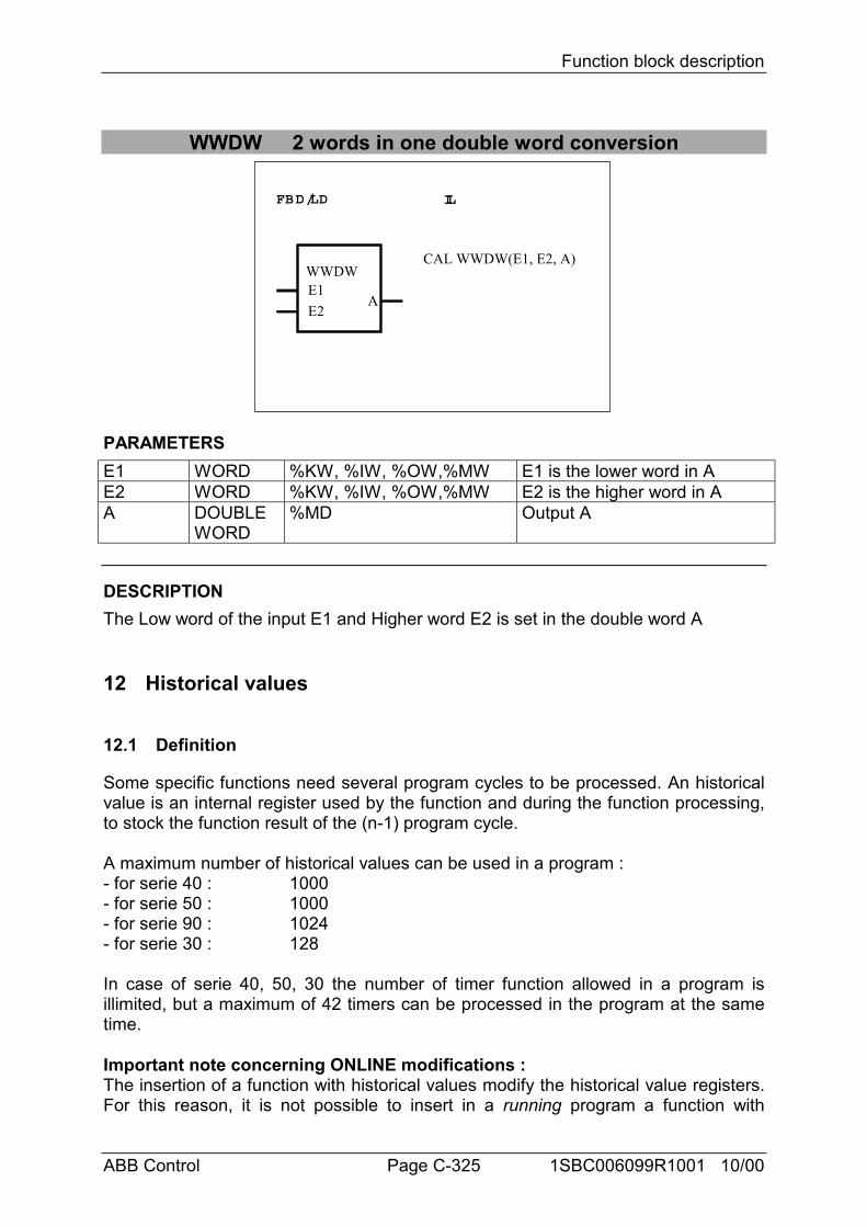
Function block description
ABB Control Page C-325 1SBC006099R1001 10/00
WWDW 2 words in one double word conversion
FBD/LD IL
WWDWE1
A
CAL WWDW(E1, E2, A)
E2
PARAMETERSE1 WORD %KW, %IW, %OW,%MW E1 is the lower word in AE2 WORD %KW, %IW, %OW,%MW E2 is the higher word in AA DOUBLE
WORD%MD Output A
DESCRIPTIONThe Low word of the input E1 and Higher word E2 is set in the double word A
12 Historical values
12.1 Definition
Some specific functions need several program cycles to be processed. An historicalvalue is an internal register used by the function and during the function processing,to stock the function result of the (n-1) program cycle.
A maximum number of historical values can be used in a program :- for serie 40 : 1000- for serie 50 : 1000- for serie 90 : 1024- for serie 30 : 128
In case of serie 40, 50, 30 the number of timer function allowed in a program isillimited, but a maximum of 42 timers can be processed in the program at the sametime.
Important note concerning ONLINE modifications :The insertion of a function with historical values modify the historical value registers.For this reason, it is not possible to insert in a running program a function with
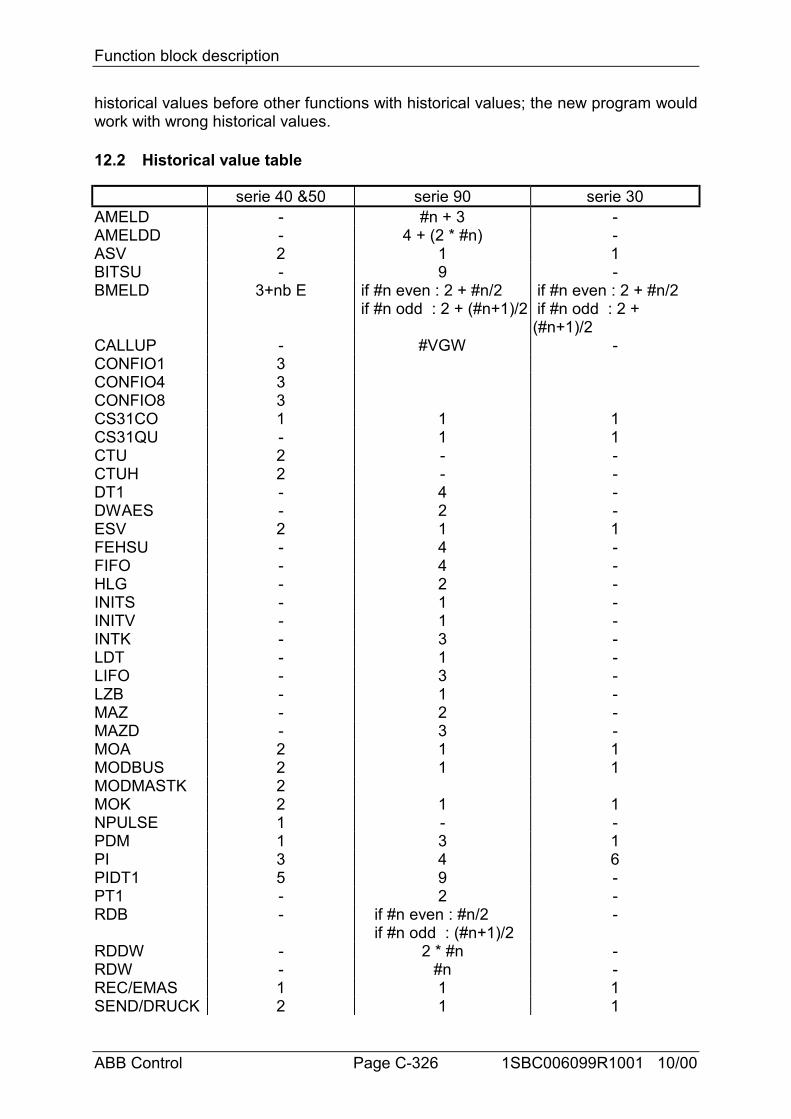
Function block description
ABB Control Page C-326 1SBC006099R1001 10/00
historical values before other functions with historical values; the new program wouldwork with wrong historical values.
12.2 Historical value table
serie 40 &50 serie 90 serie 30AMELD - #n + 3 -AMELDD - 4 + (2 * #n) -ASV 2 1 1BITSU - 9 -BMELD 3+nb E if #n even : 2 + #n/2
if #n odd : 2 + (#n+1)/2 if #n even : 2 + #n/2 if #n odd : 2 +(#n+1)/2
CALLUP - #VGW -CONFIO1 3CONFIO4 3CONFIO8 3CS31CO 1 1 1CS31QU - 1 1CTU 2 - -CTUH 2 - -DT1 - 4 -DWAES - 2 -ESV 2 1 1FEHSU - 4 -FIFO - 4 -HLG - 2 -INITS - 1 -INITV - 1 -INTK - 3 -LDT - 1 -LIFO - 3 -LZB - 1 -MAZ - 2 -MAZD - 3 -MOA 2 1 1MODBUS 2 1 1MODMASTK 2MOK 2 1 1NPULSE 1 - -PDM 1 3 1PI 3 4 6PIDT1 5 9 -PT1 - 2 -RDB - if #n even : #n/2
if #n odd : (#n+1)/2-
RDDW - 2 * #n -RDW - #n -REC/EMAS 1 1 1SEND/DRUCK 2 1 1
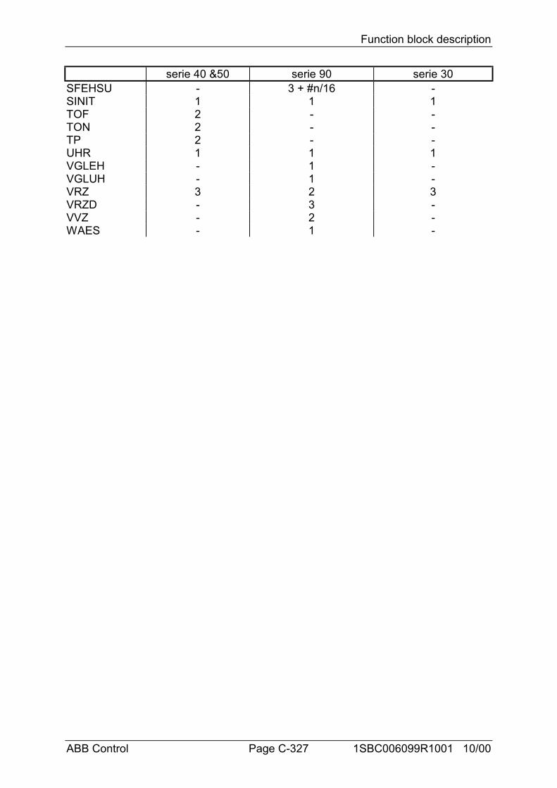
Function block description
ABB Control Page C-327 1SBC006099R1001 10/00
serie 40 &50 serie 90 serie 30SFEHSU - 3 + #n/16 -SINIT 1 1 1TOF 2 - -TON 2 - -TP 2 - -UHR 1 1 1VGLEH - 1 -VGLUH - 1 -VRZ 3 2 3VRZD - 3 -VVZ - 2 -WAES - 1 -
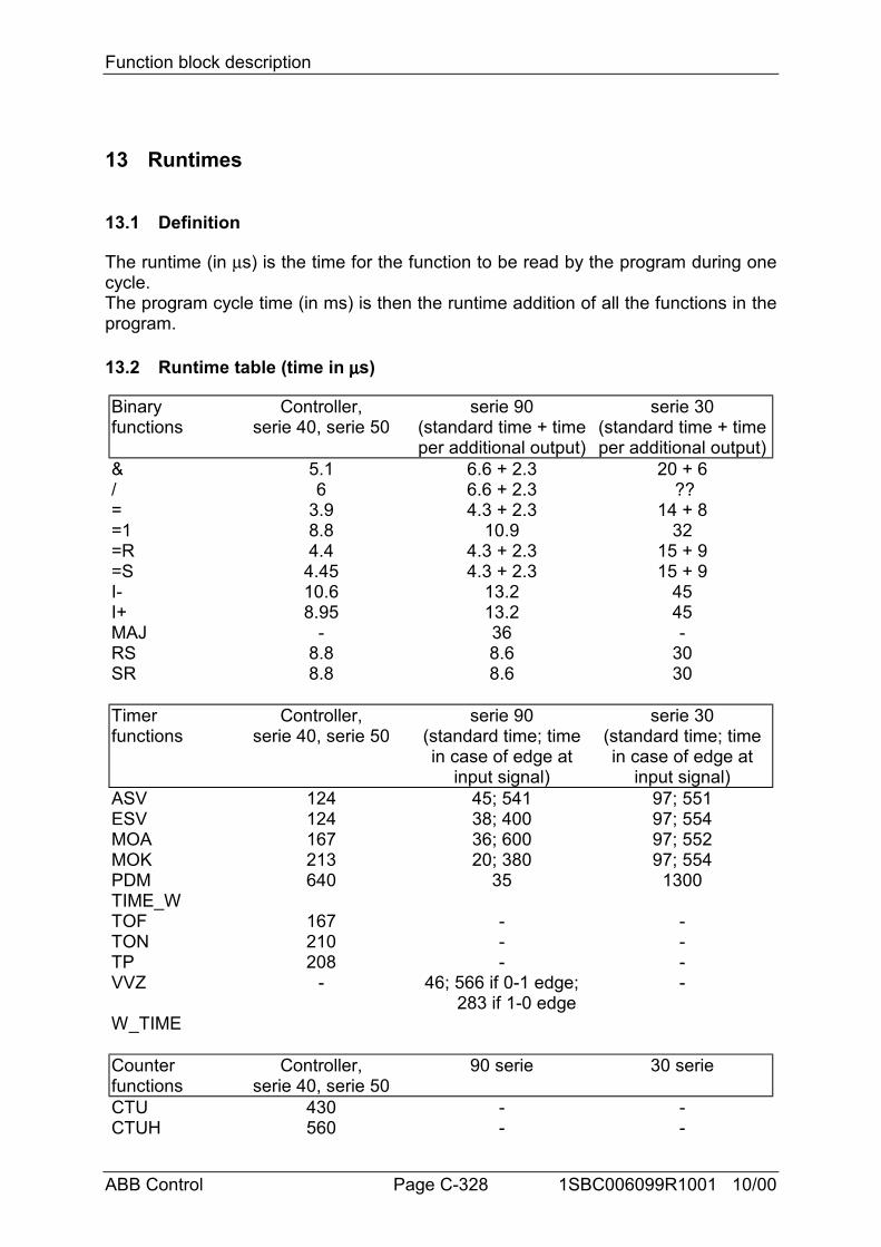
Function block description
ABB Control Page C-328 1SBC006099R1001 10/00
13 Runtimes
13.1 Definition
The runtime (in µs) is the time for the function to be read by the program during onecycle.The program cycle time (in ms) is then the runtime addition of all the functions in theprogram.
13.2 Runtime table (time in µµµµs)
Binaryfunctions
Controller,serie 40, serie 50
serie 90(standard time + timeper additional output)
serie 30(standard time + timeper additional output)
& 5.1 6.6 + 2.3 20 + 6/ 6 6.6 + 2.3 ??= 3.9 4.3 + 2.3 14 + 8=1 8.8 10.9 32=R 4.4 4.3 + 2.3 15 + 9=S 4.45 4.3 + 2.3 15 + 9I- 10.6 13.2 45I+ 8.95 13.2 45MAJ - 36 -RS 8.8 8.6 30SR 8.8 8.6 30
Timerfunctions
Controller,serie 40, serie 50
serie 90(standard time; timein case of edge at
input signal)
serie 30(standard time; timein case of edge at
input signal)ASV 124 45; 541 97; 551ESV 124 38; 400 97; 554MOA 167 36; 600 97; 552MOK 213 20; 380 97; 554PDM 640 35 1300TIME_WTOF 167 - -TON 210 - -TP 208 - -VVZ - 46; 566 if 0-1 edge;
283 if 1-0 edge-
W_TIME
Counterfunctions
Controller,serie 40, serie 50
90 serie 30 serie
CTU 430 - -CTUH 560 - -
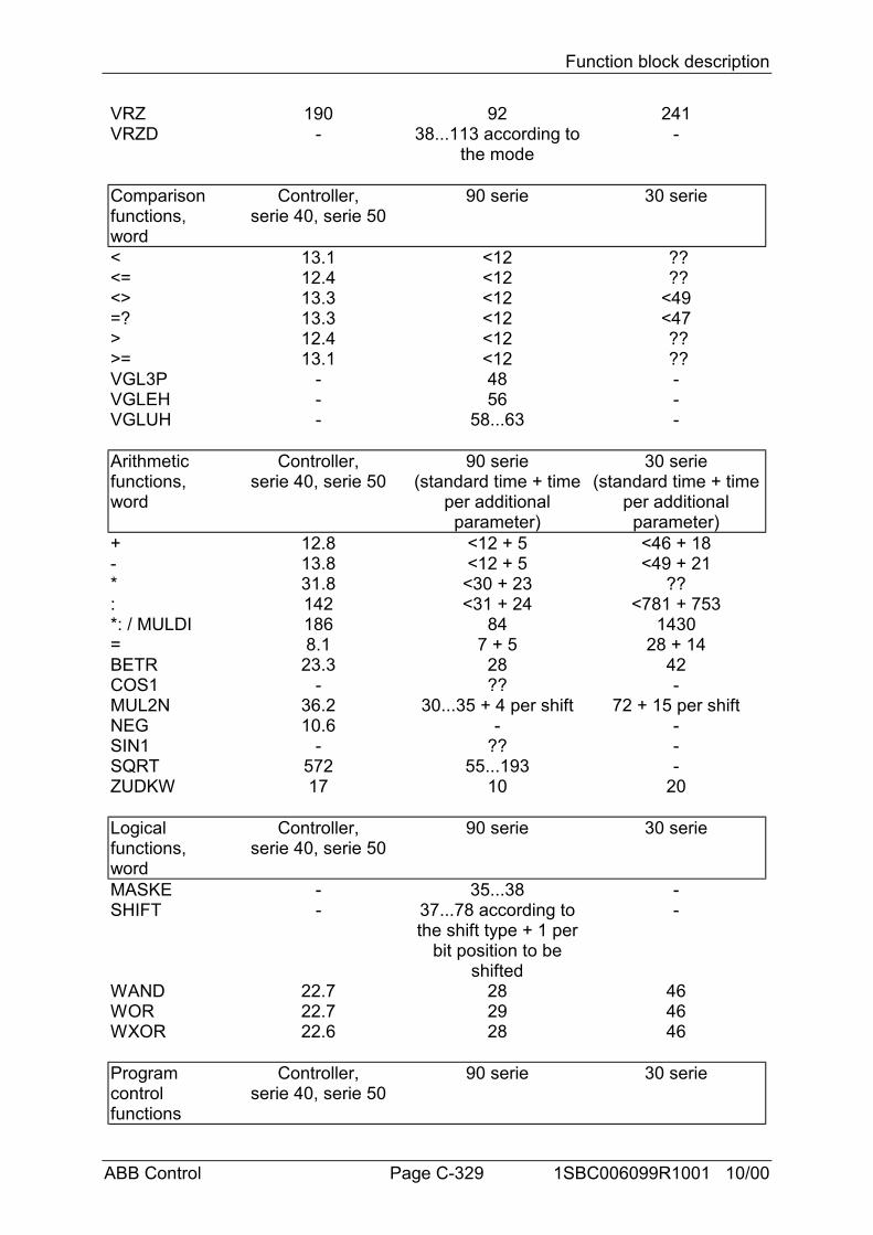
Function block description
ABB Control Page C-329 1SBC006099R1001 10/00
VRZ 190 92 241VRZD - 38...113 according to
the mode-
Comparisonfunctions,word
Controller,serie 40, serie 50
90 serie 30 serie
< 13.1 <12 ??<= 12.4 <12 ??<> 13.3 <12 <49=? 13.3 <12 <47> 12.4 <12 ??>= 13.1 <12 ??VGL3P - 48 -VGLEH - 56 -VGLUH - 58...63 -
Arithmeticfunctions,word
Controller,serie 40, serie 50
90 serie(standard time + time
per additionalparameter)
30 serie(standard time + time
per additionalparameter)
+ 12.8 <12 + 5 <46 + 18- 13.8 <12 + 5 <49 + 21* 31.8 <30 + 23 ??: 142 <31 + 24 <781 + 753*: / MULDI 186 84 1430= 8.1 7 + 5 28 + 14BETR 23.3 28 42COS1 - ?? -MUL2N 36.2 30...35 + 4 per shift 72 + 15 per shiftNEG 10.6 - -SIN1 - ?? -SQRT 572 55...193 -ZUDKW 17 10 20
Logicalfunctions,word
Controller,serie 40, serie 50
90 serie 30 serie
MASKE - 35...38 -SHIFT - 37...78 according to
the shift type + 1 perbit position to be
shifted
-
WAND 22.7 28 46WOR 22.7 29 46WXOR 22.6 28 46
Programcontrolfunctions
Controller,serie 40, serie 50
90 serie 30 serie
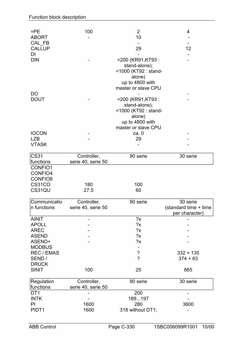
Function block description
ABB Control Page C-330 1SBC006099R1001 10/00
=PE 100 2 4ABORT - 10 -CAL_FB - -CALLUP 29 12DI - -DIN - <200 (KR91,KT93 :
stand-alone); <1000 (KT92 : stand-
alone)up to 4800 with
master or slave CPU
-
DO - -DOUT - <200 (KR91,KT93 :
stand-alone); <1000 (KT92 : stand-
alone)up to 4800 with
master or slave CPU
-
IOCON - ca. 0 -LZB - 29 -VTASK - -
CS31functions
Controller,serie 40, serie 50
90 serie 30 serie
CONFIO1CONFIO4CONFIO8CS31CO 180 100CS31QU 27.5 60
Communication functions
Controller,serie 40, serie 50
90 serie 30 serie(standard time + time
per character)AINIT - ?x -APOLL - ?x -AREC - ?x -ASEND - ?x -ASEND+ - ?x -MODBUS -REC / EMAS ? 332 + 135SEND /DRUCK
? 374 + 63
SINIT 100 25 865
Regulationfunctions
Controller,serie 40, serie 50
90 serie 30 serie
DT1 - 200 -INTK - 189...197 -PI 1600 280 3600PIDT1 1600 318 without DT1; -
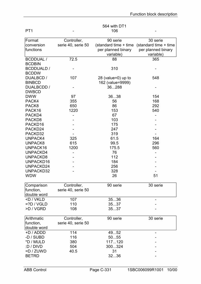
Function block description
ABB Control Page C-331 1SBC006099R1001 10/00
564 with DT1PT1 - 106 -
Formatconversionfunctions
Controller,serie 40, serie 50
90 serie(standard time + time
per planned binaryvariable)
30 serie(standard time + time
per planned binaryvariable)
BCDDUAL /BCDBIN
72.5 88 365
BCDDUALD /BCDDW
- 310 -
DUALBCD /BINBCD
107 28 (value=0) up to162 (value=9999)
548
DUALBCDD /DWBCD
- 36...288 -
DWW 97 36...38 154PACK4 355 56 168PACK8 650 86 292PACK16 1220 153 540PACKD4 - 67 -PACKD8 - 103 -PACKD16 - 175 -PACKD24 - 247 -PACKD32 - 319 -UNPACK4 325 61.5 164UNPACK8 615 99.5 296UNPACK16 1200 175.5 560UNPACKD4 - 76 -UNPACKD8 - 112 -UNPACKD16 - 184 -UNPACKD24 - 256 -UNPACKD32 - 328 -WDW 26 51
Comparisonfunction,double word
Controller,serie 40, serie 50
90 serie 30 serie
<D / VKLD 107 35...36 -=?D / VGLD 110 35...37 ->D / VGRD 108 35...37 -
Arithmaticfunction,double word
Controller,serie 40, serie 50
90 serie 30 serie
+D / ADDD 114 49...52 --D / SUBD 116 50...55 -*D / MULD 380 117...120 -:D / DIVD 504 300...324 -=D / ZUWD 40.5 31 -BETRD 32...36 -
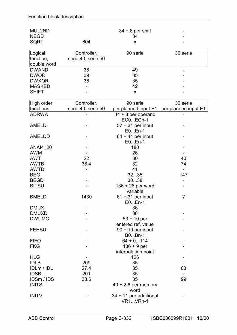
Function block description
ABB Control Page C-332 1SBC006099R1001 10/00
MUL2ND 34 + 6 per shift -NEGD 34 -SQRT 604 x -
Logicalfunction,double word
Controller,serie 40, serie 50
90 serie 30 serie
DWAND 38 49 -DWOR 39 35 -DWXOR 38 35 -MASKED - 42 -SHIFT - x -
High orderfunctions
Controller,serie 40, serie 50
90 serieper planned input E1
30 serieper planned input E1
ADRWA - 44 + 8 per operandEC0...ECn-1
-
AMELD - 57 + 31 per inputE0...En-1
-
AMELDD - 64 + 41 per inputE0...En-1
-
ANAI4_20 - 180 -AWM - 26 -AWT 22 30 40AWTB 38.4 32 74AWTD - 41 -BEG 32...35 147BEGD - 30...38 -BITSU - 136 + 26 per word
variable-
BMELD 1430 61 + 31 per inputE0...En-1
?
DMUX - 36 -DMUXD - 38 -DWUMC - 53 + 10 per
entered ref. value-
FEHSU - 90 + 10 per inputB0...Bn-1
-
FIFO - 64 + 0...114 -FKG - 136 + 9 per
interpolation point-
HLG - 126 -IDLB 209 35 -IDLm / IDL 27.4 35 63IDSB 201 35 -IDSm / IDS 38.6 35 99INITS - 40 + 2.6 per memory
word-
INITV - 34 + 11 per additionalVR1...VRn-1
-
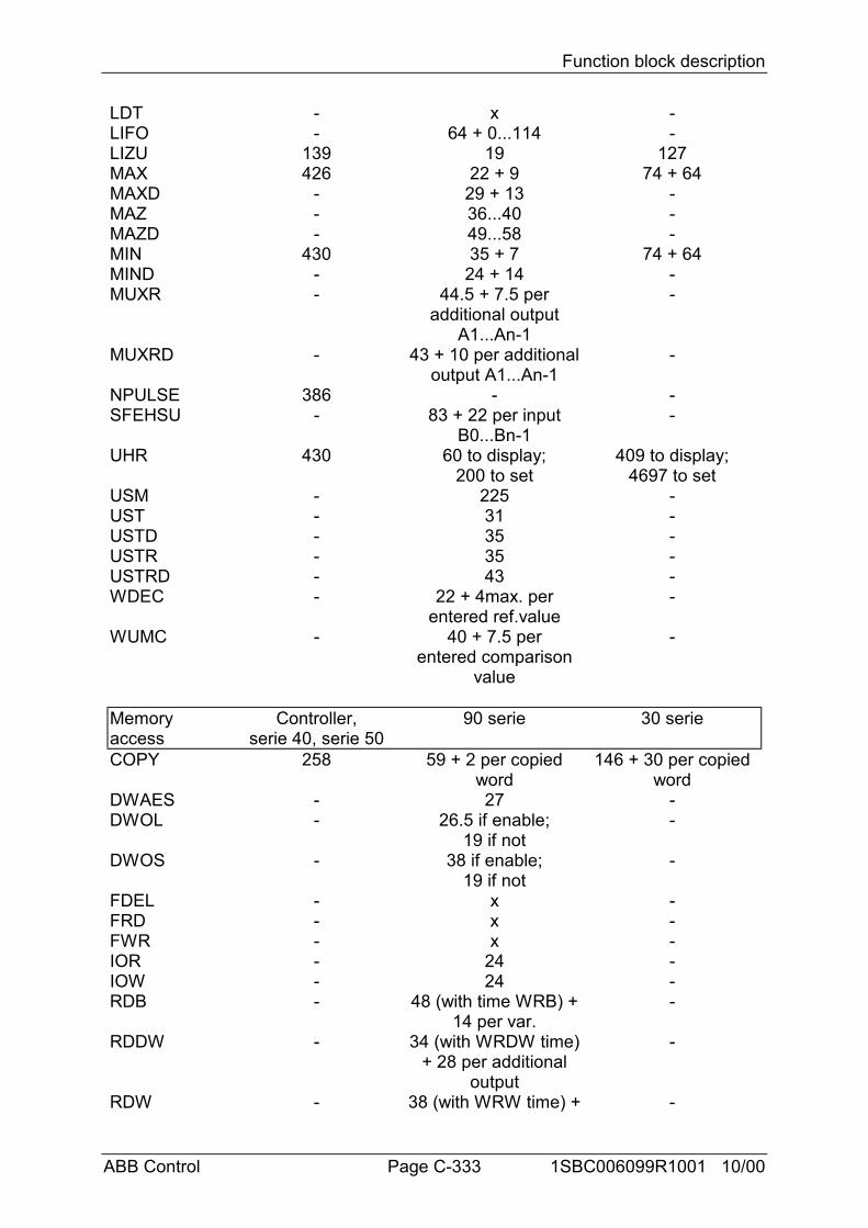
Function block description
ABB Control Page C-333 1SBC006099R1001 10/00
LDT - x -LIFO - 64 + 0...114 -LIZU 139 19 127MAX 426 22 + 9 74 + 64MAXD - 29 + 13 -MAZ - 36...40 -MAZD - 49...58 -MIN 430 35 + 7 74 + 64MIND - 24 + 14 -MUXR - 44.5 + 7.5 per
additional outputA1...An-1
-
MUXRD - 43 + 10 per additionaloutput A1...An-1
-
NPULSE 386 - -SFEHSU - 83 + 22 per input
B0...Bn-1-
UHR 430 60 to display;200 to set
409 to display;4697 to set
USM - 225 -UST - 31 -USTD - 35 -USTR - 35 -USTRD - 43 -WDEC - 22 + 4max. per
entered ref.value-
WUMC - 40 + 7.5 perentered comparison
value
-
Memoryaccess
Controller,serie 40, serie 50
90 serie 30 serie
COPY 258 59 + 2 per copiedword
146 + 30 per copiedword
DWAES - 27 -DWOL - 26.5 if enable;
19 if not-
DWOS - 38 if enable;19 if not
-
FDEL - x -FRD - x -FWR - x -IOR - 24 -IOW - 24 -RDB - 48 (with time WRB) +
14 per var.-
RDDW - 34 (with WRDW time)+ 28 per additional
output
-
RDW - 38 (with WRW time) + -
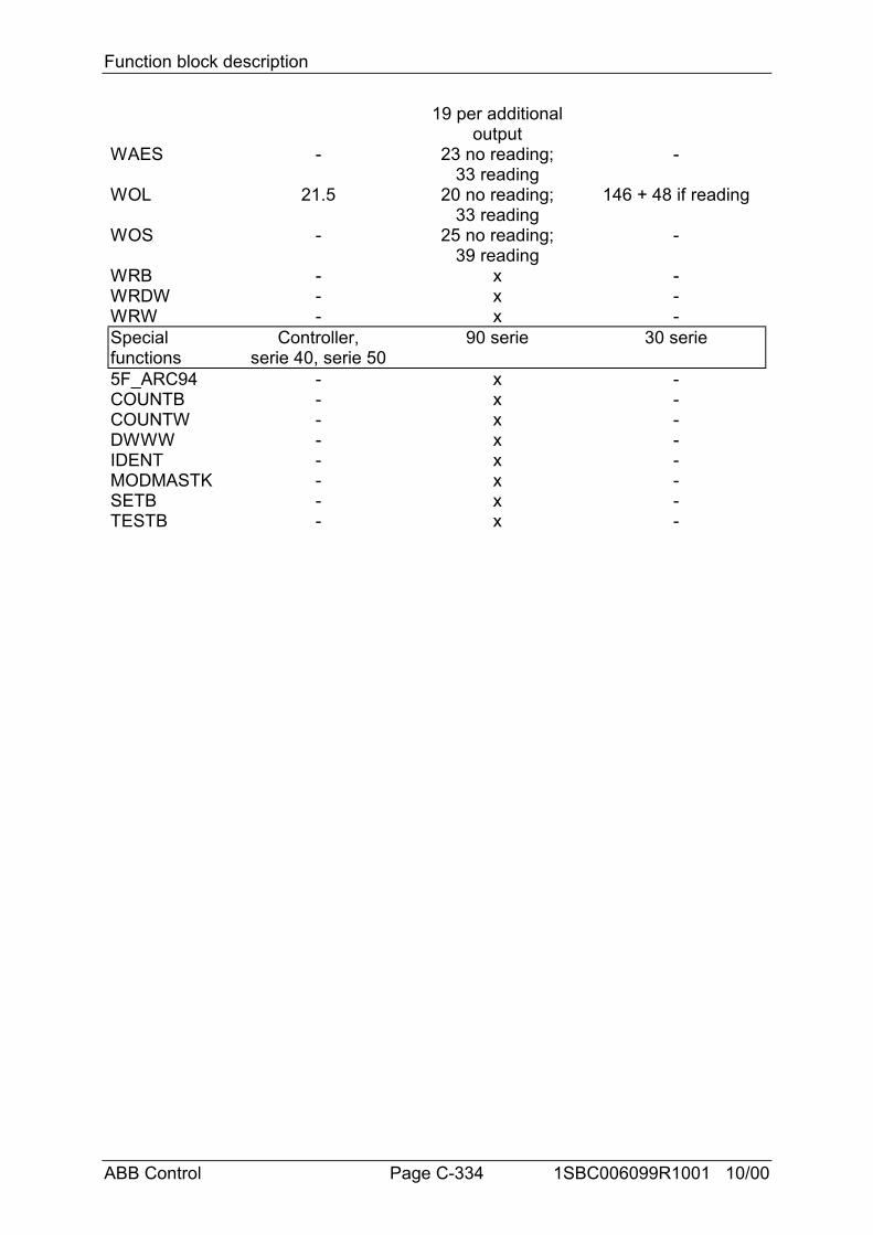
Function block description
ABB Control Page C-334 1SBC006099R1001 10/00
19 per additionaloutput
WAES - 23 no reading;33 reading
-
WOL 21.5 20 no reading;33 reading
146 + 48 if reading
WOS - 25 no reading;39 reading
-
WRB - x -WRDW - x -WRW - x -Specialfunctions
Controller,serie 40, serie 50
90 serie 30 serie
5F_ARC94 - x -COUNTB - x -COUNTW - x -DWWW - x -IDENT - x -MODMASTK - x -SETB - x -TESTB - x -