Embed Size (px)
Citation preview

VerilogVerilog HDL SyntaxHDL Syntax
정보통신용 SoC설계연구실

연세대학교연세대학교 정보통신용정보통신용SoCSoC설계연구실설계연구실-2-
HDL HDL 이란이란??HDL(Hardware Description Language)
VLSI 설계가 복잡도 증가 및 time-to-market 감소
GLM의 schematic 설계 불가능
HDL 언어를 이용한 시스템 및 회로 수준 구현 보편화
하드웨어 기술 언어
논리 회로의 프로그래밍 언어에 의한 표현
네트리스트 및 프로그래밍 언어적 표현
– 다양한 하드웨어 설계 방법 지원
Structural 및 Functional 방법에 의한 설계
– 병렬 처리 구문의 설계 가능
하드웨어 구현이전에 시뮬레이션 가능
concurrent language
A
B
C

연세대학교연세대학교 정보통신용정보통신용SoCSoC설계연구실설계연구실-3-
HDL HDL 종류종류VHDL
ADA와 비슷한 syntax
미국 국방성 중심으로 1987년 표준화(IEEE 1076)
언어 기술 방법이 다양하고 엄격함
학계에서 많이 사용
Verilog HDLC와 비슷한 syntaxGateway Design System 사에서 개발 Cadence로 흡수
약 70%이상의 기업체에서 사용

연세대학교연세대학교 정보통신용정보통신용SoCSoC설계연구실설계연구실-4-
HDLHDL의의 장단점장단점장점
설계 효율화
설계 기간 단축
검증 정확도 향상
디자인 재사용 가능
회로 기능 변경 용이
라이브러리화 지원
공정 라이브러리에 무관한 설계 가능

연세대학교연세대학교 정보통신용정보통신용SoCSoC설계연구실설계연구실-5-
일반적인일반적인 ASIC ASIC 설계설계 흐름흐름Design Specification
Behavioral Description
RTL Description (HDL)
Functional Verification
Logic Synthesis
Gate-Level Netlist
Physical Layout
Layout Verification
Logical Verification
Floor Planning Automatic Place & Route
Implementation
Back annotation

연세대학교연세대학교 정보통신용정보통신용SoCSoC설계연구실설계연구실-6-
VerilogVerilog의의 다양한다양한 기술기술 형태형태Verilog는 다양한 형태로 기술될 수 있다. 가장 일반적으로는 다음의 3가지 기술 형태를 혼용한다
Structural modelprimitive (built-in verilog logic gate, 라이브러리 모듈의 인스턴스, 혹은 사용자 설계 모듈)들의 계층적 구조로 기술
Dataflow modelexpression을 사용한 combinational logic 기술
assign target = expression의 형태
Arithmetic operators: +, -, *, /, %, >>, <<Relational operators: <, <=, ==, !=, >=, >, ===, !==Logical operators: &&, ||, !, ?:Bit-wise operators: ~, &, |, ^, ~^, ^~Reduction operators: &, ~&, |, ~|, ^, ~^Concatenation, replication: {sigs…} {number{…}}
연세대학교연세대학교 정보통신용정보통신용SoCSoC설계연구실설계연구실-7-
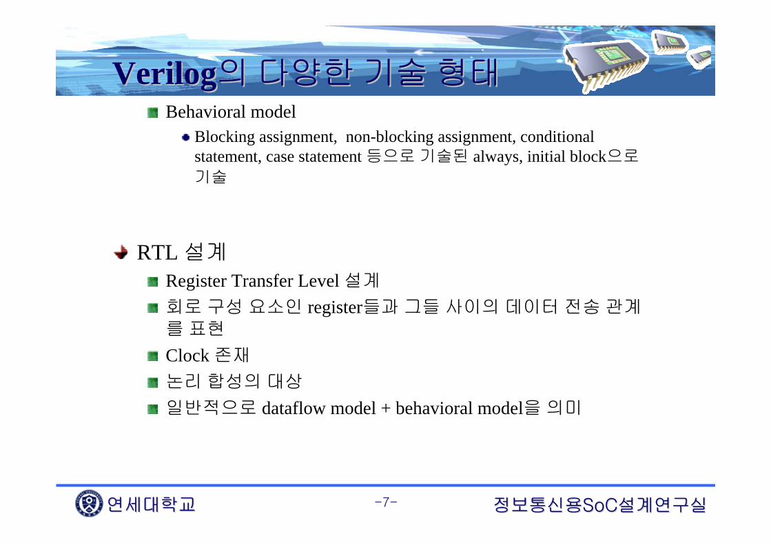
VerilogVerilog의의 다양한다양한 기술기술 형태형태Behavioral model
Blocking assignment, non-blocking assignment, conditional statement, case statement 등으로 기술된 always, initial block으로
기술
RTL 설계Register Transfer Level 설계
회로 구성 요소인 register들과 그들 사이의 데이터 전송 관계를 표현
Clock 존재
논리 합성의 대상
일반적으로 dataflow model + behavioral model을 의미

연세대학교연세대학교 정보통신용정보통신용SoCSoC설계연구실설계연구실-8-
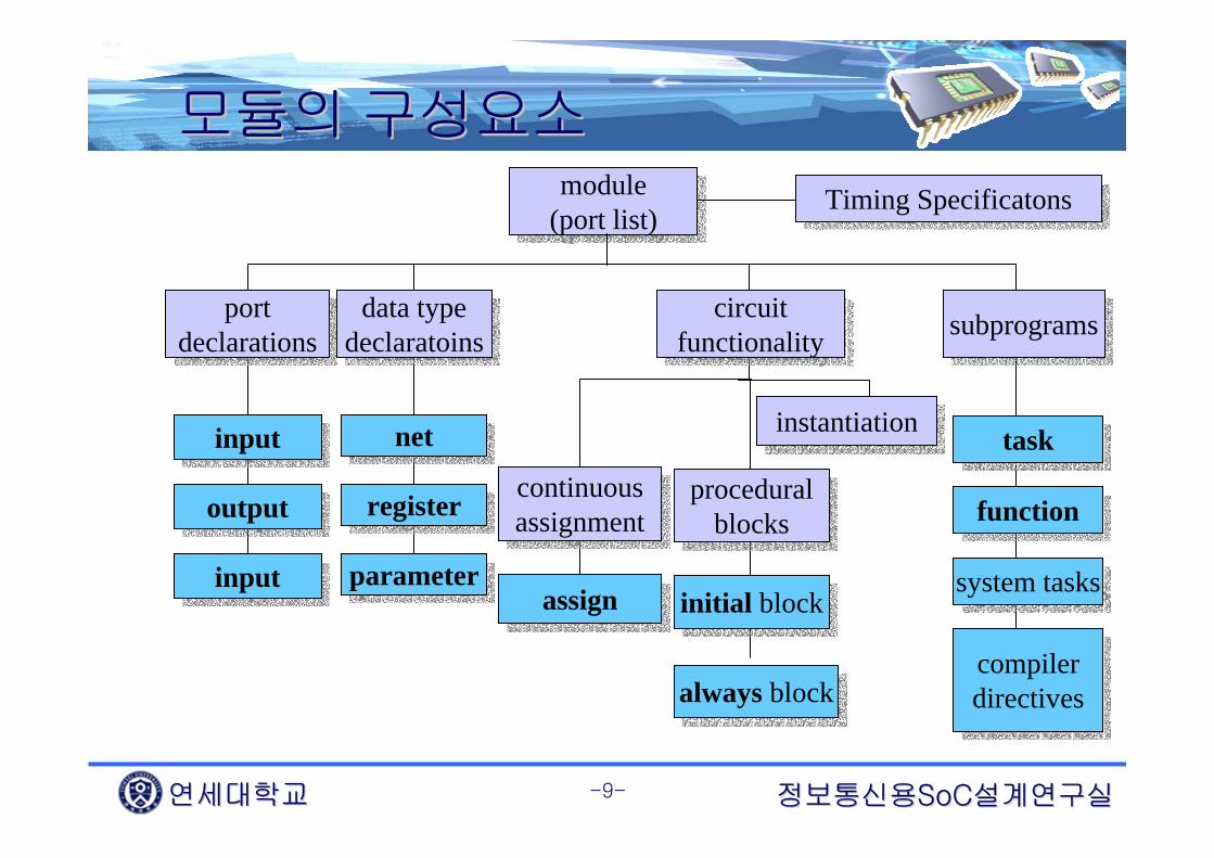
VerilogVerilog 코딩의코딩의 기본기본 구조구조모듈(Module)
Verilog HDL 프로그램의 기본 구조
대소문자 구별
Statement terminator로 semicolon을 사용
Timing specification은 시뮬레이션을 위해서 사용
module module_name(port_list);
endmodule
port declarations
data type declarations
circuit functionality
timing specifications
연세대학교연세대학교 정보통신용정보통신용SoCSoC설계연구실설계연구실-9-
모듈의모듈의 구성요소구성요소module
(port list)module
(port list) Timing SpecificatonsTiming Specificatons
portdeclarations
portdeclarations
data typedeclaratoinsdata type
declaratoinscircuit
functionalitycircuit
functionality subprogramssubprograms
inputinput
outputoutput
inputinput
netnet
registerregister
parameterparameter
continuousassignmentcontinuousassignment
proceduralblocks
proceduralblocks
initial blockinitial block
always blockalways block
assignassign
tasktask
functionfunction
system taskssystem tasks
compilerdirectivescompilerdirectives
instantiationinstantiation

연세대학교연세대학교 정보통신용정보통신용SoCSoC설계연구실설계연구실-10-
모듈모듈 구조구조 예예
module Add_half_1 (sum, c_out, a, b);input a, b;output sum, c_out;wire c_out_bar;
xor (sum, a, b);nand (c_out_bar, a, b);not (c_out, c_out_bar);
endmodule
Add_half_1a
b
sum
c_out
Sum = a ^ bC_out = a & b
모듈 선언
포트 선언
데이터 타입 선언
회로 function 기술Predefined primitives를사용하여 instantiation
c_out

연세대학교연세대학교 정보통신용정보통신용SoCSoC설계연구실설계연구실-11-
모듈모듈 구조구조 예예
module Add_half_2 (sum, c_out, a, b);input a, b;output sum, c_out;
assign {c_out, sum} = a + b;endmodule
Add_half_2a
b
sum
c_out
Sum = a ^ bC_out = a & b
회로 function 기술
continuous assignment 구문사용

연세대학교연세대학교 정보통신용정보통신용SoCSoC설계연구실설계연구실-12-
모듈모듈 구조구조 예예module Add_full (sum, c_out, a, b, c_in);input a, b, c_in;output sum, c_out;wire w1, w2, w3;
Add_half_1 M1 (w1, w2, a, b);Add_half_2 M2 (sum, w3, w1, c_in);or (c_out, w2, w3);
endmodule
•기존에 설계한 half_adder를 이용한Structural description
• module instantiation 사용(parent module / child module)
• module instantiation시 반드시module instance name이 들어가야 함
(primitive instantiation시는 optional)
M1
M2
ab
c_in sum
c_out
w1
w2
w3

연세대학교연세대학교 정보통신용정보통신용SoCSoC설계연구실설계연구실-13-
모듈모듈 구조구조 예예
module full_adder (sum, carryout, in1, in2, carryin);
input in1, in2, carryin;output sum, carryout;
reg sum, carryout;
always @(in1 or in2) begin{carryout, sum} = in1+in2+carryin;end
endmodule
sumHA = a ^ bc_outHA = absumFA = (a + b) ^ c_inc_outFA = (a + b) c_in + abc_in
sumFA = (a + b) + c_inc_outFA = a&b | a&b&c_in
Half_adder의 결과를sum을 연산자 +,c_out를 연산자 &로치환하면
full_adder
in1 in2
sum
carryoutcarryin
연세대학교연세대학교 정보통신용정보통신용SoCSoC설계연구실설계연구실-14-
모듈모듈 구조구조 예예
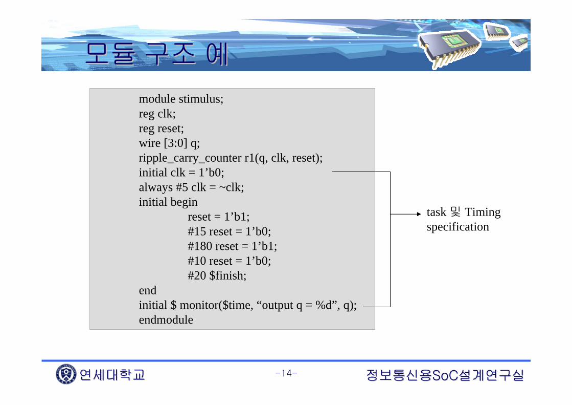
module stimulus;reg clk;reg reset;wire [3:0] q;ripple_carry_counter r1(q, clk, reset);initial clk = 1’b0;always #5 clk = ~clk;initial begin
reset = 1’b1;#15 reset = 1’b0;#180 reset = 1’b1;#10 reset = 1’b0;#20 $finish;
endinitial $ monitor($time, “output q = %d”, q);endmodule
task 및 Timing specification

연세대학교연세대학교 정보통신용정보통신용SoCSoC설계연구실설계연구실-15-
포트포트 선언선언포트 리스트
모듈에 사용되는 포트 이름의 list예 : module mux_latch(y_out, sel_a, sel_b, data_a, data_b);
포트 타입input : 입력 포트
output : 출력 포트
inout : 입•출력 포트
포트 선언포트 리스트에 나열된 포트명의 타입을 결정하는 과정을 의미
<port type> <port_name>;예
input sel_a, sel_b, data_a, data_b;output y_out;input [3:0] a;output [3:0] a, b;

연세대학교연세대학교 정보통신용정보통신용SoCSoC설계연구실설계연구실-16-
데이터데이터 형태형태
논리 값 의미
0
1
X
Z
논리 적 0 값 또는 조건 False
논리적 1 값 또는 조건 True
Unknown 논리 값
High impedance
물리적 데이터 형태논리 값 종류
추상적 테이터 형태Integer, real, time 등
논리 값 의미
integer Count
integer K[1:63]
32 bit integer
Array of 64 integers

연세대학교연세대학교 정보통신용정보통신용SoCSoC설계연구실설계연구실-17-
데이터데이터 형태형태변수선언(데이터 형태 선언)
종류reg : register (latch 또는 flip-flop)
– 일시적으로 데이터를 저장하는 변수를 의미
– 하드웨어 레지스터를 의미하지는 않는다
– always, initial 문 등에서 사용
– 예 : reg alu_reg;reg [7:0] alu_reg;
wire : net (배선)– 값 저장 불가능
– assign 문에서 사용
– 예 : wire adder_out;wire [15:0] adder_out, mult_out;
constant– 파라미터를 이용하여 변수 값을 사용할 때

연세대학교연세대학교 정보통신용정보통신용SoCSoC설계연구실설계연구실-18-
데이터데이터 형형수 표현
Sized 또는 unsized 형식의 수 표현 가능
Sized 형식의 수 표현
형식 : <size>’<base format><number>예 : 3’b010 //3의 prefix는 수의 size를 의미
Unsized 형식의 수 표현
Base format이 없는 경우는 default로 decimal을 의미
Size가 없는 경우는 default로 32-bit의 수를 의미
예 : 321 //32-bit을 갖는 decimal number 321을 의미
Base formatDecimal : ‘d 또는 ‘DHexadecimal : ‘h 또는 ‘HBinary : ‘b 또는 ‘BOctal : ‘o 또는 ‘O

연세대학교연세대학교 정보통신용정보통신용SoCSoC설계연구실설계연구실-19-
데이터데이터 형형수 표현
음수의 표현
<size> 앞에 – 부호를 위치하여 표현
예 : -8’d3 //3의 2의 보수 형태로 저장된 8bit의 음수
틀린 예 : 4’d-2수의 확장 법칙
MSB가 0, X, 또는 Z 인 경우
– 각 각 MSB가 0, X, Z가 되도록 확장
– 예 : 3’b01 = 3’b001, 3’bx1 = 3’bxx1 , 3’bz = 3’bzzzMSB가 1인 경우
– MSB를 0으로 채우는 방향으로 확장
– 예 : 3’b1 = 3’b001

연세대학교연세대학교 정보통신용정보통신용SoCSoC설계연구실설계연구실-20-
데이터데이터 형형수 표현
Number #Bits Base Dec. Equiv. Stored10 32 Decimal 10 00....01010 2’b10 2 Binary 2 103’d5 3 Decimal 5 1018’o5 8 Octal 5 000001018’ha 8 Hex 10 000010103’b01x 3 Binary - 01x12’hx 12 Hex - xxxxxxxxxxxx8’b0000_0001 8 Binary 1 000000018’bx01 8 Binary - xxxxxx018’HAD 8 Hex 173 10101101

연세대학교연세대학교 정보통신용정보통신용SoCSoC설계연구실설계연구실-21-
연산자연산자Binary 연산자의 종류
Operator Name Comments
+ Addition
- Subtraction
* Multiplication
/ Division Divide by zero produces an x.
% Modulus
(예)
A = 4’b0011, B = 4’b0100, D = 6, E =4 일때
A * B = 4’b1100
D / E = 1 //Truncates any fractional part
A + B = 4’b0111
B – A = 4’b0001
13 % 3 = 1
(예)
어떤 operand bit이 x값을 가지면 전체 연산
결과는 x 이다.
in1 = 4’b101x, in2 = 4’b1010 일 때
Sum = in1 + in 2; //sum은 4’bx
-7 % 2 = -1 //첫 번째 operand의 부호
7 % -2 = 1 //첫 번째 operand의 부호

연세대학교연세대학교 정보통신용정보통신용SoCSoC설계연구실설계연구실-22-
연산자연산자관계 연산자
Operator Name Comments > Greater than
>= Greater than or equal< Less than
<= Less than or equal== Logical equality!= Logical inequality
(예)
ain = 3’b010, bin = 3’b100, cin = 3’b111, din = 3’b01z, ein = 3’b01x일 때
ain > bin 은 false(1’b0) 의 결과
ain < bin 은 ture(1’b1)의 결과
ain >= bin 은 unknown(1’bx)의 결과
ain <= ein은 unknown(1’bx)의 결과

연세대학교연세대학교 정보통신용정보통신용SoCSoC설계연구실설계연구실-23-
연산자연산자논리 연산자
Operator Name Comments
! Logical negation
&& Logical AND
|| Logical OR
(예)
A = 3 ; B = 0;
A && B //Evaluates to 0. Equivalent to (logical 1 && logical 0)
A || B //Evaluates to 1. Equivalent to (logical 1 && logical 0)
!A //Evaluates to 0. Equivalent to not(logical 1)
!B //Evaluates to 1. Equivalent to not(logical 0)
A = 2’b0x ; B = 2’b10;
A && B //Evaluates to x. Equivalent to (x && logical 1)
(a == 2) && (b == 3) //Evaluates to 1 if both a == 2 and b==3 are true

연세대학교연세대학교 정보통신용정보통신용SoCSoC설계연구실설계연구실-24-
연산자연산자Bitwise 연산자
Operator Name Comments ~ Bitwise negation& Bitwise AND| Bitwise OR
^ Bitwise XOR~& Bitwise NAND~| Bitwise NOR
~^ or ^~ Bitwise XNOR Bitwise NOT XOR
만일 두 operand의 길이가 다르면 짧은 길이의 operand가 0으로 left-extend(예)X = 4’b1010, Y = 4’b1101, Z = 4’b10x1일 때
~X //Result is 4’b0101X & Y //Result is 4’b1000X | Y //Result is 4’b1111X ^ Y //Result is 4’b0111X ^~ Y //Result is 4’b1000X & Z //Result is 4’b10x0

연세대학교연세대학교 정보통신용정보통신용SoCSoC설계연구실설계연구실-25-
연산자연산자Unary Reduction 연산자
Operator Name Comments& AND reduction| OR reduction^ XOR reduction
~& NAND reduction~| NOR reduction~^ XNOR reduction
vector를 하나의 bit로 줄이는 연산을 수행한다. X 또는 Z는 연산자에 따라서unknown일 수도 있고 known일 수도 있다. (예)ain = 5’b10101, bin = 4’b0011, cin = 3’bz00, din = 3’bx011일 때
&ain //Result is 1’b0~&ain //Result is 1’b1|cin //Result is 1’bx&din //Result is 1’b0

연세대학교연세대학교 정보통신용정보통신용SoCSoC설계연구실설계연구실-26-
연산자연산자Equality 연산자
Operator Name Possible Logic CommentsValue
== Equality 0, 1, x!= Inequality 0, 1, x
=== Case equality 0, 1 including x and Z!== Case inequality 0, 1 including x and Z
case equality와 case inequality를 제외하고 operand에 X 나 Z를 포함하면 결과는 unknown(예) A = 4, B = 3, X = 4’b1010, Y = 4’b1101, Z = 4’b1xxz, M = 4’b1xxz, N = 4’b1xxx일 때A == B //Result is logical 0X != Y //Result is logical 1X == Z //Result is xZ == M //Result is logical 1(all bits match, including x and z)Z == N //Result is logical 0(least significant bit does not match)M != N //Result is logical 1

연세대학교연세대학교 정보통신용정보통신용SoCSoC설계연구실설계연구실-27-
연산자연산자기타 연산자
Operator Name Comments
<< Shift left Vacated bit positions are filled with zeros,
e. g., A = A << 2; shifts A two bits to left with zero fill.
>> Shift right Vacated bit positions are filled with zeros.
? : Conditional Assigns one of two values depending on the conditional
expression. E. g., A = C>D ? B+3 : B-2 means
if C greater than D, the value of A is B+3 otherwise B-2.
{ } Concatenate ain = 3’b010, bin = 4’b1100
{ain, bin} results 7’b0101100
{ { } } Replicate {3{2’b10}} results 6’b101010

연세대학교연세대학교 정보통신용정보통신용SoCSoC설계연구실설계연구실-28-
Multi bit Multi bit 선언선언신호 선언 [MSB:LSB]
Input [7:0] abus; reg [15:8] add;
한 비트의 선택assign abc = abus[5] ; assign abus[5] = abc ;
여러 신호를 하나의 신호로 할당assign abcd[15:0] = {abus[7:0],add[15:8]} ;

연세대학교연세대학교 정보통신용정보통신용SoCSoC설계연구실설계연구실-29-
ArrayArrayRegister 형은 array로 선언 가능
Reg [15:0] mem [0:255];mem은 16bit * 256word, 512 byte의 메모리
resister 배열은 bit 선택과 부분 선택 불가
반드시 word 단위의 액세스
Bit 선택이나 부분 선택일시적인 net 신호를 이용
Ex) wire [15:0] temp;
assign temp = mem [100];

연세대학교연세대학교 정보통신용정보통신용SoCSoC설계연구실설계연구실-30-
기술기술 방법방법(Description)(Description)구조적 기술방법(Structural description)
Explicit structural descriptionPrimitive 또는 라이브러리 셀의 instance 및 연결을 통한 기술
Implicit structural descriptionContinuous assignment를 통한 기술
동작 기술 방법(Behavioral description)회로의 동작을 기술함으로 설계하는 방법
대표적으로 initial, always behavior를 사용
Procedural block 과 procedural statement로 구성

연세대학교연세대학교 정보통신용정보통신용SoCSoC설계연구실설계연구실-31-
기술방법기술방법Explicit description
Implicit description
module 8bit_or_gate (y, a, b) ;input [7:0] a, b ;output y ;
or G1 (y, a, b) ;endmodule
module 8bit_or_gate (y, a, b) ;input [7:0] a, b ;output y ;
or8bit (y, a, b) ;endmodule
Primitive를 이용한 기술 라이브러리 셀을 이용한 기술
module 8bit_or_gate (y, a, b) ;input [7:0] a, b ;output y ;assign y = a | b ;
endmodule

연세대학교연세대학교 정보통신용정보통신용SoCSoC설계연구실설계연구실-32-
PrimitivesPrimitivesPredetermined primitives
pulluppulldown
trantranif0tranif1rtran
rtranif0rtranif1
cmosrcmos
nmospmosrnmosrpmos
bufif0bufif1notif0notif1
and nand
ornorxor
xnorbufnot
Pull Gates
Bi-Directional Gates
CMOS Gates
MOS Gates
Three State
Combinational logic

연세대학교연세대학교 정보통신용정보통신용SoCSoC설계연구실설계연구실-33-
Module instantiationModule instantiationPort connection의 2가지 방법
Connecting by ordered listConnecting ports by name
Connecting by ordered listmodule Top;reg [3:0] A, B;reg C_IN;wire[3:0] SUM;wire C_OUT;
fulladd4 fa_ordered(SUM, C_OUT, A, B, C_IN);….
<stimulus>….
endmodule
module fulladd4(sum, c_out, a, b, c_in);output [3:0] sum;output c_out;input [3:0] a, b;input c_in;
…<module internals>…
endmodule

연세대학교연세대학교 정보통신용정보통신용SoCSoC설계연구실설계연구실-34-
Module instantiationModule instantiationConnecting ports by name
module Top;reg [3:0] A, B;reg C_IN;wire[3:0] SUM;wire C_OUT;
fulladd4 fa_byname( .c_out(C_OUT), .sum(SUM), .b(B),.c_in(C_IN), .a(A) );
….<stimulus>….
endmodule
module fulladd4(sum, c_out, a, b, c_in);output [3:0] sum;output c_out;input [3:0] a, b;input c_in;
…<module internals>…
endmodule

연세대학교연세대학교 정보통신용정보통신용SoCSoC설계연구실설계연구실-35-
Continuous AssignmentsContinuous AssignmentsContinuous Assignments
Wire에 값을 가하고 update 하기 위해 사용
LHS (Left Hand Side)의 데이터 타입은 항상 net data type이여야 한다
Always active RHS (Right Hand Side)의 어느 한 operand라도 변화하면, expression은 실행되고 LHS 값은 즉시 update 된다
RHS의 데이터 타입은 net, register, function call등 어떤 것이여도 상관 없다
implicit continuous assignment implicit continuous assignment
wire adder_out = mult_out + out; wire adder_out;assign adder_out = mult_out+out;

연세대학교연세대학교 정보통신용정보통신용SoCSoC설계연구실설계연구실-36-
Procedural BlocksProcedural BlocksProcedure의 정의
sequential 하게 동작하는 코드 부분을 의미
procedural statementprocedure안에 존재하는 statement
예를 들어, 2-to-1 MUX의 경우
beginif (sel == 0)
Y = B;
elseY = A;
end
ExecutionFlow Procedural assignments:
Y must be reg !!Procedural assignments:
Y must be reg !!

연세대학교연세대학교 정보통신용정보통신용SoCSoC설계연구실설계연구실-37-
Initial BlockInitial BlockInitial block
시뮬레이션을 위한 초기화, 모니터링, waveform의 기술시에주로 사용된다
시뮬레이션 타임 0에서 시작하여 오직 1번만 실행된다
하나의 initial block이 여러 개의 behavioral statement를 가질 경우 begin ~ end로 group 되어야 한다
독립적인 initial block은 서로 concurrent 하다
Initial block 내부의 statement들은 sequential 하게 동작한다
initial block은 중첩될 수 없다
synthesis 되지 않는다

연세대학교연세대학교 정보통신용정보통신용SoCSoC설계연구실설계연구실-38-
Initial BlockInitial Blockmodule TestBench;reg a, b, c, d;initial a = 1’b0;initialbegin
b = 1’b1;#5 c = 1’b0;#10 d = 1’b0;
endinitial #20 $finish;endmodule
simulation eventTime051520
a = 1’b0; b = 1’b1;c = 1’b0;d = 1’b0;$finish

연세대학교연세대학교 정보통신용정보통신용SoCSoC설계연구실설계연구실-39-
Always BlockAlways BlockAlways block
항상 반복되는 행동블록을 모델링할 때 사용
시뮬레이션 타임 0에서 시작하여시뮬레이션이 끝날 때 까지 반복
C 언어의 무한 루프와 비슷한 개념$finish 나 $stop에 의해서만 정지
하나의 always block이 여러 개의behavioral statement를 가질 경우begin ~ end로 group 되어야 한다
독립적인 initial block은 서로concurrent 하다
Initial block 내부의 statement들은sequential 하게 동작한다
(예)클록 발생 모듈을 기술initial clk = 1’b0;always #10 clk = ~ clk;initial #1000 $finish;

연세대학교연세대학교 정보통신용정보통신용SoCSoC설계연구실설계연구실-40-
Initial Initial vsvs AlwaysAlways
initial
always
Starts when simulation
starts
Execute once and stop
Continually loop—while (power on)do statements;
Not used in synthesis
Used in synthesis
Statement Starts How it works Use in Synthesis?Looks like
initialbegin…end
alwaysbegin…end

연세대학교연세대학교 정보통신용정보통신용SoCSoC설계연구실설계연구실-41-
Timing Control Timing Control Timing control
Procedural statement가 실행될 때 simulation time을 규정하는 방법을 제공
Timing control의 3가지 방법Delay-based timing controlEvent-based timing controlLevel-based timing control

연세대학교연세대학교 정보통신용정보통신용SoCSoC설계연구실설계연구실-42-
DelayDelay--based Timing based Timing Control(contControl(cont’’dd))Delay
statement를 encounter한 부터 그 statement를 실행하기 전까지의 시간
Delay-based timing control의 3가지 형태Regular delay controlIntra-assignment delay controlZero-delay control
Syntax<delay>::= #<NUMBER>||= #<identifier>||= #(<mintypemax_exp><,<mintypmax_exp>>*)

연세대학교연세대학교 정보통신용정보통신용SoCSoC설계연구실설계연구실-43-
DelayDelay--based Timing Control (contbased Timing Control (cont’’d)d)Regular Delay Control
Delay symbol으로 #을 사용
procedural assignment의 왼쪽에 non-zero delay를 규정
statement가 encounter되는 시뮬레이션 타임을 기준으로 delay를 적용parameter latency = 20;parameter delta = 2;reg x, y, z, p, q;initial begin
x = 0;#10 y = 1; //delay control with a number#latency z = 0; //delay control with identifier#(latency + delta) p = 1; //delay control with expression#y x = x + 1; //delay control with identifier#(4:5:6) q = 0; //minimum, typical, maximum delay value
end

연세대학교연세대학교 정보통신용정보통신용SoCSoC설계연구실설계연구실-44-
DelayDelay--based Timing Control (contbased Timing Control (cont’’d)d)Intra-assignment delay control
assignment의 우변에 delay를 규정
regular vs intra-assignmentregular – assignment 문장 전체를 delayintra-assignment – delay없이 우변의 표현을 계산, 좌변으로의
대입을 delayreg x, y, z;initial begin
x = 0; z = 0;y = #5 x + z; //Take value of x and z at the time=0, evaluate
end //x+z and then wait 5 time units to assign value to y
initial beginx =0; z =0;temp_xz = x + z; #5 y = temp_xz; //Take value of x + z at the current time and
end //store it in a temporary variable. Even though // x and z might change between 0 and 5, the value// assigned to y at time 5 is unaffected.

연세대학교연세대학교 정보통신용정보통신용SoCSoC설계연구실설계연구실-45-
DelayDelay--based Timing Controlbased Timing ControlZero Delay Control
#0의 symbol 사용
동일한 시뮬레이션 타임에 서로 다른 initial/always block의statement의 실행 순서는 non-deterministiczero delay는 동일한 시뮬레이션 타임에 실행되는 statement 중에서 제일 나중에 실행되는 것을 보장
동일한 시뮬레이션 타임에 여러 개의 zero delay를 사용한 경우는 역시 non-deterministicrace condition을 막을 수 있다
initial beginx = 0; y= 0;
end
initial begin#0 x = 1;#0 y = 1;
end

연세대학교연세대학교 정보통신용정보통신용SoCSoC설계연구실설계연구실-46-
EventEvent--based Timing Control (contbased Timing Control (cont’’d)d)Event : register나 net 값의 변화
Event-based timing control event 가 발생하는 시점을 기준으로 어떤 statement가 실행되도록 기술하는 방법
Event-based timing control의 종류Regular event controlNamed event controlEvent OR control

연세대학교연세대학교 정보통신용정보통신용SoCSoC설계연구실설계연구실-47-
EventEvent--based Timing Control (contbased Timing Control (cont’’d)d)Regular event control
형식 : @(<event>)event의 종류
posedge sig: sig 신호가 임의의 값에서 1로 변화 또는 0에서 임의의 값으로 변화
negedge sig : sig 신호가 임의의 값에서 0으로 변화 또는 1에서 임의의 값으로 변화
sig : sig 신호의 임의의 변화
@(clock) q = d; // q=d is executed whenever signal clock changes values
@(posedge clock) q = d; //q=d is executed whenever signal clock does a //positive transition (0 to 1, x, or z, x to 1, z to 1)
@(negedge clock) q = d; //q=d is executed whenever signal clock does a //negative transition (1 to 0, x or z, x to 0, z to 0)
q = @(posedge clock) d; //d is evaluated immediately and assigned to q //at the positive edge of clock

연세대학교연세대학교 정보통신용정보통신용SoCSoC설계연구실설계연구실-48-
EventEvent--based Timing Controlbased Timing ControlEvent OR control
다수의 event 중에 어느 한 event가 발생하였을 때 block이trigger되도록 할 때 사용
sensitivity list : 일련의 event들. event 사이에 or keyword 사용
always @(reset or clock or d) //wait for reset or clock or d to changebegin
if(reset)q = 1’b0;
else if(clock)q = d;
end

연세대학교연세대학교 정보통신용정보통신용SoCSoC설계연구실설계연구실-49-
Procedural StatementProcedural Statementif-else statement
어떤 조건을 근거로 하여 statement를 실행 할 것인지를 결정하는데 사용
TOP에서 BOTTOM으로 조건 평가 실시
모든 조건이 false이면 else에 관계되는 statement를 실행
if(<condition1>)sequence of statement(s)
else if(<condition2>)sequence of statement(s)
……
elsesequence of statements(s)
E.g. 4-to-1 muxmodule mux4_1(out, in, sel);output out;input [3:0] in;input [1:0] sel;reg out;wire [3:0] in;wire [1:0] sel;always @(in or sel)
if (sel == 0)out = in[0];
else if (sel == 1)out = in[1];
else if (sel == 2)out = in[2];
else out = in[3];
endmodule
연세대학교연세대학교 정보통신용정보통신용SoCSoC설계연구실설계연구실-50-
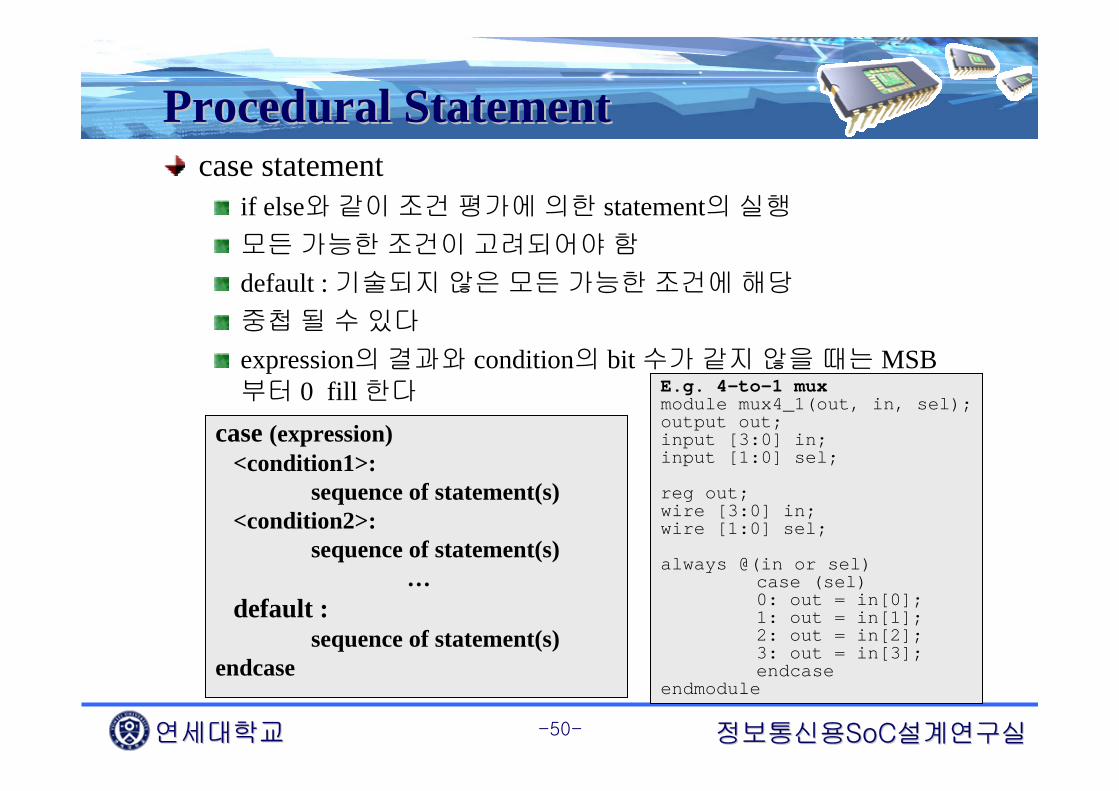
Procedural StatementProcedural Statementcase statement
if else와 같이 조건 평가에 의한 statement의 실행
모든 가능한 조건이 고려되어야 함
default : 기술되지 않은 모든 가능한 조건에 해당
중첩 될 수 있다
expression의 결과와 condition의 bit 수가 같지 않을 때는 MSB부터 0 fill 한다
case (expression)<condition1>:
sequence of statement(s)<condition2>:
sequence of statement(s)…
default :sequence of statement(s)
endcase
E.g. 4-to-1 muxmodule mux4_1(out, in, sel);output out;input [3:0] in;input [1:0] sel;
reg out;wire [3:0] in;wire [1:0] sel;
always @(in or sel)case (sel)0: out = in[0];1: out = in[1];2: out = in[2];3: out = in[3];endcase
endmodule

연세대학교연세대학교 정보통신용정보통신용SoCSoC설계연구실설계연구실-51-
Procedural StatementProcedural Statementforever
시뮬레이션 동안 $finish를 만날 때까지 무한 loop를 수행
Testbench안에서 clock generation module 기술에 주로 사용
module test;
reg clk;
initial beginclk = 0;forever #10 clk = ~clk;end
other_module1 o1(clk, ..);other_module2 o2(.., clk, ..);
endmodule
Tclk = 20 time unitsTclk = 20 time units
연세대학교연세대학교 정보통신용정보통신용SoCSoC설계연구실설계연구실-52-
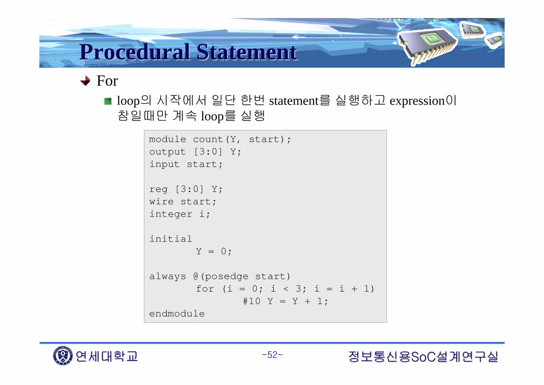
Procedural StatementProcedural StatementFor
loop의 시작에서 일단 한번 statement를 실행하고 expression이참일때만 계속 loop를 실행
module count(Y, start);output [3:0] Y;input start;
reg [3:0] Y;wire start;integer i;
initialY = 0;
always @(posedge start)for (i = 0; i < 3; i = i + 1)
#10 Y = Y + 1;endmodule

연세대학교연세대학교 정보통신용정보통신용SoCSoC설계연구실설계연구실-53-
Blocking vs. NonBlocking vs. Non--BlockingBlockingBlocking procedural assignment
= 토큰 사용
Evaluation과 assignment가 동일한 시뮬레이션 스텝에서 발생
Procedure 내에서 execution flow는 assignment가 완료될 때까지block된다

연세대학교연세대학교 정보통신용정보통신용SoCSoC설계연구실설계연구실-54-
Blocking vs. NonBlocking vs. Non--BlockingBlockingNon-blocking procedural assignment
<= 토큰 사용
Evaluation과 assignment가 두 개의 시뮬레이션 스텝으로 분리
우변 값은 즉시 evaluation 된다
좌변으로의 assignment는 현재 타임 스텝의 모든 evaluation이 완료될 때 까지 연기 된다
Procedure 내에서 execution flow는 새로운 timing control을 만날때까지 계속 진행된다(non-block)

연세대학교연세대학교 정보통신용정보통신용SoCSoC설계연구실설계연구실-55-
Blocking vs. NonBlocking vs. Non--BlockingBlocking시뮬레이션 스케줄링 규칙
각각의 verilog 시뮬레이션 타임 스탭은 다음과 같은 4개의 queue로 구성된다
Queue1 모든 non-blocking assignment의 RHS를 계산하고 procedural timing control에의해서 규정된 시뮬레이션 타임에 assign이 발생하도록 scheduling모든 blocking assignment의 RHS를 계산하고 동시에 LHS를 update모든 continuous assignment의 RHS를 계산하고 동시에 LHS를 update모든 primitive의 input, output의 변화를 계산
$display, $write 처리
Queue2모든 non-blocking assignment의 LHS를 변화
Queue3$monitor, $strobe 처리
reason_synchronize로 PLI를 호출
Queue4reason_rosynchronize로 PLI 호출

연세대학교연세대학교 정보통신용정보통신용SoCSoC설계연구실설계연구실-56-
Blocking vs. NonBlocking vs. Non--BlockingBlockingmodule evaluates;reg a, b, c;initial begin
a = 0;b = 1;c = 0;
endalways c = #5 ~c;always @(posedge c) begin
a <= b;b <= a;
endendmodule

연세대학교연세대학교 정보통신용정보통신용SoCSoC설계연구실설계연구실-57-
Blocking vs. NonBlocking vs. Non--BlockingBlockingmodule evaluates;reg a, b, c;initial begin
a = 0;b = 1;c = 0;
endalways c = #5 ~c;always @(posedge c) begin
a = b;b = a;
endendmodule

연세대학교연세대학교 정보통신용정보통신용SoCSoC설계연구실설계연구실-58-
Sequential Block vs. Parallel BlockSequential Block vs. Parallel BlockSequential Block
begin ~ end 사이의 statement들은 sequential 하게 동작
initial 과 always block에 sequential 하게 동작하기 원하는 다수의 statement가 존재할 경우는 begin ~ end 로 묶는다
Sequential block과 parallel block은 중첩될 수 있다

연세대학교연세대학교 정보통신용정보통신용SoCSoC설계연구실설계연구실-59-
Timing ControlTiming Control과과 SynthesisSynthesismodule mux_sample(f, sel, b, c);
output f;input sel, b, c;reg f;always @(sel or b or c)
if(sel == 1'b1)f = b;
elsef = c;
endmodule
module mux_sample(f, sel, b, c);output f;input sel, b, c;reg f;always @(sel or b or c)
if(sel == 1'b1)#5 f = b;
else#88 f = c;
endmodule
Synthesis tool은 time delay를 무시
Synthesis tool은 combinational 입력으로부터 출력까지의 propagation을최소화하려는 노력을 하기 때문

연세대학교연세대학교 정보통신용정보통신용SoCSoC설계연구실설계연구실-60-
Procedural BlockProcedural Block과과 SynthesisSynthesismodule mux_sample(f, sel, a, b, c, d);
output f;input [1:0] sel;input a, b, c, d;reg f;always @(sel or a)
if(sel == 2'b00) f = a;
always @(sel or b)if(sel == 2'b01) f = b;
always @(sel or c)if(sel == 2'b10) f = c;
always @(sel or d)if(sel == 2'b11) f = d;
endmodule
하나의 신호를 2개 이상의always 문에서 출력할 때
시뮬레이션 결과와synthesis 결과가 같지 않을수 있으므로 피해야 한다
연세대학교연세대학교 정보통신용정보통신용SoCSoC설계연구실설계연구실-61-
Behavioral ConstructBehavioral Construct를를 사용한사용한 Combinational Combinational Circuit Circuit 표현표현
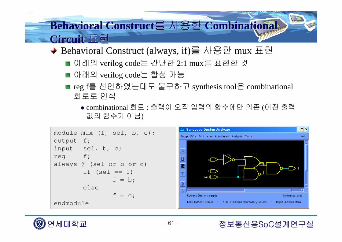
Behavioral Construct (always, if)를 사용한 mux 표현아래의 verilog code는 간단한 2:1 mux를 표현한 것
아래의 verilog code는 합성 가능
reg f를 선언하였는데도 불구하고 synthesis tool은 combinational 회로로 인식
combinational 회로 : 출력이 오직 입력의 함수에만 의존 (이전 출력값의 함수가 아님)
module mux (f, sel, b, c);output f;input sel, b, c;reg f;always @ (sel or b or c)
if (sel == 1)f = b;
elsef = c;
endmodule
연세대학교연세대학교 정보통신용정보통신용SoCSoC설계연구실설계연구실-62-
Behavioral ConstructBehavioral Construct를를 사용한사용한 Combinational Combinational Circuit Circuit 표현표현
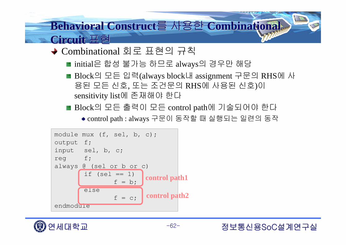
Combinational 회로 표현의 규칙initial은 합성 불가능 하므로 always의 경우만 해당
Block의 모든 입력(always block내 assignment 구문의 RHS에 사용된 모든 신호, 또는 조건문의 RHS에 사용된 신호)이sensitivity list에 존재해야 한다
Block의 모든 출력이 모든 control path에 기술되어야 한다
control path : always 구문이 동작할 때 실행되는 일련의 동작
module mux (f, sel, b, c);output f;input sel, b, c;reg f;always @ (sel or b or c)
if (sel == 1)f = b;
elsef = c;
endmodule
control path1
control path2

연세대학교연세대학교 정보통신용정보통신용SoCSoC설계연구실설계연구실-63-
Behavioral ConstructBehavioral Construct를를 사용한사용한 Combinational Combinational Circuit Circuit 표현표현module blah (f, g, a, b, c);output f, g;input a, b, c;reg f, g;always @ (a or b or c)
if (a == 1)f = b;
elseg = c;
endmodule
module blah (f, g, a, b, c);output f, g;input a, b, c;reg f, g;always @ (a or b or c)
if (a == 1)f = b;
elsef = c;
endmodule
a == 0이면 f = old value (seq.)

연세대학교연세대학교 정보통신용정보통신용SoCSoC설계연구실설계연구실-64-
Behavioral ConstructBehavioral Construct를를 사용한사용한 Combinational Combinational Circuit Circuit 표현표현
다음과 같이 한다면?module sample(f, g, a, b, c);output f, g;input a, b, c;reg f, g;
always @(a or b or c) beginf = 0 ; g = 0 ; if (a == 1)
f = b; else
g = c; end
endmodule
-Function이 복잡한 경우 모든 control path에 출력값을 할당하였는지 잘알지 못함-모든 출력값을 known value(예에서는 0)로 할당하고 각 control path에서는 필요한 값만 할당- synthesis tool은 combinational 회로로 인식

연세대학교연세대학교 정보통신용정보통신용SoCSoC설계연구실설계연구실-65-
Behavioral ConstructBehavioral Construct를를 사용한사용한 Combinational Combinational Circuit Circuit 표현표현
Case 구문을 사용한 경우마치 case 구문을 사용하여 진리표를 표현하는것과 같은 의미
모든 입력 조합에 대해서 기술해 주어야 한다
module fred (f, a, b, c);output f;input a, b, c;reg f;always @ (a or b or c)
case ({a, b, c})3’b000: f = 1’b0;3’b001: f = 1’b1;3’b010: f = 1’b1;3’b011: f = 1’b1;3’b100: f = 1’b1;3’b101: f = 1’b0;3’b110: f = 1’b0;3’b111: f = 1’b1;
endcaseendmodule
abc = 3’b1xz와 같은 표현은 simulation에서는 의미를 갖으나synthesis 회로에서는 의미를 갖지 않는다그러므로 위의 경우는 full case description이라 할 수 있다

연세대학교연세대학교 정보통신용정보통신용SoCSoC설계연구실설계연구실-66-
Behavioral ConstructBehavioral Construct를를 사용한사용한 Combinational Combinational Circuit Circuit 표현표현
module caseExample(f, a, b, c);output f;input a, b, c;reg f;always @ (a or b or c)
case ({a, b, c})3’b001: f = 1’b1;3’b010: f = 1’b1;3’b011: f = 1’b1;3’b100: f = 1’b1;3’b111: f = 1’b1;3’b110: f = 1’b0;default: f = 1’bx;
endcaseendmodule
00 01 11 100
1
ab
c1 1
11 1
0x
x
위와 같이 default를 기술한 경우는 위와 같은 진리표를 이용하여combinational 회로를 합성그러므로 역시 full case description
연세대학교연세대학교 정보통신용정보통신용SoCSoC설계연구실설계연구실-67-
Behavioral ConstructBehavioral Construct를를 사용한사용한 Combinational Combinational Circuit Circuit 표현표현
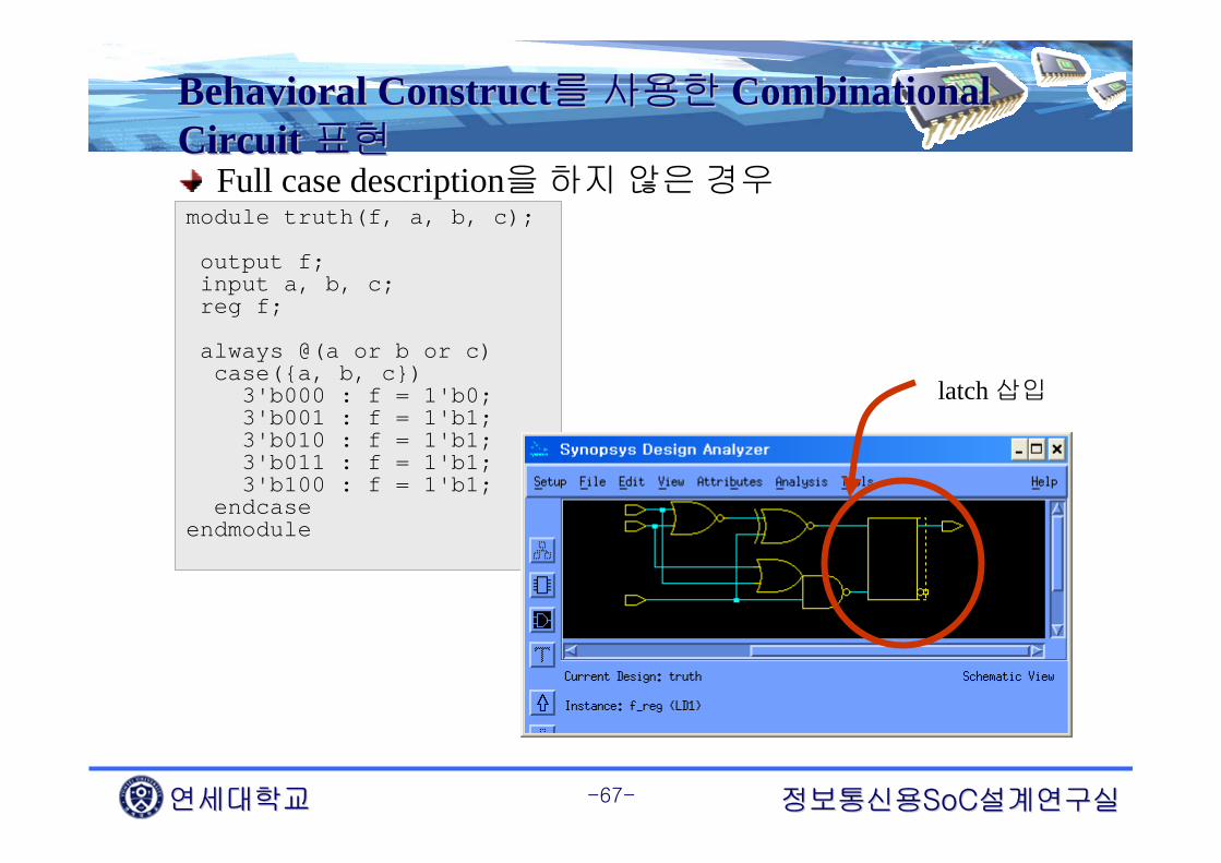
Full case description을 하지 않은 경우module truth(f, a, b, c);
output f;input a, b, c; reg f;
always @(a or b or c)case({a, b, c})
3'b000 : f = 1'b0;3'b001 : f = 1'b1;3'b010 : f = 1'b1;3'b011 : f = 1'b1;3'b100 : f = 1'b1;
endcaseendmodule
latch 삽입

연세대학교연세대학교 정보통신용정보통신용SoCSoC설계연구실설계연구실-68-
VerilogVerilog Coding Guideline for SynthesisCoding Guideline for Synthesis일반적으로 synthesis tool에서 합성 지원되지 않는verilog 문법들
Initial Loops
repeatforeverWhile
Data typeseventrealtime
UDPsFork … join blocksProcedural assignments
assign and desassignforce and releasedisable
Some operators/ and %=== and !==

연세대학교연세대학교 정보통신용정보통신용SoCSoC설계연구실설계연구실-69-
레지스터의 초기화신호의 초기화를 위해서 initial을 사용하지 않는다
initial은 synthesis 불가능
다음의 template를 사용
// Bad codinginitial
data <= 1’b0 ;
always @ (posedge clk)data <= data_in
// Good coding// Asynchronous RESETalways @ (posedge RESET or poesedge clk)
if (RESET) data <= 1’b0 ;
elsedata <= data_in ;
// Better coding// Synchronous RESETalways @(poesedge clk)
if (RESET) data <= 1’b0 ;
elsedata <= data_in ;
VerilogVerilog Coding Guideline for SynthesisCoding Guideline for Synthesis

연세대학교연세대학교 정보통신용정보통신용SoCSoC설계연구실설계연구실-70-
불필요한 latch의 사용을 피하라case나 if-else statement에 default value를 사용
모든 입력 조건에 모든 출력 신호값을 할당
// latch를사용하여합성always @ (d)
begincase (d)
2’b00: z <= 1’b1;2’b01: z <=1’b0;2’b10: z <= 1’b1; s<= 1’b1;
endcaseend
// latch가사용되지않고합성always @ (d)
begincase (d)
2’b00: z <= 1’b1; s<=1’b0;2’b01: z <=1’b0; s<=1’b0;2’b10: z <= 1’b1; s<= 1’b1;defaults: z <= 1’b0; s<=1’b0;
endcaseend
VerilogVerilog Coding Guideline for SynthesisCoding Guideline for Synthesis

연세대학교연세대학교 정보통신용정보통신용SoCSoC설계연구실설계연구실-71-
Combinational feedback이 발생하지 않도록 하라
• GOOD
SEQ SEQCOMB
COMBCOMB
SEQ SEQ
COMB
COMBCOMB
• BAD
VerilogVerilog Coding Guideline for SynthesisCoding Guideline for Synthesis

연세대학교연세대학교 정보통신용정보통신용SoCSoC설계연구실설계연구실-72-
always @(posedge/negedge) block에는 non-blocking assignment를 사용하는 것이 좋다
always @(posedge clk)begin
b <= a ; c <= b ;
end
always @(posedge clk)begin
c <= b ; b <= a ;
end
VerilogVerilog Coding Guideline for SynthesisCoding Guideline for Synthesis

연세대학교연세대학교 정보통신용정보통신용SoCSoC설계연구실설계연구실-73-
always @(posedge clk)begin
b = a ; c = b ;
end
always @(posedge clk)begin
c = b ; b = a ;
end
VerilogVerilog Coding Guideline for SynthesisCoding Guideline for Synthesis

연세대학교연세대학교 정보통신용정보통신용SoCSoC설계연구실설계연구실-74-
이상적인 clock 기술 구조하나의 clock source 사용
Register에서의 출력
CLK
VerilogVerilog Coding Guideline for SynthesisCoding Guideline for Synthesis
연세대학교연세대학교 정보통신용정보통신용SoCSoC설계연구실설계연구실-75-
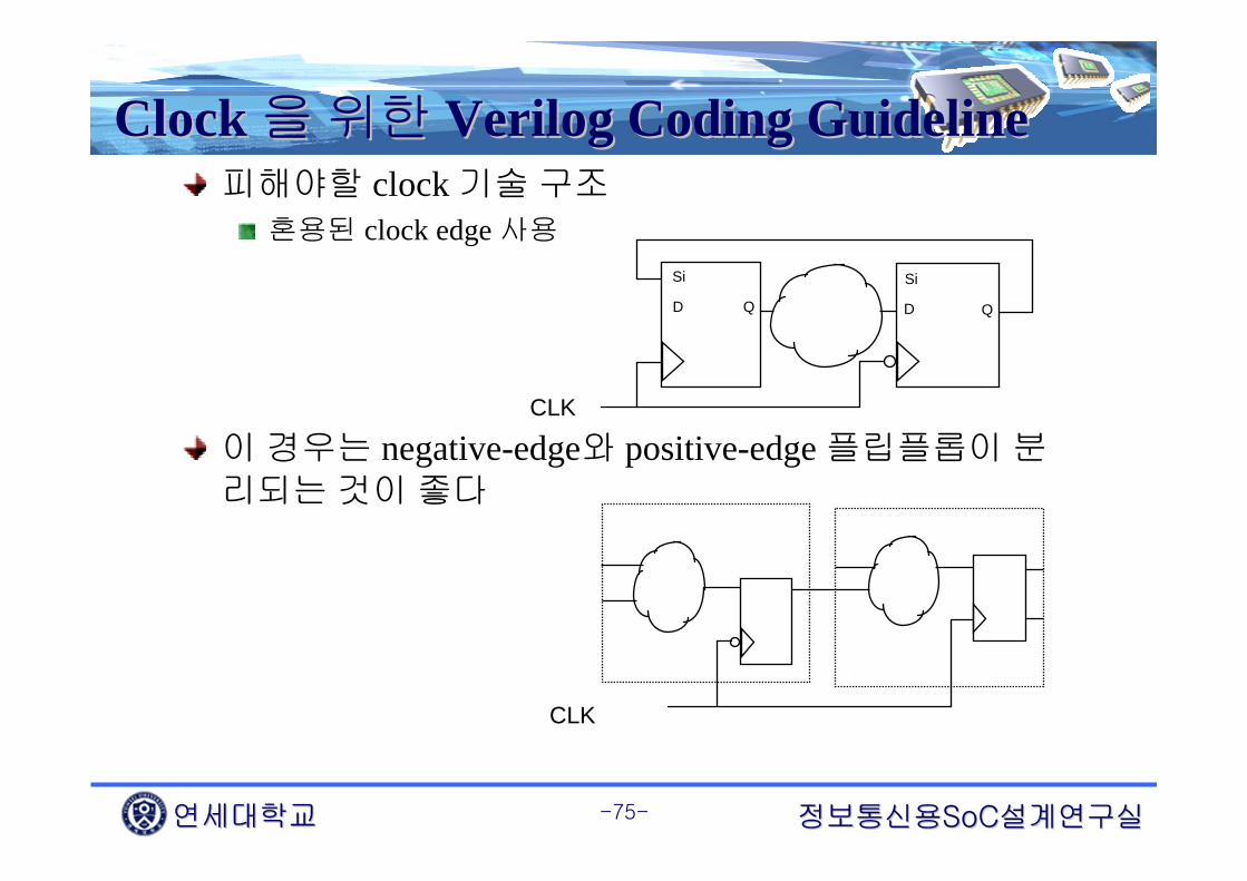
Clock Clock 을을 위한위한 VerilogVerilog Coding GuidelineCoding Guideline피해야할 clock 기술 구조
혼용된 clock edge 사용
이 경우는 negative-edge와 positive-edge 플립플롭이 분리되는 것이 좋다
Si
D D QQ
Si
CLK
CLK

연세대학교연세대학교 정보통신용정보통신용SoCSoC설계연구실설계연구실-76-
Clock Clock 을을 위한위한 VerilogVerilog Coding GuidelineCoding Guideline피해야할 clock 기술 구조
Gated clocksSkew 문제
Glitch 문제
Scan chain을 엮을 수 없는 문제
CLK
U1 U2
Q

연세대학교연세대학교 정보통신용정보통신용SoCSoC설계연구실설계연구실-77-
FSM FSM 기술을기술을 위한위한 VerilogVerilog Coding GuidelineCoding GuidelineCombinational port와 sequential part를 분리
2-process FSM 기술, 3-process FSM 기술
State 변수를 기술하기 위해 parameter 사용
Current StateRegister
(sequential)
Next State Logic
(combinational)
Output Logic(combinational)
clockAsynchronous reset
InputsOutputs
<3-process FSM>

연세대학교연세대학교 정보통신용정보통신용SoCSoC설계연구실설계연구실-78-
module FSM_S3(Clock, Reset, X, Y);input Clock, Reset, X;output [2:0] Y;reg [2:0] Y;reg [1:0] CS, NS;parameter [1:0] ST0 = 0, ST1 = 1, ST2 = 2, ST3 = 3;
always @(X or CS)begin : COMB
NS = ST0;case (CS)ST0 : begin
NS = ST1;endST1 : begin
if (X)NS = ST3;elseNS = ST2;
end
Next State Logic(combinational)
FSM FSM 기술을기술을 위한위한 VerilogVerilog Coding GuidelineCoding Guideline

연세대학교연세대학교 정보통신용정보통신용SoCSoC설계연구실설계연구실-79-
ST2 : beginNS = ST3;
endST3 : begin
NS = ST0;end endcase
end// end process COMB
always @(posedge Clock or posedge Reset)begin : SEQif (Reset)
CS <= ST0;else
CS <= NS;end
Next State Logic(combinational)
Current StateRegister(sequential)
FSM FSM 기술을기술을 위한위한 VerilogVerilog Coding GuidelineCoding Guideline

연세대학교연세대학교 정보통신용정보통신용SoCSoC설계연구실설계연구실-80-
always @(CS)begin : OUTcase (CS)
ST0 : Y = 1;ST1 : Y = 2;ST2 : Y = 3;ST3 : Y = 4;default : Y = 1;
endcaseend
endmodule
Output Logic(combinational)
FSM FSM 기술을기술을 위한위한 VerilogVerilog Coding GuidelineCoding Guideline