Embed Size (px)
Citation preview
ARMY RESEARCH LABORATORY
Information Operations Vulnerability/Survivability Assessment (IOVSA) for the Bradley Fire Support
Team Vehicle (BFIST): System Familiarization Phase
by Brian G. Ruth
ARL-TR-2448 April 2001
20010416 077
Approved for public release; distribution in unlimited.

The findings in this report are not to be construed as an official Department of the Army position unless so designated by other authorized documents.
Citation of manufacturer's or trade names does not constitute an official endorsement or approval of the use thereof.
Destroy this report when it is no longer needed. Do not return it to the originator.

Army Research Laboratory Aberdeen Proving Ground, MD 21010-5423
ARL-TR-2448 April 2001
Information Operations Vulnerability/Survivability Assessment (IOVSA) for the Bradley Fire Support Team Vehicle (BFIST): System Familiarization Phase
Brian G. Ruth Survivability/Lethality Analysis Directorate, ARL
Approved for public release; distribution in unlimited.
Abstract
The Information Operations Vulnerability/Survivability Assessment (IOVSA) process, developed by the Survivability/Lethality Analysis Directorate (SLAD) of the U.S. Army Research Laboratory (ARL) for the purpose of conducting an analysis of the effects of information operations/information warfare (IO/IW) threats on battlefield information systems was applied to the M7 model of the Bradley Fire Support Team Vehicle (BFIST). The IOVSA process consists of five distinct phases which must be completed for a complete analysis of IO/IW threat impact on weapon system capability: (1) system familiarization, (2) system design analysis, (3) threat definition and susceptibility assessment, (4) vulnerability risk assessment, and (5) protection assessment and recommendations. This report documents the IOVSA system familiarization phase for the M7 BFIST with particular focus on those critical information systems relating to battlefield communications.
n
Table of Contents
Page
List of Figures vii
List of Tables ix
Executive Summary xi
1. Introduction 1
1.1 Purpose 1 1.2 Background 2 1.2.1 The IOVSA Process 2 1.2.2 Threat 2 1.3 Scope 3
2. System Description 4
3. System Architecture 5
3.1 BFIST M7 MEP 5 3.1.1 Overview 5 3.1.2 External Communication 6 3.1.2.1 LCU 6 3.1.2.2 TCIM 6 3.1.2.3 HTU. 7 3.1.2.4 SINCGARS 7 3.2 FBCB2 Interface Upgrade 7 3.2.1 SINCGARS SIP Radio 9 3.2.2 EPLRSData Radio 10 3.2.2.1 Full-Duplex Needline 10 3.2.2.2 Simplex Needline 11 3.2.2.3 CSMA Needline 11 3.2.2.4 MSG Needline 11 3.2.3 Applique+ Computer 12 3.2.3.1 Applique+ B-Kit 12 3.2.3.2 V2 Enhanced B-Kit 13 3.2.3.3 Display Unit Interface 14 3.2.3.4 Serial I/O Port 14 3.2.4 INC Router 15 3.2.4.1 C2 Data Processing Through the INC Router 16 3.2.4.2 SA Data Processing Through the INC Router 16 3.2.4.3 SA Agents 16
in
Page
4. Software 18
4.1 TCM Resident Software 18 4.2 FOS Software 20 4.2.1 FO/FIST Operational Mode 20 4.2.2 FSO/CDR Operational Mode 21 4.2.3 Survey Operational Mode 22 4.2.4 Capabilities Common to All Operational Modes 22 4.2.5 Limitations of FOS Capabilities 23 4.2.6 FOS Initialization Sequence 23 4.2.7 External Net Configuration 23 4.2.8 FOS Function Keys 26 4.2.8.1 Transmit Key '. 26 4.2.8.2 Mode Key 26 4.2.8.3 Message Key 26 4.2.8.4 Save Key 27 4.2.8.5 Map Key 27 4.2.8.6 Fire Mission Key 27 4.2.8.7 Previous Key 28 4.2.8.8 Next Key 28 4.2.8.9 Enter Key 31 4.2.8.10 Page Up Key 32 4.2.8.11 Page Down Key 32 4.2.8.12 Print Screen Key 32 4.2.8.13 Print File Key 32 4.2.8.14 Print Abort Key 33 4.2.8.15 View Transmit Status Block Key 33 4.2.8.16 Survey Calculator Key 33 4.2.9 Outputs 34 4.2.10 Operational Capabilities From Mode Menu 34 4.2.11 Priority Processing 34 4.2.12 Message Processing 34 4.2.13 FOS Internal Interfaces 35 4.2.14 Security 35 4.3 FBCB2 Software 35 4.3.1 SA Processing 36 4.3.2 TI Connectivity 41 4.3.3 JVMF Processing 41 4.3.4 Security 41 4.3.5 Basic Operations 42
5. Conclusions 43
References ; 45
IV
Page
Appendix: Tactical Internet Protocols 47
Bibliography 55
List of Abbreviations 57
Distribution List 61
Report Documentation Page 67
v

INTENTIONALLY LEFT BLANK
VI

List of Figures
Figure Page
1. Schematic of the Methodology Flow of an IOVSA 3
2. BFIST M7 MEP Architecture 5
3. Modifications to BFIST M7 MEP Architecture Resultant From an FBCB2 Upgrade 9
4. SINCGARS SA Agent and C2 Message Processing 17
5. EPLRS CSMA SA Agent and C2 Message Processing 18
6. EPLRS MSG SA Agent and C2 Message Processing 19
7. FOS External Interface Diagram 21
8. FOS System Model 36
9. FOS System Capabilities Model 37
10. FBCB2 Software Flow From the Session Manager Screen 38
11. SA Dissemination Architecture 40
A-l. FBCB2 Host Protocol Stack 50
A-2. INC Protocol Stack 50
Vll

INTENTIONALLY LEFT BLANK.
vm
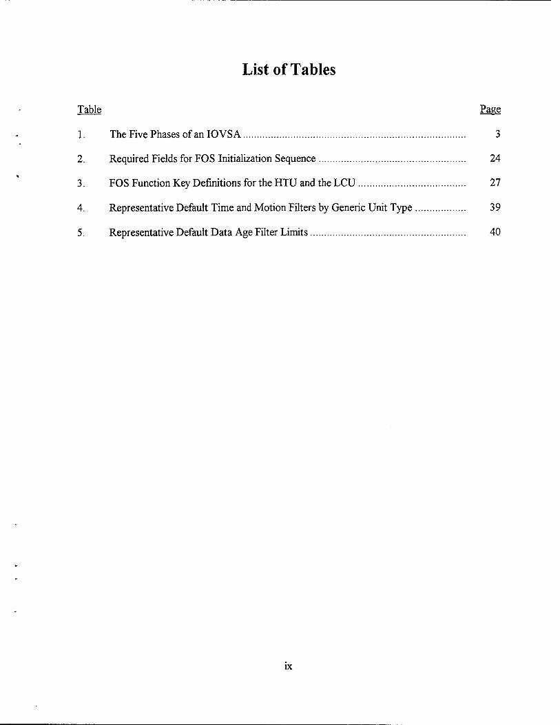
List of Tables
Table Page
1. The Five Phases of an 10 VS A 3
2. Required Fields for FOS Initialization Sequence 24
3. FOS Function Key Definitions for the HTU and the LCU 27
4. Representative Default Time and Motion Filters by Generic Unit Type 39
5. Representative Default Data Age Filter Limits 40
IX

INTENTIONALLY LEFT BLANK.
x
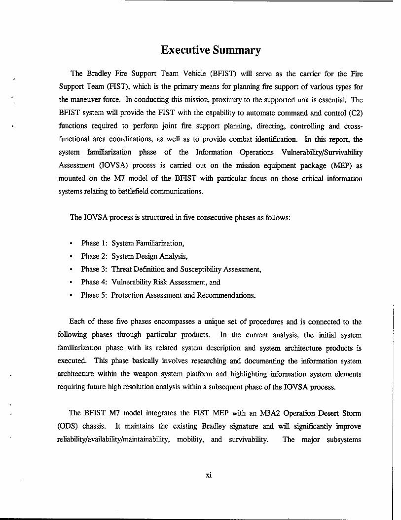
Executive Summary
The Bradley Fire Support Team Vehicle (BFIST) will serve as the carrier for the Fire
Support Team (FIST), which is the primary means for planning fire support of various types for
the maneuver force. In conducting this mission, proximity to the supported unit is essential. The
BFIST system will provide the FIST with the capability to automate command and control (C2)
functions required to perform joint fire support planning, directing, controlling and cross-
functional area coordinations, as well as to provide combat identification. In this report, the
system familiarization phase of the Information Operations Vulnerability/Survivability
Assessment (IOVSA) process is carried out on the mission equipment package (MEP) as
mounted on the M7 model of the BFIST with particular focus on those critical information
systems relating to battlefield communications.
The IOVSA process is structured in five consecutive phases as follows:
Phase 1: System Familiarization,
Phase 2: System Design Analysis,
Phase 3: Threat Definition and Susceptibility Assessment,
Phase 4: Vulnerability Risk Assessment, and
Phase 5: Protection Assessment and Recommendations.
Each of these five phases encompasses a unique set of procedures and is connected to the
following phases through particular products. In the current analysis, the initial system
familiarization phase with its related system description and system architecture products is
executed. This phase basically involves researching and documenting the information system
architecture within the weapon system platform and highlighting information system elements
requiring future high resolution analysis within a subsequent phase of the IOVSA process.
The BFIST M7 model integrates the FIST MEP with an M3A2 Operation Desert Storm
(ODS) chassis. It maintains the existing Bradley signature and will significantly improve
reliability/availability/maintainability, mobility, and survivability. The major subsystems
xi
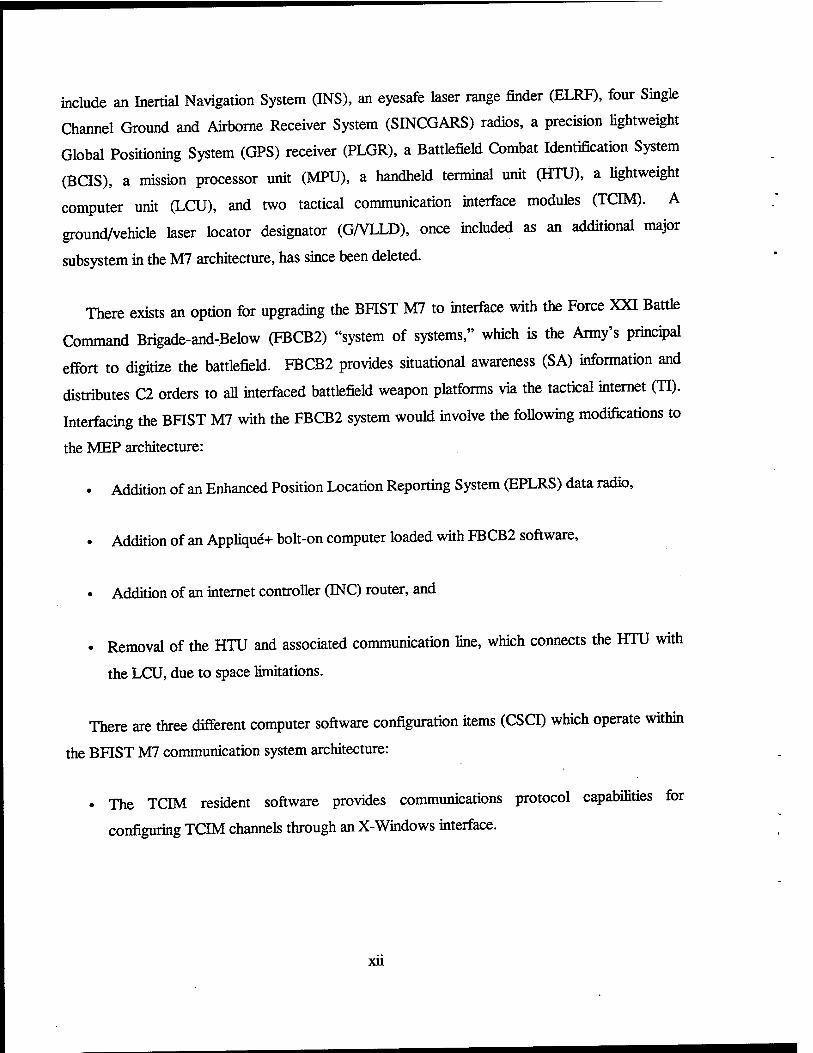
include an Inertial Navigation System (INS), an eyesafe laser range finder (ELRF), four Single
Channel Ground and Airborne Receiver System (SINCGARS) radios, a precision lightweight
Global Positioning System (GPS) receiver (PLGR), a Battlefield Combat Identification System
(BCIS), a mission processor unit (MPU), a handheld terminal unit (HTU), a lightweight
computer unit (LCU), and two tactical communication interface modules (TOM). A
ground/vehicle laser locator designator (G/VLLD), 0nce included as an additional major
subsystem in the M7 architecture, has since been deleted.
There exists an option for upgrading the BFIST M7 to interface with the Force XXI Battle
Command Brigade-and-Below (FBCB2) "system of systems," which is the Army's principal
effort to digitize the battlefield. FBCB2 provides situational awareness (SA) information and
distributes C2 orders to all interfaced battlefield weapon platforms via the tactical internet (TI).
Interfacing the BFIST M7 with the FBCB2 system would involve the following modifications to
the MEP architecture:
• Addition of an Enhanced Position Location Reporting System (EPLRS) data radio,
• Addition of an Applique+ bolt-on computer loaded with FBCB2 software,
• Addition of an internet controller (INC) router, and
• Removal of the HTU and associated communication line, which connects the HTU with
the LCU, due to space limitations.
There are three different computer software configuration items (CSCI) which operate within
the BFIST M7 communication system architecture:
• The TCIM resident software provides communications protocol capabilities for
configuring TCIM channels through an X-Windows interface.
xu
• The Forward Observer System (FOS) (Version 11.0) software provides automated digital
message and data processing, data storage and recall, and communications capabilities to
field artillery (FA) fire support personnel, FA commanders, and FA survey personnel.
• The FBCB2 software provides digital SA and C2 capabilities across all Army platforms.
These CSCIs are loaded on the TCIM, the LCU/HTU, and the Applique+ computer, respectively.
In documenting the BFIST M7 information system architecture during the current phase of
this IOVSA, there are several indicators that survivability was considered during the information
system design process. First, there is considerable redundancy in many of the hardware
components. Second, communication system processing is functionally separate from other
system processing. Finally, both the FOS and FBCB2 software have been developed in
accordance with Army Regulation (AR) 380-19.1
As a result of the current system familiarization phase of the BFIST M7 IOVSA process
which focused on communication system components, two information system components are
recommended for further in-depth analysis in the future: the FOS CSCI and the FBCB2 CSCI.
In the next phase of the IOVSA process (system design analysis) both a system functionality
assessment and a data flow analysis will be executed.
'U.S. Department of the Army. Information Systems Security. AR 380-19, Washington, DC, 27 February 1998.
xui

INTENTIONALLY LEFT BLANK.
xiv
1. Introduction
1.1 Purpose. In response to information operations (10) requirements, the
Survivability/Lethality Analysis Directorate (SLAD) Bradley Fire Support Team Vehicle
(BFIST) system leader (SL) determined that an Information Operations
Vulnerability/Survivability Assessment (IOVSA) needed to be performed on the vehicle.
Phase 1 of the IOVSA (system famiharization), sponsored by the SLAD ground systems mission
area, was initiated in fiscal year (FT) 1999. The SLAD BFIST SL contacted the SLAD Non-
Command, Control, Communications, Computers, and Intelligence (C4I) systems IO team
leader, who jointly planned the effort. The SLAD Non-C4I systems IO team leader contracted
with the Nuclear, Biological, Chemical (NBC) Effects Branch within SLAD for the performance
of the initial phase of the IOVSA (documented in this report). This effort provides the
preliminary groundwork needed to answer the question:
Does the Bradley Fire Support Team Vehicle (BFIST) have any 10 susceptibilities
of concern, and, if so, what can be done to protect the BFIST platform from the
10 threat?
The IOVSA process involves a sequence of analytical phases that are applied to networked
automated Information Systems (INFOSYS) of military interest. Within the context of this
report, INFOSYS are defined in accordance with Joint Publication 6-0 [1], and Field Manual
(FM) 100-6 [2].
• INFOSYS as Defined in Joint Pub 6-0: The entire infrastructure, organization,
personnel, and components that collect, process, store, transmit, display, disseminate, and
act on information.
• INFOSYS as Defined in FM 100-6: INFOSYS allows the commander to view and
understand his battle space, communicate his intent, lead his forces, and disseminate his
pertinent information throughout his chain of command and his area of operation.
Effective military and nonmilitary INFOSYS help the staff get the right information to
the right location in time to allow commanders to make quality decisions and take
appropriate actions.
The IOVSA focuses primarily on the INFOSYS survivability as defined in
VAL-CE-TR-92-22 [3].
• Information System Survivability as Defined in VAL-CE-TR-92-22: The ability of a
computer-communication system-based application to continue satisfying its
requirements (for example, requirements for security, reliability, real-time
responsiveness, and correctness) in adverse conditions.
1.2 Background.
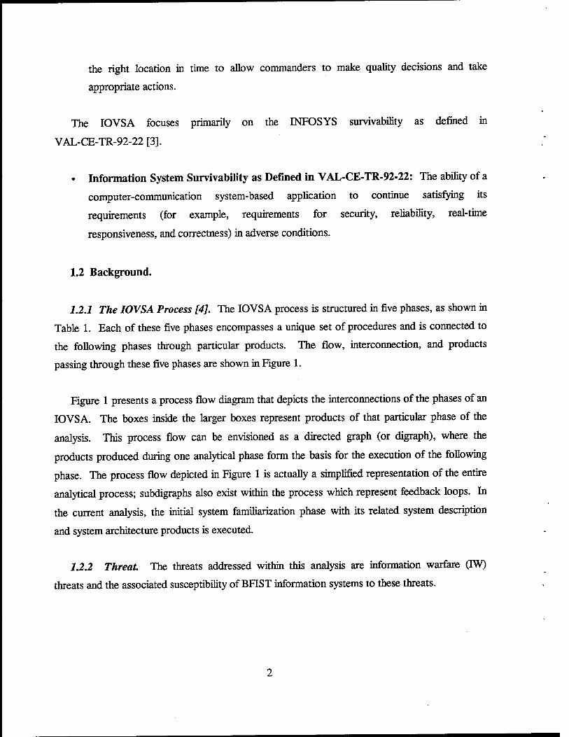
1.2.1 The IOVSA Process [4J. The IOVSA process is structured in five phases, as shown in
Table 1. Each of these five phases encompasses a unique set of procedures and is connected to
the following phases through particular products. The flow, interconnection, and products
passing through these five phases are shown in Figure 1.
Figure 1 presents a process flow diagram that depicts the interconnections of the phases of an
IOVSA. The boxes inside the larger boxes represent products of that particular phase of the
analysis. This process flow can be envisioned as a directed graph (or digraph), where the
products produced during one analytical phase form the basis for the execution of the following
phase. The process flow depicted in Figure 1 is actually a simplified representation of the entire
analytical process; subdigraphs also exist within the process which represent feedback loops. In
the current analysis, the initial system familiarization phase with its related system description
and system architecture products is executed.
1.2.2 Threat. The threats addressed within this analysis are information warfare (IW)
threats and the associated susceptibility of BFIST information systems to these threats.
Table 1. The Five Phases of an IOVSA [4]
Phase Number Phase Title 1 System Familiarization 2 System Design Analysis 3 Threat Definition and Susceptibility Assessment 4 Vulnerability Risk Assessment 5 Protection Assessment and Recommendations
System Familiarization ISystem Description! jSystem Architecture!
System Design Analysis System
Functionality Assessment
Data Flow Analysis
Data Dictionary
Data Flow Diagram
Threat Definition and Susceptibility
Assessment
Vulnerability Risk Assessment Analytical
Assessment Modeling & Simulation
Experimental Assessment
Protection Assessment and Recommendations
Figure 1. Schematic of the Methodology Flow of an IOVSA [4].
13 Scope. The information gateway components (and associated software) that connect the
BFIST platform with the digital battlefield form the primary focus of this analysis; these
components include the Single Channel Ground and Airborne Radio System (SINCGARS) radio,
the lightweight computer unit (LCU), the handheld terminal unit (HTU), the tactical
communication interface modules (TCIM), the Enhanced Position Location Reporting System
(EPLRS) data radio, the internet controller (INC), and the Applique+ computer. This set of
components also comprises the primary point of ingress into the system used by radio frequency
(RF) and network-based IW threats. Thus, the current system familiarization phase of the BFIST
IOVSA addresses the identification and high-level connectivity of all information systems within
the platform with primary focus on the communication systems. In this work, communication
components, software, and associated interConnectivity are described in detail; elements
requiring a future high resolution IOVSA are highlighted.
2. System Description
The BFIST serves as the carrier for the fire support team (FIST), replacing the M981 vehicle
in some first-to-fight units. The FIST is the primary means for planning fire support of various
types for the maneuver force. In conducting this mission, proximity to the supported unit is
essential. The BFIST system provides the FIST with the capability to automate command and
control (C2) functions required to perform joint fire support planning, directing, controlling and
cross-functional area coordinating, as well as providing combat identification. The BFIST
consists of two models: XM7 and XM7A1. Both versions of the BFIST have the same mobility,
survivability, signature, and night vision capability as the maneuver force they support and will
utilize Bradley common repair parts. In this report, only the XM7 model is addressed.
The XM7 model integrates the FIST mission equipment package (MEP) with an M3A2
Operation Desert Storm (ODS) chassis. It maintains the existing Bradley signature and
significantly improves reliabüity/availability/maintainability, mobility, and survivability. The
major subsystems include an Inertial Navigation System (INS), an eyesafe laser range finder
(ELRF), four SINCGARS radios, a precision lightweight Global Positioning System (GPS)
receiver (PLGR), a Battlefield Combat Identification System (BCIS), a mission processor unit
(MPU), an HTU, and an LCU. A ground/vehicle laser locator designator (G/VLLD), once
included as an additional major subsystem in the XM7 architecture, has since been deleted.
3. System Architecture
3.1 BFIST M7 MEP.
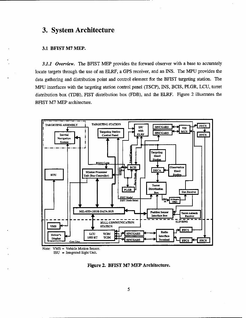
3.1.1 Overview. The BFIST MEP provides the forward observer with a base to accurately
locate targets through the use of an ELRF, a GPS receiver, and an INS. The MPU provides the
data gathering and distribution point and control element for the BFIST targeting station. The
MPU interfaces with the targeting station control panel (TSCP), INS, BCIS, PLGR, LCU, turret
distribution box (TDB), FIST distribution box (FDB), and the ELRF. Figure 2 illustrates the
BFIST M7 MEP architecture.
r: TARGETING ASSEMBLY TARGETING STATION
Inertia] Navigation
^^vsteni^
HTU
Targeting Station Control Panel
5 ion ■—► W1™ ri ELR1
RS422 Cable
Mission Processor Unit (Bus Controller)
ISU with
ELRF
SINCGARS
SINCGARS
BCIS
I PLGR Y
FIST Mode/ FIST Mode Select
MIL-STD-1553B DATA BUS
1
7 VIS
MCS i-*i
Targeting Hand
Statfcii atia
I DECA K- Observation
Hand
Sfflr?"
Turret Distribution
Box
FFCS
Gun Resolver
,10cSrJ
Position Sensor Interface Box
Turret Admuth Resolver
VMS H HULL COMMUNICATION STATION
SLIP RING
Driver's Display
Com Line
LCU 1553 RT
TOM TCIM
vJ m SINCGARS
SINCGARS
>
y Radio
Interface Terminal
FFCS
FFCS
Note: VMS = Vehicle Motion Sensor. ISU - Integrated Sight Unit.
Figure 2. BFIST M7 MEP Architecture.
The MPU replaces the targeting station electronics unit (TSEU) of the
engineering/manufacturing/development (EMD) XM7 systems. The function of the MPU is
identical to that of the TSEU with the MPU also assuming the responsibility of the MIL-STD-
1553 [5] bus controller for the MEP and adding enhanced built-in test (BIT) capability.
3.1.2 External Communication.
3.12.1 LCU. The LCU and its associated fire-support software, Forward Observer Systems
(FOS), implements the BFIST's basic capability as a node on the fire support C2 network. It
replaces the functionality of the digital message device (DMD) in the M981 FIST vehicle, and
contains new functionality in the baseline design. The communications station operator uses the
LCU as a data-handling terminal in conducting fire support planning and execution mission
functions.
The AN/GYK-37 LCU is an IBM-compatible computer equipped with a 200-MHz Intel
Pentium processor, which runs under Santa Cruz Operations (SCO) UNIX (Version 5.02) [6] and
various hardware interface drivers controlling standard serial, parallel, small computer system
interface (SCSI)-H, and floppy interfaces as well as an Institute of Electrical and Electronic
Engineers (IEEE) 802.3 local area network (LAN) interface. Applications are loaded
automatically on power-up using UNIX scripts. Additionally, the LCU provides hardware
support (resources) in the form of a keyboard, external display, RS-232C serial port, removable
hard disk, memory, and radio communications interface through multiple TCIM.
3.1.2.2 TCIM. The TCIM is a front-end communications processor that supports joint
tactical communications. A TCIM can support over 26 protocols developed by the joint services,
including MIL-STD-188-220A [7], and can also support communications interoperability by
dynamically switching between these protocols. Each TCIM is configured to support two digital
channels, where each channel is dynamically configured via FOS software downloads from the
host LCU random-access memory (RAM) (see sections 4.2.6 and 4.2.7). The LCU interfaces
with two TCIM units: an internal TCIM which fits into an expansion slot of the LCU, and an
additional TCIM that connects to the LCU via an external interface. This provides the LCU with
access to four different digital channels.
3.123 HTU. The HTU is a small, lightweight computer that is functionally redundant with
the LCU. The HTU is equipped with an 80586 133-MHz Pentium-class processor, 16 MB
(expandable to 64 MB) of RAM, either a 260-MB or a 520-MB hard drive, an embedded two-
button mouse, two RS-232C serial ports, a Centronics parallel port, and a TCIM-compatible dual
channel modem. As with the LCU, the HTU operates under SCO UNIX (Version 5.02) [6] and
also runs the FOS software. Although they both can operate independently, there is data flow
communication between the HTU and the LCU via a half-duplex (two conductor path) system
cable referred to as "Com Line" in Figure 2; one of the four available TQM channels is used to
establish HTU/LCU intercommunication. The principal function of the HTU is to display the
same data that appears on the LCU to a second crew member, the HTU can also be utilized for
dismount operations in conjunction with a tripod-mounted sensor.
3.1.2.4 SINCGARS. SINCGARS is a family of very high frequency (VHF), frequency-
modulated, combat net radio (CNR) sets designed for tactical communications in the 30-87.975-
MHz frequency range. It is designed for simple and quick operation using a 16-element keypad
for push-button tuning. SINCGARS is capable of both short-range (200-400 m) and long-range
(10-40 km) operation for voice and/or data communications. It can be used for single-channel
operation or in a jam-resistant, frequency-hopping mode which can be changed as needed.
Inherent in the SINCGARS radio are significant security features in terms of complex low
probability of intercept (LPI) transmission techniques, data-coding techniques, and data
encryption. The SINCGARS radio system for vehicular installations includes the RT-1523C/D
receiver/transmitter (RT) and the AM-7239C/D vehicular amplifier adapter (VAA). The BFIST
M7 MEP includes four RT-1523 integrated communication security (COMSEC) (ICOM)
SINCGARS radios with 50 W peak RF output power and peak data transmission rates of
16 kbps, 4800 bps, and 600-2400 bps at ranges of 3 to 10 km, 5 to 22 km, and 5 to 25 km,
respectively.
3.2 FBCB2 Interface Upgrade. An option exists for upgrading the BFIST M7 enabling it
to interface with the Force XXI Battle Command Brigade-and-Below (FBCB2) "system of
systems," which is the Army's principal effort to digitize the battlefield. The FBCB2 visually
displays situational awareness (SA) information; processes and displays information provided by
weapon systems, sensors, and support platforms; prepares and distributes C2 orders and
graphics; and receives, develops, and distributes information and data based on a common
battlefield picture. The FBCB2 also provides the Army the architecture for the tactical internet
(TI) which is the communication infrastructure that provides the connectivity between the
platforms and provides the medium to exchange digital information. The FBCB2 incorporates
situation understanding, which includes the capability to react to data received (whether from the
user, sensors, TI, or other sources) based on rules and knowledge which are role- and echelon-
dependent. Examples include "smart" displays, alerts triggered by computer analysis of the
evolving real-time situation, tailoring of functionality by role, tailoring connectivity and
bandwidth allocation by role, and other adaptive measures in which the FBCB2 takes action (or
suggests actions to the user) based on its understanding of the situation in which its individual
user is to operate.
The FBCB2, as a key component of the Army Battle Command System (ABCS), seamlessly
interfaces with the component of the Army Tactical Command and Control System (ATCCS) at
the battalion level. The FBCB2 supports SA down to the soldier/platform level across all
battlefield functional areas (BFAs) and echelons. The FBCB2 also allows brigade and battalion
commanders to command when away from their tactical operations centers (TOC) and when
interoperating with subordinate commanders and leaders also using the FBCB2.
The following components are the building blocks of the FBCB2 system:
• Software for embedded air and ground platforms,
• Hardware and software for nonembedded air and ground platforms,
• Platform interfaces, and
• Supporting communications systems.
Interfacing the BFIST M7 with the FBCB2 system would involve the following
modifications to the MEP architecture:

• Addition of an EPLRS data radio,
• Addition of an Applique+ bolt-on computer loaded with FBCB2 software,
• Addition of an INC router, and
• Removal of the HTU and associated communication line with the LCU due to space
limitations.
Figure 3 illustrates the BFIST M7 MEP architecture modifications that would result from the
FBCB2 interface upgrade. The following sections address the FBCB2 upgrade hardware in
detail.
HTU
"X"
I EPLRS H H INC H ►[
[ ¥\ SINCGARS ]*-► To VIS
W-k> MCS SINCGARS
| Applique-i-H I
HULL COMMUNICATION STATION
LCU 1553 RT
TCIM TCIM
HJ SINCGARS
SINCGARS
To Radio Interface Terminal
Figure 3. Modifications to BFIST M7 MEP Architecture Resultant From an FBCB2 Upgrade.
3.2.1 SINCGARS SIP Radio. The SINCGARS System Improvement Program (SIP) radio
replaces the current ICOM version as part of the FBCB2 upgrade. The SINCGARS SIP radio is
a modified version of the SINCGARS ICOM radio, where modifications include new RF
waveforms with significantly improved data performance, voice/data channel access
performance improvements, and host-selectable automatic position reporting features. The
SINCGARS SIP also provides for regulated power, a radio control interface, and provisions for
incorporation of the INC router (see section 3.2.4).
3.2.2 EPLRS Data Radio. The very high-speed integrated circuit (VHSIC) EPLRS radio
provides data-only communication capability in the form of platform position information,
network coordination, and data communication. Inherent in the EPLRS data radio are significant
security features in terms of complex LPI transmission techniques, data coding techniques, and
data encryption. The primary components of an EPLRS network are the network control station
(NCS) and the EPLRS user units (EPUUs). The NCS is the centralized control element used for
system initialization and dynamic monitoring and control of the EPLRS network. The EPUU is
the radio RT provided to the users of EPLRS. The EPUU interfaces to the INC in accordance
with the Army Data Distribution System Interface (ADDSI) [8]. The FBCB2 system
architecture utilizes EPLRS radios to provide wide area network (WAN) connectivity between
SINCGARS SIP radio networks from the platoon to brigade level. EPLRS utilizes the ADDSI to
flow data to/from the INC. The ADDSI is primarily based on the International Consultative
Committee for Telegraphy and Telephony (CCITT) Recommendation X.25 [9], which allows
access to a secured public packet switched network. Different EPLRS needline types (virtual
circuits which are established between radios based on host data requirements) are used to
support the various types of message traffic. An EPLRS network provides a communication
resource of eight frequencies, each with eight logical time slots (LTS) in its time division
multiple access (TDMA) architecture. Once enabled by the NCS, the needlines are
automatically maintained by the EPLRS radios without operator or NCS intervention. These
needline types are discussed in the following sections.
3.2.2.1 Full-Duplex Needline. The full-duplex needline (also called a permanent virtual
circuit [PVC]), is a point-to-point bi-directional communications path between EPUUs. This
needline type is used to support forward area air defense (FAAD) command, control, and
intelligence (C2I) hierarchical transfer of battle management messages and the distribution of
EPLRS-derived data from the NCS to the NCS multisource group (MSG) position server radio
set (RS).
10
3.2.2.2 Simplex Needline. The simplex needline is a unidirectional communications path
from one EPUU to many EPUUs. It is generally used for community-wide distribution of
EPLRS position data, such as situation awareness data link (SADL) forward air controller (FAC)
to aircraft.
3.2.2.3 CSMA Needline. The carrier-sense multiple-access (CSMA) needline is a
multisource, multidestination communications path among EPUUs, on which a CSMA protocol
is used by all members to gain authority to transmit, and all members are able to receive. This
needline type is used to broadcast SA and C2 Joint Variable Message Format (JVMF) messages
within organizational boundaries such as battalions. There are up to two CSMA needlines per
radio which are used to transmit and receive data: one for battalion-area SA, and one for
battalion-area C2.
3.2.2.4 MSG Needline. The MSG needline is a multisource, multidestination
communication path among EPUUs, on which up to 16 active EPUUs are assigned shares of the
MSG transmit resource, and which all MSG participants are able to receive. Each MSG
participant is assigned a source index of 1-120 or 127, a priority, and preassigned shares of the
transmit resource.
Only EPUUs with a source index of 120 or less are eligible to transmit or can act as relays.
EPUUs with a source index of 127 are only capable of receiving. All preassigned shares are
always claimed during initialization. EPUUs with a priority of 1 or 2 never release their shares.
Once the host has no more data to transmit, an EPUU with a priority of 3 or greater releases its
shares within two epochs (128 s).
Unclaimed shares are available for any eligible radio to claim that has data to transmit and a
source index of 120 or less. The highest priority EPUUs claim the available shares first. The
EPUUs periodically transmit information on the shares they have claimed; consequently, if a
radio that has claimed shares becomes disabled, all eligible radios become aware that those
shares are available.
11
This wide-area MSG needline type allows contention-free access and is used to broadcast SA
JVMF position reports from SA position servers located in each battalion and the brigade-area
CSMA communities to all EPLRS-equipped platforms. An interbrigade server transmits onto
the wide-area MSG needline position data received from the division area and other brigades.
Furthermore, NCS-derived SA position data is transmitted over the wide-area MSG needline via
an application layer gateway. Additionally, a separate brigade-wide MSG needline enables
transmission of multicast C2 messages across the brigade. A gateway router is selected from
each battalion and the brigade area to the MSG by means of Request for Comments (RFC)
1256+ [10], gateway selection. AU EPUU in the brigade receive messages transmitted onto the
brigade-wide MSG. Separate from the wide-area MSG SA needline, the FAAD C2I distributes
air tracks from the sensor C2 to the fire units on an MSG sensor broadcast needline.
3.2.3 Applique* Computer. The Applique+ computer is the primary FBCB2 host that
interfaces to the INC router via an RS-423 cable at the physical layer; Point-to-Point Protocol
(PPP) at the link layer; Internet Protocol (IP), Internet Control Message Protocol (ICMP), and
Internet Group Management Protocol (IGMP) at the network layer; and Challenge Handshake
Authentication Protocol (CHAP) and Simple Network Management Protocol (SNMP) at the
application layer. The Applique+ computer provides the host with the capability to display SA
and C2 data received via the FBCB2 software JVMF application layer, and Transmission Control
Protocol (TCP) and User Datagram Protocol (UDP) transport layer interfaces to the INC.
There are two versions of the Applique+ computer bolt-on-kit (B-Kit): the Applique+ B-Kit
and the V2 Enhanced B-Kit. In both versions, the "Year 2000 Problem" is correctly supported
by the basic input/output system (BIOS) software and computer hardware as measured by the
National Software Testing Laboratories YMark2000 program (2000.exe) [11]. The Applique+
and V2 Enhanced B-Kit versions are described in sections 3.2.3.1 and 3.2.3.2, respectively,
while the display unit interface and serial input/output (I/O) ports (the same for both B-Kit
versions) are described in sections 3.2.3.3 and 3.2.3.4, respectively.
3.2.3.1 Applique* B-Kit. The Applique+ B-Kit is ruggedized and is intended for use in
military operational environments. Power for the Applique+ is supplied by the host platform
12
with the Applique+ responsible for providing protection against power ripples, surges, and spike
voltage conditions. The Applique+ is composed of the following units: (1) a central processing
unit (CPU), (2) a flat-panel color display unit with touch-screen input capability and tethered-
remote operating capability up to 25 ft, and (3) a backlit keyboard which connects to the display
unit. The processor unit is comprised of a 90-MHz Pentium processor board with 16 MB of
RAM and a 510-MB hard disk drive. The display unit is available in three variations: (1) a
12-in display version; (2) a 10.4-in display with bezel keys, and (3) a 10.4-in display without
bezel keys. All variations have five serial interface ports, a universal serial bus (USB) interface
port (currently not used by the FBCB2), a parallel interface port, and a super video graphics
array (SVGA) interface port. The Applique+ also includes an analog resistive touchscreen panel
overlaying the liquid crystal display (LCD) that provides pointing device functionality using a
supplied nonmetallic stylus. A Sound Blaster-compatible audio controller device is provided by
the Applique+ to intemperate with the vehicle intercommumcations system (VIS). Finally, the
current operating system running on the Applique+ is Solaris X86 (UNIX) Version 2.5 [12],
which, in turn, hosts the FBCB2 application software (FBCB2 Versions 2-4).
3.2.3.2 V2 Enhanced B-Kit. The V2 Enhanced B-Kit, is an upgraded Version 1
(Ruggedized) Applique computer that was originally produced for use in the Task Force XXI
Army Warfighting Experiment (AWE) and was improved by additional memory, a larger hard
disk drive, and (in some instances) a faster processor for use in FBCB2-related activities. The
V2 Enhanced B-Kit includes the computer, interconnecting cables, and an installation kit
appropriate to the host vehicle type. There are two configurations of the V2 Enhanced B-Kit.
The first configuration retained the original 90-MHz Pentium processor board, whereas the
second configuration replaced the original board with a 200-MHz processor board. Both
configurations were upgraded to include 80 MB of RAM and a 4-GB hard disk drive. Both V2
Enhanced B-Kit configurations include a processor unit, a transmissive active matrix LCD with a
remote operating capability up to 25 ft, a keyboard, and a built-in trackball. Similar to the
Applique+, power for the V2 Enhanced B-Kit is supplied by the host platform with the V2
responsible for providing protection against power ripples, surges, and spike voltage conditions.
The V2 Enhanced B-kit provides a number of interface ports including a flat panel display (FPD)
port, an external monitor port, a SCSI-II port; a LAN port, a parallel printer port, and dual serial
13
ports. In addition, the V2 Enhanced B-Kit provides an instruction set architecture (ISA)/personal
computer interface (PCI) expansion slot and floppy disk drive interface. The V2 computer also
provides a speaker output port to interface with the VIS for the output of warning and alert tones.
3233 Display Unit Interface. The display unit interface video/graphics output is
compatible with National Semiconductor's flat panel display (FPD) link interface using low-
voltage differential-signaling (LVDS) technology. The display unit interface utilizes the PC-
compatible communications (COM)-l serial port to communicate with the display unit's
touchscreen controller, with design support for a future transition to the USB-based human
interface devices (such as touchscreen, keyboard, bezel buttons, etc.). The display unit interface
also supports tethered-remote operation of the display unit through an interface cable with a
MIL-C-38999 [13], Type m, 55-pin connector.
3.23.4 Serial I/O Port. The CPU provides external serial data port interfaces configured as
described in the following paragraphs.
COM-B is an Electronics Industries Association-232 (EIA-232), asynchronous interface
connected to the COM2 serial port. Four serial ports (COM-C, COM-D, COM-E, and COM-F)
function as asynchronous interfaces supporting EIA-422 and EIA-423 signaling levels dependent
upon wiring of the external interface harness. Serial ports COM-B, and COM-C through
COM-F, are compatible with the industry standard 16550 universal asynchronous
receiver/transmitter (UART) [14] which is operable at data rates up to 115.2 KBaud.
A single, factory-programmable, processor interrupt is used for serial ports COM-C through
COM-F. All of these ports have their I/O addresses in a contiguous block of 32 addresses such
that the hexadecimal value of the factory-programmable starting address ends in a zero; the first
eight addresses are associated with COM-C, the next eight with COM-D, etc.
The processor interrupt also has a status register which indicates which ports, if any, are
causing the interrupt. The status register indicates a bit value of one if the corresponding ports
have an interrupt request pending, and a zero, otherwise. The least significant data bit of the
register represents the status of COM-C, the next bit COM-D, etc. Data bits of the status register
14
which are not associated with ports are output as zero. The status register is located at an offset
of 40 hexadecimal above the starting address of the I/O block.
The serial I/O port connector is a MIL-C-38999 [13], Type III, 37-pin connector. Signal
assignments on the serial I/O port connector are normally configured as follows:
• COM-B: INC router,
• COM-C: GPS receiver,
• COM-D: BCIS,
• COM-E: Sensor Link Protocol device, or
• COM-F: JVMF device.
3.2.4 INC Router. The INC is the primary data router in the TI and provides data
subscriber, intranet relay, and internet routing. The INC is a five-port data router, where two
ports are for operation with SINCGARS SIP radios; one port is for operation with a host
computer; one port is for operation with either an EPUU, TOC router, or a second host computer;
and one last port supports an Ethernet connection in lieu of the second host/EPUU port.
The INC router processes both SA and C2 data types. However, SA data is handled
differently in the TI network than is C2 message traffic. Since there is no guarantee of where a
particular host is located in the TI, C2 traffic has to be routed through normal IP routing
mechanisms to the final destination. SA data, on the other hand, is not sent to a specific
individual but to a physical network. Because of this, the TI network can use SA agents to
reduce the size of the message and thereby reduce the load on the TI. The FBCB2 host, in some
cases, replaces the MIL-STD-2045-47001 [15] header on SA messages, again, to help reduce the
data load on the TI.
In the following sections, INC router processing of both SA and C2 data types is described in
more detail.
15
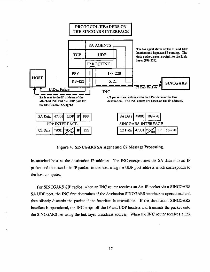
3.2.4.1 C2 Data Processing Through the INC Router. As depicted in Figures 4, 5, and 6, C2
traffic is handled the same in each case. The host wraps the JVMF data with
MIL-STD-2045-47001 TCP or UDP, IP, and PPP headers and sends the message to the INC
router. The IP header contains the destination IP address of the recipient. Multicast traffic uses
a UDP header, while unicast traffic uses a TCP header. The INC router receives the packet,
strips off the PPP header, and sends it up the protocol stack to the IP layer. The IP layer, using
the current routing table, routes the message to the SINCGARS SIP interface or to an EPLRS
interface. As a C2 message traverses the TI, only the link layer header is affected until the
destination host receives the message.
3.2.4.2 SA Data Processing Through the INC Router. The first step in SA data processing is
for the host to determine if the SA data is being sent to the EPLRS CSMA network. If so, the
host replaces the MIL-STD-2045-47001 header with two bits to indicate either friendly position
or entity data messages. In all other cases, a full 47001 [15] header is used. The host then wraps
the data and 47001 header in UDP, IP, and PPP headers and sends the message to the INC router.
The IP header contains the destination IP address of the directly attached INC. The UDP header
contains a UDP port number to indicate to which SA agent the message is to be sent. There are
three SA agent types: (1) SINCGARS (Figure 4), (2) EPLRS CSMA (Figure 5), and (3) EPLRS
MSG (Figure 6). The INC router receives the message, strips off the PPP header, and determines
that the message is addressed to the router and strips off the IP header. The INC then looks at
the UDP header for the port number and passes the message to the appropriate SA agent.
3.2.4.3 SA Agents. SA agents are utilized by the INC router to efficiently disseminate SA
data via EPLRS and SINCGARS SIP radios. For EPLRS, the SA agent is used for SA data
collected by the local area or CSMA position servers to be disseminated onto the
battalion/brigade area CSMA needline or the brigade MSG needline. When the INC receives an
SA IP packet from the host via the EPLRS CSMA or MSG SA UDP port, the INC strips off the
IP and UDP headers and broadcasts the data onto the respective needline, CSMA, or MSG. INC
routers receiving SA data via the CSMA or MSG needline builds an IP/UDP header which uses
16
PROTOCOL HEADERS ON THE SINCGARS INTERFACE
TCP
PPP
RS-423
SA Data Packets
SA AGENTS
UDP
IP ROUTING
T 188-220
I X.21
The SA agent strips off the IP and UDP headers and bypasses IP routing. The data packet is sent straight to the Link layer (188-220).
C2 Data Packets
J INC
SINCGARS
SA is sent to the IP address of the attached INC and the UDP port for the SINCGARS SA agent
C2 packets are addressed to the IP address of the final destination. The INC routes are based on the IP address.
SA Data 47001 UDP IP PPP
PPP INTERFACE
C2Data 47001 x'UDP IP PPP
SAData 47001 188-220
SINCGARS INTERFACE
C2Data 47001 -XuDP IP 188-220
Figure 4. SINCGARS SA Agent and C2 Message Processing.
its attached host as the destination IP address. The INC encapsulates the SA data into an IP
packet and then sends the IP packet to the host using the UDP port address which corresponds to
the host computer.
For SINCGARS SIP radios, when an INC router receives an SA IP packet via a SINCGARS
SA UDP port, the INC first determines if the destination SINCGARS interface is operational and
then silently discards the packet if the interface is unavailable. If the destination SINCGARS
interface is operational, the INC strips off the IP and UDP headers and transmits the packet onto
the SINCGARS net using the link layer broadcast address. When the INC router receives a link
17
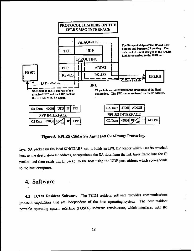
PROTOCOL HEADERS ON THE EPLRS MSG INTERFACE
TCP
SA AGENTS
UDP
IP ROUTING t
The SA agent strips off the IP and UDP headers and bypasses IP routing. The data packet is sent straight to the EPLRS Link layer and on to the MSG net.
SA is sent to the IP address of the attached TNC and the UDP port for the EPLRS MSG SA agent
C2 packets are addressed to the IP address of the final destination. The INC routes are based on the IP address.
SAData 47001 UDP IP PPP
PPP INTERFACE
C2Data 47001 TCPV^ IP PPP
SAData 47001 ADDSI
EPLRS INTERFACE
C2Data 47001 W ADDSI
Figure 5. EPLRS CSMA SA Agent and C2 Message Processing.
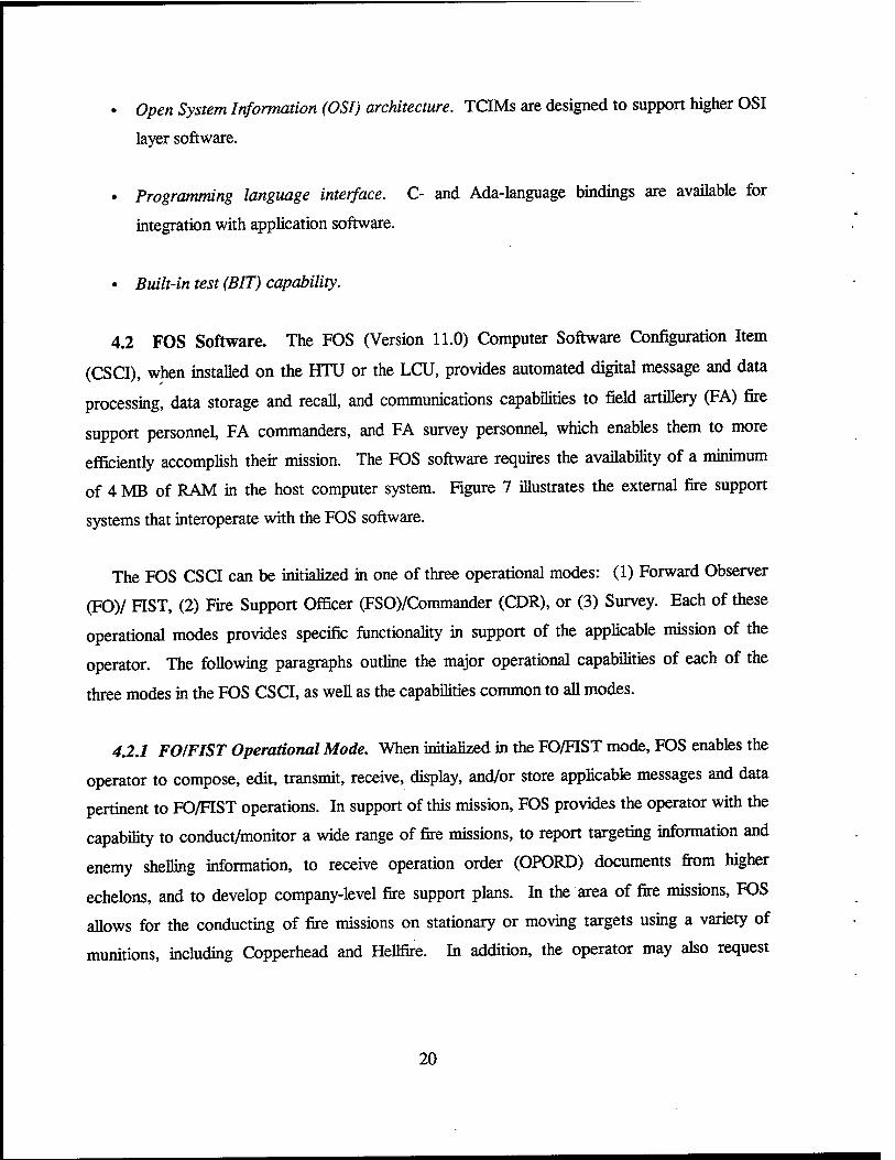
layer SA packet on the local SINCGARS net, it builds an IP/UDP header which uses its attached
host as the destination IP address, encapsulates the SA data from the link layer frame into the IP
packet, and then sends this IP packet to the host using the UDP port address which corresponds
to the host computer.
4. Software
4.1 TCIM Resident Software. The TCIM resident software provides communications
protocol capabilities that are independent of the host operating system. The host resident
portable operating system interface (POSLX) software architecture, which interfaces with the
18
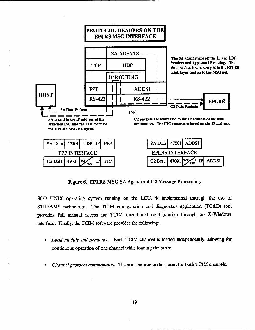
PROTOCOL HEADERS ON THE EPLRS MSG INTERFACE
TCP
PPP
RS-423
SA Data Packets
SA AGENTS
UDP
IP ROUTING I
T 1 ADDSI
I RS-422
The SA agent strips off the IP and UDP headers and bypasses IP routing. The data packet is sent straight to the EPLRS Link layer and on to the MSG net.
STLTT.-T* C2 Data Packets
J INC
EPLRS
SA is sent to the IP address of the attached INC and the UDP port for the EPLRS MSG SA agent
C2 packets are addressed to the IP address of the final destination. The INC routes are based on the D? address.
SAData 47001 UDP IP PPP
PPP INTERFACE
C2Data 47001 IP PPP
SAData 47001 ADDSI
EPLRS INTERFACE
C2Data 47001 IP ADDSI
Figure 6. EPLRS MSG SA Agent and C2 Message Processing.
SCO UNIX operating system running on the LCU, is implemented through the use of
STREAMS technology. The TCIM configuration and diagnostics application (TC&D) tool
provides full manual access for TCIM operational configuration through an X-Windows
interface. Finally, the TCIM software provides the following:
• Load module independence. Each TCIM channel is loaded independently, allowing for
continuous operation of one channel while loading the other.
• Channel protocol commonality. The same source code is used for both TCIM channels.
19
• Open System Information (OSI) architecture. TCIMs are designed to support higher OSI
layer software.
• Programming language interface. C- and Ada-language bindings are available for
integration with application software.
• Built-in test (BIT) capability.
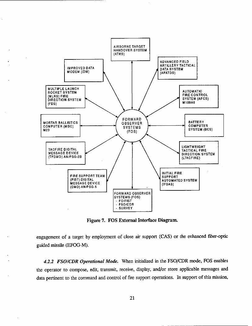
4.2 FOS Software. The FOS (Version 11.0) Computer Software Configuration Item
(CSCI), when installed on the HTU or the LCU, provides automated digital message and data
processing, data storage and recall, and communications capabilities to field artillery (FA) fire
support personnel, FA commanders, and FA survey personnel, which enables them to more
efficiently accomplish their mission. The FOS software requires the availability of a minimum
of 4 MB of RAM in the host computer system. Figure 7 illustrates the external fire support
systems that interoperate with the FOS software.
The FOS CSCI can be initialized in one of three operational modes: (1) Forward Observer
(FO)/ FIST, (2) Fire Support Officer (FSO)/Commander (CDR), or (3) Survey. Each of these
operational modes provides specific functionality in support of the applicable mission of the
operator. The following paragraphs outline the major operational capabilities of each of the
three modes in the FOS CSCI, as well as the capabilities common to all modes.
4.2.1 FO/FIST Operational Mode. When initialized in the FO/FIST mode, FOS enables the
operator to compose, edit, transmit, receive, display, and/or store applicable messages and data
pertinent to FO/FIST operations. In support of this mission, FOS provides the operator with the
capability to conduct/monitor a wide range of fire missions, to report targeting information and
enemy shelling information, to receive operation order (OPORD) documents from higher
echelons, and to develop company-level fire support plans. In the area of fire missions, FOS
allows for the conducting of fire missions on stationary or moving targets using a variety of
munitions, including Copperhead and Hellfire. In addition, the operator may also request
20
IMPROVED DATA MODEM (IDM)
AIRBORNE TARGET HANDOVER SYSTEM (ATHS)
MULTIPLE LAUNCH ROCKET SYSTEM (MLRS)FIRE DIRECTION SYSTEM (FDS)
ADVANCED FIELD ARTILLERY TACTICAL DATA SYSTEM (AFATDS)
MORTAR BALLISTICS COMPUTER (MBC) M23
TACFIRE DIGITAL MESSAGE DEVICE (TFDMD)AN/PSG-2B
AUTOMATIC FIRE CONTROL SYSTEM (AFCS) M109A6
BATTERY -*\ COMPUTER
SYSTEM (BCS)
FIRE SUPPORT TEAM (FIST) DIGITAL MESSAGE DEVICE (DMD)AN/PSG-5
LIGHTWEIGHT TACTICAL FIRE DIRECTION SYSTEM (LTACFIRE)
FORWARD OBSERVER SYSTEMS (FOS)
- FO/FIST - FSO/CDR - SURVEY
INITIAL FIRE SUPPORT AUTOMATED SYSTEM (IFSAS)
Figure 7. FOS External Interface Diagram.
engagement of a target by employment of close air support (CAS) or the enhanced fiber-optic
guided missile (EFOG-M).
4.2.2 FSO/CDR Operational Mode. When initialized in the FSO/CDR mode, FOS enables
the operator to compose, edit, transmit, receive, display, and/or store applicable messages and
data pertinent to the command and control of fire support operations. In support of this mission,
21
FOS provides the operator with the capability to monitor/control external fire missions of interest
or conduct local fire missions (as with the FO/FIST mode); to conduct deliberate and quick fire
planning; to receive OPORD documents from higher echelons or generate original OPORD
documents and exchange them with other agencies; to receive and transmit survey point
information; and to store and display decision graphics information.
4.2.3 Survey Operational Mode. When initialized in the Survey mode, FOS enables the
operator to compose, edit, transmit, receive, display, and/or store applicable messages and data
pertinent to survey operations. In support of this mission, FOS provides the operator with the
capability to perform various survey calculations and datum-to-datum coordinate conversions; to
maintain a survey point database for use by external fire support agencies; to print standard
survey forms; and to generate, transmit, and receive OPORD documents. In addition, a limited
FO capability is provided to allow the surveyor to conduct basic fire missions and to report
targeting information.
4.2.4 Capabilities Common to All Operational Modes. For all operational modes, FOS
provides the operator with the following common capabilities:
• A capability to request medical evacuation of friendly/enemy casualties;
• A graphics capability which enables the exchange of battlefield geometry and
unit/equipment information used to display pertinent tactical military symbols on a
graphics map display;
• A print capability which enables the printing of the current screen display or the contents
of selected files to an external printer;
• Two-way digital communications using various communications protocols over standard
Army tactical communications equipment, including wire (both 2 and 4 wire), combat net
radio (CNR), EPLRS data radio, and mobile subscriber equipment (MSE); and
22
• A capability to save the current database and deactivate the keyboard when battery power
is low or completely lost; functionality is restored when the battery is replaced or an
acceptable alternate power source is used (applies only to HTU-mounted operation).
4.2.5 Limitations ofFOS Capabilities. The capabilities implemented in the FOS CSCI are
known to exhibit the following limitations:
• The fire planning capability does not provide for the automatic generation of a fire plan
schedule; nor does it provide for the automatic execution of the fire plan.
• The decision graphics capability does not provide for any automatic updating of files
from mission messages.
• On selection of a database purge, the database files are not actually erased. Instead, the
database is overwritten three times, alternating with ones and zeroes, and then restored to
default parameters.
4.2.6 FOS Initialization Sequence. The FOS initialization sequence presents the operator
with a series of system configuration displays used to initialize the FOS software. On several
displays, one or more fields require operator input prior to proceeding to the next display,
attempting to move forward to the next display without providing input to those fields results in
the cursor being placed on the required field and opening the edit window instead of advancing
to the next display. The required displays include the FOS setup display, net status display,
member data display, and map modification data display. Once all required displays have been
entered, pressing the <MODE> key displays the applicable mode menu for the current
operational mode (see section 4.2.8.2). The sequence of displays, including the required and
conditional fields for each display, are listed in Table 2. In this table, net n refers to one of four
possible communication nets (see section 4.2.7).
4.2.7 External Net Configuration. The function of the net configuration process is to
activate and deactivate communication data nets according to operator-supplied parameters
contained in the net status file, member file, and setup file. There are four different net types that
23
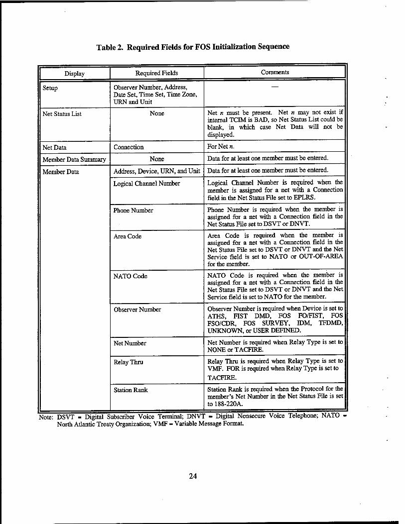
Table 2. Required Fields for FOS Initialization Sequence
Display
Setup
Net Status List
Net Data
Member Data Summary
Member Data
Required Fields
Observer Number, Address, Date Set, Time Set, Time Zone, URN and Unit
None
Connection
None
Address, Device, URN, and Unit
Logical Channel Number
Phone Number
Area Code
NATO Code
Observer Number
Net Number
Relay Thru
Station Rank
Comments
Net n must be present. Net n may not exist if internal TCIM is BAD, so Net Status List could be blank, in which case Net Data will not be displayed.
For Net n.
Data for at least one member must be entered.
Data for at least one member must be entered.
Logical Channel Number is required when the member is assigned for a net with a Connection field in the Net Status File set to EPLRS.
Phone Number is required when the member is assigned for a net with a Connection field in the Net Status File set to DSVT or DNVT.
Area Code is required when the member is assigned for a net with a Connection field in the Net Status File set to DSVT or DNVT and the Net Service field is set to NATO or OUT-OF-AREA for the member.
NATO Code is required when the member is assigned for a net with a Connection field in the Net Status File set to DSVT or DNVT and the Net Service field is set to NATO for the member.
Observer Number is required when Device is set to ATHS, FIST DMD, FOS FO/FIST, FOS FSO/CDR, FOS SURVEY, IDM, TFDMD, UNKNOWN, or USER DEFINED.
Net Number is required when Relay Type is set to NONE or TACFIRE.
Relay Thru is required when Relay Type is set to VMF. FOR is required when Relay Type is set to
TACFIRE.
•Station Rank is required when the Protocol for the member's Net Number in the Net Status File is set to 188-220A.
Note: DSVT = Digital Subscriber Voice Terminal; DNVT - Digital Nonsecure Voice Telephone; NATO North Atlantic Treaty Organization; VMF - Variable Message Format.
24
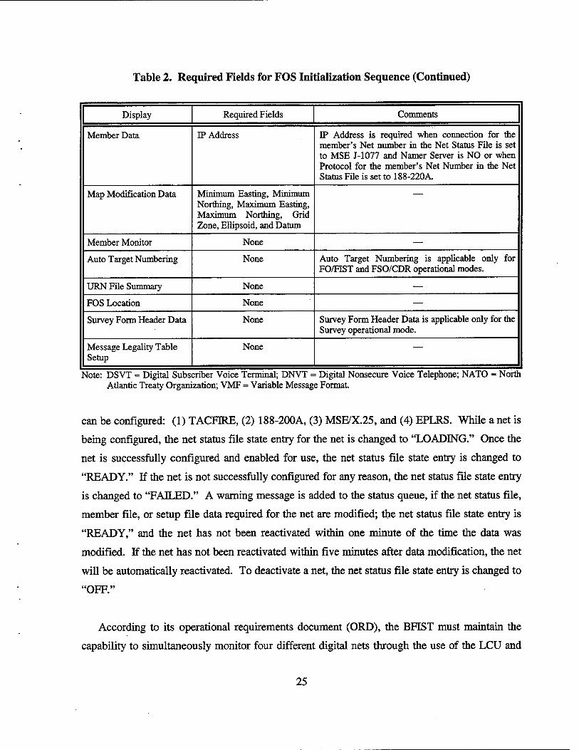
Table 2. Required Fields for FOS Initialization Sequence (Continued)
Display Required Fields Comments
Member Data IP Address IP Address is required when connection for the member's Net number in the Net Status File is set to MSE J-1077 and Namer Server is NO or when Protocol for the member's Net Number in the Net Status File is set to 188-220A.
Map Modification Data Minimum Easting, Minimum Northing, Maximum Easting, Maximum Northing, Grid Zone, Ellipsoid, and Datum
Member Monitor None —
Auto Target Numbering None Auto Target Numbering is applicable only for FO/FIST and FSO/CDR operational modes.
URN File Summary None —
FOS Location None —
Survey Form Header Data None Survey Form Header Data is applicable only for the Survey operational mode.
Message Legality Table Setup
None —
Note: DSVT = Digital Subscriber Voice Terminal; DNVT = Digital Nonsecure Voice Telephone; NATO = North Atlantic Treaty Organization; VMF = Variable Message Format,
can be configured: (1) TACHRE, (2) 188-200A, (3) MSE/X.25, and (4) EPLRS. While a net is
being configured, the net status file state entry for the net is changed to "LOADING." Once the
net is successfully configured and enabled for use, the net status file state entry is changed to
"READY." If the net is not successfully configured for any reason, the net status file state entry
is changed to "FADLED." A warning message is added to the status queue, if the net status file,
member file, or setup file data required for the net are modified; the net status file state entry is
"READY," and the net has not been reactivated within one minute of the time the data was
modified. If the net has not been reactivated within five minutes after data modification, the net
will be automatically reactivated. To deactivate a net, the net status file state entry is changed to
"OFF."
According to its operational requirements document (ORD), the BFIST must maintain the
capability to simultaneously monitor four different digital nets through the use of the LCU and
25
associated TCM channels and SINCGARS radios. Since the probability of simultaneous data
flow activity over all four nets is very remote, the system is thus configured for a maximum of
three digital nets available for simultaneous access. Although the FOS software running on the
LCU will support a maximum of four nets (one net per TCM channel), one of the TCM
channels is currently committed to establishing an HTU/LCU interface (see section 3.1.2.3).
Each of the three remaining TCM channels utilizes a SINCGARS radio for net interfacing (the
fourth SINCGARS radio is reserved for voice-only communications).
4.2.8 FOS Function Keys. The function keys on the FOS keyboard provide the operator
with the capability to display, edit, delete, save, and transmit message data. The HTU and LCU
function key definitions are summarized in Table 3.
4.2.8.1 Transmit Key. The <XMIT> (transmit) key is enabled when a message is being
displayed, with the exception of message copies or monitored messages.
4.2.8.2 Mode Key. The <MODE> key is enabled at all times except when priority displays
are active, when the initialization sequence is ongoing, or when a confirmation message is
displayed. When the <MODE> key is pressed, the mode menu is displayed unless the FOS
initialization sequence is ongoing. The operational mode determines the specific capabilities
available to the operator from the mode menu.
4.2.8.3 Message Key. The <MSG> (message) key is enabled at all times except when
Copperhead or Airborne Mission Command priority displays are active, when the initialization
sequence is ongoing, or when a confirmation message is displayed. When the <MSG> key is
pressed and any of the received message indicators (message bell sounding or clock display in
reverse video) are on indicating that a message has been received, the indicators are subsequently
turned off. When the <MSG> key is pressed and the received message indicators are off, the
received message function is accessed and the index to the receive queue is displayed. FOS
provides the operator the capability to review, edit, transmit, save, delete, or update the database
with received messages with the exception that monitored messages cannot be transmitted.
26
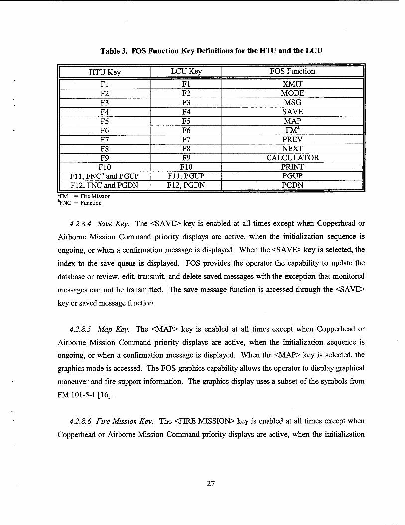
Table 3. FOS Function Key Definitions for the HTU and the LCU
HTU Key LCU Key FOS Function
Fl Fl XMIT F2 F2 MODE F3 F3 MSG F4 F4 SAVE F5 F5 MAP F6 F6 FMa
F7 F7 PREV F8 F8 NEXT F9 F9 CALCULATOR F10 F10 PRINT
F11,FNCD and PGUP F11,PGUP PGUP F12,FNC and PGDN F12, PGDN PGDN
aFM = Fire Mission "TrNC = Function
4.2.8.4 Save Key. The <SAVE> key is enabled at all times except when Copperhead or
Airborne Mission Command priority displays are active, when the initialization sequence is
ongoing, or when a confirmation message is displayed. When the <SAVE> key is selected, the
index to the save queue is displayed. FOS provides the operator the capability to update the
database or review, edit, transmit, and delete saved messages with the exception that monitored
messages can not be transmitted. The save message function is accessed through the <SAVE>
key or saved message function.
4.2.8.5 Map Key. The <MAP> key is enabled at all times except when Copperhead or
Airborne Mission Command priority displays are active, when the initialization sequence is
ongoing, or when a confirmation message is displayed. When the <MAP> key is selected, the
graphics mode is accessed. The FOS graphics capability allows the operator to display graphical
maneuver and fire support information. The graphics display uses a subset of the symbols from
FM 101-5-1 [16].
4.2.8.6 Fire Mission Key. The <FIRE MISSION> key is enabled at all times except when
Copperhead or Airborne Mission Command priority displays are active, when the initialization
27
sequence is ongoing, or when a confirmation message is displayed. If the <FIRE MISSION>
key is selected, the following requirements are applicable:
• If buffer one or two is empty, then the fire request message "FR GRID" is placed in the
empty buffer.
• If buffers one and two contain active missions, then they are checked for a fire mission
with a target number. If a target number is found, then the mission is moved to the first
empty buffer of buffers three through nine and the FR GRID message is stored in buffer
one or two.
• If buffer one or two contains only a composed message, then that message is moved to
the first available buffer of buffers three through nine and the FR GRID message is stored
in buffer one or two. Otherwise, the FR GRID message is placed in the first empty buffer
of buffers three through nine.
• If there is no empty buffer, then a search is made to find the first buffer containing only a
composed message, which is then overwritten with the FR GRID message.
• If all buffers are busy, then a warning message is displayed indicating that all buffers are
busy.
4.2.8.7 Previous Key. The <PREV> (previous) key is enabled when the current display is a
sublevel of another display except when a confirmation message is displayed or the initialization
sequence is ongoing. When the <PREV> key is selected, the previous level of display is
displayed.
4.2.8.8 Next Key. The <NEXT> key is enabled at all times except when a confirmation
message is displayed. If the <NEXT> key is selected, the following requirements are applicable.
28
Status Line Message Displayed. The <NEXT> key clears the status line message that is
displayed from the status line. If there is another status line message in the status queue,
then the next message in the queue is displayed. When the status queue is full and there
is a new status line message to be placed in the queue, the displayed status line message
is automatically replaced with the status line message next in the queue using reverse
video, and the new status line message is added to the queue. In addition, if the message
bell volume is turned on in the FOS status file, an audible alarm sounds during the
display of status line messages and can be silenced only when the last status line message
is cleared from the status queue. The status line message alarm uses a unique audio
frequency to distinguish it from the audible alarm which sounds when messages are
placed in the receive queue. If the status line message alarm is sounding when a message
is placed in the receive queue, the received message alarm takes precedence over the
status line message alarm.
Receive Queue Summary. When the status message queue is empty, a two-line summary
of the contents of the receive queue and number of active missions is displayed on the
status line. If any categories of the summary are in reverse video, pressing the <NEXT>
key sets those fields back to normal video. The receive queue summary consists of the
following categories:
(1) FO/FIST and FSO/CDR operational modes:
(a) MSN = Active Missions (local and nonlocal missions)
(b) FR = Fire Requests
(c) INFO = Information messages
(d) GEOM = Geometry messages
(e) FP = Fire planning messages
(f) CKF = Check fire messages
(g) ERR = Messages with errors
29
(2) Survey operational mode:
(a) MSN = Active Missions (local missions)
(b) FR = Fire Requests
(c) INFO = Information messages
(d) GEOM = Geometry messages
(e) SP = Survey point messages
(f) CKF = Check fire messages
(g) ERR = Messages with errors
MSN Category. If the current FOS operational mode is FO/FIST or FSO/CDR, the MSN
category of the receive queue summary consists of the total count of active missions in the
nonlocal and local mission files. If the current FOS operational mode is Survey, the MSN
category consists of the total count of active missions in the local mission file.
FR Category. The FR category of the receive queue summary consists of the total count of all
fire request messages in the receive queue. Fire request messages include FRGRID,
FR POLAR, FR SHIFT, FR LASER, FR MOV1, FR MOV2, MMED FIRES, TACAIR
REQST, and AIR FIRE. In addition, if FR QUICK, RDR REG, MTO, or HB/MPI messages are
used to initiate a mission, then these messages are also included.
INFO Category. The INFO category of the receive queue summary consists of the total count of
all information messages in the receive queue. Information messages include FL TRACE,
SHELREP, ATI GRID, ATI POLAR, OBSR LOC, MEDEVAC, and FREETEXT. If FR
QUICK, RDR REG, MTO, or HB/MPI messages are not used to initiate a mission, then these
messages are included. If the FOS operational mode is FO/FIST or FSO/CDR, then SURV PNT,
SURV SRCH, and SURV LIST messages are also included. Finally, if the FOS operational
mode is Survey, then ATI TGT, PLAN SCHD, PLAN DESC, PLAN INST, and FIREPLAN
messages are included.
30

GEOM Category. The GEOM category of the receive queue summary consists of the total count
of all geometry messages in the receive queue. Geometry messages include SPRTUNIT,
SPRT PNT, SPRT GEOM, and SPRT ACA.
FP Category. The FP category of the receive queue summary consists of the total count of all
fire planning messages in the receive queue. Fire planning messages include ATITGT,
PLAN SCHD, PLAN DESC, PLAN ESTST, and FIREPLAN.
SP Category. The SP category of the receive queue summary consists of the total count of all
survey point messages in the receive queue. Survey point messages include SURV PNT,
SURV SRCH, and SURV LIST.
CKF Category. The CKF category of the receive queue summary consists of the total count of
all check fire messages in the receive queue. Check fire messages include the following:
• AIR COMD message with the mission command field set to either "CHECK" (Check
Firing) or "CANCFR" (Cancel Check Fire).
• FO CMD message with the fire info field set to either "CHECK FIRE" (Check Firing),
"CHECK FIRE ALL" (Check Firing All), "CANCFR" (Cancel Check Fire), or
"CANCFR ALL" (Cancel Check Fire All).
ERR Category. The ERR category of the receive queue summary consists of the total count of
all messages in the receive queue that are flagged with an error.
4.2.8.9 Enter Key. The <ENTER> key provides the operator the capability to toggle
between the review mode and the edit mode. If the operator is in the edit mode, FOS provides
the capability of windowing. The <ENTER> key is pressed to toggle the window on and off.
The window displays either legal ranges or a selection table for the field indicated by the current
cursor location. If a selection table has only one selection, FOS automatically makes that
selection and moves to the next field for editing. FOS displays a character entered by the
31

operator only if the entry is within the legal range for the field or unless the operator is in
overstrike mode. Otherwise, the input is ignored and FOS makes a check to determine if the
illegal entry bell is "OFF." If the illegal entry bell volume in the FOS status file is not "OFF," a
bell is sounded to audibly notify the operator of the invalid keystroke. For all data field types,
FOS indicates the data entry sequence by moving the prompt and reversing the video for the data
field of the display to be edited.
4.2.8.10 Page Up Key. The <PGUP> (page up) key is enabled whenever the current display
or edit window has multiple segments. If the edit window is open, the <PGUP> key is active for
the edit window. Otherwise, the <PGUP> key is active for the current display. When the
<PGUP> key is selected, the previous segment is displayed. If the message segment is the first
segment, then the last segment is displayed.
4.2.8.11 Page Down Key. The <PGDN> (page down) key is enabled whenever the current
display or edit window has multiple segments. If the edit window is open, the <PGDN> key is
active for the edit window. Otherwise, the <PGDN> key is active for the current display. When
the <PGDN> key is selected, the next segment is displayed. If the message segment is the last
segment, then the first segment is displayed.
4.2.8.12 Print Screen Key. The <F10> key or <FNC> key followed by the <P> key provides
the operator the capability to print the current display on the screen except when a confirmation
message is displayed or the initialization sequence is ongoing. The print banner window is
displayed to prompt the operator for the appropriate classification banner to be centered on the
top and bottom of the printed page. The serial status file is checked to determine if the printer
capability is on. If the printer capability is not on, then a warning message is displayed. If all
available print buffers are allocated, an error message is displayed, indicating that the print queue
is full. If the print request is accepted, the current display is printed after all previous print
requests have been printed.
4.2.8.13 Print File Key. The <FNC> key followed by the <Q> key provides the operator the
capability to print the contents of the file when the current screen is a file list display, except
32
when the initialization sequence is ongoing. The print banner window is displayed to prompt the
operator for the appropriate classification banner to be centered on the top and bottom of the
printed page. The serial status file is checked to determine if the print capability is on. If the
printer is not on, then a warning message is displayed. If the queue is full, an error message is
displayed indicating that the queue is full. If the queue is not full, each record in the file to be
printed is queued up and printed after all previous print requests have been printed. If the current
screen is not a file list display, then no print action is taken.
4.2.8.14 Print Abort Key. The <FNC> key followed by the <A> key allows the operator to
abort the current print job and all the print jobs in the print queue, except when a confirmation
message is displayed or the initialization sequence is ongoing.
4.2.8.15 View Transmit Status Block Key. If the operator presses a valid key for that display
during the transmission of a message, the transmit status block is removed from the display. To
view the transmit status block for the current message, the operator presses the <?> key and the
current transmit status is displayed.
4.2.8.16 Survey Calculator Key. The <CALCULATOR> <F9> key provides the operator
access to the survey calculator. The <CALCULATOR> key is enabled in the Survey operational
mode when the current display is the survey mode menu or a survey calculation display. The
survey calculator consists of the survey calculator display and the survey formula calculator
display. The operator has the capability to use the <PGUP> and <PGDN> keys to change
between the displays. The survey calculator provides normal calculator functions: addition,
subtraction, multiplication, division, SIN, COS, TAN, ASIN, ACOS, ATAN, square root,
exponential log, and natural log. The calculator has a memory location to store one value. The
operator has the ability to clear the memory, add to the memory, and recall the value stored in
memory. In addition, specialized survey algorithms are provided from the survey formula
calculator display. The calculator allows the operator to move the calculated value to the field of
the survey calculation display from which the calculator was invoked. If the value cannot be
moved because of legal range limitations or the calculator was invoked from the survey mode
menu, then an error message is displayed. For all calculator functions, "ERROR" is displayed in
33
the value field when all required fields are not present, when the calculated result is too large for
the value field, or when a mathematical error is encountered (e.g., when operator attempts to
divide by 0).
4.2.9 Outputs. FOS provides the operator with the following output options:
• Save Queue,
• Transmit Queue,
• Print Queue, and
• Operator output via the FOS screen.
4.2.10 Operational Capabilities From Mode Menu. The operational capabilities available
from the different mode menus (FO/FIST, FSO/CDR, and Survey) enable the operator to access
various files and functions. The operator has the capability to select any local mission buffer for
activation. If the active mission buffer contains a composed message, the message type is
displayed with the mission buffer number. If the active mission buffer contains a mission other
than a tactical air (TACAIR) mission with a target number, that target number is also displayed.
Finally, if the active mission buffer contains a TACAIR mission with a request number, then the
request number is displayed. Each mode menu provides the operator access to only those
operational capabilities applicable to the specific system functionality.
4.2.11 Priority Processing. FOS provides the capability to display and process priority
messages. Priority warning messages are displayed on the status line of the screen if space
permits. If screen space does not allow for a status line, the priority warning messages are
displayed on a full screen. FOS also provides the operator the capability to compose the next
message in the logical sequence of messages.
4.2.12 Message Processing. The processing associated with each data message is dependent
upon the origin/destination within the system. There are five main areas of processing to which
a message may be subjected: (1) composition and transmission initiation, (2) prepare received
message, (3) transmission continuation, (4) process monitored message, and (5) update key. In
the paragraph specific to each message, there will be a subparagraph for each of these areas
34
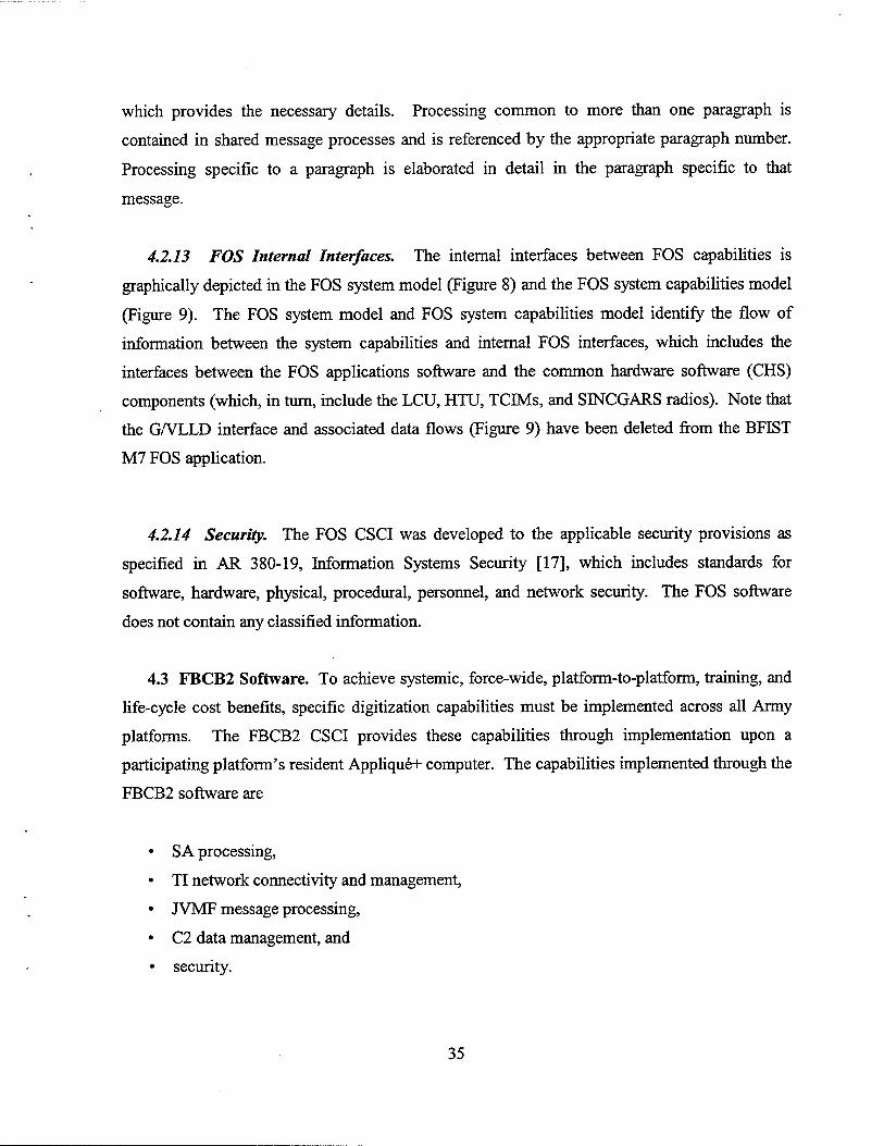
which provides the necessary details. Processing common to more than one paragraph is
contained in shared message processes and is referenced by the appropriate paragraph number.
Processing specific to a paragraph is elaborated in detail in the paragraph specific to that
message.
4.2.13 FOS Internal Interfaces. The internal interfaces between FOS capabilities is
graphically depicted in the FOS system model (Figure 8) and the FOS system capabilities model
(Figure 9). The FOS system model and FOS system capabilities model identify the flow of
information between the system capabilities and internal FOS interfaces, which includes the
interfaces between the FOS applications software and the common hardware software (CHS)
components (which, in turn, include the LCU, HTU, TCTMs, and SINCGARS radios). Note that
the G/VLLD interface and associated data flows (Figure 9) have been deleted from the BFIST
M7 FOS application.
4.2.14 Security. The FOS CSCI was developed to the applicable security provisions as
specified in AR 380-19, Information Systems Security [17], which includes standards for
software, hardware, physical, procedural, personnel, and network security. The FOS software
does not contain any classified information.
4.3 FBCB2 Software. To achieve systemic, force-wide, platform-to-platform, training, and
life-cycle cost benefits, specific digitization capabilities must be implemented across all Army
platforms. The FBCB2 CSCI provides these capabilities through implementation upon a
participating platform's resident Applique+ computer. The capabilities implemented through the
FBCB2 software are
• SA processing,
• TI network connectivity and management,
• JVMF message processing,
• C2 data management, and
• security.
35
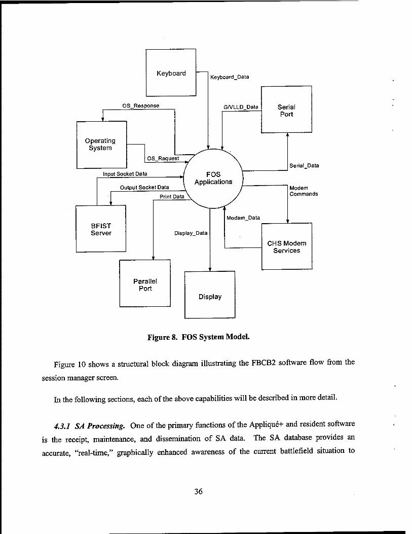
Keyboard
OS_Response
Operating System
Keyboard_Data
GA/LLD Data Serial Port
OS_Request
Input Socket Data
Output Socket Data
Print Data
BFIST Server Display_Data
Parallel Port
Modem Data
Serial Data
Modem Commands
CHS Modem Services
Display
Figure 8. FOS System Model.
Figure 10 shows a structural block diagram illustrating the FBCB2 software flow from the
session manager screen.
In the following sections, each of the above capabilities will be described in more detail.
4.3.1 SA Processing. One of the primary functions of the Applique+ and resident software
is the receipt, maintenance, and dissemination of SA data. The SA database provides an
accurate, "real-time," graphically enhanced awareness of the current battlefield situation to
36
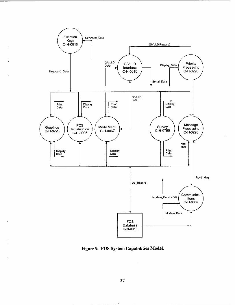
Rcvd_Msg
FOS Database C-N-0013
Figure 9. FOS System Capabilities Model.
37
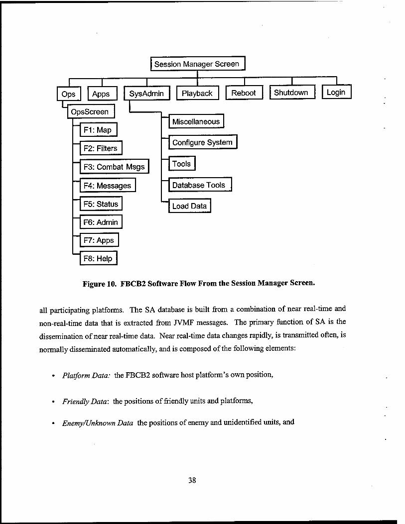
Session Manager Screen
Ops Apps I
SysAdmin
OpsScreen
F1:Map
F2: Filters
F3: Combat Msgs
F4: Messages
F5: Status
F6: Admin
F7: Apps
F8: Help
Playback Reboot
Miscellaneous
Configure System
Tools
Database Tools
Load Data
Shutdown Login
Figure 10. FBCB2 Software Flow From the Session Manager Screen.
all participating platforms. The SA database is built from a combination of near real-time and
non-real-time data that is extracted from JVMF messages. The primary function of SA is the
dissemination of near real-time data. Near real-time data changes rapidly, is transmitted often, is
normally disseminated automatically, and is composed of the following elements:
• Platform Data: the FBCB2 software host platform's own position,
• Friendly Data: the positions of friendly units and platforms,
• Enemy/Unknown Data the positions of enemy and unidentified units, and
38
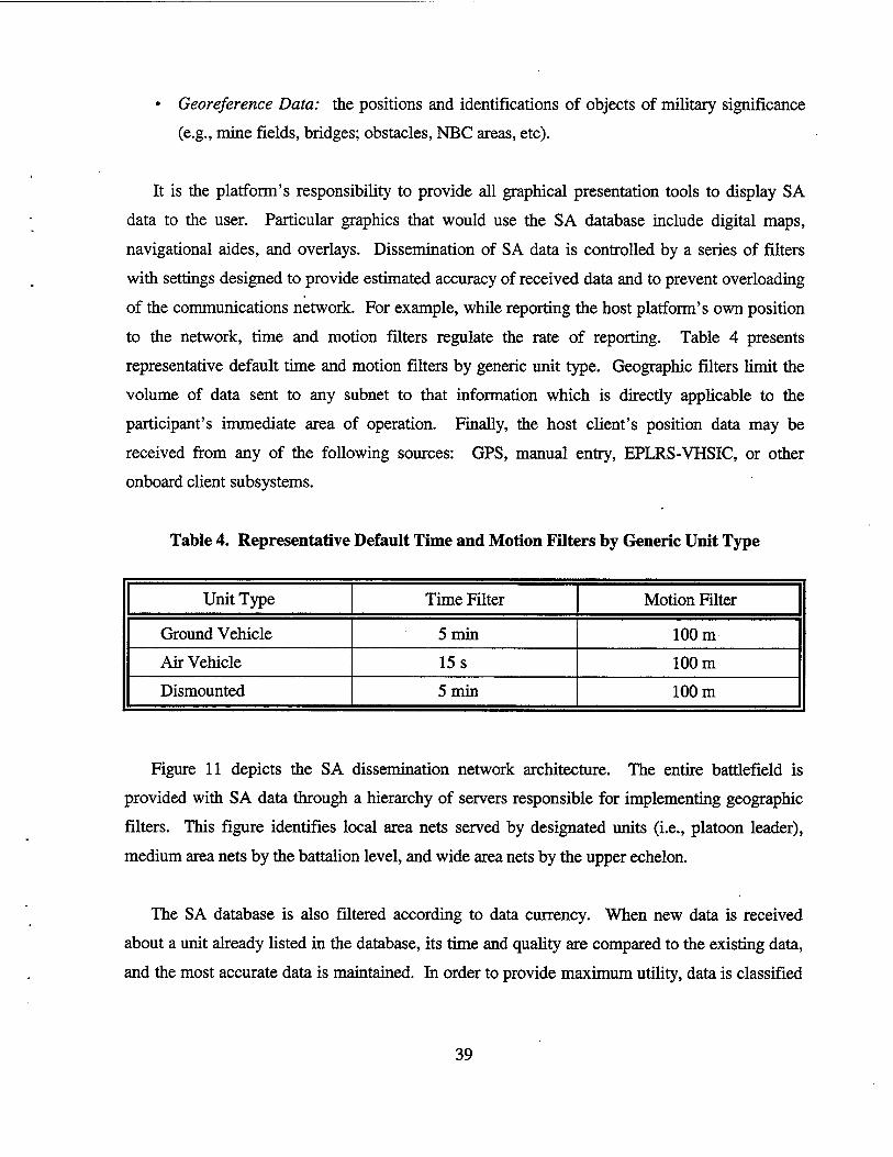
• Georeference Data: the positions and identifications of objects of military significance
(e.g., mine fields, bridges; obstacles, NBC areas, etc).
It is the platform's responsibility to provide all graphical presentation tools to display SA
data to the user. Particular graphics that would use the SA database include digital maps,
navigational aides, and overlays. Dissemination of SA data is controlled by a series of filters
with settings designed to provide estimated accuracy of received data and to prevent overloading
of the communications network. For example, while reporting the host platform's own position
to the network, time and motion filters regulate the rate of reporting. Table 4 presents
representative default time and motion filters by generic unit type. Geographic filters limit the
volume of data sent to any subnet to that information which is directly applicable to the
participant's immediate area of operation. Finally, the host client's position data may be
received from any of the following sources: GPS, manual entry, EPLRS-VHSIC, or other
onboard client subsystems.
Table 4. Representative Default Time and Motion Filters by Generic Unit Type
Unit Type Time Filter Motion Filter
Ground Vehicle 5min 100 m
Air Vehicle 15 s 100 m
Dismounted 5 min 100 m
Figure 11 depicts the SA dissemination network architecture. The entire battlefield is
provided with SA data through a hierarchy of servers responsible for implementing geographic
filters. This figure identifies local area nets served by designated units (i.e., platoon leader),
medium area nets by the battalion level, and wide area nets by the upper echelon.
The SA database is also filtered according to data currency. When new data is received
about a unit already listed in the database, its time and quality are compared to the existing data,
and the most accurate data is maintained. In order to provide maximum utility, data is classified
39
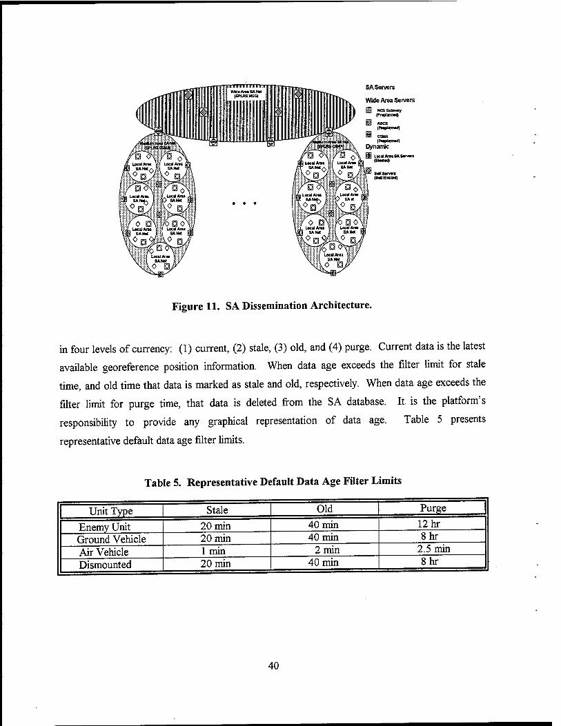
SA Servers
Wide Area Servers
NCSOatwny (PrtptiniMd)
WCS (Prtplanmd)
/mt£\ /fett» Dynamic
Figure 11. SA Dissemination Architecture.
in four levels of currency: (1) current, (2) stale, (3) old, and (4) purge. Current data is the latest
available georeference position information. When data age exceeds the filter limit for stale
time, and old time that data is marked as stale and old, respectively. When data age exceeds the
filter limit for purge time, that data is deleted from the SA database. It is the platform's
responsibility to provide any graphical representation of data age. Table 5 presents
representative default data age filter limits.
Table 5. Representative Default Data Age Filter Limits
Unit Type Stale Old Purge
Enemy Unit 20 min 40 min 12 hr
Ground Vehicle 20 min 40 min 8hr
Air Vehicle 1 min 2 min 2.5 min
Dismounted 20 min 40 min 8hr
40
4.3.2 TI Connectivity. The FBCB2 software provides TI connectivity and communications
services by configuring, controlling, and employing the INC router to send and receive digital
information across the EPLRS VHSIC and SINCGARS SIP radios.
4.3.3 JVMF Processing. JVMF messages are composed of two parts: header and body.
The header format is governed by MIL-STD-2045-47001B [18]; body formats are governed by
the Joint Interoperability of Tactical Command and Control Systems Variable Message Format
Technical Interface Design Plan (Test Edition), Reissue 3 [19]. There will also be a "to be
supplied" (TBS) set of critical, though not yet approved, interface change proposals (ICP)
implemented. For inbound messages, the message header and message body are passed to the
platform when the appropriate application programming interface (API) service is requested.
For outbound messages, the platform provides the FBCB2 software the message type and
message body; the software then creates the appropriate message header. Finally, the FBCB2
software uses the message type to determine appropriate default message addresses.
4.3.4 Security. System security procedures were developed to prevent enemy access to the
digitized battlefield, in accordance with AR 380-19 [17]; and Department of Defense (DOD)
5200.28-STD, "Orange Book" [20] The FBCB2 software operates at a System High Mode, as
defined in AR 380-19 and Program Executive Office (PEO) Command, Control, and
Communications Systems Security Policy [21]. System High is a mode of operation wherein all
users of the FBCB2 computer system possess the required security authorization, but not
necessarily at a need-to-know level, for all data handled by the FBCB2 system. The FBCB2
software supports operation at either of two system (high) sensitivity levels. These levels
include SENSITIVE BUT UNCLASSIFIED (SBU) and SECRET (S). The system sensitivity
level controls message marking, message rejection, and screen marking functions. In addition to
maintaining a system sensitivity level, the FBCB2 software exercises the principle of "least
privileged." Specifically, the software limits the user to only those operational capabilities and
data needed to perform the user's assignment in accordance with the user's mission. To
accomplish this, the FBCB2 software identifies each user by a user access role. The software
also associates one or more access privileges with each user access role. These privileges define
41
the user's access to FBCB2 functionality and data. From a security perspective, the FBCB2
software enforces a role-based method of access control.
4.3.5 Basic Operations. In this section, the basic operations available through the use of the
FBCB2 software are described, where these operations consist of those procedures most often
used by an operator. The basic operations procedures include the following options:
• Select a Map: allows the operator to retrieve a map from the database and then display
that map.
• Center on a Map: allows the operator to adjust the map display to center the icon
representing himself as the screen center.
• Auto-Center: allows the operator to redisplay the map automatically with the icon
representing himself as the screen center.
• Select Map Scale/Zoom: allows the operator to change the scale of a map or to
zoom in/zoom out on a displayed map.
• Set Map 6, 8,10 Digit Representation: allows the operator to set the map grid pattern.
• Turn Filters OnlOjf. allows the operator to engage/disengage the system filters or select
only those items that he wishes to display on the SA map.
• Send Combat Message: combat messages may be created and sent either by using the
touchscreen button "Combat Msgs" on the display or the eight-button function bar
(10.4-in display only) after setting up the appropriate transmission settings.
• Default and Address Settings: allows the operator to set up the defaults and the addresses
for the eight-button function bar or for combat message destinations.
The operator initiates these procedures from the operations (OPS) screen.
42
5. Conclusions
In this report, an overview description of the information systems on the BF1ST M7 model
with a comprehensive focus on the communication system hardware and software components is
provided. These latter components include the SINCGARS radios, the LCU, the HTU, the
TCM, the FOS CSCI, the EPLRS data radio, the INC router, the Applique+ computer, and the
FBCB2 CSCI. In the execution of the IOVSA system familiarization phase, numerous
contractor and government resources were utilized to ensure proper representation of the BFIST
M7 configuration. In addition, supplemental information was obtained from various public-
access DOD and commercial vendor web sites.
In documenting the BFIST M7 information system architecture during the current phase of
this IOVSA, there are several indicators that survivability was considered during the information
system design process. First, there is considerable redundancy in many of the hardware
components (i.e., SINCGARS radios, full-function crew stations, TCIMs, LCU/HTU, and hand
stations). Second, communication system processing is functionally separate from other system
processing, so that loss of the MPU (for example) would not directly affect the BFIST's digital
communication capability. Finally, both the FOS and FBCB2 software have been developed in
accordance with AR 380-19 [ 17].
As a result of the current system familiarization phase of the BFIST M7 IOVSA process,
which focused on communication system components, two information system components are
recommended for future in-depth analysis. The first of these components is the FOS CSCI,
which is the key for access to battlefield C2 systems such as the Advanced Field Artillery
Tactical Data System (AFATDS) and the Initial Fire Support Automated System (IFSAS). If the
BFIST were overrun and boarded by a hostile force during the course of a mission, the FOS
software potentially could provide the enemy an avenue into numerous fire support
communication nets. Also meriting further in-depth analysis is the FBCB2 CSCI, which could
provide that same enemy even greater access into the Army's TL This is of secondary concern
relative to the FOS software, however, since the FBCB2 upgrade is tentatively set for in FY 2002
at the earliest.
43
In the next phase of the IOVSA process (system design analysis), both a system functionality
assessment and a data flow analysis will be executed [4]. In the system functionality assessment
process, a determination is made as to whether a system can achieve its specific requirements
from a DOD Information Technology Security Certification and Accreditation Process
(DrrSCAP) perspective. In the data flow analysis, the detailed program specifications for an
information flow model (IFM) are formulated, and provides an initial analytical measure of
system performance as a function of configuration and scenario.
44
6. References
1. U.S. Department of Defense. "Doctrine for C4 Systems Support to Joint Operations." Joint Publication 6-0, Washington, DC, 3 June 1992.
2. U.S. Department of the Army. "Information Operations." FM 100-6, Washington, DC, August 1996.
3. Barnes, A., A. Hollway, and P. G. Neumann. "Survivable Computer-Communication Systems: The Problem and Working Group Recommendations." VAL-CE-TR-92-22 (revision 1), U.S. Army Research Laboratory, White Sands Missile Range, NM, May 1993.
4. zum Brunnen, R. L., C. D. McDonald, P. R. Stay, M. W. Starks, and A. L. Barnes. "Information Operations Vulnerability/Survivability Assessment (IOVSA): Process Structure." ARL-TR-2250, U.S. Army Research Laboratory, Aberdeen Proving Ground, MD, June 2000.
5. U.S. Department of Defense. Military Standard for Digital Time Division Command Response Multiplex Databus. MJL-STD-1553, Washington, DC, 30 April 1975.
6. Santa Cruz Operations. UNTX Version 5.02. Santa Cruz, CA, 1995.
7. U.S. Department of Defense. Interoperability Standard for Digital Message Transfer Device Systems. MJL-STD-188-220(A), Washington, DC, 28 March 1995.
8. U.S. Department of the Army. Interface Specifications for the Army Data Distribution System Interface (ADDSI). ACCS-A3-407-008D, Washington, DC, 10 April 1990.
9. International Consultative Committee for Telegraphy and Telephony. "Interface Between Data Terminal Equipment (DTE) and Data Circuit Terminating Equipment (DCE) for Terminals Operating in the Packet Mode and Connected to Public Data Networks by Dedicated Dircuit." Recommendation X.25, Geneva, Switzerland, October 1996.
10. Deering, S. Internet Control Message Protocol Router Discovery Messages. RFC 1256+, Xerox Palo Alto Research Center, Palo Alto, CA, September 1991.
11. National Software Testing Laboratories. Ymark2000 (2000.exe). Conshohocken, PA, 1998.
12. Sun Microsystems, Inc. Solaris X86 (UNIX) Version 2.5. Palo Alto, CA 1997.
45
13. U.S. Department of Defense. General Specification for Connectors, Electrical Circular, Miniature, High Density, Quick Disconnect (Bayonett, Threaded and Breech Coupling), Environment Resistant, Removable Crimp and Hermetic Solder Contacts. MIL-C-38999, Washington, DC, 20 June 1990.
14. Anonymous. Universal Asynchronous Receiver/Transmitter. 16550 UART, 1994.
15. U.S. Department of Defense. Connectionless Data Transfer Application Layer Standard. MIL-STD-2045-47001, Washington, DC, 27 July 1995.
16. U.S. Department of the Army. Operational Terms and Graphics. FM 101-5-1, Washington, DC, 30 September 1997.
17. U.S. Department of the Army. Information Systems Security. AR 380-19, Washington, DC, 27 February 1998.
18. U.S. Department of Defense. Interoperability Standard for Connectionless Data Transfer Application Layer Standard. MIL-STD-2045-47001B, Washington, DC, 27 July 1995.
19. U.S. Department of Defense. Joint Interoperability of Tactical Command and Controls Systems Variable Message Format Technical Interface Design Plan (Test Edition), Reissue 3. Washington, DC, June 1996.
20. U.S. Department of Defense. Department of Defense Trusted Computer System Evaluation Criteria. DOD 5200.28-STD, Washington, DC, 26 December 1985.
21. U.S. Army Communication Electronics Command. Program Executive Office Command, Control, and Communications Systems Policy. Fort Monmouth, NJ, 24 May 1999.
46

Appendix:
Tactical Internet Protocols
47

INTENTIONALLY LEFT BLANK.
48
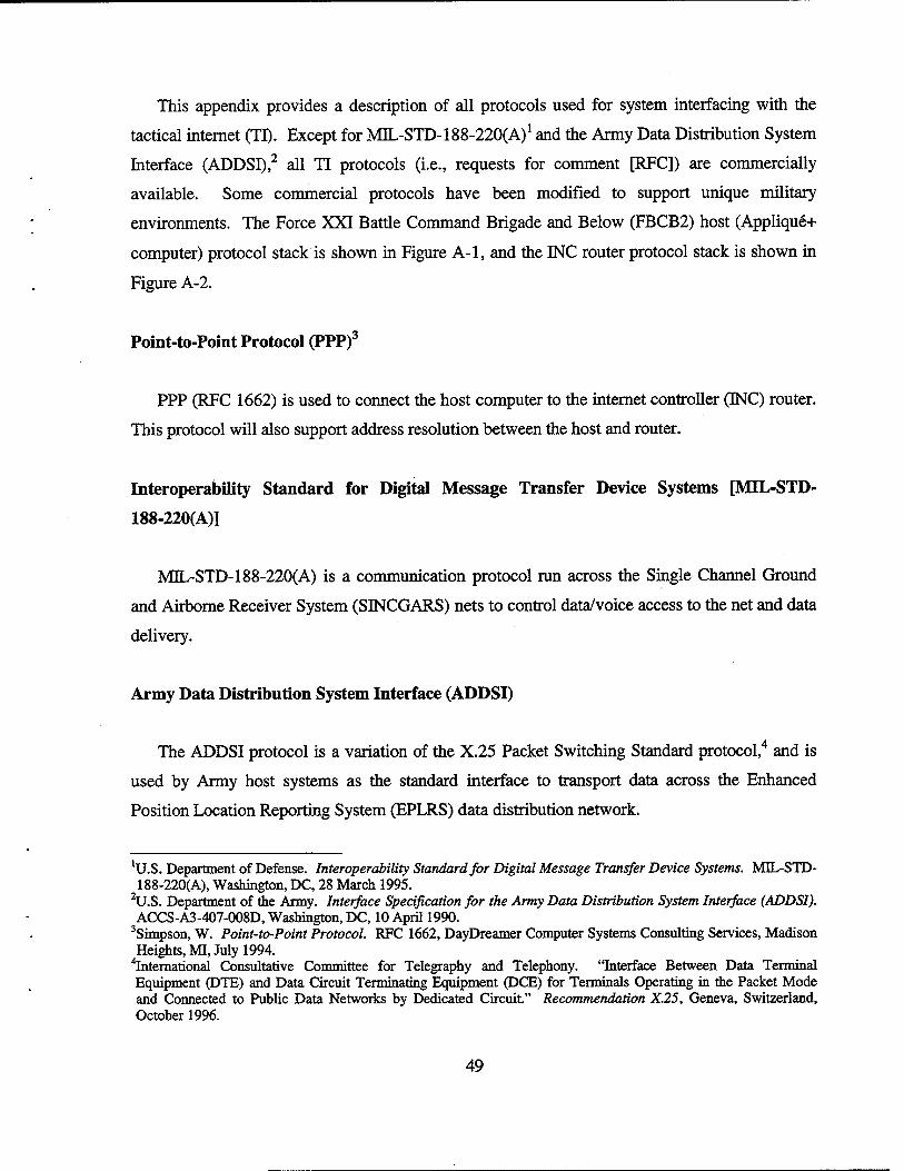
This appendix provides a description of all protocols used for system interfacing with the
tactical internet (IT). Except for MJL-STD-188-220CA)1 and the Army Data Distribution System
Interface (ADDSI),2 all TI protocols (i.e., requests for comment [RFC]) are commercially
available. Some commercial protocols have been modified to support unique military
environments. The Force XXI Battle Command Brigade and Below (FBCB2) host (Applique+
computer) protocol stack is shown in Figure A-l, and the INC router protocol stack is shown in
Figure A-2.
Point-to-Point Protocol (PPP)3
PPP (RFC 1662) is used to connect the host computer to the internet controller (INC) router.
This protocol will also support address resolution between the host and router.
Interoperability Standard for Digital Message Transfer Device Systems [MIL-STD-
188-220(A)]
MIL-STD-188-220(A) is a communication protocol run across the Single Channel Ground
and Airborne Receiver System (SINCGARS) nets to control data/voice access to the net and data
delivery.
Army Data Distribution System Interface (ADDSI)
The ADDSI protocol is a variation of the X.25 Packet Switching Standard protocol,4 and is
used by Army host systems as the standard interface to transport data across the Enhanced
Position Location Reporting System (EPLRS) data distribution network.
'U.S. Department of Defense. Interoperability Standard for Digital Message Transfer Device Systems. MDL-STD- 188-220(A), Washington, DC, 28 March 1995.
2U.S. Department of the Aimy. Interface Specification for the Army Data Distribution System Interface (ADDSI). ACCS-A3-407-008D, Washington, DC, 10 April 1990.
3Simpson, W. Point-to-Point Protocol. RFC 1662, DayDreamer Computer Systems Consulting Services, Madison Heights, MI, July 1994.
"international Consultative Committee for Telegraphy and Telephony. "Interface Between Data Terminal Equipment (DTE) and Data Circuit Terminating Equipment (DCE) for Terminals Operating in the Packet Mode and Connected to Public Data Networks by Dedicated Circuit." Recommendation X.25, Geneva, Switzerland, October 1996.
49
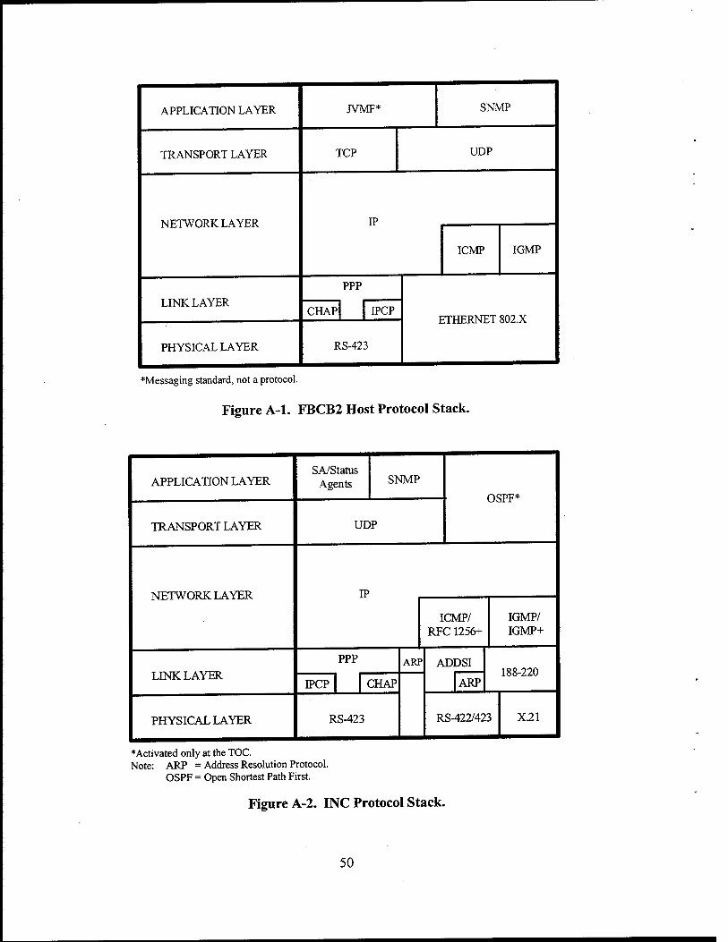
APPLICATION LAYER JVMF* SNMP
TRANSPORT LAYER TCP UDP
NETWORK LAYER IP
ICMP IGMP
LINK LAYER PPP
ETtrCPXTPT Rfi? Y CHAP IPCP
PHYSICAL LAYER RS-423
♦Messaging standard, not a protocol.
Figure A-l. FBCB2 Host Protocol Stack.
APPLICATION LAYER SA/Status
Agents SNMP HQPT;*
TRANSPORT LAYER UDP
NETWORK LAYER TP
ICMP/ RFC 1256+
IGMP/ IGMP+
LINK LAYER PPP ARP ADDSI
188-220 IPCP CHAP ARP
PHYSICAL LAYER RS-423 RS-422/423 X21
♦Activated only at the TOC. Note: ARP = Address Resolution Protocol.
OSPF = Open Shortest Path First.
Figure A-2. INC Protocol Stack.
50
Internet ProtocoI5/Internet Control Message Protocol6 (IP/ICMP)
IP/ICMP (RFC 791 and 792) are used for the routing and delivery of all message types
through the TI.
RFC 12567 and RFC 1256+8
RFC 1256 is used on the SINCGARS nets so that INC routers can advertise their exit
gateway eligibility/priority. The primary function of RFC 1256+ is the same as RFC 1256;
however, the RFC 1256+ also advertises the directly attached host IP address as well as the
eligible router IP address. RFC 1256+ involves no changes to the RFC 1256 format but is used
in a router-to-router mode instead of a host-to-router mode.
Transmission Control Protocol (TCP)9
TCP (RFC 793) is a protocol used between two hosts to provide acknowledged delivery of
unicast messages. Large messages (greater than 576 B) are sent by serial unicast using TCP.
10 User Datagram Protocol (UDP)
UDP (RFC 768) is used for a connectionless or nonacknowledged delivery of all SNMP
messages and SA data sent between the FBCB2 host computer and the directly connected INC
router. All multicast C2 messages are sent using UDP.
hostel, J. Internet Protocol. RFC 791, Information Sciences Institute, Marina del Rey, CA, September 1981. Hostel, J. Internet Control Message Protocol. RFC 792, Information Sciences Institute, Marina del Rey, CA, September 1981.
7Deering, S. Internet Control Message Protocol Router Discovery Messages. RFC 1256+, Xerox Palo Alto Research Center, Palo Alto, CA, September 1991.
8Deering, S. Internet Control Message Protocol Router Discovery Messages. RFC 1256+, Xerox Palo Alto Research Center, Palo Alto, CA, September 1991.
'Postel, J. Transmission Control Protocol. RFC 793, Information Sciences Institute, Marina del Rey, CA, September 1981. hostel J. User Datagram Protocol. RFC 768, Information Sciences Institute, Marina del Rey, CA, August 1980.
51
Internet Group Management Protocol (IGMP and IGMP+)11
IGMP (RFC 1112) is used by the FBCB2 host computer to register for multicast services
with the directly connected INC router. IGMP is used between the host and router to inform the
router of the multicast groups from which the host wishes to receive traffic. IGMP+ is used from
router to router (instead of from host to router) to allow a SINCGARS-only router to inform the
gateway router of the multicast groups from which the host wishes to receive traffic.
Simple Network Management Protocol (SNMP)12
The INC routers will receive all necessary router initialization data or changes to router
initialization data from their local host via their PPP interfaces using SNMP. The host also
determines router and local radio interface status via SNMP.
PPP Challenge Handshake Authentication Protocol (CHAP)13
CHAP (RFC 1994) is used by the INC router to authenticate the directly connected host.
Utilizing CHAP, the INC authenticates the host upon initial PPP link establishment and
periodically thereafter. Authentication is accomplished by a three-way handshake between the
INC and the host, whereby the INC verifies that the host possesses a valid password. Both the
host and the router maintain the password as a shared secret. A one-way message digest 5
(MD5) hash function is applied to the password data so that the password is never exposed in the
clear over the PPP link.
"Deering, S. Internet Group Management Protocol. RFC 1112, Stanford University, Stanford, CA, August 1989. 12Case, J., M. Fedor, M. Schoffstall, and C. Davin. Simple Network Management Protocol. RFC 1098, University
of Tennessee, Knoxville, TN, April 1989. "Simpson, W. Challenge Handshake Authentication Protocol. RFC 1994, DayDreamer Computer Systems
Consulting Services, Madison Heights, MI, August 1996.
52
Internet Protocol Control Protocol (IPCP)14
IPCP (RFC 1332) is a part of IP, and is responsible for configuring, enabling, and disabling
the IP protocol modules on both ends of the INC router to host point-to-point link. The primary
use of IPCP by the FBCB2 host computer is to enable router discovery in the event the host's
INC is replaced.
'McGregor, G. Internet Protocol Control Protocol. RFC 1332, Merit Network, Inc., Ann Arbor, MI, May 1992.
53

INTENTIONALLY LEFT BLANK.
54
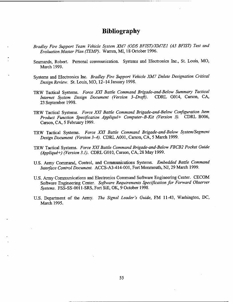
Bibliography
Bradley Fire Support Team Vehicle System XM7 (ODS BFIST)/XM7E1 (A3 BFIST) Test and Evaluation Master Plan (TEMP). Warren, MI, 18 October 1996.
Seamands, Robert. Personal communication. Systems and Electronics Inc., St. Louis, MO, March 1999.
Systems and Electronics Inc. Bradley Fire Support Vehicle XM7 Delete Designation Critical Design Review. St. Louis, MO, 12-14 January 1998.
TRW Tactical Systems. Force XXI Battle Command Brigade-and-Below Summary Tactical Internet System Design Document (Version 3-Draft). CDRL G014, Carson, CA, 23 September 1998.
TRW Tactical Systems. Force XXI Battle Command Brigade-and-Below Configuration Item Product Function Specification Applique+ Computer-B-Kit (Version 3). CDRL B006, Carson, CA, 5 February 1999.
TRW Tactical Systems. Force XXI Battle Command Brigade-and-Below System/Segment Design Document (Version 3-4). CDRL A001, Carson, CA, 5 March 1999.
TRW Tactical Systems. Force XXI Battle Command Brigade-and-Below FBCB2 Pocket Guide (Applique+) (Version 3.1). CDRL G010, Carson, CA, 28 May 1999.
U.S. Army Command, Control, and Communications Systems. Embedded Battle Command Interface Control Document. ACCS-A3-414-001, Fort Monmouth, NJ, 29 March 1999.
U.S. Army Communications and Electronics Command Software Engineering Center. CECOM Software Engineering Center. Software Requirements Specification for Forward Observer Systems. FSS-SS-0011-SRS, Fort Sill, OK, 9 October 1998.
U.S. Department of the Army. The Signal Leader's Guide, FM 11-43, Washington, DC, March 1995.
55

INTENTIONALLY LEFT BLANK.
56
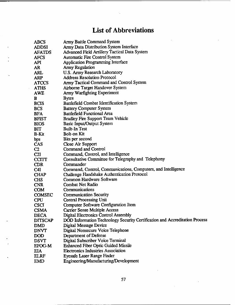
List of Abbreviations
ABCS Army Battle Command System ADDSI Army Data Distribution System Interface AFATDS Advanced Field Artillery Tactical Data System AFCS Automatic Fire Control System API Application Programming Interface AR Army Regulation ARL U.S. Army Research Laboratory ARP Address Resolution Protocol ATCCS Army Tactical Command and Control System ATHS Airborne Target Handover System AWE Army Warfighting Experiment B Bytes BCIS Battlefield Combat Identification System BCS Battery Computer System BFA Battlefield Functional Area BFIST Bradley Fire Support Team Vehicle BIOS Basic Input/Output System BIT Built-in Test B-Kit Bolt-on Kit bps Bits per second CAS Close Air Support C2 Command and Control C2I Command, Control, and Intelligence CCITT Consultative Committee for Telegraphy and Telephony CDR Commander C4I Command, Control, Communications, Computers, and Intelligence CHAP Challenge Handshake Authentication Protocol CHS Common Hardware Software CNR Combat Net Radio COM Communications COMSEC Communication Security CPU Central Processing Unit CSCI Computer Software Configuration Item CSMA Carrier Sense Multiple Access DECA Digital Electronics Control Assembly DITSCAP DOD Information Technology Security Certification and Accreditation Process DMD Digital Message Device DNVT Digital Nonsecure Voice Telephone DOD Department of Defense DSVT Digital Subscriber Voice Terminal EFOG-M Enhanced Fiber Optic Guided Missile EIA Electronics Industries Association ELRF Eyesafe Laser Range Finder EMD Engineering/Manufacturing/Development
57
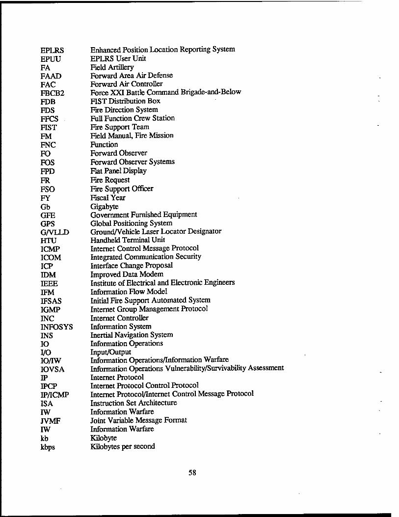
EPLRS Enhanced Position Location Reporting System EPUU EPLRS User Unit FA Field Artillery FAAD Forward Area Air Defense FAC Forward Air Controller FBCB2 Force XXI Battle Command Brigade-and-Below FDB FIST Distribution Box FDS Fire Direction System FFCS Full Function Crew Station FIST Fire Support Team FM Field Manual, Fire Mission FNC Function FO Forward Observer FOS Forward Observer Systems FPD Flat Panel Display FR Fire Request FSO Fire Support Officer FY Fiscal Year Gb Gigabyte GFE Government Furnished Equipment GPS Global Positioning System G/VLLD Ground/Vehicle Laser Locator Designator HTU Handheld Terminal Unit ICMP Internet Control Message Protocol ICOM Integrated Communication Security ICP Interface Change Proposal IDM Improved Data Modem IEEE Institute of Electrical and Electronic Engineers IFM Information Flow Model IFS AS Initial Fire Support Automated System IGMP Internet Group Management Protocol INC Internet Controller INFOSYS Information System INS Inertial Navigation System IO Information Operations I/O Input/Output IO/TW Information Operations/Information Warfare IOVS A Information Operations Vulnerability/Survivability Assessment IP Internet Protocol IPCP Internet Protocol Control Protocol IP/ICMP Internet Protocol/Internet Control Message Protocol ISA Instruction Set Architecture IW Information Warfare JVMF Joint Variable Message Format IW Information Warfare kb Kilobyte kbps Kilobytes per second
58
LAN Local Area Network LCD Liquid Crystal Display LCU Lightweight Computer Unit LPI Low Probability of Intercept LTACFIRE Lightweight Tactical Fire Direction System LTS Logical Time Slot LVDS Low Voltage Differential Signaling MB Megabyte (1 million bytes) MBC Mortar Ballistics Computer MD5 Message Digest 5 MEP Mission Equipment Package MHz Megahertz MIL-C Military Circular MIL-STD Military Standard MLRS Multiple Launch Rocket System MPU Mission Processor Unit (replacement for TSEU) MSE Mobile Subscriber Equipment MSG Multisource Group NBC Nuclear, Biological, Chemical NATO North Atlantic Treaty Organization NCS Network Control Station ODS Operation Desert Storm OPORD Operation Order OPSEC Operations Security ORD Operational requirements Document OSI Open System Information OSPF Open Shortest Path First PC Personal Computer PCI Personal Computer Interface PEO Program Executive Office PLGR Precision Lightweight GPS Receiver POSDC Portable Operating System Interface PPP Point-to-Point Protocol PVC Permanent Virtual Circuit RAM Random-Access Memory RF Radio Frequency RFC Request for Comment RS Radio Set RT Receiver/Transmitter S SECRET SA Situational Awareness SADL Situation Awareness Data Link SBU SENSITIVE BUT UNCLASSIFIED SCO Santa Cruz Operations SCSI Small Computer Serial Interface SINCGARS Single Channel Ground and Airborne Receiver System SIP System Improvement Program
59
SL System Leader SLAD Survivability/Lethality Analysis Directorate SNMP Simple Network Management Protocol SVGA Super Video Graphics Array TACAIR Tactical Air TACFIRE Tactical Fire Direction System TBS To Be Supplied TC&D TOM Configuration and Diagnostics Application TCIM Tactical Communications Interface Module TCP Transmission Control Protocol TDB Turret Distribution Box TDMA Time Division Multiple Access TEMP Test and Evaluation Master Plan TFDMD TACFIRE Digital Message Device TI Tactical Internet TOC Tactical Operations Center TSCP Targeting Station Control Panel TSEU Targeting Station Electronics Unit UART Universal Asynchronous Receiver/Transmitter UDP User Datagram Protocol URN Unit Reference Number USB Universal Serial Bus VAA Vehicular Amplifier Adapter VHF Very High Frequency VHSIC Very High Speed Integrated Circuit VIS Vehicle Intercommunications System VMF Variable Message Format WAN Wide Area Network
60
NO. OF COPIES ORGANIZATION
DEFENSE TECHNICAL INFORMATION CENTER DTIC DDA 8725 JOHN J KINGMAN RD STE 0944 FT BELVOIR VA 22060-6218
HQDA DAMOFDT 400 ARMY PENTAGON WASHINGTON DC 20310-0460
OSD OUSD(A&T)/ODDDR&E(R) RJTREW THE PENTAGON WASHINGTON DC 20301-7100
NO. OF COPIES
1
ORGANIZATION
DIRECTOR US ARMY RESEARCH LAB AMSRLDD 2800 POWDER MOLL RD ADELPHI MD 20783-1197
DIRECTOR US ARMY RESEARCH LAB AMSRL CI AI R (RECORDS MGMT) 2800 POWDER MILL RD ADELPHI MD 20783-1145
DIRECTOR US ARMY RESEARCH LAB AMSRL CILL 2800 POWDER MILL RD ADELPHI MD 20783-1145
DPTYCGFORRDA US ARMY MATERIEL CMD AMCRDA 5001 EISENHOWER AVE ALEXANDRIA VA 22333-0001
DIRECTOR US ARMY RESEARCH LAB AMSRL CI AP 2800 POWDER MULL RD ADELPHI MD 20783-1197
INST FOR ADVNCD TCHNLGY THE UNIV OF TEXAS AT AUSTIN PO BOX 202797 AUSTIN TX 78720-2797
DARPA B KASPAR 3701 N FAIRFAX DR ARLINGTON VA 22203-1714
US MILITARY ACADEMY MATH SCI CTR OF EXCELLENCE MADNMATH MAJHUBER THAYERHALL WEST POINT NY 10996-1786
DIRECTOR US ARMY RESEARCH LAB AMSRL D DR SMITH 2800 POWDER MILL RD ADELPHI MD 20783-1197
ABERDEEN PROVING GROUND
DIRUSARL AMSRL CI LP (BLDG 305)
61
NO. OF COPIES ORGANIZATION
NO. OF COPIES ORGANIZATION
OASD C3I MR BUCHHEISTER RM 3D174 6000 DEFENSE PENTAGON WASHINGTON DC 20310-6000
OUSD AT STRT TAC SYS DR SCHNEITER RM 3E130 3090 DEFENSE PENTAGON WASHINGTON DC 20310-3090
OUSD AT S&T AIR WARFARE RM 3E139 R MUTZELBUG 3090 DEFENSE PENTAGON WASHINGTON DC 20301-3090
OUSD AT S&T LAND WARFARE RMEB1060 AVIILU 3090 DEFENSE PENTAGON WASHINGTON DC 20310-3090
UNDER SEC OF THE ARMY DUSA OR ROOM 2E660 102 ARMY PENTAGON WASHINGTON DC 20310-0102
ASST SECY ARMY ACQUISITION LOGISTICS TCHNLGY SARD ZD ROOM 2E673 103 ARMY PENTAGON WASHINGTON DC 20310-0103
ASST SECY ARMY ACQUISITION LOGISTICS TCHNLGY SARD ZP ROOM 2E661 103 ARMY PENTAGON WASHINGTON DC 20310-0103
ASST SECY ARMY ACQUISITION LOGISTICS TCHNLGY SAAL ZS ROOM 3E448 103 ARMY PENTAGON WASHINGTON DC 20310-0103
OADCSOPS FORCE DEV DIR DAMOFDZ ROOM 3A522 460 ARMY PENTAGON WASHINGTON DC 20310-0460
HQDA ODCSPER DAPE MR (RM 2C733) 300 ARMY PENTAGON WASHINGTON DC 20310-0300
US ARMY MATERIEL CMD DEP CHF OF STAFF FOR RDA SCIENCE TECH ENG AMCRDA 5001 EISENHOWER AVE ALEXANDRIA VA 22333-0001
US ARMY MATERIEL CMD DEP CHF OF STAFF FOR RDA SCIENCE TECH ENG AMCRDA T 5001 EISENHOWER AVE ALEXANDRIA VA 22333-0001
US ARMY ARMAMENT RDEC AMSTAARTD MFISETTEBLDG1 PICATINNY ARSENAL NJ 07806-5000
ECBC AMSSBRTD JZARZYCKI 5183BLACKHAWKRD APG MD 21010-5424
US ARMY MISSILE RDEC AMSMIRD W MCCORKLE RSA AL 35898-5240
NATICK SOLDIER CENTER SBCNT P BRANDLER KANSAS STREET NATICK MA 01760-5056
62
NO. OF COPIES ORGANIZATION
NO. OF COPIES ORGANIZATION
US ARMY TANK AUTOMTV RDEC AMSTATR JCHAPIN WARREN MI 48397-5000
US ARMY INFO SYS ENGRG CMD AMSEL IE TD FJENIA FT HUACHUCA AZ 85613-5300
US ARMY SIM TRNGINST CMD AMSTI CG M MACEDONIA 12350 RESEARCH PKWY ORLANDO FL 32826-3726
US ARMY TRADOC BATTLELAB INTEGRATION TECH B CONCEPTS DIRATCDB FT MONROE VA 23561-5000
ARMY TRADOC ANL CTR ATRCW MRKEINTZ WSMRNM 88002-5502
US ARMY RESEARCH LAB AMSRLSL PLANS AND PGMS MGR WSMRNM 88002-5513
US ARMY RESEARCH LAB AMSRL SL E WSMRNM 88002-5513
US ARMY RESEARCH LAB AMSRL SLEA RFLORES WSMRNM 88002-5513
US ARMY RESEARCH LAB AMSRLSL EM JPALOMO WSMRNM 88002-5513
US ARMY RESEARCH LAB AMSRLSL El J NOWAK FT MONMOUTH NJ 07703-5602
ABERDEEN PROVING GROUND
US ARMY DEV TEST COM CSTE DTC TT T APGMD 21005-5055
US ARMY EVALUATION CENTER CSTE AEC SV D DELATTRE 4120 SUSQUEHANNA AVE APGMD 21005-3013
US ARMY RESEARCH LAB AMSRL SL BN D FARENWALD APGMD 21010-5423
US ARMY RESEARCH LAB AMSRLSL
DRWADE J BEILFUSS
US ARMY RESEARCH LAB AMSRL SL B
J SMITH J FRANZ M VOGEL RGROTE
US ARMY RESEARCH LAB AMSRL SLBA
MRITONDO
US ARMY RESEARCH LAB AMSRL SLBD
JMORRISSEY
S ARMY RESEARCH LAB AMSRLSL BE
R SANDMEYER
US ARMY RESEARCH LAB AMSRL SL BG
DBELY
US ARMY RESEARCH LAB AMSRL SLE
MSTARKS
63

NO. OF COPIES ORGANIZATION
ABERDEEN PROVING GROUND
US ARMY RESEARCH LAB AMSRLSLEA
D BAYLOR
US ARMY RESEARCH LAB AMSRL SL EM
JFEENEY
US ARMY RESEARCH LAB AMSRL SL EC
EPANUSKA
64

NO. OF COPIES ORGANIZATION
ABERDEEN PROVING GROUND
11 US ARMY RESEARCH LAB AMSRLSLBN
EFIORAVANTE BRUTH(IOCPS)
1 US ARMY RESEARCH LAB AMSRLSLEA
R ZUM BRUNNEN
65

INTENTIONALLY LEFT BLANK.
66
REPORT DOCUMENTATION PAGE Form Approved OMB No. 0704-0188
Public reporting burden for this collection of information is estimated to average 1 hour per response. Including the time for reviewing instructions, searching existing data sources, gathering and maintaining the data needed, and completing and reviewing the collection of information. Send comments regarding this burden estimate or any other aspect of this collection of Information, including suggestions for reducing this burden, to Washington Headquarters Services, Directorate for Information Operations and Reports, 1215 Jefferson Davis Hiqhwav, Suite 1204. Arlington. VA 22202-4302. and to the Office of Management and Budget. Paperwork Reduction Prolect(0704-0188i. Washington. DC 20503.
1. AGENCY USE ONLY ("Leave blank) | 2. REPORT DATE | 3. REPORT TYPE AND DATES COVERED
April 2001 Final, Oct 98 - Sep 99 4. TITLE AND SUBTITLE
Information Operations Vulnerability/Survivability Assessment (IOVSA) for the Bradley Fire Support Team Vehicle (BFIST): System Familiarization Phase
6. AUTHOR(S)
Brian G. Ruth
5. FUNDING NUMBERS
665604D677
7. PERFORMING ORGANIZATION NAME(S) AND ADDRESS(ES) U.S. Army Research Laboratory ATTN: AMSRL-SL-BN Aberdeen Proving Ground, MD 21010-5423
8. PERFORMING ORGANIZATION REPORT NUMBER
ARL-TR-2448
9. SPONSORING/MONITORING AGENCY NAMES{S) AND ADDRESS(ES) 10.SPONSORING/MON1TORING AGENCY REPORT NUMBER
11. SUPPLEMENTARY NOTES
12a. DISTRIBUTION/AVAILABILITY STATEMENT
Approved for public release; distribution is unlimited.
12b. DISTRIBUTION CODE
13. ABSTRACTfMax/mum 200 words)
The Information Operations Vulnerability/Survivability Assessment (IOVSA) process, developed by the Survivability/Lethality Analysis Directorate (SLAD) of the U.S. Army Research Laboratory (ARL) for the purpose of conducting an analysis of the effects of information operations/information warfare (IO/TW) threats on battlefield information systems was applied to the M7 model of the Bradley Fire Support Team Vehicle (BFIST). The IOVSA process consists of five distinct phases which must be completed for a complete analysis of IO/IW threat impact on weapon system capability: (1) system familiarization, (2) system design analysis, (3) threat definition and susceptibility assessment, (4) vulnerability risk assessment, and (5) protection assessment and recommendations. This report documents the IOVSA system familiarization phase for the M7 BFIST with particular focus on those critical information systems relating to battlefield communications.
14. SUBJECT TERMS
Bradley Fire Support Team Vehicle, Information Operations Vulnerability/Survivability Assessment
15. NUMBER OF PAGES
74 16. PRICE CODE
17. SECURITY CLASSIFICATION OF REPORT
UNCLASSIFIED
18. SECURITY CLASSIFICATION OF THIS PAGE
UNCLASSIFIED
19. SECURITY CLASSIFICATION OF ABSTRACT
UNCLASSIFIED
20. LIMITATION OF ABSTRACT
UL NSN 7540-01-280-5500
67 Standard Form 298 (Rev. 2-89) Prescribed by ANSI Std. 239-18 298-102

INTENTIONALLY LEFT BLANK.
68
USER EVALUATION SHEET/CHANGE OF ADDRESS
This Laboratory undertakes a continuing effort to improve the quality of the reports it publishes. Your comments/answers to the items/questions below will aid us in our efforts.
1. ARL Report Number/Author ARL-TR-2448 (Ruth) Date of Report April 2001
2. Date Report Received ,
3. Does this report satisfy a need? (Comment on purpose, related project, or other area of interest for which the report will be
used.)
4. Specifically, how is the report being used? (Information source, design data, procedure, source of ideas, etc.).
5. Has the information in this report led to any quantitative savings as far as man-hours or dollars saved, operating costs
avoided, or efficiencies achieved, etc? If so, please elaborate.
6. General Comments. What do you think should be changed to improve future reports? (Indicate changes to organization,
technical content, format, etc.)
Organization
CURRENT Name E-mail Name ADDRESS
Street or P.O. Box No.
City, State, Zip Code
7. If indicating a Change of Address or Address Correction, please provide the Current or Correct address above and the Old or
Incorrect address below.
Organization
OLD Name ADDRESS
Street or P.O. Box No.
City, State, Zip Code
(Remove this sheet, fold as indicated, tape closed, and mail.) (DO NOT STAPLE)
DEPARTMENT OF THE ARMY
OFFICIAL BUSINESS
BUSINESS REPLY MAIL FIRST CLASS PERMIT NO 0001, APG, MD
POSTAGE WILL BE PAID BY ADDRESSEE
DIRECTOR US ARMY RESEARCH LABORATORY ATTNAMSRLSLBN ABERDEEN PROVING GROUND MD 21010-5423
NO POSTAGE NECESSARY IF MAILED
IN THE UNITED STATES


