Embed Size (px)
Citation preview

AD-A275 912
Technical Report 992 AD'-A275 91
Battalion Evaluation of the CombatVehicle Command and Control Systemin Distributed Interactive Simulation:Preliminary Findings
Bruce C. Leibrecht, Beverly J. Winsch, Laura A. Ford,Alicia R. Sawyer, Glen A. Meade, Frances M. Ainslie,Paul G. Smith, Robert S. Sever, and William J. DohertyBDM Federal, Inc.......
DTICELECTE
November 1993 FEB 141994
94-047121111111U1IE1
United States Army Research Institutefor the Behavioral and Social Sciences
Approved for public release; distribution is unrImrltd.
94 2 10 039 DTIO QUALM INSPECTED 5

BestAvailable
Copy
U.S. ARMY RESEARCH INSTITUTE
FOR THE BEHAVIORAL AND SOCIAL SCIENCES
A Field Operating Agency Under the Jurisdiction
of the Deputy Chief of Staff for Personnel
EDGAR M. JOHNSONDirector
Research accomplished under contractfor the Department of the Army
Sj'• esi,? To, •
BDM Federal, Inc. , ,i .
Technical review by DIIC i ,, -
jU SDonald M. Kristiansen tFt;rt,-,.Margaret S. Salter [EBy.
................................................J2 -. -l 1
Dtst
A-i
NOTICES
[]I UTION: 'bution of th' eot n made by •s
Pon co ingdistri n* nof re rts to: U.S. Res-arInstitute for theBe 6oral and Sciences, ATTN: -POX, 5001 Eisenho ye., Alexandria, Virginia
FINAL DISPOSITION: This report may be destroyed when it is no longer needed. Please do notreturn it to the U.S. Army Research Institute for the Behavioral and Social Sciences.
NOTE: The findings in this report are not to be construed as an official Department of the Armyposition, unless so designated by other authorized documents.
Form Approve
REPORT DOCUMENTATION PAGE OS No. 0704-0o188
eui uwi uM ttSsSSWsO .WU6 d@tot ==2m o'titerawW. SOW.* tWAe Me roetf ton b~m mmnsru atoue,~t =..d=~ n===7 trot
t ~ ~ ~ ~ ~ ~ ~ ~~O gjDjai.seua sUS o ega 6 bJS . to WastImWag itoedwiaftaf ,om oawecterew vdommt~ wzon , aadto ow 005 . 121 is jefeOA
1. AGENCY USE ONLY (LAdV0 oddfl) 2. REPORT DATE 3. REPORT TYPE AND DATES COVERED
1 1993, November Final Sep 91 - Aug 934. TITLE AND SUBTITLE S. FUNDING NUMBERS
Battalion Evaluation of the Combat Vehicle Command and N61339-91-D-OOO1/0006Control System in Distributed Interactive Simulation: 63007APreliminary Findings 7956. AUTHOR(S) 3101Leibrecht, Bruce C.; Winsch, Beverly J.; Ford, Laura A.; C10Sawyer, Alicia R.; Meade, Glen A.; Ainslie, Frances M.;Smith, Paul G.; Sever, Robert S.; and Doherty, William J.
7. PERFORMING ORGANIZATION NAME(S) AND ADORESS(ES) B. PERFORMING ORGANIZATION
BDM Federal, Inc. REPORT NUMBER
P.O. Box 967Fort Knox, KY 40121-0967
9. SPONSORING / MONITORING AGENCY NAME(S) AND ADDRESS(ES) 10. SSORING / MONITORING
U.S. Army Research Institute for the Behavioral and AGENCY REPORT NUMBER
Social SciencesATTN: PERI-IK ARI Technical Report5001 Eisenhower Avenue 992Alexandria, VA 22333-5600
11. SUPPLEMENTARY NOTES
Contracting Officer's Representative, Kathleen A. Quinkert.
12a. DISTRIBUTION I AVAILABILITY STATEMENT 12b. DISTRIUTION CODEApproved for public release;distribution is unlimited.
13. ABSTRACT (Mesamum 200 womsTo meet command, control, and communications (C3) challenges of the future
battlefield, the Combat Vehicle Command and Control (CVCC) research and developmentprogram evaluates automated C3 technology using soldier-in-the-loop simulation.The CVCC system includes a digital Position Navigation system, a digital Command andControl Display, the Commander's Independent Thermal Viewer, and digital workstationsin the Tactical Operations Center. The battalion-level evaluation compares the CVCCsystem with a Baseline (conventional) configuration in terms of operational effective-ness. Soldier-machine interface (SMI) and training implications are also addressed.Using M1 tank simulators in the Mounted Warfare Test Bed at Fort Knox, Kentucky, unitcommanders and executive officers with crews are integrated with semiautomatedvehicles under their control to form complete tank battalions. Each battalion com-pletes 4 days of training and testing, culminating in a simulated combat testscenario. This report presents preliminary data based on two Baseline battalions andtwo CVCC-equipped battalions. Improvements in the performance of unit and vehiclecommanders are noted, and selected SMI and training results are discussed. The
(Continued)
14. SUBJECT TERMS 15. NUMBER OF PAGESCVCC Command and control C3 training requirements 312CITV Operational effectiveness Soldier-in-the-loop 16. PMUCE CODEMl tank Distributed interactive simulation assessment --
17. SECURITY C.ASSWICATION 18. SECURITY CIASSIFICATION 19. SECURITY CLASSIFICATION 20. LMITATION OF ABSTRACTOF REPORT OF THIS PAGE OF ABSTRACT
Unclassified Unclassified Unclassified Unlimited
NSN 7S10-1.280-S00 Standard Form 296 (Rev 2-9)iJl d ft ANSI Sid rn-16
ARI Technical Report 992
13. ABSTRACT (Continued)
findings help determine operational effectiveness parameters, user require-ments, and training requirements for future automated C3 systems for combatvehicles.
li
Technical Report 992
Battalion Evaluation of the Combat Vehicle Commandand Control System in Distributed Interactive
Simulation: Preliminary Findings
Bruce C. Lelbrecht, Beverly J. Winsch, Laura A. Ford,Alicia R. Sawyer, Glen A. Meade, Frances M. Ainslie,
Paul G. Smith, Robert S. Sever,and William J. Doherty
BDM Federal, Inc.
Field Unit at Fort Knox, KentuckyBarbara A. Black, Chief
Training Systems Research DivisionJack H. Hiller, Director
U.S. Army Research Institute for the Behavioral and Social Sciences5001 Eisenhower Avenue, Alexandria, Virginia 22333-5600
Office, Deputy Chief of Staff for PersonnelDepartment of the Army
November 1993
Army Project Number Training Simulation2C263007A795
Approved for public release; distribution is unlimited.
.ii
FOREWORD
The Fort Knox Field Unit of the U.S. Army Research Institutefor the Behavioral and Social Sciences (ARI) conducts soldier-in-the-loop simulation-based research that addresses trainingrequirements for the future integrated battlefield. Theseefforts are supported by Memoranda of Understanding (MOU) with(a) the U.S. Army Armor Center and Fort Knox, Subject: Researchin Future Battlefield Conditions, 12 April 1989, and (b) the U.S.Army Tank-Automotive Command (TACOM), Subject: Combat VehicleCommand and Control (CVCC) Program, 22 March 1989.
The CVCC research program combines advanced digital andthermal technologies to enhance mounted warfighting capabilitiesto accomplish command, control, and communications (C3). TheCVCC system includes digital map, report and overlay features,positioning and navigation functions, digital transmissioncapabilities, and independent thermal viewing for unit andvehicle commanders. This configuration provides a powerfulmedium for investigating training requirements of future auto-mated technology for armored vehicles. The research reportedhere used distributed interactive simulation to evaluate the CVCCcapabilities at the battalion level. The preliminary findingspresented in this report support Army developers in determininguser requirements, specifying training requirements, and assess-ing operational effectiveness of automated C3 systems for groundcombat vehicles. In addition, the training and simulation tech-niques developed for this effort are of use to other Army train-ing and testing agencies.
Information resulting from this research has been briefed tothe following personnel: Commanding General, U.S. Army Trainingand Doctrine Command; Commanding General, U.S. Army Armor Centerand School; Deputy Commanding General for Combat Developments,U.S. Army Combined Arms Command; Deputy Chief of Staff for Train-ing, U.S. Army Training and Doctrine Command; Director, Direc-torate of Combat Developments, U.S. Army Armor School; andDirector, Mounted Warfighting Battlespace Lab.
Director
v

ACDOWLRDGENTS
The following members of the U.S. Army Research Institutefor the Behavioral and Social Sciences Fort Knox Field Unitprovided invaluable input to this evaluation: Barbara Black,Field Unit chief; Kathleen Quinkert, Leader of the FutureBattlefield Conditions (FBC) team; Carl Lickteig and GaryElliott, FBC team members; and Major James Whitehead, the FieldUnit's research and development coordinator.
In addition to the authors, the BDM Federal, Inc., researchstaff included Nancy Atwood, Major General (Ret.) Charles Heiden,Owen Pitney, and Ryszard Lozicki. Jeffrey Schmidt and MargaretShay provided invaluable assistance in developing and editing thereport. Research Assistants supporting the project includedSilver Campbell, Ann Cash, Kenneth Fergus, Brian Gary, GaryGulbranson, Michael Gustafson, David Johnson, Ronald Jones,William Myers, Robert Pollock, Ronald Reyna, Charles Sawyer,Daniel Schultz, Timothy Voss, and Harold Wager.
Personnel of the on-site support contractor, Loral Trainingand Technical Services, supported simulation equipment and datacollection/analysis. These included Jimmy Adams, DavidClippinger, Michael Krages, Paul Monday, Rob Smith, and DianeYork.
vi
BATTALION EVALUATION OF THE COMBAT VEHICLE COMMAND AND CONTROLSYSTEM IN DISTRIBUTED INTERACTIVE SIMULATION: PRELIMINARYFINDINGS
EXECUTIVE SUMMARY
Requirement:
Meeting the command, control, and communications (C3)challenges of the high-speed, high-intensity, widely-dispersedfuture battlefield requires automated C3 systems. Systematicresearch and development efforts, including careful assessment oftraining requirements, are necessary to field and deploy auto-mated C3 systems. The U.S. Army's Combat Vehicle Command andControl (CVCC) research and development program uses soldier-in-the-loop, simulation-based methodology to evaluate future C3technology. Previous CVCC research focused on tank crews,platoons, companies, and the battalion Tactical OperationsCenter. A focus on performance of unit commanders and executiveofficers led to the battalion-level evaluation.
Procedure:
An independent group's design compared two conditions:(a) Baseline, modeling conventional M1 tank and Tactical Opera-tions Center (TOC) C3 tools (mainly voice radio and paper maps),and (b) CVCC, supplementing Baseline capabilities with a digitalPosition Navigation (POSNAV) system, a digital Command and Con-trol Display (CCD), the Commander's Independent Thermal Viewer(CITV), and digital TOC workstations. Using autoloading tanksimulators in the Mounted Warfare Test Bed (MWTB) at Fort Knox,Kentucky, eight qualified armor crews (battalion commander, bat-talion operations officer, three company commanders, and threecompany executive officers, each working with a gunner anddriver) were integrated with semiautomated elements under theircontrol to form a complete tank battalion. Two Baseline and twoCVCC-equipped battalions completed a standard sequence of train-ing scenarios and then executed a standard simulated combat testscenario. Each battalion used only its assigned equipment (Base-line or CVCC) throughout training and testing. Measures of per-formance were designed to reveal the impact of the CVCCcapabilities.
vii
Findings:
Based on only two CVCC and two Baseline battalions, theresults in this report are strictly preliminary and do notconstitute statistically reliable trends. The findings areindicative of trends that may be confirmed with the completebattalion-level database, which will contain six battalions ineach condition. The CVCC capabilities appeared to enhancetactical communications, as reflected in reduced voice transmis-sion time, fewer SITUATION reports submitted, and fewer requeststo clarify fragmentary orders. CVCC-equipped battalions sentmore accurate CALL FOR FIRE and SPOT reports and appeared moresuccessful in controlling terrain. The CVCC groups executedcombat missions more quickly, inflicted greater casualties on theenemy, and sustained fewer combat losses. Based on participants'questionnaire responses and debriefing comments, soldier-machineinterface and training issues included concern about the infor-mation load generated by digital reporting, recommendations forimproving the CVCC interface, and desire for additional tasktraining.
Utilization of Findings:
The preliminary findings of the CVCC battalion evaluationprovide important input in determining operational effectivenessparameters, training requirements, and user requirements forfuture automated C3 systems in ground combat vehicles. Inaddition, the training and simulation methods are of use to otherArmy training and testing efforts.
viii

BATTALION EVALUATION OF THE COMBAT VEHICLE COMMAND AND CONTROLSYSTEM IN DISTRIBUTED INTERACTIVE SIMULATION: PRELIMINARYFINDINGS
CONTENTS
Page
INTRODUCTION . . . . . . . . . . . . . . . . . . * 1
BACKGROUND AND REVIEW OF KEY LITERATURE . . . . . . . .. . 5
Command, Control, and Communications . . . . . . . .. 5The Mounted Warfare Test Bed . . . . . . . . . . . . 6ARI-Fort Knox Future Battlefield Conditions
Research Program . . . . . . . . .............. 11Soldier Training Factors . . . . . . . . . . . . . . 14Soldier-Machine Interface Considerations ....... .. 15
DESIGN OF THE EVALUATION ................. 17
Research Issues.... . . . . . . . . . . . . . .. . 17General Approach . . . . . . . . . . . . . . . . . . . 18Research D esign..... . . . . . . . . . . . . . . 19
METHOD............. . . . . . . . . . . . . . ... . . 21
Participants . . . . . o . . . . . . . . . . . . . . . 21Test Facilities and Materials . . . . . . . . . . . . . 25Procedures . . . . . . . . . . . . . . . . . . . . . . 59
Support Staff . . . . . . . . . . . . . . . . o . o 70Methodological Limitations . . . . . . . . . . . . . . 73
PERFORMANCE MEASURES . . . . . . . . . . . . . . . . . . . 75
Approach . . . . . . . . . . . . . . . . . . . . . . 75Operational Issues and Hypotheses . . . . . . . . . . 76Diagnostic Issues .......................... .... 78Training Issue . . . . . . . . . . . . . . . . . . . 79Summary of Measures . . . . . . . . . . . . . . . . . . 79
RESULTS AND DISCUSSION . . . . . . . . . . . . . . . . .. 87
Maneuver Battlefield Operating System . . . . . . . .. 87Fire Support Battlefield Operating System ....... .. 93Command and Control Battlefield Operating System . . . 95Intelligence Battlefield Operating System . . . . 104Soldier-Machine Interface . . . . . . . . . . . . 107Training Assessment . . . . . . . . . . . . . .... . 117Methodological Implications . . . . . . . . ...... 122
ix
CONTENTS (Continued)
Page
CONCLUSIONS AND RECOMMENDATIONS . . . . . . . . . . . . ... 127
Conclusions . . . . . . . . . . . . . . . . . . . . . . 127Recommendations for Future Research . . . . . . . . . . 127
REFERENCES ...... . . . . . . . . . . . 129
APPENDIX A. TEST SCENARIO MATERIALS. . . . . . . . . . . . A-1
B. EXERCISE CONTROL PROCEDURES . . . . . . . . . . B-1
C. SAMPLE DATA COLLECTION INSTRUMENTS . . . . . . C-I
D. SAMPLE MEASURE DEFINITIONS AND DATAREDUCTION PROCEDURES ................... D-I
E. DATA TABLES . . . . . . . . . * . . . . . . . . E-I
F. ACRONYM LIST . . . . . . . . . . . . . . . . . F-1
LIST OF TABLES
Table 1. The MWTB'S Major Features . . . . . . . . . . . . 8
2. Battlefield Operating Systems AssociatedWith the Blueprint of the Battlefield . . . . . . 18
3. Types of Measures With Associated Measure-ment Methods . . . . . . . . . . . . . . . . . . . 20
4. Summary of Participant Requirements . . . . . . . 21
5. Responsibilities of Battalion TOCStaff During Scenarios .............. 24
6. Comparison of Baseline and CVCC M1 SimulatorCapabilities ................... 28
7. C3 Capabilities of the CVCC CCD and POSNAVConfiguration . . . . . . . . . . . . . . . . .. 30
8. Changes to the CCD and POSNAV Since theBattalion TOC Evaluation . . . o . . . . . . . . 37
9. Capabilities of the CVCC CITV Configuration . . . 39
x
CONTENTS (Continued)
Page
Table 10. Tactical Structure of the BattalionDefensive Scenario . . . . . . . . . . . . . . . 55
11. Roles and Responsibilities of theExercise Control Staff During Scenarios . . . . . 71
12. The Maneuver BOS Linked to CVCCHypotheses .............. . . . . ............... . 76
13. The Fire Support BOS Linked to CVCCHypothesis .. .. .. .. .. .. .. .. . .. 77
14. The Command and Control BOS Linked toCVCC Hypotheses ................. 77
15. The Intelligence BOS Linked to CVCCHypothesis . . . . . . . . . . . . . . . . . . . 78
16. Operational Measures by Maneuver BOSFunction . . . . . . . . . . . . . . . . . . . . 79
17. Operational Measures by Fire SupportBOS Function . . . . . . . . . . . . . . . . . . 81
18. Operational Measures by Command andControl BOS Function .............. 81
19. Operational Measures by IntelligenceBOS Function . . . . . . . . . . . . . . . . . . 83
20. Summary of Diagnostic Measures forIssue Dl: How Frequently Were theCCD Features Used? ............... 83
21. Summary of Diagnostic Measures forIssue D2: How Frequently Were theCITV Features Used? . .............. 84
22. Summary of Maneuver Data ............ 92
23. Summary of Fire Support Data . . . . . . . . . . 94
24. Summary of Command and Control Data . . . . . . . 103
25. Summary of Intelligence Data . . . . . . . . . . 106
xi

CONTENTS (Continueda
Page
LIST OF FIGURES
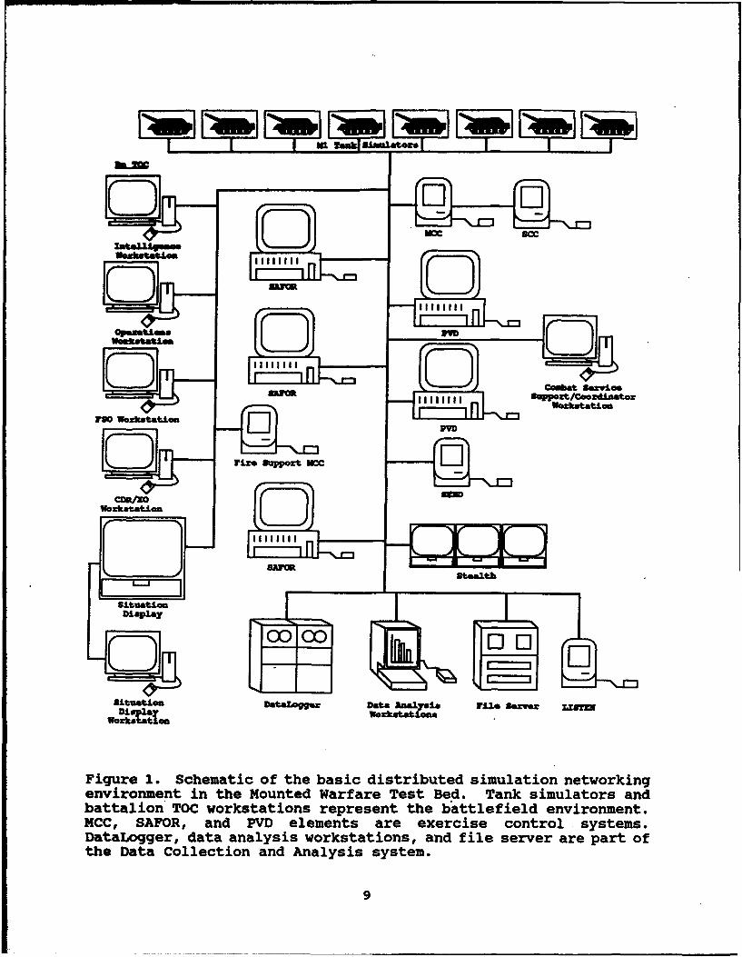
Figure 1. Schematic of the basic distributed simulationnetworking environment in the Mounted WarfareTest Bed . . . . . . . . . . . .. *. . . . . . .. 9
2. Illustration of the battalion configuration . . 23
3. Floor plan of the Mounted Warfare Test Bed . . . 26
4. Basic M1 simulator used in the evaluation,showing the turret crew compartment anddriver's compartment . . . . . . . . . . . . . . 27
5. Vehicle commander's crewstation as seenin the CVCC condition . . . . . . . . . . . .. 29
6. Command and Control Display (CCD) interface . . 31
7. Commander's Independent Thermal Viewer(CITV) interface ................ 40
8. Floor plan of the battalion TacticalOperations Center used in the CVCC condition . . 43
9. Auzomated workstation used in the battalionTactical Operations Center for the CVCCcondition . . . . . . . . . . . . . . . . . . . 43
10. Floor plan of the Exercise Control Room(ECR), showing the layout of exercisecontrol equipment . . . . . . . . . . . . . . . 47
11. Diagram of the tactical radio networks(voice) implemented in the evaluation ..... 48
12. Weekly training and testing schedule forthe CVCC condition ............... 61
xii
BATTALION EVALUATION OF THE COMBAT VEHICLE COMMAND ANDCONTROL SYSTEM IN DISTRIBUTED INTERACTIVE SIMULATION:
PRELIMINARY FINDINGS
Introduction
The command, control, and communications (C3) challenges ofthe future battlefield promise to exceed the capabilities ofcurrently fielded combat systems. The U.S. Army's cornerstonedocument on combat doctrine, FM 100-5, (Department of the Army,1986) portrays a combat environment characterized by speed,intensity, dispersion, and fluidity. The intense, rapid pace ofoperations will shorten planning and decision cycles, driving aneed for faster gathering and exchange of tactical information.It also will necessitate rapid and accurate massing of fires,both direct and indirect. Highly mobile operations will increasethe importance of timely, effective coordination with adjacentand supporting units of the combined arms team. Sustainingrapid, highly mobile initiatives will require timely, accuratelogistics information, especially while in contact with enemyforces. The high technology character of future threat systemswill severely threaten the survivability of friendly forcesunless C3 systems can support more dispersed, highly flexiblemaneuvers while guarding against electronic surveillance andelectronic counter-measures. Given the extremely fluid nature ofthe future battlefield, the ability of unit leaders to maintainan accurate, up-to-date picture of their battle sector will be acritical imperative. Situational awareness will be a coipellingfactor in preventing fratricide. The lessons learned in DesertStorm graphically illustrate many of the C3 problems of a high-tempo, highly fluid battlefield, such as navigation difficulties,delays or interruptions in disseminating information, confusionabout friendly and enemy locations, and tragic instances offratricide (Department of Defense, 1992).
Meeting the C3 challenges of the future battlefield willrequire automated capabilities based on advanced digitaltechnology. To field and deploy combat-effective digitalsystems, extensive research and development efforts are needed.An important focus of these efforts must address the trainingrequirements that will ensure optimum C3 on the combined armsbattlefield. The Army's C3 modernization thrust aims tocapitalize on an extensive network of digital nodes that are tobe capable of rapidly and reliably exchanging combat-criticalinformation. Under this thrust, the U.S. Army Tank-AutomotiveCommand (TACOM) sponsors a U.S-German bilateral research anddevelopment effort. Known as the Combat Vehicle Command andControl (CVCC) program, this effort addresses automated C3requirements for ground combat vehicles. The program is managedby four teams, each with a counterpart German team: the UserRequirements Team, chaired by the Directorate of CombatDevelopments, U.S. Army Armor School; the Communications Team,chaired by the U.S. Army Communications-Electronics Command; theVehicle Integration Team, chaired by TACOM; and the Soldier-
1
Machine-Interface and Simulation Team, chaired by the U.S. ArmyResearch Institute for the Behavioral and Social Sciences (ARI).The efforts of the four teams are interdependent and mutuallysupportive.
The capabilities of the CVCC conceptual system are typicalof automated C3 systems in general. The capabilities spannavigation, communication, target acquisition, battle monitoring,and mission planning. The functional features include: (a) adigital tactical map capable of displaying graphic overlays; (b)automated navigation functions, including generation of graphicroutes, display of steering information to the driver, andgraphic display of friendly element locations; (c) digitalprocessing of reports, orders, and graphic overlays, to includepreparation, transmission, storage, and retrieval; (d) input ofprecise location information to digital reports; (e) graphicpresentation of key report information; (f) automatic reportingof tank/unit status; (g) independent thermal viewing for thevehicle commander; and (h) support of battalion staff planningand control by means of automated workstations. The CVCCincorporates presentation of processed information in graphic orpictorial form, making it easier for users to assimilate.Exchange of information among vehicles and staff elements isaccomplished via digital burst transmission. The collectivecapabilities of the CVCC provide near real-time acquisition,processing, and dissemination of combat-critical information.
The CVCC capabilities are designed to support faster, moreefficient, more effective C3. In turn, this will have importantimpacts in terms of enhanced combat effectiveness (Department ofthe Army, 1992). The greater accuracy and consistency ofinformation transmitted across echelons will improve the overallquality of C3 processes. More rapid exchange of information willspeed the plans-orders cycle, enabling commanders to react moreeffectively to mission changes while they are on the move.Battlefield lethality will benefit from more rapid and moreaccurate application of decisive combat power, including directand indirect fires. The near real-time exchange of combat-critical information and graphic presentation of processed datawill enhance situational awareness, owing especially to preciseinformation on locations of friendly and enemy elements. This inturn will enable more effective mission planning and execution.Force survivability will increase through increased tacticaldispersion and reduced electronic signature. Improvedsituational awareness, together with better coordination ofdirect and indirect fires, will reduce the incidence offratricide. As a recent Army concept paper (Department of theArmy, 1992) states, automated C3 "will contribute to a dramaticimprovement in force effectiveness" (p. v).
The research described in this report was the fifth in aseries of CVCC experiments conducted by the Future BattlefieldConditions Team of the ARI Fort Knox Field Unit. The researchbegan with evaluations of individual components at the crew andplatoon levels, then progressed to a company-level evaluation of
2
integrated components. The next effort advanced the research tothe battalion level, with a limited evaluation focusing on therole of the battalion Tactical Operations Center (TOC) equippedwith automated workstations. At each stage of the research, thecapabilities of the CVCC have been improved and expanded, alongwith the materials and procedures supporting the evaluation. Thegoal of the current evaluation was to compare the performance ofCVCC-equipped armor battalions with that of conventionally-equipped battalions, focusing on unit commanders and executiveofficers as well as overall battalion capabilities. Specificobjectives were to (a) evaluate operational effectiveness, (b)identify critical soldier-machine interface (SMI) issues, and (c)investigate training issues.
The current CVCC experimental configuration integratesdigital reporting capabilities, digital tactical map and overlayfunctions, automated positioning and navigation features, andindependent thermal viewing for the vehicle commander. A Commandand Control Display (CCD) forms the heart of the system,integrating digital reporting and map functions with a PositionNavigation (POSNAV) system. The Commander's Independent ThermalViewer (CITV) affords the vehicle commander his own capability tosearch the battlefield, acquire targets by lasing, and hand offtargets to his gunner. In addition, automated workstationsenable the battalion staff to support the maneuver elements bypreparing digital orders, overlays, and messages and by digitallymonitoring the battle.
This report presents the preliminary findings of thebattalion evaluation, based on a limited number of samplebattalions. The preliminary data will be combined with thosefrom the continuing data collection effort to produce acomprehensive database on battalion-level contributions of CVCCtechnology. At the conclusion of the evaluation, a series ofreports will document the collective findings related tooperational effectiveness, SMI implications, and training issues.
Six primary sections serve to organize the remainder of thisreport:
1. Background and Review of Key Literature - examinespublished research efforts pertaining to conventional andautomated C3, previous CVCC research, and selected SMI issues.
2. Design of the Evaluation - presents the objectives andissues addressed by the research, along with the general approachand the experimental design.
3. Method - describes the participants, test unitconfiguration, equipment, facilities, materials, and proceduressupporting the evaluation.
3
4. Performance Measures - summarizes the approach andhypotheses which guided the quantification of performance, andoutlines the organized set of performance measures.
5. Results and Discussion - presents the preliminaryfindings regarding performance of unit leaders, discusses SMI andtraining implications, and reviews methodological issues.
6. Conclusions and Recommendations - recaps key findingsand discusses implications for future research.
4
Background and Review of Key Literature
Command. Control. and Communications
As a crucial component of combat operations, C3 refers tothe process and means through which the activities of a combatunit are planned, directed, coordinated, and controlled toaccomplish the mission (Department of the Army, 1988). C3 ismade up of systems and procedures all designed to achieve acommon goal: successful accomplishment of the current missionwhile retaining sufficient combat capability to continue follow-on missions in accordance with the commander's intent. It is theexecution of the command and control processes and theutilization of the various communication means that form theprimary behaviors toward which this distributed simulationevaluation is directed.
Conventional C3
The literature on conventional C3 is extensive, primarilyfound in the myriad of Army Field Manuals, in tactics,techniques, and procedures (TTPs) publications, and in a varietyof articles and papers published in Army periodicals (e.g.,Military Review and Armor) or originating in the combatdevelopment/training development communities. All, however, havea common thread in terms of purpose and outcome of the C3 system:"... to enable the commander to make timely decisions during theturmoil of battle" (Department of the Army, in preparation).Observations and conclusions from the U.S. Army's NationalTraining Center (NTC) identify the critical relationship betweeneffective C3 and battlefield success. These conclusionsemphasize that the commander must "SEE" the battlefield, (i.e.,know the location, activities, and status of both friendly andenemy forces). He does this through fast and accurate reporting,and with the support of the TOC for information processing,planning, and coordination (Department of the Army, 1985).
More recent observations of combat operations during DesertStorm support the 1985 NTC conclusions. The Department ofDefense's 1992 Final Report to Congress, Conduct of the PersianGulfWar, identified shortcomings for the MIAl tank included alack of a positive combat vehicle identification system, (e.g., ahigher resolution thermal sight which would improve detection,recognition and identification, and the lack of an on-boardnavigation device). Solutions to these shortcomings are beingimplemented in the MlA2 by fielding a CITV and a POSNAV devicefor each vehicle (Department of Defense, 1992).
Conventional command and control procedures are most "...frequently dictated by the limitations of the Army's voice-basedradio system" (Lickteig, 1991, p. 5), and are conducted using"manual" tools, (i.e., mapboards, acetate, grease pencils, andhand-written/maintained logs, journals, and workbooks). Theseprocedures are cumbersome and inefficient at best, and, in theheat of battle, may result in the loss of critical information or
5

misinterpretation of instructions or intent. In contrast,automated tools using improved communications linkages have thepotential not only to enhance the accuracy and speed of thecommand and control process, but "1... to provide an unprecedentedcapability ... to 'see the battlefield'" (Lickteig, 1991, p. 5).
Automated C3
The advent of automated command and control tools coupledwith improved communications equipment (e.g., Single ChannelGround and Airborne Radio System--SINCGARS) have a potentialsignificant impact on both the method and outcome of command andcontrol in combat. In addition to the CITV and POSNAVcapabilities being fielded for the MlA2, "the introduction of theIVIS (Intervehicular Information System] to the tank is expectedto provide an exponential increase in the ability of thecommander and the staff to plan, execute, and support missions,as well as enhance the ability of the crew to acquire, engage,and destroy enemy targets" (Department of the Army, 1992, p. v).The U.S. Army Armor Center has played a key role in developingautomated C3 concepts.
The continuing series of CVCC evaluations, a recentassessment of the MlA2 and its C3 enhancements, and a just-completed demonstration of IVIS in a combined arms environmentare past and current efforts using distributed interactivesimulation facilities to investigate automated C3 concepts.Simulation tools developed within the Armor Center's MountedWarfare Test Bed (e.g., POSNAV, CCD, IVIS, CITV, and automatedTOC workstations) form the high technology nucleus with which tocompare automated and conventional C3 methods and means. Plannedefforts capitalizing on these and other technologies includeCombined Arms Command and Control initiatives sponsored by theMounted Warfighting Battlespace Lab, interactive integration witha Fort Leavenworth corps battle simulation exercise, and"seamless" support to large-scale Army training exercises.
The Mounted Warfare Test Bed
The U.S. Army's Mounted Warfare Tes• Bed (MWTB) is apioneering battlefield C3 simulation environment where, amongother research and development efforts, combat, training, andmateriel developers can put their ideas on trial before "issuingdoctrinal changes or ... bending ... metal" (Lunsford, 1989).More specifically, the MWTB is designed to provide low-cost,unit-level, full mission simulation using extended local andlong-haul networking and families of simulators supported bysite-specific microprocessors (Du Bois & Smith, 1989; Miller &Chung, 1987). Using a soldier-in-the-loop approach, the MWTBemulates a realistic C3 and battlefield environment in which toconduct combat simulations to assess the combat capabilities ofexperimental C3 configurations before final design, production,and field implementation.
6
The MWTB represents distributed networking architecture thatcan be modified to accommodate a broad range of soldierperformance research and development (R&D). The evolution of theMWTB began with a Defense Advanced Research Projects Agency(DARPA) initiative called SIMulation NETworking (SIMOET) todemonstrate the feasibility of linking manned and unmannedsimulators in a computer network (Alluisi, 1991). SIMNET-T(Training) was used to examine the use of SIMNET technology intraining troops. SIMNET-D (Developmental) was established toapply SIMNET technology to testing, and to the development ofmateriel, combat and doctrine, and organizational concepts. TheMWTB, originally the SIMNET-D Facility (and, until recently,called the Close Combat Test Bed [CCTB]), now supports a varietyof initiatives sponsored by DARPA, ARI, the Mounted WarfightingBattlespace Laboratory and the Combat Developments community atFort Knox, and others.
The SIMNET architecture was designed specifically toaccommodate the introduction of newer and more powerful equipmentas it became available. With the explosion of both simulator andsimulation technology in the late 1980's, however, much of whichwas developed for specific purposes and often unique and/orproprietary, DARPA and the U.S. Army Simulation, Training, andInstrumentation Command (then Project Manager, Training Devices)initiated a project in 1989 to establish industry standards forthe SIMNET protocols, called Distributed Interactive Simulation(DIS). The DIS architecture provides the structure through which"... independently developed systems may interact with each otherin a well managed and validated combat simulation environment..."(Loral Systems Company, 1992). The MWTB is today closelyinvolved with the development of and compliance with those DISstandards.
The MWTB's automated C3 capabilities (including the CVCCtechnologies) are characterized by selective fidelity ofcomponents, collective training, and an iterative approach tosystem design. Selective fidelity enables system performance tobe sufficiently emulated to elicit the required levels ofperceptual realism among users (Chung, Dickens, O'Toole, &Chiang, 1988). This "psychological fidelity" enables thebattlefield-oriented perceptual cues within the test bed to beexploited without having to employ more expensive operationaltechnology.
MWTB Capabilities
The MWTB's research capabilities have been thoroughlydescribed by Leibrecht, Kerins, Ainslie, Sawyer, Childs andDoherty (1992). Central to the test bed are the manned vehiclesimulators, which model actual vehicl's to the minimum degreenecessary for soldiers to accept them as realistic and useful(Chung et al., 1988). Sound and visual simulation componentsreproduce key aspects of the battlefield operating environment.A variety of computer-based systems provide tacticalcommunications, scenario control and monitoring capabilities, and
7

robust data collection and analysis support. Table 1 summarizesthese capabilities, and Figure 1 shows a schematic of the basicsystem architecture.
Table 1
The MWTB's Major Features
Features Description
Manned simulators Selective fidelity crewstations, withsupporting hardware and software,including terrain database.
TOC workstations Automated workstations for selected TOCstaff, with supporting hardware andsoftware, including large-screen displayand screen printer.
Tactical communications Simulated SINCGARS network for linkingmanned simulators, TOC workstations, andcontrol stations; capable of both voiceand digital burst transmission.
Surrogate vehicles Semiautomated forces program forcreating and controlling unmannedvehicles and aircraft, both friendly andenemy; provides digital message traffic.
Scenario control Management, Command and Control (MCC)system for initializing and monitoringmanned simulators and implementing firesupport. Workstation for inserting andmonitoring digital messages.
Scenario monitoring Plan View Display providing a "bird'seye view" of a simulation exercise;supports map manipulation and eventflagging. Stealth station for out-the-window viewing of the battlefield.
Data recording and Data Collection and Analysis systemanalysis for on-line recording of automated data
and off-line reduction and analysis;supports playback. Includes DataLogger,DataProbelm, and RS/I17 (Registeredtrademarks of BBN Software ProductsCorporation).
Utilities Network control station, capability tosave and restart exercise states, SAFORreport generation, LISTEN system torecord digital messages, and playbacksupport.
8
=
I I Igg~ Data alya! Ill 8. I' IWorkistuppoa't/cootrd
e vr9 o nmenAt~Lt in t e o n ed W rf r es ed a k i u ators anbatlo O okttions represent th ateield• enirnmnt
Datua~t0 Dtogger, aaaayi woksatiosa ndUF f£i. le sever arepat of
Wozkotat.Ion
the Data Collection and Analysis system.
9
MWTB Advantaaes
Armor crew and unit performance-oriented research carriedout within the test bed in recent years has produced data ofsubstantial operational significance (Leibrecht et al., 1992; DuBois & Smith, 1991; Atwood, Quinkert, Campbell, Lameier,Leibrecht, & Doherty, 1991). This is directly related to theMWTB's inherent advantages (O'Brien, Wigginton, Morey, Leibrecht,Ainslie, & Sawyer, 1992), including its:
1. Flexibility in allowing crews to perform a broad rangeof missions.
2. Versatility in providing realistic engagementinteraction in a variety of simulated battlefield settings.
3. Capability to present tank crews and units withoperationally realistic task and mission loading levels.
4. Fidelity of tactical communications.
5. Adaptability in ensuring standardization ofexperimental procedures.
6. Value in identifying training requirements.
7. Relatively. low cost in evaluating experimentalconfigurations of C3 and related systems.
8. Automated capability to capture and analyze objectiveperformance data.
9. Unique analysis capabilities afforded by playback.
MWTB Constraints
As with any large-scale simulation, the MWTB has severalconstraints in its representation of operational combat settings.These limitations, many of which have been addressed by Du Boisand Smith (1989), include the following:
1. Limited visual fidelity of the computer-generatedimagery, which limits depth perception, battlefield orientation,long-range target identification, and certain tactical maneuvers.
2. Maximum simulated viewing distance of 3500 meters,resulting in a potentially misrepresented horizon.
3. Loss of vision block imagery, especially for the driver,when the computer image generator is overloaded.
4. Inability to conduct open hatch operations, which,together with a limited number of cupola vision blocks,constrains the vehicle commander's view of the battlefield andcomplicates navigation.
10

5. Limited fidelity of the dynamic battlefield environment,including a zero-motion platform, limited representation ofcombat noises, absence of weather variations and atmosphericdegradations, and lack of dynamic terrain.
6. Potential for vehicle commanders to follow semiautomatedvehicles instead of navigating on their own.
7. Absence of machine guns and smoke grenades.
8. Problematic performance of the sighting and fire controlsystems, such as difficulty in maintaining proper bore sight andunrealistic implementation of target lead functionality.
9. Simplistic implementation of combat support (e.g., firesupport, combat engineering) and combat service support (e.g.,resupply).
10. Unrealistic behavior of semiautomated vehicles,including perfect identification of targets, unrealistic firecontrol and distribution, and failure to use cover andconcealment when moving.
11. Lack of vehicle identification plates, resulting inproblematic identification of friendly vehicles.
12. Lack of the gunner's auxiliary sight (GAS),constraining the use of terrain for protective positioning.
It is important to note that these constraints applied atthe time the CVCC battalion evaluation was being planned andimplemented. Ongoing technical efforts continue to improve thesimulation technology, especially in the areas of semiautomatedforces and combat support capabilities.
Several special features help offset the NWTB constraints.For example, a grid azimuth indicator and a turret-to-hullreference display (provided in each simulator) help compensatefor the closed hatch constraint, providing cues that are criticalfor positioning, maneuvering, and navigation. To counter thelimited visual fidelity, crews can be provided with specialtopographic paper maps that represent buildings, rivers, roads,etc. as they appear on the simulated battlefield. Also, specialtactical guidelines have been developed to mitigate the limitedviewing distance, along with navigation training.
ARI-Fort Knox Future Battlefield Conditions Research Program
The ARI-Fort Knox Future Battlefield Conditions Team haspioneered and sustained the application of the MWTB to evaluateemerging armor concepts, particularly under the CVCC program.In a ground-breaking study, Du Bois and Smith (1989) empiricallyevaluated an automated POSNAV system configured in either grid orterrain map format. The performance of armor crews using theseformats was compared with that of crews using conventional
11

navigational techniques. By using POSNAV, crews were able tonavigate more accurately and efficiently than crews usingconventional means in virtually all battlefield situations. Forexample, both POSNAV groups performed road marches significantlybetter than the control group.
Relative to the control group, POSNAV crews were better ableto determine own-tank location, maintain own-tank orientation,determine locations of other battlefield elements, perform mapterrain association, navigate point to point, bypass obstacles,and react to enemy fire. Differences between POSNAV and controlconditions in their questionnaire responses were statisticallysignificant for 32 of the 36 measures analyzed. The researchclearly suggests that POSNAV systems can be expected tosignificantly improve the performance of tank crews and platoonson the battlefield.
In a similar effort, Du Bois and Smith (1991) evaluated theIVIS, an automated C3 display, using the MWTB. IVIS is adistributed information management system designed to provideimproved capabilities to assess both friendly and threatbattlefield situations. Findings of the IVIS study indicatedthat tank crews and platoons equipped with IVIS performedsig ificantly better than conventionally-equipped control crewsand platoons in virtually every capacity. Specifically, IVISsignificantly improved unit performance in mission execution timeand success, report times and accuracy, fragmentary order (FRAGO)execution, battle position occupation, and obstacle bypassefficiency. IVIS crews not only performed better overall thancontrol crews, but perhaps more importantly, they also performedmore consistently as indicated by smaller standard deviations forall measures. Significant differences in favor of IVIS-equippedcrews were also found for a number of process measures, includingfuel use and mean velocity. The benefits of IVIS were attributedalmost solely to the system's POSNAV capabilities, as opposed tothe automated report functions. This may have resulted, at leastin part, because the platoon level used in the evaluation was nothigh enough to fully reveal the advantage of the automated C3equipment. This underscored the importance of extending theresearch to the company and battalion levels.
Quinkert (1990) examined the performance enhancementcapabilities of the CITV, using Conduct of Fire Trainer (COFT)facilities. The CITV is a surveillance and target acquisitionsystem for use in the M1. It allows a vehicle commander toindependently search a sector, identify and hand-off targets tothe gunner, and continue searching for targets while the gunnerengages another. The increase in "hunter-killer" efficiencyafforded by the CITV led to a reduction in the time to detect andengage multiple threat targets.
Results of the CITV assessment (Quinkert, 1990) indicatedthat the CITV's principal advantage is for those targets that areacquired and engaged after the initial target. This advantagewas represented by an increase in the number of detections and
12
subsequent kills accomplished at a significantly faster pace.Accuracy, as defined by gunners' aiming error, was not improvedby using the CITV. Gunners did not feel it necessary to takemore time to engage the targets, even though the shorter vehiclecommander search times nominally gave them more time. Thisreflected their high level of confidence in their gunnery skills.
Recommended improvements to the CITV included a directionalorientation capability for the own-vehicle icon, shorter firecontrol commands, and ergonomic enhancements in the palm anddesignate switches on the control handle. It was also suggestedthat emphasis should be placed on training to improve thecoordination between the vehicle commander's and gunner's use ofthe CITV.
In a follow-on effort, Leibrecht et al. (1992) examined theCVCC's impact on company-level performance. The company-leveleffort integrated the technologies of POSNAV, IVIS, and the CITVcomponents to form CVCC vehicles and units. The study found thatthe enhanced capabilities of the CVCC experimental configurationenabled companies to complete both defensive and offensivemissions in significantly less time. As a result, every CVCCcompany was able to complete all missions, whereas only 25% ofthe Baseline companies were able to complete offensive missionsand 50% were able to complete defensive missions. The POSNAVcapabilities led to CVCC companies traveling significantly lessdistance and consuming significantly less fuel in executing bothdefensive and offensive missions.
The CCD's automated reporting functions significantlyimproved both accuracy and timeliness of FRAGOs and CONTACTreports. Especially useful was the ability to input locations todigital reports by lasing to a target or by touching the digitalmap display. Digital transmission improved the clarity of FRAGOsand INTELLIGENCE reports. At the same time, the net-wide routingof digitally transmitted reports and the absence of confirmationof reception by the addressee resulted in numerous duplicatereports. Directly related to this, soldier-participantsfrequently complained about receiving excessive numbers ofreports. This pointed to the need to reduce redundant reports(e.g., filtering based on report identifiers) and to provideverification of report reception. CVCC vehicle commandersfrequently transmitted voice radio messages (e.g., brief ordersor queries) that did not fit the established report formats,indicating a need to provide free text capabilities on the CCD.
The CVCC capabilities enhanced target engagementperformance, extending maximum lasing range as well as ranges forhitting and killing targets. These improvements were significantonly during defensive missions. Further, more timely unitdisplacement during the delay mission was observed. The CCD-related C3 demands on CVCC leaders did not decrease theirvehicles' participation in firing activities.
13
The battalion TOC evaluation (O'Brien et al., 1992) built onprevious CVCC efforts by extending the research to the battalionlevel, integrating the CVCC into battalion C3 activities. Tofully achieve this integration, automated TOC workstations weredeveloped to interact with the digital data capabilities of theCVCC-equipped vehicles. Procedures for successfully integratingthe TOC with the other CVCC elements were developed and assessed.Participants indicated they received too many reports and thatcreating and reading reports consumed too much time, particularlyduring engagements. Questionnaire responses indicated the CVCCsignificantly reduced some of the workload on unit commanders,especially for determining battlefield locations, monitoring anddirecting navigation, and monitoring the unit's position. Thiseffort established the foundation for a full-scale battalion-level evaluation.
Soldier Trainina Factors
The training requirements for soldiers have become moredifficult as technological advances increase the complexity of C3systems. Concerned with the early identification of trainingrequirements to keep pace with the introduction of newtechnologies, ARI has embarked on efforts to develop/refine theCVCC training package (Atwood et al., 1991), to conuuct detailedtask analyses (Morey, Wigginton & O'Brien, 1992), to prototypetraining methods (Lickteig, 1991; Winsch et al., in preparation),and to explore innovative training applications for the CVCCtechnologies (Atwood, Winsch, & Quinkert, in preparation). Oneconcern from a training perspective is the allocation ofinformation processing workload. As these systems evolvedtechnologically, task demands on the soldier shifted. Now thereis more emphasis on visual processing than in the past. Thisshift in utilization dictates a change in training procedures forarmor crews. Therefore, much attention has been focused on theimpact of training procedures.
Collective training encompasses several guidelines whichhave been identified as necessary components in an advanced-technology environment (Alluisi, 1991). Generally, these are:a) identify realistic objectives before training needs aredeveloped; b) employ viable technologies; c) utilize repetitive,rapid prototyping, and innovative approaches; d) provide explicitdemonstrations; and e) encourage participants' support and effortin training development. In prior CVCC efforts, all of theseguidelines were part of the routine developmental approach (e.g.,Atwood et al., 1991).
The current effort identifies where these guidelines havebeen employed and where improvement is needed in the proceduresthat are used for training soldiers on the CVCC system. As apreliminary account based on a limited database, this reportfocuses only on major training-related findings and issues.
14
Soldier-Machine Interface Considerations
Previous evaluations have examined SMI issues of the CVCCtechnology at crew, platoon, company, and battalion TOC levels(e.g., Du Bois & Smith, 1991; Ainslie, Leibrecht, & Atwood, 1991;O'Brien et al., 1992). Through this series of evaluations, adesign-evaluate-design cycle has been established as an iterativeapproach to the development of automated C3 systems. The presenteffort was aimed at evaluating the design changes (e.g., CCD,CITV) that were made as a result of the CVCC battalion TOCevaluation (O'Brien et al., 1992). These changes are describedin the "Method" section of this report under the "CVCC MlSimulator" sub-heading. The design-evaluate-design cycle willlead to a CVCC system that is responsive to the needs andcapabilities of its users.
In a soldier-machine system, the soldier and his equipmenthave a complementary relationship with one another (Grandjean,1986). Soldier and machine can combine to form a very productivesystem, as long as their respective capabilities are utilizedsensibly. The interface between the soldier and the equipmentcan be improved by studying the exchange of information betweenthe two.
As an example of this information exchange, a representativepathway for the task of processing a SPOT report follows:
1. The vehicle commander (company commander or executiveofficer) receives a digital SPOT report from one of his platoonleaders on his CCD.
2. On the strength of his interpretation, and the depth ofhis knowledge and experience, he makes a decision to relay thisinformation to the adjacent and higher headquarters.
3. The next step is to communicate this decision to the CCDby using the input controls. The display shows the soldier theresult of his action (i.e., highlights the "Send" input key).
4. The machine carries out the process as programmed (i.e.,the report is transmitted).
5. The cycle is completed when significant parts of theprocess are displayed for the soldier to see (Grandjean, 1986).In this case, a "message sent" indicator appears on the display.
Effective interfaces can make a substantial difference inlearning time, performance speed, error rates, memory load, long-term retention of information, and system satisfaction (Mueller,1991). Well-designed interfaces can also positively impact theamount of technical support required, and the number of systemmodifications and enhancements needed following implementation.As a result, system design should be accomplished from the user'spoint of view and requires repeated testing of the interface.
15
This approach has been followed throughout the design-evaluate-design cycles of the series of CVCC evaluations.
Since poorly designed interfaces can lead to negativeconsequences that match or exceed the positive impact of thesystem, the importance of the SKI should not be overlooked.Further, the consideration of SKI issues becomes even morecritical when the additional complexities of working within ahighly automated environment are considered. Automated systemsare a feature of much state-of-the-art technology and areprevalent in our society, ranging from video-cassette recordersto automated teller machines to nuclear power plants. Designersmust consider the impact of new technologies on humanperformance. This requires close analysis of performance ondifferent kinds of tasks and serious consideration of SKI issues.
This report addresses SKI issues based on preliminaryobjective and subjective data collected in this effort.
16
Design of the Evaluation
Research Issues
Earlier research evaluating CVCC technology began withindividual components at lower echelons and progressed to theintegrated CVCC system at the company and battalion TOC levels.An emergent focus on the CVCC's impact on battalion commandersinteracting with company commanders led to the battalionevaluation, reported here. At the battalion level, severalquestions are of direct interest. How does the CVCC experimentalconfiguration impact battalion-level performance, especially inthe context of operational effectiveness? What improvements arenecessary to optimize utilization by unit commanders and TOCpersonnel? How will the CVCC system affect requirements fortraining armor unit leaders and crews?
These questions set the stage for the battalion evaluation,designed to establish a database to help guide doctrine,training, and design decisions and concepts for utilizing theCVCC system in the armor environment. Based on the questions ofinterest, the planning and execution of this evaluationincorporated three overall objectives:
1. Evaluate the operational effectiveness of armorbattalions using the CVCC experimental configuration, compared toconventionally-equipped battalions.
2. Identify critical SMI concerns and make recommendationsregarding CVCC design and utilization.
3. Investigate operational training issues and concernsassociated with the CVCC.
Each of these objectives formed the basis for specificresearch issues. In generating the research issues linked to theoperational effectiveness objective, the Blueprint of theBattlefield (Department of the Army, 1991) provided anestablished doctrinal basis. An integration of currentwarfighting principles, the Blueprint of the Battlefield is asystematic framework for organizing tactical activities. Asoutlined in Table 2, the framework consists of seven BattlefieldOperating Systems (BOSs), each of which encompasses a family ofrelated functions required for effective combat operations.Because of the expected contributions of the CVCC to armorbattalion operational effectiveness, the following four BOSs wereselected for use in this evaluation: Maneuver, Fire Support,Command and Control, and Intelligence. Based on these BOSs, fourresearch issues were generated to identify key areas where theCVCC was expected to improve performance relative to the Baselinesystem, as follows:
1. Does the CVCC system enhance the Maneuver BOS?
2. Does the CVCC system enhance the Fire Support BOS?
17
3. Does the CVCC system enhance the Command and Control
BOS?
4. Does the CVCC system enhance the Intelligence BOS?
Table 2
Battlefield Operating Systems Associated With the Blueprint ofthe Battlefield
- Maneuver- Fire Support- Air Defense- Command and Control- Intelligence- Mobility and Survivability- Combat Service Support
The remaining research issues are associated with thetraining and SKI objectives. These issues provide informationneeded to further understand performance effects related to theoperational effectiveness issues and to evaluate the SMI andtraining requirements. They are
5. What SMI factors critically affect utilization of theCVCC configuration, and how do they impact CVCC design?
6. What training considerations and implications areimportant in training unit commanders and crews to operate andutilize the CVCC?
General ADDroach
To enable realistic quantification of CVCC contributions tounit leader performance, both Baseline and CVCC conditions weresimulated. In the Baseline condition, C3 functions wereaccomplished by means of voice radio, paper maps, manualnavigation techniques, and manual recording and processing ofmessages. In the Baseline TOC, battlefield information wasprocessed manual-,y with the aid of wall charts and staffjournals. In th3 ;-TCC condition, the manual means available inthe Baseline condition were supplemented with the CVCC's enhancedcapabilities, principally the CCD integrated with the POSNAV, theCITV, and a digital link between the CVCC system and the SINCGARScommunications system. The CVCC TOC included automatedworkstations designed to support digital processing ofbattlefield information. These workstations simulated the linkbetween the maneuver elements and the TOC staff, providing arobust capability to exchange digital information.
Utilizing an independent groups approach to directly comparethe Baseline and CVCC conditions, participating armor battalions
18
used either Baseline-configured simulators or CVCC-configuredsimulators, interacting with battalion TOC elements. Themethodology combined MWTB tank simulators modeling an autoloader,a doctrinally-based combat scenario designed to fully exercisethe C3 capabilities of an armor battalion, and a variety of datacollection methods. To optimize scenario consistency, mannedsimulators were not permitted to be killed. Multiple stageswithin the scenario enabled repeated observations of performance.
Four different Fort Knox units furnished armor soldiers asparticipants who formed key crews within the battalion:battalion commander, battalion S3, three company commanders, andthree company executive officers (XOs). This manning structurewas shaped by the evaluation's focus on the C3 interactions amongbattalion and company leaders, battalion TOC evaluation lessonsregarding the importance of the company XO, the relativeavailability of supporting troops, and the number of availabletank simulators. Each crew also included a gunner and a driver;the autoloader obviated the need for a loader/crewmember. Theeight crews formed by the participants were combined withsemiautomated forces (SAFOR) controlled by the participants toconstitute the full tank battalion. Training incorporatedclassroom, supervised hands-on, and crew and unit practiceexercises.
Other battalion personnel, generally corresponding to keySAFOR vehicle commanders and TOC staff, were role-played by testsupport personnel. The TOC staff, which included militarysubject matter experts (SMEs), assumed the roles of the battalionXO, intelligence officer (S2), assistant operations officer(assistant S3), and fire support officer (FSO). Other supportstaff members played the roles of the brigade commander, adjacentunit commanders, and platoon leaders. Semiautomated opposingforces (OPFOR) units comprised the entire enemy force and werecontrolled by test support personnel to simulate a realisticthreat environment.
A single multi-stage simulated combat scenario, defensive inorientation, generated the environment for test data collection.Designed to be briefed, executed, and debriefed in two-thirds ofa day, the test scenario comprised three stages: an initialdelay mission, then a counterattack, followed by a concludingdelay operation. This structure sampled different types ofcombat activities. Each week's participating battalion executedthe test scenario only once.
Research Des in
The primary independent variable, condition, formed abetween-subjects variable with two levels--CVCC and Baseline.These conditions were defined in the preceding subsection. Asecondary independent variable resulted from the two echelons ofmanned positions within the battalion's organizational structure:battalion command group (battalion commander and S3) and companycommand elements (company commanders and XOs). This structure
19

resulted in a between-subjects variable with two levels, thenumber of subjects varying between echelons by the ratio 2:6.
In addition, one incidental variable, stage (for which datawere analyzed separately, but for which no statisticalcomparisons were planned), completed the design. The testscenario's three stages--delay, counterattack, delay--representeddifferent types of combat missions sharing a unifying overallstructure. Thus there were three levels of this repeatedmeasures variable. However, due to the dissimilar performancerequirements resulting primarily from widely varying enemy forcestructures between the delay and counterattack stages, directcomparison of the stages was deemed inappropriate.
Measurement requirements spanned tactical performance,participant assessment of battle outcomes, CVCC equipment usage,training effectiveness, and recommendations for CVCC improvement.Data collection was accomplished through a combination of directobservation, self-report questionnaires, automated datacollection, transcription of recorded radio traffic, andpost-scenario debriefings. The types of measures and theirassociated measurement methods appear in Table 3.
Table 3
Types of Measures With Associated Measurement Methods
Type Measurement Method
Maneuver Automated, Observational
Fire support Automated, Observational,Transcription
Command and control Automated, Observational,
Transcription
Intelligence Automated, Transcription
Battlefield assessment Self-report
SMI Automated, Observational,Self-report
Training effectiveness Observational, Self-report
Biographical factors Self-report
20
Method
This section describes the participants, facilities,materials, and procedures supporting the evaluation. The sectionconcludes with a discussion of the major limitations of theevaluation.
Participants
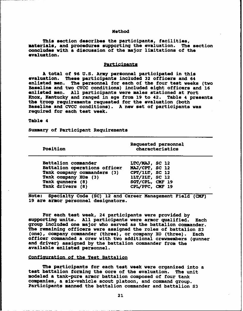
A total of 96 U.S. Army personnel participated in thisevaluation. These participants included 32 officers and 64enlisted men. The personnel for each of the four test weeks (twoBaseline and two CVCC conditions) included eight officers and 16enlisted men. All participants were males stationed at FortKnox, Kentucky and ranged in age from 19 to 42. Table 4 presentsthe troop requirements requested for the evaluation (bothBaseline and CVCC conditions). A new set of participants wasrequired for each test week.
Table 4
Summary of Participant Requirements
Requested personnelPosition characteristics
Battalion commander LTC/MAJ, SC 12Battalion operations officer MAJ/CPT, SC 12Tank company commanders (3) CPT/ILT, SC 12Tank company XOs (3) 1LT/2LT, SC 12Tank gunners (8) SGT/CPL, CMF 19Tank drivers (8) CPL/PFC, CMF 19
Note: Specialty Code (SC) 12 and Career Management Field (CMF)19 are armor personnel designators.
For each test week, 24 participants were provided bysupporting units. All participants were armor qualified. Eachgroup included one major who served as the battalion commander.The remaining officers were assigned the roles of battalion S3(one), company commander (three), or company XO (three). Eachofficer commanded a crew with two additional crewmembers (gunnerand driver) assigned by the battalion commander from theavailable enlisted personnel.
Configuration of the Test Battalion
The participants for each test week were organized into atest battalion forming the core of the evaluation. The unitmodeled a tank-pure armor battalion composed of four tankcompanies, a six-vehicle scout platoon, and command group.Participants manned the battalion commander and battalion S3
21
vehicles in the command group, as well as the company commanderand company XO vehicles in A, B, and C companies. Thebattalion's remaining combat vehicles (i.e., the tank platoons,all of D Company, and the scout platoon) were represented bySAFOR elements controlled by unit commanders and operated byrole-playing test personnel. Friendly forces may be referred toas BLUFOR (Blue Forces) and are comprised of both the mannedsimulators and SAFOR tanks. The OPFOR (Opposing Forces)consisted of SAFOR only. Figure 2 illustrates the battalion(BLUFOR) configuration (minus the scout platoon and the battalion
TOC), and differentiates between the manned simulators and SAFOR.
Battalion TOC Staff
The battalion TOC was staffed by four test personnel whoemulated the functions of a battalion main command post. Thesepersonnel, subject matter experts (SMEs) in the areas of commandand control, operations, intelligence, and fire support, role-played the positions of battalion XO, assistant S3, S2, and FSO.Performing as an integral part of the battalion organization forcombat, the TOC staff provided C3 support for combat operationsin a standardized and doctrinally-based (albeit abbreviated andstreamlined) manner. In the CVCC condition, these individualsperformed their tasks using the TOC workstations augmented byvoice radio. In the Baseline condition, these staff membersperformed their tasks manually and communicated with thesimulators solely by voice radio. The responsibilities assignedto members of the battalion TOC staff appear in Table 5.
22

02
FF
z
z0
Figure 2. Illustration of the battalion configuration (minus theTactical Operations Center and scout platoon).
23
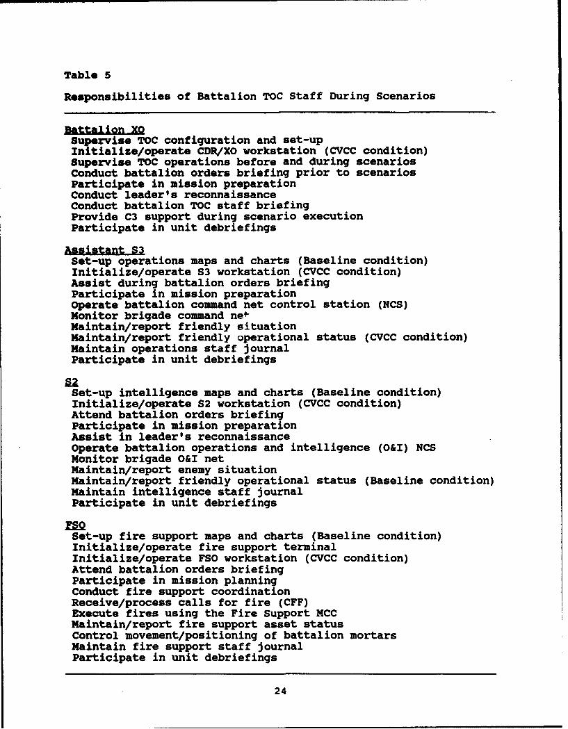
Table 5
Responsibilities of Battalion TOC Staff During Scenarios
Battalion XOSupervise TOC configuration and set-upInitialize/operate CDR/XO workstation (CVCC condition)Supervise TOC operations before and during scenariosConduct battalion orders briefing prior to scenariosParticipate in mission preparationConduct leader's reconnaissanceConduct battalion TOC staff briefingProvide C3 support during scenario executionParticipate in unit debriefings
Assistant S3Set-up operations maps and charts (Baseline condition)Initialize/operate S3 workstation (CVCC condition)Assist during battalion orders briefingParticipate in mission preparationOperate battalion command net control station (NCS)Monitor brigade command ne*Maintain/report friendly situationMaintain/report friendly operational status (CVCC condition)Maintain operations staff journalParticipate in unit debriefings
SUSet-up intelligence maps and charts (Baseline condition)Initialize/operate S2 workstation (CVCC condition)Attend battalion orders briefingParticipate in mission preparationAssist in leader's reconnaissanceOperate battalion operations and intelligence (O&I) NCSMonitor brigade O&I netMaintain/report enemy situationMaintain/report friendly operational status (Baseline condition)Maintain intelligence staff journalParticipate in unit debriefings
Set-up fire support maps and charts (Baseline condition)Initialize/operate fire support terminalInitialize/operate FSO workstation (CVCC condition)Attend battalion orders briefingParticipate in mission planningConduct fire support coordinationReceive/process calls for fire (CFF)Execute fires using the Fire Support MCCMaintain/report fire support asset statusControl movement/positioning of battalion mortarsMaintain fire support staff journalParticipate in unit debriefings
24
Test Facilities and Materials
This subsection describes the test facilities, equipment,and materials used to control the execution of training andtesting. It also describes the additional materials used tosupport training and testing, and the equipment used to collectand analyze the data from this evaluation.
Test Facilities
MWrB facilities used in this evaluation included aclassroom, eight vehicle simulators, the TOC, the ExerciseControl Room (ECR), a Stealth station, and the Data Collectionand Analysis (DCA) system. Figure 3 presents a schematic of theMWTB identifying the components used for this evaluation. Morecomplete facility descriptions may be found in previous CVCCpublications, especially O'Brien et al. (1992). Details on thesecomponents are presented in the following paragraphs.
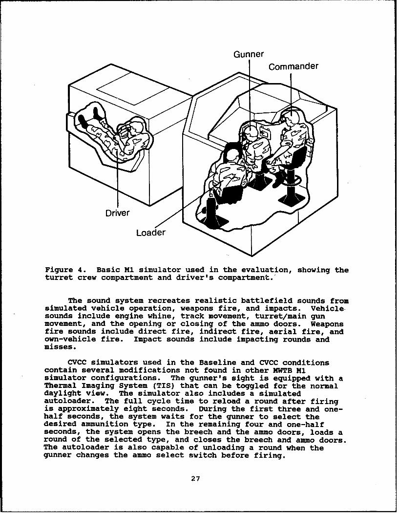
Baseline M1 simulators. Eight M1 tank simulators were usedin the evaluation. As depicted in Figure 4, the M1 simulatorconsists of two major sections: a driver's compartment and aturret crew compartment. The turret crew compartment hasstations for the vehicle commander, gunner, and loader. Moredetailed descriptions of the components and operation of both theBaseline and CVCC simulators may be found in the MILSImiEOperator's Guide (U.S. Army Armor School, 1987), in the SIMNETUsers' Guide (U.S. Army Armor School, 1989), and in the SIMNETCombat Vehicle Command and Control (CVC21 System User's Guide(Smith, 1990).
All M1 simulators in the MWTB contain the following majorfunctional components: a simulation host computer, a computerimage generation (CIG) system, a sound system, and severalinteractive device controller (IDC) boards. The simulation hostcomputer simulates the vehicle dynamics, kinematics, and thehydraulic, electrical, and fuel systems. The IDC boards read thestatus of crew controls and send the information to the hostcomputer. The host processes this information, along withinformation from other simulation elements transmitted over thesimulation Ethernet. The host then sends messages to the CIGsystem (what views to display), to the sound system (what soundsto transmit), and to the IDC boards (current status of crewcontrols). Messages about the current vehicle status arebroadcast over the simulation Ethernet to other simulators andexercise control systems.
The MWTB simulators were developed using a selectivefidelity approach. The simulators do not include all functionsand controls found in an actual M1 tank, but only those necessaryto fight. The simulator is equipped with a 105mm main guncapable of firing HEAT and SABOT rounds, three out-the-windowviews in the driver's and commander's stations, a gunner'sprimary sight (GPS), a GPS extension (GPSE) at the commander's
25

station, and a single rotatable view in the loader's station.The vehicle commander's station also includes a rotatable cupolathat allows him to manipulate his tkree out-the-window views. Aheadset with boom microphone is used for radio and intercomcommunication. The Ml simulators do not have the machine guns,Nuzzle Reference System (MRS), Gunner's Auxiliary Sight (GAS),nor open-hatch views available on the fielded Ml. The visualsystem is limited to views out to 3500 meters.
RMiTOG
M
EXERCISE BREAKCONTROL AREA
ROOM
CLASSROOM
F --•'UA AILOB8Y\
Figure 3. Floor plan of the Mounted Warfare Test Bed.
26
GunnerCommander
Loader
Figure 4. Basic M1 simulator used in the evaluation, showing theturret crew compartment and driver's compartment.'
The sound system recreates realistic battlefield sounds fromsimulated vehicle operation, weapons fire, and impacts. Vehiclesounds include engine whine, track movement, turret/main gunmovement, and the opening or closing of the ammo doors. Weaponsfire sounds include direct fire, indirect fire, aerial fire, andown-vehicle fire. Impact sounds include impacting rounds andmisses.
CVCC simulators used in the Baseline and CVCC conditionscontain several modifications not found in other MWTB M1simulator configurations. The gunner's sight is equipped with aThermal Imaging System (TIS) that can be toggled for the normaldaylight view. The simulator also includes a simulatedautoloader. The full cycle time to reload a round after firingis approximately eight seconds. During the first three and one-half seconds, the system waits for the gunner to select thedesired ammunition type. In the remaining four and one-halfseconds, the system opens the breech and the ammo doors, loads around of the selected type, and closes the breech and ammo doors.The autoloader is also capable of unloading a round when thegunner changes the ammo select switch before firing.
27
Each simulator is also equipped with two simulated SINCGARSradios. These radios replace the CB radios found in other MWTBsimulators. The radios convert voice transmissions into digitalsignals, which are broadcast over the simulation Ethernet. Thiscapability also makes it possible to capture voice transmissionsalong with simulation data broadcast over the Ethernet.
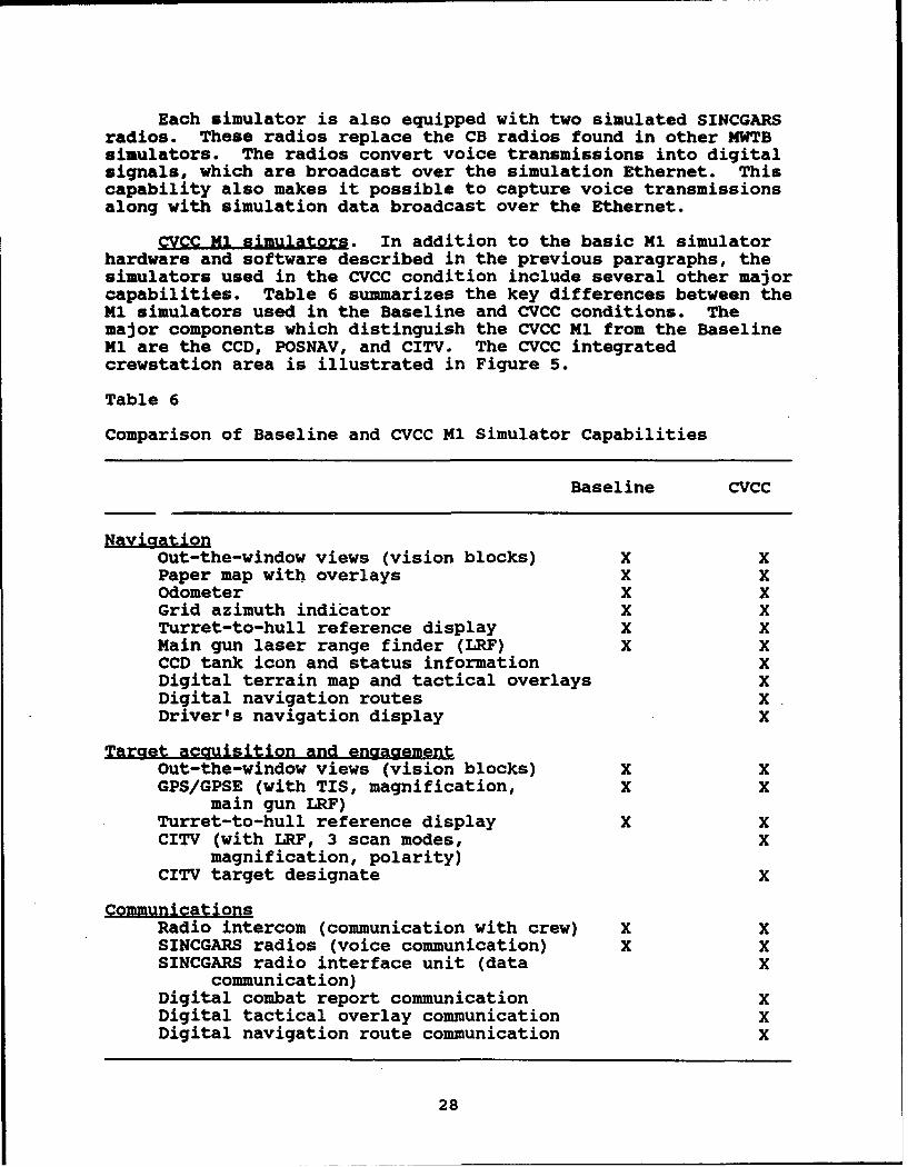
CVCC M1 simulators. In addition to the basic M1 simulatorhardware and software described in the previous paragraphs, thesimulators used in the CVCC condition include several other majorcapabilities. Table 6 summarizes the key differences between theMl simulators used in the Baseline and CVCC conditions. Themajor components which distinguish the CVCC M1 from the BaselineM1 are the CCD, POSNAV, and CITV. The CVCC integratedcrewstation area is illustrated in Figure 5.
Table 6
Comparison of Baseline and CVCC M1 Simulator Capabilities
Baseline CVCC
Out-the-window views (vision blocks) X XPaper map with overlays x xOdometer X XGrid azimuth indicator X XTurret-to-hull reference display X xMain gun laser range finder (LRF) X XCCD tank icon and status information XDigital terrain map and tactical overlays xDigital navigation routes XDriver's navigation display X
Target acquisition and enaaaementOut-the-window views (vision blocks) X XGPS/GPSE (with TIS, magnification, X X
main gun LRF)Turret-to-hull reference display X XCITV (with LRF, 3 scan modes, X
magnification, polarity)CITV target designate X
CommunicationsRadio intercom (communication with crew) X XSINCGARS radios (voice communication) X XSINCGARS radio interface unit (data X
communication)Digital combat report communication XDigital tactical overlay communication XDigital navigation route communication X
28
Ij
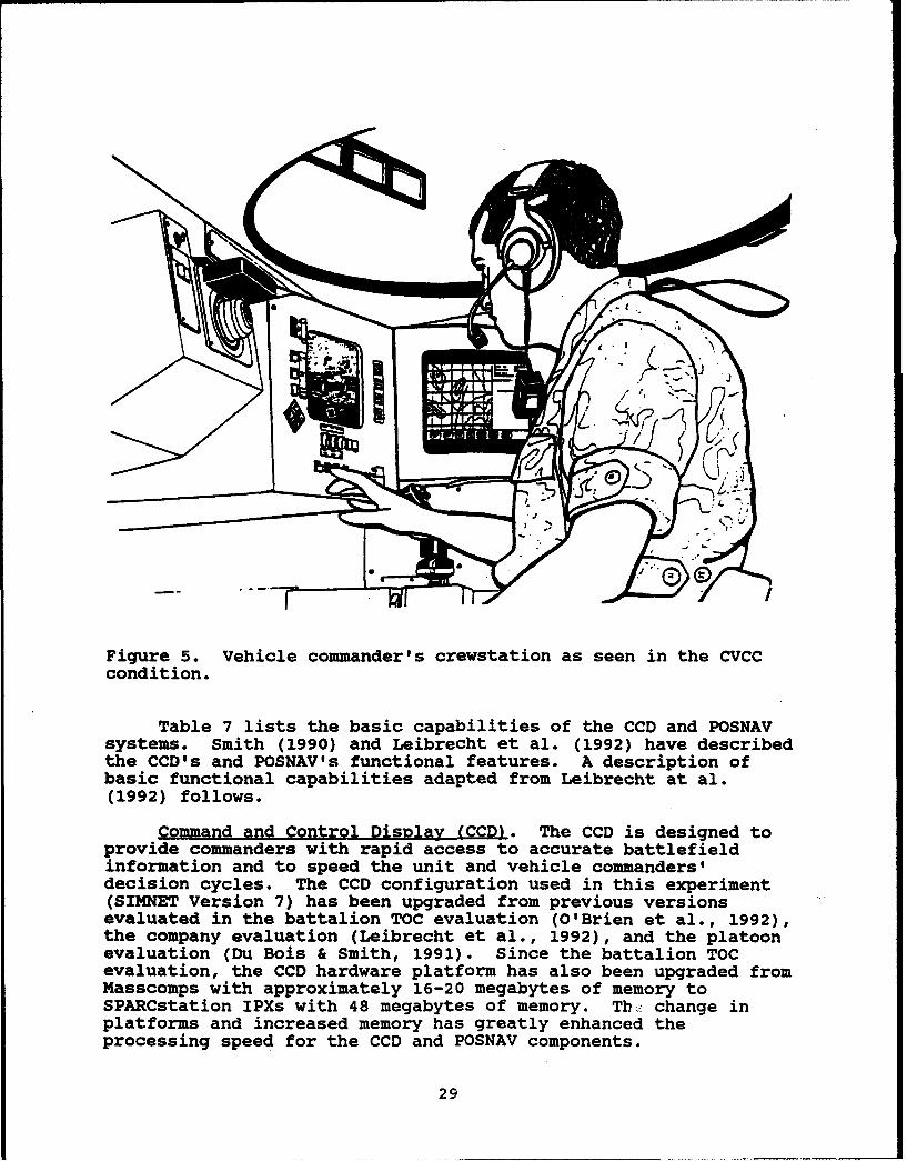
Figure 5. Vehicle commander's crewstation as seen in the CVCCcondition.
Table 7 lists the basic capabilities of the CCD and POSNAVsystems. Smith (1990) and Leibrecht et al. (1992) have describedthe CCD's and POSNAV's functional features. A description ofbasic functional capabilities adapted from Leibrecht at al.(1992) follows.
Command and Control DisDlay (CCD). The CCD is designed toprovide commanders with rapid access to accurate battlefieldinformation and to speed the unit and vehicle commanders'decision cycles. The CCD configuration used in this experiment(SIMNET Version 7) has been upgraded from previous versionsevaluated in the battalion TOC evaluation (O'Brien et al., 1992),the company evaluation (Leibrecht et al., 1992), and the platoonevaluation (Du Bois & Smith, 1991). Since the battalion TOCevaluation, the CCD hardware platform has also been upgraded fromMasscomps with approximately 16-20 megabytes of memory toSPARCstation IPXs with 48 megabytes of memory. Tbh. change inplatforms and increased memory has greatly enhanced theprocessing speed for the CCD and POSNAV components.
29
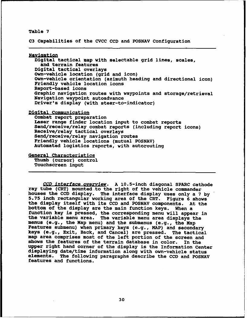
Table 7
C3 Capabilities of the CVCC CCD and POSNAV Configuration
Digital tactical map with selectable grid lines, scales,and terrain features
Digital tactical overlaysOwn-vehicle location (grid and icon)Own-vehicle orientation (azimuth heading and directional icon)Friendly vehicle location iconsReport-based iconsGraphic navigation routes with waypoints and storage/retrievalNavigation waypoint autoadvanceDriver's display (with steer-to-indicator)
Diaital CommunicationCombat report preparationLaser range finder location input to combat reportsSend/receive/relay combat reports (including report icons)Receive/relay tactical overlaysSend/receive/relay navigation routesFriendly vehicle locations (mutual POSNAV)Automated logistics reports, with autorouting
General CharacteristicsThumb (cursor) controlTouchscreen input
CCD interface overview. A 10.5-inch diagonal SPARC cathoderay tube (CRT) mounted to the right of the vehicle commanderhouses the CCD display. The interface display uses only a 7 by5.75 inch rectangular working area of the CRT. Figure 6 showsthe display itself with its CCD and POSNAV components. At thebottom of the display are the main function keys. When afunction key is pressed, the corresponding menu will appear inthe variable menu area. The variable menu area displays themenus (e.g., the Map menu) and the submenus (e.g., the MapFeatures submenu) when primary keys (e.g., MAP) and secondarykeys (e.g., Exit, Back, and Cancel) are pressed. The tacticalmap area comprises most of the left portion of the screen andshows the features of the terrain database in color. In theupper right hand corner of the display is the Information Centerdisplaying date/time information along with own-vehicle statuselements. The following paragraphs describe the CCD and POSNAVfeatures and functions.
30
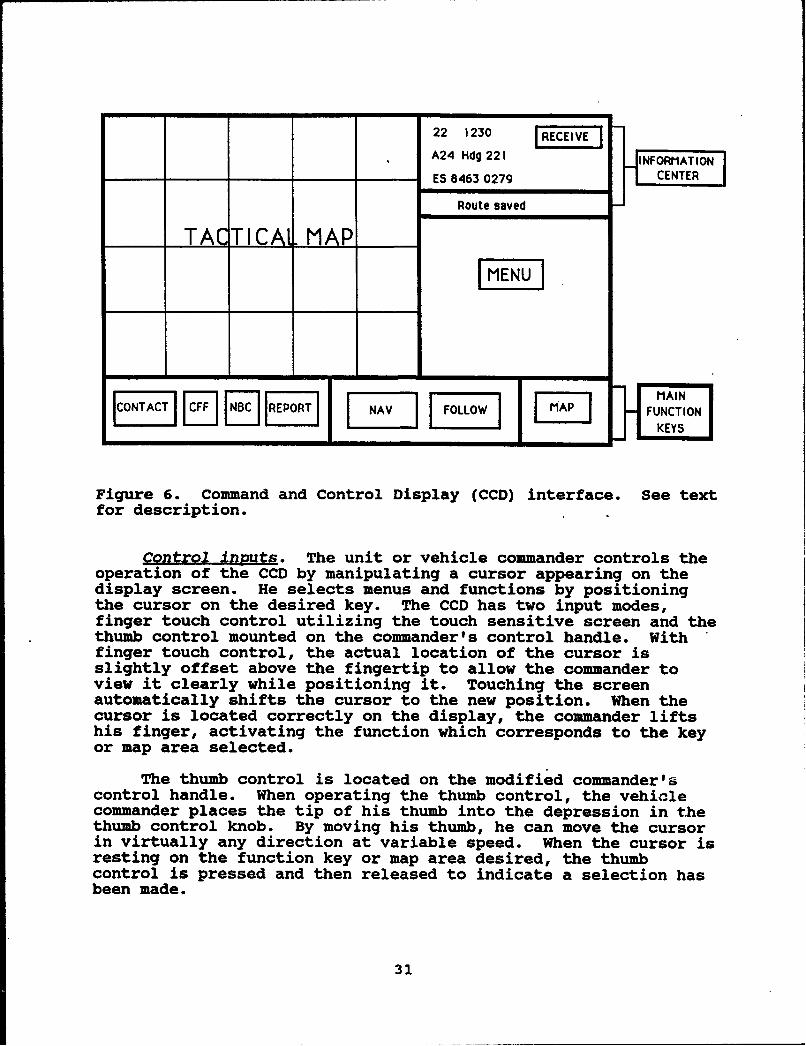
22 1230 I EA24 Hdg 221 INFORMATION
ES 8463 0279 CENTER
Route saved
I ACTAI CAI MAP
MAINLAC ~ JHAPT FUNCTION]
Figure 6. Command and Control Display (CCD) interface. See textfor description.
Control inputs. The unit or vehicle commander controls theoperation of the CCD by manipulating a cursor appearing on thedisplay screen. He selects menus and functions by positioningthe cursor on the desired key. The CCD has two input modes,finger touch control utilizing the touch sensitive screen and thethumb control mounted on the commander's control handle. Withfinger touch control, the actual location of the cursor isslightly offset above the fingertip to allow the commander toview it clearly while positioning it. Touching the screenautomatically shifts the cursor to the new position. When thecursor is located correctly on the display, the commander liftshis finger, activating the function which corresponds to the keyor map area selected.
The thumb control is located on the modified commander'scontrol handle. When operating the thumb control, the vehiclecommander places the tip of his thumb into the depression in thethumb control knob. By moving his thumb, he can move the cursorin virtually any direction at variable speed. When the cursor isresting on the function key or map area desired, the thumbcontrol is pressed and then released to indicate a selection hasbeen made.
31
Renort functions. The CCD supports preparation of digitalreports by means of menu-driven screens. The participant is ableto prepare any of the eight types of formal reports available onthe CCD: CONTACT reports, SPOT reports, SITREPs, INTELLIGENCE(INTEL) reports, CFF reports, ADJUST FIRE reports,Nuclear/Biological/Chemical (NBC) reports, and SHELL reports.The commander can call up CONTACT, CFF, and NBC report formatsdirectly from fixed function keys along the bottom of thedisplay. When preparing the other five report types, he mustselect the REPORT function key first, then select a report typeand "New" from the Report menu.
Each CCD report is composed of one or more pages of fieldstailored to that report type. The commander enters grid locationinformation into these report fields by lasing to a vehicle orterrain point or by indicating a location on the map using thetouchscreen or thumb control. He enters numbers of vehicles intoreport fields from a soft numeric keypad. He enters vehicletypes, activities, and other report information by makingselections from pulldown menus. Blank fields are permitted. Ashe enters "what" and "where" information into a report, adoctrinally correct North Atlantic Treaty Organization (NATO)symbol, called a report icon, appears on the tactical map at thelocation cited. The icon may be blue for friendly elements, redfor enemy elements, or green for obstacles (friendly or enemy).SPOT, SHELL, and INTELLIGENCE report icons may have small numbersabove them to reflect the numbers given in the report.
Participants may begin a report and then exit beforefinishing to perform another CCD or POSNAV function. Forexample, a vehicle commander may be creating a routine SITREPwhen he comes in enemy contact. He can leave the SITREP withoutcompleting it, create a CONTACT report, follow it up with a SPOTreport, and then return to complete the SITREP later. Multipletypes of reports may be open and stacked on the screensimultaneously, with the most recently accessed one visible ontop. However, only one of each type of report can be open at atime. When the participant has finished the report, he can sendit digitally by pressing the SEND key.
Diital report transmission. A simulated radio interfaceenables the unit or vehicle commander to transmit reportsprepared on the CCD. A routing menu offers the option of sendingany report on the CCD nets available. The battalion commanderand S3 have access only to the battalion command net on theirCCDs. The company commanders and XOs can send digital reports onthe company command net, the battalion command net, or bothsimultaneously. Default nets based on type and logical routingdirection (upward/adjacent or downward) exist for each reporttype. Of the eight types which can be created on a CCD, onlyone, an INTEL report, defaults downward. The other report typesdefault to the upward/adjacent net. The unit or vehiclecommander may override the default before pressing the SEND key.Once the report has been transmitted, a copy is kept in thecreator's "old" file for later retrieval and review. Also, the
32

message display in the Information Center shows "Message Sent" toreassure the creator that the report was sent. However, the CCDprovides no feedback to the sender as to whether the recipientshave opened, read, or will act in accordance with the report.
When a unit or vehicle commander receives a transmittedreport, three cues signal its arrival: the RECEIVE keyhighlights, an audible tone sounds in his headset (three beepsfor high priority reports, one beep for low priority), and itsreport icon appears on the tactical map, blinking for the firstfive seconds. High priority reports go to the top of the Receivequeue with low priority reports beneath them. Report priority isbased on immediacy of information. High priority reports whichcan be received include CONTACT, CALL FOR FIRE, ADJUST FIRE,FRAGO, FREE TEXT, INTELLIGENCE, and NBC reports. (FRAGO and FREETEXT messages cannot be created using the CCD, but they can bereceived and relayed.) Routes and overlays are also receivedlike high priority reports. Once received, reports remain in theReceive queue for five minutes. Meanwhile, the icon accompanyingthe report remains on the map. The Receive queue lists thereport type, originator, time the report was created, status(i.e., whether the report has been previously opened or relayed),and an asterisk indicating that the report icon is posted to thetactical map. The Receive queue will display up to nine items ata time. A paging function is available for viewing multi-pagelistings.
Once the commander selects and reads a report, he cannotmodify it. He may post the report icon to the tactical map if hedesires and then either exit the report, relay the report, ordelete the report. If he reaches the Report Action page in thereport, a copy automatically is placed in his "old" files forfuture reference. The default routing options are different whenrelaying a received report than when sending a report. Whenrelaying a report, the default net is based not on report typebut on routing nets. The CCD system defaults to the net thereport was not received on. This default was designed to preventcopies of a report from being rerouted on the same net.
Features for reducing duDlicate reports. A duplicate reportis a copy of a report received previously during an exercise.Before a report is shown in the Receive queue, the CCD checks tosee if it already has a copy in the Receive queue. If so, theCCD will not admit the new copy. However, if a report is in the"old" file, a copy can enter the Receive queue. Once the reportis in the Receive queue, the CCD provides other cues to the userthat the report received is a duplicate. The call signs of thereport's creator and sender at the highest echelon are given onthe routing page to help the receiver decide whether he needs torelay the report. For example, if the battalion commanderreceives a CONTACT report relayed by the A Company commander, thebattalion commander knows that the report was sent to him on thebattalion command net. Because the S2 is on CCD battalioncommand net, too, the battalion commander should not relay the
33

report using the CCD. He could, however, relay the report viavoice radio on the brigade command net.
Another CCD feature which helps reduce the number ofduplicate reports is the use of status symbols in the reportqueues. The symbols indicate whether a copy of the report hasbeen opened or routed. If a copy of the report is available inthe "old" files, the new report in the Receive queue willduplicate the status symbol of the copy in the "old" file. Thus,if a report appears in the RECEIVE queue with an arrow (-->), thereceiver knows that he relayed the earlier copy. He can deletethe new copy immediately. Likewise, if a report enters with thesymbol "0," the receiver knows that he has reviewed the copy butdid not relay it. He can choose to relay the report this time orcan delete it from his Receive queue.
Other CCD functions. The first of the remaining CCDfunctions is the Unpost Icons function. When numerous reportsare received during an exercise, the tactical map may becomecluttered with report icons. To declutter the tactical map, acommander can delete icons one at a time or he can select a menuoption to delete all icons posted longer than the times shown(e.g., posted longer than five minutes). Another CCD function isthe overlays function. The overlays function provides thecapability to receive and post mission overlays transmitted fromthe TOC workstations. These overlays are received like highpriority messages in the Receive queue and may be posted to thetactical map and relayed if desired. Friendly operationsoverlays are black, enemy operations overlays are red, andbarrier overlays are green.
An additional CCD map-related capability is aggregation anddeaggregation of friendly vehicle icons. Users can aggregatefriendly vehicle icons to the following levels: battalion,company, platoon, section, and vehicle level. The defaultaggregation levels are platoon level at 1:25,000 and 1:50,000 andcompany level at 1:125,000 and 1:250,000.
One of the newer CCD functions is the LOGISTICS report. TheLOGISTICS report is unique in that it allows the TOC workstationsto automatically receive status information on ammunition, fuel,equipment, and personnel from each vehicle with a CCD; no actionis required by any commander. Furthermore, the LOGISTICS reportallows the commander to check his own vehicle's ammunition,equipment, personnel, and fuel status. He can also check theammunition, equipment, personnel, and fuel status of his unit andof other units in the battalion. The equipment status will showlosses with any kind of equipment destruction (e.g., mobilitykill, main gun damage, or catastrophic kill). The fuel andammunition status are based on the number of units currentlycapable of using the supplies (i.e., dead vehicles are notincluded in the calculations). Personnel status decreases byfour crewmembers every time a vehicle is catastrophically killed.The LOGISTICS report updates within ten seconds of a change instatus.
34
PONY. The POSNAV component provides unit and vehiclecommanders with automated, accurate updates of criticalpositioning and navigation information, such as own-vehicle andother friendly vehicle locations presented on a tailorable,digitized map as well as grid locations and vehicle headings.POSNAV also provides commanders with the means to create routesand to send navigational information to the driver. The driveruses this navigational information to steer to the next controlpoint. The POSNAV configuration used in this experiment has beenupgraded from previous versions evaluated in the battalion TOCevaluation (O'Brien et al., 1992), the company evaluation(Leibrecht et al., 1992), the platoon evaluation (Du Bois &Smith, 1991), and the crew evaluation (Du Bois & Smith, 1989).
MAR functions. The basic tactical map is a UniversalTransverse Mercator (UTM) grid representation of the terrain.Digital data in the SIMNET terrain database constitute the basisfor all resident map graphics. The digital map may be tailoredto show color-coded contour lines, rivers, roads, vegetation, andUTM grid lines.
Map rescaling and scrolling functions are available as well.The four map scales available are 1:25,000, 1:50,000, 1:125,000,and 1:250,000. There are three map scrolling functions availableso that a commander can keep his map at the same scale but shiftthe map section displayed to see different terrain. The MoveVehicle function allows the user to position his tank iconanywhere on the screen. The map shifts as the icon repositionsso that the own vehicle location remains accurate. MoveVehicle's counterpart, Follow, allows the vehicle icon to remainstationary on the display while the map scrolls beneath the iconas the vehicle itself moves. A third scrolling option, Jump,allows the use of blue "jump spots" on the corners and sides ofthe map to move the map one-half the map screen height/width per"jump." If a "jump spot" is not touched, the map remainsstationary. When the vehicle moves, the own-vehicle icon willmove across the stationary map terrain. Jump mode allows the mapto be quickly shifted for inspection of off-screen icons or toplace waypoints off the currently shown map display. Thecommander can quickly return the map to its original position bygoing back to Follow mode.
Own-vehicle and friendly vehicle icons. A directional, all-parts-moving own vehicle icon is displayed at the correct gridlocation on the tactical map. The own-vehicle icon has featuresrepresenting the gun tube, the CITV line-of-sight (LOS), thefront slope of the vehicle, and the hull. The digital map alsodisplays blue tank icons which represent the friendly vehicles inthe battalion. These tank icons move as the actual vehiclesmove, providing information on friendly mission execution to aidC3.
The Information Center augments the vehicle statusinformation shown graphically by the POSNAV own vehicle icon.The center shows the date, time of day, vehicle call sign, own
35
vehicle heading in degrees, and the six-digit own vehicle UTmgrid location. The status information, like the POSNAV own-vehicle icon, will update as the vehicle moves along the databaseor at a rate of approximately every ten seconds.
Commanderts station navigation functions. POSNAV enablesthe unit or vehicle commander to create and modify routes fornavigation and to send route information to his driver and toother vehicles in his battalion. Using the Navigation function,routes are created when locations for up to six control points,called waypoints, are selected on the digital map. An icon foreach waypoint appears on the tactical map. The waypoints areconnected by lines to form a route. The commander can sendwaypoints to his driver one at a time (manually) or automaticallyby means of an Autoadvance option. Autoadvance sends informationon the next waypoint when the vehicle is within 100 meters of thecurrent waypoint.
Driver's display. When the driver's display receiveswaypoint information from the vehicle commander, the relativedirection to the selected waypoint is depicted graphically viathe steer-to display, a directional "clock" which providessteering guidance to the driver to allow him to stay on course.To the right of the steer-to display is information on thewaypoint number, the current vehicle heading (in degrees), thedeviation in degrees from the selected waypoint, and the distance(in kilometers) to the selected waypoint. There is also an areaat the top of the steer-to-display where the driver sees themessage "Auto Advancing to WP XX" when the system autoadvances tothe next waypoint.
CCD and POSNAV changes since the battalion TOC evaluation.A number of hardware and software changes have been made to theCCD and POSNAV systems following the battalion TOC evaluation.These modifications capitalize on findings and lessons learnedfrom iterative CVCC research. The change most affecting the CCDand POSNAV has been upgrading the equipment platform from aNasscomp with 16-20 megabytes of memory to a SPARCstation IPXwith 48 megabytes of memory. Besides making the CCD morecompatible with the TOC workstations, the processing speed forall CCD and POSNAV functions has increased greatly. For example,rescaling the map now takes only a few seconds, compared with upto ten seconds previously. The memory increase brings severalother beneficial changes. For the first time, the tactical mapdisplays tree canopies instead of only tree lines, and vegetationcan be viewed at scales of 1:125,000 and above. POSNAV iconlocations update more consistently despite the variable load onthe CCD nets. Previously, stacked overlays and report screenshad tied up so much available memory that the slowed processessometimes caused menus to be drawn top to bottom before thecommander's eyes. With the additional memory and new platform,the incidence of slow processing is substantially less. Asummary listing of CCD and POSNAV changes, along with briefrationale statements, may be seen in Table 8.
36

Table 8
Changes to the CCD and POSNAV Since the Battalion TOC Evaluation
Change Reason
Hardware
" Platform upgraded from Mass- Provides greatercomps to SPARCstation IPXs compatibility with TOC
workstations.
"* Memory increased from 16-20 Increases processingmegabytes to 48 megabytes. speed and provides more
detailed map terrain.
Software
" Soft numeric keypads added to Provides greater precision inINTEL, SHELL, and SPOT reports. reporting numbers of vehicles
and shell impacts.
"• Text incorporated in overlays. Allows overlays and textto be linked for sendingand reviewing.
" Obstacle icons represented by Provides doctrinally correct,green NATO symbols. standardized symbols.
"• Overlays made deletable from Gives commander flexibilityoverlay file list. in managing overlays.
" Paging up and down added to Provides more precisereport queues and FREE TEXT means of scrolling thanreports. scroll bars and arrows.
"• Posted icons indicated by Allows commanders toasterisk in report queues. quickly assess which reports
are already posted.
"* Ammo status report replaced by Provides automatic andautomated Logistics status accurate fuel, ammo,reporting. equipment, and personnel
status for own vehicle,own unit, and other units.
(table continues)
37
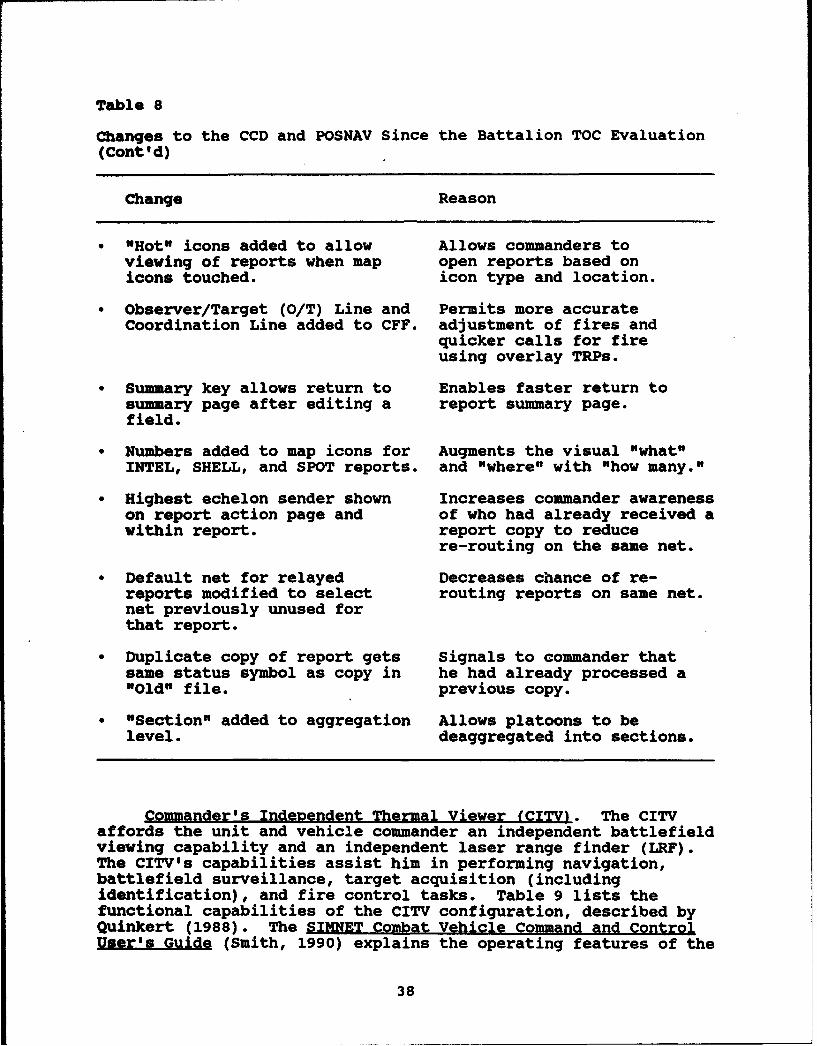
Table 8
Changes to the CCD and POSNAV Since the Battalion TOC Evaluation(Cont'd)
Change Reason
" "Hot" icons added to allow Allows commanders toviewing of reports when map open reports based onicons touched. icon type and location.
" Observer/Target (O/T) Line and Permits more accurateCoordination Line added to CFF. adjustment of fires and
quicker calls for fireusing overlay TRPs.
"* Summary key allows return to Enables faster return tosummary page after editing a report summary page.field.
"* Numbers added to map icons for Augments the visual "what"INTEL, SHELL, and SPOT reports. and "where" with "how many."
"* Highest echelon sender shown Increases commander awarenesson report action page and of who had already received awithin report. report copy to reduce
re-routing on the same net.
" Default net for relayed Decreases chance of re-reports modified to select routing reports on same net.net previously unused forthat report.
" Duplicate copy of report gets Signals to commander thatsame status symbol as copy in he had already processed a"Old" file. previous copy.
" "Section" added to aggregation Allows platoons to belevel. deaggregated into sections.
Commander's Independent Thermal Viewer (CITV). The CITVaffords the unit and vehicle commander an independent battlefieldviewing capability and an independent laser range finder (LRF).The CITV's capabilities assist him in performing navigation,battlefield surveillance, target acquisition (includingidentification), and fire control tasks. Table 9 lists thefunctional capabilities of the CITV configuration, described byQuinkert (1988). The SIMNET Combat Vehicle Command and ControlUser's Guide (Smith, 1990) explains the operating features of the
38
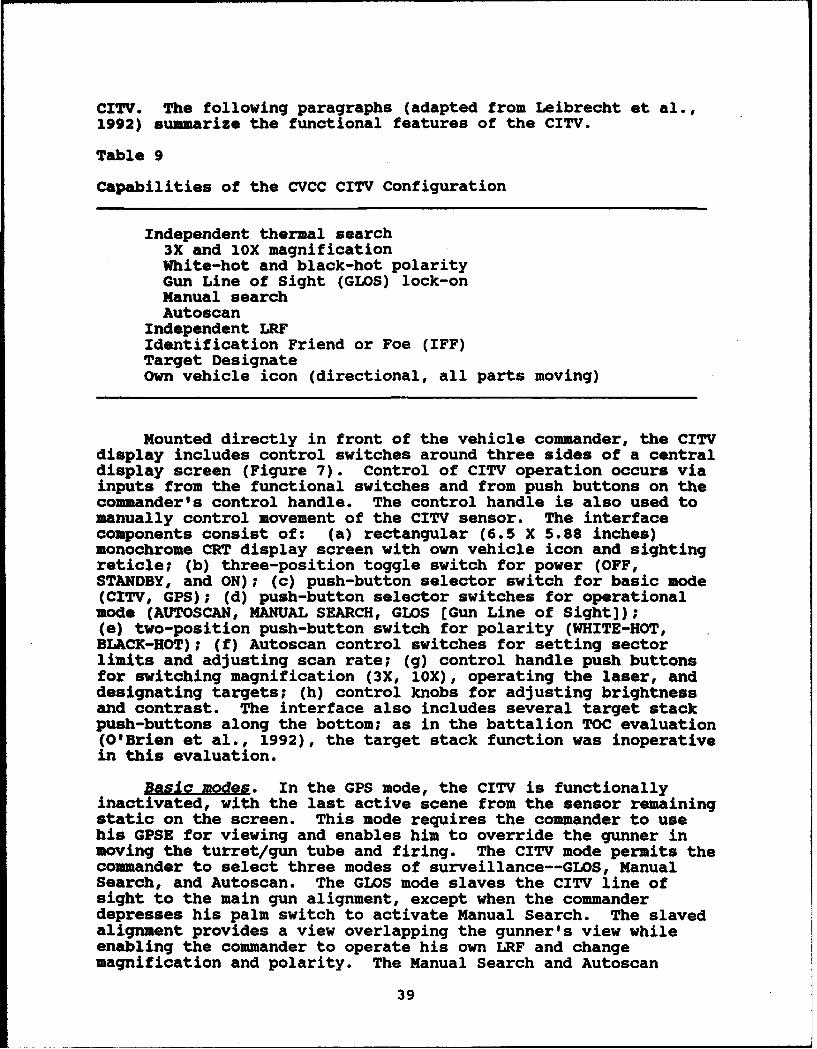
CITV. The following paragraphs (adapted from Leibrecht et al.,
1992) summarize the functional features of the CITV.
Table 9
Capabilities of the CVCC CITV Configuration
Independent thermal search3X and 1oX magnificationWhite-hot and black-hot polarityGun Line of Sight (GLOS) lock-onManual searchAutoscan
Independent LRFIdentification Friend or Foe (IFF)Target DesignateOwn vehicle icon (directional, all parts moving)
Mounted directly in front of the vehicle commander, the CITVdisplay includes control switches around three sides of a centraldisplay screen (Figure 7). Control of CITV operation occurs viainputs from the functional switches and from push buttons on thecommander's control handle. The control handle is also used tomanually control movement of the CITV sensor. The interfacecomponents consist of: (a) rectangular (6.5 X 5.88 inches)monochrome CRT display screen with own vehicle icon and sightingreticle; (b) three-position toggle switch for power (OFF,STANDBY, and ON); (c) push-button selector switch for basic mode(CITV, GPS); (d) push-button selector switches for operationalmode (AUTOSCAN, MANUAL SEARCH, GLOS [Gun Line of Sight]);(e) two-position push-button switch for polarity (WHITE-HOT,BLACK-HOT); (f) Autoscan control switches for setting sectorlimits and adjusting scan rate; (g) control handle push buttonsfor switching magnification (3X, 1OX), operating the laser, anddesignating targets; (h) control knobs for adjusting brightnessand contrast. The interface also includes several target stackpush-buttons along the bottom; as in the battalion TOC evaluation(O'Brien et al., 1992), the target stack function was inoperativein this evaluation.
Basic modes. In the GPS mode, the CITV is functionallyinactivated, with the last active scene from the sensor remainingstatic on the screen. This mode requires the commander to usehis GPSE for viewing and enables him to override the gunner inmoving the turret/gun tube and firing. The CITV mode permits thecommander to select three modes of surveillance--GLOS, ManualSearch, and Autoscan. The GLOS mode slaves the CITV line ofsight to the main gun alignment, except when the commanderdepresses his palm switch to activate Manual Search. The slavedalignment provides a view overlapping the gunner's view whileenabling the commander to operate his own LRF and changemagnification and polarity. The Manual Search and Autoscan
39
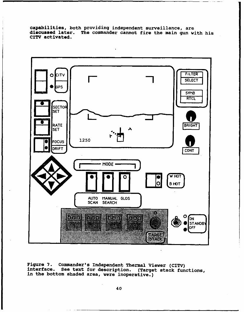
capabilities, both providing independent surveillance, arediscussed later. The commander cannot fire the main gun with hisCITV activated.
0 ITV FILTER
II" SELECT
te~J SYMB5SET
5RRATET
S00C U SO 1250
[~~MODE)
40
[ AUTO MANUAL GLOSSCAN SEARCH
.. .. 1;~ ..........
S ....0 ON
* OFFj
Figure 7. Commander's Independent Thermal Viewer (CITV)interface. See text for description. (Target stack functions,in the bottom shaded area, were inoperative.)
40
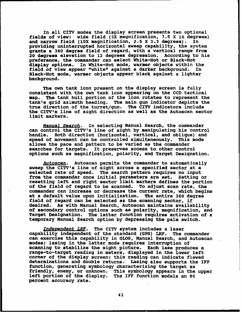
In all CITV modes the display screen presents two optionalfields of view: wide field (3X magnification, 7.5 X 10 degrees)and narrow field (1OX magnification, 2.5 X 3.3 degrees). Inproviding uninterrupted horizontal sweep capability, the systemgrants a 360 degree field of regard, with a vertical range from20 degrees elevation to 12 degrees depression. According to hispreference, the commander can select White-Hot or Black-Hotdisplay options. In White-Hot mode, warmer objects within thefield of view appear "white" against a darker background. InBlack-Hot mode, warmer objects appear black against a lighterbackground.
The own tank icon present on the display screen is fullyconsistent with the own tank icon appearing on the CCD tacticalmap. The tank hull portion of the icon rotates to represent thetank's grid azimuth heading. The main gun indicator depicts thetrue direction of the turret/gun. The CITV indicators includethe CITV's line of sight direction as well as the Autoscan sectorlimit markers.
Manual Search. In selecting Manual Search, the commandercan control the CITV's line of sight by manipulating his controlhandle. Both direction (horizontal, vertical, and oblique) andspeed of movement can be controlled simultaneously. This modeallows the pace and pattern to be varied as the commandersearches for targets. It preserves access to other controloptions such as magnification, polarity, and Target Designation.
Autoscan. Autoscan permits the commander to automaticallysweep the CITV's line of sight across a specified sector at aselected rate of speed. The search pattern requires no inputfrom the commander once initial parameters are set. Setting orresetting left and right sector limit markers defines the portionof the field of regard to be scanned. To adjust scan rate, thecommander can increase or decrease the current rate, which beginsat a default value upon initialization. The entire 360 degreefield of regard can be selected as the scanning sector, ifdesired. As with Manual Search, Autoscan maintains availabilityof secondary control options such as polarity, magnification, andTarget Designation. The latter function requires activation of atemporary Manual Search option by depressing the palm switch.
Independent LRF. The CITV system includes a lasercapability independent of the standard (GPS) LRF. The commandercan exercise this capability in GLOS, Manual Search, and Autoscanmodes; lasing in the latter mode requires interruption ofscanning to stabilize the sight picture. Each lase produces arange-to-target reading in meters, displayed in the lower leftcorner of the display screen; this reading can indicate flaweddeterminations and double returns. Lasing also supports the IFFfunction, generating symbology characterizing the target asfriendly, enemy, or unknown. This symbology appears in the upperleft portion of the display. The IFF function models an 80percent accuracy rate.
41
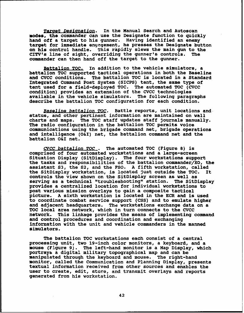
Tar et Designation. In the Manual Search and Autoscanmodes, the commander can use the Designate function to quicklyhand off a target to his gunner. Having identified an enemytarget for immediate engagement, he presses the Designate buttonon his control handle. This rapidly slews the main gun to theCITV's line of sight, overriding the gunner's controls. Thecommander can then hand off the target to the gunner.
Battalion TOC. In addition to the vehicle simulators, abattalion TOC supported tactical operations in both the Baselineand CVCC conditions. The battalion TOC is located in a StandardIntegrated Command Post System (SICPS) tent, the same type oftent used for a field-deployed TOC. The automated TOC (CVCCcondition) provides an extension of the CVCC technologiesavailable in the vehicle simulators. The following paragraphsdescribe the battalion TOC configuration for each condition.
Baseline battalion TOC. Battle reports, unit locations andstatus, and other pertinent information are maintained on wallcharts and maps. The TOC staff updates staff journals manually.The radio configuration in the battalion TOC permits voicecommunications using the brigade command net, brigade operationsand intelligence (O&I) net, the battalion command net and thebattalion O&I net.
CVCC battalion TOC . The automated TOC (Figure 8) iscomprised of four automated workstations and a large-screenSituation Display (SitDisplay). The four workstations supportthe tasks and responsibilities of the battalion commander/XO, theassistant S3, the S2, and the FSO. A fifth workstation, calledthe SitDisplay workstation, is located just outside the TOC. Itcontrols the view shown on the SitDisplay screen as well asserving as a technical "troubleshooting" station. The SitDisplayprovides a centralized-location for individual workstations topost various mission overlays to gain a composite tacticalpicture. A sixth workstation is located in the ECR and is usedto coordinate combat service support (CSS) and to emulate higherand adjacent headquarters. The workstations exchange data on aTOC local area network, which in turn connects to the CVCCnetwork. This linkage provides the means of implementing commandand control procedures and coordination and exchanginginformation with the unit and vehicle commanders in the mannedsimulators.
The battalion TOC workstations each consist of a centralprocessing unit, two 19-inch color monitors, a keyboard, and amouse (Figure 9). The left-hand monitor is a Map Display, whichportrays a digital military topographical map and can bemanipulated through the keyboard and mouse. The right-handmonitor, called the Communication and Planning Display, presentstextual information received from other sources and enables theuser to create, edit, store, and transmit overlays and reportsgenerated from his workstation.
42
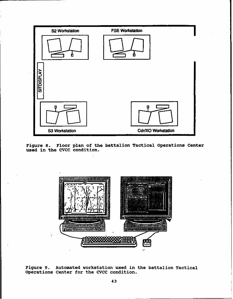
S2 Workstation FSE Workstation
S3 Workstaton Cdr/XO Worksation
Figure S. Floor plan of the battalion Tactical operations Centerused in the CVCC condition.
Figure 9. Automated workstation used in the battalion TacticalOperations Center for the CVCC condition.
43

The TOC workstations permit TOC personnel to perform keycommand and control functions such as receiving combatinformation, generating combat orders and overlays, andcommunicating information within the TOC and throughout thebattalion. All TOC workstations have common hardware andfunctional features described in the following paragraphs. Acomplete guide to the functionality and operation of the TOCworkstations may be found in the Battalion Tactical OperationsCenter (TOCI Job Aid (BDM Federal, Inc., 1992).
The workstation software consists of two major components:the Map Module and Message Module. Map Module functions providethe means to create and edit overlays, manipulate map objects,and adjust features (e.g., map scale, contour lines, terrainfeatures) of the tactical map. The Map Module can display threeclasses of objects. These objects include (a) graphic overlays,(b) friendly vehicle icons (POSNAV-generated), and (c) messageicons.
Overlays are created by workstation operators to representoverlays commonly associated with tactical combat operations(e.g., operations, intelligence, fire support, barrier). Thestaff can create these overlays by selecting objects such as unitsymbols and points of military interest (e.g., checkpoints,target reference points, coordinating points) and by constructingroutes, boundaries, and other graphic control measures usingdrawing tools. Although graphic symbols are available to supportthe individual types of overlays drawn (e.g., fire support), allworkstations have the same library of overlay features from whichto choose. For example, the current version of the battalion TOCsoftware has been updated since the battalion TOC evaluation, toinclude those fire support graphic control measures and points ofinterest which allow the FSO to plan fires based on incomingdigital CFF and ADJUST FIRE reports. The visual richness of the.display can be varied by changing the stacking order ofoverlapping objects and clustering unit symbols hierarchically.Hierarchically clustered symbols can be represented by theirsuperordinate unit symbol. Once created, overlays can be edited,stored, retrieved, and transmitted by the battalion TOC staff onthe battalion network to the simulators. They can also be postedto the SitDisplay to create an updated picture of the battlefieldsituation.
The Course of Action (COA) overlay is a unique type ofoverlay in that it has the ability to show via "animation" theprojected movement of units across the battlefield. It is a newfeature added to the TOC workstations since the battalion TOCevaluation. The COA overlay is a tool for the battalioncommander, battalion XO, cr battalion S3 to use as they wargamepossible courses of action as well as a visual aid for briefingunits on the upcoming mission. As each stage of the mission isplanned, phase icons are placed on the overlay in the variousanticipated locations. When the planning is complete, the COAcan be activated to show the progression of the unit symbols fromone phase/location to the next. Unlike other types of overlays,
44
the COA cannot be sent to the simulators, so it plays a key roleonly in the pre-mission stage of the exercise.
Another feature added to the TOC workstations since thebattalion TOC evaluation is the Task Organization/OperationalEffectiveness (TO/OE) module. The TO/OE module allows the TOCworkstations to receive the LOGISTICS report information from theCCDs. It uses this logistics information to display color-codedbar graphs which represent the color-coded level (green, amber,red, black--GARB) of the ammunition, fuel, equipment, andpersonnel for units with CCDs.
Friendly vehicle icons are also an element of the MapModule. Like the POSNAV icons on the CCD map displays, theseicons indicate actual location information received from thePOSNAV-equipped individual vehicles in the battalion. The iconlocations are dynamically updated as the vehicles maneuver acrossthe simulated battlefield. The workstation operator canaggregate the individual vehicle icons into higher level unitsymbols (i.e., from a tank icon to a platoon, company, orbattalion unit symbol) to reduce display clutter, or he canselectively deaggregate them as necessary (e.g., deaggregate BCompany to the platoon level).
Message icons indicate information from digital combatreports (e.g., SPOT, CONTACT) that have been viewed or created.They may also represent information previously posted to the MapDisplay. Reports can be viewed by selecting their message icons.They can also be linked to the appropriate unit symbols within anoverlay (e.g., linking a SPOT report to a threat icon placed onan INTEL overlay). In the event of multiple icons in the samelocation, the stacking order of message icons can be also bechanged.
The Message Module functions enable the staff to receivedigital combat reports from the CVCC network and store them inthe workstation's database. The staff can also create digitalmessages and/or route them on the battalion command net to thesimulators, other workstations, or to internal workstationfolders. A complete description of the Message Module contentsand functionality may be found in the Battalion TacticalOperations Center (TOCI Job Aid (0DM Federal, Inc., 1992).
The following operations can be performed on digitalmessages: (a) receive incoming messages, (b) create new ordelete existing messages, (c) view a message; (d) route a messageto another folder (e) post a message to the Map Display orSitDisplay; (f) send a message to another workstation or to aCCD. Messages are created using report formats containingseveral option fields that permit the user to input the contentsof a standardized message. To read a message, a message headermust be selected from a folder's message list, or a posted iconmust be selected from the Map Display.
45
Folders provide the means for managing message traffic. Allnew messages appear in the InFolder. The Miscellaneous folderserves as a holding file, with unprocessed reports moving fromthe InFolder to the Miscellaneous folder five minutes afterreception. Reports can be copied to the Journal folder, whichprovides a permanent, chronological record of events. There isno capacity to delete reports from the Journal. The Map Displayfolder stores the message contents associated with reports postedto the workstations' own map displays. Likewise, the SitDisplayfolder stores the messages posted by each workstation to theindependent SitDisplay. The operator can create additionalfolders as needed. Workstation operators can also view thecontents of other workstations' folders.
Exercise control eouiDment. The stations that control thetraining events, the training exercises, and the training andtest scenarios are located in the ECR. These stations consistof: (a) two Plan View Displays (PVD), (b) six SINCGARS simulators(stand-alone), (c) a CB radio, (d) a Management, Command, &Control terminal, (e) a SIMNET Control Console, (f) threesemiautomated forces (SAFOR) workstations, (g) a combat servicesupport battalion TOC workstation, and (h) a LISTEN station.
One PVD is used for brigade-level monitoring and one forbattalion-level monitoring. The six table-top SINCGARSsimulators and one CB unit provide tactical and administrativecontrol radio communications. The Management, Command, andControl (MCC) system monitors and controls the status of thesimulators, while a LISTEN station monitors the digital messagetraffic. The three SAFOR stations (two for friendly SAFOR andone for OPFOR) control and operate the simulation-generatedforces. A Combat Service Support (CSS) workstation is used fordigital communication (e.g., transmission of messages andoverlays) between the TOC and ECR. The CSS workstation alsoaccommodates the SEND ktility for preparing, retrieving fromstorage, and transmitting electronic reports at the brigade stafflevel. Figure 10 depicts the configuration of the ECR during thebattalion evaluations. The following sections describe eachstation in greater detail.
Mg. Two PVDs provide the primary monitoring capabilitiesduring the execution of the training and test scenarios. The PVDscreen provides the control staff with a real-time, "God's eye"view of the battlefield. All vehicles, aircraft, gunnerytargets, impacting artillery, and mortar fires are displayed. Inaddition, graphic control measures, grid lines and coordinates,lasing, and direct fire engagements are available for viewing.Through a series of keyboard commands, the PVD operator caninsert a "flag" or time marker into the data stream to denote asignificant or critical event useful for later analysis. PVDcapabilities include map manipulation, vehicle identification,intervisibility plotting, and a number of other functions.
46

LISTEN Station (INCGRa i s -- ,. ,, ,
SAFOR Workstations
OSS Workstation
cc{ cO cc Monitor
MCC Array
Bde PVD
Bde 0 & I
Figure 10. Floor plan of the Exercise Control Room (EcR),showing the layout of exercise control equipment.
Radio network. The simulated SINCGARS radio system servicesseven voice radio nets--brigade command, battalion command,battalion O&I, and four company command nets. Figure 11 showsthe radio networks and configuration used in the Baseline andCVCC conditions. All nets except the battalion O&I net areavailable for digital burst transmission of reports and overlays.The company XOs, like the company commanders, have the battalion•ommand net and the company command net routing options on their,CDs.
Seven send/receive stand-alone radios are used to monitoroperational radio nets in the ECR. Six of these are stand-aloneSINCGARS simulators. The brigade command net, located at thebrigade PVD station, is used by the Battle Master (military SMEwho oversees scenario execution) to represent adjacent
47

battalions. During training and the test scenarios, thebattalion command net, located next to the battalion PVD;monitors voice messages (e.g., crossing phase lines [PLs],reporting SET).
Odgae ComumdNot 4M A Compwiy Command Net
-rkpgd Operationw a kftetene Net - B Cont Comm-md Net
-"Bmattaon Command Net - C Coipwny Commwnd Net
-Bafttaion Operabmon & kftftence Net
Gmmuumnd O& INJ~t
TOC
Roan
,-- -. •-- --------: aA GoI ___
Figure 11. Diagram of the tactical radio networks (voice)implemented in the evaluation.
48
SAFOR operators monitor the nets appropriate to their roles.During training and the test scenarios, five nets are monitored:thre. company nets, the battalion command net, and the battalionO&I net. An additional CB radio (brigade O&I net) permitsprivate radio communication between the battalion TOC and theECR.
Management. Command. and Control syAtem (MCC). The MCCsystem initializes and manages the simulation. Initializationselections define the terrain database, the exercise identifier,simulator parameters, and unit organizations. Theseinitialization selections permit the control staff to repeatedlycall up and execute scenarios in a standardized manner. Onceinitialized, the MCC provides easy access to status informationabout all operational manned simulators.
The SIMNET Control Console (SCC) is a component of the MCCsystem used to initiate the MCC's involvement in an exercise andto access most of the functions simulated by the MCC system. TheSCC allows the control staff to place simulators and gunnerytargets in specific locations on the terrain database. Standardfiles for each scenario and exercise permit all vehicles andtargets to be placed on the terrain database with only a few keystrokes. Thus, initialization and setup are both rapid andstandardized. The SCC also provides the control staff with theability to "reconstitute" or restore any elements that may havemalfunctioned or "dropped off" the simulation network during thecourse of a scenario.
SAFOR workstations. The SAFOR workstations are used by therole-playing operators to monitor and control the automatedfriendly (BLUFOR) and enemy (OPFOR) units. BLUFOR operatorsrespond to and implement the commands of unit and vehiclecommanders located in the M1 simulators. Two SAFOR operators areresponsible for directing the activities of the subordinateautomated forces in accordance with the directives of theparticipant commanders. A single OPFOR workstation operator isresponsible for directing the activities of the simulated threatforces in accordance with the training and test scenarios. Withstandardized operating procedures, events lists, and scriptedOPFOR engagement timelines and axes of advance, the set-up andexecution are standardized for both conditions and all rotations.Offensive and defensive scenario events lists can be found in thebattalion-level preliminary evaluation (O'Brien et al., 1992); inaddition, the RA and Battle Master logs in Appendix C containscenario events.
Each SAFOR workstation provides a top-down color map displaycapable of depicting the current state of the battlefield. Inthe case of the battalion evaluation, however, this view islimited to the information reported by forces on the battlefield.The operator may zoom in or pan to any point on the map display.Features such as contour lines, UTM grids, roads, water, trees,bridges, railroad tracks, control measures, and buildings may allbe displayed. Engagement and speed parameters for all SAFOR
49

vehicles are entered using the workstation keyboard (e.g.,engagement distance rules and cross-country rate of movement).Initialization files for each scenario and exercise permit bothfriendly BLUFOR and OPFOR units to be called up in their correctstarting locations using a few keyboard commands.
SAFOR software routines automatically generate and sendevent-driven digital reports to the manned-simulator CCDs in theCVCC condition. During both conditions, RadioTelephone Operators(RTOs) role-play subordinate platoon leaders and the D companycommander and XO. During Baseline, they relay the automatedSAFOR reports and coordination items via voice radio. Thisautomated information includes CONTACT reports, SPOT reports, andSITREPs. During the CVCC condition, the CCD-type reports aresent digitally, but coordination items not supported by the CCD(e.g., SET on BP 41) are still sent by voice.
Stealth vehicle. The Stealth station is a "ghost" simulatorwhose appearance cannot be detected by other combat simulators.The Stealth can move about the battlefield, undetected by mannedsimulators, and observe vehicles, fires, maneuver, and virtuallyall combat activities. The Stealth station consists of three 25-inch monitors, a PVD, and a SpaceBall control integrated into asingle simulated vehicle. The SpaceBall provides control inputto move the vehicle around on the battlefield. The PVD is usedto determine the observer location on the simulated battlefieldor to attach the Stealth to other combat vehicles in thesimulation. Once attached, the Stealth moves around thebattlefield with the vehicle to which it was linked.
CSS workstation (CVCC condition only). The CSS workstationfacilitates the transmission and reception of digital reportsbetween the ECR and the TOC workstations. It is used to transmitbrigade-generated digital information to the battalion commander-and the S3. To send reports to other battalion TOC workstationsonly, the CSS workstation operator selects "Staff" from theindividual report's routing menu. The CSS workstation may alsobe used to store, copy, and post other workstations' scenariooverlays. The CSS workstation is a part of the digital battalioncommand net as well. The CSS workstation is used as acoordinator (addressed in more detail later) to transmitscenario-building messages that provided context and situationdevelopment for the evaluation participants.
CVCC utilities. Several CVCC utilities are available to theECR staff. These include the CVCC-SEND and CVCC-LISTEN programs,and a special workstation coordinator option (usually running onthe CSS workstation). The coordinator option permits the CSSworkstation controller to checkpoint or "snapshot" the currentstate of all TOC workstations and CCDs. All overlays, messages,folders, and other information on each workstation and CCD arestored to files when the checkpoint was initiated. Thecoordinator workstation also restores these checkpoint files.The use of checkpoint files initiates the start of each scenariostage. This capability permits a complex series of overlays and
50

initial message traffic to be quickly and accurately called upfor each stage.
The CVCC-SEND utility permits the Battle Master to senddigital combat messages to the battalion TOC workstations andCCDe. The SEND utility can send digital reports over anycommunication network, with any unit designation. In addition,messages can be saved in files on the coordinator workstation.Saving these files permits the Battle Master to send preformattedmessages quickly and accurately to participants in the exercises.
The CVCC-LISTEN utility provides real-time display of alldigital messages transmitted over any communication network,unlike a CCD or workstation that is limited to one or twonetworks. The LISTEN utility provides a printed copy of alldigital messages transmitted during an exercise.
Remote communication devices. Each vehicle trainer wears aMaxon 49-HX communicator. These communicators operate as single-channel two-way communication devices, permitting each vehicletrainer to communicate with the floor monitor. The Floor Monitormay pass administrative information such as the status of abreakdown to the vehicle trainers using the walkie-talkies inorder to minimize disruptions and sustain operations.
Video recording capabilities. Audiovisual recordingsprovide a supplemental mechanism for examining the performance ofselected unit and vehicle commanders as well as the TOC staff.Miniature cameras, approximately three inches in length, areinstalled in unobtrusive locations in the simulators and in thebattalion TOC. All the audiovisual recordings are time-stampedwith current clock time. Verbal communications in the TOC arerecorded via a microphone.
Automated data collection and analysis CDCA) system. TheDCA system provides automated data recording, reduction,management, and analysis capabilities. O'Brien et al. (1992)provide a detailed description of the data collection, reduction,and analysis procedures developed for this evaluation.DataLogger, one of the elements of the DCA system, records allsimulation network data traffic transmitted over the Ethernet inthe form of data packets. A variety of data packets is generatedby operator-initiated events (e.g., a CCD soft-switch press) orby timed cycles (e.g., periodic vehicle appearance packetsconveying location and orientation). DataLogger permits real-time digital data recording by storing on magnetic tape all datapackets broadcast by ev- y simulation element. These recordingsare then available for .dter reduction and analysis. The two PVI)stations in the control room are used to embed event flags in theDataLogger recordings. These flags indicate key events such asthe start of an exercise, a radio transmission, or crossing of aphase line. CCD report contents as well as voice radiotransmissions broadcast over the simulation network are availablefor subsequent analysis.
51
Two DCA subsystems process off-line reduction and analysisof DataLogger recordings. DataProbew (a registered trademark ofBolt, Beranek, and Newman, Inc.), a data management and analysissoftware package, extracts data elements from the DataLoggerrecordings and structures them into intermediate files.DataProbelm includes a SIMNET Data Dictionary to define and labelthe various data packets, enabling the accurate isolation of dataelements of interest. RS/1u (a registered trademark of Bolt,Beranek, and Newman, Inc.), an interactive, programmable advancedstatistics software package, is used to analyze data from theseintermediate files using software routines developed specificallyfor CVCC databases.
Trainina Materials
Participant training followed the "crawl-walk-run" approach,beginning with individual training on the use of the varioussystems and progressing through crew, company, and battalionexercises. The scope of this wide range of activities required avariety of training materials. These included detailed lecturematerials for classroom training, outlines and performance-basedskills tests for hands-on training, trainer checklists, unit SOP,navigation aids, and operational exercise-control specificationsfor unit exercises. Every effort was made to provide equivalenttraining for both conditions despite content differences.
The support package for the battalion evaluation (BDMFederal, Inc., unpublished) contains the actual materials (e.g.,lesson plans, briefing charts, evaluation instruments) used inthe course of this effort. The following paragraphs summarizethe content of the training materials.
Classroom briefings. Briefing materials, includingviewgraphs and scripts, were developed to support the differentclassroom briefings presented in this evaluation. The viewgraphsand scripts, available in the support package (BDM Federal, Inc.,unpublished), supported the following classroom sessions: (a) ageneral introduction to the evaluation (b) an orientationcomparing the Ml simulator to an actual M1 tank, (c) a SIMNETnavigation briefing (Baseline only), (d) a CITV orientation (CVCConly), and (e) a SAFOR orientation.
Seat-specific orientation outlines. For the seat-specificorientation, training outlines were developed to standardize thepresentation given to all participants. These presentations weretailored to the CVCC or Baseline conditions and providedorientation to specific crew positions (i.e., vehicle commander,gunner, or driver).
CCD demonstration (CVCC condition only). The CCDdemonstration, utilizing the large-screen monitor and a "stand-alone" TOC workstation, was designed as an overview of the CCDfunctionality and operation. The instructor's demonstrationoutline, contained in the support package (BDM Federal, Inc.,unpublished), provided a general orientation and described
52
critical features and functions of the CCD. Specific contentsincluded the CCD's information center, creating, receiving, andrelaying reports, the tactical map functions, and vehicle icons(both own-vehicle and POSNAV-generated).
Hands-on trainina outlines (CVCC condition only!. Tostructure hands-on training regarding the use of the CCD, POSNAV,and CITV, outlines were developed to standardize the explanationand demonstration of specific functions. These outlines provideda systematic, step-by-step walk-through of all features andfunctions.
SIMNET. CCD. and CITV Skills Tests. These tests helpeddetermine if a unit or vehicle commander was prepared to continuetraining. All test items were scored by vehicle trainers on apass-fail basis immediately after the participant made eachresponse. The SIMNET skills test (Baseline condition) includedeight questions regarding attaining proper vehicle heading,azimuth, and odometer readings. The CCD and CITV skills tests(CVCC condition) covered the major functional features of theCCD, POSNAV, and CITV components. Each test consisted of aseries of tasks with instructions to be read by the trainer. TheCCD test contained 19 items; the CITV test had 11. Thesematerials were based on previous versions, which can be found inO'Brien et al (1992).
Ut SO The battalion SOP, provided in paper form to eachunit and vehicle commander on the second day of training,included general guidelines to be followed by the participants intraining and test exercises. Actually an SOP "extract" (seeAppendix A for the CVCC version), the content and format followedcurrent doctrine and guidelines. Both the Baseline and CVCCversions of the battalion SOP detailed the rules applying tomaneuver, engagement, communication and reporting, combatsupport, combat service support, and command and control. TheSOP for both conditions defined the format for each structuredreport as well. The only major difference between the SOPs wasin the CVCC version, which stated crews should use digitalinstead of voice report transmission techniques.
Unit trainina checklists. During crew, company, andbattalion training, a checklist (see BDM Federal, Inc.,unpublished) served to remind the vehicle trainer of the MI,CITV, CCD, and POSNAV functions the crewmembers were expected toexercise. The checklists also required the vehicle trainers tomake judgments on whether or not the equipment was being usedcorrectly and provided vehicle trainers with opportunities topractice report tallying. For the Baseline condition, thechecklist emphasized radio reporting, crew interaction,navigation, and operation of the M1 simulator only. For the CVCCcondition, the checklist included additional items on CCD,POSNAV, and CITV usage.
Navigation aids. Each unit and vehicle commander wasprovided a standard set of materials to help him navigate during
53
training scenarios. These included: SIMNET terrain maps encasedin clear plastic map covers, operational overlays drawn on clearacetate sheets, erasable markers for drawing on overlays andmaps, duct tape for securing overlays to the map cases, and mapprotractors for plotting azimuths.
Tactical Training Exercises
The tactical training exercises provided the participantswith opportunities to practice using the equipment to accumplishcritical C3 tasks during a tactical mission. Four trainingexercises were used in this evaluation: tank crew training, thecompany situational training exercise (STX) (concurrent withbattalion staff situational training), the battalion STX, and thebattalion training scenario. All of these exercises aredescribed in detail in the battalion evaluation support package(BDM Federal, Inc., unpublished). Two of the exercises (companySTX and battalion training scenario) were adapted from materialsdeveloped by Microanalysis and Design, Inc. (Smart & Williams,unpublished).
Detailed descriptions were developed for each trainingexercise which described the tasks to be trained during theexercise, as well as the conditions, standards, instructions (forthe test personnel), and all supporting materials used to conductthe exercise. The company STX, battalion STX, and battaliontraining scenarios were based on current doctrine and combinedtypical elements of realistic offensive and defensive combatoperations staged on the terrain surrounding Fort Knox, Kentucky.For these exercises detailed overlays, brigade and battalion-level operations orders (OPORDs), Baseline and CVCC scenarioevent lists, SAFOR exercise files, and battalion TOC checkpointfiles (CVCC only) were prepared. These materials helped thesupport staff initialize and execute the exercises in astandardized manner.
Test Materials
Battalion defense scenario. The defense test scenario wasdeveloped with the assistance of and approved for use by theDirectorate of Combat Developments (DCD), U.S. Army Armc:.. School,Fort Knox, Kentucky. This scenario was based largely on anearlier version developed by Microanalysis and Design, Inc.(Smart & Williams, unpublished). Executed in three stages, thetest scenario involved the following missions: delay,counterattack, and delay. The test scenario began with a brigadeOPORD briefing followed by the battalion OPORD. Appendix Apresents the battalion-level OPORDs only; (the brigade versiondiffers only in level of echelon). During the mission planningperiod, a leaders' reconnaissance was presented for the battalioncommander, the S3, and the three company commanders assigned tothe manned simulators. The leaders' reconnaissance was conductedover a pre-determined route using the Stealth station mimicking aSAFOR tank. Table 10 presents an vverview of the tacticalstructure of this scenario.
54
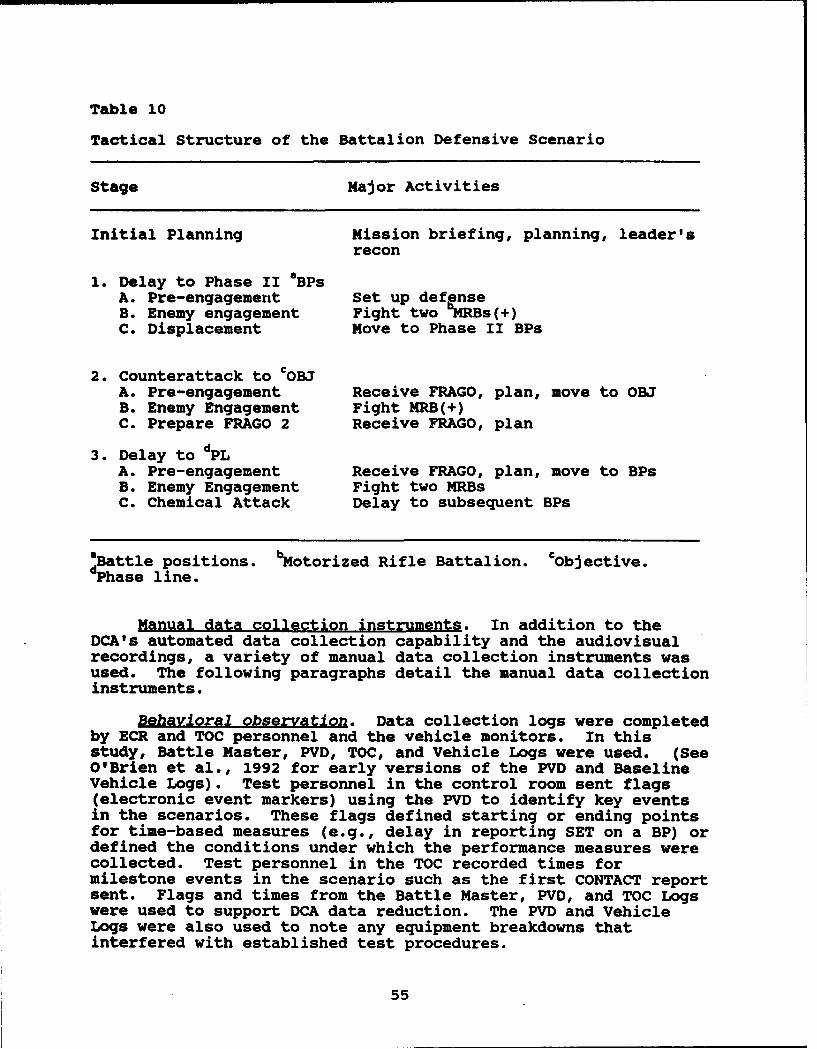
Table 10
Tactical Structure of the Battalion Defensive Scenario
Stage Major Activities
Initial Planning Mission briefing, planning, leader'srecon
1. Delay to Phase II 4BPsA. Pre-engagement Set up defenseB. Enemy engagement Fight two -MRBs(+)C. Displacement Move to Phase II BPs
2. Counterattack to cOBJA. Pre-engagement Receive FRAGO, plan, move to OBJB. Enemy Engagement Fight MRB(+)C. Prepare FRAGO 2 Receive FRAGO, plan
3. Delay to dPLA. Pre-engagement Receive FRAGO, plan, move to BPsB. Enemy Engagement Fight two MRBsC. Chemical Attack Delay to subsequent BPs
Battle positions. 'Motorized Rifle Battalion. cObjective.dae line.
Manual data collection instruments. In addition to theDCA's automated data collection capability and the audiovisualrecordings, a variety of manual data collection instruments wasused. The following paragraphs detail the manual data collectioninstruments.
Behavioral observation. Data collection logs were completedby ECR and TOC personnel and the vehicle monitors. In thisstudy, Battle Master, PVD, TOC, and Vehicle Logs were used. (SeeO'Brien et al., 1992 for early versions of the PVD and BaselineVehicle Logs). Test personnel in the control room sent flags(electronic event markers) using the PVD to identify key eventsin the scenarios. These flags defined starting or ending pointsfor time-based measures (e.g., delay in reporting SET on a BP) ordefined the conditions under which the performance measures werecollected. Test personnel in the TOC recorded times formilestone events in the scenario such as the first CONTACT reportsent. Flags and times from the Battle Master, PVD, and TOC Logswere used to support DCA data reduction. The PVD and VehicleLogs were also used to note any equipment breakdowns thatinterfered with established test procedures.
55
Baseline vehicle monitors in the battalion commander, S3, BCompany commander, and B Company XO vehicles manually recordeddata for selected performance measures such as the number ofreports sent over the radio by their unit or vehicle commander.Information selected from these logs was used to provide datathat the DCA system could not collect (e.g., information onvision block versus GPSE usage). Vehicle monitors also recordedany observations that they felt might help explain any unusualperformance by a crewmember (e.g., a unit or vehicle commanderwho complained about lack of sleep after pulling night duty).
The CVCC version of the Vehicle Log (Appendix C) requiredthe same information as the Baseline version with the addition ofthe number of CCD-type reports sent and CCD tactical map versuslap map usage by the commander.
Re~ort transcription. Test personnel used playback of radiocommunications during the Baseline and CVCC test scenarios totranscribe key elements of the reports sent over the radio.Playback sessions consisted of reviewing the exercise as it wasreplayed on the PVD and listening to the voice radio trafficsynchronized with the battlefield activities. Prior to playback,PVD logs were reviewed for missing data. If possible, themissing data were collected during playback. Each radiotransmission was categorized first as to whether it was a CCD-type report (i.e., a re-ort type that the CCD supports such as aCONTACT report or INTEL report). Special attention was paid toCCD-type reports which were sent via the radio in either theBaseline or CVCC conditions so that the accuracy of the voicereports could be scored against the same types of reports sentdigitally. Once playback of radio traffic was complete, testpersonnel reduced the data using manual data reduction formsbefore the data were entered into a database for later analysis.
SMI assessment questionnaires. Two SMI questionnaires wereadministered, one covering the CCD and POSNAV, and one pertainingto the CITV. Questionnaires were administered to all unit andvehicle commanders after the debriefing for the test scenario. Amember of the research staff administered these questionnaires.Instructions were read aloud and provided in writing. Thequestionnaires were self-paced. These SMI questionnaires werebased on previous versions which can be found in O'Brien et al.(1992).
The CCD questionnaire contained 47 items with whichparticipants used a seven-point scale (1 represented "TotallyUnacceptable, 7 represented "Totally Acceptable") to rate thelevel of acceptability of 32 items regarding individual CCD andPOSNAV functions, as well as four items regarding CCD componentsas a whole. In addition, 11 open-ended questions solicitedparticipants' suggested changes, preferences, and problemsconcerning the CCD, with space for additional comments.
The CITV questionnaire contained a total of 20 items, 16 ofwhich concerned individual CITV functions and the CITV as a
56

whole. Participants used the same rating scale used for the CCDand POSNAV questionnaire. In addition, four open-ended questionsasked for participant's opinions concerning the CITV, includingany additional comments on its training.
Training assessment questionnaires. All participants ratedthe training they received during the first three days of theevaluation via training assessment questionnaires. There wereBaseline and CVCC versions tailored to the commander, gunner, anddriver positions, focusing on each training module, with spacefor participants' recommendations on improving each of thetraining modules. Questionnaires were administered toparticipants at the conclusion of the test scenario. Earlierversions of these questionnaires can be found in O'Brien et al.(1992).
Baseline vehicle commanders rated 17 items regardingclassroom training, hands-on training, tactical trainingexercises, their own level of preparation, debriefs, and SAFORusing a five-point rating scale, with 1 represerzing "Poor" and 5representing "Excellent". Participants used another five-pointscale (1 representing "Very Unclear", 5 representing "VeryClear") to rate three items pertaining to the training program asa whole. Included with both sets of ratings were questionsasking participants to explain any responses on the extremenegative end of the scales. In addition, five open-endedquestions pertained to participants' suggestions, preferences,and problems with the training program.
The CVCC version of the vehicle commander's trainingevaluation included the same topics as the Baseline version, plusadditional items to cover the training of the CCD and CITV.
The Baseline gunner's evaluation had participants rate threeitems pertaining to the adequacy of training using the same"Poor" to "Excellent" scale as with the vehicle commander'squestionnaire. In addition, one open-ended question asked forcomments on the quality of training and equipment.
The CVCC version included the same three Baseline ratingquestions concerning training adequacy. In addition, sevenquestions regarding participant's opinions on the targetdesignation feature were presented for rating on a five-pointscale with 1 representing "Strongly Agree" and 5 representing"Strongly Disagree." There were also three open-ended questionspertaining to gunners' opinions about the CITV equipment.
The Baseline driver's training evaluation was identical tothat of the gunner's baseline evaluation. The CVCC versioncontained three training questions rated on the same five-pointscale the vehicle commanders and gunners used. In addition, 11questions obtained drivers' opinions of the Steer-To-Indicator(STI) through ratings on a five-point scale of "StronglyDisagree" to "Strongly Agree." Four open-ended questions askedfor participants' overall opinions about the STI.
57
_______________________________ Al
BiooraDhical questionnaire. The biographical questionnairewas used to obtain background information on participants and wasadministered during the General Introduction. This questionnairewas designed to obtain selected information on demographicvariables and military experience from each participant. Thisinformation provided a profile of participants and helpeddetermine group comparability. Officers and enlisted personnelcompleted the same questionnaire, which requested basicinformation such as age, rank, mi'itary specialty, and time inservice. Additional items recorded experience with variousarmored vehicles, experience in each tank duty position, militarycourses completed, National Training Center (NTC) or CombatManeuver Training Center (CMTC) experience, and combat maneuverunit experience. Participants were asked about previousexperience with both the Combined Arms Tactical Training Center(CATTC) and MWTB. Information regarding educational backgroundand familiarity with computers was also collected.
One biographical questionnaire item was aimed at measuringthe degree to which participants are comfortable with computers.This item was expected to provide unique information regardingindividual differences and supplement the information concerningparticipants' computer experience.
Situational Assessment questionnaire. The SituationalAssessment questionnaire was designed to measure a unit orvehicle commander's awareness of his unit's performance as itrelates to target damage and other battlefield events. Theinformation from this questionnaire provided insight into thedegree to which CVCC might affect this awareness.
All of these participants assessed the number of tanks andBMPs that their unit (for the battalion commander and the S3, theunit is defined as the battalion) destroyed, and whether anyenemy vehicles were destroyed after a certain point in the stage.They also assessed the number of casualties suffered by theirunit. A final question dealt with the location of a given phaseline (PL) in relation to another PL.
Control staff oDerating rules. Two types of documentsspecified the rules to be followed by the control personnel toensure consistent implementation of training and testingexercises. The first type included operating guidelines for theECR and TOC staff (Appendix B). Especially important in the ECRwere the SAFOR operating guidelines, including voice radioprotocols. The activities of the ECR staff were supervised bythe Battle Master, who monitored execution of exercises forcompliance with the operating rules. In the TOC, the SME whorole-played the battalion XO supervised the TOC staff activities,monitoring and directing the staff to ensure consistentapplication of the rules. The operating rules were practicedduring staff training sessions and carefully followed during alltest week training and testing activities.
58
The second type of exercise control document specified thedecision process and options for handling contingencies relatedto technical and personnel problems. The contingency rulesdocument (see Appendix B) addressed cases involving participantabsences, research staff absences, interaction betweenparticipants and research staff, equipment breakdowns, andschedule delays. Research staff absences were handled bysubstituting trained backup personnel. Participant absences andequipment breakdowns could be resolved by moderate delays, movingindividual crewmembers to protect more critical crews,reallocating entire crews to protect company commander positions,or dismissing an entire crew. Significant schedule delays couldlead to rescheduling of major events, usually with a consequentcancellation of data collection normally scheduled for the lastday. The contingency rules helped to ensure that personnel andtechnical problems were handled in a consistent manner acrosstest weeks.
Any significant departures from established controlprocedures (as might be necessitated by equipment problems) orcontingency rules were noted in writing and later reviewed by theresearch staff for impact on the data collected. Wherenecessary, data reduction or analysis was adjusted to account fordepartures from planned procedures.
A complete description of the training and test proceduresis provided in the battalion evaluation support package (BDMFederal, Inc., unpublished). Highlights of the proceduresfollow.
General Instructions to Participants
Instructions at the start of the evaluation. Upon reportingto the MWTB, participants were escorted to the classroom wherethey received the general introduction, which gave them anoverview of the evaluation. A schedule for the week was providedto each participant and the general requirements regardingparticipant support were discussed. The importance of beingpresent for all scheduled activities was emphasized strongly andthe group was queried to determine if any participants hadappointments, duties, or other conflicts which would interferewith full participation. If conflicts were identified, they wereresolved with the aid of the battalion commander and his staff.All participants were given a point of contact and telephonenumber in case conflicts should arise later.
Instructions during traininQ exercises. Prior to eachtraining exercise the battalion received a briefing by the BattleMaster. This briefing included the training objectives for thesession and key milestones (in-simulator time, readinesscondition [REDCON] 1 time, mission start time). The BattleMaster also provided special instructions for the exercise at
59
hand, such as exercise-specific communication or coordinationprovisions.
Instructions for scenarios. Each battalion received abrigade OPORD briefing by the Battle Master followed by abattalion OPORD briefing by the battalion XO. The OPORDbriefings were presented to all participants using the actualOPORD as a script guide to ensure standardization acrossrotations. These briefings were supported by visual graphictraining aids presenting the unit's task organization, enemycomposition and disposition, operational graphics on mapdisplays, and reporting requirements.
Evaluation Week Schedule
Each evaluation week consisted of a standard sequence oftraining and testing events. Figure 12 provides an overview ofthe schedule for the CVCC condition, listing each event. Thefollowing sections describe each event in greater detail. Acomplete description and copies of all lesson materials for thebelow listed classes/events are available in the support packagefor this evaluation (BDM Federal, Inc., unpublished).
Day 1 events
la: General introduction. The objectives of the generalintroduction were to (a) provide an overview of the battalionevaluation program and schedule, (b) describe the importance ofthe battalion evaluation to the Army's long range goals forimproving battlefield performance, (c) describe the testfacilities and general procedures that were to be followedthroughout the evaluation. All participants received the generalintroduction as a group. At the end of the session, eachparticipant completed a Privacy Act statement and theBiographical Questionnaire.
lb: MI tank versus M1 simulator. This classroompresentation highlighted major differences between the Mlsimulator and the Ml tank. All personnel participated.
ic: CCD demonstration CCVCC condition only). This lecturedemonstrated the functionality and operation of the CCD. Onlyunit and vehicle commanders participated. Procedures weredesigned to configure a TOC workstation as a stand-alone CCD witha functional CCD screen (mouse-controlled cursor) and theoverlays needed for the demonstration. Through an electronicinterface, the large-screen monitor mimicked the display of thestand-alone workstation, allowing a group to comfortably view theCCD during the demonstration. An instructor's assistantmanipulated the CCD workstation in accordance with thedemonstration outline and instructor cues. CVCC-SEND messagefiles were prepared ahead of time to transmit messages to thestandalone CCD.
60
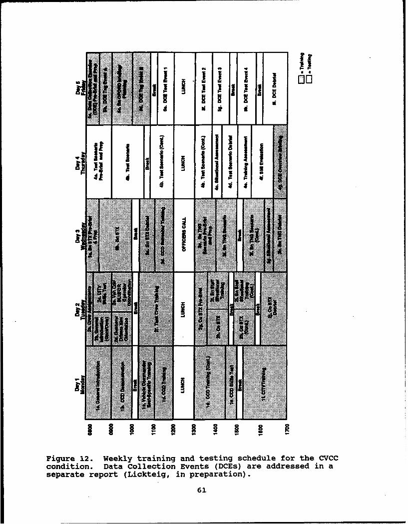
... ... 9 V" - I 0n
....111 ..1.....U :K
.. ... .
"Q-:I.::;il
...J .** ............4.........1........... ...... . . ..
K. .... ....
.... .... a ........-Figur 12. Weekl traning nd tstingscheule.fr. th...Ccondition. ~ ~ ~ ~ ~ ~ ~ .Daa.oletin Evnt...s.ae .ddese.i
seart report.. (Lcteg in.prpara.on)
X61
id: Vehicle commander seat-sg!ecific training. This lessontrained unit and vehicle commanders on Ml simulator uniquefeatures. While the vehicle trainers gave a global orientationon most of the features of the simulator, they focused on thosefeatures that were different from an actual M1 (e.g., the turret-to-hull reference display and the grid azimuth indicator).
le: CCD training CCVCC condition only). This equipmenttraining provided detailed instruction and hands-on practice inthe operation of the CCD and POSNAV. Only unit and vehiclecommanders participated. A uniform sequence was followed foreach function: explanation of the function's purpose, followedby a step-by-step explanation and demonstration, and ending withpractice by the participant.
If: CCD Skills Test (CVCC condition only). This testevaluated unit and vehicle commander proficiency on CCDoperation. The vehicle trainer first ensured the CCD was set upproperly (e.g., a route was in the system, reports were in thequeue) before beginning. Each task was then read to thecommander; a response was required within 90 seconds. Eachperformance was observed and recorded as a "Go" or "No-go" on theform. If necessary, upon completion of the test, the vehicletrainer conducted remedial training until the participant couldperform each task.
1g: CITV training (CVCC condition only). This trainingprovided detailed instruction and hands-on practice in theoperation of the CITV for unit and vehicle commanders. As withCCD hands-on training, a uniform sequence was followed for eachfunction: explanation of the function's purpose, followed by astep-by-step explanation and demonstration, and ending withpractice.
SIMNET navigation trainina (Baseline only). Following theMl tank versus Mi simulator lecture, the Baseline unit andvehicle commanders received training on navigating in the SIMNETenvironment. This session began with a classroom presentationreviewing conventional navigation procedures (e.g., polarplotting, resection) plus the special tools available in the M1simulators (e.g., LRF, grid azimuth indicator). Hands-ontraining in simulators followed, with participants paired so thatone drove while the other navigated. Each participant navigatedto at least three, checkpoints, responding to control staffqueries requiring determination of current location oridentification of prominent terrain features along the way. Thissession concluded with administration of the SIMNET Skills Test.
This test assessed participants' ability to navigate in theSIMNET environment. Vehicle trainers read the questions aloud;responses were required within 90 seconds. Participants wereprovided with protractors, paper, and pencils to use as theyneeded.
62

Day 2 events
2a: CITV Skills Test (CVCC condition only). Used only withunit and vehicle commanders, this test evaluated proficiency onCITV operation. The vehicle trainer ensured proper configurationof the CITV for the test (e.g., ensuring enemy targets werepresent) then conducted this session in the same manner as theCCD Skills Test. Following administration of the test, thevehicle trainer conducted remedial training, as needed, until theparticipant could perform each task.
2b: Gunners/drivers simulator orientation. This lessonoriented the gunners and drivers on the features and functions oftheir respective simulator crew stations. The instruction tookplace in the simulators.
2c: Vehicle commander/BLUFOR operator coordination. Thismodule consisted of a classroom briefing and orientation toBLUFOR (SAFOR) operation, for unit and vehicle commanders only.The lecture explained the coordination required between thecommanders and the BLUFOR operators who would, in accordance withthe mission, intent, and specific directives, control theirsubordinate forces during tactical execution. Instructionemphasized that command was exercised by the unit commanders inthe manned simulators through immediate intervention or FRAGOs.The capabilities and operating characteristics of the SAFOR wereaddressed in detail, to include formations, speed (both rate ofmovement and response time), coordination of fires, andengagement criterion. Limitations such as lack of platoon firecommands and inability to split sections were also addressed.
2d: Tank crew trainin . All participants were trained incollective crew tasks and skills. The focus of this training wason crew coordination, navigation, and terrain negotiation.Opportunities for initial practice of target engagement andcombat reporting tasks were provided. Each crew navigated a six-waypoint route laid out in a 4-5 km by 4-5 km terrain square or"sandbox." Stationary gunnery targets provided the engagementand reporting opportunities. Unit and vehicle commanders wereinstructed to send reports based on events encountered during theexercise. When a crew completed its route, its simulator was re-initialized in a new sandbox, and another route negotiated. Thisprocess continued until the time allotted for the module hadexpired. All personnel participated in this and all followingtraining and testing events.
2e: Company STX Dre-brief. Pre-mission activities for thecompany STX included an overview briefing by the ExerciseDirector, an OPORD briefing by the Battle Master, missionpreplanning by participants, and a battalion command groupbriefing conducted by the Exercise Director and battalion XO.
2f: Company STX. Company commanders and XOs and their crewsexecuted the company level scenario with minimal involvement of
63
the TOC. The scenario was designed to provide these participantspractice in working with SAFOR platoons.
2g: Battalion staff situational training. Concurrent withthe company STX, the command group (i.e., battalion commander andS3) and the TOC staff (i.e., battalion XO, S2, Assistant S3, andFSO) practiced working together in parallel with the company STXbattlefield activities. The objectives of this training were toorient the command group on TOC capabilities and limitations, toprovide the TOC staff an opportunity to understand the operating"style" of the commander and S3, and to practice providing TOCsupport to the maneuvering tank companies. In this two-stageexercise, the command group operated "off-line" (i.e., onlyinteracted with the TOC while the Battle Master role played thecommander/S3), becoming familiar with the capabilities andprocedures of TOC operations. During stage one, the commandgroup could rotate at will between their simulator and the TOC,observing activities and listening to communications as the STXunfolded. During stage two, the commander and the S3 wererestricted to their respective simulator, but remained in anobserver role.
2h: Comrany STX debrief. Participants were briefed on theoverall performance of the unit during the company STX. TheBattle Master pointed out instances in which the participants didnot act in accordance with the battalion SOP or scenarioinstructions and described procedures for correcting thesediscrepancies. This debriefing also included feedback from thetest support staff and participants regarding issues such asreporting performance.
Day 3 events
3a: Battalion STXpre-brief. Pre-mission activities for thebattalion STX followed the same general structure as for othertraining and test scenarios. The battalion XO briefed thebattalion OPORD, and participants conducted mission planning andpreparation. The TOC staff was available and participated incoordination and preparation. As part of the mission preparationfor the Baseline condition, an execution matrix was provided tothe battalion commander and the S3. This matrix depicted thephases of the operation and indicated sequence of activities foreach subordinate unit. For the CVCC condition, the COA overlaywas activated on the large-screen monitor in the TOC where thebattalion XO "walked through" the operation for the commandersand S3 using sequenced phasing techniques of the COA module.
3b: Battalion STX. The battalion training exerciseincluded two phases. Phase one required the participants toexecute a delay operation, while phase two required them toexecute a counterattack. The battalion commander was givenoptions from which to choose in conducting the counterattack.All elements in the battalion, including the battalion TOC staff,participated in the exercise.
64
3c: Battalion STX debrief. The battalion STX debrief wasconducted in the same manner as the company STX debrief.
3d: CCD refresher training CCVCC condition only). Toreinforce CCD operating procedures, a refresher training session(for unit and vehicle commanders only) followed the battalion STXdebriefing. This session began with an abbreviated CCDdemonstration highlighting common problems, and concluded with amessage processing exercise.
Officers call. A mid-week officers call was held for allunit and vehicle commanders. The purpose of this session was toclarify role-playing responsibilities, with special reference tokey issues, and to allow research staff members to answerparticipants' questions. The key issues addressed were: (a) theprotection of manned simulators from being killed; (b) thepossibility of unrealistically aggressive behavior (dubbed"Rambo" behavior); and (c) the potential for crews to followSAFOR instead of navigating on their own. For each of theseissues, the basic research concerns were explained, the potentialimpacts on the evaluation's findings were discussed, andguidelines for role-playing behavior were provided. This sessionwas conducted in an informal manner, with the research staffexercising an "honest-broker" role.
3e: Battalion training scenario =re-brief. Pre-missionactivities for the battalion training scenario followed the samegeneral structure as for the other training and test scenarios.The brigade OPORD was briefed by the Battle Master, the battalionOPORD was briefed by the battalion XO, and participants conductedmission planning and preparation. The TOC staff was availableand participated in coordination and planning.
Pre-mission preparation included a leader's reconnaissanceconducted for the battalion commander, the S3, and the threecompany commanders. In this activity, the battalion XO attachedthe Stealth sensor to a vehicle simulator which moved accordingto a previously recorded exercise. As the vehicle maneuvered onthe battlefield, the Stealth followed. This permitted thebattalion XO to lead the commanders and staff on a standardizedreconnaissance over the simulated terrain, highlighting friendlypositions, engagement areas, enemy avenues of approach (no OPFORvehicles were visible) and areas of terrain masking. The S2 wasavailable at the Stealth to respond to queries about the enemy orterrain. This reconnaissance technique immediately followed thebattalion OPORD briefing.
3f: Battalion training scenario. The battalion trainingscenario was executed in two stages. During stage one, thebattalion executed a delay operation. In stage two, theyexecuted a brigade-directed counterattack. During stage one, thebrigade issued a warning order followed by the counterattackFRAGO, which initiated the battalion planning process. Stage twowas initiated with the issuance of the battalion counterattackFRAGO. To ensure consistency and standardization of the starting
65
conditions at each stage for all rotations, a previously preparedFRAGO was issued in lieu of the one developed by the commanderand staff. The participants were given a brief re-orientation(if required) prior to beginning stage two.
3g: Situational assessment. At the end of the battaliontraining scenario, the unit and vehicle commanders received ashort orientation to the Situational Assessment questionnaire.Details of the questionnaire were addressed earlier.
3h: Battalion training scenario debrief. The battaliontraining scenario debrief was conducted in the same manner as thecompany STX and battalion STX debriefs.
Day 4 events
4a: Battalion test scenario pre-brief. Pre-missionprocedures for the battalion test scenario followed the samestructure as for the training scenarios.
4b: Battalion test scenario. The battalion executed adefensive scenario with three stages: delay, counterattack,delay. Stages one and two were similar to their counterpartstages in the battalion training scenario (force orientation wasdifferent). Stage three was a continuation of the delay aftercompletion of the brigade-directed counterattack. The samesequence of events which linked stages one and two (i.e., brigadewarning order/FRAGO, battalion planning/FRAGO) was used also toaccomplish the transition from stage two to stage three.
4c: Situational assessment. At the end of the testscenario, each unit and vehicle commander completed a SituationalAssessment questionnaire outside his simulator. Thisquestionnaire was similar to that presented in the orientation atthe conclusion of the battalion training scenario.
4d: Battalion test scenario debrief. The battalion testscenario debrief was conducted in the same manner as the debriefat the conclusion of the battalion training scenario. Inaddition, participants were queried as to techniques used toaccomplish certain tasks (e.g., target detection andidentification, IFF, navigation methods).
4e: Training assessment. A detailed questionnaire askingall participants to rate the quality and effectiveness of thetraining they received during the first three days of theevaluation was administered. This self-paced questionnaire alsosolicited opinions for improving each of the training modules.
4f: SMI evaluation (C/CC unit and vehicle commanders only).In the CVCC condition, a detailed questionnaire was administeredto the unit and vehicle commanders to obtain their opinions andinsights about the design and operation of the CCD and CITVinterfaces. Completion of this questionnaire was self-paced.
66
Data Collection Exercise events on Day 4 and Day 5.Participants in this study also participated in a series ofspecial Data Collection Exercises (DCEs). These exercises aredescribed in detail elsewhere (see Lickteig, in preparation).
Particibant Training Procedures
Separate training programs were developed for two categoriesof participants--unit and vehicle commanders in one group, andtank gunners and drivers in another. Both groups began theirtraining with the general introduction. The training paths forthese two groups diverged for the individual position-specificportion of the training program. The two groups came togetheragain for the tank crew training module that started theircollective training.
On Day 1, all participants began with the generalintroduction. Baseline commanders then received the M1 tankversus Mi simulator presentation, seat-specific orientation,navigation training, and the SIMNET Skills test. CVCC commandersreceived the CCD demonstration, seat-specific orientation, CCDhands-on training, CCD Skills Test, and CITV hands-on training onDay 1. On Day 2, CVCC commanders began with the CITV SkillsTest. Gunners and drivers for both conditions received separategunner and driver seat-specific orientations, while thecommanders participated in a SAFOR orientation session with thesenior BLUFOR operator. This session addressed rules andprocedures for executing scenarios. Before lunch on Day 2, theunit and vehicle commanders, gunners, and drivers participated intank crew training as functional crews.
After completing tank crew training, the company commandersand XOs began integrated collective training with the company STXand battalion STX. During this session, the company commanderspracticed working with their SAFOR components. At the same time,the battalion command group and contractor-furnished TOCpersonnel practiced working together in battalion staffsituational training, conducted in parallel with the company STX.This collective training was concluded on Day 3, when the entirebattalion participated in the battalion STX and battaliontraining scenario.
Professional Role Playing
A key factor in the successful simulation of the battlefieldenvironment, professional role playing was mandated to ensurerealistic command and control and combat performance.Unrealistic behavior had a strong potential to compromise testintegrity and skew test results (e.g., unrealistic forceattrition or tactical maneuvers). As a result, the test supportstaff monitored participants and implemented corrective actionwhen unrealistic behavior was observed. Feedback to theparticipants included individual counseling, use of the chain-of-command, and non-attributed examples at the debriefings.
67

Past CVCC research efforts (O'Brien et al., 1992) indicatedthat some test participants exhibit unrealistic risk-takingbehavior during evaluations. This evaluation utilized a kill-suppress option to protect manned vehicles, which is suspected tocontribute to that risk-taking behavior (i.e., attitude ofinvincibility). This behavior is commonly referred to as "Rambo"behavior. The officers call, addressed earlier, specificallyemphasized the importance of professional role playing and thepotential impact on the test results. Special emphasis wasplaced on the "Rambo" factor to discourage unrealistic risk-taking.
Scenario Execution Procedures
Each scenario was executed according to established controlprocedures to maintain consistency between conditions androtations. The battalion TOC staff, role-played by members ofthe support staff, assisted the battalion commander by preparing,tactical overlays, synthesizing critical battlefield information,and maintaining a broad picture of the entire battlefield. Whileexercise participants could conduct pre-mission planning andcoordination in the TOC, they were not permitted to enter the TOCduring the exercises. The Battle Master advised the battalioncommander that the pace of battlefield activities realisticallydid not accommodate battalion commander or S3 visits to the TOC.The specific scenario execution procedures, which guided scenarioset-up and execution, are detailed in Appendix B.
Data Collection Procedures
The DCA system was the primary means of data collection. Alist of sample measures for each BOS appears in Appendix D.Refer to O'Brien et al. (1992) for a complete set of measuresdefinitions.
Standard DataLogger procedures were employed in collectingautomated data. All test exercises were recorded on magnetictape for subsequent reduction and analysis. PVD operatorsentered flags corresponding to key tactical and administrativeevents. Examples of these events included the start and endpoints of the scenario, scheduled breaks, significant equipmentbreakdowns, significant vehicle/unit movement events (e.g.,crossing the Line of Departure (LD)), and selected data elements.The PVD operator also kept a log which provided additionalinformation related to the flags. The flags and logs were usedto break scenario recordings into discrete mission stages, and toadjust performance measures for unscheduled breaks. PVD logsalso served as important sources of data during manual datareduction.
In addition, simulator logs were completed for selectedvehicles (battalion commander, S3, B Company commander, B CompanyXO) in the test scenario. Data collectors recorded observationsof various aspects of the participant's behavior such as
68

equipment operation, radio communications, use of paper map andvisual display devices, and interactions among crewmembers.
Test support personnel administered the previously-describedquestionnaires to participants at designated points during thetest week. During the debriefs following the training and testscenarios, participants' comments and suggestions weretranscribed by support personnel.
Following each test week, playback sessions were conducted.These sessions focused on voice radio messages, and completetranscriptions of combat reports (see the CVCC Battalion SOP inAppendix A for a listing of combat reports used) as well as othermessages were generated. A complete listing of voice message-based measures is provided under the Command and Control BOSheading in the Results and Discussion section of this report.Prior to the playback, PVD and Battle Master logs were reviewedfor missing data. In cases where missing data were identified,attempts were made to capture the information in the playback.
Data Reduction and Analysis Procedures
To protect the privacy of individual soldiers, eachparticipant was assigned a unique number at the start of theevaluation. This number was used in place of the individual'sname on all data collection instruments, except for theBiographical Questionnaire. This numbering system identifiedindividual cases in all database activities.
Reduction and analysis of data proceeded through threesteps: database management (data entry and quality control),data reduction, and descriptive analyses. The first two steps ofthis sequence were tailored for automated and manual data,respectively. Each step is summarized below.
Database management. To organize the manually collecteddata, a set of database management system (DBMS) files wascreated. Individual files were created for each manual datacollection instrument (e.g., Biographical Questionnaire). Testsupport personnel entered data into these files using dBASE III+N(a registered trademark of Ashton-Tate) customized data entryscreens on a personal computer. Quality control procedures wereimplemented to verify the accuracy of data entry, using 100%review of print-outs.
In the case of automated data collected by DataLogger,DataProbew extracted raw data from magnetic tapes recorded duringthe test scenario and RS/1U organized the resulting data intofiles. Research team members reviewed printouts of these files,checking for out-of-range or inconsistent data. These filesprovided intermediate data for the reduction process described inthe following section.
Data reduction. A number of measures required hands-onprocessing of manually collected data (e.g., counts of voice
69
radio messages). For each measure in this category, datareduction forms were developed to guide the data reducercarefully through each step. Test personnel received training inadministering these forms. Data reduction forms were also spot-checked by experienced behavioral scientists on the test supportteam. When the data reduction forms were complete, the data weredirectly entered into DBMS files.
To reduce the automated data, data packets from theDataLogger-recorded files established during creation of theautomated database were combined by RS/1 3 to produce specifiedmeasures. This lengthy process resulted in a set of AmericanStandard Code for Information Interchange (ASCII) filescontaining DataLogger-based data for all test weeks.
Descri~tive analyses. Prior to analyzing manual andautomated data, procedures for accommodating missing andcontaminated data were applied. Missing data may have resultedfrom a unit's failure to complete the test scenario due toequipment failures or participant absences. Also, participantsoccasionally skipped a question on a questionnaire. Contaminateddata could be produced by equipment malfunctions or crewadjustments due to participant absences. The general rule forhandling both missing and contaminated data was to omit theaffected measures from, analyses. Only those measures/valuesinfluenced by the unplanned event were omitted. This strategyreduced sample size across cells and across measures.
The Statistical Package for the Social Sciences for the IBMPersonal Computer (SPSS/PC+N,V2.0) was used for all data analyses(SPSS/PC+ is a trademark of SPSS Inc). The REPORT procedurecomputed means, medians, and standard deviations. The CROSSTABSprocedure generated frequency distributions, including percentresponse breakouts for questionnaire items. Other proceduresincluded MEANS and COMPUTE.
Support Staff
The test support staff was responsible for training exerciseparticipants, controlling all scenarios and exercises, operatingthe ECR stations, and operating the surrogate battalion TOC.This staff also administered manual data collection instruments.
Scenz.rio Roles and Responsibilities
Table 11 summarizes the primary responsibilities assigned toeach member of the support staff during the training and testingscenarios.
The Exercise Director retained overall decision-makingauthority for all matters regarding the conduct of training andtesting. The Event Coordinator, Battle Master, Floor Monitor,and others assisted the Exercise Director in ensuring properexecution of events. This permitted decentralized executionconsistent with the research plan.
70
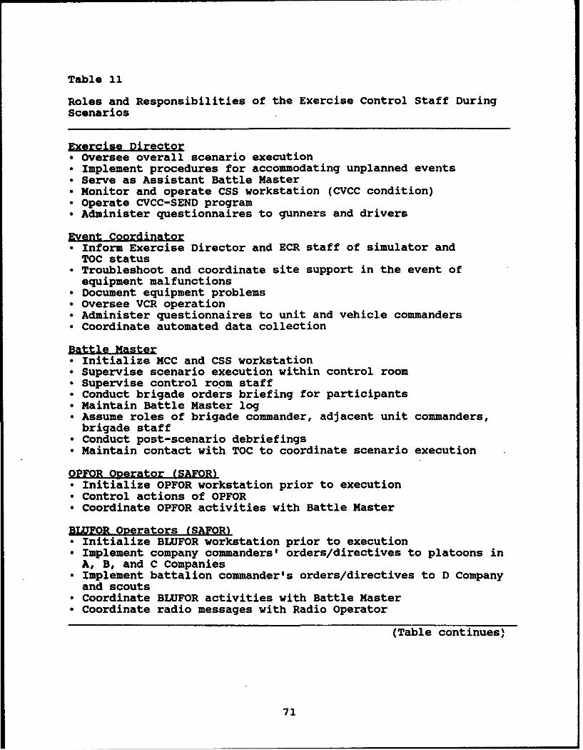
Table 11
Roles and Responsibilities of the Exercise Control Staff DuringScenarios
Exercise Director"* Oversee overall scenario execution"* Implement procedures for accommodating unplanned events"* Serve as Assistant Battle Master"* Monitor and operate CSS workstation (CVCC condition)"* Operate CVCC-SEND program"• Administer questionnaires to gunners and drivers
Event Coordinator"* Inform Exercise Director and ECR staff of simulator and
TOC status"* Troubleshoot and coordinate site support in the event of
equipment malfunctions"* Document equipment problems"* Oversee VCR operation"* Administer questionnaires to unit and vehicle commanders"* Coordinate automated data collection
Battle Master"* Initialize MCC and CSS workstation"* Supervise scenario execution within control room• Supervise control room staff"• Conduct brigade orders briefing for participants"* Maintain Battle Master log* Assume roles of brigade commander, adjacent unit commanders,
brigade staff"* Conduct post-scenario debriefings"* Maintain contact with TOC to coordinate scenario execution
OPFOR Operator (SAFOR)"* Initialize OPFOR workstation prior to execution"* Control actions of OPFOR"* Coordinate OPFOR activities with Battle Master
BLUFOR Operators (SAFORI"* Initialize BLUFOR workstation prior to execution"* Implement company commanders' orders/directives to platoons in
A, B, and C Companies"* Implement battalion commander's orders/directives to D Company
and scouts"* Coordinate BLUFOR activities with Battle Master"• Coordinate radio messages with Radio Operator
(Table continues)
71
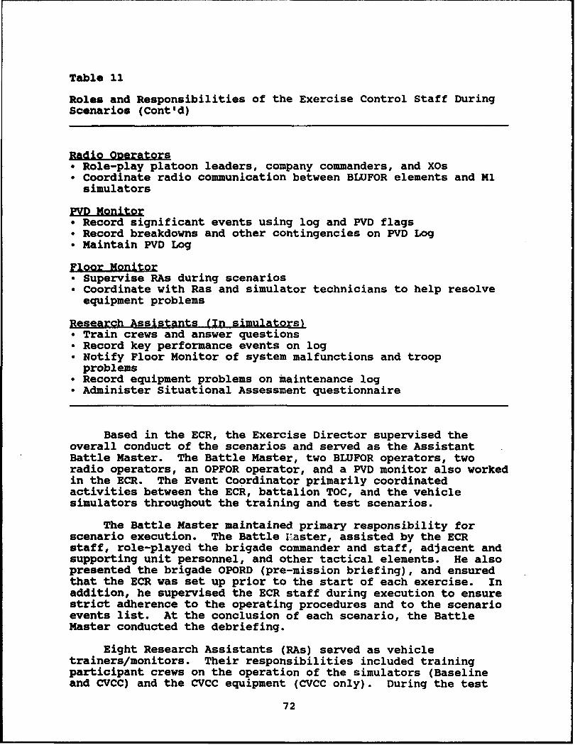
Table 11
Roles and Responsibilities of the Exercise Control Staff DuringScenarios (Cont'd)
Radio Operators"• Role-play platoon leaders, company commanders, and XOs"° Coordinate radio communication between BLUFOR elements and Ml
simulators
PV~HD oit~r"• Record significant events using log and PVD flags"* Record breakdowns and other contingencies on PVD Log"• Maintain PVD Log
Floor Monitor"* Supervise RAs during scenarios"* Coordinate with Ras and simulator technicians to help resolve
equipment problems
Research Assistants (In simulators)"* Train crews and answer questions"• Record key performance events on log"* Notify Floor Monitor of system malfunctions and troop
problems"* Record equipment problems on maintenance log"* Administer Situational Assessment questionnaire
Based in the ECR, the Exercise Director supervised theoverall conduct of the scenarios and served as the AssistantBattle Master. The Battle Master, two BLUFOR operators, tworadio operators, an OPFOR operator, and a PVD monitor also workedin the ECR. The Event Coordinator primarily coordinatedactivities between the ECR, battalion TOC, and the vehiclesimulators throughout the training and test scenarios.
The Battle Master maintained primary responsibility forscenario execution. The Battle I'aster, assisted by the ECRstaff, role-played the brigade commander and staff, adjacent andsupporting unit personnel, and other tactical elements. He alsopresented the brigade OPORD (pre-mission briefing), and ensuredthat the ECR was set up prior to the start of each exercise. Inaddition, he supervised the ECR staff during execution to ensurestrict adherence to the operating procedures and to the scenarioevents list. At the conclusion of each scenario, the BattleMaster conducted the debriefing.
Eight Research Assistants (RAs) served as vehicletrainers/monitors. Their responsibilities included trainingparticipant crews on the operation of the simulators (Baselineand CVCC) and the CVCC equipment (CVCC only). During the test
72
scenario, four vehicle monitors collected data on crewperformance. The Floor Monitor supervised the trainers/monitors.The Floor Monitor also assisted the Event Coordinator bynotifying site support staff (technicians) during equipmentmalfunctions, and tracking the status and resolution of theseproblems.
Methodoloaical Limitations
A number of methodological limitations stemmed from thesimulation technology itself, from certain design choices, andoccasionally from implementing procedures. These limitations,which may impact the evaluation's results and theirinterpretation, are discussed in this subsection. Facility-basedissues have been provided to the MWTB site manager for action, asappropriate.
Given the allocation of manned simulators, the lowestechelon manned within the battalion was the company level(company XO). In other words, only SAFOR elements were operativeat the platoon level. Thus, battlefield information from thewingman and platoon leader levels originated from SAFORalgorithms or from BLUFOR operators. The working framework usedby the company commanders and XOs to interpret SAFOR-generatedreports may have varied across individuals. Further, there wasno strong incentive for them to relay INTEL reports, FRAGOs, andother information to their SAFOR elements. These factors mayhave influenced the flow of information within the battalion. Incombination with the lack of Fire Support Team (FIST) personnelwithin the companies, these factors also may have affected thebattalion's command and control dynamics. One practicalconsequence was that the ability to study transmission of reportsacross echelons was very limited.
Radio net differences between the Baseline and CVCCconditions complicate the interpretation of communication-basedperformance. The voice radio nets were identical in bothconditions: company command and battalion command nets forcompany commanders, company command and battalion O&I nets forcompany XOs. However, the CVCC equipped company XOs had thebattalion command digital net instead of a digital O&I net. Whenthe CVCC TOC transmitted digital reports and FRAGOs on thebattalion command net, the company commanders and company XOsreceived them at the same time. But when the Baseline TOCtransmitted voice reports and FRAGOs on the battalion commandnet, the company XOs did not receive them until the companycommanders relayed them on the company command nets. Thismethodological difference would be expected to impact selectedaspects of communications, such as time to transmit INTEL reportsand FRAGOs.
Due to limited processing capacity of each simulator'scomputer image generator, the driver's vision blocks occasionallyfailed to display surrounding vehicles properly. Vehicle imagescould flash intermittently or disappear for extended periods,
73
depriving the driver of important visual information. Theseproblems degraded the driver's ability to maintain properposition within a tactical formation and to steer clear ofneighboring vehicles. Occasional collisions resulted.Additionally, if a vehicle commander found it necessary toverbally guide his driver, the commander's ability to fight hisunit or his vehicle may have suffered. Altogether, thislimitation could somewhat compromise performance related topositioning and navigation, and perhaps reduce overall attentionto C3 activities.
Constraints limiting SAFOR behavior compromised the realismof the simulated battlefield. SAFOR responsiveness was sometimesslowed by keyboard command requirements, especially given thatone SAFOR operator controlled the actions of several platoons.Maneuver options for SAFOR units were limited; for example, OPFORplatoon vehicles did not disperse when artillery fell.Unrealistic movement of SAFOR elements occurred (e.g., failure tofollow cover and concealment principles, circling around terraincanopies, scrambled patterns when two units intersect). Inaddition, SAFOR vehicles never committed fratricide, due toperfect IFF capabilities. As with other DIS evaluations, theseand similar limitations require caution when attempting to applyfindings to other environments, including actual combat.
Several factors posed special challenges to the crewmembersas they strove to role play professionally. The use of killsuppress to protect manned simulators may have encouragedunnecessary risk-taking when crews discovered they were"invincible." Crews occasionally appeared to be engaging in"Rambo" behavior. Compounding this was the lack of a clear,immediate signal telling the crewmembers that their vehicle hadtaken a killing hit. Combining manned and BLUFOR vehicles in thesame unit meant that crews could follow BLUFOR elements insteadof navigating for themselves. Also, minefields and obstacleswere not implemented on the terrain database, so the crew mighthave discovered that ignoring them on the overlay carried nopenalty. The mid-week officers call addressing these issues wasdesigned to ensure that participants were clear about their role-playing responsibilities.
The simulation algorithms modelling ballistic performance,probability of hits, and probability of kills were based on out-of-date 105 mm service round data. In addition, the simulationimplementation of target lead differed appreciably from thefielded tank, making it difficult for gunners to master firing atmoving targets. Thus, target engagement performance in thisevaluation cannot be considered representative of actual tankbattalion gunnery performance.
The following section presents a comprehensive account ofthe quantitative measures used in the current evaluation, and theprocess followed in developing them.
74
Performance Measures
This section presents the hypotheses and performancemeasures developed to structure the analysis of data in thecurrent evaluation. The process for developing the performancemeasures will be described first, followed by a review ofhypotheses (organized by research issue); a summary of measureswill conclude the section.
As discussed in the Design of the Evaluation section of thisreport, the research issues spanned tactical maneuver, firesupport, command and control, and intelligence activities. Themeasures supporting this evaluation quantified a comprehensivecross-section of unit performance. The measurement categoriesencompassed tactical movement and navigation, target acquisitionand engagement, control of terrain, gathering and processing ofbattlefield information (enemy and friendly), situationalassessment, and usage of equipment.
AR~rOach
The current set of performance measures was derived from thebattalion TOC evaluation (O'Brien et al., 1992). In turn, themeasures used in the battalion TOC evaluation were based onmeasures from earlier CVCC efforts (e.g., Du Bois & Smith, 1989;Du Bois & Smith, 1991; Leibrecht et al., 1992; Quinkert, 1990).Thus, this current set of performance measures was built onpreceding CVCC efforts, based on the results of data analysis andlessons learned. Details on this process follow.
Develop Performance Hvootheses
The issues underpinning the evaluation have been presentedin the Design of the Evaluation section of this report. Based onfour BOSs from the Blueprint of the Battlefield (Department ofthe Army, 1991), these operational issues provided the foundationfor developing hypotheses to describe the expected differencesbetween the CVCC and Baseline configurations. The specifichypotheses appear in the following subsection.
Adapt List of Measures for Each Hv~othesis
Measures used in past CVCC evaluations (cited above) wereadapted for addressing each hypothesis. For the most part,multiple measures were identified for each hypothesis. Whereverpossible, previously existing measures that fit into the BOSstructure were employed. Certain new measures were developed, asnecessary.
Revise ODerational Definitions
Operational definitions from previous evaluations wererevised where necessary; or definitions were developed for newly-defined measures.
75

Revise Data Reduction and Analysis Procedures
The specific data instruments required to provide the inputvariables for each measure were identified. The operationsnecessary to compute each performance measure were then defined.
Revise Data Collection Ljas
Logs were inspected to ensure that they captured thenecessary information. Revisions were made accordingly.
The performance hypotheses and measures that were developedby this process are listed in the subsections that follow. Alist of sample measures and their operational definitions can befound in Appendix D. A more complete list can be found inO'Brien et al. (1992).
Operational Issues and Hvnotheses
In the paragraphs that follow, the operational issues andhypotheses that supported the current research effort arepresented.
Issue 1: Does the CVCC system enhance the Maneuver BOS?The CVCC system's CITV, steer-to display, and tactical map withPOSNAV icons and overlays were expected to provide an overalladvantage for a subset of Maneuver BOS tasks. Table 12 showsthose Maneuver BOS tasks linked to CVCC hypotheses for Issue 1.A statement of each hypothesis for Issue 1 follows.
Table 12
The Maneuver BOS Linked to CVCC Hypotheses
TASKS HYPOTHESIS
MoveMove On or Under Surface 1.1Navigate 1.2
Engae EnemyEmploy Direct Fire
Process Direct Fire Targets 1.3Engage Direct Fire Targets 1.4
Control Terrain 1.5
Hypotheses 1.1 through 1.5, respectively, state the CVCCunits' performance on the battlefield was expected to be betterthan the Baseline units' regarding the ability to: (a) move onthe surface; (b) naviga; (c) process direct fire targets; (d)engaae direct fire taraets; and (e) control terrain.
76
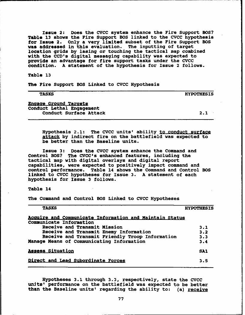
Issue 2: Does the CVCC system enhance the Fire Support BOS?Table 13 shows the Fire Support BOS linked to the CVCC hypothesisfor Issue 2. Only a very limited subset of the Fire Support BOSwas addressed in this evaluation. The inputting of targetlocation grids by lasing or touching the tactical map combinedwith the CCD's digital messaging capability was expected toprovide an advantage for fire support tasks under the CVCCcondition. A statement of the hypothesis for Issue 2 follows.
Table 13
The Fire Support BOS Linked to CVCC Hypothesis
TASKS HYPOTHESIS
Enaaae Ground TargetsConduct Lethal Engagement
Conduct Surface Attack 2.1
Hypothesis 2.1: The CVCC units' ability to conduct surfaceattack by indirect fire on the battlefield was expected tobe better than the Baseline units.
Issue 3: Does the CVCC system enhance the Command andControl BOS? The CVCC's enhanced features, including thetactical map with digital overlays and digital reportcapabilities, were expected to positively impact command andcontrol performance. Table 14 shows the Command and Control BOSlinked to CVCC hypotheses for Issue 3. A statement of eachhypothesis for Issue 3 follows.
Table 14
The Command and Control BOS Linked to CVCC Hypotheses
TASKS HYPOTHESIS
Acquire and Communicate Information and Maintain StatusCommunicate Information
Receive and Transmit Mission 3.1Receive and Transmit Enemy Information 3.2Receive and Transmit Friendly Troop Information 3.3
Manage Means of Communicating Information 3.4
Assess Situation SAI
Direct and Lead Subordinate Forces 3.5
Hypotheses 3.1 through 3.3, respectively, state the CVCCunits' performance on the battlefield was expected to be betterthan the Baseline units' regarding the ability to: (a) receive
77
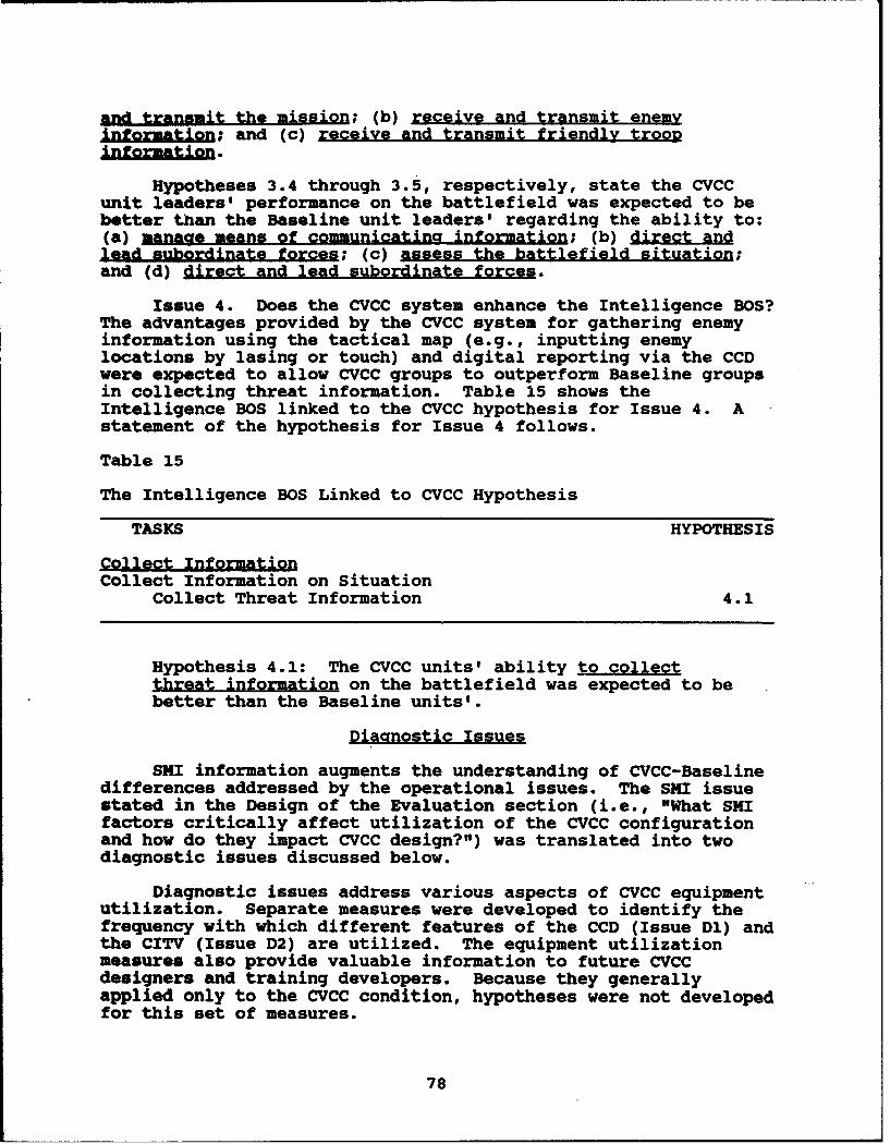
and transmit the mission; (b) receive and transmit enemyinformation; and (c) receive and transmit friendly trooDinformation.
Hypotheses 3.4 through 3.5, respectively, state the CVCCunit leaders' performance on the battlefield was expected to bebetter than the Baseline unit leaders' regarding the ability to:(a) manage means of communicatina information; (b) direct anlead subordinate forces; (c) assess the battlefield situation;and (d) direct and lead subordinate forces.
Issue 4. Does the CVCC system enhance the Intelligence BOS?The advantages provided by the CVCC system for gathering enemyinformation using the tactical map (e.g., inputting enemylocations by lasing or touch) and digital reporting via the CCDwere expected to allow CVCC groups to outperform Baseline groupsin collecting threat information. Table 15 shows theIntelligence BOS linked to the CVCC hypothesis for Issue 4. Astatement of the hypothesis for Issue 4 follows.
Table 15
The Intelligence BOS Linked to CVCC Hypothesis
TASKS HYPOTHESIS
Collect InformationCollect Information on Situation
Collect Threat Information 4.1
Hypothesis 4.1: The CVCC units' ability to collectthreat information on the battlefield was expected to bebetter than the Baseline units'.
Diaanostic Issues
SKI information augments the understanding of CVCC-Baselinedifferences addressed by the operational issues. The SMI issuestated in the Design of the Evaluation section (i.e., "What SMIfactors critically affect utilization of the CVCC configurationand how do they impact CVCC design?") was translated into twodiagnostic issues discussed below.
Diagnostic issues address various aspects of CVCC equipmentutilization. Separate measures were developed to identify thefrequency with which different features of the CCD (Issue Dl) andthe CITV (Issue D2) are utilized. The equipment utilizationmeasures also provide valuable information to future CVCCdesigners and training developers. Because they generallyapplied only to the CVCC condition, hypotheses were not developedfor this set of measures.
78
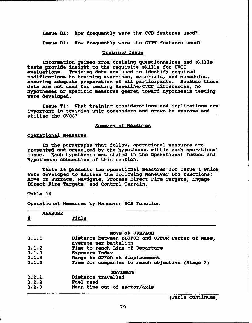
Issue D1: How frequently were the CCD features used?
Issue D2: How frequently were the CITV features used?
Trainina Issue
Information gained from training questionnaires and skillstests provide insight to the requisite skills for CVCCevaluations. Training data are used to identify requiredmodifications to training exercises, materials, and schedules,ensuring adequate preparation of all participants. Because thesedata are not used for testing Baseline/CVCC differences, nohypotheses or specific measures geared toward hypothesis testingwere developed.
Issue Ti: What training considerations and implications areimportant in training unit commanders and crews to operate andutilize the CVCC?
Summary of Measures
Ogerational Measures
In the paragraphs that follow, operational measures arepresented and organized by the hypotheses within each operationalissue. Each hypothesis was stated in the Operational Issues andHypotheses subsection of this section.
Table 16 presents the operational measures for Issue 1 whichwere developed to address the following Maneuver BOS functions:Move on Surface, Navigate, Process Direct Fire Targets, EngageDirect Fire Targets, and Control Terrain.
Table 16
Operational Measures by Maneuver BOS Function
MEASURE£Title
KOVE ON SURFACE1.1.1 Distance between BLUFOR and OPFOR Center of Mass,
average per battalion1.1.2 Time to reach Line of Departure1.1.3 Exposure Index1.2.4 Range to OPFOR at displacement1.1.5 Time for companies to reach objective (Stage 2)
NAVIGATE1.2.1 Distance travelled1.2.2 Fuel used1.2.3 Mean time out of sector/axis
(Table continues)
79

Table 16
Operational Measures by Maneuver BOS Function (Cont'd)
MEASURE
NAVIGATE1.2.4 Mean time misoriented1.2.5 Time to complete exercise
PROCESS DIRECT FIRE TARGETS1.3.1 Time to acquire targets1.3.2 Time between lases to different targets1.3.3 Time from lase to first fire1.3.4 Maximum lase range1.3.5 Number of fratricide hits by manned vehicles1.3.6 Number of fratricide kills by manned vehicles
ENGAGE DIRECT FIRE TARGETS1.4.1 Percent of OPFOR killed by end of stage1.4.2 Percent of BLUFOR killed by end of stage1.4.3 Losses/kill ratio1.4.4 Mean target hit range1.4.5 Mean target kill range1.4.6 Percent OPFOR vehicles killed by all manned
vehicles
ENGAGE DIRECT FIRE TARGETS1.4.7 Hits/round ratio, manned vehicles1.4.8 Kills/hit ratio, manned vehicles1.4.9 Kills/round ratio, manned vehicles1.4.10 Number of manned vehicles sustaining a killing hit1.4.11 Number of rounds fired by manned vehicles, by
echelon1.4.12 Number of OPFOR vehicles killed south of PL King1.4.13 Number of OPFOR vehicles killed south of PL Club1.4.14 Number of OPFOR vehicles killed south of PL Queen1.4.15 Number of OPFOR vehicles killed south of PL ACE
CONTROL TERRAIN1.5.1 Number of OPFOR vehicles penetrating designated
line (counterattack)1.5.2 Was the battalion bypassed by the OPFOR?1.5.3 Number of OPFOR vehicles penetrating designated
line (delay)1.5.4 Number of OPFOR vehicles that crossed PL Queen
Table 17 presents the operational measures for Issue 2 whichwere developed to address the Conduct Surface Attack function ofthe Fire Support BOS.
80

Table 17
Operational Measures by Fire Support BOS Function
MEASUREI ~Ti~tle
CONDUCT SURFACE ATTACK2.1.1 Mean accuracy of CFF locations2.1.2 Percent of CFFs with correct type
Table 18 presents the operational measures for Issue 3 whichwere developed to address the following functions of the Commandand Control BOS: Receive and Transmit Mission, Receive andTransmit Enemy Information, Receive and Transmit Friendly TroopInformation, Manage Means of Communicating Information, AssessSituation, and Direct and Lead Subordinate Forces.
Table 18
Operational Measures by Command and Control BOS Function
MEASURE
I Title
RECEIVE AND TRANSMIT MISSION3.1.1 Elapsed time from battalion transmission of FRAGO
to receipt by company commander/XO3.1.2 Duration of request by company commander to
clarify FRAGO/overlay3.1.3 Consistency of relayed FRAGO
RECEIVE AND TRANSMIT ENEMY INFORMATION3.2.1 Time to transmit INTEL report full net: battalion
TOC to lowest manned net3.2.2 Consistency of relayed INTEL
RECEIVE AND TRANSMIT FRIENDLY TROOP INFORMATION3.3.1 Mean time to transmit SITREP full net: lowest
net to battalion TOC3.3.2 Deviation of BLUFOR location reported in SITREP
from actual location3.3.3 Delay between observed phase line/line of
departure/FCL crossing and reported crossing3.3.4 Delay between observed battle position arrival and
reporting SET at battle position3.3.5 Elapsed time from request for fuel and/or
ammunition report until received by battalion TOC(Baseline only)
(Table continues)
81
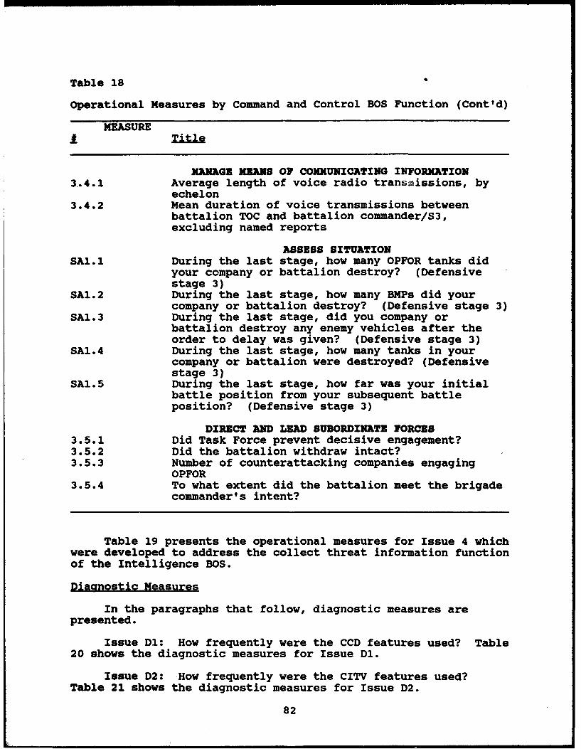
Table 18
Operational Measures by Command and Control BOS Function (Cont'd)
MEASUREi Title
MANAGE MEONS OF COMMUNICATING INFORMATION3.4.1 Average length of voice radio transmissions, by
echelon3.4.2 Mean duration of voice transmissions between
battalion TOC and battalion commander/S3,excluding named reports
ASSESS SITUATIONSAl.1 During the last stage, how many OPFOR tanks did
your company or battalion destroy? (Defensivestage 3)
SA1.2 During the last stage, how many BMPs did yourcompany or battalion destroy? (Defensive stage 3)
SA1.3 During the last stage, did you company orbattalion destroy any enemy vehicles after theorder to delay was given? (Defensive stage 3)
SA1.4 During the last stage, how many tanks in yourcompany or battalion were destroyed? (Defensivestage 3)
SA1.5 During the last stage, how far was your initialbattle position from your subsequent battleposition? (Defensive stage 3)
DIRECT AND LEAD SUBORDINATE FORCES3.5.1 Did Task Force prevent decisive engagement?3.5.2 Did the battalion withdraw intact?3.5.3 Number of counterattacking companies engaging
OPFOR3.5.4 To what extent did the battalion meet the brigade
commander's intent?
Table 19 presents the operational measures for Issue 4 whichwere developed to address the collect threat information functionof the Intelligence BOS.
Diagnostic Measures
In the paragraphs that follow, diagnostic measures arepresented.
Issue D1: How frequently were the CCD features used? Table20 shows the diagnostic measures for Issue Dl.
Issue D2: How frequently were the CITV features used?Table 21 shows the diagnostic measures for Issue D2.
82
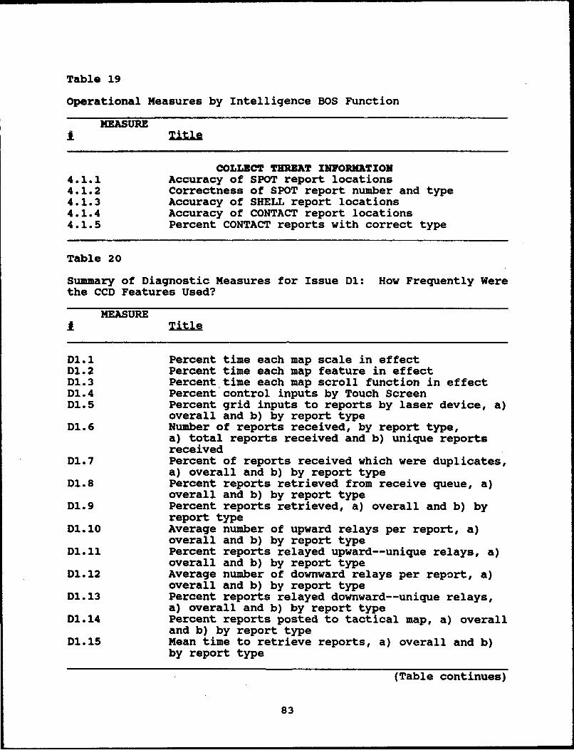
Table 19
Operational Measures by Intelligence BOS Function
MEASURE
COLLECT THREAT INFORMATION4.1.1 Accuracy of SPOT report locations4.1.2 Correctness of SPOT report number and type4.1.3 Accuracy of SHELL report locations4.1.4 Accuracy of CONTACT report locations4.1.5 Percent CONTACT reports with correct type
Table 20
Summary of Diagnostic Measures for Issue D1: How Frequently Werethe CCD Features Used?
MEASURE1.1ler
D1.1 Percent time each map scale in effectDl. 2 Percent time each map feature in effectD1.3 Percent time each map scroll function in effectD1.4 Percent control inputs by Touch ScreenD1.5 Percent grid inputs to reports by laser device, a)
overall and b) by report typeD1.6 Number of reports received, by report type,
a) total reports received and b) unique reportsreceived
Dl.7 Percent of reports received which were duplicates,a) overall and b) by report type
D1.8 Percent reports retrieved from receive queue, a)overall and b) by report type
D1.9 Percent reports retrieved, a) overall and b) byreport type
D1.10 Average number of upward relays per report, a)overall and b) by report type
D1.11 Percent reports relayed upward--unique relays, a)overall and b) by report type
D1.12 Average number of downward relays per report, a)overall and b) by report type
D1.13 Percent reports relayed downward--unique relays,a) overall and b) by report type
D1.14 Percent reports posted to tactical map, a) overalland b) by report type
D1.15 Mean time to retrieve reports, a) overall and b)by report type
(Table continues)
83
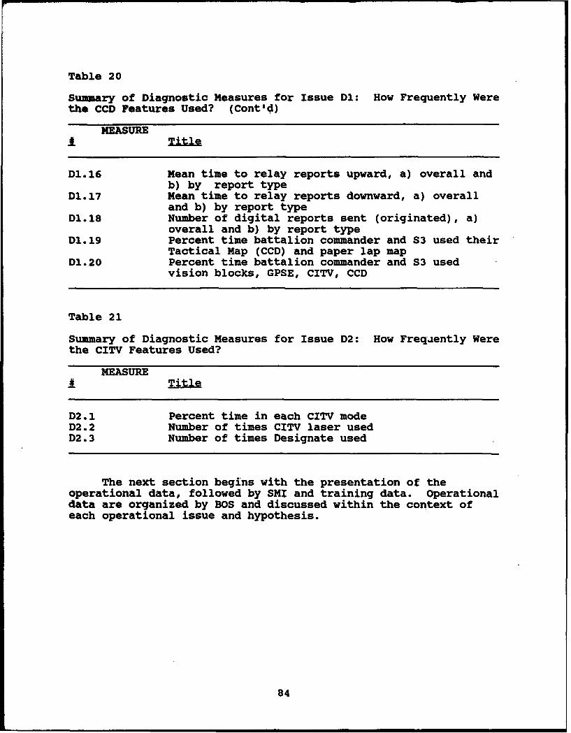
Table 20
Summary of Diagnostic Measures for Issue D1: How Frequently Werethe CCD Features Used? (Cont'd)
MEASURE
D1.16 Mean time to relay reports upward, a) overall andb) by report type
D1.17 Mean time to relay reports downward, a) overalland b) by report type
D1.18 Number of digital reports sent (originated), a)overall and b) by report type
D1.19 Percent time battalion commander and S3 used theirTactical Map (CCD) and paper lap map
D1.20 Percent time battalion commander and S3 usedvision blocks, GPSE, CITV, CCD
Table 21
Summary of Diagnostic Measures for Issue D2: How Frequently Werethe CITV Features Used?
MEASUREj Title
D2.1 Percent time in each CITV modeD2.2 Number of times CITV laser usedD2.3 Number of times Designate used
The next section begins with the presentation of theoperational data, followed by SMI and training data. Operationaldata are organized by BOS and discussed within the context ofeach operational issue and hypothesis.
84

Table 21
Summary of Diagnostic Measures for Issue D2: How Frequently Werethe CITV Features Used?
MEASURETil
D2.1 Percent time in each CITV modeD2.2 Number of times CITV laser usedD2.3 Number of times Designate used
The next section begins with the presentation of theoperational data, followed by SMI and training data. Operationaldata are organized by BOS and discussed within the context ofeach operational issue and hypothesis.
85
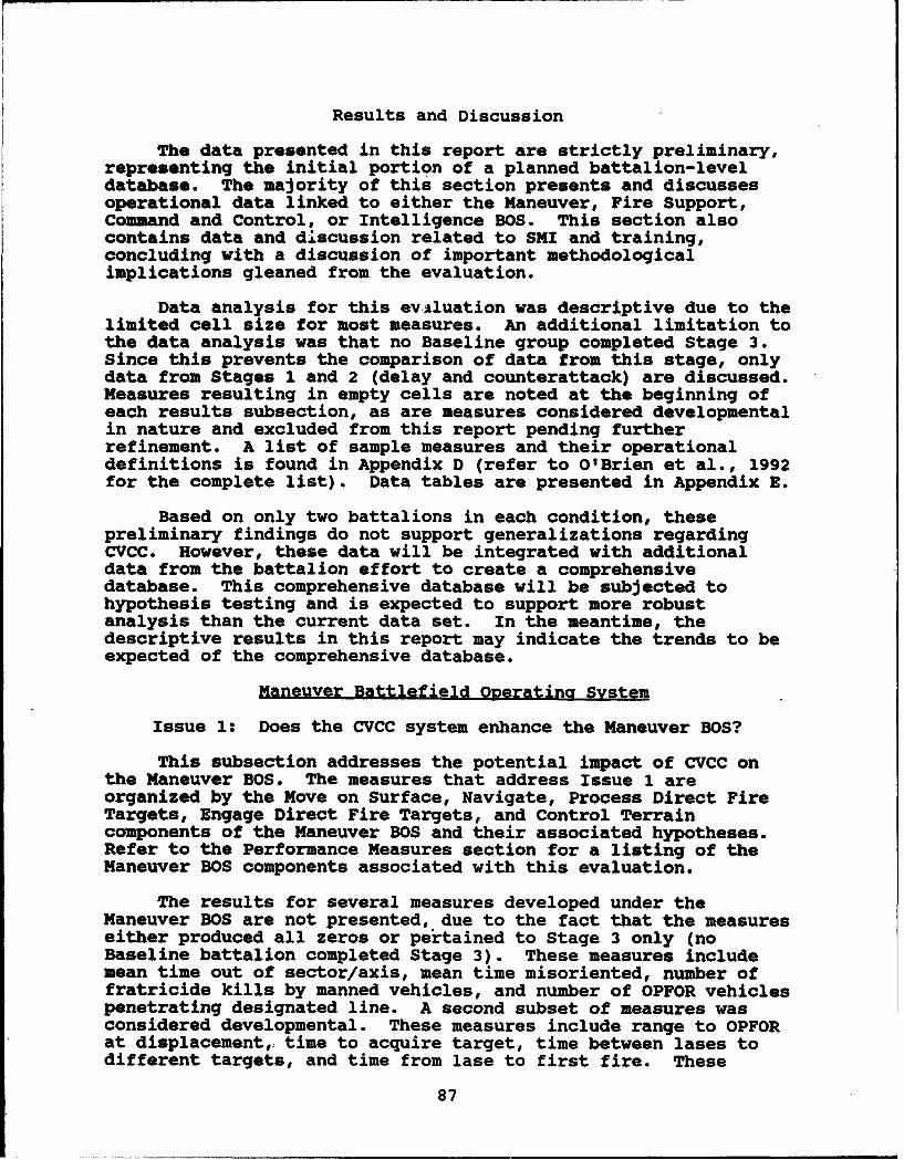
Results and Discussion
The data presented in this report are strictly preliminary,representing the initial portion of a planned battalion-leveldatabase. The majority of this section presents and discussesoperational data linked to either the Maneuver, Fire Support,Command and Control, or Intelligence BOS. This section alsocontains data and discussion related to SMI and training,concluding with a discussion of important methodologicalimplications gleaned from the evaluation.
Data analysis for this evAluation was descriptive due to thelimited cell size for most measures. An additional limitation tothe data analysis was that no Baseline group completed Stage 3.Since this prevents the comparison of data from this stage, onlydata from Stages I and 2 (delay and counterattack) are discussed.Measures resulting in empty cells are noted at the beginning ofeach results subsection, as are measures considered developmentalin nature and excluded from this report pending furtherrefinement. A list of sample measures and their operationaldefinitions is found in Appendix D (refer to O'Brien et al., 1992for the complete list). Data tables are presented in Appendix E.
Based on only two battalions in each condition, thesepreliminary findings do not support generalizations regardingCVCC. However, these data will be integrated with additionaldata from the battalion effort to create a comprehensivedatabase. This comprehensive database will be subjected tohypothesis testing and is expected to support more robustanalysis than the current data set. In the meantime, thedescriptive results in this report may indicate the trends to beexpected of the comprehensive database.
Maneuver Battlefield ODerating System
Issue 1: Does the CVCC system enhance the Maneuver BOS?
This subsection addresses the potential impact of CVCC onthe Maneuver BOS. The measures that address Issue 1 areorganized by the Move on Surface, Navigate, Process Direct FireTargets, Engage Direct Fire Targets, and Control Terraincomponents of the Maneuver BOS and their associated hypotheses.Refer to the Performance Measures section for a listing of theManeuver BOS components associated with this evaluation.
The results for several measures developed under theManeuver BOS are not presented, due to the fact that the measureseither produced all zeros or pertained to Stage 3 only (noBaseline battalion completed Stage 3). These measures includemean time out of sector/axis, mean time misoriented, number offratricide kills by manned vehicles, and number of OPFOR vehiclespenetrating designated line. A second subset of measures wasconsidered developmental. These measures include range to OPFORat displacement, time to acquire target, time between lases todifferent targets, and time from lase to first fire. These
87

measures are not presented here because they need furtherrefinement. Exposure Index is also considered in this category,but since its development is more advanced than the othermeasures, its data are included for review in Table E-3. Alldevelopmental measures are expected to be included in theanalysis of the complete database.
Move on Surface
Hypothesis 1.1: The CVCC units' ability to move on thesurface of the battlefield was expected to be better than theBaseline units'.
Distance between BLUFOR and OPFOR Center of Mass (CoMl.BLUFOR was defined for this measure as all non-reserve companiesand included all manned and SAFOR vehicles. Com is defined as thearithmetic mean of the company's x,y plot, including dead OPFORvehicles within 500 meters. In Stages 1 and 2, the average end-of-stage distance between BLUFOR and the OPFOR CoM appeared muchgreater for the CVCC companies relative to the Baseline companies(these data appear in Table E-l). For the CVCC companies, thedistances ranged from 9,792 meters to 10,641 meters, at the endof the engagements. For the Baseline companies, the distancesranged from 1,978 meters to 9,819 meters. This result suggeststhat CVCC companies did a much better job holding off the enemyforces or preventing the enemy force from getting too close.From this limited set of data, there do not seem to be anydifferences between Stage 1 (delay) and Stage 2 (counterattack).
Time to reach line of departure (Stage 2 onlvy. These data(see Table E-2) indicate that CVCC units were slightly faster andless variable than Baseline units in elapsed time to reach theline of departure (LD) during Stage 2 (counterattack). For thetwo CVCC units, time to LD were 11.50 and 20.70 minutes. For theBaseline units, the elapsed times were 4.68 to 22.03 minutes.These data do not exclude times at halt which might explain aportion of the Baseline/CVCC differences since past CVCCevaluations (e.g., Leibrecht et al., 1992) found that Baselinegroups spent more time at halt than CVCC groups.
Time for comDanies to reach objective (StaQe 2 only).Overall, CVCC companies were faster than Baseline companies intime required to execute the Stage 2 counterattack (see Table E-2). For the CVCC companies, the average time from the start ofthe stage until each company reported set on their respectiveobjectives varied from 17.85 minutes to 26.38 minutes. For theBaseline companies, this average varied from 15.37 to 47.13minutes. Again, time at halt was not excluded from thecalculation of data for this measure and may account for aportion of these apparent Baseline/CVCC differences.
88
Hypothesis 1.2: The CVCC unit's ability to navigate on thebattlefield was expected to be better than the Baseline units.
Distance traveled. The average distances driven by mannedvehicles during each stage do not appear to support anynoteworthy differences between groups (Table E-4). Potentialinterpretations of these data are complicated by the fact thatBaseline distance traveled may be low since Baseline commandersmay have relied more on unmanned BLUFOR vehicles to navigate,particularly in Stage 1 (delay). Additionally, CVCC commanderscan easily navigate to unit locations for direct observation,possibly resulting in artificially high travel distances.
Ful•s•dia . Only negligible differences in average fuel usedcould be detected between condition and echelon across the twostages. These data appear in Table E-4.
Time to complete exercise. Congruent with the data for timeto reach LD and time to reach objective, Baseline units tooklonger than the CVCC units to complete each stage. The elapsedtime for the Baseline units to execute Stage 1 ranged from 75.10to 87.28 minutes, while Stage 2 completion times ranged from58.87 to 67.15 minutes. The elapsed time for CVCC units toexecute Stage 1 ranged from 63.38 to 66.55 minutes, while Stage 2completion times ranged from 40.53 to 40.88 minutes. These datacan be found in Table E-5. This apparent trend replicatesprevious findings (e.g., Leibrecht et al., 1992).
Process Direct Fire Targets
Hypothesis 1.3: The CVCC units' ability to process directfire targets on the battlefield was expected to be better thanthe Baseline units'.
Maximum lase range. This measure was operationalized as themaximum distance a manned vehicle lased to a potential targetusing the GPS or CITV laser. No appreciable differences betweenBaseline or CVCC groups, or stages are apparent in these data.These data are presented in Table E-6.
Number of fratricide hits by manned vehicles. There wereonly three incidents of manned vehicles firing at other BLUFORvehicles throughout the experiment. Baseline battalions wereresponsible for two of these incidents during Stage 2. CVCCcompanies were responsible for the other fratricide hit whichoccurred during the Stage 1 delay. These data appear in Table E-6.
Enaaae Direct Fire Targets
Hypothesis 1.4: The CVCC units' ability to engage directfire targets on:the battlefield was expected to be better thanthe Baseline units'.
89
Percent of OPFOR killed by end of stage. No noteworthydifference in the percent of OPFOR vehicles killed by BLUFOR inthe Baseline or CVCC units is apparent for Stage 1. In Stage 2,both CVCC units and one Baseline unit killed all OPFOR vehicles.The other Baseline unit killed'66% of the OPFOR in this stage.The data for this measure appear in Table E-7.
Percent of BLUFOR killed by end of stage. This measure wasused to evaluate whether the battalion successfully "protectedits forces." BLUFOR included manned and unmanned units andexcluded mobility kills. There is some indication that CVCCunits did a better job protecting their forces in Stages 1 and 2than Baseline units. The greatest apparent differences occurredin Stage 2 with Baseline units sustaining a range of 11 to 16%casualties compared to CVCC units which sustained a range of 2 to6% casualties. These data are presented in Table E-7.
Percent of OPFOR vehicles killed by all manned vehicles.There does appear to be some evidence that the manned vehicles inthe CVCC groups killed a greater percent of the OPFOR than theBaseline groups in Stages 1 and 2. In Stage 1 (delay), thepercentage of OPFOR killed by the manned vehicles in Baselinegroups ranged from 7% to 13%. In the same stage, the percentageof OPFOR killed by manned vehicles in the CVCC groups ranged from12% and 22%. In Stage 2, CVCC manned vehicle kills ranged from7% to 11% of the OPFOR, while the Baseline groups killed between3% and 8%. These data appear in Table E-7.
Number of manned vehicles sustainina a killina hit. CVCCmanned simulators appeared to sustain fewer kills than Baselinesimulators. In Stage 1, CVCC simulator kills varied from 12 to24, while Baseline kills ranged from 22 to 26. In Stage 2, CVCCsimulator kills ranged from 1 to 4, compared to a range of 7 to10 for Baseline simulators. These data can be found in Table E-7.
Losses/kill ratio. The losses/kill ratio providesinformation about a units' combat effectiveness, and iscalculated by dividing the total number of BLUFOR losses by thetotal number of OPFOR losses. In Stage 1, there was nonoteworthy difference in the losses/kill ratios of Baseline andCVCC units. In Stage 2, the losses/kill ratio appeared toindicate greater combat effectiveness for CVCC units than forBaseline units. In this case, loss/kill ratio for CVCC unitsranged from .02 to .06. For Baseline units, this ratio rangedfrom .11 to .25. These data appear in Table E-7.
Mean taraet hit range. This measure was operationalized asthe distance from a firing manned vehicle to the OPFOR vehiclehit by the round fired. These limited data (presented in TableE-8) do not indicate any substantial differences between CVCC andBaseline groups in Stages 1 or 2.
Mean taraet kill range. There is some evidence that
Baseline groups killed targets at longer ranges than CVCC groups.
90
However, it is important to note that this measure should beconsidered in conjunction with the data for percent of OPFORkilled (CVCC advantage), number of manned vehicles sustaining akilling hit (CVCC advantage), and losses/kill ratio (CVCCadvantage). The limited data do not provide any reliableevidence of differences in mean target kill range betweenechelons (see Table E-8).
Hits/round ratio. for manned vehicles. During Stage 1 andStage 2, there do not appear to be any noteworthy differences inthe hits/round ratio between Baseline and CVCC companies. Thedata for this measure appear in Table E-8.
Kills/hit ratio, for manned vehicles. No noteworthydifferences could be detected between Baseline and CVCC groups inthe number of OPFOR vehicles killed per hit (See Table E-9).
Kills/round ratio. for manned vehicles. No notabledifferences between Baseline and CVCC groups could be detectedfor this ratio. These data are presented in Table E-9.
Number of rounds fired by manned vehicles. For thismeasure, no apparent differences occurred between CVCC andBaseline groups for Stage 2 (see Table E-9). For Stage 1(delay), the Baseline data indicate that both battalion vehicles(2 - 6.00, S.D. - 5.48) and company vehicles (X - 16.33, S.D. -9.36) tended to fire fewer rounds per vehicle than CVCC groups.CVCC battalion vehicles averaged 18.25 rounds (S.D. - 12.04) andcompany vehicles averaged 17.58 rounds per vehicle (S.D. = 5.66).These possible trends differ slightly from past work (e.g.,Leibrecht et al., 1992), and will be carefully examined when thecomprehensive database is available.
Number of OPFOR vehicles killed south of a desianated line.Two measures examined the total number of OPFOR vehicles killedby the battalion south of a designated phase line during Stage 1.The data for this measure appear in Table E-10. These measures(crossing PL King and PL Club) were designed as components of alater measure that addressed how well the battalion met thecommander's intent (measure 3.5.4), discussed in the Command andControl BOS subsection. No differences were apparent betweenBaseline and CVCC units in either of these measures.
Control Terrain
Hypothesis 1.5: The CVCC units' ability to control terrainon the battlefield was expected to be better than the Baselineunits'.
Measures developed to test this hypothesis failed to producenon-zero data for CVCC and Baseline units. No OPFOR vehiclespassed the designated line.
91
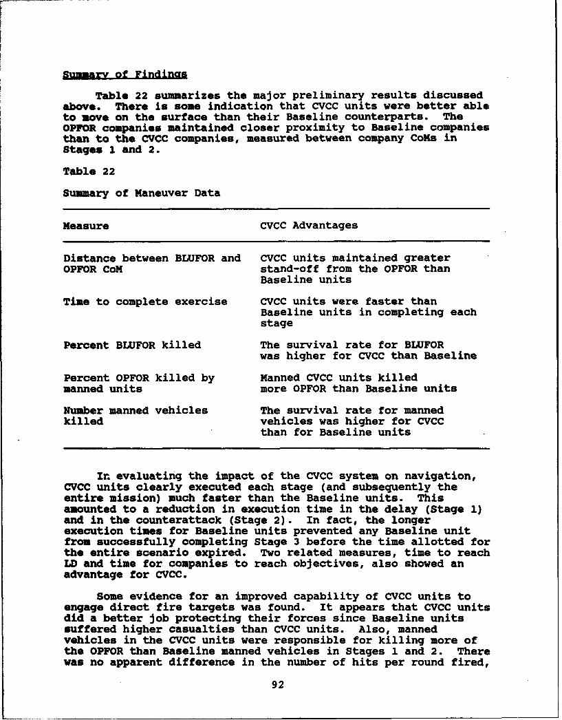
S-umary of Findings
Table 22 summarizes the major preliminary results discussedabove. There is some indication that CVCC units were better ableto move on the surface than their Baseline counterparts. TheOPFOR companies maintained closer proximity to Baseline companiesthan to the CVCC companies, measured between company CoMs inStages 1 and 2.
Table 22
Summary of Maneuver Data
Measure CVCC Advantages
Distance between BLUFOR and CVCC units maintained greaterOPFOR CoM stand-off from the OPFOR than
Baseline units
Time to complete exercise CVCC units were faster thanBaseline units in completing eachstage
Percent BLUFOR killed The survival rate for BLUFORwas higher for CVCC than Baseline
Percent OPFOR killed by Manned CVCC units killedmanned units more OPFOR than Baseline units
Number manned vehicles The survival rate for mannedkilled vehicles was higher for CVCC
than for Baseline units
In evaluating the impact of the CVCC system on navigation,CVCC units clearly executed each stage (and subsequently theentire mission) much faster than the Baseline units. Thisamounted to a reduction in execution time in the delay (Stage 1)and in the counterattack (Stage 2). In fact, the longerexecution times for Baseline units prevented any Baseline unitfrom successfully completing Stage 3 before the time allotted forthe entire scenario expired. Two related measures, time to reachLD and time for companies to reach objectives, also showed anadvantage for CVCC.
Some evidence for an improved capability of CVCC units toengage direct fire targets was found. It appears that CVCC unitsdid a better job protecting their forces since Baseline unitssuffered higher casualties than CVCC units. Also, mannedvehicles in the CVCC units were responsible for killing more ofthe OPFOR than Baseline manned vehicles in Stages 1 and 2. Therewas no apparent difference in the number of hits per round fired,
92
the number of kills per round fired, or the mean target killrange.
The hypothesized improvement in the capability of CVCC unitsto control terrain was not directly supported since both CVCC andBaseline units denied the OPFOR passage beyond critical controlmeasures, preventing any comparisons between the two conditions.However, CVCC companies did show an advantage for holding off theenemy force, killing more OPFOR vehicles overall, and sustainingtheir own combat power. Taken together, these data seem tosuggest that CVCC units did control terrain more effectively.
Once again, the preliminary nature of these findings shouldbe emphasized. Due to the limited sample size and thevariability of the data for individual measures, it is difficultto draw conclusions. These data are to be combined into a largerdata base currently under development, which is designed toproduce more statistically reliable results.
Fire SunDort Battlefield Operating System
Issue 2: Does the CVCC system enhance the Fire Support BOS?
The potential effect of the CVCC on fire support isdiscussed in this section. A single hypothesis, based on theConduct Surface Attack component of the Fire Support BOS,organizes the presentation of data.
Conduct Surface Attack
Hypothesis 2.1: The CVCC units' ability to conduct surfaceattack by indirect fire on the battlefield was expected tobe better than the Baseline units'.
Mean accuracy of CFF locations. Mean accuracy of CFFlocations was assessed by calculating the average deviation, inmeters, of the nearest three OPFOR vehicles from the reportedOPFOR location. This measure is based only on those vehiclesrequesting calls for fire.
The data for this measure are shown in Table E-11. The mostnotable result was that the CVCC group provided more accurate CFFlocations (I = 530.75, S.D. = 550.89, n = 8) than the Baselinegroup (N - 1882.20, S.D. = 2518.76, n = 10) in Stage 1 (delayoperation). In Stage 2, a low number of reports for Baseline(n - 1) and CVCC (n = 3) prevent any comparisons. The low numberof reports may be a reflection of the offensive maneuvers ofStage 2. While making these maneuvers, crews may not have takenas much time to request calls for fire as they did in thedefense-oriented Stage 1.
These data indicate CVCC may have increased reported CFFlocation accuracy. This is evidenced by the difference in
93

accuracy between the Baseline and CVCC groups in Stage 1, but dueto infrequency of occurrence, not supported by the Stage 2 data.
Percent of CFFs with correct tyDe. This measure wasassessed by calculating the percent of scorable reports for whichthe reported type of OPFOR vehicle (tank, helicopter, orpersonnel carrier) was found to have intervisibility with therequesting vehicle. Scorable reports were those containing gridlocations and type.
The data for this measure are displayed in Table E-11.During Stage 1, 89% of the CVCC group's CFFs (n = 8) containedthe correct vehicle type compared to the Baseline group's 28% (n- 10). As with the CFF location accuracy data for Stage 2, thelow number of CFFs prevents Baseline/CVCC comparisons.
These data indicate that CVCC increases CFF report accuracyin terms of vehicle type identified for Stage 1.
Summary of Findinas
In sum, both measures indicate CVCC may increase CFF reportaccuracy (see Table 23 for summary of data). However, data forthe CFF locations measure suggest the benefit of CVCC may beslightly reduced during stages that place more time constraintson requesting calls for fire. In both Baseline and CVCCconditions, offensive maneuvers may demand more attention fortarget acquisition than defensive maneuvers, leading to less timefor making the requests and possibly decreasing CFF reportlocation accuracy.
Table 23
Summary of Fire Support Data
Measures CVCC Advantages
Accuracy of CFFs (meters) CVCC CFF report locationaccuracy greater thanBaseline for Stage 1
* CFFs with CVCC CFF report vehicleCorrect Type identification accuracy
greater than Baseline forStage 1
Vehicle identification accuracy is clearly achieved withCVCC during Stage 1. This may be due to the fact that a CVCCvehizle commander has menu-style vahicle type options on theCCD's CFF screen available for his immediate selection. Inaddition, reported vehicle types are considered correct based onall OPFOR vehicles in the reported location with which the
94

reporting vehicle has intervisibility lasting at least sixseconds. The CCD map feature may allow for more precise locationof these targets, enabling more accurate inclusion of the correcttarget type.
The results presented in this section indicate how CVCCcapabilities can help vehicle commanders form accurate calls forfire to increase the effectiveness of their surface attacks.CVCC use in managing other information vital to mission success,including friendly and enemy situations (e.g., SITREPS and INTELreports), is discussed in the following Command and Controlsubsection.
Command and Control Battlefield Operatina System
Issue 3: Does the CVCC system enhance the Command andControl BOS?
This section addresses the potential impact of CVCC oncommand and control. The measures were developed to address fivedistinct hypotheses. The following categories, each representingone of these hypotheses, were used to organize this section:Receive and Transmit Mission, Receive and Transmit EnemyInformation, Receive and Transmit Friendly Troop Information,Manage Means of Communicating Information, Direct and LeadSubordinate Forces, and Assess the Battlefield Situation.
The communication network structures used by the CVCC andBaseline groups in this test were not identical. The digitalstructure for CVCC groups comprised one level reaching all mannedelements instantaneously. This net structure preventedmeaningful comparison of communication throughput measuresbetween the two groups. For example, when the CVCC TOCtransmitted a FRAGO on the digital battalion command net, allvehicle commanders received the information at the same time.However, when the Baseline TOC transmitted a FRAGO using thevoice battalion command net, it had to be relayed on the companycommand net to the company XOs.
One measure not presented in this section is the time forsubmission of fuel and/or ammo report, an element of the Receiveand Transmit Friendly Information measures. The time the reportwas requested was flagged on the PVD and subsequently analyzedusing the DCA system. The time the report was received in theTOC was retrieved through playback. DCA data are adjusted forexercise start and stop times and exclude times when the exercisewas stopped due to technical problems. The playback times do notexclude exercise down times. Therefore, the times from the DCAand playbacks are incompatible. In the future, both time ofreport request and time received should be flagged.
95

Receive and Transmit Mission Information
Hypothesis 3.1: The CVCC units' ability to receive andtransmit information on the battlefield was expected to be betterthan the Baseline units'.
Elapsed time from battalion transmission of FRAGO to receiptby XO (Staae 1 & 21. This measure was defined as the totalelapsed time between the time the battalion TOC initiatestransmission of a FRAGO until the time the last company commanderfinishes transmitting the FRAGO, including clarification time.Table E-12 presents these data. Baseline FRAGO transmissionsranged from 16.33 to 18.15 minutes to reach the XO. In CVCCbattalions, the FRAGOs were received instantaneously by all unitcommanders and their XOs.
Consistency of relayed FRAGO (Stage 2 only). Theconsistency of FRAGO contents was measured by comparing therelayed FRAGO to the scripted FRAGO. The Baseline battalionsproduced six relays of the FRAGO. The mean percentage of FRAGOelements correctly relayed was 16% (S.D. = 8.20). These dataappear in Table E-12. The CVCC condition required no relay sinceall manned simulators received the digital FRAGO simultaneously.
Duration of reauest by comRanv commanders to clarifyFRAGO/overlay. This measure was defined as the average length ofthe unit commanders' requests for clarification of the FRAGO andthe accompanying overlay. CVCC commanders made no clarificationrequests, while Baseline commanders made five requests. Thesedata can be found in Table E-13. The likelihood that a CVCC unitcommander would have to clarify a FRAGO or an overlay is lowbecause the FRAGO text is in FREE TEXT form, and it can bereread. Also, every vehicle receives identical digital overlayson the CCD.
Receive and Transmit Enemy Information
Hypothesis 3.2: The CVCC units' ability to receive andtransmit enemy information on the battlefield was expected to bebetter than the Baseline units'.
The measures in this subsection address the timeliness ofenemy information that is relayed from higher echelons to lowerechelons (top-down reports), with the exception of the number ofSPOT, CONTACT, and SHELL reports. The timeliness of reports fromlower echelons to higher echelons is not meaningful in thepresent evaluation because lower echelons (Company D, platoonleaders, and scouts) are automated or role-played by testpersonnel. The accuracy of enemy information that is relayedbottom-up is discussed in the Intelligence BOS (followingsubsection).
Time to transmit INTEL report full net: battalion TOC tolowest manned net (XO). The time to transmit INTEL reports wasdefined as the elapsed time between the time the battalion TOC
96
initiated a transmission of the INTEL report to the time the lastXO received the report. Baseline transmissions took an averageof 43 seconds (S.D. = 22.06). Refer to Table E-14 for thismeasure's data.
Consistency of relayed INTEL. INTEL report consistency wasdefined as the percentage of scripted INTEL elements correctlyrelayed. This measure produced only one data point for eachstage in the Baseline condition, because the radio networkrequired only one relay between the battalion command net to thecompany command net. In Stage 1, the INTEL report consistencyrelayed by the company commander was 100%. In Stage 2, theconsistency was 25%. See Table E-15 for these data.
Ouantitv of combat reports: CONTACT. SPOT. and SHELL.Although not a defined measure, the number of reports duringcombat is of interest because a complete description of thebattlefield is critical. The number of CONTACT, SPOT, and SHELLreports differed between the CVCC and the Baseline battalionsduring Stage 2 (counterattack). The number of reports sentduring this stage was greater for the CVCC battalions than theBaseline battalions. Eight SPOT reports were sent by the CVCCbattalions while only four SPOT reports were sent by the Baselinebattalions. More S!1ELL (CVCC = 4, Baseline = 3) and CONTACT(CVCC - 8, Baseline = 3) reports were sent by CVCC battalions aswell. The combination of Stage 2's offensive maneuvers and theabsence of the CVCC may place heavy constraints on report sendingin Baseline units. The larger number of reports sent overall byCVCC crews during Stage 2 highlights how CVCC can benefitreporting efficiency during complex maneuvers.
Receive and Transmit Friendly Troop Information
Hypothesis 3.3: The CVCC units' ability to receive andtransmit friendly troop information on the battlefield wasexpected to be better than the Baseline units'.
Mean time to transmit'SITREP full net: lowest net (platoon)to battalion TOC. The mean time to transmit SITREPs wasspecified as the elapsed time from the lowest net (platoon)transmission of the SITREP to the time the battalion TOC receivedthe company SITREP. SITREPs from Baseline units took an averageof 2.98 minutes to transmit (S.D. = 3.53).
Deviation of BLUFOR location reported in SITREP from actuallocation. To assess the accuracy of friendly vehicle informationtransmitted in combat reports, this measure examined thedeviation, in meters, of the SITREP's Forward Line of Own Troops(FLOT) from the actual FLOT. The actual FLOT was determined byidentifying the most forward vehicle on either flank of thecompany formation at the time a SITREP was transmitted. Themidpoint between the two actual locations was compared to themidpoint between the two reported FLOT locations in the SITREP toyield a direct line distance (see Table E-16 for these data).For Baseline battalions, there was only one scorable report (out
97
of 105) transmitted, because only one SITREP included a FLOT gridlocation.
For CVCC battalions, four SITREPs were transmitted, two ineach stage. The distance between the transmitted and actual FLOTranged from 427 to 1592 meters. These data reveal anotheradvantage CVCC battalions have because of the capabilities of theCCD. Fewer SITREPs are necessary in CVCC because much of theinformation contained in a SITREP is available to each unitcommander on the LOGISTICS report. The LOGISTICS report providesinformation on unit equipment, ammunition, personnel, and fuel.The information in the LOGISTICS report is automaticallyforwarded every 10 seconds and is always correct. In addition,it becomes less essential to send FLOT locations in CVCC becauseevery vehicle and unit commander can see friendly vehiclelocations on his CCD. The Baseline battalions must rely onsubordinate accounts of the same information, which then must berelayed via radio.
Delay between observed PL/LD/FCL crossing and reportedcrssng. This measure quantifies the timeliness of controlmeasure reporting within the tactical scenarios. The exercisecontrol staff flagged the time a unit crossed given controlmeasures and the time those control measures were reported on thebattalion net. CVCC units were asked to report when they crossedlinear control measures despite the fact that their progresscould be monitored on CCD and battalion TOC map displays. Thedata for this measure show CVCC battalions were faster inreporting crossings in the delay stage than Baseline battalions.The ranges for CVCC units were .15 to .48 minutes in the delaystage (Stage 1), and .22 to 3.35 minutes in the counterattack(Stage 2). Baseline unit report latency ranged from .22 to 2.57minutes in the delay. Only one Baseline battalion reportedcrossing the designated control measure in the counterattackstage. In this case the delay was 1.95 minutes. These data canbe found in Table E-16.
Delay between observed BP arrival and reborting SET at BP.This measure reports the delay, in minutes, between the time aunit arrives within a battle position (delay stage) or objective(counterattack stage), and when the unit reports that it is setin that position. In the delay stage, CVCC units rendered moretimely reports (R = 4.14, S.D. = 5.41) than did Baseline units (z= 9.76, S.D. = 12.62). Only one Baseline report was recorded inStage 2, 9.22 minutes after the unit was observed entering itsobjective, preventing any comparisons between Baseline and CVCCunits (see Table E-16).
An explanation of these data lies in the capabilitydifferences between the CVCC and Baseline vehicles. With theCVCC system, a unit commander can observe his unit's position asreported by the POSNAV aystem on the tactical map. Since themaneuver graphicv are also posted on the CCD, the commander needonly confirm that the POSNAV symbols are superimposed on the BPor objective to confirm this unit's arrival. In other words,
98
arrival can be reported immediately, without reliance onsubordinate reports. In Baseline, the commander relies more onsubordinate reports and observations through the vision blocks.The latter implies a need to verify navigational accuracy, whichwould further delay a report. Hence, of the two conditions,Baseline reporting is more likely to be delayed if the unit is incontact with the OPFOR.
Manaae Means of Communicating Information
Hypothesis 3.4: The CVCC units' ability to manage means ofcommunicating information on the battlefield was expected to bebetter than the Baseline units'.
Mean duration of voice transmissions between battalion TOCand battalion commander/S3. excluding named reports. Playbackswere used to record the sender, start time, and stop time of eachtransmission between the battalion TOC and the battalioncommander or S3. Excluded from these communications were anycombat reports which could be received or prepared using the CCD.A small difference was detected in the average length of voiceradio transmissions between the battalion TOC and battalioncommander/S3 for CVCC battalions (2 = 36.20 seconds, S.D. =31.50) compared to the Baseline battalions (I = 27.60 secondsS.D. = 26.40). The Baseline battalions, however, transmittedmore reports (n = 133) than the CVCC battalions (n = 22), placinga larger voice load on the radio network. See Table E-17 forthese data.
Average lenath of voice radio transmissions. by echelon.This measure reports the duration of voice transmission; definedas the length of time the microphone was keyed. The data werecollected, by vehicle, during each stage and then meantransmission durations-were calculated. The means and standarddeviations reported in Table E-18 are based on the averagetransmission durations (in seconds) for each vehicle. Themaximum and minimum times reported are absolute values. In orderto further evaluate the impact of the CVCC equipment on voiceradio traffic, the mean number (in addition to duration) of voicetransmissions was analyzed.
The data (see Table E-18) indicate that the difference inaverage transmission duration was not influenced by condition orechelon. However, far fewer voice transmissions were sent bymanned vehicles when digital communications were available.These trends mirrored the voice transmission data discussedearlier in this section between battalion TOC and battalioncommander/S3.
Direct and Lead Subordinate Forces
Hypothesis 3.5: The CVCC units' ability to direct and leadsubordinate forces on the battlefield was expected to be betterthan the Baseline units'.
99

Did Task Force (TF) grevent decisive enaaaement (Staae 1)?The Battle Master determined whether the TF successfullyprevented a decisive engagement. This determination was basedon: (a) the Battle Master's assessment of the reaction time ofthe battalion commander and the company commanders , (b) theproportion of battalion vehicles successfully displacing (50% ormore), and (c) a consideration of BLUFOR controller responsetimes. Using these criteria, both CVCC battalions weresuccessful, while both Baseline battalions were not.
Did the battalion withdraw intact (Staae 1 only)? Thismeasure was based on the percentage of the BLUFOR vehiclesremaining at the end of the Stage 1. Values obtained from theDCA routine determined BLUFOR strength at the end of a stage.This value was then divided by the starting BLUFOR strength.Values greater than 70% indicated the battalion withdrew intact.The 70% criterion is based on the ARTEP 71-2 MTP. No Baseline orCVCC battalion withdrew intact.
Number of counterattackina companies engaagin OPFOR(Satge21. This measure was determined by the Battle Master'sassessment of how many counterattacking companies simultaneouslyengaged the OPFOR during Stage 2. Negligible differences werefound between CVCC and Baseline units (See Table E-19). Thenumber of counterattacking companies engaged ranged from 1 to 3.
To what extent did the battalion meet the briaadecommander's intent (Stage 1 and Staae 2)? In order to determinehow well the battalion met the brigade commander's intent, anumber of previously-defined measures were combined to produce acomposite percentage. This paragraph describes how the measurewas calculated. For Stage 1, each of the following measurescontributed 25% of the total score: (a) the percent of BLUFORkilled by the end of the stage, (b) the number of OPFOR vehicleskilled south of PL King, (c) the number of OPFOR vehicles killedsouth of PL Club, and (d) the number of OPFOR vehiclespenetrating a designated line. Each of these component measureswas discussed in the Maneuver BOS results subsection. For Stage2, each of the following measures contributed 33.33% of the totalscore: (a) the percent of OPFOR killed by end of the stage, (b)the percent of BLUFOR killed by the end of the stage, and (c) thenumber of OPFOR vehicles penetrating a designated line by the endof the stage. These component measures are discussed in theManeuver BOS results section.
The data are presented in Table E-20. From these limiteddata, it is not possible to detect reliable differences betweenBeseline and CVCC units. Scores on this measure ranged from 81to 95% in Stage 1, and 95 to 100% in Stage 2.
Assess Situation
Hypothesis SAl: The CVCC unit leaders' assessment ofbattlefield events was expected to be better than Baseline unitleaders'.
100
The potential impact of CVCC on situational assessment isaddressed in this section. The hypothesis, based on the AssessSituation component of the Command and Control BOS, organizes thepresentation of data. The Situational Assessment questionnairemay be found in Appendix C.
The Situational Assessment questionnaire was administered atthe conclusion of the test scenario. The questionnaire wasoriginally designed with reference to tactical events in Stage 3of the test scenario. For units that only completed two stages,the items and comparisons to actual events were adapted to Stage2. However, two items (destruction of OPFOR vehicles after theorder to delay, and deviation between true and reported distance)were not appropriate to Stage 2, and therefore, no data on thoseitems were available for those units. Given that only CVCC unitsprogressed through the third stage, no data were availableregarding the ability of Baseline unit members to judge spatialdisplacement, or to compare the possible effect of CVCC on thosekinds of judgments. At the completion of the battalionevaluation, the full database may include Stage 3 data fromBaseline groups.
Percentage of destroyed OPFOR tanks correctly identified.This measure was assessed by totaling the number of T72s
destroyed (catastrophic kills only) by A, B, and C Companies andby the battalion as a whole, and comparing the data to the unitand vehicle commanders' estimates. The score is expressed as apercentage, see Table E-21.
The CVCC group more accurately reported killed T72s (R =53%, S.D. = 44) than did the Baseline group (X = 25%, S.D. = 36)at the battalion level. However, at the company level, theBaseline group made more accurate identifications (I = 50%, S.D.= 45) than the CVCC group (2 = 23%, S.D. = 26). Baseline groups.repori, higher confidence in their assessments at both echelons(battalion 2 = 3.00, S.D.= 1.41; company R = 4.17, S.D. = 1.27)than CVCC groups (battalion R = 1.50, S.D. = .58, company 2 -3.00, S.D. = .77).
The fact that CVCC units were reporting on Stage 3, andBaseline groups were reporting on Stage 2 may help explain thesedifferences. In Stage 3, the BLUFOR displaces to the rear whenthe OPFOR closes to within 2000 meters, in order to avoid beingoverrun. Therefore, the subjects' direct observations of thebattlefield are conducted at relatively long ranges. In Stage 2,the BLUFOR moves toward the enemy, seizes and holds a tacticalobjective. In this case, the BLUFOR closes on the OPFOR, or atleast maintains its distance from the OPFOR. In all scenarios,company level participants are more likely to be in directcontact with the enemy than are battalion level participants.Given that direct observations may be made at closer ranges inStage 2, one would expect more accurate enemy vehicleidentification at the company level, and higher confidence levelsin that assessment.
101
Percentage of destroyed BKPs correctly identified.Percentage of correct BWP identification was assessed bycalculating the percent of correctly reported BIPs suffering acatastrophic kill by A, B, and C Companies and by the battalionas a whole. The data are presented in Table E-22.
The CVCC group correctly reported a greater percentage ofdestroyed BIPs (Z - 58%, S.D. - 41.27) than those in the Baselinegroup (2 - 15%, S.D. - 16.54) at the battalion level. The CVCCgroup also reported more accurately at the company level (I -36%, S.D. - 26.30) than the Baseline group (9 - 29%, S.D -40.37). Baseline groups at both echelons were more confident intheir assessments (battalion X - 3.50, S.D. - 1.73; company X -4.17, S.D. - 1.27) than were CVCC groups (battalion X - 2.00,S.D. - .82; company 2 = 2.73, S.D. = .65).
Destruction of OPFOR vehicles after the order to delay.This measure required the participants to report whether anyenemy vehicles suffered a catastrophic kill after the order todelay was given. The failure of Baseline groups to progress toStage 3 limited the data in this measure to CVCC groups.Therefore, it is not possible to make any comparisons betweengroups.
Among CVCC groups, 75% of the participants in the battalionechelon responded accurately to this item. At the companyechelon, 83% of respondents responded accurately.
Percentage of own vehicles destroyed. Percentage of ownvehicles destroyed was assessed by calculating the percent of A,B, C Company and battalion vehicles correctly identified thatsuffered catastrophic kills. Refer to Table E-23 for data.
Within the battalion echelon, CVCC group members reportedfriendly losses more accurately (2 = 56%, S.D. - 31.06) than didmembers of the Baseline group (2 = 18%, S.D. = 11.90). At thecompany echelon, the margin between conditions was small(Baseline: 2 = 63%, CVCC: X = 58%). However, Baseline groupscores were more variable than the CVCC group (Baseline: S.D. -47.07, CVCC: S.D. = 27.79).
The differences at both echelons may be explained by theoperational effectiveness utility within CVCC. The operationaleffectiveness module provides an immediate, up-to-date count ofthe operational vehicles in the unit.
Deviation between true and regorted distance. This distancewas assessed by calculating the deviation, in kilometers, betweenquestionnaire response and actual distance between successive BPsin the third stage of the test scenario. Comparative data forthis measure are not available due to the failure of Baselineunits to progress to the third stage of the test scenario.
The mean deviation score among CVCC group members at thebattalion echelon was .38 kilometers (S.D. = .26), as seen in
102
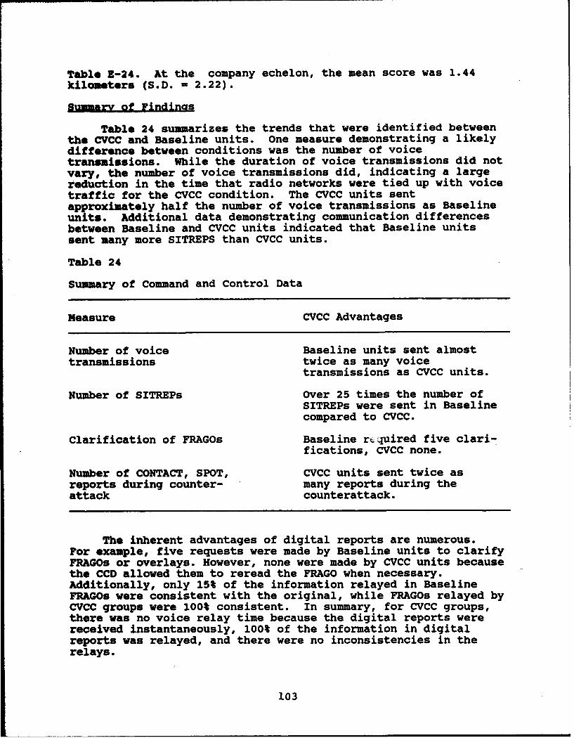
Table E-24. At the company echelon, the mean score was 1.44
kilometers (S.D. - 2.22).
Sumary of Findinas
Table 24 summarizes the trends that were identified betweenthe CVCC and Baseline units. One measure demonstrating a likelydifference between conditions was the number of voicetransmissions. While the duration of voice transmissions did notvary, the number of voice transmissions did, indicating a largereduction in the time that radio networks were tied up with voicetraffic for the CVCC condition. The CVCC units sentapproximately half the number of voice transmissions as Baselineunits. Additional data demonstrating communication differencesbetween Baseline and CVCC units indicated that Baseline unitssent many more SITREPS than CVCC units.
Table 24
Summary of Command and Control Data
Measure CVCC Advantages
Number of voice Baseline units sent almosttransmissions twice as many voice
transmissions as CVCC units.
Number of SITREPs Over 25 times the number ofSITREPs were sent in Baselinecompared to CVCC.
Clarification of FRAGOs Baseline rcquired five clari-fications, CVCC none.
Number of CONTACT, SPOT, CVCC units sent twice asreports during counter- many reports during theattack counterattack.
The inherent advantages of digital reports are numerous.For example, five requests were made by Baseline units to clarifyFRAGOs or overlays. However, none were made by CVCC units becausethe CCD allowed them to reread the FRAGO when necessary.Additionally, only 15% of the information relayed in BaselineFRAGOs were consistent with the original, while FRAGOs relayed byCVCC groups were 100% consistent. In summary, for CVCC groups,there was no voice relay time because the digital reports werereceived instantaneously, 100% of the information in digitalreports was relayed, and there were no inconsistencies in therelays.
103
In summarizing situational assessment capabilities, datasuggest some possible trends between the Baseline and CVCCgroups. However, two of the situational assessment measures canonly be analyzed if future Baseline groups complete the finaltest stage. Furthermore, the tactical differences between Stage2 and Stage 3 may be enough to influence the accuracy ofparticipant responses, such that the data should not be compared.Modifications should be considered prior to implementation of theSituational Assessment questionnaire in future research efforts.In all, preliminary findings suggest that the CVCC equipped unitshave advantages over Baseline units in the realm of command andcontrol. A related area of investigation in the battalionevaluation is whether the CVCC offers advantages in the transferof intelligence information. Measures dealing with this questionare discussed in the following Intelligence BOS subsection.
Intelliloence Battlefield Operating System
Issue 4: Does the CVCC system enhance the Intelligence BOS?
This section examines the effect of CVCC on collectingintelligence information. One hypothesis, based on the CollectThreat Information component of the Intelligence BOS, organizesdata presentation.
Collect Threat Information
Hypothesis 4.1: The CVCC units' ability to collect threatinformation on the battlefield was expected to be better than theBaseline units'.
Accuracy of SPOT report locations. The assessment of SPOTreport location accuracy was based on the deviation, in meters,of the nearest OPFOR vehicle to its reported OPFOR location. The"observed" and "destroyed" elements of the SPOT reports werescored independently.
The location accuracy data are presented in Table E-25.During Stage 1, SPOT report locations of observed enemy forceswere more accurate (X = 351.17, S.D. - 272.62, n - 12) forBaseline units than those from the CVCC units (R - 456.17, S.D. -573.93, n - 12). However, location accuracy was higher with theCVCC units (I - 404.63, S.D. = 397.86, n - 8) than with Baseline(2 - 708.00, S.D. - 1003.83, n = 4) during Stage 2.
Reports identifying the location of destroyed enemy vehicleswere more accurate for CVCC units in Stage 1, but Baseline reportaccuracy was higher in Stage 2. However, the Baseline resultswere based on only two reports in Stage 1 and one report in Stage2, compared to 12 and 8 reports for CVCC.
Correctness of SPOT report number and tyDe. For eachscorable SPOT report, this measure was assessed by calculatingthe percentage of reported vehicles, of the reported type, whichwere found to have intervisibility with the reporting vehicle.
104
Independent calculations were made for the "observed' and"adestroyed" elements of the reports.
Refer to Table E-25 for a listing of these data. DuringStage 1, 77% (S.D. - 23.79) of CVCC SPOT reports contained thecorect number of vehicles observed compared to 58% (S.D. -31.84) of Baseline's reports. Likewise, observations in CVCCSPOT reports from Stage 2 were 100% accurate compared to the 67%(S.D. - 47.20) accuracy of Baseline reports.
Accurate identification of the number and type of enemyvehicles was better with the CVCC group in both Stages 1 and 2.Although, the data include only three SPOT reports withidentification information from Baseline units in Stage I and onein Stage 2, compared to CVCC units with 12 reports in Stage I anda reports in Stage 2). However, the fact that CVCC units had theopportunity to create more complete SPOT reports may show anindirect advantage for CVCC capabilities.
Agouragv of SHELL reDort locations. The accuracy of SHELLreports was assessed by computing the deviation, in meters, ofthe nearest OPFOR artillery impact to the reported artilleryimpact.
The data for this measure are in T&.Nle E-25. SHELL reportsfrom the CVCC group were more accurate (2 - 1461.75, S.D. -996.51, n - 4) than those from the Baseline group (I - 1701.56,S.D. - 982.74, n - 9) during Stage 1. However, in Stage 2, SHELLreports from the Baseline group were more accurate (R - 1070.67,S.D. - 78.50, n - 3) than those from the CVCC group (Z- 1262.00,S.D. - 702.58, n - 4).
Accuragy of CONTACT report locations. CONTACT reportaccuracy was assessed by calculating the deviation, in meters, ofthe nearest OPPOR location.
Table E-25 presents the CONTACT report accuracy data. TheCVCC group provided more accurate reports (2 - 875.89,S.D. - 873.04, n - 9) than did the Baseline group (Z - 982.36,S.D. - 1106.73, n - 11) in Stage 1. Stage 2 report accuracy washigher, though, with the Baseline group. Again, Baseline's Stage2 results were based on three reports compared to eight for CVCC.
Correctness of CONTACT renort ty&e. This measure was basedon the percent of scorable CONTACT reports for which thereported type of OPFOR vehicle was found to be visible to thereporting vehicle.
The data for this measure are displayed in Table E-25.During Stage 1, 87% (S.D. - 20.17, n - 9) of the CONTACT reportsfrom the CVCC group contained the correct vehicle type comparedto 58% (S.D. - 42.01, n = 11) from the Baseline group. In Stage2, 56% (S.D. - 49.55, n - 8) of the CVCC group's CONTACT reportsincluded correct vehicle types, compared to 50% (S.D. - 70.71,n - 2) of Baseline's reports.
105
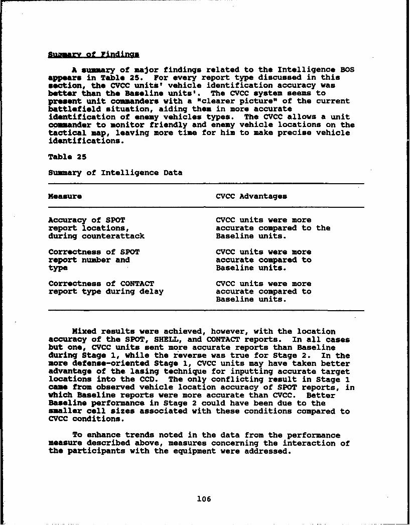
fnarv of Findinas
A summary of major findings related to the Intelligence BOSappears in Table 25. For every report type discussed in thissection, the CVCC units' vehicle identification accuracy wasbetter than the Baseline units'. The CVCC system seems topresent unit commanders with a "clearer picture" of the currentbattlefield situation, aiding them in more accurateidentification of enemy vehicles types. The CVCC allows a unitcamander to monitor friendly and enemy vehicle locations on thetactical map, leaving more time for him to make precise vehicleidentifications.
Table 25
Summary of Intelligence Data
Measure CVCC Advantages
Accuracy of SPOT CVCC units were morereport locations, accurate compared to theduring counterattack Baseline units.
Correctness of SPOT CVCC units were morereport number and accurate compared totype Baseline units.
Correctness of CONTACT CVCC units were morereport type during delay accurate compared to
Baseline units.
Mixed results were achieved, however, with the locationaccuracy of the SPOT, SHELL, and CONTACT reports. In all casesbut one, CVCC units sent more accurate reports than Baselineduring Stage 1, while the reverse was true for Stage 2. In themore defense-oriented Stage 1, CVCC units may have taken betteradvantage of the lasing technique for inputting accurate targetlocations into the CCD. The only conflicting result in Stage 1came from observed vehicle location accuracy of SPOT reports, inwhich Baseline reports were more accurate than CVCC. BetterBaseline performance in Stage 2 could have been due to thesmaller cell sizes associated with these conditions compared toCVCC conditions.
To enhance trends noted in the data from the performancemeasure described above, measures concerning the interaction ofthe participants with the equipment were addressed.
106

Soldier-Machine Interface
Two diagnostic issues are addressed in this subsection: (Dl)How frequently were the CCD features used? (D2) How frequentlywere the CITV features used? These issues address variousaspects of CVCC utilization. Usage measures, averaged acrossstages, quantified the frequency with which different features ofthe CCD (Issue D1) and the CITV (Issue D2) were utilized.Additional SKI data were drawn from SKI questionnaire ratings,written comments and comments recorded during debriefing sessionsfrom unit and vehicle commanders (n - 16) during the battalionevaluation.
The automated usage data in this section are organizedby echelon levels of battalion and company because of theresponsibility differences between the battalion commander andthe S3 (battalion echelon) compared to the company commanders andtheir XOs (company echelon). Differences between echelons havebeen found in previous SKI efforts (O'Brien et al., 1992; Ainslieet al., 1991). These data can be found in Tables E-26 to E-34.
The SKI CCD and CITV Questionnaires were administered todetermine the acceptability of these components to the CVCCparticipants. More specifically, soldiers were asked to rate CCDand CITV capabilities, answer open-ended questions and offersuggestions for improvement. The rating scale on thequestionnaires consisted of a seven-point scale: "1 - TotallyUnacceptable," "2 - Very Unacceptable," "3 - SomewhatUnacceptable," "4 -Borderline," "5 - Somewhat Acceptable," "6 -Very Acceptable," "7 - Totally Acceptable."
When responding to individual items on the SKIquestionnaire, a unit or vehicle commander was asked to considerhow acceptable CVCC components were in helping him fight abattle. The concept of acceptability was defined as whether aspecific CVCC capability: (a) enabled him to perform his job, (b)was easy to use, and (c) was not confusing. This definition waspresented in written form on the questionnaires and was also readaloud. All SKI questionnaire data are presented in Tables E-35and E-36.
The data presented under most headings include Usage datawere not collected for all features. To facilitate descriptionof related equipment usage and SKI questionnaire data, mostheadings include automated usage measures, SKI questionnaireratings, and written and debriefing comments. When equipmentusage data is followed immediately by SKI questionnaire data,data tables are not presented in consecutive order.
CCD Input Devices
Information can be input to the CCD via the touchscreen, thethumb cursor, CITV laser or the gunners's laser depending on thetask. For instance, two of these features, the touchscreen and
107
the thumb cursor, can be used to activate the CCD functions(e.g., opening reports, changing map scales, etc.).
The integration of the CCD and the CITV allows users toinput grid locations to reports. The CITV laser or the gunner'slaser can be used to input exact grid locations to CONTACT, SPOT,CPT, SHELL, NBC, INTEL, SITREP, and ADJUST FIRE reports, bylasing to an object when a report location is needed. Input viaa laser device is most beneficial for CONTACT, SPOT, and CFFbecause enemy location is crucial. The alternative methods forinput of grid location are the touchscreen and the thumb cursor.
The touchscreen vs the thumb cursor. In order to determinewhich CCD input device is preferred by soldiers, several measureswere considered. First, the percent of control inputs bytouchscreen was defined as the proportion of the total number ofcontrol inputs (touchscreen and thumb cursor) to the CCD via thetouchscreen. This measure did not include inputs to the CCD thatwere made with the CITV laser. Battalion level personnel usedthe touchscreen 100% of the time. The company level personnelalso preferred the touchscreen as an input device: they used thetouchacreen 99.8% of the time (see Table Z-35).
Based on these figures, the touchscreen was the mostpreferred input method to the CCD. The data show that the thumbcursor was rarely used for input since the maximum percentage forany one unit commander inputting via the thumb cursor was 2%.The thumb cursor was disabled in one simulator (C company's XO)during Week 5 because of cursor instability on the CCD. However,the thumb cursor may be the preferable input device forcommanders who complained that they could not activate thecorners of the tactical map via the touchscreen. Their fingerswere too big and came into contact with the edge of the screenbelow the point they wanted to touch.
The SMI questionnaire ratings of the touchscreen and thethumb cursor (Table E-35) support the input device usage data.The SKI ratings showed that 81% of unit and vehicle commandersrated the touchscreen as "Somewhat Acceptable" or higher. Fortypercent of commanders rated the thumb cursor as "Borderline," and47% rated it "Somewhat Unacceptable" or worse. Only 13% ratedthe thumb cursor as "Somewhat Acceptable."
L. The percent of grid inputs by laser device wasdefined as the proportion of the total number of grid locationinputs to the CCD reports using the laser. The data indicatethat grid locations were input by laser 46% of the time bybattalion personnel and 34% of the time by company personnel (seeTable R-26). This finding is expected since company echelonvehicles are more likely to be in close contact with the enemyand use the touchscreen because it is faster than entering gridlocations via laser.
The SMI questionnaire item that addressed the integration ofthe CCD with the CITV, such as lasing to an object to input grids
103

in a report, was rated highly. Fifty-six percent of the unit andvehicle commanders rated this capability as "Totally Acceptable"and 37% rated it as "Very Acceptable" (see Table E-35).
In debriefing sessions, several soldiers remarked that theypreferred the laser as an input device over the touchscreenbecause the laser was more accurate. However, the usage datashow that the touchscreen was used more often.
Overall, the data suggest that the touchscreen is usedmore often than the other input devices by participants in thiseffort, although inputting grid locations by laser was ratedpositively as well. These findings are similar to those fromprevious SMI evaluations (Ainslie et al., 1991; O'Brien et al.,1992).
Navigation Function
The Navigation function allows unit and vehicle commandersto create navigation routes and send them to their driver or toother vehicle commanders. A navigation route can include up tosix waypoints that are input to the system by selecting points onthe tactical map. Once waypoints have been entered into thesystem, they can be sent manually to the driver'ssteer-to-display or they can be sent automatically, using theautoadvance feature. SMI questionnaire data and debriefingcomments were used to evaluate the usability of this function forsoldiers in the present study.
Several items on the SHI questionnaire addressed theNavigation function. First, unit commanders were asked to ratetheir ability to navigate using POSNAV. Eighty-one percent ofunit commanders rated this feature as "Totally Acceptable" and19% rated it as "Very Acceptable."
Other questionnaire items referring to navigation functionswere: creating routes, changing waypoints in a route, and sendingwaypoints to the driver. The most common rating on all three ofthese options was that they were "Totally Acceptable" functions.The majority of unit and vehicle commanders agreed that theywould not change the Navigation function. In general, unit andvehicle commanders found this component easy to use andunderstand.
Another item on the questionnaire addressed the ability toallocate more responsibility to the driver. This ability wasrated as "Very Acceptable" by 56% of commanders and "TotallyAcceptable" by 44%. The amount of time saved by this method maybe a factor in the commanders' ratings. With POSNAV, lessattention (e.g. giving directions to the driver, keeping track ofdistance travelled, using azimuth indicator, etc.) was necessaryfor navigational purposes after a waypoint had been sent.
Drivers were queried about the Navigation function as well.In an open-ended question drivers were asked if they had any
109
problems using the steer-to-display. A majority of the driversindicated that they had little trouble using this feature fornavigation. When asked if, in a real tank, the driver's displaywould improve their performance, 88% of the drivers agreed thatit would.
According to the unit and vehicle commanders and the driversin this evaluation, the Navigation function was one of theeasiest to use and most time saving components of all the CCDfeatures.
Tactical Man
The methods used to investigate the usability of theTactical Map include a number of equipment usage measures andSMI questionnaire ratings.
Ma2 scale. Usage data show that battalion level personnelgenerally preferred to use the 1:50,000 scale map (52% of time)although they also spent a substantial amount of time using the1:125,000 scale (36%). The company commanders, however, used the1:50,000 scale 69% of the time and were more likely to use ascale with greater detail, as they spent 26% of the time on the1:25,000 scale (see Table E-27). This is what would be expectedas the company commanders are responsible for their company andneed to see the area and vehicle icons in substantial detail.The battalion commanders may prefer to view a larger area of thebattlefield in order to see all their company forces. It shouldbe noted that the largest map scale, 1:250,000, was rarely usedby company or battalion commanders.
Comments made on the SMI questionnaire supported the usagedata. When asked how they would change the tactical map, twocommanders said they would favor a 1:100,000 map scale instead ofthe 1:125,000 scale, to match the Army standard. Several unitcommanders were adamant in their statements that the map screenneeded to be larger. Apparently many commanders had problemsseeing details on the map such as numbers and phase line names.
MaD terrain features. A second usage measure was thepercent of time each map feature was in effect. The map featuresinclude contour lines, grid lines, rivers, roads, and vegetation(see Table E-28). For battalion commanders, all the featureswere on 99% of the time with the exception of vegetation, whichwas on 74% on the time. Company commanders were somewhat lesslikely to use contour lines (R = 80%) and vegetation (R = 69%).Because company commanders usually used more detailed map scales,they may have preferred fewer map features in order to keep themap from becoming visually cluttered. Overall, these datasuggest that commanders were satisfied with available map terrainfeatures.
MaD Movement Feature. The scroll function on the tacticalmap entails FOLLOW, JUMP, and MOVE. The JUMP and FOLLOW optionsof this function are activated using a dedicated function key.
110
If JUMP is activated, eight boxes appear around the perimeter ofthe map at 45 degree increments. When a box is activated (bytouchscreen or thumb cursor), the map scrolls one-half thedistance of its length or width in the desired direction. TheMOVE function allows the user to place his own vehicle iconanywhere on the display, relative to his location. The FOLLOWmode allows the map to scroll beneath the vehicle icon whereverit was last placed on the map using the MOVE function.
On the SMI questionnaire, soldiers were asked to rate theMap scroll function. Fifty percent rated this function as"Very Acceptable" and 31% rated it as "Totally Acceptable" (TableE-35). These ratings suggest that the commanders were satisfiedwith the function. The acceptability ratings were higher for thescrolling function in this evaluation compared to similar ratingsfrom the Battalion TOC Evaluation, perhaps because systemresponse time has improved since the Battalion TOC Evaluation(O'Brien et al., 1992).
The usage measure for the Map Scroll functions was thepercent of time each map scroll function was in effect. Therewere only slight differences in mode usage based on echelon forFOLLOW (company = 46%, battalion = 49%) and JUMP (company = 52%,battalion = 49%), while the MOVE function was rarely used (lessthan 2% of the time) by either echelon group (see Table E-29).
Vehicle Icon Aaareaation. Aggregation of vehicle icons isanother feature of the tactical map. This feature allows theuser to reduce the amount of visual information on the tacticalmap by aggregating individual vehicle icons into platoon-level orcompany-level icons. No usage data were collected on thisfeature but the SMI Questionnaire addressed it. This feature wasrated "Totally Acceptable" or "Very Acceptable" by 81% of theunit commanders. The lowest rating was "Somewhat Acceptable"(18.80%). Comments on the SMI questionnaire indicated that mostcommanders preferred to aggregate the vehicle icons at theplatoon level or individual vehicle level. One unit commanderstated that he liked to aggregate by platoon because "it doesn'tclutter the screen too much and still lets you see the elementsof each company." A commander who preferred aggregation at theindividual vehicle level wrote "it's a plus knowing whereindividual vehicles are."
An overall rating of the tactical map on the SMIquestionnaire indicated that it is a well-accepted feature of theCCD (Table E-35). Eighty-one percent of the commanders rated thetactical map as being "Very Acceptable" or better, and only 12%of the commanders rated the tactical map as "Borderline."
CCD Reports
The reports that can be created on the CCD are SHELL, SPOT,CONTACT, CFF, ADJUST FIRE, NBC, INTEL, and SITREPs. In additionto the above reports, the CCD can receive FREE TEXT reports,FRAGOs, and overlays sent from the battalion TOC. Several
ill
equipment usage measures, SMI questionnaire ratings and writtencomments were utilized to examine the CCD report function.Comments from debriefing sessions were also utilized.
ReDorts received. For company commanders, the mean numberof all reports received (total number of unique and duplicatereports received, averaged across three stages) was 75 (see TableE-30) and the mean number of unique reports received was 72 (seeTable E-31). The mean number of all reports received was 53 forbattalion commanders and the mean number of unique reportsreceived was 52 (see Table E-31). Thus, the number of reportsreceived by vehicle commanders was not greatly inflated due tothe reception of duplicate reports. Duplicate report problemswere reported in the company SMI evaluation (Ainslie et al.,1991). However, because of software changes, duplicate reportswere not a significant problem in the battalion TOC evaluation(O'Brien et al., 1992) or this evaluation, as the data aboveindicate. Hence, throughout the remainder of this section,"reports" will refer to "unique reports" unless otherwise stated.
Fifty percent of commanders rated the "number of reportsreceived" item on the SMI Questionnaire as "Somewhat Acceptable"or "Totally Acceptable" while the other 50% rated this item as"Borderline" or below (Table E-35). It is helpful to look at thecomments that were made pertaining to the number of reportsreceived. One unit commander commented that the number ofreports he received was "totally overwhelming." He and threeother unit commanders suggested that a "filter" was needed thatcould select out reports that did not pertain to them. Anotherrecommendation was that unit commanders be able to addressreports to specific call signs. This capability would "beextremely helpful in preventing information overflow," wrote onebattalion S3.
Changing the priority of reports was also a commonsuggestion. For example, one battalion commander wrote "As abattalion commander I am very dependent upon SPOT reports forvisualization of the battlefield. The fact that these reportswere low priority on the CCD greatly hindered my effectiveness."A company commander suggested that the individual user should setthe report priority; for instance, an FSO would set CFFs as highpriority whereas a ground commander would set CONTACT and SPOTreports as high priority.
Reports o2ened. The reports opened measure was defined asthe proportion of the total number of unique reports received onthe CCD which were subsequently opened. Battalion commandersopened 51% of the reports received while company commandersopened 33% (see Table E-32). Because battalion level personnelare responsible for all company elements it is a reasonableexpectation that they would open more reports. However, companylevel personnel also have a battalion command net and receive thesame reports on this net as the battalion commanders. This maypartially explain why company commanders were more likely tosuggest an automatic report filter. Conceivably, company
112
commanders perused the reports in the report queue as they werereceived. Their decision to open a report may have been based onthe report type, when the report was created, and the reportorigin. Perhaps the decision making process regarding whatreport should or should not be opened resulted in increasedmental workload on the part of the company level personnel. Thebattalion level personnel, on the other hand, may not have beenas overwhelmed because they did not have to go through the abovedecision making process, simply opening the report. Thispossibility will be investigated further in analyzing thecomplete database.
In one debriefing, a company commander and his XO agreedthat the SAFOR vehicles sent too many SITREPs. The companycommander went on to say that he automatically deleted SITREPsfrom SAFOR units. This may be another reason why companycommanders were deluged with reports that they had difficultymanaging. The SAFOR reports were sent on company nets;therefore, the battalion commanders did not receive them.
DIS exercises designed to train information managementskills are described in Winsch et al. (in preparation). Theresults above indicate that such a training program should beuseful in training skills for future fielded systems.
Creatina reports. On the SMI questionnaire, unit commandersrated the "Creating reports" item pertaining to the creation ofdigital reports on the CCD. Seventy-five percent of thecommanders rated this item "Somewhat Acceptable" or higher.Twenty-five percent rated the item "Borderline" or below (referto Table E-35). The majority of commanders were satisfied withthe report creation capabilities on the CCD. One companycommander, who did not find the capability acceptable, made thecomment that commanders need to have the ability to create FREETEXT reports, overlays, and FRAGOs at the company level. Anothercommander's comment was that the actual report formats wereacceptable, but the report prioritization should be changed. Infuture SMI efforts the report priority issue should be addressedon the questionnaire.
Report formats and icons. The "Report formats" item on theSKI questionnaire was rated as "Somewhat Acceptable" by 50% and"Very Acceptable" by 43% of unit commanders (see Table E-35). Afew unit commanders thought that the ability to create FREE TEXTmessages should be incorporated in the CCD, as stated earlier.
In reference to the report icons, 73% rated them as "VeryAcceptable." Comments indicated that report icons could beimproved if they contained more information. For example, it wassuggested that SPOT report icons have not only number observedbut also the number destroyed. Another suggestion was that deadBLUFOR vehicles display an icon at its last known location with ablack box around it to indicate a kill.
113

Regort sianals. Incoming reports are signaled visually andauditorially to the unit commanders. A report is signaledvisually by a flashing report icon on the tactical map and thereceive button is highlighted.. Additionally, reports aresignaled auditorially with one or three beeps in the headsetsdepending on the priority of the incoming report (one beep forlow priority reports and three beeps for high priority reports).
Seventy-three percent of the unit commanders rated theauditory signals as "Somewhat Acceptable" or higher (Table E-35).The occasional lower ratings were partially due to technicalproblems; one commander's simulator did not generate any beepsduring this evaluation. Another reason for low ratings becameapparent in debriefing sessions when several unit commandersexplained that they did not rely on the beeps to get theirattentlon because they were not as meaningful as voice reports.For example, the beeps did not carry the emotional urgency thatsometimes accompany a voice report, and there was no way todistinguish an incoming CONTACT report from any other highpriority report if relying solely on the beeps. Therefore, someverbal messages were more likely than beeps to get participants'attention because they contain more diverse information.
The visual signals were rated "Totally Acceptable" or "VeryAcceptable" by 56% of the commanders and "Somewhat Acceptable" by31%. Although comments suggested that the map became clutteredwhen numerous reports were received simultaneously, thecommanders were trained to avoid this problem. The CCD hasseveral functions to declutter the Tactical Map: deletingparticular icons, deleting by amount of time posted, or deletingthe corresponding report.
LOGISTICS report. A new feature introduced in the BattalionEvaluation was the LOGISTICS report. The LOGISTICS report is anautomatically distributed report that can be accessed for currentstatus of ammunition, equipment, fuel, and personnel by showingthe status in a green, amber, red, or black (GARB) colored bar.A unit commander can get LOGISTICS information on his own vehicleor unit level information. Two questions on the SMIquestionnaire that addressed this feature were: (a) Do you findthe LOGISTICS report to be useful? and (b) How would you changethe LOGISTICS report? In response to the first question, allcommanders agreed that the LOGISTICS report was useful because ofthe up-to-date information. SITREPs were less necessary becausemuch of the SITREP information was available in the LOGISTICSreport. In answer to the second question, commanders'suggestions on improving the LOGISTICS report included:constantly displaying GARB information on ammunition, equipment,fuel, and personnel in a corner of the CCD screen; distinguishingtype of ammunition (HEAT and SABOT) separately; and displaying aLOGISTICS main function key on the bottom of the CCD screen(instead of in the report menu) for quick access.
Ovelys. Commanders were asked to rate the "Capability toreceive/transmit overlays" on the SMI questionnaire. This item
114

was rated "Very Acceptable" or "Totally Acceptable" by 69% ofcommanders (see Table E-35). Nineteen percent rated this CCDfeature as "Somewhat Acceptable." Although unit commanders weretrained to remove overlays from the Tactical Map, vehiclesmonitors noted that some unit commanders were retrieving newoverlays before deleting the old overlays. Consequently thefeatures of one overlay were difficult to distinguish fromanother. The hesitancy in removing overlays may have been summedup by a company XO who requested "the ability to remove oldoverlays from [the] map without trying to guess which ones theyare." Apparently, this XO found it difficult to determine whichoverlay was which when several were posted on the CCD at the sametime. Further comments concerning the overlay component includeddetails for improving the graphics quality and the labelling ofthe overlays so there is no question about content.
Global CCD Assessment
Several SMI usage measures and questionnaire items addressedCCD features from a global point of view. Unit commanders wereasked to rate the CCD for "its contribution to your ability toperform your duties." Eighty-one percent of unit commandersrated this item as "Very Acceptable" or higher. Only one unitcommander rated this item as "Borderline."
When asked in an open-ended question whether the CCD wasmore useful in an offensive or defensive operation, 56% on theunit commanders said it was equally useful in both situations.Twenty-five percent said the CCD was more useful in offensiveoperations because of the navigational capabilities and theability to locate friendly units. Approximately 19% of the unitcommanders said the CCD was more useful to them in defensiveoperations. Reasons given were that more time was available toplan in defensive operations, and that in a real tank they wouldspend more time outside of the hatch during offensive operationsand therefore would not have the ability to use the CCD in itspresent location.
Unit commanders were also asked whether they were morelikely to use the CCD before or after contact with the enemy.Most unit commanders remarked that they were equally likely touse the CCD prior to and after contact but not during contact.For example, a company XO wrote that he was too busy fightingduring contact to be a computer operator. However, no trendemerged comparing usage prior to contact versus usage aftercontact with the enemy.
Information collected by vehicle monitors on equipment usageduring this evaluation illustrate the amount of time users spendusing the CCD and CITV as opposed to looking out the visionblocks or the GPSE. In the Baseline condition, commanders usedthe vision blocks approximately 84% of the time and the GPSE 16%of the time. In the CVCC condition, the commanders' attentionshifted from the vision blocks (6% of time) and the GPSE (3% oftime) to the CCD (60% of time) and the CITV (31% of time). It is
115

evident that a large amount of visual attention is directedtoward the CCD and CITV. More research is necessary to determineif appropriate amounts of visual attention are allocated to thisequipment.
This section contains the results of the CITV SMIQuestionnaire and the equipment usage measures. The rating scaleon the CITV SMI Questionnaire was identical to the scale used onthe CCD SMI Questionnaire described earlier. A copy of the CITVquestionnaire can be found in Appendix C. The data for the SMICITV Questionnaire are presented in Table E-36.
The automated usage data in this section are organizedby echelon levels of battalion and company. The usage measuresfor the CITV consisted of percent time in each CITV mode, numberof times the CITV laser was used, and number of times Designatewas used.
ODeratina mode. The usage measures show the percent of timethe unit commanders stayed in the CITV modes (Manual Search mode,Autoscan mode, GLOS mode) versus the GPS mode (see Table E-33).In the GPS mode the CITV is not functional. In Manual Searchmode, the commander controls the movement of the CITV with thecontrol handle. If the handle is not moved then the view throughthe CITV does not change. In Autoscan mode, the commander sets asector that he wants to scan and the CITV continuously scans thatsector. The GLOS mode allows the commander to quickly slew theCITV to the main gun's location. Battalion commanders and S3s,on average, spent the most time in the GPS mode (I - 50%),followed by Manual Search mode (X = 37%) and Autoscan mode (2 I13%). Company commanders and XOs spent an equivalent amount oftime in the Manual Search mode (R = 44%) and the GPS mode (X =50%), followed by Autoscan mode (X = 6%). The GLOS mode wasrarely used by any unit or vehicle commander. One company XOwrote that he preferred Manual Search because he had control ofthe sight and knew exactly where he was scanning.
Identification Friend or Foe (IFF). The commanders weretrained to use the IFF cautiously. Specifically, the commanderswere told that if they identified a vehicle with the IFF functionthey should always verify the IFF in the GPSE or vision blocks.Although 50% of the commanders rated the IFF as "SomewhatAcceptable" or higher (see Table E-36), the written commentstended to be less positive. For example, several commandersremarked that the IFF was not very accurate and they would behesitant to use it in the field (with its present reliability of80% correct identification) because allies and enemies have someequipment in common. Another complaint about the IFF was thatwhen it was needed the most (over 2000 meters) the reliabilitydecreased.
Deignae. Although unit commanders found this feature tobe highly acceptable, usage measures (Table E-34) show they did
116

not use it very often (2 - 1.17 times per battalion commander or83, 2 - 1.42 per company commander or XO). One hundred percentof the unit commanders rated it either "Very Acceptable" or"Totally Acceptable." According to logs kept by vehicle monitorsduring the CVCC condition, the percent of firing done by the unitor vehicle commanders (as opposed to gunners) was less than onepercent. These data suggest that the unit commanders wererelying on the gunner to do the majority of target engagements.
SummaXry of the Findings
= l. The SMI questionnaire ratings and comments revealedthat unit commanders found most features of the CCD to beacceptable. In other words, most components of the CCD were easyto use, helped them perform their job, and were not confusing.The POSNAV capabilities of the CCD were especially well-accepted.Several unit commanders agreed that not only did it take lesstime to navigate, POSNAV gave them confidence because they wereless likely to get lost. The CCD improved their ability toperform the task of commanding a company or battalion.
=. Most of the features on the CITV were rated asacceptable by the unit commanders. The IFF was one feature ofthe CITV that commanders were reluctant to use. On an overallrating of the CITV the ratings ranged from "Somewhat Acceptable"(6%) to "Very Acceptable" (69%) to "Totally Acceptable" (25%).In all, the CITV was considered to be a useful component by thevehicle and unit commanders.
Trainina Assessment
The quality of the Baseline and CVCC training can influenceperformance data if the participants do not attain the requiredskills to successfully use the equipment in the tacticalscenarios presented. The training materials and techniquesdiscussed in this subsection were conceptualized during thecompany evaluation as described in Atwood et al. (1991). Thecurrent training materials and methods are the result of severaliterative evaluations involving testing and subsequent revisions.Standardization of the training techniques is emphasized duringstaff training and reinforced continually throughout Baseline andCVCC test weeks. Trainers use standard outlines, checklists, andguidelines to ensure consistency across individual trainers andacross test weeks. The quality of the Baseline and CVCC trainingmaterials and the effectiveness of the current standardizedtraining procedures are judged from analysis of various traininginstruments as well as training staff observations.
Due to the interim nature of this report, only data from theCVCC Vehicle Commander Training Evaluation Questionnaire arepresented (see Appendix E for data tables). Data for Baselineunit and vehicle commanders, gunners, and drivers and for CVCCgunners and drivers are not presented. This subsection presentsdata suggesting potential trends in CVCC training which may be
117
more fully explored in the SMI/Training report to be prepared atthe conclusion of the battalion evaluation.
The CVCC version of the training questionnaire utilized twotypes of questions: a) items requiring ratings evaluating thequantity and clarity of different components of the trainingprograms based on a 5-point scale with 1 at the low end (Poor)and 5 at the high end (Excellent), and b) open-ended questionsrequesting commanders' views on strengths, shortcomings, andpotential improvements for the current CVCC training programs.There were sixteen commanders assigned to the CVCC condition,making the number of responses for each question equal to 16except where otherwise noted.
Commanders based their training evaluation ratings onwhether a specific training event prepared them to meetperformance standards as derived from various assessment methods.First of all, CVCC participants completed CCD and CITV SkillsTests which provided the first opportunity for participants torate their own performance using the CVCC equipment against thestandards of completeness and effectiveness (i.e., training wasreceived on all the functions and was effective enough to allowhim to perform tested functions correctly). Before taking thesetests, participants were told to consider their performance onthe tests as indicators of how well the training on theindividual components (e.g., the CCD classroom) had prepared themto complete the tasks.
After the skills tests were completed, criterion forpreparedness was expanded from performance on isolated functionsto the training opportunities provided by various trainingscenarios to facilitate the maximum transfer of skills to atactical situation. Although the term "tactical situation" wasleft generic, the test scenario just completed providedparticipants with an opportunity to assess their own level ofpreparedness to use the CVCC equipment. Therefore, eachparticipant rated whether the successive training scenariosprovided unique and increasingly demanding and realisticopportunities to utilize the CCD and CITV in preparation forexecution of a tactical situation like the one provided in thetest scenario.
Individual Trainina
CVCC individual training included the M1 simulator hands-ontraining provided in Baseline but did not include the navigationtraining. CVCC individual training did include hands-on trainingon the components of the CVCC system, in particular the POSNAVcomponents which provided equivalent navigation training to thatin Baseline. Tables E-37 through E-41 contain data summarizingthe CVCC unit and vehicle commanders' ratings of the instructor-led and hands-on simulator training provided on the CITV and theCCD, respectively.
118
The CVCC opening briefing was designed to provideparticipants with information on the history and operationalconcepts underlying the CVCC equipment. Table E-37 shows that8at of the commanders felt that the instructor provided enoughoperational comments on the new equipment. One vehicle commanderwrote that the classroom briefing should emphasize using theposition of POSNAV icons relative to threat icons to reducefratricide.
The quality of the CITV training in the classroom and hands-on forums was considered next. Table E-38 shows that 69% ratedthe components of the CITV classroom instruction as "AboveAverage" or "Excellent." Eighty-eight percent rated the CITVclassroom instructor as "Above Average" or "Excellent" and ratedhis tactical examples as "Average" or better (n - 14 with 2missing cases).
Table E-39 shows that the CITV hands-on training was morehighly rated than the classroom training, with 94% of commandersrating the CITV hands-on as "Above Average" or "Excellent."Seventy-five percent felt their vehicle trainers' explanations ofthe equipment were "Above Average" or "Excellent." The CITVSkills Test was also received well, with 75% rating the test as"Above Average" or better.
In lieu of classroom instruction, the CCD training featureda demonstration of some of the more complex CCD functions inorder to prepare the commanders for their hands-on session in thesimulators. This CCD demonstration was shortened from forty-fiveminutes to thirty minutes based on comments from a previousevaluation (see O'Brien et al., 1992). Data for the CCDdemonstration and CCD hands-on training are shown in Tables E-40and E-41, respectively. The demonstration was well received bythe group, with 81% rating the presentation as "Above Average".or "Excellent," and 94% rating the instructor as "Above Average"or "Excellent." Several wrote that the demonstration preparedthem so well that they felt impatient with the repetition ofinformation in the CCD hands-on training.
The unit and vehicle commanders rated the CCD hands-ontraining favorably as well, with 88% of the participants evenlydivided between "Above Average" or "Excellent." Vehicle trainerexplanations of the CCD received "Above Average" or "Excellent"ratings from 69% of the respondents. Many participants augmentedtheir ratings with written suggestions on how the hands-ontraining could be improved. Some of the quicker learnersexpressed impatience with vehicle trainer adherence to the"explain and demonstrate" method of training. Commanders wereconcerned that this lock-step approach to training even thesimplest CCD function was limiting their own hands-on time on theequipment. Although several received "No-gos" on some CCD skillstest tasks, the test itself received no ratings of less than"Average," with 75% rating the test as "Above Average" or"Excellent."
119

The first of the two CVCC refresher training components, theCCD refresher demonstration, was designed to correct someequipment usage shortcomings noted by the vehicle trainers aswell as to offer additional hints for optimizing the CCDfeatures. Fifty-seven percent of the commanders felt that theCCD refresher demonstration was "Average," with the other 43%rating it as "Above Average" or "Excellent" (n - 14, 2 casesmissing). Upon completion of the CCD refresher demonstration,they were asked to perform map manipulation and messageprocessing exercises at their own pace, called "refresher tasks."Sixty-nine percent felt that the refresher tasks were "AboveAverage" or "Excellent."
Although much of the individual training for the CVCCcondition concentrated on the CVCC equipment, hands-on trainingon the basic M1 tank simulator was provided as well. Table E-42shows that basic simulator training was rated as "Above Average"or "Excellent" by 81% of the unit and vehicle commanders.
Tactical Training Exercises
Table E-43 presents the CVCC commanders' ratings on thetactical training exercises adequacy in preparing them to use theCITV in a tactical situation. Table E-44 presents similar datafor the CCD. The mean ratings of the tactical training exercisesincreased incrementally from the lowest-rated crew-level exerciseto the higher-rated battalion-level exercises. Fifty percent ofthe respondents considered the crew exercise to be "AboveAverage" or better in preparing them to use the CITV. A higherpercentage, 63%, rated the crew exercise to be "Above Average" or"Excellent" for CCD preparation. Although a few felt that thecrew exercise was too fast-paced, most managed to complete atleast one navigation sandbox using the CVCC navigation features.They also used the CCD report functions and CITV scanningcapabilities to acquire, engage, and report on multiplestationary gunnery targets. Seventy-five percent rated thecompany STX as "Above Average" or better for the CITV, and sixty-nine percent rated it "Above Average" or better for the CCD.
For the battalion level exercises, 75% of the commandersfelt that the battalion STX offered an "Above Average" or betteropportunity to use both the CITV and the CCD. Ratings were evenhigher for the battalion training scenario, with 88% giving"Above Average" or better ratings for CITV usage opportunitiesand 81% giving the same ratings for the CCD. Eighty-eightpercent of the respondents (Table E-45) felt that the tacticalscenarios provided "Above Average" or "Excellent" hands-onopportunities for both the CITV and CCD. The cumulative trainingresulted in unit and vehicle commanders who felt well-preparedfor the battalion training scenario, with 81% giving preparationratings of "Above Average" or "Excellent" as seen in Table E-46.
As Table E-47 shows, 69% of the CVCC vehicle commandersindicated that there were CITV and CCD functions that they didnot use during the battalion training scenario. Some functions
120
cited as not used were the CITV's Designate and Rate Setfunctions, and the CCD's hot icon, NBC, and SITREP reportfunctions. Reasons for not using these CITV and CCD functionsrevolved around lack of time to use them (stated as a reason whyDesignate was not used), the responsibilities intrinsic to aparticular duty position (e.g., battalion commanders seldomgenerate their own CFF reports), lack of an appropriatecircumstance (an NBC event) or feeling that a function isunnecessary (e.g., forwarding logistics information in a SITREPwhen the CCD Logistics module sends it automatically).
None of the unit or vehicle commanders indicated that theCITV or CCD training had inadequately prepared them to use theomitted functions. However, they did offer several suggestionsfor improved CVCC training. The most common request was for moretraining on retrieving text FRAGOs from the OLD file. Anotherwas a request that more extensive training be provided on thecapability to lase and place report icons relative to POSNAVicons on the CCD map in order to reduce fratricide.
Trainina Objectives and Quality of Feedback
The clarity ratings for the CITV training objectives andduring-training feedback are shown in Table E-48. Table E-49shows the CCD clarity ratings. Eighty-eight percent of thecommanders found the training objectives "Somewhat Clear" or"Very Clear" for the CITV. Ninety-four percent perceived the CCDtraining objectives as "Somewhat" or "Very Clear."
The vehicle trainer in each simulator was the primaryprovider of feedback during training scenario execution and kepta checklist to help monitor the crew's equipment usage; tacticalfeedback was not permitted. Sixty-three percent of thecommanders felt that the CITV feedback during training was either"Somewhat Clear" or "Very Clear" with another 25% finding it"Neutral." Fifty-six percent felt that the CCD feedback duringtraining scenarios was "Somewhat Clear" or "Very Clear" withanother 31% finding the feedback "Neutral." It appears that alarge factor in the variability of ratings for training scenariofeedback was whether the participant was satisfied by the vehicletrainer's CVCC equipment-oriented feedback in lieu of tacticalfeedback. Another factor in the large number of "Neutral"responses may have been the limited opportunity for the vehicletrainer to provide the necessary feedback at the end of eachscenario.
The issue of equipment-oriented versus tactical feedback wasa factor in the debriefing ratings as well. Unit and vehiclecommanders used the 5-point "quality" scale to rate thedebriefings. The debriefing ratings are shown in Table E-50.Sixty-three percent considered the battalion STX debrief to be"Above Average" or "Excellent." When evaluating the battaliontraining scenario debrief, the ratings were a bit higher, with75% finding the debrief "Above Average" or "Excellent."Accompanying comments were divided between those who wanted more
121
feedback on their personal performance (i.e., as in a militaryAAR) and those who wanted no feedback on their personalperformance and believed the emphasis should be solely on thetest equipment.
SAFOR as a Trainina Tool
When asked about the potential contribution of SAFOR as atraining tool, 100% of the commanders rated it "Average" or above(see Table E-51).
Suaaestions for Fielded CVCC EauiDment
When asked for suggestions on training the CVCC equipment ifit were fielded, several unit and vehicle commanders focused onthe requirement for adequate time to reach the proficiency leveldemanded for actual combat mission execution. They agreed thathigh standards would have to be placed on equipment usage.Others stressed that gunners should be cross-trained on the CVCCequipment in case they had to replace the vehicle commanders, andthat frequent training opportunities would be the key toremaining proficient.
Summary of the Findinas
The CVCC unit and vehicle commanders data favorably reflectCVCC training. Eighty-eight percent or more of the respondentsrated their CCD and CITV hands-on training and tactical scenariousage opportunities as "Above Average" or "Excellent," with basicsimulator training rated highly as well. Consequently, almost ashigh a percentage of commanders described their preparation forthe battalion training scenario as "Above Average" or better.Potential improvements to the CVCC training program wereidentified (such as adding training on overlays containing text).,but these data show that the current, much-piloted trainingmaterials and standardized training procedures effectivelyprepare the unit and vehicle commanders to use the basicsimulator and CVCC equipment in a tactical test scenario.
Methodological Implications
An assessment of the evaluation's methodological limitationswas performed to identify options for improving the experimentalmethodology. With enhancements for future research in mind, a"lessons learned" framework was used to develop suggestions forkey methods and procedures. Where appropriate, suggestions havebeen provided in writing to the MWTB site manager.
Given the use of kill-suppress to protect manned simulators,it is important for a crew to know when their vehicle hassustained a killing hit. This would give them an immediate basisfor modifying pertinent battlefield behavior. A clear feedbacksignal (visual and/or auditory) should be developed andimplemented on the manned simulators.
122

The SAFOR constraints discussed in the MethodologicalLimitations subsection of the Method section are characteristicof current distributed interactive simulation technology.Improvements in SAFOR capabilities, to include more responsiveand intelligent behavior, would materially enhance the simulationmethodology. New SAFOR developments underway in the DIS program,such as the Modified SAFOR and Computer Generated Forces efforts,should help.
Limited processing capacity of the computer image generatorhardware led to occasional loss of visual information availableto the driver. In particular, when numerous vehicles werevisible to a manned simulator, the vehicle images in the driver'svision blocks were prone to flash or disappear for a time. Thisadversely impacted his ability to drive, help acquire targets,etc. A hardware upgrade could obviate this problem and enhancethe overall quality of the simulation.
The inability to place minefields and obstacles on theterrain database somewhat compromised the realism of thesimulation environment. The ability to emplace minefields hasbeen developed since finalization of evaluation procedures andcould be employed in future research. Expanded engineer supportcapabilities should be developed to support obstacles and relatedfeatures.
Time constraints in the testing schedule led to the use ofmaximum scenario execution time limits. As a result, bothBaseline units exhausted the available time before they couldcomplete Stage 3 of the test scenario. This meant that noBaseline data were available from Stage 3 for comparison with theCVCC units' performance. The lost opportunity to generate alarger database was unfortunate. To remedy this, future researchcould schedule additional time for test scenario execution or thetest scenario(s) might be constructed to require less time forexecution.
The flagging and recording of events by control staffobserving a PVD did not afford the relilility desired.Competing tasks, distractions, and diff.culty in interpreting on-line tactical events resulted in lost and unusable data elements.It may be possible to develop procedures for obtaining log-baseddata elements from DataLogger recordings, and efforts in thisdirection have been initiated at MWTB. This would greatlyincrease the reliability of the associated data.
In contrast with earlier CVCC evaluations, digital FRAGOswere implemented in the form of overlays with associated text,rather than free text reports. As such, FRAGOs were notclassified by the DCA system as a type of report. This makes itvery difficult to include FRAGOs in analyses of measures brokenout by report type. Adjusting the analytical software to supportconvenient analyses across the full spectrum of report typeswould be worthwhile.
123
The Situational Assessment techniques used in thisevaluation resulted in data interpretation problems, partly dueto the failure of Baseline units to complete Stage 3 of the testscenario. This shortcoming was largely unanticipated during theplanning of the evaluation. A concerted effort to systematicallydevelop reliable instruments and procedures is needed. Thedevelopment program should include iterative pilot testing andrevision, along with validation against consensus criteria.
Resource limitations necessitated only partial monitoring ofmanned simulators during test exercises. This seriously limitedthe opportunities to obtain in-simulator observational data ofcrew performance. It would be helpful in future projects toensure monitoring of every simulator during data collection. Inaddition, development of an electronic clipboard for convenientin-simulator use could significantly enhance observationalrecording capabilities.
Manual reduction of data was complicated in some cases bythe difficulty in converting DataLogger time to real time. Arecently developed MWTB capability to record real clock time aspart of the data stream during recording of test events shouldresolve this problem in future research efforts.
The following measures under the Maneuver BOS requirefurther development: range to OPFOR at displacement, exposureindex, time to acquire target, time between lases to differenttargets, and time from lase to first fire. It is intended thatthese measures will be refined and included in the comprehensivedatabase.
Problems in the implementation of elapsed time for fuel andammo reports arose, preventing this Baseline measure from beingproperly analyzed. The battalion TOC requests for these reportswere "flagged" and analyzed using the DCA system. The resultingreports were captured in playbacks of the radio traffic. SinceDCA measures were adjusted for exercise breaks and start times,it was not possible to integrate these data. In futureevaluations this measure should be implemented by "flags" for DCAanalysis.
The communication network structures used by CVCC andBaseline groups in this test were not identical. The netstructure for CVCC groups contained one level that could reachall manned elements instantaneously, resulting in a digital netstructure that prevented meaningful comparison of communicationthroughput measures between the two groups. For example, whenthe CVCC TOC transmitted a FRAGO on the digital battalion commandnet, all vehicle commanders received the information at the sametime. This led to the exhibited "instantaneous" reporttransmission times for CVCC throughput measures. However, whenthe Baseline TOC transmitted a FRAGO using the voice battalioncommand net, it had to be relayed on the company command net tothe company XOs. Future evaluations should address this
124

limitation by requiring the radio network configuration structurefor Baseline and CVCC groups to be identical.
Many measures relating to,communications effectivenessrequired transcription of voice radio transmissions during off-line exercise playbacks. This process proved to be very time-consuming. Failures of the playback system occurred frequentlyand required starting the run over at the beginning of the tape.System upgrades to prevent frequent failures would significantlyreduce the time required for transcription playbacks. In thelong run, perhaps voice recognition technology could be adaptedto automate the process of converting spoken transmissions to apaper record.
It should be noted that many lessons learned from previousCVCC research efforts, especially the company-level evaluation(Leibrecht . al., 1992), were implemented in the current effort.These incl :
1. Addition of a filtering mechanism for duplicate digitalreports.
2. The capability to receive and relay integrated digitalFRAGOs.
3. A logistics module which allows for automatic updatingof resource status across echelons.
4. Addition of positions critical to armor operations, suchas company XO, FSO, and S3, to the task organization of friendlyforces.
5. More realistic timing of SAFOR reports.
6. Development and refinement of many performance measures.
7. Treatment of echelon as a primary variable whereappropriate.
8. Adjustment of report measures for non-unique reportswhere appropriate.
125
Conclusions and Recommendations
In the previous section, operational effectiveness data werepresented by BOS, followed by SKI and training data. Since thenature of the findings in this evaluation are preliminary due tolimited sample sizes and variability of the data, it is difficultto draw clear conclusions for many measures. This sectionpresents conclusions in terms of possible trends that may beconfirmed in a complete battalion database. These data will becombined with subsequent data to form a larger battalion-leveldatabase, currently under development. Refer to the end of each"Results and Discussion" subsection for a more complete summaryof the data. Suggestions for future research follow descriptionof the conclusions.
Conclusions
CVCC units outperformed Baseline units by: inflicting morecasualties on enemy forces and sustaining lighter casualtiesthemselves (with CITV); allowing company commanders and XOs toprevent opposing forces from encroaching on their defensivepositions; completing each stage more quickly (no Baseline groupcompleted an entire test scenario); controlling their terrainmore effectively; issuing more accurate CFFs and SPOT reports forat least one stage; spending less time communicating over thevoice-radio networks; issuing fewer SITREPS and requests forFRAGO clarification; having greater opportunities to createreports during a counterattack; and helping commanders providemore accurate identification of enemy vehicle type.
Recommendations for Future Research
Changes in the combined arms battlefield, including advancedweapon systems and new threat contingencies, demand new C3technologies such as CVCC. Research efforts to date haveestablished clear advantages for the CVCC system (Du Bois &Smith, 1991; Du Bois & Smith, 1989; Leibrecht et al., 1992;Quinkert, 1990). The complete results of the battalionevaluation are expected to reinforce these advantages. At thesame time, extensive research and development efforts are neededto support successful fielding and deployment of the CVCC system.Important remaining questions include:
1. How can the CVCC system be optimally implemented in acombined arms, vehicle-based environment? Future research shouldinclude an evaluation of CVCC technology in a combined armsenvironment possibly using Ml, M2, M3, and Line-of-Sight/Anti-Tank (LOSAT) vehicles at different echelons.
2. What is the contribution of automated TOC capabilitiesto operational and tactical aspects of performance when the TOCis staffed by participants? Future efforts should assess on thetraining requirements of a participant-staffed TOCand evaluate its contributions.
127
3. What are the best SMI design and format features for theCVCC system? Before the CVCC system is fielded, directcomparison of system design features and formats for the CVCCsystem should be conducted.
4. What task-based requirements should drive futuretraining development for the CVCC system? It is important to doa thorough analysis of tasks and skills from a component andsystem perspective before the CVCC system is fielded.
5. How can training be developed to maximize retention andtransfer of training? CVCC efforts should assess the learningand retention functions associated with CVCC skill attainment.Transfer of training studies should be conducted to isolate areaswhere transfer of skills is problematic.
6. What is the best procedure for ensuring that manualskills are maintained once tasks become automated? Explorationof the amount and frequency of refresher training required forretention of manual skills replaced by automated functions (e.g.,navigating with a paper map) should be conducted.
7. How can allocation of attention be influenced tominimize information overload and optimize performance? Futureresearch should systematically address this question, beginningwith a thorough analysis of task priorities from an informationmanagement and system design perspective.
Armed with answers to these and related questions, C3 on thefuture digitized battlefield should be enhanced dramatically.The resulting improvement in force effectiveness can be expectedto yield substantial payoffs in future conflicts.
128
References
Ainslie, F. M., Leibrecht, B. r,., & Atwood, N. K. (1991). Combatvehicle command and control systems: III. Simulation-basedcom~anv evaluation of the soldier-machine-interface (SKI)(ARI Technical Report 944). Alexandria, VA: U.S. ArmyResearch Institute for the Behavioral and Social Sciences.(AD A246 237)
Alluisi, E. A. (1? 1). The development of technology forcollective tý.dining: SIMNET, a case history. Human Factors,,U, 343-362.
Atwood, N. K., Winsch, B. J., & Quinkert, K. A. (in preparation).Cataloa of trainina tools for use in distributedinteractive simulation (DIS) environments (ARI ResearchProduct). Alexandria, VA: U.S. Army Research Institutefor the Behavioral and Social Sciences.
Atwood, N. K., Quinkert, K. A., Campbell, M. R., Lameier, K. F.,Leibrecht, B. C., & Doherty, W. J. (1991). Combat vehiclecommand and control systems: Training implications based oncompany level simulation (ARI Technical Report 943).Alexandria, VA: U.S. Army Research Institute for theBehavioral and Social Sciences. (AD A246 460)
BDM Federal, Inc. (1992). Battalion Tactical OverationsCenter (TOC) Job Aid (BDM Technical Report BDM/LEV-92-0208-TR). Albuquerque, NM: BDM Federal, Inc.
BDM Federal, Inc. (unpublished). SUDDort 2ackaae for thebattalion evaluation of the Combat Vehicle Command andControl (CVCC) system. Albuquerque, NM: BDM Federal,Inc.
BDM Federal, Inc. (in preparation). Combat vehicle command andcontrol (CVCC) simulator commander's intearated display JobA"d. Albuquerque, NM: BDM Federal, Inc.
Chung, J. W., Dickens, A. R., O'Toole, B. P., & Chiang, C. J.(1988). SIMNET Ml Abrams main battle tank simulation:Software descrition and documentation (Revision 11 (BBNReport 6323). Cambridge, MA: Bolt, Beranek, and NewmanSystems and Technologies Corp.
Department of the Army (1985). National Training Centercommanders memorandum. Fort Irwin, CA: Headquarters,National Training Center and Fort Irwin.
Department of the Army (1986). Field Manual 100-5: QOerations.Washington, DC: Headquarters, Department of the Army.
129
Department of the Army (1988). Field Manual 71-2: The tank andmechanized infantry battalion task force. Washington, DC:Headquarters, Department of the Army.
Department of the Army (1991). TRADOC Pamphlet 11-9: Blueprintof the battlefield. Fort Monroe, VA: U.S. Army Trainingand Doctrine Command.
Department of the Army (1992). IVIS operational concept. FortKnox, KY: U.S. Army Armor Center.
Department of the Army (in preparation). Field Manual 71-100-1:Armor and mechanized division operations: Tactics andte (Coordinating Draft). Fort Leavenworth, KS:Concepts and Doctrine Directorate, U.S. Army Command andGeneral Staff College.
Department of Defense (1992). Final report to Congress: Conductof the Persian Gulf war. Washington, DC: Department ofDefense.
Du Bois, R. S., & Smith, P. G. (1989). A simulation-basedevaluation of a Rosition navigation system for Armor:Soldier performance, training, and functional requirements(ARI Technical Report 834). Alexandria, VA: U.S. ArmyResearch Institute for the Behavioral and Social Sciences.(AD A210 696)
Du Bois, R. S., & Smith, P. G. (1991). A simulation-basedassessment of automated command. control. and communicationsfor armor crews and platoons: The intervehicularinformation system (IVIS1 (ARI Technical Report 918).Alexandria, VA: U.S. Army Research Institute for theBehavioral and Social Sciences. (AD A233 509)
Grandjean, E. (1986). Fitting the Task to the Man: An ErgonomicApproach. London: Taylor & Francis.
Keele, S. W. (1973). Attention and Human Performance. PacificPalisades, CA: Goodyear.
Leibrecht, B. C., Kerins, J. W., Ainslie, F. M., Sawyer, A. R.,Childs, J. M., & Doherty, W. J. (1992). Combat vehiclecommand and control systems: I. Simulation-based company-level evaluation (ARI Technical Report 950). Alexandria,VA: U.S. Army Research Institute for the Behavioral andSocial Sciences. (AD A251 917)
Lickteig, C. W. (1991). Prototype methods for training andassessina future tactical command and control skills (ARIResearch Product 92-01). Alexandria, VA: U.S. ArmyResearch Institute for the Behavioral and Social Sciences.(AD A244 328)
130

Licktaig, C. W. (in preparation). Innovative assessment ofbattalions usina the Combat Vehicle Command and Control(CVCCI system: Data collection exercises (ARI ResearchNote). Alexandria, VA: U.S. Army Research Institute forthe Behavioral and Social Sciences.
Loral Systems Company (1992). Strawman distributed interactivesimulation architecture description document. volume I:Summary description. Orlando, FL: Loral Systems Company,ADST Systems Office.
Lunsford, R. J., Jr. (1989). U.S. Army trainina systems fore-cast. FY 1990-1994. Orlando, FL: Project Manager forTraining Devices, U.S. Army Materiel Command.
Miller, D. C., & Chung, J. W. (1987). SIMNET-D capabilities andgye vie. (BBN Report). Cambridge, MA: Bolt, Beranek, andNewman, Inc.
Morey J. C., Wigginton, D., & O'Brien, L. H. (1992). Workloadassessment for the combat vehicle command and controlcompanv-level evaluation (ARI Research Report 1615).Alexandria, VA: U.S. Army Research Institute for theBehavioral and Social Sciences, Fort Knox Field Unit.(AD A252 239)
Mueller, N. S. (1991). Face to interface. CBT Directions. July,31-33.
O'Brien, L. H., Wigginton, D., Morey, J. C., Leibrecht, B. C.,Ainslie, F. M., & Sawyer, A. R. (1992). Combat VehicleCommand and Control battalion-level Rreliminarv evaluation(ARI Research Report 1627). Alexandria, VA: U.S. ArmyResearch Institute for the Behavioral and Social Sciences.(AD A257 467)
Quinkert, K. A. (1988). Design and functional sMecifications forthe simulation of the commander's independent thermal viewer(CITL) (ARI Research Product 88-17). Alexandria, VA: U.S.Army Research Institute for the Behavioral and SocialSciences. (AD A201 419)
Quinkert, K. A. (1990). Crew performance assessment associatedwith the simulation of the commander's independent thermalviewer (CITV) (ARI Technical Report 900). Alexandria, VA:U.S. Army Research Institute for the Behavioral and SocialSciences. (AD A226 890)
Smart, D. L., & Williams, G. S. (unpublished). Scenario supoOrtRackaae--battalion TOC evaluation. Boulder, CO: Micro-analysis and Design, Inc.
131
Smith, P. G. (1990). SIMNET combat vehicle command and control(CVC2) svstem user's guide (BBN Technical Report 7323). FortKnox, KY: Bolt Beranek and Newman, Inc.
Summers, J. J. (1981). Motor programs. In D. H. Holding (Ed.),Human Skills. New York: Wiley.
U.S. Army Armor School (1987). M1 SIMNET Operator's Guide. FortKnox, KY: Headquarters, U.S. Army Armor School.
U.S. Army Armor School (1989). SIMNET Users' Guide. Fort Knox,KY: Headquarters, U.S. Army Armor School.
Wickens, C. D. (1984). Engineering Psvcholoav and Human Perfor-mance. Glenview, IL: Scott, Foreman, and Company.
Winsch, B. J., Atwood, N. K., Sawyer, A. R., Quinkert, K. A.,Heiden, C. K., Smith, P. G., & Schwartz, B. (in preparation).Innovative trainina concepts for use in distributed inter-active simulation (DIS) environments (ARI Research Product).Alexandria, VA: U.S. Army Research Institute for theBehavioral and Social Sciences.
132
3PPZNDIZ A
TUS! SCINkRIO MNATURALS
Appendix A contains the following sections:
A-1 Friendly and Enemy Situation GraphicsA-2 Battalion OPORD 200A-3 FRAGOs to OPORD 200A-4 Battalion SOP (CVCC Version)
A-1
A-i
FRIENDLY AND ENE1Y SITUATION GRAPHICS
Section A-1 contains the following graphics:
Task OrganizationFriendly Situation8 CAA Deployment39th GMRD Tactical Deployment
A-i-1
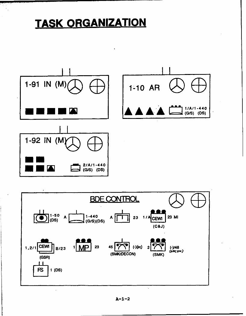
TAS ORANIZATION
IIA1-92 I N (M)
~~ 2/All -440((3/5)/S (OS)
BDE C.ONTROL
(DS A GS(S A~~ 23 1 /A[ýý]23 MI
(C&J)
1.2/IS B/23 1~ 23 45)000 2~ (-Y48N
(GSR) (SMKIDECON) (SMK) *cd
S1 (DS)
A-1-2
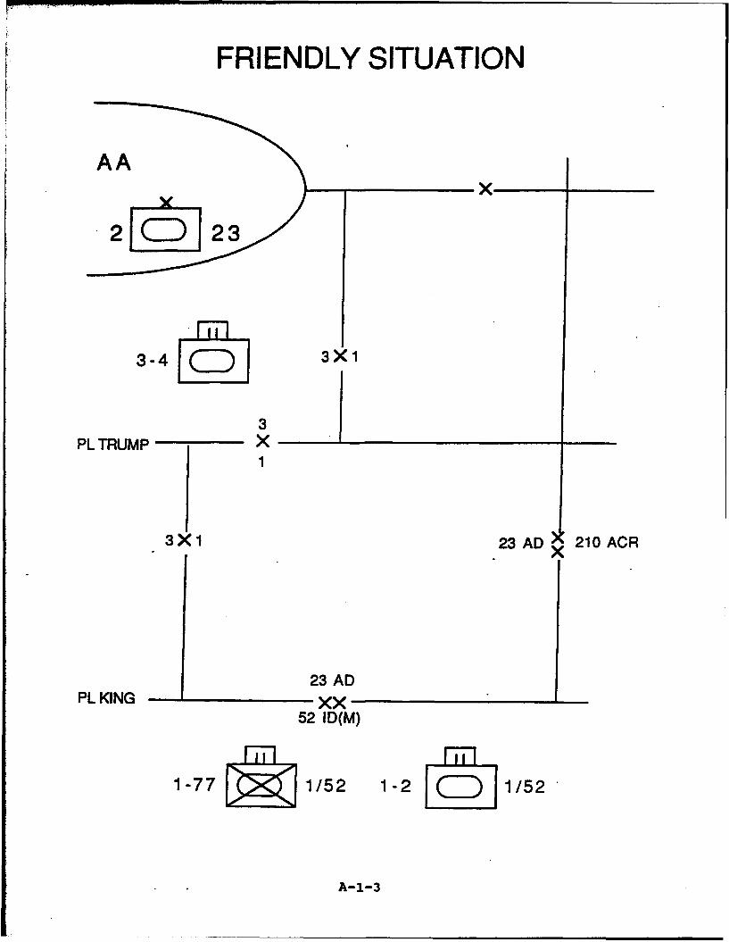
FRIENDLY SITUATION
AAx
.2[( 2
3-4 3X1
3PLTRUMP X
1
3X1 23AD 210ACR
23 ADPL KING xx
52 ID(M)
1-77 1/52 1-2 1/52
A-1-3
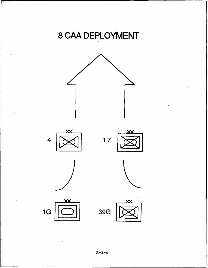
8CMA DEPLOYMENT
17J
1G 39G
A-1-4

39th GMRD
Tactical Deployment
140G 144GBMP-2, T-80 BMP-2, T-80
90% 90%
FII
79G 146G
T-80 BMP-2, T-80
95% 95%
A-1-5
A-2
Battalion OPORD 200
A-2-1
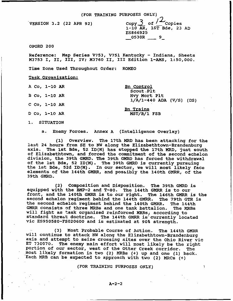
(FOR TRAINING PURPOSES ONLY)
"VERSION 3.2 (22 APR 92) Copy.± of / 2 Copies1-10 AR, 1ST Bde, 23 ADES866925_0530R _ 9
OPORD 200
Reference: Map Series V753, V751 Kentucky - Indiana, SheetsM3753 I, II, III, IV; M3760 II, III Edition 1-AMS, 1:50,000.
Time Zone Used Throughout Order: ROMEO
Task Organization:
A Co, 1-10 AR Bn ControlScout.Plt
B Co, 1-10 AR Hvy Mort PltI/A/l-440 ADA (V/S) (DS)
C Co, 1-10 ARBn Trains
D Co, 1-10 AR MST/B/1 FSB
1. SITUATION
a. Enemy Forces. Annex A (Intelligence Overlay)
(1) Overview. The 17th MRD has been attacking for thelast 24 hours from SE to NW along the Elizabethtown-Brandenburgaxis. The ist Bde, 52 ID(M) has stopped the 17th MRD, just southof Elizabethtown, and forced the commitment of the second echelondivision, the 39th GMRD. The 39th GMRD has forced the withdrawalof the 1st Bde, 52 ID(M). The 39th GMRD is currently pursuingthe 1st Bde, 52d ID(M). In our sector, we will most likely faceelements of the 144th GMRR, and possibly the 140th GMRR, of the39th GMRD.
(2) Composition and Disposition. The 39th GMRD isequipped with the BMP-2 and T-80. The 144th GMRR is to ourfront, and the 140th GMRR is to our right. The 146th GMRR is thesecond echelon regiment behind the 144th GMRR. The 79th GTR isthe second echelon regiment behind the 140th GMRR. The 144thGMRR consists of three MRBs and one tank battalion. The MRBswill fight as task organized reinforced MRBs, according tostandard threat doctrine. The 144th GMRR isý currently locatedvic ES950580-FS020600 and is estimated at 90% strength.
(3) Most Probable Course of Action. The 144th GMRRwill continue to attack NW alonq the Elizabethtown-Brandenburgaxis and attempt to seize crossing sites over the Ohio River vicET 730070. The enemy main effort will most likely be the rightportion of our sector, west of the Otter Creek corridor. Themost likely formation is two (2) MRBs (+) up and one (1) back.Each MRB can be expected to approach with two (2) MRCs (+)
(FOR TRAINING PURPOSES ONLY)
A-2-2
(FOR TRAINING PURPOSES ONLY)
forward and one (1) back. All rivers in our sector are fordableand the terrain offers good cross country mobility.
b. Friendly Forces.
(1) (Higher) 1st Bde 23 AD accepts battle handoverfrom and assists with the rearward passage of lines of ist Bde,52 ID (M) NLT 0950R 9 . 1st Bde delays in sector from -
0950R to 1350R _ 9 to destroy the first echelon regimentsof the 39th GMRD forward of PL TRUMP. The Brigade commander'sintent is to hit the enemy hard at PL KING, disrupt his pursuit,and destroy the leading companies of the lead regiments. Heintends to continue the delay in depth, continuing to attrite theenemy, to force the commitment of the second echelon regimentsnorth of PL TRUMP.
(2) (L) 210 ACR delays in sector on the Corps easternflank.
(3) (R) 1-92 IN (M) accepts battle handover from andassists the rearward passage of lines of TF 1-77, then delays insector from 0950R 9 to _1350R _ 9 to destroy the 140thGMRR south of PL TRUMP.
(4) (Front) TF 1-2, 1st Bde, 52 IN (M) conducts awithdrawal and battle handover at PL King and executes a rearwardpassage of lines through 1-10 AR NLT _0950R 9_.
(5) 1-91 IN (M) (Bde Reserve) prepares defensivepositions vic PL TRUMP NLT _0950R _ 9_. 0/0 conductscounterattack south.
(6) 1-50 FA DS to 1st Bde.
(7) A/23d ENGR OPCON to ist Bde, 23 AD.
(8) A/1-440 ADA DS to 1st Bde, 23 AD.
c. Attachments and Detachments. See Task Organization.
2. MISSION
1-10 AR accepts battle handover from, and assists inrearward passage of lines of TF 1-2 NLT 0950R 9 at PLKING. 1-10 AR delays in sector from __09-50R to _1350R _ 9 todestroy the 144th GMRR south of PL TRUMP. 0/0 conducts rearwardpassage of lines through 1-91 IN (M).
3. EXECUTION
a. Concept of Operation. Annex B (Operations Overlay). Myintent is to accept the battle from TF 1-2 at PL KING and destroy4 reinforced motorized rifle companies at PL KING. We will then
(FOR TRAINING PURPOSES ONLY)
A-2-3
(FOR TRAINING PURPOSES ONLY)
delay in sector, defending from successive company BPs,destroying the enemy without becoming decisively engaged, forcingthe deployment of the 146th GMRR, the second echelon regimentfollowing the 144th GMRR, prior to PL TRUMP.
(1) Maneuver. The'battalion scouts will establishContact Points 7, 9, 10, and 2 forward of PL KING and assist TF1-2, 1st Bde, 52d IN (M) in their rearward passage of lines. Myintent is to hit the enemy hard at PL KING, disrupt his pursuit,and destroy at least one company each in EAs STING, WHIP, andCHAIN. The 144th GMRR's main effort is expected to be in theright portion of our sector. A Co will probably be hit hardestdue to its location on our right and because of the open terrainin its sector. We will fall back to BPs, vic PL JACK, in orderto confirm his main effort. As we delay throughout the Bnsector, I plan to keep constant contact with the enemy unless weare forced to pull back to prevent a major penetration. I seefew opportunities to shape the battlefield for a counterattack,but we must be ready to launch a limited counterattack if theenemy exposes a flank or appears vulnerable. We will prevent the39th GMRD from penetrating PL TRUMP until after __1350R _ 9_.I plan to accomplish this delay in three phases:
(a) Phase I. Cover the BHL with three Cos in BPs10, 20, and 30, and position at least two platoons forward ineach. Accept the battle handover from TF 1-2, and assist as theyconduct a rearward passage of lines through our sector on PassageLanes ELEPHANT, PONY, DOG, AND CAT. Scouts establish observationof enemy forces and follow TF 1-2 through the passage points,then consolidate and screen the left flank. Destroy the leadenemy companies in EAs STING, WHIP, and CHAIN. Displace if anenemy company closes to within 2000 m or when an enemy unit ofcompany size or larger attempts to bypass one of our companies.A Co will probably delay to BP 13 first, overwatched by B Co. BCo will then delay to BP 23, overwatched by A Co and C Co. C Cowill delay to BP 33 overwatched by B Co. Do not cross PL CLUBwithout permission.
(b) Phase II. Cos continue to defend onsuccessive BPs in the battalion sector. Scouts establish ScreenLine ONE along eastern boundary. Bn will be alert for enemyexposed flanks-which would present opportunities forcounterattack. I anticipate that A Co will be hard pressed onthe right flank. As they delay to BP 11, D Co will stage in BP42, then counterattack into the enemy's flank forward of BP 11.B and C Co will protect D Co's flank, then fall back to anddefend from BPs 24 and 34, respectively. A Co will support thecounterattack by fire from BP 11, then withdraw to BP 12,consolidate, and reconstitute the Bn reserve. D Co willconsolidate on BP 11 after its counterattack. The timing on thislimited counterattack is critical. We must anticipate theopportunity and have the forces in motion before it's too late.
(FOR TRAINING PURPOSES ONLY)
A-2-4

(FOR TRAINING PURPOSES ONLY)
(c) Phase III. Continue to attrite the enemybetween PL SPADE and PL TRUMP. Be prepared to launch limitedcounterattacks if opportunities arise. We must force thecommitment of the second echelon regiment, 146th GMRR prior to PLTRUMP. Scouts establish Screen Line TWO. Cos occupy BPs vic. PLTRUMP and defend to retain. 0/0 establish contact with 1-91 Mechscouts at designated Contact Points and conduct BHO and rearwardpassage of lines through 1-91 Mech on designated Passage Lanes.0/0 move to assembly areas (TBD) to become the 1st Bde Reserve.
(2) Fires (Fire Support Overlay):
(a) 1-10 AR has priority of FA Fires within theBde.
(b) Priority of Fires (FA): Phase I--Scouts, ACo, B Co, C Co, D Co; Phase II, III--A Co, B Co, C Co, D Co,Scouts.
(c) Priority of Fires (Mtrs): Phase I--Scouts, ACo, B Co, C Co, D Co; Phases II, III--A Co, B Co, C Co, D Co,Scouts.
(d) 1-10 AR has two FASCAM minefields available.FASCAM requires Bde Cdr's approval for use.
(3) Obstacles.
(a) Priority of Support: A Co, B Co, C Co, D Co.
(b) Priority of Effort: Countermobility,survivability, mobility.
b. A Co.
(1) Phase I: Defend BP 10. Provide guides forPassage Lane PONY. Engage enemy in EA STING.
(2) 0/0 delay thru BP 13 to BP 11. Be prepared todefend from BP 13.
(3) Phase II: On order, defend BP 11.
(4) 0/0 support D Co counterattack by fire.
(5) Phase III: On order, defend BP 12.
(6) On order, conduct rearward passage of lines onPassage Lanes BLUE and GREY.
(FOR TRAINING PURPOSES ONLY)
A-2-5

(FOR TRAINING PURPOSES ONLY)
c. B Co.
(1) Phase I: Defend BP 20. Provide guides forPassage Lane DOG. Engage enemy in EA WHIP.
(2) 0/0 delay though BP 23 to BP 24. Be prepared todefend from BP 24.
(3) Phase II: On order, defend BP 42.
(4) 0/0 delay to BP 21.
(5) Phase III: On order, defend BP 41.
(6) On order, conduct rearward passage jof lines onPassage Lane YELLOW.
d. C Co.
(1) Phase I: Defend BP 30. Provide guides forPassage Lanes CAT and ELEPHANT. Engage enemy in EA CHAIN.
(2) 0/0 delay through BP 33 to BP 34. Be prepared todefend from BP 34.
(3) Phase II: On order, defend BP 31.
(4) Phase III: On order, defend BP 32.
(5) On order, conduct rearward passage of lines onPassage Lanes PURPLE and BLALY.
e. D Co.
(1) Phase I-III: Be prepared to reinforce A, B, or CCo sector once enemy's main effort is identified.
(2) Occupy BP 40 initially; be prepared to occupy BP22.
(3) Be prepared to conduct counterattacks to maintainintegrity of the Bn sector or when opportunities arise, withpriority of planning for counterattack from BP 42 to relievepressure on A Co, vic BP 11.
(4) Be prepared to occupy BP 22 and to conductrearward passage of lines on Passage Lane ORANGE.
f. S!outs.
(1) Phase I: Establish Contact Points 7, 9, 10 and 2NLT 0800R 9_. Screen forward of PL KING. 0/0, conductrear;ward passage of lines on routes PONY, DOG, CAT, and ELEPHANT.
(FOR TRAINING PURPOSES ONLY)
A-2-6
(FOR TRAINING PURPOSES ONLY)
consolidate at CP 10, then screen BN left flank from rear of C Coto PL CLUB.
(2) Phase II: Establish Screen Line ONE.
(3) Phase III: Establish Screen Line TWO.
g. Mortars.
(1) Phase I: Occupy initial Firing Point vicES895810. Be prepared to operate split section to support Bndelay.
(2) Phase II-III: Move under control of Bn FSO. Onorder, coordinate own rearward passage of lines.
h. 1/A/1-440 ADA. Priority of protection: reserve and TOC.
i. Coordinating Instructions.
(1) PIR:
(a) Concentrations of ten or more tanks.
(b) Use of Chemical munitions.
(c) Use of airmobile opns.
(d) Report penetration of CO size or greater atall PLs.
(e) Report changes in enemy equipment, uniforms,formations, etc. which would indicate commitment of secondechelon units.
(2) MOPP: Level 1 in effect NLT 0950R 9
(3) OEG: 70 cGy Report 50 cGy.
(4) Air Defense Warning -- Yellow.
(5) Weapons Control Status -- Tight.
(6) Disengagement criteria: MRC close within 2000 mor when company size unit attempts to bypass your position.
(7) Other Reporting Requirements.
(a) Report BH complete.
(b) Report initial enemy contact.
(c) Report crossing PLs.
(FOR TRAINING PURPOSES ONLY)
A-2-7

(FOR TRAINING PURPOSES ONLY)
(d) Report Passage of Lines complete.
(8) Recognition symbol for rearward passage of linesis orange panel marker front Qf vehicle during the day -- redflashlight at night.
4. SERVICE SUPPORT. Annex E (Service Support). (Omitted)
5. COMMAND AND SIGNAL.
a. Command.
(1) Succession of Command: SOP.
(2) Cmd Group will be to rear of B Co.
(3) Bn TOC initial location ES866925, subsequentlocation ES851947.
(4) Alternate Bn CP is Combat Trains CP.
(5) Brigade Main CP located vic ET872023.
(6) Brigade TAC located vic ES877947.
(7) Brigade alternate CP is Bde Tns ET785227.
b. Signal.
(1) SOI index ALPHA in effect.
(2) Radio listening silence in effect __0930R 9until first contact is reported or passage of lines completed.
ACKNOWLEDGE:
OFFICIAL: PATTONCdr
HASZARDS3
Annexes: A--IntelligenceB--Operations OverlayE--Service Support (Omitted)
(FOR TRAINING PURPOSES ONLY)
A-2-8

(FOR TRAINING PURPOSES ONLY)Copy of Copies
1-10 AR, Ist Bde, 23 ADES866925
0530R _ 9VERSION 3.1 (22 APR 92)
ANNEX A (INTELLIGENCE) TO OPORD 200
REFERENCE: Map Series V753, V751 Kentucky - Indiana, SheetsM3753 I, II, III, IV; M3760 II, III Edition 1-AMS, 1:50,000.
Time Zone Used Throughout Order: ROMEO
1. GENERAL. (See Appendix 1, Enemy Situation Overlay)
a. Enemy Situation
(1) Location. The first echelon divisions of the 8thCAA have been stopped by the 52d IN (M). The 1st GTD and the39th GMRD, second echelon divisions of the 8th CAA, werecommitted at 0200 hrs this morning to continue the attacknorthwest along the Elizabethtown to Brandenburg axis. The 1stBde faces the 39th GMRD, which is currently moving north vic.ES850580 to FS020600.
(2) Strength. The 1st echelon regiments of the 39thGMRD consist of the 140th GMRR, on our right, and the 144th GMRRto our front. These regiments are estimated at 90% strength.The second echelon regiments, the 79th GTR following the 140thGMRR, and the 146th GMRR following the 144th GMRR, are estimatedat 95% strength.
b. Enemy Capabilities. The enemy is expected to advanceinto the ist Bde sector NET 100OR 9_. They can attack in-the brigade sector with 2 MRR--s followed by a second echelon,consisting of I MRR and 1 TR. The MRRs are equipped with BMP-2sand T-80s. There are unconfirmed reports that the 79th GTR hasbeen upgraded to T-80 Us. Use of chemical agents is anticipated.
c. Most Probable Course of Action. The 144th GMRR willcontinue to attack NW along the Elizabethown7Brandenburg axiswith 2 MRBs (+) in the first echelon followed by 1 MRB (+) in thesecond. The regimental tank battalion has been split up toprovide tanks to each MRB. Each MRB will consist of three (3)MRCs with four (4) tanks each. These MRBs will also probablyattack two (2) up and one (1) back. The enemy main effort willmost likely be the right portion of our sector, west of OtterCreek. The first echelon MRBs will attack along Avenues ofapproach Al and A2 to seize Bn immediate objectives vic ES860830and ES930855. Expect the second echelon MRB to be committed atthis point along Al and continue north-northeast to seize the MRR
(FOR TRAINING PURPOSES ONLY)
A-2-9
(FOR TRAINING PURPOSES ONLY)
immediate objective vic ES810920 to ES875955. Expect the RAG tosupport the initial attack from vic ES9174. Significant Bn-sizeflank AA from the east are: B1--ES9683; B2--ES9294. From thewest, two Bn size AA are signi-icant: C1--ES8579 and C3--ES8288,respectively.
2. PRIORITY INFORMATION REQUIREMENTS (PIR)
a. Para 3,i,(1), OPORD 200.
b. Has the 2d echelon MRB been committed to AA Al (NAI 30,31, 32, 33, and 34.)?
c. Where has the RAG been positioned (NAI 30)?
d. Is the enemy attempting to attack the Bn flanks (NAI 20,21, 22, and 23)?
e. Will the enemy conduct airmobile operations (NAI 36 and45)?
f. Is the enemy headed toward Brandenburg (NAI 33, 34, 35,42, 43)?
g. Is the enemy in MOPP 3 or 4?
h. Is the enemy using new formations or equipment, such asthe T-80U?
3. INTELLIGENCE ACQUISITION TASKS.
a. Subordinate and Attached Units.
(1) A Co. Size, composition, and direction of enemy.(NAI 20, 21,,30, 31, 32, 33, 34, 35, and 36).
(2) B Co. Size, composition, and direction of enemy.(NAI 30, 31, 32, 34, 35, 40, 41, 42, 43, and 45.)
(3) C Co. Size, composition, and direction of enemy.(NAI 22, 23, 40, 41, 42, 44, and 45).
(4) Scouts. Size, composition, and direction of enemy.(Initial--NAI 30, and 40; subsequent--NAI 22 and 23).
(5) GSR. Initial--NAI 30, 31, 40, and 41.
b. Higher and Adjacent.
(1) 1st Bde. (1-92 IN (M)). Size, composition, anddirection of enemy. (NAI 20 and 21).
(FOR TRAINING PURPOSES ONLY)
A-2-10

(FOR TRAINING PURPOSES ONLY)
(2) 1st Bde, (210 ACR). Size, composition, anddirection of enemy. (NAI 22 and 23).
4. MEASURES FOR HANDLING PERSONNEL DOCUMENTS AND MATERIAL. SOP.
5. DOCUMENTS AND EQUIPMENT REQUIRED. Omitted.
6. COUNTERINTELLIGENCE. Omitted.
7. REPORTS AND DISTRIBUTION. SOP.
8. MISCELLANEOUS INSTRUCTIONS. Omitted.
APPENDICES:
1 -- Enemy Situation Overlay2 -- NAI/TAI
(FOR TRAINING PURPOSES ONLY)
A-2-11
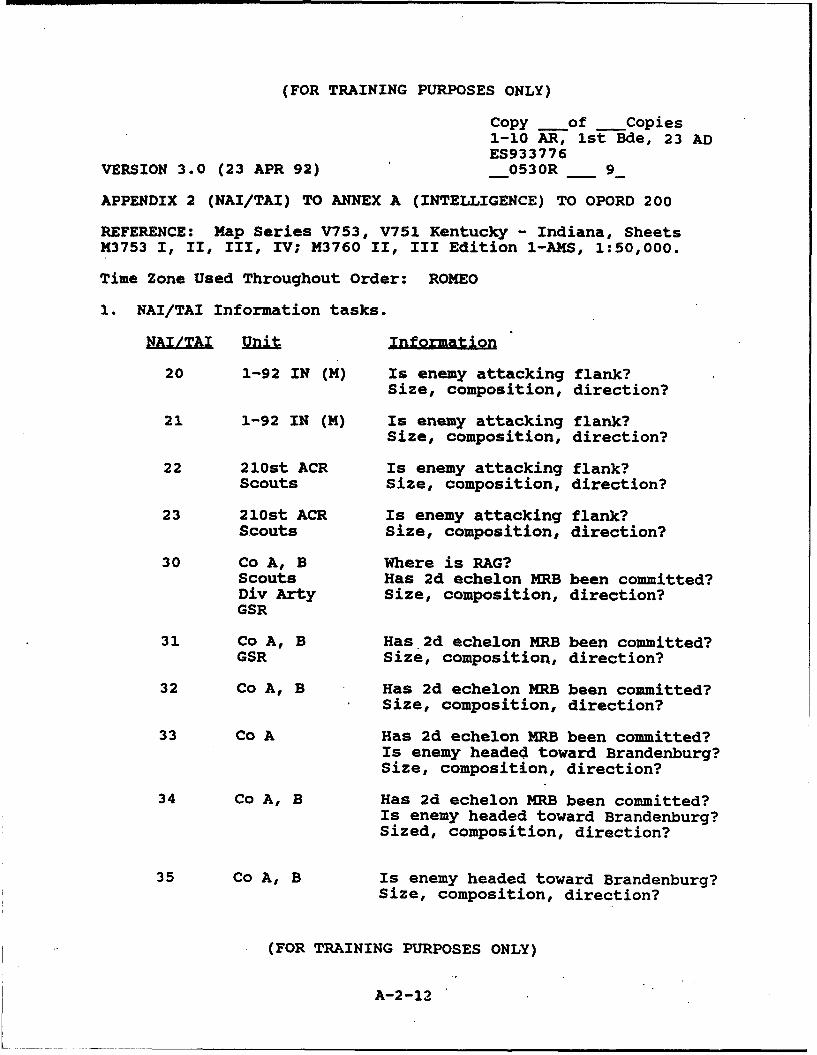
(FOR TRAINING PURPOSES ONLY)
Copy of _Copies1-10 AR, 1st Bde, 23 ADES933776
VERSION 3.0 (23 APR 92) 0530R _ 9
APPENDIX 2 (NAI/TAI) TO ANNEX A (INTELLIGENCE) TO OPORD 200
REFERENCE: Map Series V753, V751 Kentucky - Indiana, SheetsM3753 I, II, III, IV; M3760 II, III Edition 1-AMS, 1:50,000.
Time Zone Used Throughout Order: ROMEO
1. NAI/TAI Information tasks.
NAUnit Informatio
20 1-92 IN (M) Is enemy attacking flank?Size, composition, direction?
21 1-92 IN (M) Is enemy attacking flank?Size, composition, direction?
22 210st ACR Is enemy attacking flank?Scouts Size, composition, direction?
23 210st ACR Is enemy attacking flank?Scouts Size, composition, direction?
30 Co A, B Where is RAG?Scouts Has 2d echelon MRB been committed?Div Arty Size, composition, direction?GSR
31 Co A, B Has 2d echelon MRB been committed?GSR size, composition, direction?
32 Co A, B Has 2d echelon MRB been committed?Size, composition, direction?
33 Co A Has 2d echelon MRB been committed?Is enemy headed toward Brandenburg?Size, composition, direction?
34 Co A, B Has 2d echelon MRB been committed?Is enemy headed toward Brandenburg?Sized, composition, direction?
35 Co A, B Is enemy headed toward Brandenburg?Size, composition, direction?
(FOR TRAINING PURPOSES ONLY)
A-2-12
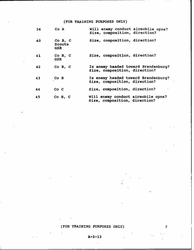
(FOR TRAINING PURPOSES ONLY)
36 Co A Will enemy conduct airmobile opns?Size, composition, direction?
40 Co B, C Size, composition, direction?ScoutsGSR
41 Co B, C Size, composition, direction?GSR
42 Co B, C Is enemy headed toward Brandenburg?Size, composition, direction?
43 Co B Is enemy headed toward Brandenburg?Size, composition, direction?
44 Co C Size, composition, direction?
45 Co B, C Will enemy conduct airmobile opns?Size, composition, direction?
(FOR TRAINING PURPOSES ONLY) 2
A-2-13

1.00.
% i~
S4o-ioq
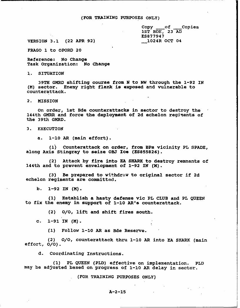
(FOR TRAINING PURPOSES ONLY)
Copy of _Copies1ST BDE, 23 ADES877947
VERSION 3.1 (22 APR 92) 1024R OCT 04
FRAGO 1 to OPORD 20
Reference: No ChangeTask Organization: No Change
1. SITUATION
39TH GMRD shifting course from N to NW through the 1-92 IN(M) sector. Enemy right flank is exposed and vulnerable tocounterattack.
2. MISSION
On order, 1st Bde counterattacks in sector to destroy the144th GMRR and force the deployment of 2d echelon regiments ofthe 39th GMRD.
3. EXECUTION
a. 1-10 AR (main effort).
(1) Counterattack on order, from BPs vicinity PL SPADE,along Axis Stingray to seize OBJ Ice (ES855826).
(2) Attack by fire into EA SHARK to destroy remnants of144th and to prevent envelopment of 1-92 IN (M).
(3) Be prepared to withdraw to original sector if 2dechelon regiments are committed.
b. 1-92 IN (M).
(1) Establish a hasty defense vic PL CLUB and PL QUEENto fix the enemy in support of 1-10 AR's counterattack.
(2) 0/0, lift and shift fires south.
c. 1-91 IN (M).
(1) Follow 1-10 AR as Bde Reserve.
(2) 0/0, counterattack thru 1-10 AR into EA SHARK (maineffort, 0/0).
d. Coordinating Instructions.
(1) PL QUEEN (PLD) effective on implementation. PLDmay be adjusted based on progress of 1-10 AR delay in sector.
(FOR TRAINING PURPOSES ONLY)
A-2-15
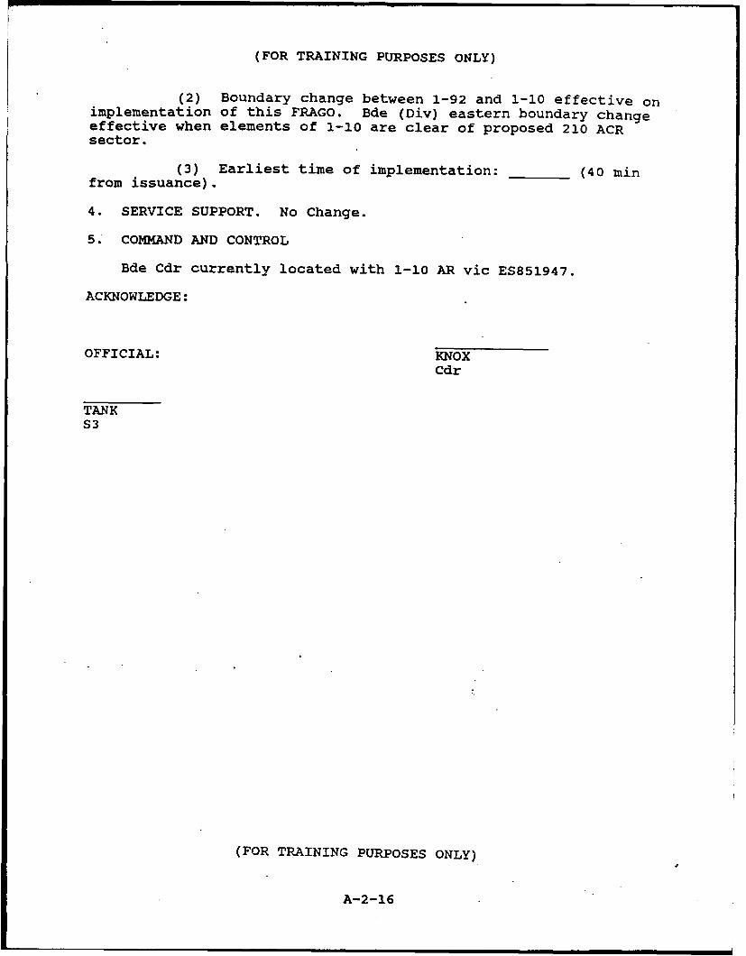
(FOR TRAINING PURPOSES ONLY)
(2) Boundary change between 1-92 and 1-10 effective onimplementation of this FRAGO. Bde (Div) eastern boundary changeeffective when elements of 1-10 are clear of proposed 210 ACRsector.
(3) Earliest time of implementation: (40 minfrom issuance).
4. SERVICE SUPPORT. No Change.
5. COMMAND AND CONTROL
Bde Cdr currently located with 1-10 AR vic ES851947.
ACKNOWLEDGE:
OFFICIAL: KNOXCdr
TANKS3
(FOR TRAINING PURPOSES ONLY)
A-2-16

A-3
FRAGOs to OPORD 200
Section A-3 contains the following FRAGOs:
FRAGO 1 to OPORD 200FRAGO 2 to OPORD 200
A-3-1
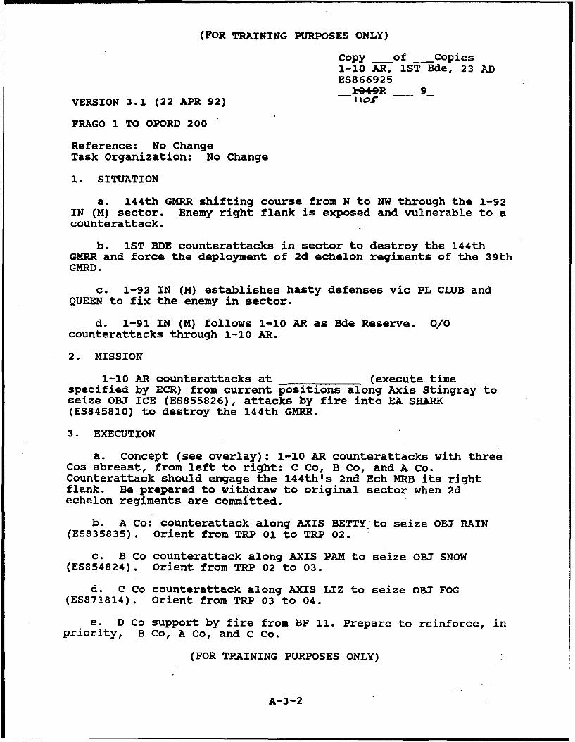
(FOR TRAINING PURPOSES ONLY)
Copy of _Copies1-10 AR, 1ST Bde, 23 ADES866925
-14e+9ýR 9VERSION 3.1 (22 APR 92) -I1os
FRAGO 1 TO OPORD 200
Reference: No ChangeTask Organization: No Change
1. SITUATION
a. 144th GMRR shifting course from N to NW through the 1-92IN (M) sector. Enemy right flank is exposed and vulnerable to acounterattack.
b. IST BDE counterattacks in sector to destroy the 144thGMRR and force the deployment of 2d echelon regiments of the 39thGMRD.
c. 1-92 IN (M) establishes hasty defenses vic PL CLUB andQUEEN to fix the enemy in sector.
d. 1-91 IN (M) follows 1-10 AR as Bde Reserve. 0/0counterattacks through 1-10 AR.
2. MISSION
1-10 AR counterattacks at (execute timespecified by ECR) from current positions along Axis Stingray toseize OBJ ICE (ES855826), attacks by fire into EA SHARK(ES845810) to destroy the 144th GMRR.
3. EXECUTION
a. Concept (see overlay): 1-10 AR counterattacks with threeCos abreast, from left to right: C Co, B Co, and A Co.Counterattack should engage the 144th's 2nd Ech MRB its rightflank. Be prepared to withdraw to original sector when 2dechelon regiments are committed.
b. A Co: counterattack along AXIS BETTY to seize OBJ RAIN(ES835835). Orient from TRP 01 to TRP 02.
c. B Co counterattack along AXIS PAM to seize OBJ SNOW(ES854824). Orient from TRP 02 to 03.
d. C Co counterattack along AXIS LIZ to seize OBJ FOG(ES871814). Orient from TRP 03 to 04.
e. D Co support by fire from BP 11. Prepare to reinforce, inpriority, B Co, A Co, and C Co.
(FOR TRAINING PURPOSES ONLY)
A-3-2
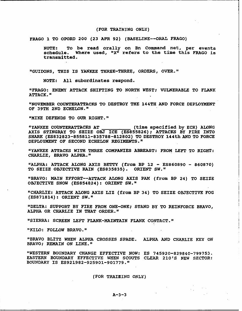
(FOR TRAINING ONLY)
FRAGO 1 TO OPORD 200 (23 APR 92) (BASELINE--ORAL FRAGO)
NOTE: To be read orally on Bn Command net, per eventsschedule. Where used, "X11 refers to the time this FRAGO istransmitted.
"GUIDONS, THIS IS YANKEE THREE-THREE, ORDERS, OVER."
NOTE: All subordinates respond.
"FRAGO: ENEMY ATTACK SHIFTING TO NORTH WEST; VULNERABLE TO FLANKATTACK."
"NOVEMBER COUNTERATTACKS TO DESTROY THE 144TH AND FORCE DEPLOYMENTOF 39TH 2ND ECHELON."
"MIKE DEFENDS TO OUR RIGHT."
"YANKEE COUNTERATTACKS AT (time specified by ECR) ALONGAXIS STINGRAY TO SEIZE OBJ ICE (ES855826); ATTACKS BY FIRE INTOSHARK (ES832823-855811-835788-812802) TO DESTROY 144th AND TO FORCEDEPLOYMENT OF SECOND ECHELON REGIMENTS."
"YANKEE ATTACKS WITH THREE COMPANIES ABREAST: FROM LEFT TO RIGHT:CHARLIE, BRAVO ALPHA."
"ALPHA: ATTACK ALONG AXIS BETTY (from BP 12 - ES860890 - 860870)TO SEIZE OBJECTIVE RAIN (ES835835). ORIENT SW."
"BRAVO: MAIN EFFORT--ATTACK ALONG AXIS PAM (from BP 24) TO SEIZEOBJECTIVE SNOW (ES854824): ORIENT SW."
"CHARLIE: ATTACK ALONG AXIS LIZ (from BP 34) TO SEIZE OBJECTIVE FOG(ES871814): ORIENT SW.""DELTA: SUPPORT BY FIRE FROM ONE-ONE; STAND BY TO REINFORCE BRAVO,
ALPHA OR CHARLIE IN THAT ORDER."
"SIERRA: SCREEN LEFT FLANK-MAINTAIN FLANK CONTACT."
"KILO: FOLLOW BRAVO."
"BRAVO BLITZ WHEN ALPHA CROSSES SPADE. ALPHA AND CHARLIE KEY ONBRAVO; REMAIN ON LINE."
"WESTERN BOUNDARY CHANGE EFFECTIVE NOW: ES 745920-829840-799753.EASTERN BOUNDARY EFFECTIVE WHEN SCOUTS CLEAR 210'S NEW SECTOR:BOUNDARY IS ES921982-925901-901779."
(FOR TRAINING ONLY)
A-3-3
(FOR TRAINING ONLY)
"OTHER GRAPHICS EFFECTIVE NOW:
"PL QUEEN: ES834864-850870-886876-924892.""LINE OF DEPARTURE: NW-SE RUNNING ROAD VIC ES850870-870860-
910847-953825."
"REPORT REDCON ONE. ACKNOWLEDGE, OVER."
NOTE: All subordinate units respond. If necessary, transmitadded graphics.
(FOR TRAINING ONLY)
A-3-4
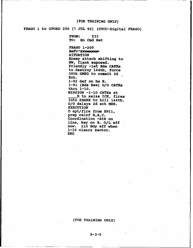
(FOR TRAINING ONLY)
FRAGO 1 to OPORD 200 (7 JUL 92) (CVCC-Digital FRAGO)
FROM: Y33TO: Bn Cmd Net
FRAGO 1-200
SITUATIONEnemy attack shifting toNW, flank exposed.Friendly -1st Bde CATKsto destroy 144th, force39th GMRD to commit 2dEch.1-92 def on bn R.1-91 (Bde Res) 0/0 CATKsthru 1-10.MISSION -1-10 CATKs at
R to seize ICE, firesinto SHARK to kill 144th.0/0 delays 2d ech MRR.EXECUTIOND spt/fire from BPll,prep reinf B,A,C.Coordination -Atk online, key on B. O/L effnow. 210 Bdy eff when1-10 clears sector.END
(FOR TRAINING ONLY)
A-3-5
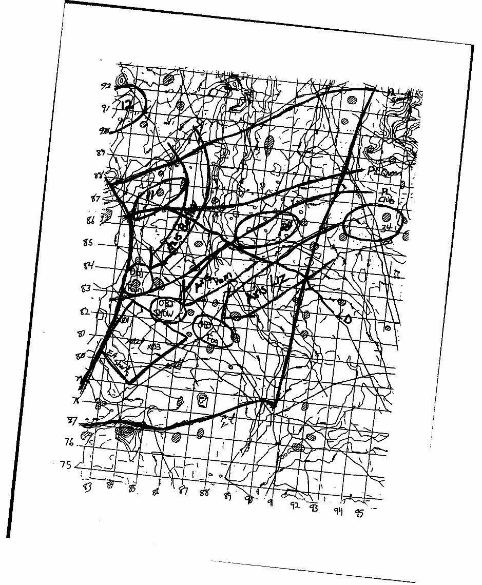
Its
53
<2
Irl
'77
74.
75
94 '15

(FOR TRAINING PURPOSES ONLY)
Copy __of Copies1-10 AR, 1ST Bde, 23 ADES866925
1310R _ 9VERSION 3.2 (22 APR 92)
FRAGO 2 TO OPORD 200
Reference: No ChangeTask Organization: No Change
1. SITUATION
a. Enemy. 2d echelon regiments of the 39 GMRD are moving NWinto the Bde sector. ETA: - (20 minutes from time of FRAGOpublication).
b. 1ST BDE defends along PL ACE to delay the enemy in sectorS of PL TRUMP until (approx 2 hrs).
c. 1-92 IN (M) delays in sector on our right flank.
d. 1-91 IN (M) Bde Reserve, reoccupies positions at PLTRUMP, to our rear.
2. MISSION
a. 1-10 AR defends at (time specified by ECR)along PL ACE (83 E-W grid line). On order, delays enemy S. of PLTRUMP until (approx 2 hrs).
3. EXECUTION
a. Concept (see overlay). 1-10 AR defends from BPs along PLACE with three Cos abreast; from left to right, C Co, B Co, and ACo. D Co occupies a BP to the rear as Bn reserve. On order, Bndelays in sector.
b. A Co: defend from BP 25; orient toward TRP AQ30. Onorder, displace to subsequent BPs 11 and 12.
c. B Co: defend from BP 45; orient toward TRP AR30. Onorder, displace to subsequent BPs 46, 21, and 22.
d. C Co: defend from BP 35; orient toward TRP AT30. Onorder, displace to subsequent BPs 26, 31, and 32.
e. D Co: occupy BP 46. Prepare to reinforce, in priority, BCo, A Co, and C Co. On order, displace to BP 41.
f. Mortars: locate to rear of B Co.
g. Scouts: screen eastern flank.
(FOR TRAINING PURPOSES ONLY)
A-3-7
(FOR TRAINING PURPOSES ONLY)
h. Companies report when "set" in BPs.
4. SERVICE SUPPORT. No Change.
5. COMMAND AND CONTROL
Bn Cdr will locate to rear of B Co vic BP 45.
ACKNOWLEDGE:
OFFICIAL: PATTONCdr
HASZARDS3
FRAGO 2 Overlay
(FOR TRAINING PURPOSES ONLY)
A-3-8

(FOR TRAINING ONLY)
FRAGO 2 TO OPORD 200 (23 APR 92) (BASELINE--ORAL FRAGO)
NOTE: To be read orally on Bn Command net, per eventsschedule. Where used, "X" refers to the time this FRAGO istrans",itted.
"GUIDONS, THIS IS YANKEE THREE-THREE, ORDERS, OVER."
NOTE: All subordinates respond.
"FRAGO: SECOND ECHELON MRR IS APPROACHING BN SECTOR FROM SOUTHEAST, ETA: 20 MINUTES."
"NOVEMBER RESUMES DELAY AT PL ACE. BDE DISPOSITION PER ORIGINALORDER."
"YANKEE DEFENDS _____AT (time specified by ECR) ALONG PLACE (83 E-W gridline), DELAYS ENEMY S OF PL TRUMP FOR ANOTHER TWOHOURS."
"ALPHA., DEFEND FROM BP 25 (ES840840) ORIENT SOUTH. DELAY THRU BPs11 THEN 12."
"BRAVO: DEFEND FROM BP 45 (ES867840) ORIENT SOUTH. DELAY THRU BPs46 THEN 21, THEN 22."
"CHARLIE: DEFEND FROM BP 35 (ES896840) ORIENT SOUTH. DELAY THRUBP 36 THREE-SIX (ES902870) THEN BPs 31 AND 32."
"DELTA: OCCUPY BP 46 (ES873875). BE PREPARED TO REINFORCE BRAVO,
ALPHA OR CHARLIE IN THAT ORDER. BLITZ TO BP 41 ON ORDER."
"KILO SUPPORT FROM CENTER OF SECTOR."
"SIERRA: SCREEN LEFT FLANK."
"BLITZ WHEN READY, REPORT WHEN SET. ACKNOWLEDGE, OVER."
(FOR TRAINING ONLY)
A-3-9
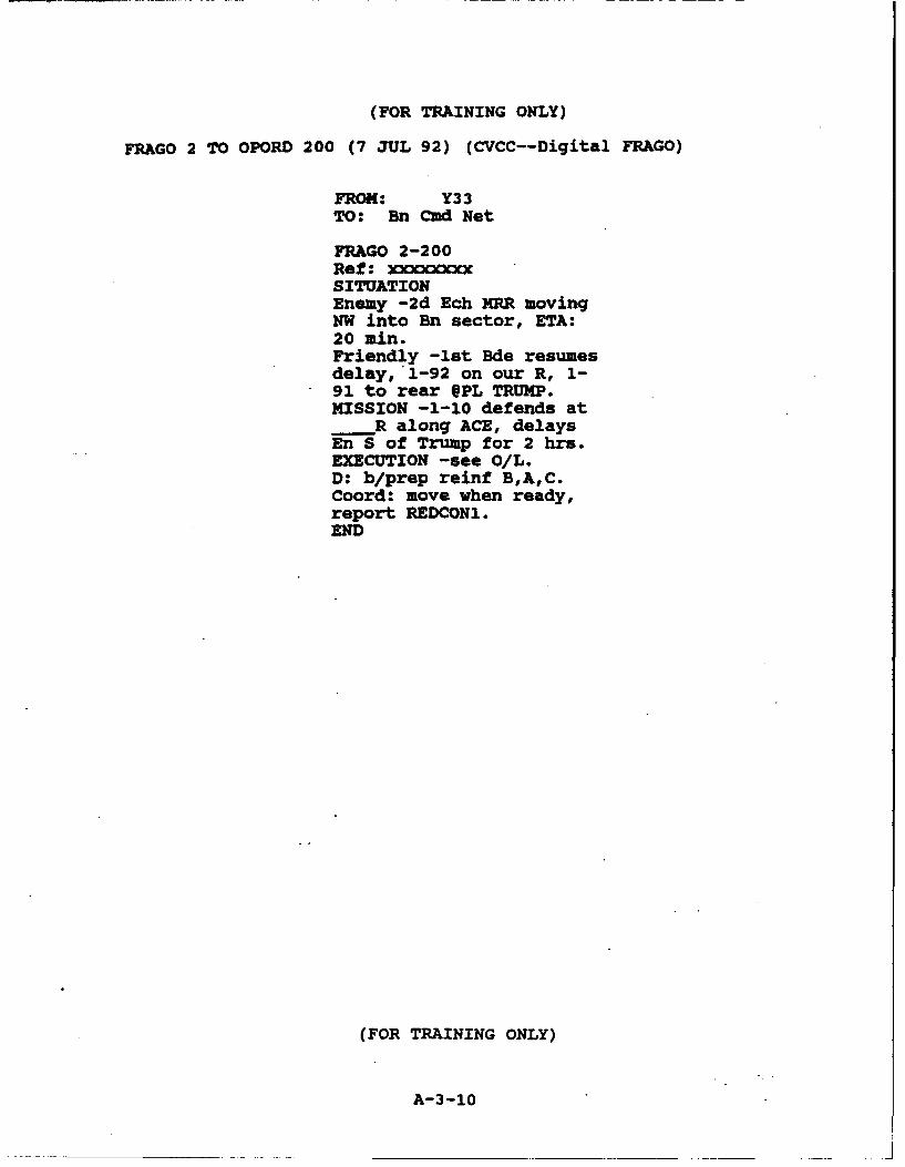
(FOR TRAINING ONLY)
FRAGO 2 TO OPORD 200 (7 JUL 92) (CVCC--Digital FRAGO)
FROM: Y33TO: Bn Cmd Net
FRAGO 2-200Ref: xxxxxxxxSITUATIONEnemy -2d Ech MRR movingNW into Bn sector, ETA:20 min.Friendly -1st Bde resumesdelay, 1-92 on our R, 1-91 to rear @PL TRUMP.MISSION -1-10 defends at
R along ACE, delaysEn S of Trump for 2 hrs.EXECUTION -see O/L.D: b/prep reinf B,A,C.Coord: move when ready,report REDCON1.END
(FOR TRAINING ONLY)
A-3-10
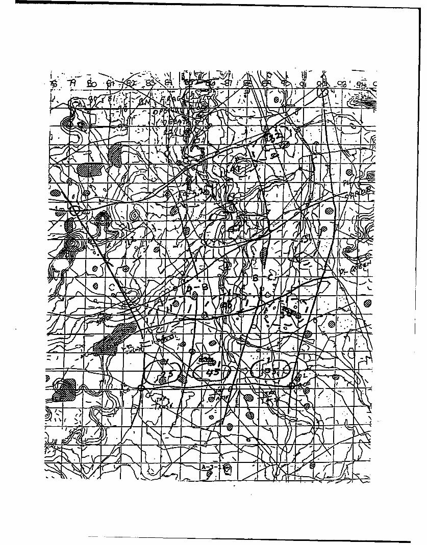
Al C2
'l,
;12
LIFY
TZ
V, j
N j JA- -ut

A-4
Battalion SOP Extract (CVCC Version)
A-4-1
CVCC BATTALION LEVEL EVALUATION
BATTALION SOP EXTRACT (EXPERIMENTAL)
Administrative Note.
This SOP applies to training and test exercises in the CVCCBattalion Evaluation, experimental condition. Its purpose is tostandardize the routine combat, combat support (CS), and combatservice support (CSS) procedures within the battalion during theconduct of collective training exercises, the test scenario(s)and data collection exercises.
Administrative Guidelines. The on-site exercise staffconsists of civilian personne' filling a number of roles. Theseroles can be segregated into tuhree basic fuhctions: controlstaff, unit augmentees, and trainer/observers.
The control staff includes the Exercise Director, ExerciseCoordinator, Battlemaster, Assistant Battlemaster, and FloorMonitor. During the course of tactical scenarios, these staffmembers will assume both administrative and tactical roles. Intheir administrative role, control staff will control exerciseduration, breaks, briefings, and so on. In their tactical role,control staff assume the positions of the Bde commandex andstaff, and adjacent unit personnel, as required.
The control staff also includes the OPFOR operator. Opposingforces are controlled according to standard scripts that do notvary by unit or condition. Interaction between unit members andthe OPFOR operator will be limited to tactical debriefings.
I
Unit augmentees include the TOC staff and BLUFOR SAFoperators. These personnel assume roles within the Bn: the XO,S2, Asst S3, FSO, and subordinate Co Cdrs or Plt Ldrs, asrequired by the situation. Although these personnel are familiarwith the scenarios that are to be played out, they are notpermitted to use that privileged information in any manner toinfluence the actions of military participants. It is imperativethat all members of the unit respect the need to maintainstandardization between iterations of the test, and thereforeinteract accordingly with the unit augmentees.
During the course of tactical events, the Bn will receive BdeFRAGOs or encounter situations requiring the development of a BnFRAGO. During these periods, unit augmentees will play theirunit roles as realistically as possible: responding to thecommander without providing any priveleged information. Prior toFRAGO execution, a standardized Bn FRAGO will be interjected bythe unit augmentees. The standardized" FRAGO must be adopted andexecuted, regardless of the degree of similarity or differencewith the FRAGO that was developed by the command group and staff,
Bn SOP (CVCC) 9/9/92 i
A-4-2
in order to maintain standard schemes of maneuver between testweeks.
Simulator trainer/observers work directly with crews in thesimulator, and have two roles. They serve as tank crewinstructors during the early phases of training, and offerrefresher training and advice during the training exercisesshould problems be encountered. During test events,trainer/observers monitor activities in selected simulators as apart of the data collection effort. They are not permitted toassist the crew in any way during test events, although they mayassist in trouble-shooting if equipment malfunctions occur.
All simulators will be manned at all times during training andtest events (except during scheduled and maintenance breaks), inorder to assure complete training and data collection. Duringtactical events, all interaction with control staff and unitaugmentees (excluding administrative matters) will be conducted"in character."
Bn SOP (CVCC) 9/9/92 ii
A-4-3
Contents
I. General
A. Purpose and Scope .................B. Reference ........................... 1C. Conformity ......................... 1
II. Command and Control
A. Organization ................................. 1B. succession of Command ................................ 1C. Orders . . ............D. Security Readiness Condition (REDC ON.) ... .... . 2
III. Organization for Combat
A. Task Organization ............... ................. 2B. Intelligence (PIR) ................ ................ 3C. Fire Support .................. .................... 3D. Air Defense ................. .................... 4
IV. Tactical Operations
A. Hatch Positions ................. .................. 4B. Operations ................ ..................... 4C. Tactical Road Marches ............. ............... 4D. Offensive Operations .............. ................ 5E. Defensive Operations .............. ................ 5
V. Command and Signal
A. COMSEC ....................... ................... 6B. Voice Radio Frequency Settings . ... . . . ... ..... 6C. Digital Message Transmission ............. 7D. Reporting ................... ..................... 7
VI. Service Support ................. ................... 8
Annexes
A -- Precombat Inspection Checklist ........ ............ .. A-1
B-- TOC SOP . . . . . . . . . . . . . . . . ... . . . .
C - Reports....................................... ... C-i
D -- Brevity Codes..................... D-1
E -- SOI Extract....................................... E-1
Bn SOP (CVCC) 9/9/9.2
A-4-4
I. GENERAL.
A. Purpose and ScoDe. This SOP standardizes the routinecombat, combat support (CS), and combat service support (CSS)procedures within the battalion during the conduct of tacticaloperations. It applies to all personnel and units assigned,attached, OPCON or DS to the battalion, either temporarily orpermanently.
B. R This is an extract of the Combined Arms HeavyBattalion/Task Force Standard Operating Procedure (SOP), SpecialText 17-17 (ST 17-17), dated May 1990; modified for purposes ofthe CVCC BN Evaluation (experimental condition).
C. Conformity. All battalion personnel will read and complywith this SOP extract. Follow the procedures of ST 17-17 incases not covered by this extract.
II. COMMAND AND CONTROL.
A. Oraanization.
1. Command Group: CDR & S3 in simulators (with gunner &driver)
2. TOC Group: XO, S2, Asst S3, FSO.
B. Succession of Command.
BN XOBN S3B CO CDRC CO CDRA CO CDRD CO CDR
C. Orders.
1. Complete OPORDs will be prepared and issued when timepermits. FRAGOs will be issued when required.
2. Warning Orders (WO) will be issued when a change ofmission is recei-ed.
Bn SOP (CVCC) 9/9/92
A-4-5

3. Orders group.
a. Prior to tactical operations the BN CDR mayassemble subordinate leaders for detailed oral orders:
Orders Group A: CDR, XO, S3Orders Group B: Group A + staffOrders Group C: Group B + CO CDRsOrders Group D: CDR, S3, CO CDRs
b. During tactical operations oral and/or digitalFRAGOs will be transmitted by radio. When time permits, warningorders and FRAGOs will be transmitted in digital text and overlayformats. Digital warning orders will be freetext messages.Digital FRAGOs will normally consist of an overlay with text.When time is critical, oral FRAGOs will be implemented andfollowed up with digital messages.
D. Security Readiness Condition (REDCON).
1. REDCON-1 (Full alert): All personnel alert, in thesimulators, and prepared for action. All equipment functionaland in good operating condition. Simulators ready to moveimmediately. Weapons in battlecarry or standby condition.
2. REDCON-2: Stand to complete. All simulators ready tomove within 15 minutes of notification. Weapons in standbycondition.
3. REDCON-3: Crews stand down for scheduled break.Simulators remain operational and running. Simulators ready tomove in 30 minutes. Ready racks/ammunition boxes fully loaded,weapons clear and safe.
4. REDCON-4: Simulators shut down. Simulators ready tomove in 1 hour.
III. ORGANIZATION FOR COMBAT.
A. Task Oraanization. The standard Bn task organizationwill be as follows, unless modified by OPORD or FRAGO. As usedbelow, the term "partially-manned" means: two manned simulatorscontaining the Co Cdr and XO, and SAFOR platoons.
Co A (Partially-manned) Bn controlScout Plt (SAFOR)
Co B (Partially-manned) Hvy Mort Plt (Simulated)Attached, OPCON and DS
Co C (Partially-manned) units (notional)
Co D (SAFOR) Bn Trains (notional)
Bn SOP (CVCC) 9/9/92 2
A-4-6
B. Intelligence. Priority Intelligence Requirements (PiR):Report the following immediately. Additional PIR will bespecified in OPORDs.
1. Apparent enemy plang/indications of attack ormovement.
2. Enemy use of NBC weapons.
3. Location, composition, identity, activity of enemyforces.
4. Direction of enemy advance.
5. Enemy aircraft.
C. Fire Sunvort.
1. Scheduled fires: FSO insures that scheduled fires areexecuted as planned, until lifted or shifted according to unitprogress. FSO monitors Bn Cmd and O&I nets and observes unitprogress on Bn TOC workstation to coordinate supporting fireswith maneuver.
2. Immediate/on call fires:
a. Any crew may initiate a call for fire (CFF). Tankcrews will initiate immediate calls for fire using the digitalCFF format. The Co XO (acting as FIST) is responsible forrelaying calls for fire to the FSO, and for integrating indirectfires to support the Co scheme of maneuver.
b. Crews will use the digital adjust fire reportformat to shift fires, to execute fires for effect (FFE) whenrounds are successfully adjusted on target, and to end thecurrent fire mission (EOM). Adjust fire reports (to include EOM)are assumed to refer to the last target requested by theoriginator.
c. The Co XOs will request final protective fires(FPFs) by voice radio on the Bn O&I net.
3. In the absence of immediate calls for fire andscheduled fires, the FSO will obtain targeting data from the S2and attack targets per the Bn Cdr's guidance and intent. The FSOwill clear suspected danger-close fires with the Asst S3 and/orclosest friendly Co Cdr/XO.
Bn SOP (CVCC) 9/9/92 3
A-4-7
D. Air Defense.
1. Readiness posture--situation dependent.
a. White - Attack not expected.b. Yellow - Attack expected.c. Red - Attack imminent.
2. Weapons control status: FREE unless downgraded byOPORD or FRAGO.
IV. TACTICAL OPERATIONS.
A. Hatch positions. For the purpose of this evaluation, allsimulators will operate closed-hatch.
B. Operations.
1. Maintain liaison left to right, supporting tosupported, front to rear at each echelon. During passage oflines, maintain liaison from passing to stationary unit.
2. No crossing boundaries without prior approval.
3. Battlecarry (Tanks). Effective whenever the unit isforward of the LD/LC or is established in forward defensivepositions (e.g., when enemy contact is possible):
Main gun: SABOT loaded and indexed;Battle Range settings: Sabot = 1200, HEAT = 900, Coax = 500;Coax locked and loaded, manual safe off;LRF safety set on first return;Trigger select on safe;Cal .50 locked and loaded, manual safety off, cupola in power
mode, Cal .50 manual elevation crank safed and locked;Loader's M240 dismounted and ammo stowed during extended
operations in closed hatch.
4. Standby condition. Used when the unit is behind theLD/LC, or in defensive positions in depth when enemy contact ispossible but not likely. All weapons will be in battlecarryposture with manual safeties on and the LRF in safe.
C. Tactical Road Marches.
1. Order of March: IAW OPORD/FRAGO.
2. March speed: 50 KPH.
Bn SOP (CVCC) 9/9/92 4
A-4-8
3. Formation: column.
4. Scheduled halts (breaks): as directed by Bde (exercisecontrol cell).
D. Of fensive oerations.
1. Bn formations: as situation dictates.
2. Actions on contact.
a. Return fire, deploy, and report (send digitalCONTACT report).
b. Seek cover and concealment.
c. Develop situation through direct and indirect fireand movement.
d. Send a digital SPOT report as soon as possible andagain when enemy situation changes (e.g., enemy withdraws or isdestroyed).
3. Consolidation.
a. Eliminate all enemy resistance on the objective.
b. Establish a hasty defense (prepare to repelcounter attack).
c. Prepare to continue the mission.
d. Co XO submit digital SITREP to Bn.
e. Bn S3 & Bn TOC staff monitor operational readinessof each subordinate unit through the automated system. Voiceradio is the back-up medium to clarify/verify status.
E. Defensive oDerations.
1. Deliberate occupation of a battle position (BP).
a. Companies enter BPs from rear.
b. SAFOR platoons report SET to CO CDR when inposition.
c. CO CDR report SET to BN when in position.
d. Co XO submit digital SITREP to BN.
Bn SOP (CVCC) 9/9/92 5
A-4-9
2. Hasty occupation of a BP.
a. All tanks will come from rear of BP and goimmediately into a turret down position selected by the platoonleader (SAFOR).
b. Co XO submit digital SITREP to BN.
V. COMMAND AND SIGNAL.
A. COMSEC.
1. All FM radio nets are secure.
2. Report any loss of SOI material to Bn ASAP.
3. Reports/information about the unit or friendlyelements will always be transmitted by secure means.
4. SOI extract for Bn evaluation is attached.
B. Voice Radio Freauencv Settinas. The following is thestandard battlecarry configuration(s) for SINCGARS radio sets oncommand simulators.
1. Bn Cmd Group.
a. Primary ("A") Radio: Bn Cmd.
b. Alternate ("B") Radio: Bde Cmd.
2. Co Cdrs.
a. Primary ("A") Radio: Co Cmd.
b. Alternate ("B") Radio: Bn Cmd.
3. Co XOs.
a. Primary ("A") Radio: Bn O&I.
b. Alternate ("B") Radio: Co Cmd.
4. Plt Ldrs/PSGs.
a. Primary ("A") Radio: Plt net.
b. Alternate ("B") Radio: Co Cmd.
Bn SOP (CVCC) 9/9/92 6
A-4-10
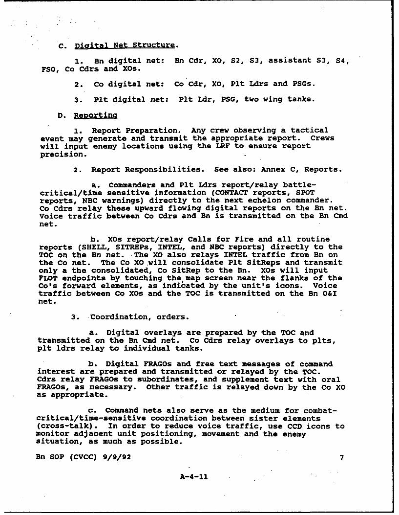
C. Digital Net Structure.
1. Bn digital net: Bn Cdr, XO, S2, S3, assistant S3, S4,FSO, Co Cdrs and XOs.
2. Co digital net: Co Cdr, XO, Plt Ldrs and PSGs.
3. Plt digital net: Plt Ldr, PSG, two wing tanks.
D. EaD2tifl
1. Report Preparation. Any crew observing a tacticalevent may generate and transmit the appropriate report. Crewswill input enemy locations using the LRF to ensure reportprecision.
2. Report Responsibilities. See also: Annex C, Reports.
a. Commanders and Plt Ldrs report/relay battle-critical/time sensitive information (CONTACT reports, SPOTreports, NBC warnings) directly to the next echelon commander.Co Cdrs relay these upward flowing digital reports on the Bn net.Voice traffic between Co Cdrs and Bn is transmitted on the Bn Cmdnet.
b. XOs report/relay Calls for Fire and all routinereports (SHELL, SITREPs, INTEL, and NBC reports) directly to theTOC on the Bn net. The XO also relays INTEL traffic from Bn onthe Co net. The Co XO will consolidate Plt SitReps and transmitonly a the consolidated, Co SitRep to the Bn. XOs will inputFLOT endpoints by touching the map screen near the flanks of theCo's forward elements, as indicated by the unit's icons. Voicetraffic between Co XOs and the TOC is transmitted on the Bn O&Inet.
3. Coordination, orders.
a. Digital overlays are prepared by the TOC andtransmitted on the Bn Cmd net. Co Cdrs relay overlays to plts,plt ldrs relay to individual tanks.
b. Digital FRAGOs and free text messages of commandinterest are prepared and transmitted or relayed by the TOC.Cdrs relay FRAGOs to subordinates, and supplement text with oralFRAGOs, as necessary. Other traffic is relayed down by the Co XOas appropriate.
c. Command nets also serve as the medium for combat-critical/time-sensitive coordination between sister elements(cross-talk). In order to reduce voice traffic, use CCD icons tomonitor adjacent unit positioning, movement and the enemysituation, as much as possible.
Bn SOP (CVCC) 9/9/92 7
A-4-11
VI. SERVICE SUPPORT
CSS is not exercised in the current evaluation. However, theimpact of logistics on ongoing tactical operations must beconsidered. Logistic information is provided on an automatedquery basis. Cdrs, XOs, Plt Ldrs/PSGs and the S3 willperiodically check the status of subordinate elements via theCCD. Individual tank commanders will also periodically checkvehicle status via CCD. Be prepared to transmit or verify statususing voice radio, if requested.
Bn SOP (CVCC) 9/9/92 8
A-4-12
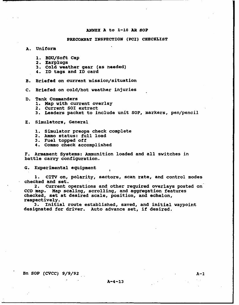
ANNEX A to 1-10 AR1 SOP
PRECOMBAT INSPECTION (PCI) CHECKLIST
A. Uniform
1. BDU/Soft Cap2. Earplugs3. Cold weather gear (as needed)4. ID tags and ID card
B. Briefed on current mission/situation
C. Briefed on cold/hot weather injuries
D. Tank Commanders1. Map with current overlay2. Current SOI extract3. Leaders packet to include unit SOP, markers, pen/pencil
E. Simulators, General
1. Simulator preops check complete2. Ammo status: full load3. Fuel topped off4. Commo check accomplished
F. Armament Systems: Ammunition loaded and all switches inbattle carry configuration.
G. Experimental equipment
1. CITV on, polarity, sectors, scan rate, and control modeschecked and set.
2. Current operations and other required overlays posted onCCD map. Map scaling, scrolling, and aggtegation featureschecked, set at desired scale, position, and echelon,respectively.
3. Initial route established, saved, and initial waypointdesignated for driver. Auto advance set, if desired.
Bn SOP (CVCC) 9/9/92 A-i
A-4-13

ANNEX C to 1-10 AR SOP
Reports
Combat-Critical Reports C-2Contact Report C-2Spot Report C-2Call For Fire C-2Adjust Fire C-3
Routine Reports C-3Situation Report C-3Ammunition Status Report C-3Fuel Status Report C-4NBC Report C-4Shell Report C-4Intelligence Report C-5
Report formats shown on the next few pages indicate thefields that are input for each report using the CVCC.Where abbreviations are used in the CCD, the full fieldtitle is indicated in this annex. Example reports areshown as they appear when received.
Bn SOP (CVCC) 9/9/92 C-i
A-4-14

Combat-Critical Reports
Contact Report
Purpose: To report initial enemy contact.
Prepared/Relayed by: Co Cdr
Format: Example:
WHATa RWEREa FROM C21 ORIG C21/0905( ( WHAT WHERE( 3 [ ] Tank ES782946
PC ES784945
Spot Reoort
Purpose: To report results of enemy contacts, enemy activities,and friendly activities.
Prepared/Relayed by: Co Cdr
Format: Example:
WHATa OBSERVED DESTROYED FROM A06 ORIG All/1021[ J [ 3 3 XWHAT OBSERVED DESTROYED( 3 [3 [3 PC 5 6WHERE Tank 0 7HEADING WHERE ES784921ENEMY ACTION HEADING 30OWN ACTION ENEMY ACTION Gnd AtkAS OF FRIENDLY ACTION Delay
AS OF 22 1856:42
Notes"&Icons depict locations on the map screen when the report is inthe receive queue, open, or posted to the map.
Bn SOP (CVCC) 9/9/92 C-2
A-4-15
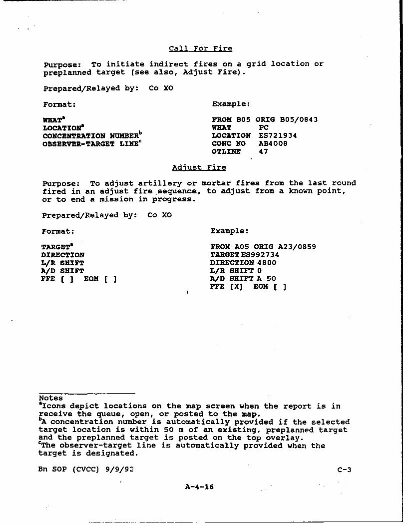
Call For Fire
Purpose: To initiate indirect fires on a grid location orpreplanned target (see also, Adjust Fire).
Prepared/Relayed by: Co XO
Format: Example:
WMTa FROM B05 ORIG B05/0843LOCATZONa WHAT PCCONCENTRATION NUMBERb LOCATION ES721934OBSERVER-TARGET LINEc CONC NO AB4008
OTLINE 47
Adjust Fire
Purpose: To adjust artillery or mortar fires from the last roundfired in an adjust fire.sequence, to adjust from a known point,or to end a mission in progress.
Prepared/Relayed by: Co XO
Format: Example:
TARGETO FROM A05 ORIG A23/0859DIRECTION TARGET ES992734L/R SHIFT DIRECTION 4800A/D SHIFT L/R SHIFT 0FFE [ ] EOM [ ] A/D SHIFTA 50
FFE [X] EON [ ]
Notes"aIcons depict locations on the map screen when the report is in
receive the queue, open, or posted to the map.bA concentration number is automatically provided if the selectedtarget location is within 50 m of an existing. preplanned targetand the preplanned target is posted on the top overlay.CThe observer-target line is automatically provided when thetarget is designated.
Bn SOP (CVCC) 9/9/92 C-3
A-4-16
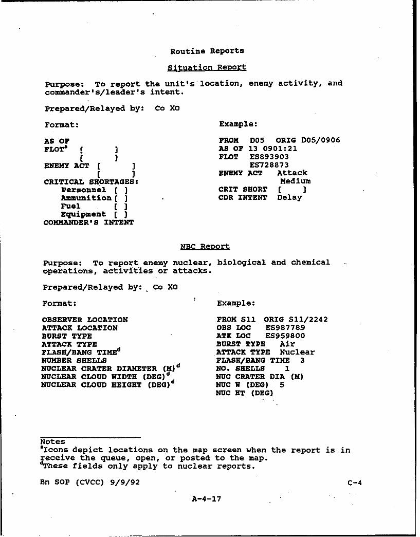
Routine Reports
Situation Report
Purpose: To report the unit's location, enemy activity, andcommander's/leader's intent.
Prepared/Relayed by: Co XO
Format: Example:
AS OF FROM D05 ORIG D05/0906FLOTO ( ] AS OF 13 0901:21
( ] PLOT ES893903ENEMY ACT [ J ES728873
( ] ENEMY ACT AttackCRITICAL SHORTAGES: Medium
Personnel ( ] CRIT SHORT [ JAmmunition ] CDR INTENT DelayFuel []Equipment ( J
COMMANDER' S INTENT
NBC Report
Purpose: To report enemy nuclear, biological and chemicaloperations, activities or attacks.
Prepared/Relayed by:. Co XO
Format: Example:
OBSERVER LOCATION FROM S11 ORIG S11/2242ATTACK LOCATION OBS LOC ES987789BURST TYPE ATK LOC ES959800ATTACK TYPE BURST TYPE AirFLASH/BANG TIMEd ATTACK TYPE NuclearNUMBER SHELLS FLASH/BANG TIME 3NUCLEAR CRATER DIAMETER (M)d NO. SHELLS 1NUCLEAR CLOUD WIDTH (DEG) d NUC CRATER DIA (M)NUCLEAR CLOUD HEIGHT (DEG)d NUC W (DEG) 5
NUC HT (DEG)
NotessIcons depict locations on the map screen when the report is inreceive the queue, open, or posted to the map.dThese fields only apply to nuclear reports.
Bn SOP (CVCC) 9/9/92 C-4
A-4-17
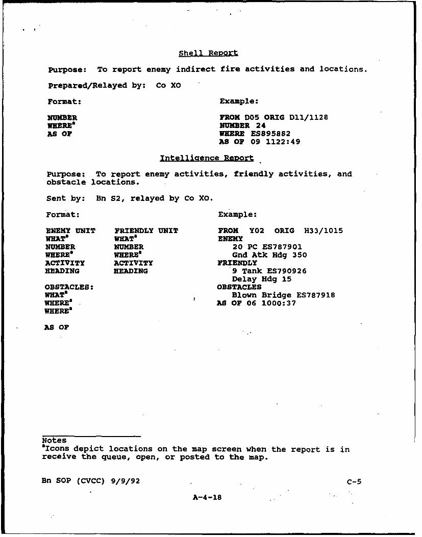
Shell Report
Purpose: To report enemy indirect fire activities and locations.
Prepared/Relayed by: Co XO
Format: Example:
NUMBER FROM D05 ORIG D11/1128WHERE* NUMBER 24AS OF WHERE ES895882
AS OF 09 1122:49
Intelligence Report
Purpose: To report enemy activities, friendly activities, andobstacle locations.
Sent by: Bn 52, relayed by Co XO.
Format: Example:
ENEMY UNIT FRIENDLY UNIT FROM Y02 ORIG H33/1015WHATa WHATa ENEMYNUMBER NUMBER 20 PC ES787901WHERE" WHERE" Gnd Atk Hdg 350ACTIVITY ACTIVITY FRIENDLYHEADING HEADING 9 Tank ES790926
Delay Hdg 15OBSTACLES: OBSTACLESWMT" Blown Bridge ES787918WHEREa AS OF 06 1000:37WHERE&
AS OF
Notes"aIcons depict locations on the map screen when the report is inreceive the queue, open, or posted to the map.
Bn SOP (CVCC) 9/9/92 C-5
A-4-18
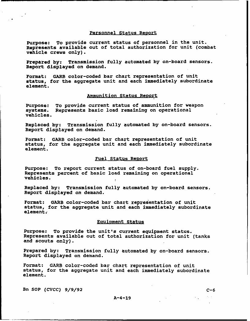
Personnel Status Report
Purpose: To provide current status of personnel in the unit.Represents available out of total authorization for unit (combatvehicle crews only).
Prepared by: Transmission fully automated by on-board sensors.Report displayed on demand.
Format: GARB color-coded bar chart representation of unitstatus, for the aggregate unit and each immediately subordinateelement.
Ammunition Status Report
Purpose: To provide current status of ammunition for weaponsystems. Represents basic load remaining on operationalvehicles.
Replaced by: Transmission fully automated by on-board sensors.Report displayed on demand.
Format: GARB color-coded bar chart representation of unitstatus, for the aggregate unit and each immediately subordinateelement.
Fuel Status Report
Purpose: To report current status of on-board fuel supply.Represents percent of basic load remaining on operationalvehicles.
Replaced by: Transmission fully automated by on-board sensors.Report displayed on demand.
Format: GARB color-coded bar chart representation of unitstatus, for the aggregate unit and each immediately subordinateelement.;
Eauipment Status
Purpose: To provide the unit's current equipment status.Represents available out of total authorization for unit (tanksand scouts only).
Prepared by: Transmission fully automated by on-board sensors.Report displayed on demand.
Format: GARB color-coded bar chart representation of unitstatus, for the aggregate unit and each immediately subordinateelement.
Bn SOP (CVCC) 9/9/92 C-6
A-4-19
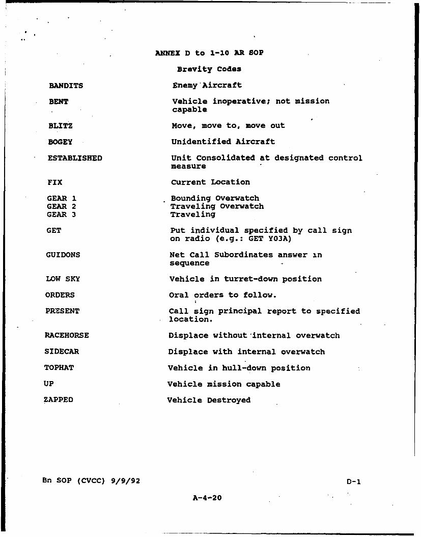
ANNEX D to 1-10 AR SOP
Brevity Codes
BANDITS Enemy'Aircraft
BENT Vehicle inoperative; not missioncapable
BLITZ Hove, move to, move out
BOGEY Unidentified Aircraft
ESTABLISHED Unit Consolidated at designated controlmeasure
,FIX Current Location
GEAR 1 Bounding OverwatchGEAR 2 Traveling OverwatchGEAR 3 Traveling
GET Put individual specified by call signon radio (e.g.: GET YO3A)
GUI DONS Net Call Subordinates answer insequence
LOW SKY Vehicle in turret-down position
ORDERS Oral orders to follow.
PKR.SENT call sign principal report to specifiedlocation.
RACEHORSE Displace without internal overwatch
SIDECAR Displace with internal overwatch
TOPHAT Vehicle in hull-down position
UP Vehicle mission capable
ZAPPED Vehicle Destroyed
Bn SOP (CVCC) 9/9/92 D- 1
A-4-20
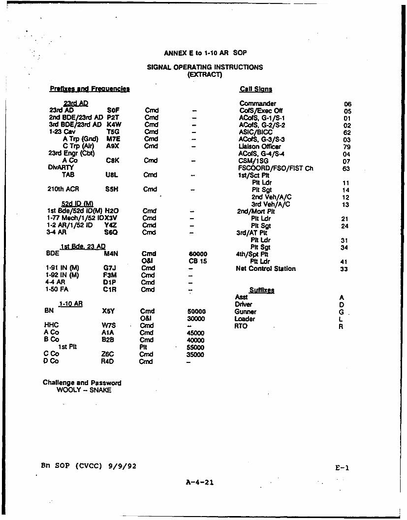
ANNEX E to 1-10 AR SOP
SIGNAL OPERATING INSTRUCTIONS(EXTRACT)
Prefixes and Freauencles Call Slans
23ra AD Commander 0623rd AD SOF Cmd - CoIS/Exec Off 052nd BDE/23rd AD P2T Cmd - ACofS. G-l/S-1 013rd BDE/23rd AD K4W Cmd - ACofS, G-2/S-2 021-23 Cav T5G Crnd - ASIC/BICC 62
A Trp (Gnd) M7E Cmd - ACoiS. G-3/S-3 03C Trp (Air) A9X Cmnd - Liaison Officer 79
23rd Engr (Cbt) ACofS, G-4/S-4 04A Co CSK Cmd - CSM/lSG 07
DivARTY FSCOORD/FSO/FIST Ch 63TAB U8L Cmd - lst/Sct Pit
Pit Ldr 11210th ACR SSH Cmd Pit Sgt 14
2nd Veh/A/C 121 52d ID(M) 3rd Veh/A/C 13
1st Bde/52d D(M) H20 Cmd - 2lnd/Mort Pit1-77 Mech/1/52 IDX3V Cmd - Pit Ldr 211-2 AR/1/52 ID Y4Z Cmd - Pit Sgt 243-4 AR s6e Cmd - 3rd/AT Pit
Pit Ldr 31Pit Sgt 34
BDE M4N Cmd 60000 4th/Spt PitO&l CB 15 Pit Ldr 41
1-91 IN (M) G7J Cmd - Net Control Station 331-92 IN (M) F3M Cmd4-4 AR DiP Cmd -1-50 FA CIR Cmd 7 Suffixes
Ast A1-10 AR Driver D
BN X5Y Cmd 50000 Gunner GO&l 30000 Loader L
HHC W7S Cmd - RTO RA Co AIA CmGd 45000B Co B2B Cmd 40000
1st Pit Pit 55000C Co Z6C Cmd 35000D Co R4D Cmd -
Challenge and PasswordWOOLY - SNAKE
Bn SOP (CVCC) 9/9/92 E-1
A-4-21
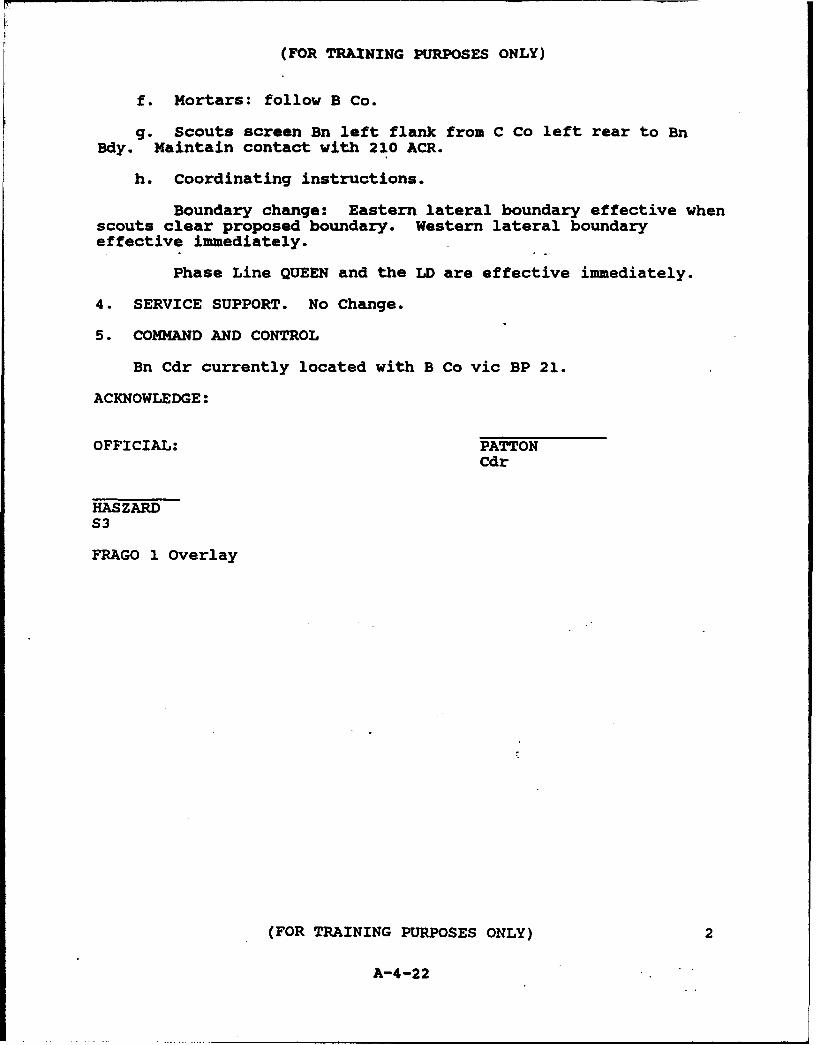
(FOR TRAINING PURPOSES ONLY)
f. Mortars: follow B Co.
g. Scouts screen Bn left flank from C Co left rear to Bn
Bdy. Maintain contact with 210 ACR.
h. Coordinating instructions.
Boundary change: Eastern lateral boundary effective whenscouts clear proposed boundary. Western lateral boundaryeffective immediately.
Phase Line QUEEN and the LD are effective immediately.
4. SERVICE SUPPORT. No Change.
5. COMMAND AND CONTROL
Bn Cdr currently located with B Co vic BP 21.
ACKNOWLEDGE:
OFFICIAL: PATTONCdr
HASZARDS3
FRAGO 1 Overlay
(FOR TRAINING PURPOSES ONLY) 2
A-4-22

APPENDIX B
ZXZRCBIZ CONTROL PROCIDURS
Appendix B contains the following sections:
B-I Contingency Rules for Personnel, Technical andExercise Problems
B-2 Battlemaster ProceduresB-3 SAFOR Operator ProceduresB-4 SAFOR Operator Radio Protocols
B-i
B-1
CONTINGENCY RULES FOR PERSONNEL, TECHNICAL ANDEXERCISE PROBLEMS
B-I-I

CVCC Battalion Evaluation
CONTINGENCY RULES FOR PERSONNEL,!EMICAL L]IDD,ZERCISE PROBLEMB
These contingency rules address general and specific problem areasthat may be encountered during the conduct of the CVCC BattalionEvaluation. These rules are guidelines that should be used asappropriate. Decision makers will be required to exerciseprofessional judgement in all applications of these rules.
Contents
A. General Rules . . . . . . . . . . . . . . . . . . 1
B. Rules for Missing Participants. . . . . . . . . . 3
C. Rules for Missing Research Staff. . . . . . . . . 5
D. Rules for Participant/Staff Interaction . . . . . 5
E. Rules for Technical Problems . . . . . . . . . . 7
F. Rules for Schedule Adjustments when Delays Occur. 8
G. Rules for Deviations from Planned Events . . . . 9
A. General Rules
1. Decision Authority: The Exercise Director assigned to theresearch effort retains overall decision authority for any and allmatters that may impact on the conduct of the test or the datacollection effort.
2. Basic ANnroaah:
a. The option with the least disruptive overall impact willnormally be the preferred course of action. The goal is toidentify solutions which minimize impacts on:
(1) The data collected or the measures involved (e.g., lostor contaminated data).
(2) C3 dynamics (e.g., interaction between the Bn and CoCdrs).
(3) Scenario execution, including SAFOR (e.g., firepower,maneuver, mission accomplishment).
B-1-2

b. Whenever problems are encountered that may impact on testconduct, an estimate of the time necessary to correct the situationwill be made. Delays will normally be appropriate for short-termproblems, whereas adjustments to crew and/or simulatorconfigurations may be necessary for longer-term problems. See "B.Rules for Missing Participants" and "E. Rules for TechnicalProblems" for a comprehensive set of decision guidelines.
(1) Short-term problems are those which can likely becorrected within the time frame of a training period, trainingexercise, test scenario, or data collection exercises (DCEs). Thatis, a problem that can be corrected quickly enough to allow thecurrent and subsequent exercises to be completed on the dayscheduled. Example: replacing an IDC board in a simulator with aboard that is in stock on-site.
(2) Longer-term problems are those likely to outlast thecurrent event (as described above). That is, a problem that cannotbe "worked around" or corrected quickly. Example: a faulty IDCboard for which no replacement is available on-site.
(3) The weekly schedule will be followed for all scheduledtraining and test events until delays occur. When delays occur,the primary goal is to accomplish all training on the day for whichit is scheduled. If an event is not accomplished on the dayscheduled, the Exercise Director will publish a revised exerciseschedule at the earliest opportunity. Events will be rescheduledso as to accomplish required data collection activities andstandardize the collective training sequence across iterations.See "F. Rules for Schedule Adjustments when Delays Occur."
3. Standardization:
a. The events lists detail the actions which ECR personnelmust ensure are accomplished during each scenario or exercise.Control staff will ensure that all events are executed, and that adlib communications with participants are consistent with thescript, based on the progress of the scenario.
b. All control staff will avoid conversation that providesthe current test group with any information about the performanceof prior test groups. This includes characterizing the currentgroup's performance in terms of implied norms (e.g., "average" or"better than average"). Such information is confidential and maycontaminate test results.
B-1-3
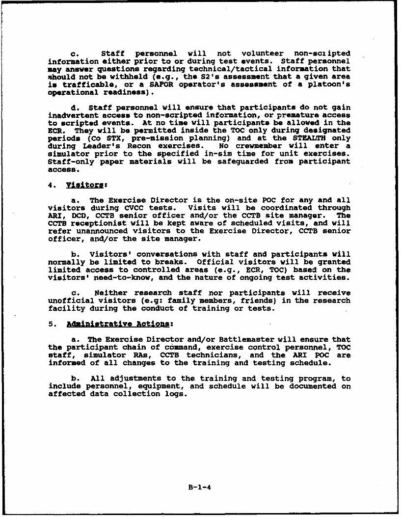
c. Staff personnel will not volunteer non-sctiptedinformation either prior to or during test events. Staff personnelmay answer questions regarding technical/tactical information thatshould not be withheld (e.g., the S2's assessment that a given areais trafficable, or a SAFOR operator's assessment of a platoon'soperational readiness).
d. Staff personnel will ensure that participants do not gaininadvertent access to non-scripted information, or premature accessto scripted events. At no time will participants be allowed in theECR. They will be permitted inside the TOC only during designatedperiods (Co STX, pre-mission planning) and at the STEALTH onlyduring Leader's Recon exercises. No crewmember will enter asimulator prior to the specified in-sim time for unit exercises.Staff-only paper materials will be safeguarded from participantaccess.
4.viios
a. The Exercise Director is the on-site POC for any and allvisitors during CVCC tests. Visits will be coordinated throughARI, DCD, CCTB senior officer and/or the CCTB site manager. TheCCTB receptionist will be kept aware of scheduled visits, and willrefer unannounced visitors to the Exercise Director, CCTB seniorofficer, and/or the site manager.
b. Visitors' conversations with staff and participants willnormally be limited to breaks. Official visitors will be grantedlimited access to controlled areas (e.g., ECR, TOC) based on thevisitors' need-to-know, and the nature of ongoing test activities.
c. Neither research staff nor participants will receiveunofficial visitors (e.g: family members, friends) in the researchfacility during the conduct of training or tests.
5. Administrative Aotions:
a. The Exercise Director and/or Battlemaster will ensure thatthe participant chain of command, exercise control personnel, TOCstaff, simulator RAs, CCTB technicians, and the ARI POC areinformed of all changes to the training and testing schedule.
b. All adjustments to the training and testing program, toinclude personnel, equipment, and schedule will be documented onaffected data collection logs.
B-1-4

B. Rules for Missing Participants
1. 2o The Exercise Director will verify that allparticipants are aware of attendance requirements for a test weekduring the initial introduction. Soldiers with appointments orother anticipated absences will either reschedule the appointmentor be replaced by the unit prior to the start of their training.
2. Battle Roster:
a. Vehicle commander assignments will become permanent assoon as the first training event commences. Gunner and Driverassignments are fixed as soon as crew training commences. Theparticipating unit has until that time to resolve any absences orto find suitable substitutes.b. Vehicle commander absences: A vehicle commander's absence fortraining or test events may require the reassignment of othervehicle commander roles. Such role changes will be followedthrough to all affected crews. For example, if the Bn Cdr isabsent, the S3 assumes his role, vacating the S3 position. In thatevent, the unit completes the exercise without an S3.
3. Term of Absence:
a. Any participant that misses a significant portion of acollective training event may be dismissed for the remainder of thetest week at the discretion of the Exercise Director. Allparticipants must complete all seat-specific training. Significantportions of collective training include (but are not limited to):the entire crew training period or any single stage of a trainingevent, to include the preparation stage. The exercise directorwill consult with other research staff to determine whether ashort-term absence during a portion of any stage constitutes asignificant loss of scheduled training, and therefore becomesgrounds for dismissal of the participant.
b. Temporary (short-term) absences justify delayed starttimes for training events. Once a training or test event begins,the participant group will remain constant for the remainder of theevent unless an emergency arises. Permanent vehicle commanderabsences will modify the unit structure for the remainder of thetest, and may influence the manner by which the Bn Cdr employs hisforce. It is therefore preferable to delay the start of an eventif the absent officer is expected to return soon. If a participantis called away temporarily after a scenario starts, he will resumehis position at an appropriate break point when he returns, unlessthe loss of training meets the preceding criteria and results inhis dismissal.
B-1-5

c. The loss of up to two crews (as the result of Veh Cdrabsences) can be managed. The loss of a third crew represents anunacceptable level of lost data.
C. Rules for Missing Research Staff
1. The Exercise Director will manage personnel issues not coveredin the established contingency plan, as required.
2. Training assignments are managed by the floor monitor with theconcurrence of the Exercise Director.
D. Rules for Participant/Staff Interaction
1. The purpose of CVCC participant training is to prepare soldiersto operate the simulators during the test exercises. Theperformance of some tasks during test scenarios and events iscritical to the success of the test, as a whole. If a participantis experiencing difficulty accomplishing a discrete CCD task thatis critical to the exercise (e.g., post an overlay to the CCD, orrestore the map screen after it has been scrolled so far that thevehicle icon is lost and the TC is misoriented), unobtrusiveprompts or hints should be used to lead theparticipant through the task, at the discretion of the ExerciseDirector.
2. During training and test events, control staff personnel in theTOC and ECR will remain in character during all tacticalcommunications with participants. This includes mostcommunications between the TOC and the ECR in order to maintain thefocus on the tactical exercise. Control staff will step out ofcharacter only for administrative communications.
3. Participant requests for information from the TOC or ECR willbe handled as follows.
a. Information that represents feedback, synthesis ofpreviously reported information, or the status of an ongoing actionwill be provided immediately. For example, if the Bn Cdr asks thestatus of a fire mission, the FSO may respond, "none available," or"guns are repositioning."
B-1-6
b. Information that is not readily available will benotionally referred to an appropriate tactical element (e.g., CEWIunits, Fwd Spt Bn), and an appropriate delay imposed. If theinformatior is or may be tactically relevant to the currentsituation, it will only be provided if scripted. Otherinformation without immediate tactical relevance may be transmittedfor the sake of realism.
C. A complete set of procedural rules for BLUFOR SAFoperators and RTOs is published separately as the "SAF RadioOperator Protocols." Procedural guidelines for the control of SAFvehicles are integrated in events lists, as supplemented byoperator notes.
R. Rules for Technical Problems
1. Simulator or Software Breakdowns:
a. Short-term:
(1) Minor problems (e.g., non-critical CITVmalfunction): Delay start of training/exercise or fix withoutinterrupting or suspending training/exercise or repair at scheduledbreak.
(2) Major problems (e.g., critical CCD malfunction,simulator crash): delay start of training/exercise or suspendtraining/exercise for repairs.
b. Longer-term: The loss of up to two (2) simulators may beaccommodated for a training scenario, test scenario or the datacollection exercises. The loss of a third simulator would resultin unacceptable data loss. In that event, the Exercise Directorwill coordinate with ARI to determine what follow-up action isfeasible. If the simulator can be returned to operation prior tothe end of the test week, it may be used if the crew is consideredavailable, as described in subparagraph (3), below. The followingactions will be taken to adjust for the loss of simulators:
(1) During individual training, double up on avallabletrainers.
(2) During collective training and test exercises,reallocate simulators as follows:
tThe test of tactical relevance must be applied carefully. Ifthere is any question, treat the information as potentiallyrelevant.
B-1-7
(a) For Training and Test Scenarios: Maintain theBn Cdr, all Co Cdrs, and two Co XOs.
(b) For DCEs, maintain the fully manned platoon,the Co Cdr and the Bn Cdr.
(3) If a crew loses significant training because of asimulator breakdown, as defined in section B.3, then the crew willbe dismissed and the test will continue with the reduced number ofcrews and operating simulators. If the simulator is subsequentlyrepaired, it will serve as a back-up for the remainder of the testweek.
2. TOC Workstations (CVCC only):
a. Short-term: See paragraph E.1.a.
b. Longer-term: Reorganize available workstations andreassign operators as required.
3. Radios:
a. Simulators: Short-term malfunctions will be repaired assoon as possible, commensurate with rules for simulator breakdowns(paragraph E1.a). Longer-term malfunctions will be handled asfollows:
(1) Training/Test scenarios. See paragraph E.l.b.(2) (a).
b. TOC/ECR. For longer-term malfunctions:
(1) Training/Test Scenario(s). Replace the affectedradio by implementing the following steps, in the order listed.
(a) S2/PSO share one RT on the Bn O&I net.
(b) Reallocate radios and remote speakers betweenthe ECR and the TOC to maintain monitoring capabilities.
(c) If further losses occur, reallocate the ECRradio monitoring the 1st Plt net.
4. fl0OR:
a. No training scenario, test scenario, or will begin ifsufficient SAFOR equipment is non-functional. For all exercises,three workstations and simulator hosts are required.
B-1-8
b. If a SAFOR malfunction occurs during a scenario, thenormal course of action will be to freeze the scenario and save theexecise on each workstation immediately. As soon as themalfunction is resolved, the spenario will resume as soon as theexercise can be restored on all workstations.
1. Rules for Sohedule Adjustments When Delays Occur
1. No more than one test scenario or the set of data collectionexercises will be conducted in a single day. The pre-missionbriefing and preparation will occur on the same day as theassociated exercise.
2. Collective training and test exercises will be terminated:
a. Upon completion of the scenario;
b. At the end of the training day; or
c. At a logical point when the maximum time allotted for theexercise is fulfilled, at the discretion of the Exercise Director.Time allocations for training and test events are shown in TableIII. "Execution time," as used in Table III, refers to the actualrun time of scripted scenario events from "T-hour" to scenariocompletion, less breaks and maintenance down-time.
3. When problems occur during the conduct of hands-on training ortesting, the Exercise Director will determine whether participantswill remain in place (in simulators) or be allowed to go on break.Generally, participants will not be left in place for greater than10 to 15 minutes. When maintenance delays occur, participants willbe asked = to discuss the ongoing scenario with the exercisestaff or each other.
4. Between-stage breaks during scenarios may coincide with a lunchbreak.
5. Exercises may continue after 1700 hrs if coordination with thesite manager has verified that site support staff are available.No scenario will be continued overnight.
6. An AAR/debriefing may be delayed to the next day, if necessary.
B-1-9
0. ules for Deviations from Planned Events
1. Illoyable Deviations:
a. Generally, tactical situations which progress logicallyfrom scripted events will be allowed to play themselves through toa natural conclusion. Control staff will avoid limiting thetactical decisions of the Bn or Co Cdrs beyond scriptedconstraints. TOC staff will fully support the Bn Cdr as situationsdevelop, taking care not to corrupt the process with privilegedinformation. Likewise, SAFOR operators will execute the ordersgivep them from manned simulators in order to play the situationout.
b. Under no circumstances will SAFOR engagement parameters bemodified, or the Bomb button used to kill off BLUFOR or OPFOR unitsduring the course of a stage or scenario.
2. Nisoriented PaKticinants:
a. SAFOR operators will avoid giving precise position data toparticipants over the radio, except for that information providedin the symbolics message screen.
b. Under the conditions of this test, manned simulators willroutinely operate adjacent to unmanned (SAFOR) elements.Participants will be admonished not to follow the semi-automatedforces, but instead, to actively navigate their own vehicles. Ifa manned simulator is separated from subordinate SAFOR elements,the Battlemaster will determine whether to let the participantwander, or to provide hints to help the crew reorient itself.Generally, if the vehicle commander continues to maintain effectivecommand and control of a subordinate unit, remains behind friendlylines, and remains within the unit sector, he will be left alone.
b. Tf the lost crew is in line of sight of any friendlyelement, tLctically appropriate actions, consistent with fratricidepiavention procedures, will be taken to identify the vehicle anddirect it to its own unit. Example: a SAFOR operator withestimated line-of-sight (LOS) to the lost vehicle reports anunidentified friendly vehicle to his front (or flank). The lostvehicle's exact location will not be transmitted, but anapproximate direction and range from the SAFOR unit will beprovided. It then becomes the chain of command's responsibility toidentify the errant vehicle, and take appropriate action.
2This guideline assumes that the reconstitution of units andimposition of canned FRAGOs at the beginning of subsequent stages,along with the scripted intelligence and operations play providesufficient control for the test event.
B-1-10

c. If the crew asks for help but is out of LOS contact, helpwill be limited to tactically based responses. For example, if anengagement occurs after a crew asks for assistance, a SAFORoperator may direct the lost vehicle to the sound of the guns.
3. Mimuaderstood Orders or FRA10s: Every effort (save theextension of preparatory time) will be made prior to execution toensure that all participants understand the mission. BLUFORoperators will remain alert for orders from the Bn or Co Cdr thatdo not correspond with the established plan (e.g, implymisunderstanding). Generally, these will be handled as allowabledeviations, unless the change might result in the loss ofsignificant data (e.g., takes the unit out of position for ascripted engagement). If such orders are received, the operatorwill alert the Battlemaster and/or Exercise Director, and stall(ask for a retransmission). The Battlemaster/Exercise Directorwill determine whether to intervene. Possible interventionsinclude:
a. Direct that BLUFOR and OPFOR march rates be modifiedso that the OPFOR intercepts the unit at a suitable location, orsuch that the OPFOR's arrival is delayed until the unit is back inposition.
b. Assume a tactical role to verify the errant unit'sposition and intentions, and to influence the Bn to revert to amore suitable scheme of maneuver (e.g., get the unit back where itbelongs).
4. Ina MoMriate Initiative: The Battlemaster will cautionparticipants against unrealistically aggressive behavior that takesadvantage of the kill suppress feature (e.g., a lone tankcounterattacks or performs high-risk reconnaissance). The killsuppress feature will not be addressed or acknowledged by theBattlemaster directly in any "open forum" (e.g: scenariodebriefing). On Wednesday of each test week, this topic will beaddressed during the officer's call. At that time, representativesfrom ARI, DCD, and the research staff will discuss the rationalefor kill suppress and its implications. Participants will be askedto assume the responsibility for appropriate behavior. Subsequentinstances will be addressed one-on-one between the Battlemaster orExercise Director and the individual participant.
B-i-11
B-2
BATTLEMASTER PROCEDURES
B-2-1
Battlemaster Procedures
1. Battlemaster is responsible for insuring that all interactionsfollow appropriate Army procedures wherever it is possible. He isalso responsible for answering all questions regarding militaryoperations.
2. Battlemaster will inform participants that they must conserveamno while executing Stages 2 and 3 of Test Scenario.
3. Battlemaster must coordinate with Data Logger operator on whento stop and start stage breaks and with PVD operator for sendingflags to key the stop and start of each stage. The receipt of thedigital Situation Report by the CCD operator is the key for theBattlemaster to end that stage.
4. Battlemaster is to inform the participants during Pre-BriefActivities that the "Rambo" attitude during execution of a scenariowill not be tolerated.
5. Battlemaster will stress the point that during the company STXhe will be acting as Bn Cdr and during remainder of scenarios asthe Bde Cdr. He must conduct himself in such a manner as to conveythis image to the participants.
6. Battlemaster will ensure that the control staff is familiarwith the OPORD for conducting scenario in regards to the priorityof fires, and preplanned fires desired by the unit and understandsactions required to accomplish firing mission.
7. Battlemaster must be observant during Pre-Brief Activities (Bdepre-brief) to assure the participants' understanding of what isexpected of them, not only in execution of Bde order but in theconduct of the overall test.
8. Battlemaster is to ensure that the BLWFOR operators arefamiliar with the events list for the designated scenario and thatthey understand that their "Birds-eye view" of the battlefield isnot to effect the normal reporting requirements. Battlemaster mustensure that BWUFOR operators not lead or make decisions for thecommanders based on their additional knowledge of the situation.
9. Battlemaster is to reinforce with all ECR personnel that therewill be no discussion with participants in regards to other units'performances during their tests. This is confidential informationand may contaminate test results.
10. Battlemaster is responsible for all activities in the ECR, toinclude the personnel participating as support staff, visitors orother interested parties. The ECR is off-limits to unit personnelparticipating in the tests. This should be emphasized during thePre-Brief Activities and any information exchange required betweenparticipants and SAFOR operators should be conducted outside theECR. Any visitors or government support personnel should inform
B-2-2
the Battlemaster as to their need of access to the ECR during atest. In the event that this process is not followed, it is theBattlemaster's responsibility to control their entrance to the EcR.
11. Battlemaster is responsible for all ECR equipment in preparingit for an operational test. He may have an assistant or designateto someone else certain duties to prepare the different systems foroperation, but the ultimate responsibility is his. TheBattlemaster should make a last minute check of all systems whileparticipants are engaging in their Mission Pre-planning Activities.
12. Battlemaster is responsible for all Pre-Brief Activities inpreparation for running scenarios. He must be familiar with allthe functions required to conduct the Brigade Brief and otheractions outlined in the Pre-Brief Activities outline. He is toensure that all materials necessary for this presentation arepresent and available in sufficient quantities for theparticipants, including the back-up paper overlays for simulatorand TOC personnel. This back-up material will be made available atthe end of the preparation phase.
13. Battlemaster is responsible for all Debriefing activities,including conducting the AAR session. The Battlemaster mustcollect any comments from ECR personnel on unit performance toprovide as feedback to the participants during the debrief. TheAAR session should be tape-recorded and that recording should betranscribed as soon as possible.
14. Battlemaster should be familiar with the functions of thesimulators and TOC WSs.
15. Battlemaster or Assistant Battlemaster will present theclassroom CITV training unless the Test Director himself gives theclass.
16. Battlemaster must emphasize the importance for the unit tofollow the OPORD in executing the scenario. He should tell theparticipants that the reserve company cannot be changed (D Co) asthis will be a SAFOR company. He will stress the importance inusing A Co as the lead company for all exercises as this is afully-manned company.
B-2-3
B-3
SAFOR OPERATOR PROCEDURES
B-3-1
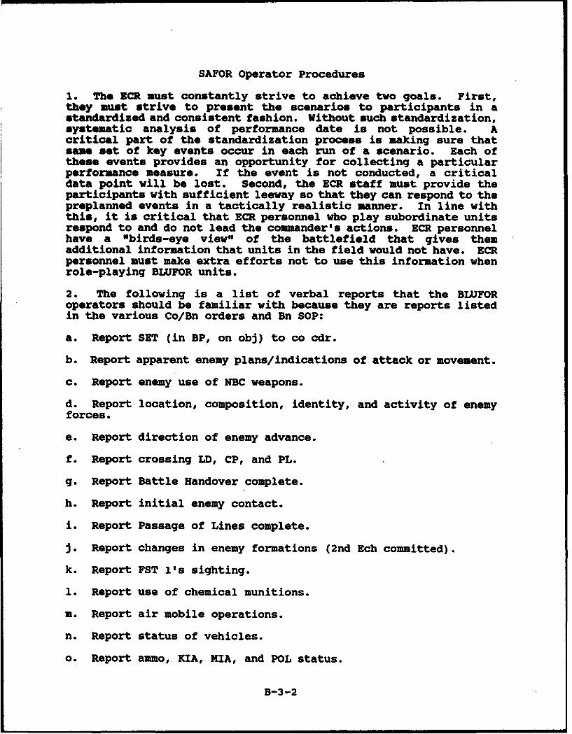
SAFOR Operator Procedures
1. The NCR must constantly strive to achieve two goals. First,they must strive to present the scenarios to participants in astandardized and consistent fashion. Without such standardization,systematic analysis of performance date is not possible. Acritical part of the standardization process is making sure thatsame set of key events occur in each run of a scenario. Each ofthese events provides an opportunity for collecting a particularperformance measure. If the event is not conducted, a criticaldata point will be lost. Second, the ECR staff must provide theparticipants with sufficient leeway so that they can respond to thepreplanned events in a tactically realistic manner. In line withthis, it is critical that ECR personnel who play subordinate unitsrespond to and do not lead the commander's actions. ECR personnelhave a "birds-eye view" of the battlefield that gives themadditional information that units in the field would not have. ECRpersonnel must make extra efforts not to use this information whenrole-playing BLUFOR units.
2. The following is a list of verbal reports that the BLUFORoperators should be familiar with because they are reports listedin the various Co/Bn orders and Bn SOP:
a. Report SET (in BP, on obj) to co cdr.
b. Report apparent enemy plans/indications of attack or movement.
c. Report enemy use of NBC weapons.
d. Report location, composition, identity, and activity of enemyforces.
e. Report direction of enemy advance.
f. Report crossing LD, CP, and PL.
g. Report Battle Handover complete.
h. Report initial enemy contact.
i. Report Passage of Lines complete.
J. Report changes in enemy formations (2nd Ech committed).
k. Report FST l's sighting.
1. Report use of chemical munitions.
m. Report air mobile operations.
n. Report status of vehicles.
o. Report ammo, KIA, MIA, and POL status.
B-3-2
3. BLUFOR operators will not discuss with participants what or howindividuals performed in other tests. This is confidentialinformation and may compromise test results if discussed withparticipants.
4. BLUFOR operators will discuss any mission planning issues withparticipants outside the ECR. Participants are not allowed in theECi.5. BLUFOR operators will provide input to the Battlemaster ontheir observations of the units' performance during execution ofall scenarios. This information will become feedback to the unitsduring the Debriefs.
6. OPFOR operator will provide input to the Battlemaster fromobservation of the units' performance.
7. CCD Stand-alone operator must be familiar with the OPORD forscenario to be executed. This includes specifically the priorityof fires in the OPORD and the preplanned fires the unit hasdeveloped. The operator must inform the Battlemaster if the firesrequested are landing on friendly units and provide thisinformation as input for the Battlemaster's feedback during theDebrief. As part of this feedback, the operator will note whetherthe unit adhered to its priority of fires and preplanned fires.Additionally, the operator will provide an estimate (by sender) oftype and number of reports sent, which will help identify thoseparticipants who were deficient in sending reports. Finally, it iscritical that the operator inform the Battlemaster when the finalSITREP at the end of each stage is completed.
8. All SAFOR operators must check their individual stations forproper functioning and have the stations prepared for the scenarioto be executed. Any malfunctions must be reported immediately tothe Battlemaster and then to support personnel.
B-3-3
B-4
SAFOR OPERATOR RADIO PROTOCOLS
B-4-1
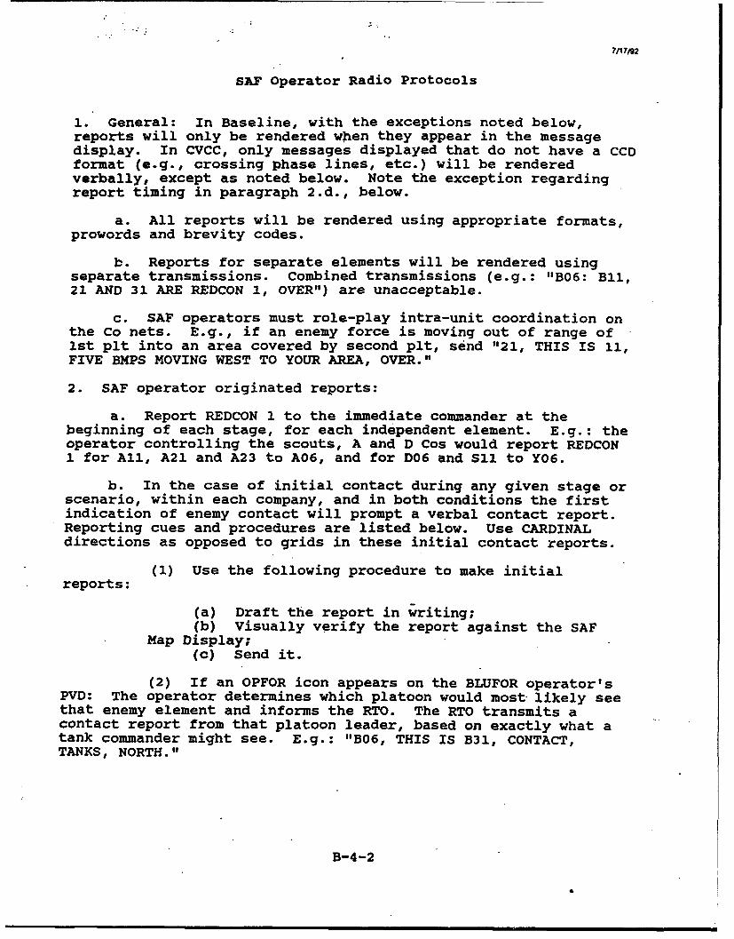
7/17/92
SAP Operator Radio Protocols
1. General: In Baseline, with the exceptions noted below,reports will only be rendered when they appear in the messagedisplay. In CVCC, only messages displayed that do not have a CCDformat (e.g., crossing phase lines, etc.) will be renderedverbally, except as noted below. Note the exception regardingreport timing in paragraph 2.d., below.
a. All reports will be rendered using appropriate formats,prowords and brevity codes.
b. Reports for separate elements will be rendered usingseparate transmissions. Combined transmissions (e.g.: "B06: BIl,21 AND 31 ARE REDCON 1, OVER") are unacceptable.
c. SAP operators must role-play intra-unit coordination onthe Co nets. E.g., if an enemy force is moving out of range of1st plt into an area covered by second plt, send "21, THIS IS 11,FIVE BMPS MOVING WEST TO YOUR AREA, OVER."
2. SAF operator originated reports:
a. Report REDCON 1 to the immediate commander at thebeginning of each stage, for each independent element. E.g.: theoperator controlling the scouts, A and D Cos would report REDCON1 for All, A21 and A23 to A06, and for D06 and S11 to Y06.
b. In the case of initial contact during any given stage orscenario, within each company, and in both conditions the firstindication of enemy contact will prompt a verbal contact report.Reporting cues and procedures are listed below. Use CARDINALdirections as opposed to grids in these initial contact reports.
(1) Use the following procedure to make initialreports:
(a) Draft the report in writing;(b) Visually verify the report against the SAP
Map Display;(c) Send it.
(2) If an OPFOR icon appears on the BLUFOR operator'sPVD: The operator determines which platoon would most likely seethat enemy element and informs the RTO. The RTO transmits acontact report from that platoon leader, based on exactly what atank commander might see. E.g.: "B06, THIS IS B31, CONTACT,TANKS, NORTH."
B-4-2
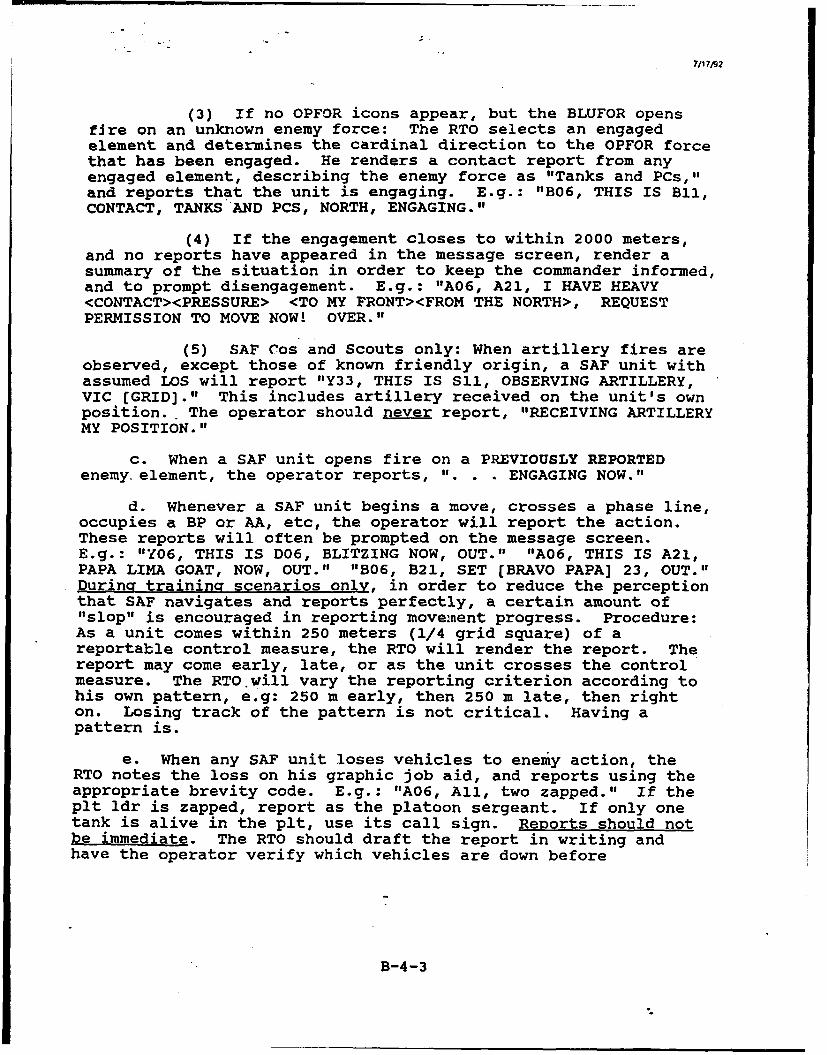
(3) If no OPFOR icons appear, but the BLUFOR opensfire on an unknown enemy force: The RTO selects an engagedelement and determines the cardinal direction to the OPFOR forcethat has been engaged. He renders a contact report from anyengaged element, describing the enemy force as "Tanks and PCs,,,and reports that the unit is engaging. E.g.: "B06, THIS IS BIlI,CONTACT, TANKSAND PCS, NORTH, ENGAGING."
(4) If the engagement closes to within 2000 meters,and no reports have appeared in the message screen, render asummary of the situation in order to keep the commander informed,and to prompt disengagement. E.g.: "A06, A21, I HAVE HEAVY<CONTACT><PRESSURE> <TO MY FRONT><FROM THE NORTH>, REQUESTPERMISSION TO MOVE NOW! OVER."
(5) SAF Cos and Scouts only: When artillery fires areobserved, except those of known friendly origin, a SAF unit withassumed LOS will report "Y33, THIS IS Sll, OBSERVING ARTILLERY,VIC (GRID]." This includes artillery received on the unit's ownposition.- The operator should never report, "RECEIVING ARTILLERYMY POSITION."
c. When a SAF unit opens fire on a PREVIOUSLY REPORTEDenemy. element, the operator reports, ". . . ENGAGING NOW."
d. Whenever a SAF unit begins a move, crosses a phase line,occupies a BP or AA, etc, the operator will report the action.These reports will often be prompted on the message screen.E.g.: "Y06, THIS IS D06, BLITZING NOW, OUT." "A06, THIS IS A21,PAPA LIMA GOAT, NOW, OUT." "B06, B21, SET (BRAVO PAPA] 23, OUT."During training scenarios only, in order to reduce the perceptionthat SAF navigates and reports perfectly, a certain amount of"slop" is encouraged in reporting movement progress. Procedure:As a unit comes within 250 meters (1/4 grid square) of areportable control measure, the RTO will render the report. Thereport may come early, late, or as the unit crosses the controlmeasure. The RTO.will vary the reporting criterion according tohis own pattern, e.g: 250 m early, then 250 m late, then righton. Losing track of the pattern is not critical. Having apattern is.
e. When any SAF unit loses vehicles to enemy action, theRTO notes the loss on his graphic job aid, and reports using theappropriate brevity code. E.g.: "A06, All, two zapped." If theplt ldr is zapped, report as the platoon sergeant. If only onetank is alive in the plt, use its call sign. Reports should notbe immediate. The RTO should draft the report in writing andhave the operator verify which vehicles are down before
B-4-3
reporting. This represents the time a plt ldr might spend tryingto confirm a combat loss.
f. Only SAF Cos or the Scout plt will initiate Calls forfire from the SAF workstation..
g. In Baseline, when a unit closes in a BP, OBJ, or AA, andis out of contact, check the unit's status and render a SITREP,FUEL and AMMO REPORT based on the displayed information. E.g.:
1. . . SITREP: FLOT [GRID] TO (GRID] NEGATIVE ENEMY CONTACT;EQUIPMENT AND PERSONNEL BLACK; DEFENDING." "AMMO: SABOT AMBER,HEAT BLACK." "FUEL: GREEN." In CVCC, routine SITREPs aegenerated by the SAFOR program. Furthermore, most of the datathat a Co XO or Cdr needs to generate a SITREP are available thru
automated data.
h. NBC reports are t ansmitted verbally when indicated on
the events list. e/'-t. - 5iiV o--/ 4
3. Responses to requests for information:
a. Once an initial contact report has been rendered, if thesuperior commander asks for additional information, respond"WAIT, OUT" until the report comes up in the message display.
b. Any time the commander asks for a SITREP other thanunder the criteria at 2.g., report current activity (e.g.: MOVINGTO BP32), number of operational vehicles, (e.g: 3 UP) and enemyaction & activity level.
c. Previously reported information may be retransmitted onrequest. New information will not be introduced unless theappropriate conditions in paragraph 3 are met.
B-4-4
APPENDIX C
SAMPLE DATA COLLECTION INSTRUMENTS
Appendix C contains the following sections:
C-i Rosters/Privacy Act StatementC-2 QuestionnairesC-3 Logs
C-1
c-
C-1
ROSTERS/PRIVACY ACT STATEMENT
Section C-1 contains the following:
Sign-Up RosterAssignment RosterPrivacy Act Statement
C-i-I
0
o LU
>w oZ WI-
0 2
J02
00u
>Z
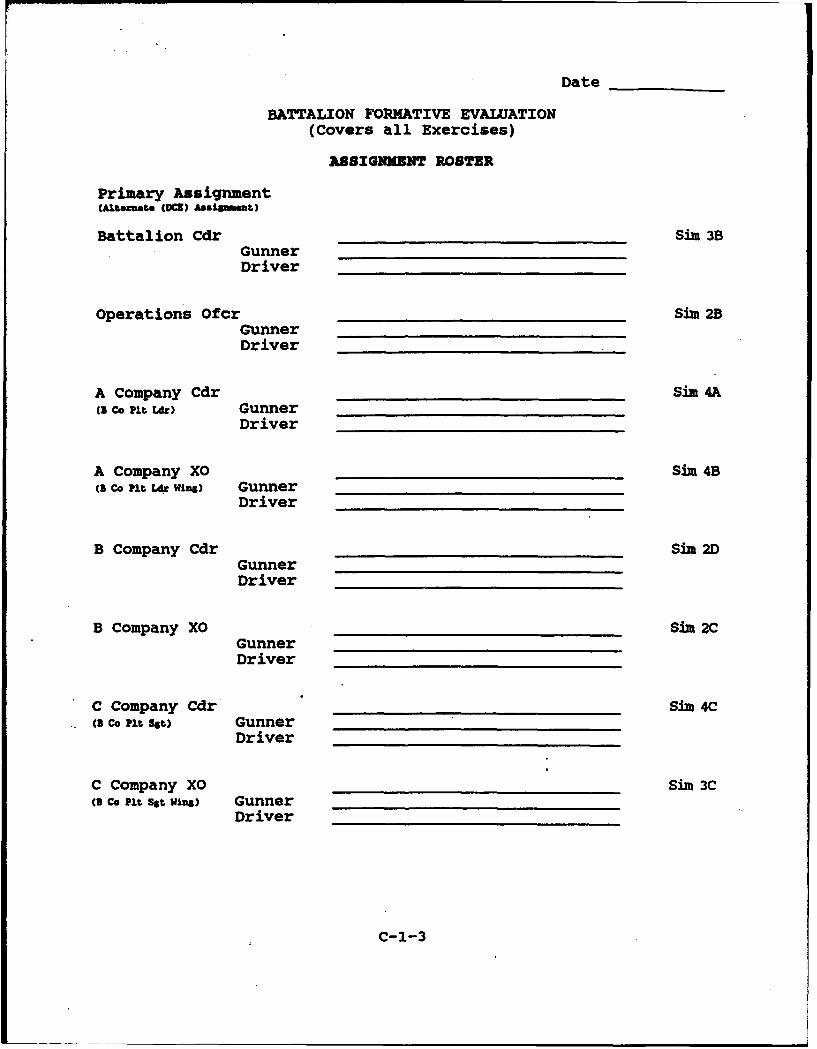
Date
BATTALION FORMATIVE EVALUATION(Covers all Exercises)
ASSIGNMENT ROSTER
Primary Assignment(A•tozmate (DC=) Assilmnt)
Battalion Cdr Sire 3BGunnerDriver
Operations Ofcr Sim 2BGunnerDriver
A Company Cdr Sim 4A(3 Co Pit Lft) Gunner
Driver
A Company XO Sire 4B(1 co Pit U, Wins) Gunner
Driver
B Company Cdr Sim 2DGunnerDriver
B Company XO Sim 2CGunnerDriver
C Company Cdr Sime 4C(. co Pit 36t) Gunner
Driver
C Company XO Sim 3Cci co it Sst Wins) Gunner
Driver
C-1-3
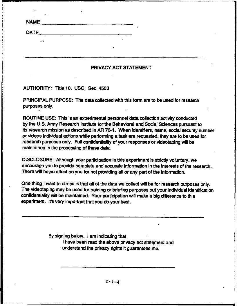
NAME
DATE
PRIVACY ACT STATEMENT
AUTHORITY: Title 10, USC, Sec 4503
PRINCIPAL PURPOSE: The data collected with this form are to be used for researchpurposes only.
ROUTINE USE: This is an experimental personnel data collection activity conductedby the U.S. Army Research Institute for the Behavioral and Social Sciences pursuant toits research mission as described in AR 70-1. When identifiers, name, social security numberor videos individual actions while performing a task are requested, they are to be used forresearch purposes only. Full confidentiality of your responses or videotaping will bemaintained in the processing of these data.
DISCLOSURE: Although your participation in this experiment is strictly voluntary, weencourage you to provide complete and accurate information in the interests of the research.There will be nio effect on you for not providing all or any part of the information.
One thing I want to stress is that all of the data we collect will be for research purposes only.The videotaping may be used for training or briefing purposes but your individual identificationconfidentiality will be maintained. i'our participation will make a big difference to thisexperiment. It's very important that you do your best.
By signing below, I am indicating thatI have been read the above privacy act statement andunderstand the privacy rights it guarantees me.
C-1-4
C-2
Questionnaires
Section C-2 contains the following questionnaires:
Biographical QuestionnairesSituational Assessment Questionnaire - Battalion Commander/S3Situational Assessment Questionnaire - Company Commander/XO
C-2-1

NOWN Date- Psertc U - Dty Pas PAN_ R PT 5832 (R)
0 0 0 0 0 0 0 0 0 0 0 * 0 * * * * * * •**
BIOGR•A•ICAL QURSTIONWMIRE
Name SSN - -
1. Age years 2. Current Army Rank
3. Current unit of assignment
4. Military Specialty: 12A 12B 12C 193 19K Other
5. Total time on active duty: _ years/ months
6. Total active duty time in Armor units (include Cavalry):yrs/ months
7. How much experience as a crewmember have you had with thefollowing families of vehicles?
a. M1 /__ c. X113 /,yrs m0 yrs 01M
b. M60 /__ d. M2/13 _ /yrs N06 yrs Min
8. Circle your present Duty Position in your current unit:
Plt Ldr Co Cdr Co XO Bn 52 Bn 83 Bn XO Student
Driver Loader Gunner Tank Cdr Plt Sgt Instructor
Other
9. How much experience do you have in each of the followingTO&E (combat maneuver unit) positions?
a. Driver / h. Co XO /yrs 0e yrs mos
b. Loader / . i. Co Cdr /WeW yrs moy s
c. Gunner / __ J. Bn 82 /Is W" yrs Ws
d. Tnk Cdr/ k.BnS3 /8yrs Mss yrs 10s
e. Pit Sgt__ / 1. Bn Staff_ /yES N" (Si 1, S4, B ) yrs mAs
f. Plt Ldr_ / m. Bn XO /30 on yrs mAs
g. Spec _ / n. Bn Cdr /Plt Ldr yrs mu yrs ms
C-2-2
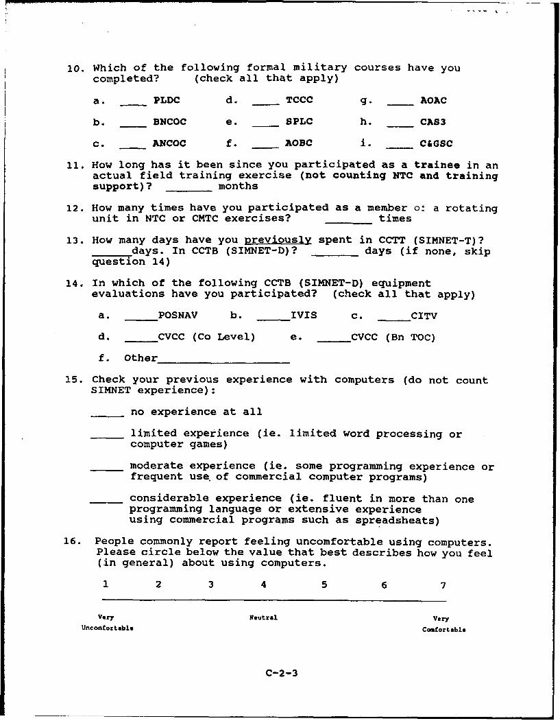
lo. Which of the following formal military courses have youcompleted? (check all that apply)
a. PLDC d. TCCC g. AOAC
b. BNCOC e. SPLC h. CAS3
c. ANCOC f. AOBC i. C&GSC
11. How long has it been since you participated as a trainee in anactual field training exercise (not counting NTC and trainingsupport)? months
12. How many times have you participated as a member or a rotatingunit in NTC or CMTC exercises? times
13. How many days have you previously spent in CCTT (SIMNET-T)?days. In CCTB (SIMNET-D)? days (if none, skip
question 14)
14. In which of the following CCTB (SIMNET-D) equipment
evaluations have you participated? (check all that apply)
a. POSNAV b. IVIS c. CITV
d. CVCC (Co Level) e. CVCC (Bn TOC)
f. Other
15. Check your previous experience with computers (do not countSIMNET experience):
no experience at all
_ limited experience (ie. limited word processing orcomputer games)
_ moderate experience (ie. some programming experience orfrequent use of commercial computer programs)
considerable experience (ie. fluent in more than oneprogramming language or extensive experienceusing commercial programs such as spreadsheats)
16. People commonly report feeling uncomfortable using computers.Please circle below the value that best describes how you feel(in general) about using computers.
1 2 3 4 5 6 7
Very Neutral VeryUncomfortable Comfortable
C-2-3
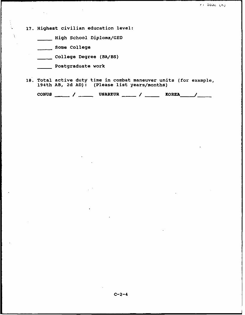
ri DO,)4 r
17. Highest civilian education level:
High School Diploma/GED
Some College
College Degree (BA/BS)
Postgraduate work
18. Total active duty time in combat maneuver units (for example,194th AB, 2d AD): (Please list years/months)
CONUS / USAREUR /___/KOREA- /__-
C-2-4
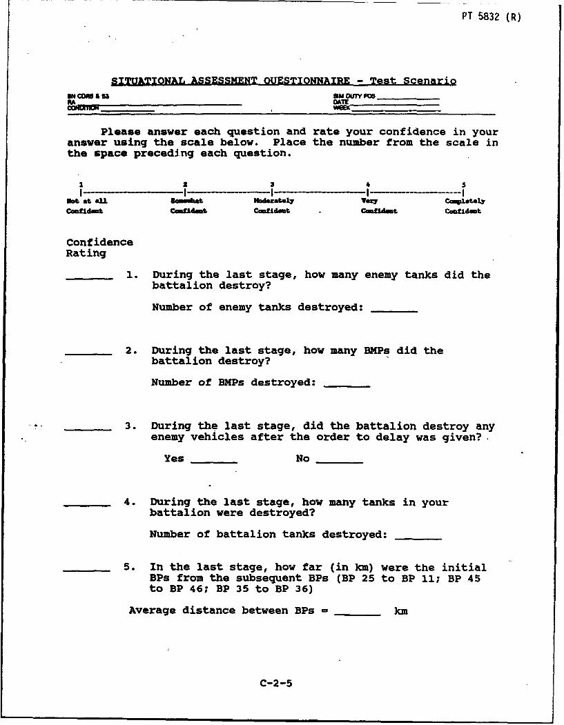
PT 5832 (R)
SITUATIONAL ASSESSMENT OUESTIONNAIRE - Test ScenarioUN CO £3 SM OUTM 6________
Please answer each question and rate your confidence in youranswer using the scale below. Place the number from the scale inthe space preceding each question.
1 2 3 4I I -**- -I I-..--.-----Inot at AU 8mmet hdezate4 VOW Cm3 tely
inudfdt CaOMlWm& Coamldkat Cinml"t Camtidmt
ConfidenceRating
1. During the last stage, how many enemy tanks did thebattalion destroy?
Number of enemy tanks destroyed:
2. During the last stage, how many BMPs did thebattalion destroy?
Number of BMPs destroyed:
__ 3. During the last stage, did the battalion destroy anyenemy vehicles after the order to delay was given?-
Yes No
4. During the last stage, how many tanks in yourbattalion were destroyed?
Number of battalion tanks destroyed:
5. In the last stage, how far (in km) were the initialBPs from the subsequent BPs (BP 25 to BP 11; BP 45to BP 46; BP 35 to BP 36)
Average distance between BPs = km
C-2-5
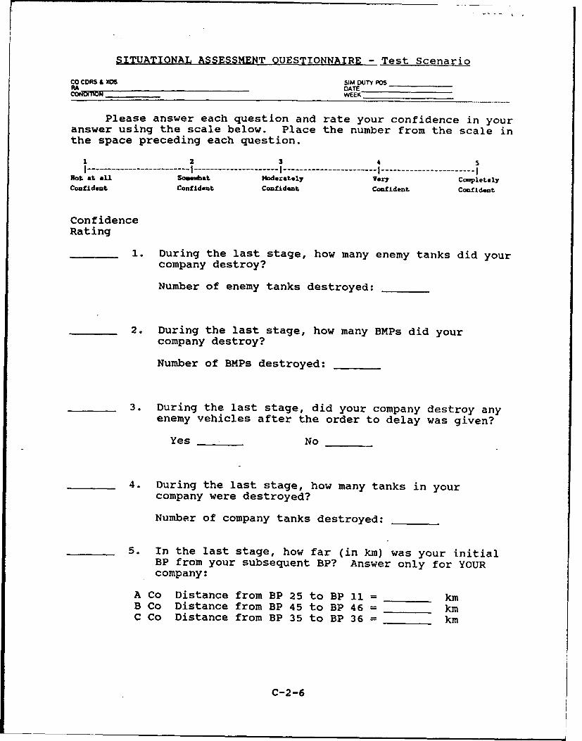
SITUATIONAL ASSESSMENT QUESTIONNAIRE - Test Scenario
Co CORS & X06 SIM DUTY POSADATECON JON __WEEK
Please answer each question and rate your confidence in youranswer using the scale below. Place the number from the scale inthe space preceding each question.
1 2 3 5I---------------- I ------------- I --------------- I --------------- I
Not at aLl Somewbatt Moderately Very CompletelyConfident Confident Confident Confident Confident
ConfidenceRating
1. During the last stage, how many enemy tanks did yourcompany destroy?
Number of enemy tanks destroyed:
2. During the last stage, how many BMPs did yourcompany destroy?
Number of BMPs destroyed:
3. During the last stage, did your company destroy anyenemy vehicles after the order to delay was given?
Yes No
4. During the last stage, how many tanks in yourcompany were destroyed?
Number of company tanks destroyed:
5. In the last stage, how far (in km) was your initialBP from your subsequent BP? Answer only for YOURcompany:
A Co Distance from BP 25 to BP 11 = kmB Co Distance from BP 45 to BP 46 = kmC Co Distance from BP 35 to BP 36 = km
C-2-6

Logs
Section C-3 contains the following logs:
Battlemaster LogTOC LogRA Defensive Log - CVCC
C-3-1
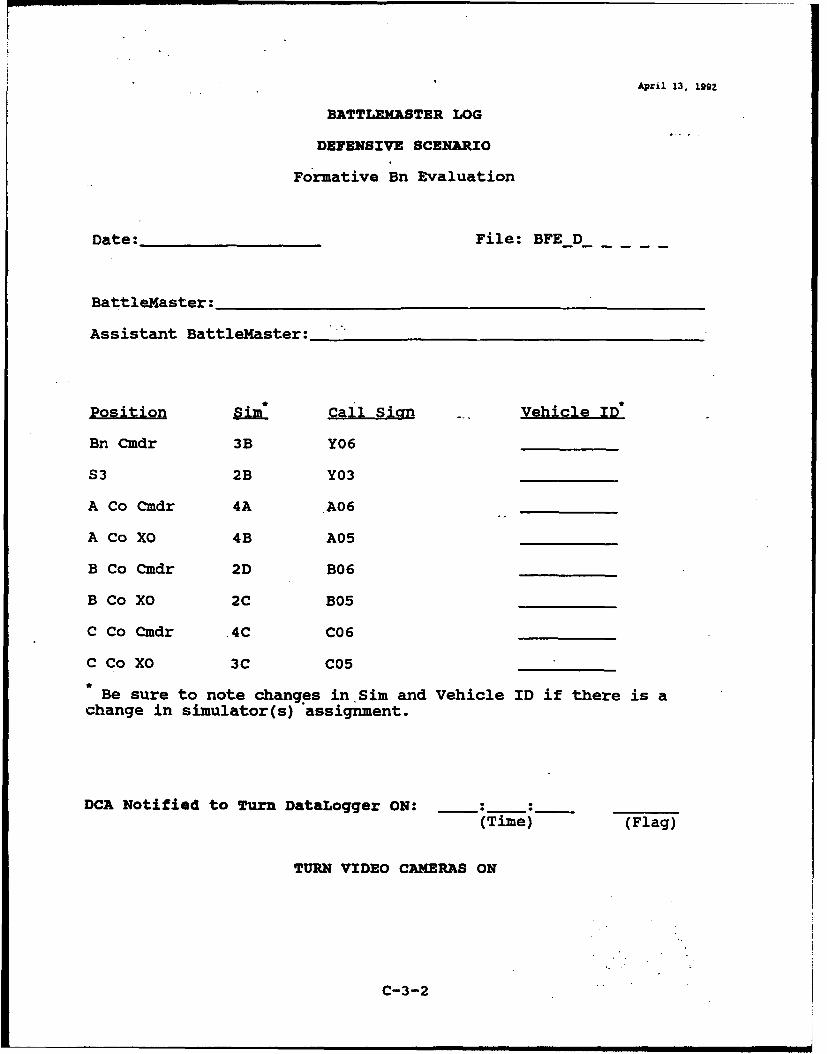
April 13. 1992
BATTLEXASTER LOG
DEFENSIVE SCENARIO
Formative Bn Evaluation
Date: File: BFED_
BattleMaster:
Assistant BattleMaster:__
SSim" Call Sian Vehicle ID
Bn Cmdr 3B Y06
S3 2B Y03
A Co Cmdr 4A A06
A Co XO 4B A05
B Co Cmdr 2D B06
B Co XO 2C B05
C Co Cmdr .4C C06
C Co XO 3C C05
Be sure to note changes in Sim and Vehicle ID if there is achange in simulator(s) assignment.
DCA Notified to Turn DataLogger ON:(Time) (Flag)
TURN VIDEO CAMERAS ON
C-3-2
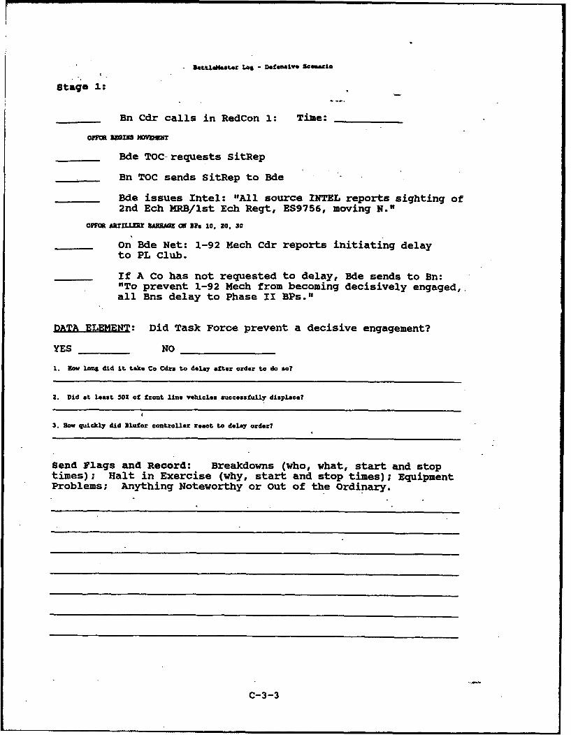
BettLellaster Los - Defensive SGGmuAlo
Stage 1:
Bn Cdr calls in RedCon 1: Time:
On=E SWTS "MOMEWT
Bade TOC requests SitRep
Bn TOC sends SitRep to Bde
Bde issues Intel: "All source INTEL reports sighting of2nd Ech MRB/lst Ech Regt, ES9756, moving N."
OFa £RULL A I, RR U I ON BPs 10, 20, 30
On Bde Net: 1-92 Mech Cdr reports initiating delayto PL Club.
If A Co has not requested to delay, Bde sends to Bn:"To prevent 1-92 Mech from becoming decisively engaged,.all Bns delay to Phase II BPs."
DATA ELEMENT: Did Task Force prevent a decisive engagement?
YES NO
1. Mow long did It take Co Cdza to delay after order to do so?
2. Did at least 502 of front line vehicles successfully displace?
3. How quickly did Blufor controller zeact to delay order?
Send Flags and Record: Breakdowns (who, what, start and stoptimes); Halt in Exercise (why, start and stop times); EquipmentProblems; Anything Noteworthy or Out of the Ordinary.
C-3-3
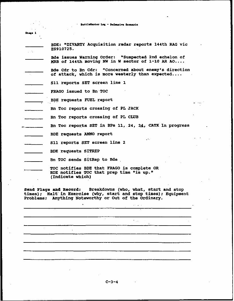
baL,.o.N•,Maz Log - DefusLyvo uc5zLe
S$a.• I
BDE: "DIVARTY Acquisition radar reports 144th RAG vicES910725.
Bde issues Warning Order: "Suspected 2nd echelon ofMRS of 144th moving NW in W sector of 1-10 AR AO....
Bde Cdr to Bn Cdr: "Concerned about enemy's directionof attack, which is more westerly than expected....
S11 reports SET screen line 1
FRAGO issued to Bn TOC
BDE requests FUEL report
Bn Toc reports crossing of PL JACK
Bn Toc reports crossing of PL CLUB
Bn Toc reports SET in BPs 11, 24, 34., CATK In progress
BDE requests AMMO report
S11 reports SET screen line 2
BDE requests SITREP
Bn TOC sends SitRep to Bde
TOC notifies BDE that FRAGO is complete ORBDE notifies TOC that prep time "is up."(Indicate which)
Send Flags and Record: Breakdowns (who, what, start and stoptimes) ; Halt in Exercise (why, start and stop times); EquipmentProblems; Anything Noteworthy or Out of the ordinary.
C-3-4
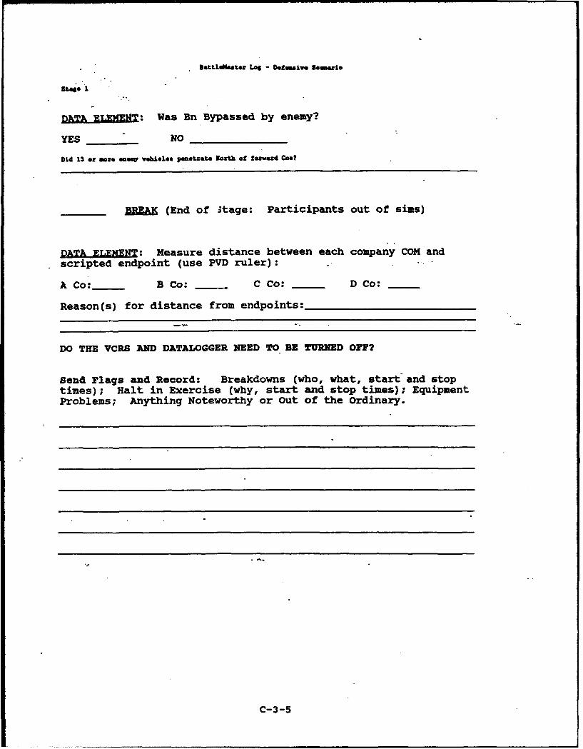
ttleflatexr Log - Dotgsve Saemmieo
stage 1
DA UT.fN: Was Bn Bypassed by enemy?
YES NO
Did 13 or moze aew vehicl.e penet.ate Worth of fozward Cos?
BREAK (End of itage: Participants out of sims)
DATA ELEMENT: Measure distance between each company COM and
scripted endpoint (use PVD ruler):
A Co:__ B Co: C Co: D Co:
Reason(s) for distance from endpoints:
DO THE VCRS AND DATALOGGER NEED TO BE TURNED OF?
Send Flags and Record: Breakdowns (who, what, start and stoptimes); Halt in Exercise (why, start and stop times); EquipmentProblems; Anything Noteworthy or Out of the Ordinary.
C-3-5
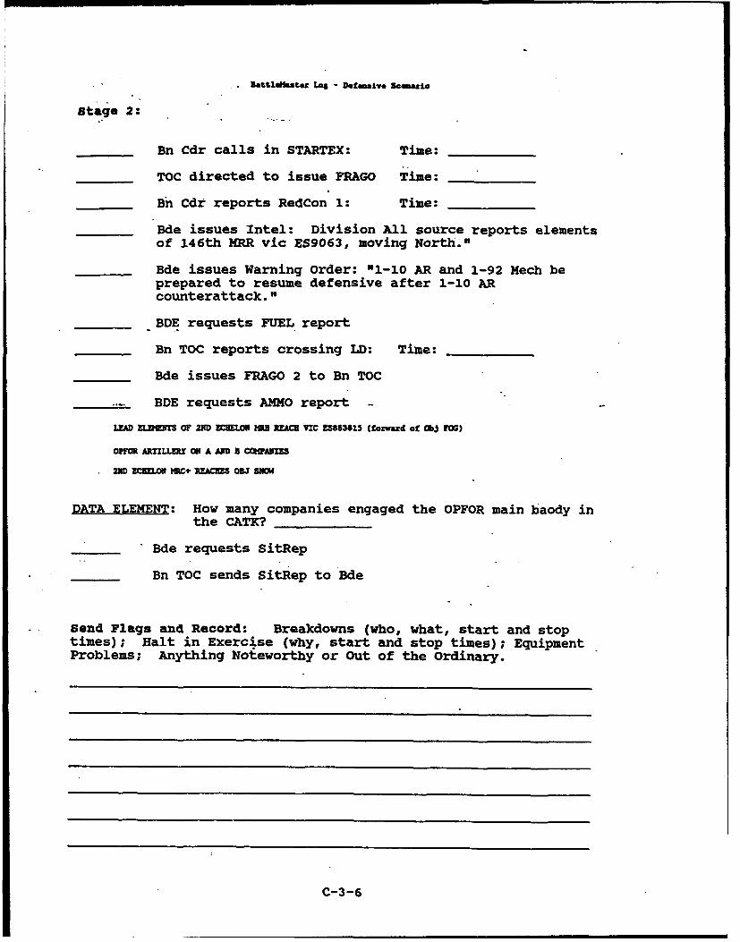
Battldlastee Loa - Detmaive semenrio
stage 2:
Bn Cdr calls in STARTEX: Time:
TOC directed to issue FRAGO Time:
B n Cdr reports RedCon 1: Time:
Bde issues Intel: Division All source reports elementsof 146th MRR vic ES9063, moving North."
Bde issues Warning Order: "1-10 AR and 1-92 Mech beprepared to resume defensive after 1-10 ARcounterattack."
BDE requests FUEL report
Bn TOC reports crossing LD: Time:
Bde issues FRAGO 2 to Bn TOC
BDE requests AMMO report -
LEAD MC 0F 2ND ECKUOK ME MM VIC ZS86382.5 (fozward of Cbj FOG)
OP1F ARTILLUY ON A AND B CCMAUMUS
2MD ECHELON MC+ RPACES OwJ Sam
DATA ELEMENT: How many companies engaged the OPFOR main baody inthe CATK?
Bde requests SitRep
Bn TOC sends SitRep to Bde
Send Flags and Record: Breakdowns (who, what, start and stoptimes); Halt in Exercise (why, start and stop times); EquipmentProblems; Anything Noteworthy or Out of the Ordinary.
C-3-6
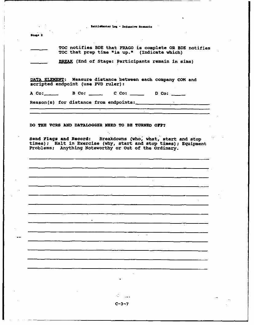
battldw-atex Los - Detmlve s•m•,io
TOC notifies BDE that FRAGO is complete OR BDE notifiesTOC that prep time "is up." (Indicate which)
REAK (End of Stage: Participants remain in sims)
DATA ELEMENT: Measure distance between each company COM and
scripted endpoint (use PVD ruler):
A Co:__ B Co: -_ C Co: D Co:
Reason(s) for distance from endpoints:
DO THE VCRS AND DATALOGGER NEED TO BE TURNED OFP?
Send Flags and Record: Breakdowns (who; what, start and stoptimes); Halt in Exercise (why, start and stop times); EquipmentProblems; Anything Noteworthy or Out of the Ordinary.
C-3-7

BotL•Jm4aSL Lo6 - DOINaalv* Smar.to
Stage 3:
Bn Cdr calls in STARTEX: Time:
TOC directed to issue FRAGO Time: ..
Bn Cdr reports RedCon 1: Time:
DATA ELEMENT: Time unit was told to be in BPs Time:
Send flag at time units SHOULD be in BPs (from above)
Time Bn reports SET in BPs
OPTM NEGINS HVDMIT
Bn TOC sends SitRep to Bde
OPFFOR .tillegy barrase along PL ACM (on Ps 25. 45. &35)
On Bde Net: 1-92 Cdr reports facing elements of
79th GTR.
LATOOIW COWLLUM FOR A CO R1PMTS GAS TO A CO COR
PLACON CNITROLLE FM C CO RZ1GM GS TO C CO CM
Bn TOC sends NBC warning (GAS) to Bde
Bn TOC sends NBC report to Bde
Bde issues Intel: "2nd echelon MRB+ sightedvicinity ES8673, moving North."
Bde orders 1-10 AR to delay to PL Queen (ifrequest has not yet been made)
Send Flags and Record: Breakdowns (who, what, start and stoptimes) ; Halt in Exercise (why, start and stop times); EquipmentProblems; Anything Noteworthy or Out of the Ordinary.
C-3-8
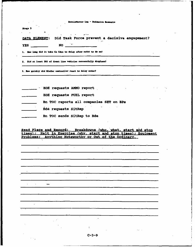
IRatLLst.. Las - Defensive Scamaro
stage
DATA ELEMENT: Did Task Force prevent a decisive engagement?
YES NO
1. Sow Long did L tLake C. Cdsa to delay aft.er ordek to do as?
2. Did at least 502 of front lino vekioLes successfuLLy d&eplacel
3. Bow qudcklry did Blular omntsolU react to deLay oe'•z?
"BDE requests AMMO report
BDE requests FUEL report
Bn TOC reports all companies SET on BPs
Bde requests SitRep
Bn TOC sends SitRep to Bde
Send Flags and Record: Breakdowns (who. what. start and stontimes) " Halt in Exercise (why. start and stOD times): EguiDmentProblems; Anvthing Noteworthy or Out of the Ordinary.
C-3-9
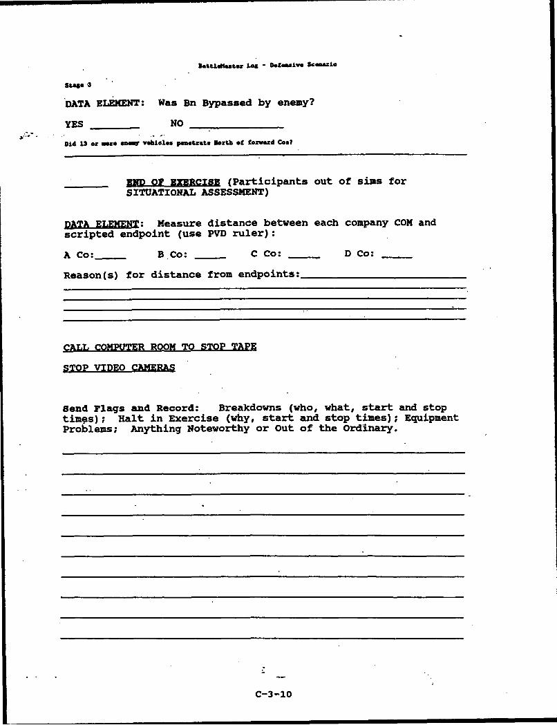
stae -3
DATA ELEMENT: Was Bn Bypassed by enemy?
YES NO
Did 13 or mowe ene4 vehicles penetrate Saoth of fozva' d Coal
END OF EXERCISE (Participants out of sims forSITUATIONAL ASSESSMENT)
DATA ELEMENT: Measure distance between each company COX and
scripted endpoint (use PVD ruler):
A Co: BBCo: C Co: _--- D Co:
Reason(s) for distance from endpoints:
CALL COMPUTER ROOM TO STOP TAPE
STOP VIDEO CAMERAS
Send Flags and Record: Breakdowns (who, what, start and stoptim4es) ; Halt in Exercise (why, start and stop times); EquipmentProblems; Anything Noteworthy or Out of the Ordinary.
C-3-10
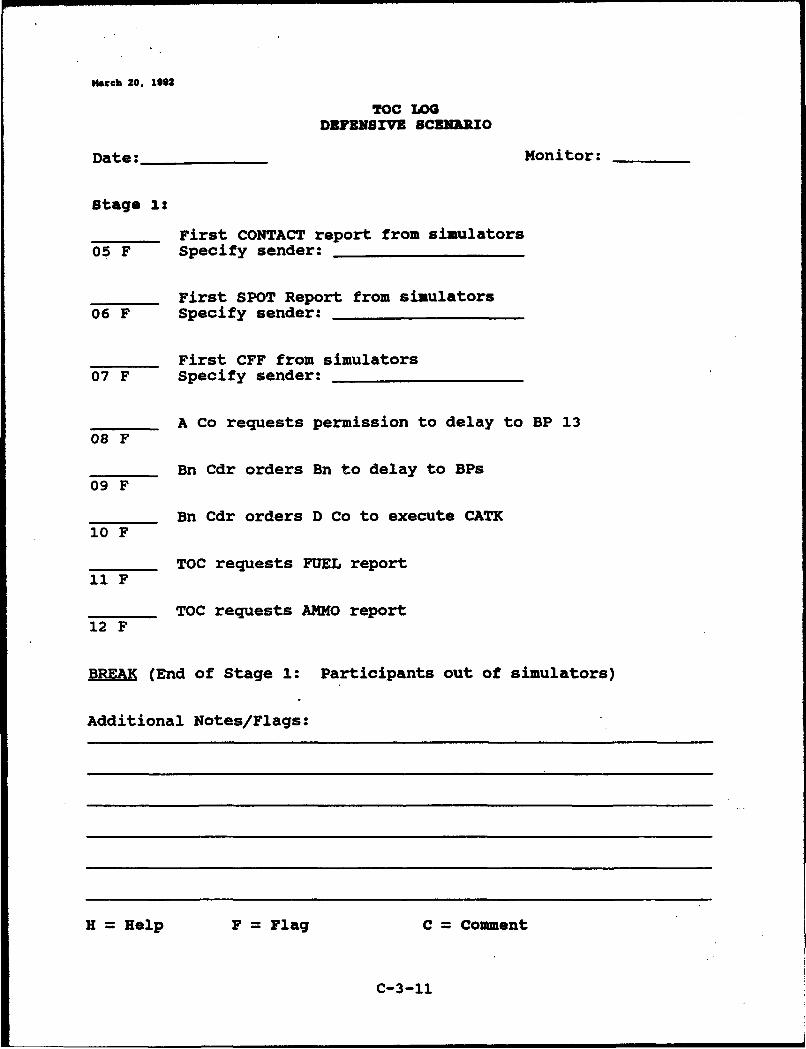
Nach 20, 1992
TOC LOG
DEFENSIVE SCZNIRIO
Date: Monitor:
Stage 1:
First CONTACT report from simulators05 F Specify sender:
First SPOT Report from simulators06 F Specify sender:
First CFF from simulators07 F Specify sender:
A Co requests permission to delay to BP 1308 F
Bn Cdr orders Bn to delay to BPs09 F
Bn Cdr orders D Co to execute CATK10 F
TOC requests FUEL report11 F
TOC requests AMMO report12 F
B (End of Stage 1: Participants out of simulators)
Additional Notes/Flags:
H Help F Flag C Comment
C-3-11
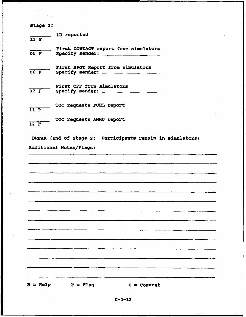
Stage 2:
LD reported13 F
First CONTACT report from simulators05 F Specify sender:
First SPOT Report from simulators06 F Specify sender:
First CFF from simulators07 F Specify sender:
TOC requests FUEL report11 F
TOC requests AMMO report12 F
BREA (End of Stage 2: Participants remain in simulators)
Additional Notes/Flags:
H Help F Flag C Comment
C-3-12
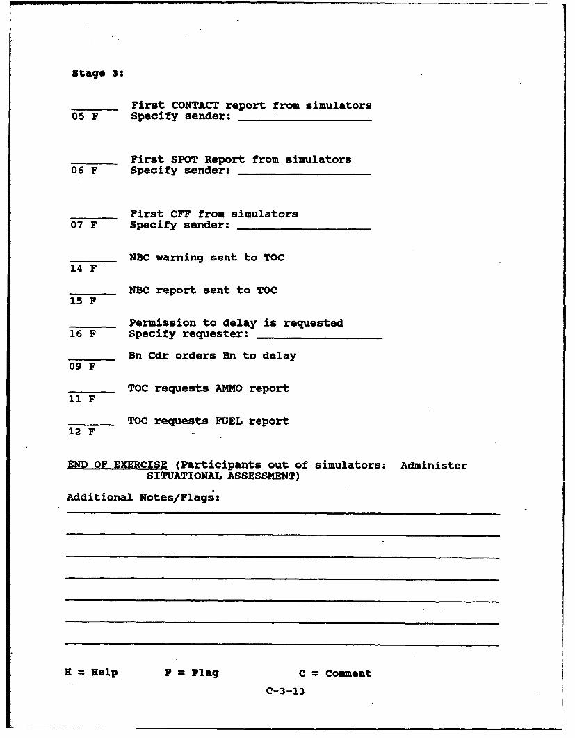
Stage 3:
First CONTACT report from simulators05 F Specify sender:
First SPOT Report from simulators06 F Specify sender:
First CFF from simulators07 F Specify sender:
NBC warning sent to TOC14 F
NBC report sent to TOC15 F
Permission to delay is requested16 F Specify requester:
Bn Cdr orders Bn to delay09 F
TOC requests AMMO report11 F
TOC requests FUEL report12 F
END OF EXERCISE (Participants out of simulators: AdministerSITUATIONAL ASSESSMENT)
Additional Notes/Flags:
H =Help F= Flag C= Comment
C-3-13
-- - -- - -- -
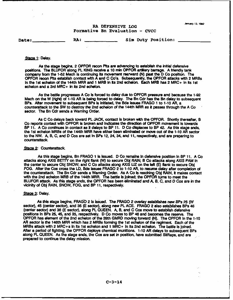
.uWWY 13). I9W2
RA DEFENSIVE 4GFormative Bn Evaluation - CVCC
Date: RA: Sim Duty Position:
%IMe1: Delay.
As the stage begins, 2 OPFOR recon Pits are advancing to establish the Initial defensivepositions. The BLUFOR along PL K]NG receive a 10 min OPFOR artillery barrage. A friendly tankcompany from the 1-52 Mech is continuing Its movement reewward (N) past the D Co position. TheOPFOR recon Pits establish contact with A and C Co's. Subsequently, the OPFOR attacks with 2 MRBsIn the Ist echelon of the 144th MRR and I MRB In Its 2nd echelon. Each MRB has 2 MRC + In its Istechelon and a 3rd MRC+ In its 2nd echelon.
As the battle progresses A Co is forced to delay due to OPFOR pressure and because the 1-92Mech on the W (right) of 1-10 AR is being forced to delay. The Bn Cdr has the Bn delay to subsequentBPs. After movement to subsequent BPs Is Initiated. the Bde Issues FRAGO 1 to 1-10 AR. acounterattack to the SW to destroy the 2nd echelon of the 144th MRR as it passes through the A Cosector. The Bn Cdr sends a Warning Order.
As C Co delays back toward PL JACK, contact is broken with the OPFOR. Shortly thereafter. BCo reports contact with OPFOR Is broken and Indicates the direction of OPFOR movement is towardsBP 11. A Co continues In contact as It delays to BP 11. D Co displaces to BP 42. As this stage ends,the Ist echelon MRBs of the 144th MRR have either been eliminated or move out of the 1-10 AR sectorto the NW. A, B, C, and D Cos are set in BPs 12, 24, 34, and 11. respectively. and are preparing tocounterattack.
Staoe 2: Counterattack.
As this stage begins, Bn FRAGO 1 Is Issued. D Co remains in defensive position in BP 11. A Coattacks along AXIS BETTY on the right flank (W) to secure Obj RAIN; B Co attacks along AXIS PAM inthe center to secure ObJ SNOW; and C Co attacks along AXIS UZ on the left (E) flank to secure ObJFOG. After the Cos cross the .D, Bde Issues FRAGO 2 to 1-10 AR, to resume delay after completion ofthe counterattack. The Bn Cdr sends a Warning Order. As A Co Is reaching Obj RAIN, it makes contactwith the 2nd echelon MRB of the 144th MRR. The battle Is Joined; the OPFOR turns to meet theBLUFOR attack. As this stage ends, the OPFOR has been eliminated and A, B. C, and D Cos are in thevicinity of Obj RAIN, SNOW, FOG, and BP 11, respectively.
%Maoe 3: Delay.
As this stage begins, FRAGO 2 is Issued. The FRAGO 2 overlay establishes new BPs P5 (Wsector), 45 (center sector), and 35 (E sector), along new PL ACE FRAGO 2 also establishes BPs 46(center sector) and 36 (E sector), along PL QUEEN. A, B, and C Cos move to establish defensivepositions In BPs 25, 45, and 35. respectively. D Co moves to BP 46 and becomes the reserve. TheOPFOR has element of the 2nd echelon of the 39th GMRD moving forward (N). The OPFOR In the 1-10AR sector is the 146th MRR which has 2 MRBs forming the 1st echelon of the regiment Each of theMRBs attack with 2 MRC+s In its 1st echelon and 1 MRC+ in its 2nd echelon. The battle Is Joined.After a period of fighting, the OPFOR deploys chemical munitions. 1-10 AR delays to subsequent BPsalong PL QUEEN. As the stage ends, the Cos are set In position, have submitted SitReps, and areprepared to continue the delay mission.
C-3-14

Stage 1 (Def):
STARTING SITUATIO: The Dn is set. In BPs along PL KING; A Co is in AP 10. B Co is in SP 20. C Co is inBP 30. 0 Co Is In reserve a&ong PL CLUB in BP 40. The simalatiom is Initiated by OPTFR movement.
Dde Not: "All Souco rIntel reports sighting of MRB, possibly 2nd echelon of MU. moving E5940650.-
CPFR artillery barrage on BPs 10. 20, 30
3de Net: 1-92 Hech Dn Cdr reports to Bde Cdr heavy contact aIong• L KING
511 reports consolidated at CP10, moving to screen Line 1.
Bde issues Intel: "210 ACR reports only light contact in their sector."
Dde issues Warning Order: "1-10 AR be prepared to counter attack to SW from vicinity PL Spade; 1-91Hech be prepared to establish ho.ty defense along P1. Club."
1-92 Hech Cd: requests permission to delay to FL Club.
ide sends to Bn, "To prevent 1-02 Hech from becoming decisively engaged, all ins delay to Phase IIBPs." (if request to delay has not been made)
DIVARTY reports l44tbhRAG vic ES 910725.
Dde issues Warning Order: "Suspected 2nd echelon of MRB of 144th moving VW in W sector of 1-10 ARAO. 1-10 AR be prepared to establish hasty defense laon& FL CLUB.
Bde Cdr to Bn Cdr: "Concerned about enemy's direction of attack. which is more westerly thanexpected. Ensure that your eastern flank comipanies do not get bypassed.
A Co report SET at BPl 11; ] Co reports SET at BP 24; C Co reports SET at BP 34;D Co reports SET at UP 42
Revort Tally
Adjust Fire
Ammo
Call for Fire
Contact
Shell
S itRep
Spot
Intel
FRAGO
NBC
OTHER
C-3-15
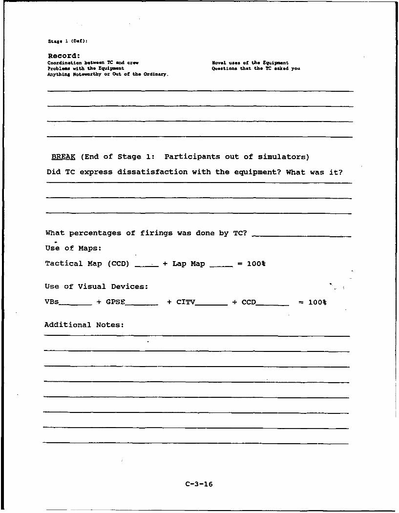
Stage 1 (Def):
Record:Coordination between TC and crew Novel uses of the EquipmentProblems with the Equipment Questions that the TC asked youAnything Notewortby or Out of the Ordinary.
BREA (End of Stage 1: Participants out of simulators)
Did TC express dissatisfaction with the equipment? What was it?
What percentages of firings was done by TC?
Use of Maps:
Tactical Map (CCD) + Lap Map = 100%
Use of Visual Devices:
VBs + GPSE + CITV_ + CCD_ _ 100%
Additional Notes:
C-3-16
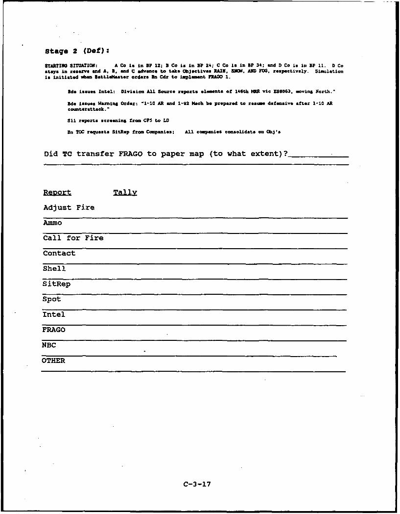
Stage 2 (Def):
STARTING SITUATION: A Co is in SP 12; 3 Co is in SP 24; C Co is in 3P 34; and D Co is in BP 11. D Costays In reserve and A, B, and C advance to take Objectives RAIN, SIME. AND FOG. respectively. Simulationis initiated wben SattleHaster orders ]n Cdr to implement FRAGO 1.
dae issues Intel: Division All Source reports elements of 146th IRR vic ES9063. moving North.-
Bde issues Warning Order: "1-10 AR and 1-92 1ech be prepared to resume defensive after 1-10 ARcoumterattack."
S11 reports screening from CPS to LD
Bn TOC requests SitRep from Companies; All companies consolidate on ObJ's
Did TC transfer FRAGO to paper map (to what extent)?
Report
Adjust Fire
Ammo
Call for Fire
Contact
Shell
SitRep
Spot
Intel
FRAGO
NBC
OTHER
C-3-17
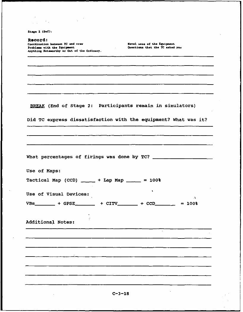
Stage 2 (Def):
Record:Coordination between TC and crew Novel uses of the EquipmentProblems with the Equipment Questions that the TC asked youAnything Noteworthy or Out of the Ordinary.
BREA (End of Stage 2: Participants remain in simulators)
Did TC express dissatisfaction with the equipment? What was it?
What percentages of firings was done by TC?
Use of Maps:
Tactical Map (CCD) + Lap Map = 100%
Use of Visual Devices:
VBs _ + GPSE _ + CITV _ + CCD_= 100%
Additional Notes:
C-3-18
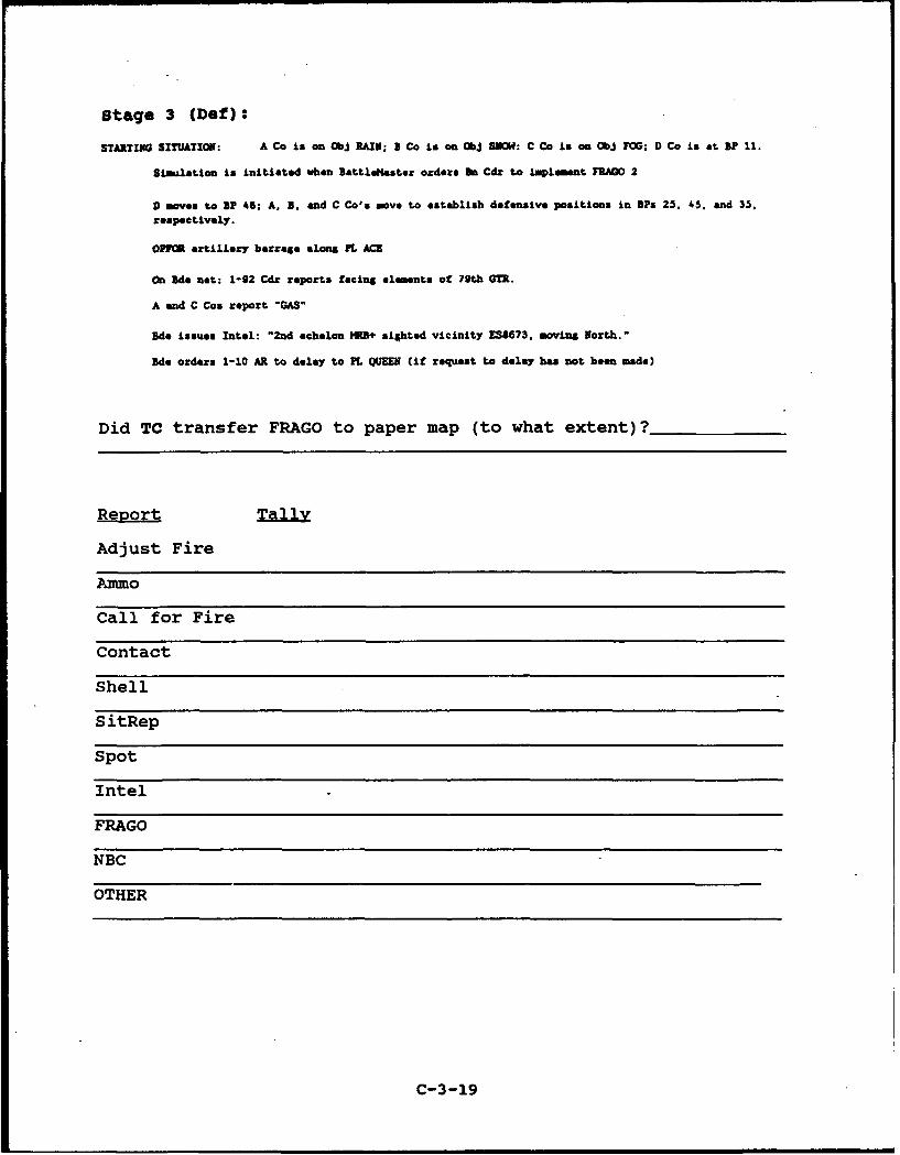
Stage 3 (Def):
STARTING SITUATION: A Co is on ObJ RAIN; a Co is on ObJ SNOW: C Co is on ObJ FOG; D Co is at BF 11.
Simulation is initiated when BIttlu@daster orders Di Cdc to implement FRAGO 2
D moves to uP 46; A. B. and C Co's move to esteblish defensive positions in BPs 25. 45. and 35.
respectively.
OP7M artillery barrage &Long PL ACE
On Sde net: 1-92 Cdr reports facing elements of 79th GTR.
A and C Cos report "GAS"
Sde issues Intel: "2nd echelon ME+ sighted vicinity ES8673. moving North."
Bde orders 1-10 AR to delay to PL QUEE (if request to delay has not been made)
Did TC transfer FRAGO to paper map (to what extent)?
Report Tally
Adjust Fire
Ammo
Call for Fire
Contact
Shell
SitRep
Spot
Intel
FRAGO
NBC
OTHER
C-3-19
St~e. 3 (DOef)
Record:Coordination between TC and crew Novel uses of the EquipmentProblm with the EquAipent Questions that the TC asked youAnything Noteworthy or Out of the Ordinary.
END OF EXERCISE (Participants out of simulators for SITUTIONALASSESSMENT)
Did TC express dissatisfaction with the equipment? What was it?
What percentages of firings was Qone by TC?
Use of Maps:
Tactical Map (CCD) + Lap Map = 100%
Use of Visual Devices:.
VBs _ + GPSE _ + CITV___ + CCD _= 100%
Additional Notes:
C-3-20
EXAMPLES OF COORDINATION BETWEEN TC AND OTHER CREW MEMBERS
Designate was NOT clearly signalled to gunner.
Gunner tells TC to let go of palm switch--after designating atarget.
TC asks gunner to input grids to reports.
TC forgets to switch to GPS mode so gunner can input grids toreports.
Driver requests next waypoint.
Driver requests clarification of waypoint(s).
C-3-21
"APPENDIX D:
8AMPXL NMEASURE DEIINITIONS AND DATA REDUCTION PROCEDURES
D-1
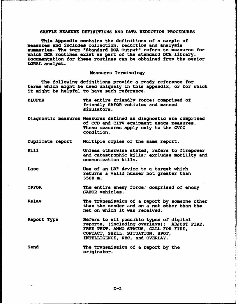
SAMPLE MEASURE DEFINITIONS AND DATA REDUCTION PROCEDURES
This Appendix contains the definitions of a sample ofmeasures and includes collection, reduction and analysissummaries. The term "Standard DCA Output" refers to measures forwhich DCA routines exist as part of the standard DCA library.Documentation for these routines can be obtained from the seniorLORAL analyst.
Measures Terminology
The following definitions provide a ready reference forterms which might be used uniquely in this appendix, or for whichit might be helpful to have such reference.
BLUFOR The entire friendly force; comprised offriendly SAFOR vehicles and mannedsimulators.
Diagnostic measures Measures defined as diagnostic are comprisedof CCD and CITV equipment usage measures.These measures apply only to the CVCCcondition.
Duplicate report Multiple copies of the same report.
Kill Unless otherwise stated, refers to firepowerand catastrophic kills; excludes mobility andcommunication kills.
Lase Use of an LRF device to a target whichreturns a valid number not greater than3500 m.
OPFOR The entire enemy force; comprised of enemySAFOR vehicles.
Relay The transmission of a report by someone otherthan the sender and on a net other than thenet on which it was received.
Report Type Refers to all possible types of digitalreports, (including overlays): ADJUST FIRE,FREE TEXT, AMMO STATUS, CALL FOR FIRE,CONTACT, SHELL, SITUATION, SPOT,INTELLIGENCE, NBC, and OVERLAY.
Send The transmission of a report by theoriginator.
D-2

Stage The defensive test scenario consists of threestages. Each stage is thus defined fromREDCONI to completion of the last scriptedevent, minus any periods of breakdown. Dataare analyzed for completed stages only.
Transmission The sending of a report. For verbal reportsrefers to "appearance" of the sender on theradio net. For digital reports refers topressing of the CCD SEND button.
Unique report The original report for which duplicatesexist or a report with no duplicates.
D-3
SAMPLE PERFORMMICE NMESURES
Maneuver BO8
1.1.1: Distance between BLUFOR and OPFOR center of mass (Com),average per Bn (Stages 1 and 3)
Operational Definition: Distance, in meters, between each non-reserve company's Coi and the nearest OPFOR company's Cox at endof delay stages; averaged across three companies in each stage.During stages 1 & 3, after the last OPFOR firing: Coi mayinclude dead vehicles (OPFOR or BLUFOR) but will not includevehicles greater than 500 m from computed CoM.
Colleotion & Reduction Summary: At last OPFOR firing: ComputeCoN for A, B, and C BLUFOR companies and OPFOR companies;determine linear distance between each BLUFOR company and itsnearest OPFOR company; compute average per stage across threecompanies.
3NOVA Summary: Condition
Ezpected N (per Cell): 1/stage/week
1.4.6: Percent OPFOR vehicles killed by all manned vehicles
Operational Definition: Of the total number of OPFOR vehicleskilled (catastrophic and firepower) by direct fire during thestage, the proportion killed by the manned vehicles combined.
Collection & Reduction Summary: Standard DCA routine
ANOV 8w uary: Condition
Expected N (per cell): 1/stage/week
Fire Support BOS
2.1.1 Mean accuracy of CFF locations
Operational Definition: Deviatieri, in meters, of nearest threeOPFOR vehicles to reported OPFC _ocation. For descriptivepurposes a tally of the number of CFFs which could not be scored(due to missing locations) will be kept. Only CFFs with gridlocations will be analyzed; objectives, pre-planned fires, andfinal protective fires will not be included.
Collection/Reduction Summary: Baseline: Record CFF sender, sendtime, and contents from playback tapes, enter into database forinput to RS/1 table. CVCC: Essential report elements are inputdirectly to RS/1 table via DCA.
D-4
For each report location, determine the OPFOR vehicles (ofany type) intervisible with the original vehicle for at least 6seconds. If this is not the first CFF for the originatingvehicle (do not score relays), the search backward extends to theprevious CFF. If this is the first CFF, the search backwardextends to stage start.
Of those OPFOR vehicles having intervisibility with theoriginating vehicle, determine direct distance between reportedlocation and the Com of the three OPFOR vehicles closest to thatreported location.
3UOV& Summary: Condition
Bzpected N (per Cell): Occurrence dependent
2.1.2 Percent of CFFs with correct type
Operational Definition: Percent of scorable CFF reports forwhich the reported type of OPFOR vehicle was found to be visibleto the reporting vehicle. Scorable reports are those whichcontain grid locations and type.
Collection/Reduction Summary: Baseline: Record CFF sender, sendtime and contents from playback tapes, enter into database forinput to RS/i table. CVCC: Essential report elements are inputdirectly to RS/i table via DCA.
For each reported location, determine the type of OPFORvehicles with which the original reporting vehicle (do not scorerelays) had intervisibility lasting at least 6 seconds(regardless of location). If this is not the first CFF for thereporting vehicle, the search backward extends to the previousCFF. If this is the first CFF, the search backward extends tostage start.
Of those OPFOR vehicles having intervisibility, compare thetype of visible vehicles with the reported vehicles. If thereare vehicles of that type, score the report "correct." If thereare not vehicles of that type, score the report "incorrect."Divide the number of correct reports by the total number ofreports scored for the reporting vehicle.
ANOVA Summary: Condition
Expected N (per Cell): Occurrence dependent
Command and Control BOS
3.3.1: Mean time to transmit SITUATION report full net: lowestmanned net to Bn TOC
D-5
Operational Definition: The elapsed time, in minutes, from thelowest manned net transmission of the SITUATION report to thetime the Bn TOC receives the company SITREP.
Collection/Reduotion ummaty: Baseline: Record SITREP sender,send times (start of transmission), receive times (end oftransmission), and contents from audio playback of Bn Cmd/Bn O&Inets, enter into database for input to RS/1 table. CVCC:Essential report elements are input to RS/1 table via DCA.
For each report, compute transmission time for each net:From initiation at lowest net until company report received bythe TOC; cumulate across nets. For Baseline compute transmissiontimes from start of transmission to acknowledgement on thereceiving net. For CVCC compute transmission times from SENDtime until report arrives in receiving queue.
1OVT SUMOMY: Condition
Ezpected N (per Cell): Occurrence dependent
3.4.1: Average length of voice radio transmissions, by echelon
Operational Definition: The average duration of voice radiotransmissions, as defined by keying the microphone. Computeaverage per vehicle.Colleotion/Reduotion Summary: DCA routine determines duration ofradio transmissions between microphone key events.
ANOV Summary: Condition X echelon
Expected N (per Cell):Bn Cmd echelon: 2/stage/weekCo echelon: 6/stage/week
3.1.1 Elapsed time from Bn transmission of FRAGO to receipt byCo Cdr/XO (Stages 2 and 3)
Operational Definition: The total elapsed time between the timethe Bn TOC initiates transmission of a FRAGO to the time the lastCo Cdr/XO receives (reception completed includes time to lastclarification, if any) the FRAGO. For CVCC condition, FRAGOconsists of FREE TEXT message containing FRAGO and accompanyingoverlay.
Colleotion/Reduotion Summary: Baseline: Record from audioplayback of Bn Cmd/Bn O&I nets: Bn TOC, send time (start oftransmission) of FRAGO; acknowledge time by Co Cdr/XO (includesall time in request for clarification). Subtract battalion sendtime from last Co Cdr/XO acknowledge time.
D-6
CVCC: (a) Subtract battalion send time of FREE TEXT messagecontaining "FRAGO" as first word, from arrival time in last CoCdr/XO receive queue. Add appropriate clarification timerecorded from audio playback. *(b) Subtract battalion send timeof overlay (names of overlays provided below) from arrival tiein last Co Cdr/XO receive queue. Add appropriate clarificationtime recorded from audio playback. (c) Indicate longer of thetwo, a or b, for comparative analysis. All three will beprovided, as a and b provide diagnostic information.
Overlay Names
Stage 2 - BNFRAGOIStage 3 - BNFRAGO2
)UOVA Summary: Condition
Expected N (per Cell): 1/stage/week
Intelligence BOB
4.1.1: Accuracy of SPOT report locations
Operational Definition: Deviation, in meters, of nearest OPFORvehicle to reported OPFOR location. Any report containing morethan one location will be treated as separate reports. The"observed" and "destroyed" elements of the SPJT report will bescored independently. For descriptive purposes a tally (%) willbe kept of reports which could not be scored (due to missinglocations).
Collection/Reduction Summary: Baseline: Record SPOT sender, sendtime and contents from playback tapes, enter into database forinput to RS/1 table. CVCC: Essential report elements are inputto RS/1 table via DCA.
To score the "SPOT-Observed Report:"
For each report location, at report create time (or AS OFtime, whichever is applicable), determine the OPFOR vehicleshaving intervisibilit., lasting at least 6 seconds (regardless oftype). If this is not the first SPOT report for the originalreporting vehicle (do not score relays), the search backwardextends to the previous SPOT. If this is the first SPOT, thesearch backward extends to the start of the stage.
Of those OPFOR vehicles having intervisibility, determinedistance from reported location to location of the OPFOR vehicleclosest to that reported location.
To score the "SPOT-Destroyed Report:"
For each report location, at report create time (or AS OFtime, whichever is applicable), determine the OPFOR vehicles
D-7
having intervisibility lasting at least 6 seconds (regardless oftype). If this is not the first SPOT report for the originalreporting vehicle (do not score relays), the search backwardextends to the previous SPOT. If this is the first SPOT, thesearch backward extends to the start of the stage.
Of those OPFOR vehicles having intervisibility, determinethose which have suffered catastrophic kills; of those, determinedistance from reported location to location of dead OPFOR vehicleclosest to that reported location.
AWOVA Sumary (for each SPOT report type): Condition
Zzpected N (per cell): Occurrence dependent
4.1.5: Percent CONTACT reports with correct type
Operational Definition: Percent of scorable CONTACT reports forwhich the reported type of OPFOR vehicle was found to be visibleto the reporting vehicle. Reports containing more than onelocation will be treated as separate reports. Scorable reportsare those which contain grid location(s) and type.
Colleotion/Reduotion summary: Baseline: Record CONTACT sender,send time and contents from playback tapes, enter into databasefor input to RS/1 table. CVCC: Essential report elements areinput directly to RS/1 table via DCA.
For each reported location, determine the type of OPFORvehicles with which the original reporting vehicle (do not scorerelays) had intervisibility lasting at least 6 seconds. If thisis not the first CONTACT for the reporting vehicle, the searchbackward extends to the previous CONTACT. If this is the firstCONTACT, the search backward extends to stage start.
Of those OPFOR vehicles having intervisibility, compare thetype of vehicles (regardless of location) with the reportedvehicles. If there are vehicles of the type reported, score thereport "correct." If there are not vehicles of that type, scorethe report "incorrect." Divide the number of correct reports bythe total number of reports scored for the reporting vehicle.
ANOVA Summary: Condition
Ezpected N (per cell): Occurrence dependent
SMI Objective
Di.6: Number of reports received, by report type, a) totalreports received and b) unique reports received
D-8
Operational Definition: (a) Total number of reports received(unique and duplicate) on the CCD via all radio nets. (b) Numberof unique reports received on the CCD via all radio nets. Bothmeasures computed by report type and averaged across the threedefensive stages.
Collection & Reduction Summary: Standard DCA routine
ANOVA Summary: Echelon
Expected N (per Cell): Battalion echelon: 2/weekCompany echelon: 6/week
Dl.15: Mean time to retrieve reports, a) overall and b) byreport type
Operational Definition: Elapsed time from report arrival inReceive Queue until it is retrieved (first retrievals only);excludes duplicate reports. Computed for (a) all reports and (b)by report type. Averaged across the three defensive stages.
Collection & Reduction Summary: Standard DCA routine
ANOVA Summary: Echelon
Expected N (per Cell): Battalion echelon: 2/weekCompany echelon: 6/week
D-9

APPEIX B
DATA TABLES 1
'Data tables E-1 through E-34 are structured to capitalize
on SPSS/PC+r¶, V 2.0 analytic routine output.
E-1

Table E-1
Distance Between BLUFOR and OPFOR CoM (Hypothesis 1.1) byCondition and Stage (in Meters)
DistancebetweenBLUFORandOPFOR
Stage Condition CoN
Baseline
N 2Mean --S.D. --Minimum 3804.00Maximum 7346.00
CVCC
N 2Mean --S.D. --Minimum 10129.00Maximum 10448.00
2 Baseline
N 2Mean --S.D. --Minimum 1978.00Maximum 9819.00
CVCC
N 2Mean --S.D. --Minimum 9792.00Maximum 10641.00
E-2
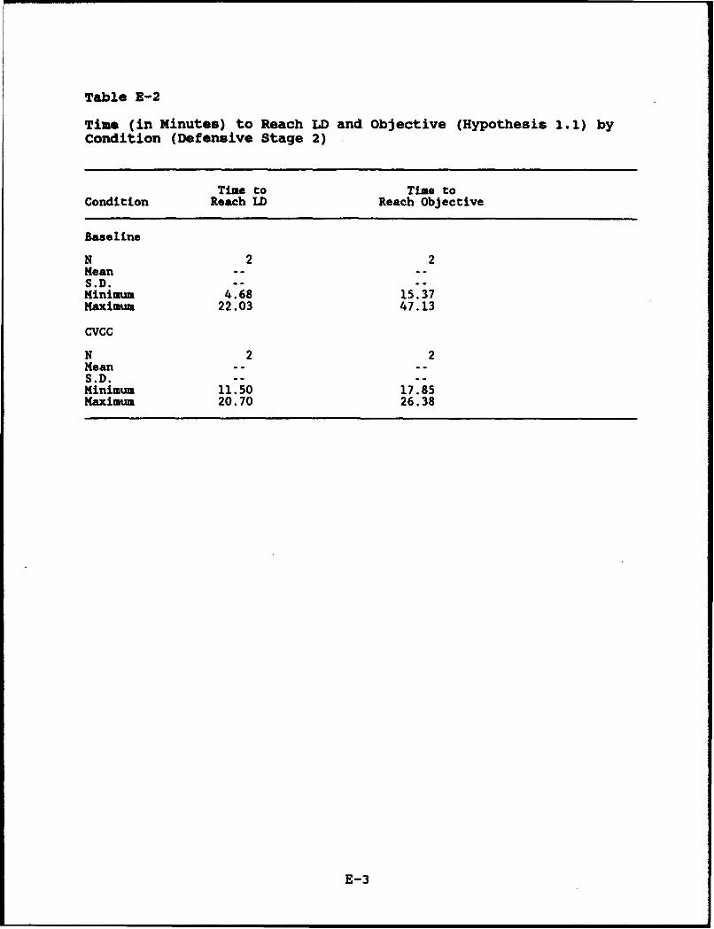
Table E-2
Time (in Minutes) to Reach LD and Objective (Hypothesis 1.1) byCondition (Defensive Stage 2)
Time to Time toCondition Reach LD Reach Objective
Baseline
N 2 2Mean ...S.D. -- --Minimum 4.68 15.37Maximum 22.03 47.13
CVCC
N 2 2Mean .- .S.D. --Minimum 11.50 17.85Maximum 20.70 26.38
E-3
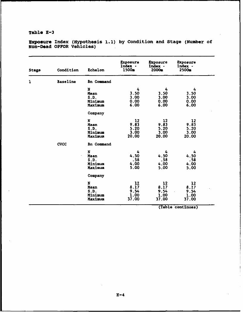
Table E-3
Exposure Index (Hypothesis 1.1) by Condition and Stage (Number ofNon-Dead OPFOR Vehicles)
Exposure Exposure ExposureIndex - Index - Index -
Stage Condition Echelon 1500m 2000m 2500.
Baseline Bn Command
N 4 4 4Mean 3.50 3.50 3.50S.D. 3.00 3.00 3.00Minimum 0.00 0.00 0.00Maximum 6.00 6.00 6.00
Company
N 12 12 12Mean 9.83 9.83 9.83S.D. 5.20 5.20 5.20Minimum 3.00 3.00 3.00Maximum 20.00 20.00 20.00
CVCC Bn Command
N 4 4 4Mean 4.50 4.50 4.50S.D. .58 .58 .58Minimum 4.00 4.00 4.00Maximum 5.00 5.00 5.00
Company
N 12 12 12Mean 8.17 8.17 8.17S.D. 9.54 9.54 9.54Minimum 1.00 1.00 1.00Maximum 37.00 37.00 37.00
(Table continues)
E-4
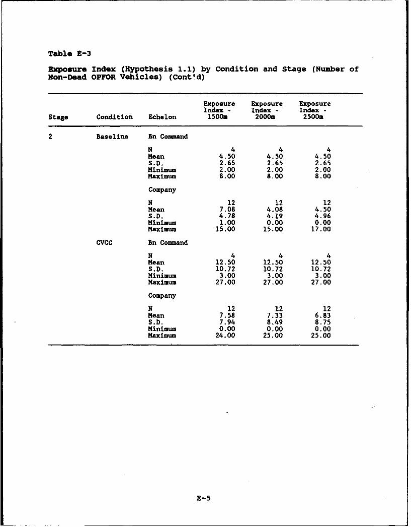
Table E-3
Exposure Index (Hypothesis 1.1) by Condition and Stage (Number ofNon-Dead OPFOR Vehicles) (Cont' d)
Exposure Exposure ExposureIndex - Index - Index -
Stage Condition Echelon 1500m 2000m 2500m
2 Baseline Bn Command
N 4 4 4Mean 4.50 4.50 4.50S.D. 2.65 2.65 2.65Minimum 2.00 2.00 2.00Maximum 8.00 8.00 8.00
Company
N 12 12 12Mean 7.08 4.08 4.50S.D. 4.78 4.19 4.96Minimum 1.00 0.00 0.00Maximum 15.00 15.00 17.00
CVCC Bn Command
N 4 4 4Mean 12.50 12.50 12.50S.D. 10.72 10.72 10.72Minimum 3.00 3.00 3.00Maximum 27.00 27.00 27.00
Company
N 12 12 12Mean 7.58 7.33 6.83S.D. 7.94 8.49 8.75Minimum 0.00 0.00 0.00Maximum 24.00 25.00 25.00
E-5
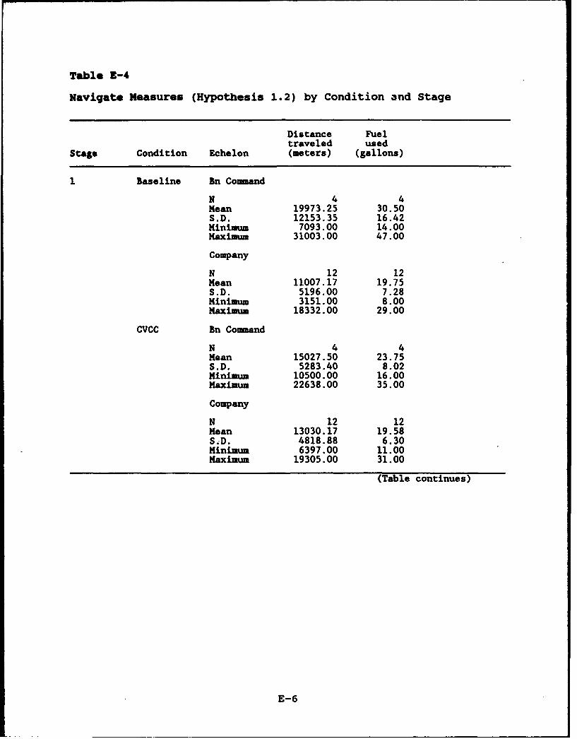
Table E-4
Navigate Measures (Hypothesis 1.2) by Condition 3nd Stage
Distance Fueltraveled used
Stage Condition Echelon (meters) (gallons)
Baseline Bn Command
N 4 4Mean 19973.25 30.50S.D. 12153.35 16.42Minimum 7093.00 14.00Maximum 31003.00 47.00
Company
N 12 12Mean 11007.17 19.75S.D. 5196.00 7.28Minimum 3151.00 8.00Maximum 18332.00 29.00
CVCC Bn Command
N 4 4Mean 15027.50 23.75S.D. 5283.40 8.02Minimum 10500.00 16.00Maximum 22638.00 35.00
Company
N 12 12Mean 13030.17 19.58S,D. 4818.88 6.30Minimum 6397.00 11.00Maximum 19305.00 31.00
(Table continues)
E-6
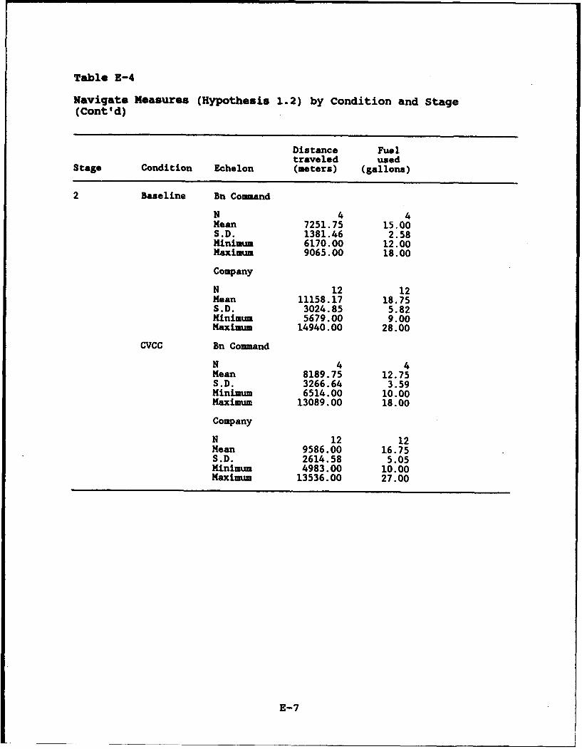
Table E-4
Navigate Measures (Hypothesis 1.2) by Condition and Stage(Cont'd)
Distance Fueltraveled used
Stage Condition Echelon (meters) (gallons)
2 Baseline Bn Command
N 4 4Mean 7251.75 15.00S.D. 1381.46 2.58Minimum 6170.00 12.00Maximum 9065.00 18.00
Company
N 12 12Mean 11158.17 18.75S.D. 3024.85 5.82Minimum 5679.00 9.00Maximum 14940.00 28.00
CVCC Bn Command
N 4 4Mean 8189.75 12.75S.D. 3266.64 3.59Minimum 6514.00 10.00Maximum 13089.00 18.00
Company
N 12 12Mean 9586.00 16.75S.D. 2614.58 5.05Minimum 4983.00 10.00Maximum 13536.00 27.00
E-7
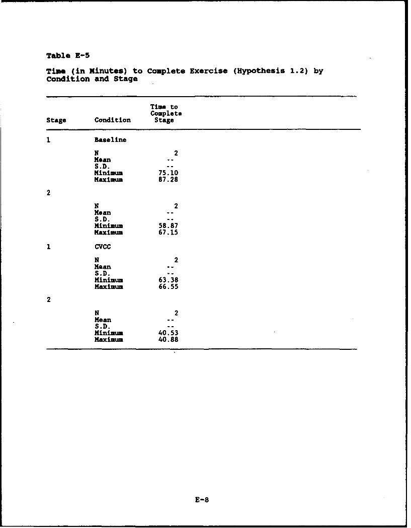
Table E-5
Time (in Minutes) to Complete Exercise (Hypothesis 1.2) byCondition and Stage
Time toComplete
Stage Condition Stage
1 Baseline
N 2Mean o -S.D. --Minimum 75.10Maximum 87.28
2
N 2Mean - -
S.D. --Minimum 58.87Maximum 67.15
1 CVCC
N 2Mean - oS.D. --Minimum 63.38Maximum 66.55
2
N 2Mean - -S.D. --Minimum 40.53Maximau 40.88
E-8
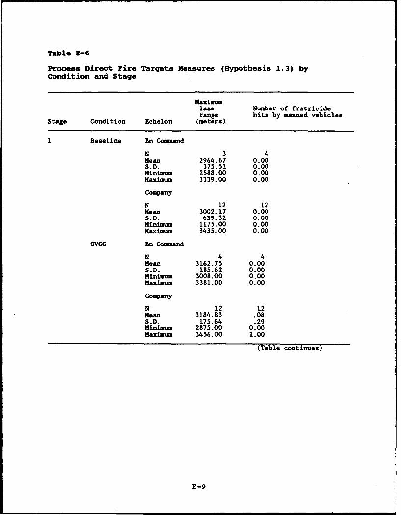
Table E-6
Process Direct Fire Targets Measures (Hypothesis 1.3) byCondition and Stage
Maximumlase Number of fratriciderange hits by manned vehicles
Stage Condition Echelon (meters)
Baseline Bn Command
N 3 4Mean 2964.67 0.00S.D. 375.51 0.00Minimum 2588.00 0.00Maximum 3339.00 0.00
Company
N 12 12Mean 3002.17 0.00S.D. 639.32 0.00Minimum 1175.00 0.00Maximum 3435.00 0.00
CVCC Bn Command
N 4 4Mean 3162.75 0.00S.D. 185.62 0.00Minimum 3008.00 0.00Maximum 3381.00 0.00
Company
N 12 12Mean 3184.83 .08S.D. 175.64 .29Minimum 2875.00 0.00Maximum 3456.00 1.00
(Table continues)
E-9

Table E-6
Process Direct Fire Targets Measures (Hypothesis 1.3) byCondition and Stage (Cont'd)
Maximumlase Number of fratriciderange hits by manned vehicles
Stage Condition Echelon (meters)
2 Baseline Bn Command
N 3 4Mean 3073.00 .25S.D. 594.30 .50Minimum 389.00 0.00Maximum 3463.00 1.00
Company
N 10 12Mean 2811.10 .08S.D. 517.88 .29Minimum 1806.00 0.00Maximum 3493.00 1.00
CVCC Bn Command
"N 4 4Mean 2958.75 0.00S.D. 345.83 0.00Minimum 2464.00 0.00Maximum 3256.00 0.00
Company
N 11 12Mean 2680.73 0.00S.D. 468.72 0.00Minimum 2105.00 0.00Maximum 3438.00 0.00
E-10
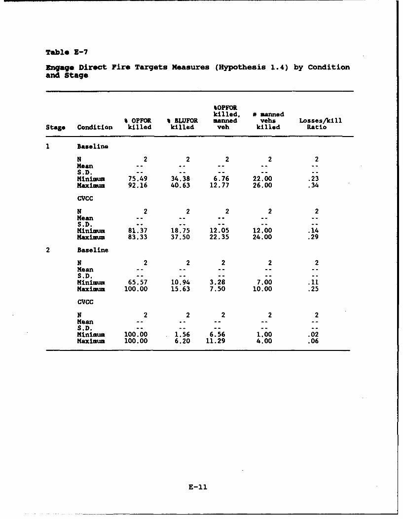
Table E-7
Engago Direct Fire Targets Measures (Hypothesis 1.4) by Conditionand Stage
%OPFORkilled, # manned
% OPFOR % BLUFOR manned vehs Losses/killStage Condition killed killed veh killed Ratio
Baseline
N 2 2 2 2 2Mean ..-.-S.D. - .........Minimum 75.49 34.38 6.76 22.00 .23Maximum 92.16 40.63 12.77 26.00 .34
CvCC
N 2 2 2 2 2Mean ..........S.D. - .........Minimum 81.37 18.75 12.05 12.00 .14Maximum 83.33 37.50 22.35 24.00 .29
2 Baseline
N 2 2 2 2 2Mean -- -- -- -. --S.D. -- -- -- --Minimum 65.57 10.94 3.28 7.00 .11Maximum 100.00 15.63 7.50 10.00 .25
CVCC
N 2 2 2 2 2Mean -- -- -- -- --S.D. - - -- -- --Minimum 100.00 1.56 6.56 1.00 .02Maximum 100.00 6.20 11.29 4.00 .06
E-11
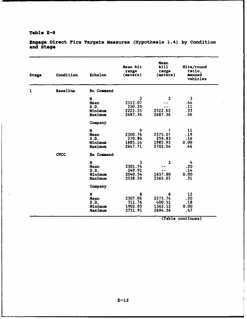
Table E-8
Engage Direct Fire Targets Measures (Hypothesis 1.4) by Conditionand Stage
MeanMean hit kill Hits/round
range range ratio,Stage Condition Echelon (meters) (meters) manned
vehicles
1 Baseline Bn Command
N 3 2 3Mean 2512.07 -- .44S.D. 250.35 -- .11Minimum 2225.35 2522.62 .33Maximum 2687.36 2687.36 .56
Company
N 9 7 11Mean 2300.76 2375.07 .19S.D. 270.86 259.83 .16Minimum 1885.14 1985.95 0.00Maximum 2647.71 2702.54 .46
CVCC Bn Command
N 3 2 4Mean 2301.74 -- .20S.D. 249.91 -- .14Minimum 2040.54 1657.80 0.00Maximum 2538.59 2365.01 .31
Company
N 8 8 12Mean 2307.06 2275.74 .20S.D. 311.76 400.51 .18Minimum 1902.85 1562.12 0.00Maximum 2751.91 2694.56 .47
(Table continues)
E-12
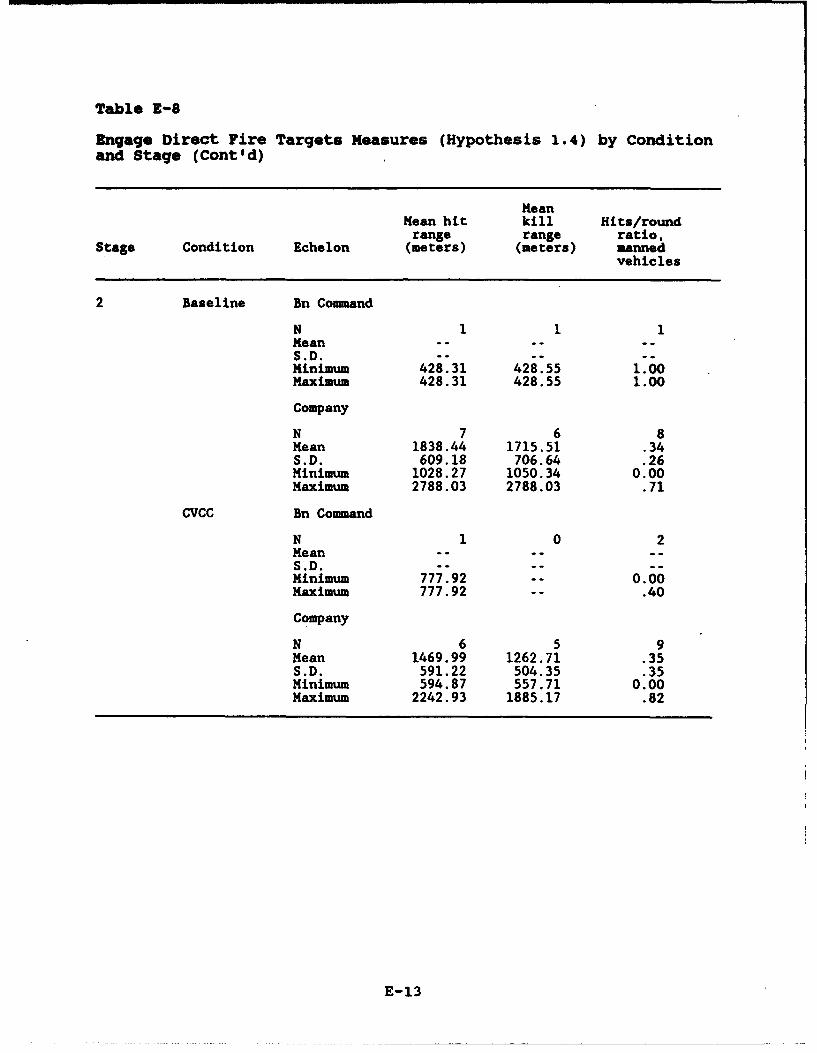
Table E-8
Engage Direct Fire Targets Measures (Hypothesis 1.4) by Conditionand Stage (Cont'd)
MeanMean hit kill Hits/roundrange range ratio,
Stage Condition Echelon (meters) (meters) mannedvehicles
2 Baseline Bn Command
N 1 1 1Mean .....S.D.- -....Minimum 428.31 428.55 1.00Maximum 428.31 428.55 1.00
Company
N 7 6 8Mean 1838.44 1715.51 .34S.D. 609.18 706.64 .26Minimum 1028.27 1050.34 0.00Maximum 2788.03 2788.03 .71
CVCC Bn Command
N 1 0 2Mean ......S.D. - .....Minimum 777.92 -- 0.00Maximum 777.92 -- .40
Company
N 6 5 9Mean 1469.99 1262.71 .35S.D. 591.22 504.35 .35Minimum 594.87 557.71 0.00Maximum 2242.93 1885.17 .82
E-13
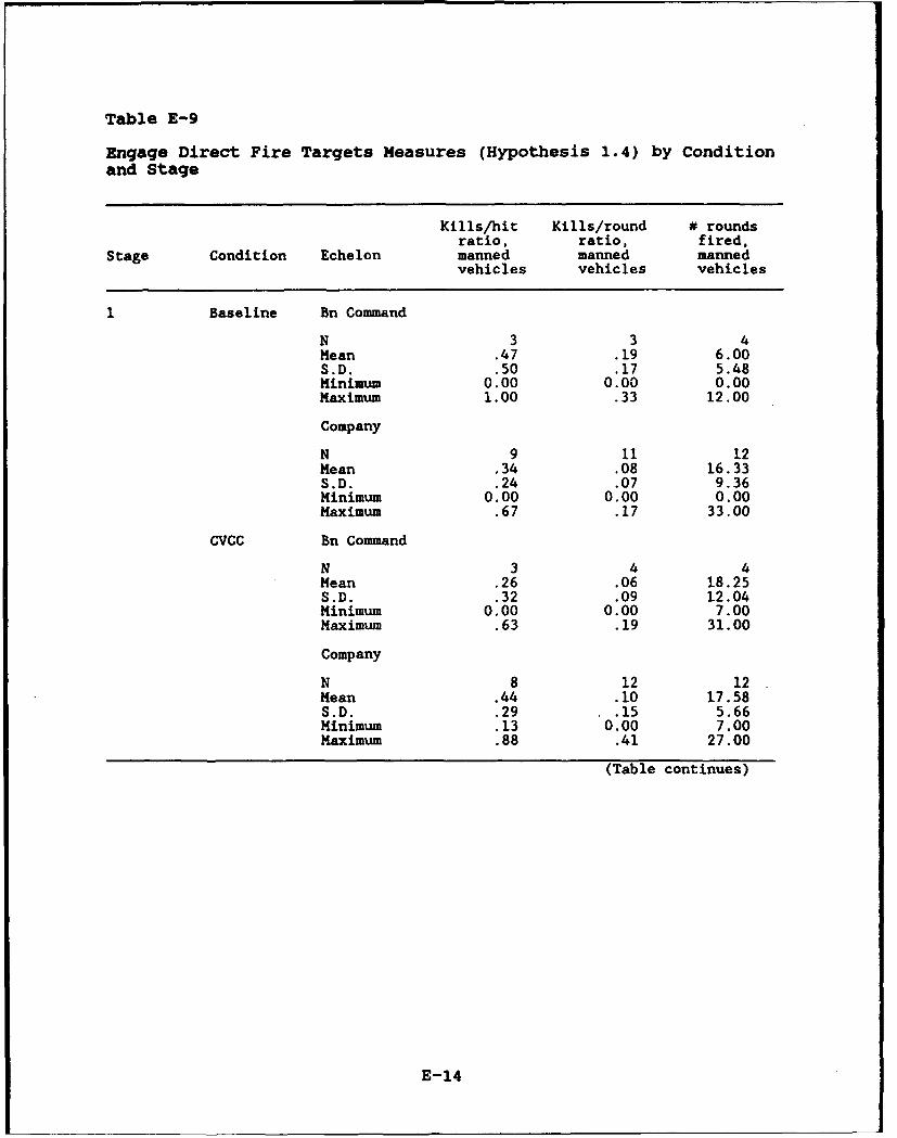
Table E-9
Engage Direct Fire Targets Measures (Hypothesis 1.4) by Conditionand Stage
Kills/hit Kills/round # roundsratio, ratio, fired,
Stage Condition Echelon manned manned mannedvehicles vehicles vehicles
1 Baseline Bn Command
N 3 3 4Mean .47 .19 6.00S.D. .50 .17 5.48Minimum 0.00 0.00 0.00Maximum 1.00 .33 12.00
Company
N 9 11 12Mean .34 .08 16.33S.D. .24 .07 9.36Minimum 0.00 0.00 0.00Maximum .67 .17 33.00
CVCC Bn Command
N 3 4 4Mean .26 .06 18.25S.D. .32 .09 12.04Minimum 0.00 0.00 7.00Maximum .63 .19 31.00
Company
N 8 12 12Mean .44 .10 17.58S.D. .29 .15 5.66Minimum .13 0.00 7.00Maximum .88 .41 27.00
(Table continues)
E-14
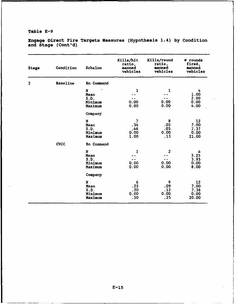
Table E-9
Engage Direct Fire Targets Measures (Hypothesis 1.4) by Conditionand Stage (Cont'd)
Kills/hit Kills/round # roundsratio, ratio, fired,
Stage Condition Echelon manned manned mannedvehicles vehicles vehicles
2 Baseline Bn Command
N 1 1 4Mean 1.. I.100S.D. -- -- 2.00Minimum 0.00 0.00 0.00Maximum 0.00 0.00 4.00
Company
N 7 8 12Mean .34 .05 7.00S.D. .46 .05 7.37Minimum 0.00 0.00 0.00Maximum 1.00 .13 21.00
CVCC Bn Command
N 1 2 4Mean -- -- 3.25S.D. -- -- 3.95Minimum 0.00 0.00 0.00Maximum 0.00 0.00 8.00
Company
N 6 9 12Mean .25 .09 7.00S.D. .20 .12 7.36Minimum 0.00 0.00 0.00Maximum .50 .25 20.00
E-15
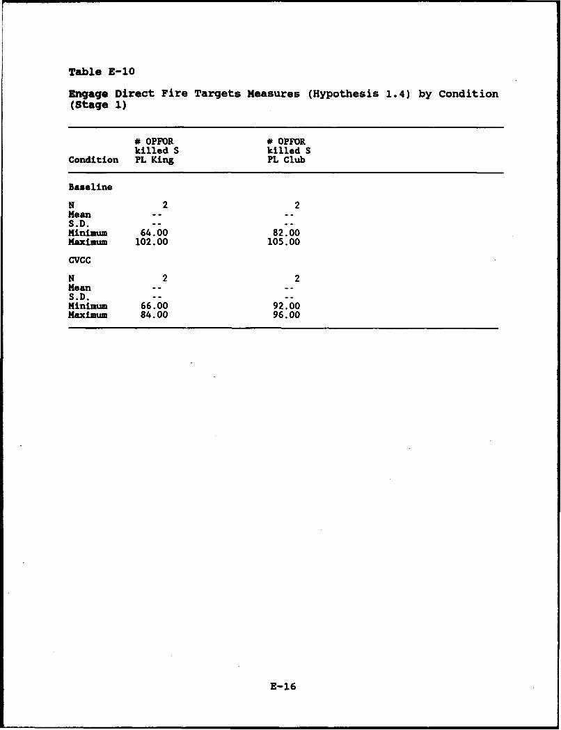
Table E-10
Engage Direct Fire Targets Measures (Hypothesis 1.4) by Condition(Stage 1)
# OPFOR # OPFORkilled S killed S
Condition PL King PL Club
Baseline
N 2 2Mean ....S.D. -- --Minimum 64.00 82.00Maximum 102.00 105.00
CVCC
N 2 2Mean -- -.S.D. -- --Minimum 66.00 92.00Maximum 84.00 96.00
E-16
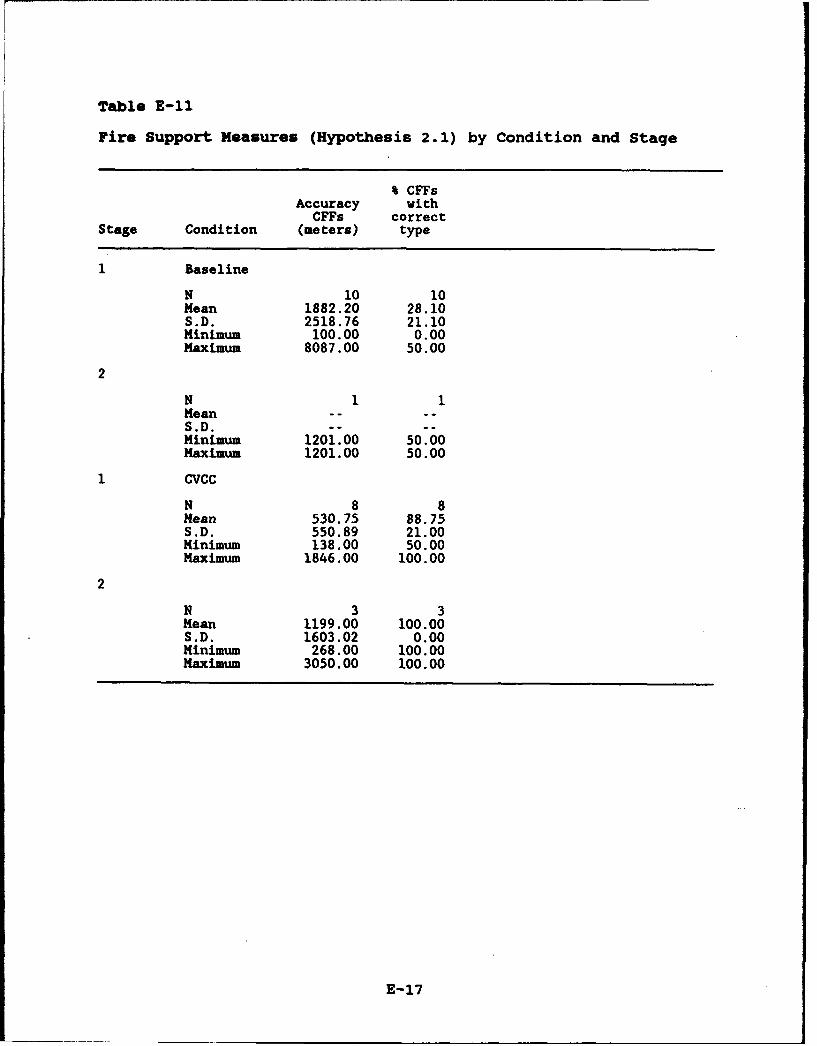
Table E-11
Fire Support Measures (Hypothesis 2.1) by Condition and Stage
% CFFsAccuracy with
CFFs correctStage Condition (meters) type
Baseline
N 10 10Mean 1882.20 28.10S.D. 2518.76 21.10Minimum 100.00 0.00Maximum 8087.00 50.00
2
N 1 1Mean -- --S.D. -- --Minimum 1201.00 50.00Maximum 1201.00 50.00
CVCC
N 8 8Mean 530.75 88.75S.D. 550.89 21.00Minimum 138.00 50.00Maximum 1846.00 100.00
2
N 3 3Mean 1199.00 100.00S.D. 1603.02 0.00Minimum 268.00 100.00Maximum 3050.00 100.00
E-17
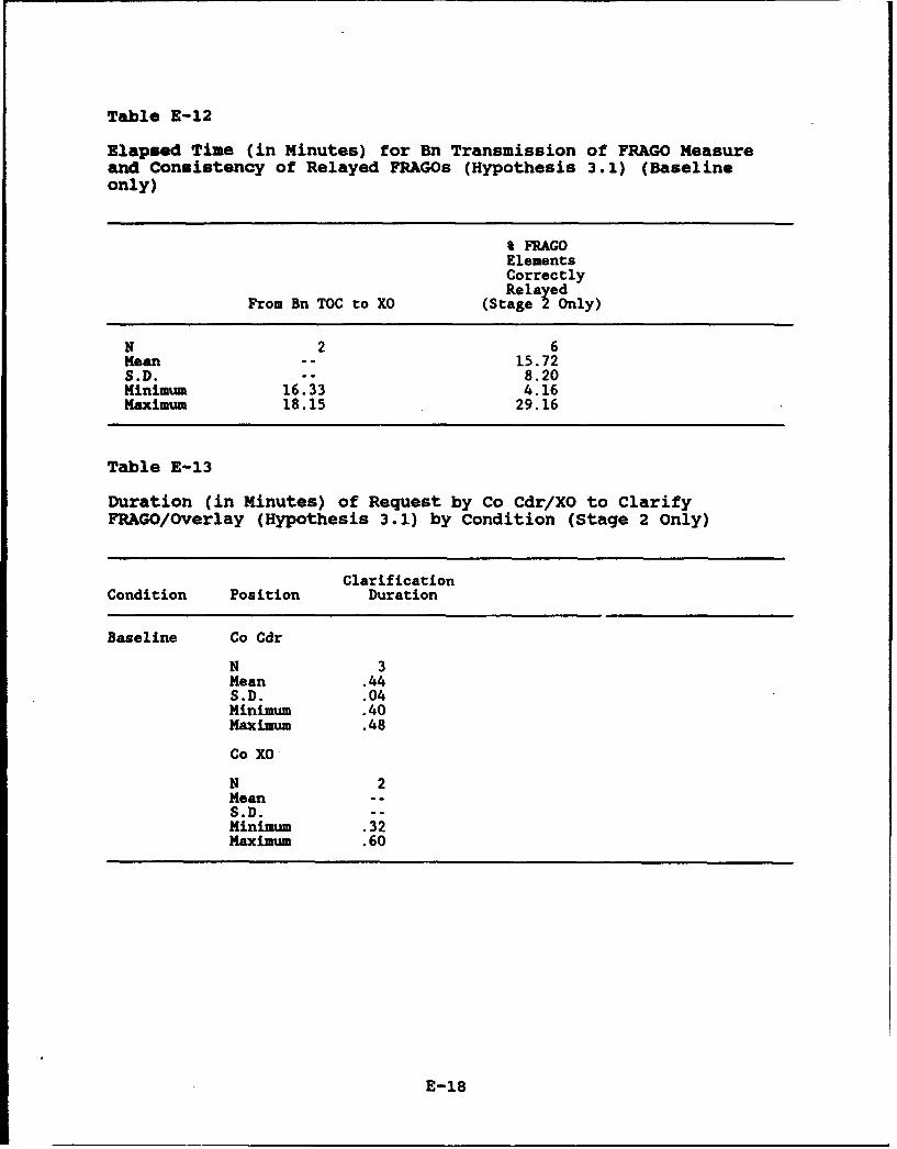
Table E-12
Elapsed Time (in Minutes) for Bn Transmission of FRAGO Measureand Consistency of Relayed FRAGOs (Hypothesis 3.1) (Baselineonly)
%FRAGOElementsCorrectlyRelayed
From Bn TOC to XO (Stage 2 Only)
N 2 6Mean -- 15.72S.D. -- 8.20Minimum 16.33 4.16Maximum 18.15 29.16
Table E-13
Duration (in Minutes) of Request by Co Cdr/XO to ClarifyFRAGO/Overlay (Hypothesis 3.1) by Condition (Stage 2 only)
ClarificationCondition Position Duration
Baseline Co Cdr
N 3Mean .44S.D. .04Minimum .40Maximum .48
Co XO
N 2Mean --S.D. --Minimum .32Maximum .60
E-18
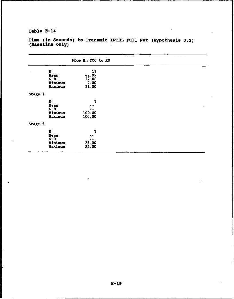
Table E-14
Time (in Seconds) to Transuit INTEL Full Net (Hypothesis 3.2)(Baseline only)
From Bn TOC to XO
N 11Mean 42.99S.D. 22.06Minimum 9.00Maximum 81.00
Stage 1
N 1Mean - -
S.D --Minimum 100.00Maximum 100.00
Stage 2
N 1Mean - -S.D. --Minimum 25.00Maximum 25.00
E-19
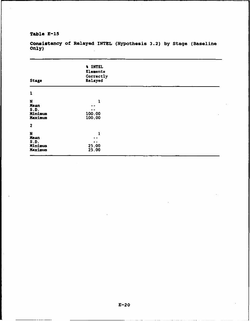
Table E-15
Consistency of Relayed INTEL (Hypothesis 3.2) by Stage (BaselineOnly)
% INTELElementsCorrectly
Stage Relayed
1
N 1Mean - -S.D. --Minimum 100.00Maximum 100.00
2
N 1Mean - -
S.D. --Minimum 25.00Maximum 25.00
E-20
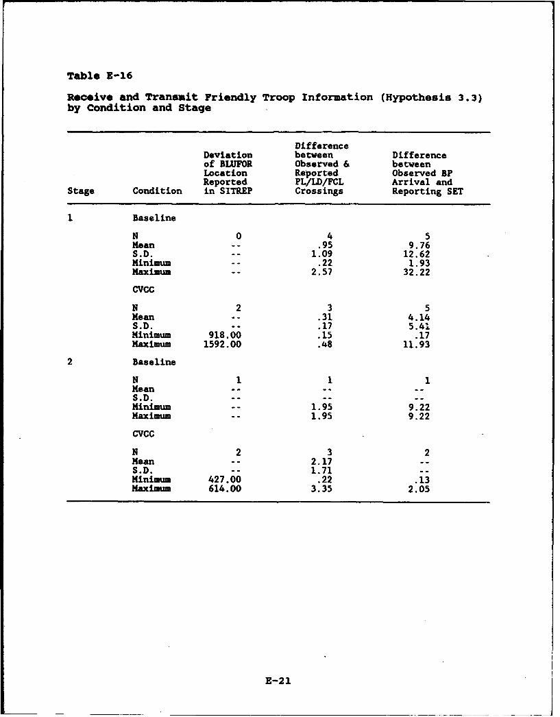
Table E-16
Receive and Transmit Friendly Troop Information (Hypothesis 3.3)by Condition and Stage
DifferenceDeviation between Differenceof BLUFOR Observed & betweenLocation Reported Observed BPReported PL/LD/FCL Arrival and
Stage Condition in SITREP Crossings Reporting SET
Baseline
N 0 4 5Mean -- .95 9.76S.D. -- 1.09 12.62Minimum -- .22 1.93Maximum -- 2.57 32.22
CVCC
N 2 3 5Mean -- .31 4.14S.D. -- .17 5.41Minimum 918.00 .15 .17Maximum 1592.00 .48 11.93
2 Baseline
N 1 1 1Mean ......S.D. - .....Minimum -- 1.95 9.22Maximum -- 1.95 9.22
CVCC
N 2 3 2Mean -- 2.17 --S.D. -- 1.71 --Minimum 427.00 .22 .13Maxim 614.00 3.35 2.05
E-21
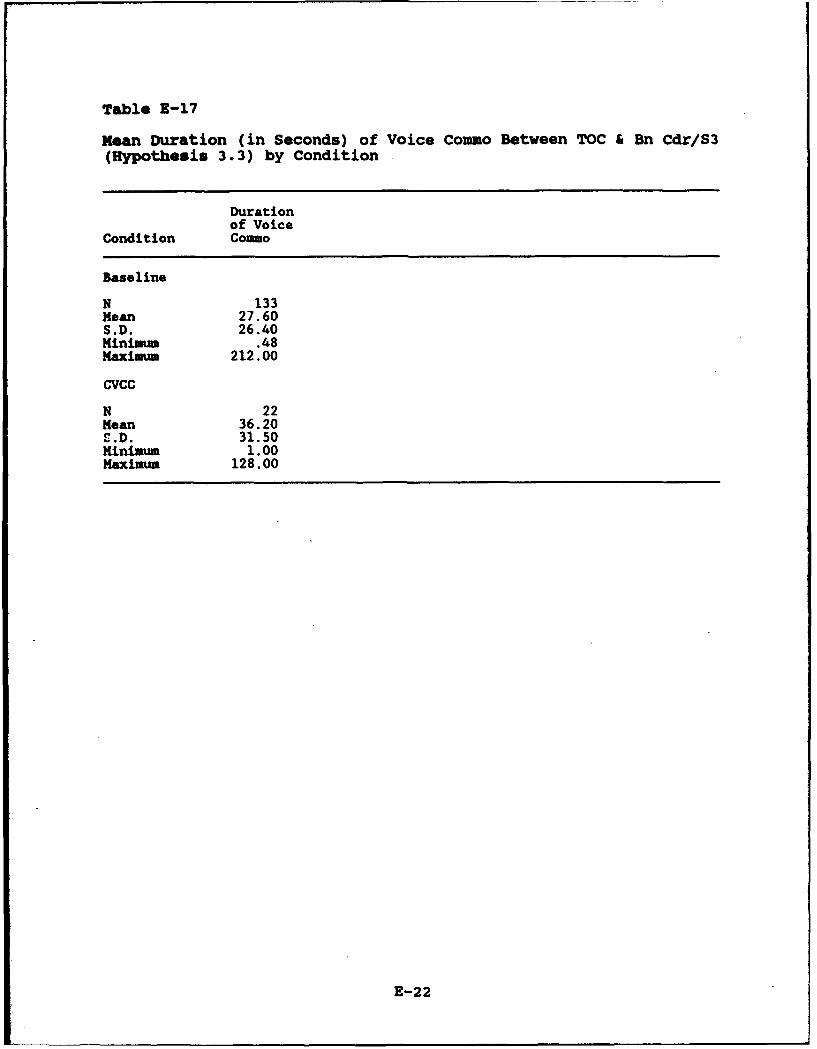
Table E-17
KMean Duration (in Seconds) of Voice Commo Between TOC & Bn Cdr/S3(Hypothesis 3.3) by Condition
Durationof Voice
Condition Commo
Baseline
N 133Mean 27.60S.D. 26.40Minimum .48Maximm 212.00
CVCC
N 22Mean 36.20S.D. 31.50Minimum 1.00Maximum 128.00
E-22
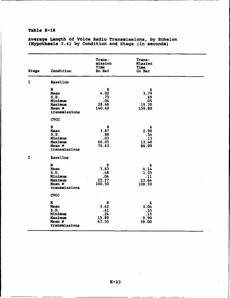
Table E-18
Average Length of Voice Radio Transmissions, by Echelon(Hypothesis 3.4) by Condition and Stage (in seconds)
Trans- Trans-mission MissionTime Time
Stage Condition Bn Net Co Net
1 Baseline
N 8 6Mean 4.02 3.79S.D. .75 .69Minimum .04 .05Maximum 28.66 19.70Mean * 140.40 159.80transmissions
CVCC
N 8 6Mean 3.87 2.90S.D. .88 .34Minimum .03 .13Maximum 66.05 13.40Mean # 76.63 86.00transmissions
2 Baseline
N 8 6Mean 3.83 4.14S.D. .48 1.35Minimum .04 .11Maximum 22.27 23.64Mean # 100.50 128.50transmissions
CVCC
N 8 6Mean 3.42 3.04S.D. .61 .55Minimum .24 .13Maximum 15.89 9.90Mean # 47.50 58.00transmissions
E-23
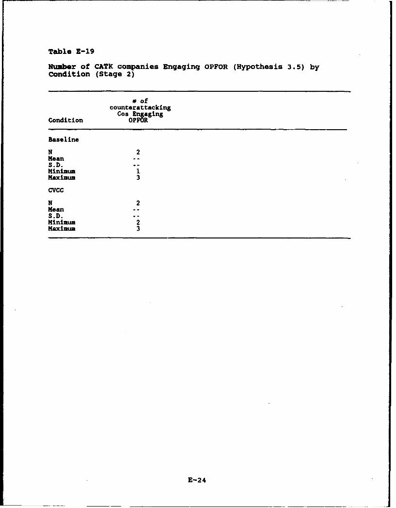
Table E-19
Number of CATK companies Engaging OPFOR (Hypothesis 3.5) byCondition (Stage 2)
# ofcounterattacking
Cos EngagingCondition OPFOR
Baseline
N 2Mean --S.D. --
Minium 1Maximum 3
CVCC
N 2Mean - -
S.D. --
Minimum 2Maximum 3
E-24

Table 3-20
Direct and Lead Subordinate Forces Measures (Hypothesis 3.5) byCondition and Stage
BLUFOR % Bn Metintact Cdris
Stage Condition (Stage 1) Intent
Baseline
N 2 2Mean ....S.D. -- --Minimum 52.00 80.86Maximum 63.00 84.77
CVCC
N 2 2Mean ....S.D. -- --Minimum 63.00 82.81Maximum 69.00 94.53
2 Baseline
N -- 2Mean ....S.D. -- --Minimum -- 95.22Maximum -- 99.12
CvCC
N -- 2Mean ....S.D. -- --Minimum -- 99.90Maximum -- 99.90
E-25
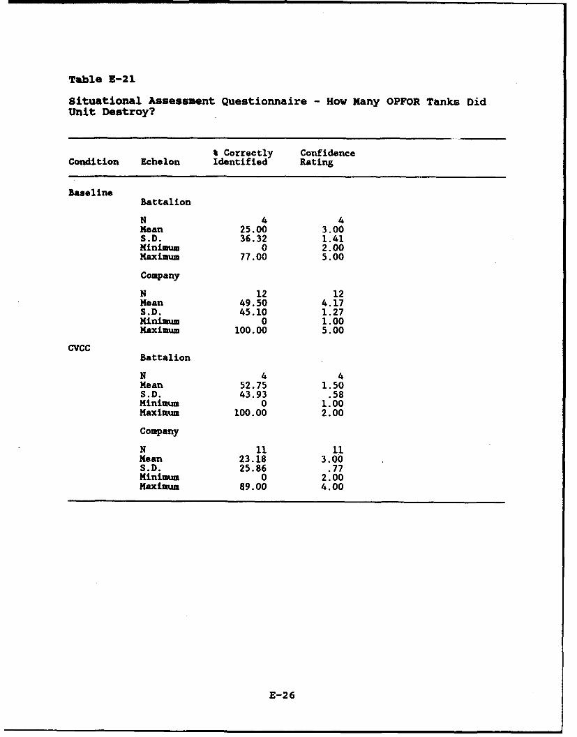
Table E-21
Situational Assessment Questionnaire - How Many OPFOR Tanks DidUnit Destroy?
% Correctly ConfidenceCondition Echelon Identified Rating
BaselineBattalion
N 4 4Mean 25.00 3.00S.D. 36.32 1.41Minimum 0 2.00Maximum 77.00 5.00
Company
N 12 12Mean 49.50 4.17S.D. 45.10 1.27Minimum 0 1.00Maximum 100.00 5.00
CVCC Battalion
N 4 4Mean 52.75 1.50S.D. 43.93 .58Minimum 0 1.00Maximum 100.00 2.00
Company
N 11 11Mean 23.18 3.00S.D. 25.86 .77Minimum 0 2.00Maximum 89.00 4.00
E-26

Table E-22
Situational Assessment Questionnaire - How Many BMPs Did UnitDestroy?
% Correctly ConfidenceCondition Echelon Identified Rating
BaselineBattalion
N 4 4Mean 14.50 3.50S.D. 16.54 1.73Minimum 0 2.00Maximum 38.00 5.00
Company
N 12 12Mean 28.58 4.17S.D. 40.37 1.27Minimum 0 1.00Maximum 100.00 5.00
CVCCBattalion
N 4 4Mean 58.00 2.00S.D. 41.27 .82Minimum 0 1.00Maximum 89.00 3.00
Company
N 11 11Mean 36.09 2.73S.D. 26.30 .65Minimum 0 2.00Maximum 77.00 4.00
E-27
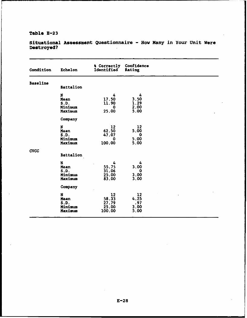
Table E-23
Situational Assessment Questionnaire - How Many in Your Unit WereDestroyed?
% Correctly ConfidenceCondition Echelon Identified Rating
BaselineBattalion
N 4 4Mean 17.50 3.50S.D. 11.90 1.29Minimum 0 2.00Maximum 25.00 5.00
Company
N 12 12Mean 62.50 5.00S.D. 47.07 0Minimum 0 5.00Maximum 100.00 5.00
CVCCBattalion
N 4 4Mean 55.75 3.00S.D. 31.06 0Minimum 25.00 3.00Maximum 83.00 3.00
Company
N 12 12Mean 58.33 4.25S.D. 27.79 .97Minimum 25.00 3.00Maximum 100.00 5.00
E-28

Table E-24
Situational Assessment Questionnaire - How Far Was Initial BPfrom Later BP?
Deviationbetween True& Reported Confidence
Condition Echelon Distance Rating
CVCCBattalion
N 4 4Mean .38 3.75S.D. .26 .96Minimum .23 3.00Maximum .77 5.00
Company
N 12 12Mean 1.44 3.67S.D. 2.22 .98Minimum 0.00 2.00Maximum 7.40 5.00
E-29

Table E-25
Collect Threat Information Measures (Hypothesis 4.1) by Conditionand Stage
AccuracySPOT Accuracy I SPOTs 0 SPOTs
report SPOT report correct correctStage Condition (observed) (destroyed) (observed) (destroyed)
Baseline
N 12 2 12 3Mean 351.17 -- 58.42 21.00S.D. 272.62 -- 31.84 36.37Minimum 11.00 236.00 0.00 0.00Maximum 1020.00 1393.00 100.00 63.00.
2
N 4 1 5 1Mean 708.00 -- 66.60 --S.D. 1003.83 -- 47.20 --Minimum 31.00 121.00 0.00 0.00Maximum 2201.00 121.00 100.00 0.00
CVCC
N 12 12 12 12Mean 456.17 455.50 77.25 79.67S.D. 573.93 586.92 23.79 27.01Minimum 1.00 1.00 25.00 25.00Maximum 1700.00 1700.00 100.00 100.00
2
N 8 8 8 8Mean 404.63 467.25 100.00 91.63S.D. 397.86 465.69 0.00 17.84Minimum 2.00 54.00 100.00 50.00Maximum 1101.00 1229.00 100.00 100.00
(Table continues)
E-30
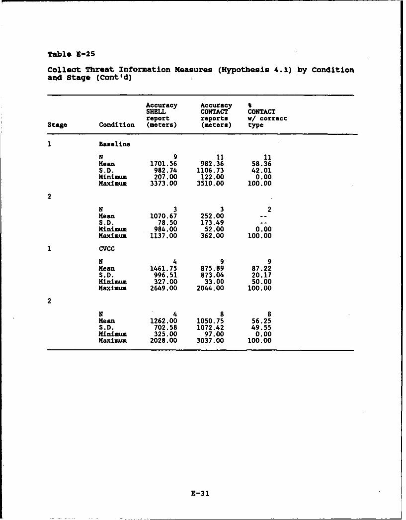
Table E-25
Collect Threat Information Measures (Hypothesis 4.1) by Conditionand Stage (Cont'd)
Accuracy Accuracy %SHELL CONTACT CONTACTreport reports w/ correct
Stage Condition (meters) (meters) type
Baseline
N 9 11 11Mean 1701.56 982.36 58.36S.D. 982.74 1106.73 42.01Minimum 207.00 122.00 0.00Maximum 3373.00 3510.00 100.00
2
N 3 3 2Mean 1070.67 252.00 --S.D. 78.50 173.49 --Minimum 984.00 52.00 0.00Maximum 1137.00 362.00 100.00
1 CVCC
N 4 9 9Mean 1461.75 875.89 87.22S.D. 996.51 873.04 20.17Minimum 327.00 33.00 50.00Maximum 2649.00 2044.00 100.00
2
N 4 8 8Mean 1262.00 1050.75 56.25S.D. 702.58 1072.42 49.55Minimum 325.00 97.00 0.00Maximum 2028.00 3037.00 100.00
E-31

Table E-26
Input Neasures, by Echelon
0 Input 9 Input toby Touch Reports by
Echelon Screen Laser
Battalion
N 4 4Mean 100.00 45.79S.D. 0.00 19.58Minimum 100.00 17.00Maximum 100.00 60.67
Company
N 12 12Mean 99.78 34.00S.D. .57 20.43Minimum 98.00 9.00Maximum 100.00 61.33
Table E-27
Percent Time each Map Scale in Effect, by Echelon
Echelon 25K 50K 125K 250K
Battalion
N 4 4 4 4.Mean 10.92 51.83 36.50 .08S.D. 15.12 36.84 42.14 .17Minimum 1.67 7.67 1.67 0.00Maximum 33.33 95.67 89.67 .33
Company
N 12 12 12 12Mean 25.92 68.94 4.17 .31S.D. 29.04 31.07 4.23 .86Minimum 0.00 9.00 0.00 0.00Maximum 83.67 98.33 13.67 3.00
E-32
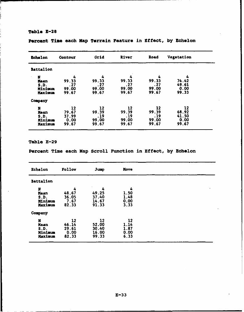
Table E-28
Percent Time each Map Terrain Feature in Effect, by Echelon
Echelon Contour Grid River Road Vegetation
Battalion
N 4 4 4 4 4Mean 99.33 99.33 99.33 99.33 74.42S.D. .27 .27 .27 .27 49.61Minimum 99.00 99.00 99.00 99.00 0.00Maximum 99.67 99.67 99.67 99.67 99.33
Company
N 12 12 12 12 12Mean 79.67 99.39 99.39 99.39 68.92S.D. 37.99 .19 .19 .19 41.50Minimum 0.00 99.00 99.00 99.00 0.00Maximum 99.67 99.67 99.67 99.67 99.67
Table E-29
Percent Time each Map Scroll Function in Effect, by Echelon
Echelon Follow Jump Move
Battalion
N 4 4 4Mean 48.67 49.25 1.50S.D. 36.05 37.40 1.48Minimum 7.67 14.67 0.00Maximum 82.33 91.33 3.33
Company
N 12 12 12Mean 46.14 52.00 1.14S.D. 29.61 30.40 1.87Minimum 0.00 16.00 0.00Maximum 82.33 99.33 6.33
E-33
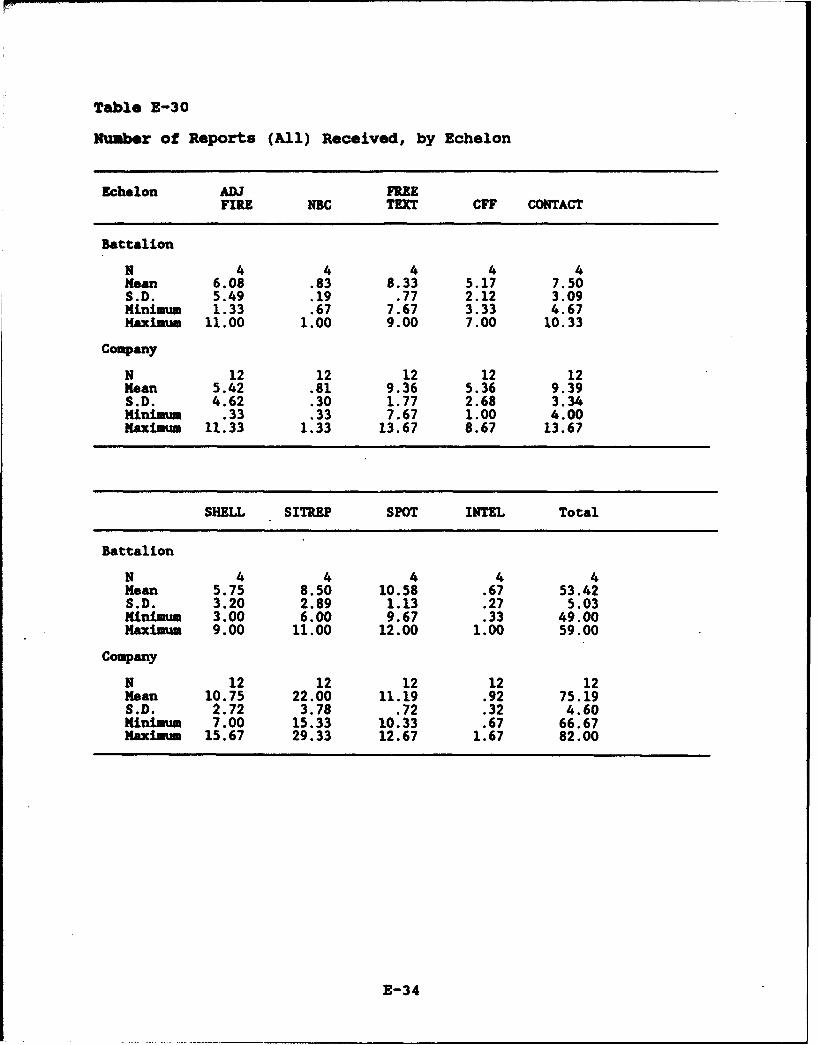
Table Z-30
Number of Reports (All) Received, by Echelon
Echelon ADJ FREEFIRE NBC TEXT CFF CONTACT
Battalion
N 4 4 4 4 4Mean 6.08 .83 8.33 5.17 7.50S.D. 5.49 .19 .77 2.12 3.09Minimum 1.33 .67 7.67 3.33 4.67Maximum 11.00 1.00 9.00 7.00 10.33
Company
N 12 12 12 12 12Mean 5.42 .81 9.36 5.36 9.39S.D. 4.62 .30 1.77 2.68 3.34Minimm .33 .33 7.67 1.00 4.00Maximum 11.33 1.33 13.67 8.67 13.67
SHELL SITUEP SPOT INTEL Total
Battalion
N 4 4 4 4 4Mean 5.75 8.50 10.58 .67 53.42S.D. 3.20 2.89 1.13 .27 5.03Minimum 3.00 6.00 9.67 .33 49.00Maximum 9.00 11.00 12.00 1.00 59.00
Company
N 12 12 12 12 12Mean 10.75 22.00 11.19 .92 75.19S.D. 2.72 3.78 .72 .32 4.60Minimum 7.00 15.33 10.33 .67 66.67Maximum 15.67 29.33 12.67 1.67 82.00
E-34
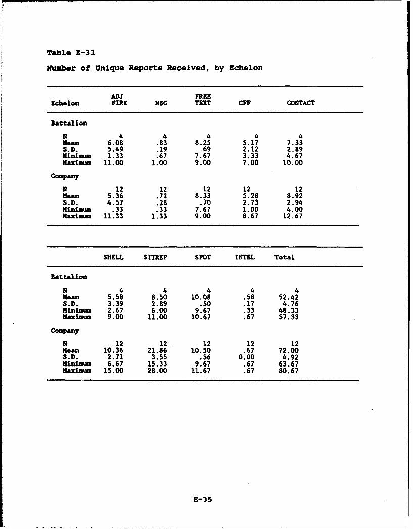
Table E-31
Number of Unique Reports Received, by Echelon
ADJ FREEEchelon FIRE NBC TEXT CFF CONTACT
Battalion
N 4 4 4 4 4Mean 6.08 .83 8.25 5.17 7.33S.D. 5.49 .19 .69 2.12 2.89Minimum 1.33 .67 7.67 3.33 4.67Maximum 11.00 1.00 9.00 7.00 10.00
Company
N 12 12 12 12 12Mean 5.36 .72 8.33 5.28 8.92S.D. 4.57 .28 .70 2.73 2.94Minimum .33 .33 7.67 1.00 4.00Maximum 11.33 1.33 9.00 8.67 12.67
SHELL SITREP SPOT INTEL Total
Battalion
N 4 4 4 4 4Mean 5.58 8.50 10.08 .58 52.42S.D. 3.39 2.89 .50 .17 4.76Minim=m 2.67 6.00 9.67 .33 48.33Maximum 9.00 11.00 10.67 .67 57.33
Company
N 12 12. 12 12 12Mean 10.36 21.86 10.50 .67 72.00S.D. 2.71 3.55 .56 0.00 4.92Minimum 6.67 15.33 9.67 .67 63.67Maximum 15.00 28.00 11.67 .67 80.67
E-35

Table E-32
Percent Reports Retrieved, by Echelon
ADJ FREEEchelon FIRE NBC TEXT CFF CONTACT
Battalion
N 4 4 4 4 4Mean 15.00 58.25 91.42 16.33 64.83S.D. 17.80 50.06 36.30 21.14 34.49Minimum 0.00 0.00 49.00 2.67 16.67Maximum 35.00 100.00 137.67 47.67 93.33
Company
N 12 12 12 12 12Mean .83 38.92 78.75 11.81 37.86S.D. 1.81 44.02 20.97 17.36 22.75Minimum 0.00 0.00 41.00 0.00 8.33Maximum 6.00 100.00 113.00 50.00 83.33
SHELL SITREP SPOT INTEL Total
Battalion
N 4 4 4 4 4Mean 8.33 51.33 61.42 100.00 51.00S.D. 9.62 29.70 30.27 0.00 26.32Minimum 0.00 9.00 16.33 100.00 13.33Maximum 16.67 78.33 80.33 100.00 72.00
Company
N 12 12 12 12 12Mean 16.97 30.72 32.89 83.33 33.14S.D. 19.57 27.01 25.54 32.57 19.70Minimum 0.00 1.00 2.00 0.00 9.00Maximum 65.33 80.00 87.67 100.00 76.33
E-36
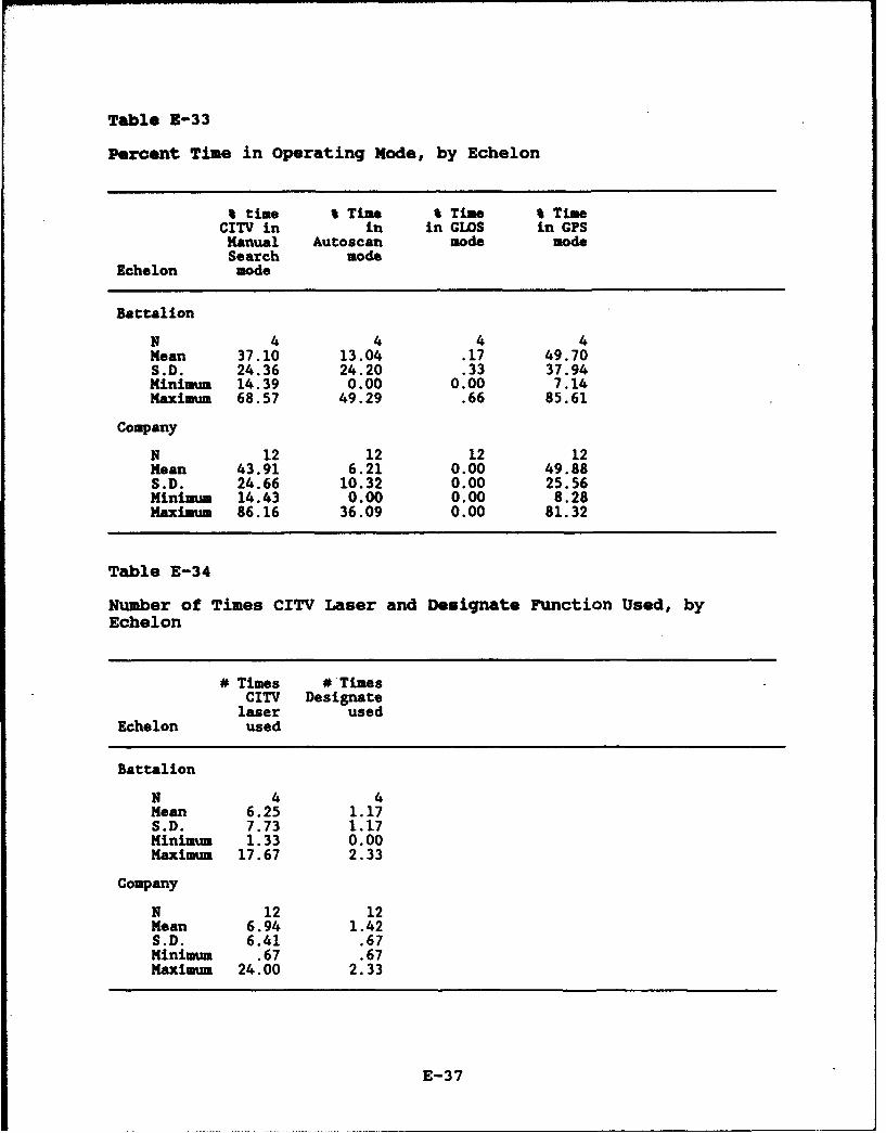
Table Z-33
Percent Time in Operating Mode, by Echelon
% time % Time I Time % TimeCITV in in in GWLS in CPS
Manual Autoscan mode modeSearch mode
Echelon mode
Battalion
N 4 4 4 4Mean 37.10 13.04 .17 49.70S.D. 24.36 24.20 .33 37.94Minimum 14.39 0.00 0.00 7.14Maximum 68.57 49.29 .66 85.61
Company
N 12 12 12 12Mean 43.91 6.21 0.00 49.88S.D. 24.66 10.32 0.00 25.56Minimum 14.43 0.00 0.00 8.28Maximum 86.16 36.09 0.00 81.32
Table E-34
Number of Times CITV Laser and Designate Function Used, byEchelon
# Times # TimesCITV Designate
laser usedEchelon used
Battalion
N 4 4Mean 6.25 1.17S.D. 7.73 1.17Minimum 1.33 0.00Maximum 17.67 2.33
Company
N 12 12Mean 6.94 1.42S.D. 6.41 .67Minimum .67 .67Maximum 24.00 2.33
E-37
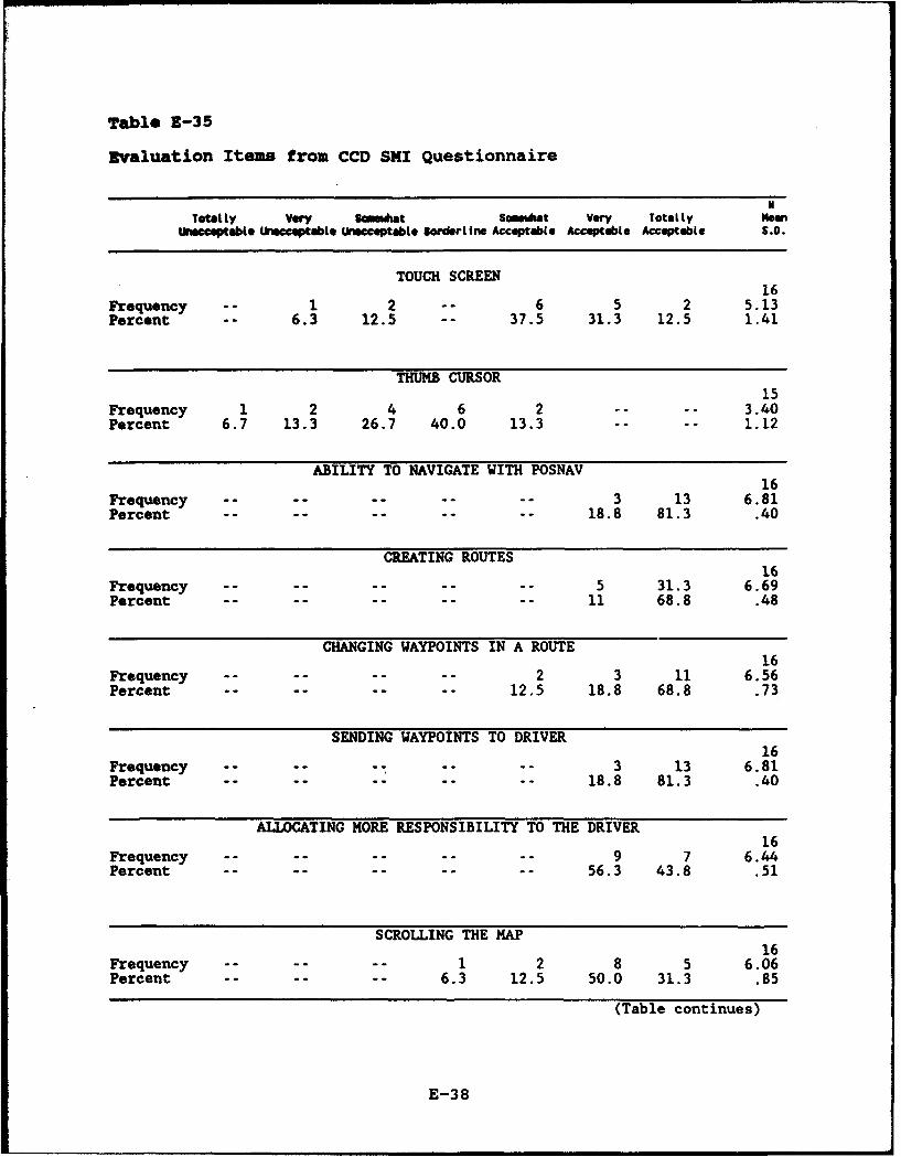
Table E-35
Evaluation Items from CCD SKI Questionnaire
N
Totally Vwry Soemdhat S,,aht V"ry Totally NaanUaptabte UnMceeptable Unee£ptabte Borderline Acceptable Acceptabte Acceptable S.O.
TOUCH SCREEN16
Frequency 1 2 -- 6 5 2 5.13Percent -- 6.3 12.5 -- 37.5 31.3 12.5 1.41
THUMB CURSOR15
Frequency 1 2 4 6 2 -- -- 3.40Percent 6.7 13.3 26.7 40.0 13.3 -- -- 1.12
ABILITY TO NAVIGATE WITH POSNAV16
Frequency -- -- .. .. 3 13 6.81Percent .......... 18.8 81.3 .40
CREATING ROUTES16
Frequency .......... 5 31.3 6.69Percent .......... 11 68.8 .48
CHANGING WAYPOINTS IN A ROUTE16
Frequency .. .... .. 2 3 11 6.56Percent ........ 12.5 18.8 68.8 .73
SENDING WAYPOINTS TO DRIVER16
Frequency .. ... -.. 3 13 6.81Percent .......... 18.8 81.3 .40
ALLOCATING MORE RESPONSIBILITY TO THE DRIVER16
Frequency .. .... .... 9 7 6.44Percent .......... 56.3 43.8 .51
SCROLLING THE MAP16
Frequency .. .... 1 2 8 5 6.06Percent .. .... 6.3 12.5 50.0 31.3 .85
(Table continues)
E-38
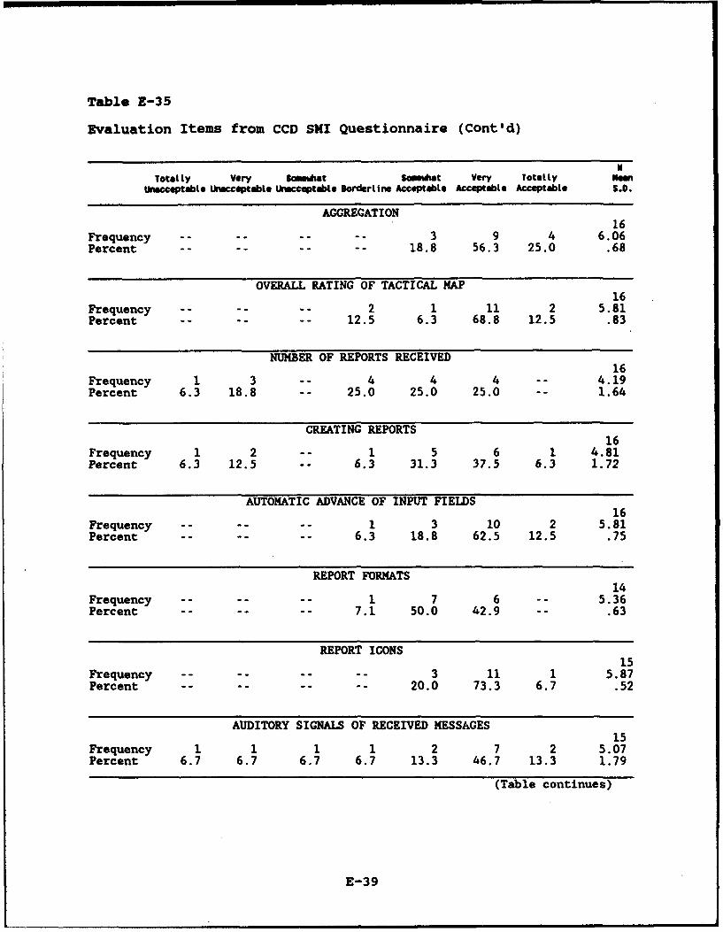
Table E-35
Evaluation Items from CCD SKI Questionnaire (Cont'd)
Totally Vey Sdaiat Scmstwat Very Total lyUnecceptabLte riacceptebLe Unacceptable BorderLine Acceptable Acceptable Acceptable S.D.
AGGREGATION16
Frequency .. .... .. 3 9 4 6.06Percent .. .... .. 18.8 56.3 25.0 .68
OVERALL RATING OF TACTICAL MAP16
Frequency .. .... 2 1 11 2 5.81Percent .. .... 12.5 6.3 68.8 12.5 .83
NUMBER OF REPORTS RECEIVED16
Frequency 1 3 4 4 4 -- 4.19Percent 6.3 18.8 -- 25.0 25.0 25.0 -- 1.64
CREATING REPORTS16
Frequency 1 2 -- 1 5 6 1 4.81Percent 6.3 12.5 -- 6.3 31.3 37.5 6.3 1.72
AUTOMATIC ADVANCE OF INPUT FIELDS16
Frequency -- 1 3 10 2 5.81Percent .. .... 6.3 18.8 62.5 12.5 .75
REPORT FORMATS14
Frequency .. .... 1 7 6 5.36Percent .. .... 7.1 50.0 42.9 -- .63
REPORT ICONS15
Frequency .. .... .. 3 11 1 5.87Percent .. .... .. 20.0 73.3 6.7 .52
AUDITORY SIGNALS OF RECEIVED MESSAGES15
Frequency 1 1 1 1 2 7 2 5.07Percent 6.7 6.7 6.7 6.7 13.3 46.7 13.3 1.79
(Table continues)
E-39
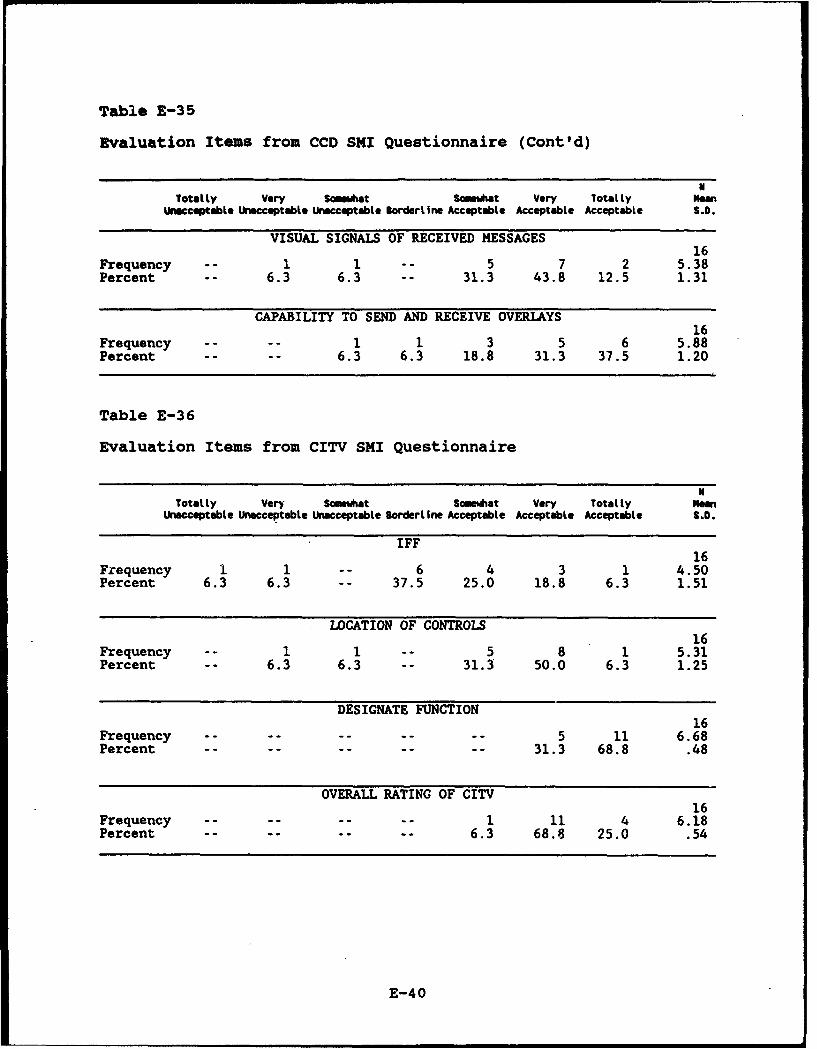
Table E-35
Evaluation Items from CCD SMI Questionnaire (Cont'd)
NTotltly Very Scmewhat Somewhat Very Totalty Mean
Unacceptable Unacceptable Unacceptable Borderline Acceptable Acceptable Acceptable S.D.
VISUAL SIGNALS OF RECEIVED MESSAGES16
Frequency -- 1 1 -- 5 7 2 5.38Percent -- 6.3 6.3 -- 31.3 43.8 12.5 1.31
CAPABILITY TO SEND AND RECEIVE OVERLAYS16
Frequency .. .. 1 1 3 5 6 5.88Percent .. .. 6.3 6.3 18.8 31.3 37.5 1.20
Table E-36
Evaluation Items from CITV SMI Questionnaire
NTotally Very Somehat Somewhat Very Totalty Mean
Unacceptable Unacceptable Unacceptable Borderline Acceptable Acceptable Acceptable S.D.
IFF16
Frequency 1 1 -- 6 4 3 1 4.50Percent 6.3 6.3 -- 37.5 25.0 18.8 6.3 1.51
LOCATION OF CONTROLS16
Frequency -- 1 1 -- 5 8 1 5.31Percent -- 6.3 6.3 31.3 50.0 6.3 1.25
DESIGNATE FUNCTION16
Frequency .. .... .... 5 11 6.68Percent .......... 31.3 68.8 .48
OVERALL RATING OF CITV16
Frequency .. .... .. 1 11 4 6.18Percent .. .... .. 6.3 68.8 25.0 .54
E-40
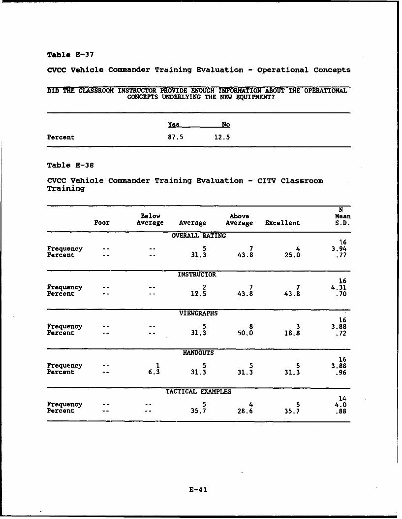
Table E-37
CVCC Vehicle Commander Training Evaluation - Operational Concepts
DID THE CLASSROOM INSTRUCTOR PROVIDE ENOUGH INFORMATION ABOUT THE OPERATIONALCONCEPTS UNDERLYING THE NEW EQUIPMENT?
Yes No
Percent 87.5 12.5
Table E-38
CVCC Vehicle Commander Training Evaluation - CITV ClassroomTraining
NBelow Above Mean
Poor Average Average Average Excellent S.D.
OVERALL RATING16
Frequency .... 5 7 4 3.94Percent .... 31.3 43.8 25.0 .77
INSTRUCTOR16
Frequency .... 2 7 7 4.31Percent .... 12.5 43.8 43.8 .70
VIEWGRAPHS16
Frequency .... 5 8 3 3.88Percent .... 31.3 50.0 18.8 .72
HANDOUTS16
Frequency -- 1 5 5 5 3.88Percent -- 6.3 31.3 31.3 31.3 .96
TACTICAL EXAMPLES14
Frequency ..-- 5 4 5 4.0Percent .... 35.7 28.6 35.7 .88
E-41
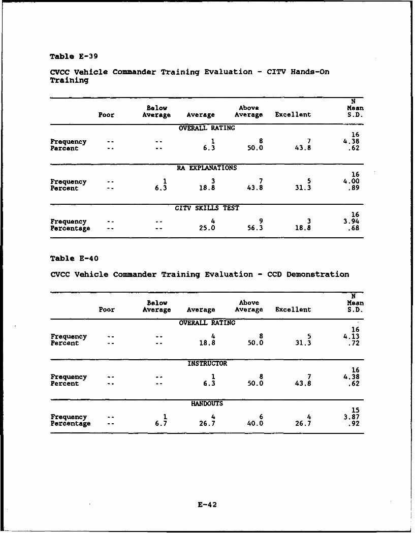
Table E-39
CVCC Vehicle Commander Training Evaluation - CITV Hands-OnTraining
NBelow Above Mean
Poor Average Average Average Excellent S.D.
OVERALL RATING16
Frequency .... 1 8 7 4.38Percent .... 6.3 50.0 43.8 .62
RA EXPLANATIONS16
Frequency -- 1 3 7 5 4.00Percent -- 6.3 18.8 43.8 31.3 .89
CITV SKILLS TEST 16Frequency .... 4 9 3 3.94Percentage .... 25.0 56.3 18.8 .68
Table E-40
CVCC Vehicle Commander Training Evaluation - CCD Demonstration
NBelow Above Mean
Poor Average Average Average Excellent S.D.
OVERALL RATING16
Frequency .... 4 8 5 4.13Percent .... 18.8 50.0 31.3 .72
INSTRUCTOR16
Frequency .... 1 8 7 4.38Percent .... 6.3 50.0 43.8 .62
HANDOUTS15
Frequency -- 1 4 6 4 3.87Percentage 6.7 26.7 40.0 26.7 .92
E-42
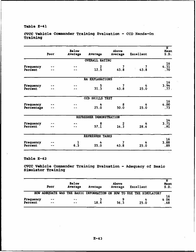
Table E-41
CVCC vehicle Commander Training Evaluation - CCD Hands-OnTraining
NBelow Above Mean
Poor Average Average Average Excellent S.D.
OVERALL RATING16
Frequency .... 2 7 7 4.31Percent .... 12.5 43.8 43.8 .70
RA EXPLANATIONS16
Frequency .. 5 7 4 3.94Percent .... 31.3 43.8 25.0 .77.
CCD SKILLS TEST16
Frequency .... 4 8 4 4.00Percentage .... 25.0 50.0 25.0 .73
REFRESHER DEMONSTRATION14
Frequency .... 8 2 4 3.71Percent .... 57.1 14.3 28.6 .91
REFRESHER TASKS16
Frequency -- 1 4 7 4 3.88Percent -- 6.3 25.0 43.8 25.0 .89
Table E-42
CVCC Vehicle Commander Training Evaluation - Adequacy of BasicSimulator Training
NBelow Above Mean
Poor Average Average Average Excellent S.D.
HOW ADEQUATE WAS THE BASIC INFORMATION ON HOW TO USE THE SIMULATOR?16
Frequency .... 3 9 4 406Percent .... 18.8 56.3 25.0 .68
E-43

Table E-43
CVCC Vehicle Commander Training Evaluation - Adequacy of TrainingExercises to Prepare for CITV Use in a Tactical Situation
NBelow Above Mean
Poor Average Average Average Excellent S.D.
CREW EXERCISE16
Frequency -- 2 6 5 3 3.56Percent -- 12.5 37.5 31.3 18.8 .96
COMPANY STX16
Frequency -- 1 3 11 1 3.75Percent -- 6.3 18.8 68.8 6.3 .68.
BATTALION STX16
Frequency ..-- 4 7 5 4.06Percentage .... 25.0 43.8 31.3 .77
BATTALION TRAINING SCENARIO16
Frequency .... 2 7 7 4.31Percent .... 12.5 43.8 43.8 .70
E-44
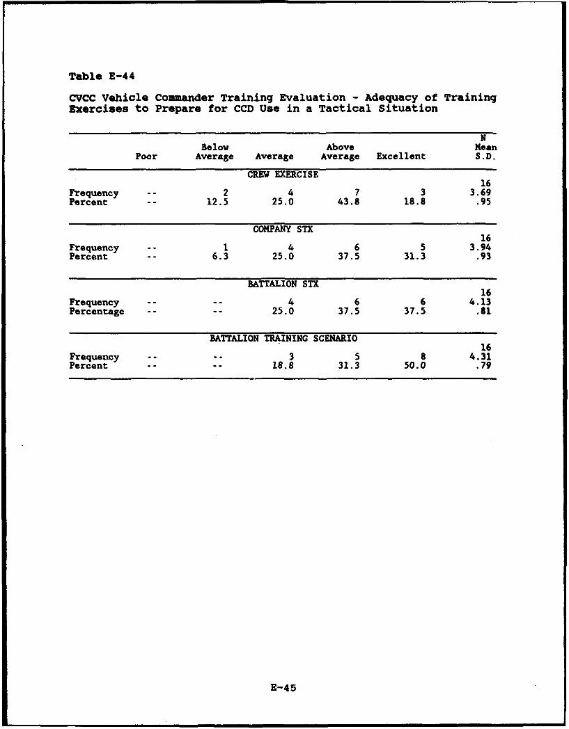
Table E-44
CVCC Vehicle Commander Training Evaluation - Adequacy of TrainingExercises to Prepare for CCD Use in a Tactical Situation
NBelow Above Mean
Poor Average Average Average Excellent S.D.
CREW EXERCISE16
Frequency -- 2 4 7 3 3.69Percent -- 12.5 25.0 43.8 18.8 .95
COMPANY STX16
Frequency -- 1 4 6 5 3.94Percent -- 6.3 25.0 37.5 31.3 .93
BATTALION STX16
Frequency -. 4 6 6 4.13Percentage .... 25.0 37.5 37.5 .81
BATTALION TRAINING SCENARIO 16Frequency ... 3 5 8 4.31Percent .... 18.8 31.3 50.0 .79
E-45

Table E-45
CVCC Vehicle Commander Training Evaluation - Opportunity forHands-On Practice During Training Scenarios
NBelow Above Mean
Poor Average Average Average Excellent S.D.
CITV16
Frequency .... 2 7 7 4.31Percent .... 12.5 43.8 43.8 .70
CCD16
Frequency .... 4 7 7 4.31Percent .. 12.5 43.8 43.8 .70.
Table E-46
CVCC Vehicle Commander Training Evaluation - Preparedness forFinal Battalion Training Exercise
NBelow Above Mean
Poor Average Average Average Excellent S.D.
16Frequency -- 1 2 9 4 4.00Percent -- 6.3 12.5 56.3 25.0 .82
Table E-47
CVCC Vehicle Commander Training Evaluation - CVCC Equipment NotUsed During Final Battalion Training Exercise
WERE THERE ANY CITV OR CCD FUNCTIONS THAT YOU DIDN'T USE DURING THE FINALBATTALION TRAINING EXERCISE?
No Yes
Percent 68.8 31.3
E-46
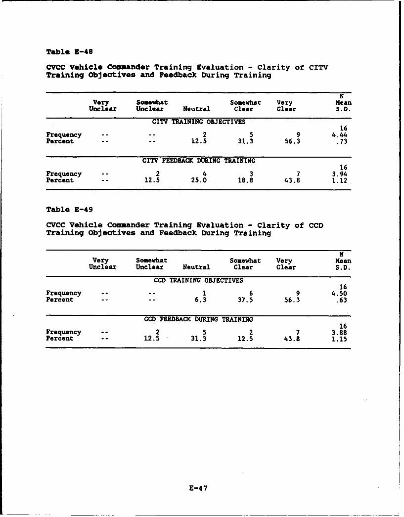
Table 1-48
CVCC Vehicle Commander Training Evaluation - Clarity of CITvTraining Objectives and Feedback During Training
NVery Somewhat Somewhat Very Mean
Unclear Unclear Neutral Clear Clear S.D.
CITV TRAINING OBJECTIVES16
Frequency .... 2 5 9 4.44Percent .... 12.5 31.3 56.3 .73
CITV FEEDBACK DURING TRAINING16
Frequency -- 2 4 3 7 3.94Percent -- 12.5 25.0 18.8 43.8 1.12
Table E-49
CVCC Vehicle Commander Training Evaluation - Clarity of CCDTraining Objectives and Feedback During Training
NVery Somewhat Somewhat Very Mean
Unclear Unclear Neutral Clear Clear S.D.
CCD TRAINING OBJECTIVES16
Frequency .... 1 6 9 4.50Percent .... 6.3 37.5 56.3 .63
CCD FEEDBACK DURING TRAINING16
Frequency -- 2 5 2 7 3.88Percent -- 12.5 31.3 12.5 43.8 1.15
E-47
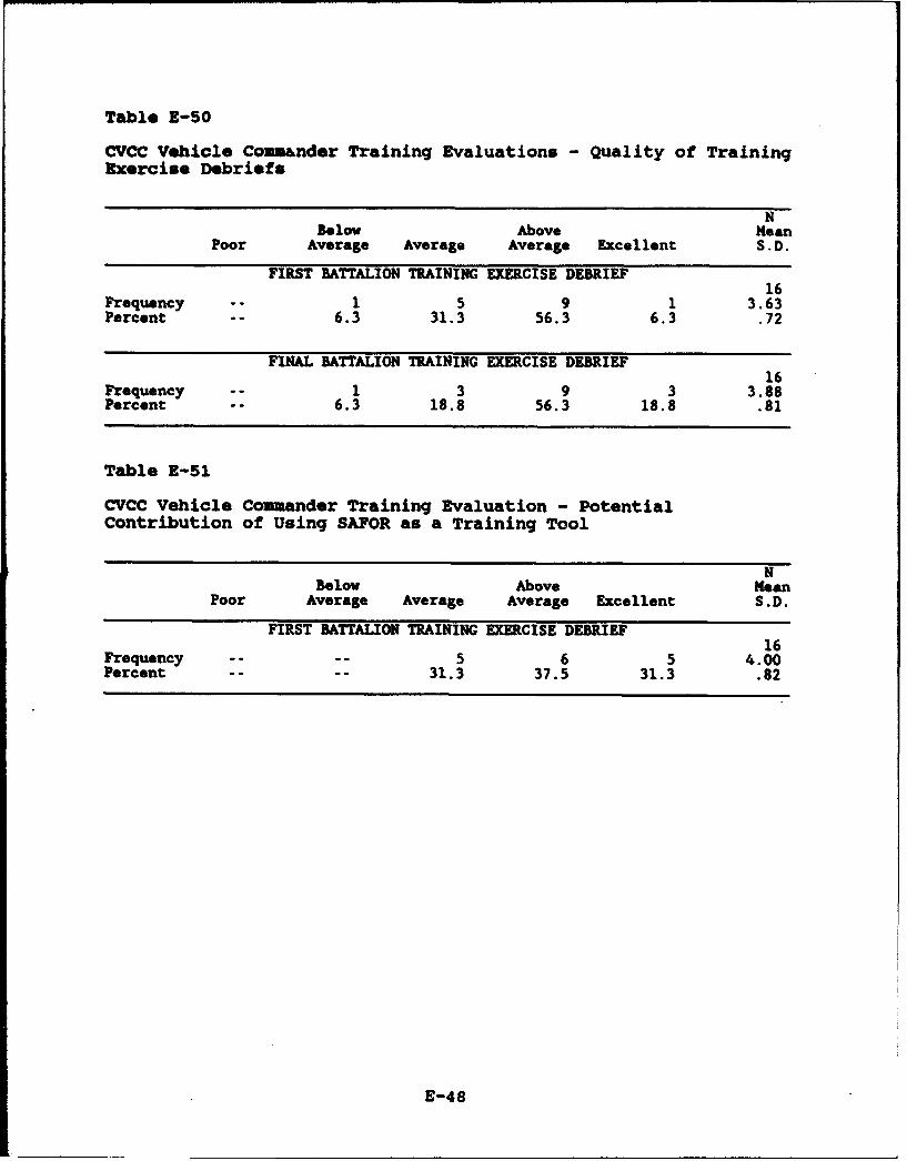
Table E-50
CVCC Vehicle Comm&nder Training Evaluations - Quality of TrainingExercise Debriefs
NBelow Above Mean
Poor Average Average Average Excellent S.D.
FIRST BATTALION TRAINING EXERCISE DEBRIEF16
Frequency -- 1 5 9 1 3.63Percent -- 6.3 31.3 56.3 6.3 .72
FINAL BATTALION TRAINING EXERCISE DEBRIEF16
Frequency -- 1 3 9 3 3.88Percent -- 6.3 18.8 56.3 18.8 .81
Table E-51
CVCC Vehicle Comuander Training Evaluation - PotentialContribution of Using SAFOR as a Training Tool
NBelow Above Mean
Poor Average Average Average Excellent S.D.
FIRST BATTALION TRAINING EXERCISE DEBRIEF16
Frequency .... 5 6 5 4.00Percent .... 31.3 37.5 31.3 .82
E-48

APIRzMIZACRONYM LIO!
F-1
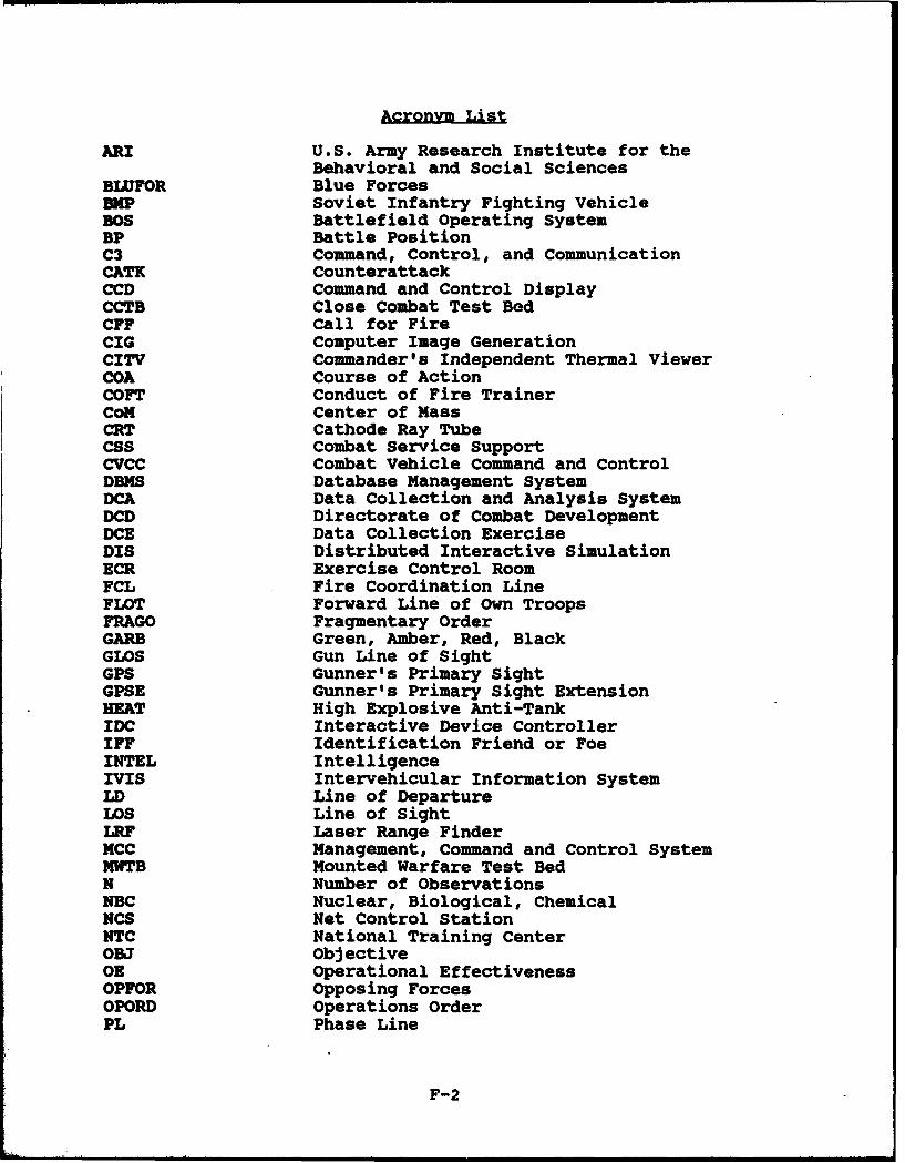
Acronym List
ARI U.S. Army Research Institute for theBehavioral and Social Sciences
BLUFOR Blue ForcesaIP Soviet Infantry Fighting VehicleBOS Battlefield Operating SystemBP Battle PositionC3 Command, Control, and CommunicationCATK CounterattackCCD Command and Control DisplayCCTB Close Combat Test BedCFF Call for FireCIG Computer Image GenerationCITV Commander's Independent Thermal ViewerCOA Course of ActionCOFT Conduct of Fire TrainerCox Center of MassCRT Cathode Ray TubeCSS Combat Service SupportCVCC Combat Vehicle Command and ControlDBMS Database Management SystemDCA Data Collection and Analysis SystemDCD Directorate of Combat DevelopmentDCE Data Collection ExerciseDIS Distributed Interactive SimulationECR Exercise Control RoomFCL Fire Coordination LineFLOT Forward Line of Own TroopsFRAGO Fragmentary OrderGARB Green, Amber, Red, BlackGLOS Gun Line of SightGPS Gunner's Primary SightGPSE Gunner's Primary Sight ExtensionHEAT High Explosive Anti-TankIDC Interactive Device ControllerIFF Identification Friend or FoeINTEL IntelligenceIVIS Intervehicular Information SystemLD Line of DepartureLOS Line of SightLRF Laser Range FinderMCC Management, Command and Control SystemMWTB Mounted Warfare Test BedN Number of ObservationsNBC Nuclear, Biological, ChemicalNCS Net Control StationNTC National Training CenterOBJ ObjectiveOR Operational EffectivenessOPFOR Opposing ForcesOPORD Operations OrderPL Phase Line
F-2

Acronym List (Cont'd)
POSNAV Position NavigationPVD Plan View DisplayREDCON Readiness ConditionS2 Intelligence Staff OfficerS3 Operations Staff OfficerSA Situational AwarenessSAFOR Semiautomated ForcesSCC SINNET Control ConsoleSD Standard DeviationSIJNET Simulation NetworkSIMNET-D Simulation Network--DevelopmentalSIMNET-T Simulation Network--TrainingSINCGARS Single Channel Ground/Air Radio SystemSitDisplay Situation and Planning DisplaySITREP Situation ReportSME Subject Matter ExpertSKI Soldier-Machine InterfaceSOP Standard Operating ProcedureSTX Situational Trainiag ExerciseTACOM Tank Automotive CommandTF Task ForceTO Task OrganizationTOC Tactical Operations CenterTRP Target Reference PointTTP Tactics, Training, and ProceduresVBs Vision BlocksXO Executive Officer
F-3


