Embed Size (px)
Citation preview
Positioning Systems Linear Axes and Axis Systems HX
www.hiwin.de

HIWIN GmbHBrücklesbünd 2D-77654 OffenburgPhone +49 (0) 7 81 9 32 78 - 0Fax +49 (0) 7 81 9 32 78 - [email protected]
All rights reserved.Complete or partial reproduction is not permitted without our permission.
Note:The technical data in this catalogue may be changed without prior notice.
3HX-03-0-EN-1810-K
Positioning Systems Linear axes and axis systems HX
Linear axes and axis systems are used in many industrial areas, e.g. to transport or position components. HIWIN offers linear axes with toothed belt drive for applications requiring high dynamic responses and speeds. The HIWIN modular system is a flexible solution for combining belt axes into twin and multi-axis systems, depending on the application. HIWIN linear axes with ballscrew drive are available for applications requiring high feed forces and precision. HIWIN linear axes with linear motor drive fulfil the highest demands on dynamics, accuracy and synchro-nism.
4
Contents
1 Product overview ............................................................................................................................................................6
2 General information ........................................................................................................................................................82.1 Properties of the linear modules HM 82.2 Properties of the linear tables HT 82.3 Properties of the double axes HD 82.4 Properties of the two-axis system HS2 82.5 Properties of the adapters for cross tables and multi-axis systems 92.6 Glossary 92.7 Requirements at the installation site 102.8 Maximum drive torque 102.9 Calculating the service life 102.10 Calculating the support spacing 122.11 Product selection 14
3 Linear modules HM-B ................................................................................................................................................... 163.1 Properties of linear modules HM-B with toothed belt drive 163.2 Order code for linear modules HM-B 173.3 Dimensions and specifications of HM040B 183.4 Dimensions and specifications of HM060B 203.5 Dimensions and specifications of HM080B 223.6 Dimensions and specifications of HM120B 24
4 Linear modules HM-S ................................................................................................................................................... 264.1 Properties of linear modules HM-S with ballscrew drive 264.2 Order code for linear modules HM-S 274.3 Dimensions and specifications of HM040S 284.4 Dimensions and specifications of HM060S 304.5 Dimensions and specifications of HM080S 324.6 Dimensions and specifications of HM120S 34
5 Linear tables HT-B ........................................................................................................................................................ 365.1 Properties of linear tables HT-B with toothed belt drive 365.2 Order code for linear tables HT-B 375.3 Dimensions and specifications of HT100B 385.4 Dimensions and specifications of HT150B 405.5 Dimensions and specifications of HT200B 425.6 Dimensions and specifications of HT250B 44
6 Linear tables HT-S ........................................................................................................................................................ 466.1 Properties of linear tables HT-S with ballscrew drive 466.2 Order code for linear tables HT-S 476.3 Dimensions and specifications of HT100S 486.4 Dimensions and specifications of HT150S 506.5 Dimensions and specifications of HT200S 526.6 Dimensions and specifications of HT250S 54
7 Linear tables HT-L ........................................................................................................................................................ 567.1 Properties of linear tables HT-S with linear motor 567.2 Order code for linear tables HT-L 577.3 Dimensions and specifications of HT150L 587.4 Dimensions and specifications of HT200L 607.5 Dimensions and specifications of HT250L 62
Linear axes and axis systems HXContents
5HX-03-0-EN-1810-K
8 Double axes HD ............................................................................................................................................................ 648.1 Properties of the double axes HD with toothed belt drive 648.2 Order code for double axes HD 658.3 Dimensions and specifications of HD1 668.4 Dimensions and specifications of HD2 678.5 Dimensions and specifications of HD3 688.6 Dimensions and specifications of HD4 69
9 Two-axis systems HS2 .................................................................................................................................................. 709.1 Properties of the two-axis systems HS2 709.2 Order code for two-axis systems HS2 719.3 Dimensions and specifications of HS21-D-M 729.4 Dimensions and specifications of HS21-D-T 749.5 Dimensions and specifications of HS22-D-M 769.6 Dimensions and specifications of HS22-D-T 789.7 Dimensions and specifications of HS23-D-M 809.8 Dimensions and specifications of HS23-D-T 829.9 Dimensions and specifications of HS24-D-T 84
10 Adapters for cross tables and multi-axis systems .......................................................................................................... 8610.1 Product selection 8610.2 CPN adapter 8810.3 CPR adapter 9010.4 CCN adapter 92
11 Positioning measuring system ...................................................................................................................................... 9311.1 Dimensions of external positioning measuring system HIWIN MAGIC for linear axes HM-B, HM-S, HT-B and HT-S 93
12 Drive adapter ................................................................................................................................................................ 9512.1 Drive adapter for linear modules HM-B, linear tables HT-B and double axes HD 9512.2 Drive adapter for linear modules HM-S, and linear tables HT-S 11412.3 Connection interface and energy supply for linear motor axes HT-L 127
13 HIWIN servo motors and drives ................................................................................................................................... 12913.1 HIWIN servo motors 12913.2 HIWIN D2T servo drive 12913.3 HIWIN D1-N servo drive for linear tables with linear motor HT-L 130
14 Accessories ................................................................................................................................................................ 13114.1 Clamping profiles 13114.2 T nut 13214.3 Centring sleeve 13214.4 Groove cover 13314.5 Limit switch 13314.6 Extension cable for limit switch 13414.7 Damping element 13414.8 Motor cable for HT-L linear table 13414.9 Encoder cable for incremental positioning measuring system 13514.10 Encoder cable for absolute positioning measuring system 13514.11 Separators for energy chain 13614.12 Journal for HM-B linear axis 13614.13 Synchronous shaft 13714.14 HIWIN lubricants 13814.15 HIWIN grease nipples 138
6
Linear axes and axis systems HXProduct overview
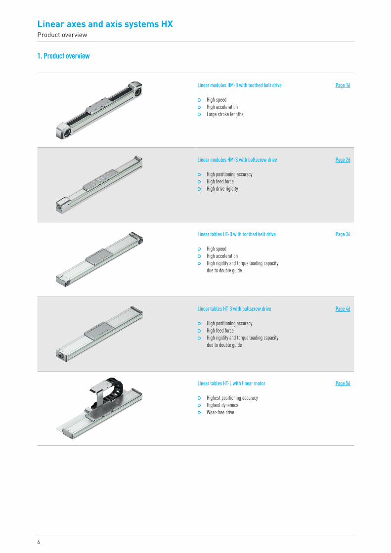
1. Product overview
Linear modules HM-B with toothed belt drive Page 16
High speed High acceleration Large stroke lengths
Linear modules HM-S with ballscrew drive Page 26
High positioning accuracy High feed force High drive rigidity
Linear tables HT-B with toothed belt drive Page 36
High speed High acceleration High rigidity and torque loading capacity
due to double guide
Linear tables HT-S with ballscrew drive Page 46
High positioning accuracy High feed force High rigidity and torque loading capacity
due to double guide
Linear tables HT-L with linear motor Page 56
Highest positioning accuracy Highest dynamics Wear-free drive
7HX-03-0-EN-1810-K
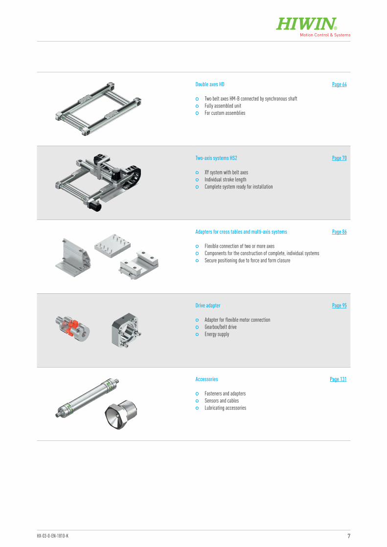
Double axes HD Page 64
Two belt axes HM-B connected by synchronous shaft Fully assembled unit For custom assemblies
Two-axis systems HS2 Page 70
XY system with belt axes Individual stroke length Complete system ready for installation
Adapters for cross tables and multi-axis systems Page 86
Flexible connection of two or more axes Components for the construction of complete, individual systems Secure positioning due to force and form closure
Drive adapter Page 95
Adapter for flexible motor connection Gearbox/belt drive Energy supply
Accessories Page 131
Fasteners and adapters Sensors and cables Lubricating accessories
8
Linear axes and axis systems HXGeneral information
2. General information
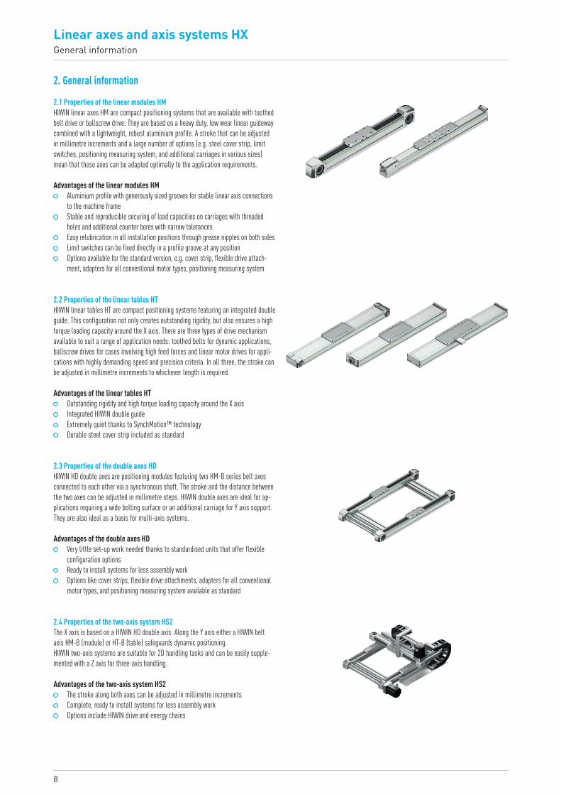
2.1 Properties of the linear modules HMHIWIN linear axes HM are compact positioning systems that are available with toothed belt drive or ballscrew drive. They are based on a heavy duty, low wear linear guideway combined with a lightweight, robust aluminium profile. A stroke that can be adjusted in millimetre increments and a large number of options (e.g. steel cover strip, limit switches, positioning measuring system, and additional carriages in various sizes) mean that these axes can be adapted optimally to the application requirements.
2.2 Properties of the linear tables HTHIWIN linear tables HT are compact positioning systems featuring an integrated double guide. This configuration not only creates outstanding rigidity, but also ensures a high torque loading capacity around the X axis. There are three types of drive mechanism available to suit a range of application needs: toothed belts for dynamic applications, ballscrew drives for cases involving high feed forces and linear motor drives for appli-cations with highly demanding speed and precision criteria. In all three, the stroke can be adjusted in millimetre increments to whichever length is required.
Advantages of the linear modules HM Aluminium profile with generously sized grooves for stable linear axis connections
to the machine frame Stable and reproducible securing of load capacities on carriages with threaded
holes and additional counter bores with narrow tolerances Easy relubrication in all installation positions through grease nipples on both sides Limit switches can be fixed directly in a profile groove at any position Options available for the standard version, e.g. cover strip, flexible drive attach-
ment, adapters for all conventional motor types, positioning measuring system
Advantages of the double axes HD Very little set-up work needed thanks to standardised units that offer flexible
configuration options Ready to install systems for less assembly work Options like cover strips, flexible drive attachments, adapters for all conventional
motor types, and positioning measuring system available as standard
Advantages of the linear tables HT Outstanding rigidity and high torque loading capacity around the X axis Integrated HIWIN double guide Extremely quiet thanks to SynchMotion™ technology Durable steel cover strip included as standard
Advantages of the two-axis system HS2 The stroke along both axes can be adjusted in millimetre increments Complete, ready to install systems for less assembly work Options include HIWIN drive and energy chains
2.3 Properties of the double axes HDHIWIN HD double axes are positioning modules featuring two HM-B series belt axes connected to each other via a synchronous shaft. The stroke and the distance between the two axes can be adjusted in millimetre steps. HIWIN double axes are ideal for ap-plications requiring a wide bolting surface or an additional carriage for Y axis support. They are also ideal as a basis for multi-axis systems.
2.4 Properties of the two-axis system HS2The X axis is based on a HIWIN HD double axis. Along the Y axis either a HIWIN belt axis HM-B (module) or HT-B (table) safeguards dynamic positioning.HIWIN two-axis systems are suitable for 2D handling tasks and can be easily supple-mented with a Z axis for three-axis handling.
9HX-03-0-EN-1810-K
Advantages of the adapters Quick and easy assembly of individual multi-axis systems Rigid and safe power transmission Low construction effort due to standardised sets including fixing material
2.5 Properties of the adapters for cross tables and multi-axis systemsWith the HIWIN adapters for cross tables and multi-axis systems, two or more axes can be flexibly combined with each other. This way individual multi-axis systems can be designed quickly and easily. Forces and torques are safely transmitted due to force and form closure. Centering sleeves ensure an exact and reproducible connection.
Positioning accuracyThe positioning accuracy describes the maximum difference between the actual and nominal position.
RepeatabilityRepeatability is the value of how precise the carriage is positioned when it approaches a position several times from the same direction. It specifies the maximum position error between the reached positions.
Static load rating C0The static load rating C0 equals the static load that causes a plastic deformation of 0.0001 × ball diameter at the contact point under the heaviest load. This is a funda-mental quantity in calculations for static applications.
Dynamic load rating CdynThe dynamic load rating Cdyn equals the load under which 90 % of identical linear guideways reach the life expectancy of 50 km. This is a fundamental quantity in calculations for dynamic applications.
StrokeStroke is the distance the carriage must travel between the two end points of the limit switches.
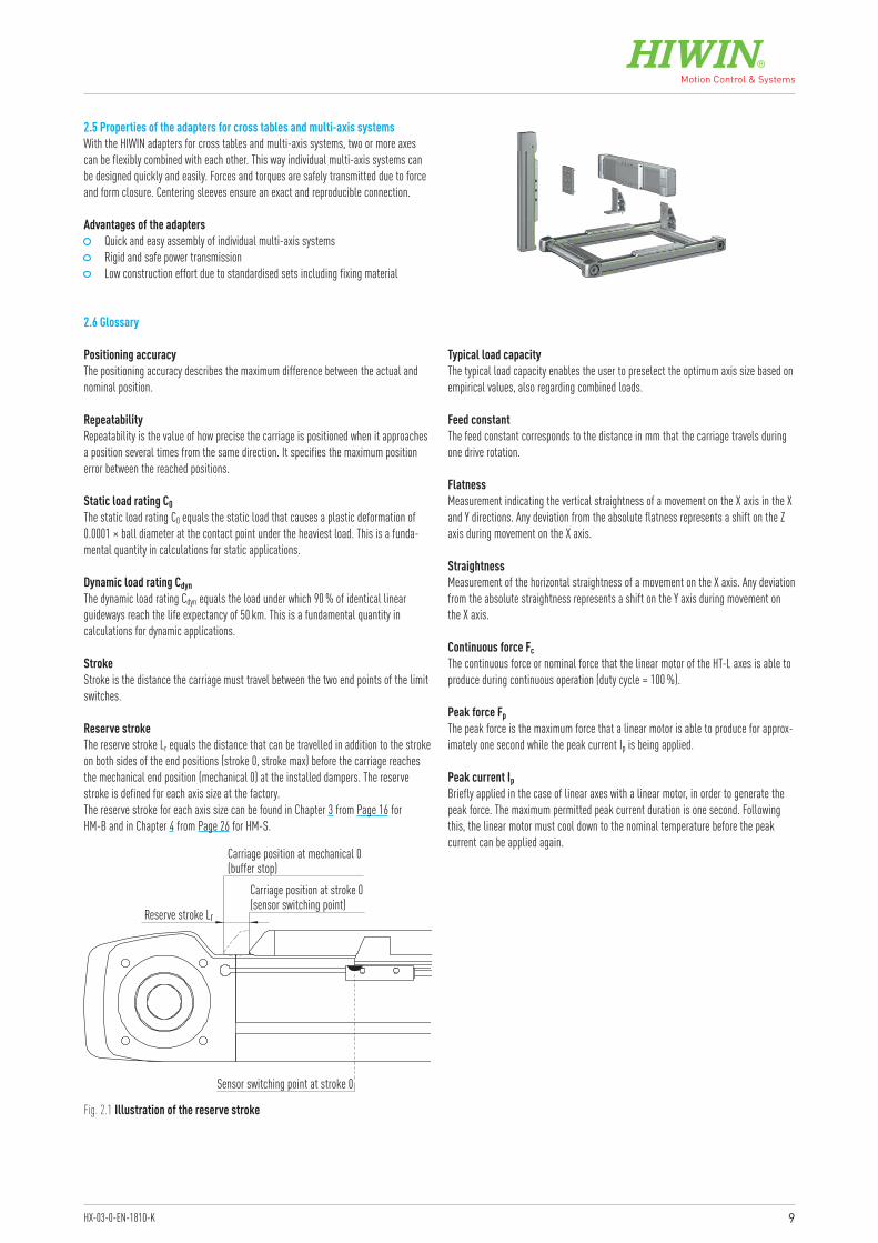
Reserve strokeThe reserve stroke Lr equals the distance that can be travelled in addition to the stroke on both sides of the end positions (stroke 0, stroke max) before the carriage reaches the mechanical end position (mechanical 0) at the installed dampers. The reserve stroke is defined for each axis size at the factory.The reserve stroke for each axis size can be found in Chapter 3 from Page 16 for HM-B and in Chapter 4 from Page 26 for HM-S.
Typical load capacityThe typical load capacity enables the user to preselect the optimum axis size based on empirical values, also regarding combined loads.
Feed constantThe feed constant corresponds to the distance in mm that the carriage travels during one drive rotation.
FlatnessMeasurement indicating the vertical straightness of a movement on the X axis in the X and Y directions. Any deviation from the absolute flatness represents a shift on the Z axis during movement on the X axis.
StraightnessMeasurement of the horizontal straightness of a movement on the X axis. Any deviation from the absolute straightness represents a shift on the Y axis during movement on the X axis.
Continuous force FcThe continuous force or nominal force that the linear motor of the HT-L axes is able to produce during continuous operation (duty cycle = 100 %).
Peak force FpThe peak force is the maximum force that a linear motor is able to produce for approx-imately one second while the peak current Ip is being applied.
Peak current IpBriefly applied in the case of linear axes with a linear motor, in order to generate the peak force. The maximum permitted peak current duration is one second. Following this, the linear motor must cool down to the nominal temperature before the peak current can be applied again.
Fig. 2.1 Illustration of the reserve stroke
Reserve stroke Lr
Carriage position at mechanical 0(buffer stop)
Carriage position at stroke 0(sensor switching point)
Sensor switching point at stroke 0
2.6 Glossary
10
Linear axes and axis systems HXGeneral information
2.7 Requirements at the installation site Temperature range: 0 °C to +50 °C Dry environment Not explosive No vacuum
F 2.1
F 2.2
Fx Feed force [N]MA Required drive torque [Nm]Mload Load torque [Nm]Midle Idle torque [Nm]p Feed constant [mm/rotation] Toothed belt drive: equals the pulley circumference
Ballscrew: equals the spindle leadη Efficiency (about 0.9 for ballscrew drive)
(about 0.98 for toothed belt drive)
Mx
MzFz
MyFy
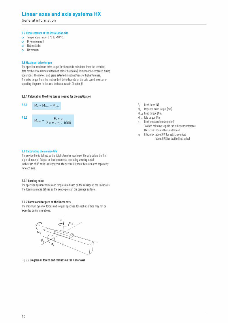
Fig. 2.2 Diagram of forces and torques on the linear axis
MA = Mload + Midle
Mload = Fx × p2 × π × η × 1000
2.8 Maximum drive torqueThe specified maximum drive torque for the axis is calculated from the technical data for the drive elements (toothed belt or ballscrew). It may not be exceeded during operations. The motors and gears selected must not transfer higher torques. The drive torque from the toothed belt drive depends on the axis speed (see corre-sponding diagrams in the axis’ technical data in Chapter 3).
2.8.1 Calculating the drive torque needed for the application
2.9 Calculating the service lifeThe service life is defined as the total kilometre reading of the axis before the first signs of material fatigue on its components (excluding wearing parts).In the case of HS multi-axis systems, the service life must be calculated separately for each axis.
2.9.1 Loading pointThe specified dynamic forces and torques are based on the carriage of the linear axis. The loading point is defined as the centre point of the carriage surface.
2.9.2 Forces and torques on the linear axisThe maximum dynamic forces and torques specified for each axis type may not be exceeded during operations.
11HX-03-0-EN-1810-K
fv = + |Fy|Fydynmax
|Fz|Fzdynmax
+ |Mx|Mxdynmax
+ |My|Mydynmax
+ |Mz|Mzdynmax
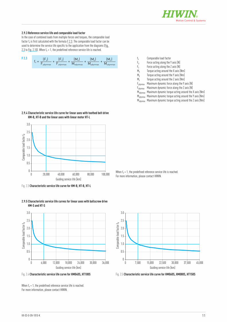
fv Comparable load factorFy Force acting along the Y axis [N]Fz Force acting along the Z axis [N]Mx Torque acting around the X axis [Nm]My Torque acting around the Y axis [Nm]Mz Torque acting around the Z axis [Nm]Fydynmax Maximum dynamic force along the Y axis [N]Fzdynmax Maximum dynamic force along the Z axis [N]Mxdynmax Maximum dynamic torque acting around the X axis [Nm]Mydynmax Maximum dynamic torque acting around the Y axis [Nm]Mzdynmax Maximum dynamic torque acting around the Z axis [Nm]
F 2.3
Fig. 2.3 Characteristic service life curve for HM-B, HT-B, HT-L
Fig. 2.4 Characteristic service life curve for HM040S, HT100S Fig. 2.5 Characteristic service life curve for HM060S, HM080S, HT150S
When fv = 1, the predefined reference service life is reached.For more information, please contact HIWIN.
When fv = 1, the predefined reference service life is reached.For more information, please contact HIWIN.
0
0.5
1.0
1.5
2.0
2.5
3.0
0 20,000 40,000 60,000 80,000 100,000Guiding service life [km]
Comp
arable
load
facto
r fv
0
0.5
1.0
1.5
2.0
2.5
3.0
0 6,000 12,000 18,000 24,000 30,000 36,000Guiding service life [km]
Comp
arable
load
facto
r fv
0
0.5
1.0
1.5
2.0
2.5
3.0
0 7,500 15,000 22,500 30,000 37,500 45,000Guiding service life [km]
Comp
arable
load
facto
r fv
2.9.3 Reference service life and comparable load factorIn the case of combined loads from multiple forces and torques, the comparable loadfactor fv is first calculated with the formula F 2.3. The comparable load factor can beused to determine the service life specific to the application from the diagrams (Fig. 2.3 to Fig. 2.10). When fv = 1, the predefined reference service life is reached.
2.9.4 Characteristic service life curve for linear axes with toothed belt drive HM-B, HT-B and the linear axes with linear motor HT-L
2.9.5 Characteristic service life curves for linear axes with ballscrew drive HM-S and HT-S
12
Linear axes and axis systems HXGeneral information
Fig. 2.6 Characteristic service life curve for HM120S, HT200S
0
0.5
1.0
1.5
2.0
2.5
3.0
0 10,000 20,000 30,000 40,000 50,000Guiding service life [km]
Comp
arable
load
facto
r fv
0
0.5
1.0
1.5
2.0
2.5
3.0
0 12,500 25,000 37,500 50,000 62,500Guiding service life [km]
Comp
arable
load
facto
r fv
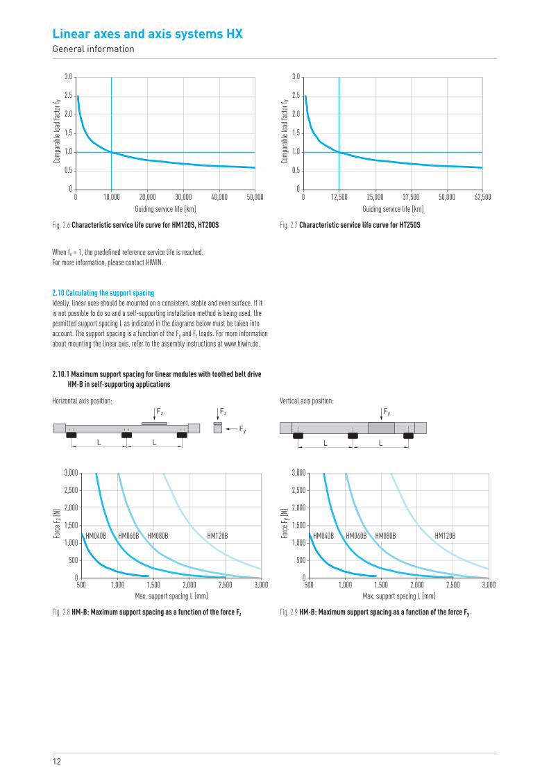
When fv = 1, the predefined reference service life is reached.For more information, please contact HIWIN.
Fz Fz
Fy
L L
Fy
L L
Horizontal axis position: Vertical axis position:
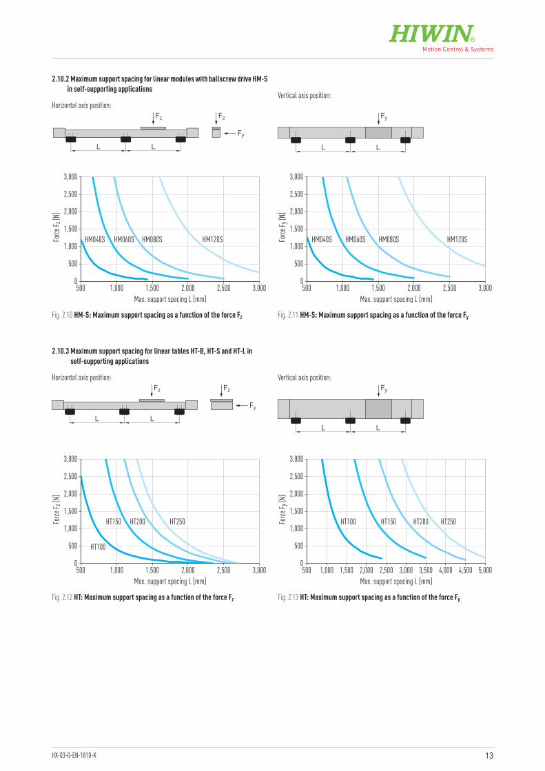
2.10 Calculating the support spacingIdeally, linear axes should be mounted on a consistent, stable and even surface. If it is not possible to do so and a self-supporting installation method is being used, the permitted support spacing L as indicated in the diagrams below must be taken into account. The support spacing is a function of the Fy and Fz loads. For more information about mounting the linear axis, refer to the assembly instructions at www.hiwin.de.
2.10.1 Maximum support spacing for linear modules with toothed belt drive HM-B in self-supporting applications
0
500
1,000
1,500
2,000
2,500
3,000
500 1,500 2,0001,000 2,500 3,000
HM040B HM060B HM080B HM120B
Max. support spacing L [mm]
Force
F z [N
]
0
500
1,000
1,500
2,000
2,500
3,000
500 1,500 2,0001,000 2,500 3,000
HM040B HM060B HM080B HM120B
Max. support spacing L [mm]
Force
F y [N
]
Fig. 2.7 Characteristic service life curve for HT250S
Fig. 2.8 HM-B: Maximum support spacing as a function of the force Fz Fig. 2.9 HM-B: Maximum support spacing as a function of the force Fy
13HX-03-0-EN-1810-K
Fz Fz
Fy
L L
Fy
L L
Fig. 2.10 HM-S: Maximum support spacing as a function of the force Fz Fig. 2.11 HM-S: Maximum support spacing as a function of the force Fy
Horizontal axis position:Vertical axis position:
2.10.2 Maximum support spacing for linear modules with ballscrew drive HM-S in self-supporting applications
0
500
1,000
1,500
2,000
2,500
3,000
500 1,500 2,0001,000 2,500 3,000
HM040S HM060S HM080S HM120S
Max. support spacing L [mm]
Force
F z [N
]
0
500
1,000
1,500
2,000
2,500
3,000
500 1,500 2,0001,000 2,500 3,000
HM040S HM060S HM080S HM120S
Max. support spacing L [mm]
Force
F y [N
]
Fz Fz
Fy
L L
Fy
L L
0
500
1,000
1,500
2,000
2,500
3,000
500 1,500 2,0001,000 2,500 3,000
HT250HT200HT150
HT100
Max. support spacing L [mm]
Force
F z [N
]
0
500
1,000
1,500
2,000
2,500
3,000
500 1,500 2,0001,000 2,500 5,0003,000 3,500 4,5004,000
HT250HT200HT150HT100
Max. support spacing L [mm]
Force
F y [N
]
Fig. 2.12 HT: Maximum support spacing as a function of the force Fz Fig. 2.13 HT: Maximum support spacing as a function of the force Fy
Horizontal axis position: Vertical axis position:
2.10.3 Maximum support spacing for linear tables HT-B, HT-S and HT-L in self-supporting applications
14
Linear axes and axis systems HXGeneral information
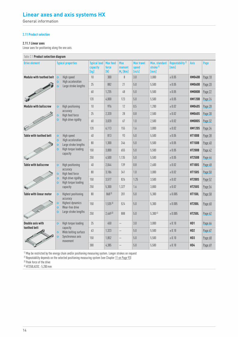
2.11 Product selection
2.11.1 Linear axesLinear axes for positioning along the one axis.
Table 2.1 Product selection diagram
Drive element Typical properties Typical load capacity [kg]
Max feed force [N]
Max moment Mx [Nm]
Max travel speed [m/s]
Max. standard stroke 1) [mm]
Repeatability 2) [mm]
Axis Page
Module with toothed belt High speed High acceleration Large stroke lengths
10 300 8 3.0 3,000 ± 0.05 HM040B Page 18
25 882 21 5.0 5,500 ± 0.05 HM060B Page 20
60 1,235 48 5.0 5,500 ± 0.05 HM080B Page 22
120 4,000 123 5.0 5,500 ± 0.05 HM120B Page 24
Module with ballscrew High positioning accuracy
High feed force High drive rigidity
10 976 12 0.5 1,200 ± 0.02 HM040S Page 28
25 2,320 28 0.8 2,500 ± 0.02 HM060S Page 30
60 3,020 67 1.0 2,500 ± 0.02 HM080S Page 32
120 6,113 155 1.6 3,800 ± 0.02 HM120S Page 34
Table with toothed belt High speed High acceleration Large stroke lengths High torque loading
capacity
40 813 93 5.0 5,500 ± 0.05 HT100B Page 38
80 1,300 246 5.0 5,500 ± 0.05 HT150B Page 40
150 3,000 655 5.0 5,500 ± 0.05 HT200B Page 42
250 4,500 1,135 5.0 5,500 ± 0.05 HT250B Page 44
Table with ballscrew High positioning accuracy
High feed force High drive rigidity High torque loading
capacity
40 2,044 139 0.8 2,600 ± 0.02 HT100S Page 48
80 3,186 341 1.0 3,000 ± 0.02 HT150S Page 50
150 3,517 826 1.25 3,500 ± 0.02 HT200S Page 52
250 5,300 1,327 1.6 3,800 ± 0.02 HT250S Page 54
Table with linear motor Highest positioning accuracy
Highest dynamics Wear-free drive Large stroke lengths
80 868 3) 201 5.0 5,300 ± 0.005 HT150L Page 58
150 1,535 3) 524 5.0 5,300 ± 0.005 HT200L Page 60
250 2,469 3) 888 5.0 5,300 4) ± 0.005 HT250L Page 62
Double axis with toothed belt
High torque loading capacity
Wide bolting surface Synchronous axis
movement
25 450 — 3.0 3,000 ± 0.10 HD1 Page 66
63 1,323 — 5.0 5,500 ± 0.10 HD2 Page 67
150 1,852 — 5.0 5,500 ± 0.10 HD3 Page 68
300 4,385 — 5.0 5,500 ± 0.10 HD4 Page 69
1) May be restricted by the energy chain and/or positioning measuring system. Longer strokes on request 2) Repeatability depends on the selected positioning measuring system (see Chapter 11 on Page 93)3) Peek force of the drive 4) HT250LA33C : 5,200 mm
15HX-03-0-EN-1810-K
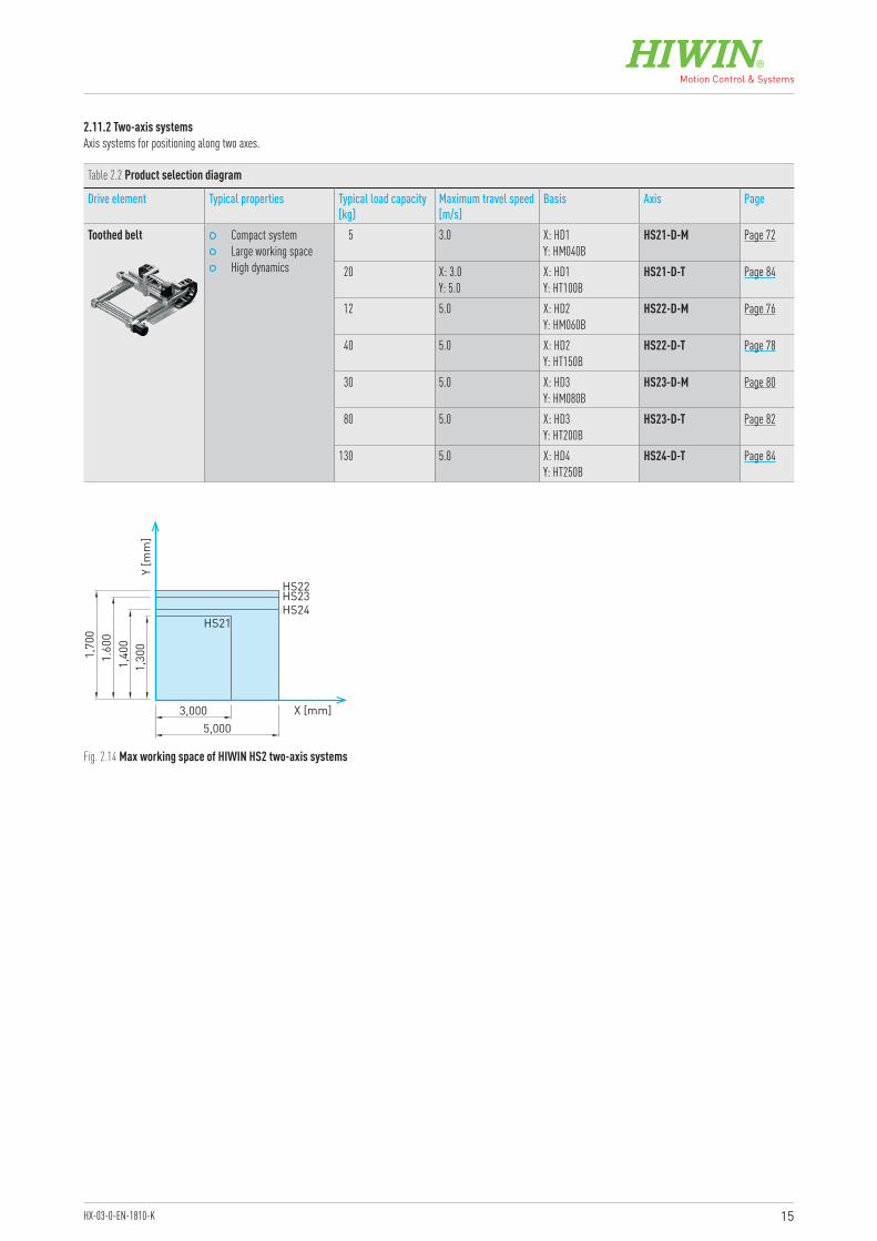
2.11.2 Two-axis systemsAxis systems for positioning along two axes.
Fig. 2.14 Max working space of HIWIN HS2 two-axis systems
Table 2.2 Product selection diagram
Drive element Typical properties Typical load capacity [kg]
Maximum travel speed [m/s]
Basis Axis Page
Toothed belt Compact system Large working space High dynamics
5 3.0 X: HD1 Y: HM040B
HS21-D-M Page 72
20 X: 3.0 Y: 5.0
X: HD1 Y: HT100B
HS21-D-T Page 84
12 5.0 X: HD2 Y: HM060B
HS22-D-M Page 76
40 5.0 X: HD2 Y: HT150B
HS22-D-T Page 78
30 5.0 X: HD3 Y: HM080B
HS23-D-M Page 80
80 5.0 X: HD3 Y: HT200B
HS23-D-T Page 82
130 5.0 X: HD4 Y: HT250B
HS24-D-T Page 84
HS21
HS23HS24
HS22
3,000
Y [m
m]
X [mm]5,000
1,30
01,
400
1.60
01,
700
16
Linear axes and axis systems HXLinear modules HM-B
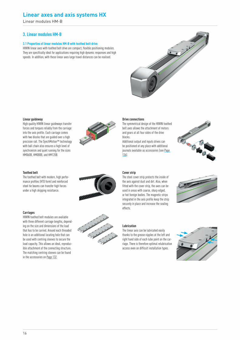
3. Linear modules HM-B
3.1 Properties of linear modules HM-B with toothed belt driveHIWIN linear axes with toothed belt drive are compact, flexible positioning modules. They are specifically ideal for applications requiring high dynamic responses and high speeds. In addition, with these linear axes large travel distances can be realised.
Linear guidewayHigh quality HIWIN linear guideways transfer forces and torques reliably from the carriage into the axis profile. Each carriage comes with two blocks that are guided over a high precision rail. The SynchMotion™ technology with ball chain also ensures a high level of synchronism and quiet running for the sizes HM060B, HM080B, and HM120B.
Drive connectionsThe symmetrical design of the HIWIN toothed belt axes allows the attachment of motors and gears at all four sides of the drive blocks.Additional output and inputs drives can be positioned at any place with additional journals available as accessories (see Page 136).
Cover stripThe steel cover strip protects the inside of the axis against dust and dirt. Also, when fitted with the cover strip, the axes can be used in areas with coarse, sharp edged, or hot foreign bodies. The magnetic strips integrated in the axis profile keep the strip securely in place and increase the sealing effects.
LubricationThe linear axis can be lubricated easily thanks to the grease nipples at the left and right hand side of each lube point on the car-riage. There is therefore optimal relubrication access even on difficult installation types.
Toothed beltThe toothed belt with modern, high perfor-mance profiles (HTD form) and reinforced steel tie beams can transfer high forces under a high skipping resistance.
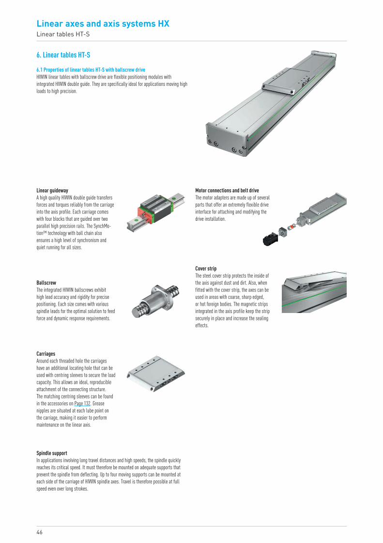
CarriagesHIWIN toothed belt modules are available with three different carriage lengths, depend-ing on the size and dimensions of the load that has to be carried. Around each threaded hole is an additional locating hole that can be used with centring sleeves to secure the load capacity. This allows an ideal, reproduc-ible attachment of the connecting structure. The matching centring sleeves can be found in the accessories on Page 132.
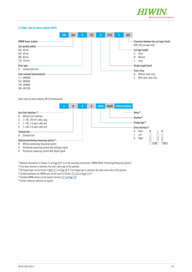
17HX-03-0-EN-1810-K
HIWIN linear module
Motor 5)
Gearbox 4)
Flange type 3)
Optional positioning measuring system 1):N: Without positioning measuring systemA: Positioning measuring system with analogue signalD: Positioning measuring system with digital signal
Drive interface 2):N: NoneL: LeftR: Right
Toothed belt:N: Standard belt
Axis limit switches: 6):N: Without limit switchesA: 2 × NC, 100 mm cable, plugC: 2 × NC, 4 m open cable endD: 2 × NO, 5 m open cable end
Size (profile width):040: 40 mm060: 60 mm080: 80 mm120: 120 mm
Feed constant [mm/rotation]:111: HM040B155: HM060B190: HM080B288: HM120B
Stroke length [mm]
Carriage length:S: ShortM: MediumL: Long
Clearance between two carriages [mm]:(000: One carriage only)
Drive type:B: Toothed belt drive Cover strip:
N: Without cover stripC: With steel cover strip
HM 060 B 155 N 0755 S 000
A N N R HW05 G0605 FRMS4020506A
Order code for linear modules HM-B (continuation)
1) Detailed information in Chapter 11 on Page 93 ff. or in the assembly instructions “HIWIN MAGIC Positioning Measuring Systems”2) If no drive interface is selected, the order code ends at this position3) All flange types can be found in Table 12.1 on Page 96 ff. If no flange type is selected, the order code ends at this position4) Suitable gearboxes for HIWIN axes can be found in Section 12.1.3.5 on Page 111 ff.5) Suitable HIWIN motors can be found in Section 13.1 on Page 1296) Further reference switches on request
3.2 Order code for linear modules HM-B
N L R

18
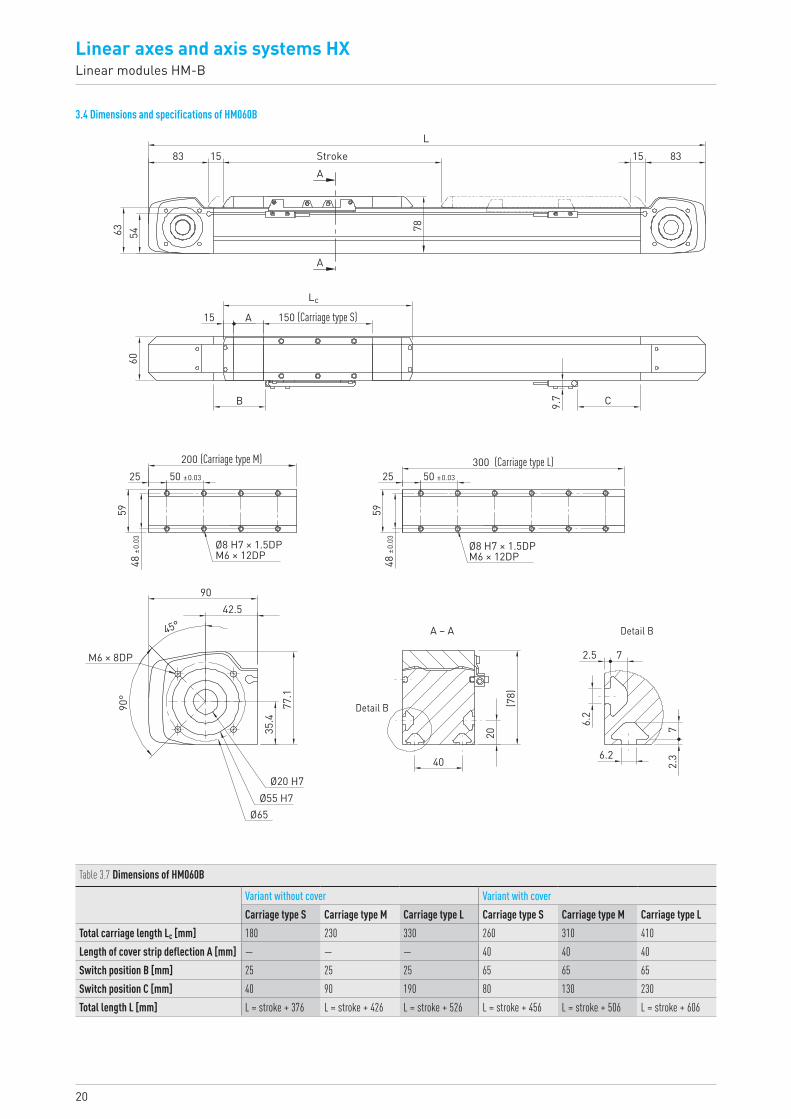
Linear axes and axis systems HXLinear modules HM-B
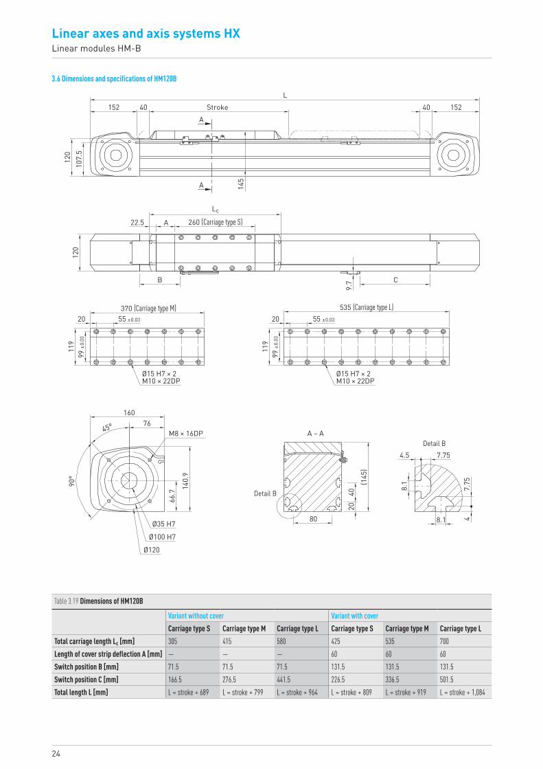
3.3 Dimensions and specifications of HM040B
Table 3.1 Dimensions of HM040B
Variant without cover Variant with coverCarriage type S Carriage type M Carriage type L Carriage type S Carriage type M Carriage type L
Total carriage length Lc [mm] 150 185 255 230 265 335Length of cover strip deflection A [mm] — — — 40 40 40Switch position B [mm] 24 24 24 64 64 64Switch position C [mm] 9 44 114 49 84 154Total length L [mm] L = stroke + 294 L = stroke + 329 L = stroke + 399 L = stroke + 374 L = stroke + 409 L = stroke + 479
45°
90°
10 Stroke
5
4.7
1.6
5
1.6
4.7
Detail B
Detail B
10
20
(60)
A – A
58.2
Ø14 H7
Ø42 H7
Ø50
6532.5
M4 × 6DP
27.3
62 62L
604047.5
10
A
A
A
40
C
11.2B
12.5 125 (Carriage type S)
Lc
27.5160 (Carriage type M)
Ø8 H7 × 1.5DPM5 × 10DP
30 ±
0.03
35 ±0.03
39
27.5230 (Carriage type L)
Ø8 H7 × 1.5DPM5 × 10DP
30 ±
0.03
35 ±0.03
39
19HX-03-0-EN-1810-K
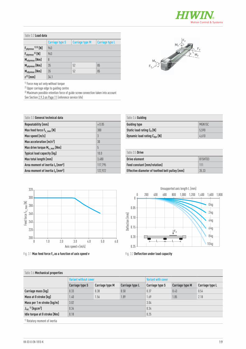
Table 3.6 Mechanical properties
Variant without cover Variant with coverCarriage type S Carriage type M Carriage type L Carriage type S Carriage type M Carriage type L
Carriage mass [kg] 0.33 0.38 0.50 0.37 0.43 0.54Mass at 0 stroke [kg] 1.40 1.56 1.89 1.69 1.85 2.18Mass per 1 m stroke [kg/m] 3.02 3.04Jrot. 1) [kgcm2] 0.34 0.34Idle torque at 0 stroke [Nm] 0.18 0.251) Rotatory moment of inertia
Table 3.2 Load data
Carriage type S Carriage type M Carriage type LFydynmax 1) 3) [N] 963Fzdynmax 3) [N] 963Mxdynmax [Nm] 8Mydynmax [Nm] 35 52 85Mzdynmax [Nm] 35 52 85z 2) [mm] 34.11) Force may act only without torque2) Upper carriage edge to guiding centre 3) Maximum possible retention force of guide screw connection taken into accountSee Section 2.9.3 on Page 11 (reference service life)
Table 3.3 General technical data
Repeatability [mm] ± 0.05Max feed force Fx_max [N] 300Max speed [m/s] 3Max acceleration [m/s2] 30Max drive torque Ma_max [Nm] 5Typical load capacity [kg] 10.0Max total length [mm] 3,480Area moment of inertia Ix [mm4] 117,795Area moment of inertia Iy [mm4] 122,922
Table 3.4 Guiding
Guiding type MGN15CStatic load rating C0 [N] 5,590Dynamic load rating Cdyn [N] 4,610
Table 3.5 Drive
Drive element B15HTD3Feed constant [mm/rotation] 111Effective diameter of toothed belt pulley [mm] 35.33
Fz
Fx
MzFy
z My
Mx
Fig. 3.1 Max feed force Fx as a function of axis speed v Fig. 3.2 Deflection under load capacity
200
220
240
260
280
300
320
0 1.0 2.0 3.0 4.0 5.0 6.0Axis speed v [m/s]
Feed
force
F x_m
ax [N
]
0.25
0.20
0.15
0.10
0.05
00 200 400 600 800 1,000 1,200 1,400 1,600 1,800
0 kg
2 kg
4 kg
6 kg
8 kg
10 kg
Unsupported axis length L [mm]
Defle
ction
[mm]
LL
Fz
20
Linear axes and axis systems HXLinear modules HM-B
3.4 Dimensions and specifications of HM060B
Table 3.7 Dimensions of HM060B
Variant without cover Variant with coverCarriage type S Carriage type M Carriage type L Carriage type S Carriage type M Carriage type L
Total carriage length Lc [mm] 180 230 330 260 310 410Length of cover strip deflection A [mm] — — — 40 40 40Switch position B [mm] 25 25 25 65 65 65Switch position C [mm] 40 90 190 80 130 230Total length L [mm] L = stroke + 376 L = stroke + 426 L = stroke + 526 L = stroke + 456 L = stroke + 506 L = stroke + 606
45°
90°
15 Stroke
6.2
72.5
6.2
2.3
7
Detail B
Detail B
20
40
(78)
A – A
77.1
Ø20 H7Ø55 H7
Ø65
9042.5
M6 × 8DP
35.4
83 83L
785463
15
A
A
A
60
C9.7B
15 150 (Carriage type S)
Lc
25200 (Carriage type M)
Ø8 H7 × 1.5DPM6 × 12DP
48 ±0
.03
50 ±0.03
59
25300 (Carriage type L)
Ø8 H7 × 1.5DPM6 × 12DP48
±0.0
3
50 ±0.03
59

21HX-03-0-EN-1810-K
Table 3.8 Load data
Carriage type S Carriage type M Carriage type LFydynmax 1) 3) [N] 2,152Fzdynmax 3) [N] 2,616Mxdynmax [Nm] 21Mydynmax [Nm] 98 164 294Mzdynmax [Nm] 81 135 242z 2) [mm] 45.61) Force may act only without torque2) Upper carriage edge to guiding centre 3) Maximum possible retention force of guide screw connection taken into accountSee Section 2.9.3 on Page 11 (reference service life)
Table 3.9 General technical data
Repeatability [mm] ± 0.05Max feed force Fx_max [N] 882Max speed [m/s] 5Max acceleration [m/s2] 30Max drive torque Ma_max [Nm] 22Typical load capacity [kg] 25Max total length [mm] 6,080Area moment of inertia Ix [mm4] 507,521Area moment of inertia Iy [mm4] 625,920
Table 3.10 Guiding
Guiding type QEH15CAStatic load rating C0 [N] 15,280Dynamic load rating Cdyn [N] 12,530
Table 3.11 Drive
Drive element B25HTD5Feed constant [mm/rotation] 155Effective diameter of toothed belt pulley [mm] 49.34
Fz
Fx
MzFy
z My
Mx
Fig. 3.3 Max feed force Fx as a function of axis speed v Fig. 3.4 Deflection under load capacity
Table 3.12 Mechanical properties
Variant without cover Variant with coverCarriage type S Carriage type M Carriage type L Carriage type S Carriage type M Carriage type L
Carriage mass [kg] 0.81 0.96 1.25 0.89 1.03 1.32Mass at 0 stroke [kg] 3.44 3.85 4.69 3.97 4.39 5.23Mass per 1 m stroke [kg/m] 5.47 5.51Jrot. 1) [kgcm2] 1.92 1.92Idle torque at 0 stroke [Nm] 0.47 1.001) Rotatory moment of inertia
400
500
600
700
800
900
1,000
0 1.0 2.0 3.0 4.0 5.0 6.0Axis speed v [m/s]
Feed
force
F x_m
ax [N
]
0.8
0.7
0.6
0.4
0.2
0.5
0.3
0.1
00 500 1,000 1,500 2,000 2,500 3,000
0 kg
5 kg
10 kg
15 kg
20 kg
25 kg
Unsupported axis length L [mm]
Defle
ction
[mm]
LL
Fz
22
Linear axes and axis systems HXLinear modules HM-B
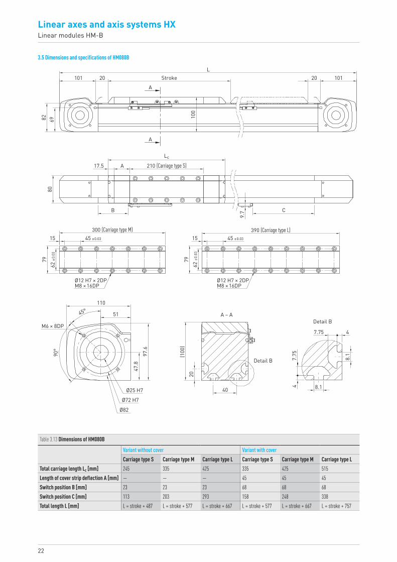
3.5 Dimensions and specifications of HM080B
Table 3.13 Dimensions of HM080B
Variant without cover Variant with coverCarriage type S Carriage type M Carriage type L Carriage type S Carriage type M Carriage type L
Total carriage length Lc [mm] 245 335 425 335 425 515Length of cover strip deflection A [mm] — — — 45 45 45Switch position B [mm] 23 23 23 68 68 68Switch position C [mm] 113 203 293 158 248 338Total length L [mm] L = stroke + 487 L = stroke + 577 L = stroke + 667 L = stroke + 577 L = stroke + 667 L = stroke + 757
Stroke
A
A
A17.5
B
(100
)20
47.
75
7.75
8.1
8.190
°
45°
4
40
Detail B
Detail B
9.7
210 (Carriage type S)
C
80
L101 101
100
82 69
20 20
Lc
A – A
M6 × 8DP
110
51
97.6
47.8
Ø25 H7
Ø72 H7
Ø82
15
7962
±0.0
3
45 ±0.03
300 (Carriage type M)
Ø12 H7 × 2DPM8 × 16DP
15
7962
±0.0
3
45 ±0.03
390 (Carriage type L)
Ø12 H7 × 2DPM8 × 16DP
23HX-03-0-EN-1810-K
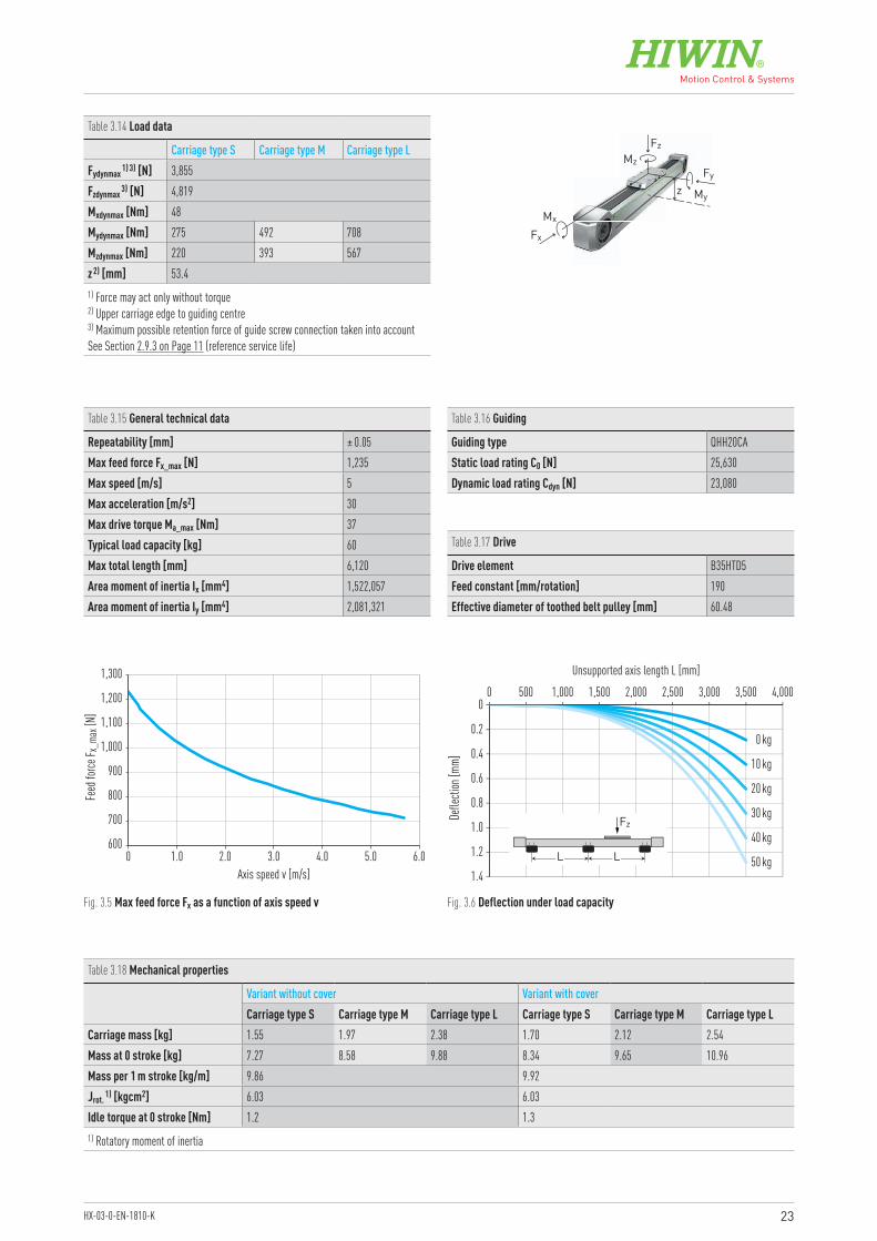
Table 3.14 Load data
Carriage type S Carriage type M Carriage type LFydynmax 1) 3) [N] 3,855Fzdynmax 3) [N] 4,819Mxdynmax [Nm] 48Mydynmax [Nm] 275 492 708Mzdynmax [Nm] 220 393 567z 2) [mm] 53.41) Force may act only without torque2) Upper carriage edge to guiding centre 3) Maximum possible retention force of guide screw connection taken into accountSee Section 2.9.3 on Page 11 (reference service life)
Table 3.15 General technical data
Repeatability [mm] ± 0.05Max feed force Fx_max [N] 1,235Max speed [m/s] 5Max acceleration [m/s2] 30Max drive torque Ma_max [Nm] 37Typical load capacity [kg] 60Max total length [mm] 6,120Area moment of inertia Ix [mm4] 1,522,057Area moment of inertia Iy [mm4] 2,081,321
Table 3.16 Guiding
Guiding type QHH20CAStatic load rating C0 [N] 25,630Dynamic load rating Cdyn [N] 23,080
Table 3.17 Drive
Drive element B35HTD5Feed constant [mm/rotation] 190Effective diameter of toothed belt pulley [mm] 60.48
Fz
Fx
MzFy
z My
Mx
Fig. 3.5 Max feed force Fx as a function of axis speed v Fig. 3.6 Deflection under load capacity
Table 3.18 Mechanical properties
Variant without cover Variant with coverCarriage type S Carriage type M Carriage type L Carriage type S Carriage type M Carriage type L
Carriage mass [kg] 1.55 1.97 2.38 1.70 2.12 2.54Mass at 0 stroke [kg] 7.27 8.58 9.88 8.34 9.65 10.96Mass per 1 m stroke [kg/m] 9.86 9.92Jrot. 1) [kgcm2] 6.03 6.03Idle torque at 0 stroke [Nm] 1.2 1.31) Rotatory moment of inertia
600
700
900
800
1,000
1,100
1,200
1,300
0 1.0 2.0 3.0 4.0 5.0 6.0Axis speed v [m/s]
Feed
force
F x_m
ax [N
]
1.4
1.2
1.0
0.6
0.2
0.8
0.4
00 500 1,000 1,500 2,5002,000 3,5003,000 4,000
0 kg
10 kg
20 kg
30 kg
40 kg
50 kg
Unsupported axis length L [mm]
Defle
ction
[mm]
LL
Fz
24
Linear axes and axis systems HXLinear modules HM-B
3.6 Dimensions and specifications of HM120B
Table 3.19 Dimensions of HM120B
Variant without cover Variant with coverCarriage type S Carriage type M Carriage type L Carriage type S Carriage type M Carriage type L
Total carriage length Lc [mm] 305 415 580 425 535 700Length of cover strip deflection A [mm] — — — 60 60 60Switch position B [mm] 71.5 71.5 71.5 131.5 131.5 131.5Switch position C [mm] 166.5 276.5 441.5 226.5 336.5 501.5Total length L [mm] L = stroke + 689 L = stroke + 799 L = stroke + 964 L = stroke + 809 L = stroke + 919 L = stroke + 1,084
LStroke
A
A
40 40 152152
107.
5
145
120
Lc
260 (Carriage type S)22.5
120
9.7
A
B
16076
90°
66.7
20
80
4.5 7.757.
7548.1
8.1
40
(145
)
140.
9
45°
C
Ø35 H7
Ø100 H7
M8 × 16DP
Ø120
Detail B
Detail BA – A
119
99 ±0
.03
20 55 ±0.03
370 (Carriage type M)
Ø15 H7 × 2M10 × 22DP
Ø15 H7 × 2M10 × 22DP
119
99 ±0
.03
20 55 ±0.03
535 (Carriage type L)
25HX-03-0-EN-1810-K
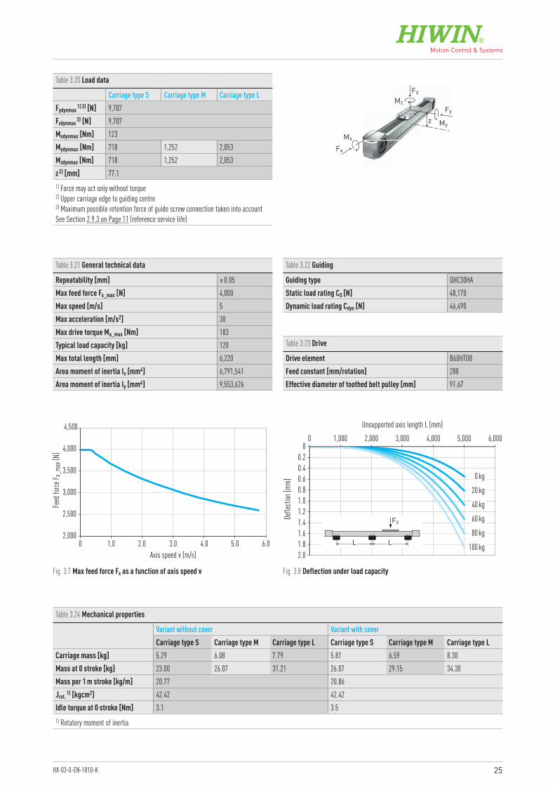
Table 3.20 Load data
Carriage type S Carriage type M Carriage type LFydynmax 1) 3) [N] 9,707Fzdynmax 3) [N] 9,707Mxdynmax [Nm] 123Mydynmax [Nm] 718 1,252 2,053Mzdynmax [Nm] 718 1,252 2,053z 2) [mm] 77.11) Force may act only without torque2) Upper carriage edge to guiding centre 3) Maximum possible retention force of guide screw connection taken into accountSee Section 2.9.3 on Page 11 (reference service life)
Table 3.21 General technical data
Repeatability [mm] ± 0.05Max feed force Fx_max [N] 4,000Max speed [m/s] 5Max acceleration [m/s2] 30Max drive torque Ma_max [Nm] 183Typical load capacity [kg] 120Max total length [mm] 6,220Area moment of inertia Ix [mm4] 6,791,541Area moment of inertia Iy [mm4] 9,553,626
Table 3.22 Guiding
Guiding type QHC30HAStatic load rating C0 [N] 48,170Dynamic load rating Cdyn [N] 46,490
Table 3.23 Drive
Drive element B60HTD8Feed constant [mm/rotation] 288Effective diameter of toothed belt pulley [mm] 91.67
Fz
Fx
MzFy
z My
Mx
Fig. 3.7 Max feed force Fx as a function of axis speed v Fig. 3.8 Deflection under load capacity
Table 3.24 Mechanical properties
Variant without cover Variant with coverCarriage type S Carriage type M Carriage type L Carriage type S Carriage type M Carriage type L
Carriage mass [kg] 5.29 6.08 7.79 5.81 6.59 8.30Mass at 0 stroke [kg] 23.00 26.07 31.21 26.07 29.15 34.30Mass per 1 m stroke [kg/m] 20.77 20.86Jrot. 1) [kgcm2] 42.42 42.42Idle torque at 0 stroke [Nm] 3.1 3.51) Rotatory moment of inertia
2,000
2,500
3,000
3,500
4,000
4,500
0 1.0 2.0 3.0 4.0 5.0 6.0Axis speed v [m/s]
Feed
force
F x_m
ax [N
]
2.01.81.6
1.21.0
0.40.2
1.4
0.80.6
00 1,000 2,000 3,000 5,0004,000 6,000
0 kg
20 kg
40 kg
60 kg
80 kg
100 kg
Unsupported axis length L [mm]
Defle
ction
[mm]
LL
Fz
26
Linear axes and axis systems HXLinear modules HM-S
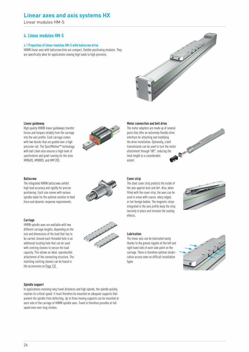
4. Linear modules HM-S
4.1 Properties of linear modules HM-S with ballscrew driveHIWIN linear axes with ballscrew drive are compact, flexible positioning modules. They are specifically ideal for applications moving high loads to high precision.
Linear guidewayHigh quality HIWIN linear guideways transfer forces and torques reliably from the carriage into the axis profile. Each carriage comes with two blocks that are guided over a high precision rail. The SynchMotion™ technology with ball chain also ensures a high level of synchronism and quiet running for the sizes HM060S, HM080S, and HM120S.
Motor connection and belt driveThe motor adapters are made up of several parts that offer an extremely flexible drive interface for attaching and modifying the drive installation. Optionally, a belt transmission can be used to turn the motor attachment through 180°, reducing the total length to a considerable extent.
Cover stripThe steel cover strip protects the inside of the axis against dust and dirt. Also, when fitted with the cover strip, the axes can be used in areas with coarse, sharp edged, or hot foreign bodies. The magnetic strips integrated in the axis profile keep the strip securely in place and increase the sealing effects.
LubricationThe linear axis can be lubricated easily thanks to the grease nipples at the left and right hand side of each lube point on the carriage. There is therefore optimal relubri-cation access even on difficult installation types.
BallscrewThe integrated HIWIN ballscrews exhibit high lead accuracy and rigidity for precise positioning. Each size comes with various spindle leads for the optimal solution to feed force and dynamic response requirements.
CarriageHIWIN spindle axes are available with two different carriage lengths, depending on the size and dimensions of the load that has to be carried. Around each threaded hole is an additional locating hole that can be used with centring sleeves to secure the load capacity. This allows an ideal, reproducible attachment of the connecting structure. The matching centring sleeves can be found in the accessories on Page 132.
Spindle supportIn applications involving long travel distances and high speeds, the spindle quickly reaches its critical speed. It must therefore be mounted on adequate supports that prevent the spindle from deflecting. Up to three moving supports can be mounted at each side of the carriage of HIWIN spindle axes. Travel is therefore possible at full speed even over long strokes.
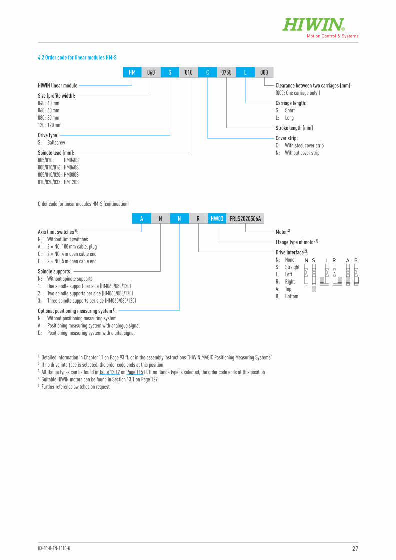
27HX-03-0-EN-1810-K
HIWIN linear module
Motor 4)
Flange type of motor 3)
Optional positioning measuring system 1):N: Without positioning measuring systemA: Positioning measuring system with analogue signalD: Positioning measuring system with digital signal
Spindle supports:N: Without spindle supports1: One spindle support per side (HM060/080/120)2: Two spindle supports per side (HM060/080/120)3: Three spindle supports per side (HM060/080/120)
Axis limit switches 5):N: Without limit switchesA: 2 × NC, 100 mm cable, plugC: 2 × NC, 4 m open cable endD: 2 × NO, 5 m open cable end
Size (profile width):040: 40 mm060: 60 mm080: 80 mm120: 120 mm
Spindle lead [mm]:005/010: HM040S005/010/016: HM060S005/010/020: HM080S010/020/032: HM120S
Stroke length [mm]
Carriage length:S: ShortL: Long
Clearance between two carriages [mm]:(000: One carriage only))
Drive type:S: Ballscrew
Cover strip:C: With steel cover stripN: Without cover strip
HM 060 S 010 C 0755 L 000
A N N R HW03 FRLS2020506A
Order code for linear modules HM-S (continuation)
1) Detailed information in Chapter 11 on Page 93 ff. or in the assembly instructions “HIWIN MAGIC Positioning Measuring Systems”2) If no drive interface is selected, the order code ends at this position3) All flange types can be found in Table 12.12 on Page 115 ff. If no flange type is selected, the order code ends at this position4) Suitable HIWIN motors can be found in Section 13.1 on Page 1295) Further reference switches on request
4.2 Order code for linear modules HM-S
Drive interface 2):N: NoneS: StraightL: LeftR: RightA: TopB: Bottom
N S L R A B

28
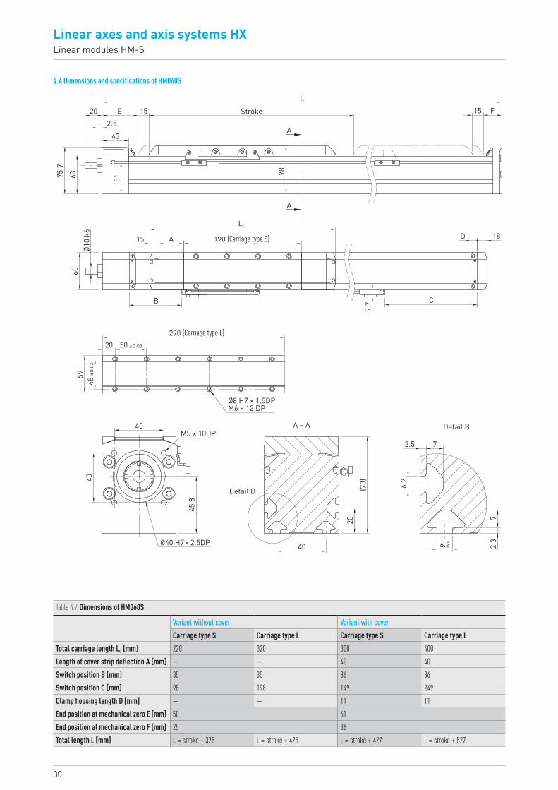
Linear axes and axis systems HXLinear modules HM-S
4.3 Dimensions and specifications of HM040S
Table 4.1 Dimensions of HM040S
Variant without cover Variant with coverCarriage type S Carriage type L Carriage type S Carriage type L
Total carriage length Lc [mm] 175 245 255 325Length of cover strip deflection A [mm] — — 40 40Switch position B [mm] 33.5 33.5 83.5 83.5Switch position C [mm] 42.5 112.5 92.5 162.5Clamp housing length D [mm] — — 10 10End position at mechanical zero E [mm] 38 48End position at mechanical zero F [mm] 20 30Total length L [mm] L = stroke + 253 L = stroke + 323 L = stroke + 353 L = stroke + 423
StrokeL
60
10 10 FE20.53
32
5847
.5
Ø8 k
640
12.5 A
B
(60)
10
5
4.7
1.6
28
36.2
5
28M4 × 8DP
5
1.6 4.7
Detail B
20
Detail B
11.2
14D
C
150 (Carriage type S)
40A
A
Lc
A – A
Ø30 H7
35 ±0.0322.5
3930
±0.0
3
220 (Carriage type L)
Ø8 H7 × 1.5DPM5 × 10DP
29HX-03-0-EN-1810-K
Table 4.2 Load data
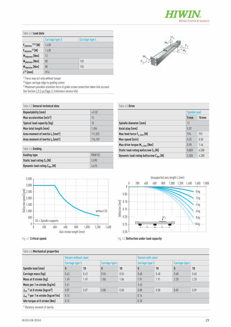
Carriage type S Carriage type LFydynmax 1) 3) [N] 1,438Fzdynmax 3) [N] 1,438Mxdynmax [Nm] 12Mydynmax [Nm] 80 130Mzdynmax [Nm] 80 130z 2) [mm] 39.61) Force may act only without torque2) Upper carriage edge to guiding centre 3) Maximum possible retention force of guide screw connection taken into accountSee Section 2.9.3 on Page 11 (reference service life)
Table 4.3 General technical data
Repeatability [mm] ± 0.02Max acceleration [m/s2] 15Typical load capacity [kg] 10Max total length [mm] 1,484Area moment of inertia Ix [mm4] 111,032Area moment of inertia Iy [mm4] 116,769
Table 4.4 Guiding
Guiding type MGN15CStatic load rating C0 [N] 5,590Dynamic load rating Cdyn [N] 4,610
Table 4.5 Drive
Spindle lead5 mm 10 mm
Spindle diameter [mm] 12Axial play [mm] 0.02Max feed force Fx_max [N] 976 792Max speed [m/s] 0.25 0.50Max drive torque Ma_max [Nm] 0.98 1.46Static load rating ballscrew C0 [N] 8,800 6,500Dynamic load rating ballscrew Cdyn [N] 5,300 4,300
Fz
Fx
MzFy
My
Mx
z
Fig. 4.1 Critical speed Fig. 4.2 Deflection under load capacity
Table 4.6 Mechanical properties
Variant without cover Variant with coverCarriage type S Carriage type L Carriage type S Carriage type L
Spindle lead [mm] 5 10 5 10 5 10 5 10Carriage mass [kg] 0.43 0.43 0.55 0.55 0.48 0.48 0.60 0.60Mass at 0 stroke [kg] 1.49 1.49 1.86 1.86 1.91 1.91 2.28 2.28Mass per 1 m stroke [kg/m] 3.61 3.63Jrot. 1) at 0 stroke [kgcm2] 0.07 0.07 0.08 0.08 0.08 0.08 0.09 0.09Jrot. 1) per 1 m stroke [kgcm2/m] 0.16 0.16Idle torque at 0 stroke [Nm] 0.15 0.201) Rotatory moment of inertia
0
500
1,000
1,500
2,000
2,500
3,000
3,500
0 200 400 600 800 1,000 1,200 1,400Axis stroke length [mm]
Balls
crew
spee
d [rpm
]
without SS
SS = Spindle supports
0.30
0.25
0.20
0.15
0.10
0.05
00 200 400 600 800 1,000 1,200 1,400 1,600 1,800
0 kg
2 kg
4 kg
6 kg
8 kg
10 kg
Unsupported axis length L [mm]
Defle
ction
[mm]
LL
Fz
30
Linear axes and axis systems HXLinear modules HM-S
4.4 Dimensions and specifications of HM060S
Table 4.7 Dimensions of HM060S
Variant without cover Variant with coverCarriage type S Carriage type L Carriage type S Carriage type L
Total carriage length Lc [mm] 220 320 300 400Length of cover strip deflection A [mm] — — 40 40Switch position B [mm] 35 35 86 86Switch position C [mm] 98 198 149 249Clamp housing length D [mm] — — 11 11End position at mechanical zero E [mm] 50 61End position at mechanical zero F [mm] 25 36Total length L [mm] L = stroke + 325 L = stroke + 425 L = stroke + 427 L = stroke + 527
Stroke
L
78
15 15 FE202.5
43
75.7
63
Ø10
k660
15 A
B
(78)
20
6.2
72.
3
40
45.8
40M5 × 10DP
6.2
2.5 7
Detail B
40
Detail B
9.7
18D
C
190 (Carriage type S)
51
A
A
Lc
A – A
Ø40 H7 × 2.5DP
50 ±0.0320
5948
±0.0
3
290 (Carriage type L)
Ø8 H7 × 1.5DPM6 × 12 DP
31HX-03-0-EN-1810-K
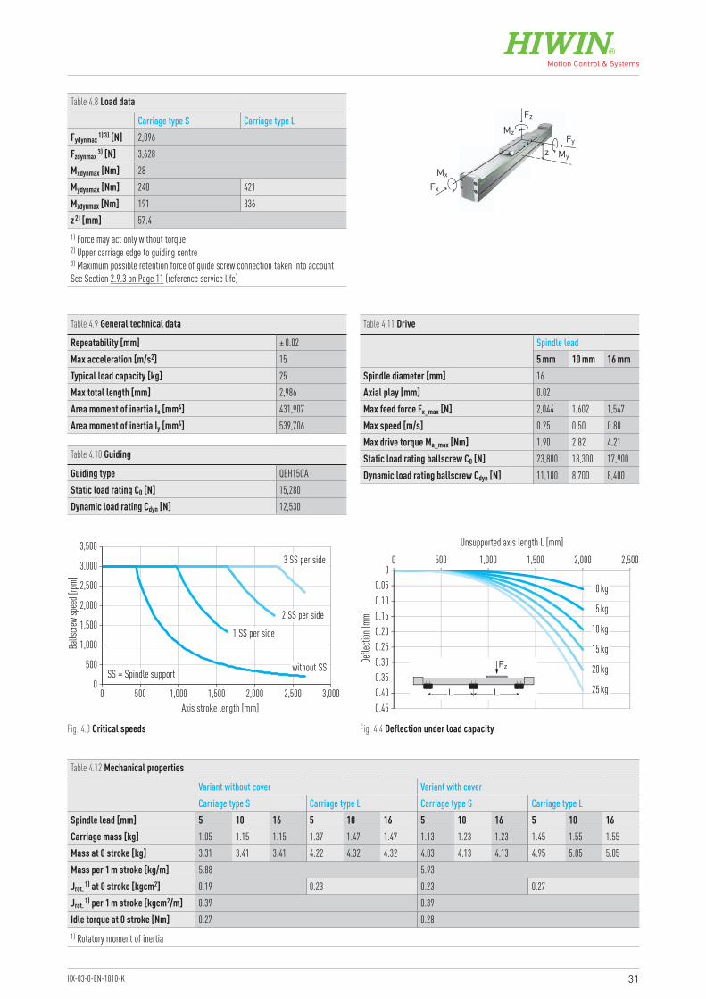
Table 4.8 Load data
Carriage type S Carriage type LFydynmax 1) 3) [N] 2,896Fzdynmax 3) [N] 3,628Mxdynmax [Nm] 28Mydynmax [Nm] 240 421Mzdynmax [Nm] 191 336z 2) [mm] 57.41) Force may act only without torque2) Upper carriage edge to guiding centre 3) Maximum possible retention force of guide screw connection taken into accountSee Section 2.9.3 on Page 11 (reference service life)
Table 4.9 General technical data
Repeatability [mm] ± 0.02Max acceleration [m/s2] 15Typical load capacity [kg] 25Max total length [mm] 2,986Area moment of inertia Ix [mm4] 431,907Area moment of inertia Iy [mm4] 539,706
Table 4.10 Guiding
Guiding type QEH15CAStatic load rating C0 [N] 15,280Dynamic load rating Cdyn [N] 12,530
Fz
Fx
MzFy
My
Mx
z
Fig. 4.3 Critical speeds Fig. 4.4 Deflection under load capacity
0
500
1,000
1,500
2,000
2,500
3,000
3,500
0 500 1,000 1,500 2,000 2,500 3,000
SS = Spindle support
Axis stroke length [mm]
Balls
crew
spee
d [rpm
]
3 SS per side
2 SS per side
1 SS per side
without SS
0.450.400.350.30
0.20
0.10
0.25
0.15
0.050
0 500 1,000 1,500 2,000 2,500
0 kg
5 kg
10 kg
15 kg
20 kg
25 kg
Unsupported axis length L [mm]
Defle
ction
[mm]
LL
Fz
Table 4.11 Drive
Spindle lead5 mm 10 mm 16 mm
Spindle diameter [mm] 16Axial play [mm] 0.02Max feed force Fx_max [N] 2,044 1,602 1,547Max speed [m/s] 0.25 0.50 0.80Max drive torque Ma_max [Nm] 1.90 2.82 4.21Static load rating ballscrew C0 [N] 23,800 18,300 17,900Dynamic load rating ballscrew Cdyn [N] 11,100 8,700 8,400
Table 4.12 Mechanical properties
Variant without cover Variant with coverCarriage type S Carriage type L Carriage type S Carriage type L
Spindle lead [mm] 5 10 16 5 10 16 5 10 16 5 10 16Carriage mass [kg] 1.05 1.15 1.15 1.37 1.47 1.47 1.13 1.23 1.23 1.45 1.55 1.55Mass at 0 stroke [kg] 3.31 3.41 3.41 4.22 4.32 4.32 4.03 4.13 4.13 4.95 5.05 5.05Mass per 1 m stroke [kg/m] 5.88 5.93Jrot. 1) at 0 stroke [kgcm2] 0.19 0.23 0.23 0.27Jrot. 1) per 1 m stroke [kgcm2/m] 0.39 0.39Idle torque at 0 stroke [Nm] 0.27 0.281) Rotatory moment of inertia
32
Linear axes and axis systems HXLinear modules HM-S
4.5 Dimensions and specifications of HM080S
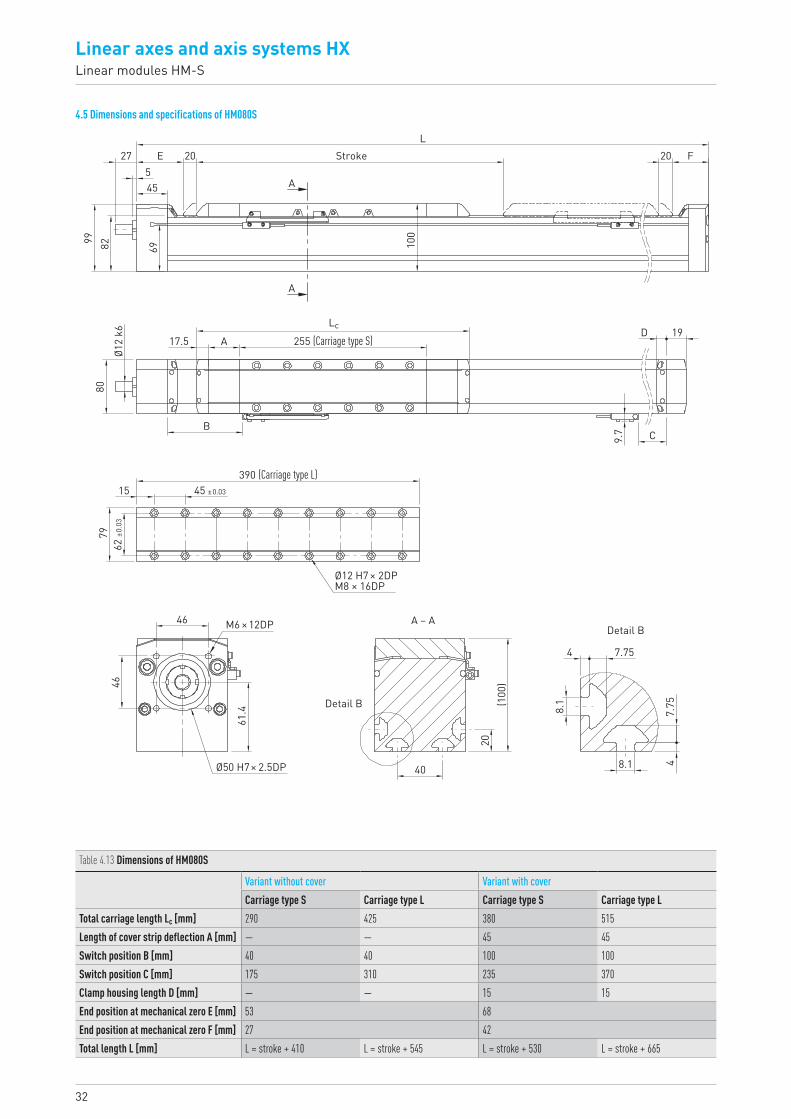
Table 4.13 Dimensions of HM080S
Variant without cover Variant with coverCarriage type S Carriage type L Carriage type S Carriage type L
Total carriage length Lc [mm] 290 425 380 515Length of cover strip deflection A [mm] — — 45 45Switch position B [mm] 40 40 100 100Switch position C [mm] 175 310 235 370Clamp housing length D [mm] — — 15 15End position at mechanical zero E [mm] 53 68End position at mechanical zero F [mm] 27 42Total length L [mm] L = stroke + 410 L = stroke + 545 L = stroke + 530 L = stroke + 665
E27545 A
Stroke 20 F20L
100
A
99 82Ø1
2 k6
80
69
17.5 A 255 (Carriage type S)D 19
C
Lc
B
9.7
4
8.1
8.1
4
40
20(1
00)
7.757.
75
46
46 M6 × 12DP
61.4
A – ADetail B
Detail B
Ø50 H7 × 2.5DP
390 (Carriage type L)15 45 ±0.03
7962
±0.0
3
Ø12 H7 × 2DPM8 × 16DP
33HX-03-0-EN-1810-K
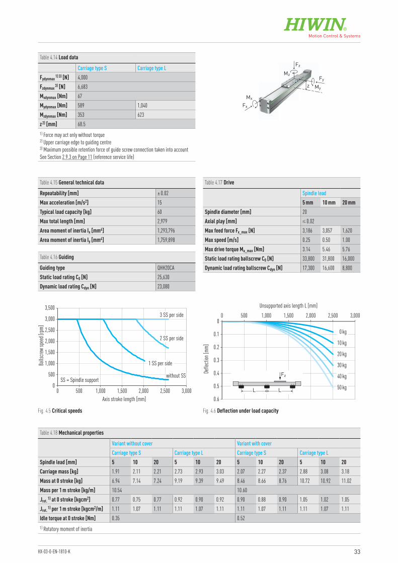
Table 4.14 Load data
Carriage type S Carriage type LFydynmax 1) 3) [N] 4,000Fzdynmax 3) [N] 6,683Mxdynmax [Nm] 67Mydynmax [Nm] 589 1,040Mzdynmax [Nm] 353 623z 2) [mm] 68.51) Force may act only without torque2) Upper carriage edge to guiding centre 3) Maximum possible retention force of guide screw connection taken into accountSee Section 2.9.3 on Page 11 (reference service life)
Table 4.15 General technical data
Repeatability [mm] ± 0.02Max acceleration [m/s2] 15Typical load capacity [kg] 60Max total length [mm] 2,979Area moment of inertia Ix [mm4] 1,293,796Area moment of inertia Iy [mm4] 1,759,898
Table 4.16 Guiding
Guiding type QHH20CAStatic load rating C0 [N] 25,630Dynamic load rating Cdyn [N] 23,080
Table 4.17 Drive
Spindle lead5 mm 10 mm 20 mm
Spindle diameter [mm] 20Axial play [mm] ≤ 0.02Max feed force Fx_max [N] 3,186 3,057 1,620Max speed [m/s] 0.25 0.50 1.00Max drive torque Ma_max [Nm] 3.14 5.46 5.76Static load rating ballscrew C0 [N] 33,800 31,800 16,000Dynamic load rating ballscrew Cdyn [N] 17,300 16,600 8,800
Fz
Fx
MzFy
My
Mx
z
Fig. 4.5 Critical speeds Fig. 4.6 Deflection under load capacity
Table 4.18 Mechanical properties
Variant without cover Variant with coverCarriage type S Carriage type L Carriage type S Carriage type L
Spindle lead [mm] 5 10 20 5 10 20 5 10 20 5 10 20Carriage mass [kg] 1.91 2.11 2.21 2.73 2.93 3.03 2.07 2.27 2.37 2.88 3.08 3.18Mass at 0 stroke [kg] 6.94 7.14 7.24 9.19 9.39 9.49 8.46 8.66 8.76 10.72 10.92 11.02Mass per 1 m stroke [kg/m] 10.54 10.60Jrot. 1) at 0 stroke [kgcm2] 0.77 0.75 0.77 0.92 0.90 0.92 0.90 0.88 0.90 1.05 1.02 1.05Jrot. 1) per 1 m stroke [kgcm2/m] 1.11 1.07 1.11 1.11 1.07 1.11 1.11 1.07 1.11 1.11 1.07 1.11Idle torque at 0 stroke [Nm] 0.35 0.521) Rotatory moment of inertia
0
500
1,000
1,500
2,000
2,500
3,000
3,500
0 500 1,000 1,500 2,000 2,500 3,000
SS = Spindle support
Axis stroke length [mm]
Balls
crew
spee
d [rpm
]
3 SS per side
2 SS per side
1 SS per side
without SS
0.6
0.5
0.4
0.2
0.3
0.1
00 500 1,000 1,500 2,5002,000 3,000
0 kg
10 kg
20 kg
30 kg
40 kg
50 kg
Unsupported axis length L [mm]
Defle
ction
[mm]
LL
Fz
34
Linear axes and axis systems HXLinear modules HM-S
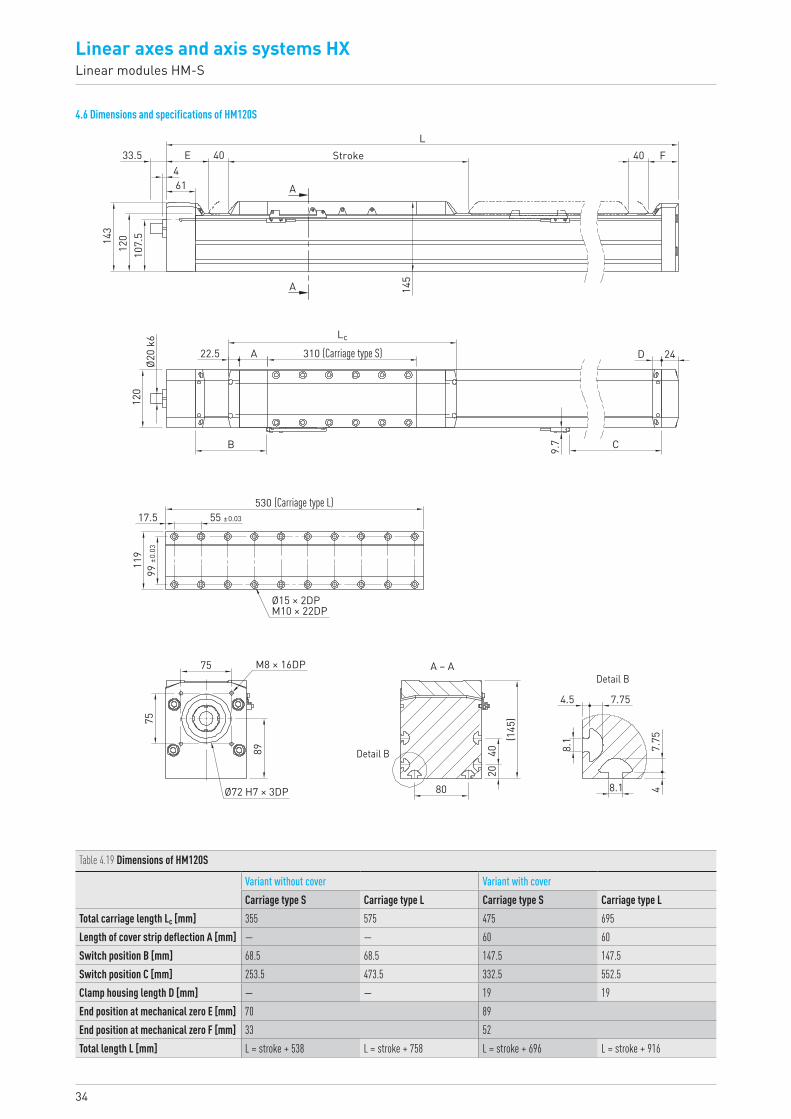
4.6 Dimensions and specifications of HM120S
Table 4.19 Dimensions of HM120S
Variant without cover Variant with coverCarriage type S Carriage type L Carriage type S Carriage type L
Total carriage length Lc [mm] 355 575 475 695Length of cover strip deflection A [mm] — — 60 60Switch position B [mm] 68.5 68.5 147.5 147.5Switch position C [mm] 253.5 473.5 332.5 552.5Clamp housing length D [mm] — — 19 19End position at mechanical zero E [mm] 70 89End position at mechanical zero F [mm] 33 52Total length L [mm] L = stroke + 538 L = stroke + 758 L = stroke + 696 L = stroke + 916
Stroke40E
614
33.5Ø2
0 k6
120
9.7
22.5 A
B
80
20
8.1
47.
75
75
75 M8 × 16DP
89
Ø72 H7 × 3DP
7.754.5
8.1
40
(145
)
310 (Carriage type S)
C
D 24
143
120
107.
5
145
40 FL
A
A
Lc
A – ADetail B
Detail B
55 ±0.0317.5
119
99 ±0
.03
530 (Carriage type L)
Ø15 × 2DPM10 × 22DP
35HX-03-0-EN-1810-K
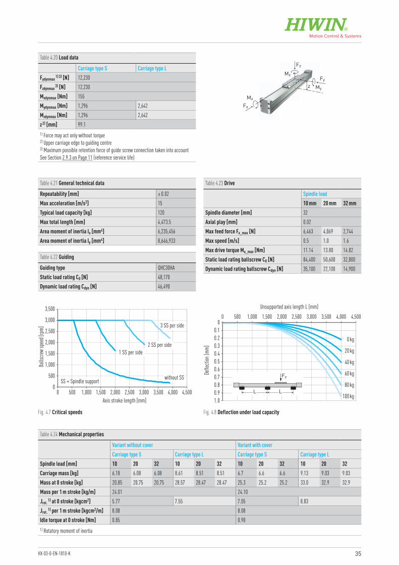
Table 4.20 Load data
Carriage type S Carriage type LFydynmax 1) 3) [N] 12,230Fzdynmax 3) [N] 12,230Mxdynmax [Nm] 155Mydynmax [Nm] 1,296 2,642Mzdynmax [Nm] 1,296 2,642z 2) [mm] 99.11) Force may act only without torque2) Upper carriage edge to guiding centre 3) Maximum possible retention force of guide screw connection taken into accountSee Section 2.9.3 on Page 11 (reference service life)
Table 4.21 General technical data
Repeatability [mm] ± 0.02Max acceleration [m/s2] 15Typical load capacity [kg] 120Max total length [mm] 4,473.5Area moment of inertia Ix [mm4] 6,235,456Area moment of inertia Iy [mm4] 8,646,933
Table 4.22 Guiding
Guiding type QHC30HAStatic load rating C0 [N] 48,170Dynamic load rating Cdyn [N] 46,490
Table 4.23 Drive
Spindle lead10 mm 20 mm 32 mm
Spindle diameter [mm] 32Axial play [mm] 0.02Max feed force Fx_max [N] 6,463 4,069 2,744Max speed [m/s] 0.5 1.0 1.6Max drive torque Ma_max [Nm] 11.14 13.80 14.82Static load rating ballscrew C0 [N] 84,400 50,600 32,800Dynamic load rating ballscrew Cdyn [N] 35,100 22,100 14,900
Fz
Fx
MzFy
My
Mx
z
Fig. 4.7 Critical speeds Fig. 4.8 Deflection under load capacity
Table 4.24 Mechanical properties
Variant without cover Variant with coverCarriage type S Carriage type L Carriage type S Carriage type L
Spindle lead [mm] 10 20 32 10 20 32 10 20 32 10 20 32Carriage mass [kg] 6.18 6.08 6.08 8.61 8.51 8.51 6.7 6.6 6.6 9.13 9.03 9.03Mass at 0 stroke [kg] 20.85 20.75 20.75 28.57 28.47 28.47 25.3 25.2 25.2 33.0 32.9 32.9Mass per 1 m stroke [kg/m] 24.01 24.10Jrot. 1) at 0 stroke [kgcm2] 5.77 7.55 7.05 8.83Jrot. 1) per 1 m stroke [kgcm2/m] 8.08 8.08Idle torque at 0 stroke [Nm] 0.85 0.901) Rotatory moment of inertia
0
500
1,000
1,500
2,000
2,500
3,500
3,000
0 1,000 1,500500 2,000 2,500 3,000 3,500 4,000 4,500
SS = Spindle support
Axis stroke length [mm]
Balls
crew
spee
d [rpm
] 3 SS per side
2 SS per side1 SS per side
without SS
1.00.90.8
0.60.5
0.20.1
0.7
0.40.3
00 500 1,000 1,500 2,000 3,500 4,0002,500 3,000 4,500
0 kg
20 kg
40 kg
60 kg
80 kg
100 kg
Unsupported axis length L [mm]
Defle
ction
[mm]
LL
Fz
36
Linear axes and axis systems HXLinear tables HT-B
5. Linear tables HT-B
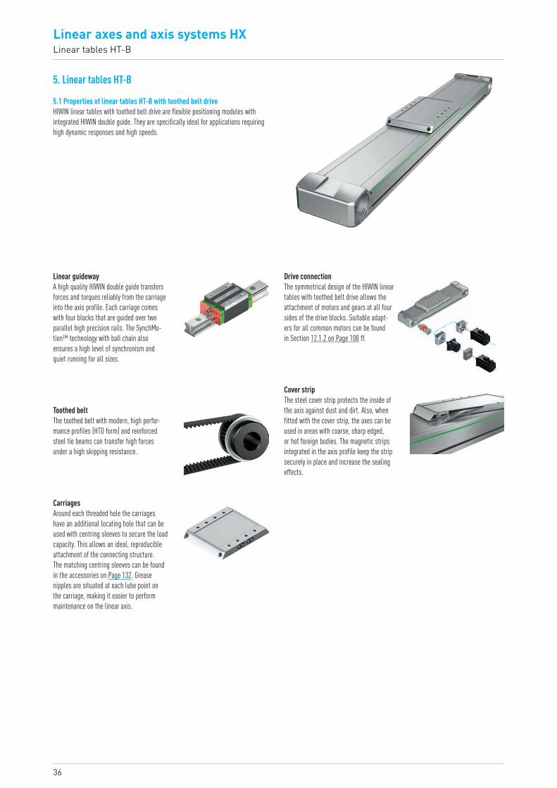
5.1 Properties of linear tables HT-B with toothed belt driveHIWIN linear tables with toothed belt drive are flexible positioning modules with integrated HIWIN double guide. They are specifically ideal for applications requiring high dynamic responses and high speeds.
Drive connectionThe symmetrical design of the HIWIN linear tables with toothed belt drive allows the attachment of motors and gears at all four sides of the drive blocks. Suitable adapt-ers for all common motors can be found in Section 12.1.2 on Page 100 ff.
Linear guidewayA high quality HIWIN double guide transfers forces and torques reliably from the carriage into the axis profile. Each carriage comes with four blocks that are guided over two parallel high precision rails. The SynchMo-tion™ technology with ball chain also ensures a high level of synchronism and quiet running for all sizes.
Toothed beltThe toothed belt with modern, high perfor-mance profiles (HTD form) and reinforced steel tie beams can transfer high forces under a high skipping resistance.
Cover stripThe steel cover strip protects the inside of the axis against dust and dirt. Also, when fitted with the cover strip, the axes can be used in areas with coarse, sharp edged, or hot foreign bodies. The magnetic strips integrated in the axis profile keep the strip securely in place and increase the sealing effects.
CarriagesAround each threaded hole the carriages have an additional locating hole that can be used with centring sleeves to secure the load capacity. This allows an ideal, reproducible attachment of the connecting structure. The matching centring sleeves can be found in the accessories on Page 132. Grease nipples are situated at each lube point on the carriage, making it easier to perform maintenance on the linear axis.
37HX-03-0-EN-1810-K
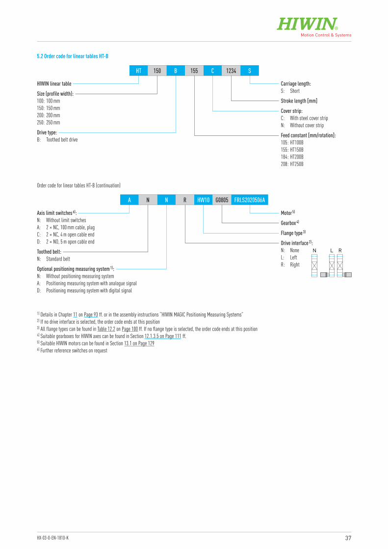
HIWIN linear table
Motor 5)
Gearbox 4)
Flange type 3)
Optional positioning measuring system 1):N: Without positioning measuring systemA: Positioning measuring system with analogue signalD: Positioning measuring system with digital signal
Drive interface 2):N: NoneL: LeftR: Right
Toothed belt:N: Standard belt
Axis limit switches 6):N: Without limit switchesA: 2 × NC, 100 mm cable, plugC: 2 × NC, 4 m open cable endD: 2 × NO, 5 m open cable end
Size (profile width):100: 100 mm150: 150 mm200: 200 mm250: 250 mm
Cover strip:C: With steel cover stripN: Without cover strip
Feed constant [mm/rotation]:105: HT100B155: HT150B184: HT200B208: HT250B
Stroke length [mm]
Carriage length:S: Short
Drive type:B: Toothed belt drive
HT 150 B 155 C 1234 S
A N N R HW10 G0805 FRLS2020506A
Order code for linear tables HT-B (continuation)
1) Details in Chapter 11 on Page 93 ff. or in the assembly instructions “HIWIN MAGIC Positioning Measuring Systems”2) If no drive interface is selected, the order code ends at this position3) All flange types can be found in Table 12.2 on Page 100 ff. If no flange type is selected, the order code ends at this position4) Suitable gearboxes for HIWIN axes can be found in Section 12.1.3.5 on Page 111 ff.5) Suitable HIWIN motors can be found in Section 13.1 on Page 1296) Further reference switches on request
5.2 Order code for linear tables HT-B
N L R
38
Linear axes and axis systems HXLinear tables HT-B
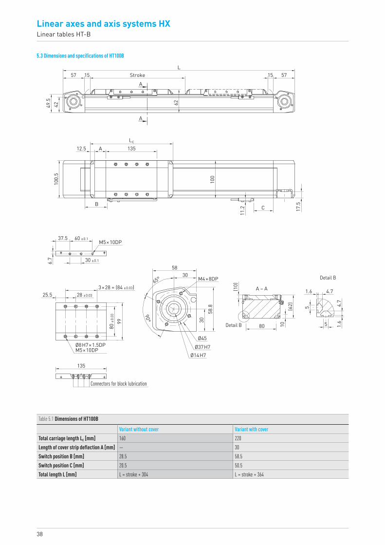
5.3 Dimensions and specifications of HT100B
57
49.5
42
15
62
135
100
11.2 17
.5C
A
B
12.5
100.
5
37.5
6.7
25.5
15 57StrokeL
A
A
Lc
3×28 = (84 ±0.03)
80 ±0
.03
99
135
5830
58.8
30
80
1.6
1.6
5
5
4.7
4.7
10
(10)
(62)
90°
65°
28 ±0.03
60 ±0.1
30 ±0.1
M5×10DP
M4×8DP
Ø8H7×1.5DPM5×10DP
Ø45Ø37H7
Ø14H7
A – A
Detail B
Detail B
Connectors for block lubrication
Table 5.1 Dimensions of HT100B
Variant without cover Variant with coverTotal carriage length Lc [mm] 160 220Length of cover strip deflection A [mm] — 30Switch position B [mm] 28.5 58.5Switch position C [mm] 20.5 50.5Total length L [mm] L = stroke + 304 L = stroke + 364
39HX-03-0-EN-1810-K
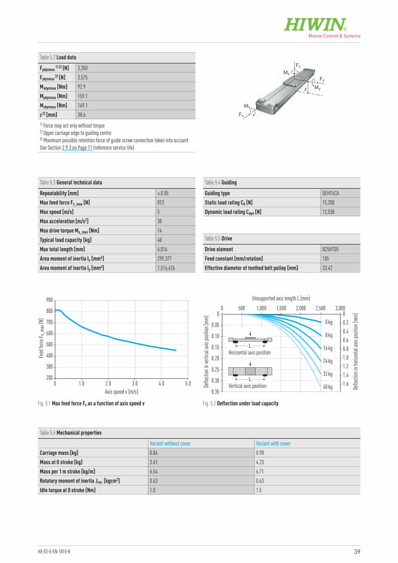
Table 5.2 Load data
Fydynmax 1) 3) [N] 3,350Fzdynmax 3) [N] 3,575Mxdynmax [Nm] 92.9Mydynmax [Nm] 159.1Mzdynmax [Nm] 149.1z 2) [mm] 38.61) Force may act only without torque2) Upper carriage edge to guiding centre 3) Maximum possible retention force of guide screw connection taken into accountSee Section 2.9.3 on Page 11 (reference service life)
Table 5.3 General technical data
Repeatability [mm] ± 0.05Max feed force Fx_max [N] 813Max speed [m/s] 5Max acceleration [m/s2] 30Max drive torque Ma_max [Nm] 14Typical load capacity [kg] 40Max total length [mm] 6,016Area moment of inertia Ix [mm4] 299,377Area moment of inertia Iy [mm4] 1,516,426
Table 5.4 Guiding
Guiding type QEH15CAStatic load rating C0 [N] 15,280Dynamic load rating Cdyn [N] 12,530
Table 5.5 Drive
Drive element B25HTD5Feed constant [mm/rotation] 105Effective diameter of toothed belt pulley [mm] 33.42
Fz
Fx
MzFy
z My
Mx
200
300
400
500
600
700
800
900
0 1.0 2.0 3.0 4.0 5.0Axis speed v [m/s]
Feed
force
F x_m
ax [N
]
0.35
0.30
0.25
0.20
0.15
0.10
0.05
0 00 500 1,000 1,500 2,000 2,500 3,000
0 kg
8 kg
16 kg
24 kg
32 kg
40 kg
Unsupported axis length L [mm]
Defle
ction
in ve
rtica
l axis
posit
ion [m
m]
Defle
ction
in ho
rizon
tal ax
is po
sition
[mm]
0.2
1.61.41.21.00.80.60.4
LVertical axis position
LHorizontal axis position
Fig. 5.1 Max feed force Fx as a function of axis speed v Fig. 5.2 Deflection under load capacity
Table 5.6 Mechanical properties
Variant without cover Variant with coverCarriage mass [kg] 0.84 0.98Mass at 0 stroke [kg] 3.61 4.23Mass per 1 m stroke [kg/m] 6.54 6.71Rotatory moment of inertia Jrot. [kgcm2] 0.63 0.63Idle torque at 0 stroke [Nm] 1.0 1.5
40
Linear axes and axis systems HXLinear tables HT-B
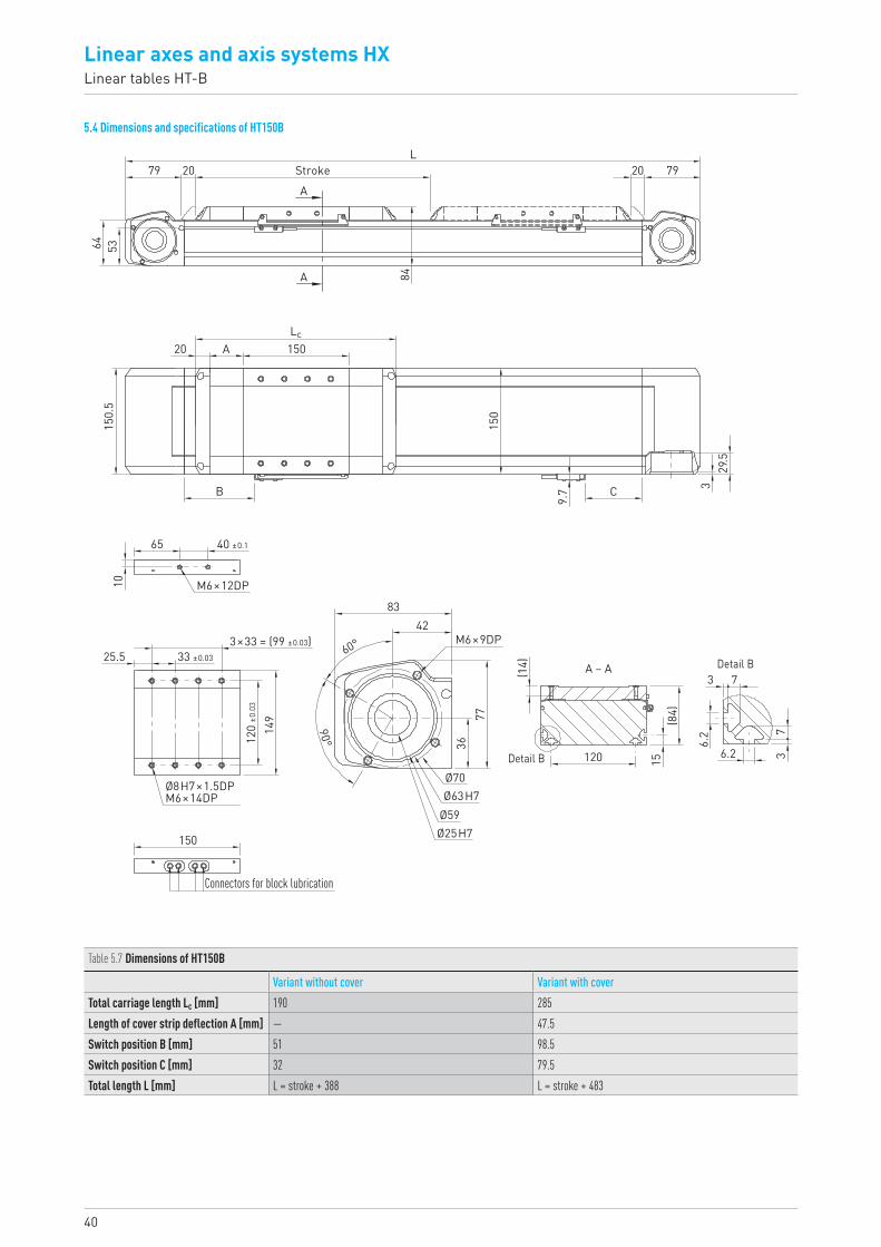
5.4 Dimensions and specifications of HT150B
79L
5364
20 Stroke
20
150.
510
25.5
65
150
150
9.7 3
29.5
C
A
B
Lc
A
A 84
20 79
40 ±0.1
M6×12DP
M6×9DP
Ø8H7×1.5DPM6×14DP
3×33 = (99 ±0.03)33 ±0.03
120
±0.0
3
149
3677
(14)
3
3 7
7
6.2
6.2
15(8
4)
120
4283
Ø70
Ø59Ø63H7
Ø25H7
60°
90°
150
Connectors for block lubrication
A – A
Detail B
Detail B
Table 5.7 Dimensions of HT150B
Variant without cover Variant with coverTotal carriage length Lc [mm] 190 285Length of cover strip deflection A [mm] — 47.5Switch position B [mm] 51 98.5Switch position C [mm] 32 79.5Total length L [mm] L = stroke + 388 L = stroke + 483

41HX-03-0-EN-1810-K
Table 5.8 Load data
Fydynmax 1) 3) [N] 3,350Fzdynmax 3) [N] 5,233Mxdynmax [Nm] 245.9Mydynmax [Nm] 245.9Mzdynmax [Nm] 157.5z 2) [mm] 51.481) Force may act only without torque2) Upper carriage edge to guiding centre 3) Maximum possible retention force of guide screw connection taken into accountSee Section 2.9.3 on Page 11 (reference service life)
Table 5.9 General technical data
Repeatability [mm] ± 0.05Max feed force Fx_max [N] 1,300Max speed [m/s] 5Max acceleration [m/s2] 30Max drive torque Ma_max [Nm] 32Typical load capacity [kg] 80Max total length [mm] 6,066Area moment of inertia Ix [mm4] 907,754Area moment of inertia Iy [mm4] 7,417,610
Table 5.10 Guiding
Guiding type QEH15CAStatic load rating C0 [N] 15,280Dynamic load rating Cdyn [N] 12,530
Table 5.11 Drive
Drive element B40HTD5Feed constant [mm/rotation] 155Effective diameter of toothed belt pulley [mm] 49.34
400
600
800
1,000
1,200
1,400
0 1.0 2.0 5.04.03.0 6.0 7.0Axis speed v [m/s]
Feed
force
F x_m
ax [N
]
0.450.40
0.300.35
0.250.200.150.100.05
0 00 1,000 2,000 3,000 4,000
0 kg
16 kg
32 kg
48 kg
64 kg
80 kg
Unsupported axis length L [mm]
Defle
ction
in ve
rticla
l axis
posit
ion [m
m]
Defle
ction
in ho
rizon
tal ax
is po
sition
[mm]
0.5
3.5
3.0
2.5
2.0
1.5
1.0
LVertical axis position
LHorizontal axis position
Fig. 5.3 Max feed force Fx as a function of axis speed v Fig. 5.4 Deflection under load capacity
Fz
Fx
MzFy
z My
Mx
Table 5.12 Mechanical properties
Variant without cover Variant with coverCarriage mass [kg] 1.77 2.2Mass at 0 stroke [kg] 7.78 9.41Mass per 1 m stroke [kg/m] 10.87 11.16Rotatory moment of inertia Jrot. [kgcm2] 5.09 5.09Idle torque at 0 stroke [Nm] 1.0 1.5
42
Linear axes and axis systems HXLinear tables HT-B
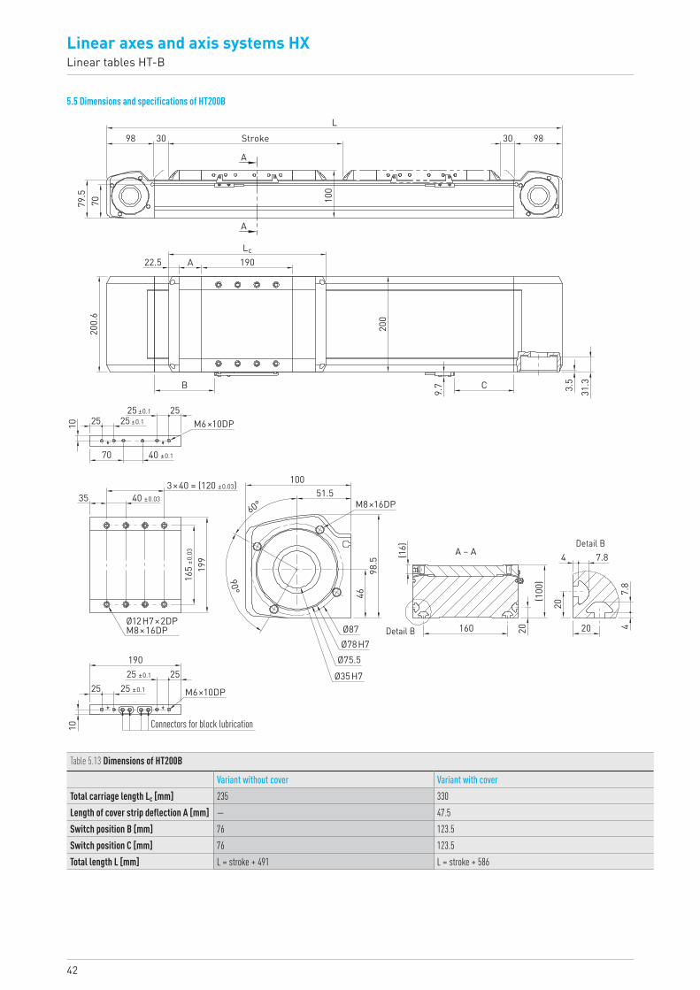
5.5 Dimensions and specifications of HT200B
79.5
70
98 30 30 98Stroke
A
A
22.5
200.
6
B
190A
100
L
Lc
40 ±0.1
25 ±0.125 ±0.1
70
10 2525
M6×10DP
3×40 = (120 ±0.03)40 ±0.03
165
±0.0
3
199
190
100
(16)
51.5
98.5
160 20
204
4
7.8
7.8
20
(100
)
46
60°
90°
35
Ø12H7×2DPM8×16DP
M8×16DP
Detail B
Detail BA – A
Ø78H7
Ø35H7
Ø87
Ø75.525 ±0.1
25 ±0.1
2525
10
M6×10DP
Connectors for block lubrication
C
9.7
200
3.5
31.3
Table 5.13 Dimensions of HT200B
Variant without cover Variant with coverTotal carriage length Lc [mm] 235 330Length of cover strip deflection A [mm] — 47.5Switch position B [mm] 76 123.5Switch position C [mm] 76 123.5Total length L [mm] L = stroke + 491 L = stroke + 586

43HX-03-0-EN-1810-K
Table 5.14 Load data
Fydynmax 1) 3) [N] 7,800Fzdynmax 3) [N] 9,638Mxdynmax [Nm] 655.4Mydynmax [Nm] 544.6Mzdynmax [Nm] 440.7z 2) [mm] 58.481) Force may act only without torque2) Upper carriage edge to guiding centre 3) Maximum possible retention force of guide screw connection taken into accountSee Section 2.9.3 on Page 11 (reference service life)
Table 5.15 General technical data
Repeatability [mm] ± 0.05Max feed force Fx_max [N] 3,000Max speed [m/s] 5Max acceleration [m/s2] 30Max drive torque Ma_max [Nm] 88Typical load capacity [kg] 150Max total length [mm] 6,100Area moment of inertia Ix [mm4] 2,071,928Area moment of inertia Iy [mm4] 19,658,810
Table 5.16 Guiding
Guiding type QHH20CAStatic load rating C0 [N] 25,630Dynamic load rating Cdyn [N] 23,080
Table 5.17 Drive
Drive element B50HTD8Feed constant [mm/rotation] 184Effective diameter of toothed belt pulley [mm] 58.57
600
1,100
1,600
2,100
2,600
3,100
3,600
0 7.01.0 2.0 5.04.03.0 6.0 8.0Axis speed v [m/s]
Feed
force
F x_m
ax [N
]
0.7
0.6
0.5
0.4
0.3
0.2
0.1
0 00 1,000 2,000 3,000 4,000 5,000
0 kg
30 kg
60 kg
90 kg
120 kg
150 kg
Unsupported axis length L [mm]
Defle
ction
in ve
rtica
l axis
posit
ion [m
m]
Defle
ction
in ho
rizon
tal ax
is po
sition
[mm]
1.0
6.0
5.0
4.0
3.0
2.0
LVertical axis position
LHorizontal axis position
Fig. 5.5 Max feed force Fx as a function of axis speed v Fig. 5.6 Deflection under load capacity
Fz
Fx
MzFy
z My
Mx
Table 5.18 Mechanical properties
Variant without cover Variant with coverCarriage mass [kg] 3.11 3.63Mass at 0 stroke [kg] 15.87 18.22Mass per 1 m stroke [kg/m] 17.25 17.57Rotatory moment of inertia Jrot. [kgcm2] 18.37 18.37Idle torque at 0 stroke [Nm] 2.0 2.5
44
Linear axes and axis systems HXLinear tables HT-B
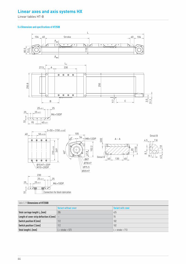
5.6 Dimensions and specifications of HT250B
40 104
Lc
25 ±0.1
25 ±0.1
40 ±0.195
25
10
25
M6×10DP
M6×10DP
M8×12DP
3×50 = (150 ±0.03)50 ±0.03
210 ±
0.03
249
105
47.8 10
2.2
54
(20)
20
130 40
4.5
8.1
8.1
7.8
7.8
4.540
(110
)60°
90°
40
Ø15H7×2DPM10×20DP
Ø78H7
Ø35H7
Ø87
Ø75.5
Detail B
Detail BA – A
25 ±0.1
25 ±0.1
2525
10
230
StrokeA
A
27.5 A
B
250.
8
230
250
C9.7 3.5
31.3
L
110
40104
73.5
85.5
Connectors for block lubrication
Table 5.19 Dimensions of HT250B
Variant without cover Variant with coverTotal carriage length Lc [mm] 285 425Length of cover strip deflection A [mm] — 70Switch position B [mm] 112 182Switch position C [mm] 112 182Total length L [mm] L = stroke + 573 L = stroke + 713

45HX-03-0-EN-1810-K
Table 5.20 Load data
Fydynmax 1) 3) [N] 11,600Fzdynmax 3) [N] 13,271Mxdynmax [Nm] 1,134.7Mydynmax [Nm] 1,028.5Mzdynmax [Nm] 899z 2) [mm] 68.071) Force may act only without torque2) Upper carriage edge to guiding centre 3) Maximum possible retention force of guide screw connection taken into accountSee Section 2.9.3 on Page 11 (reference service life)
Table 5.21 General technical data
Repeatability [mm] ± 0.05Max feed force Fx_max [N] 4,500Max speed [m/s] 5Max acceleration [m/s2] 30Max drive torque Ma_max [Nm] 149Typical load capacity [kg] 250Max total length [mm] 6,110Area moment of inertia Ix [mm4] 3,265,771Area moment of inertia Iy [mm4] 39,262,043
Table 5.22 Guiding
Guiding type QHH25CAStatic load rating C0 [N] 33,680Dynamic load rating Cdyn [N] 31,780
Table 5.23 Drive
Drive element B75HTD8Feed constant [mm/rotation] 208Effective diameter of toothed belt pulley [mm] 66.21
2,000
2,500
3,000
3,500
4,000
4,500
5,000
0 1.0 2.0 5.04.03.0 6.0Axis speed v [m/s]
Feed
force
F x_m
ax [N
]
1.00.90.8
0.60.7
0.50.40.30.20.1
0 00 1,000 2,000 3,000 5,0004,000 6,000
0 kg
50 kg
100 kg
150 kg
200 kg
250 kg
Unsupported axis length L [mm]
Defle
ction
in ve
rtica
l axis
posit
ion [m
m]
Defle
ction
in ho
rizon
tal ax
is po
sition
[mm]
2.0
12.0
10.0
8.0
6.0
4.0
LVertical axis position
LHorizontal axis position
Fig. 5.7 Max feed force Fx as a function of axis speed v Fig. 5.8 Deflection under load capacity
Fz
Fx
MzFy
z My
Mx
Table 5.24 Mechanical properties
Variant without cover Variant with coverCarriage mass [kg] 5.67 6.89Mass at 0 stroke [kg] 26.45 31.2Mass per 1 m stroke [kg/m] 22.48 22.87Rotatory moment of inertia Jrot. [kgcm2] 36.38 36.38Idle torque at 0 stroke [Nm] 4.0 4.5
46
Linear axes and axis systems HXLinear tables HT-S
6. Linear tables HT-S
6.1 Properties of linear tables HT-S with ballscrew driveHIWIN linear tables with ballscrew drive are flexible positioning modules with integrated HIWIN double guide. They are specifically ideal for applications moving high loads to high precision.
Linear guidewayA high quality HIWIN double guide transfers forces and torques reliably from the carriage into the axis profile. Each carriage comes with four blocks that are guided over two parallel high precision rails. The SynchMo-tion™ technology with ball chain also ensures a high level of synchronism and quiet running for all sizes.
Motor connections and belt driveThe motor adapters are made up of several parts that offer an extremely flexible drive interface for attaching and modifying the drive installation.
Cover stripThe steel cover strip protects the inside of the axis against dust and dirt. Also, when fitted with the cover strip, the axes can be used in areas with coarse, sharp edged, or hot foreign bodies. The magnetic strips integrated in the axis profile keep the strip securely in place and increase the sealing effects.
BallscrewThe integrated HIWIN ballscrews exhibit high lead accuracy and rigidity for precise positioning. Each size comes with various spindle leads for the optimal solution to feed force and dynamic response requirements.
CarriagesAround each threaded hole the carriages have an additional locating hole that can be used with centring sleeves to secure the load capacity. This allows an ideal, reproducible attachment of the connecting structure. The matching centring sleeves can be found in the accessories on Page 132. Grease nipples are situated at each lube point on the carriage, making it easier to perform maintenance on the linear axis.
Spindle supportIn applications involving long travel distances and high speeds, the spindle quickly reaches its critical speed. It must therefore be mounted on adequate supports that prevent the spindle from deflecting. Up to four moving supports can be mounted at each side of the carriage of HIWIN spindle axes. Travel is therefore possible at full speed even over long strokes.
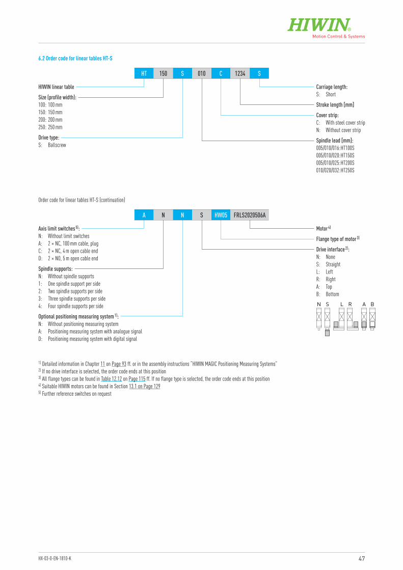
47HX-03-0-EN-1810-K
HIWIN linear table
Motor 4)
Flange type of motor 3)
Optional positioning measuring system 1):N: Without positioning measuring systemA: Positioning measuring system with analogue signalD: Positioning measuring system with digital signal
Spindle supports:N: Without spindle supports1: One spindle support per side2: Two spindle supports per side 3: Three spindle supports per side4: Four spindle supports per side
Axis limit switches 5):N: Without limit switchesA: 2 × NC, 100 mm cable, plugC: 2 × NC, 4 m open cable endD: 2 × NO, 5 m open cable end
Size (profile width):100: 100 mm150: 150 mm200: 200 mm250: 250 mm
Cover strip:C: With steel cover stripN: Without cover strip
Spindle lead [mm]:005/010/016: HT100S005/010/020: HT150S005/010/025: HT200S010/020/032: HT250S
Stroke length [mm]
Carriage length:S: Short
Drive type:S: Ballscrew
HT 150 S 010 C 1234 S
A N N S HW05 FRLS2020506A
Order code for linear tables HT-S (continuation)
1) Detailed information in Chapter 11 on Page 93 ff. or in the assembly instructions “HIWIN MAGIC Positioning Measuring Systems”2) If no drive interface is selected, the order code ends at this position3) All flange types can be found in Table 12.12 on Page 115 ff. If no flange type is selected, the order code ends at this position4) Suitable HIWIN motors can be found in Section 13.1 on Page 1295) Further reference switches on request
6.2 Order code for linear tables HT-S
Drive interface 2):N: NoneS: StraightL: LeftR: RightA: TopB: Bottom
N S L R A B
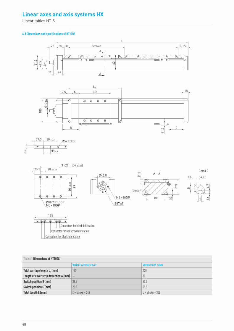
48
Linear axes and axis systems HXLinear tables HT-S
6.3 Dimensions and specifications of HT100S
28 35 10
2611
4249.561.2
62
StrokeA
A
10 27L
Ø10g
6
Lc
60 ±0.1
30 ±0.1
M5×10DP
3×28 = (84 ±0.03)28 ±0.03
80 ±0
.03
99
25.5
Ø8H7×1.5DPM5×10DP
135
M5×10DP
Ø43.8 (10)
(62)
1080
1.6
1.6
5
5
4.7
4.7
Ø37g7
A – A
Detail B
Detail B
Connectors for block lubrication
Connectors for block lubricationConnector for ballscrew lubrication
100
12.5 A
B
135
11.2 C
18
37.5
6.7
Table 6.1 Dimensions of HT100S
Variant without cover Variant with coverTotal carriage length Lc [mm] 160 220Length of cover strip deflection A [mm] — 30Switch position B [mm] 33.5 63.5Switch position C [mm] 25.5 55.5Total length L [mm] L = stroke + 242 L = stroke + 302

49HX-03-0-EN-1810-K
0.35
0.30
0.25
0.20
0.15
0.10
0.05
0 00 500 1,000 1,500 2,000 2,500 3,000
0 kg
8 kg
16 kg
24 kg
32 kg
40 kg
Unsupported axis length L [mm]
Defle
ction
in ve
rtica
l axis
posit
ion [m
m]
Defle
ction
in ho
rizon
tal ax
is po
sition
[mm]
0.2
1.61.41.21.00.80.60.4
LVertical axis position
LHorizontal axis position
Table 6.2 Load data
Fydynmax 1) 3) [N] 3,350Fzdynmax 3) [N] 5,340Mxdynmax [Nm] 139Mydynmax [Nm] 280Mzdynmax [Nm] 176z 2) [mm] 36.61) Force may act only without torque2) Upper carriage edge to guiding centre 3) Maximum possible retention force of guide screw connection taken into accountSee Section 2.9.3 on Page 11 (reference service life)
Table 6.3 General technical data
Repeatability [mm] ± 0.02Max acceleration [m/s2] 15Typical load capacity [kg] 40Max total length [mm] 2,978Area moment of inertia Ix [mm4] 299,377Area moment of inertia Iy [mm4] 1,516,426
Fz
Fx
MzFy
My
Mx
z
Table 6.4 Guiding
Guiding type QEH15SAStatic load rating C0 [N] 8,790Dynamic load rating Cdyn [N] 8,560
Table 6.5 Drive
Spindle lead5 mm 10 mm 16 mm
Spindle diameter [mm] 16Axial play [mm] ≤ 0.02Max feed force Fx_max [N] 2,044 1,602 1,547Max speed [m/s] 0.25 0.50 0.80Max drive torque Ma_max [Nm] 2.03 2.95 4.34Static load rating ballscrew C0 [N] 23,800 18,300 17,900Dynamic load rating ballscrew Cdyn [N] 11,00 8,700 8,400
Fig. 6.1 Critical speed
Table 6.6 Mechanical properties
Variant without cover Variant with coverSpindle lead [mm] 5 10 16 5 10 16Carriage mass [kg] 0.93 0.92 0.99 1.06 1.05 1.13Mass at 0 stroke [kg] 3.35 3.34 3.41 4.02 4.01 4.08Mass per 1 m stroke [kg/m] 7.67 7.85Rotatory moment of inertia Jrot. at 0 stroke [kgcm2] 0.16 0.19Rotatory moment of inertia Jrot. per 1 m stroke [kgcm2/m] 0.39 0.39Idle torque at 0 stroke [Nm] 0.4 0.5
0
500
1,000
1,500
2,000
2,500
3,500
3,000
0 1,000 1,500500 2,000 2,500 3,000
SS = Spindle support
3 SS per side
2 SS per side
1 SS per side
without SS
Axis stroke length [mm]
Balls
crew
spee
d [rpm
]
Fig. 6.2 Deflection under load capacity
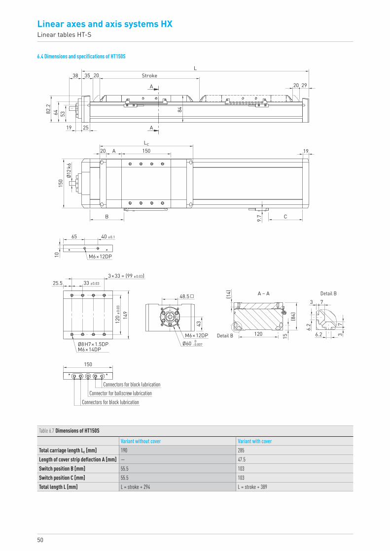
50
Linear axes and axis systems HXLinear tables HT-S
6.4 Dimensions and specifications of HT150S
Stroke
2519
38
6482.2
53
35L
20
A – A Detail B
Detail B 0–0.007Ø60
M6×12DP
150
25.5 33 ±0.03
120
±0.0
3
(84)
6.2
3 7
73
6.2
15120
48.5
43
(14)
149
Ø8H7×1.5DPM6×14DP
3×33 = (99 ±0.03)
A
A
20 29
19Lc
84
150A
B 9.7 C
20
Ø12k
615
0
40 ±0.165
10 M6×12DP
Connectors for block lubrication
Connectors for block lubricationConnector for ballscrew lubrication
Table 6.7 Dimensions of HT150S
Variant without cover Variant with coverTotal carriage length Lc [mm] 190 285Length of cover strip deflection A [mm] — 47.5Switch position B [mm] 55.5 103Switch position C [mm] 55.5 103Total length L [mm] L = stroke + 294 L = stroke + 389
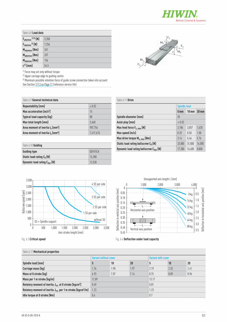
51HX-03-0-EN-1810-K
0.450.40
0.300.35
0.250.200.150.100.05
0 00 1,000 2,000 3,000 4,000
0 kg
16 kg
32 kg
48 kg
64 kg
80 kg
Unsupported axis length L [mm]
Defle
ction
in ve
rticla
l axis
posit
ion [m
m]
Defle
ction
in ho
rizon
tal ax
is po
sition
[mm]
0.5
3.5
3.0
2.5
2.0
1.5
1.0
LVertical axis position
LHorizontal axis position
Table 6.8 Load data
Fydynmax 1) 3) [N] 3,350Fzdynmax 3) [N] 7,256Mxdynmax [Nm] 341Mydynmax [Nm] 337Mzdynmax [Nm] 156z 2) [mm] 54.51) Force may act only without torque2) Upper carriage edge to guiding centre 3) Maximum possible retention force of guide screw connection taken into accountSee Section 2.9.3 on Page 11 (reference service life)
Table 6.9 General technical data
Repeatability [mm] ± 0.02Max acceleration [m/s2] 15Typical load capacity [kg] 80Max total length [mm] 3,468Area moment of inertia Ix [mm4] 907,754Area moment of inertia Iy [mm4] 7,417,610
Table 6.10 Guiding
Guiding type QEH15CAStatic load rating C0 [N] 15,280Dynamic load rating Cdyn [N] 12,530
Table 6.11 Drive
Spindle lead5 mm 10 mm 20 mm
Spindle diameter [mm] 20Axial play [mm] ≤ 0.02Max feed force Fx_max [N] 3,186 3,057 1,620Max speed [m/s] 0.25 0.50 1.00Max drive torque Ma_max [Nm] 3.14 5.46 5.76Static load rating ballscrew C0 [N] 33,800 31,800 16,000Dynamic load rating ballscrew Cdyn [N] 17,300 16,600 8,800
Fig. 6.3 Critical speed
Table 6.12 Mechanical properties
Variant without cover Variant with coverSpindle lead [mm] 5 10 20 5 10 20Carriage mass [kg] 1.76 1.90 1.97 2.19 2.33 2.41Mass at 0 stroke [kg] 6.93 7.07 7.14 8.75 8.89 8.96Mass per 1 m stroke [kg/m] 12.89 13.17Rotatory moment of inertia Jrot. at 0 stroke [kgcm2] 0.69 0.81Rotatory moment of inertia Jrot. per 1 m stroke [kgcm2/m] 1.23 1.23Idle torque at 0 stroke [Nm] 0.6 0.7
Fz
Fx
MzFy
My
Mx
z
0
500
1,000
1,500
2,000
2,500
3,500
3,000
0 1,000 1,500500 2,000 2,500 3,000 3,500
SS = Spindle support
Axis stroke length [mm]
Balls
crew
spee
d [rpm
]
4 SS per side
2 SS per side
3 SS per side
1 SS per side
without SS
Fig. 6.4 Deflection under load capacity
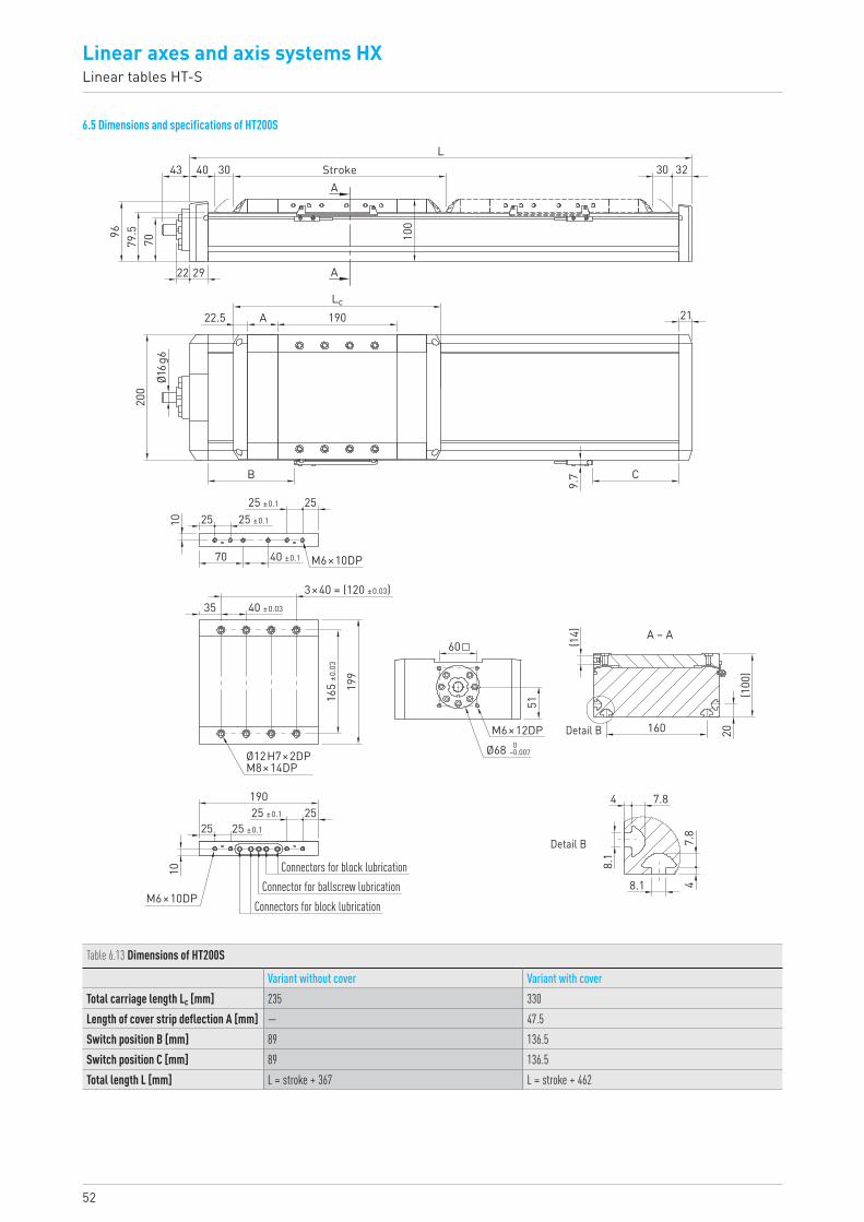
52
Linear axes and axis systems HXLinear tables HT-S
6.5 Dimensions and specifications of HT200S
43
70
22 29
100
30
21
32
79.596
40 30
22.5
200
A
B C
9.7
190Lc
Ø16g
6
25 ±0.1
25 ±0.1
40 ±0.1
252510
70
353×40 = (120 ±0.03)
40 ±0.03
165
±0.0
3
199
51
160 20(1
00)
(14)
60
M6×10DP
Ø12H7×2DPM8×14DP
M6×10DP
M6×12DP 0–0.007Ø68
4
4
7.8
7.8
8.1
8.1
A – A
Detail B
Detail B
Connectors for block lubrication
Connectors for block lubricationConnector for ballscrew lubrication
A
AStroke
L
25 ±0.1
25 ±0.1
2525
10
190
Table 6.13 Dimensions of HT200S
Variant without cover Variant with coverTotal carriage length Lc [mm] 235 330Length of cover strip deflection A [mm] — 47.5Switch position B [mm] 89 136.5Switch position C [mm] 89 136.5Total length L [mm] L = stroke + 367 L = stroke + 462

53HX-03-0-EN-1810-K
0.7
0.6
0.5
0.4
0.3
0.2
0.1
0 00 1,000 2,000 3,000 4,000 5,000
0 kg
30 kg
60 kg
90 kg
120 kg
150 kg
Unsupported axis length L [mm]
Defle
ction
in ve
rtica
l axis
posit
ion [m
m]
Defle
ction
in ho
rizon
tal ax
is po
sition
[mm]
1.0
6.0
5.0
4.0
3.0
2.0
LVertical axis position
LHorizontal axis position
Table 6.14 Load data
Fydynmax 1) 3) [N] 7,800Fzdynmax 3) [N] 12,143Mxdynmax [Nm] 826Mydynmax [Nm] 686Mzdynmax [Nm] 441z 2) [mm] 581) Force may act only without torque2) Upper carriage edge to guiding centre 3) Maximum possible retention force of guide screw connection taken into accountSee Section 2.9.3 on Page 11 (reference service life)
Table 6.15 General technical data
Repeatability [mm] ± 0.02Max acceleration [m/s2] 15Typical load capacity [kg] 150Max total length [mm] 3,965Area moment of inertia Ix [mm4] 2,071,928Area moment of inertia Iy [mm4] 19,658,810
Table 6.16 Guiding
Guiding type QHH20CAStatic load rating C0 [N] 25,630Dynamic load rating Cdyn [N] 23,080
Table 6.17 Drive
Spindle lead5 mm 10 mm 25 mm
Spindle diameter [mm] 25Axial play [mm] ≤ 0.02Max feed force Fx_max [N] 3,517 3,517 1,786Max speed [m/s] 0.20 0.50 1.25Max drive torque Ma_max [Nm] 3.60 6.40 7.91Static load rating ballscrew C0 [N] 43,000 42,600 20,200Dynamic load rating ballscrew Cdyn [N] 19,100 19,100 9,700
Fig. 6.5 Critical speed
Table 6.18 Mechanical properties
Variant without cover Variant with coverSpindle lead [mm] 5 10 25 5 10 25Carriage mass [kg] 3.24 3.33 3.45 3.76 3.85 3.97Mass at 0 stroke [kg] 12.89 12.99 13.11 15.61 15.70 15.82Mass per 1 m stroke [kg/m] 20.30 20.61Rotatory moment of inertia Jrot. at 0 stroke [kgcm2] 2.01 2.30Rotatory moment of inertia Jrot. per 1 m stroke [kgcm2/m] 3.01 3.01Idle torque at 0 stroke [Nm] 0.8 1.0
Fz
Fx
MzFy
My
Mx
z
0
500
1,000
1,500
2,000
2,500
3,500
3,000
0 1,000 1,500500 2,000 2,500 3,000 4,0003,500
SS = Spindle support
Axis stroke length [mm]
Balls
crew
spee
d [rpm
]
4 SS per side
2 SS per side
3 SS per side
1 SS per side
without SS
Fig. 6.6 Deflection under load capacity
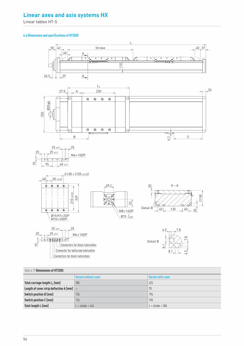
54
Linear axes and axis systems HXLinear tables HT-S
6.6 Dimensions and specifications of HT250S
50 4240
40 37Stroke
Detail B
Detail B
L
A
A29
110
24.5
27.5
250
B C
9.7
A 230 24Lc
Ø20g
6
25 ±0.1
40 ±0.195
2525
10
25 ±0.1
3×50 = (150 ±0.03)50 ±0.03
210
±0.0
3
249
65
52
20
20
(110
)
40
4.5 7.8
8.1
8.1
7.8
4.5
40130
40
M6×10DP
Ø15H7×2DPM10×20DP
M8×16DP 0–0.007Ø75
A – A
25 ±0.1 2525
10
25 ±0.1
Connectors for block lubrication
Connectors for block lubricationConnector for ballscrew lubrication
M6×10DP
Table 6.19 Dimensions of HT250S
Variant without cover Variant with coverTotal carriage length Lc [mm] 285 425Length of cover strip deflection A [mm] — 70Switch position B [mm] 126 196Switch position C [mm] 126 196Total length L [mm] L = stroke + 444 L = stroke + 584
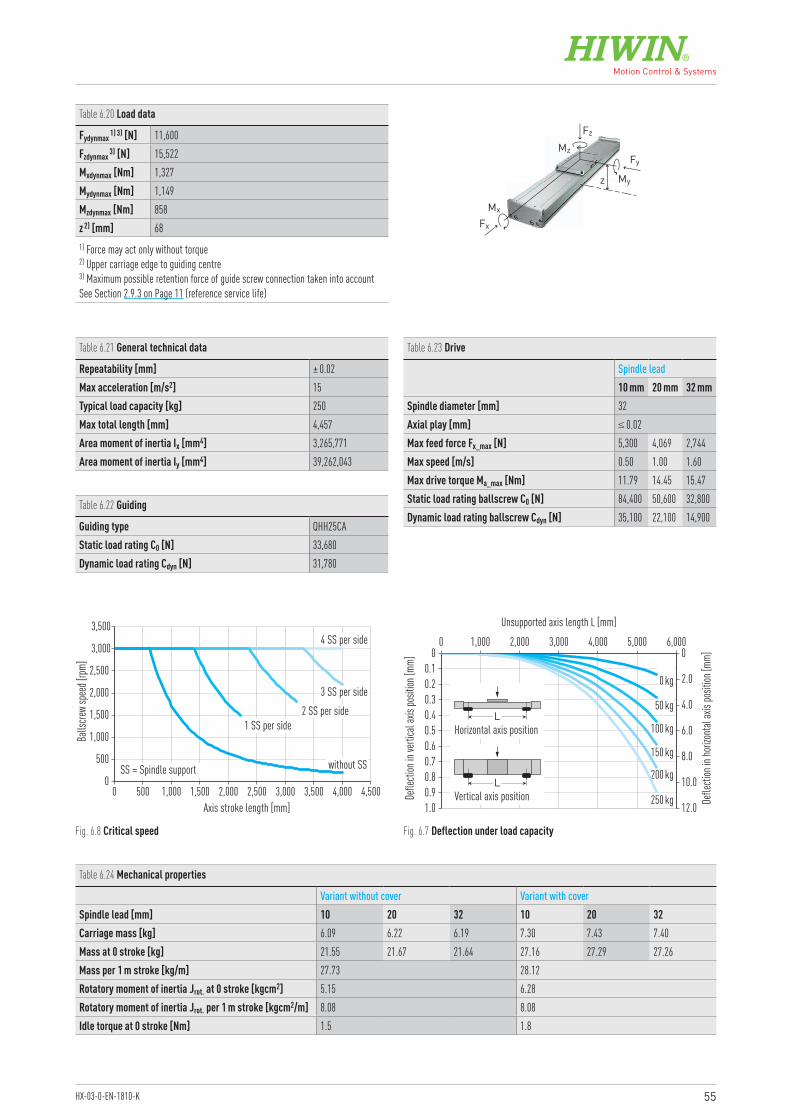
55HX-03-0-EN-1810-K
1.00.90.8
0.60.7
0.50.40.30.20.1
0 00 1,000 2,000 3,000 5,0004,000 6,000
0 kg
50 kg
100 kg
150 kg
200 kg
250 kg
Unsupported axis length L [mm]
Defle
ction
in ve
rtica
l axis
posit
ion [m
m]
Defle
ction
in ho
rizon
tal ax
is po
sition
[mm]
2.0
12.0
10.0
8.0
6.0
4.0
LVertical axis position
LHorizontal axis position
Table 6.20 Load data
Fydynmax 1) 3) [N] 11,600Fzdynmax 3) [N] 15,522Mxdynmax [Nm] 1,327Mydynmax [Nm] 1,149Mzdynmax [Nm] 858z 2) [mm] 681) Force may act only without torque2) Upper carriage edge to guiding centre 3) Maximum possible retention force of guide screw connection taken into accountSee Section 2.9.3 on Page 11 (reference service life)
Table 6.21 General technical data
Repeatability [mm] ± 0.02Max acceleration [m/s2] 15Typical load capacity [kg] 250Max total length [mm] 4,457Area moment of inertia Ix [mm4] 3,265,771Area moment of inertia Iy [mm4] 39,262,043
Table 6.22 Guiding
Guiding type QHH25CAStatic load rating C0 [N] 33,680Dynamic load rating Cdyn [N] 31,780
Table 6.23 Drive
Spindle lead10 mm 20 mm 32 mm
Spindle diameter [mm] 32Axial play [mm] ≤ 0.02Max feed force Fx_max [N] 5,300 4,069 2,744Max speed [m/s] 0.50 1.00 1.60Max drive torque Ma_max [Nm] 11.79 14.45 15.47Static load rating ballscrew C0 [N] 84,400 50,600 32,800Dynamic load rating ballscrew Cdyn [N] 35,100 22,100 14,900
Fig. 6.7 Deflection under load capacityFig. 6.8 Critical speed
Table 6.24 Mechanical properties
Variant without cover Variant with coverSpindle lead [mm] 10 20 32 10 20 32Carriage mass [kg] 6.09 6.22 6.19 7.30 7.43 7.40Mass at 0 stroke [kg] 21.55 21.67 21.64 27.16 27.29 27.26Mass per 1 m stroke [kg/m] 27.73 28.12Rotatory moment of inertia Jrot. at 0 stroke [kgcm2] 5.15 6.28Rotatory moment of inertia Jrot. per 1 m stroke [kgcm2/m] 8.08 8.08Idle torque at 0 stroke [Nm] 1.5 1.8
Fz
Fx
MzFy
My
Mx
z
0
500
1,000
1,500
2,000
2,500
3,500
3,000
0 1,000 1,500500 2,000 2,500 3,000 4,5003,500 4,000
SS = Spindle support
Axis stroke length [mm]
Balls
crew
spee
d [rpm
]
4 SS per side
2 SS per side3 SS per side
1 SS per side
without SS
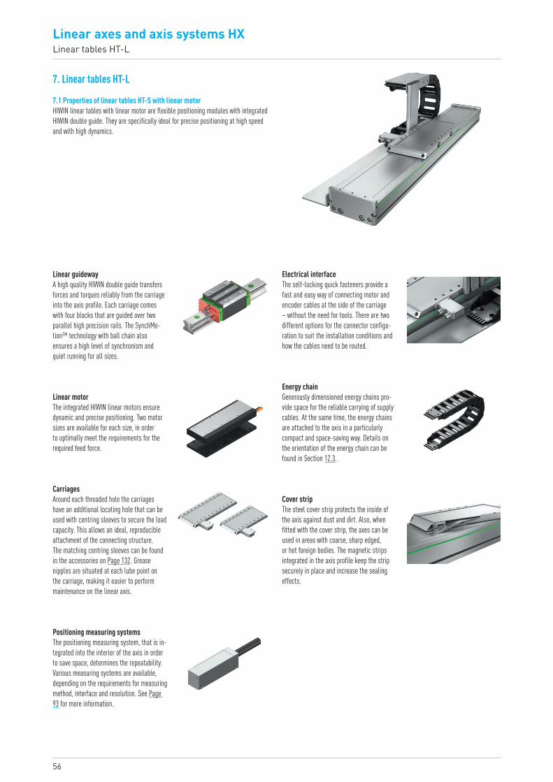
56
Linear axes and axis systems HXLinear tables HT-L
7. Linear tables HT-L
7.1 Properties of linear tables HT-S with linear motorHIWIN linear tables with linear motor are flexible positioning modules with integrated HIWIN double guide. They are specifically ideal for precise positioning at high speed and with high dynamics.
Linear guidewayA high quality HIWIN double guide transfers forces and torques reliably from the carriage into the axis profile. Each carriage comes with four blocks that are guided over two parallel high precision rails. The SynchMo-tion™ technology with ball chain also ensures a high level of synchronism and quiet running for all sizes.
Electrical interfaceThe self-locking quick fasteners provide a fast and easy way of connecting motor and encoder cables at the side of the carriage – without the need for tools. There are two different options for the connector configu-ration to suit the installation conditions and how the cables need to be routed.
Cover stripThe steel cover strip protects the inside of the axis against dust and dirt. Also, when fitted with the cover strip, the axes can be used in areas with coarse, sharp edged, or hot foreign bodies. The magnetic strips integrated in the axis profile keep the strip securely in place and increase the sealing effects.
Energy chainGenerously dimensioned energy chains pro-vide space for the reliable carrying of supply cables. At the same time, the energy chains are attached to the axis in a particularly compact and space-saving way. Details on the orientation of the energy chain can be found in Section 12.3.
Linear motorThe integrated HIWIN linear motors ensure dynamic and precise positioning. Two motor sizes are available for each size, in order to optimally meet the requirements for the required feed force.
CarriagesAround each threaded hole the carriages have an additional locating hole that can be used with centring sleeves to secure the load capacity. This allows an ideal, reproducible attachment of the connecting structure. The matching centring sleeves can be found in the accessories on Page 132. Grease nipples are situated at each lube point on the carriage, making it easier to perform maintenance on the linear axis.
Positioning measuring systemsThe positioning measuring system, that is in-tegrated into the interior of the axis in order to save space, determines the repeatability. Various measuring systems are available, depending on the requirements for measuring method, interface and resolution. See Page 93 for more information.
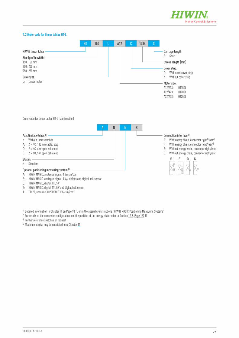
57HX-03-0-EN-1810-K
HIWIN linear table
Connection interface 2):R: With energy chain, connector right/front 4)
F: With energy chain, connector right/rear 4)
B: Without energy chain, connector right/frontD: Without energy chain, connector right/rear
Optional positioning measuring system 1):A: HIWIN MAGIC, analogue signal, 1 VPP sin/cosB: HIWIN MAGIC, analogue signal, 1 VPP sin/cos and digital hall sensorD: HIWIN MAGIC, digital TTL 5 VE: HIWIN MAGIC, digital TTL 5 V and digital hall sensorT: TTK70, absolute, HIPERFACE 1 VPP sin/cos 4)
Stator:N: Standard
Axis limit switches 3):N: Without limit switchesA: 2 × NC, 100 mm cable, plugC: 2 × NC, 4 m open cable endD: 2 × NO, 5 m open cable end
Size (profile width):150: 150 mm200: 200 mm250: 250 mm
Cover strip:C: With steel cover stripN: Without cover strip
Motor size:A12/A13: HT150LA22/A23: HT200LA32/A33: HT250L
Stroke length [mm]
Carriage length:S: Short
Drive type:L: Linear motor
HT 150 L A12 C 1234 S
A N N R
Order code for linear tables HT-L (continuation)
7.2 Order code for linear tables HT-L
R F B D
1) Detailed information in Chapter 11 on Page 93 ff. or in the assembly instructions “HIWIN MAGIC Positioning Measuring Systems”2) For details of the connector configuration and the position of the energy chain, refer to Section 12.3, Page 127 ff.3) Further reference switches on request4) Maximum stroke may be restricted; see Chapter 11
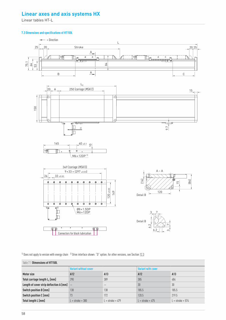
58
Linear axes and axis systems HXLinear tables HT-L
7.3 Dimensions and specifications of HT150L
+ Direction5364
25
20
150
145
10
26
(14)
15 (84)
120
3
6.2
6.2
7
73
A
B
9.7
C
15250 (carriage LMSA12)
349 (carriage LMSA13)
20 20 25Stroke
84
L
75.1
Lc
40 ±0.1
2)
M6×12DP 1)
A – A9×33 = (297 ±0.03)33 ±0.03
120
±0.0
3
149
Ø8×1.5DPM6×12DP
Detail B
Detail B
Connectors for block lubrication
A
A
Table 7.1 Dimensions of HT150L
Variant without cover Variant with coverMotor size A12 A13 A12 A13Total carriage length Lc [mm] 290 389 385 484Length of cover strip deflection A [mm] — — 30 30Switch position B [mm] 138 138 185.5 185.5Switch position C [mm] 73 172 120.5 219.5Total length L [mm] L = stroke + 380 L = stroke + 479 L = stroke + 475 L = stroke + 574
1) Does not apply to version with energy chain 2) Drive interface shown: “D” option; for other versions, see Section 12.3
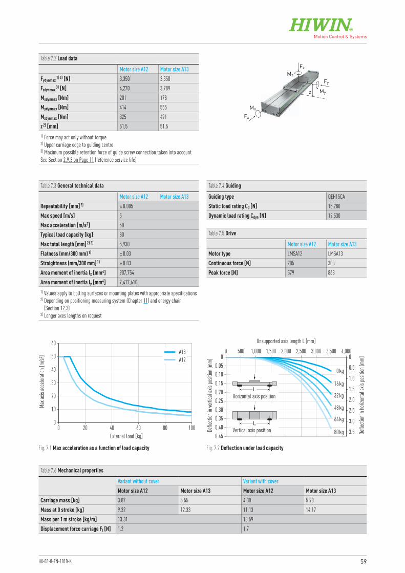
59HX-03-0-EN-1810-K
0
10
20
30
40
50
60
0 20 40 60 80 100External load [kg]
Max a
xis ac
celer
ation
[m/s²
] A13A12
0.450.40
0.300.35
0.250.200.150.100.05
0 00 500 1,000 1,500 3,5003,0002,5002,000 4,000
0 kg
16 kg
32 kg
48 kg
64 kg
80 kg
Unsupported axis length L [mm]
Defle
ction
in ve
rtica
l axis
posit
ion [m
m]
Defle
ction
in ho
rizon
tal ax
is po
sition
[mm]
0.5
3.5
3.0
2.5
2.0
1.5
1.0
LVertical axis position
LHorizontal axis position
Table 7.2 Load data
Motor size A12 Motor size A13Fydynmax 1) 3) [N] 3,350 3,350Fzdynmax 3) [N] 4,270 3,789Mxdynmax [Nm] 201 178Mydynmax [Nm] 414 555Mzdynmax [Nm] 325 491z 2) [mm] 51.5 51.51) Force may act only without torque2) Upper carriage edge to guiding centre 3) Maximum possible retention force of guide screw connection taken into accountSee Section 2.9.3 on Page 11 (reference service life)
Table 7.3 General technical data
Motor size A12 Motor size A13Repeatability [mm] 2) ± 0.005Max speed [m/s] 5Max acceleration [m/s2] 50Typical load capacity [kg] 80Max total length [mm] 2) 3) 5,930Flatness (mm/300 mm) 1) ± 0.03Straightness (mm/300 mm) 1) ± 0.03Area moment of inertia Ix [mm4] 907,754Area moment of inertia Iy [mm4] 7,417,6101) Values apply to bolting surfaces or mounting plates with appropriate specifications 2) Depending on positioning measuring system (Chapter 11) and energy chain
(Section 12.3)3) Longer axes lengths on request
Fz
Fx
MzFy
z My
Mx
Table 7.4 Guiding
Guiding type QEH15CAStatic load rating C0 [N] 15,280Dynamic load rating Cdyn [N] 12,530
Table 7.5 Drive
Motor size A12 Motor size A13Motor type LMSA12 LMSA13Continuous force [N] 205 308Peak force [N] 579 868
Fig. 7.1 Max acceleration as a function of load capacity Fig. 7.2 Deflection under load capacity
Table 7.6 Mechanical properties
Variant without cover Variant with coverMotor size A12 Motor size A13 Motor size A12 Motor size A13
Carriage mass [kg] 3.87 5.55 4.30 5.98Mass at 0 stroke [kg] 9.32 12.33 11.13 14.17Mass per 1 m stroke [kg/m] 13.31 13.59Displacement force carriage Fl [N] 1.2 1.7
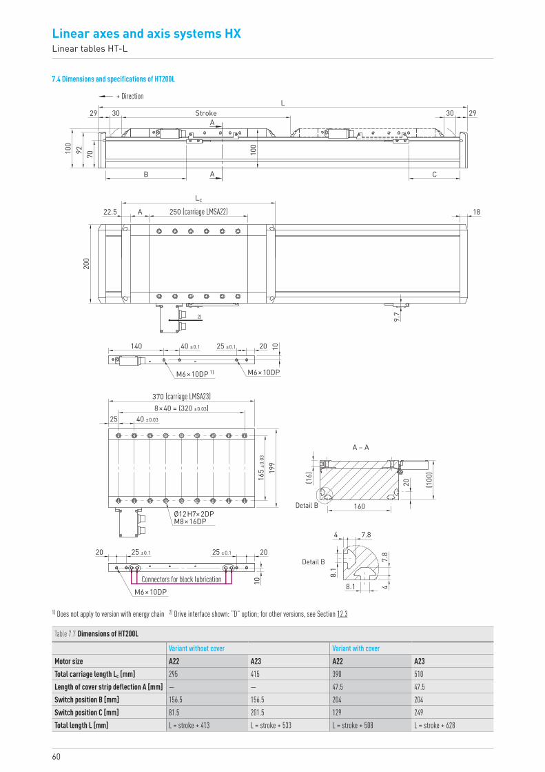
60
Linear axes and axis systems HXLinear tables HT-L
7.4 Dimensions and specifications of HT200L
29
100
92 70
30
B
22.5
200
140
A
A
AStroke
L2930
C
100
250 (carriage LMSA22)
Lc
40 ±0.1 25 ±0.1 20 10
370 (carriage LMSA23)
M6×10DP 1) M6×10DP
8×40 = (320 ±0.03)
165
±0.0
3
199
(16)
20 (100
)
160
7.8
2020
10
7.8
8.1
8.1
4
4
40 ±0.0325
Ø12H7×2DPM8×16DP
M6×10DP
A – A
Detail B
Detail B25 ±0.125 ±0.1
Connectors for block lubrication
9.7
18
+ Direction
2)
Table 7.7 Dimensions of HT200L
Variant without cover Variant with coverMotor size A22 A23 A22 A23Total carriage length Lc [mm] 295 415 390 510Length of cover strip deflection A [mm] — — 47.5 47.5Switch position B [mm] 156.5 156.5 204 204Switch position C [mm] 81.5 201.5 129 249Total length L [mm] L = stroke + 413 L = stroke + 533 L = stroke + 508 L = stroke + 628
1) Does not apply to version with energy chain 2) Drive interface shown: “D” option; for other versions, see Section 12.3
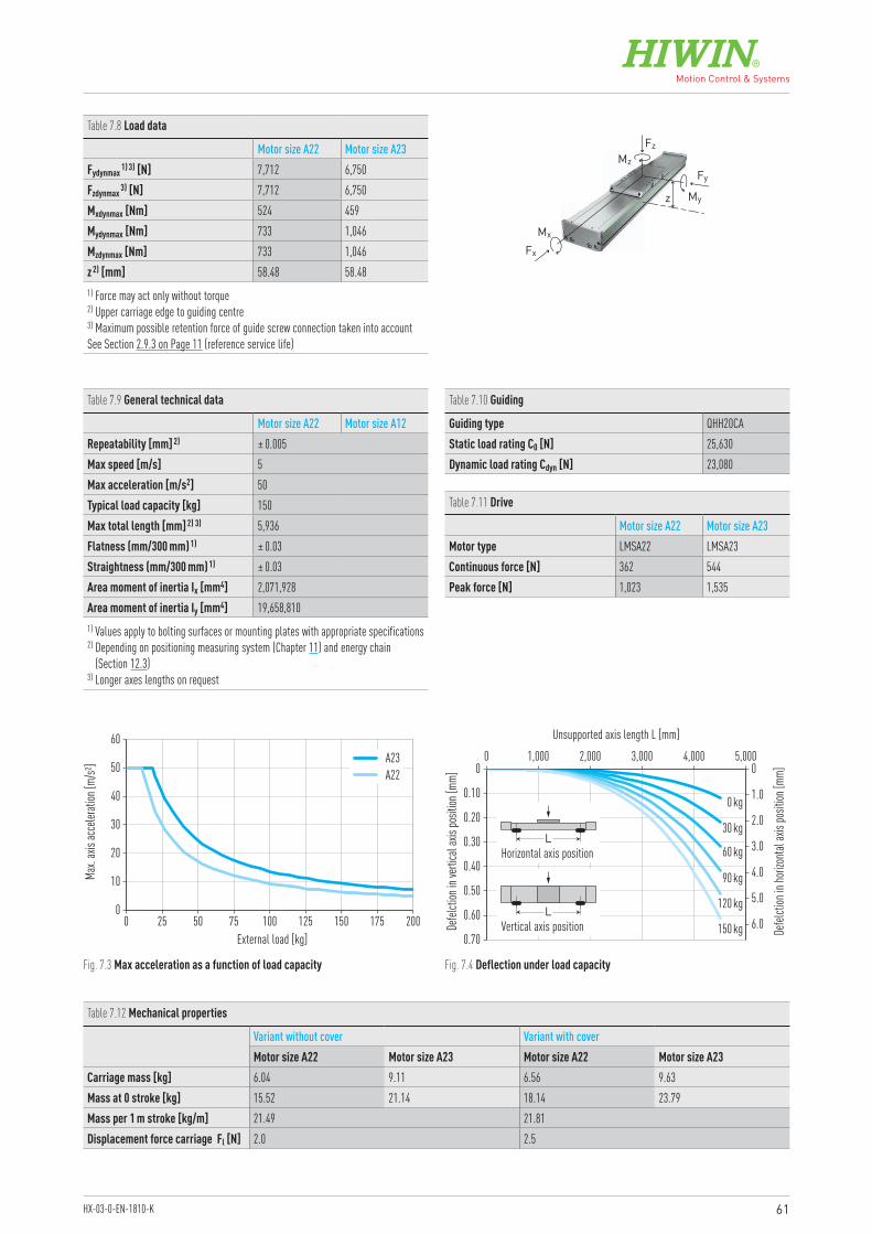
61HX-03-0-EN-1810-K
0
10
20
30
40
50
60
0 5025 75 100 125 150 175 200External load [kg]
Max.
axis
acce
lerati
on [m
/s²] A23
A22
0.70
0.60
0.50
0.40
0.30
0.20
0.10
0 00 1,000 4,0003,0002,000 5,000
0 kg
30 kg
60 kg
90 kg
120 kg
150 kg
Unsupported axis length L [mm]
Defel
ction
in ve
rtica
l axis
posit
ion [m
m]
Defel
ction
in ho
rizon
tal ax
is po
sition
[mm]
1.0
6.0
5.0
4.0
3.0
2.0
LVertical axis position
LHorizontal axis position
Fig. 7.3 Max acceleration as a function of load capacity Fig. 7.4 Deflection under load capacity
Table 7.8 Load data
Motor size A22 Motor size A23Fydynmax 1) 3) [N] 7,712 6,750Fzdynmax 3) [N] 7,712 6,750Mxdynmax [Nm] 524 459Mydynmax [Nm] 733 1,046Mzdynmax [Nm] 733 1,046z 2) [mm] 58.48 58.481) Force may act only without torque2) Upper carriage edge to guiding centre 3) Maximum possible retention force of guide screw connection taken into accountSee Section 2.9.3 on Page 11 (reference service life)
Table 7.9 General technical data
Motor size A22 Motor size A12Repeatability [mm] 2) ± 0.005Max speed [m/s] 5Max acceleration [m/s2] 50Typical load capacity [kg] 150Max total length [mm] 2) 3) 5,936Flatness (mm/300 mm) 1) ± 0.03Straightness (mm/300 mm) 1) ± 0.03Area moment of inertia Ix [mm4] 2,071,928Area moment of inertia Iy [mm4] 19,658,8101) Values apply to bolting surfaces or mounting plates with appropriate specifications 2) Depending on positioning measuring system (Chapter 11) and energy chain
(Section 12.3)3) Longer axes lengths on request
Table 7.10 Guiding
Guiding type QHH20CAStatic load rating C0 [N] 25,630Dynamic load rating Cdyn [N] 23,080
Table 7.11 Drive
Motor size A22 Motor size A23Motor type LMSA22 LMSA23Continuous force [N] 362 544Peak force [N] 1,023 1,535
Table 7.12 Mechanical properties
Variant without cover Variant with coverMotor size A22 Motor size A23 Motor size A22 Motor size A23
Carriage mass [kg] 6.04 9.11 6.56 9.63Mass at 0 stroke [kg] 15.52 21.14 18.14 23.79Mass per 1 m stroke [kg/m] 21.49 21.81Displacement force carriage Fl [N] 2.0 2.5
Fz
Fx
MzFy
z My
Mx
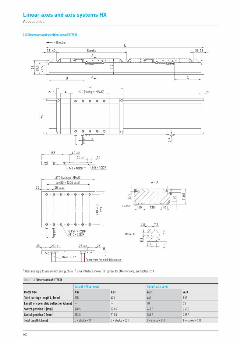
Linear axes and axis systems HXAccessories
62
7.5 Dimensions and specifications of HT250L
33
98 85.5
73.5
40 3340
C
StrokeA
AB
110
L
9.7
20270 (carriage LMSA32)Lc
25 ±0.1 2540 ±0.1155
370 (carriage LMSA33)
M6×10DP 1) M6×10DP
6×50 = (300 ±0.03)
210
±0.0
3
25 ±0.1 25 ±0.125 25
1024
9
(20)
(110
)
20
40 40130
4.5
4.58.1
8.1
7.8
7.8
50 ±0.0335
Ø15H7×2DPM10×20DP
M6×10DP
Detail B
Detail B
A – A
27.5
250
A
Connectors for block lubrication
+ Direction
2)
Table 7.13 Dimensions of HT250L
Variant without cover Variant with coverMotor size A32 A33 A32 A33Total carriage length Lc [mm] 325 425 465 565Length of cover strip deflection A [mm] — — 70 70Switch position B [mm] 178.5 178.5 248.5 248.5Switch position C [mm] 113.5 213.5 183.5 283.5Total length L [mm] L = stroke + 471 L = stroke + 571 L = stroke + 611 L = stroke + 711
1) Does not apply to version with energy chain 2) Drive interface shown: “D” option; for other versions, see Section 12.3
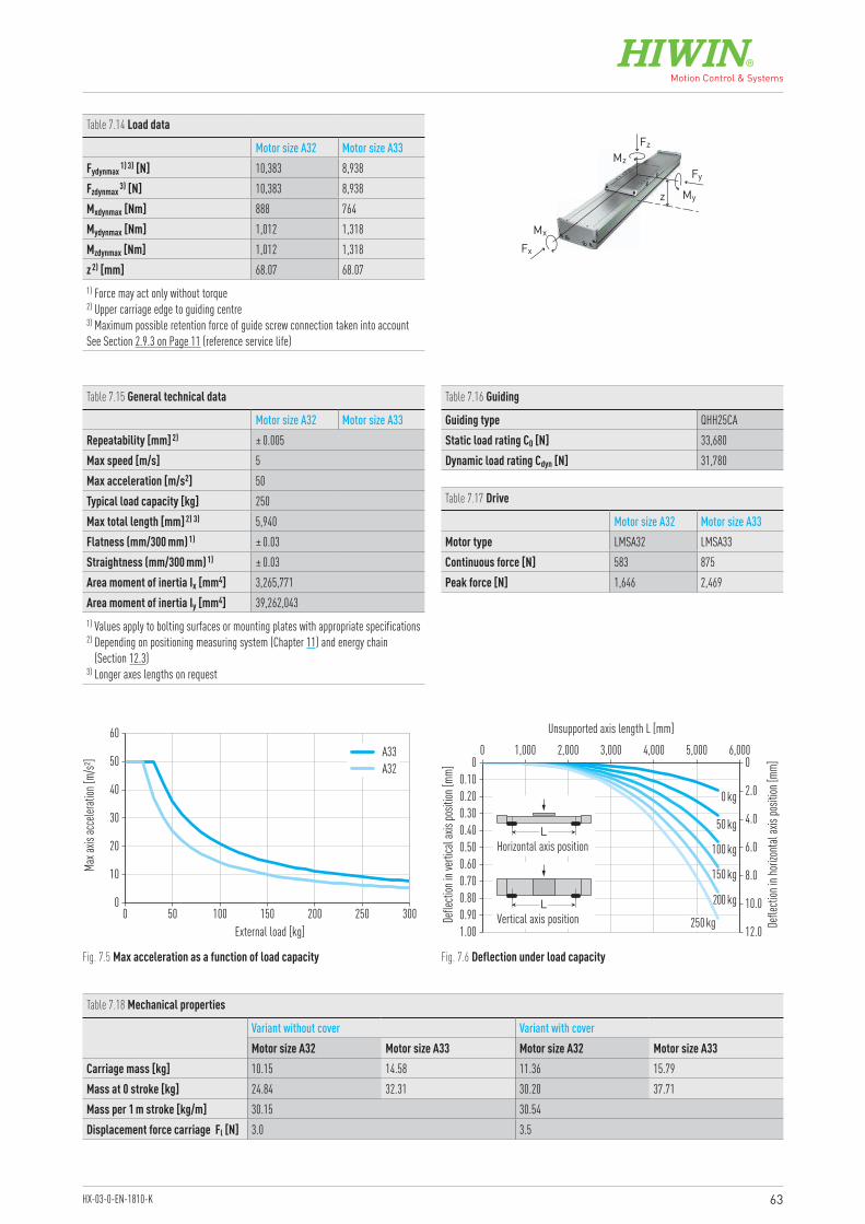
63HX-03-0-EN-1810-K
0
10
20
30
40
50
60
0 10050 150 200 250 300External load [kg]
Max a
xis ac
celer
ation
[m/s²
] A33A32
1.000.900.800.700.600.500.400.300.200.10
0 00 1,000 4,000 5,0003,0002,000 6,000
Unsupported axis length L [mm]
Defle
ction
in ve
rtica
l axis
posit
ion [m
m]
Defle
ction
in ho
rizon
tal ax
is po
sition
[mm]
2.0
12.0
10.0
8.0
6.0
4.0
LVertical axis position
LHorizontal axis position
0 kg
50 kg
100 kg
150 kg
200 kg
250 kg
Fig. 7.5 Max acceleration as a function of load capacity Fig. 7.6 Deflection under load capacity
Table 7.14 Load data
Motor size A32 Motor size A33Fydynmax 1) 3) [N] 10,383 8,938Fzdynmax 3) [N] 10,383 8,938Mxdynmax [Nm] 888 764Mydynmax [Nm] 1,012 1,318Mzdynmax [Nm] 1,012 1,318z 2) [mm] 68.07 68.071) Force may act only without torque2) Upper carriage edge to guiding centre 3) Maximum possible retention force of guide screw connection taken into accountSee Section 2.9.3 on Page 11 (reference service life)
Table 7.15 General technical data
Motor size A32 Motor size A33Repeatability [mm] 2) ± 0.005Max speed [m/s] 5Max acceleration [m/s2] 50Typical load capacity [kg] 250Max total length [mm] 2) 3) 5,940Flatness (mm/300 mm) 1) ± 0.03Straightness (mm/300 mm) 1) ± 0.03Area moment of inertia Ix [mm4] 3,265,771Area moment of inertia Iy [mm4] 39,262,0431) Values apply to bolting surfaces or mounting plates with appropriate specifications 2) Depending on positioning measuring system (Chapter 11) and energy chain
(Section 12.3)3) Longer axes lengths on request
Table 7.16 Guiding
Guiding type QHH25CAStatic load rating C0 [N] 33,680Dynamic load rating Cdyn [N] 31,780
Table 7.17 Drive
Motor size A32 Motor size A33Motor type LMSA32 LMSA33Continuous force [N] 583 875Peak force [N] 1,646 2,469
Table 7.18 Mechanical properties
Variant without cover Variant with coverMotor size A32 Motor size A33 Motor size A32 Motor size A33
Carriage mass [kg] 10.15 14.58 11.36 15.79Mass at 0 stroke [kg] 24.84 32.31 30.20 37.71Mass per 1 m stroke [kg/m] 30.15 30.54Displacement force carriage Fl [N] 3.0 3.5
Fz
Fx
MzFy
z My
Mx
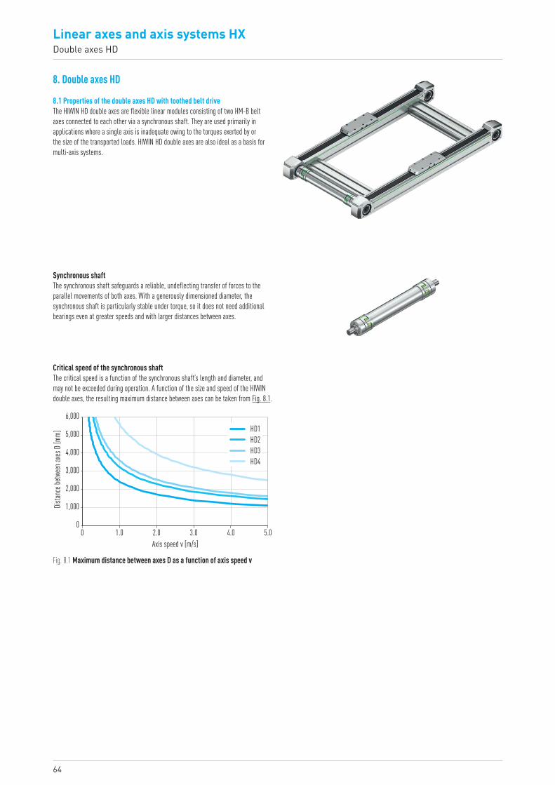
64
Linear axes and axis systems HXDouble axes HD
8. Double axes HD
8.1 Properties of the double axes HD with toothed belt driveThe HIWIN HD double axes are flexible linear modules consisting of two HM-B belt axes connected to each other via a synchronous shaft. They are used primarily in applications where a single axis is inadequate owing to the torques exerted by or the size of the transported loads. HIWIN HD double axes are also ideal as a basis for multi-axis systems.
Synchronous shaftThe synchronous shaft safeguards a reliable, undeflecting transfer of forces to the parallel movements of both axes. With a generously dimensioned diameter, the synchronous shaft is particularly stable under torque, so it does not need additional bearings even at greater speeds and with larger distances between axes.
Critical speed of the synchronous shaftThe critical speed is a function of the synchronous shaft’s length and diameter, and may not be exceeded during operation. A function of the size and speed of the HIWIN double axes, the resulting maximum distance between axes can be taken from Fig. 8.1.
Fig. 8.1 Maximum distance between axes D as a function of axis speed v
0
1,000
2,000
3,000
4,000
5,000
6,000
0 1.0 2.0 3.0 4.0 5.0Axis speed v [m/s]
Distan
ce be
twee
n axe
s D [m
m]
HD1HD2HD3HD4
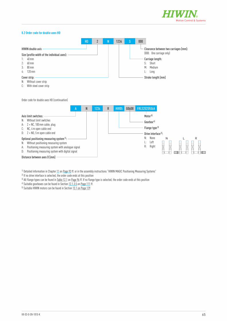
65HX-03-0-EN-1810-K
HIWIN double axis
Motor 5)
Flange type 3)
Distance between axes D [mm]
Optional positioning measuring system 1):N: Without positioning measuring systemA: Positioning measuring system with analogue signalD: Positioning measuring system with digital signal
Axis limit switches:N: Without limit switchesA: 2 × NC, 100 mm cable, plugC: NC, 4 m open cable endD: 2 × NO, 5 m open cable end
Size (profile width of the individual axes):1: 40 mm2: 60 mm3: 80 mm4: 120 mm
Stroke length [mm]
Carriage length:S: ShortM: MediumL: Long
Clearance between two carriages [mm]:(000: One carriage only)
Cover strip:N: Without cover stripC: With steel cover strip
HD 2 N 1234 S 000
A N 1234 R HW05 G0608 FRLS2020506A
Order code for double axes HD (continuation)
1) Detailed information in Chapter 11 on Page 93 ff. or in the assembly instructions “HIWIN MAGIC Positioning Measuring Systems”2) If no drive interface is selected, the order code ends at this position3) All flange types can be found in Table 12.1 on Page 96 ff. If no flange type is selected, the order code ends at this position4) Suitable gearboxes can be found in Section 12.1.3.5 on Page 111 ff.5) Suitable HIWIN motors can be found in Section 13.1 on Page 129
8.2 Order code for double axes HD
Drive interface 2):N: NoneL: LeftR: Right
N L R
Gearbox 4)
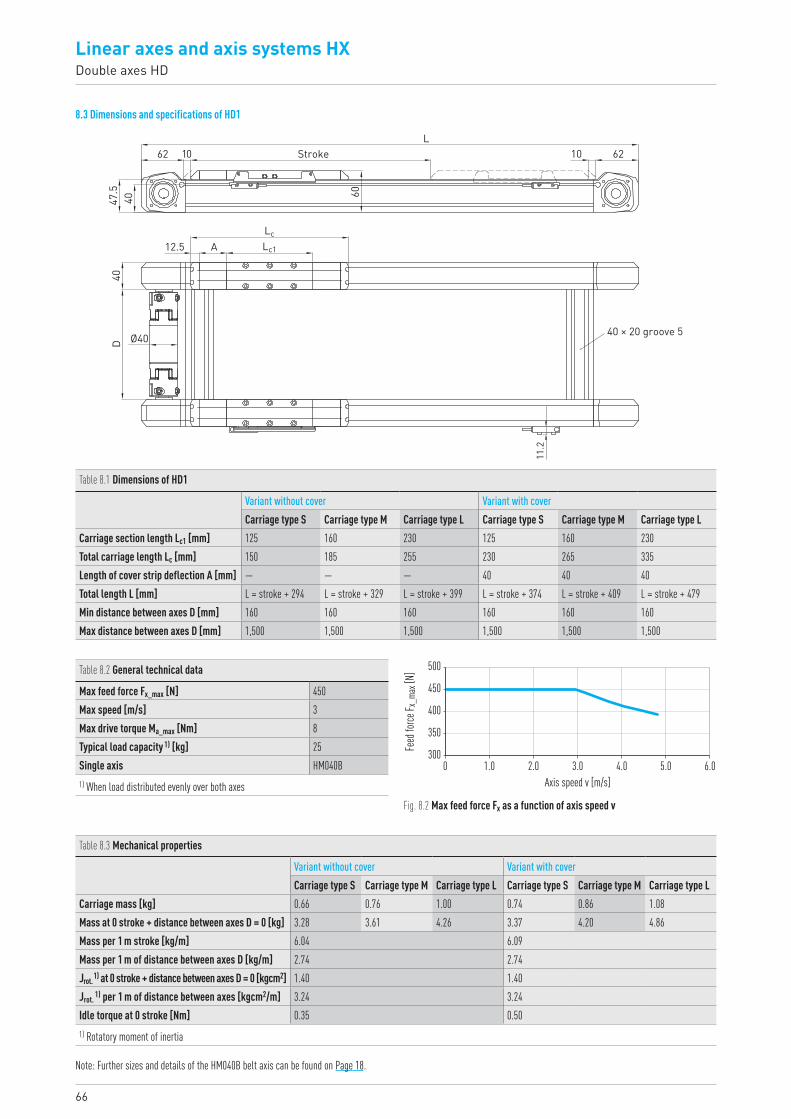
66
Linear axes and axis systems HXDouble axes HD
8.3 Dimensions and specifications of HD1
Table 8.1 Dimensions of HD1
Variant without cover Variant with coverCarriage type S Carriage type M Carriage type L Carriage type S Carriage type M Carriage type L
Carriage section length Lc1 [mm] 125 160 230 125 160 230Total carriage length Lc [mm] 150 185 255 230 265 335Length of cover strip deflection A [mm] — — — 40 40 40Total length L [mm] L = stroke + 294 L = stroke + 329 L = stroke + 399 L = stroke + 374 L = stroke + 409 L = stroke + 479Min distance between axes D [mm] 160 160 160 160 160 160Max distance between axes D [mm] 1,500 1,500 1,500 1,500 1,500 1,500
300
350
400
450
500
0 1.0 2.0 3.0 4.0 5.0 6.0Axis speed v [m/s]
Feed
force
F x_m
ax [N
]
Fig. 8.2 Max feed force Fx as a function of axis speed v
Table 8.2 General technical data
Max feed force Fx_max [N] 450Max speed [m/s] 3Max drive torque Ma_max [Nm] 8Typical load capacity 1) [kg] 25Single axis HM040B1) When load distributed evenly over both axes
Table 8.3 Mechanical properties
Variant without cover Variant with coverCarriage type S Carriage type M Carriage type L Carriage type S Carriage type M Carriage type L
Carriage mass [kg] 0.66 0.76 1.00 0.74 0.86 1.08Mass at 0 stroke + distance between axes D = 0 [kg] 3.28 3.61 4.26 3.37 4.20 4.86Mass per 1 m stroke [kg/m] 6.04 6.09Mass per 1 m of distance between axes D [kg/m] 2.74 2.74Jrot. 1) at 0 stroke + distance between axes D = 0 [kgcm2] 1.40 1.40Jrot. 1) per 1 m of distance between axes [kgcm2/m] 3.24 3.24Idle torque at 0 stroke [Nm] 0.35 0.501) Rotatory moment of inertia
Note: Further sizes and details of the HM040B belt axis can be found on Page 18.
LcLc1A
Ø40D40
12.5
40 × 20 groove 5
60
47.5
L40
1062 Stroke 10 62
11.2
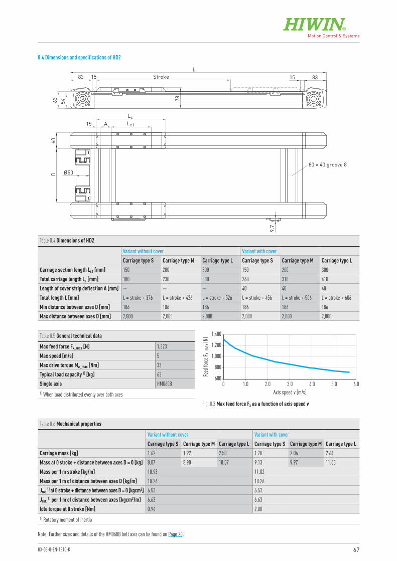
67HX-03-0-EN-1810-K
8.4 Dimensions and specifications of HD2
Table 8.4 Dimensions of HD2
Variant without cover Variant with coverCarriage type S Carriage type M Carriage type L Carriage type S Carriage type M Carriage type L
Carriage section length Lc1 [mm] 150 200 300 150 200 300Total carriage length Lc [mm] 180 230 330 260 310 410Length of cover strip deflection A [mm] — — — 40 40 40Total length L [mm] L = stroke + 376 L = stroke + 426 L = stroke + 526 L = stroke + 456 L = stroke + 506 L = stroke + 606Min distance between axes D [mm] 186 186 186 186 186 186Max distance between axes D [mm] 2,000 2,000 2,000 2,000 2,000 2,000
600
800
1,000
1,200
1,400
0 1.0 2.0 3.0 4.0 5.0 6.0Axis speed v [m/s]
Feed
force
F x_m
ax [N
]
Fig. 8.3 Max feed force Fx as a function of axis speed v
Table 8.5 General technical data
Max feed force Fx_max [N] 1,323Max speed [m/s] 5Max drive torque Ma_max [Nm] 33Typical load capacity 1) [kg] 63Single axis HM060B1) When load distributed evenly over both axes
Table 8.6 Mechanical properties
Variant without cover Variant with coverCarriage type S Carriage type M Carriage type L Carriage type S Carriage type M Carriage type L
Carriage mass [kg] 1.62 1.92 2.50 1.78 2.06 2.64Mass at 0 stroke + distance between axes D = 0 [kg] 8.07 8.90 10.57 9.13 9.97 11.65Mass per 1 m stroke [kg/m] 10.93 11.02Mass per 1 m of distance between axes D [kg/m] 10.26 10.26Jrot. 1) at 0 stroke + distance between axes D = 0 [kgcm2] 6.53 6.53Jrot. 1) per 1 m of distance between axes [kgcm2/m] 6.63 6.63Idle torque at 0 stroke [Nm] 0.94 2.001) Rotatory moment of inertia
A15
D60
9.7
Ø5080 × 40 groove 8
L
7863
83 15 8315Stroke
54
LcLc1
Note: Further sizes and details of the HM060B belt axis can be found on Page 20.
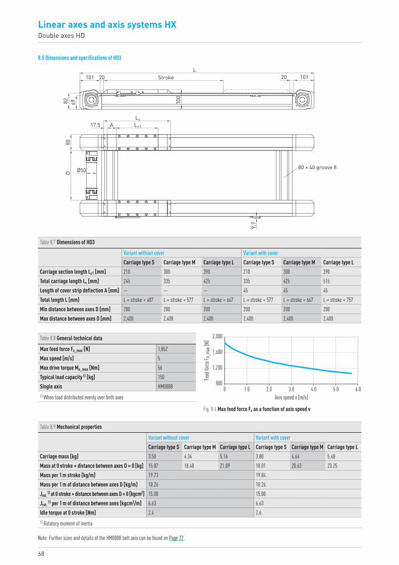
68
Linear axes and axis systems HXDouble axes HD
8.5 Dimensions and specifications of HD3
Table 8.7 Dimensions of HD3
Variant without cover Variant with coverCarriage type S Carriage type M Carriage type L Carriage type S Carriage type M Carriage type L
Carriage section length Lc1 [mm] 210 300 390 210 300 390Total carriage length Lc [mm] 245 335 425 335 425 515Length of cover strip deflection A [mm] — — — 45 45 45Total length L [mm] L = stroke + 487 L = stroke + 577 L = stroke + 667 L = stroke + 577 L = stroke + 667 L = stroke + 757Min distance between axes D [mm] 200 200 200 200 200 200Max distance between axes D [mm] 2,400 2,400 2,400 2,400 2,400 2,400
800
1,200
1,600
2,000
0 1.0 2.0 3.0 4.0 6.05.0Axis speed v [m/s]
Feed
force
F x_m
ax [N
]
Fig. 8.4 Max feed force Fx as a function of axis speed v
Table 8.8 General technical data
Max feed force Fx_max [N] 1,852Max speed [m/s] 5Max drive torque Ma_max [Nm] 56Typical load capacity 1) [kg] 150Single axis HM080B1) When load distributed evenly over both axes
Lc1
LcA17.5
80D Ø50
9.7
80 × 40 groove 8
100
82L
2010169
10120Stroke
Note: Further sizes and details of the HM080B belt axis can be found on Page 22.
Table 8.9 Mechanical properties
Variant without cover Variant with coverCarriage type S Carriage type M Carriage type L Carriage type S Carriage type M Carriage type L
Carriage mass [kg] 3.50 4.34 5.16 3.80 4.64 5.48Mass at 0 stroke + distance between axes D = 0 [kg] 15.87 18.48 21.09 18.01 20.63 23.25Mass per 1 m stroke [kg/m] 19.73 19.84Mass per 1 m of distance between axes D [kg/m] 10.26 10.26Jrot. 1) at 0 stroke + distance between axes D = 0 [kgcm2] 15.00 15.00Jrot. 1) per 1 m of distance between axes [kgcm2/m] 6.63 6.63Idle torque at 0 stroke [Nm] 2.4 2.61) Rotatory moment of inertia
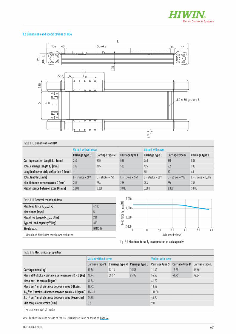
69HX-03-0-EN-1810-K
8.6 Dimensions and specifications of HD4
Table 8.10 Dimensions of HD4
Variant without cover Variant with coverCarriage type S Carriage type M Carriage type L Carriage type S Carriage type M Carriage type L
Carriage section length Lc1 [mm] 260 370 535 260 370 535Total carriage length Lc [mm] 305 415 580 425 535 700Length of cover strip deflection A [mm] — — — 60 60 60Total length L [mm] L = stroke + 689 L = stroke + 799 L = stroke + 964 L = stroke + 809 L = stroke + 919 L = stroke + 1,084Min distance between axes D [mm] 256 256 256 256 256 256Max distance between axes D [mm] 3,000 3,000 3,000 3,000 3,000 3,000
0 1.0 2.0 3.0 4.0 5.0 6.0Axis speed v [m/s]
Feed
force
F x_m
ax [N
]
2,000
3,000
4,000
5,000
Fig. 8.5 Max feed force Fx as a function of axis speed v
Table 8.11 General technical data
Max feed force Fx_max [N] 4,385Max speed [m/s] 5Max drive torque Ma_max [Nm] 201Typical load capacity 1) [kg] 300Single axis HM120B1) When load distributed evenly over both axes
Lc1
Lc
A22.5
120
D Ø80
9.7
80 × 80 groove 8
145
120
L10
7.5
15240Stroke152 40
Note: Further sizes and details of the HM120B belt axis can be found on Page 24.
Table 8.12 Mechanical properties
Variant without cover Variant with coverCarriage type S Carriage type M Carriage type L Carriage type S Carriage type M Carriage type L
Carriage mass [kg] 10.58 12.16 15.58 11.62 13.59 16.60Mass at 0 stroke + distance between axes D = 0 [kg] 49.44 55.57 65.85 55.53 61.73 72.04Mass per 1 m stroke [kg/m] 41.54 41.72Mass per 1 m of distance between axes D [kg/m] 18.42 18.42Jrot. 1) at 0 stroke + distance between axes D = 0 [kgcm2] 104.30 104.30Jrot. 1) per 1 m of distance between axes [kgcm2/m] 44.90 44.90Idle torque at 0 stroke [Nm] 6.2 9.01) Rotatory moment of inertia
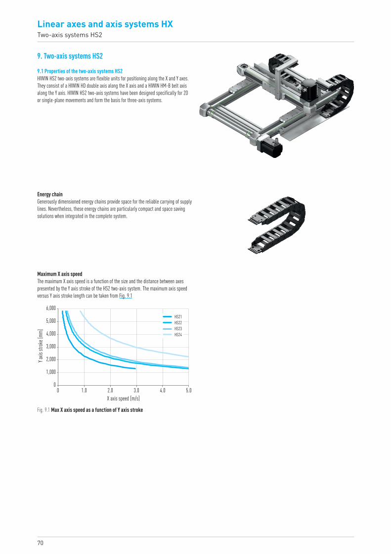
70
0
1,000
2,000
3,000
4,000
5,000
6,000
0 1.0 2.0 3.0 4.0 5.0X axis speed [m/s]
Y axis
strok
e [mm
]
HS21HS22HS23HS24
Linear axes and axis systems HXTwo-axis systems HS2
9. Two-axis systems HS2
9.1 Properties of the two-axis systems HS2HIWIN HS2 two-axis systems are flexible units for positioning along the X and Y axes. They consist of a HIWIN HD double axis along the X axis and a HIWIN HM-B belt axis along the Y axis. HIWIN HS2 two-axis systems have been designed specifically for 2D or single-plane movements and form the basis for three-axis systems.
Energy chainGenerously dimensioned energy chains provide space for the reliable carrying of supply lines. Nevertheless, these energy chains are particularly compact and space saving solutions when integrated in the complete system.
Maximum X axis speedThe maximum X axis speed is a function of the size and the distance between axes presented by the Y axis stroke of the HS2 two-axis system. The maximum axis speed versus Y axis stroke length can be taken from Fig. 9.1
Fig. 9.1 Max X axis speed as a function of Y axis stroke
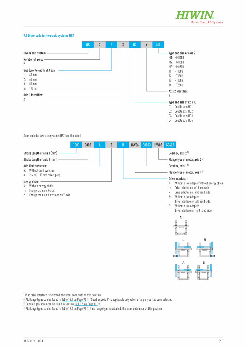
71HX-03-0-EN-1810-K
HIWIN axis system
Gearbox, axis 2 3)
Axis limit switches:N: Without limit switchesA: 2 × NC, 100 mm cable, plug
Energy chain:N: Without energy chain1: Energy chain on X-axis2: Energy chain on X-axis and on Y-axis
Stroke length of axis 2 [mm]
Stroke length of axis 1 [mm]
Axis 2 identifier:Y
Type and size of axis 2:M1: HM040BM2: HM060BM3: HM080BT1: HT100BT2: HT150BT3: HT200BT4: HT250B
Number of axes:2
Size (profile width of X axis):1: 40 mm2: 60 mm3: 80 mm4: 120 mm
Axis 1 identifier:X
Type and size of axis 1:D1: Double axis HD1D2: Double axis HD2D3: Double axis HD3D4: Double axis HD4
HS 2 2 X D2 Y M2
1000 0800 A 2 R HW06 G0803 HW05 G0608
Order code for two-axis systems HS2 (continuation)
1 If no drive interface is selected, the order code ends at this position2) All flange types can be found in Table 12.1 on Page 96 ff. “Gearbox, Axis 1” is applicable only when a flange type has been selected3) Suitable gearboxes can be found in Section 12.1.3.5 on Page 111 ff.4) All flange types can be found in Table 12.1 on Page 96 ff. If no flange type is selected, the order code ends at this position
9.2 Order code for two-axis systems HS2
Gearbox, axis 1 3)
Flange type of motor, axis 1 2)
Drive interface 1)
N: Without drive adapter/without energy chainL: Drive adapter on left hand sideR: Drive adapter on right hand sideA: Without drive adapter,
drive interface on left hand sideB: Without drive adapter,
drive interface on right hand side
RL
BA
N
Flange type of motor, axis 2 4)
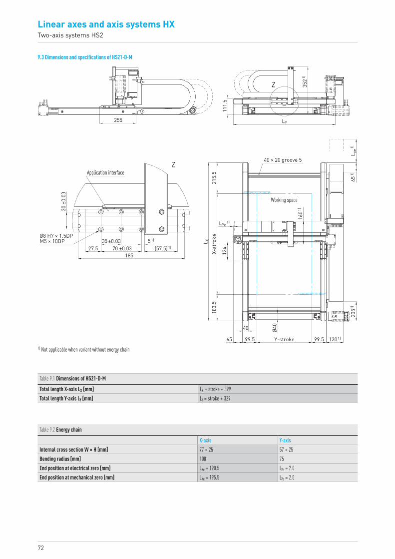
72
Linear axes and axis systems HXTwo-axis systems HS2
9.3 Dimensions and specifications of HS21-D-M
Table 9.1 Dimensions of HS21-D-M
Total length X-axis LX [mm] LX = stroke + 399Total length Y-axis LY [mm] LY = stroke + 329
Table 9.2 Energy chain
X-axis Y-axisInternal cross section W × H [mm] 77 × 25 57 × 25Bending radius [mm] 100 75End position at electrical zero [mm] LXe = 190.5 LYe = 7.0End position at mechanical zero [mm] LXe = 195.5 LYe = 2.0
1) Not applicable when variant without energy chain65
1)20
51)
1601)
Ø40
1201)
40
65
124
L X
L xe1)
LYe1)
99.5Y-stroke99.5
215.
5X-
stro
ke18
3.5
40 × 20 groove 5
Working space
111.
5
3521)
Z
255
27.535 ±0.03
70 ±0.0351)
(57.5)1)
185
Z
30 ±
0.03
Ø8 H7 × 1.5DPM5 × 10DP
Application interface
LY

73HX-03-0-EN-1810-K
Table 9.3 General technical data
X-axis Y-axisAxis type HD1N HM040B-NCarriage type L MMax feed force Fx_max [N] 450 300Max speed [m/s] 1) 3 3Max acceleration [m/s²] 1) 30 30Max drive torque Ma_max [Nm] 8 5Max stroke [mm] 3,000 1,300Typical load capacity [kg] 5 51) Restrictions in version with energy chain possible, depending on strokeNote: Measurements and specifications of HM040B single axes can be found in Section 3.3
Table 9.4 Drive
X-axis Y-axisToothed belt drive element B15HTD3 B15HTD3Feed constant [mm/rotation] 111 111Effective diameter of toothed belt pulley [mm] 35.33 35.33
Table 9.5 Mechanical properties
Moving mass on Y axis [kg] 0.42Moving mass on X axis at 0 stroke Y axis [kg] 2.91Moving mass on X axis per 1 m of stroke Y axis [kg/m] 3.02Mass of complete system at 0 stroke X and Y axes [kg] 7.28Mass of complete system per 1 m of stroke X axis [kg/m] 6.04Mass of complete system per 1 m of stroke Y axis [kg/m] 5.36
Note: All values without energy chain and without drive
X-axis
Y-axis
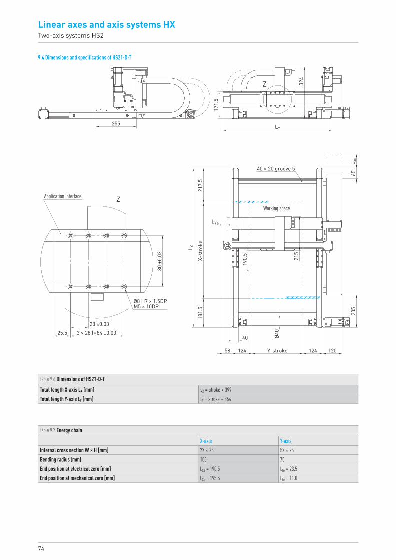
74
Linear axes and axis systems HXTwo-axis systems HS2
9.4 Dimensions and specifications of HS21-D-T
Table 9.6 Dimensions of HS21-D-T
Total length X-axis LX [mm] LX = stroke + 399Total length Y-axis LY [mm] LY = stroke + 364
Table 9.7 Energy chain
X-axis Y-axisInternal cross section W × H [mm] 77 × 25 57 × 25Bending radius [mm] 100 75End position at electrical zero [mm] LXe = 190.5 LYe = 23.5End position at mechanical zero [mm] LXe = 195.5 LYe = 11.0
255
171.
5
324
Z
Z
LY
Application interface
80 ±
0.03
28 ±0.0325.5
58 124
40
Y-stroke
X-st
roke
181.
5
124 12020
5
215
190.
5
3 × 28 (=84 ±0.03)
Ø8 H7 × 1.5DPM5 × 10DP
Working space
LYe
L X21
7.5
Ø40
L xe
65
40 × 20 groove 5

75HX-03-0-EN-1810-K
Table 9.8 General technical data
X-axis Y-axisAxis type HD1N HT100B-CCarriage type L SMax feed force Fx_max [N] 450 813Max speed [m/s] 1) 3 5Max acceleration [m/s²] 1) 30 30Max drive torque Ma_max [Nm] 8 14Max stroke [mm] 3,000 1,300Typical load capacity [kg] 20 201) Restrictions in version with energy chain possible, depending on strokeNote: Measurements and specifications of the HT100B linear table can be found in Section 5.3
Table 9.9 Drive
X-axis Y-axisToothed belt drive element B15HTD3 B25HTD5Feed constant [mm/rotation] 111 105Effective diameter of toothed belt pulley [mm] 35.33 33.42
Table 9.10 Mechanical properties
Moving mass on Y axis [kg] 1.04Moving mass on X axis at 0 stroke Y axis [kg] 5.74Moving mass on X axis per 1 m of stroke Y axis [kg/m] 6.71Mass of complete system at 0 stroke X and Y axes [kg] 10.36Mass of complete system per 1 m of stroke X axis [kg/m] 6.04Mass of complete system per 1 m of stroke Y axis [kg/m] 9.10
Note: All values without energy chain and without drive
X-axis
Y-axis
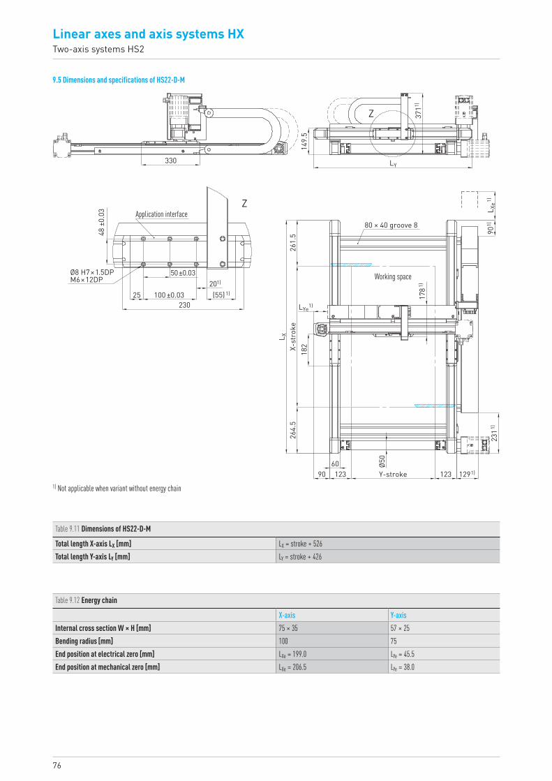
76
Linear axes and axis systems HXTwo-axis systems HS2
9.5 Dimensions and specifications of HS22-D-M
Table 9.11 Dimensions of HS22-D-M
Total length X-axis LX [mm] LX = stroke + 526Total length Y-axis LY [mm] LY = stroke + 426
1) Not applicable when variant without energy chain
Table 9.12 Energy chain
X-axis Y-axisInternal cross section W × H [mm] 75 × 35 57 × 25Bending radius [mm] 100 75End position at electrical zero [mm] LXe = 199.0 LYe = 45.5End position at mechanical zero [mm] LXe = 206.5 LYe = 38.0
182
901)
60
2311)
Ø50
1291)90
L X
1781)
X-st
roke
264.
526
1.5
123 123Y-stroke
L Xe1)
LYe1)
80 × 40 groove 8
Working space
3711)
149.
5
Z
330
48 ±
0.03
50 ±0.03
25201)
(55)1)100 ±0.03230
ZApplication interface
Ø8 H7×1.5DPM6×12DP
LY
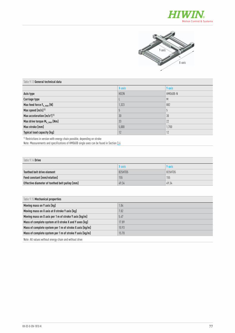
77HX-03-0-EN-1810-K
Table 9.13 General technical data
X-axis Y-axisAxis type HD2N HM060B-NCarriage type L MMax feed force Fx_max [N] 1,323 882Max speed [m/s] 1) 5 5Max acceleration [m/s²] 1) 30 30Max drive torque Ma_max [Nm] 33 22Max stroke [mm] 5,000 1,700Typical load capacity [kg] 12 121) Restrictions in version with energy chain possible, depending on stroke Note: Measurements and specifications of HM060B single axes can be found in Section 3.4
Table 9.14 Drive
X-axis Y-axisToothed belt drive element B25HTD5 B25HTD5Feed constant [mm/rotation] 155 155Effective diameter of toothed belt pulley [mm] 49.34 49.34
Table 9.15 Mechanical properties
Moving mass on Y axis [kg] 1.04Moving mass on X axis at 0 stroke Y axis [kg] 7.02Moving mass on X axis per 1 m of stroke Y axis [kg/m] 5.47Mass of complete system at 0 stroke X and Y axes [kg] 17.89Mass of complete system per 1 m of stroke X axis [kg/m] 10.93Mass of complete system per 1 m of stroke Y axis [kg/m] 15.70
Note: All values without energy chain and without drive
X-axis
Y-axis
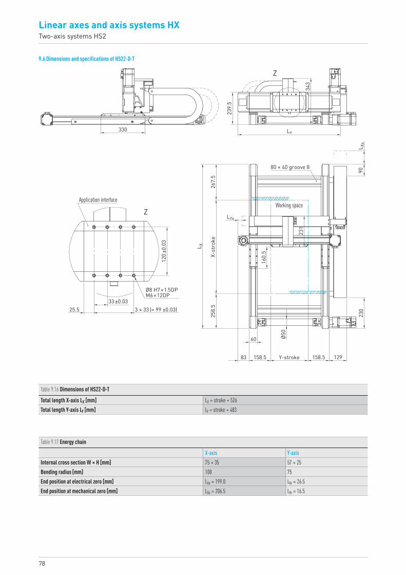
78
Linear axes and axis systems HXTwo-axis systems HS2
9.6 Dimensions and specifications of HS22-D-T
Table 9.16 Dimensions of HS22-D-T
Total length X-axis LX [mm] LX = stroke + 526Total length Y-axis LY [mm] LY = stroke + 483
Table 9.17 Energy chain
X-axis Y-axisInternal cross section W × H [mm] 75 × 35 57 × 25Bending radius [mm] 100 75End position at electrical zero [mm] LXe = 199.0 LYe = 26.5End position at mechanical zero [mm] LXe = 206.5 LYe = 16.5
L X
LYe
330
Application interface
Ø8 H7×1.5DPM6×12DP
239.
5
343
LY
L Xe
90
231
160.
5
Working space
Ø50
60
258.
5
33 ±0.033 × 33 (= 99 ±0.03)25.5
X-st
roke
267.
5
83 158.5 Y-stroke 158.5 12923
0
80 × 40 groove 812
0 ±0.
03
Z
Z

79HX-03-0-EN-1810-K
Table 9.18 General technical data
X-axis Y-axisAxis type HD2N HT150B-CCarriage type L SMax feed force Fx_max [N] 1,323 1,300Max speed [m/s] 1) 5 5Max acceleration [m/s²] 1) 30 30Max drive torque Ma_max [Nm] 33 32Max stroke [mm] 5,000 1,650Typical load capacity [kg] 40 401) Restrictions in version with energy chain possible, depending on stroke Note: Measurements and specifications of the HT150B linear table can be found in Section 5.4
Table 9.19 Drive
X-axis Y-axisToothed belt drive element B25HTD5 B40HTD5Feed constant [mm/rotation] 155 155Effective diameter of toothed belt pulley [mm] 49.34 49.34
Table 9.20 Mechanical properties
Moving mass on Y axis [kg] 2.34Moving mass on X axis at 0 stroke Y axis [kg] 12.92Moving mass on X axis per 1 m of stroke Y axis [kg/m] 11.16Mass of complete system at 0 stroke X and Y axes [kg] 24.81Mass of complete system per 1 m of stroke X axis [kg/m] 10.93Mass of complete system per 1 m of stroke Y axis [kg/m] 21.48
Note: All values without energy chain and without drive
X-axis
Y-axis
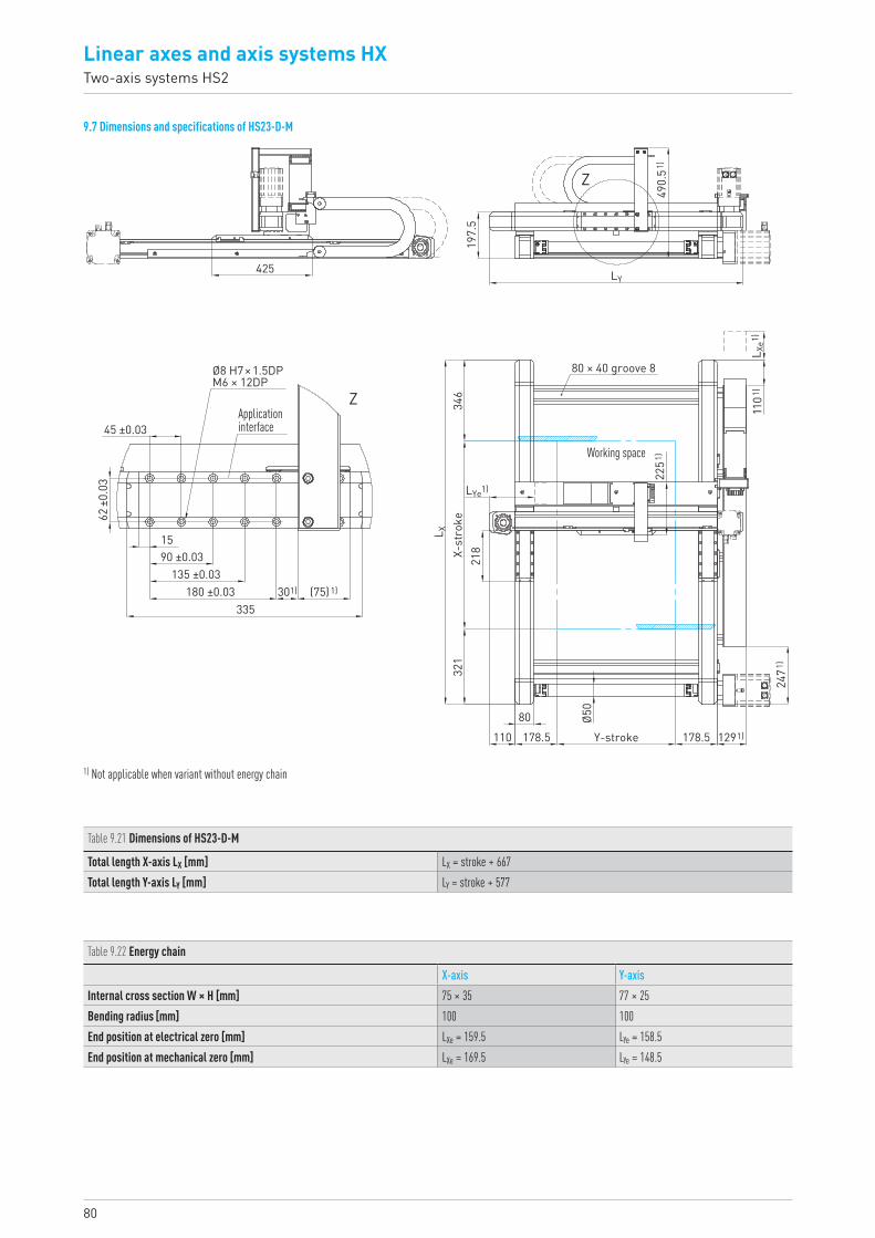
80
Linear axes and axis systems HXTwo-axis systems HS2
9.7 Dimensions and specifications of HS23-D-M
Table 9.21 Dimensions of HS23-D-M
Total length X-axis LX [mm] LX = stroke + 667Total length Y-axis LY [mm] LY = stroke + 577
1) Not applicable when variant without energy chain
Table 9.22 Energy chain
X-axis Y-axisInternal cross section W × H [mm] 75 × 35 77 × 25Bending radius [mm] 100 100End position at electrical zero [mm] LXe = 159.5 LYe = 158.5End position at mechanical zero [mm] LXe = 169.5 LYe = 148.5
1101
)
2471
)
Ø50
80110 1291)
218
2251
)
L X
L Xe1)
LYe1)
Y-stroke178.5 178.5
321
X-st
roke
346
80 × 40 groove 8
Working space
490.
51)
197.
5
Z
425
62 ±
0.03
15
45 ±0.03
90 ±0.03
301) (75)1)
335
135 ±0.03180 ±0.03
ZApplication interface
Ø8 H7 × 1.5DPM6 × 12DP
LY

81HX-03-0-EN-1810-K
Table 9.23 General technical data
X-axis Y-axisAxis type HD3N HM080B-NCarriage type L MMax feed force Fx_max [N] 1,852 1,235Max speed [m/s] 1) 5 5Max acceleration [m/s²] 1) 30 30Max drive torque Ma_max [Nm] 56 37Max stroke [mm] 5,000 1,600Typical load capacity [kg] 30 301) Restrictions in version with energy chain possible, depending on stroke Note: Measurements and specifications of HM080B single axes can be found in Section 3.5
Table 9.24 Drive
X-axis Y-axisToothed belt drive element B35HTD5 B35HTD5Feed constant [mm/rotation] 190 190Effective diameter of toothed belt pulley [mm] 60.48 60.48
Table 9.25 Mechanical properties
Moving mass on Y axis [kg] 2.13Moving mass on X axis at 0 stroke Y axis [kg] 15.10Moving mass on X axis per 1 m of stroke Y axis [kg/m] 9.86Mass of complete system at 0 stroke X and Y axes [kg] 35.97Mass of complete system per 1 m of stroke X axis [kg/m] 19.73Mass of complete system per 1 m of stroke Y axis [kg/m] 20.27
Note: All values without energy chain and without drive
X-axis
Y-axis
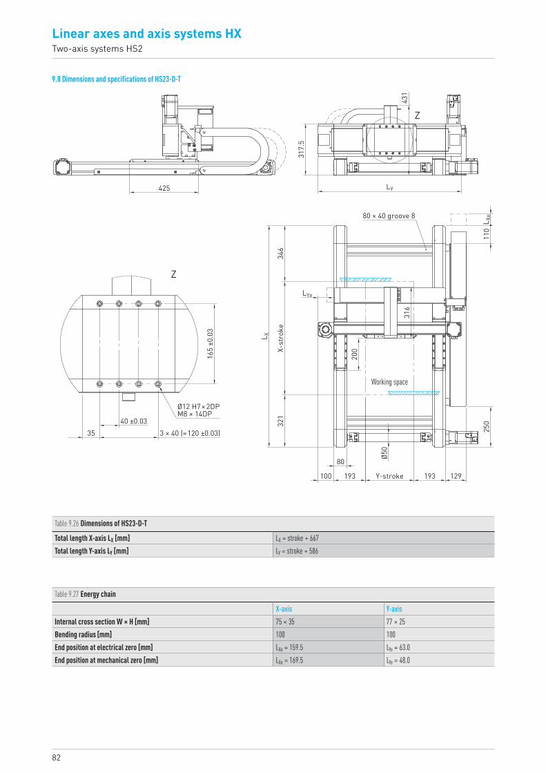
82
Linear axes and axis systems HXTwo-axis systems HS2
9.8 Dimensions and specifications of HS23-D-T
Table 9.26 Dimensions of HS23-D-T
Total length X-axis LX [mm] LX = stroke + 667Total length Y-axis LY [mm] LY = stroke + 586
Table 9.27 Energy chain
X-axis Y-axisInternal cross section W × H [mm] 75 × 35 77 × 25Bending radius [mm] 100 100End position at electrical zero [mm] LXe = 159.5 LYe = 63.0End position at mechanical zero [mm] LXe = 169.5 LYe = 48.0
425
317.
5
431
LY
L Xe
110
Z
Z
80 × 40 groove 8
LYe
L X
346
X-st
roke
321
3 × 40 (=120 ±0.03)40 ±0.03
165
±0.0
3
35
Ø12 H7 × 2DPM8 × 14DP
250
129193193
80 Ø50
200
316
Working space
100 Y-stroke
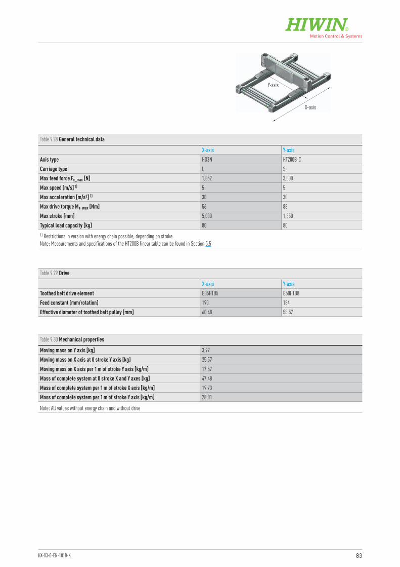
83HX-03-0-EN-1810-K
Table 9.28 General technical data
X-axis Y-axisAxis type HD3N HT200B-CCarriage type L SMax feed force Fx_max [N] 1,852 3,000Max speed [m/s] 1) 5 5Max acceleration [m/s²] 1) 30 30Max drive torque Ma_max [Nm] 56 88Max stroke [mm] 5,000 1,550Typical load capacity [kg] 80 801) Restrictions in version with energy chain possible, depending on stroke Note: Measurements and specifications of the HT200B linear table can be found in Section 5.5
Table 9.29 Drive
X-axis Y-axisToothed belt drive element B35HTD5 B50HTD8Feed constant [mm/rotation] 190 184Effective diameter of toothed belt pulley [mm] 60.48 58.57
Table 9.30 Mechanical properties
Moving mass on Y axis [kg] 3.97Moving mass on X axis at 0 stroke Y axis [kg] 25.57Moving mass on X axis per 1 m of stroke Y axis [kg/m] 17.57Mass of complete system at 0 stroke X and Y axes [kg] 47.48Mass of complete system per 1 m of stroke X axis [kg/m] 19.73Mass of complete system per 1 m of stroke Y axis [kg/m] 28.01
Note: All values without energy chain and without drive
X-axis
Y-axis
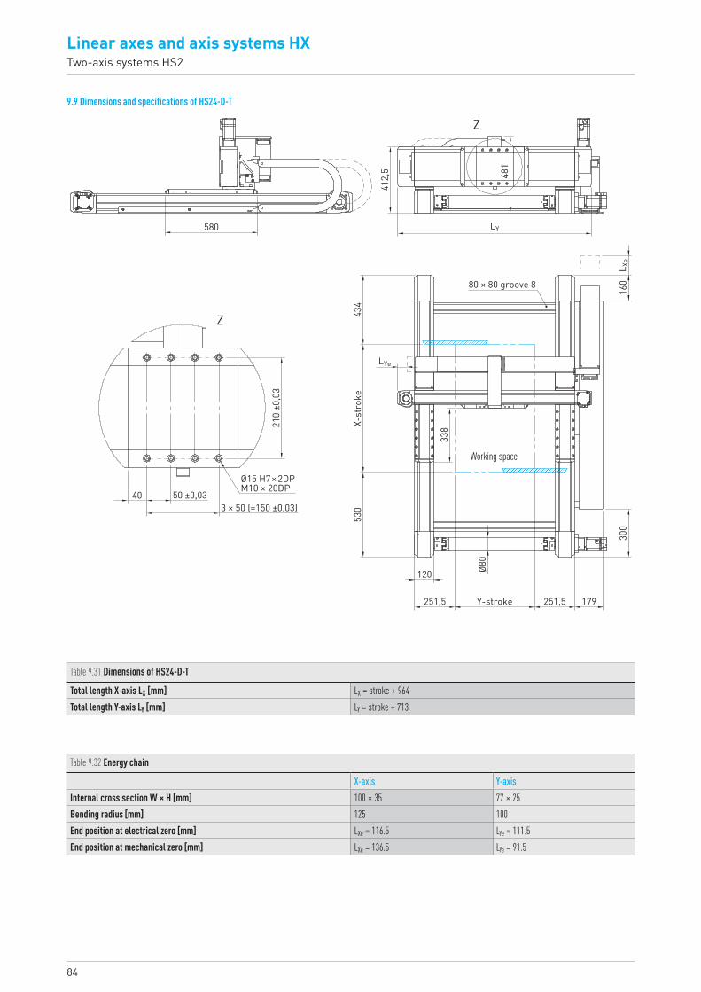
84
Linear axes and axis systems HXTwo-axis systems HS2
9.9 Dimensions and specifications of HS24-D-T
Table 9.31 Dimensions of HS24-D-T
Total length X-axis LX [mm] LX = stroke + 964Total length Y-axis LY [mm] LY = stroke + 713
Table 9.32 Energy chain
X-axis Y-axisInternal cross section W × H [mm] 100 × 35 77 × 25Bending radius [mm] 125 100End position at electrical zero [mm] LXe = 116.5 LYe = 111.5End position at mechanical zero [mm] LXe = 136.5 LYe = 91.5
X-st
roke
Working space33
8
Ø80
434
210
±0,0
3
530
120
251,5 Y-stroke 251,5 179
300
40 50 ±0,033 × 50 (=150 ±0,03)
Ø15 H7 × 2DPM10 × 20DP
LYe
L Xe
LY
Z
Z
16080 × 80 groove 8
481
412,
5
580

85HX-03-0-EN-1810-K
Table 9.33 General technical data
X-axis Y-axisAxis type HD4N HT250B-CCarriage type L SMax feed force Fx_max [N] 4,385 4,500Max speed [m/s] 1) 5 5Max acceleration [m/s²] 1) 30 30Max drive torque Ma_max [Nm] 201 149Max stroke [mm] 5,000 1,400Typical load capacity [kg] 130 1301) Restrictions in version with energy chain possible, depending on stroke Note: Measurements and specifications of the HT250B linear table can be found in Section 5.6
Table 9.34 Drive
X-axis Y-axisToothed belt drive element B60HTD8 B75HTD8Feed constant [mm/rotation] 288 208Effective diameter of toothed belt pulley [mm] 91.67 66.21
Table 9.35 Mechanical properties
Moving mass on Y axis [kg] 7.49Moving mass on X axis at 0 stroke Y axis [kg] 51.66Moving mass on X axis per 1 m of stroke Y axis [kg/m] 22.87Mass of complete system at 0 stroke X and Y axes [kg] 111.72Mass of complete system per 1 m of stroke X axis [kg/m] 41.54Mass of complete system per 1 m of stroke Y axis [kg/m] 39.62
Note: All values without energy chain and without drive
X-axis
Y-axis
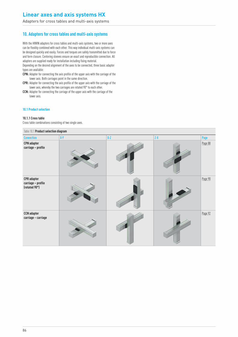
86
Linear axes and axis systems HXAdapters for cross tables and multi-axis systems
10. Adapters for cross tables and multi-axis systems
10.1 Product selection
10.1.1 Cross tableCross table combinations consisting of two single axes.
With the HIWIN adapters for cross tables and multi-axis systems, two or more axes can be flexibly combined with each other. This way individual multi-axis systems can be designed quickly and easily. Forces and torques are safely transmitted due to force and form closure. Centering sleeves ensure an exact and reproducible connection. All adapters are supplied ready for installation including fixing material.Depending on the desired alignment of the axes to be connected, three basic adapter types are available: CPN: Adapter for connecting the axis profile of the upper axis with the carriage of the
lower axis. Both carriages point in the same direction.CPR: Adapter for connecting the axis profile of the upper axis with the carriage of the
lower axis, whereby the two carriages are rotated 90° to each other.CCN: Adapter for connecting the carriage of the upper axis with the carriage of the
lower axis.
Table 10.1 Product selection diagram
Connection X-Y X-Z Z-X PageCPN adapter carriage – profile
Page 88
CPR adapter carriage – profile (rotated 90°)
Page 90
CCN adapter carriage – carriage
Page 92
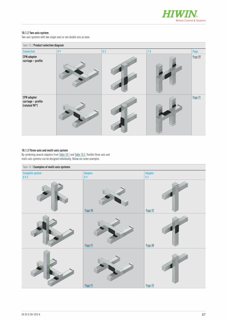
87HX-03-0-EN-1810-K
Table 10.3 Examples of multi-axis systems
Complete systemX-Y-Z
Adapter X-Y
Adapter Y-Z
10.1.2 Two-axis systemTwo-axis systems with two single axes or one double axis as base.
10.1.3 Three-axis and multi-axis systemBy combining several adapters from Table 10.1 and Table 10.2, flexible three-axis and multi-axis systems can be designed individually. Below are some examples.
Table 10.2 Product selection diagram
Connection X-Y X-Z Z-X PageCPN adapter carriage – profile
Page 89
CPR adapter carriage – profile (rotated 90°)
Page 91
Page 90
Page 91
Page 91
Page 88
Page 92
Page 92
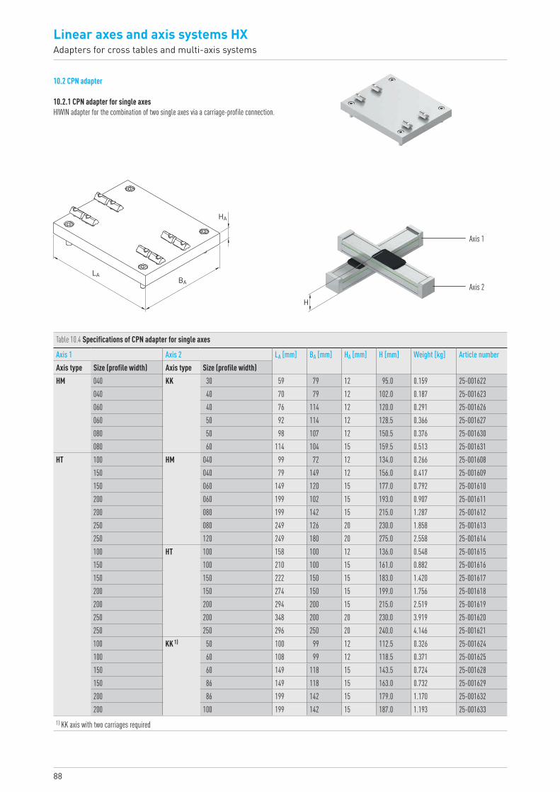
88
Linear axes and axis systems HXAdapters for cross tables and multi-axis systems
10.2 CPN adapter
10.2.1 CPN adapter for single axesHIWIN adapter for the combination of two single axes via a carriage-profile connection.
LABA
HA
Table 10.4 Specifications of CPN adapter for single axes
Axis 1 Axis 2 LA [mm] BA [mm] HA [mm] H [mm] Weight [kg] Article numberAxis type Size (profile width) Axis type Size (profile width)HM 040 KK 30 59 79 12 95.0 0.159 25-001622
040 40 70 79 12 102.0 0.187 25-001623060 40 76 114 12 120.0 0.291 25-001626060 50 92 114 12 128.5 0.366 25-001627080 50 98 107 12 150.5 0.376 25-001630080 60 114 104 15 159.5 0.513 25-001631
HT 100 HM 040 99 72 12 134.0 0.266 25-001608150 040 79 149 12 156.0 0.417 25-001609150 060 149 120 15 177.0 0.792 25-001610200 060 199 102 15 193.0 0.907 25-001611200 080 199 142 15 215.0 1.287 25-001612250 080 249 126 20 230.0 1.858 25-001613250 120 249 180 20 275.0 2.558 25-001614100 HT 100 158 100 12 136.0 0.548 25-001615150 100 210 100 15 161.0 0.882 25-001616150 150 222 150 15 183.0 1.420 25-001617200 150 274 150 15 199.0 1.756 25-001618200 200 294 200 15 215.0 2.519 25-001619250 200 348 200 20 230.0 3.919 25-001620250 250 296 250 20 240.0 4.146 25-001621100 KK 1) 50 100 99 12 112.5 0.326 25-001624100 60 108 99 12 118.5 0.371 25-001625150 60 149 118 15 143.5 0.724 25-001628150 86 149 118 15 163.0 0.732 25-001629200 86 199 142 15 179.0 1.170 25-001632200 100 199 142 15 187.0 1.193 25-001633
1) KK axis with two carriages required
Axis 1
Axis 2
H
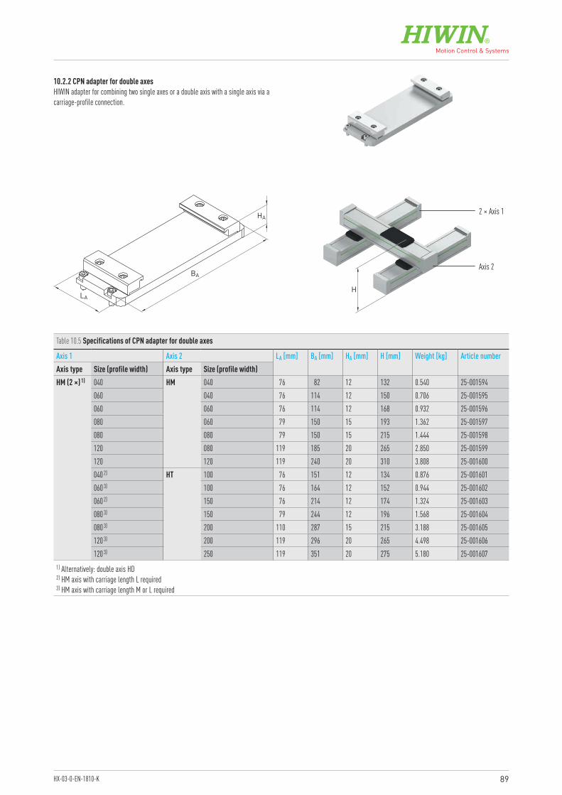
89HX-03-0-EN-1810-K
10.2.2 CPN adapter for double axesHIWIN adapter for combining two single axes or a double axis with a single axis via a carriage-profile connection.
LA
BA
HA
Table 10.5 Specifications of CPN adapter for double axes
Axis 1 Axis 2 LA [mm] BA [mm] HA [mm] H [mm] Weight [kg] Article numberAxis type Size (profile width) Axis type Size (profile width)HM (2 ×) 1) 040 HM 040 76 82 12 132 0.540 25-001594
060 040 76 114 12 150 0.706 25-001595060 060 76 114 12 168 0.932 25-001596080 060 79 150 15 193 1.362 25-001597080 080 79 150 15 215 1.444 25-001598120 080 119 185 20 265 2.850 25-001599120 120 119 240 20 310 3.808 25-001600040 2) HT 100 76 151 12 134 0.876 25-001601060 3) 100 76 164 12 152 0.944 25-001602060 2) 150 76 214 12 174 1.324 25-001603080 3) 150 79 244 12 196 1.568 25-001604080 3) 200 110 287 15 215 3.188 25-001605120 3) 200 119 296 20 265 4.498 25-001606120 3) 250 119 351 20 275 5.180 25-001607
1) Alternatively: double axis HD 2) HM axis with carriage length L required 3) HM axis with carriage length M or L required
2 × Axis 1
Axis 2
H
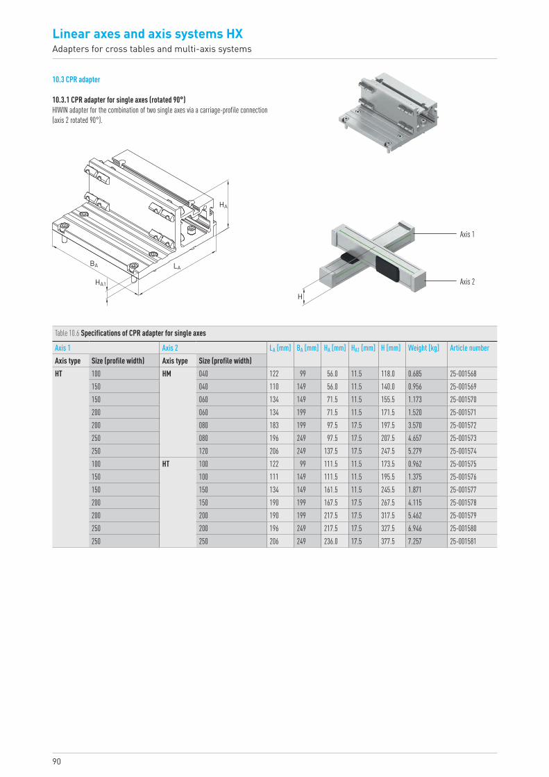
90
Linear axes and axis systems HXAdapters for cross tables and multi-axis systems
10.3 CPR adapter
10.3.1 CPR adapter for single axes (rotated 90°)HIWIN adapter for the combination of two single axes via a carriage-profile connection (axis 2 rotated 90°).
Table 10.6 Specifications of CPR adapter for single axes
Axis 1 Axis 2 LA [mm] BA [mm] HA [mm] HA1 [mm] H [mm] Weight [kg] Article numberAxis type Size (profile width) Axis type Size (profile width)HT 100 HM 040 122 99 56.0 11.5 118.0 0.685 25-001568
150 040 110 149 56.0 11.5 140.0 0.956 25-001569150 060 134 149 71.5 11.5 155.5 1.173 25-001570200 060 134 199 71.5 11.5 171.5 1.520 25-001571200 080 183 199 97.5 17.5 197.5 3.570 25-001572250 080 196 249 97.5 17.5 207.5 4.657 25-001573250 120 206 249 137.5 17.5 247.5 5.279 25-001574100 HT 100 122 99 111.5 11.5 173.5 0.962 25-001575150 100 111 149 111.5 11.5 195.5 1.375 25-001576150 150 134 149 161.5 11.5 245.5 1.871 25-001577200 150 190 199 167.5 17.5 267.5 4.115 25-001578200 200 190 199 217.5 17.5 317.5 5.462 25-001579250 200 196 249 217.5 17.5 327.5 6.946 25-001580250 250 206 249 236.0 17.5 377.5 7.257 25-001581
Axis 1
Axis 2
H
HA
LABA
HA1
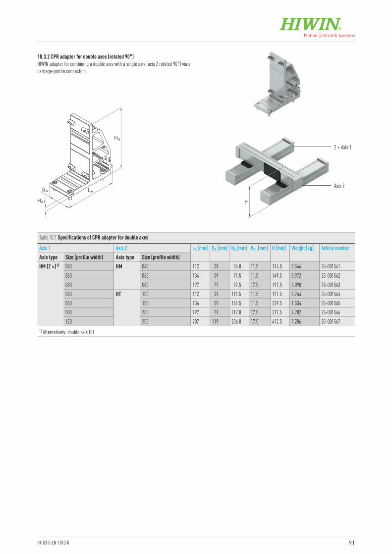
91HX-03-0-EN-1810-K
10.3.2 CPR adapter for double axes (rotated 90°)HIWIN adapter for combining a double axis with a single axis (axis 2 rotated 90°) via a carriage-profile connection.
LABA
HA1
HA
Table 10.7 Specifications of CPR adapter for double axes
Axis 1 Axis 2 LA [mm] BA [mm] HA [mm] HA1 [mm] H [mm] Weight [kg] Article numberAxis type Size (profile width) Axis type Size (profile width)HM (2 ×) 1) 040 HM 040 112 39 56.0 11.5 116.0 0.546 25-001561
060 060 134 59 71.5 11.5 149.5 0.972 25-001562080 080 197 79 97.5 17.5 197.5 3.098 25-001563040 HT 100 112 39 111.5 11.5 171.5 0.764 25-001564060 150 134 59 161.5 11.5 239.5 1.534 25-001565080 200 197 79 217.0 17.5 317.5 4.282 25-001566120 250 207 119 236.0 17.5 412.5 7.206 25-001567
1) Alternatively: double axis HD
2 × Axis 1
Axis 2
H
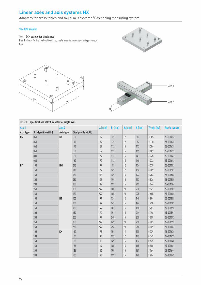
92
Linear axes and axis systems HXAdapters for cross tables and multi-axis systems / Positioning measuring system
10.4 CCN adapter
10.4.1 CCN adapter for single axesHIWIN adapter for the combination of two single axes via a carriage-carriage connec-tion.
LABA
HA
Table 10.8 Specifications of CCN adapter for single axes
Axis 1 Axis 2 LA [mm] BA [mm] HA [mm] H [mm] Weight [kg] Article numberAxis type Size (profile width) Axis type Size (profile width)HM 040 KK 30 39 79 12 87 0.105 25-001634
040 40 39 79 12 92 0.110 25-001635060 40 59 112 15 113 0.256 25-001638060 50 59 112 15 119 0.287 25-001639080 50 79 112 15 141 0.345 25-001642080 60 79 112 15 148 0.372 25-001643
HT 100 HM 040 97 99 12 134 0.335 25-001582150 040 79 149 12 156 0.409 25-001583150 060 118 149 15 177 0.783 25-001584200 060 102 199 15 193 0.876 25-001585200 080 142 199 15 215 1.246 25-001586250 080 249 180 20 230 2.547 25-001587250 120 249 180 20 275 2.605 25-001646100 HT 100 99 134 12 148 0.894 25-001588150 100 149 142 15 176 1.758 25-001589150 150 149 182 15 198 2.257 25-001590200 150 199 194 15 214 3.196 25-001591200 200 199 240 15 230 3.958 25-001592250 200 249 249 20 250 6.803 25-001593250 250 249 296 20 260 8.109 25-001647100 KK 50 98 104 12 100 0.339 25-001636100 60 98 113 12 107 0.369 25-001637150 60 116 149 15 132 0.675 25-001640150 86 114 168 15 145 0.808 25-001641200 86 140 199 15 161 1.164 25-001644200 100 140 199 15 170 1.206 25-001645
Axis 1
Axis 2
H
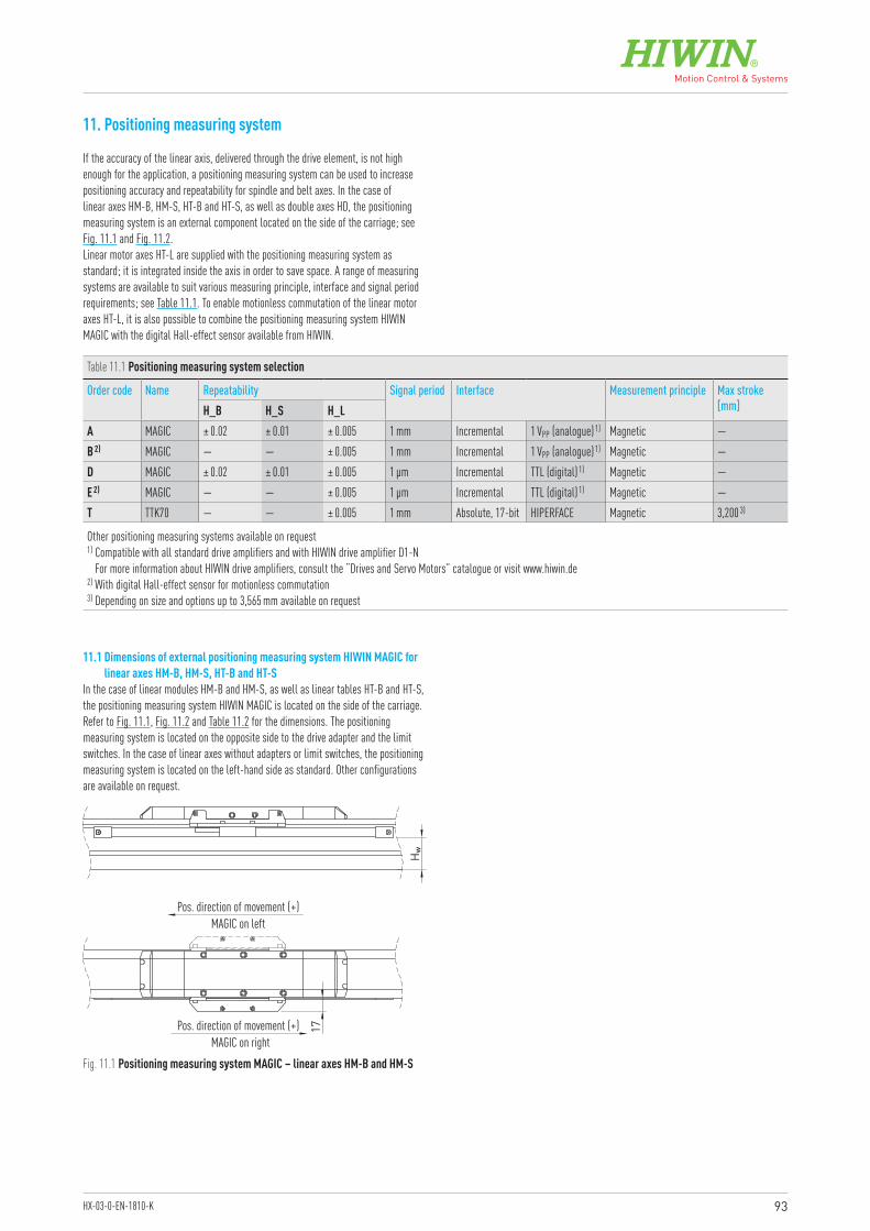
93HX-03-0-EN-1810-K
11. Positioning measuring system
If the accuracy of the linear axis, delivered through the drive element, is not high enough for the application, a positioning measuring system can be used to increase positioning accuracy and repeatability for spindle and belt axes. In the case of linear axes HM-B, HM-S, HT-B and HT-S, as well as double axes HD, the positioning measuring system is an external component located on the side of the carriage; see Fig. 11.1 and Fig. 11.2.Linear motor axes HT-L are supplied with the positioning measuring system as standard; it is integrated inside the axis in order to save space. A range of measuring systems are available to suit various measuring principle, interface and signal period requirements; see Table 11.1. To enable motionless commutation of the linear motor axes HT-L, it is also possible to combine the positioning measuring system HIWIN MAGIC with the digital Hall-effect sensor available from HIWIN.
11.1 Dimensions of external positioning measuring system HIWIN MAGIC for linear axes HM-B, HM-S, HT-B and HT-S
In the case of linear modules HM-B and HM-S, as well as linear tables HT-B and HT-S, the positioning measuring system HIWIN MAGIC is located on the side of the carriage. Refer to Fig. 11.1, Fig. 11.2 and Table 11.2 for the dimensions. The positioning measuring system is located on the opposite side to the drive adapter and the limit switches. In the case of linear axes without adapters or limit switches, the positioning measuring system is located on the left-hand side as standard. Other configurations are available on request.
Table 11.1 Positioning measuring system selection
Order code Name Repeatability Signal period Interface Measurement principle Max stroke [mm]H_B H_S H_L
A MAGIC ± 0.02 ± 0.01 ± 0.005 1 mm Incremental 1 VPP (analogue) 1) Magnetic —B 2) MAGIC — — ± 0.005 1 mm Incremental 1 VPP (analogue) 1) Magnetic —D MAGIC ± 0.02 ± 0.01 ± 0.005 1 µm Incremental TTL (digital) 1) Magnetic —E 2) MAGIC — — ± 0.005 1 µm Incremental TTL (digital) 1) Magnetic —T TTK70 — — ± 0.005 1 mm Absolute, 17-bit HIPERFACE Magnetic 3,200 3)
Other positioning measuring systems available on request1) Compatible with all standard drive amplifiers and with HIWIN drive amplifier D1-N
For more information about HIWIN drive amplifiers, consult the “Drives and Servo Motors” catalogue or visit www.hiwin.de2) With digital Hall-effect sensor for motionless commutation3) Depending on size and options up to 3,565 mm available on request
Hw
17
Pos. direction of movement (+)MAGIC on left
Pos. direction of movement (+)MAGIC on right
Fig. 11.1 Positioning measuring system MAGIC – linear axes HM-B and HM-S
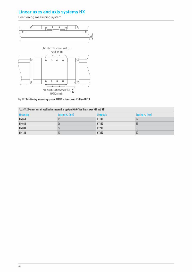
94
Linear axes and axis systems HXPositioning measuring system
Table 11.2 Dimensions of positioning measuring system MAGIC for linear axes HM and HT
Linear axis Spacing Hw [mm] Linear axis Spacing Hw [mm]HM040 25 HT100 27HM060 36 HT150 38HM080 54 HT200 55HM120 93 HT250 59
17.5
Hw
Pos. direction of movement (+)MAGIC on left
Pos. direction of movement (+)MAGIC on right
Fig. 11.2 Positioning measuring system MAGIC – linear axes HT-B and HT-S
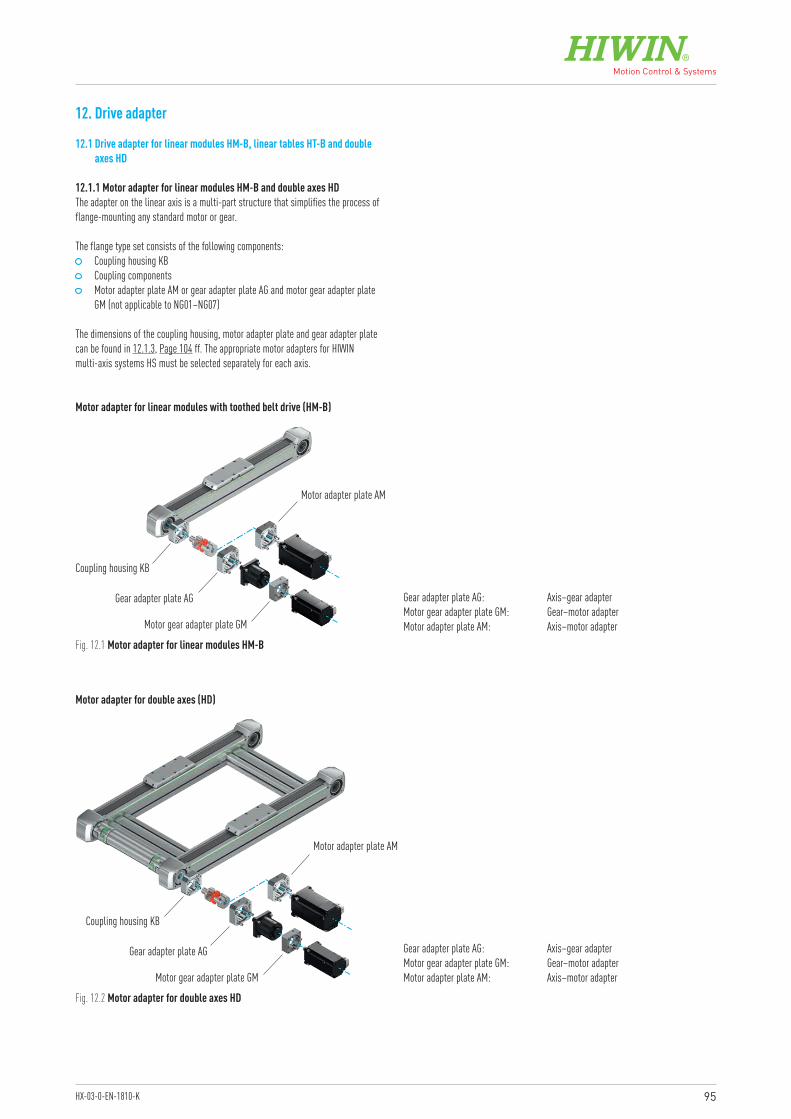
95HX-03-0-EN-1810-K
12. Drive adapter
12.1 Drive adapter for linear modules HM-B, linear tables HT-B and double axes HD
Motor adapter for linear modules with toothed belt drive (HM-B)
Motor adapter for double axes (HD)
Coupling housing KB
Coupling housing KB
Gear adapter plate AG
Gear adapter plate AG
Motor gear adapter plate GM
Motor gear adapter plate GM
Motor adapter plate AM
Motor adapter plate AM
Fig. 12.1 Motor adapter for linear modules HM-B
Fig. 12.2 Motor adapter for double axes HD
Gear adapter plate AG: Axis–gear adapterMotor gear adapter plate GM: Gear–motor adapterMotor adapter plate AM: Axis–motor adapter
Gear adapter plate AG: Axis–gear adapterMotor gear adapter plate GM: Gear–motor adapterMotor adapter plate AM: Axis–motor adapter
12.1.1 Motor adapter for linear modules HM-B and double axes HDThe adapter on the linear axis is a multi-part structure that simplifies the process of flange-mounting any standard motor or gear.
The flange type set consists of the following components: Coupling housing KB Coupling components Motor adapter plate AM or gear adapter plate AG and motor gear adapter plate
GM (not applicable to NG01–NG07)
The dimensions of the coupling housing, motor adapter plate and gear adapter plate can be found in 12.1.3, Page 104 ff. The appropriate motor adapters for HIWIN multi-axis systems HS must be selected separately for each axis.
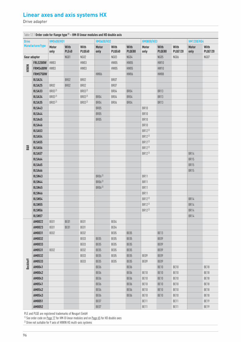
96
Linear axes and axis systems HXDrive adapter
Table 12.1 Order code for flange type 1) – HM-B linear modules and HD double axis
Drive Manufacturer/type
HM040B/HD1 HM060B/HD2 HM080B/HD3 HM120B/HD4Motor only
With PLE40
With PLQE60
Motor only
With PLQE60
With PLQE80
Motor only
With PLQE80
With PLQE120
Motor only
With PLQE120
Gear adapter NG01 NG02 NG03 NG04 NG05 NG06 NG07
HIW
IN
FRLS200W HW03 HW03 HW05 HW05 HW10FRMS400W HW03 HW03 HW05 HW05 HW10FRMS750W HW06 HW06 HW08
B&R
8LSA24 BR02 BR02 BR078LSA25 BR02 BR02 BR02 BR078LSA33 BR03 2) BR03 2) BR04 BR04 BR138LSA34 BR03 2) BR03 2) BR04 BR04 BR04 BR138LSA35 BR03 2) BR03 2) BR04 BR04 BR04 BR138LSA43 BR05 BR108LSA44 BR05 BR108LSA45 BR05 BR108LSA46 BR108LSA53 BR12 2)
8LSA54 BR12 2)
8LSA55 BR12 2)
8LSA56 BR12 2)
8LSA57 BR12 2) BR148LSA64 BR158LSA65 BR158LSA66 BR158LSN43 BR06 2) BR118LSN44 BR06 2) BR118LSN45 BR06 2) BR118LSN46 BR118LSN54 BR12 2) BR148LSN55 BR12 2) BR148LSN56 BR12 2) BR148LSN57 BR14
Beck
hoff
AM8022 BE01 BE01 BE01 BE04AM8023 BE01 BE01 BE01 BE04AM8031 BE02 BE02 BE05 BE05 BE13AM8032 BE03 BE05 BE05 BE05 BE09AM8033 BE03 BE05 BE05 BE05 BE09AM8531 BE02 BE02 BE05 BE05 BE05 BE09AM8532 BE03 BE05 BE05 BE05 BE09 BE09AM8533 BE03 BE05 BE05 BE05 BE09 BE09AM8041 BE06 BE06 BE10 BE10 BE18AM8042 BE06 BE06 BE10 BE10 BE10 BE18AM8043 BE06 BE06 BE10 BE10 BE10 BE18AM8541 BE06 BE06 BE10 BE10 BE10 BE18AM8542 BE06 BE06 BE10 BE10 BE10 BE18AM8543 BE06 BE06 BE10 BE10 BE10 BE18AM8051 BE07 BE11 BE11 BE19AM8052 BE07 BE11 BE11 BE19
PLE and PLQE are registered trademarks of Neugart GmbH1) See order code on Page 17 for HM-B linear modules and on Page 65 for HD double axes2) Drive not suitable for Y axis of HIWIN HS multi-axis systems
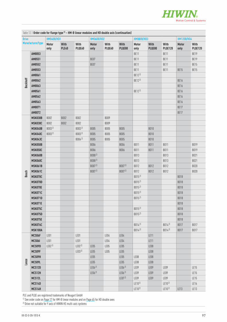
97HX-03-0-EN-1810-K
Table 12.1 Order code for flange type 1) – HM-B linear modules and HD double axis (continuation)
Drive Manufacturer/type
HM040B/HD1 HM060B/HD2 HM080B/HD3 HM120B/HD4Motor only
With PLE40
With PLQE60
Motor only
With PLQE60
With PLQE80
Motor only
With PLQE80
With PLQE120
Motor only
With PLQE120
Beck
hoff
AM8053 BE11 BE11 BE19AM8551 BE07 BE11 BE11 BE19AM8552 BE07 BE11 BE11 BE15AM8553 BE11 BE11 BE15 BE15AM8061 BE12 2)
AM8062 BE12 2) BE16AM8063 BE16AM8561 BE12 2) BE16AM8562 BE16AM8563 BE16AM8071 BE17AM8072 BE17
Bosc
h
MSK030B BO02 BO02 BO02 BO09MSK030C BO02 BO02 BO02 BO09MSK040B BO03 2) BO03 2) BO05 BO05 BO05 BO10MSK040C BO03 2) BO03 2) BO05 BO05 BO05 BO10MSK043C BO04 2) BO05 BO05 BO05 BO10MSK050B BO06 BO06 BO11 BO11 BO11 BO19MSK050C BO06 BO06 BO11 BO11 BO11 BO19MSK060B BO08 2) BO13 BO13 BO21MSK060C BO08 2) BO13 BO13 BO21MSK061B BO07 2) BO07 2) BO12 BO12 BO12 BO20MSK061C BO07 2) BO07 2) BO12 BO12 BO12 BO20MSK070C BO15 2) BO18MSK070D BO15 2) BO18MSK070E BO15 2) BO18MSK071C BO15 2) BO18MSK071D BO15 2) BO18MSK071E BO18MSK075C BO15 2) BO18MSK075D BO15 2) BO18MSK075E BO18MSK076C BO14 2) BO14 2) BO17 BO17MSK100A BO14 2) BO14 2) BO17 BO17
Lenz
e
MCS06F LE01 LE01 LE04 LE04 LE11MCS06I LE01 LE01 LE04 LE04 LE11MCS09D LE02 2) LE02 2) LE05 LE05 LE05 LE08MCS09F LE03 2) LE05 LE05 LE05 LE08MCS09H LE05 LE05 LE08 LE08MCS09L LE05 LE05 LE08 LE08MCS12D LE06 2) LE06 2) LE09 LE09 LE09 LE15MCS12H LE06 2) LE06 2) LE09 LE09 LE09 LE15MCS12L LE07 2) LE09 LE09 LE09 LE15MCS14D LE10 2) LE10 2) LE16MCS14H LE10 2) LE10 2) LE13 LE13
PLE and PLQE are registered trademarks of Neugart GmbH1) See order code on Page 17 for HM-B linear modules and on Page 65 for HD double axes2) Drive not suitable for Y axis of HIWIN HS multi-axis systems
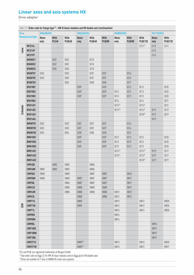
98
Linear axes and axis systems HXDrive adapter
Table 12.1 Order code for flange type 1) – HM-B linear modules and HD double axis (continuation)
Drive Manufacturer/type
HM040B/HD1 HM060B/HD2 HM080B/HD3 HM120B/HD4Motor only
With PLE40
With PLQE60
Motor only
With PLQE60
With PLQE80
Motor only
With PLQE80
With PLQE120
Motor only
With PLQE120
Lenz
e MCS14L LE12 2) LE13 LE13MCS14P LE13MCS19F LE14
Schn
eider
BSH0551 SE02 SE02 SE10BSH0552 SE02 SE02 SE10BSH0553 SE05 SE05 SE10BSH0701 SE03 SE03 SE07 SE07 SE16BSH0702 SE03 SE03 SE07 SE07 SE16BSH0703 SE06 SE08 SE08 SE17BSH1001 SE09 SE09 SE13 SE13 SE20BSH1002 SE09 SE09 SE13 SE13 SE13 SE20BSH1003 SE09 SE09 SE13 SE13 SE13 SE20BSH1004 SE14 SE14 SE21BSH1401 SE15 2) SE15 2) SE22BSH1402 SE15 2) SE15 2) SE19 SE19BSH1403 SE18 2) SE19 SE19BSH1404 SE19BMH0701 SE03 SE03 SE07 SE07 SE07 SE16BMH0702 SE03 SE03 SE07 SE07 SE07 SE16BMH0703 SE04 SE04 SE08 SE08 SE08 SE12BMH1001 SE09 SE09 SE13 SE13 SE13 SE20BMH1002 SE09 SE09 SE13 SE13 SE13 SE20BMH1003 SE09 SE09 SE13 SE13 SE13 SE20BMH1401 SE15 2) SE15 2) SE19 SE19BMH1402 SE15 2) SE15 2) SE19 SE19BMH1403 SE18 2) SE19 SE19
SEW
CMP40S SW02 SW02 SW06CMP40M SW02 SW02 SW02 SW06CMP50S SW03 SW03 SW07 SW07 SW15CMP50M SW03 SW03 SW07 SW07 SW07 SW11CMP50L SW04 SW07 SW07 SW07 SW11CMP63S SW05 SW08 SW08 SW08 SW12CMP63M SW05 SW08 SW08 SW08 SW12 SW12CMP63L SW08 SW08 SW12 SW12CMP71S SW09 SW13 SW13 SW20CMP71M SW09 SW13 SW13 SW20CMP71L SW13 SW13 SW20CMP80S SW14CMP80M SW14CMP80L SW18CMP100S SW19CMP100M SW19CMP100L SW19CMPZ71S SW09 2) SW13 SW13 SW20CMPZ71M SW09 2) SW13 SW13 SW17
PLE and PLQE are registered trademarks of Neugart GmbH1) See order code on Page 17 for HM-B linear modules and on Page 65 for HD double axes2) Drive not suitable for Y axis of HIWIN HS multi-axis systems
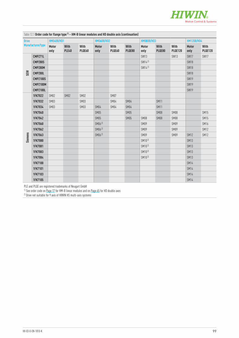
99HX-03-0-EN-1810-K
Table 12.1 Order code for flange type 1) – HM-B linear modules and HD double axis (continuation)
Drive Manufacturer/type
HM040B/HD1 HM060B/HD2 HM080B/HD3 HM120B/HD4Motor only
With PLE40
With PLQE60
Motor only
With PLQE60
With PLQE80
Motor only
With PLQE80
With PLQE120
Motor only
With PLQE120
SEW
CMPZ71L SW13 SW13 SW17 SW17CMPZ80S SW14 2) SW18CMPZ80M SW14 2) SW18CMPZ80L SW18CMPZ100S SW19CMPZ100M SW19CMPZ100L SW19
Sieme
ns
1FK7022 SM02 SM02 SM02 SM071FK7032 SM03 SM03 SM04 SM04 SM111FK7034 SM03 SM03 SM04 SM04 SM04 SM111FK7040 SM05 SM05 SM08 SM08 SM151FK7042 SM05 SM05 SM08 SM08 SM08 SM151FK7060 SM06 2) SM09 SM09 SM161FK7062 SM06 2) SM09 SM09 SM121FK7063 SM06 2) SM09 SM09 SM12 SM121FK7080 SM10 2) SM131FK7081 SM10 2) SM131FK7083 SM10 2) SM131FK7084 SM10 2) SM131FK7100 SM141FK7101 SM141FK7103 SM141FK7105 SM14
PLE and PLQE are registered trademarks of Neugart GmbH1) See order code on Page 17 for HM-B linear modules and on Page 65 for HD double axes2) Drive not suitable for Y axis of HIWIN HS multi-axis systems
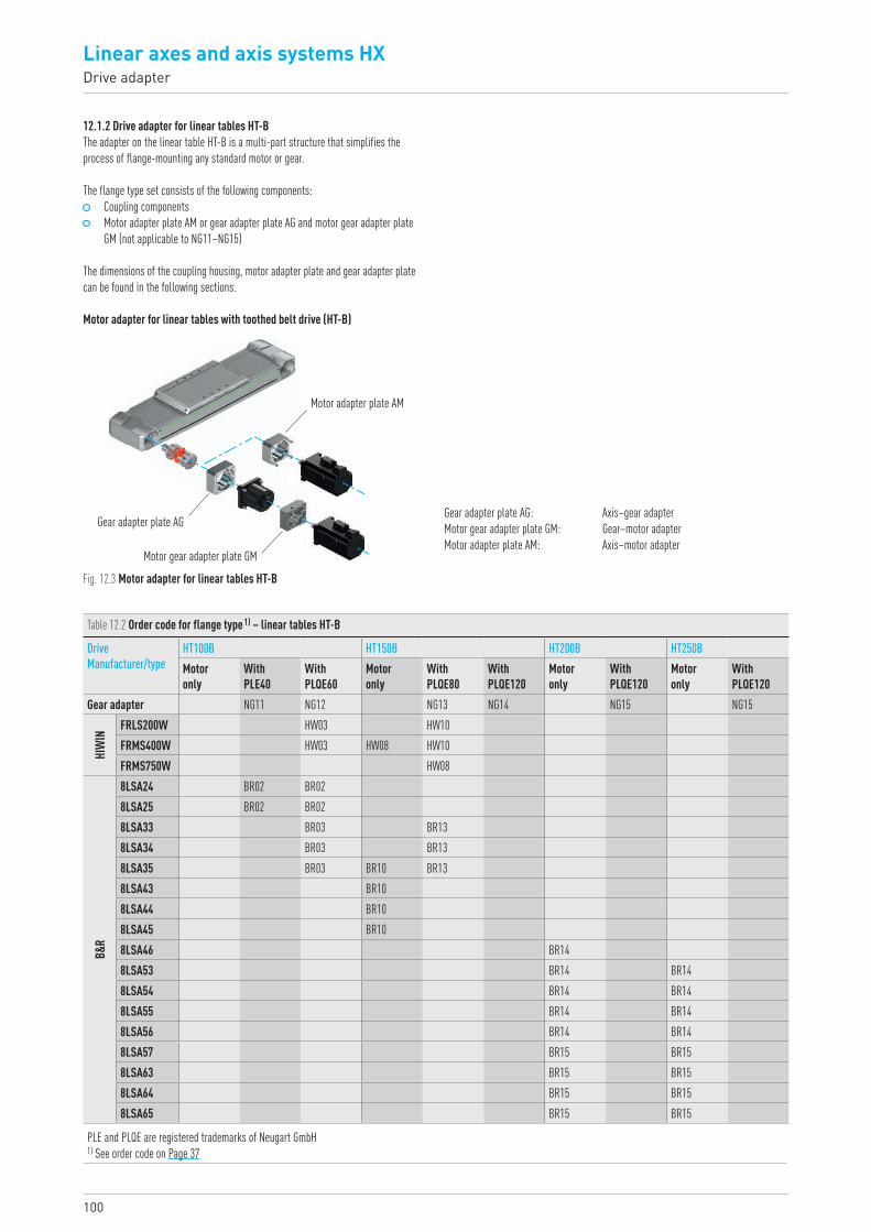
100
Linear axes and axis systems HXDrive adapter
Motor adapter for linear tables with toothed belt drive (HT-B)
Fig. 12.3 Motor adapter for linear tables HT-B
Table 12.2 Order code for flange type 1) – linear tables HT-B
Drive Manufacturer/type
HT100B HT150B HT200B HT250BMotor only
With PLE40
With PLQE60
Motor only
With PLQE80
With PLQE120
Motor only
With PLQE120
Motor only
With PLQE120
Gear adapter NG11 NG12 NG13 NG14 NG15 NG15
HIW
IN
FRLS200W HW03 HW10 FRMS400W HW03 HW08 HW10 FRMS750W HW08
B&R
8LSA24 BR02 BR02 8LSA25 BR02 BR02 8LSA33 BR03 BR13 8LSA34 BR03 BR13 8LSA35 BR03 BR10 BR13 8LSA43 BR10 8LSA44 BR10 8LSA45 BR10 8LSA46 BR14 8LSA53 BR14 BR148LSA54 BR14 BR148LSA55 BR14 BR148LSA56 BR14 BR148LSA57 BR15 BR158LSA63 BR15 BR158LSA64 BR15 BR158LSA65 BR15 BR15
12.1.2 Drive adapter for linear tables HT-BThe adapter on the linear table HT-B is a multi-part structure that simplifies the process of flange-mounting any standard motor or gear.
The flange type set consists of the following components: Coupling components Motor adapter plate AM or gear adapter plate AG and motor gear adapter plate
GM (not applicable to NG11–NG15)
The dimensions of the coupling housing, motor adapter plate and gear adapter plate can be found in the following sections.
Gear adapter plate AG
Motor gear adapter plate GM
Motor adapter plate AM
Gear adapter plate AG: Axis–gear adapterMotor gear adapter plate GM: Gear–motor adapterMotor adapter plate AM: Axis–motor adapter
PLE and PLQE are registered trademarks of Neugart GmbH1) See order code on Page 37
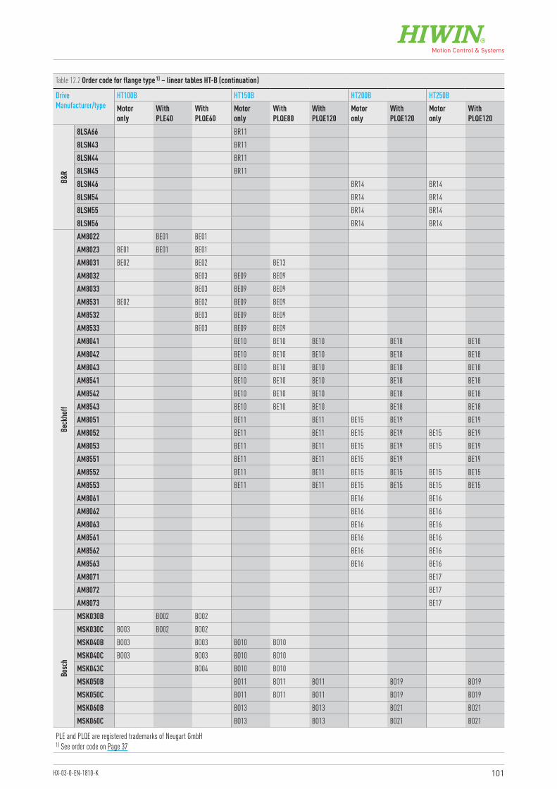
101HX-03-0-EN-1810-K
Table 12.2 Order code for flange type 1) – linear tables HT-B (continuation)
Drive Manufacturer/type
HT100B HT150B HT200B HT250BMotor only
With PLE40
With PLQE60
Motor only
With PLQE80
With PLQE120
Motor only
With PLQE120
Motor only
With PLQE120
B&R
8LSA66 BR11 8LSN43 BR11 8LSN44 BR11 8LSN45 BR11 8LSN46 BR14 BR148LSN54 BR14 BR148LSN55 BR14 BR148LSN56 BR14 BR14
Beck
hoff
AM8022 BE01 BE01 AM8023 BE01 BE01 BE01 AM8031 BE02 BE02 BE13 AM8032 BE03 BE09 BE09 AM8033 BE03 BE09 BE09 AM8531 BE02 BE02 BE09 BE09 AM8532 BE03 BE09 BE09 AM8533 BE03 BE09 BE09 AM8041 BE10 BE10 BE10 BE18 BE18AM8042 BE10 BE10 BE10 BE18 BE18AM8043 BE10 BE10 BE10 BE18 BE18AM8541 BE10 BE10 BE10 BE18 BE18AM8542 BE10 BE10 BE10 BE18 BE18AM8543 BE10 BE10 BE10 BE18 BE18AM8051 BE11 BE11 BE15 BE19 BE19AM8052 BE11 BE11 BE15 BE19 BE15 BE19AM8053 BE11 BE11 BE15 BE19 BE15 BE19AM8551 BE11 BE11 BE15 BE19 BE19AM8552 BE11 BE11 BE15 BE15 BE15 BE15AM8553 BE11 BE11 BE15 BE15 BE15 BE15AM8061 BE16 BE16AM8062 BE16 BE16AM8063 BE16 BE16AM8561 BE16 BE16AM8562 BE16 BE16AM8563 BE16 BE16AM8071 BE17AM8072 BE17AM8073 BE17
Bosc
h
MSK030B BO02 BO02 MSK030C BO03 BO02 BO02 MSK040B BO03 BO03 BO10 BO10 MSK040C BO03 BO03 BO10 BO10 MSK043C BO04 BO10 BO10 MSK050B BO11 BO11 BO11 BO19 BO19MSK050C BO11 BO11 BO11 BO19 BO19MSK060B BO13 BO13 BO21 BO21MSK060C BO13 BO13 BO21 BO21
PLE and PLQE are registered trademarks of Neugart GmbH1) See order code on Page 37
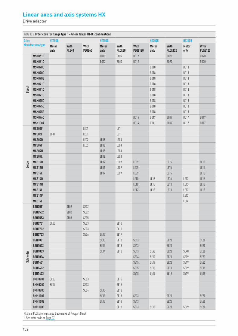
102
Linear axes and axis systems HXDrive adapter
Table 12.2 Order code for flange type 1) – linear tables HT-B (continuation)
Drive Manufacturer/type
HT100B HT150B HT200B HT250BMotor only
With PLE40
With PLQE60
Motor only
With PLQE80
With PLQE120
Motor only
With PLQE120
Motor only
With PLQE120
Bosc
h
MSK061B BO12 BO12 BO12 BO20 BO20MSK061C BO12 BO12 BO12 BO20 BO20MSK070C BO18 BO18MSK070D BO18 BO18MSK070E BO18 BO18MSK071C BO18 BO18MSK071D BO18 BO18MSK071E BO18 BO18MSK075C BO18 BO18MSK075D BO18 BO18MSK075E BO18 BO18MSK076C BO14 BO17 BO17 BO17 BO17MSK100A BO14 BO17 BO17 BO17 BO17
Lenz
e
MCS06F LE01 LE11 MCS06I LE01 LE01 LE11 MCS09D LE02 LE08 LE08 MCS09F LE03 LE08 LE08 MCS09H LE08 LE08 MCS09L LE08 LE08 MCS12D LE09 LE09 LE09 LE15 LE15MCS12H LE09 LE09 LE09 LE15 LE15MCS12L LE09 LE09 LE09 LE15 LE15MCS14D LE10 LE13 LE16 LE13 LE16MCS14H LE10 LE13 LE13 LE13 LE13MCS14L LE12 LE13 LE13 LE13 LE13MCS14P LE13MCS19F LE14
Schn
eider
BSH0551 SE02 SE02 BSH0552 SE02 SE02 BSH0553 SE05 SE05 BSH0701 SE03 SE03 SE16 BSH0702 SE03 SE16 BSH0703 SE06 SE13 SE17 BSH1001 SE13 SE13 SE13 SE20 SE20BSH1002 SE13 SE13 SE13 SE20 SE20BSH1003 SE14 SE13 SE13 SE40 SE20 SE40 SE20BSH1004 SE14 SE19 SE21 SE19 SE21BSH1401 SE15 SE19 SE22 SE19 SE22BSH1402 SE15 SE19 SE19 SE19 SE19BSH1403 SE18 SE19 SE19 SE19 SE19BMH0701 SE03 SE03 SE16 BMH0702 SE04 SE03 SE16 BMH0703 SE04 SE13 SE12 BMH1001 SE13 SE13 SE13 SE20 SE20BMH1002 SE13 SE13 SE13 SE20 SE20BMH1003 SE13 SE13 SE19 SE20 SE19 SE20
PLE and PLQE are registered trademarks of Neugart GmbH1) See order code on Page 37
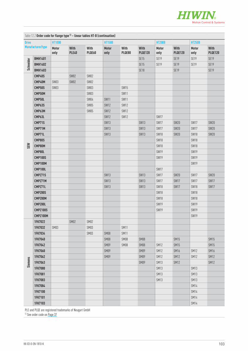
103HX-03-0-EN-1810-K
Table 12.2 Order code for flange type 1) – linear tables HT-B (continuation)
Drive Manufacturer/type
HT100B HT150B HT200B HT250BMotor only
With PLE40
With PLQE60
Motor only
With PLQE80
With PLQE120
Motor only
With PLQE120
Motor only
With PLQE120
Schn
eider BMH1401 SE15 SE19 SE19 SE19 SE19
BMH1402 SE15 SE19 SE19 SE19 SE19BMH1403 SE18 SE19 SE19
SEW
CMP40S SW02 SW02 CMP40M SW03 SW02 SW02 CMP50S SW03 SW03 SW15 CMP50M SW03 SW11 CMP50L SW04 SW11 SW11 CMP63S SW05 SW12 SW12 CMP63M SW05 SW12 SW12 CMP63L SW12 SW12 SW17 CMP71S SW13 SW13 SW17 SW20 SW17 SW20CMP71M SW13 SW13 SW17 SW20 SW17 SW20CMP71L SW13 SW13 SW18 SW20 SW18 SW20CMP80S SW18 SW18CMP80M SW18 SW18CMP80L SW19 SW19CMP100S SW19 SW19CMP100M SW19CMP100L SW17 CMPZ71S SW13 SW13 SW17 SW20 SW17 SW20CMPZ71M SW13 SW13 SW17 SW17 SW17 SW17CMPZ71L SW13 SW13 SW18 SW17 SW18 SW17CMPZ80S SW18 SW18CMPZ80M SW18 SW18CMPZ80L SW19 SW19CMPZ100S SW19 SW19CMPZ100M SW19
Sieme
ns
1FK7022 SM02 SM02 1FK7032 SM03 SM03 SM11 1FK7034 SM03 SM08 SM11 1FK7040 SM08 SM08 SM08 SM15 SM151FK7042 SM09 SM08 SM08 SM12 SM15 SM151FK7060 SM09 SM09 SM12 SM16 SM12 SM161FK7062 SM09 SM09 SM12 SM12 SM12 SM121FK7063 SM09 SM13 SM12 SM121FK7080 SM13 SM131FK7081 SM13 SM131FK7083 SM13 SM131FK7084 SM141FK7100 SM141FK7101 SM141FK7103 SM14
PLE and PLQE are registered trademarks of Neugart GmbH1) See order code on Page 37
104
Linear axes and axis systems HXDrive adapter
The overall width of the toothed belt axis depends on the following factors: Adaptor materials (coupling housing KB, motor adapter plate AM, gear adapter
plate AG, motor gear adapter plate GM) Gearbox Motor
12.1.3 Dimensions of motor adapter for linear modules HM-B, linear tables HT-B and double axis HD
Linear axis without gearbox
LKB LAM
Fig. 12.4 HM-B linear module motor connection without gears
LKB Length of coupling housing, see Table 12.3LAM Motor adapter plate length, see Table 12.4
LAM
Fig. 12.5 HT-B linear table motor connection without gears
LAM Motor adapter plate length, see Table 12.5
Linear axis with gearbox
Fig. 12.6 HM-B linear module motor connection with gears
LKB Length of coupling housing, see Table 12.3LAG Gear adapter plate length, see Table 12.6LG Length of gearbox, see Table 12.8LGM Motor gear adapter plate length, see Table 12.7
LKB LAG LGMLG
Fig. 12.7 HT-B linear table motor connection with gears
LAG Gear adapter plate length, see Table 12.6LG Length of gearbox, see Table 12.8LGM Motor gear adapter plate length, see Table 12.7
LAG LGMLG
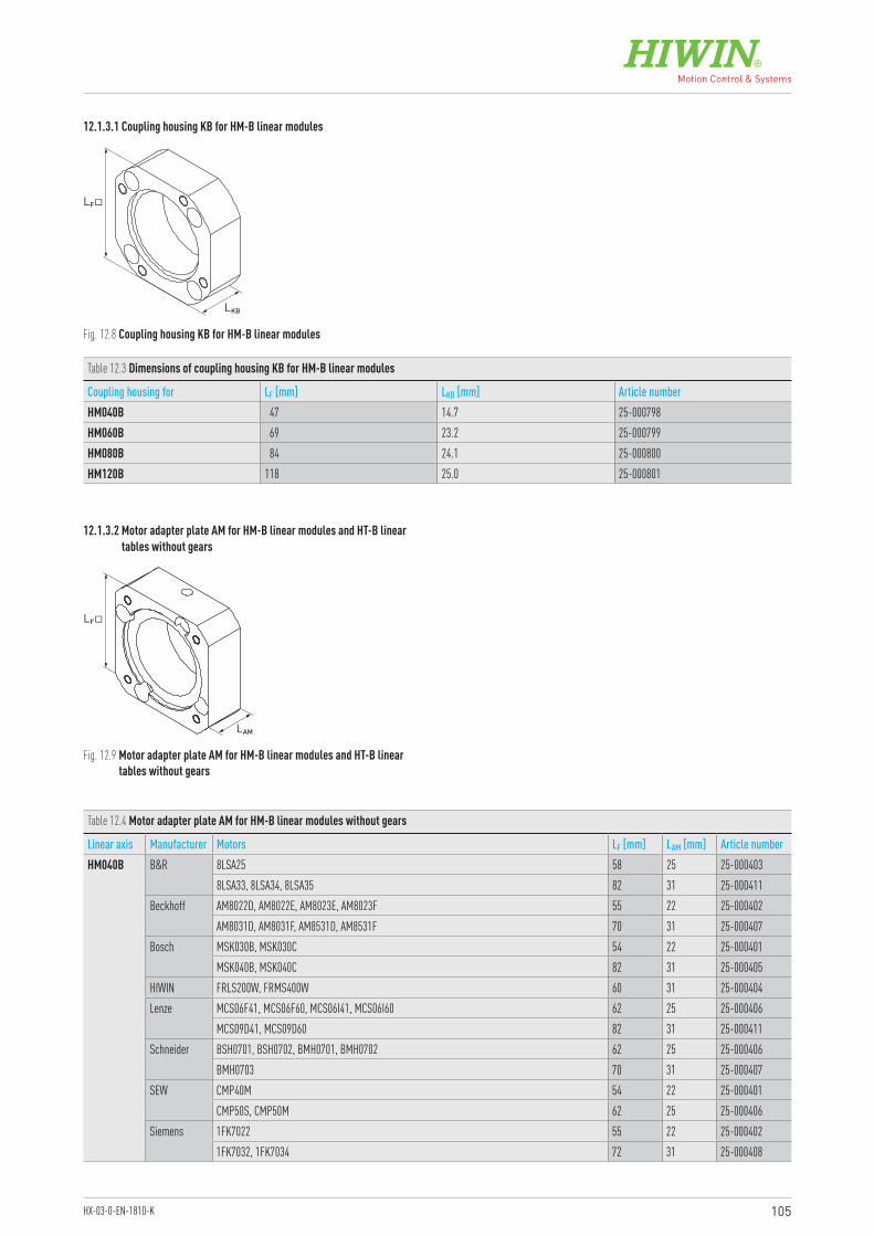
105HX-03-0-EN-1810-K
Fig. 12.8 Coupling housing KB for HM-B linear modules
Fig. 12.9 Motor adapter plate AM for HM-B linear modules and HT-B linear tables without gears
12.1.3.1 Coupling housing KB for HM-B linear modules
12.1.3.2 Motor adapter plate AM for HM-B linear modules and HT-B linear tables without gears
LF�
LKB
Table 12.3 Dimensions of coupling housing KB for HM-B linear modules
Coupling housing for LF [mm] LKB [mm] Article numberHM040B 47 14.7 25-000798HM060B 69 23.2 25-000799HM080B 84 24.1 25-000800HM120B 118 25.0 25-000801
LF�
LAM
Table 12.4 Motor adapter plate AM for HM-B linear modules without gears
Linear axis Manufacturer Motors LF [mm] LAM [mm] Article numberHM040B B&R 8LSA25 58 25 25-000403
8LSA33, 8LSA34, 8LSA35 82 31 25-000411Beckhoff AM8022D, AM8022E, AM8023E, AM8023F 55 22 25-000402
AM8031D, AM8031F, AM8531D, AM8531F 70 31 25-000407Bosch MSK030B, MSK030C 54 22 25-000401
MSK040B, MSK040C 82 31 25-000405HIWIN FRLS200W, FRMS400W 60 31 25-000404Lenze MCS06F41, MCS06F60, MCS06I41, MCS06I60 62 25 25-000406
MCS09D41, MCS09D60 82 31 25-000411Schneider BSH0701, BSH0702, BMH0701, BMH0702 62 25 25-000406
BMH0703 70 31 25-000407SEW CMP40M 54 22 25-000401
CMP50S, CMP50M 62 25 25-000406Siemens 1FK7022 55 22 25-000402
1FK7032, 1FK7034 72 31 25-000408
106
Linear axes and axis systems HXDrive adapter
Table 12.4 Motor adapter plate AM for HM-B linear modules without gears (continuation)
Linear axis Manufacturer Motors LF [mm] LAM [mm] Article numberHM060B Bosch MSK040B, MSK040C, MSK043B 82 27 25-000415
MSK061B, MSK061C 116 37 25-000428MSK060B, MSK060C 116 47 25-000429
B&R 8LSA35, 8LSA34 86 27 25-0004238LSA43, 8LSA44, 8LSA45 100 37 25-0004268LSN43, 8LSN44, 8LSN45 116 37 25-000430
Beckhoff AM8032D, AM8032E, AM8032H, AM8033E, AM8033F, AM8033J, AM8531F, AM8532D, AM8532E, AM8532H, AM8533E, AM8533F, AM8533J
70 27 25-000418
AM8041D, AM8041E, AM8041H, AM8042E, AM8042F, AM8042J, AM8043E, AM8043H, AM8043K, AM8541D, AM8541E, AM8541H, AM8542E, AM8542F, AM8542J, AM8543E, AM8543H, AM8543K
87 37 25-000424
AM8051E, AM8051G, AM8051K, AM8052F, AM8052J, AM8052L, AM8551E, AM8551G, AM8551K, AM8552F, AM8552J, AM8552L
104 47 25-000427
HIWIN FRMS750W 80 37 25-000421Lenze MCS09D41, MCS09D60, MCS09F38, MCS09F60, MCS09H41, MCS09H60, MCS09L41, MCS09L51 86 27 25-000423
MCS12D20, MCS12D41, MCS12H15, MCS12H35 116 37 25-000430Schneider BMH0701, BMH0702 72 21 25-000417
BMH0703 70 27 25-000418BSH1001, BSH1002, BSH1003, BMH1001, BMH1002, BMH1003 98 37 25-000425
SEW CMP50M, CMP50L 72 21 25-000417CMP63S, CMP63M, CMP63SL 86 27 25-000423CMP71S, CMP71M, CMPZ71S, CMPZ71M 116 47 25-000431
Siemens 1FK7034 72 27 25-0004191FK7040, 1FK7042 87 37 25-0004241FK7060, 1FK7062, 1FK7063 116 47 25-000431
HM080B Beckhoff AM8532D, AM8532E, AM8532H, AM8533E, AM8533F, AM8533J 73 27 25-000436AM8042E, AM8042F, AM8042J, AM8043E, AM8043H, AM8043K, AM8541D, AM8541E, AM8541H, AM8542E, AM8542F, AM8542J, AM8543E, AM8543H, AM8543K
87 37 25-000441
AM8051E, AM8051G, AM8051K, AM8052F, AM8052J, AM8052L, AM8053G, AM8053K, AM8053N, AM8551E, AM8551G, AM8551K, AM8552F, AM8552J, AM8552L, AM8553G, AM8553K, AM8553N
100 51 25-000444
AM8061G, AM8061J, AM8061M, AM8062J, AM8062L, AM8062P, AM8561G, AM8561J, AM8561M 138 56 25-000453B&R 8LSA43, 8LSA44, 8LSA45, 8LSA46 100 37 25-000443
8LSA53, 8LSA54, 8LSA55, 8LSA56, 8LSA57, 8LSN54, 8LSN55, 8LSN56 142 51 25-0004548LSN43, 8LSN44, 8LSN45, 8LSN46 116 37 25-000447
Bosch MSK050B, MSK050C 98 37 25-000442MSK061B, MSK061C 116 37 25-000445MSK060B, MSK060C 116 51 25-000446MSK076C, MSK100A 139 51 25-000451MSK70C, MSK70D, MSK70E, MSK71C, MSK71D, MSK75C, MSK75D 138 56 25-000453
Lenze MCS09H41, MCS09H60, MCS09L41, MCS09L51 86 26 25-000440MCS12D20, MCS12D41, MCS12H15, MCS12H35, MCS12L20, MCS12L41 116 37 25-000447MCS14D15, MCS14D36, MCS14H15, MCS14H32 139 51 25-000452
Schneider BSH1002, BSH1003, BMH1001, BMH1002, BMH1003 98 37 25-000442BSH1004 100 51 25-000444BSH1401, BSH1402, BMH1401, BMH1402 139 51 25-000452
SEW CMP63M, CMP63L 86 27 25-000440CMP71S, CMP71M, CMP71L, CMPZ71S, CMPZ71M, CMPZ71L 116 51 25-000448CMP80S, CMP80M, CMPZ80S, CMPZ80M 138 56 25-000453
Siemens 1FK7042 87 37 25-0004411FK7060, 1FK7062, 1FK7063 116 51 25-0004481FK7080, 1FK7081, 1FK7083, 1FK7984 138 56 25-000460
107HX-03-0-EN-1810-K
Table 12.4 Motor adapter plate AM for HM-B linear modules without gears (continuation)
Linear axis Manufacturer Motors LF [mm] LAM [mm] Article numberHM120B Beckhoff AM8553G, AM8553K, AM8553N 104 46 25-000456
AM8062J, AM8062L, AM8062P, AM8063K, AM8063N, AM8063R, AM8561G, AM8561J, AM8561M, AM8562J, AM8562L, AM8562P, AM8563K, AM8563N, AM8563R,
138 56 25-000460
AM8071K, AM8071R, AM8072T 192 76 25-000466B&R 8LSA57, 8LSN54, 8LSN55, 8LSN56, 8LSN57 142 46 25-000461
8LSA64, 8LSA65, 8LSA66 190 46 25-000464Bosch MSK076C, MSK100A 140 46 25-000458
MSK70C, MSK70D, MSK70E, MSK71C, MSK71D, MSK75C, MSK75D, MSK75E 138 56 25-000460Lenze MCS14H15, MCS14H32, MCS14L15, MCS14L32, MCS14P14 140 46 25-000459
MCS19F14 190 56 25-000465Schneider BSH1402, BSH1403, BSH1404, BMH1401, BMH1402, BMH1403 140 46 25-000459SEW CMPZ71L 116 46 25-000457
CMP80L, CMPZ80S, CMPZ80M, CMPZ80L 138 56 25-000460CMP100S, CMP100M, CMP100L, CMPZ100S, CMPZ100M, CMPZ100L 163 56 25-000463
Siemens 1FK7063 116 46 25-0004571FK7100, 1FK7101, 1FK7103, 1FK7105 192 76 25-0004661FK7080, 1FK7081, 1FK7083, 1FK7984 138 56 25-000460
Table 12.5 Motor adapter plate AM for HT-B linear tables without gears
Linear axis Manufacturer Motors LF [mm] LAM [mm] Article numberHT100B Beckhoff AM8023E, AM8023F 55 22 25-000402
AM8031D, AM8031F, AM8531D, AM8531F 70 31 25-000407Bosch MSK040B, MSK040C 82 31 25-000405Lenze MCS06I41, MCS06I60 62 25 25-000406Schneider BSH0701, BMH0701, BMH0702 62 25 25-000406SEW CMP50S, CMP50M 62 25 25-000406Siemens 1FK7032 72 31 25-000408
HT150B Beckhoff AM8032D, AM8032E, AM8032H, AM8033E, AM8033F, AM8033J, AM8532D, AM8532E, AM8532H, AM8533E, AM8533F, AM8533J
73 27 25-000436
AM8041D, AM8041E, AM8041H, AM8042E, AM8042F, AM8042J, AM8043E, AM8043H, AM8043K, AM8541D, AM8541E, AM8541H, AM8542E, AM8542F, AM8542J, AM8543E, AM8543H, AM8543K
87 37 25-000441
AM8051E, AM8051G, AM8051K, AM8052F, AM8052J, AM8052L, AM8053G, AM8053K, AM8053N, AM8551E, AM8551G, AM8551K, AM8552F, AM8552J, AM8552L, AM8553G, AM8553K, AM8553N
100 51 25-000444
B&R 8LSA43, 8LSA44, 8LSA45, 8LSA46 100 37 25-0004438LSN43, 8LSN44, 8LSN45, 8LSN46 116 37 25-000447
Bosch MSK050B, MSK050C 98 37 25-000442MSK040B, MSK040C, MSK43C 82 27 25-000433MSK061B, MSK061C 116 37 25-000445MSK060B, MSK060C 116 51 25-000446
HIWIN FRMS400W 80 37 25-000438Lenze MCS09D41, MCS09D60, MCS09F38, MCS09F60, MCS09H41, MCS09H60, MCS09L41, MCS09L51 86 26 25-000440
MCS12D20, MCS12D41, MCS12H15, MCS12H35, MCS12L20, MCS12L41 116 37 25-000447Schneider BSH0703, BSH1001, BSH1002, BMH0703, BMH1001, BMH1002 98 37 25-000442
BSH1003 100 51 25-000444SEW CMP63S, CMP63M, CMP63L 86 27 25-000440
CMP50L 73 20 25-000435CMP71S, CMP71M, CMP71L, CMPZ71S, CMPZ71M, CMPZ71L 116 51 25-000448
Siemens 1Fk7040, 1FK7042 87 37 25-0004411FK7060, 1FK7062, 1FK7063 116 51 25-000448
108
Linear axes and axis systems HXDrive adapter
Table 12.5 Motor adapter plate AM for HT-B linear tables without gears (continuation)
Linear axis Manufacturer Motors LF [mm] LAM [mm] Article numberHT200B Beckhoff AM8051E, AM8051G, AM8051K, AM8052F, AM8052J, AM8052L, AM8053G, AM8053K, AM8551E,
AM8551G, AM8551K, AM8552F, AM8552J, AM8552L, AM8053N, AM8553G, AM8553K, AM8553N104 46 25-000456
AM8061G, AM8061J, AM8061M, AM8062J, AM8062L, AM8062P, AM8063K, AM8063N, AM8063R, AM8561G, AM8561J, AM8561M, AM8562J, AM8562L, AM8562P, AM8563K, AM8563N, AM8563R,
138 56 25-000460
B&R 8LSN54, 8LSN55, 8LSN56, 8LSN57, 8LSA53, 8LSA54, 8LSA55, 8LSA56, 8LSA57 142 46 25-0004618LSA63, 8LSA64, 8LSA65, 8LSA66 190 46 25-000464
Bosch MSK076C, MSK100A 140 46 25-000458MSK70C, MSK70D, MSK70E, MSK71C, MSK71D, MSK75C, MSK75D, MSK75E 138 56 25-000460
Lenze MCS14D15, MCS14D36, MCS14H15, MCS14H32, MCS14L15, MCS14L32, MCS14P14 140 46 25-000459Schneider BSH1401, BSH1402, BSH1403, BSH1404, BMH1401, BMH1402, BMH1403 140 46 25-000459
BSH1004 104 46 25-000456SEW CMP71S, CMP71M, CMP71L, CMPZ71S, CMPZ71M, CMPZ71L 116 46 25-000457
CMP80S, CMP80M, CMP80L, CMPZ80S, CMPZ80M, CMPZ80L 138 56 25-000460CMP100S, CMP100M, CMPZ100S, CMPZ100M 163 56 25-000463
Siemens 1FK7060, 1FK7062, 1FK7063 116 46 25-0004571FK7080, 1FK7081, 1FK7083, 1FK7984 138 56 25-000460
HT250B Beckhoff AM8052F, AM8052J, AM8052L, AM8053G, AM8053K, AM8552F, AM8552J, AM8552L, AM8053N, AM8553G, AM8553K, AM8553N
104 46 25-000456
AM8061G, AM8061J, AM8061M, AM8062J, AM8062L, AM8062P, AM8063K, AM8063N, AM8063R, AM8561G, AM8561J, AM8561M, AM8562J, AM8562L, AM8562P, AM8563K, AM8563N, AM8563R,
138 56 25-000460
AM8071K, AM8071R, AM8072T, AM8073T 192 76 25-000466B&R 8LSN54, 8LSN55, 8LSN56, 8LSN57, 8LSA54, 8LSA55, 8LSA56, 8LSA57 142 46 25-000461
8LSA63, 8LSA64, 8LSA65, 8LSA66 190 46 25-000464Bosch MSK076C, MSK100A 140 46 25-000458
MSK70C, MSK70D, MSK70E, MSK71C, MSK71D, MSK75C, MSK75D, MSK75E 138 56 25-000460Lenze MCS14D15, MCS14D36, MCS14H15, MCS14H32, MCS14L15, MCS14L32, MCS14P14 140 46 25-000459
MCS19F14 190 56 25-000465Schneider BSH1401, BSH1402, BSH1403, BSH1404, BMH1401, BMH1402, BMH1403 140 46 25-000459
BSH1004 104 46 25-000456SEW CMP71S, CMP71M, CMP71L, CMPZ71S, CMPZ71M, CMPZ71L 116 46 25-000457
CMP80S, CMP80M, CMP80L, CMPZ80S, CMPZ80M, CMPZ80L 138 56 25-000460CMP100S, CMP100M, CMPZ100S, CMPZ100M 163 56 25-000463
Siemens 1FK7062, 1FK7063 116 46 25-0004571FK7081, 1FK7083, 1FK7984 138 56 25-0004601FK7100, 1FK7101, 1FK7103, 1FK7105 192 76 25-000466
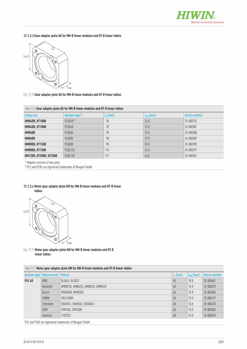
109HX-03-0-EN-1810-K
12.1.3.3 Gear adapter plate AG for HM-B linear modules and HT-B linear tables
Fig. 12.10 Gear adapter plate AG for HM-B linear modules and HT-B linear tables
LF�
LAG
Table 12.6 Gear adapter plate AG for HM-B linear modules and HT-B linear tables
Linear axis Gearbox type 2) LF [mm] LAG [mm] Article numberHM040B, HT100B PLE040 1) 50 23.0 25-000735HM040B, HT100B PLQE60 70 32.8 25-000387HM060B PLQE60 70 27.5 25-000388HM060B PLQE80 90 37.0 25-000389HM080B, HT150B PLQE80 90 35.0 25-000390HM080B, HT150B PLQE120 115 47.5 25-000391HM120B, HT200B, HT250B PLQE120 115 43.6 25-0003921) Adapter consists of two parts 2) PLE and PLQE are registered trademarks of Neugart GmbH
Fig. 12.11 Motor gear adapter plate GM for HM-B linear modules and HT-B linear tables
12.1.3.4 Motor gear adapter plate GM for HM-B linear modules and HT-B linear tables
LF�
LGM
Table 12.7 Motor gear adapter plate GM for HM-B linear modules and HT-B linear tables
Gearbox type Manufacturer Motors LF [mm] LGM [mm] Article numberPLE 40 B&R 8LSA24, 8LSA25 60 18.0 25-000481
Beckhoff AM8022D, AM8022E, AM8023E, AM8023F 60 15.0 25-000478Bosch MSK030B, MSK030C 60 15.0 25-000480HIWIN FRLS100W 40 19.0 25-000479Schneider BSH0551, BSH0552, BSH0553 60 15.0 25-000478SEW CMP40S, CMP40M 60 15.0 25-000480Siemens 1FK7022 60 15.0 25-000478
PLE and PLQE are registered trademarks of Neugart GmbH
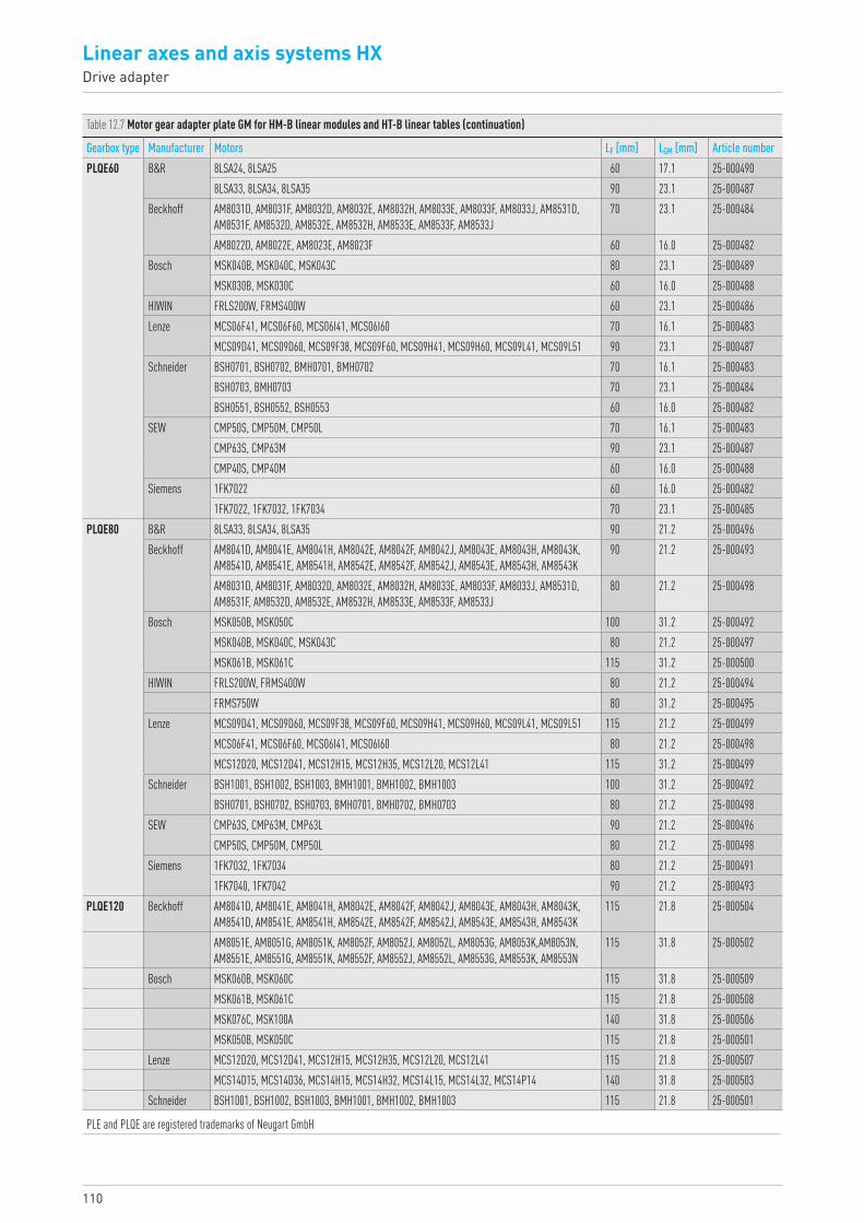
110
Linear axes and axis systems HXDrive adapter
Table 12.7 Motor gear adapter plate GM for HM-B linear modules and HT-B linear tables (continuation)
Gearbox type Manufacturer Motors LF [mm] LGM [mm] Article numberPLQE60 B&R 8LSA24, 8LSA25 60 17.1 25-000490
8LSA33, 8LSA34, 8LSA35 90 23.1 25-000487Beckhoff AM8031D, AM8031F, AM8032D, AM8032E, AM8032H, AM8033E, AM8033F, AM8033J, AM8531D,
AM8531F, AM8532D, AM8532E, AM8532H, AM8533E, AM8533F, AM8533J70 23.1 25-000484
AM8022D, AM8022E, AM8023E, AM8023F 60 16.0 25-000482Bosch MSK040B, MSK040C, MSK043C 80 23.1 25-000489
MSK030B, MSK030C 60 16.0 25-000488HIWIN FRLS200W, FRMS400W 60 23.1 25-000486Lenze MCS06F41, MCS06F60, MCS06I41, MCS06I60 70 16.1 25-000483
MCS09D41, MCS09D60, MCS09F38, MCS09F60, MCS09H41, MCS09H60, MCS09L41, MCS09L51 90 23.1 25-000487Schneider BSH0701, BSH0702, BMH0701, BMH0702 70 16.1 25-000483
BSH0703, BMH0703 70 23.1 25-000484BSH0551, BSH0552, BSH0553 60 16.0 25-000482
SEW CMP50S, CMP50M, CMP50L 70 16.1 25-000483CMP63S, CMP63M 90 23.1 25-000487CMP40S, CMP40M 60 16.0 25-000488
Siemens 1FK7022 60 16.0 25-0004821FK7022, 1FK7032, 1FK7034 70 23.1 25-000485
PLQE80 B&R 8LSA33, 8LSA34, 8LSA35 90 21.2 25-000496Beckhoff AM8041D, AM8041E, AM8041H, AM8042E, AM8042F, AM8042J, AM8043E, AM8043H, AM8043K,
AM8541D, AM8541E, AM8541H, AM8542E, AM8542F, AM8542J, AM8543E, AM8543H, AM8543K90 21.2 25-000493
AM8031D, AM8031F, AM8032D, AM8032E, AM8032H, AM8033E, AM8033F, AM8033J, AM8531D, AM8531F, AM8532D, AM8532E, AM8532H, AM8533E, AM8533F, AM8533J
80 21.2 25-000498
Bosch MSK050B, MSK050C 100 31.2 25-000492MSK040B, MSK040C, MSK043C 80 21.2 25-000497MSK061B, MSK061C 115 31.2 25-000500
HIWIN FRLS200W, FRMS400W 80 21.2 25-000494FRMS750W 80 31.2 25-000495
Lenze MCS09D41, MCS09D60, MCS09F38, MCS09F60, MCS09H41, MCS09H60, MCS09L41, MCS09L51 115 21.2 25-000499MCS06F41, MCS06F60, MCS06I41, MCS06I60 80 21.2 25-000498MCS12D20, MCS12D41, MCS12H15, MCS12H35, MCS12L20, MCS12L41 115 31.2 25-000499
Schneider BSH1001, BSH1002, BSH1003, BMH1001, BMH1002, BMH1003 100 31.2 25-000492BSH0701, BSH0702, BSH0703, BMH0701, BMH0702, BMH0703 80 21.2 25-000498
SEW CMP63S, CMP63M, CMP63L 90 21.2 25-000496CMP50S, CMP50M, CMP50L 80 21.2 25-000498
Siemens 1FK7032, 1FK7034 80 21.2 25-0004911FK7040, 1FK7042 90 21.2 25-000493
PLQE120 Beckhoff AM8041D, AM8041E, AM8041H, AM8042E, AM8042F, AM8042J, AM8043E, AM8043H, AM8043K, AM8541D, AM8541E, AM8541H, AM8542E, AM8542F, AM8542J, AM8543E, AM8543H, AM8543K
115 21.8 25-000504
AM8051E, AM8051G, AM8051K, AM8052F, AM8052J, AM8052L, AM8053G, AM8053K,AM8053N, AM8551E, AM8551G, AM8551K, AM8552F, AM8552J, AM8552L, AM8553G, AM8553K, AM8553N
115 31.8 25-000502
Bosch MSK060B, MSK060C 115 31.8 25-000509MSK061B, MSK061C 115 21.8 25-000508MSK076C, MSK100A 140 31.8 25-000506MSK050B, MSK050C 115 21.8 25-000501
Lenze MCS12D20, MCS12D41, MCS12H15, MCS12H35, MCS12L20, MCS12L41 115 21.8 25-000507MCS14D15, MCS14D36, MCS14H15, MCS14H32, MCS14L15, MCS14L32, MCS14P14 140 31.8 25-000503
Schneider BSH1001, BSH1002, BSH1003, BMH1001, BMH1002, BMH1003 115 21.8 25-000501
PLE and PLQE are registered trademarks of Neugart GmbH
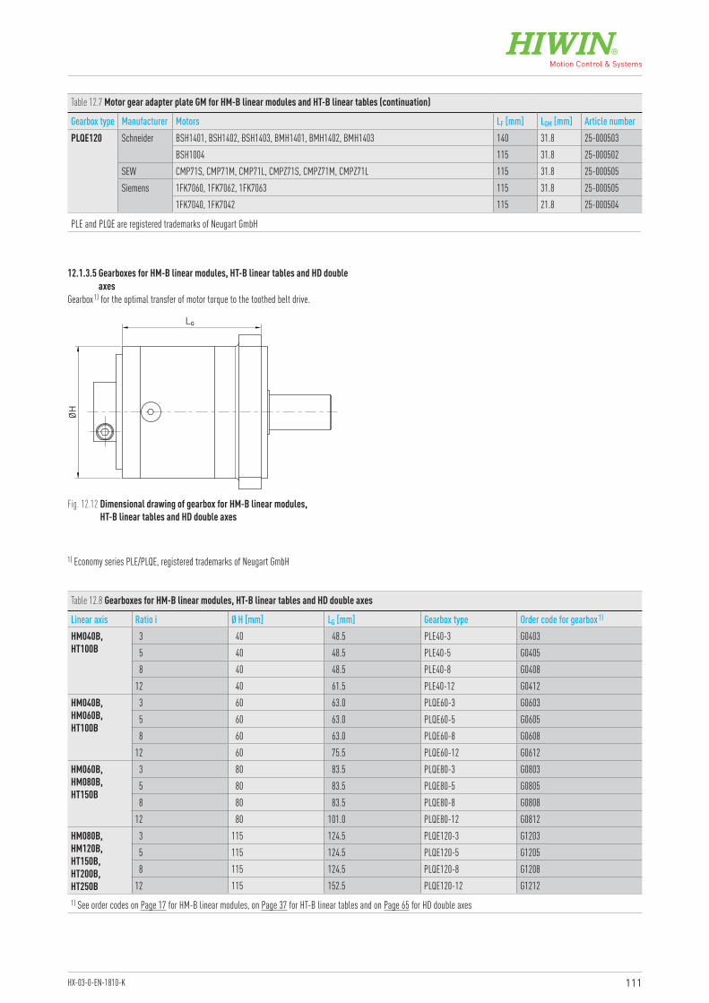
111HX-03-0-EN-1810-K
12.1.3.5 Gearboxes for HM-B linear modules, HT-B linear tables and HD double axes
Gearbox 1) for the optimal transfer of motor torque to the toothed belt drive.
LG
ØH
Fig. 12.12 Dimensional drawing of gearbox for HM-B linear modules, HT-B linear tables and HD double axes
1) Economy series PLE/PLQE, registered trademarks of Neugart GmbH
Table 12.8 Gearboxes for HM-B linear modules, HT-B linear tables and HD double axes
Linear axis Ratio i Ø H [mm] LG [mm] Gearbox type Order code for gearbox 1)
HM040B,HT100B
3 40 48.5 PLE40-3 G04035 40 48.5 PLE40-5 G04058 40 48.5 PLE40-8 G0408
12 40 61.5 PLE40-12 G0412HM040B,HM060B,HT100B
3 60 63.0 PLQE60-3 G06035 60 63.0 PLQE60-5 G06058 60 63.0 PLQE60-8 G0608
12 60 75.5 PLQE60-12 G0612HM060B,HM080B,HT150B
3 80 83.5 PLQE80-3 G08035 80 83.5 PLQE80-5 G08058 80 83.5 PLQE80-8 G0808
12 80 101.0 PLQE80-12 G0812HM080B,HM120B, HT150B,HT200B,HT250B
3 115 124.5 PLQE120-3 G12035 115 124.5 PLQE120-5 G12058 115 124.5 PLQE120-8 G1208
12 115 152.5 PLQE120-12 G12121) See order codes on Page 17 for HM-B linear modules, on Page 37 for HT-B linear tables and on Page 65 for HD double axes
Table 12.7 Motor gear adapter plate GM for HM-B linear modules and HT-B linear tables (continuation)
Gearbox type Manufacturer Motors LF [mm] LGM [mm] Article numberPLQE120 Schneider BSH1401, BSH1402, BSH1403, BMH1401, BMH1402, BMH1403 140 31.8 25-000503
BSH1004 115 31.8 25-000502SEW CMP71S, CMP71M, CMP71L, CMPZ71S, CMPZ71M, CMPZ71L 115 31.8 25-000505Siemens 1FK7060, 1FK7062, 1FK7063 115 31.8 25-000505
1FK7040, 1FK7042 115 21.8 25-000504
PLE and PLQE are registered trademarks of Neugart GmbH
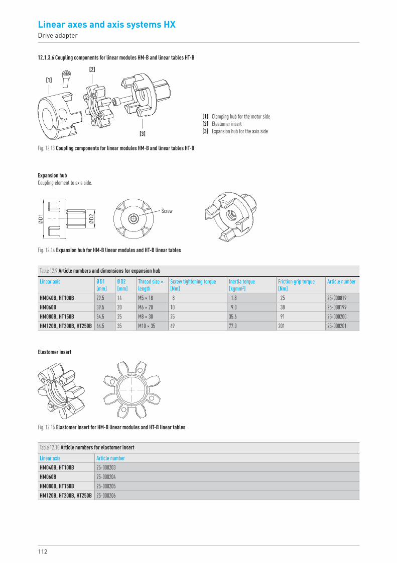
112
Linear axes and axis systems HXDrive adapter
12.1.3.6 Coupling components for linear modules HM-B and linear tables HT-B
[1]
[2]
[3]
Fig. 12.13 Coupling components for linear modules HM-B and linear tables HT-B
[1] Clamping hub for the motor side[2] Elastomer insert[3] Expansion hub for the axis side
Expansion hubCoupling element to axis side.
ØD1
ØD2
Screw
Fig. 12.14 Expansion hub for HM-B linear modules and HT-B linear tables
Table 12.9 Article numbers and dimensions for expansion hub
Linear axis Ø D1 [mm]
Ø D2 [mm]
Thread size × length
Screw tightening torque [Nm]
Inertia torque [kgmm2]
Friction grip torque [Nm]
Article number
HM040B, HT100B 29.5 14 M5 × 18 8 1.8 25 25-000819 HM060B 39.5 20 M6 × 20 10 9.0 38 25-000199HM080B, HT150B 54.5 25 M8 × 30 25 35.6 91 25-000200HM120B, HT200B, HT250B 64.5 35 M10 × 35 49 77.0 201 25-000201
Elastomer insert
Fig. 12.15 Elastomer insert for HM-B linear modules and HT-B linear tables
Table 12.10 Article numbers for elastomer insert
Linear axis Article numberHM040B, HT100B 25-000203 HM060B 25-000204HM080B, HT150B 25-000205HM120B, HT200B, HT250B 25-000206
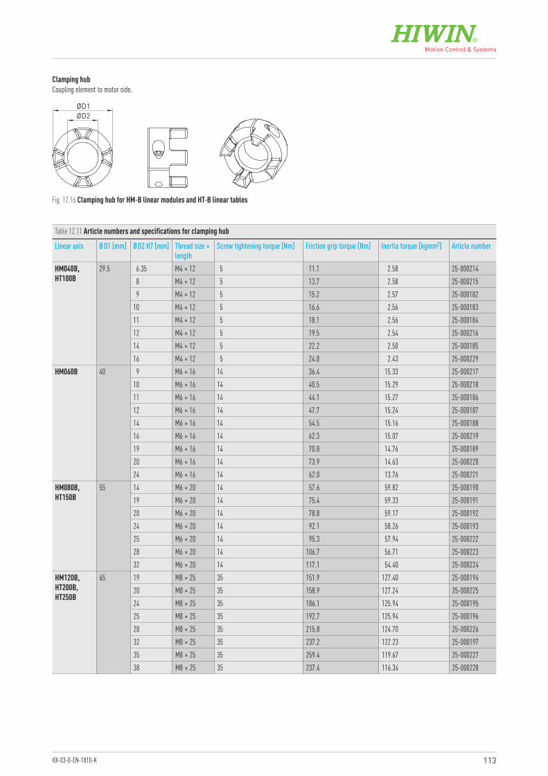
113HX-03-0-EN-1810-K
Clamping hubCoupling element to motor side.
Fig. 12.16 Clamping hub for HM-B linear modules and HT-B linear tables
ØD2ØD1
Table 12.11 Article numbers and specifications for clamping hub
Linear axis Ø D1 [mm] Ø D2 H7 [mm] Thread size × length
Screw tightening torque [Nm] Friction grip torque [Nm] Inertia torque [kgmm2] Article number
HM040B,HT100B
29.5 6.35 M4 × 12 5 11.1 2.58 25-0002148 M4 × 12 5 13.7 2.58 25-0002159 M4 × 12 5 15.2 2.57 25-000182
10 M4 × 12 5 16.6 2.56 25-00018311 M4 × 12 5 18.1 2.56 25-00018412 M4 × 12 5 19.5 2.54 25-00021614 M4 × 12 5 22.2 2.50 25-00018516 M4 × 12 5 24.8 2.43 25-000229
HM060B 40 9 M6 × 16 14 36.4 15.33 25-00021710 M6 × 16 14 40.5 15.29 25-00021811 M6 × 16 14 44.1 15.27 25-00018612 M6 × 16 14 47.7 15.24 25-00018714 M6 × 16 14 54.5 15.16 25-00018816 M6 × 16 14 62.3 15.07 25-00021919 M6 × 16 14 70.8 14.76 25-00018920 M6 × 16 14 73.9 14.63 25-00022024 M6 × 16 14 62.0 13.76 25-000221
HM080B,HT150B
55 14 M6 × 20 14 57.6 59.82 25-00019019 M6 × 20 14 75.4 59.33 25-00019120 M6 × 20 14 78.8 59.17 25-00019224 M6 × 20 14 92.1 58.26 25-00019325 M6 × 20 14 95.3 57.94 25-00022228 M6 × 20 14 106.7 56.71 25-00022332 M6 × 20 14 117.1 54.40 25-000224
HM120B,HT200B,HT250B
65 19 M8 × 25 35 151.9 127.40 25-00019420 M8 × 25 35 158.9 127.24 25-00022524 M8 × 25 35 186.1 125.94 25-00019525 M8 × 25 35 192.7 125.94 25-00019628 M8 × 25 35 215.8 124.70 25-00022632 M8 × 25 35 237.2 122.23 25-00019735 M8 × 25 35 259.4 119.67 25-00022738 M8 × 25 35 237.4 116.34 25-000228
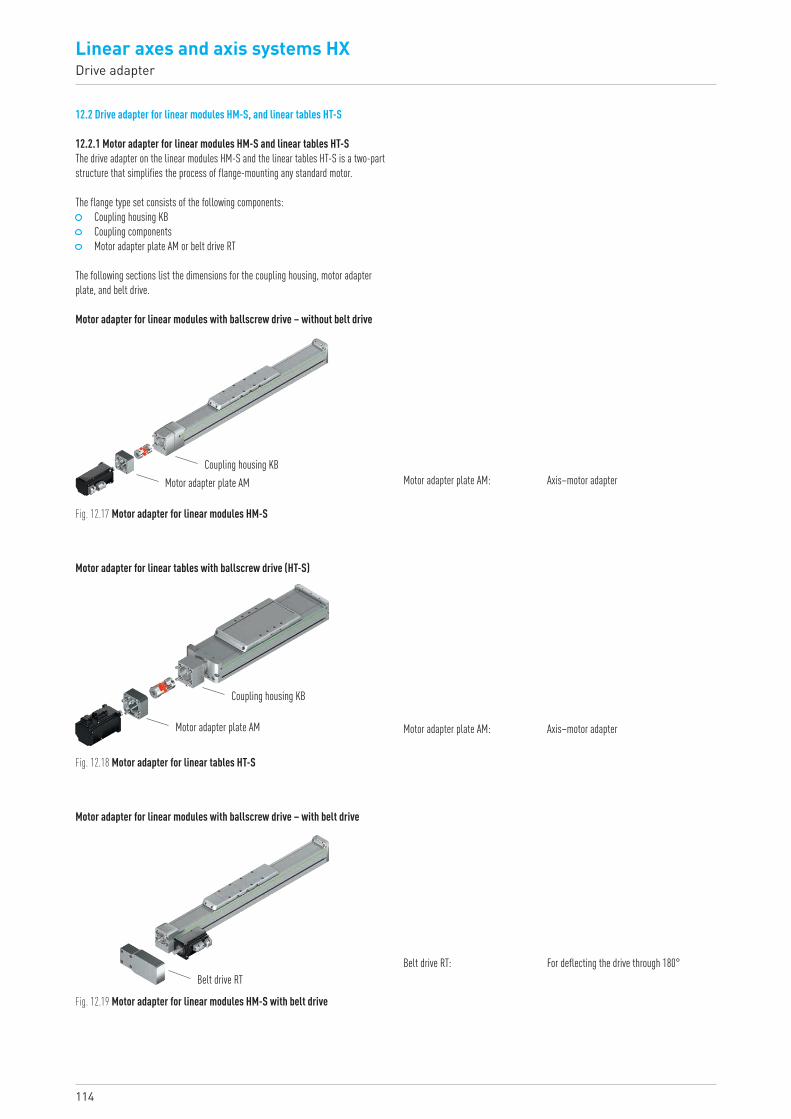
114
Linear axes and axis systems HXDrive adapter
12.2 Drive adapter for linear modules HM-S, and linear tables HT-S
12.2.1 Motor adapter for linear modules HM-S and linear tables HT-SThe drive adapter on the linear modules HM-S and the linear tables HT-S is a two-part structure that simplifies the process of flange-mounting any standard motor.
The flange type set consists of the following components: Coupling housing KB Coupling components Motor adapter plate AM or belt drive RT
The following sections list the dimensions for the coupling housing, motor adapterplate, and belt drive.
Motor adapter for linear modules with ballscrew drive – without belt drive
Motor adapter for linear modules with ballscrew drive – with belt drive
Coupling housing KBMotor adapter plate AM
Belt drive RT
Fig. 12.17 Motor adapter for linear modules HM-S
Motor adapter plate AM: Axis–motor adapter
Belt drive RT: For deflecting the drive through 180°
Motor adapter for linear tables with ballscrew drive (HT-S)
Coupling housing KB
Motor adapter plate AM
Fig. 12.18 Motor adapter for linear tables HT-S
Motor adapter plate AM: Axis–motor adapter
Fig. 12.19 Motor adapter for linear modules HM-S with belt drive
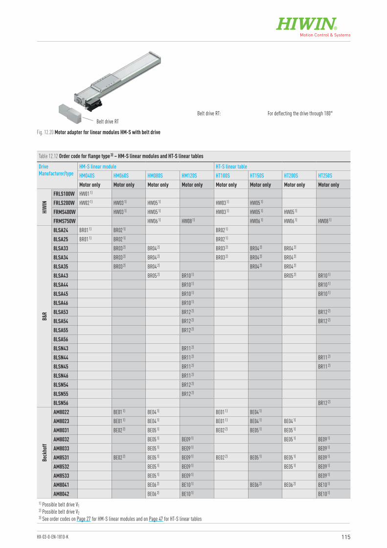
115HX-03-0-EN-1810-K
Belt drive RTBelt drive RT: For deflecting the drive through 180°
Fig. 12.20 Motor adapter for linear modules HM-S with belt drive
Table 12.12 Order code for flange type 3) – HM-S linear modules and HT-S linear tables
Drive Manufacturer/type
HM-S linear module HT-S linear tableHM040S HM060S HM080S HM120S HT100S HT150S HT200S HT250SMotor only Motor only Motor only Motor only Motor only Motor only Motor only Motor only
HIW
IN
FRLS100W HW01 1)
FRLS200W HW02 1) HW03 1) HW05 1) HW03 1) HW05 1)
FRMS400W HW03 1) HW05 1) HW03 1) HW05 1) HW05 1)
FRMS750W HW06 1) HW08 1) HW06 1) HW06 1) HW08 1)
B&R
8LSA24 BR01 1) BR02 1) BR02 1)
8LSA25 BR01 1) BR02 1) BR02 1)
8LSA33 BR03 2) BR04 2) BR03 2) BR04 2) BR04 2)
8LSA34 BR03 2) BR04 2) BR03 2) BR04 2) BR04 2)
8LSA35 BR03 2) BR04 2) BR04 2) BR04 2)
8LSA43 BR05 2) BR10 1) BR05 2) BR10 1)
8LSA44 BR10 1) BR10 1)
8LSA45 BR10 1) BR10 1)
8LSA46 BR10 1)
8LSA53 BR12 2) BR12 2)
8LSA54 BR12 2) BR12 2)
8LSA55 BR12 2)
8LSA568LSN43 BR11 2)
8LSN44 BR11 2) BR11 2)
8LSN45 BR11 2) BR11 2)
8LSN46 BR11 2)
8LSN54 BR12 2)
8LSN55 BR12 2)
8LSN56 BR12 2)
Beck
hoff
AM8022 BE01 1) BE04 1) BE01 1) BE04 1)
AM8023 BE01 1) BE04 1) BE01 1) BE04 1) BE04 1)
AM8031 BE02 2) BE05 1) BE02 2) BE05 1) BE05 1)
AM8032 BE05 1) BE09 1) BE05 1) BE09 1)
AM8033 BE05 1) BE09 1) BE09 1)
AM8531 BE02 2) BE05 1) BE09 1) BE02 2) BE05 1) BE05 1) BE09 1)
AM8532 BE05 1) BE09 1) BE05 1) BE09 1)
AM8533 BE05 1) BE09 1) BE09 1)
AM8041 BE06 2) BE10 1) BE06 2) BE06 2) BE10 1)
AM8042 BE06 2) BE10 1) BE10 1)
1) Possible belt drive V12) Possible belt drive V23) See order codes on Page 27 for HM-S linear modules and on Page 47 for HT-S linear tables
116
Linear axes and axis systems HXDrive adapter
Beck
hoff
AM8043 BE10 1) BE10 1)
AM8541 BE06 2) BE10 1) BE06 2) BE06 2) BE10 1)
AM8542 BE06 2) BE10 1) BE10 1)
AM8543 BE10 1) BE10 1)
AM8051 BE07 2) BE11 1) BE11 1)
AM8052 BE11 1)
AM8551 BE07 2) BE11 1) BE11 1)
AM8552 BE11 1)
AM8061 BE12 2)
AM8561 BE12 2)
Bosc
h
MSK030B BO01 1) BO02 1) BO02 1) MSK030C BO02 1) BO02 1) MSK040B BO03 2) BO05 1) BO10 1) BO03 2) BO05 1) BO05 1) BO10 1)
MSK040C BO03 2) BO05 1) BO10 1) BO03 2) BO05 1) BO05 1) BO10 1)
MSK043C BO05 1) BO10 1) BO05 1) BO10 1)
MSK050B BO06 2) BO11 1) BO06 2) BO06 2) BO11 1)
MSK050C BO06 2) BO11 1) BO06 2) BO11 1)
MSK060B BO08 2) BO13 2) BO08 2) BO13 2)
MSK060C BO13 2) BO13 2)
MSK061B BO07 2) BO12 2) BO07 2) BO12 2)
MSK061C BO12 2)
MSK070C BO15 2)
MSK071C BO15 2)
MSK075C BO15 2)
MSK076C BO14 2)
Lenz
e
MCS06F LE01 2) LE04 1) LE01 2) LE04 1)
MCS06I LE01 2) LE04 1) LE01 2) LE04 1) LE04 1)
MCS09D LE02 2) LE05 2) LE08 1) LE05 2) LE05 2) LE08 1)
MCS09F LE05 2) LE08 1) LE05 2) LE08 1)
MCS09H LE08 1) LE08 1)
MCS09L LE08 1)
MCS12D LE06 2) LE09 2) LE09 2)
MCS12H LE09 2) LE09 2)
MCS14D LE10 2) LE10 2)
Schn
eider
BSH0551 SE01 1) SE02 1) SE02 1)
BSH0552 SE01 1) SE02 1) SE02 1)
BSH0701 SE03 2) SE07 1) SE03 2) SE07 1)
BSH0702 SE03 2) SE07 1) SE03 2) SE07 1) SE07 1)
BSH0703 SE08 1) SE08 1) SE08 1)
BSH1001 SE09 2) SE13 1) SE09 2) SE09 2) SE13 1)
BSH1002 SE13 1) SE13 1)
BSH1003 SE13 1) SE13 1)
BSH1004 SE13 1)
BSH1401 SE15 2) SE15 2)
BMH0701 SE03 2) SE07 1) SE03 2) SE07 1) SE07 1)
Table 12.12 Order code for flange type 3) – HM-S linear modules and HT-S linear tables (continuation)
Drive Manufacturer/type
HM-S linear module HT-S linear tableHM040S HM060S HM080S HM120S HT100S HT150S HT200S HT250SMotor only Motor only Motor only Motor only Motor only Motor only Motor only Motor only
1) Possible belt drive V12) Possible belt drive V23) See order codes on Page 27 for HM-S linear modules and on Page 47 for HT-S linear tables
117HX-03-0-EN-1810-K
Schn
eider
BMH0702 SE03 2) SE07 1) SE03 2) SE07 1) SE07 1)
BMH0703 SE08 1) SE12 1) SE08 1) SE08 1) SE12 1)
BMH1001 SE09 2) SE13 1) SE09 2) SE09 2) SE13 1)
BMH1002 SE09 2) SE13 1) SE13 1)
BMH1003 SE13 1) SE13 1)
BMH1401 SE15 2)
SEW
CMP40S SW01 1) SW02 1) SW02 1)
CMP40M SW02 1) SW06 1) SW02 1) SW06 1)
CMP50S SW03 2) SW07 1) SW03 2) SW07 1) SW07 1)
CMP50M SW07 1) SW07 1) SW07 1)
CMP50L SW07 1) SW11 1) SW07 1) SW11 1)
CMP63S SW08 2) SW12 1) SW08 2) SW08 2) SW12 1)
CMP63M SW12 1) SW12 1)
CMP63L SW12 1) SW12 1)
CMP71S SW13 2) SW13 2)
CMP71M SW13 2) SW13 2)
CMP71L SW13 2)
CMP80S SW14 2)
CMPZ71S SW13 2) SW13 2)
CMPZ71M SW13 2) SW13 2)
CMPZ71L SW13 2)
CMPZ80S SW14 2)
Sieme
ns
1FK7022 SM01 1) SM02 1) SM02 1FK7032 SM03 2) SM04 1) SM03 SM04 SM04 1FK7034 SM03 2) SM04 1) SM03 SM04 SM04 1FK7040 SM05 2) SM08 1) SM05 SM05 SM081FK7042 SM05 2) SM08 1) SM05 SM05 SM081FK7060 SM06 SM09 2) SM091FK7062 SM09 2) SM091FK7063 SM09 2) 1FK7080 SM10 2) SM101FK7081 SM10 2)
1FK7083 SM10 2)
Table 12.12 Order code for flange type 3) – HM-S linear modules and HT-S linear tables (continuation)
Drive Manufacturer/type
HM-S linear module HT-S linear tableHM040S HM060S HM080S HM120S HT100S HT150S HT200S HT250SMotor only Motor only Motor only Motor only Motor only Motor only Motor only Motor only
1) Possible belt drive V12) Possible belt drive V23) See order codes on Page 27 for HM-S linear modules and on Page 47 for HT-S linear tables
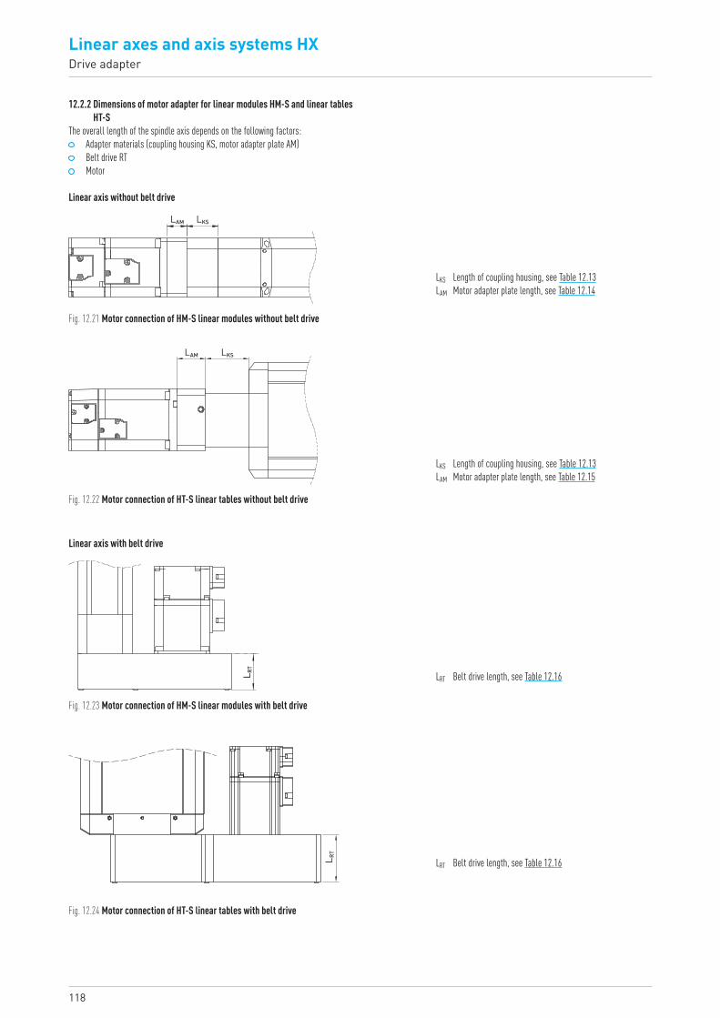
118
Linear axes and axis systems HXDrive adapter
12.2.2 Dimensions of motor adapter for linear modules HM-S and linear tables HT-S
The overall length of the spindle axis depends on the following factors: Adapter materials (coupling housing KS, motor adapter plate AM) Belt drive RT Motor
Linear axis without belt drive
LAM LKS
Fig. 12.21 Motor connection of HM-S linear modules without belt drive
LKS Length of coupling housing, see Table 12.13LAM Motor adapter plate length, see Table 12.14
Linear axis with belt drive
LRT Belt drive length, see Table 12.16
LRT Belt drive length, see Table 12.16
L RT
LAM LKS
LKS Length of coupling housing, see Table 12.13LAM Motor adapter plate length, see Table 12.15
Fig. 12.22 Motor connection of HT-S linear tables without belt drive
Fig. 12.23 Motor connection of HM-S linear modules with belt drive
Fig. 12.24 Motor connection of HT-S linear tables with belt drive
L RT
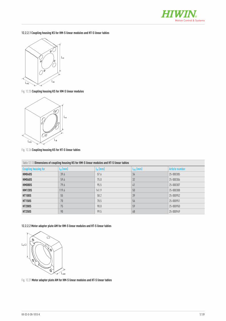
119HX-03-0-EN-1810-K
12.2.2.1 Coupling housing KS for HM-S linear modules and HT-S linear tables
LH
LBLKS
LH
LBLKS
Fig. 12.25 Coupling housing KS for HM-S linear modules
Fig. 12.26 Coupling housing KS for HT-S linear tables
12.2.2.2 Motor adapter plate AM for HM-S linear modules and HT-S linear tables
Table 12.13 Dimensions of coupling housing KS for HM-S linear modules and HT-S linear tables
Coupling housing for LB [mm] LH [mm] LKS [mm] Article numberHM040S 39.6 57.6 34 25-000305HM060S 59.6 75.0 32 25-000306HM080S 79.6 95.5 41 25-000307HM120S 119.6 141.9 50 25-000308HT100S 55 58.2 39 25-000952HT150S 70 78.5 56 25-000951HT200S 75 90.0 59 25-000950HT250S 90 99.5 68 25-000949
LF�
LAM
Fig. 12.27 Motor adapter plate AM for HM-S linear modules and HT-S linear tables
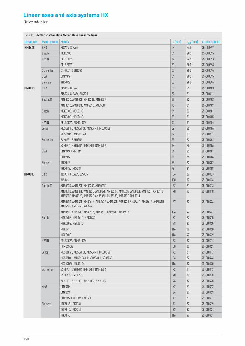
120
Linear axes and axis systems HXDrive adapter
Table 12.14 Motor adapter plate AM for HM-S linear modules
Linear axis Manufacturer Motors LF [mm] LAM [mm] Article numberHM040S B&R 8LSA24, 8LSA25 58 24,5 25-000397
Bosch MSK030B 54 20,5 25-000395HIWIN FRLS100W 42 24,5 25-000393
FRLS200W 60 30,0 25-000398Schneider BSH0551, BSH0552 55 20,5 25-000396SEW CMP40S 54 20,5 25-000395
Siemens 1FK7022 55 20,5 25-000396HM060S B&R 8LSA24, 8LSA25 58 25 25-000403
8LSA33, 8LSA34, 8LSA35 82 31 25-000411Beckhoff AM8022D, AM8022E, AM8023E, AM8023F 55 22 25-000402
AM8031D, AM8031F, AM8531D, AM8531F 70 31 25-000407Bosch MSK030B, MSK030C 54 22 25-000401
MSK040B, MSK040C 82 31 25-000405HIWIN FRLS200W, FRMS400W 60 31 25-000404Lenze MCS06F41, MCS06F60, MCS06I41, MCS06I60 62 25 25-000406
MCS09D41, MCS09D60 82 31 25-000411Schneider BSH0551, BSH0552 55 22 25-000402
BSH0701, BSH0702, BMH0701, BMH0702 62 25 25-000406SEW CMP40S, CMP40M 54 22 25-000401
CMP50S 62 25 25-000406Siemens 1FK7022 55 22 25-000402
1FK7032, 1FK7034 72 31 25-000408HM080S B&R 8LSA33, 8LSA34, 8LSA35 86 27 25-000423
8LSA43 100 37 25-000426Beckhoff AM8022D, AM8022E, AM8023E, AM8023F 72 21 25-000413
AM8031D, AM8031F, AM8032D, AM8032E, AM8032H, AM8033E, AM8033F, AM8033J, AM8531D, AM8531F, AM8532D, AM8532E, AM8532H, AM8533E, AM8533F, AM8533J
70 27 25-000418
AM8041D, AM8041E, AM8041H, AM8042E, AM8042F, AM8042J, AM8541D, AM8541E, AM8541H, AM8542E, AM8542F, AM8542J,
87 37 25-000424
AM8051E, AM8051G, AM8051K, AM8551E, AM8551G, AM8551K 104 47 25-000427Bosch MSK040B, MSK040C, MSK043C 82 27 25-000415
MSK050B, MSK050C 98 37 25-000425MSK061B 116 37 25-000428MSK060B 116 47 25-000429
HIWIN FRLS200W, FRMS400W 72 27 25-000414FRMS750W 80 37 25-000421
Lenze MCS06F41, MCS06F60, MCS06I41, MCS06I60 72 21 25-000417MCS09D41, MCS09D60, MCS09F38, MCS09F60 86 27 25-000423MCS12D20, MCS12D41 116 37 25-000430
Schneider BSH0701, BSH0702, BMH0701, BMH0702 72 21 25-000417BSH0703, BMH0703 70 27 25-000418BSH1001, BMH1001, BMH1002, BMH1003 98 37 25-000425
SEW CMP40M 72 21 25-000412CMP63S 86 27 25-000423CMP50S, CMP50M, CMP50L 72 21 25-000417
Siemens 1FK7032, 1FK7034 72 27 25-0004191KF7040, 1FK7042 87 37 25-0004241FK7060 116 47 25-000431
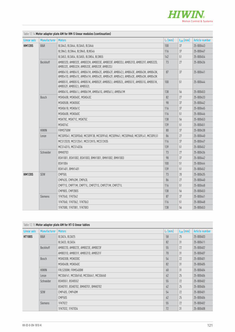
121HX-03-0-EN-1810-K
Table 12.14 Motor adapter plate AM for HM-S linear modules (continuation)
Linear axis Manufacturer Motors LF [mm] LAM [mm] Article numberHM120S B&R 8LSA43, 8LSA44, 8LSA45, 8LSA46 100 37 25-000443
8LSN43, 8LSN44, 8LSN45, 8LNS46 116 37 25-0004478LSA53, 8LSA54, 8LSA55, 8LSN54, 8LSN55 142 51 25-000454
Beckhoff AM8032D, AM8032E, AM8032H, AM8033E, AM8033F, AM8033J, AM8531D, AM8531F, AM8532D, AM8532E, AM8532H, AM8533E, AM8533F, AM8533J
73 27 25-000436
AM8041D, AM8041E, AM8041H, AM8042E, AM8042F, AM8042J, AM8043E, AM8043H, AM8043K, AM8541D, AM8541E, AM8541H, AM8542E, AM8542F, AM8542J, AM8543E, AM8543H, AM8543K
87 37 25-000441
AM8051E, AM8051G, AM8051K, AM8052F, AM8052J, AM8052L, AM8551E, AM8551G, AM8551K, AM8552F, AM8552J, AM8552L
100 51 25-000444
AM8061G, AM8061J, AM8061M, AM8561G, AM8561J, AM8561M 138 56 25-000453Bosch MSK040B, MSK040C, MSK043C 82 27 25-000433
MSK050B, MSK050C 98 37 25-000442MSK061B, MSK061C 116 37 25-000445MSK060B, MSK060C 116 51 25-000446MSK70C, MSK71C, MSK75C 138 56 25-000453MSK076C 139 51 25-000451
HIWIN FRMS750W 80 37 25-000438Lenze MCS09D41, MCS09D60, MCS09F38, MCS09F60, MCS09H41, MCS09H60, MCS09L41, MCS09L51 86 27 25-000440
MCS12D20, MCS12D41, MCS12H15, MCS12H35 116 37 25-000447MCS14D15, MCS14D36 139 51 25-000452
Schneider BMH0703 73 27 25-000436BSH1001, BSH1002, BSH1003, BMH1001, BMH1002, BMH1003 98 37 25-000442BSH1004 100 51 25-000444BSH1401, BMH1401 139 51 25-000452
HM120S SEW CMP50L 73 20 25-000435CMP63S, CMP63M, CMP63L 86 27 25-000440CMP71S, CMP71M, CMP71L, CMPZ71S, CMPZ71M, CMPZ71L 116 51 25-000448CMP80S, CMPZ80S 138 56 25-000453
Siemens 1FK7040, 1FK7042 87 37 25-0004411FK7060, 1FK7062, 1FK7063 116 51 25-0004481FK7080, 1FK7081, 1FK7083 138 56 25-000453
Table 12.15 Motor adapter plate AM for HT-S linear tables
Linear axis Manufacturer Motors LF [mm] LAM [mm] Article numberHT100S B&R 8LSA24, 8LSA25 58 25 25-000403
8LSA33, 8LSA34 82 31 25-000411Beckhoff AM8022D, AM8022E, AM8023E, AM8023F 55 22 25-000402
AM8031D, AM8031F, AM8531D, AM8531F 70 31 25-000407Bosch MSK030B, MSK030C 54 22 25-000401
MSK040B, MSK040C 82 31 25-000405
HIWIN FRLS200W, FRMS400W 60 31 25-000404Lenze MCS06F41, MCS06F60, MCS06I41, MCS06I60 62 25 25-000406Schneider BSH0551, BSH0552 55 22 25-000402
BSH0701, BSH0702, BMH0701, BMH0702 62 25 25-000406SEW CMP40S, CMP40M 54 22 25-000401
CMP50S 62 25 25-000406Siemens 1FK7022 55 22 25-000402
1FK7032, 1FK7034 72 31 25-000408
122
Linear axes and axis systems HXDrive adapter
Table 12.15 Motor adapter plate AM for HT-S linear tables (continuation)
Linear axis Manufacturer Motors LF [mm] LAM [mm] Article numberHT150S B&R 8LSA33, 8LSA34, 8LSA35 86 27 25-000423
Beckhoff AM8022D, AM8022E, AM8023E, AM8023F 72 21 25-000413AM8031D, AM8031F, AM8531D, AM8531F 70 27 25-000418AM8041D, AM8041E, AM8041H, AM8541D, AM8541E, AM8541H 87 37 25-000424
Bosch MSK040B, MSK040C 82 27 25-000415MSK050B 98 37 25-000425
HIWIN FRLS200W, FRMS400W 72 27 25-000414FRMS750W 80 37 25-000421
Lenze MCS06F41, MCS06F60, MCS06I41, MCS06I60 72 21 25-000417MCS09D41, MCS09D60 86 27 25-000423
Schneider BSH0702, BMH0701, BMH0702 72 21 25-000417BSH0703, BMH0703 70 27 25-000418BSH1001, BMH1001, BMH1003 98 37 25-000425
SEW CMP40M 72 21 25-000412CMP63S 86 27 25-000423CMP50S, CMP50M 72 21 25-000417
Siemens 1FK7032, 1FK7034 72 27 25-0004191KF7040, 1FK7042 87 37 25-000424
HT200S B&R 8LSA33, 8LSA34, 8LSA35 86 27 25-0004238LSA43 100 37 25-000426
Beckhoff AM8023E, AM8023F 72 21 25-000413AM8031D, AM8031F, AM8032D, AM8032E, AM8032H, AM8531D, AM8531F, AM8532D, AM8532E, AM8532H
70 27 25-000418
AM8041D, AM8041E, AM8041H, AM8541D, AM8541E, AM8541H 87 37 25-000424Bosch MSK040B, MSK040C, MSK043C 82 27 25-000415
MSK050B, MSK050C 98 37 25-000425MSK061B 116 37 25-000428MSK060B 116 47 25-000429
HIWIN FRMS400W 72 27 25-000414FRMS750W 80 37 25-000421
Lenze MCS06I41, MCS06I60 72 21 25-000417MCS09D41, MCS09D60, MCS09F38, MCS09F60 86 27 25-000423
Schneider BSH0702, BMH0701, BMH0702 72 21 25-000417BSH0703, BMH0703 70 27 25-000418BSH1001, BMH1001, BMH1003 98 37 25-000425
SEW CMP63S 86 27 25-000423CMP50S, CMP50M, CMP50L 72 21 25-000417
Siemens 1FK7032, 1FK7034 72 27 25-0004191KF7040, 1FK7042 87 37 25-000424
HT250S B&R 8LSA43, 8LSA44, 8LSA45 100 37 25-0004438LSN43, 8LSN44 116 37 25-0004478LSA53, 8LSA54, 8LSN54 142 51 25-000454
Beckhoff AM8032D, AM8032E, AM8032H, AM8033E, AM8033F, AM8033J, AM8531D, AM8531F, AM8532D, AM8532E, AM8532H, AM8533E, AM8533F, AM8533J
73 27 25-000436
AM8041D, AM8041E, AM8041H, AM8042E, AM8042F, AM8042J, AM8043E, AM8043H, AM8043K, AM8541D, AM8541E, AM8541H, AM8542E, AM8542F, AM8542J, AM8543E, AM8543H, AM8543K
87 37 25-000441
AM8051E, AM8051G, AM8051K, AM8551E, AM8551G, AM8551K 100 51 25-000444Bosch MSK040B, MSK040C, MSK043C 82 27 25-000433
MSK050B, MSK050C 98 37 25-000442MSK060B, MSK060C 116 51 25-000446
123HX-03-0-EN-1810-K
Table 12.15 Motor adapter plate AM for HT-S linear tables (continuation)
Linear axis Manufacturer Motors LF [mm] LAM [mm] Article numberHT250S HIWIN FRMS750W 80 37 25-000438
Lenze MCS09D41, MCS09D60, MCS09F38, MCS09F60, MCS09H41, MCS09H60 86 27 25-000440MCS12D20, MCS12D41, MCS12H15, MCS12H35 116 37 25-000447MCS14D15, MCS14D36 139 51 25-000452
Schneider BMH0703 73 27 25-000436BSH1001, BSH1002, BSH1003, BMH1001, BMH1002, BMH1003 98 37 25-000442BSH1401 139 51 25-000452
SEW CMP50L 73 20 25-000435CMP63S, CMP63M, CMP63L 86 27 25-000440CMP71S, CMP71M, CMPZ71S, CMPZ71M 116 51 25-000448
Siemens 1FK7040, 1FK7042 87 37 25-0004411FK7060, 1FK7062 116 51 25-0004481FK7080 138 56 25-000453
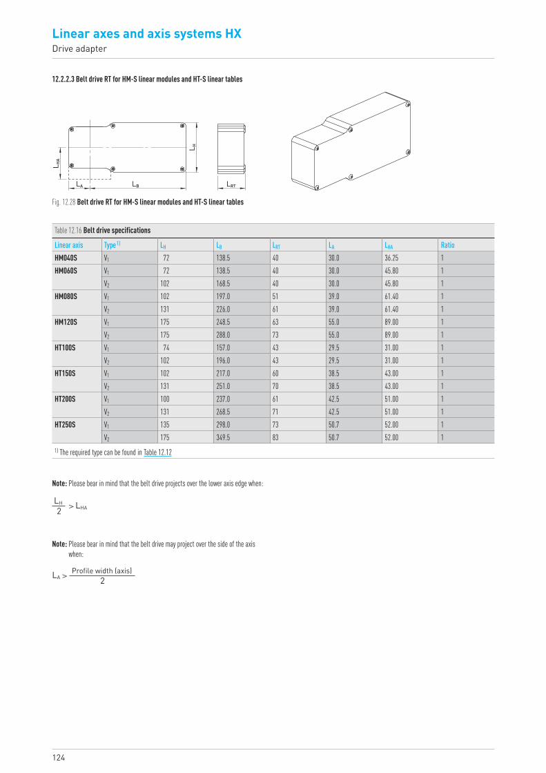
124
Linear axes and axis systems HXDrive adapter
12.2.2.3 Belt drive RT for HM-S linear modules and HT-S linear tables
L HA
LA LB LRTL H
Fig. 12.28 Belt drive RT for HM-S linear modules and HT-S linear tables
Table 12.16 Belt drive specifications
Linear axis Type 1) LH LB LRT LA LHA RatioHM040S V1 72 138.5 40 30.0 36.25 1HM060S V1 72 138.5 40 30.0 45.80 1
V2 102 168.5 40 30.0 45.80 1HM080S V1 102 197.0 51 39.0 61.40 1
V2 131 226.0 61 39.0 61.40 1HM120S V1 175 248.5 63 55.0 89.00 1
V2 175 288.0 73 55.0 89.00 1HT100S V1 74 157.0 43 29.5 31.00 1
V2 102 196.0 43 29.5 31.00 1HT150S V1 102 217.0 60 38.5 43.00 1
V2 131 251.0 70 38.5 43.00 1HT200S V1 100 237.0 61 42.5 51.00 1
V2 131 268.5 71 42.5 51.00 1HT250S V1 135 298.0 73 50.7 52.00 1
V2 175 349.5 83 50.7 52.00 11) The required type can be found in Table 12.12
Note: Please bear in mind that the belt drive projects over the lower axis edge when:
Note: Please bear in mind that the belt drive may project over the side of the axis when:
> LHALH
2
LA > Profile width (axis)2
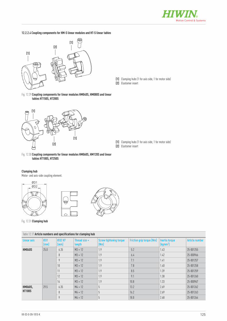
125HX-03-0-EN-1810-K
12.2.2.4 Coupling components for HM-S linear modules and HT-S linear tables
Clamping hubMotor- and axis-side coupling element.
Fig. 12.29 Coupling components for linear modules HM040S, HM080S and linear tables HT150S, HT200S
Fig. 12.30 Coupling components for linear modules HM060S, HM120S and linear tables HT100S, HT250S
[1] Clamping hubs (1 for axis side, 1 for motor side)[2] Elastomer insert
[1] Clamping hubs (1 for axis side, 1 for motor side)[2] Elastomer insert
[1]
[2][1]
ØD2ØD1
Table 12.17 Article numbers and specifications for clamping hub
Linear axis Ø D1 [mm]
Ø D2 H7 [mm]
Thread size × length
Screw tightening torque [Nm]
Friction grip torque [Nm] Inertia torque [kgmm2]
Article number
HM040S 25.0 6.35 M3 × 12 1.9 5.2 1.43 25-0012558 M3 × 12 1.9 6.4 1.42 25-0009669 M3 × 12 1.9 7.1 1.41 25-001257
10 M3 × 12 1.9 7.8 1.40 25-00125811 M3 × 12 1.9 8.5 1.39 25-00125912 M3 × 12 1.9 9.1 1.38 25-00126014 M3 × 12 1.9 10.8 1.33 25-000967
HM060S,HT100S
29.5 6.35 M4 × 12 5 13.2 2.69 25-0012628 M4 × 12 5 16.2 2.69 25-0012639 M4 × 12 5 18.0 2.68 25-001264
[1]
[2]
[1]
Fig. 12.31 Clamping hub
126
Linear axes and axis systems HXDrive adapter
Table 12.17 Article numbers and specifications for clamping hub (continuation)
Linear axis Ø D1 [mm]
Ø D2 H7 [mm]
Thread size × length
Screw tightening torque [Nm]
Friction grip torque [Nm] Inertia torque [kgmm2]
Article number
HM060S,HT100S
29.5 10 M4 × 12 5 19.7 2.67 25-00096811 M4 × 12 5 21.5 2.66 25-00126512 M4 × 12 5 23.1 2.65 25-00126614 M4 × 12 5 26.4 2.61 25-00096916 M4 × 12 5 29.5 2.55 25-001267
HM080S,HT150S,HT200S
40.0 9 M6 × 16 14 18.4 14.54 25-00126810 M6 × 16 14 20.3 14.53 25-00126911 M6 × 16 14 22.1 14.51 25-00127012 M6 × 16 14 23.8 14.48 25-00097014 M6 × 16 14 27.3 14.40 25-00127116 M6 × 16 14 30.6 14.28 25-00127219 M6 × 16 14 35.4 14.00 25-00097120 M6 × 16 14 36.9 13.87 25-00127324 M5 × 16 10 37.8 12.95 25-000972
HM120S,HT250S
55.0 14 M6 × 20 14 54.3 58.33 25-00127419 M6 × 20 14 68.0 57.86 25-00097420 M6 × 20 14 71.1 57.71 25-00097324 M6 × 20 14 83.1 56.81 25-00127525 M6 × 20 14 86.0 56.50 25-00127628 M6 × 20 14 94.6 55.32 25-00127732 M6 × 20 14 105.6 53.03 25-000975
Elastomer insert
Fig. 12.32 Elastomer insert
Table 12.18 Article number for elastomer insert
Linear axis Article numberHM040S 25-000202HM060S, HT100S 25-000203HM080S, HT150S, HT200S 25-000204HM120S, HT250S 25-000205
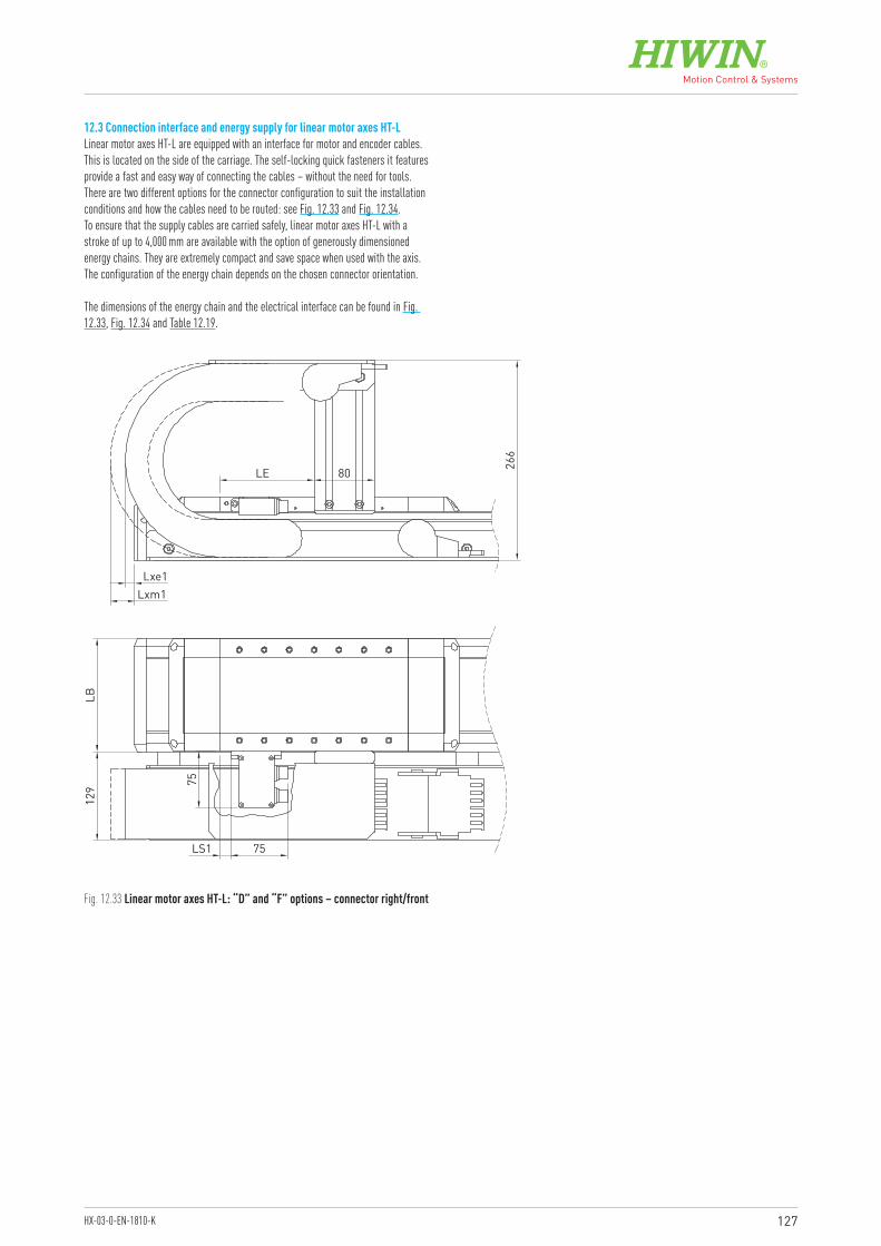
127HX-03-0-EN-1810-K
12.3 Connection interface and energy supply for linear motor axes HT-LLinear motor axes HT-L are equipped with an interface for motor and encoder cables. This is located on the side of the carriage. The self-locking quick fasteners it features provide a fast and easy way of connecting the cables – without the need for tools. There are two different options for the connector configuration to suit the installation conditions and how the cables need to be routed: see Fig. 12.33 and Fig. 12.34.To ensure that the supply cables are carried safely, linear motor axes HT-L with a stroke of up to 4,000 mm are available with the option of generously dimensioned energy chains. They are extremely compact and save space when used with the axis. The configuration of the energy chain depends on the chosen connector orientation.
The dimensions of the energy chain and the electrical interface can be found in Fig. 12.33, Fig. 12.34 and Table 12.19.
75LS1
75
129
LB
Lxe1
LE 266
80
Lxm1
Fig. 12.33 Linear motor axes HT-L: “D” and “F” options – connector right/front
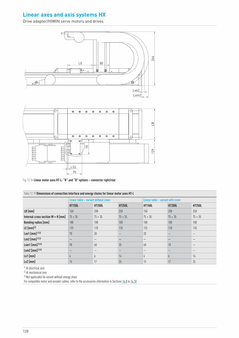
128
Linear axes and axis systems HXDrive adapter/HIWIN servo motors and drives
LS275
75
LB
Lxe2
LE 80
Lxm2
129
266
Fig. 12.34 Linear motor axes HT-L: “R” and “B” options – connector right/rear
Table 12.19 Dimensions of connection interface and energy chains for linear motor axes HT-L
Linear table – variant without cover Linear table – variant with coverHT150L HT200L HT250L HT150L HT200L HT250L
LB [mm] 150 200 250 150 200 250Internal cross section W × H [mm] 75 × 35 75 × 35 75 × 35 75 × 35 75 × 35 75 × 35Bending radius [mm] 100 100 100 100 100 100LE [mm] 3) 125 120 135 125 120 135Lxe1 [mm] 1) 3) 70 30 — 20 — —Lxe2 [mm] 1) 3) — — — — — —Lxm1 [mm] 2) 3) 90 60 35 40 10 —Lxm2 [mm] 2) 3) — — — — — —Ls1 [mm] 4 6 14 4 6 14Ls2 [mm] 15 17 25 15 17 251) At electrical zero2) At mechanical zero3) Not applicable for variant without energy chain For compatible motor and encoder cables, refer to the accessories information in Sections 14.8 to 14.10
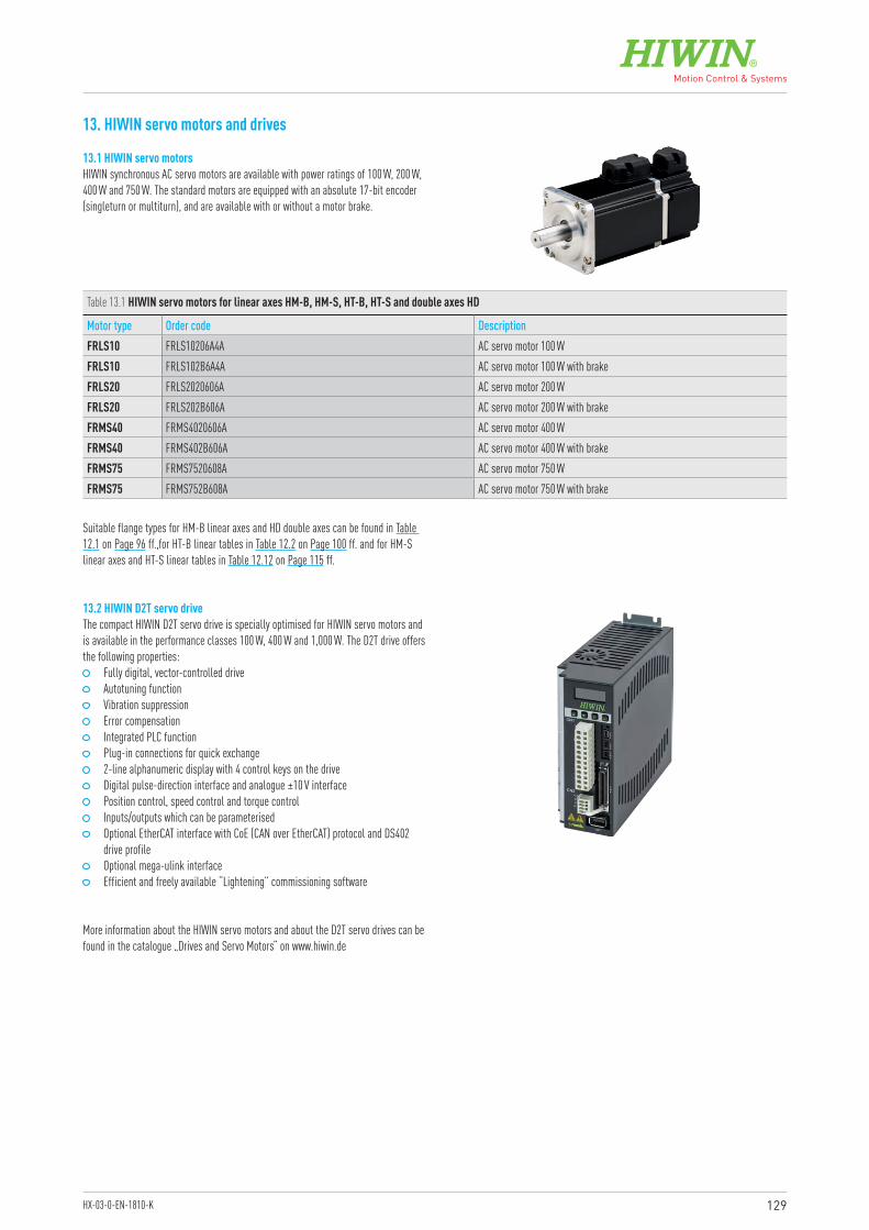
129HX-03-0-EN-1810-K
13. HIWIN servo motors and drives
13.1 HIWIN servo motorsHIWIN synchronous AC servo motors are available with power ratings of 100 W, 200 W, 400 W and 750 W. The standard motors are equipped with an absolute 17-bit encoder (singleturn or multiturn), and are available with or without a motor brake.
13.2 HIWIN D2T servo driveThe compact HIWIN D2T servo drive is specially optimised for HIWIN servo motors and is available in the performance classes 100 W, 400 W and 1,000 W. The D2T drive offers the following properties:
Fully digital, vector-controlled drive Autotuning function Vibration suppression Error compensation Integrated PLC function Plug-in connections for quick exchange 2-line alphanumeric display with 4 control keys on the drive Digital pulse-direction interface and analogue ±10 V interface Position control, speed control and torque control Inputs/outputs which can be parameterised Optional EtherCAT interface with CoE (CAN over EtherCAT) protocol and DS402
drive profile Optional mega-ulink interface Efficient and freely available “Lightening” commissioning software
Table 13.1 HIWIN servo motors for linear axes HM-B, HM-S, HT-B, HT-S and double axes HD
Motor type Order code DescriptionFRLS10 FRLS10206A4A AC servo motor 100 WFRLS10 FRLS102B6A4A AC servo motor 100 W with brakeFRLS20 FRLS2020606A AC servo motor 200 WFRLS20 FRLS202B606A AC servo motor 200 W with brakeFRMS40 FRMS4020606A AC servo motor 400 WFRMS40 FRMS402B606A AC servo motor 400 W with brakeFRMS75 FRMS7520608A AC servo motor 750 WFRMS75 FRMS752B608A AC servo motor 750 W with brake
Suitable flange types for HM-B linear axes and HD double axes can be found in Table 12.1 on Page 96 ff.,for HT-B linear tables in Table 12.2 on Page 100 ff. and for HM-S linear axes and HT-S linear tables in Table 12.12 on Page 115 ff.
More information about the HIWIN servo motors and about the D2T servo drives can be found in the catalogue „Drives and Servo Motors“ on www.hiwin.de
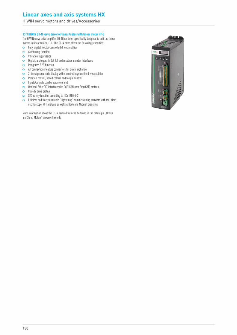
130
Linear axes and axis systems HXHIWIN servo motors and drives/Accessories
13.3 HIWIN D1-N servo drive for linear tables with linear motor HT-LThe HIWIN servo drive amplifier D1-N has been specifically designed to suit the linear motors in linear tables HT-L. The D1-N drive offers the following properties:
Fully digital, vector-controlled drive amplifier Autotuning function Vibration suppression Digital, analogue, EnDat 2.2 and resolver encoder interfaces Integrated SPS function All connections feature connectors for quick exchange 2-line alphanumeric display with 4 control keys on the drive amplifier Position control, speed control and torque control Inputs/outputs can be parameterised Optional EtherCAT interface with CoE (CAN over EtherCAT) protocol CiA 402 drive profile STO safety function according to IEC61800-5-2 Efficient and freely available “Lightening” commissioning software with real-time
oscilloscope, FFT analysis as well as Bode and Nyquist diagrams
More information about the D1-N servo drives can be found in the catalogue „Drives and Servo Motors“ on www.hiwin.de
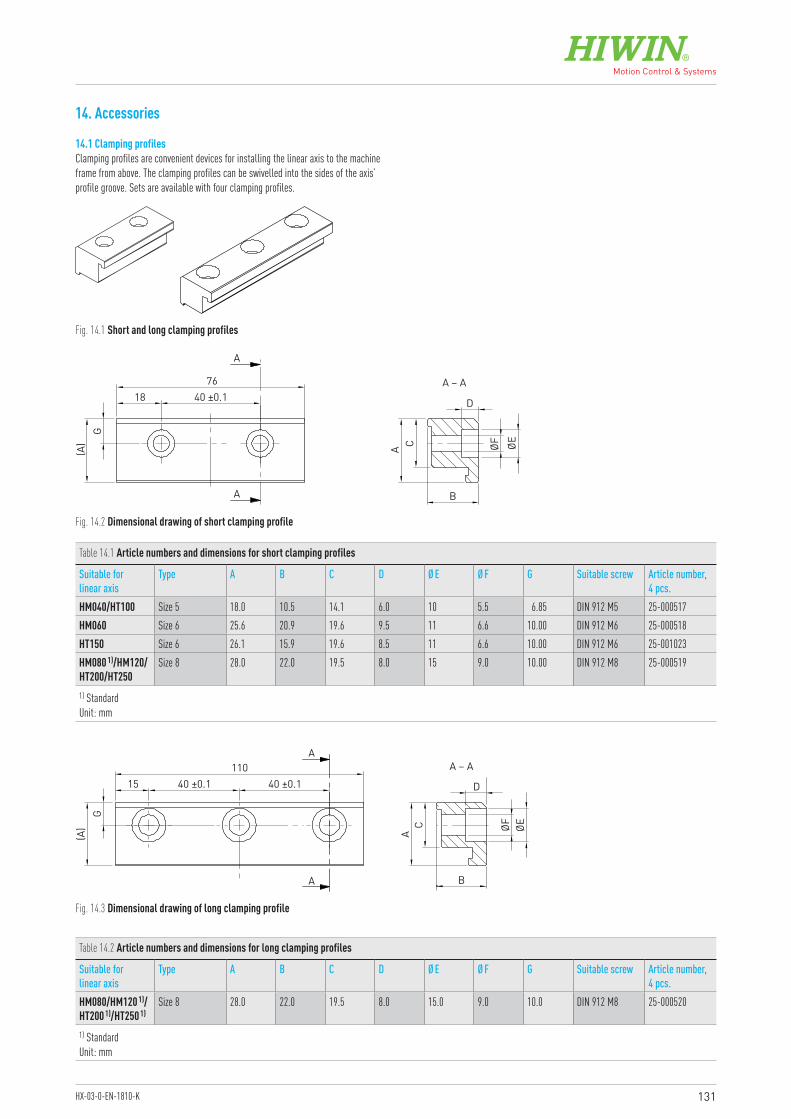
131HX-03-0-EN-1810-K
14. Accessories
14.1 Clamping profilesClamping profiles are convenient devices for installing the linear axis to the machine frame from above. The clamping profiles can be swivelled into the sides of the axis’ profile groove. Sets are available with four clamping profiles.
Fig. 14.1 Short and long clamping profiles
Fig. 14.2 Dimensional drawing of short clamping profile
Fig. 14.3 Dimensional drawing of long clamping profile
Table 14.1 Article numbers and dimensions for short clamping profiles
Suitable for linear axis
Type A B C D Ø E Ø F G Suitable screw Article number, 4 pcs.
HM040/HT100 Size 5 18.0 10.5 14.1 6.0 10 5.5 6.85 DIN 912 M5 25-000517HM060 Size 6 25.6 20.9 19.6 9.5 11 6.6 10.00 DIN 912 M6 25-000518HT150 Size 6 26.1 15.9 19.6 8.5 11 6.6 10.00 DIN 912 M6 25-001023HM080 1)/HM120/HT200/HT250
Size 8 28.0 22.0 19.5 8.0 15 9.0 10.00 DIN 912 M8 25-000519
1) StandardUnit: mm
Table 14.2 Article numbers and dimensions for long clamping profiles
Suitable for linear axis
Type A B C D Ø E Ø F G Suitable screw Article number, 4 pcs.
HM080/HM120 1)/HT200 1)/HT250 1)
Size 8 28.0 22.0 19.5 8.0 15.0 9.0 10.0 DIN 912 M8 25-000520
1) Standard Unit: mm
(A) A ØEØF
D
B
C
G
18 40 ±0.176
A
A – A
A
(A) A ØEØF
D
B
A – A
C
G
15 40 ±0.1 40 ±0.1110
A
A
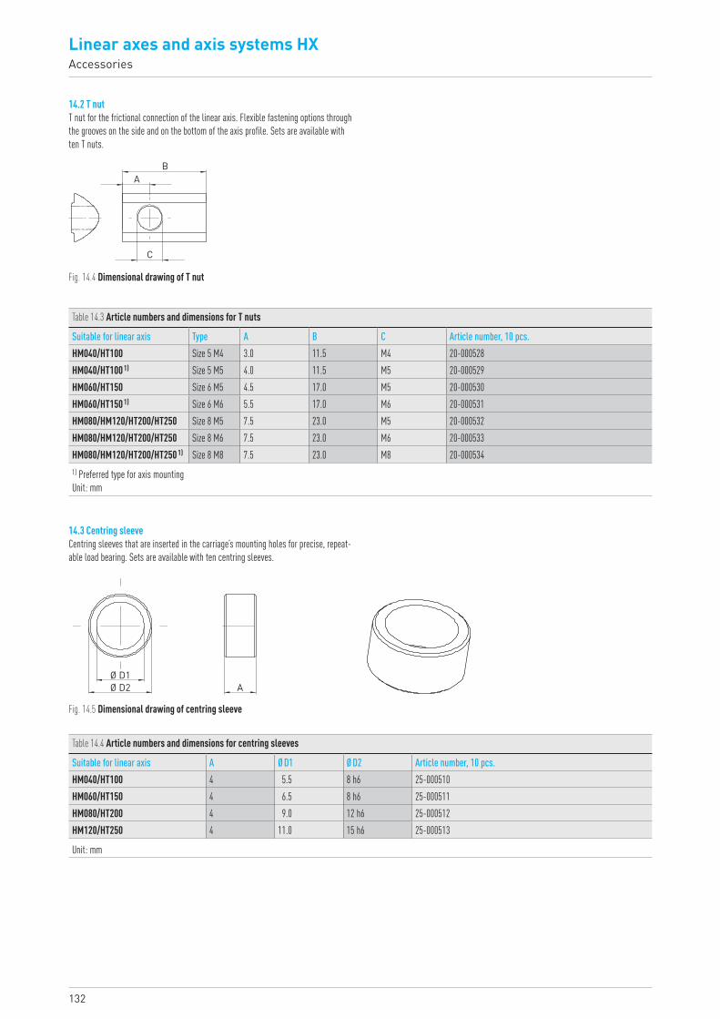
Linear axes and axis systems HXAccessories
132
14.2 T nutT nut for the frictional connection of the linear axis. Flexible fastening options through the grooves on the side and on the bottom of the axis profile. Sets are available with ten T nuts.
14.3 Centring sleeveCentring sleeves that are inserted in the carriage’s mounting holes for precise, repeat-able load bearing. Sets are available with ten centring sleeves.
Fig. 14.4 Dimensional drawing of T nut
Fig. 14.5 Dimensional drawing of centring sleeve
Table 14.3 Article numbers and dimensions for T nuts
Suitable for linear axis Type A B C Article number, 10 pcs.HM040/HT100 Size 5 M4 3.0 11.5 M4 20-000528HM040/HT100 1) Size 5 M5 4.0 11.5 M5 20-000529HM060/HT150 Size 6 M5 4.5 17.0 M5 20-000530HM060/HT150 1) Size 6 M6 5.5 17.0 M6 20-000531HM080/HM120/HT200/HT250 Size 8 M5 7.5 23.0 M5 20-000532HM080/HM120/HT200/HT250 Size 8 M6 7.5 23.0 M6 20-000533HM080/HM120/HT200/HT250 1) Size 8 M8 7.5 23.0 M8 20-0005341) Preferred type for axis mounting Unit: mm
Table 14.4 Article numbers and dimensions for centring sleeves
Suitable for linear axis A Ø D1 Ø D2 Article number, 10 pcs.HM040/HT100 4 5.5 8 h6 25-000510HM060/HT150 4 6.5 8 h6 25-000511HM080/HT200 4 9.0 12 h6 25-000512HM120/HT250 4 11.0 15 h6 25-000513
Unit: mm
C
BA
Ø D1Ø D2 A
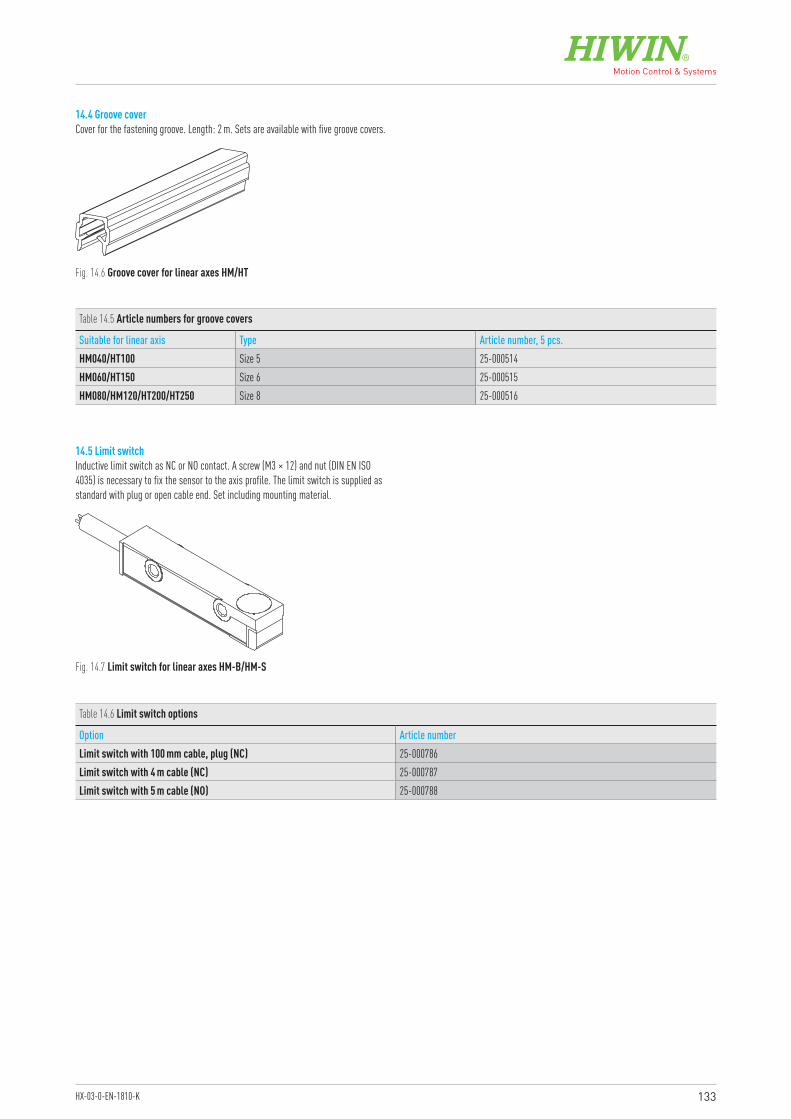
133HX-03-0-EN-1810-K
14.4 Groove coverCover for the fastening groove. Length: 2 m. Sets are available with five groove covers.
14.5 Limit switchInductive limit switch as NC or NO contact. A screw (M3 × 12) and nut (DIN EN ISO 4035) is necessary to fix the sensor to the axis profile. The limit switch is supplied as standard with plug or open cable end. Set including mounting material.
Fig. 14.6 Groove cover for linear axes HM/HT
Fig. 14.7 Limit switch for linear axes HM-B/HM-S
Table 14.5 Article numbers for groove covers
Suitable for linear axis Type Article number, 5 pcs.HM040/HT100 Size 5 25-000514HM060/HT150 Size 6 25-000515HM080/HM120/HT200/HT250 Size 8 25-000516
Table 14.6 Limit switch options
Option Article numberLimit switch with 100 mm cable, plug (NC) 25-000786Limit switch with 4 m cable (NC) 25-000787Limit switch with 5 m cable (NO) 25-000788
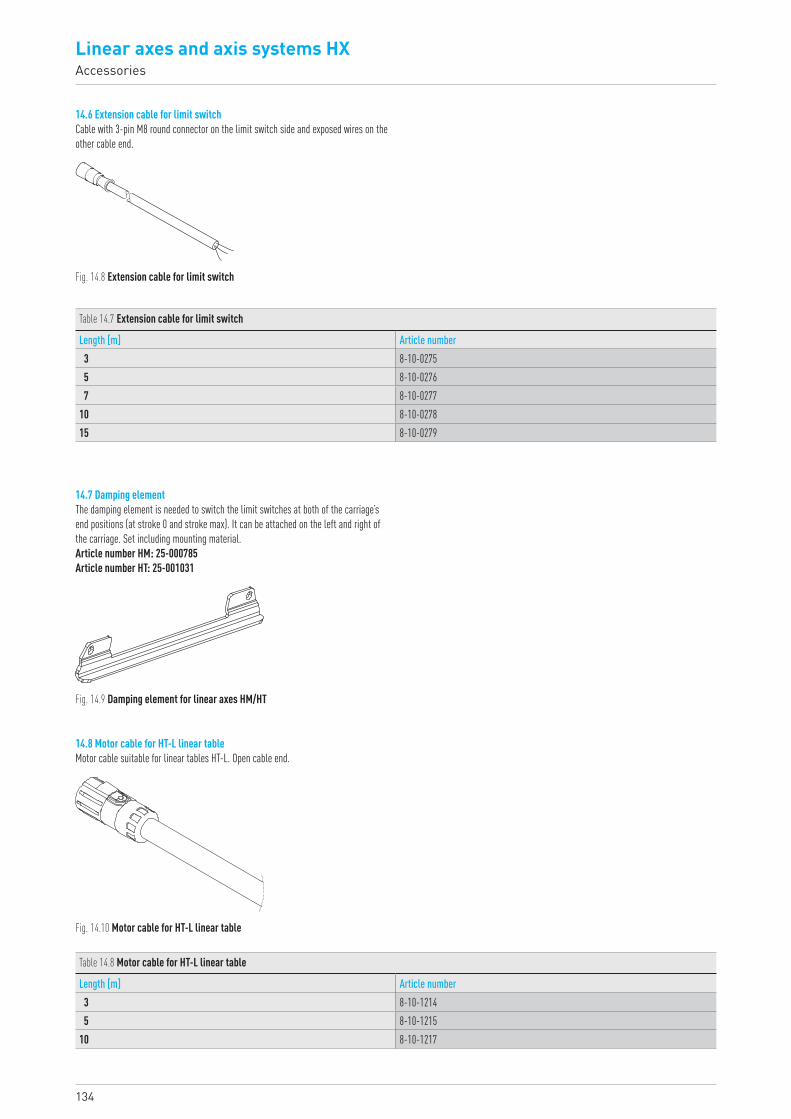
Linear axes and axis systems HXAccessories
134
14.6 Extension cable for limit switchCable with 3-pin M8 round connector on the limit switch side and exposed wires on the other cable end.
14.7 Damping elementThe damping element is needed to switch the limit switches at both of the carriage’s end positions (at stroke 0 and stroke max). It can be attached on the left and right of the carriage. Set including mounting material.Article number HM: 25-000785Article number HT: 25-001031
14.8 Motor cable for HT-L linear tableMotor cable suitable for linear tables HT-L. Open cable end.
Fig. 14.8 Extension cable for limit switch
Fig. 14.9 Damping element for linear axes HM/HT
Fig. 14.10 Motor cable for HT-L linear table
Table 14.7 Extension cable for limit switch
Length [m] Article number3 8-10-02755 8-10-02767 8-10-0277
10 8-10-027815 8-10-0279
Table 14.8 Motor cable for HT-L linear table
Length [m] Article number3 8-10-12145 8-10-1215
10 8-10-1217
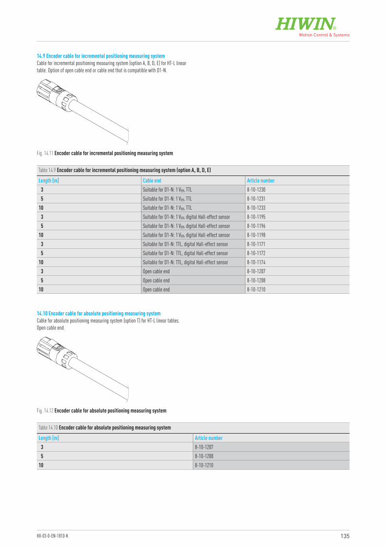
135HX-03-0-EN-1810-K
14.9 Encoder cable for incremental positioning measuring systemCable for incremental positioning measuring system (option A, B, D, E) for HT-L linear table. Option of open cable end or cable end that is compatible with D1-N.
14.10 Encoder cable for absolute positioning measuring systemCable for absolute positioning measuring system (option T) for HT-L linear tables. Open cable end.
Fig. 14.11 Encoder cable for incremental positioning measuring system
Fig. 14.12 Encoder cable for absolute positioning measuring system
Table 14.9 Encoder cable for incremental positioning measuring system (option A, B, D, E)
Length [m] Cable end Article number3 Suitable for D1-N: 1 VPP, TTL 8-10-12305 Suitable for D1-N: 1 VPP, TTL 8-10-1231
10 Suitable for D1-N: 1 VPP, TTL 8-10-12333 Suitable for D1-N: 1 VPP, digital Hall-effect sensor 8-10-11955 Suitable for D1-N: 1 VPP, digital Hall-effect sensor 8-10-1196
10 Suitable for D1-N: 1 VPP, digital Hall-effect sensor 8-10-11983 Suitable for D1-N: TTL, digital Hall-effect sensor 8-10-11715 Suitable for D1-N: TTL, digital Hall-effect sensor 8-10-1172
10 Suitable for D1-N: TTL, digital Hall-effect sensor 8-10-11743 Open cable end 8-10-12075 Open cable end 8-10-1208
10 Open cable end 8-10-1210
Table 14.10 Encoder cable for absolute positioning measuring system
Length [m] Article number3 8-10-12075 8-10-1208
10 8-10-1210
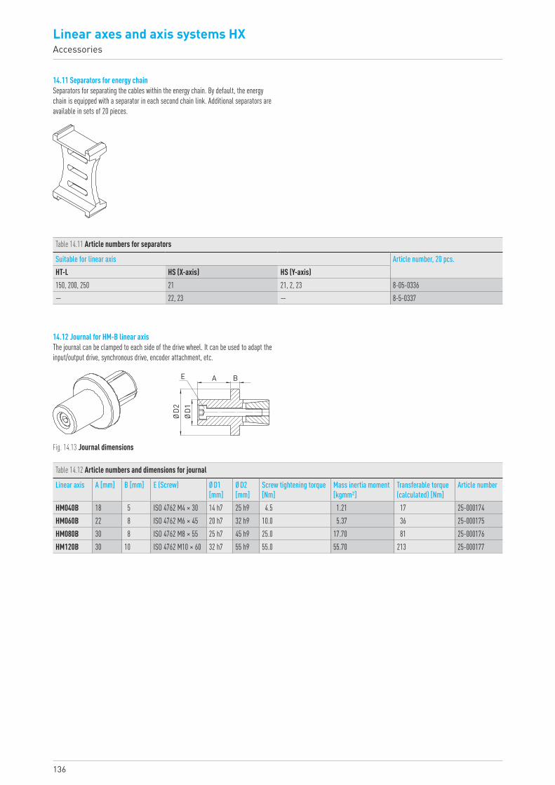
Linear axes and axis systems HXAccessories
136
Fig. 14.13 Journal dimensions
Table 14.11 Article numbers for separators
Suitable for linear axis Article number, 20 pcs.HT-L HS (X-axis) HS (Y-axis)150, 200, 250 21 21, 2, 23 8-05-0336— 22, 23 — 8-5-0337
Table 14.12 Article numbers and dimensions for journal
Linear axis A [mm] B [mm] E (Screw) Ø D1 [mm]
Ø D2 [mm]
Screw tightening torque [Nm]
Mass inertia moment [kgmm²]
Transferable torque (calculated) [Nm]
Article number
HM040B 18 5 ISO 4762 M4 × 30 14 h7 25 h9 4.5 1.21 17 25-000174HM060B 22 8 ISO 4762 M6 × 45 20 h7 32 h9 10.0 5.37 36 25-000175HM080B 30 8 ISO 4762 M8 × 55 25 h7 45 h9 25.0 17.70 81 25-000176HM120B 30 10 ISO 4762 M10 × 60 32 h7 55 h9 55.0 55.70 213 25-000177
14.11 Separators for energy chainSeparators for separating the cables within the energy chain. By default, the energy chain is equipped with a separator in each second chain link. Additional separators are available in sets of 20 pieces.
14.12 Journal for HM-B linear axisThe journal can be clamped to each side of the drive wheel. It can be used to adapt the input/output drive, synchronous drive, encoder attachment, etc.
AE
ØD1
ØD2
B
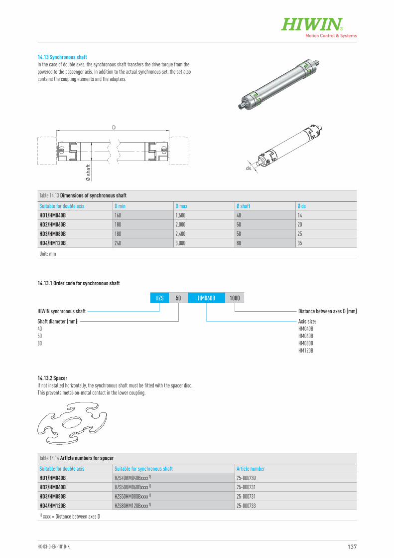
137HX-03-0-EN-1810-K
14.13 Synchronous shaftIn the case of double axes, the synchronous shaft transfers the drive torque from the powered to the passenger axis. In addition to the actual synchronous set, the set also contains the coupling elements and the adapters.
14.13.1 Order code for synchronous shaft
14.13.2 Spacer
Ø sh
aft
D
ds
Table 14.13 Dimensions of synchronous shaft
Suitable for double axis D min D max Ø shaft Ø dsHD1/HM040B 160 1,500 40 14HD2/HM060B 180 2,000 50 20HD3/HM080B 180 2,400 50 25HD4/HM120B 240 3,000 80 35
Unit: mm
Table 14.14 Article numbers for spacer
Suitable for double axis Suitable for synchronous shaft Article numberHD1/HM040B HZS40HM040Bxxxx 1) 25-000730HD2/HM060B HZS50HM060Bxxxx 1) 25-000731HD3/HM080B HZS50HM080Bxxxx 1) 25-000731HD4/HM120B HZS80HM120Bxxxx 1) 25-0007331) xxxx = Distance between axes D
HIWIN synchronous shaft
Shaft diameter [mm]:405080
Axis size:HM040BHM060BHM080BHM120B
Distance between axes D [mm]
HZS 50 HM060B 1000
If not installed horizontally, the synchronous shaft must be fitted with the spacer disc. This prevents metal-on-metal contact in the lower coupling.
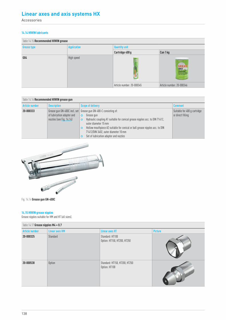
Linear axes and axis systems HXAccessories
138
14.14 HIWIN lubricants
Table 14.15 Recommended HIWIN grease
Grease type Application Quantity unitCartridge 400 g Can 1 kg
G04 High speed
Article number: 20-000345 Article number: 20-000346
Table 14.16 Recommended HIWIN grease gun
Article number Description Scope of delivery Comment20-000333 Grease gun GN-400C incl. set
of lubrication adapter and nozzles (see Fig. 14.14)
Grease gun GN-400-C consisting of: Grease gun Hydraulic coupling A1 suitable for conical grease nipples acc. to DIN 71412,
outer diameter 15 mm Hollow mouthpiece A2 suitable for conical or ball grease nipples acc. to DIN
71412/DIN 3402, outer diameter 10 mm Set of lubrication adapter and nozzles
Suitable for 400 g cartridge or direct filling
Table 14.17 Grease nipples M4 × 0.7
Article number Linear axes HM Linear axes HT Picture20-000325 Standard Standard: HT100
Option: HT150, HT200, HT250
20-000538 Option Standard: HT150, HT200, HT250Option: HT100
Fig. 14.14 Grease gun GN-400C
14.15 HIWIN grease nipplesGrease nipples suitable for HM and HT (all sizes).

Linear Actuators
Linear Motor Components
Linear Axes
Ballscrews Linear Motor Systems
Rotary Tables
Robots
Linear Guideways
Drives & Servo Motors
GermanyHIWIN GmbHBrücklesbünd 2D-77654 OffenburgPhone +49 (0) 7 81 9 32 78 - 0Fax +49 (0) 7 81 9 32 78 - [email protected]
TaiwanHeadquartersHIWIN Technologies Corp.No. 7, Jingke Road Taichung Precision Machinery ParkTaichung 40852, TaiwanPhone +886-4-2359-4510Fax [email protected]
TaiwanHeadquartersHIWIN Mikrosystem Corp.No. 6, Jingke Central Road Taichung Precision Machinery ParkTaichung 40852, TaiwanPhone +886-4-2355-0110Fax [email protected]
ItalyHIWIN SrlVia Pitagora 4I-20861 Brugherio (MB)Phone +39 039 287 61 68Fax +39 039 287 43 [email protected]
PolandHIWIN GmbHul. Puławska 405a PL-02-801 WarszawaPhone +48 22 544 07 07Fax +48 22 544 07 [email protected]
SwitzerlandHIWIN Schweiz GmbHEichwiesstrasse 20CH-8645 JonaPhone +41 (0) 55 225 00 25Fax +41 (0) 55 225 00 [email protected]
SlovakiaHIWIN s.r.o., o.z.z.o.Mládežnicka 2101SK-01701 Považská BystricaPhone +421 424 43 47 77Fax +421 424 26 23 [email protected]
Czech RepublicHIWIN s.r.o.Medkova 888/11CZ-62700 BrnoPhone +42 05 48 528 238Fax +42 05 48 220 [email protected]
France HIWIN [email protected]/fr
NetherlandsHIWIN [email protected]
AustriaHIWIN [email protected]
SloveniaHIWIN [email protected]
HungaryHIWIN [email protected]
ChinaHIWIN Corp.www.hiwin.cn
JapanHIWIN [email protected]
USAHIWIN [email protected]
KoreaHIWIN Corp.www.hiwin.kr
SingaporeHIWIN Corp.www.hiwin.sg
Linear Axes
HX-03-0-EN-1810-K