Embed Size (px)
Citation preview

Using the VitalSource® ebookAccess to the VitalBookTM ebook accompanying this book is via VitalSource® Bookshelf – an ebook reader which allows you to make and share notes and highlights on your ebooks and search across all of the ebooks that you hold on your VitalSource Bookshelf. You can access the ebook online or offline on your smartphone, tablet or PC/Mac and your notes and highlights will automatically stay in sync no matter where you make them.
1. Create a VitalSource Bookshelf account at https://online.vitalsource.com/user/new or log into your existing account if you already have one.
2. Redeem the code provided in the panel below to get online access to the ebook. Log in to Bookshelf and click the Account menu at the top right of the screen. Select Redeem and enter the redemption code shown on the scratch-off panel below in the Code To Redeem box. Press Redeem. Once the code has been redeemed your ebook will download and appear in
your library.
DOWNLOAD AND READ OFFLINE To use your ebook offline, download BookShelf to your PC, Mac, iOS device, Android device or Kindle Fire, and log in to your Bookshelf account to access your ebook:
On your PC/MacGo to http://bookshelf.vitalsource.com/ and follow the instructions to download the free VitalSource Bookshelf app to your PC or Mac and log into your Bookshelf account.
On your iPhone/iPod Touch/iPad Download the free VitalSource Bookshelf App available via the iTunes App Store and log into your Bookshelf account. You can find more information at https://support.vitalsource.com/hc/en-us/categories/200134217-Bookshelf-for-iOS
On your Android™ smartphone or tabletDownload the free VitalSource Bookshelf App available via Google Play and log into your Bookshelf account. You can find more information at https://support.vitalsource.com/hc/en-us/categories/200139976-Bookshelf-for-Android-and-Kindle-Fire
On your Kindle FireDownload the free VitalSource Bookshelf App available from Amazon and log into your Bookshelf account. You can find more information at https://support.vitalsource.com/hc/en-us/categories/200139976-Bookshelf-for-Android-and-Kindle-Fire
N.B. The code in the scratch-off panel can only be used once. When you have created a Bookshelf account and redeemed the code you will be able to access the ebook online or offline on your smartphone, tablet or PC/Mac.
SUPPORTIf you have any questions about downloading Bookshelf, creating your account, or accessing and using your ebook edition, please visit http://support.vitalsource.com/
Accessing the E-book edition of CLARK’S POSITIONING IN RADIOGRAPHY,
THIRTEENTH EDITION

CLARK’SPOSITIONING IN RADIOGRAPHY

This page intentionally left blankThis page intentionally left blank

CLARK’SPOSITIONING IN RADIOGRAPHY
13THEDITION
A. STEWART WHITLEY ■ GAIL JEFFERSON ■ KEN HOLMESCHARLES SLOANE ■ CRAIG ANDERSON ■ GRAHAM HOADLEY
CRC PressTaylor & Francis Group6000 Broken Sound Parkway NW, Suite 300Boca Raton, FL 33487-2742
© 2015 by Taylor & Francis Group, LLCCRC Press is an imprint of Taylor & Francis Group, an Informa business
No claim to original U.S. Government worksVersion Date: 20160203
International Standard Book Number-13: 978-1-4441-6505-0 (eBook - PDF)
This book contains information obtained from authentic and highly regarded sources. While all reasonable efforts have been made to publish reliable data and information, neither the author[s] nor the publisher can accept any legal responsibility or liability for any errors or omissions that may be made. The publishers wish to make clear that any views or opinions expressed in this book by individual editors, authors or contributors are personal to them and do not necessarily reflect the views/opinions of the publishers. The information or guidance contained in this book is intended for use by medical, scientific or health-care professionals and is provided strictly as a supplement to the medical or other professional’s own judgement, their knowledge of the patient’s medical history, relevant manufacturer’s instructions and the appropriate best practice guidelines. Because of the rapid advances in medi-cal science, any information or advice on dosages, procedures or diagnoses should be independently verified. The reader is strongly urged to consult the relevant national drug formulary and the drug companies’ and device or material manufacturers’ printed instructions, and their websites, before administering or utilizing any of the drugs, devices or materials mentioned in this book. This book does not indicate whether a particular treatment is appropriate or suitable for a particular individual. Ultimately it is the sole responsibility of the medical professional to make his or her own professional judgements, so as to advise and treat patients appropriately. The authors and publishers have also attempted to trace the copyright holders of all material reproduced in this publication and apologize to copyright holders if permission to publish in this form has not been obtained. If any copyright material has not been acknowledged please write and let us know so we may rectify in any future reprint.
Except as permitted under U.S. Copyright Law, no part of this book may be reprinted, reproduced, transmitted, or utilized in any form by any electronic, mechanical, or other means, now known or hereafter invented, including photocopying, microfilming, and recording, or in any information storage or retrieval system, without written permission from the publishers.
For permission to photocopy or use material electronically from this work, please access www.copyright.com (http://www.copyright.com/) or contact the Copyright Clearance Center, Inc. (CCC), 222 Rosewood Drive, Danvers, MA 01923, 978-750-8400. CCC is a not-for-profit organization that provides licenses and registration for a variety of users. For organizations that have been granted a photocopy license by the CCC, a separate system of payment has been arranged.
Trademark Notice: Product or corporate names may be trademarks or registered trademarks, and are used only for identification and explanation without intent to infringe.
Visit the Taylor & Francis Web site athttp://www.taylorandfrancis.com
and the CRC Press Web site athttp://www.crcpress.com

v
Dedication
This volume is dedicated to the many student radiographers and radiographers in the field of Diagnostic Medical Imaging whose skills, knowledge and dedication play an important and pivotal role in modern medicine and ensuring that the patient’s journey delivers the best outcomes.
We also wish to acknowledge the professional support and advice of a huge number of colleagues who have given their own time to offer advice and help in the preparation of the 13th edition. This has truly been a team effort.

This page intentionally left blankThis page intentionally left blank
vii
Contents
Foreword ixAuthors and contributors xiPreface xiiiAcknowledgements to the 13th edition xvAcknowledgements to previous editions xviiAbbreviations xix
1 Basic principles of radiography and digital technology 1
2 Upper limb 51
3 Shoulder 95
4 Lower limb 123
5 Hips, pelvis and sacro-iliac joints 169
6 Vertebral column 193
7 Thorax and upper airway 227
8 Skull, facial bones and sinuses 265
9 Dental radiography 311Vivian Rushton
10 Abdomen and pelvic cavity 365
11 Ward radiography 385
12 Theatre radiography 405
13 Paediatric radiography 421J. Valmai Cook, Kaye Shaw and Alaa Witwit
14 Miscellaneous 495
References/further reading 547Index 555

This page intentionally left blankThis page intentionally left blank
ix
Foreword
Radiography remains at the forefront of diagnosis in health-care. Competent practitioners are required to justify and optimise exposures so that diagnostic yield is maximised and examination hazards minimised. There are a number of chal-lenges facing educators of such practitioners including rapid technology developments, changing legal and policy con-texts, increased variety of student types and greater patient reservations around radiation exposures. This text provides a wonderful core text that considers all these challenges, and will continue to be an excellent reference text for qualified personnel.
The approach used by the authors is comprehensive, current and easy to follow. The chapters for the specific body areas are presented extremely logically, each kicking off with a sum-mary of the basic projections, followed by anatomic considera-tions, which in turn is followed by a detailed treatment of the relevant projections. The chapters are superbly complemented by clear and up-to-date line diagrams, photographs and X-ray images, with an easy to follow series of bullet points. The radi-ologic considerations are very useful and references provided are an effective reflective resource.
The preparatory sections in the text are invaluable, covering issues such as terminology, image quality, digital imaging and exposure factors. It was very reassuring to see the emphasis placed on radiation protection, which includes a mature and realistic appraisal of doses delivered, associated risk factors and the latest IRMER regulations. Increasingly patients are expect-ing to be examined by practitioners who can convey in the clear-est way the potential dangers of diagnostic X-ray exposures; this book prepares the students well for these types of encounters.
The text has not shied away from the variety of clinical situations facing radiographers and chapters are dedicated to
dental, theatre and paediatric contexts. In addition Chapter 14, Miscellaneous, addresses an array of important current emerg-ing contexts including bariatrics, tomosynthesis and forensic radiography. The section on trauma radiography is particularly impressive.
It should not be a surprise that this text demonstrates excel-lence. Alfred Stewart Whitley FCR, HDCR, TDCR has been the driving force behind the work as well as being responsible for a number of the sections. His involvement and leadership in radiography over five decades are evident throughout this project and his achievements with, and contributions to, our profession are an inspiration for all of us. It is clear that the revision process has been lengthy with significant contributions from a dedicated team based at the University of Cumbria, and a range of other individuals including Dr. Graham Hoadley and paediatric and dental experts, who have contributed to specific sections. Stewart has steered this team of contributors to this highly successful conclusion.
In summary, this 13th edition of Clark’s Positioning is an excellent text, which I would recommend to all my students and academic and clinical colleagues. It conveys to the reader an immense amount of easy to digest knowledge that is current, relevant and essential to modern day radiographic practice. But it does more. Increasingly as practitioners and academics we must reflect wisely on our long-established techniques and question dogma that is presented historically or by technology producers. This book encourages such reflection and question-ing, and thrusts the radiographer at the centre of the justifica-tion and optimisation processes.
The patient must surely benefit by this publication.
Professor Patrick C. Brennan DCR, HDCR, PhD

This page intentionally left blankThis page intentionally left blank

xi
Authors and contributors
A. Stewart WhitleyRadiology AdvisorUK Radiology Advisory ServicesPreston, Lancashire, UK
Gail JeffersonSenior Lecturer/Advanced PractitionerDepartment of Medical and Sport Sciences, University of CumbriaCarlisle, UK
Ken HolmesRadiography Programme LeaderDepartment of Medical and Sport Sciences, University of CumbriaLancaster, UK
Charles SloanePrincipal LecturerDepartment of Medical and Sport Sciences, University of CumbriaLancaster, UK
Craig AndersonClinical Tutor and Reporting RadiographerX-ray Department, Furness General HospitalCumbria, UK
Graham HoadleyConsultant RadiologistBlackpool, Fylde and Wyre Hospitals NHS TrustBlackpool, Lancashire, UK
J. Valmai CookConsultant RadiologistQueen Mary’s Hospital for Sick Children, Epsom and
St. Helier University NHS Trust Carshalton, UK
Kaye ShahSuperintendent RadiographerQueen Mary’s Hospital for Sick Children, Epsom and
St. Helier University NHS Trust Carshalton, UK
Alaa WitwitConsultant RadiologistQueen Mary’s Hospital for Sick Children, Epsom and
St. Helier University NHS Trust Carshalton, UK
Viv RushtonLecturer in Dental & Maxillofacial RadiologyUniversity Dental Hospital of ManchesterManchester, UK
Andy ShawGroup Leader Medical PhysicistNorth West Medical Physics, Christie HospitalManchester, UK
Alistair MackenzieResearch PhysicistNCCPM, Medical Physics Department, Royal Surrey
County HospitalGuildford, UK
Alexander PeckInformation Systems ManagerRoyal Brompton & Harefield NHS Foundation TrustLondon, UK
Keith HornerProfessorSchool of Dentistry, University of ManchesterManchester, UK
Paul CharnockRadiation Protection AdviserIntegrated Radiological Services (IRS) LtdLiverpool, UK
Ben ThomasTechnical OfficerIntegrated Radiological Services (IRS) LtdLiverpool, UK

This page intentionally left blankThis page intentionally left blank
xiii
Preface
This new edition, with a newly expanded team, continues with the success of the 12th edition in containing the majority of cur-rent plain radiographic imaging techniques in a single volume. Mammography, however, is not included but is to be found in the companion volume Clark’s Procedures in Diagnostic Imaging, where it is included in a separate chapter devoted to all the imaging modalities associated with breast imaging.
This fully revised 13th edition builds on the changes made in the 12th edition, reflecting the changing technology and demands on a modern diagnostic imaging department and the need to provide optimal images consistent with the ALARP principle.
New in Chapter 1 is the emphasis on the ‘patient journey’, with a focus on the needs of the patient and a reflection on the important steps in the process of delivering images of high quality.
Also introduced is the formal process of ‘image evaluation’, which radiographers are frequently engaged in, delivering their comments on acquired images as part of an ‘initial report’ in an agreed structure. Additionally, the student is further guided with the inclusion of a ‘10 Point Plan’ which will aid in ensur-ing excellent diagnostic images are presented for viewing and interpretation.
The important role that ‘imaging informatics’ plays is added to provide a general understanding as to how it is used best, both to maximise image quality and to provide the means to administer, store and communicate images where they are needed.
For the first time recommended diagnostic reference levels (DRLs) are included within the description of a number of radiographic techniques. Those quoted are derived from the recommended references doses published in the UK in the HPA – CRCE – 034 report Doses to patients from radiographic and fluoroscopic X-ray imaging procedures in the UK 2010 Review. For those DRLs not included in the report DRLs are added, which are calculated on a regional basis by means of electronic X-ray examination records courtesy of Integrated Radiological
Services (IRS) Ltd, Liverpool. These DRLs are meant to guide the student and to encourage them to look at the specific DRLs set in their respective health institutions. This in a small way reflects the original ‘Kitty Clark’ publications where guidance on exposure factors was provided. We hope that this will pro-mote the importance of ‘optimisation’ and encourage practi-tioners and students alike to be aware of the appropriate dose for a specific patient-related examination.
The Miscellaneous chapter includes a new section on bari-atric radiography reflecting the challenges in society and the need for careful pre-exposure preparation and patient care. Additionally, the tomography section is expanded to include tomosynthesis, in order to provide a wider understanding as to the capabilities of this digital technique.
Overall the book describes radiographic techniques under-taken using either computed radiography (CR) or direct digital radiography (DDR) equipment, which continues to advance both in terms of capability and detector size and weight. However, there is recognition that screen/film and chemical processing still exists and this is reflected in some of the text.
With respect to the standard template for the general radio-graphic technique, the familiar sub-heading ‘Direction and centring of the X-ray beam’ has been replaced with ‘Direction and location of the X-ray beam’. This slight change is meant to focus on the fact that the beam should be collimated to the area of interest whilst still paying attention to the general guid-ance related to centring points.
The Paediatric chapter has been updated with a number of images included focusing on image evaluation and the Dental chapter updated to include coned beam computed tomography.
This edition contains a number of helpful references com-pared to previous editions with a number of suggestions for further reading.
We hope that these changes will improve the usefulness of the book and its relevance to current radiographic practice, and provide a lasting tribute to the originator, Miss K.C. Clark.

This page intentionally left blankThis page intentionally left blank
xv
Acknowledgements to the 13th edition
We are indebted for the help and advice given by a vast range of colleagues throughout the radiological community with contributions enthusiastically given by radiographers, radiolo-gists, physicists, lecturers from many learning institutions and colleagues in the medical imaging industry and UK govern-ment public bodies. Particular thanks go to Philips Healthcare and Agfa HealthCare for their financial support in sponsoring much of the artwork of the book.
We would particularly like to thank all of our partners and families who patiently endured the long process and the sup-port and from many staff within the School of Medical Imaging Sciences, University of Cumbria and the X-ray Department at Blackpool Victoria Hospital who assisted with many aspects of the book.
Our thanks go to Joshua Holmes who ably undertook the majority of new positioning photographs of the book.
Thanks are also given to the many models who patiently posed for the photographs. These were drawn mainly from radiography students based at the Carlisle, Blackburn and Blackpool Hospital sites. The students include Louise Storr, Clare McFadden, Riad Harrar, Nicole Graham and Laith Hassan. Other models who we also thank include Kevin Ney, Malcolm Yeo, Amanda Spence, Simon Wilsdon and Mark Jackson and others who acted as models in the 12th edition but were not mentioned specifically.
We also would like to acknowledge the support provided by Philips Healthcare, GE Healthcare, Med Imaging UK (Liverpool) and Siemens Healthcare for their assistance in the provision of a number of diagrams, photographs and images, with thanks to Stephanie Holden, Steve Oliver, Catherine Rock and Dawn Stewart.
Thanks also go to the many departments who kindly pro-vided images and photographs and in particular Lesley Stanney, Terry Gadallah, Elaine Scarles and Chris Lund of Blackpool Victoria Hospital, Rosemary Wilson of the Royal Lancaster
Infirmary, Michael MacKenzie of the Pennine Acute Hospitals NHS Trust, Andrea Hulme of the Royal Manchester Childrens Hospital and Bill Bailey, Radiology Management Solutions Ltd, Radiology management solutions, Elite MRI Ltd.
We are particularly indebted for specific and detailed advice and illustrations to the following colleagues: Alistair Mackenzie, Research Physicist, NCCPM, Medical Physics Department, Royal Surrey County Hospital, Guildford; Andy Shaw, Group Leader Medical Physicist, North West Medical Physics, Christie Hospital, Manchester; Alexander Peck, Information Systems Manager, PACS/RIS/Agfa Cardiology, Royal Brompton & Harefield NHSFT, London; Paul Charnock, Radiation Protection Advisor and Ben Thomas, Technical Officer, Integrated Radiological Services (IRS) Ltd, Liverpool, UK; Anant Patel, Barts Health NHS Trust; Adham Nicola and Neil Barron, London North West Hospitals NHS Trust; and Keith Horner, Professor, School of Dentistry, University of Manchester, UK.
Thanks also go to Sue Edyvean, Kathlyn Slack and Sarah Peters from Public Health England for their DRL advice and providing equipment photographs and to Dr Frank Gaillard (Melbourne), founder of Radiopaedia.org, for access to images. Lastly, thanks go to Professor Maryann Hardy for her encour-agement and helpful advice in a number of aspects of radio-graphic technique.
We also acknowledge those contributors for the 12th edition whose help and advice is still used in the 13th edition. These include: Dr Tom Kane, Mrs K. Hughes, Mrs Sue Field, Mrs R. Child, Mrs Sue Chandler, Miss Caroline Blower, Mr Nigel Kidner, Mr Sampath, Dr Vellore Govindarajan Chandrasekar and Sister Kathy Fraser, Blackpool Victoria Hospital; Dr J.R. Drummond, Dental School, University of Dundee; the International Association of Forensic Radiographers; Keith Taylor, University of Cumbria, Lancaster; and Elizabeth M. Carver (née Unett) and Barry Carver, University of Wales, Bangor.

This page intentionally left blankThis page intentionally left blank
xvii
Acknowledgements to previous editions
Miss K.C. Clark was Principal of the ILFORD Department of Radiography and Medical Photography at Tavistock House, from 1935 to 1958. She had an intense interest in the teach-ing and development of radiographic positioning and proce-dure, which resulted in an invitation by Ilford Ltd to produce Positioning in Radiography.
Her enthusiasm in all matters pertaining to this subject was infectious. Ably assisted by her colleagues, she was responsible for many innovations in radiography, playing a notable part in the development of mass miniature radiography. Her ability and ever active endeavor to cement teamwork between radi-ologist and radiographer gained worldwide respect.
At the conclusion of her term of office as President of the Society of Radiographers in 1936 she was elected to Honorary Fellowship. In 1959 she was elected to Honorary Membership of the Faculty of Radiologists and Honorary Fellowship of the Australasian Institute of Radiography.
Miss Clark died in 1968 and the Kathleen Clark Memorial Library was established by the Society of Radiographers. Today the library can be accessed by request at the Society and College of Radiographers.
The ninth edition was published in two volumes, edited and revised by James McInnes FSR, TE, FRPS, whose involve-ment with Positioning in Radiography began in 1946 when he joined Miss Clark’s team at Tavistock House. He originated many techniques in radiography and in 1958 became Principal of Lecture and Technical Services at Tavistock House, which
enabled him to travel as lecturer to the Radiographic Societies of Britain, Canada, America, South and West Africa.
The 10th edition, also published in two volumes, was revised and edited by Louis Kreel MD, FRCP, FRCR, a radiologist of international repute and wide experience of new imaging tech-nologies.
The 11th edition, totally devoted to plain radiographic imag-ing, was edited by Alan Swallow FCR, TE and Eric Naylor FCR, TE and assisted by Dr E J Roebuck MB, BS, DMRD, FRCR and Stewart Whitley FCR, TDCR. Eric and Alan were both principals of Schools of Radiography and well respected in the radiography world and champions in developing and extending radiography education to a wide radiographer and radiological community.
The 12th edition again totally devoted to plain radiographic imaging was edited by A. Stewart Whitley, FCR, TDCR, Charles Sloane MSC DCR DRI Cert CI, Graham Hoadley BSc (Hons), MB BS, FRCR, Adrian D. Moore MA, FCR,TDCR and Chrissie W. Alsop DCR. This successful team, represent-ing both clinical and academic environments, was responsible for updating the text during the transition to digital radiogra-phy and adding a number of new features to the book.
We are indebted to these editors and the many radiogra-phers and radiologists who contributed to previous editions for providing us with the foundations of the current edition and we hope that we have not failed to maintain their high standards.

This page intentionally left blankThis page intentionally left blank
xix
Abbreviations
A&E accident and emergencyACJ acromio-clavicular jointAEC automatic exposure controlALARP as low as reasonably practicableAP antero-posteriorASIS anterior superior iliac spineATLS Advanced Trauma and Life SupportBSS Basic Safety StandardsCBCT cone beam computed tomographyCCD charge-coupled deviceCCU Coronary care unitCDH congenital dislocation of the hipCEC Commission of European CommunitiesCHD congenital hip dysplasiaCID charge-injection deviceCMOS complementary metal oxide semiconductorCPD continued professional developmentCR computed radiographyCSF cerebrospinal fluidCSU Cardiac surgery unitCT computed tomographyCTU computed tomography urographyCTR cardio-thoracic ratioCXR chest X-rayDAP dose–area productDCS dynamic condylar screwDDH developmental dysplasia of the hipDDR direct digital radiographyDHS dynamic hip screwDICOM digital imaging and communications in medicineDNA deoxyribonucleic acidDP dorsi-palmar/dorsi-plantarDPO dorsi-plantar obliqueDPT dental panoramic tomographyDQE detection quantum efficiencyDRL diagnostic reference levelDTS digital tomosynthesisECG electrocardiogramEI exposure indicatorEAM external auditory meatus EPR electronic patient recordESD entrance skin/surface doseETT endotracheal tubeFB foreign bodyFFD focus-to-film distanceFO fronto-occipitalFOD focus-to-object distanceFoV field-of-viewFRD focus-to-receptor distanceFSD focus-to-skin distanceII image intensifier
IRMER Ionising Radiation (Medical Exposure) Regulations
GCS Glasgow Coma ScaleGIT gastrointestinal tractGP general practitionerHB horizontal beamHDU High-dependency unitHIS hospital information systemHPA Health Protection AgencyHSE Health and Safety ExecutiveHTTP hypertext transfer protocolIAEA International Atomic Energy AgencyICRP International Commission on Radiological
ProtectionIRMER Ionising Radiation (Medical Exposure)
RegulationsITU Intensive treatment unitIV intravenousIVU intravenous urogram/urographyKUB kidneys–ureters–bladderLAO left anterior obliqueLBD light beam diaphragmLDR local diagnostic reference levelLMP last menstrual periodLPO left posterior obliqueLUL left upper lobeLUT look-up tableMC metacarpalMCPJ metacarpo-phalangeal jointMO mento-occipitalMPE medical physics expertMPR multiplanar reformatting/reconstructionMRCP magnetic resonance cholangiopancreatographyMRI magnetic resonance imagingMRSA methicillin resistant Staphylococcus aureusMSCT multislice computed tomographyMT metatarsalMTF modulation transfer functionMTPJ metatarso-phalangeal jointMUA manipulation under anaestheticNAI non-accidental injuryNGT naso-gastric tubeNICE National Institute for Health and Care
ExcellenceNM nuclear medicineNNU Neonatal unitNRPB National Radiological Protection BoardOA osteoarthritisOF occipto-frontalOFD object-to-focus distance/object-to-film distanceOM occipito-mental

xx
OPG orthopantomographyORD object-to-receptor distanceORIF open reduction and internal fixationPA postero-anteriorPACS picture archiving and communication systemPAS patient administration systemPCNL percutaneous nephrolithotomyPET positron emission tomographyPNS post-nasal spacePPE personal protective equipmentPPR photostimulable phosphor radiographyPSL photostimulable luminescencePSP photostimulable phosphorQA quality assuranceRBL radiographic baselineRIS Radiology information systemRML right middle lobeRPA Radiation Protection AdvisorRPS Radiation Protection SupervisorSCIWORA spinal cord injury without radiological
bony injury
SCBU Special care baby unitSD standard deviationSIDS sudden infant death syndromeSMV submento-verticalSOD source-to-object distanceSP storage phosphorSPR storage phosphor radiographySS solid stateSUFE slipped upper femoral epiphysisSXR skull X-rayTB tuberculosisTFT thin-film transistorTLD thermoluminescent dosimeterTMJ temporo-mandibular jointTOD table-to-object distanceUAC umbilical arterial catheterUS ultrasoundUVC umbilical venous catheterVNA vendor neutral archiveWHO World Health OrganizationXDS-I cross enterprise document sharing for imaging
1
Basic Principles of Radiography and Digital Technology
Section 1
CONTENTS
TERMINOLOGY 2Introduction 2Image evaluation – 10-point plan 8Anatomical terminology 13Positioning terminology 13Projection terminology 17
THE RADIOGRAPHIC IMAGE 22Image formation and density 22Contrast 23Magnification and distortion 25Image sharpness 26Image acquisition and display 28
DIGITAL IMAGING 29Image acquisition 29Factors affecting image quality 31Imaging informatics 32Image processing 36
EXPOSURE FACTORS 39Introduction 39Milliampere seconds 40Kilovoltage 40Focus-to-receptor distance 41Intensifying screens 41Digital imaging 41Secondary radiation grids 42Choice of exposure factors 42
SUMMARY OF FACTORS CONTRIBUTING TO OPTIMUM RADIOGRAPHIC IMAGE QUALITY 43
RADIATION PROTECTION 44Medical exposure 44Occupational exposure 49

2
1 Terminology
Introduction
The patient journeySuccessful radiography is dependent on many factors but uppermost is the patient’s experience during their short jour-ney and encounter with the Diagnostic Imaging Department (see Fig. 1.3). The radiographer has a duty of care to the patient and must treat them with respect and ensure their dignity is maintained. It is essential that the radiographer establishes a rapport with the patient and carers. The radi-ographer must introduce themselves to the patient/carer and inform them of their role in the examination. They must make sure the request form is for the patient being exam-ined and that the clinical details and history are accurate. The radiographer must request consent from the patient and the patient must give consent for the examination before the radiographer starts the examination.
The flow chart demonstrating a systematic way of undertak-ing an X-ray examination is on page 7. The purpose of the flow chart is to ensure that the patient journey is patient focussed and mistakes are eliminated. The key aspects are:
• Effective communication with patients and carers.
• The ability to follow a logical framework in order to be able to perform the X-ray examination proficiently and effectively.
• Efficient use of technology to produce diagnostic images at the first attempt.
• Evaluation of the radiographic image using the 10-point plan.
Whilst there are several ‘main headings’ to the algorithm it is essential to emphasise that the primary focus is the patient and their interaction within the process. Effective communi-cations encompasses a myriad of interactions, which include being ‘open and friendly’ to the patient, telling them who you are, what you are intending to do, gaining consent and also inviting and answering any questions they may have about the examination.
Stages of an X-ray examination
There are 3 stages to undertaking an X-ray examination, prep-aration, the radiographic procedure itself and follow up from the examination undertaken. Each of these stages can be fur-ther subdivided as shown below:
Preparation for the examination:
• The request form.
• The X-ray room.
• The patient, including consent for the examination and identity checks.
Undertaking the examination:
• Patient care.
• Radiographic procedure.
• Radiation protection.
Post-examination and aftercare:
• Image quality.
• Patient aspects.
• Imaging informatics.
Preparation for the examination
The request form
• Ensure the examination requested is authorised and signed with a suitable rationale.
•Make sure the examination is justified using the IR(ME)R 2000 regulations1 and the request card has a justifiable clini-cal reason for the X-ray, e.g. history of injury and pain in the metacarpal region ?fractured foot.
•Any examination using X-rays must affect the management of the patient.
•Check the protocol for the examination.
•Make sure you know which projections are required, e.g. DP and oblique foot.
Preparation of the X-ray room
•Make sure the X-ray room is clean, safe and tidy, ensure that the floor is clear and the X-ray tube is not in a position where the patient can walk into it.
• Set a preliminary exposure for the examination, i.e. X-ray tube focus size, mAs and kV.
•Have any accessory equipment available, e.g. foam pads and lead-rubber.
Preparation of the patient
•Correctly note the details on the request form ready for checking with the patient:
• Patient’s full name, date of birth and address.
•Correct examination requested and reason for the X-ray.
• Is the patient fit and ambulant or have any physical needs?
•Mode of transport.
If applicable ensure the patient is undressed and dress them in a radiolucent gown.
The patient is asked:
• If they have carried out any required preparation for the examination.
• If they understand the nature of the examination and if they have any questions prior to proceeding.
• For verbal permission to proceed with the examination.
• For written consent if an examination incurs a higher risk, e.g. angiography.

3
1TerminologyTo be able to give consent (adult or child) the patient should
meet the following criteria. They should:
•Understand the risk versus benefit.
•Understand the nature of the examination and why it is being performed.
•Understand the consequences of not having the examination.
• Be able to make and communicate an informed decision.
If these conditions are not satisfied then other individuals may be able to give consent, e.g. parents, or in an emergency situation the examination may proceed if it is considered in the best interest of the patient (see hospital policy). Page 7 has a full page timeline.
Undertaking the examination
Patient careAt the commencement of the examination introduce your-self to the patient and ask permission to take the X-ray. If the patient has been prepared for the examination, check they have followed the instructions, e.g. undressed appropriately and in a gown, nil by mouth or any other preparation. Make a positive identity check on the patient using the details on the request form and ensure that the correct examination is indicated along with the rationale for the X-ray examination.
•Check the pregnancy status of the patient.
•Check for the patient’s infection status, i.e. MRSA or other transferable diseases, to prevent cross infection by appropri-ate methods.
•Visibly clean hands in front of the patient before you start the procedure.
• Patient identity. Once again the patients’ identity is estab-lished using the departmental protocol, which normally asks the patient to state their full name, address and date of birth. These are then cross referenced with the request form. The examination must not proceed unless the radiog-rapher is sure of the identity of the patient.
The procedure is explained to the patient in easy to under-stand terms.
Radiographic procedureIt is important that the department protocols are followed for the examination and that the equipment is used safely and pro-ficiently. The preliminary exposure should be set on control panel (make sure the exposure factors are optimised for the patient body type).
As part of the procedure ensure:
• The patient is positioned accurately in relation to the exami-nation being undertaken.
• The X-ray tube is positioned and centred to the patient and image receptor.
• The beam is collimated to the area of interest.
•Appropriate radiation protection is carried out.
•An anatomical marker is correctly applied to the image receptor.
• Instructions are effectively communicated to the patient.
• Radiographers and other staff/carers stand behind the lead glass protective control screen and exposure undertaken after the exposure factors confirmed on control panel.
• Image acquisition is correct first time.
• The patient waits whilst the image is checked.
• The image is assessed for diagnostic quality.
• You wash your hands or clean them with alcohol gel in sight of the patient.
• You consider using pads and sandbags to immobilise the patient when necessary. Distraction techniques may also be of value with paediatric patients.
Introduction (cont.)
4
1 Terminology
Introduction (cont.)
Radiation protectionPatient protection
Radiation protection and patient dose matters are discussed in depth at the end of this chapter. The following section sum-marises some of the important aspects of the examination, which includes before and during the procedure both in terms of the patient, staff and carers with consideration to relevant legislation.
On reviewing a request for an X-ray examination, the radi-ographer needs to consider carefully if the request for the examination is appropriate and has sufficient information to undertake it. In other words – is the examination justified? The radiographer should consider several questions when assessing any request for imaging:
Will the examination change the clinical management of the patient?
•While this can be a contentious area, the radiographer should consider if the requested examination will be of benefit to the patient and if the findings will affect the treatment or management of the patient. If the examination is not going to change the management of the patient the radiographer should seek further information from the referrer until they are satisfied the request is justified.
• The Radiographer has a duty of care to have a further dis-cussion with the referrer. This must establish if the exami-nation is justified or not under the radiation regulations and protocols of the department.
Does the completed request comply with local protocols? For example, is the request card completed in a legible man-ner? Are the requested projections in line with the departmen-tal protocol?
What are the risks/ benefits of the examination?Even low X-ray doses can cause changes to cell DNA, lead-ing to increased probability of cancer occurring in the years following the exposure. While in many cases the probability of this occurring is low, this risk should always be balanced against the benefits of the patient undergoing the examination. This is often acutely emphasised when a seriously ill patient or a young patient undergoes frequent X-ray examinations and the need to consider carefully each request is very important. Consultation with radiological colleagues is often required if there is any doubt over the legitimacy of any request.
Does the request comply with government legislation? Legislation varies between countries; however, the request should comply with national legislation where applicable.
In the UK the underlying legislation is known as the Ionising Radiation (Medical Exposure) Regulations (IRMER) 2000.1 This legislation is designed to protect patients by keeping doses ‘as low as reasonably practicable’ (ALARP). The regulations set out responsibilities:
• Those that refer patients for an examination (Referrers).
• Those that justify the exposure to take place (Practitioners).
• Those that undertake the exposure (Operators).
Radiographers frequently act as practitioners and operators and as such must be aware of the legislation along with the risks and benefits of the examination to be able to justify it.
Is there an alternative imaging modality?The use of an alternative imaging modality that may provide more relevant information or the information required at a lower dose should be considered. The use of non-ionising imaging modalities, such as ultrasound and MRI should also be considered where appropriate.
Optimisation of radiographic exposureThe radiographer has a duty of care to ensure that the exposure delivered to the patient conforms to the departmental optimi-sation policy. This ensures that that the ALARP principle has been applied.2
Optimisation will involve consideration of a number of fac-tors associated with image acquisition including:
• Exposure factors applied.
• Image detector system used.
• Patient compliance.
•Collimation and field size.
Diagnostic reference levelsStatutory dose limits do not apply to individual medical expo-sures. However, IRMER requires employers to establish diag-nostic reference levels (DRLs) for their standard diagnostic and interventional procedures in order to assess whether these exposures are optimised. These local DRLs are based on the typical doses received by average sized patients when they undergo common procedures. DRLs have been established as a critical method in determining if a patient has been over irradi-ated. Contemporary practice will involve imaging departments publishing a list of DRLs for all common X-ray examinations. Patient dose must be recorded for all examinations. This will be given in different formats such as:
•Dose (kerma) area product (DAP) – Gy cm2.
• Entrance surface (skin) dose (ESD) – mGy.
• Exposure factors/examination room.
• Fluoroscopy times.
This will be explained fully in the radiation protection section at the end of this chapter, but it is important that the radiographer ensures that the local DRL has not been exceeded.

5
1 TerminologyPregnancy
Avoiding exposure in pregnancyAll imaging departments should have written procedures for managing the small but significant radiation risk to the foetus (Fig. 1.1). Radiographers should refer to their departmental working procedures and apply them as part of their everyday working practice. The chart opposite has been constructed using joint guidance from the Health Protection Agency, the College of Radiographers and the Royal College of Radiologists (2009). Most departmental procedures will follow a similar procedure although practices may vary between departments according to specific circumstances. The procedure for pregnancy is usu-ally applied to examinations that involve the primary beam exposing the pelvic area. Examinations of other areas can be undertaken as long as the radiographer ensures good beam col-limation and employs the use of lead protection for the pelvis.
Evaluating and minimising the radiation risks in pregnancyIf a decision is made to irradiate a woman who is pregnant it will be in conjunction with the referring clinician who will have decided that there are overriding clinical reasons for the examination to take place. In such cases the relatively small radiation risk to the patient/foetus will be outweighed by the benefit of the diagnosis and subsequent treatment of poten-tially life-threatening or serious conditions. These could pre-sent a much greater risk to both parties if left undiagnosed.
To minimise the risks when examining pregnant women the radiographer should adopt the following strategies:
•Use of the highest imaging speed system available, e.g. 800 speed or equivalent settings for CR/DDR.
• Limit collimation to area of interest.
•Use of shielding (can the uterus be shielded without signifi-cant loss of diagnostic information?).
•Use of the minimum number of exposures to establish a diag-nosis.
•Use of projections that give the lowest doses.
•Use pregnancy tests if doubt exists.
Staff and other personnel protection
Radiography is undertaken in conformance with relevant radi-ation legislation. This will be discussed in detail and the end of the section. The following section summarises some of the important protection aspects:
•Adherence to the local Radiation Rules.
•Monitoring of staff radiation doses.
• Staff doses conform with the ALARP principle. Adherence with the use of a controlled area both for static, mobile radi-ography and fluoroscopy.
•Collimation and limitation of X-ray beam.
•Use of personal protective equipment (PPE) when appro-priate.
• Safe use of X-ray equipment.
Introduction (cont.)
Record LMP. Proceed withexamination providing LMPwas within previous 28 days*
A typical ‘pregnancy rule’ for women of child-bearing age. *Somewomen have menstrual cycles of more or less than 28 days or haveirregular cycles. CT, computed tomography; LMP, last menstrual period.
Ask patient 'Are you or might you be pregnant?'
For low-doseprocedures, e.g.plain radiographyof abdomen, spineor extremities
Patient hasmissed aperiod/theirperiod overdue,i.e. more than28 days ago*
Review justificationfor examinationwith referringclinician†
If overridingclinical reasons forexamination exist,then proceed usingdose reductionstrategies
Patient has notmissed a period,i.e. period lessthan 28 daysago*
Re-bookexaminationwithin first 10days of onset ofmenstrual cycle
For high-doseprocedures, e.g.CT of abdomen orpelvis, bariumenema
Record LMP.Proceed withexaminationprovidingLMP was withinprevious 28 days*
If patient subsequentlyis found to be pregnantthen review justificationfor procedure withreferring clinician
Answer: Yes Answer: Unsure† Answer: No, not pregnant
Fig. 1.1 Typical flow chart for ‘pregnancy rule’.
6
1 Terminology
Introduction (cont.)
Post-examination and aftercareImmediately following image acquisition the image will be reviewed to ensure it is of diagnostic quality; the patient will be managed and be given instructions as to what to do next and the examination will be completed in terms of the imaging information of the X-ray procedure.
Image qualityThe image is reviewed using the ‘10-point plan’:
1. Patient identification.
2. Area of interest is included.
3. Markers and legends.
4. Correct projection.
5. Correct exposure indicator (EI) – optimum EI and within acceptable range. Limited/no noise.
6. Optimum definition – can you see the detail of the relevant anatomy/structures, i.e. is it sharp?
7. Collimation is restricted to the area of interest.
8. Are there any artefacts and are they obscuring anatomy?
9. Any need for repeat radiographs or further projections.
10. Anatomical variations and pathological appearances.
Patient aspectsAt this important stage of the procedure the Radiographer has a duty of care to ensure the patient is given and under-stands instructions. They need to know what to expect next in regard to the report from the examination, who will receive the report and how long this process will take. There will be local protocols to ensure the process is robust and the patient is managed effectively, e.g.:
•Go back to clinic immediately.
• The report will be posted to your GP within a certain time-frame.
•Arrange transport via porters/ambulance or ensure the patient has transport home.
• It is important that the patient takes all their belongings and valuables home with them.
• The radiographer should answer any questions the patient or carers may have on the examination /process within their scope of practice.
Imaging informatics
• It is important that the acquired images are viewed care-fully using optimised conditions, e.g. ambient light condi-tions and the monitor is correctly adjusted. This may mean manipulating the image on the workstation monitor to dem-onstrate different areas of the image (Fig. 1.2).
• For extremity and axial radiography ensure an acquired image of a body part is displayed on a single monitor in order to ensure optimum display (i.e. only one image per monitor).
•Department/manufacturers’ recommendations regarding any specific algorithms associated with a body part must be followed.
•Any further post processing must be carefully considered before the images are sent to picture archiving and commu-nication system (PACS).
•Check the EI is of an optimum value to evaluate expo-sure to the patient and there is minimal /no noise on the image.
• The images are sent to PACS so the referring clinician can view the image and the image can be reported by the report-ing radiographer or radiologist.
• The examination is completed on the Radiology informa-tion system (RIS), making sure the image is in the correct patient folder and the documentation regarding exposure details/dose reading and number of images taken is com-pleted.
• The radiographer who is acting as the practitioner and oper-ator must be identified on the RIS system.
Fig. 1.2 Students and tutor at the monitor.
7
1 Terminology
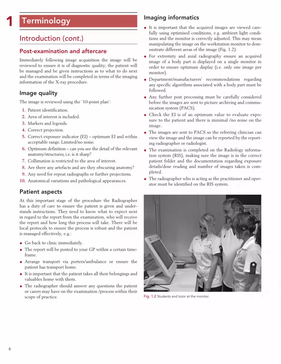
Fig. 1.3 Flow chart of the patient journey.
Examination timeline
Preparation
• Review the request• Justification and authorisation of examination using appropriate legislation• Check previous studies• Review departmental protocols and decide if any modfications are needed• Consider infection risk• Consider specific radiation protection requirements
• Ensure the correct procedure is carried out for the patient• Use a precise technique• Consider immobilisation or distraction techniques• Follow deparment protocols• Quick safe and efficient• Get it right first time• Wash hands following the procedure
• Follow local rules• Correct protocol• Only essentials people in the room• Optimum exposure for the examination• Consider using an AEC• Correct collimation to the area of interest• Lead protection where appropriate
ImageinformaticsPatient
ImagequalityAftercare
• Visibly clean your hands• Communicate effectively• Be friendly and smile• Give clear instructions• Explain what you are doing• Explain why you are doing it• Ensure patient is positioned comfortably• Invite and answer any questions
TEN POINT PLAN• Identification parameters• Area of interest included• Markers and legends• Correct projection• Correct exposure• Optimum definition• Collimation to area of interest• Artifacts obscuring image• Need for repeat radiographs or further projections (Are the images what you would expect for the examination undertaken)• Anatomical variations and pathological appearances
• Wash hands following the procedure• Communicate effectively• Explain what they need to do next• Invite and answer any questions within your role• Arrange patient transfer if necessary
• Request card completed• Radiographer comment/initial report• Consider contacting referrer if major pathology or red flag• Check images are in the correct folder• Images and data (e.g. dose) sent to PACS local archives IMMEDIATELY for reporting
Examination Patient careRadiographic
procedureRadiationprotection
• Room safe and tidy• Equipment set up for the study and preliminary exposure set• X-ray tube set for correct procedure• Collect CR image receptors• Accessory equipment available• Consider any contrandications and confounding factors
• Communicate effectively• Introduce yourself• Identify the patient using local protocol• Check pregenancy status• Explain procedure and gain consent• Are there any special needs for the patient (Physical or psychological)• Prepare patient if necessary e.g. appropriate clothing and remove any potential artifacts
Requestedprocedure X-ray room Patient

8
1 Terminology
Image evaluation – 10-point planIt is imperative that radiographic images are properly evalu-ated to ensure that they are fit for purpose, i.e. they must answer the diagnostic question posed by the clinician making the request. In order to do this effectively the person undertak-ing the evaluation must be aware of the radiographic appear-ances of potential pathologies and the relevant anatomy that needs to be demonstrated by a particular projection. Points to consider when evaluating the suitability of radiographic images include:
1. Patient identification: do the details on the image match those on the request card and those of the patient who was examined? Such details will include patient name and demographics, accession number, date of examination and the name of the hospital.
2. Area of interest: does the radiograph include all the relevant areas of anatomy? The anatomy that needs to be demon-strated may vary depending on the clinical indications for the examination.
3. Markers and legends: check that the correct anatomical side markers are clearly visible in the radiation field. Ensure the marker that has been used matches the body part on the radiograph and that this in turn matches the initial request from the clinician. Ensure the cor-rect legends have been included if not stated in the examination protocol, e.g. prone/supine. It is poor prac-tice not to include a marker within the radiation field when making an exposure.3
4. Correct projections: does the acquired image follow standard radiographic technique as outlined throughout the book, with the patient being correctly positioned together with the appropriate tube angulation?
It is important to consider the pathology in question and the clinical presentation of the patient. If debating whether a projection is acceptable always consider if the ‘diagnostic question’ has been answered.
5. Correct exposure: the evaluation of the suitability of the exposure factors used for a radiograph will depend on the equipment and medium used to acquire and cap-ture the image.
Conventional screen/film-based imaging
• Image density: the degree of image blackening should allow relevant anatomy to be sufficiently demonstrated, thus allowing diagnosis.
• Image contrast: the range of useful densities produced on the radiographic image should correspond to the structures within the area of interest. Each anatomical area should be of sufficient contrast to allow relevant anatomical structures to be clearly visualised.
Digital image acquisition systemsGiven the wide exposure latitude of digital systems, the primary task when evaluating the image is to assess for over- or underexposure. The imaging equipment will usually give a numerical indication of the exposure used, the EI. The reading is compared with a range of exposure limits provided by the manufacturer to see if it is above or below recommended values. Unfortunately, the method used is not standardised by the different manufacturers.
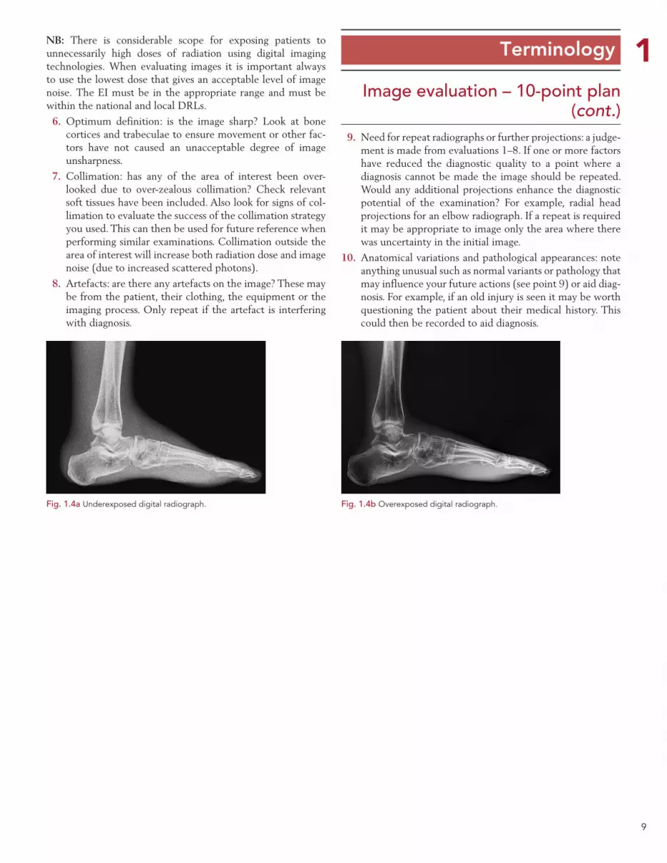
Underexposure: images that are underexposed will show unacceptable levels of ‘noise’ or ‘mottle’ even though the computer screen brightness (image density) will be acceptable (Fig. 1.4a).
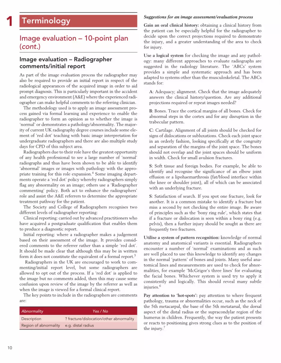
Overexposure: image quality will actually improve as exposure increases due to lower levels of noise. However, once a certain point is reached, further increases in exposure will result in reduced contrast. Eventually a point is reached when the image contrast becomes unacceptable (Fig. 1.4b).
9
1 Terminology
Image evaluation – 10-point plan (cont.)
NB: There is considerable scope for exposing patients to unnecessarily high doses of radiation using digital imaging technologies. When evaluating images it is important always to use the lowest dose that gives an acceptable level of image noise. The EI must be in the appropriate range and must be within the national and local DRLs.
6. Optimum definition: is the image sharp? Look at bone cortices and trabeculae to ensure movement or other fac-tors have not caused an unacceptable degree of image unsharpness.
7. Collimation: has any of the area of interest been over-looked due to over-zealous collimation? Check relevant soft tissues have been included. Also look for signs of col-limation to evaluate the success of the collimation strategy you used. This can then be used for future reference when performing similar examinations. Collimation outside the area of interest will increase both radiation dose and image noise (due to increased scattered photons).
8. Artefacts: are there any artefacts on the image? These may be from the patient, their clothing, the equipment or the imaging process. Only repeat if the artefact is interfering with diagnosis.
9. Need for repeat radiographs or further projections: a judge-ment is made from evaluations 1–8. If one or more factors have reduced the diagnostic quality to a point where a diagnosis cannot be made the image should be repeated. Would any additional projections enhance the diagnostic potential of the examination? For example, radial head projections for an elbow radiograph. If a repeat is required it may be appropriate to image only the area where there was uncertainty in the initial image.
10. Anatomical variations and pathological appearances: note anything unusual such as normal variants or pathology that may influence your future actions (see point 9) or aid diag-nosis. For example, if an old injury is seen it may be worth questioning the patient about their medical history. This could then be recorded to aid diagnosis.
Fig. 1.4a Underexposed digital radiograph. Fig. 1.4b Overexposed digital radiograph.
10
1 Terminology
Image evaluation – 10-point plan (cont.)
Image evaluation – Radiographer comments/initial report As part of the image evaluation process the radiographer may also be required to provide an initial report in respect of the radiological appearances of the acquired image in order to aid prompt diagnosis. This is particularly important in the accident and emergency environment (A&E) where the experienced radi-ographer can make helpful comments to the referring clinician.
The methodology used is to apply an image assessment pro-cess gained via formal learning and experience to enable the radiographer to form an opinion as to whether the image is ‘normal’ or demonstrates a pathology/abnormality. The major-ity of current UK radiography degree courses include some ele-ment of ‘red dot’ teaching with basic image interpretation for undergraduate radiographers and there are also multiple study days for CPD of this subject area.
Radiographers due to their role have the greatest opportunity of any health professional to see a large number of ‘normal’ radiographs and thus have been shown to be able to identify ‘abnormal’ images or images with pathology with the appro-priate training for this role expansion.4 Some imaging depart-ments operate a ‘red dot’ policy whereby radiographers simply flag any abnormality on an image; others use a ‘Radiographer commenting’ policy. Both act to enhance the radiographers’ role and assist the A&E referrers to determine the appropriate treatment pathway for the patient.
The Society and College of Radiographers recognises two different levels of radiographer reporting:
Clinical reporting: carried out by advanced practitioners who have acquired a postgraduate qualification that enables them to produce a diagnostic report.
Initial reporting: where a radiographer makes a judgement based on their assessment of the image. It provides consid-ered comments to the referrer rather than a simple ‘red dot’. It should be made clear that although this may be in written form it does not constitute the equivalent of a formal report.5
Radiographers in the UK are encouraged to work to com-menting/initial report level, but some radiographers are allowed to opt out of the process. If a ‘red dot’ is applied to the image but no comments added, then this may cause some confusion upon review of the image by the referrer as well as when the image is viewed for a formal clinical report.
The key points to include in the radiographers are comments are:
Abnormality Yes / No
Description ? fracture/dislocation/other abnormality
Region of abnormality e.g. distal radius
Suggestions for an image assessment/evaluation process
Gain an oral clinical history: obtaining a clinical history from the patient can be especially helpful for the radiographer to decide upon the correct projections required to demonstrate the injury, and a greater understanding of the area to check for injury.
Use a logical system for checking the image and any pathol-ogy: many different approaches to evaluate radiographs are suggested in the radiology literature. The ‘ABCs’ system provides a simple and systematic approach and has been adapted to systems other than the musculoskeletal. The ABCs stands for:
A: Adequacy; alignment. Check that the image adequately answers the clinical history/question. Are any additional projections required or repeat images needed?
B: Bones. Trace the cortical margins of all bones. Check for abnormal steps in the cortex and for any disruption in the trabecular pattern.
C: Cartilage. Alignment of all joints should be checked for signs of dislocations or subluxations. Check each joint space in an orderly fashion, looking specifically at the congruity and separation of the margins of the joint space. The bones should not overlap and the joint spaces should be uniform in width. Check for small avulsion fractures.
S: Soft tissue and foreign bodies. For example, be able to identify and recognise the significance of an elbow joint effusion or a lipohaemarthrosis (fat/blood interface within the knee or shoulder joint), all of which can be associated with an underlying fracture.
S: Satisfaction of search. If you spot one fracture, look for another. It is a common mistake to identify a fracture but miss a second by not checking the entire image. Be aware of principles such as the ‘bony ring rule’, which states that if a fracture or dislocation is seen within a bony ring (e.g. pelvis), then a further injury should be sought as there are frequently two fractures.
Utilise a system of pattern recognition: knowledge of normal anatomy and anatomical variants is essential. Radiographers encounter a number of ‘normal’ examinations and as such are well placed to use this knowledge to identify any changes in the normal ‘pattern’ of bones and joints. Many useful ana-tomical lines and measurements are used to check for abnor-malities, for example ‘McGrigor’s three lines’ for evaluating the facial bones. Whichever system is used try to apply it consistently and logically. This should reveal many subtle injuries.6
Pay attention to ‘hot-spots’: pay attention to where frequent pathology, trauma or abnormalities occur, such as the neck of the 5th metacarpal, the base of the 5th metatarsal, the dorsal aspect of the distal radius or the supracondylar region of the humerus in children. Frequently, the way the patient presents or reacts to positioning gives strong clues as to the position of the injury.7

11
1 Terminology
Image evaluation – 10-point plan (cont.)
The following examples of how image evaluation is applied are illustrated throughout the book using a standard template that the reader is encouraged to apply, using the basics principles of evaluating an image and providing an initial report.8
In these first examples comments are listed that are helpful in the checking process. In the other examples demonstrated not all correctly identified criteria are listed but only those main points to consider that may require further attention, with the assumption that the absence of comments indicates a satisfactory situation.
Evaluation using the 10-point plan. In this example the patient has been referred for a possible fracture of the right hip.
1. Patient identification. Patient identity has been removed from the image but should include the patient name and another form of identification.
2. Area of interest. The area of interest is included and includes the top of the ilium superiorly, the lateral margins of the pelvic ring and proximal femora.
3. Markers and legends. The Left marker is applied to the left side of the patient.
4. Correct projection. The pelvis is not positioned correctly as the hips are not at the same anatomical level; however, the pelvis is not rotated and the pelvic ring is symmetrical. The right hip is not internally rotated so the femoral neck is foreshortened.
5. Image exposure. The EI is not indicated on the image; however, there is no noise in the image as the bony tra-beculae can be clearly demonstrated.
6. Optimum definition. There is no blurring of the image and the structures appear to be well defined.
7. Collimation. The X-ray beam is collimated to the area of interest.
8. Artefacts. There are no artefacts obscuring the anatomy.
9. Need for repeat radiographs or further projections. Additional images are required. It is not possible to evaluate any frac-ture of the right hip without the hip being internally rotated. A lateral image is also required to determine the pathology.
10. Anatomical variations and pathological appearances. No significant anatomical variations. Evaluation of a fracture to the right hip needs to wait until a repeat hip X-ray and lateral is undertaken.
Radiographer Comments/Initial report
AP pelvis (Fig. 1.5)AP pelvis demonstrating foreshortening of right fem-oral neck with a lateral projection required to exclude NOF #.
Fig. 1.5 Pelvic girdle.

12
1 Terminology
Image evaluation – 10-point plan
In this example a 20-year-old male was referred for ankle X-ray following an injury playing football. The request was justified by the practitioner and the following images taken. Patient identification was confirmed on the RIS/PACS system.
In this example a 34-year-old female runner was referred from A&E with generalised forefoot pain, worse after exercise. The request was justified by the practitioner and the following image taken. Patient identification was confirmed on the RIS/PACS system.
IMAGE EVALUATION
AP & lateral ankle (Fig. 1.6a)The main points to consider are:
•Images are of diagnostic quality with patient posi-tioned optimally.
•There is an undisplaced fracture of the lateral malleolus.
IMAGE EVALUATION
DP foot (Fig. 1.6b)The main points to consider are:•Radio-opaque marker was applied post examina-
tion.•Image is slightly over rotated.•Image is well penetrated through the tarsal area.•There is some early callus formation around the
neck of the 3rd metatarsal (MT).Radiographer Comments/Initial report
Undisplaced fracture of the lateral malleolus. Radiographer Comments/Initial report
? Stress fracture neck of 3rd MT.
Fig. 1.6a AP and lateral ankle. Fig. 1.6b DP foot.
13
1 Terminology
The human body is a complicated structure. Errors in radio-graphic positioning or diagnosis can easily occur unless practi-tioners have a common set of rules that are used to describe the body and its movements.
This section describes terminology pertinent to radiogra-phy. It is vital that a good understanding of the terminology is attained to allow the reader to understand fully and practise the various techniques described in this text.
All the basic terminology descriptions below refer to the patient in the standard reference position, known as the ana-tomical position (see opposite).
Anatomical terminology
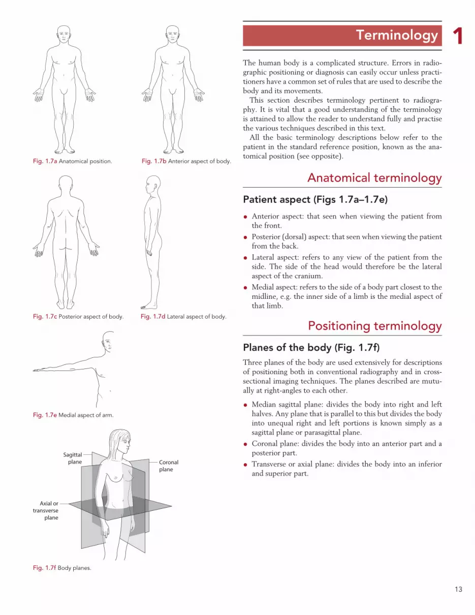
Patient aspect (Figs 1.7a–1.7e)
•Anterior aspect: that seen when viewing the patient from the front.
• Posterior (dorsal) aspect: that seen when viewing the patient from the back.
• Lateral aspect: refers to any view of the patient from the side. The side of the head would therefore be the lateral aspect of the cranium.
•Medial aspect: refers to the side of a body part closest to the midline, e.g. the inner side of a limb is the medial aspect of that limb.
Positioning terminology
Planes of the body (Fig. 1.7f)Three planes of the body are used extensively for descriptions of positioning both in conventional radiography and in cross-sectional imaging techniques. The planes described are mutu-ally at right-angles to each other.
•Median sagittal plane: divides the body into right and left halves. Any plane that is parallel to this but divides the body into unequal right and left portions is known simply as a sagittal plane or parasagittal plane.
•Coronal plane: divides the body into an anterior part and a posterior part.
• Transverse or axial plane: divides the body into an inferior and superior part.
Fig. 1.7a Anatomical position. Fig. 1.7b Anterior aspect of body.
Fig. 1.7c Posterior aspect of body. Fig. 1.7d Lateral aspect of body.
Fig. 1.7e Medial aspect of arm.
Sagittalplane Coronal
plane
Axial ortransverse
plane
Fig. 1.7f Body planes.
14
1 Terminology
Positioning terminology (cont.) (Figs 1.8a–1.8e)This section describes how the patient is positioned for the various radiographic projections described in the book.
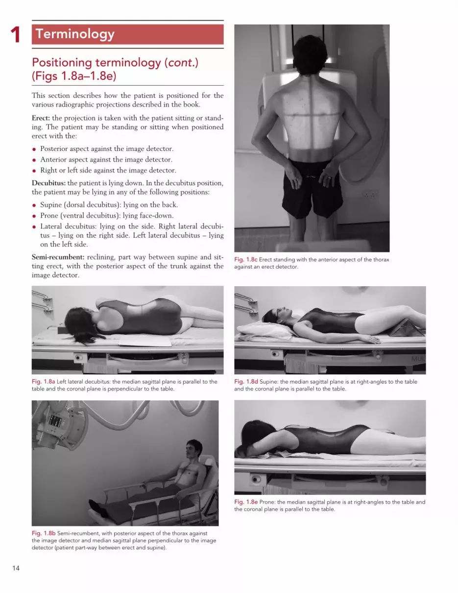
Erect: the projection is taken with the patient sitting or stand-ing. The patient may be standing or sitting when positioned erect with the:
• Posterior aspect against the image detector.
•Anterior aspect against the image detector.
• Right or left side against the image detector.
Decubitus: the patient is lying down. In the decubitus position, the patient may be lying in any of the following positions:
• Supine (dorsal decubitus): lying on the back.
• Prone (ventral decubitus): lying face-down.
• Lateral decubitus: lying on the side. Right lateral decubi-tus – lying on the right side. Left lateral decubitus – lying on the left side.
Semi-recumbent: reclining, part way between supine and sit-ting erect, with the posterior aspect of the trunk against the image detector.
Fig. 1.8a Left lateral decubitus: the median sagittal plane is parallel to the table and the coronal plane is perpendicular to the table.
Fig. 1.8b Semi-recumbent, with posterior aspect of the thorax against the image detector and median sagittal plane perpendicular to the image detector (patient part-way between erect and supine).
Fig. 1.8c Erect standing with the anterior aspect of the thorax against an erect detector.
Fig. 1.8d Supine: the median sagittal plane is at right-angles to the table and the coronal plane is parallel to the table.
Fig. 1.8e Prone: the median sagittal plane is at right-angles to the table and the coronal plane is parallel to the table.
15
1 Terminology
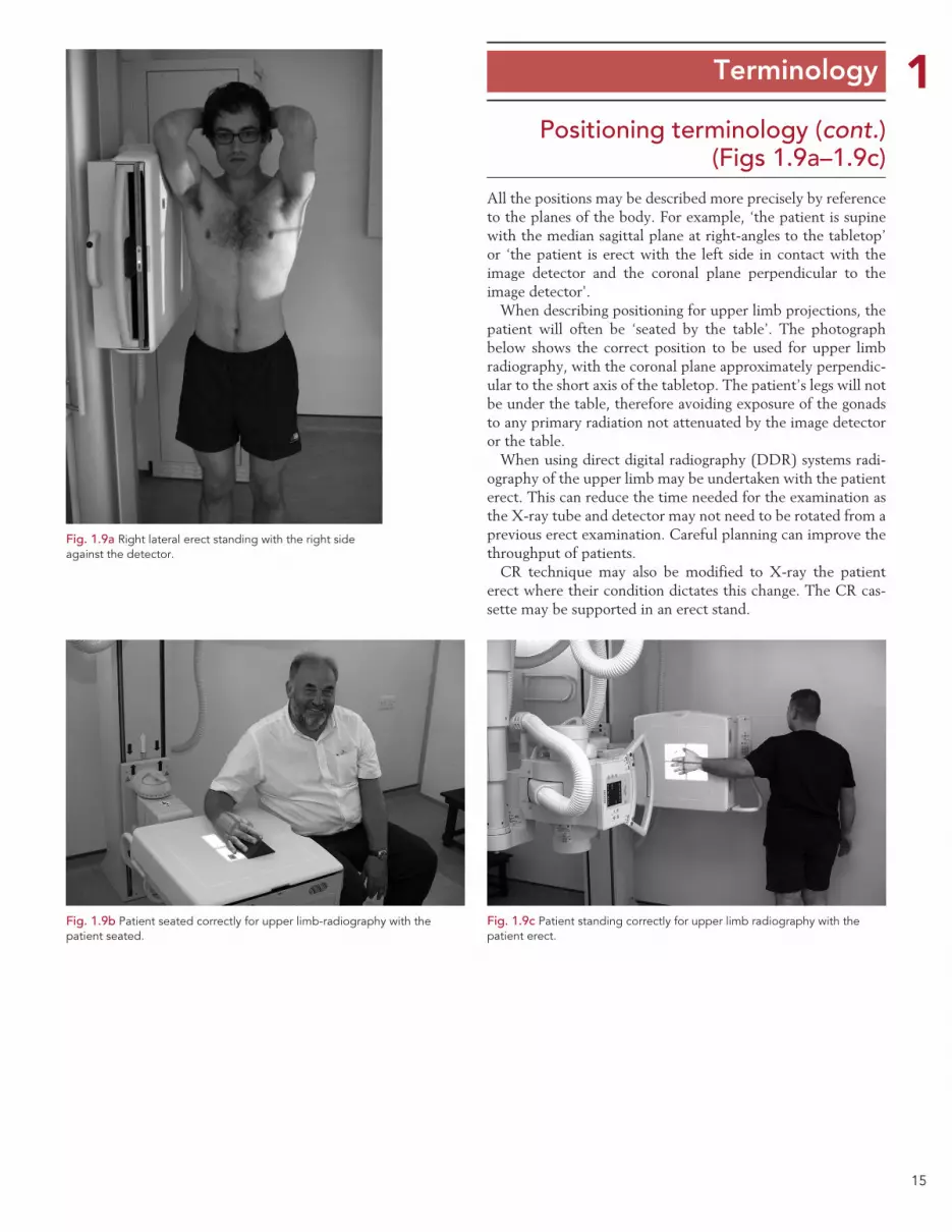
Positioning terminology (cont.) (Figs 1.9a–1.9c)
All the positions may be described more precisely by reference to the planes of the body. For example, ‘the patient is supine with the median sagittal plane at right-angles to the tabletop’ or ‘the patient is erect with the left side in contact with the image detector and the coronal plane perpendicular to the image detector’.
When describing positioning for upper limb projections, the patient will often be ‘seated by the table’. The photograph below shows the correct position to be used for upper limb radiography, with the coronal plane approximately perpendic-ular to the short axis of the tabletop. The patient’s legs will not be under the table, therefore avoiding exposure of the gonads to any primary radiation not attenuated by the image detector or the table.
When using direct digital radiography (DDR) systems radi-ography of the upper limb may be undertaken with the patient erect. This can reduce the time needed for the examination as the X-ray tube and detector may not need to be rotated from a previous erect examination. Careful planning can improve the throughput of patients.
CR technique may also be modified to X-ray the patient erect where their condition dictates this change. The CR cas-sette may be supported in an erect stand.
Fig. 1.9a Right lateral erect standing with the right side against the detector.
Fig. 1.9b Patient seated correctly for upper limb-radiography with the patient seated.
Fig. 1.9c Patient standing correctly for upper limb radiography with the patient erect.
16
1 Terminology
Positioning terminology (cont.) (Figs 1.10a–1.10h)
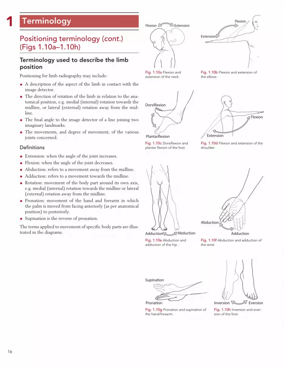
Terminology used to describe the limb position Positioning for limb radiography may include:
•A description of the aspect of the limb in contact with the image detector.
• The direction of rotation of the limb in relation to the ana-tomical position, e.g. medial (internal) rotation towards the midline, or lateral (external) rotation away from the mid-line.
• The final angle to the image detector of a line joining two imaginary landmarks.
• The movements, and degree of movement, of the various joints concerned.
Definitions
• Extension: when the angle of the joint increases.
• Flexion: when the angle of the joint decreases.
•Abduction: refers to a movement away from the midline.
•Adduction: refers to a movement towards the midline.
• Rotation: movement of the body part around its own axis, e.g. medial (internal) rotation towards the midline or lateral (external) rotation away from the midline.
• Pronation: movement of the hand and forearm in which the palm is moved from facing anteriorly (as per anatomical position) to posteriorly.
• Supination is the reverse of pronation.
The terms applied to movement of specific body parts are illus-trated in the diagrams.
Flexion Extension
Fig. 1.10a Flexion and extension of the neck.
Flexion
Extension
Fig. 1.10b Flexion and extension of the elbow.
Dorsiflexion
Plantarflexion
Fig. 1.10c Dorsiflexion and plantar flexion of the foot.
Flexion
Extension
Fig. 1.10d Flexion and extension of the shoulder.
Abduction
Adduction
Fig. 1.10f Abduction and adduction of the wrist.
Inversion Eversion
Fig. 1.10h Inversion and ever-sion of the foot.
AbductionAdduction
Fig. 1.10e Abduction and adduction of the hip.
Pronation
Supination
Fig. 1.10g Pronation and supination of the hand/forearm.
17
1 Terminology
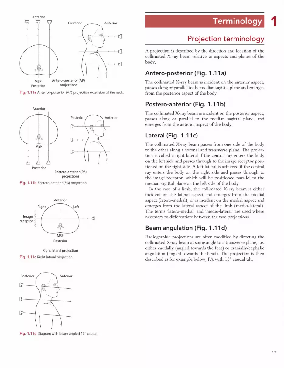
Projection terminologyA projection is described by the direction and location of the collimated X-ray beam relative to aspects and planes of the body.
Antero-posterior (Fig. 1.11a)The collimated X-ray beam is incident on the anterior aspect, passes along or parallel to the median sagittal plane and emerges from the posterior aspect of the body.
Postero-anterior (Fig. 1.11b)The collimated X-ray beam is incident on the posterior aspect, passes along or parallel to the median sagittal plane, and emerges from the anterior aspect of the body.
Lateral (Fig. 1.11c)The collimated X-ray beam passes from one side of the body to the other along a coronal and transverse plane. The projec-tion is called a right lateral if the central ray enters the body on the left side and passes through to the image receptor posi-tioned on the right side. A left lateral is achieved if the central ray enters the body on the right side and passes through to the image receptor, which will be positioned parallel to the median sagittal plane on the left side of the body.
In the case of a limb, the collimated X-ray beam is either incident on the lateral aspect and emerges from the medial aspect (latero-medial), or is incident on the medial aspect and emerges from the lateral aspect of the limb (medio-lateral). The terms ‘latero-medial’ and ‘medio-lateral’ are used where necessary to differentiate between the two projections.
Beam angulation (Fig. 1.11d)Radiographic projections are often modified by directing the collimated X-ray beam at some angle to a transverse plane, i.e. either caudally (angled towards the feet) or cranially/cephalic angulation (angled towards the head). The projection is then described as for example below, PA with 15° caudal tilt.
Fig. 1.11a Anterior-posterior (AP) projection extension of the neck.
Anterior
AnteriorPosterior
MSPPosterior
Antero-posterior (AP)projections
Fig. 1.11b Postero-anterior (PA) projection.
Anterior
Anterior
Posterior
Posterior
MSP
Postero-anterior (PA)projections
Anterior
PosteriorMSP
Imagereceptor
Right Left
Right lateral projection
Fig. 1.11c Right lateral projection.
AnteriorPosterior
Fig. 1.11d Diagram with beam angled 15° caudal.
18
1 Terminology
Projection terminology (cont.)
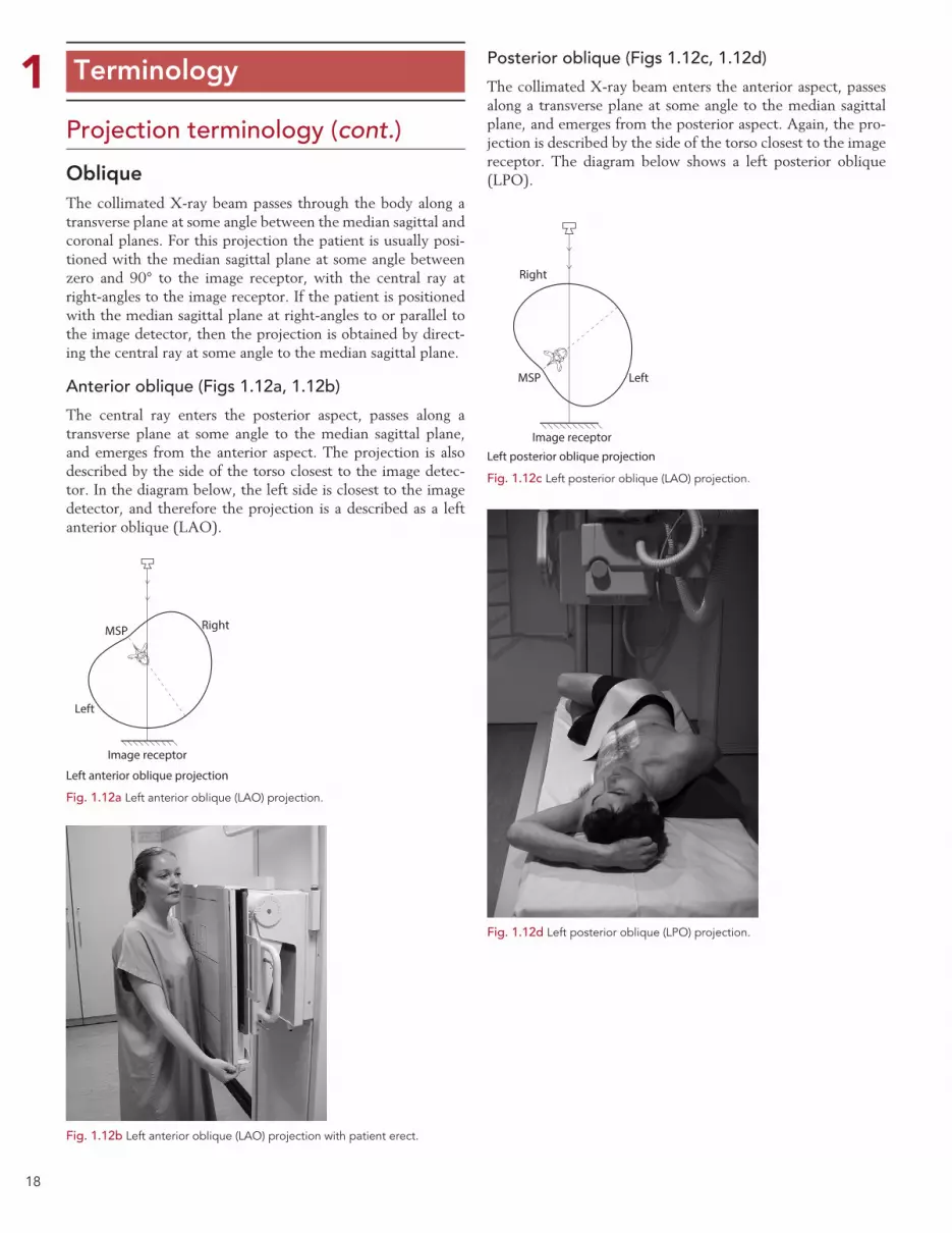
ObliqueThe collimated X-ray beam passes through the body along a transverse plane at some angle between the median sagittal and coronal planes. For this projection the patient is usually posi-tioned with the median sagittal plane at some angle between zero and 90° to the image receptor, with the central ray at right-angles to the image receptor. If the patient is positioned with the median sagittal plane at right-angles to or parallel to the image detector, then the projection is obtained by direct-ing the central ray at some angle to the median sagittal plane.
Anterior oblique (Figs 1.12a, 1.12b)
The central ray enters the posterior aspect, passes along a transverse plane at some angle to the median sagittal plane, and emerges from the anterior aspect. The projection is also described by the side of the torso closest to the image detec-tor. In the diagram below, the left side is closest to the image detector, and therefore the projection is a described as a left anterior oblique (LAO).
Posterior oblique (Figs 1.12c, 1.12d)
The collimated X-ray beam enters the anterior aspect, passes along a transverse plane at some angle to the median sagittal plane, and emerges from the posterior aspect. Again, the pro-jection is described by the side of the torso closest to the image receptor. The diagram below shows a left posterior oblique (LPO).
MSP
Image receptor
Right
Left
Left anterior oblique projection
Fig. 1.12a Left anterior oblique (LAO) projection.
Fig. 1.12b Left anterior oblique (LAO) projection with patient erect.
MSP
Image receptor
Right
Left
Left posterior oblique projection
Fig. 1.12c Left posterior oblique (LAO) projection.
Fig. 1.12d Left posterior oblique (LPO) projection.

19
1 Terminology
Lateral oblique (Figs 1.13c, 1.13d)
The collimated X-ray beam enters one lateral aspect, passes along a transverse plane at an angle to the coronal plane, and emerges from the opposite lateral aspect. With the coronal plane at right-angles to the image receptor, lateral oblique pro-jections can also be obtained by angling the central ray to the coronal plane.
Note: this cannot be done if using a grid, unless the grid lines are parallel to the central ray.
Oblique using beam angulation (Figs 1.13a, 1.13b)
When the median sagittal plane is at right-angles to the image receptor, right and left anterior or posterior oblique projec-tions may be obtained by angling the central ray to the median sagittal plane.
Note: this cannot be done if using a grid, unless the grid lines are parallel to the central ray.
Projection terminology (cont.)
Image receptor
Right Left
Fig. 1.13a LPO projection using beam angulation.
Fig. 1.13b LAO projection using beam angulation.
MSP
Image receptor
Right
Left
Left lateral oblique projection
Coronalplane
Fig. 1.13c Lateral oblique projection obtained using beam angulation.
Fig. 1.13d Example of the position for a right lateral oblique projection.
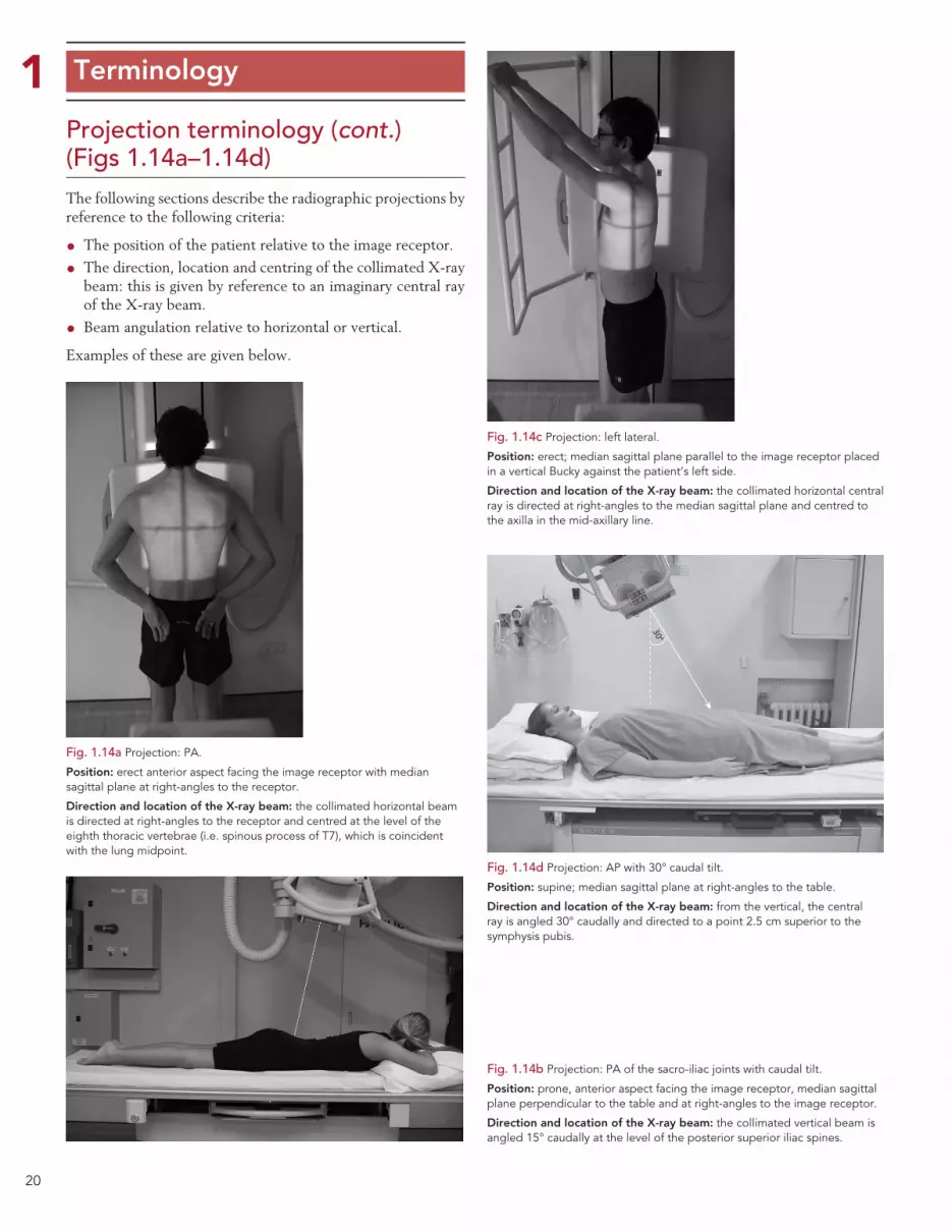
20
1 Terminology
Projection terminology (cont.) (Figs 1.14a–1.14d)The following sections describe the radiographic projections by reference to the following criteria:
• The position of the patient relative to the image receptor.
• The direction, location and centring of the collimated X-ray beam: this is given by reference to an imaginary central ray of the X-ray beam.
• Beam angulation relative to horizontal or vertical.
Examples of these are given below.
Fig. 1.14a Projection: PA.
Position: erect anterior aspect facing the image receptor with median sagittal plane at right-angles to the receptor.
Direction and location of the X-ray beam: the collimated horizontal beam is directed at right-angles to the receptor and centred at the level of the eighth thoracic vertebrae (i.e. spinous process of T7), which is coincident with the lung midpoint.
Fig. 1.14b Projection: PA of the sacro-iliac joints with caudal tilt.
Position: prone, anterior aspect facing the image receptor, median sagittal plane perpendicular to the table and at right-angles to the image receptor.
Direction and location of the X-ray beam: the collimated vertical beam is angled 15° caudally at the level of the posterior superior iliac spines.
Fig. 1.14c Projection: left lateral.
Position: erect; median sagittal plane parallel to the image receptor placed in a vertical Bucky against the patient’s left side.
Direction and location of the X-ray beam: the collimated horizontal central ray is directed at right-angles to the median sagittal plane and centred to the axilla in the mid-axillary line.
Fig. 1.14d Projection: AP with 30° caudal tilt.
Position: supine; median sagittal plane at right-angles to the table.
Direction and location of the X-ray beam: from the vertical, the central ray is angled 30° caudally and directed to a point 2.5 cm superior to the symphysis pubis.
30°

21
1 Terminology
Projection terminology (cont.) (Figs 1.15a–1.15d)
Fig. 1.15a Right lateral.
Projection: right lateral.
Position: supine; median sagittal plane parallel to the image receptor placed in a vertical Bucky against the patient’s left side.
Direction and location of X-ray beam: the collimated horizontal central ray is directed at right-angles to the median sagittal plane to the lower costal margin in the mid-axillary line.
Fig. 1.15b Right posterior oblique.
Projection: right posterior oblique.
Position: supine and then rotated so that the left side is moved away from the table to bring the median sagittal plane at 45° to the table.
Direction and location of X-ray beam: the vertical beam central ray is directed to a point 2.5 cm to the right of the midline at the level of the 3rd lumbar vertebra.
Fig. 1.15c Left lateral decubitus.
Projection: antero-posterior.
Position: left lateral decubitus. The median sagittal plane is parallel to the couch and right-angles to the image receptor, which is vertically against the patient’s posterior aspect.
Direction and location of X-ray beam: the collimated horizontal X-ray beam is directed at right-angles to the anterior aspect of the patient in the midline and passes along the median plane at the level of the 3rd lumbar vertebra.
Fig 1.15d Lateral thumb.
Projection: lateral.
Position: patient erect adjacent to and facing the image receptor, with the arm extended and in contact with the vertical DDR detector. The thumb is flexed slightly and the palm of the hand is placed on the image receptor. The palm of the hand is raised slightly with the fingers partially flexed and may be supported on a non-opaque pad, such that the lateral aspect of the thumb is in contact with the image receptor.
Direction and location of X-ray beam: the collimated horizontal beam is centred over the 1st metacarpo-phalangeal joint.
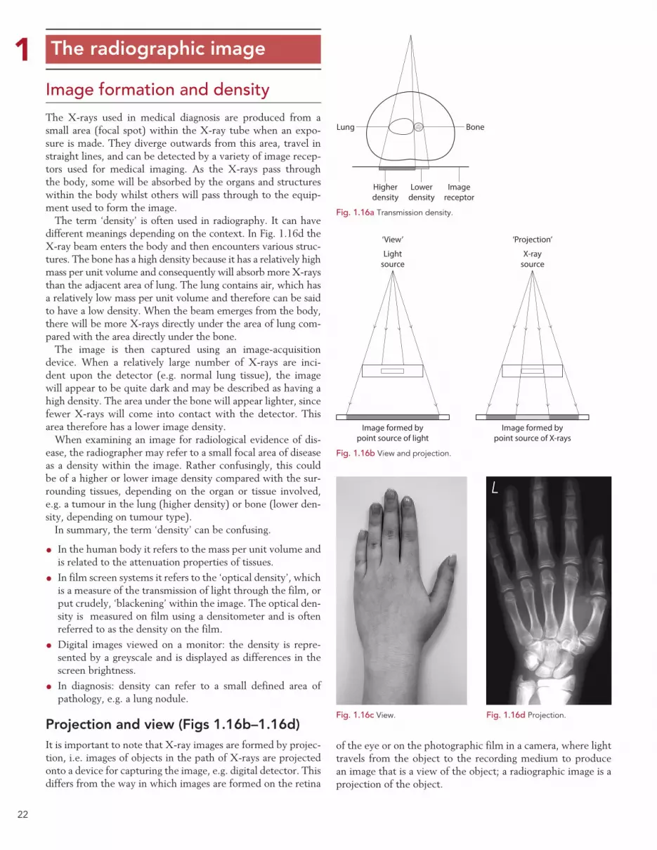
22
1 The radiographic image
Image formation and densityThe X-rays used in medical diagnosis are produced from a small area (focal spot) within the X-ray tube when an expo-sure is made. They diverge outwards from this area, travel in straight lines, and can be detected by a variety of image recep-tors used for medical imaging. As the X-rays pass through the body, some will be absorbed by the organs and structures within the body whilst others will pass through to the equip-ment used to form the image.
The term ‘density’ is often used in radiography. It can have different meanings depending on the context. In Fig. 1.16d the X-ray beam enters the body and then encounters various struc-tures. The bone has a high density because it has a relatively high mass per unit volume and consequently will absorb more X-rays than the adjacent area of lung. The lung contains air, which has a relatively low mass per unit volume and therefore can be said to have a low density. When the beam emerges from the body, there will be more X-rays directly under the area of lung com-pared with the area directly under the bone.
The image is then captured using an image-acquisition device. When a relatively large number of X-rays are inci-dent upon the detector (e.g. normal lung tissue), the image will appear to be quite dark and may be described as having a high density. The area under the bone will appear lighter, since fewer X-rays will come into contact with the detector. This area therefore has a lower image density.
When examining an image for radiological evidence of dis-ease, the radiographer may refer to a small focal area of disease as a density within the image. Rather confusingly, this could be of a higher or lower image density compared with the sur-rounding tissues, depending on the organ or tissue involved, e.g. a tumour in the lung (higher density) or bone (lower den-sity, depending on tumour type).
In summary, the term ‘density’ can be confusing.
• In the human body it refers to the mass per unit volume and is related to the attenuation properties of tissues.
• In film screen systems it refers to the ‘optical density’, which is a measure of the transmission of light through the film, or put crudely, ‘blackening’ within the image. The optical den-sity is measured on film using a densitometer and is often referred to as the density on the film.
•Digital images viewed on a monitor: the density is repre-sented by a greyscale and is displayed as differences in the screen brightness.
• In diagnosis: density can refer to a small defined area of pathology, e.g. a lung nodule.
Projection and view (Figs 1.16b–1.16d)It is important to note that X-ray images are formed by projec-tion, i.e. images of objects in the path of X-rays are projected onto a device for capturing the image, e.g. digital detector. This differs from the way in which images are formed on the retina
of the eye or on the photographic film in a camera, where light travels from the object to the recording medium to produce an image that is a view of the object; a radiographic image is a projection of the object.
Lung Bone
Imagereceptor
Lowerdensity
Higherdensity
Fig. 1.16a Transmission density.
‘View’
Lightsource
X-raysource
‘Projection’
Image formed bypoint source of light
Image formed bypoint source of X-rays
Fig. 1.16b View and projection.
Fig. 1.16c View. Fig. 1.16d Projection.

23
1 The radiographic imagePhotographic filmIf the image is captured on a photographic emulsion, then the term ‘photographic density’ or ‘optical density’ should be used. Higher densities will be produced by greater exposures of radiation, which in turn leads to a form of silver being lib-erated from the photographic emulsion. This remains on the film after processing and produces the ‘blackening’ within the image. Photographic or optical density can be measured by determining the degree of opacity, i.e. the proportion of light absorbed by the processed film.
Digital image captureIf the image was captured by a digital system such as computed radiography (CR) or direct digital radiography (DDR), then the term ‘image density’ refers to the greyscale displayed on the monitor used to display the image. Put simply, it is the computer screen brightness.
The image-processing software will analyse the range of exposures that were captured by the image receptor (e.g. the CR phosphor screen). It will then assign the highest computer screen brightness to areas that have received relatively low exposures (low image density). Conversely, the lowest com-puter screen brightness (darkest areas) will be assigned to areas that have received a relatively high radiation exposure (high image density) (Fig. 1.17b).
ContrastIn order to detect pathology, an imaging system must be able to detect the differences in the density (patient density) of the pathology compared with that of the surrounding tissues. This must then be translated into differences in density within the final image (a digital image or film density) that are visible to the observer. Contrast is the difference in density between structures of interest within the image. A low-contrast image will show little difference in density between structures of interest, whereas a high-contrast image will show a larger dif-ference in density between structure (Fig. 1.17a).
The contrast seen on a radiographic image (film) or digital display can be described in three ways:
• Subject contrast is a feature of the object (subject) under examination. The differences in radiation intensities emerging from the object result from the spatial distribution of X-ray attenuation within the object. At a given beam energy, the degree of beam attenuation between anatomical structures is determined by the physical density and atomic number of those structures. Differential absorption and therefore subject contrast will change if the beam energy (kV) is varied. A radi-ological contrast agent will also change the atomic number within an area of the object and hence subject contrast.
• Subjective contrast is the personal appreciation of the dif-ferences in optical density or computer screen brightness when the image is viewed. This varies with the experience and training of the viewer.
• Radiographic contrast is the difference in optical density on different parts of the processed film or differences in com-puter screen brightness recorded as a result of the range of emergent beam intensities.
Subject contrast
X-radiation passing through the body is attenuated by different amounts by the different thicknesses, densities and atomic num-bers of the structures in the body. The beam emerging from the patient varies in intensity: more will emerge if the beam encoun-ters only a small thickness of soft tissue. The difference in intensi-ties in the emergent beam is called subject contrast or radiation contrast. Factors that influence subject contrast include the fol-lowing:
• The region of the body under examination. There is less subject contrast if all parts of the region have a similar atten-uation coefficient. Soft-tissue structures such as the breast have a low subject contrast, whereas the subject contrast increases if the region includes bone or large differences in the thickness of tissue. A good example of an area of the body that demonstrates high subject contrast is the chest.
•Contrast media. If high- or low-density/atomic number sub-stances are introduced into cavities in a region, then there will be a greater difference in absorption of X-rays by different parts of that region and thus an increase in subject contrast.
• Pathology. If the density of a structure is changed due to pathology, then there will be a change in subject contrast; for instance, it will be reduced if the bone density reduces, as in osteoporosis.
Contrast
Fig. 1.17a Comparison of chest images with high and low contrast.
Fig. 1.17b Image of a step wedge showing a range of densities.
123456789101112131415161718192021
24
1 The radiographic image
Contrast (cont.)Subject contrast (cont.)
•Kilovoltage (kV). At lower kV, there is a greater difference in attenuation by structures of different density and atomic number than at higher kV. Therefore, at lower kV, there is a greater subject contrast. This can be used to advantage when examining areas of low subject contrast, such as the breast. Conversely, there is a high subject contrast within the chest (marked differences in patient density when comparing the lungs and the heart). A higher kV will therefore reduce this subject contrast and produce a more even image density.
Subjective contrast
When a radiographic image is viewed, the observer sees an image made up of structures of different light intensities i.e. range of densities. However, different observers might have a different/altered appreciation of the image contrast. The personal appre-ciation of the contrast in the image is called subjective contrast. Subjective contrast depends not only on the person but also on the viewing conditions. For example, if an image is viewed on a computer monitor and that monitor is placed near a win-dow, then the sunlight incident upon the screen will severely impair the observer’s ability to appreciate the density differences within the image. There may be good radiographic contrast but the observer cannot appreciate this because of the sunlight on the screen, so the subjective contrast will be low.
Subjective contrast depends on:
• The observer’s visual perception and level of experience in viewing images. It may also depend on the time of day and how long the observer has been working.
• The viewing conditions, e.g. the type of monitor, the set-tings used on the monitor and ambient lighting.
Radiographic contrast
After leaving the patient, the X-radiation passes to an image-acquisition device. As it passes through the body, some of the radiation will be scattered. Scatter reduces the differences in X-ray intensity emerging from different areas of the body and thus reduces contrast. The effects of scatter can be controlled by:
•Collimating the beam or by the use of compression devices. In each of these cases, this reduces the volume of tissue irra-diated and the amount of scatter produced.
• The use of a secondary radiation grid between the patient and the image receptor to reduce the scatter reaching the image receptor improves radiographic contrast.
• The use of an air gap technique will reduce the proportion of scatter photons reaching the image receptor. The scat-tered photons will ‘miss’ the detector due to their angle of deflection.
Once the image has been captured, it can be viewed either on computer monitor or in rare cases photographic film. The different patient densities are recorded either as varying photographic densities or as differences in computer screen brightness. These different densities can be measured either using densitometer or image-analysis software to give an objec-tive measurement of contrast.
Thus, differences in measured image density between speci-fied parts of the radiographic image may be described as radio-graphic or objective contrast.
The design and function of the image-acquisition device used to acquire the image can have a profound effect on contrast. In digital systems, the contrast is also influenced profoundly by the software used to process the initial image captured by the device. The contrast may also be ‘post-processed’ to enhance image quality. Certain types of film emulsion, intensifying screen and phosphor plate may be designed to give inherently greater contrast.
Film based systemsContrast will also be dependent on a number of factors related to image capture using film. This will include:
• Film fog: if the image is viewed using a photographic-based system, then film fogging due to incorrect film handling or storage may reduce radiographic contrast.
• Exposure: if too much or too little radiation is used, then the film screen system may be unable to respond or may be saturated to the point that it is unable to func-tion properly. In these examples, there may be a reduced range of densities or no difference in density visible on the image, thus radiographic contrast will be reduced or non-existent.
• Film processing/development: if a photographic emulsion is used to capture the image, then optimum radiographic contrast will be attained only if the film is developed cor-rectly. This is achieved by careful control of factors such as developer temperature, development time and processing chemical activity. To ensure this, the film processor must be subject to a rigid quality-control regime.
Optimum radiographic image quality and contrast
In summary it is important to remember that the quality of the image perceived, i.e. subjective contrast is influenced both by the inherent subject contrast of the region under examination and the radiographic contrast related to the image acquisition system/process. These facts and some of the factors influencing them are highlighted on page 43.
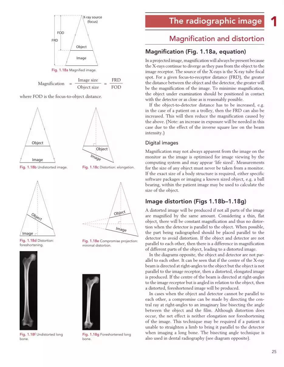
25
1 The radiographic image
Magnification and distortion
Magnification (Fig. 1.18a, equation)In a projected image, magnification will always be present because the X-rays continue to diverge as they pass from the object to the image receptor. The source of the X-rays is the X-ray tube focal spot. For a given focus-to-receptor distance (FRD), the greater the distance between the object and the detector, the greater will be the magnification of the image. To minimise magnification, the object under examination should be positioned in contact with the detector or as close as is reasonably possible.
If the object-to-detector distance has to be increased, e.g. in the case of a patient on a trolley, then the FRD can also be increased. This will then reduce the magnification caused by the above. (Note: an increase in exposure will be needed in this case due to the effect of the inverse square law on the beam intensity.)
Digital images
Magnification may not always apparent from the image on the monitor as the image is optimised for image viewing by the computing system and may appear ‘life sized’. Measurements for the size of any object must never be taken from a monitor. If the exact size of a body structure is required, either specific software packages or imaging a known sized object, e.g. a ball bearing, within the patient image may be used to calculate the size of the object.
Image distortion (Figs 1.18b–1.18g)A distorted image will be produced if not all parts of the image are magnified by the same amount. Considering a thin, flat object, there will be constant magnification and thus no distor-tion when the detector is parallel to the object. When possible, the part being radiographed should be placed parallel to the detector to avoid distortion. If the object and detector are not parallel to each other, then there is a difference in magnification of different parts of the object, leading to a distorted image.
In the diagrams opposite, the object and detector are not par-allel to each other. It can be seen that if the centre of the X-ray beam is directed at right-angles to the object but the object is not parallel to the image receptor, then a distorted, elongated image is produced. If the centre of the beam is directed at right-angles to the image receptor but is angled in relation to the object, then a distorted, foreshortened image will be produced.
In cases when the object and detector cannot be parallel to each other, a compromise can be made by directing the cen-tral ray at right-angles to an imaginary line bisecting the angle between the object and the film. Although distortion does occur, the net effect is neither elongation nor foreshortening of the image. This technique may be required if a patient is unable to straighten a limb to bring it parallel to the detector when imaging a long bone. The bisecting angle technique is also used in dental radiography (see diagram opposite).
Magnification =Image size
=FRD
Object size FOD
where FOD is the focus-to-object distance.
FOD
FRD
Object
Image
X-ray source(focus)
Fig. 1.18a Magnified image.
Object
Image
Fig. 1.18b Undistorted image.
Object
Image
Fig. 1.18c Distortion: elongation.
Object
Image
Fig. 1.18d Distortion: foreshortening.
Object
Image
Fig. 1.18e Compromise projection: minimal distortion.
Fig. 1.18f Undistorted long bone.
Fig. 1.18g Foreshortened long bone.

26
1 The radiographic image
Image sharpnessThe aim in radiography is to produce images that have a mini-mal level of unsharpness in order to resolve fine detail within the image. This is particularly important when looking for sub-tle fractures or changes in bone architecture. Diagnostic images have a level of unsharpness which is not visible to the person viewing the image. This is approximately 0.3 mm and is deter-mined by a number of factors:
•Geometry of the image production (Ug).
•Movement (Um).
•Absorption (inherent factors) (Ua).
Geometric unsharpness (Figs 1.19a, 1.19b)If X-rays originated from a point source, then a perfectly sharp image would always be obtained. In an X-ray tube, however, the X-rays are produced from the small area of the focal spot on the anode. As can be seen from the diagram opposite, this leads to the formation of penumbra or ‘partial shadows’ at the edge of the object; it is this that gives rise to geometric unsharpness.
The degree of geometric unsharpness increases with an increased focal spot size and increased object-to-receptor distance:
Geometric unsharpness (Ug) =
Object-to-receptor distance (ORD)× focal spot size
Focus-to-object distance (FOD)
Geometric unsharpness can be a small, insignificant quantity if the object is close to the receptor and a small focal spot is used. For instance, with a PA projection of the wrist, where the maximum object-to-receptor distance is about 5 cm, and if a normal FRD of 100 cm is used, then geometric unsharpness is only 0.05 mm using a 1 mm focal spot and only 0.1 mm with a 2 mm focal spot (common focal spot sizes are 0.6 and 1.2 mm). When thicker parts of the body are being examined, which might require the use of a larger (broad) focal spot, then geometric unsharpness can make a significant contribution to total image unsharpness owing to the greater object-to-receptor distance.
Movement unsharpness (Fig. 1.19c)This type of unsharpness is due to patient, equipment or detec-tor vibration during the exposure. Patient movement may be involuntary, e.g. owing to heartbeat or peristalsis, or it may the type of movement that may be controlled by immobilisation. It is important to note that any patient movement is magni-fied on the image because of the space between the moving object and the detector. Sharpness can be minimised by using a shorter exposure time (achieved by a lower mAs with higher kV, higher mA, or greater tube loading), by a small object-to-detector distance and particularly by immobilisation of the patient.
Various accessories can be used for immobilisation, including non-opaque pads and sandbags to immobilise the extremities.
Distraction and immobilisation may be required to aid patients to keep still (Fig. 1.20b). Binders and Velcro straps may be used where appropriate. These accessories should be avail-able in all examination rooms and should be used routinely. It is equally important to make the patient as comfortable as possible and to explain the procedure fully. The radiographer can also invite questions about the procedure, thus increasing the likelihood of achieving full cooperation from the patient. It may be worthwhile rehearsing respiratory manoeuvres prior to an actual exposure being made.
Object
Point source
Image
Object
Focal spot
Image
Penumbra causinggeometric unsharpness
Fig. 1.19a Effect of finite focal spot.
Larger FRDsreduce geometric
unsharpness
LargerFRD
Smaller FRD =greater geometric
unsharpness
Fig. 1.19b Effect of FRD.
Fig. 1.19c Movement unsharpness.
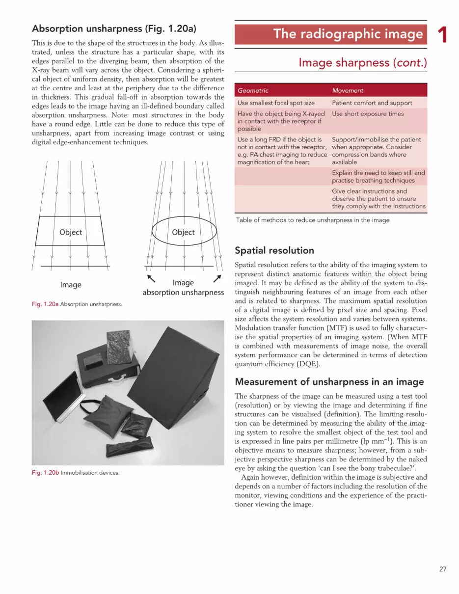
27
1 The radiographic image
Image sharpness (cont.)
Geometric Movement
Use smallest focal spot size Patient comfort and support
Have the object being X-rayed in contact with the receptor if possible
Use short exposure times
Use a long FRD if the object is not in contact with the receptor, e.g. PA chest imaging to reduce magnification of the heart
Support/immobilise the patient when appropriate. Consider compression bands where available
Explain the need to keep still and practise breathing techniques
Give clear instructions and observe the patient to ensure they comply with the instructions
Table of methods to reduce unsharpness in the image
Absorption unsharpness (Fig. 1.20a)This is due to the shape of the structures in the body. As illus-trated, unless the structure has a particular shape, with its edges parallel to the diverging beam, then absorption of the X-ray beam will vary across the object. Considering a spheri-cal object of uniform density, then absorption will be greatest at the centre and least at the periphery due to the difference in thickness. This gradual fall-off in absorption towards the edges leads to the image having an ill-defined boundary called absorption unsharpness. Note: most structures in the body have a round edge. Little can be done to reduce this type of unsharpness, apart from increasing image contrast or using digital edge-enhancement techniques.
Spatial resolutionSpatial resolution refers to the ability of the imaging system to represent distinct anatomic features within the object being imaged. It may be defined as the ability of the system to dis-tinguish neighbouring features of an image from each other and is related to sharpness. The maximum spatial resolution of a digital image is defined by pixel size and spacing. Pixel size affects the system resolution and varies between systems. Modulation transfer function (MTF) is used to fully character-ise the spatial properties of an imaging system. (When MTF is combined with measurements of image noise, the overall system performance can be determined in terms of detection quantum efficiency (DQE).
Measurement of unsharpness in an imageThe sharpness of the image can be measured using a test tool (resolution) or by viewing the image and determining if fine structures can be visualised (definition). The limiting resolu-tion can be determined by measuring the ability of the imag-ing system to resolve the smallest object of the test tool and is expressed in line pairs per millimetre (lp mm−1). This is an objective means to measure sharpness; however, from a sub-jective perspective sharpness can be determined by the naked eye by asking the question ‘can I see the bony trabeculae?’.
Again however, definition within the image is subjective and depends on a number of factors including the resolution of the monitor, viewing conditions and the experience of the practi-tioner viewing the image.
Fig. 1.20b Immobilisation devices.
Object
Image
Object
Imageabsorption unsharpness
Fig. 1.20a Absorption unsharpness.
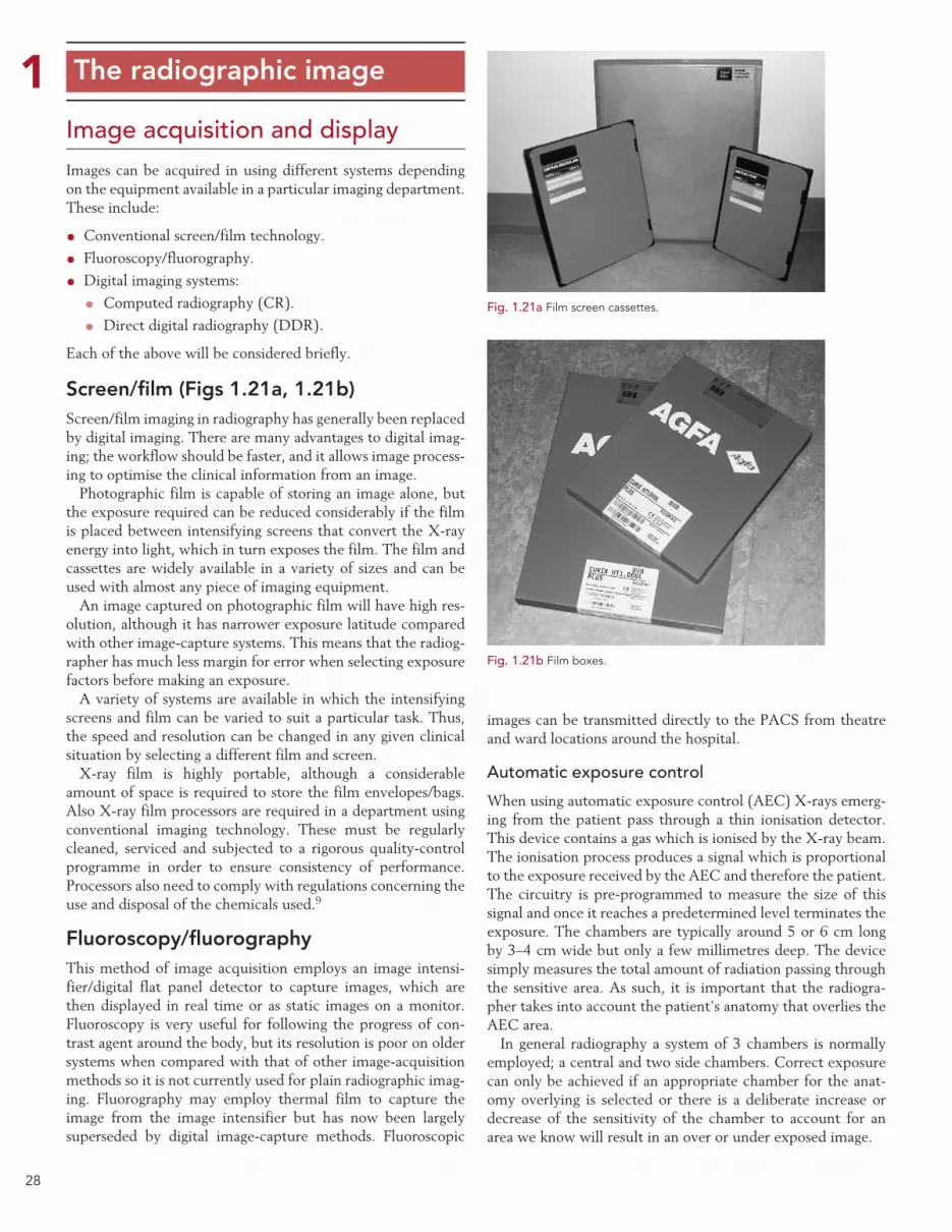
28
1 The radiographic image
Image acquisition and displayImages can be acquired in using different systems depending on the equipment available in a particular imaging department. These include:
•Conventional screen/film technology.
• Fluoroscopy/fluorography.
•Digital imaging systems:
• Computed radiography (CR).
• Direct digital radiography (DDR).
Each of the above will be considered briefly.
Screen/film (Figs 1.21a, 1.21b)Screen/film imaging in radiography has generally been replaced by digital imaging. There are many advantages to digital imag-ing; the workflow should be faster, and it allows image process-ing to optimise the clinical information from an image.
Photographic film is capable of storing an image alone, but the exposure required can be reduced considerably if the film is placed between intensifying screens that convert the X-ray energy into light, which in turn exposes the film. The film and cassettes are widely available in a variety of sizes and can be used with almost any piece of imaging equipment.
An image captured on photographic film will have high res-olution, although it has narrower exposure latitude compared with other image-capture systems. This means that the radiog-rapher has much less margin for error when selecting exposure factors before making an exposure.
A variety of systems are available in which the intensifying screens and film can be varied to suit a particular task. Thus, the speed and resolution can be changed in any given clinical situation by selecting a different film and screen.
X-ray film is highly portable, although a considerable amount of space is required to store the film envelopes/bags. Also X-ray film processors are required in a department using conventional imaging technology. These must be regularly cleaned, serviced and subjected to a rigorous quality-control programme in order to ensure consistency of performance. Processors also need to comply with regulations concerning the use and disposal of the chemicals used.9
Fluoroscopy/fluorographyThis method of image acquisition employs an image intensi-fier/digital flat panel detector to capture images, which are then displayed in real time or as static images on a monitor. Fluoroscopy is very useful for following the progress of con-trast agent around the body, but its resolution is poor on older systems when compared with that of other image-acquisition methods so it is not currently used for plain radiographic imag-ing. Fluorography may employ thermal film to capture the image from the image intensifier but has now been largely superseded by digital image-capture methods. Fluoroscopic
images can be transmitted directly to the PACS from theatre and ward locations around the hospital.
Automatic exposure control
When using automatic exposure control (AEC) X-rays emerg-ing from the patient pass through a thin ionisation detector. This device contains a gas which is ionised by the X-ray beam. The ionisation process produces a signal which is proportional to the exposure received by the AEC and therefore the patient. The circuitry is pre-programmed to measure the size of this signal and once it reaches a predetermined level terminates the exposure. The chambers are typically around 5 or 6 cm long by 3–4 cm wide but only a few millimetres deep. The device simply measures the total amount of radiation passing through the sensitive area. As such, it is important that the radiogra-pher takes into account the patient’s anatomy that overlies the AEC area.
In general radiography a system of 3 chambers is normally employed; a central and two side chambers. Correct exposure can only be achieved if an appropriate chamber for the anat-omy overlying is selected or there is a deliberate increase or decrease of the sensitivity of the chamber to account for an area we know will result in an over or under exposed image.
Fig. 1.21a Film screen cassettes.
Fig. 1.21b Film boxes.

29
1 Digital imaging
Image acquisition
Digital systems overviewThese can be computed radiography (CR) or direct digital radiography (DDR) systems.
Advantages of digital systemsDigital imaging exhibits a number of advantages when com-pared with conventional screen/film imaging:
• Increased latitude and dynamic range.
• Images can be accessed simultaneously at any workstation.
•Viewing stations can be set up in any location.
•Ability to use digital image archives rather than film libraries.
• Images will generally be quicker to retrieve and less likely to be lost.
•Ability to post-process images to aid visualisation of anat-omy and pathology.
•Availability of soft-copy reporting.
•No manual handling of cassettes for DDR systems.
• Potential patient dose reduction and less need to repeat images.
• Potential lower running costs, providing only soft-copy reporting is used.
•No handling of processing chemicals.
CR is used in all areas where screen/film systems are cur-rently used, including mammography. DDR can be also be used in general radiography, A&E and mobile radiography. DDR is very popular in small-field mammography and is being introduced into full-field mammography. DDR detectors are now being used instead of image intensifiers in fluoroscopy.
Computed radiography (Figs 1.22a, 1.22b)CR is a system that produces digital radiographic images utilis-ing imaging plates (cassettes). From a user’s perspective it is very similar to film screen technology and does not generally require modifications to the X-ray equipment itself. The CR plate is in a cassette, which will fit the table and vertical Bucky trays and can be used with mobile equipment. Following an exposure, the CR imaging plate retains a latent image in a similar way to previous film screen technology and is processed in a reader.
Direct digital radiographyDDR systems are available in two formats:
• Fixed systems where the detector is fixed within the table/Bucky assembly.
• Portable systems which use wireless technology or are con-nected via a cable system.
The portable systems offer the same flexibility as cassettes but tend to be much larger physical size; however, at the time of writing smaller cassette sizes are being manufactured. These can be used in SCBU and smaller body part radiography. These systems offer the advantage of immediate image display with-out having to disturb the patient. The patient is radiographed and the image appears on the acquisition workstation in a few seconds. Here, the image can be optimised and then sent for reporting or repeated if necessary.
Computed radiography technologyThe active phosphor layer of a CR plate often comprises a layer of europium-doped barium fluorobromide, which is coated on to a semi-rigid or flexible polyester base. X-ray photons are absorbed by the phosphor layer, and the phosphor electrons become ‘excited’ and are raised to a higher energy level, where they can stay trapped in a semi-stable higher-energy state. The trapped electrons represent a latent image in the phosphor plate in the form of ‘stored energy’. The stored energy can be released by adding energy to the trapped electrons. This is done by stimulation with a laser beam. The trapped electrons then ‘escape’ from the traps to fall back to their equilibrium state. As they fall back, the electrons release energy in the form of light. This phenomenon is otherwise known as photostimulable luminescence (PSL). The emitted light intensity is proportional to the original X-ray intensity. The light energy is detected and the signal is digitised. These data are processed digitally to pro-duce a visible diagnostic image on a monitor. The phosphor plate is then ‘erased’ with a bright white light to remove any remaining trapped electrons, and the plate is then ready for the next examination.
Fig. 1.22b Computed radiog-raphy reader.
Fig. 1.22a Computed radiography plate/cassette.
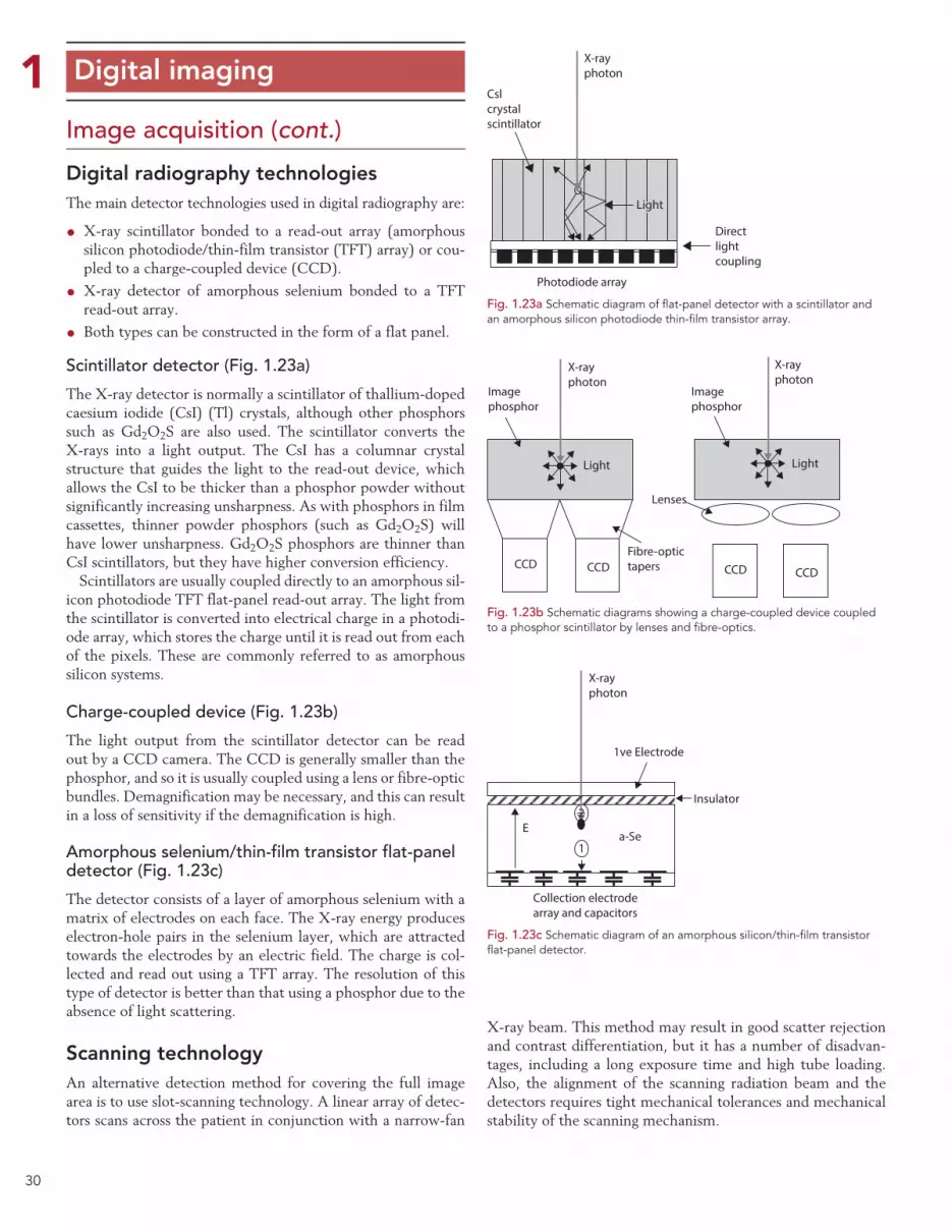
30
1 Digital imaging
Image acquisition (cont.)
Digital radiography technologiesThe main detector technologies used in digital radiography are:
•X-ray scintillator bonded to a read-out array (amorphous silicon photodiode/thin-film transistor (TFT) array) or cou-pled to a charge-coupled device (CCD).
•X-ray detector of amorphous selenium bonded to a TFT read-out array.
• Both types can be constructed in the form of a flat panel.
Scintillator detector (Fig. 1.23a)
The X-ray detector is normally a scintillator of thallium-doped caesium iodide (CsI) (Tl) crystals, although other phosphors such as Gd2O2S are also used. The scintillator converts the X-rays into a light output. The CsI has a columnar crystal structure that guides the light to the read-out device, which allows the CsI to be thicker than a phosphor powder without significantly increasing unsharpness. As with phosphors in film cassettes, thinner powder phosphors (such as Gd2O2S) will have lower unsharpness. Gd2O2S phosphors are thinner than CsI scintillators, but they have higher conversion efficiency.
Scintillators are usually coupled directly to an amorphous sil-icon photodiode TFT flat-panel read-out array. The light from the scintillator is converted into electrical charge in a photodi-ode array, which stores the charge until it is read out from each of the pixels. These are commonly referred to as amorphous silicon systems.
Charge-coupled device (Fig. 1.23b)
The light output from the scintillator detector can be read out by a CCD camera. The CCD is generally smaller than the phosphor, and so it is usually coupled using a lens or fibre-optic bundles. Demagnification may be necessary, and this can result in a loss of sensitivity if the demagnification is high.
Amorphous selenium/thin-film transistor flat-panel detector (Fig. 1.23c)
The detector consists of a layer of amorphous selenium with a matrix of electrodes on each face. The X-ray energy produces electron-hole pairs in the selenium layer, which are attracted towards the electrodes by an electric field. The charge is col-lected and read out using a TFT array. The resolution of this type of detector is better than that using a phosphor due to the absence of light scattering.
Scanning technologyAn alternative detection method for covering the full image area is to use slot-scanning technology. A linear array of detec-tors scans across the patient in conjunction with a narrow-fan
X-ray beam. This method may result in good scatter rejection and contrast differentiation, but it has a number of disadvan-tages, including a long exposure time and high tube loading. Also, the alignment of the scanning radiation beam and the detectors requires tight mechanical tolerances and mechanical stability of the scanning mechanism.
Fig. 1.23a Schematic diagram of flat-panel detector with a scintillator and an amorphous silicon photodiode thin-film transistor array.
Cslcrystalscintillator
X-rayphoton
Photodiode array
Directlightcoupling
Light
Imagephosphor
Imagephosphor
Lenses
Fibre-optictapersCCD CCD CCD CCD
X-rayphoton
X-rayphoton
Light Light
Fig. 1.23b Schematic diagrams showing a charge-coupled device coupled to a phosphor scintillator by lenses and fibre-optics.
X-rayphoton
1ve Electrode
Insulator
Collection electrodearray and capacitors
Ea-Se
1
2
Fig. 1.23c Schematic diagram of an amorphous silicon/thin-film transistor flat-panel detector.
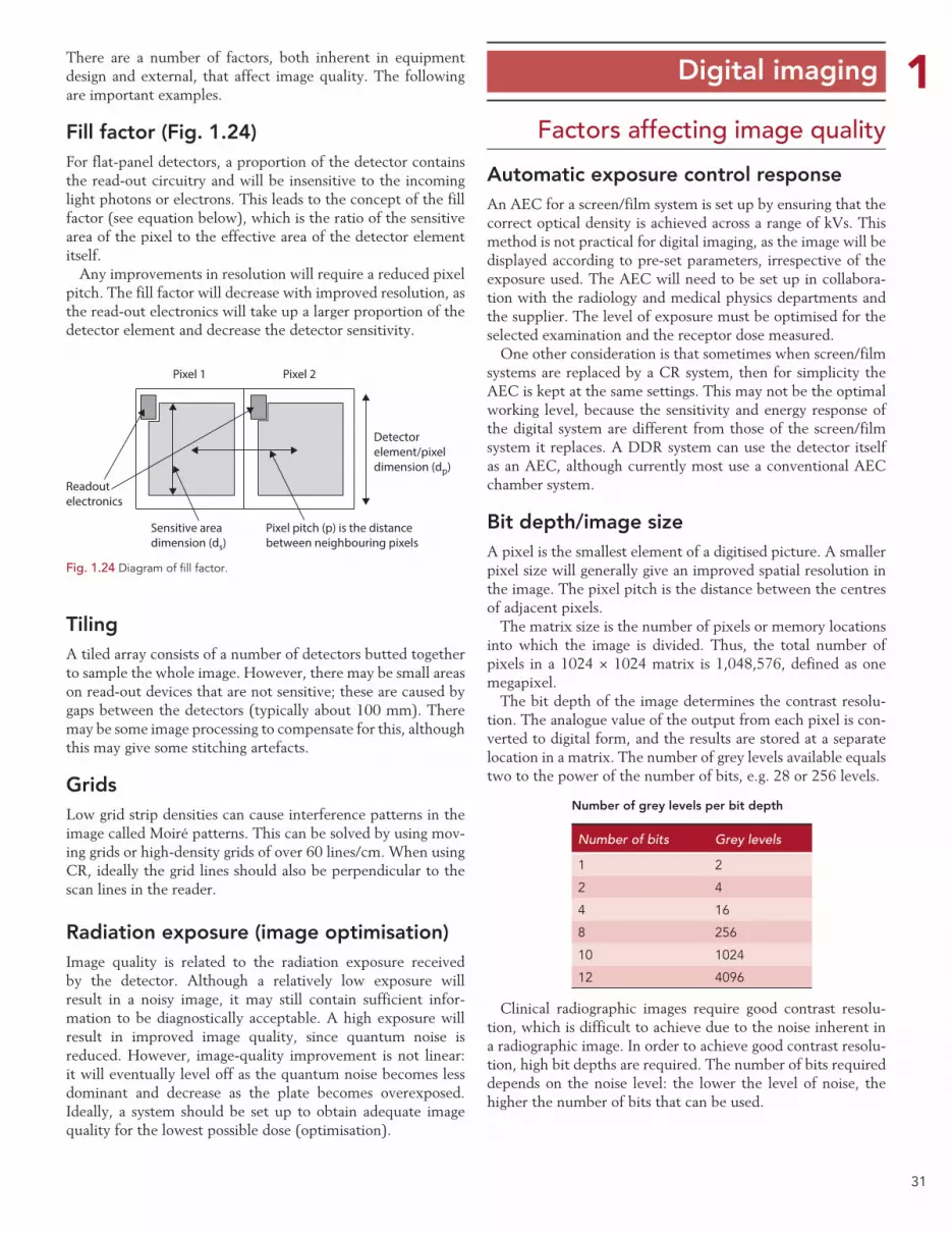
31
1There are a number of factors, both inherent in equipment design and external, that affect image quality. The following are important examples.
Fill factor (Fig. 1.24)For flat-panel detectors, a proportion of the detector contains the read-out circuitry and will be insensitive to the incoming light photons or electrons. This leads to the concept of the fill factor (see equation below), which is the ratio of the sensitive area of the pixel to the effective area of the detector element itself.
Any improvements in resolution will require a reduced pixel pitch. The fill factor will decrease with improved resolution, as the read-out electronics will take up a larger proportion of the detector element and decrease the detector sensitivity.
TilingA tiled array consists of a number of detectors butted together to sample the whole image. However, there may be small areas on read-out devices that are not sensitive; these are caused by gaps between the detectors (typically about 100 mm). There may be some image processing to compensate for this, although this may give some stitching artefacts.
GridsLow grid strip densities can cause interference patterns in the image called Moiré patterns. This can be solved by using mov-ing grids or high-density grids of over 60 lines/cm. When using CR, ideally the grid lines should also be perpendicular to the scan lines in the reader.
Radiation exposure (image optimisation)Image quality is related to the radiation exposure received by the detector. Although a relatively low exposure will result in a noisy image, it may still contain sufficient infor-mation to be diagnostically acceptable. A high exposure will result in improved image quality, since quantum noise is reduced. However, image-quality improvement is not linear: it will eventually level off as the quantum noise becomes less dominant and decrease as the plate becomes overexposed. Ideally, a system should be set up to obtain adequate image quality for the lowest possible dose (optimisation).
Digital imaging
Automatic exposure control responseAn AEC for a screen/film system is set up by ensuring that the correct optical density is achieved across a range of kVs. This method is not practical for digital imaging, as the image will be displayed according to pre-set parameters, irrespective of the exposure used. The AEC will need to be set up in collabora-tion with the radiology and medical physics departments and the supplier. The level of exposure must be optimised for the selected examination and the receptor dose measured.
One other consideration is that sometimes when screen/film systems are replaced by a CR system, then for simplicity the AEC is kept at the same settings. This may not be the optimal working level, because the sensitivity and energy response of the digital system are different from those of the screen/film system it replaces. A DDR system can use the detector itself as an AEC, although currently most use a conventional AEC chamber system.
Bit depth/image sizeA pixel is the smallest element of a digitised picture. A smaller pixel size will generally give an improved spatial resolution in the image. The pixel pitch is the distance between the centres of adjacent pixels.
The matrix size is the number of pixels or memory locations into which the image is divided. Thus, the total number of pixels in a 1024 × 1024 matrix is 1,048,576, defined as one megapixel.
The bit depth of the image determines the contrast resolu-tion. The analogue value of the output from each pixel is con-verted to digital form, and the results are stored at a separate location in a matrix. The number of grey levels available equals two to the power of the number of bits, e.g. 28 or 256 levels.
Number of grey levels per bit depth
Number of bits Grey levels
1 2
2 4
4 16
8 256
10 1024
12 4096
Clinical radiographic images require good contrast resolu-tion, which is difficult to achieve due to the noise inherent in a radiographic image. In order to achieve good contrast resolu-tion, high bit depths are required. The number of bits required depends on the noise level: the lower the level of noise, the higher the number of bits that can be used.
Factors affecting image quality
Fig. 1.24 Diagram of fill factor.
Pixel 2Pixel 1
Readoutelectronics
Sensitive areadimension (ds)
Pixel pitch (p) is the distancebetween neighbouring pixels
Detectorelement/pixeldimension (dp)
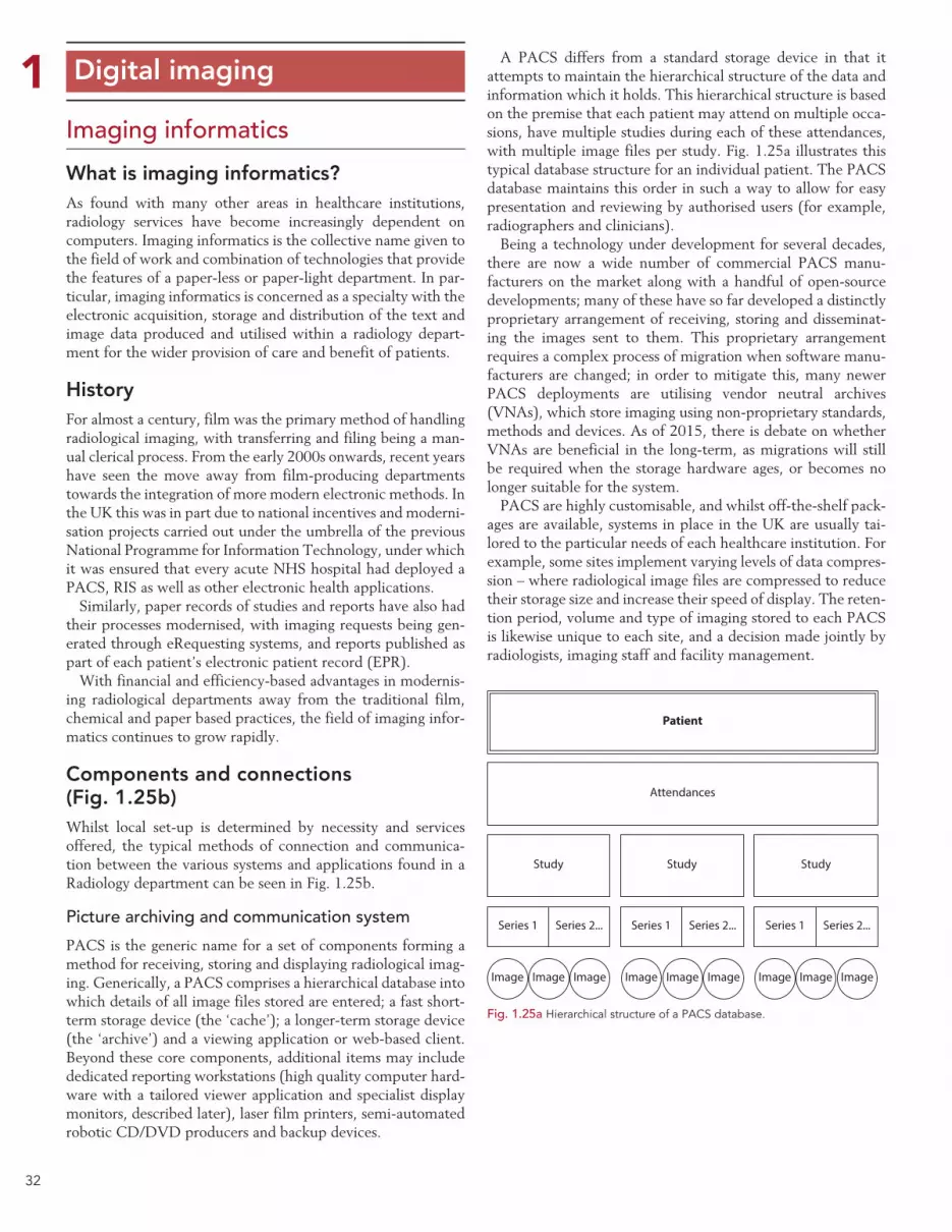
32
1 Digital imaging
Imaging informatics
What is imaging informatics?As found with many other areas in healthcare institutions, radiology services have become increasingly dependent on computers. Imaging informatics is the collective name given to the field of work and combination of technologies that provide the features of a paper-less or paper-light department. In par-ticular, imaging informatics is concerned as a specialty with the electronic acquisition, storage and distribution of the text and image data produced and utilised within a radiology depart-ment for the wider provision of care and benefit of patients.
HistoryFor almost a century, film was the primary method of handling radiological imaging, with transferring and filing being a man-ual clerical process. From the early 2000s onwards, recent years have seen the move away from film-producing departments towards the integration of more modern electronic methods. In the UK this was in part due to national incentives and moderni-sation projects carried out under the umbrella of the previous National Programme for Information Technology, under which it was ensured that every acute NHS hospital had deployed a PACS, RIS as well as other electronic health applications.
Similarly, paper records of studies and reports have also had their processes modernised, with imaging requests being gen-erated through eRequesting systems, and reports published as part of each patient’s electronic patient record (EPR).
With financial and efficiency-based advantages in modernis-ing radiological departments away from the traditional film, chemical and paper based practices, the field of imaging infor-matics continues to grow rapidly.
Components and connections (Fig. 1.25b)Whilst local set-up is determined by necessity and services offered, the typical methods of connection and communica-tion between the various systems and applications found in a Radiology department can be seen in Fig. 1.25b.
Picture archiving and communication system
PACS is the generic name for a set of components forming a method for receiving, storing and displaying radiological imag-ing. Generically, a PACS comprises a hierarchical database into which details of all image files stored are entered; a fast short-term storage device (the ‘cache’); a longer-term storage device (the ‘archive’) and a viewing application or web-based client. Beyond these core components, additional items may include dedicated reporting workstations (high quality computer hard-ware with a tailored viewer application and specialist display monitors, described later), laser film printers, semi-automated robotic CD/DVD producers and backup devices.
A PACS differs from a standard storage device in that it attempts to maintain the hierarchical structure of the data and information which it holds. This hierarchical structure is based on the premise that each patient may attend on multiple occa-sions, have multiple studies during each of these attendances, with multiple image files per study. Fig. 1.25a illustrates this typical database structure for an individual patient. The PACS database maintains this order in such a way to allow for easy presentation and reviewing by authorised users (for example, radiographers and clinicians).
Being a technology under development for several decades, there are now a wide number of commercial PACS manu-facturers on the market along with a handful of open-source developments; many of these have so far developed a distinctly proprietary arrangement of receiving, storing and disseminat-ing the images sent to them. This proprietary arrangement requires a complex process of migration when software manu-facturers are changed; in order to mitigate this, many newer PACS deployments are utilising vendor neutral archives (VNAs), which store imaging using non-proprietary standards, methods and devices. As of 2015, there is debate on whether VNAs are beneficial in the long-term, as migrations will still be required when the storage hardware ages, or becomes no longer suitable for the system.
PACS are highly customisable, and whilst off-the-shelf pack-ages are available, systems in place in the UK are usually tai-lored to the particular needs of each healthcare institution. For example, some sites implement varying levels of data compres-sion – where radiological image files are compressed to reduce their storage size and increase their speed of display. The reten-tion period, volume and type of imaging stored to each PACS is likewise unique to each site, and a decision made jointly by radiologists, imaging staff and facility management.
Fig. 1.25a Hierarchical structure of a PACS database.
Patient
Attendances
Study
Image Image Image Image ImageImage Image ImageImage
Series 1 Series 2... Series 1 Series 2... Series 1 Series 2...
Study Study

33
1 Digital imaging
Imaging informatics (cont.)
Overview of imaging informatics applications
Fig. 1.25b Overview of typical imaging informatics applications and interactions.
Hospital master patient index
Demographics Demographics Demographics
DemographicseRequesting
Requests
Study status andreports
RISElectronic
patient record(EPR)
Other hospitalapplications
Demographics,Study details and status
Study details
Images
Images
Imaging modalities
NMCT
MRI
US
Plain filmCR / DR
Scannedstudies
etc.
PACS
Worklists
DICOMimages
DICOMimages DICOM
images DICOMimages
DICOMimages
ProcessedDICOMimages
ProcessedDICOM images
Viewer application/Web client
Hierarchicaldatabase
(patient, study,image)
Short term storage(local cache)
Longer term storage(archive)
Viewingclinician
GPetc.
Viewingclinician
Images orraw data
Specialist applications
(CT reprocessingPET fusion, etc.)
Remote viewingapplication
(Community care/Teleradiology/
Home viewing etc.)
Image sharing gateway/Network
Images (via WebVieweror another PACS)
Appointments andreports
34
1Imaging informatics (cont.)Radiology information system (RIS)
This is the generic name for an application or group of appli-cations used to handle the textual data related to imaging procedures – for example examination details, the attendance lists, appointment diaries, reports and billing data, as well as data required under IR(ME)R 20001 (e.g. radiation dose, referrer and operator details), IRR992 (radioisotope data) as well as the Medicines Act 1968 (any prescription-only phar-maceuticals administered as part of the imaging exam, such as contrast in intravenous urograms [IVUs] or glyceryl trinitrate in computed tomography [CT] imaging).
In the UK aggregated statistics from the RIS are also pro-vided by NHS hospitals to a body of the Department of Health (currently the Health and Social Care Information Centre) for payments and performance monitoring. Whilst being primar-ily designed for use in a radiology imaging department, other areas of the hospital may in addition use RIS in locally agreed ways.
Other systems that interact with elements of the imaging infor-matics suite but are traditionally maintained by those outside of the radiology department:
Master patient index: also commonly known as the hospital information system (HIS) or patient administration system (PAS), the master patient index is a database application that primarily stores the demographic and contact details of patients, as well as any national identifiers (‘NHS Number’ in England and Wales; ‘Community Health Index’ [CHI Number’] in Scotland). It is common practice for demographic changes in this master database, including the addition of new patients, to be passed down to the other imaging informatics and hospital systems.
This ‘cascade’ update process ensures that the records on other systems each match the primary details recorded in the master patient index. Communication between the master patient index and other text-based imaging informatics com-ponents is usually carried out using the health level 7 (HL7) standard (discussed later).
Electronic patient record: the EPR is a method of storing a patient’s medical records and notes electronically. A viewer application is also included to allow for clinicians and other authorised healthcare staff (and in some instances the patient themselves) to read and add to the records, just as if they were paper based. EPR applications are expected gradually to include PACS images and RIS data over the coming years.
eRequesting: eRequesting systems allow referrers to place requests for a range of diagnostic tests (including Radiology examinations) into a single online application, which then directly sends the request to the relevant department (for Radiology examinations, this would be via the RIS). In addi-tion, eRequesting systems typically offer a range of tracking functions to allow clinicians to view the status of their request, as well as the report when available.10 eRequesting is popu-lar within healthcare institutions as it removes the need for a paper request form to be conveyed physically to a collection point and also provides higher quality audit data.
Other hospital applications: larger healthcare institutions in particular will have a range of other medical informatics appli-cations, which will be required to interface with elements of the imaging informatics suite. For example, dedicated research databases, cardiology or echocardiography information systems or backup devices may well have some degree of interaction with the RIS or PACS.
Modalities: an imaging ‘modality’ is a term given to a particular type of image acquisition method, such as CR, DDR, ultrasound (US), CT, magnetic resonance imaging (MRI), nuclear medicine (NM) and molecular imaging. The majority of the image acquisi-tion methods communicate images electronically into the PACS using the Digital Imaging and Communications in Medicine (DICOM) standards after the operator has post-processed them.
Specialist applications: with ‘simple’ imaging modalities such as CR, DDR and US, the post-acquisition processing functions may be incorporated into a workstation at the acquiring device. Multi-slice modalities that produce complex raw data imaging sets have separate workstations and applications to allow for the intricate and detailed post-acquisition processing to take place. This is commonly found with CT, MRI and NM imaging modal-ities, where the acquired imaging is reprocessed to allow for the clinical question to be answered. The reprocessed data are then stored to PACS for future reference, with some sites choosing not to store permanently the originally acquired raw data.
Remote viewing applications: in recent years, great emphasis has been placed upon allowing 24/7 access to diagnostics. To facilitate this, remote viewing applications allow for the secure and reliable viewing of radiological images beyond the tradi-tional boundaries of PACS, whether this is an offsite night reporting facility or a Radiologist on-call at home.
Image sharing gateways or networks: with increased instances of collaborative care and the geographical mobility of patients, the sharing of radiological image files and textual data between healthcare institutions has become more and more of a neces-sity. Whereas removable media (CDs and DVDs) were ini-tially used, direct peer-to-peer transfers and hub-and-spoke systems are now available.
Digital imaging

35
1CommunicationThe various components and applications within the realm of imaging informatics use well-developed international stand-ards to communicate with each other. The key standards used are described below, and are complimentary to others, which together provide the ability for software from different manufac-turers to communicate without significant difficulty or expense.
DICOM
DICOM is an international standard designed and imple-mented worldwide for the storage and exchange of medical imaging data.11 Released in 1993 and supported universally by manufacturers of imaging equipment, new updates are back-wards compatible, meaning several billion medical images can be reliably viewed and transferred today.12 DICOM allows radiographers to be sure that the digital images they produce will store to a PACS and be viewable for the foreseeable future.
Unlike photographs taken with a digital camera or smart-phone, medical imaging utilises high resolution greyscale images and is required to have some patient or clinical data attached to it. For this, the DICOM file format (.DCM extension) is used to store medical images. In a similar manner to the common JPEG file format being designed to offer a balance between size of file, quality and speed of display for domestic photographs, the DICOM file storage format was developed to meet the needs of the medical imaging community and provides similar benefits.
A DICOM file consists of multiple components, including a preamble (identifying the file type and components), a block of data (comprising patient demographics, technical informa-tion about the image, the study, its acquisition parameters and acquisition device together with many other listed attributes), and the image data. The DICOM standard also describes meth-ods for the transmission of data across networks, and between imaging devices.
HL7 messaging
Almost all communication between modern text-based applica-tions such as RIS, EPR, eRequesting and the patient master index will use the HL7 format. HL7 is a long-standing supplier neu-tral group of standards, named after their position (the seventh ‘layer’) on the International Organization for Standardization Open Systems Interconnection Model13 – in the same manner as hypertext transfer protocol (HTTP) is for internet usage. The HL7 standards14 define specified methods for healthcare systems to communicate data between each other, again allow-ing interoperability between software vendors. HL7 messaging (part of the standards) is a specified format for communication between different text-based systems, including EPR and RIS. HL7 version 2.x is routinely used by healthcare systems with ver-sion 3.x becoming more prevalent in other areas. Put concisely, HL7 standards are primarily concerned with text-based commu-nications, whereas DICOM is utilised when handling image data.
Networks
Networks in this context refer to the physical connections between pieces of image acquisition equipment, storage and
display devices. Whilst important to be aware of the methods of software communicating amongst each other, a physical network connection is required between each of the compo-nents, including to any workstations upon which the viewing applications are being utilised in order to allow this to hap-pen. Networks are customarily maintained by a healthcare institutions information technology department, and must be of suitable quality to ensure fast and reliable transmis-sions between the imaging informatics components. Modern fibre-based networks (an optical transmission technology) are inherently faster than traditional copper-based networks (where data are transmitted electrically). Fast fibre connec-tions are commonly used between servers, network switches and routers, with copper connecting the ‘final hop’ to indi-vidual computers and devices. Wireless networking is pre-ferred in some applications, such as for theatre fluoroscopy equipment, wireless digital mobile units and handheld image display devices (tablets).
Onward transfers of radiological data to external institutions
Increasingly, with PACS archives now containing potentially around a decade of digitally stored prior imaging for each patient, there is a need to forward this data and imaging onwards to other healthcare institutions, either for immediate on-going care or for historical comparisons. With the advent of numerous electronic transfer methods now available via the internet or the intra-NHS (N3) network, this is possible without the need to create hard copies, CDs or DVDs. Networked image sharing can be one of three types – mailbox, cloud or direct:
Mailbox-based methods allow an upload into a specific virtual mailbox, either one for an entire healthcare institution, a service group or a specific clinician.
Cloud-based services provide an off-site storage of imaging data and allow for the images to be exchanged in a portal or other web-based application.
The approach taken for direct sharing varies and can involve creating a remote connection to a PACS or by utilising new technical architectures such as cross enterprise document shar-ing for imaging (XDS-I).
Data protectionThere are legal considerations in any such transfers, whether electronic or physical, mainly stemming from the rights and principles enshrined by the Data Protection Act 1998. Along with the duties surrounding keeping patient data confiden-tial, it is good practice to ensure that all radiological data transfers are necessary, justified and proportionate, together with records being kept to allow for audit of each individual transfer.
Digital imaging
Imaging informatics (cont.)

36
1Image processingOne of the drawbacks to the historic film-based imaging pro-cess was the comparative lack of ability to alter the image easily once chemically developed; if, for example, a film was significantly overexposed, there were few options other than repeating the image with corrected exposure factors. Now, with digital acquisition and post processing, more options are possible, even for the manifestly undiagnostic image.
Post processingAcquisition workstations which are part of the acquiring modali-ties are used to enhance the images obtained and produce a superior quality image set for transmission to PACS. Functions provided on these workstations typically include the ability to correct demographics, place electronic markers, apply secondary collimation (shuttering), add informational text, adjust window width/level values and edit any look-up table (LUT) applied to the image. It is cautioned that good radiographic technique still needs to be followed – the principles of dose minimisation (ALARP) should not be depreciated due to the relative ease with which modern imaging modalities allow enhancement.
Look-up tablesEach digital radiological image is comprised of individual units, called pixels (or voxels for three-dimensional imaging – see opposite) (Fig. 1.26b). LUTs convert the greyscale values of each of these units to another, based on a pre-set conversion table (Fig. 1.26a). This creates a new image, intended to be of bet-ter diagnostic quality than the original. A demonstration of this effect can be seen in Fig. 1.26c. LUTs are used either to reduce the dynamic range of an acquired image (where an acquisition device acquires a wider range of data than can be displayed), or where it is known that it is clinically more appropriate to real-locate specified densities within an image to other shades of grey, such as for specifically viewing particular types of tissue or bone.
Colours may be artificially added to an image, perhaps to highlight flow rates in ultrasound Doppler imaging, or radio-isotope activity levels in fused positron emission tomography (PET)–CT imaging.
Window width/window level (Fig. 1.26d)The human eye has a non-linear response to greyscale values – not every graduation from one greyscale value to another in an image is as perceivable as others. In order to visualise the required anatomy better within radiological images, changes to the window width and level can be made either during post processing, or during later viewing. Briefly simplified, changing the window width has the effect of altering the contrast ratio of the image, whereas adjusting the window level has the effect of altering the average brightness of the image. Combinations of the two adjustments are used to enhance imaging, particularly those obtained with suboptimal exposures (Fig. 1.27).
Digital imaging
Pre-processed pixel value
Post
-pro
cess
ed p
ixel
val
ue
Fig. 1.26a Example of a look-up table (LUT).
Fig. 1.26b Pixel vs. Voxel (both highly enlarged for illustration). Left: black two-dimensional square illustrating one pixel in a larger image. Right: black three-dimensional cube illustrating one voxel.
Fig. 1.26c Applying a look-up table. Left: Raw unprocessed image. Right: suitable LUT applied to the same image.
Window level
Window width
Fig. 1.26d Diagram showing the relationship between window level and window width.
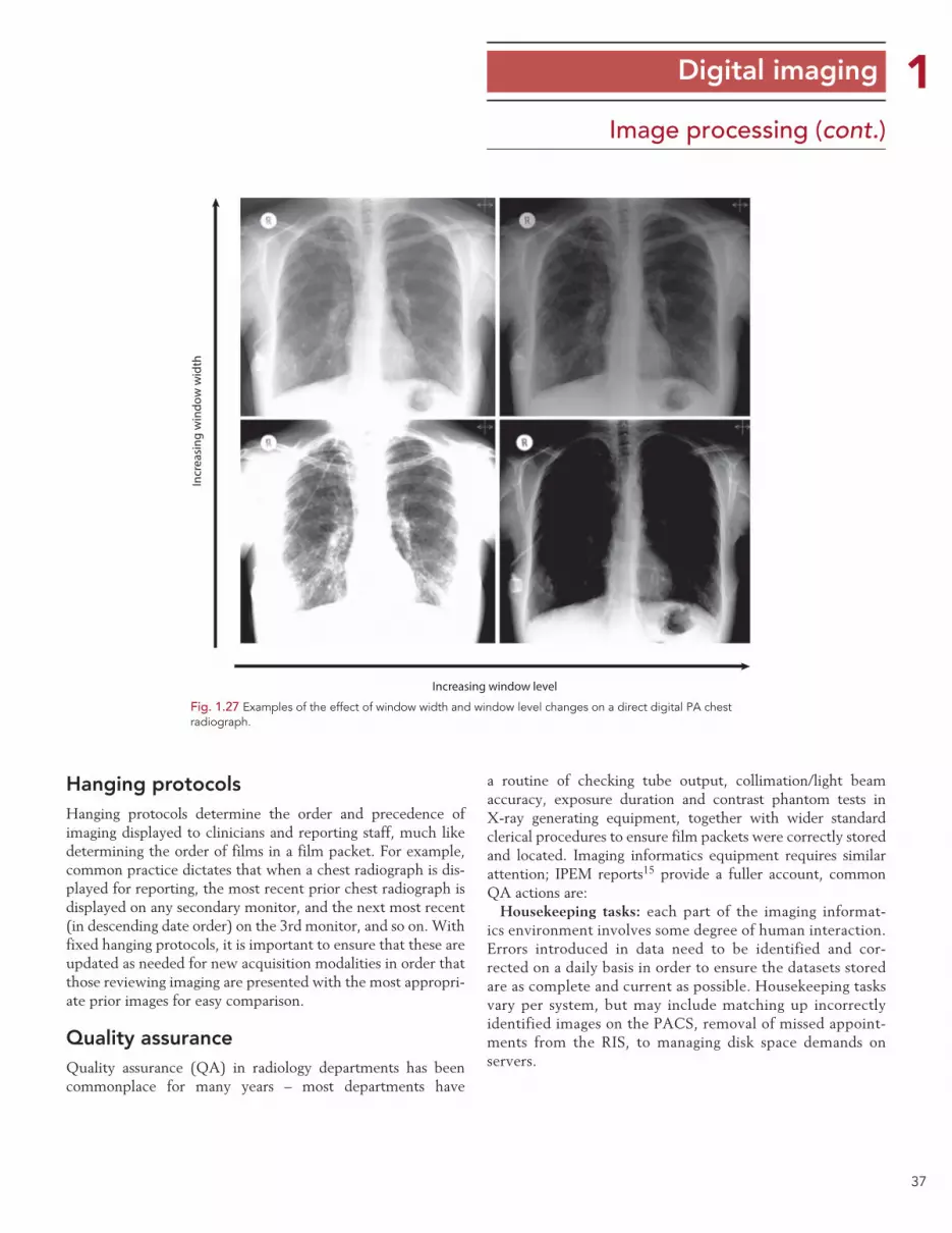
37
1Image processing (cont.)
Hanging protocolsHanging protocols determine the order and precedence of imaging displayed to clinicians and reporting staff, much like determining the order of films in a film packet. For example, common practice dictates that when a chest radiograph is dis-played for reporting, the most recent prior chest radiograph is displayed on any secondary monitor, and the next most recent (in descending date order) on the 3rd monitor, and so on. With fixed hanging protocols, it is important to ensure that these are updated as needed for new acquisition modalities in order that those reviewing imaging are presented with the most appropri-ate prior images for easy comparison.
Quality assuranceQuality assurance (QA) in radiology departments has been commonplace for many years – most departments have
Digital imaging
a routine of checking tube output, collimation/light beam accuracy, exposure duration and contrast phantom tests in X-ray generating equipment, together with wider standard clerical procedures to ensure film packets were correctly stored and located. Imaging informatics equipment requires similar attention; IPEM reports15 provide a fuller account, common QA actions are:
Housekeeping tasks: each part of the imaging informat-ics environment involves some degree of human interaction. Errors introduced in data need to be identified and cor-rected on a daily basis in order to ensure the datasets stored are as complete and current as possible. Housekeeping tasks vary per system, but may include matching up incorrectly identified images on the PACS, removal of missed appoint-ments from the RIS, to managing disk space demands on servers.
Incr
easi
ng w
indo
w w
idth
Increasing window level
Fig. 1.27 Examples of the effect of window width and window level changes on a direct digital PA chest radiograph.

38
1Image processing (cont.)Display monitor calibration: with electronic acquisition, distri-bution and display now being standard, modern day radiology services are heavily dependent on properly functioning display devices. Most widely used display devices are flat panel moni-tors with images composed of a grid formed by millions of pixels, which are backlit by light emitting diodes (or now less commonly, cold cathode fluorescent tubes). Both the pixels and backlights within flat panel monitors degrade with age and use and should be regularly checked. For workstations used to report on diagnostic images, calibration to a DICOM response curve should be carried out (if not built in and automated) utilising a manual ‘puck’ test device and software, at least annually.
Display monitor environment: the physical surroundings and environment in healthcare institutions changes over time; lights around display devices can be altered, walls painted more brightly and windows uncovered. The suitability of viewing locations should be assessed as required, taking note of advice from medical physics personnel. Fingerprints, which accumulate on medical displays, should be cleaned away on a regular basis with care taken not to damage the screen surface.
Database integrity checks: it must be possible to guarantee that all databases and connections within an imaging informat-ics suite are operating correctly. These can be tested by ana-lysing a sample of the data held on each system and ensuring results are in line with expectations. Integrity checks are typi-cally performed before and after any changes or upgrades are carried out to the informatics equipment.
System availability: high expectations are placed on availability of imaging informatics systems; for business continuity pur-poses the regular testing of the redundancy of the systems and processes that surround them is important. These should be documented and might form part of a larger, institution-wide, disaster recovery programme.
Artefacts (Figs 1.28a–1.28d)Just as found with film/chemistry-based radiography, artefacts in radiographic imaging have existed from the inception of the technology. These require guarding against as much as practi-cable to avoid reducing the diagnostic accuracy of the imaging, or the need to repeat any radiation exposure. Artefacts are spe-cific to the modalities and equipment utilised; radiographers should be aware of the possible types of image degradation and their causes from the equipment that they are using. The images opposite demonstrate a small sample of common arte-facts from CR and DDR systems; a wider range can be found in investigative studies such as Honey & Mackenzie and Shetty et al.16,17
Digital imaging
Fig. 1.28a Electronics overlaying image, due to exposure through reverse of DDR plate.
Fig. 1.28b Linear artefact caused by particle of dust obstructing portion of CR reader light guide during readout.
Fig. 1.28c Data transfer error – partial network communication loss during image data transmission.
Fig. 1.28d Localised backscatter artefacts caused by damaged lead backing on a CR cassette.
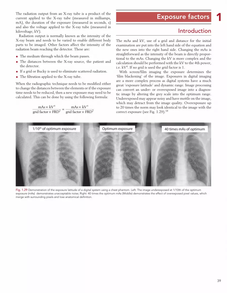
39
1 Exposure factorsThe radiation output from an X-ray tube is a product of the current applied to the X-ray tube (measured in milliamps, mA), the duration of the exposure (measured in seconds, s) and also the voltage applied to the X-ray tube (measured in kilovoltage, kV).
Radiation output is normally known as the intensity of the X-ray beam and needs to be varied to enable different body parts to be imaged. Other factors affect the intensity of the radiation beam reaching the detector. These are:
• The medium through which the beam passes.
• The distances between the X-ray source, the patient and the detector.
• If a grid or Bucky is used to eliminate scattered radiation.
• The filtration applied to the X-ray tube.
When the radiographic technique needs to be modified either to change the distances between the elements or if the exposure time needs to be reduced, then a new exposure may need to be calculated. This can be done by using the following formula:
××
= ××
mAs kVgrid factor FRD
mAs kVgrid factor FRD
4
2
4
2
The mAs and kV, use of a grid and distance for the initial examination are put into the left hand side of the equation and the new ones into the right hand side. Changing the mAs is straightforward as the intensity of the beam is directly propor-tional to the mAs. Changing the kV is more complex and the calculation should be performed with the kV to the 4th power, i.e. kV4. If no grid is used the grid factor is 1.
With screen/film imaging the exposure determines the ‘film blackening’ of the image. Exposures in digital imaging are a more complex process as digital systems have a much great ‘exposure latitude’ and dynamic range. Image processing can convert an under- or overexposed image into a diagnos-tic image by altering the grey scale into the optimum range. Underexposed may appear noisy and have mottle on the image, which may detract from the image quality. Overexposure up to 20 times the norm may look identical to the image with the correct exposure (see Fig. 1.29).18
Introduction
1/10th of optimum exposure Optimum exposure 40 times mAs of optimum
Fig. 1.29 Demonstration of the exposure latitude of a digital system using a chest phantom. Left: The image underexposed at 1/10th of the optimum exposure (mAs) demonstrates unacceptable noise; Right: 40 times the optimum mAs (Middle) demonstrates the effect of overexposed pixel values, which merge with surrounding pixels and lose anatomical definition.
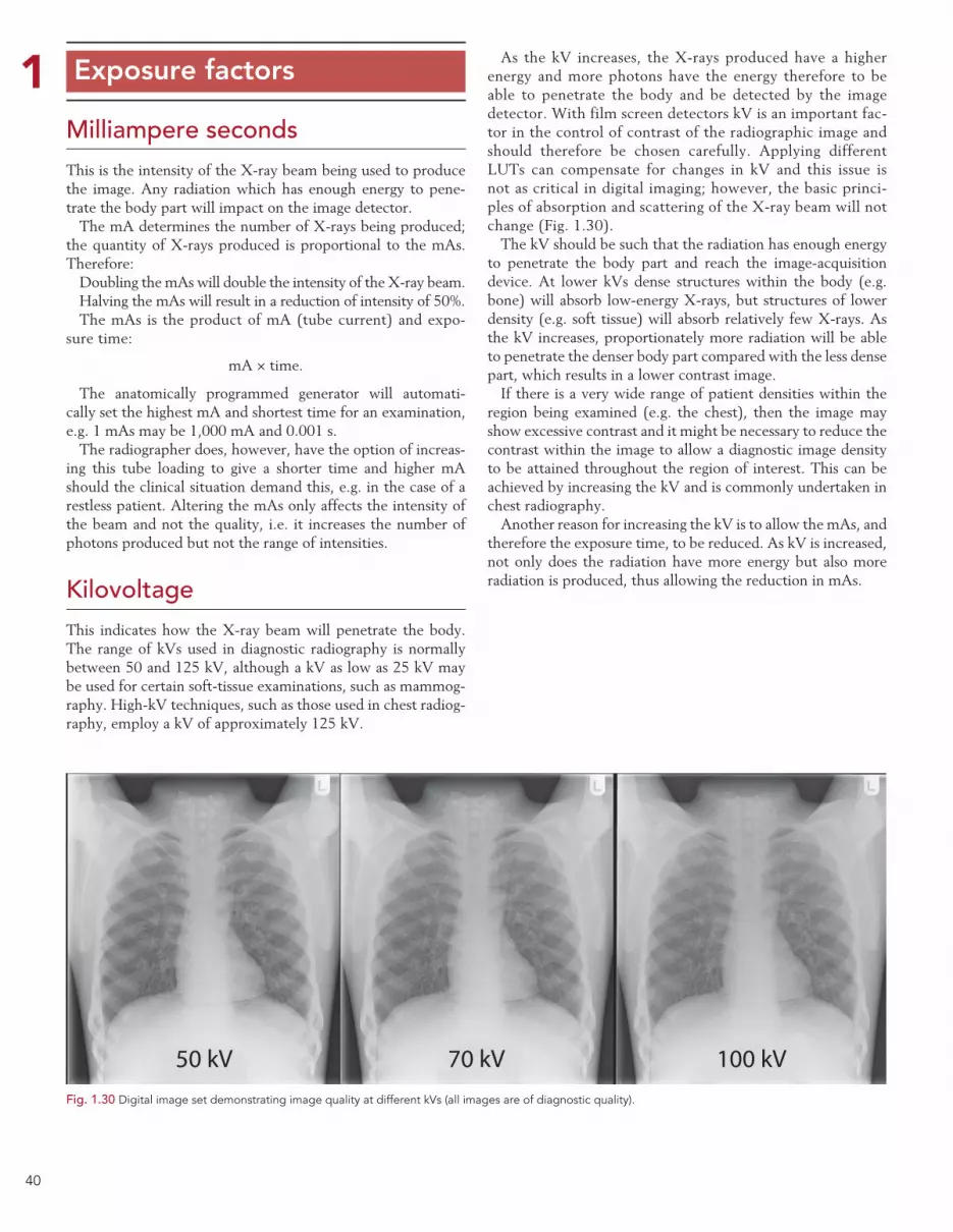
40
1 Exposure factors
Milliampere secondsThis is the intensity of the X-ray beam being used to produce the image. Any radiation which has enough energy to pene-trate the body part will impact on the image detector.
The mA determines the number of X-rays being produced; the quantity of X-rays produced is proportional to the mAs. Therefore:
Doubling the mAs will double the intensity of the X-ray beam.Halving the mAs will result in a reduction of intensity of 50%.The mAs is the product of mA (tube current) and expo-
sure time:
mA × time.
The anatomically programmed generator will automati-cally set the highest mA and shortest time for an examination, e.g. 1 mAs may be 1,000 mA and 0.001 s.
The radiographer does, however, have the option of increas-ing this tube loading to give a shorter time and higher mA should the clinical situation demand this, e.g. in the case of a restless patient. Altering the mAs only affects the intensity of the beam and not the quality, i.e. it increases the number of photons produced but not the range of intensities.
KilovoltageThis indicates how the X-ray beam will penetrate the body. The range of kVs used in diagnostic radiography is normally between 50 and 125 kV, although a kV as low as 25 kV may be used for certain soft-tissue examinations, such as mammog-raphy. High-kV techniques, such as those used in chest radiog-raphy, employ a kV of approximately 125 kV.
As the kV increases, the X-rays produced have a higher energy and more photons have the energy therefore to be able to penetrate the body and be detected by the image detector. With film screen detectors kV is an important fac-tor in the control of contrast of the radiographic image and should therefore be chosen carefully. Applying different LUTs can compensate for changes in kV and this issue is not as critical in digital imaging; however, the basic princi-ples of absorption and scattering of the X-ray beam will not change (Fig. 1.30).
The kV should be such that the radiation has enough energy to penetrate the body part and reach the image-acquisition device. At lower kVs dense structures within the body (e.g. bone) will absorb low-energy X-rays, but structures of lower density (e.g. soft tissue) will absorb relatively few X-rays. As the kV increases, proportionately more radiation will be able to penetrate the denser body part compared with the less dense part, which results in a lower contrast image.
If there is a very wide range of patient densities within the region being examined (e.g. the chest), then the image may show excessive contrast and it might be necessary to reduce the contrast within the image to allow a diagnostic image density to be attained throughout the region of interest. This can be achieved by increasing the kV and is commonly undertaken in chest radiography.
Another reason for increasing the kV is to allow the mAs, and therefore the exposure time, to be reduced. As kV is increased, not only does the radiation have more energy but also more radiation is produced, thus allowing the reduction in mAs.
Fig. 1.30 Digital image set demonstrating image quality at different kVs (all images are of diagnostic quality).
50 kV 70 kV 100 kV

41
1 Exposure factors
Intensifying screensIntensifying screens used in conjunction with photographic film are usually in pairs, with the film sandwiched between them and contained in a rigid, light-tight container, i.e. a cassette.
Different types of intensifying screen emit different intensi-ties and different colours of light when irradiated by X-rays. It is important to ensure that the type of film used with a particu-lar type of screen is matched in terms of the colour of light to which it is most sensitive.
‘Fast’ or regular screens require less radiation to produce the same film blackening than the ‘slow’ screens used for extremity radiography. When changing from slow to fast screens, the expo-sure must be reduced. This has the advantage that a lower radia-tion dose is received by the patient; however, greater screen speed will result in greater photographic unsharpness, with a resultant decrease in image quality. It is important to consult the screen manufacturers’ guidelines to become aware of the difference in speed of the particular screens used in a particular department.
Digital imagingWhen a digital method of image acquisition is being used then a wide range of exposures will produce a diagnostic image. If the equipment does not receive an exposure within the dynamic range, then the image may show noise or mottle and will not be suitable for diagnosis. Exposures over a given optimum will still produce an acceptable image up to a point (approximately 20 times more), but the patient will have been exposed to a radiation dose that is unjustifiable.
The equipment used for digital image acquisition should have an exposure index (EI) that displays how much expo-sure was used for a particular examination. The radiographer should check the exposure is within the correct value recom-mended by the manufacturer. All manufacturers use different EIs, therefore the radiographer must be familiar with the val-ues for each piece of digital equipment they use.
Focus-to-receptor distance (Figs 1.31a, 1.31b)
For a given kV and mAs, the greater the FRD, the lower the intensity of radiation reaching the image receptor. Therefore, to obtain the same intensity, if the FRD is increased the mAs must also be increased.
When choosing the FRD, the following factors are taken into consideration:
• The X-ray tube must not be too close to the patient’s skin, otherwise radiation damage could be caused.19
• Short FRDs could give unacceptable geometric unsharpness.
Most extremity and table radiographic examinations are car-ried out with an FRD of 100–110 cm, which gives acceptable focus-to-skin distance and geometrical unsharpness. The FRD used may have an impact on the type of grids used. Focused grids need to be purchased which fit the FRD used in your department.
If there is a large object-to-receptor distance, FRD is some-times increased to reduce geometrical unsharpness and mag-nification. To calculate the new exposure at the changed distance, the following formula can be used:
= ×New mAsNew distanceOld distance
Original mAs2
2
For example, if at 100 cm FRD an exposure of 60 kV and 20 mAs produced a satisfactory result, then at 200 cm FRD, the new mAs would be calculated as follows:
= ×New mAs200100
202
2
Therefore, the exposure factors required at an FRD of 200 cm will be 60 kV and 80 mAs.
Fig. 1.31b Radiographic image with excessive noise from underexposure.
Fig. 1.31a FRD increased to reduce increased geometric unsharpness from a large OFD.

42
1Secondary radiation gridsGrids are used when the thicker or denser parts of the body are being examined, where scattered radiation is likely to reduce/degrade significantly the contrast of the image. Bucky assem-blies/antiscatter grids are the most commonly used method to reduce noise and thus improve contrast in an X-ray image in large body parts, e.g. the spine and pelvis. This is achieved by absorbing scattered radiation that exits the patient before it reaches the image receptor. The grid allows the majority of the primary X-rays to be transmitted and the majority of the scat-tered X-rays to be absorbed. It is constructed from lead strips (that absorb the scatter) that are separated by radiolucent alu-minium material or fibre.
The grid, however, also absorbs some of the primary beam and the radiation exposure to the patient must be increased by a factor of 2–3 to compensate for the loss of primary and scat-tered X-rays removed by the grid.
Grids can be stationary and simply placed between the patient and the image receptor or inserted into a Bucky mecha-nism where they move in a reciprocating manner to absorb the scattered photons.
If the grid remains stationary during the exposure, then the grid pattern may be seen on the radiograph. This is usually the case when a stationary grid is used, e.g. for ward and some trauma radiography. In the imaging department, the grid is attached to a mechanism in the X-ray table or vertical stand that gives it an oscillatory movement, so that the grid pattern is not seen. If the grid has a lattice of 50 lines or more per cen-timetre, then it can be used stationary without the grid lines being visible on the resultant image.
The Bucky mechanism is located under the X-ray table or vertical-stand. The specifications of different grids can vary based on:
• The number of strips over the length of the grid (numbers of strips per centimetre).
• The grid ratio (height of the lead strips to the interspace distance) (Fig. 1.32a).
•Whether the grid is focused or parallel (alignment of the lead strips). A focused grid allows more useful photons to reach the image detector but has restrictions of the FRD used. Focused grids are available that are manufactured for a range of specific FRDs, and care must be taken to select the relevant grid for the FRD employed.
• The pattern of the lead strips or orientation.
The grid frequency and ratio can range from 25 to 45 lines/cm and from a ratio of 4:1 to 16:1, respectively. The higher the frequency the more effective the removal of scatter. The grid pattern can be linear (strips running in one direction) or crossed (strips running perpendicular to one another), where crossed grids are associated with higher scatter reduction.
The higher the grid capability to absorb scattered radiation (i.e. higher frequency or ratio or grid with crossed pattern),
the more it absorbs useful X-ray photons and the more increase in dose is needed. It is also important to note that grid mis-alignment may result in grid ‘cut-off’ where a large number of useful X-ray photons are absorbed by the grid, thus causing a substantial loss of image density (Figs 1.32b, 1.32c).
Choice of exposure factorsExposure factors must be optimised according to the ALARP principle. The appropriate kV is selected to give the required penetration and subject contrast. The mAs is selected to give the correct incident intensity. The magnitude of the exposure depends on:
Exposure factorsSpacing material
8
1 1
4
Pb slat
4 : 1 ratio
Fig. 1.32a Grid ratio.
X-ray tube
Object
GridImage receptor Beam
attenuated by grid
Fig. 1.32b One cause of grid cut-off: beam angulation across gridlines.
Fig. 1.32c Grid cut-off due to focused grid being upside down.

43
1 Summary of factors
contributing to optimum radiographic image quality
• The type of image-acquisition device, e.g. the relative speed of intensifying screens.
• The FRD.
• The grid factor (if a grid is used).
Measures used to reduce the exposure time should be con-sidered if movement unsharpness is likely to be a problem by increasing the kV and using a shorter exposure time.
Fig. 1.33 Factors affecting image quality.
Information to justify the examination andan accurate history
Eliminate mottle dueto underexposure
Image sharpness
Optimum image of diagnosticquality
Clinical history and clinical question
Optimum contrast
Optimum viewingconditions
Correct exposure factors(mAs, kV) depending on
patient anatomicalarea and size
Apply correct imagingalgorithm for digital
systems
Reduce scatterreaching the
detector
Geometric unsharpness • Small focal spot size • Increase distances between the focus, and image receptor • Minimise distance between object (patient) and detector
Eliminate movementunsharpness
Use of edgeenhancementsoftware tools
Image capture device
CR/DDR/film screen
44
1 Radiation protection
Although imaging with X-rays offers great benefits to patients, the risks associated with using ionising radiation require the implementation of robust systems of radiation protection for patients, staff and members of the public. In the UK the requirements for protection of staff and the public are set out in the Ionising Radiations Regulations 1999 (IRR99),2 while pro-tection of patients is mainly covered by the Ionising Radiations (Medical Exposures) Regulations. Both sets of regulations fol-low accepted international principles for radiation protection: that all exposures are justified taking the risks and benefits into account; exposures are optimised so that they are as low as practicable given the intended purpose; and that doses do not exceed statutory limits where these apply.
The radiographer has a duty of care to undertake radiog-raphy within an environment that takes into account legisla-tion that specifically relates to medical exposures. Legislation is specific to the use of equipment generating ionising radia-tion. This section will deal with these issues in detail taking into consideration the radiographer, patient, carers and other healthcare professionals.
Medical exposureThe Ionising Radiation (Medical Exposure) Regulations (IRMER) 2000 and IR(ME)R Amendment Regulations 2006/2011
These regulations are intended to protect individuals against the dangers of ionising radiation while undergoing medical exposures. These include diagnostic procedures such as X-rays, CT scans and NM examinations, as well as treatment such as radiotherapy, irrespective of where they are undertaken, e.g. hospital department, dental practice, chiropractic clinic. Medical exposures undertaken for research purposes are also covered by these Regulations.
The Regulations define the duty-holders who carry responsi-bility under IR(ME)R 2000. These are:
• The employer (normally a NHS Trust or regulated private sector provider of the hospital-based environment) is the body responsible for putting all of the necessary procedures and protocols in place to ensure that the IR(ME)R 2000 regulations can be fully applied.
• The referrer, a registered healthcare professional (e.g. a medi-cal or dental practitioner, radiographer, chiropodist, physi-otherapist) who is entitled in accordance with the employer’s procedures to refer patients for medical exposures.
• The practitioner, a registered healthcare professional who is entitled in accordance with the employer’s procedures and
whose primary responsibility is justification of the individ-ual medical exposure (e.g. the radiographer or radiologist).
• The operator, a person who is entitled in accordance with the employer’s procedures to undertake the medical exposure (e.g. a radiographer, radiologist, clinical scientist, technolo-gist or an assistant practitioner). Operators are also involved in other aspects of medical exposures, such as equipment calibration or quality control. Student radiographers may undertake imaging procedures under strict protocols and with supervision by a practitioner.
JustificationThe regulations state that no person shall carry out a medi-cal exposure unless it has been justified by the practitioner as showing a sufficient net benefit to the individual. As part of the justification a risk–benefit analysis must be undertaken.
Risk–benefitRisk–benefit analysis is one of the best tools for managing risk on a daily basis and is still a part of the process of protecting radia-tion workers, patients and carers. The use of X-rays for diagnosis has associated dangers or risks, yet distinct benefits for mankind (can you imagine a 21st century hospital providing its services without using X-rays in either a diagnostic or therapeutic capac-ity?). It therefore follows that it is necessary to use a process that assesses risks and benefits when using X-rays.
Radiation legislation in the UK requires that those patients referred as part of their own medical diagnosis or treatment should not be irradiated intentionally unless there is a valid clinical indication. In making this judgement, the clinician must determine that the benefit to the patient in having the examination will outweigh the risk. This is the process of jus-tification; if the result of having the X-ray examination will change the clinical management of the patient then that exam-ination can be said to be justified.
We have to be aware however, that requesting an X-ray to exclude an injury or a disease process can be perfectly justifi-able also, providing it is not possible to be reasonably sure of the outcome by other, ‘less risky’ means. An example of ‘less risky’ in this case might be a thorough clinical examination.
So justification is the first step in a radiation protection strategy because the best way to reduce the radiation dose to the patient is not to undertake the examination in the first place, if this is con-sidered to be an appropriate course of action. The justification of an X-ray examination is a two-stage process and should be the responsibility of both the referring clinician along with the radi-ographer responsible for undertaking the request. Determining whether an examination is justified will vary depending on fac-tors such as the age of the individual, the pregnancy status or the availability of other diagnostic procedures.

45
1 Radiation protection
Medical exposure (cont.)
Dose quantitiesIn order to assess potential harm caused by ionising radiation, quantification of the radiation used is essential.
The likelihood and severity of harm depends on the amount of X-ray energy absorbed in the patient. Radiation dose (expressed in joules/kilogram. J/kg or Gray, Gy) is used to quantify the amount of energy absorbed within a known mass of tissue. Some types of radiation cause more harm than others for the same absorbed dose. The equivalent dose (expressed in Sieverts, Sv) is found by multiplying the absorbed dose by the quality factor assigned to specific types of radiation. For diagnostic X-rays, the quality factor is one, so that absorbed dose and equivalent dose have the same value. The risk also depends on which organs and tissues are irradiated. To take account of this, the tissues are given a weighting factor accord-ing to their susceptibility to harm from radiation. Organ dose multiplied by the tissue-weighting factor gives the weighted equivalent dose for that organ. The effective dose for an exami-nation (expressed in Sv) is found by adding up the weighted equivalent doses for tissues or organs that have been irradiated. Effective dose indicates the detriment to health of an X-ray, allowing for the site of the examination and the exposure con-ditions.
For most tissues, it is not feasible to measure organ doses directly. However, they can be derived using mathematical models of the dose distributions within simulated patients for different examinations and exposure conditions. The models are used to convert patient dose–area product readings (DAP, expressed in Gy cm2) or entrance skin dose measurements (ESD, expressed in mGy) into organ doses. Combining the weighted organ doses gives the effective dose for the given examination conditions. Skin doses are usually measured using thermoluminescent dosimeters (TLDs) or are calculated indi-rectly from tube output and back-scatter data.
For monitoring the relative patient dose levels for different types of examination performed using a variety of equipment, it is usually sufficient to analyse DAP readings or skin dose data without deriving effective doses. National and local DRLs will also be set in terms of these quantities and are discussed on page 48.
Radiation dose quantities
Dose quantity Unit Definition
Absorbed dose Gy Energy absorbed in known mass of tissue
Organ dose mGy Average dose to specific tissue
Effective dose mSv Overall dose weighted for sensitivity of different organs; indicates risk
Entrance surface dose
mGy Dose measured at entrance surface; used to monitor doses and set DRLs for radiographs
Dose–area product Gy cm2 Product of dose (in air) and beam area; used to monitor doses and set DRLs for examinations
DRL, dose reference level.
Radiation risk for X-ray examinations to an average adult
Examination Typical effective dose (mSv) Risk*
Chest 0.02 1 in 1000 000
Mammography 0.06 1 in 300 000
Abdomen 0.7 1 in 30 000
Lumbar spine 1.3 1 in 15 000
CT head 2 1 in 10 000
Barium enema 7.2 1 in 2800
CT body 9 1 in 2200
* Additional lifetime risk of fatal cancer.
Benefits of X-ray examinationsThe benefits of having X-ray procedures are associated with managing the treatment and or diagnosis of the patient. These may include:
• Saving the person’s life by providing the correct diagnosis that may not be able to be made without the use of X-rays, e.g. chest X-ray to demonstrate extent of pathology.
•Giving the patient the correct treatment as a result of the correct diagnosis.
• Eliminating disease/disorders that affect the management of the patient, e.g. determining if a patient has a fracture and how best to manage the patient’s fracture.
•Managing the treatment of a patient by imaging the response to treatment, e.g. images to determine the effect of radio-therapy.
•Making a diagnosis with an examination that has less mor-bidity and mortality than an alternative test, e.g. CT rather than invasive surgery.19
46
1Medical exposure (cont.)
Radiation risksThere is no safe dose limit and all exposures carry some risk. The purpose of a risk–benefit discussion should therefore be to justify the examination to the patient, discuss the need for the examination and quantify the risk. The Health Protection Agency produces an excellent leaflet called X-rays: how safe are they?, which outlines the common imaging procedures and levels of risk for common X-ray and isotope procedures. To quote them:
“You will be glad to know that the radiation doses used for X-ray examinations or isotope scans are many thousands of times too low to produce immediate harmful effects, such as skin burns or radiation sickness. The only effect on the patient that is known to be possible at these low doses is a very slight increase in the chance of cancer occurring many years or even decades after the exposure.”.20
It also gives approximate estimates of the chance or risk that a particular examination or scan might result in a radiation-induced cancer later in the lifetime of the patient are shown in the table opposite.
There are a number of ways of describing the risk.18 These include:
• Equivalent background dose, expressed in equivalent period of natural background radiation, e.g. a few days to several years.
• Statistical risk expressed in numbers, such as minimal risk of cancer of 1 in 1,000,000 to 1 in 100,000.
•Comparisons to general risks of cancer, i.e. the population have a 1 in 3 chance of getting cancer.
•Comparison to everyday activities: e.g. airline flights are very safe with the risk of a crash being well below 1 in 1,000,000.
A 4-hour plane flight exposes you to the same radiation dose (from cosmic rays) as a chest X-ray.
The purpose of managing radiation dose in diagnostic proce-dures using X-ray is to avoid predictable (deterministic) health effects and to reduce the probability of randomly determined (stochastic) health effects of ionising radiation.
Referrers and practitioners must be educated in the risks and benefits and the radiation dose given from different X-ray pro-cedures and how to communicate them effectively to patients and carers. Whichever comparison you decide to use, make sure that the correct information is at hand and always discuss risk verses benefit. The principles of justification and optimi-sation can be used to inform the patient that X-rays are not undertaken without a valid clinical reason. Any examinations will use the lowest dose compatible with making a diagnosis (ALARP principle) and the exposure will be optimised. It must also be remembered that the patient always has the right to decide not to have the examination.
OptimisationThe IRMER regulations states that “The practitioner and the operator, to the extent of their respective involvement in a medical exposure, shall ensure that doses arising from the exposure are kept as low as reasonably practicable consistent with the intended purpose.”
Additionally the regulations also state that that the operator shall select equipment and methods to ensure that for each medical exposure the dose of ionising radiation to the individ-ual undergoing the exposure is as low as reasonably practicable and consistent with the intended diagnostic or therapeutic pur-pose, and in doing so shall pay special attention to:
•Careful/precise technique to minimise repeat examinations.
•QA of equipment.
•Optimisation of exposure factors to provide a diagnostic image within the DRLs set for each procedure.
•Agreed exposure charts.
•Clinical audit of procedures and exposures.
It is important therefore, that special attention is paid to these relevant issues to ensure that patient doses are kept to a minimum.1
Radiation protection
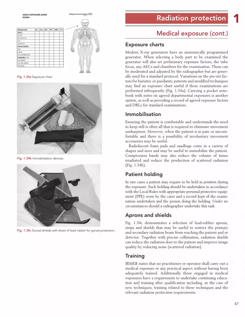
47
1Medical exposure (cont.)
Exposure chartsModern X-ray generators have an anatomically programmed generator. When selecting a body part to be examined the generator will also set preliminary exposure factors, the tube focus, any AECs and chambers for the examination. These can be moderated and adjusted by the radiographer but are gener-ally used for a standard protocol. Variations on the pre-set fac-tors for bariatric or paediatric patients and modified techniques may find an exposure chart useful if these examinations are performed infrequently (Fig. 1.34a). Carrying a pocket note-book with notes on agreed departmental exposures is another option, as well as providing a record of agreed exposure factors and DRLs for standard examinations.
ImmobilisationEnsuring the patient is comfortable and understands the need to keep still is often all that is required to eliminate movement unsharpness. However, when the patient is in pain or uncom-fortable and there is a possibility of involuntary movement accessories may be useful.
Radiolucent foam pads and sandbags come in a variety of shapes and sizes and may be useful to immobilise the patient. Compression bands may also reduce the volume of tissue irradiated and reduce the production of scattered radiation (Fig. 1.34b).
Patient holdingIn rare cases a patient may require to be held in position during the exposure. Such holding should be undertaken in accordance with the Local Rules with appropriate personal protective equip-ment (PPE) worn by the carer and a record kept of the exami-nation undertaken and the person doing the holding. Under no circumstances should a radiographer undertake this task.
Aprons and shieldsFig. 1.34c demonstrates a selection of lead-rubber aprons, strips and shields that may be useful to restrict the primary and secondary radiation beam from reaching the patient and or detector. Together with precise collimation, radiation shields can reduce the radiation dose to the patient and improve image quality by reducing noise (scattered radiation).
TrainingIRMER states that no practitioner or operator shall carry out a medical exposure or any practical aspect without having been adequately trained. Additionally those engaged in medical exposures have a requirement to undertake continuing educa-tion and training after qualification including, in the case of new techniques, training related to these techniques and the relevant radiation protection requirements.
Radiation protection
Fig. 1.34a Exposure chart.
PROJECTION
SKULL
OF/FO
OF 30/FO 30
ADULT EXPOSURE GUIDEROOM :-
LAT
SCALP F.B.
FACIAL BONES
MANDIBLE – PA
LAT MAND.
LAT OBL MAND.
LAT NOSE
OM
OM 30
OF 30 (ORBITS FB)
kVp mAs AEC FFD GRID F/S
Fig. 1.34c Gonad shields with sheet of lead rubber for gonad protection.
Fig. 1.34b Immobilisation devices.
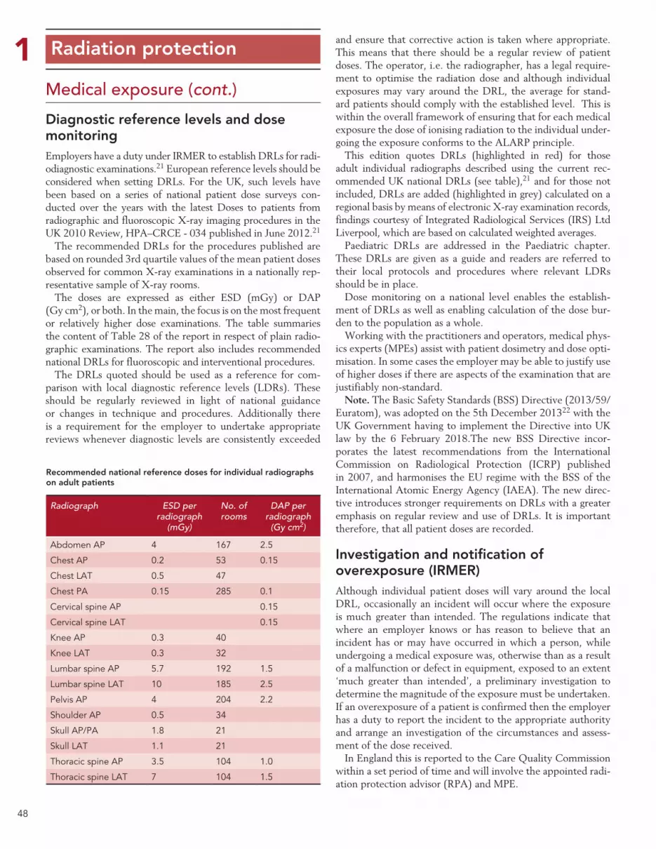
48
1Medical exposure (cont.)
Diagnostic reference levels and dose monitoringEmployers have a duty under IRMER to establish DRLs for radi-odiagnostic examinations.21 European reference levels should be considered when setting DRLs. For the UK, such levels have been based on a series of national patient dose surveys con-ducted over the years with the latest Doses to patients from radiographic and fluoroscopic X-ray imaging procedures in the UK 2010 Review, HPA–CRCE - 034 published in June 2012.21
The recommended DRLs for the procedures published are based on rounded 3rd quartile values of the mean patient doses observed for common X-ray examinations in a nationally rep-resentative sample of X-ray rooms.
The doses are expressed as either ESD (mGy) or DAP (Gy cm2), or both. In the main, the focus is on the most frequent or relatively higher dose examinations. The table summaries the content of Table 28 of the report in respect of plain radio-graphic examinations. The report also includes recommended national DRLs for fluoroscopic and interventional procedures.
The DRLs quoted should be used as a reference for com-parison with local diagnostic reference levels (LDRs). These should be regularly reviewed in light of national guidance or changes in technique and procedures. Additionally there is a requirement for the employer to undertake appropriate reviews whenever diagnostic levels are consistently exceeded
and ensure that corrective action is taken where appropriate. This means that there should be a regular review of patient doses. The operator, i.e. the radiographer, has a legal require-ment to optimise the radiation dose and although individual exposures may vary around the DRL, the average for stand-ard patients should comply with the established level. This is within the overall framework of ensuring that for each medical exposure the dose of ionising radiation to the individual under-going the exposure conforms to the ALARP principle.
This edition quotes DRLs (highlighted in red) for those adult individual radiographs described using the current rec-ommended UK national DRLs (see table),21 and for those not included, DRLs are added (highlighted in grey) calculated on a regional basis by means of electronic X-ray examination records, findings courtesy of Integrated Radiological Services (IRS) Ltd Liverpool, which are based on calculated weighted averages.
Paediatric DRLs are addressed in the Paediatric chapter. These DRLs are given as a guide and readers are referred to their local protocols and procedures where relevant LDRs should be in place.
Dose monitoring on a national level enables the establish-ment of DRLs as well as enabling calculation of the dose bur-den to the population as a whole.
Working with the practitioners and operators, medical phys-ics experts (MPEs) assist with patient dosimetry and dose opti-misation. In some cases the employer may be able to justify use of higher doses if there are aspects of the examination that are justifiably non-standard.
Note. The Basic Safety Standards (BSS) Directive (2013/59/Euratom), was adopted on the 5th December 201322 with the UK Government having to implement the Directive into UK law by the 6 February 2018.The new BSS Directive incor-porates the latest recommendations from the International Commission on Radiological Protection (ICRP) published in 2007, and harmonises the EU regime with the BSS of the International Atomic Energy Agency (IAEA). The new direc-tive introduces stronger requirements on DRLs with a greater emphasis on regular review and use of DRLs. It is important therefore, that all patient doses are recorded.
Investigation and notification of overexposure (IRMER)Although individual patient doses will vary around the local DRL, occasionally an incident will occur where the exposure is much greater than intended. The regulations indicate that where an employer knows or has reason to believe that an incident has or may have occurred in which a person, while undergoing a medical exposure was, otherwise than as a result of a malfunction or defect in equipment, exposed to an extent ‘much greater than intended’, a preliminary investigation to determine the magnitude of the exposure must be undertaken. If an overexposure of a patient is confirmed then the employer has a duty to report the incident to the appropriate authority and arrange an investigation of the circumstances and assess-ment of the dose received.
In England this is reported to the Care Quality Commission within a set period of time and will involve the appointed radi-ation protection advisor (RPA) and MPE.
Radiation protection
Recommended national reference doses for individual radiographs on adult patients
Radiograph ESD per radiograph
(mGy)
No. of rooms
DAP per radiograph
(Gy cm2)
Abdomen AP 4 167 2.5
Chest AP 0.2 53 0.15
Chest LAT 0.5 47
Chest PA 0.15 285 0.1
Cervical spine AP 0.15
Cervical spine LAT 0.15
Knee AP 0.3 40
Knee LAT 0.3 32
Lumbar spine AP 5.7 192 1.5
Lumbar spine LAT 10 185 2.5
Pelvis AP 4 204 2.2
Shoulder AP 0.5 34
Skull AP/PA 1.8 21
Skull LAT 1.1 21
Thoracic spine AP 3.5 104 1.0
Thoracic spine LAT 7 104 1.5

49
1Occupational exposure
Ionising Radiations Regulation 1999 (IRR99)Whereas the IR(ME)R regulations deal specifically with medi-cal exposure to patients, the IRR99 regulations and associated guidance notes facilitate the protection of staff and the public when using ionising radiation, including equipment generat-ing X-rays. This next section highlights some of the important aspects of occupational exposure.
A key requirement of IRR99 is that there must always be prior risk assessments of all work involving ionising radiation and that these are reviewed regularly and whenever there is a change of practice. Employers are required to apply a range of regulations in order to restrict the exposures to their employees and other persons so far as is reasonably practicable (ALARP). These include individual dose limitation (Fig. 1.35c), ensur-ing the safe design, installation and assessment of radiation equipment and employing a hierarchy of control measures. Engineered means of controlling exposures, such as fixed shielding, interlocks and warning devices are preferred, backed up by supporting systems of work described in local rules, and with provision of PPE to restrict exposure further where prac-ticable.
In order to restrict doses, employers are required to designate the areas where staff or the public could exceed the dose limits that apply to them. X-ray rooms are usually controlled areas (Figs 1.35a, 1.35b), requiring staff to be classified or to follow strict systems of work when they work in them. Sometimes, other areas where the public could exceed their lower dose limit are designated as supervised. Designated areas must be clearly marked, with systems to control entry and require supervision by radiation protection supervisors (RPSs). The areas, systems of work and supervision must be documented in local rules and there may be additional requirements for dose monitoring of an area. Contingency arrangements in the event of an accident or incident are also a requirement.
A system of personal dose monitoring is required to ensure that staff do not exceed the relevant dose limits. In situations where staff could exceed 3/10ths of a dose limit, these staff must be classified, which will entail closer monitoring of their doses and health. Classification is rare when using X-rays in diagnostic radiology though is occasionally needed for those performing interventional procedures.
Employers must have sound management arrangements in place, to ensure that they meet the requirements of IRR99. Normally they will have to consult a RPA to advise them on compliance. The employer must also inform, instruct and train all categories of staff involved in work with ionising radiation so that they follow the specified systems of work.
Radiation protectionThe reporting of such incidents takes a different pathway com-
pared with overexposures due to malfunction of equipment, which are covered under the Ionising Radiation Regulations 1999 as discussed in the next page.
The Health and Safety Executive (HSE) specific guidance in determining dose overexposure, as addressed in the next sec-tions, is employed in determining the dose.
Patients, who undergo a procedure that was not intended, as a result of mistaken identification or other procedural failure, and consequently have been exposed to an ionising radiation dose, should be considered as having an unintended exposure.
Fig. 1.35a Controlled area.
Fig. 1.35b Entrance to a controlled area showing warning signs and lights.
Adult employees – 20 mSvTrainees under 18 – 6 mSvOthers – 1 mSvComforters and carers (5 years) – 5 mSvDose to foetus during pregnancy – 1mSvDose to abdomen of woman of reproductive capacity in 3 month period – 13 mSv
Fig. 1.35c The application of the Dose Equivalent Limits for different categories of workers.
50
1Occupational exposure (cont.)The protection of staff is largely controlled through the appli-cation of IRR99. The legislation makes stringent requirements of employers to protect their staff and also patients and mem-bers of the general public. Practical aspects of the regulations that will be encountered will include:
• Staff dose and environmental monitoring.
• The selection, installation, maintenance, calibration and replacement of equipment.
•Criteria of acceptability of both new and older equipment.
•QA programmes, including adoption of suspension levels.
• The investigation of incidents involving a malfunction or defect in radiation equipment that results in an exposure much greater than intended.
The following section expands on some of the important protection elements of the legislation.
Designation of classified persons This is defined as those employees who are likely to receive an effective dose in excess of 6mSv per year or an equivalent dose which exceeds 3/10ths of any relevant dose limit.
Investigation and notification of incidents resulting in much greater than intended exposureThis applies to both patients and staff where the overexposure is related to a malfunction or defect in equipment.
An overexposure may be defined as an exposure in excess of a relevant dose limit (employee or member of the public).This is an exposure much greater than intended, therefore the dose to a patient that exceeds the guideline multiplying fac-tors in HSE publication Guidance Note PM77 (3rd edition) Appendix 2 should be investigated and notified to the appro-priate Authority.
The notification guidelines are broadly representative of patient exposure, i.e. effective dose or mean glandular dose. Suitable measurements for determining these quantities are:
•DAP.
•Duration of exposure.
• Product of tube current and time (mAs) and/or
•Volume of tissue irradiated.
• Radiography of extremities, skull, dentition, shoulder, chest, elbow and knee, with intended dose of 0.5mSv must notify the HSE if the dose is 20 times more than intended.
ALARP principleALARP refers to the radiation doses that may be absorbed by operators of equipment generating ionising radiation.
Applying the ALARP principle is one of the main considera-tions when staff operate X-ray equipment to ensure that any dose that they might receive is kept to the minimum. This must be applied not only to the patient but to visitors and other staff.
Optimisation of the exposure factors and simple measures such as ensuring that all X-ray room doors are closed and all non-essential staff are excluded during X-ray examinations and that the X-ray tube is directed away from staff areas are impor-tant considerations.
Designated areasThe X-ray room is a controlled area and warning signs must be present and lit when an exposure is taking place. Entry/exit doors must be closed during exposure and staff must not enter (Fig. 1.35b).
Radiation protection of staffStaff must ensure they are not accidentally exposed to radia-tion and have a legal requirement to protect themselves from risk. This can be achieved in a number of ways:
•X-ray and gamma camera rooms are designed to minimise the dose to staff.
•Only staff necessary should be present when an exposure is made.
• The use of time, distance and shielding principles:
• Time: staff should minimise the amount of time spent in fluoroscopy.
• Distance: use the inverse square law to stand far enough away from the X-ray or radiation source. NB: There is a 2 metre controlled area from the image intensifier in which the staff MUST wear appropriate PPE.
• Shielding:
• Stand behind a protective screen when an exposure is made (Fig. 1.35a).
• Wear PPE when undertaking fluoroscopy.
• Staff may also be monitored to ensure they do not exceed the legal dose limits for workers.
Radiation protection


