Embed Size (px)
Citation preview

Canadian Journal on Multimedia and Wireless Networks Vol. 2, No. 1, February 2011
14
Hybrid Mobile Positioning Managment Framework Based on Radio Communication and Global
Positioning Approaches
Hamid Mcheick, Abdelali Goundafi
Abstract — Mobile devices location systems for remote
objects (vehicle, person, commodity, etc.), such as RTLS (Real
Time Location System) in general and AVL (Automatic
Vehicle Location) particularly for vehicles and persons, are
increasingly used today by several enterprises. Indeed, this
facilitates the management of personal, products, increases
productivity, and so on. These systems use positioning devices
such as GPS and communication devices to send remote
location data. The first constraint of GPS is that it does not
provide a precise position at any time. The extensions of GPS
such as WAAS systems and A-GPS, that improve the precision,
have also other constraints (availability and cost). The second
constraint comes when sending remote location data. Often,
the communication devices used for this purpose are GSM
modules that send data on the GSM network. The use of GSM
network is expensive to send data periodically. To overcome
these drawbacks (improve precision and send data with
minimum cost), we propose a framework on hybrid mobile
devices management system to create a reliable and optimal
location system by: i) coupling the radio devices at low
integration cost with GPS devices, ii) allowing different
mobile objects to cooperate and deliver the positioning data to
the remote server1.
Key Words — Location system, positioning management, radio
communication.
I. INTRODUCTION
Location systems are becoming increasingly sought today to
ensure the location of distant objects [Assad, 2007], to
facilitate the management of personal, and their products,
increase the productivity, etc. these systems are known as AVL
(for vehicle location) and generally the RTLS (for real-time
location of several objects). These systems can be divided into
two approaches: i) positioning approach by satellites, such as
1 This work was supported in part by the CRSNG of Canada (CRSNG). H. Mcheick is an associate professor in the University of Quebec at
Chicoutimi (UQAC), Quebec, Canada. (e-mail: [email protected]). A. Goundafi has a master degree of computer Science at the University of
Quebec at Chicoutimi, Quebec, Canada. (e-mail: [email protected]).
GPS, and ii) positioning approach by WSN (Wireless Sensor
Networks) that use networks of wireless sensors. This second
approach is divided into two categories: Coarse-grained and
Fine-Grained.
Coarse-grained. In this category, we have the RFID (Radio
Frequency Identification) that uses short range labels or tags
(only a few kilometres). To cover an area of hundred meters in
diameter, it is necessary to install tens of RFID readers, or a
hundred of readers to cover a small town. This technique
allows the location by detecting the proximity of the label vis-
à-vis of RFID reader. The precision in this case is lesser as
much as the readers coverage is larger [Wilson et al., 2007].
Fine-grained. The systems of this category are more
accurate than the previous case. It uses several techniques: i)
RSS (Radio Signal Strength) that operates as radar system.
The signal strength is increased while the transmitter gets
closer [Wilson et al., 2007]. ii) TDoA (Time Difference on
Arrival) is a technique even more precise and sends our radio
signal at the same time than an ultrasonic wave. By comparing
the arrival times of the two waves, it can determine the
distance from the transmitter (object to locate) [Bischoff et al.,
2006]. As in the first category, the number of antennas used is
proportional to the area to cover.
For approaches (GPS and WSN), triangulation using three
antennas or at least three satellites, provides a point of
geographical position. The method is called APIT
(Approximate Point In Triangle) [He et al., 2006].
Unlike WSN, GPS does not require complex and costly
ground infrastructure to find its position. It is based on an
existing satellite network open to the public, to triangulate its
position [GPS, 2010].
A GPS device cannot transmit remote data, since it can only
read signals from GPS satellites to interpret. Some GPS
devices use a GSM-GPRS embedded module to send the
location data. Sending data via the GSM network is reliable
given the wide coverage of the global network. Because it is a
private network, data sent are charged. The accuracy of GPS
positioning can be improved by a correction signal from
WAAS satellites reaching WAAS (Wide Augmentation Area

Canadian Journal on Multimedia and Wireless Networks Vol. 2, No. 1, February 2011
15
System) [WAAS, 2010]. This signal is not always received
and still rely on the sensitivity of the GPS antenna and
weather. A-GPS is a costly alternative, in case of non
availability of WAAS data correction. It allows to contact
ground stations that provides data corrections similar to
WAAS via a GSM-GPRS. However, the use of
communication via GPRS is expensive.
The following sub-sections summarize the problem and
describe possible usage scenarios:
A. System Features
The proposed system must meet the following points:
1. How can we improve the positions identified by the GPS at a lower cost
2. How to centralize data from multiple traceable mobiles objects to create a overview of the system and facilitate its management?
3. How to create a cooperative system between mobile objects of the mobile network?
B. Scenario of use
A person with Alzheimer's may get out of a security
perimeter. The tracking localisation system reports this
dangerous movement by giving the position of the person
using the coordinates X, Y, Z. The system also receives the
coordinates of vehicles of different services (police or
ambulance) to help that person. This system is able to establish
radio communication with the vehicles of health services or
police to i) identify those who are closer to our patient, and ii)
guide the vehicles to the position of the patient.
A car equipped with this localization system will
periodically send its position and speed to our system. In the
case of exceeding speed limit, the system notifies the nearest
police cars of the incident.
To increase the precision of measurement devices (GPS)
(portable or vehicle) in the two previous cases, the system is
able to broadcast data correction (A-GPS) to these devices, via
a long range radio communication.
C. The Framework on Hybrid Devices Management System
(FHMDMS)
We propose a model network (topology and application
logic) and its implementation. In this model we use radio
(wireless) devices to freely transmit and receive position
coordinates and correction data via a long range radio antenna.
Indeed, it is firstly a communication model that provides
location data relayed from one device to the others till it
reaches our main server. Secondly, our model introduces a
new way of using correction data which can be used for
accuracy improvement and loading it on the remote location
devices. Therefore, this model is providing a cooperating
communication system which extends the basic routines of a
standard communication system to allow collaboration
between all nodes of the mobile system. FHMDMS will be
detailed in section 3.
Section 2 contains a short description of technologies and
systems used in this research. In section 3, we bring the
elements of our solution for an optimal system in terms of cost
and location accuracy and availability. We give in section 4 an
overview of program implementation via a pseudo-code
supported with comments. Conclusion and future research will
be given at the end of this article.
II. BACKGRIUND
This section describes briefly GPS, WAAS, AGPS, and
communication radio systems that are used in this paper.
A. Global Positioning System (GPS)
GPS (Global Positioning System) is a navigation system that
has overall mission in comprehensive coverage of the earth.
Through a constellation with between 24 and 32 satellites, it
can provide information to GPS receivers on their position,
speed and time of acquisition of such information [GPS,
2010].
GPS satellites synchronize sending their signals to receivers
on the ground, and the distance is calculated based on the
moment of the signal arrival. A signal from a remote satellite
takes more time to arrive than the signal of closer satellite to
the GPS receiver. To localize, a GPS receiver requires three
satellites (2D position) and four satellites for a 3D position
(this includes the depth). Moreover, more visible GPS satellite
there is more accurate is the calculated position. The position
accuracy also depends on the receiver; the majority of location
systems has an accuracy of 10 meters which varies depending
on the design quality (chipset, antenna type, protocol, etc.).
Other receivers use DGPS signals (Differential GPS). These
signals include data for correcting the position to achieve
accuracy levels of less than 5 m.
The stand-alone GPS cannot achieve optimum accuracy
(less than 5m) if weather conditions weaken the signal, or
obstacles in urban obstruct the view of satellites and cause
multiple reflections of waves [Trimble, 2009]. In these cases,
GPS needs assistance through WAAS or A-GPS to correct its
position and properly handle the signal location.
WAAS. As with DGPS, WAAS is a differential technique
and consists of three geostationary satellites and 25 ground
stations (WRS: Wide area Reference Stations). It has the
ability to bring precision to three meters or less, in horizontal
and vertical [WAAS, 2010] [CDGPS, 2010]. The stations
collect data on the constellation of GPS satellites and send this
information to two master stations (WMS Wide area Master
Station, located on the west and east sides). These stations
calculate the clock corrections for GPS satellites and the
integrity of collected information to the geostationary
satellites. However, GPS compatible with WAAS can make

Canadian Journal on Multimedia and Wireless Networks Vol. 2, No. 1, February 2011
16
the needed corrections. If the accurate information on data
integrity is below the threshold tolerated, DGPS is disabled so
that the signal is processed only with GPS signal having a
greater precision error margin [FAA, 2010].
Assisted-GPS (A-GPS). Unlike GPS, which requires a
receiver and an antenna, the A-GPS works in conjunction with
a server hosted by A-GPS operator [SAGEM, 2010]. The
mobile terminal, equipped with a miniaturized GPS receiver,
sends a request to the server through the IP network. The
latter, which knows in real time positioning satellites, and
serves as dispatcher tells the terminal to monitor the GPS
signals. With this method, the mobile terminal A-GPS receiver
can, unlike traditional GPS receivers, detect signals of very
low amplitude [A-GPS, 2010]. The A-GPS servers can
provide correction data that can bring accuracy on some GPS
to a few tens of centimetres [GPSBase, 2010] [FAA, 2010].
Often A-GPS data is sent via the cellular network.
Radio Communication. The radio transmission was initially
implemented to provide point to point communication over
long distances (microwave, satellite connections geostationary)
between the fixed networks.
As we are in mobility-oriented environment (e.g. cellular
phones), buildings obstruct the view of the antennas by radio
equipments that are at ground level in an urban environment.
The mobility principle was introduced to overcome the
problem of non-visibility of the radio mobile equipments by
the base station transmitter [res_rad, 2000]. The waves will no
longer be spreading only in visibility but we take into account
the reflective waves on all types of obstacles (buildings, roofs,
trees, etc.).
In an urban environment, communication via radio waves is
carried by radio signals that are reflected to all buildings along
several directions (multipath). The most used waves belong to
the UHF frequency band (300MHz-3GHz) to provide mobile
communications in urban areas such as wave allows multi-
path, crossing barriers with a tolerable loss of signal,
depending on the material (loss: 4dB Wood, Concrete 10dB)
[COS 99].
To allow a communication radio, we need modems and
radio antennas to increase signal gain. There are several types
of antennas. Those we are interested in are the omnidirectional
antennas (transmitting in all directions) of type:
• Whip antennas found in cell phones and allows a gain of 2 dBi, the antenna length is 6.35 to 12.7 cm, an optimum length for integration into small mobile devices carried out by people;
• The collinear antennas, are also omnidirectional like the Whip but allows a higher gain (10dBi-4). This type of antennas consists of a stack of multiple antennas, more the number of antennas is, the highest is the gain. Because of the stacking, these antennas are larger than the Whip and will be more suitable for vehicles [Mes799, 2007].
III. FRAMEWORK ON HYBRID MOBILE DEVICES
MANAGEMENT SYSTEM (FHMDMS)
A. Model Description
The RFID or wave radio location systems, cannot compete
with the accuracy of GPS. Our FHMDMS uses GPS to identify
object location without going through the GSM network to
provide location data. The system may use GPS modules that
enable to read the correction data (e.g. RINEX). The
correction data will be downloaded via a server connected to a
correcting land station through an internet connection. An
antenna will be used via a radio modem connected to our
server and be able to broadcast the correction data over a
dozen kilometres (the chosen modem can achieve a
transmission radius of 50 km in open field). The geo-localized
objects are classified into two categories:
i) The portable devices: cell phones, portable GPS and
other portable devices including a small GPS.
Given the small size of these devices and to keep
the portability aspect, we must couple these
devices with small modems RADIO. The
disadvantage of the small size results in a low radio
range (800m to 2km).
ii) The large objects: such as vehicles, the old
merchandise, etc. These objects give us more
leeway for the use of big modem and antennas. On
a vehicle, we can install a big radio modem and
high-sensitivity antenna on the hood. The coverage
radius becomes larger and may reach, as in the case
of the antenna connected to our server, several tens
of kilometres.
The case of large located objects does not make a problem
of coverable radius to transmit location coordinates and
receive correction data from our server.
The smallest detectable objects are often located far from
the antenna of our server. To overcome this problem, we
propose a model to allow portable devices to relay messages to
our radio antenna. This later is connected to the server via the
largest objects that have greater range and in the vicinity of our
short-range devices.
In the case where the short range modem is not in the range
of the servers antenna for a direct connection or the range of a
relay device as explained before; we must ensure that the
location data are transmitted by another mean to ensure the
real time aspect. By defining a time or timeout radio
transmission, we must switch to GSM-GPRS mode.
In fact, our hybrid communication system provides location
data relayed from one source device throughout the other relay
devices till it reaches our main server. Second, our model
introduced a new way of using correction data which can be
used for accuracy improvement and to load it on the remote

Canadian Journal on Multimedia and Wireless Networks Vol. 2, No. 1, February 2011
17
location devices. Therefore, FHMDMS is providing a
cooperating communication system which extends the basic
routines of a standard communication system (radio system) to
allow collaboration between all nodes of the mobile system.
Each device integrates our OSGI based software which
chooses the optimal communication canal (see fig 2 for further
more details) in order to avoid the costly GSM/GPRS system
as much as possible by using free radio communication.
When a device with a low radio coverage is in need of
sending its data to our main server, it broadcasts a signal, on a
radio canal said number 1, saying “I am in need of a relay to
send my data” over the relaying nodes of our devices network.
This signal is sent for example each 10 seconds. This period of
time allows us to avoid radio network saturation and jamming
the other devices radio signal. When a relaying node (a device
capable of sending radio signals farther than small radio
devices limited in their transmission radius) is in the
neighbourhood of a requesting device, it gets its ID included
in the relay requesting signal. The first device signal that
reaches the relay node is the first to be processed. Then the
relay node sends an acknowledgment signal to the device
accepted to be served, by including its own ID in the ACK
signal. When the small device receives the ACK signal on the
radio channel number 2 with the ID of the relay node, it sends
a radio signal containing all its positioning data on this second
radio channel that should be received by the relay node. When
the relay node gets all the positions, it stores them to its
memory in order to send them as soon as it gets a direct radio
connection to our main server.
To summarize, the solution consists of three modules: GPS,
radio and GSM/GPRS for handheld devices. The first
handheld devices to send the details via the radio module to
our server. If direct connection is not possible, these devices
ask the long range radio modules nearby to relay information
to the server. When the second method fails, the GSM / GPRS
module is requested to send location data to the server.
Vehicles can also work together if they are out of range of our
server radio antenna. In the opposite way, the server
broadcasts the data to correct positions without using long
range antenna which is capable of covering a large urban area.
B. System Network Topology
Figure 1 illustrates the network topology of our system.
Fig. 1. Network Topology of our system to communicate Radio and GPRS.
This topology is described by the following steps:
i) The GPS satellite sends the signal to three
components 2, 3 and 4, which calculate
respectively their positions by analyzing the GPS
signal.
ii) Set of portable devices that can communicate in
radio mode A1 to send their positions to our server

Canadian Journal on Multimedia and Wireless Networks Vol. 2, No. 1, February 2011
18
6. In case where the radio fails, the system switches
to GSM-GPRS data items A2 that sends data via
the Internet (B2) to our server 6.
iii) The vehicles are equipped with larger Radio
Modems with a broader, enabling them to relay
location data of Group 2 in B1. Cars can also be
equipped with GSM/GPRS module and further to
use as portable devices for two (2).
iv) A-GPS station (4) which calculates the positioning
error of GPS in its area. These data are
downloaded from our server via an Internet
connection D. The GPS correction data is
broadcasted in F over a wide area throughout a
long-range modem at 5. This allows our mobile
network equipments (2) and (3) to use the
correction positioning data in (4) to adjust their
positions.
v) Radio Modem Long Range up to 50 km. It receives
location data from our server with a serial
connection (USB, RS232, etc..) via E, transforms
the data into radio packets and broadcasts to our
remote location equipment in 2 and 3 via radio
waves F.
vi) Our server collects location data via B1 and B2,
formats data and stores them on a database. It can
also allow regularly to consult the A-GPS server 4
to download data for correcting the position and
spread via the radio modem in 5. It also provides
an access interface to an application (GoogleMap),
which will display the location data on a terminals
(computers, PDAs, etc.) in 7 through an Internet
connection G.
vii) A set of users who have access rights to our server
6.
C. Communication System Process and Algorithm
Below is a chart that describes the algorithm of the
communication software:
Fig. 2. Communication Algorithm of Hybrid Communication System.
Figure 2 explains extended communication system
considering each remote mobile device as a node of our
mobile network. This extended communication system allows
relaying radio devices with low radio coverage to reach its
final destination. It looks like an ad-hoc communication
network. However, we use a specific routing algorithm which
allows the following:
1) Relay the positioning data of the devices with low
radio coverage to the long range available radio

Canadian Journal on Multimedia and Wireless Networks Vol. 2, No. 1, February 2011
19
device in proximity as vehicles which are able to
reach our radio server antenna directly.
2) Lets the long range radio equipment to wait before
sending the positioning data to the server when it is
out of its range. In this case the data are saved in an
internal ROM till the device recovers its lost direct
connection with our data server.
3) If the source emitter (low-range radio) or even the
intermediate relay (medium to long-range radio)
are not able to transmit their awaiting data to our
server, our algorithm allows the system to change
its communication mode to work with the costly
GSM/GPRS in order to transmit the positioning
data before it becomes obsolete.
4) To avoid signal jams in the case of simultaneous
transmissions our system acts in three steps (a, b
and c) as the following :
a) The mobile radio equipments awaiting to transmit
their data to a relay are sending a specific short
signal on the first radio channel including its own
unique ID every few seconds and waits for an
answer from the available and ready relaying
equipment in their range.
b) The radio devices (long-range radio) of our
network that acts as relays, stands in a listening
mode till they receive the first low range radio
devices request signal as those in step (a). This
relaying node (long-range radio equipment) gets
the first captured request and extracts the senders
ID. The relay is now ready to gather the data of
the chosen low range device (first come first
served) and sends back to it an acknowledgment
signal with its own unique relay ID on a second
radio channel.
c) The relay requesting low-range radio device gets
the acknowledgement and starts broadcasting its
positioning data with the destination relay ID on
the second transmission channel.
The standard ad-hoc mode needs an overstocking wireless
network cards compared to our small radio modules that
allows making more portable and lighter devices.
With our radio mobile system we also do not need managing
the IP addresses of each equipment or using a heavy routing
protocols.
Our communication algorithm chooses the optimal
communication mode available for transmitting data (see
figure 2). Our approach gives, to each mobile radio equipment,
the opportunity to transmit its positioning data freely using
free radio communication channels. In the case where the radio
equipment is not able to send its positioning data directly or
through a relay to our main server, FHMDMS system
calculates a timeout for the radio transmission. Then it
switches to the GPRS mode to send the awaiting data for a
direct upload to our server. This strategy avoids to the data
uploaded to become obsolete by sending it in a reasonable
time. This Smart routing system with lightweight
communication is not handled by any of the standard wireless
communication systems and allows us insure that our data is
transmitted under all circumstances switching between costly
GPRS and free radio communication.
D. OSGI Based System
In a mobile environment we need to dispatch heterogeneous
devices over our network. The application that will equip our
devices should be able to run on different platforms.
Portability, maintenance and reuse should be kept in mind for
the ease of use of the system, expending the system fast, easily
and making the future upgrades and developments an easy task
for the programmer or system integrators.
The OSGI (Open Services Gateway initiative) offers, by the
mean of a middleware and a set of tools, the required
environment to allow applications to be constructed from
small, reusable and collaborative components. These
components can be composed into an application and
deployed.
The OSGi technology provides a service-oriented
architecture that enables the components, called bundles, of
an application to dynamically discover each other for
collaboration. The OSGI Alliance has developed many
standard component interfaces for common functions like
HTTP servers, configuration, logging, security, user
administration, XML, etc.
The technology also reduces maintenance costs and saves
time because components can be dynamically delivered to
devices in the field without any restart.
The following chart describes the architecture of the OSGI
framework that acts as a middleware between any java system
based and an application deployed as a set of OSGI bundles:
Fig. 3. Layers of the OSGI Framework.
• Layer 0: Execution environment of the Framework
that meets the specifications of the Java runtime
environment compatible with the configurations
and profiles such as Java J2SE, CDC, CLDC,
MIDP, etc. The OSGI Framework is able to be
deployed on any platform with Java Runtime
Canadian Journal on Multimedia and Wireless Networks Vol. 2, No. 1, February 2011
20
Environment, from handheld devices such as those
used in my model, to larger equipment such as
servers.
• Layer 1: Modules layer that defines the class loading
policies. In Java there is a single execution path
(classpath) that contains all classes and resources.
The OSGI platform adds the "modularization" via
the layer "Modules" by adding private classes for
each module in order to use separate resources of
another module. This layer "modules" can also
manage the connections between modules using
fully integrated security architecture. This model
offers options to deploy closed or protected
systems while allowing the developer choosing his
own management policies.
• Layer 2: the life cycle of the bundle is handled by
this layer. Although this is the modules layer that
manages the classes loading in a bundle, the life
cycle layer adds functionalities automatically via
an API. This API makes it possible to install a
bundle via the command INSTALL when
providing the access path of the bundle. The
function START uses the ID of the chosen
installed bundle to run it. Stopping the execution is
performed by the STOP function using the bundle
ID as a parameter. Uninstalling the bundle can be
done with the Uninstall command when providing
the access path of the bundle to uninstall. This life
cycle layer provides a robust system of dependency
management to ensure perfect execution of
bundles. The security architecture used makes it
virtually impossible to compromise the operations
of the life cycle through the attacks of computer
viruses.
• Layer 3 (Service registry) : The service registry layer
provides a cooperative model that supports
dynamic bundles (new services, services that no
longer exist). Several events are defined to manage
the services becoming available when entering and
unregistering the exiting services. The services are
simple Java objects that can represent a server (like
http), a phone, a Bluetooth device, etc. A security
services model enables secure communication
between the bundles.
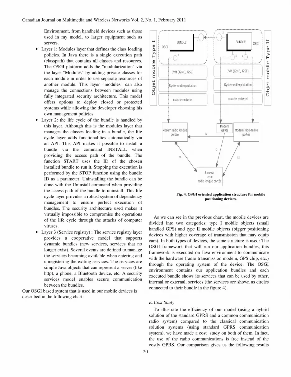
Our OSGI based system that is used in our mobile devices is described in the following chart:
Fig. 4. OSGI oriented application structure for mobile
positioning devices.
As we can see in the previous chart, the mobile devices are
divided into two categories: type I mobile objects (small
handled GPS) and type II mobile objects (bigger positioning
devices with higher coverage of transmission that may equip
cars). In both types of devices, the same structure is used: The
OSGI framework that will run our application bundles, this
framework is executed on Java environment to communicate
with the hardware (radio transmission modem, GPS chip, etc.)
through the operating system of the device. The OSGI
environment contains our application bundles and each
executed bundle shows its services that can be used by other,
internal or external, services (the services are shown as circles
connected to their bundle in the figure 4).
E. Cost Study
To illustrate the efficiency of our model (using a hybrid
solution of the standard GPRS and a common communication
radio system) compared to the classical communication
solution systems (using standard GPRS communication
system), we have made a cost study on both of them. In fact,
the use of the radio communications is free instead of the
costly GPRS. Our comparison gives us the following results

Canadian Journal on Multimedia and Wireless Networks Vol. 2, No. 1, February 2011
21
(see the table 1 below).
The use of the GPRS needs a monthly communication plan,
mobile hardware and a server. The cost of this solution is
getting higher with the communication plan. The overall cost
of this solution on a period of 5 years for 100 units is 416 000
$.
Combining the free radio communication with a smaller
GPRS plan in the case that the radio communication falls to
transmit data will lead us to a great gain on the overall cost.
We need 3 types of devices, Small radio mobiles with short
transmission range, medium radio mobiles like the ones we
can put in vehicles with medium to long transmission range,
and a long range modem with its antenna on the server side to
receive the radio data packets. If we consider 100 units during
5 years, this solution costs approximately 122 275 $.
Comparing the two solutions, we concludes that we make a
gain of 293 725 $ on our solution compared to the classical
GPRS solution because of saving on the costly GPRS
communication plan. In other words 2.4 times less than the
GPRS exclusively.
TABLE I
COMPARE THE COST OF CLASSICAL SOLUTION GPRS AND RADIO COMMUNICATION
classical Solution GPRS Radio modem solution
GPRS communication cost2
65 $ / Month (Rogers)
15$ / Month (of GPRS data in case of a non availability of radio communication)
-
-
Hardware cost per unit3
250 $ (GPS+GPRS+A-GPS)
1000 $ (Data server)
Small mobile equipment
Large mobile equipment
Server side equipment
35 $ (GPS+A-GPS) + 75 $ (MB) + 90 $ (RF 1-2km) + 75 $ (GPRS) = 275 $
35 $ (GPS+ A-GPS) + 75 $ (MB) + 200 $ (RF 10-24 Km) = 310 $
500 $ (RF 40-50 Km) 1 000 $ (Data server) = 1 500 $
Cost based on a period of 5 years
100 units (75 mobile objects + 25 vehicles ) ((65*12*5*100)+(250*100)+1000) = 416 000 $
75 units (small mobile objects) ((15*12*5*100)+(35+75+90+75)*75) = 111 525 $
25 units (vehicles) ((35+75+90+75)*25) = 7 750 $
2 units (1 relay + 1 central) ((500*2)+(1000*2))= 3 000 $
Overall cost during 5 years
416 000 $
122 275 $
Benefit accomplished by using our solution during 5 years
293 725 $ (2.4 times the cost of our system)
2 Cost based on the average cost of GPRS plans according to the main telecommunications companies in Quebec as ROGERS, FIDO and BELL.
3 Cost according to the GPS and radio devices resellers prices.: www.sparkfun.com, www.semiconductorstore.com, www.data-linc.com, www.electronicdiscountsales.com.

Canadian Journal on Multimedia and Wireless Networks Vol. 2, No. 1, February 2011
22
IV. REALIZATION
This section briefly describes in pseudo code the
implementation of the communication program (Figure 2).
Subsequently, we illustrate the communication with the GPS
on a COM port. Finally, some screenshots are given.
A. Pseudo Code of Communication Program
This section specify a set of functions used to establish the
communication between mobile devices in FHMDMS. Function send_serv(msg, Id)
Start function
If connexion_serveur_radio.open(port)==true do
/* We have the parameters as location message to be
transmitted, a random verification key generated by RAND
and the Id_serv which is the ID of our server for a shipment
sent (Id_serv) */ Send_radio( message_localisation, cle_aleat,
Id_serv)
/* connexion_serveur_radio with "port" which is our local
radio port parameter is a function that opens a connection via
the radio port. if the connection is established, it returns true,
otherwise returns false.*/
Timer1=5000; // put the variable to 5 seconds
/* Check_Ack function that turns timer1 awaiting acquittal.
the server when it receives our message, pay our random key,
and ack cle_aleat are compared, if they are equal, then the
payment is positive and we conclude that the transmission is
complete. The function returns true if matching and false
otherwise */ If Check_Ack(cle_aleat, ack, timer1) == true
do
connexion_serveur_radio.close(port)
// closure of the radio connection elseif
/* when you do not receive acknowledgment from the server
to the end of timer1, there is a new invocation send_serv (msg,
Id) and the current is stopped with a return. */ send_serv(msg, Id)
return
end elseif
elseif
/* if no possible connection to the server, it tries to pass the
message to a relay object (vehicle radio device with long
range) which will relay it to our server and exit the current
function.*/
… send_relais(message, Id)
return
End Elseif
…
End function
/* function demande_relais broadcasts via the radio device
comprising a message identifier (id) of the issuer needs to
relay a message. If a relay receives the signal and is capable of
relaying it to the referring customer (id) are a different ID (id2
example). The function demande_relais (customer_id) will
return the id received from the runner, if not return null */ Function send_relais(message, Id)
…
Start function
Id_relais=Demande_relais(id_client)
If id_relais different of null do
Count=0
/* the counter Count is initialized to 0 each time we send a
message to our purpose relay and the timer function included
in the Relayer(message, id_relais, id_client) expire, we make a
second attempt in the loop and hang that increment the
narrator, until the relay function returns true (success of the
operation) or that the narrator reaches 2. In the latter case, we
stop running the relay function and we invoking the function
GSM shipments, send_GPRS(message, addr_serv) */
while count <> 2 do
Relais=Relayer(message, id_relais, id_client)
if relais ==false do
Count++
elseif
break
End if
End while
if count==2
send_relais(message, Id)
return
End if
elseif
send _GPRS(message, addr_serv)
…
End function
/* The connection protocol, encryption and mailing
equipment is managed by the GPRS and GSM operator and
management of shipments. That leaves just a few lines of code
to write on the port where the modem is working and GPRS
function GPRS.send(message,CNX) that uses AT commands
to send the message */
Function send _GPRS(message, addr_serv)
Start function
CNX=modem_GPRS.connect(port)
…
GPRS.send(message,CNX)
…
End function
B. Example of AT commands to GPS modem of a phone Nokia
[Nokia, 2010]
To send a message between devices using GPRS mode, we
can use one of two modes:
i) Mode Text[DevHome, 2010] :

Canadian Journal on Multimedia and Wireless Networks Vol. 2, No. 1, February 2011
23
AT+CMGW="+85291234567" > A simple demo of SMS text messaging.
ii) Mode PDU [GSMPDU, 2010] :
AT+CMGS=23 //Send message, 23 octets (excluding the two initial zeros) >0011000B916407281553F80000AA0AE8329BFD4697D9EC37
An example is given in the appendix at the end of this paper
to illustrate this realization.
C. Running The Tool For Reading The GPS Position
(Screenshots)
The tool (program) scans the available communication ports
and puts them in a dropdown menu. In our case, COM5 is the
GPS port.
Fig. 5. Running the programme to read the positions on the GPS.
After logging on COM5, our application communicates with
the GPS using Trimble TAIP protocol. The information

Canadian Journal on Multimedia and Wireless Networks Vol. 2, No. 1, February 2011
24
Fig. 6. Locating mobile objects in real time via a USB port.
Web Page generated via Google Map. On the server side,
we have a database that contains the positions received from
our GPS, a table in our database named field, contains the area
(road) as a polygon that is associated with a speed limit. In this
case, we have put this part of the street “ Rue Rabelais” in a
polygon format:
(48.396275? -71.089984,48.395657? -71.085987, 48.395714? -71.085832,48.396157? -71.085674,48.396161? -
71.085505,48.395664? -71.085684,48.395523? -71.085969,48.396143? -71.090032,48.396275? -71.089984)
Then, we have limited the speed to 45km / h. The gray
points are points that belong to any area in our database and
therefore are outside the road. The green point is a point which
is located in the rue Rabelais, whose speed is less than the
speed limit. The red dots belong to the road but they exceed
the speed limit.
Fig. 7. Web Page generated via our PHP pages using GoogleMap API.
Canadian Journal on Multimedia and Wireless Networks Vol. 2, No. 1, February 2011
25
V. CONCLUSION
By comparing the different approaches to localization, we
argue that the fine-grained methods can provide very good
accuracy. The problem with these methods is that they rely on
physical infrastructure rather expensive because it will install
multiple sensors to cover a large area. The GPS satellite
network offers the opportunity to provide the location without
additional hardware with a reasonable accuracy in the range 5-
10 meters which can be enhanced with WAAS or A-GPS.
The WAAS system is not available all the time; we have
proposed a model where a long range antenna will broadcast
the correction signal over a wide area (up to 50KM). Our
system allows you to benefit from the increased accuracy of
GPS improved by A-GPS. The data download can be done
without cost, via radio communications, to our server. The
system supports mobility, accuracy and implementation with a
lower cost since it uses radio waves to communicate data
without recourse to a complex communication infrastructure.
To strengthen the system, we have added communication
via cellular networks where the radio communication fails.
To summarize, our system offers the following advantages:
1- Free exchange of data via radio waves.
2- Global vision of different types of objects detectable with better resource management and better coordination of field teams.
3- Moving Objects cooperative. The short-range devices may require long-range devices to relay their messages to the server.
4- Facilitate the process of detection and rapid response (in cases of speeding in cars, medical emergency related to mental or physical health such as heart or for people with Alzheimer's, etc.).
For future research, we suggest i) the use of an encryption
algorithm for secure radio data. The algorithm must be light
enough not to take a fairly limited bandwidth with the radio
systems. ii) Add a device WiMax for long range wireless
communication. This technology allows to achieve very high
flow rates. Vehicles equipped with this device can centralize a
greater number of radio data from several objects at short
range. A large amount of data will be transmitted much faster
than Wi-Max connectivity classical radio. Wi-Max is natively
secured via encryption keys using WEP, WPA and WPA2.
APPENDIX
This appendix is used in section IV realization.
A. Communication With GPS on a port COM
To allow communication with GPS devices via with specific
configuration through a serial COM port, it is necessary to
specify each parameter using Java code as the following:
// we import the classes javax.comm that manage the
communication
// we create our class to open the communications port public class OuvrePort {
/** This is our read buffer from a specific port that we
define later in this code */ protected BufferedReader is;
/** variable contains the message to send to our system */
protected PrintStream os;
/** Here, we create an ID of the port */
CommPortIdentifier PortId;
...
/* Chosing physical port COM1 */
portId=CommPortIdentifier.getPortIdentifier("C
OM1");
…
SerialPort port;//create a serial port
/* Open our port with the message GPS_Appli and a
timeout of 30s */ port=(SerialPort)portId.open("GPS_Appli",
TIMEOUTSECONDS);
...
/* configuration of a serial port for communication */ try {
port.setSerialPortParams(BAUD,
SerialPort.DATABITS_8,
SerialPort.STOPBITS_1,
SerialPort.PARITY_NONE);
}
catch(UnsupportedCommOperationException e)
{}
/* to communicate with the device, we use our variables (is
and os): */
os = port.getOutputStream();
is = port.getInputStream();
/* we send our command by writing on the port via println
*/ os.println(msg);
/* to retrieve the message from the device we must read
through our port variable (is) */ is.readLine();
…
B. Positions Stored in Databases Via GougleMap
The following PHP code creates the points representing the
geo-localization places retrieved from our database which has
previously saved the positioning data of different mobile
devices. This points are displayed on a browser using the
GoogleMap API.
<?php
Canadian Journal on Multimedia and Wireless Networks Vol. 2, No. 1, February 2011
26
// we create a link to connect to the database $link = mysql_connect("ServerAddr", "myLogin",
"myPass");
…
// pointInPolygon is an imported function that tests if a point
is included in an area as a polygon, the polygon can be a road
or area of any number of sides. This function is available on
many internet sites and does not need to be rewritten. include_once("pointInPolygon.php");
/* if the point belongs to a zone and that the velocity of the
point exceeds the speed limit of the area, it generates AJAX
code using GoogleMap API, and puts the point in red via in
the map with the function createMarkerR() */
if(($inclus==1) and
($row1['vitesse']>$row2['limite'])) {
echo "var point = new GLatLng(" .
$coord['x'] . "," . $coord['y'] . ");\n";
echo "var marker = createMarkerR(point,
'vitesse:" . addslashes($row1['vitesse']) ."
<br> Source:". addslashes($row1['precision'])
. " <br> date:". addslashes($row1['dat'])
."<br> ___________________________
<cite><em>Copyright
A.Goundafi</em></cite>');\n";
…
// if the point belongs to a zone and that speed does not
exceed the speed limit zone, we generate AJAX code that puts
a green position point with the function createMarkerV as we
did for the red point in the previous function (...)
…
Etc.
ACKNOWLEDGMENT
This work is sponsored by NSERC (Natural Sciences and
Engineering Research Council of Canada) and by the
University of Quebec at Chicoutimi (Quebec).
REFERENCES
[1] Muhammad Ali Assad, A Real-time Laboratory Testbed For Evaluating
Localization Performance of Wifi Technologies. Faculty of Worcester Polytechnic Institute, Electrical and Computer Engineering, 2007.
[2] P. Wilson, D. Prashanth, and H. Aghajan. Utlizing RFID signaling scheme for localization of stationary objects and speed estimation of mobile objects. In IEEE International Conference on RFID, 2007.
[3] U. Bischoff, M. Strohbach, M. Hazas, and G. Kortuem. Constraint-based distance estimation in ad-hoc wireless sensor networks. In EWSN, 2006.
[4] T. He, C. Huang, B. M. Bium, J. A. Stankovic, and T. Abdelzaher. Range-free localization schemes for large scale sensor networks. In
ACM MobiCom’03, 2003. [5] [GPS, 2010] : Global Positioning System, http://www.gps.gov/, 2010. [6] [WAAS, 2010] : Federal Aviation: Administration , www.faa.gov, 2010 [7] [SAGEM, 2010] : A-GPS : The world's first Assited GPS SIM card,
www.sagem-orga.com, 2010.
[8] [CDGPS, 2010] : The real-time Canada wide DGPS service, http://www.cdgps.com/e/desc.htm, 2010.
[9] [A-GPS, 2010] : Assisted GPS, A-GPS: an overview, information or turorial about the basics of Assisted GPS (Global Positioning System) or A-GPS used to provide location based services used for cellular
technology and cellular networks, http://www.radio-electronics.com/info/cellulartelecomms/location_services/assisted_gps.php , 2010
[10] [GPSBase, 2010] : GPS Base station for post-treatment, www.gsf.qc.ca, 2010.
[11] [Nokia, 2010] :Activexpert : NOKIA GSM AT command set, http://www.activexperts.com/activcomport/at/nokia/, 2010.
[12] [DevHome, 2010]:Developpers home: How to send SMS message from a computer, http://www.developershome.com/sms/howToSendSMSFromPC.asp, 2010
[13] [GSMPDU, 2010]:GSM Favorite: Introduction to SMS PDU mode, http://www.gsmfavorites.com/documents/sms/pdutext/, 2010
[14] [Trimble, 2009] : GPS tutorial, www.trimble.com, 2010. [15] [FAA, 2010]:GNSS library, www.faa.gov, 2010.
BIOGRAPHIES
H. Mcheick is currently an associate professor in computer science department at the University of Quebec At Chicoutimi (UQAC), Canada. He holds a master degree and PhD. in software engineering and distributed system from Montreal University, Canada. Professor Mcheick is interested in software development, architecture and distributed for enterprise applications as
well as in separation of concerns (component, services, aspect, etc.). His research is supported by many research grants he has received from the Canadian government, University of Montreal, CRIM (Centre de Recherche informatique de Montreal), University of UQAM, and University of UQAC.