Embed Size (px)
Citation preview

Indoor Positioning Using GPS Revisited
Mikkel Baun Kjærgaard1, Henrik Blunck1, Torben Godsk1, Thomas Toftkjær1, DanLund Christensen2, and Kaj Grønbæk1
{mikkelbk, blunck, tbg, toughcar, dalc, kgronbak}@cs.au.dk
1 Department of Computer Science, Aarhus University, Denmark2 Alexandra Institute A/S, Denmark
Abstract. It has been considered a fact that GPS performs too poorly insidebuildings to provide usable indoor positioning. We analyze results of a measure-ment campaign to improve on the understanding of indoor GPS reception char-acteristics. The results show that using state-of-the-art receivers GPS availabil-ity is good in many buildings with standard material walls and roofs. The mea-sured root mean squared 2D positioning error was below five meters in woodenbuildings and below ten meters in most of the investigated brick and concretebuildings. Lower accuracies, where observed, can be linked to either low signal-to-noise ratios, multipath phenomena or bad satellite constellation geometry. Wehave also measured the indoor performance of embedded GPS receivers in mobilephones which provided lower availability and accuracy than state-of-the-art ones.Finally, we consider how the GPS performance within a given building is depen-dent on local properties like close-by building elements and materials, number ofwalls, number of overlaying stories and surrounding buildings.
1 Introduction
Applying the visions of ubiquitous computing to a variety of domains requires posi-tioning with (i) pervasive coverage and (ii) independence from local infrastructures.Examples of such domains are fire fighting [1], search and rescue, health care and polic-ing. Furthermore, also many other position-based applications would benefit from po-sitioning technologies that fulfill both requirements [9]. One technology fulfilling (ii)is positioning by GPS. However, it has been considered as a fact that GPS positioningdoes not work indoors and therefore does not fulfill the coverage requirement (i). Dueto recent technological advances, e.g, high-sensitivity receivers and the promise of anincrease in the number of global navigation satellites, this situation is changing.
In 2005, LaMarca et al. [11] studied GPS availability with an off-the-shelf receiverfor tracking the daily tasks of an immunologist, a home maker and a retail clerk. Forthe three studied persons, the availability was on average only 4.5% and the averagegap between fixes was 105 minutes. To address these shortcomings they proposedfingerprinting-based positioning [8] as a solution. However, for the previously men-tioned domains fingerprinting-based solutions are less suitable, given the requirementof fingerprinting collection, the vulnerability to hacking, that e.g. fires might alter thebuilding and the unknown factor of whether or not fingerprinted base stations are takenout, e.g. by a fire.

We have conducted a measurement campaign at several indoor sites, includingwooden and brick houses, a public school, a warehouse, a shopping mall and a towerblock, to determine to what extent GPS is usable indoors and which performance toexpect from it. Furthermore, we intended to link the measured performance to the typeof errors affecting GPS as well as to local properties of the buildings like dominatingmaterials and proximity to external walls and windows or surrounding buildings.
In this paper we argue that—when using state-of-the-art receivers GPS— GPS in-door performance is better than suggested in earlier literature. The results of our mea-surement campaign, which is to our knowledge the most comprehensive of its kind,show good GPS availability in many buildings except for larger ones with thick roofs orwalls. The horizontal RMS error in our measurements was below five meters in woodenand below ten meters in most of the brick and concrete buildings investigated. Loweraccuracies could be linked to low signal-to-noise ratios, multipath phenomena or badsatellite constellation geometry. We also considered GPS receivers embedded in mobilephones which provided lower availability and accuracy than dedicated receivers.
The rest of this paper is structured as follows: In Section 2 we give a brief intro-duction and overview of research on GPS and satellite based navigation with a focuson indoor usage. In Section 3 we present our measuring methodology. In Section 4 wepresent our analysis of the measurement campaign. Finally, Section 5 concludes thepaper and provides directions for future work.
2 GPS Primer
GPS satellites send signals for civilian use at the L1 frequency at 1.575 GHz; these sig-nals are modulated with a Pseudo-Random Noise (PRN) code unique to each satellite.A GPS receiver tries to acquire each GPS satellite’s signal by correlating the signalspectrum it receives at L1 with a local copy of the satellite’s PRN code. An acquisitionis successful, once the local copy is in sync with the received signal, which requiresshifting the copy appropriately both in time and in frequency. The latter shift is due tothe Doppler effect caused by the satellite’s and the user’s relative motion. Once a satel-lite’s signal has been acquired, the receiver tracks it, that is, the receiver continuouslychecks the validity of the shift parameters above and updates them if necessary.
Each satellite’s signal is modulated not only with its PRN code but additionally witha navigation message, which contains almanac data (for easier acquisition of furthersatellites) as well as its precise ephemeris data, that is the satellite’s predicted trajectoryas a function of time, allowing GPS receivers to estimate the current position of thesatellite. Finally, to achieve precise 3D positioning with a standard GPS receiver viatrilateration, the positions of and distances to at least 4 satellites have to be known; thosedistances can be computed from the time shift maintained while tracking the respectivesatellites. As a general rule, the more satellites can be tracked, and the wider they arespread over the sky as seen by the user, the more precise the positioning – due to theadditional distance data and a satellite geometry resulting in less error-prone lateration.
A popular enhancement of GPS positioning is given by Assisted GPS (A-GPS) [17].A-GPS provides assistance data to GPS receivers via an additional communicationchannel e.g. a cellular network. This assisting data may consist of e.g. ephemerides
and atmospheric corrections. Also, a cellular network provides means for a rough posi-tioning of the GPS enabled device. A-GPS eases satellite acquisition and can thereforedrastically reduce the time to first fix and the initial positioning imprecision of a receiverin cold start (i.e. when no initial information about satellite constellations is available):Essentially, A-GPS allows for a hot start (precise ephemerides for all satellites avail-able), once the assisting data has been transmitted. Furthermore, A-GPS can improvepositioning accuracy by eliminating systemic error sources [12, Chapter 13.4].
GPS performance degrades in terms of both coverage and accuracy when experi-encing problematic signal conditions, e.g. in urban canyons and especially in indoorenvironments. The cause for this is termed signal fading, subsuming two fundamen-tal signal processing obstacles: First, when GPS signals penetrate building materials,they are subjected to attenuation, resulting in lower signal-to-noise ratio (SNR). Fur-thermore, the signal is subject to multipath phenomena: Reflection and refraction ofthe signal results in multiple echoes of the line-of-sight (LOS) signal arriving at the re-ceiver. Low signal-to-noise ratios and multipath handicap both acquiring and trackingGPS signals and usually result in less reliable positioning due to less suitable satellitegeometry and individual time shifts measurements being less accurate. High-SensitivityGPS (HSGPS) [10] receivers are specifically designed for difficult signal conditions, i.e.to alleviate the above problems. HSGPS is claimed to allow tracking for received GPSsignal strengths down to -190 dBW: three orders of magnitude less than to be expectedin open-sky conditions [12]. These thresholds are constantly being improved using newprocessing techniques [17, Ch. 6]. Note, that for acquiring signals at cold start, a some-what (around 15dBW) higher signal strength is usually necessary, as during acquisitionreliable time and frequency shifts of the signal have not only to be maintained, butinstead searched for in a wide spectrum.
With respect to future improvements towards satellite based indoor positioning, notealso that the upcoming Galileo system is a Global Navigation Satellite Systems(GNSS),like GPS, and will soon be interoperable with the latter, resulting in roughly a doublingof GNSS satellites available [12, Ch. 3]. Combined satellite constellations will yield, ineffect, better geometries at the user position, improving positioning accuracy, especiallyindoors, where signals from only parts of the sky may be available. Other upcomingimprovements for indoor GNSS are provided by the modernized public signal structuresof GPS and Galileo, allowing improved tracking of weakened signals via pilot channels,and yielding additional protection against multipath-induced inaccuracies [2]. In theGNSS community indoor positioning and respective obstacles and improvements arebeing investigated, see, e.g., Teuber et al. [16], Paonni et al. [13], Lachapelle et al. [10],Watson et al. [18] and references therein. This paper adds to this line of work but froman application-oriented perspective using real-world measurements to investigate whereand to what extent one can employ GPS for indoor positioning.
3 Measurement Campaign Methodology
In the following, we describe the measurement campaign, the equipment used, as wellas methodology regarding measurement collection procedures and choice of in-buildinglocations; for a more thorough justification of the chosen methodology see also [3].

3.1 Receiver Equipment Employed
Throughout our campaign, we employed a u-blox LEA-5H Evaluation Kit and a SiRF-Star III BU-353 USB GPS receiver as examples of dedicated receivers, and a NokiaN95 8GB driven by Texas Instruments’ NaviLink 4.0 GPS5300 chip as an examplefor a currently used in-phone GPS receiver system. The u-blox receiver is specifiedto have a -190dBW (-175dBW) threshold for tracking (respectively, acquisition) andwas connected to a 48x40x13mm u-blox ANN-MS patch antenna, providing 27dB gainand specified with a 1.5dB noise figure. We will focus on the measurements obtainedwith this dedicated receiver and note in passing, that the SiRF product performeredequivalently, though slightly poorer which might be solely due to the u-blox’s highquality external patch antenna. To obtain A-GPS assistance data [17], we connected theu-blox receiver to a N95 phone.
The two classes of receivers considered differ not only in performance but also inprice, energy consumption and size: Whereas the larger and more power consumingdedicated receivers will be used in specific scenarios mentioned in the introduction,such as search and rescue operations, the Nokia N95 in-phone receiver represents typ-ical hardware for the every-day consumer use of location based services. Furthermore,given the pace of development the chosen dedicated receiver allows an outlook on theperformance of future in-phone GPS receivers used, e.g., for location-based services.3
3.2 Data Collection Procedures
During our campaign, we focused on static measurements at a number of locationsper building, partially in order to eliminate effects from the receiver’s recent history ofmeasurements. Consequently, we reset the receivers prior to each measurement, therebyminimizing the effects of, e.g. Kalman filtering techniques, which exploit recent mea-surement history and therefore potentially pollute static measurements w.r.t. both loca-tions and durations, see, e.g., Brown and Hwang [4].
To focus on and to fairly compare signal conditions at individual indoor locations,we also decided against an on-person receiver setup. Instead, each of the GPS enableddevices was mounted on the seat of a light-weight wooden chair, spaced 20 cm apartfrom the other receiver devices to remove the chance of any near-field interference. Notethough, that the measurements carried out within the shopping mall, the warehouse andthe tower block were conducted during business hours, providing realistic pedestriantraffic conditions, see also [14] for the impact of pedestrian traffic on GPS performance.The chair was then placed at the in-building measurement locations chosen and wecollected GPS measurements using the following procedure:
After initializing the programs for logging GPS data at 1 Hz, we “hot started” theNokia and the u-blox receivers. Note, that by hot start we refer to a initialization usingA-GPS data. If the hot start of the u-blox receiver was successful, i.e., if it within 10minutes produced a position fix, we subsequently logged the u-blox receivers’ NMEAformatted data for 5 minutes; then we repeated as above, but this time cold starting
3 The generation 6 of the u-blox receiver has been improved over the version used here, specifi-cally focusing on low energy consumption, allowing for more economic use in mobile gadgets.

the receivers without A-GPS. In case the hot start of the u-blox was not successful, weproduced a successful hot start at a nearby location and walked back to the measure-ment location. If the receiver still produced position fixes upon arrival, we logged thereceivers’ data for 5 minutes.
3.3 Choosing Measurement Locations
For choosing where to measure GPS reception within the buildings, we overlaid thelarger buildings’ floor plans with a regular grid, choosing measurement locations as thecenters of the grid cells, where feasible, i.e. where these centers fall within the respectivebuilding. We chose this strategy to avoid biases induced by alternative approaches inwhich locations are picked so to reflect environmental conditions which are—by a priorihypotheses—associated with specific GPS signal reception conditions.
4 Results
Using the measurement procedures described above allows us to explore the perfor-mance of GPS positioning in various environments using state-of-the-art receiver tech-nology. In section 4.1 we will introduce the environments investigated in our measure-ment campaign and characterize them with regards to availability, the most fundamen-tal measure for GPS performance. Subsequently, we will cover further GPS perfor-mance measures, namely time-to-first-fix in Section 4.2 and positioning accuracy inSection 4.3. Throughout this section, we not only present performance measures forthe individual measurement locations, but also elaborate on general rules which governGPS indoor performance, as observable in the analysis of our measurement campaign.In Section 4.4 we give results for measurements using the Nokia N95 in-phone receiver,comparing them to the measurements obtained from dedicated receivers.
4.1 GPS Availability and Signal Strength
The GPS availability results for the eight environments chosen for our campaign areillustrated in Figure 1. The figure shows for each in-building measurement locationwhether and by which means we were able to acquire GPS fixes. As described by thefigure legend, we categorize availability performance into 4 categories: (i) both hotstart and cold start (indicated by a green circle) were successful; (ii) a hot start but nocold start (indicated by a blue square) was successful; (iii) neither hot or cold startswere successful, but tracking was, that is acquiring a GPS position at a location withhigh GPS availability and moving to the measurement location where GPS upon arrivalcontinued to produce position fixes (indicated by a purple triangle); (iv) and finallyblocked where no GPS position fixes could be established (indicated by a red cross).
A main factor impacting to which extent and quality one can get GPS fixes at spe-cific in-building locations are the surrounding building structures and elements. There-fore, complementing Figure 1, we listed in Table 4.1 for the environments investigatedthe respective dominating materials used for external and internal building elements.The table also contains approximations, compiled from various sources [6, 15, 19], for

(a) Wood 1 (13m x 9m) (b) Wood 2 (12m x 12m)
(c) Brick 1 (18m x 11m) (d) Brick 2 (12.50m x 8m, floor sep.:2.80m)
(e) Warehouse (82m x 38m) (f) School (136m x 134m, floor sep.:4m)
(g) Shopping Mall (242m x 150m) (h) Tower block (60m x 15m, floor sep.:4m)
Note, that the distances between floors are modified in the figure in order for all grid points to become visible.
Fig. 1. Overview of GPS availability in various building types.

WallsBuilding Type External dB Internal dB Roof dBWood 1 Wood 2.40 Wood 2.40 Tiles 5.19Wood 2 Wood 2.40 Wood 2.40 Tiles 5.19Brick 1 Double Brick 10.38 Brick 5.19 Fiber Cement N/ABrick 2 Double Brick 10.38 Brick 5.19 Tiles 5.19Schoolmain building + right wing Double Brick 10.38 Brick 5.19 Tiles 5.19annex + left wing Brick and Concrete 14.76 Concrete 9.57 Tiles 5.19Warehouse Fiber Cement and N/A Equipment N/A Fiber Cement N/A
Curtains/Openings N/AShopping Mall Reinforced Concrete 16.70 Brick 5.19 Flagstone N/A
Tinted Glass 24.44 Sand 2Glass 2.43 Felt roofing N/A
Concrete 9.57Tower block Double Brick 19.95 Brick 5.19 Tiles 5.19
around Concrete
Table 1. Building materials and their attenuation properties in the buildings investigated.
the attenuation (w.r.t. GPS L1 frequency signals and assuming an incident angle of0 degree) caused by the respective building materials (assuming common respectivethicknesses).4 The attenuation values listed directly impact the signal-to-noise-ratioof GPS signals indoors, since, as a rule of thumb, a penetrated material’s attenuationvalue is to be subtracted from the received signal-to-noise-ratio as experienced outsidethe given building. For signals penetrating multiple layers of building materials, atten-uation can be considered at least additive. The average signal-to-noise-ratio over timefor the 4 satellites with the strongest received SNR is shown in Figure 2 for all mea-surements, grouped by building, see, e.g., Misra and Enge [12] for relating signal-to-noise-ratios and GPS signal power. Differences in the SNR figures within one buildingare naturally due to properties of the individual in-building locations. Such propertiesinclude the number and distances to building elements such as walls and roofs: For ex-ample, Teuber et al. [16] concluded from their measurements, that the power of receivedGNSS signals does not only depend on the building materials penetrated, but also fur-ther decreases with the distance traveled after the respective penetrations. In general,our measurements confirmed that observation.
Per-case availability analysis When looking at Figure 1 the GPS availability seemspromising for both the two wooden houses 1(b) and 1(a) as well as for the two brickhouses 1(c) and 1(d), of which only the last one is a multi-story building. However,in the other buildings GPS is only partially available, and in order to understand thesevariations we will go deeper into the analysis of these particular buildings.
The larger 82m x 38m warehouse 1(e) is a relatively open environment, with justcloth curtains between roof and lowered outer walls, and four 50cm wide skylights
4 For GNSS frequencies lower than L1, e.g., L2 and L5, the attenuation for most of the listedmaterials is somewhat lower, see, e.g., [6, Table 3]. For further studies on the strength of GPSfrequency signals in indoor environments see also [5, Ch. 9.4.2] and references therein.

15
20
25
30
35
40
45
SNR
[4 s
trong
est S
Vs a
vera
ged]
SNR
Wood 1 Wood 2 Brick 1 Brick 2 School Warehouse Shopping Mall Tower block
Fig. 2. Averaged signal-to-noise ratio at individual measurement locations.
along the roof. Consequently, it allows for proper GPS fixes. Further analysis showsthat reception was difficult and SNR low for signals which had to penetrate interior el-ements of the warehouse—whereas signals entering close to or through skylights werereceived much stronger. That GPS signals are received strongly only from certain partsof the sky is observable in the skyplots [7] in Figure 3 for two exemplary measurementlocations close to exterior walls of the warehouse. In the skyplots, the 3 concentric cir-cles represent 0, 30, and 60 degrees elevation, respectively. Depicted are the locationof the satellites, tracked by the receiver during the respective hot start measurementperiod. Individual satellites are identified by the id of the PRN code, they are sending,respectively. The individual positions over time of each shown satellite are depicted by“+” symbols, where the symbol’s color indicates signal-to-noise ratio, as experiencedby the u-blox receiver at the respective measurement location and according to the colorscale given in the figure. A green arrow trailing the orbit of a satellite signals its direc-tion of movement. The pseudorange error for each satellite and for each individual timeinstance of reception during the measurement period are sketched in blue color, accord-ing to the scale given in the figure, and—for presentation purposes—perpendicular tothe respective satellite’s direction of movement.5
The school building at Figure 1(f) forms an H with two single-story wings and onethree-story middle section and finally a single-story annex. First, due to the skylightwindows signals have easy access to locations in the two wings. In the annex and also inthe middle section on the second floor strong signals were present. Second, the first floorallowed for receivable but weaker signals, in particular at the location at the center ofthe middle section. Here a cold start was not successful, possibly due to the attenuationcaused by the top floor, and due to the location being in a wide part of the building.Third, in the basement the signals are attenuated by the two top floors and only due tothe relatively open area at the center were we able to track the signal there. At anotherbasement location no GPS fixed were achieved at all.
5 Note that while a GPS receiver can only output pseudorange errors w.r.t. the estimated posi-tion, they can be transformed into pseudorange errors w.r.t. the actual receiver position, givenproperly surveyed ground truth by means of, e.g., satellite imagery, building floor plans andlaser ranging, as done by the authors, see also [3, Ch.3].

20 meters10 meters2 meters
5010 SNR
Pseudorange error
20 meters10 meters2 meters
5010 SNR
Pseudorange error
Fig. 3. Skyplots of measurements at two locations inside the warehouse.
Figure 1(g) depicts the middle floor a three-story shopping mall. The grid points willbe refereed to by coordinate tuples, where the bottom left corner would be (1,4), and theupper right would be (8,1),which is consistent with Figure 9, which will be discussedin Section 4.3 and which depicts most of the mall’s middle floor plan, overlaid withskyplots. The center (3-5,3) of the middle floor is covered by a top floor of smaller size,and some other locations (2,2-4), (3-8,1), (7,1-3) are not only covered by a roof, but alsoby a parking deck. As a first observation, the grid points where both a cold and a hotstart was possible are located in the single-story part of the building where only a topfelt roof attenuates the GPS signals, with the exception of one grid point at the bottomof the second most right row (7,3), which is covered by the parking deck. Second,the signal could at least be tracked at all grid points that are covered by the secondstory, which consists of shops, offices and an atrium-like opening from the top floorroof down to the basement. Third, hot starts could also be performed at the grid points(4,3) and (5,3)—most likely due to the closeness to the glass atrium covering all floors.This hypothesis is supported by the relatively high SNR values experienced at thesetwo locations (as compared with other measurement locations beneath the same heavyroof structure). Third, grid point (1,4), located in another atrium, presumably depictsthe highly attenuating effect of tinted glass, see Table 4.1, resulting in comparativelylow SNR values and allowing only for a hot, but not for a cold start. Fourth, all 5blocked locations are among the 11 grid points covered by the top floor parking lot,where the separation to the middle floor consists of layers of steel-reinforced concrete,sand and flagstones. With the exception of point (7,3) only tracking is possible at theremaining 6 points, implying that GPS reception is still difficult. Note also, that, thoughnot depicted in Figure 1(g), measurements were performed also in the basement, whichprovided position fixes only near exits and near the atriums spanning all floors.
Figure 1(h) shows all stories except the ground floor of a seven-story office buildingbuilt in a tower block fashion. Averaged over the in-building measurement locations,this building showed the highest signal attenuations experienced in any of the exploredbuildings. This is only partially due to the outer double-brick and concrete walls. Ad-ditionally, our measurements showed that SNR was significantly impacted by the innerwalls or ceilings, the respective signals had to penetrate. Fittingly, all blocked locations,apart from those residing on the staircase, are in narrow aisles surrounded by small of-fices. Furthermore, the two measurement locations at the 2nd and 3rd floor where hot

20 meters10 meters2 meters
5010 SNR
Pseudorange error
20 meters10 meters2 meters
5010 SNR
Pseudorange error
Fig. 4. Skyplots of measurements on 2nd (left) and 7th (right) floor of a tower block.
starts were possible are both located adjacent to a two story library which means thatGPS signals from lower elevation satellites have to penetrate only the external walls.Similarly, reception was possible at all three locations on the top floor, where signalscan pass with less attenuation, not being obstructed by multiple inner building elements.
The poor reception on the lower floors can also be attributed to an additional shield-ing effect caused by two adjacent four-story buildings. These are placed in the samemajor direction as the building depicted and in immediate continuation and on oppositesides of what is depicted as the rightmost end of the building. The signal attenuationby these two buildings are contributing to the GPS unavailability on the second, thirdand fourth floor in the staircase to the right, additional to the attenuation caused bythe concrete-built staircase as well as building elements further above. Consistent withthis explanation, on the same staircase, but on the highest three level (clear from theshielding buildings), tracking, and for the 5th and 7th even hot starts, were successful.
To illustrate exemplary the effects of attenuation by multiple building stories, Fig-ure 4 shows skyplots [7] for the middle location in Figure 1(h) on the 2nd and 7th floor,respectively. The observed SNR values are generally, and especially around the zenith,higher at the location on the highest floor, since the latter is separated from open sky byless elements of its own (as well as of the neighboring) building(s). Noteworthy, the lowSNR values around the zenith are typical for the measurements we carried out at lowerlevels of multi-story buildings, but stand in contrast to the outdoor situation where SNRvalues generally increase with the satellites’ elevation w.r.t. the receiver position. Bothskyplots depict also the positive effect of the tower block’s windows in east and westdirection, adding to the proper signal reception from low elevation satellites.
Summary We have found that both signal-to-noise-ratios as well as, in result, the avail-ability of GPS indoors—using today’s receiver technology—is generally more promis-ing than suggested by earlier positioning literature. Furthermore, covering many differ-ent building types, we found, mostly in confirmation with empirical studies for differentindividual environments, that GPS availability is negatively impacted by: the number ofoverlaying stories, the roof material, e.g. reinforced steel, in contrast to more favorablematerials such as felt roofing or fiber-cement, as well as wall materials and the num-ber of walls, the distance to the walls separating the receiver from the outside and thecloseness to surrounding buildings.

4.2 Time To First Fix
The time to first position fix is prolonged, where acquisition of weaker and refractedsignals is necessary, in particular indoors. Figure 5 plots on a logarithmic scale time tofirst fix in seconds for hot and cold starts of the u-blox receiver in three environments.
1
10
100
1000
Wood 2 Brick 1 Shopping Mall
Tim
e [s
econ
ds]
U-blox with cold start U-blox with hot start
Fig. 5. Time to first fix for three measurement sites.
Inside both buildings ‘wood 2’ and ‘brick 1’ the u-blox receiver shows a fast hotacquisition of less than four seconds. As expected, the cold starts take longer, around 40seconds on average, with some faster at half a minute and some slower. In comparison,for outdoor use the technical specification of the u-blox receiver states that hot startstake less than one second and cold starts take about 29 seconds. In the shopping mallthe hot starts take around ten seconds on average but at three locations the time increasesto several minutes. Comparing SNR and time to first fix for each measurement location,one can observe a strong dependency between the weakness of signals and the timeit takes to acquire the signals. This implies that in locations with weak signals onecan expect high values for time to first fix. For cold starts the average time-to-first-fix isaround 60 seconds but at the three last locations cold start were not even possible withinthe 10 minute time limit.
4.3 Accuracy
To study the GPS positioning accuracy in the environments investigated using a dedi-cated receiver we have compared the u-blox receiver’s GPS position fixes with manuallysurveyed ground truth positions. Figure 6 shows for each measurement location,whichallowed for a hot start or tracking the root mean squared 2D and 3D positioning errors,averaged over the five minutes of data gathered. Figure 7 shows per building the cu-mulative 2D error distribution, averaged over all position fixes gathered at in-buildingmeasurement locations. These CDFs yield popular comparative measures of GPS qual-ity, implying an order on the investigated buildings—which is noticeably invariant formost of the popular confidence intervals, e.g., 50th, 67th (i.e. RMS), and 95th per-centile. Note, that u-blox claims to allow for a horizontal RMS position error of 3m orless, a claim which holds for outdoor measurements we carried out in open-sky sur-roundings. The accuracy achieved for cold starts (not shown) averaged over 5 minutes

0
10
20
30
40
50
60
70
Posi
tioni
ng E
rror [
m]
2D Error3D Error
Wood 1 Wood 2 Brick 1 Brick 2 School Warehouse Shopping Mall Tower block
Fig. 6. RMS positioning error in 2 and 3 dimensions.
is as expected lower due to the usually small number of satellite ephemerides knownand the resulting poor DOP values, when achieving first position fixes without assis-tance data. The accuracy, though, usually converges over time to the one for hot starts,as more parts of the almanac and precise ephemerides for newly acquired satellites canbe decoded. For the remainder, when referring to or visualizing measurement details,we implicitly refer to ‘hot start’ measurements where successful and to ‘tracking’ ones,where not.
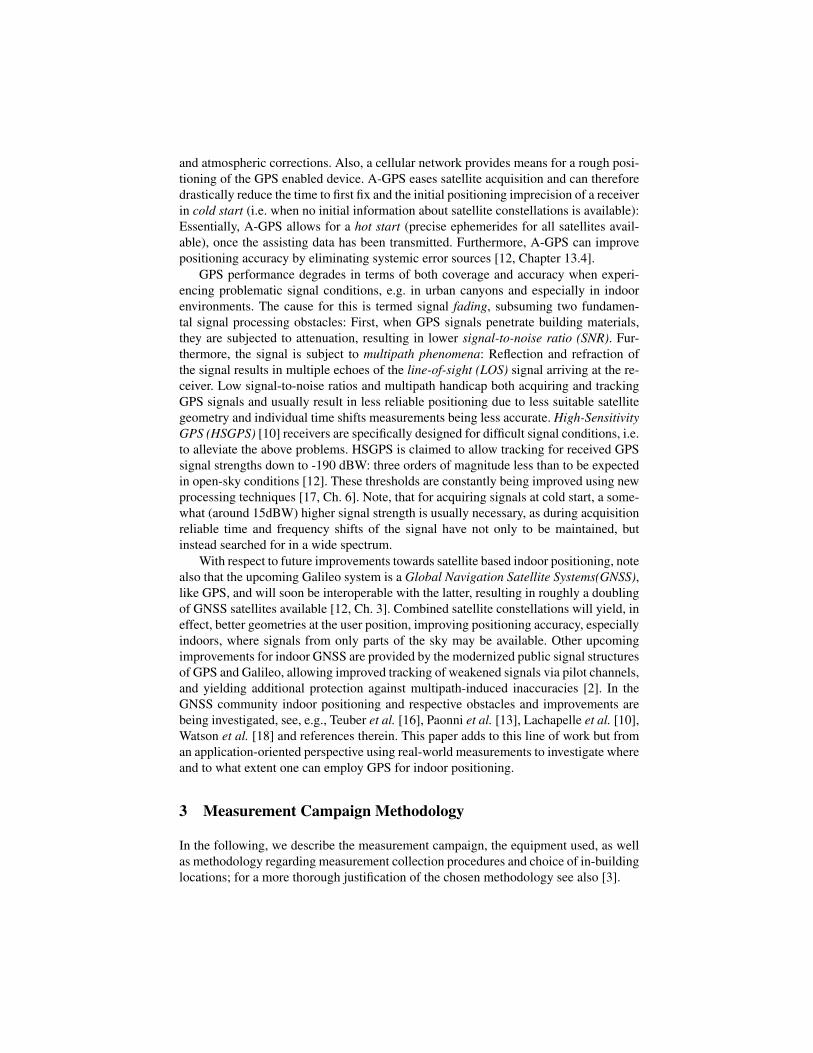
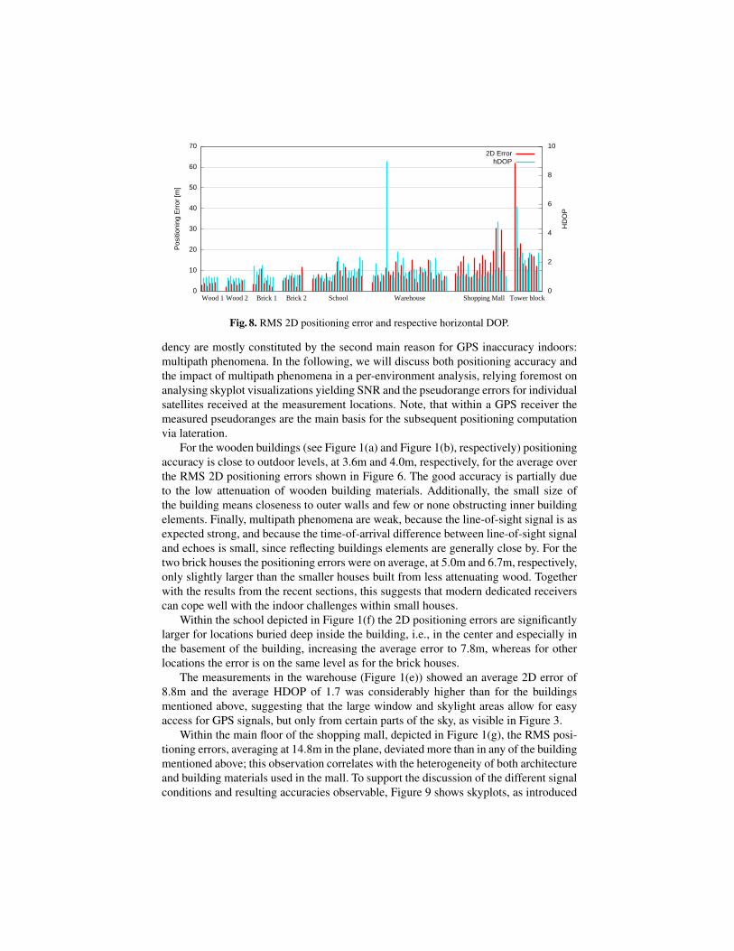
Similar to the performances measures of availability and time to first fix, also ac-curacy is impaired by signal attenuation. This is mainly due to the following two rea-sons: First, signal attenuation may lead to fewer satellites being tracked and thereforeto less favorable satellite constellation geometries. Second, low signal-to-noise-ratio ofreceived signals may result in less precise tracking of the signal, and therefore in lessaccurate measurements of the distance to the satellite. Figure 8 shows both the RMS 2Derror as well as the horizontal DOP value, as an indicator for the negative impact of thesatellite geometry with values below 1 being considered ideal. In an outdoor setting, alinear dependency of DOP value and positioning inaccuracy should be observable, andso it is also, to a large extent, in our measurements. Deviations from this linear depen-
0 10 20 30 40 50 60 70 80 90
100
0 20 40 60 80 100
Prob
abilit
y
Error [Meters]
Wood 1Wood 2
Brick 1Brick 2
SchoolWarehouse
Shopping MallOffice Building
Fig. 7. Cumulative distribution functions (CDFs) of 2D positioning errors per building.
0
10
20
30
40
50
60
70
0
2
4
6
8
10
Posi
tioni
ng E
rror [
m]
HD
OP
2D ErrorhDOP
Wood 1 Wood 2 Brick 1 Brick 2 School Warehouse Shopping Mall Tower block
Fig. 8. RMS 2D positioning error and respective horizontal DOP.
dency are mostly constituted by the second main reason for GPS inaccuracy indoors:multipath phenomena. In the following, we will discuss both positioning accuracy andthe impact of multipath phenomena in a per-environment analysis, relying foremost onanalysing skyplot visualizations yielding SNR and the pseudorange errors for individualsatellites received at the measurement locations. Note, that within a GPS receiver themeasured pseudoranges are the main basis for the subsequent positioning computationvia lateration.
For the wooden buildings (see Figure 1(a) and Figure 1(b), respectively) positioningaccuracy is close to outdoor levels, at 3.6m and 4.0m, respectively, for the average overthe RMS 2D positioning errors shown in Figure 6. The good accuracy is partially dueto the low attenuation of wooden building materials. Additionally, the small size ofthe building means closeness to outer walls and few or none obstructing inner buildingelements. Finally, multipath phenomena are weak, because the line-of-sight signal is asexpected strong, and because the time-of-arrival difference between line-of-sight signaland echoes is small, since reflecting buildings elements are generally close by. For thetwo brick houses the positioning errors were on average, at 5.0m and 6.7m, respectively,only slightly larger than the smaller houses built from less attenuating wood. Togetherwith the results from the recent sections, this suggests that modern dedicated receiverscan cope well with the indoor challenges within small houses.
Within the school depicted in Figure 1(f) the 2D positioning errors are significantlylarger for locations buried deep inside the building, i.e., in the center and especially inthe basement of the building, increasing the average error to 7.8m, whereas for otherlocations the error is on the same level as for the brick houses.
The measurements in the warehouse (Figure 1(e)) showed an average 2D error of8.8m and the average HDOP of 1.7 was considerably higher than for the buildingsmentioned above, suggesting that the large window and skylight areas allow for easyaccess for GPS signals, but only from certain parts of the sky, as visible in Figure 3.
Within the main floor of the shopping mall, depicted in Figure 1(g), the RMS posi-tioning errors, averaging at 14.8m in the plane, deviated more than in any of the buildingmentioned above; this observation correlates with the heterogeneity of both architectureand building materials used in the mall. To support the discussion of the different signalconditions and resulting accuracies observable, Figure 9 shows skyplots, as introduced

Fig. 9. Measurement locations in the shopping mall, overlaid with skyplots showing SNR andpseudorange error, as observed by the u-blox receiver.
in Section 4.1, for all measurement locations in the center part of the mall’s main floor.All locations in the top row and and rightmost column lie beneath the mall’s parkinglot—causing low SNR values. Interestingly, the pseudorange errors for satellites aroundthe zenith are not necessarily large. Notably, though, location (7,2) shows different data:Mostly in the sky part below which windows lie, reflections through these windowsseem to be stronger than the line-of-sight signals, resulting in large multipath-inducederrors.6 The biased pseudorange measurements lead to strongly biased positioning, re-sulting in the largest horizontal RMS error of all locations in the mall, except (4,1). Atthe latter location tracking was possible only for 4 satellites and for a short amount oftime, leading to the within the mall by far largest horizontal DOP values of over 4.
Another area where accuracy is strongly impacted by multipath phenomena is underthe atrium roof. The atrium located between locations (4,3) and (5,3) spans all threeroof and provides signal echoes easy access especially to locations (3-5,3) which areotherwise covered by the mall’s top floor. Consequently, the skyplots for (3,3) and (5,3)suffer from large pseudorange errors indicating that the echoes hinder precise tracking
6 Note, that multipath-induced errors can be con- or destructive: Depending on the relative phaseof the incoming signal versions, they either lengthen or shorten the pseudorange measured.

of the line-of-sight (versions of the) GPS signals, resulting in biased position fixes,deviating in particular directions from the true location. Such an effect does not occurand the pseudorange error is small, in case a satellite is received in direct line of sightthrough the atrium, as e.g., PRN 23 as received from (4,3).
When rerunning measurements at day-times yielding considerably different satelliteconstellations, we noted only minor changes in GPS performance measures. Exceptionsoccurred where SNR is rather good, but multipath phenomena impact the positioningstrongly, depending on the current satellite constellation: Of all mall locations inves-tigated, location (4,3) showed the largest deviation in 2D error, from an original 8.1mRMS to 17.2m for the rerun of the measurement, averaged over 5 minutes, respectively.
The tower block (Figure 1(h)) exhibits, averaging over measurement durations andlocations, the by far poorest SNR (of 23), and the highest HDOP (of 2.7) and, conse-quently, also the largest horizontal errors (of 21.7m RMS) amongst all investigated en-vironments. While the highest floor shows acceptable reception, SNR and pseudorangeerrors are worse on lower floors as shown for the 2nd floor in Figure 4. Consequentlyand consistent with the results obtained in the other investigated buildings, the atten-uated and indirect signals yield here a much larger HDOP value of 5.8 and horizontalRMS error of 62.1m than on the top floor with 1.5 and 12.2m, respectively.
Summary The accuracy in the four wooden and brick houses investigated was good us-ing the dedicated u-blox receiver due to it being separated from the outside both by onlyfew building elements and also only short distances, resulting in low signal attenuationand dispersion and in only small delays of multipath echoes. If more building elementsget between the receiver and the outside, as in the basement of a school or a mall, undera roof parking lot or deep inside a tall building, signal attenuation impacts both avail-ability and positioning accuracy, since only few satellites and only in restricted parts ofthe sky can be acquired leading to poor satellite constellation geometries.
Especially in environments of heterogeneous architecture like in the investigatedmall, GPS accuracy varies considerably and can be strongly biased and impaired bymultipath phenomena, e.g., when window areas allow for echoes being potentiallystronger than the line-of-sight signal which may have to penetrate strongly attenuat-ing building elements to be received directly.
4.4 Embedded GPS Receivers
Embedded GPS receivers in mobile phones are restricted both in terms of power con-sumption and antenna type and size. In result, such receivers are less sensitive than thosetypically used for standalone receivers, implying less sensitive antennas and weaker am-plification stages, see also [5, Ch. 9.4.2.1]. Therefore, it is relevant to consider how wellan embedded GPS receiver performs compared to the state-of-the-art receiver we reliedon in the previous sections. As mentioned in Section 3, we collected data with a NokiaN95 8GB phone which employs a Texas Instruments GPS chip launched in 2006.
Figure 10 shows the horizontal RMS error and the average horizontal DOP value foreach measurement location in the six environments where we collected measurementsusing the N95 embedded receiver. The labellings at the bottom of the figure includethe number of measurement locations for each environment. By comparing for each

0
10
20
30
40
50
0
2
4
6
8
10
Erro
r [M
eter
s]
HD
OP
ErrorHDOP
Wood 1 [6] Wood 2 [7] Brick 1 [8] Brick 2 [8] Warehouse [13] Shopping Mall [24]
Fig. 10. Horizontal RMS errors and DOP values, using the N95 in-phone receiver.
environment the latter number to the number of bars shown, one can comment on theavailability for the N95. Generally, the N95 allows for GPS positioning in fewer loca-tions than the u-blox receiver, except for the house ‘wood 1’ and the warehouse, whereavailability was equivalent.
The horizontal RMS errors measured in the four houses average around 10 meters,for the warehouse and the shopping mall even higher. Particularly for the four houses,the RMS values are twice as bad as when using the u-blox receiver. Due to the N95 ac-quiring consistently fewer satellites than the more sensitive u-blox receiver, the HDOPresults for the N95 are usually higher than 2 and twice as large as for the u-blox, whichyields the main explanation for the lower positioning accuracy of the N95. The time tofirst fix for hot starts is shown on a logarithmic scale in Figure 11. For the ‘wood 2’ and‘brick 1’ environments it is around 10 seconds, thus longer than the 1-3 seconds used bythe u-blox receiver. For the shopping mall it averages around 90 seconds—much morethan the on average 10 seconds used by the u-blox.
1
10
100
1000
Wood 2 Brick 1 Shopping Mall
Tim
e [s
econ
ds]
N95 8GB with hot start
Fig. 11. Time to first fix for the N95 for hot starts.
In summary, the embedded N95 GPS receiver is able to provide positioning in con-siderably fewer indoor environments than the u-blox receiver. Furthermore, the time tofirst fix is considerably longer and positioning errors are twice as large.

5 Conclusions
In this paper we improve on the understanding of indoor GPS reception characteristicsby analyzing results from a measurement campaign covering eight different buildings.We have found that both signal-to-noise-ratios as well as, in result, the availability ofGPS indoors using state-of-the-art receiver technology is generally more promising thansuggested in the positioning literature. Furthermore, covering many different buildingtypes, we found that GPS availability is negatively impacted by: the number of over-laying stories, the roof material, as well as wall materials and the number of walls andthe closeness to surrounding buildings. Time to first fix with at hot starts, i.e. usingA-GPS, generally took less than ten seconds. However, at some locations longer timewas required, occasionally more than a minute. Especially for battery-powered devicesthis might be a drawback as longer time to first fix will consume extra power.The 2Droot mean squared accuracy of the measurements was below 5 meters in the woodenand below 10 meters in most of the brick and concrete buildings. Low accuracies canbe linked, depending on the environment’s characteristics, to either low signal-to-noiseratios, multipath phenomena or poor satellite constellation geometries. We also carriedout measurements using GPS receivers, embedded in mobile phones, which providedconsiderably lower availability, lower accuracy and longer time to first fix than the state-of-the-art receivers employed in the campaign.
Our results indicate for the application domains mentioned in the paper, that GPScan be used as a positioning technology to provide situational awareness at a building-part granularity, especially when A-GPS is available, yielding an accuracy level of tensof meters and a time to first fix in the range from a few seconds to minutes. GPS though,does not currently provide instantly available indoor positioning accurate to the meteras might be crucial for some indoor applications, e.g. fire fighters navigating in burningbuildings. Therefore, another use of indoor GPS would be as a complementary indoorpositioning technology, e.g., to help fighting the error growth over time of inertial po-sitioning systems when available. The results are also indicative for the performance offuture embedded GPS devices, as state-of-the-art receivers are being constantly minia-turized and power optimized.
The line of work presented in this paper naturally gives rise to further items of re-search, potentially inspiring or giving input to improved GPS positioning algorithms. Itwould be relevant to study systematically to which extents in-building position param-eters like distance and angle to the closest wall, window or room corner affect signalstrength and quality as measured at the receiver position. Whereas such dependencieswere found and formulated already by Teuber et al. using data gathered in a singleoffice building, a validation of such dependencies in other real-world indoor environ-ments is yet to be done. Furthermore, it would be relevant to conduct new measurementcampaigns to evaluate the impact on indoor GNSS performance of the new GPS andGalileo signals and satellites as they become available.
Acknowledgements We thank Anders and Jens Emil Kristensen for their help in col-lecting measurements and acknowledge the financial support granted by the DanishNational Advanced Technology Foundation for the project ”Galileo: A Platform for

Pervasive Positioning” (009-2007-2) and by the Danish National Research Foundationfor MADALGO - Center for Massive Data Algorithmics.
References
1. M. Angermann, M. Khider, and P. Robertson. Towards operational systems for continuousnavigation of rescue teams. In Proc. Position, Location and Navigation Symposium, 2008.
2. J.-A. Avila-Rodriguez, G. Hein, S. Wallner, J.-L. Issler, L. Ries, L. Lestarquit, A. de Latour,J. Godet, F. Bastide, T. Pratt, and J. Owen. The mboc modulation. a final touch for the galileofrequency and signal plan. Inside GNSS, 2(6):43–58, 2007.
3. H. Blunck, M. B. Kjærgaard, T. Godsk, T. Toftkjær, D. L. Christensen, and K. Grønbæk.Empirical analysis and characterization of indoor gps signal fading and multipath conditions.In Proc. 22nd Intl. Techn. Meeting Satellite Division Inst. of Navigation (ION GNSS), 2009.
4. R. Brown and P. Y. C. Hwang. Introduction to random signals and applied Kalman filtering:with MATLAB exercises and solutions. Third edition, 1997.
5. J. Bullock, M. Floss, G. Geier, and M.King. Integration of gps with other sensors and net-work assistance. In E. D. Kaplan and C. Hegarty, editors, Understanding GPS: Principlesand Applications, chapter 9. Artech House, Reading, Massachusetts, second edition, 2006.
6. G. Hein, A. Teuber, H. Thierfelder, and A. Wolf. Fighting the fading - part 2. Inside GNSS,2008.
7. S. Hilla. Plotting pseudorange multipath with respect to satellite azimuth and elevation. GPSSolutions, 8(1), 2004.
8. M. B. Kjærgaard. A Taxonomy for Radio Location Fingerprinting. In Proceedings of theThird International Symposium on Location and Context Awareness, 2007.
9. A. Kupper. Location-Based Services: Fundamentals and Operation. Wiley, October 2005.10. G. Lachapelle, H. Kuusniemi, D. Dao, G. MacGougan, and M. Cannon. HSGPS signal
analysis and performance under various indoor conditions. Navigation, Inst. of Navigation,51(1):29–43, 2004.
11. A. LaMarca, Y. Chawathe, S. Consolvo, J. Hightower, I. Smith, J. Scott, T. Sohn, J. Howard,J. Hughes, F. Potter, J. Tabert, P. Powledge, G. Borriello, and B. Schilit. Place Lab: De-vice Positioning Using Radio Beacons in the Wild. In Proc. 3rd Intl. Conf. on PervasiveComputing, pages 116–133, 2005.
12. P. Misra and P. Enge. Global Positioning System: Signals, Measurements, and Performance.Navtech, 2nd edition, 2006.
13. M.Paonni, V. Kropp, A. Teuber, and G. Hein. A new statistical model of the indoor propa-gation channel for satellite navigation. In Proc. 21st Intl. Techn. Meeting Satellite DivisionInst. of Navigation (ION GNSS), 2008.
14. N. Sokolova and B. Forssell. Moderate pedestrian traffic: Indoor hsgps receiver performance.European Journal of Navigation, 5(3):2–7, 2007.
15. W. Stone. Electromagnetic signal attenuation in construction materials. NIST ConstructionAutomation Program Report No. 3, National Inst. Standards and Technology (U.S.), 1997.
16. A. Teuber, M.Paonni, V. Kropp, and G. Hein. Galileo signal fading in an indoor environment.In Proc. 21st Intl. Techn. Meeting Satellite Division Inst. of Navigation (ION GNSS), 2008.
17. F. van Diggelen. A-GPS: Assisted GPS, GNSS, and SBAS. Artech House, 2009.18. R. Watson, G. Lachapelle, R. Klukas, S. Turunen, S. Pietil, and I. Halivaara. Investigating
gps signals indoors with extreme high-sensitivity detection techniques. Navigation, Inst. ofNavigation, 52(4):199–213, 2006.
19. K. Williams and R. Greeley. Radar attenuation by sand: laboratory measurements of radartransmission. IEEE Transactions Geoscience and Remote Sensing, 39(11):2521–2526, 2001.


