Embed Size (px)
Citation preview
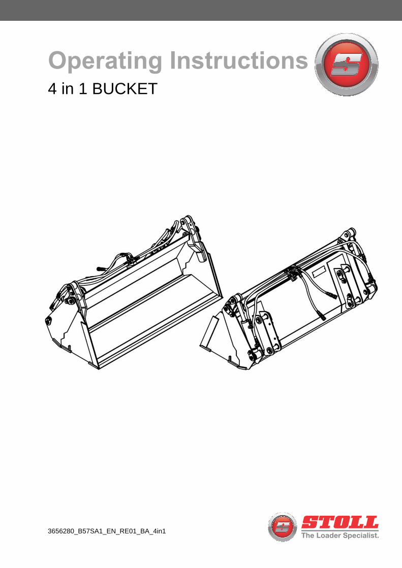
3656280_B57SA1_EN_RE01_BA_4in1
Operating Instructions4 in 1 BUCKET

- 1 -
CONGRATULATIONS! You have invested in the best implement of its type on the market today.
The care you give your ANSUNG implement will greatly determine your satisfaction with its performance and its service life. We urge a careful study of
this manual to provide you with a thorough understanding of your new implement before operating, as well as suggestions for operation and
maintenance.
As an authorized ANSUNG dealer, we stock genuine ANSUNG parts which are manufactured with the same precision and skill as our original equipment.
Our trained service personnel are well informed on methods required to service ANSUNG equipment, and are ready and able to help you.
Should you require additional information or assistance, please contact us.
YOUR AUTHORIZED ANSUNG DEALER
ANSUNG reserves the rights to change the specifications. The models and specifications
described here can be subjected to modifications for improvements without any prior notice
by the manufacturer.
- 2 -
Operator's Manual
TABLE OF CONTENTS
SECTION PAGE
Warranty ................................................ ..........4 Dealer Preparation Check List ........................7 Safety Precautions................................... .......8
I. LOADER SPECIFICATIONS .........................11 II. INTRODUCTION & DESCRIPTION ...............12
2-1 Introduction ..............................................12 2-2 Description ...............................................12
III. PREPARATION FOR USE .............................14 3-1 Attaching to Tractor ..................................14 3-2 Torque specifications………………………20
IV. OPERATING INSTRUCTIONS .......................22 4-1 General Safety ..........................................22 4-2 Operation ..................................................22
V. MAINTENANCE ..............................................26 5-1 Maintenance Check list.............................26 5-2 Lubrication ................................................28 5-3 Troubleshooting .......................................29 Part List 4 in 1 Bucket BF Series………..................30 Part List 4 in 1 Bucket FIO Series……….................32 Part List Cylinder BF Series……….........................34 Part List Cylinder FIO Series...................................36
- 3 -
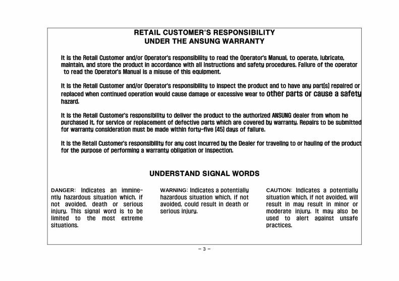
RETAIL CUSTOMER'S RESPONSIBILITY
UNDER THE ANSUNG WARRANTY
It is the Retail Customer and/or Operator's responsibility to read the Operator's Manual, to operate, lubricate,
maintain, and store the product in accordance with all instructions and safety procedures. Failure of the operator
to read the Operator's Manual is a misuse of this equipment.
It is the Retail Customer and/or Operator's responsibility to inspect the product and to have any part(s) repaired or
replaced when continued operation would cause damage or excessive wear to other parts or cause a safety hazard.
It is the Retail Customer's responsibility to deliver the product to the authorized ANSUNG dealer from whom he
purchased it, for service or replacement of defective parts which are covered by warranty. Repairs to be submitted
for warranty consideration must be made within forty-five (45) days of failure.
It is the Retail Customer's responsibility for any cost incurred by the Dealer for traveling to or hauling of the product
for the purpose of performing a warranty obligation or inspection.
UNDERSTAND SIGNAL WORDS
DANGER: Indicates an immine-
ntly hazardous situation which, if
not avoided, death or serious
injury. This signal word is to be
limited to the most extreme
situations.
WARNING: Indicates a potentially
hazardous situation which, if not
avoided, could result in death or
serious injury.
CAUTION: Indicates a potentially
situation which, if not avoided, will
result in may result in minor or
moderate injury. It may also be
used to alert against unsafe
practices.

- 4 -
LIMITED WARRANTY
☆☆☆☆☆☆☆☆☆☆☆☆☆☆☆☆☆☆☆☆☆☆☆☆☆☆☆☆☆☆☆☆☆☆☆☆☆☆☆☆☆☆☆☆☆☆☆☆☆☆☆☆☆☆☆
ANSUNG warrants to the original purchaser of any new ANSUNG equipment, purchased from an authorized
ANSUNG dealer, that the equipment be free from defects in material and workmanship for a period of one (1) year
for non-commercial, state, and municipalities' use and ninety (90) days for commercial use from date of retail sale.
The obligation of ANSUNG to the purchaser under this warranty is limited to the repair or replacement of defective
parts.
Replacement or repair parts installed in the equipment covered by this limited warranty are warranted for
ninety (90) days from the date of purchase of such part or to the expiration of the applicable new equipment
warranty period, whichever occurs later. Warranted parts shall be provided at no cost to the user at an authorized
ANSUNG dealer during regular working hours. ANSUNG reserves the right to inspect any equipment or parts which are
claimed to have been defective in material or workmanship.
DISCLAIMER OF IMPLIED WARRANTIES & CONSEQUENTIAL DAMAGES
ANSUNG's obligation under this limited warranty, to the extent allowed by law, is in lieu of all warranties,
implied or expressed, INCLUDING IMPLIED WARRANTIES OF MERCHANTABILITY AND FITNESS FOR A
PARTICULAR PURPOSE and any liability for incidental and consequential damages with respect to the sale or use
of the items warranted. Such incidental and consequential damages shall include but not be limited to:
transportation charges other than normal freight charges; cost of installation other than cost approved by
ANSUNG; duty; taxes; charges for normal service or adjustment; loss of crops or any other loss of income; rental of
substitute equipment, expenses due to loss, damage, detention or delay in the delivery of equipment or parts
resulting from acts beyond the control of ANSUNG.

- 5 -
THIS LIMITED WARRANTY SHALL NOT APPLY:
1. To vendor items which carry their own warranties, such as engines, tires, and tubes.
2. If the unit has been subjected to misapplication, abuse, misuse, negligence, fire or other accident.
3. If parts not made or supplied by ANSUNG have been used in connection with the unit, if, in the sole judgement of
ANSUNG such use affects its performance, stability or reliability.
4. If the unit has been altered or repaired outside of an authorized ANSUNG dealership in a manner which, in the
sole judgement of ANSUNG, affects its performance, stability or reliability.
5. To normal maintenance service and normal replacement items such as gearbox lubricant, hydraulic fluid, worn
blades, or to normal deterioration of such things as belts and exterior finish due to use or exposure.
6. To expendable or wear items such as teeth, chains, sprockets, belts, springs and any other items that in the
company's sole judgement is a wear item.
NO EMPLOYEE OR REPRESENTATIVE OF ANSUNG IS AUTHORIZED TO CHANGE THIS LIMITED WARRANTY IN
ANY WAY OR GRANT ANY OTHER WARRANTY UNLESS SUCH CHANGE IS MADE IN WRITING AND SIGNED BY
ANSUNG'S SERVICE MANAGER, SEOUL, KOREA ☆☆☆☆☆☆☆☆☆☆☆☆☆☆☆☆☆☆☆☆☆☆☆☆☆☆☆☆☆☆☆☆☆☆☆☆☆☆☆☆☆☆☆☆☆☆☆☆☆☆☆☆☆
Record the model number, serial number and date
purchased. This information will be helpful to your MODEL NUMBER dealer if parts or service are required.
MAKE CERTAIN THE WARRANTY REGISTRATION SERIAL NUMBER CARD HAS BEEN FILED WITH ANSUNG/
SEOUL, KOREA DATE OF RETAIL SALE
- 6 -
DEALER PREPARATION CHECK LIST
BEFORE DELIVERING MACHINE - The following check list should be completed.
Use the Operator's Manual as a guide.
■ Machine properly assembled.
■ All safety decals readable (See decal page).
■ All bolts tightened to torque specifications given in torque chart.
■ Machine operates properly.
■ Customer has appropriate mounting kit for his tractor and loader.
■ Operators manual has been delivered to owner and he has been instructed on the safe and proper use of
the front end loader.
It is recommended that the tractor be equipped with Rollover Protection System (ROPS) and
seat belt be used for all loader operations.
To avoid serious injury or death, do not handle large heavy objects (large round bales,
machinery, etc.) with this loader.
It is the responsibility of the dealer to complete the procedures listed above before
delivery of this implement to the customer.
Dealer's Signature
THIS CHECKLIST TO REMAIN IN OWNER'S MANUAL
It is responsibility of the dealer to complete the procedures listed above before of this
implement to the customer
- 7 -
IMPORTANT SAFETY PRECAUTIONS
This symbol is used to call attention to
safety precautions that should be followed
by the operator to avoid accidents. When
you see this symbol, carefully read the
message that follows and heed its advice.
Failure to comply with safety precautions
could result in serious bodily injury.
In addition to the design and configuration of equipment, hazard control and accident
prevention are dependent upon the awareness, concern, prudence and proper training of
personnel in the operation, transport, maintenance and storage of equipment. Lack of
attention to safety can result in accident, personal injury, reduction of efficiency and
worst of all-loss of life. Watch for safety hazards and correct deficiencies promptly. Use
the following safety precautions as a general guide to safe operations when using this
machine. Additional safety precautions are used throughout this manual for specific
operating and maintenance procedures. Read this manual and review the safety
precautions often until you know the limitations.
- 8 -
THE TRACTOR
1. Read the tractor operator's manual to learn how to operate your tractor safely. Failure to do so could result
in serious injury or death and equipment damage.
2. It is recommended that tractor be equipped with Rollover Protective System (ROPS) and a seat belt be used
for all loader operations.
3. When operating loader directly off tractor remotes always remove or lockout detent on tractor's hydraulic
valves.
This allows levers return to neutral position when released.
4. Add wheel ballast or rear weight for stability.
5. Move wheels to the tractor manufacturer's widest recommended settings to increase stability.
6. For better stability, use tractor with wide front axle.
7. Move and turn the tractor at low speeds.
8. Stop tractor engine, place transmission in park (or neutral), engage parking brake, lower loader arms to
ground, cycle all hydraulic controls to relieve pressure, allow machine moving parts to stop, remove ignition
key to prevent unauthorized person from starting engine before dismounting tractor or serving, repairing, or
making adjustments to the equipment.
9. Wear personal protective equipment (PPE), such as, but not limited to, protection for eyes, ears, lungs, head,
hands and feet when operating, servicing, or repairing equipment. Avoid wearing loose clothing or jewelry
that may catch and entangle on equipment moving parts.
- 9 -
THE 4 in 1 BUCKET
1. Read the 4 in 1 bucket operator's manual to learn how to operate your loader safely. Failure to do so could
result in serious injury or death and equipment damage.
2. Become familiar with all the machine's controls and all the caution, warning and danger decals affixed to the
machine before attempting to start or operate.
3. Improper use of a 4 in 1 bucket can cause serious injury or death.
4. Do not lift or carry anybody on the loader or in the 4 in 1 bucket or attachment.
5. Never allow anyone to get under the loader bucket or reach through the booms when the bucket is raised.
6. Do not walk or work under a raised loader bucket or attachment unless it is securely blocked or held in
position.
7. Avoid overhead wires and obstacles when loader is raised. Contacting electrical lines can cause
electrocution.
8. Make sure all parked loaders on stands are on a hard, level surface.
9. Use a piece of cardboard or wood rather than hands and wear eye protection when searching for hydraulic
leaks.
10. Escaping hydraulic oil under pressure can penetrate skin. If oil is injected into skin, it must be surgically
removed within a few hours by a doctor or gangrene may result.
12. Before disconnecting hydraulic lines, relieve all hydraulic pressure.
12. Always wear safety goggles when repairing or servicing machine.
13. When servicing or replacing pins in cylinder ends, buckets, etc., always use a brass punch and hammer.
Failure to do so could result in injury from flying fragments.
14. Replace damaged or illegible safety decals. See decal page for required decals.
15. Do not modify or alter or permit anyone else to modify or alter the 4 in 1 bucket, any of its components or any
4 in 1 bucket function without first consulting your local dealer.
- 10 -
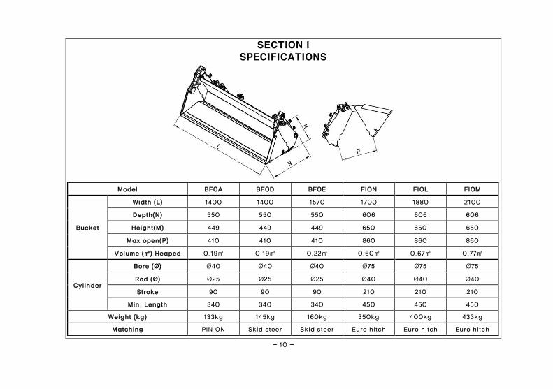
SECTION I
SPECIFICATIONS
Model BF0A BF0D BF0E FION FIOL FIOM
Bucket
Width (L) 1400 1400 1570 1700 1880 2100
Depth(N) 550 550 550 606 606 606
Height(M) 449 449 449 650 650 650
Max open(P) 410 410 410 860 860 860
Volume (㎥) Heaped 0.19㎥ 0.19㎥ 0.22㎥ 0.60㎥ 0.67㎥ 0.77㎥
Cylinder
Bore (Ø) Ø40 Ø40 Ø40 Ø75 Ø75 Ø75
Rod (Ø) Ø25 Ø25 Ø25 Ø40 Ø40 Ø40
Stroke 90 90 90 210 210 210
Min. Length 340 340 340 450 450 450
Weight (kg) 133kg 145kg 160kg 350kg 400kg 433kg
Matching PIN ON Skid steer Skid steer Euro hitch Euro hitch Euro hitch
- 11 -
SECTION II
INTRODUCTION AND DESCRIPTION
2-1 INTRODUCTION We are pleased to have you as a ANSUNG customer. Your Front end Loader has been carefully designed to give
maximum service with minimum down time. This manual is provided to give you the necessary operating and
maintenance instructions for keeping your loader in top operating condition. Please read this manual thoroughly.
Understand what each control is for and how to use it. Observe all safety precautions decaled on the machine and
noted throughout the manual for safe operation of implement. If any assistance or additional information is needed,
contact your authorized ANSUNG dealer.
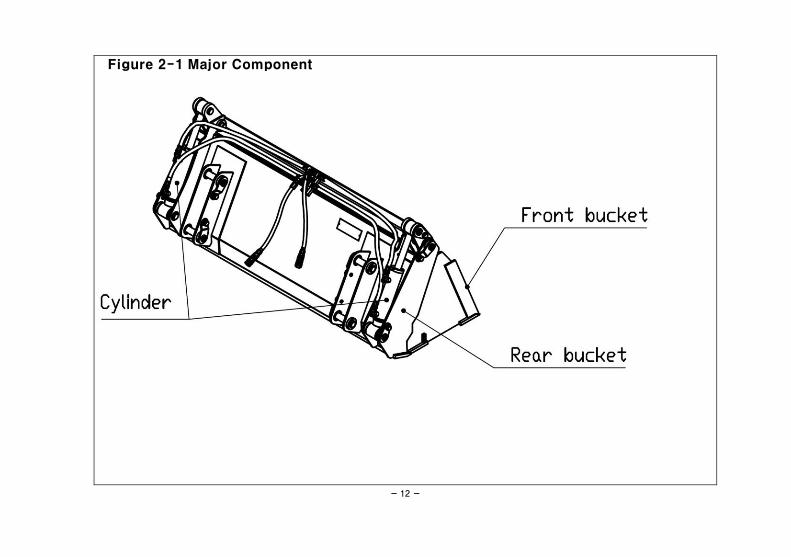
2-2 DESCRIPTION The 4 in 1 BUCKET is designed for four purpose functions. They are intended to bulldozing, clam, scraping and grab
the loose materials, wood and hay that will fit in the bucket. Cylinders are double-acting and control by 3rd function
valve with electronic switch and control lever of Front end loader. Major components of 4 in 1 Bucket are shown in
Figure 2-1.
- 12 -
Figure 2-1 Major Component
- 13 -
SECTION lIl PREPARATION FOR USE
3-1 ATTACHING TO FRONT END LOADER
WEIGHT SHOULD BE APPLIED TO TRACTOR REAR WHEELS AND/OR 3-POINT HITCH TO INCREASE STABILITY.
TO AVOID INJURY OR DEATH:
ALWAYS CONNECT LOADER HOSES TO APPROPRIATE TRACTOR AUXILIARY OUTLET. ALWAYS REMOVE OR LOCKOUT TRACTOR'S
HYDRAULIC VALVES DETENT POSITIONS FOR LEVER NEUTRAL RETURN WHEN RELEASED.
It is recommended that tractor wheels be moved to the widest setting and rear ballast be applied to increase
tractor stability. Three point hitch mounted weights are available from your dealer. Air pressure in front tires
should be adequate for heavy loads. Refer to tractor owner's manual for further instructions. Attach 4 in 1 Bucket
to Front end loader as follows:
THE FOLLOWING SAFETY PRECAUTIONS SHOULD BE THOROUGHLY UNDERSTOOD BEFORE ATTEMPTING MACHINE ASSEMBLY.
1. Do not lift heavy parts or assemblies. Use crane, jack, tackle, fork trucks, or other mechanical devices.
2. Select an area for assembly that is clean and free of any debris which might cause persons working on the
assembly to trip.
3. Arrange parts to be assembled neatly in the work area and have tools and other mechanical assisting devices
in easy reach.
4. Inspect all parts and assemblies thoroughly and remove any sharp edges, grease, oil, or dirt which might cause
pieces to slip when handling.
- 14 -
5. Preview the assembly instructions in your operator's manual before proceeding further.
6. If the assembly instructions call for parts or assemblies to be blocked up, use only blocking material that is in
good condition and is capable of handling the weight of the assembly to be blocked. Also, insure that the
blocking material is on a clean, dry surface.
7. Never put hands or any other body under blocked up assemblies if at all possible.
8. Always wear goggles or safety glasses when hammering, grinding or drilling metal parts.
9. If the assembly calls for welding or cutting, be sure that there are no flammable materials close at hand and
that bystanders have taken necessary precautions.
AFTER COMPLETING ANY ASSEMBLY STEP, THOROUGHLY READ THE NEXT STEP IN THE ASSEMBLY INSTRUCTIONS BEFORE
PROCEEDING WITH THAT STEP.
10. After completing assembly, thoroughly inspect the machine to be sure that all nuts, bolts, hydraulic fittings or
any other fastened assemblies have been thoroughly tightened.
11. After completing assembly be sure that all safety locking devices or guards are in place.
12. Before operating the machine, thoroughly read the operation section of this manual.
13. Before operating, read the maintenance section of this manual to be sure that any parts requiring lubrication
such as pins are full to avoid any possible damage.
14. Wear personal protective equipment such as, but not limited to, protection for eyes, ears, feet, hands, lungs
and head when assembling the equipment. Do not wear loose clothing or jewelry that may catch on equipment
moving parts.
BEFORE OPERATING THE EQUIPMENT, IF YOU HAVE ANY QUESTIONS REGARDING THE PROPER ASSEMBLY OR OPERATION, CONTACT
YOUR AUTHORIZED ANSUNG DEALER OR REPRESENTATIVE.
- 15 -
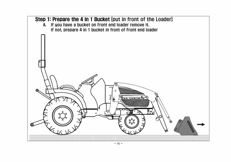
Step 1: Prepare the 4 in 1 Bucket (put in front of the Loader) A. If you have a bucket on Front end loader remove it.
If not, prepare 4 in 1 bucket in front of Front end loader
- 16 -
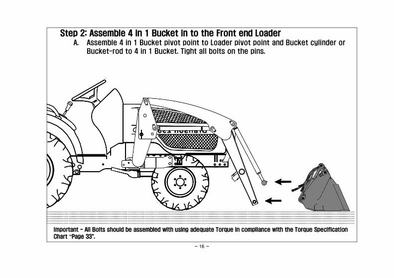
Step 2: Assemble 4 in 1 Bucket in to the Front end Loader A. Assemble 4 in 1 Bucket pivot point to Loader pivot point and Bucket cylinder or
Bucket-rod to 4 in 1 Bucket. Tight all bolts on the pins.
Important - All Bolts should be assembled with using adequate Torque in compliance with the Torque Specification
Chart “Page 33".
- 17 -
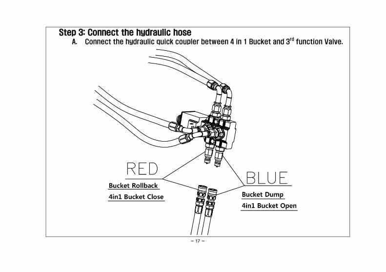
Step 3: Connect the hydraulic hose A. Connect the hydraulic quick coupler between 4 in 1 Bucket and 3
rd function Valve.
- 18 -
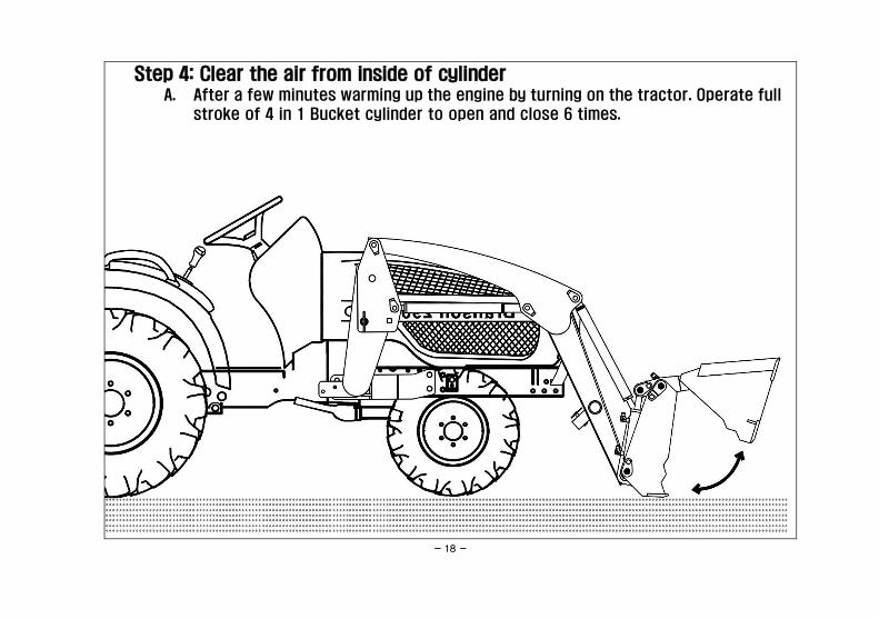
Step 4: Clear the air from inside of cylinder A. After a few minutes warming up the engine by turning on the tractor. Operate full
stroke of 4 in 1 Bucket cylinder to open and close 6 times.
- 19 -
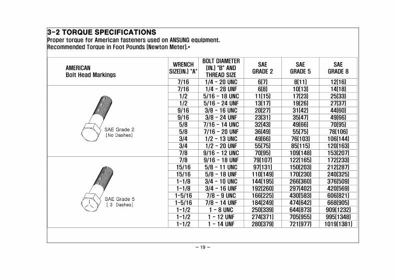
3-2 TORQUE SPECIFICATIONS Proper torque for American fasteners used on ANSUNG equipment.
Recommended Torque in Foot Pounds (Newton Meter).*
AMERICAN
Bolt Head Markings
WRENCH
SIZE(IN.) "A"
BOLT DIAMETER
(IN.) "B" AND
THREAD SIZE
SAE
GRADE 2
SAE
GRADE 5
SAE
GRADE 8
7/16 1/4 - 20 UNC 6(7) 8(11) 12(16)
7/16 1/4 - 28 UNF 6(8) 10(13) 14(18)
1/2 5/16 - 18 UNC 11(15) 17(23) 25(33)
1/2 5/16 - 24 UNF 13(17) 19(26) 27(37)
9/16 3/8 - 16 UNC 20(27) 31(42) 44(60)
9/16 3/8 - 24 UNF 23(31) 35(47) 49(66)
5/8 7/16 - 14 UNC 32(43) 49(66) 70(95)
5/8 7/16 - 20 UNF 36(49) 55(75) 78(106)
3/4 1/2 - 13 UNC 49(66) 76(103) 106(144)
3/4 1/2 - 20 UNF 55(75) 85(115) 120(163)
7/8 9/16 - 12 UNC 70(95) 109(148) 153(207)
7/8 9/16 - 18 UNF 79(107) 122(165) 172(233)
15/16 5/8 - 11 UNC 97(131) 150(203) 212(287)
15/16 5/8 - 18 UNF 110(149) 170(230) 240(325)
1-1/8 3/4 - 10 UNC 144(195) 266(360) 376(509)
1-1/8 3/4 - 16 UNF 192(260) 297(402) 420(569)
1-5/16 7/8 - 9 UNC 166(225) 430(583) 606(821)
1-5/16 7/8 - 14 UNF 184(249) 474(642) 668(905)
1-1/2 1 - 8 UNC 250(339) 644(873) 909(1232)
1-1/2 1 - 12 UNF 274(371) 705(955) 995(1348)
1-1/2 1 - 14 UNF 280(379) 721(977) 1019(1381)
- 20 -
WRENCH
SIZE(IN.) "A"
BOLT DIAMETER
(IN.) "B" AND
THREAD SIZE
SAE
GRADE 2
SAE
GRADE 5
SAE
GRADE 8
1-11/16 1-1/8 - 7 UNC 354(480) 795(1077) 1288(1745)
1-11/16 1-1/8 - 12 UNF 397(538) 890(1206) 1444(1957)
1-7/8 1-1/4 - 7 UNC 500(478) 1120(1518) 1817(2462)
1-7/8 1-1/4 - 12 UNF 553(749) 1241(1682) 2013(2728)
2-1/16 1-3/8 - 6 UNC 655(887) 1470(1992) 2382(3228)
2-1/16 1-3/8 - 12 UNF 746(1011) 1672(2266) 2712(3675)
2-1/4 1-1/2 - 6 UNC 870(1179) 1950(2642) 3161(4283)
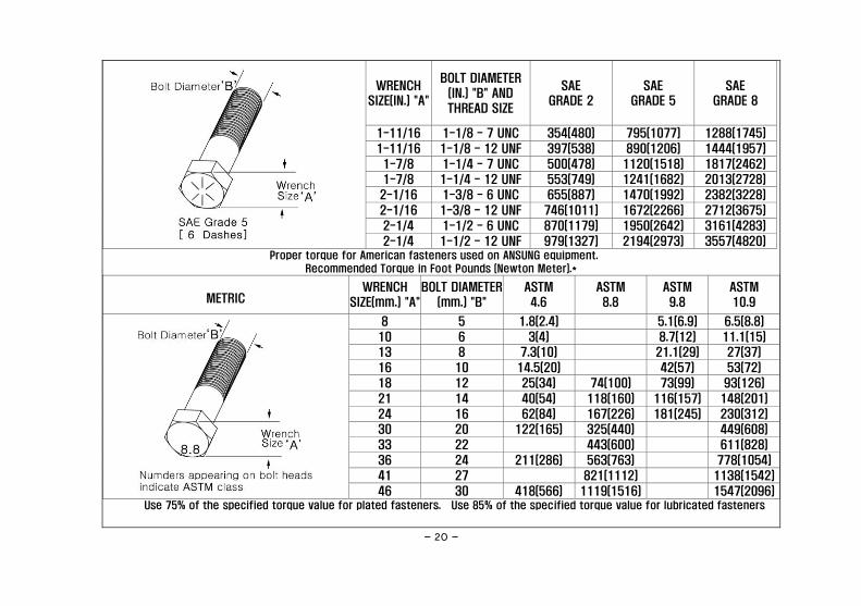
2-1/4 1-1/2 - 12 UNF 979(1327) 2194(2973) 3557(4820) Proper torque for American fasteners used on ANSUNG equipment.
Recommended Torque in Foot Pounds (Newton Meter).*
METRIC WRENCH
SIZE(mm.) "A"
BOLT DIAMETER
(mm.) "B"
ASTM
4.6
ASTM
8.8
ASTM
9.8
ASTM
10.9
8 5 1.8(2.4) 5.1(6.9) 6.5(8.8)
10 6 3(4) 8.7(12) 11.1(15)
13 8 7.3(10) 21.1(29) 27(37)
16 10 14.5(20) 42(57) 53(72)
18 12 25(34) 74(100) 73(99) 93(126)
21 14 40(54) 118(160) 116(157) 148(201)
24 16 62(84) 167(226) 181(245) 230(312)
30 20 122(165) 325(440) 449(608)
33 22 443(600) 611(828)
36 24 211(286) 563(763) 778(1054)
41 27 821(1112) 1138(1542)
46 30 418(566) 1119(1516) 1547(2096) Use 75% of the specified torque value for plated fasteners. Use 85% of the specified torque value for lubricated fasteners
- 21 -
SECTION lV
OPERATING INSTRUCTIONS
DO NOT LIFT ROUND HAY BALES. ROUND BALES CAN ROLL DOWN LOADER ARMS CAUSING SERIOUS
INJURY OR DEATH TO OPERATOR.
4-1 GENERAL SAFETY Only qualified people familiar with this manual should operate this machine. Operator should wear hard hat, safety
glasses and safety shoes. The operator should read, understand and practice all safety messages shown on the
caution, warning and danger decals affixed to the loader to avoid serious injury or death. It is recommended that
tractor be equipped with Rollover Protective System (ROPS) and a seat belt be used. Check for ditches, stumps,
holes or other obstacles that could damage tractor or loader. Fluid and/or weights for rear tires is recommended
for added stability. See tractor operator's manual. Three point hitch mounted weights are available from your
ANSUNG dealer. Always turn off tractor engine, set parking brake and lower loader to ground before dismounting
tractor. See page 4 for additional safety precautions.
4-2 OPERATION The loader should be operated with the tractor engine running at 1200-1700 rpm. Excessive speeds are dangerous
and may cause bucket spillage and unnecessary strain on both the tractor and loader.
The following text and illustrations offer suggested loader and tractor operating techniques.
- 22 -
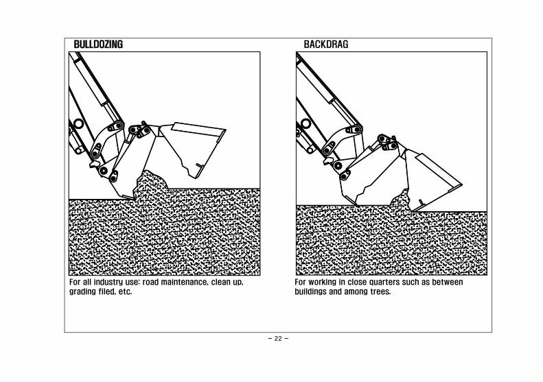
BULLDOZING
For all industry use: road maintenance, clean up,
grading filed, etc.
BACKDRAG
For working in close quarters such as between
buildings and among trees.
- 23 -
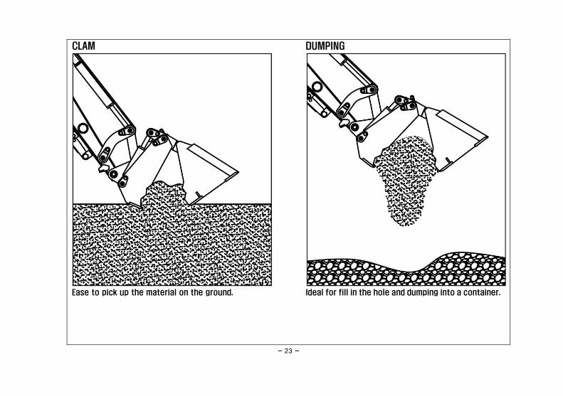
CLAM
Ease to pick up the material on the ground.
DUMPING
Ideal for fill in the hole and dumping into a container.
- 24 -
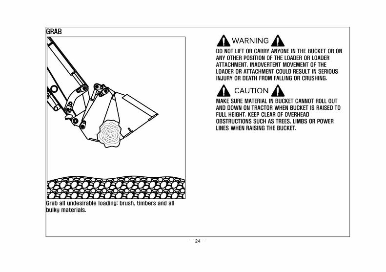
GRAB
Grab all undesirable loading: brush, timbers and all
bulky materials.
DO NOT LIFT OR CARRY ANYONE IN THE BUCKET OR ON
ANY OTHER POSITION OF THE LOADER OR LOADER
ATTACHMENT. INADVERTENT MOVEMENT OF THE
LOADER OR ATTACHMENT COULD RESULT IN SERIOUS
INJURY OR DEATH FROM FALLING OR CRUSHING.
MAKE SURE MATERIAL IN BUCKET CANNOT ROLL OUT
AND DOWN ON TRACTOR WHEN BUCKET IS RAISED TO
FULL HEIGHT. KEEP CLEAR OF OVERHEAD
OBSTRUCTIONS SUCH AS TREES, LIMBS OR POWER
LINES WHEN RAISING THE BUCKET.
- 25 -
SECTION V
MAINTENANCE
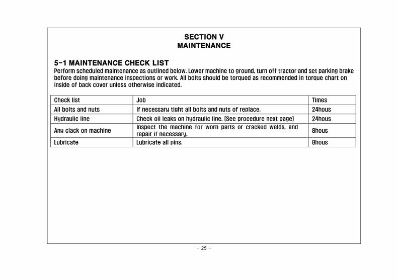
5-1 MAINTENANCE CHECK LIST Perform scheduled maintenance as outlined below. Lower machine to ground, turn off tractor and set parking brake
before doing maintenance inspections or work. All bolts should be torqued as recommended in torque chart on
inside of back cover unless otherwise indicated.
Check list Job Times
All bolts and nuts If necessary tight all bolts and nuts of replace. 24hous
Hydraulic line Check oil leaks on hydraulic line. (See procedure next page) 24hous
Any clack on machine Inspect the machine for worn parts or cracked welds, and
repair if necessary. 8hous
Lubricate Lubricate all pins. 8hous
- 26 -
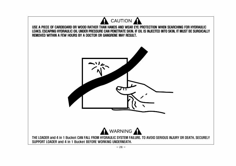
USE A PIECE OF CARDBOARD OR WOOD RATHER THAN HANDS AND WEAR EYE PROTECTION WHEN SEARCHING FOR HYDRAULIC
LEAKS. ESCAPING HYDRAULIC OIL UNDER PRESSURE CAN PENETRATE SKIN. IF OIL IS INJECTED INTO SKIN, IT MUST BE SURGICALLY
REMOVED WITHIN A FEW HOURS BY A DOCTOR OR GANGRENE MAY RESULT.
THE LOADER and 4 in 1 Bucket CAN FALL FROM HYDRAULIC SYSTEM FAILURE. TO AVOID SERIOUS INJURY OR DEATH, SECURELY
SUPPORT LOADER and 4 in 1 Bucket BEFORE WORKING UNDERNEATH.

- 27 -
5-2 LUBRICATION
NOTE
The multipurpose grease referenced in this section is an NLGI Grade 2 type grease.
Lubrication Points
- 28 -
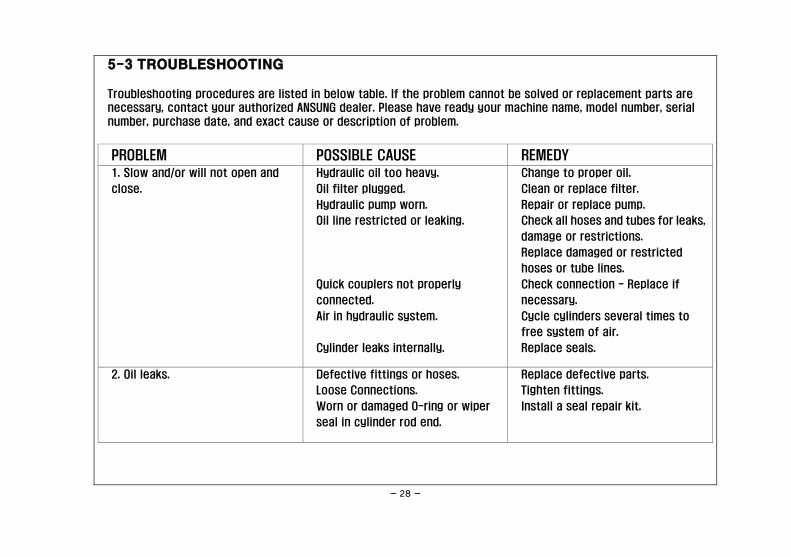
5-3 TROUBLESHOOTING
Troubleshooting procedures are listed in below table. If the problem cannot be solved or replacement parts are
necessary, contact your authorized ANSUNG dealer. Please have ready your machine name, model number, serial
number, purchase date, and exact cause or description of problem.
PROBLEM POSSIBLE CAUSE REMEDY
1. Slow and/or will not open and
close.
Hydraulic oil too heavy.
Oil filter plugged.
Hydraulic pump worn.
Oil line restricted or leaking.
Quick couplers not properly
connected.
Air in hydraulic system.
Cylinder leaks internally.
Change to proper oil.
Clean or replace filter.
Repair or replace pump.
Check all hoses and tubes for leaks,
damage or restrictions.
Replace damaged or restricted
hoses or tube lines.
Check connection - Replace if
necessary.
Cycle cylinders several times to
free system of air.
Replace seals.
2. Oil leaks.
Defective fittings or hoses.
Loose Connections.
Worn or damaged O-ring or wiper
seal in cylinder rod end.
Replace defective parts.
Tighten fittings.
Install a seal repair kit.

- 29 -
Memo
- 30 -
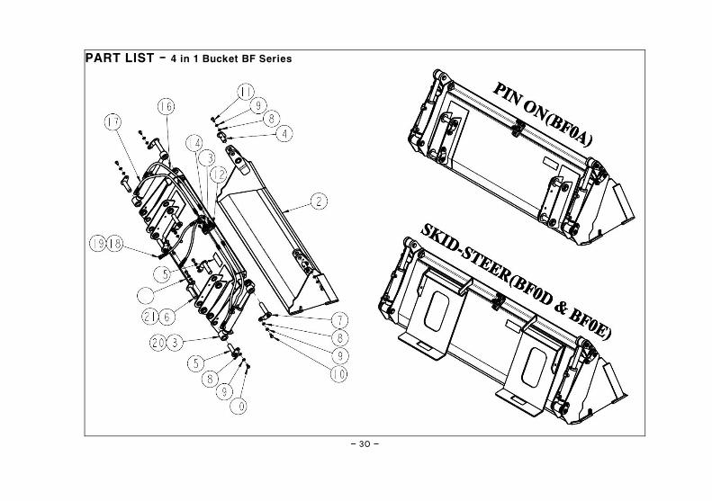
PART LIST - 4 in 1 Bucket BF Series
- 31 -
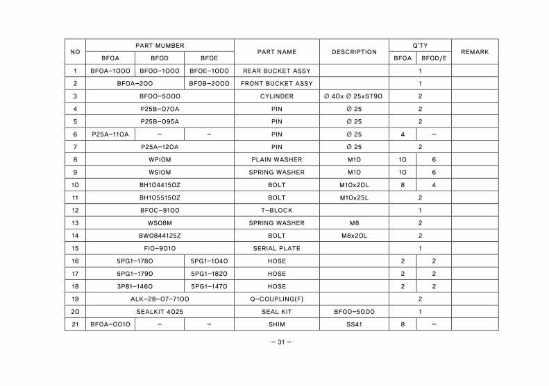
NO PART MUMBER
PART NAME DESCRIPTION Q`TY
REMARK BF0A BF0D BF0E BF0A BF0D/E
1 BF0A-1000 BF0D-1000 BF0E-1000 REAR BUCKET ASSY
1
2 BF0A-200 BF0B-2000 FRONT BUCKET ASSY
1
3 BF00-5000 CYLINDER Ø 40x Ø 25xST90 2
4 P25B-070A PIN Ø 25 2
5 P25B-095A PIN Ø 25 2
6 P25A-110A - - PIN Ø 25 4 -
7 P25A-120A PIN Ø 25 2
8 WPI0M PLAIN WASHER M10 10 6
9 WSI0M SPRING WASHER M10 10 6
10 BH1044150Z BOLT M10x20L 8 4
11 BH1055150Z BOLT M10x25L 2
12 BF0C-9100 T-BLOCK
1
13 WS08M SPRING WASHER M8 2
14 BW0844125Z BOLT M8x20L 2
15 FI0-9010 SERIAL PLATE
1
16 5PG1-1780 5PG1-1040 HOSE
2 2
17 5PG1-1790 5PG1-1820 HOSE
2 2
18 3P81-1460 5PG1-1470 HOSE
2 2
19 ALK-28-07-7100 Q-COUPLING(F)
2
20 SEALKIT 4025 SEAL KIT BF00-5000 1
21 BF0A-0010 - - SHIM SS41 8 -
- 32 -
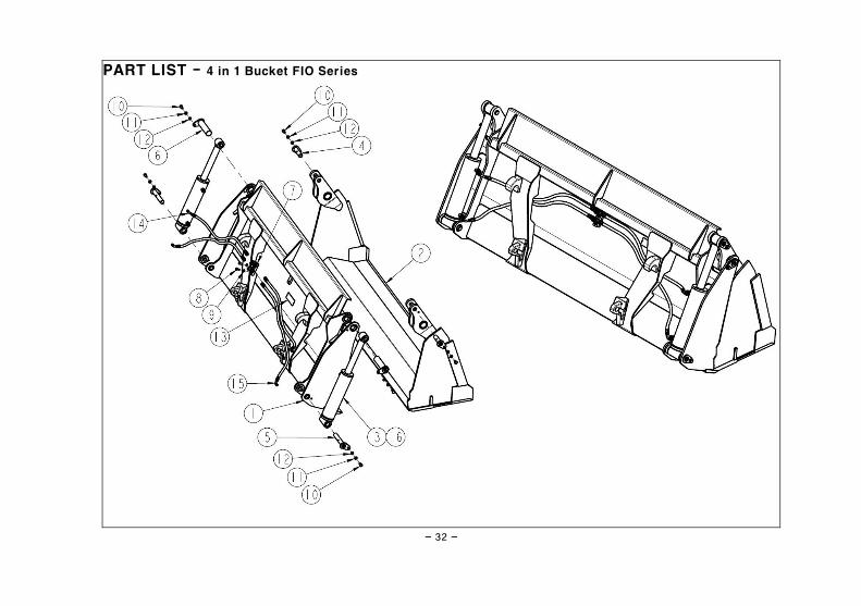
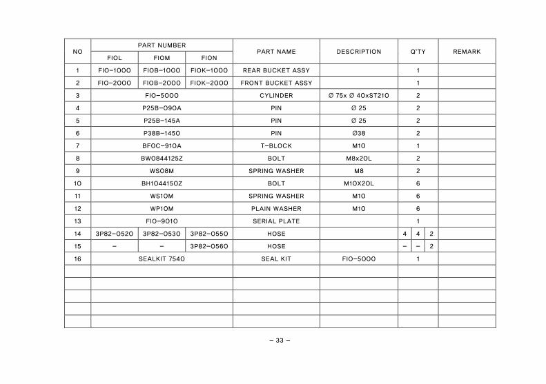
PART LIST - 4 in 1 Bucket FIO Series
- 33 -
NO PART NUMBER
PART NAME DESCRIPTION Q`TY REMARK FIOL FIOM FION
1 FIO-1000 FIOB-1000 FIOK-1000 REAR BUCKET ASSY 1
2 FIO-2000 FIOB-2000 FIOK-2000 FRONT BUCKET ASSY 1
3 FIO-5000 CYLINDER Ø 75x Ø 40xST210 2
4 P25B-090A PIN Ø 25 2
5 P25B-145A PIN Ø 25 2
6 P38B-1450 PIN Ø38 2
7 BF0C-910A T-BLOCK M10 1
8 BW0844125Z BOLT M8x20L 2
9 WS08M SPRING WASHER M8 2
10 BH1044150Z BOLT M10X20L 6
11 WS10M SPRING WASHER M10 6
12 WP10M PLAIN WASHER M10 6
13 FIO-9010 SERIAL PLATE 1
14 3P82-0520 3P82-0530 3P82-0550 HOSE 4 4 2
15 - - 3P82-0560 HOSE - - 2
16 SEALKIT 7540 SEAL KIT FIO-5000 1
- 34 -
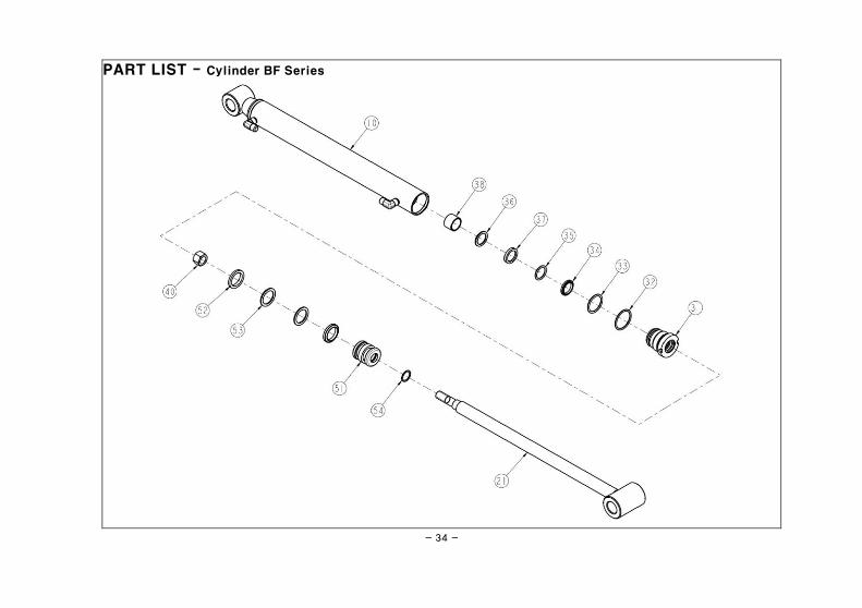
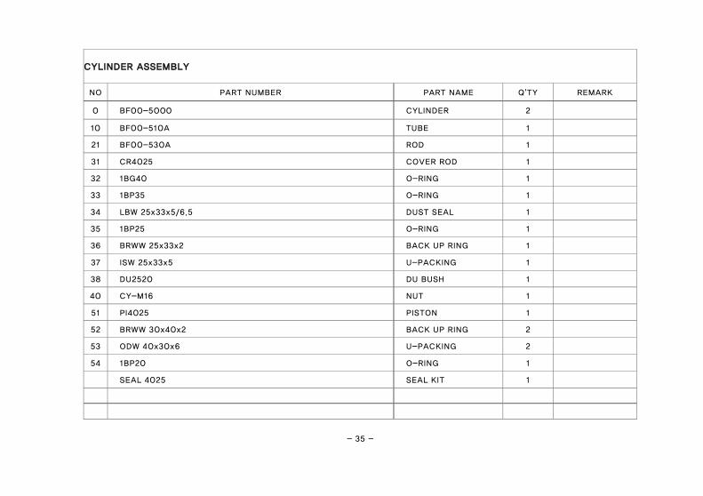
PART LIST - Cylinder BF Series
- 35 -
CYLINDER ASSEMBLY
NO PART NUMBER PART NAME Q'TY REMARK
0 BF00-5000 CYLINDER 2
10 BF00-510A TUBE 1
21 BF00-530A ROD 1
31 CR4025 COVER ROD 1
32 1BG40 O-RING 1
33 1BP35 O-RING 1
34 LBW 25x33x5/6.5 DUST SEAL 1
35 1BP25 O-RING 1
36 BRWW 25x33x2 BACK UP RING 1
37 ISW 25x33x5 U-PACKING 1
38 DU2520 DU BUSH 1
40 CY-M16 NUT 1
51 PI4025 PISTON 1
52 BRWW 30x40x2 BACK UP RING 2
53 ODW 40x30x6 U-PACKING 2
54 1BP20 O-RING 1
SEAL 4025 SEAL KIT 1
- 36 -
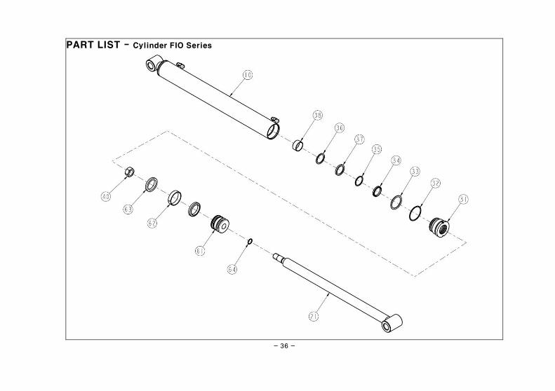
PART LIST - Cylinder FIO Series
- 37 -
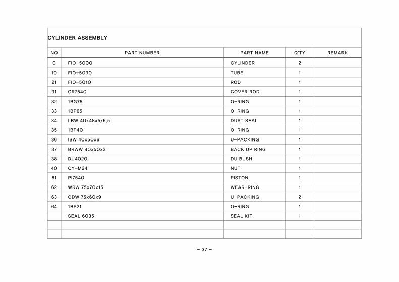
CYLINDER ASSEMBLY
NO PART NUMBER PART NAME Q'TY REMARK
0 FIO-5000 CYLINDER 2
10 FIO-5030 TUBE 1
21 FIO-5010 ROD 1
31 CR7540 COVER ROD 1
32 1BG75 O-RING 1
33 1BP65 O-RING 1
34 LBW 40x48x5/6.5 DUST SEAL 1
35 1BP40 O-RING 1
36 ISW 40x50x6 U-PACKING 1
37 BRWW 40x50x2 BACK UP RING 1
38 DU4020 DU BUSH 1
40 CY-M24 NUT 1
61 PI7540 PISTON 1
62 WRW 75x70x15 WEAR-RING 1
63 ODW 75x60x9 U-PACKING 2
64 1BP21 O-RING 1
SEAL 6035 SEAL KIT 1

- 39 -
Memo


3656280_B57SA1_EN_RE01_BA_4in1
Address of the dealer
Stick or write down the serial number here
Wilhelm STOLL Maschinenfabrik GmbH STOLL on the Internet:
PO box 1181, 38266 Lengede www.stoll-germany.com
Bahnhofstr. 21, 38268 Lengede www.facebook.com\STOLLFrontloader
Phone: +49 (0) 53 44/20 0 www.youtube.com\STOLLFrontloader
Fax: +49 (0) 53 44/20 182
E-mail: [email protected]