Embed Size (px)
Citation preview
YILMAZ REDÜKTÖR ISO 9001 YILMAZ REDÜKTÖR ISO 9001
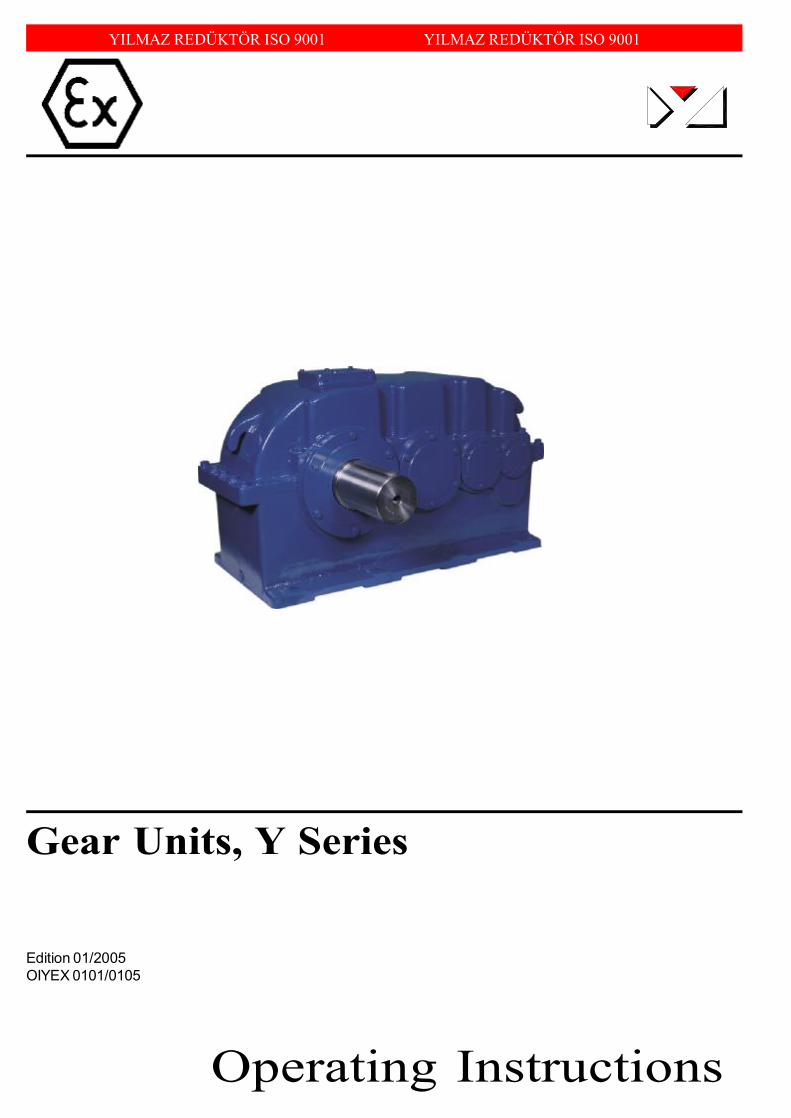
Gear Units, Y Series
Operating Instructions
Edition 01/2005OIYEX 0101/0105

Operating InstructionY SeriesContents
yilmaz redÜktÖr 03
Contents
1 How To Use This Manual.................................................................................... 5
2 Unit Designation................................................................................................... 62.a Detailed unit designation................................................................................. 62.b Nameplate unit designation............................................................................. 7
3 Part List of Standard Type Gear Units................................................................ 83.a YRM1.. Type................................................................................................. 83.b YRM2.. Type................................................................................................. 93.c YRD2.. Type.................................................................................................. 103.d YRM3.. Type.................................................................................................. 113.e YRD3.. Type.................................................................................................. 123.f YRM4.. Type................................................................................................. 133.g YRD4.. Type.................................................................................................. 14
4 Thinks to Check Before the Gear Unit or Geared Motor is Installed.............. 164.a Safety notes................................................................................................... 164.b Transportation............................................................................................... 174.c Storage......................................................................................................... 17
5 Installing The Gear Unit...................................................................................... 185.a Before you start............................................................................................. 185.b Check Name Plate........................................................................................ 185.c Check the ambient conditions and temperature.............................................. 185.d Check fitting elements and the shaft dimensions to fit..................................... 185.e Check the voltage supply............................................................................... 205.f Check the mounting position.......................................................................... 205.g Use the breather plug..................................................................................... 205.h Check the oil level.......................................................................................... 215.i Check shaft ends and mounting faces.............................................................. 215.j Cover abresive ambient.................................................................................. 215.k Check accessibility to filling, breather and drain plugs...................................... 21
6 Mechanical Installation........................................................................................ 226.a Installing gear units in category II2G/D-II3G/D............................................... 226.b Fittting outputshaft elements........................................................................... 236.c Correct position of otputshaft elements......................................................... 236.d Installing customer shaft with shoulder............................................................. 246.e Disassembling customer shaft with shoulder..................................................... 256.f Shaft tightening torques................................................................................... 276.g Recommended shaft dimensions for YRD types............................................... 286.h Fittting Couplings............................................................................................ 29

yilmaz redÜktÖr04
Operating InstructionY Series
7 Inspections............................................................................................................. 30
8 Lubrication.............................................................................................................. 318.a Oil Types......................................................................................................... 318.b Oil Quantities................................................................................................... 328.c Mounting Positions........................................................................................... 33
9 Troubleshooting Guide................. ........................................................................ 34
10 Decleration by the Manufacturer ........................................................................ 38
11 Waranty conditions................................................................................................. 39
12 Waranty................................................................................................................... 40
13 Service Contact Points.......................................................................................... 41
Operating InstructionY SeriesGeneral Information
yilmaz redÜktÖr 05
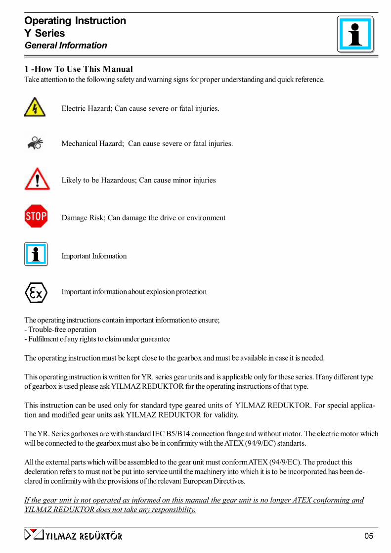
1 -How To Use This ManualTake attention to the following safety and warning signs for proper understanding and quick reference.
Electric Hazard; Can cause severe or fatal injuries.
Mechanical Hazard; Can cause severe or fatal injuries.
Likely to be Hazardous; Can cause minor injuries
Damage Risk; Can damage the drive or environment
Important Information
Important information about explosion protection
The operating instructions contain important information to ensure;- Trouble-free operation- Fulfilment of any rights to claim under guarantee
The operating instruction must be kept close to the gearbox and must be available in case it is needed.
This operating instruction is written for YR. series gear units and is applicable only for these series. If any different typeof gearbox is used please ask YILMAZ REDUKTOR for the operating instructions of that type.
This instruction can be used only for standard type geared units of YILMAZ REDUKTOR. For special applica-tion and modified gear units ask YILMAZ REDUKTOR for validity.
The YR. Series garboxes are with standard IEC B5/B14 connection flange and without motor. The electric motor whichwill be connected to the gearbox must also be in confirmity with the ATEX (94/9/EC) standarts.
All the external parts which will be assembled to the gear unit must conform ATEX (94/9/EC). The product thisdecleration refers to must not be put into service until the machinery into which it is to be incorporated has been de-clared in confirmity with the provisions of the relevant European Directives.
If the gear unit is not operated as informed on this manual the gear unit is no longer ATEX conforming andYILMAZ REDUKTOR does not take any responsibility.

yilmaz redÜktÖr06
Operating InstructionY SeriesType Designation
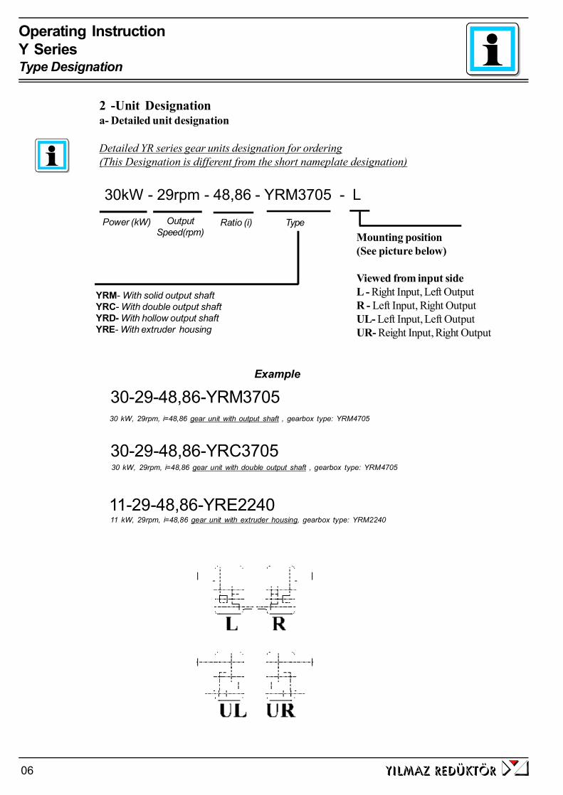
30kW - 29rpm - 48,86 - YRM3705 - L
Power (kW) OutputSpeed(rpm)
Ratio (i)
Example
30-29-48,86-YRM370530 kW, 29rpm, i=48,86 gear unit with output shaft , gearbox type: YRM4705
Detailed YR series gear units designation for ordering(This Designation is different from the short nameplate designation)
2 -Unit Designationa- Detailed unit designation
YRM- With solid output shaftYRC- With double output shaftYRD- With hollow output shaftYRE- With extruder housing
Type
30-29-48,86-YRC3705
11-29-48,86-YRE2240
30 kW, 29rpm, i=48,86 gear unit with double output shaft , gearbox type: YRM4705
11 kW, 29rpm, i=48,86 gear unit with extruder housing, gearbox type: YRM2240
Mounting position(See picture below)
Viewed from input sideL - Right Input, Left OutputR - Left Input, Right OutputUL- Left Input, Left OutputUR- Reight Input, Right Output
yilmaz redÜktÖr 07
Operating InstructionY SeriesType Designation
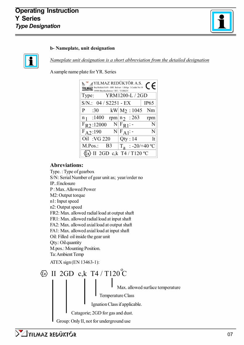
b- Nameplate, unit designation
Nameplate unit designation is a short abbreviation from the detailed designation
A sample name plate for YR. Series
Abreviations:Type. : Type of gearboxS/N: Serial Number of gear unit as; year/order noIP..:EnclosureP : Max. Allowed PowerM2: Output torquen1: Input speedn2: Output speedFR2: Max. allowed radial load at output shaftFR1: Max. allowed radial load at input shaftFA2: Max. allowed axial load at output shaftFA1: Max. allowed axial load at input shaftOil: Filled oil inside the gear unitQty.: Oil quantityM.pos.: Mounting Position.Ta: Ambient TempATEX sign (EN 13463-1):
Group: Only II, not for underground use
Catagorie; 2GD for gas and dust.
Ignation Class if applicable.
Temperature ClassMax. allowed surface temperature
II 2GD c,k T4 / T120 Co
263n :rpm 2 rpm1 :n 1400
A2R2
M.Pos.:
FF
Oil-20/+40Ta : ºCB3
R1A1
VG 220 Qty
FF
12000::
:190
NN
:
--
::14
NN
lt
S/N.: 04 / S2251 - EXType
P
:
2M:30 kW : 1045 Nm
II 2GD c,k T4 / T120 ºC
IP65
YILMAZ REDÜKTÖR A.S.Beylikdüzü SAN - BIR Bulvari 1.Bölge 3.Cadde No:1834900 Büyükçekmece / IST. / TURKEY
YRM1200-L / 2GD

yilmaz redÜktÖr08
Operating InstructionY SeriesPart Designation
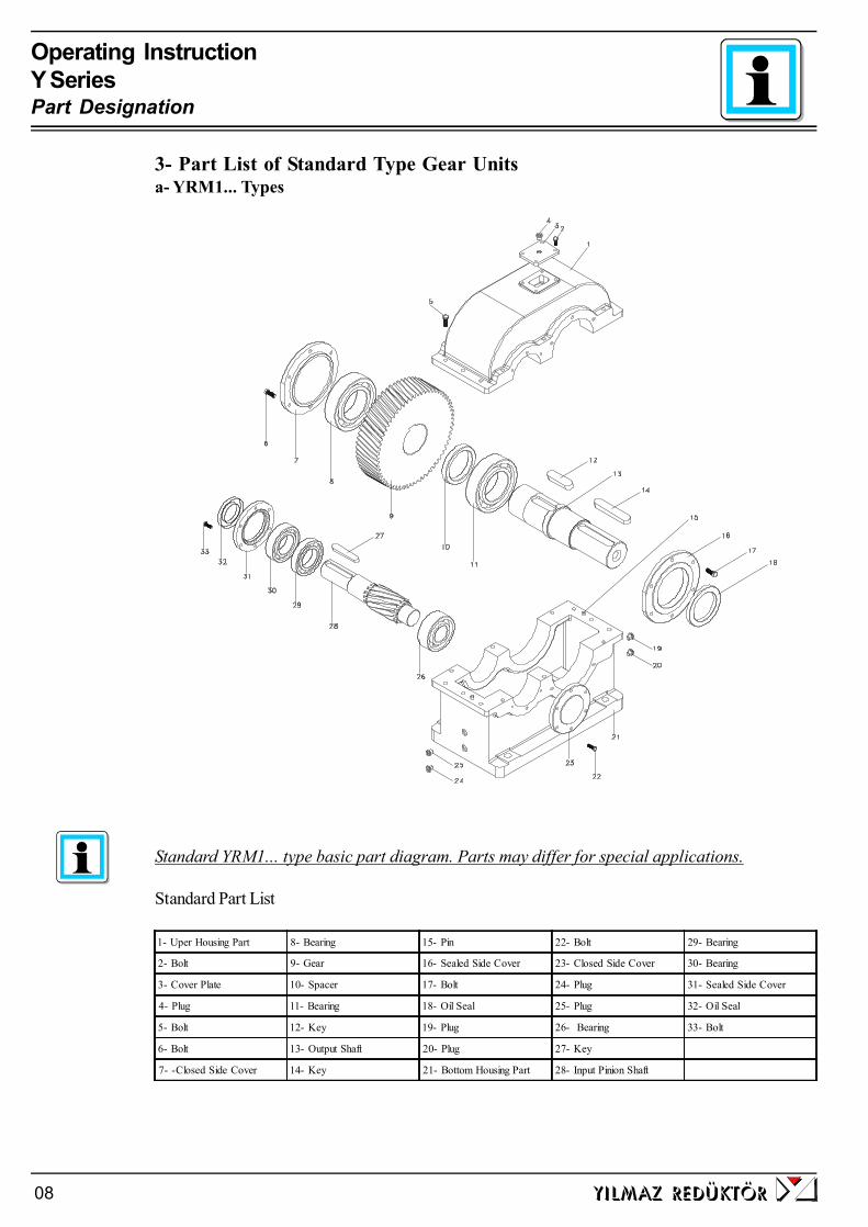
Standard YRM1... type basic part diagram. Parts may differ for special applications.
Standard Part List
3- Part List of Standard Type Gear Unitsa- YRM1... Types
1- Uper Housing Part 8- Bearing 15- Pin 22- Bolt 29- Bearing
2- Bolt 9- Gear 16- Sealed Side Cover 23- Closed Side Cover 30- Bearing
3- Cover Plate 10- Spacer 17- Bolt 24- Plug 31- Sealed Side Cover
4- Plug 11- Bearing 18- Oil Seal 25- Plug 32- Oil Seal
5- Bolt 12- Key 19- Plug 26- Bearing 33- Bolt
6- Bolt 13- Output Shaft 20- Plug 27- Key
7- -Closed Side Cover 14- Key 21- Bottom Housing Part 28- Input Pinion Shaft
yilmaz redÜktÖr 09
Operating InstructionY SeriesPart Designation
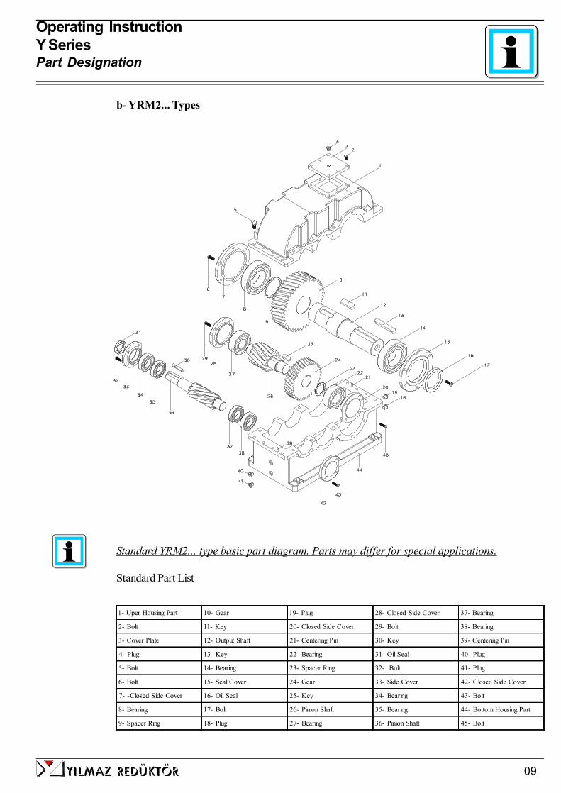
b- YRM2... Types
Standard YRM2... type basic part diagram. Parts may differ for special applications.
Standard Part List
1- Uper Housing Part 10- Gear 19- Plug 28- Closed Side Cover 37- Bearing
2- Bolt 11- Key 20- Closed Side Cover 29- Bolt 38- Bearing
3- Cover Plate 12- Output Shaft 21- Centering Pin 30- Key 39- Centering Pin
4- Plug 13- Key 22- Bearing 31- Oil Seal 40- Plug
5- Bolt 14- Bearing 23- Spacer Ring 32- Bolt 41- Plug
6- Bolt 15- Seal Cover 24- Gear 33- Side Cover 42- Closed Side Cover
7- -Closed Side Cover 16- Oil Seal 25- Key 34- Bearing 43- Bolt
8- Bearing 17- Bolt 26- Pinion Shaft 35- Bearing 44- Bottom Housing Part
9- Spacer Ring 18- Plug 27- Bearing 36- Pinion Shaft 45- Bolt

Operating InstructionY SeriesPart Designation
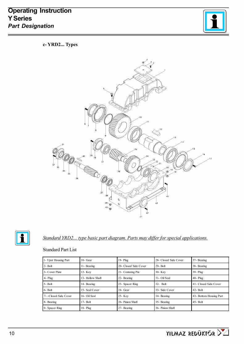
c- YRD2... Types
Standard YRD2... type basic part diagram. Parts may differ for special applications.
Standard Part List
1- Uper Housing Part 10- Gear 19- Plug 28- Closed Side Cover 37- Bearing
2- Bolt 11- Bearing 20- Closed Side Cover 29- Bolt 38- Bearing
3- Cover Plate 12- Key 21- Centering Pin 30- Key 39- Plug
4- Plug 13- Hollow Shaft 22- Bearing 31- Oil Seal 40- Plug
5- Bolt 14- Bearing 23- Spacer Ring 32- Bolt 41- Closed Side Cover
6- Bolt 15- Seal Cover 24- Gear 33- Side Cover 42- Bolt
7- -Closed Side Cover 16- Oil Seal 25- Key 34- Bearing 43- Bottom Housing Part
8- Bearing 17- Bolt 26- Pinion Shaft 35- Bearing 45- Bolt
9- Spacer Ring 18- Plug 27- Bearing 36- Pinion Shaft
yilmaz redÜktÖr10

yilmaz redÜktÖr 11
Operating InstructionY SeriesPart Designation
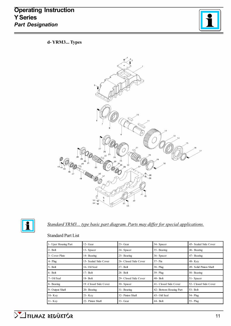
d- YRM3... Types
Standard YRM3... type basic part diagram. Parts may differ for special applications.
Standard Part List
1- Uper Housing Part 12- Gear 23- Gear 34- Spacer 45- Sealed Side Cover
2- Bolt 13- Spacer 24- Spacer 35- Bearing 46- Bearing
3- Cover Plate 14- Bearing 25- Bearing 36- Spacer 47- Bearing
4- Plug 15- Sealed Side Cover 26- Closed Side Cover 37- Pin 48- Key
5- Bolt 16- Oil Seal 27- Bolt 38- Plug 49- Solid Pinion Shaft
6- Bolt 17- Bolt 28- Bolt 39- Plug 50- Bearing
7- Oil Seal 18- Bolt 29- Closed Side Cover 40- Bolt 51- Spacer
8- Bearing 19 -Closed Side Cover 30- Spacer 41- Closed Side Cover 52- Closed Side Cover
9- Output Shaft 20- Bearing 31- Bearing 42- Bottom Housing Part 53- Bolt
10- Key 21- Key 32- Pinion Shaft 43- Oiil Seal 54- Plug
11- Key 22- Pinion Shaft 33- Gear 44- Bolt 55- Plug

Operating InstructionY SeriesPart Designation
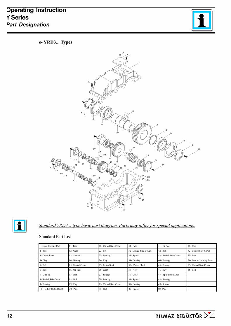
e- YRD3... Types
Standard YRD3... type basic part diagram. Parts may differ for special applications.
Standard Part List
1- Uper Housing Part 11- Key 21- Closed Side Cover 31- Bolt 41- Oil Seal 51- Plug
2- Bolt 12- Gear 22- Pin 32- Closed Side Cover 42- Bolt 52- Closed Side Cover
3- Cover Plate 13- Spacer 23- Bearing 33- Spacer 43- Sealed Side Cover 53- Bolt
4- Plug 14- Bearing 24- Key 34- Bearing 44- Bearing 54- Bottom Housing Part
5- Bolt 15- Sealed Cover 25- Pinion Shaft 35- Pinion Shaft 45- Bearing 55- Closed Side Cover
6- Bolt 16- Oil Seal 26- Gear 36- Key 46- Key 56- Bolt
7- Oil Seal 17- Bolt 27- Spacer 37- Gear 47- Input Pinion Shaft
8- Sealed Side Cover 18- Bolt 28- Bearing 38- Spacer 48- Bearing
9- Bearing 19- Plug 29- Closed Side Cover 39- Bearing 49- Spacer
10- Hollow Output Shaft 20- Plug 30- Bolt 40- Spacer 50- Plug
yilmaz redÜktÖr12
yilmaz redÜktÖr 13
Operating InstructionY SeriesPart Designation
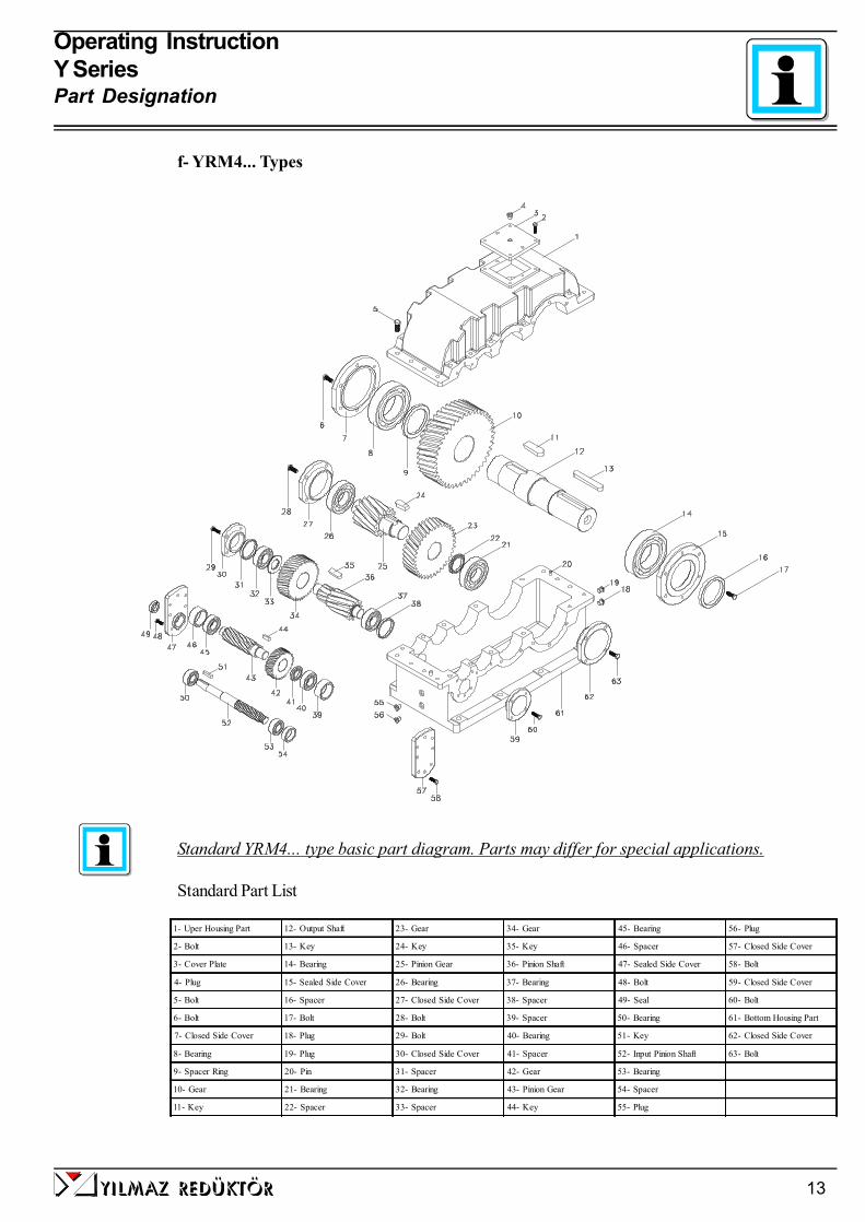
f- YRM4... Types
Standard YRM4... type basic part diagram. Parts may differ for special applications.
Standard Part List
1- Uper Housing Part 12- Output Shaft 23- Gear 34- Gear 45- Bearing 56- Plug
2- Bolt 13- Key 24- Key 35- Key 46- Spacer 57- Closed Side Cover
3- Cover Plate 14- Bearing 25- Pinion Gear 36- Pinion Shaft 47- Sealed Side Cover 58- Bolt
4- Plug 15- Sealed Side Cover 26- Bearing 37- Bearing 48- Bolt 59- Closed Side Cover
5- Bolt 16- Spacer 27- Closed Side Cover 38- Spacer 49- Seal 60- Bolt
6- Bolt 17- Bolt 28- Bolt 39- Spacer 50- Bearing 61- Bottom Housing Part
7- Closed Side Cover 18- Plug 29- Bolt 40- Bearing 51- Key 62- Closed Side Cover
8- Bearing 19- Plug 30- Closed Side Cover 41- Spacer 52- Input Pinion Shaft 63- Bolt
9- Spacer Ring 20- Pin 31- Spacer 42- Gear 53- Bearing
10- Gear 21- Bearing 32- Bearing 43- Pinion Gear 54- Spacer
11- Key 22- Spacer 33- Spacer 44- Key 55- Plug
yilmaz redÜktÖr14
Operating InstructionY SeriesPart Designation
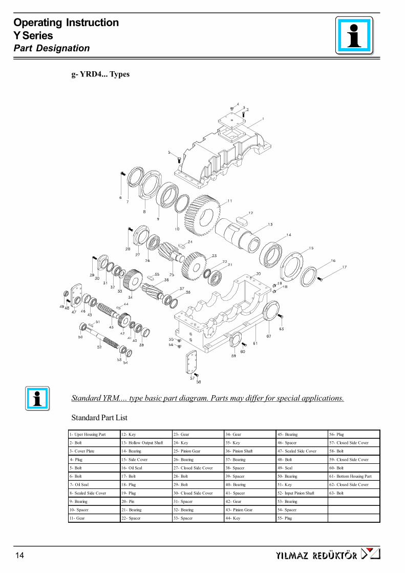
Standard YRM.... type basic part diagram. Parts may differ for special applications.
Standard Part List
g- YRD4... Types
1- Uper Housing Part 12- Key 23- Gear 34- Gear 45- Bearing 56- Plug
2- Bolt 13- Hollow Output Shaft 24- Key 35- Key 46- Spacer 57- Closed Side Cover
3- Cover Plate 14- Bearing 25- Pinion Gear 36- Pinion Shaft 47- Sealed Side Cover 58- Bolt
4- Plug 15- Side Cover 26- Bearing 37- Bearing 48- Bolt 59- Closed Side Cover
5- Bolt 16- Oil Seal 27- Closed Side Cover 38- Spacer 49- Seal 60- Bolt
6- Bolt 17- Bolt 28- Bolt 39- Spacer 50- Bearing 61- Bottom Housing Part
7- Oil Seal 18- Plug 29- Bolt 40- Bearing 51- Key 62- Closed Side Cover
8- Sealed Side Cover 19- Plug 30- Closed Side Cover 41- Spacer 52- Input Pinion Shaft 63- Bolt
9- Bearing 20- Pin 31- Spacer 42- Gear 53- Bearing
10- Spacer 21- Bearing 32- Bearing 43- Pinion Gear 54- Spacer
11- Gear 22- Spacer 33- Spacer 44- Key 55- Plug


4 -Thinks to Check Before the Gear Unit or Geared Motor is Installed
a) Safety notes for use in potentially explosive atmosphere
Explosive gas mixtures or concentration of dust can lead to severe or fata injuries in conjunc-tion with hot or moving parts of the gear unit / gearmotor
Before you install the gearbox you have to be sure that the gearbox is arrived with the all necessaryequipment and without damage. Thinks to take into consideration before you start to install the unit;- You have received the correct operation manual of the your product.- The gearbox and all its parts are transported without damage.- The gearbox is stored correctly according the instructions in this manual- The nameplate is clearly visible and all the data can be read.- All the regulations and requirements according to the currently valid national/regional regulations.- The gearbox is used according its intended use
Intended use of gearbox:The gearboxes covered by this manuel can only be used in ATEX zone 2G,2D,3G,3D and ignationclass IIA/IIB.
The gear units are intended for industrial systems and may only be used in accordance with theinformation provided in this manual and the nameplate of the gearbox. They comply with the applica-ble standards and regulations and meet the requirements of the directive 94/9/EC. The gearbox isstarted up, maintained and operated according this manual. The gearbox is incorporated with 94/9/EC confirming parts/machines.
A motor connected to the gear unit is only allowed to be operated in the frequency entries sothat the data provided on nameplate of the gear unit is not exceeded and is accordance withthe nameplate. The input speed range will be provided on the name plate if YILMAZREDUKTOR is informed that the gear unit will be used with frequency inverter. If not in-formed the nameplate will have a single fixed input speed and only this input speed is allowed.The electric motor and frequency inverter must be in accordance with 94/9/EC
If the gear units input is used with variable speed gear unit, this must be informed to YILMAZREDUKTOR before ordering and on the nameplate the allowed maximum and minimuminput speeds (speed range) will be provided. If not mentioned by ordering the gear units inputspeed will be a fixes single input speed and only this speed is allowed.
If the gear unit will be driven by belt / coupling / chain drive etc. the gear unit is onlt allowedto be used according the nameplate entries. Diffrent speed, higher motor power, higherradial/axial loads etc. than nameplate is not allowed.
The ambient conditions must be accordance with the name plate and no agresive media mustattack the paint and seals.
yilmaz redÜktÖr16
Operating InstructionY SeriesInstalling

The gearbox maintanance (oil change / check ) must be done according this manuel
b) TransportationWhen the goods arrive, first check for any damage. If some damage observed, immediatelycontact the transport company and inform about the damage. Contact YILMAZ for thedamage and do not start to install the unit until it is agreed that the damage has no affect ofoperation.
Use the supplied eyebolts or lifting holes for lifting up the gear unit. The eyebolts arecapable to carry the weight of gearboxes only. Do not hang additional loads.
c) StorageIf the geared unit or gearedmotor will be stored up to 3 years refer to the following instruc-tions;
With Packing;-Use corrosion protection oil for the output shaft and connection surfaces like flange surfaceor foot assembling surface. Seal the unit in a plastic wrap and pack it in container. A moistureindicator should be placed around the container to observe the moisture. Relative atmos-pheric humidity should not exceed 50%. The container should be kept under roof whichprotects from snow and rain. Under this condition the gear unit can be stored up to 3 yearwith regular check.
Without Packing;-Use protection oil for the output shaft and connection surfaces like flange surface or footassembling surface. If no packing is used and the gearbox is stored without packing, theambient temperature should be between 5 to 60 Celsius degrees. The gearbox must be keptunder enclosed roof with constant temperature and constant humidity not exceeding 50%.The storage should be free of dust and dirt and ventilated with filter. If the gearbox is storedwithout packing it is recommended not to store more than 2 years and regular check duringthis time is recommended.
If stored in open protect against insect damage.
yilmaz redÜktÖr 17
Operating InstructionY SeriesInstalling
5- Installing The Gear Unit
a) Before you start;- Observe the gear unit for damages of storage or transportation. If any damage please contactYILMAZ REDUKTOR.- Be sure that you have all the equipment necessary for installing like; Spanners, torquewrench, shims and distance rings, fixing devices for input and output elements, lubricant, boltadhesive etc.
b) Check nameplate of the gear unit;- ATEX conforming gear gear units have a nameplate indicating the “EX” sign shown on the left sideand the following information;
- Equipment group- Ex category- Ex zone- Temprature class- Maximum surface temperature
If you can not see this sign and values, your gearbos is not intended for use on potentially explosiveatmosphere. If some of the data can not be read because of some reason, please contact YILMAZREDUKTOR.
c) Check the ambient conditions and temperature;Have measures been taken to ensure that no potentially explosive atmosphere, oils, acids, gases,vapors or radiated interference are present when the gear unit is being installed.
The ambient temperature must be in accordance with the oil tables given on the manual. If differentcontact YILMAZ REDUKTOR for special solutions.
The ambient air temperature must not exceed 40 degrees celcius as mentioned on the name-plate. The cooling air surrounding the gear unit must bellow 40 degrees and the gear unitmust not subject to heating from external sources. The gear unit surface must be kept cleanand sufficiently ventilated.
d) Check fitting elements and the shaft dimensions to fit;
All external elements that will be fitted to the gear unit must be ATEX confirming.
The shaft/flange dimention are shown bellow. Use correct tolerances to fit external elements. Ob-serve the assemly instructions provided in this manual.
yilmaz redÜktÖr18
Operating InstructionY SeriesInstalling

yilmaz redÜktÖr 19
Operating InstructionY SeriesInstalling
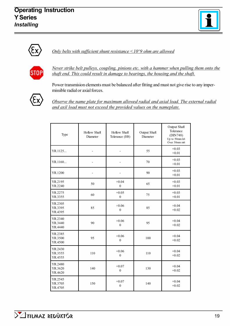
Only belts with sufficient shunt resistance <10^9 ohm are allowed
Never strike belt pulleys, coupling, pinions etc. with a hammer when pulling them onto theshaft end. This could result in damage to bearings, the housing and the shaft.
Power transmision elements must be balanced after fitting and must not give rise to any imper-missible radial or axial forces.
Observe the name plate for maximum allowed radial and axial load. The external radialand axil load must not exceed the provided values on the nameplate.
Type Hollow ShaftDiameter
Hollow ShaftTolerance (H8)
Output ShaftDiameter
Output ShaftTolerance(DIN748)
Up to 50mm k6Over 50mm m6
YR.1125... - - 55 +0.03+0.01
YR.1160... - - 70 +0.03+0.01
YR.1200 - - 90 +0.03+0.01
YR.2195YR.2240 50 +0.04
0 65 +0.03+0.01
YR.2275YR.3355 60 +0.05
0 75 +0.03+0.01
YR.2305YR.3395YR.4395
85 +0.060 85 +0.04
+0.02
YR.2340YR.3440YR.4440
90 +0.060 95 +0.04
+0.02
YR.2385YR.3500YR.4500
95 +0.060 100 +0.04
+0.02
YR.2430YR.3555YR.4555
110 +0.060 110 +0.04
+0.02
YR.2480YR.3620YR.4620
140 +0.070 130 +0.04
+0.02
YR.2545YR.3705YR.4705
150 +0.070 140 +0.04
+0.02

Operating InstructionY SeriesInstalling
yilmaz redÜktÖr20
e) Check the voltage supply;ATEX Conforming gear units are supplied by YILMAZ without motor. The motor that will be fittedmust have ATEX certificate and the instruction manual of the electric motor provider must be ob-served. Observe the name plate of the electric motor and the instructions of the supplier. Check thebasic electric connection diagrams below. Use experienced electric technician. The gearbox and themotor must be grounded to prewent potential differences of earth and gearbox/motor.
Using wrong connection or voltage can damage the electric motor or environment.The elctric connection must be done by experienced electric technician.
f) Check the mounting position;The mounting position must be in accordance with the mounting position mentioned on thename plate. If different please contact YILMAZ REDUKTOR for possibilities of using in adifferent mounting position. Different use of mounting position than indicated on the name platewithout informing YILMAZ REDUKTOR will cancel the ATEX confirmity and YILMAZ does nottake any responsibility.
Do not mix synthetic oils with mineral oils which can cause serious damage on the gear unit.
g) Use of breather plug;Breather plugs are supplied as a standard part for ATEX conforming gear units. The breather plug isattached to the gear unit and must be changed with the most top plug according to the mountingposition.Take out the plug over the gear box and replace it with the supplied breather plug afterassembling to its place and before start-up.
All plug points are not machined. Only plugs according mounting position is machined. If nomounting position is mentioned by ordering the standard B3 position plugs are machined.

yilmaz redÜktÖr 21
Operating InstructionY SeriesInstalling
h) Check the oil level ;On the mounting position tables the oil level plug is shown. Please refer to those tables and be surethat the oil level is correct according the mounting position. Use a wire as shown below for checkingthe oil level entering from the level plug. The oil level must be within 3mm from the plugs enteringpoint as shown below. If you need to adjust the oil level refer to the oil tables given on this manueland be sure you are using the correct oil. Observe the nameplate for the correct oil.
Do not mix synthetic oils with mineral which can cause serious damage on the gear unit.
i) Check shaft ends and mounting faces;Before you start to installing be sure that all the connection elements are free of oil and dust. Theoutput shaft may be protected by anti-corrosion oil. Please remove this using available solventson your market. By using this do not touch sealing lips or painting of the housing.
j) Cover abrasive ambient;If the gear unit will be placed on a abrasive ambient be sure that the output seals are covered sothat no abrasive material, chemicals or water touches the seals. Any pressure coming fromoutside over the seals can cause that the out staying substances to enter the gearbox and causeserious damage to the gear unit. If pressure or abrasive material can not be prevented fromcoming over the sealing, contact YILMAZ for solutions.
Abrasive material, chemicals, water, positive or negative pressure exceeding 0,2 bar canaffect or damage the sealing lip or output shaft. Inside entering substances from the sealscan cause serious damage to the gear unit.
k) Check accessibility to filling, breather and drain plugs;The filling, breather and drain plugs must be freely accessible for further checking and service.
Operating InstructionY SeriesInstalling
yilmaz redÜktÖr22
6- Mechanical InstallationThe mounting plate must be rigid enough not allowing torsions, flat enough to prevent strains by tighten-ing the bolts and stable enough not allowing vibrations. By using chain drives this becomes much moreimportant because of the polygon effect on chain drives. According to your connection elements themaximal permitted radial and axial load of the gear unit must be in accordance with your application.Check the product catalogue for permitted radial loads and calculation.
If the output or input shaft is overloaded by radial or axial loads it can cause serious damage tothe gear unit.
Secure the gear unit using 8.8 or higher quality bolts.
All bolts are locked by use of locktide adhesives or gear-shims on the gearbox. By assembling the gearunit locktides adhesives or gear-shims must be used to prevent loosening of bolts.
Cover all the turning parts from human entering or touching. Turning parts can cause severe orfatal injuries.
For different kind of basic installations refer to the following illustrations.
Only ATEX-approved input and output elements are allowed to be used, assum-ing the elements are subject to Directive 94/9/EC
a- Installing gear units in category II2G/D-II3G/D
Explosion-proof gear units comply with the design requirements for unit group II,catagory 2G,2D,3D,3G. These units are intended for use in zones 1 and 21.
The gear units in catagory II2D must be used in ambient teperature between -20C to +40 C only. If different ambient conditions this must be inforned beforeorder and the name plate must be in accordance with the ambient conditions.
The temperature class depends on the speed, type and mounting position of thegearbox and is indicated on the name plate. Temperature classes from T4 to T6are provided by YILMAZ REDUKTOR.
The surface temperature of the gearbox must not exceed the provided max. sur-face temperature on the name plate. After all installations finished and the gear-box is started up according this manual let the gear unit run 4 hours at full loadand check the surface temperature from the shown point bellow and the ambienttemperature. Check the following;
(40-Ta)+Tw < Tmax. of nameplate ( Ta: Ambient Temp., Tw: Surface Temp)
yilmaz redÜktÖr 23
Operating InstructionY SeriesInstalling
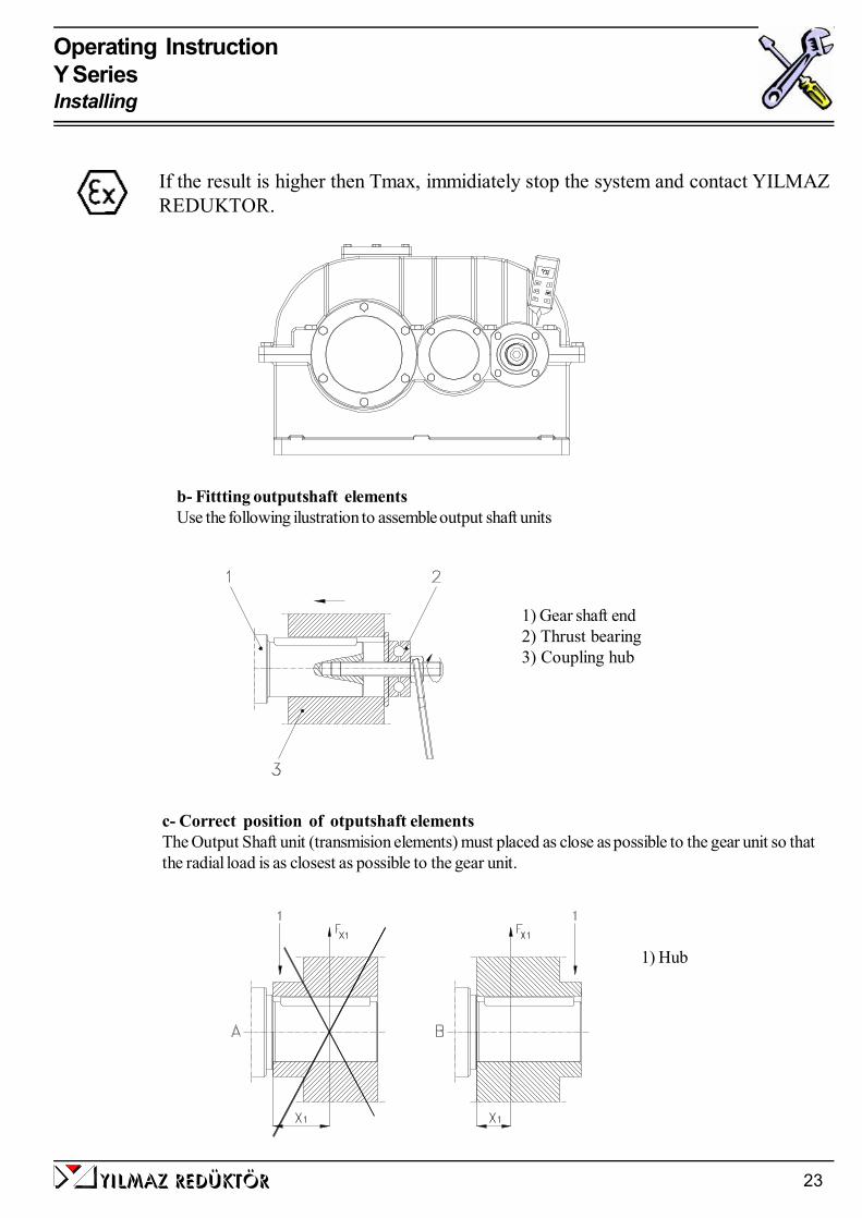
b- Fittting outputshaft elementsUse the following ilustration to assemble output shaft units
c- Correct position of otputshaft elementsThe Output Shaft unit (transmision elements) must placed as close as possible to the gear unit so thatthe radial load is as closest as possible to the gear unit.
1) Gear shaft end2) Thrust bearing3) Coupling hub
1) Hub
If the result is higher then Tmax, immidiately stop the system and contact YILMAZREDUKTOR.

Operating InstructionY SeriesInstalling
yilmaz redÜktÖr24
d2 -Fasten the bold as shown below.
d- Installing customer shaft with shoulderd1- Use anti-seize assembling paste available on your market. Use a brush to apply the paste.
Operating InstructionY SeriesInstalling
yilmaz redÜktÖr 25
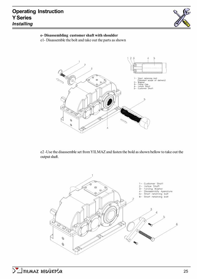
e2 -Use the disassemble set from YILMAZ and fasten the bold as shown bellow to take out theoutput shaft.
e- Disassembling customer shaft with shouldere1- Disassemble the bolt and take out the parts as shown

Operating InstructionY SeriesInstalling
yilmaz redÜktÖr26
e3- Push the output shaft using disassemble set and tightening tne screw as shown on the followingisustration.
Operating InstructionY SeriesInstalling
yilmaz redÜktÖr 27
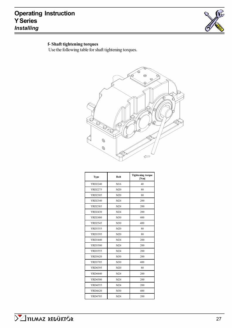
f- Shaft tightening torques Use the following table for shaft tightening torques.
Type Bolt Tightening torque[Nm]
YRD2240 M16 40
YRD2275 M20 80
YRD2305 M20 80
YRD2340 M24 200
YRD2385 M24 200
YRD2430 M24 200
YRD2480 M30 400
YRD2545 M30 400
YRD3355 M20 80
YRD3395 M20 80
YRD3440 M24 200
YRD3500 M24 200
YRD3555 M24 200
YRD3620 M30 200
YRD3705 M30 400
YRD4395 M20 80
YRD4440 M24 200
YRD4500 M24 200
YRD4555 M24 200
YRD4620 M30 400
YRD4705 M24 200

Operating InstructionY SeriesInstalling
yilmaz redÜktÖr28
g- Recomended shaft dimensions for YRD... types
Type d d1 b b1 b2 b3 c m1 f h i g e1 t1YRD2240 50 49 240 65 125 50 3 68 5 36 45 M16 54 14YRD2275 60 59 260 95 85 80 3 78 5 42 53 M20 64 16YRD2305 85 84 320 110 115 95 4 117 5 42 53 M20 90 22YRD2340 90 89 355 115 140 100 4 117 5 50 63 M24 95 25YRD2385 95 94 355 125 120 110 4 127 5 50 63 M24 100 25YRD2430 110 109 390 115 175 100 5 147 5 50 63 M24 116 28YRD2480 140 139 470 165 155 150 5 176 5 60 77 M30 148 36YRD2545 150 149 535 155 240 140 5 184 5 60 77 M30 158 36YRD3355 60 59 260 95 85 80 3 78 5 42 53 M20 64 16YRD3395 85 84 320 110 115 95 4 117 5 42 53 M20 90 22YRD3440 90 89 355 120 130 105 4 117 5 50 63 M24 95 25YRD3500 95 94 355 125 120 110 4 127 5 50 63 M24 100 25YRD3555 110 109 390 115 175 100 5 147 5 50 63 M24 116 28YRD3620 140 139 470 165 155 150 5 176 5 60 77 M30 148 36YRD3705 150 149 535 155 240 140 5 184 5 60 77 M30 158 36YRD4395 85 84 320 110 115 95 4 117 5 42 53 M20 90 22YRD4440 90 89 335 120 110 105 4 117 5 50 63 M24 95 25YRD4500 95 94 355 125 120 110 4 127 5 50 63 M24 100 25YRD4555 110 109 390 115 175 100 5 147 5 50 63 M24 116 28YRD4620 140 139 470 165 155 150 5 176 5 60 77 M30 148 36YRD4705 150 149 535 155 240 140 5 184 5 60 77 M30 158 36
m1 d

yilmaz redÜktÖr 29
Operating InstructionY SeriesInstalling
h- Fittting Couplingsh1-By fitting couplings be sure that there is some clearanve between the two elements
h2-By fitting couplings be sure that there is no exantricity between the two shafts.
h3-By fitting couplings be sure that the two shafts are not angular miss-aligned.

Operating InstructionY SeriesInstalling
yilmaz redÜktÖr30
7- InspectionsUnder normal ambient and working conditions the gear unit should be checked according thefollowing intervals. (For definition of normal working conditions refer to the product catalogue:“Selecting Gearbox” section);
0
5000
10000
15000
20000
25000
30000
35000
40000
45000
70 80 90 100 110 120 130 140 150 160
Oil bath temperature (Celcius)
Oil
chan
ge in
terv
al
MineralSynthetic PAOSynthetic PG
For normal ambient conditions 70 degrees Celcius Should be taken as referance
* For Y series Mineral oil is used unless it is differently ordered. For oil type and quantities refer tothe following tables.
Item to check / replaceEvery 3.000 working
hoursor every 6 months
Every 4.000 workinghours
Every 10.000 workinghours or every 3 years
Every 25.000 workinghours
Check for oil leakage x
Check for oil level x
Check oil leakage from seal x
Check Rubber buffer x (Change if necessary)
Check Bearings Noise x (Change if necessary)
Change Mineral Oil x (See Below for details)
Change Synthetic-PAO Oil x (See Below for details)
Change Sealing x
Change Bearing Grease x
Change Bearings x
Check for noise Changes x
yilmaz redÜktÖr 31
Operating InstructionY SeriesInspection
Yağ CinsiLubricantArt des
Schmierstoffes
Kullanım SıcaklığıUsage Temparature
Gebrauchstemperature
ISO Vizkozite SınıfıISO Viscosity ClassVizkozitäts Klasse
ISO
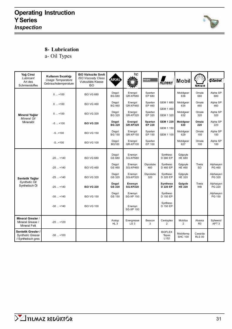
Mineral YağlarMineral OilMineralöl
0 ... +100
0 ... +100
0 ... +100
-5 ... +100
-5...+100
-5...+100
ISO VG 680
ISO VG 460
ISO VG 320
ISO VG 220
ISO VG 150
ISO VG 100
DegolBG 680
DegolBG 460
DegolBG 320
DegolBG 220
DegolBG 150
DegolBG100
EnergolGR-XP680
EnergolGR-XP460
EnergolGR-XP320
EnergolGR-XP220
EnergolGR-XP150
EnergolGR-XP100
SpartanEP 680
SpartanEP 460
SpartanEP 320
SpartanEP 220
SpartanEP 150
SpartanEP 100
GEM 1 680
GEM 1 460
GEM 1 320
GEM 1 220
GEM 1 150
GEM 1 100
Mobilgear636
Mobilgear634
Mobilgear632
Mobilgear630
Mobilgear629
Mobilgear627
Omala680
Omala460
Omala320
Omala220
Omala150
Omala100
Alpha SP680
Alpha SP460
Alpha SP320
Alpha SP220
Alpha SP150
Alpha SP100
Sentetik YağlarSynthetic OilSynthetisch Öl
-20 ... +140
-20 ... +140
-25 ... +140
-25 ... +140
-30 ... +140
-30 ... +140
ISO VG 680
ISO VG 460
ISO VG 320
ISO VG 220
ISO VG 150
ISO VG 100
DegolGS 680
DegolGS 460
DegolGS 320
DegolGS 220
DegolGS 150
EnersynSG-XP680
EnersynSG-XP460
EnersynSG-XP320
EnersynSG-XP220
EnersynSG-XP 150
EnersynSG-XP 100
Glycolube460
Glycolube320
SynthesoD 680 EP
SynthesoD 460 EP
SynthesoD 320 EP
SynthesoD 220 EP
SynthesoD 150 EP
SynthesoD 150 EP
GylgoyleHE 680
GylgoyleHE 460
GylgoyleHE 320
GylgoleHE 220
TivelaSD
TivelaWB
AlphasyonPG 460
AlphasyonPG 320
AlphasyonPG 220
AlphasyonPG 150
Mineral Gresler /Minaral Grease /
Mineral Fett-20 ... +120 Aralup
HL 3Energrease
LS 3Beacon
3Centoplex
2Mobilux
2Alvania
R3Spheerol
APT 3
Sentetik Gresler /Synthetic Grease/ Synthetisch gres
-30 ... +100ISOFLEX
TopasL152
MobiltempSHC 100
CassidaRLS 00
8- Lubricationa- Oil Types

Operating InstructionY SeriesLubrication
yilmaz redÜktÖr32
b- Oil Quantities. (lt)
G ear Box Type O il Q uantity (lt)M ounting P osition B3
YR.1125 5
YR.1160 8,5
YR.1200 17,7
YR.2195 4,7
YR.2240 9
YR.2275 14
YR.2305 21
YR.2340 29
YR.2385 36
YR.2430 50
YR.2480 79
YR.2545 104
YR.3355 17
YR.3395 / Y R.4395 21
YR.3440 / Y R.4440 32
YR.3500 / Y R.4500 44
YR.3555 / Y R.4555 60
YR.3620 / Y R.4620 86
YR.3705 / Y R.4705 125
yilmaz redÜktÖr 33
Operating InstructionY SeriesOil Quantities
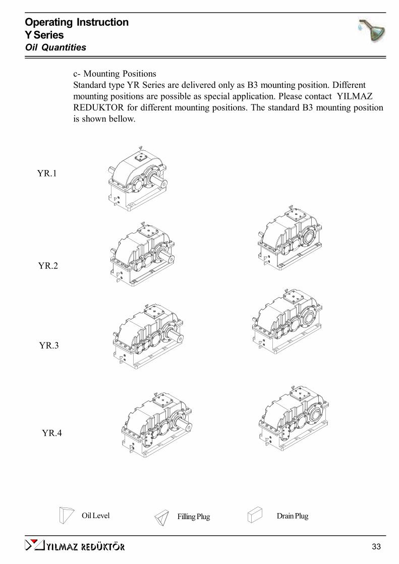
c- Mounting PositionsStandard type YR Series are delivered only as B3 mounting position. Differentmounting positions are possible as special application. Please contact YILMAZREDUKTOR for different mounting positions. The standard B3 mounting positionis shown bellow.
YR.1
YR.2
YR.3
YR.4
Oil Level Drain PlugFilling Plug
Operating InstructionY SeriesOil Quantities
yilmaz redÜktÖr34
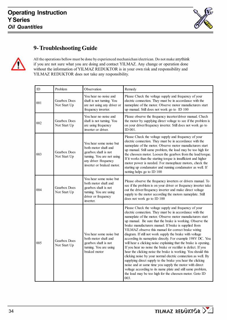
ID Problem Observation Remedy
001 Gearbox DoesNot Start Up
You hear no noise andshaft is not turning. Youare not using any driver orfrequency inverter.
Please Check the voltage supply and frequency of yourelectric connection. They must be in accordance with thenameplate of the motor. Observe motor manufacturers startup manual. Still does not work go to ID 100
002 Gearbox DoesNot Start Up
You hear no noise andshaft is not turning. Youare using frequencyinverter or driver.
Please observe the frequency incerter/driver manual. Chechthe motor by supplying direct voltage to see if the problem ison your driver/frequency inverter. Still does not work go toID 001.
003 Gearbox DoesNot Start Up
You hear some noise butboth motor shaft andgearbox shaft is notturning. You are not usingany driver /frequencyinverter or braked motor.
Please Check the voltage supply and frequency of yourelectric connection. They must be in accordance with thenameplate of the motor. Observe motor manufacturers startup manual. Still same problem, the load may be too high forthe choosen motor. Loosen the gearbox from the load/torque.If it works than the starting torque is insufficient and highermotor power is needed. For monophaze motors, check thestarting up condansator and running condansator as well. Ifnotting helps go to ID 100
004 Gearbox DoesNot Start Up
You hear some noise butboth motor shaft andgearbox shaft is notturning. You are usingdriver or frequencyinverter.
Please observe the frequency inverters or drivers manual. Tosee if the problem is on your driver or frequency inverter takeout the driver/frequency inverter and make direct voltagesupply to the motor according the motors nameplate. Stilldoes not work go to ID 100
005 Gearbox DoesNot Start Up
You hear some noise butboth motor shaft andgearbox shaft is notturning. You are usingbraked motor
Please Check the voltage supply and frequency of yourelectric connection. They must be in accordance with thenameplate of the motor. Observe motor manufacturers startup manual. Be sure that the brake is working. Observe thebrake manufacturers manuel. If brake is supplied fromYILMAZ observe this manuel for correct brake wiringdiagram. If still not work supply the brake with voltageaccording its nameplate directly. For example 198V DC. Youwill hear a clicking noise explaining that the brake is opening.If you hear no noise the brake or rectifier is defect. If youhear the clicking noise the brake is working. You should thisclicking noise by your normal electric connection as well. Bysupplying direct supply to the brake you hear the clickingnoise and at same time you supply the motor with directvoltage according to its name plate and still same problem,the load may be too high for the choosen motor. Goto ID003.
9- Troubleshooting Guide
All the operations bellow must be done by experienced mechanichan/electrican. Do not make anythinkif you are not sure what you are doing and contact YILMAZ. Any change or operation donewithout the information of YILMAZ REDUKTOR is in your own risk and responsibility andYILMAZ REDUKTOR does not take any responsibility.
Operating InstructionY SeriesMounting Positions
yilmaz redÜktÖr 35
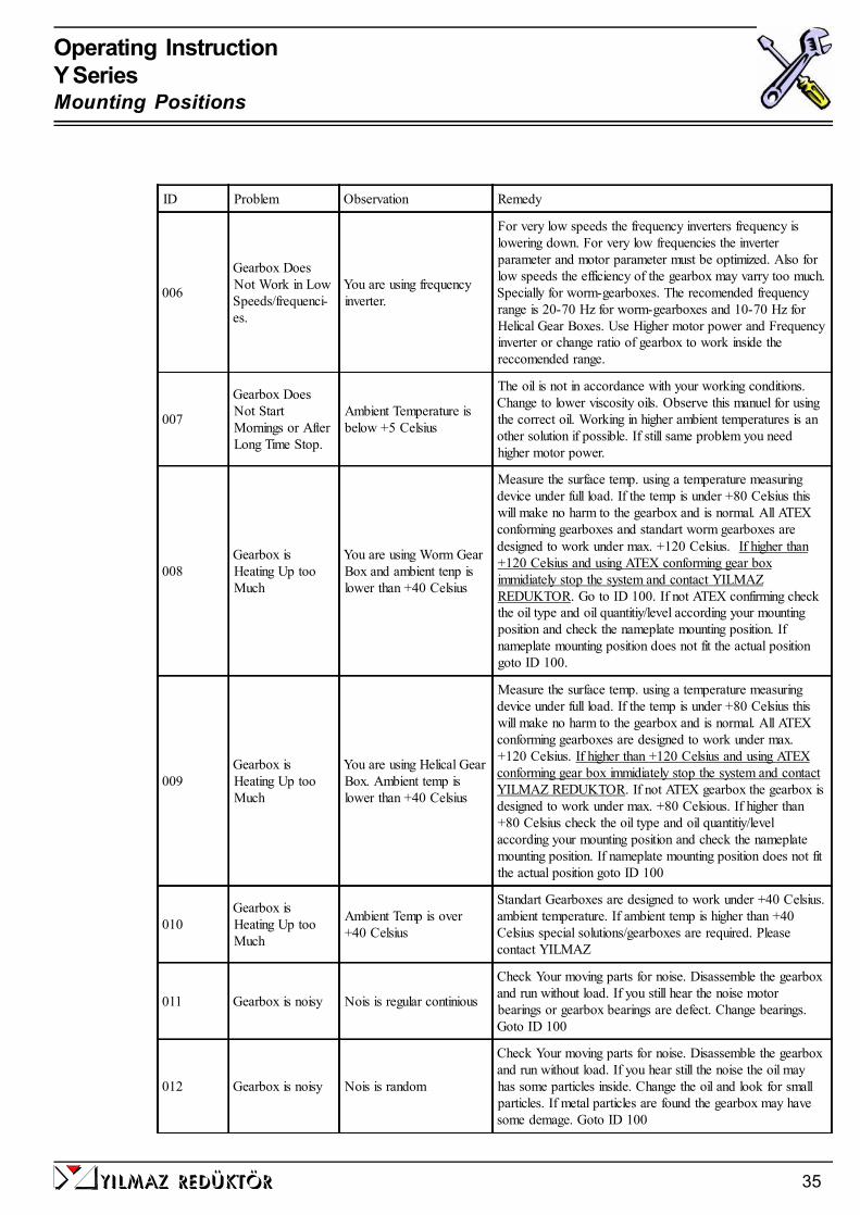
ID Problem Observation Remedy
006
Gearbox DoesNot Work in LowSpeeds/frequenci-es.
You are using frequencyinverter.
For very low speeds the frequency inverters frequency islowering down. For very low frequencies the inverterparameter and motor parameter must be optimized. Also forlow speeds the efficiency of the gearbox may varry too much.Specially for worm-gearboxes. The recomended frequencyrange is 20-70 Hz for worm-gearboxes and 10-70 Hz forHelical Gear Boxes. Use Higher motor power and Frequencyinverter or change ratio of gearbox to work inside thereccomended range.
007
Gearbox DoesNot StartMornings or AfterLong Time Stop.
Ambient Temperature isbelow +5 Celsius
The oil is not in accordance with your working conditions.Change to lower viscosity oils. Observe this manuel for usingthe correct oil. Working in higher ambient temperatures is another solution if possible. If still same problem you needhigher motor power.
008Gearbox isHeating Up tooMuch
You are using Worm GearBox and ambient tenp islower than +40 Celsius
Measure the surface temp. using a temperature measuringdevice under full load. If the temp is under +80 Celsius thiswill make no harm to the gearbox and is normal. All ATEXconforming gearboxes and standart worm gearboxes aredesigned to work under max. +120 Celsius. If higher than+120 Celsius and using ATEX conforming gear boximmidiately stop the system and contact YILMAZREDUKTOR. Go to ID 100. If not ATEX confirming checkthe oil type and oil quantitiy/level according your mountingposition and check the nameplate mounting position. Ifnameplate mounting position does not fit the actual positiongoto ID 100.
009Gearbox isHeating Up tooMuch
You are using Helical GearBox. Ambient temp islower than +40 Celsius
Measure the surface temp. using a temperature measuringdevice under full load. If the temp is under +80 Celsius thiswill make no harm to the gearbox and is normal. All ATEXconforming gearboxes are designed to work under max.+120 Celsius. If higher than +120 Celsius and using ATEXconforming gear box immidiately stop the system and contactYILMAZ REDUKTOR. If not ATEX gearbox the gearbox isdesigned to work under max. +80 Celsious. If higher than+80 Celsius check the oil type and oil quantitiy/levelaccording your mounting position and check the nameplatemounting position. If nameplate mounting position does not fitthe actual position goto ID 100
010Gearbox isHeating Up tooMuch
Ambient Temp is over+40 Celsius
Standart Gearboxes are designed to work under +40 Celsius.ambient temperature. If ambient temp is higher than +40Celsius special solutions/gearboxes are required. Pleasecontact YILMAZ
011 Gearbox is noisy Nois is regular continious
Check Your moving parts for noise. Disassemble the gearboxand run without load. If you still hear the noise motorbearings or gearbox bearings are defect. Change bearings.Goto ID 100
012 Gearbox is noisy Nois is random
Check Your moving parts for noise. Disassemble the gearboxand run without load. If you hear still the noise the oil mayhas some particles inside. Change the oil and look for smallparticles. If metal particles are found the gearbox may havesome demage. Goto ID 100

Operating InstructionY SeriesOil Quantities
yilmaz redÜktÖr36
ID Problem Observation Remedy
013 Gearbox is noisy Regular nocking noiseCheck Your moving parts for noise. Disassemble the gearboxand run without load. If you still hear the noise one of thegears inside is defect. Goto ID 10
014 Gearbox is noisy Regular up and downnoise (Sinosial noise)
Check the output-shaft connection alements for runout. Takeout the output shaft element and run without load. If you stillhear the noise one of the gears has runout problem. Goto ID10
015 Gearbox is noisy
Gearbox is with brakedmotor and noise iscomming from the brakeside randomly.
Low randomly clicking noise may come from the brake diskwhich is normal. If noise level is disturbing the brake may bedefect or brake clearance is not adjusted. Goto ID 100
016 Gearbox is noisy
You are using frequencyinverter and the noise levelis changing according yourspeed.
The frequency inverter parameters are not optimized for thefrequency range or motor you are using. Observe thefrequency inverters manual. If still same problem change theratio of gearbox. Goto ID 100
017 Oil is Leaking Oil Leakage from Seal
If ambient Temp is over +40 Celsious or none stop workover 16 hours please change the top plug with a breatherplug. Observe this manual for using breather plug. If this isnot your case the seal could be damaged. Goto ID 100
018 Oil is Leaking Oil Leakage from Plug
If you are using breather plug be sure it is in the correctplace. This is the most top plug position according yourmounting position. The plug may be not tight enough. Thereare some particles under the plug rubber surface. Clean andtifgten the plug. If still same problem goto ID 100
019 Oil is Leaking Oil Leakage from Housing
Observe exactly where the oil is comming out. It could beseal or plug point where it comes out and leakes over thehousing. If this is your case goto ID 018/019. If you are sureoil comes out from housing than housing has some micro split/ crack. Goto ID 100
020 Oil is Leaking Oil Leakage from CoverThe sealing liquit under cover is split/defect. Disassemle thecover and put new sealing liquit. Assemle the cover andtighten the bolts. If still same problem goto ID 100
021Gearbox is movingregularly on itsmounting point
You are using Torque Arm
The movement of gear box is because of the runout of theshaft which you assemle the gearbox. This has no bad affector harm to the gearbox and is normal unless you are usingtorque arm.
022Gearbox is movingrandomly on itsmounting point
You are using Torque Arm
The movement of gear box is because of the runout andclearance of the shaft which you assemle the gearbox. Checkthe clearance of the assemling shaft and the clearances onyour machine. This has no bad affect or harm to the gearboxunless you are using torque arm.
023 Motor is heatingup
Motor is running over itsnominal current
The motor power is not enough or some overload to themotor is possible. The motor may be defect. Goto ID 100
023 Motor is heatingup Ambient is dusty
Check the motor Fan Hub and rips. They must be free ofdust. If you are using forced external fan, check if it isworking. If you are using frequency inverter in low speedsand you do not have forced external fan, you may needforced external fan. Goto ID 100
Operating InstructionY SeriesMounting Positions
yilmaz redÜktÖr 37
ID Problem Observation Remedy
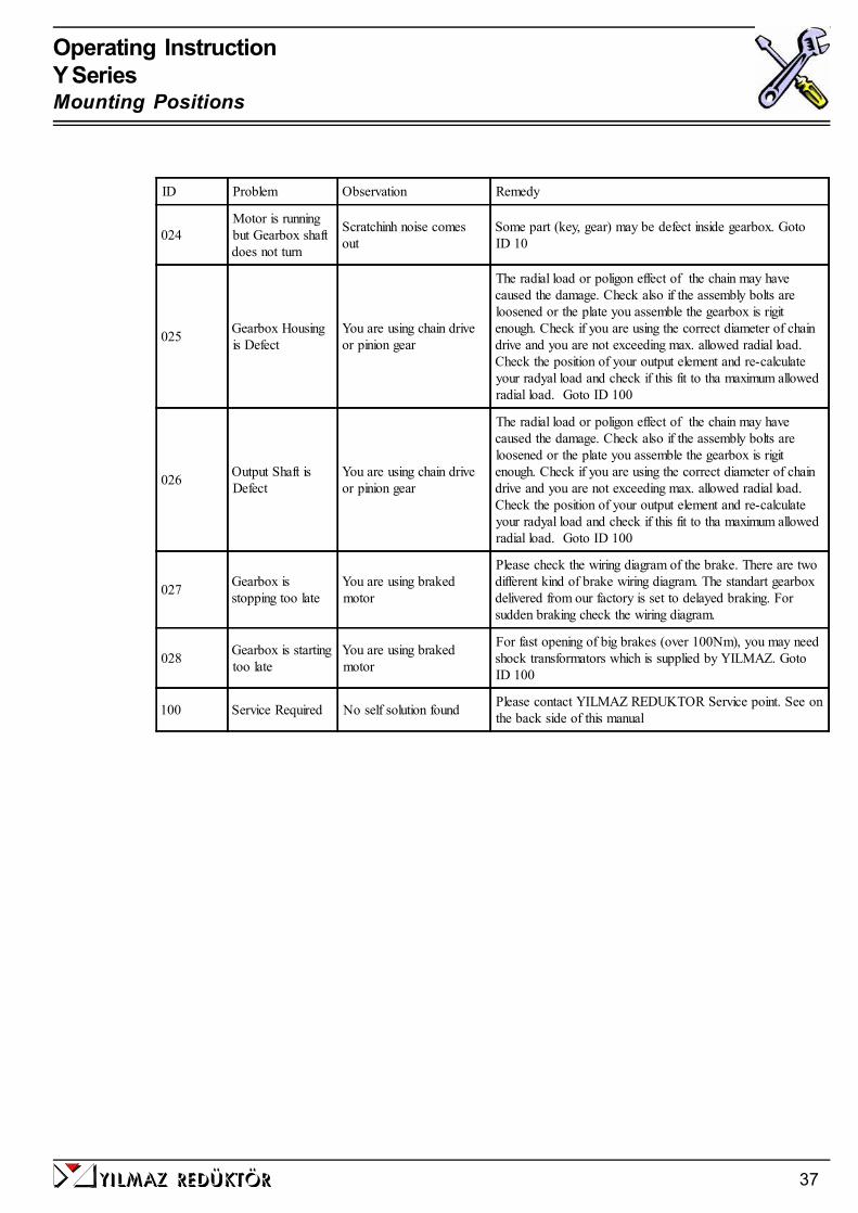
024Motor is runningbut Gearbox shaftdoes not turn
Scratchinh noise comesout
Some part (key, gear) may be defect inside gearbox. GotoID 10
025 Gearbox Housingis Defect
You are using chain driveor pinion gear
The radial load or poligon effect of the chain may havecaused the damage. Check also if the assembly bolts areloosened or the plate you assemble the gearbox is rigitenough. Check if you are using the correct diameter of chaindrive and you are not exceeding max. allowed radial load.Check the position of your output element and re-calculateyour radyal load and check if this fit to tha maximum allowedradial load. Goto ID 100
026 Output Shaft isDefect
You are using chain driveor pinion gear
The radial load or poligon effect of the chain may havecaused the damage. Check also if the assembly bolts areloosened or the plate you assemble the gearbox is rigitenough. Check if you are using the correct diameter of chaindrive and you are not exceeding max. allowed radial load.Check the position of your output element and re-calculateyour radyal load and check if this fit to tha maximum allowedradial load. Goto ID 100
027 Gearbox isstopping too late
You are using brakedmotor
Please check the wiring diagram of the brake. There are twodifferent kind of brake wiring diagram. The standart gearboxdelivered from our factory is set to delayed braking. Forsudden braking check the wiring diagram.
028 Gearbox is startingtoo late
You are using brakedmotor
For fast opening of big brakes (over 100Nm), you may needshock transformators which is supplied by YILMAZ. GotoID 100
100 Service Required No self solution found Please contact YILMAZ REDUKTOR Service point. See onthe back side of this manual
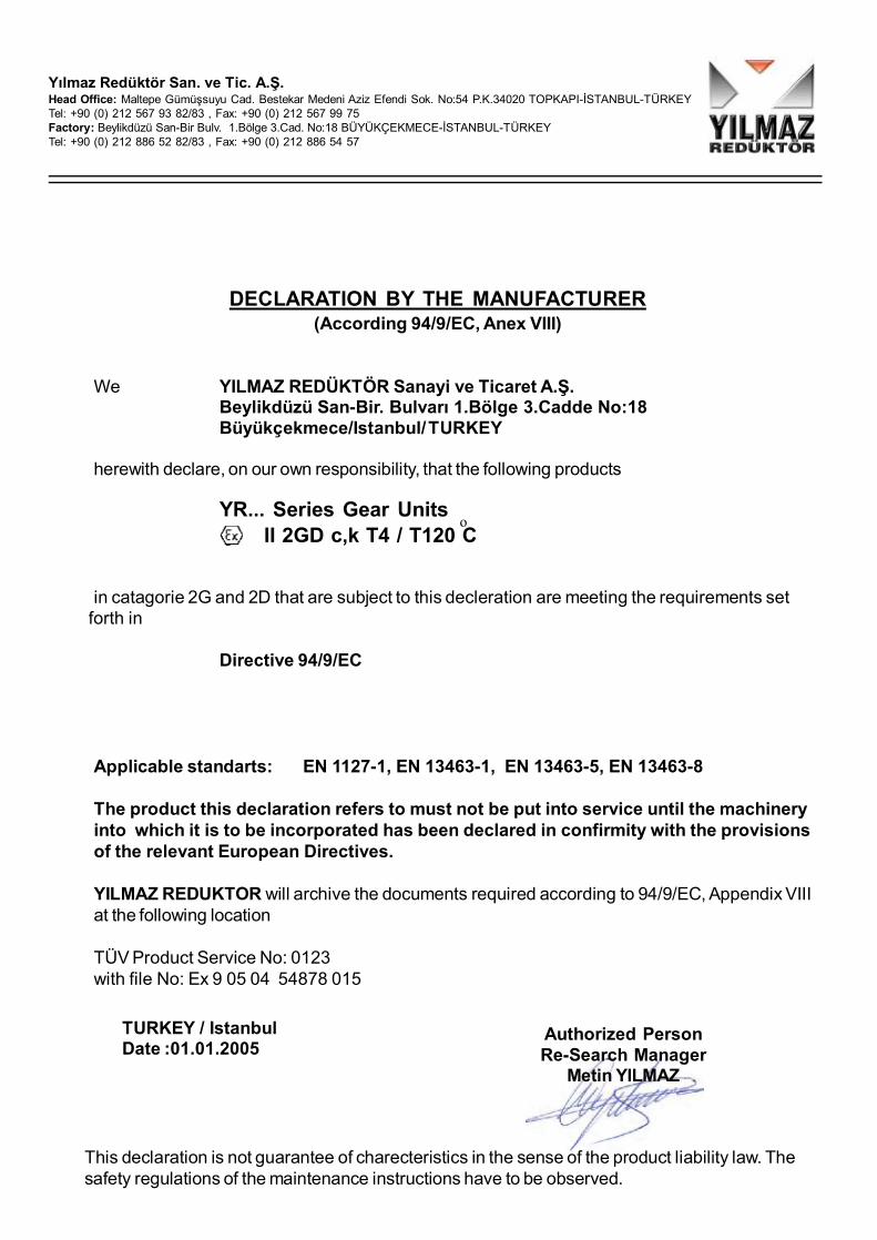
DECLARATION BY THE MANUFACTURER(According 94/9/EC, Anex VIII)
We YILMAZ REDÜKTÖR Sanayi ve Ticaret A.Ş.Beylikdüzü San-Bir. Bulvarı 1.Bölge 3.Cadde No:18Büyükçekmece/Istanbul/TURKEY
herewith declare, on our own responsibility, that the following products
YR... Series Gear Units II 2GD c,k T4 / T120 C
in catagorie 2G and 2D that are subject to this decleration are meeting the requirements set forth in
Directive 94/9/EC
Applicable standarts: EN 1127-1, EN 13463-1, EN 13463-5, EN 13463-8
The product this declaration refers to must not be put into service until the machineryinto which it is to be incorporated has been declared in confirmity with the provisionsof the relevant European Directives.
YILMAZ REDUKTOR will archive the documents required according to 94/9/EC, Appendix VIIIat the following location
TÜV Product Service No: 0123with file No: Ex 9 05 04 54878 015
Yılmaz Redüktör San. ve Tic. A.Ş.Head Office: Maltepe Gümüşsuyu Cad. Bestekar Medeni Aziz Efendi Sok. No:54 P.K.34020 TOPKAPI-İSTANBUL-TÜRKEYTel: +90 (0) 212 567 93 82/83 , Fax: +90 (0) 212 567 99 75Factory: Beylikdüzü San-Bir Bulv. 1.Bölge 3.Cad. No:18 BÜYÜKÇEKMECE-İSTANBUL-TÜRKEYTel: +90 (0) 212 886 52 82/83 , Fax: +90 (0) 212 886 54 57
TURKEY / IstanbulDate :01.01.2005
Authorized PersonRe-Search Manager
Metin YILMAZ
This declaration is not guarantee of charecteristics in the sense of the product liability law. Thesafety regulations of the maintenance instructions have to be observed.
o

Warranty Conditions:
1. The geared motors and gear units are warranted for two year except the electricmotor. For motor warranty please refer to the manual of the electric motor manufactureror the warranty document of the motor manufacturer. This warranty is valid only if thegearbox is assembled and started up according our operating instructions and is usedunder the allowed conditions for the appropriate gearbox type in our catalogue.
2. The warranty time starts from the start up time written on the warranty document andlast for two years. If the start-up time is more then three months after the billing time,the total warranty time is limited to 27 months starting from billing time. If the warrantydocument is not send to our company after start-up, the total warranty time will belimited to 24 months after the billing time.
3. Any time during the warranty for maintenance, repair or change will be added to thewarranty time. This time starts from the date which the company or representative wasmade aware of the problem and ends on the date of the re-start-up.
4. If the product fails to operate because of a manufacturing or assembly failure duringthe warranty time, the product will be repaired free of charge.
5. If the product fails to operate because of a manufacturing or assembly failure duringthe warranty time and it is not possible to repair it, the product will be changed with anew one according to the report from our service department mentioning that the haz-ard can not be repaired.
6. Costumers must inform the manufacturer if there are some problems after the ser-vice and repair of the failed product.
7. The extra costs like stopped plant, physical or mental injuries etc. by the costumerside are not covered by this warranty except the product itself.
Yılmaz Redüktör San. ve Tic. A.Ş.Head Office: Maltepe Gümüşsuyu Cad. Bestekar Medeni Aziz Efendi Sok. No:54P.K.34020 TOPKAPI-İSTANBUL-TURKEY Phone: +90 (0) 212 567 93 82/83 , Fax: +90(0) 212 567 99 75Factory : Beylikdüzü San-Bir Bulv. 1.Bölge 3.Cad. No:18 BÜYÜKÇEKMECE-İSTANBUL- TURKEYPhone: +90 (0) 212 886 90 00 - PBX 10lines , Fax: +90 (0) 212 886 54 57

Warranty
YILMAZ REDÜKTÖR products are warranted for 2 (Two) years covering all parts and mate-rials used in products and their production errors unless they are started-up and used accordingour service manual and is not modified or disassembled without an acknowledgement from ourcompany.
The warranty covers all costs like repair, service, spare parts etc. and no charge will be askedunder any name. The time for repair, service will be added to the warranty time.
For detailed warranty conditions please refer the back side of this page.
Serial No:Type:
Manufacturer:Company : YILMAZ REDÜKTÖR SANAYİ VE TİCARET A.Ş.Address : Gümüşsuyu Cad. Bes.Medeni Aziz Efendi Sok. No:54
Topkapı / Maltepe / İsyanbul / TURKEYPhone : +90 (0) 212 567 93 82 / 83 - +90 (0) 212 886 50 43/44Fax : +90 (0) 212 567 99 75 - +90 (0) 212 886 54 57
Stamp and Signature
Supplier / End User:Name:Billing Date/ Bill No.:Start-Up Place / Date:Address:Phone - Fax:Supplier/ End User Stamp and Signature
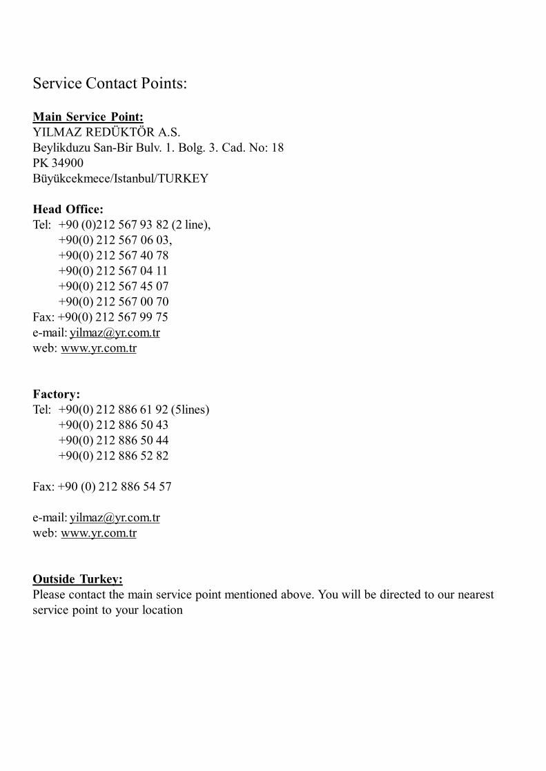
Service Contact Points:
Main Service Point:YILMAZ REDÜKTÖR A.S.Beylikduzu San-Bir Bulv. 1. Bolg. 3. Cad. No: 18PK 34900Büyükcekmece/Istanbul/TURKEY
Head Office:Tel: +90 (0)212 567 93 82 (2 line),
+90(0) 212 567 06 03,+90(0) 212 567 40 78+90(0) 212 567 04 11+90(0) 212 567 45 07+90(0) 212 567 00 70
Fax: +90(0) 212 567 99 75e-mail: [email protected]: www.yr.com.tr
Factory:Tel: +90(0) 212 886 61 92 (5lines)
+90(0) 212 886 50 43+90(0) 212 886 50 44+90(0) 212 886 52 82
Fax: +90 (0) 212 886 54 57
e-mail: [email protected]: www.yr.com.tr
Outside Turkey:Please contact the main service point mentioned above. You will be directed to our nearestservice point to your location

YILMAZ REDÜKTÖR ISO 9001 YILMAZ REDÜKTÖR ISO 9001
Gear Units, Y Series
Operating Instructions
Edition 01/2005OIYEX 0101/0105
Operating InstructionY SeriesContents
yilmaz redÜktÖr 03
Contents
1 How To Use This Manual.................................................................................... 5
2 Unit Designation................................................................................................... 62.a Detailed unit designation................................................................................. 62.b Nameplate unit designation............................................................................. 7
3 Part List of Standard Type Gear Units................................................................ 83.a YRM1.. Type................................................................................................. 83.b YRM2.. Type................................................................................................. 93.c YRD2.. Type.................................................................................................. 103.d YRM3.. Type.................................................................................................. 113.e YRD3.. Type.................................................................................................. 123.f YRM4.. Type................................................................................................. 133.g YRD4.. Type.................................................................................................. 14
4 Thinks to Check Before the Gear Unit or Geared Motor is Installed.............. 164.a Safety notes................................................................................................... 164.b Transportation............................................................................................... 174.c Storage......................................................................................................... 17
5 Installing The Gear Unit...................................................................................... 185.a Before you start............................................................................................. 185.b Check Name Plate........................................................................................ 185.c Check the ambient conditions and temperature.............................................. 185.d Check fitting elements and the shaft dimensions to fit..................................... 185.e Check the voltage supply............................................................................... 205.f Check the mounting position.......................................................................... 205.g Use the breather plug..................................................................................... 205.h Check the oil level.......................................................................................... 215.i Check shaft ends and mounting faces.............................................................. 215.j Cover abresive ambient.................................................................................. 215.k Check accessibility to filling, breather and drain plugs...................................... 21
6 Mechanical Installation........................................................................................ 226.a Installing gear units in category II2G/D-II3G/D............................................... 226.b Fittting outputshaft elements........................................................................... 236.c Correct position of otputshaft elements......................................................... 236.d Installing customer shaft with shoulder............................................................. 246.e Disassembling customer shaft with shoulder..................................................... 256.f Shaft tightening torques................................................................................... 276.g Recommended shaft dimensions for YRD types............................................... 286.h Fittting Couplings............................................................................................ 29
yilmaz redÜktÖr04
Operating InstructionY Series
7 Inspections............................................................................................................. 30
8 Lubrication.............................................................................................................. 318.a Oil Types......................................................................................................... 318.b Oil Quantities................................................................................................... 328.c Mounting Positions........................................................................................... 33
9 Troubleshooting Guide................. ........................................................................ 34
10 Decleration by the Manufacturer ........................................................................ 38
11 Waranty conditions................................................................................................. 39
12 Waranty................................................................................................................... 40
13 Service Contact Points.......................................................................................... 41

Operating InstructionY SeriesGeneral Information
yilmaz redÜktÖr 05
1 -How To Use This ManualTake attention to the following safety and warning signs for proper understanding and quick reference.
Electric Hazard; Can cause severe or fatal injuries.
Mechanical Hazard; Can cause severe or fatal injuries.
Likely to be Hazardous; Can cause minor injuries
Damage Risk; Can damage the drive or environment
Important Information
Important information about explosion protection
The operating instructions contain important information to ensure;- Trouble-free operation- Fulfilment of any rights to claim under guarantee
The operating instruction must be kept close to the gearbox and must be available in case it is needed.
This operating instruction is written for YR. series gear units and is applicable only for these series. If any different typeof gearbox is used please ask YILMAZ REDUKTOR for the operating instructions of that type.
This instruction can be used only for standard type geared units of YILMAZ REDUKTOR. For special applica-tion and modified gear units ask YILMAZ REDUKTOR for validity.
The YR. Series garboxes are with standard IEC B5/B14 connection flange and without motor. The electric motor whichwill be connected to the gearbox must also be in confirmity with the ATEX (94/9/EC) standarts.
All the external parts which will be assembled to the gear unit must conform ATEX (94/9/EC). The product thisdecleration refers to must not be put into service until the machinery into which it is to be incorporated has been de-clared in confirmity with the provisions of the relevant European Directives.
If the gear unit is not operated as informed on this manual the gear unit is no longer ATEX conforming andYILMAZ REDUKTOR does not take any responsibility.
yilmaz redÜktÖr06
Operating InstructionY SeriesType Designation
30kW - 29rpm - 48,86 - YRM3705 - L
Power (kW) OutputSpeed(rpm)
Ratio (i)
Example
30-29-48,86-YRM370530 kW, 29rpm, i=48,86 gear unit with output shaft , gearbox type: YRM4705
Detailed YR series gear units designation for ordering(This Designation is different from the short nameplate designation)
2 -Unit Designationa- Detailed unit designation
YRM- With solid output shaftYRC- With double output shaftYRD- With hollow output shaftYRE- With extruder housing
Type
30-29-48,86-YRC3705
11-29-48,86-YRE2240
30 kW, 29rpm, i=48,86 gear unit with double output shaft , gearbox type: YRM4705
11 kW, 29rpm, i=48,86 gear unit with extruder housing, gearbox type: YRM2240
Mounting position(See picture below)
Viewed from input sideL - Right Input, Left OutputR - Left Input, Right OutputUL- Left Input, Left OutputUR- Reight Input, Right Output

yilmaz redÜktÖr 07
Operating InstructionY SeriesType Designation
b- Nameplate, unit designation
Nameplate unit designation is a short abbreviation from the detailed designation
A sample name plate for YR. Series
Abreviations:Type. : Type of gearboxS/N: Serial Number of gear unit as; year/order noIP..:EnclosureP : Max. Allowed PowerM2: Output torquen1: Input speedn2: Output speedFR2: Max. allowed radial load at output shaftFR1: Max. allowed radial load at input shaftFA2: Max. allowed axial load at output shaftFA1: Max. allowed axial load at input shaftOil: Filled oil inside the gear unitQty.: Oil quantityM.pos.: Mounting Position.Ta: Ambient TempATEX sign (EN 13463-1):
Group: Only II, not for underground use
Catagorie; 2GD for gas and dust.
Ignation Class if applicable.
Temperature ClassMax. allowed surface temperature
II 2GD c,k T4 / T120 Co
263n :rpm 2 rpm1 :n 1400
A2R2
M.Pos.:
FF
Oil-20/+40Ta : ºCB3
R1A1
VG 220 Qty
FF
12000::
:190
NN
:
--
::14
NN
lt
S/N.: 04 / S2251 - EXType
P
:
2M:30 kW : 1045 Nm
II 2GD c,k T4 / T120 ºC
IP65
YILMAZ REDÜKTÖR A.S.Beylikdüzü SAN - BIR Bulvari 1.Bölge 3.Cadde No:1834900 Büyükçekmece / IST. / TURKEY
YRM1200-L / 2GD
yilmaz redÜktÖr08
Operating InstructionY SeriesPart Designation
Standard YRM1... type basic part diagram. Parts may differ for special applications.
Standard Part List
3- Part List of Standard Type Gear Unitsa- YRM1... Types
1- Uper Housing Part 8- Bearing 15- Pin 22- Bolt 29- Bearing
2- Bolt 9- Gear 16- Sealed Side Cover 23- Closed Side Cover 30- Bearing
3- Cover Plate 10- Spacer 17- Bolt 24- Plug 31- Sealed Side Cover
4- Plug 11- Bearing 18- Oil Seal 25- Plug 32- Oil Seal
5- Bolt 12- Key 19- Plug 26- Bearing 33- Bolt
6- Bolt 13- Output Shaft 20- Plug 27- Key
7- -Closed Side Cover 14- Key 21- Bottom Housing Part 28- Input Pinion Shaft

yilmaz redÜktÖr 09
Operating InstructionY SeriesPart Designation
b- YRM2... Types
Standard YRM2... type basic part diagram. Parts may differ for special applications.
Standard Part List
1- Uper Housing Part 10- Gear 19- Plug 28- Closed Side Cover 37- Bearing
2- Bolt 11- Key 20- Closed Side Cover 29- Bolt 38- Bearing
3- Cover Plate 12- Output Shaft 21- Centering Pin 30- Key 39- Centering Pin
4- Plug 13- Key 22- Bearing 31- Oil Seal 40- Plug
5- Bolt 14- Bearing 23- Spacer Ring 32- Bolt 41- Plug
6- Bolt 15- Seal Cover 24- Gear 33- Side Cover 42- Closed Side Cover
7- -Closed Side Cover 16- Oil Seal 25- Key 34- Bearing 43- Bolt
8- Bearing 17- Bolt 26- Pinion Shaft 35- Bearing 44- Bottom Housing Part
9- Spacer Ring 18- Plug 27- Bearing 36- Pinion Shaft 45- Bolt
Operating InstructionY SeriesPart Designation
c- YRD2... Types
Standard YRD2... type basic part diagram. Parts may differ for special applications.
Standard Part List
1- Uper Housing Part 10- Gear 19- Plug 28- Closed Side Cover 37- Bearing
2- Bolt 11- Bearing 20- Closed Side Cover 29- Bolt 38- Bearing
3- Cover Plate 12- Key 21- Centering Pin 30- Key 39- Plug
4- Plug 13- Hollow Shaft 22- Bearing 31- Oil Seal 40- Plug
5- Bolt 14- Bearing 23- Spacer Ring 32- Bolt 41- Closed Side Cover
6- Bolt 15- Seal Cover 24- Gear 33- Side Cover 42- Bolt
7- -Closed Side Cover 16- Oil Seal 25- Key 34- Bearing 43- Bottom Housing Part
8- Bearing 17- Bolt 26- Pinion Shaft 35- Bearing 45- Bolt
9- Spacer Ring 18- Plug 27- Bearing 36- Pinion Shaft
yilmaz redÜktÖr10
yilmaz redÜktÖr 11
Operating InstructionY SeriesPart Designation
d- YRM3... Types
Standard YRM3... type basic part diagram. Parts may differ for special applications.
Standard Part List
1- Uper Housing Part 12- Gear 23- Gear 34- Spacer 45- Sealed Side Cover
2- Bolt 13- Spacer 24- Spacer 35- Bearing 46- Bearing
3- Cover Plate 14- Bearing 25- Bearing 36- Spacer 47- Bearing
4- Plug 15- Sealed Side Cover 26- Closed Side Cover 37- Pin 48- Key
5- Bolt 16- Oil Seal 27- Bolt 38- Plug 49- Solid Pinion Shaft
6- Bolt 17- Bolt 28- Bolt 39- Plug 50- Bearing
7- Oil Seal 18- Bolt 29- Closed Side Cover 40- Bolt 51- Spacer
8- Bearing 19 -Closed Side Cover 30- Spacer 41- Closed Side Cover 52- Closed Side Cover
9- Output Shaft 20- Bearing 31- Bearing 42- Bottom Housing Part 53- Bolt
10- Key 21- Key 32- Pinion Shaft 43- Oiil Seal 54- Plug
11- Key 22- Pinion Shaft 33- Gear 44- Bolt 55- Plug
Operating InstructionY SeriesPart Designation
e- YRD3... Types
Standard YRD3... type basic part diagram. Parts may differ for special applications.
Standard Part List
1- Uper Housing Part 11- Key 21- Closed Side Cover 31- Bolt 41- Oil Seal 51- Plug
2- Bolt 12- Gear 22- Pin 32- Closed Side Cover 42- Bolt 52- Closed Side Cover
3- Cover Plate 13- Spacer 23- Bearing 33- Spacer 43- Sealed Side Cover 53- Bolt
4- Plug 14- Bearing 24- Key 34- Bearing 44- Bearing 54- Bottom Housing Part
5- Bolt 15- Sealed Cover 25- Pinion Shaft 35- Pinion Shaft 45- Bearing 55- Closed Side Cover
6- Bolt 16- Oil Seal 26- Gear 36- Key 46- Key 56- Bolt
7- Oil Seal 17- Bolt 27- Spacer 37- Gear 47- Input Pinion Shaft
8- Sealed Side Cover 18- Bolt 28- Bearing 38- Spacer 48- Bearing
9- Bearing 19- Plug 29- Closed Side Cover 39- Bearing 49- Spacer
10- Hollow Output Shaft 20- Plug 30- Bolt 40- Spacer 50- Plug
yilmaz redÜktÖr12

yilmaz redÜktÖr 13
Operating InstructionY SeriesPart Designation
f- YRM4... Types
Standard YRM4... type basic part diagram. Parts may differ for special applications.
Standard Part List
1- Uper Housing Part 12- Output Shaft 23- Gear 34- Gear 45- Bearing 56- Plug
2- Bolt 13- Key 24- Key 35- Key 46- Spacer 57- Closed Side Cover
3- Cover Plate 14- Bearing 25- Pinion Gear 36- Pinion Shaft 47- Sealed Side Cover 58- Bolt
4- Plug 15- Sealed Side Cover 26- Bearing 37- Bearing 48- Bolt 59- Closed Side Cover
5- Bolt 16- Spacer 27- Closed Side Cover 38- Spacer 49- Seal 60- Bolt
6- Bolt 17- Bolt 28- Bolt 39- Spacer 50- Bearing 61- Bottom Housing Part
7- Closed Side Cover 18- Plug 29- Bolt 40- Bearing 51- Key 62- Closed Side Cover
8- Bearing 19- Plug 30- Closed Side Cover 41- Spacer 52- Input Pinion Shaft 63- Bolt
9- Spacer Ring 20- Pin 31- Spacer 42- Gear 53- Bearing
10- Gear 21- Bearing 32- Bearing 43- Pinion Gear 54- Spacer
11- Key 22- Spacer 33- Spacer 44- Key 55- Plug

yilmaz redÜktÖr14
Operating InstructionY SeriesPart Designation
Standard YRM.... type basic part diagram. Parts may differ for special applications.
Standard Part List
g- YRD4... Types
1- Uper Housing Part 12- Key 23- Gear 34- Gear 45- Bearing 56- Plug
2- Bolt 13- Hollow Output Shaft 24- Key 35- Key 46- Spacer 57- Closed Side Cover
3- Cover Plate 14- Bearing 25- Pinion Gear 36- Pinion Shaft 47- Sealed Side Cover 58- Bolt
4- Plug 15- Side Cover 26- Bearing 37- Bearing 48- Bolt 59- Closed Side Cover
5- Bolt 16- Oil Seal 27- Closed Side Cover 38- Spacer 49- Seal 60- Bolt
6- Bolt 17- Bolt 28- Bolt 39- Spacer 50- Bearing 61- Bottom Housing Part
7- Oil Seal 18- Plug 29- Bolt 40- Bearing 51- Key 62- Closed Side Cover
8- Sealed Side Cover 19- Plug 30- Closed Side Cover 41- Spacer 52- Input Pinion Shaft 63- Bolt
9- Bearing 20- Pin 31- Spacer 42- Gear 53- Bearing
10- Spacer 21- Bearing 32- Bearing 43- Pinion Gear 54- Spacer
11- Gear 22- Spacer 33- Spacer 44- Key 55- Plug

4 -Thinks to Check Before the Gear Unit or Geared Motor is Installed
a) Safety notes for use in potentially explosive atmosphere
Explosive gas mixtures or concentration of dust can lead to severe or fata injuries in conjunc-tion with hot or moving parts of the gear unit / gearmotor
Before you install the gearbox you have to be sure that the gearbox is arrived with the all necessaryequipment and without damage. Thinks to take into consideration before you start to install the unit;- You have received the correct operation manual of the your product.- The gearbox and all its parts are transported without damage.- The gearbox is stored correctly according the instructions in this manual- The nameplate is clearly visible and all the data can be read.- All the regulations and requirements according to the currently valid national/regional regulations.- The gearbox is used according its intended use
Intended use of gearbox:The gearboxes covered by this manuel can only be used in ATEX zone 2G,2D,3G,3D and ignationclass IIA/IIB.
The gear units are intended for industrial systems and may only be used in accordance with theinformation provided in this manual and the nameplate of the gearbox. They comply with the applica-ble standards and regulations and meet the requirements of the directive 94/9/EC. The gearbox isstarted up, maintained and operated according this manual. The gearbox is incorporated with 94/9/EC confirming parts/machines.
A motor connected to the gear unit is only allowed to be operated in the frequency entries sothat the data provided on nameplate of the gear unit is not exceeded and is accordance withthe nameplate. The input speed range will be provided on the name plate if YILMAZREDUKTOR is informed that the gear unit will be used with frequency inverter. If not in-formed the nameplate will have a single fixed input speed and only this input speed is allowed.The electric motor and frequency inverter must be in accordance with 94/9/EC
If the gear units input is used with variable speed gear unit, this must be informed to YILMAZREDUKTOR before ordering and on the nameplate the allowed maximum and minimuminput speeds (speed range) will be provided. If not mentioned by ordering the gear units inputspeed will be a fixes single input speed and only this speed is allowed.
If the gear unit will be driven by belt / coupling / chain drive etc. the gear unit is onlt allowedto be used according the nameplate entries. Diffrent speed, higher motor power, higherradial/axial loads etc. than nameplate is not allowed.
The ambient conditions must be accordance with the name plate and no agresive media mustattack the paint and seals.
yilmaz redÜktÖr16
Operating InstructionY SeriesInstalling
The gearbox maintanance (oil change / check ) must be done according this manuel
b) TransportationWhen the goods arrive, first check for any damage. If some damage observed, immediatelycontact the transport company and inform about the damage. Contact YILMAZ for thedamage and do not start to install the unit until it is agreed that the damage has no affect ofoperation.
Use the supplied eyebolts or lifting holes for lifting up the gear unit. The eyebolts arecapable to carry the weight of gearboxes only. Do not hang additional loads.
c) StorageIf the geared unit or gearedmotor will be stored up to 3 years refer to the following instruc-tions;
With Packing;-Use corrosion protection oil for the output shaft and connection surfaces like flange surfaceor foot assembling surface. Seal the unit in a plastic wrap and pack it in container. A moistureindicator should be placed around the container to observe the moisture. Relative atmos-pheric humidity should not exceed 50%. The container should be kept under roof whichprotects from snow and rain. Under this condition the gear unit can be stored up to 3 yearwith regular check.
Without Packing;-Use protection oil for the output shaft and connection surfaces like flange surface or footassembling surface. If no packing is used and the gearbox is stored without packing, theambient temperature should be between 5 to 60 Celsius degrees. The gearbox must be keptunder enclosed roof with constant temperature and constant humidity not exceeding 50%.The storage should be free of dust and dirt and ventilated with filter. If the gearbox is storedwithout packing it is recommended not to store more than 2 years and regular check duringthis time is recommended.
If stored in open protect against insect damage.
yilmaz redÜktÖr 17
Operating InstructionY SeriesInstalling

5- Installing The Gear Unit
a) Before you start;- Observe the gear unit for damages of storage or transportation. If any damage please contactYILMAZ REDUKTOR.- Be sure that you have all the equipment necessary for installing like; Spanners, torquewrench, shims and distance rings, fixing devices for input and output elements, lubricant, boltadhesive etc.
b) Check nameplate of the gear unit;- ATEX conforming gear gear units have a nameplate indicating the “EX” sign shown on the left sideand the following information;
- Equipment group- Ex category- Ex zone- Temprature class- Maximum surface temperature
If you can not see this sign and values, your gearbos is not intended for use on potentially explosiveatmosphere. If some of the data can not be read because of some reason, please contact YILMAZREDUKTOR.
c) Check the ambient conditions and temperature;Have measures been taken to ensure that no potentially explosive atmosphere, oils, acids, gases,vapors or radiated interference are present when the gear unit is being installed.
The ambient temperature must be in accordance with the oil tables given on the manual. If differentcontact YILMAZ REDUKTOR for special solutions.
The ambient air temperature must not exceed 40 degrees celcius as mentioned on the name-plate. The cooling air surrounding the gear unit must bellow 40 degrees and the gear unitmust not subject to heating from external sources. The gear unit surface must be kept cleanand sufficiently ventilated.
d) Check fitting elements and the shaft dimensions to fit;
All external elements that will be fitted to the gear unit must be ATEX confirming.
The shaft/flange dimention are shown bellow. Use correct tolerances to fit external elements. Ob-serve the assemly instructions provided in this manual.
yilmaz redÜktÖr18
Operating InstructionY SeriesInstalling
yilmaz redÜktÖr 19
Operating InstructionY SeriesInstalling
Only belts with sufficient shunt resistance <10^9 ohm are allowed
Never strike belt pulleys, coupling, pinions etc. with a hammer when pulling them onto theshaft end. This could result in damage to bearings, the housing and the shaft.
Power transmision elements must be balanced after fitting and must not give rise to any imper-missible radial or axial forces.
Observe the name plate for maximum allowed radial and axial load. The external radialand axil load must not exceed the provided values on the nameplate.
Type Hollow ShaftDiameter
Hollow ShaftTolerance (H8)
Output ShaftDiameter
Output ShaftTolerance(DIN748)
Up to 50mm k6Over 50mm m6
YR.1125... - - 55 +0.03+0.01
YR.1160... - - 70 +0.03+0.01
YR.1200 - - 90 +0.03+0.01
YR.2195YR.2240 50 +0.04
0 65 +0.03+0.01
YR.2275YR.3355 60 +0.05
0 75 +0.03+0.01
YR.2305YR.3395YR.4395
85 +0.060 85 +0.04
+0.02
YR.2340YR.3440YR.4440
90 +0.060 95 +0.04
+0.02
YR.2385YR.3500YR.4500
95 +0.060 100 +0.04
+0.02
YR.2430YR.3555YR.4555
110 +0.060 110 +0.04
+0.02
YR.2480YR.3620YR.4620
140 +0.070 130 +0.04
+0.02
YR.2545YR.3705YR.4705
150 +0.070 140 +0.04
+0.02
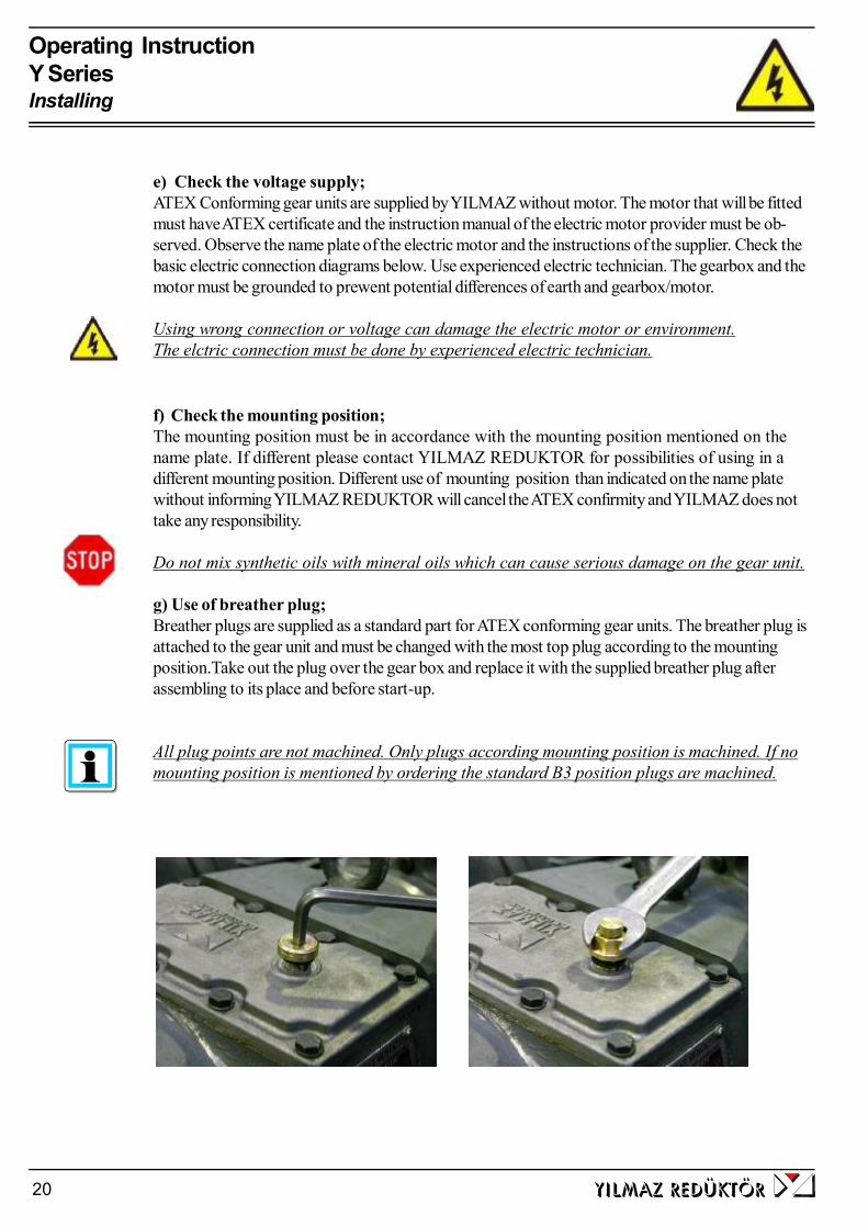
Operating InstructionY SeriesInstalling
yilmaz redÜktÖr20
e) Check the voltage supply;ATEX Conforming gear units are supplied by YILMAZ without motor. The motor that will be fittedmust have ATEX certificate and the instruction manual of the electric motor provider must be ob-served. Observe the name plate of the electric motor and the instructions of the supplier. Check thebasic electric connection diagrams below. Use experienced electric technician. The gearbox and themotor must be grounded to prewent potential differences of earth and gearbox/motor.
Using wrong connection or voltage can damage the electric motor or environment.The elctric connection must be done by experienced electric technician.
f) Check the mounting position;The mounting position must be in accordance with the mounting position mentioned on thename plate. If different please contact YILMAZ REDUKTOR for possibilities of using in adifferent mounting position. Different use of mounting position than indicated on the name platewithout informing YILMAZ REDUKTOR will cancel the ATEX confirmity and YILMAZ does nottake any responsibility.
Do not mix synthetic oils with mineral oils which can cause serious damage on the gear unit.
g) Use of breather plug;Breather plugs are supplied as a standard part for ATEX conforming gear units. The breather plug isattached to the gear unit and must be changed with the most top plug according to the mountingposition.Take out the plug over the gear box and replace it with the supplied breather plug afterassembling to its place and before start-up.
All plug points are not machined. Only plugs according mounting position is machined. If nomounting position is mentioned by ordering the standard B3 position plugs are machined.
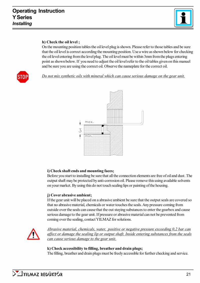
yilmaz redÜktÖr 21
Operating InstructionY SeriesInstalling
h) Check the oil level ;On the mounting position tables the oil level plug is shown. Please refer to those tables and be surethat the oil level is correct according the mounting position. Use a wire as shown below for checkingthe oil level entering from the level plug. The oil level must be within 3mm from the plugs enteringpoint as shown below. If you need to adjust the oil level refer to the oil tables given on this manueland be sure you are using the correct oil. Observe the nameplate for the correct oil.
Do not mix synthetic oils with mineral which can cause serious damage on the gear unit.
i) Check shaft ends and mounting faces;Before you start to installing be sure that all the connection elements are free of oil and dust. Theoutput shaft may be protected by anti-corrosion oil. Please remove this using available solventson your market. By using this do not touch sealing lips or painting of the housing.
j) Cover abrasive ambient;If the gear unit will be placed on a abrasive ambient be sure that the output seals are covered sothat no abrasive material, chemicals or water touches the seals. Any pressure coming fromoutside over the seals can cause that the out staying substances to enter the gearbox and causeserious damage to the gear unit. If pressure or abrasive material can not be prevented fromcoming over the sealing, contact YILMAZ for solutions.
Abrasive material, chemicals, water, positive or negative pressure exceeding 0,2 bar canaffect or damage the sealing lip or output shaft. Inside entering substances from the sealscan cause serious damage to the gear unit.
k) Check accessibility to filling, breather and drain plugs;The filling, breather and drain plugs must be freely accessible for further checking and service.

Operating InstructionY SeriesInstalling
yilmaz redÜktÖr22
6- Mechanical InstallationThe mounting plate must be rigid enough not allowing torsions, flat enough to prevent strains by tighten-ing the bolts and stable enough not allowing vibrations. By using chain drives this becomes much moreimportant because of the polygon effect on chain drives. According to your connection elements themaximal permitted radial and axial load of the gear unit must be in accordance with your application.Check the product catalogue for permitted radial loads and calculation.
If the output or input shaft is overloaded by radial or axial loads it can cause serious damage tothe gear unit.
Secure the gear unit using 8.8 or higher quality bolts.
All bolts are locked by use of locktide adhesives or gear-shims on the gearbox. By assembling the gearunit locktides adhesives or gear-shims must be used to prevent loosening of bolts.
Cover all the turning parts from human entering or touching. Turning parts can cause severe orfatal injuries.
For different kind of basic installations refer to the following illustrations.
Only ATEX-approved input and output elements are allowed to be used, assum-ing the elements are subject to Directive 94/9/EC
a- Installing gear units in category II2G/D-II3G/D
Explosion-proof gear units comply with the design requirements for unit group II,catagory 2G,2D,3D,3G. These units are intended for use in zones 1 and 21.
The gear units in catagory II2D must be used in ambient teperature between -20C to +40 C only. If different ambient conditions this must be inforned beforeorder and the name plate must be in accordance with the ambient conditions.
The temperature class depends on the speed, type and mounting position of thegearbox and is indicated on the name plate. Temperature classes from T4 to T6are provided by YILMAZ REDUKTOR.
The surface temperature of the gearbox must not exceed the provided max. sur-face temperature on the name plate. After all installations finished and the gear-box is started up according this manual let the gear unit run 4 hours at full loadand check the surface temperature from the shown point bellow and the ambienttemperature. Check the following;
(40-Ta)+Tw < Tmax. of nameplate ( Ta: Ambient Temp., Tw: Surface Temp)

yilmaz redÜktÖr 23
Operating InstructionY SeriesInstalling
b- Fittting outputshaft elementsUse the following ilustration to assemble output shaft units
c- Correct position of otputshaft elementsThe Output Shaft unit (transmision elements) must placed as close as possible to the gear unit so thatthe radial load is as closest as possible to the gear unit.
1) Gear shaft end2) Thrust bearing3) Coupling hub
1) Hub
If the result is higher then Tmax, immidiately stop the system and contact YILMAZREDUKTOR.
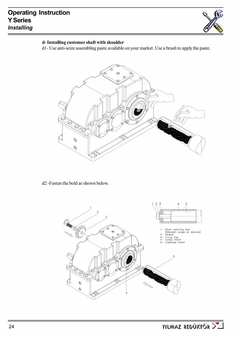
Operating InstructionY SeriesInstalling
yilmaz redÜktÖr24
d2 -Fasten the bold as shown below.
d- Installing customer shaft with shoulderd1- Use anti-seize assembling paste available on your market. Use a brush to apply the paste.

Operating InstructionY SeriesInstalling
yilmaz redÜktÖr 25
e2 -Use the disassemble set from YILMAZ and fasten the bold as shown bellow to take out theoutput shaft.
e- Disassembling customer shaft with shouldere1- Disassemble the bolt and take out the parts as shown
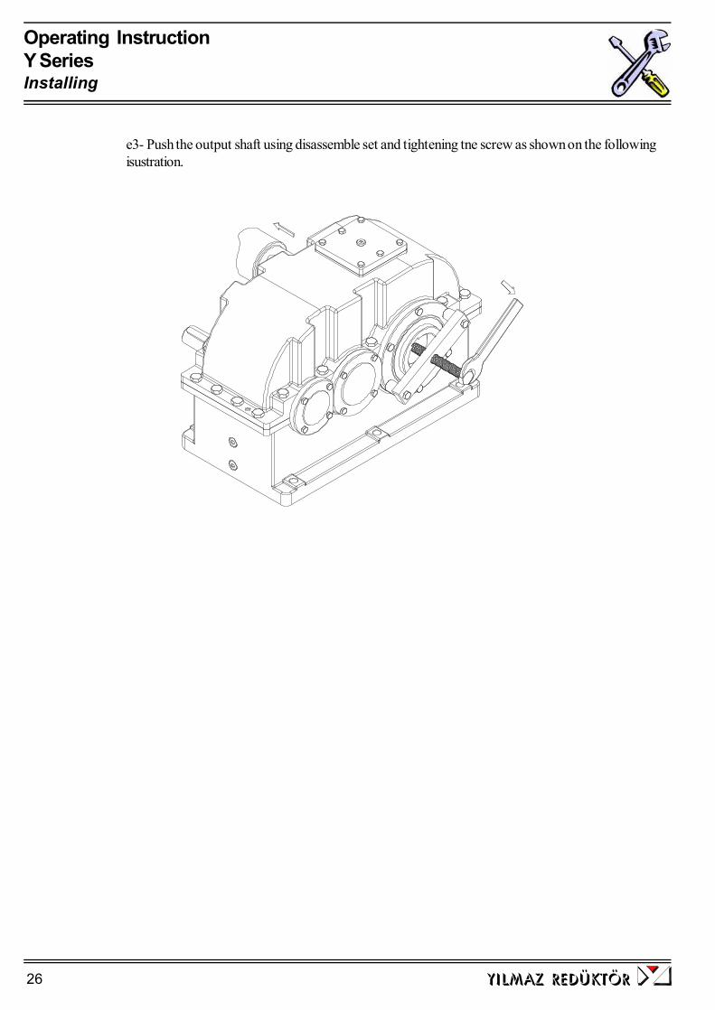
Operating InstructionY SeriesInstalling
yilmaz redÜktÖr26
e3- Push the output shaft using disassemble set and tightening tne screw as shown on the followingisustration.

Operating InstructionY SeriesInstalling
yilmaz redÜktÖr 27
f- Shaft tightening torques Use the following table for shaft tightening torques.
Type Bolt Tightening torque[Nm]
YRD2240 M16 40
YRD2275 M20 80
YRD2305 M20 80
YRD2340 M24 200
YRD2385 M24 200
YRD2430 M24 200
YRD2480 M30 400
YRD2545 M30 400
YRD3355 M20 80
YRD3395 M20 80
YRD3440 M24 200
YRD3500 M24 200
YRD3555 M24 200
YRD3620 M30 200
YRD3705 M30 400
YRD4395 M20 80
YRD4440 M24 200
YRD4500 M24 200
YRD4555 M24 200
YRD4620 M30 400
YRD4705 M24 200
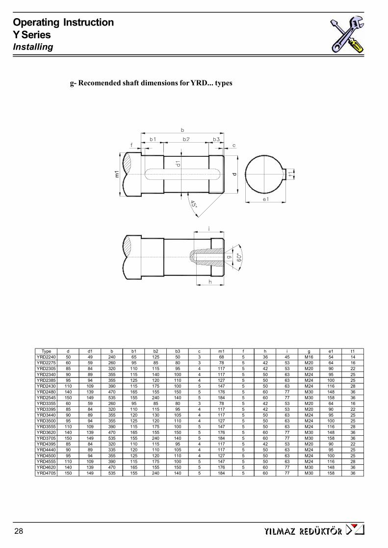
Operating InstructionY SeriesInstalling
yilmaz redÜktÖr28
g- Recomended shaft dimensions for YRD... types
Type d d1 b b1 b2 b3 c m1 f h i g e1 t1YRD2240 50 49 240 65 125 50 3 68 5 36 45 M16 54 14YRD2275 60 59 260 95 85 80 3 78 5 42 53 M20 64 16YRD2305 85 84 320 110 115 95 4 117 5 42 53 M20 90 22YRD2340 90 89 355 115 140 100 4 117 5 50 63 M24 95 25YRD2385 95 94 355 125 120 110 4 127 5 50 63 M24 100 25YRD2430 110 109 390 115 175 100 5 147 5 50 63 M24 116 28YRD2480 140 139 470 165 155 150 5 176 5 60 77 M30 148 36YRD2545 150 149 535 155 240 140 5 184 5 60 77 M30 158 36YRD3355 60 59 260 95 85 80 3 78 5 42 53 M20 64 16YRD3395 85 84 320 110 115 95 4 117 5 42 53 M20 90 22YRD3440 90 89 355 120 130 105 4 117 5 50 63 M24 95 25YRD3500 95 94 355 125 120 110 4 127 5 50 63 M24 100 25YRD3555 110 109 390 115 175 100 5 147 5 50 63 M24 116 28YRD3620 140 139 470 165 155 150 5 176 5 60 77 M30 148 36YRD3705 150 149 535 155 240 140 5 184 5 60 77 M30 158 36YRD4395 85 84 320 110 115 95 4 117 5 42 53 M20 90 22YRD4440 90 89 335 120 110 105 4 117 5 50 63 M24 95 25YRD4500 95 94 355 125 120 110 4 127 5 50 63 M24 100 25YRD4555 110 109 390 115 175 100 5 147 5 50 63 M24 116 28YRD4620 140 139 470 165 155 150 5 176 5 60 77 M30 148 36YRD4705 150 149 535 155 240 140 5 184 5 60 77 M30 158 36
m1 d
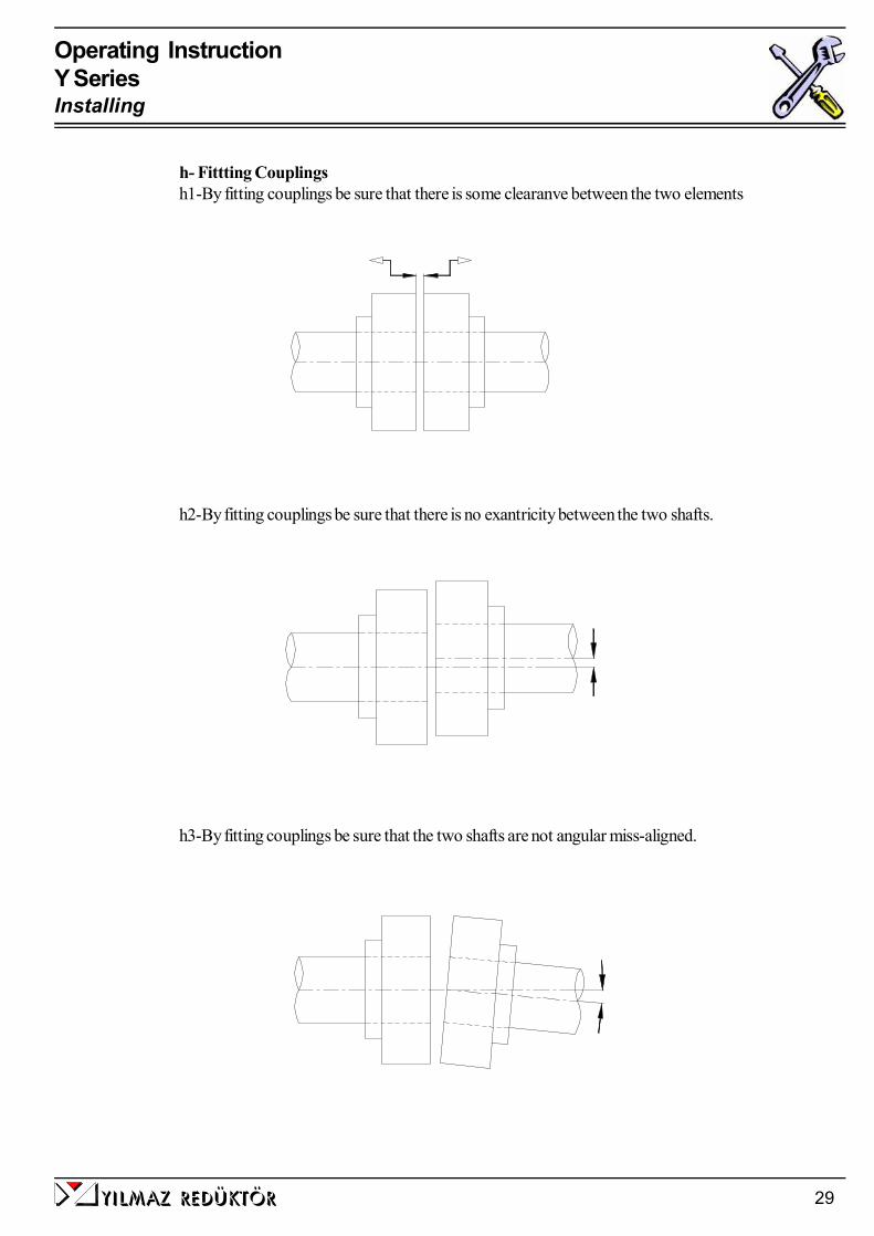
yilmaz redÜktÖr 29
Operating InstructionY SeriesInstalling
h- Fittting Couplingsh1-By fitting couplings be sure that there is some clearanve between the two elements
h2-By fitting couplings be sure that there is no exantricity between the two shafts.
h3-By fitting couplings be sure that the two shafts are not angular miss-aligned.
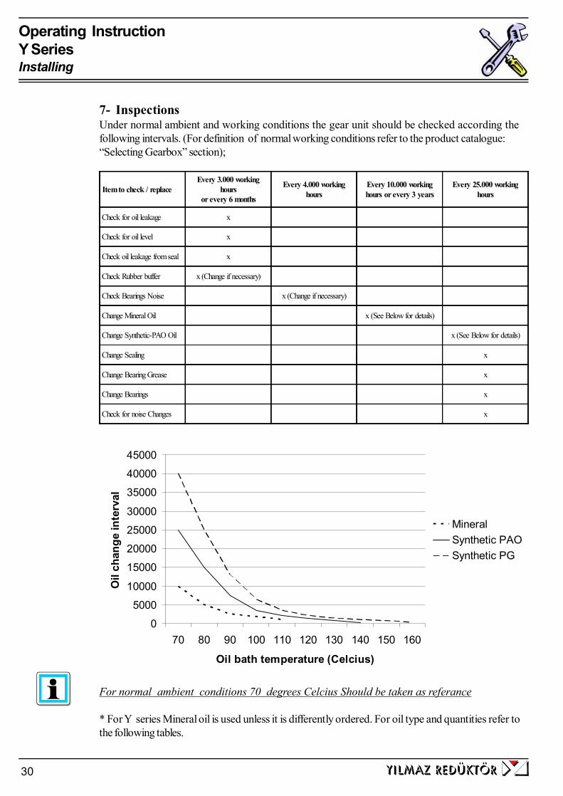
Operating InstructionY SeriesInstalling
yilmaz redÜktÖr30
7- InspectionsUnder normal ambient and working conditions the gear unit should be checked according thefollowing intervals. (For definition of normal working conditions refer to the product catalogue:“Selecting Gearbox” section);
0
5000
10000
15000
20000
25000
30000
35000
40000
45000
70 80 90 100 110 120 130 140 150 160
Oil bath temperature (Celcius)
Oil
chan
ge in
terv
al
MineralSynthetic PAOSynthetic PG
For normal ambient conditions 70 degrees Celcius Should be taken as referance
* For Y series Mineral oil is used unless it is differently ordered. For oil type and quantities refer tothe following tables.
Item to check / replaceEvery 3.000 working
hoursor every 6 months
Every 4.000 workinghours
Every 10.000 workinghours or every 3 years
Every 25.000 workinghours
Check for oil leakage x
Check for oil level x
Check oil leakage from seal x
Check Rubber buffer x (Change if necessary)
Check Bearings Noise x (Change if necessary)
Change Mineral Oil x (See Below for details)
Change Synthetic-PAO Oil x (See Below for details)
Change Sealing x
Change Bearing Grease x
Change Bearings x
Check for noise Changes x

yilmaz redÜktÖr 31
Operating InstructionY SeriesInspection
Yağ CinsiLubricantArt des
Schmierstoffes
Kullanım SıcaklığıUsage Temparature
Gebrauchstemperature
ISO Vizkozite SınıfıISO Viscosity ClassVizkozitäts Klasse
ISO
Mineral YağlarMineral OilMineralöl
0 ... +100
0 ... +100
0 ... +100
-5 ... +100
-5...+100
-5...+100
ISO VG 680
ISO VG 460
ISO VG 320
ISO VG 220
ISO VG 150
ISO VG 100
DegolBG 680
DegolBG 460
DegolBG 320
DegolBG 220
DegolBG 150
DegolBG100
EnergolGR-XP680
EnergolGR-XP460
EnergolGR-XP320
EnergolGR-XP220
EnergolGR-XP150
EnergolGR-XP100
SpartanEP 680
SpartanEP 460
SpartanEP 320
SpartanEP 220
SpartanEP 150
SpartanEP 100
GEM 1 680
GEM 1 460
GEM 1 320
GEM 1 220
GEM 1 150
GEM 1 100
Mobilgear636
Mobilgear634
Mobilgear632
Mobilgear630
Mobilgear629
Mobilgear627
Omala680
Omala460
Omala320
Omala220
Omala150
Omala100
Alpha SP680
Alpha SP460
Alpha SP320
Alpha SP220
Alpha SP150
Alpha SP100
Sentetik YağlarSynthetic OilSynthetisch Öl
-20 ... +140
-20 ... +140
-25 ... +140
-25 ... +140
-30 ... +140
-30 ... +140
ISO VG 680
ISO VG 460
ISO VG 320
ISO VG 220
ISO VG 150
ISO VG 100
DegolGS 680
DegolGS 460
DegolGS 320
DegolGS 220
DegolGS 150
EnersynSG-XP680
EnersynSG-XP460
EnersynSG-XP320
EnersynSG-XP220
EnersynSG-XP 150
EnersynSG-XP 100
Glycolube460
Glycolube320
SynthesoD 680 EP
SynthesoD 460 EP
SynthesoD 320 EP
SynthesoD 220 EP
SynthesoD 150 EP
SynthesoD 150 EP
GylgoyleHE 680
GylgoyleHE 460
GylgoyleHE 320
GylgoleHE 220
TivelaSD
TivelaWB
AlphasyonPG 460
AlphasyonPG 320
AlphasyonPG 220
AlphasyonPG 150
Mineral Gresler /Minaral Grease /
Mineral Fett-20 ... +120 Aralup
HL 3Energrease
LS 3Beacon
3Centoplex
2Mobilux
2Alvania
R3Spheerol
APT 3
Sentetik Gresler /Synthetic Grease/ Synthetisch gres
-30 ... +100ISOFLEX
TopasL152
MobiltempSHC 100
CassidaRLS 00
8- Lubricationa- Oil Types
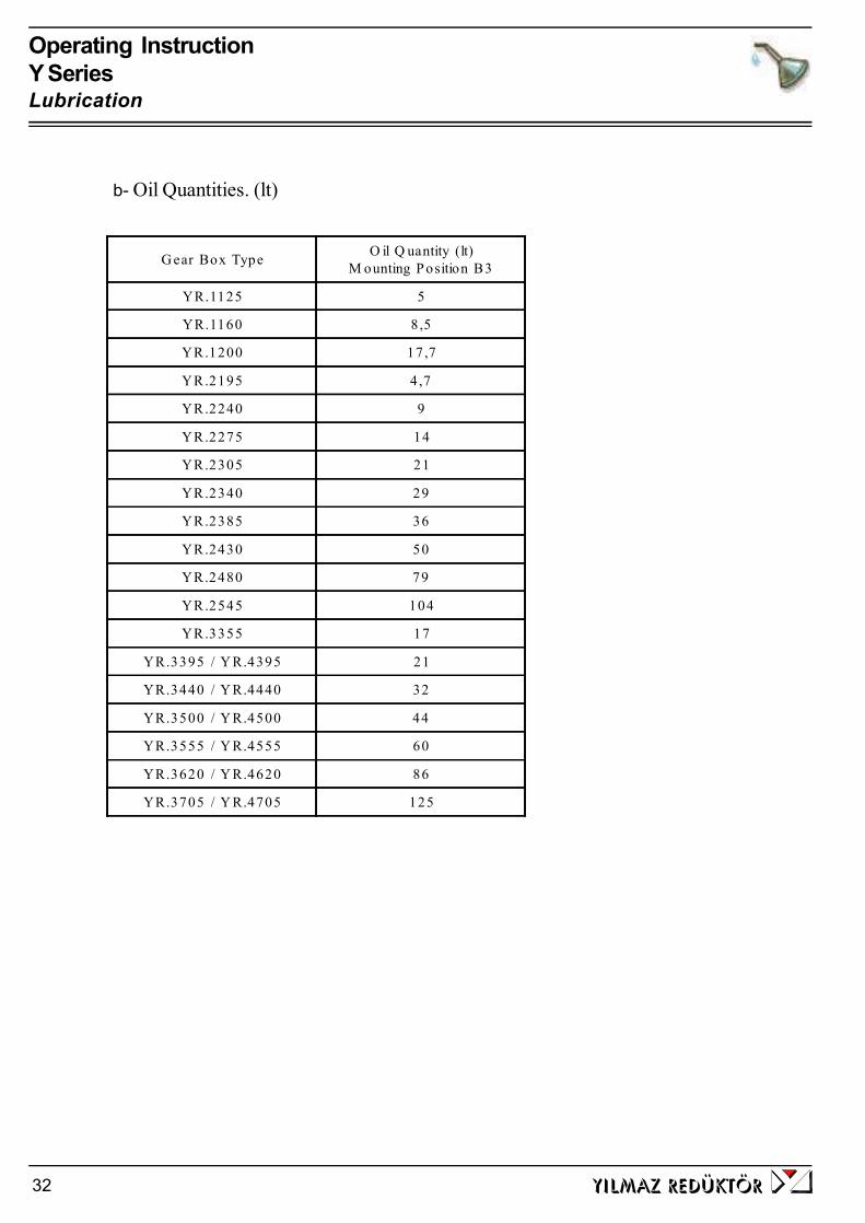
Operating InstructionY SeriesLubrication
yilmaz redÜktÖr32
b- Oil Quantities. (lt)
G ear Box Type O il Q uantity (lt)M ounting P osition B3
YR.1125 5
YR.1160 8,5
YR.1200 17,7
YR.2195 4,7
YR.2240 9
YR.2275 14
YR.2305 21
YR.2340 29
YR.2385 36
YR.2430 50
YR.2480 79
YR.2545 104
YR.3355 17
YR.3395 / Y R.4395 21
YR.3440 / Y R.4440 32
YR.3500 / Y R.4500 44
YR.3555 / Y R.4555 60
YR.3620 / Y R.4620 86
YR.3705 / Y R.4705 125

yilmaz redÜktÖr 33
Operating InstructionY SeriesOil Quantities
c- Mounting PositionsStandard type YR Series are delivered only as B3 mounting position. Differentmounting positions are possible as special application. Please contact YILMAZREDUKTOR for different mounting positions. The standard B3 mounting positionis shown bellow.
YR.1
YR.2
YR.3
YR.4
Oil Level Drain PlugFilling Plug

Operating InstructionY SeriesOil Quantities
yilmaz redÜktÖr34
ID Problem Observation Remedy
001 Gearbox DoesNot Start Up
You hear no noise andshaft is not turning. Youare not using any driver orfrequency inverter.
Please Check the voltage supply and frequency of yourelectric connection. They must be in accordance with thenameplate of the motor. Observe motor manufacturers startup manual. Still does not work go to ID 100
002 Gearbox DoesNot Start Up
You hear no noise andshaft is not turning. Youare using frequencyinverter or driver.
Please observe the frequency incerter/driver manual. Chechthe motor by supplying direct voltage to see if the problem ison your driver/frequency inverter. Still does not work go toID 001.
003 Gearbox DoesNot Start Up
You hear some noise butboth motor shaft andgearbox shaft is notturning. You are not usingany driver /frequencyinverter or braked motor.
Please Check the voltage supply and frequency of yourelectric connection. They must be in accordance with thenameplate of the motor. Observe motor manufacturers startup manual. Still same problem, the load may be too high forthe choosen motor. Loosen the gearbox from the load/torque.If it works than the starting torque is insufficient and highermotor power is needed. For monophaze motors, check thestarting up condansator and running condansator as well. Ifnotting helps go to ID 100
004 Gearbox DoesNot Start Up
You hear some noise butboth motor shaft andgearbox shaft is notturning. You are usingdriver or frequencyinverter.
Please observe the frequency inverters or drivers manual. Tosee if the problem is on your driver or frequency inverter takeout the driver/frequency inverter and make direct voltagesupply to the motor according the motors nameplate. Stilldoes not work go to ID 100
005 Gearbox DoesNot Start Up
You hear some noise butboth motor shaft andgearbox shaft is notturning. You are usingbraked motor
Please Check the voltage supply and frequency of yourelectric connection. They must be in accordance with thenameplate of the motor. Observe motor manufacturers startup manual. Be sure that the brake is working. Observe thebrake manufacturers manuel. If brake is supplied fromYILMAZ observe this manuel for correct brake wiringdiagram. If still not work supply the brake with voltageaccording its nameplate directly. For example 198V DC. Youwill hear a clicking noise explaining that the brake is opening.If you hear no noise the brake or rectifier is defect. If youhear the clicking noise the brake is working. You should thisclicking noise by your normal electric connection as well. Bysupplying direct supply to the brake you hear the clickingnoise and at same time you supply the motor with directvoltage according to its name plate and still same problem,the load may be too high for the choosen motor. Goto ID003.
9- Troubleshooting Guide
All the operations bellow must be done by experienced mechanichan/electrican. Do not make anythinkif you are not sure what you are doing and contact YILMAZ. Any change or operation donewithout the information of YILMAZ REDUKTOR is in your own risk and responsibility andYILMAZ REDUKTOR does not take any responsibility.

Operating InstructionY SeriesMounting Positions
yilmaz redÜktÖr 35
ID Problem Observation Remedy
006
Gearbox DoesNot Work in LowSpeeds/frequenci-es.
You are using frequencyinverter.
For very low speeds the frequency inverters frequency islowering down. For very low frequencies the inverterparameter and motor parameter must be optimized. Also forlow speeds the efficiency of the gearbox may varry too much.Specially for worm-gearboxes. The recomended frequencyrange is 20-70 Hz for worm-gearboxes and 10-70 Hz forHelical Gear Boxes. Use Higher motor power and Frequencyinverter or change ratio of gearbox to work inside thereccomended range.
007
Gearbox DoesNot StartMornings or AfterLong Time Stop.
Ambient Temperature isbelow +5 Celsius
The oil is not in accordance with your working conditions.Change to lower viscosity oils. Observe this manuel for usingthe correct oil. Working in higher ambient temperatures is another solution if possible. If still same problem you needhigher motor power.
008Gearbox isHeating Up tooMuch
You are using Worm GearBox and ambient tenp islower than +40 Celsius
Measure the surface temp. using a temperature measuringdevice under full load. If the temp is under +80 Celsius thiswill make no harm to the gearbox and is normal. All ATEXconforming gearboxes and standart worm gearboxes aredesigned to work under max. +120 Celsius. If higher than+120 Celsius and using ATEX conforming gear boximmidiately stop the system and contact YILMAZREDUKTOR. Go to ID 100. If not ATEX confirming checkthe oil type and oil quantitiy/level according your mountingposition and check the nameplate mounting position. Ifnameplate mounting position does not fit the actual positiongoto ID 100.
009Gearbox isHeating Up tooMuch
You are using Helical GearBox. Ambient temp islower than +40 Celsius
Measure the surface temp. using a temperature measuringdevice under full load. If the temp is under +80 Celsius thiswill make no harm to the gearbox and is normal. All ATEXconforming gearboxes are designed to work under max.+120 Celsius. If higher than +120 Celsius and using ATEXconforming gear box immidiately stop the system and contactYILMAZ REDUKTOR. If not ATEX gearbox the gearbox isdesigned to work under max. +80 Celsious. If higher than+80 Celsius check the oil type and oil quantitiy/levelaccording your mounting position and check the nameplatemounting position. If nameplate mounting position does not fitthe actual position goto ID 100
010Gearbox isHeating Up tooMuch
Ambient Temp is over+40 Celsius
Standart Gearboxes are designed to work under +40 Celsius.ambient temperature. If ambient temp is higher than +40Celsius special solutions/gearboxes are required. Pleasecontact YILMAZ
011 Gearbox is noisy Nois is regular continious
Check Your moving parts for noise. Disassemble the gearboxand run without load. If you still hear the noise motorbearings or gearbox bearings are defect. Change bearings.Goto ID 100
012 Gearbox is noisy Nois is random
Check Your moving parts for noise. Disassemble the gearboxand run without load. If you hear still the noise the oil mayhas some particles inside. Change the oil and look for smallparticles. If metal particles are found the gearbox may havesome demage. Goto ID 100
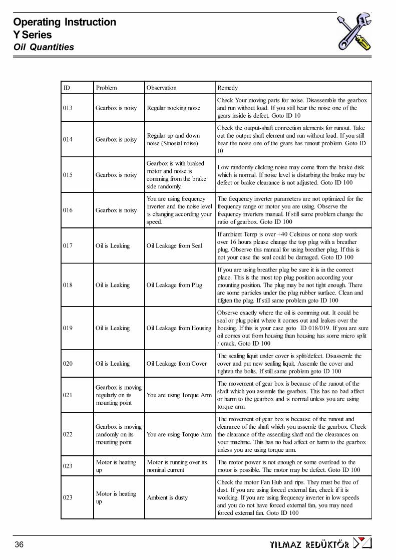
Operating InstructionY SeriesOil Quantities
yilmaz redÜktÖr36
ID Problem Observation Remedy
013 Gearbox is noisy Regular nocking noiseCheck Your moving parts for noise. Disassemble the gearboxand run without load. If you still hear the noise one of thegears inside is defect. Goto ID 10
014 Gearbox is noisy Regular up and downnoise (Sinosial noise)
Check the output-shaft connection alements for runout. Takeout the output shaft element and run without load. If you stillhear the noise one of the gears has runout problem. Goto ID10
015 Gearbox is noisy
Gearbox is with brakedmotor and noise iscomming from the brakeside randomly.
Low randomly clicking noise may come from the brake diskwhich is normal. If noise level is disturbing the brake may bedefect or brake clearance is not adjusted. Goto ID 100
016 Gearbox is noisy
You are using frequencyinverter and the noise levelis changing according yourspeed.
The frequency inverter parameters are not optimized for thefrequency range or motor you are using. Observe thefrequency inverters manual. If still same problem change theratio of gearbox. Goto ID 100
017 Oil is Leaking Oil Leakage from Seal
If ambient Temp is over +40 Celsious or none stop workover 16 hours please change the top plug with a breatherplug. Observe this manual for using breather plug. If this isnot your case the seal could be damaged. Goto ID 100
018 Oil is Leaking Oil Leakage from Plug
If you are using breather plug be sure it is in the correctplace. This is the most top plug position according yourmounting position. The plug may be not tight enough. Thereare some particles under the plug rubber surface. Clean andtifgten the plug. If still same problem goto ID 100
019 Oil is Leaking Oil Leakage from Housing
Observe exactly where the oil is comming out. It could beseal or plug point where it comes out and leakes over thehousing. If this is your case goto ID 018/019. If you are sureoil comes out from housing than housing has some micro split/ crack. Goto ID 100
020 Oil is Leaking Oil Leakage from CoverThe sealing liquit under cover is split/defect. Disassemle thecover and put new sealing liquit. Assemle the cover andtighten the bolts. If still same problem goto ID 100
021Gearbox is movingregularly on itsmounting point
You are using Torque Arm
The movement of gear box is because of the runout of theshaft which you assemle the gearbox. This has no bad affector harm to the gearbox and is normal unless you are usingtorque arm.
022Gearbox is movingrandomly on itsmounting point
You are using Torque Arm
The movement of gear box is because of the runout andclearance of the shaft which you assemle the gearbox. Checkthe clearance of the assemling shaft and the clearances onyour machine. This has no bad affect or harm to the gearboxunless you are using torque arm.
023 Motor is heatingup
Motor is running over itsnominal current
The motor power is not enough or some overload to themotor is possible. The motor may be defect. Goto ID 100
023 Motor is heatingup Ambient is dusty
Check the motor Fan Hub and rips. They must be free ofdust. If you are using forced external fan, check if it isworking. If you are using frequency inverter in low speedsand you do not have forced external fan, you may needforced external fan. Goto ID 100

Operating InstructionY SeriesMounting Positions
yilmaz redÜktÖr 37
ID Problem Observation Remedy
024Motor is runningbut Gearbox shaftdoes not turn
Scratchinh noise comesout
Some part (key, gear) may be defect inside gearbox. GotoID 10
025 Gearbox Housingis Defect
You are using chain driveor pinion gear
The radial load or poligon effect of the chain may havecaused the damage. Check also if the assembly bolts areloosened or the plate you assemble the gearbox is rigitenough. Check if you are using the correct diameter of chaindrive and you are not exceeding max. allowed radial load.Check the position of your output element and re-calculateyour radyal load and check if this fit to tha maximum allowedradial load. Goto ID 100
026 Output Shaft isDefect
You are using chain driveor pinion gear
The radial load or poligon effect of the chain may havecaused the damage. Check also if the assembly bolts areloosened or the plate you assemble the gearbox is rigitenough. Check if you are using the correct diameter of chaindrive and you are not exceeding max. allowed radial load.Check the position of your output element and re-calculateyour radyal load and check if this fit to tha maximum allowedradial load. Goto ID 100
027 Gearbox isstopping too late
You are using brakedmotor
Please check the wiring diagram of the brake. There are twodifferent kind of brake wiring diagram. The standart gearboxdelivered from our factory is set to delayed braking. Forsudden braking check the wiring diagram.
028 Gearbox is startingtoo late
You are using brakedmotor
For fast opening of big brakes (over 100Nm), you may needshock transformators which is supplied by YILMAZ. GotoID 100
100 Service Required No self solution found Please contact YILMAZ REDUKTOR Service point. See onthe back side of this manual

DECLARATION BY THE MANUFACTURER(According 94/9/EC, Anex VIII)
We YILMAZ REDÜKTÖR Sanayi ve Ticaret A.Ş.Beylikdüzü San-Bir. Bulvarı 1.Bölge 3.Cadde No:18Büyükçekmece/Istanbul/TURKEY
herewith declare, on our own responsibility, that the following products
YR... Series Gear Units II 2GD c,k T4 / T120 C
in catagorie 2G and 2D that are subject to this decleration are meeting the requirements set forth in
Directive 94/9/EC
Applicable standarts: EN 1127-1, EN 13463-1, EN 13463-5, EN 13463-8
The product this declaration refers to must not be put into service until the machineryinto which it is to be incorporated has been declared in confirmity with the provisionsof the relevant European Directives.
YILMAZ REDUKTOR will archive the documents required according to 94/9/EC, Appendix VIIIat the following location
TÜV Product Service No: 0123with file No: Ex 9 05 04 54878 015
Yılmaz Redüktör San. ve Tic. A.Ş.Head Office: Maltepe Gümüşsuyu Cad. Bestekar Medeni Aziz Efendi Sok. No:54 P.K.34020 TOPKAPI-İSTANBUL-TÜRKEYTel: +90 (0) 212 567 93 82/83 , Fax: +90 (0) 212 567 99 75Factory: Beylikdüzü San-Bir Bulv. 1.Bölge 3.Cad. No:18 BÜYÜKÇEKMECE-İSTANBUL-TÜRKEYTel: +90 (0) 212 886 52 82/83 , Fax: +90 (0) 212 886 54 57
TURKEY / IstanbulDate :01.01.2005
Authorized PersonRe-Search Manager
Metin YILMAZ
This declaration is not guarantee of charecteristics in the sense of the product liability law. Thesafety regulations of the maintenance instructions have to be observed.
o
Warranty Conditions:
1. The geared motors and gear units are warranted for two year except the electricmotor. For motor warranty please refer to the manual of the electric motor manufactureror the warranty document of the motor manufacturer. This warranty is valid only if thegearbox is assembled and started up according our operating instructions and is usedunder the allowed conditions for the appropriate gearbox type in our catalogue.
2. The warranty time starts from the start up time written on the warranty document andlast for two years. If the start-up time is more then three months after the billing time,the total warranty time is limited to 27 months starting from billing time. If the warrantydocument is not send to our company after start-up, the total warranty time will belimited to 24 months after the billing time.
3. Any time during the warranty for maintenance, repair or change will be added to thewarranty time. This time starts from the date which the company or representative wasmade aware of the problem and ends on the date of the re-start-up.
4. If the product fails to operate because of a manufacturing or assembly failure duringthe warranty time, the product will be repaired free of charge.
5. If the product fails to operate because of a manufacturing or assembly failure duringthe warranty time and it is not possible to repair it, the product will be changed with anew one according to the report from our service department mentioning that the haz-ard can not be repaired.
6. Costumers must inform the manufacturer if there are some problems after the ser-vice and repair of the failed product.
7. The extra costs like stopped plant, physical or mental injuries etc. by the costumerside are not covered by this warranty except the product itself.
Yılmaz Redüktör San. ve Tic. A.Ş.Head Office: Maltepe Gümüşsuyu Cad. Bestekar Medeni Aziz Efendi Sok. No:54P.K.34020 TOPKAPI-İSTANBUL-TURKEY Phone: +90 (0) 212 567 93 82/83 , Fax: +90(0) 212 567 99 75Factory : Beylikdüzü San-Bir Bulv. 1.Bölge 3.Cad. No:18 BÜYÜKÇEKMECE-İSTANBUL- TURKEYPhone: +90 (0) 212 886 90 00 - PBX 10lines , Fax: +90 (0) 212 886 54 57
Warranty
YILMAZ REDÜKTÖR products are warranted for 2 (Two) years covering all parts and mate-rials used in products and their production errors unless they are started-up and used accordingour service manual and is not modified or disassembled without an acknowledgement from ourcompany.
The warranty covers all costs like repair, service, spare parts etc. and no charge will be askedunder any name. The time for repair, service will be added to the warranty time.
For detailed warranty conditions please refer the back side of this page.
Serial No:Type:
Manufacturer:Company : YILMAZ REDÜKTÖR SANAYİ VE TİCARET A.Ş.Address : Gümüşsuyu Cad. Bes.Medeni Aziz Efendi Sok. No:54
Topkapı / Maltepe / İsyanbul / TURKEYPhone : +90 (0) 212 567 93 82 / 83 - +90 (0) 212 886 50 43/44Fax : +90 (0) 212 567 99 75 - +90 (0) 212 886 54 57
Stamp and Signature
Supplier / End User:Name:Billing Date/ Bill No.:Start-Up Place / Date:Address:Phone - Fax:Supplier/ End User Stamp and Signature

Service Contact Points:
Main Service Point:YILMAZ REDÜKTÖR A.S.Beylikduzu San-Bir Bulv. 1. Bolg. 3. Cad. No: 18PK 34900Büyükcekmece/Istanbul/TURKEY
Head Office:Tel: +90 (0)212 567 93 82 (2 line),
+90(0) 212 567 06 03,+90(0) 212 567 40 78+90(0) 212 567 04 11+90(0) 212 567 45 07+90(0) 212 567 00 70
Fax: +90(0) 212 567 99 75e-mail: [email protected]: www.yr.com.tr
Factory:Tel: +90(0) 212 886 61 92 (5lines)
+90(0) 212 886 50 43+90(0) 212 886 50 44+90(0) 212 886 52 82
Fax: +90 (0) 212 886 54 57
e-mail: [email protected]: www.yr.com.tr
Outside Turkey:Please contact the main service point mentioned above. You will be directed to our nearestservice point to your location