Embed Size (px)
Citation preview

Operating InstructionsFULL HD LCD Display For business use
Model No. TH-43LFE8U 43-inch modelTH-48LFE8U 48-inch modelTH-55LFE8U 55-inch modelTH-65LFE8U 65-inch modelTH-43LFE8E 43-inch modelTH-48LFE8E 48-inch modelTH-55LFE8E 55-inch modelTH-65LFE8E 65-inch model
English Please read these instructions before operating your set and retain them for future reference.

Dear Panasonic CustomerWelcome to the Panasonic family of customers. We hope that you will have many years of enjoyment from your new LCD Display.To obtain maximum benefit from your set, please read these Instructions before making any adjustments, and retain them for future reference.Retain your purchase receipt also, and note down the model number and serial number of your set in the space provided on the rear cover of these instructions.Visit our Panasonic Web Site http://panasonic.com

3English
Table of ContentsBefore use● IllustrationsandscreensinthisOperatingInstructionsareimagesforillustrationpurposes,andmaybedifferentfromtheactualones.
●DescriptiveillustrationsinthisOperatingInstructionsarecreatedmainlybasedonthe48-inchmodel.
Important Safety Instructions ..................................... 4FCC STATEMENT ......................................................... 5Important Safety Notice .............................................. 6Safety Precautions ...................................................... 7
WARNING·········································································7CAUTION································································· 8
Precautions for use ..................................................... 9Cautionswheninstalling····················································9Cleaningandmaintenance··············································10WiredLAN·······································································10Disposal··········································································10
Accessories ............................................................... 11AccessoriesSupply························································· 11RemoteControlBatteries················································12Kensingtonsecurity·························································12
Connections ............................................................... 13ACcordconnectionandfixing·········································13Cablefixing······································································ 14Videoequipmentconnection···········································15HDMI1and2terminalsconnection································16DVI-DINterminalconnection··········································17PCINterminalconnection··············································· 18VIDEOterminalconnection·············································19SERIALterminalconnection············································19IRIN/OUTterminalconnection·······································21AUDIOOUTterminalconnection····································21USBterminalconnection·················································22
Identifying Controls ................................................... 23MainUnit·········································································23RemoteControlTransmitter············································ 24
Basic Controls ........................................................... 25Selectingtheinputsignal················································27RECALL···········································································27VolumeAdjustment·························································· 28SoundmuteOn/Off······················································· 28OFFTIMER····································································· 28
ASPECT Controls ...................................................... 29Digital ZOOM .............................................................. 30USB Media Player ...................................................... 31Functiondescription························································31Preparation······································································31Playingbackthefiles·······················································32Networkenvironment(MultiMediaPlayeronly)·············· 34Starting/endingMediaPlayer········································35ResumePlayfunction·····················································35
On-Screen Menu Displays ........................................ 36
Adjusting Position ..................................................... 38Autosetup······································································· 38
Sound Adjustment ..................................................... 40Picture Adjustments .................................................. 41Picture Profiles .......................................................... 43Savingprofiles································································· 44Loadingprofiles······························································· 45Editingprofiles································································· 45
Setup menu ................................................................ 47Signal·············································································· 47Screensaver(Forpreventingimageretention)·····································50Inputlabel········································································51Powermanagementsettings···········································51Wobbling·········································································52Noactivitypoweroff························································52OSDlanguage·································································52MultiDisplaySettings······················································53Setuptimer····································································· 54Dateandtime·································································· 54Networksettings······························································55USBmediaplayersettings··············································56Functionbuttonsettings··················································57Displayorientation··························································· 58OSDposition··································································· 58Menudisplayduration····················································· 58Menutransparency·························································· 58
Options Adjustments ................................................ 59Using Network Function ........................................... 64Necessaryenvironmentforcomputerstobeconnected· 64Exampleofnetworkconnection······································ 64Commandcontrol····························································65PJLinkprotocol································································65EarlyWarningSoftware···················································66MultiMonitoring&ControlSoftware································66
Connecting with LAN ................................................ 66Computeroperation·························································66
Using Web Browser Control ..................................... 67BeforeUsingWebBrowserControl································67AccessfromWebBrowser··············································67OperatingwithWebBrowser··········································· 68UsingWebBrowserControl············································71
ID Remote Control Function ..................................... 73Settingtheremotecontrol’sIDnumber···························73Cancellingthesettingofremotecontrol’sIDnumber······73
Entering characters ................................................... 74Preset Signals ............................................................ 75Shipping condition .................................................... 77Data Cloning .............................................................. 78CopyingthedisplaydatatotheUSBmemory················· 78CopyingtheUSBmemorydatatothedisplay·················79
Troubleshooting ........................................................ 80Specifications ............................................................ 82Software License ....................................................... 84
English4
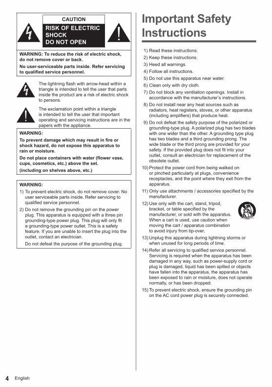
CAUTIONRISK OF ELECTRIC SHOCK DO NOT OPEN
WARNING: To reduce the risk of electric shock, do not remove cover or back.No user-serviceable parts inside. Refer servicing to qualified service personnel.
Thelightningflashwitharrow-headwithinatriangleisintendedtotelltheuserthatpartsinsidetheproductareariskofelectricshocktopersons.
Theexclamationpointwithinatriangleisintendedtotelltheuserthatimportantoperatingandservicinginstructionsareinthepaperswiththeappliance.
WARNING : To prevent damage which may result in fire or shock hazard, do not expose this apparatus to rain or moisture.Do not place containers with water (flower vase, cups, cosmetics, etc.) above the set.(including on shelves above, etc.)
WARNING : 1)Topreventelectricshock,donotremovecover.No
userserviceablepartsinside.Referservicingtoqualifiedservicepersonnel.
2)Donotremovethegroundingpinonthepowerplug.Thisapparatusisequippedwithathreepingrounding-typepowerplug.Thisplugwillonlyfitagrounding-typepoweroutlet.Thisisasafetyfeature.Ifyouareunabletoinserttheplugintotheoutlet,contactanelectrician.Donotdefeatthepurposeofthegroundingplug.
Important Safety Instructions 1)Readtheseinstructions.2)Keeptheseinstructions.3)Heedallwarnings.4)Followallinstructions.5)Donotusethisapparatusnearwater.6)Cleanonlywithdrycloth.7)Donotblockanyventilationopenings.Installin
accordancewiththemanufacturer’sinstructions.8)Donotinstallnearanyheatsourcessuchas
radiators,heatregisters,stoves,orotherapparatus(includingamplifiers)thatproduceheat.
9)Donotdefeatthesafetypurposeofthepolarizedorgrounding-typeplug.Apolarizedplughastwobladeswithonewiderthantheother.Agroundingtypeplughastwobladesandathirdgroundingprong.Thewidebladeorthethirdprongareprovidedforyoursafety.Iftheprovidedplugdoesnotfitintoyouroutlet,consultanelectricianforreplacementoftheobsoleteoutlet.
10)Protectthepowercordfrombeingwalkedonorpinchedparticularlyatplugs,conveniencereceptacles,andthepointwheretheyexitfromtheapparatus.
11)Onlyuseattachments/accessoriesspecifiedbythemanufacturer.
12)Useonlywiththecart,stand,tripod,bracket,ortablespecifiedbythemanufacturer,orsoldwiththeapparatus.Whenacartisused,usecautionwhenmovingthecart/apparatuscombinationtoavoidinjuryfromtip-over.
13)Unplugthisapparatusduringlightningstormsorwhenunusedforlongperiodsoftime.
14)Referallservicingtoqualifiedservicepersonnel.Servicingisrequiredwhentheapparatushasbeendamagedinanyway,suchaspower-supplycordorplugisdamaged,liquidhasbeenspilledorobjectshavefallenintotheapparatus,theapparatushasbeenexposedtorainormoisture,doesnotoperatenormally,orhasbeendropped.
15)Topreventelectricshock,ensurethegroundingpinontheACcordpowerplugissecurelyconnected.
5English
FCC STATEMENTThisequipmenthasbeentestedandfoundtocomplywiththelimitsforaclassAdigitaldevice,pursuanttoPart15oftheFCCRules.Theselimitsaredesignedtoprovidereasonableprotectionagainstharmfulinterferencewhentheequipmentisoperatedinacommercialenvironment.Thisequipmentgenerates,usesandcanradiateradiofrequencyenergyand,ifnotinstalledandusedinaccordancewiththeinstructionsmanual,maycauseharmfulinterferencetoradiocommunications.Operationofthisequipmentinaresidentialareaislikelytocauseharmfulinterferenceinwhichcasetheuserwillberequiredtocorrecttheinterferenceathisownexpense.
FCC CAUTION:To assure continued compliance, follow the attached installation instructions and use only the provided power supply cord. Any changes or modifications not expressly approved by Panasonic Corp. of North America could void the user’s authority to operate this device.
DeclarationofVerificationModelNo.
TH-43LFE8U,TH-48LFE8UTH-55LFE8U,TH-65LFE8U
ResponsibleParty:PanasonicCorporationofNorthAmericaTwoRiverfrontPlaza,Newark,NewJersey07102-5490
ContactSource:PanasonicSystemCommunicationsCompanyofNorthAmerica1-877-655-2357
GeneralContact:http://www.panasonic.com/contactinfo
ThisdevicecomplieswithPart15oftheFCCRulesandallapplicableICRSSstandards.Operationissubjecttothefollowingtwoconditions:(1)Thisdevicemaynotcauseharmfulinterference,and(2)thisdevicemustacceptanyinterferencereceived,includinginterferencethatmaycauseundesiredoperation.
CANADIAN NOTICE:ThisClassAdigitalapparatuscomplieswithCanadianICES-003.
WARNING:• NotforuseinacomputerroomasdefinedintheStandardfortheProtectionofElectronicComputer/DataProcessingEquipment,ANSI/NFPA75.
• Forpermanentlyconnectedequipment,areadilyaccessibledisconnectdeviceshallbeincorporatedinthebuildinginstallationwiring.
• Forpluggableequipment,thesocket-outletshallbeinstalledneartheequipmentandshallbeeasilyaccessible.
Note:Imageretentionmayoccur.Ifyoudisplayastillpictureforanextendedperiod,theimagemightremainonthescreen.However,itwilldisappearwhenageneralmovingpictureisdisplayedforawhile.
Trademark Credits• Microsoft®,Windows®,WindowsVista®,Windows®7,Windows®8andInternetExplorer®aretheregisteredtrademarksortrademarksofMicrosoftCorporationintheUnitedStatesand/orothercountries.
• Macintosh,Mac,MacOS,OSXandSafariarethetrademarksofAppleInc.registeredintheUnitedStatesandothercountries.
• PJLinkisaregisteredorpendingtrademarkinJapan,theUnitedStates,andothercountriesandregions.
• HDMI,theHDMILogo,andHigh-DefinitionMultimediaInterfacearetrademarksorregisteredtrademarksofHDMILicensingLLCintheUnitedStatesandothercountries.
• JavaScriptisaregisteredtrademarkoratrademarkofOracleCorporationanditssubsidiaryandassociatedcompaniesintheUnitedStatesand/orothercountries.
• RoomView,CrestronRoomViewandFusionRVareregisteredtrademarksofCrestronElectronics,Inc,andCrestronConnectedisthetrademarkofCrestronElectronics,Inc.
Evenifnospecialnotationhasbeenmadeofcompanyorproducttrademarks,thesetrademarkshavebeenfullyrespected.

English6
Important Safety Notice
WARNING1)Topreventdamagewhichmayresultinfireor
shockhazard,donotexposethisappliancetodrippingorsplashing.Donotplacecontainerswithwater(flowervase,cups,cosmetics,etc.)abovetheset.(includingonshelvesabove,etc.)Nonakedflamesources,suchaslightedcandles,shouldbeplacedon/abovetheset.
2)Topreventelectricshock,donotremovecover.Nouserserviceablepartsinside.Referservicingtoqualifiedservicepersonnel.
3)Donotremovetheearthingpinonthepowerplug.Thisapparatusisequippedwithathreepinearthing-typepowerplug.Thisplugwillonlyfitanearthing-typepoweroutlet.Thisisasafetyfeature.Ifyouareunabletoinserttheplugintotheoutlet,contactanelectrician.Donotdefeatthepurposeoftheearthingplug.
4)Topreventelectricshock,ensuretheearthingpinontheACcordpowerplugissecurelyconnected.
CAUTIONThisapplianceisintendedforuseinenvironmentswhicharerelativelyfreeofelectromagneticfields.Usingthisappliancenearsourcesofstrongelectromagneticfieldsorwhereelectricalnoisemayoverlapwiththeinputsignalscouldcausethepictureandsoundtowobbleorcauseinterferencesuchasnoisetoappear.Toavoidthepossibilityofharmtothisappliance,keepitawayfromsourcesofstrongelectromagneticfields.
WARNINGThisisaclassAproduct.Inadomesticenvironmentthisproductmaycauseradiointerferenceinwhichcasetheusermayberequiredtotakeadequatemeasures.
IMPORTANT: THE MOULDED PLUG FOR YOUR SAFETY, PLEASE READ THE FOLLOWING TEXT CAREFULLY.Thisdisplayissuppliedwithamouldedthreepinmainsplugforyoursafetyandconvenience.A5ampfuseisfittedinthisplug.Shallthefuseneedtobereplaced,pleaseensurethatthereplacementfusehasaratingof5ampsandthatitisapprovedbyASTAorBSItoBS1362.
CheckfortheASTAmark ortheBSImark onthebodyofthefuse.Iftheplugcontainsaremovablefusecover,youmustensurethatitisrefittedwhenthefuseisreplaced.Ifyoulosethefusecovertheplugmustnotbeuseduntilareplacementcoverisobtained.AreplacementfusecovercanbepurchasedfromyourlocalPanasonicdealer.Donotcutoffthemainsplug.Donotuseanyothertypeofmainsleadexcepttheonesuppliedwiththisdisplay.Thesuppliedmainsleadandmouldedplugaredesignedtobeusedwiththisdisplaytoavoidinterferenceandforyoursafety.Ifthesocketoutletinyourhomeisnotsuitable,getitchangedbyaqualifiedelectrician.Iftheplugormainsleadbecomesdamaged,purchaseareplacementfromanauthorizeddealer.
WARNING : — THIS DISPLAY MUST BE EARTHED.
How to replace the fuse.Openthefusecompartmentwithascrewdriverandreplacethefuse.

7English
Safety PrecautionsWARNING
■ SetupThis LCD Display is for use only with the following optional accessories.Use with any other type of optional accessories may cause instability which could result in the possibility of injury.(AllofthefollowingaccessoriesaremanufacturedbyPanasonicCorporation.)• Pedestal
TY-ST43PE8(for43/48/55-inchmodels)TY-ST65PE8(for65-inchmodel)
Wearenotresponsibleforanyproductdamage,etc.causedbyfailuresintheinstallationenvironmentforthepedestalorwall-hangingbracketevenduringthewarrantyperiod.Alwaysbesuretoaskaqualifiedtechniciantocarryoutset-up.Smallpartscanpresentchokinghazardifaccidentallyswallowed.Keepsmallpartsawayfromyoungchildren.Discardunneededsmallpartsandotherobjects,includingpackagingmaterialsandplasticbags/sheetstopreventthemfrombeingplayedwithbyyoungchildren,creatingthepotentialriskofsuffocation.Do not place the Display on sloped or unstable surfaces and ensure that the Display does not hang over the edge of the base.• TheDisplaymayfalloffortipover.
Install this unit at a location with minimal vibration and which can support the weight of the unit.• Droppingorfallingoftheunitmaycauseinjuryormalfunction.
Do not place any objects on top of the Display.• IfforeignobjectsorwatergetinsidetheDisplay,ashort-circuitmayoccurwhichcouldresultinfireorelectricshock.IfanyforeignobjectsgetinsidetheDisplay,pleaseconsultyourlocalPanasonicdealer.
Transport only in upright position!• Transportingtheunitwithitsdisplaypanelfacinguprightordownwardmaycausedamagetotheinternalcircuitry.
Ventilation should not be impeded by covering the ventilation openings with items such as newspapers, table cloths and curtains.For sufficient ventilation, see page 9.
Caution - For use only with UL Listed Wall Mount Bracket with minimum weight/load 36.2kg.
When installing the Display vertically;WheninstallingtheDisplayvertically,besurethatthePowerIndicatorcomestothedownside.HeatisgeneratedanditmaycausefireordamagetotheDisplay.
Powerindicator
43/48/55-inchmodels65-inchmodel
Cautions for Wall or Pedestal Installation• WallorPedestalinstallationshouldbeperformedbyaninstallationprofessional.InstallingtheDisplayincorrectlymayleadtoanaccidentthatresultsindeathorseriousinjury.UsetheoptionalPedestal.
• Wheninstallingonawall,awallhangingbracketthatconformstoVESAstandardsmustbeused.
• 43/48-inchmodels:VESA200×20055/65-inchmodels:VESA400×400(seepage9)
• IfyouterminatetheuseoftheDisplayontheWallorPedestal,askaprofessionaltoremovetheDisplayassoonaspossible.
• WhenmountingtheDisplayonthewall,preventthemountingscrewsandpowercablefromcontactingmetalobjectsinsidethewall.Anelectricshockmayoccuriftheycontactmetalobjectsinsidethewall.
Do not install the product to a place where the product is exposed to direct sunlight.• Ifthescreenisexposedtodirectsunlight,theliquidcrystalpanelmayhaveadverseeffect.
■When using the LCD DisplayThe Display is designed to operate on 110 - 127 or 220 - 240 V AC, 50/60 Hz.Do not cover the ventilation holes.• DoingsomaycausetheDisplaytooverheat,whichcancausefireordamagetotheDisplay.
Do not stick any foreign objects into the Display.• DonotinsertanymetalorflammableobjectsintotheventilationsholesordropthemontotheDisplay,asdoingsocancausefireorelectricshock.
Do not remove the cover or modify it in any way.• HighvoltageswhichcancausesevereelectricshocksarepresentinsidetheDisplay.Foranyinspection,adjustmentandrepairwork,pleasecontactyourlocalPanasonicdealer.
English8
Ensure that the mains plug is easily accessible.65-inch model
The mains plug shall be connected to a mains socket outlet with a protective earthing connection.
Do not use any power supply cord other than that provided with this unit.• Doingsomaycauseshort-circuit,generatesheat,etc.,whichcouldcauseelectricshockorfire.
Do not use the supplied power supply cord with any other devices.• Doingsocouldcauseelectricshockorfire.
Securely insert the power supply plug as far as it will go.• Iftheplugisnotfullyinserted,heatmaybegeneratedwhichcouldcausefire.Iftheplugisdamagedorthewallsocketisloose,theyshallnotbeused.
Do not handle the power supply plug with wet hands.• Doingsomaycauseelectricshocks.
Do not do anything that may damage the power cable. When disconnecting the power cable, pull on the plug body, not the cable.• Donotdamagethecable,makeanymodificationstoit,placeheavyobjectsontopofit,heatit,placeitnearanyhotobjects,twistit,benditexcessivelyorpullit.Todosomaycausefireandelectricshock.Ifthepowercableisdamaged,haveitrepairedatyourlocalPanasonicdealer.
Do not remove covers and NEVER modify the Display yourself• Donotremovetherearcoveraslivepartsareaccessiblewhenitisremoved.Therearenouserserviceablepartsinside.(High-voltagecomponentsmaycauseseriouselectricalshock.)
• HavetheDisplaychecked,adjusted,orrepairedatyourlocalPanasonicdealer.
Keep the supplied AAA/R03/UM4 batteries out of reach of children. If accidentally swallowed, it will be harmful to the body.• Pleasecontactadoctorimmediatelyincaseyoudoubtthatthechildmayhaveswallowedit.
If the Display is not going to be used for any prolonged length of time, unplug the power supply plug from the wall outlet.Picture noise may occur if you connect / disconnect the connection cables of the input terminals you are currently not watching, or if you turn the power of the video equipment on / off, but it is not a malfunction.
To prevent the spread of fire, keep candles or other open flames away from this product at all times.
CAUTION
If problems or malfunction occur, stop using immediately.
■ If problems occur, unplug the power supply plug.
• Smokeoranabnormalodourcomeoutfromtheunit.• Nopictureappearsornosoundisheard,occasionally.
• Liquidsuchaswaterorforeignobjectsgotinsidetheunit.
• Theunithasdeformedorbrokenparts.If you continue to use the unit in this condition, it could result in fire or electric shock.• Turnthepoweroffimmediately,unplugthepowersupplyplugfromthewalloutlet,andthencontactthedealerforrepairs.
• TocutoffthepowersupplytothisDisplaycompletely,youneedtounplugthepowersupplyplugfromthewalloutlet.
• Repairingtheunityourselfisdangerous,andshallneverbedone.
• Toenabletounplugthepowersupplyplugimmediately,usethewalloutletwhichyoucanreacheasily.
■When using the LCD Display Do not bring your hands, face or objects close to the ventilation holes of the Display.• HeatedaircomesoutfromtheventilationholesatthetopofDisplaywillbehot.Donotbringyourhandsorface,orobjectswhichcannotwithstandheat,closetothisport,otherwiseburnsordeformationcouldresult.
At least 2 people are required to carry or unpack this unit.• Ifthisisnotobserved,theunitmaydrop,resultingininjury.
Be sure to disconnect all cables before moving the Display.• IftheDisplayismovedwhilesomeofthecablesarestillconnected,thecablesmaybecomedamaged,andfireorelectricshockcouldresult.
Disconnect the power supply plug from the wall socket as a safety precaution before carrying out any cleaning.• Electricshockscanresultifthisisnotdone.
Clean the power cable regularly to prevent it becoming dusty.• Ifdustbuiltuponthepowercordplug,theresultanthumiditycandamagetheinsulation,whichcouldresultinfire.Pullthepowercordplugoutfromthewalloutletandwipethemainsleadwithadrycloth.
Do not step on, or hang from the display or the Pedestal.• Theymighttipover,ormightbebrokenanditmayresultininjury.Payspecialattentiontothechildren.

9English
Do not reverse the polarity (+ and -) of the battery when inserting.• Mishandlingthebatterymaycauseitsexplosionorleakage,resultinginfire,injuryordamagetosurroundingproperties.
• Insertthebatterycorrectlyasinstructed.(seepage12)
Remove the batteries from the remote control transmitter when not using for a long period of time.• Thebatterymayleak,heat,igniteorburst,resultinginfireordamagetosurroundingproperties.
Do not burn or breakup batteries.• Batteriesmustnotbeexposedtoexcessiveheatsuchassunshine,fireorthelike.
Precautions for useCautions when installing
Do not set up the Display outdoors.• TheDisplayisdesignedforindooruse.
Environmental temperature to use this unit• Whenusingtheunitwhereitisbelow1400m(4593ft)abovesealevel:0°Cto40°C(32°Fto104°F)
• Whenusingtheunitathighaltitudes(1400m(4593ft)andhigherandbelow2800m(9186ft)abovesealevel):0°Cto35°C(32°Fto95°F)
Do not install the unit where it is 2 800 m (9 186 ft) and higher above sea level.• Failuretodosomayshortenthelifeoftheinternalpartsandresultinmalfunctions.
About space when installingWhen using the pedestal (optional accessory), leave a space of 10 cm (3 15/16”) or more at the top, left and right, and 5 cm (1 31/32”) or more at the rear, and also keep the space between the bottom of the display and the floor surface.If using some other setting-up method, follow the manual of it. (If there is no specific indication of installation dimension in the installation manual, leave a space of 10 cm (3 15/16”) or more at the top, bottom, left and right, and 5 cm (1 31/32”) or more at the rear.)Minimumdistance:
a
ab a:10cm
(315/16”)b:5cm(131/32”)
a
About the screws used when using a wall hanging bracket that conforms to VESA standardsInch model
Screw pitch for installation
Depth of screw hole
Screw (quantity)
43 200mm×200mm 16mm M6(4)48 200mm×200mm 16mm M6(4)55 400mm×400mm 16mm M6(4)65 400mm×400mm 20mm M8(4)
For43/48/55-inchmodelsScrewholesotherthantheabovehavealsobeenprovidedonthisunit,however,thescrewholesintheabovetablearerecommended.
English10
Be careful of the movable structure of the power indicator and remote control sensor.• Asfactorydefault,thepowerindicatorandremotecontrolsensorarestoredinthemainunit.Fornormaluse,pullouttheremotecontrolsensorfromtheedgesideofthemainunitbyoperatingtheleverontherearpanel.Dependingonthesetupconditionsuchaswhenusingthemultidisplay,storetheremotecontrolsensorinthemainunit.(seepage23)
Do not grab the liquid crystal panel.• Donotforciblypresstheliquidcrystalpanel,orpushitwithapointedobject.Applyingastrongforcetotheliquidcrystalpanelwillcauseunevennessofthescreendisplay,resultinginmalfunction.
Depending on the temperature or humidity conditions, uneven brightness may be observed. This is not a malfunction.• Thisunevennesswilldisappearwhileapplyingcurrentcontinuously.Ifnot,consultthedistributor.
Cleaning and maintenanceThe front of the display panel has been specially treated. Wipe the surface of the display panel gently using only a cleaning cloth or a soft, lint-free cloth.• Ifthesurfaceisparticularlydirty,wipewithasoft,lint-freeclothwhichhasbeensoakedinpurewaterorwaterinwhichneutraldetergenthasbeendiluted100times,andthenwipeitevenlywithadryclothofthesametypeuntilthesurfaceisdry.
• Donotscratchorhitthesurfaceofthepanelwithfingernailsorotherhardobjects,otherwisethesurfacemaybecomedamaged.Furthermore,avoidcontactwithvolatilesubstancessuchasinsectsprays,solventsandthinner,otherwisethequalityofthesurfacemaybeadverselyaffected.
If the cabinet becomes dirty, wipe it with a soft, dry cloth.• Ifthecabinetisparticularlydirty,soaktheclothinwatertowhichasmallamountofneutraldetergenthasbeenaddedandthenwringtheclothdry.Usethisclothtowipethecabinet,andthenwipeitdrywithadrycloth.
• DonotallowanydetergenttocomeintodirectcontactwiththesurfaceoftheDisplay.Ifwaterdropletsgetinsidetheunit,operatingproblemsmayresult.
• Avoidcontactwithvolatilesubstancessuchasinsectsprays,solventsandthinner,otherwisethequalityofthecabinetsurfacemaybeadverselyaffectedorthecoatingmaypeeloff.Furthermore,donotleaveitforlongperiodsincontactwitharticlesmadefromrubberorPVC.
Usage of a chemical cloth• Donotuseachemicalclothforthepanelsurface.• Followtheinstructionsforthechemicalclothtouseitforthecabinet.
Wired LANWhen setting up the Display at a place, where electric statistic occurs often, take a sufficient anti-static measure before start using.• WhentheDisplayisusedatalocation,wherestaticelectricityoccursoften,suchasonacarpet,communicationsofthewiredLANaredisconnectedmoreoften.Inthatcase,removestaticelectricityandthenoisesourcethatmaycauseproblemswithanantistaticmat,andre-connectthewiredLAN.
• Inrarecases,theLANconnectionisdisabledduetostaticelectricityornoise.Inthatcase,turnoffthepoweroftheDisplayandtheconnecteddevicesonceandthenre-turnonthepower.ConnecttheLAN.
The Display may not work properly due to strong radio wave from the broadcast station or the radio.• Ifthereisanyfacilityorequipment,whichoutputsstrongradiowave,neartheinstallationlocation,setuptheDisplayatalocationsufficientlyfarfromthesourceoftheradiowave.Or,wraptheLANcableconnectedtotheLANterminalbyusingapieceofmetalfoilorametalpipe,ofwhichisgroundedatbothends.
Disposal When disposing the product, ask your local authority or dealer about the correct methods of disposal.
11English
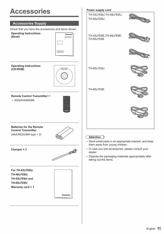
AccessoriesAccessories Supply
CheckthatyouhavetheaccessoriesanditemsshownOperating Instructions (Book)
Operating Instructions (CD-ROM)
Remote Control Transmitter×1●N2QAYA000099
Batteries for the Remote Control Transmitter(AAA/R03/UM4type×2)
Clamper × 3
For TH-43LFE8U, TH-48LFE8U, TH-55LFE8U and TH-65LFE8UWarranty card × 1
Power supply cordTH-43LFE8U,TH-48LFE8U,TH-55LFE8U
TH-43LFE8E,TH-48LFE8E,TH-55LFE8E
TH-65LFE8U
TH-65LFE8E
Attention●Storesmallpartsinanappropriatemanner,andkeepthemawayfromyoungchildren.
● Incaseyoulostaccessories,pleaseconsultyourdealer.
●Disposethepackagingmaterialsappropriatelyaftertakingouttheitems.

English12
Remote Control Batteries1. Pullandholdthehook,thenopenthebatterycover.
2. Insertbatteries-notecorrectpolarity(+and-).
AAA/R03/UM4type
3.Replacethecover.
Helpful Hint● Forfrequentremotecontrolusers,replaceoldbatterieswithAlkalinebatteriesforlongerlife.
Precaution on battery use
Incorrectinstallationcancausebatteryleakageandcorrosionthatwilldamagetheremotecontroltransmitter.Disposalofbatteriesshouldbeinanenvironment-friendlymanner.Observe the following precaution:1. Batteriesshallalwaysbereplacedasapair.Always
usenewbatterieswhenreplacingtheoldset.2. Donotcombineausedbatterywithanewone.3. Donotmixbatterytypes(example:“ZincCarbon”with
“Alkaline”).4. Donotattempttocharge,short-circuit,disassemble,
heatorburnusedbatteries.5. Batteryreplacementisnecessarywhenremote
controlactssporadicallyorstopsoperatingtheDisplayset.
6. Donotburnorbreakupbatteries.7. Batteriesmustnotbeexposedtoexcessiveheatsuch
assunshine,fireorthelike.
Kensington securityThissecurityslotiscompatiblewiththeKensingtonsecuritycables.
43-inch model
48-inch model
55-inch model
65-inch model
13English
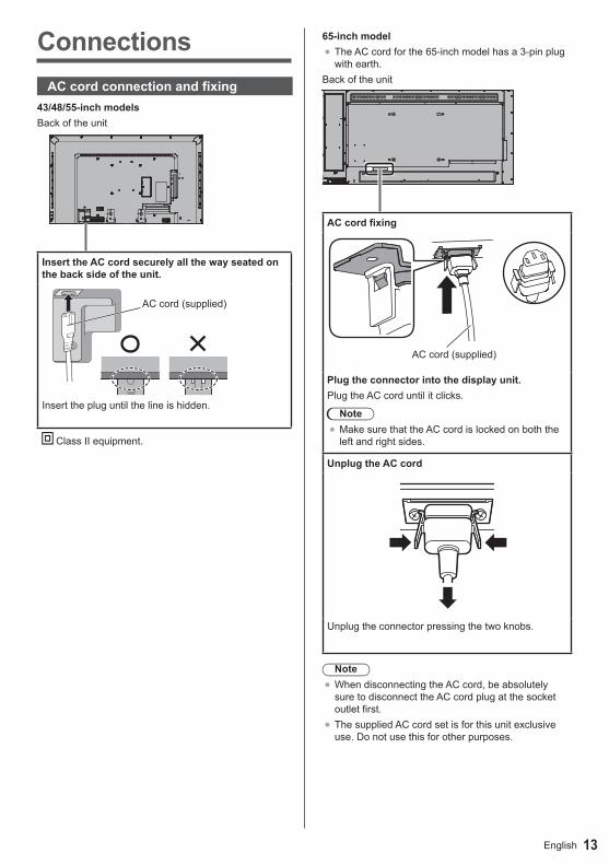
ConnectionsAC cord connection and fixing
43/48/55-inch modelsBack of the unit
Insert the AC cord securely all the way seated on the back side of the unit.
Class II equipment.
65-inch model●The AC cord for the 65-inch model has a 3-pin plug
with earth.Back of the unit
AC cord fixing
AC cord (supplied)
Plug the connector into the display unit.Plug the AC cord until it clicks.
Note●Make sure that the AC cord is locked on both the
left and right sides.
Unplug the AC cord
Unplug the connector pressing the two knobs.
Note●When disconnecting the AC cord, be absolutely
sure to disconnect the AC cord plug at the socket outlet first.
●The supplied AC cord set is for this unit exclusive use. Do not use this for other purposes.
AC cord (supplied)
Insert the plug until the line is hidden.

English14
Cable fixingNote
●3 clampers are supplied with this unit. Fix the cables at 3 locations using the holes of clampers as shown below.If you need more clampers, purchase them from your dealer. (Available from the customer service)
Keep pushing both side snaps
hole
1. Attach the clamper
Insert the clamper in a hole.
To remove from the unit:
snaps
Keep pushing the knob
hooks
2. Bundle the cables
Set the tip in the hooks
To loosen:
knob
15English
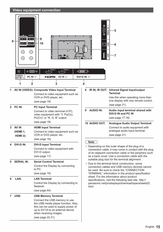
Video equipment connection
1 AV IN (VIDEO): Composite Video Input TerminalConnect to video equipment such as VCR or DVD player, etc.(see page 19)
2 PC IN: PC Input TerminalConnect to video terminal of PC, video equipment with “Y, PB(CB), PR(CR)” or “R, G, B” output.(see page 18)
3 AV IN(HDMI 1, HDMI 2):
HDMI Input TerminalConnect to video equipment such as VCR or DVD player, etc.(see page 16)
4 DVI-D IN: DVI-D Input TerminalConnect to video equipment with DVI-D output.(see page 17)
5 SERIAL IN: Serial Control TerminalControl the Display by connecting to PC.(see page 19)
6 LAN: LAN TerminalControl the Display by connecting to Network.(see page 64)
7 USB: USB Memory TerminalConnect the USB memory to use the USB media player function. Also, this can be used to supply power of up to 5V/1A to an external device when receiving images.(see page 22,31)
8 IR IN, IR OUT: Infrared Signal Input/output TerminalUse this when operating more than one display with one remote control.(see page 21)
9 AUDIO IN: Audio input terminal shared with DVI-D IN and PC IN(see page 17,18)
10 AUDIO OUT: Analogue Audio Output TerminalConnect to audio equipment with analogue audio input terminal.(see page 21)
Note●Depending on the outer shape of the plug of a
connection cable, it may come in contact with the plug of an adjacent connection cable or the periphery such as a back cover. Use a connection cable with the suitable plug size for the terminal alignment.
●Due to the terminal block construction, some connection cables and USB memory devices cannot be used. Be sure to check the “CONNECTION TERMINAL” information in the product specification sheet. For the information about product specifications, visit the following web site. http://panasonic.net/prodisplays/download/specsheets02.html

English16
HDMI 1 and 2 terminals connectionNote
●Additional equipment and HDMI cable shown are not supplied with this set.
●Some HDMI equipment may not be able to display picture.
HDMI cable (not supplied) Video Cassette Recorder DVD Player
Pin assignments and signal names for HDMI Terminal
Pin No. Signal nameT.M.D.S Data2+T.M.D.S Data2 ShieldT.M.D.S Data2-T.M.D.S Data1+T.M.D.S Data1 ShieldT.M.D.S Data1-T.M.D.S Data0+T.M.D.S Data0 ShieldT.M.D.S Data0-T.M.D.S Clock+T.M.D.S Clock ShieldT.M.D.S Clock-CEC
SCLSDADDC/CEC Ground+5V DCHot Plug Detect
17English
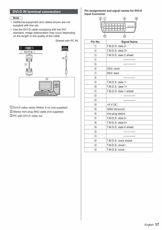
DVI-D IN terminal connectionNote
●Additional equipment and cables shown are not supplied with this set.
●Use the DVI-D cable complying with the DVI standard. Image deterioration may occur depending on the length or the quality of the cable.
Shared with PC IN.
DVI-D video cable (Within 5 m) (not supplied) Stereo mini plug (M3) cable (not supplied) PC with DVI-D video out
Pin assignments and signal names for DVI-D Input Connector
Pin No. Signal NameT.M.D.S. data 2-T.M.D.S. data 2+T.M.D.S. data 2 shield
DDC clockDDC data
T.M.D.S. data 1-T.M.D.S. data 1+T.M.D.S. data 1 shield
+5 V DCGND (Ground)Hot plug detect T.M.D.S. data 0-T.M.D.S. data 0+ T.M.D.S. data 0 shield
T.M.D.S. clock shieldT.M.D.S. clock+T.M.D.S. clock-
English18
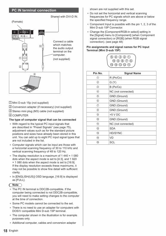
PC IN terminal connection
Connect a cable which matches the audio output terminal on the computer.(not supplied)
(Male)
(Female)
Shared with DVI-D IN.
Mini D-sub 15p (not supplied) Conversion adapter (if necessary) (not supplied) Stereo mini plug (M3) cable (not supplied) COMPUTER
The type of computer signal that can be connected●With regard to the typical PC input signals that
are described in “Preset Signals” (see page 75), adjustment values such as for the standard picture positions and sizes have already been stored in this unit. You can add up to eight PC input signal types that are not included in the list.
●Computer signals which can be input are those with a horizontal scanning frequency of 30 to 110 kHz and vertical scanning frequency of 48 to 120 Hz.
●The display resolution is a maximum of 1 440 × 1 080 dots when the aspect mode is set to [4:3], and 1 920 × 1 080 dots when the aspect mode is set to [16:9]. If the display resolution exceeds these maximums, it may not be possible to show fine detail with sufficient clarity.
● In [ENGLISH(US)] OSD language, [16:9] is displayed as [FULL].
Note●The PC IN terminal is DDC2B-compatible. If the
computer being connected is not DDC2B-compatible, you will need to make setting changes to the computer at the time of connection.
●Some PC models cannot be connected to the set.●There is no need to use an adapter for computers with
DOS/V compatible Mini D-sub 15P terminal.●The computer shown in the illustration is for example
purposes only.●Additional computer, cables and conversion adapter
shown are not supplied with this set.●Do not set the horizontal and vertical scanning
frequencies for PC signals which are above or below the specified frequency range.
●Component Input is possible with the pin 1, 2, 3 of the Mini D-sub 15P Connector.
●Change the [Component/RGB-in select] setting in the [Signal] menu to [Component] (when Component signal connection) or [RGB] (when RGB signal connection). (see page 48)
Pin assignments and signal names for PC Input Terminal (Mini D-sub 15P)
1678
39
4510
15 14 13 12 11
2
Pin No. Signal NameR (PR/CR)G (Y) B (PB/CB)NC (not connected)GND (Ground)GND (Ground)GND (Ground)GND (Ground)+5 V DCGND (Ground)NC (not connected)SDAHD/SYNCVDSCL

19English
VIDEO terminal connectionNote
●Video equipment, connection cables and conversion plugs are not supplied with this unit.
Yellow
White
Red
4-pole mini plug conversion cable (commercially available)
Audio video pin cable Video Cassette Recorder DVD Player
Wiring specifications for 4-pole mini plug
Note●Use a 4-pole mini plug (M3) with the following
wiring specifications for the VIDEO terminal of this unit. If the wiring of a plug is different, audio and video are not correctly input.
1
34
2
Audio L (White)Video (Yellow)GND (Ground)Audio R (Red)
SERIAL terminal connectionThe SERIAL terminal conforms to the RS-232C interface specification, so that the Display can be controlled by a computer which is connected to this terminal.
(Male)
(Female)
(D-sub 9p)
RS-232C Straight cable (not supplied) COMPUTER, etc.
Note●Use the RS-232C straight cable to connect the
computer to the Display.●The computer shown is for example purposes only.●Additional computer and cables shown are not
supplied with this set.
The computer will require software which allows the sending and receiving of control data which satisfies the conditions given below. Use a computer application such as programming language software. Refer to the documentation for the computer application for details.

English20
Pin assignments and signal names for SERIAL Terminal
6 7 8 9
1 3 4 52
Pin No. Signal NameNC (not connected)RXDTXDNon useGND (Ground)Non useRTS
Shorted in this setCTSNC (not connected)
These signal names are those of computer specifications.
Communication parametersSignal level: RS-232C compliantSynchronization method: AsynchronousBaud rate: 9600 bpsParity: NoneCharacter length: 8 bitsStop bit: 1 bitFlow control: None
Basic format for control dataThe transmission of control data from the computer starts with a STX signal, followed by the command, the parameters, and lastly an ETX signal in that order. If there are no parameters, then the parameter signal does not need to be sent.
STX C1 C2 C3 P1 P2 P3 P4: P5 ETX
Start (02h)
3-character command (3 bytes)
Colon
Parameter(s)
End (03h)
Command
Command Parameter Control detailsPON None Power ON
POF None Power OFF
AVL *** Volume 000 - 100
AMT0 Audio MUTE OFF
1 Audio MUTE ON
IMS None Input select (toggle)
HM1 HDMI 1 input (HDMI1)
HM2 HDMI 2 input (HDMI2)
DV1 DVI-D IN input (DVI-D)
PC1 PC IN input (PC)
VD1 VIDEO input (VIDEO)
UD1 USB input (USB)
Note● If multiple commands are transmitted, be sure to wait
for the response for the first command to come from this unit before sending the next command.
● If an incorrect command is sent by mistake, this unit will send an “ER401” command back to the computer.
● In Standby condition (power OFF with remote control), the unit responds to PON command only.
●Consult your local Panasonic dealer for detail instructions on command usage.

21English
IR IN/OUT terminal connection
Connect the mini plug (M3) cable from the IR OUT
terminal of the first display to the IR IN terminal of the
second display.
The infrared signal of the first display is sent to the
second display.
In this case, the IR (infrared ray reception on the remote
control sensor) on the second display does not operate.
Repeating the above connections enables the daisy
chain connection.
Note●Connection cables are not supplied with this unit.
Mini plug (M3) cable (commercially available) First display Second display Third display
AUDIO OUT terminal connection
line-in
Stereophonic sound code (not supplied) Audio equipment
Note●Audio equipment and the cable shown are not
supplied with this set.●To output sound from AUDIO OUT Terminal of the
unit, be sure to set [Output select] in the [Sound] menu to [AUDIO OUT]. (see page 40)

English22
USB terminal connectionConnect the USB memory to use the USB media player function. (see page 31)Also, power is supplied when a separately sold stick PC, etc. are connected.
Note●A stick PC and connection cables are not supplied
with this unit.
Stick PC USB cable (commercially available) HDMI extension cable (commercially available)
Pin assignments and signal names for USB Terminal
1 3 42
Pin No. Signal name+5 V DCDATA -DATA +GND (Ground)
Power of up to 5V/1A can be supplied to an external device when receiving images.● If the electric current exceeding the power supplying
capability is applied, the output is blocked, and the following message is displayed. [USB DC5V OUT overload. Please remove cable or equipment, then turn the display off / on.]
In this case, remove the equipment and then turn the power off/on using the remote control, etc.
Note● If the direct connection to this unit is not possible due
to the size of a stick PC, etc. use a commercially sold extension cable.
●Depending on the type of a USB memory device, it may come in contact with the periphery such as a back cover, and cannot be attached. Use a commercially sold extension cable, or use a small type of a USB memory device connectable to this unit.

23English
Identifying ControlsMain Unit
43/48/55-inch models
65-inch model
●For normal use, pull out the power indicator and remote control sensor from the edge side of the main unit by operating the lever on the rear panel. Depending on the setup condition such as when using the multi display, store them in the main unit.
Note●For normal use, pull out the power indicator and
remote control sensor from the edge side of the main unit by operating the lever on the rear panel. Depending on the setup condition such as when using the multi display, store them in the main unit.
1 Power Indicator / Remote control sensor The Power Indicator will light.When the power of the unit is ON (Main Power On /
Off switch: ON)●Picture is displayed: Green●Power OFF (Standby) with remote control: Red
When [Network control] is set to [On] (see page 55) : Orange (Red/Green)
●Power OFF with “Power management” function: Orange (Red/Green)
“Power management” function (see page 51)When the power of the unit is OFF (Main Power On Off switch: OFF): No light
NoteThe unit will still consume some power as long as the power cord is still inserted into the wall outlet.When the power indicator is orange, power consumption during standby is generally larger than that of when the power indicator is red.
MENU ENTERINPUT + -
1 External Input Terminal●Connect to video equipment, PC, etc. (see page
15)2 <Main Power On / Off switch>
●Turns the power On / Off.3 <INPUT (Unit)> (INPUT signal selection)
●Selects the connected device. (see page 27)4 <MENU (Unit)>
●Each time the <MENU (Unit)> button is pressed, the menu screen will switch. (see page 36)
5 <+ (Unit)> / <- (Unit)> ●Volume Up “+” Down “–”●Adjusts the volume. Also, switches the settings or
adjusts the level on the main screen. (see page 28, 36)
6 < ▲ (Unit)> / < ▼ (Unit)> ●Selects the setting item. (see page 36)
7 <ENTER (Unit)>●Configures the item on menu screen. (see page
36)●Switches aspect mode. (see page 29)
English24
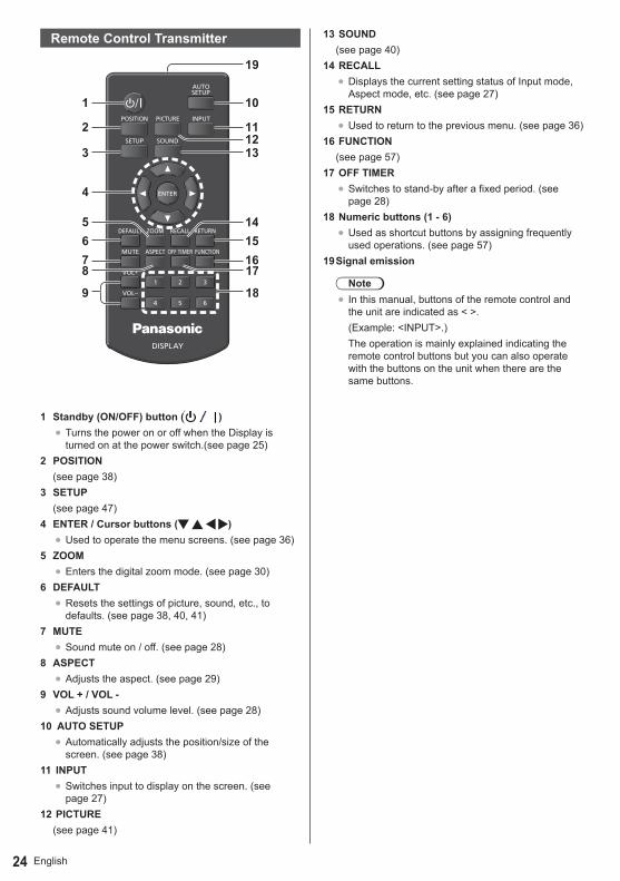
Remote Control Transmitter
1 Standby (ON/OFF) button ( )●Turns the power on or off when the Display is
turned on at the power switch.(see page 25) 2 POSITION
(see page 38)3 SETUP
(see page 47)4 ENTER / Cursor buttons ( )
●Used to operate the menu screens. (see page 36)5 ZOOM
●Enters the digital zoom mode. (see page 30)6 DEFAULT
●Resets the settings of picture, sound, etc., to defaults. (see page 38, 40, 41)
7 MUTE●Sound mute on / off. (see page 28)
8 ASPECT●Adjusts the aspect. (see page 29)
9 VOL + / VOL -●Adjusts sound volume level. (see page 28)
10 AUTO SETUP●Automatically adjusts the position/size of the
screen. (see page 38)11 INPUT
●Switches input to display on the screen. (see page 27)
12 PICTURE(see page 41)
13 SOUND(see page 40)
14 RECALL●Displays the current setting status of Input mode,
Aspect mode, etc. (see page 27)15 RETURN
●Used to return to the previous menu. (see page 36)16 FUNCTION
(see page 57)17 OFF TIMER
●Switches to stand-by after a fixed period. (see page 28)
18 Numeric buttons (1 - 6)●Used as shortcut buttons by assigning frequently
used operations. (see page 57)19 Signal emission
Note● In this manual, buttons of the remote control and
the unit are indicated as < >.(Example: <INPUT>.)The operation is mainly explained indicating the remote control buttons but you can also operate with the buttons on the unit when there are the same buttons.
25English
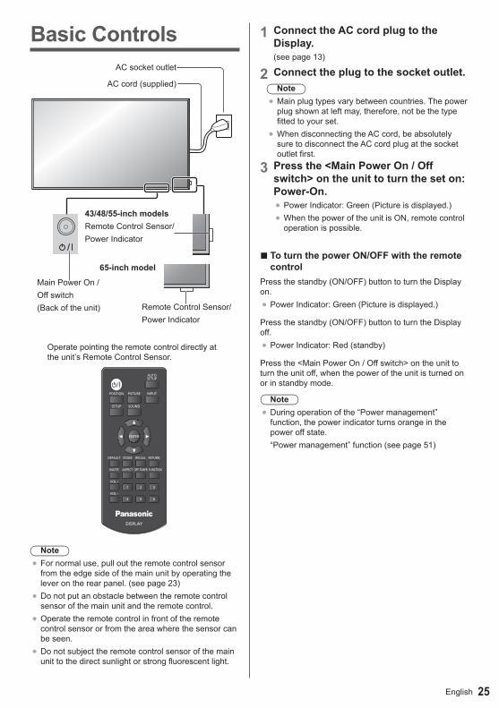
Basic Controls
MUTE
Main Power On /Off switch(Back of the unit)
43/48/55-inch modelsRemote Control Sensor/Power Indicator
Remote Control Sensor/Power Indicator
AC socket outlet
AC cord (supplied)
Operate pointing the remote control directly at the unit’s Remote Control Sensor.
Note●For normal use, pull out the remote control sensor
from the edge side of the main unit by operating the lever on the rear panel. (see page 23)
●Do not put an obstacle between the remote control sensor of the main unit and the remote control.
●Operate the remote control in front of the remote control sensor or from the area where the sensor can be seen.
●Do not subject the remote control sensor of the main unit to the direct sunlight or strong fluorescent light.
1 Connect the AC cord plug to the Display.(see page 13)
2 Connect the plug to the socket outlet.Note
●Main plug types vary between countries. The power plug shown at left may, therefore, not be the type fitted to your set.
●When disconnecting the AC cord, be absolutely sure to disconnect the AC cord plug at the socket outlet first.
3 Press the <Main Power On / Off switch> on the unit to turn the set on: Power-On.●Power Indicator: Green (Picture is displayed.)●When the power of the unit is ON, remote control
operation is possible.
■ To turn the power ON/OFF with the remote control
Press the standby (ON/OFF) button to turn the Display on.●Power Indicator: Green (Picture is displayed.)
Press the standby (ON/OFF) button to turn the Display off.●Power Indicator: Red (standby)
Press the <Main Power On / Off switch> on the unit to turn the unit off, when the power of the unit is turned on or in standby mode.
Note●During operation of the “Power management”
function, the power indicator turns orange in the power off state.“Power management” function (see page 51)
65-inch model

English26
■ When the Unit is turned on for the first timeFollowing screen will be displayed.
1 Select the language with and press <ENTER>.
English (UK)DeutschFrançaisItalianoEspañol
ENGLISH (US)
Русский
OSD language
2 Select [Year] / [Month] / [Day] / [Hour] / [Minute] with and set with .
Date and time
Set- - - - - - : - -- - - - / - - / - -
Year - - - -MonthDayHourMinute
- -- -- -- -
3 Select [Set] with and press <ENTER>.
Date and time
SetTHURSDAY 10:202015/01/01
Year 2015MonthDayHourMinute
111020
4 For vertical installation, select [Portrait] with and press <ENTER>.
Display orientation
LandscapePortrait
Note●Once the items are set, the screens won’t be
displayed when switching on the unit next time.After the setting, the items can be changed in the following menus.[OSD language] (see page 52)[Date and time] (see page 54)[Display orientation] (see page 58)
■ Power ON messageThe following message may be displayed when turning the unit power ON:No activity power off Precautions
‘No activity power off’ is enabled.
When [No activity power off] in the [Setup] menu is set to [Enable], a warning message is displayed every time the power is turned ON. (see page 52)
“Power management” Information
Last turn off due to ‘Power management’.
When “Power management” is functioned, an information message is displayed every time the power is turned ON. (see page 51)These message displays can be set with the following menu:● [Options] menu
Power on message(No activity power off) (see page 63)Power on message(Power management) (see page 63)

27English
Selecting the input signalSelect the signals input to the unit.Press <INPUT> or <INPUT (Unit)>.
MENU ENTERINPUT + -
Switches input every time the buttons are pressed.
PC16:9
→ HDMI1 → HDMI2 → DVI-D→ PC → VIDEO→ USB
HDMI1: HDMI 1 terminal, HDMI inputHDMI2: HDMI 2 terminal, HDMI inputDVI-D:DVI-D IN terminal, DVI-D inputPC: PC IN terminal, PC inputVIDEO: VIDEO terminal, composite video inputUSB: USB terminal, USB input
Note●Displays the signal name as set in [Input label]. (see
page 51)● Input will not be switched unless [Input lock] is set to
[Off]. (see page 60)● Image retention (image lag) may occur on the LCD
display panel when a still picture is kept on the panel for an extended period. To prevent such a problem, using the screensaver and wobbling is recommended. (see page 50, 52)
RECALLIt is possible to check the setting status of input label, picture mode, etc.Press <RECALL>.
Current setting status will be displayed.
16:9
Off timer 90 min
Memory name: MEMORY2
1 Input label2 Aspect mode (see page 29)3 Profile name (see page 45)4 Off timer remaining time (see page 28)5 Clock / Mute (see page 28)●When there is no signal to the selected input, [No
signal] is displayed for about 30 seconds at the end.●To display the clock, set [Date and time], and then
set [Clock display] to [On]. (see page 54, 63)
Unit
English28
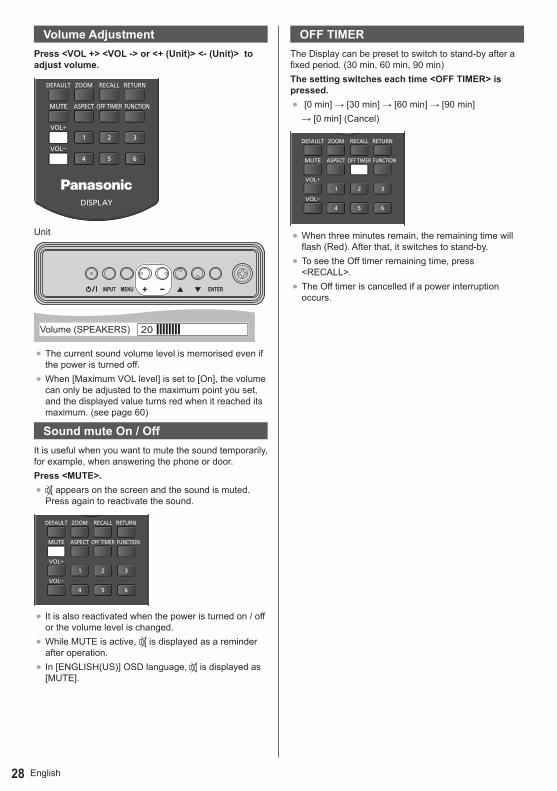
Volume AdjustmentPress <VOL +> <VOL -> or <+ (Unit)> <- (Unit)> to adjust volume.
MENU ENTERINPUT + -
Unit
20Volume (SPEAKERS)
●The current sound volume level is memorised even if the power is turned off.
●When [Maximum VOL level] is set to [On], the volume can only be adjusted to the maximum point you set, and the displayed value turns red when it reached its maximum. (see page 60)
Sound mute On / OffIt is useful when you want to mute the sound temporarily, for example, when answering the phone or door.Press <MUTE>.● appears on the screen and the sound is muted.
Press again to reactivate the sound.
● It is also reactivated when the power is turned on / off or the volume level is changed.
●While MUTE is active, is displayed as a reminder after operation.
● In [ENGLISH(US)] OSD language, is displayed as [MUTE].
OFF TIMERThe Display can be preset to switch to stand-by after a fixed period. (30 min, 60 min, 90 min)The setting switches each time <OFF TIMER> is pressed.● [0min]→[30min]→[60min]→[90min]→[0min](Cancel)
●When three minutes remain, the remaining time will flash (Red). After that, it switches to stand-by.
●To see the Off timer remaining time, press <RECALL>.
●The Off timer is cancelled if a power interruption occurs.

29English
ASPECT ControlsPress <ASPECT> or <ENTER (Unit)> repeatedly to move through the aspect options:
MENU ENTERINPUT + -
[4:3] → [Zoom1] → [Zoom2] → [16:9]
Note● The aspect mode is memorised separately for each
input terminal.● When input from USB, the aspect mode is fixed to
[16:9].
■ List of Aspect ModesAspect mode Description
16:9
Picture Enlarged screen
Pictures are displayed filling the screen.
4:3
Pictures are displayed in the 4:3 area. Pictures with a 4:3 aspect ratio are displayed as is. PC signals are enlarged or reduced to be displayed in the 4:3 area. Side panels are displayed both at the right and left edges of the screen.
Pictures with a 4:3 aspect ratio in 16:9 signals are displayed with their original aspect ratio. The left and right edges of the pictures are masked by side panels.
Aspect mode Description
Zoom1 Letterbox pictures with a 16:9 aspect ratio are enlarged vertically to fill the screen. The top and bottom edges of the pictures are cut off.
Zoom2Letterbox pictures with a 16:9 aspect ratio are enlarged vertically and horizontally to fill the screen. The top and bottom edges as well as the left and right edges of the pictures are cut off.
Note● Do not allow the picture to be displayed in 4:3
mode for an extended period, as this can cause a permanent image retention to remain on the Display Panel.
● Be aware that if you put the display in a public place for commercial purposes or a public showing and then use the aspect mode select function to shrink or expand the picture, you may be violating the copyright under copyright law. It is prohibited to show or alter the copyrighted materials of other people for commercial purposes without the prior permission of the copyright holder.
● In [ENGLISH(US)] OSD language, [16:9] is displayed as [FULL].
Unit
English30
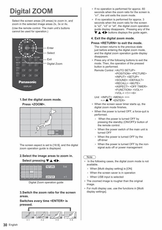
Digital ZOOMSelect the screen areas (25 areas) to zoom in, and zoom in the selected image areas 2x, 3x or 4x.(Use the remote control. The main unit’s buttons cannot be used for operation.)
Enter
Select
ExitDigital Zoom
1.Set the digital zoom mode. Press <ZOOM>.
×1
ExitRETURN
ENTER
The screen aspect is set to [16:9], and the digital zoom operation guide is displayed.
2.Select the image areas to zoom in. Select pressing .
×1
Exit
デジタルズーム操作ガイド
RETURN
ENTER
Digital Zoom operation guide
3.Switch the zoom ratio for the screen areas.Switches every time <ENTER> is pressed.
×1Exit
×2Exit
×3Exit
×4Exit
×1 ×2 ×3 ×4
● If no operation is performed for approx. 60 seconds when the zoom ratio for the screen is “x1”, the unit exits the zoom mode.
● If no operation is performed for approx. 3 seconds when the zoom ratio for the screen is “x2”, “x3” or “x4”, the digital zoom operation guide display disappears. Pressing any of the
buttons displays the guide again.
4. Exit the digital zoom mode.Press <RETURN> to exit the mode.
The screen returns to the previous state just before entering the digital zoom mode, and the digital zoom operation guide display disappears.
● Press any of the following buttons to exit the mode. Then, the operation of the pressed button is performed.Remote Control : <AUTO SETUP>
<POSITION> <PICTURE> <INPUT> <SETUP> <SOUND> <DEFAULT> <RECALL> <MUTE> <ASPECT> <OFF TIMER> <FUNCTION> <VOL+> <VOL-> <1>~<6>
Unit <INPUT> <MENU> <+> <-> <ENTER>
● When the screen saver timer starts up, the digital zoom mode finishes.
● When the power is turned OFF, a force-quit is performed.
• When the power is turned OFF by pressing the standby (ON/OFF)r button of the remote control.
• When the power switch of the main unit is turned OFF
• When the power is turned OFF by the off-timer
• When the power is turned OFF by the non-signal auto off or power management
Note● In the following cases, the digital zoom mode is not
available. • When [Multi display setting] is [ON] • When the screen saver is in operation • When USB input is selected
● The zoomed image is rougher than the original image.
● For multi display use, use the functions in [Multi display settings].

31English
USB Media PlayerFunction description
The USB media player displays still pictures and motion pictures saved in a USB memory by inserting the USB memory device into the display unit.
Note● To use this function, set [USB media player] to
[Enable] in [Setup] - [USB media player settings]. (see page 56)
Single Media PlayerFiles are played by a single unit.
USB memory
Multi Media PlayerConnecting more than one unit using LAN cables plays back files in the USB memory simultaneously.One of the multiple units becomes the master, and the others are slaves. The two-unit configuration example is shown below.For LAN connection, see “Network environment (Multi Media Player only)” (page 34).
USB memory
Master Slave
USB memory
Hub or broadband router
Note● For Multi Media Player, one USB memory device is
required for one unit.
Preparation ■ Supported device
● Commercially available USB memory devices are supported. (Those with security functions are not supported.)
● USB memory devices other than those formatted in FAT16 or FAT32 cannot be used.
● Up to 32 GB of USB memory in size are supported.● Only single partition configuration is supported.
■ PreparationPrepare the following files in the USB memory for the media player.● Play file● Scenario (as necessary)● File list (as necessary)
■ Play fileThe unit’s Media Player supports the formats below.
File name (Extension)Still image
JPG, JPEG, JPE
Moving image
AVI, MKV, ASF, WMV, TS, MTS, MP4, 3GP, MOV, FLV, F4V
CodecMoving image Codec Maximum resolutionMPEG4VISUAL 480@30fpsMPEG4AVC 1080@30fps, High ProfileVC-1 Advanced 1080@30fpsVC-1 Simple & Main 1080@30fps
AudioCodec Sampling frequency
(kHz)Bit rate (kbps)
MP3 8/11.025/12/16/22.05/24/32/44.1/48
8-320
AAC 8/11.025/12/16/22.05/24/32/44.1/48
1-1728
WMA Standard WMA 9 WMA 10 Pro
8/11.025/12/16/22.05/24/32/44.1/48
1-1728
Still image Codec Maximum resolutionJPEG 4096×4096
Note● Maximum size per one file is 2 GB.● Files protected by Digital Rights Management (DRM)
cannot be played back.● Some files may not be played back even if their
formats are supported as described here.● Use a file of which audio and video are both
supported.● If there is no video file, playback is not possible.

English32
■ ScenarioThe play order and time can be specified for a play file. Save under the name “scenario.dat” immediately below root in USB memory.● Save files as UTF-8N format.
■ File listIt is a list of play files. Save under the name “filelist.dat” immediately below root in USB memory.● Save files as UTF-8N format.
■ Scenario- / File list-associated terms File nameIt is the name of a play file.A file name needs to include its extension.Example) introduction.jpg
Contents_video01.wmv
● Enter the extension of a file name using one-byte alphanumeric characters.
File definitionIt is a file definition that is shared among scenarios and files.
PHOTO_”xxx”: still image file definitionVIDEO_”xxx”: moving image file
definition
● The “xxx” portion can be set from 001 to 999.● Enter a file definition using one-byte alphanumeric
characters.Play timeIt is the play time of a file.Play time can be specified from 3 seconds to 24 hours. (Unit: second)Example) 3: 3 seconds
86400: 24 hours 10.5: 10.5 seconds It can be set
down to one-tenth (1/10) of a second using a decimal point (full stop).
Play time is omissible.For still images, a file will be played for the period of time that you selected in [USB media player settings] - [Slide show duration]. (see page 56)For moving images: a file will be played for the duration of the play time of the file.● Enter play time using English one-byte characters.● When playing back large sized files, if you set the
playing back duration short, it may not be played back properly, for example, noise appears on the screen. In that case, set the playing back duration longer (10 seconds or longer).
Group ID (for Multi Media Player)It is an ID used for grouping on a network during Multi Media Player conditions. GroupID:Gxx : Group xxThe “xx” portion can be set from 01 to 10.
● Enter a group ID using one-byte alphanumeric characters.
NOTE● “UTF-8N”:UTF-8 encoding without BOM. Notepad
for windows doesn’t support this encoding. Please use another editor supported UTF-8 encoding without BOM.
Playing back the files ■ Example of setting in each mode
Single Media Player Type1Files will be played in the order in which their names appear in USB memory.
Scenario and file listScenario:UnnecessaryFile list:Unnecessary
Setting example
USB memory contents001_Introduction.jpg002_Contents_Video1.wmv
003_Contents_Video2.wmv
004_Contents_Video3.wmv
Play contentsFor the above setting example, the following contents will be played on repeat (loop).1. 001_Introduction.jpg (*1)2. 002_Contents_Video1.wmv (*2)3. 003_Contents_Video2.wmv (*2)4. 004_Contents_Video3.wmv (*2)
*1 Played for the duration set in [Slide show duration].*2 Played for the duration of the play time of the file.
Single Media Player Type2Files will be played in the order they were listed in a scenario. Scenario and file list
Scenario: Enter [File name: Play time].File list: Unnecessary
Setting example USB memory contents
scenario.datIntroduction.jpg
Contents_Video1.wmv
Contents_Video2.wmv
Contents_Video3.wmv
33English
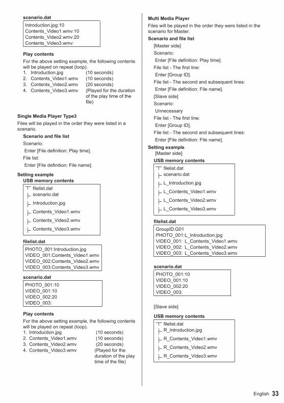
scenario.datIntroduction.jpg:10Contents_Video1.wmv:10Contents_Video2.wmv:20Contents_Video3.wmv:
Play contentsFor the above setting example, the following contents will be played on repeat (loop).1. Introduction.jpg (10 seconds)2. Contents_Video1.wmv (10 seconds)3. Contents_Video2.wmv (20 seconds)4. Contents_Video3.wmv (Played for the duration
of the play time of the file)
Single Media Player Type3Files will be played in the order they were listed in a scenario.
Scenario and file listScenario: Enter [File definition: Play time].File list: Enter [File definition: File name].
Setting example USB memory contents
filelist.datscenario.dat
Introduction.jpg
Contents_Video1.wmv
Contents_Video2.wmv
Contents_Video3.wmv
filelist.datPHOTO_001:Introduction.jpgVIDEO_001:Contents_Video1.wmvVIDEO_002:Contents_Video2.wmvVIDEO_003:Contents_Video3.wmv
scenario.datPHOTO_001:10VIDEO_001:10VIDEO_002:20VIDEO_003:
Play contentsFor the above setting example, the following contents will be played on repeat (loop).1. Introduction.jpg (10 seconds)2. Contents_Video1.wmv (10 seconds)3. Contents_Video2.wmv (20 seconds)4. Contents_Video3.wmv (Played for the
duration of the play time of the file)
Multi Media PlayerFiles will be played in the order they were listed in the scenario for Master.Scenario and file list
[Master side]Scenario: Enter [File definition: Play time].File list - The first line: Enter [Group ID].File list - The second and subsequent lines: Enter [File definition: File name].[Slave side]Scenario: UnnecessaryFile list - The first line: Enter [Group ID].File list - The second and subsequent lines: Enter [File definition: File name].
Setting example [Master side]USB memory contents
filelist.datscenario.dat
L_Introduction.jpg
L_Contents_Video1.wmv
L_Contents_Video2.wmv
L_Contents_Video3.wmv
filelist.datGroupID:G01PHOTO_001: L_Introduction.jpgVIDEO_001: L_Contents_Video1.wmvVIDEO_002: L_Contents_Video2.wmvVIDEO_003: L_Contents_Video3.wmv
scenario.datPHOTO_001:10VIDEO_001:10VIDEO_002:20VIDEO_003:
[Slave side]
USB memory contentsfilelist.datR_Introduction.jpg
R_Contents_Video1.wmv
R_Contents_Video2.wmv
R_Contents_Video3.wmv

English34
filelist.datGroupID:G01PHOTO_001: R_Introduction.jpgVIDEO_001: R_Contents_Video1.wmvVIDEO_002: R_Contents_Video2.wmvVIDEO_003: R_Contents_Video3.wmv
Play contentsFor the above setting example, the following contents will be played on repeat (loop). [Master side]1. L_Introduction.jpg (10 seconds)2. L_Contents_Video1.wmv (10 seconds)3. L_Contents_Video2.wmv (20 seconds)4. L_Contents_Video3.wmv ( *1)
[Slave side]1. R_Introduction.jpg (10 seconds)2. R_Contents_Video1.wmv (10 seconds)3. R_Contents_Video2.wmv (20 seconds)4. R_Contents_Video3.wmv ( *1)
*1 Played for the duration of the play time of L_Contents_Video3.wmv (Master side).
Note● [Multi display settings] is not supported.
■ USB memory contents checkYou can run a USB memory contents check in [USB media player settings] - [Scenario file check]. (see page 56)If an error is present, the information is given with the following details.A(B):CA: Name of the file with an errorB: Row with an errorC: Error code
Note● Shows leading error codes. Details of the detected
errors are as follows.
Error code Detail of the error
1. No USB memory is inserted2. scenario.dat / filelist.dat cannot be opened3. There is an error in writing scenario.dat /
filelist.dat4. The play file format is not supported5. No play file exists6. It is Multi Media Player, but no group ID is
specified yet7. There are several identical file definitions8. The play time is outside the range9. The file listed in the scenario is not in the
file list10. The scenario contains 0 or over 1000
play files11. There are 0 or over 1000 play files (Single
Media Player Type3 only)12. Only the group ID is listed on the file list
(Multi Media Player only)
Supplementary noteThe USB memory contents check does not determine whether or not a play file is playable.If a file cannot be played while Media Player is active, an error message will be displayed.When performing the synchronized playback on the Multi Media Player, check if the file is playable using the “Scenario File Check” for “USB Media Player Setting”
Network environment (Multi Media Player only) ■ Example of setting up LAN connection and IP address / Subnet mask
As mentioned below, connect several units together with LAN cables and set up IP addresses / Subnet masks so that all the displays exist on the same network.
MasterIP address:
Subnet mask:192.168.10.1255.255.255.0
SlaveIP address:
Subnet mask:192.168.10.2255.255.255.0
SlaveIP address:
Subnet mask:192.168.10.3255.255.255.0
SlaveIP address:
Subnet mask:192.168.10.4255.255.255.0

35English
Note● Set [Network control] of all displays to [On]. (see page
55)● Depending on the network environment,
synchronization may be largely lost.● Do not connect other devices to prevent network
traffic jam.● With a router put in between, you cannot set up
connection. Use them within the same subnet.● Do not use wireless LAN for connection since
playback may not be performed normally.
Starting / ending Media Player ■ For Single Media PlayerStart1. Insert USB memory for Media Player.
Note● Depending on the type of a USB memory
device, it may come in contact with the periphery such as a back cover, and cannot be attached. Use a commercially sold extension cable, or use a small type of a USB memory device connectable to this unit.
USB memory
USB terminal
2. Run a USB memory contents check. 3. Change INPUT to USB.
EndingChange INPUT to other than USB.
■ For Multi Media PlayerStart1. Connect several units with LAN cables.
(see page 34 "Example of setting up LAN connection and IP address / Subnet mask")
2. Insert USB memory for Media Player into each Display.
3. Executes USB memory contents check on each Display.
4. Change INPUT for Slave to [USB].5. Change INPUT for Master to [USB].
EndingChange INPUT for Master to other than [USB]
Resume Play functionAfter Media Player ends, the file to be resumed when resuming playing varies depending on the setting of [USB media player settings] - [Resume play].When set to [On]:
The file played prior to the end of Media Player starts playing from the beginning.
When set to [Off]:Play starts from the beginning of the first file of the scenario.
Note● The resume play function is retained until the unit is
turned off or the USB memory device is taken out.

English36
On-Screen Menu Displays1 Display the menu screen.
Remote Control
Press to select
Unit
MENU ENTERINPUT + -Press for several times.
Each time the button is pressed, the menu screen will switch.Normal Viewing → [Picture] → [Setup] → [Position]→ [Sound]
2 Select the item.
MENU ENTERINPUT + -
Press.Press to select.
(Example: [Picture] menu)
505050505050
5
Picture
Default DefaultPicture mode Normal
2.29300K
BacklightContrastBrightnessColourHueSharpnessGammaColour temperatureDynamic contrastColour enhancement
Memory saveMemory loadMemory edit
Off
SubmenuPress <ENTER> to display the submenu.
3 Set.
MENU ENTERINPUT + -
Press.Press to select.
4 Exit from the menu.
Press
Press <RETURN> to return to the previous screen.
MENU ENTERINPUT + -
Press for several times.

37English
Menu display list● Menu that cannot be adjusted is greyed out.
Adjustable menu changes depending on signal, input and menu setting.
[Position] menu
00
0000
Position
Default Default
Auto setup
H-position
H-sizeV-position
V-size
Clock phase
Dot Clock
1:1 pixel mode Off
(see page 38-39)
[Sound] menu
000
Sound
Default DefaultOutput select SPEAKERS
Normal
Off
Sound modeBassTrebleBalanceSurround
(see page 40)
[Picture] menu
505050505050
5
Picture
Default DefaultPicture mode NormalBacklight
BrightnessColourHueSharpnessGamma 2.2
9300K
Colour enhancement
Memory saveMemory loadMemory edit
Off
(see page 41-46)
[Setup] menu1/2Setup
ScreensaverSignal
Input labelPower management settingsWobblingNo activity power offOSD language
OffDisable
English(UK)
2/2
20
Setup
Set up timerMulti Display Settings
Date and timeNetwork settings
USB media player settingsFunction button settingsDisplay orientationOSD positionMenu display durationMenu transparency
PortraitUpper/Right
60 sec
(see page 47-58)
Contrast
Colour temperatureDynamic contrast

English38
Adjusting Position1 Press <POSITION> to display the
[Position] menu.
00
0000
Position
Default DefaultAuto setup
H-positionH-sizeV-position
V-size
Clock phase
Dot clock
1:1 pixel mode Off
2 Select the item to adjust with .● Unadjustable items are greyed out.
Adjustable items differ depending on the input signal and the display mode.
3 Adjust with .
4 Press <POSITION> to exit from adjustmode.
■ To return to the previous screenPress <RETURN>.
■ To reset to defaultsPress <DEFAULT> while the menu is displayed, or press <ENTER> when [Default] is selected, then the settings will be set to factory settings.
Note● Settings for [Position] are memorised separately for
each input signal.● During USB input, the settings for [Position] cannot
be made.
Setting [Position] when the display is installed verticallyWhen adjusting, please note that even when the display is installed vertically, setting directions of position / size are the same as that of horizontal installation.
Auto setupWhen inputting a PC signal, [H-position] / [V-position], [H-size] / [V-size], [Dot clock] and [Clock phase] are automatically corrected.
This setting is enabled under the following conditions:● When inputting an analogue signal (PC).
While displaying the picture of the corresponding signal, select [Auto setup] and press <ENTER>.Using Remote Control
Press <AUTO SETUP>.When Auto Setup does not work, [Invalid] is displayed.
Auto modeWhen the [PC auto setting] is set to [On] in the [Options] menu (see page 61), automatic position adjustment starts:● When the display power is turned ON.● When the input signal is switched.
Note● When the dot clock frequency of a PC signal is 162
MHz or higher, [Dot clock] and [Clock phase] cannot be automatically corrected.
● Auto Setup may not work when a cropped or dark image is input. In such case, switch to a bright image with borders and other objects are clearly shown, and then try auto setup again.
● Depending on the signal, out of alignment may occur after Auto Setup. Carry out fine tuning for the position/size as required.
● If Auto Setup cannot set properly for XGA signal (1024×768, 1280×768, 1366×768), pre-selecting the individual signal in [XGA mode] (see page 48) may results in correct Auto Setup.
● Auto Setup does not work well when a signal such as additional information is superimposed out of valid image period or when intervals between synchronizing signal and image signal are short. Also it does not work well for image signals with trilevel synchronizing signal added, or for some SYNC ON G signals.
● If Auto Setup does not work well, select [Default], press <ENTER>, and then adjust the position/size manually.

39English
[H-position] Adjust the horizontal position with .
[H-size] Adjust the horizontal size with .
[V-position] Adjust the vertical position with .
[V-size] Adjust the vertical size with .
[Clock phase]
(During PC input signal)In some cases, frame of the screen appears blurred or smudged, when RGB signal or PC signal are input.
[Dot clock] (During PC input signal)Periodic striped pattern interference (noise) may occur when a striped pattern is displayed. If this happens, adjust so that any such noise is minimized.
[Over scan] Turn image over scan On/Off.Applicable input signal:525i, 525p, 625i, 625p, 750/60p, 750/50p (Component Video, RGB, DVI-D, HDMI)
[On] [Off]
Note● When [Off] is set, [H-size] and
[V-size] cannot be adjusted.
[1:1 pixel mode]
Adjusts the display size when 1125i or 1125p signal is input.
[Off] [On]Applicable input signal:1125 / 50i, 60i, 24PsF, 24p, 25p, 30p, 50p, 60p
Note● Select [Off] when flickering is shown
around the image.● [H-size] and [V-size] cannot be
adjusted when [On] is selected.
Note● In some cases, noise appears outside the area
picture is displayed, but it is not a malfunction.
English40
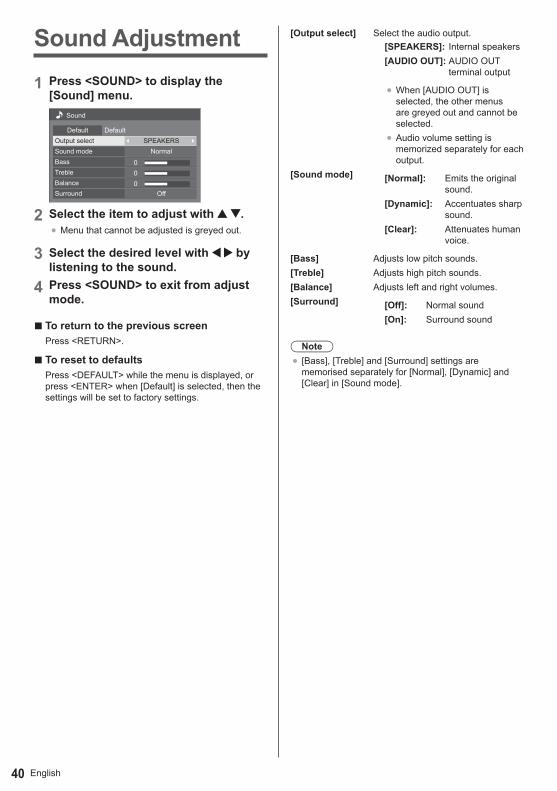
Sound Adjustment
1 Press <SOUND> to display the [Sound] menu.
000
Sound
Default DefaultOutput select SPEAKERS
Normal
Off
Sound modeBassTrebleBalanceSurround
2 Select the item to adjust with .● Menu that cannot be adjusted is greyed out.
3 Select the desired level with by listening to the sound.
4 Press <SOUND> to exit from adjust mode.
■ To return to the previous screenPress <RETURN>.
■ To reset to defaultsPress <DEFAULT> while the menu is displayed, or press <ENTER> when [Default] is selected, then the settings will be set to factory settings.
[Output select] Select the audio output.[SPEAKERS]: Internal speakers[AUDIO OUT]: AUDIO OUT
terminal output
● When [AUDIO OUT] is selected, the other menus are greyed out and cannot be selected.
● Audio volume setting is memorized separately for each output.
[Sound mode] [Normal]: Emits the original sound.
[Dynamic]: Accentuates sharp sound.
[Clear]: Attenuates human voice.
[Bass] Adjusts low pitch sounds.[Treble] Adjusts high pitch sounds.[Balance] Adjusts left and right volumes.[Surround] [Off]: Normal sound
[On]: Surround sound
Note● [Bass], [Treble] and [Surround] settings are
memorised separately for [Normal], [Dynamic] and [Clear] in [Sound mode].

41English
Picture Adjustments
1 Press <PICTURE> to display the [Picture] menu.
505050505050
5
Picture
Default DefaultPicture mode Normal
2.29300K
BacklightContrastBrightnessColourHueSharpnessGammaColour temperature
Colour enhancement
Memory saveMemory loadMemory edit
Off
2 Select the item to adjust with .● Menu that cannot be adjusted is greyed out.
3 Select the desired level with by looking at the picture behind the menu.
4 Press <PICTURE> to exit from adjust mode.
■ To return to the previous screenPress <RETURN>.
■ To reset to defaultsPress <DEFAULT> while the menu is displayed, or press <ENTER> when [Default] is selected, then the settings will be set to factory settings.
Note● During PC IN input, the following settings cannot be
made.[Colour], [Hue], [Sharpness], [Dynamic contrast], [Colour enhancement]
● For still image during USB input, the following settings are not valid. [Contrast], [Brightness], [Colour], [Hue], [Sharpness], [Dynamic contrast], [Colour enhancement]
[Picture mode] This menu switches to easy-to-see pictures suitable to the picture source or environment where this unit is used.
[Normal]For viewing in standard (evening lighting) environments.[Dynamic]For viewing in brighter environments.[Cinema]For use in viewing tone-focused pictures with brightness reduced.
● The setting are memorised separately for each input terminal.
● In [ENGLISH(US)] OSD language, [Normal] is displayed as [STANDARD].
● In [ENGLISH(US)] OSD language, the [Picture mode] is displayed as [PICTURE MENU].
[Backlight] Adjusts luminance of the back light.
Darker ↔ Brighter[Contrast] Selects the proper brightness and
density for the room.Less ↔ More
● In [ENGLISH(US)] OSD language, [Contrast] is displayed as [PICTURE].
[Brightness] Adjusts for easier viewing of dark pictures such as night scenes and black hair.
Darker ↔ Brighter[Colour] Adjusts colour saturation.
Less ↔ More[Hue] Adjusts for nice skin colour.
Reddish ↔ Greenish[Sharpness] Adjusts picture sharpness.
Less ↔ More[Gamma] Adjusts gamma.
[2.0], [2.2], [2.4], [2.6]Small tilt - Large tilt
Dynamic contrast

English42
[Colour temperature]
Adjusts colour tone.[3200K], [4000K], [5000K], [6500K], [7500K], [9300K], [10700K], [Native], [USER1], [USER2]
Note● Emphasizes red when the
numerical value of [Colour temperature] is small, and emphasizes blue when it is big.
● [Native] is a colour tone of the panel element, and [Gamma] is fixed to 2.2 or equivalent.
● You can select [USER1] and [USER2] when you set the following user settings.
User setting of [Colour temperature]
2 kinds of detailed [Colour temperature] settings can be stored.
1 Press <ENTER> while setting [Colour temperature].
502.2
6500K
SharpnessGammaColour temperature
Example: When [Colour temperature] is [6500K], it is possible to reflect the set point, [6500K], to the set point of [USER1] and [USER2].
2 Select the user to memorise settings with and press <ENTER>.
Adjust colour temperature
Change to 6500KUSER1USER2
USER3
3 Select [Yes] with and press <ENTER>.
Adjust colour temperature
Overwrite colour temperature “USER1”?
Yes No
4 Set each item on detail settings screen.
150255
64000
Adjust colour temperature
USER1R gainG gainB gainR biasG biasB bias
[R gain]Adjusts the white balance for light red areas.
0 to 255[G gain]Adjusts the white balance for light green areas.
0 to 255 [B gain] Adjusts the white balance for light blue areas.
0 to 255 [R bias]Adjusts the white balance for dark red areas.
-127 to 128 [G bias]Adjusts the white balance for dark green areas.
-127 to 128 [B bias]Adjusts the white balance for dark blue areas.
-127 to 128The settings are memorised separately for each input terminal.When you return to [Picture] menu, the user you have set is selected for [Colour temperature].
552.2
USER1
SharpnessGammaColour temperature
[Dynamic contrast]
Automatically adjusts the contrast by determining the changes in the use of colours for images that constantly change, such as motion pictures.
[Colour enhancement]
While set to [On], displays images by emphasising colours.

43English
Picture ProfilesUp to 6 combinations of picture adjustment values (in the [Picture] menu) can be stored in the display memory as profiles and applied as needed, for a convenient way to enjoy your preferred picture settings.
505050505050
5
Picture
Default DefaultPicture mode Normal
9300K
BacklightContrastBrightnessColourHueSharpnessGammaColour temperature
Colour enhancement
Memory saveMemory loadMemory edit
Off
[Memory save](see page 44)[Memory load](see page 45)[Memory edit](see page 45)
1. [ ]2. [ ]3. [ ]
MEMORY1MEMORY2MEMORY3
4. [ ] MEMORY45. [ ] MEMORY56. [ ] MEMORY67. [ ] MEMORY78. [ ] MEMORY8
Overview of Picture Profiles
Original pictureAdjust picture.(see page 41-42)
Custom pictureExample:Save the picture adjustment values in the [MEMORY1] profile.[Memory save]
Original pictureExample:Load [MEMORY1].[Memory load]
Custom picture
[Memory edit] screen1. [ ]2. [ ]3. [ ]
MEMORY1MEMORY2MEMORY3
Example:Change the memory name to [MY PICTURE].[Memory edit]
1. [ ]2. [ ]3. [ ]
MY PICTUREMEMORY2MEMORY3
Dynamic contrast
2.2
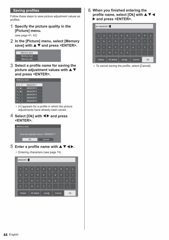
English44
Saving profilesFollow these steps to save picture adjustment values as profiles.
1 Specify the picture quality in the [Picture] menu.(see page 41, 42)
2 In the [Picture] menu, select [Memory save] with and press <ENTER>.
Memory saveMemory loadMemory edit
3 Select a profile name for saving the picture adjustment values with and press <ENTER>.
1. [ ]2. [ ]3. [ ]
MEMORY1MEMORY2MEMORY3
4. [ ] MEMORY45. [ ] MEMORY56. [ ] MEMORY67. [ ] MEMORY78. [ ] MEMORY8
Memory save
● [*] appears for a profile in which the picture adjustments have already been saved.
4 Select [Ok] with and press <ENTER>.
Memory save
Save the adjusted value in “MEMORY1”
Ok Cancel
5 Enter a profile name with .● Entering characters (see page 74)
MEMORY1█
01 2 3 4 5 6 7 8 9
a
a/A/@
b c d e f g h i j
k l m n o p q r s t
u v w x y z – _.
OkCancelAll deleteDelete
6 When you finished entering the profile name, select [Ok] with
and press <ENTER>.
MY MEMORY1█
01 2 3 4 5 6 7 8 9
a b c d e f g h i j
k l m n o p q r s t
u v w x y z – _.
a/A/@ OkCancelAll deleteDelete
● To cancel saving the profile, select [Cancel].
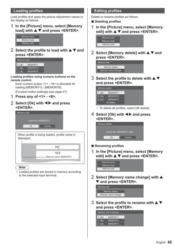
45English
Loading profilesLoad profiles and apply the picture adjustment values to the display as follows.
1 In the [Picture] menu, select [Memory load] with and press <ENTER>.
Memory saveMemory loadMemory edit
2 Select the profile to load with and press <ENTER>.
1. [ ]2. [ ]3. [ ]
MEMORY1MEMORY2MEMORY3
Memory load
Loading profiles using numeric buttons on the remote control.
Each numeric button <1> - <6> is allocated for loading [MEMORY1] - [MEMORY6].[Function button settings] (see page 57)
1 Press any of <1> - <6>.
2 Select [Ok] with and press <ENTER>.
Memory load
Load from “MEMORY2”
Ok Cancel
When profile is being loaded, profile name is displayed.
PC
16:9Memory name: MEMORY2
Note● Loaded profiles are stored in memory according
to the selected input terminal.
Editing profilesDelete or rename profiles as follows.
■ Deleting profiles
1 In the [Picture] menu, select [Memory edit] with and press <ENTER>.
Memory saveMemory loadMemory edit
2 Select [Memory delete] with and press <ENTER>.
Memory edit
Memory deleteMemory name change
3 Select the profile to delete with and press <ENTER>.
1. [ ]2. [ ]3. [ ]
MEMORY1MEMORY2MEMORY3
Memory delete
All delete
● To delete all profiles, select [All delete].
4 Select [Ok] with and press <ENTER>.
Memory delete
Delete the “MEMORY1” data
Ok Cancel
■ Renaming profiles
1 In the [Picture] menu, select [Memory edit] with and press <ENTER>.
Memory saveMemory loadMemory edit
2 Select [Memory name change] with and press <ENTER>.
Memory edit
Memory deleteMemory name change
3 Select the profile to rename with and press <ENTER>.
1. [ ]2. [ ]3. [ ]
MEMORY1MEMORY2MEMORY3
Memory name change
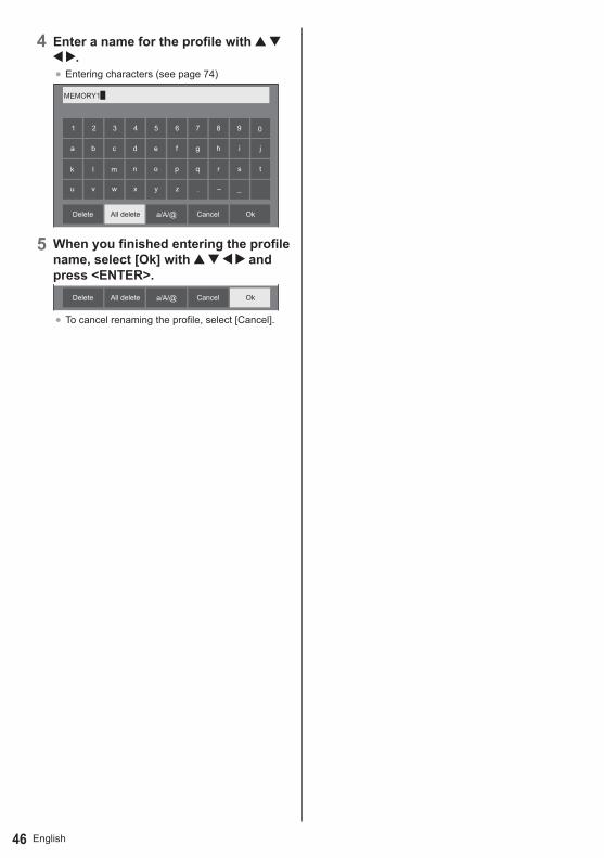
English46
4 Enter a name for the profile with .
● Entering characters (see page 74)
01 2 3 4 5 6 7 8 9
a b c d e f g h i j
k l m n o p q r s t
u v w x y z – _.
MEMORY1█
a/A/@ OkCancelAll deleteDelete
5 When you finished entering the profile name, select [Ok] with and press <ENTER>.
a/A/@ OkCancelAll deleteDelete
● To cancel renaming the profile, select [Cancel].
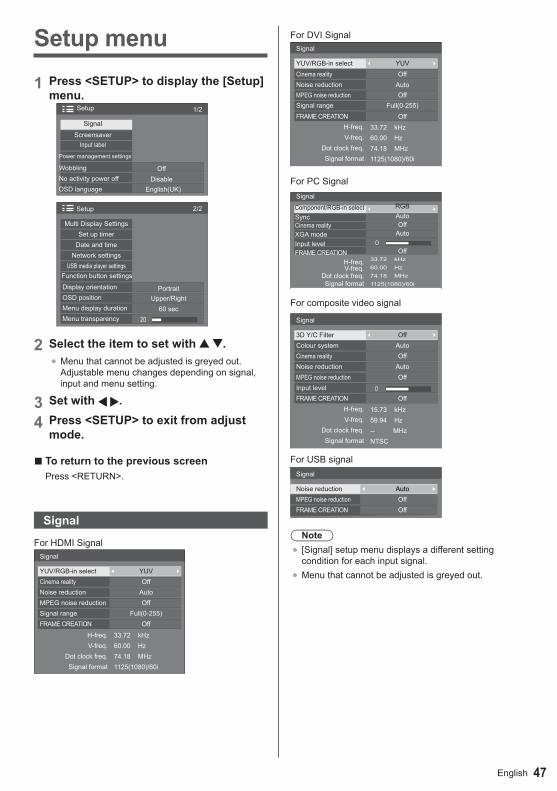
47English
Setup menu
1 Press <SETUP> to display the [Setup] menu.
1/2Setup
Screensaver
Signal
Input label
Power management settings
WobblingNo activity power offOSD language
OffDisable
English(UK)
2/2
20
Setup
Set up timerMulti Display Settings
Date and timeNetwork settings
USB media player settingsFunction button settings
Display orientationOSD positionMenu display durationMenu transparency
PortraitUpper/Right
60 sec
2 Select the item to set with .●Menu that cannot be adjusted is greyed out.
Adjustable menu changes depending on signal, input and menu setting.
3 Set with .
4 Press <SETUP> to exit from adjust mode.
■ To return to the previous screenPress <RETURN>.
Signal
For HDMI Signal
60.00 Hz74.18 MHz1125(1080)/60i
33.72 kHz
Signal
Cinema realityYUV/RGB-in select
Noise reduction
Signal rangeMPEG noise reduction
FRAME CREATION
V-freq.H-freq.
Dot clock freq.Signal format
OffYUV
Auto
Full(0-255)Off
Off
For DVI Signal
60.00 Hz74.18 MHz1125(1080)/60i
33.72 kHz
Signal
YUV/RGB-in selectCinema reality
MPEG noise reductionSignal range
Noise reduction
FRAME CREATIONH-freq.V-freq.
Dot clock freq.Signal format
YUVOff
OffFull(0-255)
Auto
Off
For PC Signal
60.00 Hz74.18 MHz1125(1080)/60i
33.72 kHz
0
Signal
Component/RGB-in selectSyncCinema reality
Input levelXGA mode
FRAME CREATIONH-freq.V-freq.
Dot clock freq.Signal format
RGBAutoOff
Auto
Off
For composite video signal
59.94 Hz-- MHzNTSC
15.73 kHz
0
Signal
3D Y/C Filter Colour system
MPEG noise reduction
Cinema reality
Input level
Noise reduction
FRAME CREATION
OffAuto
Off
OffAuto
OffH-freq.V-freq.
Dot clock freq.Signal format
For USB signalSignal
Noise reductionMPEG noise reductionFRAME CREATION
AutoOffOff
Note● [Signal] setup menu displays a different setting
condition for each input signal.●Menu that cannot be adjusted is greyed out.

English48
[Component/RGB-in select]This menu is displayed when the PC signal input.Select to match the signals from the source connected to the PC IN terminal.
[Component] Y, PB, PR/Y, CB, CR signals[RGB] RGB signals
[YUV/RGB-in select]This menu is displayed when the HDMI and PC signal inputs.Select to match the signals from the source connected to the HDMI 1, HDMI 2 and DVI-D IN terminals.
[YUV] YUV signals[RGB] RGB signals
[Sync]This function operates only during PC IN input.Setting RGB/PC sync signal
[Auto]:
The H and V sync or synchronized signal is automatically selected. When both of them have sync, H and V sync will be selected.
[on G]:Uses a synchronized signal on the Video G signal, which is input from the G connector.
[HV sync]:
Uses a synchronized signal on the Video HD/VD signal, which is input from the HD/VD connector.
Setting Component sync signal[Auto]:
The H and V sync or synchronized signal is automatically selected. When both of them have sync, H and V sync will be selected.
[on Y]:Uses a synchronized signal on the Video Y signal, which is input from the Y connector.
[HV sync]:Uses a synchronized signal on the Video HD/VD signal, which is input from the HD/VD connector.
[Cinema reality]
Faithfully reproduces videos shot with cinema films. Set this to [Off] normally.
Note● In [ENGLISH(US)] OSD language, [Cinema
reality] is displayed as [3:2 PULLDOWN].● If [Cinema reality] is set to [On], videos including
movies shot at 24 frames per second are reproduced more naturally.
● If the video is unnatural with [On] set, set it to [Off].
[Noise reduction]
Reduces picture noise.[Off]:Disables Noise Reduction.[Min], [Mid], [Max]:Sets strength of Noise Reduction.[Auto]:Noise reduction will be automatically selected from [Min], [Mid] or [Max].
Note●This menu is not displayed during PC IN input.
[MPEG noise reduction]
Reduces block noise and mosquito noise on MPEG videos.[Off]:Disables Noise Reduction.[Min], [Mid], [Max]:Sets strength of Noise Reduction.
Note●This menu is not displayed during PC IN input.
[XGA mode]This menu is displayed during PC IN input.This unit supports XGA signals (1024 × 768, 1280 × 768, 1366 × 768) having different aspect ratios and sampling rates.[Auto]:Automatically detects the signal.Switch the setting to suit the input signal for better display depending on the angle of view or display resolution condition.
Note●After making this setting, be sure to make each
adjustment (such as [Auto setup]) on the [Position] menu as necessary. (see page 38)

49English
[Signal range]Switches the dynamic range according to the input signals below.HDMI1, HDMI2, DVI-D[Video(16-235)]:
If the input signal is the video range, Example: HDMI terminal output for DVD player
[Full(0-255)]:If the input signal is full range, Example: HDMI terminal output for personal computer
[Auto]:Switches the dynamic range automatically between [Video(16-235)] and [Full(0-255)] according to the input signal.
Note● [Auto] can be selected when the HDMI signal input.
[Input level]This menu is displayed at PC IN and VIDEO input.Adjustment of parts which are extremely bright and hard to see.-16 to + 16:
(Level low) - (Level high)
[3D Y/C filter]Set this if the video looks unnatural during the composite video signal input. Set this to [On] normally.
Note●Depending on the signaling system, this setting may
be less effective or may not be effective at all.
[Colour system]Sets the colour system according to the signal method during the composite video signal input. Set this to [Auto] normally. This automatically detects the input signal format.[Auto], [PAL], [SECAM], [NTSC], [NTSC 4.43], [PAL M], [PAL N]:Set this to [Auto] when viewing PAL-60 videos.When images are unstableWhen the system is set to [Auto], images become unstable in rare case under the condition that the input signals are at low level or have many noises. In this case, set the system so it conforms with the input signal format.
For 65-inch model[FRAME CREATION]
Improves motion picture quality. Select [Off] when the motion picture looks unnatural.
[Off]:The frame creation is disabled.
[Min], [Mid], [Max]:Set the degree of the frame creation.
Note● [FRAME CREATION] is a function for 65-inch models.
This function is not available for 43 / 48 / 55-inch models.
Input signal displayDisplays the frequency and the type of the current input signal.
60.00 Hz74.18 MHz1125(1080)/60i
33.72 kHzH-freq.V-freq.
Dot clock freq.Signal format
Display range:
Horizontal (15 kHz - 135 kHz)Vertical (24 Hz - 120 Hz)
The dot clock frequency is displayed during Digital and PC signal inputs.

English50
Screensaver (For preventing image retention)
Do not display a still picture, especially in 4:3 mode, for any length of time.If the display must remain on, a Screensaver should be used.
Screensaver
Start10:002015/01/01 THURSDAY
Mode Off
■ Screensaver settingsScreensaver operationWhen the Screensaver is operating, the following 5 patterns are displayed full screen for 5 seconds each, and it will be repeated.Black→ Dark grey → Grey → Light grey → White → Light grey → Grey → Dark grey
To start Screensaver now Select [On] in [Mode]. Select [Start] and press <ENTER>.
●The menu screen will disappear and the Screensaver will be activated.
Screensaver
Start10:002015/01/01 THURSDAY
Mode On
Note● If the following buttons are pressed while the screen
saver is operating, the screen saver is cancelled. Remote control: <RETURN> Main unit:
<MENU> <INPUT> <+> <-> <ENTER>●When the display is turned off, the Screensaver will
be deactivated.
To set interval of Screensaver Select [Interval] in [Mode]. Set [Periodic time].●Press to change the time by 15 minutes.
Set [Operating time].●Press once to change the time by 1 minute.
Keep pressing down to change the time by 15 minutes.
Screensaver
Start10:002015/01/01 THURSDAY
Mode IntervalPeriodic timeOperating time
0:000:00
Periodic time
Deactivated. Operating time
Note● It is not possible to set the duration of [Operating
time] longer than that of [Periodic time].
To set start and finish time of Screensaver Select [Time designation] in [Mode]. Set [Start time] and [Finish time].●Press once to change the time by 1 minute.
Keep pressing down to change the time by 15 minutes.
Screensaver
Start10:002015/01/01 THURSDAY
Mode Time designationStart timeFinish time
0:000:00
Note●Please set [Date and time] before setting [Start
time] and [Finish time]. (see page 54)
To turn the power off after Screensaver Select [Standby after SCR saver] in [Mode]. Set [Screensaver duration].●Press once to change the time by 1 minute.
Keep pressing down to change the time by 15 minutes.
Select [Start] and press <ENTER>.●Screensaver will be activated and the power will
be turned off (Standby) at the time set.
Screensaver
Start10:002015/01/01 THURSDAY
Mode Standby after SCR saverScreensaver duration 0:00
Note● [Screensaver duration] can be set from 0:00 to
23:59.When this is set to [0:00], [Standby after SCR saver] will not be activated.

51English
Input labelThis function can change the label of the Input signal to be displayed.
HDMI1HDMI2DVI-DPC
VIDEOPC
DVI-DHDMI2HDMI1
VIDEO
Input label
[HDMI1] [HDMI1] / [DVD1] / [DVD2] / [DVD3] / [Blu-ray1] / [Blu-ray2] / [Blu-ray3] / [CATV] / [VCR] / [STB] / (Skip)
[HDMI2] [HDMI2] / [DVD1] / [DVD2] / [DVD3] / [Blu-ray1] / [Blu-ray2] / [Blu-ray3] / [CATV] / [VCR] / [STB] / (Skip)
[DVI-D] [DVI-D] / [DVD1] / [DVD2] / [DVD3] / [Blu-ray1] / [Blu-ray2] / [Blu-ray3] / [CATV] / [VCR] / [STB] / (Skip)
[PC] [PC] / [DVD1] / [DVD2] / [DVD3] / [Blu-ray1] / [Blu-ray2] / [Blu-ray3] / [CATV] / [VCR] / [STB] / (Skip)
[VIDEO] [VIDEO] / [DVD1] / [DVD2] / [DVD3] /[Blu-ray1] / [Blu-ray2] / [Blu-ray3] / [CATV] / [VCR] / [STB] / (Skip)
● (Skip): When <INPUT> is pressed, the input will be skipped.
Power management settingsSet each item to reduce power consumption.
Power management settings
Power management mode
No signal power offHDMI1 power managementHDMI2 power management
PC power managementDVI-D power management
Power save
Custom
OffOff
Disable
Off
Off
Off
■ Power management mode: OnThe following fixed values are set to the menu of power consumption reduction. Individual setting is not available.
[No signal power off]: [Enable][HDMI1 power management]: [On][HDMI2 power management]: [On][DVI-D power management]: [On][PC power management]: [On][Power save]: [On]
■ Power management mode: CustomThe menu of the power consumption reduction is individually set. This setting is enabled when [Power management mode] is set to [Custom].
[No signal power off]When this is set to [Enable], the power supply of the unit goes off automatically when there is no operation or sync signal for about 10 minutes.
Note●With the USB input, the unit determines no signal is
present when the USB device is not connected.
[HDMI1 power management] [HDMI2 power management]
When this function is set to [On], it operates under the following conditions to turn the power on or off automatically.
When no pictures (sync signal) are detected for 60 or so seconds at HDMI1 or HDMI2 input:
Power is turned off (standby); the power indicator lights up orange.
When pictures (sync signal) are subsequently detected:
Power is turned on; the power indicator lights up green.
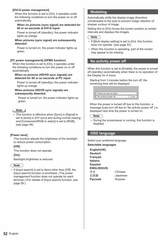
English52
[DVI-D power management]When this function is set to [On], it operates under the following conditions to turn the power on or off automatically.
When no pictures (sync signal) are detected for 60 or so seconds at DVI-D input:Power is turned off (standby); the power indicator lights up orange.
When pictures (sync signal) are subsequently detected:
Power is turned on; the power indicator lights up green.
[PC power management] (DPMS function)When this function is set to [On], it operates under the following conditions to turn the power on or off automatically.
When no pictures (HD/VD sync signals) are detected for 60 or so seconds at PC input:
Power is turned off (standby); the power indicator lights up orange.
When pictures (HD/VD sync signals) are subsequently detected:
Power is turned on; the power indicator lights up green.
Note●This function is effective when [Sync] in [Signal] is
set to [Auto] or [HV sync] and during normal viewing and [Component/RGB-in select] is set to [RGB]. (see page 48)
[Power save]This function adjusts the brightness of the backlight to reduce power consumption.[Off]:This function does not operate.[On]:Backlight brightness is reduced.
Note● If [Input search] is set to items other than [Off], the
[Input search] function is prioritised. (The power management function does not operate for each terminal.) (For details of [Input search] function, see page 59.)
WobblingAutomatically shifts the display image (therefore unnoticeable to the eye) to prevent image retention of sharper contour of image.Setting this to [On] moves the screen position at certain intervals and displays the images.
Note● If [Multi display setting] is set to [On], this function
does not operate. (see page 53)●When this function is operating, part of the screen
may appear to be missing
No activity power off
When this function is set to [Enable], the power is turned off (standby) automatically when there is no operation of the Display for 4 hours.
Starting from 3 minutes before the turn off, the remaining time will be displayed.
No activity power offPress any key to abort.
3 min
When the power is turned off due to this function, a message [Last turn off due to ‘No activity power off’.] is displayed next time the power is turned on.
Note●During the screensaver is running, this function is
disabled.
OSD language
Select your preferred language.Selectable languages
English(UK)DeutschFrançaisItalianoEspañolENGLISH(US)中文 : Chinese日本语 : JapaneseРусский : Russian

53English
Multi Display Settings1 to 5 displays can be aligned in horizontal direction and vertical direction respectively, and those displays are regarded as one group. The enlarged image is shown on the combined display.
Multi Display Settings
00
Multi Display Settings
Multi display settingHorizontal scale
Bezel H adjustmentVertical scale
Bezel V adjustmentLocation
Off22
A1
Note●The settings are memorised separately for each
input terminal.●When the multi display is set to [Off], adjust to
the same angle of view for [Position] (see page 38). Then, set the multi display to [On]. Again, make fine adjustment of the angle of view for [Position].
●The [Position] menu can be adjusted in the multi display status.
●During USB input, the Multi Display mode is not available.
■ Multi display settingOff: The display is not divided when enlarged.On: The display is divided when enlarged.When [On] is set, the display aspect is [16:9].
■ Horizontal scaleSet the horizontal scale in the multi display.
1- 5
■ Vertical scaleSet the vertical scale in the multi display.
1- 5e.g.) Horizontal scale [5] and Vertical scale [5] is set in the multi display
■ Bezel H adjustment, Bezel V adjustmentAdjust the area of image hidden in the joint horizontally and vertically respectively.0 - 100Display example
Setting value: 0
Displays the entire image including the joint area. (Suitable when displaying character information on PC.)
Setting value: 100
Does not display the image of the joint area. (Suitable when displaying motion pictures.)
■ Enlarged positionAssign the multi display position.e.g.) Horizontal scale [5], Vertical scale [5]
A1 A2 A3B1 B2 B3C1 C2 C3
A4B4C4
E1 E2 E3 E4D1 D2 D3 D4
A5B5C5D5E5
Select from A1 to A5, B1 to B5, C1 to C5, D1 to D5, E1 to E5.●The displayed content for setting changes
according to the settings for the [Horizontal scale] and [Vertical scale].
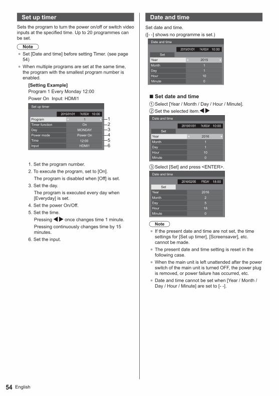
English54
Set up timerSets the program to turn the power on/off or switch video inputs at the specified time. Up to 20 programmes can be set.
Note●Set [Date and time] before setting Timer. (see page
54)●When multiple programs are set at the same time,
the program with the smallest program number is enabled.
[Setting Example]Program 1 Every Monday 12:00Power On Input: HDMI1
12:00
Set up timer
ProgramTimer function
1On
Power On
HDMI1
Day
TimePower mode
Input
MONDAY
123456
10:00THURSDAY2015/01/01
1. Set the program number.2. To execute the program, set to [On].
The program is disabled when [Off] is set. 3. Set the day.
The program is executed every day when [Everyday] is set.
4. Set the power On/Off.5. Set the time.
Pressing once changes time 1 minute.Pressing continuously changes time by 15 minutes.
6. Set the input.
Date and timeSet date and time.([- -] shows no programme is set.)
Date and time
SetTHURSDAY 10:002015/01/01
Year 2015MonthDayHour
11
100
■ Set date and time Select [Year / Month / Day / Hour / Minute]. Set the selected item.
Date and time
SetTHURSDAY 10:002015/01/01
Year 2016MonthDayHour
11
100
Select [Set] and press <ENTER>.Date and time
SetFRIDAY 18:002016/02/05
Year 2016MonthDayHourMinute
25
180
Note● If the present date and time are not set, the time
settings for [Set up timer], [Screensaver], etc. cannot be made.
●The present date and time setting is reset in the following case.
●When the main unit is left unattended after the power switch of the main unit is turned OFF, the power plug is removed, or power failure has occurred, etc.
●Date and time cannot be set when [Year / Month / Day / Hour / Minute] are set to [- -].
Minute
Minute

55English
Network settings
Set when networking with a computer.[Network settings] submenu will be displayed.
Network settings
Network controlLFE8-00
Off
Off
Off
Display name
Network statusLAN setup
AMX D.D.Crestron Connected™
Reset
■ [Network control]Set when controlling with the unit’s LAN terminal.[On]:
Controls via LAN using the LAN terminal of the Display. The power indicator lights orange when the power is turned off with the remote control (standby).
[Off]:Invalidates control with LAN terminal.(In this case, the power consumption of Standby condition (when the power is turned off with the remote control) will be slightly reduced.)
Note●When using the LAN control function for “Using
Network Function” (page 64-72), set this function to [On].
■ [Display name]The name of the Display that is shown on the network can be changed.
■ [LAN setup]
Detailed network settings for the LAN established via the LAN terminal of the Display or twisted pair cable transmitter can be configured.Select [LAN setup] with and press <ENTER>.
192.168. 0. 8255.255.255. 0192.168. 0. 1
1024
0--:--:--:--:--:--
LAN setup
SaveDHCP Off
IP addressSubnet maskGateway
Port
[DHCP], [IP address], [Subnet mask], [Gateway]
Press to set [On] / [Off] of [DHCP] and press <ENTER>.When [Off] is selected, IP address and other settings can be set manually.
[DHCP]:(DHCP client function)
[On]:Obtains an IP address automatically when a DHCP server exists in the network the Display is going to be connected.
[Off]:When a DHCP server does not exist in the network the Display is going to be connected, set [IP address], [Subnet mask] and [Gateway] manually.
[IP address]:(IP address display and setting)
Enter an IP address when DHCP server is not used.[Subnet mask]:(Subnet mask display and setting)
Enter a Subnet mask when DHCP server is not used.
[Gateway]:(Gateway address display and setting)
Enter a gateway address when DHCP server is not used.
Note●When [DHCP] is set to [On], the IP address, etc. will
be displayed in gray.
Entering numbers
I192.168. 0. 8IP address
1. Select the address and press <ENTER>.2. Select digits with .3. Change numbers with .4. Press <ENTER>.
You can cancel the change by pressing <RETURN>.
Select [Save] and press <ENTER>.Save the current network Setup.
Note●To use a DHCP server, make sure the DHCP server
is started.●Contact your network administrator for details on [IP
address], [Subnet mask] and [Gateway].●Shipping condition
[DHCP]: Off[IP address]: 192.168.0.8[Subnet mask]: 255.255.255.0[Gateway]: 192.168.0.1
[Port]Set the port number used for command control.Select [Port] and press <ENTER> to set the number.●The available setting range is 1024 - 65535.●Entering numbers (see page 55)

English56
Note●When the PJLink protocol is used, the port setting is
not necessary.
■ [Network status]
Checks the current Network settings status.
192. 168. 0. 1255. 255. 255. 0192. 168. 0. 8
12:34:56:78:9A:BC
Network status
DHCPIP addressSubnet maskGatewayMAC address
Off
■ [AMX D.D.]Set whether to allow the Display to be detected by AMX Device Discovery.[On]:
Enables detection by AMX Device Discovery.[Off]:
Disables detection by AMX Device Discovery.●For more details, visit the following web site.
http://www.amx.com/ ■ [Crestron Connected™]When this function is set to [On], the Display can be monitored or controlled via the network using equipment and application software of Crestron Electronics, Inc.This Display supports the following application software from Crestron Electronics, Inc.●RoomView® Express●Fusion RV®●RoomView® Server Edition[Crestron Connected™] is a function to connect to a system developed by Crestron Electronics, Inc. which manages and controls multiple system devices connected to the network.●For details of “Crestron Connected™”, refer to the
Crestron Electronics, Inc. website (Provided only in English).
http://www.crestron.com/For the download of “RoomView® Express”, refer to the Crestron Electronics, Inc. website (Provided only in English).http://www.crestron.com/getroomview
■ [Reset]You can reset the network setting to the factory default of the Display.Select [Yes] with . and press <ENTER>.
Network settings
Reset
Yes No
USB media player settingsSet for USB media player function.USB media player settings
USB media player settings
USB media playerResume playScenario file checkNo scenario fileSlide show duration
Enable
10 sec
On
■ USB media playerSet to enable or disable to USB media player function.
■ Resume PlaySet to enable or disable to play to be resumed.
■ Scenario file checkExecute the USB memory contents check. If any error is detected, the error code and file name will be displayed.For details of the error codes, refer to “USB memory contents check”.(see page 34)
Select [Scenario file check] with and press <ENETR>.
Available
Scenario file check
■ Slide show durationSelect the displaying duration for still images.10 sec - 600 sec

57English
Function button settingsAssigns specific functions to the numeric buttons (<1> to <6>). The buttons can be used as shortcut keys by assigning frequently used operations.
1 Switch [Function group] with .
OnUSB
PCDVI-DHDMI2HDMI1
VIDEO
Function button settings
Function groupFunction button 1Function button 2Function button 3Function button 4Function button 5Function button 6Function button guide
Input Input↓
Memory load↓
Shortcut
2 Select the numeric button with and set the function to assign with
.
■ Functions assignable to the numeric buttons
[Input] (Direct input select)Input can be selected with single-touch operation.HDMI1 / HDMI2 / DVI-D / PC / VIDEO / USB
[Memory load]Memory can be loaded with single-touch operation.Memory load (see page 45)
[MEMORY1] - [MEMORY6][MEMORY1] to [MEMORY6] load functions are already assigned to <1> to <6> respectively. These settings cannot be changed.
[Shortcut] [Signal], [Screensaver], [Set up timer], [Power management settings], [Network settings] ●Pressing the numeric button displays the menu
screen. Pressing the button again exits the menu screen.
[AV mute]●Pressing the numeric button mutes the audio and
pictures.To cancel, press any button on the remote control except Standby (ON/OFF) button.
Shipping conditionThe following functions are assigned to the numeric buttons as factory default.
[Input] [Memory load] [Shortcut]1 HDMI1 MEMORY1 [Signal]
2 HDMI2 MEMORY2 [Screensaver]3 DVI-D MEMORY3 [Set up timer]4 PC MEMORY4 [Power
management settings]
5 VIDEO MEMORY5 [Network settings]6 USB MEMORY6 [AV mute]
■ Function button guideSets the function display when numeric buttons are pressed. Set this for each function group.
[On]: Displays the function list for the numeric buttons.
[Off]: Does not display the function list. Operation starts when numeric buttons are pressed.
Note●When <FUNCTION > is pressed, [Function button
guide] will be displayed regardless of the [On] / [Off] settings.
To use shortcut (numeric buttons)
1 Press <FUNCTION> or <1> - <6>.[Function button guide] will be displayed.[Function button guide]: When [Off] is set, pressing the numeric button starts operation.Example: Input
1. 2. 3. 4. 5. 6.
HDMI 1HDMI 2DVI-DPCVIDEOUSB
Input
2 Press <FUNCTION> to switch function group.Example: Memory load
1. 2. 3. 4. 5. 6.
MEMORY 1MEMORY 2MEMORY 3MEMORY 4MEMORY 5MEMORY 6
Memory load
3 Press <1> - <6>.The function for the pressed button starts to operate.Example: When <2> is pressed.
Memory load
Load from “MEMORY2”
Ok Cancel

English58
Display orientation
Sets the on-screen display orientation in the portrait setting.
[Landscape]:On-screen display angle is for horizontal installation.
[Portrait]:The on-screen display rotates anticlockwise by 90 degrees for easy view in the portrait setting.
Power Indicator
Note● In the portrait setting, the power indicator shall come
to the downside.
OSD positionSets the display position of the on-screen menu.Each time or is pressed, the display position of the on-screen menu changes.Display example:
Upper/Left
18:00
Centre/Centre
18:00
Menu display durationSets the display duration time for the on-screen menu.[5 sec - 180 sec]
Menu transparencySets the transparency rate of the on-screen display background.0 - 100
43/48/55-inch models
65-inch model

59English
Options AdjustmentsThis unit offers special functions conveniently used according to the installation location and application.
1 Press <SETUP>.[Setup] menu screen will be displayed.
2 Select [OSD language] with and press <ENTER> for more than 3 seconds.Following screen will be displayed.
OptionsDisplay serial number
USB data cloningSoftware licenses
Shipping
3 Select [Options] with and press <ENTER>.[Options] menu screen will be displayed.
1/3
00
Options
Input searchOnscreen display
Initial VOL levelInitial input
Maximum VOL levelInput lockButton lockController user levelPC auto setting
OffOffOff
On
OffOffOffOff
2/3
0
Options
Off-timer functionInitial power modeDisplay IDController ID functionSerial ID function
Information timingLAN control protocol Protocol 1
OffOff
EnableNormal
3/3Options
Power on screen delayClock displayPower on message(No activity power off)Power on message(Power management)POWER button lock Off
OnOn
OffOff
4 Select the item to set with .●For [Input search] and [Information timing], the
sub menu screen will be displayed when you press <ENTER>.(see page 59, 62)
5 Set with .
6 Press <SETUP> to exit from [Options] menu.
Note●The remote control is necessary to display the
[Options] menu. The control panel buttons on the main unit cannot be used to display the menu.
●Press <RETURN> to return to the previous menu.●The serial number of this device is displayed when
[Display serial number] is selected in step 3.●The software License is displayed when [Software
licenses] is selected in step 3.
Input searchWhen a signal is not detected, another input with a signal is automatically selected.Select the item with .Select the set point with .
Input search
Input search1st search input2nd search input
Custom
[Input search]
[Off]:When there is no signal, the input is not switched automatically.
[All inputs]:Searches all inputs and switches to an input with a signal.Input search is executed in the following order.(Example) When the current input is [HDMI1][HDMI2]→[DVI-D]→·········→[USB]→[HDMI1]
[Custom]:Repeatedly searches [Current input], [1st search input] and [2nd search input] in order, and switches to an input with a signal.
PC16:9
Searching.. .
[Searching...] is displayed during the input search.
[1st search input], [2nd search input]Set the input to search when [Custom] is selected.(None) / [HDMI1] / [HDMI2] / [DVI-D] / [PC] / [VIDEO] / [USB]
Note●This menu is available only when [Input lock] is [Off].
(see page 60)● If the input is changed by this function, the last input
is selected when the power is turned on next time.If you wish to retain the original input when the power is turned on, set [Initial input] to the original input.
(None)(None)

English60
Onscreen displaySet to display / hide the following Onscreen display.●Power on display● Input signal switch display●No signal display●MUTE display after displaying the menu screen●MUTE and off timer remaining time display after
<RECALL> is pressed●Off timer remaining time display when 3 minutes
remaining
[On]: Displays the Onscreen display.[Off]: Hides the Onscreen display.
Initial inputAdjusts the input signal when the unit is turned on.
[Off] / [HDMI1] / [HDMI2] / [DVI-D] / [PC] / [VIDEO] / [USB]
Note●This menu is available only when [Input lock] is [Off].
(see page 60)
Initial VOL levelAdjusts the sound volume level when the unit is turned on.
[Off]: It will be the sound volume level which had been set before the power of the unit was turned off.
[On]: Sets your preferred volume.
●You can hear the changed volume regardless of your volume setting before opening the [Options] menu if you adjust the volume when [Initial VOL level] is [On] and cursor is on the menu.
■ To adjust sound volume levelPress <VOL +> <VOL ->.
Note●When [Maximum VOL level] is [On], the volume
can only be adjusted between 0 and your maximum range. (see page 60)
Maximum VOL levelAdjusts the maximum volume.
[Off]: The sound volume level can be set up to 100 (maximum).
[On]: The sound volume level will not exceed the set point.
●You can hear the changed volume regardless of your volume setting before opening the [Options] menu if you adjust the volume when [Maximum VOL level] is [On] and cursor is on the menu.
■ To adjust sound volume levelPress <VOL +> <VOL ->.
Note●When the [Maximum VOL level] is set lower than the
[Initial VOL level], the [Initial VOL level] automatically becomes the same as the [Maximum VOL level].The volume display can go up to 63 regardless of the settings.
Input lockLocks the input switch operation.
[Off] / [HDMI1] / [HDMI2] / [DVI-D] / [PC] / [VIDEO] / [USB]
Note● Input switch can be used when this is set to [Off].
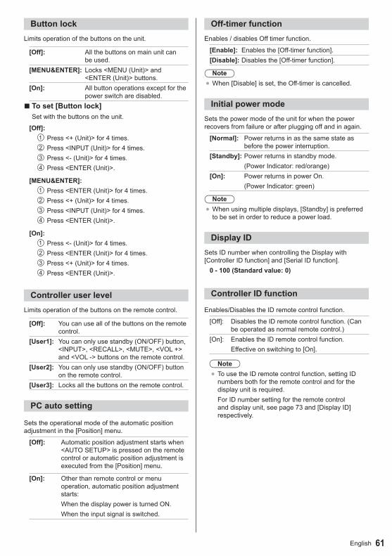
61English
Button lockLimits operation of the buttons on the unit.
[Off]: All the buttons on main unit can be used.
[MENU&ENTER]: Locks <MENU (Unit)> and <ENTER (Unit)> buttons.
[On]: All button operations except for the power switch are disabled.
■ To set [Button lock]Set with the buttons on the unit.
[Off]: Press <+ (Unit)> for 4 times. Press <INPUT (Unit)> for 4 times. Press <- (Unit)> for 4 times. Press <ENTER (Unit)>.
[MENU&ENTER]: Press <ENTER (Unit)> for 4 times. Press <+ (Unit)> for 4 times. Press <INPUT (Unit)> for 4 times. Press <ENTER (Unit)>.
[On]: Press <- (Unit)> for 4 times. Press <ENTER (Unit)> for 4 times. Press <+ (Unit)> for 4 times. Press <ENTER (Unit)>.
Controller user levelLimits operation of the buttons on the remote control.
[Off]: You can use all of the buttons on the remote control.
[User1]: You can only use standby (ON/OFF) button, <INPUT>, <RECALL>, <MUTE>, <VOL +> and <VOL -> buttons on the remote control.
[User2]: You can only use standby (ON/OFF) button on the remote control.
[User3]: Locks all the buttons on the remote control.
PC auto setting
Sets the operational mode of the automatic position adjustment in the [Position] menu.
[Off]: Automatic position adjustment starts when <AUTO SETUP> is pressed on the remote control or automatic position adjustment is executed from the [Position] menu.
[On]: Other than remote control or menu operation, automatic position adjustment starts:When the display power is turned ON.When the input signal is switched.
Off-timer functionEnables / disables Off timer function.
[Enable]: Enables the [Off-timer function].[Disable]: Disables the [Off-timer function].
Note●When [Disable] is set, the Off-timer is cancelled.
Initial power modeSets the power mode of the unit for when the power recovers from failure or after plugging off and in again.
[Normal]: Power returns in as the same state as before the power interruption.
[Standby]: Power returns in standby mode. (Power Indicator: red/orange)
[On]: Power returns in power On. (Power Indicator: green)
Note●When using multiple displays, [Standby] is preferred
to be set in order to reduce a power load.
Display IDSets ID number when controlling the Display with [Controller ID function] and [Serial ID function].
0 - 100 (Standard value: 0)
Controller ID function
Enables/Disables the ID remote control function.
[Off]: Disables the ID remote control function. (Can be operated as normal remote control.)
[On]: Enables the ID remote control function.Effective on switching to [On].
Note●To use the ID remote control function, setting ID
numbers both for the remote control and for the display unit is required.For ID number setting for the remote control and display unit, see page 73 and [Display ID] respectively.
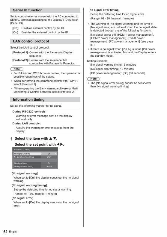
English62
Serial ID functionSet to control external control with the PC connected to SERIAL terminal according to the Display’s ID number (Panel ID).
[Off]: Disables external control by the ID.[On]: Enables the external control by the ID.
LAN control protocolSelect the LAN control protocol.
[Protocol 1]: Control with the Panasonic Display sequence.
[Protocol 2]: Control with the sequence that compatible with Panasonic Projector.
Note●For PJLink and WEB browser control, the operation is
possible regardless of the setting.●When performing the command control with TCP/IP,
select [Protocol 1].● When operating the Early warning software or Multi
Monitoring & Control Software, select [Protocol 2].
Information timingSet up the informing manner for no signal.
During RS-232C controls:Warning or error message sent on the display automatically.
During LAN controls:Acquire the warning or error message from the display.
1 Select the item with .Select the set point with .Information timing
No signal warningNo signal warning timing
No signal errorNo signal error timing
On5min
On10min
[No signal warning]When set to [On], the display sends out the no signal warning.
[No signal warning timing]Set up the detecting time for no signal warning.(Range: 01 - 60, Interval: 1 minute)
[No signal error]When set to [On], the display sends out the no signal error.
[No signal error timing]Set up the detecting time for no signal error.(Range: 01 - 90, Interval: 1 minute)
●The warning of [No signal warning] and the error of [No signal error] are not sent when the no signal state is detected through any of the following functions: [No signal power off], [HDMI1 power management], [HDMI2 power management], [DVI-D power management], [PC power management] (see page 51)
● If there is no signal when [PC IN] is input, [PC power management] is activated first and the Display enters the standby mode.
Setting Example:[No signal warning timing]: 5 minutes[No signal error timing]: 10 minutes[PC power management]: [On] (60 seconds)
Note●The [No signal error timing] cannot be set shorter
than [No signal warning timing].
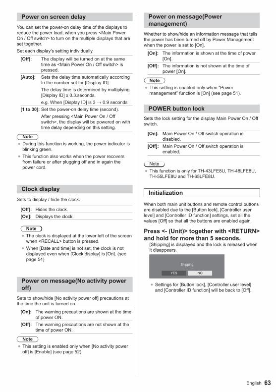
63English
Power on screen delayYou can set the power-on delay time of the displays to reduce the power load, when you press <Main Power On / Off switch> to turn on the multiple displays that are set together.Set each display’s setting individually.
[Off]: The display will be turned on at the same time as <Main Power On / Off switch> is pressed.
[Auto]: Sets the delay time automatically according to the number set for [Display ID].The delay time is determined by multiplying [Display ID] x 0.3.seconds.e.g.When[DisplayID]is3→0.9seconds
[1 to 30]: Set the power-on delay time (second).After pressing <Main Power On / Off switch>, the display will be powered on with time delay depending on this setting.
Note●During this function is working, the power indicator is
blinking green.●This function also works when the power recovers
from failure or after plugging off and in again the power cord.
Clock displaySets to display / hide the clock.
[Off]: Hides the clock.[On]: Displays the clock.
Note●The clock is displayed at the lower left of the screen
when <RECALL> button is pressed.●When [Date and time] is not set, the clock is not
displayed even when [Clock display] is [On]. (see page 54)
Power on message(No activity power off)
Sets to show/hide [No activity power off] precautions at the time the unit is turned on.
[On]: The warning precautions are shown at the time of power ON.
[Off]: The warning precautions are not shown at the time of power ON.
Note●This setting is enabled only when [No activity power
off] is [Enable] (see page 52).
Power on message(Power management)
Whether to show/hide an information message that tells the power has been turned off by Power Management when the power is set to [On].
[On]: The information is shown at the time of power [On].
[Off]: The information is not shown at the time of power [On].
Note●This setting is enabled only when “Power
management” function is [On] (see page 51).
POWER button lockSets the lock setting for the display Main Power On / Off switch.
[On]: Main Power On / Off switch operation is disabled.
[Off]: Main Power On / Off switch operation is enabled.
Note●This function is only for TH-43LFE8U, TH-48LFE8U,
TH-55LFE8U and TH-65LFE8U.
Initialization
When both main unit buttons and remote control buttons are disabled due to the [Button lock], [Controller user level] and [Controller ID function] settings, set all the values [Off] so that all the buttons are enabled again.
Press <- (Unit)> together with <RETURN> and hold for more than 5 seconds.
[Shipping] is displayed and the lock is released when it disappears.
Shipping
YES NO
●Settings for [Button lock], [Controller user level] and [Controller ID function] will be back to [Off].

English64
Using Network FunctionThis unit has a network function and you can control the Display connected to the network using your computer.
Necessary environment for computers to be connected
First of all, confirm your computer whether it has a wired LAN or a built-in wireless LAN.Before connecting the Display to the computer, be sure to check the following settings.
Check 1: About LAN cable
● Is the cable connected properly?●To connect a device using 100BASE-TX, use LAN
cable that is compatible with category 5 or above.
Check 2: LAN settings
Computer with a built-in LAN function● Is your LAN switched on?Computer without a built-in LAN function● Is your LAN adapter recognized properly?● Is your LAN adapter switched on?● Install the LAN adapter driver beforehand.
For details on how to install the driver, refer to the instructions accompanying the LAN adapter.
■ About Web BrowserWeb Browser is necessary to use WEB control.●Compatible OS:
Windows XP / Windows Vista / Windows 7 / Windows 8,Mac OS X v10.4 / v10.5 / v10.6, OS X v10.7 / v10.8
●Compatible Web Browser: Internet Explorer 7.0 / 8.0 / 9.0 / 10.0,Safari 4.x / 5.x / 6.x (Mac OS)
Example of network connectionNote
●To use the network function, set each item in [Network settings] and make sure to set [Network control] to [On].(see page 55)When it is set to [On], power indicator lights orange under the condition of power “Off” with remote control (stand-by state).
■ LAN Terminal connection
Back of the Display COMPUTER LAN Terminal LAN cable (not supplied) Hub or broadband router
Note●For LAN cable, use shielded cable, otherwise picture
noise may be caused.●Make sure the broadband router or hub supports
10BASE-T/100BASE-TX.●Touching the LAN Terminal with a statically charged
hand (body) may cause damage to the device due to its discharge.Do not touch the LAN Terminal or the metal part of the LAN cable.
●For instructions on connection, consult your network administrator.

65English
Command controlNetwork function of the unit can control the unit in the same way as serial control from a network.
Supported commandsCommands used in the serial control are supported. (see page 20)
Note● If you would like more detail, please contact the
dealer.
PJLink protocolThe unit’s Network function is compatible with PJLink Class 1. The following operations can be performed from a computer when PJLink protocol is used.●Setting the Display●Querying the Display status
Supported commandsThe commands to control the unit with PJLink protocol are as follows.
Command ControlPOWR Power control
0: Standby1: Power On
POWR? Power status query0: Standby1: Power On
INPT Input switch11: PC IN input (PC)21: VIDEO input (VIDEO)31: HDMI 1 input (HDMI1)32: HDMI 2 input (HDMI2)33: DVI-D IN input (DVI-D)41: USB input (USB)
INPT? Input switch query11: PC IN input (PC)21: VIDEO input (VIDEO)31: HDMI 1 input (HDMI1)32: HDMI 2 input (HDMI2)33: DVI-D IN input (DVI-D)41: USB input (USB)
Command ControlAVMT Shutter control
10: Picture On (picture mute deactivated)
11: Picture Off (picture on mute)
20: Audio On (audio mute deactivated)
21: Audio Off (audio on mute)
30: Shutter mode Off (picture and audio mute deactivated)
31: Shutter mode On (picture and audio on mute)
AVMT? Shutter control query11: Picture Off (picture on mute)21: Audio Off (audio on mute)30: Shutter mode Off
(picture and audio mute deactivated)
31: Shutter mode On (picture and audio on mute)
ERST? Error status queryFirst byte: 0Second byte: 0Third byte: 0Fourth byte: 0Fifth byte: 0Sixth byte: Other error. 0 or 2.●Meaning of 0, 2.
0: Error is not detected,2: Error
LAMP? Lamp status queryNot supported
INST? Input switch list query11: PC IN input (PC)21: VIDEO input (VIDEO)31: HDMI 1 input (HDMI1)32: HDMI 2 input (HDMI2)33: DVI-D IN input (DVI-D)41: USB input (USB)
NAME? Display name queryThe name selected in [Display name] is returned.
INF1? Manufacturer name queryReturns “Panasonic”.
INF2? Model name queryReturns “48LFE8U”.(Example: 48-inch U model)Returns “48LFE8E”.(Example: 48-inch E model)
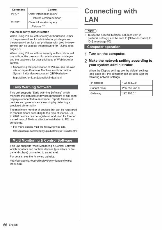
English66
Command ControlINFO? Other information query
Returns version number.CLSS? Class information query
Returns “1”.
PJLink security authenticationWhen using PJLink with security authorization, either of the password set for administrator privileges and the password set for user privileges with Web browser control can be used as the password for PJLink. (see page 67)When using PJLink without security authorization, set use without the password for administrator privileges and the password for user privileges of Web browser control.●Concerning the specification of PJLink, see the web
site of Japan Business Machine and Information System Industries Association (JBMIA) below:http://pjlink.jbmia.or.jp/english/index.html
Early Warning SoftwareThis unit supports “Early Warning Software” which monitors the statuses of devices (projectors or flat-panel displays) connected to an intranet, reports failures of devices and gives advance warning by detecting a predicted abnormality.The maximum number of devices that can be registered to monitor differs according to the type of license. Up to 2048 devices can be registered and used for free for a maximum of 90 days after the installation to PC has completed.●For more details, visit the following web site.
http://panasonic.net/prodisplays/products/et-swa100/index.html
Multi Monitoring & Control SoftwareThis unit supports “Multi Monitoring & Control Software” which monitors and controls devices (projectors or flat-panel displays) connected to an intranet.For details, see the following website.http://panasonic.net/prodisplays/download/software/index.html
Connecting with LAN
Note●To use the network function, set each item in
[Network settings] and be sure to [Network control] to [On]. (see page 55)
Computer operation
1 Turn on the computer.
2 Make the network setting according to your system administrator.When the Display settings are the default settings (see page 55), the computer can be used with the following network settings.
IP address 192.168.0.9
Subnet mask 255.255.255.0
Gateway 192.168.0.1

67English
Using Web Browser ControlYou can use a Web browser to control the unit and set up a network and password.
Before Using Web Browser ControlTo use the Web browser control, the unit and computer set ups are required.
■ About Web BrowserSet each item in [Network settings] and be sure to set [Network control] to [On]. (see page 55) ■ Computer SetupDisable the proxy server settings and enable JavaScript.●The setting procedure differs depending on the
software version.Please refer to description in HELP, etc. of the software.
(Windows)Windows 7 is used as an example.Disable proxy server settings1 Display [Internet Properties] window.
Click [Start] - [Control Panel] - [Network and Internet] - [Internet Options].● If the on screen display looks different, please set
[View by:] to [Category].2 Click the [Connections] tab and then [LAN Settings].3 Deselect the [Use automatic configuration script] and
[Use a proxy server for your LAN] boxes.4 Click [OK].
Enable JavaScript1 Display [Internet Properties] window.
Click [Start] - [Control Panel] - [Network and Internet] - [Internet Options].● If the on screen display looks different, please set
[View by:] to [Category].2 Set the security level on the [Security] tab to [Default
Level]. Alternatively enable [Active scripting] from the [Custom Level] button.
(Macintosh)Disable proxy server settings1 From the [Safari] menu, click [Preferences].
General screen is displayed.2 From the [Advanced] tab, click the [Change
Settings…] button next to [Proxies].Click [Proxies] and set up a proxy server.
3 Deselect the [Web Proxy] and [Automatic Proxy Configuration] boxes.
4 Click [Apply Now].
Enable JavaScript1 Display [Security] of Safari.2 Select [Enable JavaScript] under [Web content].
Access from Web BrowserAccess to the TOP screen of the Web browser control using a Web browser.
1 Start your Web browser.
2 Enter the IP address set with the [LAN setup] of the unit.(see page 55)
3 Enter the user name and password when the Authentication screen is displayed.
4 Click [OK].After logged in, the TOP screen of the Web Browser Control is displayed. (see page 68)
Note●The password used here is the same password
used for command control and the PJLink security authentication.
●Default user name and password are as follows:User name: user1 (User rights), admin1 (administrator rights)Password: panasonicChange password first.
●The password can be changed on the Password Setup screen after logging in (see page 69). Log in with administer privileges to change this.
●When using “Crestron Connected™” (see page 71), log in with the administrator rights.
●Under no circumstances, Panasonic Corporation or its associated companies will ask customers their password directly.Even if you are asked directly, please do not reveal your password.

English68
Operating with Web Browser ■ Description of each item
Page tabClick these to switch pages.[Status]Click this item, and the status of the Display is displayed.[Display control]Click this item to display the Display control page.[Detailed set up]Click this item to display the advanced settings page.[Change password]Crestron Connected™Click this item to display the Crestron Connected™ operation page.
Display status pageClick [Status], then [Display status] to display the Status information page.This page displays the Display statuses established for the items shown below.
Displays the type of Display.
Displays the firmware version of the Display main unit.
Network status pageClick [Status], then [Network status] to display the Status information page.Displays the current configuration information of the network.
Displays the configuration details of wired LAN.
Basic control pageTo move from another page, click [Display control], then [Basic control].
Power On/Off control
Use these to select the input signals
AUDIO mute
Switches aspect mode
Detail control pageClick [Display control], then [Advanced control] to display the Detail control page.
Enter a command. Use the same command used for the serial control.Response from the unit is displayed.
Command is sent and run.
Note●After the settings are changed, it may take a while
till the display status is displayed.
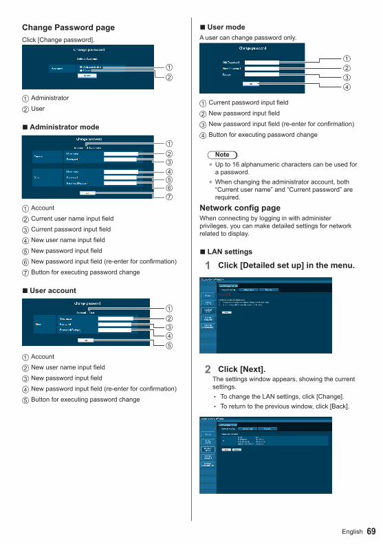
69English
Change Password pageClick [Change password].
12
Administrator
User
■ Administrator mode
1234567
Account
Current user name input field
Current password input field
New user name input field
New password input field
New password input field (re-enter for confirmation)
Button for executing password change
■ User account
12345
Account
New user name input field
New password input field
New password input field (re-enter for confirmation)
Button for executing password change
■ User modeA user can change password only.
1234
Current password input field
New password input field
New password input field (re-enter for confirmation)
Button for executing password change
Note●Up to 16 alphanumeric characters can be used for
a password.●When changing the administrator account, both
“Current user name” and “Current password” are required.
Network config pageWhen connecting by logging in with administer privileges, you can make detailed settings for network related to display.
■ LAN settings
1 Click [Detailed set up] in the menu.
2 Click [Next].The settings window appears, showing the current settings.
• To change the LAN settings, click [Change]. • To return to the previous window, click [Back].

English70
3 Complete the detailed settings and click [Next].
Setting contents here are the same as the address information contents set for the [LAN setup] menu of the Display.After all required items have been entered, click [Next]. Then, a confirmation window appears.
4 Click [Submit].The settings will be registered.
Note●Changing the setting of LAN while connected with
LAN might disconnect the connection.
Adjust clock pageClick [Detailed set up], then [Adjust clock] to display the Adjust clock page.
New date field
New time field
Button to update time and date settings
Note●Date and time is displayed as [- -] when they are
not set.●When [Network control] is set to [On] and it is in
standby mode, date and time display will be blank and they cannot be set.
● If the time becomes incorrect immediately after setting the correct time, contact the dealer where you bought the Display.
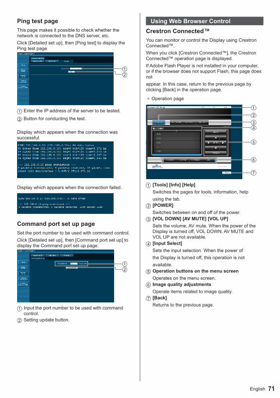
71English
Ping test pageThis page makes it possible to check whether the network is connected to the DNS server, etc.Click [Detailed set up], then [Ping test] to display the Ping test page.
Enter the IP address of the server to be tested.
Button for conducting the test.
Display which appears when the connection was successful.
Display which appears when the connection failed.
Command port set up pageSet the port number to be used with command control.Click [Detailed set up], then [Command port set up] to display the Command port set up page.
Input the port number to be used with command control.Setting update button.
Using Web Browser ControlCrestron Connected™ You can monitor or control the Display using Crestron Connected™.When you click [Crestron Connected™], the Crestron Connected™ operation page is displayed.If Adobe Flash Player is not installed in your computer, or if the browser does not support Flash, this page does notappear. In this case, return to the previous page by clicking [Back] in the operation page.
●Operation page
[Tools] [Info] [Help]Switches the pages for tools, information, helpusing the tab.[POWER]Switches between on and off of the power.[VOL DOWN] [AV MUTE] [VOL UP]Sets the volume, AV mute. When the power of the Display is turned off, VOL DOWN, AV MUTE and VOL UP are not available.[Input Select]Sets the input selection. When the power ofthe Display is turned off, this operation is notavailable.Operation buttons on the menu screenOperates on the menu screen.Image quality adjustmentsOperate items related to image quality.[Back]Returns to the previous page.
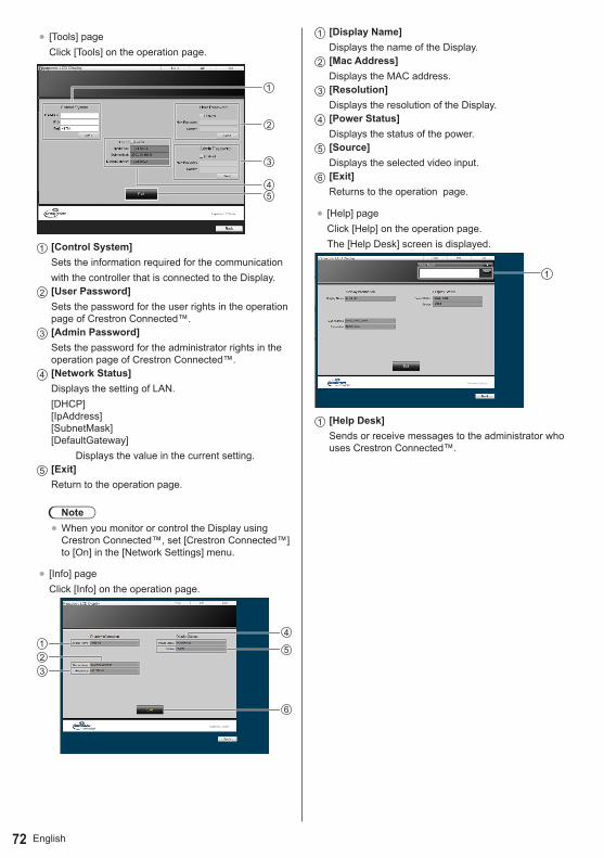
English72
● [Tools] pageClick [Tools] on the operation page.
Panasonic LCD Display
[Control System]Sets the information required for the communicationwith the controller that is connected to the Display.[User Password]Sets the password for the user rights in the operation page of Crestron Connected™.[Admin Password]Sets the password for the administrator rights in the operation page of Crestron Connected™.[Network Status]Displays the setting of LAN.[DHCP] [IpAddress] [SubnetMask] [DefaultGateway]
Displays the value in the current setting.[Exit]Return to the operation page.
Note●When you monitor or control the Display using
Crestron Connected™, set [Crestron Connected™] to [On] in the [Network Settings] menu.
● [Info] pageClick [Info] on the operation page.
[Display Name]Displays the name of the Display.[Mac Address]Displays the MAC address.[Resolution]Displays the resolution of the Display.[Power Status]Displays the status of the power.[Source]Displays the selected video input.[Exit]Returns to the operation page.
● [Help] pageClick [Help] on the operation page.The [Help Desk] screen is displayed.
[Help Desk]Sends or receive messages to the administrator who uses Crestron Connected™.
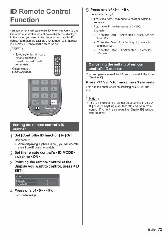
73English
ID Remote Control FunctionYou can set the remote control ID when you want to use this remote control on one of several different displays. In that case, you need to set the remote control’s ID number to match the Display’s ID number you have set in [Display ID] following the steps below.
Note
●To operate this function, please purchase ID remote controller sold separately.
Object model : N2QAYA000093
Setting the remote control’s ID number
1 Set [Controller ID function] to [On].(see page 61)●While displaying [Options] menu, you can operate
even if the ID does not match.
2 Set the remote control’s <ID MODE> switch to <ON>.
3 Pointing the remote control at the Display you want to control, press <ID SET>.
0?
ID set
Display IDController ID
4 Press one of <0> - <9>.Sets the tens digit.
5 Press one of <0> - <9>.Sets the units digit.
●The steps from 3 to 5 need to be done within 5 seconds.
●Adjustable ID number range is 0 - 100.Example:
• To set the ID to “1”: After step 3, press <0> and then <1>.
• To set the ID to “12”: After step 3, press <1> and then <2>.
• To set the ID to “100”: After step 3, press <1> <0> <0>.
Cancelling the setting of remote control’s ID number
You can operate even if the ID does not match the ID set in [Display ID].
Press <ID SET> for more then 3 seconds.This has the same effect as pressing <ID SET> <0> <0>.
Note●The ID remote control cannot be used when [Display
ID] is set to anything other than “0”, and the remote control ID is not the same as the [Display ID] number. (see page 61)

English74
Entering charactersSome settings require to enter characters.To enter text, select characters in the on-screen keyboard.
Example: Entering profile names ([Memory save])
MEMORY1█
01 2 3 4 5 6 7 8 9
a
a/A/@
b c d e f g h i j
k l m n o p q r s t
u v w x y z – _.
OkCancelAll deleteDelete
The default profile name is [MEMORY1], here, we are changing it to [MY PICTURE] as an example.
1 Select [All delete] with , and press <ENTER>.
MEMORY1█
All text is deleted.To delete individual characters, select [Delete].
2 Select [a / A / @] with and press <ENTER>.
a/A/@
01 2 3 4 5 6 7 8 9
a
a/A/@
b c d e f g h i j
k l m n o p q r s t
u v w x y z – _.
OkCancelAll deleteDelete
Switches the keyboard to the upper case alphabet.Each time <ENTER> is pressed, the keyboard is switched in the order of lower case, upper case and symbols.
3 Select [M] with , and press <ENTER>.
M█
Repeat this process to enter the next character.
4 Select Space key with , and press <ENTER>.
MY█
01 2 3 4 5 6 7 8 9
a
a/A/@
b c d e f g h i j
k l m n o p q r s t
u v w x y z – _.
OkCancelAll deleteDelete
Space key
As shown in step 3, select the characters to enter [PICTURE].
5 When you finished entering the profile name, select [Ok] with and press <ENTER>.
MY PICTURE█
01 2 3 4 5 6 7 8 9
a
a/A/@
b c d e f g h i j
k l m n o p q r s t
u v w x y z – _.
OkCancelAll deleteDelete
●To cancel saving the profile, select [Cancel].
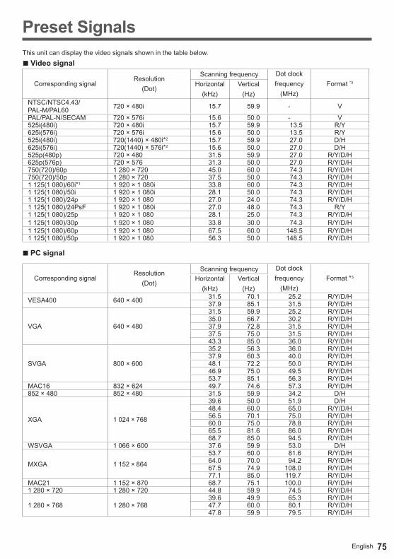
75English
Preset SignalsThis unit can display the video signals shown in the table below.
■ Video signal
Corresponding signalResolution
(Dot)
Scanning frequency Dot clockfrequency
(MHz)Format *3Horizontal
(kHz)Vertical
(Hz)NTSC/NTSC4.43/ PAL-M/PAL60 720 × 480i 15.7 59.9 - V
PAL/PAL-N/SECAM 720 × 576i 15.6 50.0 - V525i(480i) 720 × 480i 15.7 59.9 13.5 R/Y625i(576i) 720 × 576i 15.6 50.0 13.5 R/Y525i(480i) 720(1440) × 480i*2 15.7 59.9 27.0 D/H625i(576i) 720(1440) × 576i*2 15.6 50.0 27.0 D/H525p(480p) 720 × 480 31.5 59.9 27.0 R/Y/D/H625p(576p) 720 × 576 31.3 50.0 27.0 R/Y/D/H750(720)/60p 1 280 × 720 45.0 60.0 74.3 R/Y/D/H750(720)/50p 1 280 × 720 37.5 50.0 74.3 R/Y/D/H1 125(1 080)/60i*1 1 920 × 1 080i 33.8 60.0 74.3 R/Y/D/H1 125(1 080)/50i 1 920 × 1 080i 28.1 50.0 74.3 R/Y/D/H1 125(1 080)/24p 1 920 × 1 080 27.0 24.0 74.3 R/Y/D/H1 125(1 080)/24PsF 1 920 × 1 080i 27.0 48.0 74.3 R/Y1 125(1 080)/25p 1 920 × 1 080 28.1 25.0 74.3 R/Y/D/H1 125(1 080)/30p 1 920 × 1 080 33.8 30.0 74.3 R/Y/D/H1 125(1 080)/60p 1 920 × 1 080 67.5 60.0 148.5 R/Y/D/H1 125(1 080)/50p 1 920 × 1 080 56.3 50.0 148.5 R/Y/D/H
■ PC signal
Corresponding signalResolution
(Dot)
Scanning frequency Dot clockfrequency
(MHz)Format *3Horizontal
(kHz)Vertical
(Hz)
VESA400 640 × 400 31.5 70.1 25.2 R/Y/D/H37.9 85.1 31.5 R/Y/D/H
VGA 640 × 480
31.5 59.9 25.2 R/Y/D/H35.0 66.7 30.2 R/Y/D/H37.9 72.8 31.5 R/Y/D/H37.5 75.0 31.5 R/Y/D/H43.3 85.0 36.0 R/Y/D/H
SVGA 800 × 600
35.2 56.3 36.0 R/Y/D/H37.9 60.3 40.0 R/Y/D/H48.1 72.2 50.0 R/Y/D/H46.9 75.0 49.5 R/Y/D/H53.7 85.1 56.3 R/Y/D/H
MAC16 832 × 624 49.7 74.6 57.3 R/Y/D/H852 × 480 852 × 480 31.5 59.9 34.2 D/H
XGA 1 024 × 768
39.6 50.0 51.9 D/H48.4 60.0 65.0 R/Y/D/H56.5 70.1 75.0 R/Y/D/H60.0 75.0 78.8 R/Y/D/H65.5 81.6 86.0 R/Y/D/H68.7 85.0 94.5 R/Y/D/H
WSVGA 1 066 × 600 37.6 59.9 53.0 D/H
MXGA 1 152 × 864
53.7 60.0 81.6 R/Y/D/H64.0 70.0 94.2 R/Y/D/H67.5 74.9 108.0 R/Y/D/H77.1 85.0 119.7 R/Y/D/H
MAC21 1 152 × 870 68.7 75.1 100.0 R/Y/D/H1 280 × 720 1 280 × 720 44.8 59.9 74.5 R/Y/D/H
1 280 × 768 1 280 × 76839.6 49.9 65.3 R/Y/D/H47.7 60.0 80.1 R/Y/D/H47.8 59.9 79.5 R/Y/D/H
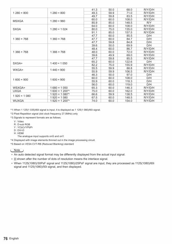
76 English
1 280 × 800 1 280 × 80041.3 50.0 68.0 R/Y/D/H49.3 59.9 71.0 R/Y/D/H49.7 59.8 83.5 R/Y/D/H
MSXGA 1 280 × 960 60.0 60.0 108.0 R/Y/D/H85.9 85.0 148.5 R/Y
SXGA 1 280 × 1 02464.0 60.0 108.0 R/Y/D/H80.0 75.0 135.0 R/Y/D/H91.1 85.0 157.5 R/Y/D/H
1 360 × 768 1 360 × 76847.7 60.0 85.5 D/H47.7 60.0 84.7 D/H47.7 59.8 84.8 D/H
1 366 × 768 1 366 × 768
39.6 50.0 69.9 D/H48.4 60.0 86.7 R/Y/D/H48.0 60.0 72.0 R/Y/D/H39.6 49.9 69.0 R/Y/D/H47.7 59.8 85.5 R/Y/D/H
SXGA+ 1 400 × 1 050 65.2 60.0 122.6 D/H82.2 75.0 155.9 R/Y/D/H
WXGA+ 1 440 × 900 55.5 59.9 88.8 R/Y/D/H55.9 59.9 106.5 R/Y/D/H
1 600 × 900 1 600 × 900
46.3 50.0 97.0 D/H60.0 60.0 108.0 D/H55.9 60.0 118.3 D/H56.0 60.0 119.0 D/H
WSXGA+ 1 680 × 1 050 65.3 60.0 146.3 R/Y/D/HUXGA 1 600 × 1 200*4 75.0 60.0 162.0 R/Y/D/H
1 920 × 1 080 1 920 × 1 080*5 66.6 59.9 138.5 R/Y/D/H1 920 × 1 080 67.5 60.0 148.5 R/Y/D/H
WUXGA 1 920 × 1 200*4 74.0 60.0 154.0 R/Y/D/H
*1: When 1 125(1 035)/60i signal is input, it is displayed as 1 125(1 080)/60i signal.*2: Pixel-Repetition signal (dot clock frequency 27.0MHz) only*3: Signals to represent formats are as follows.
V : Video R : D-sub RGB Y : YCbCr/YPbPr D : DVI-D H : HDMI
The analogue input supports onG and onY.*4: Displayed with image elements thinned out in the image processing circuit.*5: Based on VESA CVT-RB (Reduced Blanking) standard
Note●An auto detected signal format may be differently displayed from the actual input signal.● [i] shown after the number of dots of resolution means the interlace signal.●When 1125(1080)/30PsF signal and 1125(1080)/25PsF signal are input, they are processed as 1125(1080)/60i
signal and 1125(1080)/50i signal, and then displayed.
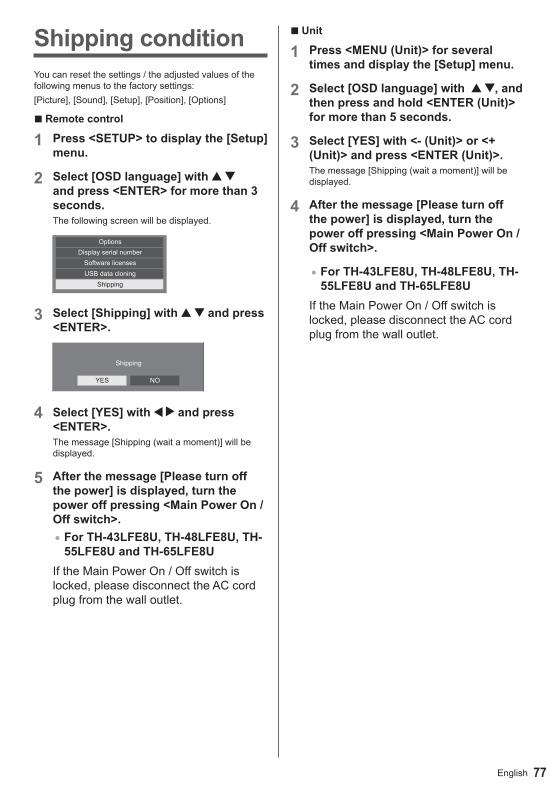
77English
■ Unit
1 Press <MENU (Unit)> for several times and display the [Setup] menu.
2 Select [OSD language] with , and then press and hold <ENTER (Unit)> for more than 5 seconds.
3 Select [YES] with <- (Unit)> or <+ (Unit)> and press <ENTER (Unit)>.The message [Shipping (wait a moment)] will be displayed.
4 After the message [Please turn off the power] is displayed, turn the power off pressing <Main Power On / Off switch>.
●For TH-43LFE8U, TH-48LFE8U, TH-55LFE8U and TH-65LFE8U
If the Main Power On / Off switch is locked, please disconnect the AC cord plug from the wall outlet.
Shipping conditionYou can reset the settings / the adjusted values of the following menus to the factory settings:[Picture], [Sound], [Setup], [Position], [Options]
■ Remote control
1 Press <SETUP> to display the [Setup] menu.
2 Select [OSD language] with and press <ENTER> for more than 3 seconds.The following screen will be displayed.
OptionsDisplay serial number
ShippingUSB data cloningSoftware licenses
3 Select [Shipping] with and press <ENTER>.
Shipping
YES NO
4 Select [YES] with and press <ENTER>.The message [Shipping (wait a moment)] will be displayed.
5 After the message [Please turn off the power] is displayed, turn the power off pressing <Main Power On / Off switch>.●For TH-43LFE8U, TH-48LFE8U, TH-
55LFE8U and TH-65LFE8UIf the Main Power On / Off switch is locked, please disconnect the AC cord plug from the wall outlet.

English78
Data CloningMenu settings and adjusted values set on a single display can be copied to multiple displays using a USB memory.
■ Data that can be copiedSettings and set values of [Picture], [Sound], [Setup], [Position] and [Options] menus●The following data cannot be copied. Setting is
required for each display.Date and time Setting for [Network settings] - [LAN setup]Display ID in [Options] - [Display ID]
■ Supported device● Commercially available USB memory devices are
supported. (Those with security functions are not supported.)
●USB memory devices other than those formatted in FAT16 or FAT32 cannot be used.
●Up to 32 GB of USB memory in size are supported.●Only single partition configuration is supported.
Note● If the inch size for display differs, the cloning
function does not operate. Use the common inch size.
●The remote control is used to display [USB data cloning] menu. Unit buttons cannot be used to display the menu.
●Set the input to something other than [USB], and perform the data cloning.
Copying the display data to the USB memory
1 Insert the USB memory device to the USB terminal on the side edge of the display.
USB memory
USB terminal
Note●Depending on the type of a USB memory device,
it may come in contact with the periphery such as a back cover, and cannot be attached. Use a commercially sold extension cable, or use a small type of a USB memory device connectable to this unit.
● If the USB memory containing the data for cloning is connected in power-on state, the [Select Copy Type] message in step 5 is displayed. Select [Display→USBMemory].Also,ifthedatacopyisperformed, the saved data is overwritten.
●Failure to save in or read from the USB memory displays an error message.
2 Display [Setup] menu pressing <SETUP>.
3 Select [OSD Language] with and press <ENTER> for over 3 seconds.The following display appears.
OptionsDisplay serial number
ShippingUSB data cloningSoftware licenses
4 Select [USB data cloning] with and press <ENTER>.
5 Select [Display → USB Memory] with and press <ENTER>.
Select Copy Type Display →USBMemory USBMemory→Display
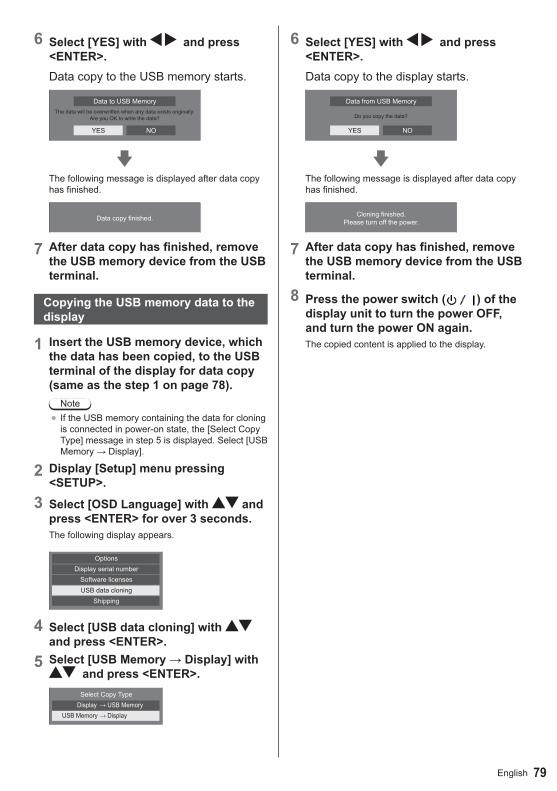
79English
6 Select [YES] with and press <ENTER>. Data copy to the USB memory starts.
The data will be overwritten when any data exists originally.Are you OK to write the data?
Data to USB Memory
YES NO
The following message is displayed after data copy has finished.
Data copy finished.
7 After data copy has finished, remove the USB memory device from the USB terminal.
Copying the USB memory data to the display
1 Insert the USB memory device, which the data has been copied, to the USB terminal of the display for data copy (same as the step 1 on page 78).
Note● If the USB memory containing the data for cloning
is connected in power-on state, the [Select Copy Type] message in step 5 is displayed. Select [USB Memory→Display].
2 Display [Setup] menu pressing <SETUP>.
3 Select [OSD Language] with and press <ENTER> for over 3 seconds.The following display appears.
OptionsDisplay serial number
ShippingUSB data cloningSoftware licenses
4 Select [USB data cloning] with and press <ENTER>.
5 Select [USB Memory → Display] with and press <ENTER>.
Select Copy Type Display →USBMemory USBMemory→Display
6 Select [YES] with and press <ENTER>.Data copy to the display starts.
Do you copy the data?
Data from USB Memory
YES NO
The following message is displayed after data copy has finished.
Cloning finished. Please turn off the power.
7 After data copy has finished, remove the USB memory device from the USB terminal.
8 Press the power switch ( ) of the display unit to turn the power OFF, and turn the power ON again.The copied content is applied to the display.

80 English
TroubleshootingBefore you call for service, determine the symptoms and make a few simple checks as shown below.
Symptoms CheckPicture Sound
Electrical AppliancesCars / MotorcyclesFluorescent light
Interference Noisy Sound
Normal Picture No Sound
Volume(Check whether the mute function has been activated on the remote control.)
No Picture No Sound
Not plugged into AC outletNot switched onPicture and Brightness/Volume setting(Check by pressing the power switch or stand-by button on the remote control.)
No Picture Normal SoundIf a signal with a non-applicable colour system format, or frequency is input, only the input terminal indication is displayed.
No Colour Normal SoundColour controls set at minimum level (see page 41, 42)
No remote control operations can be performed.
Check whether the batteries have discharged completely and, if they have not, whether they were inserted properly.Check whether the remote control sensor is exposed to an outdoor light or a strong fluorescent light.Check whether any obstacle is present between the remote control sensor and the remote control.If the installation condition is normal, pull out the remote control sensor from the edge side of the main unit when using.Check whether the remote control designed specifically for use with the unit is being used. (The unit cannot be operated by any other remote control.)Check whether the option other than [Off] is selected in [Controller user level] in the [Options] menu. (see page 61)Check whether [Controller ID function] in [Options] menu is set to [On]. (see page 61)Check whether <ID MODE> switch is set to <ON> (When using ID remote controller).(see page 73)
[Controller ID function] function cannot be used.(When using ID remote controller)
Check whether [Controller ID function] is set to [On], or <ID MODE> switch is set to <ON>. (see page 61, 73)(When [Controller ID function] is set to [On], you need to set <ID MODE> switch to <ON> and set the ID number.)
The top or bottom of the picture on the screen is cut off.
Adjust the position of the picture on the screen.(see page 38, 39)
There are areas at the top and bottom of the screen where picture is not displayed.
When using a video software program (such as a cinema size program) with a screen wider than one in the 16:9 mode, blank areas separate from the images are formed at the top and bottom of the screen.(see page 29)

81English
Symptoms Check
Parts of the unit become hot.Even when the temperature of parts of the front, top and rear panels has risen, these temperature rises will not pose any problems in terms of performance or quality.
Power automatically turns off unexpectedly.
Check the settings of [No signal power off], [HDMI1 power management], [HDMI2 power management], [DVI-D power management], [PC power management] and [No activity power off]. Any of them may be set to [On (Enable)]. (see page 51, 52)
There is no picture displayed or sound output sometimes.
When HDMI or DVI signals are input to the Display using a selector or distributor, sound or images may not be output in the normal fashion depending on the selector or distributor used.The symptoms may be improved by turning the power off and on again, or by replacing the selector or distributor.
The RS-232C is uncontrollable Check whether the connection has been made properly. (see page 19)
The LAN is uncontrollable
Check whether the connection has been made properly. (see page 64)When controlling with the Web Browser Control or the command control, check whether [Network control] is set to [On] (see page 55). When connecting to a device of AMX, set [AMX D.D.] according to the device to use.(see page 56)Check whether [LAN setup] is set correctly.
Power indicator is blinking in red. There is possibility of malfunction. Please contact an Authorized Service Centre.
This LCD Display uses special image processing. Hence a slight time lag may occur between image and audio, depending on the type of input signal. However, this is not a malfunction.
LCD Display panel
Symptoms Check
The screen darkens slightly when bright pictures with minimal movements are shown.
The screen will darken slightly when photos, still images of a computer or other pictures with minimal movements are shown for an extended period. This is done to reduce image retention on the screen and the shortening of the screen’s service life: It is normal and not indicative of malfunctioning.
It takes a while for the picture to appear.
The unit digitally processes the various signals in order to reproduce esthetically pleasing images. As such, it sometimes takes a few moments for the picture to appear when the power has been turned on, when the input has been switched.
The edges of the images flicker.
Due to the characteristics of the system used to drive the panel, the edges may appear to flicker in the fast-moving parts of the images: This is normal and not indicative of malfunctioning.
There may be red spots, blue spots, green spots and black spots on the screen.
This is a characteristic of liquid crystal panels and is not a problem. The liquid crystal panel is built with very high precision technology giving you fine picture details. Occasionally, a few non-active pixels may appear on the screen as fixed points of red, blue, green, or black. Please note this does not affect the performance of your LCD.
Image retention appears
Image retention may occur. If you display a still picture for an extended period, the image might remain on the screen. However, it will disappear when a general moving picture is displayed for a while. This is not considered as malfunction.
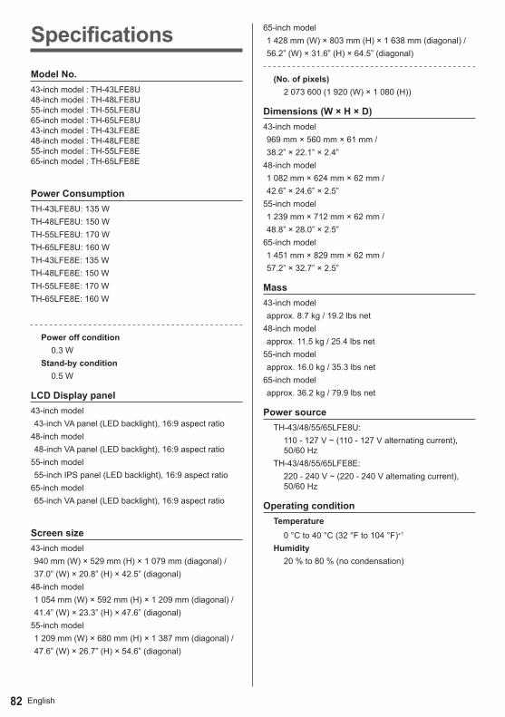
English82
SpecificationsModel No.43-inch model : TH-43LFE8U48-inch model : TH-48LFE8U55-inch model : TH-55LFE8U65-inch model : TH-65LFE8U43-inch model : TH-43LFE8E48-inch model : TH-48LFE8E55-inch model : TH-55LFE8E65-inch model : TH-65LFE8E
Power ConsumptionTH-43LFE8U: 135 WTH-48LFE8U: 150 WTH-55LFE8U: 170 WTH-65LFE8U: 160 WTH-43LFE8E: 135 WTH-48LFE8E: 150 WTH-55LFE8E: 170 WTH-65LFE8E: 160 W
Power off condition0.3 W
Stand-by condition0.5 W
LCD Display panel43-inch model 43-inch VA panel (LED backlight), 16:9 aspect ratio48-inch model 48-inch VA panel (LED backlight), 16:9 aspect ratio55-inch model 55-inch IPS panel (LED backlight), 16:9 aspect ratio65-inch model 65-inch VA panel (LED backlight), 16:9 aspect ratio
Screen size43-inch model 940 mm (W) × 529 mm (H) × 1 079 mm (diagonal) / 37.0” (W) × 20.8” (H) × 42.5” (diagonal)48-inch model 1 054 mm (W) × 592 mm (H) × 1 209 mm (diagonal) / 41.4” (W) × 23.3” (H) × 47.6” (diagonal)55-inch model 1 209 mm (W) × 680 mm (H) × 1 387 mm (diagonal) / 47.6” (W) × 26.7” (H) × 54.6” (diagonal)
65-inch model 1 428 mm (W) × 803 mm (H) × 1 638 mm (diagonal) / 56.2” (W) × 31.6” (H) × 64.5” (diagonal)
(No. of pixels)2 073 600 (1 920 (W) × 1 080 (H))
Dimensions (W × H × D)43-inch model 969 mm × 560 mm × 61 mm / 38.2” × 22.1” × 2.4”48-inch model 1 082 mm × 624 mm × 62 mm / 42.6” × 24.6” × 2.5”55-inch model 1 239 mm × 712 mm × 62 mm / 48.8” × 28.0” × 2.5”65-inch model 1 451 mm × 829 mm × 62 mm / 57.2” × 32.7” × 2.5”
Mass43-inch model approx. 8.7 kg / 19.2 lbs net48-inch model approx. 11.5 kg / 25.4 lbs net55-inch model approx. 16.0 kg / 35.3 lbs net65-inch model approx. 36.2 kg / 79.9 lbs net
Power sourceTH-43/48/55/65LFE8U:
110 - 127 V ~ (110 - 127 V alternating current), 50/60 Hz
TH-43/48/55/65LFE8E:220 - 240 V ~ (220 - 240 V alternating current), 50/60 Hz
Operating conditionTemperature
0 °C to 40 °C (32 °F to 104 °F)*1
Humidity20 % to 80 % (no condensation)
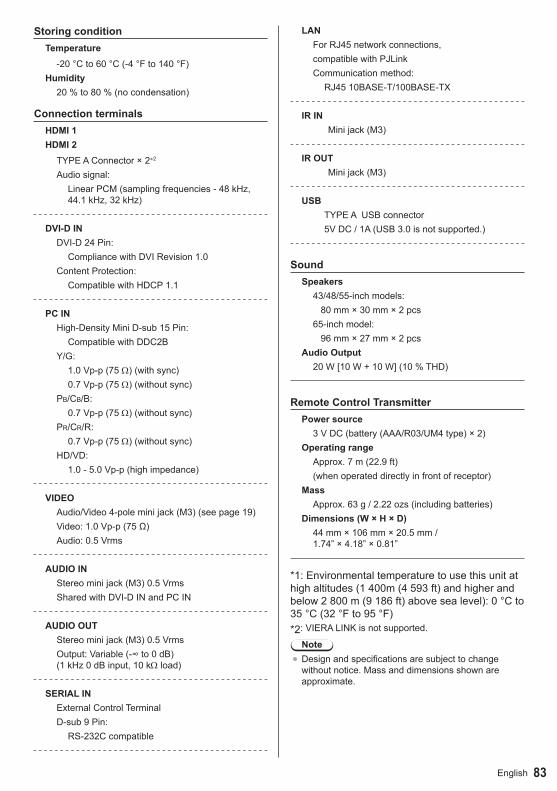
83English
Storing conditionTemperature
-20 °C to 60 °C (-4 °F to 140 °F)Humidity
20 % to 80 % (no condensation)
Connection terminalsHDMI 1HDMI 2
TYPE A Connector × 2*2
Audio signal:Linear PCM (sampling frequencies - 48 kHz, 44.1 kHz, 32 kHz)
DVI-D INDVI-D 24 Pin:
Compliance with DVI Revision 1.0Content Protection:
Compatible with HDCP 1.1
PC INHigh-Density Mini D-sub 15 Pin:
Compatible with DDC2BY/G:
1.0 Vp-p (75 Ω) (with sync)0.7 Vp-p (75 Ω) (without sync)
PB/CB/B:0.7 Vp-p (75 Ω) (without sync)
PR/CR/R:0.7 Vp-p (75 Ω) (without sync)
HD/VD:1.0 - 5.0 Vp-p (high impedance)
VIDEOAudio/Video 4-pole mini jack (M3) (see page 19)Video: 1.0 Vp-p (75 Ω)Audio: 0.5 Vrms
AUDIO INStereo mini jack (M3) 0.5 VrmsShared with DVI-D IN and PC IN
AUDIO OUTStereo mini jack (M3) 0.5 VrmsOutput: Variable (-∞ to 0 dB) (1 kHz 0 dB input, 10 kΩ load)
SERIAL INExternal Control TerminalD-sub 9 Pin:
RS-232C compatible
LANFor RJ45 network connections, compatible with PJLink Communication method:
RJ45 10BASE-T/100BASE-TX
IR IN Mini jack (M3)
IR OUT Mini jack (M3)
USBTYPE A USB connector5V DC / 1A (USB 3.0 is not supported.)
SoundSpeakers
43/48/55-inch models: 80 mm × 30 mm × 2 pcs65-inch model: 96 mm × 27 mm × 2 pcs
Audio Output20 W [10 W + 10 W] (10 % THD)
Remote Control TransmitterPower source
3 V DC (battery (AAA/R03/UM4 type) × 2)Operating range
Approx. 7 m (22.9 ft)(when operated directly in front of receptor)
MassApprox. 63 g / 2.22 ozs (including batteries)
Dimensions (W × H × D)44 mm × 106 mm × 20.5 mm / 1.74” × 4.18” × 0.81”
*1: Environmental temperature to use this unit at high altitudes (1 400m (4 593 ft) and higher and below 2 800 m (9 186 ft) above sea level): 0 °C to 35 °C (32 °F to 95 °F)*2: VIERA LINK is not supported.
Note● Design and specifications are subject to change
without notice. Mass and dimensions shown are approximate.
84 English
Software LicenseThis product incorporates the following software:(1) the software developed independently by or for Panasonic Corporation,(2) the software owned by third party and licensed to Panasonic Corporation,(3) the software licensed under the GNU General Public License, Version 2.0 (GPL V2.0),(4) the software licensed under the GNU LESSER General Public License, Version 2.1 (LGPL V2.1), and/or(5) open source software other than the software licensed under the GPL V2.0 and/or LGPL V2.1.The software categorized as (3) - (5) are distributed in the hope that it will be useful, but WITHOUT ANY WARRANTY, without even the implied warranty of MERCHANTABILITY or FITNESS FOR A PARTICULAR PURPOSE. For details, see the license conditions displayed by selecting [Software licenses], following the specified operation from the initial setting menu of this product.At least three (3) years from delivery of this product, Panasonic will give to any third party who contacts us at the contact information provided below, for a charge no more than our cost of physically performing source code distribution, a complete machine-readable copy of the corresponding source code covered under GPL V2.0, LGPL V2.1 or the other licenses with the obligation to do so, as well as the respective copyright notice thereof. Contact Information:[email protected]
Notice about AVC/VC-1/MPEG-4This product is licensed under the AVC Patent Portfolio License, VC-1 Patent Portfolio License and MPEG-4 Visual
Patent Portfolio License for the personal use of a consumer or other uses in which it does not receive remuneration
to (i) encode video in compliance with the AVC Standard, VC-1 Standard and MPEG-4 Visual Standard (“AVC/
VC-1/MPEG-4 Video”) and/or (ii) decode AVC/VC-1/MPEG-4 Video that was encoded by a consumer engaged in
a personal activity and/or was obtained from a video provider licensed to provide AVC/VC-1/MPEG-4 Video. No
license is granted or shall be implied for any other use. Additional information may be obtained from MPEG LA,
LLC. See http://www.mpegla.com.
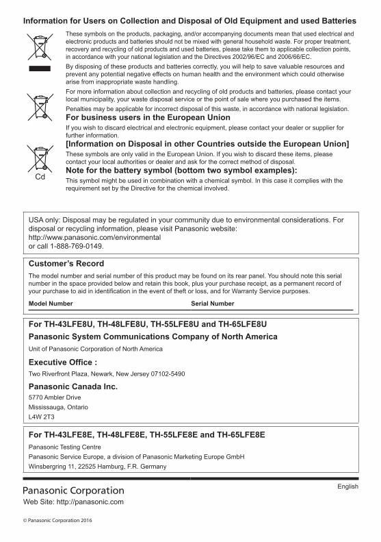
USA only: Disposal may be regulated in your community due to environmental considerations. For disposal or recycling information, please visit Panasonic website: http://www.panasonic.com/environmental or call 1-888-769-0149.
Customer’s RecordThe model number and serial number of this product may be found on its rear panel. You should note this serial number in the space provided below and retain this book, plus your purchase receipt, as a permanent record of your purchase to aid in identification in the event of theft or loss, and for Warranty Service purposes.
Model Number Serial Number
For TH-43LFE8U, TH-48LFE8U, TH-55LFE8U and TH-65LFE8UPanasonic System Communications Company of North AmericaUnit of Panasonic Corporation of North America
Executive Office :Two Riverfront Plaza, Newark, New Jersey 07102-5490
Panasonic Canada Inc.5770 Ambler DriveMississauga, OntarioL4W 2T3
For TH-43LFE8E, TH-48LFE8E, TH-55LFE8E and TH-65LFE8EPanasonic Testing CentrePanasonic Service Europe, a division of Panasonic Marketing Europe GmbHWinsbergring 11, 22525 Hamburg, F.R. Germany
Web Site: http://panasonic.com
© Panasonic Corporation 2016
English
Information for Users on Collection and Disposal of Old Equipment and used BatteriesThese symbols on the products, packaging, and/or accompanying documents mean that used electrical and electronic products and batteries should not be mixed with general household waste. For proper treatment, recovery and recycling of old products and used batteries, please take them to applicable collection points, in accordance with your national legislation and the Directives 2002/96/EC and 2006/66/EC.By disposing of these products and batteries correctly, you will help to save valuable resources and prevent any potential negative effects on human health and the environment which could otherwise arise from inappropriate waste handling.For more information about collection and recycling of old products and batteries, please contact your local municipality, your waste disposal service or the point of sale where you purchased the items.Penalties may be applicable for incorrect disposal of this waste, in accordance with national legislation.For business users in the European UnionIf you wish to discard electrical and electronic equipment, please contact your dealer or supplier for further information.[Information on Disposal in other Countries outside the European Union]These symbols are only valid in the European Union. If you wish to discard these items, please contact your local authorities or dealer and ask for the correct method of disposal.Note for the battery symbol (bottom two symbol examples):This symbol might be used in combination with a chemical symbol. In this case it complies with the requirement set by the Directive for the chemical involved.