Embed Size (px)
Citation preview
Operating instructions
OmniaTap 6 | UV | UV/UF
OmniaTap 12 | UV | UV/UF
50001393

Contents 1 Safety precautions and user information ........................................................................................ 1
2 Intended purpose ............................................................................................................................ 4
3 Technical data.................................................................................................................................. 4
4 Flow charts ...................................................................................................................................... 6
4.1 Flow chart for OmniaTap ......................................................................................................... 6
4.2 Flow chart for OmniaTap UV ................................................................................................... 6
4.3 Flow chart for OmniaTap UV/UF ............................................................................................. 7
5 Description of the system................................................................................................................ 8
5.1 System construction ................................................................................................................ 8
5.2 System equipping .................................................................................................................. 10
5.3 How the system functions ..................................................................................................... 11
6 Assembly........................................................................................................................................ 12
6.1 Extent of delivery .................................................................................................................. 12
6.2 Operating environment ......................................................................................................... 12
6.3 Assembly................................................................................................................................ 13
6.4 Wall mounting ....................................................................................................................... 15
6.5 How to connect an optional pump station ........................................................................... 17
7 Operating concept ......................................................................................................................... 18
8 Putting into operation ................................................................................................................... 20
9 Operation ...................................................................................................................................... 21
9.1 Menu structure ...................................................................................................................... 21
9.2 Main display .......................................................................................................................... 22
9.3 Withdrawal of water / Withdrawal display ........................................................................... 22
9.4 Menu / Settings ..................................................................................................................... 23
9.4.1 System ........................................................................................................................... 23
9.4.2 Setup .............................................................................................................................. 24
10 Maintenance and care ............................................................................................................... 27
10.1 Maintenance / Care intervals ................................................................................................ 27
10.2 Cartridge replacement .......................................................................................................... 28
10.3 Disinfection ............................................................................................................................ 29
11 Faults, causes and solutions ...................................................................................................... 30
11.1 Automatic system monitoring ............................................................................................... 30
11.2 Table of faults ........................................................................................................................ 32
12 Consumables and accessories ................................................................................................... 34
13 Waste disposal........................................................................................................................... 34

1
__________________________________________________________________________________ OmniaTap UV|UV/UF State April 2017 Rights to technical changes reserved
1 Safety precautions and user information
The information given here is an important part of the product and provides basic information that is
to be observed when setting-up, operating and servicing the system. Please therefore read these
instructions completely and thoroughly before you start to install the OmniaTap System and put it into
operation for the first time.
These operating instructions must always be kept at the operating location. Should your OmniaTap
system be passed on to a different person, these instructions must be passed on with it.
The personnel must have the necessary qualifications for system operation, maintenance, inspections
and assembly work. The operator must clearly set the spheres of responsibility, competencies and
supervision of the personnel.
In addition to the observance of safety precautions that are given in this section, you must also pay
attention to the safety regulations that are valid at the system location, in particular to the accident
prevention regulations.
Area of validity
These operating instructions are equally valid for the OmniaTap 6 and OmniaTap 12 series in both their
basic form and the differently equipped UV and UV/UF variants. In the following, “OmniaTap systems”
will be given to describe all of these. Should there be differences in the operation of the individual
system variants, this will be brought to your attention by appropriate notes.
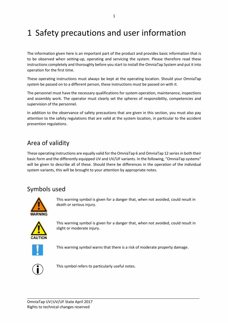
Symbols used
This warning symbol is given for a danger that, when not avoided, could result in death or serious injury.
This warning symbol is given for a danger that, when not avoided, could result in slight or moderate injury.
This warning symbol warns that there is a risk of moderate property damage.
This symbol refers to particularly useful notes.
2
__________________________________________________________________________________ OmniaTap UV|UV/UF State April 2017 Rights to technical changes reserved
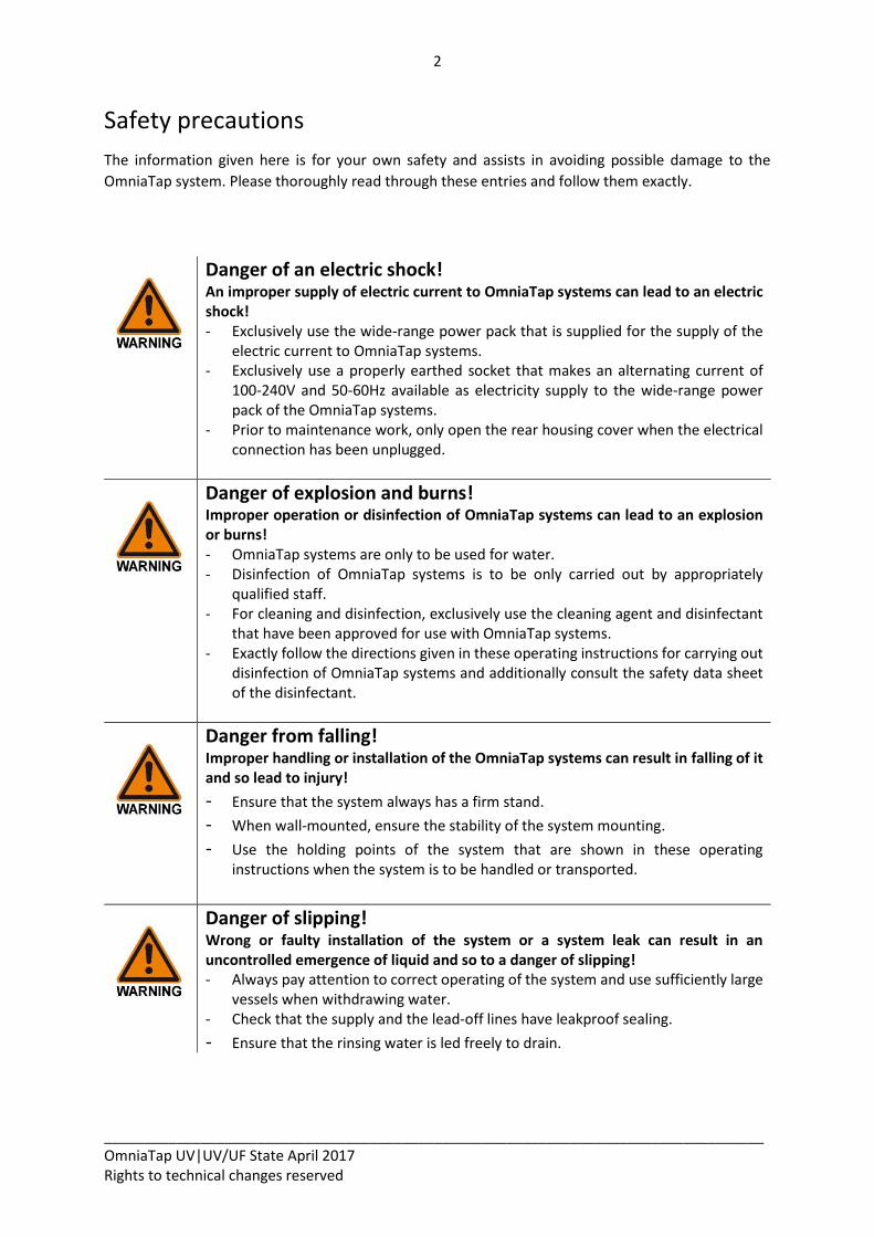
Safety precautions
The information given here is for your own safety and assists in avoiding possible damage to the
OmniaTap system. Please thoroughly read through these entries and follow them exactly.
Danger of an electric shock! An improper supply of electric current to OmniaTap systems can lead to an electric shock! - Exclusively use the wide-range power pack that is supplied for the supply of the
electric current to OmniaTap systems. - Exclusively use a properly earthed socket that makes an alternating current of
100-240V and 50-60Hz available as electricity supply to the wide-range power pack of the OmniaTap systems.
- Prior to maintenance work, only open the rear housing cover when the electrical connection has been unplugged.
Danger of explosion and burns! Improper operation or disinfection of OmniaTap systems can lead to an explosion or burns! - OmniaTap systems are only to be used for water. - Disinfection of OmniaTap systems is to be only carried out by appropriately
qualified staff. - For cleaning and disinfection, exclusively use the cleaning agent and disinfectant
that have been approved for use with OmniaTap systems. - Exactly follow the directions given in these operating instructions for carrying out
disinfection of OmniaTap systems and additionally consult the safety data sheet of the disinfectant.
Danger from falling! Improper handling or installation of the OmniaTap systems can result in falling of it and so lead to injury!
- Ensure that the system always has a firm stand. - When wall-mounted, ensure the stability of the system mounting. - Use the holding points of the system that are shown in these operating
instructions when the system is to be handled or transported.
Danger of slipping! Wrong or faulty installation of the system or a system leak can result in an uncontrolled emergence of liquid and so to a danger of slipping! - Always pay attention to correct operating of the system and use sufficiently large
vessels when withdrawing water. - Check that the supply and the lead-off lines have leakproof sealing.
- Ensure that the rinsing water is led freely to drain.
3
__________________________________________________________________________________ OmniaTap UV|UV/UF State April 2017 Rights to technical changes reserved
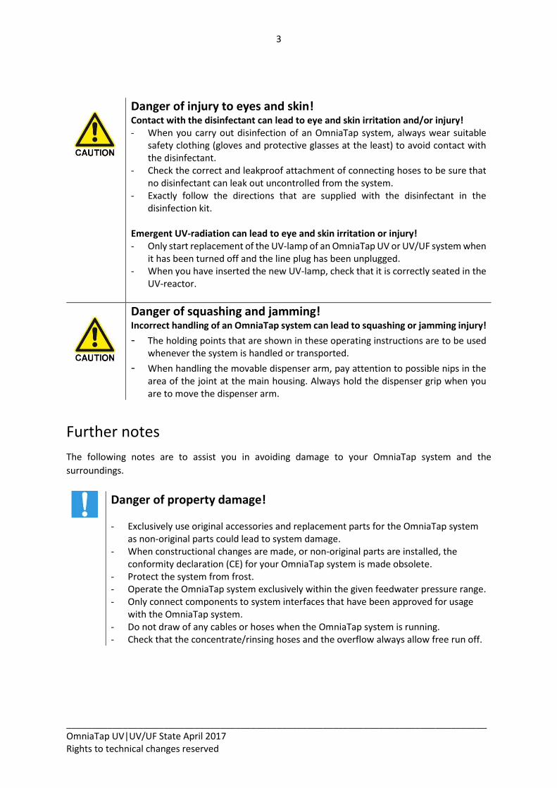
Danger of injury to eyes and skin! Contact with the disinfectant can lead to eye and skin irritation and/or injury! - When you carry out disinfection of an OmniaTap system, always wear suitable
safety clothing (gloves and protective glasses at the least) to avoid contact with the disinfectant.
- Check the correct and leakproof attachment of connecting hoses to be sure that no disinfectant can leak out uncontrolled from the system.
- Exactly follow the directions that are supplied with the disinfectant in the disinfection kit.
Emergent UV-radiation can lead to eye and skin irritation or injury! - Only start replacement of the UV-lamp of an OmniaTap UV or UV/UF system when
it has been turned off and the line plug has been unplugged. - When you have inserted the new UV-lamp, check that it is correctly seated in the
UV-reactor.
Danger of squashing and jamming! Incorrect handling of an OmniaTap system can lead to squashing or jamming injury!
- The holding points that are shown in these operating instructions are to be used whenever the system is handled or transported.
- When handling the movable dispenser arm, pay attention to possible nips in the area of the joint at the main housing. Always hold the dispenser grip when you are to move the dispenser arm.
Further notes
The following notes are to assist you in avoiding damage to your OmniaTap system and the
surroundings.
Danger of property damage!
- Exclusively use original accessories and replacement parts for the OmniaTap system
as non-original parts could lead to system damage. - When constructional changes are made, or non-original parts are installed, the
conformity declaration (CE) for your OmniaTap system is made obsolete. - Protect the system from frost. - Operate the OmniaTap system exclusively within the given feedwater pressure range. - Only connect components to system interfaces that have been approved for usage
with the OmniaTap system. - Do not draw of any cables or hoses when the OmniaTap system is running. - Check that the concentrate/rinsing hoses and the overflow always allow free run off.
4
__________________________________________________________________________________ OmniaTap UV|UV/UF State April 2017 Rights to technical changes reserved
2 Intended purpose Systems of the OmniaTap series serve to directly purify drinking water to the pure and ultra pure water
quality that is needed in many laboratory uses. To ensure maximum quality of the pure and ultra pure
water and as long a service life as possible of the disposables, the OmniaTap system must be fed with
drinking water that is in conformity with DIN 2000. Usage of OmniaTap systems for any other purpose
is not permissible and is defined as improper usage.
The pure and ultra pure water that is produced find use as a solvent or rinsing fluid in greatly different
analytical procedures such as high performance chromatography (HPLC), ion chromatography (IC),
atom absorption spectrometry (AAS) and ultra trace analysis. They are also used in many chemical and
biochemical applications for reagent preparation and cell culturing etc. The water that is produced is
not fit for human consumption.
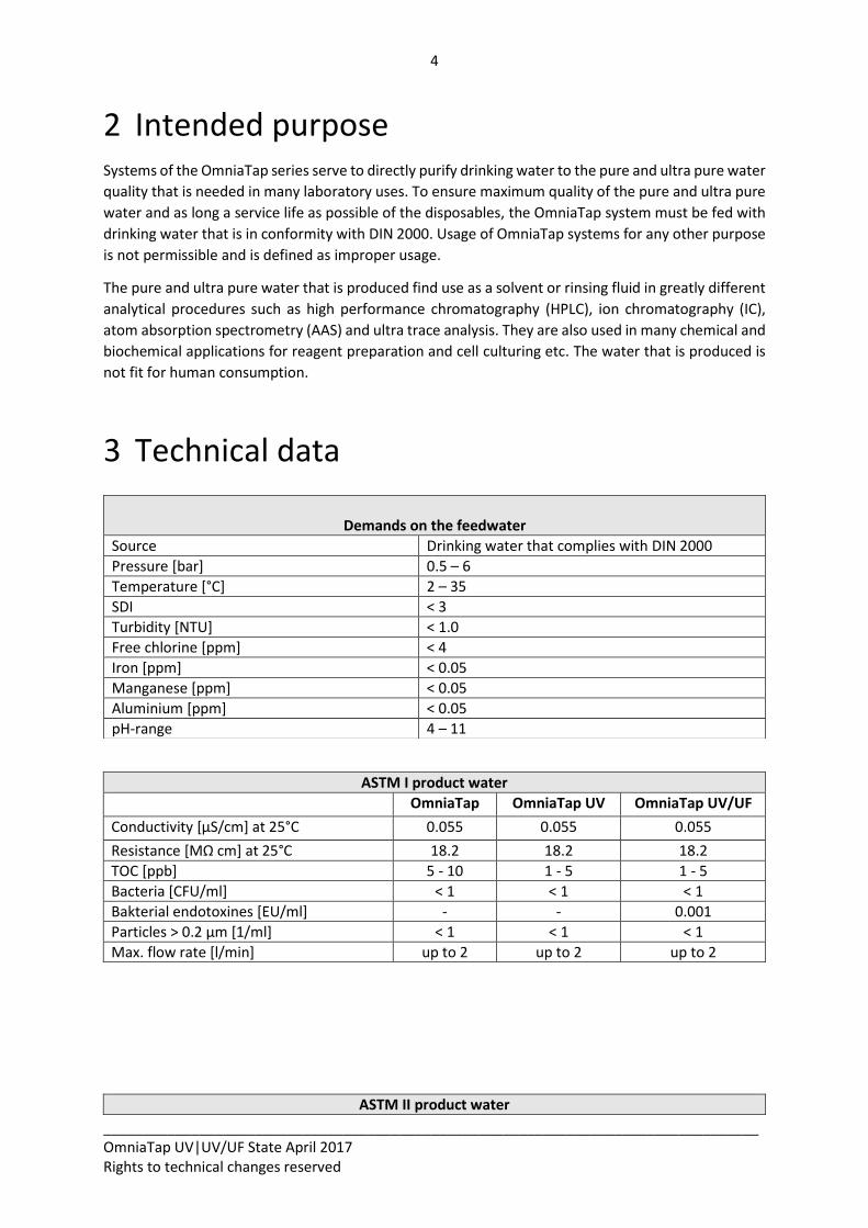
3 Technical data
ASTM I product water
OmniaTap OmniaTap UV OmniaTap UV/UF
Conductivity [µS/cm] at 25°C 0.055 0.055 0.055
Resistance [MΩ cm] at 25°C 18.2 18.2 18.2
TOC [ppb] 5 - 10 1 - 5 1 - 5
Bacteria [CFU/ml] < 1 < 1 < 1
Bakterial endotoxines [EU/ml] - - 0.001
Particles > 0.2 µm [1/ml] < 1 < 1 < 1
Max. flow rate [l/min] up to 2 up to 2 up to 2
ASTM II product water
Demands on the feedwater
Source Drinking water that complies with DIN 2000
Pressure [bar] 0.5 – 6
Temperature [°C] 2 – 35
SDI < 3
Turbidity [NTU] < 1.0
Free chlorine [ppm] < 4
Iron [ppm] < 0.05
Manganese [ppm] < 0.05
Aluminium [ppm] < 0.05
pH-range 4 – 11
5
__________________________________________________________________________________ OmniaTap UV|UV/UF State April 2017 Rights to technical changes reserved
OmniaTap 6|12
OmniaTap 6|12 UV
OmniaTap 6|12 UV/UF
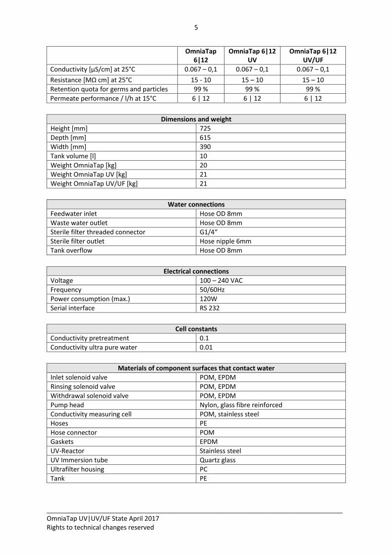
Conductivity [µS/cm] at 25°C 0.067 – 0,1 0.067 – 0,1 0.067 – 0,1
Resistance [MΩ cm] at 25°C 15 - 10 15 – 10 15 – 10
Retention quota for germs and particles 99 % 99 % 99 %
Permeate performance / l/h at 15°C 6 | 12 6 | 12 6 | 12
Dimensions and weight
Height [mm] 725
Depth [mm] 615
Width [mm] 390
Tank volume [l] 10
Weight OmniaTap [kg] 20
Weight OmniaTap UV [kg] 21
Weight OmniaTap UV/UF [kg] 21
Water connections
Feedwater inlet Hose OD 8mm
Waste water outlet Hose OD 8mm
Sterile filter threaded connector G1/4“
Sterile filter outlet Hose nipple 6mm
Tank overflow Hose OD 8mm
Electrical connections
Voltage 100 – 240 VAC
Frequency 50/60Hz
Power consumption (max.) 120W
Serial interface RS 232
Cell constants
Conductivity pretreatment 0.1
Conductivity ultra pure water 0.01
Materials of component surfaces that contact water
Inlet solenoid valve POM, EPDM
Rinsing solenoid valve POM, EPDM
Withdrawal solenoid valve POM, EPDM
Pump head Nylon, glass fibre reinforced
Conductivity measuring cell POM, stainless steel
Hoses PE
Hose connector POM
Gaskets EPDM
UV-Reactor Stainless steel
UV Immersion tube Quartz glass
Ultrafilter housing PC
Tank PE
6
__________________________________________________________________________________ OmniaTap UV|UV/UF State April 2017 Rights to technical changes reserved
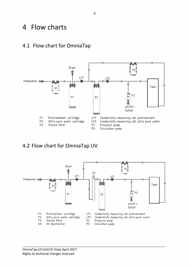
4 Flow charts
4.1 Flow chart for OmniaTap
4.2 Flow chart for OmniaTap UV
7
__________________________________________________________________________________ OmniaTap UV|UV/UF State April 2017 Rights to technical changes reserved
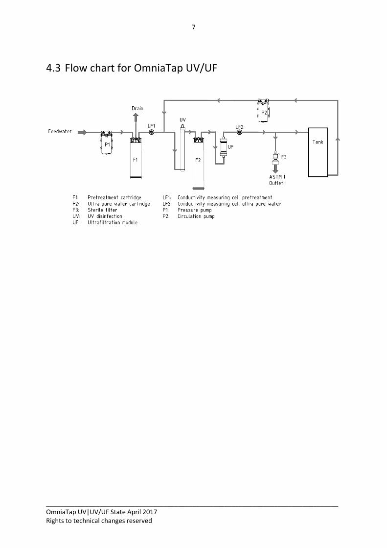
4.3 Flow chart for OmniaTap UV/UF
8
__________________________________________________________________________________ OmniaTap UV|UV/UF State April 2017 Rights to technical changes reserved
5 Description of the system
5.1 System construction
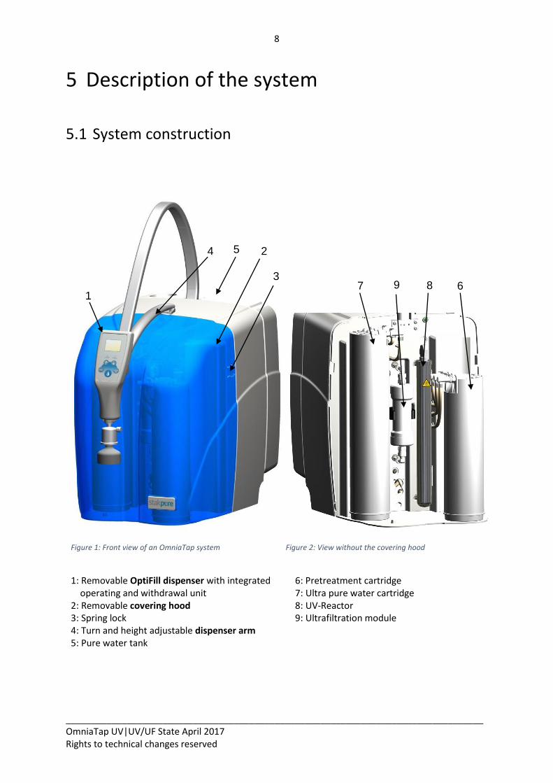
Figure 1: Front view of an OmniaTap system
Figure 2: View without the covering hood
1: Removable OptiFill dispenser with integrated operating and withdrawal unit 2: Removable covering hood 3: Spring lock 4: Turn and height adjustable dispenser arm 5: Pure water tank
6: Pretreatment cartridge 7: Ultra pure water cartridge 8: UV-Reactor 9: Ultrafiltration module
1
4 2
7 6 9 8
5
3
9
__________________________________________________________________________________ OmniaTap UV|UV/UF State April 2017 Rights to technical changes reserved
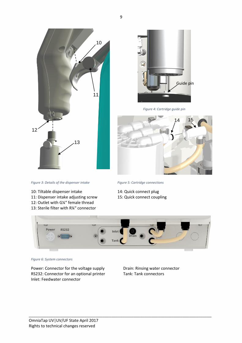
Figure 3: Details of the dispenser intake
Figure 4: Cartridge guide pin
Figure 5: Cartridge connections
10: Tiltable dispenser intake 11: Dispenser intake adjusting screw 12: Outlet with G¼“ female thread 13: Sterile filter with R¼“ connector
14: Quick connect plug 15: Quick connect coupling
Figure 6: System connectors
Power: Connector for the voltage supply RS232: Connector for an optional printer Inlet: Feedwater connector
Drain: Rinsing water connector Tank: Tank connectors
15
10
12
11
13
Guide pin
inührungsdorn
14
10
__________________________________________________________________________________ OmniaTap UV|UV/UF State April 2017 Rights to technical changes reserved
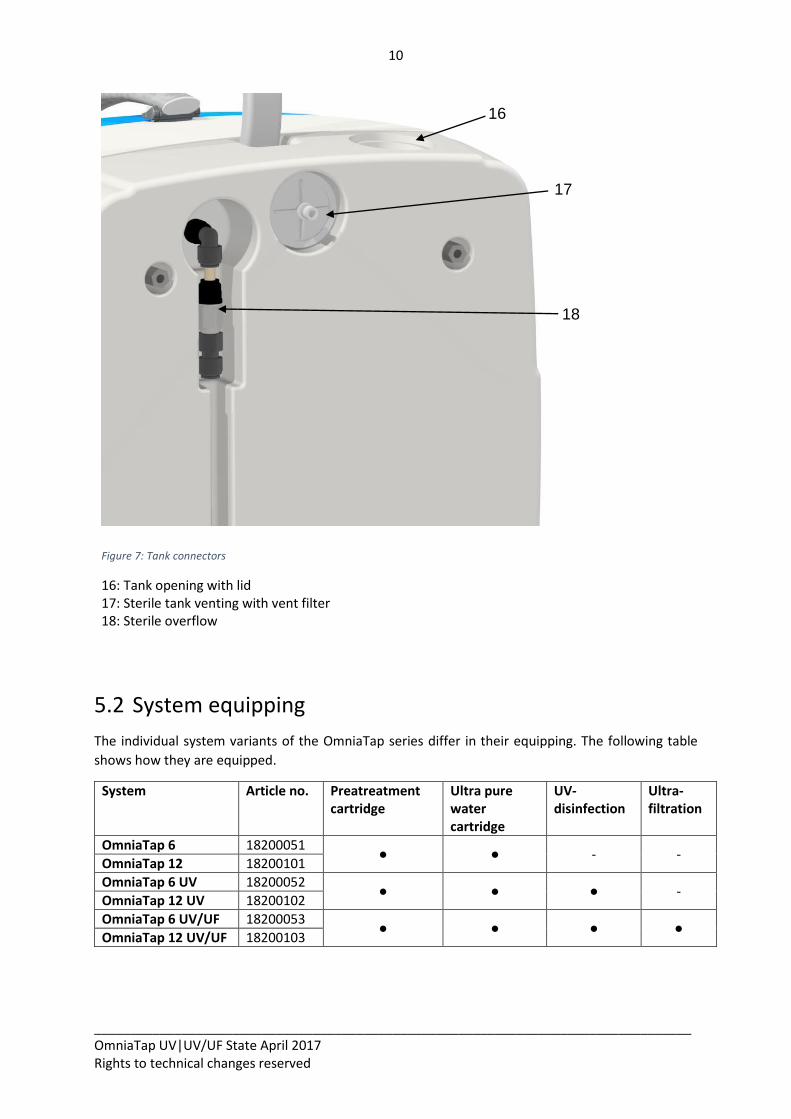
Figure 7: Tank connectors
16: Tank opening with lid 17: Sterile tank venting with vent filter 18: Sterile overflow
5.2 System equipping
The individual system variants of the OmniaTap series differ in their equipping. The following table
shows how they are equipped.
System Article no. Preatreatment cartridge
Ultra pure water cartridge
UV-disinfection
Ultra-filtration
OmniaTap 6 18200051 ● ● - -
OmniaTap 12 18200101
OmniaTap 6 UV 18200052 ● ● ● -
OmniaTap 12 UV 18200102
OmniaTap 6 UV/UF 18200053 ● ● ● ●
OmniaTap 12 UV/UF 18200103
16
18
17
11
__________________________________________________________________________________ OmniaTap UV|UV/UF State April 2017 Rights to technical changes reserved
5.3 How the system functions
The systems in the OmniaTap series utilize several purification technologies to directly convert drinking
water to pure and ultra pure water. The ultra pure water that is produced fulfils the current
requirements of ASTM, ISO, USP and CLSI standards.
To start the process, drinking water (feedwater) that is DIN 2000 conform is fed into the OmniaTap
system. As can be seen in “4 Flow charts“, a pressure booster pump pumps the feedwater through the
pretreatment cartridge with integrated reverse osmosis module. This pretreatment removes most of
the salts, bacteria and other substances from the feedwater. The quality of the water that has been so
pre-treated and also the condition of the prefilter cartridge, are continuously monitored by the first
conductivity measurement (LF1). The actual conductivity values can be shown in the display of the
operating-/withdrawal unit (OptiFill dispenser) as a check. In the next step, the water flows through a
UV reactor (this is only for OmniaTap UV and UV/UF) where it is disinfected by means of UV-radiation.
With all three types, the water now flows through the ultra pure water cartridge that removes
remaining ions. To remove a maximum of non-ionized compounds, the water passes through an
ultrafiltration module (only for OmniaTap UV/UF). Monitoring of the quality of the ultra pure water
and the conditions of the consumables is made via a temperature compensated conductivity meter
(LF2). The measured conductivity values, as well as those of the temperature, are displayed in the
OptiFill dispenser display.
The water that has been so processed first fills the integrated tank up to its maximum filling level. No
further processing of the feedwater occurs when the tank is full. To maintain the constant high quality
of the processed water, it is periodically pumped by the circulation pump from the tank, through the
ion exchanger cartridge, the UV reactor and the ultrafiltration module and back into the tank.
The OptiFill dispenser makes withdrawal of ultra pure water directly possible. To maintain a maximum
quality, and with the help of the circulation pump, the water is forced through the ultra pure cartridge,
the UV-reactor and the ultrafiltration module and to the withdrawal position immediately prior to
withdrawal. As final purification step the ultra pure water passes through a sterile filter, which is
connected directly at the OptiFill Dispenser.
To supply an external user, such as an analyzer, with pure water an optional pump station is available.
12
__________________________________________________________________________________ OmniaTap UV|UV/UF State April 2017 Rights to technical changes reserved
6 Assembly When you receive your OmniaTap, first check the packaging for possible transport damage. Now remove the system from the packaging and check the outside of the system for transport damage. The OmniaTap system has been carefully tested and packed, despite this, damage during transport
cannot unfortunately be completely ruled out. If your OmniaTap system has been damaged,
immediately contact the appropriate destination carrier or shipping agent. In this case, keep the
complete packaging as possibly needed proof of the complaint or return shipment.
6.1 Extent of delivery
The extent of delivery of your OmniaTap system is as follows:
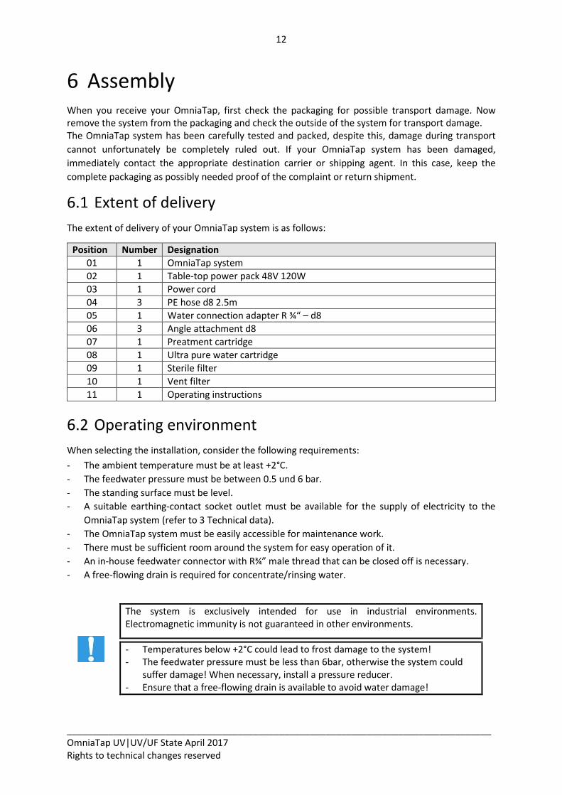
Position Number Designation
01 1 OmniaTap system
02 1 Table-top power pack 48V 120W
03 1 Power cord
04 3 PE hose d8 2.5m
05 1 Water connection adapter R ¾“ – d8
06 3 Angle attachment d8
07 1 Preatment cartridge
08 1 Ultra pure water cartridge
09 1 Sterile filter
10 1 Vent filter
11 1 Operating instructions
6.2 Operating environment
When selecting the installation, consider the following requirements:
- The ambient temperature must be at least +2°C.
- The feedwater pressure must be between 0.5 und 6 bar.
- The standing surface must be level.
- A suitable earthing-contact socket outlet must be available for the supply of electricity to the
OmniaTap system (refer to 3 Technical data).
- The OmniaTap system must be easily accessible for maintenance work.
- There must be sufficient room around the system for easy operation of it.
- An in-house feedwater connector with R¾” male thread that can be closed off is necessary.
- A free-flowing drain is required for concentrate/rinsing water.
The system is exclusively intended for use in industrial environments. Electromagnetic immunity is not guaranteed in other environments.
- Temperatures below +2°C could lead to frost damage to the system! - The feedwater pressure must be less than 6bar, otherwise the system could
suffer damage! When necessary, install a pressure reducer. - Ensure that a free-flowing drain is available to avoid water damage!
13
__________________________________________________________________________________ OmniaTap UV|UV/UF State April 2017 Rights to technical changes reserved
6.3 Assembly
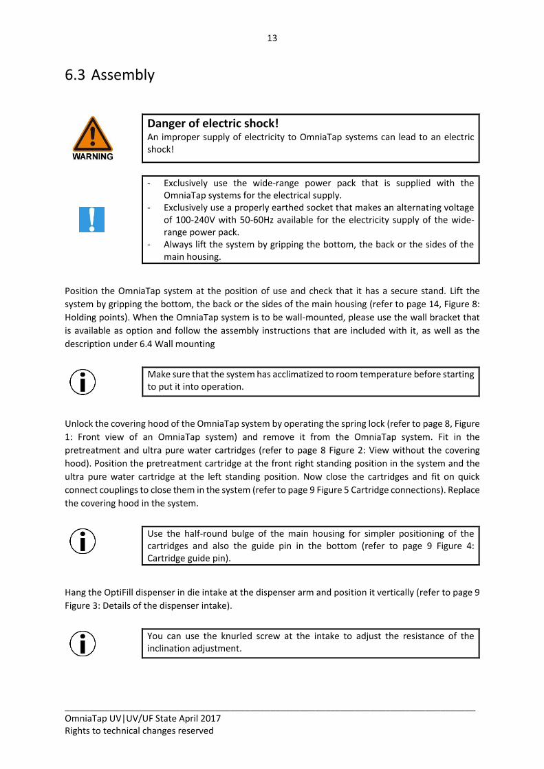
Danger of electric shock! An improper supply of electricity to OmniaTap systems can lead to an electric shock!
- Exclusively use the wide-range power pack that is supplied with the OmniaTap systems for the electrical supply.
- Exclusively use a properly earthed socket that makes an alternating voltage of 100-240V with 50-60Hz available for the electricity supply of the wide-range power pack.
- Always lift the system by gripping the bottom, the back or the sides of the main housing.
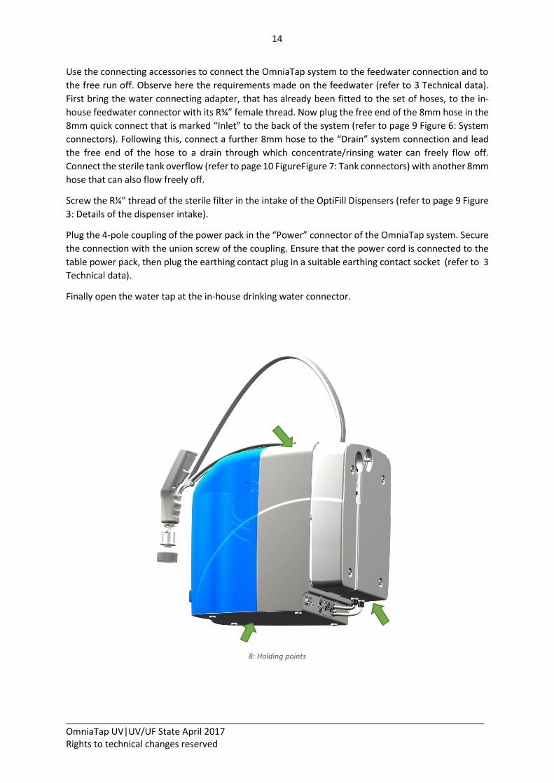
Position the OmniaTap system at the position of use and check that it has a secure stand. Lift the
system by gripping the bottom, the back or the sides of the main housing (refer to page 14, Figure 8:
Holding points). When the OmniaTap system is to be wall-mounted, please use the wall bracket that
is available as option and follow the assembly instructions that are included with it, as well as the
description under 6.4 Wall mounting
Make sure that the system has acclimatized to room temperature before starting to put it into operation.
Unlock the covering hood of the OmniaTap system by operating the spring lock (refer to page 8, Figure
1: Front view of an OmniaTap system) and remove it from the OmniaTap system. Fit in the
pretreatment and ultra pure water cartridges (refer to page 8 Figure 2: View without the covering
hood). Position the pretreatment cartridge at the front right standing position in the system and the
ultra pure water cartridge at the left standing position. Now close the cartridges and fit on quick
connect couplings to close them in the system (refer to page 9 Figure 5 Cartridge connections). Replace
the covering hood in the system.
Use the half-round bulge of the main housing for simpler positioning of the cartridges and also the guide pin in the bottom (refer to page 9 Figure 4: Cartridge guide pin).
Hang the OptiFill dispenser in die intake at the dispenser arm and position it vertically (refer to page 9
Figure 3: Details of the dispenser intake).
You can use the knurled screw at the intake to adjust the resistance of the inclination adjustment.
14
__________________________________________________________________________________ OmniaTap UV|UV/UF State April 2017 Rights to technical changes reserved
Use the connecting accessories to connect the OmniaTap system to the feedwater connection and to
the free run off. Observe here the requirements made on the feedwater (refer to 3 Technical data).
First bring the water connecting adapter, that has already been fitted to the set of hoses, to the in-
house feedwater connector with its R¾” female thread. Now plug the free end of the 8mm hose in the
8mm quick connect that is marked “Inlet” to the back of the system (refer to page 9 Figure 6: System
connectors). Following this, connect a further 8mm hose to the “Drain” system connection and lead
the free end of the hose to a drain through which concentrate/rinsing water can freely flow off.
Connect the sterile tank overflow (refer to page 10 FigureFigure 7: Tank connectors) with another 8mm
hose that can also flow freely off.
Screw the R¼” thread of the sterile filter in the intake of the OptiFill Dispensers (refer to page 9 Figure
3: Details of the dispenser intake).
Plug the 4-pole coupling of the power pack in the “Power” connector of the OmniaTap system. Secure
the connection with the union screw of the coupling. Ensure that the power cord is connected to the
table power pack, then plug the earthing contact plug in a suitable earthing contact socket (refer to 3
Technical data).
Finally open the water tap at the in-house drinking water connector.
8: Holding points
15
__________________________________________________________________________________ OmniaTap UV|UV/UF State April 2017 Rights to technical changes reserved
6.4 Wall mounting
Danger of injury from dropping and squashing! The OmniaTap system is to exclusively fixed to a suitable wall with the optional wall mount. Only use this wall mount for the OmniaTap system. Pay attention that the wall and the mounting material have a sufficient weight-bearing capacity of at least 100kg. The mounting material that is supplied in the extent of delivery of the wall mount is designed for use in concrete or solid brick walls. Test the suitability of it for your wall material. If necessary, exchange it for a more suitable one.
The optional wall mount enables you to save work space by fixing your OmniaTap system to a suitable
wall. The free wall area for this is approximately 60cm x 80cm (W x H). For professional and reliable
mounting, we recommend that our customer service carries it out.
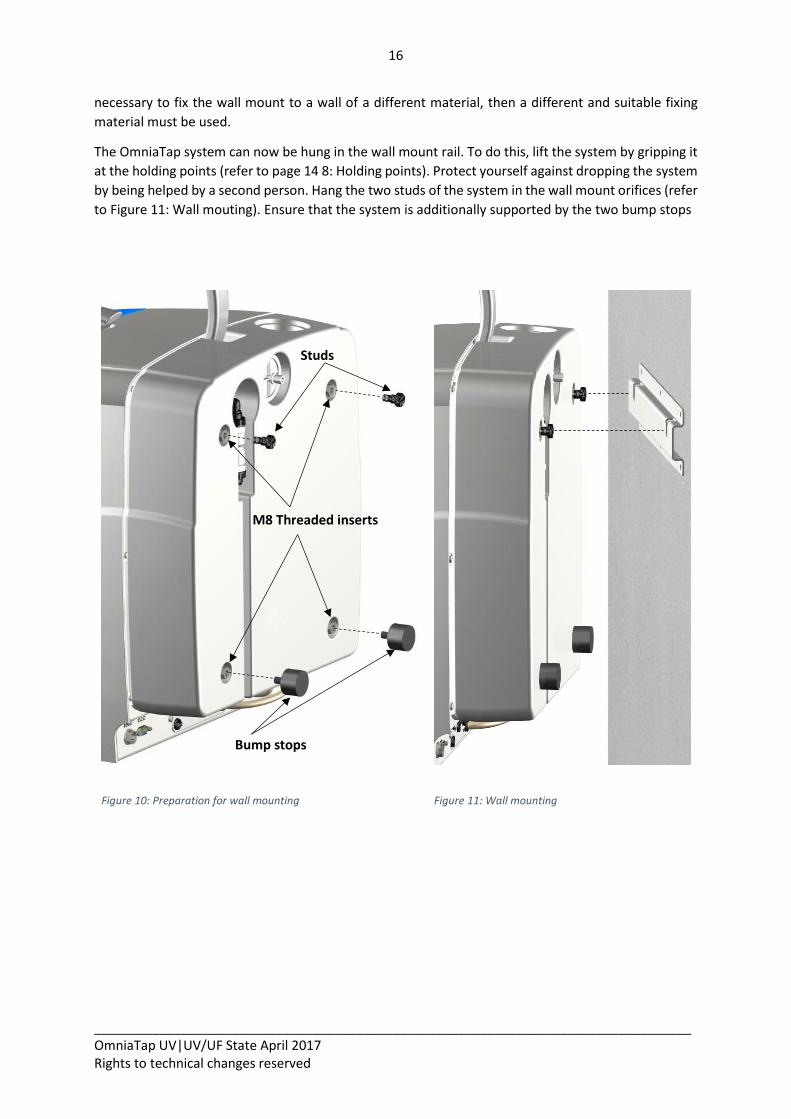
Your OmniaTap system must be prepared for wall mounting. The parts that are required for this are in
the extent of delivery of the wall mount. Start by screwing the two M8 studs in the two upper M8
screw thread sockets that are at the back of the system (refer to Figure 10: Preparation for wall
mounting). The two bump stops are screwed into the two lower M8 screw-thread sockets at the back
of the system.
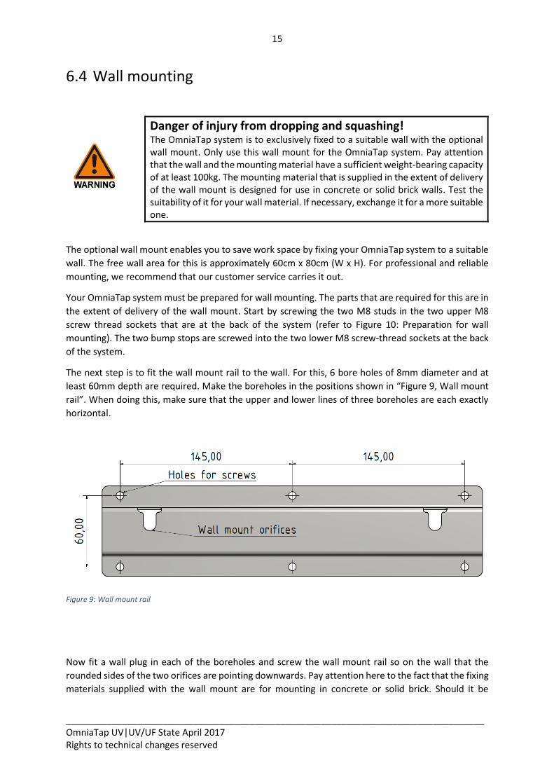
The next step is to fit the wall mount rail to the wall. For this, 6 bore holes of 8mm diameter and at
least 60mm depth are required. Make the boreholes in the positions shown in “Figure 9, Wall mount
rail”. When doing this, make sure that the upper and lower lines of three boreholes are each exactly
horizontal.
Figure 9: Wall mount rail
Now fit a wall plug in each of the boreholes and screw the wall mount rail so on the wall that the
rounded sides of the two orifices are pointing downwards. Pay attention here to the fact that the fixing
materials supplied with the wall mount are for mounting in concrete or solid brick. Should it be
16
__________________________________________________________________________________ OmniaTap UV|UV/UF State April 2017 Rights to technical changes reserved
necessary to fix the wall mount to a wall of a different material, then a different and suitable fixing
material must be used.
The OmniaTap system can now be hung in the wall mount rail. To do this, lift the system by gripping it
at the holding points (refer to page 14 8: Holding points). Protect yourself against dropping the system
by being helped by a second person. Hang the two studs of the system in the wall mount orifices (refer
to Figure 11: Wall mouting). Ensure that the system is additionally supported by the two bump stops
Figure 10: Preparation for wall mounting
Figure 11: Wall mounting
Studs
M8 Threaded inserts
insertsadinserte
insertswindebuchsen
Bump stops
stopsnschlagpuffer
17
__________________________________________________________________________________ OmniaTap UV|UV/UF State April 2017 Rights to technical changes reserved
6.5 How to connect an optional pump station
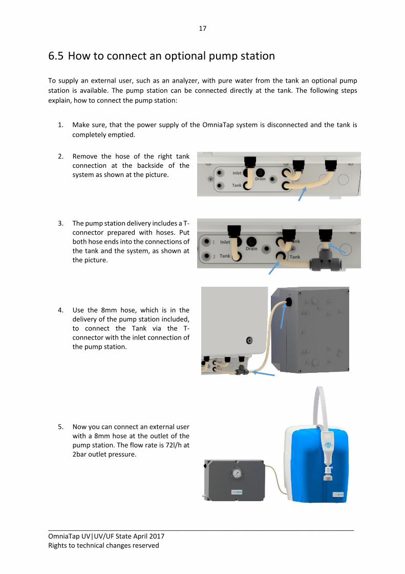
To supply an external user, such as an analyzer, with pure water from the tank an optional pump
station is available. The pump station can be connected directly at the tank. The following steps
explain, how to connect the pump station:
1. Make sure, that the power supply of the OmniaTap system is disconnected and the tank is
completely emptied.
2. Remove the hose of the right tank connection at the backside of the system as shown at the picture.
3. The pump station delivery includes a T-
connector prepared with hoses. Put both hose ends into the connections of the tank and the system, as shown at the picture.
4. Use the 8mm hose, which is in the delivery of the pump station included, to connect the Tank via the T-connector with the inlet connection of the pump station.
5. Now you can connect an external user with a 8mm hose at the outlet of the pump station. The flow rate is 72l/h at 2bar outlet pressure.
18
__________________________________________________________________________________ OmniaTap UV|UV/UF State April 2017 Rights to technical changes reserved
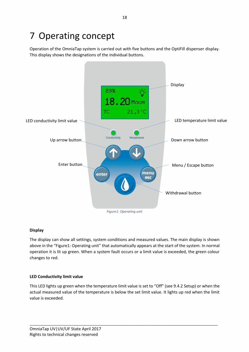
7 Operating concept Operation of the OmniaTap system is carried out with five buttons and the OptiFill dispenser display.
This display shows the designations of the individual buttons.
Figure1: Operating unit
Display
The display can show all settings, system conditions and measured values. The main display is shown
above in the “Figure1: Operating unit” that automatically appears at the start of the system. In normal
operation it is lit up green. When a system fault occurs or a limit value is exceeded, the green colour
changes to red.
LED Conductivity limit value
This LED lights up green when the temperature limit value is set to “Off” (see 9.4.2 Setup) or when the
actual measured value of the temperature is below the set limit value. It lights up red when the limit
value is exceeded.
Menu / Escape button
Up arrow button Down arrow button
Enter button
LED temperature limit value
Withdrawal button
LED conductivity limit value
Display
19
__________________________________________________________________________________ OmniaTap UV|UV/UF State April 2017 Rights to technical changes reserved
LED Temperature limit value
This LED lights up green when the temperature limit value is set to “Off” (see 9.4.2 Setup) or when the
actual measured value of the temperature is below the set limit value. It lights up red when the limit
value is exceeded.
Withdrawal button
When the system is in the main display, a press on the withdrawal button opens the withdrawal display
(see 9.3: Withdrawal of water / Withdrawal display). The withdrawal button only has a function
together with all other displays when the symbol for the withdrawal button symbol is shown
alongside a particular command.
Menu-/ Esc-button
A press on the Menu-/Esc-button in the main display brings you to the selection menu (see 9.4 Menu
/ Settings). In all other displays, this button takes on an ESC function with which you can abort an entry
at any time or return to the previous menu level.
Enter button
When you have opened a display in which you wish to make an entry, a press on the Enter button
activates the input function. The activation of this input function is acknowledged by the appearance
of a cursor. When the function is active, a further press on the Enter button confirms the
input/selection and switches to the next input field or ends the input function.
Up arrow button
This arrow button enables you to browse through a particular menu upwards. When an input function
is active, you can increase a given value in this or change the selection at the actual cursor position.
Down arrow button
This arrow button enables you to browse through a particular menu downwards. When an input
function is active, you can decrease a given value in this or change the selection at the actual cursor
position.
20
__________________________________________________________________________________ OmniaTap UV|UV/UF State April 2017 Rights to technical changes reserved
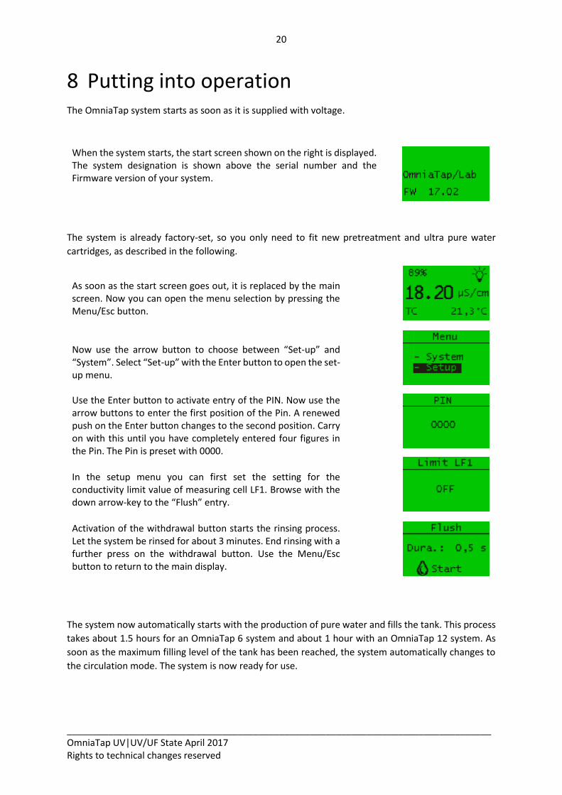
8 Putting into operation The OmniaTap system starts as soon as it is supplied with voltage.
When the system starts, the start screen shown on the right is displayed. The system designation is shown above the serial number and the Firmware version of your system.
The system is already factory-set, so you only need to fit new pretreatment and ultra pure water
cartridges, as described in the following.
As soon as the start screen goes out, it is replaced by the main screen. Now you can open the menu selection by pressing the Menu/Esc button.
Now use the arrow button to choose between “Set-up” and “System”. Select “Set-up” with the Enter button to open the set-up menu.
Use the Enter button to activate entry of the PIN. Now use the arrow buttons to enter the first position of the Pin. A renewed push on the Enter button changes to the second position. Carry on with this until you have completely entered four figures in the Pin. The Pin is preset with 0000.
In the setup menu you can first set the setting for the conductivity limit value of measuring cell LF1. Browse with the down arrow-key to the “Flush” entry.
Activation of the withdrawal button starts the rinsing process. Let the system be rinsed for about 3 minutes. End rinsing with a further press on the withdrawal button. Use the Menu/Esc button to return to the main display.
The system now automatically starts with the production of pure water and fills the tank. This process
takes about 1.5 hours for an OmniaTap 6 system and about 1 hour with an OmniaTap 12 system. As
soon as the maximum filling level of the tank has been reached, the system automatically changes to
the circulation mode. The system is now ready for use.
21
__________________________________________________________________________________ OmniaTap UV|UV/UF State April 2017 Rights to technical changes reserved
9 Operation The menu structure, the displays and the setting possibilities of OmniaTap systems are described in
the following. Use them to navigate in the menu and change settings as described under “7 Operating
concept“ for system input possibilities.
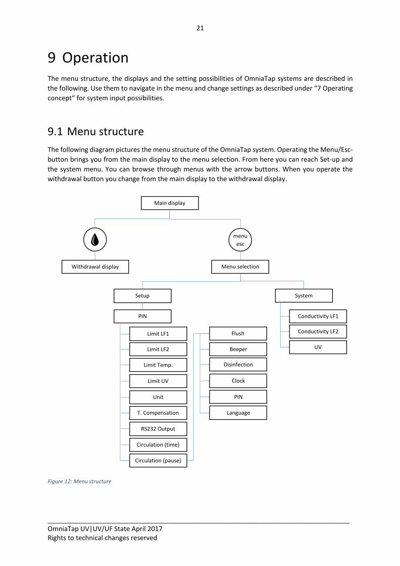
9.1 Menu structure
The following diagram pictures the menu structure of the OmniaTap system. Operating the Menu/Esc-
button brings you from the main display to the menu selection. From here you can reach Set-up and
the system menu. You can browse through menus with the arrow buttons. When you operate the
withdrawal button you change from the main display to the withdrawal display.
Figure 12: Menu structure
Main display
Withdrawal display Menu selection
menu
esc
Setup System
Limit LF1
Unit
Limit UV
Limit Temp.
Limit LF2
T. Compensation
Circulation (time)
Conductivity LF1
UV
Conductivity LF2
RS232 Output
PIN
Circulation (pause)
Flush
Beeper
Disinfection
Clock
PIN
Language
22
__________________________________________________________________________________ OmniaTap UV|UV/UF State April 2017 Rights to technical changes reserved
Tank level
Tank level
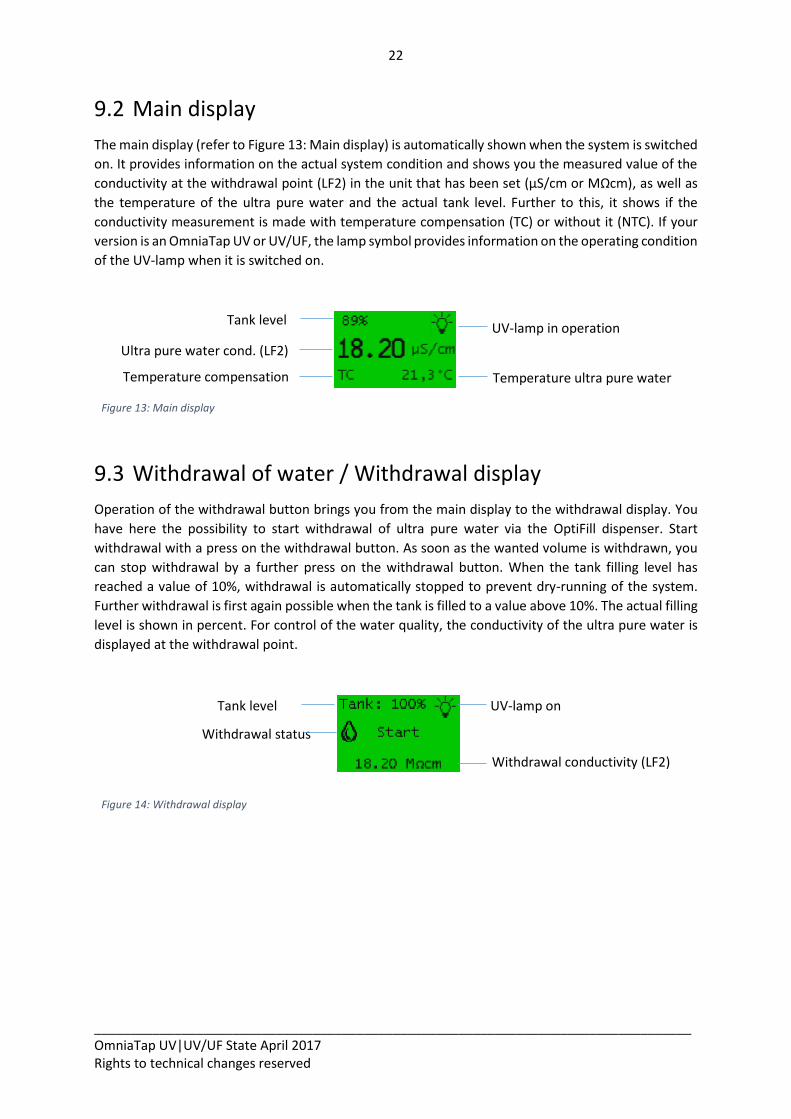
9.2 Main display
The main display (refer to Figure 13: Main display) is automatically shown when the system is switched
on. It provides information on the actual system condition and shows you the measured value of the
conductivity at the withdrawal point (LF2) in the unit that has been set (µS/cm or MΩcm), as well as
the temperature of the ultra pure water and the actual tank level. Further to this, it shows if the
conductivity measurement is made with temperature compensation (TC) or without it (NTC). If your
version is an OmniaTap UV or UV/UF, the lamp symbol provides information on the operating condition
of the UV-lamp when it is switched on.
Figure 13: Main display
9.3 Withdrawal of water / Withdrawal display
Operation of the withdrawal button brings you from the main display to the withdrawal display. You
have here the possibility to start withdrawal of ultra pure water via the OptiFill dispenser. Start
withdrawal with a press on the withdrawal button. As soon as the wanted volume is withdrawn, you
can stop withdrawal by a further press on the withdrawal button. When the tank filling level has
reached a value of 10%, withdrawal is automatically stopped to prevent dry-running of the system.
Further withdrawal is first again possible when the tank is filled to a value above 10%. The actual filling
level is shown in percent. For control of the water quality, the conductivity of the ultra pure water is
displayed at the withdrawal point.
Figure 14: Withdrawal display
Ultra pure water cond. (LF2)
UV-lamp in operation
Temperature ultra pure water Temperature compensation
UV-lamp on
Withdrawal status
Withdrawal conductivity (LF2)
23
__________________________________________________________________________________ OmniaTap UV|UV/UF State April 2017 Rights to technical changes reserved
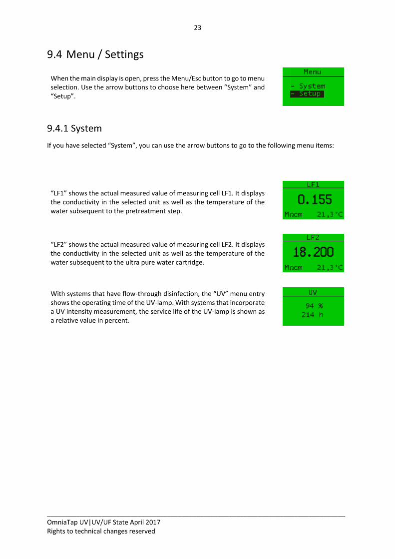
9.4 Menu / Settings
When the main display is open, press the Menu/Esc button to go to menu selection. Use the arrow buttons to choose here between “System” and “Setup”.
9.4.1 System
If you have selected “System”, you can use the arrow buttons to go to the following menu items:
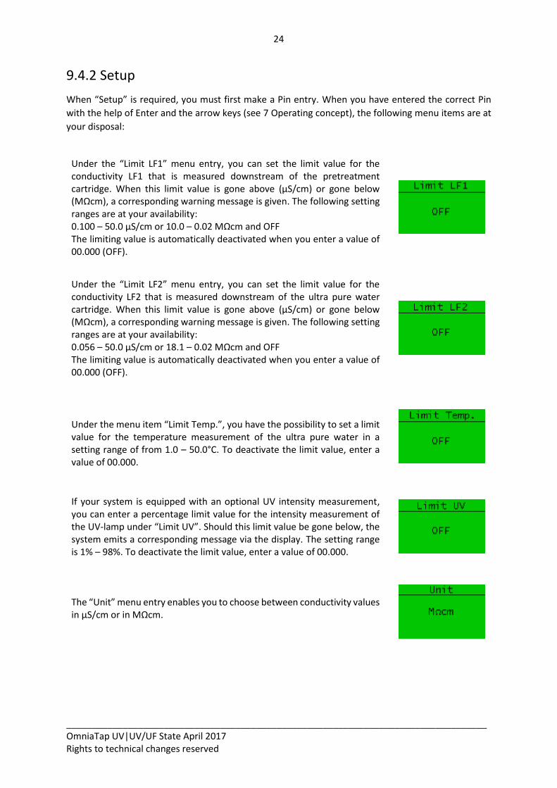
“LF1” shows the actual measured value of measuring cell LF1. It displays the conductivity in the selected unit as well as the temperature of the water subsequent to the pretreatment step.
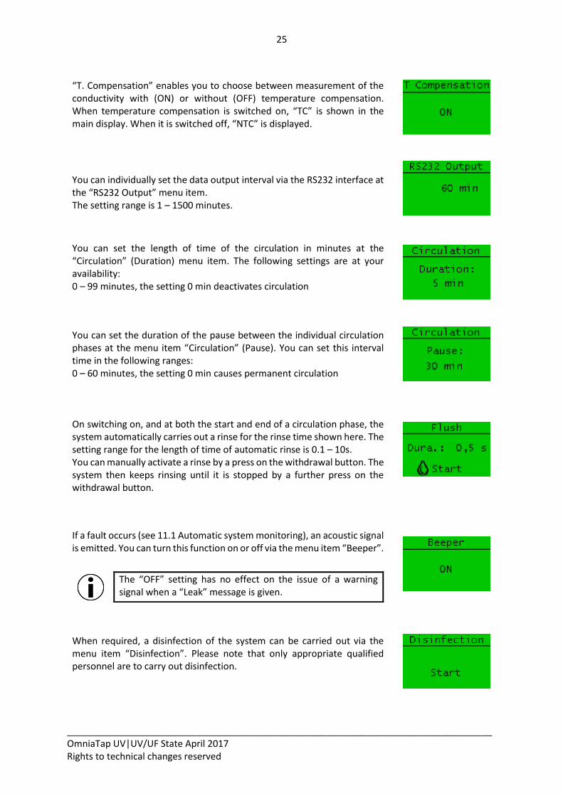
“LF2” shows the actual measured value of measuring cell LF2. It displays the conductivity in the selected unit as well as the temperature of the water subsequent to the ultra pure water cartridge.
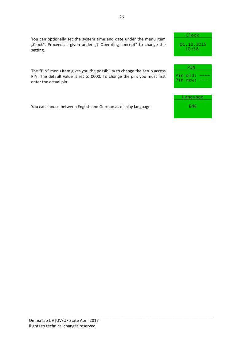
With systems that have flow-through disinfection, the “UV” menu entry shows the operating time of the UV-lamp. With systems that incorporate a UV intensity measurement, the service life of the UV-lamp is shown as a relative value in percent.
24
__________________________________________________________________________________ OmniaTap UV|UV/UF State April 2017 Rights to technical changes reserved
9.4.2 Setup
When “Setup” is required, you must first make a Pin entry. When you have entered the correct Pin
with the help of Enter and the arrow keys (see 7 Operating concept), the following menu items are at
your disposal:
Under the “Limit LF1” menu entry, you can set the limit value for the conductivity LF1 that is measured downstream of the pretreatment cartridge. When this limit value is gone above (µS/cm) or gone below (MΩcm), a corresponding warning message is given. The following setting ranges are at your availability: 0.100 – 50.0 µS/cm or 10.0 – 0.02 MΩcm and OFF The limiting value is automatically deactivated when you enter a value of 00.000 (OFF).
Under the “Limit LF2” menu entry, you can set the limit value for the conductivity LF2 that is measured downstream of the ultra pure water cartridge. When this limit value is gone above (µS/cm) or gone below (MΩcm), a corresponding warning message is given. The following setting ranges are at your availability: 0.056 – 50.0 µS/cm or 18.1 – 0.02 MΩcm and OFF The limiting value is automatically deactivated when you enter a value of 00.000 (OFF).
Under the menu item “Limit Temp.”, you have the possibility to set a limit value for the temperature measurement of the ultra pure water in a setting range of from 1.0 – 50.0°C. To deactivate the limit value, enter a value of 00.000.
If your system is equipped with an optional UV intensity measurement, you can enter a percentage limit value for the intensity measurement of the UV-lamp under “Limit UV”. Should this limit value be gone below, the system emits a corresponding message via the display. The setting range is 1% – 98%. To deactivate the limit value, enter a value of 00.000.
The “Unit” menu entry enables you to choose between conductivity values in µS/cm or in MΩcm.
25
__________________________________________________________________________________ OmniaTap UV|UV/UF State April 2017 Rights to technical changes reserved
“T. Compensation” enables you to choose between measurement of the conductivity with (ON) or without (OFF) temperature compensation. When temperature compensation is switched on, “TC” is shown in the main display. When it is switched off, “NTC” is displayed.
You can individually set the data output interval via the RS232 interface at the “RS232 Output” menu item. The setting range is 1 – 1500 minutes.
You can set the length of time of the circulation in minutes at the “Circulation” (Duration) menu item. The following settings are at your availability: 0 – 99 minutes, the setting 0 min deactivates circulation
You can set the duration of the pause between the individual circulation phases at the menu item “Circulation” (Pause). You can set this interval time in the following ranges: 0 – 60 minutes, the setting 0 min causes permanent circulation
On switching on, and at both the start and end of a circulation phase, the system automatically carries out a rinse for the rinse time shown here. The setting range for the length of time of automatic rinse is 0.1 – 10s. You can manually activate a rinse by a press on the withdrawal button. The system then keeps rinsing until it is stopped by a further press on the withdrawal button.
If a fault occurs (see 11.1 Automatic system monitoring), an acoustic signal is emitted. You can turn this function on or off via the menu item “Beeper”.
The “OFF” setting has no effect on the issue of a warning signal when a “Leak” message is given.
When required, a disinfection of the system can be carried out via the menu item “Disinfection”. Please note that only appropriate qualified personnel are to carry out disinfection.
26
__________________________________________________________________________________ OmniaTap UV|UV/UF State April 2017 Rights to technical changes reserved
You can optionally set the system time and date under the menu item „Clock“. Proceed as given under „7 Operating concept“ to change the setting.
The “PIN” menu item gives you the possibility to change the setup access PIN. The default value is set to 0000. To change the pin, you must first enter the actual pin.
You can choose between English and German as display language.
27
__________________________________________________________________________________ OmniaTap UV|UV/UF State April 2017 Rights to technical changes reserved
10 Maintenance and care Regular maintenance and care of your OmniaTap system are necessary for it to maintain a constant
high water quality. We recommend that you close a contract with an authorized customer service
company for professional and regular maintenance of your OmniaTap system.
The warranty for the system loses its validity when improper maintenance, service or repair work is carried out on the system, replacement parts and consumable materials that have not been approved are used and/or if conversion measures are carried out. The Declaration of Conformity also becomes invalid.
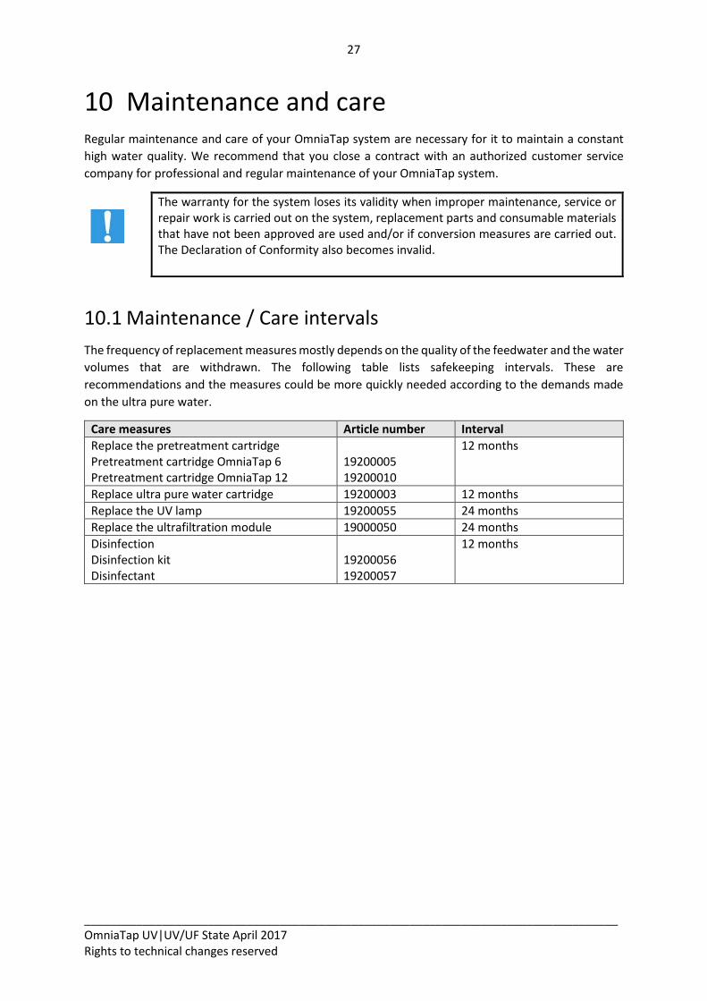
10.1 Maintenance / Care intervals
The frequency of replacement measures mostly depends on the quality of the feedwater and the water
volumes that are withdrawn. The following table lists safekeeping intervals. These are
recommendations and the measures could be more quickly needed according to the demands made
on the ultra pure water.
Care measures Article number Interval
Replace the pretreatment cartridge Pretreatment cartridge OmniaTap 6 Pretreatment cartridge OmniaTap 12
19200005 19200010
12 months
Replace ultra pure water cartridge 19200003 12 months
Replace the UV lamp 19200055 24 months
Replace the ultrafiltration module 19000050 24 months
Disinfection Disinfection kit Disinfectant
19200056 19200057
12 months
28
__________________________________________________________________________________ OmniaTap UV|UV/UF State April 2017 Rights to technical changes reserved
10.2 Cartridge replacement
Cartridges are to be replaced at regular intervals (12 months) or earlier when the limit values that you
have entered are permanently exceeded. The time that the particular filter cartridge was first
connected is taken to be the start of the interval. Proceed as follows to replace pretreatment and ultra
pure water cartridges:
1. Switch the OmniaTap system off by separating it from the line voltage.
2. Remove the OptiFill dispenser from its fixture and swivel the dispenser arm to the upper
position.
3. Remove the covering hood from the system by opening the two side spring locks and drawing
the covering hood forwards (refer to page 8, Figure 2: View without covering hood), then draw
the covering hood off forwards from the main housing.
4. The ultra pure water cartridge is at the standing position on the left and the pretreatment
cartridge at the one on the right (refer to page 8, Figure 2: View without covering hood). Open
the quick connects of the cartridge that is to be replaced (refer to page 9, Figure 5: Cartridge
connectors) and remove it from the system.
5. To fit a new cartridge in the system at the appropriate standing position, utilize the half-round
bulge for easier positioning of the ultra pure water cartridge in the main housing. Use the guide
pin to help position the pretreatment cartridge (refer to page 9, Figure 4: Cartridge guide pin).
6. Connect the cartridge to the system with the quick connects.
7. Replace the covering hood and plug the OptiFill dispenser back in its fixture.
8. Plug the mains plug back in to start the system.
9. Finally rinse the system as described in “8 Putting into operation“.
29
__________________________________________________________________________________ OmniaTap UV|UV/UF State April 2017 Rights to technical changes reserved
10.3 Disinfection
The OmniaTap should be disinfected at regular intervals (12 months) to protect it against biological
deposits. A disinfection kit (article no. 19200056) and a disinfectant (article no. 19200057) are required
for this.
Danger of explosion and burns! Disinfection of OmniaTap systems is to be only carried out by appropriately qualified staff. Protect yourself against harm by means of suitable safety clothing (protective gloves and eye protective glasses at the least). Observe the instructions given by the safety data sheet that is supplied with the disinfectant and exactly follow the instructions given for handling the disinfectant. Exclusively use the disinfectant that has been approved for use with the OmniaTap system.
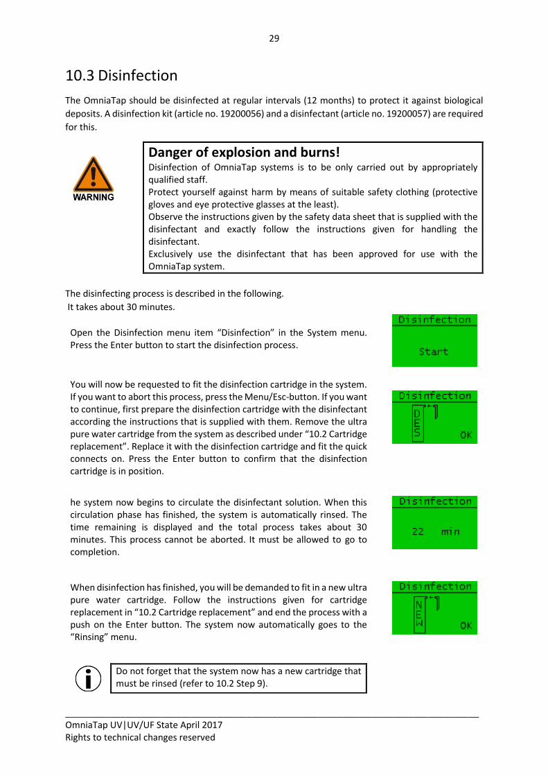
The disinfecting process is described in the following.
It takes about 30 minutes.
Open the Disinfection menu item “Disinfection” in the System menu. Press the Enter button to start the disinfection process.
You will now be requested to fit the disinfection cartridge in the system. If you want to abort this process, press the Menu/Esc-button. If you want to continue, first prepare the disinfection cartridge with the disinfectant according the instructions that is supplied with them. Remove the ultra pure water cartridge from the system as described under “10.2 Cartridge replacement”. Replace it with the disinfection cartridge and fit the quick connects on. Press the Enter button to confirm that the disinfection cartridge is in position.
he system now begins to circulate the disinfectant solution. When this circulation phase has finished, the system is automatically rinsed. The time remaining is displayed and the total process takes about 30 minutes. This process cannot be aborted. It must be allowed to go to completion.
When disinfection has finished, you will be demanded to fit in a new ultra pure water cartridge. Follow the instructions given for cartridge replacement in “10.2 Cartridge replacement” and end the process with a push on the Enter button. The system now automatically goes to the “Rinsing” menu.
Do not forget that the system now has a new cartridge that must be rinsed (refer to 10.2 Step 9).
30
__________________________________________________________________________________ OmniaTap UV|UV/UF State April 2017 Rights to technical changes reserved
11 Faults, causes and solutions
11.1 Automatic system monitoring
The OmniaTap system automatically carries out fault monitoring for several system parameters. When
one of the monitored system parameters deviates from the entered stipulation, both an optical and
an acoustic fault message are issued. In the case of a fault, the colour of the display changes to red and
a warning signal is emitted (when it is active). The type of fault is shown by a corresponding output in
the display. When the fault is for exceeding a limit value, the corresponding LED changes from green
to red.
Confirm the fault message with the Enter key and so end the emittance of the audio warning signal.
The individual fault messages are described here:
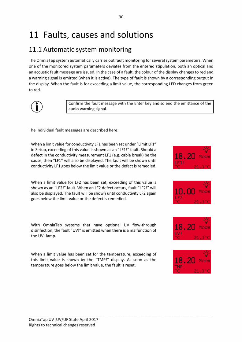
When a limit value for conductivity LF1 has been set under “Limit LF1” in Setup, exceeding of this value is shown as an “LF1!” fault. Should a defect in the conductivity measurement LF1 (e.g. cable break) be the cause, then “LF1” will also be displayed. The fault will be shown until conductivity LF1 goes below the limit value or the defect is remedied.
When a limit value for LF2 has been set, exceeding of this value is shown as an “LF2!” fault. When an LF2 defect occurs, fault “LF2!” will also be displayed. The fault will be shown until conductivity LF2 again goes below the limit value or the defect is remedied.
With OmniaTap systems that have optional UV flow-through disinfection, the fault “UV!” is emitted when there is a malfunction of the UV- lamp.
When a limit value has been set for the temperature, exceeding of this limit value is shown by the “TMP!” display. As soon as the temperature goes below the limit value, the fault is reset.
31
__________________________________________________________________________________ OmniaTap UV|UV/UF State April 2017 Rights to technical changes reserved
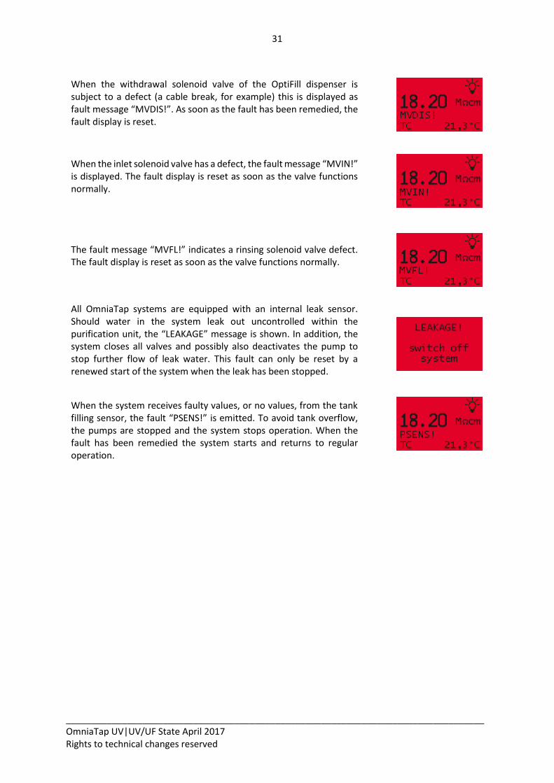
When the withdrawal solenoid valve of the OptiFill dispenser is subject to a defect (a cable break, for example) this is displayed as fault message “MVDIS!”. As soon as the fault has been remedied, the fault display is reset.
When the inlet solenoid valve has a defect, the fault message “MVIN!” is displayed. The fault display is reset as soon as the valve functions normally.
The fault message “MVFL!” indicates a rinsing solenoid valve defect. The fault display is reset as soon as the valve functions normally.
All OmniaTap systems are equipped with an internal leak sensor. Should water in the system leak out uncontrolled within the purification unit, the “LEAKAGE” message is shown. In addition, the system closes all valves and possibly also deactivates the pump to stop further flow of leak water. This fault can only be reset by a renewed start of the system when the leak has been stopped.
When the system receives faulty values, or no values, from the tank filling sensor, the fault “PSENS!” is emitted. To avoid tank overflow, the pumps are stopped and the system stops operation. When the fault has been remedied the system starts and returns to regular operation.
32
__________________________________________________________________________________ OmniaTap UV|UV/UF State April 2017 Rights to technical changes reserved
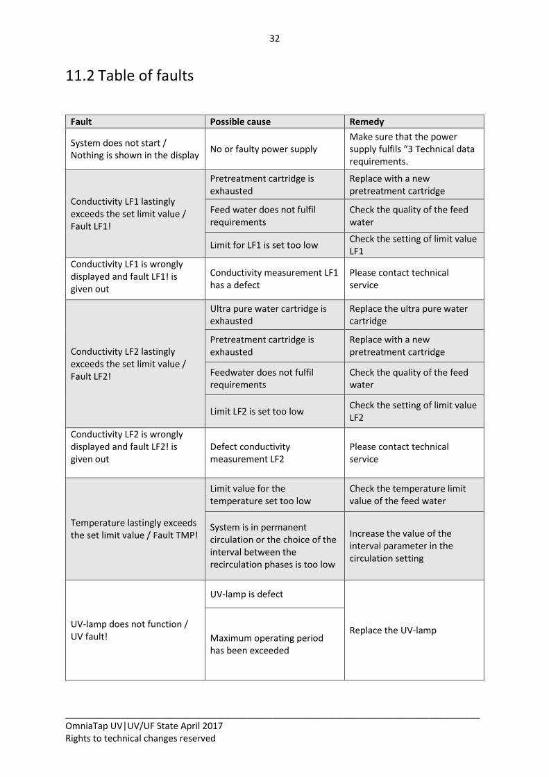
11.2 Table of faults
Fault Possible cause Remedy
System does not start / Nothing is shown in the display
No or faulty power supply Make sure that the power supply fulfils “3 Technical data requirements.
Conductivity LF1 lastingly exceeds the set limit value / Fault LF1!
Pretreatment cartridge is exhausted
Replace with a new pretreatment cartridge
Feed water does not fulfil requirements
Check the quality of the feed water
Limit for LF1 is set too low Check the setting of limit value LF1
Conductivity LF1 is wrongly displayed and fault LF1! is given out
Conductivity measurement LF1 has a defect
Please contact technical service
Conductivity LF2 lastingly exceeds the set limit value / Fault LF2!
Ultra pure water cartridge is exhausted
Replace the ultra pure water cartridge
Pretreatment cartridge is exhausted
Replace with a new pretreatment cartridge
Feedwater does not fulfil requirements
Check the quality of the feed water
Limit LF2 is set too low Check the setting of limit value LF2
Conductivity LF2 is wrongly displayed and fault LF2! is given out
Defect conductivity measurement LF2
Please contact technical service
Temperature lastingly exceeds the set limit value / Fault TMP!
Limit value for the temperature set too low
Check the temperature limit value of the feed water
System is in permanent circulation or the choice of the interval between the recirculation phases is too low
Increase the value of the interval parameter in the circulation setting
UV-lamp does not function / UV fault!
UV-lamp is defect
Replace the UV-lamp Maximum operating period has been exceeded
33
__________________________________________________________________________________ OmniaTap UV|UV/UF State April 2017 Rights to technical changes reserved
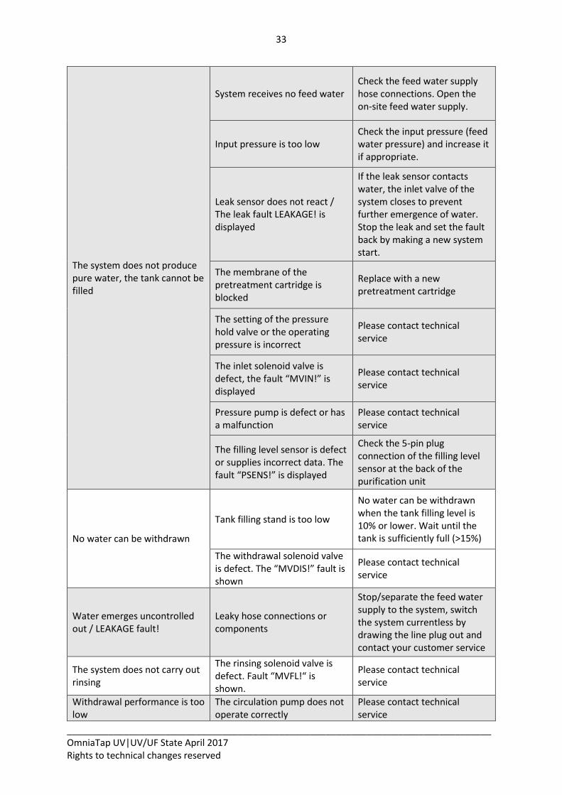
The system does not produce pure water, the tank cannot be filled
System receives no feed water Check the feed water supply hose connections. Open the on-site feed water supply.
Input pressure is too low Check the input pressure (feed water pressure) and increase it if appropriate.
Leak sensor does not react / The leak fault LEAKAGE! is displayed
If the leak sensor contacts water, the inlet valve of the system closes to prevent further emergence of water. Stop the leak and set the fault back by making a new system start.
The membrane of the pretreatment cartridge is blocked
Replace with a new pretreatment cartridge
The setting of the pressure hold valve or the operating pressure is incorrect
Please contact technical service
The inlet solenoid valve is defect, the fault “MVIN!” is displayed
Please contact technical service
Pressure pump is defect or has a malfunction
Please contact technical service
The filling level sensor is defect or supplies incorrect data. The fault “PSENS!” is displayed
Check the 5-pin plug connection of the filling level sensor at the back of the purification unit
No water can be withdrawn
Tank filling stand is too low
No water can be withdrawn when the tank filling level is 10% or lower. Wait until the tank is sufficiently full (>15%)
The withdrawal solenoid valve is defect. The “MVDIS!” fault is shown
Please contact technical service
Water emerges uncontrolled out / LEAKAGE fault!
Leaky hose connections or components
Stop/separate the feed water supply to the system, switch the system currentless by drawing the line plug out and contact your customer service
The system does not carry out rinsing
The rinsing solenoid valve is defect. Fault “MVFL!“ is shown.
Please contact technical service
Withdrawal performance is too low
The circulation pump does not operate correctly
Please contact technical service
34
__________________________________________________________________________________ OmniaTap UV|UV/UF State April 2017 Rights to technical changes reserved
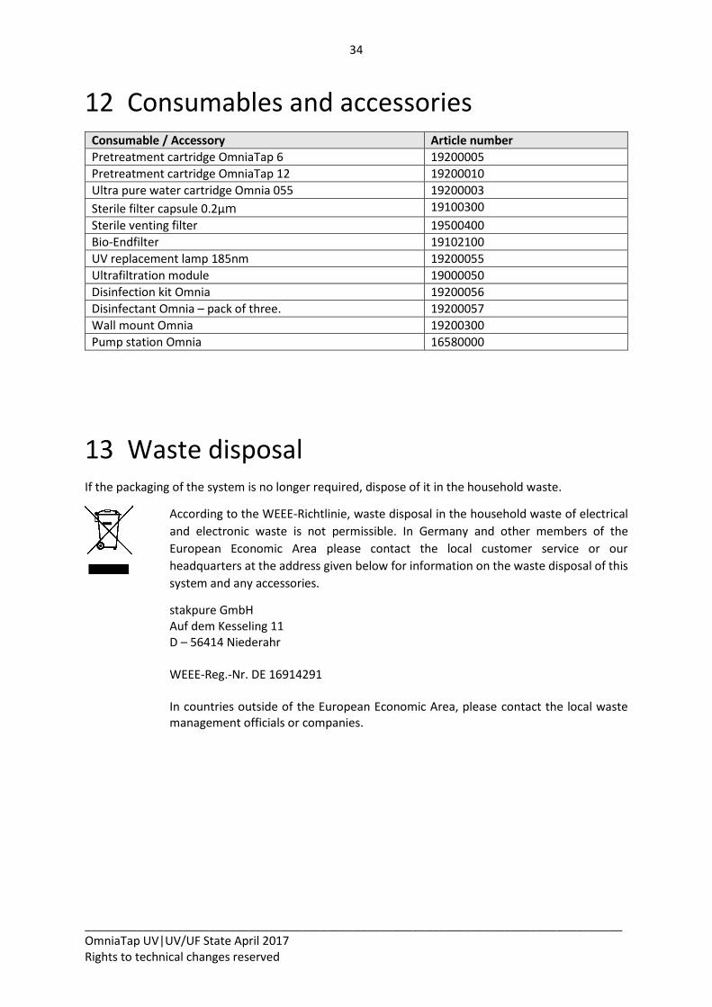
12 Consumables and accessories Consumable / Accessory Article number
Pretreatment cartridge OmniaTap 6 19200005
Pretreatment cartridge OmniaTap 12 19200010
Ultra pure water cartridge Omnia 055 19200003
Sterile filter capsule 0.2µm 19100300
Sterile venting filter 19500400
Bio-Endfilter 19102100
UV replacement lamp 185nm 19200055
Ultrafiltration module 19000050
Disinfection kit Omnia 19200056
Disinfectant Omnia – pack of three. 19200057
Wall mount Omnia 19200300
Pump station Omnia 16580000
13 Waste disposal If the packaging of the system is no longer required, dispose of it in the household waste.
According to the WEEE-Richtlinie, waste disposal in the household waste of electrical
and electronic waste is not permissible. In Germany and other members of the
European Economic Area please contact the local customer service or our
headquarters at the address given below for information on the waste disposal of this
system and any accessories.
stakpure GmbH Auf dem Kesseling 11 D – 56414 Niederahr
WEEE-Reg.-Nr. DE 16914291 In countries outside of the European Economic Area, please contact the local waste management officials or companies.
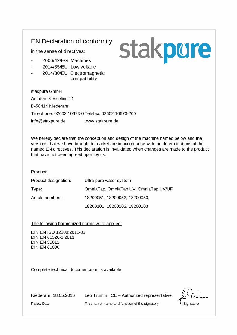
EN Declaration of conformity
in the sense of directives:
- 2006/42/EG Machines
- 2014/35/EU Low voltage
- 2014/30/EU Electromagnetic compatibility
stakpure GmbH
Auf dem Kesseling 11
D-56414 Niederahr
Telephone: 02602 10673-0 Telefax: 02602 10673-200
[email protected] www.stakpure.de
We hereby declare that the conception and design of the machine named below and the
versions that we have brought to market are in accordance with the determinations of the
named EN directives. This declaration is invalidated when changes are made to the product
that have not been agreed upon by us.
Product:
Product designation: Ultra pure water system
Type: OmniaTap, OmniaTap UV, OmniaTap UV/UF
Article numbers: 18200051, 18200052, 18200053,
18200101, 18200102, 18200103
The following harmonized norms were applied:
DIN EN ISO 12100:2011-03 DIN EN 61326-1:2013 DIN EN 55011 DIN EN 61000
Complete technical documentation is available.
Niederahr, 18.05.2016 Leo Trumm, CE – Authorized representative
Place, Date First name, name and function of the signatory Signature

stakpure GmbH Auf dem Kesseling 11 D – 56414 Niederahr Tel.: +49 2602 10673-0 Fax: +49 2602 10673-200 [email protected] www.stakpure.de