Embed Size (px)
Citation preview
IRO AB Box 54 SE-523 22 Ulricehamn SWEDEN Tel: (+46) 321 297 00 www.iroab.com [email protected]
2231 X2Operating Instructions
Ref. no. 31-8938-0201-05/1805
EN
2Ref. no. 31-8938-0201-05/1805
2231 X2
This section contains important safety information. Read the manual carefully before installing, using or maintaining the weft feeder.
WARNINGIndicates a possible dangerous situation which could result in serious injury or damage to the unit.
CAUTION Indicates a possible dangerous situation which could result in minor/moderate injury or damage to the unit.
NOTEUsed in order to draw attention to important information, which facilitates operation or handling.
IRO AB reserve the right to change the contents of the user’s guide and technical specifications without prior notification.
Original language instruction
Contents/ Information
Contents/ Information ............................................................. 2Warnings ................................................................................ 3Technical Specifications ......................................................... 4Installation/ Mains Connection................................................ 5Handling ................................................................................. 6Operating diagram/ Connections feeder pneumatics ............. 7Connections interface ............................................................. 8Main Parts .............................................................................. 9System Orientation ............................................................... 10
Settings..................................................................................11Yarn store ............................................................................. 12Balloon Control/Threading .................................................... 13Rotating the spoolbody ......................................................... 14Maintenance ......................................................................... 15Fault finding .......................................................................... 16Accessories - Bobbin Switch Sensor .................................... 17Accessories - Multi yarn break sensor system ................ 18-20Declaration of conformity ...................................................... 21
3Ref. no. 31-8938-0201-05/1805
2231 X2Warnings
NOTETo ensure the selection of the most suitable feeder and associated accessories, it is recommended making weaving tests with the intended yarns.
Please dispose of obsolete or unwanted equipment responsibly, taking into consideration any local regulations regard-ing the disposal and / or recycling of materials that are applicable
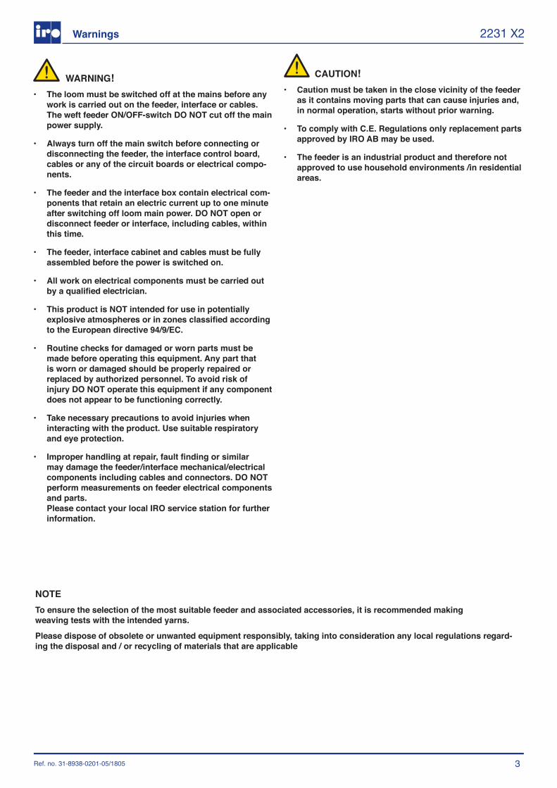
WARNING!• The loom must be switched off at the mains before any
work is carried out on the feeder, interface or cables. The weft feeder ON/OFF-switch DO NOT cut off the main power supply.
• Always turn off the main switch before connecting or disconnecting the feeder, the interface control board, cables or any of the circuit boards or electrical compo-nents.
• The feeder and the interface box contain electrical com-ponents that retain an electric current up to one minute after switching off loom main power. DO NOT open or disconnect feeder or interface, including cables, within this time.
• The feeder, interface cabinet and cables must be fully assembled before the power is switched on.
• All work on electrical components must be carried out by a qualified electrician.
• This product is NOT intended for use in potentially explosive atmospheres or in zones classified according to the European directive 94/9/EC.
• Routine checks for damaged or worn parts must be made before operating this equipment. Any part that is worn or damaged should be properly repaired or replaced by authorized personnel. To avoid risk of injury DO NOT operate this equipment if any component does not appear to be functioning correctly.
• Take necessary precautions to avoid injuries when interacting with the product. Use suitable respiratory and eye protection.
• Improper handling at repair, fault finding or similar may damage the feeder/interface mechanical/electrical components including cables and connectors. DO NOT perform measurements on feeder electrical components and parts. Please contact your local IRO service station for further information.
CAUTION!
• Caution must be taken in the close vicinity of the feeder as it contains moving parts that can cause injuries and, in normal operation, starts without prior warning.
• To comply with C.E. Regulations only replacement parts approved by IRO AB may be used.
• The feeder is an industrial product and therefore not approved to use household environments /in residential areas.
4
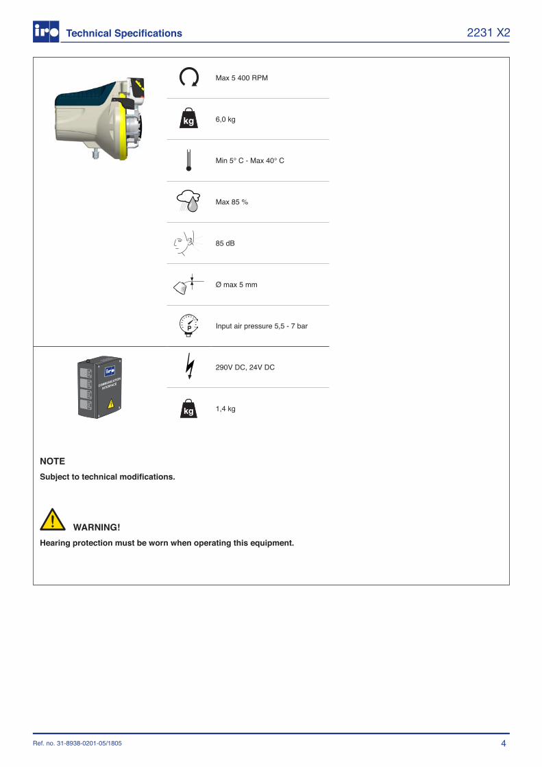
Max 5 400 RPM
6,0 kg
Min 5° C - Max 40° C
Max 85 %
85 dB
Ø max 5 mm
Input air pressure 5,5 - 7 bar
290V DC, 24V DC
1,4 kg
Ref. no. 31-8938-0201-05/1805
2231 X2
NOTESubject to technical modifications.
Technical Specifications
WARNING!Hearing protection must be worn when operating this equipment.
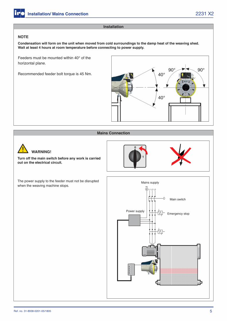
Installation
Mains Connection
5
40°90° 90°
40°
L2L1 L3PE
Mains supply
Main switch
Emergency stopPower supply
Ref. no. 31-8938-0201-05/1805
2231 X2
WARNING!Turn off the main switch before any work is carried out on the electrical circuit.
The power supply to the feeder must not be disrupted when the weaving machine stops.
Installation/ Mains Connection
NOTECondensation will form on the unit when moved from cold surroundings to the damp heat of the weaving shed. Wait at least 4 hours at room temperature before connecting to power supply.
Feeders must be mounted within 40° of the horizontal plane.
Recommended feeder bolt torque is 45 Nm.

6
Handling
Handle and carry the feeder carefully to avoid mechanical damage and/or personal injuries.
NOTEDo not expose the spool body parts to external forces. Do not, for instance, carry the feeder by holding the spool body fingers.
NOTEDo not expose the winding disc to mechanical force at any time. Store the feeder resting on the back to avoid damaging/deforming the winding disc.
Ref. no. 31-8938-0201-05/1805
2231 X2
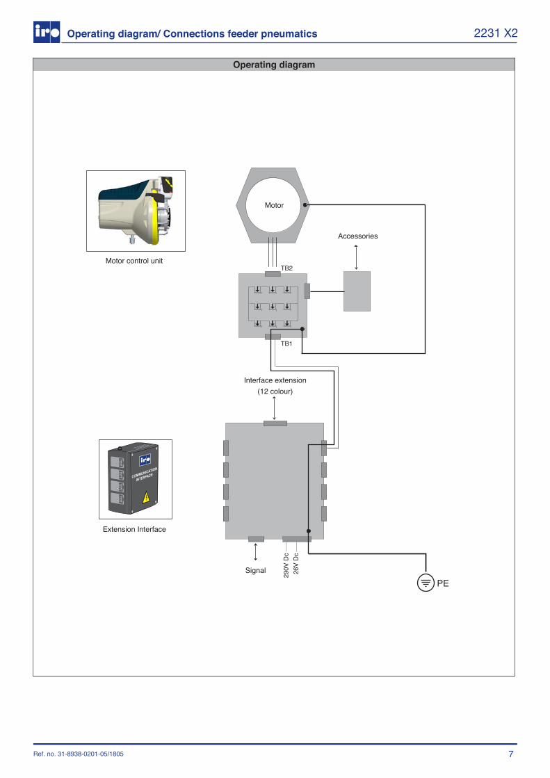
Operating diagram
7
290V
Dc
26V
Dc
TB1
TB2
Motor
Accessories
Interface extension (12 colour)
Signal
Motor control unit
Extension Interface
Ref. no. 31-8938-0201-05/1805
2231 X2Operating diagram/ Connections feeder pneumatics
8
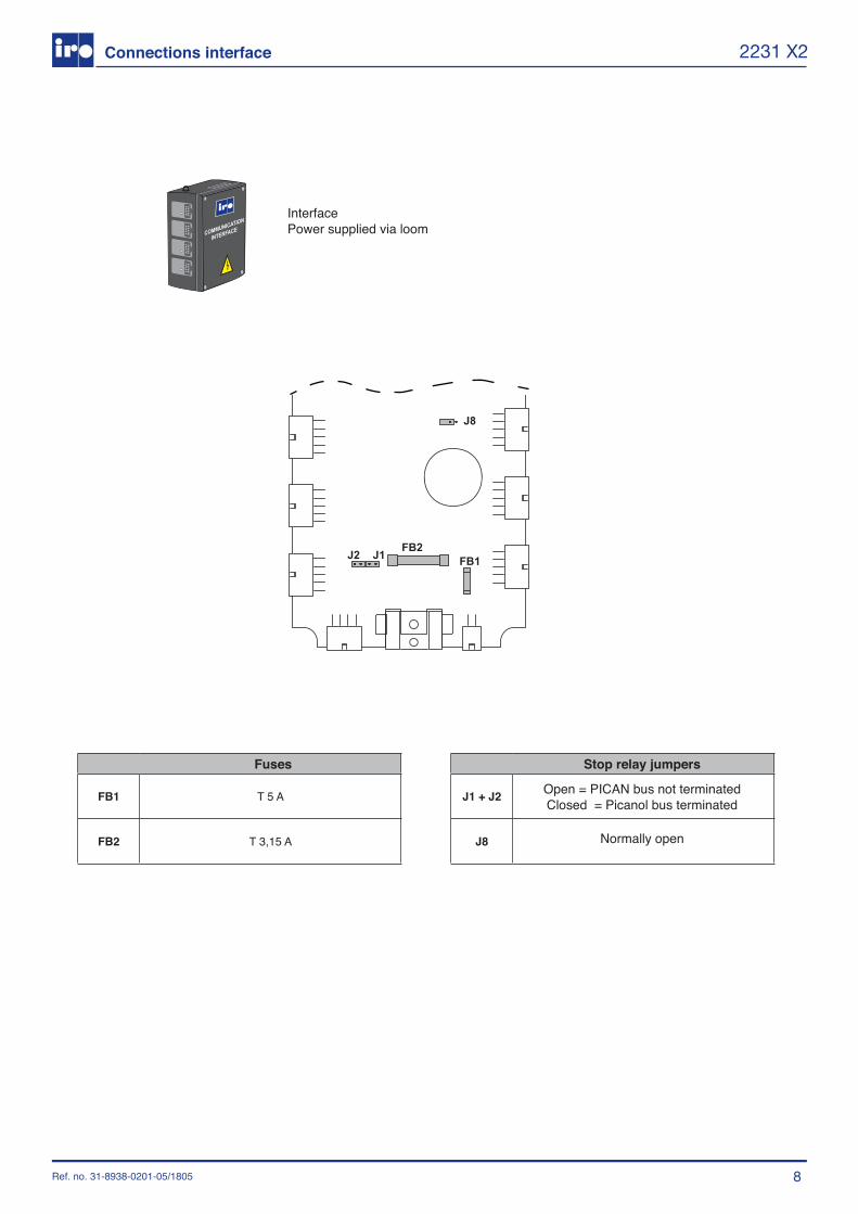
FB1 T 5 A
FB2 T 3,15 A
J1 + J2
J8
FB1FB2
J8
J1J2
Ref. no. 31-8938-0201-05/1805
2231 X2
Interface Power supplied via loom
Fuses Stop relay jumpers
Open = PICAN bus not terminatedClosed = Picanol bus terminated
Normally open
Connections interface
9
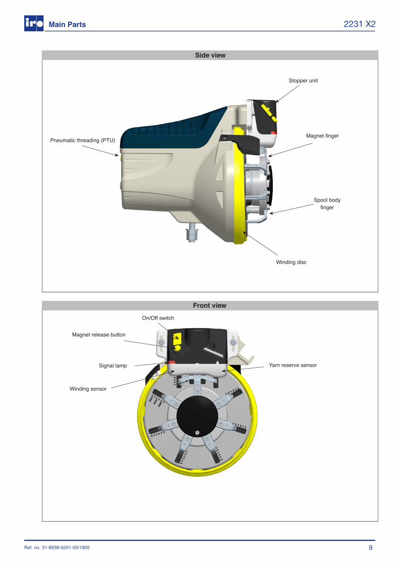
Pneumatic threading (PTU)
Stopper unit
Magnet finger
Winding disc
Spool body finger
Side view
Winding sensor
Magnet release button
On/Off switch
Signal lamp
Front view
Yarn reserve sensor
Ref. no. 31-8938-0201-05/1805
2231 X2Main Parts
10Ref. no. 31-8938-0201-05/1805
2231 X2System Orientation
SYSTEMThe system consists of feeders, cables to each feeder, interface control box, PTU (pneumatic threading up),input yarn tensioners and external accessories such as bobbin break sensors and bobbin change detectors.
INTERFACEThis control box handles all communication between feeders and machine via the CAN-bus system. The control box also distributes 290 VDC and 24VDC from the machine to each feeder.
FEEDERThe feeder consists of:• Motor and control unit• Spoolbodywith7independentlyadjustablefingers• Pick length control stopper magnet• Yarn store sensor• Positioning sensor• Winding sensor
Spool body circumference, yarn store size and stopper unit are mechanically adjusted on the feeder. All other settings are carried out on the weaving machines terminal and transmitted to the feeder through the CAN bus.The permanent magnet motor is controlled from the control board situated under the top cover. At feeder start-up, the number of windings on the spool body is controlled by the yarn store sensor which indicates the outer limit of the yarn store. The number of windings supplied to the yarn store is continuously counted by the wind-on sensor whilst at the same time the number of windings removed from the yarn store is counted by the winding sensor. For optimal regulation the pattern information is transferred to each feeder a few picks in advance.The weft length is equal to the spool body circumference multiplied with number of windings removed during one insertion. The stopper magnet pin is opened at a requested machine-angle by reading the anglebus and closed directly after the second last winding sensor pulse. The stopper magnet is driven in both directions electrically, but held in closed position after the power is switched off.

11
Spool body Circumference
Ref. no. 31-8938-0201-05/1805
2231 X2Settings
No. of Winds Pick lengthrange (MM)Min Max
1 366 5112 732 10223 1098 15334 1464 20445 1830 25556 2196 30667 2562 35778 2928 40889 3294 459910 3660 5110
The required pick length is the deciding factor when calculating the spool body circumference and thenumber of windings for each pick. The table below indicates the pick length ranges that can be obtainedfrom different numbers of windings. To calculate the appropriate spool body circumference / number ofwindings per pick, proceed as follows:
1. Determine the required pick length (drawing-in width plus waste).2. Using the table below determine a pick length range that covers the required pick length.3. The number of windings necessary to obtain the required pick length will be found in the left hand
column. Adjust the spool body to the required circumference as follows:
Stopper unit positioning screws
Circumference scale1,0 mm
Spool body finger screws
1. Move the stopper unit to its uppermost position.2. Loosen the spool body finger screws.3. Adjust the fingers using the scale on the oscillating disc as a reference.4. Tighten the finger screws and reposition the stopper unit.5. Make a weft insertion test and, if necessary, adjust.
12
Yarn store
Ref. no. 31-8938-0201-05/1805
2231 X2Yarn store
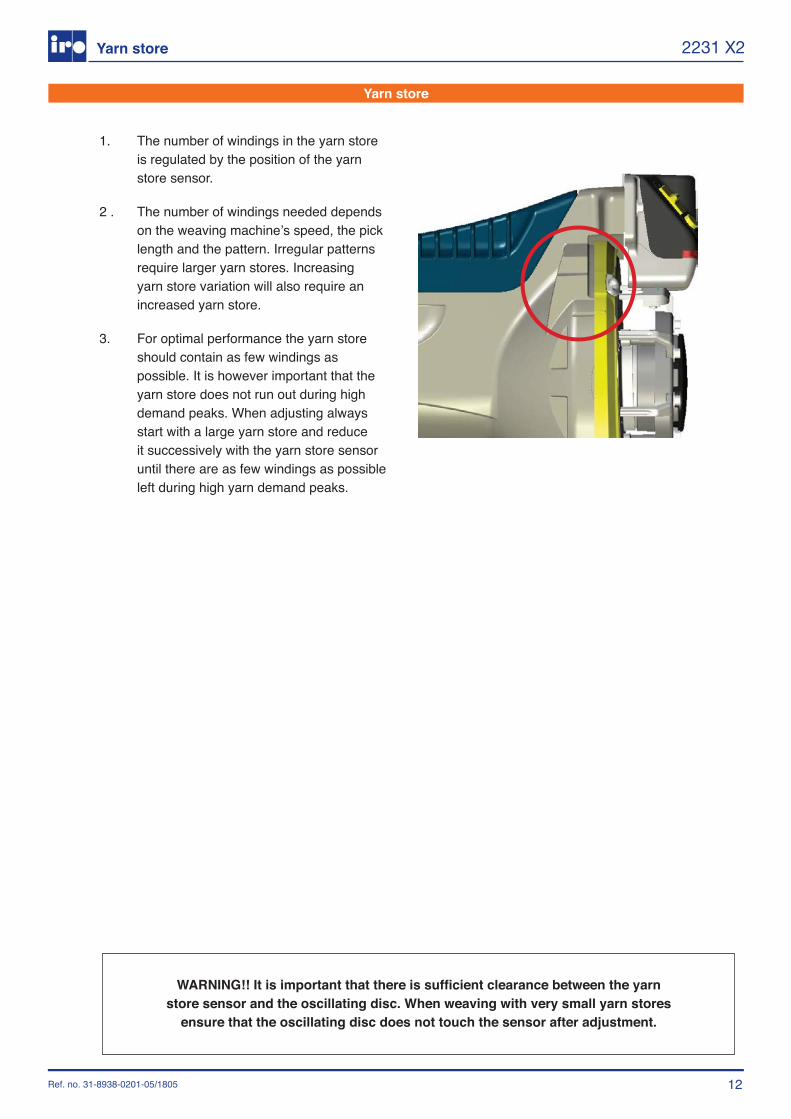
WARNING!! It is important that there is sufficient clearance between the yarnstore sensor and the oscillating disc. When weaving with very small yarn stores
ensure that the oscillating disc does not touch the sensor after adjustment.
1. The number of windings in the yarn store is regulated by the position of the yarn store sensor.
2 . The number of windings needed depends ontheweavingmachine’sspeed,thepicklength and the pattern. Irregular patterns require larger yarn stores. Increasing yarn store variation will also require an increased yarn store.
3. For optimal performance the yarn store should contain as few windings as possible. It is however important that the yarn store does not run out during high demand peaks. When adjusting always start with a large yarn store and reduce it successively with the yarn store sensor until there are as few windings as possible left during high yarn demand peaks.
Threading
Balloon control
13Ref. no. 31-8938-0201-05/1805
2231 X2Balloon Control/Threading
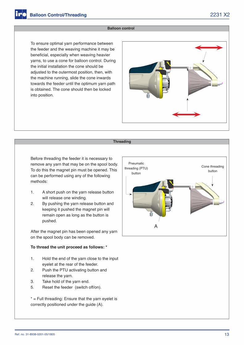
To ensure optimal yarn performance between the feeder and the weaving machine it may be beneficial, especially when weaving heavier yarns, to use a cone for balloon control. During the initial installation the cone should be adjusted to the outermost position, then, with the machine running, slide the cone inwards towards the feeder until the optimum yarn path is obtained. The cone should then be locked into position.
A
Before threading the feeder it is necessary to remove any yarn that may be on the spool body. To do this the magnet pin must be opened. This can be performed using any of the following methods:
1. A short push on the yarn release button will release one winding.
2. By pushing the yarn release button and keeping it pushed the magnet pin will remain open as long as the button is pushed.
After the magnet pin has been opened any yarn on the spool body can be removed.
To thread the unit proceed as follows: *
1. Hold the end of the yarn close to the input eyelet at the rear of the feeder.
2. Push the PTU activating button and release the yarn.
3. Take hold of the yarn end.5. Reset the feeder (switch off/on).
* = Full threading: Ensure that the yarn eyelet is correctly positioned under the guide (A).
Pneumatic threading (PTU)
button
Cone threading button
14
A
Ref. no. 31-8938-0201-05/1805
2231 X2Rotating the spoolbody
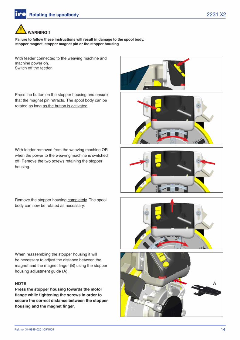
With feeder connected to the weaving machine and machine power on.Switch off the feeder.
Press the button on the stopper housing and ensure that the magnet pin retracts. The spool body can be rotated as long as the button is activated.
With feeder removed from the weaving machine OR when the power to the weaving machine is switched off. Remove the two screws retaining the stopper housing.
Remove the stopper housing completely. The spool body can now be rotated as necessary.
WARNING!!Failure to follow these instructions will result in damage to the spool body, stopper magnet, stopper magnet pin or the stopper housing
When reassembling the stopper housing it will be necessary to adjust the distance between the magnet and the magnet finger (B) using the stopper housing adjustment guide (A).
NOTE Press the stopper housing towards the motor flange while tightening the screws in order to secure the correct distance between the stopper housing and the magnet finger.
15Ref. no. 31-8938-0201-05/1805
2231 X2
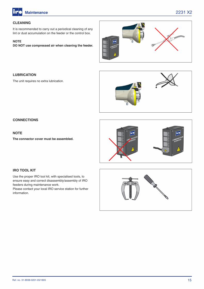
LUBRICATIONThe unit requires no extra lubrication.
IRO TOOL KIT Use the proper IRO tool kit, with specialised tools, to ensure easy and correct disassembly/assembly of IRO feeders during maintenance work. Please contact your local IRO service station for further information.
Maintenance
CLEANINGIt is recommended to carry out a periodical cleaning of any lint or dust accumulation on the feeder or the control box.
NOTEDO NOT use compressed air when cleaning the feeder.
CONNECTIONS
NOTEThe connector cover must be assembled.
16Ref. no. 31-8938-0201-05/1805
2231 X2
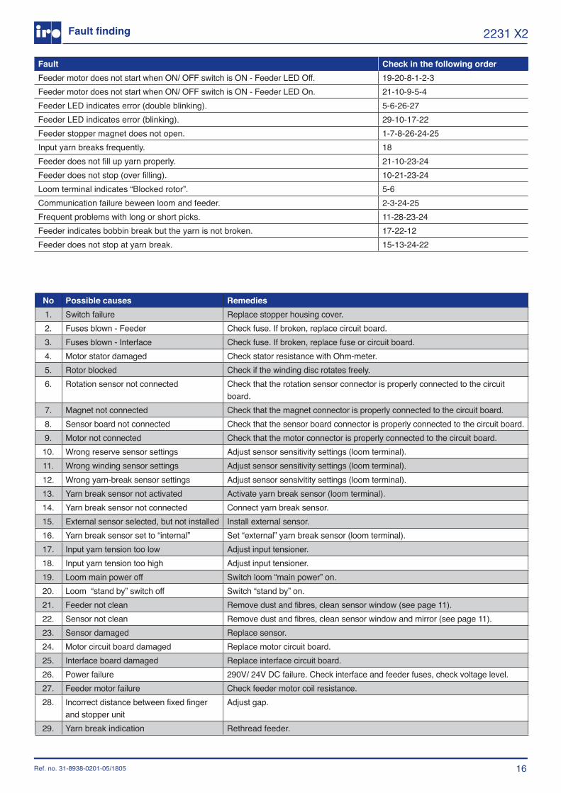
No Possible causes Remedies1. Switch failure Replace stopper housing cover.2. Fuses blown - Feeder Check fuse. If broken, replace circuit board.3. Fuses blown - Interface Check fuse. If broken, replace fuse or circuit board.4. Motor stator damaged Check stator resistance with Ohm-meter.5. Rotor blocked Check if the winding disc rotates freely.6. Rotation sensor not connected Check that the rotation sensor connector is properly connected to the circuit
board.7. Magnet not connected Check that the magnet connector is properly connected to the circuit board.8. Sensor board not connected Check that the sensor board connector is properly connected to the circuit board.9. Motor not connected Check that the motor connector is properly connected to the circuit board.
10. Wrong reserve sensor settings Adjust sensor sensitivity settings (loom terminal).11. Wrong winding sensor settings Adjust sensor sensitivity settings (loom terminal).12. Wrong yarn-break sensor settings Adjust sensor sensivitity settings (loom terminal).13. Yarn break sensor not activated Activate yarn break sensor (loom terminal).14. Yarn break sensor not connected Connect yarn break sensor.15. External sensor selected, but not installed Install external sensor.16. Yarn break sensor set to “internal” Set “external” yarn break sensor (loom terminal).17. Input yarn tension too low Adjust input tensioner.18. Input yarn tension too high Adjust input tensioner.19. Loom main power off Switch loom “main power” on.20. Loom “stand by” switch off Switch “stand by” on.21. Feeder not clean Remove dust and fibres, clean sensor window (see page 11). 22. Sensor not clean Remove dust and fibres, clean sensor window and mirror (see page 11).23. Sensor damaged Replace sensor.24. Motor circuit board damaged Replace motor circuit board.25. Interface board damaged Replace interface circuit board.26. Power failure 290V/ 24V DC failure. Check interface and feeder fuses, check voltage level.27. Feeder motor failure Check feeder motor coil resistance.28. Incorrect distance between fixed finger
and stopper unitAdjust gap.
29. Yarn break indication Rethread feeder.
Fault Check in the following orderFeeder motor does not start when ON/ OFF switch is ON - Feeder LED Off. 19-20-8-1-2-3Feeder motor does not start when ON/ OFF switch is ON - Feeder LED On. 21-10-9-5-4Feeder LED indicates error (double blinking). 5-6-26-27Feeder LED indicates error (blinking). 29-10-17-22Feeder stopper magnet does not open. 1-7-8-26-24-25Input yarn breaks frequently. 18Feeder does not fill up yarn properly. 21-10-23-24Feeder does not stop (over filling). 10-21-23-24Loom terminal indicates “Blocked rotor”. 5-6Communication failure beween loom and feeder. 2-3-24-25Frequent problems with long or short picks. 11-28-23-24Feeder indicates bobbin break but the yarn is not broken. 17-22-12Feeder does not stop at yarn break. 15-13-24-22
Fault finding
17Ref. no. 31-8938-0201-05/1805
2231 X2
SYSTEM DESCRIPTION:
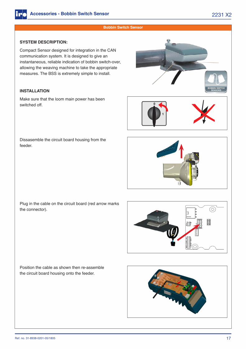
Compact Sensor designed for integration in the CAN communication system. It is designed to give an instantaneous, reliable indication of bobbin switch-over, allowing the weaving machine to take the appropriate measures. The BSS is extremely simple to install.
INSTALLATION
Make sure that the loom main power has been switched off.
Dissasemble the circuit board housing from thefeeder.
Plug in the cable on the circuit board (red arrow marks the connector).
Position the cable as shown then re-assemblethe circuit board housing onto the feeder.
Accessories - Bobbin Switch Sensor
Bobbin Switch Sensor
CREELS & STANDS
BALLOON CONTROLTENSIONERSYARN BREAK
SENSORS BOBBIN SWITCH
SENSORS
POWER SUPPLY& INTERFACES
KNOT SENSORS LUBRICATORS WEFT
DETECTORS
BALLOON CONTROL& TENSIONERS
18
Multi yarn break sensor system
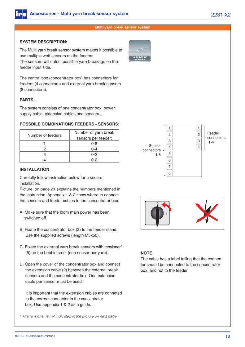
NOTE The cable has a label telling that the connec-tor should be connected to the concentrator box, and not to the feeder.
1
32
4
12345678
Sensor connectors
1-8
Feeder connectors 1-4
Ref. no. 31-8938-0201-05/1805
2231 X2Accessories - Multi yarn break sensor system
SYSTEM DESCRIPTION:
The Multi yarn break sensor system makes it possible to use multiple weft sensors on the feeders.The sensors will detect possible yarn breakage on the feeder input side.
The central box (concentrator box) has connectors for feeders (4 connectors) and external yarn break sensors (8 connectors).
PARTS:
The system consists of one concentrator box, power supply cable, extension cables and sensors.
POSSBILE COMBINATIONS FEEDERS - SENSORS:
Number of feeders Number of yarn break sensors per feeder:
1 0-82 0-43 0-24 0-2
INSTALLATION
Carefully follow instruction below for a secure installation.Picture on page 21 explains the numbers mentioned in the instruction. Appendix 1 & 2 show where to connect the sensors and feeder cables to the concentrator box.
A. Make sure that the loom main power has been switched off. B. Fixate the concentrator box (3) to the feeder stand. Use the supplied screws (length M5x50).
C. Fixate the external yarn break sensors with tensioner* (5) on the bobbin creel (one sensor per yarn).
D. Open the cover of the concentrator box and connect the extension cable (2) between the external break sensors and the concentrator box. One extension cable per sensor must be used.
It is important that the extension cables are conneted to the correct connector in the concentrator box. Use appendix 1 & 2 as a guide.
* The tensioner is not indicated in the picture on next page
CREELS & STANDS
BALLOON CONTROLTENSIONERSYARN BREAK
SENSORS BOBBIN SWITCH
SENSORS
POWER SUPPLY& INTERFACES
KNOT SENSORS LUBRICATORS WEFT
DETECTORS
BALLOON CONTROL& TENSIONERS
19
Multi yarn break sensor systemMulti yarn break sensor system
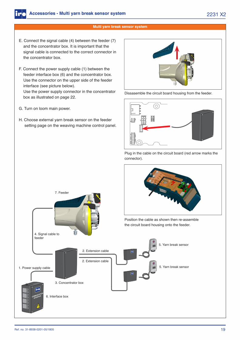
1. Power supply cable
4. Signal cable to feeder
3. Concentrator box
6. Interface box
5. Yarn break sensor
5. Yarn break sensor2. Extension cable
2. Extension cable
7. Feeder
Ref. no. 31-8938-0201-05/1805
2231 X2Accessories - Multi yarn break sensor system
E. Connect the signal cable (4) between the feeder (7) and the concentrator box. It is important that the signal cable is connected to the correct connector in the concentrator box.
F. Connect the power supply cable (1) between the feeder interface box (6) and the concentrator box. Use the connector on the upper side of the feeder interface (see picture below). Use the power supply connector in the concentrator box as illustrated on page 22.
G. Turn on loom main power.
H. Choose external yarn break sensor on the feeder setting page on the weaving machine control panel.
Dissasemble the circuit board housing from the feeder.
Plug in the cable on the circuit board (red arrow marks the connector).
Position the cable as shown then re-assemblethe circuit board housing onto the feeder.
20
Multi yarn break sensor system
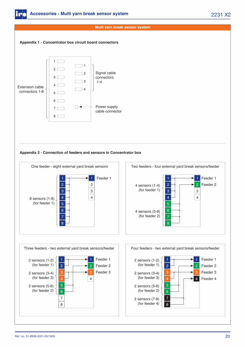
Appendix 1 - Concentrator box circuit board connectors
1
2
3
4
5
6
7
8
1
2
3
4Extension cable connectors 1-8
Signal cable connectors 1-4
Power supply cable connector
Appendix 2 - Connection of feeders and sensors in Concentrator box
One feeder - eight external yard break sensors Two feeders - four external yard break sensors/feeder
Three feeders - two external yard break sensors/feeder Four feeders - two external yard break sensors/feeder
1
32
4
12345678
8 sensors (1-8) (for feeder 1)
Feeder 1
1
32
4
12345678
2 sensors (1-2) (for feeder 1)
2 sensors (3-4) (for feeder 3)
2 sensors (5-6) (for feeder 2)
Feeder 1Feeder 2Feeder 3
1
32
4
12345678
2 sensors (1-2) (for feeder 1)
2 sensors (3-4) (for feeder 3)
2 sensors (5-6) (for feeder 2)
2 sensors (7-8) (for feeder 4)
Feeder 1Feeder 2Feeder 3Feeder 4
1
32
4
12345678
Feeder 1Feeder 24 sensors (1-4)
(for feeder 1)
4 sensors (5-8) (for feeder 2)
Ref. no. 31-8938-0201-05/1805
2231 X2Accessories - Multi yarn break sensor system
21
IRO ABBox 54SE-523 22 Ulricehamn
Pär Josefsson, Manager Product and Development department, 2017-07-06
2231 X2
Declaration of conformity
EC DECLARATION OF CONFORMITY
Guarantee that machine type:
is manufactured in conformity with the provisions of the following EC directives and applicable amendments:
Safety of machinery 2006/42/EC EN ISO 111 11-1
Low voltage equipment 2014/35/EC EN ISO 111 11-1
Electromagnetic compatility 2014/30/EC EN ISO 111 11-1
Ref. no. 31-8938-0201-05/1805
2231 X2
![Solid-State Cells with Buffer Electrodes for the Measurement of Thermodynamic Properties of IrO[sub 2], CaIrO[sub 3], Ca[sub 2]IrO[sub 4], and Ca[sub 4]IrO[sub 6]](https://img.dokumen.tips/doc/110x75/634c41368b264d9afb05a9b9/solid-state-cells-with-buffer-electrodes-for-the-measurement-of-thermodynamic-properties.jpg)


