Embed Size (px)
Citation preview

Operating InstructionsFunctional Manual
Wireless Presentation System For business use
Model No. TY-WPS1WPS Basic Set
TY-WPB1WPS Transmitter
TY-WPBC1WPS USB-C Transmitter
TY-WP2B1WPS Transmitter Set
TY-WP2BC1WPS USB-C Transmitter Set
* WPS is an abbreviation of “Wireless Presentation System”.
* PressIT is a nickname for “Wireless Presentation System”.
English
Thank you for purchasing the Panasonic product. • Please read these instructions before operating this product and retain them for future reference. • Be sure to read “Safety Precautions” (page 2 to 3) before use. • These Operating Instructions are shared by TY-WPS1, TY-WP2B1, TY-WPB1, TY-WP2BC1 and TY-WPBC1.
DA0920TS0 -PB DPQP1359ZA/X1

2 English
WARNING:Stop using the product immediately when an abnormality or malfunction occurs.Remove the power plug in the case of an abnormality.
• Smoke is emitted, or abnormal smell or sound occurs. • Video or audio is not reproduced in some cases. • Liquid such as water or a foreign object has entered inside the product.
• The product is deformed or damaged.Using the product in such states may cause a fire or electric shock.
• Remove the power plug from the outlet and request repair to the dealer where you purchased the product.
• It is necessary to remove the power plug to completely turn off the power of this product.
• Do not repair the product by the customer since it is dangerous.
• Use an outlet located at a position where the hand can reach easily so that the power plug can be removed quickly.
Do not insert foreign objects into the product.Do not insert or drop metals or flammable items into the inside the product from the vent hole, etc.Smoke is emitted, or abnormal smell or sound occurs.
• Keep an eye on children in particular.
■About AC adaptorDo not use an AC adaptor or AC adaptor cable other than those supplied with this product.Using an AC adaptor or AC adaptor cable other than those supplied may cause an electric shock or fire due to short circuit or heat generation.Clean the power plug periodically to prevent dust from accumulating.Failure to do so may cause a fire or electric shock due to moisture.
• Remove the power plug and wipe it with dry cloth.Do not insert or remove the power plug with wet hand.Doing so may cause an electric shock.Do not use the outlet or wiring devices exceeding rated values or with currents other than 100 ‒ 240 V AC.Using them exceeding rated values by connecting too many plugs in one outlet may cause a fire due to heat generation.Insert the power plug securely to the end.Insufficient insertion may cause a fire due to an electric shock or heat generation.
• Do not use the product with a damaged plug or loose outlet.
Do not damage the AC adaptor and power plug.by damaging, modifying, forcibly bending, twisting, pulling or bundling them, bringing them close to heat appliances, placing heavy items on them, etc.
INDEX Safety Precautions
Safety Precautions ...........................................2Before Using .....................................................4
Features of the system ········································4Precautions for use ············································4
Notes on Using Wireless LAN .........................6Request Regarding Security ...........................7Accessories ......................................................8Part Names ........................................................9Connection ...................................................... 11
Connecting the receiver ···································· 11Connecting the transmitter ································· 12
Basic Use ........................................................13Single connection ············································ 13Multi connection ·············································· 14
Fixing image switching (fixed mode) ...........15Setting the fixed mode ······································ 15Canceling the fixed mode ·································· 15
Transmitter Extension Method (Pairing) ......16Pairing by connecting the receiver and transmitter ·· 16Pairing by saving a file to the USB memory ··········· 17
Using with Android device (Android 5.0 and later versions) .................................................18
Use an app on the Android device and connect the device to the wireless LAN coming from the receiver ························· 18Use an app on the Android device and connect the device to the external wireless LAN ····················· 18
Setting .............................................................20About the standby screen ·································· 20Displaying the Web setting screen ······················· 22Configuring various settings on the Web setting screen ··· 25[Setup] menu (display setting) ···························· 32Using the HDMI-CEC function ···························· 36
Installing the Receiver Installing the Receiver ........39Components for receiver mounting bracket ··········· 39Mounting the base bracket (common) ·················· 39Installing on the ceiling or wall ···························· 40Installing on the display ····································· 40Recommended example for installing on the projector professional model ············································· 42Recommended example for installing on the projector system model ··················································· 43Recommended example for installing on the projector portable model ················································ 44
Image Signals Supported by This Product ..45Troubleshooting… ..........................................45Specifications .................................................46Software License ............................................47Trademark Credit ............................................47FCC STATEMENT ............................................48

3English
Doing so may cause a fire or electric shock due to short circuit or disconnection.
• Request the dealer for repair of the AC adaptor or power plug.
Use the product 15 cm or more away from a location where a cardiac pacemaker is embedded.Radio waves may affect the operation of the pacemaker.Do not use the product in an airplane.The operational safety may be impaired.Do not use the product near an automatic door, fire alarm or other automatic control devices.Radio waves from this product may affect automatic control devices, which may cause an operational error, resulting in an accident.Do not use the product in hospital or a location with medical equipment.Radio waves from this product may affect medical equipment, which may cause an operational error, resulting in an accident.Do not use the product while touching it for a long time.Touching the hot parts of the product and AC adaptor for a long time may cause a low-temperature burn*.* Persons with poor bloodstream (due to vascular
impairment, poor blood circulation, diabetes or strong compression) or poor skin sensitivity (elderly persons) tend to get a low-temperature burn.
Do not touch the product and AC adaptor if it begins to thunder.Doing so may cause an electric shock.Do not wet the product.Doing so may cause a fire or electric shock.Do not place the product on unstable locations.Placing the product on a shaky table or an inclined location may cause an injury due to falling over or dropping.Do not remove or modify the back cover (cabinet).Keep the screws supplied with the receiver out of reach of infants.The screws may be accidentally swallowed.
• In the event this occurs, consult a doctor immediately.For installation, please ask a qualified technician or a dealer.If installation is not carried out and secured correctly, it can cause falling accidents.
• If you terminate the use of the product, ask a professional to remove it promptly.
Do not touch the bottom surface of the transmitter during use.The bottom surface of the transmitter may be hot during and after use for a while, resulting in a burn injury.Also, do not place it on an object sensitive to heat. Doing so may cause deformation or discoloration.
CAUTION:Do not block the vent hole of this product.Do not push the product into a narrow and poorly ventilated space.Doing so may cause heat to accumulate inside, resulting in a fire or malfunction.Do not place a heavy item on the product.Doing so may cause a fire or malfunction.Do not place the product at a high-temperature location, humid or dusty location, or location subject to oil smoke or steam (such as a cooking table and humidifier).Doing so may cause a fire or electric shock.When removing the connection cables, be sure to hold the connector and pull it.Pulling the cord may damage the cord, resulting in a fire due to an electric shock or short circuit.When transferring the product, remove the connection cables of equipment beforehand.Failure to do so may damage the cord or product, resulting in a fire or electric shock.When not using the product for a prolonged period, remove the power plug from the outlet.Dust may accumulate in the power plug, resulting in a fire or electric shock.Do not pull or hang the connection cables.Doing so may cause the product to fall over or drop, resulting in an injury.
• Keep an eye on children in particular.
■MaintenanceFor maintenance, remove the power plug from the outlet for safety.Failure to do so may cause an electric shock.

4 English
Before Using
Features of the systemThe wireless presentation system allows screens displayed on an image output device to be projected (mirroring) on a display or projector installed at a remote location.Since small screens of a smartphone, notebook computer, etc. can be displayed on a large screen, this system is convenient to show presentation materials on a large display in a meeting, enjoy images on a large display, show images with a display installed at a location where wiring cables is difficult or other cases.
This system is composed of a transmitter and a receiver, and sends images on an image output device to the receiver via wireless LAN using the transmitter.Also, images can be sent to the receiver from a mobile device (Android device) without using the transmitter.Using the following methods allows images on an image output device to be displayed on a display or projector.
Send images on an image output device to the receiver using the transmitter to display the images on a display or projector.
Send images on a mobile device (Android device) directly to the receiver using a dedicated application to display the images on a display or projector.
Send images on a mobile device (Android device) to the receiver using a dedicated application via external wireless LAN to display the images on a display or projector.
Note • Depending on the usage environment, some of the displayed contents on the application screen or Web setting screen may differ.
Precautions for use
■When transporting this productDo not apply excessive vibrations or impacts during transport.Doing so may damage the internal parts, resulting in a malfunction.
■When installing this productDo not install the product outdoors.This product is intended for exclusive use indoors. Using it outdoors is prohibited by radio wave-related laws.Do not install the product in the following locations. • Locations subject to vibrations or impacts such as vehicles and vessels: The internal parts may be damaged, resulting in a malfunction.
• Near the sea or locations where corrosive gases are generated: The life-span of parts may be affected or a malfunction may occur.
• Near high-voltage wires or power sources: The operation of the product may be disturbed.Do not install the product at a location of 2 700 m (8 853 ft) or higher above sea level.Doing so may affect the life-span of parts or cause a malfunction.The operating temperatures for this product are 0 °C to 35 °C (32 °F to 95 °F) at a location of less than 1 400 m (4 593 ft) above sea level, and 0 °C to 30 °C (32 °F to 86 °F) at a location of 1 400 m (4 593 ft) or higher and less than 2 700 m (8 853 ft) above sea level.Do not block the air inlet and air outlet of the product. Do not use the product in a manner that disturbs inlet and outlet of air.Doing so may damage the internal parts, resulting in a malfunction.We are not responsible for any product damage, etc. caused by failures in the installation environment even during the warranty period.

5English
■About wired LANTake sufficient shielding measures at a location where static electricity tends to be generated before using the product.When using the product at locations where lots of static electricity is generated such as carpet, wired LAN communication tends to be disconnected. In this case, use an antistatic mat, etc. to eliminate the problematic static electricity and noise source from the area surrounding this product and cables.On rare occasions, LAN connection may not be established due to static electricity or noises. In this case, turn off the power of the product and devices connected to this product once, and then turn on the power of them again.When there is equipment that generates strong radio waves in the vicinity, install the product sufficiently away from such equipment.
■Cleaning and maintenanceFirst, remove the mains plug from the mains socket.Gently wipe the surface of the case by using a soft cloth to remove dirt.
• To remove stubborn dirt or fingerprints, dampen a cloth with diluted neutral detergent (1 part detergent to 100 parts water), wring out the cloth firmly, and then wipe away the dirt. Finally, wipe away all the moisture with a dry cloth.
• If water droplets get inside the unit, operating problems may result.Usage of a chemical cloth
• Follow the instructions for the chemical cloth.Avoid contact with volatile substances such as insect sprays, solvents and thinner.
• This may cause damage to the case or cause peeling of the paint. Furthermore, do not leave it in contact with a rubber or PVC substance for a long time.
Note when using alcohol • Soak a small amount of alcohol at a concentration of 60 % or less in a soft cloth and wipe the housing. Then be sure to use a dry cloth to wipe it.Note that wiping the housing with a hard cloth or rubbing it strongly may cause damage. Also, do not allow water droplets to enter the inside to prevent malfunction. Do not directly spray alcohol.
• Do not use antiseptic solutions other than alcohol.
■DisposalWhen disposing the product, ask your local authority or dealer about the correct methods of disposal.

6 English
Notes on Using Wireless LAN
Wireless LAN uses radio waves in the 5 GHz bands.Be sure to read and fully understand the following items before use.
If at all possible, avoid the use of cellular phones, TV sets or radios near the product. ●Cellular phones, TV sets, radios and similar devices use different radio bands from the product, so there is no effect on wireless communication or the transmission and reception of these devices. However, radio waves from the product may produce audio or video noise.
Wireless communication radio waves cannot penetrate steel reinforcements, metal, concrete, etc. ●Communication is possible through walls and floors made from materials such as wood and glass (except glass containing wire mesh), but not through walls and floors made from steel reinforcements, metal, concrete, etc.
The product may not work properly due to strong radio wave from the broadcast station or the radio. ●If there is any facility or equipment, which outputs strong radio wave, near the installation location, set up the product at a location sufficiently far from the source of the radio wave.
Using the product outside the country ●It is forbidden to take the product outside the country or region where you purchased it, so use it only in the said country or region. Also, note that depending on countries or regions there are restrictions on the channels and frequencies at which you can use the wireless LAN.
Available wireless LAN channels ●Refer to the table below.
Available channels Standard Frequency band36/40/44/48 channel (W52) IEEE802.11a/n/ac 5.150 GHz - 5.250 GHz
• Use this product indoors. • Using the 5 GHz-band wireless device of this product outdoors is prohibited by the Radio Act.
Using receivers • Up to 4 receivers can be installed for this product in the same room. To ensure operations, configure the settings in such a way that radio frequencies output from each receiver do not duplicate with each other.
• Receivers installed in more than one rooms can be used by configuring the settings in the same way as above to avoid duplication of radio frequencies, depending on the state of radio waves leaked from receivers installed in other rooms. However, if the receivers do not operate normally due to interference etc., take necessary measures such as extending the straight-line distance between receivers in each room.
Declaration of Conformity (DoC)“Hereby, Panasonic Corporation declares that this product is in compliance with the essential requirements and other relevant provisions of the Directive 2014/53/EU.”If you want to get a copy of the original DoC of this product, please visit the following website:http://www.ptc.panasonic.deAuthorized Representative: Panasonic Testing CentrePanasonic Service Europe, a division of Panasonic Marketing Europe GmbHWinsbergring 15, 22525 Hamburg, GermanyIndoor use restrictions are to be followed for the following countries if using 5 GHz frequency band.Austria, Belgium, Bulgaria, Croatia, Cyprus, Czech Republic, Denmark, Estonia, Finland, France, Germany, Greece, Hungary, Iceland, Ireland, Italy, Latvia, Liechtenstein, Lithuania, Luxembourg, Malta, Netherlands, Norway, Poland, Portugal, Romania, Slovakia, Slovenia, Spain, Sweden, Switzerland, Turkey, United Kingdom
WLAN: Maximum Power 23 dBm (5.150 GHz - 5.250 GHz)
Directive: 2014/53/EU

7English
When using this product, take safety measures against the following incidents. ●Personal information being leaked via this product ●Unauthorized operation of this product by a malicious third party ●Interfering or stopping of this product by a malicious third party ●Set a password restrict the users who can log in. ●Make your password difficult to guess as much as possible. ●It is recommended to use a password different from passwords of PC and other devices. ●Change your password periodically. ●Panasonic Corporation or its affiliate companies will never ask for your password directly. Do not divulge your password in case you receive such inquiries. ●The connecting network must be secured by a firewall, etc. ●When disposing the product, initialize the data before disposing. ([Reset to Factory Default] (see page 31))
Take sufficient security measures.
Precautions on security when using wireless LAN products ●The advantage of a wireless LAN is that information can be exchanged between a PC or other such equipment and an access point using radio waves as long as you are within range for radio transmissions.On the other hand, because the radio waves can travel through obstacles (such as walls) and are available everywhere within a given range, problems of the type listed below may occur if security-related settings are not made. • A malicious third-party may intentionally intercept and monitor transmitted data including the content of e-mail and personal information such as your ID, password, and/or credit card numbers.
• A malicious third-party may access your personal or corporate network without authorization and engage in the following types of behaviour.Retrieve personal and/or secret information (information leak)Spread false information by impersonating a particular person (spoofing)Overwrite intercepted communications and issue false data (tampering)Spread harmful software such as a computer virus and crash your data and/or system (system crash)
●Since most wireless LAN adaptors or access points are equipped with security features to take care of these problems, you can reduce the possibility of these problems occurring when using this product by making the appropriate security settings for the wireless LAN device. ●Some wireless LAN devices may not be set for security immediately after purchase. To decrease the possibility of occurrence of security problems, before using any wireless LAN devices, be absolutely sure to make all security-related settings according to the instructions given in the operation manuals supplied with them.Depending on the specifications of the wireless LAN, a malicious third-party may be able to break security settings by special means.Please contact Panasonic if you need help taking care of security settings or other such.If you cannot perform security settings for your wireless LAN by yourself, please contact the Panasonic Support Center. ●Panasonic asks customers to thoroughly understand the risk of using this product without making security settings, and recommends that the customer make security settings at their own discretion and responsibility.
Request Regarding Security

8 English8
Accessories
Check that you have the accessories and items shown.
WPS Basic Set TY-WPS1WPS Receiver(TY-WPR1) .....................................1
WPS Transmitter(TY-WPB1) .....................................2
Transmitter case(TY-WPC1) .....................................1
AC adaptor(DPVF3514ZA/X1)..........................1(including 3 conversion plugs)
AC adaptor cable(DPVF3515ZA/X1)..........................1
HDMI cable(DPVF3512ZA/X1)..........................1
USB extension cable(DPVF3513ZA/X1)..........................2
Receiver mounting bracket(see page 39) .................................1
WPS Transmitter Set TY-WP2B1WPS Transmitter(TY-WPB1) .....................................2
Transmitter case(TY-WPC1) .....................................1
USB extension cable(DPVF3513ZA/X1)..........................2
WPS Transmitter TY-WPB1WPS Transmitter(TY-WPB1) .....................................1
USB extension cable(DPVF3513ZA/X1)..........................1
WPS USB-C Transmitter Set TY-WP2BC1WPS USB-C Transmitter(TY-WPBC1) ...................................2
Transmitter case(TY-WPC1) .....................................1
Conversion adaptor for pairing(DPVF3516ZA/X1)..........................1
WPS USB-C Transmitter TY-WPBC1WPS USB-C Transmitter(TY-WPBC1) ...................................1
Conversion adaptor for pairing(DPVF3516ZA/X1)..........................1
Attention • Store small parts in an appropriate manner, and keep them away from young children. • The part numbers of accessories are subject to change without notice.
(The actual part number may differ from the ones shown above.) • In case you lost accessories, please purchase them from your dealer. (Available from the customer service) • Dispose the packaging materials appropriately after taking out the items.

9English
1
3
2
4
5 6 7 8 109 11
Part Names
1 Antenna
2 FUNCTION button / LEDUsed to save a pairing file to the USB memory.
3 IndicatorDisplays the power supply status, and connection statuses of LAN and USB.
4 Screw holes for mounting bracket (page 39)Used to attach the receiver to the mounting bracket.
▼Connectionterminals/Controls5 Security Slot
This security slot is compatible with a Noble Wedge slot.
6 Power input terminal
7 Power buttonTurns ON/OFF the power of the receiver.
8 Reset buttonRestores the product to the factory default state.This is the same operation as that when [Reset RX] is selected for [Reset to Factory Default]. (page 31)Reset operation starts when the reset button is pressed for 5 seconds or more while the power is being supplied. Initialization will be complete in approx. 1 minute.
9 USB terminal (Type-A)Connects the transmitter or USB memory when pairing devices.Use this by connecting an HID device.
10 LAN terminal (RJ45)Connects to the network to change the settings of the product.
11 HDMI output terminalConnects an imaging device equipped with HDMI input.
■Receiver
▼Connectionterminals/Controls
* HID deviceA common mouse and a touch module built into the display operate. For information of operable touch modules, see the Panasonic information site. These can be used only with one screen display. After the USB cable of the HID device is connected, “HID driver install..” appears. When this message disappears, the device can be used.

10 English
2 4
1
3
5 6
5 6
7
3 4
Part Names Continued
1 HDMI input terminalConnect to an imaging device equipped with HDMI output.
2 USB terminal (Type-A)Connect to a USB power supply device.
3 Main button / LEDSwitches between on and off of image display.
4 Sub button / LEDSwitches to the multi-screen mode.
5 Mode switchIt is used when pairing. (see page 16)Set the switch to the STD side when receiving information from an HID device.
6 USB terminal (Type-A)Connects a USB memory when pairing with the receiver.
7 USB terminal (Type- C)Connect to an imaging device with USB Type-C output.
■Transmitter
■USB-C transmitter ■Transmitter case 2 transmitters and the USB extension cable can be stored.
11English 11
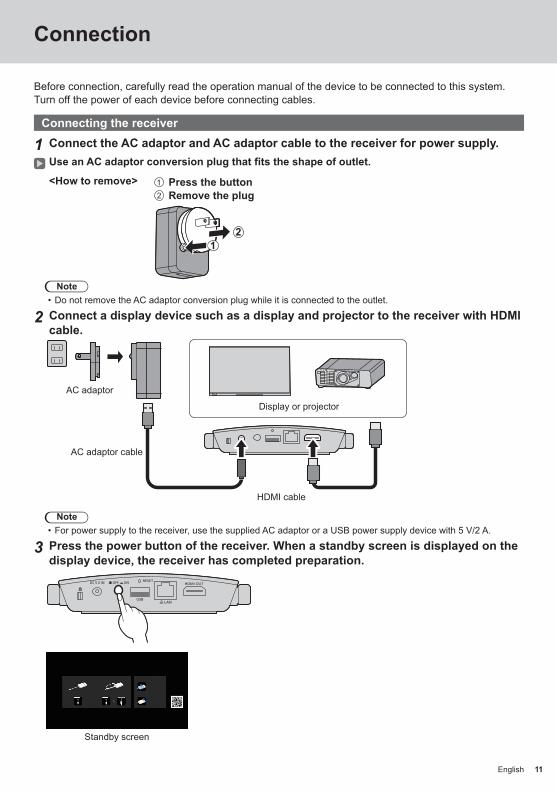
Connection
Before connection, carefully read the operation manual of the device to be connected to this system.Turn off the power of each device before connecting cables.
Connecting the receiver
1 Connect the AC adaptor and AC adaptor cable to the receiver for power supply.Use an AC adaptor conversion plug that fits the shape of outlet.
<How to remove> Press the button Remove the plug
21
Note • Do not remove the AC adaptor conversion plug while it is connected to the outlet.
2 Connect a display device such as a display and projector to the receiver with HDMI cable.
HDMI cable
Display or projector
AC adaptor
AC adaptor cable
Note • For power supply to the receiver, use the supplied AC adaptor or a USB power supply device with 5 V/2 A.
3 Press the power button of the receiver. When a standby screen is displayed on the display device, the receiver has completed preparation.
Standby screen

12 English12
Connecting the transmitter
1 Connect the USB terminal and HDMI input terminal of the transmitter to the image output device.
• For power supply to the transmitter, 5 V/0.9 A power supply is necessary.
HDMI input terminal
USB terminal
For the USB-C transmitter, connect the USB terminal (Type-C) to the image output device.Note
• The USB Type-C terminal of an image output device requires the following functions. Confirm the specifications of the device before using.
• DisplayPort ALT Mode (image output function) • Function to supply power to the connected device (5 V/0.9 A)
2 Main LED changes from red blinking (connecting) to white illumination (standby).
Red blinking (connecting)
White illumination (standby)
Connection Continued

13English 13
Basic Use
Single connectionThis section describes how to display an image using one transmitter.
1 Press the main button of the transmitter while the standby screen is displayed.The image is displayed.
Standby screen Full screen display
White illumination (standby)
Green illumination (display)
Pressing the main button again changes the main LED to white and returns to standby state.(The screen returns to the standby screen as well.)
• When using multiple transmitters, the image is switched to the image of the transmitter of which the main button is pressed.
14 English14
Basic Use Continued
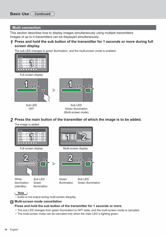
Multi connectionThis section describes how to display images simultaneously using multiple transmitters.Images of up to 4 transmitters can be displayed simultaneously.
1 Press and hold the sub button of the transmitter for 1 seconds or more during full screen display.The sub LED changes to green illumination, and the multi-screen mode is enabled.
Full screen display
11
1 11 1
Sub LEDOFF
Sub LEDGreen illumination
(Multi-screen mode)
2 Press the main button of the transmitter of which the image is to be added.The image is added.
Full screen display
11Multi-screen display
11 22
2 22 2
White illumination(standby)
Green illumination
Sub LED Green illumination
Sub LED Green illumination
Note • Audio is not output during multi-screen disuplay.
Multi-screen mode cancellationPress and hold the sub button of the transmitter for 1 seconds or more.
• The sub LED changes from green illumination to OFF state, and the multi-screen mode is canceled. • The multi-screen mode can be canceled only when the main LED is lighting green.

15English 15
When images of 1 transmitter are displayed with multiple transmitters paired and used, you can make a setting that prohibits switching to images of another transmitter.This setting prevents accidental image-switching operation.
Setting the fixed modePress and hold the main button of the transmitter for 1 seconds or more while an image of one transmitter is displayed.The main LED changes from green illumination to blue illumination, and the fixed mode is enabled.
11 11
1 11 1
Green illumination Blue illumination(fixed mode)
Other transmitters
2 22 2
White illuminatio(standby)
Red illumination(operation disabled)
Canceling the fixed modePress and hold the main button of the transmitter for 1 seconds or more.The main LED changes from blue illumination to green illumination, and the fixed mode is canceled.
1 11 1
Blue illumination(fixed mode)
Green illumination(fixed mode canceled)
Fixing image switching (fixed mode)

16 English16
Pairing settings have been made for transmitter and receiver of TY-WPS1 Basic Set.
Pairing by connecting the receiver and transmitter
1 Slide the mode switch to the STD side.
2 Connect the USB terminal of the transmitter to the USB terminal of the receiver.
USB-C transmitter
USB-A transmitter
Use the supplied conversion adaptor for pairing to connect the USB-C transmitter.
Wait for a while until the LED of the receiver blinks in white. Then, pairing starts automatically.“Pairing…” (pairing in progress) is displayed on the standby screen.
3 Pairing is complete.“Pairing OK” is displayed and the LED of the receiver lights up in white.
Pairing... Pairing OK
4 Remove the USB cable of the transmitter from the receiver.
Transmitter Extension Method (Pairing)

17English 17
Pairing by saving a file to the USB memorySupported device
●Commercially available USB memory devices are supported. (Those with security functions are not supported.) ●USB memory devices other than those formatted in FAT16 or FAT32 cannot be used. ●Up to 32 GB of USB memory in size are supported. ●Only single partition configuration is supported.
1 Connect the USB memory to the USB terminal of the receiver.
1
2
2 Press the FUNCTION button.The LED lights up in white and the pairing file is saved to the USB memory.
3 Remove the USB memory.
4 Slide the mode switch to the EXT side.
5 Supply power to the transmitter.
6
55 V/0.9 APower supply
6 Connect the USB memory to the USB terminal of the transmitter.
7 Pairing is complete.The main LED of the transmitter lights up in white.
8 Remove the USB memory from the transmitter.

18 English
Using the following two methods allows images on an Android device to (Android 5.0 and later versions supported) be projected (mirroring) on a display or projector. Wireless LAN, security measures, etc. can be used according to the usage environment.1 Use an app on the Android device and connect the device to the wireless LAN coming from
the receiver.2 Use an app on the Android device and connect the device to the external wireless LAN.
1 Use an app on the Android device and connect the device to the wireless LAN coming from the receiver
When mirroring is performed with this method, the Android device cannot be connected to Internet.Use method 2 to perform mirroring with the device connected to Internet.
1 Connect the receiver to the display device with the HDMI cable, and turn on the receiver. (page 11)The standby screen appears. “About the standby screen” (page 20)
2 Install the dedicated app [PressIT] on the Android device from the Google Play Store.You can also scan the QR code below to install the app.
The app can also be installed from the Web setting screen. (page 25)
3 Connect the Android device to the wireless LAN coming from the receiver.SSID and a password necessary for wireless LAN connection are displayed on the lower left of the standby screen.Turn on the wireless LAN function of the Android device and select SSID displayed on the standby screen.* For the Android device setting method, see the user’s manual of your device.
4 Start up the [PressIT] app.An image with the same design as that of the transmitter is displayed on the Android device. Tap the main button of the transmitter on the screen. (The Android OS may provide a notification. Operate the device according to the notification.)
5 Mirroring starts.
2 Use an app on the Android device and connect the device to the external wireless LAN
Note • Before installing the dedicated app, make sure that the receiver and Android device are connected to the same wireless LAN. (page 23)
1 Connect the receiver to the display device with the HDMI cable, and turn on the receiver. (page 11)The standby screen appears. “About the standby screen” (page 20)
2 Install the dedicated app [PressIT] on the Android device from the Google Play Store.You can also scan the QR code below to install the app.
The app can also be installed from the Web setting screen. (page 25)
Using with Android device (Android 5.0 and later versions)
19English
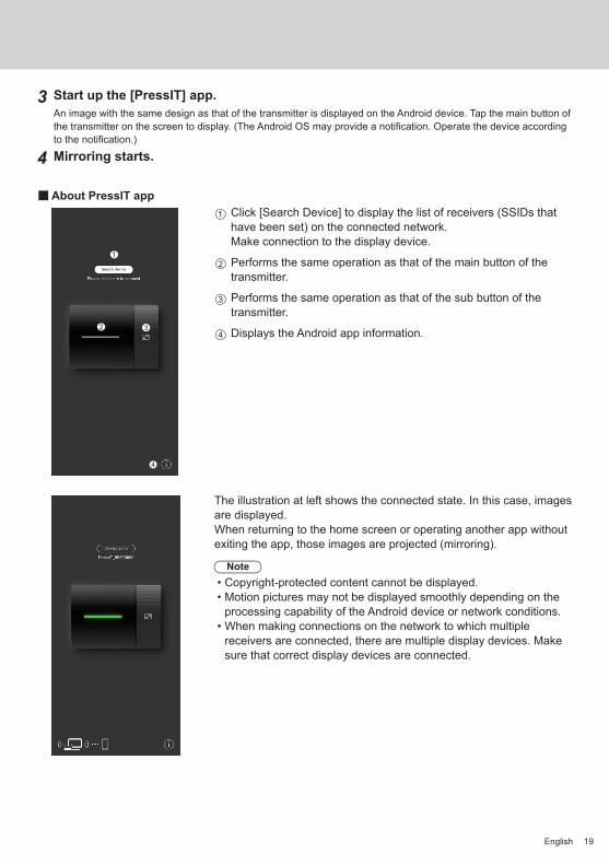
3 Start up the [PressIT] app.An image with the same design as that of the transmitter is displayed on the Android device. Tap the main button of the transmitter on the screen to display. (The Android OS may provide a notification. Operate the device according to the notification.)
4 Mirroring starts.
■About PressIT appClick [Search Device] to display the list of receivers (SSIDs that have been set) on the connected network.Make connection to the display device.
Performs the same operation as that of the main button of the transmitter.
Performs the same operation as that of the sub button of the transmitter.
Displays the Android app information.
The illustration at left shows the connected state. In this case, images are displayed.When returning to the home screen or operating another app without exiting the app, those images are projected (mirroring).
Note • Copyright-protected content cannot be displayed. • Motion pictures may not be displayed smoothly depending on the processing capability of the Android device or network conditions.
• When making connections on the network to which multiple receivers are connected, there are multiple display devices. Make sure that correct display devices are connected.

20 English
Connect to the Web page of the receiver to configure the settings of this system.
About the standby screenTurn on the receiver to display the standby screen on the display device.
Note • For connecting the receiver and display device, see “Connecting the receiver” (page 11).
Displays the number of mobile devices connected via wireless LAN of the transmitter or receiver.
Displays the number of mobile devices connected via external wireless LAN.
Displays SSID. This is used when directly connecting from PC or mobile devices.
Displays the password. This is used when directly connecting from PC or mobile devices and when connecting to the Web page immediately after purchase or after initialization of data.
Displayed when a mouse or a touch module of the display is connected to the USB terminal of the receiver.
Displayed when connected to a wireless access point or router.
Displayed when connected to an external network (LAN) via a wired LAN or external wireless LAN access point. Use this IP address when connecting from an external network to the receiver.
Receiver’s IP address for wireless LAN. Use this IP address for wireless LAN connection.
Displays the QR code linked to the site for downloading the operating instructions.
Note • Select [Device Management] - [Language] to change the displayed language. (page 26)
Setting

21English
■When connecting for the first time immediately after purchaseUser ID and password are required when connecting to the Web page of the receiver immediately after purchase or after initialization by pressing the reset button of the receiver. Then, the password needs to be changed.User ID: PressIT_adminPassword: Enter the password ( ) displayed on the standby screen.

22 English
Setting Continued
Displaying the Web setting screen
■About web browsersWe recommend using the web browsers shown below to operate the Web setting screen.
Chrome Version 85.0.4183.83 and later versions Firefox Version 80.0.1 and later versionsInternet Explorer 11 Safari Version.13.0.5 and later versionsEdge Version 84.0.522.52 and later versions
■ When configuring the settings in an environment without wireless access point in the surrounding areaConnect to the wireless LAN of the receiver and open the Web setting screen. Note that while operating the web settings using this method, the mobile device cannot be connected to Internet temporarily. SSID and a password necessary for wireless LAN connection are displayed on the lower left of the standby screen.
1 Turn on wireless LAN of the PC or mobile device and select SSID displayed on the standby screen.Above example: PressIT-A132F34D
2 Enter the wireless LAN password.Above example: 75847328
3 After the connection is complete, enter the IP address displayed on the lower right of the standby screen into the address bar of the web browser, and press Enter.
* The IP address on the image is an example and may be different depending on the environment.
When connection is established correctly, the Web setting screen is displayed.
Web setting screen when accessed from PC
Web setting screen when accessed from smartphone

23English
■When configuring the settings in an environment where wireless LAN (5GHz band) access point can be used freelyConnect the receiver to the external wireless LAN and open the Web setting screen. You can also connect to the external wireless access point different from the wireless access point coming from the receiver to open the Web setting screen. The advantage of this method is that logging in to the Web setting screen is possible with the mobile device connected to the network. However, the password of the external wireless access point must be obtained beforehand.Obtain the password, etc. from the system administrator managing the local network.
1 After opening the Web setting screen with the procedure in “When configuring the settings in an environment without wireless access point in the surrounding area” (page 22), log in with administrator privileges and select “Network Management”.
2 Click “Connect to 5GHz Wireless”.
* When a network cable is connected to the receiver, DHCP of the wired LAN is prioritized.
3 Select SSID to connect and enter the password.
This is a state where connection to Internet is established via external wireless access point.

24 English
Setting Continued
When the receiver is connected to the external wireless access point, the wireless LAN icon is displayed on the lower right of the standby screen.
To store the external wireless access point in the receiver, set [Remember Wireless Access Point] to [ON] and click [OK]. The system restarts.
4 To open the Web setting screen from the PC or mobile device, confirm that it is connected to the same wireless access point as that of the receiver, enter the IP address displayed on the lower right into the address bar of the web browser, and press Enter.
When connection is established correctly, the Web setting screen is displayed.
Web setting screen when accessed from PC

25English
Configuring various settings on the Web setting screenSettings including [Device Management], [Network Management] and [Detail Settings] can be changed on the Web setting screen.
■Download Android APKThe Android app (page 18) can be downloaded and installed. Use this app when the device cannot be connected to the Google Play Store. When the app is downloaded from the Web setting screen, confirmation is required to install the app on the Android device since it is not the one downloaded from the Google Play Store. Confirm the version information of the Android device/Android OS.
■Network ManagementThe receiver can be connected to Internet via external wireless access point instead of wireless LAN coming from the receiver.
●Connect to 5GHz WirelessThis product supports only the wireless access points using the 5GHz band.Enter the SSID and password necessary to connect the mobile device and the receiver to the same wireless access point.
The password connection information of the wireless access point once connected can be stored in the receiver.
ON: Stores the external wireless access point settings in the receiver.OFF: Deletes the external wireless access point settings stored in the receiver.
26 English
Setting Continued
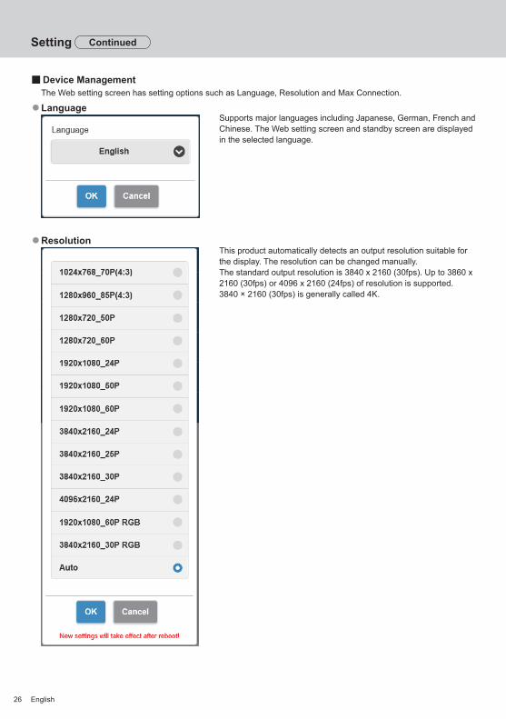
■Device ManagementThe Web setting screen has setting options such as Language, Resolution and Max Connection.
●LanguageSupports major languages including Japanese, German, French and Chinese. The Web setting screen and standby screen are displayed in the selected language.
●ResolutionThis product automatically detects an output resolution suitable for the display. The resolution can be changed manually.The standard output resolution is 3840 x 2160 (30fps). Up to 3860 x 2160 (30fps) or 4096 x 2160 (24fps) of resolution is supported.3840 × 2160 (30fps) is generally called 4K.
27English
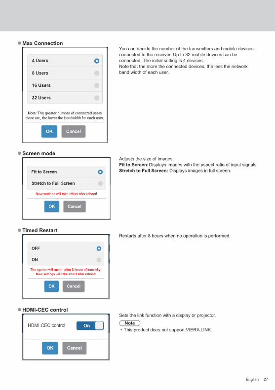
●Max ConnectionYou can decide the number of the transmitters and mobile devices connected to the receiver. Up to 32 mobile devices can be connected. The initial setting is 4 devices.Note that the more the connected devices, the less the network band width of each user.
●Screen modeAdjusts the size of images.Fit to Screen: Displays images with the aspect ratio of input signals.Stretch to Full Screen: Displays images in full screen.
●Timed RestartRestarts after 8 hours when no operation is performed.
●HDMI-CEC controlSets the link function with a display or projector.
Note • This product does not support VIERA LINK.

28 English
Setting Continued
■Detail SettingsThis setting function is designed mainly for persons in charge of information system department and network administrators, enabling more detailed setting changes.
●Wireless ChannelSets the Wireless channel. This product provides the following options.
ChannelBandwidth
* Note that when the receiver is connected to an external wireless access point, the Wireless channel cannot be set.
●LAN IP SettingsNetwork settings can be manually configured including IP address, gateway, netmask and DNS server.
●SSIDChanges the name of SSID, hides SSID and disables SSID.
Hide SSID: Setting this to [ON] hides SSID displayed on the standby screen.* Be sure to take a note before setting.
Turn Off SSID: Setting this to [ON] disables the SSID function of the receiver. Communication is disabled between transmitter and receiver.
Even if pairing is performed, communication is disabled.

29English
●PasswordChanges the wireless LAN connection password for the receiver. The administrator can hide the wireless LAN password on the standby screen for security enhancement.
Note • Changing password requires pairing again.
●My ScreenUploading an arbitrary image allows the background of the standby screen to be changed. The image size should be less than 2 MB with 1920 x 1080 in PNG format.
Note • Note that once the background is changed, the product needs to be initialized to restore the image to the original one. (page 31 “Reset to Factory Default”)
●Administrator PasswordChanges the administrator password. It is recommended to change the administrator password periodically for security enhancement.
●Screen SaverSpecifies the time until the screensaver is activated.When the screensaver is activated, the image being projected disappears.Pressing the main button of the transmitter cancels the screensaver.

30 English
Setting Continued
●WPA/WPA2 EnterpriseUsing this function, an electronic certificate key file supporting encryption communication can be uploaded. This function is designed for persons in charge of information system department and network administrators.
●UpgradeThe firmware of the receiver and transmitter can be to the latest versions. This product needs to be stably connected to Internet to upgrade the firmware.It is strongly recommended to use the same firmware version for the receiver and transmitter upgraded of this product.The firmware can be upgraded with the following method.
Connect the transmitter to an external power source. Confirm that the receiver is connected to Internet and the receiver and transmitter have been paired.
Click the [Select All] check box to upgrade all the firmware of the receiver and transmitter collectively.
Tap the [Update] button to start downloading the latest firmware. This process will finish in a few minutes. Please wait for a while.
Note • The firmware upgrade information displayed for [Upgrade] on the [Detail Settings] menu shows the confirmation result of the receiver version.
• When the firmware upgrade for the receiver is available, a mark to prompt you to upgrade the firmware is displayed on the receiver at the lower right of the standby screen.
●Download Pairing FileDownload the pairing file and save it on a USB flash drive.After downloading is complete, perform step 5 and the subsequent steps in “Pairing by saving a file to the USB memory” (page 17) to copy the pairing file to the transmitter.The receiver and transmitter of the TY-WPS1 basic set are paired at the time of shipment. When the transmitter is initialized or a new transmitter is additionally purchased, pairing with the receiver is required before using.
●Background Color settingSpecifies the background colors for the standby screen and no-signal image.[Black] or [Blue] can be specified.
Note • When the [My Screen] is specified, this setting is not reflected.

31English
●Date/Time settingSpecifies the time zone and the display style of date displayed on the standby screen.Time Server:Sets the NTP saver.When the NTP server is not specified, a server registered beforehand is accessed.
Date and time shows the following information.1. Information obtained from the NTP server via wireless LAN or wired LAN of
the receiver (priority) 2. Information from HDMI-CEC of the corresponding display or projector
●RebootRestart the product when the firmware is upgraded to the latest version or the receiver does not respond.Tap [Reboot] and select [YES].
●Reset to Factory DefaultInitializes this product to the default state. Note that the customized language setting, resolution setting, wireless LAN setting, etc. once stored are initialized. (SSID is not initialized.)When the transmitter is initialized, the paired state between the receiver and transmitter is canceled. Perform pairing according to the procedure in “Transmitter Extension Method (Pairing)” (page 16) after initialization.
Reset RX:Initializes the receiver only.Reset TX:Initializes the transmitter only.Reset RX + TX:Initializes both the receiver and transmitter.
■About DeviceDisplays [SSID], [Firmware Version], [Wireless Channel] and other basic information related to this product.When the transmitter is connected, the basic information of the transmitter is also displayed.
■Software licensesDisplays the software license description.

32 English
Setting Continued
[Setup] menu (display setting)When this product is connected to the compatible display and the [Setup] menu is set, the following functions can be used.This section explains each setting using the display SQ1 series as an example. For settings on other models, see the Panasonic information site.
■SignalExamples of [Signal] submenu screenWhen HDMI is selected
30.00 Hz297.00 MHz3840x2160/30p
67.50 kHz
Signal
Cinema realityYUV/RGB-in select
Noise reduction
Signal rangeMPEG noise reduction
Dynamic backlight control
V-freq.H-freq.
Dot clock freq.Signal format
OffYUV
Auto
Full(0-255)Off
Off
HDCP status Protected
EDID select 4K/60p/HDR
Frame creation Off
● [EDID select]This menu is displayed in HDMI 1 and HDMI 2 inputs. EDID data of each terminal is switched.[4K/60p/SDR]: Sets EDID compatible with 4K video signals (Max. 4 096 x 2 160 dots, Max. vertical scanning
frequency 60 Hz).This EDID supports SDR (Standard Dynamic Range). HDR (High Dynamic Range) is not supported.
[4K/60p/HDR]: Sets EDID compatible with 4K video signals (Max. 4 096 x 2 160 dots, Max. vertical scanning frequency 60 Hz).This EDID supports HDR (High Dynamic Range).
[4K/30p]: Sets EDID compatible with 4K video signals (Max. 4 096 x 2 160 dots, Max. vertical scanning frequency 30 Hz).
[2K]: Sets EDID compatible with 2K video signals (Max. 1 920 x 1 200 dots).
Note • This function is explained using the Panasonic display SQ1 series as an example. Depending on the model, the setting items differ.
• When EDID is set to [4K/60p/SDR] or [4K/60p/HDR], images of 4K/30p are output. • When the setting is changed, the image disappears for approx. 10 seconds, and then the specified image format is output.
• When [Resolution] on the Web setting screen is set to something other than [Auto], the settings on this menu are not reflected.
• When [Wireless presentation link] is set to [Off], the settings are not reflected until the receiver is restarted after this menu is changed.

33English
Panasonic display link functionJust connect the receiver to a Panasonic display supporting this product using HDMI cable and turn them on to perform the link operation. (It is necessary to set [Wireless presentation link] to [On].)Set link function details in the following setting menus.
■CheckSets external device link.[Check]- submenu screen
Check
Please check the display to register. Off
Wireless presentation link On
● [Please check the display to register.]Sets whether to display or hide the information of the device connected to the HDMI terminal.[Off]: Connected device information is not displayed.[On]: Connected device information is displayed as shown below.
HDMI116:9
Player1
Note • The obtained information of either signal or HDMICEC is displayed. • Up to the first 16 characters obtained are displayed.
●Wireless presentation linkSets the link of the Display with this product.[Off]: Does not link with this product.[On]: Links with this product.
Note • When this product. is connected to the HDMI terminal, the link function works. • The following functions are fixed.
These settings are held even if this function is switched from [On] to [Off]. The settings can be changed on each setting menu.
• [Picture mode] is fixed to [Graphic]. • [HDMI-CECcontrol]isfixedto[Enable].[Display→Device]isfixedto[Poweroff/on].[Device→Display]isfixed to [Power off / on].
• Even if this function is set to [Off], the HDMI-CEC function works.

34 English34
Setting Continued
■ [Wireless presentation settings]Note
• Approx. 5 seconds may be required to reflect the menu settings.[Wireless presentation settings] - sub menu screen
Wireless presentation settings
Background color setting BlackDate/Time setting Y/M/DLanguage link Enable
● [Background color setting][Black]: The background color for the standby screen and no-signal image is set to black.[Blue]: The background color for the standby screen and no-signal image is set to blue.
Note • When the image is changed with the [My Screen] function on the Web setting screen, this setting is not reflected.
● [Date/Time setting]Specifies the display style of date on the standby screen.[Y-M-D]: e.g. 2021-08-24 [M-D-Y]: e.g. 08-24-2021[Y/M/D]: e.g. 2021/08/24 [M/D/Y]: e.g. 08/24/2021[Y.M.D]: e.g. 2021.08.24 [M.D.Y]: e.g. 08.24.2021[D-M-Y]: e.g. 24-08-2021 [M D,Y]: e.g. 08 24,2021[D/M/Y]: e.g. 24/08/2021 [Off]: Date is not displayed on the standby screen.[D.M.Y]: e.g. 24.08.2021
Note • When this is set to [Off], the setting is applied at the next startup of this system. • There is the same menu on the Web setting screen as this menu item. Since the setting on the display is prioritized, when the system is started next time or the HDMI cable is connected/disconnected, the setting value on the display is reflected.
● [Language link][Enable]: Sets the language for the standby screen, no-signal image and Web setting screen to the language set
for [OSD language].[Disable]: Sets the language for the standby screen, no-signal image and Web setting screen to the language set
for [Language] on the Web setting screen.

35English 35
■HDMI-CEC settingsSet for HDMI-CEC function.For details of HDMI-CEC function, r efer to “Using the HDMI-CEC function”. (see page 36)[HDMI-CEC settings] - submenu screen
11
HDMI-CEC settings
HDMI-CEC control Enable
Disable
HDMI2 --------
HDMI-CEC operationMENU code
HDMI1
Display→DeviceDisableDevice→Display
Link function
SLOT ----
● [HDMI-CEC control]Enables/Disables the HDMI-CEC function.[Disable]: Disables HDMI-CEC control.[Enable]: Enables HDMI-CEC control.Note
• Setting this item to [Enable] enables the HDMI-CEC function for this product and display.
● [HDMI1] / [HDMI2][PressIT] is displayed for a terminal to which this product is connected.
● [MENU code]No code is assigned to this system.
● [Display → Device]Enables/Disables the Display to perform interlocking control of the HDMI-CEC compatible device.[Disable]: Disables the Display to perform interlocking control of the HDMI-CEC compatible device.
Even if the power status of the Display changes, the power status of the device will not be affected.
[Power off]: Turning the Display off (standby) turns off (standby) all the devices connected to the HDMI 1, HDMI 2 or SLOT terminal. The power-on operation is not interlocked.
[Power off / on]: The device turns off/on (standby) in conjunction with the power-off/on (standby) operation of the Display.
● [Device → Display]Enables/Disables the HDMI-CEC compatible device to perform interlocking control of the Display.[Disable]: Disables the device to perform interlocking control of the Display.
Even if the power status of the device changes, the power status of the Display will not be affected.
[Power on]: Turning on the device turns on the Display, and the input (HDMI1 / HDMI2 / SLOT) is switched to that of the device.
[Power off / on]: The power status of the Display interlocks with the power-off/on operation of the device.

36 English36
Using the HDMI-CEC functionThe HDMI-CEC function allows the display to be turned on/off or the input to be switched by linking the operation of this product.
■CEC-ON linkThe display is turned on (image-receiving state) when it is turned off (standby state). The image of this product is projected by switching to the input to which this product is connected.ON link is enabled by performing the following 4 operations.
(1) When the receiver is turned onWhen the receiver is switched from off to on, the display is turned on and switched to the input to which the receiver is connected.
Display power off (standby) HDMI input (standby screen)
HDMI cable
Receiver power on
(2) When the transmitter is turned onWhen the USB terminal of the transmitter is connected to PC, etc. and the power supply starts, the display is turned on and switched to the input to which the receiver is connected.
Display power off (standby) HDMI input (standby screen)
HDMI cable
Power starts to be supplied to the transmitter
Setting Continued
37English 37
(3) When the image from the transmitter is displayed in standby stateWhen the transmitter is in standby state, press the main button to send the image to the receiver. Then the display is turned on and the image is displayed.The input of the display is linked to the operation of the transmitter and switched to the input to which the receiver is connected.e.g.) PC input for display
PC input HDMI input (full screen display)
HDMI cable
Display the image
(4) In multi-screen modePress the main button in multi-screen mode to add an image. Then the display is turned on and the multi-screen display appears.
Display power off (standby) Multi-screen display
11 22
HDMI cable
First transmitter(Multi-screen mode)
Second transmitter(Add an image)

38 English38
■CEC-OFF linkPerforming the following 2 operations allows the display to be turned off (standby state).
(1) When the screensaver is activatedWhen the screensaver of this product is activated while the transmitter is in standby state, the display is turned off.
Standby screen Display power off (standby)
HDMI cable
Transmitter (in standby)
After the specified time for screensaver has
elapsed
(2) When the transmitter is standby statePress and hold the main button and the sub button of the transmitter simultaneously while the transmitter connected. Then the display is turned off.When the transmitter enters the standby state, the main LED blinks in red.
Image being displayed or standby screen
Display power off (standby)
11
HDMI cable
Press and hold the main and sub buttons simultaneously
Transmitter (in standby)
Note • To restore the transmitter from standby state to the active state, disconnect and connect the USB terminal of the transmitter.
Setting Continued

39English
Installing the Receiver
Components for receiver mounting bracketCheck the following parts are included.Base bracket (A-1) ........................1(DPVF3503ZA/X1)
Connecting bracket C (A-4) .........1(DPVF3506ZA/X1)Used to install on the projector.
Knurled screw (C-1)......................2(DPVF3509ZA/X)(M4×5)
Connecting bracket A (A-2) .........1(DPVF3505ZA/X1)Used to install on the display.
Sheet A (B-1) .................................1(DPVF3507ZA/X1)(30×12 mm)
Screw (C-2) ....................................6(DPVF3510ZA/X1)(M4×5)
Connecting bracket B (A-3) .........1(DPVF3504ZA/X1)Used to install on the display.
Sheet B (B-2) .................................3(DPVF3508ZA/X1)(24×20 mm)
Screw (C-3) ....................................2(DPVF3511ZA/X1)(M3×8)
Mounting the base bracket (common)
1 Place the base bracket (A-1) aligning it with the 4 screw holes on the bottom surface of the receiver.
2 Fix the base bracket (A-1) with 4 screws (C-2).C-2
A-1
The base bracket can be mounted in either vertical or horizontal direction.

40 English
Installing on the ceiling or wall
1 Mount the base bracket (A-1) to the receiver.
2 Fix the receiver to the ceiling or wall with 2 screws.Use screws (commercially available) of the appropriate type and length according to the ceiling or wall to be installed. (Recommended size: M4)
Installing on the display
1 Mount the base bracket (A-1) to the receiver.
2 Fix the connecting bracket A (A-2) to the base bracket (A-1) with 2 screws (C-2).C-2
A-2
3 Fix the connecting bracket B (A-3) to the connecting bracket A (A-2) with 2 knurled screw (C-1).
A-3
C-1
Installing the Receiver Continued
41English 41
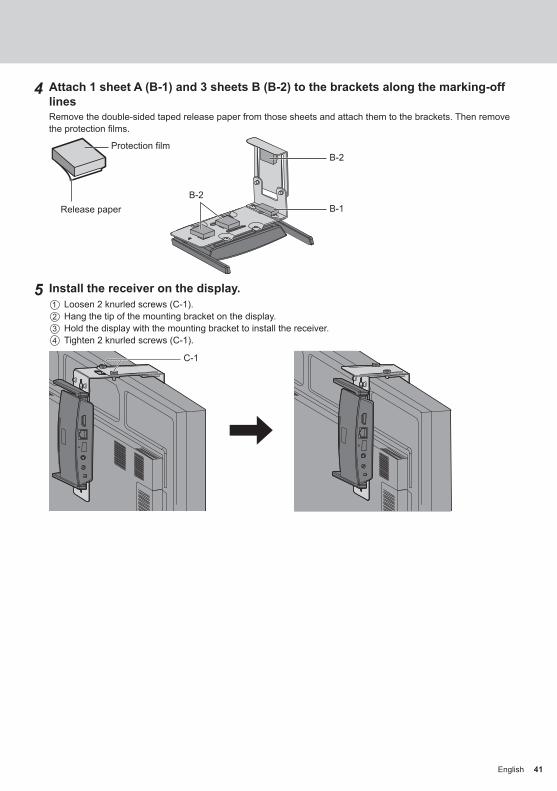
4 Attach 1 sheet A (B-1) and 3 sheets B (B-2) to the brackets along the marking-off linesRemove the double-sided taped release paper from those sheets and attach them to the brackets. Then remove the protection films.
B-2
B-2B-1Release paper
Protection film
5 Install the receiver on the display. Loosen 2 knurled screws (C-1). Hang the tip of the mounting bracket on the display. Hold the display with the mounting bracket to install the receiver. Tighten 2 knurled screws (C-1).
C-1

42 English42
Recommended example for installing on the projector professional model
1 Mount the base bracket (A-1) to the receiver.
2 Remove 2 round covers from the side of the projector.Screw holes for installing the receiver are exposed.
Cover
3 Install the receiver on the projector with 2 screws (C-3).Install the receiver with marking “UP” of the base bracket facing upward.
C-3
Note • The illustrations show the PT-RZ21K model. • Depending on the model of projector, the above method may not be used for installation.
Installing the Receiver Continued

43English 43
Recommended example for installing on the projector system model
1 Mount the base bracket (A-1) to the receiver.
2 Fix the connecting bracket C (A-4) to the base bracket (A-1) with 2 screws (C-2).
C-2
A-4
3 Remove the adjuster on the bottom surface of the projector by turning it counterclockwise.Install the receiver at a position that does not block the air inlet and air outlet.Be careful not to allow the receiver to hit the AC cord. Also, the receiver should be installed in such a direction that the cable to be connected does not interfere with the cable of the projector.
Adjuster
4 Pass the adjuster through the long hole of the connecting bracket C (A-4).
5 While pressing the connecting bracket C (A-4) against the projector so that the connecting bracket is stabilized, tighten the adjuster to fix it.
Note • The illustrations show the PT-RZ570 model. • Depending on the model of projector, the above method may not be used for installation. • Depending on some models, the choices for the receiver’s installation position are limited. For details, refer to the following URL.https://panasonic.net/cns/prodisplays/wps2/

44 English44
Recommended example for installing on the projector portable modelUse a commercially sold fixing band with a width of 25 mm or less.
1 Mount the base bracket (A-1) to the receiver.
2 Attach 2 sheets B (B-2) to the bracket along the marking-off linesRemove the double-sided taped release paper from those sheets and attach them to the brackets. Then remove the protection films.
Release paper
Protection film B-2
3 Pass the band through the slit of the base bracket (A-1).
Band
4 Install the receiver on the ceiling-hanging base bracket of the projector.
5 Wrap the band through the ceiling-hanging base bracket and fix the receiver.
Note • The illustrations show the PT-VMZ60 model. • Depending on the model of projector, the above method may not be used for installation.
Installing the Receiver Continued

45English 45
Image Signals Supported by This Product
■ Image output resolution of the receiverWPS Receiver (TY-WPR1)
HDMI output signals3840 x 2160@30Hz RGB 1920 x 1080@50Hz1920 x 1080@60Hz RGB 1920 x 1080@24Hz
4096 x 2160@24Hz 1280 x 960@85Hz3840 x 2160@30Hz 1280 x 720@60Hz3840 x 2160@25Hz 1280 x 720@50Hz3840 x 2160@24Hz 1024 x 768@70Hz1920 x 1080@60Hz
■ Image input resolution of the transmitter
WPS Transmitter (TY-WPB1) WPS USB-C Transmitter (TY-WPBC1)
HDMI input-supported signals USB-C input-supported signals
1920 x 1080@60Hz 1920 x 1080@60Hz
1920 x 1080@50Hz 1920 x 1080@50Hz
Symptoms Checks PagePairing does not start by connecting the transmitter to the USB terminal of the receiver.
●Is the mode switch of the transmitter on the STD side? 16
Pairing does not start by connecting the USB memory where the pairing file is stored to the USB terminal of the transmitter.
●Is the mode switch of the transmitter on the EXT side? 17
Touch information is not sent to the PC although the USB cable of the touch module is connected to the receiver.
●Is the mode switch of the transmitter on the STD side? ●Some devices do not support the touch module.
Forgot the login password for the Web setting screen.
●After activating the receiver, press and hold the reset button for 5 seconds or more. The password is initialized.
9
The main LED and sub LED of the transmitter do not light up properly.
●Power supplied to the transmitter may be insufficient. Change the power source for the transmitter.
12
HDMI-CEC function does not work. ●When power is supplied from the USB terminal of the display or projector to the receiver, the power may become insufficient when the power is turned off. Change the power source for the receiver.
11
Troubleshooting

46 English
■ReceiverModel No. TY-WPR1
Product name WPS ReceiverVideo output HDMI × 1 (HDCP1.4)Output resolution 1920 x 1080/60p, 3840 x 2160/30p (max.)Number of simultaneous connections 32
Wireless communication standard IEEE802.11a/n/ac
Data rate wireless 867 Mbps (max.)Frequency band 5 GHz (5.150 GHz to 5.250 GHz)Security WPA/WPA2Reachable distance Up to 30 m (Locations with good visibility and radio wave conditions)FUNCTION LED
White blinking Pairing in progressWhite illumination Pairing complete
LAN terminal RJ45 × 1 PoE power reception supported10BASE-T/100BASE-TX/1000BASE-T supported
USB terminal USB connector × 1, Type-APower supply DC 5 V/2 A, PoEDimensions (W × H × D) 120 mm × 26 mm × 81 mm / 4.71” × 1.03” × 3.19” (excluding antennas)Mass Approx. 181 g / 0.4 lbs
Operating condition Temperature: 0 °C to 35 °C (32 °F to 95 °F)Humidity: 20 % to 80 % (no condensation)
Storage condition Temperature: -20 °C to 60 °C (-4 °F to 140 °F)Humidity: 20 % to 80 % (no condensation)
■TransmitterModel No. TY-WPB1 TY-WPBC1
Product name WPS Transmitter WPS USB-C TransmitterVideo input HDMI × 1 (HDCP1.4) USB Type-C × 1 (HDCP1.4)Input resolution 1920 x 1080/60p (max.)Wireless communication standard IEEE802.11ac
Data rate wireless 433 Mbps (max.)Frequency band 5 GHz (5.150 GHz to 5.250 GHz)Security WPA/WPA2Reachable distance Up to 30 m (Locations with good visibility and radio wave conditions)Main LED
White blinking Pairing in progressWhite illumination Standby or pairing completeRed blinking ConnectingRed illumination Operation disabledGreen illumination Image being displayedBlue illumination Fixed mode
Sub LEDGreen illumination Multi-screen mode
USB terminal USB connector × 1, Type-APower supply DC 5 V/0.9 A
Dimensions (W × H × D) 51 mm × 21 mm × 73 mm / 2.00” × 0.80” × 2.86” (excluding cables)51 mm × 21 mm × 283 mm / 2.00” × 0.80” × 11.12” (including cables)
Mass Approx. 110 g / 0.3 lbs
Operating condition Temperature: 0 °C to 35 °C (32 °F to 95 °F)Humidity: 20 % to 80 % (no condensation)
Storage condition Temperature: -20 °C to 60 °C (-4 °F to 140 °F)Humidity: 20 % to 80 % (no condensation)
Specifications

47English
This product incorporates the following software:(1) the software developed independently by or for Panasonic Corporation,(2) the software owned by third party and licensed to Panasonic Corporation,(3) the software licensed under the GNU General Public License, Version 2.0 (GPL V2.0),(4) the software licensed under the GNU LIBRARY General Public License, Version 2.0 (LGPL V2.0),(5) the software licensed under the GNU LESSER General Public License, Version 2.1 (LGPL V2.1), and/or(6) open source software other than the software licensed under the GPL V2.0, LGPL V2.0 and/or LGPL V2.1.The software categorized as (3) - (6) are distributed in the hope that it will be useful, but WITHOUT ANY WARRANTY, without even the implied warranty of MERCHANTABILITY or FITNESS FOR A PARTICULAR PURPOSE. For details, see the license conditions displayed by selecting [Software licenses], following the specified operation from the Web setting screen of this product.At least three (3) years from delivery of this product, Panasonic will give to any third party who contacts us at the contact information provided below, for a charge no more than our cost of physically performing source code distribution, a complete machine-readable copy of the corresponding source code covered under GPL V2.0, LGPL V2.0, LGPL V2.1 or the other licenses with the obligation to do so, as well as the respective copyright notice thereof.
Contact Information:[email protected]
Trademark Credit
• HDMI, High-Definition Multimedia Interface and the HDMI Logo are trademarks or registered trademarks of HDMI Licensing Administrator, Inc. in the United States and other countries.
• USB Type-C and USB-C are trademarks or registered trademarks of USB Implementers Forum. • PressIT is a trademark of Panasonic Corporation.
Even if no special notation has been made of company or product trademarks, these trademarks have been fully respected.
Software License

48 English
This equipment has been tested and found to comply with the limits for a Class B digital device, pursuant to Part 15 of the FCC Rules. These limits are designed to provide reasonable protection against harmful interference in a residential installation. This equipment generates, uses and can radiate radio frequency energy and, if not installed and used in accordance with the instructions, may cause harmful interference to radio communications.However, there is no guarantee that interference will not occur in a particular installation. If this equipment does cause harmful interference to radio or television reception, which can be determined by turning the equipment off and on, the user is encouraged to try to correct the interference by one or more of the following measures:
• Reorient or relocate the receiving antenna. • Increase the separation between the equipment and receiver. • Connect the equipment into an outlet on a circuit different from that to which the receiver is connected. • Consult the dealer or an experienced technician for help.
FCC CAUTION:To assure continued compliance, follow the attached installation instructions and use only the provided power supply cord. Any changes or modifications not expressly approved by Panasonic Corp. of North America could void the user’s authority to operate this device.FCC RF Exposure Warning:
• This transmitter complies with FCC radiation exposure limits set forth for an uncontrolled environment for mobile use with minimum 8 inches (20 cm) spacing requirement between transmitter and all person’s body (excluding extremities of hands, wrist and feet) during wireless modes of operation.
<Only for wireless LAN if capable of transmission in the 5.150 to 5.250 GHz frequency band>This product is restricted to indoor use due to its operation in the 5.150 to 5.250 GHz frequency range.
Supplier’s Declaration of ConformityModel No.
TY-WPR1, TY-WPB1, TY-WPBC1Responsible Party:
Panasonic Corporation of North AmericaTwo Riverfront Plaza, Newark, New Jersey07102-5490
Contact Source:Panasonic System Solutions Company of North America1-877-655-2357
General Contact:http://shop.panasonic.com/support
This device complies with Part 15 of the FCC Rules. Operation is subject to the following two conditions: (1) This device may not cause harmful interference, and (2) this device must accept any interference received, including interference that may cause undesired operation.
FCC STATEMENT

Notice (U.S.A. only)Disposal may be regulated in your community due to environmental considerations. For disposal or recycling information, please visit Panasonic website: http://www.panasonic.com/environmental or call 1-888-769-0149.
Customer’s RecordThe model number and serial number of this product may be found on its rear panel. You should note this serial number in the space provided below and retain this book, plus your purchase receipt, as a permanent record of your purchase to aid in identification in the event of theft or loss, and for Warranty Service purposes.
Model Number Serial Number
Panasonic System Solutions Company of North AmericaUnit of Panasonic Corporation of North America
Executive Office :Two Riverfront Plaza, Newark, New Jersey 07102
Panasonic Testing CentrePanasonic Service Europe, a division of Panasonic Marketing Europe GmbHWinsbergring 15, 22525 Hamburg, F.R. Germany
Web Site: https://panasonic.net/cns/prodisplays/
© Panasonic Corporation 2020
English
Disposal of Old EquipmentOnly for European Union and countries with recycling systems
This symbol on the products, packaging, and/or accompanying documents mean that usedelectrical and electronic products must not be mixed with general household waste.For proper treatment, recovery and recycling of old products, please takethem to applicable collection points in accordance with your national legislation.By disposing of them correctly, you will help to save valuable resources and prevent anypotential negative effects on human health and the environment.For more information about collection and recycling, please contact your local municipality.Penalties may be applicable for incorrect disposal of this waste, in accordance with national legislation.
Information on Disposal in other Countries outside the European UnionThis symbol is only valid in the European Union.If you wish to discard this product, please contact your local authorities or dealer and ask for the correct method of disposal.