Embed Size (px)
Citation preview
Operating Instructions
audio/video multi-channel receiver
SCLX81_71.book 1 ページ 2008年7月25日 金曜日 午後3時1分
D3-4-2-1-1_En-A
The exclamation point within an equilateral triangle is intended to alert the user to the presence of important operating and maintenance (servicing) instructions in the literature accompanying the appliance.
The lightning flash with arrowhead symbol, within an equilateral triangle, is intended to alert the user to the presence of uninsulated "dangerous voltage" within the product's enclosure that may be of sufficient magnitude to constitute a risk of electric shock to persons.
CAUTION:TO PREVENT THE RISK OF ELECTRIC SHOCK, DO NOT REMOVE COVER (OR BACK). NO USER-SERVICEABLE PARTS INSIDE. REFER SERVICING TO QUALIFIED SERVICE PERSONNEL.
CAUTIONRISK OF ELECTRIC SHOCK
DO NOT OPEN
IMPORTANT
WARNINGTo prevent a fire hazard, do not place any naked flame sources (such as a lighted candle) on the equipment. D3-4-2-1-7a_A_En
WARNINGThis equipment is not waterproof. To prevent a fire or shock hazard, do not place any container filled with liquid near this equipment (such as a vase or flower pot) or expose it to dripping, splashing, rain or moisture. D3-4-2-1-3_B_En
[Singapore model only]
Operating EnvironmentOperating environment temperature and humidity:+5 ºC to +35 ºC (+41 ºF to +95 ºF); less than 85 %RH (cooling vents not blocked)Do not install this unit in a poorly ventilated area, or in locations exposed to high humidity or direct sunlight (or strong artificial light) D3-4-2-1-7c_A_En
CAUTIONThe STANDBY/ON switch on this unit will not completely shut off all power from the AC outlet. Since the power cord serves as the main disconnect device for the unit, you will need to unplug it from the AC outlet to shut down all power. Therefore, make sure the unit has been installed so that the power cord can be easily unplugged from the AC outlet in case of an accident. To avoid fire hazard, the power cord should also be unplugged from the AC outlet when left unused for a long period of time (for example, when on vacation). D3-4-2-2-2a_A_En
WARNING
The voltage of the available power supply differs according to country or region. Be sure that the power supply voltage of the area where this unit will be used meets the required voltage (e.g., 230 V or 120 V) written on the rear panel. D3-4-2-1-4_A_En
Before plugging in for the first time, read the following section carefully.
Replacement and mounting of an AC plug on the power supply cord of this unit should be performed only by qualified service personnel.
D3-4-2-1-2-2_B_En
IMPORTANT: THE MOULDED PLUGThis appliance is supplied with a moulded three pin mains plug for your safety and convenience. A 5 amp fuse is fitted in this plug. Should the fuse need to be replaced, please ensure that the replacement fuse has a rating of 5 amps and that it is approved by ASTA or BSI to BS1362.
Check for the ASTA mark or the BSI mark on the body of the fuse.
If the plug contains a removable fuse cover, you must ensure that it is refitted when the fuse is replaced. If you lose the fuse cover the plug must not be used until a replacement cover is obtained. A replacement fuse cover can be obtained from your local dealer.
If the fitted moulded plug is unsuitable for your socket outlet, then the fuse shall be removed and the plug cut off and disposed of safely. There is a danger of severe electrical shock if the cut off plug is inserted into any 13 amp socket.
If a new plug is to be fitted, please observe the wiring code as shown below. If in any doubt, please consult a qualified electrician.
IMPORTANT: The wires in this mains lead are coloured in accordance with the following code: Blue : Neutral Brown : LiveAs the colours of the wires in the mains lead of this appliance may not correspond with the coloured markings identifying the terminals in your plug, proceed as follows ;
The wire which is coloured BLUE must be connected to the terminal which is marked with the letter N or coloured BLACK.The wire which is coloured BROWN must be connected to the terminal which is marked with the letter L or coloured RED.
How to replace the fuse: Open the fuse compartment with a screwdriver and replace the fuse.
SCLX81_71.book 2 ページ 2008年7月25日 金曜日 午後3時1分
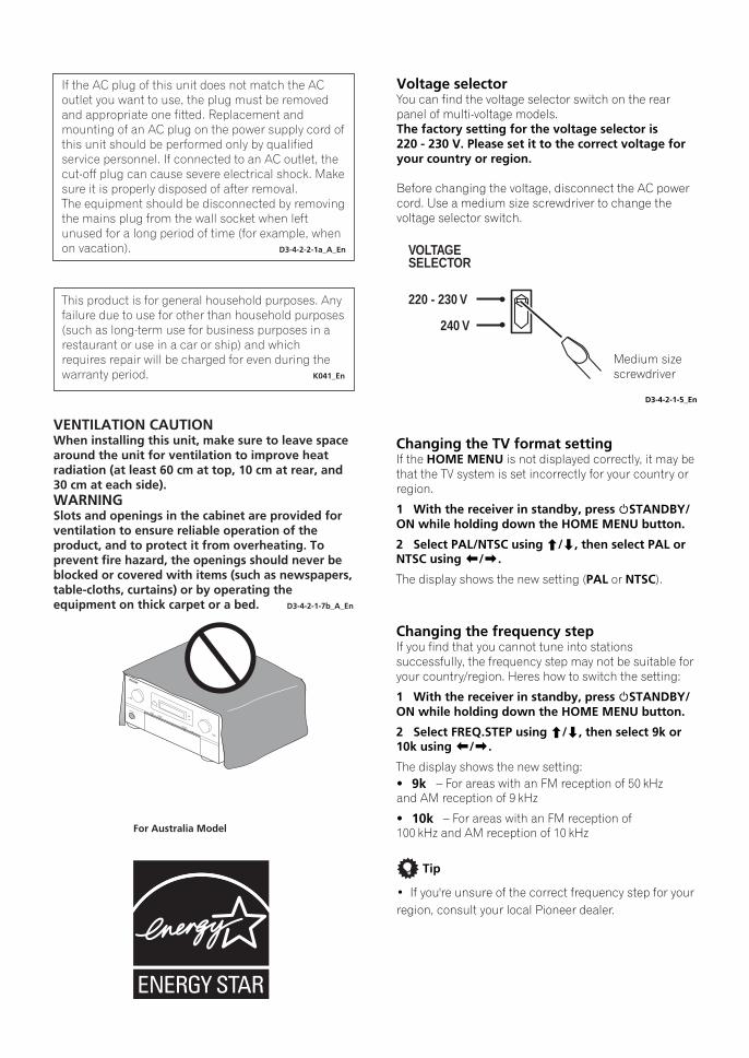
Voltage selectorYou can find the voltage selector switch on the rear panel of multi-voltage models.The factory setting for the voltage selector is 220 - 230 V. Please set it to the correct voltage for your country or region. Before changing the voltage, disconnect the AC power cord. Use a medium size screwdriver to change the voltage selector switch.
Medium size screwdriver
D3-4-2-1-5_En
Changing the TV format settingIf the HOME MENU is not displayed correctly, it may be that the TV system is set incorrectly for your country or region.
1 With the receiver in standby, press STANDBY/ON while holding down the HOME MENU button.
2 Select PAL/NTSC using /, then select PAL or NTSC using /.
The display shows the new setting (PAL or NTSC).
Changing the frequency stepIf you find that you cannot tune into stations successfully, the frequency step may not be suitable for your country/region. Heres how to switch the setting:
1 With the receiver in standby, press STANDBY/ON while holding down the HOME MENU button.
2 Select FREQ.STEP using /, then select 9k or 10k using /.
The display shows the new setting:9k
10k
220 - 230 V
240 V
VOLTAGESELECTOR
For Australia Model
VENTILATION CAUTIONWhen installing this unit, make sure to leave space around the unit for ventilation to improve heat radiation (at least 60 cm at top, 10 cm at rear, and 30 cm at each side).WARNINGSlots and openings in the cabinet are provided for ventilation to ensure reliable operation of the product, and to protect it from overheating. To prevent fire hazard, the openings should never be blocked or covered with items (such as newspapers, table-cloths, curtains) or by operating the equipment on thick carpet or a bed. D3-4-2-1-7b_A_En
This product is for general household purposes. Any failure due to use for other than household purposes (such as long-term use for business purposes in a restaurant or use in a car or ship) and which requires repair will be charged for even during the warranty period. K041_En
If the AC plug of this unit does not match the AC outlet you want to use, the plug must be removed and appropriate one fitted. Replacement and mounting of an AC plug on the power supply cord of this unit should be performed only by qualified service personnel. If connected to an AC outlet, the cut-off plug can cause severe electrical shock. Make sure it is properly disposed of after removal.The equipment should be disconnected by removing the mains plug from the wall socket when left unused for a long period of time (for example, when on vacation). D3-4-2-2-1a_A_En
STANDBY/ON
INPUTSELECTOR
PHASECONTROLADVANCEDMCACC
DIGITAL VIDEOSCALER
HDMI
MASTERVOLUME
SCLX81_71.book 3 ページ 2008年7月25日 金曜日 午後3時1分
4En
Contents01 Before you startChecking what’s in the box . . . . . . . . . . . . . . . . . . . . . . . . 7Installing the receiver . . . . . . . . . . . . . . . . . . . . . . . . . . . . 7Loading the batteries . . . . . . . . . . . . . . . . . . . . . . . . . . . . . 7
02 Simple Home Theater GuideIntroduction to home theater . . . . . . . . . . . . . . . . . . . . . . 8Listening to Surround Sound . . . . . . . . . . . . . . . . . . . . . . 8Automatically setting up for surround sound (MCACC & Full Band Phase Control) . . . . . . . . . . . . . . . . 9
Problems when using the Auto MCACC Setup . . . . . 10Playing a source. . . . . . . . . . . . . . . . . . . . . . . . . . . . . . . . 10Better sound using Phase Control and Full Band Phase Control . . . . . . . . . . . . . . . . . . . . . . . . . 11
Using Phase Control . . . . . . . . . . . . . . . . . . . . . . . . . . . 11Using Full Band Phase Control . . . . . . . . . . . . . . . . . . 12
03 Connecting your equipmentRear panel . . . . . . . . . . . . . . . . . . . . . . . . . . . . . . . . . . . . 14When making cable connections. . . . . . . . . . . . . . . . . . 15About the video converter . . . . . . . . . . . . . . . . . . . . . . . . 16Connecting using HDMI . . . . . . . . . . . . . . . . . . . . . . . . . 16
About HDMI. . . . . . . . . . . . . . . . . . . . . . . . . . . . . . . . . . 17Connecting your Blu-ray disc player . . . . . . . . . . . . . . . 18Connecting your TV and DVD player . . . . . . . . . . . . . . . 19Connecting a satellite/cable receiver or other set-top box . . . . . . . . . . . . . . . . . . . . . . . . . . . . . 20Connecting a DVD/HDD recorder, VCR and other video sources . . . . . . . . . . . . . . . . . . . . . . . . . 21Using the component video jacks . . . . . . . . . . . . . . . . . 22Connecting digital audio sources. . . . . . . . . . . . . . . . . . 23
About the WMA9 Pro decoder . . . . . . . . . . . . . . . . . . . 23Connecting analog audio sources . . . . . . . . . . . . . . . . . 24Connecting a component to the front panel inputs . . . 24Installing your speaker system . . . . . . . . . . . . . . . . . . . . 25
Connecting the speakers . . . . . . . . . . . . . . . . . . . . . . . 25Placing the speakers. . . . . . . . . . . . . . . . . . . . . . . . . . . 26
Connecting antennas . . . . . . . . . . . . . . . . . . . . . . . . . . . 27AM loop antenna . . . . . . . . . . . . . . . . . . . . . . . . . . . . . . 27FM wire antenna . . . . . . . . . . . . . . . . . . . . . . . . . . . . . . 28Connecting external antennas . . . . . . . . . . . . . . . . . . . 28
Plugging in the receiver . . . . . . . . . . . . . . . . . . . . . . . . . 28
04 Controls and displaysFront panel . . . . . . . . . . . . . . . . . . . . . . . . . . . . . . . . . . . . 29
Operating range of remote control unit . . . . . . . . . . . 30Display . . . . . . . . . . . . . . . . . . . . . . . . . . . . . . . . . . . . . . . 31Remote control. . . . . . . . . . . . . . . . . . . . . . . . . . . . . . . . . 32
05 Listening to your systemAuto playback . . . . . . . . . . . . . . . . . . . . . . . . . . . . . . . . . 35Listening in surround sound . . . . . . . . . . . . . . . . . . . . . 35
Standard surround sound . . . . . . . . . . . . . . . . . . . . . . 35Using the Home THX modes . . . . . . . . . . . . . . . . . . . . 36Using the Advanced surround effects . . . . . . . . . . . . 36
Listening in stereo. . . . . . . . . . . . . . . . . . . . . . . . . . . . . . 37Using Front Stage Surround Advance. . . . . . . . . . . . . . 37Using Stream Direct . . . . . . . . . . . . . . . . . . . . . . . . . . . . 38Selecting MCACC presets . . . . . . . . . . . . . . . . . . . . . . . 38Choosing the input signal . . . . . . . . . . . . . . . . . . . . . . . 38Using surround back channel processing . . . . . . . . . . 39
Using the Virtual Surround Back mode . . . . . . . . . . . 39Using the genre synchronizing function. . . . . . . . . . . . 40
06 Using the tunerListening to the radio . . . . . . . . . . . . . . . . . . . . . . . . . . . 41
Improving FM sound . . . . . . . . . . . . . . . . . . . . . . . . . . 41Using the noise cut mode . . . . . . . . . . . . . . . . . . . . . . 41Using Neural THX . . . . . . . . . . . . . . . . . . . . . . . . . . . . . 41Tuning directly to a station . . . . . . . . . . . . . . . . . . . . . 41
Saving station presets. . . . . . . . . . . . . . . . . . . . . . . . . . . 41Naming station presets . . . . . . . . . . . . . . . . . . . . . . . . 42Listening to station presets . . . . . . . . . . . . . . . . . . . . . 42
07 The Advanced MCACC menuMaking receiver settings from the Advanced MCACC menu . . . . . . . . . . . . . . . . . . . . . . . . . . . . . . . . . 43Automatic MCACC (Expert) . . . . . . . . . . . . . . . . . . . . . . 44Manual MCACC setup . . . . . . . . . . . . . . . . . . . . . . . . . . 46
Fine Channel Level . . . . . . . . . . . . . . . . . . . . . . . . . . . . 47Fine Speaker Distance . . . . . . . . . . . . . . . . . . . . . . . . . 47Standing Wave . . . . . . . . . . . . . . . . . . . . . . . . . . . . . . . 48Acoustic Calibration EQ Adjust. . . . . . . . . . . . . . . . . . 48Acoustic Calibration EQ Professional. . . . . . . . . . . . . 49
Checking MCACC Data . . . . . . . . . . . . . . . . . . . . . . . . . 51Data Management . . . . . . . . . . . . . . . . . . . . . . . . . . . . . 53
08 The System Setup menuMaking receiver settings from the System Setup menu . . . . . . . . . . . . . . . . . . . . . . . . . . . . 55Manual speaker setup . . . . . . . . . . . . . . . . . . . . . . . . . . 55
Surround back speaker setting . . . . . . . . . . . . . . . . . . 56Speaker Setting. . . . . . . . . . . . . . . . . . . . . . . . . . . . . . . 56Channel Level . . . . . . . . . . . . . . . . . . . . . . . . . . . . . . . . 57Speaker Distance . . . . . . . . . . . . . . . . . . . . . . . . . . . . . 58X-Curve. . . . . . . . . . . . . . . . . . . . . . . . . . . . . . . . . . . . . . 58THX Audio Setting . . . . . . . . . . . . . . . . . . . . . . . . . . . . 58
Thank you for buying this Pioneer product. Please read through these operating instructions so you will know how to operate your model properly. After you have finished reading the instructions, put them away in a safe place for future reference.
SCLX81_71.book 4 ページ 2008年7月25日 金曜日 午後3時1分
5En
09 Other connectionsConnecting the multichannel analog inputs. . . . . . . . . 60
Selecting the multichannel analog inputs . . . . . . . . . 60Speaker B setup. . . . . . . . . . . . . . . . . . . . . . . . . . . . . . . . 60
Switching the speaker system . . . . . . . . . . . . . . . . . . . 61Bi-amping your speakers . . . . . . . . . . . . . . . . . . . . . . . . 61Bi-wiring your speakers. . . . . . . . . . . . . . . . . . . . . . . . . . 62Connecting additional amplifiers . . . . . . . . . . . . . . . . . . 62MULTI-ZONE listening . . . . . . . . . . . . . . . . . . . . . . . . . . . 63
Making MULTI-ZONE connections . . . . . . . . . . . . . . . 63Using the MULTI-ZONE controls . . . . . . . . . . . . . . . . . 65
Connecting an IR receiver. . . . . . . . . . . . . . . . . . . . . . . . 66Switching components on and off using the 12 volt trigger. . . . . . . . . . . . . . . . . . . . . . . . . . 67Using this receiver with a Pioneer flat screen TV . . . . . 67Using the SR+ mode with a Pioneer flat screen TV. . . 68Connecting a PC for Advanced MCACC output . . . . . . 69
Advanced MCACC output using your PC . . . . . . . . . . 69
10 Playback with HOME MEDIA GALLERY inputsEnjoying the Home Media Gallery . . . . . . . . . . . . . . . . . 70Features of Home Media Gallery . . . . . . . . . . . . . . . . . . 70Steps to enjoy the Home Media Gallery. . . . . . . . . . . . . 70
Playing back audio files on the network and listening to Internet radio stations . . . . . . . . . . . . 70Playing back audio or photo files stored on a USB memory device . . . . . . . . . . . . . . . . . . . . . . . 70Playing back audio files stored on an iPod. . . . . . . . . 71
Connecting to the network through LAN interface. . . . 71Connecting an iPod . . . . . . . . . . . . . . . . . . . . . . . . . . . . . 71Connecting a USB device . . . . . . . . . . . . . . . . . . . . . . . . 72Introduction . . . . . . . . . . . . . . . . . . . . . . . . . . . . . . . . . . . 72About network playback . . . . . . . . . . . . . . . . . . . . . . . . . 72
Windows Media Connect . . . . . . . . . . . . . . . . . . . . . . . 72Windows Media DRM. . . . . . . . . . . . . . . . . . . . . . . . . . 72DLNA . . . . . . . . . . . . . . . . . . . . . . . . . . . . . . . . . . . . . . . 72Content playable over a network . . . . . . . . . . . . . . . . . 73About playback behavior over a network . . . . . . . . . . 73Authorizing this receiver. . . . . . . . . . . . . . . . . . . . . . . . 73
Playback with Home Media Gallery . . . . . . . . . . . . . . . . 73Playing back audio files stored on components on the network. . . . . . . . . . . . . . . . . . . . . . . . . . . . . . . . 75Playing back audio files stored on an iPod. . . . . . . . . 75Playing back audio files stored on a USB memory device . . . . . . . . . . . . . . . . . . . . . . . . . . . . . . . 76Finding what you want to play . . . . . . . . . . . . . . . . . . . 76Basic playback controls . . . . . . . . . . . . . . . . . . . . . . . . 77Playing back photo files stored in components on the network or USB memory device. . . . . . . . . . . . 77Listening to Internet radio stations . . . . . . . . . . . . . . . 77Listening to Neural Music Direct. . . . . . . . . . . . . . . . . 79Playing back your favorite songs . . . . . . . . . . . . . . . . . 79About playable file formats . . . . . . . . . . . . . . . . . . . . . 80
Advanced operations for Internet radio . . . . . . . . . . . . . 81Saving Internet radio stations . . . . . . . . . . . . . . . . . . . 81Retrieving saved Internet radio stations . . . . . . . . . . . 81
Setting up the network . . . . . . . . . . . . . . . . . . . . . . . . . . 81Checking the network settings . . . . . . . . . . . . . . . . . . 84Software update . . . . . . . . . . . . . . . . . . . . . . . . . . . . . . 84
Glossary . . . . . . . . . . . . . . . . . . . . . . . . . . . . . . . . . . . . . . 84
11 HDMI ControlMaking the HDMI Control connections . . . . . . . . . . . . 86Setting the HDMI options. . . . . . . . . . . . . . . . . . . . . . . . 87
Setting the HDMI Control mode . . . . . . . . . . . . . . . . . 87Before using synchronization . . . . . . . . . . . . . . . . . . . . 87Synchronized amp mode . . . . . . . . . . . . . . . . . . . . . . . . 88
Synchronized amp mode operations . . . . . . . . . . . . . 88Canceling synchronized amp mode . . . . . . . . . . . . . . 88
About HDMI Control . . . . . . . . . . . . . . . . . . . . . . . . . . . . 88About PQLS . . . . . . . . . . . . . . . . . . . . . . . . . . . . . . . . . . . 88
12 Other SettingsThe Input Setup menu . . . . . . . . . . . . . . . . . . . . . . . . . . 89
Input function default and possible settings . . . . . . . 90Changing the OSD display language (OSD Language) . . . . . . . . . . . . . . . . . . . . . . . . . . . . . . . 90The Other Setup menu . . . . . . . . . . . . . . . . . . . . . . . . . . 91
Multi Channel Input Setup . . . . . . . . . . . . . . . . . . . . . 91ZONE Audio Setup . . . . . . . . . . . . . . . . . . . . . . . . . . . . 92SR+ Setup for Pioneer flat screen TVs. . . . . . . . . . . . 92Flicker Reduction Setup. . . . . . . . . . . . . . . . . . . . . . . . 92
13 Using other functionsSetting the Audio options. . . . . . . . . . . . . . . . . . . . . . . . 93Setting the Video options . . . . . . . . . . . . . . . . . . . . . . . . 95Making an audio or a video recording. . . . . . . . . . . . . . 95Reducing the level of an analog signal . . . . . . . . . . . . . 96Using the sleep timer . . . . . . . . . . . . . . . . . . . . . . . . . . . 96Dimming the display. . . . . . . . . . . . . . . . . . . . . . . . . . . . 96Switching the HDMI output . . . . . . . . . . . . . . . . . . . . . . 97Checking your system settings . . . . . . . . . . . . . . . . . . . 97Resetting the system . . . . . . . . . . . . . . . . . . . . . . . . . . . 97
Default system settings . . . . . . . . . . . . . . . . . . . . . . . . 98
14 Controlling the rest of your systemSetting the remote to control other components. . . . . 99Selecting preset codes directly . . . . . . . . . . . . . . . . . . . 99Programming signals from other remote controls . . . . . . . . . . . . . . . . . . . . . . . . . . . . . . . 100Erasing one of the remote control button settings . . . . . . . . . . . . . . . . . . . . . . . . . . . . . . . 100Resetting the remote control presets . . . . . . . . . . . . . 101Confirming preset codes . . . . . . . . . . . . . . . . . . . . . . . 101Renaming input source names . . . . . . . . . . . . . . . . . . 101Direct function. . . . . . . . . . . . . . . . . . . . . . . . . . . . . . . . 101Multi Operation and System Off . . . . . . . . . . . . . . . . . 102
Programming a multi-operation or a shutdown sequence . . . . . . . . . . . . . . . . . . . . . . 102Using multi operations . . . . . . . . . . . . . . . . . . . . . . . 103Using System off. . . . . . . . . . . . . . . . . . . . . . . . . . . . . 103
Controls for TVs . . . . . . . . . . . . . . . . . . . . . . . . . . . . . . . 103Controls for other components . . . . . . . . . . . . . . . . . . 104Operating other Pioneer components with this unit’s sensor . . . . . . . . . . . . . . . . . . . . . . . . . . . . . . 105
SCLX81_71.book 5 ページ 2008年7月25日 金曜日 午後3時1分
6En
15 Additional informationSpeaker Setting Guide. . . . . . . . . . . . . . . . . . . . . . . . . . 106
Positional relationship between speakers and monitor . . . . . . . . . . . . . . . . . . . . . . . . . . . . . . . . . 108
Troubleshooting . . . . . . . . . . . . . . . . . . . . . . . . . . . . . . . 109Power . . . . . . . . . . . . . . . . . . . . . . . . . . . . . . . . . . . . . . 109No sound . . . . . . . . . . . . . . . . . . . . . . . . . . . . . . . . . . . 110Other audio problems . . . . . . . . . . . . . . . . . . . . . . . . . 111Video. . . . . . . . . . . . . . . . . . . . . . . . . . . . . . . . . . . . . . . 112Settings . . . . . . . . . . . . . . . . . . . . . . . . . . . . . . . . . . . . 112Professional Calibration EQ graphical output . . . . . 113Display . . . . . . . . . . . . . . . . . . . . . . . . . . . . . . . . . . . . . 113Remote control . . . . . . . . . . . . . . . . . . . . . . . . . . . . . . 114HDMI . . . . . . . . . . . . . . . . . . . . . . . . . . . . . . . . . . . . . . 114Important information regarding the HDMI connection . . . . . . . . . . . . . . . . . . . . . . . . . . . . 115HOME MEDIA GALLERY . . . . . . . . . . . . . . . . . . . . . . . 116About status messages . . . . . . . . . . . . . . . . . . . . . . . 118Meaning of messages displayed when the HDMI control function is set to ON . . . . . . . . . . . . . . 118
Surround sound formats . . . . . . . . . . . . . . . . . . . . . . . . 119Dolby. . . . . . . . . . . . . . . . . . . . . . . . . . . . . . . . . . . . . . . 119DTS . . . . . . . . . . . . . . . . . . . . . . . . . . . . . . . . . . . . . . . . 120Windows Media Audio 9 Professional. . . . . . . . . . . . 120
About THX. . . . . . . . . . . . . . . . . . . . . . . . . . . . . . . . . . . . 121About Neural – THX Surround . . . . . . . . . . . . . . . . . . . 122About FLAC. . . . . . . . . . . . . . . . . . . . . . . . . . . . . . . . . . . 123
FLAC Decoder . . . . . . . . . . . . . . . . . . . . . . . . . . . . . . . 123Listening modes with different input signal formats . . . . . . . . . . . . . . . . . . . . . . . . . . . . . . . . . . . . . . 124Stream direct with different input signal formats. . . . 129Specifications. . . . . . . . . . . . . . . . . . . . . . . . . . . . . . . . . 130Cleaning the unit . . . . . . . . . . . . . . . . . . . . . . . . . . . . . . 131Our philosophy. . . . . . . . . . . . . . . . . . . . . . . . . . . . . . . . 131
Features . . . . . . . . . . . . . . . . . . . . . . . . . . . . . . . . . . . . 131Pioneer Authorized Distributors . . . . . . . . . . . . . . . . . . 133
SCLX81_71.book 6 ページ 2008年7月25日 金曜日 午後3時1分
Before you start 01
7En
Chapter 1:
Before you start
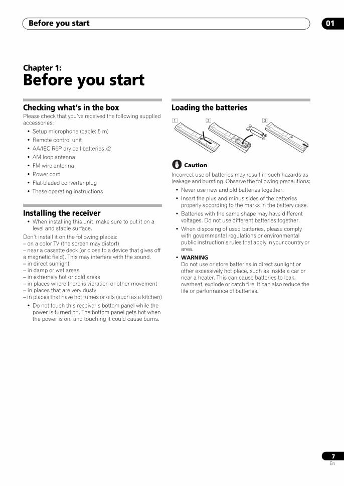
Checking what’s in the boxPlease check that you’ve received the following supplied accessories:
• Setup microphone (cable: 5 m)
• Remote control unit
• AA/IEC R6P dry cell batteries x2
• AM loop antenna
• FM wire antenna
• Power cord
• Flat-bladed converter plug
• These operating instructions
Installing the receiver• When installing this unit, make sure to put it on a
level and stable surface.
Don’t install it on the following places:– on a color TV (the screen may distort)– near a cassette deck (or close to a device that gives off a magnetic field). This may interfere with the sound.– in direct sunlight– in damp or wet areas– in extremely hot or cold areas– in places where there is vibration or other movement– in places that are very dusty– in places that have hot fumes or oils (such as a kitchen)
• Do not touch this receiver’s bottom panel while the power is turned on. The bottom panel gets hot when the power is on, and touching it could cause burns.
Loading the batteries
Caution
Incorrect use of batteries may result in such hazards as leakage and bursting. Observe the following precautions:
• Never use new and old batteries together.
• Insert the plus and minus sides of the batteries properly according to the marks in the battery case.
• Batteries with the same shape may have different voltages. Do not use different batteries together.
• When disposing of used batteries, please comply with governmental regulations or environmental public instruction’s rules that apply in your country or area.
• WARNINGDo not use or store batteries in direct sunlight or other excessively hot place, such as inside a car or near a heater. This can cause batteries to leak, overheat, explode or catch fire. It can also reduce the life or performance of batteries.
SCLX81_71.book 7 ページ 2008年7月25日 金曜日 午後3時1分
Simple Home Theater Guide02
8En
Chapter 2:
Simple Home Theater Guide
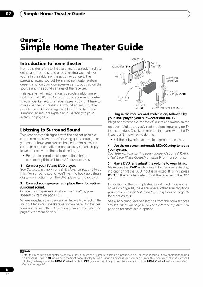
Introduction to home theaterHome theater refers to the use of multiple audio tracks to create a surround sound effect, making you feel like you’re in the middle of the action or concert. The surround sound you get from a home theater system depends not only on your speaker setup, but also on the source and the sound settings of the receiver.
This receiver will automatically decode multichannel Dolby Digital, DTS, or Dolby Surround sources according to your speaker setup. In most cases, you won’t have to make changes for realistic surround sound, but other possibilities (like listening to a CD with multichannel surround sound) are explained in Listening to your system on page 35.
Listening to Surround SoundThis receiver was designed with the easiest possible setup in mind, so with the following quick setup guide, you should have your system hooked up for surround sound in no time at all. In most cases, you can simply leave the receiver in the default settings.
• Be sure to complete all connections before connecting this unit to an AC power source.
1 Connect your TV and DVD player.See Connecting your TV and DVD player on page 19 to do this. For surround sound, you’ll want to hook up using a digital connection from the DVD player to the receiver.
2 Connect your speakers and place them for optimal surround sound.Connect your speakers as shown in Installing your speaker system on page 25.
Where you place the speakers will have a big effect on the sound. Place your speakers as shown below for the best surround sound effect. See also Placing the speakers on page 26 for more on this.
3 Plug in the receiver and switch it on, followed by your DVD player, your subwoofer and the TV.Plug the power cable into the AC outlet and switch on the receiver.1 Make sure you’ve set the video input on your TV to this receiver. Check the manual that came with the TV if you don’t know how to do this.
• Set the subwoofer volume to a comfortable level.
4 Use the on-screen automatic MCACC setup to set up your system.See Automatically setting up for surround sound (MCACC & Full Band Phase Control) on page 9 for more on this.
5 Play a DVD, and adjust the volume to your liking.Make sure that DVD is showing in the receiver’s display, indicating that the DVD input is selected. If it isn’t, press DVD on the remote control to set the receiver to the DVD input.
In addition to the basic playback explained in Playing a source on page 10, there are several other sound options you can select. See Listening to your system on page 35 for more on this.
See also Making receiver settings from the The Advanced MCACC menu on page 43 or The System Setup menu on page 55 for more setup options.
Note1 After this receiver is connected to an AC outlet, a 15-second HDMI initialization process begins. You cannot carry out any operations during
this process. The HDMI indicator in the front panel display blinks during this process, and you can turn on this receiver once it has stopped blinking. When you set the HDMI Control mode to OFF, you can skip this process. For details about the HDMI Control feature, see HDMI Control on page 86.
Center (C)
Front Right (R)
Surround Right (SR)
SurroundBack Right (SBR)
Surround Back Left (SBL)Surround Left (SL)
Listening position
FrontLeft (L)
Subwoofer (SW)
SCLX81_71.book 8 ページ 2008年7月25日 金曜日 午後3時1分
Simple Home Theater Guide 02
9En
Automatically setting up for surround sound (MCACC & Full Band Phase Control)The Auto MCACC Setup measures the acoustic characteristics of your listening area, taking into account ambient noise, speaker size and distance, and tests for both channel delay and channel level. After you have set up the microphone provided with your system, the receiver uses the information from a series of test tones to optimize the speaker settings and equalization for your particular room, and also to calibrate the frequency-phase characteristics of the speakers connected.
Make sure you do this before moving on to Playing a source on page 10.
Important
• Make sure the microphone and speakers are not moved during the Auto MCACC Setup.
• Using the Auto MCACC Setup will overwrite any existing settings for the MCACC preset you select.
• Before using the Auto MCACC Setup, the headphones should be disconnected and the HOME MEDIA GALLERY function should not be selected as an input source.
Caution
• The test tones used in the Auto MCACC Setup are output at high volume.
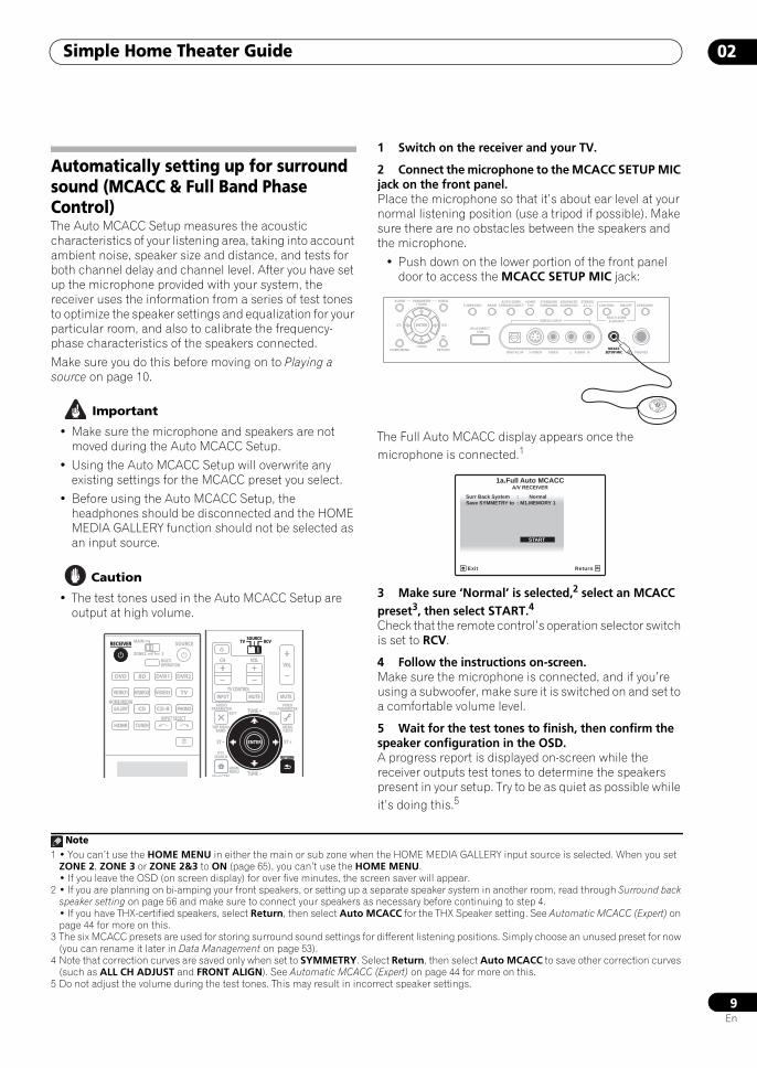
1 Switch on the receiver and your TV.
2 Connect the microphone to the MCACC SETUP MIC jack on the front panel. Place the microphone so that it’s about ear level at your normal listening position (use a tripod if possible). Make sure there are no obstacles between the speakers and the microphone.
• Push down on the lower portion of the front panel door to access the MCACC SETUP MIC jack:
The Full Auto MCACC display appears once the microphone is connected.1
3 Make sure ‘Normal’ is selected,2 select an MCACC preset3, then select START.4
Check that the remote control’s operation selector switch is set to RCV.
4 Follow the instructions on-screen.Make sure the microphone is connected, and if you’re using a subwoofer, make sure it is switched on and set to a comfortable volume level.
5 Wait for the test tones to finish, then confirm the speaker configuration in the OSD.A progress report is displayed on-screen while the receiver outputs test tones to determine the speakers present in your setup. Try to be as quiet as possible while it’s doing this.5
DVD
RECEIVER SOURCEMAIN
MULTIOPERATION
ZONE2 3
VIDEO1
GALLERYHOME MEDIA
INPUT SELECT
CD
HDMI TUNER
PHONO
VIDEO2 VIDEO3 TV
BD DVR1 DVR2
CD-R
RECEIVER
AUDIOPARAMETER
TOP MENUBAND
iPod CTRL
PTYSEARCH
EXIT TOOLS
HOMEMENU
MENUT.EDIT
VIDEOPARAMETER
SOURCETV RCV
INPUT MUTE
TUNE +
TUNE
ST ST +
MUTE
VOLVOL
TV CONTROL
CH
RETURNRETURN
ENTER
SOURCETV RCV
Note1 • You can’t use the HOME MENU in either the main or sub zone when the HOME MEDIA GALLERY input source is selected. When you set
ZONE 2, ZONE 3 or ZONE 2&3 to ON (page 65), you can’t use the HOME MENU.• If you leave the OSD (on screen display) for over five minutes, the screen saver will appear.
2 • If you are planning on bi-amping your front speakers, or setting up a separate speaker system in another room, read through Surround back speaker setting on page 56 and make sure to connect your speakers as necessary before continuing to step 4.• If you have THX-certified speakers, select Return, then select Auto MCACC for the THX Speaker setting. See Automatic MCACC (Expert) on page 44 for more on this.
3 The six MCACC presets are used for storing surround sound settings for different listening positions. Simply choose an unused preset for now (you can rename it later in Data Management on page 53).
4 Note that correction curves are saved only when set to SYMMETRY. Select Return, then select Auto MCACC to save other correction curves (such as ALL CH ADJUST and FRONT ALIGN). See Automatic MCACC (Expert) on page 44 for more on this.
5 Do not adjust the volume during the test tones. This may result in incorrect speaker settings.
VIDEO3 INPUT
DIGITAL IN S-VIDEO VIDEO L RAUDIO PHONES
SPEAKERSCONTROL
MULTI-ZONE& SOURCE
ON/OFF
MCACCSETUP MIC
PARAMETER
ENTER
(TUNE)
(TUNE)
(ST)(ST)
AUDIO VIDEOTUNER EDIT
iPod DIRECTUSB
AUTO SURR/STREAM DIRECT
HOMETHX
STANDARDSURROUND
ADVANCEDSURROUND
STEREO/A.L.C.BAND
HOME MENU RETURN MCACCSETUP MIC
Surr Back System : Normal
1a.Full Auto MCACCA/V RECEIVER
Exit Return
START
Save SYMMETRY to : M1.MEMORY 1
SCLX81_71.book 9 ページ 2008年7月25日 金曜日 午後3時1分
Simple Home Theater Guide02
10En
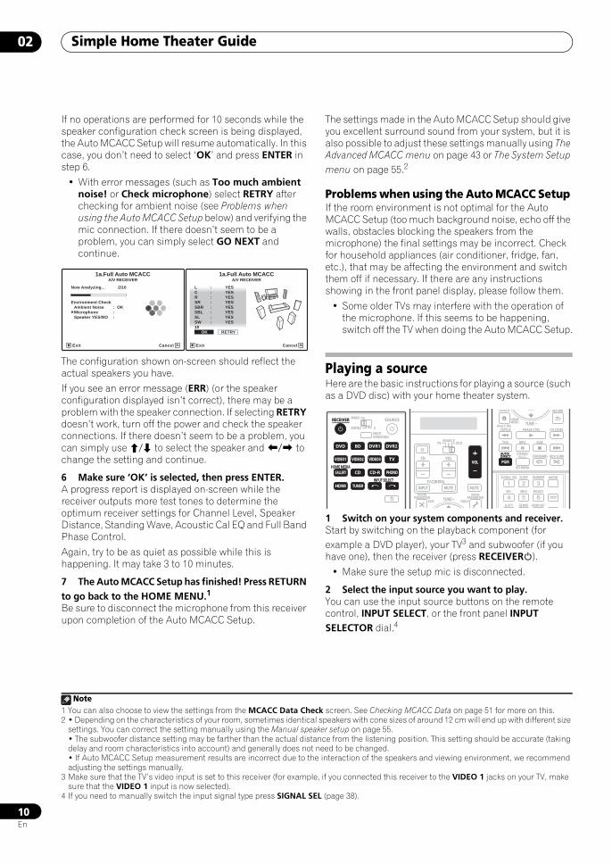
If no operations are performed for 10 seconds while the speaker configuration check screen is being displayed, the Auto MCACC Setup will resume automatically. In this case, you don’t need to select ‘OK’ and press ENTER in step 6.
• With error messages (such as Too much ambient noise! or Check microphone) select RETRY after checking for ambient noise (see Problems when using the Auto MCACC Setup below) and verifying the mic connection. If there doesn’t seem to be a problem, you can simply select GO NEXT and continue.
The configuration shown on-screen should reflect the actual speakers you have.
If you see an error message (ERR) (or the speaker configuration displayed isn’t correct), there may be a problem with the speaker connection. If selecting RETRY doesn’t work, turn off the power and check the speaker connections. If there doesn’t seem to be a problem, you can simply use / to select the speaker and / to change the setting and continue.
6 Make sure ‘OK’ is selected, then press ENTER.A progress report is displayed on-screen while the receiver outputs more test tones to determine the optimum receiver settings for Channel Level, Speaker Distance, Standing Wave, Acoustic Cal EQ and Full Band Phase Control.
Again, try to be as quiet as possible while this is happening. It may take 3 to 10 minutes.
7 The Auto MCACC Setup has finished! Press RETURN to go back to the HOME MENU.1
Be sure to disconnect the microphone from this receiver upon completion of the Auto MCACC Setup.
The settings made in the Auto MCACC Setup should give you excellent surround sound from your system, but it is also possible to adjust these settings manually using The Advanced MCACC menu on page 43 or The System Setup menu on page 55.2
Problems when using the Auto MCACC Setup If the room environment is not optimal for the Auto MCACC Setup (too much background noise, echo off the walls, obstacles blocking the speakers from the microphone) the final settings may be incorrect. Check for household appliances (air conditioner, fridge, fan, etc.), that may be affecting the environment and switch them off if necessary. If there are any instructions showing in the front panel display, please follow them.
• Some older TVs may interfere with the operation of the microphone. If this seems to be happening, switch off the TV when doing the Auto MCACC Setup.
Playing a sourceHere are the basic instructions for playing a source (such as a DVD disc) with your home theater system.
1 Switch on your system components and receiver.Start by switching on the playback component (for example a DVD player), your TV3 and subwoofer (if you have one), then the receiver (press RECEIVER).
• Make sure the setup mic is disconnected.
2 Select the input source you want to play.You can use the input source buttons on the remote control, INPUT SELECT, or the front panel INPUT SELECTOR dial.4
Note1 You can also choose to view the settings from the MCACC Data Check screen. See Checking MCACC Data on page 51 for more on this.
Now Analyzing... 2/10
Environment Check
1a.Full Auto MCACCA/V RECEIVER
Exit Cancel
Ambient Noise : OKMicrophone : Speaker YES/NO :
L : YES
R : YESC : YES
1a.Full Auto MCACC
SR : YESSBR : YESSBL : YESSL : YESSW : YES10 OK RETRY
A/V RECEIVER
Exit Cancel
2 • Depending on the characteristics of your room, sometimes identical speakers with cone sizes of around 12 cm will end up with different size settings. You can correct the setting manually using the Manual speaker setup on page 55.• The subwoofer distance setting may be farther than the actual distance from the listening position. This setting should be accurate (taking delay and room characteristics into account) and generally does not need to be changed.• If Auto MCACC Setup measurement results are incorrect due to the interaction of the speakers and viewing environment, we recommend adjusting the settings manually.
3 Make sure that the TV’s video input is set to this receiver (for example, if you connected this receiver to the VIDEO 1 jacks on your TV, make sure that the VIDEO 1 input is now selected).
4 If you need to manually switch the input signal type press SIGNAL SEL (page 38).
RECEIVER SOURCEMAIN
MULTIOPERATION
ZONE2 3
INPUT SELECT
RECEIVER
DVD
VIDEO1
GALLERYHOME MEDIA
CD
HDMI TUNER
PHONO
VIDEO2 VIDEO3 TV
BD DVR1 DVR2
CD-R
AUDIOPARAMETER
EXIT TOOLS
VIDEOPARAMETER
SOURCETV RCV
INPUT MUTE MUTE
VOLVOL
TV CONTROL
CH
TUNE +
VOL
iPod CTRL
HOMEMENU
STATUS
THX MPX
PHASE CTRL CH LEVEL
PGM
STEREO/A.L.C.
BD MENU
SIGNAL SEL SLEEP AUDIODIMMER
SR+ SBch MCACC
A.ATT GENRE HDMI OUT
DISP
AUTO/DIRECT STANDARD ADV SURR
RETURNSEARCH
EON
TUNE
PGM
AUTO/DIRECT
SCLX81_71.book 10 ページ 2008年7月25日 金曜日 午後3時1分
Simple Home Theater Guide 02
11En
3 Set the operation selector switch to RCV, then press AUTO/DIRECT (AUTO SURR/STREAM DIRECT) to select ‘AUTO SURROUND’ and start playback of the source.1
If you’re playing a Dolby Digital or DTS surround sound DVD disc, you should hear surround sound. If you are playing a stereo source, you will only hear sound from the front left/right speakers in the default listening mode.
• See also Listening to your system on page 35 for information on different ways of listening to sources.
It is possible to check on the front panel display whether or not multi-channel playback is being performed properly.
When using a surround back speaker, 2D+PLIIx MOVIE is displayed when playing Dolby Digital signals, and DTS+Neo:6 is displayed when playing DTS 5.1-channel signals.
When not using a surround back speaker, DOLBY DIGITAL is displayed when playing Dolby Digital signals.
For other details, see Listening modes with different input signal formats on page 124. If the display does not correspond to the input signal and listening mode, check the connections and settings.
4 Use the volume control to adjust the volume level.Turn down the volume of your TV so that all sound is coming from the speakers connected to this receiver.
Better sound using Phase Control and Full Band Phase ControlThis receiver is equipped with the two types of functions that correct phase distortion and group delay: Phase Control and Full Band Phase Control. Activating Full Band Phase Control is strongly recommended because it also involves the effects of Phase Control. For details on each of these two features, refer to the following explanations.
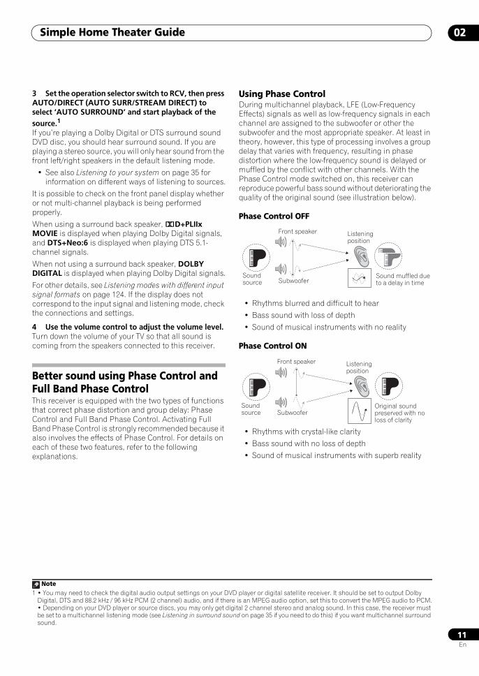
Using Phase ControlDuring multichannel playback, LFE (Low-Frequency Effects) signals as well as low-frequency signals in each channel are assigned to the subwoofer or other the subwoofer and the most appropriate speaker. At least in theory, however, this type of processing involves a group delay that varies with frequency, resulting in phase distortion where the low-frequency sound is delayed or muffled by the conflict with other channels. With the Phase Control mode switched on, this receiver can reproduce powerful bass sound without deteriorating the quality of the original sound (see illustration below).
Phase Control OFF
• Rhythms blurred and difficult to hear
• Bass sound with loss of depth
• Sound of musical instruments with no reality
Phase Control ON
• Rhythms with crystal-like clarity
• Bass sound with no loss of depth
• Sound of musical instruments with superb reality
Note1 • You may need to check the digital audio output settings on your DVD player or digital satellite receiver. It should be set to output Dolby
Digital, DTS and 88.2 kHz / 96 kHz PCM (2 channel) audio, and if there is an MPEG audio option, set this to convert the MPEG audio to PCM.• Depending on your DVD player or source discs, you may only get digital 2 channel stereo and analog sound. In this case, the receiver must be set to a multichannel listening mode (see Listening in surround sound on page 35 if you need to do this) if you want multichannel surround sound.
Front speaker
SubwooferSound source
Sound muffled due to a delay in time
Listening position
Front speaker
SubwooferSound source
Original sound preserved with no loss of clarity
Listening position
SCLX81_71.book 11 ページ 2008年7月25日 金曜日 午後3時1分
Simple Home Theater Guide02
12En
Phase Control technology provides coherent sound reproduction through the use of phase matching1 for an optimal sound image at your listening position. The default setting is on and we recommend leaving Phase Control switched on for all sound sources.
• Set the operation selector switch to RCV, then press PHASE CTRL (PHASE CONTROL) to select PHASE CONTROL.The PHASE CONTROL indicator on the front panel lights.
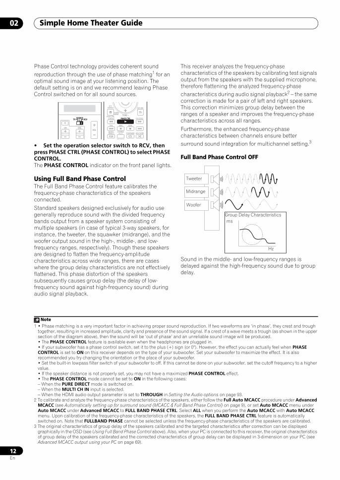
Using Full Band Phase ControlThe Full Band Phase Control feature calibrates the frequency-phase characteristics of the speakers connected.
Standard speakers designed exclusively for audio use generally reproduce sound with the divided frequency bands output from a speaker system consisting of multiple speakers (in case of typical 3-way speakers, for instance, the tweeter, the squawker (midrange), and the woofer output sound in the high-, middle-, and low-frequency ranges, respectively). Though these speakers are designed to flatten the frequency-amplitude characteristics across wide ranges, there are cases where the group delay characteristics are not effectively flattened. This phase distortion of the speakers subsequently causes group delay (the delay of low-frequency sound against high-frequency sound) during audio signal playback.
This receiver analyzes the frequency-phase characteristics of the speakers by calibrating test signals output from the speakers with the supplied microphone, therefore flattening the analyzed frequency-phase characteristics during audio signal playback2 – the same correction is made for a pair of left and right speakers. This correction minimizes group delay between the ranges of a speaker and improves the frequency-phase characteristics across all ranges.
Furthermore, the enhanced frequency-phase characteristics between channels ensure better surround sound integration for multichannel setting.3
Full Band Phase Control OFF
Sound in the middle- and low-frequency ranges is delayed against the high-frequency sound due to group delay.
Note1 • Phase matching is a very important factor in achieving proper sound reproduction. If two waveforms are ‘in phase’, they crest and trough
together, resulting in increased amplitude, clarity and presence of the sound signal. If a crest of a wave meets a trough (as shown in the upper section of the diagram above), then the sound will be ‘out of phase’ and an unreliable sound image will be produced.• The PHASE CONTROL feature is available even when the headphones are plugged in.• If your subwoofer has a phase control switch, set it to the plus (+) sign (or 0°). However, the effect you can actually feel when PHASE CONTROL is set to ON on this receiver depends on the type of your subwoofer. Set your subwoofer to maximize the effect. It is also recommended you try changing the orientation or the place of your subwoofer.• Set the built-in lowpass filter switch of your subwoofer to off. If this cannot be done on your subwoofer, set the cutoff frequency to a higher value.• If the speaker distance is not properly set, you may not have a maximized PHASE CONTROL effect.• The PHASE CONTROL mode cannot be set to ON in the following cases:– When the PURE DIRECT mode is switched on.– When the MULTI CH IN input is selected.– When the HDMI audio output parameter is set to THROUGH in Setting the Audio options on page 93.
SOURCETV RCV
VOLVOLCH
SOURCETV RCV
iPod CTRL
HOMEMENU
STATUS
THX MPX
PHASE CTRL CH LEVEL
PGM
STEREO/A.L.C.
BD MENU
AUTO/DIRECT STANDARD ADV SURR
RETURNPTY
SEARCH
EON
TUNEPHASE CTRL
2 To calibrate and analyze the frequency-phase characteristics of the speakers, either follow the Full Auto MCACC procedure under Advanced MCACC (see Automatically setting up for surround sound (MCACC & Full Band Phase Control) on page 9), or set Auto MCACC menu under Auto MCACC under Advanced MCACC to FULL BAND PHASE CTRL. Select ALL when you perform the Auto MCACC with Auto MCACC menu. Upon calibration of the frequency-phase characteristics of the speakers, the FULL BAND PHASE CTRL feature is automatically switched on. Note that FULLBAND PHASE cannot be selected unless the frequency-phase characteristics of the speakers are calibrated.
3 The original characteristics of group delay of the speakers calibrated and the targeted characteristics after correction can be displayed graphically in the OSD (see Using Full Band Phase Control above). Also, when your PC is connected to this receiver, the original characteristics of group delay of the speakers calibrated and the corrected characteristics of group delay can be displayed in 3-dimension on your PC (see Advanced MCACC output using your PC on page 69).
Tweeter
Midrange
Woofer
Group Delay Characteristicsms
Hz
SCLX81_71.book 12 ページ 2008年7月25日 金曜日 午後3時1分
Simple Home Theater Guide 02
13En
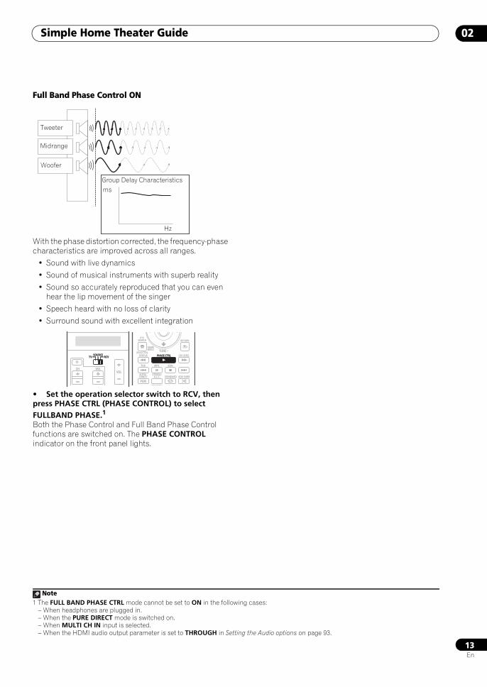
Full Band Phase Control ON
With the phase distortion corrected, the frequency-phase characteristics are improved across all ranges.
• Sound with live dynamics
• Sound of musical instruments with superb reality
• Sound so accurately reproduced that you can even hear the lip movement of the singer
• Speech heard with no loss of clarity
• Surround sound with excellent integration
• Set the operation selector switch to RCV, then press PHASE CTRL (PHASE CONTROL) to select FULLBAND PHASE.1
Both the Phase Control and Full Band Phase Control functions are switched on. The PHASE CONTROL indicator on the front panel lights.
Note1 The FULL BAND PHASE CTRL mode cannot be set to ON in the following cases:
– When headphones are plugged in.– When the PURE DIRECT mode is switched on.– When MULTI CH IN input is selected.– When the HDMI audio output parameter is set to THROUGH in Setting the Audio options on page 93.
Tweeter
Midrange
Woofer
Group Delay Characteristicsms
Hz
SOURCETV RCV
VOLVOLCH
SOURCETV RCV
iPod CTRL
HOMEMENU
STATUS
THX MPX
PHASE CTRL CH LEVEL
PGM
STEREO/A.L.C.
BD MENU
AUTO/DIRECT STANDARD ADV SURR
RETURNPTY
SEARCH
EON
TUNEPHASE CTRL
SCLX81_71.book 13 ページ 2008年7月25日 金曜日 午後3時1分
Connecting your equipment03
14En
Chapter 3:
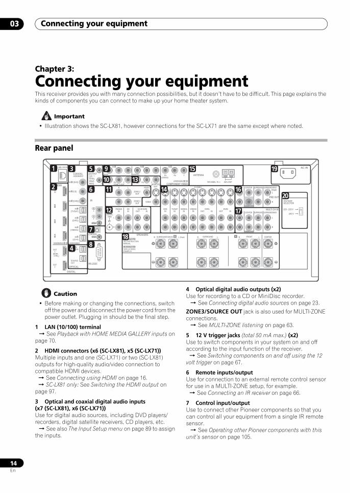
Connecting your equipmentThis receiver provides you with many connection possibilities, but it doesn’t have to be difficult. This page explains the kinds of components you can connect to make up your home theater system.
Important
• Illustration shows the SC-LX81, however connections for the SC-LX71 are the same except where noted.
Rear panel
Caution
• Before making or changing the connections, switch off the power and disconnect the power cord from the power outlet. Plugging in should be the final step.
1 LAN (10/100) terminal See Playback with HOME MEDIA GALLERY inputs on page 70.
2 HDMI connectors (x6 (SC-LX81), x5 (SC-LX71))Multiple inputs and one (SC-LX71) or two (SC-LX81) outputs for high-quality audio/video connection to compatible HDMI devices. See Connecting using HDMI on page 16. SC-LX81 only: See Switching the HDMI output on page 97.
3 Optical and coaxial digital audio inputs (x7 (SC-LX81), x6 (SC-LX71))Use for digital audio sources, including DVD players/recorders, digital satellite receivers, CD players, etc. See also The Input Setup menu on page 89 to assign the inputs.
4 Optical digital audio outputs (x2)Use for recording to a CD or MiniDisc recorder. See Connecting digital audio sources on page 23.
ZONE3/SOURCE OUT jack is also used for MULTI-ZONE connections. See MULTI-ZONE listening on page 63.
5 12 V trigger jacks (total 50 mA max.) (x2)Use to switch components in your system on and off according to the input function of the receiver. See Switching components on and off using the 12 volt trigger on page 67.
6 Remote inputs/outputUse for connection to an external remote control sensor for use in a MULTI-ZONE setup, for example. See Connecting an IR receiver on page 66.
7 Control input/outputUse to connect other Pioneer components so that you can control all your equipment from a single IR remote sensor. See Operating other Pioneer components with this unit’s sensor on page 105.
LAN (10/100)
DIGITAL
SPEAKERS
OPTICALRS-232C
HDMI
COAXIAL
COMPONENT VIDEO
ANTENNA
PRE OUT
MULTI CH IN
A
IR
CONTROL
BDIN
12 VTRIGGER
IN1
IN2
IN3
OUT1
OUT2
SOURCEOUT
ZONE3/SOURCEOUT
31ASSIGNABLE -
31ASSIGNABLE -
(HDMI CTRL)
ASSIGNABLE
ASSIGNABLE
(CD-R)IN 4
(VIDEO1)IN 3
(DVR1)IN 2
(TV/SAT)IN 1
IN 3 (DVR2)
IN 2 (CD)
IN 1 (DVD)
IN 1 IN 2
(OUTPUT 12V TOTAL 50mA MAX)
1
2
IN1
IN
IN2
OUT
OUT
(DVD)
PR PB Y PR PB Y
PR PB Y(VIDEO1)
IN 3
(VIDEO2)
RZONE 2 OUT MONITOR
OUT
PHONOIN
CDIN
DVDIN
TV/SATIN
VIDEO1IN
VIDEO2IN OUT
DVR1IN OUT
DVR2INOUT IN
CD-R/TAPE
SIGNALGND
ZONE 2 OUT
ZONE 3 OUT
VIDEO
VIDEO S-VIDEO FRONT CENTER
SUBWOOFER
SURROUND SURROUND BACK
FRONT CENTER
CENTERLR FRONTB LR SURROUND BACK/ LR SURROUND
SUBWOOFER
SURROUND SURROUND BACK
(Single)
(Single)
L
L
R
SEE INSTRUCTIONMANUAL
L
R
L
R
FM UNBAL 75 AM LOOP
SELECTABLE
VOIR LE MODED'EMPLOI
SELECTABLE
AC IN
220 - 230 V
240 V
VOLTAGESELECTOR
1
2
3
4
5
6
7
8
9
1011
12
1314
15
16
19
20
17
18
SCLX81_71.book 14 ページ 2008年7月25日 金曜日 午後3時1分
Connecting your equipment 03
15En
8 RS-232C connectorUse for connection to a PC for graphical output when using Advanced MCACC or Full Band Phase Control. See Connecting a PC for Advanced MCACC output on page 69.
9 Component video inputs (x3)Use the inputs to connect any video source that has component video output, such as a DVD player. See Using the component video jacks on page 22.
10 SC-LX81 only: ZONE 2 component video outputUse to connect monitors or TVs in a separate room. See MULTI-ZONE listening on page 63.
11 MULTI-ZONE audio/video outputsUse to connect a second or third amplifier and monitors or TVs in a separate room. See MULTI-ZONE listening on page 63.
12 Stereo analog audio source inputs/(outputs) (x4)Use for connection to audio sources such as CD players, tape decks, turntables, etc. See Connecting analog audio sources on page 24.
13 Composite, S-Video and Component monitor outputsUse to connect monitors and TVs. See Connecting your TV and DVD player on page 19. See Using the component video jacks on page 22.
14 Audio/video source inputs/(outputs) (x8)Use for connection to audio/visual sources, such as DVD players/recorders, VCRs, etc. Each set of inputs has jacks for composite video, S-Video and stereo analog audio.
See Connecting a DVD/HDD recorder, VCR and other video sources on page 21.
15 AM and FM antenna terminalsUse to connect indoor or outdoor antennas for radio broadcasts. See Connecting antennas on page 27.
16 Multichannel pre-amplifier outputsUse to connect separate amplifiers for front, center, surround, surround back and subwoofer channels. See Connecting additional amplifiers on page 62 (see also Installing your speaker system on page 25 for powered subwoofer connection).
17 Multichannel analog audio inputs7.1 channel inputs for connection to a DVD player with multichannel analog outputs. See Connecting the multichannel analog inputs on page 60.
18 Speaker terminalsUse for connection to the main front, center, surround and surround back speakers. See Installing your speaker system on page 25.
19 AC power inletConnect the supplied power cord here.
20 Voltage selector switchUse these to match the voltage coming into the receiver with the voltage in your country or region.
Voltage selector on page 3.
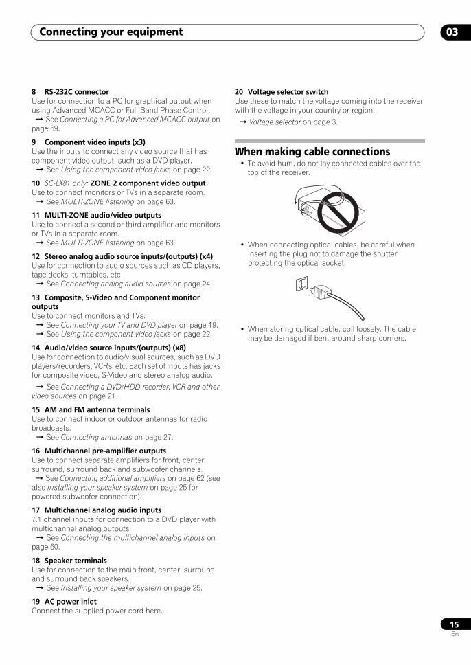
When making cable connections• To avoid hum, do not lay connected cables over the
top of the receiver.
• When connecting optical cables, be careful when inserting the plug not to damage the shutter protecting the optical socket.
• When storing optical cable, coil loosely. The cable may be damaged if bent around sharp corners.
SCLX81_71.book 15 ページ 2008年7月25日 金曜日 午後3時1分
Connecting your equipment03
16En
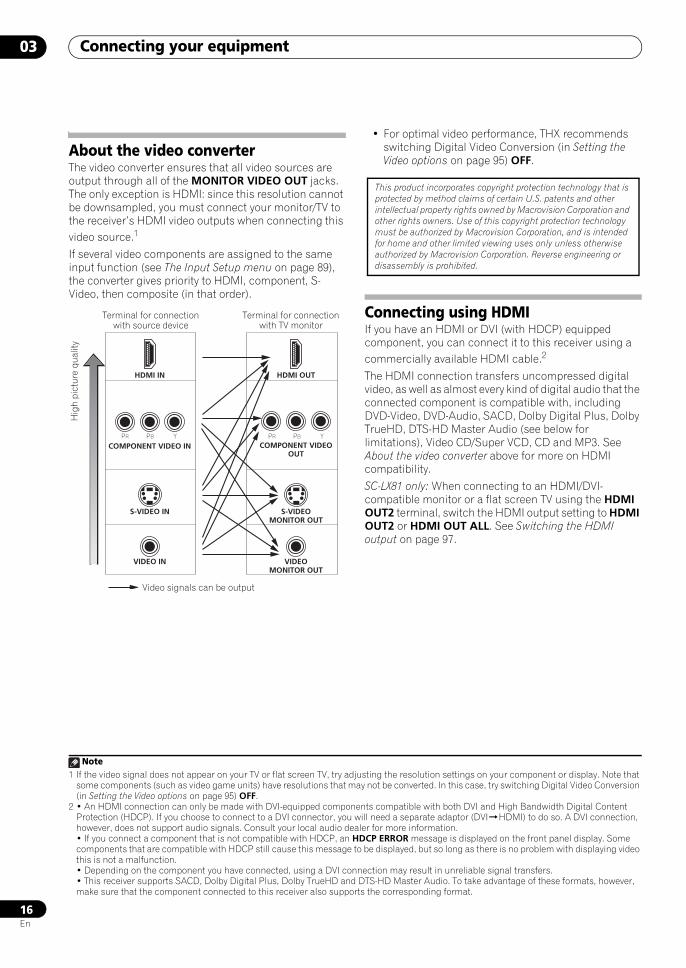
About the video converterThe video converter ensures that all video sources are output through all of the MONITOR VIDEO OUT jacks. The only exception is HDMI: since this resolution cannot be downsampled, you must connect your monitor/TV to the receiver’s HDMI video outputs when connecting this video source.1
If several video components are assigned to the same input function (see The Input Setup menu on page 89), the converter gives priority to HDMI, component, S-Video, then composite (in that order).
• For optimal video performance, THX recommends switching Digital Video Conversion (in Setting the Video options on page 95) OFF.
Connecting using HDMIIf you have an HDMI or DVI (with HDCP) equipped component, you can connect it to this receiver using a commercially available HDMI cable.2
The HDMI connection transfers uncompressed digital video, as well as almost every kind of digital audio that the connected component is compatible with, including DVD-Video, DVD-Audio, SACD, Dolby Digital Plus, Dolby TrueHD, DTS-HD Master Audio (see below for limitations), Video CD/Super VCD, CD and MP3. See About the video converter above for more on HDMI compatibility.
SC-LX81 only: When connecting to an HDMI/DVI-compatible monitor or a flat screen TV using the HDMI OUT2 terminal, switch the HDMI output setting to HDMI OUT2 or HDMI OUT ALL. See Switching the HDMI output on page 97.
Note1 If the video signal does not appear on your TV or flat screen TV, try adjusting the resolution settings on your component or display. Note that
some components (such as video game units) have resolutions that may not be converted. In this case, try switching Digital Video Conversion (in Setting the Video options on page 95) OFF.
HDMI IN
S-VIDEO IN
VIDEO IN
PR PB Y PR PB Y
HDMI OUT
S-VIDEOMONITOR OUT
VIDEOMONITOR OUT
COMPONENT VIDEO IN COMPONENT VIDEOOUT
Hig
h pi
ctur
e qu
ality
Terminal for connection with source device
Terminal for connection with TV monitor
Video signals can be output
2 • An HDMI connection can only be made with DVI-equipped components compatible with both DVI and High Bandwidth Digital Content Protection (HDCP). If you choose to connect to a DVI connector, you will need a separate adaptor (DVIHDMI) to do so. A DVI connection, however, does not support audio signals. Consult your local audio dealer for more information.• If you connect a component that is not compatible with HDCP, an HDCP ERROR message is displayed on the front panel display. Some components that are compatible with HDCP still cause this message to be displayed, but so long as there is no problem with displaying video this is not a malfunction.• Depending on the component you have connected, using a DVI connection may result in unreliable signal transfers.• This receiver supports SACD, Dolby Digital Plus, Dolby TrueHD and DTS-HD Master Audio. To take advantage of these formats, however, make sure that the component connected to this receiver also supports the corresponding format.
This product incorporates copyright protection technology that is protected by method claims of certain U.S. patents and other intellectual property rights owned by Macrovision Corporation and other rights owners. Use of this copyright protection technology must be authorized by Macrovision Corporation, and is intended for home and other limited viewing uses only unless otherwise authorized by Macrovision Corporation. Reverse engineering or disassembly is prohibited.
SCLX81_71.book 16 ページ 2008年7月25日 金曜日 午後3時1分
Connecting your equipment 03
17En
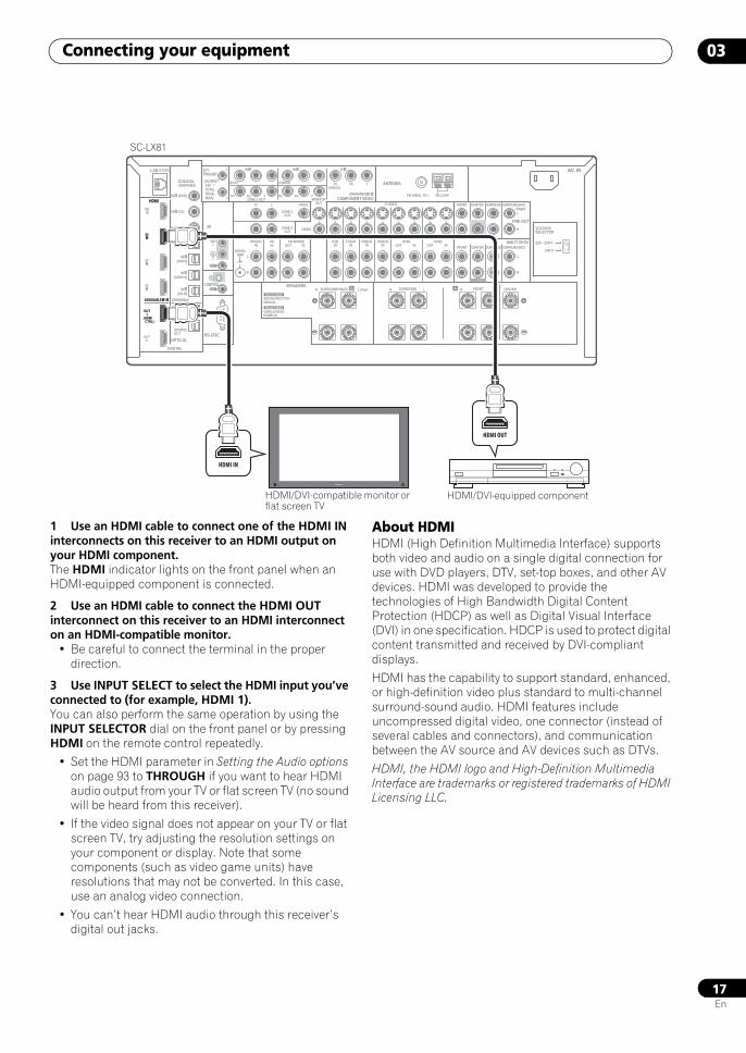
1 Use an HDMI cable to connect one of the HDMI IN interconnects on this receiver to an HDMI output on your HDMI component.The HDMI indicator lights on the front panel when an HDMI-equipped component is connected.
2 Use an HDMI cable to connect the HDMI OUT interconnect on this receiver to an HDMI interconnect on an HDMI-compatible monitor.
• Be careful to connect the terminal in the proper direction.
3 Use INPUT SELECT to select the HDMI input you’ve connected to (for example, HDMI 1).You can also perform the same operation by using the INPUT SELECTOR dial on the front panel or by pressing HDMI on the remote control repeatedly.
• Set the HDMI parameter in Setting the Audio options on page 93 to THROUGH if you want to hear HDMI audio output from your TV or flat screen TV (no sound will be heard from this receiver).
• If the video signal does not appear on your TV or flat screen TV, try adjusting the resolution settings on your component or display. Note that some components (such as video game units) have resolutions that may not be converted. In this case, use an analog video connection.
• You can’t hear HDMI audio through this receiver’s digital out jacks.
About HDMIHDMI (High Definition Multimedia Interface) supports both video and audio on a single digital connection for use with DVD players, DTV, set-top boxes, and other AV devices. HDMI was developed to provide the technologies of High Bandwidth Digital Content Protection (HDCP) as well as Digital Visual Interface (DVI) in one specification. HDCP is used to protect digital content transmitted and received by DVI-compliant displays.
HDMI has the capability to support standard, enhanced, or high-definition video plus standard to multi-channel surround-sound audio. HDMI features include uncompressed digital video, one connector (instead of several cables and connectors), and communication between the AV source and AV devices such as DTVs.
HDMI, the HDMI logo and High-Definition Multimedia Interface are trademarks or registered trademarks of HDMI Licensing LLC.
LAN (10/100)
DIGITAL
SPEAKERS
OPTICALRS-232C
HDMI
COAXIAL
COMPONENT VIDEO
ANTENNA
PRE OUT
MULTI CH IN
A
IR
CONTROL
BDIN
12 VTRIGGER
IN1
IN2
IN3
OUT1
OUT2
SOURCEOUT
ZONE3/SOURCEOUT
31ASSIGNABLE -
31ASSIGNABLE -
(HDMI CTRL)
ASSIGNABLE
ASSIGNABLE
(CD-R)IN 4
(VIDEO1)IN 3
(DVR1)IN 2
(TV/SAT)IN 1
IN 3 (DVR2)
IN 2 (CD)
IN 1 (DVD)
IN 1 IN 2
(OUTPUT 12V TOTAL 50mA MAX)
1
2
IN1
IN
IN2
OUT
OUT
(DVD)
PR PB Y PR PB Y
PR PB Y(VIDEO1)
IN 3
(VIDEO2)
RZONE 2 OUT MONITOR
OUT
PHONOIN
CDIN
DVDIN
TV/SATIN
VIDEO1IN
VIDEO2IN OUT
DVR1IN OUT
DVR2INOUT IN
CD-R/TAPE
SIGNALGND
ZONE 2 OUT
ZONE 3 OUT
VIDEO
VIDEO S-VIDEO FRONT CENTER
SUBWOOFER
SURROUND SURROUND BACK
FRONT CENTER
CENTERLR FRONTB LR SURROUND BACK/ LR SURROUND
SUBWOOFER
SURROUND SURROUND BACK
(Single)
(Single)
L
L
R
SEE INSTRUCTIONMANUAL
L
R
L
R
FM UNBAL 75 AM LOOP
SELECTABLE
VOIR LE MODED'EMPLOI
SELECTABLE
AC IN
220 - 230 V
240 V
VOLTAGESELECTOR
IN1
OUT1
31ASSIGNABLE -
(HDMI CTRL)
HDMI
HDMI IN
HDMI OUT
SC-LX81
HDMI/DVI-equipped componentHDMI/DVI-compatible monitor or flat screen TV
SCLX81_71.book 17 ページ 2008年7月25日 金曜日 午後3時1分
Connecting your equipment03
18En
Connecting your Blu-ray disc player
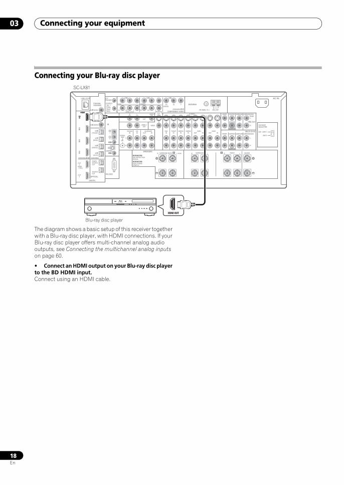
The diagram shows a basic setup of this receiver together with a Blu-ray disc player, with HDMI connections. If your Blu-ray disc player offers multi-channel analog audio outputs, see Connecting the multichannel analog inputs on page 60.
• Connect an HDMI output on your Blu-ray disc player to the BD HDMI input.Connect using an HDMI cable.
LAN (10/100)
DIGITAL
OPTICALRS-232C
HDMI COMPONENT VIDEO
ANTENNA
PRE OUT
MULTI CH IN
A
IR
CONTROL
BDIN
12 VTRIGGER
IN1
IN2
IN3
OUT1
OUT2
SOURCEOUT
ZONE3/SOURCEOUT
31ASSIGNABLE -
31ASSIGNABLE -
(HDMI CTRL)
ASSIGNABLE
(CD-R)IN 4
(VIDEO1)IN 3
(DVR1)IN 2
(TV/SAT)IN 1
IN 3 (DVR2)
IN 2 (CD)
IN 1 (DVD)
IN 1 IN 2
(OUTPUT 12V TOTAL 50mA MAX)
1
2
IN1
IN
IN2
OUT
OUT
(DVD)
PR PB Y PR PB Y
PR PB Y(VIDEO1)
IN 3
(VIDEO2)
RZONE 2 OUT MONITOR
OUT
PHONOIN
CDIN
DVDIN
TV/SATIN
VIDEO1IN
VIDEO2IN OUT
DVR1IN OUT
DVR2INOUT IN
CD-R/TAPE
SIGNALGND
ZONE 2 OUT
ZONE 3 OUT
VIDEO
VIDEO S-VIDEO FRONT CENTER
SUBWOOFER
SURROUND SURROUND BACK
FRONT CENTER
CENTERLR FRONTB LR SURROUND BACK/ LR SURROUND
SUBWOOFER
SURROUND SURROUND BACK
(Single)
(Single)
L
L
R
L
R
L
R
FM UNBAL 75 AM LOOP
SPEAKERS
COAXIALASSIGNABLE
SEE INSTRUCTIONMANUAL
SELECTABLE
VOIR LE MODED'EMPLOI
SELECTABLE
AC IN
220 - 230 V
240 V
VOLTAGESELECTOR
HDMI
BDIN
HDMI OUT
SC-LX81
Blu-ray disc player
SCLX81_71.book 18 ページ 2008年7月25日 金曜日 午後3時1分
Connecting your equipment 03
19En
Connecting your TV and DVD player
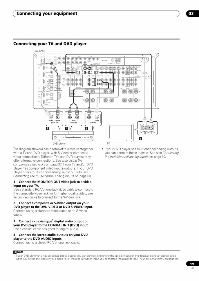
The diagram shows a basic setup of this receiver together with a TV and DVD player, with S-Video or composite video connections. Different TVs and DVD players may offer alternative connections. See also Using the component video jacks on page 22 if your TV and/or DVD player has component video inputs/outputs. If your DVD player offers multichannel analog audio outputs, see Connecting the multichannel analog inputs on page 60.
1 Connect the MONITOR OUT video jack to a video input on your TV.Use a standard RCA/phono jack video cable to connect to the composite video jack, or for higher quality video, use an S-Video cable to connect to the S-Video jack.
2 Connect a composite or S-Video output on your DVD player to the DVD VIDEO or DVD S-VIDEO input.Connect using a standard video cable or an S-Video cable.
3 Connect a coaxial-type1 digital audio output on your DVD player to the COAXIAL IN 1 (DVD) input.Use a coaxial cable designed for digital audio.
4 Connect the stereo audio outputs on your DVD player to the DVD AUDIO inputs.Connect using a stereo RCA/phono jack cable.
• If your DVD player has multichannel analog outputs, you can connect these instead. See also Connecting the multichannel analog inputs on page 60.
LAN (10/100)
DIGITAL
OPTICALRS-232C
HDMI COMPONENT VIDEO
ANTENNA
PRE OUT
MULTI CH IN
A
IR
CONTROL
BDIN
12 VTRIGGER
IN1
IN2
IN3
OUT1
OUT2
SOURCEOUT
ZONE3/SOURCEOUT
31ASSIGNABLE -
31ASSIGNABLE -
(HDMI CTRL)
ASSIGNABLE
(CD-R)IN 4
(VIDEO1)IN 3
(DVR1)IN 2
(TV/SAT)IN 1
IN 3 (DVR2)
IN 2 (CD)
IN 1 (DVD)
IN 1 IN 2
(OUTPUT 12V TOTAL 50mA MAX)
1
2
IN1
IN
IN2
OUT
OUT
(DVD)
PR PB Y PR PB Y
PR PB Y(VIDEO1)
IN 3
(VIDEO2)
RZONE 2 OUT MONITOR
OUT
PHONOIN
CDIN
DVDIN
TV/SATIN
VIDEO1IN
VIDEO2IN OUT
DVR1IN OUT
DVR2INOUT IN
CD-R/TAPE
SIGNALGND
ZONE 2 OUT
ZONE 3 OUT
VIDEO
VIDEO S-VIDEO FRONT CENTER
SUBWOOFER
SURROUND SURROUND BACK
FRONT CENTER
CENTERLR FRONTB LR SURROUND BACK/ LR SURROUND
SUBWOOFER
SURROUND SURROUND BACK
(Single)
(Single)
L
L
R
L
R
L
R
FM UNBAL 75 AM LOOPMONITOR
OUT
DVDIN
VIDEO
IN 1 (DVD)
(DVR1)IN 2
SPEAKERS
COAXIALASSIGNABLE
SEE INSTRUCTIONMANUAL
SELECTABLE
VOIR LE MODED'EMPLOI
SELECTABLE
AC IN
220 - 230 V
240 V
VOLTAGESELECTOR
VIDEOIN
S-VIDEOIN
S-VIDEO
VIDEO OUT
AUDIOR L
ANALOG OUT
OPTICAL
DIGITAL OUT
COAXIAL
1
3 24
SC-LX81
DVD player TV
Note1 If your DVD player only has an optical digital output, you can connect it to one of the optical inputs on this receiver using an optical cable.
When you set up the receiver you’ll need to tell the receiver which input you connected the player to (see The Input Setup menu on page 89).
SCLX81_71.book 19 ページ 2008年7月25日 金曜日 午後3時1分
Connecting your equipment03
20En
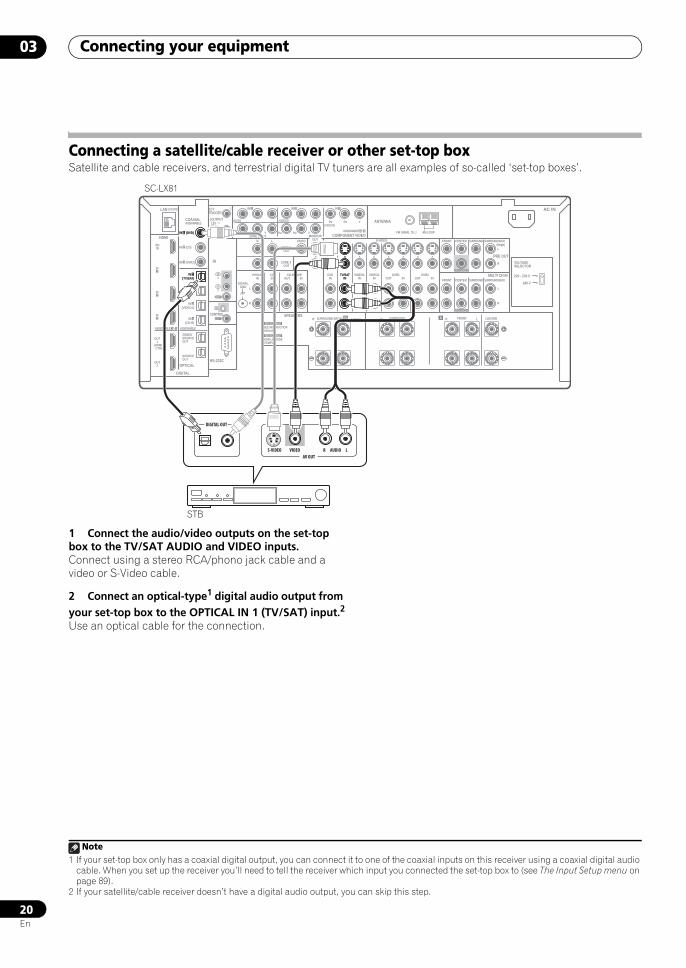
Connecting a satellite/cable receiver or other set-top boxSatellite and cable receivers, and terrestrial digital TV tuners are all examples of so-called ‘set-top boxes’.
1 Connect the audio/video outputs on the set-top box to the TV/SAT AUDIO and VIDEO inputs.Connect using a stereo RCA/phono jack cable and a video or S-Video cable.
2 Connect an optical-type1 digital audio output from your set-top box to the OPTICAL IN 1 (TV/SAT) input.2
Use an optical cable for the connection.
LAN (10/100)
DIGITAL
OPTICALRS-232C
HDMI COMPONENT VIDEO
ANTENNA
PRE OUT
MULTI CH IN
A
IR
CONTROL
BDIN
12 VTRIGGER
IN1
IN2
IN3
OUT1
OUT2
SOURCEOUT
ZONE3/SOURCEOUT
31ASSIGNABLE -
31ASSIGNABLE -
(HDMI CTRL)
ASSIGNABLE
(CD-R)IN 4
(VIDEO1)IN 3
(DVR1)IN 2
(TV/SAT)IN 1
IN 3 (DVR2)
IN 2 (CD)
IN 1 (DVD)
IN 1 IN 2
(OUTPUT 12V TOTAL 50mA MAX)
1
2
IN1
IN
IN2
OUT
OUT
(DVD)
PR PB Y PR PB Y
PR PB Y(VIDEO1)
IN 3
(VIDEO2)
RZONE 2 OUT MONITOR
OUT
PHONOIN
CDIN
DVDIN
TV/SATIN
VIDEO1IN
VIDEO2IN OUT
DVR1IN OUT
DVR2INOUT IN
CD-R/TAPE
SIGNALGND
ZONE 2 OUT
ZONE 3 OUT
VIDEO
VIDEO S-VIDEO FRONT CENTER
SUBWOOFER
SURROUND SURROUND BACK
FRONT CENTER
CENTERLR FRONTB LR SURROUND BACK/ LR SURROUND
SUBWOOFER
SURROUND SURROUND BACK
(Single)
(Single)
L
L
R
L
R
L
R
FM UNBAL 75 AM LOOP
SPEAKERS
COAXIALASSIGNABLE
SEE INSTRUCTIONMANUAL
SELECTABLE
VOIR LE MODED'EMPLOI
SELECTABLE
AC IN
(TV/SAT)IN 1
IN 1 (DVD)
TV/SATIN
DIGITAL OUT
AV OUTVIDEOS-VIDEO AUDIOR L
220 - 230 V
240 V
VOLTAGESELECTOR
SC-LX81
STB
Note1 If your set-top box only has a coaxial digital output, you can connect it to one of the coaxial inputs on this receiver using a coaxial digital audio
cable. When you set up the receiver you’ll need to tell the receiver which input you connected the set-top box to (see The Input Setup menu on page 89).
2 If your satellite/cable receiver doesn’t have a digital audio output, you can skip this step.
SCLX81_71.book 20 ページ 2008年7月25日 金曜日 午後3時1分
Connecting your equipment 03
21En
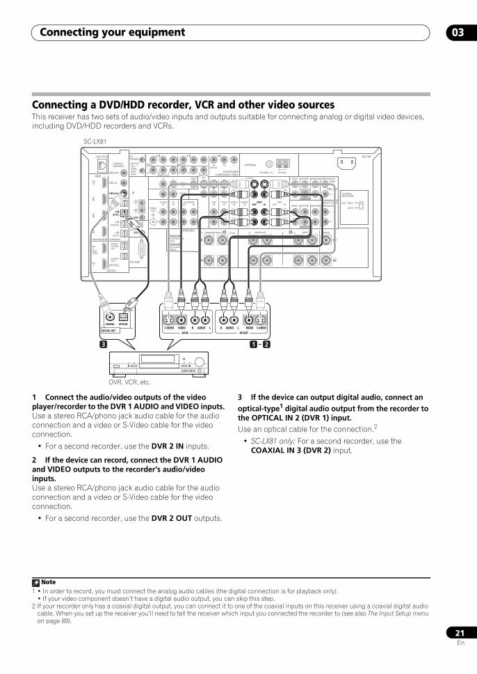
Connecting a DVD/HDD recorder, VCR and other video sources This receiver has two sets of audio/video inputs and outputs suitable for connecting analog or digital video devices, including DVD/HDD recorders and VCRs.
1 Connect the audio/video outputs of the video player/recorder to the DVR 1 AUDIO and VIDEO inputs.Use a stereo RCA/phono jack audio cable for the audio connection and a video or S-Video cable for the video connection.
• For a second recorder, use the DVR 2 IN inputs.
2 If the device can record, connect the DVR 1 AUDIO and VIDEO outputs to the recorder’s audio/video inputs.Use a stereo RCA/phono jack audio cable for the audio connection and a video or S-Video cable for the video connection.
• For a second recorder, use the DVR 2 OUT outputs.
3 If the device can output digital audio, connect an optical-type1 digital audio output from the recorder to the OPTICAL IN 2 (DVR 1) input.Use an optical cable for the connection.2
• SC-LX81 only: For a second recorder, use the COAXIAL IN 3 (DVR 2) input.
LAN (10/100)
DIGITAL
OPTICALRS-232C
HDMI COMPONENT VIDEO
ANTENNA
PRE OUT
MULTI CH IN
A
IR
CONTROL
BDIN
12 VTRIGGER
IN1
IN2
IN3
OUT1
OUT2
SOURCEOUT
ZONE3/SOURCEOUT
31ASSIGNABLE -
31ASSIGNABLE -
(HDMI CTRL)
ASSIGNABLE
(CD-R)IN 4
(VIDEO1)IN 3
(DVR1)IN 2
(TV/SAT)IN 1
IN 3 (DVR2)
IN 2 (CD)
IN 1 (DVD)
IN 1 IN 2
(OUTPUT 12V TOTAL 50mA MAX)
1
2
IN1
IN
IN2
OUT
OUT
(DVD)
PR PB Y PR PB Y
PR PB Y(VIDEO1)
IN 3
(VIDEO2)
RZONE 2 OUT MONITOR
OUT
PHONOIN
CDIN
DVDIN
TV/SATIN
VIDEO1IN
VIDEO2IN OUT
DVR1IN OUT
DVR2INOUT IN
CD-R/TAPE
SIGNALGND
ZONE 2 OUT
ZONE 3 OUT
VIDEO
VIDEO S-VIDEO FRONT CENTER
SUBWOOFER
SURROUND SURROUND BACK
FRONT CENTER
CENTERLR FRONTB LR SURROUND BACK/ LR SURROUND
SUBWOOFER
SURROUND SURROUND BACK
(Single)
(Single)
L
L
R
L
R
L
R
FM UNBAL 75 AM LOOP
SPEAKERS
COAXIALASSIGNABLE
SEE INSTRUCTIONMANUAL
SELECTABLE
VOIR LE MODED'EMPLOI
SELECTABLE
AC IN
220 - 230 V
240 V
VOLTAGESELECTOR
OUTDVR1
IN
1 23
AV OUT
VIDEOAUDIOR L
AV IN
S-VIDEOAUDIOR LVIDEOS-VIDEOOPTICALCOAXIAL
DIGITAL OUT
SC-LX81
DVR, VCR, etc.
Note1 • In order to record, you must connect the analog audio cables (the digital connection is for playback only).
• If your video component doesn’t have a digital audio output, you can skip this step.2 If your recorder only has a coaxial digital output, you can connect it to one of the coaxial inputs on this receiver using a coaxial digital audio
cable. When you set up the receiver you’ll need to tell the receiver which input you connected the recorder to (see also The Input Setup menu on page 89).
SCLX81_71.book 21 ページ 2008年7月25日 金曜日 午後3時1分
Connecting your equipment03
22En
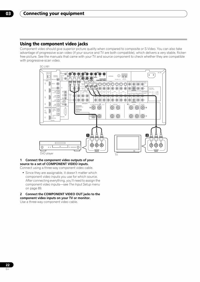
Using the component video jacksComponent video should give superior picture quality when compared to composite or S-Video. You can also take advantage of progressive scan video (if your source and TV are both compatible), which delivers a very stable, flicker-free picture. See the manuals that came with your TV and source component to check whether they are compatible with progressive-scan video.
1 Connect the component video outputs of your source to a set of COMPONENT VIDEO inputs.Connect using a three-way component video cable.
• Since they are assignable, it doesn’t matter which component video inputs you use for which source. After connecting everything, you’ll need to assign the component video inputs—see The Input Setup menu on page 89.
2 Connect the COMPONENT VIDEO OUT jacks to the component video inputs on your TV or monitor.Use a three-way component video cable.
LAN (10/100)
DIGITAL
OPTICALRS-232C
HDMI COMPONENT VIDEO
ANTENNA
PRE OUT
MULTI CH IN
A
IR
CONTROL
BDIN
12 VTRIGGER
IN1
IN2
IN3
OUT1
OUT2
SOURCEOUT
ZONE3/SOURCEOUT
31ASSIGNABLE -
31ASSIGNABLE -
(HDMI CTRL)
ASSIGNABLE
(CD-R)IN 4
(VIDEO1)IN 3
(DVR1)IN 2
(TV/SAT)IN 1
IN 3 (DVR2)
IN 2 (CD)
IN 1 (DVD)
IN 1 IN 2
(OUTPUT 12V TOTAL 50mA MAX)
1
2
IN1
IN
IN2
OUT
OUT
(DVD)
PR PB Y PR PB Y
PR PB Y(VIDEO1)
IN 3
(VIDEO2)
RZONE 2 OUT MONITOR
OUT
PHONOIN
CDIN
DVDIN
TV/SATIN
VIDEO1IN
VIDEO2IN OUT
DVR1IN OUT
DVR2INOUT IN
CD-R/TAPE
SIGNALGND
ZONE 2 OUT
ZONE 3 OUT
VIDEO
VIDEO S-VIDEO FRONT CENTER
SUBWOOFER
SURROUND SURROUND BACK
FRONT CENTER
CENTERLR FRONTB LR SURROUND BACK/ LR SURROUND
SUBWOOFER
SURROUND SURROUND BACK
(Single)
(Single)
L
L
R
L
R
L
R
FM UNBAL 75 AM LOOP
SPEAKERS
COAXIALASSIGNABLE
SEE INSTRUCTIONMANUAL
SELECTABLE
VOIR LE MODED'EMPLOI
SELECTABLE
AC IN
220 - 230 V
240 V
VOLTAGESELECTOR
COMPONENT VIDEO31ASSIGNABLE -
IN 1 IN 2
(DVD)
PR PB Y
PR PB Y(VIDEO1)
IN 3
(VIDEO2)
MONITOROUT
YPBPR
COMPONENTVIDEO OUT
YPBPR
COMPONENTVIDEO IN
1 2
SC-LX81
DVD player TV
SCLX81_71.book 22 ページ 2008年7月25日 金曜日 午後3時1分
Connecting your equipment 03
23En
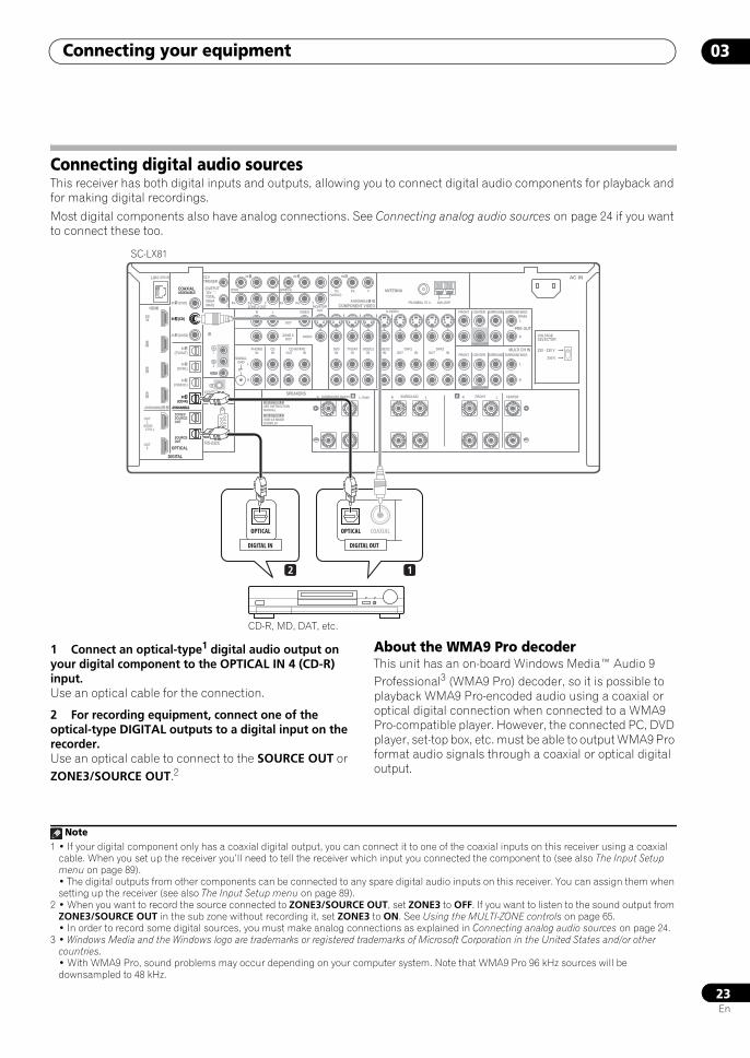
Connecting digital audio sources This receiver has both digital inputs and outputs, allowing you to connect digital audio components for playback and for making digital recordings.
Most digital components also have analog connections. See Connecting analog audio sources on page 24 if you want to connect these too.
1 Connect an optical-type1 digital audio output on your digital component to the OPTICAL IN 4 (CD-R) input.Use an optical cable for the connection.
2 For recording equipment, connect one of the optical-type DIGITAL outputs to a digital input on the recorder.Use an optical cable to connect to the SOURCE OUT or ZONE3/SOURCE OUT.2
About the WMA9 Pro decoderThis unit has an on-board Windows Media™ Audio 9 Professional3 (WMA9 Pro) decoder, so it is possible to playback WMA9 Pro-encoded audio using a coaxial or optical digital connection when connected to a WMA9 Pro-compatible player. However, the connected PC, DVD player, set-top box, etc. must be able to output WMA9 Pro format audio signals through a coaxial or optical digital output.
LAN (10/100)
DIGITAL
OPTICALRS-232C
HDMI COMPONENT VIDEO
ANTENNA
PRE OUT
MULTI CH IN
A
IR
CONTROL
BDIN
12 VTRIGGER
IN1
IN2
IN3
OUT1
OUT2
SOURCEOUT
ZONE3/SOURCEOUT
31ASSIGNABLE -
31ASSIGNABLE -
(HDMI CTRL)
ASSIGNABLE
(CD-R)IN 4
(VIDEO1)IN 3
(DVR1)IN 2
(TV/SAT)IN 1
IN 3 (DVR2)
IN 2 (CD)
IN 1 (DVD)
IN 1 IN 2
(OUTPUT 12V TOTAL 50mA MAX)
1
2
IN1
IN
IN2
OUT
OUT
(DVD)
PR PB Y PR PB Y
PR PB Y(VIDEO1)
IN 3
(VIDEO2)
RZONE 2 OUT MONITOR
OUT
PHONOIN
CDIN
DVDIN
TV/SATIN
VIDEO1IN
VIDEO2IN OUT
DVR1IN OUT
DVR2INOUT IN
CD-R/TAPE
SIGNALGND
ZONE 2 OUT
ZONE 3 OUT
VIDEO
VIDEO S-VIDEO FRONT CENTER
SUBWOOFER
SURROUND SURROUND BACK
FRONT CENTER
CENTERLR FRONTB LR SURROUND BACK/ LR SURROUND
SUBWOOFER
SURROUND SURROUND BACK
(Single)
(Single)
L
L
R
L
R
L
R
FM UNBAL 75 AM LOOP
SPEAKERS
COAXIALASSIGNABLE
SEE INSTRUCTIONMANUAL
SELECTABLE
VOIR LE MODED'EMPLOI
SELECTABLE
AC IN
220 - 230 V
240 V
VOLTAGESELECTOR
IN 2 (CD)
ASSIGNABLE
(CD-R)IN 4
ZONE3/SOURCEOUT
12
OPTICAL COAXIAL
DIGITAL OUT
OPTICAL
DIGITAL IN
SC-LX81
CD-R, MD, DAT, etc.
Note1 • If your digital component only has a coaxial digital output, you can connect it to one of the coaxial inputs on this receiver using a coaxial
cable. When you set up the receiver you’ll need to tell the receiver which input you connected the component to (see also The Input Setup menu on page 89).• The digital outputs from other components can be connected to any spare digital audio inputs on this receiver. You can assign them when setting up the receiver (see also The Input Setup menu on page 89).
2 • When you want to record the source connected to ZONE3/SOURCE OUT, set ZONE3 to OFF. If you want to listen to the sound output from ZONE3/SOURCE OUT in the sub zone without recording it, set ZONE3 to ON. See Using the MULTI-ZONE controls on page 65.• In order to record some digital sources, you must make analog connections as explained in Connecting analog audio sources on page 24.
3 • Windows Media and the Windows logo are trademarks or registered trademarks of Microsoft Corporation in the United States and/or other countries.• With WMA9 Pro, sound problems may occur depending on your computer system. Note that WMA9 Pro 96 kHz sources will be downsampled to 48 kHz.
SCLX81_71.book 23 ページ 2008年7月25日 金曜日 午後3時1分
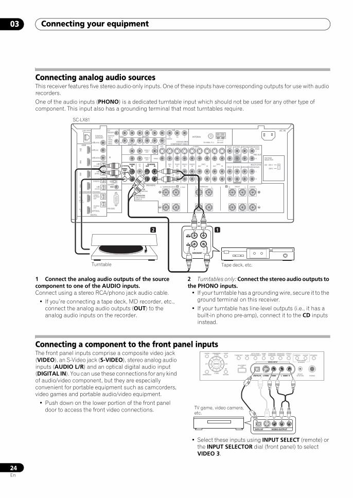
Connecting your equipment03
24En
Connecting analog audio sourcesThis receiver features five stereo audio-only inputs. One of these inputs have corresponding outputs for use with audio recorders.
One of the audio inputs (PHONO) is a dedicated turntable input which should not be used for any other type of component. This input also has a grounding terminal that most turntables require.
1 Connect the analog audio outputs of the source component to one of the AUDIO inputs.Connect using a stereo RCA/phono jack audio cable.
• If you’re connecting a tape deck, MD recorder, etc., connect the analog audio outputs (OUT) to the analog audio inputs on the recorder.
2 Turntables only: Connect the stereo audio outputs to the PHONO inputs.
• If your turntable has a grounding wire, secure it to the ground terminal on this receiver.
• If your turntable has line-level outputs (i.e., it has a built-in phono pre-amp), connect it to the CD inputs instead.
Connecting a component to the front panel inputsThe front panel inputs comprise a composite video jack (VIDEO), an S-Video jack (S-VIDEO), stereo analog audio inputs (AUDIO L/R) and an optical digital audio input (DIGITAL IN). You can use these connections for any kind of audio/video component, but they are especially convenient for portable equipment such as camcorders, video games and portable audio/video equipment.
• Push down on the lower portion of the front panel door to access the front video connections.
• Select these inputs using INPUT SELECT (remote) or the INPUT SELECTOR dial (front panel) to select VIDEO 3.
LAN (10/100)
DIGITAL
OPTICALRS-232C
HDMI COMPONENT VIDEO
ANTENNA
PRE OUT
MULTI CH IN
A
IR
CONTROL
BDIN
12 VTRIGGER
IN1
IN2
IN3
OUT1
OUT2
SOURCEOUT
ZONE3/SOURCEOUT
31ASSIGNABLE -
31ASSIGNABLE -
(HDMI CTRL)
ASSIGNABLE
(CD-R)IN 4
(VIDEO1)IN 3
(DVR1)IN 2
(TV/SAT)IN 1
IN 3 (DVR2)
IN 2 (CD)
IN 1 (DVD)
IN 1 IN 2
(OUTPUT 12V TOTAL 50mA MAX)
1
2
IN1
IN
IN2
OUT
OUT
(DVD)
PR PB Y PR PB Y
PR PB Y(VIDEO1)
IN 3
(VIDEO2)
RZONE 2 OUT MONITOR
OUT
PHONOIN
CDIN
DVDIN
TV/SATIN
VIDEO1IN
VIDEO2IN OUT
DVR1IN OUT
DVR2INOUT IN
CD-R/TAPE
SIGNALGND
ZONE 2 OUT
ZONE 3 OUT
VIDEO
VIDEO S-VIDEO FRONT CENTER
SUBWOOFER
SURROUND SURROUND BACK
FRONT CENTER
CENTERLR FRONTB LR SURROUND BACK/ LR SURROUND
SUBWOOFER
SURROUND SURROUND BACK
(Single)
(Single)
L
L
R
L
R
L
R
FM UNBAL 75 AM LOOP
SPEAKERS
COAXIALASSIGNABLE
SEE INSTRUCTIONMANUAL
SELECTABLE
VOIR LE MODED'EMPLOI
SELECTABLE
AC IN
PHONOIN OUT IN
CD-R/TAPE
SIGNALGND L
R
PLAYOUT
INREC
R L
AUDIO IN/OUT
2 1
220 - 230 V
240 V
VOLTAGESELECTOR
SC-LX81
Turntable Tape deck, etc.
VIDEO3 INPUT
DIGITAL IN S-VIDEO VIDEO L RAUDIO PHONES
SPEAKERSCONTROL
MULTI-ZONE& SOURCE
ON/OFF
MCACCSETUP MIC
PARAMETER
ENTER
(TUNE)
(TUNE)
(ST)(ST)
AUDIO VIDEOTUNER EDIT
iPod DIRECTUSB
AUTO SURR/STREAM DIRECT
HOMETHX
STANDARDSURROUND
ADVANCEDSURROUND
STEREO/A.L.C.BAND
HOME MENU RETURN
VIDEO3 INPUT
DIGITAL IN S-VIDEO VIDEO L RAUDIO
VIDEO OUTPUTDIGITAL OUT
TV game, video camera, etc.
SCLX81_71.book 24 ページ 2008年7月25日 金曜日 午後3時1分
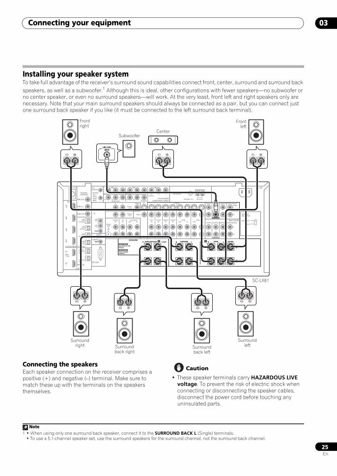
Connecting your equipment 03
25En
Installing your speaker systemTo take full advantage of the receiver’s surround sound capabilities connect front, center, surround and surround back speakers, as well as a subwoofer.1 Although this is ideal, other configurations with fewer speakers—no subwoofer or no center speaker, or even no surround speakers—will work. At the very least, front left and right speakers only are necessary. Note that your main surround speakers should always be connected as a pair, but you can connect just one surround back speaker if you like (it must be connected to the left surround back terminal).
Connecting the speakersEach speaker connection on the receiver comprises a positive (+) and negative (–) terminal. Make sure to match these up with the terminals on the speakers themselves.
Caution
• These speaker terminals carry HAZARDOUS LIVE voltage. To prevent the risk of electric shock when connecting or disconnecting the speaker cables, disconnect the power cord before touching any uninsulated parts.
Note1 • When using only one surround back speaker, connect it to the SURROUND BACK L (Single) terminals.
• To use a 5.1-channel speaker set, use the surround speakers for the surround channel, not the surround back channel.
LAN (10/100)
DIGITAL
OPTICALRS-232C
HDMI COMPONENT VIDEO
ANTENNA
PRE OUT
MULTI CH IN
A
IR
CONTROL
BDIN
12 VTRIGGER
IN1
IN2
IN3
OUT1
OUT2
SOURCEOUT
ZONE3/SOURCEOUT
31ASSIGNABLE -
31ASSIGNABLE -
(HDMI CTRL)
ASSIGNABLE
(CD-R)IN 4
(VIDEO1)IN 3
(DVR1)IN 2
(TV/SAT)IN 1
IN 3 (DVR2)
IN 2 (CD)
IN 1 (DVD)
IN 1 IN 2
(OUTPUT 12V TOTAL 50mA MAX)
1
2
IN1
IN
IN2
OUT
OUT
(DVD)
PR PB Y PR PB Y
PR PB Y(VIDEO1)
IN 3
(VIDEO2)
RZONE 2 OUT MONITOR
OUT
PHONOIN
CDIN
DVDIN
TV/SATIN
VIDEO1IN
VIDEO2IN OUT
DVR1IN OUT
DVR2INOUT IN
CD-R/TAPE
SIGNALGND
ZONE 2 OUT
ZONE 3 OUT
VIDEO
VIDEO S-VIDEO FRONT CENTER
SUBWOOFER
SURROUND SURROUND BACK
FRONT CENTER
CENTERLR FRONTB LR SURROUND BACK/ LR SURROUND
SUBWOOFER
SURROUND SURROUND BACK
(Single)
(Single)
L
L
R
L
R
L
R
FM UNBAL 75 AM LOOP
SPEAKERS
COAXIALASSIGNABLE
SEE INSTRUCTIONMANUAL
SELECTABLE
VOIR LE MODED'EMPLOI
SELECTABLE
AC IN
220 - 230 V
240 V
VOLTAGESELECTOR
A CENTERLR FRONTB LR SURROUND BACK/ LR SURROUND(Single)
SUBWOOFER
LINE LEVELINPUT
Front right
Frontleft
SubwooferCenter
SC-LX81
Surround left
Surround right Surround
back rightSurround back left
SCLX81_71.book 25 ページ 2008年7月25日 金曜日 午後3時1分
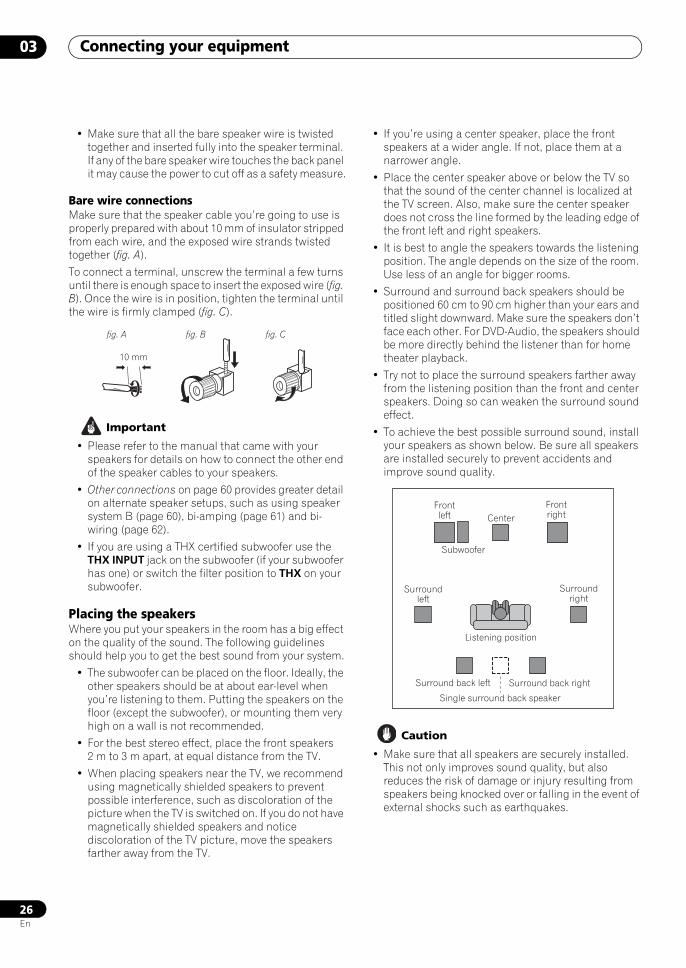
Connecting your equipment03
26En
• Make sure that all the bare speaker wire is twisted together and inserted fully into the speaker terminal. If any of the bare speaker wire touches the back panel it may cause the power to cut off as a safety measure.
Bare wire connectionsMake sure that the speaker cable you’re going to use is properly prepared with about 10 mm of insulator stripped from each wire, and the exposed wire strands twisted together (fig. A).
To connect a terminal, unscrew the terminal a few turns until there is enough space to insert the exposed wire (fig. B). Once the wire is in position, tighten the terminal until the wire is firmly clamped (fig. C).
Important
• Please refer to the manual that came with your speakers for details on how to connect the other end of the speaker cables to your speakers.
• Other connections on page 60 provides greater detail on alternate speaker setups, such as using speaker system B (page 60), bi-amping (page 61) and bi-wiring (page 62).
• If you are using a THX certified subwoofer use the THX INPUT jack on the subwoofer (if your subwoofer has one) or switch the filter position to THX on your subwoofer.
Placing the speakersWhere you put your speakers in the room has a big effect on the quality of the sound. The following guidelines should help you to get the best sound from your system.
• The subwoofer can be placed on the floor. Ideally, the other speakers should be at about ear-level when you’re listening to them. Putting the speakers on the floor (except the subwoofer), or mounting them very high on a wall is not recommended.
• For the best stereo effect, place the front speakers 2 m to 3 m apart, at equal distance from the TV.
• When placing speakers near the TV, we recommend using magnetically shielded speakers to prevent possible interference, such as discoloration of the picture when the TV is switched on. If you do not have magnetically shielded speakers and notice discoloration of the TV picture, move the speakers farther away from the TV.
• If you’re using a center speaker, place the front speakers at a wider angle. If not, place them at a narrower angle.
• Place the center speaker above or below the TV so that the sound of the center channel is localized at the TV screen. Also, make sure the center speaker does not cross the line formed by the leading edge of the front left and right speakers.
• It is best to angle the speakers towards the listening position. The angle depends on the size of the room. Use less of an angle for bigger rooms.
• Surround and surround back speakers should be positioned 60 cm to 90 cm higher than your ears and titled slight downward. Make sure the speakers don’t face each other. For DVD-Audio, the speakers should be more directly behind the listener than for home theater playback.
• Try not to place the surround speakers farther away from the listening position than the front and center speakers. Doing so can weaken the surround sound effect.
• To achieve the best possible surround sound, install your speakers as shown below. Be sure all speakers are installed securely to prevent accidents and improve sound quality.
Caution
• Make sure that all speakers are securely installed. This not only improves sound quality, but also reduces the risk of damage or injury resulting from speakers being knocked over or falling in the event of external shocks such as earthquakes.
fig. A fig. B fig. C
10 mm
CenterFront left
Front right
Surround left
Surround right
Listening position
Single surround back speaker
Surround back left Surround back right
Subwoofer
SCLX81_71.book 26 ページ 2008年7月25日 金曜日 午後3時1分
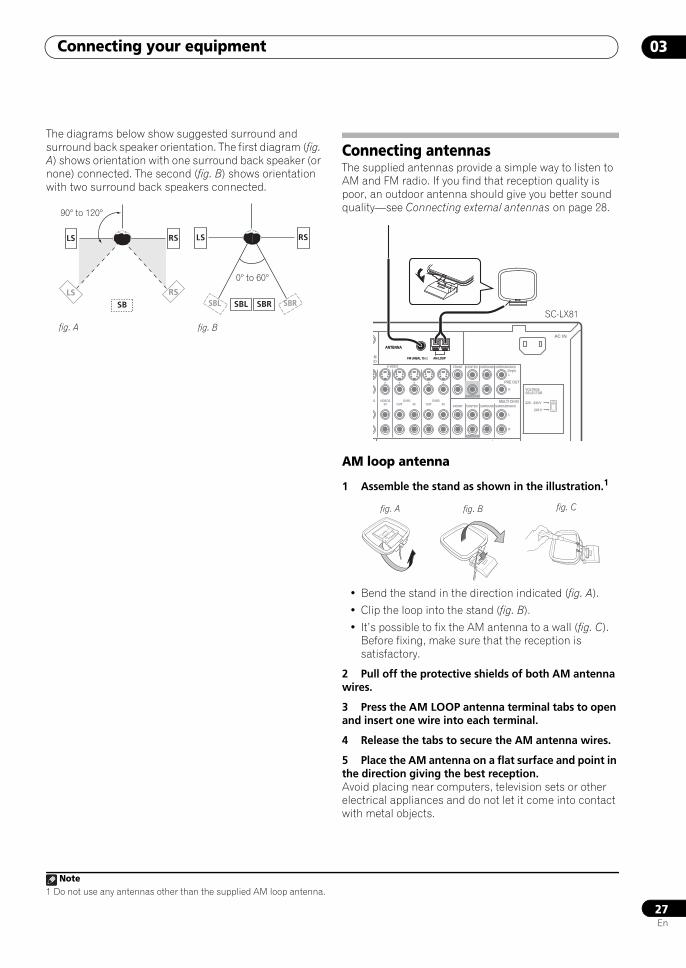
Connecting your equipment 03
27En
The diagrams below show suggested surround and surround back speaker orientation. The first diagram (fig. A) shows orientation with one surround back speaker (or none) connected. The second (fig. B) shows orientation with two surround back speakers connected.
Connecting antennasThe supplied antennas provide a simple way to listen to AM and FM radio. If you find that reception quality is poor, an outdoor antenna should give you better sound quality—see Connecting external antennas on page 28.
AM loop antenna
1 Assemble the stand as shown in the illustration.1
• Bend the stand in the direction indicated (fig. A).
• Clip the loop into the stand (fig. B).
• It’s possible to fix the AM antenna to a wall (fig. C). Before fixing, make sure that the reception is satisfactory.
2 Pull off the protective shields of both AM antenna wires.
3 Press the AM LOOP antenna terminal tabs to open and insert one wire into each terminal.
4 Release the tabs to secure the AM antenna wires.
5 Place the AM antenna on a flat surface and point in the direction giving the best reception.Avoid placing near computers, television sets or other electrical appliances and do not let it come into contact with metal objects.
LS
LS
RS
RS
SB
LS RS
SBL SBL SBRSBR
90° to 120°
0° to 60°
fig. A fig. B
Note1 Do not use any antennas other than the supplied AM loop antenna.
EO
ANTENNA
PRE OUT
MULTI CH IN
3-
O1 VIDEO2IN OUT
DVR1IN OUT
DVR2IN
S-VIDEO FRONT CENTER
SUBWOOFER
SURROUND SURROUND BACK
FRONT CENTER
SUBWOOFER
SURROUND SURROUND BACK
(Single)
L
R
L
R
FM UNBAL 75 AM LOOP
AC IN
220 - 230 V
240 V
VOLTAGESELECTOR
ANTENNA
FM UNBAL 75 AM LOOP
SC-LX81
fig. A fig. B fig. C
SCLX81_71.book 27 ページ 2008年7月25日 金曜日 午後3時1分
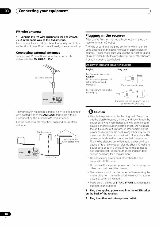
Connecting your equipment03
28En
FM wire antenna
• Connect the FM wire antenna to the FM UNBAL 75 Ω in the same way as the AM antenna.For best results, extend the FM antenna fully and fix to a wall or door frame. Don’t drape loosely or leave coiled up.
Connecting external antennasTo improve FM reception connect an external FM antenna to the FM UNBAL 75 Ω.
To improve AM reception, connect a 5 m to 6 m length of vinyl-coated wire to the AM LOOP terminals without disconnecting the supplied AM loop antenna.
For the best possible reception, suspend horizontally outdoors.
Plugging in the receiverAfter you’ve finished making all connections, plug the receiver into an AC outlet.
The type of cord and the plug converter which can be used depends on the power voltage in each region or country. Please make sure you use the correct cord and plug converter due to the possibility of fire or other hazard if used incorrectly (see below).
Caution
• Handle the power cord by the plug part. Do not pull out the plug by tugging the cord, and never touch the power cord when your hands are wet, as this could cause a short circuit or electric shock. Do not place the unit, a piece of furniture, or other object on the power cord or pinch the cord in any other way. Never make a knot in the cord or tie it with other cables. The power cords should be routed so that they are not likely to be stepped on. A damaged power cord can cause a fire or give you an electric shock. Check the power cord once in a while. If you find it damaged, ask your nearest Pioneer authorized independent service company for a replacement.
• Do not use any power cord other than the one supplied with this unit.
• Do not use the supplied power cord for any purpose other than that described below.
• The receiver should be disconnected by removing the mains plug from the wall socket when not in regular use, e.g., when on vacation.
• Make sure the blue STANDBY/ON light has gone out before unplugging.
1 Plug the supplied power cord into the AC IN socket on the back of the receiver.
2 Plug the other end into a power outlet.
FM UNBAL 75 Ω AM LOOP
ANTENNA
75 Ω coaxial cable
FM UNBAL 75 Ω AM LOOP
ANTENNA
Outdoor antenna
5 m to 6 m
Indoor antenna (vinyl-coated wire)
AC power cord and converter plug use
Region Plug type
For European type regionCautionDo not use this power cord set in Singapore and Malaysia. European two-pin plug
For regions with two pin flat-bladed plug
European two-pin plug with two-pin flat-bladed converter plug
SCLX81_71.book 28 ページ 2008年7月25日 金曜日 午後3時1分
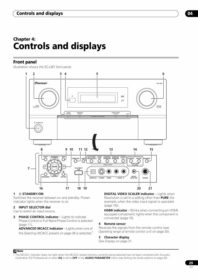
Controls and displays 04
29En
Chapter 4:
Controls and displays
Front panelIllustration shows the SC-LX81 front panel.
1 STANDBY/ON Switches the receiver between on and standby. Power indicator lights when the receiver is on.
2 INPUT SELECTOR dialUse to select an input source.
3 PHASE CONTROL indicator – Lights to indicate Phase Control or Full Band Phase Control is selected (page 11).ADVANCED MCACC indicator – Lights when one of the Selecting MCACC presets on page 38 is selected.1
DIGITAL VIDEO SCALER indicator – Lights when Resolution is set to a setting other than PURE (for example, when the video input signal is upscaled (page 16)).
HDMI indicator – Blinks when connecting an HDMI-equipped component; lights when the component is connected (page 16).
4 Remote sensorReceives the signals from the remote control (see Operating range of remote control unit on page 30).
5 Character displaySee Display on page 31.
STANDBY/ON
INPUTSELECTOR
PHASECONTROL
ADVANCEDMCACC
DIGITAL VIDEOSCALER HDMI
MASTERVOLUME
SC-LX81
VIDEO3 INPUT
DIGITAL IN S-VIDEO VIDEO L RAUDIO PHONES
SPEAKERSCONTROL
MULTI-ZONE& SOURCE
ON/OFF
MCACCSETUP MIC
PARAMETER
ENTER
(TUNE)
(TUNE)
(ST)(ST)
AUDIO VIDEOTUNER EDIT
iPod DIRECTUSB
AUTO SURR/STREAM DIRECT
HOMETHX
STANDARDSURROUND
ADVANCEDSURROUND
STEREO/A.L.C.BAND
HOME MENU RETURN
1
7
2 3
8
16 17
9 11 12 151410
4 5 6
13
20 211918
Note1 The MCACC indicator does not light when the MCACC preset memory currently being selected has not been corrected with Acoustic
Calibration EQ Professional or when EQ is set to OFF in the AUDIO PARAMETER menu (see Setting the Audio options on page 93).
SCLX81_71.book 29 ページ 2008年7月25日 金曜日 午後3時1分
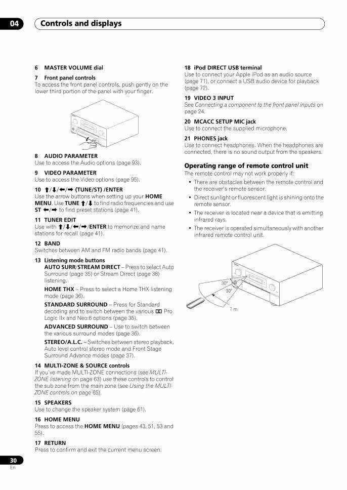
Controls and displays04
30En
6 MASTER VOLUME dial
7 Front panel controlsTo access the front panel controls, push gently on the lower third portion of the panel with your finger.
8 AUDIO PARAMETERUse to access the Audio options (page 93).
9 VIDEO PARAMETERUse to access the Video options (page 95).
10 /// (TUNE/ST) /ENTERUse the arrow buttons when setting up your HOME MENU. Use TUNE / to find radio frequencies and use ST / to find preset stations (page 41).
11 TUNER EDITUse with ////ENTER to memorize and name stations for recall (page 41).
12 BANDSwitches between AM and FM radio bands (page 41).
13 Listening mode buttonsAUTO SURR/STREAM DIRECT – Press to select Auto Surround (page 35) or Stream Direct (page 38) listening.
HOME THX – Press to select a Home THX listening mode (page 36).
STANDARD SURROUND – Press for Standard decoding and to switch between the various 2 Pro Logic IIx and Neo:6 options (page 35).
ADVANCED SURROUND – Use to switch between the various surround modes (page 36).
STEREO/A.L.C. – Switches between stereo playback, Auto level control stereo mode and Front Stage Surround Advance modes (page 37).
14 MULTI-ZONE & SOURCE controlsIf you’ve made MULTI-ZONE connections (see MULTI-ZONE listening on page 63) use these controls to control the sub zone from the main zone (see Using the MULTI-ZONE controls on page 65).
15 SPEAKERSUse to change the speaker system (page 61).
16 HOME MENUPress to access the HOME MENU (pages 43, 51, 53 and 55).
17 RETURN Press to confirm and exit the current menu screen.
18 iPod DIRECT USB terminalUse to connect your Apple iPod as an audio source (page 71), or connect a USB audio device for playback (page 72).
19 VIDEO 3 INPUTSee Connecting a component to the front panel inputs on page 24.
20 MCACC SETUP MIC jackUse to connect the supplied microphone.
21 PHONES jackUse to connect headphones. When the headphones are connected, there is no sound output from the speakers.
Operating range of remote control unitThe remote control may not work properly if:
• There are obstacles between the remote control and the receiver’s remote sensor.
• Direct sunlight or fluorescent light is shining onto the remote sensor.
• The receiver is located near a device that is emitting infrared rays.
• The receiver is operated simultaneously with another infrared remote control unit.
STANDBY/ON
INPUTSELECTOR
PHASECONTROLADVANCEDMCACC
DIGITAL VIDEOSCALER
HDMI
MASTERVOLUME
STANDBY/ON
INPUTSELECTOR
PHASECONTROLADVANCEDMCACC
DIGITAL VIDEOSCALER
HDMI
MASTERVOLUME
7 m
30°
30°
SCLX81_71.book 30 ページ 2008年7月25日 金曜日 午後3時1分
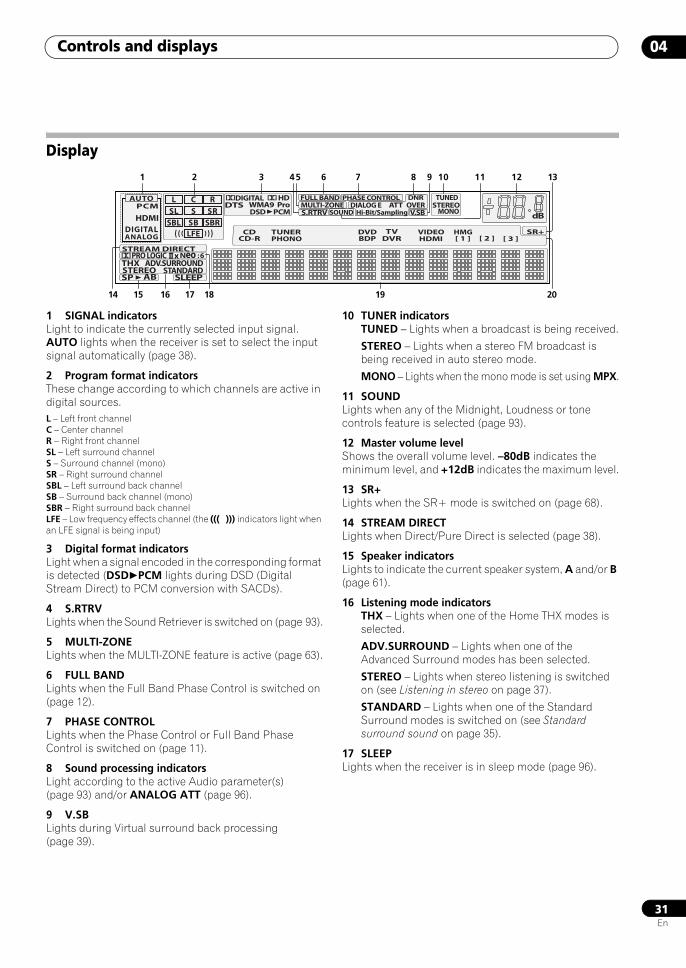
Controls and displays 04
31En
Display
1 SIGNAL indicatorsLight to indicate the currently selected input signal. AUTO lights when the receiver is set to select the input signal automatically (page 38).
2 Program format indicatorsThese change according to which channels are active in digital sources.L – Left front channelC – Center channelR – Right front channelSL – Left surround channelS – Surround channel (mono)SR – Right surround channelSBL – Left surround back channelSB – Surround back channel (mono)SBR – Right surround back channelLFE – Low frequency effects channel (the ((( ))) indicators light when an LFE signal is being input)
3 Digital format indicatorsLight when a signal encoded in the corresponding format is detected (DSDPCM lights during DSD (Digital Stream Direct) to PCM conversion with SACDs).
4 S.RTRVLights when the Sound Retriever is switched on (page 93).
5 MULTI-ZONELights when the MULTI-ZONE feature is active (page 63).
6 FULL BANDLights when the Full Band Phase Control is switched on (page 12).
7 PHASE CONTROLLights when the Phase Control or Full Band Phase Control is switched on (page 11).
8 Sound processing indicatorsLight according to the active Audio parameter(s) (page 93) and/or ANALOG ATT (page 96).
9 V.SBLights during Virtual surround back processing (page 39).
10 TUNER indicatorsTUNED – Lights when a broadcast is being received.
STEREO – Lights when a stereo FM broadcast is being received in auto stereo mode.
MONO – Lights when the mono mode is set using MPX.
11 SOUNDLights when any of the Midnight, Loudness or tone controls feature is selected (page 93).
12 Master volume levelShows the overall volume level. –80dB indicates the minimum level, and +12dB indicates the maximum level.
13 SR+Lights when the SR+ mode is switched on (page 68).
14 STREAM DIRECTLights when Direct/Pure Direct is selected (page 38).
15 Speaker indicators Lights to indicate the current speaker system, A and/or B (page 61).
16 Listening mode indicatorsTHX – Lights when one of the Home THX modes is selected.
ADV.SURROUND – Lights when one of the Advanced Surround modes has been selected.
STEREO – Lights when stereo listening is switched on (see Listening in stereo on page 37).
STANDARD – Lights when one of the Standard Surround modes is switched on (see Standard surround sound on page 35).
17 SLEEPLights when the receiver is in sleep mode (page 96).
STREAM DIRECT
HDMI
PCML C R
SL S SRSBL SB
LFESBR
AUTO
ADV.SURROUNDSTANDARD
SLEEP
THXSTEREOSP AB
DIGITAL
PRO LOGIC
DIGITALWMA9 Pro
SR+
DTS OVERATTS.RTRV MONO
dBDIALOG E
PHASE CONTROLSTEREO
V.SB
TUNED
Neo : 62
2
ANALOG
FULL BANDMULTI-ZONE
2HD
AAC DSD PCM
DNR
SOUND Hi-Bit/Sampling
HMGVIDEOTVDVDHDMIDVRBDP
CD TUNERCD-R PHONO [ 1 ] [ 2 ] [ 3 ]
21 3 8765 10 11 12 13
191514 17 2018
4 9
16
SCLX81_71.book 31 ページ 2008年7月25日 金曜日 午後3時1分
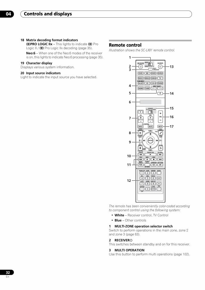
Controls and displays04
32En
18 Matrix decoding format indicators2PRO LOGIC IIx – This lights to indicate 2 Pro Logic II / 2 Pro Logic IIx decoding (page 35).
Neo:6 – When one of the Neo:6 modes of the receiver is on, this lights to indicate Neo:6 processing (page 35).
19 Character displayDisplays various system information.
20 Input source indicatorsLight to indicate the input source you have selected.
Remote controlIllustration shows the SC-LX81 remote control.
The remote has been conveniently color-coded according to component control using the following system:
• White – Receiver control, TV Control
• Blue – Other controls
1 MULTI-ZONE operation selector switchSwitch to perform operations in the main zone, zone 2 and zone 3 (page 63).
2 RECEIVERThis switches between standby and on for this receiver.
3 MULTI OPERATIONUse this button to perform multi operations (page 102).
DVD
RECEIVER SOURCEMAIN
MULTIOPERATION
AUDIOPARAMETER
TOP MENUBAND
iPod CTRL
PTYSEARCH
EXIT TOOLS
HOMEMENU
STATUS
THX MPX EON
PHASE CTRL CH LEVEL
MENUT.EDIT
VIDEOPARAMETER
ZONE2
SOURCETV RCV
3
VIDEO1
GALLERYHOME MEDIA
INPUT SELECT
CD
HDMI
INPUT MUTE
TUNE +
ST +
MUTE
PGM
VOLVOL
TV CONTROL
CH
STEREO/A.L.C.
BD MENU
SIGNAL SEL SLEEP AUDIODIMMER
SR+
CLR
SBch MCACC
A.ATT GENRE HDMI OUT
D.ACCESS
ENTER
CLASS
DISP
CH
AUTO/DIRECT STANDARD ADV SURR
TUNER
PHONO
VIDEO2 VIDEO3 TV
BD DVR1 DVR2
CD-R
ENTER
RETURN
TUNE
ST
2 13
14
15
16
17
3
4
6
7
8
9
10
11
12
1
5
SCLX81_71.book 32 ページ 2008年7月25日 金曜日 午後3時1分
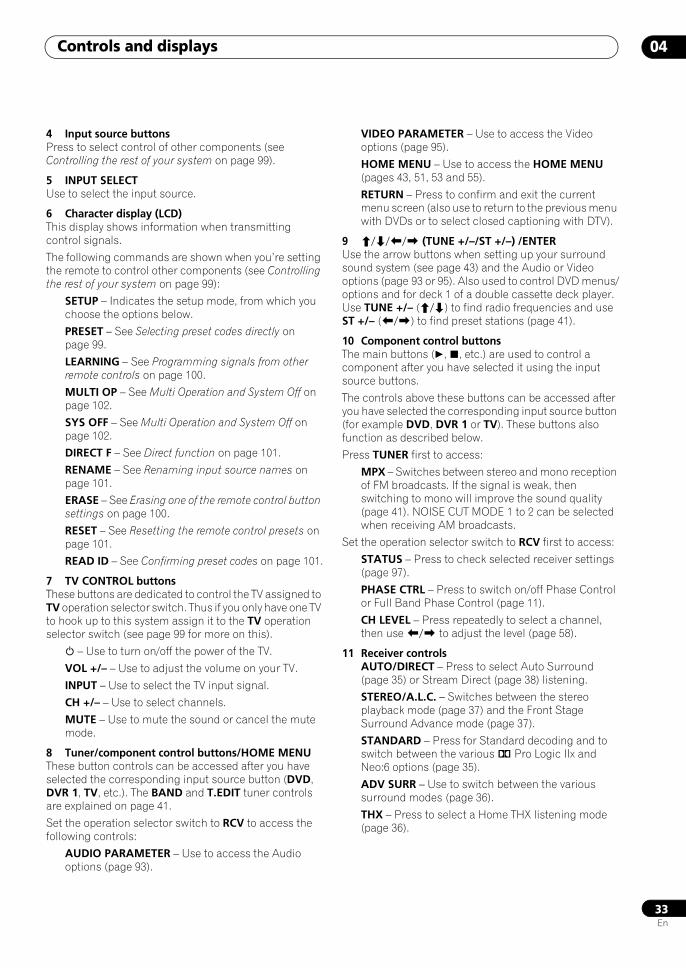
Controls and displays 04
33En
4 Input source buttonsPress to select control of other components (see Controlling the rest of your system on page 99).
5 INPUT SELECTUse to select the input source.
6 Character display (LCD)This display shows information when transmitting control signals.
The following commands are shown when you’re setting the remote to control other components (see Controlling the rest of your system on page 99):
SETUP – Indicates the setup mode, from which you choose the options below.
PRESET – See Selecting preset codes directly on page 99.
LEARNING – See Programming signals from other remote controls on page 100.
MULTI OP – See Multi Operation and System Off on page 102.
SYS OFF – See Multi Operation and System Off on page 102.
DIRECT F – See Direct function on page 101.
RENAME – See Renaming input source names on page 101.
ERASE – See Erasing one of the remote control button settings on page 100.
RESET – See Resetting the remote control presets on page 101.
READ ID – See Confirming preset codes on page 101.
7 TV CONTROL buttonsThese buttons are dedicated to control the TV assigned to TV operation selector switch. Thus if you only have one TV to hook up to this system assign it to the TV operation selector switch (see page 99 for more on this).
– Use to turn on/off the power of the TV.
VOL +/– – Use to adjust the volume on your TV.
INPUT – Use to select the TV input signal.
CH +/– – Use to select channels.
MUTE – Use to mute the sound or cancel the mute mode.
8 Tuner/component control buttons/HOME MENUThese button controls can be accessed after you have selected the corresponding input source button (DVD, DVR 1, TV, etc.). The BAND and T.EDIT tuner controls are explained on page 41.
Set the operation selector switch to RCV to access the following controls:
AUDIO PARAMETER – Use to access the Audio options (page 93).
VIDEO PARAMETER – Use to access the Video options (page 95).
HOME MENU – Use to access the HOME MENU (pages 43, 51, 53 and 55).
RETURN – Press to confirm and exit the current menu screen (also use to return to the previous menu with DVDs or to select closed captioning with DTV).
9 /// (TUNE +/–/ST +/–) /ENTERUse the arrow buttons when setting up your surround sound system (see page 43) and the Audio or Video options (page 93 or 95). Also used to control DVD menus/options and for deck 1 of a double cassette deck player. Use TUNE +/– (/) to find radio frequencies and use ST +/– (/) to find preset stations (page 41).
10 Component control buttonsThe main buttons (, , etc.) are used to control a component after you have selected it using the input source buttons.
The controls above these buttons can be accessed after you have selected the corresponding input source button (for example DVD, DVR 1 or TV). These buttons also function as described below.
Press TUNER first to access:
MPX – Switches between stereo and mono reception of FM broadcasts. If the signal is weak, then switching to mono will improve the sound quality (page 41). NOISE CUT MODE 1 to 2 can be selected when receiving AM broadcasts.
Set the operation selector switch to RCV first to access:
STATUS – Press to check selected receiver settings (page 97).
PHASE CTRL – Press to switch on/off Phase Control or Full Band Phase Control (page 11).
CH LEVEL – Press repeatedly to select a channel, then use / to adjust the level (page 58).
11 Receiver controlsAUTO/DIRECT – Press to select Auto Surround (page 35) or Stream Direct (page 38) listening.
STEREO/A.L.C. – Switches between the stereo playback mode (page 37) and the Front Stage Surround Advance mode (page 37).
STANDARD – Press for Standard decoding and to switch between the various 2 Pro Logic IIx and Neo:6 options (page 35).
ADV SURR – Use to switch between the various surround modes (page 36).
THX – Press to select a Home THX listening mode (page 36).
SCLX81_71.book 33 ページ 2008年7月25日 金曜日 午後3時1分
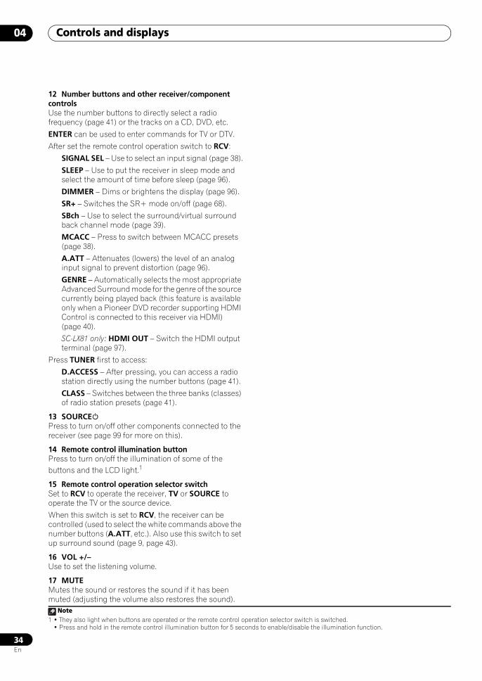
Controls and displays04
34En
12 Number buttons and other receiver/component controlsUse the number buttons to directly select a radio frequency (page 41) or the tracks on a CD, DVD, etc.
ENTER can be used to enter commands for TV or DTV.
After set the remote control operation switch to RCV:
SIGNAL SEL – Use to select an input signal (page 38).
SLEEP – Use to put the receiver in sleep mode and select the amount of time before sleep (page 96).
DIMMER – Dims or brightens the display (page 96).
SR+ – Switches the SR+ mode on/off (page 68).
SBch – Use to select the surround/virtual surround back channel mode (page 39).
MCACC – Press to switch between MCACC presets (page 38).
A.ATT – Attenuates (lowers) the level of an analog input signal to prevent distortion (page 96).
GENRE – Automatically selects the most appropriate Advanced Surround mode for the genre of the source currently being played back (this feature is available only when a Pioneer DVD recorder supporting HDMI Control is connected to this receiver via HDMI) (page 40).
SC-LX81 only: HDMI OUT – Switch the HDMI output terminal (page 97).
Press TUNER first to access:
D.ACCESS – After pressing, you can access a radio station directly using the number buttons (page 41).
CLASS – Switches between the three banks (classes) of radio station presets (page 41).
13 SOURCEPress to turn on/off other components connected to the receiver (see page 99 for more on this).
14 Remote control illumination buttonPress to turn on/off the illumination of some of the buttons and the LCD light.1
15 Remote control operation selector switchSet to RCV to operate the receiver, TV or SOURCE to operate the TV or the source device.
When this switch is set to RCV, the receiver can be controlled (used to select the white commands above the number buttons (A.ATT, etc.). Also use this switch to set up surround sound (page 9, page 43).
16 VOL +/–Use to set the listening volume.
17 MUTEMutes the sound or restores the sound if it has been muted (adjusting the volume also restores the sound).
Note1 • They also light when buttons are operated or the remote control operation selector switch is switched.
• Press and hold in the remote control illumination button for 5 seconds to enable/disable the illumination function.
SCLX81_71.book 34 ページ 2008年7月25日 金曜日 午後3時1分
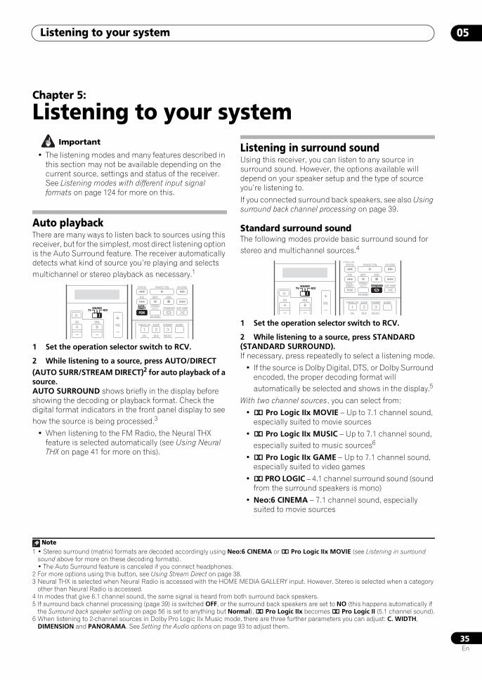
Listening to your system 05
35En
Chapter 5:
Listening to your system Important
• The listening modes and many features described in this section may not be available depending on the current source, settings and status of the receiver. See Listening modes with different input signal formats on page 124 for more on this.
Auto playbackThere are many ways to listen back to sources using this receiver, but for the simplest, most direct listening option is the Auto Surround feature. The receiver automatically detects what kind of source you’re playing and selects multichannel or stereo playback as necessary.1
1 Set the operation selector switch to RCV.
2 While listening to a source, press AUTO/DIRECT (AUTO SURR/STREAM DIRECT)2 for auto playback of a source.AUTO SURROUND shows briefly in the display before showing the decoding or playback format. Check the digital format indicators in the front panel display to see how the source is being processed.3
• When listening to the FM Radio, the Neural THX feature is selected automatically (see Using Neural THX on page 41 for more on this).
Listening in surround soundUsing this receiver, you can listen to any source in surround sound. However, the options available will depend on your speaker setup and the type of source you’re listening to.
If you connected surround back speakers, see also Using surround back channel processing on page 39.
Standard surround soundThe following modes provide basic surround sound for stereo and multichannel sources.4
1 Set the operation selector switch to RCV.
2 While listening to a source, press STANDARD (STANDARD SURROUND).If necessary, press repeatedly to select a listening mode.
• If the source is Dolby Digital, DTS, or Dolby Surround encoded, the proper decoding format will automatically be selected and shows in the display.5
With two channel sources, you can select from:
• 2 Pro Logic IIx MOVIE – Up to 7.1 channel sound, especially suited to movie sources
• 2 Pro Logic IIx MUSIC – Up to 7.1 channel sound, especially suited to music sources6
• 2 Pro Logic IIx GAME – Up to 7.1 channel sound, especially suited to video games
• 2 PRO LOGIC – 4.1 channel surround sound (sound from the surround speakers is mono)
• Neo:6 CINEMA – 7.1 channel sound, especially suited to movie sources
Note1 • Stereo surround (matrix) formats are decoded accordingly using Neo:6 CINEMA or 2 Pro Logic IIx MOVIE (see Listening in surround
sound above for more on these decoding formats).• The Auto Surround feature is canceled if you connect headphones.
2 For more options using this button, see Using Stream Direct on page 38.3 Neural THX is selected when Neural Radio is accessed with the HOME MEDIA GALLERY input. However, Stereo is selected when a category
other than Neural Radio is accessed.
SOURCETV RCV
VOLVOLCH
SOURCETV RCV
STATUS
THX MPX EON
PHASE CTRL CH LEVEL
PGM
STEREO/A.L.C.
BD MENU
SIGNAL SEL SLEEP AUDIODIMMER
SR+ SBch MCACC
AUTO/DIRECT STANDARD ADV SURR
PGM
AUTO/DIRECT
4 In modes that give 6.1 channel sound, the same signal is heard from both surround back speakers. 5 If surround back channel processing (page 39) is switched OFF, or the surround back speakers are set to NO (this happens automatically if
the Surround back speaker setting on page 56 is set to anything but Normal), 2 Pro Logic IIx becomes 2 Pro Logic II (5.1 channel sound).6 When listening to 2-channel sources in Dolby Pro Logic IIx Music mode, there are three further parameters you can adjust: C. WIDTH,
DIMENSION and PANORAMA. See Setting the Audio options on page 93 to adjust them.
SOURCETV RCV
VOLVOLCH
SOURCETV RCV
iPod CTRLSTATUS
THX MPX
PHASE CTRL CH LEVEL
PGM
STEREO/A.L.C.
BD MENU
SIGNAL SEL SLEEP AUDIODIMMER
SR+ SBch MCACC
AUTO/DIRECT STANDARD ADV SURR
EON
STANDARD
SCLX81_71.book 35 ページ 2008年7月25日 金曜日 午後3時1分
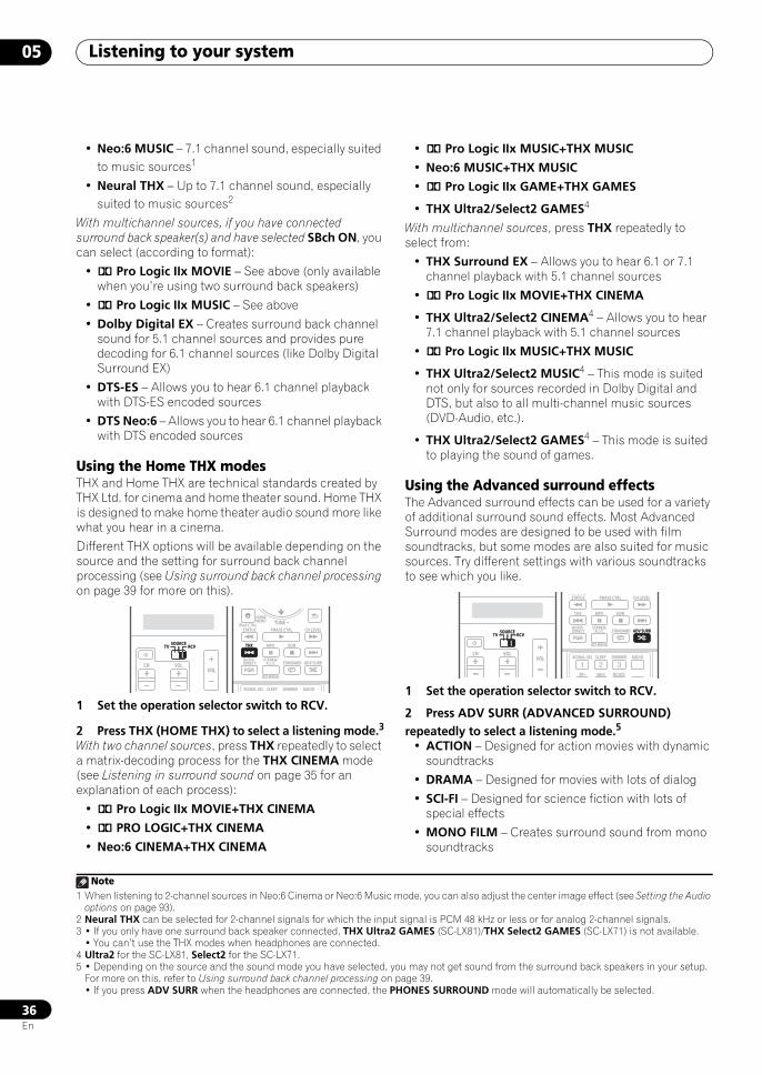
Listening to your system05
36En
• Neo:6 MUSIC – 7.1 channel sound, especially suited to music sources1
• Neural THX – Up to 7.1 channel sound, especially suited to music sources2
With multichannel sources, if you have connected surround back speaker(s) and have selected SBch ON, you can select (according to format):
• 2 Pro Logic IIx MOVIE – See above (only available when you’re using two surround back speakers)
• 2 Pro Logic IIx MUSIC – See above
• Dolby Digital EX – Creates surround back channel sound for 5.1 channel sources and provides pure decoding for 6.1 channel sources (like Dolby Digital Surround EX)
• DTS-ES – Allows you to hear 6.1 channel playback with DTS-ES encoded sources
• DTS Neo:6 – Allows you to hear 6.1 channel playback with DTS encoded sources
Using the Home THX modesTHX and Home THX are technical standards created by THX Ltd. for cinema and home theater sound. Home THX is designed to make home theater audio sound more like what you hear in a cinema.
Different THX options will be available depending on the source and the setting for surround back channel processing (see Using surround back channel processing on page 39 for more on this).
1 Set the operation selector switch to RCV.
2 Press THX (HOME THX) to select a listening mode.3
With two channel sources, press THX repeatedly to select a matrix-decoding process for the THX CINEMA mode (see Listening in surround sound on page 35 for an explanation of each process):
• 2 Pro Logic IIx MOVIE+THX CINEMA
• 2 PRO LOGIC+THX CINEMA
• Neo:6 CINEMA+THX CINEMA
• 2 Pro Logic IIx MUSIC+THX MUSIC
• Neo:6 MUSIC+THX MUSIC
• 2 Pro Logic IIx GAME+THX GAMES
• THX Ultra2/Select2 GAMES4
With multichannel sources, press THX repeatedly to select from:
• THX Surround EX – Allows you to hear 6.1 or 7.1 channel playback with 5.1 channel sources
• 2 Pro Logic IIx MOVIE+THX CINEMA
• THX Ultra2/Select2 CINEMA4 – Allows you to hear 7.1 channel playback with 5.1 channel sources
• 2 Pro Logic IIx MUSIC+THX MUSIC
• THX Ultra2/Select2 MUSIC4 – This mode is suited not only for sources recorded in Dolby Digital and DTS, but also to all multi-channel music sources (DVD-Audio, etc.).
• THX Ultra2/Select2 GAMES4 – This mode is suited to playing the sound of games.
Using the Advanced surround effectsThe Advanced surround effects can be used for a variety of additional surround sound effects. Most Advanced Surround modes are designed to be used with film soundtracks, but some modes are also suited for music sources. Try different settings with various soundtracks to see which you like.
1 Set the operation selector switch to RCV.
2 Press ADV SURR (ADVANCED SURROUND) repeatedly to select a listening mode.5
• ACTION – Designed for action movies with dynamic soundtracks
• DRAMA – Designed for movies with lots of dialog
• SCI-FI – Designed for science fiction with lots of special effects
• MONO FILM – Creates surround sound from mono soundtracks
Note1 When listening to 2-channel sources in Neo:6 Cinema or Neo:6 Music mode, you can also adjust the center image effect (see Setting the Audio
options on page 93).2 Neural THX can be selected for 2-channel signals for which the input signal is PCM 48 kHz or less or for analog 2-channel signals.3 • If you only have one surround back speaker connected, THX Ultra2 GAMES (SC-LX81)/THX Select2 GAMES (SC-LX71) is not available.
• You can’t use the THX modes when headphones are connected.
SOURCETV RCV
VOLVOLCH
SOURCETV RCV
iPod CTRL
HOMEMENU
STATUS
THX MPX
PHASE CTRL CH LEVEL
TUNE
PGM
STEREO/A.L.C.
BD MENU
SIGNAL SEL SLEEP AUDIODIMMER
AUTO/DIRECT STANDARD ADV SURR
EONTHX
4 Ultra2 for the SC-LX81, Select2 for the SC-LX71.5 • Depending on the source and the sound mode you have selected, you may not get sound from the surround back speakers in your setup.
For more on this, refer to Using surround back channel processing on page 39.• If you press ADV SURR when the headphones are connected, the PHONES SURROUND mode will automatically be selected.
SOURCETV RCV
VOLVOLCH
SOURCETV RCV
iPod CTRLSTATUS
THX MPX
PHASE CTRL CH LEVEL
PGM
STEREO/A.L.C.
BD MENU
SIGNAL SEL SLEEP AUDIODIMMER
SR+ SBch MCACC
AUTO/DIRECT STANDARD ADV SURR
EON
ADV SURR
SCLX81_71.book 36 ページ 2008年7月25日 金曜日 午後3時1分
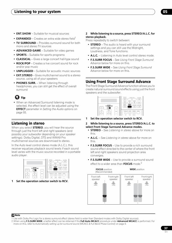
Listening to your system 05
37En
• ENT.SHOW – Suitable for musical sources
• EXPANDED – Creates an extra wide stereo field1
• TV SURROUND – Provides surround sound for both mono and stereo TV sources
• ADVANCED GAME – Suitable for video games
• SPORTS – Suitable for sports programs
• CLASSICAL – Gives a large concert hall-type sound
• ROCK/POP – Creates a live concert sound for rock and/or pop music
• UNPLUGGED – Suitable for acoustic music sources
• EXT.STEREO – Gives multichannel sound to a stereo source, using all of your speakers
• PHONES SURR. – When listening through headphones, you can still get the effect of overall surround
Tip
• When an Advanced Surround listening mode is selected, the effect level can be adjusted using the EFFECT parameter in Setting the Audio options on page 93.
Listening in stereoWhen you select STEREO, you will hear the source through just the front left and right speakers (and possibly your subwoofer depending on your speaker settings). Dolby Digital, DTS and WMA9 Pro multichannel sources are downmixed to stereo.
In the Auto level control stereo mode (A.L.C.), this receiver equalizes playback sound levels if each sound level varies with the music source recorded in a portable audio player.
1 Set the operation selector switch to RCV.
2 While listening to a source, press STEREO/A.L.C. for stereo playback.Press repeatedly to switch between:
• STEREO – The audio is heard with your surround settings and you can still use the Midnight, Loudness, and Tone functions.
• A.L.C. – Listening in Auto level control stereo mode.
• F.S.SURR FOCUS – See Using Front Stage Surround Advance below for more on this.
• F.S.SURR WIDE – See Using Front Stage Surround Advance below for more on this.
Using Front Stage Surround AdvanceThe Front Stage Surround Advance function allows you to create natural surround sound effects using just the front speakers and the subwoofer.
1 Set the operation selector switch to RCV.
2 While listening to a source, press STEREO/A.L.C. to select Front Stage Surround Advance modes.
• STEREO – See Listening in stereo above for more on this.
• A.L.C. – See Listening in stereo above for more on this.
• F.S.SURR FOCUS – Use to provide a rich surround sound effect directed to the center of where the front left and right speakers sound projection area converges.
• F.S.SURR WIDE – Use to provide a surround sound effect to a wider area than FOCUS mode.2
Note1 Use with Dolby Pro Logic for a stereo surround effect (stereo field is wider than Standard modes with Dolby Digital sources).
SOURCETV RCV
VOLVOLCH
SOURCETV RCV
iPod CTRLSTATUS
THX MPX
PHASE CTRL CH LEVEL
PGM
STEREO/A.L.C.
BD MENU
SIGNAL SEL SLEEP AUDIODIMMER
SR+ SBch MCACC
AUTO/DIRECT STANDARD ADV SURR
EON
STEREO/A.L.C.
2 When using F.S.SURR WIDE, a better effect can be obtained if the Full Auto MCACC procedure under Advanced MCACC is performed. For more on this, refer to Automatically setting up for surround sound (MCACC & Full Band Phase Control) on page 9.
SOURCETV RCV
VOLVOLCH
SOURCETV RCV
iPod CTRLSTATUS
THX MPX
PHASE CTRL CH LEVEL
PGM
STEREO/A.L.C.
BD MENU
SIGNAL SEL SLEEP AUDIODIMMER
SR+ SBch MCACC
AUTO/DIRECT STANDARD ADV SURR
EON
STEREO/A.L.C.
FOCUS position (Recommended)
WIDE position
Front left speaker
Front right speaker
Front left speaker
Front right speaker
SCLX81_71.book 37 ページ 2008年7月25日 金曜日 午後3時1分
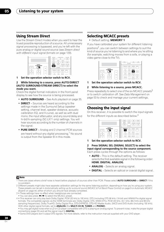
Listening to your system05
38En
Using Stream DirectUse the Stream Direct modes when you want to hear the truest possible reproduction of a source. All unnecessary signal processing is bypassed, and you’re left with the pure analog or digital sound source (see Stream direct with different input signal formats on page 129).
1 Set the operation selector switch to RCV.
2 While listening to a source, press AUTO/DIRECT (AUTO SURROUND/STREAM DIRECT) to select the mode you want.Check the digital format indicators in the front panel display to see how the source is being processed.
• AUTO SURROUND – See Auto playback on page 35.
• DIRECT – Sources are heard according to the settings made in the Surround Setup (speaker setting, channel level, speaker distance, acoustic calibration EQ, and X-curve), as well as with dual mono, the input attenuator, and any sound delay and hi-bit/hi-sampling (SC-LX71 only) settings. You will hear sources according to the number of channels in the signal.
• PURE DIRECT – Analog and 2 channel PCM sources are heard without any digital processing.1 No sound is output from the Speaker B in this mode.
Selecting MCACC presets• Default setting: MEMORY 1
If you have calibrated your system for different listening positions2, you can switch between settings to suit the kind of source you’re listening to and where you’re sitting (for example, watching movies from a sofa, or playing a video game close to the TV).
1 Set the operation selector switch to RCV.
2 While listening to a source, press MCACC.Press repeatedly to select one of the six MCACC presets3 or to switch calibration off. See Data Management on page 53 to check and manage your current settings.
Choosing the input signalOn this receiver, it is possible to switch the input signals for the different inputs as described below.4
1 Set the operation selector switch to RCV.
2 Press SIGNAL SEL (SIGNAL SELECT) to select the input signal corresponding to the source component.Each press cycles through the options as follows:
• AUTO – This is the default setting. The receiver selects the first available signal in the following order: HDMI; DIGITAL; ANALOG.
• ANALOG – Selects an analog signal.
• DIGITAL – Selects an optical or coaxial digital signal.
Note1 There are cases where a brief noise is heard before playback of sources other than PCM. Please select AUTO SURROUND or DIRECT if this
is a problem.
SOURCETV RCV
VOLVOLCH
SOURCETV RCV
STATUS
THX MPX EON
PHASE CTRL CH LEVEL
PGM
STEREO/A.L.C.
BD MENU
SIGNAL SEL SLEEP AUDIODIMMER
SR+ SBch MCACC
AUTO/DIRECT STANDARD ADV SURR
PGM
AUTO/DIRECT
2 Different presets might also have separate calibration settings for the same listening position, depending on how you’re using your system. These presets can be set in Automatically setting up for surround sound (MCACC & Full Band Phase Control) on page 9 or Automatic MCACC (Expert) on page 44, either of which you should have already completed.
3 • These settings have no effect when headphones are connected.• You can also press / to select the MCACC preset.
4 • This receiver can only play back Dolby Digital, PCM (32 kHz to 192 kHz), DTS (including DTS 96 kHz / 24 bit) and WMA9 Pro digital signal formats. The compatible signals via the HDMI terminals are: Dolby Digital, DTS, WMA 9 Pro, PCM (32 kHz, 44.1 kHz, 88.2 kHz and 96 kHz sampling frequencies), Dolby TrueHD, Dolby Digital Plus, DTS-EXPRESS, DTS-HD Master Audio, SACD and DVD Audio (including 192 kHz). With other digital signal formats, set to ANALOG (the MULTI CH IN, TUNER and PHONO).• You may get digital noise when a LD or CD player compatible with DTS is playing an analog signal. To prevent noise, make the proper digital connections (page 23) and set the signal input to DIGITAL.• Some DVD players don’t output DTS signals. For more details, refer to the instruction manual supplied with your DVD player.
SOURCETV RCV
VOLVOL
CO O
CH
SOURCETV RCV
PGMBD MENU
SIGNAL SEL SLEEP AUDIODIMMER
SR+ SBch MCACC
A.ATT GENRE HDMI OUT
D.ACCESS
ENTER
CLASS
DISP
CH
MCACC
SOURCETV RCV
VOLVOLCH
SOURCETV RCV
PGM
STEREO/A.L.C.
BD MENU
SIGNAL SEL SLEEP AUDIODIMMER
SR+ SBch MCACC
A.ATT GENRE HDMI OUT
DISP
AUTO/DIRECT STANDARD ADV SURR
SIGNAL SEL
SCLX81_71.book 38 ページ 2008年7月25日 金曜日 午後3時1分
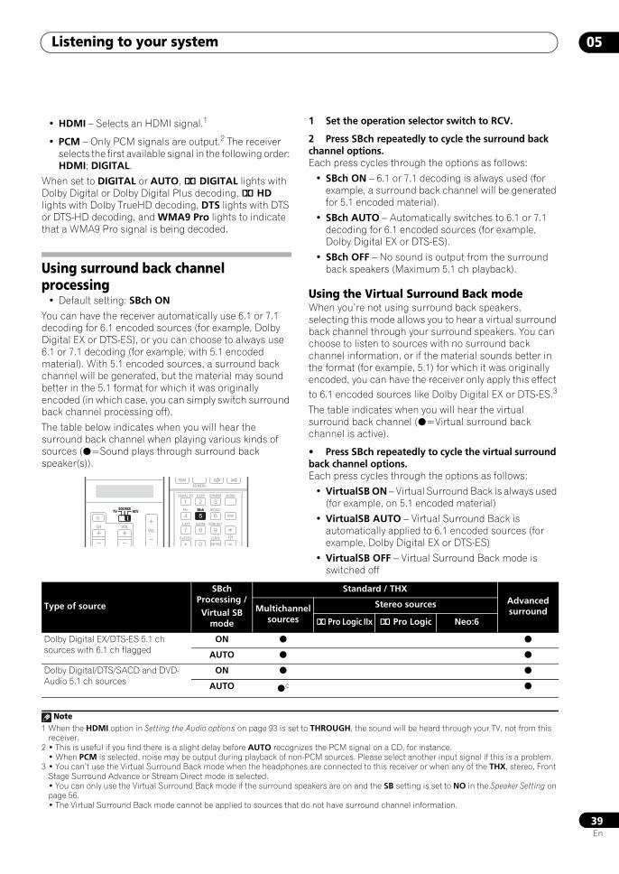
Listening to your system 05
39En
• HDMI – Selects an HDMI signal.1
• PCM – Only PCM signals are output.2 The receiver selects the first available signal in the following order: HDMI; DIGITAL.
When set to DIGITAL or AUTO, 2 DIGITAL lights with Dolby Digital or Dolby Digital Plus decoding, 2 HD lights with Dolby TrueHD decoding, DTS lights with DTS or DTS-HD decoding, and WMA9 Pro lights to indicate that a WMA9 Pro signal is being decoded.
Using surround back channel processing
• Default setting: SBch ON
You can have the receiver automatically use 6.1 or 7.1 decoding for 6.1 encoded sources (for example, Dolby Digital EX or DTS-ES), or you can choose to always use 6.1 or 7.1 decoding (for example, with 5.1 encoded material). With 5.1 encoded sources, a surround back channel will be generated, but the material may sound better in the 5.1 format for which it was originally encoded (in which case, you can simply switch surround back channel processing off).
The table below indicates when you will hear the surround back channel when playing various kinds of sources (=Sound plays through surround back speaker(s)).
1 Set the operation selector switch to RCV.
2 Press SBch repeatedly to cycle the surround back channel options.Each press cycles through the options as follows:
• SBch ON – 6.1 or 7.1 decoding is always used (for example, a surround back channel will be generated for 5.1 encoded material).
• SBch AUTO – Automatically switches to 6.1 or 7.1 decoding for 6.1 encoded sources (for example, Dolby Digital EX or DTS-ES).
• SBch OFF – No sound is output from the surround back speakers (Maximum 5.1 ch playback).
Using the Virtual Surround Back modeWhen you’re not using surround back speakers, selecting this mode allows you to hear a virtual surround back channel through your surround speakers. You can choose to listen to sources with no surround back channel information, or if the material sounds better in the format (for example, 5.1) for which it was originally encoded, you can have the receiver only apply this effect to 6.1 encoded sources like Dolby Digital EX or DTS-ES.3
The table indicates when you will hear the virtual surround back channel (=Virtual surround back channel is active).
• Press SBch repeatedly to cycle the virtual surround back channel options.Each press cycles through the options as follows:
• VirtualSB ON – Virtual Surround Back is always used (for example, on 5.1 encoded material)
• VirtualSB AUTO – Virtual Surround Back is automatically applied to 6.1 encoded sources (for example, Dolby Digital EX or DTS-ES)
• VirtualSB OFF – Virtual Surround Back mode is switched off
Note1 When the HDMI option in Setting the Audio options on page 93 is set to THROUGH, the sound will be heard through your TV, not from this
receiver.2 • This is useful if you find there is a slight delay before AUTO recognizes the PCM signal on a CD, for instance.
• When PCM is selected, noise may be output during playback of non-PCM sources. Please select another input signal if this is a problem.
SOURCETV RCV
VOLVOLCH
SOURCETV RCV
PGMBD MENU
SIGNAL SEL SLEEP AUDIODIMMER
SR+ SBch MCACC
A.ATT GENRE HDMI OUT
D.ACCESS
ENTER
CLASS
DISP
CH
SBch
3 • You can’t use the Virtual Surround Back mode when the headphones are connected to this receiver or when any of the THX, stereo, Front Stage Surround Advance or Stream Direct mode is selected.• You can only use the Virtual Surround Back mode if the surround speakers are on and the SB setting is set to NO in the Speaker Setting on page 56.• The Virtual Surround Back mode cannot be applied to sources that do not have surround channel information.
Type of source
SBch Processing / Virtual SB
mode
Standard / THXAdvanced surroundMultichannel
sources
Stereo sources
2 Pro Logic IIx 2 Pro Logic Neo:6
Dolby Digital EX/DTS-ES 5.1 ch sources with 6.1 ch flagged
ON
AUTO
Dolby Digital/DTS/SACD and DVD-Audio 5.1 ch sources
ON
AUTO c
SCLX81_71.book 39 ページ 2008年7月25日 金曜日 午後3時1分
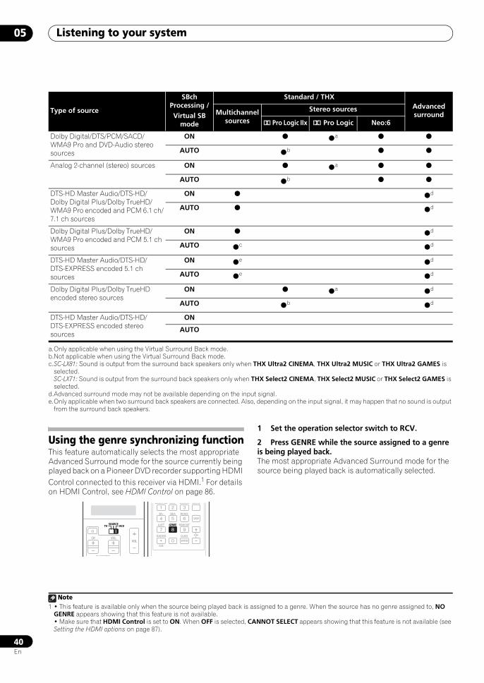
Listening to your system05
40En
Using the genre synchronizing functionThis feature automatically selects the most appropriate Advanced Surround mode for the source currently being played back on a Pioneer DVD recorder supporting HDMI Control connected to this receiver via HDMI.1 For details on HDMI Control, see HDMI Control on page 86.
1 Set the operation selector switch to RCV.
2 Press GENRE while the source assigned to a genre is being played back.The most appropriate Advanced Surround mode for the source being played back is automatically selected.
Dolby Digital/DTS/PCM/SACD/WMA9 Pro and DVD-Audio stereo sources
ON a
AUTO b
Analog 2-channel (stereo) sources ON a
AUTO b
DTS-HD Master Audio/DTS-HD/Dolby Digital Plus/Dolby TrueHD/WMA9 Pro encoded and PCM 6.1 ch/7.1 ch sources
ON d
AUTO d
Dolby Digital Plus/Dolby TrueHD/WMA9 Pro encoded and PCM 5.1 ch sources
ON d
AUTO c d
DTS-HD Master Audio/DTS-HD/DTS-EXPRESS encoded 5.1 ch sources
ON e d
AUTO e d
Dolby Digital Plus/Dolby TrueHD encoded stereo sources
ON a d
AUTO b d
DTS-HD Master Audio/DTS-HD/DTS-EXPRESS encoded stereo sources
ON
AUTO
a.Only applicable when using the Virtual Surround Back mode.b.Not applicable when using the Virtual Surround Back mode.c.SC-LX81: Sound is output from the surround back speakers only when THX Ultra2 CINEMA, THX Ultra2 MUSIC or THX Ultra2 GAMES is
selected.SC-LX71: Sound is output from the surround back speakers only when THX Select2 CINEMA, THX Select2 MUSIC or THX Select2 GAMES is selected.
d.Advanced surround mode may not be available depending on the input signal.e.Only applicable when two surround back speakers are connected. Also, depending on the input signal, it may happen that no sound is output
from the surround back speakers.
Type of source
SBch Processing / Virtual SB
mode
Standard / THXAdvanced surroundMultichannel
sources
Stereo sources
2 Pro Logic IIx 2 Pro Logic Neo:6
Note1 • This feature is available only when the source being played back is assigned to a genre. When the source has no genre assigned to, NO
GENRE appears showing that this feature is not available.• Make sure that HDMI Control is set to ON. When OFF is selected, CANNOT SELECT appears showing that this feature is not available (see Setting the HDMI options on page 87).
SOURCETV RCV
VOLVOL
TV CONTROL
CH
SOURCETV RCV
SIGNAL SEL SLEEP AUDIODIMMER
SR+
CLR
SBch MCACC
A.ATT GENRE HDMI OUT
D.ACCESS
ENTER
CLASS
DISP
CH
GENRE
SCLX81_71.book 40 ページ 2008年7月25日 金曜日 午後3時1分
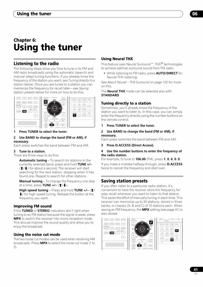
Using the tuner 06
41En
Chapter 6:
Using the tuner
Listening to the radioThe following steps show you how to tune in to FM and AM radio broadcasts using the automatic (search) and manual (step) tuning functions. If you already know the frequency of the station you want, see Tuning directly to a station below. Once you are tuned to a station you can memorize the frequency for recall later—see Saving station presets below for more on how to do this.
1 Press TUNER to select the tuner.
2 Use BAND to change the band (FM or AM), if necessary.Each press switches the band between FM and AM.
3 Tune to a station.There are three ways to do this:
Automatic tuning – To search for stations in the currently selected band, press and hold TUNE +/– (/) for about a second. The receiver will start searching for the next station, stopping when it has found one. Repeat to search for other stations.
Manual tuning – To change the frequency one step at a time, press TUNE +/– (/).
High speed tuning – Press and hold TUNE +/– (/) for high speed tuning. Release the button at the frequency you want.
Improving FM soundIf the TUNED or STEREO indicators don’t light when tuning to an FM station because the signal is weak, press MPX to switch the receiver into mono reception mode. This should improve the sound quality and allow you to enjoy the broadcast.
Using the noise cut modeThe two noise cut modes can be used when receiving AM broadcasts. Press MPX to select the noise cut mode (1 to 2).
Using Neural THXThis feature uses Neural Surround™, THX® technologies to achieve optimal surround sound from FM radio.
• While listening to FM radio, press AUTO/DIRECT for Neural THX listening.
See About Neural – THX Surround on page 122 for more on this.
The Neural THX mode can be selected also with STANDARD.
Tuning directly to a stationSometimes, you’ll already know the frequency of the station you want to listen to. In this case, you can simply enter the frequency directly using the number buttons on the remote control.
1 Press TUNER to select the tuner.
2 Use BAND to change the band (FM or AM), if necessary.Each press switches the band between FM and AM.
3 Press D.ACCESS (Direct Access).
4 Use the number buttons to enter the frequency of the radio station.For example, to tune to 106.00 (FM), press 1, 0, 6, 0, 0.
If you make a mistake halfway through, press D.ACCESS twice to cancel the frequency and start over.
Saving station presetsIf you often listen to a particular radio station, it’s convenient to have the receiver store the frequency for easy recall whenever you want to listen to that station. This saves the effort of manually tuning in each time. This receiver can memorize up to 30 stations, stored in three banks, or classes (A, B and C) of 10 stations each. When saving an FM frequency, the MPX setting (see page 41) is also stored.
DVD
VIDEO1
GALLERYHOME MEDIA
CD
HDMI TUNER
PHONO
VIDEO2 VIDEO3 TV
BD DVR1 DVR2
CD-R
INPUT SELECTTUNER
AUDIOPARAMETER
TOP MENUBAND
iPod CTRL
EXIT TOOLS
HOMEMENU
STATUS
THX MPX
PHASE CTRL CH LEVEL
MENUT.EDIT
VIDEOPARAMETER
STEREO/A.L.C.
AUTO/DIRECT STANDARD ADV SURR
ENTER
RETURNPTY
SEARCH
EON
TOP MENUBAND
ENTER
MPX
TUNE +
TUNE
ST ST +
SIGNAL SEL SLEEP AUDIODIMMER
SR+
CLR
SBch MCACC
A.ATT GENRE HDMI OUT
D.ACCESS
ENTER
CLASS
DISP
CHD.ACCESS
DVD
VIDEO1
GALLERYHOME MEDIA
CD
HDMI TUNER
PHONO
VIDEO2 VIDEO3 TV
BD DVR1 DVR2
CD-R
INPUT SELECTTUNER
AUDIOPARAMETER
TOP MENUBAND
iPod CTRL
EXIT TOOLS
HOMEMENU
STATUS
THX MPX
PHASE CTRL CH LEVEL
VIDEOPARAMETER
PGM
STEREO/A.L.C.
AUTO/DIRECT STANDARD ADV SURR
ENTER
RETURNPTY
SEARCH
EON
TUNE +
TUNE
ST ST +ENTER
MPX
MENUT.EDIT
PGMBD MENU
SIGNAL SEL SLEEP AUDIODIMMER
SR+
CLR
SBch MCACC
A.ATT GENRE HDMI OUT
D.ACCESS
ENTER
CLASS
DISP
CH
DISP
ENTER
CLASS
SCLX81_71.book 41 ページ 2008年7月25日 金曜日 午後3時1分
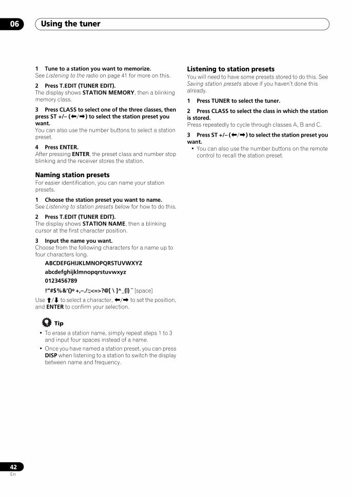
Using the tuner06
42En
1 Tune to a station you want to memorize.See Listening to the radio on page 41 for more on this.
2 Press T.EDIT (TUNER EDIT).The display shows STATION MEMORY, then a blinking memory class.
3 Press CLASS to select one of the three classes, then press ST +/– (/) to select the station preset you want.You can also use the number buttons to select a station preset.
4 Press ENTER.After pressing ENTER, the preset class and number stop blinking and the receiver stores the station.
Naming station presetsFor easier identification, you can name your station presets.
1 Choose the station preset you want to name.See Listening to station presets below for how to do this.
2 Press T.EDIT (TUNER EDIT).The display shows STATION NAME, then a blinking cursor at the first character position.
3 Input the name you want.Choose from the following characters for a name up to four characters long.
ABCDEFGHIJKLMNOPQRSTUVWXYZ
abcdefghijklmnopqrstuvwxyz
0123456789
!”#$%&’()∗+,–./:;<=>?@[ \ ]^_{|} ˜ [space]
Use / to select a character, / to set the position, and ENTER to confirm your selection.
Tip
• To erase a station name, simply repeat steps 1 to 3 and input four spaces instead of a name.
• Once you have named a station preset, you can press DISP when listening to a station to switch the display between name and frequency.
Listening to station presetsYou will need to have some presets stored to do this. See Saving station presets above if you haven’t done this already.
1 Press TUNER to select the tuner.
2 Press CLASS to select the class in which the station is stored.Press repeatedly to cycle through classes A, B and C.
3 Press ST +/– (/) to select the station preset you want.
• You can also use the number buttons on the remote control to recall the station preset.
SCLX81_71.book 42 ページ 2008年7月25日 金曜日 午後3時1分
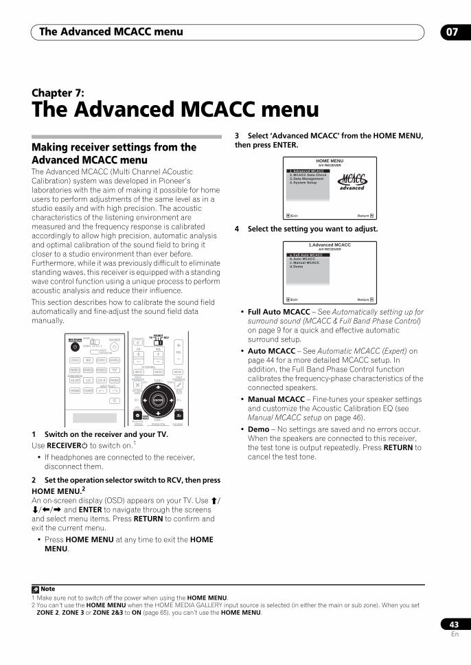
The Advanced MCACC menu 07
43En
Chapter 7:
The Advanced MCACC menu
Making receiver settings from the Advanced MCACC menuThe Advanced MCACC (Multi Channel ACoustic Calibration) system was developed in Pioneer’s laboratories with the aim of making it possible for home users to perform adjustments of the same level as in a studio easily and with high precision. The acoustic characteristics of the listening environment are measured and the frequency response is calibrated accordingly to allow high precision, automatic analysis and optimal calibration of the sound field to bring it closer to a studio environment than ever before. Furthermore, while it was previously difficult to eliminate standing waves, this receiver is equipped with a standing wave control function using a unique process to perform acoustic analysis and reduce their influence.
This section describes how to calibrate the sound field automatically and fine-adjust the sound field data manually.
1 Switch on the receiver and your TV.Use RECEIVER to switch on.1
• If headphones are connected to the receiver, disconnect them.
2 Set the operation selector switch to RCV, then press HOME MENU.2
An on-screen display (OSD) appears on your TV. Use /// and ENTER to navigate through the screens and select menu items. Press RETURN to confirm and exit the current menu.
• Press HOME MENU at any time to exit the HOME MENU.
3 Select ‘Advanced MCACC’ from the HOME MENU, then press ENTER.
4 Select the setting you want to adjust.
• Full Auto MCACC – See Automatically setting up for surround sound (MCACC & Full Band Phase Control) on page 9 for a quick and effective automatic surround setup.
• Auto MCACC – See Automatic MCACC (Expert) on page 44 for a more detailed MCACC setup. In addition, the Full Band Phase Control function calibrates the frequency-phase characteristics of the connected speakers.
• Manual MCACC – Fine-tunes your speaker settings and customize the Acoustic Calibration EQ (see Manual MCACC setup on page 46).
• Demo – No settings are saved and no errors occur. When the speakers are connected to this receiver, the test tone is output repeatedly. Press RETURN to cancel the test tone.
Note1 Make sure not to switch off the power when using the HOME MENU.2 You can’t use the HOME MENU when the HOME MEDIA GALLERY input source is selected (in either the main or sub zone). When you set
ZONE 2, ZONE 3 or ZONE 2&3 to ON (page 65), you can’t use the HOME MENU.
DVD
RECEIVER SOURCEMAIN
MULTIOPERATION
ZONE2 3
VIDEO1
GALLERYHOME MEDIA
INPUT SELECT
CD
HDMI TUNER
PHONO
VIDEO2 VIDEO3 TV
BD DVR1 DVR2
CD-R
RECEIVER
AUDIOPARAMETER
TOP MENUBAND
iPod CTRL
PTYSEARCH
EXIT TOOLS
STATUS PHASE CTRL CH LEVEL
MENUT.EDIT
VIDEOPARAMETER
SOURCETV RCV
INPUT MUTE MUTE
VOLVOL
TV CONTROL
CH
RETURN
TUNE +
TUNE
ST ST +
HOMEMENU
RETURN
ENTER
SOURCETV RCV
1. Advanced MCACC2. MCACC Data Check3. Data Management4. System Setup
Exit Return
HOME MENUA/V RECEIVER
a. Full Auto MCACCb. Auto MCACCc. Manual MCACCd. Demo
1.Advanced MCACCA/V RECEIVER
Exit Return
SCLX81_71.book 43 ページ 2008年7月25日 金曜日 午後3時1分
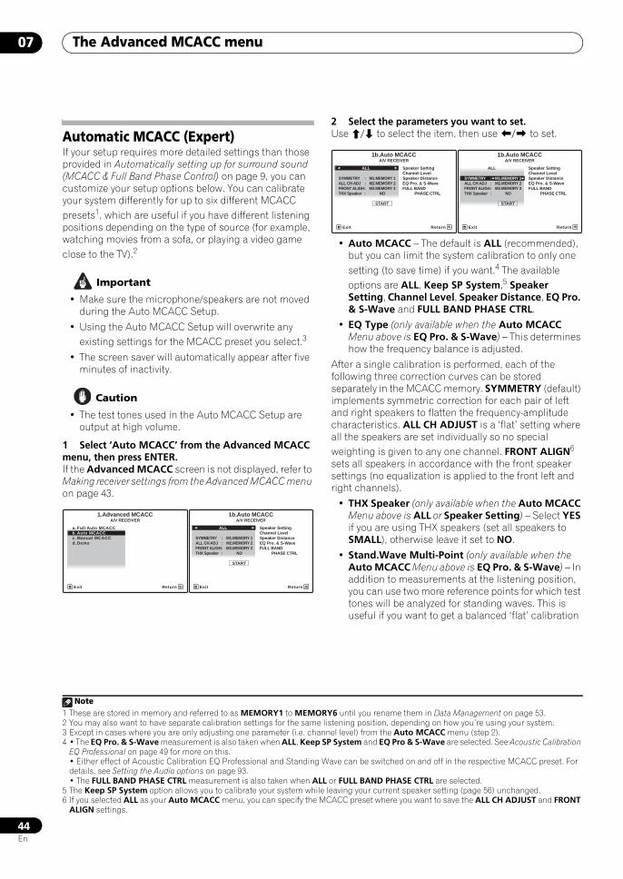
The Advanced MCACC menu07
44En
Automatic MCACC (Expert)If your setup requires more detailed settings than those provided in Automatically setting up for surround sound (MCACC & Full Band Phase Control) on page 9, you can customize your setup options below. You can calibrate your system differently for up to six different MCACC presets1, which are useful if you have different listening positions depending on the type of source (for example, watching movies from a sofa, or playing a video game close to the TV).2
Important
• Make sure the microphone/speakers are not moved during the Auto MCACC Setup.
• Using the Auto MCACC Setup will overwrite any existing settings for the MCACC preset you select.3
• The screen saver will automatically appear after five minutes of inactivity.
Caution
• The test tones used in the Auto MCACC Setup are output at high volume.
1 Select ‘Auto MCACC’ from the Advanced MCACC menu, then press ENTER.If the Advanced MCACC screen is not displayed, refer to Making receiver settings from the Advanced MCACC menu on page 43.
2 Select the parameters you want to set.Use / to select the item, then use / to set.
• Auto MCACC – The default is ALL (recommended), but you can limit the system calibration to only one setting (to save time) if you want.4 The available options are ALL, Keep SP System,5 Speaker Setting, Channel Level, Speaker Distance, EQ Pro. & S-Wave and FULL BAND PHASE CTRL.
• EQ Type (only available when the Auto MCACC Menu above is EQ Pro. & S-Wave) – This determines how the frequency balance is adjusted.
After a single calibration is performed, each of the following three correction curves can be stored separately in the MCACC memory. SYMMETRY (default) implements symmetric correction for each pair of left and right speakers to flatten the frequency-amplitude characteristics. ALL CH ADJUST is a ‘flat’ setting where all the speakers are set individually so no special weighting is given to any one channel. FRONT ALIGN6 sets all speakers in accordance with the front speaker settings (no equalization is applied to the front left and right channels).
• THX Speaker (only available when the Auto MCACC Menu above is ALL or Speaker Setting) – Select YES if you are using THX speakers (set all speakers to SMALL), otherwise leave it set to NO.
• Stand.Wave Multi-Point (only available when the Auto MCACC Menu above is EQ Pro. & S-Wave) – In addition to measurements at the listening position, you can use two more reference points for which test tones will be analyzed for standing waves. This is useful if you want to get a balanced ‘flat’ calibration
Note1 These are stored in memory and referred to as MEMORY1 to MEMORY6 until you rename them in Data Management on page 53.2 You may also want to have separate calibration settings for the same listening position, depending on how you’re using your system.3 Except in cases where you are only adjusting one parameter (i.e. channel level) from the Auto MCACC menu (step 2).
a. Full Auto MCACCb. Auto MCACCc. Manual MCACCd. Demo
1.Advanced MCACCA/V RECEIVER
Exit Return
ALL
1b.Auto MCACC
START
Exit
A/V RECEIVER
Return
Speaker SettingChannel LevelSpeaker DistanceEQ Pro. & S-WaveFULL BAND PHASE CTRL
SYMMETRY : M1.MEMORY 1ALL CH ADJ : M2.MEMORY 2FRONT ALIGH : M3.MEMORY 3THX Speaker : NO
4 • The EQ Pro. & S-Wave measurement is also taken when ALL, Keep SP System and EQ Pro & S-Wave are selected. See Acoustic Calibration EQ Professional on page 49 for more on this.• Either effect of Acoustic Calibration EQ Professional and Standing Wave can be switched on and off in the respective MCACC preset. For details, see Setting the Audio options on page 93.• The FULL BAND PHASE CTRL measurement is also taken when ALL or FULL BAND PHASE CTRL are selected.
5 The Keep SP System option allows you to calibrate your system while leaving your current speaker setting (page 56) unchanged.6 If you selected ALL as your Auto MCACC menu, you can specify the MCACC preset where you want to save the ALL CH ADJUST and FRONT
ALIGN settings.
ALL
1b.Auto MCACC
START
Exit
A/V RECEIVER
Return
Speaker SettingChannel LevelSpeaker DistanceEQ Pro. & S-WaveFULL BAND PHASE CTRL
SYMMETRY : M1.MEMORY 1ALL CH ADJ : M2.MEMORY 2FRONT ALIGH : M3.MEMORY 3THX Speaker : NO
ALL
SYMMETRY : M1.MEMORY 1
1b.Auto MCACC
ALL CH ADJ : M2.MEMORY 2FRONT ALIGH : M3.MEMORY 3THX Speaker : NO
START
A/V RECEIVER
Exit Return
Speaker SettingChannel LevelSpeaker DistanceEQ Pro. & S-WaveFULL BAND PHASE CTRL
SCLX81_71.book 44 ページ 2008年7月25日 金曜日 午後3時1分
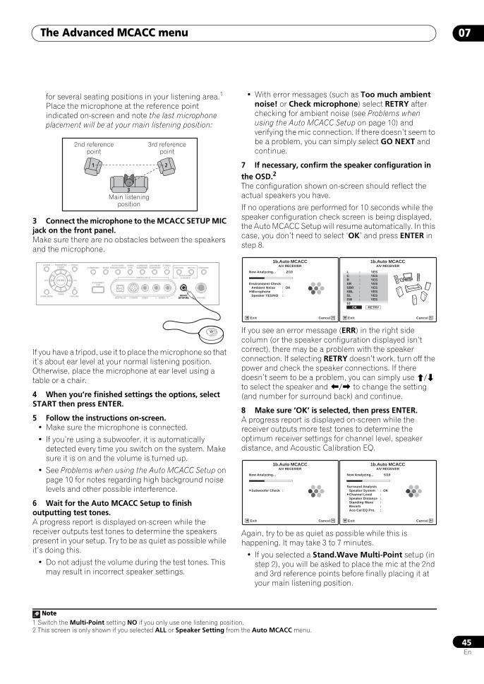
The Advanced MCACC menu 07
45En
for several seating positions in your listening area.1 Place the microphone at the reference point indicated on-screen and note the last microphone placement will be at your main listening position:
3 Connect the microphone to the MCACC SETUP MIC jack on the front panel. Make sure there are no obstacles between the speakers and the microphone.
If you have a tripod, use it to place the microphone so that it’s about ear level at your normal listening position. Otherwise, place the microphone at ear level using a table or a chair.
4 When you’re finished settings the options, select START then press ENTER.
5 Follow the instructions on-screen.• Make sure the microphone is connected.
• If you’re using a subwoofer, it is automatically detected every time you switch on the system. Make sure it is on and the volume is turned up.
• See Problems when using the Auto MCACC Setup on page 10 for notes regarding high background noise levels and other possible interference.
6 Wait for the Auto MCACC Setup to finish outputting test tones.A progress report is displayed on-screen while the receiver outputs test tones to determine the speakers present in your setup. Try to be as quiet as possible while it’s doing this.
• Do not adjust the volume during the test tones. This may result in incorrect speaker settings.
• With error messages (such as Too much ambient noise! or Check microphone) select RETRY after checking for ambient noise (see Problems when using the Auto MCACC Setup on page 10) and verifying the mic connection. If there doesn’t seem to be a problem, you can simply select GO NEXT and continue.
7 If necessary, confirm the speaker configuration in the OSD.2
The configuration shown on-screen should reflect the actual speakers you have.
If no operations are performed for 10 seconds while the speaker configuration check screen is being displayed, the Auto MCACC Setup will resume automatically. In this case, you don’t need to select ‘OK’ and press ENTER in step 8.
If you see an error message (ERR) in the right side column (or the speaker configuration displayed isn’t correct), there may be a problem with the speaker connection. If selecting RETRY doesn’t work, turn off the power and check the speaker connections. If there doesn’t seem to be a problem, you can simply use / to select the speaker and / to change the setting (and number for surround back) and continue.
8 Make sure ‘OK’ is selected, then press ENTER.A progress report is displayed on-screen while the receiver outputs more test tones to determine the optimum receiver settings for channel level, speaker distance, and Acoustic Calibration EQ.
Again, try to be as quiet as possible while this is happening. It may take 3 to 7 minutes.
• If you selected a Stand.Wave Multi-Point setup (in step 2), you will be asked to place the mic at the 2nd and 3rd reference points before finally placing it at your main listening position.
Note1 Switch the Multi-Point setting NO if you only use one listening position.
1 2
3
2nd reference point
3rd reference point
Main listening position
VIDEO3 INPUT
DIGITAL IN S-VIDEO VIDEO L RAUDIO PHONES
SPEAKERSCONTROL
MULTI-ZONE& SOURCE
ON/OFF
MCACCSETUP MIC
PARAMETER
ENTER
(TUNE)
(TUNE)
(ST)(ST)
AUDIO VIDEOTUNER EDIT
iPod DIRECTUSB
AUTO SURR/STREAM DIRECT
HOMETHX
STANDARDSURROUND
ADVANCEDSURROUND
STEREO/A.L.C.BAND
HOME MENU RETURN MCACCSETUP MIC
2 This screen is only shown if you selected ALL or Speaker Setting from the Auto MCACC menu.
Now Analyzing... 2/10
Environment Check
1b.Auto MCACCA/V RECEIVER
Exit Cancel
Ambient Noise : OKMicrophone : Speaker YES/NO :
L : YES
R : YESC : YES
1b.Auto MCACC
SR : YESSBR : YESSBL : YESSL : YESSW : YES10 OK RETRY
A/V RECEIVER
Exit Cancel
Now Analyzing...
1b.Auto MCACCA/V RECEIVER
Exit Cancel
Subwoofer Check :
Now Analyzing... 5/10
Surround Analysis
1b.Auto MCACCA/V RECEIVER
Exit Cancel
Speaker System : OKChannel Level : Speaker Distance : Standing Wave :Reverb :Aco Cal EQ Pro. :
SCLX81_71.book 45 ページ 2008年7月25日 金曜日 午後3時1分
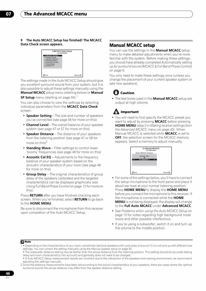
The Advanced MCACC menu07
46En
9 The Auto MCACC Setup has finished! The MCACC Data Check screen appears.
The settings made in the Auto MCACC Setup should give you excellent surround sound from your system, but it is also possible to adjust these settings manually using the Manual MCACC setup menu (starting below) or Manual SP Setup menu (starting on page 55).1
You can also choose to view the settings by selecting individual parameters from the MCACC Data Check screen:
• Speaker Setting – The size and number of speakers you’ve connected (see page 56 for more on this)
• Channel Level – The overall balance of your speaker system (see page 47 or 57 for more on this)
• Speaker Distance – The distance of your speakers from the listening position (see page 47 or 58 for more on this)2
• Standing Wave – Filter settings to control lower ‘boomy’ frequencies (see page 48 for more on this)
• Acoustic Cal EQ – Adjustments to the frequency balance of your speaker system based on the acoustic characteristics of your room (see page 48 for more on this)
• Group Delay – The original characteristics of group delay of the speakers calibrated and the targeted characteristics can be displayed graphically (see Using Full Band Phase Control on page 12 for more on this).
Press RETURN after you have finished checking each screen. When you’re finished, select RETURN to go back to the HOME MENU.
Be sure to disconnect the microphone from this receiver upon completion of the Auto MCACC Setup.
Manual MCACC setupYou can use the settings in the Manual MCACC setup menu to make detailed adjustments when you’re more familiar with the system. Before making these settings, you should have already completed Automatically setting up for surround sound (MCACC & Full Band Phase Control) on page 9.
You only need to make these settings once (unless you change the placement of your current speaker system or add new speakers).
Caution
• The test tones used in the Manual MCACC setup are output at high volume.
Important
• You will need to first specify the MCACC preset you want to adjust by pressing MCACC before pressing HOME MENU (step 2 in Making receiver settings from the Advanced MCACC menu on page 43). When Manual MCACC is selected while MCACC is set to OFF, the selection screen for the MCACC memory appears. Select a memory to adjust manually.
• For some of the settings below, you’ll have to connect the setup microphone to the front panel and place it about ear level at your normal listening position. Press HOME MENU to display the HOME MENU before you connect the microphone to this receiver. If the microphone is connected while the HOME MENU is not being displayed, the display will change to the Full Auto MCACC under Advanced MCACC.
• See Problems when using the Auto MCACC Setup on page 10 for notes regarding high background noise levels and other possible interference.
• If you’re using a subwoofer, switch it on and turn up the volume to the middle position.
Note1 • Depending on the characteristics of your room, sometimes identical speakers with cone sizes of around 12 cm will end up with different size
settings. You can correct the setting manually using the Manual speaker setup on page 55.• The subwoofer distance setting may be farther than the actual distance from the listening position. This setting should be accurate (taking delay and room characteristics into account) and generally does not need to be changed.• If Auto MCACC Setup measurement results are incorrect due to the interaction of the speakers and viewing environment, we recommend adjusting the settings manually.
2 Since the distance measurements have been set according to the sound characteristics of your speakers, there are cases where (for optimal surround sound) the actual distance may differ from the speaker distance setting.
a. Speaker Settingb. Channel Levelc. Speaker Distance
2.MCACC Data Check
d. Standing Wavee. Acoustic Cal EQf. Group Delayg. Output PC
A/V RECEIVER
Exit Return
A/V RECEIVER
Exit Cancel
Select MCACC memory.
MCACC OFF
1c.Manual MCACC
M1.MEMORY 1
SCLX81_71.book 46 ページ 2008年7月25日 金曜日 午後3時1分
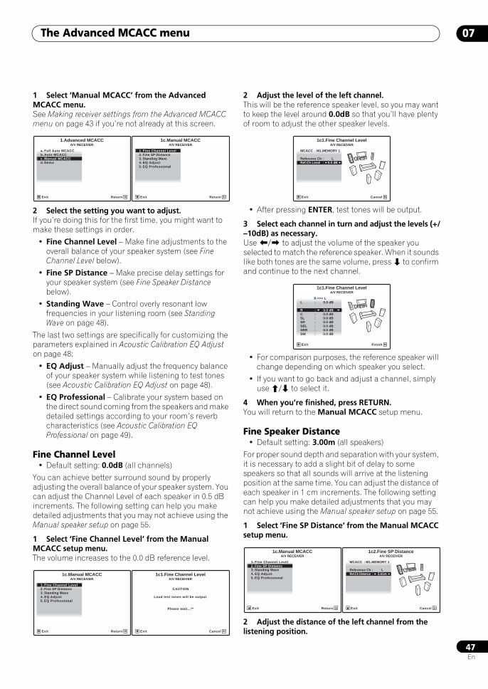
The Advanced MCACC menu 07
47En
1 Select ‘Manual MCACC’ from the Advanced MCACC menu. See Making receiver settings from the Advanced MCACC menu on page 43 if you’re not already at this screen.
2 Select the setting you want to adjust.If you’re doing this for the first time, you might want to make these settings in order.
• Fine Channel Level – Make fine adjustments to the overall balance of your speaker system (see Fine Channel Level below).
• Fine SP Distance – Make precise delay settings for your speaker system (see Fine Speaker Distance below).
• Standing Wave – Control overly resonant low frequencies in your listening room (see Standing Wave on page 48).
The last two settings are specifically for customizing the parameters explained in Acoustic Calibration EQ Adjust on page 48:
• EQ Adjust – Manually adjust the frequency balance of your speaker system while listening to test tones (see Acoustic Calibration EQ Adjust on page 48).
• EQ Professional – Calibrate your system based on the direct sound coming from the speakers and make detailed settings according to your room’s reverb characteristics (see Acoustic Calibration EQ Professional on page 49).
Fine Channel Level• Default setting: 0.0dB (all channels)
You can achieve better surround sound by properly adjusting the overall balance of your speaker system. You can adjust the Channel Level of each speaker in 0.5 dB increments. The following setting can help you make detailed adjustments that you may not achieve using the Manual speaker setup on page 55.
1 Select ‘Fine Channel Level’ from the Manual MCACC setup menu.The volume increases to the 0.0 dB reference level.
2 Adjust the level of the left channel.This will be the reference speaker level, so you may want to keep the level around 0.0dB so that you’ll have plenty of room to adjust the other speaker levels.
• After pressing ENTER, test tones will be output.
3 Select each channel in turn and adjust the levels (+/–10dB) as necessary.Use / to adjust the volume of the speaker you selected to match the reference speaker. When it sounds like both tones are the same volume, press to confirm and continue to the next channel.
• For comparison purposes, the reference speaker will change depending on which speaker you select.
• If you want to go back and adjust a channel, simply use / to select it.
4 When you’re finished, press RETURN.You will return to the Manual MCACC setup menu.
Fine Speaker Distance• Default setting: 3.00m (all speakers)
For proper sound depth and separation with your system, it is necessary to add a slight bit of delay to some speakers so that all sounds will arrive at the listening position at the same time. You can adjust the distance of each speaker in 1 cm increments. The following setting can help you make detailed adjustments that you may not achieve using the Manual speaker setup on page 55.
1 Select ‘Fine SP Distance’ from the Manual MCACC setup menu.
2 Adjust the distance of the left channel from the listening position.
a. Full Auto MCACC b. Auto MCACCc. Manual MCACCd. Demo
1.Advanced MCACCA/V RECEIVER
Exit Return
1. Fine Channel Level2. Fine SP Distance3. Standing Wave
1c.Manual MCACC
4. EQ Adjust5. EQ Professional
A/V RECEIVER
Exit Return
1. Fine Channel Level2. Fine SP Distance3. Standing Wave
1c.Manual MCACC
4. EQ Adjust5. EQ Professional
A/V RECEIVER
Exit Return
CAUTION
Loud test tones will be output.
Please wait...**
1c1.Fine Channel LevelA/V RECEIVER
Exit Cancel
A/V RECEIVER
Exit Cancel
MCACC : M1.MEMORY 1
Reference Ch : L
1c1.Fine Channel Level
Ref.Ch Level : 0.0 dB
A/V RECEIVER
Exit Finish
R <=> LL : 0.0 dB
1c1.Fine Channel Level
R : 0.0 dBC : 0.0 dB
SR : 0.0 dBSL : 0.0 dB
SBL : 0.0 dBSBR : 0.0 dBSW : 0.0 dB
1. Fine Channel Level2. Fine SP Distance3. Standing Wave
1c.Manual MCACC
4. EQ Adjust5. EQ Professional
A/V RECEIVER
Exit Return
A/V RECEIVER
Exit Cancel
MCACC : M1.MEMORY 1
Reference Ch : L
1c2.Fine SP Distance
Ref.Ch Distance : 3.61m
SCLX81_71.book 47 ページ 2008年7月25日 金曜日 午後3時1分
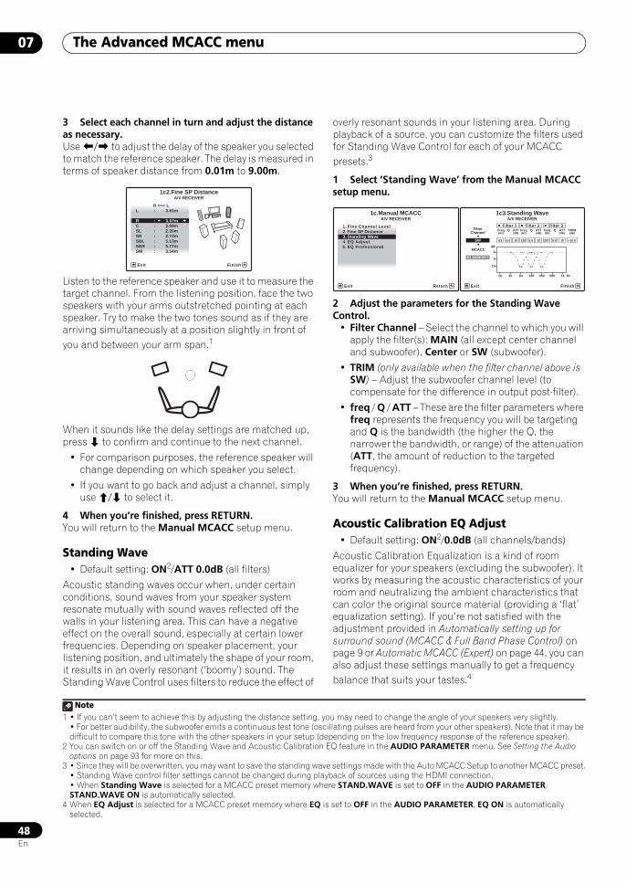
The Advanced MCACC menu07
48En
3 Select each channel in turn and adjust the distance as necessary.Use / to adjust the delay of the speaker you selected to match the reference speaker. The delay is measured in terms of speaker distance from 0.01m to 9.00m.
Listen to the reference speaker and use it to measure the target channel. From the listening position, face the two speakers with your arms outstretched pointing at each speaker. Try to make the two tones sound as if they are arriving simultaneously at a position slightly in front of you and between your arm span.1
When it sounds like the delay settings are matched up, press to confirm and continue to the next channel.
• For comparison purposes, the reference speaker will change depending on which speaker you select.
• If you want to go back and adjust a channel, simply use / to select it.
4 When you’re finished, press RETURN.You will return to the Manual MCACC setup menu.
Standing Wave• Default setting: ON2/ATT 0.0dB (all filters)
Acoustic standing waves occur when, under certain conditions, sound waves from your speaker system resonate mutually with sound waves reflected off the walls in your listening area. This can have a negative effect on the overall sound, especially at certain lower frequencies. Depending on speaker placement, your listening position, and ultimately the shape of your room, it results in an overly resonant (‘boomy’) sound. The Standing Wave Control uses filters to reduce the effect of
overly resonant sounds in your listening area. During playback of a source, you can customize the filters used for Standing Wave Control for each of your MCACC presets.3
1 Select ‘Standing Wave’ from the Manual MCACC setup menu.
2 Adjust the parameters for the Standing Wave Control.
• Filter Channel – Select the channel to which you will apply the filter(s): MAIN (all except center channel and subwoofer), Center or SW (subwoofer).
• TRIM (only available when the filter channel above is SW) – Adjust the subwoofer channel level (to compensate for the difference in output post-filter).
• freq / Q / ATT – These are the filter parameters where freq represents the frequency you will be targeting and Q is the bandwidth (the higher the Q, the narrower the bandwidth, or range) of the attenuation (ATT, the amount of reduction to the targeted frequency).
3 When you’re finished, press RETURN.You will return to the Manual MCACC setup menu.
Acoustic Calibration EQ Adjust• Default setting: ON2/0.0dB (all channels/bands)
Acoustic Calibration Equalization is a kind of room equalizer for your speakers (excluding the subwoofer). It works by measuring the acoustic characteristics of your room and neutralizing the ambient characteristics that can color the original source material (providing a ‘flat’ equalization setting). If you’re not satisfied with the adjustment provided in Automatically setting up for surround sound (MCACC & Full Band Phase Control) on page 9 or Automatic MCACC (Expert) on page 44, you can also adjust these settings manually to get a frequency balance that suits your tastes.4
Note1 • If you can’t seem to achieve this by adjusting the distance setting, you may need to change the angle of your speakers very slightly.
• For better audibility, the subwoofer emits a continuous test tone (oscillating pulses are heard from your other speakers). Note that it may be difficult to compare this tone with the other speakers in your setup (depending on the low frequency response of the reference speaker).
2 You can switch on or off the Standing Wave and Acoustic Calibration EQ feature in the AUDIO PARAMETER menu. See Setting the Audio options on page 93 for more on this.
A/V RECEIVER
Exit Finish
R <=> LL : 3.61m
1c2.Fine SP Distance
R : 3.67mC : 3.69m
SR : 2.74mSL : 2.26m
SBL : 5.13mSBR : 5.77mSW : 3.54m
3 • Since they will be overwritten, you may want to save the standing wave settings made with the Auto MCACC Setup to another MCACC preset.• Standing Wave control filter settings cannot be changed during playback of sources using the HDMI connection.• When Standing Wave is selected for a MCACC preset memory where STAND.WAVE is set to OFF in the AUDIO PARAMETER, STAND.WAVE ON is automatically selected.
4 When EQ Adjust is selected for a MCACC preset memory where EQ is set to OFF in the AUDIO PARAMETER, EQ ON is automatically selected.
1. Fine Channel Level2. Fine SP Distance3. Standing Wave
1c.Manual MCACC
4. EQ Adjust5. EQ Professional
A/V RECEIVER
Exit Return
1c3.Standing WaveA/V RECEIVER
Exit Finish
Filter 1Freq[Hz]
Q ATT[dB]
Filter 2Freq[Hz]
Q ATT[dB]
Filter 3Freq[Hz]
Q ATT[dB]
63SW
FilterChannel
0dB
5
10
16 32 63 125 250 500 1k Hz
105.0 120 105.0 201 10 +10.05.0
TRIM[dB]
MCACC
M1.MEMORY1
SCLX81_71.book 48 ページ 2008年7月25日 金曜日 午後3時1分
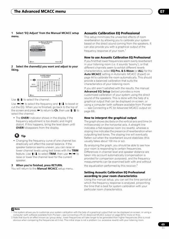
The Advanced MCACC menu 07
49En
1 Select ‘EQ Adjust’ from the Manual MCACC setup menu.
2 Select the channel(s) you want and adjust to your liking.
Use / to select the channel.
Use / to select the frequency and / to boost or cut the EQ. When you’re finished, go back to the top of the screen and press to return to Ch, then use / to select the channel.
• The OVER! indicator shows in the display if the frequency adjustment is too drastic and might distort. If this happens, bring the level down until OVER! disappears from the display.
Tip
• Changing the frequency curve of one channel too drastically will affect the overall balance. If the speaker balance seems uneven, you can raise or lower channel levels using test tones with the TRIM feature. Use / to select TRIM, then use / to raise or lower the channel level for the current speaker.
3 When you’re finished, press RETURN.You will return to the Manual MCACC setup menu.
Acoustic Calibration EQ Professional This setup minimizes the unwanted effects of room reverberation by allowing you to calibrate your system based on the direct sound coming from the speakers. It can also provide you with a graphical output of the frequency response of your room.1
How to use Acoustic Calibration EQ ProfessionalIf you find that lower frequencies seem overly reverberant in your listening room (i.e. it sounds ‘boomy’), or that different channels seem to exhibit different reverb characteristics, select EQ Pro. & S-Wave (or ALL) for the Auto MCACC setting in Automatic MCACC (Expert) on page 44 to calibrate the room automatically. This should provide a balanced calibration that suits the characteristics of your listening room.
If you still aren’t satisfied with the results, the manual Advanced EQ Setup (below) provides a more customized calibration of your system using the direct sound of the speakers. This is done with the help of a graphical output that can be displayed on-screen, or using a computer (with software available from Pioneer — see Connecting a PC for Advanced MCACC output on page 69).
How to interpret the graphical outputThe graph shows decibels on the vertical axis and time (in milliseconds) on the horizontal axis. A straight line indicates a flat-response room (no reverb), whereas a sloping line indicates the presence of reverberation when outputting test tones. The sloping line will eventually flatten out when the reverberant sound stabilizes (this usually takes about 100 ms or so).
By analyzing the graph, you should be able to see how your room is responding to certain frequencies. Differences in channel level and speaker distance are taken into account automatically (compensation is provided for comparison purposes), and the frequency measurements can be examined both with and without the equalization performed by this receiver.2
Setting Acoustic Calibration EQ Professional according to your room characteristicsUsing the manual setup, you can set the time period at which the frequency response is analyzed, pinpointing the time that is best for system calibration with your particular room characteristics.
1. Fine Channel Level2. Fine SP Distance3. Standing Wave
1c.Manual MCACC
4. EQ Adjust5. EQ Professional
A/V RECEIVER
Exit Return
63[Hz]
125[Hz]
250[Hz]
500[Hz]
1k[Hz]
2k[Hz]
4k[Hz]
8k[Hz]
16k[Hz]
TRIM
dB
1c4.EQ Adjust
Exit Finish
0.0Ch : L -6.0-8.0 0.0 +8.5+3.0 +8.5 0.0 0.0+3.0
A/V RECEIVER
MCACC
M1.MEMORY1
Note1 This system allows you to customize your system calibration with the help of a graphical output that can be displayed on-screen, or using a
computer (with software available from Pioneer—see Connecting a PC for Advanced MCACC output on page 69 for more on this). 2 Note that due to an effect known as ‘group delay’, lower frequencies will take longer to be generated than higher frequencies (this is most
obvious when comparing the frequencies at 0 ms). This initial slope is not a problem (i.e. excessive reverb) with your listening room.
SCLX81_71.book 49 ページ 2008年7月25日 金曜日 午後3時1分
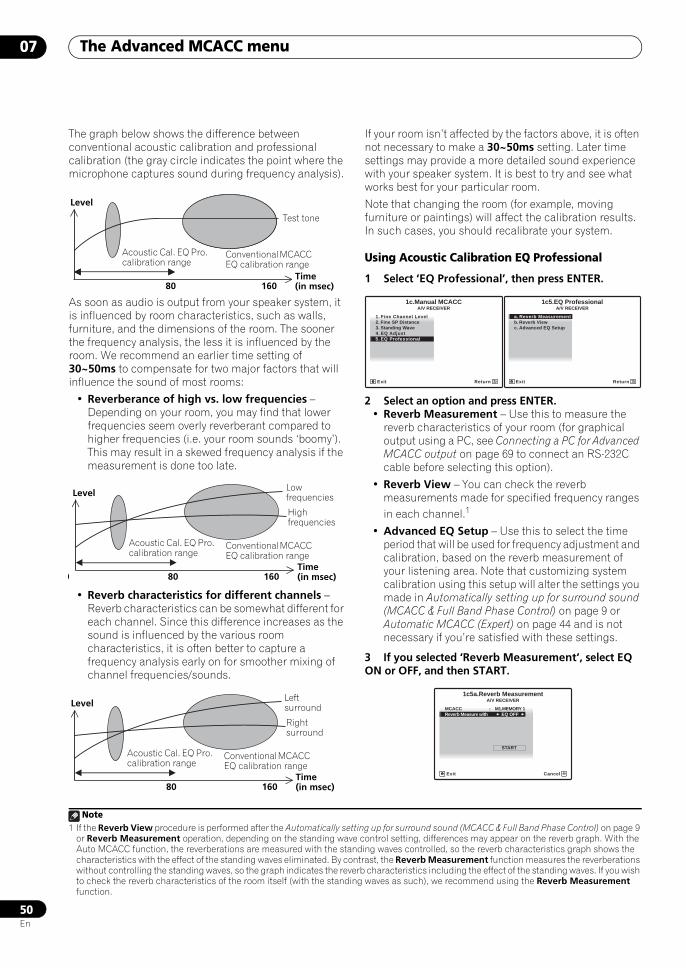
The Advanced MCACC menu07
50En
The graph below shows the difference between conventional acoustic calibration and professional calibration (the gray circle indicates the point where the microphone captures sound during frequency analysis).
As soon as audio is output from your speaker system, it is influenced by room characteristics, such as walls, furniture, and the dimensions of the room. The sooner the frequency analysis, the less it is influenced by the room. We recommend an earlier time setting of 30~50ms to compensate for two major factors that will influence the sound of most rooms:
• Reverberance of high vs. low frequencies – Depending on your room, you may find that lower frequencies seem overly reverberant compared to higher frequencies (i.e. your room sounds ‘boomy’). This may result in a skewed frequency analysis if the measurement is done too late.
• Reverb characteristics for different channels – Reverb characteristics can be somewhat different for each channel. Since this difference increases as the sound is influenced by the various room characteristics, it is often better to capture a frequency analysis early on for smoother mixing of channel frequencies/sounds.
If your room isn’t affected by the factors above, it is often not necessary to make a 30~50ms setting. Later time settings may provide a more detailed sound experience with your speaker system. It is best to try and see what works best for your particular room.
Note that changing the room (for example, moving furniture or paintings) will affect the calibration results. In such cases, you should recalibrate your system.
Using Acoustic Calibration EQ Professional
1 Select ‘EQ Professional’, then press ENTER.
2 Select an option and press ENTER.• Reverb Measurement – Use this to measure the
reverb characteristics of your room (for graphical output using a PC, see Connecting a PC for Advanced MCACC output on page 69 to connect an RS-232C cable before selecting this option).
• Reverb View – You can check the reverb measurements made for specified frequency ranges in each channel.1
• Advanced EQ Setup – Use this to select the time period that will be used for frequency adjustment and calibration, based on the reverb measurement of your listening area. Note that customizing system calibration using this setup will alter the settings you made in Automatically setting up for surround sound (MCACC & Full Band Phase Control) on page 9 or Automatic MCACC (Expert) on page 44 and is not necessary if you’re satisfied with these settings.
3 If you selected ‘Reverb Measurement’, select EQ ON or OFF, and then START.
Level
Test tone
Acoustic Cal. EQ Pro. calibration range
Conventional MCACC EQ calibration range
Time (in msec)80 160
LevelLow frequencies
Acoustic Cal. EQ Pro. calibration range
Time (in msec)0 80 160
High frequencies
Conventional MCACC EQ calibration range
LevelLeft surround
Acoustic Cal. EQ Pro. calibration range
Time (in msec)80 160
Right surround
Conventional MCACC EQ calibration range
Note1 If the Reverb View procedure is performed after the Automatically setting up for surround sound (MCACC & Full Band Phase Control) on page 9
or Reverb Measurement operation, depending on the standing wave control setting, differences may appear on the reverb graph. With the Auto MCACC function, the reverberations are measured with the standing waves controlled, so the reverb characteristics graph shows the characteristics with the effect of the standing waves eliminated. By contrast, the Reverb Measurement function measures the reverberations without controlling the standing waves, so the graph indicates the reverb characteristics including the effect of the standing waves. If you wish to check the reverb characteristics of the room itself (with the standing waves as such), we recommend using the Reverb Measurement function.
1. Fine Channel Level2. Fine SP Distance3. Standing Wave
1c.Manual MCACC
4. EQ Adjust5. EQ Professional
A/V RECEIVER
Exit Return
a. Reverb Measurementb. Reverb Viewc. Advanced EQ Setup
1c5.EQ ProfessionalA/V RECEIVER
Exit Return
MCACC : M1.MEMORY 1
1c5a.Reverb MeasurementA/V RECEIVER
Exit Cancel
START
Reverb Measure with : EQ OFF
SCLX81_71.book 50 ページ 2008年7月25日 金曜日 午後3時1分
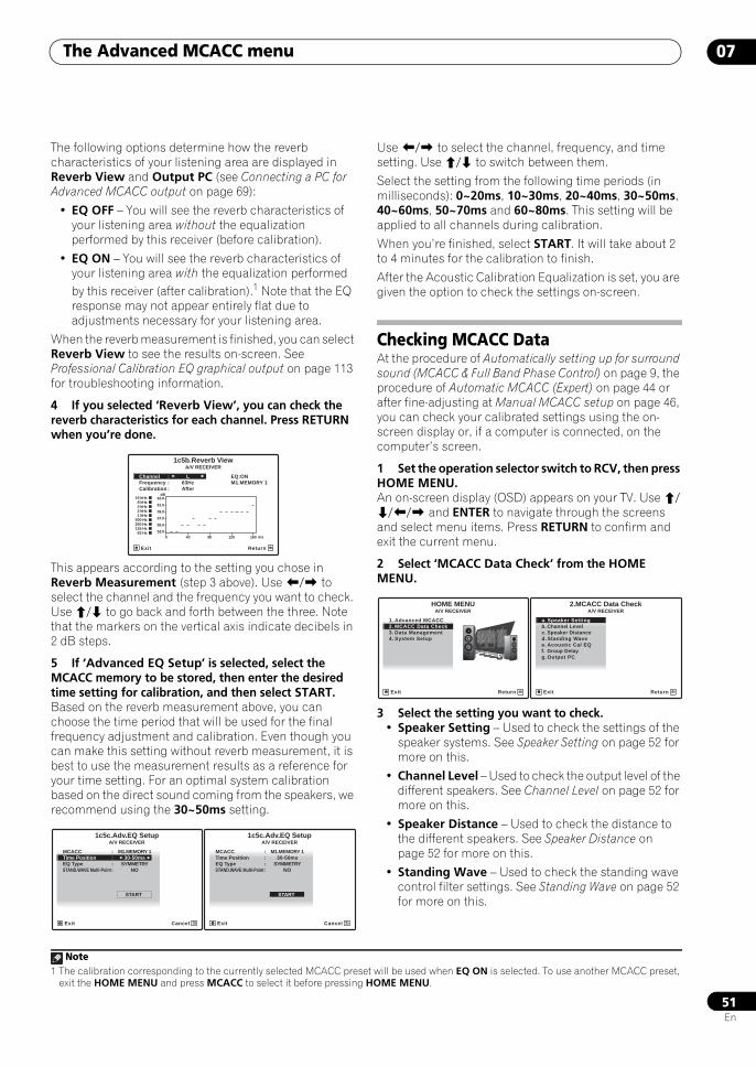
The Advanced MCACC menu 07
51En
The following options determine how the reverb characteristics of your listening area are displayed in Reverb View and Output PC (see Connecting a PC for Advanced MCACC output on page 69):
• EQ OFF – You will see the reverb characteristics of your listening area without the equalization performed by this receiver (before calibration).
• EQ ON – You will see the reverb characteristics of your listening area with the equalization performed by this receiver (after calibration).1 Note that the EQ response may not appear entirely flat due to adjustments necessary for your listening area.
When the reverb measurement is finished, you can select Reverb View to see the results on-screen. See Professional Calibration EQ graphical output on page 113 for troubleshooting information.
4 If you selected ‘Reverb View’, you can check the reverb characteristics for each channel. Press RETURN when you’re done.
This appears according to the setting you chose in Reverb Measurement (step 3 above). Use / to select the channel and the frequency you want to check. Use / to go back and forth between the three. Note that the markers on the vertical axis indicate decibels in 2 dB steps.
5 If ‘Advanced EQ Setup’ is selected, select the MCACC memory to be stored, then enter the desired time setting for calibration, and then select START.Based on the reverb measurement above, you can choose the time period that will be used for the final frequency adjustment and calibration. Even though you can make this setting without reverb measurement, it is best to use the measurement results as a reference for your time setting. For an optimal system calibration based on the direct sound coming from the speakers, we recommend using the 30~50ms setting.
Use / to select the channel, frequency, and time setting. Use / to switch between them.
Select the setting from the following time periods (in milliseconds): 0~20ms, 10~30ms, 20~40ms, 30~50ms, 40~60ms, 50~70ms and 60~80ms. This setting will be applied to all channels during calibration.
When you’re finished, select START. It will take about 2 to 4 minutes for the calibration to finish.
After the Acoustic Calibration Equalization is set, you are given the option to check the settings on-screen.
Checking MCACC DataAt the procedure of Automatically setting up for surround sound (MCACC & Full Band Phase Control) on page 9, the procedure of Automatic MCACC (Expert) on page 44 or after fine-adjusting at Manual MCACC setup on page 46, you can check your calibrated settings using the on-screen display or, if a computer is connected, on the computer’s screen.
1 Set the operation selector switch to RCV, then press HOME MENU.An on-screen display (OSD) appears on your TV. Use /// and ENTER to navigate through the screens and select menu items. Press RETURN to confirm and exit the current menu.
2 Select ‘MCACC Data Check’ from the HOME MENU.
3 Select the setting you want to check.• Speaker Setting – Used to check the settings of the
speaker systems. See Speaker Setting on page 52 for more on this.
• Channel Level – Used to check the output level of the different speakers. See Channel Level on page 52 for more on this.
• Speaker Distance – Used to check the distance to the different speakers. See Speaker Distance on page 52 for more on this.
• Standing Wave – Used to check the standing wave control filter settings. See Standing Wave on page 52 for more on this.
Note1 The calibration corresponding to the currently selected MCACC preset will be used when EQ ON is selected. To use another MCACC preset,
exit the HOME MENU and press MCACC to select it before pressing HOME MENU.
1c5b.Reverb View
Exit Return
Channel : L EQ:ON
Calibration : AfterFrequency : 63Hz M1.MEMORY 1
A/V RECEIVER
dB
53.0
55.0
57.0
59.0
61.0
63.016 kHz8 kHz4 kHz2 kHz1 kHz
500 Hz250 Hz125 Hz63 Hz
0 40 80 120 160 ms
MCACC : M1.MEMORY 1
1c5c.Adv.EQ SetupA/V RECEIVER
Exit Cancel
START
Time Position : 30-50msEQ Type : SYMMETRYSTAND.WAVE Multi-Point : NO
MCACC : M1.MEMORY 1
1c5c.Adv.EQ SetupA/V RECEIVER
Exit Cancel
START
Time Position : 30-50msEQ Type : SYMMETRYSTAND.WAVE Multi-Point : NO
1. Advanced MCACC2. MCACC Data Check3. Data Management4. System Setup
Exit Return
HOME MENUA/V RECEIVER
a. Speaker Settingb. Channel Levelc. Speaker Distance
2.MCACC Data Check
d. Standing Wavee. Acoustic Cal EQf. Group Delayg. Output PC
A/V RECEIVER
Exit Return
SCLX81_71.book 51 ページ 2008年7月25日 金曜日 午後3時1分
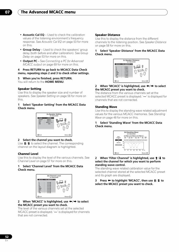
The Advanced MCACC menu07
52En
• Acoustic Cal EQ – Used to check the calibration values of the listening environment’s frequency response. See Acoustic Cal EQ on page 53 for more on this.
• Group Delay – Used to check the speakers’ group delay (both before and after calibration). See Group Delay on page 53 for more on this.
• Output PC – See Connecting a PC for Advanced MCACC output on page 69 for more on this.
4 Press RETURN to go back to MCACC Data Check menu, repeating steps 2 and 3 to check other settings.
5 When you’re finished, press RETURN.You will return to the HOME MENU.
Speaker SettingUse this to display the speaker size and number of speakers. See Speaker Setting on page 56 for more on this.
1 Select ‘Speaker Setting’ from the MCACC Data Check menu.
2 Select the channel you want to check.Use / to select the channel. The corresponding channel on the layout diagram is highlighted.
Channel LevelUse this to display the level of the various channels. See Channel Level on page 57 for more on this.
1 Select ‘Channel Level’ from the MCACC Data Check menu.
2 When ‘MCACC’ is highlighted, use / to select the MCACC preset you want to check.The level of the various channels set at the selected MCACC preset is displayed. ‘---’ is displayed for channels that are not connected.
Speaker DistanceUse this to display the distance from the different channels to the listening position. See Speaker Distance on page 58 for more on this.
1 Select ‘Speaker Distance’ from the MCACC Data Check menu.
2 When ‘MCACC’ is highlighted, use / to select the MCACC preset you want to check.The distance from the various channels set at the selected MCACC preset is displayed. ‘---’ is displayed for channels that are not connected.
Standing WaveUse this to display the standing wave related adjustment values for the various MCACC memories. See Standing Wave on page 48 for more on this.
1 Select ‘Standing Wave’ from the MCACC Data Check menu.
2 When ‘Filter Channel’ is highlighted, use / to select the channel for which you want to perform standing wave control.The standing wave related calibration value for the selected channel stored at the selected MCACC preset and its graph are displayed.
3 Press to highlight ‘MCACC’, then use / to select the MCACC preset you want to check.
Front : LARGE
Surr : SMALLCenter : SMALL
2a.Speaker Setting
SB : SMALL x 2SW : YES
A/V RECEIVER
Exit Return
A/V RECEIVER
Exit Return
MCACC : M1.MEMORY 1
L : 0.0 dB
2b.Channel Level
C : 0.0 dBR : 0.0 dB
SBR : 0.0 dBSR : 0.0 dB
SBL : 0.0 dBSL : 0.0 dBSW : 0.0 dB
A/V RECEIVER
Exit Return
L : 3.61m
2c.Speaker Distance
C : 3.69mR : 3.51m
SBR : 5.77mSR : 2.74m
SBL : 5.13mSL : 2.26mSW : 3.54m
MCACC : M1.MEMORY 1
2d.Standing WaveA/V RECEIVER
Exit Return
Filter 1Freq[Hz]
Q ATT[dB]
Filter 2Freq[Hz]
Q ATT[dB]
Filter 3Freq[Hz]
Q ATT[dB]
63SW
FilterChannel
105.0 120 105.0 201 10 +10.05.0
TRIM[dB]
0
5
10
16 32 63 125 250 500 1k Hz
dBMCACC
M1.MEMORY1
SCLX81_71.book 52 ページ 2008年7月25日 金曜日 午後3時1分
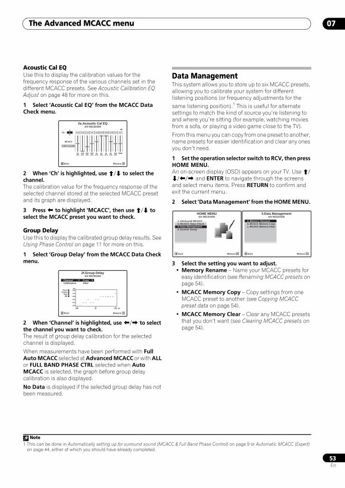
The Advanced MCACC menu 07
53En
Acoustic Cal EQUse this to display the calibration values for the frequency response of the various channels set in the different MCACC presets. See Acoustic Calibration EQ Adjust on page 48 for more on this.
1 Select ‘Acoustic Cal EQ’ from the MCACC Data Check menu.
2 When ‘Ch’ is highlighted, use / to select the channel.The calibration value for the frequency response of the selected channel stored at the selected MCACC preset and its graph are displayed.
3 Press to highlight ‘MCACC’, then use / to select the MCACC preset you want to check.
Group DelayUse this to display the calibrated group delay results. See Using Phase Control on page 11 for more on this.
1 Select ‘Group Delay’ from the MCACC Data Check menu.
2 When ‘Channel’ is highlighted, use / to select the channel you want to check. The result of group delay calibration for the selected channel is displayed.
When measurements have been performed with Full Auto MCACC selected at Advanced MCACC or with ALL or FULL BAND PHASE CTRL selected when Auto MCACC is selected, the graph before group delay calibration is also displayed.
No Data is displayed if the selected group delay has not been measured.
Data ManagementThis system allows you to store up to six MCACC presets, allowing you to calibrate your system for different listening positions (or frequency adjustments for the same listening position).1 This is useful for alternate settings to match the kind of source you’re listening to and where you’re sitting (for example, watching movies from a sofa, or playing a video game close to the TV).
From this menu you can copy from one preset to another, name presets for easier identification and clear any ones you don’t need.
1 Set the operation selector switch to RCV, then press HOME MENU.An on-screen display (OSD) appears on your TV. Use /// and ENTER to navigate through the screens and select menu items. Press RETURN to confirm and exit the current menu.
2 Select ‘Data Management’ from the HOME MENU.
3 Select the setting you want to adjust.• Memory Rename – Name your MCACC presets for
easy identification (see Renaming MCACC presets on page 54).
• MCACC Memory Copy – Copy settings from one MCACC preset to another (see Copying MCACC preset data on page 54).
• MCACC Memory Clear – Clear any MCACC presets that you don’t want (see Clearing MCACC presets on page 54).
63[Hz]
125[Hz]
250[Hz]
500[Hz]
1k[Hz]
2k[Hz]
4k[Hz]
8k[Hz]
16k[Hz]
TRIM
dB
2e.Acoustic Cal EQ
Exit Return
0.0Ch : L -6.0-8.0 0.0 +8.5+3.0 +8.5 0.0 0.0+3.0
A/V RECEIVER
MCACC
M1.MEMORY1
2f.Group Delay
Exit Return
Channel : FrontCalibration : After
A/V RECEIVER
ms
-1.0
-0.4
0.2
0.8
1.4
2.0
200 2k 20k Hz
FrontCenter
SurrSB
Note1 This can be done in Automatically setting up for surround sound (MCACC & Full Band Phase Control) on page 9 or Automatic MCACC (Expert)
on page 44, either of which you should have already completed.
1. Advanced MCACC2. MCACC Data Check3. Data Management4. System Setup
Exit Return
HOME MENUA/V RECEIVER
a. Memory Renameb. MCACC Memory Copyc. MCACC Memory Clear
3.Data ManagementA/V RECEIVER
Exit Return
SCLX81_71.book 53 ページ 2008年7月25日 金曜日 午後3時1分
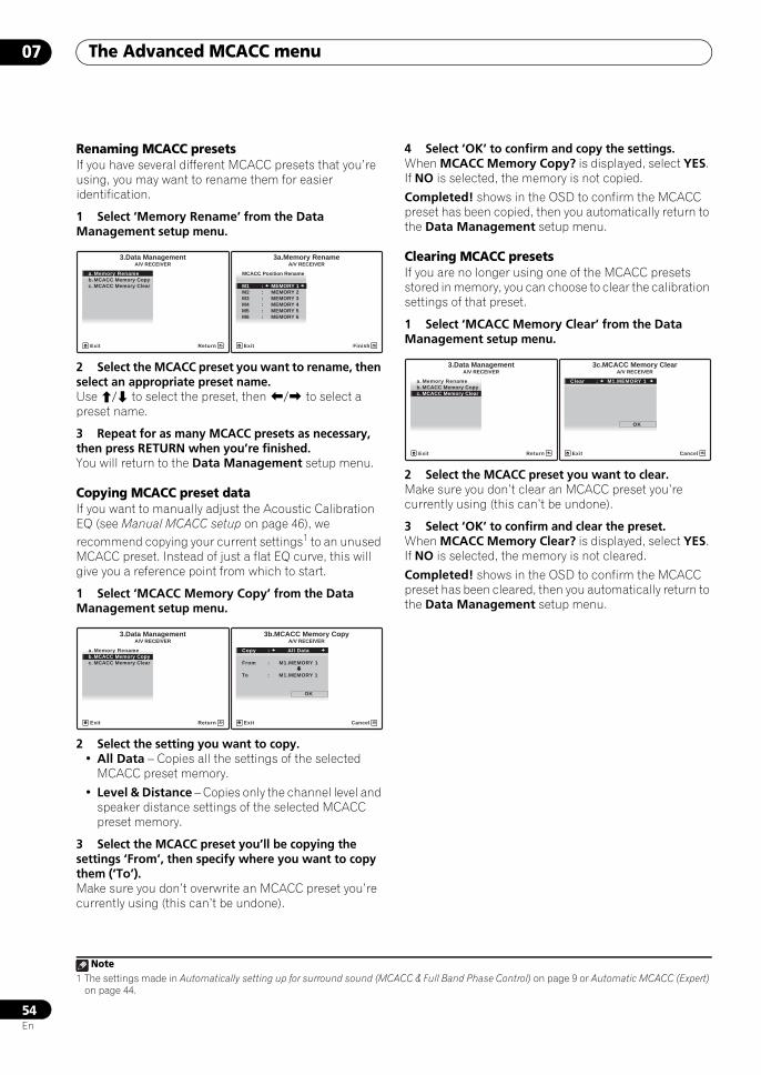
The Advanced MCACC menu07
54En
Renaming MCACC presetsIf you have several different MCACC presets that you’re using, you may want to rename them for easier identification.
1 Select ‘Memory Rename’ from the Data Management setup menu.
2 Select the MCACC preset you want to rename, then select an appropriate preset name.Use / to select the preset, then / to select a preset name.
3 Repeat for as many MCACC presets as necessary, then press RETURN when you’re finished.You will return to the Data Management setup menu.
Copying MCACC preset dataIf you want to manually adjust the Acoustic Calibration EQ (see Manual MCACC setup on page 46), we recommend copying your current settings1 to an unused MCACC preset. Instead of just a flat EQ curve, this will give you a reference point from which to start.
1 Select ‘MCACC Memory Copy’ from the Data Management setup menu.
2 Select the setting you want to copy.• All Data – Copies all the settings of the selected
MCACC preset memory.
• Level & Distance – Copies only the channel level and speaker distance settings of the selected MCACC preset memory.
3 Select the MCACC preset you’ll be copying the settings ‘From’, then specify where you want to copy them (‘To’).Make sure you don’t overwrite an MCACC preset you’re currently using (this can’t be undone).
4 Select ‘OK’ to confirm and copy the settings.When MCACC Memory Copy? is displayed, select YES. If NO is selected, the memory is not copied.
Completed! shows in the OSD to confirm the MCACC preset has been copied, then you automatically return to the Data Management setup menu.
Clearing MCACC presetsIf you are no longer using one of the MCACC presets stored in memory, you can choose to clear the calibration settings of that preset.
1 Select ‘MCACC Memory Clear’ from the Data Management setup menu.
2 Select the MCACC preset you want to clear.Make sure you don’t clear an MCACC preset you’re currently using (this can’t be undone).
3 Select ‘OK’ to confirm and clear the preset.When MCACC Memory Clear? is displayed, select YES. If NO is selected, the memory is not cleared.
Completed! shows in the OSD to confirm the MCACC preset has been cleared, then you automatically return to the Data Management setup menu.
Note1 The settings made in Automatically setting up for surround sound (MCACC & Full Band Phase Control) on page 9 or Automatic MCACC (Expert)
on page 44.
a. Memory Renameb. MCACC Memory Copyc. MCACC Memory Clear
3.Data ManagementA/V RECEIVER
Exit Return
MCACC Position Rename
M1 : MEMORY 1
3a.Memory Rename
M2 : MEMORY 2M3 : MEMORY 3M4 : MEMORY 4M5 : MEMORY 5M6 : MEMORY 6
A/V RECEIVER
Exit Finish
a. Memory Renameb. MCACC Memory Copyc. MCACC Memory Clear
3.Data ManagementA/V RECEIVER
Exit Return
Copy : All Data
From : M1.MEMORY 1
3b.MCACC Memory Copy
To : M1.MEMORY 1
OK
A/V RECEIVER
Exit Cancel
a. Memory Renameb. MCACC Memory Copyc. MCACC Memory Clear
3.Data ManagementA/V RECEIVER
Exit Return
Clear : M1.MEMORY 1
3c.MCACC Memory Clear
OK
A/V RECEIVER
Exit Cancel
SCLX81_71.book 54 ページ 2008年7月25日 金曜日 午後3時1分
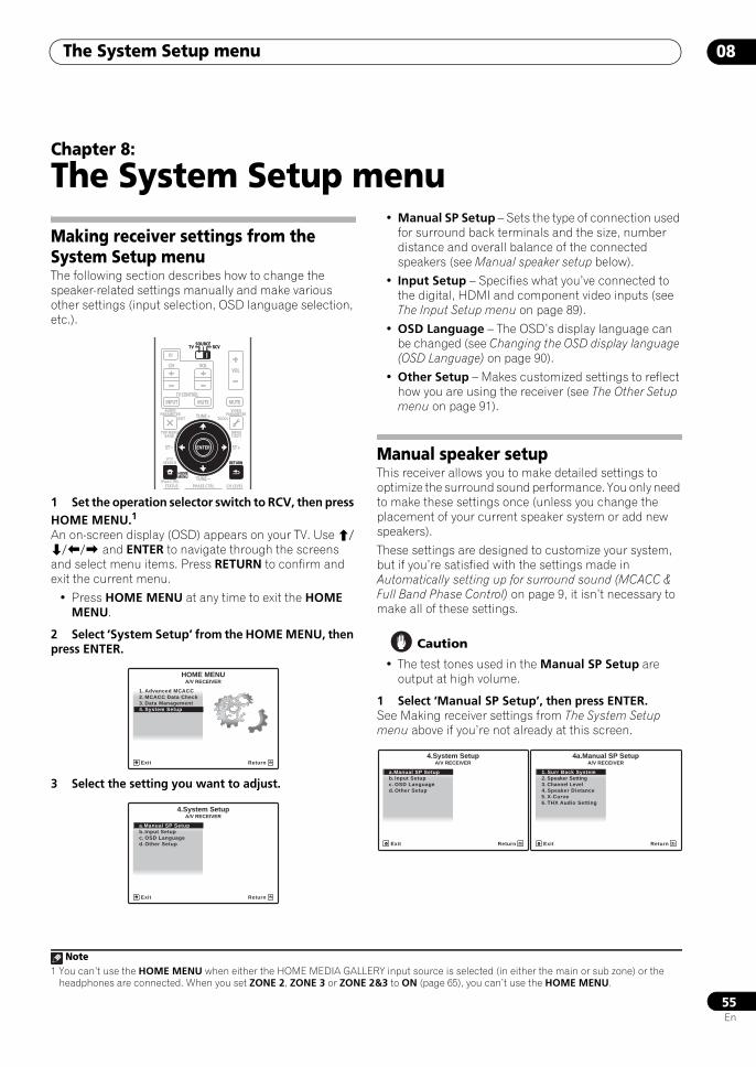
The System Setup menu 08
55En
Chapter 8:
The System Setup menu
Making receiver settings from the System Setup menuThe following section describes how to change the speaker-related settings manually and make various other settings (input selection, OSD language selection, etc.).
1 Set the operation selector switch to RCV, then press HOME MENU.1
An on-screen display (OSD) appears on your TV. Use /// and ENTER to navigate through the screens and select menu items. Press RETURN to confirm and exit the current menu.
• Press HOME MENU at any time to exit the HOME MENU.
2 Select ‘System Setup’ from the HOME MENU, then press ENTER.
3 Select the setting you want to adjust.
• Manual SP Setup – Sets the type of connection used for surround back terminals and the size, number distance and overall balance of the connected speakers (see Manual speaker setup below).
• Input Setup – Specifies what you’ve connected to the digital, HDMI and component video inputs (see The Input Setup menu on page 89).
• OSD Language – The OSD’s display language can be changed (see Changing the OSD display language (OSD Language) on page 90).
• Other Setup – Makes customized settings to reflect how you are using the receiver (see The Other Setup menu on page 91).
Manual speaker setupThis receiver allows you to make detailed settings to optimize the surround sound performance. You only need to make these settings once (unless you change the placement of your current speaker system or add new speakers).
These settings are designed to customize your system, but if you’re satisfied with the settings made in Automatically setting up for surround sound (MCACC & Full Band Phase Control) on page 9, it isn’t necessary to make all of these settings.
Caution
• The test tones used in the Manual SP Setup are output at high volume.
1 Select ‘Manual SP Setup’, then press ENTER. See Making receiver settings from The System Setup menu above if you’re not already at this screen.
Note1 You can’t use the HOME MENU when either the HOME MEDIA GALLERY input source is selected (in either the main or sub zone) or the
headphones are connected. When you set ZONE 2, ZONE 3 or ZONE 2&3 to ON (page 65), you can’t use the HOME MENU.
AUDIOPARAMETER
TOP MENUBAND
iPod CTRL
PTYSEARCH
EXIT TOOLS
STATUS PHASE CTRL CH LEVEL
MENUT.EDIT
VIDEOPARAMETER
SOURCETV RCV
INPUT MUTE MUTE
VOLVOL
TV CONTROL
CH
RETURN
TUNE +
TUNE
ST ST +
HOMEMENU
RETURN
ENTER
SOURCETV RCV
1. Advanced MCACC2. MCACC Data Check3. Data Management4. System Setup
Exit Return
HOME MENUA/V RECEIVER
A/V RECEIVER
Exit Return
a.Manual SP Setupb. Input Setupc. OSD Languaged. Other Setup
4.System Setup
A/V RECEIVER
Exit Return
a.Manual SP Setupb. Input Setupc. OSD Languaged. Other Setup
4.System Setup
1. Surr Back System2. Speaker Setting3. Channel Level
4a.Manual SP Setup
4. Speaker Distance5. X-Curve6. THX Audio Setting
A/V RECEIVER
Exit Return
SCLX81_71.book 55 ページ 2008年7月25日 金曜日 午後3時1分
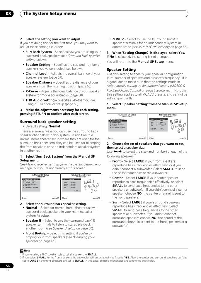
The System Setup menu08
56En
2 Select the setting you want to adjust.If you are doing this for the first time, you may want to adjust these settings in order:
• Surr Back System – Specifies how you are using your surround back speakers (see Surround back speaker setting below).
• Speaker Setting – Specifies the size and number of speakers you’ve connected (see below).
• Channel Level – Adjusts the overall balance of your speaker system (page 57).
• Speaker Distance – Specifies the distance of your speakers from the listening position (page 58).
• X-Curve – Adjusts the tonal balance of your speaker system for movie soundtracks (page 58).
• THX Audio Setting – Specifies whether you are using a THX speaker setup (page 58).
3 Make the adjustments necessary for each setting, pressing RETURN to confirm after each screen.
Surround back speaker setting• Default setting: Normal
There are several ways you can use the surround back speaker channels with this system. In addition to a normal home theater setup where they are used for the surround back speakers, they can be used for bi-amping the front speakers or as an independent speaker system in another room.
1 Select ‘Surr Back System’ from the Manual SP Setup menu.See Making receiver settings from the System Setup menu on page 55 if you’re not already at this screen.
2 Select the surround back speaker setting.• Normal – Select for normal home theater use with
surround back speakers in your main (speaker system A) setup.
• Speaker B – Select to use the (surround back) B speaker terminals to listen to stereo playback in another room (see Speaker B setup on page 60).
• Front Bi-Amp – Select this setting if you’re bi-amping your front speakers (see Bi-amping your speakers on page 61).
• ZONE 2 – Select to use the (surround back) B speaker terminals for an independent system in another zone (see MULTI-ZONE listening on page 63).
3 When ‘Setting Change?’ is displayed, select Yes.If No is selected, the setting is not changed.
You will return to the Manual SP Setup menu.
Speaker SettingUse this setting to specify your speaker configuration (size, number of speakers and crossover frequency). It is a good idea to make sure that the settings made in Automatically setting up for surround sound (MCACC & Full Band Phase Control) on page 9 are correct.1 Note that this setting applies to all MCACC presets, and cannot be set independently.
1 Select ‘Speaker Setting’ from the Manual SP Setup menu.
2 Choose the set of speakers that you want to set, then select a speaker size.Use / to select the size (and number) of each of the following speakers:2
• Front – Select LARGE if your front speakers reproduce bass frequencies effectively, or if you didn’t connect a subwoofer. Select SMALL to send the bass frequencies to the subwoofer.
• Center – Select LARGE if your center speaker reproduces bass frequencies effectively, or select SMALL to send bass frequencies to the other speakers or subwoofer. If you didn’t connect a center speaker, choose NO (the center channel is sent to the front speakers).
• Surr – Select LARGE if your surround speakers reproduce bass frequencies effectively. Select SMALL to send bass frequencies to the other speakers or subwoofer. If you didn’t connect surround speakers choose NO (the sound of the surround channels is sent to the front speakers or a subwoofer).
1. Surr Back System2. Speaker Setting3. Channel Level
4a.Manual SP Setup
4. Speaker Distance5. X-Curve6. THX Audio Setting
A/V RECEIVER
Exit Return
Normal
Front : Normal
4a1.Surr Back System
Center : NormalSurr : NormalSB : Normal
OK
A/V RECEIVER
Exit Return
Note1 If you’re using a THX speaker setup, set all speakers to SMALL.2 If you select SMALL for the front speakers the subwoofer will automatically be fixed to YES. Also, the center and surround speakers can’t be
set to LARGE if the front speakers are set to SMALL. In this case, all bass frequencies are sent to the subwoofer.
1. Surr Back System2. Speaker Setting3. Channel Level4. Speaker Distance5. X-Curve6. THX Audio Setting
4a.Manual SP SetupA/V RECEIVER
Exit Return
Front : LARGE
Surr : SMALLCenter : SMALL
4a2.Speaker Setting
SB : SMALL x 2SW : YES
X.OVER : 80Hz
A/V RECEIVER
Exit Return
SCLX81_71.book 56 ページ 2008年7月25日 金曜日 午後3時1分
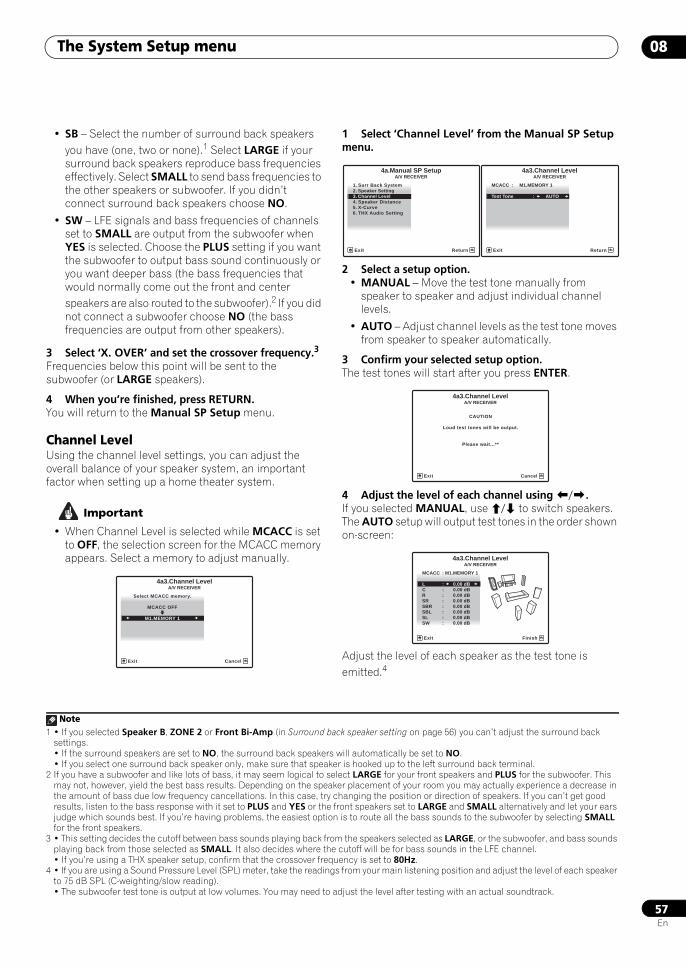
The System Setup menu 08
57En
• SB – Select the number of surround back speakers you have (one, two or none).1 Select LARGE if your surround back speakers reproduce bass frequencies effectively. Select SMALL to send bass frequencies to the other speakers or subwoofer. If you didn’t connect surround back speakers choose NO.
• SW – LFE signals and bass frequencies of channels set to SMALL are output from the subwoofer when YES is selected. Choose the PLUS setting if you want the subwoofer to output bass sound continuously or you want deeper bass (the bass frequencies that would normally come out the front and center speakers are also routed to the subwoofer).2 If you did not connect a subwoofer choose NO (the bass frequencies are output from other speakers).
3 Select ‘X. OVER’ and set the crossover frequency.3
Frequencies below this point will be sent to the subwoofer (or LARGE speakers).
4 When you’re finished, press RETURN.You will return to the Manual SP Setup menu.
Channel LevelUsing the channel level settings, you can adjust the overall balance of your speaker system, an important factor when setting up a home theater system.
Important
• When Channel Level is selected while MCACC is set to OFF, the selection screen for the MCACC memory appears. Select a memory to adjust manually.
1 Select ‘Channel Level’ from the Manual SP Setup menu.
2 Select a setup option.• MANUAL – Move the test tone manually from
speaker to speaker and adjust individual channel levels.
• AUTO – Adjust channel levels as the test tone moves from speaker to speaker automatically.
3 Confirm your selected setup option.The test tones will start after you press ENTER.
4 Adjust the level of each channel using /.If you selected MANUAL, use / to switch speakers. The AUTO setup will output test tones in the order shown on-screen:
Adjust the level of each speaker as the test tone is emitted.4
Note1 • If you selected Speaker B, ZONE 2 or Front Bi-Amp (in Surround back speaker setting on page 56) you can’t adjust the surround back
settings.• If the surround speakers are set to NO, the surround back speakers will automatically be set to NO.• If you select one surround back speaker only, make sure that speaker is hooked up to the left surround back terminal.
2 If you have a subwoofer and like lots of bass, it may seem logical to select LARGE for your front speakers and PLUS for the subwoofer. This may not, however, yield the best bass results. Depending on the speaker placement of your room you may actually experience a decrease in the amount of bass due low frequency cancellations. In this case, try changing the position or direction of speakers. If you can’t get good results, listen to the bass response with it set to PLUS and YES or the front speakers set to LARGE and SMALL alternatively and let your ears judge which sounds best. If you’re having problems, the easiest option is to route all the bass sounds to the subwoofer by selecting SMALL for the front speakers.
3 • This setting decides the cutoff between bass sounds playing back from the speakers selected as LARGE, or the subwoofer, and bass sounds playing back from those selected as SMALL. It also decides where the cutoff will be for bass sounds in the LFE channel.• If you’re using a THX speaker setup, confirm that the crossover frequency is set to 80Hz.
Select MCACC memory.
MCACC OFF
4a3.Channel Level
M1.MEMORY 1
A/V RECEIVER
Exit Cancel
4 • If you are using a Sound Pressure Level (SPL) meter, take the readings from your main listening position and adjust the level of each speaker to 75 dB SPL (C-weighting/slow reading).• The subwoofer test tone is output at low volumes. You may need to adjust the level after testing with an actual soundtrack.
4a.Manual SP SetupA/V RECEIVER
Exit Return
1. Surr Back System2. Speaker Setting3. Channel Level4. Speaker Distance5. X-Curve6. THX Audio Setting
MCACC : M1.MEMORY 1
Test Tone : AUTO
4a3.Channel LevelA/V RECEIVER
Exit Return
CAUTION
Loud test tones will be output.
Please wait...**
4a3.Channel LevelA/V RECEIVER
Exit Cancel
A/V RECEIVER
Exit Finish
MCACC : M1.MEMORY 1
L : 0.00 dB
4a3.Channel Level
C : 0.00 dBR : 0.00 dB
SBR : 0.00 dBSR : 0.00 dB
SBL : 0.00 dBSL : 0.00 dBSW : 0.00 dB
SCLX81_71.book 57 ページ 2008年7月25日 金曜日 午後3時1分
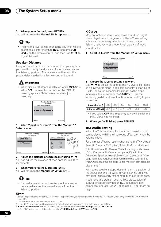
The System Setup menu08
58En
5 When you’re finished, press RETURN.You will return to the Manual SP Setup menu.
Tip
• The channel level can be changed at any time. Set the operation selector switch to RCV, then press CH LEVEL on the remote control, and then use / to adjust the level.
Speaker DistanceFor good sound depth and separation from your system, you need to specify the distance of your speakers from the listening position. The receiver can then add the proper delay needed for effective surround sound.
Important
• When Speaker Distance is selected while MCACC is set to OFF, the selection screen for the MCACC memory appears. Select a memory to adjust manually.
1 Select ‘Speaker Distance’ from the Manual SP Setup menu.
2 Adjust the distance of each speaker using /.You can adjust the distance of each speaker in 0.01 m increments.
3 When you’re finished, press RETURN.You will return to the Manual SP Setup menu.
Tip
• For best surround sound, make sure the surround back speakers are the same distance from the listening position.
X-CurveMost soundtracks mixed for cinema sound too bright when played back in large rooms. The X-Curve setting acts as a kind of re-equalization for home theater listening, and restores proper tonal balance of movie soundtracks.1
1 Select ‘X-Curve’ from the Manual SP Setup menu.
2 Choose the X-Curve setting you want.Use / to adjust the setting. The X-Curve is expressed as a downwards slope in decibels per octave, starting at 2 kHz. The sound becomes less bright as the slope increases (to a maximum of –3.0dB/oct). Use the following guidelines to set the X-Curve according to your room size:
• If you select OFF, the frequency curve will be flat and the X-Curve has no effect.
3 When you’re finished, press RETURN.
THX Audio SettingWhen the THX Loudness Plus function is used, sound can be played with the full surround effect even when the volume is low.
For the most effective results when using the THX Ultra2/Select22 Cinema, THX Ultra2/Select22 Music Mode and THX Ultra2/Select22 Games Mode listening modes (see Using the Home THX modes on page 36) with the Advanced Speaker Array (ASA) system (see About THX on page 121), it is required that you make the setting. See Placing the speakers on page 26 for more on THX speaker placement.3
With some speaker setups, depending on the position of the subwoofer and the walls in your listening area, you may experience overly resonant frequencies in the bass. If you have this problem use the THX Ultra2/Select22 subwoofer setup to switch on BGC (boundary gain compensation) (see About THX on page 121 for more on this).4
A/V RECEIVER
Exit Cancel
Select MCACC memory.
MCACC OFF
4a4.Speaker Distance
M1.MEMORY 1
1. Surr Back System2. Speaker Setting3. Channel Level4. Speaker Distance5. X-Curve6. THX Audio Setting
4a.Manual SP SetupA/V RECEIVER
Exit Return
A/V RECEIVER
Exit Finish
MCACC : M1.MEMORY 1
L : 3.61m
4a4.Speaker Distance
C : 3.69mR : 3.67m
SBR : 5.77mSR : 2.74m
SBL : 5.13mSL : 2.26mSW : 3.54m
Note1 Since the principal is the same, X-Curve isn’t applied when you’re using any of the Home THX modes (see Using the Home THX modes on
page 36).
Room size (m2) ≤36 ≤48 ≤60 ≤72 ≤300 ≤1000
X-Curve (dB/oct) –0.5 –1.0 –1.5 –2.0 –2.5 –3.0
2 Ultra2 for the SC-LX81, Select2 for the SC-LX71.3 If you don’t have surround back speakers, or just have one, you won’t be able to select this setting.4 • THX Ultra2/Select2 SW can only be selected when SW at Speaker Setting is set to YES or PLUS.
• The BGC setting can only be selected when THX Ultra2/Select2 SW is set to YES.
4a.Manual SP SetupA/V RECEIVER
Exit Return
1. Surr Back System2. Speaker Setting3. Channel Level4. Speaker Distance5. X-Curve6. THX Audio Setting
SCLX81_71.book 58 ページ 2008年7月25日 金曜日 午後3時1分
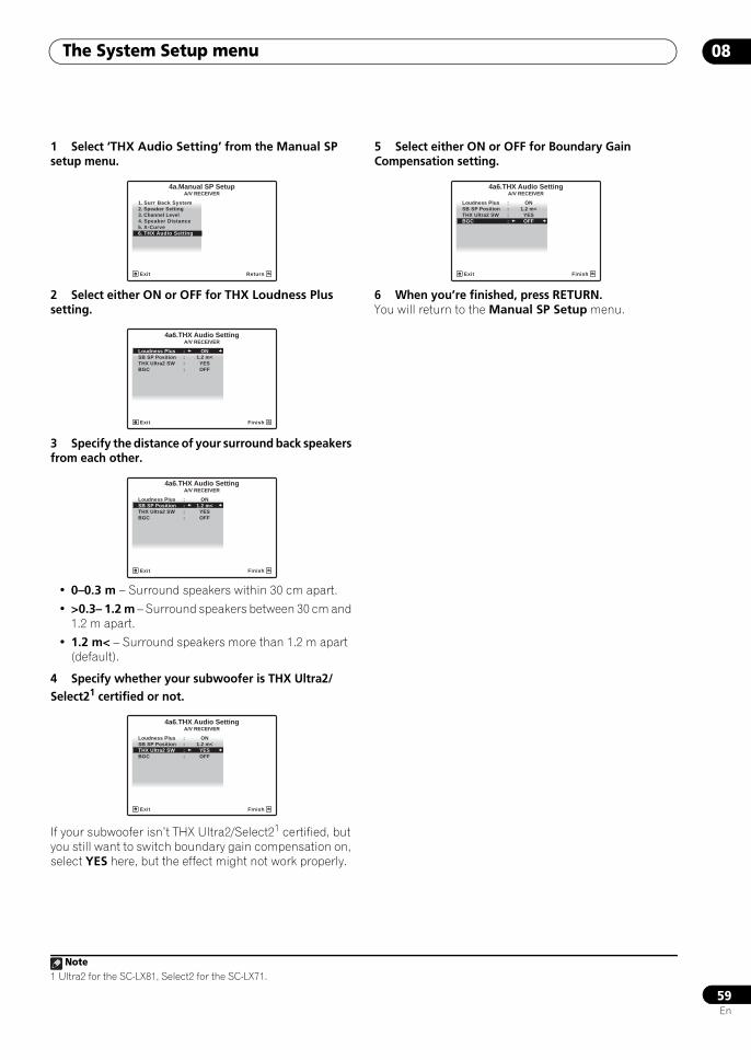
The System Setup menu 08
59En
1 Select ‘THX Audio Setting’ from the Manual SP setup menu.
2 Select either ON or OFF for THX Loudness Plus setting.
3 Specify the distance of your surround back speakers from each other.
• 0–0.3 m – Surround speakers within 30 cm apart.
• >0.3– 1.2 m – Surround speakers between 30 cm and 1.2 m apart.
• 1.2 m< – Surround speakers more than 1.2 m apart (default).
4 Specify whether your subwoofer is THX Ultra2/Select21 certified or not.
If your subwoofer isn’t THX Ultra2/Select21 certified, but you still want to switch boundary gain compensation on, select YES here, but the effect might not work properly.
5 Select either ON or OFF for Boundary Gain Compensation setting.
6 When you’re finished, press RETURN.You will return to the Manual SP Setup menu.
Note1 Ultra2 for the SC-LX81, Select2 for the SC-LX71.
4a.Manual SP SetupA/V RECEIVER
Exit Return
1. Surr Back System2. Speaker Setting3. Channel Level4. Speaker Distance5. X-Curve6. THX Audio Setting
A/V RECEIVER
Exit Finish
Loudness Plus : ONSB SP Position : 1.2 m<
BGC : OFFTHX Ultra2 SW : YES
4a6.THX Audio Setting
A/V RECEIVER
Exit Finish
4a6.THX Audio Setting
Loudness Plus : ONSB SP Position : 1.2 m<
BGC : OFFTHX Ultra2 SW : YES
A/V RECEIVER
Exit Finish
4a6.THX Audio Setting
Loudness Plus : ONSB SP Position : 1.2 m<
BGC : OFFTHX Ultra2 SW : YES
Loudness Plus : ONSB SP Position : 1.2 m<
BGC : OFFTHX Ultra2 SW : YES
A/V RECEIVER
Exit Finish
4a6.THX Audio Setting
SCLX81_71.book 59 ページ 2008年7月25日 金曜日 午後3時1分
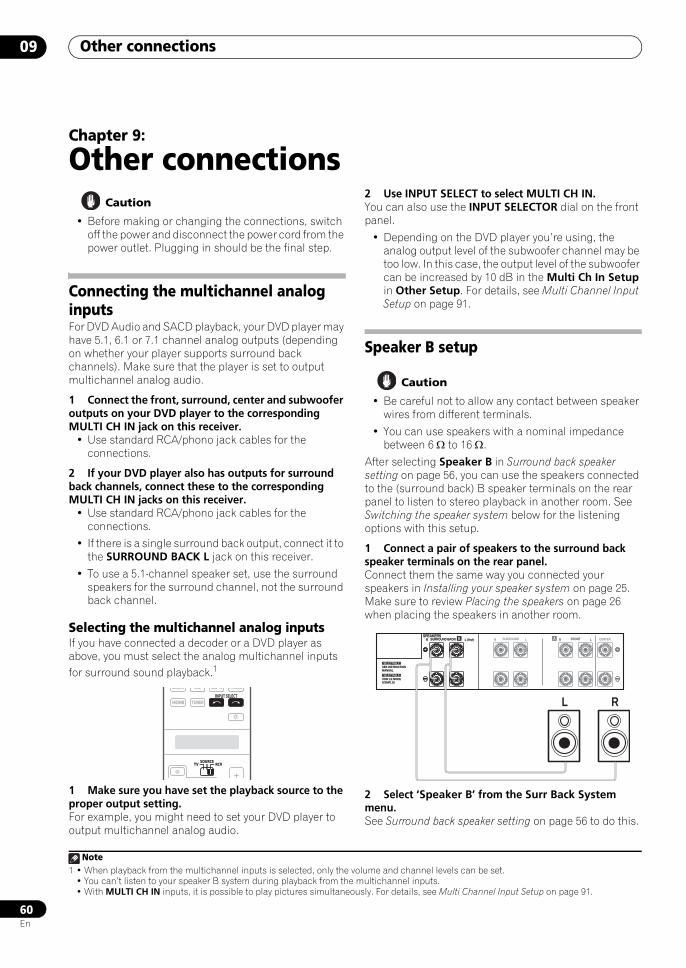
Other connections09
60En
Chapter 9:
Other connections Caution
• Before making or changing the connections, switch off the power and disconnect the power cord from the power outlet. Plugging in should be the final step.
Connecting the multichannel analog inputsFor DVD Audio and SACD playback, your DVD player may have 5.1, 6.1 or 7.1 channel analog outputs (depending on whether your player supports surround back channels). Make sure that the player is set to output multichannel analog audio.
1 Connect the front, surround, center and subwoofer outputs on your DVD player to the corresponding MULTI CH IN jack on this receiver.
• Use standard RCA/phono jack cables for the connections.
2 If your DVD player also has outputs for surround back channels, connect these to the corresponding MULTI CH IN jacks on this receiver.
• Use standard RCA/phono jack cables for the connections.
• If there is a single surround back output, connect it to the SURROUND BACK L jack on this receiver.
• To use a 5.1-channel speaker set, use the surround speakers for the surround channel, not the surround back channel.
Selecting the multichannel analog inputsIf you have connected a decoder or a DVD player as above, you must select the analog multichannel inputs for surround sound playback.1
1 Make sure you have set the playback source to the proper output setting.For example, you might need to set your DVD player to output multichannel analog audio.
2 Use INPUT SELECT to select MULTI CH IN.You can also use the INPUT SELECTOR dial on the front panel.
• Depending on the DVD player you’re using, the analog output level of the subwoofer channel may be too low. In this case, the output level of the subwoofer can be increased by 10 dB in the Multi Ch In Setup in Other Setup. For details, see Multi Channel Input Setup on page 91.
Speaker B setup
Caution
• Be careful not to allow any contact between speaker wires from different terminals.
• You can use speakers with a nominal impedance between 6 Ω to 16 Ω.
After selecting Speaker B in Surround back speaker setting on page 56, you can use the speakers connected to the (surround back) B speaker terminals on the rear panel to listen to stereo playback in another room. See Switching the speaker system below for the listening options with this setup.
1 Connect a pair of speakers to the surround back speaker terminals on the rear panel.Connect them the same way you connected your speakers in Installing your speaker system on page 25. Make sure to review Placing the speakers on page 26 when placing the speakers in another room.
2 Select ‘Speaker B’ from the Surr Back System menu.See Surround back speaker setting on page 56 to do this.
Note1 • When playback from the multichannel inputs is selected, only the volume and channel levels can be set.
• You can’t listen to your speaker B system during playback from the multichannel inputs.• With MULTI CH IN inputs, it is possible to play pictures simultaneously. For details, see Multi Channel Input Setup on page 91.
SOURCETV RCV
GALLERY CD
HDMI TUNER
PHONOCD R
INPUT SELECT
SOURCETV RCV
SPEAKERSA CENTERLR FRONTB LR SURROUND BACK/ LR SURROUND(Single)
SEE INSTRUCTIONMANUAL
SELECTABLE
VOIR LE MODED'EMPLOI
SELECTABLE
A LR FRONTSPEAKERS
L R
B LR SURROUND BACK/ (Single)
SEE INSTRUCTIONMANUAL
SELECTABLE
VOIR LE MODED'EMPLOI
SELECTABLE
SCLX81_71.book 60 ページ 2008年7月25日 金曜日 午後3時1分
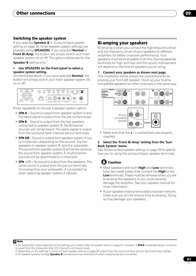
Other connections 09
61En
Switching the speaker systemIf you selected Speaker B in Surround back speaker setting on page 56, three speaker system settings are possible using SPEAKERS. If you selected Normal or Front Bi-Amp, the button will simply switch your main speaker system on or off. The options below are for the Speaker B setting only.1
• Use SPEAKERS on the front panel to select a speaker system setting.As mentioned above, if you have selected Normal, the button will simply switch your main speaker system (A) on or off.
Press repeatedly to choose a speaker system option:
• SPA – Sound is output from speaker system A and the same signal is output from the pre-out terminals.
• SPB – Sound is output from the two speakers connected to speaker system B. Multichannel sources will not be heard. The same signal is output from the surround back channel pre-out terminals.
• SPAB – Sound is output from speaker system A (up to 5 channels, depending on the source), the two speakers in speaker system B, and the subwoofer. The sound from speaker system B will be the same as the sound from speaker system A (multichannel sources will be downmixed to 2 channels).
• SP (off) – No sound is output from the speakers. The same sound is output from the pre-out terminals (including from your subwoofer, if connected) as when selecting speaker system A (above).
Bi-amping your speakersBi-amping is when you connect the high frequency driver and low frequency driver of your speakers to different amplifiers for better crossover performance. Your speakers must be bi-ampable to do this (having separate terminals for high and low) and the sound improvement will depend on the kind of speakers you’re using.
1 Connect your speakers as shown next page.This illustration below shows the connections for bi-amping your front left speaker. Hook up your bi-amp compatible speakers for other channels in the same way.
• Make sure that the + / – connections are properly inserted.
2 Select the ‘Front Bi-Amp’ setting from the ‘Surr Back System’ menu.See Surround back speaker setting on page 56 to specify how you’re using the surround back speaker terminals.
Caution
• Most speakers with both High and Low terminals have two metal plates that connect the High to the Low terminals. These must be removed when you are bi-amping the speakers or you could severely damage the amplifier. See your speaker manual for more information.
• If your speakers have a removable crossover network, make sure you do not remove it for bi-amping. Doing so may damage your speakers.
Note1 • The subwoofer output depends on the settings you made in Manual speaker setup on page 55. However, if SPB is selected above, no sound
is heard from the subwoofer (the LFE channel is not downmixed).• Depending on the settings in Surround back speaker setting on page 56 output from the surround back pre-out terminals may change.• All speaker systems (except Speaker B connections) are switched off when headphones are connected.
VIDEO3 INPUT
DIGITAL IN S-VIDEO VIDEO L RAUDIO PHONES
SPEAKERSCONTROL
MULTI-ZONE& SOURCE
ON/OFF
MCACCSETUP MIC
PARAMETER
ENTER
(TUNE)
(TUNE)
(ST)(ST)
AUDIO VIDEOTUNER EDIT
iPod DIRECTUSB
AUTO SURR/STREAM DIRECT
HOMETHX
STANDARDSURROUND
ADVANCEDSURROUND
STEREO/A.L.C.BAND
HOME MENU RETURN
SPEAKERS A CENTERLR FRONTB LR SURROUND BACK/ LR SURROUND(Single) A LR FRONTSPEAKERS
B LR SURROUND BACK/ (Single)
High
Low
SEE INSTRUCTIONMANUAL
SELECTABLE
VOIR LE MODED'EMPLOI
SELECTABLE
Bi-ampcompatible
speaker
SCLX81_71.book 61 ページ 2008年7月25日 金曜日 午後3時1分
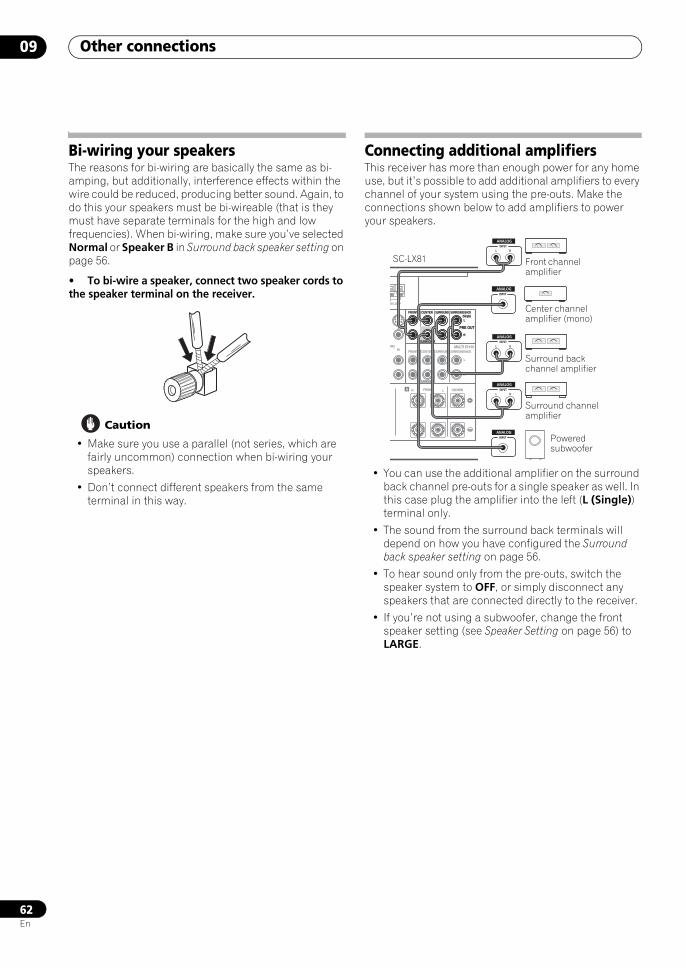
Other connections09
62En
Bi-wiring your speakersThe reasons for bi-wiring are basically the same as bi-amping, but additionally, interference effects within the wire could be reduced, producing better sound. Again, to do this your speakers must be bi-wireable (that is they must have separate terminals for the high and low frequencies). When bi-wiring, make sure you’ve selected Normal or Speaker B in Surround back speaker setting on page 56.
• To bi-wire a speaker, connect two speaker cords to the speaker terminal on the receiver.
Caution
• Make sure you use a parallel (not series, which are fairly uncommon) connection when bi-wiring your speakers.
• Don’t connect different speakers from the same terminal in this way.
Connecting additional amplifiersThis receiver has more than enough power for any home use, but it’s possible to add additional amplifiers to every channel of your system using the pre-outs. Make the connections shown below to add amplifiers to power your speakers.
• You can use the additional amplifier on the surround back channel pre-outs for a single speaker as well. In this case plug the amplifier into the left (L (Single)) terminal only.
• The sound from the surround back terminals will depend on how you have configured the Surround back speaker setting on page 56.
• To hear sound only from the pre-outs, switch the speaker system to OFF, or simply disconnect any speakers that are connected directly to the receiver.
• If you’re not using a subwoofer, change the front speaker setting (see Speaker Setting on page 56) to LARGE.
PRE OUT
MULTI CH IN
A
VR2IN
FRONT CENTER
SUBWOOFER
SURROUND SURROUND BACK
FRONT CENTER
CENTERLR FRONT
SUBWOOFER
SURROUND SURROUND BACK
(Single)
L
R
L
R
M LOOP
PRE OUT
FRONT CENTER
SUBWOOFER
SURROUND SURROUND BACK(Single)L
R
INPUTL R
ANALOG
INPUTL R
ANALOG
INPUTL R
ANALOG
INPUT
ANALOG
INPUT
ANALOG
Powered subwoofer
Front channel amplifier
Center channel amplifier (mono)
Surround channel amplifier
Surround back channel amplifier
SC-LX81
SCLX81_71.book 62 ページ 2008年7月25日 金曜日 午後3時1分
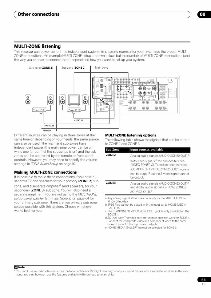
Other connections 09
63En
MULTI-ZONE listeningThis receiver can power up to three independent systems in separate rooms after you have made the proper MULTI-ZONE connections. An example MULTI-ZONE setup is shown below, but the number of MULTI-ZONE connections (and the way you choose to connect them) depends on how you want to set up your system.
Different sources can be playing in three zones at the same time or, depending on your needs, the same source can also be used. The main and sub zones have independent power (the main zone power can be off while one (or both) of the sub zones is on) and the sub zones can be controlled by the remote or front panel controls. However, you may need to specify the volume settings in ZONE Audio Setup on page 92.
Making MULTI-ZONE connectionsIt is possible to make these connections if you have a separate TV and speakers for your primary (ZONE 2) sub zone, and a separate amplifier1 (and speakers) for your secondary (ZONE 3) sub zone. You will also need a separate amplifier if you are not using the MULTI-ZONE setup using speaker terminals (Zone 2) on page 64 for your primary sub zone. There are two primary sub zone setups possible with this system. Choose whichever works best for you.
MULTI-ZONE listening optionsThe following table shows the signals that can be output to ZONE 2 and ZONE 3:
LAN (10/100)
DIGITAL
SPEAKERS
OPTICALRS-232C
HDMI
COAXIAL
COMPONENT VIDEO
ANTENNA
PRE OUT
MULTI CH IN
A
XM
IR
CONTROL
BDIN
IN
12 VTRIGGER
IN1
IN2
IN3
OUT1
OUT2
SOURCEOUT
ZONE3/SOURCEOUT
31ASSIGNABLE -
31ASSIGNABLE -
(HDMI CTRL)
ASSIGNABLE
ASSIGNABLE
(CD-R)IN 4
(VIDEO1)IN 3
(DVR1)IN 2
(TV/SAT)IN 1
IN 3 (DVR2)
IN 2 (CD)
IN 1 (DVD)
IN 1 IN 2
(OUTPUT 12V TOTAL 50mA MAX)
1
2
IN1
IN
IN2
OUT
OUT
(DVD)
PR PB Y PR PB Y
PR PB Y(VIDEO1)
IN 3
(VIDEO2)
RZONE 2 OUT MONITOR
OUT
PHONOIN
CDIN
DVDIN
TV/SATIN
VIDEO1IN
VIDEO2IN OUT
DVR1IN OUT
DVR2INOUT IN
CD-R/TAPE
SIGNALGND
ZONE 2 OUT
ZONE 3 OUT
VIDEO
VIDEO S-VIDEO FRONT CENTER
SUBWOOFER
SURROUND SURROUND BACK
FRONT CENTER
CENTERLR FRONTB LR SURROUND BACK/ LR SURROUND
SUBWOOFER
SURROUND SURROUND BACK
(Single)
(Single)
L
L
R
SEE INSTRUCTIONMANUAL
L
R
L
R
FM UNBAL 75 AM LOOP
SELECTABLE
VOIR LE MODED'EMPLOI
SELECTABLE
AC IN
220 - 230 V
240 V
VOLTAGESELECTOR
R
ZONE 2 OUT
VIDEOL
ZONE 3 OUT
ZONE3/SOURCEOUT
DIGITAL IN
AUDIO IN
AUDIO IN
PR PB Y PR PB Y
RZONE 2 OUT MONITO
OUT
PHONOIN
CDIN OUT IN
CD-R/TAPE
ZONE 2 OUT
ZONE 3 OUT
VIDEO
VIDEOL
DIGITAL
OPTICALRS-232C
CONTROL
SOURCEOUT
ZONE3/SOURCEOUT
31 - ASSIGNABLE
(CD-R)IN 4
( ) IN
OUT
Main zoneSub zone (ZONE 2)Sub zone (ZONE 3)
Note1 You can’t use sound controls (such as the tone controls or Midnight listening) or any surround modes with a separate amplifier in the sub
zone. You can, however, use the features available with your sub zone amplifier.
Sub Zone Input sources available
ZONE2 Analog audio signals (AUDIO ZONE2 OUT).a
With video signals,b the composite video (VIDEO ZONE2 OUT) and component video (COMPONENT VIDEO ZONE2 OUT)c signals can be outputd but the S-Video signal cannot be output.
a.Any analog signal. (This does not apply for the MULTI CH IN and PHONO inputs.)
b.JPEG files cannot be played with the input set to HOME MEDIA GALLERY.
c.The COMPONENT VIDEO ZONE2 OUT jack is only provided on the SC-LX81.
d.SC-LX81 only: The video convert function does not work for ZONE 2. Connect the composite video and component video to the same types of jacks for the inputs and outputs.
ZONE3 Analog audio signals (AUDIO ZONE3 OUT)a and digital audio signal (OPTICAL ZONE3/SOURCE OUT).e
e.HOME MEDIA GALLERY cannot be selected for ZONE 3.
SCLX81_71.book 63 ページ 2008年7月25日 金曜日 午後3時1分
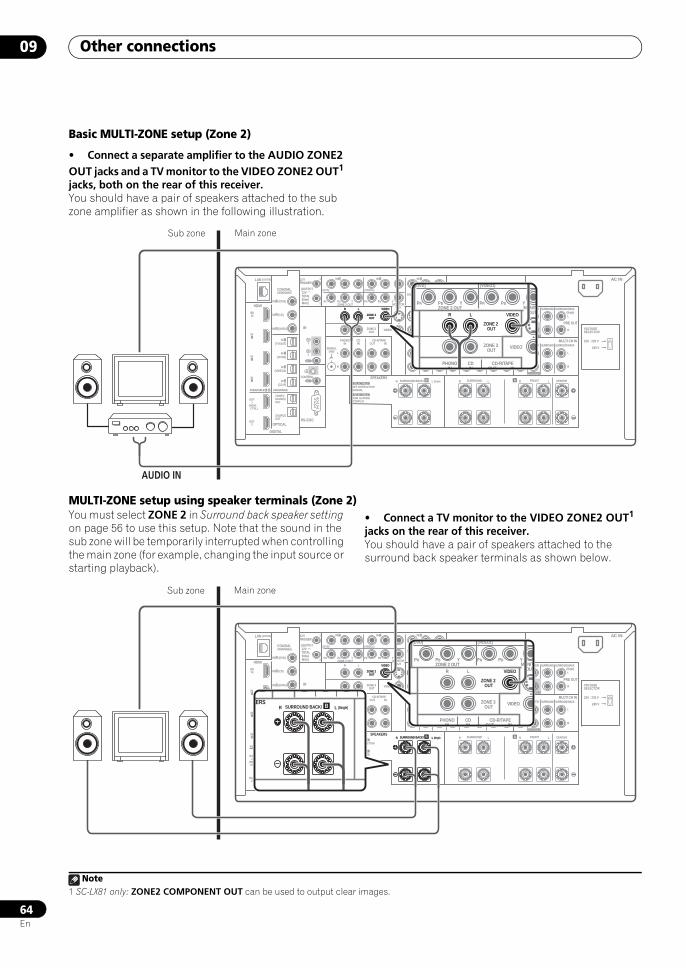
Other connections09
64En
Basic MULTI-ZONE setup (Zone 2)
• Connect a separate amplifier to the AUDIO ZONE2 OUT jacks and a TV monitor to the VIDEO ZONE2 OUT1 jacks, both on the rear of this receiver.You should have a pair of speakers attached to the sub zone amplifier as shown in the following illustration.
MULTI-ZONE setup using speaker terminals (Zone 2)You must select ZONE 2 in Surround back speaker setting on page 56 to use this setup. Note that the sound in the sub zone will be temporarily interrupted when controlling the main zone (for example, changing the input source or starting playback).
• Connect a TV monitor to the VIDEO ZONE2 OUT1 jacks on the rear of this receiver.You should have a pair of speakers attached to the surround back speaker terminals as shown below.
Note1 SC-LX81 only: ZONE2 COMPONENT OUT can be used to output clear images.
LAN (10/100)
DIGITAL
OPTICALRS-232C
HDMI
COAXIAL
COMPONENT VIDEO
ANTENNA
PRE OUT
MULTI CH IN
A
IR
CONTROL
BDIN
12 VTRIGGER
IN1
IN2
IN3
OUT1
OUT2
SOURCEOUT
ZONE3/SOURCEOUT
31ASSIGNABLE -
31ASSIGNABLE -
(HDMI CTRL)
ASSIGNABLE
ASSIGNABLE
(CD-R)IN 4
(VIDEO1)IN 3
(DVR1)IN 2
(TV/SAT)IN 1
IN 3 (DVR2)
IN 2 (CD)
IN 1 (DVD)
IN 1 IN 2
(OUTPUT 12V TOTAL 50mA MAX)
1
2
IN1
IN
IN2
OUT
OUT
(DVD)
PR PB Y PR PB Y
PR PB Y(VIDEO1)
IN 3
(VIDEO2)
RZONE 2 OUT MONITOR
OUT
PHONOIN
CDIN
DVDIN
TV/SATIN
VIDEO1IN
VIDEO2IN OUT
DVR1IN OUT
DVR2INOUT IN
CD-R/TAPE
SIGNALGND
ZONE 2 OUT
ZONE 3 OUT
VIDEO
VIDEO S-VIDEO FRONT CENTER
SUBWOOFER
SURROUND SURROUND BACK
FRONT CENTER
CENTERLR FRONTB LR SURROUND BACK/ LR SURROUND
SUBWOOFER
SURROUND SURROUND BACK
(Single)
(Single)
L
L
R
L
R
L
R
FM UNBAL 75 AM LOOP
SPEAKERS
SEE INSTRUCTIONMANUAL
SELECTABLE
VOIR LE MODED'EMPLOI
SELECTABLE
AC IN
220 - 230 V
240 V
VOLTAGESELECTOR
R
ZONE 2 OUT
VIDEOL
AUDIO IN
(DVD)
PR PB Y PR PB Y
(VIDEO1)
RZONE 2 OUT MONITO
OUT
PHONOIN
CDIN OUT IN
CD-R/TAPE
ZONE 2 OUT
ZONE 3 OUT
VIDEO
VIDEOL
Main zoneSub zone
LAN (10/100)
DIGITAL
OPTICALRS-232C
HDMI
COAXIAL
COMPONENT VIDEO
ANTENNA
PRE OUT
MULTI CH IN
A
IR
CONTROL
BDIN
12 VTRIGGER
IN1
IN2
IN3
OUT1
OUT2
SOURCEOUT
ZONE3/SOURCEOUT
31ASSIGNABLE -
31ASSIGNABLE -
(HDMI CTRL)
ASSIGNABLE
ASSIGNABLE
(CD-R)IN 4
(VIDEO1)IN 3
(DVR1)IN 2
(TV/SAT)IN 1
IN 3 (DVR2)
IN 2 (CD)
IN 1 (DVD)
IN 1 IN 2
(OUTPUT 12V TOTAL 50mA MAX)
1
2
IN1
IN
IN2
OUT
OUT
(DVD)
PR PB Y PR PB Y
PR PB Y(VIDEO1)
IN 3
(VIDEO2)
RZONE 2 OUT MONITOR
OUT
PHONOIN
CDIN
DVDIN
TV/SATIN
VIDEO1IN
VIDEO2IN OUT
DVR1IN OUT
DVR2INOUT IN
CD-R/TAPE
SIGNALGND
ZONE 2 OUT
ZONE 3 OUT
VIDEO
VIDEO S-VIDEO FRONT CENTER
SUBWOOFER
SURROUND SURROUND BACK
FRONT CENTER
CENTERLR FRONTB LR SURROUND BACK/ LR SURROUND
SUBWOOFER
SURROUND SURROUND BACK
(Single)
(Single)
L
L
R
L
R
L
R
FM UNBAL 75 AM LOOP
SPEAKERS
SEE INSTRUCTIONMANUAL
SELECTABLE
VOIR LE MODED'EMPLOI
SELECTABLE
AC IN
220 - 230 V
240 V
VOLTAGESELECTOR
ZONE 2 OUT
VIDEO
B LR SURROUND BACK/ (Single)
KERSB LR SURROUND BACK/ (Single)
(DVD)
PR PB Y PR PB Y
(VIDEO1)
RZONE 2 OUT MONITO
OUT
PHONOIN
CDIN OUT IN
CD-R/TAPE
ZONE 2 OUT
ZONE 3 OUT
VIDEO
VIDEOL
Main zoneSub zone
SCLX81_71.book 64 ページ 2008年7月25日 金曜日 午後3時1分
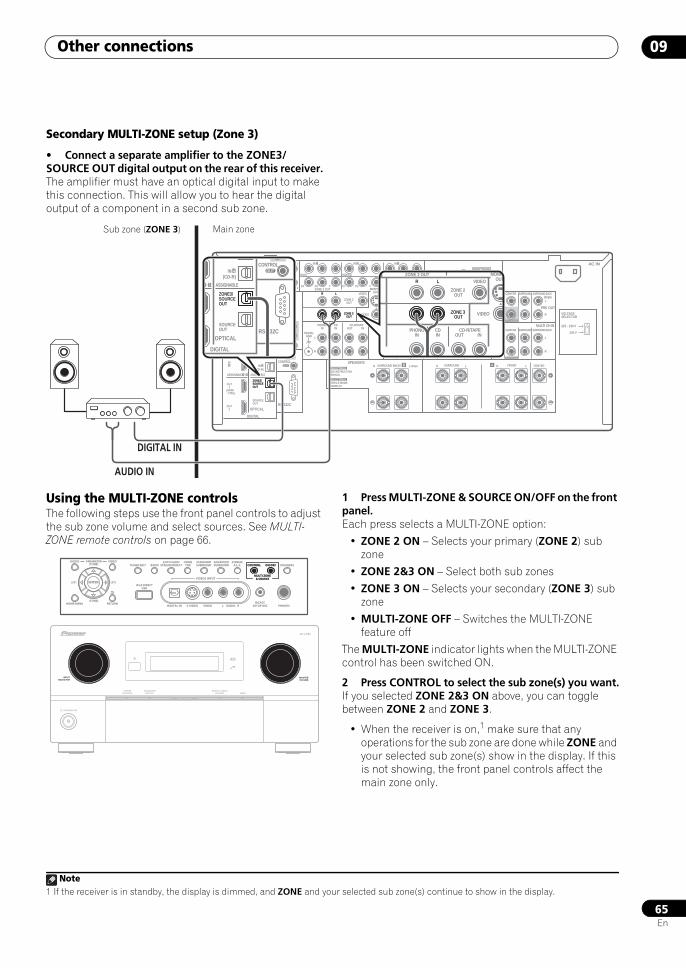
Other connections 09
65En
Secondary MULTI-ZONE setup (Zone 3)
• Connect a separate amplifier to the ZONE3/SOURCE OUT digital output on the rear of this receiver.The amplifier must have an optical digital input to make this connection. This will allow you to hear the digital output of a component in a second sub zone.
Using the MULTI-ZONE controlsThe following steps use the front panel controls to adjust the sub zone volume and select sources. See MULTI-ZONE remote controls on page 66.
1 Press MULTI-ZONE & SOURCE ON/OFF on the front panel.Each press selects a MULTI-ZONE option:
• ZONE 2 ON – Selects your primary (ZONE 2) sub zone
• ZONE 2&3 ON – Select both sub zones
• ZONE 3 ON – Selects your secondary (ZONE 3) sub zone
• MULTI-ZONE OFF – Switches the MULTI-ZONE feature off
The MULTI-ZONE indicator lights when the MULTI-ZONE control has been switched ON.
2 Press CONTROL to select the sub zone(s) you want.If you selected ZONE 2&3 ON above, you can toggle between ZONE 2 and ZONE 3.
• When the receiver is on,1 make sure that any operations for the sub zone are done while ZONE and your selected sub zone(s) show in the display. If this is not showing, the front panel controls affect the main zone only.
LAN (10/100)
DIGITAL
OPTICALRS-232C
HDMI
COAXIAL
COMPONENT VIDEO
ANTENNA
PRE OUT
MULTI CH IN
A
IR
CONTROL
BDIN
12 VTRIGGER
IN1
IN2
IN3
OUT1
OUT2
SOURCEOUT
ZONE3/SOURCEOUT
31ASSIGNABLE -
31ASSIGNABLE -
(HDMI CTRL)
ASSIGNABLE
ASSIGNABLE
(CD-R)IN 4
(VIDEO1)IN 3
(DVR1)IN 2
(TV/SAT)IN 1
IN 3 (DVR2)
IN 2 (CD)
IN 1 (DVD)
IN 1 IN 2
(OUTPUT 12V TOTAL 50mA MAX)
1
2
IN1
IN
IN2
OUT
OUT
(DVD)
PR PB Y PR PB Y
PR PB Y(VIDEO1)
IN 3
(VIDEO2)
RZONE 2 OUT MONITOR
OUT
PHONOIN
CDIN
DVDIN
TV/SATIN
VIDEO1IN
VIDEO2IN OUT
DVR1IN OUT
DVR2INOUT IN
CD-R/TAPE
SIGNALGND
ZONE 2 OUT
ZONE 3 OUT
VIDEO
VIDEO S-VIDEO FRONT CENTER
SUBWOOFER
SURROUND SURROUND BACK
FRONT CENTER
CENTERLR FRONTB LR SURROUND BACK/ LR SURROUND
SUBWOOFER
SURROUND SURROUND BACK
(Single)
(Single)
L
L
R
L
R
L
R
FM UNBAL 75 AM LOOP
SPEAKERS
SEE INSTRUCTIONMANUAL
SELECTABLE
VOIR LE MODED'EMPLOI
SELECTABLE
AC IN
220 - 230 V
240 V
VOLTAGESELECTOR
R L
ZONE 3 OUT
ZONE3/SOURCEOUT
AUDIO IN
DIGITAL IN
RZONE 2 OUT MONITO
OUT
PHONOIN
CDIN OUT IN
CD-R/TAPE
ZONE 3 OUT
ZONE 2 OUT
VIDEO
VIDEOL
DIGITAL
OPTICALRS-232C
CONTROL
SOURCEOUT
ZONE3/SOURCEOUT
31 - ASSIGNABLE
(CD-R)IN 4
( ) IN
OUT
Main zoneSub zone (ZONE 3)
VIDEO3 INPUT
DIGITAL IN S-VIDEO VIDEO L RAUDIO PHONES
SPEAKERSCONTROL
MULTI-ZONE& SOURCE
ON/OFF
MCACCSETUP MIC
PARAMETER
ENTER
(TUNE)
(TUNE)
(ST)(ST)
AUDIO VIDEOTUNER EDIT
iPod DIRECTUSB
AUTO SURR/STREAM DIRECT
HOMETHX
STANDARDSURROUND
ADVANCEDSURROUND
STEREO/A.L.C.BAND
HOME MENU RETURN
CONTROL
MULTI-ZONE& SOURCE
ON/OFF
STANDBY/ON
INPUTSELECTOR
PHASECONTROL
ADVANCEDMCACC
DIGITAL VIDEOSCALER HDMI
MASTERVOLUME
SC-LX81
Note1 If the receiver is in standby, the display is dimmed, and ZONE and your selected sub zone(s) continue to show in the display.
SCLX81_71.book 65 ページ 2008年7月25日 金曜日 午後3時1分
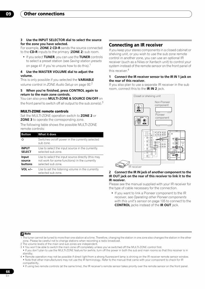
Other connections09
66En
3 Use the INPUT SELECTOR dial to select the source for the zone you have selected.For example, ZONE 2 CD-R sends the source connected to the CD-R inputs to the primary (ZONE 2) sub room.
• If you select TUNER, you can use the TUNER controls to select a preset station (see Saving station presets on page 41 if you’re unsure how to do this).1
4 Use the MASTER VOLUME dial to adjust the volume.This is only possible if you selected the VARIABLE volume control in ZONE Audio Setup on page 92.2
5 When you’re finished, press CONTROL again to return to the main zone controls.You can also press MULTI-ZONE & SOURCE ON/OFF on the front panel to switch off all output to the sub zone(s).3
MULTI-ZONE remote controlsSet the MULTI-ZONE operation switch to ZONE 2 or ZONE 3 to operate the corresponding zone.
The following table shows the possible MULTI-ZONE remote controls:
Connecting an IR receiverIf you keep your stereo components in a closed cabinet or shelving unit, or you wish to use the sub zone remote control in another zone, you can use an optional IR receiver (such as a Niles or Xantech unit) to control your system instead of the remote sensor on the front panel of this receiver.4
1 Connect the IR receiver sensor to the IR IN 1 jack on the rear of this receiver.If you also plan to use a separate IR receiver in the sub room, connect this to the IR IN 2 jack.
2 Connect the IR IN jack of another component to the IR OUT jack on the rear of this receiver to link it to the IR receiver.Please see the manual supplied with your IR receiver for the type of cable necessary for the connection.
• If you want to link a Pioneer component to the IR receiver, see Operating other Pioneer components with this unit’s sensor on page 105 to connect to the CONTROL jacks instead of the IR OUT jack.
Note1 The tuner cannot be tuned to more than one station at a time. Therefore, changing the station in one zone also changes the station in the other
zone. Please be careful not to change stations when recording a radio broadcast.2 The volume levels of the main and sub zones are independent.3 • You won’t be able to switch the main zone off completely unless you’ve switched off the MULTI-ZONE control first.
• If you don’t plan to use the MULTI-ZONE feature for awhile, turn off the power in both the sub and main rooms so that this receiver is in standby.
Button What it does
Switches on/off power in the currently selected sub zone.
INPUT SELECT
Use to select the input source in the currently selected sub zone.
Input source buttons
Use to select the input source directly (this may not work for some functions) in the currently selected sub zone.
VOL +/– Use to set the listening volume in the currently selected sub zone.
4 • Remote operation may not be possible if direct light from a strong fluorescent lamp is shining on the IR receiver remote sensor window.• Note that other manufacturers may not use the IR terminology. Refer to the manual that came with your component to check for IR compatibility.• If using two remote controls (at the same time), the IR receiver’s remote sensor takes priority over the remote sensor on the front panel.
LAN (10/100)
DIGITAL
OPTICALRS-232C
HDMI
COAXIAL
IR
CONTROL
BDIN
12 VTRIGGER
IN1
IN2
IN3
OUT1
OUT2
SOURCEOUT
ZONE3/SOURCEOUT
31ASSIGNABLE -
(HDMI CTRL)
ASSIGNABLE
ASSIGNABLE
(CD-R)IN 4
(VIDEO1)IN 3
(DVR1)IN 2
(TV/SAT)IN 1
IN 3 (DVR2)
IN 2 (CD)
IN 1 (DVD)
IN 1 IN
(OUTPUT 12V TOTAL 50mA MAX)
1
2
IN1
IN
IN2
OUT
OUT
(DVD)
PR PB Y PR
(VIDEO1)
RZONE 2 OUT
PHONOIN
CDIN OUT
CD-R
SIGNALGND
ZONE 2 OUT
ZONE 3 OUT
L
L
R
IR
CONTROL
IN1
OUT
OUT
IN
IR
IN OUT
CONTROL
IR
CONTROL
IN1
IN
IN2
OUT
OUT
SIGNALGND L
R
IR receiver
Closet or shelving unit
Non-Pioneer component
Pioneer component
SCLX81_71.book 66 ページ 2008年7月25日 金曜日 午後3時1分
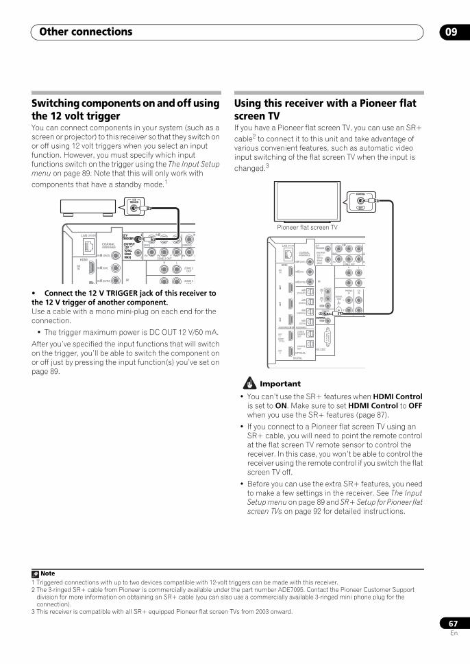
Other connections 09
67En
Switching components on and off using the 12 volt triggerYou can connect components in your system (such as a screen or projector) to this receiver so that they switch on or off using 12 volt triggers when you select an input function. However, you must specify which input functions switch on the trigger using the The Input Setup menu on page 89. Note that this will only work with components that have a standby mode.1
• Connect the 12 V TRIGGER jack of this receiver to the 12 V trigger of another component.Use a cable with a mono mini-plug on each end for the connection.
• The trigger maximum power is DC OUT 12 V/50 mA.
After you’ve specified the input functions that will switch on the trigger, you’ll be able to switch the component on or off just by pressing the input function(s) you’ve set on page 89.
Using this receiver with a Pioneer flat screen TVIf you have a Pioneer flat screen TV, you can use an SR+ cable2 to connect it to this unit and take advantage of various convenient features, such as automatic video input switching of the flat screen TV when the input is changed.3
Important
• You can’t use the SR+ features when HDMI Control is set to ON. Make sure to set HDMI Control to OFF when you use the SR+ features (page 87).
• If you connect to a Pioneer flat screen TV using an SR+ cable, you will need to point the remote control at the flat screen TV remote sensor to control the receiver. In this case, you won’t be able to control the receiver using the remote control if you switch the flat screen TV off.
• Before you can use the extra SR+ features, you need to make a few settings in the receiver. See The Input Setup menu on page 89 and SR+ Setup for Pioneer flat screen TVs on page 92 for detailed instructions.
Note1 Triggered connections with up to two devices compatible with 12-volt triggers can be made with this receiver.
LAN (10/100)
HDMI
COAXIAL
IR
BDIN
12 VTRIGGER
ASSIGNABLE
IN 3 (DVR2)
IN 2 (CD)
IN 1 (DVD)
IN 1 IN
(OUTPUT 12V TOTAL 50mA MAX)
1
2
(DVD)
PR PB Y PR P
(VIDEO1)
RZONE 2 OUT
ZONE 2 OUT
ZONE 3 OUT
L
12 VTRIGGER
(OUTPUT 12V TOTAL 50mA MAX)
1
12VTRIGGER
2 The 3-ringed SR+ cable from Pioneer is commercially available under the part number ADE7095. Contact the Pioneer Customer Support division for more information on obtaining an SR+ cable (you can also use a commercially available 3-ringed mini phone plug for the connection).
3 This receiver is compatible with all SR+ equipped Pioneer flat screen TVs from 2003 onward.
LAN (10/100)
DIGITAL
OPTICALRS-232C
HDMI
COAXIAL
IR
CONTROL
BDIN
12 VTRIGGER
IN1
IN2
IN3
OUT1
OUT2
SOURCEOUT
ZONE3/SOURCEOUT
31ASSIGNABLE -
(HDMI CTRL)
ASSIGNABLE
ASSIGNABLE
(CD-R)IN 4
(VIDEO1)IN 3
(DVR1)IN 2
(TV/SAT)IN 1
IN 3 (DVR2)
IN 2 (CD)
IN 1 (DVD)
IN 1
(OUTPUT 12V TOTAL 50mA MAX)
1
2
IN1
IN
IN2
OUT
OUT
(DVD)
PR PB Y PR
(VI
RZONE 2 OUT
PHONOIN
CDIN
SIGNALGND
Z
Z
L
L
R
CONTROL
IN
OUT
CONTROL
Pioneer flat screen TV
SCLX81_71.book 67 ページ 2008年7月25日 金曜日 午後3時1分
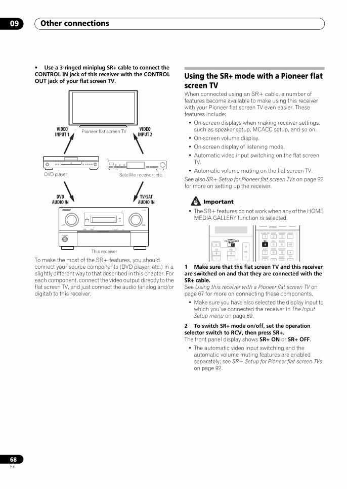
Other connections09
68En
• Use a 3-ringed miniplug SR+ cable to connect the CONTROL IN jack of this receiver with the CONTROL OUT jack of your flat screen TV.
To make the most of the SR+ features, you should connect your source components (DVD player, etc.) in a slightly different way to that described in this chapter. For each component, connect the video output directly to the flat screen TV, and just connect the audio (analog and/or digital) to this receiver.
Using the SR+ mode with a Pioneer flat screen TVWhen connected using an SR+ cable, a number of features become available to make using this receiver with your Pioneer flat screen TV even easier. These features include:
• On-screen displays when making receiver settings, such as speaker setup, MCACC setup, and so on.
• On-screen volume display.
• On-screen display of listening mode.
• Automatic video input switching on the flat screen TV.
• Automatic volume muting on the flat screen TV.
See also SR+ Setup for Pioneer flat screen TVs on page 92 for more on setting up the receiver.
Important
• The SR+ features do not work when any of the HOME MEDIA GALLERY function is selected.
1 Make sure that the flat screen TV and this receiver are switched on and that they are connected with the SR+ cable.See Using this receiver with a Pioneer flat screen TV on page 67 for more on connecting these components.
• Make sure you have also selected the display input to which you’ve connected the receiver in The Input Setup menu on page 89.
2 To switch SR+ mode on/off, set the operation selector switch to RCV, then press SR+.The front panel display shows SR+ ON or SR+ OFF.
• The automatic video input switching and the automatic volume muting features are enabled separately; see SR+ Setup for Pioneer flat screen TVs on page 92.
STANDBY/ON
INPUTSELECTOR
PHASECONTROL
ADVANCEDMCACC
DIGITAL VIDEOSCALER HDMI
MASTERVOLUME
SC-LX81
VIDEOINPUT 1
VIDEOINPUT 2
TV/SATAUDIO IN
DVDAUDIO IN
Pioneer flat screen TV
This receiver
DVD player Satellite receiver, etc.
SOURCETV RCV
VOLVOLCH
SOURCETV RCV
BD MENU
SIGNAL SEL SLEEP AUDIODIMMER
SR+ SBch MCACC
A.ATT GENRE HDMI OUT
D.ACCESS
ENTER
CLASS
DISP
CH
SR+
SCLX81_71.book 68 ページ 2008年7月25日 金曜日 午後3時1分
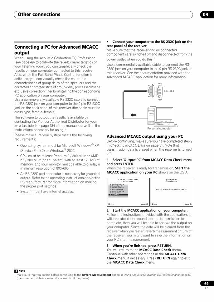
Other connections 09
69En
Connecting a PC for Advanced MCACC outputWhen using the Acoustic Calibration EQ Professional (see page 49) to calibrate the reverb characteristics of your listening room, you can graphically check the results on your computer connected to this receiver. Also, when the Full Band Phase Control function is activated, you can visually check the calibrated characteristics of group delay of the speakers and the corrected characteristics of group delay processed by the exclusive correction filter by installing the corresponding PC application on your computer. Use a commercially-available RS-232C cable to connect the RS-232C jack on your computer to the 9-pin RS-232C jack on the back panel of this receiver (the cable must be cross type, female–female).
The software to output the results is available by contacting the Pioneer Authorized Distributor for your area (as listed on page 134 of this manual) as well as the instructions necessary for using it.
Please make sure your system meets the following requirements:
• Operating system must be Microsoft Windows® XP (Service Pack 2) or Windows® 2000.
• CPU must be at least Pentium 3 / 300 MHz or AMD K6 / 300 MHz (or equivalent) with at least 128 MB of memory, and your monitor must be able to display a minimum resolution of 800x600.
• An RS-232C port connector is necessary for graphical output. Refer to the operating instructions and/or the PC manufacturer for more information on making the proper port settings.
• System must have internet access.
• Connect your computer to the RS-232C jack on the rear panel of the receiver.Make sure that the receiver and all connected components are switched off and disconnected from the power outlet when you do this.1
Use a commercially-available cable to connect the RS-232C jack on your computer to the 9-pin RS-232C jack on this receiver. See the documentation provided with the Advanced MCACC application for more information.
Advanced MCACC output using your PCBefore continuing, make sure you have completed step 2 in Checking MCACC Data on page 51. Note that transmission data is erased when the receiver is turned off.
1 Select ‘Output PC’ from MCACC Data Check menu and press ENTER.When the receiver is ready for transmission, Start the MCACC application on your PC shows on the OSD.
2 Start the MCACC application on your computer.Follow the instructions provided with the application. It will take about ten seconds for the transmission to complete, then you will be able to analyze the output on your computer. Since the data will be cleared from the receiver when you restart reverb measurement or turn off the receiver, you might want to save the information on your PC after measurement.
3 When you’re finished, press RETURN.You will return to the MCACC Data Check menu. Continue with other operations in the MCACC Data Check menu if necessary. Press RETURN again to exit the MCACC Data Check menu.
Note1 Make sure that you do this before continuing to the Reverb Measurement option in Using Acoustic Calibration EQ Professional on page 50
(measurement data is cleared if you switch off the power).
RS-232C
Personal computer
a. Speaker Settingb. Channel Levelc. Speaker Distance
2.MCACC Data Check
d. Standing Wavee. Acoustic Cal EQf. Group Delayg. Output PC
A/V RECEIVER
Exit Return
Start the MCACC application on your PC.
2g.Output PC
Exit Cancel
A/V RECEIVER
SCLX81_71.book 69 ページ 2008年7月25日 金曜日 午後3時1分
Playback with HOME MEDIA GALLERY inputs10
70En
Chapter 10:
Playback with HOME MEDIA GALLERY inputs
Enjoying the Home Media GalleryThis receiver’s Home Media Gallery function allows you to listen to audio files, play photo files or listen to Internet radio stations on a computer or other component connected to the receiver’s LAN terminal. Home Media Gallery also allows you to play audio or photo files stored on a USB memory device connected to the receiver’s USB terminal, or by connecting an iPod to play audio files stored on the iPod. This chapter describes the connection, setup, and playback procedures required to enjoy these features. It is advisory that you also refer to the operation manual supplied with your network component.
Features of Home Media GalleryThis receiver is equipped with the LAN terminal and the USB terminal, and you can enjoy the following features by connecting your components to these terminals.
• Playback the music or photo files stored in PCs1
You can playback a lot of musics and photos stored in your PCs using this unit.
See Playback with Home Media Gallery on page 73 and Playing back audio files stored on components on the network on page 75.
See Playing back photo files stored in components on the network or USB memory device on page 77.
• Listening to Internet radio stations
You can select and listen to your favorite Internet radio station from the list of Internet radio stations created, edited, and managed by the vTuner database service exclusively for use with the Pioneer products. Also, you can listen to Internet radio station managed by Neural THX.
See Playback with Home Media Gallery on page 73 and Listening to Internet radio stations on page 77 and Listening to Neural Music Direct on page 79.
• Playing audio or photo files stored on a USB memory device or audio files stored on an iPod
The desired audio or photo file can be played directly by selecting it on the folder/file list displayed on the screen.
See Playback with Home Media Gallery on page 73, Playing back audio files stored on a USB memory device on page 76 and Playing back audio files stored on an iPod on page 75.
See Playing back photo files stored in components on the network or USB memory device on page 77.
Steps to enjoy the Home Media Gallery
Playing back audio files on the network and listening to Internet radio stations
1 Connect to the network through LAN interface.See Connecting to the network through LAN interface on page 71 for more on this.
2 Configure the network settings.The setup is necessary only when the router to be connected does not have the built-in DHCP server function.
See Setting up the network on page 81 for more on this.
3 Playback with Home Media Gallery.See Playback with Home Media Gallery on page 73 for more on this.
Playing back audio or photo files stored on a USB memory device
1 Connect USB memory device to the iPod DIRECT USB terminal.See Connecting a USB device on page 72 for more on this.
2 Playback with Home Media Gallery.See Playback with Home Media Gallery on page 73 for more on this.
Note1 Besides a PC, you can also play back audio or photo files stored on your other components with the built-in media server function based on
DLNA 1.0 framework and protocols (i.e. network-capable hard disks and audio systems).
SCLX81_71.book 70 ページ 2008年7月25日 金曜日 午後3時1分
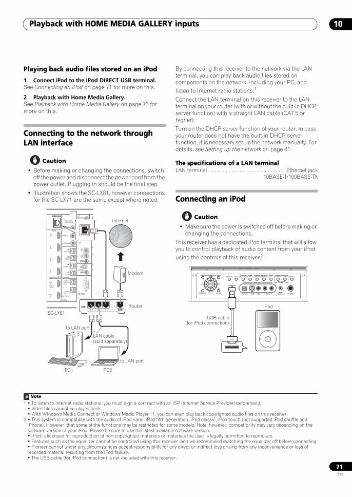
Playback with HOME MEDIA GALLERY inputs 10
71En
Playing back audio files stored on an iPod
1 Connect iPod to the iPod DIRECT USB terminal.See Connecting an iPod on page 71 for more on this.
2 Playback with Home Media Gallery.See Playback with Home Media Gallery on page 73 for more on this.
Connecting to the network through LAN interface
Caution
• Before making or changing the connections, switch off the power and disconnect the power cord from the power outlet. Plugging in should be the final step.
• Illustration shows the SC-LX81, however connections for the SC-LX71 are the same except where noted.
By connecting this receiver to the network via the LAN terminal, you can play back audio files stored on components on the network, including your PC, and listen to Internet radio stations.1
Connect the LAN terminal on this receiver to the LAN terminal on your router (with or without the built-in DHCP server function) with a straight LAN cable (CAT 5 or higher).
Turn on the DHCP server function of your router. In case your router does not have the built-in DHCP server function, it is necessary set up the network manually. For details, see Setting up the network on page 81.
The specifications of a LAN terminalLAN terminal . . . . . . . . . . . . . . . . . . . . . . . . . . . .Ethernet jack
10BASE-T/100BASE-TX
Connecting an iPod
Caution
• Make sure the power is switched off before making or changing the connections.
This receiver has a dedicated iPod terminal that will allow you to control playback of audio content from your iPod using the controls of this receiver.2
LAN (10/100)
DIGITAL
OPTICALRS-232C
HDMI
COAXIAL
IR
CONTROL
SIRIUSBDIN IN
12 VTRIGGER
IN1
IN2
IN3
OUT1
OUT2
SOURCEOUT
ZONE3/SOURCEOUT
31ASSIGNABLE -
(HDMI CTRL)
ASSIGNABLE
ASSIGNABLE
(CD-R)IN 4
(VIDEO1)IN 3
(DVR1)IN 2
(TV/SAT)IN 1
IN 3 (DVR2)
IN 2 (CD)
IN 1 (DVD)
(OUTPUT 12V TOTAL 50mA MAX)
1
2
IN1
IN
IN2
OUT
OUT
(DVD)
PR
SIGG
LAN (10/100)
WAN3 2 1LAN
SC-LX81
LAN cable(sold separately)
to LAN port
Router
Modem
Internet
to LAN port
PC1 PC2
Note1 • To listen to Internet radio stations, you must sign a contract with an ISP (Internet Service Provider) beforehand.
• Video files cannot be played back.• With Windows Media Connect or Windows Media Player 11, you can even play back copyrighted audio files on this receiver.
2 • This system is compatible with the audio of iPod nano, iPod fifth generation, iPod classic, iPod touch (not supported iPod shuffle and iPhone). However, that some of the functions may be restricted for some models. Note, however, compatibility may vary depending on the software version of your iPod. Please be sure to use the latest available software version.• iPod is licensed for reproduction of non-copyrighted materials or materials the user is legally permitted to reproduce.• Features such as the equalizer cannot be controlled using this receiver, and we recommend switching the equalizer off before connecting.• Pioneer cannot under any circumstances accept responsibility for any direct or indirect loss arising from any inconvenience or loss of recorded material resulting from the iPod failure.• The USB cable (for iPod connection) is not included with this receiver.
VIDEO3 INPUT
DIGITAL IN S-VIDEO VIDEO L RAUDIO PHONES
SPEAKERSCONTROL
MULTI-ZONE& SOURCE
ON/OFF
MCACCSETUP MIC
PARAMETER
ENTER
(TUNE)
(TUNE)
(ST)(ST)
AUDIO VIDEOTUNER EDIT
iPod DIRECTUSB
AUTO SURR/STREAM DIRECT
HOMETHX
STANDARDSURROUND
ADVANCEDSURROUND
STEREO/A.L.C.BAND
HOME MENU RETURN
MENU
��
��
iPod
USB cable(for iPod connection)
SCLX81_71.book 71 ページ 2008年7月25日 金曜日 午後3時1分
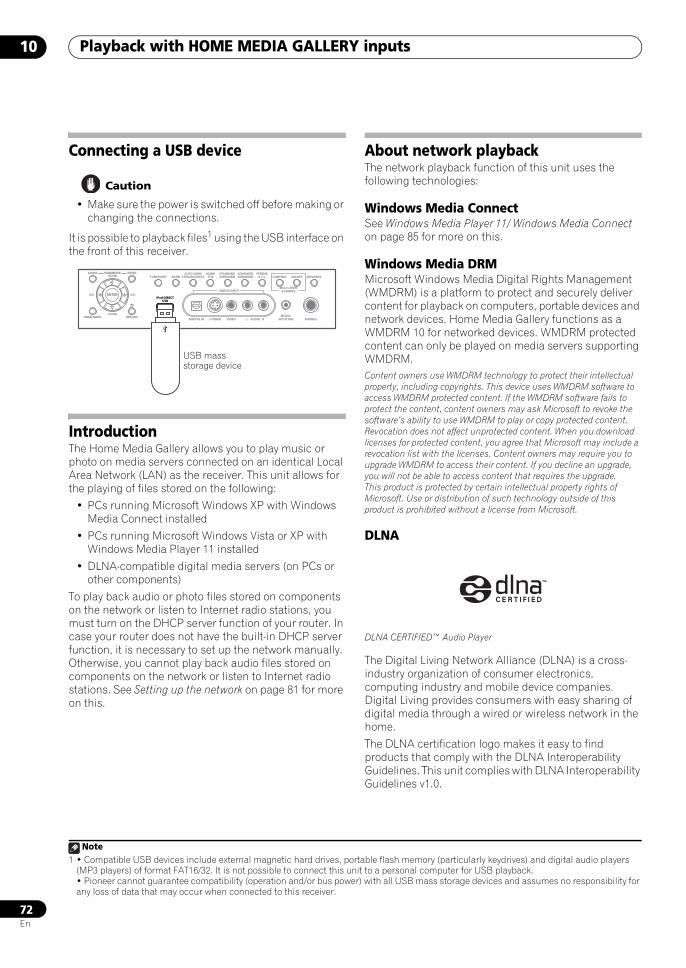
Playback with HOME MEDIA GALLERY inputs10
72En
Connecting a USB device
Caution
• Make sure the power is switched off before making or changing the connections.
It is possible to playback files1 using the USB interface on the front of this receiver.
IntroductionThe Home Media Gallery allows you to play music or photo on media servers connected on an identical Local Area Network (LAN) as the receiver. This unit allows for the playing of files stored on the following:
• PCs running Microsoft Windows XP with Windows Media Connect installed
• PCs running Microsoft Windows Vista or XP with Windows Media Player 11 installed
• DLNA-compatible digital media servers (on PCs or other components)
To play back audio or photo files stored on components on the network or listen to Internet radio stations, you must turn on the DHCP server function of your router. In case your router does not have the built-in DHCP server function, it is necessary to set up the network manually. Otherwise, you cannot play back audio files stored on components on the network or listen to Internet radio stations. See Setting up the network on page 81 for more on this.
About network playbackThe network playback function of this unit uses the following technologies:
Windows Media ConnectSee Windows Media Player 11/ Windows Media Connect on page 85 for more on this.
Windows Media DRMMicrosoft Windows Media Digital Rights Management (WMDRM) is a platform to protect and securely deliver content for playback on computers, portable devices and network devices. Home Media Gallery functions as a WMDRM 10 for networked devices. WMDRM protected content can only be played on media servers supporting WMDRM.Content owners use WMDRM technology to protect their intellectual property, including copyrights. This device uses WMDRM software to access WMDRM protected content. If the WMDRM software fails to protect the content, content owners may ask Microsoft to revoke the software’s ability to use WMDRM to play or copy protected content. Revocation does not affect unprotected content. When you download licenses for protected content, you agree that Microsoft may include a revocation list with the licenses. Content owners may require you to upgrade WMDRM to access their content. If you decline an upgrade, you will not be able to access content that requires the upgrade.This product is protected by certain intellectual property rights of Microsoft. Use or distribution of such technology outside of this product is prohibited without a license from Microsoft.
DLNA
DLNA CERTIFIED™ Audio Player
The Digital Living Network Alliance (DLNA) is a cross-industry organization of consumer electronics, computing industry and mobile device companies. Digital Living provides consumers with easy sharing of digital media through a wired or wireless network in the home.
The DLNA certification logo makes it easy to find products that comply with the DLNA Interoperability Guidelines. This unit complies with DLNA Interoperability Guidelines v1.0.
Note1 • Compatible USB devices include external magnetic hard drives, portable flash memory (particularly keydrives) and digital audio players
(MP3 players) of format FAT16/32. It is not possible to connect this unit to a personal computer for USB playback.• Pioneer cannot guarantee compatibility (operation and/or bus power) with all USB mass storage devices and assumes no responsibility for any loss of data that may occur when connected to this receiver.
VIDEO3 INPUT
DIGITAL IN S-VIDEO VIDEO L RAUDIO PHONES
SPEAKERSCONTROL
MULTI-ZONE& SOURCE
ON/OFF
MCACCSETUP MIC
PARAMETER
ENTER
(TUNE)
(TUNE)
(ST)(ST)
AUDIO VIDEOTUNER EDIT
iPod DIRECTUSB
AUTO SURR/STREAM DIRECT
HOMETHX
STANDARDSURROUND
ADVANCEDSURROUND
STEREO/A.L.C.BAND
HOME MENU RETURN
iPod DIRECTUSB
USB mass storage device
SCLX81_71.book 72 ページ 2008年7月25日 金曜日 午後3時1分
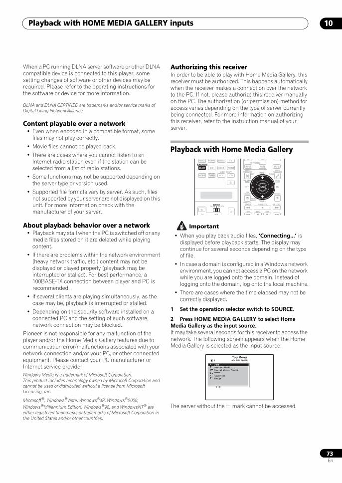
Playback with HOME MEDIA GALLERY inputs 10
73En
When a PC running DLNA server software or other DLNA compatible device is connected to this player, some setting changes of software or other devices may be required. Please refer to the operating instructions for the software or device for more information.
DLNA and DLNA CERTIFIED are trademarks and/or service marks of Digital Living Network Alliance.
Content playable over a network• Even when encoded in a compatible format, some
files may not play correctly.
• Movie files cannot be played back.
• There are cases where you cannot listen to an Internet radio station even if the station can be selected from a list of radio stations.
• Some functions may not be supported depending on the server type or version used.
• Supported file formats vary by server. As such, files not supported by your server are not displayed on this unit. For more information check with the manufacturer of your server.
About playback behavior over a network• Playback may stall when the PC is switched off or any
media files stored on it are deleted while playing content.
• If there are problems within the network environment (heavy network traffic, etc.) content may not be displayed or played properly (playback may be interrupted or stalled). For best performance, a 100BASE-TX connection between player and PC is recommended.
• If several clients are playing simultaneously, as the case may be, playback is interrupted or stalled.
• Depending on the security software installed on a connected PC and the setting of such software, network connection may be blocked.
Pioneer is not responsible for any malfunction of the player and/or the Home Media Gallery features due to communication error/malfunctions associated with your network connection and/or your PC, or other connected equipment. Please contact your PC manufacturer or Internet service provider.Windows Media is a trademark of Microsoft Corporation.This product includes technology owned by Microsoft Corporation and cannot be used or distributed without a license from Microsoft Licensing, Inc.
Microsoft®, Windows®Vista, Windows®XP, Windows®2000, Windows®Millennium Edition, Windows®98, and WindowsNT® are either registered trademarks or trademarks of Microsoft Corporation in the United States and/or other countries.
Authorizing this receiverIn order to be able to play with Home Media Gallery, this receiver must be authorized. This happens automatically when the receiver makes a connection over the network to the PC. If not, please authorize this receiver manually on the PC. The authorization (or permission) method for access varies depending on the type of server currently being connected. For more information on authorizing this receiver, refer to the instruction manual of your server.
Playback with Home Media Gallery
Important
• When you play back audio files, ‘Connecting...’ is displayed before playback starts. The display may continue for several seconds depending on the type of file.
• In case a domain is configured in a Windows network environment, you cannot access a PC on the network while you are logged onto the domain. Instead of logging onto the domain, log onto the local machine.
• There are cases where the time elapsed may not be correctly displayed.
1 Set the operation selector switch to SOURCE.
2 Press HOME MEDIA GALLERY to select Home Media Gallery as the input source.It may take several seconds for this receiver to access the network. The following screen appears when the Home Media Gallery is selected as the input source.
The server without the mark cannot be accessed.
SOURCETV RCV
VIDEO1
GALLERYHOME MEDIA
CD
HDMI
VOLCH
TUNER
PHONO
VIDEO2 VIDEO3 TV
CD-R
INPUT SELECTTUNER
AUDIOPARAMETER
TOP MENUBAND
iPod CTRL
EXIT TOOLS
HOMEMENU
STATUS
THX MPX
PHASE CTRL CH LEVEL
MENUT.EDIT
VIDEOPARAMETER
INPUT MUTE MUTETV CONTROL
ENTER
RETURNPTY
SEARCH
EON
TOP MENUBAND
ENTER
MPX
TUNE +
TUNE
ST ST +
1 / 6
Top Menu
USBInternet Radio
1
Neural Music Direct******FavoritesSetup
A/V RECEIVER
SCLX81_71.book 73 ページ 2008年7月25日 金曜日 午後3時1分
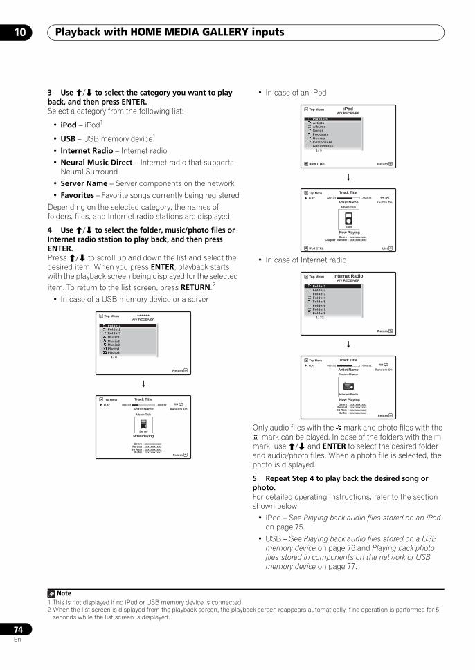
Playback with HOME MEDIA GALLERY inputs10
74En
3 Use / to select the category you want to play back, and then press ENTER.Select a category from the following list:
• iPod – iPod1
• USB – USB memory device1
• Internet Radio – Internet radio
• Neural Music Direct – Internet radio that supports Neural Surround
• Server Name – Server components on the network
• Favorites – Favorite songs currently being registered
Depending on the selected category, the names of folders, files, and Internet radio stations are displayed.
4 Use / to select the folder, music/photo files or Internet radio station to play back, and then press ENTER.Press / to scroll up and down the list and select the desired item. When you press ENTER, playback starts with the playback screen being displayed for the selected item. To return to the list screen, press RETURN.2
• In case of a USB memory device or a server
• In case of an iPod
• In case of Internet radio
Only audio files with the mark and photo files with the mark can be played. In case of the folders with the
mark, use / and ENTER to select the desired folder and audio/photo files. When a photo file is selected, the photo is displayed.
5 Repeat Step 4 to play back the desired song or photo.For detailed operating instructions, refer to the section shown below.
• iPod – See Playing back audio files stored on an iPod on page 75.
• USB – See Playing back audio files stored on a USB memory device on page 76 and Playing back photo files stored in components on the network or USB memory device on page 77.
Note1 This is not displayed if no iPod or USB memory device is connected.2 When the list screen is displayed from the playback screen, the playback screen reappears automatically if no operation is performed for 5
seconds while the list screen is displayed.
******Top Menu
Return
Folder1Folder2Folder3Music1Music2Music3Photo1Photo2
A/V RECEIVER
1 / 8
Track Title
Server
Top Menu
Return
Random On PLAY 0003:02 -0002:02
Artist Name
Now Playing
Album Title
Genre : xxxxxxxxxxxFormat : xxxxxxxxxxx
Bit Rate : xxxxxxxxxxxBuffer : xxxxxxxxxxx
iPod
iPod CTRL
Top Menu
Return
PlaylistsArtistsAlbumsSongsPodcastsGenresComposersAudiobooks
1 / 9
A/V RECEIVER
Track Title
Artist Name
Genre : xxxxxxxxxxxChapter Number : xxxxxxxxxxx
Now Playing
Album Title
iPod
iPod CTRL
Top Menu
List
Shuffle On PLAY 0003:02 -0002:02
Internet RadioTop Menu
Return
Folder1Folder2Folder3Folder4Folder5Folder6Folder7Folder8
A/V RECEIVER
1 / 32
Track Title
Now Playing
Channel Name
Internet Radio
Top Menu
Return
Random On PLAY 0003:02 -0002:02
Artist Name
Genre : xxxxxxxxxxxFormat : xxxxxxxxxxx
Bit Rate : xxxxxxxxxxxBuffer : xxxxxxxxxxx
SCLX81_71.book 74 ページ 2008年7月25日 金曜日 午後3時1分
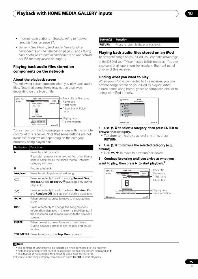
Playback with HOME MEDIA GALLERY inputs 10
75En
• Internet radio stations – See Listening to Internet radio stations on page 77.
• Server – See Playing back audio files stored on components on the network on page 75 and Playing back photo files stored in components on the network or USB memory device on page 77.
Playing back audio files stored on components on the network
About the playback screenThe following screen appears when you play back audio files. Note that some items may not be displayed depending on the type of file.
You can perform the following operations with the remote control of this receiver. Note that some buttons are not available for operation depending on the category currently being played back.
Playing back audio files stored on an iPodTo navigate songs on your iPod, you can take advantage of the OSD of your TV connected to this receiver.1 You can also control all operations for music in the front panel display of this receiver.
Finding what you want to playWhen your iPod is connected to this receiver, you can browse songs stored on your iPod by playlist, artist, album name, song name, genre or composer, similar to using your iPod directly.
1 Use / to select a category, then press ENTER to browse that category.
• To return to the previous level any time, press RETURN.
2 Use / to browse the selected category (e.g., albums).
• Use / to move to previous/next levels.
3 Continue browsing until you arrive at what you want to play, then press to start playback.2
Button(s) Function
Press to start playback.If you start playback when something other than a song is selected, all the songs that fall into that category will play.
Pauses playback.
/ Press to skip to previous/next song.
Press repeatedly to switch among Repeat One, Repeat All and Repeat Off (available only during playback).
Press repeatedly to switch between Random On and Random Off (available only during playback).
/ When browsing, press to move to previous/next levels.
DISP Press repeatedly to change the song playback information displayed in the front panel display. (If the list screen is displayed, switch to the playback screen.)
ENTER When browsing, press to move to next levels. During playback, press to set the play and pause modes.
TOP MENU Press to return to the Top Menu screen.
Play modeTrack title or File name
Album title or Folder name
Artist name
Track Title
Server
Top Menu
Return
Random On PLAY 0003:02 -0002:02
Artist Name
Now Playing
Album Title
Genre : xxxxxxxxxxxFormat : xxxxxxxxxxx
Bit Rate : xxxxxxxxxxxBuffer : xxxxxxxxxxx
Playing timeFile information
RETURN Press to return to the previous level.
Note1 • The controls of your iPod will be inoperable when connected to this receiver.
• Note that characters that cannot be displayed on this receiver are displayed as #.• This feature is not available for photos or video clips on your iPod.
2 If you’re in the song category, you can also press ENTER to start playback.
Button(s) Function
iPod
iPod CTRL
Top Menu
Return
PlaylistsArtistsAlbumsSongsPodcastsGenresComposersAudiobooks
1 / 9
A/V RECEIVER
Play modeTrack title
Album titleArtist name
Track Title
Artist Name
Genre : xxxxxxxxxxxChapter Number : xxxxxxxxxxx
Now Playing
Album Title
iPod
iPod CTRL
Top Menu
List
Shuffle On PLAY 0003:02 -0002:02
Playing timeFile information
SCLX81_71.book 75 ページ 2008年7月25日 金曜日 午後3時1分
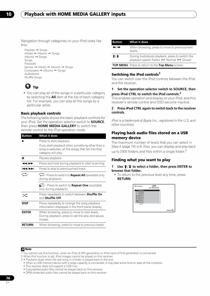
Playback with HOME MEDIA GALLERY inputs10
76En
Navigation through categories on your iPod looks like this:
Playlists SongsArtists Albums SongsAlbums SongsSongsPodcastsGenres Artists Albums SongsComposers Albums SongsAudiobooksShuffle Songs
Tip
• You can play all of the songs in a particular category by selecting the All item at the top of each category list. For example, you can play all the songs by a particular artist.
Basic playback controlsThe following table shows the basic playback controls for your iPod. Set the operation selector switch to SOURCE, then press HOME MEDIA GALLERY to switch the remote control to the iPod operation mode.
Switching the iPod controls1
You can switch over the iPod controls between the iPod and the receiver.
1 Set the operation selector switch to SOURCE, then press iPod CTRL to switch the iPod controls.2
This enables operation and display on your iPod, and this receiver’s remote control and OSD become inactive.
2 Press iPod CTRL again to switch back to the receiver controls.
iPod is a trademark of Apple Inc., registered in the U.S. and other countries.
Playing back audio files stored on a USB memory deviceThe maximum number of levels that you can select in Step 4 (page 74) is 8. Also, you can display and play back up to 2000 folders and files within a single folder.3
Finding what you want to play
1 Use / to select a folder, then press ENTER to browse that folder.
• To return to the previous level any time, press RETURN.
Button What it does
Press to start playback.If you start playback when something other than a song is selected, all the songs that fall into that category will play.
Pauses playback.
/ Press and hold during playback to start scanning.
/ Press to skip to previous/next track.
: Press to switch to Repeat All (available only during playback).
: Press to switch to Repeat One (available only during playback).
Press repeatedly to switch between Shuffle On and Shuffle Off.
DISP Press repeatedly to change the song playback information displayed in the front panel display.
ENTER When browsing, press to move to next levels. During playback, press to set the play and pause modes.
RETURN When browsing, press to move to previous levels.
1
/ When browsing, press to move to previous/next levels.
/ During Audiobook playback, press to switch the playback speed: Faster Normal Slower
TOP MENU Press to return to the Top Menu screen.
Note1 You cannot use this function, when an iPod of fifth generation or iPod nano of first generation is connected.2 When this function is set, iPod images cannot be played on this receiver.3 • Playback stops when the last song in a folder is played back to the end.
• When a USB memory device with a large capacity is connected, it may take some time to read all the contents.• This receiver does not support a USB hub.• Copyrighted audio files cannot be played back on this receiver.• DRM-protected audio files cannot be played back on this receiver.
Button What it does
USB
Return
Folder1Folder2Folder3Music1Music2Music3Photo1Photo2
1 / 9
A/V RECEIVERTop Menu
SCLX81_71.book 76 ページ 2008年7月25日 金曜日 午後3時1分
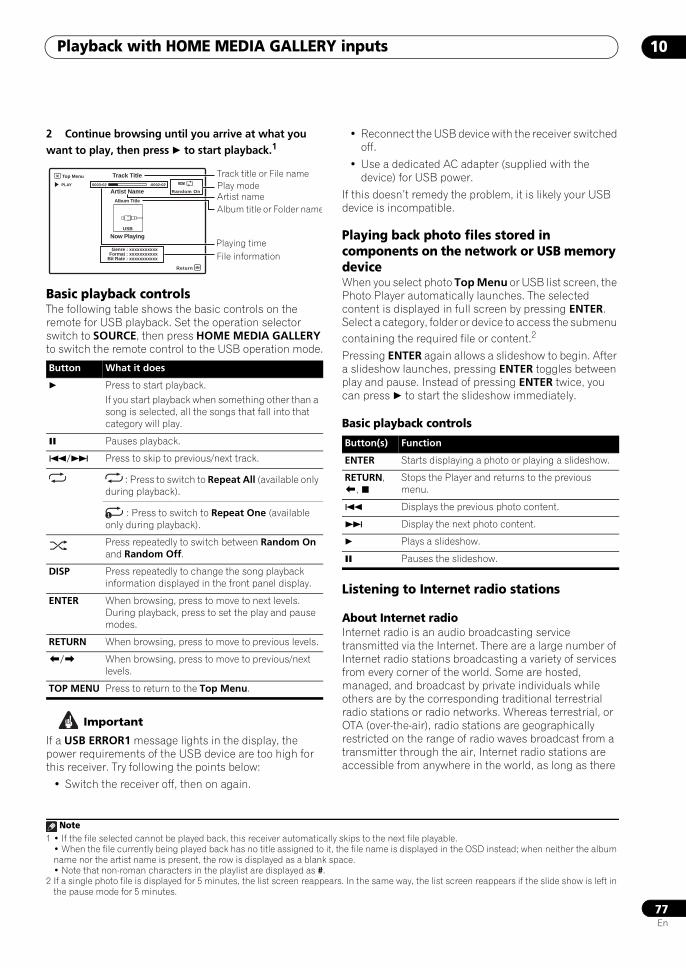
Playback with HOME MEDIA GALLERY inputs 10
77En
2 Continue browsing until you arrive at what you want to play, then press to start playback.1
Basic playback controlsThe following table shows the basic controls on the remote for USB playback. Set the operation selector switch to SOURCE, then press HOME MEDIA GALLERY to switch the remote control to the USB operation mode.
Important
If a USB ERROR1 message lights in the display, the power requirements of the USB device are too high for this receiver. Try following the points below:
• Switch the receiver off, then on again.
• Reconnect the USB device with the receiver switched off.
• Use a dedicated AC adapter (supplied with the device) for USB power.
If this doesn’t remedy the problem, it is likely your USB device is incompatible.
Playing back photo files stored in components on the network or USB memory deviceWhen you select photo Top Menu or USB list screen, the Photo Player automatically launches. The selected content is displayed in full screen by pressing ENTER. Select a category, folder or device to access the submenu containing the required file or content.2
Pressing ENTER again allows a slideshow to begin. After a slideshow launches, pressing ENTER toggles between play and pause. Instead of pressing ENTER twice, you can press to start the slideshow immediately.
Basic playback controls
Listening to Internet radio stations
About Internet radioInternet radio is an audio broadcasting service transmitted via the Internet. There are a large number of Internet radio stations broadcasting a variety of services from every corner of the world. Some are hosted, managed, and broadcast by private individuals while others are by the corresponding traditional terrestrial radio stations or radio networks. Whereas terrestrial, or OTA (over-the-air), radio stations are geographically restricted on the range of radio waves broadcast from a transmitter through the air, Internet radio stations are accessible from anywhere in the world, as long as there
Note1 • If the file selected cannot be played back, this receiver automatically skips to the next file playable.
• When the file currently being played back has no title assigned to it, the file name is displayed in the OSD instead; when neither the album name nor the artist name is present, the row is displayed as a blank space.• Note that non-roman characters in the playlist are displayed as #.
Button What it does
Press to start playback.If you start playback when something other than a song is selected, all the songs that fall into that category will play.
Pauses playback.
/ Press to skip to previous/next track.
: Press to switch to Repeat All (available only during playback).
: Press to switch to Repeat One (available only during playback).
Press repeatedly to switch between Random On and Random Off.
DISP Press repeatedly to change the song playback information displayed in the front panel display.
ENTER When browsing, press to move to next levels. During playback, press to set the play and pause modes.
RETURN When browsing, press to move to previous levels.
/ When browsing, press to move to previous/next levels.
TOP MENU Press to return to the Top Menu.
Play modeTrack title or File name
Album title or Folder nameArtist name
Track Title
USB
Top Menu
Return
Random On PLAY 0003:02 -0002:02
Artist Name
Now Playing
Album Title
Genre : xxxxxxxxxxxFormat : xxxxxxxxxxx
Bit Rate : xxxxxxxxxxx
Playing timeFile information
1
2 If a single photo file is displayed for 5 minutes, the list screen reappears. In the same way, the list screen reappears if the slide show is left in the pause mode for 5 minutes.
Button(s) Function
ENTER Starts displaying a photo or playing a slideshow.
RETURN, ,
Stops the Player and returns to the previous menu.
Displays the previous photo content.
Display the next photo content.
Plays a slideshow.
Pauses the slideshow.
SCLX81_71.book 77 ページ 2008年7月25日 金曜日 午後3時1分
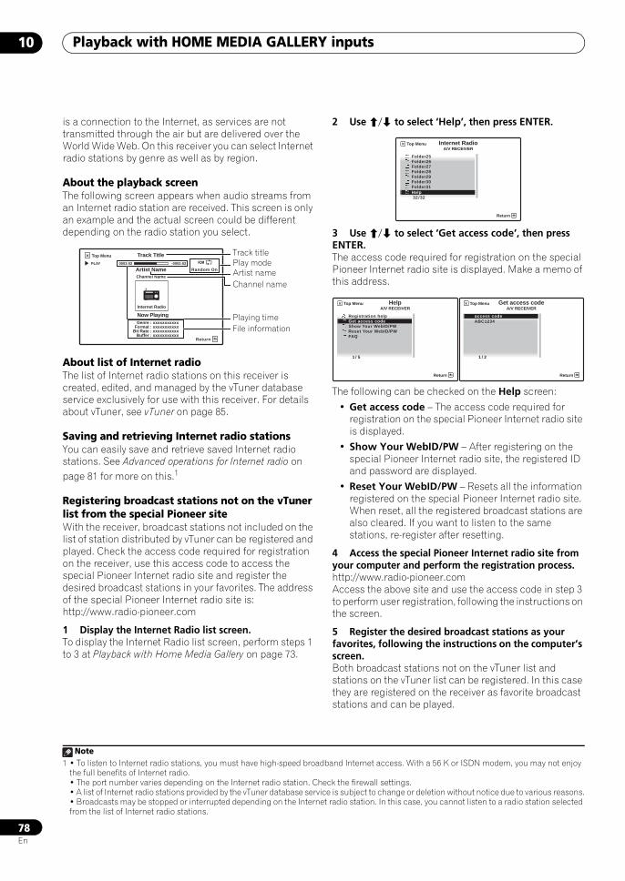
Playback with HOME MEDIA GALLERY inputs10
78En
is a connection to the Internet, as services are not transmitted through the air but are delivered over the World Wide Web. On this receiver you can select Internet radio stations by genre as well as by region.
About the playback screenThe following screen appears when audio streams from an Internet radio station are received. This screen is only an example and the actual screen could be different depending on the radio station you select.
About list of Internet radioThe list of Internet radio stations on this receiver is created, edited, and managed by the vTuner database service exclusively for use with this receiver. For details about vTuner, see vTuner on page 85.
Saving and retrieving Internet radio stationsYou can easily save and retrieve saved Internet radio stations. See Advanced operations for Internet radio on page 81 for more on this.1
Registering broadcast stations not on the vTuner list from the special Pioneer siteWith the receiver, broadcast stations not included on the list of station distributed by vTuner can be registered and played. Check the access code required for registration on the receiver, use this access code to access the special Pioneer Internet radio site and register the desired broadcast stations in your favorites. The address of the special Pioneer Internet radio site is:http://www.radio-pioneer.com
1 Display the Internet Radio list screen.To display the Internet Radio list screen, perform steps 1 to 3 at Playback with Home Media Gallery on page 73.
2 Use / to select ‘Help’, then press ENTER.
3 Use / to select ‘Get access code’, then press ENTER.The access code required for registration on the special Pioneer Internet radio site is displayed. Make a memo of this address.
The following can be checked on the Help screen:
• Get access code – The access code required for registration on the special Pioneer Internet radio site is displayed.
• Show Your WebID/PW – After registering on the special Pioneer Internet radio site, the registered ID and password are displayed.
• Reset Your WebID/PW – Resets all the information registered on the special Pioneer Internet radio site. When reset, all the registered broadcast stations are also cleared. If you want to listen to the same stations, re-register after resetting.
4 Access the special Pioneer Internet radio site from your computer and perform the registration process.http://www.radio-pioneer.comAccess the above site and use the access code in step 3 to perform user registration, following the instructions on the screen.
5 Register the desired broadcast stations as your favorites, following the instructions on the computer’s screen.Both broadcast stations not on the vTuner list and stations on the vTuner list can be registered. In this case they are registered on the receiver as favorite broadcast stations and can be played.
Note1 • To listen to Internet radio stations, you must have high-speed broadband Internet access. With a 56 K or ISDN modem, you may not enjoy
the full benefits of Internet radio.• The port number varies depending on the Internet radio station. Check the firewall settings.• A list of Internet radio stations provided by the vTuner database service is subject to change or deletion without notice due to various reasons.• Broadcasts may be stopped or interrupted depending on the Internet radio station. In this case, you cannot listen to a radio station selected from the list of Internet radio stations.
Play modeTrack title
Channel nameArtist name
Track Title
Now Playing
Channel Name
Internet Radio
Top Menu
Return
Random On PLAY 0003:02 -0002:02
Artist Name
Genre : xxxxxxxxxxxFormat : xxxxxxxxxxx
Bit Rate : xxxxxxxxxxxBuffer : xxxxxxxxxxx
Playing timeFile information
Internet RadioTop Menu
Return
Folder25Folder26Folder27Folder28Folder29Folder30Folder31Help
A/V RECEIVER
32 / 32
HelpTop Menu
Return
Registration helpGet access codeShow Your WebID/PW Reset Your WebID/PWFAQ
A/V RECEIVER
1 / 5
Get access codeTop Menu
Return
ABC1234
A/V RECEIVER
1 / 2
access code
SCLX81_71.book 78 ページ 2008年7月25日 金曜日 午後3時1分
Playback with HOME MEDIA GALLERY inputs 10
79En
Listening to Neural Music Direct
About Neural Music DirectNeural Music Direct is an Internet radio station managed and operated by Neural Audio Corporation. Neural radio stations deliver multichannel surround sound. The Neural-THX Surround mode is automatically selected and lets you enjoy a rich multichannel surround sound experience. For details about Neural THX, see the operation manual supplied separately.
Neural Surround is a trademark owned by Neural Audio Corporation, THX is a trademark of THX Ltd., which may be registered in some jurisdictions. All rights reserved.
Playing back your favorite songs
About the Favorites folderYou can register up to 20 of your favorite songs in the Favorites folder. Note that only the audio files stored on components on the network can be registered.
Registering and deleting audio files and Internet radio stations in and from the Favorites folderPress PGM while a song is being played back or stopped. The selected song is then registered in the Favorites folder.
Up to 20 songs or Internet radio stations can be registered. Songs stored on a USB memory device and iPod cannot be registered.
To delete a registered song, select the Favorites folder, select the song you want to delete from the folder, and press CLR. The selected song is then deleted from the Favorites folder.
SCLX81_71.book 79 ページ 2008年7月25日 金曜日 午後3時1分
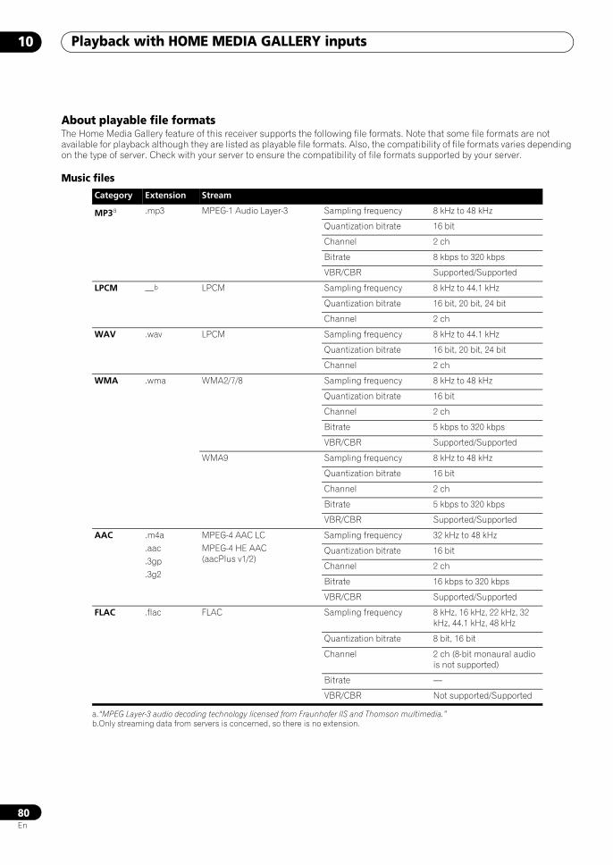
Playback with HOME MEDIA GALLERY inputs10
80En
About playable file formatsThe Home Media Gallery feature of this receiver supports the following file formats. Note that some file formats are not available for playback although they are listed as playable file formats. Also, the compatibility of file formats varies depending on the type of server. Check with your server to ensure the compatibility of file formats supported by your server.
Music files
Category Extension Stream
MP3a .mp3 MPEG-1 Audio Layer-3 Sampling frequency 8 kHz to 48 kHz
Quantization bitrate 16 bit
Channel 2 ch
Bitrate 8 kbps to 320 kbps
VBR/CBR Supported/Supported
LPCM —b LPCM Sampling frequency 8 kHz to 44.1 kHz
Quantization bitrate 16 bit, 20 bit, 24 bit
Channel 2 ch
WAV .wav LPCM Sampling frequency 8 kHz to 44.1 kHz
Quantization bitrate 16 bit, 20 bit, 24 bit
Channel 2 ch
WMA .wma WMA2/7/8 Sampling frequency 8 kHz to 48 kHz
Quantization bitrate 16 bit
Channel 2 ch
Bitrate 5 kbps to 320 kbps
VBR/CBR Supported/Supported
WMA9 Sampling frequency 8 kHz to 48 kHz
Quantization bitrate 16 bit
Channel 2 ch
Bitrate 5 kbps to 320 kbps
VBR/CBR Supported/Supported
AAC .m4a.aac.3gp.3g2
MPEG-4 AAC LCMPEG-4 HE AAC (aacPlus v1/2)
Sampling frequency 32 kHz to 48 kHz
Quantization bitrate 16 bit
Channel 2 ch
Bitrate 16 kbps to 320 kbps
VBR/CBR Supported/Supported
FLAC .flac FLAC Sampling frequency 8 kHz, 16 kHz, 22 kHz, 32 kHz, 44.1 kHz, 48 kHz
Quantization bitrate 8 bit, 16 bit
Channel 2 ch (8-bit monaural audio is not supported)
Bitrate —
VBR/CBR Not supported/Supported
a.“MPEG Layer-3 audio decoding technology licensed from Fraunhofer IIS and Thomson multimedia.”b.Only streaming data from servers is concerned, so there is no extension.
SCLX81_71.book 80 ページ 2008年7月25日 金曜日 午後3時1分
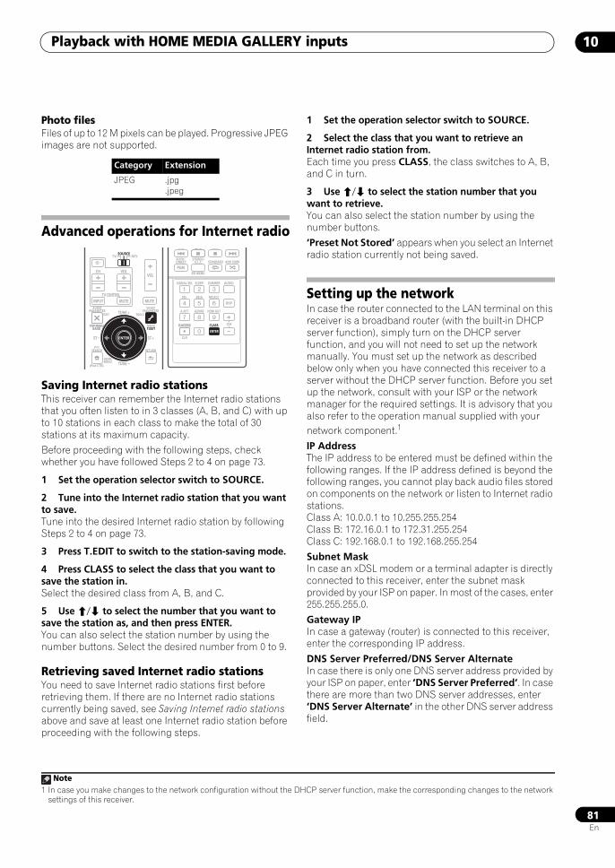
Playback with HOME MEDIA GALLERY inputs 10
81En
Photo filesFiles of up to 12 M pixels can be played. Progressive JPEG images are not supported.
Advanced operations for Internet radio
Saving Internet radio stationsThis receiver can remember the Internet radio stations that you often listen to in 3 classes (A, B, and C) with up to 10 stations in each class to make the total of 30 stations at its maximum capacity.
Before proceeding with the following steps, check whether you have followed Steps 2 to 4 on page 73.
1 Set the operation selector switch to SOURCE.
2 Tune into the Internet radio station that you want to save.Tune into the desired Internet radio station by following Steps 2 to 4 on page 73.
3 Press T.EDIT to switch to the station-saving mode.
4 Press CLASS to select the class that you want to save the station in.Select the desired class from A, B, and C.
5 Use / to select the number that you want to save the station as, and then press ENTER.You can also select the station number by using the number buttons. Select the desired number from 0 to 9.
Retrieving saved Internet radio stationsYou need to save Internet radio stations first before retrieving them. If there are no Internet radio stations currently being saved, see Saving Internet radio stations above and save at least one Internet radio station before proceeding with the following steps.
1 Set the operation selector switch to SOURCE.
2 Select the class that you want to retrieve an Internet radio station from.Each time you press CLASS, the class switches to A, B, and C in turn.
3 Use / to select the station number that you want to retrieve.You can also select the station number by using the number buttons.
‘Preset Not Stored’ appears when you select an Internet radio station currently not being saved.
Setting up the networkIn case the router connected to the LAN terminal on this receiver is a broadband router (with the built-in DHCP server function), simply turn on the DHCP server function, and you will not need to set up the network manually. You must set up the network as described below only when you have connected this receiver to a server without the DHCP server function. Before you set up the network, consult with your ISP or the network manager for the required settings. It is advisory that you also refer to the operation manual supplied with your network component.1
IP AddressThe IP address to be entered must be defined within the following ranges. If the IP address defined is beyond the following ranges, you cannot play back audio files stored on components on the network or listen to Internet radio stations.Class A: 10.0.0.1 to 10.255.255.254Class B: 172.16.0.1 to 172.31.255.254Class C: 192.168.0.1 to 192.168.255.254
Subnet MaskIn case an xDSL modem or a terminal adapter is directly connected to this receiver, enter the subnet mask provided by your ISP on paper. In most of the cases, enter 255.255.255.0.
Gateway IPIn case a gateway (router) is connected to this receiver, enter the corresponding IP address.
DNS Server Preferred/DNS Server AlternateIn case there is only one DNS server address provided by your ISP on paper, enter ‘DNS Server Preferred’. In case there are more than two DNS server addresses, enter ‘DNS Server Alternate’ in the other DNS server address field.
Category Extension
JPEG .jpg.jpeg
AUDIOPARAMETER
TOP MENUBAND
iPod CTRL
EXIT TOOLS
HOMEMENU
STATUS PHASE CTRL CH LEVEL
MENUT.EDIT
VIDEOPARAMETER
SOURCETV RCV
INPUT MUTE MUTE
VOLVOL
TV CONTROL
CH
ENTER
RETURNPTY
SEARCH
TOP MENUBAND
ENTER
TUNE +
TUNE
ST ST +
THX MPX
PGM
STEREO/A.L.C.
BD MENU
SIGNAL SEL SLEEP AUDIODIMMER
SR+
CLR
SBch MCACC
A.ATT GENRE HDMI OUT
D.ACCESS
ENTER
CLASS
DISP
CH
AUTO/DIRECT STANDARD ADV SURR
EONMPX
D.ACCESS
Note1 In case you make changes to the network configuration without the DHCP server function, make the corresponding changes to the network
settings of this receiver.
SCLX81_71.book 81 ページ 2008年7月25日 金曜日 午後3時1分

Playback with HOME MEDIA GALLERY inputs10
82En
Proxy Hostname/Proxy PortThis setting is required when you connect this receiver to the Internet via a proxy server. Enter the IP address of your proxy server in the ‘Proxy Hostname’ field. Also, enter the port number of your proxy server in the ‘Proxy Port’ field.
Tip
• Press / or the numeric buttons to enter alphanumeric characters. To delete alphanumeric characters entered one at a time, press or CLEAR. ‘Cancel Key Editing Lose Changes?’ appears when you press RETURN or while the cursor is placed in the leftmost position on the alphanumeric character entry screen. In this case, press ENTER to exit from the screen and RETURN to return to the screen.
1 Set the operation selector switch to SOURCE.
2 Press HOME MEDIA GALLERY to select ‘Home Media Gallery’ as the input source.It may take several seconds for this receiver to access the network. The following screen appears when the Home Media Gallery is selected as the input source.
3 Select ‘Setup’ and press ENTER to confirm your selection.The Setup screen appears.
4 Select ‘Network Setup’ and press ENTER to confirm your selection.The Network Setup screen appears.
5 Either ‘Network Found’ or ‘No Network Found’ appears. Check the network connection status and press ENTER.
• Network Found – Connected to a component on the network.
• No Network Found – Not connected to a component on the network.
The Network IP Settings screen appears.
6 Select ‘Static IP Address’ and press ENTER to confirm your selection.The IP address screen appears. When you select ‘Automatic (DHCP)’, the network is automatically set up, and you do not need to follow Steps 7 to 16. Proceed with Step 17.
7 Select ‘Change’ and press ENTER to confirm your selection.The Edit IP address screen appears.
8 Enter the IP address.Press / to select a number and / to move the cursor. After you select the last number, press or ENTER. You can also use the numeric buttons to enter a number. The Subnet Mask screen appears.
9 Select ‘Change’ and press ENTER to confirm your selection.The Edit Subnet Mask screen appears.
10 Enter the subnet mask.After entry, press or ENTER. The Gateway IP screen appears.
SOURCETV RCV
VIDEO1
GALLERYHOME MEDIA
CD
HDMI
VOLCH
TUNER
PHONO
VIDEO2 VIDEO3 TV
CD-R
INPUT SELECTTUNER
AUDIOPARAMETER
TOP MENUBAND
iPod CTRL
EXIT TOOLS
HOMEMENU
STATUS
THX MPX
PHASE CTRL CH LEVEL
MENUT.EDIT
VIDEOPARAMETER
INPUT MUTE MUTETV CONTROL
ENTER
RETURNPTY
SEARCH
EON
TOP MENUBAND
ENTER
MPX
TUNE +
TUNE
ST ST +
PGM
STEREO/A.L.C.
BD MENU
SIGNAL SEL SLEEP AUDIODIMMER
SR+
CLR
SBch MCACC
A.ATT GENRE HDMI OUT
D.ACCESS
ENTER
CLASS
DISP
CH
AUTO/DIRECT STANDARD ADV SURR
D.ACCESS
1 / 6
Top Menu
USBInternet Radio
1
Neural Music Direct******FavoritesSetup
A/V RECEIVER
6 / 6
Top Menu
USBInternet Radio
1
Neural Music Direct******FavoritesSetup
A/V RECEIVER
InformationNetwork Setup
SetupA/V RECEIVER
Return
Top Menu
1 / 2
Network IP SettingsA/V RECEIVER
Return
Top Menu
Automatic (DHCP)Static IP Address
2 / 2
IP addressA/V RECEIVER
Return
Top Menu
192.168.000.002Change
2 / 2
Edit IP addressA/V RECEIVER
Return
Top Menu
1 9 2 . 1 6 8 . 0 0 0 . 0 0 2
Subnet MaskA/V RECEIVER
Return
Top Menu
255.255.255.000Change
2 / 2
Edit Subnet MaskA/V RECEIVER
Return
Top Menu
2 5 5 . 2 5 5 . 2 5 5 . 0 0 0
SCLX81_71.book 82 ページ 2008年7月25日 金曜日 午後3時1分
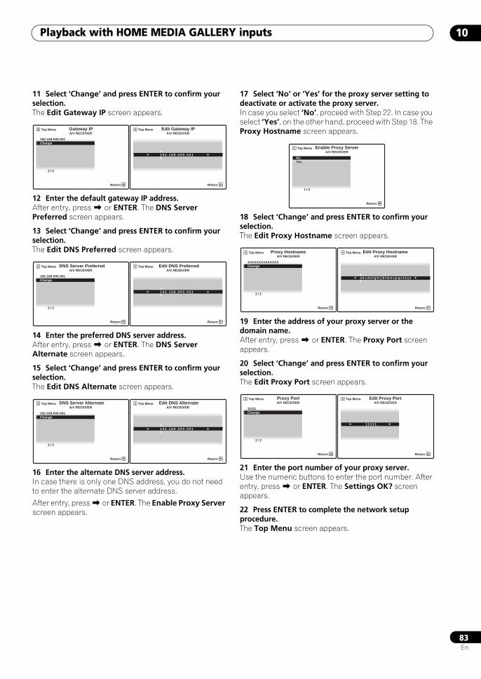
Playback with HOME MEDIA GALLERY inputs 10
83En
11 Select ‘Change’ and press ENTER to confirm your selection.The Edit Gateway IP screen appears.
12 Enter the default gateway IP address.After entry, press or ENTER. The DNS Server Preferred screen appears.
13 Select ‘Change’ and press ENTER to confirm your selection.The Edit DNS Preferred screen appears.
14 Enter the preferred DNS server address.After entry, press or ENTER. The DNS Server Alternate screen appears.
15 Select ‘Change’ and press ENTER to confirm your selection.The Edit DNS Alternate screen appears.
16 Enter the alternate DNS server address.In case there is only one DNS address, you do not need to enter the alternate DNS server address.
After entry, press or ENTER. The Enable Proxy Server screen appears.
17 Select ‘No’ or ‘Yes’ for the proxy server setting to deactivate or activate the proxy server.In case you select ‘No’, proceed with Step 22. In case you select ‘Yes’, on the other hand, proceed with Step 18. The Proxy Hostname screen appears.
18 Select ‘Change’ and press ENTER to confirm your selection.The Edit Proxy Hostname screen appears.
19 Enter the address of your proxy server or the domain name.After entry, press or ENTER. The Proxy Port screen appears.
20 Select ‘Change’ and press ENTER to confirm your selection.The Edit Proxy Port screen appears.
21 Enter the port number of your proxy server.Use the numeric buttons to enter the port number. After entry, press or ENTER. The Settings OK? screen appears.
22 Press ENTER to complete the network setup procedure.The Top Menu screen appears.
Gateway IPA/V RECEIVER
Return
Top Menu
192.168.000.001Change
2 / 2
Edit Gateway IPA/V RECEIVER
Return
Top Menu
1 9 2 . 1 6 8 . 0 0 0 . 0 0 1
DNS Server PreferredA/V RECEIVER
Return
Top Menu
192.168.000.001Change
2 / 2
Edit DNS PreferredA/V RECEIVER
Return
Top Menu
1 9 2 . 1 6 8 . 0 0 0 . 0 0 1
A/V RECEIVER
Return
Top Menu
192.168.000.001Change
2 / 2
DNS Server Alternate Edit DNS AlternateA/V RECEIVER
Return
Top Menu
1 9 2 . 1 6 8 . 0 0 0 . 0 0 1
Enable Proxy ServerA/V RECEIVER
Return
Top Menu
NoYes
1 / 2
Proxy HostnameA/V RECEIVER
Return
Top Menu
XXXXXXXXXXXXXXChange
2 / 2
Edit Proxy HostnameA/V RECEIVER
Return
Top Menu
a b c d e f g h i j k l m n o p q r s t u v
Proxy PortA/V RECEIVER
Return
Top Menu
11111Change
2 / 2
Edit Proxy PortA/V RECEIVER
Return
Top Menu
1 1 1 1 1
SCLX81_71.book 83 ページ 2008年7月25日 金曜日 午後3時1分
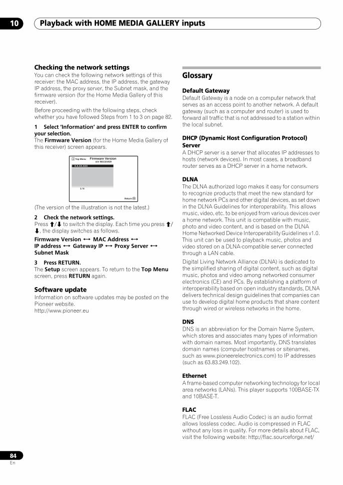
Playback with HOME MEDIA GALLERY inputs10
84En
Checking the network settingsYou can check the following network settings of this receiver: the MAC address, the IP address, the gateway IP address, the proxy server, the Subnet mask, and the firmware version (for the Home Media Gallery of this receiver).
Before proceeding with the following steps, check whether you have followed Steps from 1 to 3 on page 82.
1 Select ‘Information’ and press ENTER to confirm your selection.The Firmware Version (for the Home Media Gallery of this receiver) screen appears.
(The version of the illustration is not the latest.)
2 Check the network settings.Press / to switch the display. Each time you press /, the display switches as follows.
Firmware Version MAC Address IP address Gateway IP Proxy Server Subnet Mask
3 Press RETURN.The Setup screen appears. To return to the Top Menu screen, press RETURN again.
Software updateInformation on software updates may be posted on the Pioneer website.http://www.pioneer.eu
Glossary
Default GatewayDefault Gateway is a node on a computer network that serves as an access point to another network. A default gateway (such as a computer and router) is used to forward all traffic that is not addressed to a station within the local subnet.
DHCP (Dynamic Host Configuration Protocol) ServerA DHCP server is a server that allocates IP addresses to hosts (network devices). In most cases, a broadband router serves as a DHCP server in a home network.
DLNAThe DLNA authorized logo makes it easy for consumers to recognize products that meet the new standard for home network PCs and other digital devices, as set down in the DLNA Guidelines for interoperability. This allows music, video, etc. to be enjoyed from various devices over a home network. This unit is compatible with music, photo and video content, and is based on the DLNA Home Networked Device Interoperability Guidelines v1.0. This unit can be used to playback music, photos and video stored on a DLNA-compatible server connected through a LAN cable.
Digital Living Network Alliance (DLNA) is dedicated to the simplified sharing of digital content, such as digital music, photos and video among networked consumer electronics (CE) and PCs. By establishing a platform of interoperability based on open industry standards, DLNA delivers technical design guidelines that companies can use to develop digital home products that share content through wired or wireless networks in the home.
DNSDNS is an abbreviation for the Domain Name System, which stores and associates many types of information with domain names. Most importantly, DNS translates domain names (computer hostnames or sitenames, such as www.pioneerelectronics.com) to IP addresses (such as 63.83.249.102).
EthernetA frame-based computer networking technology for local area networks (LANs). This player supports 100BASE-TX and 10BASE-T.
FLACFLAC (Free Lossless Audio Codec) is an audio format allows lossless codec. Audio is compressed in FLAC without any loss in quality. For more details about FLAC, visit the following website: http://flac.sourceforge.net/
Firmware Version A/V RECEIVER
Return
Top Menu
X.X.XX.XXX
1 / 6
SCLX81_71.book 84 ページ 2008年7月25日 金曜日 午後3時1分
Playback with HOME MEDIA GALLERY inputs 10
85En
IP (Internet Protocol) addressA unique number that devices use in order to identify and communicate with each other on a network utilizing the Internet Protocol standard, such as ‘192.168.0.1’. No duplicate numbers are allowed in the network.
LANLAN is an abbreviation for the Local Area Network, which is a computer network covering a small geographical area, like a home, office, or group of buildings. Current LANs are most likely to be based on switched IEEE 802.3 Ethernet technology, running at 10, 100, or 1000 Mbit/s, or on IEEE 802.11 Wi-Fi technology.
MAC (Media Access Control) addressAn address attached to the port of any network device with an IP address. The MAC address is expressed as “00:e0:36:xx:xx:xx” and cannot be changed.
Mass Storage Class devicesThe standard provides an interface to a variety of storage devices, such as USB flash drive and digital cameras.
Neural SurroundNeural Surround represents the latest advancement in surround technology and has been adopted by FM Radio and Neural Music Direct for broadcasts of surround recordings and live events.
Neural Surround employs psychoacoustic frequency domain processing which allows delivery of a more detailed sound stage with superior localization of surround elements. System playback is scalable from stereo up to state-of-the-art multichannel surround.
Subnet maskThe IP address is divided into the network address part and the host address part. The subnet mask is expressed as ‘255.255.255.0’. In most cases, the subnet mask is automatically assigned by the DHCP server.
USB (Universal Serial Bus)USB provides a serial bus standard for connecting devices, usually to computers such as PCs. This receiver supports the Mass Storage Class.
vTunervTuner is a paid online database service that allows you to listen to radio and TV broadcasts on the Internet. vTuner lists thousands of stations from over 100 different countries around the globe. For more detail about vTuner, visit the following website:http://www.radio-pioneer.com
“This product is protected by certain intellectual property rights of NEMS and BridgeCo. Use or distribution of such technology outside of this product is prohibited without a license from NEMS and BridgeCo or an authorized subsidiary.”
Windows MediaWindows Media is a multimedia framework for media creation and distribution for Microsoft Windows. Windows Media is either a registered trademark or trademark of Microsoft Corporation in the U.S. and/or other countries. Use an application licensed by Microsoft Corporation to author, distribute, or play Windows Media formatted content. Using an application unauthorized by Microsoft Corporation is subject to malfunction.
Windows Media DRMWindows Media DRM is a DRM (Digital Rights Management) service for the Windows Media platform. It is designed to provide secure delivery of audio and/or video content over an IP network to a PC or other playback device in such a way that the distributor can control how that content is used. The WMDRM-protected content can only be played back on a component supporting the WMDRM service.
Windows Media Player 11/Windows Media ConnectWindows Media Connect is software to deliver music, photos and movies from a Microsoft Windows XP computer to home stereo systems and TVs.
With this software, you can play back files stored on the PC through various devices wherever you like in your home.
At this time you cannot download the Windows Media Connect software from Microsoft’s website. If your server currently does not have Windows Media Connect installed, install Windows Media Player 11 (for Windows XP) instead. This software can be downloaded from Microsoft’s website.
For more information check the official Microsoft website.
SCLX81_71.book 85 ページ 2008年7月25日 金曜日 午後3時1分
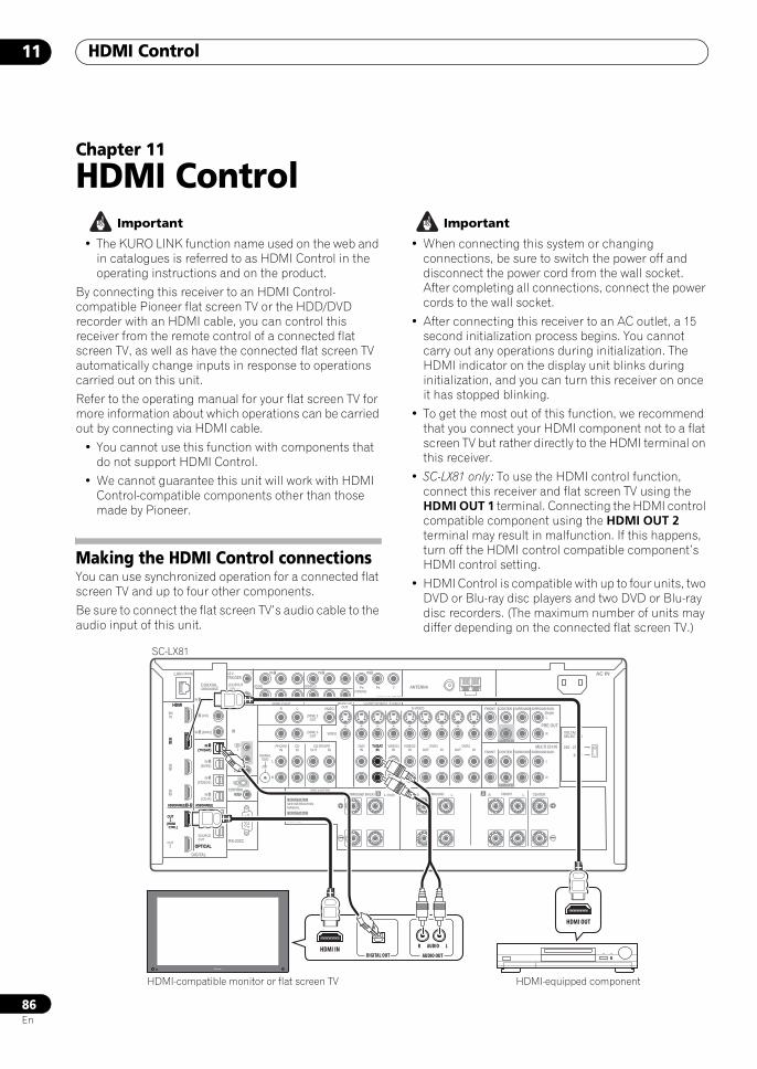
HDMI Control11
86En
Chapter 11
HDMI Control Important
• The KURO LINK function name used on the web and in catalogues is referred to as HDMI Control in the operating instructions and on the product.
By connecting this receiver to an HDMI Control-compatible Pioneer flat screen TV or the HDD/DVD recorder with an HDMI cable, you can control this receiver from the remote control of a connected flat screen TV, as well as have the connected flat screen TV automatically change inputs in response to operations carried out on this unit.
Refer to the operating manual for your flat screen TV for more information about which operations can be carried out by connecting via HDMI cable.
• You cannot use this function with components that do not support HDMI Control.
• We cannot guarantee this unit will work with HDMI Control-compatible components other than those made by Pioneer.
Making the HDMI Control connectionsYou can use synchronized operation for a connected flat screen TV and up to four other components.
Be sure to connect the flat screen TV’s audio cable to the audio input of this unit.
Important
• When connecting this system or changing connections, be sure to switch the power off and disconnect the power cord from the wall socket.After completing all connections, connect the power cords to the wall socket.
• After connecting this receiver to an AC outlet, a 15 second initialization process begins. You cannot carry out any operations during initialization. The HDMI indicator on the display unit blinks during initialization, and you can turn this receiver on once it has stopped blinking.
• To get the most out of this function, we recommend that you connect your HDMI component not to a flat screen TV but rather directly to the HDMI terminal on this receiver.
• SC-LX81 only: To use the HDMI control function, connect this receiver and flat screen TV using the HDMI OUT 1 terminal. Connecting the HDMI control compatible component using the HDMI OUT 2 terminal may result in malfunction. If this happens, turn off the HDMI control compatible component’s HDMI control setting.
• HDMI Control is compatible with up to four units, two DVD or Blu-ray disc players and two DVD or Blu-ray disc recorders. (The maximum number of units may differ depending on the connected flat screen TV.)
LAN (10/100)
DIGITAL
OPTICALRS-232C
HDMI
COAXIAL
COMPONENT VIDEO
ANTENNA
PRE OUT
MULTI CH IN
A
IR
CONTROL
BDIN
12 VTRIGGER
IN1
IN2
IN3
OUT1
OUT2
SOURCEOUT
ZONE3/SOURCEOUT
31ASSIGNABLE -
31ASSIGNABLE -
(HDMI CTRL)
ASSIGNABLE
ASSIGNABLE
(CD-R)IN 4
(VIDEO1)IN 3
(DVR1)IN 2
(TV/SAT)IN 1
IN 3 (DVR2)
IN 2 (CD)
IN 1 (DVD)
IN 1 IN 2
(OUTPUT 12V TOTAL 50mA MAX)
1
2
IN1
IN
IN2
OUT
OUT
(DVD)
PR PB Y PR PB Y
PR PB Y(VIDEO1)
IN 3
(VIDEO2)
RZONE 2 OUT MONITOR
OUT
PHONOIN
CDIN
DVDIN
TV/SATIN
VIDEO1IN
VIDEO2IN OUT
DVR1IN OUT
DVR2INOUT IN
CD-R/TAPE
SIGNALGND
ZONE 2 OUT
ZONE 3 OUT
VIDEO
VIDEO S-VIDEO FRONT CENTER
SUBWOOFER
SURROUND SURROUND BACK
FRONT CENTER
CENTERLR FRONTB LR SURROUND BACK/ LR SURROUND
SUBWOOFER
SURROUND SURROUND BACK
(Single)
(Single)
L
L
R
L
R
L
R
FM UNBAL 75 AM LOOP
SPEAKERS
SEE INSTRUCTIONMANUAL
SELECTABLE
VOIR LE MODED'EMPLOI
SELECTABLE
AC IN
220 - 230 V
240 V
VOLTAGESELECTOR
HDMI
IN1
OUT1
31ASSIGNABLE -
(HDMI CTRL)
OPTICAL
ASSIGNABLE
(TV/SAT)IN 1 TV/SAT
IN
HDMI OUT
AUDIO OUT
AUDIOR L
DIGITAL OUTHDMI IN
SC-LX81
HDMI-compatible monitor or flat screen TV HDMI-equipped component
SCLX81_71.book 86 ページ 2008年7月25日 金曜日 午後3時1分
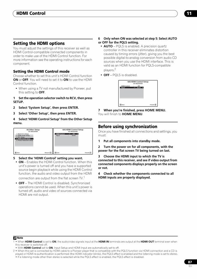
HDMI Control 11
87En
Setting the HDMI optionsYou must adjust the settings of this receiver as well as HDMI Control-compatible connected components in order to make use of the HDMI Control function. For more information see the operating instructions for each component.
Setting the HDMI Control modeChoose whether to set this unit’s HDMI Control function ON or OFF. You will need to set it to ON to use the HDMI Control function.
• When using a TV not manufactured by Pioneer, put this setting to OFF.
1 Set the operation selector switch to RCV, then press SETUP.
2 Select ‘System Setup’, then press ENTER.
3 Select ‘Other Setup’, then press ENTER.
4 Select ‘HDMI Control Setup’ from the Other Setup menu.
5 Select the ‘HDMI Control’ setting you want.• ON – Enables the HDMI Control function. When this
unit’s power is turned off and you have a supported source begin playback while using the HDMI Control function, the audio and video output from the HDMI connection are output from the flat screen TV.1
• OFF – The HDMI Control is disabled. Synchronized operations cannot be used. When this unit’s power is turned off, audio and video of sources connected via HDMI are not output.
6 Only when ON was selected at step 5: Select AUTO or OFF for the PQLS setting.
• AUTO – PQLS is enabled. A precision quartz controller in this receiver eliminates distortion caused by timing errors (jitter), giving you the best possible digital-to-analog conversion from audio CD sources when you use the HDMI interface. This is valid as an HDMI function for PQLS-compatible players.2
• OFF – PQLS is disabled.
7 When you’re finished, press HOME MENU. You will finish to HOME MENU.
Before using synchronizationOnce you have finished all connections and settings, you must:
1 Put all components into standby mode.
2 Turn the power on for all components, with the power for the flat screen TV being turned on last.
3 Choose the HDMI input to which the TV is connected to this receiver, and see if video output from connected components displays properly on the screen or not.
4 Check whether the components connected to all HDMI inputs are properly displayed.
Note1 • When HDMI Control is set to ON, the audio/video signals input at the HDMI IN terminals are output at the HDMI OUT terminal even when
this receiver is switched off.• With HDMI Control set to ON, Input Setup and HDMI Input are automatically set to off.
1. Multi Ch In Setup2. ZONE Audio Setup3. SR+ Setup
5. Flicker Reduction Setup4. HDMI Control Setup
4d.Other SetupA/V RECEIVER
Exit Return
4d4.HDMI Control SetupA/V RECEIVER
Exit Finish
HDMI Control : ONPQLS : AUTO
2 • When this set is connected by HDMI cable to a Pioneer player that is compatible with the PQLS function via HDMI connection and a CD is played or HDMI re-authentication is performed (the HDMI indicator blinks), the PQLS effect is enabled and the listening mode is set to stereo.• If a listening mode other than stereo is selected while the PQLS effect is enabled, the PQLS effect is disabled.
4d4.HDMI Control SetupA/V RECEIVER
Exit Finish
HDMI Control : ONPQLS : AUTO
SCLX81_71.book 87 ページ 2008年7月25日 金曜日 午後3時1分
HDMI Control11
88En
Synchronized amp modeSynchronized amp mode begins once you carry out an operation for the flat screen TV. For more information, see the operating manual of your flat screen TV.
Synchronized amp mode operationsBy connecting a component to this receiver with an HDMI cable you can use synchronized amp mode, which allows you to synchronize the following operations1:
• Displays on the flat screen TV when you mute or adjust the volume of this receiver.
• The input of this receiver is automatically changed when playback occurs on a connected component.
• Even if you change this receiver’s input to a device that is not connected by HDMI, the synchronized amp mode remains in effect.
• This receiver’s input switches automatically when the channel is switched on an HDMI control-compatible flat screen TV.
• This receiver’s OSD language switches automatically when the menu language is switched on an HDMI control-compatible flat screen TV.
• By pressing GENRE when listening to a source from a HDD/DVD recorder, the most appropriate listening mode is automatically selected (see Using the genre synchronizing function on page 40 for more on this).
Canceling synchronized amp modeOperate the flat screen TV to cancel the synchronized amp mode.
If you cancel synchronized amp mode while connected via HDMI to a flat screen TV or while you are watching a TV programme, the power for this unit is turned off.
About HDMI Control• Connect the flat screen TV directly to this receiver.
Interrupting a direct connection with other amps or an AV converter (such as an HDMI switch) can cause operational errors.
• Only connect components you intend to use as a source to the HDMI input of this receiver. Interrupting a direct connection with other amps or an AV converter (such as an HDMI switch) can cause operational errors.
About PQLSPQLS (Precision Quartz Lock System) is a digital audio signal transfer control technology using the KURO LINK (HDMI Control) function. It offers higher-quality audio playback by controlling audio signals from the receiver to a PQLS compatible player, etc. This enables removing jitter that has a negative effect on the quality of the sound and is generated upon transmission.
Note1 The linked mode remains in effect even when this receiver’s input is switched to something other than HDMI.
SCLX81_71.book 88 ページ 2008年7月25日 金曜日 午後3時1分
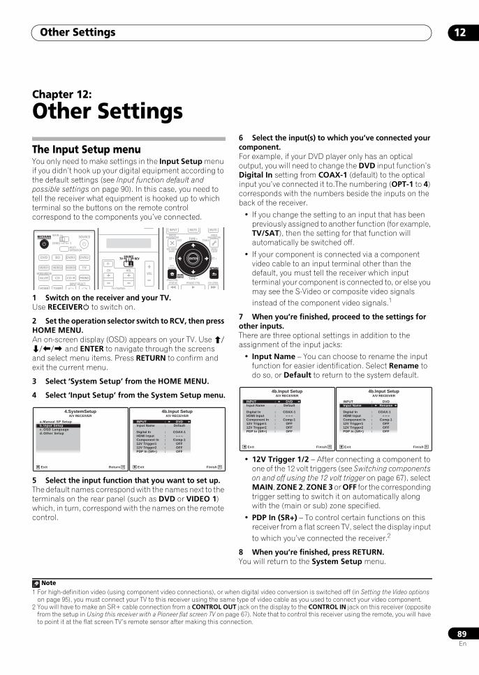
Other Settings 12
89En
Chapter 12:
Other Settings
The Input Setup menuYou only need to make settings in the Input Setup menu if you didn’t hook up your digital equipment according to the default settings (see Input function default and possible settings on page 90). In this case, you need to tell the receiver what equipment is hooked up to which terminal so the buttons on the remote control correspond to the components you’ve connected.
1 Switch on the receiver and your TV.Use RECEIVER to switch on.
2 Set the operation selector switch to RCV, then press HOME MENU.An on-screen display (OSD) appears on your TV. Use /// and ENTER to navigate through the screens and select menu items. Press RETURN to confirm and exit the current menu.
3 Select ‘System Setup’ from the HOME MENU.
4 Select ‘Input Setup’ from the System Setup menu.
5 Select the input function that you want to set up.The default names correspond with the names next to the terminals on the rear panel (such as DVD or VIDEO 1) which, in turn, correspond with the names on the remote control.
6 Select the input(s) to which you’ve connected your component.For example, if your DVD player only has an optical output, you will need to change the DVD input function’s Digital In setting from COAX-1 (default) to the optical input you’ve connected it to.The numbering (OPT-1 to 4) corresponds with the numbers beside the inputs on the back of the receiver.
• If you change the setting to an input that has been previously assigned to another function (for example, TV/SAT), then the setting for that function will automatically be switched off.
• If your component is connected via a component video cable to an input terminal other than the default, you must tell the receiver which input terminal your component is connected to, or else you may see the S-Video or composite video signals instead of the component video signals.1
7 When you’re finished, proceed to the settings for other inputs.There are three optional settings in addition to the assignment of the input jacks:
• Input Name – You can choose to rename the input function for easier identification. Select Rename to do so, or Default to return to the system default.
• 12V Trigger 1/2 – After connecting a component to one of the 12 volt triggers (see Switching components on and off using the 12 volt trigger on page 67), select MAIN, ZONE 2, ZONE 3 or OFF for the corresponding trigger setting to switch it on automatically along with the (main or sub) zone specified.
• PDP In (SR+) – To control certain functions on this receiver from a flat screen TV, select the display input to which you’ve connected the receiver.2
8 When you’re finished, press RETURN.You will return to the System Setup menu.
DVD
RECEIVER SOURCEMAIN
MULTIOPERATION
ZONE2 3
VIDEO1
GALLERYHOME MEDIA
INPUT SELECT
CD
HDMI TUNER
PHONO
VIDEO2 VIDEO3 TV
BD DVR1 DVR2
CD-R
RECEIVER
SOURCETV RCV
VOLVOL
TV CONTROL
CH
SOURCETV RCV
AUDIOPARAMETER
TOP MENUBAND
iPod CTRL
PTYSEARCH
EXIT TOOLS
STATUS PHASE CTRL CH LEVEL
MENUT.EDIT
VIDEOPARAMETER
INPUT MUTE MUTE
RETURN
TUNE +
TUNE
ST ST +
HOMEMENU
RETURN
ENTER
A/V RECEIVER
Exit Return
a.Manual SP Setupb. Input Setupc. OSD Languaged. Other Setup
4.SystemSetup 4b.Input SetupA/V RECEIVER
Exit Finish
INPUT : DVDInput Name : Default
Digital In : COAX-1HDMI Input : ---Component In : Comp-112V Trigger1 : OFF12V Trigger2 : OFFPDP In (SR+) : OFF
Note1 For high-definition video (using component video connections), or when digital video conversion is switched off (in Setting the Video options
on page 95), you must connect your TV to this receiver using the same type of video cable as you used to connect your video component.2 You will have to make an SR+ cable connection from a CONTROL OUT jack on the display to the CONTROL IN jack on this receiver (opposite
from the setup in Using this receiver with a Pioneer flat screen TV on page 67). Note that to control this receiver using the remote, you will have to point it at the flat screen TV’s remote sensor after making this connection.
4b.Input SetupA/V RECEIVER
Exit Finish
INPUT : DVDInput Name : Default
Digital In : COAX-1HDMI Input : ---Component In : Comp-112V Trigger1 : OFF12V Trigger2 : OFFPDP In (SR+) : OFF
4b.Input SetupA/V RECEIVER
Exit Finish
INPUT : DVDInput Name : Rename
Digital In : COAX-1HDMI Input : ---Component In : Comp-112V Trigger1 : OFF12V Trigger2 : OFFPDP In (SR+) : OFF
SCLX81_71.book 89 ページ 2008年7月25日 金曜日 午後3時1分
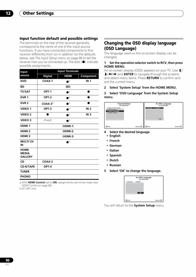
Other Settings12
90En
Input function default and possible settingsThe terminals on the rear of the receiver generally correspond to the name of one of the input source functions. If you have connected components to this receiver differently from (or in addition to) the defaults below, see The Input Setup menu on page 89 to tell the receiver how you’ve connected up. The dots () indicate possible assignments.
Changing the OSD display language (OSD Language)The language used on the on-screen display can be changed.
1 Set the operation selector switch to RCV, then press HOME MENU.An on-screen display (OSD) appears on your TV. Use /// and ENTER to navigate through the screens and select menu items. Press RETURN to confirm and exit the current menu.
2 Select ‘System Setup’ from the HOME MENU.
3 Select ‘OSD Language’ from the System Setup menu.
4 Select the desired language.• English
• French
• German
• Italian
• Spanish
• Dutch
• Russian
5 Select ‘OK’ to change the language.
You will return to the System Setup menu.
Input source
Input Terminals
Digital HDMI Component
DVD COAX-1 a
a.With HDMI Control set to ON, assignments cannot be made (see HDMI Control on page 86).
IN 1
BD (BD)
TV/SAT OPT-1 a
DVR 1 OPT-2 a
DVR 2 COAX-3b
b.SC-LX81 only
a
VIDEO 1 OPT-3 a IN 2
VIDEO 2 a IN 3
VIDEO 3 (Fixed) a
HDMI 1 (HDMI-1)
HDMI 2 (HDMI-2)
HDMI 3 (HDMI-3)
MULTI CH IN
a
HOME MEDIA GALLERY
CD COAX-2
CD-R/TAPE OPT-4
TUNER
PHONO
A/V RECEIVER
Exit Return
a.Manual SP Setupb. Input Setupc. OSD Languaged. Other Setup
4.SystemSetup 4c.OSD LanguageA/V RECEIVER
Exit Return
Language : English
OK
4c.OSD LanguageA/V RECEIVER
Exit Return
Language : English
OK
SCLX81_71.book 90 ページ 2008年7月25日 金曜日 午後3時1分
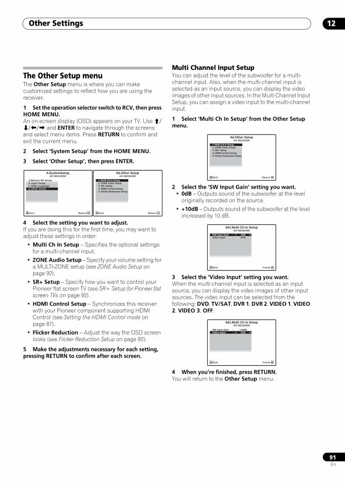
Other Settings 12
91En
The Other Setup menuThe Other Setup menu is where you can make customized settings to reflect how you are using the receiver.
1 Set the operation selector switch to RCV, then press HOME MENU.An on-screen display (OSD) appears on your TV. Use /// and ENTER to navigate through the screens and select menu items. Press RETURN to confirm and exit the current menu.
2 Select ‘System Setup’ from the HOME MENU.
3 Select ‘Other Setup’, then press ENTER.
4 Select the setting you want to adjust.If you are doing this for the first time, you may want to adjust these settings in order:
• Multi Ch In Setup – Specifies the optional settings for a multi-channel input.
• ZONE Audio Setup – Specify your volume setting for a MULTI-ZONE setup (see ZONE Audio Setup on page 92).
• SR+ Setup – Specify how you want to control your Pioneer flat screen TV (see SR+ Setup for Pioneer flat screen TVs on page 92).
• HDMI Control Setup – Synchronizes this receiver with your Pioneer component supporting HDMI Control (see Setting the HDMI Control mode on page 87).
• Flicker Reduction – Adjust the way the OSD screen looks (see Flicker Reduction Setup on page 92).
5 Make the adjustments necessary for each setting, pressing RETURN to confirm after each screen.
Multi Channel Input SetupYou can adjust the level of the subwoofer for a multi-channel input. Also, when the multi-channel input is selected as an input source, you can display the video images of other input sources. In the Multi Channel Input Setup, you can assign a video input to the multi-channel input.
1 Select ‘Multi Ch In Setup’ from the Other Setup menu.
2 Select the ‘SW Input Gain’ setting you want.• 0dB – Outputs sound of the subwoofer at the level
originally recorded on the source.
• +10dB – Outputs sound of the subwoofer at the level increased by 10 dB.
3 Select the ‘Video Input’ setting you want.When the multi-channel input is selected as an input source, you can display the video images of other input sources. The video input can be selected from the following: DVD, TV/SAT, DVR 1, DVR 2, VIDEO 1, VIDEO 2, VIDEO 3, OFF.
4 When you’re finished, press RETURN.You will return to the Other Setup menu.
A/V RECEIVER
Exit Return
a.Manual SP Setupb. Input Setupc. OSD Languaged. Other Setup
4.SystemSetup 4d.Other SetupA/V RECEIVER
Exit Return
1. Multi Ch In Setup2. ZONE Audio Setup3. SR+ Setup
5. Flicker Reduction Setup4. HDMI Control Setup
4d.Other SetupA/V RECEIVER
Exit Return
1. Multi Ch In Setup2. ZONE Audio Setup3. SR+ Setup
5. Flicker Reduction Setup4. HDMI Control Setup
4d1.Multi Ch In SetupA/V RECEIVER
Exit Finish
SW Input Gain : 0dBVideo Input : DVD
4d1.Multi Ch In SetupA/V RECEIVER
Exit Finish
SW Input Gain : +10dBVideo Input : DVD
SCLX81_71.book 91 ページ 2008年7月25日 金曜日 午後3時1分
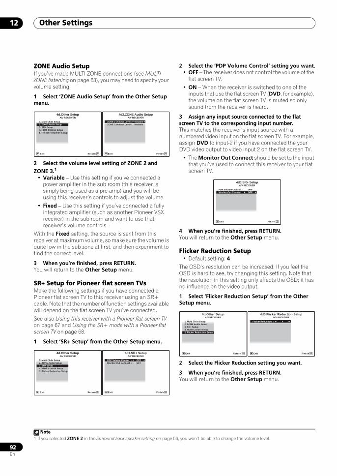
Other Settings12
92En
ZONE Audio SetupIf you’ve made MULTI-ZONE connections (see MULTI-ZONE listening on page 63), you may need to specify your volume setting.
1 Select ‘ZONE Audio Setup’ from the Other Setup menu.
2 Select the volume level setting of ZONE 2 and ZONE 3.1
• Variable – Use this setting if you’ve connected a power amplifier in the sub room (this receiver is simply being used as a pre-amp) and you will be using this receiver’s controls to adjust the volume.
• Fixed – Use this setting if you’ve connected a fully integrated amplifier (such as another Pioneer VSX receiver) in the sub room and want to use that receiver’s volume controls.
With the Fixed setting, the source is sent from this receiver at maximum volume, so make sure the volume is quite low in the sub zone at first, and then experiment to find the correct level.
3 When you’re finished, press RETURN.You will return to the Other Setup menu.
SR+ Setup for Pioneer flat screen TVsMake the following settings if you have connected a Pioneer flat screen TV to this receiver using an SR+ cable. Note that the number of function settings available will depend on the flat screen TV you’ve connected.
See also Using this receiver with a Pioneer flat screen TV on page 67 and Using the SR+ mode with a Pioneer flat screen TV on page 68.
1 Select ‘SR+ Setup’ from the Other Setup menu.
2 Select the ‘PDP Volume Control’ setting you want.• OFF – The receiver does not control the volume of the
flat screen TV.
• ON – When the receiver is switched to one of the inputs that use the flat screen TV (DVD, for example), the volume on the flat screen TV is muted so only sound from the receiver is heard.
3 Assign any input source connected to the flat screen TV to the corresponding input number.This matches the receiver’s input source with a numbered video input on the flat screen TV. For example, assign DVD to input-2 if you have connected the your DVD video output to video input 2 on the flat screen TV.
• The Monitor Out Connect should be set to the input that you’ve used to connect this receiver to your flat screen TV.
4 When you’re finished, press RETURN.You will return to the Other Setup menu.
Flicker Reduction Setup• Default setting: 4
The OSD’s resolution can be increased. If you feel the OSD is hard to see, try changing this setting. Note that the resolution in this setting only affects the OSD; it has no influence on the video output.
1 Select ‘Flicker Reduction Setup’ from the Other Setup menu.
2 Select the Flicker Reduction setting you want.
3 When you’re finished, press RETURN.You will return to the Other Setup menu.
Note1 If you selected ZONE 2 in the Surround back speaker setting on page 56, you won’t be able to change the volume level.
4d.Other SetupA/V RECEIVER
Exit Return
1. Multi Ch In Setup2. ZONE Audio Setup3. SR+ Setup
5. Flicker Reduction Setup4. HDMI Control Setup
4d2.ZONE Audio SetupA/V RECEIVER
Exit Finish
ZONE 2 Volume Level : VariableZONE 3 Volume Level : Variable
4d.Other SetupA/V RECEIVER
Exit Return
1. Multi Ch In Setup2. ZONE Audio Setup3. SR+ Setup
5. Flicker Reduction Setup4. HDMI Control Setup
4d3.SR+ SetupA/V RECEIVER
Exit Finish
PDP Volume Control : OFFMonitor Out Connect : OFF
4d3.SR+ SetupA/V RECEIVER
Exit Finish
PDP Volume Control : OFFMonitor Out Connect : OFF
1. Multi Ch In Setup2. ZONE Audio Setup3. SR+ Setup
5. Flicker Reduction Setup4. HDMI Control Setup
4d.Other SetupA/V RECEIVER
Exit Return
4d5.Flicker Reduction SetupA/V RECEIVER
Exit Finish
Flicker Reduction : 4
SCLX81_71.book 92 ページ 2008年7月25日 金曜日 午後3時1分
Using other functions 13
93En
Chapter 13:
Using other functions
Setting the Audio optionsThere are a number of additional sound settings you can make using the AUDIO PARAMETER menu. The defaults, if not stated, are listed in bold.
Important
• Note that if a setting doesn’t appear in the AUDIO PARAMETER menu, it is unavailable due to the current source, settings and status of the receiver.
1 Set the operation selector switch to RCV, then press AUDIO PARAMETER.
2 Use / to select the setting you want to adjust.Depending on the current status/mode of the receiver, certain options may not be able to be selected. Check the table below for notes on this.
3 Use / to set it as necessary.See the table below for the options available for each setting.
4 Press RETURN to confirm and exit the menu.
Setting What it does Option(s)
MCACC (MCACC preset)
Selects your favorite MCACC preset memory when multiple preset memories are saved. When a MCACC preset memory has been renamed, the name given is displayed.
M1. MEMORY 1 to
M6. MEMORY 6Default:
M1. MEMORY 1
MCACC OFFa
EQ (Acoustic Calibration EQ)
Switches on/off the effects of EQ Pro. only for the MCACC preset memory selected. This setting is available for each MCACC preset memory.
ON
OFFb
S-WAVE(Standing Wave)
Switches on/off the effects of Standing Wave Control only for the MCACC preset memory selected. This setting is available for each MCACC preset memory.
ON
OFF
SOURCETV RCV
VOLVOLCH
SOURCETV RCV
AUDIOPARAMETER
TOP MENUBAND
iPod CTRL
PTYSEARCH
EXIT TOOLS
STATUS PHASE CTRL CH LEVEL
MENUT.EDIT
VIDEOPARAMETER
INPUT MUTE MUTE
RETURN
TUNE +
TUNE
ST ST +
HOMEMENU
RETURN
ENTER
DELAY(Sound Delay)
Some monitors have a slight delay when showing video, so the soundtrack will be slightly out of sync with the picture. By adding a bit of delay, you can adjust the sound to match the presentation of the video.
0.0 to 6.0 (frames)
1 second = 25 frames (PAL)/30 frames
(NTSC)Default: 0.0
MIDNIGHT Allows you to hear effective surround sound of movies at low volumes.
MIDNIGHT/LOUDNESS
OFF
MIDNIGHT ONLOUDNESS Used to get good bass and treble
from music sources at low volumes.
LOUDNESS ON
TONE(Tone Control)
Applies the treble and bass tone controls to a source, or bypasses them completely.
BYPASS
ON
BASSc Adjusts the amount of bass. –6 to +6 (dB)Default: 0 (dB)
TREBLEc Adjusts the amount of treble. –6 to +6 (dB)Default: 0 (dB)
S.RTRV(Sound Retriever)
When audio data is removed during the WMA/MP3/MPEG-4 AAC compression process, sound quality often suffers from an uneven sound image. The Sound Retriever feature employs new DSP technology that helps bring CD quality sound back to compressed 2-channel audio by restoring sound pressure and smoothing jagged artifacts left over after compression.
OFF
ON
DNR(Digital Noise Reduction)
May improve the quality of sound in a noisy source (for example, cassette or video tape with lots of background noise) when switched on.
OFF
ON
DIALOGUE(Dialog Enhancement)
Localizes dialog in the center channel to make it stand out from other background sounds in a TV or movie soundtrack.
OFF
ON
HIBITSMP(High Bit/High Sampling)(SC-LX71 only)
Creates a wider dynamic range with digital sources like CDs or DVDs (Smoother, more delicate musical expression can be achieved by requantizing 16 bit PCM or 20 bit compressed audio signals to 24 bits).
OFF
ON
Setting What it does Option(s)
SCLX81_71.book 93 ページ 2008年7月25日 金曜日 午後3時1分
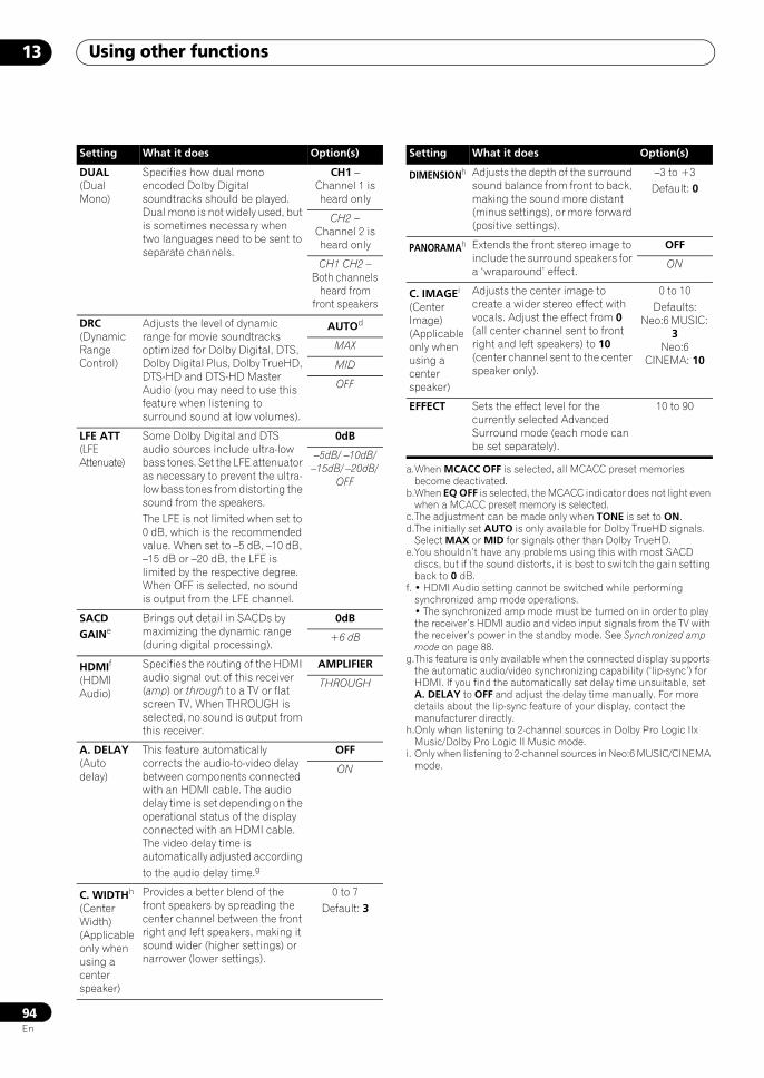
Using other functions13
94En
DUAL(Dual Mono)
Specifies how dual mono encoded Dolby Digital soundtracks should be played. Dual mono is not widely used, but is sometimes necessary when two languages need to be sent to separate channels.
CH1 – Channel 1 is heard only
CH2 – Channel 2 is heard only
CH1 CH2 – Both channels
heard from front speakers
DRC(Dynamic Range Control)
Adjusts the level of dynamic range for movie soundtracks optimized for Dolby Digital, DTS, Dolby Digital Plus, Dolby TrueHD, DTS-HD and DTS-HD Master Audio (you may need to use this feature when listening to surround sound at low volumes).
AUTOd
MAX
MID
OFF
LFE ATT (LFE Attenuate)
Some Dolby Digital and DTS audio sources include ultra-low bass tones. Set the LFE attenuator as necessary to prevent the ultra-low bass tones from distorting the sound from the speakers. The LFE is not limited when set to 0 dB, which is the recommended value. When set to –5 dB, –10 dB, –15 dB or –20 dB, the LFE is limited by the respective degree. When OFF is selected, no sound is output from the LFE channel.
0dB
–5dB/ –10dB/ –15dB/ –20dB/
OFF
SACD GAINe
Brings out detail in SACDs by maximizing the dynamic range (during digital processing).
0dB
+6 dB
HDMIf
(HDMI Audio)
Specifies the routing of the HDMI audio signal out of this receiver (amp) or through to a TV or flat screen TV. When THROUGH is selected, no sound is output from this receiver.
AMPLIFIER
THROUGH
A. DELAY(Auto delay)
This feature automatically corrects the audio-to-video delay between components connected with an HDMI cable. The audio delay time is set depending on the operational status of the display connected with an HDMI cable. The video delay time is automatically adjusted according to the audio delay time.g
OFF
ON
C. WIDTHh
(Center Width)(Applicable only when using a center speaker)
Provides a better blend of the front speakers by spreading the center channel between the front right and left speakers, making it sound wider (higher settings) or narrower (lower settings).
0 to 7Default: 3
Setting What it does Option(s)
DIMENSIONh Adjusts the depth of the surround sound balance from front to back, making the sound more distant (minus settings), or more forward (positive settings).
–3 to +3Default: 0
PANORAMAh Extends the front stereo image to include the surround speakers for a ‘wraparound’ effect.
OFF
ON
C. IMAGEi
(Center Image)(Applicable only when using a center speaker)
Adjusts the center image to create a wider stereo effect with vocals. Adjust the effect from 0 (all center channel sent to front right and left speakers) to 10 (center channel sent to the center speaker only).
0 to 10Defaults:
Neo:6 MUSIC: 3
Neo:6 CINEMA: 10
EFFECT Sets the effect level for the currently selected Advanced Surround mode (each mode can be set separately).
10 to 90
a.When MCACC OFF is selected, all MCACC preset memories become deactivated.
b.When EQ OFF is selected, the MCACC indicator does not light even when a MCACC preset memory is selected.
c.The adjustment can be made only when TONE is set to ON.d.The initially set AUTO is only available for Dolby TrueHD signals.
Select MAX or MID for signals other than Dolby TrueHD.e.You shouldn’t have any problems using this with most SACD
discs, but if the sound distorts, it is best to switch the gain setting back to 0 dB.
f. • HDMI Audio setting cannot be switched while performing synchronized amp mode operations.• The synchronized amp mode must be turned on in order to play the receiver’s HDMI audio and video input signals from the TV with the receiver’s power in the standby mode. See Synchronized amp mode on page 88.
g.This feature is only available when the connected display supports the automatic audio/video synchronizing capability (‘lip-sync’) for HDMI. If you find the automatically set delay time unsuitable, set A. DELAY to OFF and adjust the delay time manually. For more details about the lip-sync feature of your display, contact the manufacturer directly.
h.Only when listening to 2-channel sources in Dolby Pro Logic IIx Music/Dolby Pro Logic II Music mode.
i. Only when listening to 2-channel sources in Neo:6 MUSIC/CINEMA mode.
Setting What it does Option(s)
SCLX81_71.book 94 ページ 2008年7月25日 金曜日 午後3時1分
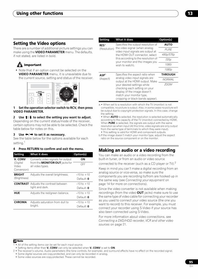
Using other functions 13
95En
Setting the Video optionsThere are a number of additional picture settings you can make using the VIDEO PARAMETER menu. The defaults, if not stated, are listed in bold.
Important
• Note that if an option cannot be selected on the VIDEO PARAMETER menu, it is unavailable due to the current source, setting and status of the receiver.
1 Set the operation selector switch to RCV, then press VIDEO PARAMETER.
2 Use / to select the setting you want to adjust.Depending on the current status/mode of the receiver, certain options may not be able to be selected. Check the table below for notes on this.
3 Use / to set it as necessary.See the table below for the options available for each setting.1
4 Press RETURN to confirm and exit the menu. Making an audio or a video recordingYou can make an audio or a video recording from the built-in tuner, or from an audio or video source connected to the receiver (such as a CD player or TV).2
Keep in mind you can’t make a digital recording from an analog source or vice-versa, so make sure the components you are recording to/from are hooked up in the same way (see Connecting your equipment on page 14 for more on connections).
Since the video converter is not available when making recordings (from the video OUT jacks) make sure to use the same type of video cable for connecting your recorder as you used to connect your video source (the one you want to record) to this receiver. For example, you must connect your recorder using S-Video if your source has also been connected using S-Video.
For more information about video connections, see Connecting a DVD/HDD recorder, VCR and other video sources on page 21.
Note1 • All of the setting items can be set for each input source.
• Setting items other than V. CONV can only be selected when V. CONV is set to ON.
Setting What it does Option(s)
V. CONV(Digital Video Conversion)
Converts video signals for output from the MONITOR OUT jacks for all video types.
ON
OFF
BRIGHT(Brightness)
Adjusts the overall brightness. –10 to +10Default: 0
CONTRAST Adjusts the contrast between light and dark.
–10 to +10Default: 0
HUE Adjusts the red/green balance. –10 to +10Default: 0
CHROMA Adjusts saturation from dull to bright.
–10 to +10Default: 0
SOURCETV RCV
VOLVOLCH
SOURCETV RCV
AUDIOPARAMETER
TOP MENUBAND
iPod CTRL
PTYSEARCH
EXIT TOOLS
STATUS PHASE CTRL CH LEVEL
MENUT.EDIT
VIDEOPARAMETER
INPUT MUTE MUTE
RETURN
TUNE +
TUNE
ST ST +
HOMEMENU
RETURN
ENTER
RESa
(Resolution)Specifies the output resolution of the video signal (when analog video input signals are output at the HDMI OUT connector, select this according to the resolution of your monitor and the images you wish to watch).
AUTO
PURE
480p/576p
720p
1080i
1080p
ASPb
(Aspect)Specifies the aspect ratio when analog video input signals are output at the HDMI output. Make your desired settings while checking each setting on your display (if the image doesn’t match your monitor type, cropping or black bands appear).
THROUGH
NORMAL
ZOOM
a.• When set to a resolution with which the TV (monitor) is not compatible, no picture is output. Also, in some cases no picture will be output due to copyright protection signals. In this case, change the setting.• When AUTO is selected, the resolution is selected automatically according to the capacity of the TV (monitor) connected by HDMI. When PURE is selected, the signals are output with the same resolution as when input (At this time, video signals are only output from the same type of terminals to which they were input).• This setting is valid for HDMI and component outputs.
b.If the image doesn’t match your monitor type, adjust the aspect ratio on the source component or on the monitor.
2 • The receiver’s volume, Audio parameters (the tone controls, for example), and surround effects have no effect on the recorded signal.• Some digital sources are copy-protected, and can only be recorded in analog.• Some video sources are copy-protected. These cannot be recorded.
Setting What it does Option(s)
SCLX81_71.book 95 ページ 2008年7月25日 金曜日 午後3時1分
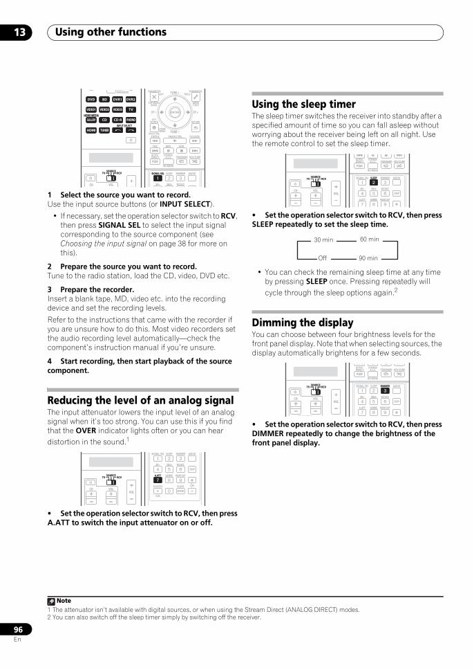
Using other functions13
96En
1 Select the source you want to record.Use the input source buttons (or INPUT SELECT).
• If necessary, set the operation selector switch to RCV, then press SIGNAL SEL to select the input signal corresponding to the source component (see Choosing the input signal on page 38 for more on this).
2 Prepare the source you want to record.Tune to the radio station, load the CD, video, DVD etc.
3 Prepare the recorder.Insert a blank tape, MD, video etc. into the recording device and set the recording levels.
Refer to the instructions that came with the recorder if you are unsure how to do this. Most video recorders set the audio recording level automatically—check the component’s instruction manual if you’re unsure.
4 Start recording, then start playback of the source component.
Reducing the level of an analog signalThe input attenuator lowers the input level of an analog signal when it’s too strong. You can use this if you find that the OVER indicator lights often or you can hear distortion in the sound.1
• Set the operation selector switch to RCV, then press A.ATT to switch the input attenuator on or off.
Using the sleep timerThe sleep timer switches the receiver into standby after a specified amount of time so you can fall asleep without worrying about the receiver being left on all night. Use the remote control to set the sleep timer.
• Set the operation selector switch to RCV, then press SLEEP repeatedly to set the sleep time.
• You can check the remaining sleep time at any time by pressing SLEEP once. Pressing repeatedly will cycle through the sleep options again.2
Dimming the displayYou can choose between four brightness levels for the front panel display. Note that when selecting sources, the display automatically brightens for a few seconds.
• Set the operation selector switch to RCV, then press DIMMER repeatedly to change the brightness of the front panel display.
Note1 The attenuator isn’t available with digital sources, or when using the Stream Direct (ANALOG DIRECT) modes.
DVD
MULTIOPERATION
SOURCETV RCV
VIDEO1
GALLERYHOME MEDIA
CD
HDMI
VOLVOLCH
TUNER
PHONO
VIDEO2 VIDEO3 DVR2
BD TV DVR1
CD-R
INPUT SELECT
DVD
VIDEO1
GALLERYHOME MEDIA
CD
HDMI TUNER
PHONO
VIDEO2 VIDEO3 TV
BD DVR1 DVR2
CD-R
SOURCETV RCV
AUDIOPARAMETER
TOP MENUBAND
iPod CTRL
EXIT TOOLS
HOMEMENU
STATUS
THX MPX
PHASE CTRL CH LEVEL
MENUT.EDIT
VIDEOPARAMETER
PGM
STEREO/A.L.C.
BD MENU
SIGNAL SEL SLEEP AUDIODIMMER
SR+ SBch MCACC
AUTO/DIRECT STANDARD ADV SURR
RETURNPTY
SEARCH
EON
TUNE +
TUNE
ST ST +
SIGNAL SEL
ENTER
SOURCETV RCV
VOLVOLCH
SOURCETV RCV
SIGNAL SEL SLEEP AUDIODIMMER
SR+
CLR
SBch MCACC
A.ATT GENRE HDMI OUT
D.ACCESS
ENTER
CLASS
DISP
CH
A.ATT
2 You can also switch off the sleep timer simply by switching off the receiver.
SOURCETV RCV
VOLVOLCH
SOURCETV RCV
PGM
STEREO/A.L.C.
BD MENU
SIGNAL SEL SLEEP AUDIODIMMER
SR+ SBch MCACC
A.ATT GENRE HDMI OUT
DISP
AUTO/DIRECT STANDARD ADV SURR
SLEEP
30 min 60 min
90 minOff
SOURCETV RCV
VOLVOL
TV CONTROL
CH
SOURCETV RCV
PGM
STEREO/A.L.C.
BD MENU
SIGNAL SEL SLEEP AUDIODIMMER
SR+ SBch MCACC
A.ATT GENRE HDMI OUT
DISP
AUTO/DIRECT STANDARD ADV SURR
DIMMER
SCLX81_71.book 96 ページ 2008年7月25日 金曜日 午後3時1分
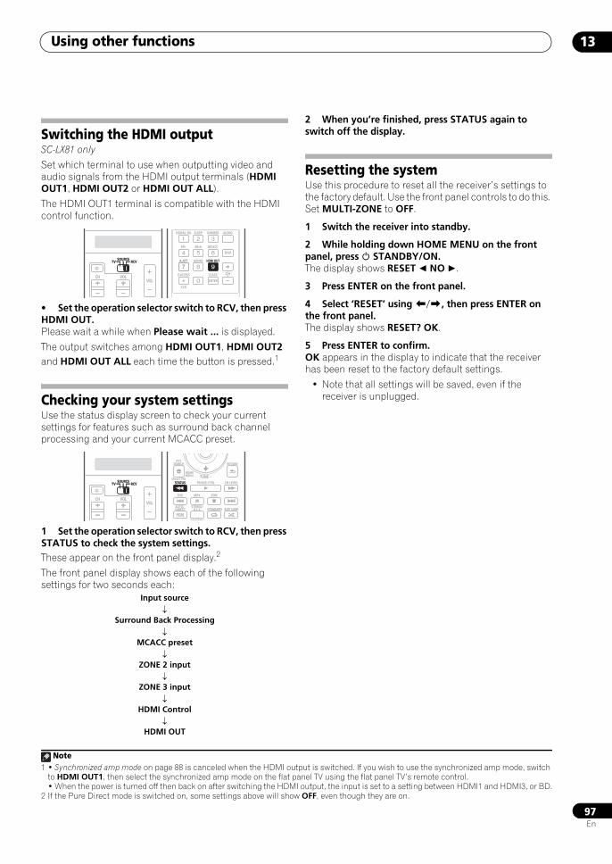
Using other functions 13
97En
Switching the HDMI outputSC-LX81 only
Set which terminal to use when outputting video and audio signals from the HDMI output terminals (HDMI OUT1, HDMI OUT2 or HDMI OUT ALL).
The HDMI OUT1 terminal is compatible with the HDMI control function.
• Set the operation selector switch to RCV, then press HDMI OUT.Please wait a while when Please wait ... is displayed.
The output switches among HDMI OUT1, HDMI OUT2 and HDMI OUT ALL each time the button is pressed.1
Checking your system settingsUse the status display screen to check your current settings for features such as surround back channel processing and your current MCACC preset.
1 Set the operation selector switch to RCV, then press STATUS to check the system settings. These appear on the front panel display.2
The front panel display shows each of the following settings for two seconds each:
2 When you’re finished, press STATUS again to switch off the display.
Resetting the systemUse this procedure to reset all the receiver’s settings to the factory default. Use the front panel controls to do this. Set MULTI-ZONE to OFF.
1 Switch the receiver into standby.
2 While holding down HOME MENU on the front panel, press STANDBY/ON.The display shows RESET NO .
3 Press ENTER on the front panel.
4 Select ‘RESET’ using /, then press ENTER on the front panel.The display shows RESET? OK.
5 Press ENTER to confirm.OK appears in the display to indicate that the receiver has been reset to the factory default settings.
• Note that all settings will be saved, even if the receiver is unplugged.
Note1 • Synchronized amp mode on page 88 is canceled when the HDMI output is switched. If you wish to use the synchronized amp mode, switch
to HDMI OUT1, then select the synchronized amp mode on the flat panel TV using the flat panel TV’s remote control.• When the power is turned off then back on after switching the HDMI output, the input is set to a setting between HDMI1 and HDMI3, or BD.
2 If the Pure Direct mode is switched on, some settings above will show OFF, even though they are on.
Input source
↓Surround Back Processing
↓MCACC preset
↓ZONE 2 input
↓ZONE 3 input
↓HDMI Control
↓HDMI OUT
SOURCETV RCV
VOLVOLCH
SOURCETV RCV
SIGNAL SEL SLEEP AUDIODIMMER
SR+
CLR
SBch MCACC
A.ATT GENRE HDMI OUT
D.ACCESS
ENTER
CLASS
DISP
CH
A.ATT
SOURCETV RCV
VOLVOLCH
SOURCETV RCV
iPod CTRL
HOMEMENU
STATUS
THX MPX
PHASE CTRL CH LEVEL
PGM
STEREO/A.L.C.
BD MENU
AUTO/DIRECT STANDARD ADV SURR
RETURNPTY
SEARCH
EON
TUNESTATUS
SCLX81_71.book 97 ページ 2008年7月25日 金曜日 午後3時1分
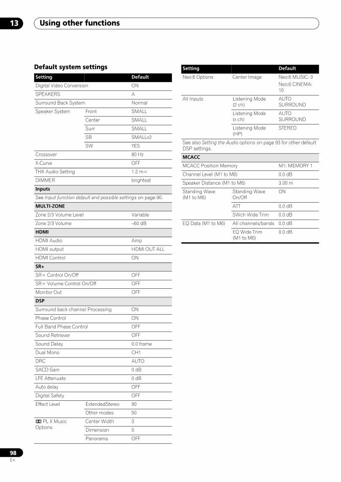
Using other functions13
98En
Default system settingsSetting Default
Digital Video Conversion ON
SPEAKERS A
Surround Back System Normal
Speaker System Front SMALL
Center SMALL
Surr SMALL
SB SMALLx2
SW YES
Crossover 80 Hz
X-Curve OFF
THX Audio Setting 1.2 m<
DIMMER brightest
Inputs
See Input function default and possible settings on page 90.
MULTI-ZONE
Zone 2/3 Volume Level Variable
Zone 2/3 Volume –60 dB
HDMI
HDMI Audio Amp
HDMI output HDMI OUT ALL
HDMI Control ON
SR+
SR+ Control On/Off OFF
SR+ Volume Control On/Off OFF
Monitor Out OFF
DSP
Surround back channel Processing ON
Phase Control ON
Full Band Phase Control OFF
Sound Retriever OFF
Sound Delay 0.0 frame
Dual Mono CH1
DRC AUTO
SACD Gain 0 dB
LFE Attenuate 0 dB
Auto delay OFF
Digital Safety OFF
Effect Level ExtendedStereo 90
Other modes 50
2 PL II Music Options
Center Width 3
Dimension 0
Panorama OFF
Neo:6 Options Center Image Neo:6 MUSIC: 3Neo:6 CINEMA: 10
All Inputs Listening Mode (2 ch)
AUTO SURROUND
Listening Mode (x ch)
AUTO SURROUND
Listening Mode (HP)
STEREO
See also Setting the Audio options on page 93 for other default DSP settings.
MCACC
MCACC Position Memory M1: MEMORY 1
Channel Level (M1 to M6) 0.0 dB
Speaker Distance (M1 to M6) 3.00 m
Standing Wave (M1 to M6)
Standing Wave On/Off
ON
ATT 0.0 dB
SWch Wide Trim 0.0 dB
EQ Data (M1 to M6) All channels/bands 0.0 dB
EQ Wide Trim (M1 to M6)
0.0 dB
Setting Default
SCLX81_71.book 98 ページ 2008年7月25日 金曜日 午後3時1分
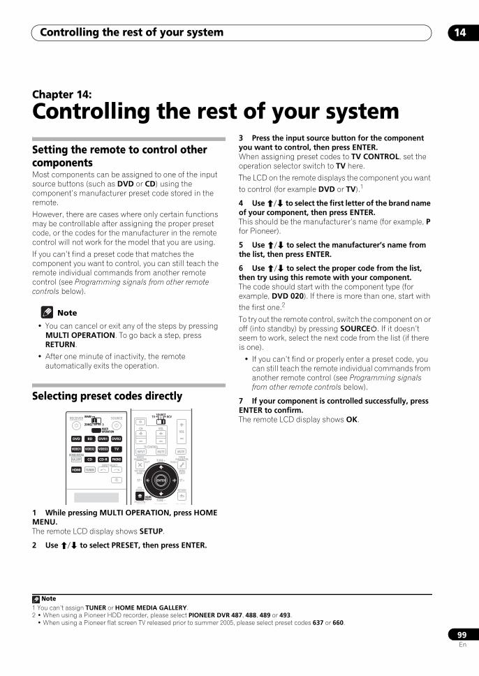
Controlling the rest of your system 14
99En
Chapter 14:
Controlling the rest of your system
Setting the remote to control other componentsMost components can be assigned to one of the input source buttons (such as DVD or CD) using the component’s manufacturer preset code stored in the remote.
However, there are cases where only certain functions may be controllable after assigning the proper preset code, or the codes for the manufacturer in the remote control will not work for the model that you are using.
If you can’t find a preset code that matches the component you want to control, you can still teach the remote individual commands from another remote control (see Programming signals from other remote controls below).
Note
• You can cancel or exit any of the steps by pressing MULTI OPERATION. To go back a step, press RETURN.
• After one minute of inactivity, the remote automatically exits the operation.
Selecting preset codes directly
1 While pressing MULTI OPERATION, press HOME MENU.The remote LCD display shows SETUP.
2 Use / to select PRESET, then press ENTER.
3 Press the input source button for the component you want to control, then press ENTER.When assigning preset codes to TV CONTROL, set the operation selector switch to TV here.
The LCD on the remote displays the component you want to control (for example DVD or TV).1
4 Use / to select the first letter of the brand name of your component, then press ENTER.This should be the manufacturer’s name (for example, P for Pioneer).
5 Use / to select the manufacturer’s name from the list, then press ENTER.
6 Use / to select the proper code from the list, then try using this remote with your component.The code should start with the component type (for example, DVD 020). If there is more than one, start with the first one.2
To try out the remote control, switch the component on or off (into standby) by pressing SOURCE. If it doesn’t seem to work, select the next code from the list (if there is one).
• If you can’t find or properly enter a preset code, you can still teach the remote individual commands from another remote control (see Programming signals from other remote controls below).
7 If your component is controlled successfully, press ENTER to confirm.The remote LCD display shows OK.
DVD
RECEIVER SOURCEMAIN
MULTIOPERATION
ZONE2 3
VIDEO1
GALLERYHOME MEDIA
CD
HDMI TUNER
PHONO
VIDEO2 VIDEO3 DVR2
BD TV DVR1
CD-R
INPUT SELECT
DVD
MULTIOPERATION
VIDEO1
GALLERYHOME MEDIA
CD
HDMI TUNER
PHONO
VIDEO2 VIDEO3 TV
BD DVR1 DVR2
CD-R
MAIN
ZONE2 3
AUDIOPARAMETER
TOP MENUBAND
iPod CTRL
EXIT TOOLS
STATUS PHASE CTRL CH LEVEL
MENUT.EDIT
VIDEOPARAMETER
SOURCETV RCV
INPUT MUTE MUTE
VOLVOL
TV CONTROL
CH
ENTER
RETURNPTY
SEARCH
TUNE +
TUNE
ST ST +ENTER
HOMEMENU
Note1 You can’t assign TUNER or HOME MEDIA GALLERY.2 • When using a Pioneer HDD recorder, please select PIONEER DVR 487, 488, 489 or 493.
• When using a Pioneer flat screen TV released prior to summer 2005, please select preset codes 637 or 660.
SCLX81_71.book 99 ページ 2008年7月25日 金曜日 午後3時1分
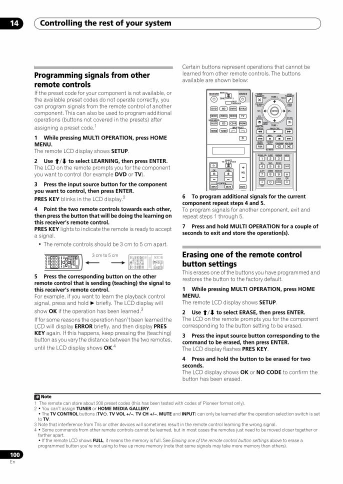
Controlling the rest of your system14
100En
Programming signals from other remote controlsIf the preset code for your component is not available, or the available preset codes do not operate correctly, you can program signals from the remote control of another component. This can also be used to program additional operations (buttons not covered in the presets) after assigning a preset code.1
1 While pressing MULTI OPERATION, press HOME MENU.The remote LCD display shows SETUP.
2 Use / to select LEARNING, then press ENTER.The LCD on the remote prompts you for the component you want to control (for example DVD or TV).
3 Press the input source button for the component you want to control, then press ENTER.PRES KEY blinks in the LCD display.2
4 Point the two remote controls towards each other, then press the button that will be doing the learning on this receiver’s remote control.PRES KEY lights to indicate the remote is ready to accept a signal.
• The remote controls should be 3 cm to 5 cm apart.
5 Press the corresponding button on the other remote control that is sending (teaching) the signal to this receiver’s remote control.For example, if you want to learn the playback control signal, press and hold briefly. The LCD display will show OK if the operation has been learned.3
If for some reasons the operation hasn’t been learned the LCD will display ERROR briefly, and then display PRES KEY again. If this happens, keep pressing the (teaching) button as you vary the distance between the two remotes, until the LCD display shows OK.4
Certain buttons represent operations that cannot be learned from other remote controls. The buttons available are shown below:
6 To program additional signals for the current component repeat steps 4 and 5.To program signals for another component, exit and repeat steps 1 through 5.
7 Press and hold MULTI OPERATION for a couple of seconds to exit and store the operation(s).
Erasing one of the remote control button settings This erases one of the buttons you have programmed and restores the button to the factory default.
1 While pressing MULTI OPERATION, press HOME MENU.The remote LCD display shows SETUP.
2 Use / to select ERASE, then press ENTER.The LCD on the remote prompts you for the component corresponding to the button setting to be erased.
3 Press the input source button corresponding to the command to be erased, then press ENTER.The LCD display flashes PRES KEY.
4 Press and hold the button to be erased for two seconds.The LCD display shows OK or NO CODE to confirm the button has been erased.
Note1 The remote can store about 200 preset codes (this has been tested with codes of Pioneer format only).2 • You can’t assign TUNER or HOME MEDIA GALLERY.
• The TV CONTROL buttons (TV, TV VOL +/–, TV CH +/–, MUTE and INPUT) can only be learned after the operation selection switch is set to TV.
3 Note that interference from TVs or other devices will sometimes result in the remote control learning the wrong signal.4 • Some commands from other remote controls cannot be learned, but in most cases the remotes just need to be moved closer together or
farther apart.• If the remote LCD shows FULL, it means the memory is full. See Erasing one of the remote control button settings above to erase a programmed button you’re not using to free up more memory (note that some signals may take more memory than others).
DV
D
RECE
IVER
SOU
RCE
MA
IN
MUL
TIOP
ERAT
ION
ZON
E2
SOU
RCE
TVRC
V
3
VIDE
O1
GALL
ERY
HOM
E MED
IA
INPU
T SEL
ECT
CD
HD
MI
INPU
TM
UTE
MUT
E
VOL
VOL
TV CO
NTRO
L
CH
TUNE
R
PHON
O
VIDE
O2VI
DEO3
DV
R2
BD
TV
DV
R1
CD
-R
3 cm to 5 cm
DVD
RECEIVER SOURCEMAIN
MULTIOPERATION
AUDIO VIDEO
ZONE2
SOURCETV RCV
3
VIDEO1
GALLERYHOME MEDIA
CD
HDMI
INPUT MUTE MUTE
VOLVOL
TV CONTROL
CH
TUNER
PHONO
VIDEO2 VIDEO3 TV
BD DVR1 DVR2
CD-R
INPUT SELECT
AUDIOPARAMETER
TOP MENUBAND
iPod CTRL
EXIT TOOLS
HOMEMENU
STATUS
THX MPX
PHASE CTRL CH LEVEL
MENUT.EDIT
VIDEOPARAMETER
PGM
STEREO/A.L.C.
BD MENU
SIGNAL SEL SLEEP AUDIODIMMER
SR+
CLR
SBch MCACC
A.ATT GENRE HDMI OUT
D.ACCESS
ENTER
CLASS
DISP
CH
AUTO/DIRECT STANDARD ADV SURR
ENTER
RETURNPTY
SEARCH
EON
TUNE +
TUNE
ST ST +
SCLX81_71.book 100 ページ 2008年7月25日 金曜日 午後3時1分
Controlling the rest of your system 14
101En
5 Repeat step 4 to erase other buttons.
6 Press and hold MULTI OPERATION for a couple of seconds when you’re done.
Resetting the remote control presets This will erase all preset remote control preset codes and programmed buttons.1
1 While pressing MULTI OPERATION, press HOME MENU.The remote LCD display shows SETUP.
2 Use / to select RESET, then press ENTER.RESET flashes in the LCD display.
3 Press and hold ENTER for about two seconds.The LCD shows OK to confirm the remote presets have been erased.
Confirming preset codesUse this feature to check which preset code is assigned to an input source button.
1 While pressing MULTI OPERATION, press HOME MENU.The remote LCD display shows SETUP.
2 Use / to select READ ID, then press ENTER.The LCD on the remote prompts you for the input source button you want to check.
3 Press the button of the component for which you want to check the preset code, then press ENTER.The brand name and preset code appears in the display for three seconds.
Renaming input source namesYou can customize the names that appear on the remote LCD when you select an input source (for example, you could change the name of DVR 1 to HDD/DVR).
1 While pressing MULTI OPERATION, press HOME MENU.The remote LCD display shows SETUP.
2 Use / to select RENAME, then press ENTER.The LCD on the remote prompts you for the button of the input source you want to rename.
3 Press the input source button you want to rename then press ENTER.
4 Use / to select NAME EDT, then press ENTER.To reset the button to its original (default) name, select NAME RST above.
5 Edit the name of the input source in the remote control LCD, pressing ENTER when you’re finished.Use / to change the character and / to move forward/back a position. The name can be up to eight characters (the possible characters are listed below).
ABCDEFGHIJKLMNOPQRSTUVWXYZ
0123456789 \ / * + – [space]
Direct function• Default setting: ON
You can use the direct function feature to control one component using the remote control while at the same time, using your receiver to playback a different component. This could let you, for example, use the remote control to set up and listen to a CD on the receiver, and then use the remote control to rewind a tape in your VCR while you continue to listen to your CD player.
When direct function is on, any component you select (using the input source buttons) will be selected by both the receiver and the remote control. When you turn direct function off, you can operate the remote control without affecting the receiver.
1 While pressing MULTI OPERATION, press HOME MENU.The remote LCD display shows SETUP.
2 Use / to select DIRECT F, then press ENTER.The LCD on the remote prompts you for the button of the input source you want to control.
3 Press the input source button for the component you want to control, then press ENTER.
4 Use / to switch direct function ON or OFF, then press ENTER.The LCD shows OK to confirm the setting.
Note1 When Selecting preset codes directly on page 99 are set, all the signals learned in the input source buttons are cleared. This function is
convenient when you want to reset some but not all of input source buttons.
SCLX81_71.book 101 ページ 2008年7月25日 金曜日 午後3時1分
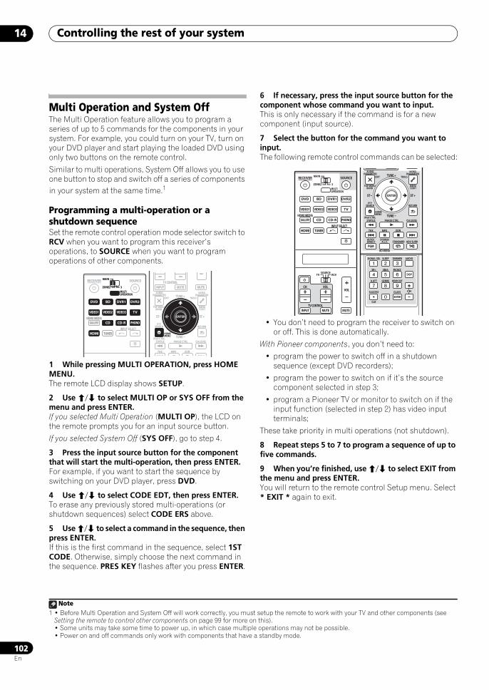
Controlling the rest of your system14
102En
Multi Operation and System OffThe Multi Operation feature allows you to program a series of up to 5 commands for the components in your system. For example, you could turn on your TV, turn on your DVD player and start playing the loaded DVD using only two buttons on the remote control.
Similar to multi operations, System Off allows you to use one button to stop and switch off a series of components in your system at the same time.1
Programming a multi-operation or a shutdown sequenceSet the remote control operation mode selector switch to RCV when you want to program this receiver’s operations, to SOURCE when you want to program operations of other components.
1 While pressing MULTI OPERATION, press HOME MENU.The remote LCD display shows SETUP.
2 Use / to select MULTI OP or SYS OFF from the menu and press ENTER.If you selected Multi Operation (MULTI OP), the LCD on the remote prompts you for an input source button.
If you selected System Off (SYS OFF), go to step 4.
3 Press the input source button for the component that will start the multi-operation, then press ENTER.For example, if you want to start the sequence by switching on your DVD player, press DVD.
4 Use / to select CODE EDT, then press ENTER.To erase any previously stored multi-operations (or shutdown sequences) select CODE ERS above.
5 Use / to select a command in the sequence, then press ENTER.If this is the first command in the sequence, select 1ST CODE. Otherwise, simply choose the next command in the sequence. PRES KEY flashes after you press ENTER.
6 If necessary, press the input source button for the component whose command you want to input.This is only necessary if the command is for a new component (input source).
7 Select the button for the command you want to input.The following remote control commands can be selected:
• You don’t need to program the receiver to switch on or off. This is done automatically.
With Pioneer components, you don’t need to:
• program the power to switch off in a shutdown sequence (except DVD recorders);
• program the power to switch on if it’s the source component selected in step 3;
• program a Pioneer TV or monitor to switch on if the input function (selected in step 2) has video input terminals;
These take priority in multi operations (not shutdown).
8 Repeat steps 5 to 7 to program a sequence of up to five commands.
9 When you’re finished, use / to select EXIT from the menu and press ENTER.You will return to the remote control Setup menu. Select * EXIT * again to exit.
Note1 • Before Multi Operation and System Off will work correctly, you must setup the remote to work with your TV and other components (see
Setting the remote to control other components on page 99 for more on this).• Some units may take some time to power up, in which case multiple operations may not be possible.• Power on and off commands only work with components that have a standby mode.
DVD
RECEIVER SOURCEMAIN
MULTIOPERATION
ZONE2 3
VIDEO1
GALLERYHOME MEDIA
CD
HDMI TUNER
PHONO
VIDEO2 VIDEO3 DVR2
BD TV DVR1
CD-R
INPUT SELECT
DVD
MULTIOPERATION
VIDEO1
GALLERYHOME MEDIA
CD
HDMI TUNER
PHONO
VIDEO2 VIDEO3 TV
BD DVR1 DVR2
CD-R
MAIN
ZONE2 3
AUDIOPARAMETER
TOP MENUBAND
iPod CTRL
EXIT TOOLS
STATUS
THX MPX
PHASE CTRL CH LEVEL
MENUT.EDIT
VIDEOPARAMETER
INPUT MUTE MUTETV CONTROL
ENTER
RETURNPTY
SEARCH
EON
TUNE +
TUNE
ST ST +ENTER
HOMEMENU
DVD
RECEIVER SOURCEMAIN
MULTIOPERATION
AUDIO VIDEO
ZONE2
SOURCETV RCV
3
VIDEO1
GALLERYHOME MEDIA
CD
HDMI
INPUT MUTE MUTE
VOLVOL
TV CONTROL
CH
TUNER
PHONO
VIDEO2 VIDEO3 TV
BD DVR1 DVR2
CD-R
INPUT SELECT
AUDIOPARAMETER
TOP MENUBAND
iPod CTRL
EXIT TOOLS
HOMEMENU
STATUS
THX MPX
PHASE CTRL CH LEVEL
MENUT.EDIT
VIDEOPARAMETER
PGM
STEREO/A.L.C.
BD MENU
SIGNAL SEL SLEEP AUDIODIMMER
SR+
CLR
SBch MCACC
A.ATT GENRE HDMI OUT
D.ACCESS
ENTER
CLASS
DISP
CH
AUTO/DIRECT STANDARD ADV SURR
ENTER
RETURNPTY
SEARCH
EON
TUNE +
TUNE
ST ST +
SCLX81_71.book 102 ページ 2008年7月25日 金曜日 午後3時1分
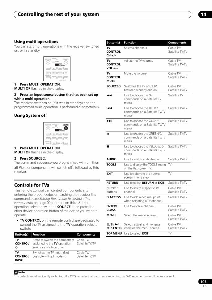
Controlling the rest of your system 14
103En
Using multi operationsYou can start multi operations with the receiver switched on, or in standby.
1 Press MULTI OPERATION.MULTI OP flashes in the display.
2 Press an input source button that has been set up with a multi operation.The receiver switches on (if it was in standby) and the programmed multi operation is performed automatically.
Using System off
1 Press MULTI OPERATION.MULTI OP flashes in the display.
2 Press SOURCE.The command sequence you programmed will run, then all Pioneer components will switch off1, followed by this receiver.
Controls for TVsThis remote control can control components after entering the proper codes or teaching the receiver the commands (see Setting the remote to control other components on page 99 for more on this). Set the operation selector switch to SOURCE, then press the other device operation button of the device you want to operate.
• TV CONTROL on the remote control are dedicated to control the TV assigned to the TV operation selector switch.
Note1 In order to avoid accidently switching off a DVD recorder that is currently recording, no DVD recorder power off codes are sent.
Button(s) Function Components
TV CONTROL
Press to switch the component assigned to the TV operation selector switch on or off.
Cable TV/Satellite TV/TV
TV CONTROL INPUT
Switches the TV input. (Not possible with all models.)
Cable TV/Satellite TV/TV
DVD
RECEIVER SOURCEMAIN
MULTIOPERATION
ZONE2 3
VIDEO1
GALLERYHOME MEDIA
CD PHONO
VIDEO2 VIDEO3 TV
BD DVR1 DVR2
CD-R
INPUT SELECT
MULTIOPERATION
DVD
RECEIVER SOURCEMAIN
MULTIOPERATION
ZONE2 3
VIDEO1
GALLERYHOME MEDIA
CD PHONO
VIDEO2 VIDEO3 TV
BD DVR1 DVR2
CD-R
MULTIOPERATION
SOURCE
TV CONTROL CH +/–
Selects channels. Cable TV/Satellite TV/TV
TV CONTROL VOL +/–
Adjust the TV volume. Cable TV/Satellite TV/TV
TV CONTROL MUTE
Mute the volume. Cable TV/Satellite TV/TV
SOURCE Switches the TV or CATV between standby and on.
Cable TV/Satellite TV/TV
Use to choose the ‘A’ commands on a Satellite TV menu.
Satellite TV
Use to choose the RED/B commands on a Satellite TV/TV menu.
Satellite TV/TV
Use to choose the CYAN/E commands on a Satellite TV/TV menu.
Satellite TV/TV
Use to choose the GREEN/C commands on a Satellite TV/TV menu.
Satellite TV/TV
Use to choose the YELLOW/D commands on a Satellite TV/TV menu.
Satellite TV/TV
AUDIO Use to switch audio tracks. Satellite TV/TV
TOOLS Use to display the TOOLS menu on the flat screen TV.
TV
EXIT Use to return to the normal screen in one step.
TV
RETURN Use to select RETURN or EXIT. Satellite TV/TV
Number buttons
Use to select a specific TV channel.
Cable TV/Satellite TV/TV
D.ACCESS Use to add a decimal point when selecting a TV channel.
Satellite TV/TV
ENTER/CLASS
Use to enter a channel. Cable TV/Satellite TV/TV
MENU Select the menu screen. Cable TV/Satellite TV/TV
/// & ENTER
Select, adjust and navigate items on the menu screen.
Cable TV/Satellite TV/TV
TOP MENU Use to select EXIT. TV
Button(s) Function Components
SCLX81_71.book 103 ページ 2008年7月25日 金曜日 午後3時1分
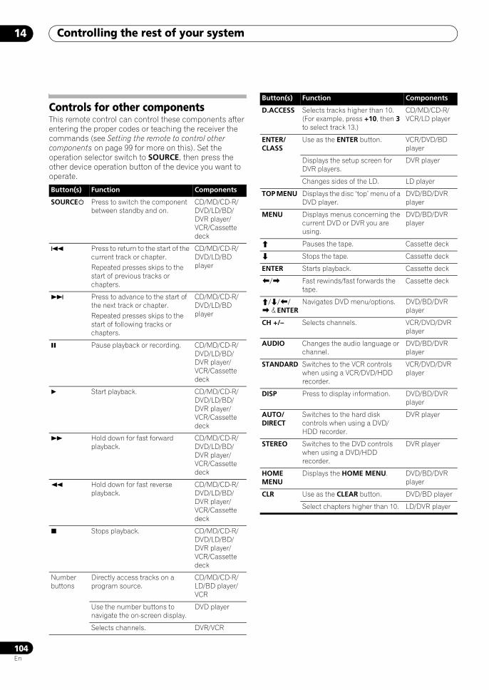
Controlling the rest of your system14
104En
Controls for other componentsThis remote control can control these components after entering the proper codes or teaching the receiver the commands (see Setting the remote to control other components on page 99 for more on this). Set the operation selector switch to SOURCE, then press the other device operation button of the device you want to operate.
Button(s) Function Components
SOURCE Press to switch the component between standby and on.
CD/MD/CD-R/DVD/LD/BD/DVR player/VCR/Cassette deck
Press to return to the start of the current track or chapter. Repeated presses skips to the start of previous tracks or chapters.
CD/MD/CD-R/DVD/LD/BD player
Press to advance to the start of the next track or chapter. Repeated presses skips to the start of following tracks or chapters.
CD/MD/CD-R/DVD/LD/BD player
Pause playback or recording. CD/MD/CD-R/DVD/LD/BD/DVR player/VCR/Cassette deck
Start playback. CD/MD/CD-R/DVD/LD/BD/DVR player/VCR/Cassette deck
Hold down for fast forward playback.
CD/MD/CD-R/DVD/LD/BD/DVR player/VCR/Cassette deck
Hold down for fast reverse playback.
CD/MD/CD-R/DVD/LD/BD/DVR player/VCR/Cassette deck
Stops playback. CD/MD/CD-R/DVD/LD/BD/DVR player/VCR/Cassette deck
Number buttons
Directly access tracks on a program source.
CD/MD/CD-R/LD/BD player/VCR
Use the number buttons to navigate the on-screen display.
DVD player
Selects channels. DVR/VCR
D.ACCESS Selects tracks higher than 10. (For example, press +10, then 3 to select track 13.)
CD/MD/CD-R/VCR/LD player
ENTER/CLASS
Use as the ENTER button. VCR/DVD/BD player
Displays the setup screen for DVR players.
DVR player
Changes sides of the LD. LD player
TOP MENU Displays the disc ‘top’ menu of a DVD player.
DVD/BD/DVR player
MENU Displays menus concerning the current DVD or DVR you are using.
DVD/BD/DVR player
Pauses the tape. Cassette deck
Stops the tape. Cassette deck
ENTER Starts playback. Cassette deck
/ Fast rewinds/fast forwards the tape.
Cassette deck
/// & ENTER
Navigates DVD menu/options. DVD/BD/DVR player
CH +/– Selects channels. VCR/DVD/DVR player
AUDIO Changes the audio language or channel.
DVD/BD/DVR player
STANDARD Switches to the VCR controls when using a VCR/DVD/HDD recorder.
VCR/DVD/DVR player
DISP Press to display information. DVD/BD/DVR player
AUTO/DIRECT
Switches to the hard disk controls when using a DVD/HDD recorder.
DVR player
STEREO Switches to the DVD controls when using a DVD/HDD recorder.
DVR player
HOME MENU
Displays the HOME MENU. DVD/BD/DVR player
CLR Use as the CLEAR button. DVD/BD player
Select chapters higher than 10. LD/DVR player
Button(s) Function Components
SCLX81_71.book 104 ページ 2008年7月25日 金曜日 午後3時1分
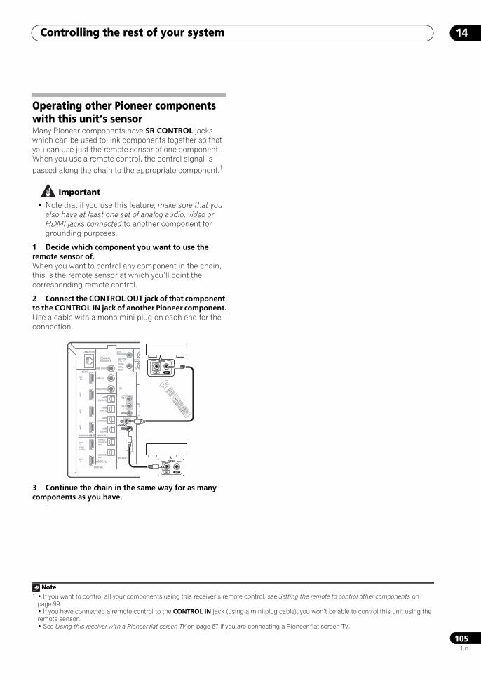
Controlling the rest of your system 14
105En
Operating other Pioneer components with this unit’s sensorMany Pioneer components have SR CONTROL jacks which can be used to link components together so that you can use just the remote sensor of one component. When you use a remote control, the control signal is passed along the chain to the appropriate component.1
Important
• Note that if you use this feature, make sure that you also have at least one set of analog audio, video or HDMI jacks connected to another component for grounding purposes.
1 Decide which component you want to use the remote sensor of.When you want to control any component in the chain, this is the remote sensor at which you’ll point the corresponding remote control.
2 Connect the CONTROL OUT jack of that component to the CONTROL IN jack of another Pioneer component.Use a cable with a mono mini-plug on each end for the connection.
3 Continue the chain in the same way for as many components as you have.
Note1 • If you want to control all your components using this receiver’s remote control, see Setting the remote to control other components on
page 99.• If you have connected a remote control to the CONTROL IN jack (using a mini-plug cable), you won’t be able to control this unit using the remote sensor.• See Using this receiver with a Pioneer flat screen TV on page 67 if you are connecting a Pioneer flat screen TV.
LAN (10/100)
DIGITAL
OPTICALRS-232C
HDMI
COAXIAL
IR
CONTROL
BDIN
12 VTRIGGER
IN1
IN2
IN3
OUT1
OUT2
SOURCEOUT
ZONE3/SOURCEOUT
31ASSIGNABLE -
(HDMI CTRL)
ASSIGNABLE
ASSIGNABLE
(CD-R)IN 4
(VIDEO1)IN 3
(DVR1)IN 2
(TV/SAT)IN 1
IN 3 (DVR2)
IN 2 (CD)
IN 1 (DVD)
(OUTPUT 12V TOTAL 50mA MAX)
1
2
IN1
IN
IN2
OUT
OUT
(DVD)
PR
SIGG
CONTROL
IN
OUT
IN OUT
CONTROL
IN OUT
CONTROL
DVD
RECEIVER
SOURCE
MAINMULTI
OPERATION
AUDIO
PARAMETER
TOP MENU
BAND
iPod CTRL
PTY
SEARCH
EXIT
TOOLS
HOME
MENU
STATUS
THX
MPX
EONPHASE CTRL
CH LEVEL
MENU
T.EDIT
VIDEO
PARAMETER
ZONE2
SOURCE
TV
RCV
3
VIDEO1
GALLERYHOME MEDIA
INPUT SELECT
CD
HDMI
INPUT
MUTE
TUNE +
ST +
MUTE
PGM
VOL
VOL
TV CONTROLCH
STEREO/
A.L.C.
BD MENU
SIGNAL SELSLEEP
AUDIO
DIMMER
SR+
CLR
SBchMCACC
A.ATTGENRE
HDMI OUT
D.ACCESS
ENTERCLASS
DISP
CH
AUTO/
DIRECT
STANDARDADV SURR
TUNER
PHONO
VIDEO2VIDEO3
TV
BD
DVR1DVR2
CD-R
ENTER RETURN
TUNEST
SCLX81_71.book 105 ページ 2008年7月25日 金曜日 午後3時1分
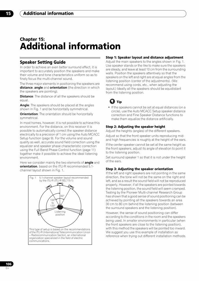
Additional information15
106En
Chapter 15:
Additional information
Speaker Setting GuideIn order to achieve an even better surround effect, it is important to accurately position the speakers and make their volume and tone characteristics uniform so as to finely focus the multi-channel sound.
The three major elements in positioning the speakers are distance, angle and orientation (the direction in which the speakers are pointing).
Distance: The distance of all the speakers should be equal.
Angle: The speakers should be placed at the angles shown in Fig. 1 and be horizontally symmetrical.
Orientation: The orientation should be horizontally symmetrical.
In most homes, however, it is not possible to achieve this environment. For the distance, on this receiver it is possible to automatically correct the speaker distance electrically to a precision of 1 cm using the Auto MCACC Setup function (page 9). For the volume and sound quality as well, accurate sound field correction using the equalizer and speaker phase characteristic correction using the Full Band Phase Control function (page 11) together make it possible to achieve the ideal listening environment.
Here we consider mainly the two elements of angle and orientation, based on the ITU-R recommended 5.1-channel layout shown in Fig. 1.
Step 1: Speaker layout and distance adjustmentAdjust the main speakers to the angles shown in Fig. 1. Use speaker stands or the like to make sure the speakers are steady, and leave at least 10 cm from the surrounding walls. Position the speakers attentively so that the speakers on the left and right are at equal angles from the listening position (center of the adjustments). (We recommend using cords, etc., when adjusting the layout.) Ideally all the speakers should be equidistant from the listening position.
Tip
• If the speakers cannot be set at equal distances (on a circle), use the Auto MCACC Setup speaker distance correction and Fine Speaker Distance functions to make them equalize the distance artificially.
Step 2: Adjusting the speaker heightAdjust the heights (angles) of the different speakers.
Adjust so that the front speaker units reproducing mid- and high frequencies is roughly at the height of the ears.
If the center speaker cannot be set at the same height as the front speakers, adjust its angle of elevation to point it to the listening position.
Set surround speaker 1 so that it is not under the height of the ears.
Step 3: Adjusting the speaker orientationIf the left and right speakers are not pointing in the same direction, the tone will not be the same on the right and left, and as a result the sound field will not be reproduced properly. However, if all the speakers are pointed towards the listening position, the sound field will seem cramped. Testing by the Pioneer Multi-channel Research Group has shown that a good sense of sound positioning can be achieved by pointing all the speakers towards an area 30 cm to 80 cm behind the listening position (between the surround speakers and the listening position).
However, the sense of sound positioning can differ according to the conditions in the room and the speakers being used. In smaller environments in particular (when the front speakers are close to the listening position), with this method the speakers will be pointed too inward. We suggest you use this example of installation as reference when trying out different installation methods.
Fig. 1 5.1-channel speaker layout recommended by the ITU-R (ITU-R BS.775-1)
This type of setup is based on the recommendations of the ITU-R (International Telecommunication Union – Radiocommunication Sector), an international organization specialized in the field of electric communications.
Listening position
60°
100° to
120°
SCLX81_71.book 106 ページ 2008年7月25日 金曜日 午後3時1分
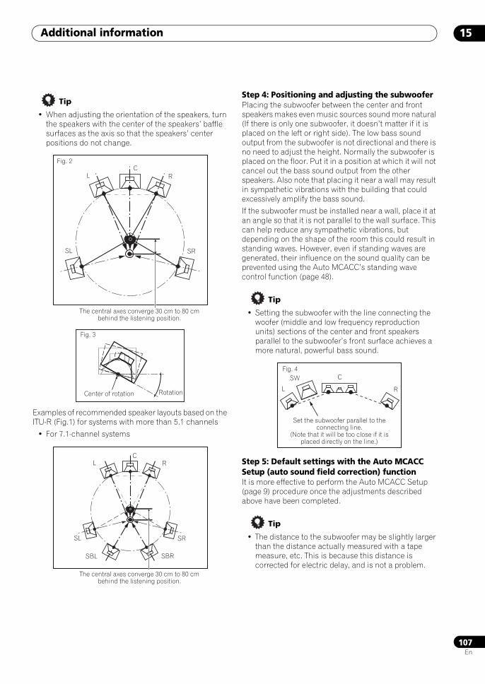
Additional information 15
107En
Tip
• When adjusting the orientation of the speakers, turn the speakers with the center of the speakers’ baffle surfaces as the axis so that the speakers’ center positions do not change.
Examples of recommended speaker layouts based on the ITU-R (Fig.1) for systems with more than 5.1 channels
• For 7.1-channel systems
Step 4: Positioning and adjusting the subwooferPlacing the subwoofer between the center and front speakers makes even music sources sound more natural (If there is only one subwoofer, it doesn’t matter if it is placed on the left or right side). The low bass sound output from the subwoofer is not directional and there is no need to adjust the height. Normally the subwoofer is placed on the floor. Put it in a position at which it will not cancel out the bass sound output from the other speakers. Also note that placing it near a wall may result in sympathetic vibrations with the building that could excessively amplify the bass sound.
If the subwoofer must be installed near a wall, place it at an angle so that it is not parallel to the wall surface. This can help reduce any sympathetic vibrations, but depending on the shape of the room this could result in standing waves. However, even if standing waves are generated, their influence on the sound quality can be prevented using the Auto MCACC’s standing wave control function (page 48).
Tip
• Setting the subwoofer with the line connecting the woofer (middle and low frequency reproduction units) sections of the center and front speakers parallel to the subwoofer’s front surface achieves a more natural, powerful bass sound.
Step 5: Default settings with the Auto MCACC Setup (auto sound field correction) functionIt is more effective to perform the Auto MCACC Setup (page 9) procedure once the adjustments described above have been completed.
Tip
• The distance to the subwoofer may be slightly larger than the distance actually measured with a tape measure, etc. This is because this distance is corrected for electric delay, and is not a problem.
The central axes converge 30 cm to 80 cm behind the listening position.
Fig. 2C
L R
SL SR
Fig. 3
Center of rotation Rotation
The central axes converge 30 cm to 80 cm behind the listening position.
CL R
SL SR
SBL SBR
Fig. 4C
L R
SW
Set the subwoofer parallel to the connecting line.
(Note that it will be too close if it is placed directly on the line.)
SCLX81_71.book 107 ページ 2008年7月25日 金曜日 午後3時1分
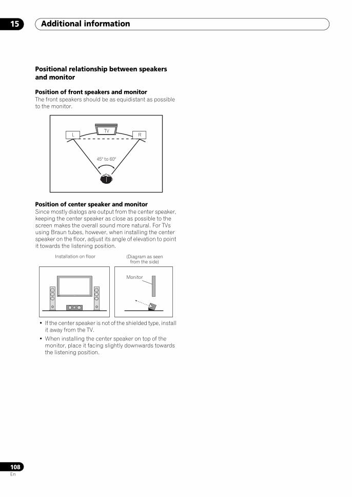
Additional information15
108En
Positional relationship between speakers and monitor
Position of front speakers and monitorThe front speakers should be as equidistant as possible to the monitor.
Position of center speaker and monitorSince mostly dialogs are output from the center speaker, keeping the center speaker as close as possible to the screen makes the overall sound more natural. For TVs using Braun tubes, however, when installing the center speaker on the floor, adjust its angle of elevation to point it towards the listening position.
• If the center speaker is not of the shielded type, install it away from the TV.
• When installing the center speaker on top of the monitor, place it facing slightly downwards towards the listening position.
TVL R
45° to 60°
Installation on floor (Diagram as seen from the side)
Monitor
SCLX81_71.book 108 ページ 2008年7月25日 金曜日 午後3時1分
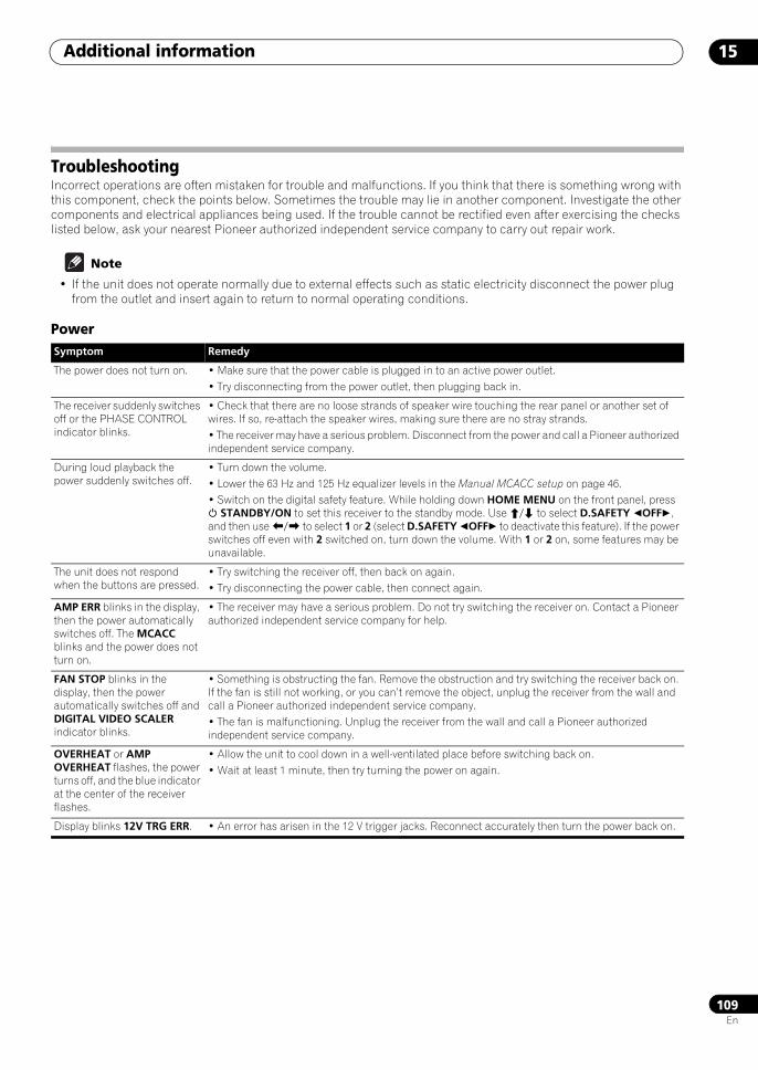
Additional information 15
109En
TroubleshootingIncorrect operations are often mistaken for trouble and malfunctions. If you think that there is something wrong with this component, check the points below. Sometimes the trouble may lie in another component. Investigate the other components and electrical appliances being used. If the trouble cannot be rectified even after exercising the checks listed below, ask your nearest Pioneer authorized independent service company to carry out repair work.
Note
• If the unit does not operate normally due to external effects such as static electricity disconnect the power plug from the outlet and insert again to return to normal operating conditions.
PowerSymptom Remedy
The power does not turn on. • Make sure that the power cable is plugged in to an active power outlet.• Try disconnecting from the power outlet, then plugging back in.
The receiver suddenly switches off or the PHASE CONTROL indicator blinks.
• Check that there are no loose strands of speaker wire touching the rear panel or another set of wires. If so, re-attach the speaker wires, making sure there are no stray strands.• The receiver may have a serious problem. Disconnect from the power and call a Pioneer authorized independent service company.
During loud playback the power suddenly switches off.
• Turn down the volume.• Lower the 63 Hz and 125 Hz equalizer levels in the Manual MCACC setup on page 46.• Switch on the digital safety feature. While holding down HOME MENU on the front panel, press STANDBY/ON to set this receiver to the standby mode. Use / to select D.SAFETY OFF, and then use / to select 1 or 2 (select D.SAFETY OFF to deactivate this feature). If the power switches off even with 2 switched on, turn down the volume. With 1 or 2 on, some features may be unavailable.
The unit does not respond when the buttons are pressed.
• Try switching the receiver off, then back on again.• Try disconnecting the power cable, then connect again.
AMP ERR blinks in the display, then the power automatically switches off. The MCACC blinks and the power does not turn on.
• The receiver may have a serious problem. Do not try switching the receiver on. Contact a Pioneer authorized independent service company for help.
FAN STOP blinks in the display, then the power automatically switches off and DIGITAL VIDEO SCALER indicator blinks.
• Something is obstructing the fan. Remove the obstruction and try switching the receiver back on. If the fan is still not working, or you can’t remove the object, unplug the receiver from the wall and call a Pioneer authorized independent service company.• The fan is malfunctioning. Unplug the receiver from the wall and call a Pioneer authorized independent service company.
OVERHEAT or AMP OVERHEAT flashes, the power turns off, and the blue indicator at the center of the receiver flashes.
• Allow the unit to cool down in a well-ventilated place before switching back on.• Wait at least 1 minute, then try turning the power on again.
Display blinks 12V TRG ERR. • An error has arisen in the 12 V trigger jacks. Reconnect accurately then turn the power back on.
SCLX81_71.book 109 ページ 2008年7月25日 金曜日 午後3時1分
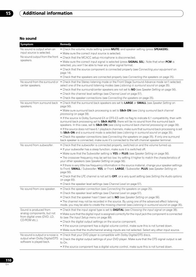
Additional information15
110En
No soundSymptom Remedy
No sound is output when an input source is selected.No sound output from the front speakers.
• Check the volume, mute setting (press MUTE) and speaker setting (press SPEAKERS).• Make sure the correct input source is selected.• Check that the MCACC setup microphone is disconnected.• Make sure the correct input signal is selected (press SIGNAL SEL). Note that when PCM is selected, you won’t be able to hear any other signal format.• Check that the source component is connected properly (see Connecting your equipment on page 14).• Check that the speakers are connected properly (see Connecting the speakers on page 25).
No sound from the surround or center speakers.
• Check that the Stereo listening mode or the Front Stage Surround Advance mode isn’t selected; select one of the surround listening modes (see Listening in surround sound on page 35).• Check that the surround/center speakers are not set to NO (see Speaker Setting on page 56).• Check the channel level settings (see Channel Level on page 57).• Check the speaker connections (see Connecting the speakers on page 25).
No sound from surround back speakers.
• Check that the surround back speakers are set to LARGE or SMALL (see Speaker Setting on page 56).• Make sure surround back processing is set to SBch ON (see Using surround back channel processing on page 39).• If the source is Dolby Surround EX or DTS ES with no flag to indicate 6.1 compatibility, then with surround back processing set to SBch AUTO, there will be no sound from the surround back speakers. In this case, set to SBch ON (see Using surround back channel processing on page 39).• If the source does not have 6.1 playback channels, make sure that surround back processing is set to SBch ON and a surround mode is selected (see Listening in surround sound on page 35).• Check the speaker connections (see Connecting the speakers on page 25). If only one surround back speaker is connected, make sure it’s connected to the left channel speaker terminal.
No sound from subwoofer. • Check that the subwoofer is connected properly, switched on and the volume turned up.• If your subwoofer has a sleep function, make sure it is switched off.• Make sure that the Subwoofer setting is YES or PLUS (see Speaker Setting on page 56).• The crossover frequency may be set too low; try setting it higher to match the characteristics of your other speakers (see Speaker Setting on page 56).• If there is very little low frequency information in the source material, change your speaker settings to Front: SMALL / Subwoofer: YES, or Front: LARGE / Subwoofer: PLUS (see Speaker Setting on page 56).• Check that the LFE channel is not set to OFF, or a very quiet setting (see Setting the Audio options on page 93).• Check the speaker level settings (see Channel Level on page 57).
No sound from one speaker. • Check the speaker connection (see Connecting the speakers on page 25).• Check the speaker level settings (see Channel Level on page 57).• Check that the speaker hasn’t been set to NO (see Speaker Setting on page 56).• The channel may not be recorded in the source. By using one of the advanced effect listening mode, you may be able to create the missing channel (see Listening in surround sound on page 35).
Sound is produced from analog components, but not from digital ones (DVD, LD, CD-ROM etc.).
• Check that the input signal type is set to DIGITAL (see Choosing the input signal on page 38).• Make sure that the digital input is assigned correctly for the input jack the component is connected to (see The Input Setup menu on page 89).• Check the digital output settings on the source component.• If the source component has a digital volume control, make sure this is not turned down.• Make sure that the multichannel analog inputs are not selected. Select any other input source.
No sound is output or a noise is output when Dolby Digital/DTS software is played back.
• Check that your DVD player is compatible with Dolby Digital/DTS discs.• Check the digital output settings of your DVD player. Make sure that the DTS signal output is set to On.• If the source component has a digital volume control, make sure this is not turned down.
SCLX81_71.book 110 ページ 2008年7月25日 金曜日 午後3時1分

Additional information 15
111En
Other audio problems
No sound when using the HOME MENU or STATUS menu.
• If the HDMI input source is selected, sound is muted until exiting either menu.• If sound is muted in the sub zone (ZONE 2), it will be restored after exiting the HOME MENU.
Symptom Remedy
Symptom Remedy
Broadcast stations cannot be selected automatically, or there is considerable noise in radio broadcasts.
For FM broadcasts• Fully extend the FM wire antenna, adjust the position for best reception and secure to a wall, etc.• Use an outdoor antenna for better reception (see page 28).For AM broadcasts• Adjust the position and direction of the AM antenna.• Use an outdoor antenna for better reception (see page 28).• Noise may be caused by interference from other equipment, such as a fluorescent light, motor, etc. Switch off or move the other equipment, or move the AM antenna.
A multichannel DVD source appears to be downmixed to 2 channels during playback.
• Make sure that the multichannel analog inputs are selected (see Selecting the multichannel analog inputs on page 60).
Noise is output when scanning a DTS CD.
• This is not a malfunction of the receiver. The scan function of your player alters the digital information, making it unreadable, resulting in noise being output. Lower the volume when scanning.
When playing a DTS format LD there is audible noise on the soundtrack.
• Make sure that the input signal type is set to DIGITAL (see Choosing the input signal on page 38).
Can’t record audio. • You can only make a digital recording from a digital source, and an analog recording from an analog source.• For digital sources, make sure that what you’re recording isn’t copy protected.• Check that the OUT jacks are properly connected to the recorders input jacks (see Connecting analog audio sources on page 24).
Subwoofer output is very low. • To route more signal to the subwoofer, set it to PLUS or set the front speakers to SMALL (see Speaker Setting on page 56).
Everything seems to be set up correctly, but the playback sound is odd.
• The speakers may be out of phase. Check that the positive/negative speaker terminals on the receiver are matched with the corresponding terminals on the speakers (see Connecting the speakers on page 25).
The PHASE CONTROL feature doesn’t seem to have an audible effect.
• If applicable, check that the lowpass filter switch on your subwoofer is off, or the lowpass cutoff is set to the highest frequency setting. If there is a PHASE setting on your subwoofer, set it to 0º (or depending on the subwoofer, the setting where you think it has the best overall effect on the sound).• Make sure the speaker distance setting is correct for all speakers (see Speaker Distance on page 58).
Noise or hum can be heard even when there is no sound being input.
• Check that personal computers or other digital components connected to the same power source are not causing interference.
There seems to be a time lag between the speakers and the output of the subwoofer.
• See Automatically setting up for surround sound (MCACC & Full Band Phase Control) on page 9 to set up your system again using MCACC (this will automatically compensate for a delay in the subwoofer output).
Can’t use the SR+ features. • Make sure that HDMI Control is set to OFF (see Setting the HDMI Control mode on page 87).
The maximum volume available (shown in the front panel display) is lower than the +12dB maximum.
• This is not a malfunction. If the levels in Channel Level on page 57 have been adjusted, the maximum volume will change accordingly.
SCLX81_71.book 111 ページ 2008年7月25日 金曜日 午後3時1分
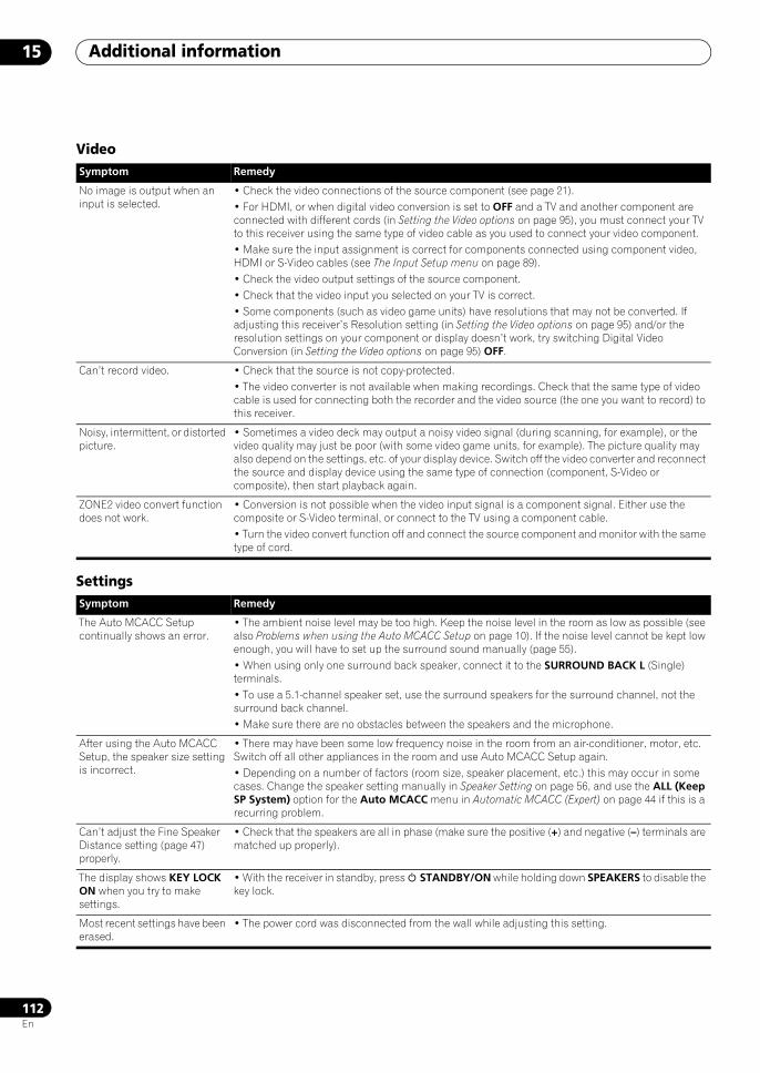
Additional information15
112En
Video
Settings
Symptom Remedy
No image is output when an input is selected.
• Check the video connections of the source component (see page 21).• For HDMI, or when digital video conversion is set to OFF and a TV and another component are connected with different cords (in Setting the Video options on page 95), you must connect your TV to this receiver using the same type of video cable as you used to connect your video component.• Make sure the input assignment is correct for components connected using component video, HDMI or S-Video cables (see The Input Setup menu on page 89).• Check the video output settings of the source component.• Check that the video input you selected on your TV is correct.• Some components (such as video game units) have resolutions that may not be converted. If adjusting this receiver’s Resolution setting (in Setting the Video options on page 95) and/or the resolution settings on your component or display doesn’t work, try switching Digital Video Conversion (in Setting the Video options on page 95) OFF.
Can’t record video. • Check that the source is not copy-protected.• The video converter is not available when making recordings. Check that the same type of video cable is used for connecting both the recorder and the video source (the one you want to record) to this receiver.
Noisy, intermittent, or distorted picture.
• Sometimes a video deck may output a noisy video signal (during scanning, for example), or the video quality may just be poor (with some video game units, for example). The picture quality may also depend on the settings, etc. of your display device. Switch off the video converter and reconnect the source and display device using the same type of connection (component, S-Video or composite), then start playback again.
ZONE2 video convert function does not work.
• Conversion is not possible when the video input signal is a component signal. Either use the composite or S-Video terminal, or connect to the TV using a component cable.• Turn the video convert function off and connect the source component and monitor with the same type of cord.
Symptom Remedy
The Auto MCACC Setup continually shows an error.
• The ambient noise level may be too high. Keep the noise level in the room as low as possible (see also Problems when using the Auto MCACC Setup on page 10). If the noise level cannot be kept low enough, you will have to set up the surround sound manually (page 55).• When using only one surround back speaker, connect it to the SURROUND BACK L (Single) terminals.• To use a 5.1-channel speaker set, use the surround speakers for the surround channel, not the surround back channel.• Make sure there are no obstacles between the speakers and the microphone.
After using the Auto MCACC Setup, the speaker size setting is incorrect.
• There may have been some low frequency noise in the room from an air-conditioner, motor, etc. Switch off all other appliances in the room and use Auto MCACC Setup again.• Depending on a number of factors (room size, speaker placement, etc.) this may occur in some cases. Change the speaker setting manually in Speaker Setting on page 56, and use the ALL (Keep SP System) option for the Auto MCACC menu in Automatic MCACC (Expert) on page 44 if this is a recurring problem.
Can’t adjust the Fine Speaker Distance setting (page 47) properly.
• Check that the speakers are all in phase (make sure the positive (+) and negative (–) terminals are matched up properly).
The display shows KEY LOCK ON when you try to make settings.
• With the receiver in standby, press STANDBY/ON while holding down SPEAKERS to disable the key lock.
Most recent settings have been erased.
• The power cord was disconnected from the wall while adjusting this setting.
SCLX81_71.book 112 ページ 2008年7月25日 金曜日 午後3時1分
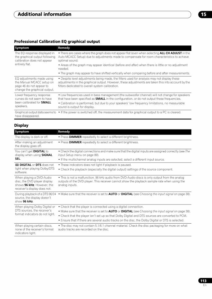
Additional information 15
113En
Professional Calibration EQ graphical output
Display
Symptom Remedy
The EQ response displayed in the graphical output following calibration does not appear entirely flat.
• There are cases where the graph does not appear flat (even when selecting ALL CH ADJUST in the Auto MCACC Setup) due to adjustments made to compensate for room characteristics to achieve optimal sound.• Areas of the graph may appear identical (before and after) when there is little or no adjustment needed.• The graph may appear to have shifted vertically when comparing before and after measurements.
EQ adjustments made using the Manual MCACC setup on page 46 do not appear to change the graphical output.
• Despite level adjustments being made, the filters used for analysis may not display these adjustments in the graphical output. However, these adjustments are taken this into account by the filters dedicated to overall system calibration.
Lower frequency response curves do not seem to have been calibrated for SMALL speakers.
• Low frequencies used in bass management (the subwoofer channel) will not change for speakers that have been specified as SMALL in the configuration, or do not output these frequencies.• Calibration is performed, but due to your speakers’ low frequency limitations, no measurable sound is output for display.
Graphical output data seems to have disappeared.
• If the power is switched off, the measurement data for graphical output to a PC is cleared.
Symptom Remedy
The display is dark or off. • Press DIMMER repeatedly to select a different brightness.
After making an adjustment the display goes off.
• Press DIMMER repeatedly to select a different brightness.
You can’t get DIGITAL to display when using SIGNAL SEL.
• Check the digital connections and make sure that the digital inputs are assigned correctly (see The Input Setup menu on page 89).• If the multichannel analog inputs are selected, select a different input source.
2 DIGITAL or DTS does not light when playing Dolby/DTS software.
• These indicators does not light if playback is paused.• Check the playback (especially the digital output) settings of the source component.
When playing a DVD-Audio disc, the DVD player display shows 96 kHz. However, the receiver’s display does not.
• This is not a malfunction. 96 kHz audio from DVD-Audio discs is only output from the analog outputs of the DVD player. This receiver cannot show the playback sample rate when using the analog inputs.
During playback of a DTS 96/24 source, the display doesn’t show 96 kHz.
• Make sure that the receiver is set to AUTO or DIGITAL (see Choosing the input signal on page 38).
When playing Dolby Digital or DTS sources, the receiver’s format indicators do not light.
• Check that the player is connected using a digital connection.• Make sure that the receiver is set to AUTO or DIGITAL (see Choosing the input signal on page 38).• Check that the player isn’t set up so that Dolby Digital and DTS sources are converted to PCM. • Ensure that if there are several audio tracks on the disc, the Dolby Digital or DTS is selected.
When playing certain discs, none of the receiver’s format indicators light.
• The disc may not contain 5.1/6.1 channel material. Check the disc packaging for more on what audio tracks are recorded on the disc.
SCLX81_71.book 113 ページ 2008年7月25日 金曜日 午後3時1分
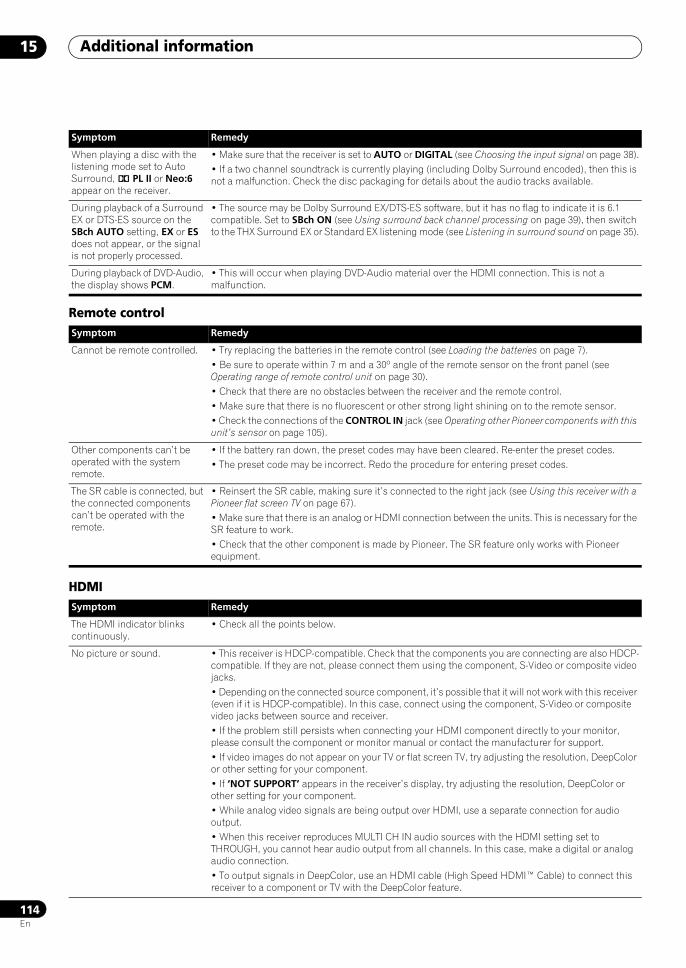
Additional information15
114En
Remote control
HDMI
When playing a disc with the listening mode set to Auto Surround, 2 PL II or Neo:6 appear on the receiver.
• Make sure that the receiver is set to AUTO or DIGITAL (see Choosing the input signal on page 38).• If a two channel soundtrack is currently playing (including Dolby Surround encoded), then this is not a malfunction. Check the disc packaging for details about the audio tracks available.
During playback of a Surround EX or DTS-ES source on the SBch AUTO setting, EX or ES does not appear, or the signal is not properly processed.
• The source may be Dolby Surround EX/DTS-ES software, but it has no flag to indicate it is 6.1 compatible. Set to SBch ON (see Using surround back channel processing on page 39), then switch to the THX Surround EX or Standard EX listening mode (see Listening in surround sound on page 35).
During playback of DVD-Audio, the display shows PCM.
• This will occur when playing DVD-Audio material over the HDMI connection. This is not a malfunction.
Symptom Remedy
Cannot be remote controlled. • Try replacing the batteries in the remote control (see Loading the batteries on page 7).• Be sure to operate within 7 m and a 30º angle of the remote sensor on the front panel (see Operating range of remote control unit on page 30).• Check that there are no obstacles between the receiver and the remote control.• Make sure that there is no fluorescent or other strong light shining on to the remote sensor.• Check the connections of the CONTROL IN jack (see Operating other Pioneer components with this unit’s sensor on page 105).
Other components can’t be operated with the system remote.
• If the battery ran down, the preset codes may have been cleared. Re-enter the preset codes.• The preset code may be incorrect. Redo the procedure for entering preset codes.
The SR cable is connected, but the connected components can’t be operated with the remote.
• Reinsert the SR cable, making sure it’s connected to the right jack (see Using this receiver with a Pioneer flat screen TV on page 67).• Make sure that there is an analog or HDMI connection between the units. This is necessary for the SR feature to work.• Check that the other component is made by Pioneer. The SR feature only works with Pioneer equipment.
Symptom Remedy
The HDMI indicator blinks continuously.
• Check all the points below.
No picture or sound. • This receiver is HDCP-compatible. Check that the components you are connecting are also HDCP-compatible. If they are not, please connect them using the component, S-Video or composite video jacks.• Depending on the connected source component, it’s possible that it will not work with this receiver (even if it is HDCP-compatible). In this case, connect using the component, S-Video or composite video jacks between source and receiver.• If the problem still persists when connecting your HDMI component directly to your monitor, please consult the component or monitor manual or contact the manufacturer for support.• If video images do not appear on your TV or flat screen TV, try adjusting the resolution, DeepColor or other setting for your component.• If ‘NOT SUPPORT’ appears in the receiver’s display, try adjusting the resolution, DeepColor or other setting for your component.• While analog video signals are being output over HDMI, use a separate connection for audio output.• When this receiver reproduces MULTI CH IN audio sources with the HDMI setting set to THROUGH, you cannot hear audio output from all channels. In this case, make a digital or analog audio connection.• To output signals in DeepColor, use an HDMI cable (High Speed HDMI™ Cable) to connect this receiver to a component or TV with the DeepColor feature.
Symptom Remedy
SCLX81_71.book 114 ページ 2008年7月25日 金曜日 午後3時1分
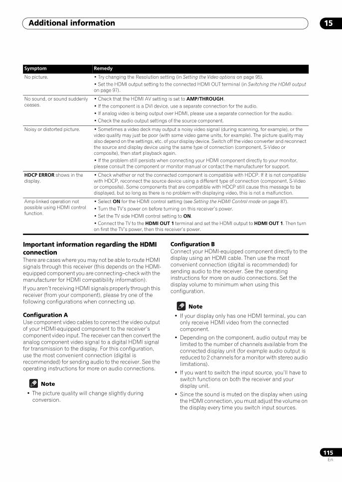
Additional information 15
115En
Important information regarding the HDMI connectionThere are cases where you may not be able to route HDMI signals through this receiver (this depends on the HDMI-equipped component you are connecting–check with the manufacturer for HDMI compatibility information).
If you aren’t receiving HDMI signals properly through this receiver (from your component), please try one of the following configurations when connecting up.
Configuration AUse component video cables to connect the video output of your HDMI-equipped component to the receiver’s component video input. The receiver can then convert the analog component video signal to a digital HDMI signal for transmission to the display. For this configuration, use the most convenient connection (digital is recommended) for sending audio to the receiver. See the operating instructions for more on audio connections.
Note
• The picture quality will change slightly during conversion.
Configuration BConnect your HDMI-equipped component directly to the display using an HDMI cable. Then use the most convenient connection (digital is recommended) for sending audio to the receiver. See the operating instructions for more on audio connections. Set the display volume to minimum when using this configuration.
Note
• If your display only has one HDMI terminal, you can only receive HDMI video from the connected component.
• Depending on the component, audio output may be limited to the number of channels available from the connected display unit (for example audio output is reduced to 2 channels for a monitor with stereo audio limitations).
• If you want to switch the input source, you’ll have to switch functions on both the receiver and your display unit.
• Since the sound is muted on the display when using the HDMI connection, you must adjust the volume on the display every time you switch input sources.
No picture. • Try changing the Resolution setting (in Setting the Video options on page 95).• Set the HDMI output setting to the connected HDMI OUT terminal (in Switching the HDMI output on page 97).
No sound, or sound suddenly ceases.
• Check that the HDMI AV setting is set to AMP/THROUGH.• If the component is a DVI device, use a separate connection for the audio.• If analog video is being output over HDMI, please use a separate connection for the audio.• Check the audio output settings of the source component.
Noisy or distorted picture. • Sometimes a video deck may output a noisy video signal (during scanning, for example), or the video quality may just be poor (with some video game units, for example). The picture quality may also depend on the settings, etc. of your display device. Switch off the video converter and reconnect the source and display device using the same type of connection (component, S-Video or composite), then start playback again.• If the problem still persists when connecting your HDMI component directly to your monitor, please consult the component or monitor manual or contact the manufacturer for support.
HDCP ERROR shows in the display.
• Check whether or not the connected component is compatible with HDCP. If it is not compatible with HDCP, reconnect the source device using a different type of connection (component, S-Video or composite). Some components that are compatible with HDCP still cause this message to be displayed, but so long as there is no problem with displaying video, this is not a malfunction.
Amp-linked operation not possible using HDMI control function.
• Select ON for the HDMI control setting (see Setting the HDMI Control mode on page 87).• Turn the TV’s power on before turning on this receiver’s power.• Set the TV side HDMI control setting to ON.• Connect the TV to the HDMI OUT 1 terminal and set the HDMI output to HDMI OUT 1. Then turn on first the TV’s power, then this receiver’s power.
Symptom Remedy
SCLX81_71.book 115 ページ 2008年7月25日 金曜日 午後3時1分
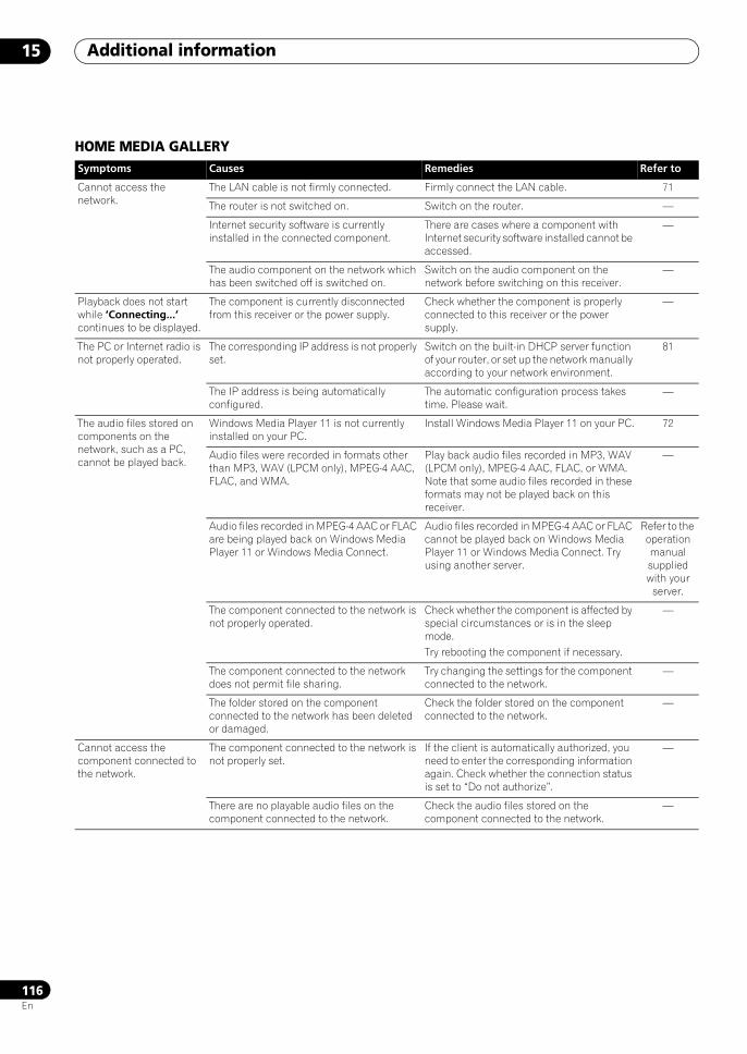
Additional information15
116En
HOME MEDIA GALLERYSymptoms Causes Remedies Refer to
Cannot access the network.
The LAN cable is not firmly connected. Firmly connect the LAN cable. 71
The router is not switched on. Switch on the router. —
Internet security software is currently installed in the connected component.
There are cases where a component with Internet security software installed cannot be accessed.
—
The audio component on the network which has been switched off is switched on.
Switch on the audio component on the network before switching on this receiver.
—
Playback does not start while ‘Connecting...’ continues to be displayed.
The component is currently disconnected from this receiver or the power supply.
Check whether the component is properly connected to this receiver or the power supply.
—
The PC or Internet radio is not properly operated.
The corresponding IP address is not properly set.
Switch on the built-in DHCP server function of your router, or set up the network manually according to your network environment.
81
The IP address is being automatically configured.
The automatic configuration process takes time. Please wait.
—
The audio files stored on components on the network, such as a PC, cannot be played back.
Windows Media Player 11 is not currently installed on your PC.
Install Windows Media Player 11 on your PC. 72
Audio files were recorded in formats other than MP3, WAV (LPCM only), MPEG-4 AAC, FLAC, and WMA.
Play back audio files recorded in MP3, WAV (LPCM only), MPEG-4 AAC, FLAC, or WMA. Note that some audio files recorded in these formats may not be played back on this receiver.
—
Audio files recorded in MPEG-4 AAC or FLAC are being played back on Windows Media Player 11 or Windows Media Connect.
Audio files recorded in MPEG-4 AAC or FLAC cannot be played back on Windows Media Player 11 or Windows Media Connect. Try using another server.
Refer to the operation manual supplied with your
server.
The component connected to the network is not properly operated.
Check whether the component is affected by special circumstances or is in the sleep mode.Try rebooting the component if necessary.
—
The component connected to the network does not permit file sharing.
Try changing the settings for the component connected to the network.
—
The folder stored on the component connected to the network has been deleted or damaged.
Check the folder stored on the component connected to the network.
—
Cannot access the component connected to the network.
The component connected to the network is not properly set.
If the client is automatically authorized, you need to enter the corresponding information again. Check whether the connection status is set to “Do not authorize”.
—
There are no playable audio files on the component connected to the network.
Check the audio files stored on the component connected to the network.
—
SCLX81_71.book 116 ページ 2008年7月25日 金曜日 午後3時1分
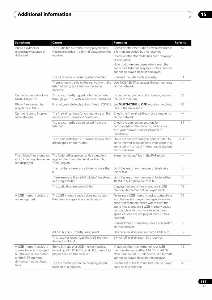
Additional information 15
117En
Audio playback is undesirably stopped or disturbed.
The audio file currently being played back was not recorded in a format playable on this receiver.
Check whether the audio file was recorded in a format supported by this receiver.Check whether the folder has been damaged or corrupted.Note that there are cases where even the audio files listed as playable on this receiver cannot be played back or displayed.
80
The LAN cable is currently disconnected. Connect the LAN cable properly. 71
There is heavy traffic on the network with the Internet being accessed on the same network.
Use 100BASE-TX to access the components on the network.
—
Cannot access Windows Media Player 11.
You are currently logged onto the domain through your PC with Windows XP installed.
Instead of logging onto the domain, log onto the local machine.
73
Photo files cannot be played for ZONE 2.
It is not possible to play photo files in ZONE 2. Set MULTI-ZONE to OFF and play the photo files in the main zone.
65
Cannot listen to Internet radio stations.
The firewall settings for components on the network are currently in operation.
Check the firewall settings for components on the network.
—
You are currently disconnected from the Internet.
Check the connection settings for components on the network, and consult with your network service provider if necessary.
81
The broadcasts from an Internet radio station are stopped or interrupted.
There are cases where you cannot listen to some Internet radio stations even when they are listed in the list of Internet radio stations on this receiver.
77, 118
The folders/files stored on a USB memory device are not displayed.
The folders/files are currently stored in a region other than the FAT (File Allocation Table) region.
Store the folders/files in the FAT region. —
The number of levels in a folder is more than 8.
Limit the maximum number of levels in a folder to 8.
76
There are more than 2000 folders/files stored in a single folder.
Limit the maximum number of folders/files stored in a single folder to 2000.
76
The audio files are copyrighted. Copyrighted audio files stored on a USB memory device cannot be played back.
72
A USB memory device is not recognized.
The USB memory device does not support the mass storage class specifications.
Try using a USB memory device compatible with the mass storage class specifications. Note that there are cases where even the audio files stored on a USB memory device compatible with the mass storage class specifications are not played back on this receiver.
72
Connect the USB memory device and switch on this receiver.
72
A USB hub is currently being used. This receiver does not support a USB hub. 72
This receiver recognizes the USB memory device as a fraud.
Switch off and on again this receiver. —
A USB memory device is connected and displayed, but the audio files stored on the USB memory device cannot be played back.
Some formats of a USB memory device, including FAT 12, NTFS, and HFS, cannot be played back on this receiver.
Check whether the format of your USB memory device is either FAT 16 or FAT 32. Note that the FAT 12, NTFS, and HFS formats cannot be played back on this receiver.
72
The file format cannot be properly played back on this receiver.
See the list of file formats that can be played back on this receiver.
80
Symptoms Causes Remedies Refer to
SCLX81_71.book 117 ページ 2008年7月25日 金曜日 午後3時1分
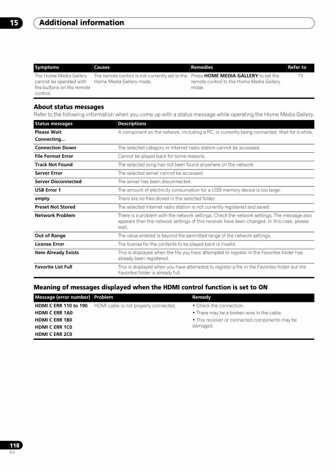
Additional information15
118En
About status messagesRefer to the following information when you come up with a status message while operating the Home Media Gallery.
Meaning of messages displayed when the HDMI control function is set to ON
The Home Media Gallery cannot be operated with the buttons on the remote control.
The remote control is not currently set to the Home Media Gallery mode.
Press HOME MEDIA GALLERY to set the remote control to the Home Media Gallery mode.
73
Status messages Descriptions
Please WaitConnecting...
A component on the network, including a PC, is currently being connected. Wait for a while.
Connection Down The selected category or Internet radio station cannot be accessed.
File Format Error Cannot be played back for some reasons.
Track Not Found The selected song has not been found anywhere on the network.
Server Error The selected server cannot be accessed.
Server Disconnected The server has been disconnected.
USB Error 1 The amount of electricity consumption for a USB memory device is too large.
empty There are no files stored in the selected folder.
Preset Not Stored The selected Internet radio station is not currently registered and saved.
Network Problem There is a problem with the network settings. Check the network settings. The message also appears then the network settings of this receiver have been changed. In this case, please wait.
Out of Range The value entered is beyond the permitted range of the network settings.
License Error The license for the contents to be played back is invalid.
Item Already Exists This is displayed when the file you have attempted to register in the Favorites folder has already been registered.
Favorite List Full This is displayed when you have attempted to register a file in the Favorites folder but the Favorites folder is already full.
Message (error number) Problem Remedy
HDMI C ERR 110 to 190HDMI C ERR 1A0HDMI C ERR 1B0HDMI C ERR 1C0HDMI C ERR 2C0
HDMI cable is not properly connected. • Check the connection.• There may be a broken wire in the cable.• This receiver or connected components may be damaged.
Symptoms Causes Remedies Refer to
SCLX81_71.book 118 ページ 2008年7月25日 金曜日 午後3時1分
Additional information 15
119En
Surround sound formatsBelow is a brief description of the main surround sound formats you’ll find on DVDs, satellite, cable and terrestrial broadcasts, and video cassettes.
DolbyThe Dolby technologies are explained below. See www.dolby.com for more detailed information.
Dolby DigitalDolby Digital is a multichannel digital audio coding system widely used in cinemas, and in the home for DVD and digital broadcast soundtracks. It can deliver up to six discrete audio channels, comprising five full range channels and a special LFE (low frequency effects) channel used mainly for deep, rumbling sound effects; hence the term “5.1-channel” Dolby Digital.
In addition to the format features above, Dolby Digital decoders offer downmixing for compatibility with mono, stereo and Dolby Pro Logic audio from a number of bit rates and channels. Another feature, called Dialog Normalization, attenuates programs based on the average level of dialog in a program relative to its peak level (also known as Dialnorm) in order to achieve uniform playback level.
Dolby Digital Surround EXDolby Digital Surround EX (the EX stands for EXtended) is an extension of Dolby Digital encoding whereby a surround back channel is matrixed into the surround left/right channels for 6.1 channel playback. This allows for compatibility with Dolby Digital 5.1 channel decoding, as well as for decoding using Dolby Digital EX.
Dolby Pro Logic IIx and Dolby SurroundDolby Pro Logic IIx is an improved version of the Dolby Pro Logic II (and Dolby Pro Logic) decoding system. Using the innovative “steering logic” circuit, this system extracts surround sound from sources as follows:
• Dolby Pro Logic – 4.1 channel sound (mono surround) from any stereo source
• Dolby Pro Logic II – 5.1 channel sound (stereo surround) from any stereo source
• Dolby Pro Logic IIx – 6.1 or 7.1 channel sound (stereo surround and surround back) from two channel or 5.1 (and 6.1) channel sources
With two channel sources, the “.1” subwoofer channel is generated by bass management in the receiver.
Dolby Surround is an encoding system which embeds surround sound information within a stereo soundtrack, which a Dolby Pro Logic decoder can then use for enhanced surround listening with greater sound detail.
Dolby Digital PlusDolby Digital Plus is the next-generation audio technology for all high-definition programming and media. It combines the efficiency to meet future broadcast demands with the power and flexibility to realize the full audio potential expected in the upcoming high-definition era. Built on Dolby Digital, the multi-channel audio standard for DVD and HD broadcasts worldwide, Dolby Digital Plus was designed for the next-generation A/V receivers but remains fully compatible with all current A/V receivers.
Dolby Digital Plus delivers multi-channel audio programs of up to 7.1 channels (*) and supports multiple programs in a single encoded bitstream with the maximum bit rate potential of up to 6 Mbps and the maximum bit rate performance of up to 3 Mbps on HD DVD and 1.7 Mbps on Blu-ray Disc, and it outputs Dolby Digital bitstreams for playback on existing Dolby Digital systems. Dolby Digital Plus can accurately reproduce the sound originally intended by directors and producers.
It also features multi-channel sound with discrete channel output, interactive mixing and streaming capability in advanced systems. Supported by High-Definition Media Interface (HDMI), a single-cable digital connection is possible for high-definition audio and video.
Dolby TrueHDDolby TrueHD is the next-generation lossless encoding technology developed for high-definition optical discs in the upcoming era. Dolby TrueHD delivers tantalizing sound that is bit-for-bit identical to the studio master, unlocking the true high-definition entertainment experience on high-definition optical discs in the next generation. When coupled with high-definition video, Dolby TrueHD offers an unprecedented home theater experience with stunning sound and high-definition picture.
It supports bit rates of up to 18 Mbps and records up to 8 full-range channels (*) individually with 24-bit/96 kHz audio. It also features extensive metadata including dialogue normalization and dynamic range control. Supported by High-Definition Media Interface (HDMI), a single-cable digital connection is possible for high-definition audio and video.
HD DVD and Blu-ray Disc standards currently limit their maximum number of audio channels to eight, whereas Dolby Digital Plus and Dolby TrueHD support more than eight audio channels.
SCLX81_71.book 119 ページ 2008年7月25日 金曜日 午後3時1分
Additional information15
120En
Manufactured under license from Dolby Laboratories. Dolby, Pro Logic, Surround EX and the double-D symbol are trademarks of Dolby Laboratories.
DTSThe DTS technologies are explained below. See www.dtstech.com for more detailed information.
DTS Digital SurroundDTS Digital Surround is a 5.1-channel audio coding system from DTS Inc. now widely used for DVD-Video, DVD-Audio, 5.1 music discs, digital broadcasts, and video games. It can deliver up to six discrete audio channels, comprising five full range channels, including an LFE channel. Higher sound quality is achieved through the use of a low compression rate, and high rates of transmittance during playback.
DTS-ESDTS-ES (the ES stands for Extended Surround) is a decoder that is capable of decoding both DTS-ES Discrete 6.1 and DTS-ES Matrix 6.1 encoded sources. DTS-ES Discrete 6.1 gives ‘true’ 6.1 channel sound, with a completely separate (discrete) surround back channel. DTS-ES Matrix 6.1 has a surround back channel matrixed into the surround left/right channels. Both sources are also compatible with a conventional DTS 5.1 channel decoder.
DTS Neo:6DTS Neo:6 can generate 7.1 channel surround sound from any matrixed stereo source (such as video or TV) and from 5.1 channel sources. It uses both the channel information already encoded into the source, as well as its own processing to determine channel localization (with two channel sources, the “.1” subwoofer channel is generated by bass management in the receiver). Two modes (Cinema and Music) are available using DTS Neo:6 with two channel sources.
DTS 96/24DTS 96/24 is an extension of the original DTS Digital Surround which offers high quality 96 kHz/24-bit audio using a DTS 96/24 decoder. This format is also fully backward compatible with all existing decoders. This means that DVD players can play this software using a conventional DTS 5.1 channel decoder.
DTS-EXPRESSDTS-EXPRESS is a low-bitrate encoding technology supporting up to 5.1 channels with fixed data transfer rates. This format is incorporated with sub audio on HD DVD and secondary audio on Blu-ray Disc while boasting the potential applicability to upcoming broadcasts and memory audio contents.
DTS-HD Master AudioDTS-HD Master Audio is a technology that delivers master audio sources recorded in a professional studio to listeners without any loss of data, preserving audio quality. DTS-HD Master Audio adopts variable data transfer rates, facilitating data transfer to the maximum rate of 24.5 Mbps in the Blu-ray disc format, 18.0 Mbps in the HD-DVD format, which by far exceeds that of a standard DVD. These high data transfer rates enable lossless transmission of 96 kHz/24-bit 7.1-channel audio sources without deteriorating the quality of the original sound. DTS-HD Master Audio is an irreplaceable technology that can reproduce sound faithfully as intended by the creator of music or movies.
Manufactured under license under U.S. Patent #’s: 5,451,942; 5,956,674; 5,974,380; 5,978,762; 6,226,616; 6,487,535 & other U.S. and worldwide patents issued & pending. DTS is a registered trademark and the DTS logos, Symbol, DTS-HD and DTS-HD Master Audio are trademarks of DTS, Inc. © 1996-2007 DTS, Inc. All Rights Reserved.
Windows Media Audio 9 ProfessionalWindows Media Audio 9 Professional (WMA9 Pro) is a discrete surround format developed by Microsoft Corporation.
WMA9 Pro can support up to 5.1/7.1 channel playback with sampling rates up to 24-bit/96 kHz. Using the unique WMA compression techniques, WMA9 Pro can deliver multichannel music and soundtracks over high-speed internet networks at low bit rates with minimal audio degradation. Playback may be enjoyed with the Windows Media Player 9 Series (or above) and other third-party media players on a personal computer, or with an AV amplifier with on-board WMA9 Pro decoding.
Windows Media and the Windows logo are trademarks or registered trademarks of Microsoft Corporation in the United States and/or other countries.
SCLX81_71.book 120 ページ 2008年7月25日 金曜日 午後3時1分
Additional information 15
121En
About THXThe THX technologies are explained below. See http://www.thx.com for more detailed information.
In case of SC-LX81
In case of SC-LX71
• THX Cinema processingTHX is an exclusive set of standards and technologies established by THX Ltd. THX grew from George Lucas’ personal desire to make your experience of the film soundtrack, in both movie theatres and in your home theatre, as faithful as possible to what the director intended. Movie soundtracks are mixed in special movie theatres called dubbing stages and are designed to be played back in movie theatres with similar equipment and conditions. This same soundtrack is then transferred directly onto Laserdisc, VHS tape, DVD, etc., and is not changed for playback in a small home theatre environment. THX engineers developed patented technologies to accurately translate the sound from the movie theatre environment into the home, correcting the tonal and spatial errors that occur. On this product, when the THX indicator is on, THX features are automatically added in Cinema modes (e.g. THX Cinema, THX Surround EX) (see page 36).
• Re-EqualizationThe tonal balance of a film soundtrack will be excessively bright and harsh when played back over audio equipment in the home because film soundtracks were designed to be played back in large movie theaters using very different professional equipment. Re-Equalization restores the correct tonal balance for watching a movie soundtrack in a small home environment.
• Timbre MatchingThe human ear changes our perception of a sound depending on the direction from which the sound is coming. In a movie theatre, there is an array of surround speakers so that the surround information is all around you. In a home theatre, you use only two speakers located to the side of your head. The Timbre Matching feature filters the information going to the surround speakers so that they more closely match the tonal characteristics of the sound coming from the front speakers. This ensures seamless panning between the front and surround speakers.
• Adaptive DecorrelationIn a movie theatre, a large number of surround speakers help create an enveloping surround sound experience, but in a home theatre there are usually only two speakers. This can make the surround speakers sound like headphones that lack spaciousness and envelopment. The surround sounds will also collapse into the closest speaker as you move away from the middle seating position. Adaptive Decorrelation slightly changes one surround channel’s time and phase relationship with respect to the other surround channel. This expands the listening position and creates—with only two speakers— the same spacious surround experience as in a movie theatre.
• THX Ultra2Before any home theatre component can be THX Ultra2 certified, it must incorporate all the features above and also pass a rigorous series of quality and performance tests. Only then can a product feature the THX Ultra2 logo, which is your guarantee that the Home Theatre products you purchase will give you superb performance for many years to come. THX Ultra2 requirements cover every aspect of the product including pre-amplifier and power amplifier performance and operation, and hundreds of other parameters in both the digital and analog domain.
• THX Select2Before any home theatre component can be THX Select2 certified, it must incorporate all the features above and also pass a rigorous series of quality and performance tests. Only then can a product feature the THX Select2 logo, which is your guarantee that the Home Theatre products you purchase will give you superb performance for many years to come. THX Select2 requirements cover every aspect of the product including pre-amplifier and power amplifier performance and operation, and hundreds of other parameters in both the digital and analog domain.
• THX Surround EXTHX Surround EX - Dolby Digital Surround EX is a joint development of Dolby Laboratories and the THX Ltd. In a movie theater, film soundtracks that have been encoded with Dolby Digital Surround EX technology are able to reproduce an extra channel which has been added during the mixing of the program. This channel, called Surround Back, places sounds behind the listener in addition to the currently available front left, front center, front right, surround right, surround left and subwoofer channels. This additional channel provides the opportunity for more detailed imaging behind the listener and brings more depth, spacious ambience and sound localization than ever before. Movies that were created using the Dolby Digital Surround EX technology, when released into the home consumer market may exhibit wording to that effect on the packaging. A list of movies created using this technology can be found on the Dolby web site at www.dolby.com.Only receiver and controller products bearing the THX Surround EX logo, when in the THX Surround EX mode, faithfully reproduce this new technology in the home.This product may also engage the “THX Surround EX” mode during the playback of 5.1 channel material that is not Dolby Digital Surround EX encoded. In such case the information delivered to the Surround Back channel will be program dependent and may or may not be very pleasing depending on the particular soundtrack and the tastes of the individual listener.
• Advanced Speaker Array (ASA)ASA is a proprietary THX technology which processes the sound fed to 2 side and 2 back surround speakers to provide the optimal surround sound experience. For the best results, go to THX Audio Set-up screen and choose the setting that most closely corresponds to the speaker spacing, which will re-optimize the surround sound -field.ASA is used in following modes; THX Ultra2/Select2 CINEMA, THX Ultra2/Select2 MUSIC and THX Ultra2/Select2 GAMES.
• Boundary Gain Compensation™Depending on the listener’s and the subwoofer’s position, the listener may experience an excessive bass effect. This feature compensates for excessive bass resulting from a boundary gain effect. This feature is designed to operate when used with a subwoofer certified to THX Ultra2™ specifications.
• THX MusicFor the replay of multi-channel music the THX MusicMode should be selected. In this mode THX ASA processing is applied to the surround channels of all 5.1 encoded music sources such as DTS, Dolby Digital and DVD-Audio to provide a wide stable rear soundstage.
SCLX81_71.book 121 ページ 2008年7月25日 金曜日 午後3時1分
Additional information15
122En
• THX GamesFor the replay of stereo and multi-channel game audio the THX Games Mode should be selected. In this mode THX ASA processing is applied to the surround channels of all 5.1 and 2.0 encoded game sources such as analog, PCM, DTS and Dolby Digital. This accurately places all game audio surround information, providing a full 360 degree playback environment. THX Games Mode is unique as it gives you a smooth transition of audio in all points of the surround field.
• THX Loudness Plus DescriptionTHX Loudness Plus is a new volume control technology featured in THX Ultra2 Plus™ and THX Select2 Plus™ Certified receivers. With THX Loudness Plus, home theater audiences can now experience the rich details in a surround mix at any volume level. A consequence of turning the volume below Reference Level is that certain sound elements can be lost or perceived differently by the listener. THX Loudness Plus compensates for the tonal and spatial shifts that occur when the volume is reduced by intelligently adjusting ambient surround channel levels and frequency response. This enables users to experience the true impact of soundtracks regardless of the volume setting. THX Loudness Plus is automatically applied when listening in any THX listening mode. The new THX Cinema, THX Music, and THX Games modes are tailored to apply the proper THX Loudness Plus settings for each type of content.
• THX Ultra2/Select2 CinemaTHX Ultra2/Select2 Cinema mode plays 5.1 movies using all 8 speakers giving you the best possible movie watching experience. In this mode, ASA processing blends the side surround speakers and back surround speakers providing the optimal mix of ambient and directional surround sounds.DTS-ES (Matrix and 6.1 Discrete) and Dolby Digital Surround EX encoded soundtracks will be automatically detected in Ultra2/Select2 Cinema mode if the appropriate flag has been encoded.
Some Dolby Digital Surround EX soundtracks are missing the digital flag that allows automatic switching. If you know that the movie that you are watching is encoded in Surround EX, you can manually select the THX Surround EX playback mode, otherwise THX Ultra2/Select2 Cinema mode will apply ASA processing to provide optimum replay.
• THX Ultra2/Select2 MusicFor the playback of multi-channel music the THX Ultra2/Select2 Music mode should be selected. In this mode THX ASA processing is applied to the surround channels of all 5.1 encoded music sources such as DTS, Dolby Digital and DVD-Audio to provide a wide stable rear soundstage.
• THX Ultra2/Select2 GamesFor the playback of stereo and multi-channel game audio the THX Ultra2/Select2 Games mode should be selected. In this mode THX ASA processing is applied to the surround channels of all 5.1 and 2.0 encoded game sources such as analog, PCM, DTS and Dolby Digital. This accurately places all game audio surround information, providing a full 360 degree playback environment. THX Ultra2/Select2 Games mode is unique as it gives you a smooth transition of audio in all points of the surround field.
THX, the THX logo, Ultra2 Plus and Select2 Plus are trademarks of THX Ltd. which may be registered in some jurisdictions. All rights reserved. All other trademarks are the property of their respective owners.
About Neural – THX Surround
Neural-THX® Surround is taking surround sound to the next level. This revolutionary new technology delivers the rich envelopment and discrete image detail of surround sound in a format that is fully compatible with stereo from various content sources. Neural-THX Surround enables 5.1, 6.1 and 7.1-channel support for gaming, movies and digital music. By unmasking the audio details, typically lost by other playback modes, audiences will experience the deep ambience and subtle details of movies, music and games.Neural-THX® Digital Music™ is a new surround mode specifically designed to enhance the playback of compressed digital music content. It provides listeners with an expanded sound stage and clean surround experience, even with compressed audio sources such as MP3s and Internet streams.Neural-THX Surround has been chosen as the official surround sound format for TV sports broadcasting, 7.1 games, Music Direct Internet streaming as well as leading FM/HD radio stations worldwide. And with this technology being used by sound designers during content creation, as well as embedded into playback devices, Neural-THX Surround promises a listening experience that is true to the original mix.For additional information, please visit www.neuralsurround.com.This product is manufactured under license from Neural Audio Corporation and THX Ltd. PIONEER Corporation hereby grants the user a non-exclusive, non-transferable, limited right of use to this product under USA and foreign patent, patent pending and other technology or trademarks owned by Neural Audio Corporation and THX Ltd. “Neural Surround”, “Neural Audio”, “Neural” and “NRL” are trademarks and logos owned by Neural Audio Corporation, THX is a trademark of THX Ltd., which may be registered in some jurisdictions. All rights reserved.
SCLX81_71.book 122 ページ 2008年7月25日 金曜日 午後3時1分
Additional information 15
123En
About FLAC
FLAC Decoder Copyright © 2000, 2001, 2002, 2003, 2004, 2005, 2006, 2007 Josh Coalson
Redistribution and use in source and binary forms, with or without modification, are permitted provided that the following conditions are met:
• Redistributions of source code must retain the above copyright notice, this list of conditions and the following disclaimer.
• Redistributions in binary form must reproduce the above copyright notice, this list of conditions and the following disclaimer in the documentation and/or other materials provided with the distribution.
• Neither the name of the Xiph.org Foundation nor the names of its contributors may be used to endorse or promote products derived from this software without specific prior written permission.
THIS SOFTWARE IS PROVIDED BY THE COPYRIGHT HOLDERS AND CONTRIBUTORS “AS IS” AND ANY EXPRESS OR IMPLIED WARRANTIES, INCLUDING, BUT NOT LIMITED TO, THE IMPLIED WARRANTIES OF MERCHANTABILITY AND FITNESS FOR A PARTICULAR PURPOSE ARE DISCLAIMED. IN NO EVENT SHALL THE FOUNDATION OR CONTRIBUTORS BE LIABLE FOR ANY DIRECT, INDIRECT, INCIDENTAL, SPECIAL, EXEMPLARY, OR CONSEQUENTIAL DAMAGES (INCLUDING, BUT NOT LIMITED TO, PROCUREMENT OF SUBSTITUTE GOODS OR SERVICES; LOSS OF USE, DATA, OR PROFITS; OR BUSINESS INTERRUPTION) HOWEVER CAUSED AND ON ANY THEORY OF LIABILITY, WHETHER IN CONTRACT, STRICT LIABILITY, OR TORT (INCLUDING NEGLIGENCE OR OTHERWISE) ARISING IN ANY WAY OUT OF THE USE OF THIS SOFTWARE, EVEN IF ADVISED OF THE POSSIBILITY OF SUCH DAMAGE.
SCLX81_71.book 123 ページ 2008年7月25日 金曜日 午後3時1分
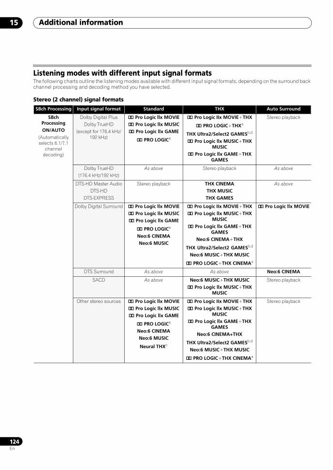
Additional information15
124En
Listening modes with different input signal formatsThe following charts outline the listening modes available with different input signal formats, depending on the surround back channel processing and decoding method you have selected.
Stereo (2 channel) signal formats
SBch Processing Input signal format Standard THX Auto Surround
SBchProcessingON/AUTO
(Automatically selects 6.1/7.1
channel decoding)
Dolby Digital PlusDolby TrueHD
(except for 176.4 kHz/192 kHz)
2 Pro Logic llx MOVIE2 Pro Logic llx MUSIC2 Pro Logic llx GAME
2 PRO LOGICa
2 Pro Logic IIx MOVIE+THX
2 PRO LOGIC+THXa
THX Ultra2/Select2 GAMESb,d
2 Pro Logic llx MUSIC+THX MUSIC
2 Pro Logic llx GAME+THX GAMES
Stereo playback
Dolby TrueHD(176.4 kHz/192 kHz)
As above Stereo playback As above
DTS-HD Master AudioDTS-HD
DTS-EXPRESS
Stereo playback THX CINEMATHX MUSICTHX GAMES
As above
Dolby Digital Surround 2 Pro Logic llx MOVIE2 Pro Logic llx MUSIC2 Pro Logic llx GAME
2 PRO LOGICa
Neo:6 CINEMANeo:6 MUSIC
2 Pro Logic IIx MOVIE+THX2 Pro Logic llx MUSIC+THX
MUSIC2 Pro Logic llx GAME+THX
GAMESNeo:6 CINEMA+THX
THX Ultra2/Select2 GAMESb,d
Neo:6 MUSIC+THX MUSIC
2 PRO LOGIC+THX CINEMAa
2 Pro Logic llx MOVIE
DTS Surround As above As above Neo:6 CINEMA
SACD As above Neo:6 MUSIC+THX MUSIC2 Pro Logic llx MUSIC+THX
MUSIC
Stereo playback
Other stereo sources 2 Pro Logic llx MOVIE2 Pro Logic llx MUSIC2 Pro Logic llx GAME
2 PRO LOGICa
Neo:6 CINEMANeo:6 MUSIC
Neural THXc
2 Pro Logic IIx MOVIE+THX2 Pro Logic llx MUSIC+THX
MUSIC2 Pro Logic llx GAME+THX
GAMESNeo:6 CINEMA+THX
THX Ultra2/Select2 GAMESb,d
Neo:6 MUSIC+THX MUSIC
2 PRO LOGIC+THX CINEMAa
Stereo playback
SCLX81_71.book 124 ページ 2008年7月25日 金曜日 午後3時1分
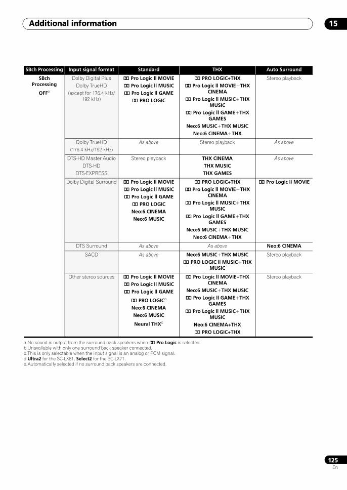
Additional information 15
125En
SBchProcessing
OFFe
Dolby Digital PlusDolby TrueHD
(except for 176.4 kHz/192 kHz)
2 Pro Logic ll MOVIE2 Pro Logic ll MUSIC2 Pro Logic ll GAME
2 PRO LOGIC
2 PRO LOGIC+THX2 Pro Logic ll MOVIE+THX
CINEMA2 Pro Logic ll MUSIC+THX
MUSIC2 Pro Logic ll GAME+THX
GAMESNeo:6 MUSIC+THX MUSIC
Neo:6 CINEMA+THX
Stereo playback
Dolby TrueHD(176.4 kHz/192 kHz)
As above Stereo playback As above
DTS-HD Master AudioDTS-HD
DTS-EXPRESS
Stereo playback THX CINEMATHX MUSICTHX GAMES
As above
Dolby Digital Surround 2 Pro Logic ll MOVIE2 Pro Logic ll MUSIC2 Pro Logic ll GAME
2 PRO LOGICNeo:6 CINEMANeo:6 MUSIC
2 PRO LOGIC+THX2 Pro Logic ll MOVIE+THX
CINEMA2 Pro Logic ll MUSIC+THX
MUSIC2 Pro Logic ll GAME+THX
GAMESNeo:6 MUSIC+THX MUSIC
Neo:6 CINEMA+THX
2 Pro Logic ll MOVIE
DTS Surround As above As above Neo:6 CINEMA
SACD As above Neo:6 MUSIC+THX MUSIC2 PRO LOGIC ll MUSIC+THX
MUSIC
Stereo playback
Other stereo sources 2 Pro Logic ll MOVIE2 Pro Logic ll MUSIC2 Pro Logic ll GAME
2 PRO LOGICa
Neo:6 CINEMANeo:6 MUSIC
Neural THXc
2 Pro Logic ll MOVIE+THX CINEMA
Neo:6 MUSIC+THX MUSIC2 Pro Logic ll GAME+THX
GAMES2 Pro Logic ll MUSIC+THX
MUSICNeo:6 CINEMA+THX2 PRO LOGIC+THX
Stereo playback
a.No sound is output from the surround back speakers when 2 Pro Logic is selected.b.Unavailable with only one surround back speaker connected.c.This is only selectable when the input signal is an analog or PCM signal.d.Ultra2 for the SC-LX81, Select2 for the SC-LX71.e.Automatically selected if no surround back speakers are connected.
SBch Processing Input signal format Standard THX Auto Surround
SCLX81_71.book 125 ページ 2008年7月25日 金曜日 午後3時1分
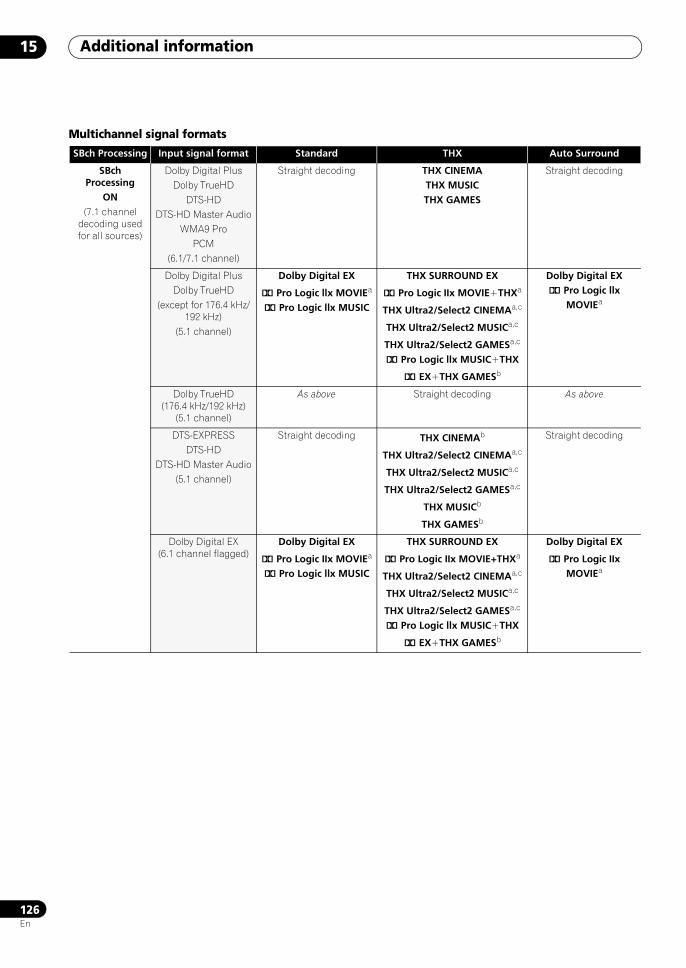
Additional information15
126En
Multichannel signal formats
SBch Processing Input signal format Standard THX Auto Surround
SBch Processing
ON(7.1 channel
decoding used for all sources)
Dolby Digital PlusDolby TrueHD
DTS-HDDTS-HD Master Audio
WMA9 ProPCM
(6.1/7.1 channel)
Straight decoding THX CINEMATHX MUSICTHX GAMES
Straight decoding
Dolby Digital PlusDolby TrueHD
(except for 176.4 kHz/192 kHz)
(5.1 channel)
Dolby Digital EX
2 Pro Logic llx MOVIEa
2 Pro Logic llx MUSIC
THX SURROUND EX
2 Pro Logic IIx MOVIE+THXa
THX Ultra2/Select2 CINEMAa,c
THX Ultra2/Select2 MUSICa,c
THX Ultra2/Select2 GAMESa,c
2 Pro Logic llx MUSIC+THX
2 EX+THX GAMESb
Dolby Digital EX2 Pro Logic llx
MOVIEa
Dolby TrueHD (176.4 kHz/192 kHz)
(5.1 channel)
As above Straight decoding As above
DTS-EXPRESSDTS-HD
DTS-HD Master Audio(5.1 channel)
Straight decoding THX CINEMAb
THX Ultra2/Select2 CINEMAa,c
THX Ultra2/Select2 MUSICa,c
THX Ultra2/Select2 GAMESa,c
THX MUSICb
THX GAMESb
Straight decoding
Dolby Digital EX (6.1 channel flagged)
Dolby Digital EX
2 Pro Logic IIx MOVIEa
2 Pro Logic llx MUSIC
THX SURROUND EX
2 Pro Logic IIx MOVIE+THXa
THX Ultra2/Select2 CINEMAa,c
THX Ultra2/Select2 MUSICa,c
THX Ultra2/Select2 GAMESa,c
2 Pro Logic llx MUSIC+THX
2 EX+THX GAMESb
Dolby Digital EX
2 Pro Logic IIx MOVIEa
SCLX81_71.book 126 ページ 2008年7月25日 金曜日 午後3時1分
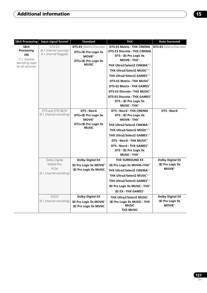
Additional information 15
127En
SBch Processing
ON(7.1 channel
decoding used for all sources)
DTS-ES (6.1 channel sources/6.1 channel flagged)
DTS-ES (Matrix/Discrete)
DTS+2 Pro Logic llx MOVIEa
DTS+2 Pro Logic llx MUSIC
DTS-ES Matrix+THX CINEMADTS-ES Discrete+THX CINEMA
DTS+2 Pro Logic IIx MOVIE+THXa
THX Ultra2/Select2 CINEMAa,c
THX Ultra2/Select2 MUSICa,c
THX Ultra2/Select2 GAMESa,c
DTS-ES Matrix+THX MUSICb
DTS-ES Matrix+THX GAMESb
DTS-ES Discrete+THX MUSICb
DTS-ES Discrete+THX GAMESb
DTS+2 Pro Logic llx MUSIC+THXa
DTS-ES (Matrix/Discrete)
DTS and DTS 96/24 (5.1 channel encoding)
DTS+Neo:6DTS+2 Pro Logic llx
MOVIEa
DTS+2 Pro Logic llx MUSIC
DTS+Neo:6+THX CINEMADTS+2 Pro Logic IIx
MOVIE+THXa
THX Ultra2/Select2 CINEMAa,c
THX Ultra2/Select2 MUSICa,c
THX Ultra2/Select2 GAMESa,c
DTS+Neo:6+THX MUSICb
DTS+Neo:6+THX GAMESb
DTS+2 Pro Logic llx MUSIC+THXa
DTS+Neo:6
Dolby DigitalWMA9 Pro
PCM(5.1 channel encoding)
Dolby Digital EX
2 Pro Logic llx MOVIEa
2 Pro Logic llx MUSIC
THX SURROUND EX
2 Pro Logic IIx MOVIE+THXa
THX Ultra2/Select2 CINEMAa,c
THX Ultra2/Select2 MUSICa,c
THX Ultra2/Select2 GAMESa,c
2 Pro Logic llx MUSIC+THXa
2 EX+THX GAMESb
Dolby Digital EX2 Pro Logic llx
MOVIEa
SACD(5.1 channel encoding)
Dolby Digital EX
2 Pro Logic llx MOVIEa
2 Pro Logic llx MUSIC
THX Ultra2/Select2 MUSICc
2 Pro Logic llx MUSIC+THX MUSIC
THX MUSIC
Dolby Digital EX2 Pro Logic llx
MOVIEa
SBch Processing Input signal format Standard THX Auto Surround
SCLX81_71.book 127 ページ 2008年7月25日 金曜日 午後3時1分
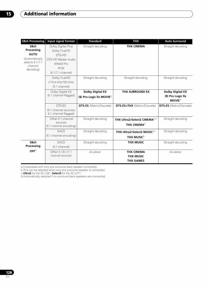
Additional information15
128En
SBch Processing
AUTO(Automatically selects 6.1/7.1
channel decoding)
Dolby Digital PlusDolby TrueHD
DTS-HDDTS-HD Master Audio
WMA9 ProPCM
(6.1/7.1 channel)
Straight decoding THX CINEMA Straight decoding
Dolby TrueHD(176.4 kHz/192 kHz)
(5.1 channel)
Straight decoding Straight decoding Straight decoding
Dolby Digital EX (6.1 channel flagged)
Dolby Digital EX
2 Pro Logic llx MOVIEa
THX SURROUND EX Dolby Digital EX2 Pro Logic llx
MOVIEa
DTS-ES (6.1 channel sources/6.1 channel flagged)
DTS-ES (Matrix/Discrete) DTS-ES+THX (Matrix/Discrete) DTS-ES (Matrix/Discrete)
Other 5.1 channel sources
(5.1 channel encoding)
Straight decoding THX Ultra2/Select2 CINEMAa,c
THX CINEMAb
Straight decoding
SACD(5.1 channel encoding)
Straight decoding THX Ultra2/Select2 MUSICa,c
THX MUSICb
Straight decoding
SBch Processing
OFFd
SACD(5.1 channel)
Straight decoding THX MUSIC Straight decoding
Other 5.1/6.1/7.1 channel sources
As above THX CINEMATHX MUSICTHX GAMES
As above
a.Unavailable with only one surround back speaker connected.b.This can be selected when only one surround speaker is connected.c.Ultra2 for the SC-LX81, Select2 for the SC-LX71.d.Automatically selected if no surround back speakers are connected.
SBch Processing Input signal format Standard THX Auto Surround
SCLX81_71.book 128 ページ 2008年7月25日 金曜日 午後3時1分
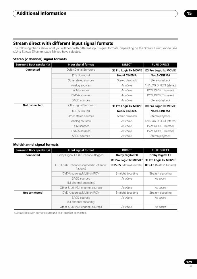
Additional information 15
129En
Stream direct with different input signal formatsThe following charts show what you will hear with different input signal formats, depending on the Stream Direct mode (see Using Stream Direct on page 38) you have selected.
Stereo (2 channel) signal formats
Multichannel signal formats
Surround Back speaker(s) Input signal format DIRECT PURE DIRECT
Connected Dolby Digital Surround 2 Pro Logic llx MOVIE 2 Pro Logic llx MOVIE
DTS Surround Neo:6 CINEMA Neo:6 CINEMA
Other stereo sources Stereo playback Stereo playback
Analog sources As above ANALOG DIRECT (stereo)
PCM sources As above PCM DIRECT (stereo)
DVD-A sources As above PCM DIRECT (stereo)
SACD sources As above Stereo playback
Not connected Dolby Digital Surround 2 Pro Logic llx MOVIE 2 Pro Logic llx MOVIE
DTS Surround Neo:6 CINEMA Neo:6 CINEMA
Other stereo sources Stereo playback Stereo playback
Analog sources As above ANALOG DIRECT (stereo)
PCM sources As above PCM DIRECT (stereo)
DVD-A sources As above PCM DIRECT (stereo)
SACD sources As above Stereo playback
Surround Back speaker(s) Input signal format DIRECT PURE DIRECT
Connected Dolby Digital EX (6.1 channel flagged) Dolby Digital EX
2 Pro Logic llx MOVIEa
Dolby Digital EX
2 Pro Logic llx MOVIEa
DTS-ES (6.1 channel sources/6.1 channel flagged)
DTS-ES (Matrix/Discrete) DTS-ES (Matrix/Discrete)
DVD-A sources/Multi-ch PCM Straight decoding Straight decoding
SACD sources(5.1 channel encoding)
As above As above
Other 5.1/6.1/7.1 channel sources As above As above
Not connected DVD-A sources/Multi-ch PCM Straight decoding Straight decoding
SACD sources(5.1 channel encoding)
As above As above
Other 5.1/6.1/7.1 channel sources As above As above
a.Unavailable with only one surround back speaker connected.
SCLX81_71.book 129 ページ 2008年7月25日 金曜日 午後3時1分
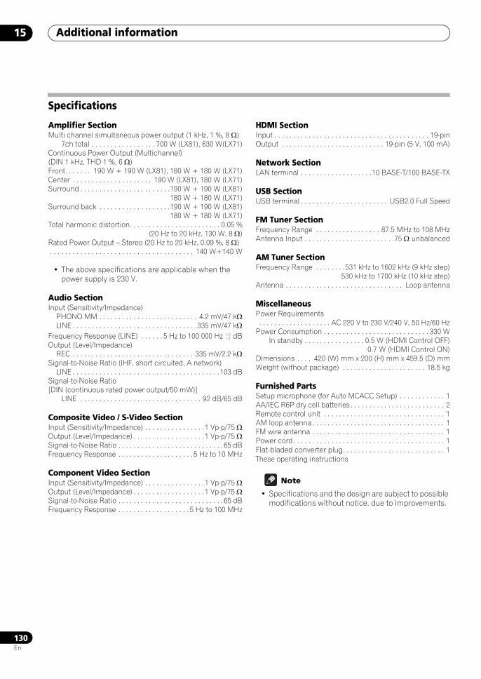
Additional information15
130En
Specifications
Amplifier SectionMulti channel simultaneous power output (1 kHz, 1 %, 8 Ω)
7ch total . . . . . . . . . . . . . . . . . 700 W (LX81), 630 W(LX71)Continuous Power Output (Multichannel) (DIN 1 kHz, THD 1 %, 6 Ω)Front. . . . . . . 190 W + 190 W (LX81), 180 W + 180 W (LX71)Center . . . . . . . . . . . . . . . . . . . . . 190 W (LX81), 180 W (LX71)Surround . . . . . . . . . . . . . . . . . . . . . . . .190 W + 190 W (LX81)
180 W + 180 W (LX71)Surround back . . . . . . . . . . . . . . . . . . .190 W + 190 W (LX81)
180 W + 180 W (LX71)Total harmonic distortion. . . . . . . . . . . . . . . . . . . . . . . . 0.05 %
(20 Hz to 20 kHz, 130 W, 8 Ω)Rated Power Output – Stereo (20 Hz to 20 kHz, 0.09 %, 8 Ω). . . . . . . . . . . . . . . . . . . . . . . . . . . . . . . . . . . . . . 140 W+140 W
• The above specifications are applicable when the power supply is 230 V.
Audio SectionInput (Sensitivity/Impedance)
PHONO MM . . . . . . . . . . . . . . . . . . . . . . . . . . 4.2 mV/47 kΩLINE . . . . . . . . . . . . . . . . . . . . . . . . . . . . . . . . . 335 mV/47 kΩ
Frequency Response (LINE) . . . . . . 5 Hz to 100 000 Hz dBOutput (Level/Impedance)
REC . . . . . . . . . . . . . . . . . . . . . . . . . . . . . . . . 335 mV/2.2 kΩSignal-to-Noise Ratio (IHF, short circuited, A network)
LINE . . . . . . . . . . . . . . . . . . . . . . . . . . . . . . . . . . . . . . .103 dBSignal-to-Noise Ratio[DIN (continuous rated power output/50 mW)]
LINE . . . . . . . . . . . . . . . . . . . . . . . . . . . . . . . . 92 dB/65 dB
Composite Video / S-Video SectionInput (Sensitivity/Impedance) . . . . . . . . . . . . . . . .1 Vp-p/75 ΩOutput (Level/Impedance) . . . . . . . . . . . . . . . . . . .1 Vp-p/75 ΩSignal-to-Noise Ratio . . . . . . . . . . . . . . . . . . . . . . . . . . . .65 dBFrequency Response . . . . . . . . . . . . . . . . . . . . 5 Hz to 10 MHz
Component Video SectionInput (Sensitivity/Impedance) . . . . . . . . . . . . . . . .1 Vp-p/75 ΩOutput (Level/Impedance) . . . . . . . . . . . . . . . . . . .1 Vp-p/75 ΩSignal-to-Noise Ratio . . . . . . . . . . . . . . . . . . . . . . . . . . . .65 dBFrequency Response . . . . . . . . . . . . . . . . . . . 5 Hz to 100 MHz
HDMI SectionInput . . . . . . . . . . . . . . . . . . . . . . . . . . . . . . . . . . . . . . . . . 19-pinOutput . . . . . . . . . . . . . . . . . . . . . . . . . . . 19-pin (5 V, 100 mA)
Network SectionLAN terminal . . . . . . . . . . . . . . . . . . .10 BASE-T/100 BASE-TX
USB SectionUSB terminal . . . . . . . . . . . . . . . . . . . . . . . USB2.0 Full Speed
FM Tuner SectionFrequency Range . . . . . . . . . . . . . . . . . 87.5 MHz to 108 MHzAntenna Input . . . . . . . . . . . . . . . . . . . . . . . .75 Ω unbalanced
AM Tuner SectionFrequency Range . . . . . . . .531 kHz to 1602 kHz (9 kHz step)
530 kHz to 1700 kHz (10 kHz step)Antenna . . . . . . . . . . . . . . . . . . . . . . . . . . . . . . . Loop antenna
MiscellaneousPower Requirements . . . . . . . . . . . . . . . . . . . AC 220 V to 230 V/240 V, 50 Hz/60 HzPower Consumption . . . . . . . . . . . . . . . . . . . . . . . . . . . . 330 W
In standby . . . . . . . . . . . . . . . . 0.5 W (HDMI Control OFF)0.7 W (HDMI Control ON)
Dimensions . . . . 420 (W) mm x 200 (H) mm x 459.5 (D) mmWeight (without package) . . . . . . . . . . . . . . . . . . . . . . 18.5 kg
Furnished PartsSetup microphone (for Auto MCACC Setup) . . . . . . . . . . . . 1AA/IEC R6P dry cell batteries. . . . . . . . . . . . . . . . . . . . . . . . . 2Remote control unit . . . . . . . . . . . . . . . . . . . . . . . . . . . . . . . . 1AM loop antenna . . . . . . . . . . . . . . . . . . . . . . . . . . . . . . . . . . . 1FM wire antenna . . . . . . . . . . . . . . . . . . . . . . . . . . . . . . . . . . . 1Power cord. . . . . . . . . . . . . . . . . . . . . . . . . . . . . . . . . . . . . . . . 1Flat-bladed converter plug. . . . . . . . . . . . . . . . . . . . . . . . . . . 1These operating instructions
Note
• Specifications and the design are subject to possible modifications without notice, due to improvements.
SCLX81_71.book 130 ページ 2008年7月25日 金曜日 午後3時1分
Additional information 15
131En
Cleaning the unit• Use a polishing cloth or dry cloth to wipe off dust and
dirt.
• When the surface is dirty, wipe with a soft cloth dipped in some neutral cleanser diluted five or six times with water, and wrung out well, and then wipe again with a dry cloth. Do not use furniture wax or cleansers.
• Never use thinners, benzine, insecticide sprays or other chemicals on or near this unit, since these will corrode the surface.
Our philosophyPioneer is dedicated to making your home theater listening experience as close as possible to the vision of the moviemakers and mastering engineer when they created the original soundtrack. We do this by focusing on three important steps:
1 Achieving the highest possible sound quality
2 Allowing for customized acoustic calibration according to any listening area
3 Fine-tuning the receiver with the help of world-class studio engineers1
1 With the cooperation of AIR Studios, this receiver has been designated AIR Studios Monitor:
Features
• Direct Energy HD AmplifierThrough a collaboration, Pioneer and ICEpower have jointly development a unique class D amplifier called a “Direct Energy High Fidelity Class D (HD) amplifier”. This new generation reference amplifier offers outstanding performance (high output of 700 W (SC-LX81)/630 W (SC-LX71) simultaneous) with high sound quality and reproduces the latest in multi-channel digital contents.
• Easy setup using Advanced MCACC The Auto MCACC Setup provides a quick but accurate surround sound setup, which includes the advanced features of Professional Acoustic Calibration EQ. This innovative technology measures the reverb characteristics of your listening area, allowing you to customize your system calibration with the help of a graphical output that can be displayed on-screen, or using a computer. With the additional benefits of
numerous MCACC preset memories, standing wave control and microphone measurements from a series of reference points, your home theater experience can be truly customized for optimal surround sound.
• Phase ControlThe Phase Control feature corrects the phase distortion as well as group delay for LFE (Low-Frequency Effects) audio signals during multichannel playback.
• Full Band Phase ControlThe Full Band Phase Control feature analyzes the frequency-phase characteristics of the speakers connected and corrects the phase distortion to the flattened frequency-phase characteristics. This correction minimizes the group delay of the middle- and low-frequency ranges against the high-frequency range and improves the frequency-phase characteristics across all ranges. Furthermore, the enhanced frequency-phase characteristics between channels ensure better surround sound integration.
• HOME MEDIA GALLERYThis receiver can play back contents stored on your computer when your computer is connected to the LAN terminal of this receiver. It is also possible to play contents stored on iPod and USB devices. Also, you can listen to the Internet radio stations.
• Dolby Digital and DTS decoding, including Dolby Digital EX, Dolby Pro Logic IIx, DTS 96/24, DTS-ES, Dolby Digital Plus, Dolby TrueHD, DTS-EXPRESS and DTS-HD Master AudioDolby Digital and DTS decoding brings theater sound right into your home with up to six channels of surround sound, including a special LFE (Low Frequency Effects) channel for deep, realistic sound effects.
The built-in Dolby Pro Logic IIx and DTS Neo:6 decoders not only provide full surround sound decoding for Dolby Surround sources, but will also generate convincing surround sound for any stereo source.
Also, with the addition of a surround back speaker, you can take advantage of the built-in Dolby Digital EX and DTS-ES decoders for six-channel surround sound.
Furthermore, Dolby Digital Plus and Dolby TrueHD, which are designed for the next-generation high-definition media such as Blu-ray Disc and HD DVD, support up to 7.1 channels and 8 channels respectively.
DTS-EXPRESS is a low-bitrate encoding technology supporting up to 5.1 channels, with fixed data transfer rates ranging from 24 kbps to 256 kbps (this encoding is available only when signals are delivered to this receiver as primary audio).
DTS-HD Master Audio delivers audio signals to listeners without any loss of data with its high transfer rates.
SCLX81_71.book 131 ページ 2008年7月25日 金曜日 午後3時1分
Additional information15
132En
• THX certified designIn case of SC-LX81
This receiver is THX Ultra2™ certified, allowing you to take advantage of new THX technologies such as ASA (Advanced Speaker Array), which can process any 5.1 channel source for 6.1 channel (THX Surround EX) or 7.1 channel (THX Ultra2 CINEMA, THX Ultra2 MUSIC and THX Ultra2 GAMES) playback.
• THX certified designIn case of SC-LX71
This receiver is THX Select2™ certified, allowing you to take advantage of new THX technologies such as ASA (Advanced Speaker Array), which can process any 5.1 channel source for 6.1 channel (THX Surround EX) or 7.1 channel (THX Select2 CINEMA, THX Select2 MUSIC and THX Select2 GAMES) playback.
• HDMI and digital video conversionThis receiver is compatible with the HDMI digital video format, providing you with high-definition digital video/audio via a single cable. High-quality sound formats such as DTS-HD and Dolby TrueHD are supported while this receiver is also compatible with the DeepColor and x.v.Color feature (x.v.Color is trademarks of Sony Corporation). You can operate this receiver in synchronization with your Pioneer component that supports the HDMI Control function by connecting your component to this receiver via HDMI. Also, the built-in digital video converter of this receiver makes both de-interlacing and up-scaling possible, and analog video signals being input are converted and output as digital video signals at the HDMI terminal.
• DCDiFaroudja’s DCDi Processing is selectable and ensures that images are smooth and natural, without staircasing or jaggies.
This product includes FontAvenue® fonts licenced by NEC corporation. FontAvenue is a registered trademark of NEC Corporation.
SCLX81_71.book 132 ページ 2008年7月25日 金曜日 午後3時1分
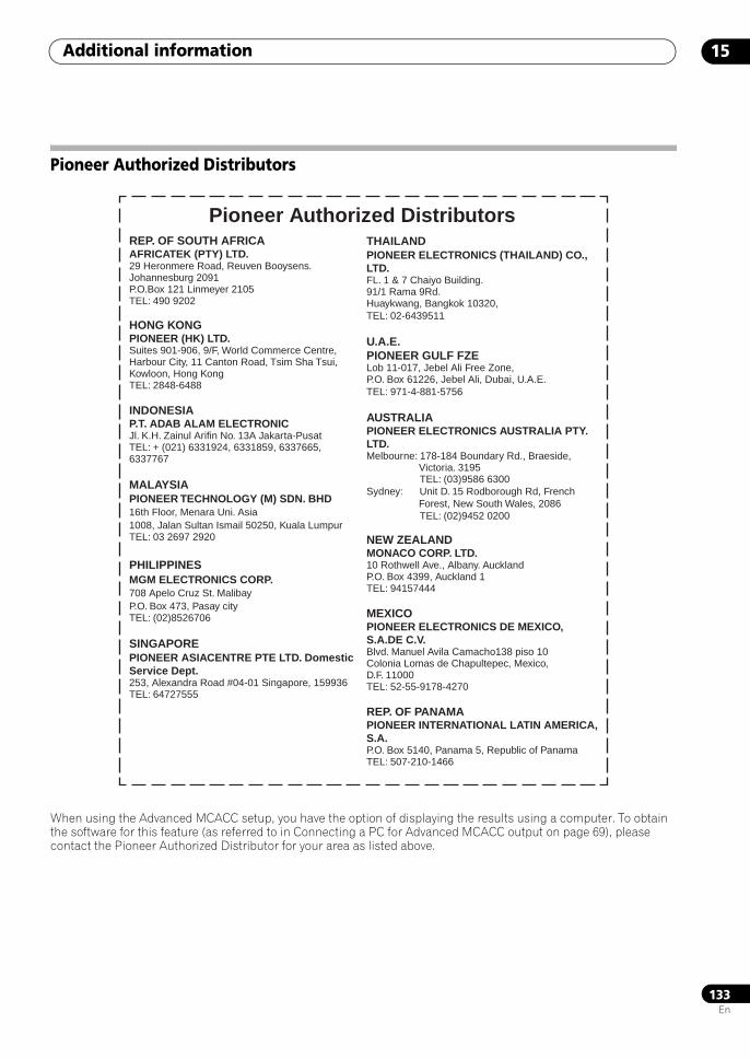
Additional information 15
133En
Pioneer Authorized Distributors
When using the Advanced MCACC setup, you have the option of displaying the results using a computer. To obtain the software for this feature (as referred to in Connecting a PC for Advanced MCACC output on page 69), please contact the Pioneer Authorized Distributor for your area as listed above.
Pioneer Authorized DistributorsREP. OF SOUTH AFRICAAFRICATEK (PTY) LTD.29 Heronmere Road, Reuven Booysens.Johannesburg 2091P.O.Box 121 Linmeyer 2105TEL: 490 9202
HONG KONGPIONEER (HK) LTD.Suites 901-906, 9/F, World Commerce Centre,Harbour City, 11 Canton Road, Tsim Sha Tsui, Kowloon, Hong KongTEL: 2848-6488
INDONESIAP.T. ADAB ALAM ELECTRONICJl. K.H. Zainul Arifin No. 13A Jakarta-Pusat TEL: + (021) 6331924, 6331859, 6337665, 6337767
MALAYSIAPIONEER TECHNOLOGY (M) SDN. BHD16th Floor, Menara Uni. Asia1008, Jalan Sultan Ismail 50250, Kuala LumpurTEL: 03 2697 2920
PHILIPPINESMGM ELECTRONICS CORP.708 Apelo Cruz St. MalibayP.O. Box 473, Pasay cityTEL: (02)8526706
SINGAPOREPIONEER ASIACENTRE PTE LTD. Domestic Service Dept.253, Alexandra Road #04-01 Singapore, 159936TEL: 64727555
THAILANDPIONEER ELECTRONICS (THAILAND) CO., LTD.FL. 1 & 7 Chaiyo Building.91/1 Rama 9Rd.Huaykwang, Bangkok 10320,TEL: 02-6439511
U.A.E.PIONEER GULF FZELob 11-017, Jebel Ali Free Zone, P.O. Box 61226, Jebel Ali, Dubai, U.A.E. TEL: 971-4-881-5756
AUSTRALIAPIONEER ELECTRONICS AUSTRALIA PTY. LTD.Melbourne: 178-184 Boundary Rd., Braeside, Victoria. 3195 TEL: (03)9586 6300Sydney: Unit D. 15 Rodborough Rd, French Forest, New South Wales, 2086 TEL: (02)9452 0200
NEW ZEALANDMONACO CORP. LTD.10 Rothwell Ave., Albany. AucklandP.O. Box 4399, Auckland 1TEL: 94157444
MEXICOPIONEER ELECTRONICS DE MEXICO, S.A.DE C.V.Blvd. Manuel Avila Camacho138 piso 10 Colonia Lomas de Chapultepec, Mexico, D.F. 11000TEL: 52-55-9178-4270
REP. OF PANAMAPIONEER INTERNATIONAL LATIN AMERICA, S.A.P.O. Box 5140, Panama 5, Republic of PanamaTEL: 507-210-1466
SCLX81_71.book 133 ページ 2008年7月25日 金曜日 午後3時1分
Printed in <ARB7394-A>
Published by Pioneer Corporation.Copyright © 2008 Pioneer Corporation.All rights reserved.
PIONEER CORPORATION4-1, Meguro 1-Chome, Meguro-ku, Tokyo 153-8654, JapanPIONEER ELECTRONICS (USA) INC.P.O. BOX 1540, Long Beach, California 90801-1540, U.S.A. TEL: (800) 421-1404PIONEER ELECTRONICS OF CANADA, INC.300 Allstate Parkway, Markham, Ontario L3R 0P2, Canada TEL: 1-877-283-5901, 905-479-4411PIONEER EUROPE NVHaven 1087, Keetberglaan 1, B-9120 Melsele, Belgium TEL: 03/570.05.11PIONEER ELECTRONICS ASIACENTRE PTE. LTD.253 Alexandra Road, #04-01, Singapore 159936 TEL: 65-6472-7555PIONEER ELECTRONICS AUSTRALIA PTY. LTD.178-184 Boundary Road, Braeside, Victoria 3195, Australia, TEL: (03) 9586-6300PIONEER ELECTRONICS DE MEXICO S.A. DE C.V.Blvd.Manuel Avila Camacho 138 10 piso Col.Lomas de Chapultepec, Mexico,D. F. 11000 TEL: 55-9178-4270K002_B_En
SCLX81_71.book 136 ページ 2008年7月25日 金曜日 午後3時1分


