Embed Size (px)
Citation preview
550-867 Operating Instructions

All rights reserved.
Property of Dürkopp Adler AG and protected by copyright.Any reuse of these contents, including extracts, is prohibited without the prior written approval of Dürkopp Adler AG.
Copyright © Dürkopp Adler AG 2016
IMPORTANT
READ CAREFULLY BEFORE USE
KEEP FOR FUTURE REFERENCE
Table of Contents
1 About these instructions .................................................................... 7
1.1 For whom are these instructions intended? .......................................... 71.2 Representation conventions – symbols and characters ........................ 81.3 Other documents................................................................................... 91.4 Liability ................................................................................................ 10
2 Safety.................................................................................................. 11
2.1 Basic safety instructions...................................................................... 112.2 Signal words and symbols used in warnings....................................... 12
3 Machine description.......................................................................... 17
3.1 Components of the machine ............................................................... 173.1.1 Complete overview.............................................................................. 173.1.2 Upper part of the machine................................................................... 183.1.3 Lower part of the machine................................................................... 183.2 Proper use........................................................................................... 193.3 Declaration of Conformity .................................................................... 20
4 Operation ........................................................................................... 21
4.1 Preparing the machine for operation ................................................... 214.1.1 Switching on the machine ................................................................... 224.1.2 Scanning barcodes.............................................................................. 234.1.3 Inserting/changing the needle ............................................................. 264.1.4 Feeding needle and hook thread......................................................... 284.1.5 Threading the needle thread ............................................................... 314.1.6 Winding the hook thread ..................................................................... 344.1.7 Inserting/changing the bobbin ............................................................. 374.1.8 Threading the hook thread .................................................................. 404.2 Thread tension .................................................................................... 414.2.1 Setting the hook thread tension........................................................... 424.2.2 Setting the needle thread tension........................................................ 434.3 Setting the needle thread regulator ..................................................... 454.4 Locking the sewing foot in top dead center ......................................... 464.5 Setting the sewing foot stroke ............................................................. 474.6 Setting the sewing foot pressure ......................................................... 484.7 Setting the stitch length ....................................................................... 484.8 Buttons on the machine arm ............................................................... 494.8.1 Switching the function of a button on and off ...................................... 504.8.2 Assigning a function to the favorite button .......................................... 514.9 LEDs on the machine .......................................................................... 524.9.1 LEDs on the machine arm................................................................... 524.9.2 LEDs on the tensioning plate .............................................................. 534.10 Remaining thread monitor ................................................................... 544.11 Electropneumatic quick stroke adjustment .......................................... 58
Operating Instructions 550-867 - 00.0 - 11/2016 1
Table of Contents
4.11.1 Setting the function of the knee button................................................ 594.11.2 Switching on maximum stroke during sewing ..................................... 604.12 Switching on and off the sewing lamp ................................................. 614.13 Additional equipment ........................................................................... 624.13.1 End label scanner................................................................................ 624.13.2 Barcode scanner for needle and hook thread ..................................... 634.13.3 Bobbin identification ............................................................................ 644.13.4 Needle cooling from the top ................................................................ 654.13.5 Needle cooling from the bottom .......................................................... 654.14 Sewing................................................................................................. 664.14.1 Pressing the pedal............................................................................... 694.14.2 Sewing in the end label ....................................................................... 714.15 Procedure in the event of a power supply disruption .......................... 754.16 Switching off the machine ................................................................... 76
5 Programming ..................................................................................... 79
5.1 Structure of the software ..................................................................... 795.1.1 Security levels (0-2)............................................................................. 795.1.2 Start screen ......................................................................................... 825.1.3 Main screen......................................................................................... 835.1.4 Register screen ................................................................................... 855.1.5 Recurring elements ............................................................................. 865.1.6 Input window ....................................................................................... 875.2 Logging into the system ...................................................................... 885.2.1 Logging in with the hand scanner........................................................ 885.2.2 Logging in via software........................................................................ 895.3 Managing users................................................................................... 905.3.1 Displaying users .................................................................................. 915.3.2 Storing a user image ........................................................................... 925.3.3 Creating a new user ............................................................................ 935.3.4 Deleting users ..................................................................................... 955.4 Seam record sets ................................................................................ 965.4.1 Opening the Seam record sets display ......................................... 975.4.2 Creating a new seam record set ......................................................... 985.4.3 Editing a seam record set
(Edit seam parameter record) ................................................ 1005.4.4 Copying a seam record set ............................................................... 1185.4.5 Deleting a seam record set ............................................................... 1205.4.6 Changing the thread
(Change thread in seam records) ......................................... 1215.5 Database ........................................................................................... 1235.5.1 Opening the Database display ........................................................ 1235.5.2 Opening a protocol database ............................................................ 1245.5.3 Printing a protocol file ........................................................................ 1255.5.4 Copying a protocol file (Copy) ........................................................... 125
2 Operating Instructions 550-867 - 00.0 - 11/2016
Table of Contents
5.5.5 Error codes (Help) ............................................................................ 1265.5.6 Printing a copy of an end label (Lab. Copy) ................................... 1275.5.7 Thread tension (Thr. tens.) ......................................................... 1285.6 Check ................................................................................................ 1295.6.1 Structure of the Checks display......................................................... 1295.6.2 Opening the Checks display............................................................. 1325.6.3 Creating a system backup (Backup system) ................................. 1335.6.4 Restoring data (Restore system) ................................................. 1355.6.5 Creating a backup of the protocol database
(Backup protoc. DB) ................................................................... 1365.6.6 Printing a special barcode label (Print BC label) ....................... 1375.6.7 Data transfer...................................................................................... 1385.6.8 Copying Dump Files .......................................................................... 1385.6.9 Displaying connections...................................................................... 1385.6.10 Setup ................................................................................................. 1395.6.11 Opening the thread database (Threads) ......................................... 1495.6.12 Printing the protocol database (DB print) ...................................... 1505.6.13 Opening the seam database (Show DB)........................................... 1515.6.14 Opening the bobbin database (Bobbins)......................................... 1525.6.15 Needle database (Needle DB) ........................................................ 1535.6.16 Calibrating the step motor (SM-Cali)............................................... 1555.6.17 Calibration database (T.Tens.-Cali) ............................................ 1565.6.18 Calibrating the stitch length (SM) ....................................................... 1575.6.19 Checking input and output (I/O)....................................................... 1605.6.20 Checking the scanners (Scanner) ................................................... 1615.6.21 Checking the sewing motor (Sew. Motor) ...................................... 1625.6.22 Thread tension (Thread tens.) ..................................................... 1635.6.23 Uninterrupted power supply (UPS)..................................................... 1665.7 Protocol printer .................................................................................. 1685.8 Uninstalling the barcode printer drivers ............................................. 1685.9 Calibrating the end label printer ........................................................ 1695.10 Barcodes ........................................................................................... 1705.10.1 Barcodes at a glance......................................................................... 1705.10.2 Opening the Barcodes display .......................................................... 1715.10.3 Changing the barcode type ............................................................... 1745.10.4 Defining a barcode ............................................................................ 1755.10.5 Saving a barcode profile.................................................................... 1765.10.6 Loading a barcode profile .................................................................. 1775.11 Setting batch mode ........................................................................... 1785.12 Setting multi barcodes....................................................................... 1795.13 Preparing the end label (Label) ....................................................... 1805.13.1 Opening the End label display........................................................... 1805.13.2 Defining the end label text ................................................................. 1815.13.3 Positioning the text on the end label ................................................. 1825.13.4 Defining the format of the end label .................................................. 183
Operating Instructions 550-867 - 00.0 - 11/2016 3
Table of Contents
5.13.5 Positioning the end label barcode ..................................................... 1845.13.6 Defining the font size......................................................................... 1855.13.7 Defining an end label barcode type................................................... 1855.13.8 Defining the content of the end label barcode................................... 1865.13.9 Saving an end label ........................................................................... 1895.13.10 Loading an end label ......................................................................... 1905.13.11 Defining extended label printing ........................................................ 1915.14 Deleting a bobbin .............................................................................. 1945.15 Storage locations and automatic backups (Path+netw.)................ 1965.15.1 Changing the storage location........................................................... 1965.15.2 Setting an automatic backup of the protocol database ..................... 1985.16 Thread database ............................................................................... 1995.16.1 Creating a new thread ....................................................................... 2005.16.2 Changing a thread............................................................................. 2025.16.3 Deleting a thread ............................................................................... 2035.17 Creating a teach-in file ...................................................................... 2035.18 Restarting the program (Reset) ....................................................... 2085.19 Exiting the program ........................................................................... 2095.20 Logging out of the system ................................................................. 2105.21 Additional program Label Creator .............................................. 2125.21.1 Preparing the end label (example) .................................................... 2145.21.2 Default settings.................................................................................. 2165.21.3 Adjusting the end label size............................................................... 2175.21.4 Opening the Toolbox ...................................................................... 2185.21.5 Inserting contents .............................................................................. 2205.21.6 Moving contents ................................................................................ 2215.21.7 Creating a barcode............................................................................ 2225.21.8 Adding an additional barcode............................................................ 2255.21.9 Creating standard text ....................................................................... 2255.21.10 Creating variable text ........................................................................ 2265.21.11 Inserting a graphic............................................................................. 2275.21.12 Saving a label script file..................................................................... 2285.21.13 Printing a test end label ..................................................................... 2295.22 Additional program SABSearch ....................................................... 2305.22.1 Performing a search (example) ......................................................... 2315.22.2 Exiting SABSearch .......................................................................... 235
6 Maintenance..................................................................................... 237
6.1 Cleaning ............................................................................................ 2386.2 Lubricating......................................................................................... 2406.3 Servicing the pneumatic system........................................................ 2426.3.1 Setting the operating pressure .......................................................... 2426.3.2 Draining the water condensation....................................................... 2436.3.3 Cleaning the filter element................................................................. 245
4 Operating Instructions 550-867 - 00.0 - 11/2016
Table of Contents
6.4 Parts list............................................................................................. 246
7 Setup ................................................................................................ 247
7.1 Checking the scope of delivery ......................................................... 2477.2 Removing the transport locks............................................................ 2477.3 Assembling the reel stand ................................................................. 2487.4 Setting the working height ................................................................. 2507.5 Setting the pedal ............................................................................... 2517.6 Assembling the control panel ............................................................ 2537.7 Electrical connection ......................................................................... 2537.8 Connecting the control panel............................................................. 2547.9 Pneumatic connection ....................................................................... 2557.9.1 Assembling the compressed air maintenance unit ............................ 2557.9.2 Setting the operating pressure .......................................................... 2567.10 Lubricating......................................................................................... 2577.11 Putting the machine into operation.................................................... 2597.12 Performing a test run......................................................................... 2607.13 Transporting the machine in house ................................................... 262
8 Decommissioning ........................................................................... 263
8.1 Decommissioning the machine ......................................................... 2638.2 Transporting the machine.................................................................. 264
9 Disposal ........................................................................................... 265
10 Troubleshooting .............................................................................. 267
10.1 Customer Service.............................................................................. 26710.2 Messages of the software ................................................................. 26810.2.1 Information messages ....................................................................... 26810.2.2 Error messages ................................................................................. 26910.2.3 Editing error messages ..................................................................... 27210.3 Errors in sewing process ................................................................... 274
11 Technical data ................................................................................. 277
11.1 Characteristics................................................................................... 27911.2 Technical features of the software .................................................... 28011.3 Data recording................................................................................... 281
12 Appendix .......................................................................................... 283
Operating Instructions 550-867 - 00.0 - 11/2016 5

Table of Contents
6 Operating Instructions 550-867 - 00.0 - 11/2016
About these instructions
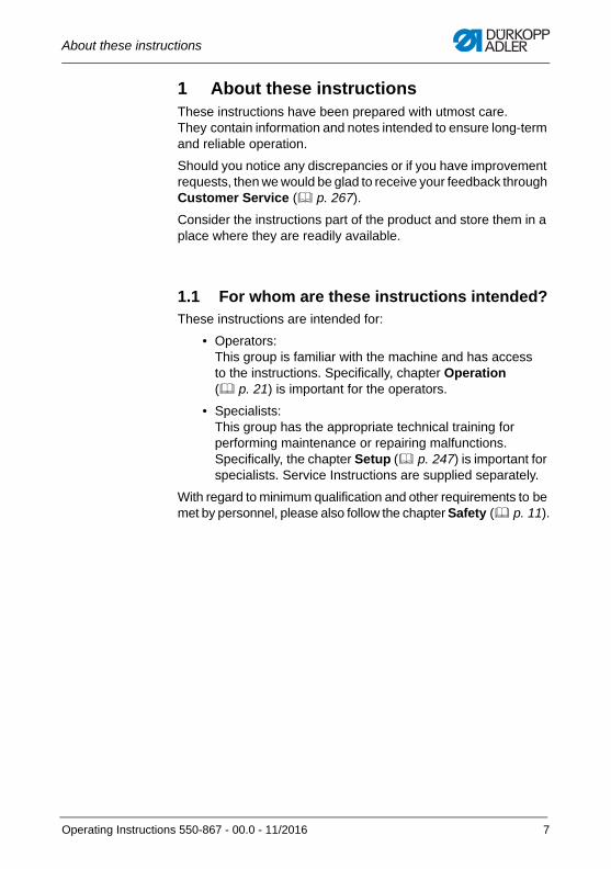
1 About these instructionsThese instructions have been prepared with utmost care. They contain information and notes intended to ensure long-term and reliable operation.
Should you notice any discrepancies or if you have improvement requests, then we would be glad to receive your feedback through Customer Service ( p. 267).
Consider the instructions part of the product and store them in a place where they are readily available.
1.1 For whom are these instructions intended?These instructions are intended for:
• Operators:This group is familiar with the machine and has access to the instructions. Specifically, chapter Operation ( p. 21) is important for the operators.
• Specialists:This group has the appropriate technical training for performing maintenance or repairing malfunctions. Specifically, the chapter Setup ( p. 247) is important for specialists. Service Instructions are supplied separately.
With regard to minimum qualification and other requirements to be met by personnel, please also follow the chapter Safety ( p. 11).
Operating Instructions 550-867 - 00.0 - 11/2016 7
About these instructions
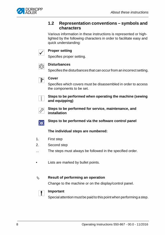
1.2 Representation conventions – symbols and characters
Various information in these instructions is represented or high-lighted by the following characters in order to facilitate easy and quick understanding:
Proper setting
Specifies proper setting.
Disturbances
Specifies the disturbances that can occur from an incorrect setting.
Cover
Specifies which covers must be disassembled in order to access the components to be set.
Steps to be performed when operating the machine (sewing and equipping)
Steps to be performed for service, maintenance, and installation
Steps to be performed via the software control panel
The individual steps are numbered:
First step
Second step
The steps must always be followed in the specified order.
Lists are marked by bullet points.
Result of performing an operation
Change to the machine or on the display/control panel.
Important
Special attention must be paid to this point when performing a step.
1.
2.
...
•
8 Operating Instructions 550-867 - 00.0 - 11/2016
About these instructions
InformationAdditional information, e.g. on alternative operating options.
Order
Specifies the work to be performed before or after a setting.
References
Reference to another section in these instructions.
Safety Important warnings for the user of the machine are specifically marked. Since safety is of particular importance, hazard symbols, levels of danger and their signal words are described separately in the chapter Safety ( p. 11).
Locationinformation
If no other clear location information is used in a figure, indications of right or left are always from the user's point of view.
1.3 Other documentsThe machine includes components from other manufacturers. Each manufacturer has performed a hazard assessment for these purchased parts and confirmed their design compliance with applicable European and national regulations. The proper use of the built-in components is described in the corresponding manu-facturer's instructions.
Operating Instructions 550-867 - 00.0 - 11/2016 9
About these instructions
1.4 LiabilityAll information and notes in these instructions have been compiled in accordance with the latest technology and the applicable stan-dards and regulations.
Dürkopp Adler cannot be held liable for any damage resulting from:
• Breakage and damage during transport
• Failure to observe these instructions
• Improper use
• Unauthorized modifications to the machine
• Use of untrained personnel
• Use of unapproved parts
Transport
Dürkopp Adler cannot be held liable for breakage and transport damages. Inspect the delivery immediately upon receiving it. Report any damage to the last transport manager. This also applies if the packaging is not damaged.
Leave machines, equipment and packaging material in the con-dition in which they were found when the damage was discovered. This will ensure any claims against the transport company.
Report all other complaints to Dürkopp Adler immediately after receiving the product.
10 Operating Instructions 550-867 - 00.0 - 11/2016

Safety
2 SafetyThis chapter contains basic information for your safety. Read the instructions carefully before setting up or operating the machine. Make sure to follow the information included in the safety instruc-tions. Failure to do so can result in serious injury and property damage.
2.1 Basic safety instructionsThe machine may only be used as described in these instructions.
The instructions should be available at the machine's location at all times.
Work on live components and equipment is prohibited. Exceptions are defined in the DIN VDE 0105.
For the following work, switch off the machine at the main switch or disconnect the power plug:
• Replacing the needle or other sewing tools
• Leaving the workstation
• Performing maintenance work and repairs
• Threading
Missing or faulty parts could impair safety and damage the machine. Only use original parts from the manufacturer.
Transport Use a lifting carriage or forklift to transport the machine. Raise the machine max. 20 mm and secure it to prevent it from slipping off.
Setup The connecting cable must have a power plug approved in the relevant country. The power plug may only be assembled to the power cable by qualified specialists.
Obligationsof the operator
Follow the country-specific safety and accident prevention regu-lations and the legal regulations concerning industrial safety and the protection of the environment.
Operating Instructions 550-867 - 00.0 - 11/2016 11

Safety
All the warnings and safety signs on the machine must always be in legible condition. Do not remove! Missing or damaged warnings and safety signs must be replaced immediately.
Requirementsto be met by
the personnel
Only qualified specialists may:
• set up the machine
• perform maintenance work and repairs
• perform work on electrical equipment
Only authorized persons may work on the machine and must first have understood these instructions.
Operation Check the machine during operating for any externally visible damage. Stop working if you notice any changes to the machine. Report any changes to your supervisor. Do not use a damaged machine any further.
Safetyequipment
Safety equipment should not be removed or deactivated. If it is essential to remove or deactivate safety equipment for a repair operation, it must be assembled and put back into operation immediately afterward.
2.2 Signal words and symbols used in warnings
Warnings in the text are distinguished by color bars.The color scheme is based on the severity of the danger. Signal words indicate the severity of the danger.
Signal words Signal words and the hazard they describe:
Signal word Meaning
DANGER (with hazard symbol)If ignored, fatal or serious injury will result
WARNING (with hazard symbol)If ignored, fatal or serious injury can result
12 Operating Instructions 550-867 - 00.0 - 11/2016
Safety
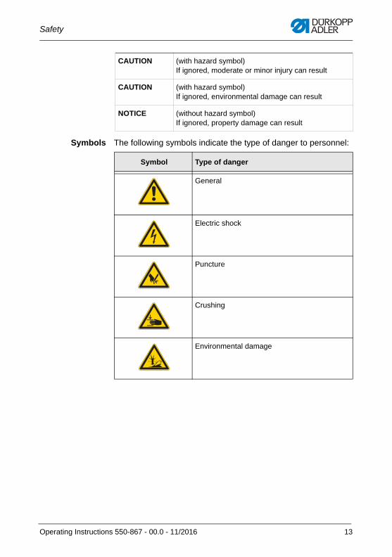
Symbols The following symbols indicate the type of danger to personnel:
CAUTION (with hazard symbol)If ignored, moderate or minor injury can result
CAUTION (with hazard symbol)If ignored, environmental damage can result
NOTICE (without hazard symbol)If ignored, property damage can result
Symbol Type of danger
General
Electric shock
Puncture
Crushing
Environmental damage
Operating Instructions 550-867 - 00.0 - 11/2016 13
Safety
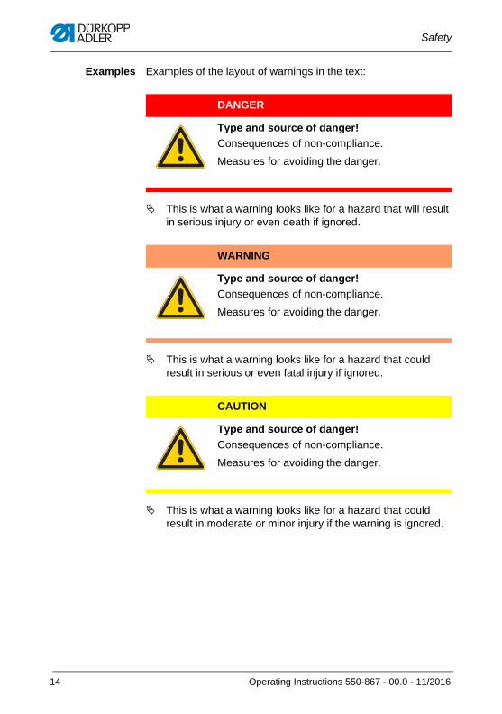
Examples Examples of the layout of warnings in the text:
This is what a warning looks like for a hazard that will result in serious injury or even death if ignored.
This is what a warning looks like for a hazard that could result in serious or even fatal injury if ignored.
This is what a warning looks like for a hazard that could result in moderate or minor injury if the warning is ignored.
DANGER
Type and source of danger!
Consequences of non-compliance.
Measures for avoiding the danger.
WARNING
Type and source of danger!
Consequences of non-compliance.
Measures for avoiding the danger.
CAUTION
Type and source of danger!
Consequences of non-compliance.
Measures for avoiding the danger.
14 Operating Instructions 550-867 - 00.0 - 11/2016
Safety
This is what a warning looks like for a hazard that could result in property damage if ignored.
This is what a warning looks like for a hazard that could result in environmental damage if ignored.
NOTICE
Type and source of danger!
Consequences of non-compliance.
Measures for avoiding the danger.
CAUTION
Type and source of danger!
Consequences of non-compliance.
Measures for avoiding the danger.
Operating Instructions 550-867 - 00.0 - 11/2016 15

Safety
16 Operating Instructions 550-867 - 00.0 - 11/2016
Machine description
3 Machine description
3.1 Components of the machine
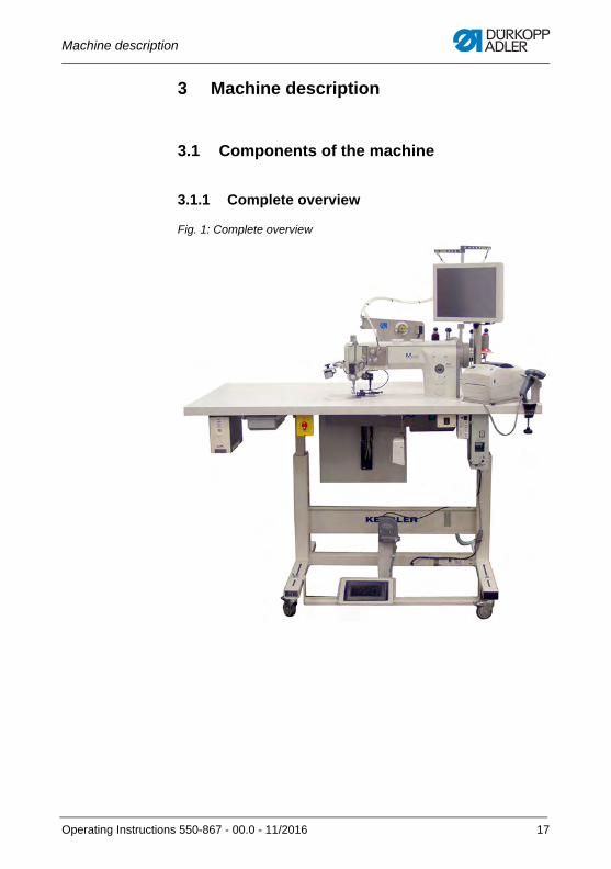
3.1.1 Complete overview
Fig. 1: Complete overview
Operating Instructions 550-867 - 00.0 - 11/2016 17
Machine description
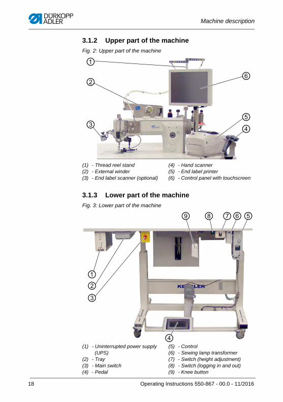
3.1.2 Upper part of the machine
Fig. 2: Upper part of the machine
3.1.3 Lower part of the machine
Fig. 3: Lower part of the machine
(1) - Thread reel stand(2) - External winder(3) - End label scanner (optional)
(4) - Hand scanner(5) - End label printer(6) - Control panel with touchscreen
(1) - Uninterrupted power supply (UPS)
(2) - Tray(3) - Main switch(4) - Pedal
(5) - Control(6) - Sewing lamp transformer(7) - Switch (height adjustment)(8) - Switch (logging in and out)(9) - Knee button
⑥
④⑤
③
②
①
①
④
⑨ ⑦⑥⑤
③
⑧
②
18 Operating Instructions 550-867 - 00.0 - 11/2016
Machine description
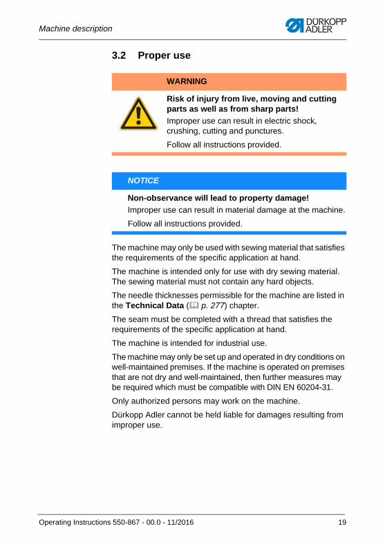
3.2 Proper use
The machine may only be used with sewing material that satisfies the requirements of the specific application at hand.
The machine is intended only for use with dry sewing material. The sewing material must not contain any hard objects.
The needle thicknesses permissible for the machine are listed in the Technical Data ( p. 277) chapter.
The seam must be completed with a thread that satisfies the requirements of the specific application at hand.
The machine is intended for industrial use.
The machine may only be set up and operated in dry conditions on well-maintained premises. If the machine is operated on premises that are not dry and well-maintained, then further measures may be required which must be compatible with DIN EN 60204-31.
Only authorized persons may work on the machine.
Dürkopp Adler cannot be held liable for damages resulting from improper use.
WARNING
Risk of injury from live, moving and cutting parts as well as from sharp parts!
Improper use can result in electric shock, crushing, cutting and punctures.
Follow all instructions provided.
NOTICE
Non-observance will lead to property damage!
Improper use can result in material damage at the machine.
Follow all instructions provided.
Operating Instructions 550-867 - 00.0 - 11/2016 19

Machine description
3.3 Declaration of ConformityThe machine complies with European regulations ensuring health, safety, and environmental protection as specified in the declara-tion of conformity or in the declaration of incorporation.
20 Operating Instructions 550-867 - 00.0 - 11/2016
Operation
4 OperationThe operating sequence on this machine consists of several different steps. Fault-free operation is necessary in order to achieve a good sewing result.
4.1 Preparing the machine for operation
Complete the following steps in preparation of sewing before starting to work:
• Scan barcodes ( p. 23)
• Log in ( p. 87)
• Insert or change the needle( p. 26)
• Feed the needle thread through the hose guide ( p. 28)
• Thread needle thread ( p. 31)
• Thread the hook thread ( p. 40)
• Edit the seam record set if necessary ( p. 100)
WARNING
Risk of injury from moving, cutting and sharp parts!
Crushing, cutting and punctures are possible.
If possible, make all preparations only when the machine is switched off.
Operating Instructions 550-867 - 00.0 - 11/2016 21
Operation
4.1.1 Switching on the machine
InformationWhen switching on the machine for the first time, proceed as described in the Setup chapter ( p. 259).
Fig. 4: Switching on the machine
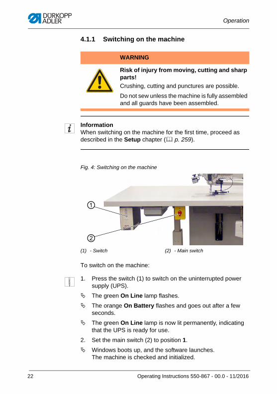
To switch on the machine:
1. Press the switch (1) to switch on the uninterrupted power supply (UPS).
The green On Line lamp flashes.
The orange On Battery flashes and goes out after a few seconds.
The green On Line lamp is now lit permanently, indicating that the UPS is ready for use.
2. Set the main switch (2) to position 1.
Windows boots up, and the software launches. The machine is checked and initialized.
WARNING
Risk of injury from moving, cutting and sharp parts!
Crushing, cutting and punctures are possible.
Do not sew unless the machine is fully assembled and all guards have been assembled.
(1) - Switch (2) - Main switch
①
②
22 Operating Instructions 550-867 - 00.0 - 11/2016
Operation
4.1.2 Scanning barcodes
To prepare the machine for sewing, the following barcodes need to be scanned:
• Barcode of the needle thread reel ( p. 63)
• Barcode of the hook thread reel ( p. 63)
• Barcode of the bobbin (optional, p. 64)
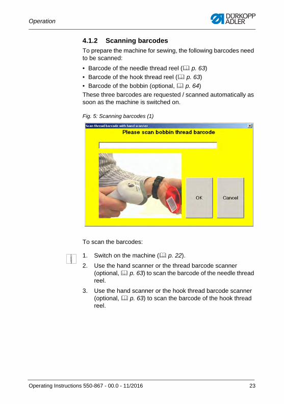
These three barcodes are requested / scanned automatically as soon as the machine is switched on.
Fig. 5: Scanning barcodes (1)
To scan the barcodes:
1. Switch on the machine ( p. 22).
2. Use the hand scanner or the thread barcode scanner (optional, p. 63) to scan the barcode of the needle thread reel.
3. Use the hand scanner or the hook thread barcode scanner (optional, p. 63) to scan the barcode of the hook thread reel.
Operating Instructions 550-867 - 00.0 - 11/2016 23
Operation
InformationIf barcode scanners have been assembled for the needle thread and the hook thread, the barcodes will be scanned automatically ( p. 63).
The display switches to:
Fig. 6: Scanning barcodes (2)
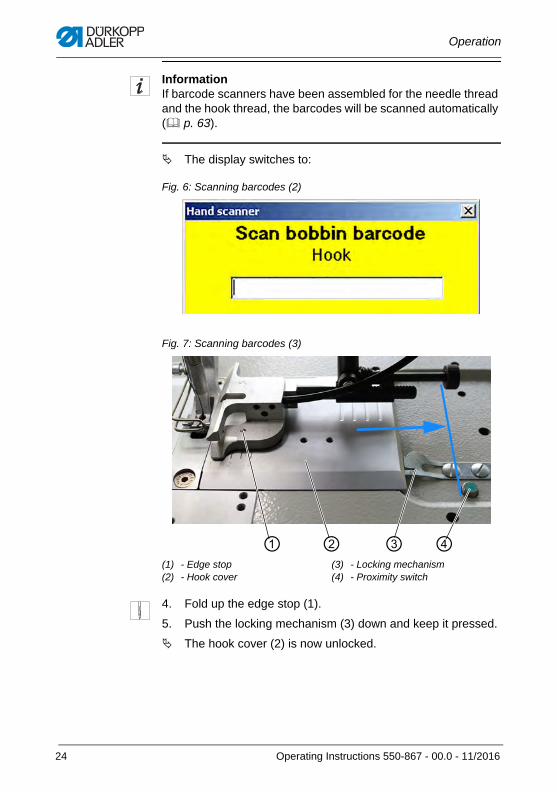
Fig. 7: Scanning barcodes (3)
4. Fold up the edge stop (1).
5. Push the locking mechanism (3) down and keep it pressed.
The hook cover (2) is now unlocked.
(1) - Edge stop(2) - Hook cover
(3) - Locking mechanism(4) - Proximity switch
① ② ③ ④
24 Operating Instructions 550-867 - 00.0 - 11/2016
Operation
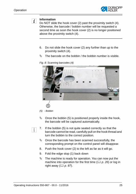
InformationDo NOT slide the hook cover (2) past the proximity switch (4). Otherwise, the barcode / bobbin number will be requested a second time as soon the hook cover (2) is no longer positioned above the proximity switch (4).
6. Do not slide the hook cover (2) any further than up to the proximity switch (4).
The barcode on the bobbin / the bobbin number is visible.
Fig. 8: Scanning barcodes (4)
Once the bobbin (5) is positioned properly inside the hook, the barcode will be captured automatically.
7. If the bobbin (5) is not quite seated correctly so that the barcode cannot be read, carefully pull on the hook thread and turn the bobbin to the correct position.
Once the barcode has been scanned successfully, the corresponding prompt on the control panel will disappear.
8. Push the hook cover (2) to the left as far as it will go.
9. Fold the edge stop (1) back down
The machine is ready for operation. You can now put the machine into operation for the first time ( p. 26) or log in right away ( p. 87).
(5) - Bobbin
⑤
Operating Instructions 550-867 - 00.0 - 11/2016 25
Operation
Important
Sewing will not be released until the system could be booted and the scanning of all barcodes could be completed without error. Otherwise, an error message will be displayed ( p. 272).
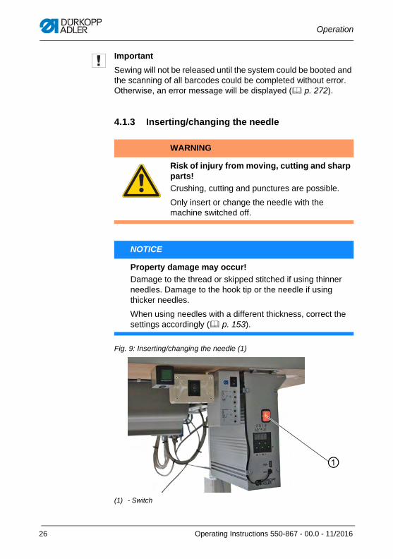
4.1.3 Inserting/changing the needle
Fig. 9: Inserting/changing the needle (1)
WARNING
Risk of injury from moving, cutting and sharp parts!
Crushing, cutting and punctures are possible.
Only insert or change the needle with the machine switched off.
NOTICE
Property damage may occur!
Damage to the thread or skipped stitched if using thinner needles. Damage to the hook tip or the needle if using thicker needles.
When using needles with a different thickness, correct the settings accordingly ( p. 153).
(1) - Switch
①
26 Operating Instructions 550-867 - 00.0 - 11/2016
Operation
To insert or change the needle:
1. Set the switch (1) of the control to position 0.
2. Turn the handwheel until the needle bar is at the top dead center.
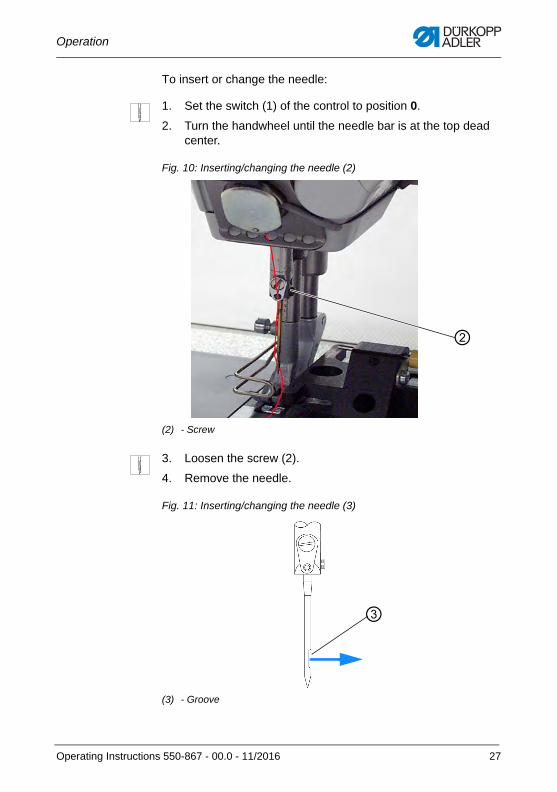
Fig. 10: Inserting/changing the needle (2)
3. Loosen the screw (2).
4. Remove the needle.
Fig. 11: Inserting/changing the needle (3)
(2) - Screw
②
(3) - Groove
③
Operating Instructions 550-867 - 00.0 - 11/2016 27
Operation
5. Insert a new needle with the groove (3) facing the hook and slide it up as far as it will go.
6. Tighten the screw (2).
The needle has been changed / inserted successfully.
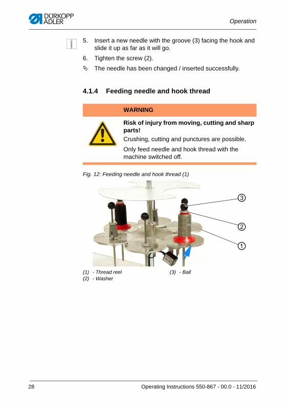
4.1.4 Feeding needle and hook thread
Fig. 12: Feeding needle and hook thread (1)
WARNING
Risk of injury from moving, cutting and sharp parts!
Crushing, cutting and punctures are possible.
Only feed needle and hook thread with the machine switched off.
(1) - Thread reel(2) - Washer
(3) - Ball
③
①
②
28 Operating Instructions 550-867 - 00.0 - 11/2016
Operation
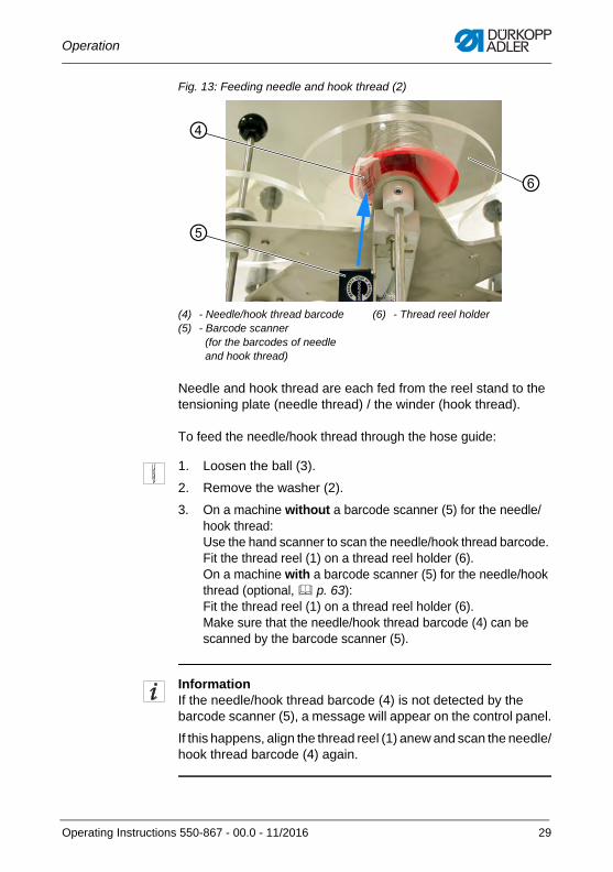
Fig. 13: Feeding needle and hook thread (2)
Needle and hook thread are each fed from the reel stand to the tensioning plate (needle thread) / the winder (hook thread).
To feed the needle/hook thread through the hose guide:
1. Loosen the ball (3).
2. Remove the washer (2).
3. On a machine without a barcode scanner (5) for the needle/hook thread: Use the hand scanner to scan the needle/hook thread barcode. Fit the thread reel (1) on a thread reel holder (6). On a machine with a barcode scanner (5) for the needle/hook thread (optional, p. 63):Fit the thread reel (1) on a thread reel holder (6). Make sure that the needle/hook thread barcode (4) can be scanned by the barcode scanner (5).
InformationIf the needle/hook thread barcode (4) is not detected by the barcode scanner (5), a message will appear on the control panel.
If this happens, align the thread reel (1) anew and scan the needle/hook thread barcode (4) again.
(4) - Needle/hook thread barcode(5) - Barcode scanner
(for the barcodes of needle and hook thread)
(6) - Thread reel holder
⑤
④
⑥
Operating Instructions 550-867 - 00.0 - 11/2016 29
Operation
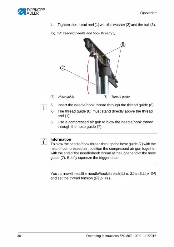
4. Tighten the thread reel (1) with the washer (2) and the ball (3).
Fig. 14: Feeding needle and hook thread (3)
5. Insert the needle/hook thread through the thread guide (8).
The thread guide (8) must stand directly above the thread reel (1).
6. Use a compressed air gun to blow the needle/hook thread through the hose guide (7).
InformationTo blow the needle/hook thread through the hose guide (7) with the help of compressed air, position the compressed air gun together with the end of the needle/hook thread at the upper end of the hose guide (7). Briefly squeeze the trigger once.
You can now thread the needle/hook thread ( p. 31 and p. 34) and set the thread tension ( p. 41).
(7) - Hose guide (8) - Thread guide
⑦
⑧
30 Operating Instructions 550-867 - 00.0 - 11/2016
Operation
4.1.5 Threading the needle thread
The 550-867 machine comes in two models:
• with mechanically regulated needle thread tension (MTT)
• with electronically regulated needle thread tension (ETT)
InformationThe needle thread cannot be threaded at the tensioning plate until it has been fed correctly through the hose guide ( p. 28).
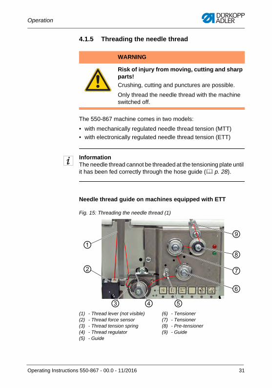
Needle thread guide on machines equipped with ETT
Fig. 15: Threading the needle thread (1)
WARNING
Risk of injury from moving, cutting and sharp parts!
Crushing, cutting and punctures are possible.
Only thread the needle thread with the machine switched off.
(1) - Thread lever (not visible)(2) - Thread force sensor(3) - Thread tension spring(4) - Thread regulator(5) - Guide
(6) - Tensioner(7) - Tensioner(8) - Pre-tensioner(9) - Guide
⑦
⑥
⑧
⑨
⑤④③
②
①
Operating Instructions 550-867 - 00.0 - 11/2016 31
Operation
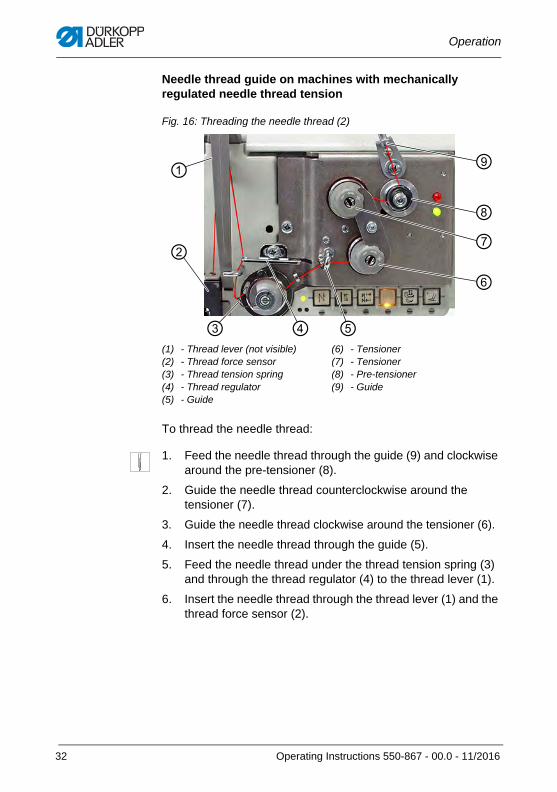
Needle thread guide on machines with mechanically regulated needle thread tension
Fig. 16: Threading the needle thread (2)
To thread the needle thread:
1. Feed the needle thread through the guide (9) and clockwise around the pre-tensioner (8).
2. Guide the needle thread counterclockwise around the tensioner (7).
3. Guide the needle thread clockwise around the tensioner (6).
4. Insert the needle thread through the guide (5).
5. Feed the needle thread under the thread tension spring (3) and through the thread regulator (4) to the thread lever (1).
6. Insert the needle thread through the thread lever (1) and the thread force sensor (2).
(1) - Thread lever (not visible)(2) - Thread force sensor(3) - Thread tension spring(4) - Thread regulator(5) - Guide
(6) - Tensioner(7) - Tensioner(8) - Pre-tensioner(9) - Guide
⑦
⑥
⑧
⑨
⑤④③
②
①
32 Operating Instructions 550-867 - 00.0 - 11/2016
Operation
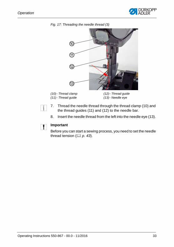
Fig. 17: Threading the needle thread (3)
7. Thread the needle thread through the thread clamp (10) and the thread guides (11) and (12) to the needle bar.
8. Insert the needle thread from the left into the needle eye (13).
Important
Before you can start a sewing process, you need to set the needle thread tension ( p. 43).
(10) - Thread clamp(11) - Thread guide
(12) - Thread guide(13) - Needle eye
⑩
⑪
⑫
⑬
Operating Instructions 550-867 - 00.0 - 11/2016 33
Operation
4.1.6 Winding the hook thread
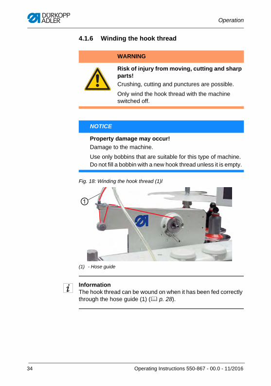
Fig. 18: Winding the hook thread (1)l
InformationThe hook thread can be wound on when it has been fed correctly through the hose guide (1) ( p. 28).
WARNING
Risk of injury from moving, cutting and sharp parts!
Crushing, cutting and punctures are possible.
Only wind the hook thread with the machine switched off.
NOTICE
Property damage may occur!
Damage to the machine.
Use only bobbins that are suitable for this type of machine.Do not fill a bobbin with a new hook thread unless it is empty.
(1) - Hose guide
①
34 Operating Instructions 550-867 - 00.0 - 11/2016
Operation
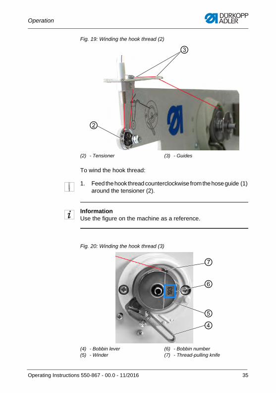
Fig. 19: Winding the hook thread (2)
To wind the hook thread:
1. Feed the hook thread counterclockwise from the hose guide (1) around the tensioner (2).
InformationUse the figure on the machine as a reference.
Fig. 20: Winding the hook thread (3)
(2) - Tensioner (3) - Guides
②
③
(4) - Bobbin lever(5) - Winder
(6) - Bobbin number(7) - Thread-pulling knife
④⑤
⑦
⑥
Operating Instructions 550-867 - 00.0 - 11/2016 35
Operation
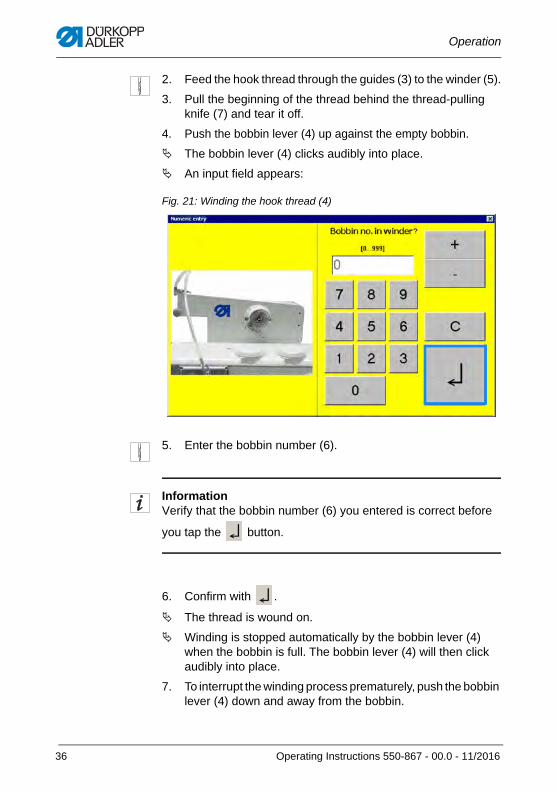
2. Feed the hook thread through the guides (3) to the winder (5).
3. Pull the beginning of the thread behind the thread-pulling knife (7) and tear it off.
4. Push the bobbin lever (4) up against the empty bobbin.
The bobbin lever (4) clicks audibly into place.
An input field appears:
Fig. 21: Winding the hook thread (4)
5. Enter the bobbin number (6).
InformationVerify that the bobbin number (6) you entered is correct before
you tap the button.
6. Confirm with .
The thread is wound on.
Winding is stopped automatically by the bobbin lever (4) when the bobbin is full. The bobbin lever (4) will then click audibly into place.
7. To interrupt the winding process prematurely, push the bobbin lever (4) down and away from the bobbin.
36 Operating Instructions 550-867 - 00.0 - 11/2016
Operation
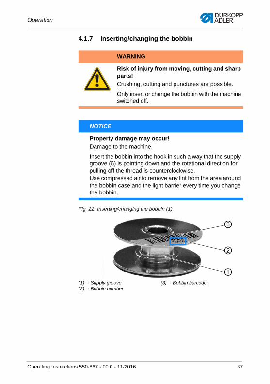
4.1.7 Inserting/changing the bobbin
Fig. 22: Inserting/changing the bobbin (1)
WARNING
Risk of injury from moving, cutting and sharp parts!
Crushing, cutting and punctures are possible.
Only insert or change the bobbin with the machine switched off.
NOTICE
Property damage may occur!
Damage to the machine.
Insert the bobbin into the hook in such a way that the supply groove (6) is pointing down and the rotational direction for pulling off the thread is counterclockwise. Use compressed air to remove any lint from the area around the bobbin case and the light barrier every time you change the bobbin.
(1) - Supply groove(2) - Bobbin number
(3) - Bobbin barcode
①
②
③
Operating Instructions 550-867 - 00.0 - 11/2016 37
Operation
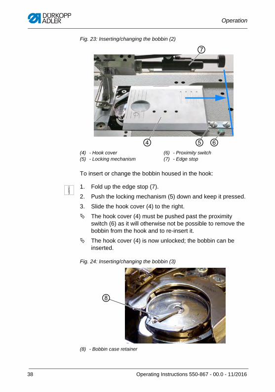
Fig. 23: Inserting/changing the bobbin (2)
To insert or change the bobbin housed in the hook:
1. Fold up the edge stop (7).
2. Push the locking mechanism (5) down and keep it pressed.
3. Slide the hook cover (4) to the right.
The hook cover (4) must be pushed past the proximity switch (6) as it will otherwise not be possible to remove the bobbin from the hook and to re-insert it.
The hook cover (4) is now unlocked; the bobbin can be inserted.
Fig. 24: Inserting/changing the bobbin (3)
(4) - Hook cover(5) - Locking mechanism
(6) - Proximity switch(7) - Edge stop
⑦
④ ⑤ ⑥
(8) - Bobbin case retainer
⑧
38 Operating Instructions 550-867 - 00.0 - 11/2016
Operation
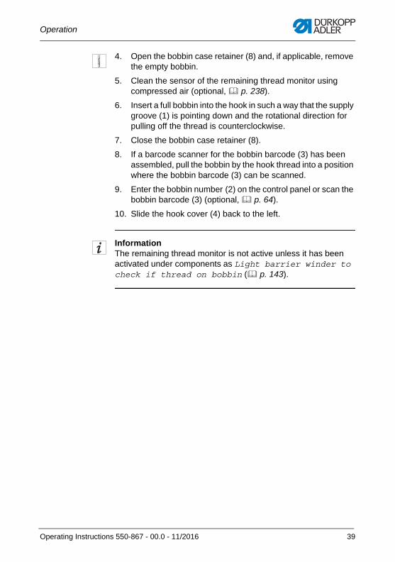
4. Open the bobbin case retainer (8) and, if applicable, remove the empty bobbin.
5. Clean the sensor of the remaining thread monitor using compressed air (optional, p. 238).
6. Insert a full bobbin into the hook in such a way that the supply groove (1) is pointing down and the rotational direction for pulling off the thread is counterclockwise.
7. Close the bobbin case retainer (8).
8. If a barcode scanner for the bobbin barcode (3) has been assembled, pull the bobbin by the hook thread into a position where the bobbin barcode (3) can be scanned.
9. Enter the bobbin number (2) on the control panel or scan the bobbin barcode (3) (optional, p. 64).
10. Slide the hook cover (4) back to the left.
InformationThe remaining thread monitor is not active unless it has been activated under components as Light barrier winder to check if thread on bobbin ( p. 143).
Operating Instructions 550-867 - 00.0 - 11/2016 39
Operation
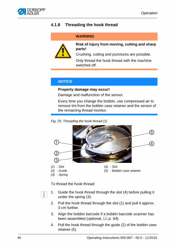
4.1.8 Threading the hook thread
Fig. 25: Threading the hook thread (1)
To thread the hook thread:
1. Guide the hook thread through the slot (4) before pulling it under the spring (3).
2. Pull the hook thread through the slot (1) and pull it approx. 3 cm further.
3. Align the bobbin barcode if a bobbin barcode scanner has been assembled (optional, p. 64).
4. Pull the hook thread through the guide (2) of the bobbin case retainer (5).
WARNING
Risk of injury from moving, cutting and sharp parts!
Crushing, cutting and punctures are possible.
Only thread the hook thread with the machine switched off.
NOTICE
Property damage may occur!
Damage and malfunction of the sensor.
Every time you change the bobbin, use compressed air to remove lint from the bobbin case retainer and the sensor of the remaining thread monitor.
(1) - Slot(2) - Guide(3) - Spring
(4) - Slot(5) - Bobbin case retainer
④
③
①
②
⑤
40 Operating Instructions 550-867 - 00.0 - 11/2016
Operation
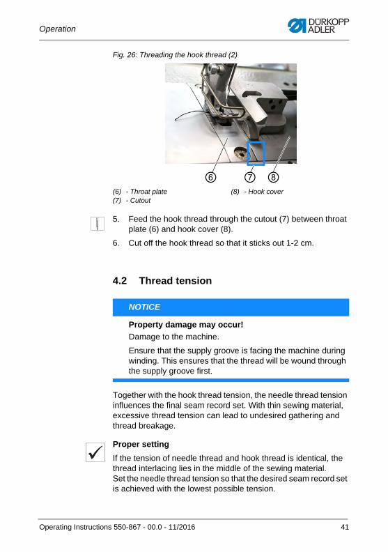
Fig. 26: Threading the hook thread (2)
5. Feed the hook thread through the cutout (7) between throat plate (6) and hook cover (8).
6. Cut off the hook thread so that it sticks out 1-2 cm.
4.2 Thread tension
Together with the hook thread tension, the needle thread tension influences the final seam record set. With thin sewing material, excessive thread tension can lead to undesired gathering and thread breakage.
Proper setting
If the tension of needle thread and hook thread is identical, the thread interlacing lies in the middle of the sewing material.Set the needle thread tension so that the desired seam record set is achieved with the lowest possible tension.
(6) - Throat plate(7) - Cutout
(8) - Hook cover
⑧⑥ ⑦
NOTICE
Property damage may occur!
Damage to the machine.
Ensure that the supply groove is facing the machine during winding. This ensures that the thread will be wound through the supply groove first.
Operating Instructions 550-867 - 00.0 - 11/2016 41
Operation
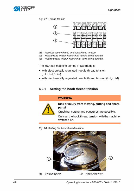
Fig. 27: Thread tension
The 550-867 machine comes in two models:
• with electronically regulated needle thread tension (ETT, p. 43)
• with mechanically regulated needle thread tension ( p. 44)
4.2.1 Setting the hook thread tension
Fig. 28: Setting the hook thread tension
(1) - Identical needle thread and hook thread tension(2) - Hook thread tension higher than needle thread tension(3) - Needle thread tension higher than hook thread tension
WARNING
Risk of injury from moving, cutting and sharp parts!
Crushing, cutting and punctures are possible.
Only set the hook thread tension with the machine switched off.
(1) - Tension spring (2) - Adjusting screw
②①
③
②①
42 Operating Instructions 550-867 - 00.0 - 11/2016
Operation
To set the hook thread tension:
1. To increase the hook thread tension, turn the adjusting screw (2) clockwise.
The tension spring (1) / the hook thread tension has been readjusted.
2. To reduce the hook thread tension, turn the adjusting screw (2) counterclockwise.
The tension spring (1) / the hook thread tension has been readjusted.
4.2.2 Setting the needle thread tension
Setting the needle thread tension electronically (ETT)
The needle thread tension can only be set electronically by users with security level 2 in the Setup menu ( p. 139).
It is not possible to adjust the needle thread tension manually.
InformationTo avoid having to set the needle thread tension anew for every seam record set, you can create so-called teach-in files and link these files to the seam record sets ( p. 203).
Important
The thread tension sensor must be re-calibrated once a year. For this purpose, turn to our Dürkopp replacement service before the year runs out (www.duerkopp-adler.com).
Operating Instructions 550-867 - 00.0 - 11/2016 43
Operation
Setting the needle thread tension mechanically
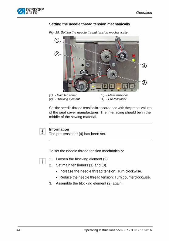
Fig. 29: Setting the needle thread tension mechanically
Set the needle thread tension in accordance with the preset values of the seat cover manufacturer. The interlacing should be in the middle of the sewing material.
InformationThe pre-tensioner (4) has been set.
To set the needle thread tension mechanically:
1. Loosen the blocking element (2).
2. Set main tensioners (1) and (3).
• Increase the needle thread tension: Turn clockwise.
• Reduce the needle thread tension: Turn counterclockwise.
3. Assemble the blocking element (2) again.
(1) - Main tensioner(2) - Blocking element
(3) - Main tensioner(4) - Pre-tensioner
①
②
③
④
44 Operating Instructions 550-867 - 00.0 - 11/2016
Operation
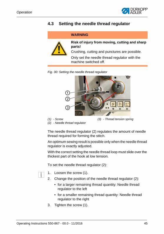
4.3 Setting the needle thread regulator
Fig. 30: Setting the needle thread regulator
The needle thread regulator (2) regulates the amount of needle thread required for forming the stitch.
An optimum sewing result is possible only when the needle thread regulator is exactly adjusted.
With the correct setting the needle thread loop must slide over the thickest part of the hook at low tension.
To set the needle thread regulator (2):
1. Loosen the screw (1).
2. Change the position of the needle thread regulator (2):
• for a larger remaining thread quantity: Needle thread regulator to the left
• for a smaller remaining thread quantity: Needle thread regulator to the right
3. Tighten the screw (1).
WARNING
Risk of injury from moving, cutting and sharp parts!
Crushing, cutting and punctures are possible.
Only set the needle thread regulator with the machine switched off.
(1) - Screw(2) - Needle thread regulator
(3) - Thread tension spring
①②③
Operating Instructions 550-867 - 00.0 - 11/2016 45
Operation
InformationIf requiring the largest possible thread quantity, you need to pull the thread tension spring (3) approx. 0.5 mm up and out of its lower end position. This occurs when the needle thread loop matches the maximum hook diameter.
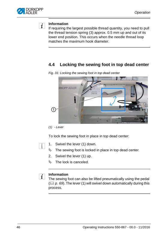
4.4 Locking the sewing foot in top dead center
Fig. 31: Locking the sewing foot in top dead center
To lock the sewing foot in place in top dead center:
1. Swivel the lever (1) down.
The sewing foot is locked in place in top dead center.
2. Swivel the lever (1) up.
The lock is canceled.
InformationThe sewing foot can also be lifted pneumatically using the pedal ( p. 69). The lever (1) will swivel down automatically during this process.
(1) - Lever
①
46 Operating Instructions 550-867 - 00.0 - 11/2016
Operation
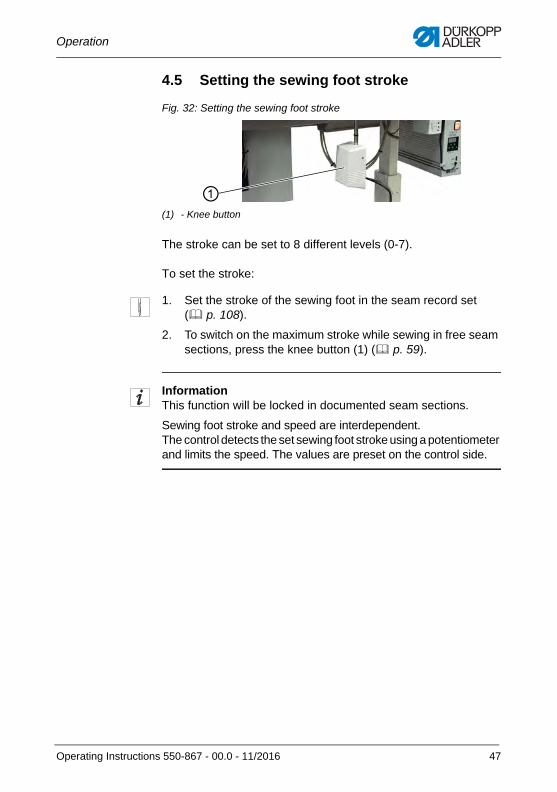
4.5 Setting the sewing foot stroke
Fig. 32: Setting the sewing foot stroke
The stroke can be set to 8 different levels (0-7).
To set the stroke:
1. Set the stroke of the sewing foot in the seam record set ( p. 108).
2. To switch on the maximum stroke while sewing in free seam sections, press the knee button (1) ( p. 59).
InformationThis function will be locked in documented seam sections.
Sewing foot stroke and speed are interdependent. The control detects the set sewing foot stroke using a potentiometer and limits the speed. The values are preset on the control side.
(1) - Knee button
①
Operating Instructions 550-867 - 00.0 - 11/2016 47
Operation
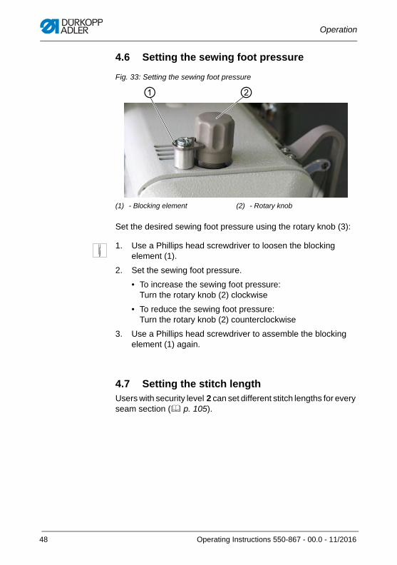
4.6 Setting the sewing foot pressure
Fig. 33: Setting the sewing foot pressure
Set the desired sewing foot pressure using the rotary knob (3):
1. Use a Phillips head screwdriver to loosen the blocking element (1).
2. Set the sewing foot pressure.
• To increase the sewing foot pressure:Turn the rotary knob (2) clockwise
• To reduce the sewing foot pressure:Turn the rotary knob (2) counterclockwise
3. Use a Phillips head screwdriver to assemble the blocking element (1) again.
4.7 Setting the stitch lengthUsers with security level 2 can set different stitch lengths for every seam section ( p. 105).
(1) - Blocking element (2) - Rotary knob
① ②
48 Operating Instructions 550-867 - 00.0 - 11/2016
Operation
4.8 Buttons on the machine arm
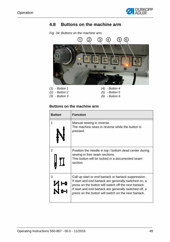
Fig. 34: Buttons on the machine arm
Buttons on the machine arm
(1) - Button 1(2) - Button 2(3) - Button 3
(4) - Button 4(5) - Button 5(6) - Button 6
Button Function
1 Manual sewing in reverse.The machine sews in reverse while the button is pressed.
2 Position the needle in top / bottom dead center during sewing in free seam sections.This button will be locked in a documented seam section.
3 Call up start or end bartack or bartack suppression.If start and end bartack are generally switched on, a press on the button will switch off the next bartack.If start and end bartack are generally switched off, a press on the button will switch on the next bartack.
① ② ③ ④ ⑤⑥
Operating Instructions 550-867 - 00.0 - 11/2016 49
Operation
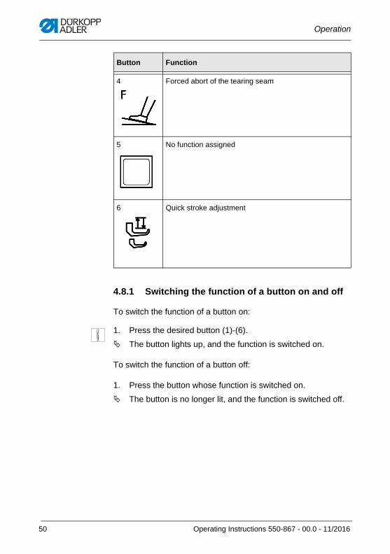
4.8.1 Switching the function of a button on and off
To switch the function of a button on:
1. Press the desired button (1)-(6).
The button lights up, and the function is switched on.
To switch the function of a button off:
1. Press the button whose function is switched on.
The button is no longer lit, and the function is switched off.
4 Forced abort of the tearing seam
5 No function assigned
6 Quick stroke adjustment
Button Function
50 Operating Instructions 550-867 - 00.0 - 11/2016
Operation
4.8.2 Assigning a function to the favorite button
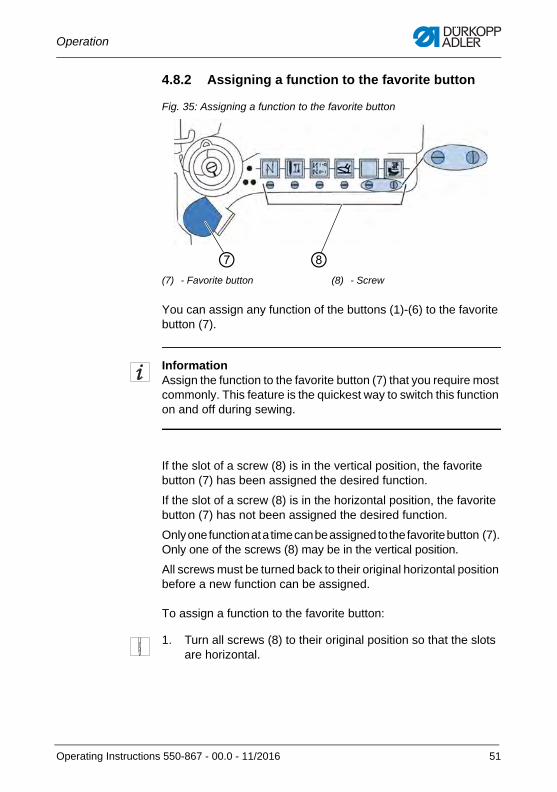
Fig. 35: Assigning a function to the favorite button
You can assign any function of the buttons (1)-(6) to the favorite button (7).
InformationAssign the function to the favorite button (7) that you require most commonly. This feature is the quickest way to switch this function on and off during sewing.
If the slot of a screw (8) is in the vertical position, the favorite button (7) has been assigned the desired function.
If the slot of a screw (8) is in the horizontal position, the favorite button (7) has not been assigned the desired function.
Only one function at a time can be assigned to the favorite button (7). Only one of the screws (8) may be in the vertical position.
All screws must be turned back to their original horizontal position before a new function can be assigned.
To assign a function to the favorite button:
1. Turn all screws (8) to their original position so that the slots are horizontal.
(7) - Favorite button (8) - Screw
⑦ ⑧
Operating Instructions 550-867 - 00.0 - 11/2016 51
Operation
2. Turn the screw (8) under the button whose function you wish to assign to the favorite button (7) such that its slot is in the vertical position.
You can now activate the function using the button (1)-(6) as well as using the favorite button (7).
4.9 LEDs on the machine
4.9.1 LEDs on the machine arm
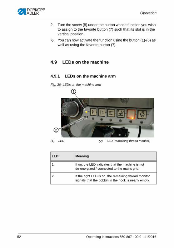
Fig. 36: LEDs on the machine arm
(1) - LED (2) - LED (remaining thread monitor)
LED Meaning
1 If on, the LED indicates that the machine is notde-energized / connected to the mains grid.
2 If the right LED is on, the remaining thread monitor signals that the bobbin in the hook is nearly empty.
①
②
52 Operating Instructions 550-867 - 00.0 - 11/2016
Operation
4.9.2 LEDs on the tensioning plate
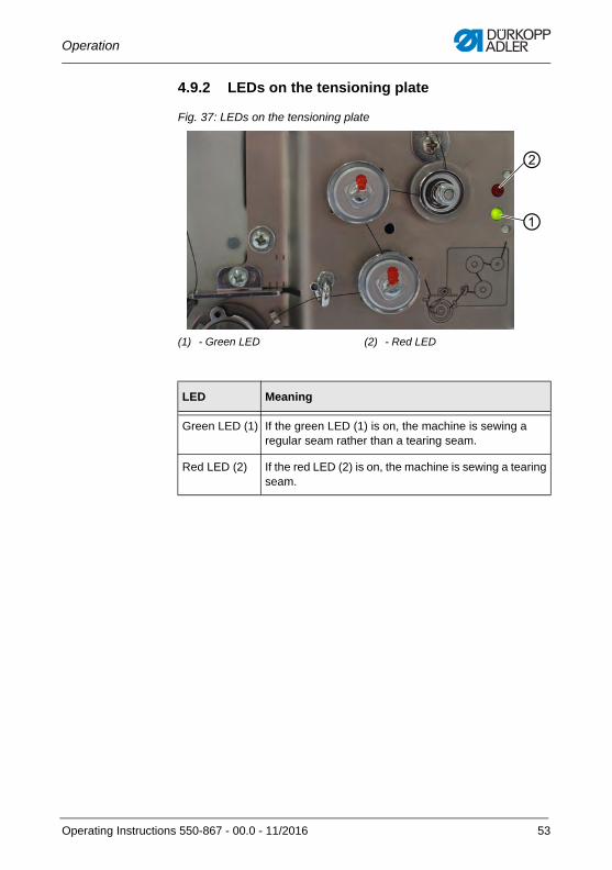
Fig. 37: LEDs on the tensioning plate
(1) - Green LED (2) - Red LED
LED Meaning
Green LED (1) If the green LED (1) is on, the machine is sewing a regular seam rather than a tearing seam.
Red LED (2) If the red LED (2) is on, the machine is sewing a tearing seam.
①
②
Operating Instructions 550-867 - 00.0 - 11/2016 53
Operation
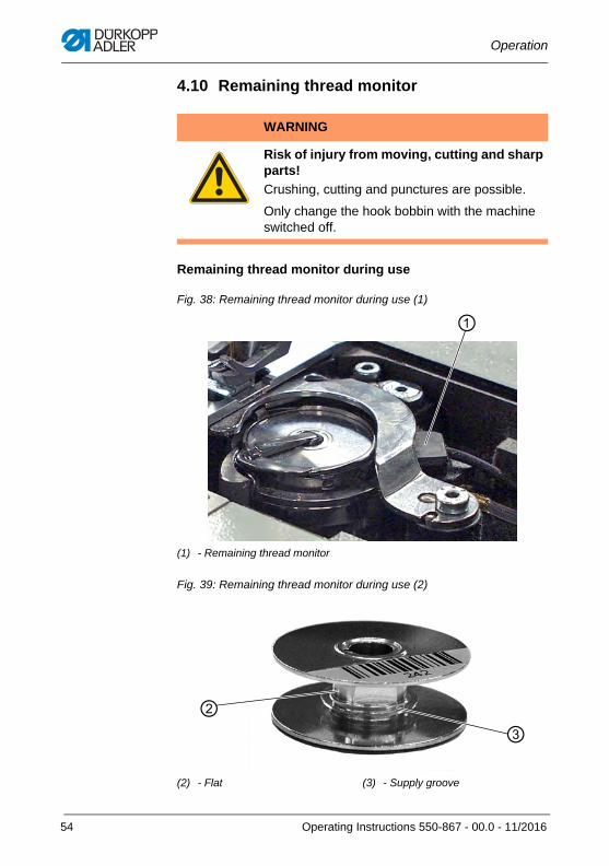
4.10 Remaining thread monitor
Remaining thread monitor during use
Fig. 38: Remaining thread monitor during use (1)
Fig. 39: Remaining thread monitor during use (2)
WARNING
Risk of injury from moving, cutting and sharp parts!
Crushing, cutting and punctures are possible.
Only change the hook bobbin with the machine switched off.
(1) - Remaining thread monitor
(2) - Flat (3) - Supply groove
①
③②
54 Operating Instructions 550-867 - 00.0 - 11/2016
Operation
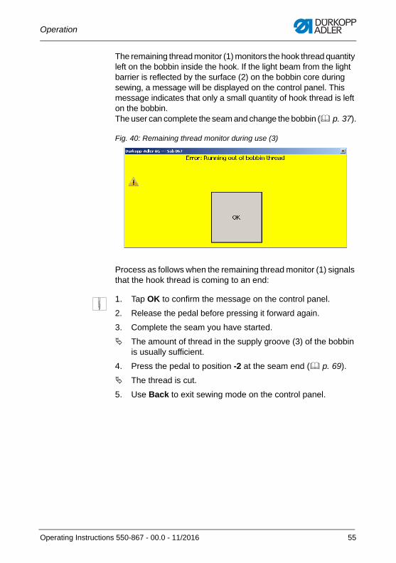
The remaining thread monitor (1) monitors the hook thread quantity left on the bobbin inside the hook. If the light beam from the light barrier is reflected by the surface (2) on the bobbin core during sewing, a message will be displayed on the control panel. This message indicates that only a small quantity of hook thread is left on the bobbin. The user can complete the seam and change the bobbin ( p. 37).
Fig. 40: Remaining thread monitor during use (3)
Process as follows when the remaining thread monitor (1) signals that the hook thread is coming to an end:
1. Tap OK to confirm the message on the control panel.
2. Release the pedal before pressing it forward again.
3. Complete the seam you have started.
The amount of thread in the supply groove (3) of the bobbin is usually sufficient.
4. Press the pedal to position -2 at the seam end ( p. 69).
The thread is cut.
5. Use Back to exit sewing mode on the control panel.
Operating Instructions 550-867 - 00.0 - 11/2016 55
Operation
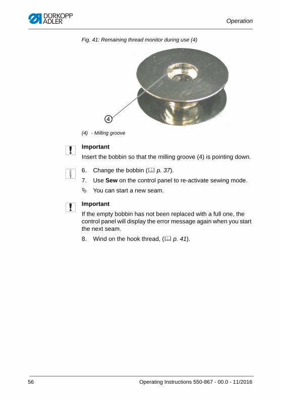
Fig. 41: Remaining thread monitor during use (4)
Important
Insert the bobbin so that the milling groove (4) is pointing down.
6. Change the bobbin ( p. 37).
7. Use Sew on the control panel to re-activate sewing mode.
You can start a new seam.
Important
If the empty bobbin has not been replaced with a full one, the control panel will display the error message again when you start the next seam.
8. Wind on the hook thread, ( p. 41).
(4) - Milling groove
④
56 Operating Instructions 550-867 - 00.0 - 11/2016
Operation
Cleaning the remaining thread monitor
Even the slightest remnants of fabric or yarn on the sensors of the remaining thread monitor may cause the sensor to no longer function properly. To ensure fault-free operation, the sensor of the remaining thread monitor must be cleaned with compressed air at least once a day ( p. 238).
To clean the remaining thread monitor:
1. Switch off the machine.
2. Clean the lenses of the light barriers using compressed air.
You can now switch the machine back on.
WARNING
Risk of injury from moving, cutting and sharp parts!
Crushing, cutting and punctures are possible.
Remove any lint from the area around the bobbin case and the light barrier. Do not clean the lenses of the light barriers unless the machine is switched off.
Operating Instructions 550-867 - 00.0 - 11/2016 57
Operation
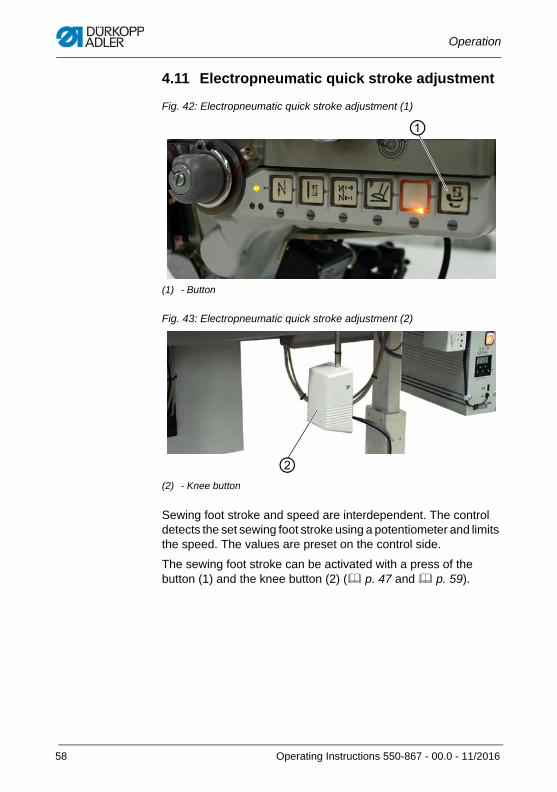
4.11 Electropneumatic quick stroke adjustment
Fig. 42: Electropneumatic quick stroke adjustment (1)
Fig. 43: Electropneumatic quick stroke adjustment (2)
Sewing foot stroke and speed are interdependent. The control detects the set sewing foot stroke using a potentiometer and limits the speed. The values are preset on the control side.
The sewing foot stroke can be activated with a press of the button (1) and the knee button (2) ( p. 47 and p. 59).
(1) - Button
(2) - Knee button
①
②
58 Operating Instructions 550-867 - 00.0 - 11/2016
Operation
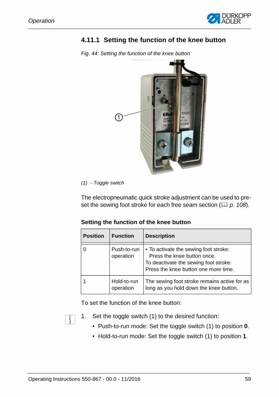
4.11.1 Setting the function of the knee button
Fig. 44: Setting the function of the knee button
The electropneumatic quick stroke adjustment can be used to pre-set the sewing foot stroke for each free seam section ( p. 108).
Setting the function of the knee button
To set the function of the knee button:
1. Set the toggle switch (1) to the desired function:
• Push-to-run mode: Set the toggle switch (1) to position 0.
• Hold-to-run mode: Set the toggle switch (1) to position 1.
(1) - Toggle switch
Position Function Description
0 Push-to-run operation
• To activate the sewing foot stroke: Press the knee button once.
To deactivate the sewing foot stroke:Press the knee button one more time.
1 Hold-to-run operation
The sewing foot stroke remains active for as long as you hold down the knee button.
①
Operating Instructions 550-867 - 00.0 - 11/2016 59
Operation
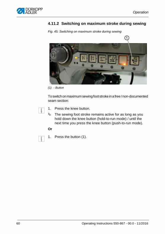
4.11.2 Switching on maximum stroke during sewing
Fig. 45: Switching on maximum stroke during sewing
To switch on maximum sewing foot stroke in a free / non-documented seam section:
1. Press the knee button.
The sewing foot stroke remains active for as long as you hold down the knee button (hold-to-run mode) / until the next time you press the knee button (push-to-run mode).
Or
1. Press the button (1).
(1) - Button
①
60 Operating Instructions 550-867 - 00.0 - 11/2016
Operation
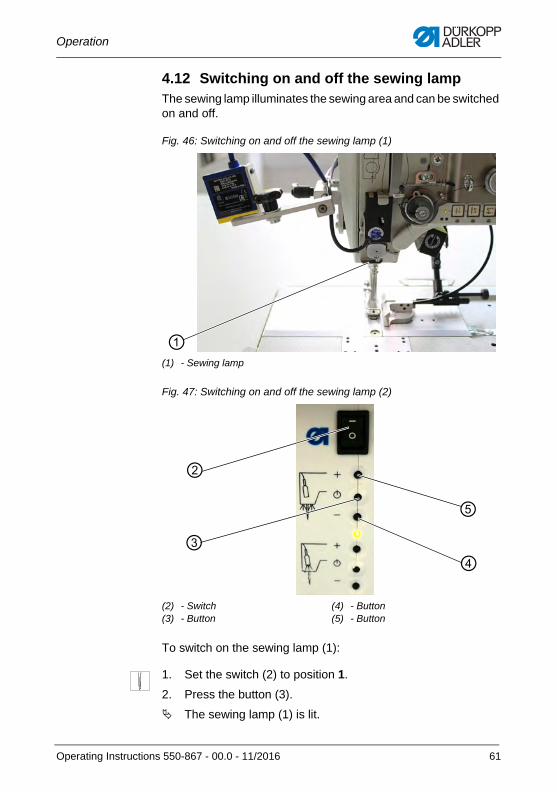
4.12 Switching on and off the sewing lampThe sewing lamp illuminates the sewing area and can be switched on and off.
Fig. 46: Switching on and off the sewing lamp (1)
Fig. 47: Switching on and off the sewing lamp (2)
To switch on the sewing lamp (1):
1. Set the switch (2) to position 1.
2. Press the button (3).
The sewing lamp (1) is lit.
(1) - Sewing lamp
(2) - Switch (3) - Button
(4) - Button(5) - Button
①
③
②
④
⑤
Operating Instructions 550-867 - 00.0 - 11/2016 61
Operation
3. Use button (4) or button (5) to set the brightness.
To switch off the sewing lamp (1):
1. Set the switch (2) to position 0.
The sewing lamp (1) is no longer lit.
InformationIt is possible to connect and operate a second LED lamp on the sewing lamp transformer. This second sewing lamp is, however, not included in the scope of delivery.
4.13 Additional equipmentThe 550-867 machine can be used in combination with different additional equipment.
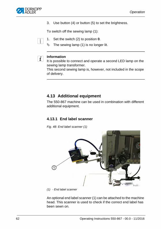
4.13.1 End label scanner
Fig. 48: End label scanner (1)
An optional end label scanner (1) can be attached to the machine head. This scanner is used to check if the correct end label has been sewn on.
(1) - End label scanner
①
62 Operating Instructions 550-867 - 00.0 - 11/2016
Operation
Important
The end label MUST be scanned and sewn into a free seam section at the end of a sewing process. Otherwise, the finished sewing material will be faulty and not suitable for use.
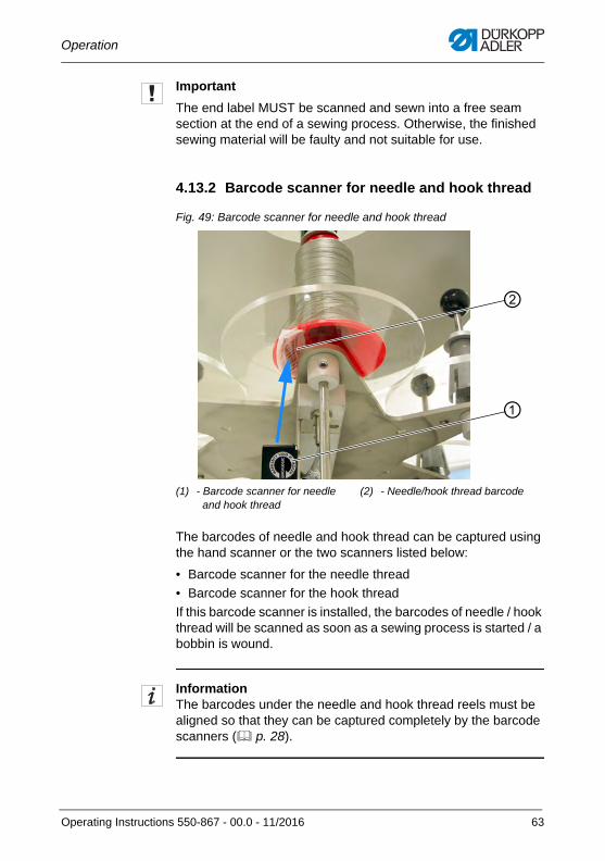
4.13.2 Barcode scanner for needle and hook thread
Fig. 49: Barcode scanner for needle and hook thread
The barcodes of needle and hook thread can be captured using the hand scanner or the two scanners listed below:
• Barcode scanner for the needle thread
• Barcode scanner for the hook thread
If this barcode scanner is installed, the barcodes of needle / hook thread will be scanned as soon as a sewing process is started / a bobbin is wound.
InformationThe barcodes under the needle and hook thread reels must be aligned so that they can be captured completely by the barcode scanners ( p. 28).
(1) - Barcode scanner for needleand hook thread
(2) - Needle/hook thread barcode
①
②
Operating Instructions 550-867 - 00.0 - 11/2016 63
Operation
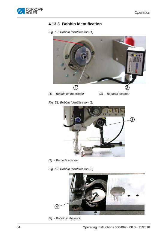
4.13.3 Bobbin identification
Fig. 50: Bobbin identification (1)
Fig. 51: Bobbin identification (2)
Fig. 52: Bobbin identification (3)
(1) - Bobbin on the winder (2) - Barcode scanner
(3) - Barcode scanner
(4) - Bobbin in the hook
②①
③
④
64 Operating Instructions 550-867 - 00.0 - 11/2016
Operation
The bobbin identification is composed of scanners (2) and (3), which capture the barcode of the bobbin on the winder (1) and the barcode of the bobbin inside the hook (4).
The bobbin number of the bobbin on the winder (1) is
• scanned prior to every winding process and
• linked to the barcode of the hook thread reel
The bobbin number of the bobbin inside the hook (4) is scanned before the seam beginning and compared to the seam record set.
This ensures that the hook thread matches the seam record set. If a different hook thread has been defined in the seam record set, the machine will lock the sewing process and report an error.
4.13.4 Needle cooling from the top
It is possible to cool the needle from the top using cold air. The cold air is fed through a small tube at the transport foot bar that is moving along with the bar.
Needle cooling is electropneumatic and may become necessary depending on the strength and thickness of the sewing material.
4.13.5 Needle cooling from the bottom
It is possible to cool the needle from the bottom using cold air. The cold air is fed through a flow of air in the feed dog.
Needle cooling is electropneumatic. This type of cooling may be useful in addition to needle cooling from the top depending on the strength and thickness of the sewing material.
Operating Instructions 550-867 - 00.0 - 11/2016 65
Operation
4.14 Sewing
The sewing process comprises the following parts:
• Scanning the barcodes parts primary
• Scanning multi barcodes if necessary
• Sewing up to 20 defined seam sections
• Sewing in the end label during the last seam section
• Sewing in a second label if necessary
To start the sewing process:
1. Log in ( p. 88).
2. Tap the Sew button on the main screen.
The display switches to:
WARNING
Risk of injury from moving, cutting and sharp parts!
Crushing, cutting and punctures are possible.
Guide the sewing material in such a way that your hands will not slip under the needle.Do not press the pedal when your fingers are in the area of the needle tip.
NOTICE
Property damage may occur!
Remnants of fabric and thread in the sewing area can cause damage or defects on the machine.
Immediately remove any contamination during the sewing process. Clean the machine daily ( p. 238).
66 Operating Instructions 550-867 - 00.0 - 11/2016
Operation
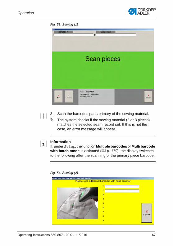
Fig. 53: Sewing (1)
3. Scan the barcodes parts primary of the sewing material.
The system checks if the sewing material (2 or 3 pieces) matches the selected seam record set. If this is not the case, an error message will appear.
InformationIf, under Setup, the function Multiple barcodes or Multi barcode with batch mode is activated ( p. 179), the display switches to the following after the scanning of the primary piece barcode:
Fig. 54: Sewing (2)
Operating Instructions 550-867 - 00.0 - 11/2016 67
Operation
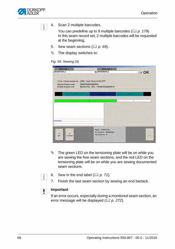
4. Scan 2 multiple barcodes.
You can predefine up to 9 multiple barcodes ( p. 179). In this seam record set, 2 multiple barcodes will be requested at the beginning.
5. Sew seam sections ( p. 69).
The display switches to:
Fig. 55: Sewing (3)
The green LED on the tensioning plate will be on while you are sewing the free seam sections, and the red LED on the tensioning plate will be on while you are sewing documented seam sections.
6. Sew in the end label ( p. 71).
7. Finish the last seam section by sewing an end bartack.
Important
If an error occurs, especially during a monitored seam section, an error message will be displayed ( p. 272).
68 Operating Instructions 550-867 - 00.0 - 11/2016
Operation
4.14.1 Pressing the pedal
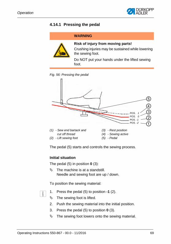
Fig. 56: Pressing the pedal
The pedal (5) starts and controls the sewing process.
Initial situation
The pedal (5) in position 0 (3):
The machine is at a standstill.Needle and sewing foot are up / down.
To position the sewing material:
1. Press the pedal (5) to position -1 (2).
The sewing foot is lifted.
2. Push the sewing material into the initial position.
3. Press the pedal (5) to position 0 (3).
The sewing foot lowers onto the sewing material.
WARNING
Risk of injury from moving parts!
Crushing injuries may be sustained while lowering the sewing foot.
Do NOT put your hands under the lifted sewing foot.
(1) - Sew end bartack and cut off thread
(2) - Lift sewing foot
(3) - Rest position(4) - Sewing active(5) - Pedal
②③④
POS. 1POS. 0POS. -1
①POS. -2
⑤
Operating Instructions 550-867 - 00.0 - 11/2016 69
Operation
At seam beginning
To begin a seam:
1. Press the pedal (5) forward (4).
The machine sews. The speed increases the further forward the pedal (5) is pressed.
When sewing
To interrupt the seam:
1. Press the pedal (5) to position 0 (3).
The machine stops. Needle and sewing foot are up / down.
To continue the seam:
1. Press the pedal (5) forward (4).
The machine continues to sew.
At seam end
To end the seam:
1. Press the pedal (5) to position -2 (1) and keep it there.
The thread is cut. The machine stops. The needle and sewing foot are lifted and remain up as long as the pedal (5) is kept in position -2 (1).
2. Remove the sewing material.
70 Operating Instructions 550-867 - 00.0 - 11/2016
Operation
4.14.2 Sewing in the end label
Since a production step that is essential to safety, the sewing of the tearing seams is documented. All production data pertaining to every tearing seam is recorded, saved and must be stored permanently ( p. 136).
In addition, every tearing seam is assigned an end label that includes a barcode. This barcode makes it possible retrieve the production data from the database at any time.
The end label is printed on tear-resistant and flame-resistant material by the end label printer and sewn into a free seam section at the end of the sewing process. This ensures for the long term that the end label will not be lost and can always be clearly attributed at any time.
If you, for instance, wish to sew the end label into the 3rd seam section and check the end label barcode, the function End label in the seam record set must be activated for the 3rd seam section.
The end label printer will then automatically print the end label at the end of the documented seam section. A scan of the end label barcode is used to check if the correct end label is sewn in.
Fault-free sewing process
To sew in the end label:
1. Use the hand scanner (1) or the end label scanner (optional, p. 62) to scan the end label barcode.
The number of the end label barcode appears in the input field on the control panel.
WARNING
Risk of injury from damaged tearing seams!
Possible damage to the tearing seam if the end label is sewn into the seam. In the event of an accident, the airbag may consequently fail to deploy, keeping it from protecting against serious injury.
Sew the end label ONLY into a free seam section.
Operating Instructions 550-867 - 00.0 - 11/2016 71
Operation
2. Confirm with OK.
3. Sew the end label into a free seam section.
The next sewing process can be started when the seam record set was completed without errors.
Faulty sewing process
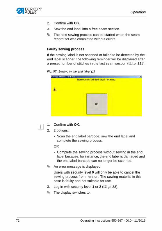
If the sewing label is not scanned or failed to be detected by the end label scanner, the following reminder will be displayed after a preset number of stitches in the last seam section ( p. 115):
Fig. 57: Sewing in the end label (1)
1. Confirm with OK.
2. 2 options:
• Scan the end label barcode, sew the end label and complete the sewing process.
OR
• Complete the sewing process without sewing in the end label because, for instance, the end label is damaged and the end label barcode can no longer be scanned.
An error message is displayed.
Users with security level 0 will only be able to cancel the sewing process from here on. The sewing material in this case is faulty and not suitable for use.
3. Log in with security level 1 or 2 ( p. 88).
The display switches to:
72 Operating Instructions 550-867 - 00.0 - 11/2016
Operation
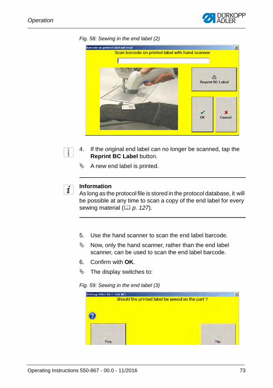
Fig. 58: Sewing in the end label (2)
4. If the original end label can no longer be scanned, tap the Reprint BC Label button.
A new end label is printed.
InformationAs long as the protocol file is stored in the protocol database, it will be possible at any time to scan a copy of the end label for every sewing material ( p. 127).
5. Use the hand scanner to scan the end label barcode.
Now, only the hand scanner, rather than the end label scanner, can be used to scan the end label barcode.
6. Confirm with OK.
The display switches to:
Fig. 59: Sewing in the end label (3)
Operating Instructions 550-867 - 00.0 - 11/2016 73
Operation
7. 2 options:
• Sew in the end label and complete the sewing process successfully: Tap the YES button
• Interrupt the sewing process: Tap the No button
A tap on the No button will end the sewing process. The sewing material is faulty and not suitable for use.
A tap on the YES will cause the display to switch to:
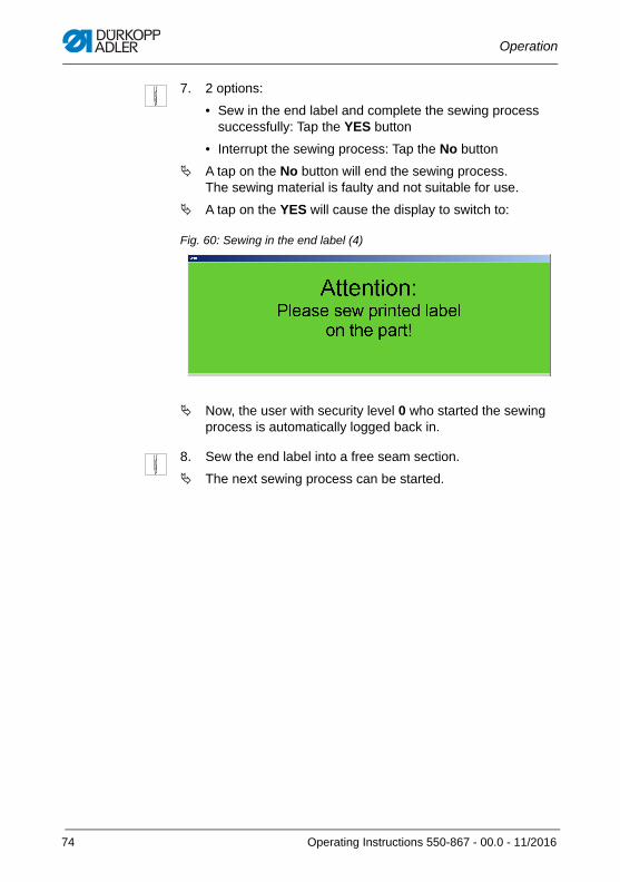
Fig. 60: Sewing in the end label (4)
Now, the user with security level 0 who started the sewing process is automatically logged back in.
8. Sew the end label into a free seam section.
The next sewing process can be started.
74 Operating Instructions 550-867 - 00.0 - 11/2016
Operation
4.15 Procedure in the event of a power supply disruption
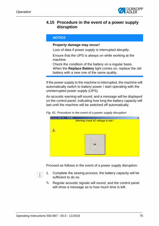
If the power supply to the machine is interrupted, the machine will automatically switch to battery power / start operating with the uninterrupted power supply (UPS).
An acoustic warning will sound, and a message will be displayed on the control panel, indicating how long the battery capacity will last until the machine will be switched off automatically.
Fig. 61: Procedure in the event of a power supply disruption
Proceed as follows in the event of a power supply disruption:
1. Complete the sewing process; the battery capacity will be sufficient to do so.
Regular acoustic signals will sound, and the control panel will show a message as to how much time is left.
NOTICE
Property damage may occur!
Loss of data if power supply is interrupted abruptly.
Ensure that the UPS is always on while working at the machine. Check the condition of the battery on a regular basis. When the Replace Battery light comes on, replace the old battery with a new one of the same quality.
Operating Instructions 550-867 - 00.0 - 11/2016 75
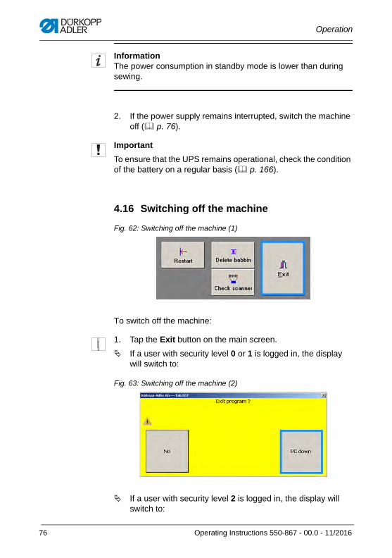
Operation
InformationThe power consumption in standby mode is lower than during sewing.
2. If the power supply remains interrupted, switch the machine off ( p. 76).
Important
To ensure that the UPS remains operational, check the condition of the battery on a regular basis ( p. 166).
4.16 Switching off the machine
Fig. 62: Switching off the machine (1)
To switch off the machine:
1. Tap the Exit button on the main screen.
If a user with security level 0 or 1 is logged in, the display will switch to:
Fig. 63: Switching off the machine (2)
If a user with security level 2 is logged in, the display will switch to:
76 Operating Instructions 550-867 - 00.0 - 11/2016
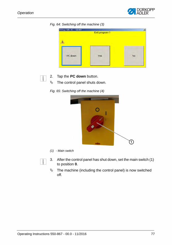
Operation
Fig. 64: Switching off the machine (3)
2. Tap the PC down button.
The control panel shuts down.
Fig. 65: Switching off the machine (4)
3. After the control panel has shut down, set the main switch (1) to position 0.
The machine (including the control panel) is now switched off.
(1) - Main switch
①
Operating Instructions 550-867 - 00.0 - 11/2016 77
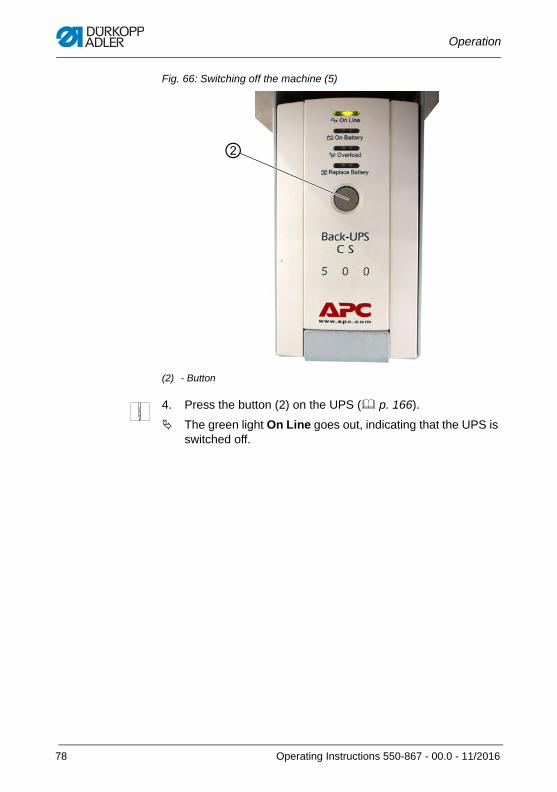
Operation
Fig. 66: Switching off the machine (5)
4. Press the button (2) on the UPS ( p. 166).
The green light On Line goes out, indicating that the UPS is switched off.
(2) - Button
②
78 Operating Instructions 550-867 - 00.0 - 11/2016
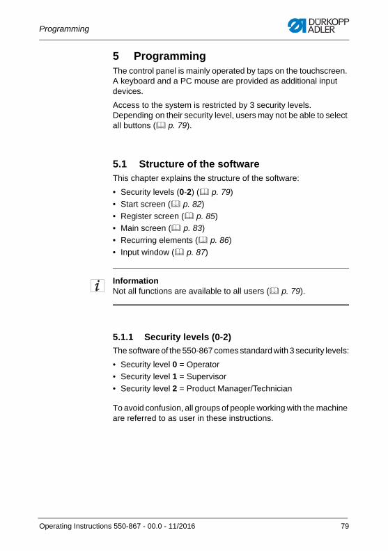
Programming
5 ProgrammingThe control panel is mainly operated by taps on the touchscreen. A keyboard and a PC mouse are provided as additional input devices.
Access to the system is restricted by 3 security levels. Depending on their security level, users may not be able to select all buttons ( p. 79).
5.1 Structure of the softwareThis chapter explains the structure of the software:
• Security levels (0-2) ( p. 79)
• Start screen ( p. 82)
• Register screen ( p. 85)
• Main screen ( p. 83)
• Recurring elements ( p. 86)
• Input window ( p. 87)
InformationNot all functions are available to all users ( p. 79).
5.1.1 Security levels (0-2)
The software of the 550-867 comes standard with 3 security levels:
• Security level 0 = Operator
• Security level 1 = Supervisor
• Security level 2 = Product Manager/Technician
To avoid confusion, all groups of people working with the machine are referred to as user in these instructions.
Operating Instructions 550-867 - 00.0 - 11/2016 79
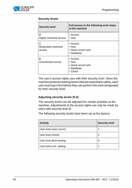
Programming
Security levels
The user's access rights vary with their security level. Since the machine produces tearing seams that are essential to safety, each user must log in first before they can perform the work designated for their security level.
Adjusting security levels (0-2)
The security levels can be adjusted for certain activities at the machine. Adjustments to the access rights can only be made by users with security level 2.
The following security levels have been set at the factory:
Security levelFull access to the following work steps at the machine
0Highly restricted access
• Access• Sew
1Moderately restricted access
• Access• Sew• Seam record sets• Database
2Unrestricted access
• Access• Sew• Seam record sets• Database• Check
Activity Security level
User level seam record 1
User level checks 2
User level abort sewing 0
User level cont. sewing 1
80 Operating Instructions 550-867 - 00.0 - 11/2016
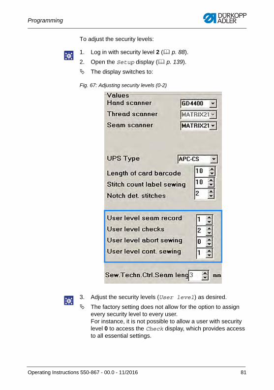
Programming
To adjust the security levels:
1. Log in with security level 2 ( p. 88).
2. Open the Setup display ( p. 139).
The display switches to:
Fig. 67: Adjusting security levels (0-2)
3. Adjust the security levels (User level) as desired.
The factory setting does not allow for the option to assign every security level to every user. For instance, it is not possible to allow a user with security level 0 to access the Check display, which provides access to all essential settings.
Operating Instructions 550-867 - 00.0 - 11/2016 81
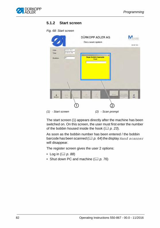
Programming
5.1.2 Start screen
Fig. 68: Start screen
The start screen (1) appears directly after the machine has been switched on. On this screen, the user must first enter the number of the bobbin housed inside the hook ( p. 23).
As soon as the bobbin number has been entered / the bobbin barcode has been scanned ( p. 64) the display Hand scanner will disappear.
The register screen gives the user 2 options:
• Log in ( p. 88)
• Shut down PC and machine ( p. 76)
(1) - Start screen (2) - Scan prompt
① ②
82 Operating Instructions 550-867 - 00.0 - 11/2016
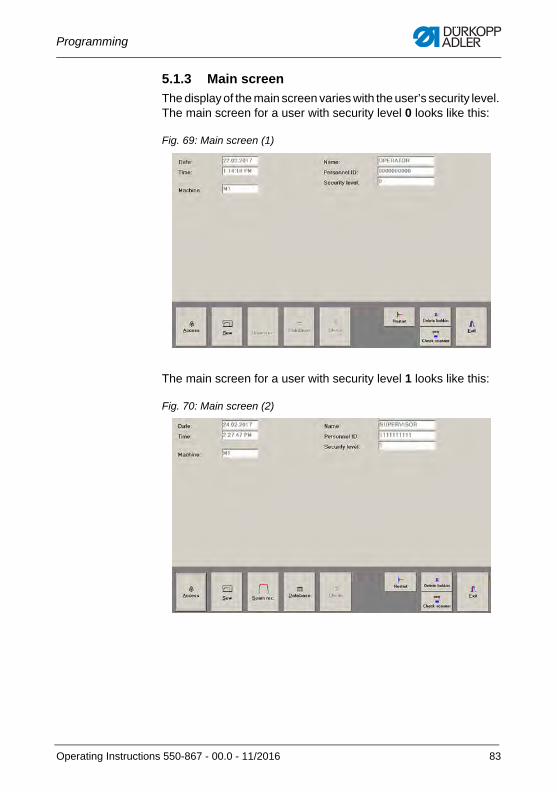
Programming
5.1.3 Main screen
The display of the main screen varies with the user’s security level. The main screen for a user with security level 0 looks like this:
Fig. 69: Main screen (1)
The main screen for a user with security level 1 looks like this:
Fig. 70: Main screen (2)
Operating Instructions 550-867 - 00.0 - 11/2016 83
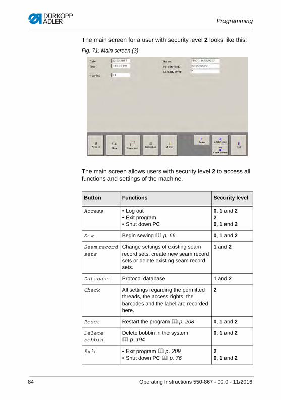
Programming
The main screen for a user with security level 2 looks like this:
Fig. 71: Main screen (3)
The main screen allows users with security level 2 to access all functions and settings of the machine.
Button Functions Security level
Access • Log out • Exit program• Shut down PC
0, 1 and 220, 1 and 2
Sew Begin sewing p. 66 0, 1 and 2
Seam record sets
Change settings of existing seam record sets, create new seam record sets or delete existing seam record sets.
1 and 2
Database Protocol database 1 and 2
Check All settings regarding the permitted threads, the access rights, the barcodes and the label are recorded here.
2
Reset Restart the program p. 208 0, 1 and 2
Delete bobbin
Delete bobbin in the system p. 194
0, 1 and 2
Exit • Exit program p. 209• Shut down PC p. 76
20, 1 and 2
84 Operating Instructions 550-867 - 00.0 - 11/2016
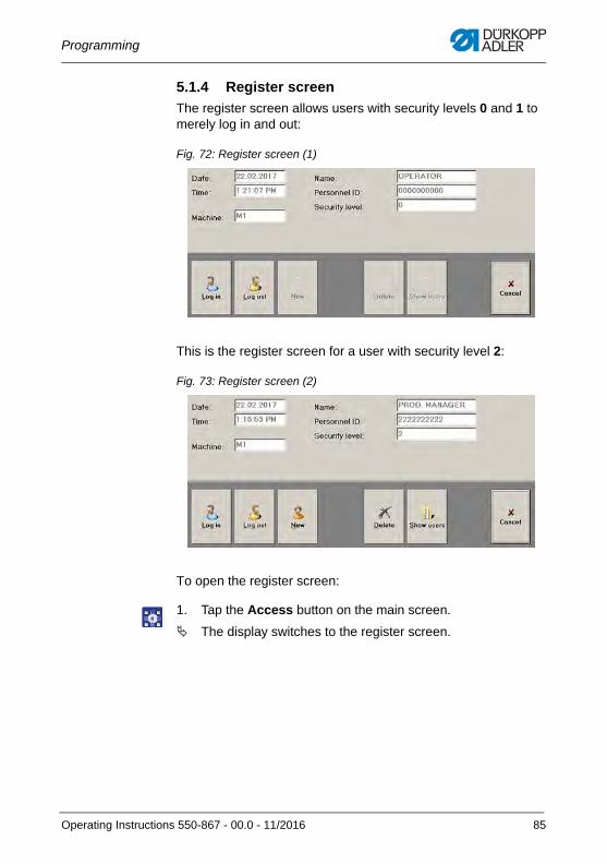
Programming
5.1.4 Register screen
The register screen allows users with security levels 0 and 1 to merely log in and out:
Fig. 72: Register screen (1)
This is the register screen for a user with security level 2:
Fig. 73: Register screen (2)
To open the register screen:
1. Tap the Access button on the main screen.
The display switches to the register screen.
Operating Instructions 550-867 - 00.0 - 11/2016 85
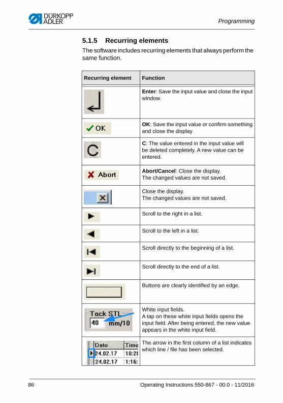
Programming
5.1.5 Recurring elements
The software includes recurring elements that always perform the same function.
Recurring element Function
Enter: Save the input value and close the input window.
OK: Save the input value or confirm something and close the display
C: The value entered in the input value will be deleted completely. A new value can be entered.
Abort/Cancel: Close the display. The changed values are not saved.
Close the display. The changed values are not saved.
Scroll to the right in a list.
Scroll to the left in a list.
Scroll directly to the beginning of a list.
Scroll directly to the end of a list.
Buttons are clearly identified by an edge.
White input fields. A tap on these white input fields opens the input field. After being entered, the new value appears in the white input field.
The arrow in the first column of a list indicates which line / file has been selected.
86 Operating Instructions 550-867 - 00.0 - 11/2016
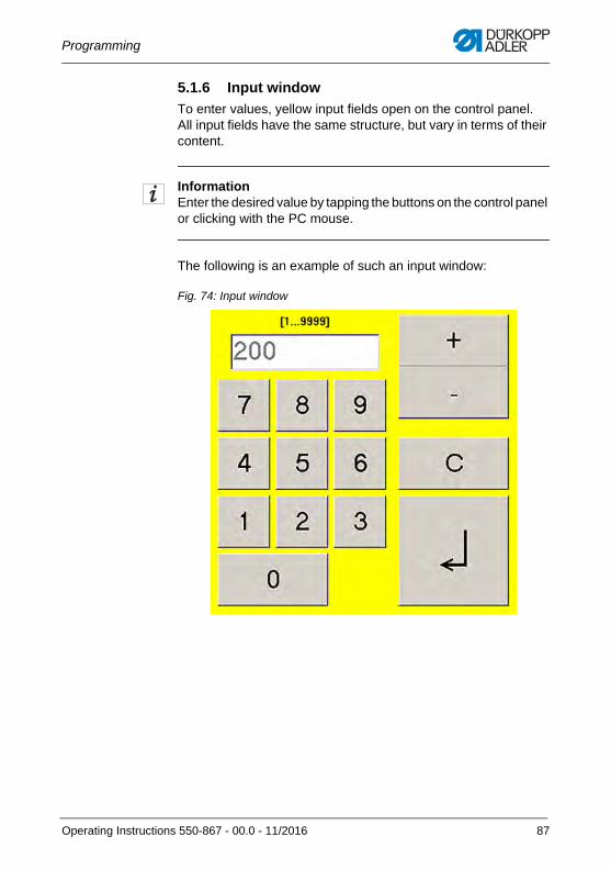
Programming
5.1.6 Input window
To enter values, yellow input fields open on the control panel. All input fields have the same structure, but vary in terms of their content.
InformationEnter the desired value by tapping the buttons on the control panel or clicking with the PC mouse.
The following is an example of such an input window:
Fig. 74: Input window
Operating Instructions 550-867 - 00.0 - 11/2016 87
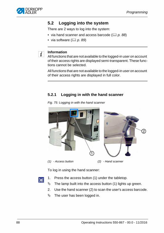
Programming
5.2 Logging into the systemThere are 2 ways to log into the system:
• via hand scanner and access barcode ( p. 88)
• via software ( p. 89)
InformationAll functions that are not available to the logged-in user on account of their access rights are displayed semi-transparent. These func-tions cannot be selected.
All functions that are not available to the logged-in user on account of their access rights are displayed in full color.
5.2.1 Logging in with the hand scanner
Fig. 75: Logging in with the hand scanner
To log in using the hand scanner:
1. Press the access button (1) under the tabletop.
The lamp built into the access button (1) lights up green.
2. Use the hand scanner (2) to scan the user's access barcode.
The user has been logged in.
(1) - Access button (2) - Hand scanner
①
②
88 Operating Instructions 550-867 - 00.0 - 11/2016
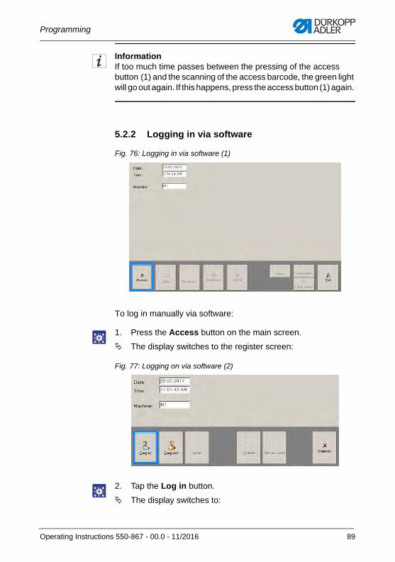
Programming
InformationIf too much time passes between the pressing of the access button (1) and the scanning of the access barcode, the green light will go out again. If this happens, press the access button (1) again.
5.2.2 Logging in via software
Fig. 76: Logging in via software (1)
To log in manually via software:
1. Press the Access button on the main screen.
The display switches to the register screen:
Fig. 77: Logging on via software (2)
2. Tap the Log in button.
The display switches to:
Operating Instructions 550-867 - 00.0 - 11/2016 89
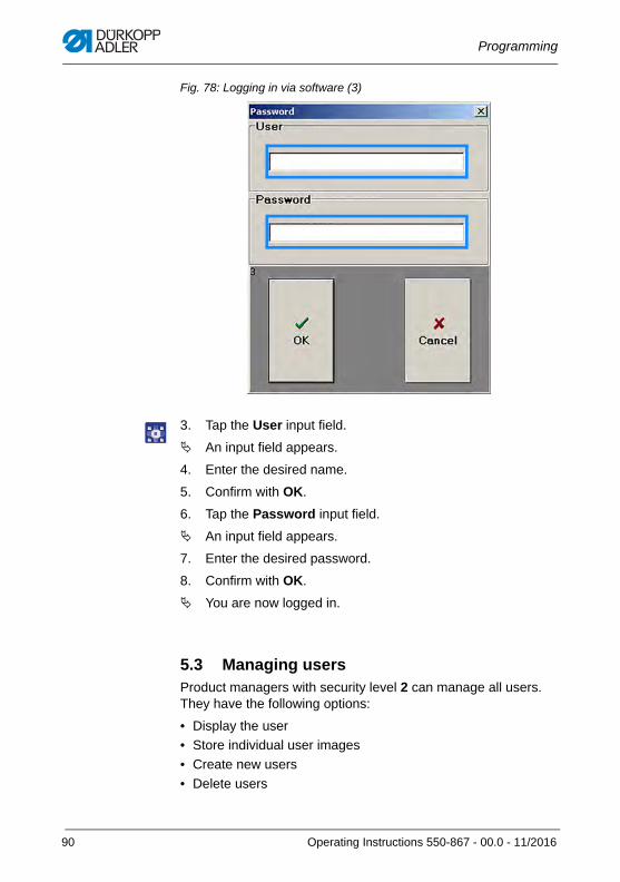
Programming
Fig. 78: Logging in via software (3)
3. Tap the User input field.
An input field appears.
4. Enter the desired name.
5. Confirm with OK.
6. Tap the Password input field.
An input field appears.
7. Enter the desired password.
8. Confirm with OK.
You are now logged in.
5.3 Managing usersProduct managers with security level 2 can manage all users. They have the following options:
• Display the user
• Store individual user images
• Create new users
• Delete users
90 Operating Instructions 550-867 - 00.0 - 11/2016
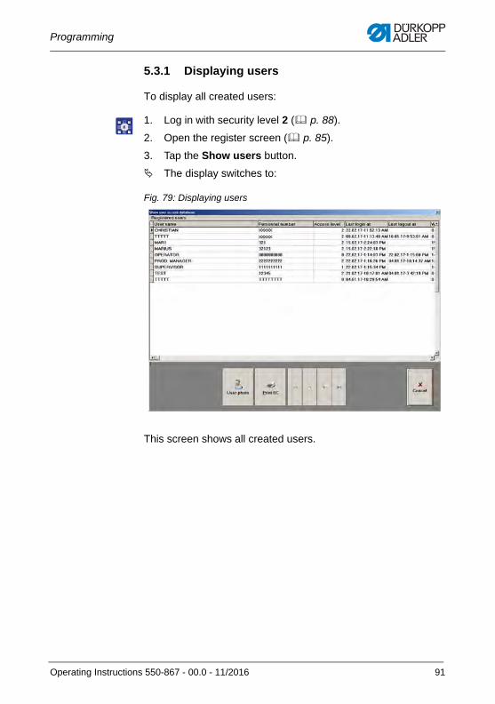
Programming
5.3.1 Displaying users
To display all created users:
1. Log in with security level 2 ( p. 88).
2. Open the register screen ( p. 85).
3. Tap the Show users button.
The display switches to:
Fig. 79: Displaying users
This screen shows all created users.
Operating Instructions 550-867 - 00.0 - 11/2016 91
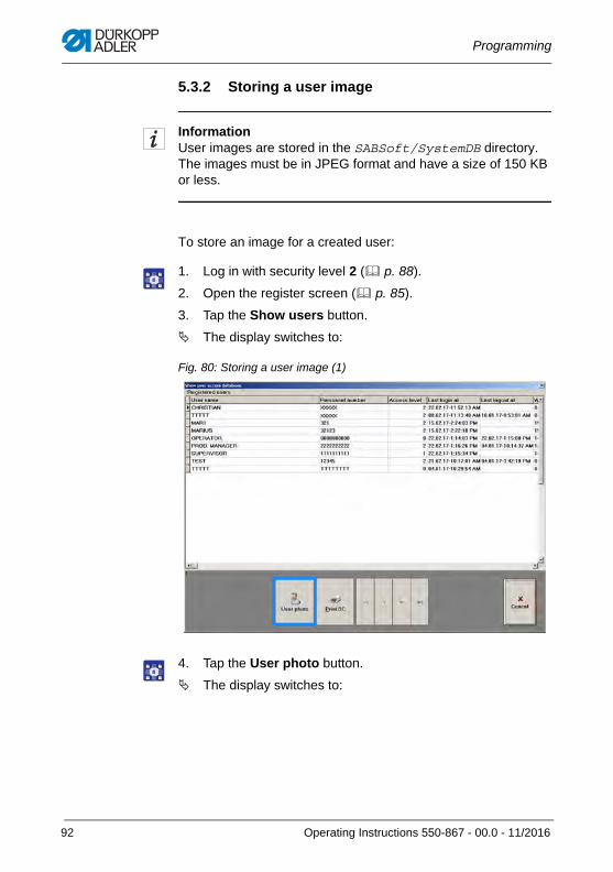
Programming
5.3.2 Storing a user image
InformationUser images are stored in the SABSoft/SystemDB directory. The images must be in JPEG format and have a size of 150 KB or less.
To store an image for a created user:
1. Log in with security level 2 ( p. 88).
2. Open the register screen ( p. 85).
3. Tap the Show users button.
The display switches to:
Fig. 80: Storing a user image (1)
4. Tap the User photo button.
The display switches to:
92 Operating Instructions 550-867 - 00.0 - 11/2016
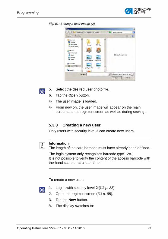
Programming
Fig. 81: Storing a user image (2)
5. Select the desired user photo file.
6. Tap the Open button.
The user image is loaded.
From now on, the user image will appear on the main screen and the register screen as well as during sewing.
5.3.3 Creating a new user
Only users with security level 2 can create new users.
InformationThe length of the card barcode must have already been defined.
The login system only recognizes barcode type 128. It is not possible to verify the content of the access barcode with the hand scanner at a later time.
To create a new user:
1. Log in with security level 2 ( p. 88).
2. Open the register screen ( p. 85).
3. Tap the New button.
The display switches to:
Operating Instructions 550-867 - 00.0 - 11/2016 93
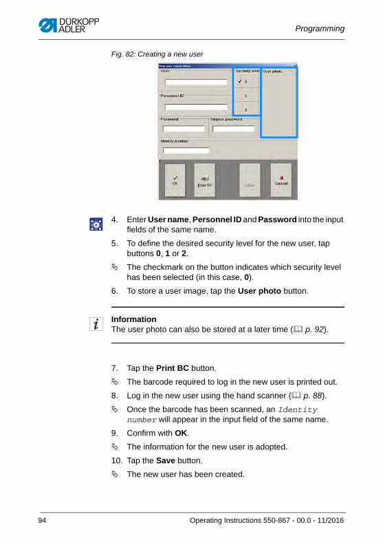
Programming
Fig. 82: Creating a new user
4. Enter User name, Personnel ID and Password into the input fields of the same name.
5. To define the desired security level for the new user, tap buttons 0, 1 or 2.
The checkmark on the button indicates which security level has been selected (in this case, 0).
6. To store a user image, tap the User photo button.
InformationThe user photo can also be stored at a later time ( p. 92).
7. Tap the Print BC button.
The barcode required to log in the new user is printed out.
8. Log in the new user using the hand scanner ( p. 88).
Once the barcode has been scanned, an Identity number will appear in the input field of the same name.
9. Confirm with OK.
The information for the new user is adopted.
10. Tap the Save button.
The new user has been created.
94 Operating Instructions 550-867 - 00.0 - 11/2016
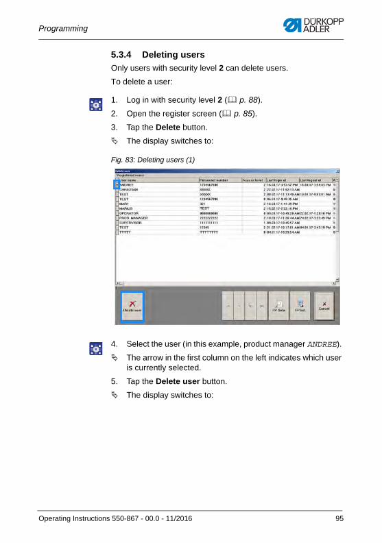
Programming
5.3.4 Deleting users
Only users with security level 2 can delete users.
To delete a user:
1. Log in with security level 2 ( p. 88).
2. Open the register screen ( p. 85).
3. Tap the Delete button.
The display switches to:
Fig. 83: Deleting users (1)
4. Select the user (in this example, product manager ANDREE).
The arrow in the first column on the left indicates which user is currently selected.
5. Tap the Delete user button.
The display switches to:
Operating Instructions 550-867 - 00.0 - 11/2016 95
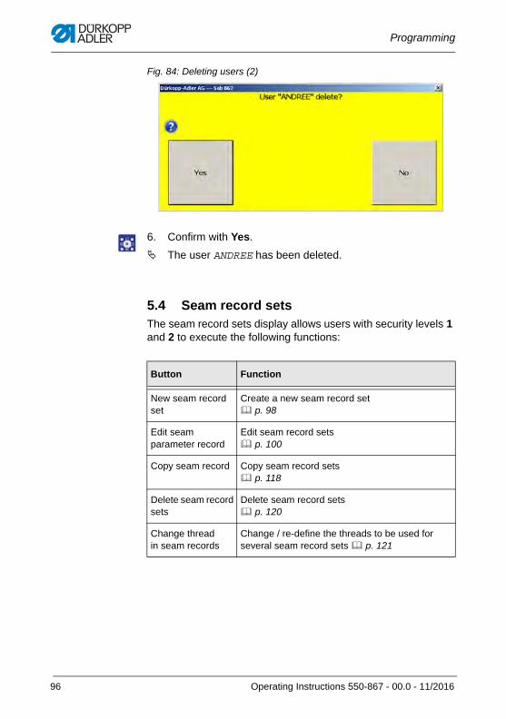
Programming
Fig. 84: Deleting users (2)
6. Confirm with Yes.
The user ANDREE has been deleted.
5.4 Seam record setsThe seam record sets display allows users with security levels 1 and 2 to execute the following functions:
Button Function
New seam record set
Create a new seam record set p. 98
Edit seam parameter record
Edit seam record sets p. 100
Copy seam record Copy seam record sets p. 118
Delete seam record sets
Delete seam record sets p. 120
Change thread in seam records
Change / re-define the threads to be used for several seam record sets p. 121
96 Operating Instructions 550-867 - 00.0 - 11/2016
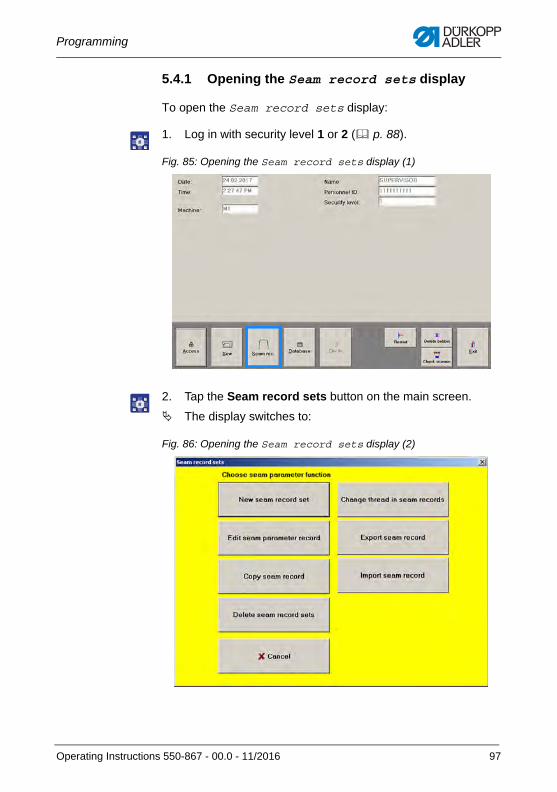
Programming
5.4.1 Opening the Seam record sets display
To open the Seam record sets display:
1. Log in with security level 1 or 2 ( p. 88).
Fig. 85: Opening the Seam record sets display (1)
2. Tap the Seam record sets button on the main screen.
The display switches to:
Fig. 86: Opening the Seam record sets display (2)
Operating Instructions 550-867 - 00.0 - 11/2016 97
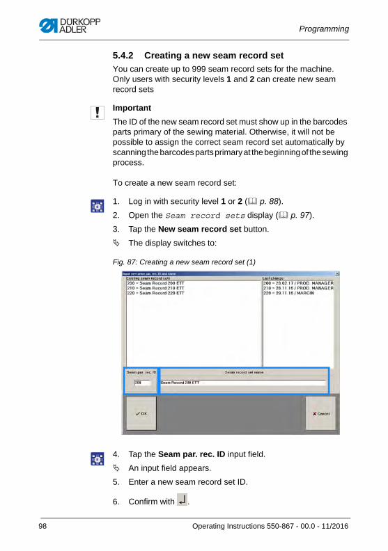
Programming
5.4.2 Creating a new seam record set
You can create up to 999 seam record sets for the machine. Only users with security levels 1 and 2 can create new seam record sets
Important
The ID of the new seam record set must show up in the barcodes parts primary of the sewing material. Otherwise, it will not be possible to assign the correct seam record set automatically by scanning the barcodes parts primary at the beginning of the sewing process.
To create a new seam record set:
1. Log in with security level 1 or 2 ( p. 88).
2. Open the Seam record sets display ( p. 97).
3. Tap the New seam record set button.
The display switches to:
Fig. 87: Creating a new seam record set (1)
4. Tap the Seam par. rec. ID input field.
An input field appears.
5. Enter a new seam record set ID.
6. Confirm with .
98 Operating Instructions 550-867 - 00.0 - 11/2016
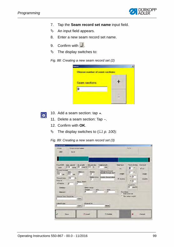
Programming
7. Tap the Seam record set name input field.
An input field appears.
8. Enter a new seam record set name.
9. Confirm with .
The display switches to:
Fig. 88: Creating a new seam record set (2)
10. Add a seam section: tap +.
11. Delete a seam section: Tap -.
12. Confirm with OK.
The display switches to ( p. 100):
Fig. 89: Creating a new seam record set (3)
Operating Instructions 550-867 - 00.0 - 11/2016 99
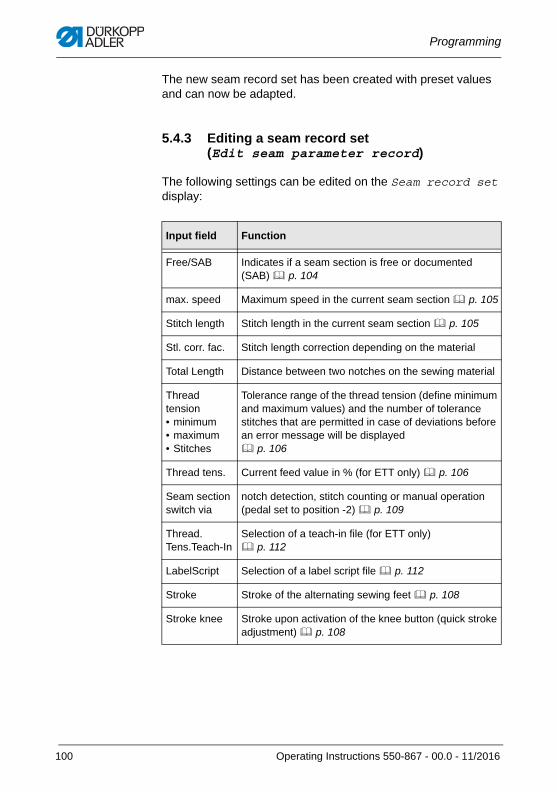
Programming
The new seam record set has been created with preset values and can now be adapted.
5.4.3 Editing a seam record set(Edit seam parameter record)
The following settings can be edited on the Seam record set display:
Input field Function
Free/SAB Indicates if a seam section is free or documented (SAB) p. 104
max. speed Maximum speed in the current seam section p. 105
Stitch length Stitch length in the current seam section p. 105
Stl. corr. fac. Stitch length correction depending on the material
Total Length Distance between two notches on the sewing material
Thread tension• minimum• maximum• Stitches
Tolerance range of the thread tension (define minimum and maximum values) and the number of tolerance stitches that are permitted in case of deviations before an error message will be displayed p. 106
Thread tens. Current feed value in % (for ETT only) p. 106
Seam section switch via
notch detection, stitch counting or manual operation (pedal set to position -2) p. 109
Thread. Tens.Teach-In
Selection of a teach-in file (for ETT only) p. 112
LabelScript Selection of a label script file p. 112
Stroke Stroke of the alternating sewing feet p. 108
Stroke knee Stroke upon activation of the knee button (quick stroke adjustment) p. 108
100 Operating Instructions 550-867 - 00.0 - 11/2016
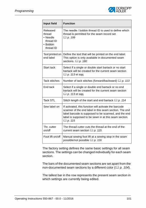
Programming
The factory setting defines the same basic settings for all seam sections. The settings can be changed individually for each seam section.
The bars of the documented seam sections are set apart from the non-documented seam sections by a different color ( p. 104).
The tallest bar in the row represents the present seam section in which settings are currently being edited.
Released thread • Needle
thread ID• Bobbin
thread ID
The needle / bobbin thread ID is used to define which thread is permitted for the seam record set p. 199
Text printed on end label
Define the text that will be printed on the end label. This option is only available in documented seam sections. p. 180
Start tack Select if a single or double start bartack or no start bartack will be created for the current seam section p. 113 et sqq.
Tack stitches Number of tack stitches (forward/backward) p. 113
End tack Select if a single or double end bartack or no end bartack will be created for the current seam section p. 113 et sqq.
Tack STL Stitch length of the start and end bartack p. 114
Sew label on If activated, this function will activate the barcode scanner of the end label in this seam section. The end label barcode is supposed to be scanned, and the end label is supposed to be sewn in at this seam section. p. 115
Thr. cutteron/off
The thread cutter cuts the thread at the end of the current seam section p. 115
Foot lift on/off Manual sewing foot lift at a sewing stop in the seam possible/not possible p. 116
Input field Function
Operating Instructions 550-867 - 00.0 - 11/2016 101
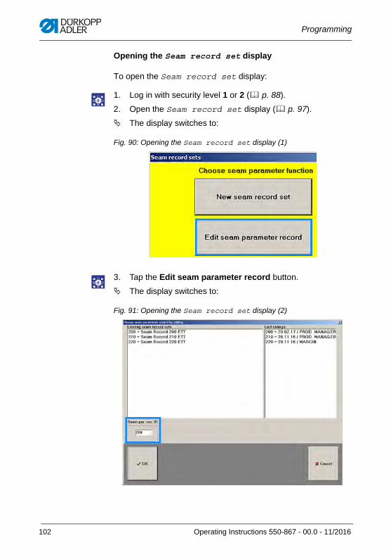
Programming
Opening the Seam record set display
To open the Seam record set display:
1. Log in with security level 1 or 2 ( p. 88).
2. Open the Seam record set display ( p. 97).
The display switches to:
Fig. 90: Opening the Seam record set display (1)
3. Tap the Edit seam parameter record button.
The display switches to:
Fig. 91: Opening the Seam record set display (2)
102 Operating Instructions 550-867 - 00.0 - 11/2016
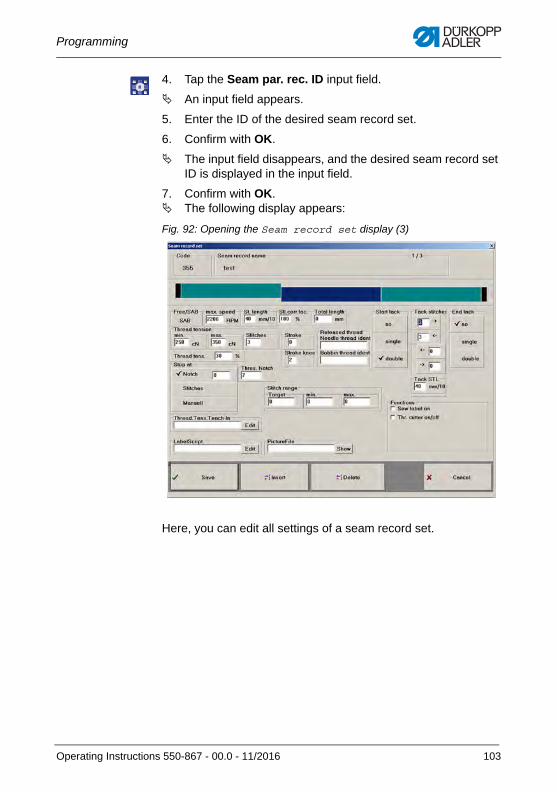
Programming
4. Tap the Seam par. rec. ID input field.
An input field appears.
5. Enter the ID of the desired seam record set.
6. Confirm with OK.
The input field disappears, and the desired seam record set ID is displayed in the input field.
7. Confirm with OK. The following display appears:
Fig. 92: Opening the Seam record set display (3)
Here, you can edit all settings of a seam record set.
Operating Instructions 550-867 - 00.0 - 11/2016 103
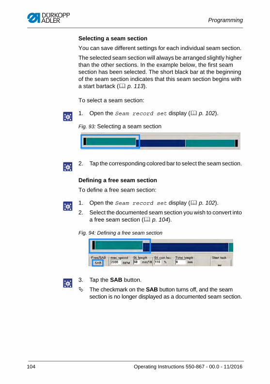
Programming
Selecting a seam section
You can save different settings for each individual seam section.
The selected seam section will always be arranged slightly higher than the other sections. In the example below, the first seam section has been selected. The short black bar at the beginning of the seam section indicates that this seam section begins with a start bartack ( p. 113).
To select a seam section:
1. Open the Seam record set display ( p. 102).
Fig. 93: Selecting a seam section
2. Tap the corresponding colored bar to select the seam section.
Defining a free seam section
To define a free seam section:
1. Open the Seam record set display ( p. 102).
2. Select the documented seam section you wish to convert into a free seam section ( p. 104).
Fig. 94: Defining a free seam section
3. Tap the SAB button.
The checkmark on the SAB button turns off, and the seam section is no longer displayed as a documented seam section.
104 Operating Instructions 550-867 - 00.0 - 11/2016
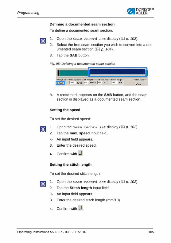
Programming
Defining a documented seam section
To define a documented seam section:
1. Open the Seam record set display ( p. 102).
2. Select the free seam section you wish to convert into a doc-umented seam section ( p. 104).
3. Tap the SAB button.
Fig. 95: Defining a documented seam section
A checkmark appears on the SAB button, and the seam section is displayed as a documented seam section.
Setting the speed
To set the desired speed:
1. Open the Seam record set display ( p. 102).
2. Tap the max. speed input field.
An input field appears.
3. Enter the desired speed.
4. Confirm with .
Setting the stitch length
To set the desired stitch length:
1. Open the Seam record set display ( p. 102).
2. Tap the Stitch length input field.
An input field appears.
3. Enter the desired stitch length (mm/10).
4. Confirm with .
Operating Instructions 550-867 - 00.0 - 11/2016 105
Programming
Setting the stitch length correction factor
Depending on the sewing material, the stitch length may not be implemented 100% (e.g. when sewing thicker fabrics).
In this case, you can slightly increase the percentage of the stitch length to actually achieve 100% of the entered stitch length.
To set the stitch length correction factor:
1. Open the Seam record set display ( p. 102).
2. Determine how many mm of the desired stitch length have actually been implemented.
3. Calculate the percentage difference between the actual stitch length and the desired stitch length.
4. Add the calculated percentage to 100%.
This result represents the stitch length correction factor.
5. Tap the Stl. corr. fac. input field.
An input field appears.
6. Enter the calculated stitch length correction factor.
7. Confirm with .
Setting the thread tension
A thread tension tolerance range is defined for every seam section.
The machine uses the electronic monitor to regulate the thread tension automatically and ensure that the thread tension remains in the medium tolerance range.
To set the thread tension tolerance range:
1. Open the Seam record set display ( p. 102).
2. Tap the Thread tension min. input field.
An input field appears.
3. Enter the desired lowest thread tension (cN).
4. Confirm with .
5. Tap the Thread tension max. input field.
An input field appears.
6. Enter the desired highest thread tension (cN).
7. Confirm with .
106 Operating Instructions 550-867 - 00.0 - 11/2016
Programming
InformationThe thread tension is monitored for every stitch during the docu-mented seam section. As soon as the thread tension falls outside the tolerance range, the sewing process stops, and an error message is displayed.
If the seam record set is linked to a teach-in file, the data stored in the teach-in file will overwrite the manually entered data.
Linking a thread tension teach-in file
A thread tension teach-in file is used to store all important data necessary to set the tolerance for the electronically regulated thread tension (for ETT only). It is possible to link such a teach-in file to every seam section.
A different teach-in file can be linked to each documented/free seam section.
To link a teach-in file to a seam section:
1. Open the Seam record set display ( p. 102).
2. Tap the Thread.Tens. Teach-In input field.
The directory holding the teach-in files that are stored on the control panel opens.
3. Select the desired teach-in file.
4. Confirm with OK.
To display the stored values:
1. Open the Seam record set display ( p. 102).
2. Tap the Edit button at Thread.Tens. Teach-In.
The values stored in the teach-in file are displayed.
Operating Instructions 550-867 - 00.0 - 11/2016 107
Programming
InformationIf the seam section is linked to a teach-in file, the data stored in the teach-in file will overwrite the manually entered data.
Setting the stroke
To set the desired stroke:
1. Open the Seam record set display ( p. 102).
2. Tap the Stroke input field.
An input field appears.
3. Enter the desired stroke.
4. Confirm with .
Setting the switchable stroke
To set the stroke that can be switched on/off using the knee button:
1. Open the Seam record set display ( p. 102).
2. Tap the Stroke knee input field.
An input field appears.
3. Enter the desired stroke.
4. Confirm with .
InformationThe maximum stroke is 9 mm/level 7.
The switchable stroke can be used in push-to-run/hold-to-run mode ( p. 59).
108 Operating Instructions 550-867 - 00.0 - 11/2016
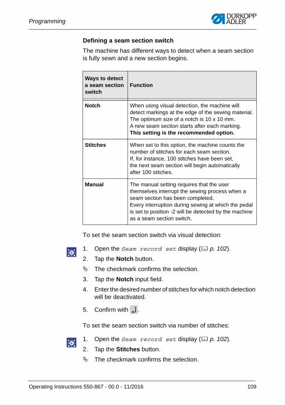
Programming
Defining a seam section switch
The machine has different ways to detect when a seam section is fully sewn and a new section begins.
To set the seam section switch via visual detection:
1. Open the Seam record set display ( p. 102).
2. Tap the Notch button.
The checkmark confirms the selection.
3. Tap the Notch input field.
4. Enter the desired number of stitches for which notch detection will be deactivated.
5. Confirm with .
To set the seam section switch via number of stitches:
1. Open the Seam record set display ( p. 102).
2. Tap the Stitches button.
The checkmark confirms the selection.
Ways to detect a seam section switch
Function
Notch When using visual detection, the machine will detect markings at the edge of the sewing material. The optimum size of a notch is 10 x 10 mm. A new seam section starts after each marking. This setting is the recommended option.
Stitches When set to this option, the machine counts the number of stitches for each seam section. If, for instance, 100 stitches have been set, the next seam section will begin automatically after 100 stitches.
Manual The manual setting requires that the user themselves interrupt the sewing process when a seam section has been completed. Every interruption during sewing at which the pedal is set to position -2 will be detected by the machine as a seam section switch.
Operating Instructions 550-867 - 00.0 - 11/2016 109
Programming
3. Tap the input field.
The display switches to Stitches.
4. Enter the desired number of stitches.
5. Confirm with .
To set the seam section switch via manual operation:
1. Open the Seam record set display ( p. 102).
2. Tap the Manual button.
The checkmark confirms the selection.
Defining the length of the documented seam section
Here, you enter the length of the documented seam section in mm. If is advisable to define the length of the documented seam section for a seam record set.
While possible, defining the length of the free seam sections is of less importance.
To set the length of the documented seam section:
1. Open the Seam record set display ( p. 102).
2. Tap the Total length input field.
An input field appears.
3. Enter the desired length (mm).
4. Confirm with .
Defining the threads
The permissible needle and hook threads must be defined for each seam record set using IDs. The ID holds all important information about the threads. The machine checks at every start which needle thread and which hook thread is currently being used. When a sewing process is started, the machine will compare needle and hook thread with those defined in the seam record set. The machine will detect if the needle and hook threads fitted on the reel stand do not match the seam record set. An error message appears. The sewing process cannot be started.
110 Operating Instructions 550-867 - 00.0 - 11/2016
Programming
To set the needle thread and hook thread IDs:
1. Open the Seam record set display ( p. 102).
2. Tap the Released thread/needle thread ID input field.
The display switches to Released needle thread (ident. no.).
3. Enter the ID.
4. Confirm with .
The input field Released bobbin thread (ident. no.) appears.
5. Enter the ID.
6. Confirm with .
Important
The thread ID is a very important piece of information for the seam record set; it is essential that it be stored in the seam record set. This is the only way to ensure that needle and hook threads matching the seam record set are used at the beginning of a sewing process.
Defining the text on the end label
Here, you can define the text that will be printed on the end label.
To enter the text:
1. Open the Seam record set display ( p. 102).
2. Tap the Text for printed label input field.
An input field opens.
3. Enter the desired text.
4. Confirm with .
InformationThis function is only available in a documented seam section. Another option is to link a label script file to the seam record set that contains all information about the end label ( p. 212).
Operating Instructions 550-867 - 00.0 - 11/2016 111
Programming
Linking a teach-in file
A thread tension teach-in file is used to store all data necessary to set the tolerance range for the electronically regulated thread tension (for ETT only). These teach-in file is created ( p. 203) and stored on the control panel and can be linked to each seam record set.
To link a teach-in file to a seam record set:
1. Open the Seam record set display ( p. 102).
2. Tap the Thread.Tens.Teach-In input field.
The directory holding the teach-in files that are stored on the control panel opens.
3. Select the desired teach-in file.
4. Confirm with OK.
5. To bring up and view the settings, tap the Edit button.
Linking a label script file
Stored in a label script file is all relevant data about the end label. Such a label script file can be created directly in the software ( p. 175) or using the Label Creator ( p. 212) and then saved on the control panel before being linked to each seam record set.
To link a label script file to a seam record set:
1. Open the Seam record set display ( p. 102).
2. Tap the LabelScript input field.
The directory holding the label script files that are stored on the control panel opens.
3. Select the desired label script file.
4. Confirm with OK.
5. To bring up and view the settings, tap the Edit button.
112 Operating Instructions 550-867 - 00.0 - 11/2016
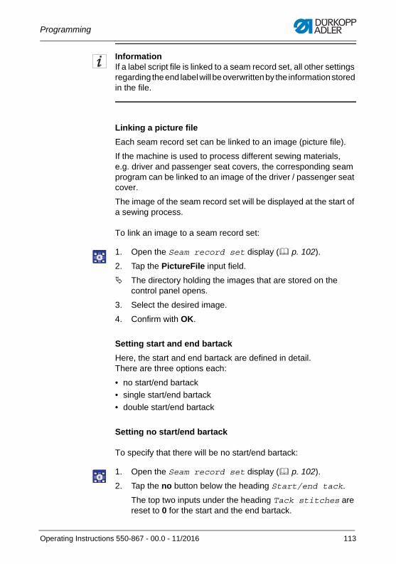
Programming
InformationIf a label script file is linked to a seam record set, all other settings regarding the end label will be overwritten by the information stored in the file.
Linking a picture file
Each seam record set can be linked to an image (picture file).
If the machine is used to process different sewing materials,e.g. driver and passenger seat covers, the corresponding seam program can be linked to an image of the driver / passenger seat cover.
The image of the seam record set will be displayed at the start of a sewing process.
To link an image to a seam record set:
1. Open the Seam record set display ( p. 102).
2. Tap the PictureFile input field.
The directory holding the images that are stored on the control panel opens.
3. Select the desired image.
4. Confirm with OK.
Setting start and end bartack
Here, the start and end bartack are defined in detail.There are three options each:
• no start/end bartack
• single start/end bartack
• double start/end bartack
Setting no start/end bartack
To specify that there will be no start/end bartack:
1. Open the Seam record set display ( p. 102).
2. Tap the no button below the heading Start/end tack.
The top two inputs under the heading Tack stitches are reset to 0 for the start and the end bartack.
Operating Instructions 550-867 - 00.0 - 11/2016 113
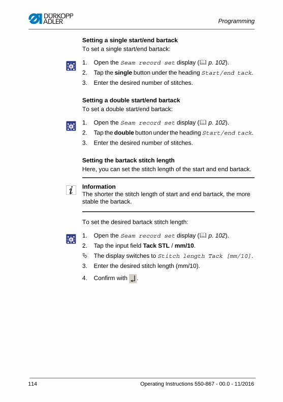
Programming
Setting a single start/end bartack
To set a single start/end bartack:
1. Open the Seam record set display ( p. 102).
2. Tap the single button under the heading Start/end tack.
3. Enter the desired number of stitches.
Setting a double start/end bartack
To set a double start/end bartack:
1. Open the Seam record set display ( p. 102).
2. Tap the double button under the heading Start/end tack.
3. Enter the desired number of stitches.
Setting the bartack stitch length
Here, you can set the stitch length of the start and end bartack.
InformationThe shorter the stitch length of start and end bartack, the more stable the bartack.
To set the desired bartack stitch length:
1. Open the Seam record set display ( p. 102).
2. Tap the input field Tack STL / mm/10.
The display switches to Stitch length Tack [mm/10].
3. Enter the desired stitch length (mm/10).
4. Confirm with .
114 Operating Instructions 550-867 - 00.0 - 11/2016
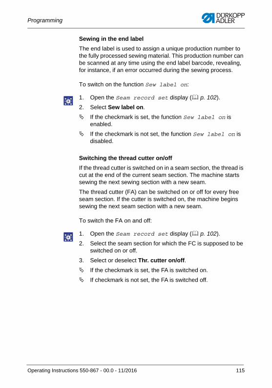
Programming
Sewing in the end label
The end label is used to assign a unique production number to the fully processed sewing material. This production number can be scanned at any time using the end label barcode, revealing, for instance, if an error occurred during the sewing process.
To switch on the function Sew label on:
1. Open the Seam record set display ( p. 102).
2. Select Sew label on.
If the checkmark is set, the function Sew label on is enabled.
If the checkmark is not set, the function Sew label on is disabled.
Switching the thread cutter on/off
If the thread cutter is switched on in a seam section, the thread is cut at the end of the current seam section. The machine starts sewing the next sewing section with a new seam.
The thread cutter (FA) can be switched on or off for every free seam section. If the cutter is switched on, the machine begins sewing the next seam section with a new seam.
To switch the FA on and off:
1. Open the Seam record set display ( p. 102).
2. Select the seam section for which the FC is supposed to be switched on or off.
3. Select or deselect Thr. cutter on/off.
If the checkmark is set, the FA is switched on.
If checkmark is not set, the FA is switched off.
Operating Instructions 550-867 - 00.0 - 11/2016 115
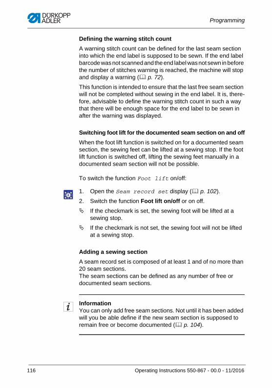
Programming
Defining the warning stitch count
A warning stitch count can be defined for the last seam section into which the end label is supposed to be sewn. If the end label barcode was not scanned and the end label was not sewn in before the number of stitches warning is reached, the machine will stop and display a warning ( p. 72).
This function is intended to ensure that the last free seam section will not be completed without sewing in the end label. It is, there-fore, advisable to define the warning stitch count in such a way that there will be enough space for the end label to be sewn in after the warning was displayed.
Switching foot lift for the documented seam section on and off
When the foot lift function is switched on for a documented seam section, the sewing feet can be lifted at a sewing stop. If the foot lift function is switched off, lifting the sewing feet manually in a documented seam section will not be possible.
To switch the function Foot lift on/off:
1. Open the Seam record set display ( p. 102).
2. Switch the function Foot lift on/off or on off.
If the checkmark is set, the sewing foot will be lifted at a sewing stop.
If the checkmark is not set, the sewing foot will not be lifted at a sewing stop.
Adding a sewing section
A seam record set is composed of at least 1 and of no more than 20 seam sections. The seam sections can be defined as any number of free or documented seam sections.
InformationYou can only add free seam sections. Not until it has been added will you be able define if the new seam section is supposed to remain free or become documented ( p. 104).
116 Operating Instructions 550-867 - 00.0 - 11/2016
Programming
To add additional seam sections:
1. Open the Seam record set display ( p. 102).
2. Select the seam section after which you wish to add the new seam section.
3. Tap the Insert button.
The display switches to a confirmation.
4. Confirm with OK.
A new free seam section is added as an additional bar on the right next to the selected seam section.
Deleting a seam section
It is possible delete any seam section.
To delete the selected seam section:
1. Open the Seam record set display ( p. 102).
2. Select the seam section you wish to delete.
3. Tap the Delete button.
The display switches to a confirmation prompt.
4. Confirm with OK.
Operating Instructions 550-867 - 00.0 - 11/2016 117
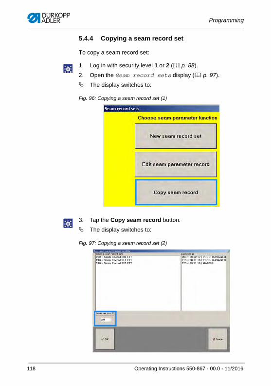
Programming
5.4.4 Copying a seam record set
To copy a seam record set:
1. Log in with security level 1 or 2 ( p. 88).
2. Open the Seam record sets display ( p. 97).
The display switches to:
Fig. 96: Copying a seam record set (1)
3. Tap the Copy seam record button.
The display switches to:
Fig. 97: Copying a seam record set (2)
118 Operating Instructions 550-867 - 00.0 - 11/2016
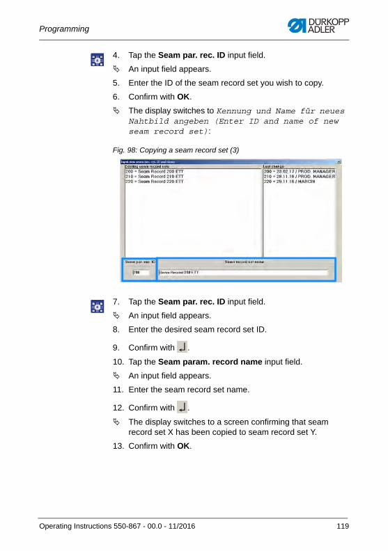
Programming
4. Tap the Seam par. rec. ID input field.
An input field appears.
5. Enter the ID of the seam record set you wish to copy.
6. Confirm with OK.
The display switches to Kennung und Name für neues Nahtbild angeben (Enter ID and name of new seam record set):
Fig. 98: Copying a seam record set (3)
7. Tap the Seam par. rec. ID input field.
An input field appears.
8. Enter the desired seam record set ID.
9. Confirm with .
10. Tap the Seam param. record name input field.
An input field appears.
11. Enter the seam record set name.
12. Confirm with .
The display switches to a screen confirming that seam record set X has been copied to seam record set Y.
13. Confirm with OK.
Operating Instructions 550-867 - 00.0 - 11/2016 119
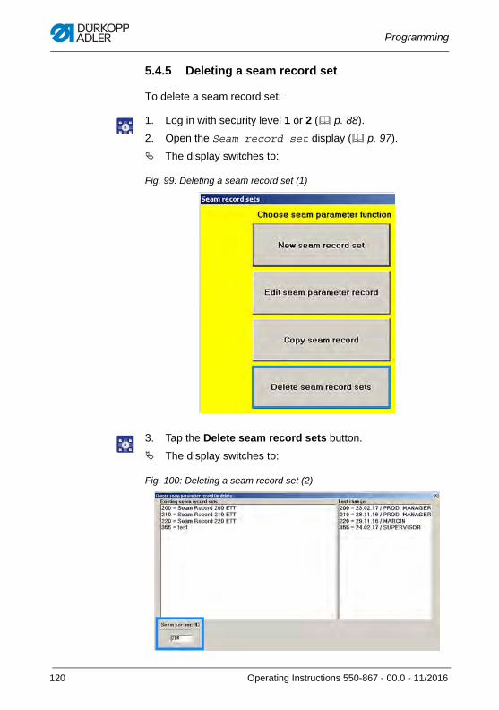
Programming
5.4.5 Deleting a seam record set
To delete a seam record set:
1. Log in with security level 1 or 2 ( p. 88).
2. Open the Seam record set display ( p. 97).
The display switches to:
Fig. 99: Deleting a seam record set (1)
3. Tap the Delete seam record sets button.
The display switches to:
Fig. 100: Deleting a seam record set (2)
120 Operating Instructions 550-867 - 00.0 - 11/2016
Programming
4. Tap the Seam par. rec. ID input field.
An input field appears.
5. Enter the ID of the seam record set you wish to delete.
6. Confirm with .
The display switches to a 2nd confirmation prompt.
7. Confirm with OK.
The seam record set has been deleted successfully.
5.4.6 Changing the thread(Change thread in seam records)
A previously used thread can be replaced with a new thread. The function Change thread in seam records covers two steps:
• the new thread is registered in the system
• the new thread is linked to any number of seam record sets
InformationHere, you can link a new thread to any number of seam record sets without the need to edit each of these seam record set separately.
It is possible to change needle and hook threads.
To change a thread:
1. Log in with security level 1 or 2 ( p. 88).
2. Open the Seam record sets display ( p. 97).
The display switches to:
Operating Instructions 550-867 - 00.0 - 11/2016 121
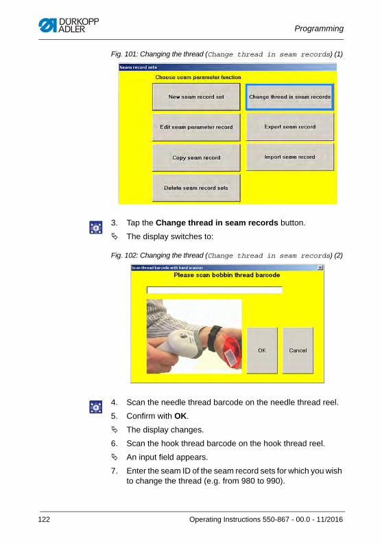
Programming
Fig. 101: Changing the thread (Change thread in seam records) (1)
3. Tap the Change thread in seam records button.
The display switches to:
Fig. 102: Changing the thread (Change thread in seam records) (2)
4. Scan the needle thread barcode on the needle thread reel.
5. Confirm with OK.
The display changes.
6. Scan the hook thread barcode on the hook thread reel.
An input field appears.
7. Enter the seam ID of the seam record sets for which you wish to change the thread (e.g. from 980 to 990).
122 Operating Instructions 550-867 - 00.0 - 11/2016
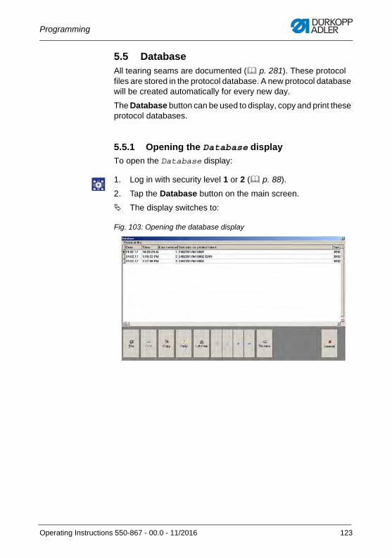
Programming
5.5 DatabaseAll tearing seams are documented ( p. 281). These protocol files are stored in the protocol database. A new protocol database will be created automatically for every new day.
The Database button can be used to display, copy and print these protocol databases.
5.5.1 Opening the Database display
To open the Database display:
1. Log in with security level 1 or 2 ( p. 88).
2. Tap the Database button on the main screen.
The display switches to:
Fig. 103: Opening the database display
Operating Instructions 550-867 - 00.0 - 11/2016 123
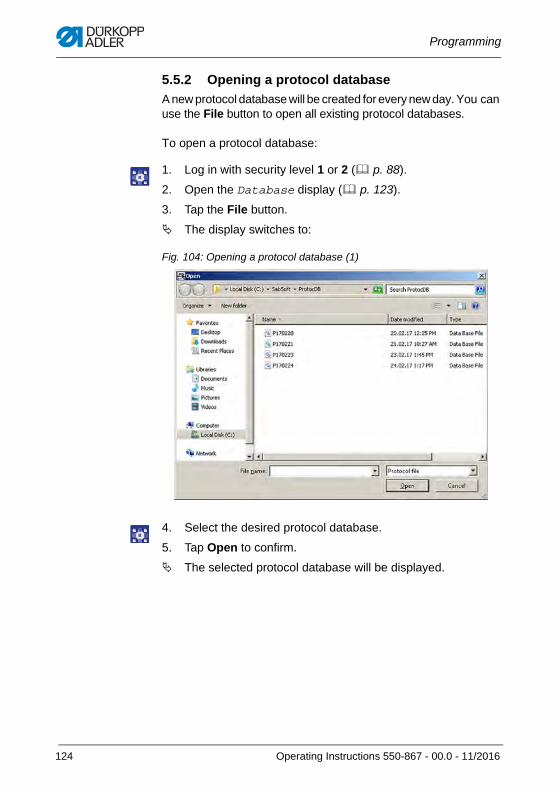
Programming
5.5.2 Opening a protocol database
A new protocol database will be created for every new day. You can use the File button to open all existing protocol databases.
To open a protocol database:
1. Log in with security level 1 or 2 ( p. 88).
2. Open the Database display ( p. 123).
3. Tap the File button.
The display switches to:
Fig. 104: Opening a protocol database (1)
4. Select the desired protocol database.
5. Tap Open to confirm.
The selected protocol database will be displayed.
124 Operating Instructions 550-867 - 00.0 - 11/2016
Programming
5.5.3 Printing a protocol file
If a protocol printer is connected and installed on the control panel, every protocol file can be printed out.
To print out a protocol file:
1. Log in with security level 1 or 2 ( p. 88).
2. Open the Database display ( p. 123).
3. Select the desired protocol file.
4. Tap the Print button.
This button cannot be tapped unless a protocol printer is connected and set up.
InformationOnce a print command has been given, the printout will not only include the file but also the entire database.
5.5.4 Copying a protocol file (Copy)
You can copy the existing protocol files to different storage locations.
Other storage locations may be other folders in the directory of the control panel and external storage media such as a USB key or external servers. The storage location can be changed manually ( p. 196).
To copy a protocol file:
1. Log in with security level 1 or 2 ( p. 88).
2. Open the Database display ( p. 123).
3. Select the desired protocol file.
4. Tap the Copy button.
InformationThe copy of the protocol file will be stored in the same location as the automatic backup copies of the entire protocol database ( p. 198).
Operating Instructions 550-867 - 00.0 - 11/2016 125
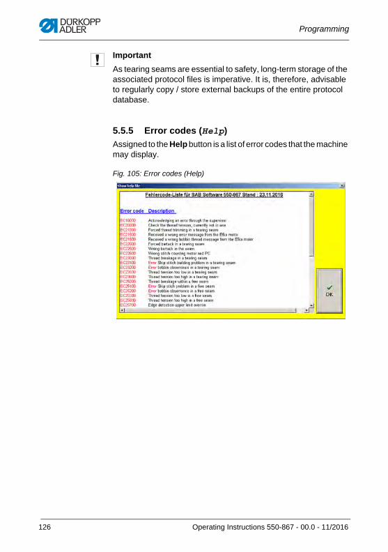
Programming
Important
As tearing seams are essential to safety, long-term storage of the associated protocol files is imperative. It is, therefore, advisable to regularly copy / store external backups of the entire protocol database.
5.5.5 Error codes (Help)
Assigned to the Help button is a list of error codes that the machine may display.
Fig. 105: Error codes (Help)
126 Operating Instructions 550-867 - 00.0 - 11/2016
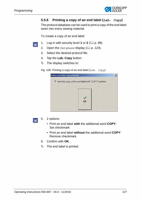
Programming
5.5.6 Printing a copy of an end label (Lab. Copy)
The protocol database can be used to print a copy of the end label sewn into every sewing material.
To create a copy of an end label:
1. Log in with security level 1 or 2 ( p. 88).
2. Open the Database display ( p. 123).
3. Select the desired protocol file.
4. Tap the Lab. Copy button.
The display switches to:
Fig. 106: Printing a copy of an end label (Lab. Copy)
5. 2 options:
• Print an end label with the additional word COPY: Set checkmark
• Print an end label without the additional word COPY:Remove checkmark
6. Confirm with OK.
The end label is printed.
Operating Instructions 550-867 - 00.0 - 11/2016 127
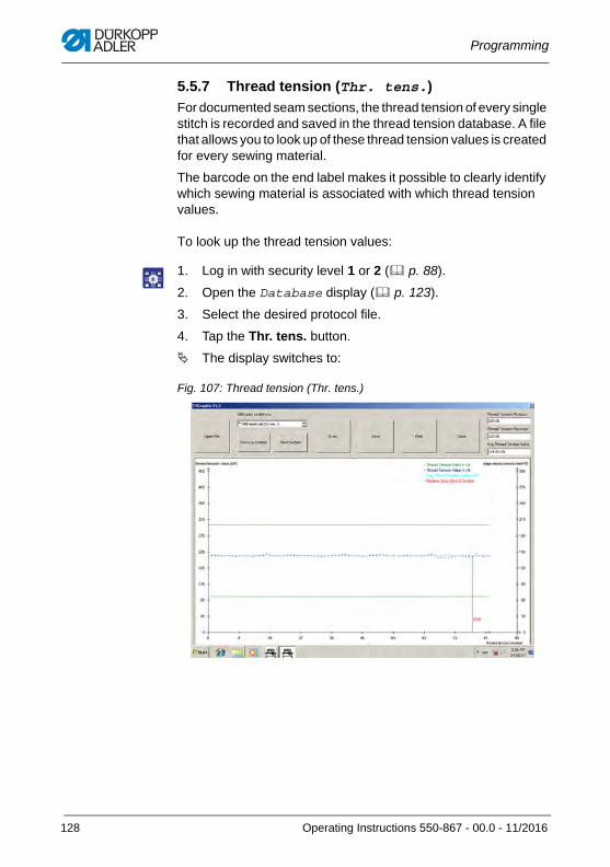
Programming
5.5.7 Thread tension (Thr. tens.)
For documented seam sections, the thread tension of every single stitch is recorded and saved in the thread tension database. A file that allows you to look up of these thread tension values is created for every sewing material.
The barcode on the end label makes it possible to clearly identify which sewing material is associated with which thread tension values.
To look up the thread tension values:
1. Log in with security level 1 or 2 ( p. 88).
2. Open the Database display ( p. 123).
3. Select the desired protocol file.
4. Tap the Thr. tens. button.
The display switches to:
Fig. 107: Thread tension (Thr. tens.)
128 Operating Instructions 550-867 - 00.0 - 11/2016
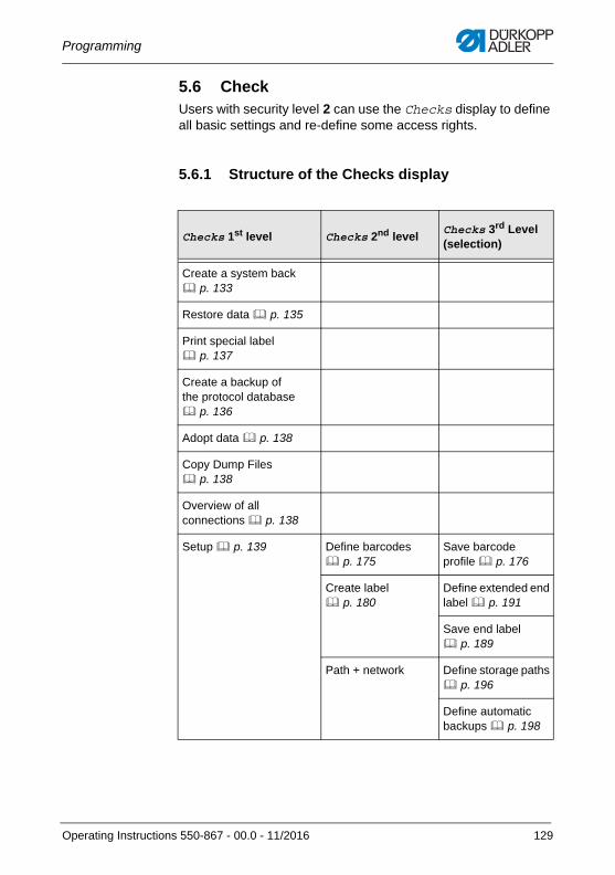
Programming
5.6 CheckUsers with security level 2 can use the Checks display to define all basic settings and re-define some access rights.
5.6.1 Structure of the Checks display
Checks 1st level Checks 2nd levelChecks 3rd Level (selection)
Create a system back p. 133
Restore data p. 135
Print special label p. 137
Create a backup of the protocol database p. 136
Adopt data p. 138
Copy Dump Files p. 138
Overview of all connections p. 138
Setup p. 139 Define barcodes p. 175
Save barcode profile p. 176
Create label p. 180
Define extended end label p. 191
Save end label p. 189
Path + network Define storage paths p. 196
Define automatic backups p. 198
Operating Instructions 550-867 - 00.0 - 11/2016 129
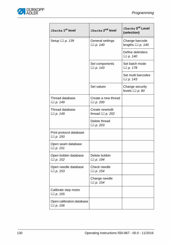
Programming
Setup p. 139 General settings p. 140
Change barcode lengths p. 140
Define delimiters p. 140
Set components p. 143
Set batch mode p. 178
Set multi barcodes p. 143
Set values Change security levels p. 80
Thread database p. 149
Create a new thread p. 200
Thread database p. 149
Create new/edit thread p. 202
Delete thread p. 203
Print protocol database p. 150
Open seam database p. 151
Open bobbin database p. 152
Delete bobbin p. 194
Open needle database p. 153
Check needle p. 154
Change needle p. 154
Calibrate step motor p. 155
Open calibration database p. 156
Checks 1st level Checks 2nd levelChecks 3rd Level (selection)
130 Operating Instructions 550-867 - 00.0 - 11/2016
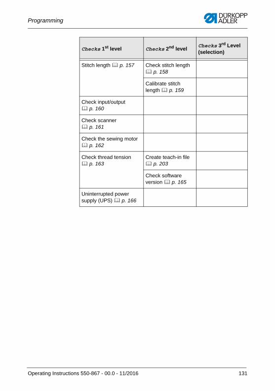
Programming
Stitch length p. 157 Check stitch length p. 158
Calibrate stitch length p. 159
Check input/output p. 160
Check scanner p. 161
Check the sewing motor p. 162
Check thread tension p. 163
Create teach-in file p. 203
Check software version p. 165
Uninterrupted power supply (UPS) p. 166
Checks 1st level Checks 2nd levelChecks 3rd Level (selection)
Operating Instructions 550-867 - 00.0 - 11/2016 131
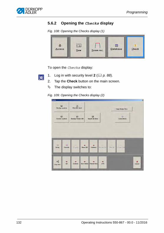
Programming
5.6.2 Opening the Checks display
Fig. 108: Opening the Checks display (1)
To open the Checks display:
1. Log in with security level 2 ( p. 88).
2. Tap the Check button on the main screen.
The display switches to:
Fig. 109: Opening the Checks display (2)
132 Operating Instructions 550-867 - 00.0 - 11/2016
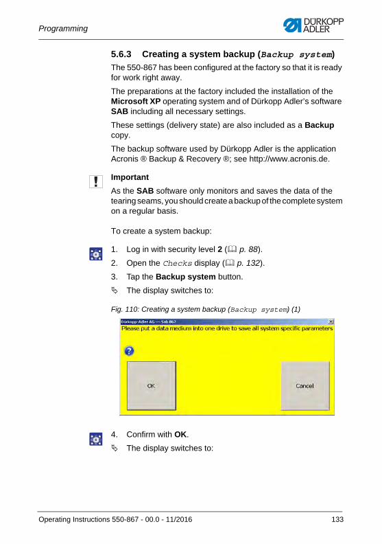
Programming
5.6.3 Creating a system backup (Backup system)
The 550-867 has been configured at the factory so that it is ready for work right away.
The preparations at the factory included the installation of the Microsoft XP operating system and of Dürkopp Adler’s software SAB including all necessary settings.
These settings (delivery state) are also included as a Backup copy.
The backup software used by Dürkopp Adler is the application Acronis ® Backup & Recovery ®; see http://www.acronis.de.
Important
As the SAB software only monitors and saves the data of the tearing seams, you should create a backup of the complete system on a regular basis.
To create a system backup:
1. Log in with security level 2 ( p. 88).
2. Open the Checks display ( p. 132).
3. Tap the Backup system button.
The display switches to:
Fig. 110: Creating a system backup (Backup system) (1)
4. Confirm with OK.
The display switches to:
Operating Instructions 550-867 - 00.0 - 11/2016 133
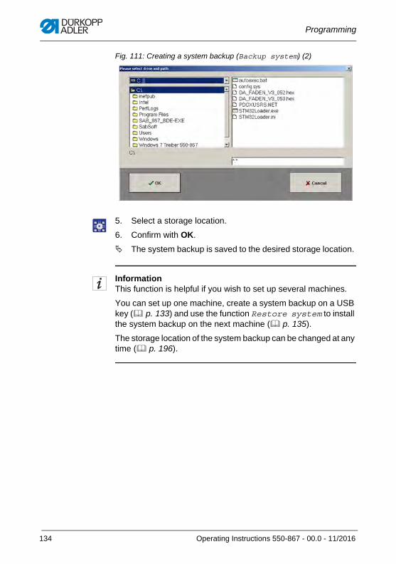
Programming
Fig. 111: Creating a system backup (Backup system) (2)
5. Select a storage location.
6. Confirm with OK.
The system backup is saved to the desired storage location.
InformationThis function is helpful if you wish to set up several machines.
You can set up one machine, create a system backup on a USB key ( p. 133) and use the function Restore system to install the system backup on the next machine ( p. 135).
The storage location of the system backup can be changed at any time ( p. 196).
134 Operating Instructions 550-867 - 00.0 - 11/2016
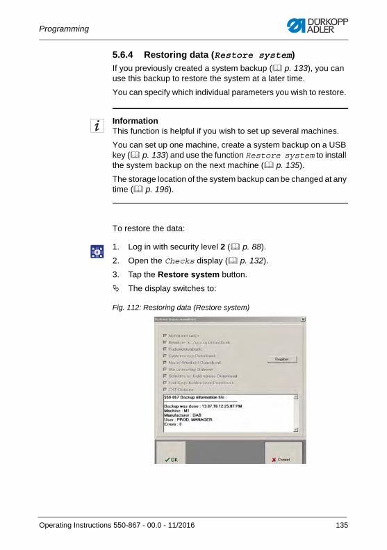
Programming
5.6.4 Restoring data (Restore system)
If you previously created a system backup ( p. 133), you can use this backup to restore the system at a later time.
You can specify which individual parameters you wish to restore.
InformationThis function is helpful if you wish to set up several machines.
You can set up one machine, create a system backup on a USB key ( p. 133) and use the function Restore system to install the system backup on the next machine ( p. 135).
The storage location of the system backup can be changed at any time ( p. 196).
To restore the data:
1. Log in with security level 2 ( p. 88).
2. Open the Checks display ( p. 132).
3. Tap the Restore system button.
The display switches to:
Fig. 112: Restoring data (Restore system)
Operating Instructions 550-867 - 00.0 - 11/2016 135
Programming
4. Tap the Release button.
The listed parameters are now no longer displayedsemi-transparent.
5. Select which parameters you wish to restore.
6. Confirm with OK.
5.6.5 Creating a backup of the protocol database (Backup protoc. DB)
This function is used to back up all protocol files under the corre-sponding names of the machine to a protocol database.
1. Log in with security level 2 ( p. 88).
2. To create a backup of the protocol database, proceed as explained for the creation of a system backup ( p. 133).
Important
Since the machine produces tearing seams that are essential to safety, it is imperative that you create regular backups of the protocol database and store them long term in an external storage location.
InformationThe name of the machine can be changed on the Setup display ( p. 140).
The storage location can be changed at any time ( p. 196).
136 Operating Instructions 550-867 - 00.0 - 11/2016
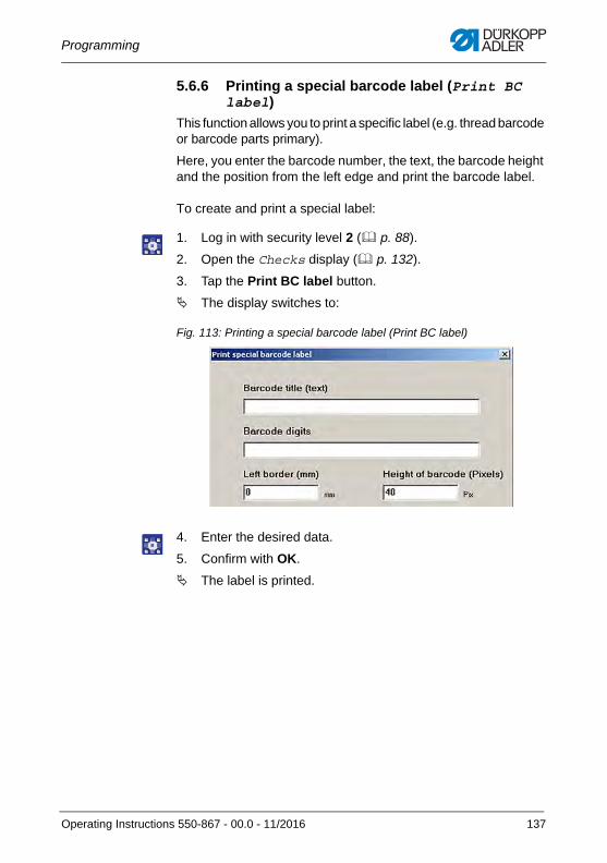
Programming
5.6.6 Printing a special barcode label (Print BC label)
This function allows you to print a specific label (e.g. thread barcode or barcode parts primary).
Here, you enter the barcode number, the text, the barcode height and the position from the left edge and print the barcode label.
To create and print a special label:
1. Log in with security level 2 ( p. 88).
2. Open the Checks display ( p. 132).
3. Tap the Print BC label button.
The display switches to:
Fig. 113: Printing a special barcode label (Print BC label)
4. Enter the desired data.
5. Confirm with OK.
The label is printed.
Operating Instructions 550-867 - 00.0 - 11/2016 137
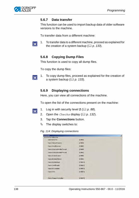
Programming
5.6.7 Data transfer
This function can be used to import backup data of older software versions to the machine.
To transfer data from a different machine:
1. To transfer data to a different machine, proceed as explained for the creation of a system backup ( p. 133).
5.6.8 Copying Dump Files
This function is used to copy all dump files.
To copy the dump files:
1. To copy dump files, proceed as explained for the creation of a system backup ( p. 133).
5.6.9 Displaying connections
Here, you can view all connections of the machine.
To open the list of the connections present on the machine:
1. Log in with security level 2 ( p. 88).
2. Open the Checks display ( p. 132).
3. Tap the Connections button.
The display switches to:
Fig. 114: Displaying connections
138 Operating Instructions 550-867 - 00.0 - 11/2016
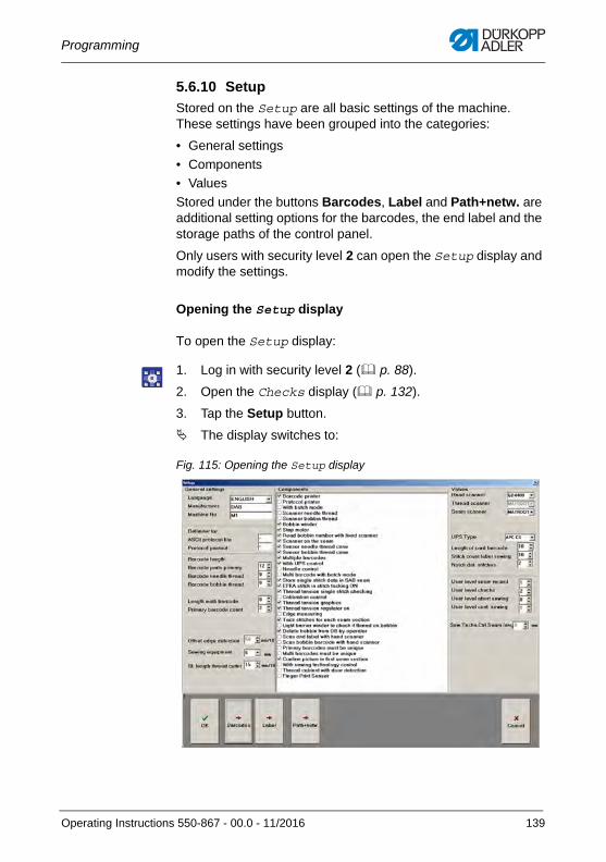
Programming
5.6.10 Setup
Stored on the Setup are all basic settings of the machine. These settings have been grouped into the categories:
• General settings
• Components
• Values
Stored under the buttons Barcodes, Label and Path+netw. are additional setting options for the barcodes, the end label and the storage paths of the control panel.
Only users with security level 2 can open the Setup display and modify the settings.
Opening the Setup display
To open the Setup display:
1. Log in with security level 2 ( p. 88).
2. Open the Checks display ( p. 132).
3. Tap the Setup button.
The display switches to:
Fig. 115: Opening the Setup display
Operating Instructions 550-867 - 00.0 - 11/2016 139
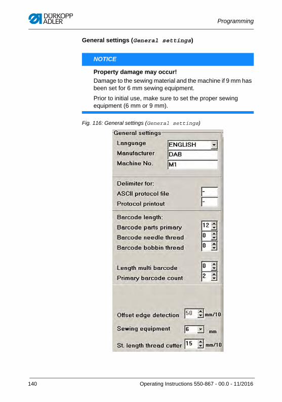
Programming
General settings (General settings)
Fig. 116: General settings (General settings)
NOTICE
Property damage may occur!
Damage to the sewing material and the machine if 9 mm has been set for 6 mm sewing equipment.
Prior to initial use, make sure to set the proper sewing equipment (6 mm or 9 mm).
140 Operating Instructions 550-867 - 00.0 - 11/2016
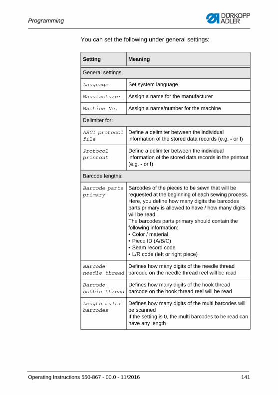
Programming
You can set the following under general settings:
Setting Meaning
General settings
Language Set system language
Manufacturer Assign a name for the manufacturer
Machine No. Assign a name/number for the machine
Delimiter for:
ASCI protocol file
Define a delimiter between the individual information of the stored data records (e.g. - or I)
Protocol printout
Define a delimiter between the individual information of the stored data records in the printout (e.g. - or I)
Barcode lengths:
Barcode parts primary
Barcodes of the pieces to be sewn that will be requested at the beginning of each sewing process. Here, you define how many digits the barcodes parts primary is allowed to have / how many digits will be read.The barcodes parts primary should contain the following information:• Color / material• Piece ID (A/B/C)• Seam record code• L/R code (left or right piece)
Barcode needle thread
Defines how many digits of the needle thread barcode on the needle thread reel will be read
Barcode bobbin thread
Defines how many digits of the hook thread barcode on the hook thread reel will be read
Length multi barcodes
Defines how many digits of the multi barcodes will be scannedIf the setting is 0, the multi barcodes to be read can have any length
Operating Instructions 550-867 - 00.0 - 11/2016 141
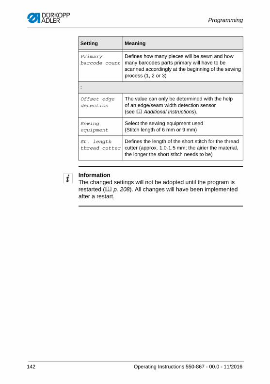
Programming
InformationThe changed settings will not be adopted until the program is restarted ( p. 208). All changes will have been implemented after a restart.
Primary barcode count
Defines how many pieces will be sewn and how many barcodes parts primary will have to be scanned accordingly at the beginning of the sewing process (1, 2 or 3)
:
Offset edge detection
The value can only be determined with the help of an edge/seam width detection sensor (see Additional Instructions).
Sewing equipment
Select the sewing equipment used (Stitch length of 6 mm or 9 mm)
St. length thread cutter
Defines the length of the short stitch for the thread cutter (approx. 1.0-1.5 mm; the airier the material, the longer the short stitch needs to be)
Setting Meaning
142 Operating Instructions 550-867 - 00.0 - 11/2016
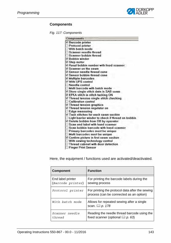
Programming
Components
Fig. 117: Components
Here, the equipment / functions used are activated/deactivated.
Component Function
End label printer(Barcode printer)
For printing the barcode labels during the sewing process
Protocol printer For printing the protocol data after the sewing process (can be connected as an option)
With batch mode Allows for repeated sewing after a single scan. p. 178
Scanner needle thread
Reading the needle thread barcode using the fixed scanner (optional p. 63)
Operating Instructions 550-867 - 00.0 - 11/2016 143
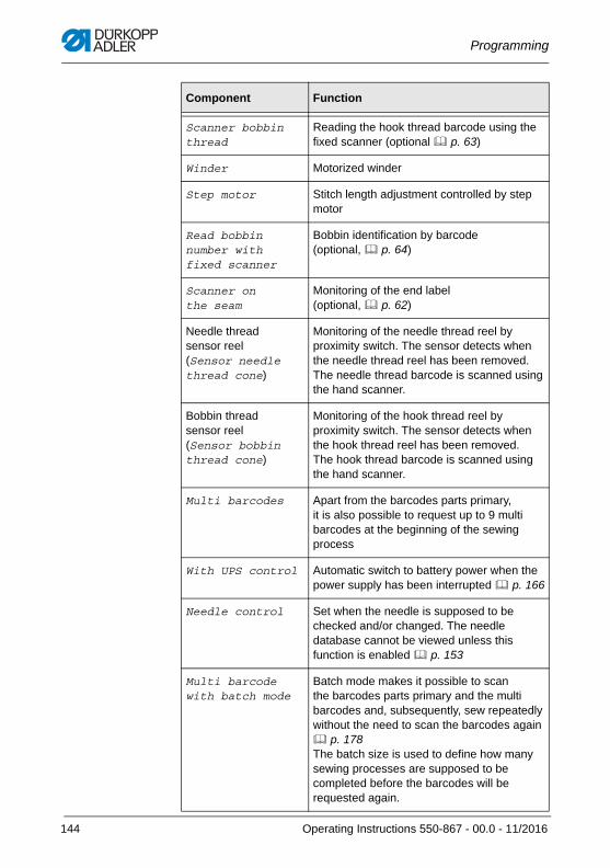
Programming
Scanner bobbin thread
Reading the hook thread barcode using the fixed scanner (optional p. 63)
Winder Motorized winder
Step motor Stitch length adjustment controlled by step motor
Read bobbin number with fixed scanner
Bobbin identification by barcode (optional, p. 64)
Scanner on the seam
Monitoring of the end label (optional, p. 62)
Needle thread sensor reel (Sensor needle thread cone)
Monitoring of the needle thread reel by proximity switch. The sensor detects when the needle thread reel has been removed. The needle thread barcode is scanned using the hand scanner.
Bobbin thread sensor reel(Sensor bobbin thread cone)
Monitoring of the hook thread reel by proximity switch. The sensor detects when the hook thread reel has been removed. The hook thread barcode is scanned using the hand scanner.
Multi barcodes Apart from the barcodes parts primary, it is also possible to request up to 9 multi barcodes at the beginning of the sewing process
With UPS control Automatic switch to battery power when the power supply has been interrupted p. 166
Needle control Set when the needle is supposed to be checked and/or changed. The needle database cannot be viewed unless this function is enabled p. 153
Multi barcode with batch mode
Batch mode makes it possible to scan the barcodes parts primary and the multi barcodes and, subsequently, sew repeatedly without the need to scan the barcodes again p. 178The batch size is used to define how many sewing processes are supposed to be completed before the barcodes will be requested again.
Component Function
144 Operating Instructions 550-867 - 00.0 - 11/2016
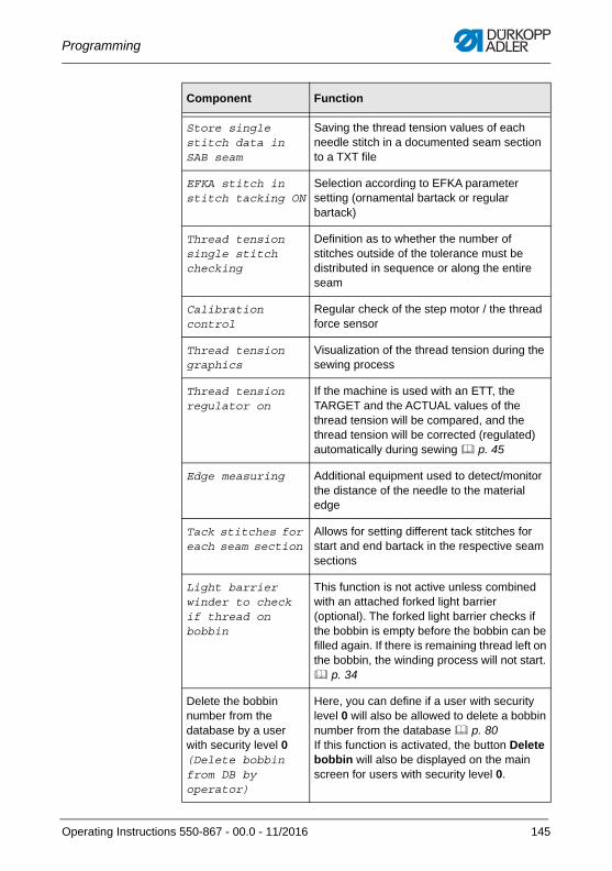
Programming
Store single stitch data in SAB seam
Saving the thread tension values of each needle stitch in a documented seam section to a TXT file
EFKA stitch in stitch tacking ON
Selection according to EFKA parameter setting (ornamental bartack or regular bartack)
Thread tension single stitch checking
Definition as to whether the number of stitches outside of the tolerance must be distributed in sequence or along the entire seam
Calibration control
Regular check of the step motor / the thread force sensor
Thread tension graphics
Visualization of the thread tension during the sewing process
Thread tension regulator on
If the machine is used with an ETT, the TARGET and the ACTUAL values of the thread tension will be compared, and the thread tension will be corrected (regulated) automatically during sewing p. 45
Edge measuring Additional equipment used to detect/monitor the distance of the needle to the material edge
Tack stitches for each seam section
Allows for setting different tack stitches for start and end bartack in the respective seam sections
Light barrier winder to check if thread on bobbin
This function is not active unless combined with an attached forked light barrier (optional). The forked light barrier checks if the bobbin is empty before the bobbin can be filled again. If there is remaining thread left on the bobbin, the winding process will not start. p. 34
Delete the bobbin number from the database by a user with security level 0(Delete bobbin from DB by operator)
Here, you can define if a user with security level 0 will also be allowed to delete a bobbin number from the database p. 80If this function is activated, the button Delete bobbin will also be displayed on the main screen for users with security level 0.
Component Function
Operating Instructions 550-867 - 00.0 - 11/2016 145
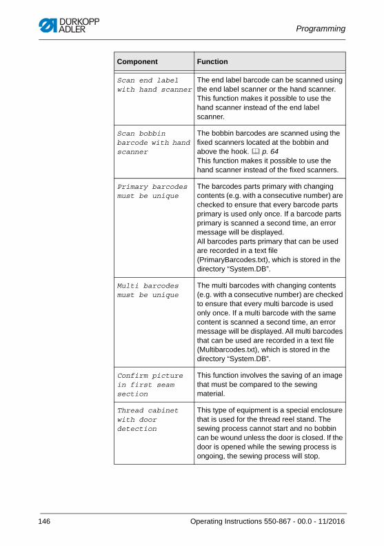
Programming
Scan end label with hand scanner
The end label barcode can be scanned using the end label scanner or the hand scanner. This function makes it possible to use the hand scanner instead of the end label scanner.
Scan bobbin barcode with hand scanner
The bobbin barcodes are scanned using the fixed scanners located at the bobbin and above the hook. p. 64This function makes it possible to use the hand scanner instead of the fixed scanners.
Primary barcodes must be unique
The barcodes parts primary with changing contents (e.g. with a consecutive number) are checked to ensure that every barcode parts primary is used only once. If a barcode parts primary is scanned a second time, an error message will be displayed. All barcodes parts primary that can be used are recorded in a text file (PrimaryBarcodes.txt), which is stored in the directory “System.DB”.
Multi barcodes must be unique
The multi barcodes with changing contents (e.g. with a consecutive number) are checked to ensure that every multi barcode is used only once. If a multi barcode with the same content is scanned a second time, an error message will be displayed. All multi barcodes that can be used are recorded in a text file (Multibarcodes.txt), which is stored in the directory “System.DB”.
Confirm picture in first seam section
This function involves the saving of an image that must be compared to the sewing material.
Thread cabinet with door detection
This type of equipment is a special enclosure that is used for the thread reel stand. The sewing process cannot start and no bobbin can be wound unless the door is closed. If the door is opened while the sewing process is ongoing, the sewing process will stop.
Component Function
146 Operating Instructions 550-867 - 00.0 - 11/2016
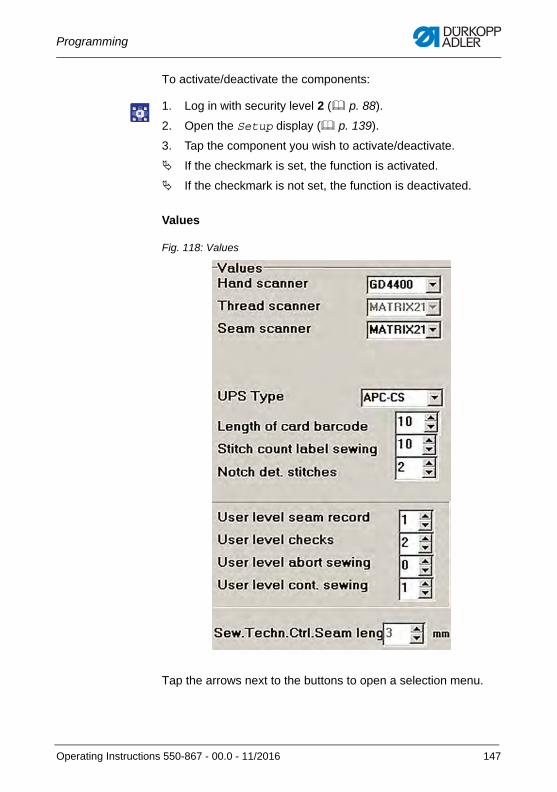
Programming
To activate/deactivate the components:
1. Log in with security level 2 ( p. 88).
2. Open the Setup display ( p. 139).
3. Tap the component you wish to activate/deactivate.
If the checkmark is set, the function is activated.
If the checkmark is not set, the function is deactivated.
Values
Fig. 118: Values
Tap the arrows next to the buttons to open a selection menu.
Operating Instructions 550-867 - 00.0 - 11/2016 147
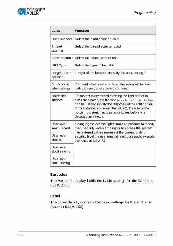
Programming
Barcodes
The Barcodes display holds the basic settings for the barcodes ( p. 170).
Label
The Label display contains the basic settings for the end label (Label) ( p. 180).
Value Function
Hand scanner Select the hand scanner used
Thread scanner
Select the thread scanner used
Seam scanner Select the seam scanner used
UPS Type Select the type of the UPS
Length of card barcode
Length of the barcode used by the users to log in
Stitch count label sewing
If an end label is sewn in later, the seam will be sewn with the number of stitches set here.
Notch det. stitches
To prevent every thread crossing the light barrier to simulate a notch, the function Notch det. stitches can be used to modify the response of the light barrier. If, for instance, you enter the value 2, the size of the notch must stretch across two stitches before it is detected as a notch.
User level seam record
Changing the access rights makes it possible to modify the 3 security levels / the rights to access the system. The entered values represent the corresponding security level the user must at least possess to execute the function p. 79.
User level checks
User level abort sewing
User level cont. sewing
148 Operating Instructions 550-867 - 00.0 - 11/2016
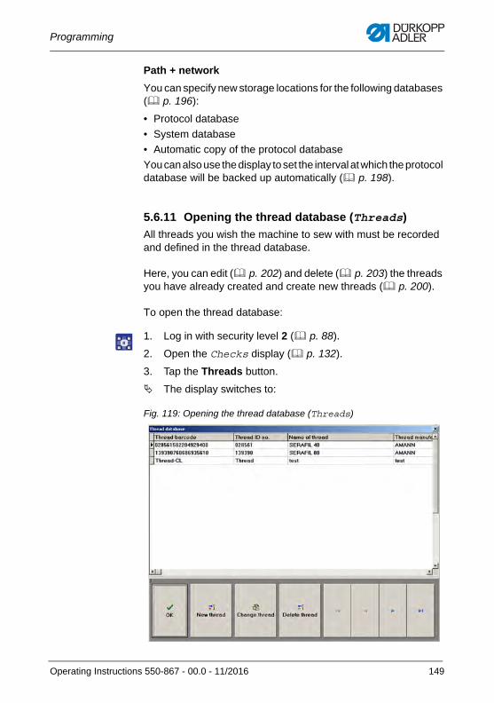
Programming
Path + network
You can specify new storage locations for the following databases ( p. 196):
• Protocol database
• System database
• Automatic copy of the protocol database
You can also use the display to set the interval at which the protocol database will be backed up automatically ( p. 198).
5.6.11 Opening the thread database (Threads)
All threads you wish the machine to sew with must be recorded and defined in the thread database.
Here, you can edit ( p. 202) and delete ( p. 203) the threads you have already created and create new threads ( p. 200).
To open the thread database:
1. Log in with security level 2 ( p. 88).
2. Open the Checks display ( p. 132).
3. Tap the Threads button.
The display switches to:
Fig. 119: Opening the thread database (Threads)
Operating Instructions 550-867 - 00.0 - 11/2016 149
Programming
5.6.12 Printing the protocol database (DB print)
Here, you can print out the protocol database.
To print the protocol database:
1. Log in with security level 2 ( p. 87).
2. Open the Checks display ( p. 132).
3. Tap the DB print button.
The protocol database is printed.
InformationThe protocol database is always printed out in full.
If the function Protocol printer is not active on the Setup display, the DB print button will be displayed semi-transparent. In that case, it will not be possible to print the protocol database even if the protocol printer is connected and set up.
150 Operating Instructions 550-867 - 00.0 - 11/2016
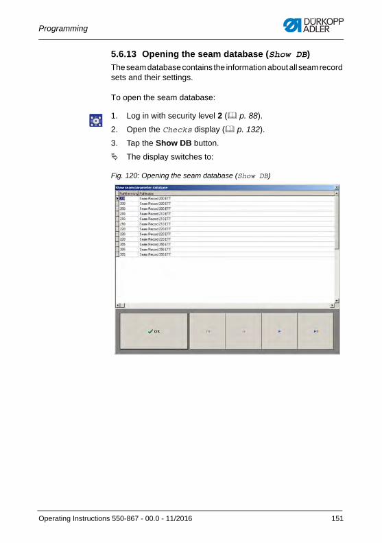
Programming
5.6.13 Opening the seam database (Show DB)
The seam database contains the information about all seam record sets and their settings.
To open the seam database:
1. Log in with security level 2 ( p. 88).
2. Open the Checks display ( p. 132).
3. Tap the Show DB button.
The display switches to:
Fig. 120: Opening the seam database (Show DB)
Operating Instructions 550-867 - 00.0 - 11/2016 151
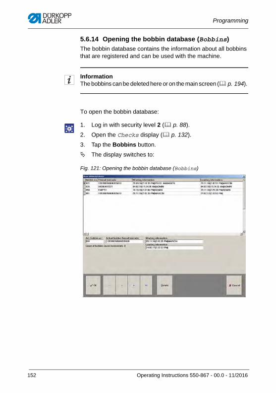
Programming
5.6.14 Opening the bobbin database (Bobbins)
The bobbin database contains the information about all bobbins that are registered and can be used with the machine.
InformationThe bobbins can be deleted here or on the main screen ( p. 194).
To open the bobbin database:
1. Log in with security level 2 ( p. 88).
2. Open the Checks display ( p. 132).
3. Tap the Bobbins button.
The display switches to:
Fig. 121: Opening the bobbin database (Bobbins)
152 Operating Instructions 550-867 - 00.0 - 11/2016
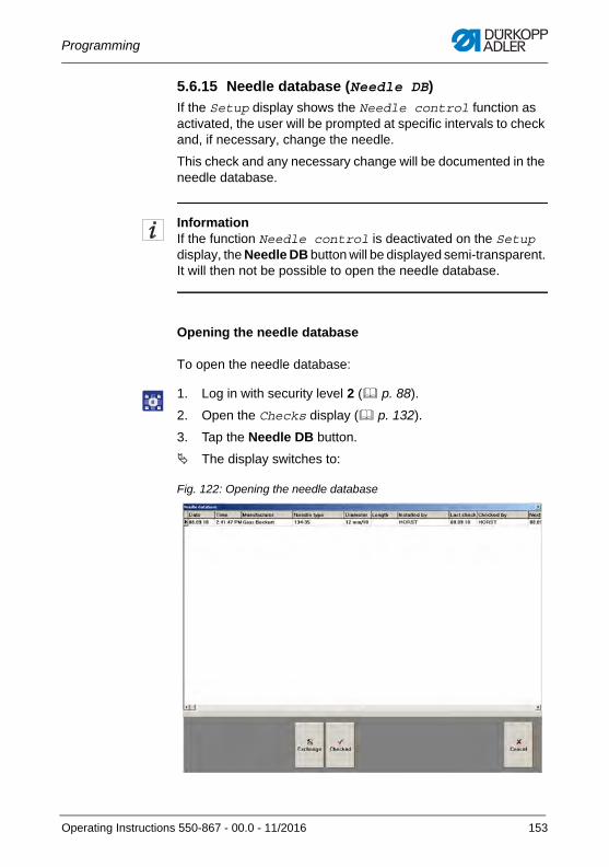
Programming
5.6.15 Needle database (Needle DB)
If the Setup display shows the Needle control function as activated, the user will be prompted at specific intervals to check and, if necessary, change the needle.
This check and any necessary change will be documented in the needle database.
InformationIf the function Needle control is deactivated on the Setup display, the Needle DB button will be displayed semi-transparent. It will then not be possible to open the needle database.
Opening the needle database
To open the needle database:
1. Log in with security level 2 ( p. 88).
2. Open the Checks display ( p. 132).
3. Tap the Needle DB button.
The display switches to:
Fig. 122: Opening the needle database
Operating Instructions 550-867 - 00.0 - 11/2016 153
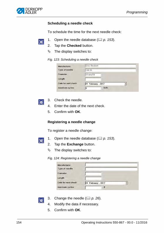
Programming
Scheduling a needle check
To schedule the time for the next needle check:
1. Open the needle database ( p. 153).
2. Tap the Checked button.
The display switches to:
Fig. 123: Scheduling a needle check
3. Check the needle.
4. Enter the date of the next check.
5. Confirm with OK.
Registering a needle change
To register a needle change:
1. Open the needle database ( p. 153).
2. Tap the Exchange button.
The display switches to:
Fig. 124: Registering a needle change
3. Change the needle ( p. 26).
4. Modify the data if necessary.
5. Confirm with OK.
154 Operating Instructions 550-867 - 00.0 - 11/2016
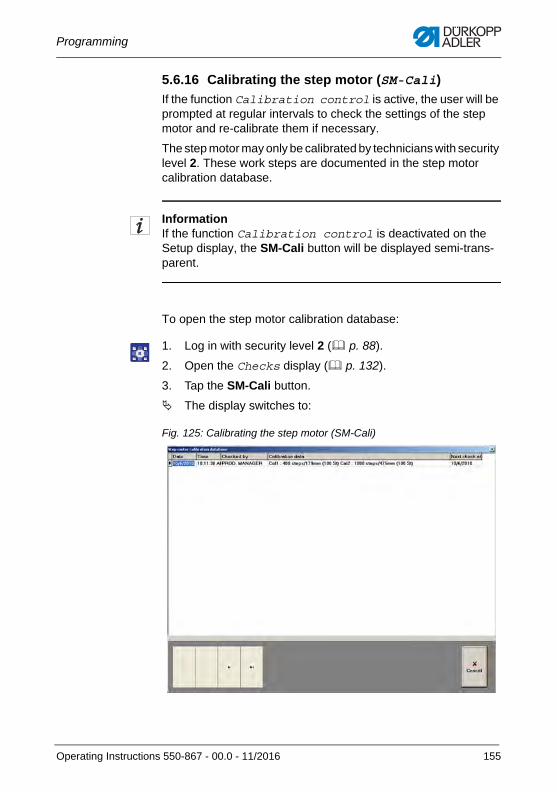
Programming
5.6.16 Calibrating the step motor (SM-Cali)
If the function Calibration control is active, the user will be prompted at regular intervals to check the settings of the step motor and re-calibrate them if necessary.
The step motor may only be calibrated by technicians with security level 2. These work steps are documented in the step motor calibration database.
InformationIf the function Calibration control is deactivated on the Setup display, the SM-Cali button will be displayed semi-trans-parent.
To open the step motor calibration database:
1. Log in with security level 2 ( p. 88).
2. Open the Checks display ( p. 132).
3. Tap the SM-Cali button.
The display switches to:
Fig. 125: Calibrating the step motor (SM-Cali)
Operating Instructions 550-867 - 00.0 - 11/2016 155
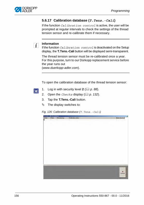
Programming
5.6.17 Calibration database (T.Tens.-Cali)
If the function Calibration control is active, the user will be prompted at regular intervals to check the settings of the thread tension sensor and re-calibrate them if necessary.
InformationIf the function Calibration control is deactivated on the Setup display, the T.Tens.-Cali button will be displayed semi-transparent.
The thread tension sensor must be re-calibrated once a year. For this purpose, turn to our Dürkopp replacement service before the year runs out (www.duerkopp-adler.com).
To open the calibration database of the thread tension sensor:
1. Log in with security level 2 ( p. 88).
2. Open the Checks display ( p. 132).
3. Tap the T.Tens.-Cali button.
The display switches to:
Fig. 126: Calibration database (T.Tens.-Cali)
156 Operating Instructions 550-867 - 00.0 - 11/2016
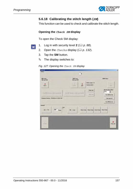
Programming
5.6.18 Calibrating the stitch length (SM)
This function can be used to check and calibrate the stitch length.
Opening the Check SM display
To open the Check SM display:
1. Log in with security level 2 ( p. 88).
2. Open the Checks display ( p. 132).
3. Tap the SM button.
The display switches to:
Fig. 127: Opening the Check SM display
Operating Instructions 550-867 - 00.0 - 11/2016 157
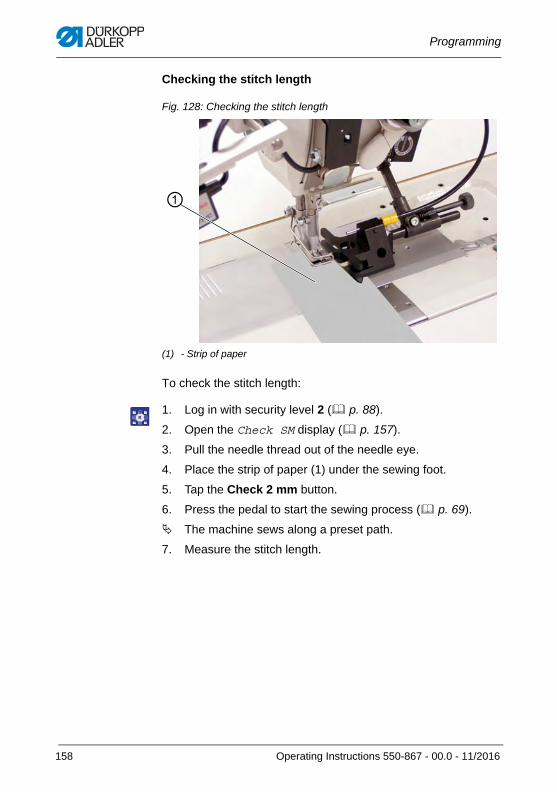
Programming
Checking the stitch length
Fig. 128: Checking the stitch length
To check the stitch length:
1. Log in with security level 2 ( p. 88).
2. Open the Check SM display ( p. 157).
3. Pull the needle thread out of the needle eye.
4. Place the strip of paper (1) under the sewing foot.
5. Tap the Check 2 mm button.
6. Press the pedal to start the sewing process ( p. 69).
The machine sews along a preset path.
7. Measure the stitch length.
(1) - Strip of paper
①
158 Operating Instructions 550-867 - 00.0 - 11/2016
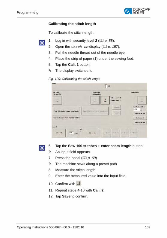
Programming
Calibrating the stitch length
To calibrate the stitch length:
1. Log in with security level 2 ( p. 88).
2. Open the Check SM display ( p. 157).
3. Pull the needle thread out of the needle eye.
4. Place the strip of paper (1) under the sewing foot.
5. Tap the Cali. 1 button.
The display switches to:
Fig. 129: Calibrating the stitch length
6. Tap the Sew 100 stitches + enter seam length button.
An input field appears.
7. Press the pedal ( p. 69).
The machine sews along a preset path.
8. Measure the stitch length.
9. Enter the measured value into the input field.
10. Confirm with .
11. Repeat steps 4-10 with Cali. 2.
12. Tap Save to confirm.
Operating Instructions 550-867 - 00.0 - 11/2016 159
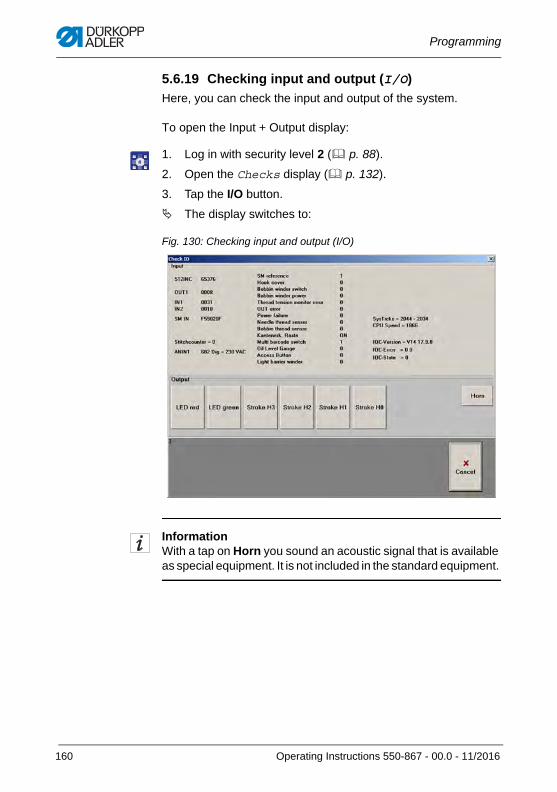
Programming
5.6.19 Checking input and output (I/O)
Here, you can check the input and output of the system.
To open the Input + Output display:
1. Log in with security level 2 ( p. 88).
2. Open the Checks display ( p. 132).
3. Tap the I/O button.
The display switches to:
Fig. 130: Checking input and output (I/O)
InformationWith a tap on Horn you sound an acoustic signal that is available as special equipment. It is not included in the standard equipment.
160 Operating Instructions 550-867 - 00.0 - 11/2016
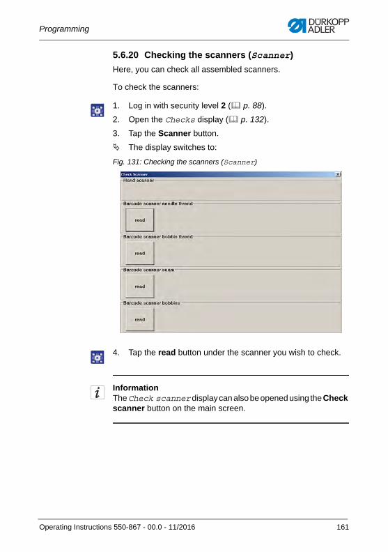
Programming
5.6.20 Checking the scanners (Scanner)
Here, you can check all assembled scanners.
To check the scanners:
1. Log in with security level 2 ( p. 88).
2. Open the Checks display ( p. 132).
3. Tap the Scanner button.
The display switches to:
Fig. 131: Checking the scanners (Scanner)
4. Tap the read button under the scanner you wish to check.
InformationThe Check scanner display can also be opened using the Check scanner button on the main screen.
Operating Instructions 550-867 - 00.0 - 11/2016 161
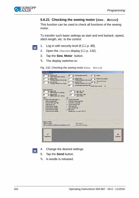
Programming
5.6.21 Checking the sewing motor (Sew. Motor)
This function can be used to check all functions of the sewing motor.
To transfer such basic settings as start and end bartack, speed, stitch length, etc. to the control:
1. Log in with security level 2 ( p. 88).
2. Open the Checks display ( p. 132).
3. Tap the Sew. Motor button.
The display switches to:
Fig. 132: Checking the sewing motor (Sew. Motor)
4. Change the desired settings.
5. Tap the Send button.
A needle is released.
162 Operating Instructions 550-867 - 00.0 - 11/2016
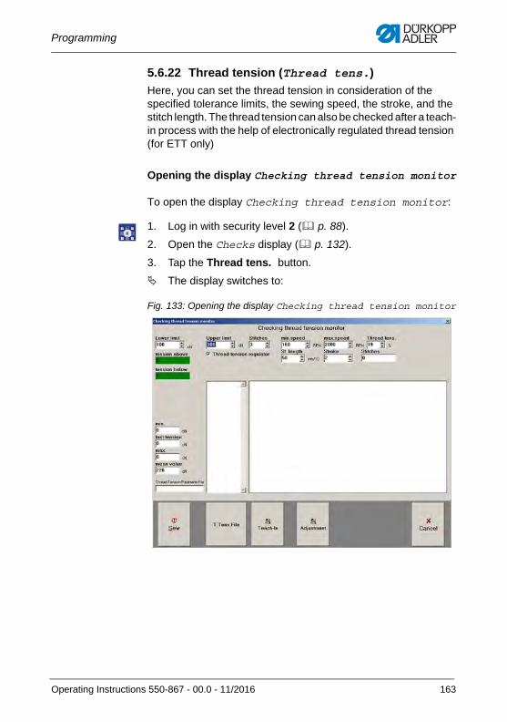
Programming
5.6.22 Thread tension (Thread tens.)
Here, you can set the thread tension in consideration of the specified tolerance limits, the sewing speed, the stroke, and the stitch length. The thread tension can also be checked after a teach-in process with the help of electronically regulated thread tension (for ETT only)
Opening the display Checking thread tension monitor
To open the display Checking thread tension monitor:
1. Log in with security level 2 ( p. 88).
2. Open the Checks display ( p. 132).
3. Tap the Thread tens. button.
The display switches to:
Fig. 133: Opening the display Checking thread tension monitor
Operating Instructions 550-867 - 00.0 - 11/2016 163
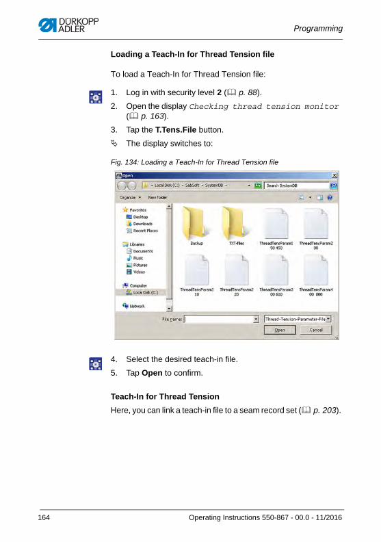
Programming
Loading a Teach-In for Thread Tension file
To load a Teach-In for Thread Tension file:
1. Log in with security level 2 ( p. 88).
2. Open the display Checking thread tension monitor ( p. 163).
3. Tap the T.Tens.File button.
The display switches to:
Fig. 134: Loading a Teach-In for Thread Tension file
4. Select the desired teach-in file.
5. Tap Open to confirm.
Teach-In for Thread Tension
Here, you can link a teach-in file to a seam record set ( p. 203).
164 Operating Instructions 550-867 - 00.0 - 11/2016
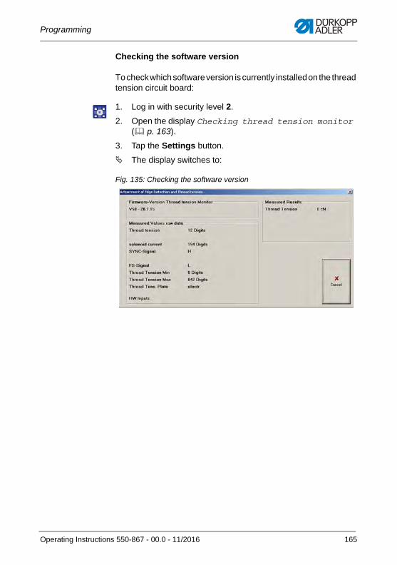
Programming
Checking the software version
To check which software version is currently installed on the thread tension circuit board:
1. Log in with security level 2.
2. Open the display Checking thread tension monitor ( p. 163).
3. Tap the Settings button.
The display switches to:
Fig. 135: Checking the software version
Operating Instructions 550-867 - 00.0 - 11/2016 165
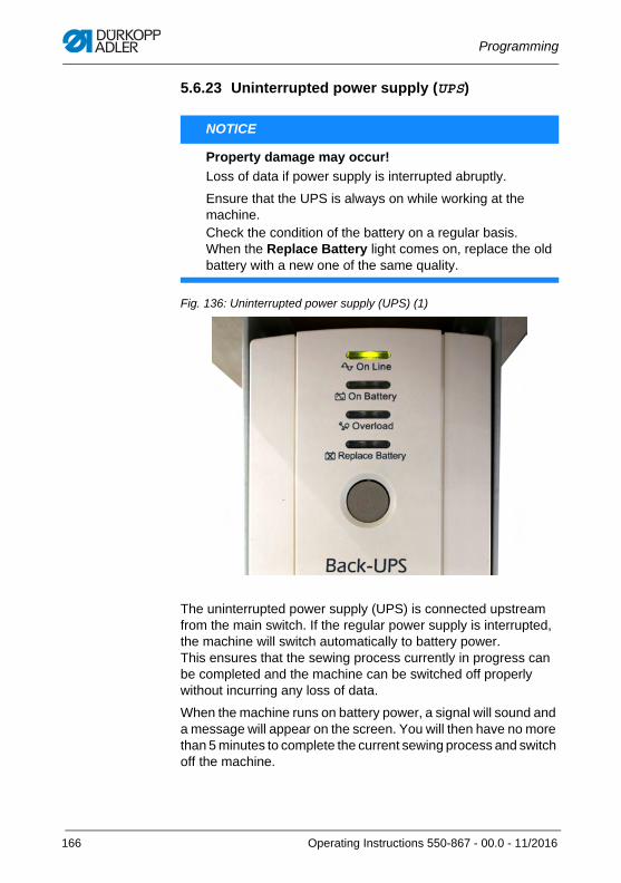
Programming
5.6.23 Uninterrupted power supply (UPS)
Fig. 136: Uninterrupted power supply (UPS) (1)
The uninterrupted power supply (UPS) is connected upstream from the main switch. If the regular power supply is interrupted, the machine will switch automatically to battery power. This ensures that the sewing process currently in progress can be completed and the machine can be switched off properly without incurring any loss of data.
When the machine runs on battery power, a signal will sound and a message will appear on the screen. You will then have no more than 5 minutes to complete the current sewing process and switch off the machine.
NOTICE
Property damage may occur!
Loss of data if power supply is interrupted abruptly.
Ensure that the UPS is always on while working at the machine. Check the condition of the battery on a regular basis. When the Replace Battery light comes on, replace the old battery with a new one of the same quality.
166 Operating Instructions 550-867 - 00.0 - 11/2016
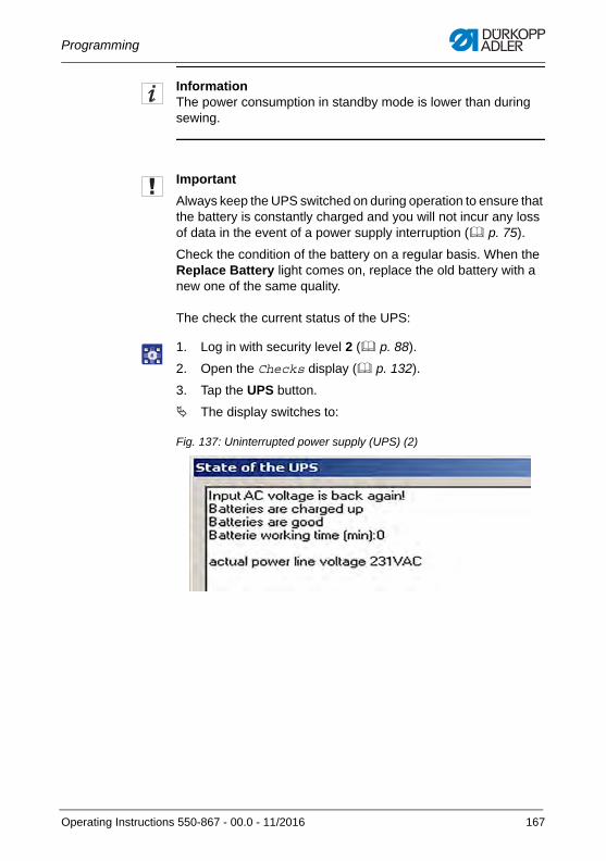
Programming
InformationThe power consumption in standby mode is lower than during sewing.
Important
Always keep the UPS switched on during operation to ensure that the battery is constantly charged and you will not incur any loss of data in the event of a power supply interruption ( p. 75).
Check the condition of the battery on a regular basis. When the Replace Battery light comes on, replace the old battery with a new one of the same quality.
The check the current status of the UPS:
1. Log in with security level 2 ( p. 88).
2. Open the Checks display ( p. 132).
3. Tap the UPS button.
The display switches to:
Fig. 137: Uninterrupted power supply (UPS) (2)
Operating Instructions 550-867 - 00.0 - 11/2016 167
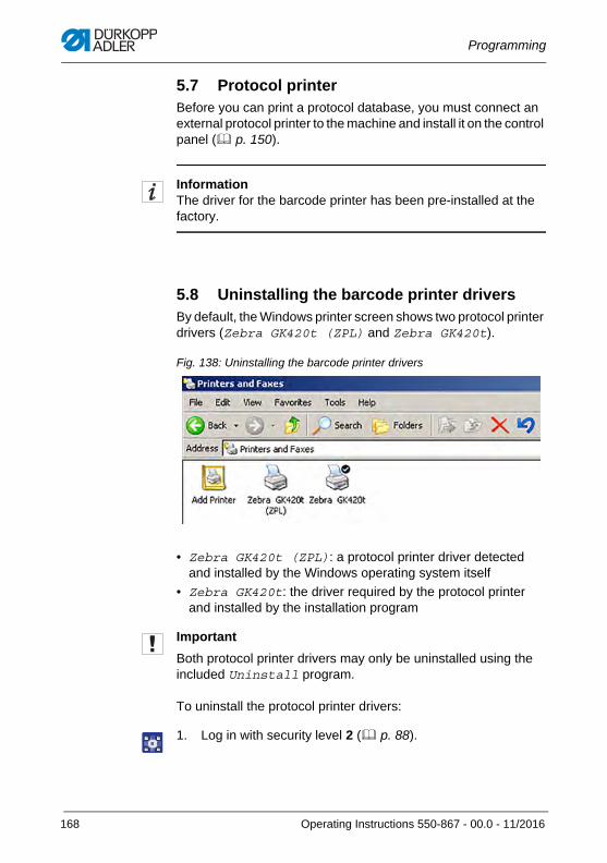
Programming
5.7 Protocol printerBefore you can print a protocol database, you must connect an external protocol printer to the machine and install it on the control panel ( p. 150).
InformationThe driver for the barcode printer has been pre-installed at the factory.
5.8 Uninstalling the barcode printer driversBy default, the Windows printer screen shows two protocol printer drivers (Zebra GK420t (ZPL) and Zebra GK420t).
Fig. 138: Uninstalling the barcode printer drivers
• Zebra GK420t (ZPL): a protocol printer driver detected and installed by the Windows operating system itself
• Zebra GK420t: the driver required by the protocol printer and installed by the installation program
Important
Both protocol printer drivers may only be uninstalled using the included Uninstall program.
To uninstall the protocol printer drivers:
1. Log in with security level 2 ( p. 88).
168 Operating Instructions 550-867 - 00.0 - 11/2016
Programming
2. To access the Windows level,
• press the Windows button on the keyboard
• Exit program ( p. 209)
3. Open Windows Explorer.
4. Open the PrinterDriver folder.
5. Double-tap the Driver Uninstall.exe program.
6. Tap the Next button.
The installed protocol printer drivers are displayed.
7. Select the Zebra GK420t driver.
8. Tap the Remove button.
9. Confirm with OK.
The corresponding files are uninstalled.
10. Select the Zebra GK420t (ZPL) driver.
11. Tap the Remove button.
12. Confirm with OK.
13. Tap the Next button.
14. Tap the Finish button.
The corresponding files are uninstalled.
5.9 Calibrating the end label printer The end label printer calibrates itself automatically to the distance of the labels on the backing material by means of a built-in light barrier. If this distance is not detected correctly, the end label printer must be re-calibrated.
To do so, refer to page 82 of the Manufacturer's instructions on the end label printer.
Operating Instructions 550-867 - 00.0 - 11/2016 169
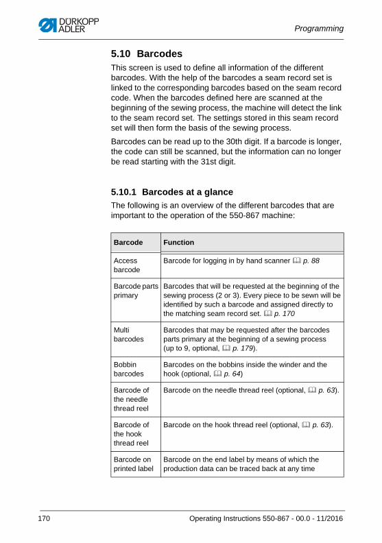
Programming
5.10 BarcodesThis screen is used to define all information of the different barcodes. With the help of the barcodes a seam record set is linked to the corresponding barcodes based on the seam record code. When the barcodes defined here are scanned at the beginning of the sewing process, the machine will detect the link to the seam record set. The settings stored in this seam record set will then form the basis of the sewing process.
Barcodes can be read up to the 30th digit. If a barcode is longer, the code can still be scanned, but the information can no longer be read starting with the 31st digit.
5.10.1 Barcodes at a glance
The following is an overview of the different barcodes that are important to the operation of the 550-867 machine:
Barcode Function
Access barcode
Barcode for logging in by hand scanner p. 88
Barcode parts primary
Barcodes that will be requested at the beginning of the sewing process (2 or 3). Every piece to be sewn will be identified by such a barcode and assigned directly to the matching seam record set. p. 170
Multi barcodes
Barcodes that may be requested after the barcodes parts primary at the beginning of a sewing process (up to 9, optional, p. 179).
Bobbin barcodes
Barcodes on the bobbins inside the winder and the hook (optional, p. 64)
Barcode of the needle thread reel
Barcode on the needle thread reel (optional, p. 63).
Barcode of the hook thread reel
Barcode on the hook thread reel (optional, p. 63).
Barcode on printed label
Barcode on the end label by means of which the production data can be traced back at any time
170 Operating Instructions 550-867 - 00.0 - 11/2016
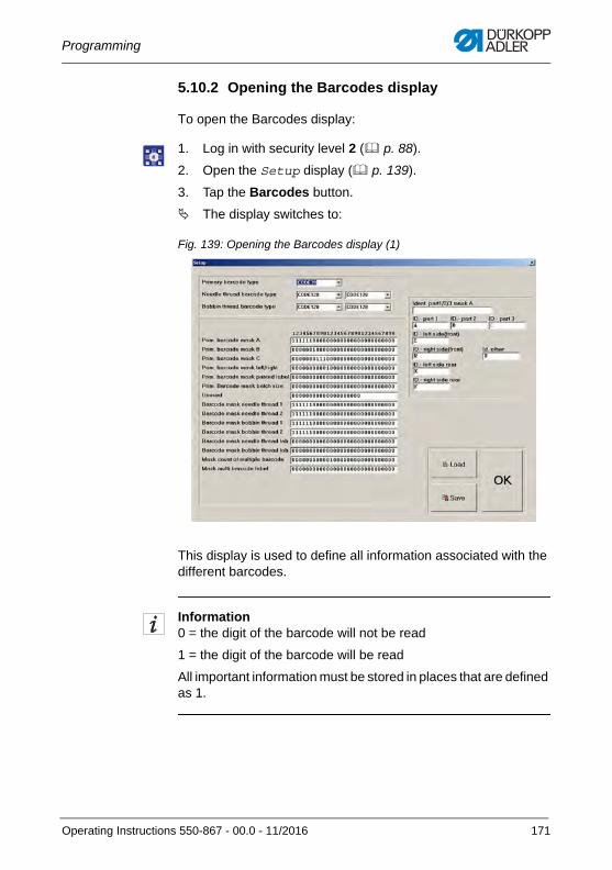
Programming
5.10.2 Opening the Barcodes display
To open the Barcodes display:
1. Log in with security level 2 ( p. 88).
2. Open the Setup display ( p. 139).
3. Tap the Barcodes button.
The display switches to:
Fig. 139: Opening the Barcodes display (1)
This display is used to define all information associated with the different barcodes.
Information0 = the digit of the barcode will not be read
1 = the digit of the barcode will be read
All important information must be stored in places that are defined as 1.
Operating Instructions 550-867 - 00.0 - 11/2016 171
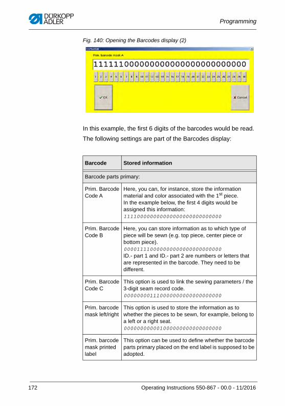
Programming
Fig. 140: Opening the Barcodes display (2)
In this example, the first 6 digits of the barcodes would be read.
The following settings are part of the Barcodes display:
Barcode Stored information
Barcode parts primary:
Prim. Barcode Code A
Here, you can, for instance, store the information material and color associated with the 1st piece. In the example below, the first 4 digits would be assigned this information:111100000000000000000000000000
Prim. Barcode Code B
Here, you can store information as to which type of piece will be sewn (e.g. top piece, center piece or bottom piece). 000011110000000000000000000000ID.- part 1 and ID.- part 2 are numbers or letters that are represented in the barcode. They need to be different.
Prim. Barcode Code C
This option is used to link the sewing parameters / the 3-digit seam record code. 000000001110000000000000000000
Prim. barcode mask left/right
This option is used to store the information as to whether the pieces to be sewn, for example, belong to a left or a right seat. 000000000001000000000000000000
Prim. barcode mask printed label
This option can be used to define whether the barcode parts primary placed on the end label is supposed to be adopted.
172 Operating Instructions 550-867 - 00.0 - 11/2016
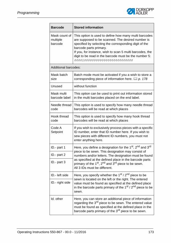
Programming
Mask count of multiple barcode
This option is used to define how many multi barcodes are supposed to be scanned. The desired number is specified by selecting the corresponding digit of the barcode parts primary. If you, for instance, wish to scan 5 multi barcodes, the digit to be read in the barcode must be the number 5:000010000000000000000000000000
Additional barcodes:
Mask batch size
Batch mode must be activated if you a wish to store a corresponding piece of information here. p. 178
Unused without function
Mask multi barcode label
This option can be used to print out information stored in the multi barcodes placed on the end label.
Needle thread code
This option is used to specify how many needle thread barcodes will be read at which places
Hook thread code
This option is used to specify how many hook thread barcodes will be read at which places
Code A Setpoint
If you wish to exclusively process pieces with a specific ID number, enter that ID number here. If you wish to sew pieces with different ID numbers, you must not enter anything here.
ID.- part 1 Here, you define a designation for the 1st, 2nd and 3rd piece to be sewn. This designation may consist of numbers and/or letters. The designation must be found as specified at the defined place in the barcode parts primary of the 1st, 2nd and 3rd piece to be sewn.All 3 IDs must be different.
ID.- part 2
ID.- part 3
ID.- left side Here, you specify whether the 1st / 2nd piece to be sewn is located on the left or the right. The entered value must be found as specified at the defined place in the barcode parts primary of the 1st / 2nd piece to be sewn.
ID.- right side
Id. other Here, you can store an additional piece of information regarding the 3rd piece to be sewn. The entered value must be found as specified at the defined place in the barcode parts primary of the 3rd piece to be sewn.
Barcode Stored information
Operating Instructions 550-867 - 00.0 - 11/2016 173
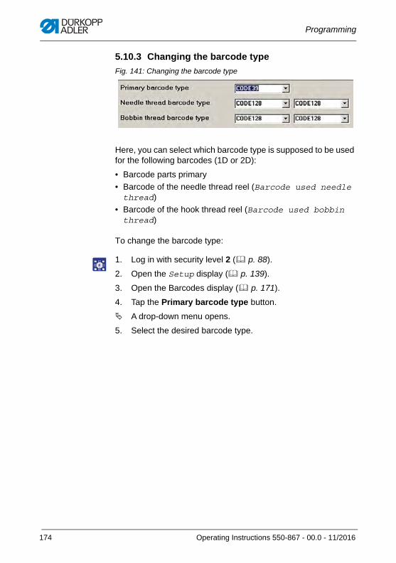
Programming
5.10.3 Changing the barcode type
Fig. 141: Changing the barcode type
Here, you can select which barcode type is supposed to be used for the following barcodes (1D or 2D):
• Barcode parts primary
• Barcode of the needle thread reel (Barcode used needle thread)
• Barcode of the hook thread reel (Barcode used bobbin thread)
To change the barcode type:
1. Log in with security level 2 ( p. 88).
2. Open the Setup display ( p. 139).
3. Open the Barcodes display ( p. 171).
4. Tap the Primary barcode type button.
A drop-down menu opens.
5. Select the desired barcode type.
174 Operating Instructions 550-867 - 00.0 - 11/2016
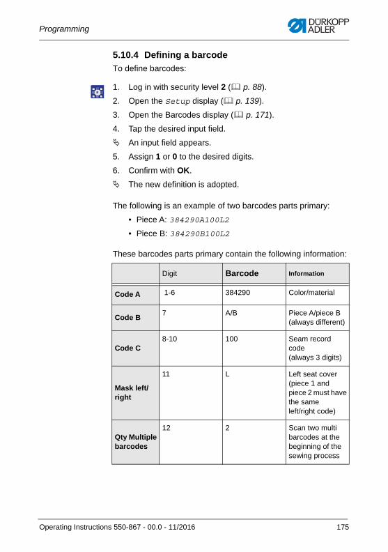
Programming
5.10.4 Defining a barcode
To define barcodes:
1. Log in with security level 2 ( p. 88).
2. Open the Setup display ( p. 139).
3. Open the Barcodes display ( p. 171).
4. Tap the desired input field.
An input field appears.
5. Assign 1 or 0 to the desired digits.
6. Confirm with OK.
The new definition is adopted.
The following is an example of two barcodes parts primary:
• Piece A: 384290A100L2
• Piece B: 384290B100L2
These barcodes parts primary contain the following information:
Digit Barcode Information
Code A 1-6 384290 Color/material
Code B7 A/B Piece A/piece B
(always different)
Code C8-10 100 Seam record
code(always 3 digits)
Mask left/right
11 L Left seat cover (piece 1 and piece 2 must have the same left/right code)
Qty Multiple barcodes
12 2 Scan two multi barcodes at the beginning of the sewing process
Operating Instructions 550-867 - 00.0 - 11/2016 175
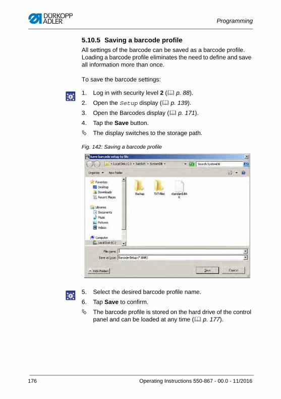
Programming
5.10.5 Saving a barcode profile
All settings of the barcode can be saved as a barcode profile. Loading a barcode profile eliminates the need to define and save all information more than once.
To save the barcode settings:
1. Log in with security level 2 ( p. 88).
2. Open the Setup display ( p. 139).
3. Open the Barcodes display ( p. 171).
4. Tap the Save button.
The display switches to the storage path.
Fig. 142: Saving a barcode profile
5. Select the desired barcode profile name.
6. Tap Save to confirm.
The barcode profile is stored on the hard drive of the control panel and can be loaded at any time ( p. 177).
176 Operating Instructions 550-867 - 00.0 - 11/2016
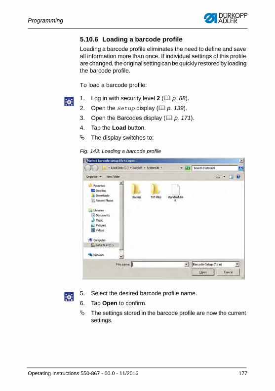
Programming
5.10.6 Loading a barcode profile
Loading a barcode profile eliminates the need to define and save all information more than once. If individual settings of this profile are changed, the original setting can be quickly restored by loading the barcode profile.
To load a barcode profile:
1. Log in with security level 2 ( p. 88).
2. Open the Setup display ( p. 139).
3. Open the Barcodes display ( p. 171).
4. Tap the Load button.
The display switches to:
Fig. 143: Loading a barcode profile
5. Select the desired barcode profile name.
6. Tap Open to confirm.
The settings stored in the barcode profile are now the current settings.
Operating Instructions 550-867 - 00.0 - 11/2016 177
Programming
5.11 Setting batch modeBatch mode is a function that is used to set a specific batch size / number of sewing processes.
You can, for instance, define that one batch is composed of 5 sewing processes. In this case, all barcodes parts primary and, if applicable, all multi barcodes will only be requested once at the beginning of the sewing process, and all 5 sewing processes will be completed before the barcodes are requested again at the beginning of the 6th sewing process ( p. 179).
To activate the batch mode function:
1. Log in with security level 2 ( p. 88).
2. Open the Setup display ( p. 139).
3. Go to the Components section and activate the With batch mode function.
The checkmark confirms that the function is active.
InformationIf, at the beginning of the sewing process, multi barcodes are requested as well, go to the Components section and activate the function Multi barcode with batch mode instead of the With batch mode function.
4. Open the Barcodes display ( p. 171).
5. Specify under Mask batch size how large the batch size is supposed to be.
If you, for instance, wish the batch size to be 5, the digit to be read in the barcode must be the number 5:
000010000000000000000000000000
178 Operating Instructions 550-867 - 00.0 - 11/2016
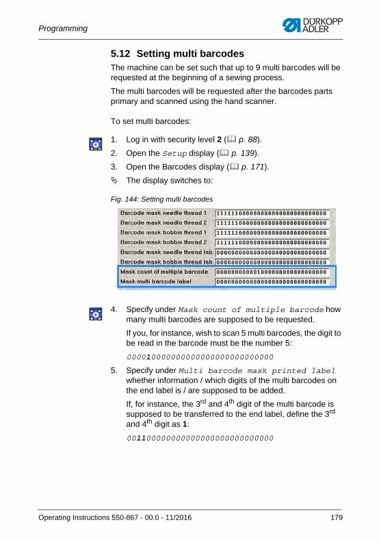
Programming
5.12 Setting multi barcodesThe machine can be set such that up to 9 multi barcodes will be requested at the beginning of a sewing process.
The multi barcodes will be requested after the barcodes parts primary and scanned using the hand scanner.
To set multi barcodes:
1. Log in with security level 2 ( p. 88).
2. Open the Setup display ( p. 139).
3. Open the Barcodes display ( p. 171).
The display switches to:
Fig. 144: Setting multi barcodes
4. Specify under Mask count of multiple barcode how many multi barcodes are supposed to be requested.
If you, for instance, wish to scan 5 multi barcodes, the digit to be read in the barcode must be the number 5:
000010000000000000000000000000
5. Specify under Multi barcode mask printed label whether information / which digits of the multi barcodes on the end label is / are supposed to be added.
If, for instance, the 3rd and 4th digit of the multi barcode is supposed to be transferred to the end label, define the 3rd and 4th digit as 1:
001100000000000000000000000000
Operating Instructions 550-867 - 00.0 - 11/2016 179
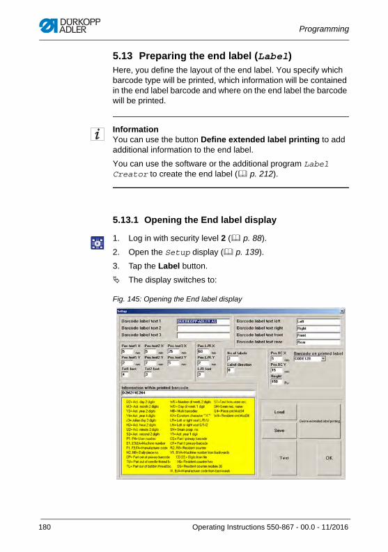
Programming
5.13 Preparing the end label (Label)Here, you define the layout of the end label. You specify which barcode type will be printed, which information will be contained in the end label barcode and where on the end label the barcode will be printed.
InformationYou can use the button Define extended label printing to add additional information to the end label.
You can use the software or the additional program Label Creator to create the end label ( p. 212).
5.13.1 Opening the End label display
1. Log in with security level 2 ( p. 88).
2. Open the Setup display ( p. 139).
3. Tap the Label button.
The display switches to:
Fig. 145: Opening the End label display
180 Operating Instructions 550-867 - 00.0 - 11/2016
Programming
5.13.2 Defining the end label text
You can define text for the end label and specify its position as well as create the information to be included in the barcode.
To define the text:
1. Log in with security level 2 ( p. 88).
2. Open the End label display ( p. 180).
3. Tap one of the following input fields:
• Barcode label text 1
• Barcode label text 2
• barcode label text 3
• Barcode label text left
• Barcode label text right
An input field appears.
4. Enter the desired text.
5. Confirm with .
InformationYou do not have to complete all text fields.
Operating Instructions 550-867 - 00.0 - 11/2016 181
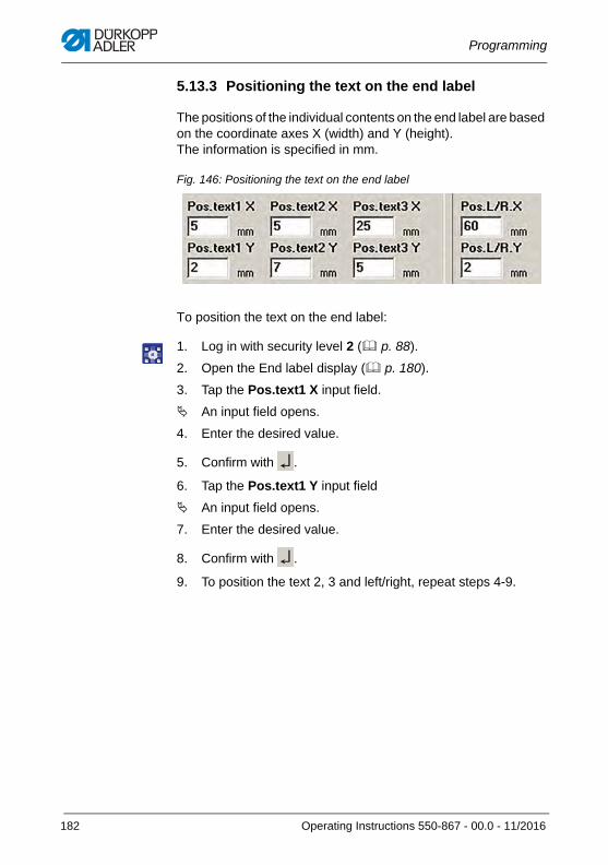
Programming
5.13.3 Positioning the text on the end label
The positions of the individual contents on the end label are based on the coordinate axes X (width) and Y (height). The information is specified in mm.
Fig. 146: Positioning the text on the end label
To position the text on the end label:
1. Log in with security level 2 ( p. 88).
2. Open the End label display ( p. 180).
3. Tap the Pos.text1 X input field.
An input field opens.
4. Enter the desired value.
5. Confirm with .
6. Tap the Pos.text1 Y input field
An input field opens.
7. Enter the desired value.
8. Confirm with .
9. To position the text 2, 3 and left/right, repeat steps 4-9.
182 Operating Instructions 550-867 - 00.0 - 11/2016
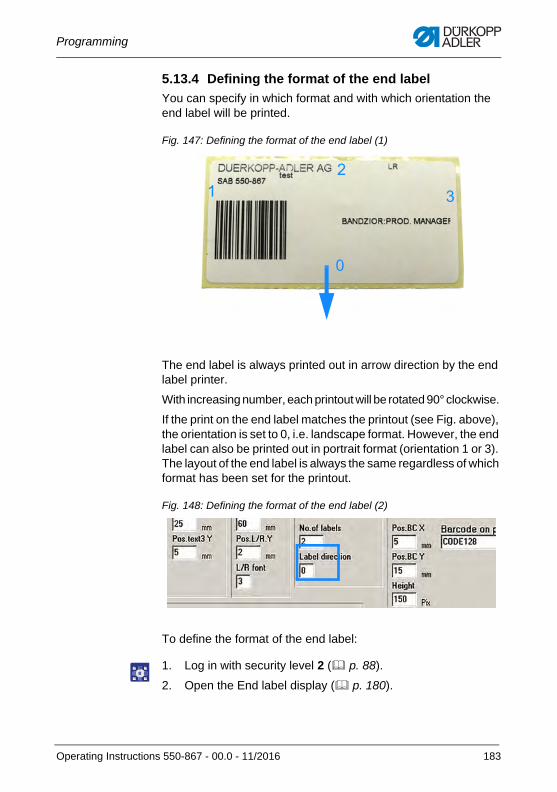
Programming
5.13.4 Defining the format of the end label
You can specify in which format and with which orientation the end label will be printed.
Fig. 147: Defining the format of the end label (1)
The end label is always printed out in arrow direction by the end label printer.
With increasing number, each printout will be rotated 90° clockwise.
If the print on the end label matches the printout (see Fig. above), the orientation is set to 0, i.e. landscape format. However, the end label can also be printed out in portrait format (orientation 1 or 3). The layout of the end label is always the same regardless of which format has been set for the printout.
Fig. 148: Defining the format of the end label (2)
To define the format of the end label:
1. Log in with security level 2 ( p. 88).
2. Open the End label display ( p. 180).
0
32
1
Operating Instructions 550-867 - 00.0 - 11/2016 183
Programming
3. Tap the Label direction input field.
An input field opens.
4. Enter the desired value:
• Landscape: 0 or 2
• Portrait: 1 or 3
5. Confirm with .
InformationTo view the end label, tap the Test button.
The end label is printed out once.
5.13.5 Positioning the end label barcode
The position of the barcode on the end label is based on the coordinate axes X (width) and Y (height). The information is spec-ified in mm.
To position the barcode on the end label:
1. Log in with security level 2 ( p. 88).
2. Open the End label display ( p. 180).
3. Tap the Pos.BC X input field.
An input field opens.
4. Enter the desired value.
5. Confirm with .
6. Tap the Pos.BC Y input field.
An input field opens.
7. Enter the desired value.
8. Confirm with .
184 Operating Instructions 550-867 - 00.0 - 11/2016
Programming
5.13.6 Defining the font size
You can define the font size to be used on the end label:
• Text 1
• Text 2
• Text left/right
To define the font size for each text:
1. Log in with security level 2 ( p. 88).
2. Open the End label display ( p. 180).
3. Tap the Txt1 font, Txt2 font or L/R font input field.
An input field opens.
4. Enter the desired value (1-5).
5. Confirm with .
5.13.7 Defining an end label barcode type
To define the end label barcode type:
1. Log in with security level 2 ( p. 88).
2. Open the End label display ( p. 180).
3. Tap the Barcode on printed label type input field.
A drop-down menu opens.
4. Select the desired end label barcode type.
InformationTo view the barcode, tap the Test button.
The end label is printed out once.
Operating Instructions 550-867 - 00.0 - 11/2016 185
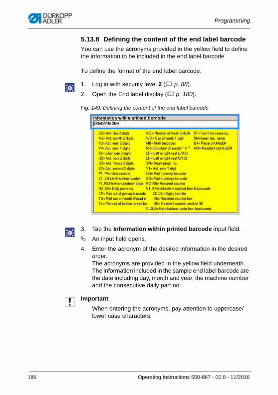
Programming
5.13.8 Defining the content of the end label barcode
You can use the acronyms provided in the yellow field to define the information to be included in the end label barcode
To define the format of the end label barcode:
1. Log in with security level 2 ( p. 88).
2. Open the End label display ( p. 180).
Fig. 149: Defining the content of the end label barcode
3. Tap the Information within printed barcode input field.
An input field opens.
4. Enter the acronym of the desired information in the desired order. The acronyms are provided in the yellow field underneath. The information included in the sample end label barcode are the date including day, month and year, the machine number and the consecutive daily part no..
Important
When entering the acronyms, pay attention to uppercase/lower case characters.
186 Operating Instructions 550-867 - 00.0 - 11/2016
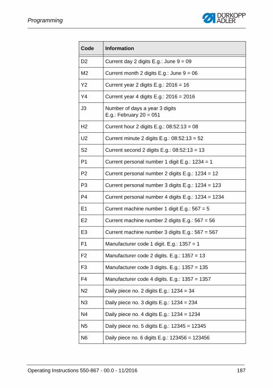
Programming
Code Information
D2 Current day 2 digits E.g.: June 9 = 09
M2 Current month 2 digits E.g.: June 9 = 06
Y2 Current year 2 digits E.g.: 2016 = 16
Y4 Current year 4 digits E.g.: 2016 = 2016
J3 Number of days a year 3 digits E.g.: February 20 = 051
H2 Current hour 2 digits E.g.: 08:52:13 = 08
U2 Current minute 2 digits E.g.: 08:52:13 = 52
S2 Current second 2 digits E.g.: 08:52:13 = 13
P1 Current personal number 1 digit E.g.: 1234 = 1
P2 Current personal number 2 digits E.g.: 1234 = 12
P3 Current personal number 3 digits E.g.: 1234 = 123
P4 Current personal number 4 digits E.g.: 1234 = 1234
E1 Current machine number 1 digit E.g.: 567 = 5
E2 Current machine number 2 digits E.g.: 567 = 56
E3 Current machine number 3 digits E.g.: 567 = 567
F1 Manufacturer code 1 digit. E.g.: 1357 = 1
F2 Manufacturer code 2 digits. E.g.: 1357 = 13
F3 Manufacturer code 3 digits. E.g.: 1357 = 135
F4 Manufacturer code 4 digits. E.g.: 1357 = 1357
N2 Daily piece no. 2 digits E.g.: 1234 = 34
N3 Daily piece no. 3 digits E.g.: 1234 = 234
N4 Daily piece no. 4 digits E.g.: 1234 = 1234
N5 Daily piece no. 5 digits E.g.: 12345 = 12345
N6 Daily piece no. 6 digits E.g.: 123456 = 123456
Operating Instructions 550-867 - 00.0 - 11/2016 187
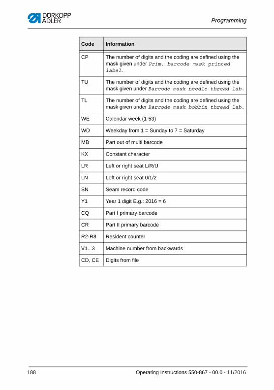
Programming
CP The number of digits and the coding are defined using the mask given under Prim. barcode mask printed label.
TU The number of digits and the coding are defined using the mask given under Barcode mask needle thread lab.
TL The number of digits and the coding are defined using the mask given under Barcode mask bobbin thread lab.
WE Calendar week (1-53)
WD Weekday from 1 = Sunday to 7 = Saturday
MB Part out of multi barcode
KX Constant character
LR Left or right seat L/R/U
LN Left or right seat 0/1/2
SN Seam record code
Y1 Year 1 digit E.g.: 2016 = 6
CQ Part I primary barcode
CR Part II primary barcode
R2-R8 Resident counter
V1...3 Machine number from backwards
CD, CE Digits from file
Code Information
188 Operating Instructions 550-867 - 00.0 - 11/2016
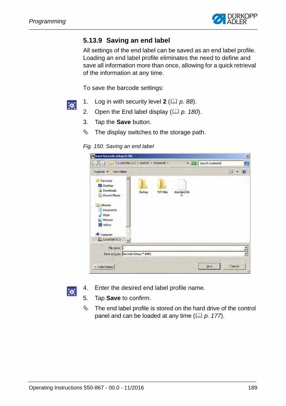
Programming
5.13.9 Saving an end label
All settings of the end label can be saved as an end label profile. Loading an end label profile eliminates the need to define and save all information more than once, allowing for a quick retrieval of the information at any time.
To save the barcode settings:
1. Log in with security level 2 ( p. 88).
2. Open the End label display ( p. 180).
3. Tap the Save button.
The display switches to the storage path.
Fig. 150: Saving an end label
4. Enter the desired end label profile name.
5. Tap Save to confirm.
The end label profile is stored on the hard drive of the control panel and can be loaded at any time ( p. 177).
Operating Instructions 550-867 - 00.0 - 11/2016 189
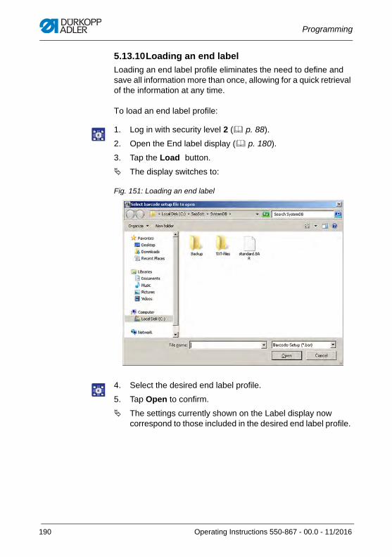
Programming
5.13.10Loading an end label
Loading an end label profile eliminates the need to define and save all information more than once, allowing for a quick retrieval of the information at any time.
To load an end label profile:
1. Log in with security level 2 ( p. 88).
2. Open the End label display ( p. 180).
3. Tap the Load button.
The display switches to:
Fig. 151: Loading an end label
4. Select the desired end label profile.
5. Tap Open to confirm.
The settings currently shown on the Label display now correspond to those included in the desired end label profile.
190 Operating Instructions 550-867 - 00.0 - 11/2016
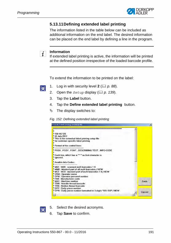
Programming
5.13.11Defining extended label printing
The information listed in the table below can be included as additional information on the end label. The desired information can be placed on the end label by defining a line in the program.
InformationIf extended label printing is active, the information will be printed at the defined position irrespective of the loaded barcode profile.
To extend the information to be printed on the label:
1. Log in with security level 2 ( p. 88).
2. Open the Setup display ( p. 139).
3. Tap the Label button.
4. Tap the Define extended label printing button.
The display switches to:
Fig. 152: Defining extended label printing
5. Select the desired acronyms.
6. Tap Save to confirm.
Operating Instructions 550-867 - 00.0 - 11/2016 191
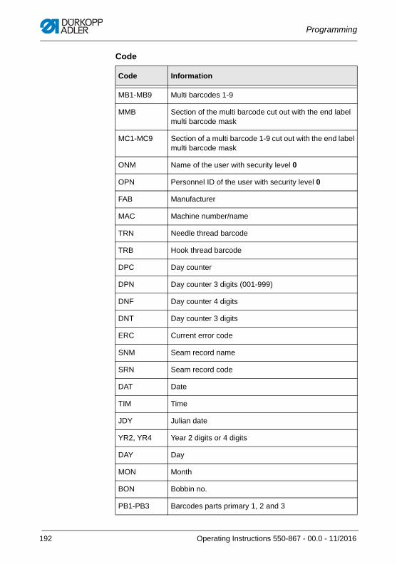
Programming
Code
Code Information
MB1-MB9 Multi barcodes 1-9
MMB Section of the multi barcode cut out with the end label multi barcode mask
MC1-MC9 Section of a multi barcode 1-9 cut out with the end label multi barcode mask
ONM Name of the user with security level 0
OPN Personnel ID of the user with security level 0
FAB Manufacturer
MAC Machine number/name
TRN Needle thread barcode
TRB Hook thread barcode
DPC Day counter
DPN Day counter 3 digits (001-999)
DNF Day counter 4 digits
DNT Day counter 3 digits
ERC Current error code
SNM Seam record name
SRN Seam record code
DAT Date
TIM Time
JDY Julian date
YR2, YR4 Year 2 digits or 4 digits
DAY Day
MON Month
BON Bobbin no.
PB1-PB3 Barcodes parts primary 1, 2 and 3
192 Operating Instructions 550-867 - 00.0 - 11/2016
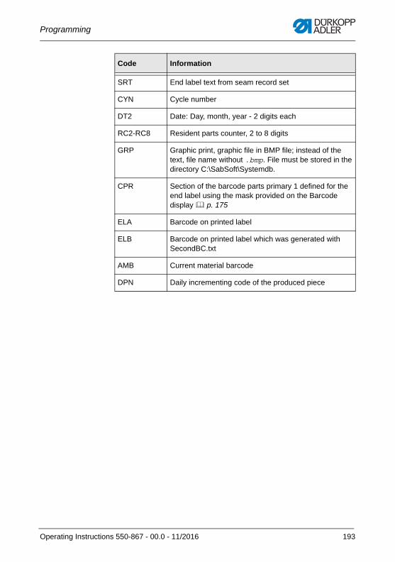
Programming
SRT End label text from seam record set
CYN Cycle number
DT2 Date: Day, month, year - 2 digits each
RC2-RC8 Resident parts counter, 2 to 8 digits
GRP Graphic print, graphic file in BMP file; instead of the text, file name without .bmp. File must be stored in the directory C:\SabSoft\Systemdb.
CPR Section of the barcode parts primary 1 defined for the end label using the mask provided on the Barcode display p. 175
ELA Barcode on printed label
ELB Barcode on printed label which was generated with SecondBC.txt
AMB Current material barcode
DPN Daily incrementing code of the produced piece
Code Information
Operating Instructions 550-867 - 00.0 - 11/2016 193
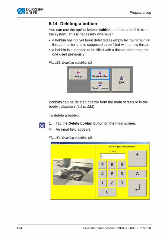
Programming
5.14 Deleting a bobbinYou can use the option Delete bobbin to delete a bobbin from the system. This is necessary whenever
• a bobbin has not yet been detected as empty by the remaining thread monitor and is supposed to be filled with a new thread
• a bobbin is supposed to be filled with a thread other than the one used previously
Fig. 153: Deleting a bobbin (1)
Bobbins can be deleted directly from the main screen or in the bobbin database ( p. 152).
To delete a bobbin:
1. Tap the Delete bobbin button on the main screen.
An input field appears:
Fig. 154: Deleting a bobbin (2)
194 Operating Instructions 550-867 - 00.0 - 11/2016
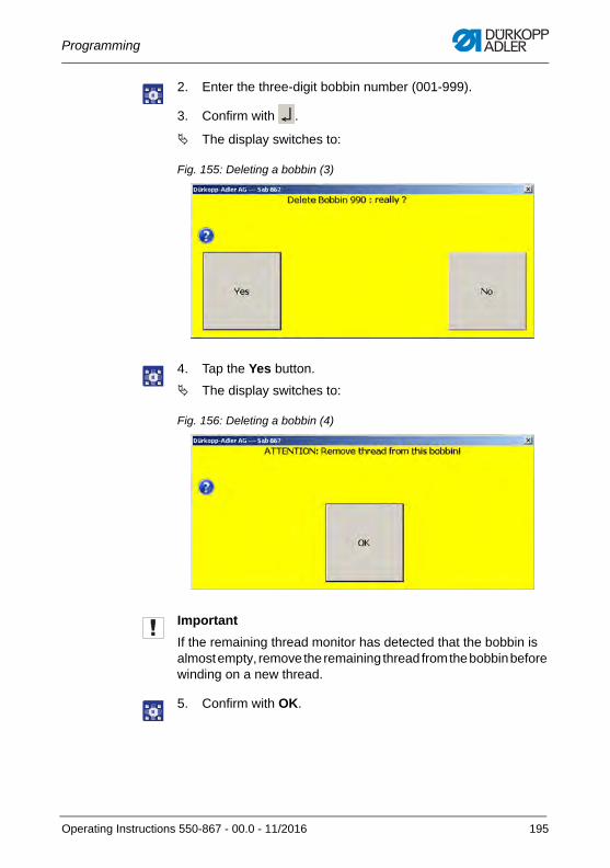
Programming
2. Enter the three-digit bobbin number (001-999).
3. Confirm with .
The display switches to:
Fig. 155: Deleting a bobbin (3)
4. Tap the Yes button.
The display switches to:
Fig. 156: Deleting a bobbin (4)
Important
If the remaining thread monitor has detected that the bobbin is almost empty, remove the remaining thread from the bobbin before winding on a new thread.
5. Confirm with OK.
Operating Instructions 550-867 - 00.0 - 11/2016 195
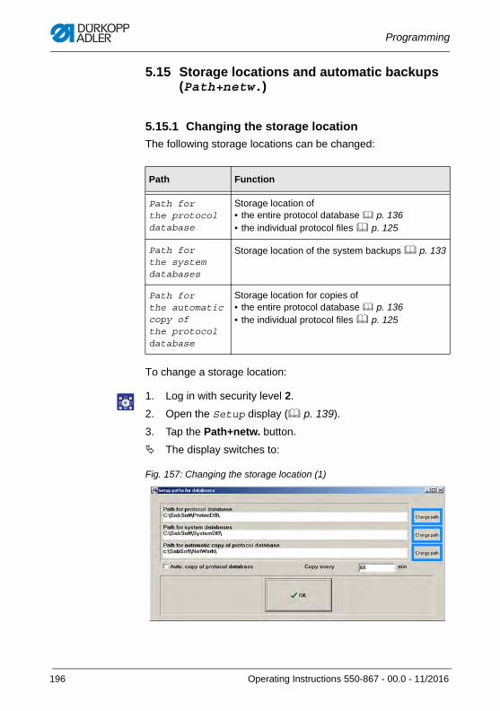
Programming
5.15 Storage locations and automatic backups (Path+netw.)
5.15.1 Changing the storage location
The following storage locations can be changed:
To change a storage location:
1. Log in with security level 2.
2. Open the Setup display ( p. 139).
3. Tap the Path+netw. button.
The display switches to:
Fig. 157: Changing the storage location (1)
Path Function
Path for the protocol database
Storage location of• the entire protocol database p. 136• the individual protocol files p. 125
Path for the system databases
Storage location of the system backups p. 133
Path for the automatic copy of the protocol database
Storage location for copies of• the entire protocol database p. 136• the individual protocol files p. 125
196 Operating Instructions 550-867 - 00.0 - 11/2016
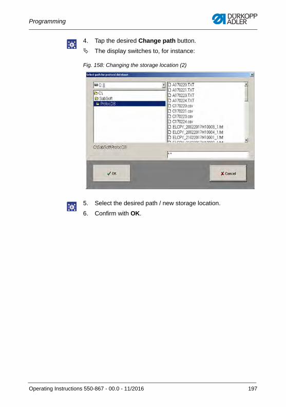
Programming
4. Tap the desired Change path button.
The display switches to, for instance:
Fig. 158: Changing the storage location (2)
5. Select the desired path / new storage location.
6. Confirm with OK.
Operating Instructions 550-867 - 00.0 - 11/2016 197
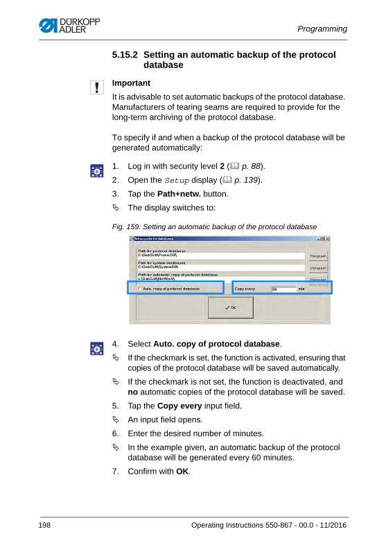
Programming
5.15.2 Setting an automatic backup of the protocol database
Important
It is advisable to set automatic backups of the protocol database. Manufacturers of tearing seams are required to provide for the long-term archiving of the protocol database.
To specify if and when a backup of the protocol database will be generated automatically:
1. Log in with security level 2 ( p. 88).
2. Open the Setup display ( p. 139).
3. Tap the Path+netw. button.
The display switches to:
Fig. 159: Setting an automatic backup of the protocol database
4. Select Auto. copy of protocol database.
If the checkmark is set, the function is activated, ensuring that copies of the protocol database will be saved automatically.
If the checkmark is not set, the function is deactivated, and no automatic copies of the protocol database will be saved.
5. Tap the Copy every input field.
An input field opens.
6. Enter the desired number of minutes.
In the example given, an automatic backup of the protocol database will be generated every 60 minutes.
7. Confirm with OK.
198 Operating Instructions 550-867 - 00.0 - 11/2016
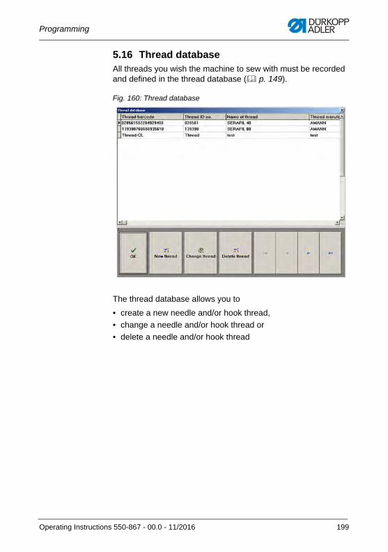
Programming
5.16 Thread databaseAll threads you wish the machine to sew with must be recorded and defined in the thread database ( p. 149).
Fig. 160: Thread database
The thread database allows you to
• create a new needle and/or hook thread,
• change a needle and/or hook thread or
• delete a needle and/or hook thread
Operating Instructions 550-867 - 00.0 - 11/2016 199
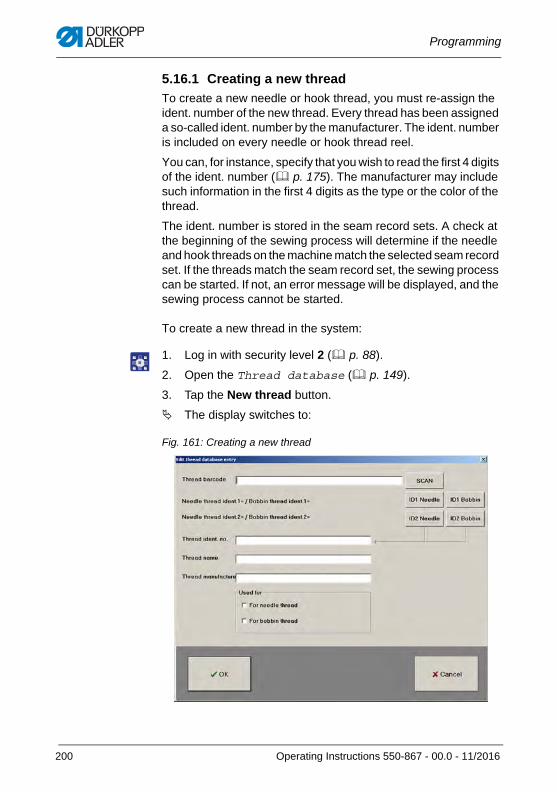
Programming
5.16.1 Creating a new thread
To create a new needle or hook thread, you must re-assign the ident. number of the new thread. Every thread has been assigned a so-called ident. number by the manufacturer. The ident. number is included on every needle or hook thread reel.
You can, for instance, specify that you wish to read the first 4 digits of the ident. number ( p. 175). The manufacturer may include such information in the first 4 digits as the type or the color of the thread.
The ident. number is stored in the seam record sets. A check at the beginning of the sewing process will determine if the needle and hook threads on the machine match the selected seam record set. If the threads match the seam record set, the sewing process can be started. If not, an error message will be displayed, and the sewing process cannot be started.
To create a new thread in the system:
1. Log in with security level 2 ( p. 88).
2. Open the Thread database ( p. 149).
3. Tap the New thread button.
The display switches to:
Fig. 161: Creating a new thread
200 Operating Instructions 550-867 - 00.0 - 11/2016
Programming
4. Register a new thread barcode by
• scanning
• entering
5. To enter the thread barcode, tap the Thread barcode button.
An input field opens.
6. Enter the desired ident. number.
7. Confirm with OK.
Or
8. To scan the thread barcode, tap the Scan button.
The display changes.
9. Use the hand scanner to scan the thread barcode.
10. Confirm with OK.
In both cases, the thread barcode will now be recorded.
11. Enter additional data.
12. Select if the new thread is a needle and/or a hook thread.
If the checkmark in front of it appears, the corresponding thread has been selected for use.
If the checkmark in front of it disappears, the corresponding thread has not been selected for use.
13. Confirm with OK.
The display returns to the Thread database.
Operating Instructions 550-867 - 00.0 - 11/2016 201
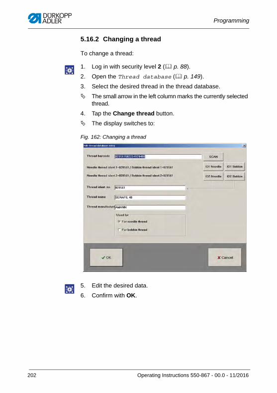
Programming
5.16.2 Changing a thread
To change a thread:
1. Log in with security level 2 ( p. 88).
2. Open the Thread database ( p. 149).
3. Select the desired thread in the thread database.
The small arrow in the left column marks the currently selected thread.
4. Tap the Change thread button.
The display switches to:
Fig. 162: Changing a thread
5. Edit the desired data.
6. Confirm with OK.
202 Operating Instructions 550-867 - 00.0 - 11/2016
Programming
5.16.3 Deleting a thread
To delete a thread:
1. Log in with security level 2 ( p. 88).
2. Open the Thread database ( p. 149).
3. Select the desired thread in the thread database.
The small arrow in the left column marks the currently selected thread.
4. Tap the Delete thread button.
5. Confirm with OK.
5.17 Creating a teach-in file If the machine is equipped with the electronically regulated thread tension (ETT), the needle thread tension during sewing is compared and readjusted based on a preset setpoint and tolerance range. The values of the needle thread tension in the documented seam sections are also logged and saved for each individual stitch.
The ideal value for the needle thread tension is influenced by different factors that include the sewing speed, the sewing material, the sewing yarn, the user, etc.
If the needle thread tension falls outside this tolerance range more frequently than specified, the seam will be defined as a seam of poor quality. In this case, the machine will display an error message during sewing. The sewing material is faulty and not suitable for use.
To achieve optimum sewing results across different materials and to be able to quickly and easily transfer the values of the needle thread tension to several seam record sets, you can create so-called teach-in files. Such a teach-in file contains all important values and can be linked to any seam record set.
Important
Only allow qualified specialists to create teach-in files.
Operating Instructions 550-867 - 00.0 - 11/2016 203
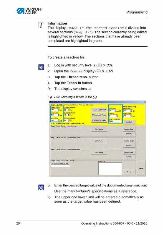
Programming
InformationThe display Teach-In for Thread Tension is divided into several sections (Step 1-5). The section currently being edited is highlighted in yellow. The sections that have already been completed are highlighted in green.
To create a teach-in file:
1. Log in with security level 2 ( p. 88).
2. Open the Checks display ( p. 132).
3. Tap the Thread tens. button.
4. Tap the Teach-In button.
The display switches to:
Fig. 163: Creating a teach-in file (1)
5. Enter the desired target value of the documented seam section.
Use the manufacturer's specifications as a reference.
The upper and lower limit will be entered automatically as soon as the target value has been defined.
204 Operating Instructions 550-867 - 00.0 - 11/2016
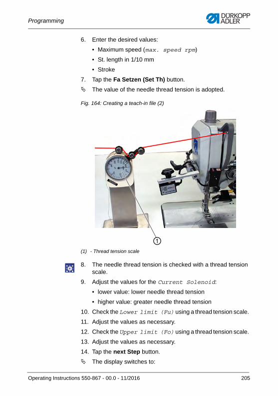
Programming
6. Enter the desired values:
• Maximum speed (max. speed rpm)
• St. length in 1/10 mm
• Stroke
7. Tap the Fa Setzen (Set Th) button.
The value of the needle thread tension is adopted.
Fig. 164: Creating a teach-in file (2)
8. The needle thread tension is checked with a thread tension scale.
9. Adjust the values for the Current Solenoid:
• lower value: lower needle thread tension
• higher value: greater needle thread tension
10. Check the Lower limit (Fu) using a thread tension scale.
11. Adjust the values as necessary.
12. Check the Upper limit (Fo) using a thread tension scale.
13. Adjust the values as necessary.
14. Tap the next Step button.
The display switches to:
(1) - Thread tension scale
①
Operating Instructions 550-867 - 00.0 - 11/2016 205
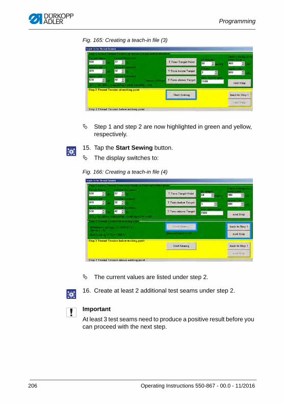
Programming
Fig. 165: Creating a teach-in file (3)
Step 1 and step 2 are now highlighted in green and yellow, respectively.
15. Tap the Start Sewing button.
The display switches to:
Fig. 166: Creating a teach-in file (4)
The current values are listed under step 2.
16. Create at least 2 additional test seams under step 2.
Important
At least 3 test seams need to produce a positive result before you can proceed with the next step.
206 Operating Instructions 550-867 - 00.0 - 11/2016
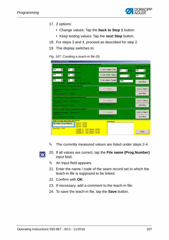
Programming
17. 2 options:
• Change values: Tap the back to Step 1 button
• Keep testing values: Tap the next Step button.
18. For steps 3 and 4, proceed as described for step 2.
19. The display switches to:
Fig. 167: Creating a teach-in file (5)
The currently measured values are listed under steps 2-4.
20. If all values are correct, tap the File name (Prog.Number) input field.
An input field appears.
21. Enter the name / code of the seam record set to which the teach-in file is supposed to be linked.
22. Confirm with OK.
23. If necessary, add a comment to the teach-in file.
24. To save the teach-in file, tap the Save button.
Operating Instructions 550-867 - 00.0 - 11/2016 207
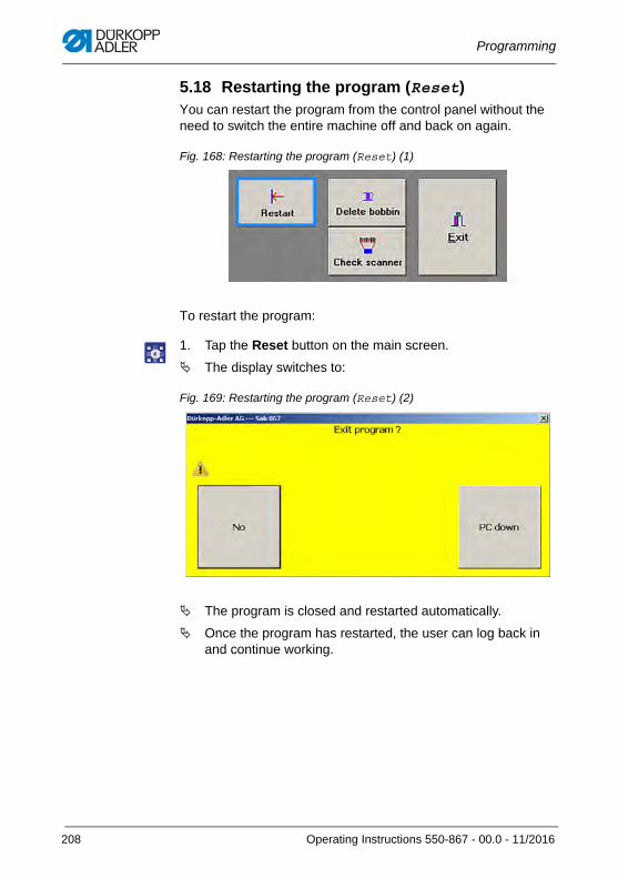
Programming
5.18 Restarting the program (Reset)You can restart the program from the control panel without the need to switch the entire machine off and back on again.
Fig. 168: Restarting the program (Reset) (1)
To restart the program:
1. Tap the Reset button on the main screen.
The display switches to:
Fig. 169: Restarting the program (Reset) (2)
The program is closed and restarted automatically.
Once the program has restarted, the user can log back in and continue working.
208 Operating Instructions 550-867 - 00.0 - 11/2016
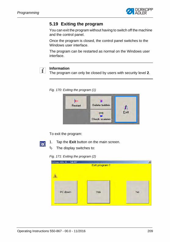
Programming
5.19 Exiting the programYou can exit the program without having to switch off the machine and the control panel.
Once the program is closed, the control panel switches to the Windows user interface.
The program can be restarted as normal on the Windows user interface.
InformationThe program can only be closed by users with security level 2.
Fig. 170: Exiting the program (1)
To exit the program:
1. Tap the Exit button on the main screen.
The display switches to:
Fig. 171: Exiting the program (2)
Operating Instructions 550-867 - 00.0 - 11/2016 209
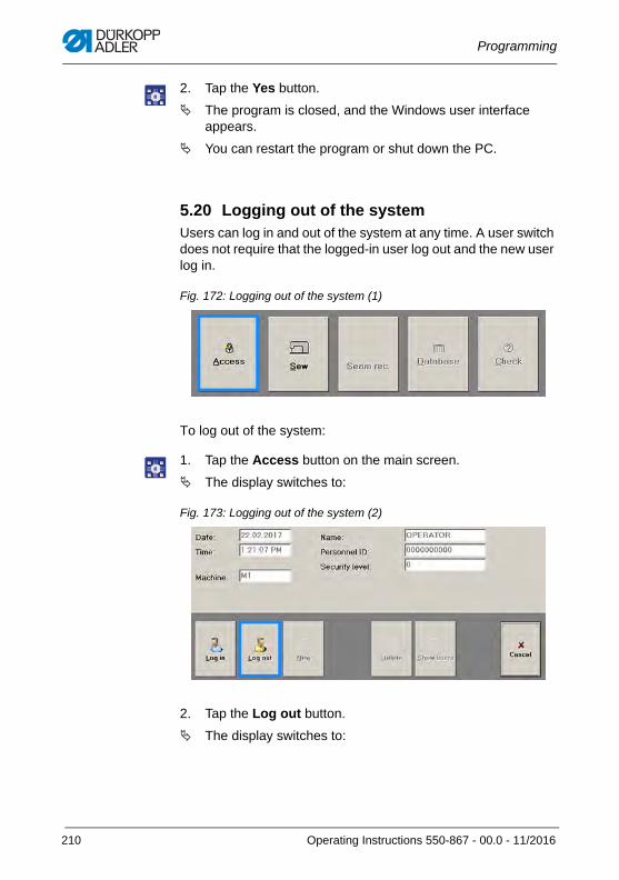
Programming
2. Tap the Yes button.
The program is closed, and the Windows user interface appears.
You can restart the program or shut down the PC.
5.20 Logging out of the systemUsers can log in and out of the system at any time. A user switch does not require that the logged-in user log out and the new user log in.
Fig. 172: Logging out of the system (1)
To log out of the system:
1. Tap the Access button on the main screen.
The display switches to:
Fig. 173: Logging out of the system (2)
2. Tap the Log out button.
The display switches to:
210 Operating Instructions 550-867 - 00.0 - 11/2016
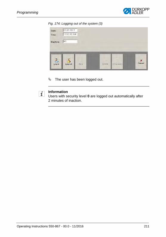
Programming
Fig. 174: Logging out of the system (3)
The user has been logged out.
InformationUsers with security level 0 are logged out automatically after 2 minutes of inaction.
Operating Instructions 550-867 - 00.0 - 11/2016 211
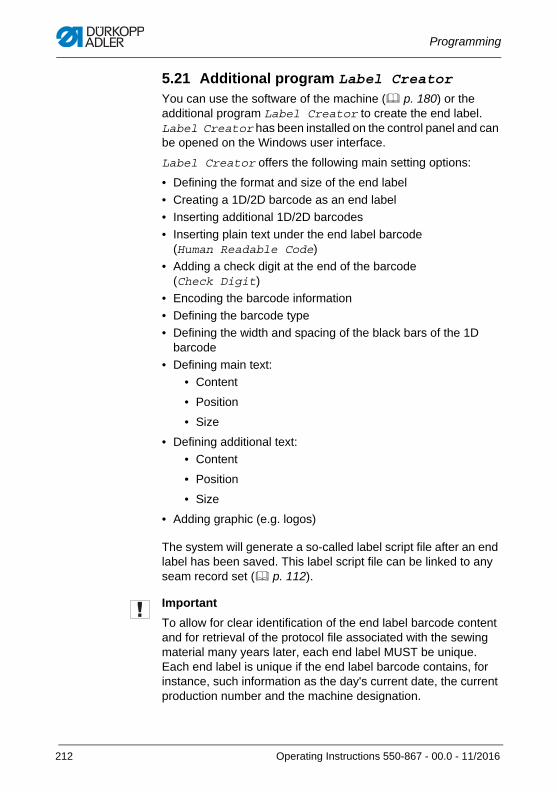
Programming
5.21 Additional program Label Creator You can use the software of the machine ( p. 180) or the additional program Label Creator to create the end label. Label Creator has been installed on the control panel and can be opened on the Windows user interface.
Label Creator offers the following main setting options:
• Defining the format and size of the end label
• Creating a 1D/2D barcode as an end label
• Inserting additional 1D/2D barcodes
• Inserting plain text under the end label barcode (Human Readable Code)
• Adding a check digit at the end of the barcode (Check Digit)
• Encoding the barcode information
• Defining the barcode type
• Defining the width and spacing of the black bars of the 1D barcode
• Defining main text:
• Content
• Position
• Size
• Defining additional text:
• Content
• Position
• Size
• Adding graphic (e.g. logos)
The system will generate a so-called label script file after an end label has been saved. This label script file can be linked to any seam record set ( p. 112).
Important
To allow for clear identification of the end label barcode content and for retrieval of the protocol file associated with the sewing material many years later, each end label MUST be unique. Each end label is unique if the end label barcode contains, for instance, such information as the day's current date, the current production number and the machine designation.
212 Operating Instructions 550-867 - 00.0 - 11/2016

Programming
Additional informationThe following description refers to the factory settings. This description cannot include any individual changes such as modified storage locations.
Label script files may only be created and linked to seam record sets by qualified specialists with security level 2.
We recommend that you use the included keyboard and PC mouse at the control panel to make the entries.
If settings stored in the label script file fail to print, check the settings in the end label printer driver.
Operating Instructions 550-867 - 00.0 - 11/2016 213
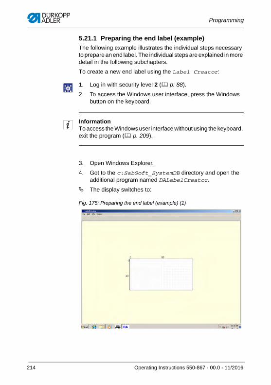
Programming
5.21.1 Preparing the end label (example)
The following example illustrates the individual steps necessary to prepare an end label. The individual steps are explained in more detail in the following subchapters.
To create a new end label using the Label Creator:
1. Log in with security level 2 ( p. 88).
2. To access the Windows user interface, press the Windows button on the keyboard.
InformationTo access the Windows user interface without using the keyboard, exit the program ( p. 209).
3. Open Windows Explorer.
4. Got to the c:SabSoft_SystemDB directory and open the additional program named DALabelCreator.
The display switches to:
Fig. 175: Preparing the end label (example) (1)
214 Operating Instructions 550-867 - 00.0 - 11/2016
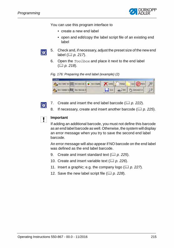
Programming
You can use this program interface to
• create a new end label
• open and edit/copy the label script file of an existing end label
5. Check and, if necessary, adjust the preset size of the new end label ( p. 217).
6. Open the Toolbox and place it next to the end label ( p. 218).
Fig. 176: Preparing the end label (example) (2)
7. Create and insert the end label barcode ( p. 222).
8. If necessary, create and insert another barcode ( p. 225).
Important
If adding an additional barcode, you must not define this barcode as an end label barcode as well. Otherwise, the system will display an error message when you try to save the second end label barcode.
An error message will also appear if NO barcode on the end label was defined as the end label barcode.
9. Create and insert standard text ( p. 225).
10. Create and insert variable text ( p. 226).
11. Insert a graphic; e.g. the company logo ( p. 227).
12. Save the new label script file ( p. 228).
Operating Instructions 550-867 - 00.0 - 11/2016 215
Programming
5.21.2 Default settings
You define the following default settings on each of the different displays of the Label Creator:
Input field Function Adjust setting
small bar Widen/narrow the black bars and white spaces for 1D barcodes
Enter new values. Recommendation: Adopt presettings. wide bar
Pos X Move content to the left/right Enter a new value.
Pos Y Move content up/down Enter a new value.
Orientation Define the orientation of the content on the end label (e.g. horizontal/vertical). 0 is the basic horizontal setting. The numbers 90, 180 and 270 represent a clockwise rotation of the content by 90° each. p. 183
Select the desired value.
Font size Enter the font size in pixels. 30 pixels correspond to a font size of approx. 3 mm on the End label display. p. 185
Enter the desired value.
216 Operating Instructions 550-867 - 00.0 - 11/2016
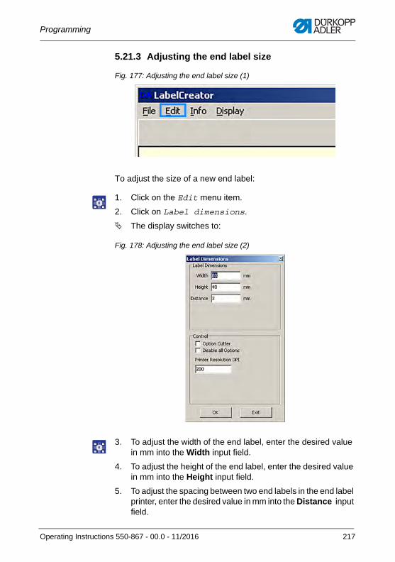
Programming
5.21.3 Adjusting the end label size
Fig. 177: Adjusting the end label size (1)
To adjust the size of a new end label:
1. Click on the Edit menu item.
2. Click on Label dimensions.
The display switches to:
Fig. 178: Adjusting the end label size (2)
3. To adjust the width of the end label, enter the desired value in mm into the Width input field.
4. To adjust the height of the end label, enter the desired value in mm into the Height input field.
5. To adjust the spacing between two end labels in the end label printer, enter the desired value in mm into the Distance input field.
Operating Instructions 550-867 - 00.0 - 11/2016 217
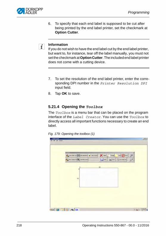
Programming
6. To specify that each end label is supposed to be cut after being printed by the end label printer, set the checkmark at Option Cutter.
InformationIf you do not wish to have the end label cut by the end label printer, but want to, for instance, tear off the label manually, you must not set the checkmark at Option Cutter. The included end label printer does not come with a cutting device.
7. To set the resolution of the end label printer, enter the corre-sponding DPI number in the Printer Resolution DPI input field.
8. Tap OK to save.
5.21.4 Opening the Toolbox
The Toolbox is a menu bar that can be placed on the program interface of the Label Creator. You can use the Toolbox to directly access all important functions necessary to create an end label.
Fig. 179: Opening the toolbox (1)
218 Operating Instructions 550-867 - 00.0 - 11/2016
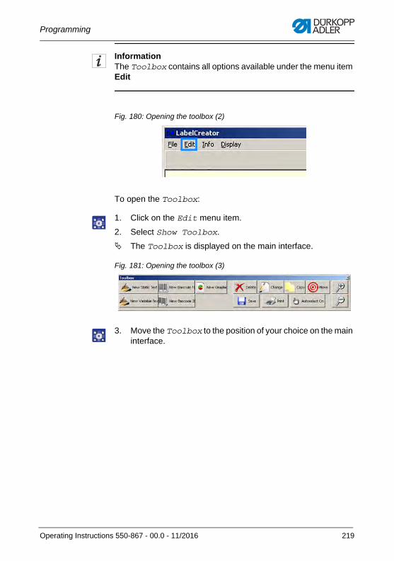
Programming
InformationThe Toolbox contains all options available under the menu item Edit
Fig. 180: Opening the toolbox (2)
To open the Toolbox:
1. Click on the Edit menu item.
2. Select Show Toolbox.
The Toolbox is displayed on the main interface.
Fig. 181: Opening the toolbox (3)
3. Move the Toolbox to the position of your choice on the main interface.
Operating Instructions 550-867 - 00.0 - 11/2016 219
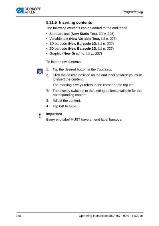
Programming
5.21.5 Inserting contents
The following contents can be added to the end label:
• Standard text (New Static Text, p. 225)
• Variable text (New Variable Text, p. 226)
• 1D barcode (New Barcode 1D, p. 222)
• 2D barcode (New Barcode 2D, p. 222)
• Graphic (New Graphic, p. 227)
To insert new contents:
1. Tap the desired button in the Toolbox.
2. Click the desired position on the end label at which you wish to insert the content.
The marking always refers to the corner at the top left.
The display switches to the setting options available for the corresponding content.
3. Adjust the content.
4. Tap OK to save.
Important
Every end label MUST have an end label barcode.
220 Operating Instructions 550-867 - 00.0 - 11/2016
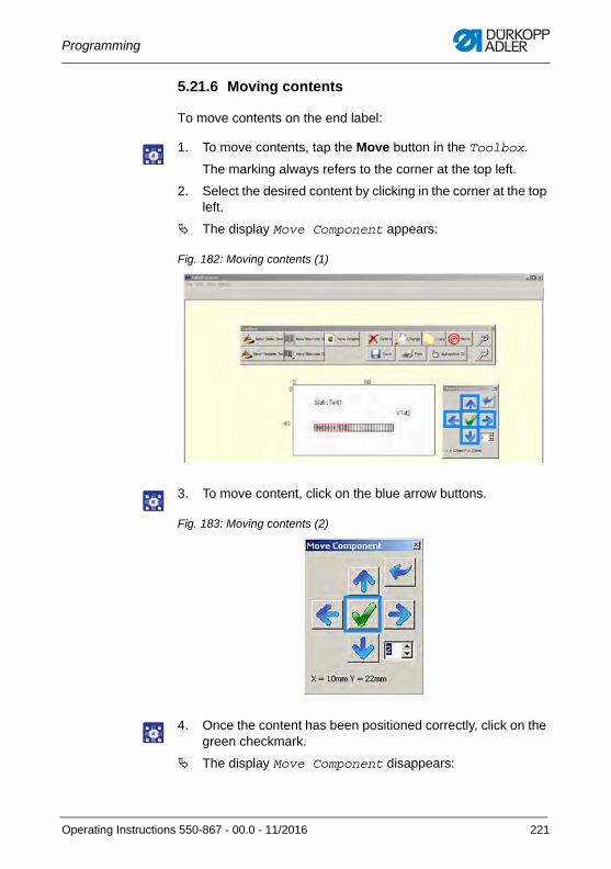
Programming
5.21.6 Moving contents
To move contents on the end label:
1. To move contents, tap the Move button in the Toolbox.
The marking always refers to the corner at the top left.
2. Select the desired content by clicking in the corner at the top left.
The display Move Component appears:
Fig. 182: Moving contents (1)
3. To move content, click on the blue arrow buttons.
Fig. 183: Moving contents (2)
4. Once the content has been positioned correctly, click on the green checkmark.
The display Move Component disappears:
Operating Instructions 550-867 - 00.0 - 11/2016 221
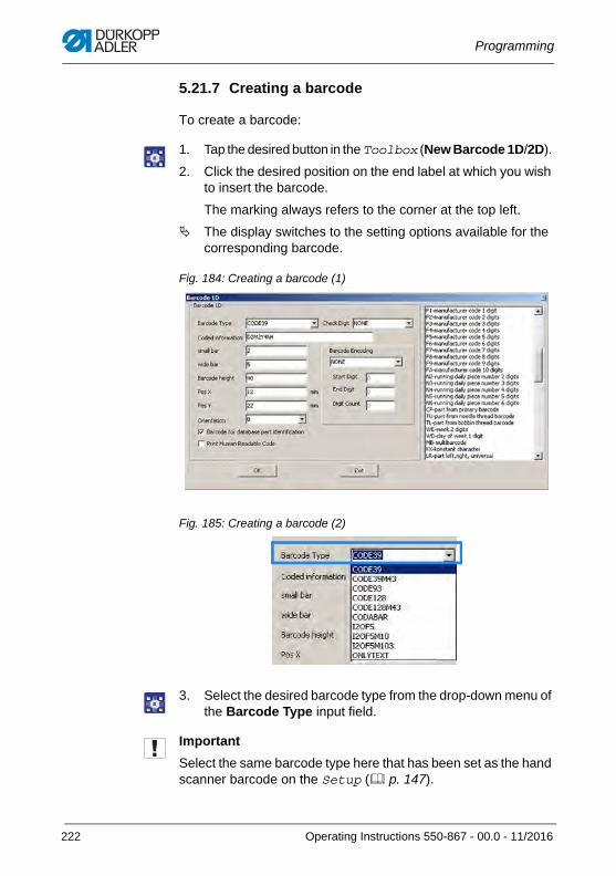
Programming
5.21.7 Creating a barcode
To create a barcode:
1. Tap the desired button in the Toolbox (New Barcode 1D/2D).
2. Click the desired position on the end label at which you wish to insert the barcode.
The marking always refers to the corner at the top left.
The display switches to the setting options available for the corresponding barcode.
Fig. 184: Creating a barcode (1)
Fig. 185: Creating a barcode (2)
3. Select the desired barcode type from the drop-down menu of the Barcode Type input field.
Important
Select the same barcode type here that has been set as the hand scanner barcode on the Setup ( p. 147).
222 Operating Instructions 550-867 - 00.0 - 11/2016
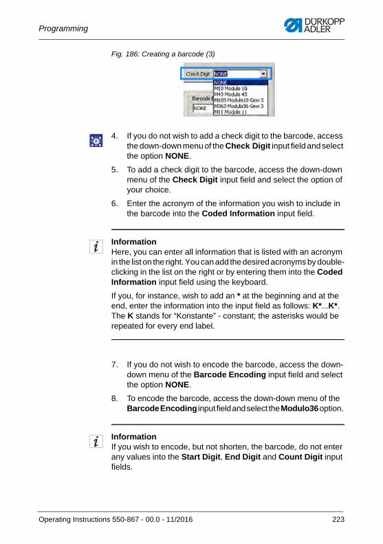
Programming
Fig. 186: Creating a barcode (3)
4. If you do not wish to add a check digit to the barcode, access the down-down menu of the Check Digit input field and select the option NONE.
5. To add a check digit to the barcode, access the down-down menu of the Check Digit input field and select the option of your choice.
6. Enter the acronym of the information you wish to include in the barcode into the Coded Information input field.
InformationHere, you can enter all information that is listed with an acronym in the list on the right. You can add the desired acronyms by double-clicking in the list on the right or by entering them into the Coded Information input field using the keyboard.
If you, for instance, wish to add an * at the beginning and at the end, enter the information into the input field as follows: K*...K*. The K stands for “Konstante” - constant; the asterisks would be repeated for every end label.
7. If you do not wish to encode the barcode, access the down-down menu of the Barcode Encoding input field and select the option NONE.
8. To encode the barcode, access the down-down menu of the Barcode Encoding input field and select the Modulo36 option.
InformationIf you wish to encode, but not shorten, the barcode, do not enter any values into the Start Digit, End Digit and Count Digit input fields.
Operating Instructions 550-867 - 00.0 - 11/2016 223
Programming
If the barcode becomes too long, you can shorten it to the desired length without losing any information.
If the barcode including all information has a length of, for instance, 18 digits, but may only be 15 digits long, encode the barcode according to Modulo36 and enter the following into the Start Digit, End Digit and Count Digit input fields:
• Start Digit:1
• End Digit: 18
• Digit Count: 15
While it will be encoded according to Modulo36 and converted to the shorter 15 digits, the barcode will still contain all desired information.
9. Adjust the desired default settings ( p. 216).
10. To adjust the height of the barcode, modify its value in the Barcode height input field.
11. If the barcode is the end label barcode, set a checkmark at Barcode for database part identification.
Important
You must define 1 barcode on the end label as the end label barcode. Otherwise, an error message will be displayed.
12. If you wish to print the information contained in the barcode as plain text on the end label, set a checkmark at Print Human Readable Code.
InformationIf plain text has been set in this label script file but the text fails to print, check the settings in the end label printer driver. The settings in the end label printer driver may overwrite the settings of the individual label script files.
Some changes to settings in the end label printer driver may require a restart.
224 Operating Instructions 550-867 - 00.0 - 11/2016
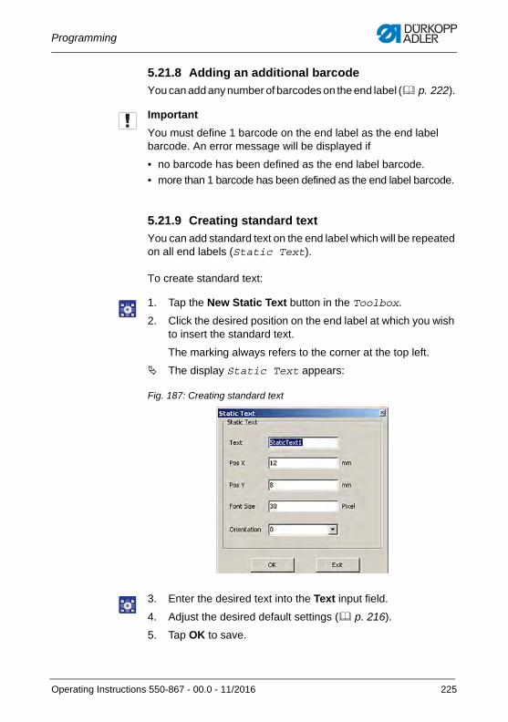
Programming
5.21.8 Adding an additional barcode
You can add any number of barcodes on the end label ( p. 222).
Important
You must define 1 barcode on the end label as the end label barcode. An error message will be displayed if
• no barcode has been defined as the end label barcode.
• more than 1 barcode has been defined as the end label barcode.
5.21.9 Creating standard text
You can add standard text on the end label which will be repeated on all end labels (Static Text).
To create standard text:
1. Tap the New Static Text button in the Toolbox.
2. Click the desired position on the end label at which you wish to insert the standard text.
The marking always refers to the corner at the top left.
The display Static Text appears:
Fig. 187: Creating standard text
3. Enter the desired text into the Text input field.
4. Adjust the desired default settings ( p. 216).
5. Tap OK to save.
Operating Instructions 550-867 - 00.0 - 11/2016 225
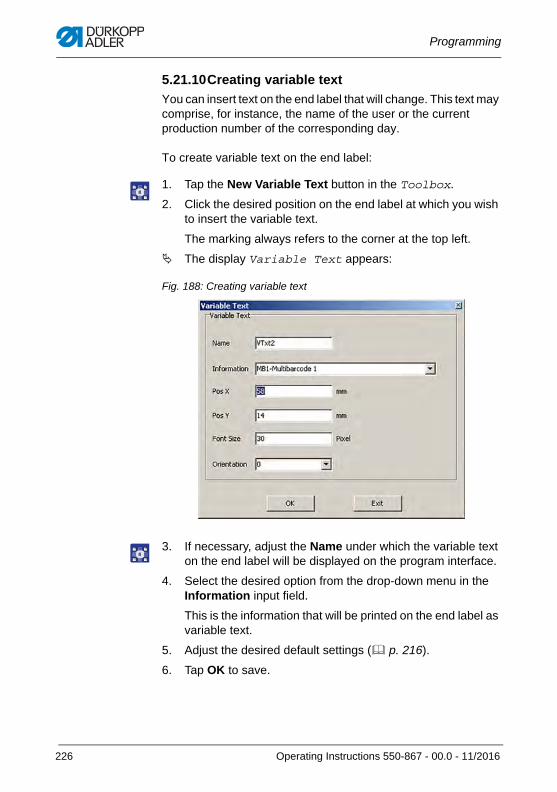
Programming
5.21.10Creating variable text
You can insert text on the end label that will change. This text may comprise, for instance, the name of the user or the current production number of the corresponding day.
To create variable text on the end label:
1. Tap the New Variable Text button in the Toolbox.
2. Click the desired position on the end label at which you wish to insert the variable text.
The marking always refers to the corner at the top left.
The display Variable Text appears:
Fig. 188: Creating variable text
3. If necessary, adjust the Name under which the variable text on the end label will be displayed on the program interface.
4. Select the desired option from the drop-down menu in the Information input field.
This is the information that will be printed on the end label as variable text.
5. Adjust the desired default settings ( p. 216).
6. Tap OK to save.
226 Operating Instructions 550-867 - 00.0 - 11/2016
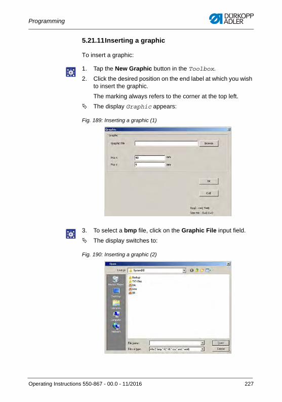
Programming
5.21.11Inserting a graphic
To insert a graphic:
1. Tap the New Graphic button in the Toolbox.
2. Click the desired position on the end label at which you wish to insert the graphic.
The marking always refers to the corner at the top left.
The display Graphic appears:
Fig. 189: Inserting a graphic (1)
3. To select a bmp file, click on the Graphic File input field.
The display switches to:
Fig. 190: Inserting a graphic (2)
Operating Instructions 550-867 - 00.0 - 11/2016 227
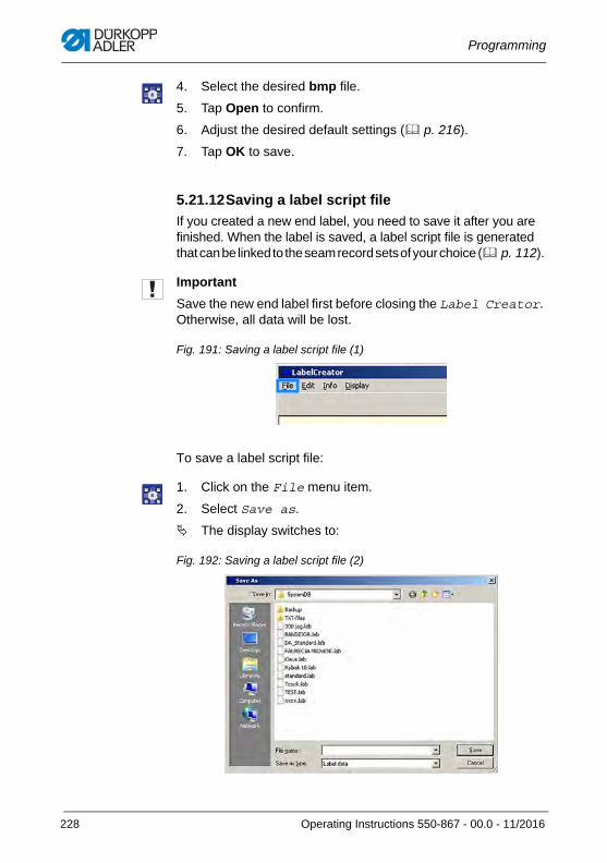
Programming
4. Select the desired bmp file.
5. Tap Open to confirm.
6. Adjust the desired default settings ( p. 216).
7. Tap OK to save.
5.21.12Saving a label script file
If you created a new end label, you need to save it after you are finished. When the label is saved, a label script file is generated that can be linked to the seam record sets of your choice ( p. 112).
Important
Save the new end label first before closing the Label Creator. Otherwise, all data will be lost.
Fig. 191: Saving a label script file (1)
To save a label script file:
1. Click on the File menu item.
2. Select Save as.
The display switches to:
Fig. 192: Saving a label script file (2)
228 Operating Instructions 550-867 - 00.0 - 11/2016
Programming
3. Enter the desired file name into the File name input field.
4. Save the information with Save.
Important
You must define 1 barcode on the end label as the end label barcode. An error message will be displayed if
• no barcode has been defined as the end label barcode.
• more than 1 barcode has been defined as the end label barcode.
InformationIt is advisable to store all label script files in the same storage location.
5.21.13Printing a test end label
The program interface of the Label Creator will not display the end label exactly as it is printed out.
To view what the end label will actually look like, you can use the test printing function.
To print the end label for testing purposes:
1. Click on the Print button in the Toolbox.
An end label with the current settings is printed.
2. Adjust the current settings if necessary.
InformationYou can also start the test print by opening the File menu item and selecting the Test Printing option.
Operating Instructions 550-867 - 00.0 - 11/2016 229
Programming
5.22 Additional program SABSearch A second additional program is included on the control panel: The search program SABSearch.
You can use SABSearch to scan the protocol database for the following criteria:
• Date
• Time
• Barcode on printed label
• Barcode part 1 (Barcode parts primary 1)
• Barcode part 2 (Barcode parts primary 2)
• Barcode part 3 (Barcode parts primary 3)
• Barcode needle thread (Needle thread barcode)
• Barcode bobbin thread (Hook thread barcode)
• Bobbin number
• Username (User name)
• Name of seam record (Name of the protocol file)
• Machine code (Machine designation)
• Manufacturer code (Manufacturer name)
• Errorcode (Error code)
• Multi barcodes
A prerequisite for a successful search is that you can access the storage location of the protocol database from the machine ( p. 196).
The search program has been installed on the control panel and can be opened on the Windows user interface.
Important
Access to SABSearch is password-protected. The password is intended only for users with security level 2 and cannot be changed. The password is: daag925.
230 Operating Instructions 550-867 - 00.0 - 11/2016
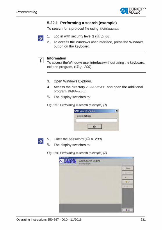
Programming
5.22.1 Performing a search (example)
To search for a protocol file using SABSearch:
1. Log in with security level 2 ( p. 88).
2. To access the Windows user interface, press the Windows button on the keyboard.
InformationTo access the Windows user interface without using the keyboard, exit the program, ( p. 209).
3. Open Windows Explorer.
4. Access the directory c:SabSoft and open the additional program SABSearch.
The display switches to:
Fig. 193: Performing a search (example) (1)
5. Enter the password ( p. 230).
The display switches to:
Fig. 194: Performing a search (example) (2)
Operating Instructions 550-867 - 00.0 - 11/2016 231
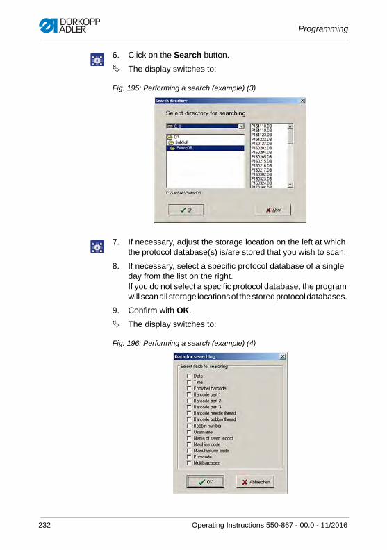
Programming
6. Click on the Search button.
The display switches to:
Fig. 195: Performing a search (example) (3)
7. If necessary, adjust the storage location on the left at which the protocol database(s) is/are stored that you wish to scan.
8. If necessary, select a specific protocol database of a single day from the list on the right. If you do not select a specific protocol database, the program will scan all storage locations of the stored protocol databases.
9. Confirm with OK.
The display switches to:
Fig. 196: Performing a search (example) (4)
232 Operating Instructions 550-867 - 00.0 - 11/2016
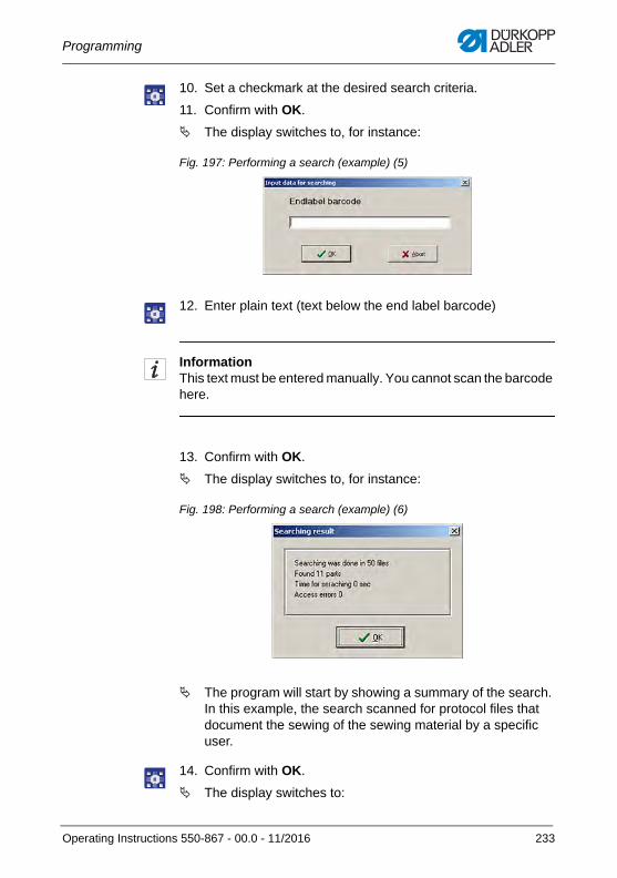
Programming
10. Set a checkmark at the desired search criteria.
11. Confirm with OK.
The display switches to, for instance:
Fig. 197: Performing a search (example) (5)
12. Enter plain text (text below the end label barcode)
InformationThis text must be entered manually. You cannot scan the barcode here.
13. Confirm with OK.
The display switches to, for instance:
Fig. 198: Performing a search (example) (6)
The program will start by showing a summary of the search. In this example, the search scanned for protocol files that document the sewing of the sewing material by a specific user.
14. Confirm with OK.
The display switches to:
Operating Instructions 550-867 - 00.0 - 11/2016 233
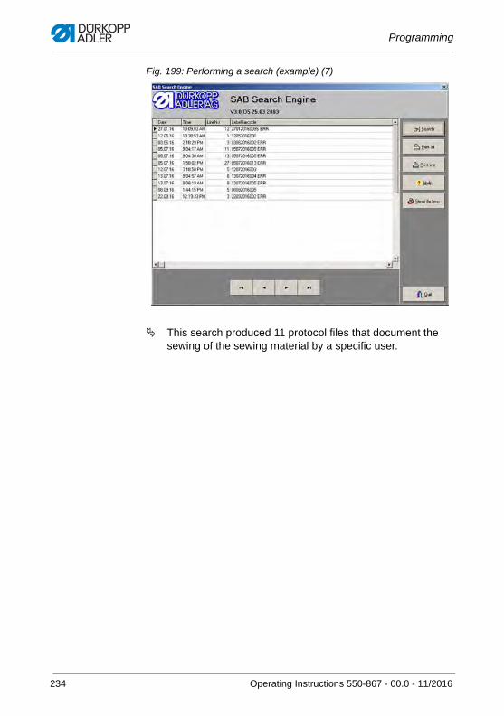
Programming
Fig. 199: Performing a search (example) (7)
This search produced 11 protocol files that document the sewing of the sewing material by a specific user.
234 Operating Instructions 550-867 - 00.0 - 11/2016
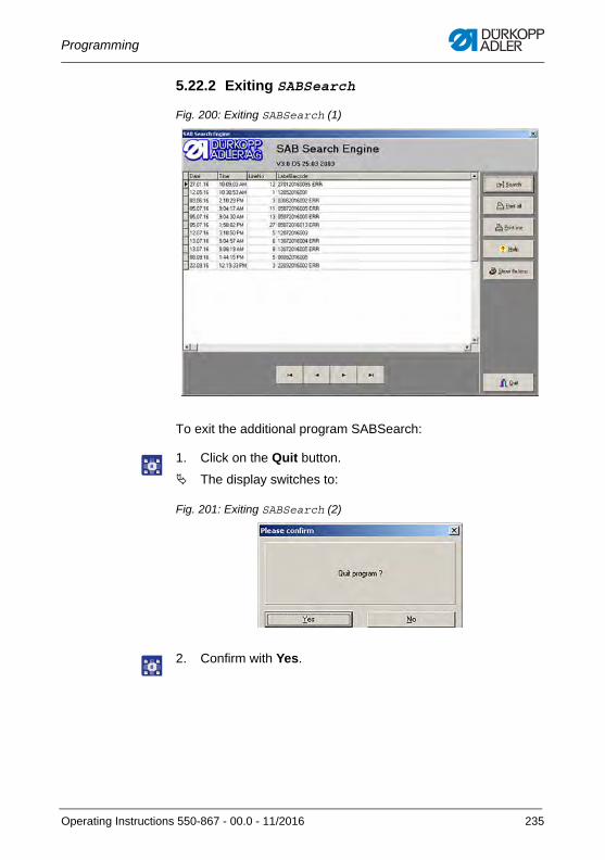
Programming
5.22.2 Exiting SABSearch
Fig. 200: Exiting SABSearch (1)
To exit the additional program SABSearch:
1. Click on the Quit button.
The display switches to:
Fig. 201: Exiting SABSearch (2)
2. Confirm with Yes.
Operating Instructions 550-867 - 00.0 - 11/2016 235

Programming
236 Operating Instructions 550-867 - 00.0 - 11/2016
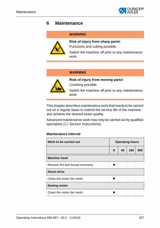
Maintenance
6 Maintenance
This chapter describes maintenance work that needs to be carried out on a regular basis to extend the service life of the machine and achieve the desired seam quality.
Advanced maintenance work may only be carried out by qualified specialists ( Service Instructions).
Maintenance interval
WARNING
Risk of injury from sharp parts!
Punctures and cutting possible.
Switch the machine off prior to any maintenance work.
WARNING
Risk of injury from moving parts!
Crushing possible.
Switch the machine off prior to any maintenance work.
Work to be carried out Operating hours
8 40 160 500
Machine head
Remove lint and thread remnants.
Direct drive
Clean the motor fan mesh
Sewing motor
Clean the motor fan mesh.
Operating Instructions 550-867 - 00.0 - 11/2016 237
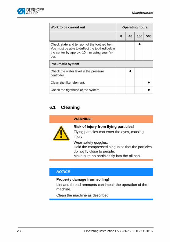
Maintenance
6.1 Cleaning
Check state and tension of the toothed belt. You must be able to deflect the toothed belt in the center by approx. 10 mm using your fin-ger.
Pneumatic system
Check the water level in the pressure controller.
Clean the filter element.
Check the tightness of the system.
WARNING
Risk of injury from flying particles!
Flying particles can enter the eyes, causing injury.
Wear safety goggles.Hold the compressed air gun so that the particles do not fly close to people.Make sure no particles fly into the oil pan.
NOTICE
Property damage from soiling!
Lint and thread remnants can impair the operation of the machine.
Clean the machine as described.
Work to be carried out Operating hours
8 40 160 500
238 Operating Instructions 550-867 - 00.0 - 11/2016
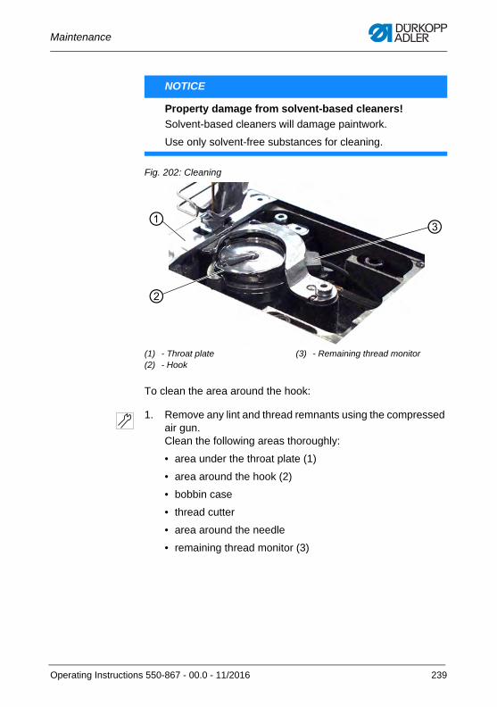
Maintenance
Fig. 202: Cleaning
To clean the area around the hook:
1. Remove any lint and thread remnants using the compressed air gun.Clean the following areas thoroughly:
• area under the throat plate (1)
• area around the hook (2)
• bobbin case
• thread cutter
• area around the needle
• remaining thread monitor (3)
NOTICE
Property damage from solvent-based cleaners!
Solvent-based cleaners will damage paintwork.
Use only solvent-free substances for cleaning.
(1) - Throat plate(2) - Hook
(3) - Remaining thread monitor
①
②
③
Operating Instructions 550-867 - 00.0 - 11/2016 239
Maintenance
6.2 Lubricating
The machine is equipped with a central oil-wick lubrication system. The bearings are supplied from the oil reservoir.
For topping off the oil reservoir, use only lubricating oil DA 10 or oil of equivalent quality with the following specifications:
• Viscosity at 40 °C:10 mm2/s
• Flash point: 150 °C
You can order the lubricating oil from our sales offices using the following part numbers.
CAUTION
Risk of injury from contact with oil!
Oil can cause a rash if it comes into contact with skin.
Avoid skin contact with oil.If oil has come into contact with your skin, wash the affected areas thoroughly.
NOTICE
Property damage from incorrect oil!
Incorrect oil types can result in damage to the machine.
Only use oil that complies with the data in the instructions.
CAUTION
Risk of environmental damage from oil!
Oil is a pollutant and must not enter the sewage system or the soil.
Carefully collect up used oil.Dispose of used oil and oily machine parts in accordance with national regulations.
240 Operating Instructions 550-867 - 00.0 - 11/2016
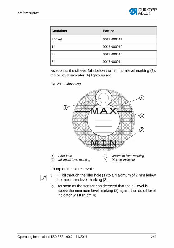
Maintenance
As soon as the oil level falls below the minimum level marking (2), the oil level indicator (4) lights up red.
Fig. 203: Lubricating
To top off the oil reservoir:
1. Fill oil through the filler hole (1) to a maximum of 2 mm below the maximum level marking (3).
As soon as the sensor has detected that the oil level is above the minimum level marking (2) again, the red oil level indicator will turn off (4).
Container Part no.
250 ml 9047 000011
1 l 9047 000012
2 l 9047 000013
5 l 9047 000014
(1) - Filler hole(2) - Minimum level marking
(3) - Maximum level marking(4) - Oil level indicator
①
②
③
④
Operating Instructions 550-867 - 00.0 - 11/2016 241
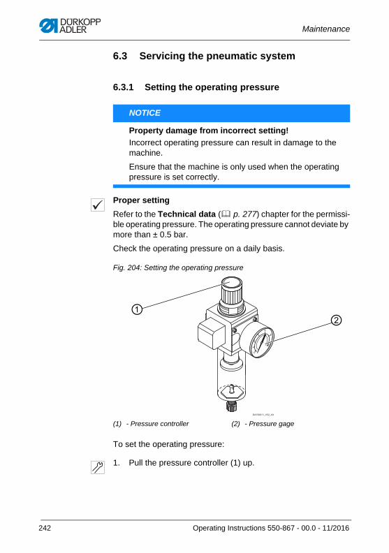
Maintenance
6.3 Servicing the pneumatic system
6.3.1 Setting the operating pressure
Proper setting
Refer to the Technical data ( p. 277) chapter for the permissi-ble operating pressure. The operating pressure cannot deviate by more than ± 0.5 bar.
Check the operating pressure on a daily basis.
Fig. 204: Setting the operating pressure
To set the operating pressure:
1. Pull the pressure controller (1) up.
NOTICE
Property damage from incorrect setting!
Incorrect operating pressure can result in damage to the machine.
Ensure that the machine is only used when the operating pressure is set correctly.
(1) - Pressure controller (2) - Pressure gage
②①
242 Operating Instructions 550-867 - 00.0 - 11/2016
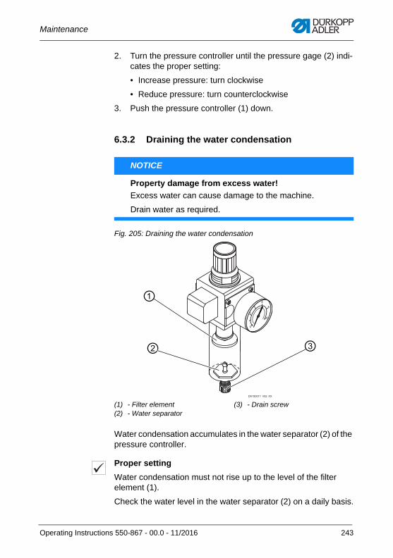
Maintenance
2. Turn the pressure controller until the pressure gage (2) indi-cates the proper setting:
• Increase pressure: turn clockwise
• Reduce pressure: turn counterclockwise
3. Push the pressure controller (1) down.
6.3.2 Draining the water condensation
Fig. 205: Draining the water condensation
Water condensation accumulates in the water separator (2) of the pressure controller.
Proper setting
Water condensation must not rise up to the level of the filter element (1).
Check the water level in the water separator (2) on a daily basis.
NOTICE
Property damage from excess water!
Excess water can cause damage to the machine.
Drain water as required.
(1) - Filter element(2) - Water separator
(3) - Drain screw
②
①
③
Operating Instructions 550-867 - 00.0 - 11/2016 243

Maintenance
To drain water condensation:
1. Disconnect the machine from the compressed air supply.
2. Place the collection tray under the drain screw (3).
3. Loosen the drain screw (3) completely.
4. Allow water to drain into the collection tray.
5. Tighten the drain screw (3).
6. Connect the machine to the compressed air supply.
244 Operating Instructions 550-867 - 00.0 - 11/2016
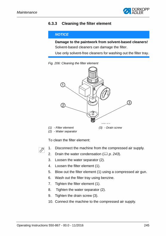
Maintenance
6.3.3 Cleaning the filter element
Fig. 206: Cleaning the filter element
To clean the filter element:
1. Disconnect the machine from the compressed air supply.
2. Drain the water condensation ( p. 243).
3. Loosen the water separator (2).
4. Loosen the filter element (1).
5. Blow out the filter element (1) using a compressed air gun.
6. Wash out the filter tray using benzine.
7. Tighten the filter element (1).
8. Tighten the water separator (2).
9. Tighten the drain screw (3).
10. Connect the machine to the compressed air supply.
NOTICE
Damage to the paintwork from solvent-based cleaners!
Solvent-based cleaners can damage the filter.
Use only solvent-free cleaners for washing out the filter tray.
(1) - Filter element(2) - Water separator
(3) - Drain screw
②
①
③
Operating Instructions 550-867 - 00.0 - 11/2016 245

Maintenance
6.4 Parts listA parts list can be ordered from Dürkopp Adler. Or visit our website for further information at:
www.duerkopp-adler.com
246 Operating Instructions 550-867 - 00.0 - 11/2016
Setup
7 Setup
7.1 Checking the scope of deliveryThe scope of delivery depends on your specific order. Check that the scope of delivery is correct after taking delivery.
7.2 Removing the transport locks
1. Prior to setup, remove all transport locks including lashing straps, Styrofoam and cardboard pieces, safety clips and wooden blocks:
• at the machine head
• at the table
• at the stand
WARNING
Risk of injury from cutting parts!
Cutting injuries may be sustained while unpacking and setting up the machine.
Only qualified specialists may set up the machine.Wear safety gloves.
WARNING
Risk of injury from moving parts!
Crushing injuries may be sustained while unpacking and setting up the machine.
Only qualified specialists may set up the machine.Wear safety shoes.
Operating Instructions 550-867 - 00.0 - 11/2016 247
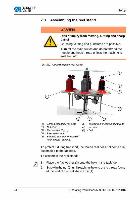
Setup
7.3 Assembling the reel stand
Fig. 207: Assembling the reel stand
To protect it during transport, the thread reel does not come fully assembled to the tabletop.
To assemble the reel stand:
1. Place the flat washer (3) onto the hole in the tabletop.
2. Screw in the nut (2) until reaching the end of the thread found at the end of the reel stand tube (4).
WARNING
Risk of injury from moving, cutting and sharp parts!
Crushing, cutting and punctures are possible.
Turn off the main switch and do not thread the needle and hook thread unless the machine is switched off.
(1) - Thread reel holder (6 pcs)(2) - Nut (2 pcs)(3) - Flat washer (2 pcs)(4) - Reel stand tube(5) - Barcode scanner for needle/
hook thread (optional)
(6) - Thread reel (needle/hook thread)(7) - Washer(8) - Ball
④
⑥⑦
⑧
② ③
⑤
①
248 Operating Instructions 550-867 - 00.0 - 11/2016
Setup
3. Slip the reel stand tube (4) through the flat washer (3) and the hole in the tabletop.
4. Slide the second flat washer (3) onto the thread at the end of the reel stand tube (4).
5. Screw the second nut (2) onto the thread at the end of the reel stand tube (4).
The reel stand is now assembled to the tabletop.
6. Align both thread guides (9) directly above two thread reel holders (1).
7. To insert a thread reel (6), loosen ball (8) and washer (7).
8. Fit the thread reel (6) on a thread reel holder (1).
If a barcode scanner has been assembled for the needle thread and hook thread reels (5), align the needle/hook thread reels such that both of them can be scanned.
9. Tighten washer (6) and ball (7) again in reverse order.
Needle/hook thread can now be threaded ( p. 31, and p. 40).
Operating Instructions 550-867 - 00.0 - 11/2016 249
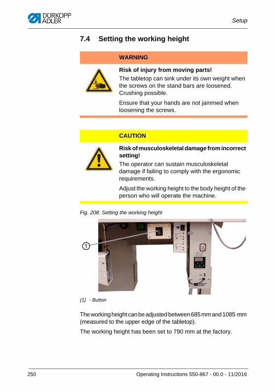
Setup
7.4 Setting the working height
Fig. 208: Setting the working height
The working height can be adjusted between 685 mm and 1085 mm (measured to the upper edge of the tabletop).
The working height has been set to 790 mm at the factory.
WARNING
Risk of injury from moving parts!
The tabletop can sink under its own weight when the screws on the stand bars are loosened. Crushing possible.
Ensure that your hands are not jammed when loosening the screws.
CAUTION
Risk of musculoskeletal damage from incorrect setting!
The operator can sustain musculoskeletal damage if failing to comply with the ergonomic requirements.
Adjust the working height to the body height of the person who will operate the machine.
(1) - Button
①
250 Operating Instructions 550-867 - 00.0 - 11/2016
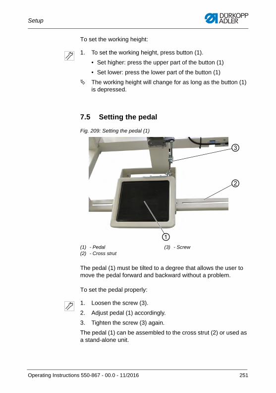
Setup
To set the working height:
1. To set the working height, press button (1).
• Set higher: press the upper part of the button (1)
• Set lower: press the lower part of the button (1)
The working height will change for as long as the button (1) is depressed.
7.5 Setting the pedal
Fig. 209: Setting the pedal (1)
The pedal (1) must be tilted to a degree that allows the user to move the pedal forward and backward without a problem.
To set the pedal properly:
1. Loosen the screw (3).
2. Adjust pedal (1) accordingly.
3. Tighten the screw (3) again.
The pedal (1) can be assembled to the cross strut (2) or used as a stand-alone unit.
(1) - Pedal(2) - Cross strut
(3) - Screw
③
②
①
Operating Instructions 550-867 - 00.0 - 11/2016 251
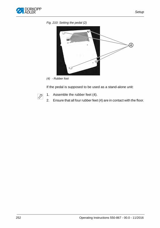
Setup
Fig. 210: Setting the pedal (2)
If the pedal is supposed to be used as a stand-alone unit:
1. Assemble the rubber feet (4).
2. Ensure that all four rubber feet (4) are in contact with the floor.
(4) - Rubber foot
④
252 Operating Instructions 550-867 - 00.0 - 11/2016
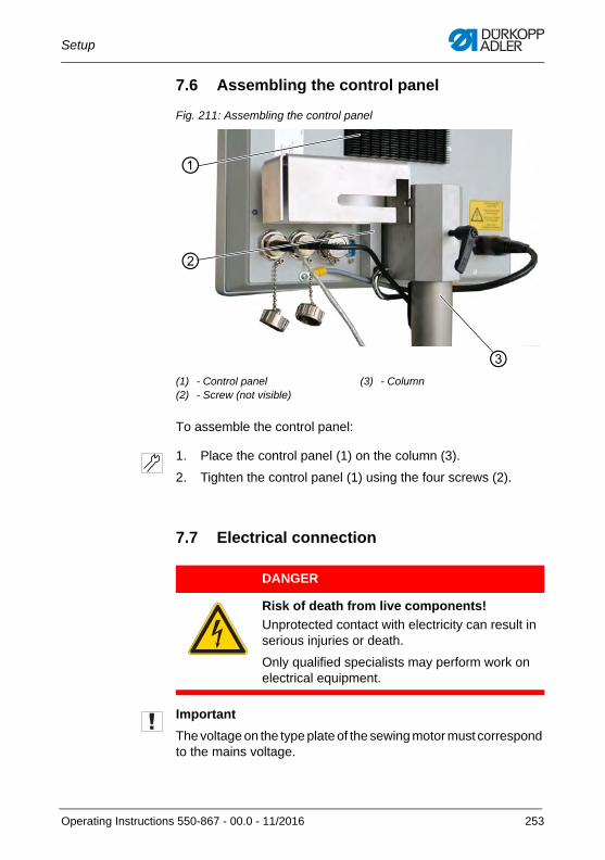
Setup
7.6 Assembling the control panel
Fig. 211: Assembling the control panel
To assemble the control panel:
1. Place the control panel (1) on the column (3).
2. Tighten the control panel (1) using the four screws (2).
7.7 Electrical connection
Important
The voltage on the type plate of the sewing motor must correspond to the mains voltage.
(1) - Control panel(2) - Screw (not visible)
(3) - Column
①
②
③
DANGER
Risk of death from live components!
Unprotected contact with electricity can result in serious injuries or death.
Only qualified specialists may perform work on electrical equipment.
Operating Instructions 550-867 - 00.0 - 11/2016 253
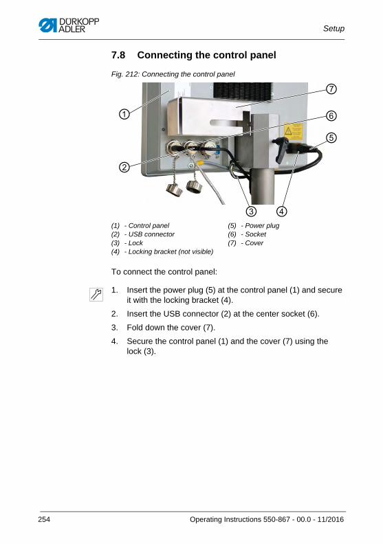
Setup
7.8 Connecting the control panel
Fig. 212: Connecting the control panel
To connect the control panel:
1. Insert the power plug (5) at the control panel (1) and secure it with the locking bracket (4).
2. Insert the USB connector (2) at the center socket (6).
3. Fold down the cover (7).
4. Secure the control panel (1) and the cover (7) using the lock (3).
(1) - Control panel(2) - USB connector(3) - Lock(4) - Locking bracket (not visible)
(5) - Power plug(6) - Socket(7) - Cover
①
⑤⑥
④
⑦
③
②
254 Operating Instructions 550-867 - 00.0 - 11/2016
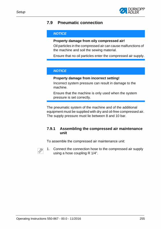
Setup
7.9 Pneumatic connection
The pneumatic system of the machine and of the additional equipment must be supplied with dry and oil-free compressed air. The supply pressure must lie between 8 and 10 bar.
7.9.1 Assembling the compressed air maintenance unit
To assemble the compressed air maintenance unit:
1. Connect the connection hose to the compressed air supply using a hose coupling R 1/4”.
NOTICE
Property damage from oily compressed air!
Oil particles in the compressed air can cause malfunctions of the machine and soil the sewing material.
Ensure that no oil particles enter the compressed air supply.
NOTICE
Property damage from incorrect setting!
Incorrect system pressure can result in damage to the machine.
Ensure that the machine is only used when the system pressure is set correctly.
Operating Instructions 550-867 - 00.0 - 11/2016 255
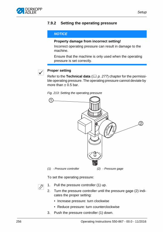
Setup
7.9.2 Setting the operating pressure
Proper setting
Refer to the Technical data ( p. 277) chapter for the permissi-ble operating pressure. The operating pressure cannot deviate by more than ± 0.5 bar.
Fig. 213: Setting the operating pressure
To set the operating pressure:
1. Pull the pressure controller (1) up.
2. Turn the pressure controller until the pressure gage (2) indi-cates the proper setting:
• Increase pressure: turn clockwise
• Reduce pressure: turn counterclockwise
3. Push the pressure controller (1) down.
NOTICE
Property damage from incorrect setting!
Incorrect operating pressure can result in damage to the machine.
Ensure that the machine is only used when the operating pressure is set correctly.
(1) - Pressure controller (2) - Pressure gage
②
①
256 Operating Instructions 550-867 - 00.0 - 11/2016
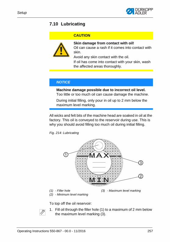
Setup
7.10 Lubricating
All wicks and felt bits of the machine head are soaked in oil at the factory. This oil is conveyed to the reservoir during use. This is why you should avoid filling too much oil during initial filling.
Fig. 214: Lubricating
To top off the oil reservoir:
1. Fill oil through the filler hole (1) to a maximum of 2 mm below the maximum level marking (3).
CAUTION
Skin damage from contact with oil!Oil can cause a rash if it comes into contact with skin.Avoid any skin contact with the oil.If oil has come into contact with your skin, wash the affected areas thoroughly.
NOTICE
Machine damage possible due to incorrect oil level.Too little or too much oil can cause damage the machine.
During initial filling, only pour in oil up to 2 mm below the maximum level marking.
(1) - Filler hole(2) - Minimum level marking
(3) - Maximum level marking
①
②
③
Operating Instructions 550-867 - 00.0 - 11/2016 257
Setup
Oil to be used:
Only DA 10 or equivalent oil should be used for the machine, which has the following properties:
• Viscosity at 40 °C: 10 mm²/s
• Flash point: 150 °C
NOTICE
Machine damage possible due to incorrect oil.An incorrect oil type can cause damage to the machine.Only use oil specified in the operating instructions.
CAUTION
Risk of pollution from oil.Oil is a pollutant and must not enter the sewage system or the soil.Collect waste oil carefully and dispose of it and oily machine parts in accordance with the applicable statutory regulations.
258 Operating Instructions 550-867 - 00.0 - 11/2016
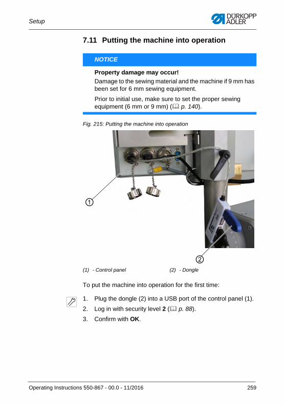
Setup
7.11 Putting the machine into operation
Fig. 215: Putting the machine into operation
To put the machine into operation for the first time:
1. Plug the dongle (2) into a USB port of the control panel (1).
2. Log in with security level 2 ( p. 88).
3. Confirm with OK.
NOTICE
Property damage may occur!
Damage to the sewing material and the machine if 9 mm has been set for 6 mm sewing equipment.
Prior to initial use, make sure to set the proper sewing equipment (6 mm or 9 mm) ( p. 140).
(1) - Control panel (2) - Dongle
①
②
Operating Instructions 550-867 - 00.0 - 11/2016 259
Setup
7.12 Performing a test run
When setup is complete, perform a test run to check the function-ality of the machine.
InformationThe test function is intended exclusively for qualified specialists with security level 2 (e.g. technicians). Here, the machine / the sewing process can be tested without the need to scan barcodes.
To perform a test run:
1. Log in with security level 2 ( p. 88).
2. Check if the proper sewing equipment has been set ( p. 140).
3. Insert the bobbin ( p. 37).
4. Thread hook thread ( p. 40).
5. Thread needle thread ( p. 31).
6. Select the sewing material.
WARNING
Risk of injury from moving, cutting and sharp parts!
Crushing, cutting and punctures are possible.
Turn off the machine and do not thread the needle and hook thread unless the machine is switched off.
NOTICE
Property damage may occur!
Damage to the sewing material and the machine itself if 9 mm has been set for 6 mm sewing equipment.
Prior to initial use, make sure to set the proper sewing equipment (6 mm or 9 mm).
260 Operating Instructions 550-867 - 00.0 - 11/2016
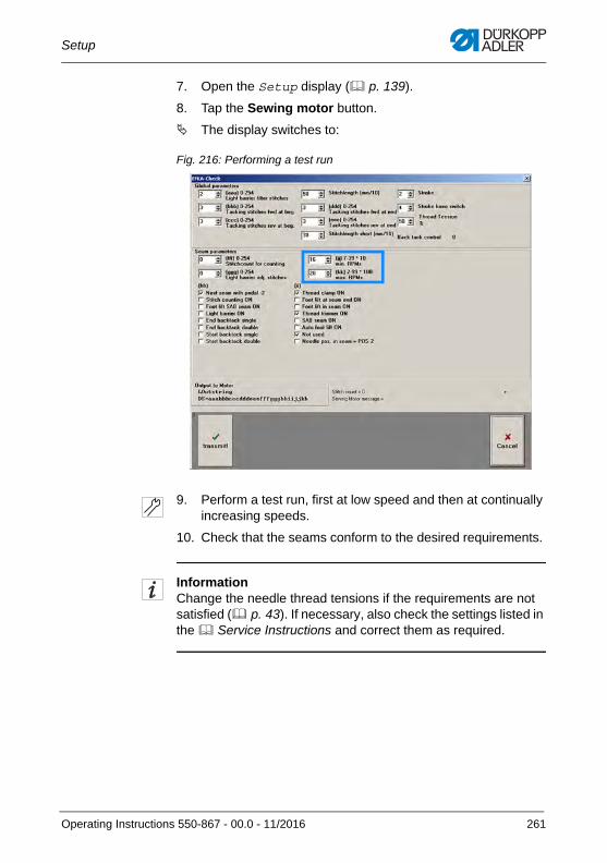
Setup
7. Open the Setup display ( p. 139).
8. Tap the Sewing motor button.
The display switches to:
Fig. 216: Performing a test run
9. Perform a test run, first at low speed and then at continually increasing speeds.
10. Check that the seams conform to the desired requirements.
InformationChange the needle thread tensions if the requirements are not satisfied ( p. 43). If necessary, also check the settings listed in the Service Instructions and correct them as required.
Operating Instructions 550-867 - 00.0 - 11/2016 261
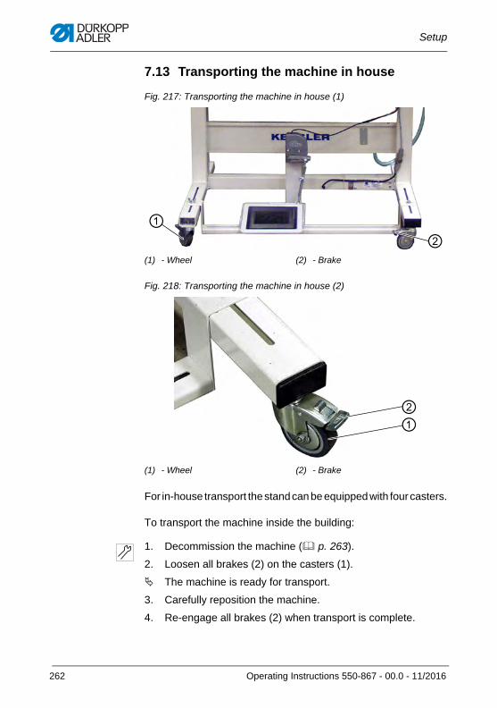
Setup
7.13 Transporting the machine in house
Fig. 217: Transporting the machine in house (1)
Fig. 218: Transporting the machine in house (2)
For in-house transport the stand can be equipped with four casters.
To transport the machine inside the building:
1. Decommission the machine ( p. 263).
2. Loosen all brakes (2) on the casters (1).
The machine is ready for transport.
3. Carefully reposition the machine.
4. Re-engage all brakes (2) when transport is complete.
(1) - Wheel (2) - Brake
(1) - Wheel (2) - Brake
①②
①②
262 Operating Instructions 550-867 - 00.0 - 11/2016
Decommissioning
8 Decommissioning
8.1 Decommissioning the machine
To decommission the machine:
1. Switch off the machine.
2. Unplug the power plug.
3. If applicable, disconnect the machine from the compressed air supply.
4. Remove residual oil from the oil pan using a cloth.
5. Cover the control panel to protect it from soiling.
6. Cover the control to protect it from soiling.
7. Cover the entire machine if possible to protect it from contam-ination and damage.
WARNING
Risk of injury from a lack of care!
Serious injuries may occur.
ONLY clean the machine when it is switched off.Allow ONLY trained personnel to disconnect the machine.
CAUTION
Risk of injury from contact with oil!
Oil can cause a rash if it comes into contact with skin.
Avoid skin contact with oil.If oil has come into contact with your skin, wash the affected areas thoroughly.
Operating Instructions 550-867 - 00.0 - 11/2016 263
Decommissioning
8.2 Transporting the machine
To transport the machine safely:
1. Decommission the machine ( p. 263).
2. Assemble the transport locks in reverse order from setup ( p. 247).
3. Transport the machine only in the upright position and only in such a way that it cannot tip over.
NOTICE
Property damage may occur!
Damage to the machine if transported without the transport locks.
Do not transport the machine unless the transport locks have been fitted.
264 Operating Instructions 550-867 - 00.0 - 11/2016
Disposal
9 Disposal
The machine must not be disposed of in the normal household waste.
Dispose of the machine in a suitable manner in accordance with all applicable national regulations.
When disposing of the machine, be aware that it consists of a range of different materials (steel, plastic, electronic components, etc.). Follow the national regulations when disposing these materials.
CAUTION
Risk of environmental damage from improper
disposal!
Improper disposal of the machine can result in serious environmental damage.
ALWAYS comply with the national regulations regarding disposal.
Operating Instructions 550-867 - 00.0 - 11/2016 265

Disposal
266 Operating Instructions 550-867 - 00.0 - 11/2016

Troubleshooting
10 Troubleshooting
10.1 Customer ServiceContact for repairs and issues with the machine:
Dürkopp Adler AG
Potsdamer Str. 19033719 Bielefeld, Germany
Tel. +49 (0) 180 5 383 756Fax +49 (0) 521 925 2594Email: [email protected]: www.duerkopp-adler.com
Operating Instructions 550-867 - 00.0 - 11/2016 267
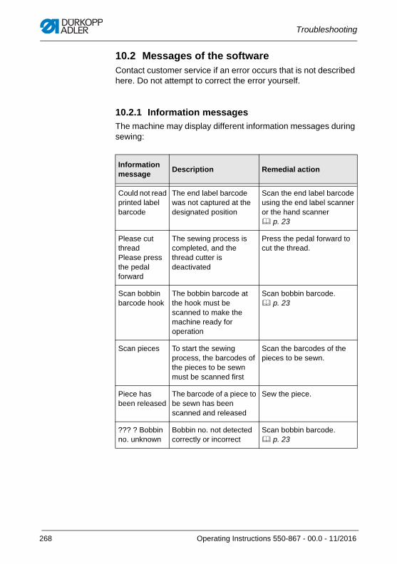
Troubleshooting
10.2 Messages of the softwareContact customer service if an error occurs that is not described here. Do not attempt to correct the error yourself.
10.2.1 Information messages
The machine may display different information messages during sewing:
Information message
Description Remedial action
Could not read printed label barcode
The end label barcode was not captured at the designated position
Scan the end label barcode using the end label scanner or the hand scanner p. 23
Please cut threadPlease press the pedal forward
The sewing process is completed, and the thread cutter is deactivated
Press the pedal forward to cut the thread.
Scan bobbin barcode hook
The bobbin barcode at the hook must be scanned to make the machine ready for operation
Scan bobbin barcode. p. 23
Scan pieces To start the sewing process, the barcodes of the pieces to be sewn must be scanned first
Scan the barcodes of the pieces to be sewn.
Piece has been released
The barcode of a piece to be sewn has been scanned and released
Sew the piece.
??? ? Bobbin no. unknown
Bobbin no. not detected correctly or incorrect
Scan bobbin barcode. p. 23
268 Operating Instructions 550-867 - 00.0 - 11/2016
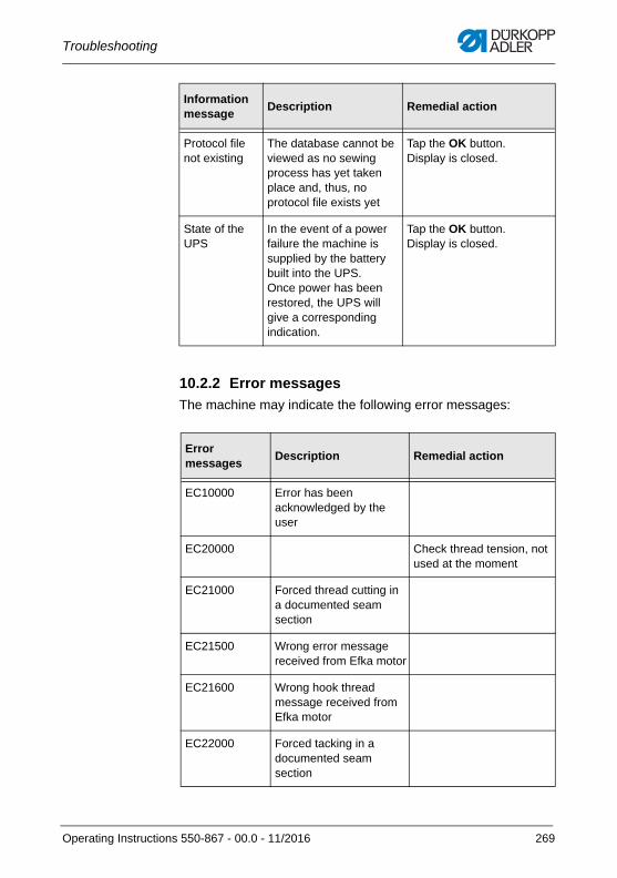
Troubleshooting
10.2.2 Error messages
The machine may indicate the following error messages:
Protocol file not existing
The database cannot be viewed as no sewing process has yet taken place and, thus, no protocol file exists yet
Tap the OK button. Display is closed.
State of the UPS
In the event of a power failure the machine is supplied by the battery built into the UPS. Once power has been restored, the UPS will give a corresponding indication.
Tap the OK button. Display is closed.
Error messages
Description Remedial action
EC10000 Error has been acknowledged by the user
EC20000 Check thread tension, not used at the moment
EC21000 Forced thread cutting ina documented seam section
EC21500 Wrong error message received from Efka motor
EC21600 Wrong hook thread message received from Efka motor
EC22000 Forced tacking in a documented seam section
Information message
Description Remedial action
Operating Instructions 550-867 - 00.0 - 11/2016 269
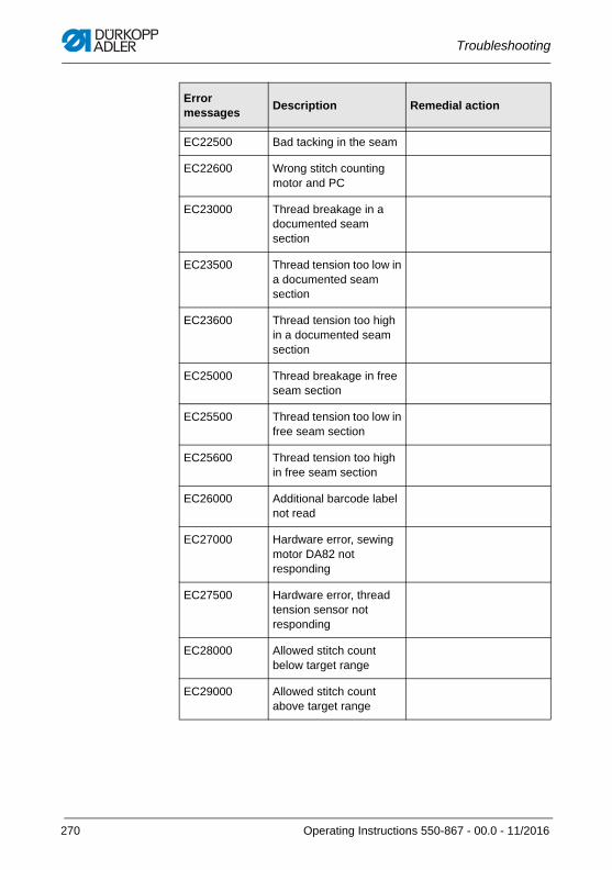
Troubleshooting
EC22500 Bad tacking in the seam
EC22600 Wrong stitch counting motor and PC
EC23000 Thread breakage in a documented seam section
EC23500 Thread tension too low in a documented seam section
EC23600 Thread tension too high in a documented seam section
EC25000 Thread breakage in free seam section
EC25500 Thread tension too low in free seam section
EC25600 Thread tension too high in free seam section
EC26000 Additional barcode label not read
EC27000 Hardware error, sewing motor DA82 not responding
EC27500 Hardware error, thread tension sensor not responding
EC28000 Allowed stitch count below target range
EC29000 Allowed stitch count above target range
Error messages
Description Remedial action
270 Operating Instructions 550-867 - 00.0 - 11/2016
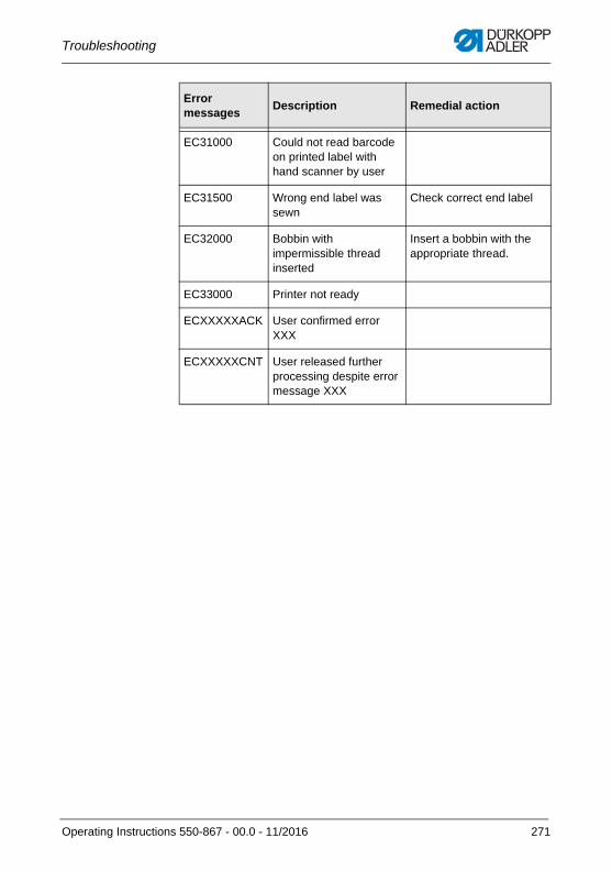
Troubleshooting
EC31000 Could not read barcode on printed label with hand scanner by user
EC31500 Wrong end label was sewn
Check correct end label
EC32000 Bobbin with impermissible thread inserted
Insert a bobbin with the appropriate thread.
EC33000 Printer not ready
ECXXXXXACK User confirmed error XXX
ECXXXXXCNT User released further processing despite error message XXX
Error messages
Description Remedial action
Operating Instructions 550-867 - 00.0 - 11/2016 271
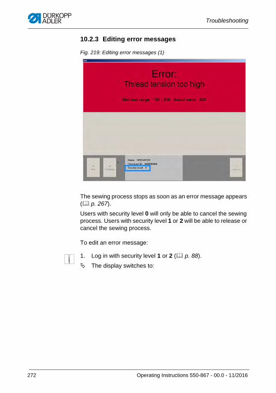
Troubleshooting
10.2.3 Editing error messages
Fig. 219: Editing error messages (1)
The sewing process stops as soon as an error message appears ( p. 267).
Users with security level 0 will only be able to cancel the sewing process. Users with security level 1 or 2 will be able to release or cancel the sewing process.
To edit an error message:
1. Log in with security level 1 or 2 ( p. 88).
The display switches to:
272 Operating Instructions 550-867 - 00.0 - 11/2016
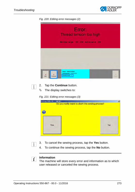
Troubleshooting
Fig. 220: Editing error messages (2)
2. Tap the Continue button.
The display switches to:
Fig. 221: Editing error messages (3)
3. To cancel the sewing process, tap the Yes button.
4. To continue the sewing process, tap the No button.
InformationThe machine will store every error and information as to which user released or canceled the sewing process.
Operating Instructions 550-867 - 00.0 - 11/2016 273
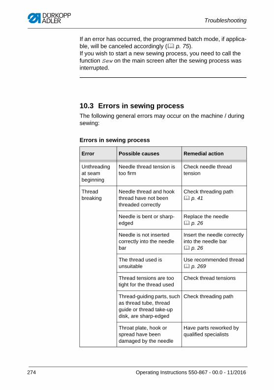
Troubleshooting
If an error has occurred, the programmed batch mode, if applica-ble, will be canceled accordingly ( p. 75). If you wish to start a new sewing process, you need to call the function Sew on the main screen after the sewing process was interrupted.
10.3 Errors in sewing processThe following general errors may occur on the machine / during sewing:
Errors in sewing process
Error Possible causes Remedial action
Unthreading at seam beginning
Needle thread tension is too firm
Check needle thread tension
Thread breaking
Needle thread and hook thread have not been threaded correctly
Check threading path p. 41
Needle is bent or sharp-edged
Replace the needle p. 26
Needle is not inserted correctly into the needle bar
Insert the needle correctly into the needle bar p. 26
The thread used is unsuitable
Use recommended thread p. 269
Thread tensions are too tight for the thread used
Check thread tensions
Thread-guiding parts, such as thread tube, thread guide or thread take-up disk, are sharp-edged
Check threading path
Throat plate, hook or spread have been damaged by the needle
Have parts reworked by qualified specialists
274 Operating Instructions 550-867 - 00.0 - 11/2016
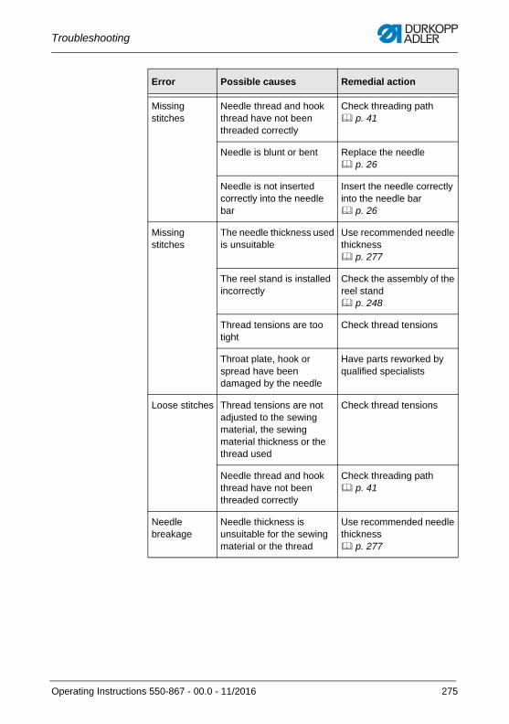
Troubleshooting
Missing stitches
Needle thread and hook thread have not been threaded correctly
Check threading path p. 41
Needle is blunt or bent Replace the needle p. 26
Needle is not inserted correctly into the needle bar
Insert the needle correctly into the needle bar p. 26
Missing stitches
The needle thickness used is unsuitable
Use recommended needle thickness p. 277
The reel stand is installed incorrectly
Check the assembly of the reel stand p. 248
Thread tensions are too tight
Check thread tensions
Throat plate, hook or spread have been damaged by the needle
Have parts reworked by qualified specialists
Loose stitches Thread tensions are not adjusted to the sewing material, the sewing material thickness or the thread used
Check thread tensions
Needle thread and hook thread have not been threaded correctly
Check threading path p. 41
Needle breakage
Needle thickness is unsuitable for the sewing material or the thread
Use recommended needle thickness p. 277
Error Possible causes Remedial action
Operating Instructions 550-867 - 00.0 - 11/2016 275

Troubleshooting
276 Operating Instructions 550-867 - 00.0 - 11/2016
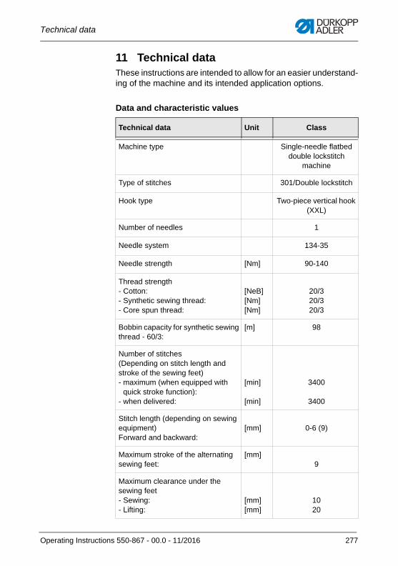
Technical data
11 Technical dataThese instructions are intended to allow for an easier understand-ing of the machine and its intended application options.
Data and characteristic values
Technical data Unit Class
Machine type Single-needle flatbed double lockstitch
machine
Type of stitches 301/Double lockstitch
Hook type Two-piece vertical hook (XXL)
Number of needles 1
Needle system 134-35
Needle strength [Nm] 90-140
Thread strength- Cotton: - Synthetic sewing thread: - Core spun thread:
[NeB][Nm][Nm]
20/320/320/3
Bobbin capacity for synthetic sewing thread - 60/3:
[m] 98
Number of stitches (Depending on stitch length and stroke of the sewing feet) - maximum (when equipped with
quick stroke function): - when delivered:
[min]
[min]
3400
3400
Stitch length (depending on sewing equipment) Forward and backward:
[mm] 0-6 (9)
Maximum stroke of the alternating sewing feet:
[mm]9
Maximum clearance under the sewing feet- Sewing: - Lifting:
[mm][mm]
1020
Operating Instructions 550-867 - 00.0 - 11/2016 277
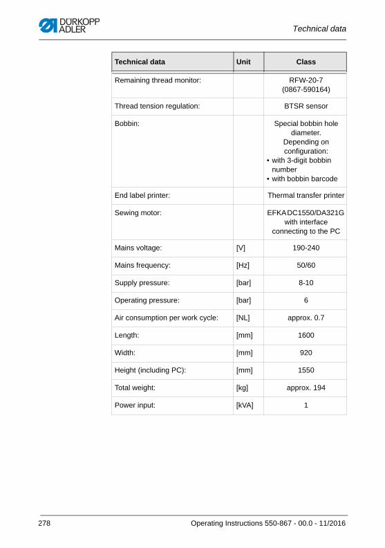
Technical data
Remaining thread monitor: RFW-20-7 (0867-590164)
Thread tension regulation: BTSR sensor
Bobbin: Special bobbin hole diameter.
Depending on configuration:
• with 3-digit bobbin number
• with bobbin barcode
End label printer: Thermal transfer printer
Sewing motor: EFKA DC1550/DA321G with interface
connecting to the PC
Mains voltage: [V] 190-240
Mains frequency: [Hz] 50/60
Supply pressure: [bar] 8-10
Operating pressure: [bar] 6
Air consumption per work cycle: [NL] approx. 0.7
Length: [mm] 1600
Width: [mm] 920
Height (including PC): [mm] 1550
Total weight: [kg] approx. 194
Power input: [kVA] 1
Technical data Unit Class
278 Operating Instructions 550-867 - 00.0 - 11/2016
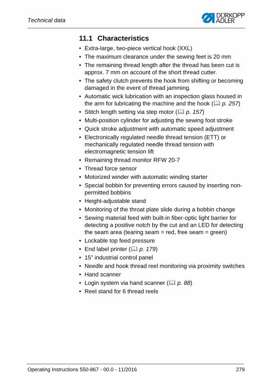
Technical data
11.1 Characteristics• Extra-large, two-piece vertical hook (XXL)
• The maximum clearance under the sewing feet is 20 mm
• The remaining thread length after the thread has been cut is approx. 7 mm on account of the short thread cutter.
• The safety clutch prevents the hook from shifting or becoming damaged in the event of thread jamming.
• Automatic wick lubrication with an inspection glass housed in the arm for lubricating the machine and the hook ( p. 257)
• Stitch length setting via step motor ( p. 157)
• Multi-position cylinder for adjusting the sewing foot stroke
• Quick stroke adjustment with automatic speed adjustment
• Electronically regulated needle thread tension (ETT) or mechanically regulated needle thread tension with electromagnetic tension lift
• Remaining thread monitor RFW 20-7
• Thread force sensor
• Motorized winder with automatic winding starter
• Special bobbin for preventing errors caused by inserting non-permitted bobbins
• Height-adjustable stand
• Monitoring of the throat plate slide during a bobbin change
• Sewing material feed with built-in fiber-optic light barrier for detecting a positive notch by the cut and an LED for detecting the seam area (tearing seam = red, free seam = green)
• Lockable top feed pressure
• End label printer ( p. 179)
• 15” industrial control panel
• Needle and hook thread reel monitoring via proximity switches
• Hand scanner
• Login system via hand scanner ( p. 88)
• Reel stand for 6 thread reels
Operating Instructions 550-867 - 00.0 - 11/2016 279
Technical data
11.2 Technical features of the software• Intuitive user guidance• Seams with up to 20 seam sections• Seam section switch via notch detection, stitch counting or
manual operation• Option to save different setup and end label masks• Teach-in function for ETT (electronically regulated needle
thread tension)• Test window for thread tension• Display of the thread tension during sewing • Detection of needle and hook thread via barcode scanner
(if available as an option)• Detection of sewing material piece 1 and/or piece 2 (or piece 3)
via hand scanner• All seam paths can be assigned with various parameters• Automatic function suppression of the following parameters in
the tearing seam• RS function (bartack via step motor)
• HP function (pneumatic stroke adjustment)
• FA function (thread cutter)
• Visual “Tearing seam” display in the user's field of vision (LED - red)
• Evaluation of the gathered sewing material data• Monitoring and active regulation of the needle thread tension
(ETT only (electronically regulated needle thread tension))• Automatic thread breakage detection• Deviations from the setpoints during the seam are detected
and result in a sewing stop• The sewer can interrupt the sewing process in the area of the
side airbag seam. To do so, press the “FA” button while moving the pedal to posi-tion 2 at the same time. The seat is automatically reported as “not OK”.
• Once the last seam path is completed, all sewing parameters are stored, bringing up the prompt to scan the next barcode parts primary.
• Data recording in a database or ASCII file • Different security levels for operator, supervisor and produc-
tion manager• Data is saved even in the event of a power outage thanks to a
UPS (uninterrupted power supply)
280 Operating Instructions 550-867 - 00.0 - 11/2016
Technical data
11.3 Data recordingThe following data is recorded and saved for each tearing seam in a protocol file and a protocol database, respectively.
• Date
• Time
• Line number
• End label barcode
• Barcode parts primary 1-3
• Barcode used needle thread
• Barcode used bobbin thread
• Additional barcode information (max. 9)
• Bobbin number
• Bobbin winding information
• Bobbin loading information
• User name
• Number of seam sections
• Adjusted stitch length per seam section
• Absolute seam section length
• Calculated stitch length
• Thread tension window
• Stitch count
• Seam record set name
• Machine number
• Manufacturer code
• Time for this cycle
• Error code
• Cycle number
• Thread tension single stitch data
• Daily part no.
Operating Instructions 550-867 - 00.0 - 11/2016 281

Technical data
282 Operating Instructions 550-867 - 00.0 - 11/2016
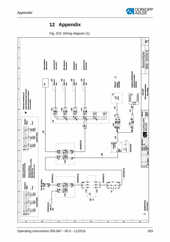
Appendix
12 Appendix
Fig. 222: Wiring diagram (1)
�������
��
�
��
��
�����
�� ������������� ������
�������
��������� ���
��
�
��
��
�
� ! " # $ %
&��� ������'( ���
&
�� ���)��
*+, &
-���
-���
-��
.�
-�
������,������%�
-���
�����������
#�
/�
-���
-���
%��0����12��*��'(�� ������1
��3������ ������������4��'( ��
-���
-���
-���
-���
%�
%�
�5(���'(
6� ������ ��7"!��5(���'( �
�� ���)��
�� ���) �
�� ���)��
�� ���)��
&
%8(������ ������
/��'(�9�����9
"1:��+ �������
+'(�� �'(���:
��'�3��!��':��
���'(�� ����
�������������
;�3)
!� ��
!� ��
���4)
$���21
����
����
����������
�
�4'/����1������
#�����4�
7� 7� 7� � 9"
�� �������<������
#7�
�
9"
������������7���
�(��
#
7�
�
�=������,������%�
9"
#
7�
�
9"4�
74��
�=������,>�
�����%�
# ��=����
����9" 4� 4� 7� /� 4�
7 4� 4�7
4�
� 4� 4��
4� 4� 4� 7� /� 4�
9" ���� ����9"
����
���� ���� ����
���'(��?����!��(� ����� ��@
/�������� �� (�����(������0�����������@
A�(�����! ��� ���4�����3
����'(�5?�����1������9(����������� �����)
+�������3'�3��������� �4�
3�� ��4� �3������B������������(����)
������������7���
������������7���
������������7��
������������7���
4�7
4�
4��
4�
����9"
�0�7
4�
7���
6�@
������,
�����%�
��,�
�0��
4�
����9"
����
7� 7� 7� 9"
#
7�
7�
9" C*/@
7"!�@��,�����
7"!�@�����
�D
������������7���
#
7�
7�
�=������,������%�
9"
7���
#
7�
7���
7�
7"!��
7"!��
9"
�� �� �� �� 0�
4�
4� ����
4�
�=������,
�����%�
# ��=����
� � � � �
�� �� 0�
4�
�0 �
7
9" � 7
9" � 7
9" � 7
9" � 7
9" � 7
9" �
C4������ (����1���� �������'(��������
��� (���������� ����
7���
4� 0�
7���
� E�FE>F�
7"!��D
��0������(
�����������
�� ���� �3�7"!���0�������
����������
7���
�(��
7���
�(��
7���
�(��
7��
�(��
%���( ��3G�� ���
/��'(�9�����9
"1:��'�� ����4�=
�0�'(�'�4���
��'�3������ ��
Operating Instructions 550-867 - 00.0 - 11/2016 283
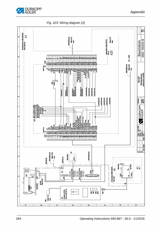
Appendix
Fig. 223: Wiring diagram (2)
�������
����
��
���
����
���
���������
����
�
����
���
����������������
�����
�
�
��
��
�
� ! " # $ % &
������'!�
�
��
(�������
�����
������
��
)���
�
*��*�
� �
������'�� ��
+ ��
+�
+ �
+ �
������'��
+ +
� � ����+
��
,�����-�����.����
����
����
/���
�������.�.����
����
�� �
������'"�
������'$�
�������-��
�������������
� 0
� �
��
1�2'
"����
"����
���3'
%�-�45�
����
���
�
������� �
!6
�3�7�
��5�����
$�����3�
!�����
3�8�"��
�%
9������'�����������
,�� �����
:/
(���
+ �
"!����
�����������
(����������
�� �
3��;��<
�� �� ���;��<��;/7
<��
��� (�--�������
(����7�����
��������� ��,� �
�����
�����������
����������
����������
��������� ��, ��
�� 3� �� �� �� �� 3 �� �� =�
���� ��3
����
3���
����
��3�
����
��3�
����
��3�
��3
3�3
����
3���
����
3���
����
����
����
����
��3
��3
����
����
����
���� ��3
/�"
����-�'
� � � � � � � �� �� � �� � �� �� �� �� �� � � � � � � � � �� �� � �� � �� �� ��
�/ :���
5'����2'
�>?,���.
@)?0�
�&7��&?0�
$$ ?0�
$$�?0�
$$�?0�
"�
���?0�
,/9?
0�$A
%@?0�
,/?0�
@:�@�
?0�
$$�?B:7�;�C��<
D ���>
D ���>
$(?B
:7;�C��
<%�"
$$ ?B:7�;�C��<
�$"
?B:7�;�C��<
$$�?,#
"?B
:7�;���
�<$A
%@?,#"
?���.�?B
:7�;���
�<@:�@�
?,#"
?B:7�;���
�<$A
%@?,#"
?������?B:7�;���
�<),?B:7�;�C��<
$A�;�
9<�/7,
�;$�<?B
:7�;�C��<
�(?
B:7�;�C��<
$$�?,#
"?B
:7�;���
�<$$
�?B:7�;�C��<
$$ ?,#
"?B
:7�;���
�<&9?
B:7�;�C��<
D ���>
@��;�C��<
$,�;�
C��<
$/�;
C��<
$��;
C��<
� D ���> D ���>� D ���> $$�?B:7�;�C��<� ),?B:7�;�C��<� $$�?,#"?B:7�;����<� �$"?B:7�;�C��<� $$�?B:7�;�C��<� ,/9?0�
�� %�"
0�?,
/��+ '��� '!�
0����+��
'��� '$�
D >
?/9/
��+
' ��� '%�
B:7�
����+
'��� '%�
0����+��
' �� '$�
/)?@
#$?�
>��+ �
'��� '%�
/)?@
#$?0���+
�' �� '&�
B:7�
� ��+
'��� '%�
0�?!
B"?$
/��+�'��� '"�
B:7
����+
'���� '%�
B:7
� ��+
'� �� '%�
B:7
����+
'� �� '%�
0�?D
$/��+
��' �� '$�
0�?$
A��+
��'���� '$�
0�?&
9��+��
' ��� '$�
0�?@
���+��
'� �� '$�
0�?$
/��+�' �� '"�
E��-��
� �
����
� ��
���,�
��
����
�
�/:���
5'����2'
�>?,���.
@)?0�
�&7��&?0�
$$ ?0�
$$�?0�
$$�?0�
"�
���?0�
,/9?
0�$A
%@?0�
,/?0�
@:�@�
?0�
%���5��-����
>"
!?/
9/$/
�;*�<
$(?B
:7;�C��
<%�"
,#"���
�,#
"?B
�D�
>?/9
/$A
%@?,#"
?���.�?B
:7�;���
�<@:�@�
?,#"
?B:7�;���
�<$A
%@?,#"
?������?B:7�;���
�<@�5'�/
),#
"���4�
�(?
B:7�;�C��<
$$�?,#
"?B
:7�;���
�<0�?!
B"?$
/$$
?,#
"?B
:7�;���
�<&:�
D ���>
&:
$,�;�
C��<
&:�
$��;
C��<
/�"
����-�'
� � � � � � � �� �� � �� � �� �� �� �� �� � � � � � � � � �� �� � �� � �� �� ��
��
3� �� �� �� �� 3 �� �� =� ����
��3
����
3���
����
��3�
����
��3�
����
��3�
��3
3�3
����
3���
����
3���
����
����
����
����
��3
��3
����
����
����
����
��3
9!��-'
���������3���
���-'
����
����
� ��,
��
����
�
����
�
284 Operating Instructions 550-867 - 00.0 - 11/2016
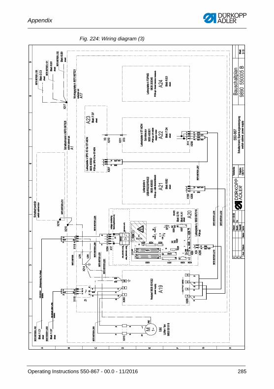
Appendix
Fig. 224: Wiring diagram (3)
�������
��
��
���
� ���
�����
����
�����������
����
����� ��!���
��
����
���
�"#������$#�
����!
" �����
� %
�&
�
��
��
�
� � ' ( ) * + ,
-&��
./0� ����0��
����
����
���
1
.
2)
� ������3'�
� ������3(�
4�
-&��
-&��
-��� 1 �5� # ����
����
��&&
-&�
-&��-&-&
� -��
-���
. #� �� ��� ��3����
����
����
-&��
-&��
����
���������/�
6!� 7
� �����&3*�
� �����3��
� ������3�&
-���
-&��
. #� �� ��� ��
8��
�9�&
�&�9�
&&
����
���
���
. #� �� ��� ����2�
�:�;�0/���
<�(1
����
���
��&
-&��
����
��������������
����
��&�
� ������3(
-&��-�
-�
-&�� -��
-&��
. #� ���
��� ����<�(1
����#��6!�!�
����
���
���
� ������3(�
-&��
!�
���
� ��� ������
����
��&�
� ������3)�
. #� �� ��� ���*�2
+
����
�&��
��
� �����&3'� � ������3��
� ������3��
������� �� ��
��������������
���
�&�
�&�
�&&
�&�
�&
=�>3
(���6
(���6
� ��$3
+ ��/0�
1!�6
1�6
&�������&�
'5
�$�<
# 0�6# #
*� #��$
������������.&��
$ �"
���������&��.��&
�� �
�����������.���
�� �
$� �"
����&�?
�'�@8
�?���82�
A
�����,
5
$
����&�?
�'
�����,
5
$�
?�$
$� $�.8
B$� . 8
��� 2) 2) 2) ��� $
$ 1 1
�!" ������ %
?�$
@1 �5����������� #� ��! ��� A
$ $ 11
B
������;�8�<�2�8�<��&?
('�������
$�
?C$�
��� 2)
���
?C$�
�����������
������������.&��
-&��-&�& -&�� -&&
�
.&��
.&&
������������.&&�
��&��� &� �������������.&&�
�� �
� �&�
& &��
-&&�� �-&�&
������������.&&�
�� � �-&�
-&�
-&� � ��� &� �� -&&� �� � $� C&?D�2�
�� & $ +1(� �
�1�D
:1��-
&�3&��3+�
�1�D
+1(��-
&�3���3+�
�� � -&&�$ �
$ 1 & -&&� -&&� -&�� -&&& ��
���� 2) �
*�
-�� �$� . 2'
���� 3
& �
-&�$� �
*� ���>
E���
� �
:1���-��
3���3*�
-&&�� -&
���! ��� �6!�#�!�#��
���������/$ �"������
-&&� ��
-&�
�&9 � �
��
������������.&��
������������.&��
� �� & �
�"#������$#� ��>!!�
������������.&&�
�� �
���������&��.&�
�� �
� $ +1(
&
2'���� 3�8��
�9�&
�&�9�
&&
� $� C&?D�2�
������������.&��
2'���� 3��2
��:�;
�0!���
<�(1
� $ +1(
&� $� C&?D�2�
�"#������$#� ���� 3
�� �
� $� C&?D�2�
& $ +1(
2'���� 3��<
�(1
�� �� ��6
!�!�
� $� C&?D�2�
$ +1(
��
�
��$�
�� ��� 3
��
�
2'���� 3���� �>
�� ��#!��6 �
���
����
����
�&��.�
&�
��
���
������
�&��.�
&�
��
���
������
�&��.�
&&
��
�
-&��
&��?
�'
Operating Instructions 550-867 - 00.0 - 11/2016 285
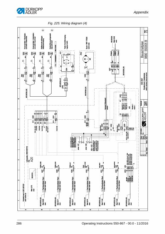
Appendix
Fig. 225: Wiring diagram (4)
�������
�
�
�� ��
����
���
������ �����
��������� ���
����
���
�������� ����
��������� �
����� �
�
!
��
��
�
� � " # $ % & '
���
������ ��������
����
���
�� �����(��
�� �����(%�
�� �����('�
�� �����(%�
�� �����(&�
�� �����(#�
�� �����("
�� ����!(%�
�)��%� ���
�*� �
�����+
�(
�)��%� ���
�*� �
�����+
�(
�)��%� ���
�*� �
�����+
�(
�)��%� ���
�*� �
�����+
�(
�)��%� ���
�*� �
����+
�(
�)��%� ���
�*� �
����+
�(
,�
,! ,,
�
,�
,�
,!�
,�
,!�
,��
,!
,
,�
,!!
-�����+� ���������
����
����
,��.�,
�),�
,�
,�,
!
,�,
,!
,�
,�
,��
,�!
,�
,�
,�
,
,��
,
����� �
�/�� �*
�*0
����� ���
��
,�,
!
,!��
,!��
,!�
,!�!
,!�
,!��
,!��
�!
�!�
1 ��
���� �����2
3��
�4 *�
��!
�
1 ��
���� �����2
5����4 *�
��!
�!
�6���� �� *�
� �4� 7�
��!
��
1 ����
48��6�
7����7
�� ����
�!��
��
���
9 �������:
��*�
; �7 �
7
�+6��������
����
��
�� �����('�
< <
� 6��� ��+� �
��������������
��
=�*(
# �6:
# �6:
�� ��(
&�+�84�
> �:
> :
�
�����!��
"?
��9�
���4 :����
%���7 ��
�������� �������+�(
���������!��-!
�����
���������!��-!�
�����
���������!��-!�
�����
���������!��-!!
�����
���������!��-!�
�����
���������!��-!�
�����
���������!��-!�
�����
�����
�)������ ��� ������+ ��
�)������ ��� ������+ ��
�)������ ��� ������+ ��
�)������ ��� ������+ ��
�)������ ��� �����+ ��
�)������ ��� �����+ �� �>
�@&>#
�>�@
A>
��@B
$%@.
��
��@B
$%@A>
��@B
$%@&
>#
�����������
�� �� 7� 7� 7�����
%�C�
&@�
A&
����
%�C�
&@�
A&�
����
����
����
%�C�
&@A�3
����
���
�+6���
� ��������*��
����
���
�C��A>C5
9
���
���
�C��359C
59
���
� ! �
�>�@
&>#��; ��(:
��(��!(#
�>�@
A>��; ��(:
��(��!(#
��@B
$%@����,(��(#�
��@B
$%@A>��,
(���($�
C"�
D6:+���� ������*���)
%��� ��� �*�� 7�����
D6:+���� ������*��!)
%��� ��� �*���+ � ��
,�(�.
�!��C
E�@3
59�
.,�
(�.
����C
E�@3
59�
�,�
(�.�
��CE�@3
59
.,�
(��.
����C
E�@3
59
�
D6:+��
! �
D6:+��
! �
,(����.
�@
�C�
,(�!��3
59�
�
/� ��F
�
+ �(0
� !
!
+ �(0
�
/C� ���F
�
��
! � �
,����.�@
�C�
,��(���A>
,��(���A>
!
,��(����A>�
,��(�!��A>
,(���359�
��
,��(���A>�
��
�� 7� 7�
.�
@�C�
�E@3
59
� ! � � � � � �� � �
� � !�� �� 7� 7� 7� �� �� �� ;�
7��� ����
�� ��
;���� �
;���� ���
CE�@3
59�
(�.
CE�@3
59�
(��
CE�@3
59�
(.
CE�@3
59�
(�
� !
��
�� 7� 7�
�����������-��
�� �� ;�
�����������-�
��
�����������-�!
��
!
!
��
�� 7� 7� 7� �� 7���
���� �� ��
�� �� 7�
/+ �(0 �
/+ �(0 �
/+ �(0 �
/+ �(0 �
��
��
�� 7�
��
������* 7� �� 7�
�� �� �� �� �� �� �� ��
.�
A>
359�
��
A�*6
���;7�
�����
����
����
��!
/G�0 � ! � �
����
����
���-
�
��
������*
7� �� 7��!�
/G�0
/G�0
/G�0
/G�0
�
7�A>
A>!
A>�
A>�
� ��
��������2�
��*������� *
� ��
��������2� �
�����
�� *
�6���� �� *�
�� :
+���7
�*7�
�76�*�
��� ��*
,� ,
%���
7����.
%���
7���.
%���
7�����
%���
7����
- 77
��7����������
� ��
������*�
� ����
����
��
����
�
�
286 Operating Instructions 550-867 - 00.0 - 11/2016
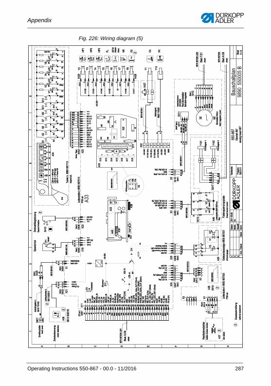
Appendix
Fig. 226: Wiring diagram (5)
�������
�
���
�� ��
�����������
���� ��
��������������
��
��
��
��
�
� � � ! " # $
%���&����'(����
���
���� �) � *
*��(+��+���,��
*,��-�����(��,��
*
���
#���&��.���
/���
�����������*
0���
0��*
0� 0�0���
1�����.����+������������
%� ���
%"2 *
0��
0���
/��
3�
0���0��
0���
0��� 0�
0�
0���
��������-����������������
���
0���0��
/.���45�
6�
0��
0���
7�
6�
���
���-�������-,��
��� ���
6�
/��� 0�
�
0���
��� "����.��,���.���
0���
*
���
6�0�
0���
���
1�����.����+������������
8�)))8�
6�3�
"1 9: "�
0�
;�����+)������������
0���
0���0�
���
���
8���
8���
0��
0��
0���
/�/�
/�
0���
%�&)/��(������
/���
/�/�
��
/��
0���
/��
0���
6�6�
0���
0���
6�6�
8�
$7�
8�
$7�
8�
$7�
8�
"1
8�%"2
8�
9:
8�
"/
8� 8��
6�
���� �)!�
���� �)#�
6�6�
* "� ":
�,�(��.�
��������������
���
<��)
�,5
�,5
����)
#�.�=&�
94�5
95�
����������
�-
�(;���&5���
"������
�4�����������54���4�
�����������
������������1���
������4�(������(��4�
4.��4���>,�.5���
�44+�(4?��
@9� �� �� �� �� �� �� � �� �� ?�
���� ���
����
����
����
����
����
����
����
����
���
���
����
����
����
����
����
����
����
����
���
���
����
����
����
���� ���
� : ! �@��,+��?������+
�����������
A���.4)B
� � � � � � � � � �� �� �� �� �� �� �� �� �� �� �� �� �� �� �� �� �� �� �� �� �� �� �� �� �� �� �� �� ��
�� �� � ��
�/ C���&)
�����)
�6D14��+
%�D@9
9$; 9$D@9
""�D@9
""�D@9
""�D@9
�����D@9
1/7D@9
"2#%D@9
1/D@9
%C %��D@9
#���&��.���
E��6D/7/
"/�A8�B
":D�C;A�F��B
#9
1! ��4�
1! D��
E�6D/7/
"2#%D1! D���+�D�C;�A��5�B
%C %��D1! D�C;�A��5�B
"2#%D1! D��(���D�C;�A��5�B
%�&)�/�
1! ���=�
9:D�C;�A�F��B
""�D1! D�C;�A��5�B
@9D�� D"/
""�D1! D�C;�A��5�B
$C��
E�����6
$C��
"1�A�F��B
$C��
"��A�F��B
1�(���(���+��+
�����������
� � � � � �
A�.4)B
� � � � 7���(.)
�: �,�4���(�
�� � �
A�.4)B
� �6D74����� � 0�� ����������4�
�� � E��6G �����������
0�� ���A"�B
A�.4)B
� ��
1! ��4�
A�.4)B
� � E�����6 � ��
�����������
0�� ���A"2#%D@9B � �� ��
A�.4)B
�
0��)��
#9 � �� �� ��� ��
@9�
�)() � �� �
0�� ���A"�B � �� �
E�����6 ���
A�.4)B
� E��6�/7/ E��6G�� � #���&��.���
�����������
4���?���,��
�����������
��
�
E�����6
E�����6
A�.4)B
� ����
���:��4���;���5)1! � ��
:��4���@���(�4��1! � �� ��
� �����
�
!5������%�(��?�� � ����
A�.4)B
� C���&)��
�
��+ ��H
���)() �� � �� � �����)�� � �6�14��+
� �)()
/.�����5����4�
�����������
0���
�� �
A�.4)B
� �)() 1�����.������������III
7��
�� � 0�� �� �����������
�����������4���4��
�� � E�����6 �� �
�� �
���
E��6D/7/A�.4)B
� ��
0�� ���A1! ��4�B � ��
7���(.)
0�� ���A1! ���=�B � ��
0�� ���A@9D�� D"/B � �� �� �
�����
/��
�� �
%"2
����� �4�
�����������
1! �6���J�%"2
��&�
1! �6���J�%"2
������
1! �6���J�74�����9
+�K.��(.)
� ��6�
6� � ��6�
�
/� /� � ��
0�� ���AE�6D/7/B
A�.4)B
� ��� ��
#9 � ��
/� /� 0�� ���A%�&)�/�B � ��
�����������
/�
6�/�
� � � �0��
0��
0��
0��
0��
0��
0��"
/�
6�/�
�� � � � � � �
/�
6�/�� �� 0�0�0�
"/��������
"/��������
��
E�����6
0�� ���A"�B
0�� ���A"1B
0�� ���A9:B
0�� ���A":B
E�����6
E�����6
#9
� � � � � � � �/����
�4�I���.4)
� 0�� ��/��
6�
0���� � 0�� �� �
��
�� ���� � 0�� � � � � 0���� � 0�� ��
/�
0��
0��
�
� �� � 0�� ��
/�� �
�� � #9 � � 0�� �
�� �� � �
/�
�
�
�� �� � E�����6 � 0���� � 0�� �
0�
��?� �� 3�
0��
/�
/�D%!"DE�6
/�D%!"D#9
/�D%!"D@9
��
���� ���� �� 0�� � 3�0����� �� 0�� �
A��7��.4)B � �
%�&)����(�����,�4�
�
����� �� 0�� ��
/�
� 0�� �
��
��� ���� �� 0�� ������ �� �)()���� �� �)()
/��
��
����
�����������
$,�5����
�����������
#���(���(���+�
�����������
/��(��������4�4�
����(�����,�4��54�4�
�� � �� �� �����
����
�����
�����
/��
�
��
E�����6
�A�.4)B
� � � � � � �
��
����
� ���
�
��
0�� ��
0�� ��
0�� ��
0�� �� 0�
0�� ��
0�� ��
�� � �� �� �� �� �� ��
��
��
����
0��)� �
0��)� �
0��)� �
0��)� �
0��)� �
0��)� �
0��)� �
��
�
��
��
��
?�
����
�4�
��
�
�� ������������1���
�����
�����������
�����
��
�
��
��
�
��
E�����6
�
��
Operating Instructions 550-867 - 00.0 - 11/2016 287
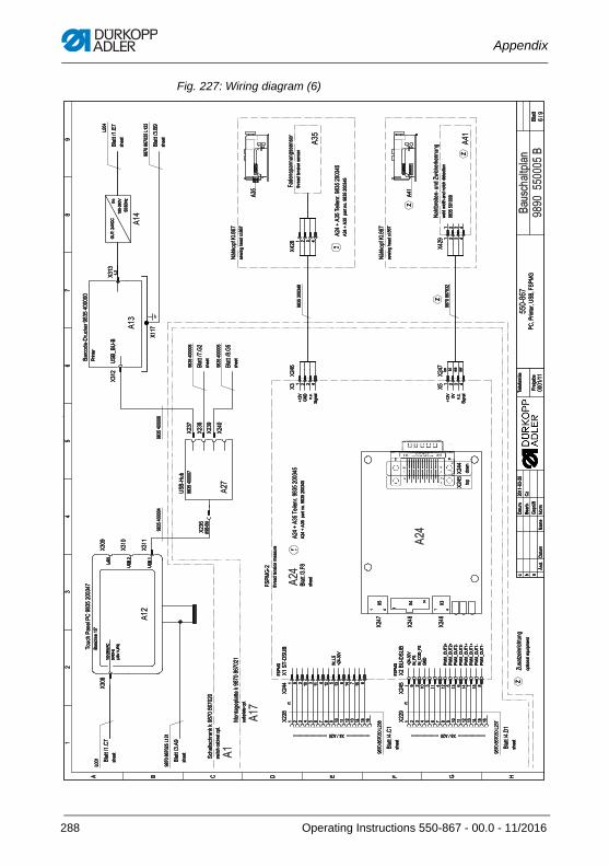
Appendix
Fig. 227: Wiring diagram (6)
�������
��
��
��
���
��
���
� ���
�����
����������������
�����
��
�������
�
�
��
��
�
� � � � � � !
�"#� �$"#���%�%�����������
� ������&��
� �����&��
'�
� ������&��
'�
� ������&��
�(���)�* �����%�����������
+,$��-�����"#�,�)
+
'���.����
�'��
'��
'�������
�
'��
.(,"#����� ������������
'��
'��
'��
� �����&��
����
��
'��
'��
'��
���/����.�� ���&���������
'�
���
�!,0
'��
'��
'�
'�
'�
'��
'��
' '�'���
������&�
� ������&��
���
1����
'�
���"(2����,"%�������������
'���
+
'�
34#%(*5�6 &���
34#%(*5�6 &���
���/����.�� ���&���������
'��
'��
3�#�0��������,�2�+7�"%��%���,�)
+
��
���
��2��$*���,�)$$��$(�
+
� ������& �
� �����&��
��,$"#� �* ��
��������������
��
���
��
��
8�2&
���,9
���,9
����0&
��*�:5�
3(�9
3�9
�
�������
�-
�0".�� �5�9� ��
����)�0�
$7��"#�"�0�����"* &
;��� $#���
�����������;��
$#���
��������������������'���������������������������������� �����������������������'�����������������������������
� � � � � � � �� �� � � �� �� ��
�����������;�
$#���
� � � � � � � �� �� � � �� �� ��
�����������;�
$#���
$,0* ����"* &
�� ��
(*��(�� ��<,�*9���
����
�
� � �� �� � � � � � �� � �� �
�
����
�
� �� �� � � � � � �� � �� �
=31;�
/���>
/���>
=31��
=31�?�1��
�3�
�@�1?�./
�@�1?�./
�@�1?�.�
�@�1?�.�
�@�1?�.�/
�@�1?�.�/
�@�1?�.��
�@�1?�.��
������>��
�����!-
A��>������B
��$�" ������CC
� � � ��
'� '� '��
$#���
�#���2����$�(��9��$,��
;�3
���
�
���
��
���/�����*�����(&���������
���
���
����������
����������
�(*
2(7�
����������
/�>
�3�
�&"&
��)��
/�> �> �&"&
��)��
� � � �
����������
$#���
����������
$#���
0� 0 7$
$7
�������
��������
���������
��
$�7��)�#��2�" &���
$�7��)�#��2�" &���
���/�����*�����(&���������
?�.D��>��
� �
��
��
7� 2�7�2�#���2��(�"#�2���"��(�
����������
=3D
������>
�����!-
�#���2����$�(��$��$(�
;���
$#���
�����������;�
$#���
288 Operating Instructions 550-867 - 00.0 - 11/2016
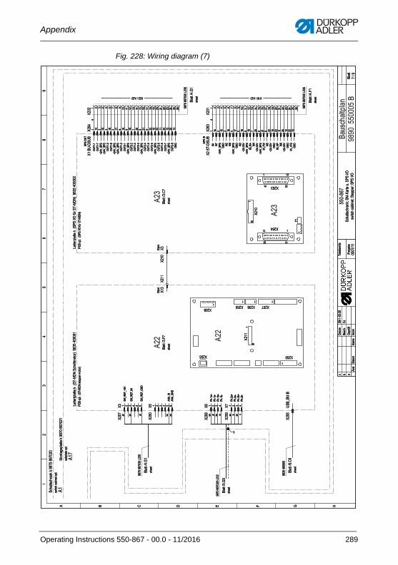
Appendix
Fig. 228: Wiring diagram (7)
�������
��
���
���
� � �
������������� �������� �� ��� ���
�������
� !��� ��"!���� ���##��� ��� ���
�$
%&
��
��
�
� ' ( ) * + ,
������������ � ���� ����$�
��� ���+�
�-���.�#���� � ���� ����$�
��� �&�+�
��� ���'�
/$��
/%
/$��
/�
/$��
/�
/$��
/�
/$��
0�10�
2�!����#���� � 3�4��(5 ����!��6-�-�7 ��%� &�����
/$��/$��
��� �%�*� /$��
/$��/$�� /$�� /$��
/$��
/�%
/$��
/%2�!���#���� � 3��� ��� 89� �4��(57 ��%� &����$
/$�&
/$��
��� �%�'�
/$�%
/$�&
/� 0�(�0
/$�%
/$ �4�(�0
/$%$
��� �&�+�
/$%�
��� �&�*�
�������#��
���� ������
�$$ �$$
�$%
�$%
:�;�
(���6
(���6
���"�
+�#�98�
5-�6
5�6�
$�����%�$�
'<
�"�4�!�8�6!!�
*��!.�"�
� !��� ��"!��� �#�
���� ����$� 2$�$
�����
��"#��� �#�
���� ����%� 2$%�
�����
��%� &�����
�����
.� .� .� "� �
� .� "� �� .� " .� ��
� $ % & � � � $ % & � � � $ % & � $ % &�' �#� 3�4��(5 ���##�� 6-�-�7
��1=)*1>�?
��1=)*1�5
��1=)*1+5(
�5�1�5
�5�1+5(
�����>
������
����">
����"�
���$�>
���$��
���$">
���$"�
�
����� $�
�
�� � �
$�#-�
$�#-�
�' �#� 3��� ��� 8-� �4��(57
�
$� *�
�����
�
�04���
�04���
>$&?1���
>$&?1���
�04��$
�04���
>$&?1���
>$&?1���
�04��%
�04$��
>$&?1���
�04$�$
�04��&
�04$�%
>$&?1���
�04$�&
�04���
�04$��
>$&?1���
�04$��
�04���
�04$��
>$&?1���
�04$��
+5(
�5�
�5�
>$&?1���
+5(
�5$
�5�
>$&?1���
+5(
�5%
>$&�%�?
>$&?1���
�51=�
�5&
>$&�%�?
>$&?1���
�51*@ �5�
>$&�%�?
+5(
�51,�
�5�
>$&�%�?
+5(
�51>*�
+5(
�
��� �04
�& $ �� % �� & �� � �� � �� � $� � $� � $$ �� $% �� $& �$ $� �%
�
��� �5
�& $ �� % �� & �� � �� � �� � $� � $� � $$ �� $% �� $& �$ $� �%
�� ��
� $ % & � � � � � �� �� �$ �% �& �� �� �� �� �� $� $� $$ $% $& $� $� ���� ����%� 2$%�
�����
� $ % & � � � � � �� �� �$ �% �& �� �� �� �� �� $� $� $$ $% $& $� $� ���� ����%� 2$%�
�������������������������������������� /$$ � �$� ���������������������������������� ��������������������������������� /�� � �$� ����������������������������������
��%
$� �&
�%�
�& $�
Operating Instructions 550-867 - 00.0 - 11/2016 289
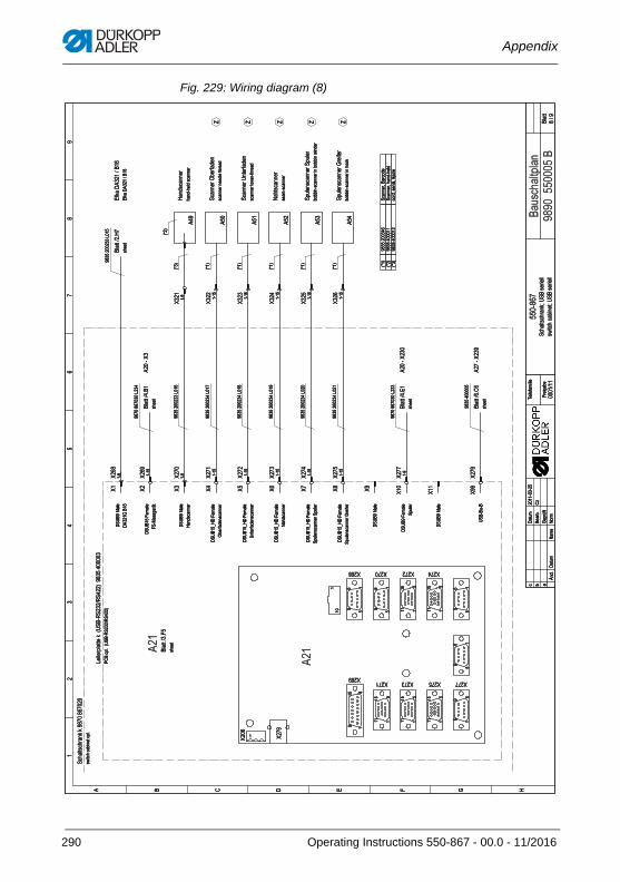
Appendix
Fig. 229: Wiring diagram (8)
�������
��
����
�����������������������
�������
������������������������
��
��
��
��
� � ! " # $ %
������������� ����������
&���
&��
&��� &��� &��� &���&��
'����(������)����*�����*����+�� ����������
�����,#�
&��� &��� &��� &���
&�&���
&��
&�
&���
&� &�&���
&�&���
&���
&� &�&���
&���
&� & &��
&���
&��
&��
&
�����,��
�����,"�
�����, �
������&�
������&���
������&��
&���
&���
&���
&���
&���
&���
�����,%�
��
���
���
���
���
���
"-��!����������
%�.������
�������/���-.��
�����������-.��
0�������
�(1�����������(1���
�(1����������$���-��
2 2 2 2 2
�1����(��
� �����������
������
3�.,
!14
!14
����,
$�(�5-
06�4
04�
����������
7
��8����-4����
#���9��
�������������(�,
�
: ���(�,��)����*�����*����+
����
���
!��� �;��
!����$����
!������#�4��
#��;���9��<
!��� �;��
%�.������
!�����=%!�#�4��
/���-.��������
!�����=%!�#�4��
����-.��������
!�����=%!�#�4��
0�������
!�����=%!�#�4��
�(1�����������(1���
!�����=%!�#�4��
�(1����������$���-��
!��� �;��
!��� �#�4��
�(1���
!��� �;��
�����1��
�� ����
�� ����
����
����
����
����
��
�����������'���
����
�����������'���
����
����������
����
�����������'���
�����������'���
�����������'���
�����������'��
�����������'���
�����������'���
��
����
����
����
����
����
)>�+
)>�+
)>�+
)>�+
)>�+
)>�+
����������
������?����6.�
)>�+
����������
������?���.����.
)>�+
����������
�6�.?������?� (6��
)>�+ �
����������'���
����
)>�+
"-��!����������
��.����.�������
����������.������.
��������6�������.
��4�������
�6����������������6��������.��
�6����������������66�
��
��
����
��
��
�
��
� �
������
�����
����
������
�� ��
�
��
�
��
�
290 Operating Instructions 550-867 - 00.0 - 11/2016
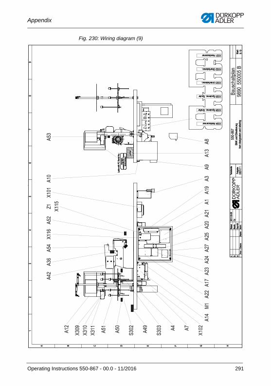
Appendix
Fig. 230: Wiring diagram (9)
�������
��
�� ��
������
������������
����
��
����������
�����
�����
����
��
�
��
��
�
! � " # � $ % &
'�� �()�*����
'����+,�����*-�%���.��
'����+,�����*-�+,����
'����/���.����*-
'����0���.����*-
'����&���*����
���*)�,��
��������������
!��
'���
'���
'��� !��
!��
+��� ! �
+��� ! !�
'���
!�
��
!��
!��!
� !��
!��
!�
!�
!��
!��
'���
!��!�� !�
�1� '��� !�
'��� !��
!��
!�!�
!��
!�
!��
2��-
#��
#��
����-
%�,�3.
(���
(�
�
����������
"4
�*5�
���.�����
$������
6����7�)�8"�+�����(
�-9
,�����
:�,��
��;
��������7�)�8"���<<<<<
������*)����;
Operating Instructions 550-867 - 00.0 - 11/2016 291

Appendix
292 Operating Instructions 550-867 - 00.0 - 11/2016

DÜRKOPP ADLER AGPotsdamer Straße 190 33719 Bielefeld GERMANYPhone +49 (0) 521 / 925-00 E-mail [email protected]
Su
bje
ct t
o d
esig
n c
han
ges
- P
art
of
the
mac
hin
es s
ho
wn
wit
h a
dd
itio
nal
eq
uip
men
t -
Pri
nte
d in
Ger
man
y ©
Dü
rko
pp
Ad
ler
AG
- O
rig
inal
Inst
ruct
ion
s -
0791
550
740
EN
- 0
0.0
- 11
/201
6


