Embed Size (px)
Citation preview
Products Solutions Services
Brief Operating InstructionsNAR300 systemOil leak detector float sensor
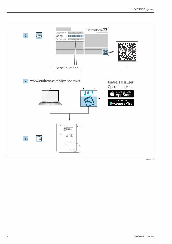
These Instructions are Brief Operating Instructions; they arenot a substitute for the Operating Instructions pertaining tothe device.Detailed information about the device can be found in theOperating Instructions and the other documentation:Available for all device versions via:• Internet: www.endress.com/deviceviewer• Smart phone/tablet: Endress+Hauser Operations App
KA01577G/00/EN/01.22-00715657622022-04-30
NAR300 system
2 Endress+Hauser
Order code:
Ext. ord. cd.:
Ser. no.:
www.endress.com/deviceviewer Endress+Hauser
Operations App
XXXXXXXXXXXX
XXXXX-XXXXXX
XXX.XXXX.XX
Serial number
1.
3.
2.
A0023555
NAR300 system Table of contents
Endress+Hauser 3
Table of contents1 Document information . . . . . . . . . . . . . . . . . . . . . . . . . . . . . . . . . . . . . . . . . . . . . . . . . . . . . . . . . . . . 31.1 Symbols used . . . . . . . . . . . . . . . . . . . . . . . . . . . . . . . . . . . . . . . . . . . . . . . . . . . . . . . . . . . . . . . . . . . . . . . . . 31.2 Documentation . . . . . . . . . . . . . . . . . . . . . . . . . . . . . . . . . . . . . . . . . . . . . . . . . . . . . . . . . . . . . . . . . . . . . . . . 6
2 Basic safety instructions . . . . . . . . . . . . . . . . . . . . . . . . . . . . . . . . . . . . . . . . . . . . . . . . . . . . . . . . . . 72.1 Requirements for personnel . . . . . . . . . . . . . . . . . . . . . . . . . . . . . . . . . . . . . . . . . . . . . . . . . . . . . . . . . . . . . . 72.2 Designated use . . . . . . . . . . . . . . . . . . . . . . . . . . . . . . . . . . . . . . . . . . . . . . . . . . . . . . . . . . . . . . . . . . . . . . . . 72.3 Workplace safety . . . . . . . . . . . . . . . . . . . . . . . . . . . . . . . . . . . . . . . . . . . . . . . . . . . . . . . . . . . . . . . . . . . . . . 72.4 Operational safety . . . . . . . . . . . . . . . . . . . . . . . . . . . . . . . . . . . . . . . . . . . . . . . . . . . . . . . . . . . . . . . . . . . . . . 82.5 Product safety . . . . . . . . . . . . . . . . . . . . . . . . . . . . . . . . . . . . . . . . . . . . . . . . . . . . . . . . . . . . . . . . . . . . . . . . . 8
3 Product description . . . . . . . . . . . . . . . . . . . . . . . . . . . . . . . . . . . . . . . . . . . . . . . . . . . . . . . . . . . . . . . 93.1 Product design . . . . . . . . . . . . . . . . . . . . . . . . . . . . . . . . . . . . . . . . . . . . . . . . . . . . . . . . . . . . . . . . . . . . . . . . 93.2 Technical data . . . . . . . . . . . . . . . . . . . . . . . . . . . . . . . . . . . . . . . . . . . . . . . . . . . . . . . . . . . . . . . . . . . . . . . . 93.3 Process conditions . . . . . . . . . . . . . . . . . . . . . . . . . . . . . . . . . . . . . . . . . . . . . . . . . . . . . . . . . . . . . . . . . . . . 123.4 Delivery example by order code . . . . . . . . . . . . . . . . . . . . . . . . . . . . . . . . . . . . . . . . . . . . . . . . . . . . . . . . . . . 133.5 Operating conditions . . . . . . . . . . . . . . . . . . . . . . . . . . . . . . . . . . . . . . . . . . . . . . . . . . . . . . . . . . . . . . . . . . . 163.6 Gasoline application . . . . . . . . . . . . . . . . . . . . . . . . . . . . . . . . . . . . . . . . . . . . . . . . . . . . . . . . . . . . . . . . . . . 16
4 Incoming acceptance and product identification . . . . . . . . . . . . . . . . . . . . . . . . . . . . . . . . . 174.1 Incoming acceptance . . . . . . . . . . . . . . . . . . . . . . . . . . . . . . . . . . . . . . . . . . . . . . . . . . . . . . . . . . . . . . . . . . . 174.2 Product identification . . . . . . . . . . . . . . . . . . . . . . . . . . . . . . . . . . . . . . . . . . . . . . . . . . . . . . . . . . . . . . . . . . 174.3 Manufacturer contact address . . . . . . . . . . . . . . . . . . . . . . . . . . . . . . . . . . . . . . . . . . . . . . . . . . . . . . . . . . . . 174.4 Storage and transport . . . . . . . . . . . . . . . . . . . . . . . . . . . . . . . . . . . . . . . . . . . . . . . . . . . . . . . . . . . . . . . . . . 17
5 Installation . . . . . . . . . . . . . . . . . . . . . . . . . . . . . . . . . . . . . . . . . . . . . . . . . . . . . . . . . . . . . . . . . . . . . . 185.1 Mounting the NAR300 system . . . . . . . . . . . . . . . . . . . . . . . . . . . . . . . . . . . . . . . . . . . . . . . . . . . . . . . . . . . 185.2 Adjustment . . . . . . . . . . . . . . . . . . . . . . . . . . . . . . . . . . . . . . . . . . . . . . . . . . . . . . . . . . . . . . . . . . . . . . . . . 26
6 Electrical Connection . . . . . . . . . . . . . . . . . . . . . . . . . . . . . . . . . . . . . . . . . . . . . . . . . . . . . . . . . . . . 286.1 Procedure for wiring grounding cables . . . . . . . . . . . . . . . . . . . . . . . . . . . . . . . . . . . . . . . . . . . . . . . . . . . . . . 286.2 NRR261-2/4/A/B/C wiring . . . . . . . . . . . . . . . . . . . . . . . . . . . . . . . . . . . . . . . . . . . . . . . . . . . . . . . . . . . . . . 306.3 NRR262-2/4/A/B/C wiring . . . . . . . . . . . . . . . . . . . . . . . . . . . . . . . . . . . . . . . . . . . . . . . . . . . . . . . . . . . . . . 326.4 NRR261-3/5 wiring . . . . . . . . . . . . . . . . . . . . . . . . . . . . . . . . . . . . . . . . . . . . . . . . . . . . . . . . . . . . . . . . . . . 346.5 Wiring diagram . . . . . . . . . . . . . . . . . . . . . . . . . . . . . . . . . . . . . . . . . . . . . . . . . . . . . . . . . . . . . . . . . . . . . . 366.6 Operating principles of alarm activation . . . . . . . . . . . . . . . . . . . . . . . . . . . . . . . . . . . . . . . . . . . . . . . . . . . . . 38
1 Document information
1.1 Symbols used
1.1.1 Safety symbolsDANGER
This symbol alerts you to a dangerous situation. Failure to avoid this situation will result inserious or fatal injury.
WARNING
This symbol alerts you to a dangerous situation. Failure to avoid this situation can result inserious or fatal injury.
Document information NAR300 system
4 Endress+Hauser
CAUTION
This symbol alerts you to a dangerous situation. Failure to avoid this situation can result inminor or medium injury.NOTICE
This symbol contains information on procedures and other facts which do not result inpersonal injury.
1.1.2 Electrical symbols
Alternating current
Direct current and alternating current
Direct current
Ground connectionA grounded terminal which, as far as the operator is concerned, is grounded via a groundingsystem.
Protective earth (PE)Ground terminals that must be connected to ground prior to establishing any otherconnections.The ground terminals are located on the interior and exterior of the device:• Interior ground terminal: protective earth is connected to the mains supply.• Exterior ground terminal: device is connected to the plant grounding system.
1.1.3 Tool symbols
Phillips head screwdriver
Flat blade screwdriver
Torx screwdriver
Allen key
Open-ended wrench
1.1.4 Symbols for certain types of information and graphics Permitted
Procedures, processes or actions that are permitted
NAR300 system Document information
Endress+Hauser 5
PreferredProcedures, processes or actions that are preferred
ForbiddenProcedures, processes or actions that are forbidden
TipIndicates additional information
Reference to documentation
Reference to graphic
Notice or individual step to be observed1. , 2. , 3.
Series of steps
Result of a step
Visual inspection
Operation via operating tool
Write-protected parameter1, 2, 3, ...Item numbersA, B, C, ...Views
Safety instructionsObserve the safety instructions contained in the associated Operating Instructions
Temperature resistance of the connection cablesSpecifies the minimum value of the temperature resistance of the connection cables
Document information NAR300 system
6 Endress+Hauser
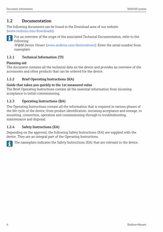
1.2 DocumentationThe following documents can be found in the Download area of our website(www.endress.com/downloads).
For an overview of the scope of the associated Technical Documentation, refer to thefollowing:W@M Device Viewer (www.endress.com/deviceviewer): Enter the serial number fromnameplate
1.2.1 Technical Information (TI)Planning aidThe document contains all the technical data on the device and provides an overview of theaccessories and other products that can be ordered for the device.
1.2.2 Brief Operating Instructions (KA)Guide that takes you quickly to the 1st measured valueThe Brief Operating Instructions contain all the essential information from incomingacceptance to initial commissioning.
1.2.3 Operating Instructions (BA)The Operating Instructions contain all the information that is required in various phases ofthe life cycle of the device: from product identification, incoming acceptance and storage, tomounting, connection, operation and commissioning through to troubleshooting,maintenance and disposal.
1.2.4 Safety Instructions (XA)Depending on the approval, the following Safety Instructions (XA) are supplied with thedevice. They are an integral part of the Operating Instructions.
The nameplate indicates the Safety Instructions (XA) that are relevant to the device.
NAR300 system Basic safety instructions
Endress+Hauser 7
2 Basic safety instructions
2.1 Requirements for personnelThe personnel for installation, commissioning, diagnostics and maintenance must fulfill thefollowing requirements:‣ Be specialists who are trained and have a relevant qualification for this specific function
and task.‣ Be authorized by the plant owner-operator.‣ Be familiar with local/national regulations.‣ Before starting work, read and understand the instructions in the Operating Instructions
and supplementary documentation as well as the certificates (depending on theapplication).
‣ Follow instructions and comply with basic conditions.The operating personnel must fulfill the following requirements:‣ Be instructed and authorized according to the requirements of the task by the facility's
owner-operator.‣ Follow the instructions in this manual.
2.2 Designated useApplication and measured materialsDepending on the version ordered, the device can also be used with potentially explosive,flammable, poisonous or oxidizing materials.Devices that are used in hazardous areas have corresponding labels on their nameplates.To ensure that the device remains in proper condition for the operation time:‣ Only use the device in full compliance with the data on the nameplate and the general
conditions listed in the Operating Instructions and supplementary documentation.‣ Check the nameplate to verify if the device can be put to its intended use in hazardous
areas.‣ If the device is not operated at an atmospheric temperature, compliance with the relevant
basic conditions specified in the relevant device documentation is absolutely essential.‣ Protect the device permanently against corrosion from environmental influences.‣ Observe the limit values in the "Technical Information".
The manufacturer is not liable for damage caused by improper or non-designated use.
2.3 Workplace safetyFor work on and with the device:‣ Wear the required personal protective equipment according to local/national regulations.
Basic safety instructions NAR300 system
8 Endress+Hauser
2.4 Operational safetyRisk of injury!‣ Operate the device in proper technical conditions and fail-safe conditions only.‣ The plant owner-operator is responsible for interference-free operation of the device.
Modifications to the deviceUnauthorized modifications to the device are not permitted and can lead to unforeseeabledangers:‣ If modifications are nevertheless required, contact your Endress+Hauser Sales Center.
RepairTo ensure continued operational safety and reliability:‣ Carry out repairs on the device only if they are expressly permitted.‣ Observe local/national regulations pertaining to repair of an electrical device.‣ Use only original spare parts and accessories from Endress+Hauser.
Ex-areaObserve the following notes to eliminate the risk of danger to persons or the facility when thedevice is used in Ex-areas (e.g. explosion protection, pressure equipment safety):‣ Check the model nameplate to ensure that the ordered device is explosion proof.‣ Observe the specifications in the separate supplementary documentation attached to these
Instructions.
2.5 Product safetyThis device was designed in accordance with GEP (Good Engineering Practice) to meet state-of-the-art safety requirements, has been tested and left the factory in a condition in which itis safe to operate. It meets the general safety standards and legal requirements.
NAR300 system Product description
Endress+Hauser 9
3 Product description
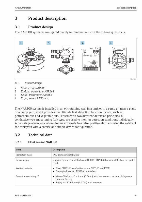
3.1 Product designThe NAR300 system is configured mainly in combination with the following products.
1. 2. 3. 4.
A0047557
1 Product design
1 Float sensor NAR3002 Ex d [ia] transmitter NRR2613 Ex [ia] transmitter NRR2624 Ex [ia] sensor I/F Ex box
The NAR300 system is installed in an oil-retaining wall in a tank or in a sump pit near a plantor a pump yard, and it provides the ultimate leak detection function for oils, such aspetrochemicals and vegetable oils. Sensors with two different detection principles, aconductive type and a tuning fork type, are used to monitor detection conditions individually.A two-stage alarm logic allows for an extremely low false-positive alert, ensuring the safety ofthe tank yard with a precise and simple device configuration.
3.2 Technical data
3.2.1 Float sensor NAR300
Item Description
Protection class IP67 (outdoor installation)
Power supply Supplied by a sensor I/F Ex box or NRR261 (NAR300 sensor I/F Ex box, integratedtype)
Wetted material • Float: SUS316L, conductive sensor: SUS316 and PTFE• Tuning fork sensor: SUS316L-equivalent
Detection sensitivity 1) • Water-filled pit: 10 ± 1 mm (0.04 in) with kerosene at the time of shipmentfrom the factory
• Empty pit: 50 ± 5 mm (0.17 in) with kerosene
Product description NAR300 system
10 Endress+Hauser
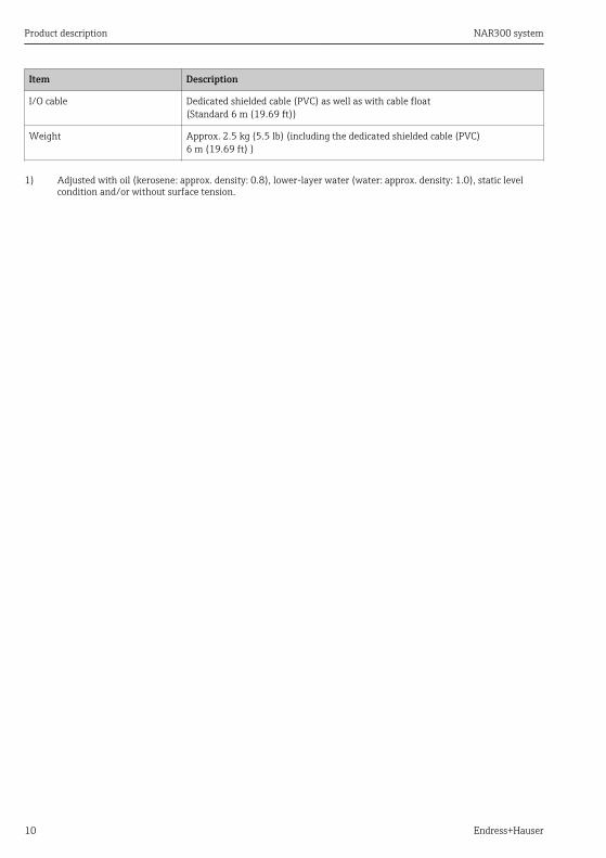
Item Description
I/O cable Dedicated shielded cable (PVC) as well as with cable float(Standard 6 m (19.69 ft))
Weight Approx. 2.5 kg (5.5 lb) (including the dedicated shielded cable (PVC)6 m (19.69 ft) )
1) Adjusted with oil (kerosene: approx. density: 0.8), lower-layer water (water: approx. density: 1.0), static levelcondition and/or without surface tension.
NAR300 system Product description
Endress+Hauser 11
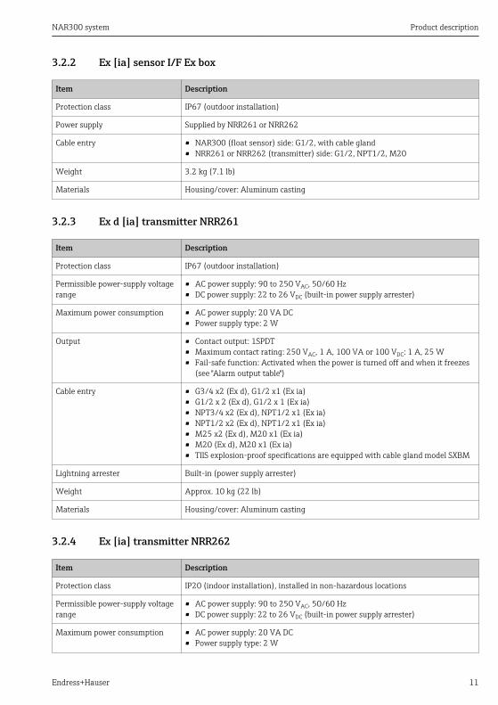
3.2.2 Ex [ia] sensor I/F Ex box
Item Description
Protection class IP67 (outdoor installation)
Power supply Supplied by NRR261 or NRR262
Cable entry • NAR300 (float sensor) side: G1/2, with cable gland• NRR261 or NRR262 (transmitter) side: G1/2, NPT1/2, M20
Weight 3.2 kg (7.1 lb)
Materials Housing/cover: Aluminum casting
3.2.3 Ex d [ia] transmitter NRR261
Item Description
Protection class IP67 (outdoor installation)
Permissible power-supply voltagerange
• AC power supply: 90 to 250 VAC, 50/60 Hz• DC power supply: 22 to 26 VDC (built-in power supply arrester)
Maximum power consumption • AC power supply: 20 VA DC• Power supply type: 2 W
Output • Contact output: 1SPDT• Maximum contact rating: 250 VAC, 1 A, 100 VA or 100 VDC: 1 A, 25 W• Fail-safe function: Activated when the power is turned off and when it freezes
(see "Alarm output table")
Cable entry • G3/4 x2 (Ex d), G1/2 x1 (Ex ia)• G1/2 x 2 (Ex d), G1/2 x 1 (Ex ia)• NPT3/4 x2 (Ex d), NPT1/2 x1 (Ex ia)• NPT1/2 x2 (Ex d), NPT1/2 x1 (Ex ia)• M25 x2 (Ex d), M20 x1 (Ex ia)• M20 (Ex d), M20 x1 (Ex ia)• TIIS explosion-proof specifications are equipped with cable gland model SXBM
Lightning arrester Built-in (power supply arrester)
Weight Approx. 10 kg (22 lb)
Materials Housing/cover: Aluminum casting
3.2.4 Ex [ia] transmitter NRR262
Item Description
Protection class IP20 (indoor installation), installed in non-hazardous locations
Permissible power-supply voltagerange
• AC power supply: 90 to 250 VAC, 50/60 Hz• DC power supply: 22 to 26 VDC (built-in power supply arrester)
Maximum power consumption • AC power supply: 20 VA DC• Power supply type: 2 W
Product description NAR300 system
12 Endress+Hauser
Item Description
Output • Contact output: 1SPDT• Maximum contact rating: 250 VAC, 1 A, 100 VA or 100 VDC: 1 A, 25 W• Fail-safe function: Activated when the power is turned off and when it freezes
(see "Alarm output table")
Lightning arrester Built-in (power supply arrester)
Weight Approx. 0.6 kg (1.3 lb)
Materials Housing: Plastic
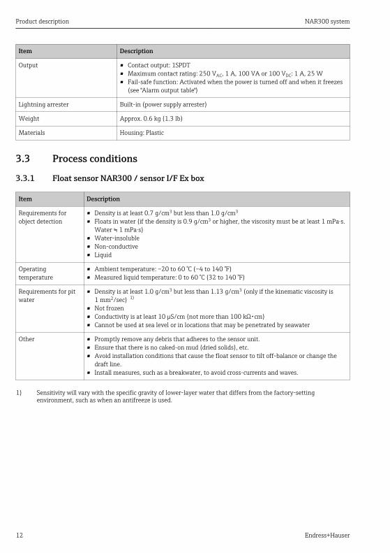
3.3 Process conditions
3.3.1 Float sensor NAR300 / sensor I/F Ex box
Item Description
Requirements forobject detection
• Density is at least 0.7 g/cm3 but less than 1.0 g/cm3
• Floats in water (if the density is 0.9 g/cm3 or higher, the viscosity must be at least 1 mPa⋅s.Water ≒ 1 mPa⋅s)
• Water-insoluble• Non-conductive• Liquid
Operatingtemperature
• Ambient temperature: –20 to 60 °C (–4 to 140 °F)• Measured liquid temperature: 0 to 60 °C (32 to 140 °F)
Requirements for pitwater
• Density is at least 1.0 g/cm3 but less than 1.13 g/cm3 (only if the kinematic viscosity is1 mm2/sec) 1)
• Not frozen• Conductivity is at least 10 µS/cm (not more than 100 kΩ・cm)• Cannot be used at sea level or in locations that may be penetrated by seawater
Other • Promptly remove any debris that adheres to the sensor unit.• Ensure that there is no caked-on mud (dried solids), etc.• Avoid installation conditions that cause the float sensor to tilt off-balance or change the
draft line.• Install measures, such as a breakwater, to avoid cross-currents and waves.
1) Sensitivity will vary with the specific gravity of lower-layer water that differs from the factory-settingenvironment, such as when an antifreeze is used.
NAR300 system Product description
Endress+Hauser 13
3.3.2 Connecting cable (connection to transmitter NRR261/262 from sensor I/F Exbox)
Item Description
Connecting cables Maximum inductance: 2.3 mH, maximum capacitance: 83 nFExample: Use of KPEV-S (instrumentation cable)C = 65 nF/Km, L= 0.65 mH/kmCW/C = 0.083 µF / 65 nF = 1.276 km....1LW/L = 2.3 mH / 0.65 mH = 3.538 km.....2Maximum extended cable length: 1.27 kmThe smaller of 1 or 2 is the maximum cable length (round down instead ofrounding off)
Operating temperature –20 to 60 °C (–4 to 140 °F)
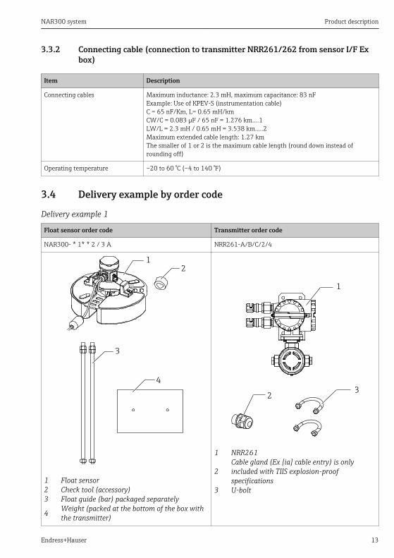
3.4 Delivery example by order code
Delivery example 1
Float sensor order code Transmitter order code
NAR300- * 1* * 2 / 3 A NRR261-A/B/C/2/4
1
2
3
4
1 Float sensor2 Check tool (accessory)3 Float guide (bar) packaged separately
4 Weight (packed at the bottom of the box withthe transmitter)
1
23
1 NRR261
2Cable gland (Ex [ia] cable entry) is onlyincluded with TIIS explosion-proofspecifications
3 U-bolt
Product description NAR300 system
14 Endress+Hauser
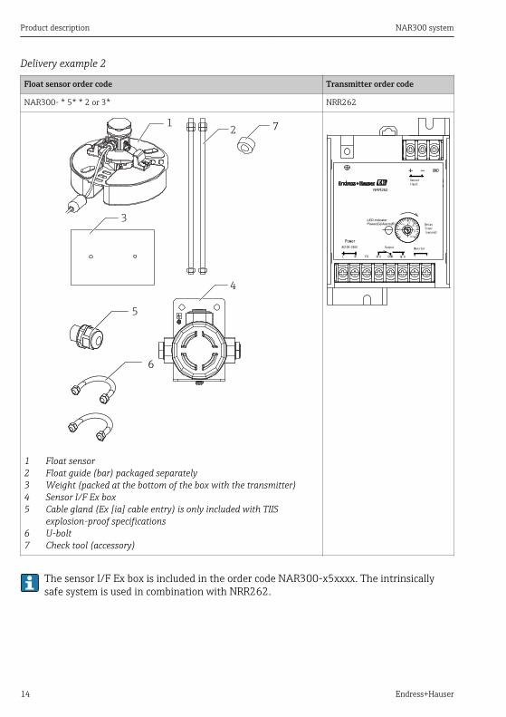
Delivery example 2
Float sensor order code Transmitter order code
NAR300- * 5* * 2 or 3* NRR262
12
3
4
5
7
6
1 Float sensor2 Float guide (bar) packaged separately3 Weight (packed at the bottom of the box with the transmitter)4 Sensor I/F Ex box5 Cable gland (Ex [ia] cable entry) is only included with TIIS
explosion-proof specifications6 U-bolt7 Check tool (accessory)
The sensor I/F Ex box is included in the order code NAR300-x5xxxx. The intrinsicallysafe system is used in combination with NRR262.
NAR300 system Product description
Endress+Hauser 15
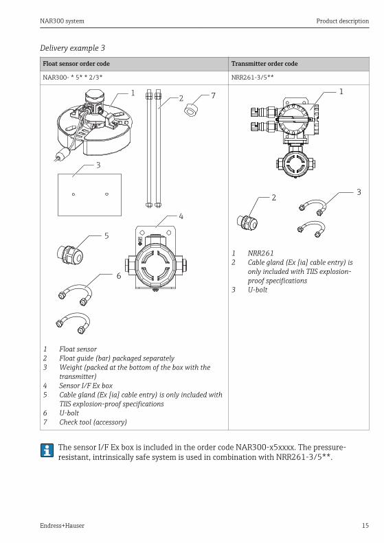
Delivery example 3
Float sensor order code Transmitter order code
NAR300- * 5* * 2/3* NRR261-3/5**
12
3
4
5
7
6
1 Float sensor2 Float guide (bar) packaged separately3 Weight (packed at the bottom of the box with the
transmitter)4 Sensor I/F Ex box5 Cable gland (Ex [ia] cable entry) is only included with
TIIS explosion-proof specifications6 U-bolt7 Check tool (accessory)
1
23
1 NRR2612 Cable gland (Ex [ia] cable entry) is
only included with TIIS explosion-proof specifications
3 U-bolt
The sensor I/F Ex box is included in the order code NAR300-x5xxxx. The pressure-resistant, intrinsically safe system is used in combination with NRR261-3/5**.
Product description NAR300 system
16 Endress+Hauser
3.5 Operating conditions
3.5.1 Detection sensitivityIf the electrode tip is pulled out of the lower-layer water due to increased thickness of the oillayer, water may cling onto the electrode tip like an icicle even if the electrode tip is in oil. Inthis case, detection sensitivity may increase by 1 to 2 mm (0.04 to 0.08 in). When an accuratedetection check is required, apply a small amount of neutral detergent to the electrode tip tokeep water from clinging to the electrode.
3.5.2 Pit waterDo not use in sea waterThe oil leak detectors is not designed for use in sea water. The following problems may occurif it is used in sea water:• Failed or delayed alarm when overturned by waves• Delayed alarm caused by generation of a bypass circuit between the conductive sensor and
the float itself due to salt coating• Corrosion of the float sensor caused by sea waterOther special pit waterIf the float sensor is used in certain special pit water, such as pit water containing solvents, itmay become corroded or damaged.Pit water with high electrical resistanceUse in pit water with high electrical resistance, such as in a steam drain and pure water, mayactivate the alarm. Ensure that the conductivity of pit water is at least 10 µS/cm (not morethan 100 kΩ・cm).Example: Pure water: 1 to 0.1 µS/cm (1 to 10 kΩ・cm)Frozen pit waterIf ice forms in the pit, the alarm may be triggered (fail-safe function). Implement anti-freezemeasures to prevent freezing.
3.6 Gasoline applicationIf the object to be detected is gasoline, check with your Endress+Hauser Sales Center andorder the gasoline application specifications under special specifications.
NAR300 system Incoming acceptance and product identification
Endress+Hauser 17
4 Incoming acceptance and product identification
4.1 Incoming acceptanceUpon receipt of the goods, check the following:• Are the order codes on the delivery note and the product label identical?• Are the goods undamaged?• Do the nameplate data match the ordering information on the delivery note?• If required (see nameplate): Are the Safety Instructions (XA) enclosed?
If one of these conditions is not satisfied, contact your Endress+Hauser Sales Center.
4.2 Product identificationThe following options are available for identification of the device:• Nameplate specifications• Extended order code with breakdown of the device features on the delivery note• W@M Device Viewer (www.endress.com/deviceviewer): Enter the serial number from the
nameplate; this will display all the information about the device.
4.3 Manufacturer contact address
Endress+Hauser Yamanashi Co., Ltd.406-0846862-1 Mitsukunugi, Sakaigawa-cho, Fuefuki-shi, Yamanashi
4.4 Storage and transport
4.4.1 TransportNOTICE
The housing may become damaged or dislodged.Risk of injury‣ When transporting the device to the measuring point, either use the device's original
packaging or hold by the process connector.‣ Secure a hoisting device (such as a hoisting ring or a lifting eye bolt) to the process
connector, not to the housing. Pay attention to the device's center of gravity to preventunexpected tilting.
‣ Comply with the safety precautions and transportation conditions for devices that weigh18 kg (39.6 lbs) or more (IEC61010).
Installation NAR300 system
18 Endress+Hauser
5 Installation
5.1 Mounting the NAR300 system
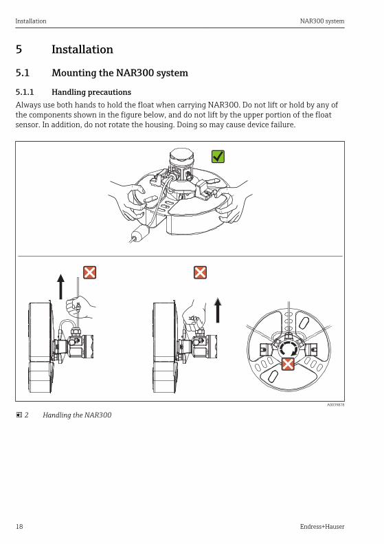
5.1.1 Handling precautionsAlways use both hands to hold the float when carrying NAR300. Do not lift or hold by any ofthe components shown in the figure below, and do not lift by the upper portion of the floatsensor. In addition, do not rotate the housing. Doing so may cause device failure.
A0039878
2 Handling the NAR300
NAR300 system Installation
Endress+Hauser 19
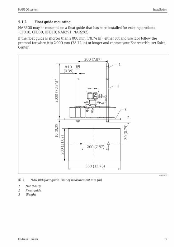
5.1.2 Float guide mountingNAR300 may be mounted on a float guide that has been installed for existing products(CFD10, CFD30, UFD10, NAR291, NAR292).If the float guide is shorter than 2 000 mm (78.74 in), either cut and use it or follow theprotocol for when it is 2 000 mm (78.74 in) or longer and contact your Endress+Hauser SalesCenter.
200 (7.87)
200 (7.87)
28
0 (
11
.02
)1
2
3
10
(0
.39
)
350 (13.78)
!10(0.39)
20
(0
.79
)
20
00
(7
8.7
4)*
A0039879
3 NAR300/float guide. Unit of measurement mm (in)
1 Nut (M10)2 Float guide3 Weight
Installation NAR300 system
20 Endress+Hauser
5.1.3 NRR261 (integrated type) cable mounting
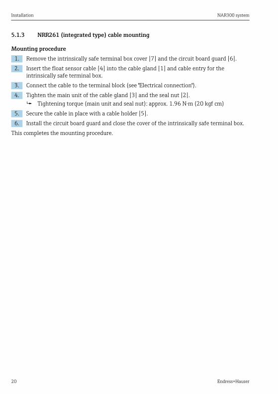
Mounting procedure1. Remove the intrinsically safe terminal box cover [7] and the circuit board guard [6].2. Insert the float sensor cable [4] into the cable gland [1] and cable entry for the
intrinsically safe terminal box.3. Connect the cable to the terminal block (see "Electrical connection").4. Tighten the main unit of the cable gland [3] and the seal nut [2].
Tightening torque (main unit and seal nut): approx. 1.96 N·m (20 kgf cm)5. Secure the cable in place with a cable holder [5].6. Install the circuit board guard and close the cover of the intrinsically safe terminal box.
This completes the mounting procedure.
NAR300 system Installation
Endress+Hauser 21
1
234
5
6
7
8
8
A0039881
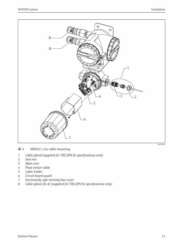
4 NRR261-2xx cable mounting
1 Cable gland (supplied for TIIS/JPN Ex specifications only)2 Seal nut3 Main unit4 Float sensor cable5 Cable holder6 Circuit board guard7 Intrinsically safe terminal box cover8 Cable gland (Ex d) (supplied for TIIS/JPN Ex specifications only)
Installation NAR300 system
22 Endress+Hauser
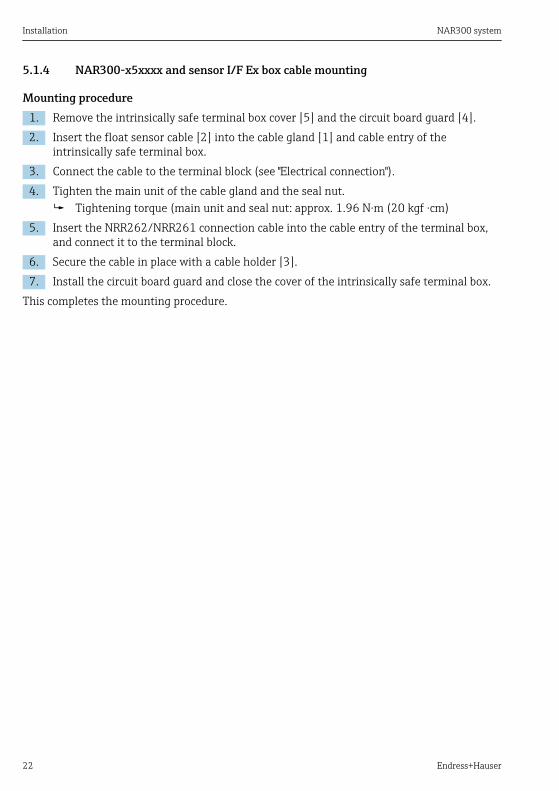
5.1.4 NAR300-x5xxxx and sensor I/F Ex box cable mounting
Mounting procedure1. Remove the intrinsically safe terminal box cover [5] and the circuit board guard [4].2. Insert the float sensor cable [2] into the cable gland [1] and cable entry of the
intrinsically safe terminal box.3. Connect the cable to the terminal block (see "Electrical connection").4. Tighten the main unit of the cable gland and the seal nut.
Tightening torque (main unit and seal nut: approx. 1.96 N·m (20 kgf ·cm)5. Insert the NRR262/NRR261 connection cable into the cable entry of the terminal box,
and connect it to the terminal block.6. Secure the cable in place with a cable holder [3].7. Install the circuit board guard and close the cover of the intrinsically safe terminal box.
This completes the mounting procedure.
NAR300 system Installation
Endress+Hauser 23
7
1
2
3
34
5
6
a
b
a
b
8
A0039882
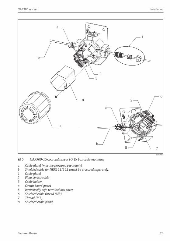
5 NAR300-15xxxx and sensor I/F Ex box cable mounting
a Cable gland (must be procured separately)b Shielded cable for NRR261/262 (must be procured separately)1 Cable gland2 Float sensor cable3 Cable holder4 Circuit board guard5 Intrinsically safe terminal box cover6 Shielded cable thread (M3)7 Thread (M5)8 Shielded cable gland
Installation NAR300 system
24 Endress+Hauser
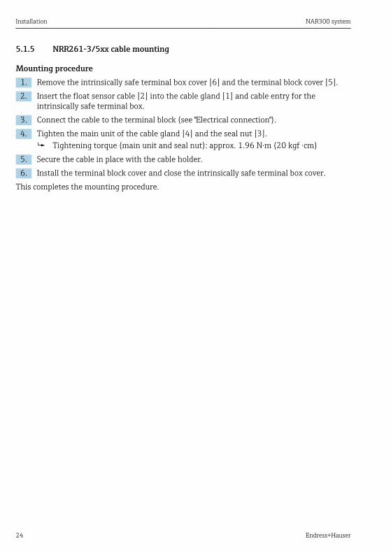
5.1.5 NRR261-3/5xx cable mounting
Mounting procedure1. Remove the intrinsically safe terminal box cover [6] and the terminal block cover [5].2. Insert the float sensor cable [2] into the cable gland [1] and cable entry for the
intrinsically safe terminal box.3. Connect the cable to the terminal block (see "Electrical connection").4. Tighten the main unit of the cable gland [4] and the seal nut [3].
Tightening torque (main unit and seal nut): approx. 1.96 N·m (20 kgf ·cm)5. Secure the cable in place with the cable holder.6. Install the terminal block cover and close the intrinsically safe terminal box cover.
This completes the mounting procedure.
NAR300 system Installation
Endress+Hauser 25
1
234
5
6
7
7
A0039883
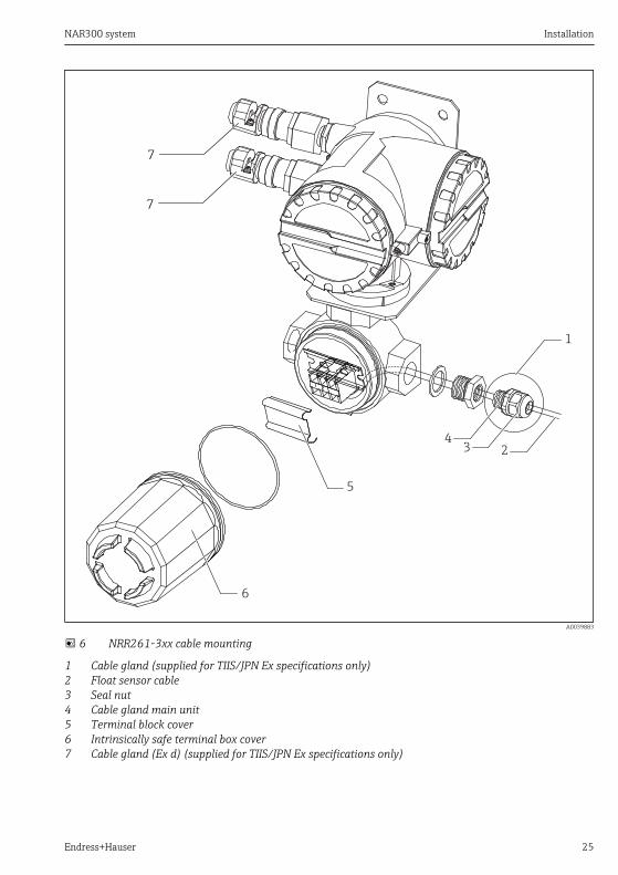
6 NRR261-3xx cable mounting
1 Cable gland (supplied for TIIS/JPN Ex specifications only)2 Float sensor cable3 Seal nut4 Cable gland main unit5 Terminal block cover6 Intrinsically safe terminal box cover7 Cable gland (Ex d) (supplied for TIIS/JPN Ex specifications only)
Installation NAR300 system
26 Endress+Hauser
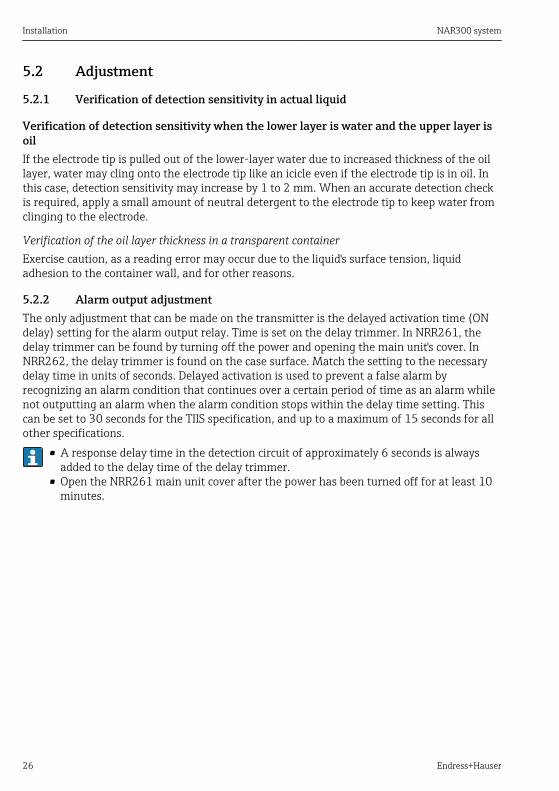
5.2 Adjustment
5.2.1 Verification of detection sensitivity in actual liquid
Verification of detection sensitivity when the lower layer is water and the upper layer isoilIf the electrode tip is pulled out of the lower-layer water due to increased thickness of the oillayer, water may cling onto the electrode tip like an icicle even if the electrode tip is in oil. Inthis case, detection sensitivity may increase by 1 to 2 mm. When an accurate detection checkis required, apply a small amount of neutral detergent to the electrode tip to keep water fromclinging to the electrode.
Verification of the oil layer thickness in a transparent containerExercise caution, as a reading error may occur due to the liquid's surface tension, liquidadhesion to the container wall, and for other reasons.
5.2.2 Alarm output adjustmentThe only adjustment that can be made on the transmitter is the delayed activation time (ONdelay) setting for the alarm output relay. Time is set on the delay trimmer. In NRR261, thedelay trimmer can be found by turning off the power and opening the main unit's cover. InNRR262, the delay trimmer is found on the case surface. Match the setting to the necessarydelay time in units of seconds. Delayed activation is used to prevent a false alarm byrecognizing an alarm condition that continues over a certain period of time as an alarm whilenot outputting an alarm when the alarm condition stops within the delay time setting. Thiscan be set to 30 seconds for the TIIS specification, and up to a maximum of 15 seconds for allother specifications.
• A response delay time in the detection circuit of approximately 6 seconds is alwaysadded to the delay time of the delay trimmer.
• Open the NRR261 main unit cover after the power has been turned off for at least 10minutes.
NAR300 system Installation
Endress+Hauser 27
1
1
2
3
3
A0039891
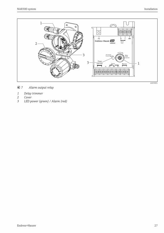
7 Alarm output relay
1 Delay trimmer2 Cover3 LED power (green) / Alarm (red)
Electrical Connection NAR300 system
28 Endress+Hauser
6 Electrical ConnectionConnect the external grounding terminal according to the "Class A grounding" standards (≤10 Ω) in the shortest implementable distance.When using Ex [ia] float sensor NAR300 and Ex d [ia] transmitter NRR261, it is necessary toground the NRR261 to a built-in safety barrier by following the procedure below (TIISspecifications only).• The grounding cable for the safety barrier should be connected independently from
grounding cables that are used for other purposes (lightning arrester), and it must beconnected to a grounding point in accordance with "Class A grounding" standards in non-hazardous locations.
• Use a conductive grounding cable with a cross-sectional area of at least 2 mm2. Thecommunication cable shield of field devices with Class A grounding in an instrument roommay also be used.
Class A grounding overview
Grounding resistance value 10 Ω
Grounding cable type Metal cable with a tensile strength of at least 1.04 kN or an annealed copper cable witha diameter of at least 2.6 mm (0.1 in)
6.1 Procedure for wiring grounding cablesIf performing Class A grounding from an Ex [ia] terminal instead of performing Class Agrounding from an Ex d terminal, refer to the figure below.
NAR300 system Electrical Connection
Endress+Hauser 29
1
2
3
4
5
6
a
bc
A
A0039886
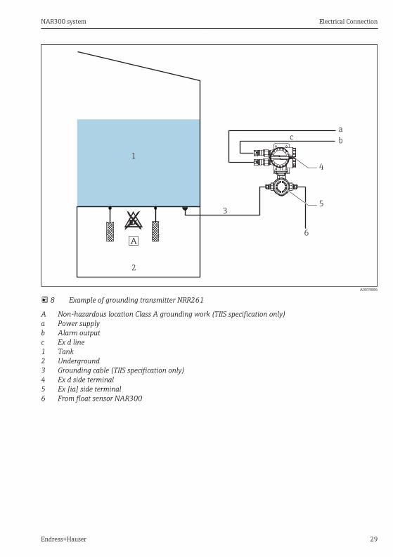
8 Example of grounding transmitter NRR261
A Non-hazardous location Class A grounding work (TIIS specification only)a Power supplyb Alarm outputc Ex d line1 Tank2 Underground3 Grounding cable (TIIS specification only)4 Ex d side terminal5 Ex [ia] side terminal6 From float sensor NAR300
Electrical Connection NAR300 system
30 Endress+Hauser
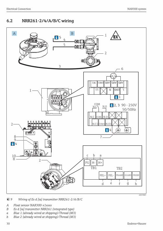
6.2 NRR261-2/4/A/B/C wiring
1
3
4
5
89
108
2
2
1
N.CCOM
N.O
N.C COM N.O
N.C1 COM1 N.O1
1
6
4
7L1 GNDN L
ARSGND1N1 ARSARS
2FG H- H+
TB1 TB2
FEL+ FEL- FRAME GUARD PROBE
c b a
d e f g h
90 - 250V
50/50Hz
2, 3
5
4
A B
A0039887
9 Wiring of Ex d [ia] transmitter NRR261-2/A/B/C
A Float sensor NAR300-x1xxxxB Ex d [ia] transmitter NRR261 (integrated type)a Blue 1 (already wired at shipping)/Thread (M3)b Blue 2 (already wired at shipping)/Thread (M3)
NAR300 system Electrical Connection
Endress+Hauser 31
c Green/Thread (M3)d Red/Thread (M3)e Blue 3/Thread (M3)f Yellow/Thread (M3)g Black/Thread (M3)h White/Thread (M3)1 Ex d terminal2 Ex [ia] terminal3 Ex [ia]-dedicated connection cable used (6 to 30 m (19.69 to 98.43 ft): Attached to the product
depending on the option code)4 Power supply: AC/DC5 Alarm output: Alarm/PLC/DCS, etc.6 Power supply arrester (installed)7 Green-yellow: FG safety barrier GND (for Class A grounding)/Thread (M4) (TIIS specification only),
see 4 below8 Terminal fixing screws (M3) (TIIS specification only)9 FG safety barrier GND (for Class A grounding)/Thread (M4) (TIIS specification only), see 4 below10 Blue 4: Internal wiring from Zener barrier/Thread (M4)
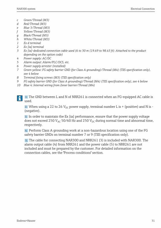
1. The GND between L and N of NRR261 is connected when an FG-equipped AC cable isused.2. When using a 22 to 26 VDC power supply, terminal number L is + (positive) and N is -(negative).3. In order to maintain the Ex [ia] performance, ensure that the power supply voltagedoes not exceed 250 VAC 50/60 Hz and 250 VDC during normal time and abnormal time,respectively.4. Perform Class A grounding work at a non-hazardous location using one of the FGsafety barrier GNDs on terminal number 7 or 9 (TIIS specification only).5. The cable for connecting NAR300 and NRR261 (3) is included with NAR300. The
alarm output cable (4) from NRR261 and the power cable (5) to NRR261 are notincluded and must be prepared by the customer. For detailed information on theconnection cables, see the "Process conditions" section.
Electrical Connection NAR300 system
32 Endress+Hauser
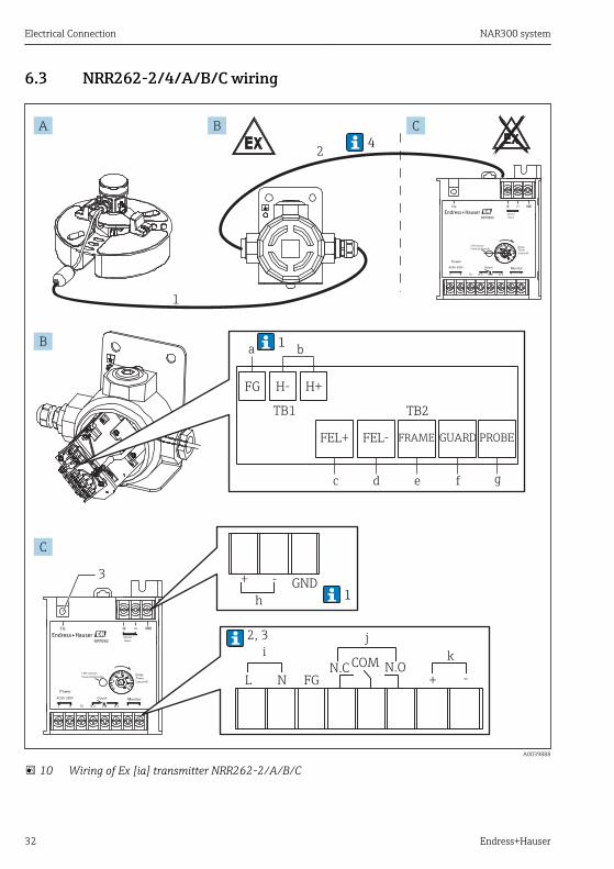
6.3 NRR262-2/4/A/B/C wiring
N.C COM N.OL N FG + -
+ - GND
h
ij
k
FG H- H+
TB1 TB2
FEL+ FEL- FRAME GUARD PROBE
a b
c d e
3
1
f g
24
2, 3
1
1
A B C
B
C
A0039888
10 Wiring of Ex [ia] transmitter NRR262-2/A/B/C
NAR300 system Electrical Connection
Endress+Hauser 33
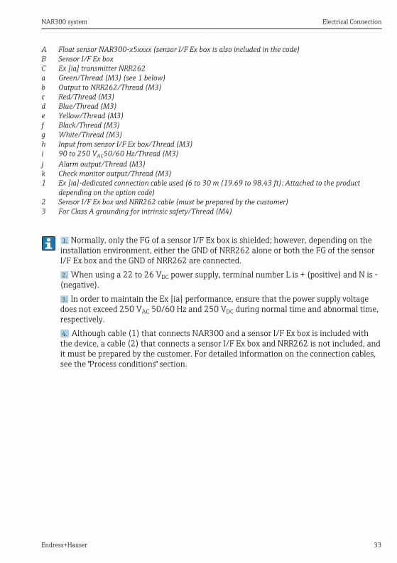
A Float sensor NAR300-x5xxxx (sensor I/F Ex box is also included in the code)B Sensor I/F Ex boxC Ex [ia] transmitter NRR262a Green/Thread (M3) (see 1 below)b Output to NRR262/Thread (M3)c Red/Thread (M3)d Blue/Thread (M3)e Yellow/Thread (M3)f Black/Thread (M3)g White/Thread (M3)h Input from sensor I/F Ex box/Thread (M3)i 90 to 250 VAC50/60 Hz/Thread (M3)j Alarm output/Thread (M3)k Check monitor output/Thread (M3)1 Ex [ia]-dedicated connection cable used (6 to 30 m (19.69 to 98.43 ft): Attached to the product
depending on the option code)2 Sensor I/F Ex box and NRR262 cable (must be prepared by the customer)3 For Class A grounding for intrinsic safety/Thread (M4)
1. Normally, only the FG of a sensor I/F Ex box is shielded; however, depending on theinstallation environment, either the GND of NRR262 alone or both the FG of the sensorI/F Ex box and the GND of NRR262 are connected.2. When using a 22 to 26 VDC power supply, terminal number L is + (positive) and N is -(negative).3. In order to maintain the Ex [ia] performance, ensure that the power supply voltagedoes not exceed 250 VAC 50/60 Hz and 250 VDC during normal time and abnormal time,respectively.4. Although cable (1) that connects NAR300 and a sensor I/F Ex box is included withthe device, a cable (2) that connects a sensor I/F Ex box and NRR262 is not included, andit must be prepared by the customer. For detailed information on the connection cables,see the "Process conditions" section.
Electrical Connection NAR300 system
34 Endress+Hauser
6.4 NRR261-3/5 wiring
6
GND
4
5 5
1
2
3
1
6
ih j
H-H+
km
L
5
N.C
COM
N.O
N.C COM N.O
N.C1 COM1 N.O1
2
7
6
8
90 - 250V50/50Hz
L1 GNDN L
ARSGND1N1 ARSARS
FG H- H+
TB1 TB2
FEL+ FEL- FRAME GUARD PROBE
a b
c d e f g
1
3, 4
A B C
B
C
A0039889
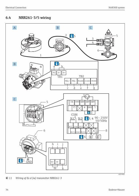
11 Wiring of Ex d [ia] transmitter NRR261-3
NAR300 system Electrical Connection
Endress+Hauser 35
A Float sensor NAR300-x5xxxx (sensor I/F Ex box is also included in the code)B Sensor I/F Ex boxC Ex d [ia] transmitter NRR261 (separate type)a Green/Thread (M3) (see 1 below)b Output to NRR261-3/5xx/Thread (M3)c Red/Thread (M3)d Blue 1/Thread (M3)e Yellow/Thread (M3)f Black/Thread (M3)g White/Thread (M3)h Blue 2/Thread (M4) (connected at the time of shipping)i Blue 3/Thread (M4) (connected at the time of shipping)j Blue 4/Thread (M4) (connected at the time of shipping) (TIIS specification only)k Class A grounding connection terminal (TIIS specification only)/Thread (M4)m Input from sensor I/F Ex box/Thread (M4)1 Ex [ia]-dedicated connection cable used (6 to 30 m (19.69 to 98.43 ft): Attached to the product
depending on the option code)2 Sensor I/F Ex box and NRR261 cable (must be prepared by the customer)3 Power supply: AC/DC4 Alarm output: Alarm/PLC/DCS, etc.5 Ex d terminal6 Intrinsically safe terminal7 Power supply arrester (installed)/Thread (M3)8 Green-yellow: FG safety barrier GND (for Class A grounding/TIIS specification only)/Thread (M4) (see
6 below)
1. Normally, only the FG of a sensor I/F Ex box is shielded; however, depending on theinstallation environment, either the GND of NRR262 alone or both the FG of the sensorI/F Ex box and the GND of NRR262 are connected.2. The GND between L and N of NRR261 is connected when an FG-equipped AC cable isused.3. When using a 22 to 26 VDC power supply, terminal number L is + (positive) and N is -(negative).4. In order to maintain the Ex [ia] performance, ensure that the power supply voltagedoes not exceed 250 VAC 50/60 Hz and 250 VDC during normal time and abnormal time,respectively.5. Cable (1) for connecting NAR300 and the sensor I/F Ex box is included with NAR300.
Cable (2) for connecting the sensor I/F Ex box to NRR261, the alarm output cable (3)from NRR261, as well as the power cable (4) to NRR261 are not included and must beprepared by the customer. For detailed information on the connection cables, see the"Process conditions" section.6. Perform Class A grounding work at a non-hazardous location using one of the FG
safety barrier GNDs on terminal number 8 or k (TIIS specification only).
Electrical Connection NAR300 system
36 Endress+Hauser
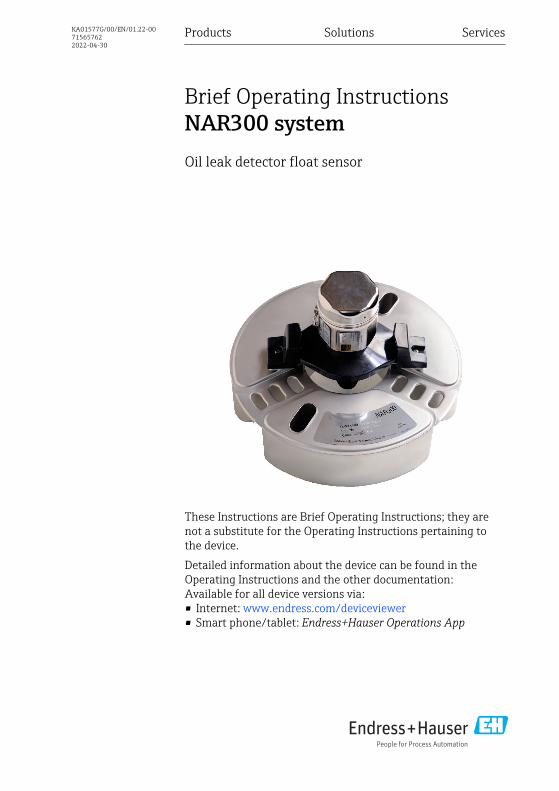
6.5 Wiring diagram
19
GND
GND
GND
A0039890
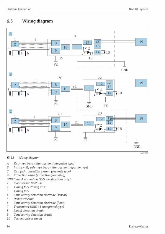
12 Wiring diagram
A Ex d-type transmitter system (integrated type)B Intrinsically safe-type transmitter system (separate type)C Ex d [ia] transmitter system (separate type)PE Protection earth (protective grounding)GND Class A grounding (TIIS specifications only)1 Float sensor NAR3002 Tuning fork driving unit3 Tuning fork4 Conductivity detection electrode (sensor)5 Dedicated cable6 Conductivity detection electrode (float)7 Transmitter NRR261 (integrated type)8 Liquid detection circuit9 Conductivity detection circuit10 Current output circuit
NAR300 system Electrical Connection
Endress+Hauser 37
11 Safety barrier12 Power supply circuit13 Relay14 Delay circuit15 Ex [ia] circuit16 Ex d circuit17 Current detection18 Delay trimmer19 Alarm20 Sensor I/F Ex box21 Current signal22 Transmitter NRR26223 Transmitter NRR261 (separate type)
Although a Class A grounding cable can be shared with grounding of other safetybarriers, it cannot be shared with grounding of a lightning arrester.
Electrical Connection NAR300 system
38 Endress+Hauser
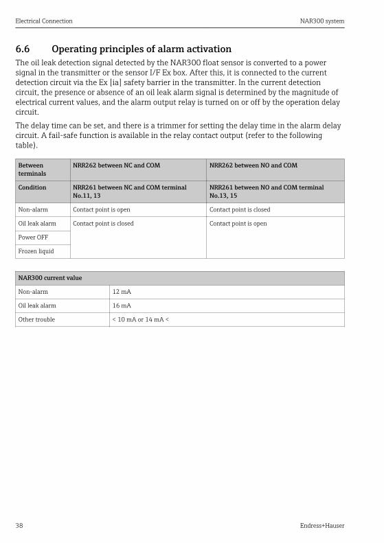
6.6 Operating principles of alarm activationThe oil leak detection signal detected by the NAR300 float sensor is converted to a powersignal in the transmitter or the sensor I/F Ex box. After this, it is connected to the currentdetection circuit via the Ex [ia] safety barrier in the transmitter. In the current detectioncircuit, the presence or absence of an oil leak alarm signal is determined by the magnitude ofelectrical current values, and the alarm output relay is turned on or off by the operation delaycircuit.The delay time can be set, and there is a trimmer for setting the delay time in the alarm delaycircuit. A fail-safe function is available in the relay contact output (refer to the followingtable).
Betweenterminals
NRR262 between NC and COM NRR262 between NO and COM
Condition NRR261 between NC and COM terminalNo.11, 13
NRR261 between NO and COM terminalNo.13, 15
Non-alarm Contact point is open Contact point is closed
Oil leak alarm Contact point is closed Contact point is open
Power OFF
Frozen liquid
NAR300 current value
Non-alarm 12 mA
Oil leak alarm 16 mA
Other trouble < 10 mA or 14 mA <


www.addresses.endress.com
*71565762*71565762