Embed Size (px)
Citation preview

Dobry, R. & C&zetas, G. (1988). Gkmchnique 38, No. 4, 557-574
Simple method for dynamic stiffness and damping of floating pile groups
R. DOBRY* and G. GAZETASt
A simple analytical solution is developed for com- puting the dynamic impedances of floating rigidly- capped pile groups with due consideration to pilesoikpile interaction. The method introduces some sound physical approximations and considers the interference of cylindrical wave fields originat- ing along each pile shaft and spreading radially outward. Axial, lateral, and rocking oscillations of rigidly-capped pile groups are studied parametri- cally. Results are presented for the dynamic stiffness and damping of the whole group, and for the distribution of dynamic loads amongst the indi- vidual piles. The predictions of the simple method for vertical and rocking oscillations compare extremely well with rigorous numerical solutions, thereby offering a valuable insight into the nature of pile-so&pile interaction. It is demonstrated and explained how the dynamic efficiency may far exceed unity at certain resonant frequencies due to destructive wave interference. The proposed method can be readily applied by engineers already familiar with the use of static interaction factors in the design of pile groups.
KEYWORDS: analysis; dynamics; foundations; piles; stiffness; waves
Une solution analytique t&s simple est dbvelopp6e pour calculer les imp&lances dynamiques de groupes de pieux flottants $ t&s rigides dans le cadre de i I’interaction pieux/sol/pieux. La m&h- ode introduit des approximations physiques val- ables et prend en considbration I’interference de champs d’ondes cylindriques qui ont leur origine le long de chaque fiit de pieux et se propagent radi- alement vers l’ext6rieur. L’article Ctudie sous l’aspect parametrique les sollicitations axiales, laterales et oscillants de groupes de pieux P casques rigides. Des r&sultats sont p&e&s pour la rigiditC dynamique et I’amortissement du groupe entier et pour la distribution des charges dyna- miques entre les pieux individuels. Les prtiictions par cette methode t&s simple des oscillations verti- tales et basculantes supportent extr&mement bien la comparaison avec celles des solutions num(?r- iques rigoureuses, ce qui donne un aperqu valable de la nature de l’interaction pieux-sol-pieux. On dCmontre et explique comment le groupe dyna- mique repr6sentant I’effet utile peut dbpasser de beaucoup l’uniti! $ certaines frbquences de rbon- ante $ cause de l’interfbrence destructive des ondes. La m6thode propo&e peut &tre facilement appli- qu&e par des ingCnieurs qui connaissent dbjzi bien I’emploi de facteurs statiques d’interaction dans la construction de groupes de pieux.
NOTATION
a0
czs, cxs, CrxS
czG, cxG, crxG
w d/v, damping coefficients for axial (z), lateral (x), and rocking (rx) oscillations of a single pile damnine coefficients for axial
f frequency of oscillation in Hz dimensionless frequency = (f = 4274
amplitude of exciting force
YyLlmic stiffness of a single pile
F
R,S, R,S, K,,:
KS, KS, KrxS
(z), lateral (x), and rocking xzs, YXS, Xx,XS (rx) oscillations of a group of fixed-head piles RGRGRG
*7 x, TX
d pile diameter (d = 2r,) E,, Es Young’s moduli of pile and xzG, XXG, XX,XG
soil
I Y
Discussion on this Paper closes on 1 April 1989. For further details, see p. ii. * Rensselaer Polytechnic Institute, New York. t National Technical University of Athens.
L M, AM
557
static stiffness of a single pile; KzS = RzS(w = 0) etc. dynamic complex-valued impedances of a single pile dynamic stiffness of a group of piles dynamic complex-valued impedances of a group of piles length of pile moment applied to the pile cap, and moment at the head

558
r.
S
v, V La
4 w, e
&h
v, B
1 w
Subscripts z, x, rx
Superscripts S, G
DOBRY AND
of each individual pile in the group pile radius time axis-to-axis distance between two neighbouring piles shear-wave velocity Lysmer’s analog wave velocity = 3.4 V$[n(l - v)] horizontal displacement, ver- tical displacement, and angle of rotation of individual pile and of pile group dynamic interaction factor for vertically (axially) oscil- lating piles dynamic interaction factor for horizontally (laterally) oscillating piles Poisson’s ratio and damping ratio of the soil shear wave length: 1= VJf circular frequency of oscilla- tion = 2lrf
response parameters in verti- cal (axial), horizontal (lateral) and rotational (rocking) oscillation, respectively
differentiation between single pile and pile group response
INTRODUCTION At static working loads, the displacement of a pile increases if this pile is located within the deforma- tion field of a neighbouring pile. As a result, the overall displacement uG of the group of piles is greater than the individual displacement us which each pile would experience were it left alone to carry the average load. The static group efficiency uSluG is thus always below unity, and it tends to decline when the distance between piles is short- ened or when the number of piles in the group increases.
Rational analyses of pile group displacements were pioneered by Poulos (1968, 1971), who introduced the concept of ‘interaction factors’ and showed that pile group effects can be assessed by superimposing the effects of only two piles. In the last 15 years, interaction factors for each degree of freedom of the pile head have been obtained by recourse to integral equation-based methods (Poulos & Mattes, 1971; Butterfield & Banerjee, 1971; Poulos & Davis, 1980) and finite element formulations (Naylor & Hooper, 1975; Ottaviani,
GAZETAS
1975), as well as by using simple but physically sound approximations (e.g. Randolph & Wroth, 1979; Scott, 1981).
Static interaction factors do not provide useful information on the steady-state dynamic response of pile groups, except perhaps at very low fre- quencies of oscillation. Early numerical studies by Wolf and Von Arx (1978) and Nogami (1979) showed that the dynamic group efficiency of a cluster of piles exhibits a strongly oscillatory behaviour and may attain values well above unity-a result verified in subsequent studies by Nogami (1980 and 1983; Kaynia & Kausel(1982a and b); Tyson & Kausel (1983); Sheta & Novak (1982); El Sharnouby & Novak (1985); Novak (1984); Waas & Hartmann (1981 and 1984); Kagawa (1983); Roesset (1984); Sen, Davies & Banerjee (1985), and others.
The available formulations differ from one another in the simplifications introduced when modelling this complicated boundary value problem. They are all of a numerical nature and they invariably involve discretizing each pile and the supporting soil; hence, application of even the most simplified of them may entail a substantial computational effort. Also, in some cases these methods rely on proprietary computer codes.
In this Paper a very simple analytical solution to the problem of dynamic pile-soil-pile inter- action in uniform soil is developed, and para- metric results for the stiffness and damping of groups of floating piles are presented.
The advantages of the proposed simple method for pile groups can be summarized as follows.
(a) The procedure is simple enough to be taught in a course on soil dynamics, and can be easily understood and applied by the engi- neer, even without the help of a computer.
(b) For a wide range of material parameters, pile separation distances, and frequencies of oscil- lation, the results of the method are in excel- lent accord with rigorous solutions.
(c) The method can be applied to all modes of oscillation while retaining its simplicity.
(6) The procedure can be extended to handle pile installation effects in a simplified but physi- cally sound way.
However, some limitations of the proposed method must also be noted. First, it tends to overestimate the peak values of both stiffness and damping for pile groups embedded in (relatively) very stiff soil, i.e. soil whose average effective Young’s modulus E, is greater than about E,/300, where E, is the pile modulus. Fortunately, this is hardly a severe restriction on the range of appli- cability of the method: soft clays, medium clays, and loose sands will typically have much lower effective moduli than E,/300, and in these soils
DYNAMIC STIFFNESS AND DAMPING OF FLOATING PILE GROUPS 559
Rigtd massless cap
\t
.-....
T z
Homogeneous halfspace ,’ = 0.40, [j = 0.05
“. r- ,.. .,.‘,‘_.. . . (. .‘,.” ‘. ‘.. . . ., ‘. .; ;.. .;:.. .:,
‘:. ‘. Homogeneous layer ‘, .. ;.; ‘, p = 0.025 ‘_ ‘. ,’
Bedrock
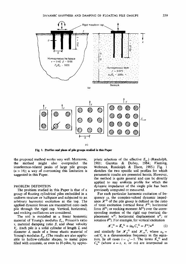
Fig. 1. Profiles and plam of pile groups studied in this Paper
the proposed method works very well. Moreover, the method might also overpredict the interference-related peaks of large pile groups (n > 16); a way of overcoming this limitation is suggested in this Paper.
PROBLEM DEFINITION The problem studied in this Paper is that of a
group of floating cylindrical piles embedded in a uniform stratum or halfspace and subjected to an arbitrary harmonic excitation at the top. The applied dynamic forces are transmitted onto each pile through the rigid cap. Vertical, horizontal, and rocking oscillations are considered.
The soil is modelled as a linear hysteretic material of Young’s modulus E,, Poisson’s ratio v, material damping ratio 8, and shear velocity V,. Each pile is a solid cylinder of length L and diameter d, made of a linear elastic material of Young’s modulus Ep . (The results are also applic- able to hollow-cylinder shapes, to metal pipes filled with concrete, or even to H-piles, by appro-
priate selection of the effective E,,.) (Randolph, 1981; Gazetas & Dobry, 1984; Fleming, Weltman, Randolph & Elson, 1985.) Fig. 1 sketches the two specific soil profiles for which parametric results are presented herein. However, the method is quite general and can be directly applied to any uniform profile for which the dynamic impedance of the single pile has been previously computed or measured.
For each particular harmonic excitation of fre- quency w, the complex-valued dynamic imped- ance XG of the pile group is defined as the ratio of total excitation (vertical force FG; horizontal force HG; or rocking moment MC) over the corre- sponding motion of the rigid cap (vertical dis- placement wG; horizontal displacement uG; or rotation eG). For example, for vertical excitation
.IX?~=I?~+~~,,C,~=F~/~~ I z (1) and similarly for XXG and XrXG, where a, = wd/Vs is a dimensionless frequency in the equa- tion. In all cases i = ,,I’- 1. The terms RaG and C,G (where a = z, x, or rx) are interpreted as
560 DOBRY AND GAZETAS
equivalent ‘spring’ and ‘dashpot’ coefftcients at the head of the pile group; they are both func- tions of the circular frequency of excitation w = 2rrj In this Paper KaG and C,G_are contrast- ed to the corresponding values of KaS and C,’ of the single pile, evaluated at the same frequency w.
FUNDAMENTAL ASSUMPTIONS OF THE METHOD
Poulos’ (1968, 1971) superposition procedure, originally developed for statically loaded pile groups, is also valid for the dynamic problem- an assumption employed frequently in other for- mulations. Kaynia & Kausel (1982a and b); Sanchez-Salinero (1983); and Roesset (1984) have demonstrated that the results of this approx- imation are, indeed, in very good agreement with more rigorous dynamic solutions. Therefore, the response of the pile group can be obtained from interaction factors derived from the study of only two piles at a time. In essence, it is assumed that the presence of the rest of the piles does not appreciably affect the interplay between the two piles being considered. This means that, when computing the influence of pile p on pile q the intermediate piles are considered to be transparent-an assumption not far from reality in view of the fact that the wavelengths (1) of practical interest
L > 6d (2)
are too large for the waves propagating in the soil to ‘see’ the cylindrical pile. However, when the number of piles in a group is very large and the pile spacing relatively short, the interaction between two distant piles in the group will unavoidably be reduced due to ‘scattering’ of waves and the corresponding ‘shadows’ formed by the piles in-between.
To derive the influence of the motion of pile p (active) on pile q (passive) we can replace pile q by its axis, neglecting its dimensions. Sanchez- Salinero (1983) and Roesset (1984) have shown that this is a realistic approximation, except perhaps at very high frequencies and close pile spacings. Other researchers have also taken advantage of this assumption (e.g. Nogami, 1979; Sheta & Novak, 1982). Equation (2) may again provide the clue to the success of this assumption; the deformations which waves emanating from pile p induce at each point along the contour of pile q are all nearly in-phase, due to the relatively small dimensions of the pile (d < J/6). Therefore, the average deformation of passive pile q at a given depth is approximately equal to the defor- mation of the middle point, i.e. at the axis of this pile.
It is worth drawing an analogy with scattering of sound waves by a rigid cylinder of diameter d: for wavelengths 1 greater than the perimeter nd, the net pressure acting on the cylinder (per unit length) has only a negligible phase lag behind the pressure which the incident wave would induce at the centre of the cylinder, if the latter were not there (Morse & Ingard, 1968). In our case A 2 2nd and hence the approximation is valid with a good degree of accuracy.
At the frequency range of interest, as the active pile p undergoes oscillations in, say, the vertical direction, cylindrical waves are assumed to emanate from the pile perimeter along the pile length and to propagate radially outward in the horizontal direction. This assumption is remi- niscent of the shearing of concentric cylinders around statically loaded piles and pile groups assumed by Randolph & Wroth (1978 and 1979) and is also somewhat similar to the ‘Winkler’ assumption introduced by Novak (1974) and extensively used in dynamic analyses of pile groups. However, the simple method presented here goes a step further; the cylindrical waves are assumed to emanate simultaneously from all points along the pile length and hence, for a homogeneous deposit, to spread out in-phase and form a cylindrical wavefront having a common axis with that of the generating pile (Fig. 2(a and b)). For an observer at the ground surface, the propagation and interference of these cylindrical wavefronts would appear as Fig. 2(a). (This is reminiscent of the water waves that would be created by a very light, rigid structure floating on a pond, composed of a horizontal platform on columns, and excited by steady-state vertical vibration.)
The variation of wave amplitude with depth along the cylindrical front arriving to the passive pile is assumed to be analogous with the ampli- tude variation of the active single pile, as depicted in Fig. 2(b). For steady-state harmonic oscillation, the assumption of waves originating simulta- neously along the whole pile length seems to be quite realistic in many cases of practical interest. Specifically
(a) for axially loaded piles in the frequency range covered in this Paper, waves propagate down the pile at a nearly infinite apparent phase velocity, while the motion diminishes almost exponentially with depth; in other words, all points along the pile shaft move in phase at the excitation frequency. (The apparent veloc- ity in the pile would be essentially infinite if the surrounding soil provided no damping and the dimensionless frequency factor cod/K were less than a cut-off frequency factor, which is always beyond the frequency range

DYNAMIC STIFFNESS AND DAMPING OF FLOATING PILE GROUPS 561
(b)
Fig. 2. (a) analogy between the- cyliodrical wave assumption for group of piles in soil aad cylindrical water waves; (b) distribution of displacement amplitudes along the shaft of an oscillating (active) pile and of a neighbouring (passive) pile are assumed to be of the same shape; (c) pile-head deformation and reactions during rocking; (d) assumed apparent velocities of waves emanating from a laterally oscil-
of interest 1985.)
lating pile
here (i.e. greater than l).) (Wolf,
(b) for lateral loading, waves propagate down the pile at a finite phase velocity (Wolf, 1985) so that ‘simultaneous arrival’ can be tried only as a first approximation.
In the interest of simplicity, the basic solution for cylindrical waves is simplified by considering the large-argument asymptotic approximation (Morse & Ingard, 1968). Here, one works with simple exponentials instead of Hankel functions; this will allow solutions for a small number of piles to be achieved with the help of only a pocket calculator. It has been found in sensitivity studies that the improvement resulting from the use of the exact cylindrical wave solution is negligibly small and would hardly rectify any potential limi- tations of the method.
In addition to these fundamental assumptions, some other assumptions are made when studying the horizontal and rocking modes of vibration.
DEVELOPMENT OF DYNAMIC INTERACTION FUNCTIONS Axial (vertical) vibration
For a homogeneous deposit (as in Fig. l(a)), only two pieces of information are needed as input to the method
(a) the S-wave velocity V, and the hysteretic damping ratio fl of the soil.
(b) the complex-valued dynamic impedance ,X,‘(w) of the single pile at the particular fre- quency (or frequencies) of interest.
The axial rigidity and the slenderness of the pile enter the analysis only through their effect on the impedance of the single pile. Also, the complex-valued dynamic impedance for a single pile is defined as
X,‘(w) = Kzs(w) + ia, C,‘(w) = FS/wS (3)
and can be obtained by any of several available numerical methods (see Sheta & Novak, 1982, for

562 DOBRY AND GAZETAS
a list of related publications) or, potentially, from full-scale dynamic pile load tests in the field.
Consider two identical piles, p and q, separated by a distance S between axes. The effect of the vibration of pile p on the response of pile q can be conveniently expressed through the dynamic interaction factor a,, which is a function of fre- quency
a, = a,(w) = wqplwqq
This simple expression is all that is needed to compute the vertical response of any group of piles, once the single pile impedance Xps is avail- able.
additional disnlacement of pile q caused by pile p
= displacement of pile q under own dynamic load
(4)
The dynamic displacement field around a vibrating pile p is described by the following asymptotic cylindrical wave expression (see Morse & Ingard, 1968)
w(r) z A - exp (-pm/V,) exp ;r [- ( 91 rw t - 7
(5)
where r = horizontal distance from the axis of pile p and A = A(z) = an amplitude constant. The other three factors in equation (5) imply that
(a) the amplitude of motion decays in proportion to r-II2 times the hysteretic damping depen- dent factor exp (-/km/V,)
(b) the phase lag of the motion at a particular location within the soil is only a function of the radial distance r.
At the axis of the neighbouring pile q, located at a distance r = S, equation (5) provides
W qp E w(r = S)
= A i exp ( -/?wS) exp [iw(t - S/V,)] JS
(6)
It is assumed that this wqp is also approximately the same in the periphery of pile q. To obtain the displacement wqq of pile q under its own dynamic load, equation (5) is used once more to provide the approximate expression
wqq v A i exp (iwt) Jr0
in which r,, = d/2 is the radius of the pile. Equa- tion (7) recognizes that there is no time lag between the axis and perimeter of the pile vibrat- ing under its own load.
By dividing equation (5) (for r = S) by equation (7) we obtain the approximate expression for the interaction function
- I,2
exp (-@S/V,) exp (-ioS/K) (8)
Rocking Rocking of piles fixed to a rigid cap induces
both axial and rotational deformations (Fig. 2(c)). Based on the evidence available from the static solutions (Poulos & Davis, 1980) and on indirect evidence for the dynamic problem, it is assumed that no interaction takes place due to the rota- tional deformation of each pile. Such deformation (under zero lateral head displacement) is felt only a few diameters down from the pile head, and produces a rapidly decaying stress field around the pile. Hence the neighbouring piles fall outside each other’s zone of influence for this effect. Therefore, although both axial and rotational deformations of pile q are considered in pile q due to its own load, only the influence of motions coming from pile p on the axial deformations of pile q is considered.
Lateral vibration For laterally oscillating piles the interaction
factor ah depends, for a given frequency w, not only on the distance S but also on the angle 6 between the line of the two piles and the direction of the horizontal applied force. However, it is suf- ficient to compute a,, only for 0” and 90” angles, and then use
ah(P) N ah(Oo) cos2 8 + a,(90”) sin’ 0 (9)
to obtain very good estimates for any arbitrary angle 0 (Poulos, 1971; Kaynia & Kausel, 1982a and b; Sanchez-Salinero, 1983). Approximate esti- mates of a,,(P) and ah(90”) are obtained with the help of Fig. 2(d). Based on evidence provided by Gazetas & Dobry (1984) the 90”-pile q is affected essentially only by S-waves which emanate from active pile p and which have a phase velocity V,. However, the 0”-pile q is affected by compression- extension waves coming from p and propagating with an apparent phase velocity which is approx- imately equal to the so-called Lysmer’s analog velocity, V,, = 3.4 VJ[lr(l - v)] (see Dobry & Gazetas, 1986). Thus as a first approximation
and
a,(90”) 2: a, (10)
S 0 -l/Z
ah(V) = ah0 = r, exp ( - PwSlK.)
x exp ( - id/V,,) (11)
DYNAMIC STIFFNESS AND DAMPING OF FLOATING PILE GROUPS 563
FIRST APPLICATION: AXIAL IMPEDANCE OF RIGIDLY-CAPPED PILE GROUPS
Referring to Fig. l(b), the following examples of application of the method are offered.
Two piles Let F exp (iwt) be the vertical excitation load
applied to each pile. The displacements of the two piles, wi exp (iwt) and w2 exp (iwt) are identical, and can be obtained by superposition
wi = wii + wiz = wii(l + a,) = 5 (1 + a,) z
(12)
where a, = a,(S) is the interaction factor for verti- cal vibration and Xzs is the dynamic impedance of the single pile corresponding to the frequency w. By definition, the impedance of the group is
xo=?!=X z Wl 1 + a, (13)
Hence the impedance of the 2 x 1 group is easily computed if, for each particular frequency, the impedance of the single pile is known and the interaction factor is calculated from equation (8).
Two by two pile group Due to symmetry, the four piles share equally
the applied load and experience the same dynamic vertical displacement. Let F exp (iwt) again be the individual pile load and wi exp (iwt) its displacement, including the group action. By superposition
w1 = WI1 + 2w,, + w14
= ~~(1 + 2x1, + xi4)
= -$ [l + Za,(S) + a,(SJ2)] (14) I
from which the group impedance takes the form
4F &-GC--Z
4z^,s I wi 1 + 2a,(S) + a&/2)
(15)
In the above expressions S,/2 is the distance between the diagonal piles and a&/2) is the cor- responding interaction factor (given by equation (8) after replacing S by S,/2). (A numerical example illustrating the use of equation (15) is given in Appendix 1.)
Three by three pile group The rigidity of the pile cap produces the same
vertical displacements of all piles, but the forces
transmitted by each pile differ. Let F, be the amplitude of the load carried by the corner piles, F, that of the centre pile, and F, = F, that of the four remaining edge piles (see Fig. l(b)). The dis- placement of the centre pile 2 is
wz = wzz + 4w,, + 4w,,
= 3 + 3 a&/Z) + 3 a,(S) x* xz
(16)
Similar expressions can be written for wi and wj to obtain a system of three algebraic equations from which F,, F, and F, are derived as a func- tion of the common displacement w1 = w2 = wj z wG. Finally, making use of the equilibrium equation
F, + 4F, + 4F, = FG (17)
where FG = the amplitude of the total force applied onto the pile group cap, is all that is needed to obtain wG, and thereby the individual pile forces. The group impedance XzG equals FG/wG.
SECOND APPLICATION: ROCKING IMPEDANCE
Only the 2 x 2 group is studied. Rotation of the cap by an angle eG is resisted by two pairs of axial forces, F, exp (iwt) and F, exp (i[wt + rr]), and by moments AM, = AM, = AM, = AM, = X,,VG exp (iwt).
The axial forces and axial displacement are related as follows
Wl = w11+ w12 + w13 + w14
= wllU + al2 + al3 + 4.4
= $j Cl - a,(S) + a,(S) - a,(S$)l
= 3 Cl - ~“(SJ2)l
i.e. the effects of the two closest piles, oscillating at the same displacement amplitude but with opposite phase, cancel each other out and only the effect of the diagonally located piles remain.
Considering moment equilibrium leads to
MG = 4AM + Z(Fixi) (19)
from which the group rocking impedance MG/BG is obtained
x G = 4xx,,S + xzs s 1
TX 1 - a&/2) (20)

564 DOBRY AND GAZETAS
-G K,
4KzS 1
0 -2 I
10 r
C,G 4 K,’
8-
6-
4-
2-
01 0 I
0.5
u,d
v,
I 1
Fig. 3. Vertical dynamic stiffness and damping group factors as a function of frequency: comparison of pro- posed simple method with rigorous solution of Kaynia & Kausel (1982) for a group of 2 x 2 fixed-bead piles in a homogeneous halfspace, EJE, = 1000, L/d = 15
Following a similar procedure one can derive the dynamic rocking impedances of the larger pile groups shown in Fig. l(b).
THIRD APPLICATION: LATERAL IMPEDANCE The method is applied only to the 2 x 2 fixed-
head pile group of Fig. l(b) undergoing a hori- zontal oscillation of amplitude u exp (iwt) without rotation. Noticing that the interaction factor between the diagonal piles can be
expressed, according to equation (9), as
G(45”) = f(% + %J) (21)
and denoting with Y,,’ the lateral impedance of the single pile, the following relation between the common pile horizontal displacement u and the common force per pile P, can be obtained
uo - - Ull + UlZ + 43 + u14
= UllU + al2 + al3 + ~1
= 3 { 1 + cLh0(S) + a,(S) + f
x CWJ2) + %cl(~Jm (22) and hence the dynamic impedance of the 2 x 2 pile group is
4ptl _f,G=- UG
_ 1 + a,(S) + O+#J2) + ClJS) + O%,,(SJ2)
(23)
In similar fashion, although computationally more involved, one can derive the lateral imped- ances of larger pile groups.
PARAMETRIC RESULTS AND COMPARISONS Dynamic response results for the pile groups of
Fig. 1 are presented in Figs 3-13, where they are compared with the rigorous solutions of Kaynia 8c Kausel(1982a and b) and the approximate sol- utions of Nogami (1983).
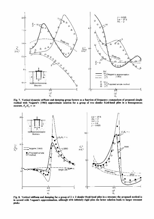
Axial (vertical) response Figures 3-8 study the vertical (axial) oscil-
lations of the 2 x 1, 2 x 2, 3 x 3, and 4 x 4 pile groups in a homogeneous viscoelastic halfspace or stratum. Figs 3-5 in particular, plot as a func- tion of the dimensionless frequency factor wd/K the dynamic stiffness and damping group factors; these are defined as the ratios of the dynamic stiffness RZG or of the dashpot coefficient CZG, to the sum of the static stiffnesses of the individual single piles. With n identical piles in the group, this sum simply equals nKzS. At zero frequency the foregoing stiffness group factor reduces to the familiar static group elllciency factor (Fleming et al., 1985). If there had been no pile-tepile inter- action the group factor curves would have coin- cided with those of the single pile (dashed lines in

-G
K, 9 KzS
DYNAMIC STIFFNESS AND DAMPING OF FLOATING PILE GROUPS
Sld
old
v,
-s=s d
565
wd
v, Fig. 4. Vertical dynamic stiffness and damping group factors as a function of frequency: comparison of proposed simple method with rigorous solution of Kaynia & Kausel (1982) for a group of 3 x 3 fixed-head piles in a homogeneous halfspace, &,/ES = 1000, L/d = 15
Fig. 3). Fig. 6 plots the distribution of forces among the piles of a 3 x 3 group as a function of frequency. For vertical response, the wavelength 1 equals 2nVJw and therefore the frequency factor wdJVs = 24(1/d). Figs 7 and 8 correspond to a pile group in a soil stratum over bedrock.
Several important trends can be seen from Figs 3-8.
For very close spacings (S/d = 2) the stiffness and damping group factors exhibit a smooth variation with frequency, with the pile group behaving very much like an isolated embedded foundation (Gazetas, Dobry & Tassoulas, 1985). Indeed, while the damping coefficients remain essentially constant in the frequency range studied, the dynamic group stiffnesses decrease steadily with increasing frequency, achieving negative values at higher frequency factors. Such a behaviour is reminiscent of the simple l-degree of freedom oscillator having mass m, spring con- stant K and dashpot coefficient C, the effective dynamic stiffness of which, K = K - ma=, decreases parabolically with frequency while C is
constant. To explain the causes of the similarity, refer to equation (2). At such close spacings (S = 24 the relevant wavelengths II are greater than S by a factor of at least 3. Hence the soil mass between piles tends to vibrate in phase with the piles and so the pile groupsoil system responds as a block.
Groups with more amply spaced piles (S/d = 5 or 10) exhibit a more complicated behaviour with the stiffness and damping curves having peaks and valleys which depend on the size of the group and the spacing of the piles.
Initially, at low enough frequencies, the group stiffnesses invariably decrease with frequency, as the relevant wavelengths are again large enough compared to pile spacing (1 > 3s) and the soil between the piles moves in phase with the piles (response as a block). However, beyond a certain limiting value of the frequency, wave interference phenomena start dominating the response of the soil-pile group system. This limiting frequency is essentially independent of group size but decreases with increasing pile spacing; it is

566 DOBRY AND GAZETAS
S/d
Kaynla - Kausel (1982)
0 10 1 A 5 Prowxed srnple method
I
0.5 rud
v,
1
C,G
16 K,’
OOk
a
a
a
Fig. 5. Vertical dynamic stiffness and damping group factors as a function of frequency: comparison of propused simple method with rigorous solution of Kaynia 81 Kausel (1982) for a group of 4 x 4 fixed-bead piles in a homogeneous halfspace, E,/E, = 1000, L/d = 15
roughly equal to wd/K = 0.40 for S/d = 5, and to cod/K = 0.15 for S/d = 10.
When the frequency exceeds that limiting value, pile-t-pile interaction leads to stiffness group factors that may far exceed both unity and the single-pile factor. The predominant peaks occur in each case at the frequency at which the corresponding wavelength 1 is about two times the pile spacing S. The explanation is straightfor- ward: when S = I/2/2 or, in general, S = I(* + n) with n = 0, 1, 2 . . . . cylindrical waves originating with a certain phase from a pile p arrive at the neighbouring pile q in exactly opposite phase, thereby inducing a displacement wqP which is negative compared to the displacement wqq due to this pile’s own load. Hence, the dynamic inter- action factor a, is negative (equation 4) and a larger force must be applied onto pile q to enforce a certain displacement amplitude.
The distribution of forces among the piles of the 3 x 3 group, shown in Fig. 6, is very sensitive to variations in frequency and pile spacing. For
static and low-frequency excitation the corner piles carry the largest portion of the applied load-their force amplitude IF, 1 varies from about 1.1 to 1.5 times the average applied force as the spacing decreases from 10 to 2 diameters. By contrast, at the same low frequencies the central pile carries only 0.7 to 0.15 times the average load, respectively. However, this picture changes at higher frequencies as cylindrical waves emanating from other piles affect the response, producing undulations in the individual pile-load curves. The central pile is particularly sensitive to such wave interferences, since the waves emitted by the surrounding eight piles hit this pile with similar phases, due to the identical distances, S and SJ2, of the four edge and four corner piles from the centre pile. Because of this, their effects (favourable or unfavourable) add up (constructive or destructive interference). At wavelengths I in the range
2S6152J2S (24)

DYNAMIC STIFFNESS AND DAMPING OF FLOATING PILE GROUPS 567
0 0 0
a 0 a
Pile 1 (corner)
PIIC! 2 (centre)
Fig. 6. Variation of the distribution of axial force amplitudes carried by the corner and centre piles in a 3 x 3 fixed-head pile group, as a function of vibration frequency and pile spacing; EJE, = 1000, L/d = 15, vertical loading: comparison of proposed simple method with rigorous solution of Kaynia & Kausel(l982)
these waves tend to lift the centre pile upward when its own load pushes downward; as a conse- quence, only by increasing its share of the total applied load can this pile be forced to follow the uniform displacement of the rigid cap. It can be seen in Fig. 6 that in the frequency ranges corre- sponding to equation (24), 1 F, 1 of the centre pile may rise to nearly 2 times the average load (regardless of pile spacing) while the share of the
corner piles drops down to nearly 60% of the average load-a rather dramatic reversal of the static situation.
In Figs 3-8 the predictions of the proposed simple analytical method compare extremely well with the rigorous numerical solutions; qualitat- ively as well as quantitatively. In particular, even detailed trends arising from pile-soil-pile inter- action were successfully predicted. The fact that
1.5
1.0
_G K, 2 K,’
05
Bedrock
0.5 cod
v,
1
C,G 2 K,’
6-
4-
2-
00
[i = 0.025 Lid = 37.5 H/L = 2
4 h
S/d
x ‘E Nogaml‘s apprownat~on
-- 2 I (1963)
0 10 \ A 5 Proposed sample method
0 2) ,
0.5 cod
v,
1 1
Fig. 7. Vertical dynamic stiffness and damping group factors as a function of frequency: comparison of proposed simple method with Nogami’s (1983) approximate solution for a group of two slender fixed-head piles in a homogeneous stratum, I&/E, = 00
2
-‘ 1
K, KZG
Bedrock
z Nogm (1963)
l Proposed simple 0 1 method
1
0.5 ,r,d
VS
I 1
1c
C,G 4 K,’
(
Lid = 37.5 H/L = 2 S/d = 5 I’ = 0.4 /i = O-025
1
0.5
wd
v,
t
1
Fig. 8. Vertical stiffness and damping for a group of 2 x 2 slender fixed-head piles in a stratum: the proposed method is in accord with Nognmi’s approximation, although with infinitely rigid piles the latter solution leads to larger resonant peaks
DYNAMIC STIFFNESS AND DAMPING OF FLOATING PILE GROUPS 569
such a greatly simplified solution can provide practically accurate results for the complicated boundary-value problem at hand leads to the conclusion that the key physical phenomenon involved is indeed the interference (constructive or destructive) of cylindrical shear waves originat- ing along the shaft of each pile.
It is fair, however, to draw attention to a potential limitation of the proposed method: it tends to overpredict the resonant peaks of large pile groups (e.g. the 4 x 4 group, see Fig. 5). This probably stems from the fact that the interaction between two distant piles in a large group will in reality be reduced due to scattering of waves and shadow-forming by the in-between piles- phenomena that are reproduced in the simplified model. In its present form the model assumes transparency of the intermediate piles. A simple improvement for such large pile groups could in principle be effected by increasing the soil damping ratio b to account for the apparent damping due to multiple scattering (Varadan, Varadan & Pao, 1978).
Rocking and lateral response For rocking around the x-axis of the 2 x 2 and
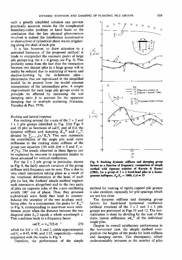
3 x 3 pile groups (sketched in Fig. l(b)) Figs 9 and 10 plot as functions of wdJV3 and of S/d, the dynamic stiffness and damping, RrxG and CrxG, divided by xi= i, &* I&‘). This sum represents the contribution of the single pile axial static stiffnesses to the rocking static stiffness of the group (see equation (19) with AM = 0 and F, = XZsxi). The trends observed in these figures can be explained by recourse to arguments similar to those advanced for vertical oscillations.
For the 2 x 2 pile group in particular, shown in Fig. 9, the fairly smooth variation of the group stiffness with frequency can be seen. This is due to very small interaction taking place as a result of the rotational deformation at the head of each pile (in fact, the Authors’ simple method neglects such interaction altogether) and to the two pairs of piles on opposite sides of the x-axis oscillating axially 180” out of phase. Thus, they generate (cylindrical) wave fields that tend to counter- balance the interplay of the two in-phase oscil- lating piles. As a consequence, the peaks for jZrxG in Fig. 9, corresponding to maximum wave inter- ference, occur when the distance between the two diagonal piles S,/2 equals a whole wavelength 1. This condition leads to a frequency factor
ad/K = x J2(s/d)- 1 (25)
which for S/d = 10, 5, and 2, yields approximately wdJVs = 0.45, 0.90, and 2.22, respectively-values consistent with the results in Fig. 9.
Therefore, the performance of the simple
3 -0
K,, + x,2 K,’
2
I I
S/d - 10
- 21
Rigorous solution Of - 5 Kayma - Kausel (1982)
4 0 10 A Proposed simple method 0
2! 5
G
c, 3_ ---__
+ xZ KzS
2-
l-
OL 0
I 0.5 rod
v,
I 1
Fig. 9. Rocking dynamic stiffness and damping group factors as a function of frequency: comparison of simple method with rigorous solution of Kaynia & Kausel (1982), for a group of 2 x 2 fixed-bead piles in a homo- geneous halfspace, E&E, = 1000, L/d = 15
method for rocking of rigidly-capped pile groups is also excellent, especially for pile spacings which are not too close.
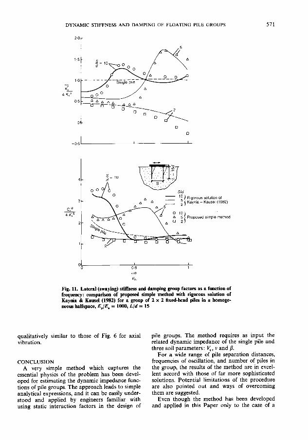
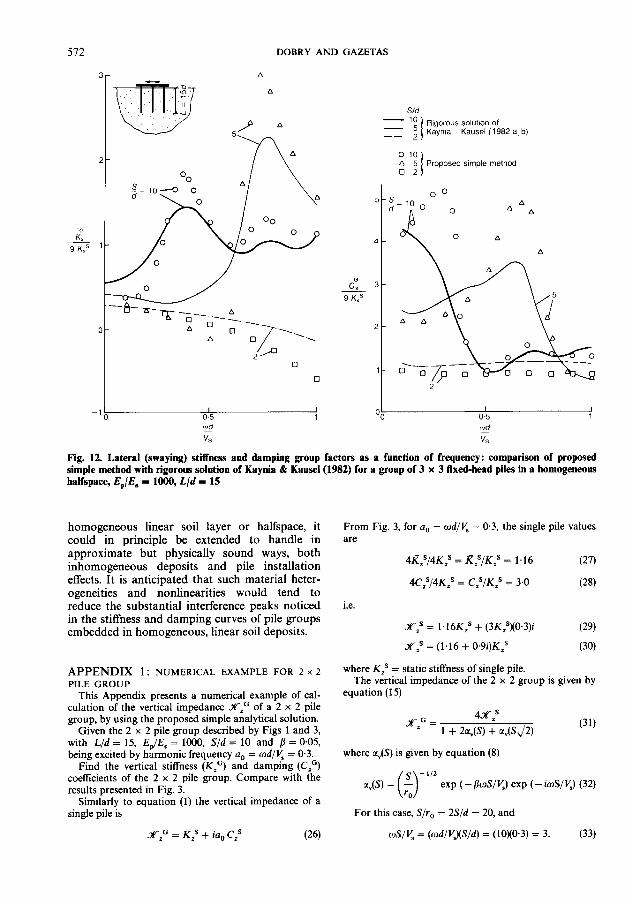
The dynamic stiffness and damping group factors for fixed-head horizontal oscillation (without rotation) of the 2 x 2 and 3 x 3 pile groups are portrayed in Figs 11 and 12. The nor- malization is done by dividing by the sum of the static lateral stiffnesses, nKXS of the individual single piles.
Despite its overall satisfactory performance in the horizontal case, the simple method over- predicts the heights of the peaks for both stiffness and damping curves. This discrepancy, which understandably increases as the number of piles

570 DOBRY AND GAZETAS
G
s/a - 10 -5 -- 2
0 10 a 5 0 2
Rigorous solutfon of Kayma - Kausel (1982)
Proposed ample method
Fig. 10. Rocking stiffness and damping group factors as a function of fre- quency: comparison of proposed simple method with the rigorous solution of Kaynia 81 Kausel (1982) for a group of 3 x 3 fixed-head piles in a homoge- neous halfspace, E&E, = 1000, L/d = 15
in the group grows, is probably due to the simpli- fied wave field assumed in Fig. 2(d) and to the finite apparent phase velocity with which flexural waves propagate down the laterally loaded pile. This renders the assumption of simultaneous emission of the waves from the various points along the pile shaft somewhat inaccurate for hori- zontal fixed-head pile vibration. Hence, simulta- neous arrival of these waves at the shaft of a neighbouring pile does not reflect reality in an accurate way. As a result, the arriving waves have (slightly) different phases along this pile, and this
modifies the wave interference phenomena con- trolling the pile group response in ways not fully accounted for by the simple model.
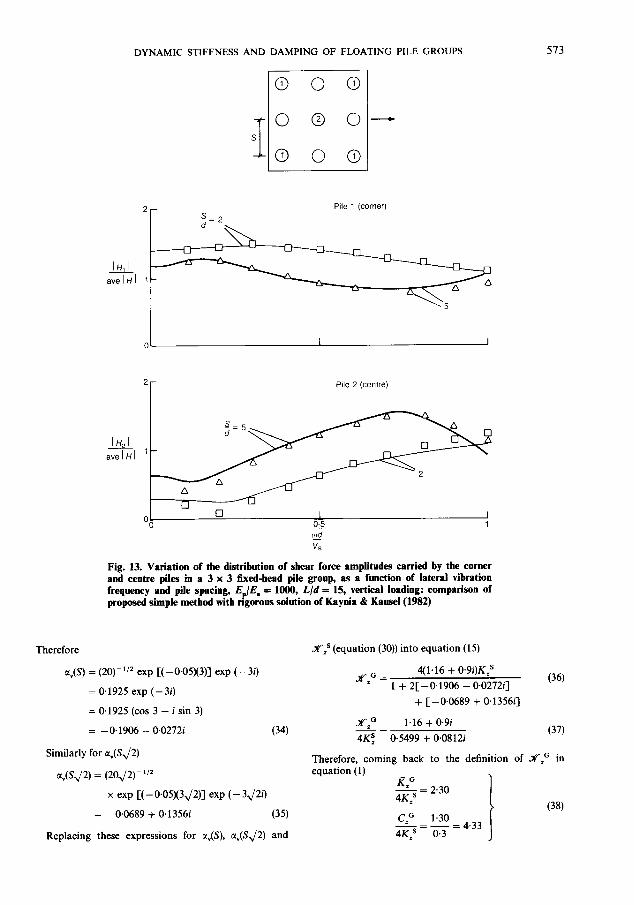
Nonetheless, even in this case the simple method proposed predicts the distribution of shear forces at the head of each pile in the group with remarkable accuracy for all frequencies, pile spacings and group sizes considered (see Fig. 13). (Although Fig. 13 presents only some of the com- parisons of lateral force distributions obtained by the Authors, the excellent agreement shown is typical of all results.) The trends in Fig. 13 are
DYNAMIC STIFFNESS AND DAMPING OF FLOATING PILE GROUPS 571
- ‘“5 ) Rigorous SOlUtlOn of _ 2 j Kaym - Kausel (1982)
wd
v,. Fig. 11. Lateral (swaying) stiffness and damping group factors as a function of frequency: comparison of proposed simple method with rigorous solution of Kaynia & Kausel (1982) for a group of 2 x 2 fixed-head piles in a homoge- neous balfspace, E,/E, = 1000, L/d = 15
qualitatively similar to those of Fig. 6 for axial vibration.
CONCLUSION A very simple method which captures the
essential physics of the problem has been devel- oped for estimating the dynamic impedance func- tions of pile groups. The approach leads to simple analytical expressions, and it can be easily under- stood and applied by engineers familiar with using static interaction factors in the design of
pile groups. The method requires as input the related dynamic impedance of the single pile and three soil parameters: V, , v and /I.
For a wide range of pile separation distances, frequencies of oscillation, and number of piles in the group, the results of the method are in excel- lent accord with those of far more sophisticated solutions. Potential limitations of the procedure are also pointed out and ways of overcoming them are suggested.
Even though the method has been developed and applied in this Paper only to the case of a
DOBRY AND GAZETAS
-G
-!L 9 KxS
0 c,
3
9 K,’
I I 0.5 1 wd
v,
S/d - 10
- *I Rigorous soluton of - 5 Kaynla - Kausel (1982 a b)
A 5 Proposed simple method 0 2 I
“‘3
cud v,
Fig. 12. Lateral (swaying) stilfness and damping group factors as a function of frequency: comparison of proposed simple method with rigorous solution of Kaynia & Kausel(l982) for a group of 3 x 3 fixed-head piles in a homogeneous halfspace, E,/E, = 1000, L/d = 15
homogeneous linear soil layer or halfspace, it could in principle be extended to handle in approximate but physically sound ways, both inhomogeneous deposits and pile installation effects. It is anticipated that such material heter- ogeneities and nonlinearities would tend to reduce the substantial interference peaks noticed in the stiffness and damping curves of pile groups embedded in homogeneous, linear soil deposits.
APPENDIX 1: NUMERICAL EXAMPLE FOR 2 x 2 PILE GROUP
This Appendix presents a numerical example of cal- culation of the vertical impedance X.o of a 2 x 2 pile group, by using the proposed simple analytical solution.
Given the 2 x 2 pile group described by Figs 1 and 3, with L/d = 15, Es/E. = 1000, S/d = 10 and B = 0.05, being excited by harmonic frequency a, = cod/V, = 0.3.
Find the vertical stiffness (KzG) and dampmg (CzG) coefficients of the 2 x 2 pile group. Compare with the results presented in Fig. 3.
Similarly to equation (1) the vertical impedance of a single pile is
XG=KRSiia Cs I z 0 I (26)
From Fig. 3, for a, = cod/V, = 0.3, the single pile values are
4&S/4K,S = ~,SjK,S = 1.16 (27)
4Czs/4KzS = CzS/KzS = 3.0 (28)
i.e.
Xzs = 1,16K,s + (3Kzs)(0.3)i (29)
X,’ = (1.16 + 0.9i)K,s (30)
where K,’ = static stiffness of single pile. The vertical impedance of the 2 x 2 group is given by
equation (15)
XG’ 4x,s
I 1 + 2a,(S) + a,(SJ2)
(31)
where a&9) is given by equation (8)
exp (-)!?wS/V,) exp (- ioS/VJ (32)
For this case, S/r, = 2S/d = 20, and
OS/V, = @d/V&?/d) = (10x0.3) = 3. (33)
DYNAMIC STIFFNESS AND DAMPING OF FLOATING PILE GROUPS 513
Pile 1 (corner)
‘r Pile 2 (centre)
Fig. 13. Variation of the distribution of shear force amplitudes carried by the corner and centre piles in a 3 x 3 fixed-head pile group, as a function of lateral vibration freqwncy and pile spacing, EP/E, 3: 1000, L/d = 15, vertical loading: comparison of proposed simple method with ngoroos solution of Kayaia & Kausel(l982)
Therefore Xzs (equation (30)) into equation (15)
a,(S) = (20)-‘I2 exp [( -0.05)(3)] exp (- 3i)
= 0.1925 exp (- 3i)
= 0.1925 (cos 3 - i sin 3)
= - 0.1906 - 0.02721’ (34)
X0= 4(1.16 + 0.9i)KzS
I 1 2[ 0.1906 + - -
0.027211 (36)
+ [ -0.0689 + 0.135611
X‘O L= 1.16 + 0.9i 4K; 0.5499 + 0.08 12i (37)
Similarly for a,(SJ2) Therefore, coming back to the definition of XzG in
a&/2) = (2OJ2)-“’ equation (1)
x exp [(-0.05X3,/2)] exp (- 3J2i)
= -0.0689 + 0.13561 (35) (38)
Replacing these expressions for a,(S), a,(SJ2) and

514 DOBRY AND GAZETAS
which would provide an additional data point for S/d = 10 and wd/< = 0.3 in both plots of Fig. 3.
Novak, M. (1984). Evaluation of dynamic experiments on a pile group. J. Geotech. Engng Div. Am. Sot. Cio. Engrs 110,738-756.
REFERENCES Ottaviani, M. (1975). Three-dimensional finite element
analysis of vertically loaded pile groups. Ghotech- Banerjee, P. K. (1978). Analysis of axially and laterally
loaded uile grouts. Deuelonments in soil mechanics. (ed. C. k. %ottj London:. Applied Science Publi- shers.
Butterfield. R. & Baneriee, P. K. (1971). The elastic
nique 25, No. 2, 159-174. Poulos, H. G. (1968). Analysis of the settlement of pile
groups. Gt?oiechnique l& No. 4,449-471. Poulos, H. G. (1971). Behavior of laterally-loaded piles
II: pile groups. J. Soil Mech. Fdns Div. Am. Sot. Ciu. En&s 91, Sti5,733-751.
Poulos. H. G. & Mattes, N. S. (1971). Settlement and
_ analysis of compressible piles and pile’ groups. GCo- technioue 21. No. 1.43-60.
Davies, ‘?. G.,’ Sen, ‘R. & Banerjee, P. K. (1985).
Div. Am. sot. &. Engrs 112, 109-135. El Shamouby, B. & Novak, M. (1985). Static and low-
Dynamic behavior of pile groups in inhomogeneous
frequency response of pile groups. Can. Geotech. J.
soil. J. Geotech. Engng Div. Am. Sot. Cio. Engrs 111,
22,79-94.
13651379. Dobry, R. & Gazetas, G. (1986). Dynamic response of
arbitrarily shaped foundations. J. Geotech. Engng
load distribution analysis oi pile’ groups. Austral.
Engng Div. Am. Sot. Cio.~Engrs 104~1465-1488. Randolph, M. F. & Wroth, C. P. (1979). An analysis of
Geomech. J. Gl, No. 1, 18-28. Poulos, H. G. & Davis, E. H. (1980). Pile foundation
the vertical deformation of pile groups. Gtotechnique
analysis and design. New York: Wiley.
29, No. 4,423439.
Randolph, M. F. & Wroth, C. P. (1978). Analysis of deformation of vertically loaded piles. J. Geotech.
Fleming, W. G. K., Weltman, A. J., Randolph, M. F. & Elson, W. K. (1985). Piling engineering, pp. 188-198. Glasgow: Surrey University Press.
Gazetas. G. & Dobrv. R. (1984). Horizontal response of piles’in layered s&ls. J: Geotech. Engng Div. Am. Sot. Ciu. Engrs 110, 2&40.
Gazetas. G., Dobrv, R. & Tassoulas, J. L. (1985). Verti- cal response of-arbitrarily shaped embedded founda- tions. J. Geotech. Engng Div. Am. Sot. Ciu. Engrs 111,75&770.
Kagawa, T. (1983). Dynamic lateral pile-group effects. J. Geotech. Emma Div. Am. Sot. Cio. Enars 109. 1267-
Randolph, M. F. (1981). The response of flexible piles to lateral loading. Gtotechnique 31, No. 2,247-259.
Roesset, J. M. (1984). Dynamic stiffness of pile groups. Pile foundations. New York: ASCE.
Sanchez-Salinero, I. (1983). Dynamic stiffness of pile groups: approximate solutions. Geotechnical Engin- eering Report GR83-5, University of Texas at Austin.
Scott, R. F. (1981). Foundation Analysis. Englewood Cliffs: Prentice-Hall.
Sen, R., Davies, T. G. & Banerjee, P. K. (1985). Dynamic analysis of piles and pile groups embedded in- homogenedus so&. Earthquake engineering and struct. Dyn. 13, 53-65.
1285. - _ Kaynia, A. M. & Kausel, E. (1982a). Dynamic behav-
iour of pile groups. 2nd Inter. Co& Numer. Meth. Offshore Piling, Austin, Texas, 509-532.
Kaynia, A. M. & Kausel, E. (1982b). Dynamic stiflness and seismic response of pile groups. Research Report R82-03, Massachusetts Institute of Technology.
Morse, P. M. & Ingard, K. U. (1968). Theoretical ocous- tics. New York: McGraw-Hill.
Naylor, D. J. & Hooper, J. A. (1975). An effective stress finite element analysis to predict the short and long- term behaviour of a pile-raft foundation on London clay. Symp. Settlement of Structures, Cambridge.
Nogami, T. (1979). Dynamic group effect of multiple piles under vertical vibration. Proc. Engng Mech. Div. ASCE Specialty Con& Austin, Texas, 75&754.
Nogami, T. (1980). Dynamic stiffness and damping of pile groups in inhomogeneous soil. Dynamic response of pile foundation. (eds M. O’Neill and R. Dobry). ASCE Special Technical Publication. New York: ASCE.
Nogami, T. (1983). Dynamic group effect in axial responses of grouped piles. J. Geotech. Engng Dio. Am. Sot. Cio. Engrs 109,225-243.
Novak, M. (1974). Dynamic stiffness and damping of piles. Can. Geotech. J. 11, No. 4.
Sheta, M. & Novak, M. (1982). Vertical vibration of pile groups. J. Geotech. Engng Div. Am. Sot. Ciu. Engrs 108,57&590.
Tyson, T. R. & Kausel, E. (1983). Dynamic analysis of axisymmetric pile groups. Research Report R8347, Massachusetts Institute of Technology.
Varadan, V. K., Varadan, V. V. & Pao, Y.-H. (1978). Multiple scattering of elastic waves by cylinders of arbitrary cross-section I. J. Acoust. Sot. America. 63, 131&1319.
Waas, G. & Hartmann, H. G. (1981). Analysis of pile foundations under dynamic loads. Co@ on Struct. Mech. in Reactor Technol., Paris.
Waas, G. & Hartmann, H. G. (1984). Seismic analysis of pile foundations including soil-pile-soil interaction. 8th World Conf: Earthauake Enana 5.55-62.
Wolf, J. P. & Van Arx, 6. A. (19?‘8j. Impedance func- tion of a group of vertical piles. Proc. ASCE Spe- cialty Conf Soil Dyn. Earthquake Engng 2, 1024-1041.
Wolf, J. P. (1985). Dynamic soil-structure interaction, pp. 166172. Englewood Cliffs: Prentice-Hall.