Embed Size (px)
Citation preview
Dynamic Stiffness and Damping Characteristics of a High-Temperature Air Foil Journal Bearing
Samuel A. Howard (Member STLE) and Christopher DellaCorte (Member STLE)
National Aeronautics and Space Administration
Glenn Research Center
Cleveland, Ohio 44135
Mark J. Valco
U.S. Army Research Laboratory
National Aeronautics and Space Administration
Glenn Research Center
Cleveland, Ohio 44135
Joseph M. Prahl
Chairman, Department of Mechanical and Aerospace Engineering
Case Western Reserve University
Cleveland, Ohio 44106
Hooshang Heshmat (Fellow STLE)
Mohawk Innovative Technology Inc.
Albany, New York
Abstract
Using a high-temperature optically based displacement measurement system, a foil air bearing's stiffness and
damping characteristics were experimentally determined. Results were obtained over a range of modified Sommeffeld
Number from !.5E6 to 1.5E7, and at temperatures from 25 to 538 °C.
An Experimental procedure was developed comparing the error in two curve fitting functions to reveal different
modes of physical behavior throughout the operating domain. The maximum change in dimensionless stiffness was 3.0E-2 to
6.5E-2 over the Sommerfeld Number range tested. Stiffness decreased with temperature by as much as a factor of two from
25 to 538°C. Dimensionless damping was a stronger function of Sommerfeld Number ranging from 20 to 300. The tempera-
ture effect on damping being more qualitative, showed the damping mechanism shifted from viscous type damping to
frictional type as temperature increased.
Keywords
FluidFilmCompliantBearings;FoilBearings;GasBearings;Turbomachinery
Nomenclature
C
D
D'
E(T)
g
L
K
K'
m
M
n
N
P
PaR
S
S,
t
T
W
W'
X
Y
A
NT)
radial clearance
general damping coefficient
Dimensionless damping coefficient: D'XqR/(Wpf(T))
modulus of elasticity, a function of temperature
gravity
bearing length
stiffness
dimensionless stiffness: K'= KC/PaR2
dimensionless stiffness: 1¢= K/E(T)t
mass of the foil
mass of the bearing and holder
number of data points
speed in radians per second
load per unit area: P = W/2RL
ambient pressure
journal radius
Sommerfeld Number; S = I.tN/P(R/C) 2
modified Sommerfeld Number or bearing number: S' = W/(IgT)RNL)
foil thickness
temperature
load
dimensionless load: W' = W/PaR2
displacement of the bearing and housing, M
displacement of the foil, m
dimensionless speed: A = 6pN/Pa(R/C)2
absolute viscosity, a function of temperature
Subscript
f foil
gas
Introduction
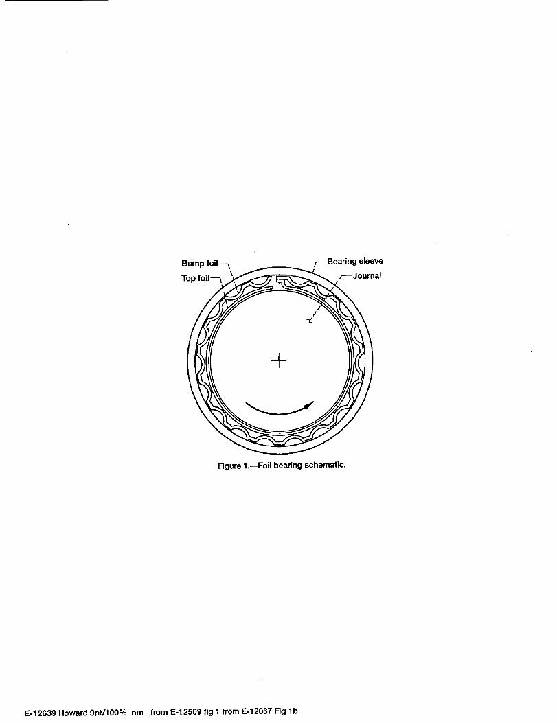
Compliant gas journal bearings, commonly referred to as foil air bearings, (Fig. I) are a class of self-acting hydrody-
namic bearings that utilize ambient air as the lubricating fluid (Heshmat, et al. 1982; Agrawal, 1990). Self-acting hydrody-
namic bearings are comprised of a shaft that rotates inside a stationary bearing sleeve. The bearings function by building up a
hydrodynamic gas film pressure in the small gap between the rotating shaft surface and the stationary bearing sleeve surface.
The pressure is generated by the surface velocity of the rotating shaft that "drags" fluid into the convergent wedge-shaped gap
formed between the two surfaces. The combination of Couette (shear driven) and Poisselle (pressure driven) flows in the gap
produce a pressure distribution that works to keep the two surfaces separated. This is the same principle by which all self-
acting hydrodynamic bearings operate.
The uniqueness of foil bearings lies in the compliant inner surface of the stationary sleeve, made up of a stack of
sheet metal foils. A smooth top foil provides the bearing surface and is often supported by a series of corrugated bump foils
acting as springs to give foil bearings their compliance. The major benefit of the inner surface being compliant is a film
thickness that is larger than would be present in a geometrically identical rigid air bearing. The larger gap results in lower
power loss due to shearing of the gas film. The thicker gas film and compliant surface combine to make foil bearings less
susceptible to damage by ingested dirt particles as the foil surface can move to allow a large foreign particle in the fluid to
pass. Misalignment and thermal/centrifugal radial growth are less of a problem with foil bearings since the compliant foils
can accommodate these changes in shaft diameter and position (Heshmat, 1994). As a result, foil bearings can operate at
temperatures and speeds far exceeding those at which rigid gas bearings would seize due to shaft growth.
Perhaps the most significant benefits of foil bearings are the added damping afforded by the relative sliding of the
smooth top foil and corrugated bump foil during dynamic shaft motions, and the opportunity for bearing designers to tailor
the stiffness and damping characteristics for a specific application. The research reported in this paper seeks to increase the
understanding of how load, speed, and temperature influence the stiffness and damping characteristics of foil air journal
bearings. It is expected that this knowledge will ultimately lead to improved bearings with capabilities that enable a new
breed of revolutionary oil-free turbomaehinery applications including turbocompressors, turbogenerators, turbopumps, and
gas turbine engines.
Experimental Displacement Measurement Technique
Since it is necessary to measure the motion of the bearing at temperatures exceeding 500 °C, transducers are needed
that can withstand that extreme environment. Accelerometers are commonly used to measure dynamic bearing motion
because they are relatively easy to set up by mounting them on the object of interest. Unfortunately, current accelerometer
technology is limited to lower temperatures. Most accelerometers are limited to 120 °C and high temperature accelerometers
are limited to 250 °C. For these tests, another measurement method was needed.
Several different types of transducers were considered including capacitance displacement probes, laser displace-
ment and velocity probes, and fiber optic displacement probes. The probes that were chosen for this research were fiber optic
displacement probes for a variety of reasons. Among these reasons, the probes offered the sensitivity necessary for the tests at
hand (0.312 I.un/mV) and had a sufficient linear range of 0.125 ram. The laser velocimeter was also a promising option and
may be something to consider for future testing of this type. Their major drawback is that they are difficult to set up properly.
The choice of fiber optic probes dictated that the shaft surface needed to have very good reflective properties at the
high temperatures expected in this testing. This problem was known from previous work done by the author (Howard, et al.,
2001) with this type of sensor. The solution found to work best was a silver based coating sprayed into a groove on the target
surface. The details of the high temperature "mirror" coating can be found in Howard (2000). This coating system provided
a good high temperature optical target at speeds up to 30,000 rpm and temperature up to 538 °C.
Test Method and Data Acquisition
Previous work by the author established a preliminary method for measuring steady state stiffness values (Howard,
et al. 2001) (Howard, 1999). However, the technique used to measure the data was only appropriate for steady state stiffness.
It was not capable of measuring damping or dynamic stiffness coefficients. A new test method was developed to measure the
dynamic characteristics of foil air bearings.
The technique is fairly straightforward. The displacement of the bearing is measured while impacting the bearing
with an electric hammer. An electric hammer was used to give repeatable impacts and to reduce double hits. The frequency of
the vibration decay is used to obtain the stiffness and the rate of decay is used to calculate damping. Only the vertical motion
is measured while the bearing is impacted in the vertical direction. Thus, only one dimensional direct stiffness and damping is
measured. The results therefore, are not sufficient for doing high fidelity rotordynamic analysis, but are good for detecting
trends in the characteristics of foil bearings at high temperature and as a guide for future work.
As a result of the optical nature of the displacement probes, special data acquisition techniques were needed to
ensure good results. The reflectivity of the target surface is a function of circumferential location because of polishing marks,
pits, scratches, etc. As the shaft rotates, reflectivity variations are erroneously read as changes in displacement. In order to
minimize this effect, data is collected at the same location on the shaft each revolution. A shaft encoder with eight equally
spaced groves was used to trigger the data acquisition system to take a data point. Thus, the data sampling rate was synced to
the running speed of the shaft and was fixed at eight times the rotation frequency. The shaft "signature" is stored by rotating
the shaft at the desired speed while storing the displacement output without exciting the bearing. The stored baseline is then
subtracted from the signal as data is collected while exciting the bearing. This made it possible to eliminate most of the false
displacement components contained in the signal.
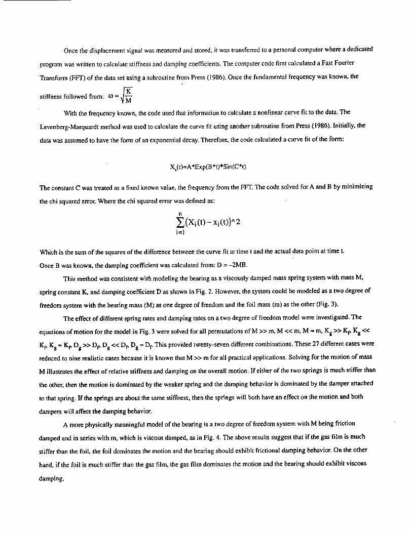
Oncethedisplacementsignalwasmeasuredandstored,itwastransferredtoapersonalcomputerwhereadedicated
programwaswrittentocalculatestiffnessanddampingcoefficients.ThecomputercodefirstcalculatedaFastFourier
Transform(FFT)ofthedatasetusingasubroutinefromPress(1986).Oncethefundamentalfrequencywasknown,the
stiffness followed from: to = _'_"
I
With the frequency known, the code used that information to calculate a nonlinear curve fit to the data. The
Levenberg-Marquardt method was used to calculate the curve fit using another subroutine from Press (1986). Initially, the
data was assumed to have the form of an exponential decay. Therefore, the code calculated a curve fit of the form:
Xv(t)=A*Exp(B*t)*Sin(C*t)
The constant C was treated as a fixed known value, the frequency from the FFT. The code solved forA and B by minimizing
the chi squared error. Where the chi squared error was defined as:
n
E(Xi(t)- xi(t))^2
i=l
Which is the sum of the squares of the difference between the curve fit at time t and the actual data point at time t.
Once B was known, the damping coefficient was calculated from: D = -2MB.
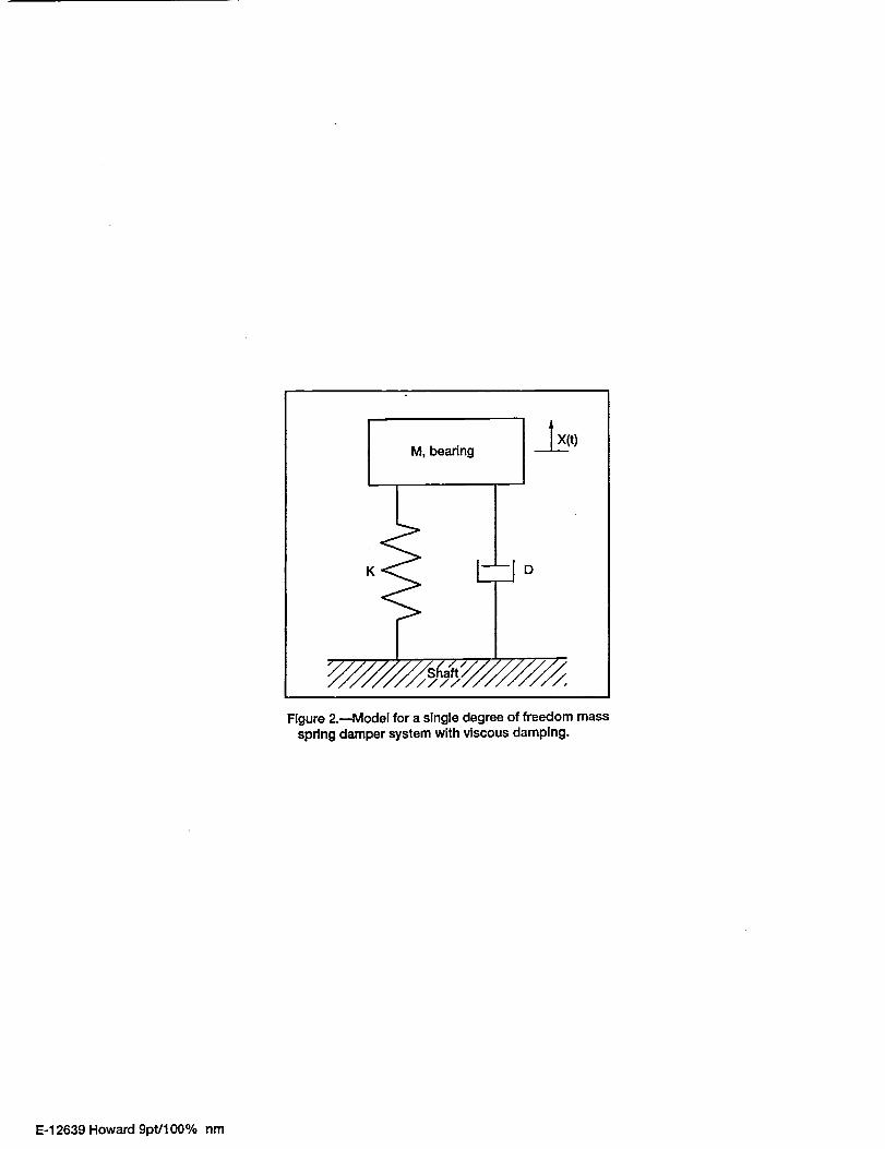
This method was consistent with modeling the bearing as a viscously damped mass spring system with mass M,
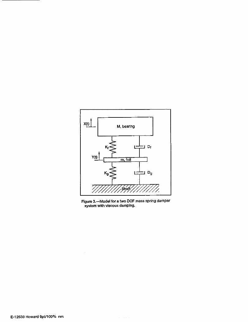
spring constant K, and damping coefficient D as shown in Fig. 2. However, the system could be modeled as a two degree of
freedom system with the bearing mass (M) as one degree of freedom and the foil mass (m) as the other (Fig. 3).
The effect of different spring rates and damping rates on a two degree of freedom model were investigated. The
equations of motion for the model in Fig. 3 were solved for all permutations of M >> m, M << m, M _ m, Kg >> K_ Kg <<
Kf, Kg _ Kf, Dg >> Dr, Dg << D r Dg = Dr. This provided twenty-seven different combinations. These 27 different cases were
reduced to nine realistic cases because it is known that M >> m for all practical applications. Solving for the motion of mass
M illustrates the effect of relative stiffness and damping on the overall motion. If either of the two springs is much stiffer than
the other, then the motion is dominated by the weaker spring and the damping behavior is dominated by the damper attached
to that spring. If the springs are about the same stiffness, then the springs will both have an effect on the motion and both
dampers will affect the damping behavior.
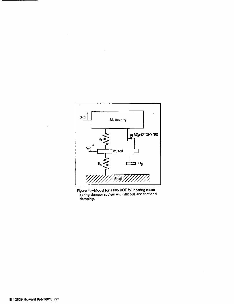
A more physically meaningful model of the bearing is a two degree of freedom system with M being friction
damped and in series with m, which is viscous damped, as in Fig. 4. The above results suggest that if the gas film is much
stiffer than the foil, the foil dominates the motion and the bearing should exhibit frictional damping behavior. On the other
hand, if the foil is much stiffer than the gas film, the gas film dominates the motion and the bearing should exhibit viscous
damping.
Thepreviousdiscussionsuggestsamethodofanalyzingthedatatogainabetterunderstandingofhowthebearing
works.Theproposedmethodistofit thedatatobothexponentialandlineardecaymodelsandcomparetheerrorinthefits.If
theexponentialfit isbetter,thebearingisassumedtobebehavingmostlylikeaviscousdampedsystem.If thelinearfit is
better,it isassumedthebearingisbehavingmostlylikeafrictiondampedsystem.Withthismethodit ispossibletodetermine
inwhichregionsoftheoperatingdomainthegasfilmdominatesthebearingmotionandinwhichregionsthefoildominates
themotion.
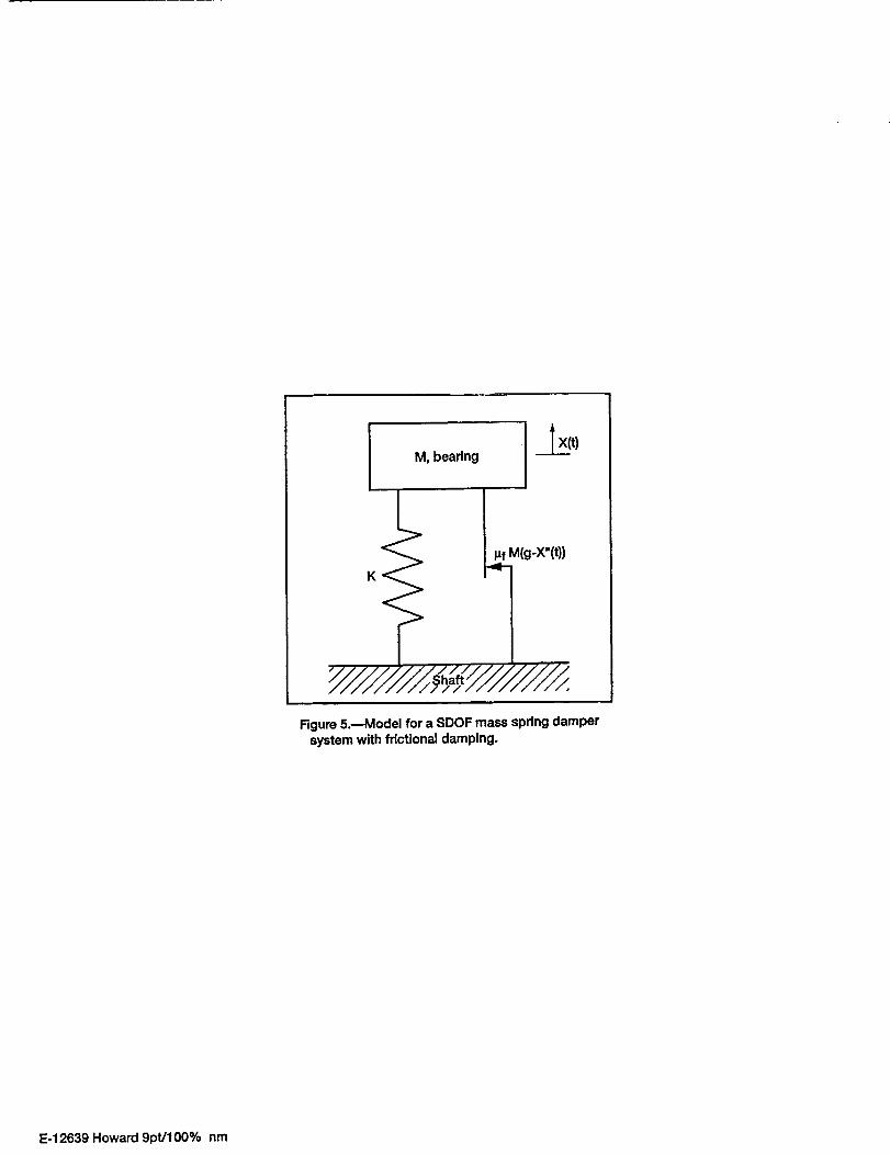
ThefrictiondampedmodelisshowninFig.5andtheequationforthecurvefit tothesolutionofthismodelisthe
following:
Xt(t)=(A- B*t)*Sin(C*t)
WhereCisthefrequencyfromtheFFTanalysisasbeforeandtheotherconstants,AandB,arefoundusingthesame
nonlinear least squared curve fitting routine.
Results and Discussion
Bearing displacement data was collected to calculate dynamic stiffness and damping in order to map bearing
behavior as a function of load, and temperature. The speed at which data was taken was 30 000 rpm. The load range tested
was 11.2 to 89.6 N in increments of 11.2 N. The temperatures tested were representative of the range of temperatures in
which foil bearings are expected to operate, except for cryogenic applications, 25 to 538 °C at approximately every 93 °C.
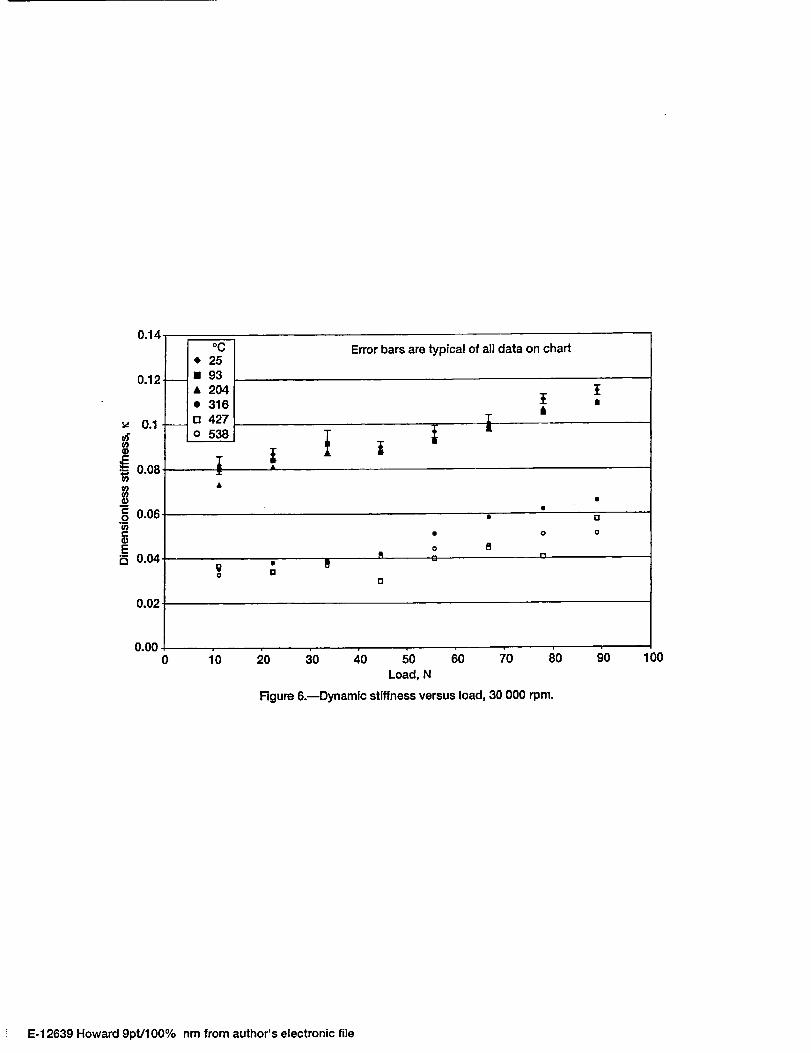
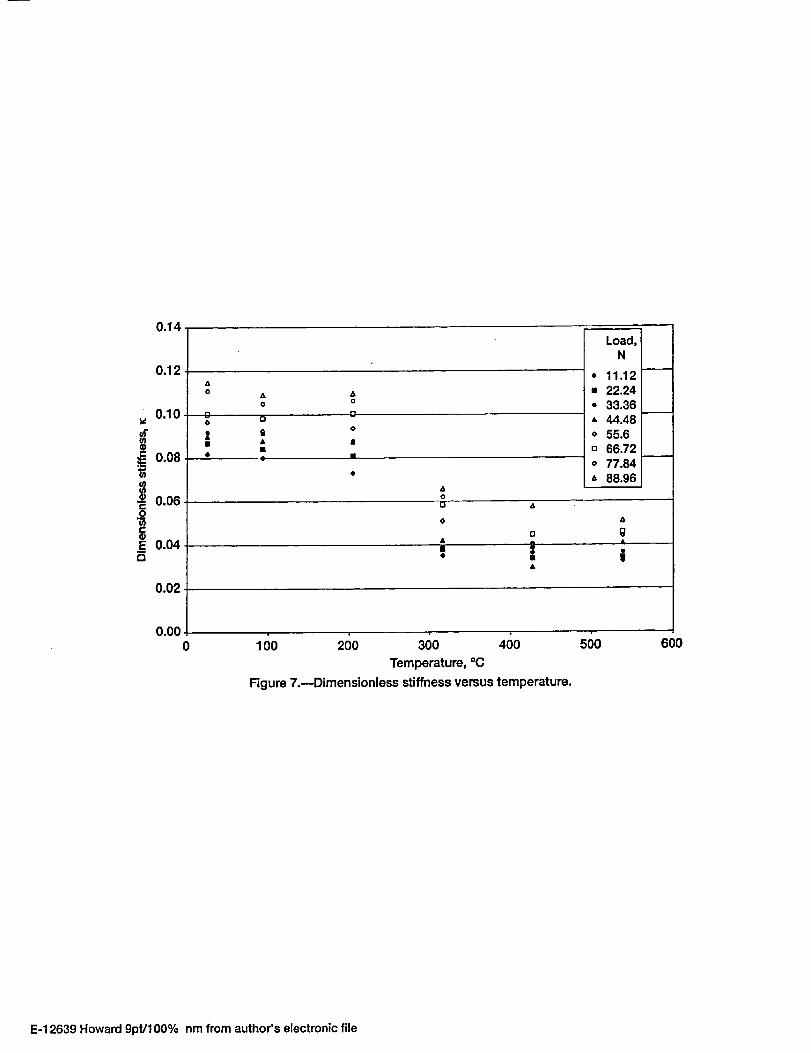
Figure 6 shows the dynamic stiffness results in dimensionless form versus load, and Fig. 7 shows the same data
versus temperature. The data indicates that foil bearing stiffness increases as load on the bearing increases and decreases as
temperature increases. From 25 °C to 204 °C it appears that stiffness is relatively constant with temperature. At 316 °C and
above stiffness decreases slightly with temperature. The plot also shows that the change in stiffness with load is less than one
order of magnitude. That result agrees, at least qualitatively, with the steady state results under the same load conditions from
previous work (Howard, et al. 2000).
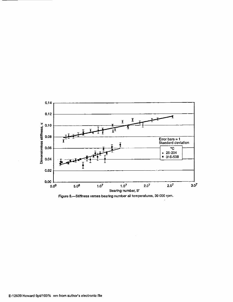
When the same data is plotted using a modified version of the Sommerfeld Number, or the bearing number, instead
of load (Fig. 8) it separates into two distinct bands. A higher temperature band (316 °C and above) and a lower temperature
band (204 °C and below). Since the nondimensional variables contain temperature dependant parameters, all the data should
fall relatively close to each other. The fact that it splits into these two bands suggests that there may be another relevant
temperature dependant parameter not included in the nondimensional variable. One possible factor is the sliding friction
coefficient between the top foil and the bumps, and between the bumps and the housing.
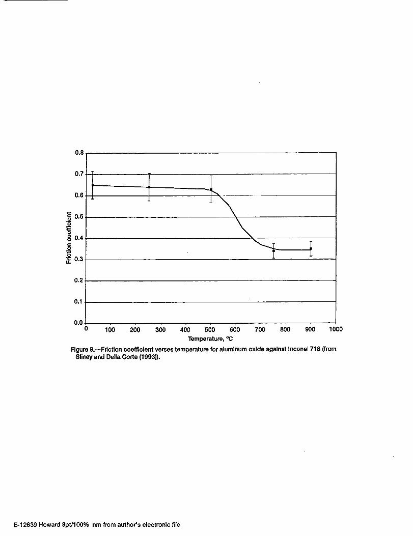
It is common for friction coefficients to be relatively constant at lower temperatures then decrease in nearly a step
function fashion and be relatively constant again at higher temperatures (Fig. 9) (Sliney and DellaCorte, 1993). If this were
the case for the foil material, it could explain the distinct temperature banding seen in the results. The friction coefficient
effectis not included in the dimensionless parameters because a functional representation of its temperature dependence is
not well known.
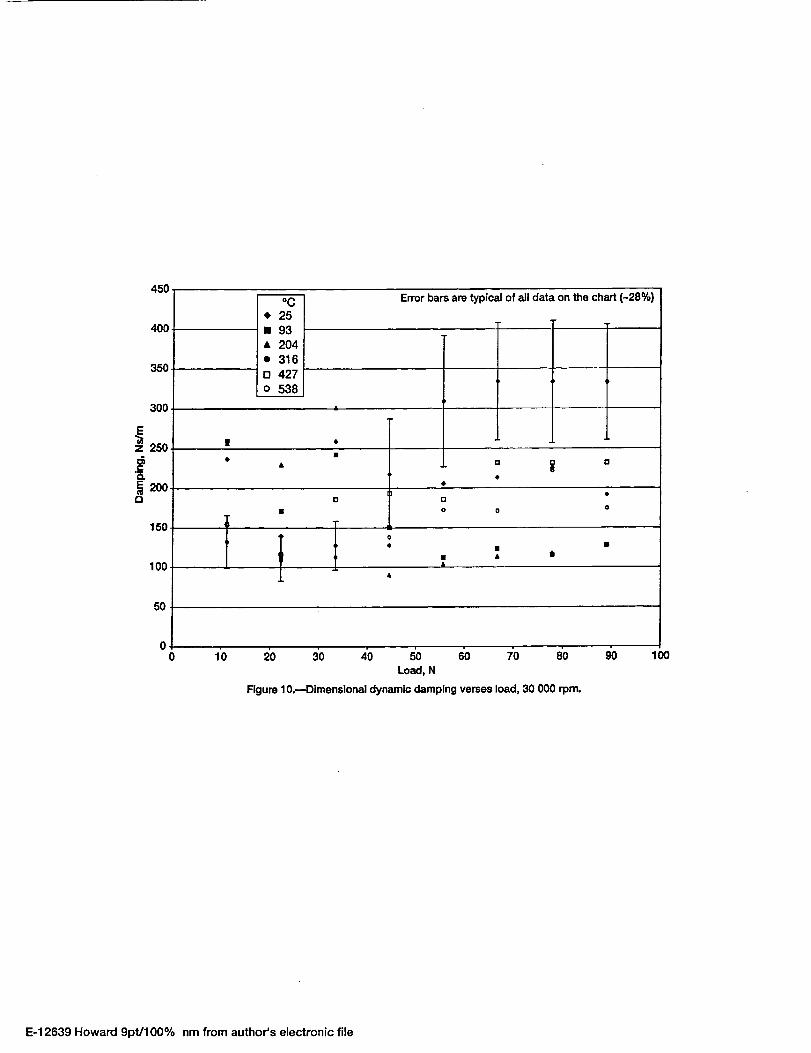
The damping results using the exponential curve fitting routine are shown in Fig. 10. The results indicate that the
damping trend is not a strong function of load, or temperature. In fact, it is difficult to learn anything from the data repre-
sented in this manner. However, when the data is non-dimensionalized, some trends become visible.
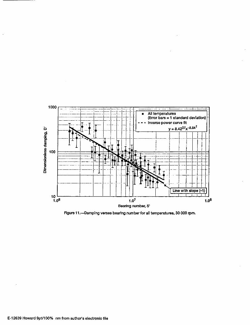
Figure I 1 shows the result of nondimensionalizing the damping results. Since the error bars for all of the data
essentially overlap, one can treat the different temperature data as one large set of data. The nondimensional damping
contains load in the denominator and the nondimensional bearing number has load in the numerator. If damping were
independent of load, the data would fall on a line with a slope of negative I on a log-log scale. The linear least squares curve
fit shown in the figure has a slope very near negative I (-0.88) suggesting that the damping is independent of load for all
practical purposes. Therefore, damping is also independent of speed.
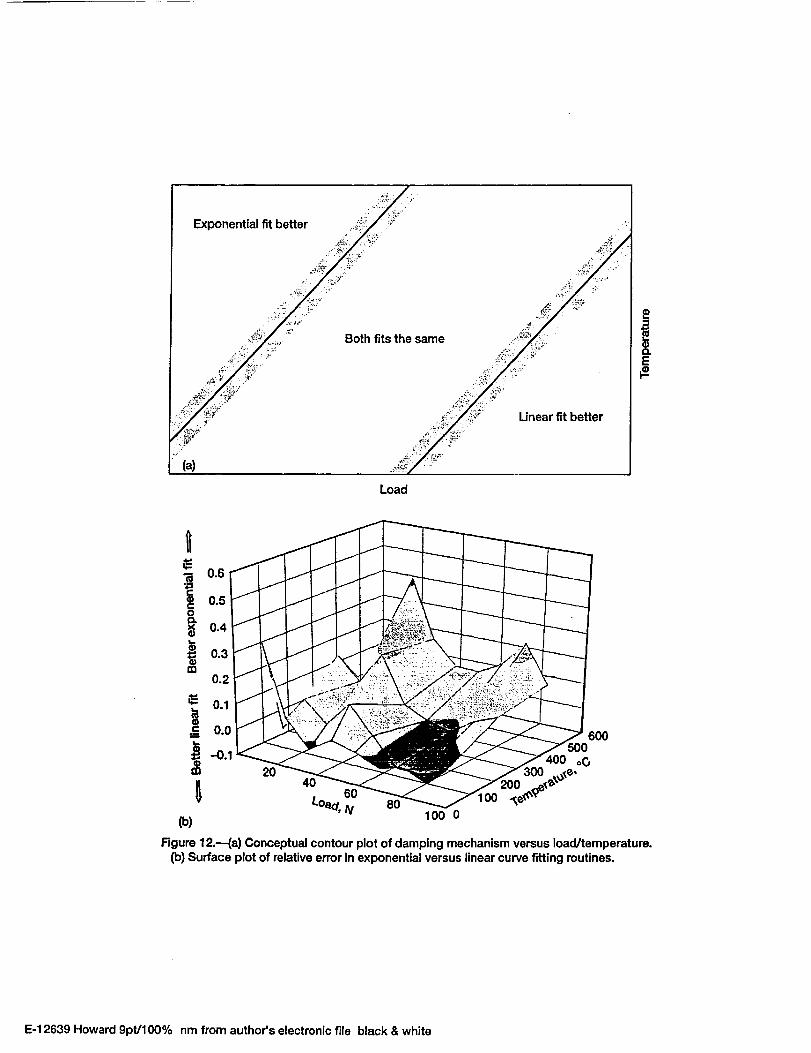
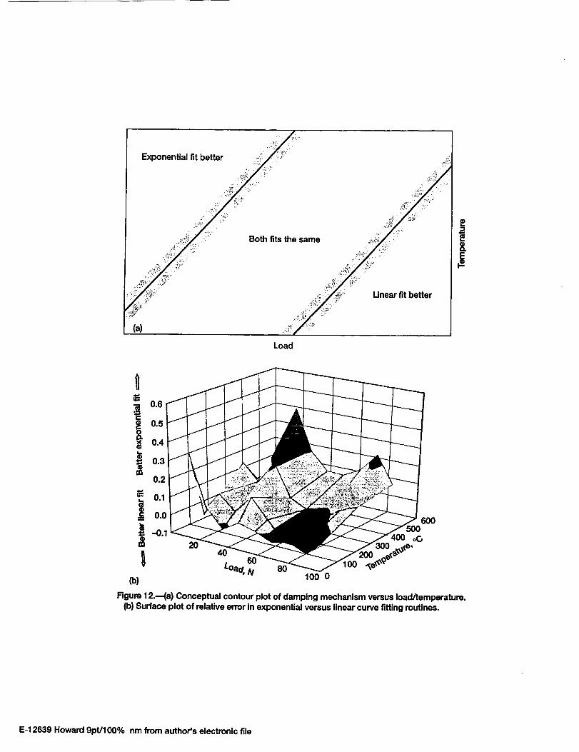
The truly important results of this study come in the form of understanding and insight gained from the data. The
error of the two different fitting functions was calculated and plotted for the load and temperature domain tested in these
experiments. Figure 12 contains a load-temperature contour plot and a three dimensional surface. The contour plot (Fig. 12a)
is a broad-brush conceptualization of how the bearing behaves in the load temperature domain. The conceptual contour plot is
substantiated in the surface plot. The surface plot (Fig. 12b) represents the error in the linear fit minus the error in the
exponential fit divided by the error in the exponential fit. Mathematically, the resulting number is the difference in the errors
expressed as a percentage of the error in the exponential fit. The actual numbers are not that important. The physical meaning
of them however, is important. If the number is positive and larger than O. !, then the error in the exponential fit is more than
10 percent less than the error in the linear fit. If the number is negative and smaller than -0. !, then the error in the linear fit is
more than 10 percent less than the error in the exponential fit. If the number is between -0. I and 0. I, then there is less than a
I 0 percent difference in the errors of the two fits.
Qualitatively, this means that if the surface is above 0.1, then the exponential fit is better and the bearing is assumed
to be exhibiting viscous type damping behavior. If the surface is below -0. I, then the linear fit is better and the bearing is
exhibiting friction type damping behavior. Otherwise, neither fit is substantially better and the bearing is behaving with a
combination of both types of damping.
The resulting surface plot is very informative in that light. The region where the surface is above 0.1 is the low load,
high temperature corner of the domain. This means that when the temperature is high and the load is low, the gas film is soft
compared to the foils. Under these conditions, the bearing behaves much like a rigid gas bearing would behave with viscous
damping. The region where the surface is below -0.1 starts in the high load low temperature corner of the domain, and
extends up into the high temperature high load corner. In this region of operating conditions, one would expect the beating to
behave like a friction damped system. In the band between the low load high temperature corner and the high load end of the
domain is the region where both damping mechanisms are likely operating.

The results presented are important because they show how foil be;_rings behave under different operating condi-
tions, particularly temperature. One of the assumptions that has been used in the past is that foil bearings have much more
damping than do identical rigid air bearings due to the rubbing of the foils. Therefore, it was thought that if more damping
were needed for a particular foil bearing, increasing the friction coefficient between the foils with different coatings would
yield more damping.
Peng and Carpino (1993) conducted an analytical study in which they found that damping in foil bearings increases
as the gas film gets stiff. They note that when the gas film is soft due to low load or speed, rigid gas bearings provide more
damping than foil bearings. At high load and high speed when the gas film is stiff, foil bearings provide more damping than
their rigid counterparts due to the coulomb damping in the foils.
The results of the present tests indicate the same phenomenon. If the bearing is operating in a region where the
viscous damping mechanism is dominant (low load, high temperature), adding more friction to the system will not help.
Rather, if more damping is needed, it may be better to load the bearing more heavily (perhaps by making it smaller) so that
foil motion can be encouraged and frictional damping that is already present in the system can contribute. The implication of
the above results is that the bearing properties can indeed be tailored to match the demands of the application to a certain
extent.
Conclusion
A high temperature displacement measurement system was successfully implemented in collecting high temperature
stiffness and damping data. Highly accurate high temperature displacement measurements can be made with the use of the
silver target surface in conjunction with the high temperature optical displacement probe as evidenced by the low error in the
dynamic stiffness measurements. Even with the electric hammer, there is some variability in impact testing. Therefore, the
error in the damping results is mostly due to nonrepeatability. The actual displacement measurements are quite accurate
(within 1 percent).
The present goal of gaining understanding of foil bearings through measurement of trends was met. The foil bearing
community now has an idea of the magnitude of changes to expect in bearing stiffness and damping with changing load,
speed, and temperature. Stiffness can be expected to change by factors of two or three with large changes in load or speed.
The same holds true of stiffness changes with temperature. Order of magnitude changes are not likely.
The major result of this work is a greater understanding of the mechanisms that control the behavior of foil bearings,
which is summed up in Fig. 12. Although trends in absolute damping characteristics are not as clear as trends in stiffness, a
greater understanding of the driving mechanisms can help bearing designers build better bearings and better oil-free
machines.
Until now, researchers and bearing designers have used viscous models to predict how the bearings behave. Judging
from the results of this research, that model may be adequate for some conditions. There is no reason not to continue to use
this model, with the understanding that it does have possible limitations. At least now, the limitations are known and it may be
advisabletoconstructbettermodels including the frictional damping mechanism into the rotordynamic design of machinery
that operates in the high load, high temperature environment.
For machinery operating in the low load, high temperature region, the damping in the bearings may be very small.
However, the bearings have an intrinsic mechanism for helping to keep these systems stable. The damping tends to respond to
high load inputs by shifting into the frictional damping domain where more energy can be dissipated from the system. The
more the bearing is perturbed, the more energy it can absorb. This result points to a definite advantage of foil bearings over
other bearing types.
Also, there is now some understanding about what happens to stiffness at higher temperatures. One can expect
stiffness to drop as the temperature increases from startup of a piece of machinery to operating conditions. However, the
impact of the stiffness drop is likely to be unimportant in light of the fact that the frictional damping mechanism tends to
increase at higher temperatures to help stabilize the system. If more damping is needed, it is now understood that increased
friction coefficients alone will not be sufficient, the bearings must also be able to activate the frictional damping mechanism
in order to reap benefits from the increased friction.
References
Agrawal, G.L. (1990), "Foil Gas Beatings for Turbomachinery," SAE Paper 901236, Presented at the SAE Society Confer-
ence on Environmental Systems, Williamsburg, VA.
Heshmat, H. (1994), "Advancements in the Performance of Aerodynamic Foil Journal Bearings: High Speed and Load
Capability" Trans. of the ASME J. of Tribology, ! 16, pp. 287-295.
Heshmat, H.; Walowit, J.A.; Pinkus, O. (1982), "Analysis of Gas-Lubricated Foil Journal Bearings" ASME Paper 82-Lub-40,
Presented at the ASME/ASLE Joint Tribology Conference, Washington, D.C.
Howard, S.A. (1999), "Preliminary Development of Charactetization Methods for Compliant Air Bearings," Tribology
Transactions, 42, 4, pp. 789-794.
Howard, S.A. (2000), "Characterization of the Rotordynamic Properties of Compliant Air Journal Bearings" Ph.D. disserta-
tion, Case Western Reserve University, Cleveland, OH.
Howard, S.A.; DellaCorte, C.; Valco, M.J.; Prahl, J.M.; Heshmat, H. (2001), "Steady State Stiffness of Foil Air Journal
Bearings at Elevated Temperatures" to be published in Tribology Transactions.
Peng, J.P.; Carpino, M. (1993), "Coulomb Friction Damping Effects in Elastically Supported Gas Foil Bearings" Tribology
Transactions, 37, pp. 91-98.
Press, W.H.; Flannery, B.P.; Teukolsky, S.A.; Vetterling, W.T. (1986), Numerical Recipes the Art of Scientific Computing,
Cambridge University Press, New York.
Sliney, S.E.; DellaCorte, C. (1993), "The Friction and Wear of Ceramic/Ceramic and Ceramic/Metal Combinations in Sliding
Contact," Lubrication Engineering, 50, 7, pp. 571-576.
Figure Captions
Figure l.--Foil bearing schematic.
Figure 2.--Model for a single degree of freedom mass spring damper system with frictional damping.
Figure 3.--Model for a two DOF mass spring damper system with viscous damping.
Figure 4.----Linearized model for a two DOF foil bearing mass spring damper system with viscous and frictional damping.
Figure 5.--Model for a SDOF mass spring damper system with frictional damping.
Figure 6.--Dynamic stiffness versus load, 30 000 rpm.
Figure 7.--Dimensionless stiffness versus temperature.
Figure 8.--Stiffness verses bearing number all temperatures, 30 000 rpm.
Figure 9.--Friction coefficient verses temperature for aluminum oxide against Inconel 718 (from Sliney [7]).
Figure 10.--Dimensional dynamic damping verses load, 30 000 rpm.
Figure 1 l.--Damping verses bearing number for all temperatures, 30 000 rpm.
Figure 12.--(a) Conceptual contour plot of damping mechanism versus load/temperature. (b) Surface plot of relative error in
exponential versus linear curve fitting routines.
Bump foil---_ /-- Beadng sleeve
Top foil--_ /_ Journal
Figure 1.--Foil bearing schematic.
E-12639 Howard 9Dt/100% nm from E-12509 fig 1 from E-12067 Fig lb.
I Mboa_ng h___t_
K_ _-jo
Figure 2.--Model for a single degree of freedom massspring damper system with viscous damping.
E-12639 Howard 9pt/100% nm
X(t)_ M,bearing
Figure3.--Modelfora two DOF mass spring dampersystem with viscous damping.
E-12639 Howard 9pt/100% nm
YK(t)_ mrfoil
" / _/=/Z
M, beadng
M(g-(X"(t)-Y"(t))
I
"-I Dg
Figure 4.reModel for a two DOF foil beadng massspdng damper system with viscous and frictional
damping.
E-12639 Howard 9pt/100% nm
M,bearing _X(t)
K (g-X'(t))
Figure 5.---Model for a SDOF mass spring dampersystem with frictional damping.
E-12639 Howard 9pt/100% nm
0.14
0.12
0.1c6
.__ 0.06-C(9E
0.04-
0.02-
0.00
Error bars are typical of all data on chart
t
A
|
rl
• O
• o o
oQ J:
m
10 20 30 40 50 60 70 80 90 00
Load, N
Figure 6.--Dynamic stiffness versus load, 30 000 rpm.
E-12639 Howard 9pt/100% nm from author's electronic file
0.14
0.12
0.10
U}
0.08
"E 0.060
.E 0.04
0.02
0.000
&0
[] &
<>
[]
Load,N
• 11.12• 22.24• 33.36• 44.48<, 55.6[] 66.72
77.8488.96
o . . o i
1 O0 200 300 400
Temperature, °C
Figure 7.--Dimensionless stiffness versus temperature.
500 600
E-12639 Howard 9pt/100% nm from author's electronic file
0.14l0.12 J,
OlOt0.08
_ 0.06
_ 0.04__5
0.02 _
Error bars = 1Standard deviation
25-204316-538
0.000.0o _ 5 _ v5. 6 1.07 1. 7 2.07 2.57
Bearing number, S'
Figure 8.--Stiffness verses bearing number all temperatures, 30 000 rpm.
3.07
E-12639 Howard 9pt/100% nm from author's electronic file
0.8
0.7 T
0.6
0.5
_0.4
c-O
0.3
0.2
0.1
0.0
J.
0 100 200 300 400 500 600 700 800
Temperature, °C
900 1000
Figure 9.--Friction coefficient verses temperature for aluminum oxide against Inconel 718 (fromSliney and Della Corte (1993)).
E-12639 Howard 9pt/100% nm from author's electronic file
450
40O
350
300
z 250
2000
• 204
• 316
I o 427 I
Error bars are typical of all data on the chart (-28%)
r_
150 _ T
T
l
T T
III • ..
• l
[]
• O O O
100 ,.
l
A
• J
5O
0 .........
0 10 20 30 40 50 60 70 80 90
Load, N
Figure l0.---Dimensionaldynamlc damping vemesload, 30 000rpm.
100
E-12639 Howard 9pt/100% nm from author's electronic file
1000
P_
t,--
Q.
"0
100C0
E
101.06 1.07
Bearing number, S'
Figure 11.--Damplng verses bearing number for all temperatures, 30 000 rpm.
1.08
E-12639 Howard 9pt/100% nm from author's electronic file
Exponentialfitbetter
(a)
Both fits the same
Unear fit better
E
i 0.60.5
0.4
0.3
0.2
_" 0.1
0.0
(b)
Rgure 12.--(a) Conceptual contour plot of damping mechanism versus load/temperature.(b) Surface plot of relative error in exponential versus linear curve fitting routines.
E-12639 Howard 9pt/100% nm from author's electronic file black & white
Exponentialtit better
Load
(b)
8O100 0
Rgure 12.---(a) Conceptual contour plot of damping mechanism versus load/temperature.(b) Surface plot of relative error in exponential versus linear curve tiffing routines,
E-12639 Howard 9pt/100% nm from author's electronic file