Embed Size (px)
Citation preview

Engineering MECHANICS, Vol. 16, 2009, No. 3, p. 209–220 209
IDENTIFICATION OF STIFFNESS AND DAMPINGCOEFFICIENTS OF AEROSTATIC JOURNAL BEARING
Jan Kozanek*, Jirı Simek**, Pavel Steinbauer, Ales Bılkovsky***
Paper deals with subject of identification of aerostatic journal bearings dynamic prop-erties with use of Rotor Kit Bently Nevada superstructure. Different bearing typeswere experimentally investigated and their static and dynamic characteristics wereidentified. Various methods of identification were used and spectral and modal prop-erties of the system were calculated. Computer program was revised on the basis ofexperimental data. The influence of non-diagonal stiffness and damping elements wasinvestigated by numeric simulation.
Keywords : aerostatic journal bearings, stiffness and damping, Rotor Kit BentlyNevada, experimental stand, mathematical model, spectral and modalproperties
1. Introduction
Project of identification of aerostatic journal bearing dynamic properties was startedin 2006. Super-structure of Rotor Kit Bently Nevada (RK) was designed and manufac-tured [1, 2] and after some modifications [3] successfully used for identification of stiffnessand damping coefficients. Methods of identification were developed to enable identificationeven in cases of not quite ideal harmonic signals. Comparison of measured and calculateddata enabled to revise computer program and to achieve much better agreement betweentheory and experiment. The influence of non-diagonal elements of stiffness and dampingmatrices on spectral properties was investigated, too.
Fig.1: Test aerostatic journal bearings – variant 1 (left) and 2 (right)
* Ing. J.Kozanek, CSc., Institute of Thermomechanics AS CR, v.v.i., Dolejskova 5, 182 00 Praha 8
** Ing. J. Simek, CSc., Techlab s.r.o., Sokolovska 207, 190 00 Praha 9*** Ing. P. Steinbauer, Ph.D., Ing. A. Bılkovsky, CTU in Prague, FME, Technicka 4, 160 00 Praha 6
210 Kozanek J. et al.: Identification of Stiffness and Damping Coefficients of Aerostatic . . .
Fig.2: Superstructure of Rotor Kit equipped with vertically (up) and horizontally(down) oriented piezoactuators for excitation of test bearing
2. Test stand and test bearings
Two test bearings were used, both with two feeding planes (two rows of feeding orifices– see Fig. 1), because bearing with one feeding plane in the middle is more sensitive toparasitic forces.

Engineering MECHANICS 211
Both bearings had 8 orifices symmetrically distributed around periphery : bearing 1 withl/D ratio of 1.5 and radial clearance of 0.04mm had orifices 0.2mm in diameter, bearing 2with l/D ratio of 1.0 and radial clearance of 0.025mm was equipped with orifices 0.3mm indiameter. When identifying bearing characteristics, the journal can to move within about50% of radial clearance, so that some space for harmonic excitation is left. One can imagineextremely high demands on accuracy of adjusting the bearing position during tests withpiezoactuator static offset. Several structural modifications had to be built and tested toattain required translational motion of the test head.
Cross section of test stand is shown in Fig. 2. Rigid shaft 1 is supported in two preciseball bearings 18 with the casings 2, 3 fastened to RK frame. Aerostatic test bearing 5,
Fig.3: Detail of Rotor Kit superstructure
Fig.4: Instrumentation for experiment control and data acquisition

212 Kozanek J. et al.: Identification of Stiffness and Damping Coefficients of Aerostatic . . .
enclosed in test head 4 located between supporting bearings, can be excited by verticallyand horizontally oriented piezoactuators 12. Exciting forces are transferred to test bearingvia load cells 13, thus enabling to measure instant values of dynamic force. Test bearingresponse is observed by two pairs of relative sensors S1, S2 and S3, S4. Parallelism of testbearing motion relative to shaft surface is secured by suspension, consisting of three thinstrings 35 anchored at test head disk 30 and two disks 31 fastened to the RK frame. Properalignment of the test head with the shaft is achieved by means of threaded pins 33 and nuts34. Detail of the test stand is presented in Fig. 3, instrumentation necessary for experimentcontrol and data recording is shown in Fig. 4.
3. Method of dynamic characteristics identification
Coefficients of stiffness and damping matrices were identified from dynamic model shownin Fig. 5, which was in more detail presented e.g. at [2], frequency of rotation ω = 2π n/60and n signifies rpm.
Fig.5: Simplified dynamic model of the test stand
The real part of the time-response q(t) = [x(t) y(t)]T of the test bearing relative to theshaft on the complex harmonic excitation force with the frequency Ω = 2π f , f > 0
f(t) =[fx(t)fy(t)
]=
[fxfy
]ei Ω t = f ei Ω t , f ∈ R2 , i =
√−1 , Ω > 0 (1)
was evaluated from measured discretized signal in the first step as the simple linear (in realparameters q0, qS, qC ∈ R2) and non-linear (related to Ω) least squares regression problems
q(t) = q0 + qS sin(Ω t) + qC cos(Ω t) (2)
and transformed into ‘complex amplitude form’
q(t) = q ei Ω t , q = qC − iqS ∈ C2 (3)

Engineering MECHANICS 213
corresponding to the complex excitation force (1). The equation of motion in harmonicregime and in amplitude form is
Kq + i ΩBq− Ω2 Mq = f , (4)
where real matrices K, B, M ∈ R2,2 are matrices of stiffness, damping and mass. In ourcase the matrix
M =[M 00 M
],
where M is mass of test head with aerostatic bearing, is known. The unknown parameters– elements of matrices
K =[Kxx Kxy
Kyx Kyy
], B =
[Bxx Bxy
Byx Byy
],
can be identified from the equations (4) for two orthogonal excitation forces f and for oneor more corresponding excitation frequencies Ω using least squares method – see [2].
Higher number of measurements with different excitation frequencies, especially in re-gions near resonance, should increase robustness of solution. In ideal case it would be alsoadvisable to identify eigenvalues by indirect identification method and to confront thesevalues with eigenvalues corresponding to identified stiffness and damping matrices. It isalso possible to determine at first step diagonal elements of stiffness and damping matrices,which are less sensitive to measurement errors, and only in further phase of evaluation todeal with cross coupling terms.
4. Calculated bearing characteristics
Very low frequencies from f = 0.5Hz to f = 4 Hz were used to compare ‘quasi-static’stiffness, defined as a ratio of excitation force amplitude to bearing response amplitude, withcalculated values. ‘Quasi-static’ stiffness is practically independent on excitation frequencyand for both bearings its measured values are summarized in Table 1.
direction stiffness (N.m−1)
of bearing 1 bearing 2
excitation 0.2 MPa 0.4 MPa 0.2 MPa 0.4 MPa
vertical 1.13×10⁶ 1.54×10⁶ 1.94×10⁶ 3.90×10⁶
horizontal — — 1.00×10⁶ 3.22×10⁶
Tab.1: Measured ‘quasi-static’ stiffness
Difference in stiffness with vertical and horizontal excitation can be explained by variedposition of journal in bearing gap. As can be seen from calculated load carrying capacitycharacteristics in Fig. 6, bearing 1 has practically linear characteristic up to relative eccen-tricity of about 0.7 . On the other hand, characteristic of bearing 2 starts to bend fromrelative eccentricity of about 0.4 . The difference in ‘quasi-static’ values of bearing 2 stiff-ness can be explained by slightly different value of relative dominant eccentricity in verticaldirection. To achieve the same magnitude of eccentricity for both directions of excitation ispractically impossible due to above-mentioned small values of bearing gap.

214 Kozanek J. et al.: Identification of Stiffness and Damping Coefficients of Aerostatic . . .
Fig.6: Calculated load capacity of bearing 1 (left) and 2 (right)
Fig.7: Calculated principal stiffness and damping coefficients of bearing 1
Fig. 7 illustrates influence of speed n = 60ω/2π and excitation ratio r = Ω/ω of excitingto rotational frequency for ω > 0 on principal stiffness and damping coefficients. As canbe seen, in test regime range (up to n = 6000 rpm) the influence of speed is very weak.Stiffness curves for excitation ratio r = 1.0 are omitted, because they are very close to thosefor excitation ratio r = 2.0 .
5. Some identified stiffness and damping coefficients
Identified stiffness and damping coefficients of test bearing 1 are presented in Table 2for two values of inlet pressure and relatively broad range of excitation and revolutionfrequencies. Due to greater bearing width, which made the test more resistant to disturbingphenomena, somewhat better results were obtained with this bearing as compared withbearing 2.

Engineering MECHANICS 215
Inlet speed excitation ratiopressure n frequency f r Kxx Kyy Bxx Byy
(MPa) (rpm) (Hz) (N.m−1) (N.m−1) (N.s.m−1) (N.s.m−1)
0.2 0 5 – 9.52E+05 9.65E+05 525 6981000 16.7 1 9.88E+05 9.79E+05 589 4652000 66.7 2 9.30E+05 9.79E+05 777 7863000 25 0.5 1.00E+06 9.66E+05 457 4614000 33.3 0.5 9.84E+05 9.77E+05 401 4295000 41.7 0.5 9.51E+05 9.71E+05 500 485
0.4 0 5 – 1.42E+06 1.41E+06 1158 12801000 8.3 0.5 1.43E+06 1.45E+06 1063 5562000 16.7 0.5 1.43E+06 1.44E+06 497 4713000 25 0.5 1.42E+06 1.42E+06 450 4474000 33.3 0.5 1.44E+06 1.45E+06 344 4445000 166.7 2 1.27E+06 1.72E+06 483 432
Tab.2: Identified stiffness and damping coefficients of bearing 1
Identified stiffness and damping elements of test bearing 2 are summarized in Table 3.Excitation frequency of 30Hz was used for all speeds, because with higher frequencies thesignals of bearing response were somewhat distorted and condition of harmonic excitationwas not therefore fulfilled. It can be seen, that in accordance with quasi-static values ofstiffness also elements Kxx and Kyy of bearing 2 differ with roughly the same ratio.
Inlet speed excitation ratiopressure n frequency f r Kxx Kyy Bxx Byy
(MPa) (rpm) (Hz) (N.m−1) (N.m−1) (N.s.m−1) (N.s.m−1)
0.2 0 30 — 2.45E+06 1.33E+06 618 9971000 30 1.8 2.35E+06 1.25E+06 759 10302000 30 0.9 2.31E+06 1.15E+06 721 11103000 30 0.6 2.32E+06 1.16E+06 774 11704000 30 0.45 2.24E+06 1.14E+06 699 10605000 20 0.24 2.17E+06 1.17E+06 668 10706000 30 0.3 2.16E+06 1.15E+06 498 1210
0.4 0 30 — 5.25E+06 3.77E+06 789 10901000 30 1.8 5.19E+06 4.09E+06 901 8552000 30 0.9 4.83E+06 3.22E+06 1810 14503000 30 0.6 4.70E+06 3.31E+06 466 9554000 30 0.45 4.54E+06 3.11E+06 1685 11795000 30 0.36 4.66E+06 3.33E+06 582 10806000 30 0.3 4.65E+06 3.40E+06 349 995
Tab.3: Identified stiffness and damping coefficients of bearing 2
Table 4 presents eigenfrequencies and eigendampings calculated from identified completestiffness and damping matrices of bearing 2. Contrary to principal stiffness and damping ele-ments, eigenfrequencies (imaginary parts of complex eigenvalues) and eigendampings (abso-lute values of real part of complex eigenvalues) were calculated from identified non-diagonalelements of corresponding matrices. Variability of non-diagonal elements of stiffness andnamely damping matrices (together with prevailing diagonal matrix elements) implicatesthe alternations in eigenfrequencies and eigendampings, mostly in the case of higher inletpressure of 0.4MPa (see Table 4). All calculated eigenvalues correspond to stable mathema-

216 Kozanek J. et al.: Identification of Stiffness and Damping Coefficients of Aerostatic . . .
Inlet speed excitation ratio 1st eigen- 1st eigen- 2nd eigen- 2nd eigen-pressure n frequency f r freguency damping freguency damping(MPa) (rpm) (Hz) (Hz) (Hz) (Hz) (Hz)
0.2 0 30 - 153 65 225 421000 30 1.8 147 69 217 492000 30 0.9 137 80 212 403000 30 0.6 136 78 215 504000 30 0.45 141 72 210 455000 20 0.24 143 73 207 436000 30 0.3 135 85 209 28
0.4 0 30 - 272 73 329 521000 30 1.8 289 56 325 602000 30 0.9 264 88 271 1283000 30 0.6 256 65 315 304000 30 0.45 209 78 288 1115000 30 0.36 256 73 310 376000 30 0.3 258 68 312 21
Tab.4: Eigenfrequencies and eigendampings calculated fromidentified stiffness and damping matrices of bearing 2
tical model (with negative real parts) and relative damping values are in intervals 〈0.4, 0.6〉,〈0.1, 0.2〉 for inlet pressure of 0.2MPa and 〈0.2, 0.3〉, 〈0.1, 0.5〉 for inlet pressure of 0.4MParespectively.
6. Comparison of experimental and calculated results
Identified ‘quasi-static’ and dynamic stiffness coefficients enabled to revise computerprogram for aerostatic journal bearings. Detailed description of theoretical solution andcomputer program can be found in [6]. Results of revised program calculation were thencompared with experimental values. Apart from experimental data from RK test stand,also load-eccentricity characteristics from work [4] were used for comparison, because itincluded rotating speeds up to more 50000 rpm, showing already strong influence of journalrotation speed on load capacity of the bearing. As can be seen from Fig. 8, qualitative as wellas quantitative agreement between revised program calculation and experimental results isquite good for both values of inlet pressure of 0.2MPa (left) and 0.4MPa (right). Similarlygood agreement was obtained also for smaller value of bearing clearance of 0.018mm, wheremaximum achieved speed was 53500 rpm.
Comparison of measured stiffness coefficients of bearing 1 with values calculated aftercomputer program revision is presented in Table 5. It is evident, that agreement of cal-culated results with experimental ones is reasonably good. Calculated damping coefficientagreed quite well with experimental data already before program revision for excitation ratioaround 1. Contrary to calculation the experimental results did not show strong dependenceof damping on excitation ratio. This fact is also respected in revised program.
7. Spectral and modal properties of mathematical model
As an example of identified mathematical model let us present experimentally deter-mined matrices of stiffness and damping, corresponding to zero speed and inlet pressure of0.2MPa for bearing 1 (K1, B1) and bearing 2 (K2, B2). Spectral (complex eigenvalues in

Engineering MECHANICS 217
Fig.8: Comparison of calculated and measured load capacity vers. relative eccentricity
Inlet speed excitation ratio measured calculatedpressure n frequency f r Kxx Kyy Kxx Kyy
(MPa) (rpm) (Hz) (N.m−1) (N.m−1) (N.m−1) (N.m−1)
0.2 0 5 — 9.52E+05 9.65E+05 1.02E+06 1.00E+061000 16.7 1 9.88E+05 9.79E+05 1.02E+06 1.01E+062000 66.7 2 9.30E+05 9.79E+05 1.02E+06 1.01E+063000 25 0.5 1.00E+06 9.66E+05 1.02E+06 1.01E+064000 33.3 0.5 9.84E+05 9.77E+05 1.02E+06 1.02E+065000 41.7 0.5 9.51E+05 9.71E+05 1.02E+06 1.01E+06
0.4 0 5 — 1.42E+06 1.41E+06 1.52E+06 1.51E+061000 8.3 0.5 1.43E+06 1.45E+06 1.52E+06 1.51E+062000 16.7 0.5 1.43E+06 1.44E+06 1.52E+06 1.51E+063000 25 0.5 1.42E+06 1.42E+06 1.53E+06 1.51E+064000 33.3 0.5 1.44E+06 1.45E+06 1.53E+06 1.51E+065000 166.7 2 1.27E+06 1.72E+06 1.53E+06 1.51E+06
Tab.5: Comparison of calculated and measured principal stiffness coefficients
diagonals of spectral matrices S1, S2) and modal (right modal matrices V1, V2 and leftmodal matrices W1, W2 with normed vectors – columns – conformed with the condition,that in absolute value bigger coordinates of right- and left-eigenvectors are identical) ma-trices were calculated for both models. Influence of non-diagonal elements of stiffness anddamping matrices K1, B1 of mathematical model of the bearing 1 will be further analyzedby means of numerical simulation.
Both identified mathematical models have non-symmetric stiffness and damping matriceswith Kxy �= Kyx and Bxy �= Byx , which, as will be shown later, with regard to substantiallypredominating diagonal elements (main stiffness elements) do not have significant influence

218 Kozanek J. et al.: Identification of Stiffness and Damping Coefficients of Aerostatic . . .
on their dynamic properties, and damping matrices, of which do not differ too much from socalled commutative matrix (i.e. with eigenvectors nearing corresponding undamped system).
Coefficient matrices for bearing 1 are
M =[
1.2 00 1.2
], K1 =
[952000 1270010900 965000
], B1 =
[525 −10.116 698
],
complex diagonal spectral matrix (in Hz)
S1 =[−46.2 + 135.1 i 0
0 −34.9 + 137.4 i
]
shows stable dynamic system with higher relative damping and with eigenfrequencies ofvibration in vertical and horizontal directions close one to the other, which are substantiallyhigher than frequency of forced vibrations from prospective unbalances at shaft speeds upto 6000 rpm.
Modal matrices are complex, but after division by the number (1− i) we get eigenvectorsclose to real ones and it is evident, that damping matrix is almost commutative and further,that ‘asymmetry’ of the model characterized by difference of right- and left-eigenvectors issmall :
V1 =[−0.0027− 0.0001 i 0.0156− 0.0156 i
0.0158− 0.0157 i −0.0003 + 0.0023 i
],
W1 =[
0.0002− 0.0022 i 0.0156− 0.0156 i0.0158− 0.0157 i 0.0025− 0.0002 i
].
Coefficient matrices for bearing 2 are
M =[
1.2 00 1.2
], K2 =
[2162649 65224
4935 1213610
], B2 =
[822 −71−99 1173
],
with similar properties as before, but now with substantially higher stiffness in verticaldirection of vibration, which manifests also by corresponding higher eigenfrequency - seeimaginary parts of spectral matrix (in Hz):
S2 =[−78.5 + 139.7 i 0
0 −53.8 + 206.5 i
].
Conclusions similar to those for bearing 1 are valid also for right and left modal matricesof bearing 2:
V2 =[−0.0011 + 0.0019 i 0.0127− 0.0126 i
0.0154− 0.0153 i −0.0002 + 0.0021 i
],
W2 =[−0.0001 + 0.0019 i 0.0127 − 0.0126 i
0.0154− 0.0153 i 0.0008 − 0.0018 i
].
As identified, namely non-diagonal elements of stiffness and damping matrices, showedgreat differences in identification, their influence on spectral properties was examined bythe way of numeric simulation and with the help of inverse formulae derived for this modelwith coefficient matrices of the 2nd order in analytic form – [5]. We proceeded by inversemethod, when for selected, relatively small interval of variation of eigendamping |Re(s1)|
Engineering MECHANICS 219
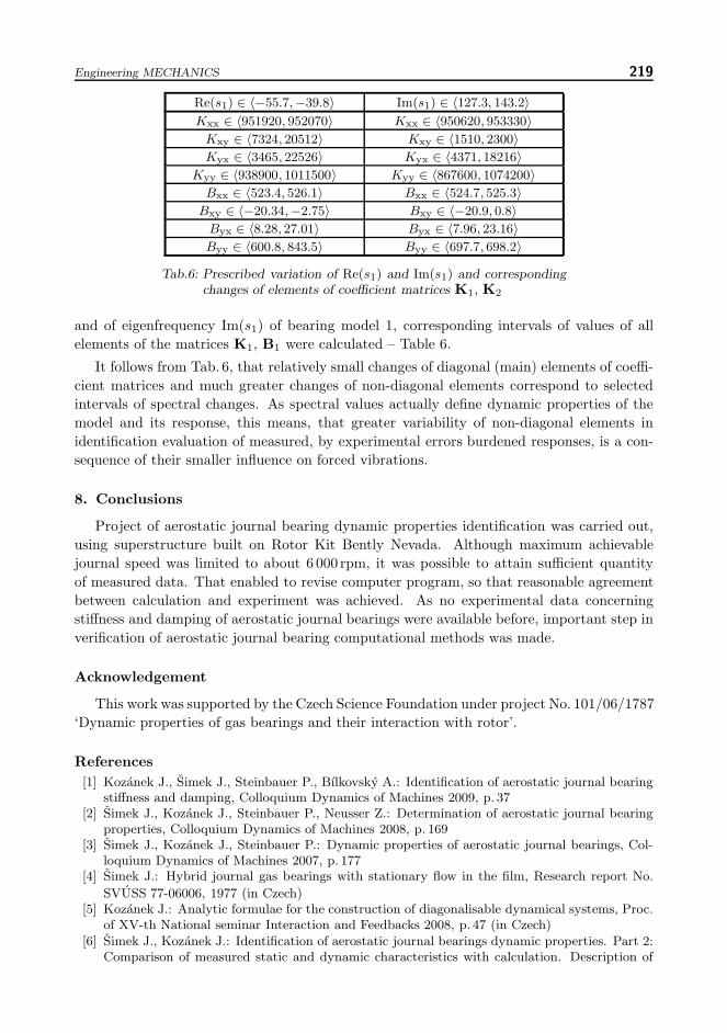
Re(s1) ∈ 〈−55.7,−39.8〉 Im(s1) ∈ 〈127.3, 143.2〉Kxx ∈ 〈951920, 952070〉 Kxx ∈ 〈950620, 953330〉
Kxy ∈ 〈7324, 20512〉 Kxy ∈ 〈1510, 2300〉Kyx ∈ 〈3465, 22526〉 Kyx ∈ 〈4371, 18216〉
Kyy ∈ 〈938900, 1011500〉 Kyy ∈ 〈867600, 1074200〉Bxx ∈ 〈523.4, 526.1〉 Bxx ∈ 〈524.7, 525.3〉
Bxy ∈ 〈−20.34,−2.75〉 Bxy ∈ 〈−20.9, 0.8〉Byx ∈ 〈8.28, 27.01〉 Byx ∈ 〈7.96, 23.16〉Byy ∈ 〈600.8, 843.5〉 Byy ∈ 〈697.7, 698.2〉
Tab.6: Prescribed variation of Re(s1) and Im(s1) and correspondingchanges of elements of coefficient matrices K1, K2
and of eigenfrequency Im(s1) of bearing model 1, corresponding intervals of values of allelements of the matrices K1, B1 were calculated – Table 6.
It follows from Tab. 6, that relatively small changes of diagonal (main) elements of coeffi-cient matrices and much greater changes of non-diagonal elements correspond to selectedintervals of spectral changes. As spectral values actually define dynamic properties of themodel and its response, this means, that greater variability of non-diagonal elements inidentification evaluation of measured, by experimental errors burdened responses, is a con-sequence of their smaller influence on forced vibrations.
8. Conclusions
Project of aerostatic journal bearing dynamic properties identification was carried out,using superstructure built on Rotor Kit Bently Nevada. Although maximum achievablejournal speed was limited to about 6 000 rpm, it was possible to attain sufficient quantityof measured data. That enabled to revise computer program, so that reasonable agreementbetween calculation and experiment was achieved. As no experimental data concerningstiffness and damping of aerostatic journal bearings were available before, important step inverification of aerostatic journal bearing computational methods was made.
Acknowledgement
This work was supported by the Czech Science Foundation under project No. 101/06/1787‘Dynamic properties of gas bearings and their interaction with rotor’.
References[1] Kozanek J., Simek J., Steinbauer P., Bılkovsky A.: Identification of aerostatic journal bearing
stiffness and damping, Colloquium Dynamics of Machines 2009, p. 37[2] Simek J., Kozanek J., Steinbauer P., Neusser Z.: Determination of aerostatic journal bearing
properties, Colloquium Dynamics of Machines 2008, p. 169[3] Simek J., Kozanek J., Steinbauer P.: Dynamic properties of aerostatic journal bearings, Col-
loquium Dynamics of Machines 2007, p. 177[4] Simek J.: Hybrid journal gas bearings with stationary flow in the film, Research report No.
SVUSS 77-06006, 1977 (in Czech)[5] Kozanek J.: Analytic formulae for the construction of diagonalisable dynamical systems, Proc.
of XV-th National seminar Interaction and Feedbacks 2008, p. 47 (in Czech)[6] Simek J., Kozanek J.: Identification of aerostatic journal bearings dynamic properties. Part 2:
Comparison of measured static and dynamic characteristics with calculation. Description of

220 Kozanek J. et al.: Identification of Stiffness and Damping Coefficients of Aerostatic . . .
methodology of solution and computer program revision. Technical report Techlab No. 08-411,2008 (in Czech)
[7] Kozanek J.: Remark on least squares problem in identification solutions, Proc. Colloquium
Dynamics of Machines 95, IT AV CR, Prague UT, pp. 55–60, 1995 (in Czech)[8] Danek O., Balda M., Turek F., Zeman V., Kozanek J.: Dynamics of non-conservative systems,
Czechoslovak Society for Mechanics CAS, Brno, 1986 (in Czech)
Received in editor’s office : March 18, 2009Approved for publishing : June 23, 2009
Note : This paper is an extended version of the contribution presented at the nationalcolloquium with international participation Dynamics of Machines 2009 in Prague.