Embed Size (px)
Citation preview

�
Application Note
Practical Tips on Making “Vector Voltmeter (VVM)” Phase Measurements using VNA Master (Option �5)
Introduction
VOR-DME. RF cable matching is a critical, yet common measurement in the construction and maintenance of air navigation antenna systems like VHF Omnirange (VOR) antenna clusters and Instrument Landing Systems (ILS). Both of these systems are used at the nation’s airports and in travel corridors for airline routes. The VOR system (conventional) features a four-antenna “Alford Loop” antenna system that is topped by individual monitoring elements around a full 360 degrees. This allows aircraft to receive a signal in any direction from the station beacon (Figure �a).
Using a different radiation technique, the Doppler VOR uses signal phase shifting to create its signal (Figure �b). This angle-sensitive signal provides the azimuth angle from the beacon to the aircraft, and is displayed in the cockpit.
Distance from the beacon is determined by a co-located transponder-based system (Distance Measuring Equipment) using a pulsed-pair signal in the �000 MHz band.
Figure 1a. Figure 1b.
Figure 1. These two formats of VOR are recognized as the classical navigation beacons for airplane location. They are characterized by multiple radiation elements, which require precise phase measurements for signal cables on installation and maintenance.

�
150 Hz
90 Hz
Localizer PathRunway
Runway
Lateral Guidance
Vertical Guidance
Glideslope
InnerMarker
MiddleMarker
OuterMarker
90 Hz
150 Hz
LOC Aerial
GS Aerial
Figure 2. The ILS shown here is the close-in navigation aid which displays an aircraft's deviation from the proper glide path, both laterally and vertically. During approach, the pilot can optimize descent for landing using feedback from the ILS elements deployed toward the end of the runway.
ILS. The ILS navigation technique consists of two independent sub-systems. One provides lateral guidance in the �08 - ��� MHz band (Localizer), while the other provides vertical guidance in the 3�9 - 336 MHz band (Glideslope or GlidePath) to aircraft approaching a runway (Figure �).
In both applications, it is important for the antenna signal cables to have the same electrical, as well as mechanical length. At the core of these types of systems is a signal distribution center that protects critical interconnects while offering access for installation and maintenance activities (Figure 3). Measuring the cables’ characteristics (e.g., phase length and insertion loss) is therefore essential to proper performance and the safety of the air-travel industry.
Figure 3. A maze of precise-length signal cables are required to feed the antenna elements with individual signals of the proper phase.

3
Traditionally, the technician or RF engineer would accomplish this task using a Vector Voltmeter (VVM) measurement system, but today these instruments are obsolete and their functionality has been replaced by the modern vector network analyzer (VNA). These powerful measurement tools not only measure raw vector (amplitude and phase) data, but also invoke sophisticated calibration/correction routines which are handled by internal software to enhance the resulting data for excellent accuracy. In addition, unlike the VVM that required an external signal generator, modern VNAs feature a built-in signal source, which lends convenience to remote field operations.
This application note focuses on cable-phase measurement procedures for applications requiring absolute phase shift at a particular frequency. It also treats the common measurement routines where many cables must be matched for identical phase shift versus frequency. Its objective is to present practical measurement tips and procedures that will help a technician or RF engineer conduct cable phase-characteristic measurements using the Anritsu VNA Master, Vector Voltmeter Option �5.
The Evolution of the VVM to Vector Network Analyzer
The VVM is an instrument that was first introduced in the mid �960s. It was designed with two basic functions in mind: to make RF circuit measurements utilizing a sampling probe containing a high-impedance probing function and to make coaxial network measurements working in 50-ohm transmission lines.
Those early commercial VVMs were based on what, at the time, was considered revolutionary new signal sampling technology. The idea was to drive a step-recovery diode with an RF local oscillator (LO), resulting in extremely narrow impulses of power at the LO frequency. According to mathematical theory, such impulses generate a wide frequency range of harmonics, almost flat with increasing frequency, to �000 MHz and beyond. This concept was similar in principal to the technology employed in sampling oscilloscopes introduced in �96�, and quickly became the foundation of an innovative new future of RF and microwave instruments for measuring complex parameters.
While early attempts at network analysis with the VVM used a two probe/coax Tee arrangement on two opposing directional couplers and resulted in a reflectometer that worked from �0 MHz to � GHz, such functionality came at the price of considerable manual effort. The two RF voltages and the phase angle between the forward and reflected signals had to be recorded by hand, and the unknown impedance (Smith Chart) calculated and plotted laboriously. Despite this limitation, the VVM with its amplitude and phase-ratio measurements enabled a significant work increase over VHF bridges and other such slow and inaccurate equipment.
By the late �960s, the VVM’s network measurement ratio function was taken over by full-fledged microwave network analyzers that went far higher in frequency, to �� GHz and above. In the decades since, the VVM has generally been used for the direct measurement of RF phase angles in transmission lines—probing RF voltages (A and B) in two channels, and displaying A, B, A/B, B/A, and the phase difference between them. Over time, circuit probing for RF amplifiers and other VHF analog circuits declined as integrated circuits and digital technology took over many analog and RF voltage functions. Later versions of VVMs were introduced with additional features, but even those instruments have now been retired. Today, the functional RF ratio measurements that were once the mainstay of the VVM are performed by modern VNAs.
�
VectorVoltmeter
SignalGenerator
DUT
DUT
S21 S21
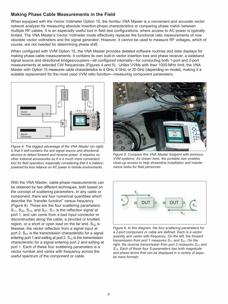
Figure 4. The biggest advantage of the VNA Master (on right) is that it self-contains the test signal source and directional devices to detect forward and reverse power. It requires no other external accessories so it is a much more convenient tool for field operation, especially considering that it is battery-powered for less reliance on AC power in remote environments.
Figure 5. Compare this VNA Master footprint with previous VVM systems. As shown here, the portable size enables close-up access to help streamline installation and mainte-nance tasks for field personnel.
Making Phase Cable Measurements in the Field
When equipped with the Vector Voltmeter Option �5, the Anritsu VNA Master is a convenient and accurate vector network analyzer for measuring absolute insertion-phase characteristics or comparing phase match between multiple RF cables. It is an especially useful tool in field test configurations, where access to AC power is typically limited. The VNA Master’s Vector Voltmeter mode effectively replaces the functional ratio measurements of now obsolete vector voltmeters and the signal generator. However, it cannot be used to measure RF voltages, which of course, are not needed for determining phase shift.
When configured with VVM Option �5, the VNA Master provides detailed software routines and data displays for making phase-cable measurements. It contains its own built-in vector insertion loss and phase receiver, a wideband signal source and directional bridges/couplers—all configured internally—for conducting both �-port and �-port measurements at selected CW frequencies (Figures � and 5). Unlike VVMs with their �000-MHz limit, the VNA Master with Option �5 measures cable characteristics to � GHz, 6 GHz, or �0 GHz (depending on model), making it a suitable replacement for the most used VVM ratio function—measuring component parameters.
DUTS11
S21
DUT
S12
S22
Figure 6. In this diagram, the four scattering parameters for a 2-port component or cable are defined. Each is a vector quantity and varies with frequency. On the left, the forward transmission from port 1 measures S11 and S21. On the right, the reverse transmission from port 2 measures S22 and S12. Each of these four S-parameters has both magnitude and phase terms that can be displayed in a variety of popu-lar trace formats.
With the VNA Master, cable-phase measurements can be obtained by two different techniques, both based on the concept of scattering parameters. In any cable or component, there are four numerical quantities which describe the “transfer function” versus frequency (Figure 6). These are the four scattering parameters: S��, S��, S��, and S��. S�� is the reflection signal at port �, and can come from a bad input connector or discontinuities along the cable, a pinched or knotted region, or a short or open load on the far end. S�� is likewise, the vector reflection from a signal input at port �. S�� is the transmission characteristic for a signal entering port � and exiting at port �. S�� is the transmission characteristic for a signal entering port � and exiting at port �. Each of these four scattering parameters is a vector number and varies with frequency across the useful spectrum of the component or cable.

5
The two techniques used by the VNA Master to obtain cable-phase measurements are:
�. Insertion technique. This technique utilizes the VNA Master’s �-port setup to make cable-phase measurements and is generally considered the preferred technique. It characterizes the insertion phase delay of a signal by measuring S�� through the cable. This allows the operator to determine the phase shift of the component or cable from input connector to output connector. Measured S�� data is displayed as insertion loss in dB, while insertion phase is displayed in degrees.
�. Reflection technique. This technique measures the S�� reflected signal on a component or cable, and is dependent on the far end of the cable being deliberately mismatched—either shorted or left as an open circuit. With the mismatch, virtually �00 percent of the input signal is reflected and as a result, the phase delay of the measured reflected signal is equal to twice the one-way phase of the cable. Likewise, the cable measured return loss is twice the one-way loss.
The reflection technique is especially useful for situations where the operator must manually create multiple phase-matched cables using the “measure-and-snip” operation. This operation requires the engineer or technician to carefully snip small amounts of cable with a diagonal cutter, perhaps �/8th inch at a time, and re-measure the effect on the �-way phase.
As an example, in one specific VOR system program, a special and detailed instruction set describes the step-by-step procedures needed to create phase-matched cables, either with standard RG-��� coax cable or with �/� inch Andrew Heliax® (solid outside conductor) coaxial transmission line. The conditions are strict since matching is needed for the cable-phase measurements to within +/-0.� degrees at the VOR system frequencies in the �08 to ��8-MHz range. For reference, at �08 MHz, �.0 inches of the RG-��� coaxial cable equals �.99 degrees, varying with frequency, of course, and going to 5.�5 degrees at ��8 MHz (Figure 7).
Figure 7. Typical cabling installation in a VOR system is shown here. The system uses RG-214/U type coax and signal splitter/combiner components. Critical phase-matching requirements ensure the overall system operates correctly as a navigational aid for aircraft.

6
Two-Port VVM Measurements
With the VNA Master, Option �5, operators can make cable-phase measurements using the insertion technique previously described. Prior to conducting a �-port measurement (S��) in VVM mode, the VNA Master must be calibrated (Figure 8). To begin, select a continuous wave (CW) frequency and choose �-port calibration. When making a �-port connection to the device under test (DUT), select the insertion measurement type and then perform a �-port calibration. For specific details on the �-port calibration procedure, refer to the VNA Master User Guide.
The process of calibration establishes a reference plane for subsequent measurements by using open, short, load, and through standards (also known as SOLT calibration, Figure 9). The standard process involves connecting these calibration components as prompted by the VNA Master. After calibration, the VNA Master is ready to conduct phase-matching measurements.
Figure 8. VNA Master’s calibration procedures provide the zero-phase reference for later insertion-phase measurements. The calibration algorithm requires a through connection so it is important to set up a male-female interconnect scheme to ensure a precise zero-phase reference.
Figure 9. Convenient calibration artifacts (e.g., N and K) are available for the VNA Master Option 15, to provide the open, short and load standards for the calibration procedure.
Phase Matching Cables
In preparation for installation, the time-consuming cable fabrication process is performed (Figure �0). When fabricating cables with precise phase requirements, system users will likely have their own recommended procedures. For federal antenna installations, for example, there are detailed instructions for the fabrication and measurement procedures. Nevertheless, a good general procedure is as follows:
�. Connectorize the first (reference) cable on both ends.�. Make an insertion phase measurement and store
the data. 3. Cut a second cable to length, being careful not to
cut shorter than the reference cable, and connectorize it on both ends.
�. Measure the second connectorized cable and compare it to the first (reference) cable. Figure 10. This system installation is configured with solid
outer conductor cables. Maintenance activities are usually scheduled to avoid peak operational periods.

7
From the difference observed, it is possible to “guesstimate” how much the second cable needs to be trimmed, but the remove/trim operation is often not that precise. In order to trim, one of the second cable’s connectors is removed and the center conductor is trimmed. The connector is then re-connected on the second cable for another measured comparison with the first cable. While it may be difficult to trim the cable correctly the first time, experienced users often achieve success in the first two or three tries.
The measure-and-cut practices vary with frequency. Lower frequencies (VHF) will likely be in the �/�6th- to �/8th-inch range for final iterations. At � GHz and above, the re-connectoring might only involve unsoldering the center conductor, moving it �/3�th inch or less, and just letting the solder cool. For example, at ��8.5 MHz, �.0 inch of �/�th inch Andrew Heliax with a Vp = 0.8�, equals approximately �.�8 degrees, while at 33�.3 MHz, it equals ��.05 degrees. Often times, those last few tenths of a degree involved with getting the cable trimmed “just right” can become very frustrating. With careful and clever attention to detail and data, users can establish their own learning curve.
Once the �-port measurements have been made, measured data appears in a display window similar to that shown in Figure ��.
Relative Phase Measurements
A key advantage of the VNA Master’s computational power is that it can store a measurement from a master cable or component—what some refer to as “gold standards”—and make further measurements on other similar cables to determine the consistency of the cables to one another. Measurement results can be displayed using VNA Master’s CW display. More information on this procedure is detailed in the VNA Master Option 15 User Guide.
As an example, consider Figure ��. Here, the VNA Master Vector Voltmeter mode saves the current cable measurement in a new reference window and converts the main measurement window to display the difference between the current measurement and saved reference. Saving a reference normalizes the results to the current measurement. When relative measurements for the second unit are displayed, REL is indicated in the main measurement window. Note that the original reference measurement is also displayed on the bottom of the screen.
Figure 11. The VNA Master’s VVM display shows the insertion signal loss (-0.70 dB) and phase shift (46.49 deg) for the test frequency of 110 MHz. These quantities are derived from the VNA Master’s measurement of S21.
Figure 12. Comparing cable parameters on phase and insertion loss is easy, as shown on this VVM display, with the relative differences in the middle and the original parameter values (gold standard unit) in the lower portion of the screen. The two cables are more phase matched as the relative differ-ence between them becomes smaller.
8
One-Port VVM Measurements
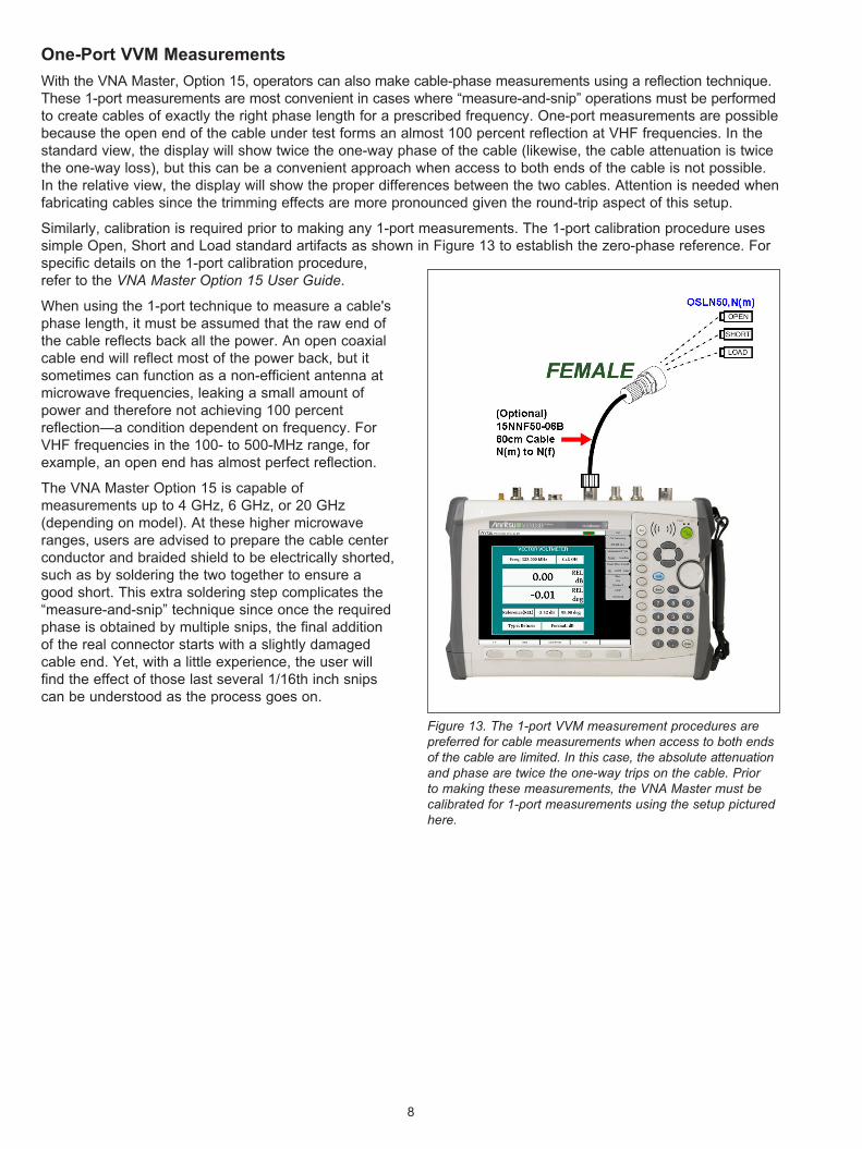
With the VNA Master, Option �5, operators can also make cable-phase measurements using a reflection technique. These �-port measurements are most convenient in cases where “measure-and-snip” operations must be performed to create cables of exactly the right phase length for a prescribed frequency. One-port measurements are possible because the open end of the cable under test forms an almost �00 percent reflection at VHF frequencies. In the standard view, the display will show twice the one-way phase of the cable (likewise, the cable attenuation is twice the one-way loss), but this can be a convenient approach when access to both ends of the cable is not possible. In the relative view, the display will show the proper differences between the two cables. Attention is needed when fabricating cables since the trimming effects are more pronounced given the round-trip aspect of this setup.
Similarly, calibration is required prior to making any �-port measurements. The �-port calibration procedure uses simple Open, Short and Load standard artifacts as shown in Figure �3 to establish the zero-phase reference. For specific details on the �-port calibration procedure, refer to the VNA Master Option 15 User Guide.
When using the �-port technique to measure a cable's phase length, it must be assumed that the raw end of the cable reflects back all the power. An open coaxial cable end will reflect most of the power back, but it sometimes can function as a non-efficient antenna at microwave frequencies, leaking a small amount of power and therefore not achieving �00 percent reflection—a condition dependent on frequency. For VHF frequencies in the �00- to 500-MHz range, for example, an open end has almost perfect reflection.
The VNA Master Option �5 is capable of measurements up to � GHz, 6 GHz, or �0 GHz (depending on model). At these higher microwave ranges, users are advised to prepare the cable center conductor and braided shield to be electrically shorted, such as by soldering the two together to ensure a good short. This extra soldering step complicates the “measure-and-snip” technique since once the required phase is obtained by multiple snips, the final addition of the real connector starts with a slightly damaged cable end. Yet, with a little experience, the user will find the effect of those last several �/�6th inch snips can be understood as the process goes on.
Figure 13. The 1-port VVM measurement procedures are preferred for cable measurements when access to both ends of the cable are limited. In this case, the absolute attenuation and phase are twice the one-way trips on the cable. Prior to making these measurements, the VNA Master must be calibrated for 1-port measurements using the setup pictured here.

9
Measurement/Cable-Snipping Tips
While interactively measuring and snipping cables for matched phase is a tedious job, made faster only by experience, a number of tips can help with this task. Two such tips are:
Tip �. At any one frequency, cut the cable to be prepared several inches longer than the final length. Solder the raw end, creating a good short and take a measurement. Next, cut off exactly one inch of cable, solder it identically again and take another measurement. Note the change in phase from the removal of the one inch segment and calculate the amount of phase difference for, say, �/8th inch. When the snip procedure gets near to the final desired value of measured phase, the user will now have a predicted mental picture of how much to snip.
Tip �. The procedure in Tip � can also be run by the operator. Using the �-port method, make a shorted-end phase measurement and note the value. Attach the final cable connector at that length using the normal connector attaching process. Next, make a �-port connector-to-connector insertion phase measurement, as described above, and record the difference in phase. This correction value can be utilized in later steps when converting from the raw end measurements to the final connectorized configuration.
Displaying Measured Data
The VNA Master Option �5 display includes a convenient table for comparing multiple cables. With this feature, the user can save the first cable measurement as a reference, view the differences between the reference cable and other cables, and then output a final report showing both absolute and relative values of all cables. As an example, Figure �� shows a display table with measured values of phase and attenuation for each cable. Their relative phase and amplitude, with respect to a chosen “golden standard cable,” is shown in the top box as the REL standard.
Figure 14. Powerful software routines not only provide mea-surement corrections and sequence-prompt instructions, but display results for multiple cables as shown in this screen capture. On the right is a typical soft key “Measurement Menu” cluster, showing the operator choices as the measure-ment progresses.

�0
Measurement Uncertainty
The phase measurement accuracy of a typical VNA Master is acquired from the published uncertainties curves. A typical uncertainty curve is shown in Figure �5 (please refer to the technical data sheet for model-specific uncertainty curves). In this example, the legend shows the uncertainties for three bands: 5 kHz to 3 GHz, 3 to 6 GHz, and 6 to �0 GHz. Select the band and then the S�� level to extract the uncertainty in degrees.
Figure 15. Phase measurement uncertainty for three different frequency ranges for the VNA Master are pictured in this graphic. Note that as the S21 insertion loss increases to 70 dB, the uncertainty increases, caused by trying to get phase information out of a much lower test signal.
VNA Master High Port Power using OSLxx50 Calibration Kits
Transmission Phase Uncertainties (S11=0)
1
10
100
-70 -60 -50 -40 -30 -20 -10 0
Un
cert
ain
ty (
deg
rees
)
6 - 20 GHz
3 - 6 GHz
5 kHz - 3 GHz
Device Transmission, |S21| (dB)
The uncertainty graphs in Figure �5 provide measurement uncertainty at �3° C, after vector correction, for the standard N-type connector. Errors are worse-case contributions of residual directivity, source match, frequency response, network analyzer dynamic range, and connector repeatability. For �-port measurements, transmission tracking, crosstalk and physical load match termination were added. Note that OSLN50 and OSLNF50 calibration components were used for these measurements.
The specification graph shows that absolute phase uncertainty in the low VHF ranges (bottom plot) and in the 0- to -�0-dB insertion loss range is quite good at approximately ±�-3 degrees. In many phased-antenna applications, the main point of interest is a comparison of phase differences among the cables under test. Here, uncertainty in phase differences is expected to be much better than this absolute uncertainty specification since many of the test conditions are identical as one cable is replaced by another.
Finally, although the applications described thus far have dealt mostly with VHF systems and their requirements for phase-matched cables in phase-sensitive antenna systems, the VNA Master easily measures accurate phase characteristics all the way up to 6 and �0 GHz, depending on the model. In such cabling, � degree of phase shift is a very short length of cable. Consequently, all measurements are exceedingly critical for careful procedures. Even connector repeatability and technique come into play. Even so, as can be seen from Figure �5, for values of insertion loss less than 30 dB, absolute phase uncertainties of about ±� degrees are possible above 6 GHz. Cable matching, however, is much more problematic. Recall, for example, that at 6 GHz, a wavelength is 5 cm (in air) meaning that even � mm (�/�5th inch) equals 7.� degrees. With �/�th inch Andrew Heliax, Vp = 0.8�, � mm would equal 8.6 degrees.

��
Summary
With the demise of the traditional VVM, the Anritsu VNA Master’s Vector Voltmeter Option �5 offers a convenient and accurate alternative for a number of critical industry measurements. It is especially well suited for phase matching cables in multi-antenna applications, and for remote component and cable characterization of navigation beacons or wireless base stations. For these applications, the battery-operated VNA Master offers the ideal means of easily measuring and displaying phase and attenuation data for station cabling.
Acknowledgements
Anritsu is indebted to, and appreciates the kind assistance of, the FAA engineering staff in reviewing this application note for procedures and accuracy. Mr. Art Chase of FAA Nav-Aids in the Fairbanks Alaska Technical Service Office was especially helpful in furnishing testing methodologies and advice for this crucial, but tedious cable creation task. Mr. Chase also furnished several operational photographs which provide an environmental snapshot of the field conditions for the task. Any errors are fully assumed by Anritsu.

Anritsu Corporation5-�-� Onna, Atsugi-shi, Kanagawa, ��3-8555 Japan Phone: +8�-�6-��3-���� Fax: +8�-�6-�96-��6�
• U.S.A. Anritsu Company��55 East Collins Boulevard, Suite �00, Richardson, Texas 7508� U.S.A. Toll Free: �-800-ANRITSU (�67-�878) Phone: +�-97�-6��-�777 Fax: +�-97�-67�-�877
• Canada Anritsu Electronics Ltd.700 Silver Seven Road, Suite ��0, Kanata, Ontario K�V �C3, Canada Phone: +�-6�3-59�-�003 Fax: +�-6�3-59�-�006
• Brazil Anritsu Electrônica Ltda.Praca Amadeu Amaral, �7-� Andar 0�3�7-0�0 - Paraiso, São Paulo, Brazil Phone: +55-��-3�83-�5�� Fax: +55-��-3�88-69�0
• MexicoAnritsu Company, S.A. de C.V. Av. Ejército Nacional No. 579 Piso 9, Col. Granada ��5�0 México, D.F., México Phone: +5�-55-��0�-�370 Fax: +5�-55-5�5�-3��7
• U.K. Anritsu EMEA Ltd.�00 Capability Green, Luton, Bedfordshire LU� 3LU, U.K. Phone: +��-�58�-�33�00 Fax: +��-�58�-73�303
• France Anritsu S.A.�6/�8 Avenue du Québec-SILIC 7�0 9�96� COURTABOEUF CEDEX, France Phone: +33-�-60-9�-�5-50 Fax: +33-�-6�-�6-�0-65
• Germany Anritsu GmbHNemetschek Haus, Konrad-Zuse-Platz � 8�8�9 München, Germany Phone: +�9 (0) 89 ���308-0 Fax: +�9 (0) 89 ���308-55
• Italy Anritsu S.p.A.Via Elio Vittorini, ��9, 00��� Roma, Italy Phone: +39-06-509-97�� Fax: +39-06-50�-���5
• Sweden Anritsu ABBorgafjordsgatan �3, �6� �0 Kista, Sweden Phone: +�6-8-53�-707-00 Fax: +�6-8-53�-707-30
• Finland Anritsu ABTeknobulevardi 3-5, FI-0�530 Vantaa, Finland Phone: +358-�0-7��-8�00 Fax: +358-�0-7��-8���
• Denmark Anritsu A/SKirkebjerg Allé 90 DK-�605 Brøndby, Denmark Phone: +�5-7�����00 Fax: +�5-7������0
• Spain Anritsu EMEA Ltd. Oficina de Representación en EspañaEdificio Veganova Avda de la Vega, no � (edf 8, pl�, of 8) �8�08 ALCOBENDAS - Madrid, Spain Phone: +3�-9��90576� Fax: +3�-9��90576�
• RussiaAnritsu EMEA Ltd. Representation Office in RussiaTverskaya str. �6/�, bld. �, 7th floor. Russia, ��5009, Moscow Phone: +7-�95-363-�69� Fax: +7-�95-935-896�
• United Arab Emirates
Anritsu EMEA Ltd. Dubai Liaison OfficeP O Box 500��3 - Dubai Internet City Al Thuraya Building, Tower �, Suite 70�, 7th Floor Dubai, United Arab Emirates Phone: +97�-�-367035� Fax: +97�-�-3688�60
• Singapore Anritsu Pte. Ltd.60 Alexandra Terrace, #0�-08, The Comtech (Lobby A) Singapore ��850� Phone: +65-6�8�-��00 Fax: +65-6�8�-�533
• India Anritsu Pte. Ltd. India Branch Office3rd Floor, Shri Lakshminarayan Niwas, #�7�6, 80 ft Road, HAL 3rd Stage, Bangalore - 560 075, India Phone: +9�-80-�058-�300 Fax: +9�-80-�058-�30�
• P. R. China (Hong Kong) Anritsu Company Ltd.Units � & 5, �8th Floor, Greenfield Tower, Concordia Plaza, No. � Science Museum Road, Tsim Sha Tsui East, Kowloon, Hong Kong, P.R. China Phone: +85�-�30�-�980 Fax: +85�-�30�-35�5
• P. R. China (Beijing) Anritsu Company Ltd. Beijing Representative OfficeRoom �5�5, Beijing Fortune Building, No. 5 , Dong-San-Huan Bei Road, Chao-Yang District, Beijing �0000�, P.R. China Phone: +86-�0-6590-9�30Fax: +86-�0-6590-9�35
• Korea Anritsu Corporation, Ltd.8F Hyunjuk Bldg. 83�-��, Yeoksam-Dong, Kangnam-ku, Seoul, �35-080, Korea Phone: +8�-�-553-6603 Fax: +8�-�-553-660�
• Australia Anritsu Pty Ltd.Unit ��/�70 Ferntree Gully Road, Notting Hill Victoria, 3�68, Australia Phone: +6�-3-9558-8�77 Fax: +6�-3-9558-8�55
• Taiwan Anritsu Company Inc.7F, No. 3�6, Sec. �, Neihu Rd., Taipei ���, Taiwan Phone: +886-�-875�-�8�6 Fax: +886-�-875�-�8�7
Application Note No. ����0-0053�, Rev. A Printed in United States �009-��©�009 Anritsu Company. All Rights Reserved.
® Anritsu All trademarks are registered trademarks of their respective companies. Data subject to change without notice. For the most recent specifications visit: www.us.anritsu.com