Embed Size (px)
Citation preview

Chapter 4
현대의 고체 이론
현대 물리학 : 작은 입자나 고체에 대한 양자역학orSchrödinger 방정식의 적용
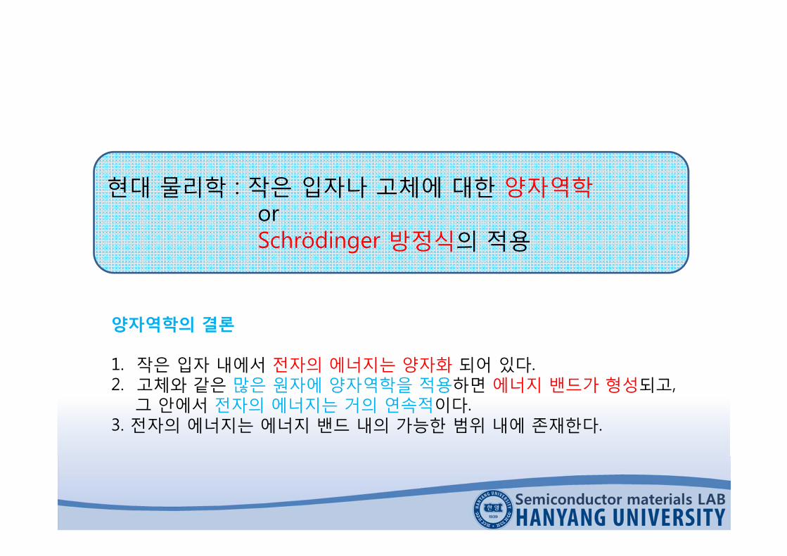
양자역학의 결론
1. 작은 입자 내에서 전자의 에너지는 양자화 되어 있다.2. 고체와 같은 많은 원자에 양자역학을 적용하면 에너지 밴드가 형성되고,
그 안에서 전자의 에너지는 거의 연속적이다.3. 전자의 에너지는 에너지 밴드 내의 가능한 범위 내에 존재한다.

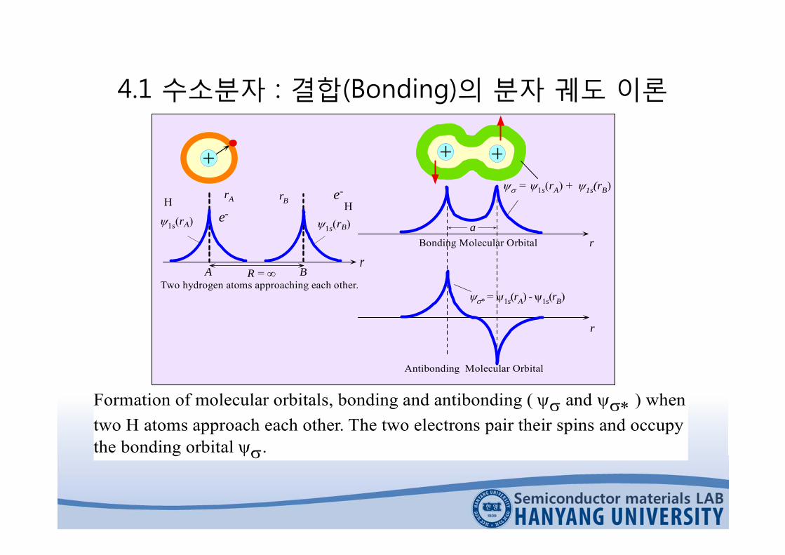
4.1 수소분자 : 결합(Bonding)의 분자 궤도 이론
두 개의 수소 원자간의 결합의 형성 → 분자 내에서의 전자의 행동에 의해 설명→ 분자 궤도 를이용→ 분자내에존재하는전자의파동함수로간주
H2 분자 내 : 두 개의 동일한 원자 궤도 1s 가 존재할 수 없음.
Why?
1. Pauli의 배타원리에 위배되기 때문2. 두 개의 원자가 접근함에 따라 그림 4.1처럼 원자의 파동함수 1s 가 중
첩됨 → 서로 다른 에너지를 갖는, 따라서 서로 다른 양자수를 갖는 새로운 파동함수를 만들어냄 → 두 원자의 파동함수가 서로 간섭 → 같은위상 or 정 반대의 위상 → 두 개의 분자 궤도 생겨나게 됨
4.1 수소분자 : 결합(Bonding)의 분자 궤도 이론
r
= 1s(rA) + 1s(rB)
* = 1s(rA) -1s(rB)
Bonding Molecular Orbital
Antibonding Molecular Orbital
ar
H
rR = A B
Two hydrogen atoms approaching each other.
1s(rA) 1s(rB)
HrA
e-
rB e-
Formation of molecular orbitals, bonding and antibonding ( and ) whentwo H atoms approach each other. The two electrons pair their spins and occupythe bonding orbital .

4.1 수소분자 : 결합(Bonding)의 분자 궤도 이론
H-H 계에서의 두 개의 분자 궤도
)()( 11 BsAs rr
)()( 11* BsAs rr
linear combination of atomic orbitals (LCAO)→ 두 개의 동일한 원자 궤도 1s 의 선형 결합으로부터 두 개의 별개의 분자 궤도 및 * 를 얻기 위해 , 원자 궤도의 선형 결합 방법(LCAO)을 이용
첫 번째 분자 궤도 는 대칭이며 핵과 핵 사이에서 상당한 크기를 갖는다.두 번째 분자 궤도 * 는 반대칭이며 핵과 핵의 사이에 절점(node)이 존재한다.

4.1 수소분자 : 결합(Bonding)의 분자 궤도 이론
(b)
(a)
H H
H H
(a) Electron probability distributions for bonding and antibonding orbitals, and *. (b) Lines represent contors of constant probability.
* 이 절점을 가지고 있으므로 궤도보다 높은 에너지를 가짐→ 에너지 양자수도 다른값을 가질 것→ 이는 Pauli의 배타원리에 위배되지 않음
| |2이 두 핵의 사이에서 상당한 전자밀도를 가짐 → 파동함수 에 대한 정전 포텐셜에너지 or 총 에너지는 각 원자의 파동함수에 대해서는 물론 * 인 경우보다도 낮을 것임

4.1 수소분자 : 결합(Bonding)의 분자 궤도 이론
H -atom H -atomH2
E
E
E = Bonding EnergyE1s E1s
(b)
E(R)1sE1s
E(a) E(R)
0
E
SYSTEM2 H-Atoms2 Electrons1 Electron/Atom1 Orbital/Atom
R, InteratomicSeparation0 R =
BondingEnergy
(a)
a
Electron energy in the system comprising two hydrogen atoms. (a) Energy of and vs. the interatomic separation, R. (b) Schematic diagramshowing the changes in the electron energy as two isolated H atoms, far leftand far right, come to form a hydrogen molecule.
각 궤도 상태는 서로 짝을 이룬두 개의 전자를 가질 수 있고 두 개의수소 원자 내에는 두 개의 전자가존재함.
이 전자들이 궤도에 들어가고스핀이 짝을 이루게 되면 이 상태는에너지 측면에서 두 개의 분리된H 원자의 경우보다 안정적인 상태가 됨.
→ 수소 분자 H2에 해당
: 결합궤도→ 가장 낮은 전자 에너지에 해당하는
파동함수* : 반결합 궤도

4.1 수소분자 : 결합(Bonding)의 분자 궤도 이론
두 원자가 결합 → 두 개의 동일한 원자 파동함수는 두 개의 서로 다른 분자 궤도를가짐 → 각각이 서로 다른 에너지를 갖는 두 가지 방식으로 결합 → E1s와 같은에너지 준위는 실제적으로 E 와 E* 로 분리됨 by 원자 궤도간의 상호작용(or 중첩)
i( )
(a)
R C
L
i()
v()
0
1 2
(b)
R C
L L
C
R
MCoupling i( )
i()
There is one resonant frequency, 0, in an isolated LCR circuit. (b) There aretwo resonant frequencies in two coupled LCR circuits. One below and theother above 0.
분자가 형성될 때 한 원자 에너지 준위의분리 ≈ 두 개의 RLC 회로가 서로 접근하여결합할 때 공진 주파수가 분리되는 것
ω0보다 낮은 ω1 및 ω0보다 높은 ω2에서 최대→ 상호 유도용량 때문
4.1 수소분자 : 결합(Bonding)의 분자 궤도 이론
E1s
E
E
E1s
He-atom He-atomHe-HeSystem
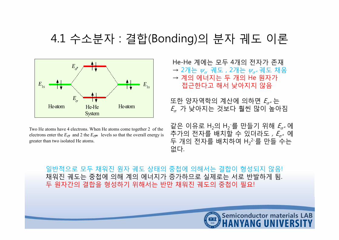
Two He atoms have 4 electrons. When He atoms come together 2 of theelectrons enter the E and 2 the E levels so that the overall energy isgreater than two isolated He atoms.
He-He 계에는 모두 4개의 전자가 존재→ 2개는 궤도 , 2개는 * 궤도 채움→ 계의 에너지는 두 개의 He 원자가
접근한다고 해서 낮아지지 않음
또한 양자역학의 계산에 의하면 E* 는E 가 낮아지는 것보다 훨씬 많이 높아짐
같은 이유로 H2의 H2-를 만들기 위해 E* 에
추가의 전자를 배치할 수 있더라도 , E* 에두 개의 전자를 배치하여 H2
2-를 만들 수는없다.
일반적으로 모두 채워진 원자 궤도 상태의 중첩에 의해서는 결합이 형성되지 않음!채워진 궤도는 중첩에 의해 계의 에너지가 증가하므로 실제로는 서로 반발하게 됨.두 원자간의 결합을 형성하기 위해서는 반만 채워진 궤도의 중첩이 필요!

4.2 고체의 밴드 이론4.2.1 에너지 밴드의 형성
3개의 수소 원자(A, B, C)를 접근시키면
a
A B C
b
c
E
Ec
E1sa
b
c
Separation
Eb
Ea
R = R = a
c
a
b
Systemin isolation3 H-Atoms3 Electrons
3 Orbitals (1s)6 States (with spin)
Symmetric
(b)(a )
Symmetric
Antisymmetric
(a) Three molecular orbitals from three 1s atomic orbitals overlappingin three different ways. (b) The energies of the three molecular orbitalslabeled as a, b and c in a system with 3 H atoms (highly simplified).
수소 원자 내의 전자의 파동함수경우와 유사하게, 분자 파동함수가 더 많은 절점을갖는다면 에너지가 더 크다고생각할 수 있음. (그림 4.7b)

4.2 고체의 밴드 이론4.2.1 에너지 밴드의 형성
원자 에너지 준위가 N개의 에너지 준위로 분리된다고 가정
1s 부껍질은 채워져 있고 핵에 가까우므로 원자간 상호작용에 의해 많은 영향을받지 않음 → 결국 1s 상태의 에너지는, 에너지의 분리가 생긴다 하더라도 무시할 수있을 만큼 작은 정도밖에는 생기지 않음→ 1s 전자들은 핵 가까이에 존재하고 있으므로 고체 형성 과정에서 고려하지 않아도 됨.

4.2 고체의 밴드 이론4.2.1 에너지 밴드의 형성
a
InteratomicSeparation (R)
SYSTEMN Li AtomsN ElectronsN Orbitals2N States
E2p
1s
2s
2p
E2s
E1s
System of N Li Atoms
solid(N)
Solid
ET
EB solid(1)
Isolated Atoms
FULL
EMPT
Y
Elec
tron
Ener
gyin
the
Syst
emof
NLi
Ato
ms
The formation of a 2s-energy band from the 2s-orbitals when N Li atomscome together to form the Li solid. The are N 2s-electrons but 2N states inthe band. The 2s-band therefore is only half full. The atomic 1s orbital isclose to the Li nucleus and remains undisturbed in the solid. Thus each Liatom has a closed K-shell (full 1s orbital).
ET, EB : 최소 원자간 거리 a에의해 결정
ET와 EB 사이에 N개의 에너지 준위
N값이 상당히 큼→ 에너지 준위 간격 매우 작음

4.2 고체의 밴드 이론4.2.1 에너지 밴드의 형성
N개의 원자 파동함수 2s 를 결합할 때 동상으로 or 반대 위상으로 더해질 수 있으므로N가지 방법이 가능→ 단일 2s 에너지 준위 E2s는 N(~1023)개의 미세하기 분리된 에너지 준위로 나누어져
그림 4.8처럼 에너지 밴드를 형성→ N개의 분리된 에너지 준위가 존재, 각각에는 반대 스핀의 전자가 2개씩 들어갈 수 있음
2s 밴드 : 원자의 2s 에너지 준위의 분리로부터 만들어진 에너지 밴드
EB – ET ≈ 10eV , N≈1023
에너지 준위 ; 미세하기 분리, 실제적으로는 연속적인 에너지 준위들을 형성

4.2 고체의 밴드 이론4.2.1 에너지 밴드의 형성
InteratomicSeparation (R)
E2s
E2p
E3s
E1s
R = a R = Isolated AtomsThe Solid
E = 0 (Vacuum Level)Free electron
FULL
EMPT
Y
Elec
tron
ener
gy
As solid atoms are brought together from infinity, the atomic orbitalsoverlap and give rise to bands. Outer orbitals overlap first. The 3sorbitals give rise to the 3s band, 2p orbitals to the 2p band and so on.The various bands overlap to produce a single band in which the energyis nearly continuous.
3s, 2p 에너지 준위들 중 일부→ 2s 밴드와 겹쳐짐→ 좀 더 많은 에너지 준위들 생김→ 2s 밴드는 그림 4.10처럼 더 높은
에너지 준위 쪽으로 확장됨
2s
2p
3s
Overlappingenergy bands
Electrons
Vacuum level
2s2p
3s3p
1s1sSolid Atom
E = 0Free electron
E
Elec
tron
Ener
gy

4.2 고체의 밴드 이론4.2.1 에너지 밴드의 형성
Electron Energy
VacuumLevel
EF0
EB
EF0
Electron inside themetal
Electron outsidethe metal
0
-2.5 eV
-7.2 eV 0
4.7 eV
7.2 eV
Typical electron energy band diagram for a metal All the valence electronsare in an energy band which they only partially fill. The top of the band isthe vacuum level where the electron is free from the solid (PE = 0).
고체에서 이러한 밴드의 에너지는(3s 밴드의 윗 부분을 포함해서)진공 준위보다 위에 있고 전자는자유로운 상태
실제로 전자들이 이만한 에너지를가질 수 있어야 고체라 할 수 있음
일반적으로 Fermi 준위는 밴드의가장 아래를 기준으로 하여 나타냄→ EFO 로 표시

4.2 고체의 밴드 이론4.2.1 에너지 밴드의 형성
절대온도 O에서 Fermi 준위까지의 모든 에너지 준위는 채워져 있다.
금속의 일함수 : Fermi 준위에서 진공 준위까지 전자를 여기 시키는데 필요한 E= 금속에서 전자를 내보내는데 필요한 E

4.2 고체의 밴드 이론4.2.1 에너지 밴드의 형성
금속의 에너지 밴드 내의 전자는 자유전자가 될 수 있는, 약하게 결합된 가전자들이고 일종의 전자 기체를 형성함→ 결정 구조 내에서 금속 이온들을 잡아당겨 금속 결합 형성
밴드 내의 전자들은 특정 원자에 속하지 않고 전체 고체에 속해 있다는 점에 유의
기본적으로 모든 2s 전자들은 전자 기체를 형성, 에너지는 에너지 밴드 내의 값 가짐.이 전자들은 금속 내에서 지속적으로 움직임.

4.2 고체의 밴드 이론4.2.2 밴드 내의 전자의 성질
Electrons
Empty states
0
(a)
E
px-x xp-x
a
pav = 0
b
(b)
Latticescattering
pav > 0
E E
pxp-x
Ea
b
(c)
FOFO
(a) Energy band diagram of a metal. (b) In the absence of a field, there are as many electrons moving right as there are moving left. The motions of two electrons at each energy cancel each other as for a and b. (c) In the presence of a field in the x direction, the electron a accelerates and gains energy to a’ where it is scattered to an empty state near EFO but moving in the -x direction. The average of all momenta values is along the +x direction and results in a net electrical current.

4.2 고체의 밴드 이론4.2.2 밴드 내의 전자의 성질
그림 4.12c : a → a’ 옮겨간 전자 a는 격자 진동에 의해 산란작은 에너지에 비해 상당한 운동량
산란된 전자들은 같은 에너지 준위에서 채워지지 않은 운동량 상태를 채우려고 하며,따라서 a’에서의 전자는 EFO 근처의 빈 에너지 준위로 산란되지만, 반대방향의 운동량을 갖게 됨 → 전자의 평균 운동량≠0, Pav>0 → -x방향 전류
정상 상태 전도 : 격자진동이 b’ 위치의 전자를 a’ 위치에서 채워주게 됨b’ 보다 낮은 에너지 준위를 가지며 오른쪽으로 움직이려고 하는모든 전자들은 그 에너지를 상쇄할만한 반대 방향의 운동량을 가짐→ b’ 준위보다 낮은 에너지 준위에 위치하는 전자들은
실제 전도에는 기여하지 못함
전도도 : ∆E 준위에 존재하는 전자들에 의해 결정됨
a’와 a의 에너지 준위차 < Fermi 준위 : 전도는 Fermi 준위에서의 전자의 유동에 의해일어남
4.2 고체의 밴드 이론4.2.2 밴드 내의 전자의 성질
Energy band diagram
Electrons
Emptylevels
x
V(x)
V
x
EFO
EB
EFO- eV
EB- eV
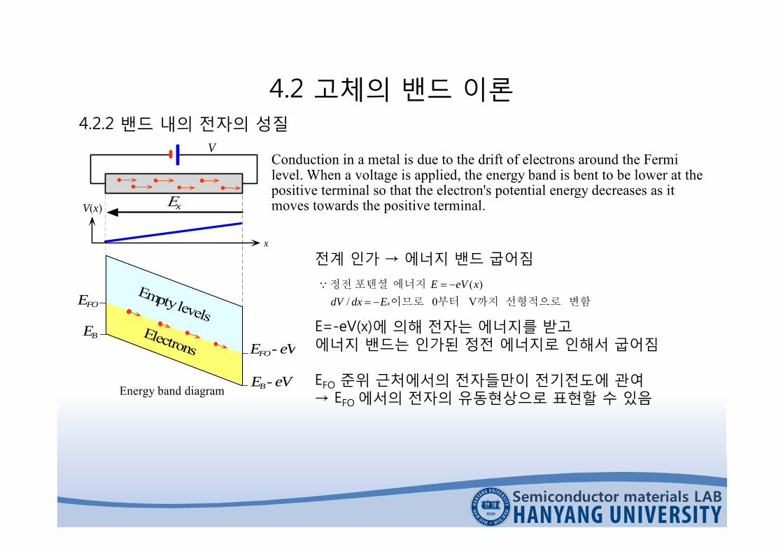
Conduction in a metal is due to the drift of electrons around the Fermilevel. When a voltage is applied, the energy band is bent to be lower at thepositive terminal so that the electron's potential energy decreases as itmoves towards the positive terminal.
전계 인가 → 에너지 밴드 굽어짐
변함선형적으로까지부터이므로
에너지포텐셜정전
V 0 /)(
xEdxdVxeVE
E=-eV(x)에 의해 전자는 에너지를 받고에너지 밴드는 인가된 정전 에너지로 인해서 굽어짐
EFO 준위 근처에서의 전자들만이 전기전도에 관여→ EFO 에서의 전자의 유동현상으로 표현할 수 있음

4.2 고체의 밴드 이론4.2.2 밴드 내의 전자의 성질
Liquid metallic hydrogen(with helium)
Molecular hydrogen andhelium
Possible rocky core
Cloud tops (the atmospheric layer iscomparatively thin compared withJupiter's size)
The interior of Jupiter is believed to contain liquid hydrogen which ismetallic (drawing adapted from T. Hey and P. Walters, The QuantumUniverse, Cambridge University Press, 1988; Fig. 7.1, p. 96)
금속에 열을 가하면?
→ 열이 금속의 전도 전자들에 의해 흡수됨→ 원자 진동의 크기도 증가
∴금속 열용량의 2가지 성분① 격자 진동에 의한 에너지 흡수 (상온)② 전도 전자에 의한 에너지 흡수 (저온)

4.3 반도체
3p
3s
2p
2s
1s
Elec
tron
Ener
gy
The electronic structure of Si.
Si 원자는 왜 4개의 이웃 원자들과 결합하는가?
3s 궤도는 전자가 가득 차 있고, 3p 궤도에는 단지 2개의전자만이 있기 때문
가득 찬 3s 궤도는 주위와 중첩되면 안되고, 결합에는 포함되어야 함.2개의 3p 궤도만이 반만 차 있으므로 결합은 두 개의 이웃한Si 원자간에 이루어져야 함.

4.3 반도체
실제로 3s와 3p 에너지 준위는 매우 근접하게 위치함.따라서 4개의 Si 원자가 접근하게 되면 원자간의 상호작용에 의해서 4개의 궤도가 서로 섞여각각이 서로 최대한도로 멀어지는 정사면체 모양의 새로운 혼성 궤도(hybrid orbital) 형성.
한 개의 s 궤도와 세 개의 p 궤도가 섞이므로 sp3 혼성화(hybridization)라고 함.

4.3 반도체
4개의 sp3 혼성궤도 hyb 는 각각 한개씩의 전자를 가지고 있음→ 반만 채워져 있음 → 4개의 Si 원자의 궤도 hyb 가 중첩되어 1개의 Si 원자와 결합→ 1개의 Si 원자는 4개의 다른 Si 원자와 정사면체 방향으로 결합
Ex) SiH4, CH4
hyb 가 이웃의 Si 원자의 hyb 와 중첩 → 결합 분자궤도(bonding molecular orbital) B→ 반결합 분자궤도(antibonding molecular orbital) A
Si-Si 결합 : B 에서 짝이 형성된 2 개의 전자에 해당
B (Si-Si 결합)간의 작용 → EB 에너지 준위 N개로 분리 → VB(valence band) 형성A 간의 작용 → EA 에너지 준위 N개로 분리 → CB(conduction band) 형성
4.3 반도체
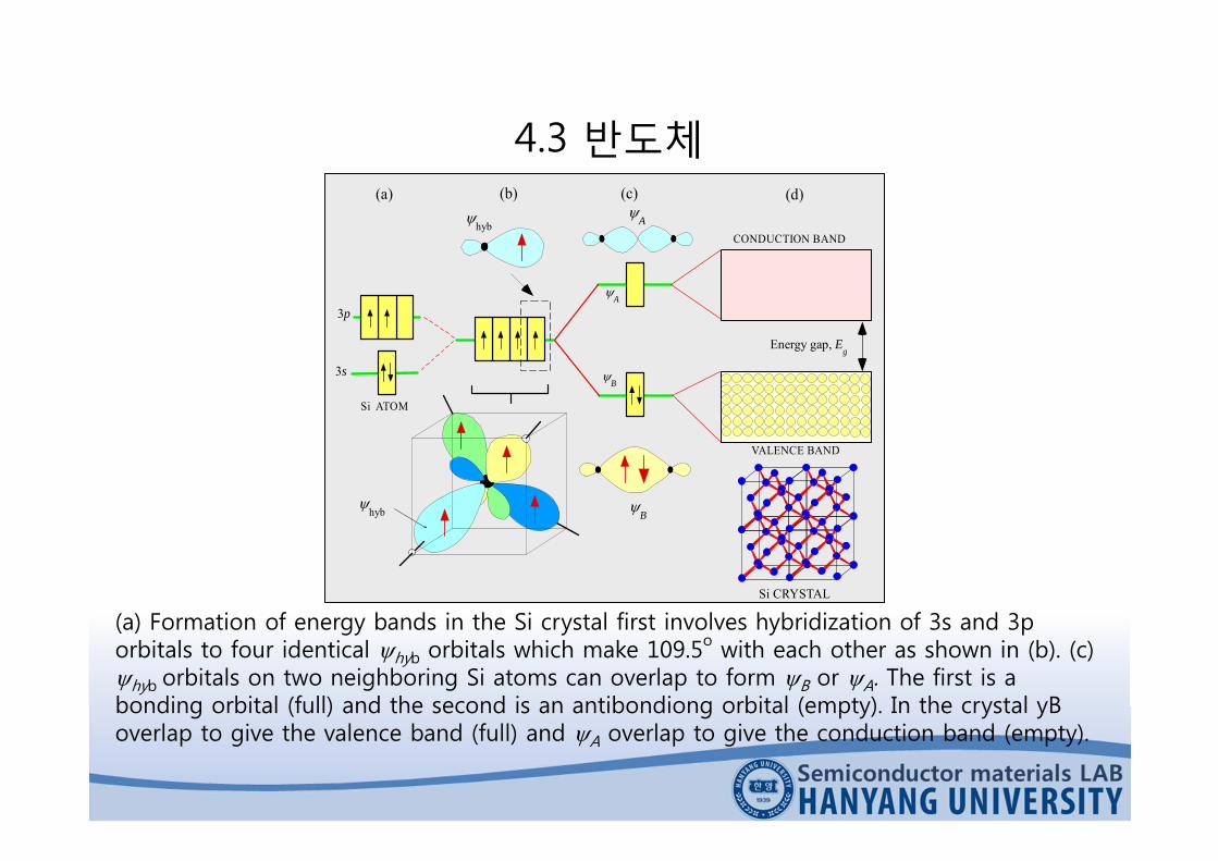
(a) Formation of energy bands in the Si crystal first involves hybridization of 3s and 3p orbitals to four identical hyb orbitals which make 109.5o with each other as shown in (b). (c)hyb orbitals on two neighboring Si atoms can overlap to form B or A. The first is a bonding orbital (full) and the second is an antibondiong orbital (empty). In the crystal yBoverlap to give the valence band (full) and A overlap to give the conduction band (empty).
hyb
Si ATOM
B
B
A
A
CONDUCTION BAND
VALENCE BAND
Energy gap, Eg
(a) (b) (c) (d)
3p
3s
Si CRYSTAL
hyb
4.3 반도체
Ec
Ev
CB
VB
EgThermalexcitation
Elec
tron
ener
gy
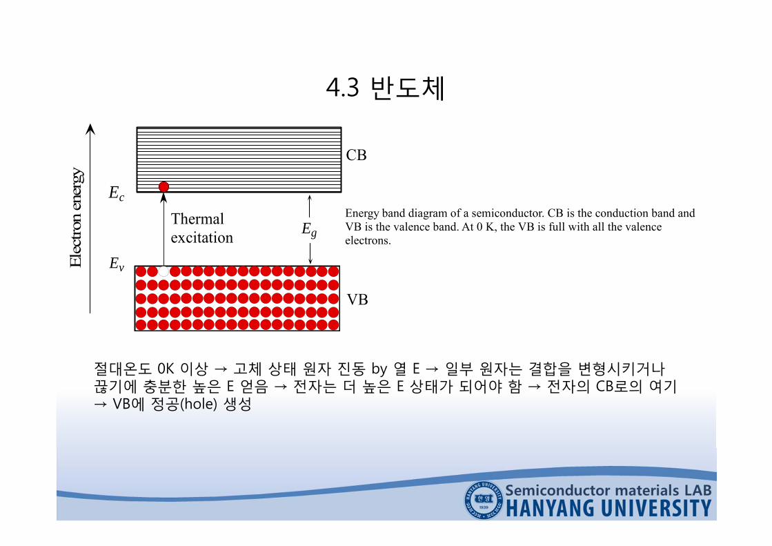
Energy band diagram of a semiconductor. CB is the conduction band andVB is the valence band. At 0 K, the VB is full with all the valenceelectrons.
절대온도 0K 이상 → 고체 상태 원자 진동 by 열 E → 일부 원자는 결합을 변형시키거나끊기에 충분한 높은 E 얻음 → 전자는 더 높은 E 상태가 되어야 함 → 전자의 CB로의 여기→ VB에 정공(hole) 생성
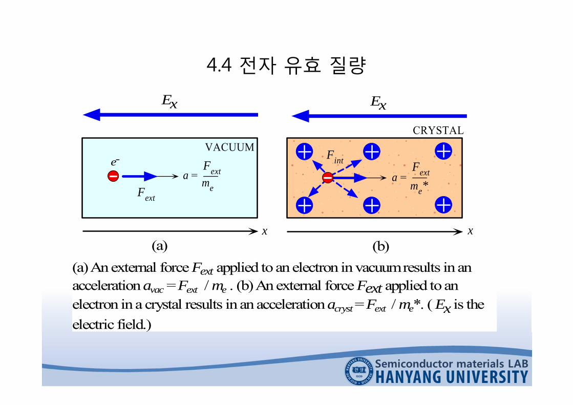
4.4 전자 유효 질량
e-
Fext
VACUUM
x
Fextme
a =
(a)
Ex
Fint
CRYSTAL
x
Fextme*
a =
(b)(a)Anexternal force Fext applied to anelectron invacuumresults inanaccelerationavac =Fext / me . (b)Anexternal force Fext applied toanelectron ina crystal results inanaccelerationacryst =Fext / me*. ( Ex is theelectric field.)
Ex

4.4 전자 유효 질량
e
extvac
mFa
e
extcryst
mFFa int
*e
extcryst
mFa
모든 내부 힘의 영향들 ; 에 포함*
em
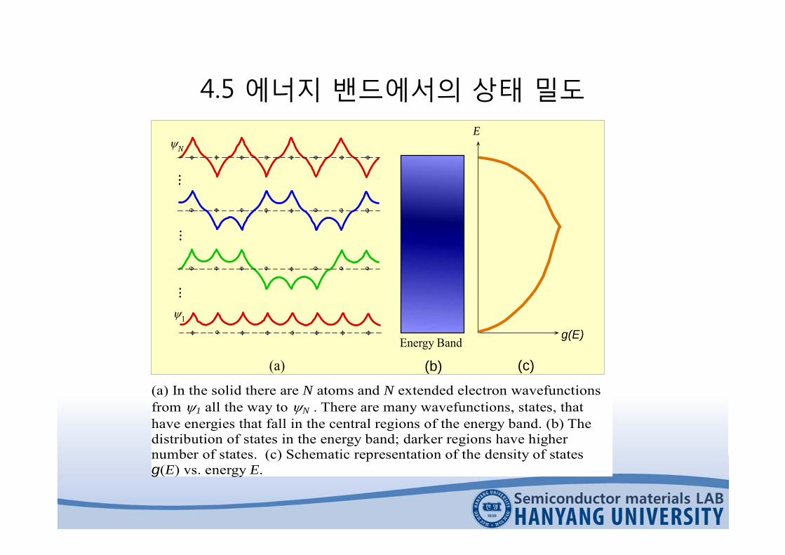
4.5 에너지 밴드에서의 상태 밀도
1
(a)
N
Energy Band
(b) (c)
E
g(E)
(a) In the solid there are N atoms and N extended electron wavefunctionsfrom 1 all the way to N . There are many wavefunctions, states, thathave energies that fall in the central regions of the energy band. (b) Thedistribution of states in the energy band; darker regions have highernumber of states. (c) Schematic representation of the density of statesg(E) vs. energy E.
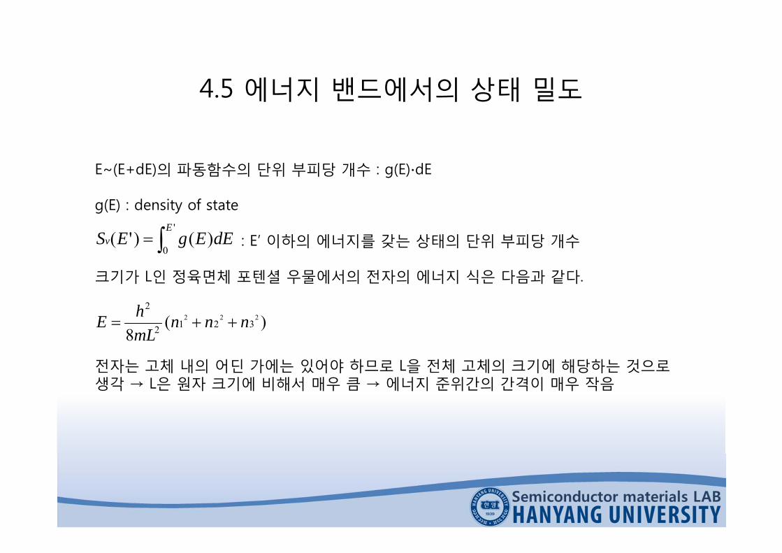
4.5 에너지 밴드에서의 상태 밀도
E~(E+dE)의 파동함수의 단위 부피당 개수 : g(E)∙dE
g(E) : density of state
: E’ 이하의 에너지를 갖는 상태의 단위 부피당 개수
크기가 L인 정육면체 포텐셜 우물에서의 전자의 에너지 식은 다음과 같다.
전자는 고체 내의 어딘 가에는 있어야 하므로 L을 전체 고체의 크기에 해당하는 것으로생각 → L은 원자 크기에 비해서 매우 큼 → 에너지 준위간의 간격이 매우 작음
'
0)()'(
Ev dEEgES
)(8
2223212
2
nnnmLhE

4.5 에너지 밴드에서의 상태 밀도
n12 + n2
2 = n' 2
n1 = 1n2 = 3
0
1
2
3
4
5
1 2 3 4 5 6
n1 = 2, n2 = 2
Each state, electron wavefunction in the crystal, can be representedby a box at n1,n2.
n2
-n2
n1-n1 n2
In here n12+n2
2+n32 n'2
n'
Vol. = 1/8(4/3 n'3)
n3
n1
In three dimensions, the volume defined by a sphere of radius n' and thepositive axes n1, n2 and n3, is all the possible combinations of poisitiven1, n2 and n3, values which satisfy n1
2+n22+n3
2 n'2.

4.5 에너지 밴드에서의 상태 밀도
각 궤도 상태는 스핀이 반대인 2개의 전자를 가질 수 있으므로
로부터 를 위의 식에 대입하면
는 고체의 부피이므로 단위 부피당 에너지가 인 상태의 수 는
33 '61)'
34(
81)'( nnnSorb
3'31)'(2)'( nnSnS orb
)(8
2223212
2
nnnmLhE 2
22 '8'
hELmn e
3
2/33
3)'8()'(
hEmLES e
3L 'EE )'(ESv
3
2/3
3)'8()'(
hEmES e
v

4.5 에너지 밴드에서의 상태 밀도
'
0)()'(
Ev dEEgES 에서 이므로
1. 는 이어야 함.2. 오직 결정 내의 자유전자에만 적용되어야 함.
But, 금속이나 반도체의 밴드 끝 부분에서 실제의g(E)와 E 관계를 근사화할 때 자주 이용함.
)'(/ EgdEdSv
2/12/32
2/1 ))(28()( EhmEg e
em *em
Fermi-Dirac 통계
전자의 에너지 : E 에너지가 E인 상태가 차 있을 확률 : f(E)
전자의 수 Band
dEEgEfn )()(

4.6 통계 : 입자들의 모임4.6.1 Boltzmann 고전 통계
E1
2
1
E2E4
E3
4
3
Interaction
Two electrons initially with wavefunctions 1 and 2 at E1 and E2interact and end up at different energies at E3 and E4. Theircorresponding wavefunctions are 3 and 4.
P(E) : 에너지 E를 갖는 전자의 비율= 전자가 에너지 E를 가질 확률
전자 에너지의 제한이 없다.즉, Pauli의 배타 원리 무시 할 수 있다고가정! → P(E1)P(E2) = P(E3)P(E4) ; 열적 평형
충돌 시 에너지 보존→ E1+E2 = E3+E4

4.6 통계 : 입자들의 모임4.6.1 Boltzmann 고전 통계
exp(-E/kT)
N1 N2
N(E)
E
E2
E1
0
The Boltzmann energy distribution describes the statistics of particles,e.g. electrons, when the particles do not interact with each other, i.e.when there are very few electrons compared with the number ofavailable states.
kTEAEP exp)(
Boltzmann probability function
P(E)는 E가 증가함에 따라 지수 함수적으로 감소
물론, 몇 개의 전자라도 주어진 에너지 E를가질 수 있다고 가정

4.6 통계 : 입자들의 모임4.6.1 Boltzmann 고전 통계
Boltzmann Statistics for two energy levels
kTEE
NN 12
1
2 expE1-E2≫kT → N2≪N1
T↑→N2/N1 ↑
고전적 의미의 입자 → Boltzmann 통계 따름즉, 입자의 수보다 상태의 수가 매우 많은 경우(ex 반도체의 Conduction Band)→ 2개의 입자가 같은 양자 수의 집합을 가질 가능성 무시할 정도→ Pauli의 배타 원리 신경 쓸 필요 없음

E1
2
1
E2E4
E3
4
3
Interaction
Two electrons initially with wavefunctions 1 and 2 at E1 and E2interact and end up at different energies at E3 and E4. Theircorresponding wavefunctions are 3 and 4.
4.6 통계 : 입자들의 모임4.6.2 Fermi-Dirac통계
Pauli의 배타 원리 따르는 전자의 상호작용
f(E) : 전자가 에너지 E를 갖는 상태에 존재할 확률
초기 충돌 사건 일어날 확률 = f(E1)f(E2)[1-f(E3)][1-f(E4)]

4.6 통계 : 입자들의 모임4.6.2 Fermi-Dirac통계
f(E1)f(E2)[1-f(E3)][1-f(E4)] = f(E3)f(E4)[1-f(E1)][1-f(E2)] ; 열적 평형 상태에너지 보존 → E1+E2 = E3+E4
kTEE
EfFexp1
1)(
The Fermi-Dirac functionE
EF
0 1/21
f(E)
T1
T = 0
T2 > T1
The Fermi-Dirac function, f(E), describes the statistics of electronsin a solid. The electrons interact with each other and theenvironment so that they obey the Pauili Exclusion Principle.
E-EF≫kT →
f(E)는 거의 Boltzmann 함수와 같아짐
kTEEEf F)(exp)(
절대 온도 0도 이상에서 E=EF → f(EF)=1/2즉, Fermi 에너지는 전자에 의해 채워져 있을확률이 ½이 되는 에너지
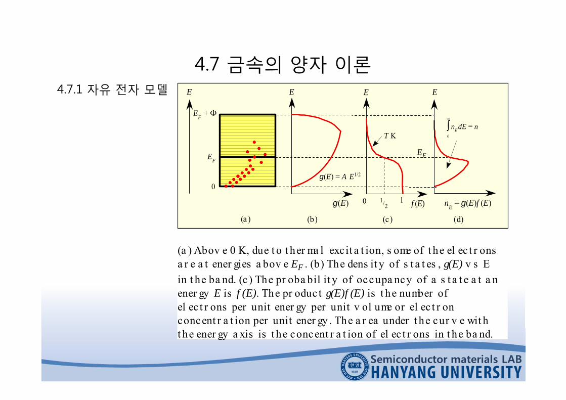
4.7 금속의 양자 이론4.7.1 자유 전자 모델
(a ) Abov e 0 K, due t o t her ma l excit a t ion, s ome of t he el ec t r onsa r e a t ener gies a bov e EF . (b) The dens it y of s t a t es , g(E) v s Ein t he ba nd. (c ) The pr oba bil it y of occupa ncy of a s t a t e a t a nener gy E is f (E). The pr oduc t g(E)f (E) is t he number ofel ec t r ons per unit ener gy per unit v ol ume or el ec t r onconcent r a t ion per unit ener gy . The a r ea under t he cur v e wit ht he ener gy a xis is t he concent r a t ion of el ec t r ons in t he ba nd.
E
0 1/21 f (E)
T K
E E
g(E)
g(E) = A E1/2
nE = g(E)f (E)
EF
EF +
E
0
(a ) (b) (c) (d)
ndEnE
0
EF

4.7 금속의 양자 이론4.7.1 자유 전자 모델
0
2/1
3
2/32/10 0
exp1
28
)()()()(
kTEE
dEEh
m
dEEfEgdEEfEgn
F
e
bandofTop

4.7 금속의 양자 이론4.7.1 자유 전자 모델
Fermi energy at T (K)
22
121)(
FOFOF E
kTETE
3/22 38
n
mhE
eFO
Fermi energy at T = 0 K
n is the concentration of conduction electrons (free carrier concentration)
EFO≫kT → EF(T)의 온도 의존성 매우 작음

4.7 금속의 양자 이론4.7.1 자유 전자 모델
Average energy per electron at T (K)
FOEE53)0(av
22
av 1251
53)(
FOFO E
kTETE
Average energy per electron at 0 K
적분하면후대입)()(, EfEgndEn
dEEnE E
E
Eav
Fermi 에너지 : 금속의 전도 전자의 평균 에너지 Eav로서 중요한 의미를 가짐
EFO≫kT 이므로 대괄호 안의 두 번째 항은1보다 훨씬 작음 → 온도 의존성 매우 작음

4.7 금속의 양자 이론4.7.1 자유 전자 모델
우리가 다루는 금속 모델 → 전자는 포텐셜 에너지가 0인 금속 내부를 자유롭게 이동→ 이에 비해 금속 외부에서는 의 값을 가짐 → 전자의 에너지는 모두 운동 에너지
→
FE
FOavee EEvm53
21 2
ve (유효 속도) : 전자 속도의 실효 값 (root mean square)

4.7 금속의 양자 이론4.7.2 금속에서의 전도
xFxe
Fex
eEeveE
mvmp
mpE x
*
*
*
xx eE
tp
힘인가한외부에서 xx eEp →
xFFFxFFFFFFx EEgvevEevEgevEEgevenJ )(])([])([ 22
)(22FF Egve 1차원
)(31 22
FF Egve 3차원

4.7 금속의 양자 이론4.7.2 금속에서의 전도
FE 는 의 위치에서 산란된 전자들이 같은 에너지 밴드에 있다는 가정에서 나온 것.
특정한 금속에서는 에서 겹치게 되는 서로 다른 에너지 밴드가 존재 할 수 있다.
Ex) Ni의 경우 3d 밴드와 4s 밴드가 에서 겹치게 된다. 이 때, 전자는 4s에서 3d 밴드로산란될 수 있고, 그 반대도 가능하다. 3d 밴드에 있는 전자는 매우 낮은 유동 이동도를갖게 되므로 효과적으로 전도에 기여하지 못하게 되고, 따라서 4s 밴드의 가 기여하게 된다. 4s에서 3d 밴드로의 산란현상은 추가적인 산란 현상이기 때문에Matthiessen 법칙에 따라 4s 밴드에서의 전자의 산란 시간 는 짧아진다. 따라서 Ni은Cu보다 낮은 전도도를 지니게 된다.
FE
FE)( FEg

4.7 금속의 양자 이론4.7.2 금속에서의 전도
2/12/32
2/1 ))(28()( Fe
F EhmEg 에 자유 전자 모델을 적용하고 단위 부피당 전자(전도에
기여하는)의 수 n과 EF 를 연관시키면
→ : Drude 모델em
ne 2

4.8 Fermi 에너지의 의미4.8.1 금속-금속 접촉 : 접촉 전위
5.36
eV
4.20
eV
Fermi level
(Pt) - (Mo) = 1.16 eV = eV
Vacuum
Vacuum
Fermi level
Pt MoVacuum
Fermi level
Vacuum
(b)
(a)
(Pt)
=5.
36eV
(M
o)=
4.20
eV
ElectronsElectrons
When two metals are brought together, there is a contact potential, V.(a) Electrons are more energetic in Mo so they tunnel to the surface of Pt.(b) Equilibrium is reached when the Fermi levels are lined up.
전자들은 Mo에서 Pt 표면으로 이동(by tunneling)→ Pt-Mo계의 전체 전자 에너지 감소
동시에 Mo 표면에 비해 Pt 표면이 음으로 대전→ Mo쪽이 양인 접촉 전압(전위차) 발생
Mo 표면에서 Pt 표면으로 향하는 자유전자를 얻기위해서는 에 해당하는 일을 해 주어야 하므로이는 전압 (=1.16V)가 발생함을 의미
e/
4.8 Fermi 에너지의 의미4.8.1 금속-금속 접촉 : 접촉 전위
Mo Pt
Mo Pt
1.1V
1.1V
I = 0
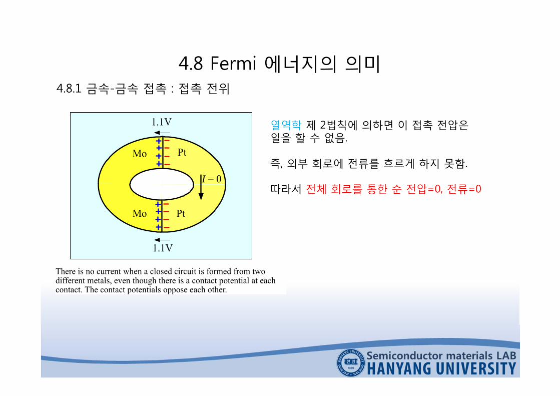
There is no current when a closed circuit is formed from twodifferent metals, even though there is a contact potential at eachcontact. The contact potentials oppose each other.
열역학 제 2법칙에 의하면 이 접촉 전압은일을 할 수 없음.
즉, 외부 회로에 전류를 흐르게 하지 못함.
따라서 전체 회로를 통한 순 전압=0, 전류=0
4.8 Fermi 에너지의 의미4.8.1 금속-금속 접촉 : 접촉 전위
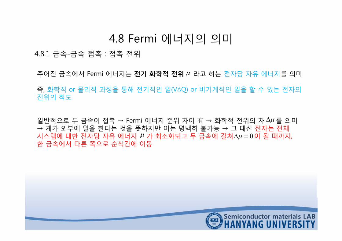
주어진 금속에서 Fermi 에너지는 전기 화학적 전위 라고 하는 전자당 자유 에너지를 의미
즉, 화학적 or 물리적 과정을 통해 전기적인 일(V∆Q) or 비기계적인 일을 할 수 있는 전자의전위의 척도
일반적으로 두 금속이 접촉 → Fermi 에너지 준위 차이 有 → 화학적 전위의 차 를 의미→ 계가 외부에 일을 한다는 것을 뜻하지만 이는 명백히 불가능 → 그 대신 전자는 전체시스템에 대한 전자당 자유 에너지 가 최소화되고 두 금속에 걸쳐 이 될 때까지, 한 금속에서 다른 쪽으로 순식간에 이동
0

4.8 Fermi 에너지의 의미4.8.2 Seebeck 효과와 열전대
뜨거운 부분의 전자 ; 에너지 크고 속도 빠름→ 뜨거운 쪽에서 차가운 쪽으로의 전자의 순 확산→ 뜨거운 쪽 ; 양의 금속 이온
차가운 쪽 ; 과잉 전자→ 뜨거운 쪽 끝이 양의 전위를 가지는 전압 발생
이와 같이
한 종류의 금속 안에서 온도 차 ∆T에 의해서전위차 ∆V가 발생하는 현상 : Seebeck 효과
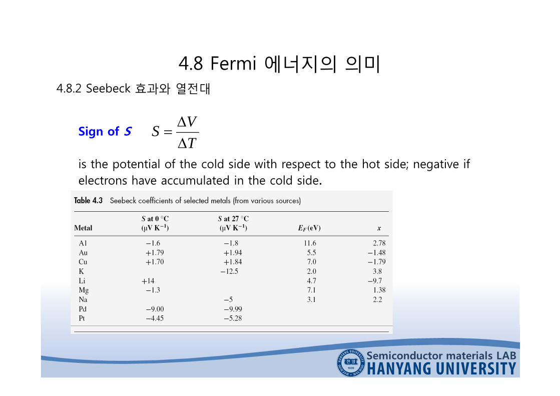
Sign of S
is the potential of the cold side with respect to the hot side; negative if electrons have accumulated in the cold side.
4.8 Fermi 에너지의 의미4.8.2 Seebeck 효과와 열전대
TVS

H C
Energy
x
(a) S positive
H C
Energy
x
(a) S negative
4.8 Fermi 에너지의 의미4.8.2 Seebeck 효과와 열전대
H→C 전자 수 =
C→H 전자 수 =
H→C 순 확산 ∝ )'(21 lln
'21 nl
nl21
Consider two neighboring regions H (hot) and C (cold) with widthscorresponding to the mean free paths and in H and C. Half theelectrons in H would be moving in +x direction and the other halfin x direction. Half of the electrons in H therefore cross into C,and half in C cross into H.

4.8 Fermi 에너지의 의미4.8.2 Seebeck 효과와 열전대
S : 온도에 대한 함수 (즉, S=S(T))
T
TSdTV
0
xeE
TkSFO3
22
Mott and Jones thermoelectric power equation
x = a numerical constant that takes into account how various charge transportparameters, such as the mean free path , depend on the electron energy.
x values are tabulated in Table 4.3

4.8 Fermi 에너지의 의미4.8.2 Seebeck 효과와 열전대
Metal
100oC
ColdHot
V
0
Metal
Metal
0oC
(a)
ColdHot
V
0Metaltype B
Metaltype B
Metaltype A
(b)
100oC 0oC
(a) If same metal wires are used to measure the Seebeck voltage across themetal rod, then the net emf is zero. (b)The thermocouple from two differentmetals, type A and B. The cold end is maintained at 0 ¡C which is thereference temperature. The other junction is used to sense the temperature. Inthis example it is heated to 100 ¡C.

4.8 Fermi 에너지의 의미4.8.2 Seebeck 효과와 열전대
Seebeck 효과는 두 가지 다른 종류의 금속을 이용하는 열전대 (thermocouple)에 효과적으로이용된다.
We can only measure differences between thermoelectric powers of materials.
When two different metals A and B are connected to make a thermocouple, then the net EMF is the voltage difference between the two elements.
T
T AB
T
T BAABoo
dTSdTSSV
BAAB SSS 를 열전대쌍 AB의 열전 전력으로 정의
열전대 방정식2)( TbTaVAB
4.8 Fermi 에너지의 의미4.8.2 Seebeck 효과와 열전대
0
10
20
30
40
50
60
70
80
0 200 400 600 800 1000
Temperature (oC)
E-Type
J-Type
S-TypeT-Type
K-Type
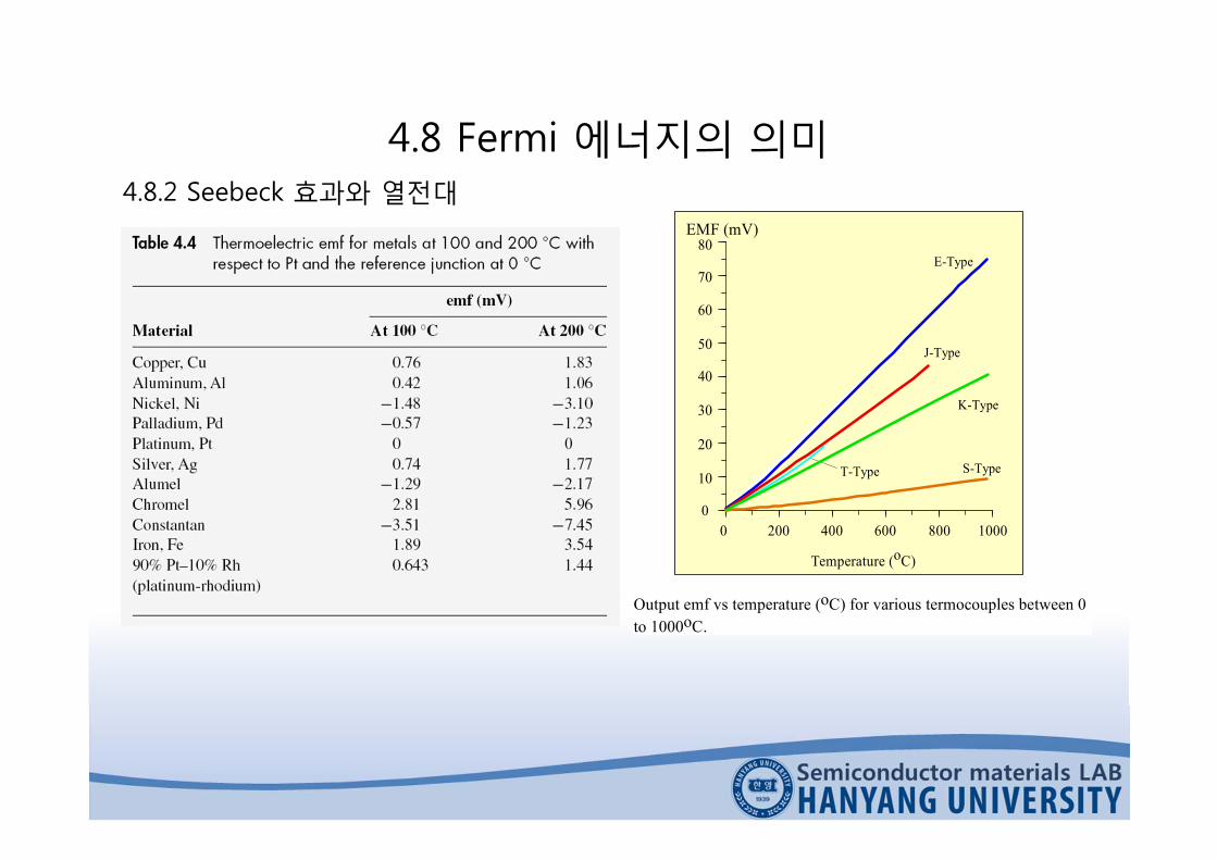
Output emf vs temperature (oC) for various termocouples between 0to 1000oC.
EMF (mV)

4.9 열전자 방출과 진공관 소자4.9.1 열전자 방출 : Richardson-Dushman 방정식
Cathode
Filament
I
Vacuum
Plate or Anode
(a )
I
V
Saturation current
(b)
(a) Thermionic electron emission in a vacuum tube.(b) Current-voltage characteristics of a vacuum diode.
음극과 양극간에 연결된 전지→ 음극의 손실된 전자를 보충,
음극으로부터 열적으로 방출된전자를 포획할 수 있도록 양극에양의 전압을 가해줌
진공관은 정류기처럼 작용→ 양극 전압이 음의 값이 되면
전자들을 밀어내어 전류 흐름이생기지 않기 때문
4.9 열전자 방출과 진공관 소자4.9.1 열전자 방출 : Richardson-Dushman 방정식
0
T3T2
n(E) = g(E)f(E)
E
T1
Electron concentrationper unit energy
E
EF +
EF
0 1.0f(E)0
Probability
T3T2T1
Free Electron
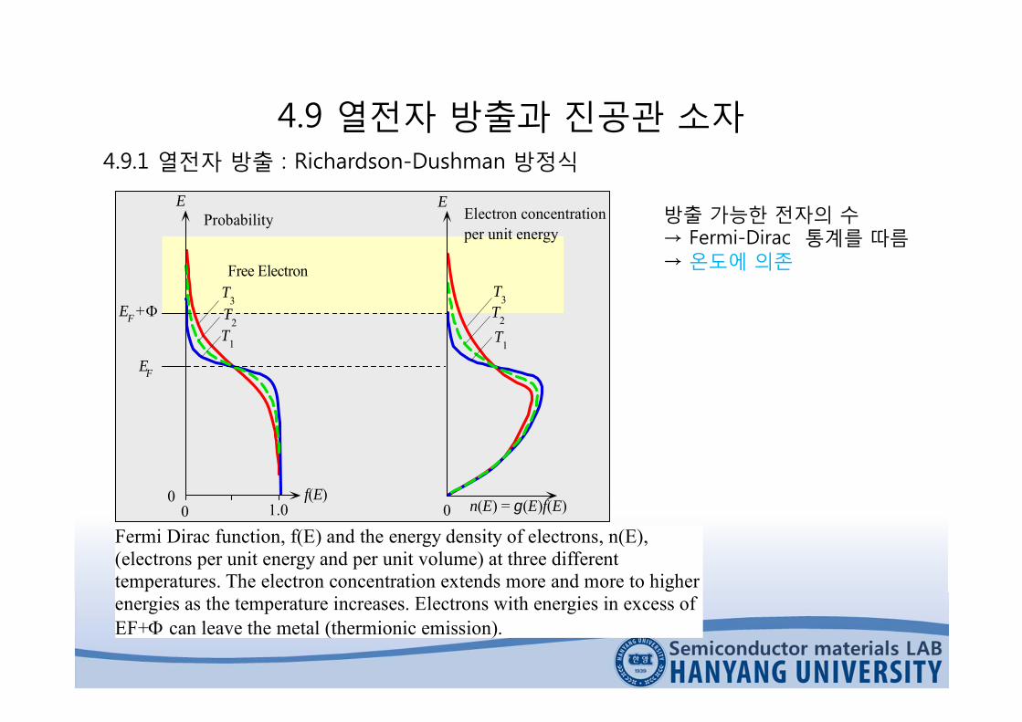
Fermi Dirac function, f(E) and the energy density of electrons, n(E),(electrons per unit energy and per unit volume) at three differenttemperatures. The electron concentration extends more and more to higherenergies as the temperature increases. Electrons with energies in excess ofEF+ can leave the metal (thermionic emission).
방출 가능한 전자의 수→ Fermi-Dirac 통계를 따름→ 온도에 의존

4.9 열전자 방출과 진공관 소자4.9.1 열전자 방출 : Richardson-Dushman 방정식
금속 내에서의 E는 단지 운동 에너지 성분만을 가짐
222
21
21
21
zeyexe mmmE
금속의 표면이 방출 방향에 수직한 방향, 즉 x 방향이라고 가정.전자가 표면에서 방출되기 위해서는 x방향 운동에너지가 포텐셜 에너지 장벽보다 커야 함.
Fxe Em 2
21
이를 만족하며 x방향으로 vx에서 (vx+dvx) 사이의 속도를 가지는 전자의 수를 dn(vx)라 하면이러한 전자들은 표면에 도달했을 때 방출될 것.

4.9 열전자 방출과 진공관 소자4.9.1 열전자 방출 : Richardson-Dushman 방정식
dn(vx) 만큼의 전자의 방출에 의한 열전자 전류 밀도는 )( xxx dnedJ Richardson-Dushman thermionic emission equation
kTTBJ o exp2 Bo=4emek2/h3 = 120×106 A m-2 K-2
Richardson-Dushman constant
전자가 금속 표면에 접근할 때 전자의 파동성 때문에, 전자가 포텐셜 장벽을 넘어 방출되지못하고 금속 내부로 반사될 수 있는 확률이 존재함.이를 고려하여 열전자 방출 방정식을 적절하게 수정하면 다음과 같다.
kTTBJ e exp2 where Be = effective emission constant, R : 반사 계수
0)1( BRBe

4.9 열전자 방출과 진공관 소자4.9.2 전계 도움 방출 : Schottky 효과
Schottky 효과 : 음극에 비해 양의 전압을 양극에 인가하면 음극에서의 전계가 포텐셜에너지 장벽 를 감소시킴으로써 열전자 방출을 용이하게 하는 현상
전자는 금속에 남아 있는 양의 유효 전하에 끌리게 됨. 인력을 발생시키는 이러한 포텐셜 에너지를 나타내기 위해 정전기학의 가상 전하 이론을 도입
→ 도체의 표면에서 x의 거리만큼 떨어져 있는 전자의 위치 에너지 : x
exPEimage
0
2
16)(

4.9 열전자 방출과 진공관 소자4.9.2 전계 도움 방출 : Schottky 효과
Image PE
0
EF +
x x
Net PE
x
EF +
Applied PE
EF + eff
(a) (b) (c)
(a) PE of the electron near the surface of a conductor,(b) Electron PE due to an applied field e.g. between cathode and anode(c) The overall PE is the sum.
xeExPE Fimage
0
2
16)()(
exExPEapplied )(
exEx
eExPE F 0
2
16)()(
2/1
0
3
4
Ee
eff
→ 일함수의 감소효과→ Schottky 효과

4.9 열전자 방출과 진공관 소자4.9.2 전계 도움 방출 : Schottky 효과
kTTBJ S
e
2/12 exp E
Schottky coefficientMetal’s work function
)/(1079.34
152/1
0
3
VmeVEe
S
4.9 열전자 방출과 진공관 소자4.9.2 전계 도움 방출 : Schottky 효과
Vo
e-
x = 0 x = xF
EF
(b)
E
Cathode
Grid or Anode
HV V
(c)
PE(x)
x
EF + eff
xF
Metal Vacuum
EF
00
(a)
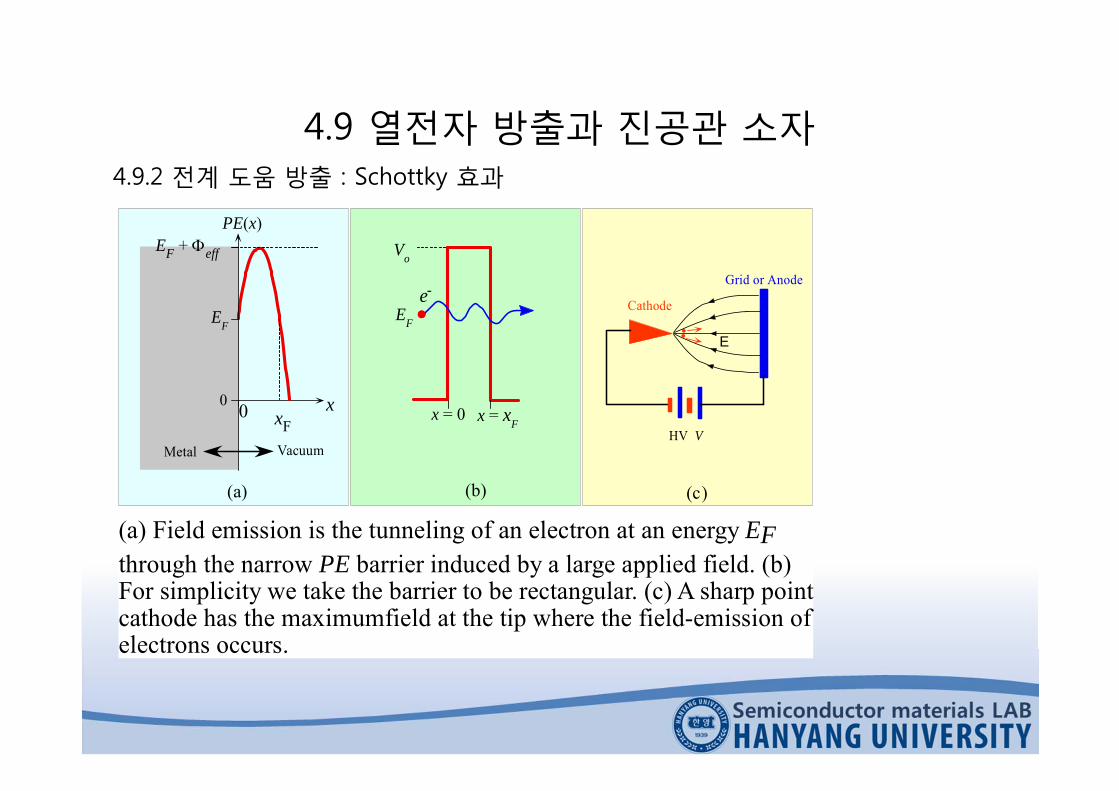
(a) Field emission is the tunneling of an electron at an energy EFthrough the narrow PE barrier induced by a large applied field. (b)For simplicity we take the barrier to be rectangular. (c) A sharp pointcathode has the maximumfield at the tip where the field-emission ofelectrons occurs.
4.9 열전자 방출과 진공관 소자4.9.2 전계 도움 방출 : Schottky 효과
Eemp e
2/1eff22exp
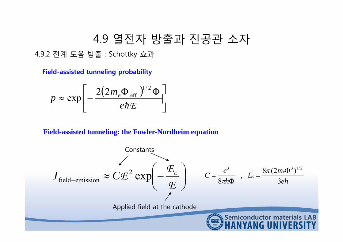
Field-assisted tunneling probability
Field-assisted tunneling: the Fowler-Nordheim equation
EE
E cCJ exp2emissionfield
Applied field at the cathode
Constants
ehmE
heC e
c3
)2(8,8
2/133

4.9 열전자 방출과 진공관 소자4.9.2 전계 도움 방출 : Schottky 효과
30 40 50 60 65554535
0
100
200
300
400(b)
Anode current, IA
Gate Voltage VG
0.020 0.024 0.026
-18
-20
-220.022
(c)-16
1/VGIn
(I A/V
G2 )
Emission tip
Phosphor
Conductingglass
Gate
Dielectric
VG
(a)
Substrate
+
+
-
(a) Spindt type cathode and the basic structure of one of the pixels inthe FED.(b) Emission (anode) current vs, gate voltage (c) Fowler-Nordheim plot that confirms field emission.
GGA
VbaVI exp2
4.9 열전자 방출과 진공관 소자4.9.2 전계 도움 방출 : Schottky 효과
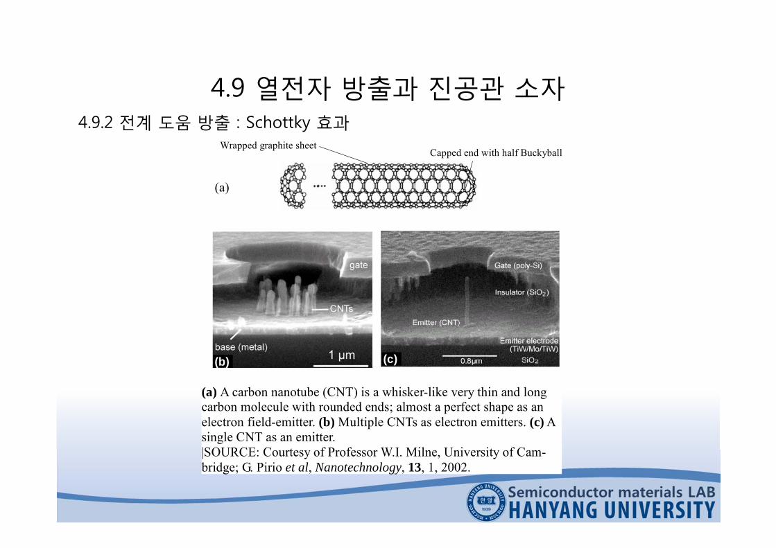
Wrapped graphite sheetCapped end with half Buckyball
(a)
(a) A carbon nanotube (CNT) is a whisker-like very thin and longcarbon molecule with rounded ends; almost a perfect shape as anelectron field-emitter. (b) Multiple CNTs as electron emitters. (c) Asingle CNT as an emitter.|SOURCE: Courtesy of Professor W.I. Milne, University of Cam-bridge; G. Pirio et al, Nanotechnology, 13, 1, 2002.
(c)(b)

4.10 포논(Phonon : 음향양자)4.10.1 조화 진동자와 격자 파동
M
xO X
O +xx
V(x)
(b)O
+xx
En
E0
E1
E2
E3
(a)
(c)
(a) Harmonic vibrations of an atom about its equilibrium positionassuming its neighbors are fixed. (b) The PE curve V(x) vs. displacementfrom equilibrium, x. (c) The enegy is quantized.
진동의 최소 에너지는 절대 0이 될수 없고라는 한정된 값을 가져야 함
→ 영점 에너지)2/1(0 E

4.10 포논(Phonon : 음향양자)4.10.1 조화 진동자와 격자 파동
Harmonic potential energy2
21)( xxV
0212 2
22
2
xEM
dxd
21nEn
Schrodinger equation for the harmonic oscillator
Energy of the harmonic oscillator
Constant
Angular vibrational frequency of the oscillator.
=(/M)1/2.
Quantum number = 0, 1, 2, …

4.10 포논(Phonon : 음향양자)4.10.1 조화 진동자와 격자 파동
ur
ur
(a)
(b)
(c)
0 a 2a ra
xr = ra No vibrations
(N 1)ax
L-wave
T-wave
(a) A chain of N atoms through a crystal in the absence of vibrations. (b)Coupled atomic vibrations generate a traveling longitudinal (L) wave along x.Atomic displacements (ur) are parallel to x. (c)Atransverse (T) wave travelingalong x. Atomic displacements (ur) are perpendicular to the x-axis. b and c aresnapshots at one instant.
4.10 포논(Phonon : 음향양자)4.10.1 조화 진동자와 격자 파동
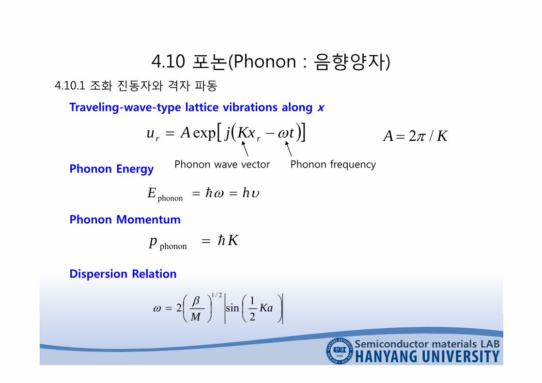
Traveling-wave-type lattice vibrations along x
tKxjAu rr exp
hE phonon
Kp phonon
Ka
M 21sin2
2/1
Phonon Energy
Phonon Momentum
Dispersion Relation
Phonon frequencyPhonon wave vector
KA /2

4.10 포논(Phonon : 음향양자)4.10.1 조화 진동자와 격자 파동
0
/a/a
max
0
vg
/a
vgmax
(a) (b)
(a) Frequency vs. wavevector K relationship for lattice(b) Group velocity vg vs. wavevector K.
AB
K K K
4.10 포논(Phonon : 음향양자)4.10.1 조화 진동자와 격자 파동
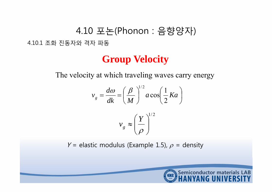
Group VelocityThe velocity at which traveling waves carry energy
Kaa
Mdkdvg 2
1cos2/1
2/1
Yvg
Y = elastic modulus (Example 1.5), = density
4.10 포논(Phonon : 음향양자)4.10.1 조화 진동자와 격자 파동
q = 1
q = 2
q = 4
q = N
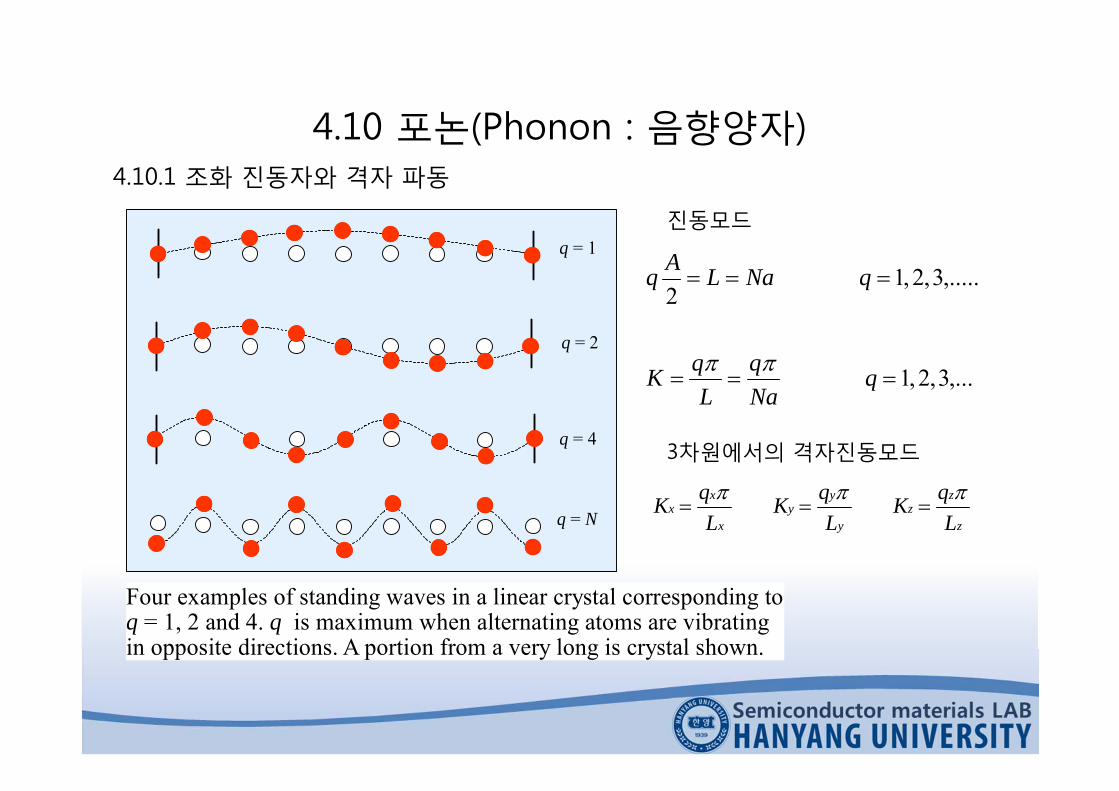
Four examples of standing waves in a linear crystal corresponding toq = 1, 2 and 4. q is maximum when alternating atoms are vibratingin opposite directions. A portion from a very long is crystal shown.
,...3,2,1
,.....3,2,12
qNaq
LqK
qNaLAq
진동모드
3차원에서의 격자진동모드
z
zz
y
yy
x
xx
LqK
LqK
LqK
4.10 포논(Phonon : 음향양자)4.10.2 Debye 열용량
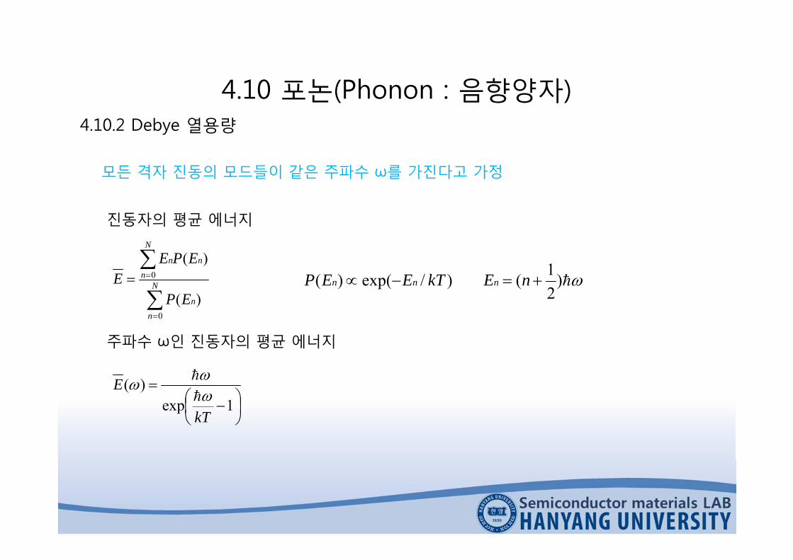
모든 격자 진동의 모드들이 같은 주파수 ω를 가진다고 가정
N
nn
N
nnn
EP
EPEE
0
0
)(
)(
진동자의 평균 에너지
)21()/exp()( nEkTEEP nnn
1exp
)(
kT
E
주파수 ω인 진동자의 평균 에너지

4.10 포논(Phonon : 음향양자)4.10.2 Debye 열용량
모든 격자 진동의 내부에너지
max
0)()(
dgEUm
격자진도에 대한 상태밀도
3
2
223)(
vVg
Debye frequency: maximum vibration (angular) frequency in the crystal
3/12max /6 VNv A
Mean velocity of lattice wavesCrystal volume
Avogadro’s number
0 1 2 3 4 5 (1023 radians/s) max
Den
sity
ofSt
ates
g(
)
Density of states for phonons in copper. The solid curve is deduced fromexperiments on neutron scattering . The broken curve is the three-dimensionalDebye approximation, scaled so that the areas under the two curves are thesame. This requires that max = 4.5 1013 radians s-1, or a Debyecharacteristic temperature D = 344 K.

4.10 포논(Phonon : 음향양자) Debye 열용량
kTD
maxbye temperature: all vibrations are fully excited up to max
TT
x
x
Dm
D
edxex
TTRC
/
0 2
43
)1(9
RCm 3
3
Dm T
TC
High temperatures
Low temperatures
Heat capacity per mole
Debye heat capacity
Dulong-Petit 법칙 ( T>TD 일 때만 성립)

0
0.1
0.2
0.3
0.4
0.5
0.6
0.7
0.8
0.9
1
0
5
10
15
20
25
0 0.1 0.2 0.3 0.4 0.5 0.6 0.7 0.8 0.9 1
Cu
Si (TD = 625 K)
CmJ K-1mole-1Cm/(3R)
T / TD
Cm = 3R
4.10 포논(Phonon : 음향양자) Debye 열용량
Debye constant-volume molar heat capacity curve. The dependence of the molar heat capacity Cm on temperature with respect to the Debye temperature: Cm vs. T/TD. For Si, TD = 625 K so that at room

4.10 포논(Phonon : 음향양자) Debye 열용량
의 집중상태는 T3에 비례해서 증가, 평균 포논 에너지는 T에 비례해서 증가서, 내부에너지는 T4에 비례해서 증가
다 높은 온도에서는 온도가 증가할수록 많은 포논들이 생기지만 평균에너지는 증가하고 주파수도 더 높은 영역으로 여기되지 않는다.
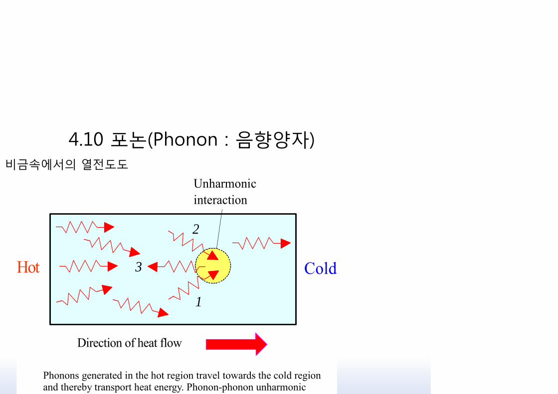
4.10 포논(Phonon : 음향양자) 비금속에서의 열전도도
Hot Cold
Unharmonicinteraction
Direction of heat flow
1
2
3
Phonons generated in the hot region travel towards the cold regionand thereby transport heat energy. Phonon-phonon unharmonic

4.10 포논(Phonon : 음향양자) 비금속에서의 열전도도
ermal conductivity
Measures the rate at which heat can be transported through a medium per unit area per unit temperature gradient.
phph31
vCv
ermal conductivity due to phononsPhonon mean free path
Phonon velocityHeat capacity per unit volume

4.10 포논(Phonon : 음향양자) 비금속에서의 열전도도
온도와 거의 무관한 상수
>TD상수 → K ∝ lph: 포논과 포논의 충돌에 의해 결정됨. 또한 온도가 높아짐에 따라 포논의 농도 nph 는증가하게 되므로 lph ∝ 1/T
전도도 K는 온도가 충분히 높은 대부분의 결정체에서와 같이 온도가 높아짐에 따라소하게 된다.
온도가 낮은 영역논과 포논의 충돌현상이 중요한 비중을 차지하기에는 포논의 농도가 너무 낮음.신 포논은 결정체 표면이나 결정립 경계등과 같은 결정 결함과 충돌하여 lph가 결정됨.는 시료의 기하학적 배열과 결정도에 의해 결정된다.
나아가, Debye 모델에서 예상할 수 있듯이, Cv ∝ T3 이므로 열전도도 K ∝ T3
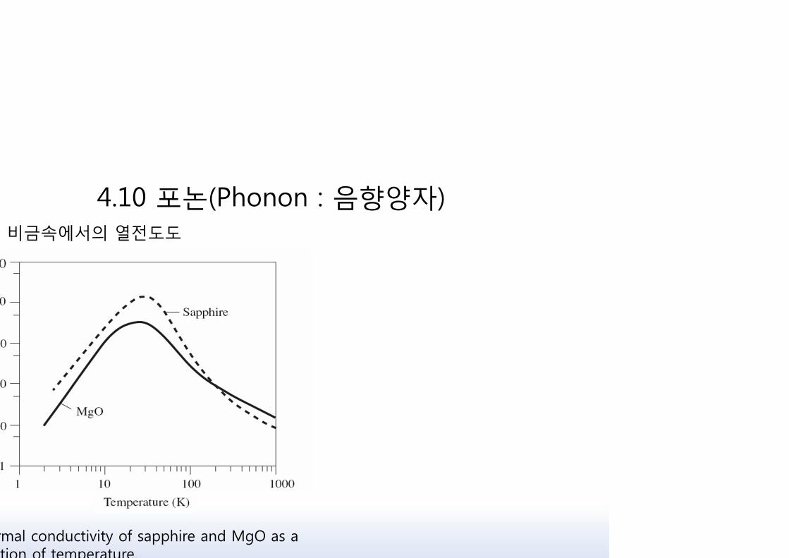
4.10 포논(Phonon : 음향양자) 비금속에서의 열전도도
rmal conductivity of sapphire and MgO as a tion of temperature.

4.10 포논(Phonon : 음향양자)4 전기 전도도
pf
pi
e
Initialmomentum
pi
pf
Phonon
x
E Final momentum
K
Low angle scaterring of a conduction electron by a phonon
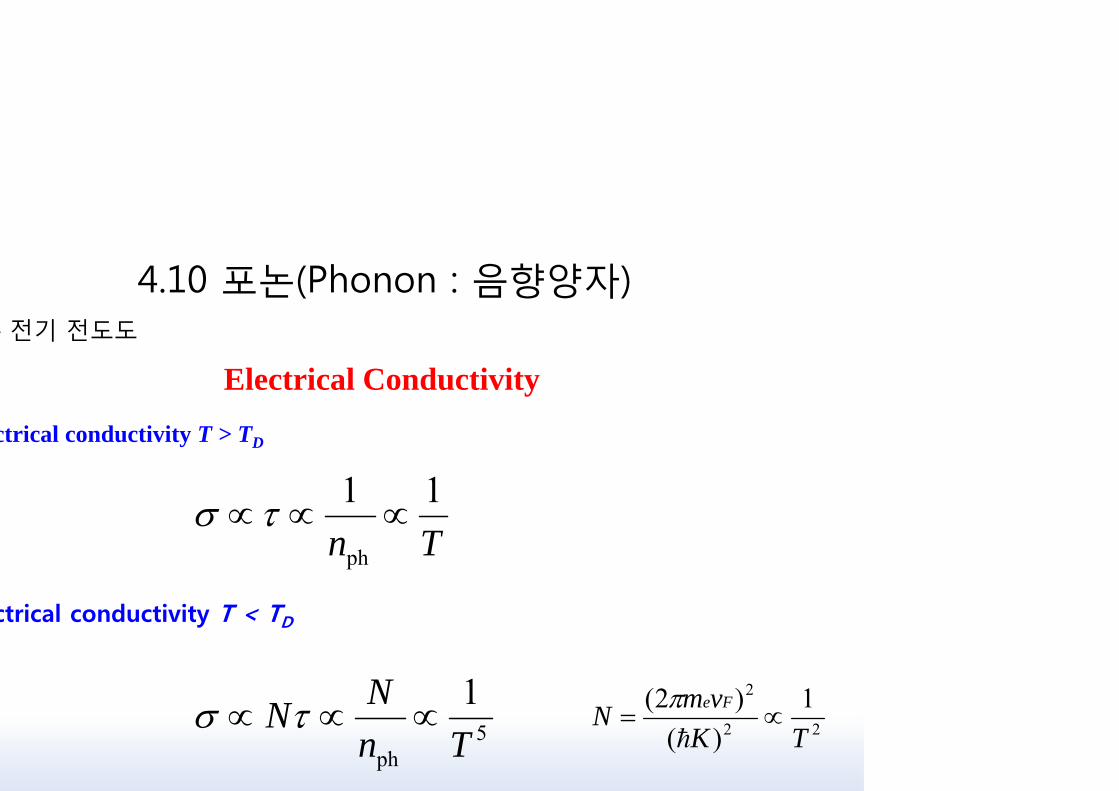
4.10 포논(Phonon : 음향양자)4 전기 전도도
Electrical Conductivityctrical conductivity T > TD
Tn11
ph
5ph
1Tn
NN
ctrical conductivity T < TD
22
2 1)(
)2(TK
vmN Fe

1 금속의 밴드 이론 : 결정 구조에서의 전자의 회절
Forward wave
B'
A
A'
Reflected waves
C'
B C
k
Backward wave
-k
x
a
An electron wave propagation through a linear lattice. For certain k valuesthe reflected waves at successive atomic planes reinforce each other togive rise to a reflected wave travelling in the backward direction. Thel t th t t th h th t l

1 금속의 밴드 이론 : 결정 구조에서의 전자의 회절
)exp()(
,...3,2,1
/2
,...3,2,1
2)()exp()(
2
jkxAx
na
n
k
nna
mkEjkxAx
ekk
대입하면

1 금속의 밴드 이론 : 결정 구조에서의 전자의 회절
c
Energy = Ec
Energy = Es
k = ± / a
s
Forward and backward waves in the crystal with k = ± /a give rise totwo possible standing waves, c and s. Their probability density
distributions, c and s , have maxima either at the ions orbetween the ions.
axnAjkxAjkxAx
axnAjkxAjkxAx
ss
cc
sin)exp()exp()(
cos)exp()exp()(

1 금속의 밴드 이론 : 결정 구조에서의 전자의 회절
경우벗어나는에서가 2
)(
2)(
2)(
|)(|)(1
2
2
2
0
2
ank
mk
ankV
mk
ankV
mk
VdxxxVL
e
ne
ne
L
nc

1 금속의 밴드 이론 : 결정 구조에서의 전자의 회절
aO aaa
2V1Ec
Es
FirstBrillouin
Zone
SecondBrillouin
Zone
SecondBrillouin
Zone
2V2
k
Energy gap
Energy gap
Band
Band
Band
Allowedenergies
Forbiddenenergies
-k
E
Ener
gy
The energy of the electron as a function of its wavevector k inside a one-dimensional crystal. There are discontinuities in the energy at k = ±n /avalues where the waves suffer Bragg reflections in the crystal. There areenergy gaps at these k values. For example, there can be no energy value forthe electron between Ec and Es. Es Ec is therefore an energy gap at

1 금속의 밴드 이론 : 결정 구조에서의 전자의 회절
Electron
k
k1
k2
Diffracted electron
(11) Planes
(01) Planes
(10) Planes
k3
[01]
[10]
y
x
[11]
45o
a
a
2a
45o
45o
raction of the electron in a two dimensional cubic crystal. Diffraction occurs enever k has a component satisfying k1 = ±n/a, k2 = ±n/a or k3 = ±21/2n/a. In

1 금속의 밴드 이론 : 결정 구조에서의 전자의 회절
Bragg Diffractiondiffraction conditions can all be expressed through the Bragg diffractionition 2d sin = n, or
dnk sin
ragg diffraction condition
Interplanar separation of the planes involved in the diffraction
Wavevector = 2 /
e between incident wave and diffracting planes
Integer
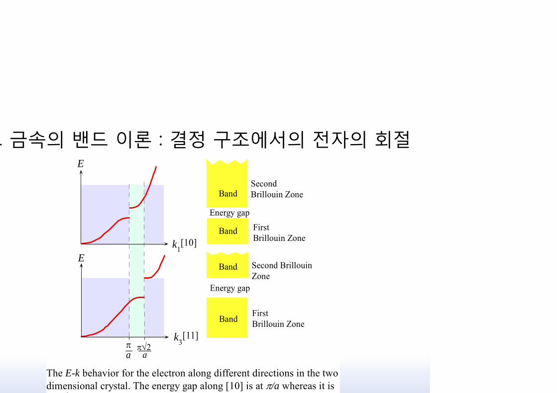
1 금속의 밴드 이론 : 결정 구조에서의 전자의 회절
a
E
[11]k3
E
k1[10]
Band
Band
Energy gap
Energy gap
Band
Band FirstBrillouin Zone
Second BrillouinZone
SecondBrillouin Zone
FirstBrillouin Zone
a
The E-k behavior for the electron along different directions in the twodimensional crystal. The energy gap along [10] is at /a whereas it is
1 금속의 밴드 이론 : 결정 구조에서의 전자의 회절
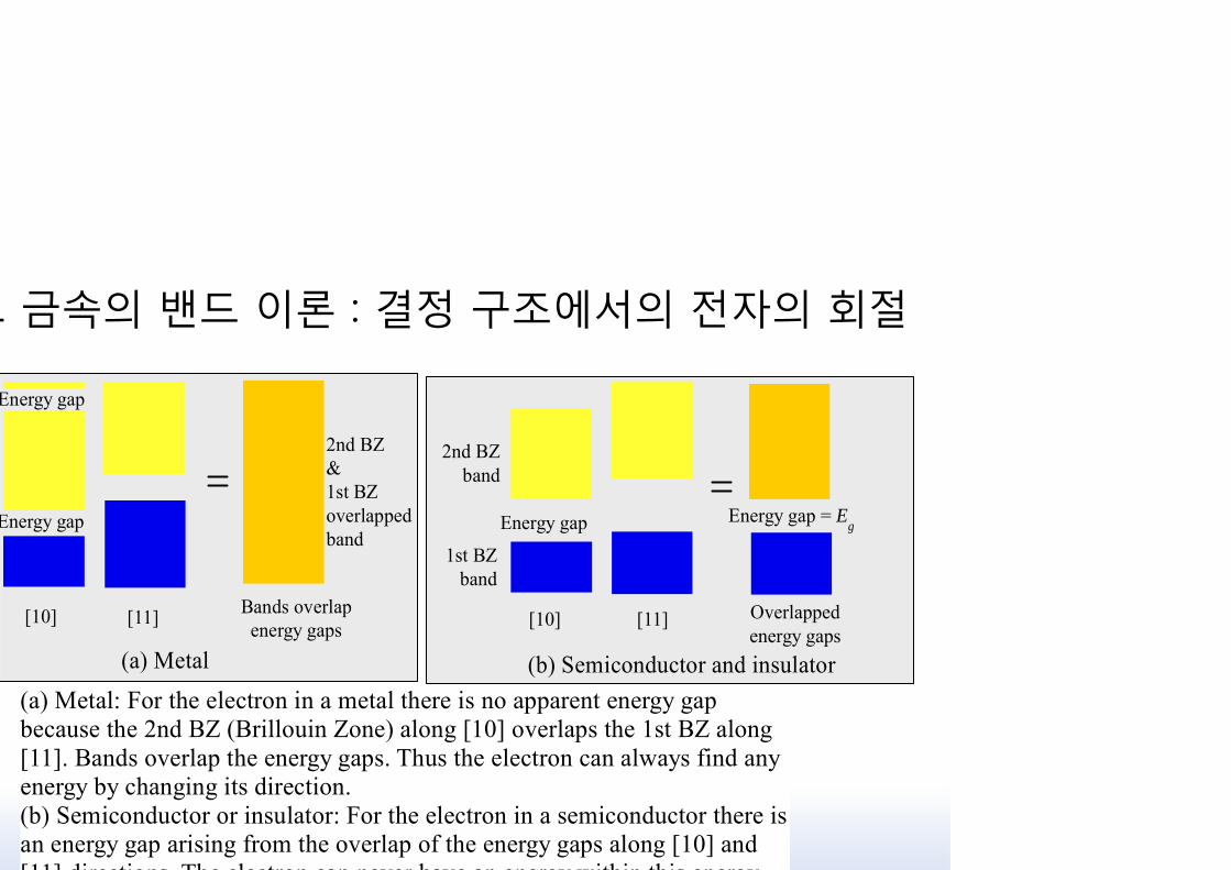
Energy gap
[11][10] Overlappedenergy gaps
Energy gap = Eg
1st BZband
2nd BZband
(b) Semiconductor and insulator
Energy gap
[11][10] Bands overlapenergy gaps
Energy gap
2nd BZ&1st BZoverlappedband
(a) Metal
(a) Metal: For the electron in a metal there is no apparent energy gapbecause the 2nd BZ (Brillouin Zone) along [10] overlaps the 1st BZ along[11]. Bands overlap the energy gaps. Thus the electron can always find anyenergy by changing its direction.(b) Semiconductor or insulator: For the electron in a semiconductor there isan energy gap arising from the overlap of the energy gaps along [10] and[11] directions The electron can never have an energy within this energy

1 금속의 밴드 이론 : 결정 구조에서의 전자의 회절
k1
k2
a
First BrillouinZone
Second BrillouinZone
[01]
k3 [11]
a 2
a2a
[10]
The Brillouin zones in two dimensions for the cubic lattice. TheBrillouin zones identify the boundaries where there are

1 금속의 밴드 이론 : 결정 구조에서의 전자의 회절
12
3
4.5
6
5
79
11O
First BZ
Second BZ
Energy contourfor E = 3 eV inthe first BZ
ky [01]
k [11]
kx [10]
(a)
kx [10]
First BZ
123
4.5
6
10
1214
16
k [11]
O
P
ky [01]
Second BZ
Energy contourfor E = 3 eV inthe first BZ
(b)
Energy contors in k space (space defined by kx, ky). Each contour represents thesame energy value. Any point P on the contor gives the values of kx and ky forthat energy in that direction from O. For the point P, E = 3 eV and OP is k along[11]. (a) In a metal the lowest energy in the second zone (5 eV) is lower than thehighest energy (6 eV) in the first zone. There is an overlap of energies betweenthe Brillouin zones. (b) In a semiconductor or an insulator, there is an energy

1 금속의 밴드 이론 : 결정 구조에서의 전자의 회절
1st BZboundary
2nd BZboundary
Be, Cd, Zn
2nd BZBoundary
Semiconductor
1st BZBoundary
Fermi surface1st BZ boundary
Li, Na or K Cu, Ag or Au1st BZ
Schematic sketches of Fermi surfaces in two dimensions to representqualitatively various materials. (a) Monovalent Group IA metals (b)Group IB metals (c) Be (Group IIA), Zn and Cd (Group IIB) (d) A
4.12 Grüneisen의 열팽창 모델
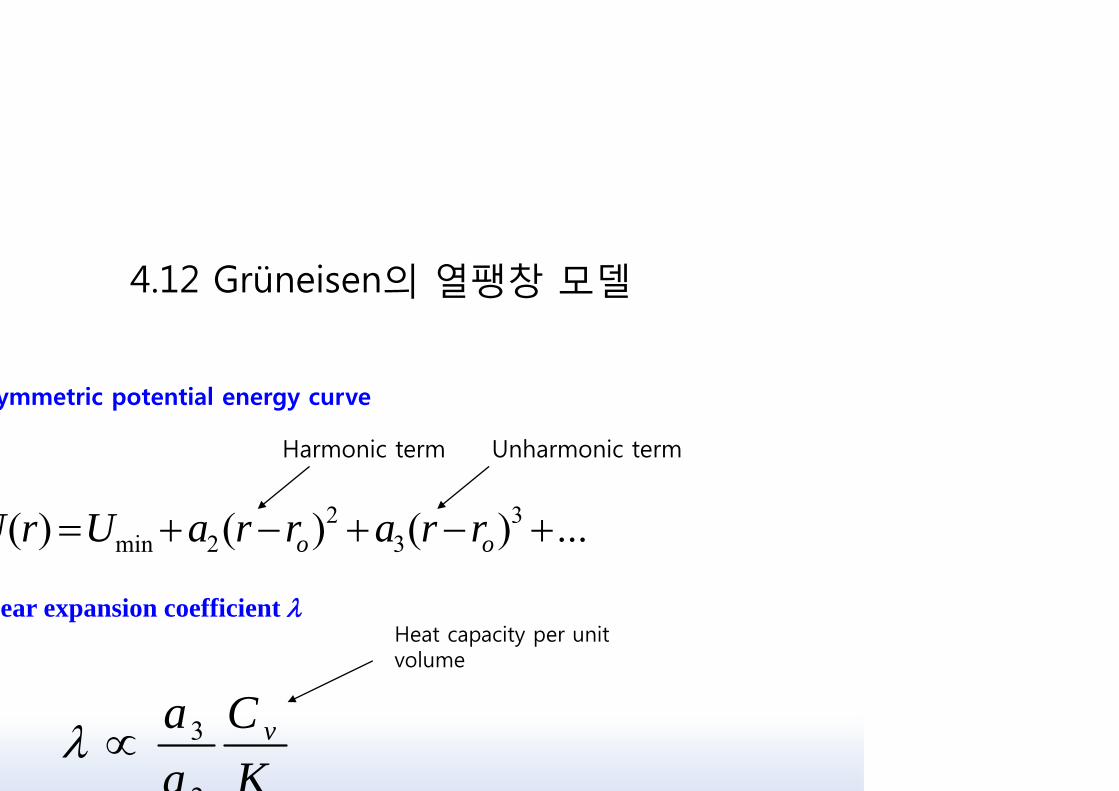
ear expansion coefficient
...)()()( 33
22min oo rrarraUrU
KC
aa v
2
3
ymmetric potential energy curve
Heat capacity per unit volume
Unharmonic termHarmonic term
4.12 Grüneisen의 열팽창 모델
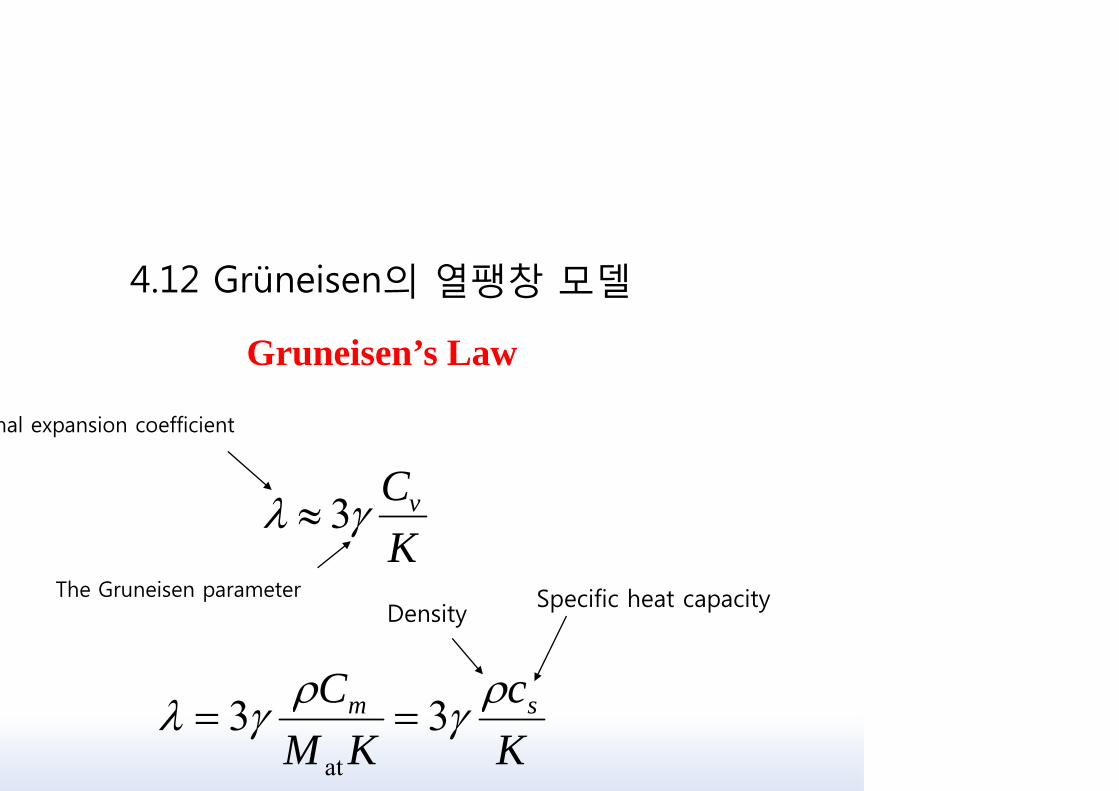
Gruneisen’s Law
KCv 3
Kc
KMC sm 33at
The Gruneisen parameter
mal expansion coefficient
Specific heat capacityDensity

4.12 Grüneisen의 열팽창 모델
![chap4-미생물대사.ppt [호환 모드]app-mic/resources/lecture/dairy... · 2015. 8. 31. · Microsoft PowerPoint - chap4-미생물대사.ppt [호환 모드] Author: Created Date:](https://img.dokumen.tips/doc/110x75/5fe4fb80568dc34d190bbca4/chap4-efeeoeppt-eeoe-app-micresourceslecturedairy-2015.jpg)