Embed Size (px)
Citation preview
The VTK User’s Guide11th Edition
Contributors:Lisa S. Avila, KitwareUtkarsh Ayachit, KitwareSébastien Barré, KitwareJeff Baumes, KitwareFrancois Bertel, KitwareRusty Blue, KitwareDavid Cole, KitwareDavid DeMarle, KitwareBerk Geveci, KitwareWilliam A. Hoffman, KitwareBrad King, KitwareKarthik Krishnan, KitwareC. Charles Law, KitwareKenneth M. Martin, KitwareWilliam McLendon, Sandia National LaboratoriesPhilippe Pebay, Sandia National LaboratoriesNiki Russell, KitwareWilliam J. Schroeder, KitwareTimothy Shead, Sandia National LaboratoriesJason Shepherd, Sandia National LaboratoriesAndrew Wilson, Sandia National LaboratoriesBrian Wylie, Sandia National Laboratories


The VTK User’s Guide11th Edition
Published by Kitware, Inc.
Join the VTK Community at http://www.vtk.org.
Commercial support and consulting is available for this software from Kitware, Inc. Please visit http://www.kitware.com for more information
or send email to [email protected].

© 2010 Kitware, Inc.http://www.kitware.com
All rights reserved. No part of this book may be reproduced, in any form or by any means,without the express written permission of the publisher.
The publisher Kitware, Inc. offers discounts on this book when ordered in bulk quantities.Kitware also publishes a companion text, The Visualization Toolkit An Object-Oriented
Approach to 3D Graphics by Schroeder, Martin and Lorensen, and provides commercial training, support and consulting for VTK. For more information contact
Kitware, Inc. at [email protected].
All product names mentioned herein are the trademarks of their respective owners.
Printed in Columbia.ISBN 978-1-930934-23-8
Contents
Part I An Introduction to VTK
Chapter 1 Welcome 31.1 User Guide Organization . . . . . . . . . . . . . . . . . . . . . . . . . . . . . . . . . . . . . .41.2 How to Learn VTK. . . . . . . . . . . . . . . . . . . . . . . . . . . . . . . . . . . . . . . . . . .41.3 Software Organization . . . . . . . . . . . . . . . . . . . . . . . . . . . . . . . . . . . . . . . .4
Obtaining The Software. . . . . . . . . . . . . . . . . . . . . . . . . . . . . . . . . . . .5Directory Structure . . . . . . . . . . . . . . . . . . . . . . . . . . . . . . . . . . . . . . .5Documentation. . . . . . . . . . . . . . . . . . . . . . . . . . . . . . . . . . . . . . . . . . .6Data . . . . . . . . . . . . . . . . . . . . . . . . . . . . . . . . . . . . . . . . . . . . . . . . . . .6
1.4 Additional Resources . . . . . . . . . . . . . . . . . . . . . . . . . . . . . . . . . . . . . . . . .6
Chapter 2 Installation 92.1 Overview . . . . . . . . . . . . . . . . . . . . . . . . . . . . . . . . . . . . . . . . . . . . . . . . . .92.2 CMake . . . . . . . . . . . . . . . . . . . . . . . . . . . . . . . . . . . . . . . . . . . . . . . . . . .102.3 Installing VTK on Windows XP, Vista or later . . . . . . . . . . . . . . . . . . . .10
Binary Installation . . . . . . . . . . . . . . . . . . . . . . . . . . . . . . . . . . . . . . .11Source Code Installation . . . . . . . . . . . . . . . . . . . . . . . . . . . . . . . . . .12
2.4 Installing VTK on Unix Systems . . . . . . . . . . . . . . . . . . . . . . . . . . . . . . .14Source Code Installation . . . . . . . . . . . . . . . . . . . . . . . . . . . . . . . . . .15CMake . . . . . . . . . . . . . . . . . . . . . . . . . . . . . . . . . . . . . . . . . . . . . . . .15Compiling the Source Code. . . . . . . . . . . . . . . . . . . . . . . . . . . . . . . .17Building VTK On Multiple Platforms. . . . . . . . . . . . . . . . . . . . . . . .17Installing VTK. . . . . . . . . . . . . . . . . . . . . . . . . . . . . . . . . . . . . . . . . .17
Chapter 3 System Overview 193.1 System Architecture . . . . . . . . . . . . . . . . . . . . . . . . . . . . . . . . . . . . . . . . .19
Low-Level Object Model . . . . . . . . . . . . . . . . . . . . . . . . . . . . . . . . .20The Rendering Engine . . . . . . . . . . . . . . . . . . . . . . . . . . . . . . . . . . . .21The Visualization Pipeline. . . . . . . . . . . . . . . . . . . . . . . . . . . . . . . . .25
3.2 Create An Application . . . . . . . . . . . . . . . . . . . . . . . . . . . . . . . . . . . . . . .29User Methods, Observers, and Commands . . . . . . . . . . . . . . . . . . . .29Tcl . . . . . . . . . . . . . . . . . . . . . . . . . . . . . . . . . . . . . . . . . . . . . . . . . . .30C++ . . . . . . . . . . . . . . . . . . . . . . . . . . . . . . . . . . . . . . . . . . . . . . . . . .30Java . . . . . . . . . . . . . . . . . . . . . . . . . . . . . . . . . . . . . . . . . . . . . . . . . .36Python . . . . . . . . . . . . . . . . . . . . . . . . . . . . . . . . . . . . . . . . . . . . . . . .36
3.3 Conversion Between Languages . . . . . . . . . . . . . . . . . . . . . . . . . . . . . . .37
Part II Learn VTK By Example
Chapter 4 The Basics 414.1 Creating Simple Models . . . . . . . . . . . . . . . . . . . . . . . . . . . . . . . . . . . . . .42
Procedural Source Object . . . . . . . . . . . . . . . . . . . . . . . . . . . . . . . . .42Reader Source Object . . . . . . . . . . . . . . . . . . . . . . . . . . . . . . . . . . . .44
4.2 Using VTK Interactors . . . . . . . . . . . . . . . . . . . . . . . . . . . . . . . . . . . . . . .45
vi
vtkRenderWindowInteractor . . . . . . . . . . . . . . . . . . . . . . . . . . . . . . 45Interactor Styles . . . . . . . . . . . . . . . . . . . . . . . . . . . . . . . . . . . . . . . . 46
4.3 Filtering Data. . . . . . . . . . . . . . . . . . . . . . . . . . . . . . . . . . . . . . . . . . . . . . 484.4 Controlling The Camera . . . . . . . . . . . . . . . . . . . . . . . . . . . . . . . . . . . . . 49
Instantiating The Camera . . . . . . . . . . . . . . . . . . . . . . . . . . . . . . . . . 49Simple Manipulation Methods . . . . . . . . . . . . . . . . . . . . . . . . . . . . . 50Controlling The View Direction. . . . . . . . . . . . . . . . . . . . . . . . . . . . 50Perspective Versus Orthogonal Views . . . . . . . . . . . . . . . . . . . . . . . 50Saving/Restoring Camera State . . . . . . . . . . . . . . . . . . . . . . . . . . . . 51
4.5 Controlling Lights . . . . . . . . . . . . . . . . . . . . . . . . . . . . . . . . . . . . . . . . . . 51Positional Lights. . . . . . . . . . . . . . . . . . . . . . . . . . . . . . . . . . . . . . . . 51
4.6 Controlling 3D Props . . . . . . . . . . . . . . . . . . . . . . . . . . . . . . . . . . . . . . . 52Specifying the Position of a vtkProp3D. . . . . . . . . . . . . . . . . . . . . . 52Actors . . . . . . . . . . . . . . . . . . . . . . . . . . . . . . . . . . . . . . . . . . . . . . . . 53Level-Of-Detail Actors. . . . . . . . . . . . . . . . . . . . . . . . . . . . . . . . . . . 55Assemblies . . . . . . . . . . . . . . . . . . . . . . . . . . . . . . . . . . . . . . . . . . . . 56Volumes . . . . . . . . . . . . . . . . . . . . . . . . . . . . . . . . . . . . . . . . . . . . . . 57vtkLODProp3D . . . . . . . . . . . . . . . . . . . . . . . . . . . . . . . . . . . . . . . . 57
4.7 Using Texture . . . . . . . . . . . . . . . . . . . . . . . . . . . . . . . . . . . . . . . . . . . . . 584.8 Picking. . . . . . . . . . . . . . . . . . . . . . . . . . . . . . . . . . . . . . . . . . . . . . . . . . . 59
vtkAssemblyPath . . . . . . . . . . . . . . . . . . . . . . . . . . . . . . . . . . . . . . . 61Example . . . . . . . . . . . . . . . . . . . . . . . . . . . . . . . . . . . . . . . . . . . . . . 61
4.9 vtkCoordinate and Coordinate Systems . . . . . . . . . . . . . . . . . . . . . . . . . 624.10 Controlling vtkActor2D . . . . . . . . . . . . . . . . . . . . . . . . . . . . . . . . . . . . . 624.11 Text Annotation. . . . . . . . . . . . . . . . . . . . . . . . . . . . . . . . . . . . . . . . . . . . 63
2DText Annotation. . . . . . . . . . . . . . . . . . . . . . . . . . . . . . . . . . . . . . 633D Text Annotation and vtkFollower . . . . . . . . . . . . . . . . . . . . . . . 65
4.12 Special Plotting Classes . . . . . . . . . . . . . . . . . . . . . . . . . . . . . . . . . . . . . 66Scalar Bar . . . . . . . . . . . . . . . . . . . . . . . . . . . . . . . . . . . . . . . . . . . . . 66X-Y Plots . . . . . . . . . . . . . . . . . . . . . . . . . . . . . . . . . . . . . . . . . . . . . 66Bounding Box Axes (vtkCubeAxesActor2D) . . . . . . . . . . . . . . . . . 68Labeling Data . . . . . . . . . . . . . . . . . . . . . . . . . . . . . . . . . . . . . . . . . . 68
4.13 Transforming Data . . . . . . . . . . . . . . . . . . . . . . . . . . . . . . . . . . . . . . . . . 70Advanced Transformation . . . . . . . . . . . . . . . . . . . . . . . . . . . . . . . . 723D Widgets. . . . . . . . . . . . . . . . . . . . . . . . . . . . . . . . . . . . . . . . . . . . 72
4.14 Antialiasing . . . . . . . . . . . . . . . . . . . . . . . . . . . . . . . . . . . . . . . . . . . . . . . 76Per-primitive type antialiasing . . . . . . . . . . . . . . . . . . . . . . . . . . . . . 77Multisampling . . . . . . . . . . . . . . . . . . . . . . . . . . . . . . . . . . . . . . . . . 79
4.15 Translucent polygonal geometry. . . . . . . . . . . . . . . . . . . . . . . . . . . . . . . 794.16 Animation . . . . . . . . . . . . . . . . . . . . . . . . . . . . . . . . . . . . . . . . . . . . . . . . 83
Animation Scene (vtkAnimationScene). . . . . . . . . . . . . . . . . . . . . . 83
Chapter 5 Visualization Techniques 895.1 Visualizing vtkDataSet (and Subclasses) . . . . . . . . . . . . . . . . . . . . . . . . 89
Working With Data Attributes . . . . . . . . . . . . . . . . . . . . . . . . . . . . . 89Color Mapping . . . . . . . . . . . . . . . . . . . . . . . . . . . . . . . . . . . . . . . . . 92Contouring . . . . . . . . . . . . . . . . . . . . . . . . . . . . . . . . . . . . . . . . . . . . 93Glyphing. . . . . . . . . . . . . . . . . . . . . . . . . . . . . . . . . . . . . . . . . . . . . . 94Streamlines . . . . . . . . . . . . . . . . . . . . . . . . . . . . . . . . . . . . . . . . . . . . 95Stream Surfaces . . . . . . . . . . . . . . . . . . . . . . . . . . . . . . . . . . . . . . . . 97Cutting . . . . . . . . . . . . . . . . . . . . . . . . . . . . . . . . . . . . . . . . . . . . . . . 98

vii
Merging Data. . . . . . . . . . . . . . . . . . . . . . . . . . . . . . . . . . . . . . . . . . .99Appending Data. . . . . . . . . . . . . . . . . . . . . . . . . . . . . . . . . . . . . . . .100Probing . . . . . . . . . . . . . . . . . . . . . . . . . . . . . . . . . . . . . . . . . 100Color An Isosurface With Another Scalar . . . . . . . . . . . . . . . . . . .102Extract Subset of Cells . . . . . . . . . . . . . . . . . . . . . . . . . . . . . . . . . .103Extract Cells as Polygonal Data . . . . . . . . . . . . . . . . . . . . . . . . . . .104
5.2 Visualizing Polygonal Data . . . . . . . . . . . . . . . . . . . . . . . . . . . . . . . . . .105Manually Create vtkPolyData . . . . . . . . . . . . . . . . . . . . . . . . . . . . .106Generate Surface Normals . . . . . . . . . . . . . . . . . . . . . . . . . . . . . . .107Decimation . . . . . . . . . . . . . . . . . . . . . . . . . . . . . . . . . . . . . . . . . . .107Smooth Mesh. . . . . . . . . . . . . . . . . . . . . . . . . . . . . . . . . . . . . . . . . .109Clip Data . . . . . . . . . . . . . . . . . . . . . . . . . . . . . . . . . . . . . . . . . . . . .110Generate Texture Coordinates . . . . . . . . . . . . . . . . . . . . . . . . . . . . .111
5.3 Visualizing Structured Grids . . . . . . . . . . . . . . . . . . . . . . . . . . . . . . . . .112Manually Create vtkStructuredGrid . . . . . . . . . . . . . . . . . . . . . . . .112Extract Computational Plane . . . . . . . . . . . . . . . . . . . . . . . . . . . . . .112Subsampling Structured Grids. . . . . . . . . . . . . . . . . . . . . . . . . . . . .113
5.4 Visualizing Rectilinear Grids . . . . . . . . . . . . . . . . . . . . . . . . . . . . . . . . .114Manually Create vtkRectilinearGrid . . . . . . . . . . . . . . . . . . . . . . . .114Extract Computational Plane . . . . . . . . . . . . . . . . . . . . . . . . . . . . . .114
5.5 Visualizing Unstructured Grids . . . . . . . . . . . . . . . . . . . . . . . . . . . . . . .115Manually Create vtkUnstructuredGrid . . . . . . . . . . . . . . . . . . . . . .115Extract Portions of the Mesh . . . . . . . . . . . . . . . . . . . . . . . . . . . . . .115Contour Unstructured Grids . . . . . . . . . . . . . . . . . . . . . . . . . . . . . .117
Chapter 6 Image Processing & Visualization 1196.1 Manually Creating vtkImageData . . . . . . . . . . . . . . . . . . . . . . . . . . . . .1206.2 Subsampling Image Data . . . . . . . . . . . . . . . . . . . . . . . . . . . . . . . . . . . .1216.3 Warp Based On Scalar Values . . . . . . . . . . . . . . . . . . . . . . . . . . . . . . . .1226.4 Image Display. . . . . . . . . . . . . . . . . . . . . . . . . . . . . . . . . . . . . . . . . . . . .123
Image Viewer . . . . . . . . . . . . . . . . . . . . . . . . . . . . . . . . . . . . . . . . .123Image Actor . . . . . . . . . . . . . . . . . . . . . . . . . . . . . . . . . . . . . . . . . . .124vtkImagePlaneWidget . . . . . . . . . . . . . . . . . . . . . . . . . . . . . . . . . . .125
6.5 Image Sources . . . . . . . . . . . . . . . . . . . . . . . . . . . . . . . . . . . . . . . . . . . .125ImageCanvasSource2D . . . . . . . . . . . . . . . . . . . . . . . . . . . . . . . . . .126ImageEllipsoidSource . . . . . . . . . . . . . . . . . . . . . . . . . . . . . . . . . . .126ImageGaussianSource . . . . . . . . . . . . . . . . . . . . . . . . . . . . . . . . . . .127ImageGridSource . . . . . . . . . . . . . . . . . . . . . . . . . . . . . . . . . . . . . .127ImageNoiseSource. . . . . . . . . . . . . . . . . . . . . . . . . . . . . . . . . . . . . .127ImageSinusoidSource . . . . . . . . . . . . . . . . . . . . . . . . . . . . . . . . . . .128
6.6 Image Processing . . . . . . . . . . . . . . . . . . . . . . . . . . . . . . . . . . . . . . . . . .128Convert Scalar Type . . . . . . . . . . . . . . . . . . . . . . . . . . . . . . . . . . . .128Change Spacing, Origin, or Extent . . . . . . . . . . . . . . . . . . . . . . . . .129Append Images . . . . . . . . . . . . . . . . . . . . . . . . . . . . . . . . . . . . . . . .129Map Image to Color. . . . . . . . . . . . . . . . . . . . . . . . . . . . . . . . . . . . .131Image Luminance . . . . . . . . . . . . . . . . . . . . . . . . . . . . . . . . . . . . . .132Histogram . . . . . . . . . . . . . . . . . . . . . . . . . . . . . . . . . . . . . . . . . . . .132Image Logic. . . . . . . . . . . . . . . . . . . . . . . . . . . . . . . . . . . . . . . . . . .132Gradient . . . . . . . . . . . . . . . . . . . . . . . . . . . . . . . . . . . . . . . . . . . . . .133Gaussian Smoothing . . . . . . . . . . . . . . . . . . . . . . . . . . . . . . . . . . . .133Image Flip . . . . . . . . . . . . . . . . . . . . . . . . . . . . . . . . . . . . . . . . . . . .134
viii
Image Permute . . . . . . . . . . . . . . . . . . . . . . . . . . . . . . . . . . . . . . . . 134Image Mathematics . . . . . . . . . . . . . . . . . . . . . . . . . . . . . . . . . . . . 135Image Reslice . . . . . . . . . . . . . . . . . . . . . . . . . . . . . . . . . . . . . . . . . 137Iterating through an image . . . . . . . . . . . . . . . . . . . . . . . . . . . . . . . 138
Chapter 7 Volume Rendering 1397.1 Historical Note on Supported Data Types. . . . . . . . . . . . . . . . . . . . . . . 1407.2 A Simple Example . . . . . . . . . . . . . . . . . . . . . . . . . . . . . . . . . . . . . . . . 1407.3 Why Multiple Volume Rendering Techniques? . . . . . . . . . . . . . . . . . . 1427.4 Creating a vtkVolume . . . . . . . . . . . . . . . . . . . . . . . . . . . . . . . . . . . . . . 1437.5 Using vtkPiecewiseFunction . . . . . . . . . . . . . . . . . . . . . . . . . . . . . . . . . 1437.6 Using vtkColorTransferFunction . . . . . . . . . . . . . . . . . . . . . . . . . . . . . 1447.7 Controlling Color / Opacity with a vtkVolumeProperty. . . . . . . . . . . . 1457.8 Controlling Shading with a vtkVolumeProperty. . . . . . . . . . . . . . . . . . 1477.9 Creating a Volume Mapper . . . . . . . . . . . . . . . . . . . . . . . . . . . . . . . . . . 1497.10 Cropping a Volume . . . . . . . . . . . . . . . . . . . . . . . . . . . . . . . . . . . . . . . . 1507.11 Clipping a Volume . . . . . . . . . . . . . . . . . . . . . . . . . . . . . . . . . . . . . . . . 1517.12 Controlling the Normal Encoding . . . . . . . . . . . . . . . . . . . . . . . . . . . . . 1527.13 Volumetric Ray Casting for vtkImageData. . . . . . . . . . . . . . . . . . . . . . 1537.14 Fixed Point Ray Casting . . . . . . . . . . . . . . . . . . . . . . . . . . . . . . . . . . . . 1567.15 2D Texture Mapping . . . . . . . . . . . . . . . . . . . . . . . . . . . . . . . . . . . . . . . 1567.16 3D Texture Mapping . . . . . . . . . . . . . . . . . . . . . . . . . . . . . . . . . . . . . . . 1567.17 Volumetric Ray Casting for vtkUnstructuredGrid . . . . . . . . . . . . . . . . 1577.18 ZSweep . . . . . . . . . . . . . . . . . . . . . . . . . . . . . . . . . . . . . . . . . . . . . . . . . 1587.19 Projected Tetrahedra . . . . . . . . . . . . . . . . . . . . . . . . . . . . . . . . . . . . . . . 1597.20 Speed vs. Accuracy Trade-offs . . . . . . . . . . . . . . . . . . . . . . . . . . . . . . . 1597.21 Using a vtkLODProp3D to Improve Performance . . . . . . . . . . . . . . . . 161
Chapter 8 Information Visualization 1638.1 Exploring Relationships in Tabular Data . . . . . . . . . . . . . . . . . . . . . . . 164
Converting a Table to a Graph . . . . . . . . . . . . . . . . . . . . . . . . . . . . 164Converting a Table to a Tree . . . . . . . . . . . . . . . . . . . . . . . . . . . . . 168
8.2 Graph Visualization Techniques . . . . . . . . . . . . . . . . . . . . . . . . . . . . . . 170Vertex Layout. . . . . . . . . . . . . . . . . . . . . . . . . . . . . . . . . . . . . . . . . 171Edge Layout . . . . . . . . . . . . . . . . . . . . . . . . . . . . . . . . . . . . . . . . . . 172Converting Layouts to Geometry . . . . . . . . . . . . . . . . . . . . . . . . . . 173Area Layouts . . . . . . . . . . . . . . . . . . . . . . . . . . . . . . . . . . . . . . . . . 175
8.3 Views and Representations . . . . . . . . . . . . . . . . . . . . . . . . . . . . . . . . . . 176Selections in Views . . . . . . . . . . . . . . . . . . . . . . . . . . . . . . . . . . . . 179
8.4 Graph Algorithms . . . . . . . . . . . . . . . . . . . . . . . . . . . . . . . . . . . . . . . . . 180Boost Graph Library Algorithms . . . . . . . . . . . . . . . . . . . . . . . . . . 182Creating Graph Algorithms . . . . . . . . . . . . . . . . . . . . . . . . . . . . . . 185The Parallel Boost Graph Library . . . . . . . . . . . . . . . . . . . . . . . . . 186Multithreaded Graph Library . . . . . . . . . . . . . . . . . . . . . . . . . . . . . 186
8.5 Databases. . . . . . . . . . . . . . . . . . . . . . . . . . . . . . . . . . . . . . . . . . . . . . . . 187Connecting to a Database . . . . . . . . . . . . . . . . . . . . . . . . . . . . . . . . 187Executing Queries . . . . . . . . . . . . . . . . . . . . . . . . . . . . . . . . . . . . . 188Queries and Threads. . . . . . . . . . . . . . . . . . . . . . . . . . . . . . . . . . . . 189Reading Results . . . . . . . . . . . . . . . . . . . . . . . . . . . . . . . . . . . . . . . 189Writing Data . . . . . . . . . . . . . . . . . . . . . . . . . . . . . . . . . . . . . . . . . . 190Table Schemata . . . . . . . . . . . . . . . . . . . . . . . . . . . . . . . . . . . . . . . 190
ix
8.6 Statistics . . . . . . . . . . . . . . . . . . . . . . . . . . . . . . . . . . . . . . . . . . . . . . . . .192Specifying columns of interest . . . . . . . . . . . . . . . . . . . . . . . . . . . .193Phases . . . . . . . . . . . . . . . . . . . . . . . . . . . . . . . . . . . . . . . . . . . . . . .193Univariate Algorithms . . . . . . . . . . . . . . . . . . . . . . . . . . . . . . . . . . .194Bivariate statistics:. . . . . . . . . . . . . . . . . . . . . . . . . . . . . . . . . . . . . .195Multivariate statistics: . . . . . . . . . . . . . . . . . . . . . . . . . . . . . . . . . . .195Using statistics algorithms. . . . . . . . . . . . . . . . . . . . . . . . . . . . . . . .196Parallel Statistics Algorithms . . . . . . . . . . . . . . . . . . . . . . . . . . . . .197
8.7 Processing Multi-Dimensional Data. . . . . . . . . . . . . . . . . . . . . . . . . . . .198Design . . . . . . . . . . . . . . . . . . . . . . . . . . . . . . . . . . . . . . . . . . . . . . .199Using multi-dimensional arrays . . . . . . . . . . . . . . . . . . . . . . . . . . .201Performance. . . . . . . . . . . . . . . . . . . . . . . . . . . . . . . . . . . . . . . . . . .203Populating Dense Arrays . . . . . . . . . . . . . . . . . . . . . . . . . . . . . . . . .203Populating Sparse Arrays . . . . . . . . . . . . . . . . . . . . . . . . . . . . . . . .203Iteration . . . . . . . . . . . . . . . . . . . . . . . . . . . . . . . . . . . . . . . . . . . . . .204Array Data . . . . . . . . . . . . . . . . . . . . . . . . . . . . . . . . . . . . . . . . . . . .205Array Sources . . . . . . . . . . . . . . . . . . . . . . . . . . . . . . . . . . . . . . . . .205Array Algorithms. . . . . . . . . . . . . . . . . . . . . . . . . . . . . . . . . . . . . . .206
Chapter 9 Geospatial Visualization 2079.1 Geographic Views and Representations. . . . . . . . . . . . . . . . . . . . . . . . .2079.2 Generating Hierarchies. . . . . . . . . . . . . . . . . . . . . . . . . . . . . . . . . . . . . .2109.3 Hierarchical Data Sources—On-demand resolution . . . . . . . . . . . . . . .2109.4 Terrain . . . . . . . . . . . . . . . . . . . . . . . . . . . . . . . . . . . . . . . . . . . . . . . . . .2119.5 Cartographic Projections . . . . . . . . . . . . . . . . . . . . . . . . . . . . . . . . . . . .211
Chapter 10 Building Models 21310.1 Implicit Modeling. . . . . . . . . . . . . . . . . . . . . . . . . . . . . . . . . . . . . . . . . .213
Creating An Implicit Model . . . . . . . . . . . . . . . . . . . . . . . . . . . . . .213Sampling Implicit Functions . . . . . . . . . . . . . . . . . . . . . . . . . . . . . .215
10.2 Extrusion. . . . . . . . . . . . . . . . . . . . . . . . . . . . . . . . . . . . . . . . . . . . . . . . .21710.3 Constructing Surfaces. . . . . . . . . . . . . . . . . . . . . . . . . . . . . . . . . . . . . . .218
Delaunay Triangulation . . . . . . . . . . . . . . . . . . . . . . . . . . . . . . . . . .218Gaussian Splatting . . . . . . . . . . . . . . . . . . . . . . . . . . . . . . . . . . . . . .222Surfaces from Unorganized Points . . . . . . . . . . . . . . . . . . . . . . . . .224
Chapter 11 Time Varying Data 22711.1 Introduction to temporal support . . . . . . . . . . . . . . . . . . . . . . . . . . . . . .22711.2 VTK's implementation of time support . . . . . . . . . . . . . . . . . . . . . . . . .228
TIME_RANGE . . . . . . . . . . . . . . . . . . . . . . . . . . . . . . . . . . . . . . . .228TIME_STEPS . . . . . . . . . . . . . . . . . . . . . . . . . . . . . . . . . . . . . . . . .228UPDATE_TIME_STEPS . . . . . . . . . . . . . . . . . . . . . . . . . . . . . . . .229DATA_TIME_STEPS. . . . . . . . . . . . . . . . . . . . . . . . . . . . . . . . . . .229CONTINUE_EXECUTING . . . . . . . . . . . . . . . . . . . . . . . . . . . . . .229Using time support . . . . . . . . . . . . . . . . . . . . . . . . . . . . . . . . . . . . .230
Chapter 12 Reading and Writing Data 23912.1 Readers . . . . . . . . . . . . . . . . . . . . . . . . . . . . . . . . . . . . . . . . . . . . . . . . . .239
Data Object Readers . . . . . . . . . . . . . . . . . . . . . . . . . . . . . . . . . . . .240
x
Data Set Readers . . . . . . . . . . . . . . . . . . . . . . . . . . . . . . . . . . . . . . 240Image and Volume Readers . . . . . . . . . . . . . . . . . . . . . . . . . . . . . . 240Rectilinear Grid Readers . . . . . . . . . . . . . . . . . . . . . . . . . . . . . . . . 241Structured Grid Readers . . . . . . . . . . . . . . . . . . . . . . . . . . . . . . . . . 241Polygonal Data Readers . . . . . . . . . . . . . . . . . . . . . . . . . . . . . . . . . 241Unstructured Grid Readers . . . . . . . . . . . . . . . . . . . . . . . . . . . . . . . 242Graph Readers . . . . . . . . . . . . . . . . . . . . . . . . . . . . . . . . . . . . . . . . 242Table Readers . . . . . . . . . . . . . . . . . . . . . . . . . . . . . . . . . . . . . . . . . 242Composite Data Readers . . . . . . . . . . . . . . . . . . . . . . . . . . . . . . . . 243
12.2 Writers. . . . . . . . . . . . . . . . . . . . . . . . . . . . . . . . . . . . . . . . . . . . . . . . . . 243Data Object Writers . . . . . . . . . . . . . . . . . . . . . . . . . . . . . . . . . . . . 244Data Set Writers . . . . . . . . . . . . . . . . . . . . . . . . . . . . . . . . . . . . . . . 244Image and Volume Writers . . . . . . . . . . . . . . . . . . . . . . . . . . . . . . 244Rectilinear Grid Writers . . . . . . . . . . . . . . . . . . . . . . . . . . . . . . . . . 244Structured Grid Writers . . . . . . . . . . . . . . . . . . . . . . . . . . . . . . . . . 244Polygonal Data Writers . . . . . . . . . . . . . . . . . . . . . . . . . . . . . . . . . 244Unstructured Grid Writers . . . . . . . . . . . . . . . . . . . . . . . . . . . . . . . 245Graph Writers . . . . . . . . . . . . . . . . . . . . . . . . . . . . . . . . . . . . . . . . . 245Table Writers . . . . . . . . . . . . . . . . . . . . . . . . . . . . . . . . . . . . . . . . . 245Composite Data Writers . . . . . . . . . . . . . . . . . . . . . . . . . . . . . . . . . 245
12.3 Importers . . . . . . . . . . . . . . . . . . . . . . . . . . . . . . . . . . . . . . . . . . . . . . . . 24512.4 Exporters . . . . . . . . . . . . . . . . . . . . . . . . . . . . . . . . . . . . . . . . . . . . . . . . 24612.5 Creating Hardcopy . . . . . . . . . . . . . . . . . . . . . . . . . . . . . . . . . . . . . . . . 246
Saving Images . . . . . . . . . . . . . . . . . . . . . . . . . . . . . . . . . . . . . . . . 247Saving Large (High-Resolution) Images . . . . . . . . . . . . . . . . . . . . 247
12.6 Creating Movie Files. . . . . . . . . . . . . . . . . . . . . . . . . . . . . . . . . . . . . . . 24812.7 Working With Field Data . . . . . . . . . . . . . . . . . . . . . . . . . . . . . . . . . . . 249
Chapter 13 Interaction, Widgets and Selections 25513.1 Interactors . . . . . . . . . . . . . . . . . . . . . . . . . . . . . . . . . . . . . . . . . . . . . . . 255
vtkRenderWindowInteractor . . . . . . . . . . . . . . . . . . . . . . . . . . . . . 255Interactor Styles . . . . . . . . . . . . . . . . . . . . . . . . . . . . . . . . . . . . . . . 256vtkInteractorStyle . . . . . . . . . . . . . . . . . . . . . . . . . . . . . . . . . . . . . . 256Adding vtkRenderWindowInteractor Observers . . . . . . . . . . . . . . 257
13.2 Widgets . . . . . . . . . . . . . . . . . . . . . . . . . . . . . . . . . . . . . . . . . . . . . . . . . 258Reconfigurable Bindings . . . . . . . . . . . . . . . . . . . . . . . . . . . . . . . . 260Cursor Management and Highlighting . . . . . . . . . . . . . . . . . . . . . . 261Widget Hierarchies. . . . . . . . . . . . . . . . . . . . . . . . . . . . . . . . . . . . . 261Timers. . . . . . . . . . . . . . . . . . . . . . . . . . . . . . . . . . . . . . . . . . . . . . . 261Priorities . . . . . . . . . . . . . . . . . . . . . . . . . . . . . . . . . . . . . . . . . . . . . 261Point Placers . . . . . . . . . . . . . . . . . . . . . . . . . . . . . . . . . . . . . . . . . . 262
13.3 A tour of the widgets. . . . . . . . . . . . . . . . . . . . . . . . . . . . . . . . . . . . . . . 262Measurement Widgets . . . . . . . . . . . . . . . . . . . . . . . . . . . . . . . . . . 262Widgets for probing or manipulating underlying data . . . . . . . . . . 265Annotation widgets. . . . . . . . . . . . . . . . . . . . . . . . . . . . . . . . . . . . . 272Segmentation / Registration widgets . . . . . . . . . . . . . . . . . . . . . . . 276Miscellaneous. . . . . . . . . . . . . . . . . . . . . . . . . . . . . . . . . . . . . . . . . 284An Example . . . . . . . . . . . . . . . . . . . . . . . . . . . . . . . . . . . . . . . . . . 289
13.4 Selections . . . . . . . . . . . . . . . . . . . . . . . . . . . . . . . . . . . . . . . . . . . . . . . 29113.5 Types of selections . . . . . . . . . . . . . . . . . . . . . . . . . . . . . . . . . . . . . . . . 292
Index selections . . . . . . . . . . . . . . . . . . . . . . . . . . . . . . . . . . . . . . . 292
xi
Pedigree ID selections . . . . . . . . . . . . . . . . . . . . . . . . . . . . . . . . . . .292Global ID selections . . . . . . . . . . . . . . . . . . . . . . . . . . . . . . . . . . . .292Frustum selections . . . . . . . . . . . . . . . . . . . . . . . . . . . . . . . . . . . . . .292Value selections. . . . . . . . . . . . . . . . . . . . . . . . . . . . . . . . . . . . . . . .293Threshold selections . . . . . . . . . . . . . . . . . . . . . . . . . . . . . . . . . . . .293Location selections . . . . . . . . . . . . . . . . . . . . . . . . . . . . . . . . . . . . .293Block selections. . . . . . . . . . . . . . . . . . . . . . . . . . . . . . . . . . . . . . . .293
Part III VTK Developer’s Guide
Chapter 14 Contributing Code 29714.1 Coding Considerations . . . . . . . . . . . . . . . . . . . . . . . . . . . . . . . . . . . . . .297
Conditions on Contributing Code To VTK . . . . . . . . . . . . . . . . . . .297Coding Style . . . . . . . . . . . . . . . . . . . . . . . . . . . . . . . . . . . . . . . . . .299How To Contribute Code . . . . . . . . . . . . . . . . . . . . . . . . . . . . . . . .299
14.2 Standard Methods: Creating and Deleting Objects . . . . . . . . . . . . . . . .30014.3 Copying Objects and Protected Methods . . . . . . . . . . . . . . . . . . . . . . . .30214.4 Using STL . . . . . . . . . . . . . . . . . . . . . . . . . . . . . . . . . . . . . . . . . . . . . . .30314.5 Managing Include Files . . . . . . . . . . . . . . . . . . . . . . . . . . . . . . . . . . . . .30414.6 Writing A VTK Class: An Overview . . . . . . . . . . . . . . . . . . . . . . . . . . .305
Find A Similar Class . . . . . . . . . . . . . . . . . . . . . . . . . . . . . . . . . . . .305Identify A Superclass . . . . . . . . . . . . . . . . . . . . . . . . . . . . . . . . . . .305Single Class Per .h File . . . . . . . . . . . . . . . . . . . . . . . . . . . . . . . . . .306Required Methods . . . . . . . . . . . . . . . . . . . . . . . . . . . . . . . . . . . . . .306Document Code . . . . . . . . . . . . . . . . . . . . . . . . . . . . . . . . . . . . . . . .306Use SetGet Macros . . . . . . . . . . . . . . . . . . . . . . . . . . . . . . . . . . . . .307Add Class To VTK . . . . . . . . . . . . . . . . . . . . . . . . . . . . . . . . . . . . .307
14.7 Object Factories . . . . . . . . . . . . . . . . . . . . . . . . . . . . . . . . . . . . . . . . . . .307Overview . . . . . . . . . . . . . . . . . . . . . . . . . . . . . . . . . . . . . . . . . . . . .308How To Write A Factory. . . . . . . . . . . . . . . . . . . . . . . . . . . . . . . . .308How To Install A Factory . . . . . . . . . . . . . . . . . . . . . . . . . . . . . . . .309Example Factory . . . . . . . . . . . . . . . . . . . . . . . . . . . . . . . . . . . . . . .310
14.8 Kitware’s Quality Software Process. . . . . . . . . . . . . . . . . . . . . . . . . . . .312CVS Source Code Repository . . . . . . . . . . . . . . . . . . . . . . . . . . . . .313CDash Regression Testing System . . . . . . . . . . . . . . . . . . . . . . . . .313Working The Process . . . . . . . . . . . . . . . . . . . . . . . . . . . . . . . . . . .314The Effectiveness of the Process . . . . . . . . . . . . . . . . . . . . . . . . . . .315
Chapter 15 Managing Pipeline Execution 31715.1 Information Objects . . . . . . . . . . . . . . . . . . . . . . . . . . . . . . . . . . . . . . . .31815.2 Pipeline Execution Models. . . . . . . . . . . . . . . . . . . . . . . . . . . . . . . . . . .31915.3 Pipeline Information Flow . . . . . . . . . . . . . . . . . . . . . . . . . . . . . . . . . . .32015.4 Interface of Information Objects . . . . . . . . . . . . . . . . . . . . . . . . . . . . . .32115.5 Standard Executives . . . . . . . . . . . . . . . . . . . . . . . . . . . . . . . . . . . . . . . .323
vtkDemandDrivenPipeline . . . . . . . . . . . . . . . . . . . . . . . . . . . . . . .323vtkStreamingDemandDrivenPipeline . . . . . . . . . . . . . . . . . . . . . . .325vtkCompositeDataPipeline . . . . . . . . . . . . . . . . . . . . . . . . . . . . . . .326
15.6 Choosing the Default Executive. . . . . . . . . . . . . . . . . . . . . . . . . . . . . . .326
xii
Chapter 16 Interfacing To VTK Data Objects 32716.1 Data Arrays . . . . . . . . . . . . . . . . . . . . . . . . . . . . . . . . . . . . . . . . . . . . . . 327
vtkDataArray Methods . . . . . . . . . . . . . . . . . . . . . . . . . . . . . . . . . . 32816.2 Datasets . . . . . . . . . . . . . . . . . . . . . . . . . . . . . . . . . . . . . . . . . . . . . . . . . 333
vtkDataSet Methods . . . . . . . . . . . . . . . . . . . . . . . . . . . . . . . . . . . . 335vtkDataSet Examples . . . . . . . . . . . . . . . . . . . . . . . . . . . . . . . . . . . 338
16.3 Image Data . . . . . . . . . . . . . . . . . . . . . . . . . . . . . . . . . . . . . . . . . . . . . . 339vtkImageData Methods . . . . . . . . . . . . . . . . . . . . . . . . . . . . . . . . . 339vtkImageData Example . . . . . . . . . . . . . . . . . . . . . . . . . . . . . . . . . 340
16.4 Rectilinear Grids . . . . . . . . . . . . . . . . . . . . . . . . . . . . . . . . . . . . . . . . . . 341vtkRectilinearGrid Methods . . . . . . . . . . . . . . . . . . . . . . . . . . . . . . 342
16.5 Point Sets. . . . . . . . . . . . . . . . . . . . . . . . . . . . . . . . . . . . . . . . . . . . . . . . 343vtkPointSet Methods . . . . . . . . . . . . . . . . . . . . . . . . . . . . . . . . . . . 343vtkPointSet Example . . . . . . . . . . . . . . . . . . . . . . . . . . . . . . . . . . . 343
16.6 Structured Grids . . . . . . . . . . . . . . . . . . . . . . . . . . . . . . . . . . . . . . . . . . 344vtkStructuredGrid Methods . . . . . . . . . . . . . . . . . . . . . . . . . . . . . . 344
16.7 Polygonal Data . . . . . . . . . . . . . . . . . . . . . . . . . . . . . . . . . . . . . . . . . . . 345vtkPolyData Methods . . . . . . . . . . . . . . . . . . . . . . . . . . . . . . . . . . . 346
16.8 Unstructured Grids . . . . . . . . . . . . . . . . . . . . . . . . . . . . . . . . . . . . . . . . 350vtkUnstructuredGrid Methods . . . . . . . . . . . . . . . . . . . . . . . . . . . . 350
16.9 Cells. . . . . . . . . . . . . . . . . . . . . . . . . . . . . . . . . . . . . . . . . . . . . . . . . . . . 352vtkCell Methods . . . . . . . . . . . . . . . . . . . . . . . . . . . . . . . . . . . . . . . 352
16.10 Supporting Objects for Data Sets . . . . . . . . . . . . . . . . . . . . . . . . . . . . . 355vtkPoints Methods . . . . . . . . . . . . . . . . . . . . . . . . . . . . . . . . . . . . . 355vtkCellArray Methods . . . . . . . . . . . . . . . . . . . . . . . . . . . . . . . . . . 357vtkCellTypes Methods . . . . . . . . . . . . . . . . . . . . . . . . . . . . . . . . . . 359vtkCellLinks Methods . . . . . . . . . . . . . . . . . . . . . . . . . . . . . . . . . . 360
16.11 Field and Attribute Data . . . . . . . . . . . . . . . . . . . . . . . . . . . . . . . . . . . . 362vtkFieldData Methods . . . . . . . . . . . . . . . . . . . . . . . . . . . . . . . . . . 362vtkDataSetAttributes Methods . . . . . . . . . . . . . . . . . . . . . . . . . . . . 364
16.12 Selections . . . . . . . . . . . . . . . . . . . . . . . . . . . . . . . . . . . . . . . . . . . . . . . 369vtkSelection Methods . . . . . . . . . . . . . . . . . . . . . . . . . . . . . . . . . . . 369vtkSelectionNode Methods . . . . . . . . . . . . . . . . . . . . . . . . . . . . . . 370vtkSelectionNode Property Methods . . . . . . . . . . . . . . . . . . . . . . . 370
16.13 Graphs . . . . . . . . . . . . . . . . . . . . . . . . . . . . . . . . . . . . . . . . . . . . . . . . . . 371vtkGraph Methods . . . . . . . . . . . . . . . . . . . . . . . . . . . . . . . . . . . . . 372vtkDirectedGraph . . . . . . . . . . . . . . . . . . . . . . . . . . . . . . . . . . . . . . 375vtkUndirectedGraph . . . . . . . . . . . . . . . . . . . . . . . . . . . . . . . . . . . . 375vtkMutableDirectedGraph and vtkMutableUndirectedGraph Methods375vtkDirectedAcyclicGraph. . . . . . . . . . . . . . . . . . . . . . . . . . . . . . . . 377vtkTree . . . . . . . . . . . . . . . . . . . . . . . . . . . . . . . . . . . . . . . . . . . . . . 377
16.14 Tables . . . . . . . . . . . . . . . . . . . . . . . . . . . . . . . . . . . . . . . . . . . . . . . . . . 377vtkTable Methods. . . . . . . . . . . . . . . . . . . . . . . . . . . . . . . . . . . . . . 377
16.15 Multi-Dimensional Arrays . . . . . . . . . . . . . . . . . . . . . . . . . . . . . . . . . . 379vtkArray Methods. . . . . . . . . . . . . . . . . . . . . . . . . . . . . . . . . . . . . . 379vtkTypedArray Methods . . . . . . . . . . . . . . . . . . . . . . . . . . . . . . . . 380vtkDenseArray Methods. . . . . . . . . . . . . . . . . . . . . . . . . . . . . . . . . 381vtkSparseArray Methods . . . . . . . . . . . . . . . . . . . . . . . . . . . . . . . . 382vtkArrayData Methods . . . . . . . . . . . . . . . . . . . . . . . . . . . . . . . . . . 383
xiii
Chapter 17 How To Write an Algorithm for VTK 38517.1 Overview . . . . . . . . . . . . . . . . . . . . . . . . . . . . . . . . . . . . . . . . . . . . . . . .385
The Pipeline Interface . . . . . . . . . . . . . . . . . . . . . . . . . . . . . . . . . . .385The User Interface . . . . . . . . . . . . . . . . . . . . . . . . . . . . . . . . . . . . . .388Fulfilling Pipeline Requests . . . . . . . . . . . . . . . . . . . . . . . . . . . . . .389
17.2 Laws of VTK Algorithms. . . . . . . . . . . . . . . . . . . . . . . . . . . . . . . . . . . .390Never Modify Input Data . . . . . . . . . . . . . . . . . . . . . . . . . . . . . . . .390Reference Count Data . . . . . . . . . . . . . . . . . . . . . . . . . . . . . . . . . . .390Use Debug Macros . . . . . . . . . . . . . . . . . . . . . . . . . . . . . . . . . . . . .391Reclaim/Delete Allocated Memory . . . . . . . . . . . . . . . . . . . . . . . . .391Compute Modified Time . . . . . . . . . . . . . . . . . . . . . . . . . . . . . . . . .391Use ProgressEvent and AbortExecute . . . . . . . . . . . . . . . . . . . . . .392Implement PrintSelf() Methods . . . . . . . . . . . . . . . . . . . . . . . . . . . .394Get Input/Output Data From Pipeline Information . . . . . . . . . . . . .394
17.3 Example Algorithms. . . . . . . . . . . . . . . . . . . . . . . . . . . . . . . . . . . . . . . .394A Graphics Filter . . . . . . . . . . . . . . . . . . . . . . . . . . . . . . . . . . . . . . .394A Simple Imaging Filter . . . . . . . . . . . . . . . . . . . . . . . . . . . . . . . . .399A Threaded Imaging Filter . . . . . . . . . . . . . . . . . . . . . . . . . . . . . . .401A Simple Reader . . . . . . . . . . . . . . . . . . . . . . . . . . . . . . . . . . . . . . .406A Streaming Filter . . . . . . . . . . . . . . . . . . . . . . . . . . . . . . . . . . . . . .409An Abstract Filter . . . . . . . . . . . . . . . . . . . . . . . . . . . . . . . . . . . . . .412Composite Dataset Aware Filters . . . . . . . . . . . . . . . . . . . . . . . . . .416Programmable Filters . . . . . . . . . . . . . . . . . . . . . . . . . . . . . . . . . . .419
Chapter 18 Integrating With The Windowing System 42118.1 vtkRenderWindow Interaction Style . . . . . . . . . . . . . . . . . . . . . . . . . . .42118.2 General Guidelines for GUI Interaction . . . . . . . . . . . . . . . . . . . . . . . . .42318.3 X Windows, Xt, and Motif . . . . . . . . . . . . . . . . . . . . . . . . . . . . . . . . . . .42718.4 Microsoft Windows / Microsoft Foundation Classes (MFC). . . . . . . . .43218.5 Tcl/Tk . . . . . . . . . . . . . . . . . . . . . . . . . . . . . . . . . . . . . . . . . . . . . . . . . .43318.6 Java . . . . . . . . . . . . . . . . . . . . . . . . . . . . . . . . . . . . . . . . . . . . . . . . . . . . .43418.7 Using VTK with Qt . . . . . . . . . . . . . . . . . . . . . . . . . . . . . . . . . . . . . . . .434
Chapter 19 Coding Resources 43719.1 Object Diagrams. . . . . . . . . . . . . . . . . . . . . . . . . . . . . . . . . . . . . . . . . . .437
Foundation . . . . . . . . . . . . . . . . . . . . . . . . . . . . . . . . . . . . . . . . . . . .437Cells . . . . . . . . . . . . . . . . . . . . . . . . . . . . . . . . . . . . . . . . . . . . . . . . .437Datasets . . . . . . . . . . . . . . . . . . . . . . . . . . . . . . . . . . . . . . . . . . . . . .438Topology and Attribute Data. . . . . . . . . . . . . . . . . . . . . . . . . . . . . .439Pipeline . . . . . . . . . . . . . . . . . . . . . . . . . . . . . . . . . . . . . . . . . . . . . .439Sources and Filters . . . . . . . . . . . . . . . . . . . . . . . . . . . . . . . . . . . . .439Mappers . . . . . . . . . . . . . . . . . . . . . . . . . . . . . . . . . . . . . . . . . . . . . .439Graphics. . . . . . . . . . . . . . . . . . . . . . . . . . . . . . . . . . . . . . . . . . . . . .441Volume Rendering. . . . . . . . . . . . . . . . . . . . . . . . . . . . . . . . . . . . . .441Imaging . . . . . . . . . . . . . . . . . . . . . . . . . . . . . . . . . . . . . . . . . . . . . .442OpenGL Renderer . . . . . . . . . . . . . . . . . . . . . . . . . . . . . . . . . . . . . .442Picking . . . . . . . . . . . . . . . . . . . . . . . . . . . . . . . . . . . . . . . . . . . . . . .442Transformation Hierarchy . . . . . . . . . . . . . . . . . . . . . . . . . . . . . . . .443Widgets and Interaction Style . . . . . . . . . . . . . . . . . . . . . . . . . . . . .443
19.2 Summary Of Filters . . . . . . . . . . . . . . . . . . . . . . . . . . . . . . . . . . . . . . . .444
xiv
Source Objects . . . . . . . . . . . . . . . . . . . . . . . . . . . . . . . . . . . . . . . . 444Imaging Filters . . . . . . . . . . . . . . . . . . . . . . . . . . . . . . . . . . . . . . . 450Visualization Filters . . . . . . . . . . . . . . . . . . . . . . . . . . . . . . . . . . . . 455Mapper Objects . . . . . . . . . . . . . . . . . . . . . . . . . . . . . . . . . . . . . . . 463Actor (Prop) Objects . . . . . . . . . . . . . . . . . . . . . . . . . . . . . . . . . . . 464Views and Informatics . . . . . . . . . . . . . . . . . . . . . . . . . . . . . . . . . . 465
19.3 VTK File Formats . . . . . . . . . . . . . . . . . . . . . . . . . . . . . . . . . . . . . . . . . 469Simple Legacy Formats . . . . . . . . . . . . . . . . . . . . . . . . . . . . . . . . . 470XML File Formats . . . . . . . . . . . . . . . . . . . . . . . . . . . . . . . . . . . . . 482

Part IAn Introduction to VTK

Chapter 1
Welcome 1
Welcome to the Visualization Toolkit (VTK) User’sGuide. VTK is an open-source, object-oriented software system for computer graphics, visualization,and image processing. Although it is large and complex, VTK is designed to be easy to use once youlearn about its basic object-oriented design and implementation methodology. The purpose of thisUser’s Guide is to help you learn this methodology, plus familiarize you with a variety of importantVTK classes.
If you are a past reader of this guide, you’ll note that we are now distinguishing updates of thisbook based on an edition number rather than a version number for VTK. This is the 11th edition ofthe VTK User’s Guide. The User’s Guide has been in publication for more than eleven years and thisedition was published over sixteen years after the start of VTK. Although a version of VTK shortlybefore the 5.6 release was used when writing this edition, we are fairly confident in saying that nearlyall the material covered here will be valid through many future releases. Backwards compatability istaken seriously in VTK, and although new features may be added that are not documented here, it isvery rare for an existing feature to change.
VTK is a large system. As a result, it is not possible to completely document all VTK objectsand their methods in this guide. Instead, this guide will introduce you to important system conceptsand lead you up the learning curve as fast and efficiently as possible. Once you master the basics, wesuggest that you take advantage of the many resources available including the Doxygen documenta-tion pages (“Documentation” on page 6) and the community of VTK users (see “AdditionalResources” on page 6).
The Visualization Toolkit is an open-source software system. What this means is that dozensand perhaps hundreds of generous developers and users like you have contributed to the code base. Ifyou find VTK a useful tool, we encourage you to contribute bug fixes, algorithms, ideas, and/orapplications back to the community. (See “How To Contribute Code” on page 299 for more informa-tion.) You can also contract with commercial firms such as Kitware to develop and add new featuresand tools.
4 Welcome
1.1 User Guide Organization
This software guide is divided into three parts, each of which is further divided into several stand-alone chapters. Part I is a general introduction to VTK, including—in the next chapter—a descriptionof how to install the Visualization Toolkit on your computer. This includes installing pre-compiledlibraries and executables or compiling the software from the source code. Part I also introduces basicsystem concepts including an overview of the system architecture as well as a description of buildingapplications in the C++, Tcl, Java, and Python programming languages. In some ways Part II is theheart of User’s Guide, since dozens of examples are used to illustrate important system features. PartIII is for the advanced VTK user. If you are a developer, Part III explains how to create your ownclasses, extend the system, and interface to various windowing and GUI systems. Chapter 19 containssimplified object diagrams that provide an overview of the relationship of VTK objects, a summarylist of filters, and a description of VTK file formats for reading and writing your own data. Finally, theindex is a handy tool for random access into the User’s Guide.
1.2 How to Learn VTK
There are two broad categories of VTK users. First are class developers, who create classes in C++.Second, application developers use the C++ class library to build turn-key applications. Class devel-opers must be proficient in C++, and if you are extending or modifying VTK, you must also be famil-iar with VTK’s internal structures and design (material covered in Part III). Application developersmay or may not use C++, since the compiled C++ class library has been “wrapped” with the inter-preted languages Tcl, Python, Visual Basic, and Java. However, as an application developer you mustknow something about the external interface to the VTK objects, and the relationships between them.
The key to learning how to use VTK is to become familiar with its palette of objects and theways of combining them. If you are a new Visualization Toolkit user, begin by installing the software.If you are a class developer, you’ll want to download the source code and then compile it. Applicationdevelopers may only need the precompiled binaries and executables. We recommend that you learnthe system by studying the examples (if you are an application developer) and then studying thesource code (if you are a class developer). Start by reading Chapter 3, which provides an overview ofsome of the key concepts in the system, and then review the examples in Part II. You may also wish torun the dozens of examples distributed with the source code found in the directory VTK/Examples.(Please see the file VTK/Examples/README.txt for a description of the examples contained in thevarious subdirectories.) There are also several hundred tests found in the source distribution such asthose found in VTK/Graphics/Testing/Tcl and VTK/Graphics/Testing/Cxx, most of whichare undocumented testing scripts. However, they may be useful to see how classes are used togetherin VTK.
1.3 Software Organization
The following sections describe the directory contents, summarize the software functionality in eachdirectory, and locate the documentation and data.
1.3 Software Organization 5
Obtaining The Software
There are two different ways to access the VTK source code.
1. from releases available on the VTK Web site http://www.vtk.org; and
2. from direct access to the CVS source code repository (instructions found at www.vtk.org).
This user’s guide assumes that you are working with an official VTK release. This book was writtenagainst VTK as of September 2009. When we wrote this book we were considering both VTK 5.4 andfeatures we were expecting in the 5.6 release. Please note that topics covered in this text will be validfor future releases of VTK as well. Also note that in the past, major releases of VTK were denoted bya major number change (i.e. VTK 4.4 to VTK 5.0) which also indicated that there was some break inbackwards compatibility somewhere in the toolkit. However, with more frequent releases we will befaced with releasing a VTK 5.10 (confusing since alpha-numerically that comes before 5.2, butchronologically it comes after 5.8) or releasing VTK 6.0 with no change in backward compatibility.Since it is likely that we will choose to release a VTK 6.0 rather than a VTK 5.10, you may be readingthis book while working with VTK 6.0 or later. Although the latest features may not be covered here,the material in this guide will be applicable to future releases. For information on new features spe-cific to future releases, see the VTK mailing lists (http://www.vtk.org/VTK/help/mailing.html) or theKitware Source (http://www.kitware.com/products/thesource.html), Kitware’s free, quarterly devel-oper’s newsletter.
We highly recommend that you use VTK 5.4 or a later official release. Official releases are sta-ble, consistent, and better tested than the current CVS repository. However, if you must use a morerecent version, please be aware of the VTK quality testing dashboard. The Visualization Toolkit isheavily tested using the Kitware Software Process (http://www.kitware.com/solutions/softwarepro-cess.html). Before updating the CVS repository, make sure that the dashboard is “green” indicatingstable code. If not green it is possible that your software update is unstable. (Learn more about theVTK quality dashboard in the section “Kitware’s Quality Software Process” on page 312.)
Directory Structure
To begin your VTK odyssey, you will first need to know something about VTK’s directory structure.Even if you are installing pre-compiled binaries, it is helpful to know enough to navigate through thecode base to find examples, code, and documentation. The VTK directory structure is organized asfollows.
• InfoVis — classes for information visualization.
• Views — specialized classes for viewing data including: filters, visualization, interaction andselection.
• VTK/CMake — configuration files for cross-platform building.
• VTK/Common — core classes.
• VTK/Examples — well-documented examples, grouped by topic.
• VTK/Filtering — classes related to data processing in the visualization pipeline.
• VTK/GenericFiltering — an adaptor framework to interface VTK to external simulationpackages.
• VTK/GeoVis — views, sources, and other objects useful in terrain visualization.
6 Welcome
• VTK/Graphics — filters that process 3D data.
• VTK/GUISupport — classes for using VTK with the MFC and Qt user interface packages.
• VTK/Hybrid — complex classes that depend on classes in multiple other directories.
• VTK/Imaging — image processing filters.
• VTK/IO — classes for reading and writing data.
• VTK/Parallel — parallel processing support such as MPI.
• VTK/Rendering — classes used to render.
• VTK/Utilities — supporting software like expat, png, jpeg, tiff, and zlib. The Doxygendirectory contains scripts and configuration programs for generating the Doxygen documenta-tion.
• VTK/VolumeRendering — classes used for volume rendering.• VTK/Widgets — 3D widget classes.
• VTK/Wrapping — support for Tcl, Python, and Java wrapping.
Documentation
Besides this text and The Visualization Toolkit text (see the next section for more information), thereare other documentation resources that you should be aware of.
• Doxygen Documentation. The Doxygen documentation is an essential resource when workingwith VTK. These extensive Web pages describe in detail every class and method in the system.The documentation also contains inheritance and collaboration diagrams, a listing of eventinvocations, and data members. The documentation is heavily hyper-linked to other classes andto the source code. The Doxygen documentation is available online at http://www.vtk.org.Make sure that you have the right documentation for your version of the source code.
• Header Files. Each VTK class is implemented with a .h and .cxx file. All methods found inthe .h header files are documented and provide a quick way to find documentation for a partic-ular method. (Indeed, Doxygen uses the header documentation to produces its output.)
Data
The data used in VTK examples and tests can be obtained from the download area at vtk.org, and viaCVS access. Instructions for CVS access to the data repository are also available at vtk.org.
1.4 Additional ResourcesThis User's Guide is just one resource available to you to learn the Visualization Toolkit. Here is
a sampling of some on-line resources, services, software applications and publications that can helpyou make effective use of this powerful toolkit.
• The companion textbook The Visualization Toolkit An Object-Oriented Approach to 3D Graph-ics covers in detail many of the algorithms and data structures utilized in VTK. The textbook is

1.4 Additional Resources 7
published by Kitware, Inc. and is available to purchase either through the Kitware web site orthrough amazon.com.
• The Source is a quarterly newsletter published by Kitware that covers all of Kitware's opensource projects. New functionality added to VTK will typically be covered by an article in theSource, and past issues are a valuable resource for articles and tutorials on a variety of VTKrelated topics. You can view the source online at kitware.com, and you can subscribe to receivea copy via postal mail.
• The VTK web site at vtk.org contains pointers to many other resources such as online manualpages, the Wiki and FAQ, the dashboard and bug tracker, and a searchable archive of thevtkusers mailing list (see below). In particular, the Doxygen manual pages are an invaluableresource for both novice users and experienced developers.
• The vtkusers mailing list allows users and developers to ask questions and receive answers;post updates, bug fixes, and improvements; and offer suggestions for improving the system.Please visit the VTK web site for more information on how to join the mailing list.
• Professional training is available from Kitware. Developer's Training Courses covering severalof Kitware's open source projects including VTK, ITK, CMake and ParaView are offered typi-cally twice per year in the upstate New York area. In addition, Kitware can bring the course toyour site for customized training for your development team. Please see the Kitware web site orsend email to [email protected] for further information.
• Commercial support and consulting contracts are available from Kitware. These contracts rangefrom small support efforts where VTK experts assist you in developing your application, tolarge-scale consulting efforts where Kitware develops an application to your specifications.Please see the Kitware web site or send email to [email protected] for further information.
• ParaView is an open source end-user application focused on scientific visualization that is builton top of VTK. You can find the ParaView web site at paraview.org. Using ParaView is anexcellent way to learn VTK since you will have access to the most popular functionality from agraphical user interface. It is also a good reference point for what is possible with VTK sinceyou can load your own data and see what sort of visualization techniques are available and whatsort of performance you should expect.
• CMake is an open source build environment for cross platform development. Although basicVTK users will need very little CMake knowledge in order to successfully build VTK on theirstandard Windows, Linux, or Mac OSX platform, advanced users may find CMake useful intheir own development efforts or may require some in-depth CMake knowledge in order to portVTK to a non-standard platform. Visit the CMake web site at cmake.org for more information.
• CDash is an open source testing platform utilized by VTK. You can find a link to the VTK test-ing dashboard (powered by CDash) on the VTK web site. The dashboard shows the results ofnightly and continuous testing on a variety of platforms. Developers who are building on non-standard platforms may with the contribute their own tests results to the dashboard. More infor-mation on the Kitware software process can be found in Section 10.8.

Chapter 2
Installation 2
This chapter describes the steps required to install VTKon your computer system. The overall difficulty of this process depends on several factors. On Micro-soft Windows, you can install the pre-built vtk.exe and run Tcl scripts using it. For Python or Javausage, to link VTK libraries into your own applications, or to use VTK on any platform other thanMicrosoft Windows, you must build VTK from source code. (There are too many platform variations– keeping binary distributions up-to-date is too much work, so we focus on making VTK easy tobuild everywhere.) If you are compiling the VTK source code and building your own libraries, expectto spend one-half hour on faster, multi-processor systems, and several hours on slower, memory lim-ited systems. Also, the time to build depends on how many interpreted languages you wrap aroundthe VTK C++ core, and your system configuration.
You may wish to refer to “System Architecture” on page 19 for an overview of the VTK archi-tecture—this may make the compile process easier to follow. Also, if you run into trouble, you cancontact the vtkusers mailing list (see “Additional Resources” on page 6).
2.1 OverviewVTK compiles and runs on many different computer platforms. By platform, we are referring to vari-ous combinations of operating systems, hardware configurations, and compilers. Because of the largenumber of combinations possible, binary distributions of VTK are generally not feasible. Therefore,to install VTK, you will have to compile and link the source code to produce libraries and executa-bles. The exception to this process is if you are creating VTK applications using the Tcl interpretedlanguage. In this case, pre-compiled binaries may be available for the Windows platform. Otherwise,you will have to compile the Tcl and Python VTK executables from the source code.
The chapter begins with an overview of CMake, the Cross-platform Make tool. CMake is usedon all operating systems to configure the build environment. Next, the chapter is divided into two sec-tions based on the type of operating system that you are installing on: either Windows or UNIX (for
10 Installation
Macintosh OSX or Linux, follow the UNIX instructions). You only need to read the appropriate sec-tion for your installation. The Visualization Toolkit does not run on older versions of Windows such asWindows 3.1. It also does not run on any Macintosh OS prior to OSX 10.2 (Jaguar).
2.2 CMakeCMake is an open-source, cross-platform tool for configuring and managing the build process. Sim-ple, platform independent files (CMakeLists.txt) are used to describe the build process and capturedependencies. When CMake is run, it produces native build files for the particular compiler/operatingsystem that you are working on. For example, on Windows with Microsoft Visual Studio, solutionfiles and project files are created. On Unix, makefiles are created. This way you can easily compileVTK on any computer using a single source tree and work with the development tools (editors,debuggers, profilers, compilers, etc.) that are natural to the platform that you are working on. (Learnmore about CMake from cmake.org. Kitware also publishes a book Mastering CMake for detailedinformation.) Download the latest CMake from http://www.cmake.org.
Running CMake requires three basic pieces of information: which compiler to use, where thesource code directory (i.e. source tree) is, and which directory (i.e., build tree) to place the objectcode, libraries, and binaries that the compilation process produces. CMake will read the top-levelCMakeLists.txt file found in the source tree and produce a cache (CMakeCache.txt) in the buildtree. Note that CMake handles complex source code directory structures just fine—there will be oneCMakeLists.txt file in each subdirectory of the source code tree.
Once these basic pieces of information are provided, the user invokes the configure step. Thiscauses CMake to read the top-level CMakeLists.txt file, determine the system configuration,locate system resources, and descend into subdirectories in the source tree. As CMake runs, it discov-ers CMake variables and flags (CMake cache entries) that control the build process. These are pre-sented to the user after the configure process ends. If the user desires to change the cache values,CMake provides a simple GUI to do so. After they are changed, another configure invocation is per-formed. This iterative configuration process continues until no additional changes are required. Oncethis point is reached, the user invokes the generate step. The generate step produces the solutionsfiles, project files or makefiles used to control the build process for the specified compiler.
In the two sections that follow (Windows and Unix), specific instructions for running CMakefor each platform are provided. Note that the general instructions described above are applicable to allsystems. The CMake user interface may vary based on your platform. Although cmake-gui, the nweQt-based interface available in CMake 2.6 and later, is very similar from platform to platform. Also,if at all possible, install precompiled binaries for CMake rather than building CMake from sourcecode.
2.3 Installing VTK on Windows XP, Vista or laterUnder Windows there are two types of VTK installations. The first is a binary/executable installationthat lets you do development in Tcl by running the pre-compiled executable. The second type is a fullsource code installation requiring you to compile the VTK source code (to generate C++ libraries)and VTK wrapper code (to generate Java, Tcl, and Python executables). Of the two types of installa-tions, the binary installation is much easier. The source code installation has the advantage that youcan monitor, debug, and modify VTK code—which is probably what you want if you are a classdeveloper. Note, however, that even if you choose the binary installation, you can still extend VTK in
2.3 Installing VTK on Windows XP, Vista or later 11
a variety of ways—creating your own class (see “Writing A VTK Class: An Overview” on page 305),using run-time programmable filters (see “Programmable Filters” on page 419), and replacing VTKclasses at run-time with your own versions of the class (see “Object Factories” on page 307).
Binary Installation
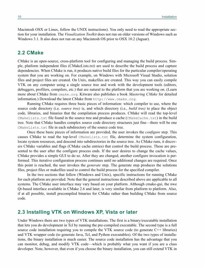
To install vtk.exe, the VTK Tcl/Tk executable, run the installer program vtk-X.X.X-win32.exe, avail-able from the download page of vtk.org which will bring up an installation GUI (see Figure 2–1). The“X.X.X” in the installer program’s filename represents the version number of VTK used to build it.You may also download corresponding *.zip files of the VTK source tree and the VTKData directory.As we release new versions of VTK, we make them available via links on the vtk.org download page.Watch for release announcements on the vtkusers mailing list.
The VTK source tree contains many *.tcl scripts you may use to learn about how various VTKclasses work. Download the vtk-X.X.X.zip and vtkdata-X.X.X.zip files and extract them to your harddrive. In the VTK folder, you will find an “Examples” folder. Under the Examples folder, there arefolders such as GUI, MangledMesa, and Parallel; each of those folders will have a sub foldercalled Tcl that contains various Tcl examples. In addition to the Examples folder, there are libraryfolders like Graphics, Imaging, and Filtering. Each of these folders contains a Testing/Tclsub folder containing the regression tests for VTK. Try running any example by double clicking onthe Tcl file. When you double-click on a Tcl file (.tcl extension) for the first time, a dialog box mayappear asking you what to use to open the file. This means that you need to create an associationbetween Tcl files and the vtk executable to run them. If this happens, click the "Select theprogram from a list" button on the dialog, and click "OK". A new dialog labeled "OpenWith" will appear. Click the "Browse" button on this dialog to display a file browser. In thebrowser, go to the directory where you installed VTK. Normally this is either C:\ProgramFiles\VTK 5.4 or C:\Program Files\Documents and Settings\<username>\My Docu-ments\VTK 5.4. In there you should see a bin folder which in turn contains a program called vtk.Double-click on vtk (or vtk.exe). Check that the "Always use the selected program toopen this kind of file" checkbutton is marked on the "Open With" dialog, and then selectthe OK button. Your example should then run. In the future, double-clicking on any Tcl scripts willautomatically begin execution of vtk.
Figure 2–1 The VTK installer program forWindows.
12 Installation
Alternatively, if Tcl files are already associated with the wish executable (from installing Tcl/Tk binaries), you will see an error message similar to the following when you double-click on a Tclfile: can’t find package vtk while executing "package require vtk". If you receivethis error message, right-click on the Tcl file, and select "Open With..." from the pop-up menudisplayed. The "Open With" dialog will appear. Follow the rest of the instructions from the previousparagraph to associate Tcl files with the vtk executable.
That completes the binary installation process for Windows. In Chapter 3 we’ll go into moredetail on how to write your own C++, Tcl, Java and Python applications.
Source Code Installation
To develop C++ applications and extend VTK, you will need to do a source code installation. This ismore challenging and may tie up your machine for a few hours as it compiles VTK. First you need tomake sure your machine is capable of building a VTK source code release. You must be running Win-dows XP, Vista or later. You will need a C++ compiler installed on your machine. The instructions inthis guide are oriented towards Microsoft Visual Studio 2005 or later, which works well with VTK.We also support the Borland C++ compiler, gcc under Cygwin or MinGW, NMake, Microsoft VisualC++ free editions, and Microsoft Visual C++ 2005. If you have not installed a C++ compiler, then youmust do this first.
The next issue to consider is what additional tools you plan to use. If you plan to do develop-ment in Java then you must download and install the Java JDK which is available from Sun Microsys-tems at http://www.java.sun.com. If you plan on using Tcl/Tk and you are not using MicrosoftVisual C++, then you will need to download and build the source code version of Tcl/Tk fromhttp://www.tcl.tk or download and install a Tcl/Tk binary from http://www.actives-tate.com/Products/ActiveTcl. (Note: Tcl/Tk version 8.4 works with VTK version 5.4.0.)
Installing CMake. To compile VTK, you will first need to install CMake. An installer for CMake isavailable from http://www.cmake.org.
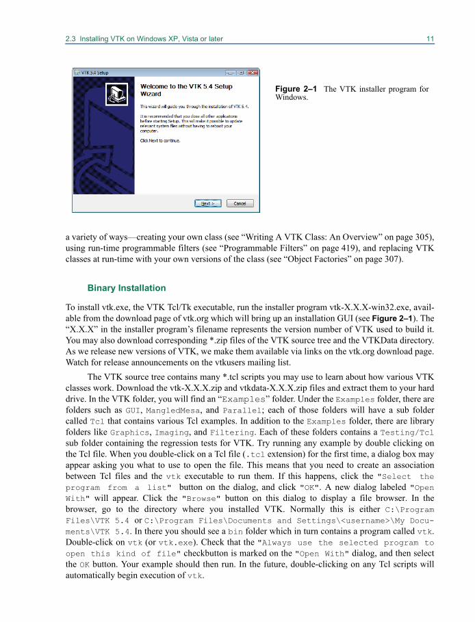
Running CMake. After you have setup your C++ compiler, installed CMake, and installed any addi-tional packages such as Tcl, Java, and Python, you are ready to run CMake. To run CMake, thereshould be a CMake entry in the Start menu under Programs->CMake->CMakeSetup. TheCMakeSetup.exe interface (Figure 2–2) is a simple program that allows you to customize the buildto your particular machine and desired options for VTK. First you must tell CMakeSetup where thesource tree for VTK is located and where you want to put the VTK binaries (these are generated as aresult of compiling the source code). You can specify those directories with the Browse buttons or by
Figure 2–2 CMake is used to generate proj-ects, makefiles, or workspaces for differentcompilers and operating systems. CMake iscross-platform.
2.3 Installing VTK on Windows XP, Vista or later 13
typing in the paths manually. Once the source and binary directories have been selected, you shouldclick on the Configure button. The first time you click the Configure button, CMake will displaya dialog from which you can select the build system you will use for compiling VTK. Then theCMakeSetup GUI will be filled with a list of variables and values found in the CMake cache. Whenfirst run, all the variables will be colored red. The red indicates that the cache entry was generated orchanged during the previous configure step.
At this point, you can customize your VTK build. For example, if you want to enable the Tclwrapping feature of VTK, scroll down in the cache values editor to the entry VTK_WRAP_TCL, andclick on the value to toggle it from OFF to ON. After that, click the Configure button again. This willcause most of the values to change to gray, and any new values to appear in red. If you installed Tcl/Tk from a binary install, none of the new values should have NOTFOUND as values; if they do, you willhave to specify those paths manually with the CMake interface. To set any value in the CMake inter-face, you click to the right of the variable where the value is displayed. Depending on the type of vari-able, there may be a file chooser, edit box or pull down that will allow you to edit the value.
Some important cache values for VTK are:
• BUILD_SHARED_LIBS — If this Boolean value is set to yes, then DLLs or shared libraries willbe built. If it is no, then static libraries will be built. The default is static libraries. The staticlibraries are somewhat easier to work with, since they do not need to be in your path when exe-cutables are run. The executables will be self-contained. This is preferred for distribution ofVTK based applications.
• VTK_WRAP_TCL — This determines if Tcl wrapping will be built.
• VTK_WRAP_PYTHON — This determines if Python wrapping will be built.
• VTK_WRAP_JAVA — This determines if Java wrapping will be built.
To get on-line help for any variable in CMake, simply click right over the value and select “Help forCache Entry”. Most of the defaults should be correct.
Continue to click on Configure until there are no longer any red values and you are happywith all of the values. At this point, you can click the OK button. This will cause CMake to write outthe build files for the build type selected. For Microsoft, a project file will be located in the binarypath you selected. Simply load this project file (VTK.dsw into Visual Studio 6.0, VTK.sln for .NET),and select the configuration you want to build in the Build->Set Active Configuration menu ofVisual Studio. You will have the choice of Debug, Release, MinSizeRel (minimum size release), andRelWithDebInfo (release with debug information). You can select the ALL_BUILD project, and com-pile it as you would any other Visual Studio project. For Borland, makefiles are generated, and youhave to use the command line make supplied with that compiler. The makefiles are located in thebinary directory you specified.
Once VTK has been built all libraries and executables produced will be located in the binarydirectory you specified to CMake in a sub-folder called bin (unless you changed theEXECUTABLE_OUTPUT_PATH, or LIBRARY_OUTPUT_PATH variables in CMake).
(Note: Do not use the MSVC++ “Rebuild All” menu selection to rebuild the source code. Thisdeletes all CMakeLists.txt files which are then automatically regenerated as part of the build pro-cess. MSVC will then try reloading them and an error will result. Instead, to rebuild everything,remove your VTK binary directory, rerun CMake, and then do a normal build.)
If you built VTK with BUILD_SHARED_LIBS on, then your client application will need tolocate and load the VTK DLLs at runtime. There are many different ways that your application might
14 Installation
find the VTK DLLs at runtime. There are pros and cons associated with each way. The easiestapproach is to make sure your application and the VTK DLLs exist in the same directory. You cancopy all the VTK DLLs into your application's directory, or build your application into the samedirectory the VTK DLLs were built in using EXECUTABLE_OUTPUT_PATH in your own applica-tion's CMakeLists files. If your application’s executable files and the VTK DLLs exist in the samedirectory, everything should just work. The "pro" of these approaches is their simplicity. The consare: if you make copies of the VTK DLLs, you'll need to make sure you copy them again if youupdate and rebuild VTK; if your application's build output is mixed in with VTK's build output, itmay be difficult to determine which build product comes from which project if necessary.
Another alternative is to modify the PATH environment variable so that your application canfind the VTK DLLs even though they are not in the same directory. However, within this alternative,there are a couple ways to accomplish the task. You can set up a command prompt where the PATH ismodified only in that command prompt and then launch your application from there, or you canchange the user's PATH environment variable or the system-wide PATH environment variable.Changing the user’s or system-wide PATH environment variable is recommended unless you need tohave two or more distinct builds of VTK on the same computer.
The KWWidgets project (http://www.kwwidgets.org) provides a good example of settingthe PATH from a batch script (to avoid changing the PATH environment variable), see the KWWid-getsSetupPaths.bat script in the build tree for the KWWidgets project. To obtain source code forKWWidgets, follow the instructions found at http://www.kwwidgets.org.
To set up a command prompt that can be used to launch an executable that can find the VTKDLLs, make a shortcut to a command prompt and then set it to call a batch file when it starts up. Thisis the technique that Visual Studio uses to create a command prompt where you can run the commandline compiler or nmake. You can right click on a shortcut in the Windows Start menu and chooseProperties to see how other command prompt shortcuts work. You can also drag-and-drop one ofthem to your desktop while holding down the control key to make a copy of it on your desktop. Thenyou can modify the properties of the shortcut on your desktop to call your own batch file that sets upyour PATH and any other environment settings you may need for your application. Use the "/K batch-filename.bat" argument to the command prompt to run the batch file and then leave the commandprompt running. Type "cmd /?" from any Windows command prompt for more information on the /Koption.
For further discussion of locating DLLs on Windows, see the Windows SDK documentation forthe LoadLibrary and LoadLibraryEx functions.
If you’ve made it this far, you’ve successfully built VTK on a PC. It can be a challenging pro-cess because of the size and complexity of the software. Please pay careful attention to the instruc-tions given earlier. If you do run into problems, you may wish to join the vtkusers mailing list (see“Additional Resources” on page 6) and ask for help there. Commercial support is also available fromKitware.
2.4 Installing VTK on Unix Systems
There are a wide variety of flavors of Unix systems. As a result you will have to compile the VTKsource code to build binaries and executables.
2.4 Installing VTK on Unix Systems 15
Source Code Installation
This section will walk you through the steps required to build VTK on a UNIX system. Unlike Win-dows, pre-compiled libraries and executables are not available for Unix systems, so you’ll have tocompile VTK yourself. (Note: check the vtkusers mailing list and other resources as described in“Additional Resources” on page 6—some users maintain binaries on the Web.) Typically, it is a fairlysimple process, and it should take about one to four hours depending on the speed of your machine.(High-end, large-memory multi-processor machines using parallel builds can build the C++ and Tcllibraries and executables in under 10 minutes!) Most of this time is spent waiting for the computer tocompile the source code. Only about 10-30 minutes of your time will be required. The first step is tomake sure you have the necessary resources to build VTK. To be safe, you will need about 300 mega-bytes of disk space. On some systems, such as SGI, you may need more space, especially if compilinga debug version of VTK. You will also need a C++ compiler since VTK is written in C++. Typicallythe C++ compiler will be called CC, g++, or acc. If you are not sure that you have a C++ compiler,check with your support staff.
If you are planning to use VTK with Tcl/Tk, Python, or Java, then you will first need to down-load and install those packages. The Java JDK is available from Sun Microsystems at http://www.java.sun.com. If you plan on using Tcl/Tk and it is not already installed on your system, thenyou will need to download Tcl/Tk from http://www.tcl.tk. Python can be downloaded fromhttp://www.python.org. Follow the instructions in these packages to build them.
CMake
Similar to the Windows environment, VTK on Unix uses CMake for the build process. (See the previ-ous section on CMake.) There are precompiled binaries of CMake available for many Unix systems;however, you may have to build CMake if binaries are not available. (Go to http://www.cmake.org to download precompiled binaries.)
Installing CMake. If pre-compiled binaries are available, download and then extract the tar filesinto your destination directory (typically /usr/local). Either make sure that cmake and associatedexecutables are in your path, or run cmake and its associated executables by giving their full path.
Building CMake. If a precompiled CMake binary is not available, you will have to build and installCMake. To build and install CMake, simply untar the sources (found at http://www.cmake.org)into a directory, and then run (in that directory):
./configure make make install
If you do not have root privileges, you can skip the third step above (i.e., make install). TheCMake executables will be located at CMake/bin/. There are two different CMake executableswhich can be used to configure VTK: ccmake that provides a terminal based interface very similar toCMakeSetup described in the Windows installation section, and cmake which implements a wizardthat requires you to answer a list of questions in order to configure the build.
It is a good idea to tell CMake which C++ and C compilers you want to use. On most Unix sys-tems, you can set the information this way:
16 Installation
setenv CXX /your/c++/compiler setenv CC /your/c/compiler
or
export CXX=/your/c++/compiler export CC=/your/c/compiler
Otherwise CMake will automatically detect your compiler—however, this may not be the one thatyou want if you have multiple compilers on your system. Once you have done this, create an emptybinary directory (e.g., VTK-bin) at the same level as the VTK source directory, and run CMake in it,passing it the path to the VTK source directory as shown below.
cd VTK-binccmake ../VTK
or
cd VTK-bincmake -i ../VTK
(The instructions in the following two subsections describe the differences between ccmake andcmake -i.) UNIX developers familiar with configure scripts will notice that CMake and configureare similar in their functionality. However, configure takes command line arguments to control thegeneration of makefiles whereas in CMake, the build options can be set from a user interface.
Customizing the Build Using the Terminal Based User Interface (ccmake). ccmake has a simpleterminal based interface that allows you to customize the VTK build to your particular machine andwith the desired options. Once you run CMake using ccmake, you will be presented with a list ofoptions that can be modified to customize the VTK build. CMake will be able to set most of theseoptions to reasonable default values. To change a value, simply scroll with arrow keys and pressenter when the desired option is highlighted. You will then be able to edit the option (unless thevariable is a boolean, in which case, pressing enter will toggle the value). After completing the editoperation, hit enter again to resume scrolling through the options. Once you set all the options youwant, press ‘c’. CMake will then process the configuration files and if necessary display new optionson top (for example, if you turn VTK_WRAP_TCL on, you will be presented with options for thelocation of Tcl/Tk libraries and include paths). If there are new options, you should set them, (or leavethem as they are if you are satisfied with the default values) and re-configure by pressing ‘c’ and con-tinue this process until there are no new options. Once this iterative process is completed, there willbe new commands available: Generate and Exit. You can now press ‘g’ to have CMake generatenew makefiles and exit. If you need to change build options in the future, simply re-run ccmake andfollow the instructions above.
Customizing the Build Using the Interactive Wizard Mode (cmake -i). On some platforms theterminal based interface provided by ccmake may not work. In this case try cmake with the -i (inter-active wizard) option. Once you do so, it will ask you whether you want to see the advanced options.Most users will not have to change the advanced options. Next, CMake will ask you a list of ques-tions. For each option, there will be a line describing what it does and a default (current) value. In

2.4 Installing VTK on Unix Systems 17
most cases, CMake will be able to generate acceptable default options. However, in certain cases, forexample when a library such as OpenGL library is not located in the expected place, you will have totell CMake the correct setting. Furthermore, by default, the bindings for Tcl, Python and Java are notcreated. If you want support for one or more of these languages, you will have to turn on the appropri-ate VTK_WRAP_XXX option on and, if necessary, tell CMake the location of necessary libraries andheader files. Once you answer all questions, all your makefiles will be generated and VTK will beready to build. If you need to change build options in the future, you can re-run CMake in wizardmode and answer all questions again.
Compiling the Source Code
Once CMake has completed running and produced the necessary makefiles, you can type make andVTK should compile. Some make utilities such as GNU make (gmake) support parallel builds (e.g.,gmake with the -j option). Use parallel make if possible, even if on a single processor system,because usually the process is IO bound and the processor can handle multiple compiles. If you dorun into problems, you may wish to join the vtkusers mailing list (see “Additional Resources” onpage 6) and ask for help there. Commercial support is also available from Kitware.
Building VTK On Multiple Platforms
If you are planning to build VTK for multiple architectures then you can either make a copy of theentire VTK tree for each architecture and follow the instructions above, or you can have one copy ofthe VTK source tree and produce object code, libraries, and executables for each architecture in a sep-arate directory. This approach requires creating a new build directory for each architecture such asvtk-solaris (make sure that you have enough disk space). Assuming that the new directory is cre-ated along side of the VTK source code directory, change directory (cd) into this directory and thenrun CMake similar to the following example:
cd /yourdisk ls (output is: VTK vtk-solaris vtk-sgi) cd vtk-solaris cmake -i ../VTK
or
ccmake ../VTK
This will create makefiles in the vtk-solaris directory. You can now follow the instructions in theprevious section for compiling VTK.
Installing VTK
Now that VTK has been built, the executables and libraries will be located in the build directory, inthe sub-directory bin/. If you plan to share the build with more than one developer on the UNIX sys-tem, and you have root privileges, it is often a good idea to run the make install command. Thiswill install VTK into /usr/local, unless you changed the build option CMAKE_INSTALL_PREFIXto another location. Running make install will copy all the files you need to compile and run VTKinto a directory that other users can share.

18 Installation
This concludes the build and installation section for VTK under UNIX. If you need more infor-mation about CMake, see http://www.cmake.org or purchase the Mastering CMake book fromKitware (http://www.kitware.com/products/cmakebook.html). Chapter 3 of this softwareguide provides more details on how to run examples and create your own applications.
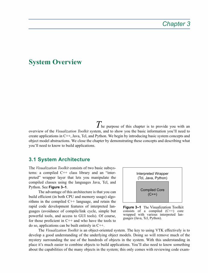
Chapter 3
System Overview 3
The purpose of this chapter is to provide you with anoverview of the Visualization Toolkit system, and to show you the basic information you’ll need tocreate applications in C++, Java, Tcl, and Python. We begin by introducing basic system concepts andobject model abstractions. We close the chapter by demonstrating these concepts and describing whatyou’ll need to know to build applications.
3.1 System ArchitectureThe Visualization Toolkit consists of two basic subsys-tems: a compiled C++ class library and an “inter-preted” wrapper layer that lets you manipulate thecompiled classes using the languages Java, Tcl, andPython. See Figure 3–1.
The advantage of this architecture is that you canbuild efficient (in both CPU and memory usage) algo-rithms in the compiled C++ language, and retain therapid code development features of interpreted lan-guages (avoidance of compile/link cycle, simple butpowerful tools, and access to GUI tools). Of course,for those proficient in C++ and who have the tools todo so, applications can be built entirely in C++.
The Visualization Toolkit is an object-oriented system. The key to using VTK effectively is todevelop a good understanding of the underlying object models. Doing so will remove much of themystery surrounding the use of the hundreds of objects in the system. With this understanding inplace it’s much easier to combine objects to build applications. You’ll also need to know somethingabout the capabilities of the many objects in the system; this only comes with reviewing code exam-
Figure 3–1 The Visualization Toolkitconsists of a compiled (C++) corewrapped with various interpreted lan-guages (Java, Tcl, Python).
Interpreted Wrapper(Tcl, Java, Python)
Compiled Core(C++)
20 System Overview
ples and online documentation. In this User’s Guide, we’ve tried to provide you with useful combina-tions of VTK objects that you can adapt to your own applications.
In the remainder of this section, we will introduce two major components of the VisualizationToolkit: the visualization pipeline and the rendering engine. The visualization pipeline is used toacquire or create data, process that data, and either write the results to a file or pass the results to therendering engine for display. The rendering engine is responsible for creating a visual representationof the data. Note that these are not truly rigid architectural components of VTK but are instead con-ceptual components. The discussion in this chapter will be fairly high-level, but when you combinethat with the specific examples in both this chapter and the next, as well as the hundreds of availableexamples in the VTK source distribution you will gain a good understanding of these components.
Low-Level Object Model
The VTK object model can be thought of as being rooted in the superclass vtkObject. Nearly all VTKclasses are derived from this class, or in some special cases from its superclass vtkObjectBase. AllVTK must be created using the object's New() method, and must be destroyed using the object'sDelete() method. VTK objects cannot be allocated on the stack because the constructor is a protectedmethod. Using a common superclass and a unified method of creating and destroying object, VTK isable to provide several basic object-oriented operations.
Reference Counting. Objects explicitly store a count of the number of pointers referencing them.When an object is created through the static New() method of a class its initial reference count is 1because a raw pointer must be used to refer to the new object:
vtkObjectBase* obj = vtkExampleClass::New();
When other references to the object are created or destroyed the reference count is incremented anddecremented using the Register() and UnRegister() methods. Usually this is handled automatically bythe various “set” methods provided in the object’s API:
otherObject->SetExample(obj);
The reference count is now 2 because both the original pointer and a pointer stored inside the otherobject both refer to it. When the raw pointer originally storing the object is no longer needed the ref-erence is removed using the Delete() method:
obj->Delete();
From this point forward it is no longer safe to use the original pointer to access the object because thepointer does not own a reference to it. In order to ensure proper management of object referencesevery call to New() must be paired with a later call to Delete() to be sure no references are leaked.
A "smart pointer" implementation is provided by the class template vtkSmartPointer<> whichsimplifies object management. The above example may be re-written:
vtkSmartPointer<vtkObjectBase> obj =vtkSmartPointer<vtkExampleClass>::New();
otherObject->SetExample(obj);
3.1 System Architecture 21
In this case the smart pointer automatically manages the reference it owns. When the smart pointervariable goes out-of-scope and is no longer used, such as when a function in which it is a local vari-able returns, it automatically informs the object by decrementing the reference count. By using thestatic New() method provided by the smart pointer no raw pointer ever needs to hold a reference tothe object, so no call to Delete() is needed.
Run-Time Type Information. In C++ the real type of an object may be different from the type ofpointer used to reference it. All classes in the public interface of VTK have simple identifiers for classnames (no templates), so a string is sufficient to identify them. The type of a VTK object may beobtained at run-time with the GetClassName() method:
const char* type = obj->GetClassName();
An object may be tested for whether it is an instance of a particular class or one of its subclasses usingthe IsA() method:
if(obj->IsA("vtkExampleClass")) { ... }
A pointer of a superclass type may be safely converted to a more derived type using the static Safe-DownCast() method provided by the class of the derived type:
vtkExampleClass* example = vtkExampleClass::SafeDownCast(obj)
This will succeed at run-time only if the object is truly an instance of the more-derived type and oth-erwise will return a null pointer.
Object State Display. When debugging it is often useful to display a human-readable description ofthe current state of an object. This can be obtained for VTK objects using the Print() method:
obj->Print(cout);
The Rendering EngineThe VTK rendering engine consists of the classes in VTK that are responsible for taking the results ofthe visualization pipeline and displaying them into a window. This involves the following compo-nents. Note that this is not an exhaustive list, but rather a sense of the most commonly used objects inthe rendering engine. The subheadings used here are the highest level superclass in VTK that repre-sents this type of object, and in many cases where there are multiple choices these are abstract classesdefining the basic API across the various concrete subclasses that implement the functionality..
vtkProp. Visible depictions of data that exist in the scene are represented by a subclass of vtkProp.The most commonly used subclasses of vtkProp for displaying objects in 3D are vtkActor (used torepresent geometric data in the scene) and vtkVolume (used to represent volumetric data in the scene).There are also props that represent data in 2D such as vtkActor2D. The vtkProp subclass is generallyresponsible for knowing its position, size, and orientation in the scene. The parameters used to controlthe placement of the prop generally depend on whether the prop is for example a 3D object in thescene, or a 2D annotation. For 3D props such as vtkActor and vtkVolume (both subclasses ofvtkProp3D which is itself a subclass of vtkProp), you can either directly control parameters such as

22 System Overview
the object's 3D position, orientation and scale, or you can use a 4x4 transformation matrix. For 2Dprops that provide annotation such as the vtkScalarBarActor, the size and position of the annotationcan be defined in a variety of ways including specifying a position, width, and height relative to thesize of the entire viewport. In addition to providing placement control, props generally have a mapperobject that holds the data and knows how to render it, and a property object that controls parameterssuch as color and opacity.
There are a large number (over 50) of specialized props such as vtkImageActor (used to displayan image) and vtkPieChartActor (used to create a pie chart visual representation of an array of data
(a) Image Data(vtkImageData)
(e) Polygonal Data(vtkPolyData)
(c) Structured Grid(vtkStructuredGrid)
(f) Unstructured Grid(vtkUnstructuredGrid)
(b) Rectilinear Grid(vtkRectilinearGrid)
(d) Unstructured Points(use vtkPolyData)
Figure 3–2 Dataset types found in VTK. Note that unstructured points can be represented by either polygonaldata or unstructured grids, so are not explicitly represented in the system.

3.1 System Architecture 23
values). Some of these specialized props directly contain the parameters that control appearance, anddirectly have a reference to the input data to be rendered, and therefore do not require the use of aproperty or a mapper. The vtkFollower prop is a specialized subclass of vtkActor that will automati-cally update its orientation in order to continually face a specified camera. This is useful for display-ing billboards or text in the 3D scene and having them remain visible as the user rotates. ThevtkLODActor is also a subclass of vtkActor that automatically changes its geometric representationin order to maintain interactive frame rates, and vtkLODProp3D is a subclass of vtkProp3D thatselects between a number of different mappers (perhaps even a mixture of volumetric and geometricmappers) in order to provide interactivity. vtkAssembly allows hierarchies of actors, properly manag-ing the transformations when the hierarchy is translated, rotated or scaled.
vtkAbstractMapper. Some props such as vtkActor and vtkVolume use a subclass of vtkAbstract-Mapper to hold a reference to the input data and to provide the actual rendering functionality. ThevtkPolyDataMapper is the primary mapper for rendering polygonal geometry. For volumetric objects,VTK provides several rendering techniques including the vtkFixedPointVolumeRayCastMapper thatcan be used to rendering vtkImageData, and the vtkProjectedTetrahedra mapper that can be used torender vtkUnstructuredGrid data.
vtkProperty and vtkVolumeProperty. Some props use a separate property object to hold the vari-ous parameters that control the appearance of the data. This allows you to more easily share appear-ance settings between different objects in your scene. The vtkActor object uses a vtkProperty to storeparameters such as color, opacity, and the ambient, diffuse, and specular coefficient of the material.The vtkVolume object instead uses a vtkVolumeProperty to capture the parameters that are applicableto a volumetric object, such as the transfer functions that map the scalar value to color and opacity.Many mappers also provide functionality to set clipping planes that can be used to reveal interiorstructure.
vtkCamera. The vtkCamera contains the parameters that control how you view the scene. The vtk-Camera has a position, a focal point, and a vector defining the direction of "up" in the scene. Otherparameters control the specific viewing transformation (parallel or perspective), the scale or viewangle of the image, and the near and far clipping planes of the view frustum.
vtkLight. When lighting is computed for a scene, one or more vtkLight objects are required. The vtk-Light objects store the position and orientation of the light, as well as the color and intensity. Lightsalso have a type that describes how the light will move with respect to the camera. For example, aHeadlight is always located at the camera's position and shines on the camera's focal point, whereas aSceneLight is located at a stationary position in the scene.
vtkRenderer. The objects that make up a scene including the props, the camera and the lights are col-lected together in a vtkRenderer. The vtkRenderer is responsible for managing the rendering processfor the scene. Multiple vtkRenderer objects can be used together in a single vtkRenderWindow. Theserenderers may render into different rectangular regions (known as viewports) of the render window,or may be overlapping.
vtkRenderWindow. The vtkRenderWindow provides a connection between the operating systemand the VTK rendering engine. Platform specific subclasses of vtkRenderWindow are responsible foropening a window in the native windowing system on your computer and managing the display pro-
24 System Overview
cess. When you develop with VTK, you simply use the platform-independent vtkRenderWindowwhich is automatically replaced with the correct platform-specific subclass at runtime. The vtkRen-derWindow contains a collection of vtkRenderers, and parameters that control rendering features suchas stereo, anti-aliasing, motion blur and focal depth.
vtkRenderWindowInteractor. The vtkRenderWindowInteractor is responsible for processingmouse, key, and timer events and routing these through VTK's implementation of the command /observer design pattern. A vtkInteractorStyle listens for these events and processes them in order toprovide motion controls such as rotating, panning and zooming. The vtkRenderWindowInteractorautomatically creates a default interactor style that works well for 3D scenes, but you can insteadselect one for 2D image viewing for example, or create your own custom interactor style.
vtkTransform. Many of the objects in the scene that require placement such as props, lights, andcameras have a vtkTransform parameter that can be used to easily manipulate the position and orien-tation of the object. The vtkTransform can be used to describe the full range of linear (also known asaffine) coordinate transformation in three dimensions, which are internally represented as a 4x4homogeneous transformation matrix. The vtkTransform object will start with a default identity matrixor you can chain transformation together in a pipeline fashion to create complex behavior. The pipe-line mechanism assures that if you modify any transform in the pipeline, all subsequent transformsare updated accordingly.
vtkLookupTable, vtkColorTransferFunction, and vtkPiecewiseFunction. Visualizing scalar dataoften involves defining a mapping from a scalar value to a color and opacity. This is true both in geo-metric surface rendering where the opacity will define the translucency of the surface, and in volumerendering where the opacity will represent the opacity accumulated along some length of of ray pass-ing through the volume. For geometric rendering, this mapping is typically created using a vtk-LookupTable, and in volume rendering both the vtkColorTransferFunction and thevtkPiecewiseFunction will be utilized.
A minimal example. The following example (adapted from ./VTK/Examples/Rendering/Cxx/Cylin-der.cxx) shows how some of these objects can be used to specify and render a scene.
vtkCylinderSource *cylinder = vtkCylinderSource::New();
vtkPolyDataMapper *cylinderMapper = vtkPolyDataMapper::New(); cylinderMapper->SetInputConnection(cylinder->GetOutputPort());
vtkActor *cylinderActor = vtkActor::New(); cylinderActor->SetMapper(cylinderMapper);
vtkRenderer *ren1 = vtkRenderer::New(); ren1->AddActor(cylinderActor);
vtkRenderWindow *renWin = vtkRenderWindow::New(); renWin->AddRenderer(ren1);
vtkRenderWindowInteractor *iren = vtkRenderWindowInteractor::New(); iren->SetRenderWindow(renWin);
3.1 System Architecture 25
renWin->Render(); iren->Start();
In this example we have directly created a vtkActor, vtkPolyDataMapper, vtkRenderer, vtkRender-Window and vtkRenderWindowInteractor. Note that a vtkProperty was automatically created by theactor, and a vtkLight and a vtkCamera were automatically created by the vtkRenderer.
The Visualization PipelineThe visualization pipeline in VTK can be used to read or create data, analyze and create derivativeversion of this data, and write the data to disk or pass it along to the rendering engine for display. Forexample, you may read a 3D volume of data from disk, process it to create a set of triangles represent-ing an isovalued surface through the volume, then write this geometric object back out to disk. Or,you may create a set of spheres and cylinders to represent atoms and bonds, then pass these off to therendering engine for display.
The Visualization Toolkit uses a data flow approach to transform information into graphicaldata. There are two basic types of objects involved in this approach.
• vtkDataObject• vtkAlgorithm
Data objects represent data of various types. The class vtkDataObject can be viewed as a generic“blob” of data. Data that has a formal structure is referred to as a dataset (class vtkDataSet). Figure 3–2 shows the dataset objects supported in VTK. Datasets consist of a geometric and topological struc-ture (points and cells) as illustrated by the figure; they also have associated attribute data such as sca-lars or vectors. The attribute data can be associated with the points or cells of the dataset. Cells aretopological organizations of points; cells form the atoms of the dataset and are used to interpolateinformation between points. Figure 19–20 and Figure 19–21 show twenty-three of the most commoncell types supported by VTK. Figure 3–3 shows the attribute data supported by VTK.
Algorithms, also referred to generally as filters, operate on data objects to produce new dataobjects. Algorithms and data objects are connected together to form visualization pipelines (i.e., data-flow networks). Figure 3–4 is a depiction of a visualization pipeline.
This figure together with Figure 3–5 illustrate some important visualization concepts. Sourcealgorithms produce data by reading (reader objects) or constructing one or more data objects (proce-dural source objects). Filters ingest one or more data objects and generate one or more data objects onoutput. Mappers (or in some cases, specialized actors) take the data and convert it into a visual repre-sentation that is displayed by the rendering engine. A writer can be thought of as a type of mapper thatwrites data to a file or stream.
There are several important issues regarding the construction of the visualization pipeline thatwe will briefly introduce here. First, pipeline topology is constructed using variations of the methods
aFilter->SetInputConnection( anotherFilter->GetOutputPort() );
which sets the input to the filter aFilter to the output of the filter anotherFilter. (Filters withmultiple inputs and outputs have similar methods.) Second, we must have a mechanism for control-ling the execution of the pipeline. We only want to execute those portions of the pipeline necessary tobring the output up to date. The Visualization Toolkit uses a lazy evaluation scheme (executes only

26 System Overview
Figure 3–3 Data attributes associated with the points and cells of a dataset.
Scalar: single data value Vector: 3D direction and magnitude
Normal: 3D direction
Texture coordinate: n-dimensional index into texture
map
Tensor:nxn matrix
s(u,v,w)
(nx, ny, nz)|n|=1
s
t
2D: (u,v)3D: (u,v,w)
a11 a12 a13
a21 a22 a23
a31 a32 a33
Field Data:An array of arrays. Each array can be of
different data type (vtkFieldData)
vtkDataArray
Array 1 Array n-1Array 0
Source Filter Filter Mapper
Data Object
Filter
Rendering engine
Multiple Input
Data Object
Data Object Data Object Data Object
Figure 3–4 Data objects are connected with algorithms (filters) to create the visualization pipeline.The arrows point in the direction of data flow.
Source
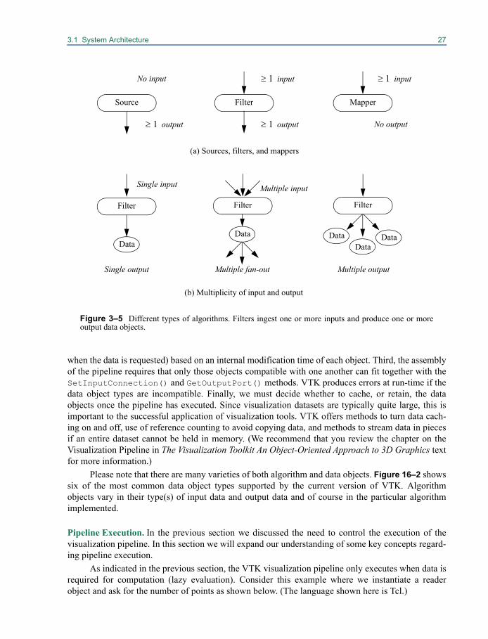
3.1 System Architecture 27
when the data is requested) based on an internal modification time of each object. Third, the assemblyof the pipeline requires that only those objects compatible with one another can fit together with theSetInputConnection() and GetOutputPort() methods. VTK produces errors at run-time if thedata object types are incompatible. Finally, we must decide whether to cache, or retain, the dataobjects once the pipeline has executed. Since visualization datasets are typically quite large, this isimportant to the successful application of visualization tools. VTK offers methods to turn data cach-ing on and off, use of reference counting to avoid copying data, and methods to stream data in piecesif an entire dataset cannot be held in memory. (We recommend that you review the chapter on theVisualization Pipeline in The Visualization Toolkit An Object-Oriented Approach to 3D Graphics textfor more information.)
Please note that there are many varieties of both algorithm and data objects. Figure 16–2 showssix of the most common data object types supported by the current version of VTK. Algorithmobjects vary in their type(s) of input data and output data and of course in the particular algorithmimplemented.
Pipeline Execution. In the previous section we discussed the need to control the execution of thevisualization pipeline. In this section we will expand our understanding of some key concepts regard-ing pipeline execution.
As indicated in the previous section, the VTK visualization pipeline only executes when data isrequired for computation (lazy evaluation). Consider this example where we instantiate a readerobject and ask for the number of points as shown below. (The language shown here is Tcl.)
No input
Data
Source Filter Mapper
Filter Filter
DataData
Single input
Single output
Multiple input
Multiple fan-out
output 1t output 1t
input 1t input 1t
No output
(a) Sources, filters, and mappers
Multiple output
(b) Multiplicity of input and output
DataData
Filter
Figure 3–5 Different types of algorithms. Filters ingest one or more inputs and produce one or moreoutput data objects.
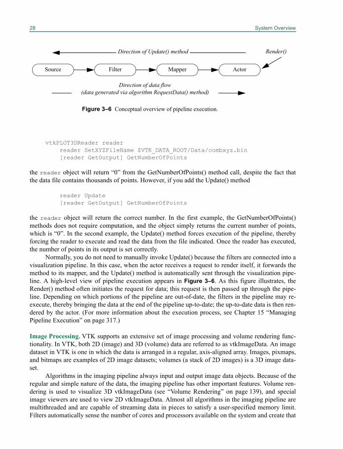
28 System Overview
vtkPLOT3DReader readerreader SetXYZFileName $VTK_DATA_ROOT/Data/combxyz.bin[reader GetOutput] GetNumberOfPoints
the reader object will return “0” from the GetNumberOfPoints() method call, despite the fact thatthe data file contains thousands of points. However, if you add the Update() method
reader Update[reader GetOutput] GetNumberOfPoints
the reader object will return the correct number. In the first example, the GetNumberOfPoints()methods does not require computation, and the object simply returns the current number of points,which is “0”. In the second example, the Update() method forces execution of the pipeline, therebyforcing the reader to execute and read the data from the file indicated. Once the reader has executed,the number of points in its output is set correctly.
Normally, you do not need to manually invoke Update() because the filters are connected into avisualization pipeline. In this case, when the actor receives a request to render itself, it forwards themethod to its mapper, and the Update() method is automatically sent through the visualization pipe-line. A high-level view of pipeline execution appears in Figure 3–6. As this figure illustrates, theRender() method often initiates the request for data; this request is then passed up through the pipe-line. Depending on which portions of the pipeline are out-of-date, the filters in the pipeline may re-execute, thereby bringing the data at the end of the pipeline up-to-date; the up-to-date data is then ren-dered by the actor. (For more information about the execution process, see Chapter 15 “ManagingPipeline Execution” on page 317.)
Image Processing. VTK supports an extensive set of image processing and volume rendering func-tionality. In VTK, both 2D (image) and 3D (volume) data are referred to as vtkImageData. An imagedataset in VTK is one in which the data is arranged in a regular, axis-aligned array. Images, pixmaps,and bitmaps are examples of 2D image datasets; volumes (a stack of 2D images) is a 3D image data-set.
Algorithms in the imaging pipeline always input and output image data objects. Because of theregular and simple nature of the data, the imaging pipeline has other important features. Volume ren-dering is used to visualize 3D vtkImageData (see “Volume Rendering” on page 139), and specialimage viewers are used to view 2D vtkImageData. Almost all algorithms in the imaging pipeline aremultithreaded and are capable of streaming data in pieces to satisfy a user-specified memory limit.Filters automatically sense the number of cores and processors available on the system and create that
Figure 3–6 Conceptual overview of pipeline execution.
Source Filter Mapper Actor
Direction of Update() method
Direction of data flow(data generated via algorithm RequestData() method)
Render()
3.2 Create An Application 29
number of threads during execution as well as automatically separating data into pieces that arestreamed through the pipeline. (See “vtkStreamingDemandDrivenPipeline” on page 325 for moreinformation.)
This concludes our brief overview of the Visualization Toolkit system architecture. We recom-mend the The Visualization Toolkit An Object-Oriented Approach to 3D Graphics text for moredetails on many of the algorithms found in VTK. Learning by example is another helpful approach.Chapters 4 through 13 contain many annotated examples demonstrating various capabilities of VTK.Also, since source code is available, you may wish to study the examples found in the VTK/Exam-ples directory of the VTK source tree.
With this abbreviated introduction behind us, let’s look at ways to create applications in C++,Tcl, Java, and Python.
3.2 Create An ApplicationThis section covers the basic information you need to develop VTK applications in the four program-ming languages Tcl, C++, Java, and Python. After reading this introduction, you should jump to thesubsection(s) that discuss the language(s) you are interested in using. In addition to providing youwith instructions on how to create and run a simple application, each section will show you how totake advantage of callbacks in that language.
User Methods, Observers, and CommandsCallbacks (or user methods) are implemented in VTK using the Subject/Observer and Commanddesign pattern. This means that nearly every class in VTK (every subclass of vtkObject) has anAddObserver() method that can be used to setup callbacks from VTK. The observer looks at everyevent invoked on an object, and if it matches one of the events that the observer is watching for, thenan associated command is invoked (i.e., the callback). For example, all VTK filters invoke aStartEvent right before they start to execute. If you add an observer that watches for aStartEvent then it will get called every time that filter starts to execute. Consider the following Tclscript that creates an instance of vtkElevationFilter, and adds an observer for the StartEvent to callthe procedure PrintStatus.
proc PrintStatus {} {puts "Starting to execute the elevation filter"}vtkElevationFilter foofoo AddObserver StartEvent PrintStatus
This type of functionality (i.e., callback) is available in all the languages VTK supports. Each sectionthat follows will show a brief example of how to use it. Further discussion on user methods is pro-vided in “Integrating With The Windowing System” on page 421. (This section also discusses userinterface integration issues.)
To create your own application, we suggest starting with one of the examples that come withVTK. They can be found in VTK/Examples in the source distribution. In the source distribution theexamples are organized first by topic and then by language. Under VTK/Examples you will finddirectories for different topics, and under the directories there will be subdirectories for different lan-guages such as Tcl.

30 System Overview
TclTcl is one of the easiest languages with which to start creating VTK applications. Once you haveinstalled VTK, you should be able to run the Tcl examples that come with the distribution. UnderUNIX you have to compile VTK with Tcl support as mentioned in “Installing VTK on Unix Systems”on page 14. Under Windows you can just install the self-extracting archive as described in “InstallingVTK on Windows XP, Vista or later” on page 10.
Windows. Under Windows, you can run a Tcl script just by double clicking on the file (Cone.tcl inthis example). If nothing happens you might have an error in your script or a problem with associatingTcl files with the vtk.exe executable. To detect this you need to run vtk.exe first. vtk.exe can befound in your start menu under VTK. Once execution begins, a console window should appear with aprompt in it. At this prompt type in a cd command to change to the directory where Cone.tcl islocated. Two examples are given below:
% cd "c:/VTK/Examples/Tutorial/Step1/Tcl"
Then you will need to source the example script using the following command.
% source Cone.tcl
Tcl will try to execute Cone.tcl, and you will be able to see errors or warning messages that wouldotherwise not appear.
Unix. Under UNIX, Tcl development can be done by running the VTK executable (after you havecompiled the source code) that can be found in your binary directory (e.g., VTK-bin/bin/vtk, VTK-Solaris/bin/vtk, etc.) and then providing the Tcl script as the first argument as shown below.
unix machine> cd VTK/Examples/Tutorial/Step1/Tclunix machine> /home/VTK-Solaris/bin/vtk Cone.tcl
User methods can be set up as shown in the introduction of this section. An example can be found inExamples/Tutorial/Step2/Tcl/Cone2.tcl. The key changes are shown below.
proc myCallback {} {puts "Starting to render"
}
vtkRenderer ren1ren1 AddObserver StartEvent myCallback
You may instead simply provide the body of the proc directly to AddObserver().
vtkRenderer ren1ren1 AddObserver StartEvent {puts "Starting to render"}
C++Using C++ as your development language will typically result in smaller, faster, and more easilydeployed applications than most any other language. C++ development also has the advantage that
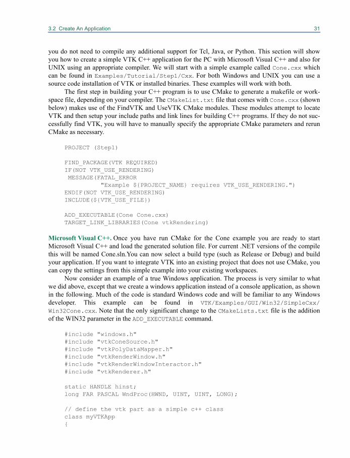
3.2 Create An Application 31
you do not need to compile any additional support for Tcl, Java, or Python. This section will showyou how to create a simple VTK C++ application for the PC with Microsoft Visual C++ and also forUNIX using an appropriate compiler. We will start with a simple example called Cone.cxx whichcan be found in Examples/Tutorial/Step1/Cxx. For both Windows and UNIX you can use asource code installation of VTK or installed binaries. These examples will work with both.
The first step in building your C++ program is to use CMake to generate a makefile or work-space file, depending on your compiler. The CMakeList.txt file that comes with Cone.cxx (shownbelow) makes use of the FindVTK and UseVTK CMake modules. These modules attempt to locateVTK and then setup your include paths and link lines for building C++ programs. If they do not suc-cessfully find VTK, you will have to manually specify the appropriate CMake parameters and rerunCMake as necessary.
PROJECT (Step1)
FIND_PACKAGE(VTK REQUIRED)IF(NOT VTK_USE_RENDERING) MESSAGE(FATAL_ERROR
"Example ${PROJECT_NAME} requires VTK_USE_RENDERING.")ENDIF(NOT VTK_USE_RENDERING)INCLUDE(${VTK_USE_FILE})
ADD_EXECUTABLE(Cone Cone.cxx)TARGET_LINK_LIBRARIES(Cone vtkRendering)
Microsoft Visual C++. Once you have run CMake for the Cone example you are ready to startMicrosoft Visual C++ and load the generated solution file. For current .NET versions of the compilethis will be named Cone.sln.You can now select a build type (such as Release or Debug) and buildyour application. If you want to integrate VTK into an existing project that does not use CMake, youcan copy the settings from this simple example into your existing workspaces.
Now consider an example of a true Windows application. The process is very similar to whatwe did above, except that we create a windows application instead of a console application, as shownin the following. Much of the code is standard Windows code and will be familiar to any Windowsdeveloper. This example can be found in VTK/Examples/GUI/Win32/SimpleCxx/Win32Cone.cxx. Note that the only significant change to the CMakeLists.txt file is the additionof the WIN32 parameter in the ADD_EXECUTABLE command.
#include "windows.h"#include "vtkConeSource.h"#include "vtkPolyDataMapper.h"#include "vtkRenderWindow.h"#include "vtkRenderWindowInteractor.h"#include "vtkRenderer.h"
static HANDLE hinst;long FAR PASCAL WndProc(HWND, UINT, UINT, LONG);
// define the vtk part as a simple c++ classclass myVTKApp{
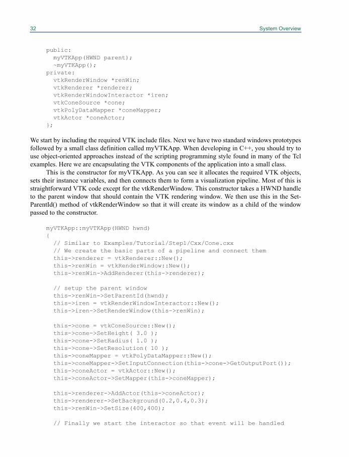
32 System Overview
public:myVTKApp(HWND parent);~myVTKApp();
private:vtkRenderWindow *renWin;vtkRenderer *renderer;vtkRenderWindowInteractor *iren;vtkConeSource *cone;vtkPolyDataMapper *coneMapper;vtkActor *coneActor;
};
We start by including the required VTK include files. Next we have two standard windows prototypesfollowed by a small class definition called myVTKApp. When developing in C++, you should try touse object-oriented approaches instead of the scripting programming style found in many of the Tclexamples. Here we are encapsulating the VTK components of the application into a small class.
This is the constructor for myVTKApp. As you can see it allocates the required VTK objects,sets their instance variables, and then connects them to form a visualization pipeline. Most of this isstraightforward VTK code except for the vtkRenderWindow. This constructor takes a HWND handleto the parent window that should contain the VTK rendering window. We then use this in the Set-ParentId() method of vtkRenderWindow so that it will create its window as a child of the windowpassed to the constructor.
myVTKApp::myVTKApp(HWND hwnd){
// Similar to Examples/Tutorial/Step1/Cxx/Cone.cxx// We create the basic parts of a pipeline and connect themthis->renderer = vtkRenderer::New();this->renWin = vtkRenderWindow::New();this->renWin->AddRenderer(this->renderer);
// setup the parent windowthis->renWin->SetParentId(hwnd);this->iren = vtkRenderWindowInteractor::New();this->iren->SetRenderWindow(this->renWin);
this->cone = vtkConeSource::New();this->cone->SetHeight( 3.0 );this->cone->SetRadius( 1.0 );this->cone->SetResolution( 10 );this->coneMapper = vtkPolyDataMapper::New();this->coneMapper->SetInputConnection(this->cone->GetOutputPort());this->coneActor = vtkActor::New();this->coneActor->SetMapper(this->coneMapper);
this->renderer->AddActor(this->coneActor);this->renderer->SetBackground(0.2,0.4,0.3);this->renWin->SetSize(400,400);
// Finally we start the interactor so that event will be handled
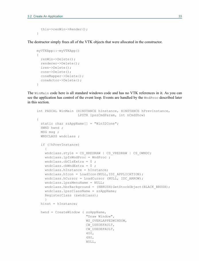
3.2 Create An Application 33
this->renWin->Render(); }
The destructor simply frees all of the VTK objects that were allocated in the constructor.
myVTKApp::~myVTKApp(){
renWin->Delete();renderer->Delete();iren->Delete();cone->Delete();coneMapper->Delete();coneActor->Delete();
}
The WinMain code here is all standard windows code and has no VTK references in it. As you cansee the application has control of the event loop. Events are handled by the WndProc described laterin this section.
int PASCAL WinMain (HINSTANCE hInstance, HINSTANCE hPrevInstance, LPSTR lpszCmdParam, int nCmdShow) {
static char szAppName[] = "Win32Cone";HWND hwnd ;MSG msg ;WNDCLASS wndclass ;
if (!hPrevInstance){ wndclass.style = CS_HREDRAW | CS_VREDRAW | CS_OWNDC;wndclass.lpfnWndProc = WndProc ;wndclass.cbClsExtra = 0 ;wndclass.cbWndExtra = 0 ;wndclass.hInstance = hInstance;wndclass.hIcon = LoadIcon(NULL,IDI_APPLICATION);wndclass.hCursor = LoadCursor (NULL, IDC_ARROW);wndclass.lpszMenuName = NULL;wndclass.hbrBackground = (HBRUSH)GetStockObject(BLACK_BRUSH);wndclass.lpszClassName = szAppName;RegisterClass (&wndclass);}
hinst = hInstance;
hwnd = CreateWindow ( szAppName,"Draw Window",WS_OVERLAPPEDWINDOW,CW_USEDEFAULT,CW_USEDEFAULT,400,480,NULL,
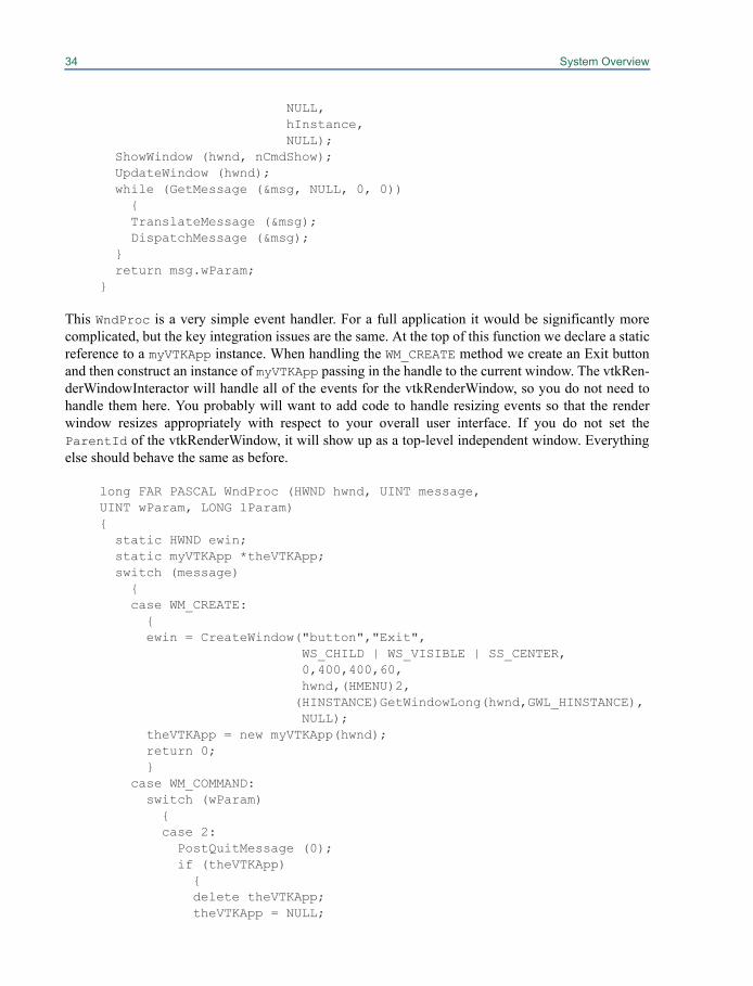
34 System Overview
NULL,hInstance,NULL);
ShowWindow (hwnd, nCmdShow);UpdateWindow (hwnd);while (GetMessage (&msg, NULL, 0, 0))
{TranslateMessage (&msg);DispatchMessage (&msg);
}return msg.wParam;
}
This WndProc is a very simple event handler. For a full application it would be significantly morecomplicated, but the key integration issues are the same. At the top of this function we declare a staticreference to a myVTKApp instance. When handling the WM_CREATE method we create an Exit buttonand then construct an instance of myVTKApp passing in the handle to the current window. The vtkRen-derWindowInteractor will handle all of the events for the vtkRenderWindow, so you do not need tohandle them here. You probably will want to add code to handle resizing events so that the renderwindow resizes appropriately with respect to your overall user interface. If you do not set theParentId of the vtkRenderWindow, it will show up as a top-level independent window. Everythingelse should behave the same as before.
long FAR PASCAL WndProc (HWND hwnd, UINT message,UINT wParam, LONG lParam){
static HWND ewin;static myVTKApp *theVTKApp;switch (message){case WM_CREATE:
{ewin = CreateWindow("button","Exit",
WS_CHILD | WS_VISIBLE | SS_CENTER,0,400,400,60,hwnd,(HMENU)2,(HINSTANCE)GetWindowLong(hwnd,GWL_HINSTANCE),NULL);
theVTKApp = new myVTKApp(hwnd);return 0;}
case WM_COMMAND:switch (wParam){case 2:PostQuitMessage (0);if (theVTKApp)
{delete theVTKApp;theVTKApp = NULL;
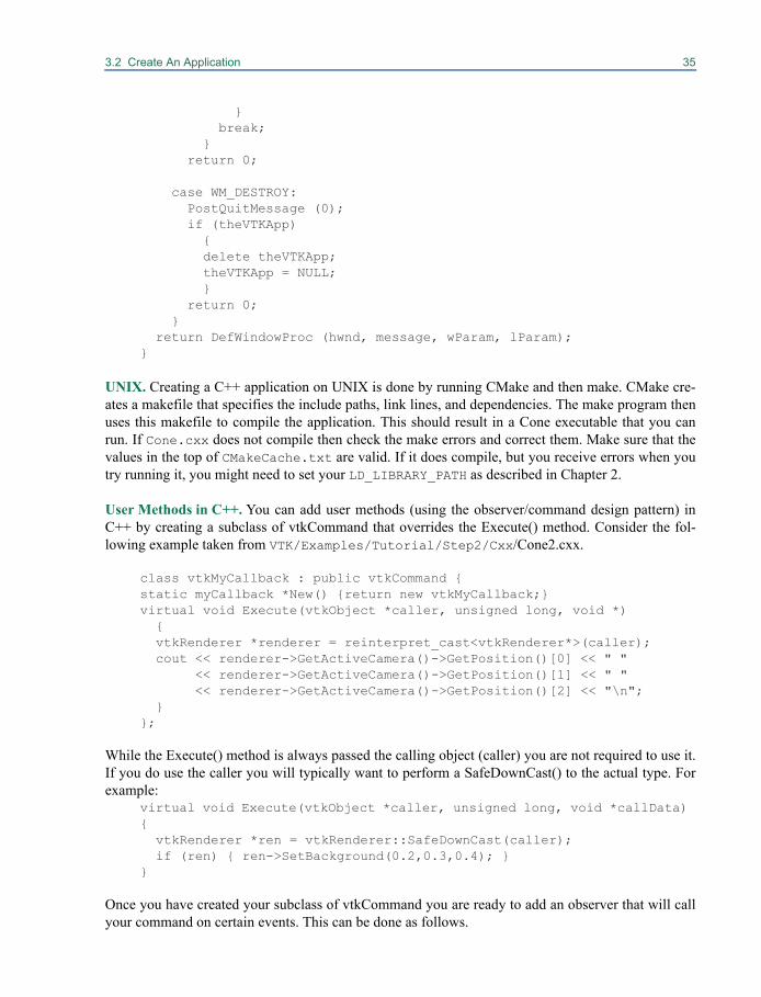
3.2 Create An Application 35
}break;
}return 0;
case WM_DESTROY:PostQuitMessage (0);if (theVTKApp)
{delete theVTKApp;theVTKApp = NULL;}
return 0;}
return DefWindowProc (hwnd, message, wParam, lParam);}
UNIX. Creating a C++ application on UNIX is done by running CMake and then make. CMake cre-ates a makefile that specifies the include paths, link lines, and dependencies. The make program thenuses this makefile to compile the application. This should result in a Cone executable that you canrun. If Cone.cxx does not compile then check the make errors and correct them. Make sure that thevalues in the top of CMakeCache.txt are valid. If it does compile, but you receive errors when youtry running it, you might need to set your LD_LIBRARY_PATH as described in Chapter 2.
User Methods in C++. You can add user methods (using the observer/command design pattern) inC++ by creating a subclass of vtkCommand that overrides the Execute() method. Consider the fol-lowing example taken from VTK/Examples/Tutorial/Step2/Cxx/Cone2.cxx.
class vtkMyCallback : public vtkCommand { static myCallback *New() {return new vtkMyCallback;} virtual void Execute(vtkObject *caller, unsigned long, void *)
{vtkRenderer *renderer = reinterpret_cast<vtkRenderer*>(caller);cout << renderer->GetActiveCamera()->GetPosition()[0] << " "
<< renderer->GetActiveCamera()->GetPosition()[1] << " "<< renderer->GetActiveCamera()->GetPosition()[2] << "\n";
}};
While the Execute() method is always passed the calling object (caller) you are not required to use it.If you do use the caller you will typically want to perform a SafeDownCast() to the actual type. Forexample:
virtual void Execute(vtkObject *caller, unsigned long, void *callData) {
vtkRenderer *ren = vtkRenderer::SafeDownCast(caller); if (ren) { ren->SetBackground(0.2,0.3,0.4); }
}
Once you have created your subclass of vtkCommand you are ready to add an observer that will callyour command on certain events. This can be done as follows.
36 System Overview
// Here is where we setup the observer, //we do a new and ren1 will eventually free the observer vtkMyCallback *mo1 = vtkMyCallback::New(); ren1->AddObserver(vtkCommand::StartEvent,mo1);mo1->Delete();
The above code creates an instance of myCallback and then adds an observer on ren1 for theStartEvent. Whenever ren1 starts to render, the Execute() method of vtkMyCallback will becalled. When ren1 is deleted, the callback will be deleted as well.
JavaTo create Java applications you must first have a working Java development environment. This sec-tion provides instructions for using Sun's JDK 1.3 or later on either Windows or UNIX. Once yourJDK has been installed and you have installed VTK, you need to set your CLASSPATH environmentvariable to include the VTK classes. Under Microsoft Windows this can be set by right clicking onthe My Computer icon, selecting the properties option, then selecting the Advanced tab, and thenclicking the Environment Variables button. Then add a CLASSPATH environment variable and set it toinclude your the path to your vtk.jar file, your Wrapping/Java directory, and the current directory.For a Windows build it will be something like "C:\vtk-bin\bin\vtk.jar;C:\vtk-bin\Wrapping\Java;.". Under UNIX you should set your CLASSPATH environment variable tosomething similar to "/yourdisk/vtk-bin/bin/vtk.jar;/yourdisk/vtk-bin/Wrapping/Java;.".
The next step is to byte compile your Java program. For starters try byte compiling (with javac)the Cone.java example that comes with VTK under VTK/Examples/Tutorial/Step1/Java.Then you should be able to run the resulting application using the java command. It should display acone which rotates 360 degrees and then exits. The next step is to create your own applications usingthe examples provided as a starting point.
public void myCallback(){
System.out.println("Starting a render");}
You set up a callback by passing three arguments. The first is the name of the event you are interestedin, the second is an instance of a class, the third is the name of the method you want to invoke. In thisexample we set up the StartEvent to invoke the myCallback method on me (which is an instance ofCone2). The myCallback method must of course be a valid method of Cone2 to avoid an error. (Thiscode fragment is from VTK/Examples/Tutorial/Step2/Java/cone2.java.)
Cone2 me = new Cone2();ren1.AddObserver("StartEvent",me,"myCallback");
PythonIf you have built VTK with Python support, a vtkpython executable will be created. Using this exe-cutable, you should be able to run Examples/Tutorial/Step1/Python/Cone.py as follows.
3.3 Conversion Between Languages 37
vtkpython Cone.py
Creating your own Python scripts is a simple matter of using some of our example scripts as a startingpoint. User methods can be set up by defining a function and then passing it as the argument to theAddObserver as shown below.
def myCallback(obj,event):print "Starting to render"
ren1.AddObserver("StartEvent",myCallback)
The complete source code for the example shown above is in VTK/Examples/Tutorial/Step2/Python/Cone2.py.
3.3 Conversion Between LanguagesAs we have seen, VTK’s core is implemented in C++ and then wrapped with the Tcl, Java, andPython programming languages. This means that you have a language choice when developing appli-cations. Your choice will depend on which language you are most comfortable with, the nature of theapplication, and whether you need access to internal data structures and/or have special performancerequirements. C++ offers several advantages over the other languages when you need to access inter-nal data structure or require the highest-performing application possible. However, using C++ meansthe extra burden of the compile/link cycle, which often slows the software development process.
You may find yourself developing prototypes in an interpreted language such as Tcl and thenconverting them to C++. Or, you may discover example code (in the VTK distribution or from otherusers) that you wish to convert to your implementation language.
Converting VTK code from one language to another is fairly straightforward. Class names andmethod names remain the same across languages; what changes are the implementation details andGUI interface, if any. For example, the C++ statement
anActor->GetProperty()->SetColor(red,green,blue);
in Tcl becomes
[anActor GetProperty] SetColor $red $green $blue
in Java becomes
anActor.GetProperty().SetColor(red,green,blue);
and in Python becomes
anActor.GetProperty().SetColor(red,green,blue)
One major limitation you’ll find is that some C++ applications cannot be converted to the other threelanguages because of pointer manipulation.While it is always possible to get and set individual valuesfrom the wrapped languages, it is not always possible to obtain a raw pointer to quickly traverse andinspect or modify a large structure. If your application requires this level of data inspection or manip-ulation, you can either develop directly in C++ or extend VTK at the C++ level with your requiredhigh-performance classes, then use these new classes from your preferred interpreted language.

Part IILearn VTK By Example

Chapter 4
The Basics 4
The purpose of this chapter is to introduce you to some ofVTK’s capabilities by way of a selected set of examples. Our focus will be on commonly used meth-ods and objects, and combinations of objects. We will also introduce important concepts and usefulapplications. By no means are all of VTK’s features covered; this chapter is meant to give you abroad overview of what’s possible. You’ll want to refer to online documentation or class .h files tolearn about other options each class might have.
Most of the examples included here are implemented in the Tcl programming language. Theycould just as easily be implemented in C++, Java, and Python—the conversion process between thelanguages is straightforward. (See “Conversion Between Languages” on page 37.) C++ does offersome advantages, mainly access and manipulation of data structures and pointers, and some examplesreflect this by being implemented in the C++ language.
Each example presented here includes sample code and often a supplemental image. We indi-cate the name of the source code file (when one exists in the VTK source tree), so you will not haveto enter it manually. We recommend that you run and understand the example and then experimentwith object methods and parameters. You may also wish to try suggested alternative methods and/orclasses. Often, the Visualization Toolkit offers several approaches to achieve similar results. Note alsothat the scripts are often modified from what’s found in the source code distribution. This is done tosimplify concepts or remove extraneous code.
Learning an object-oriented system like VTK first requires understanding the programmingabstraction, and then becoming familiar with the library of objects and their methods. We recommendthat you review “System Architecture” on page 19 for information about the programming abstrac-tion. The examples in this chapter will then provide you with a good overview of the many VTKobjects.
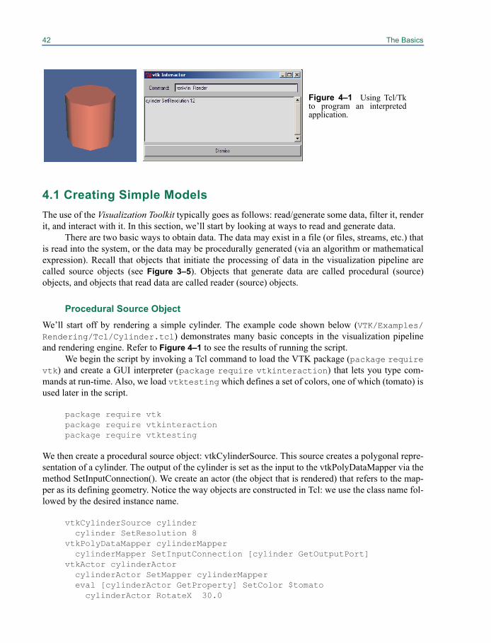
42 The Basics
4.1 Creating Simple ModelsThe use of the Visualization Toolkit typically goes as follows: read/generate some data, filter it, renderit, and interact with it. In this section, we’ll start by looking at ways to read and generate data.
There are two basic ways to obtain data. The data may exist in a file (or files, streams, etc.) thatis read into the system, or the data may be procedurally generated (via an algorithm or mathematicalexpression). Recall that objects that initiate the processing of data in the visualization pipeline arecalled source objects (see Figure 3–5). Objects that generate data are called procedural (source)objects, and objects that read data are called reader (source) objects.
Procedural Source ObjectWe’ll start off by rendering a simple cylinder. The example code shown below (VTK/Examples/Rendering/Tcl/Cylinder.tcl) demonstrates many basic concepts in the visualization pipelineand rendering engine. Refer to Figure 4–1 to see the results of running the script.
We begin the script by invoking a Tcl command to load the VTK package (package requirevtk) and create a GUI interpreter (package require vtkinteraction) that lets you type com-mands at run-time. Also, we load vtktesting which defines a set of colors, one of which (tomato) isused later in the script.
package require vtkpackage require vtkinteractionpackage require vtktesting
We then create a procedural source object: vtkCylinderSource. This source creates a polygonal repre-sentation of a cylinder. The output of the cylinder is set as the input to the vtkPolyDataMapper via themethod SetInputConnection(). We create an actor (the object that is rendered) that refers to the map-per as its defining geometry. Notice the way objects are constructed in Tcl: we use the class name fol-lowed by the desired instance name.
vtkCylinderSource cylinder cylinder SetResolution 8vtkPolyDataMapper cylinderMapper cylinderMapper SetInputConnection [cylinder GetOutputPort]vtkActor cylinderActor cylinderActor SetMapper cylinderMapper eval [cylinderActor GetProperty] SetColor $tomato
cylinderActor RotateX 30.0
Figure 4–1 Using Tcl/Tkto program an interpretedapplication.
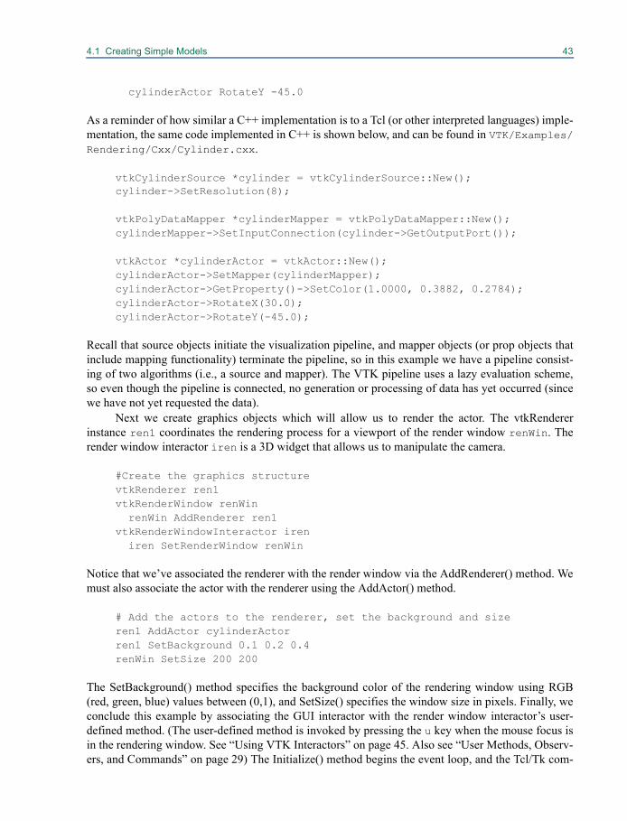
4.1 Creating Simple Models 43
cylinderActor RotateY -45.0
As a reminder of how similar a C++ implementation is to a Tcl (or other interpreted languages) imple-mentation, the same code implemented in C++ is shown below, and can be found in VTK/Examples/Rendering/Cxx/Cylinder.cxx.
vtkCylinderSource *cylinder = vtkCylinderSource::New();cylinder->SetResolution(8);
vtkPolyDataMapper *cylinderMapper = vtkPolyDataMapper::New();cylinderMapper->SetInputConnection(cylinder->GetOutputPort());
vtkActor *cylinderActor = vtkActor::New();cylinderActor->SetMapper(cylinderMapper);cylinderActor->GetProperty()->SetColor(1.0000, 0.3882, 0.2784);cylinderActor->RotateX(30.0);cylinderActor->RotateY(-45.0);
Recall that source objects initiate the visualization pipeline, and mapper objects (or prop objects thatinclude mapping functionality) terminate the pipeline, so in this example we have a pipeline consist-ing of two algorithms (i.e., a source and mapper). The VTK pipeline uses a lazy evaluation scheme,so even though the pipeline is connected, no generation or processing of data has yet occurred (sincewe have not yet requested the data).
Next we create graphics objects which will allow us to render the actor. The vtkRendererinstance ren1 coordinates the rendering process for a viewport of the render window renWin. Therender window interactor iren is a 3D widget that allows us to manipulate the camera.
#Create the graphics structurevtkRenderer ren1vtkRenderWindow renWin renWin AddRenderer ren1vtkRenderWindowInteractor iren iren SetRenderWindow renWin
Notice that we’ve associated the renderer with the render window via the AddRenderer() method. Wemust also associate the actor with the renderer using the AddActor() method.
# Add the actors to the renderer, set the background and sizeren1 AddActor cylinderActorren1 SetBackground 0.1 0.2 0.4renWin SetSize 200 200
The SetBackground() method specifies the background color of the rendering window using RGB(red, green, blue) values between (0,1), and SetSize() specifies the window size in pixels. Finally, weconclude this example by associating the GUI interactor with the render window interactor’s user-defined method. (The user-defined method is invoked by pressing the u key when the mouse focus isin the rendering window. See “Using VTK Interactors” on page 45. Also see “User Methods, Observ-ers, and Commands” on page 29) The Initialize() method begins the event loop, and the Tcl/Tk com-
44 The Basics
mand wm withdraw . makes sure that the interpreter widget .vtkInteract is not visible when theapplication starts.
# Associate the “u” keypress with a UserEvent and start the event loopiren AddObserver UserEvent {wm deiconify .vtkInteract}iren Initialize
# suppress the tk windowwm withdraw .
When the script is run, the visualization pipeline will execute because the rendering engine willrequest data. (The window expose event will force the render window to render itself.) Only after thepipeline executes are the filters up-to-date with respect to the input data. If you desire, you can manu-ally cause execution of the pipeline by invoking renWin Render.
After you get this example running, you might try a couple of things. First, use the interactor bymousing in the rendering window. Next, change the resolution of the cylinder object by invoking thecylinder SetResolution 12. You can do this by editing the example file and re-executing it, or bypressing u in the rendering window to bring up the interpreter GUI and typing the command there.Remember, if you are using the Tcl interactor popup, the changes you make are visible only after datais requested, so follow changes with a renWin Render command, or by mousing in the renderingwindow.
Reader Source ObjectThis example is similar to the previous example except that weread a data file rather than procedurally generating the data. Astereo-lithography file is read (suffix .stl) that representspolygonal data using the binary STL data format. (Refer toFigure 4–2 and the Tcl script VTK/Examples/Rendering/Tcl/CADPart.tcl.)
vtkSTLReader partpart SetFileName \$VTK_DATA_ROOT/Data/42400-IDGH.stl
vtkPolyDataMapper partMapperpartMapper SetInputConnection \[part GetOutputPort]
vtkLODActor partActorpartActor SetMapper partMapper
Notice the use of the vtkLODActor. This actor changes its representation to maintain interactive per-formance. Its default behavior is to create a point cloud and wireframe, bounding-box outline to rep-resent the intermediate and low-level representations. (See “Level-Of-Detail Actors” on page 55 formore information.) The model used in this example is small enough that on most computers todayyou will only see the high-level representation (the full geometry of the model).
Many of the readers do not sense when the input file(s) change and re-execute. For example, ifthe file 42400-IDGH.stl changes, the pipeline will not re-execute. You can manually modifyobjects by invoking the Modified() method on them. This will cause the filter to re-execute, as well asall filters downstream of it.
Figure 4–2 Reader source object.
4.2 Using VTK Interactors 45
The Visualization Toolkit has limited, built-in modeling capabilities. If you want to use VTK toedit and manipulate complex models (e.g., those created by a solid modeler or modeling tool), you’lltypically use a reader (see “Readers” on page 239) to interface to the data. (Another option is import-ers, which are used to ingest entire scenes. See “Importers” on page 245 for more information.)
4.2 Using VTK InteractorsOnce you’ve visualized your data, you typically want to interact with it. The Visualization Toolkitoffers several approaches to do this. The first approach is to use the built in class vtkRenderWindow-Interactor. The second approach is to create your own interactor by specifying event bindings. Anddon’t forget that if you are using an interpreted language you can type commands at run-time. Youmay also wish to refer to “Picking” on page 59 to see how to select data from the screen. (Note:Developers can also interface to a windowing system of their choice. See “Integrating With The Win-dowing System” on page 421.)
vtkRenderWindowInteractor
The simplest way to interact with your data is to instantiate vtkRenderWindowInteractor. This classresponds to a pre-defined set of events and actions and provides a way to override the default actions.vtkRenderWindowInteractor allows you to control the camera and actors and offers two interactionstyles: position sensitive (i.e., joystick mode) and motion sensitive (i.e., trackball mode). (More aboutinteractor styles in the next section.)
vtkRenderWindowInteractor responds to the following events in the render window. (Remem-ber that multiple renderers can draw into a rendering window and that the renderer draws into a view-port within the render window. Interactors support multiple renderers in a render window.)
• Keypress j / Keypress t — Toggle between joystick (position sensitive) and trackball(motion sensitive) styles. In joystick style, motion occurs continuously as long as a mouse but-ton is pressed. In trackball style, motion occurs when the mouse button is pressed and themouse pointer moves.
• Keypress c / Keypress a — Toggle between camera and actor (object) modes. In cameramode, mouse events affect the camera position and focal point. In object mode, mouse eventsaffect the actor that is under the mouse pointer.
• Button 1 — Rotate the camera around its focal point (if camera mode) or rotate the actoraround its origin (if actor mode). The rotation is in the direction defined from the center of therenderer’s viewport towards the mouse position. In joystick mode, the magnitude of the rotationis determined by the distance between the mouse and the center of the render window.
• Button 2 — Pan the camera (if camera mode) or translate the actor (if object mode). In joy-stick mode, the direction of pan or translation is from the center of the viewport towards themouse position. In trackball mode, the direction of motion is the direction the mouse moves.(Note: With a 2-button mouse, pan is defined as <Shift>-Button 1.)
• Button 3 — Zoom the camera (if camera mode), or scale the actor (if object mode). Zoom in/increase scale if the mouse position is in the top half of the viewport; zoom out/decrease scale ifthe mouse position is in the bottom half. In joystick mode, the amount of zoom is controlled bythe distance of the mouse pointer from the horizontal centerline of the window.
46 The Basics
• Keypress 3 — Toggle the render window into and out of stereo mode. By default, red-bluestereo pairs are created. Some systems support Crystal Eyes LCD stereo glasses; you have toinvoke SetStereoTypeToCrystalEyes() on the rendering window.
• Keypress e/q — Exit or quit the application.• Keypress f — Fly-to the point under the cursor. This sets the focal point and allows rotations
around that point.• Keypress p — Perform a pick operation. The render window interactor has an internal
instance of vtkPropPicker that it uses to pick. See “Picking” on page 59 for more informa-tion about picking.
• Keypress r — Reset the camera view along the current view direction. Centers the actors andmoves the camera so that all actors are visible.
• Keypress s — Modify the representation of all actors so that they are surfaces.• Keypress u — Invoke the user-defined method. Typically, this keypress will bring up an
interactor that you can type commands into.• Keypress w — Modify the representation of all actors so that they are wireframe.
The default interaction style is position sensitive (i.e., joystick style)—that is, it manipulates the cam-era or actor and renders continuously as long as a mouse button is pressed. If you don’t like thedefault behavior, you can change it or write your own. (See “vtkRenderWindow Interaction Style” onpage 421 for information about writing your own style.)
vtkRenderWindowInteractor has other useful features. Invoking LightFollowCameraOn() (thedefault behavior) causes the light position and focal point to be synchronized with the camera posi-tion and focal point (i.e., a “headlight” is created). Of course, this can be turned off withLightFollowCameraOff(). A callback that responds to the “u” keypress can be added with “AddOb-server(UserEvent) method. It is also possible to set several pick-related methods. AddObserver(Start-PickEvent) defines a method to be called prior to picking, and AddObserver(EndPickEvent) defines amethod after the pick has been performed. (Please see “User Methods, Observers, and Commands”on page 29 for more information on defining user methods.) You can also specify an instance of asubclass of vtkAbstractPicker to use via the SetPicker() method. (See “Picking” on page 59.)
If you are using a prop that adjusts rendering quality based on desired interactivity, you maywish to set the desired frame rate via SetDesiredUpdateRate() in the interactor. Normally, this is han-dled automatically. (When the mouse buttons are activated, the desired update rate is increased; whenthe mouse button is released, the desired update rate is set back down.) Refer to “Level-Of-DetailActors” on page 55, the “vtkLODProp3D” on page 57, and the chapter on “Volume Rendering” onpage 139 for further information on how props and their associated mappers may adjust render styleto achieve a desired frame rate..
We’ve seen how to use vtkRenderWindowInteractor previously, here’s a recapitulation.
vtkRenderWindowInteractor ireniren SetRenderWindow renWiniren AddObserver UserEvent {wm deiconify .vtkInteract}
Interactor StylesThere are two distinctly different ways to control interaction style in VTK. The first is to use a sub-class of vtkInteractorStyle, either one supplied with the system or one that you write. The second
4.2 Using VTK Interactors 47
method is to add observers that watch for events on the vtkRenderWindowInteractor and define yourown set of callbacks (or commands) to implement the style. (Note: 3D widgets are another, morecomplex way to interact with data in the scene. See “3D Widgets” on page 72 for more information.)
vtkInteractorStyle. The class vtkRenderWindowInteractor can support different interaction styles.When you type “t” or “j” in the interactor (see the previous section) you are changing between track-ball and joystick interaction styles. The way this works is that vtkRenderWindowInteractor translateswindow-system-specific events it receives (e.g., mouse button press, mouse motion, keyboard events)to VTK events such as MouseMoveEvent, StartEvent, and so on. (See “User Methods, Observers, andCommands” on page 29 for related information.) Different styles then observe particular events andperform the action(s) appropriate to the event. To set the style, use thevtkRenderWindowInteractor::SetInteractorStyle() method. For example:
vtkInteractorStyleFlight flightStylevtkRenderWindowInteractor iren
iren SetInteractorStyle flightStyle
(Note: When vtkRenderWindowInteractor is instantiated, a window-system specific render windowinteractor is actually instantiated. For example, on Unix systems the classvtkXRenderWindowInteractor is actually created and returned as an instance of vtkRenderWindow-Interactor. On Windows, the class vtkWin32RenderWindowInteractor is instantiated.)
Adding vtkRenderWindowInteractor Observers. While a variety of interactor styles are availablein VTK, you may prefer to create your own custom style to meet the needs of a particular application.In C++ the natural approach is to subclass vtkInteractorStyle. (See “vtkRenderWindow InteractionStyle” on page 421.) However, in an interpreted language (e.g., Tcl, Python, or Java), this is difficultto do. For interpreted languages the simplest approach is to use observers to define particular interac-tion bindings. (See “User Methods, Observers, and Commands” on page 29.) The bindings can bemanaged in any language that VTK supports, including C++, Tcl, Python, and Java. An example ofthis is found in the Tcl code VTK/Examples/GUI/Tcl/CustomInteraction.tcl, which definesbindings for a simple Tcl application. Here’s an excerpt to give you an idea of what’s going on.
vtkRenderWindowInteractor ireniren SetInteractorStyle ""iren SetRenderWindow renWin
# Add the observers to watch for particular events. These invoke# Tcl procedures.
set Rotating 0set Panning 0set Zooming 0
iren AddObserver LeftButtonPressEvent {global Rotating; set Rotating 1}iren AddObserver LeftButtonReleaseEvent \
{global Rotating; set Rotating 0}iren AddObserver MiddleButtonPressEvent {global Panning; set Panning 1}iren AddObserver MiddleButtonReleaseEvent \
{global Panning; set Panning 0}
48 The Basics
iren AddObserver RightButtonPressEvent {global Zooming; set Zooming 1}iren AddObserver RightButtonReleaseEvent {global Zooming; set Zooming 0}iren AddObserver MouseMoveEvent MouseMoveiren AddObserver KeyPressEvent Keypress
proc MouseMove {} {...set xypos [iren GetEventPosition]
set x [lindex $xypos 0] set y [lindex $xypos 1]
...}
proc Keypress {} { set key [iren GetKeySym]
if { $key == "e" } {vtkCommand DeleteAllObjectsexit
}...
}
Note that a key step in this example is disabling the default interaction style by invokingSetInteractionStyle(““). Observers are then added to watch for particular events which are tied to theappropriate Tcl procedures.
This example is a simple way to add bindings from a Tcl script. If you would like to create a fullGUI using Tcl/Tk, then use the vtkTkRenderWidget, and refer to “Tcl/Tk” on page 433 for moredetails.
4.3 Filtering DataThe previous example pipelines consisted of a source and mapper object; the pipeline had no filters.In this section we show how to add a filter into the pipeline.
Filters are connected by using the SetInputConnection() and GetOutputPort() methods. Forexample, we can modify the script in “Reader Source Object” on page 44 to shrink the polygons thatmake up the model. The script is shown below. (Only the pipeline and other pertinent objects areshown.) The complete script can be found atVTK/Examples/Rendering/Tcl/FilterCADPart.tcl.
vtkSTLReader partpart SetFileName \
“$VTK_DATA_ROOT/Data/42400-IDGH.stl”vtkShrinkPolyData shrink
shrink SetInputConnection [part GetOutputPort]shrink SetShrinkFactor 0.85
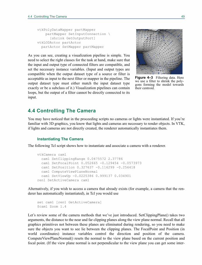
4.4 Controlling The Camera 49
vtkPolyDataMapper partMapperpartMapper SetInputConnection \[shrink GetOutputPort]
vtkLODActor partActor partActor SetMapper partMapper
As you can see, creating a visualization pipeline is simple. Youneed to select the right classes for the task at hand, make sure thatthe input and output type of connected filters are compatible, andset the necessary instance variables. (Input and output types arecompatible when the output dataset type of a source or filter isacceptable as input to the next filter or mapper in the pipeline. Theoutput dataset type must either match the input dataset typeexactly or be a subclass of it.) Visualization pipelines can containloops, but the output of a filter cannot be directly connected to itsinput.
4.4 Controlling The CameraYou may have noticed that in the proceeding scripts no cameras or lights were instantiated. If you’refamiliar with 3D graphics, you know that lights and cameras are necessary to render objects. In VTK,if lights and cameras are not directly created, the renderer automatically instantiates them.
Instantiating The CameraThe following Tcl script shows how to instantiate and associate a camera with a renderer.
vtkCamera cam1 cam1 SetClippingRange 0.0475572 2.37786 cam1 SetFocalPoint 0.052665 -0.129454 -0.0573973 cam1 SetPosition 0.327637 -0.116299 -0.256418 cam1 ComputeViewPlaneNormal cam1 SetViewUp -0.0225386 0.999137 0.034901ren1 SetActiveCamera cam1
Alternatively, if you wish to access a camera that already exists (for example, a camera that the ren-derer has automatically instantiated), in Tcl you would use
set cam1 [ren1 GetActiveCamera]$cam1 Zoom 1.4
Let’s review some of the camera methods that we’ve just introduced. SetClippingPlane() takes twoarguments, the distance to the near and far clipping planes along the view plane normal. Recall that allgraphics primitives not between these planes are eliminated during rendering, so you need to makesure the objects you want to see lie between the clipping planes. The FocalPoint and Position (inworld coordinates) instance variables control the direction and position of the camera.ComputeViewPlaneNormal() resets the normal to the view plane based on the current position andfocal point. (If the view plane normal is not perpendicular to the view plane you can get some inter-
Figure 4–3 Filtering data. Herewe use a filter to shrink the poly-gons forming the model towardstheir centroid.
50 The Basics
esting shearing effects.) Setting the ViewUp controls the “up” direction for the camera. Finally, theZoom() method magnifies objects by changing the view angle (i.e., SetViewAngle()). You can alsouse the Dolly() method to move the camera in and out along the view plane normal to either enlargeor shrink the visible actors.
Simple Manipulation MethodsThe methods described above are not always the most convenient ones for controlling the camera. Ifthe camera is “looking at” the point you want (i.e., the focal point is set), you can use the Azimuth()and Elevation() methods to move the camera about the focal point.
cam1 Azimuth 150cam1 Elevation 60
These methods move the camera in a spherical coordinate system centered at the focal point by mov-ing in the longitude direction (azimuth) and the latitude direction (elevation) by the angle (in degrees)given. These methods do not modify the view-up vector and depend on the view-up vector remainingconstant. Note that there are singularities at the north and south poles — the view-up vector becomesparallel with the view plane normal. To avoid this, you can force the view-up vector to be orthogonalto the view vector by using OrthogonalizeViewUp(). However, this changes the camera coordinatesystem, so if you’re flying around an object with a natural horizon or view-up vector (such as terrain),camera manipulation is no longer natural with respect to the data.
Controlling The View DirectionA common function of the camera is to generate a view from a particular direction. You can do this byinvoking SetFocalPoint(), SetPosition(), and ComputeViewPlaneNormal() followed by invokingResetCamera() on the renderer associated with the camera.
vtkCamera cam1 cam1 SetFocalPoint 0 0 0 cam1 SetPosition 1 1 1 cam1 ComputeViewPlaneNormal cam1 SetViewUp 1 0 0 cam1 OrthogonalizeViewUpren1 SetActiveCamera cam1ren1 ResetCamera
The initial direction (view vector or view plane normal) is computed from the focal point and positionof the camera, which, together with ComputeViewPlaneNormal(), defines the initial view vector.Optionally, you can specify an initial view-up vector and orthogonalize it with respect to the viewvector. The ResetCamera() method then moves the camera along the view vector so that the ren-derer’s actors are all visible to the camera.
Perspective Versus Orthogonal ViewsIn the previous examples, we have assumed that the camera is a perspective camera where a viewangle controls the projection of the actors onto the view plane during the rendering process. Perspec-tive projection, while generating more natural looking images, introduces distortion that can be unde-
4.5 Controlling Lights 51
sirable in some applications. Orthogonal (or parallel) projection is an alternative projection method.In orthogonal projection, view rays are parallel, and objects are rendered without distance effects.
To set the camera to use orthogonal projection, use the vtkCamera::ParallelProjectionOn()method. In parallel projection mode, the camera view angle no longer controls zoom. Instead, use theSetParallelScale() method to control the magnification of the actors.
Saving/Restoring Camera State
Another common requirement of applications is the capability to save and restore camera state (i.e.,recover a view). To save camera state, you’ll need to save (at a minimum) the clipping range, thefocal point and position, and the view-up vector. You’ll also want to compute the view plane normal(as shown in the example in “Instantiating The Camera” on page 49). Then, to recover camera state,simply instantiate a camera with the saved information, and assign it to the appropriate renderer (i.e.,SetActiveCamera()).
In some cases you may need to store additional information. For example, if the camera viewangle (or parallel scale) is set, you’ll need to save this. Or, if you are using the camera for stereo view-ing, the EyeAngle and Stereo flags are required.
4.5 Controlling LightsLights are easier to control than cameras. The most frequently used methods are SetPosition(),SetFocalPoint(), and SetColor(). The position and focal point of the light control the direction inwhich the light points. The color of the light is expressed as an RGB vector. Also, lights can be turnedon and off via the SwitchOn() and SwitchOff() methods, and the brightness of the light can be setwith the SetIntensity() method.
By default, instances of vtkLight are directional lights. That is, the position and focal pointdefine a vector parallel to which light rays travel, and the light source is assumed to be located at theinfinity point. This means that the lighting on an object does not change if the focal point and positionare translated identically.
Lights are associated with renderers as follows.
vtkLight lightlight SetColor 1 0 0light SetFocalPoint [cam1 GetFocalPoint]light SetPosition [cam1 GetPosition]
ren1 AddLight light
Here we’ve created a red headlight: a light located at the camera’s (cam1’s) position and pointingtowards the camera’s focal point. This is a useful trick, and is used by the interactive renderer to posi-tion the light as the camera moves. (See “Using VTK Interactors” on page 45.)
Positional Lights
It is possible to create positional (i.e., spot lights) by using the PositionalOn() method. This method isused in conjunction with the SetConeAngle() method to control the spread of the spot. A cone angle

52 The Basics
of 180 degrees indicates that no spot light effects will be applied (i.e., no truncated light cone), onlythe effects of position.
4.6 Controlling 3D PropsObjects in VTK that are to be drawn in the render window are generically known as “props.” (Theword prop comes from the vocabulary of theater—a prop is something that appears on stage.) Thereare several different types of props including vtkProp3D and vtkActor. vtkProp3D is an abstractsuperclass for those types of props existing in 3D space. The class vtkActor is a type of vtkProp3Dwhose geometry is defined by analytic primitives such as polygons and lines.
Specifying the Position of a vtkProp3D
We have already seen how to use cameras to move around an object; alternatively, we can also holdthe camera steady and transform the props. The following methods can be used to define the positionof a vtkProp3D (and its subclasses).
• SetPosition(x,y,z) — Specify the position of the vtkProp3D in world coordinates.
• AddPosition(deltaX,deltaY,deltaZ) — Translate the prop by the specified amountalong each of the x, y, and z axes.
• RotateX(theta), RotateY(theta), RotateZ(theta) — Rotate the prop by thetadegrees around the x, y, z coordinate axes, respectively.
• SetOrientation(x,y,z) — Set the orientation of the prop by rotating about the z axis, thenabout the x axis, and then about the y axis.
• AddOrientation(a1,a2,a3) — Add to the current orientation of the prop.
• RotateWXYZ(theta,x,y,z) — Rotate the prop by theta degress around the x-y-z vectordefined.
• SetScale(sx,sy,sz) — Scale the prop in the x, y, z axes coordinate directions.
• SetOrigin(x,y,z) — Specify the origin of the prop. The origin is the point around whichrotations and scaling occur.
These methods work together in complex ways to control the resulting transformation matrix. Themost important thing to remember is that the operations listed above are applied in a particular order,and the order of application dramatically affects the resulting actor position. The order used in VTKto apply these transformations is as follows:
1. Shift to Origin
2. Scale
3. Rotate Y
4. Rotate X
5. Rotate Z
6. Shift from Origin
7. Translate
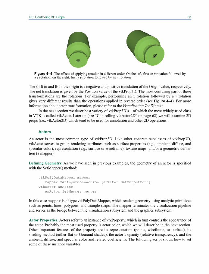
4.6 Controlling 3D Props 53
The shift to and from the origin is a negative and positive translation of the Origin value, respectively.The net translation is given by the Position value of the vtkProp3D. The most confusing part of thesetransformations are the rotations. For example, performing an x rotation followed by a y rotationgives very different results than the operations applied in reverse order (see Figure 4–4). For moreinformation about actor transformation, please refer to the Visualization Toolkit text.
In the next section we describe a variety of vtkProp3D’s—of which the most widely used classin VTK is called vtkActor. Later on (see “Controlling vtkActor2D” on page 62) we will examine 2Dprops (i.e., vtkActor2D) which tend to be used for annotation and other 2D operations.
Actors
An actor is the most common type of vtkProp3D. Like other concrete subclasses of vtkProp3D,vtkActor serves to group rendering attributes such as surface properties (e.g., ambient, diffuse, andspecular color), representation (e.g., surface or wireframe), texture maps, and/or a geometric defini-tion (a mapper).
Defining Geometry. As we have seen in previous examples, the geometry of an actor is specifiedwith the SetMapper() method:
vtkPolyDataMapper mappermapper SetInputConnection [aFilter GetOutputPort]
vtkActor anActoranActor SetMapper mapper
In this case mapper is of type vtkPolyDataMapper, which renders geometry using analytic primitivessuch as points, lines, polygons, and triangle strips. The mapper terminates the visualization pipelineand serves as the bridge between the visualization subsystem and the graphics subsystem.
Actor Properties. Actors refer to an instance of vtkProperty, which in turn controls the appearance ofthe actor. Probably the most used property is actor color, which we will describe in the next section.Other important features of the property are its representation (points, wireframe, or surface), itsshading method (either flat or Gouraud shaded), the actor’s opacity (relative transparency), and theambient, diffuse, and specular color and related coefficients. The following script shows how to setsome of these instance variables.
Figure 4–4 The effects of applying rotation in different order. On the left, first an x rotation followed bya y rotation; on the right, first a y rotation followed by an x rotation.
54 The Basics
vtkActor anActoranActor SetMapper mapper[anActor GetProperty] SetOpacity 0.25[anActor GetProperty] SetAmbient 0.5[anActor GetProperty] SetDiffuse 0.6[anActor GetProperty] SetSpecular 1.0[anActor GetProperty] SetSpecularPower 10.0
Notice how we dereference the actor’s property via the GetProperty() method. Alternatively, we cancreate a property and assign it to the actor.
vtkProperty propprop SetOpacity 0.25prop SetAmbient 0.5prop SetDiffuse 0.6prop SetSpecular 1.0prop SetSpecularPower 10.0
vtkActor anActoranActor SetMapper mapperanActor SetProperty prop
The advantage of the latter method is that we can control the properties of several actors by assigningeach the same property.
Actor Color. Color is perhaps the most important property applied to an actor. The simplest proce-dure for controlling this property is the SetColor() method, used to set the red, green, and blue (RGB)values of the actor. Each value ranges from zero to one.
[anActor GetProperty] SetColor 0.1 0.2 0.4
Alternatively, you can set the ambient, diffuse, and specular colors separately.
vtkActor anActoranActor SetMapper mapper[anActor GetProperty] SetAmbientColor .1 .1 .1[anActor GetProperty] SetDiffuseColor .1 .2 .4[anActor GetProperty] SetSpecularColor 1 1 1
In this example we’ve set the ambient color to a dark gray, the diffuse color to a shade of blue, and thespecular color to white. (Note: The SetColor() method sets the ambient, diffuse, and specular colorsto the color specified.)
Important: The color set in the actor’s property only takes effect if there is no scalar data avail-able to the actor’s mapper. By default, the mapper’s input scalar data colors the actor, and the actor’scolor is ignored. To ignore the scalar data, use the method ScalarVisibilityOff() as shown in the Tclscript below.
vtkPolyDataMapper planeMapper planeMapper SetInputConnection [CompPlane GetOutputPort] planeMapper ScalarVisibilityOffvtkActor planeActor
4.6 Controlling 3D Props 55
planeActor SetMapper planeMapper[planeActor GetProperty] SetRepresentationToWireframe[planeActor GetProperty] SetColor 0 0 0
Actor Transparency. Many times it is useful to adjust transparency (or opacity) of an actor. Forexample, if you wish to show internal organs surrounded by the skin of a patient, adjusting the trans-parency of the skin allows the user to see the organs in relation to the skin. Use thevtkProperty::SetOpacity() method as follows.
vtkActor popActor popActor SetMapper popMapper
[popActor GetProperty] SetOpacity 0.3 [popActor GetProperty] SetColor .9 .9 .9
Please note that transparency is implemented in the rendering library using an -blending process.This process requires that polygons are rendered in the correct order. In practice, this is very difficultto achieve, especially if you have multiple transparent actors. To order polygons, you should addtransparent actors to the end of renderer’s list of actors (i.e., add them last). Also, you can use the fil-ter vtkDepthSortPolyData to sort polygons along the view vector. Please see VTK/Examples/VisualizationAlgorithms/Tcl/DepthSort.tcl for an example using this filter. For moreinformation on this topic see “Translucent polygonal geometry” on page 79
Miscellaneous Features. Actors have several other important features. You can control whether anactor is visible with the VisibilityOn() and VisibilityOff() methods. If you don’t want to pick an actorduring a picking operation, use the PickableOff() method. (See “Picking” on page 59 for more infor-mation about picking.) Actors also have a pick event that can be invoked when they are picked. Addi-tionally you can get the axis-aligned bounding box of actor with the GetBounds() method.
Level-Of-Detail Actors
One major problem with graphics systems is that they often become too slow for interactive use. Tohandle this problem, VTK uses level-of-detail actors to achieve acceptable rendering performance atthe cost of lower-resolution representations.
In “Reader Source Object” on page 44 we saw how to use a vtkLODActor. Basically, the sim-plest way to use vtkLODActor is to replace instances of vtkActor with instances of vtkLODActor. Inaddition, you can control the representation of the levels of detail. The default behavior of vtkLOD-Actor is to create two additional, lower-resolution models from the original mapper. The first is apoint cloud, sampled from the points defining the mapper’s input. You can control the number ofpoints in the cloud as follows. (The default is 150 points.)
vtkLODActor dotActordotActor SetMapper dotMapperdotActor SetNumberOfCloudPoints 1000
The lowest resolution model is a bounding box of the actor. Additional levels of detail can be addedusing the AddLODMapper() method. They do not have to be added in order of complexity.
To control the level-of-detail selected by the actor during rendering, you can set the desiredframe rate in the rendering window:
D
56 The Basics
vtkRenderWindow renWinrenWin SetDesiredUpdateRate 5.0
which translates into five frames per second. The vtkLODActor will automatically select the appro-priate level-of-detail to yield the requested rate. (Note: The interactor widgets such asvtkRenderWindowInteractor automatically control the desired update rate. They typically set theframe rate very low when a mouse button is released, and increase the rate when a mouse button ispressed. This gives the pleasing effect of low-resolution/high frame rate models with camera motion,and high-resolution/low frame rate when the camera stops. If you would like more control over thelevels-of-detail, see “vtkLODProp3D” on page 57. vtkLODProp3D allow you to specifically set eachlevel.)
AssembliesActors are often grouped in hierarchal assemblies so that the motion of one actor affects the positionof other actors. For example, a robot arm might consist of an upper arm, forearm, wrist, and endeffector, all connected via joints. When the upper arm rotates around the shoulder joint, we expect therest of the arm to move with it. This behavior is implemented using assemblies, which are a type of(subclass of) vtkActor. The following script shows how it’s done (from VTK/Examples/Rendering/Tcl/assembly.tcl).
# create four parts: a top level assembly and three primitivesvtkSphereSource spherevtkPolyDataMapper sphereMapper sphereMapper SetInputConnection [sphere GetOutputPort]vtkActor sphereActor sphereActor SetMapper sphereMapper sphereActor SetOrigin 2 1 3 sphereActor RotateY 6 sphereActor SetPosition 2.25 0 0 [sphereActor GetProperty] SetColor 1 0 1
vtkCubeSource cubevtkPolyDataMapper cubeMapper cubeMapper SetInputConnection [cube GetOutputPort]vtkActor cubeActor cubeActor SetMapper cubeMapper cubeActor SetPosition 0.0 .25 0 [cubeActor GetProperty] SetColor 0 0 1
vtkConeSource conevtkPolyDataMapper coneMapper coneMapper SetInputConnection [cone GetOutputPort]vtkActor coneActor coneActor SetMapper coneMapper coneActor SetPosition 0 0 .25 [coneActor GetProperty] SetColor 0 1 0
vtkCylinderSource cylinder

4.6 Controlling 3D Props 57
vtkPolyDataMapper cylinderMapper CylinderMapper SetInputConnection [cylinder GetOutputPort]vtkActor cylinderActor cylinderActor SetMapper cylinderMapper
[cylinderActor GetProperty] SetColor 1 0 0
vtkAssembly assemblyassembly AddPart cylinderActor
assembly AddPart sphereActor assembly AddPart cubeActor assembly AddPart coneActor assembly SetOrigin 5 10 15 assembly AddPosition 5 0 0 assembly RotateX 15
# Add the actors to the renderer, set the background and sizeren1 AddActor assemblyren1 AddActor coneActor
Notice how we use vtkAssembly’s AddPart() method to build the hierarchies. Assemblies can benested arbitrarily deeply as long as there are not any self-referencing cycles. Note that vtkAssembly isa subclass of vtkProp3D, so it has no notion of properties or of an associated mapper. Therefore, theleaf nodes of the vtkAssembly hierarchy must carry information about material properties (color, etc.)and any associated geometry. Actors may also be used by more than one assembly (notice howconeActor is used in the assembly and as an actor). Also, the renderer’s AddActor() method is usedto associate the top level of the assembly with the renderer; those actors at lower levels in the assem-bly hierarchy do not need to be added to the renderer since they are recursively rendered.
You may be wondering how to distinguish the use of an actor relative to its context if an actor isused in more than one assembly, or is mixed with an assembly as in the example above. (This is par-ticularly important in activities like picking, where the user may need to know which vtkProp waspicked as well as the context in which it was picked.) We address this issue along with the introduc-tion of the class vtkAssemblyPath, which is an ordered list of vtkProps with associated transformationmatrices (if any), in detail in “Picking” on page 59.
VolumesThe class vtkVolume is used for volume rendering. It is analogous to the class vtkActor. Like vtkAc-tor, vtkVolume inherits methods from vtkProp3D to position and orient the volume. vtkVolume has anassociated property object, in this case a vtkVolumeProperty. Please see “Volume Rendering” onpage 116 for a thorough description of the use of vtkVolume and a description of volume rendering.
vtkLODProp3DThe vtkLODProp3D class is similar to vtkLODActor (see “Level-Of-Detail Actors” on page 55) inthat it uses different representations of itself in order to achieve interactive frame rates. Unlike vtk-LODActor, vtkLODProp3D supports both volume rendering and surface rendering. This means thatyou can use vtkLODProp3D in volume rendering applications to achieve interactive frame rates. Thefollowing example shows how to use the class.
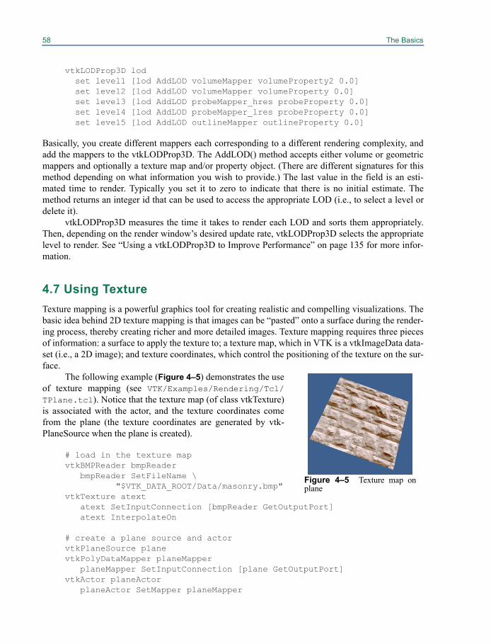
58 The Basics
vtkLODProp3D lodset level1 [lod AddLOD volumeMapper volumeProperty2 0.0]set level2 [lod AddLOD volumeMapper volumeProperty 0.0]set level3 [lod AddLOD probeMapper_hres probeProperty 0.0]set level4 [lod AddLOD probeMapper_lres probeProperty 0.0]set level5 [lod AddLOD outlineMapper outlineProperty 0.0]
Basically, you create different mappers each corresponding to a different rendering complexity, andadd the mappers to the vtkLODProp3D. The AddLOD() method accepts either volume or geometricmappers and optionally a texture map and/or property object. (There are different signatures for thismethod depending on what information you wish to provide.) The last value in the field is an esti-mated time to render. Typically you set it to zero to indicate that there is no initial estimate. Themethod returns an integer id that can be used to access the appropriate LOD (i.e., to select a level ordelete it).
vtkLODProp3D measures the time it takes to render each LOD and sorts them appropriately.Then, depending on the render window’s desired update rate, vtkLODProp3D selects the appropriatelevel to render. See “Using a vtkLODProp3D to Improve Performance” on page 135 for more infor-mation.
4.7 Using TextureTexture mapping is a powerful graphics tool for creating realistic and compelling visualizations. Thebasic idea behind 2D texture mapping is that images can be “pasted” onto a surface during the render-ing process, thereby creating richer and more detailed images. Texture mapping requires three piecesof information: a surface to apply the texture to; a texture map, which in VTK is a vtkImageData data-set (i.e., a 2D image); and texture coordinates, which control the positioning of the texture on the sur-face.
The following example (Figure 4–5) demonstrates the useof texture mapping (see VTK/Examples/Rendering/Tcl/TPlane.tcl). Notice that the texture map (of class vtkTexture)is associated with the actor, and the texture coordinates comefrom the plane (the texture coordinates are generated by vtk-PlaneSource when the plane is created).
# load in the texture mapvtkBMPReader bmpReader
bmpReader SetFileName \"$VTK_DATA_ROOT/Data/masonry.bmp"
vtkTexture atextatext SetInputConnection [bmpReader GetOutputPort]atext InterpolateOn
# create a plane source and actorvtkPlaneSource planevtkPolyDataMapper planeMapper
planeMapper SetInputConnection [plane GetOutputPort]vtkActor planeActor
planeActor SetMapper planeMapper
Figure 4–5 Texture map onplane

4.8 Picking 59
planeActor SetTexture atext
Often times texture coordinates are not available, usually because they are not generated in the pipe-line. If you need to generate texture coordinates, refer to “Generate Texture Coordinates” onpage 111. Although some older graphics card have limitations on the dimensions of textures (e.g. theymust be a power of two and less than 1024 on a side), VTK allows arbitrarily sized textures. At runtime, VTK will query the graphics system to determine its capabilities, and will automatically resam-ple your texture to meet the card's requirements.
4.8 Picking Picking is a common visualization task. Picking is used to select data and actors or to query underly-ing data values. A pick is made when a display position (i.e., pixel coordinate) is selected and used toinvoke vtkAbstractPicker’s Pick() method. Depending on the type of picking class, the informationreturned from the pick may be as simple as an x-y-z global coordinate, or it may include cell ids, pointids, cell parametric coordinates, the instance of vtkProp that was picked, and/or assembly paths. Thesyntax of the pick method is as follows.
Pick(selectionX, selectionY, selectionZ, Renderer)
Notice that the pick method requires a renderer. The actors associated with the renderer are the candi-dates for pick selection. Also, selectionZ is typically set to 0.0—it relates to depth in the z-buffer.(In typical usage, this method is not invoked directly. Rather the user interacts with the classvtkRenderWindowInteractor which manages the pick. In this case, the user would control the pickingprocess by assigning an instance of a picking class to the vtkRenderWindowInteractor, as we will seein a later example.)
The Visualization Toolkit supports several types of pickers of varying functionality and perfor-mance. (Please see Figure 19–16 which is an illustration of the picking class hierarchy.) The classvtkAbstractPicker serves as the base class for all pickers. It defines a minimal API which allows theuser to retrieve the pick position (in global coordinates) using the GetPickPosition() method.
Two direct subclasses of vtkAbstractPicker exist. The first, vtkWorldPointPicker, is a fast (usu-ally in hardware) picking class that uses the z-buffer to return the x-y-z global pick position. However,no other information (about the vtkProp that was picked, etc.) is returned. The class vtkAbstractProp-Picker is another direct subclass of vtkAbstractPicker. It defines an API for pickers that can pick aninstance of vtkProp. There are several convenience methods in this class to allow querying for thereturn type of a pick.
• GetProp() — Return the instance of vtkProp that was picked. If anything at all was picked,then this method will return a pointer to the instance of vtkProp, otherwise NULL is returned.
• GetProp3D() — If an instance of vtkProp3D was picked, return a pointer to the instance ofvtkProp3D.
• GetActor2D() — If an instance of vtkActor2D was picked, return a pointer to the instance ofvtkActor2D.
• GetActor() — If an instance of vtkActor was picked, return a pointer to the instance ofvtkActor.
60 The Basics
• GetVolume() — If an instance of vtkVolume was picked, return a pointer to the instance ofvtkVolume.
• GetAssembly() — If an instance of vtkAssembly was picked, return a pointer to the instanceof vtkAssembly.
• GetPropAssembly() — If an instance of vtkPropAssembly was picked, return a pointer to theinstance of vtkPropAssembly.
A word of caution about these methods. The class (and its subclass) return information about the toplevel of the assembly path that was picked. So if you have an assembly whose top level is of typevtkAssembly, and whose leaf node is of type vtkActor, the method GetAssembly() will return apointer to the instance of vtkAssembly, while the GetActor() method will return a NULL pointer (i.e.,no vtkActor). If you have a complex scene that includes assemblies, actors, and other types of props,the safest course to take is to use the GetProp() method to determine whether anything at all waspicked, and then use GetPath().
There are three direct subclasses of vtkAbstractPropPicker. These are vtkPropPicker,vtkAreaPicker, and vtkPicker. vtkPropPicker uses hardware picking to determine the instance of vtk-Prop that was picked, as well as the pick position (in global coordinates). vtkPropPicker is generallyfaster than all other decendents of vtkAbstractPropPicker but it cannot return information detailedinformation about what was picked.
vtkAreaPicker and its hardware picking based descendent vtkRenderedAreaPicker are similarlyincapable of determining detailed information, as all three exist for the purpose of identifying entireobjects that are shown on screen. The AreaPicker classes differ from all other pickers in that they candetermine what lies begin an entire rectangular region of pixels on the screen instead of only what liesbehind a single pixel. These classes have an AreaPick(x_min, y_min, x_max, y_max, Renderer)method that can be called in addition to the standard Pick(x,y,z, Renderer) method. If you needdetailed information, for example specific cells and points or information about what lies behind anarea, review the following picker explanations below.
vtkPicker is a software-based picker that selects vtkProp’s based on their bounding box. Its pickmethod fires a ray from the camera position through the selection point and intersects the boundingbox of each prop 3D; of course, more than one prop 3D may be picked. The “closest” prop 3D interms of its bounding box intersection point along the ray is returned. (The GetProp3Ds() method canbe used to get all prop 3D’s whose bounding box was intersected.) vtkPicker is fairly fast but cannotgenerate a single unique pick.
vtkPicker has two subclasses that can be used to retrieve more detailed information about whatwas picked (e.g., point ids, cell ids, etc.) vtkPointPicker selects a point and returns the point id andcoordinates. It operates by firing a ray from the camera position through the selection point, and pro-jecting those points that lie within Tolerance onto the ray. The projected point closest to the cameraposition is selected, along with its associated actor. (Note: The instance variable Tolerance isexpressed as a fraction of the renderer window’s diagonal length.) vtkPointPicker is slower than vtk-Picker but faster than vtkCellPicker. It cannot always return a unique pick because of the tolerancesinvolved.
vtkCellPicker selects a cell and returns information about the intersection point (cell id, globalcoordinates, and parametric cell coordinates). It operates by firing a ray and intersecting all cells ineach actor’s underlying geometry, determining if each intersects this ray, within a certain specifiedtolerance. The cell closest to the camera position along the specified ray is selected, along with itsassociated actor. (Note: The instance variable Tolerance is used during intersection calculation, andyou may need to experiment with its value to get satisfactory behavior.) vtkCellPicker is the slowest
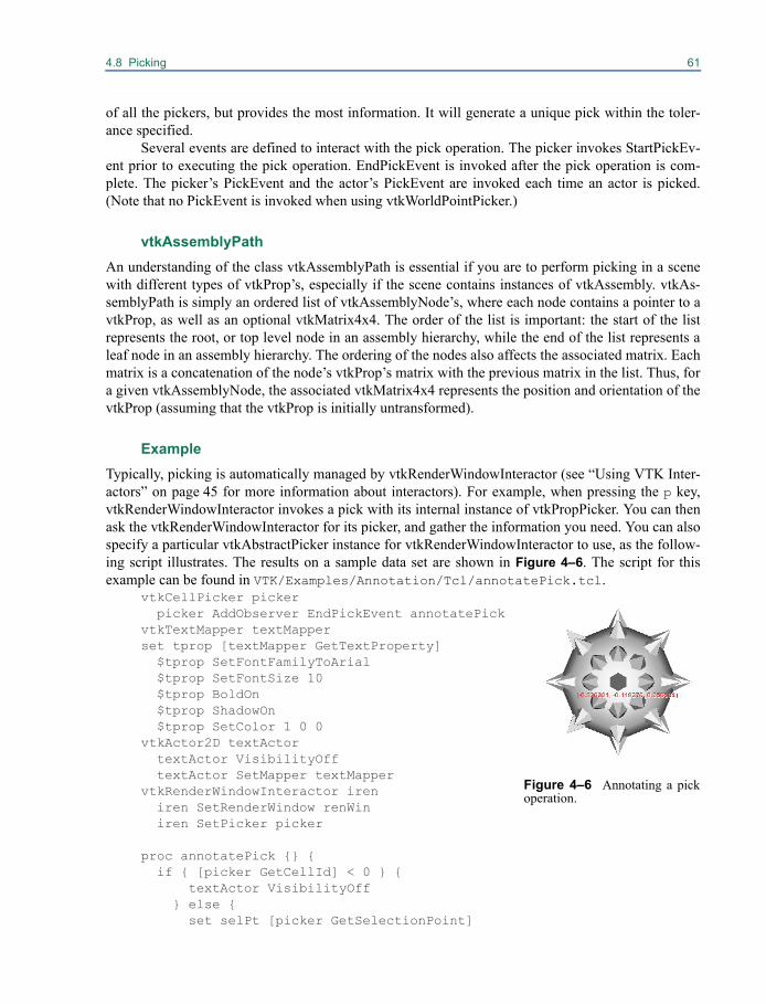
4.8 Picking 61
of all the pickers, but provides the most information. It will generate a unique pick within the toler-ance specified.
Several events are defined to interact with the pick operation. The picker invokes StartPickEv-ent prior to executing the pick operation. EndPickEvent is invoked after the pick operation is com-plete. The picker’s PickEvent and the actor’s PickEvent are invoked each time an actor is picked.(Note that no PickEvent is invoked when using vtkWorldPointPicker.)
vtkAssemblyPathAn understanding of the class vtkAssemblyPath is essential if you are to perform picking in a scenewith different types of vtkProp’s, especially if the scene contains instances of vtkAssembly. vtkAs-semblyPath is simply an ordered list of vtkAssemblyNode’s, where each node contains a pointer to avtkProp, as well as an optional vtkMatrix4x4. The order of the list is important: the start of the listrepresents the root, or top level node in an assembly hierarchy, while the end of the list represents aleaf node in an assembly hierarchy. The ordering of the nodes also affects the associated matrix. Eachmatrix is a concatenation of the node’s vtkProp’s matrix with the previous matrix in the list. Thus, fora given vtkAssemblyNode, the associated vtkMatrix4x4 represents the position and orientation of thevtkProp (assuming that the vtkProp is initially untransformed).
ExampleTypically, picking is automatically managed by vtkRenderWindowInteractor (see “Using VTK Inter-actors” on page 45 for more information about interactors). For example, when pressing the p key,vtkRenderWindowInteractor invokes a pick with its internal instance of vtkPropPicker. You can thenask the vtkRenderWindowInteractor for its picker, and gather the information you need. You can alsospecify a particular vtkAbstractPicker instance for vtkRenderWindowInteractor to use, as the follow-ing script illustrates. The results on a sample data set are shown in Figure 4–6. The script for thisexample can be found in VTK/Examples/Annotation/Tcl/annotatePick.tcl.
vtkCellPicker picker picker AddObserver EndPickEvent annotatePickvtkTextMapper textMapperset tprop [textMapper GetTextProperty] $tprop SetFontFamilyToArial $tprop SetFontSize 10 $tprop BoldOn $tprop ShadowOn $tprop SetColor 1 0 0vtkActor2D textActor textActor VisibilityOff textActor SetMapper textMappervtkRenderWindowInteractor iren iren SetRenderWindow renWin iren SetPicker picker
proc annotatePick {} { if { [picker GetCellId] < 0 } {
textActor VisibilityOff} else {set selPt [picker GetSelectionPoint]
Figure 4–6 Annotating a pickoperation.
62 The Basics
set x [lindex $selPt 0] set y [lindex $selPt 1]set pickPos [picker GetPickPosition]set xp [lindex $pickPos 0] set yp [lindex $pickPos 1]set zp [lindex $pickPos 2]textMapper SetInput "($xp, $yp, $zp)"textActor SetPosition $x $ytextActor VisibilityOn
}renWin Render
}picker Pick 85 126 0 ren1
This example uses a vtkTextMapper to draw the world coordinate of the pick on the screen. (See“Text Annotation” on page 63 for more information.) Notice that we register the EndPickEvent toperform setup after the pick occurs. The method is configured to invoke the annotatePick() proce-dure when picking is complete.
4.9 vtkCoordinate and Coordinate SystemsThe Visualization Toolkit supports several different coordinate systems, and the class vtkCoordinatemanages transformations between them. The supported coordinate systems are as follows.
• DISPLAY — x-y pixel values in the (rendering) window. (Note that vtkRenderWindow is asubclass of vtkWindow). The origin is the lower-left corner (which is true for all 2D coordinatesystems described below).
• NORMALIZED DISPLAY — x-y (0,1) normalized values in the window.
• VIEWPORT — x-y pixel values in the viewport (or renderer — a subclass of vtkViewport)
• NORMALIZED VIEWPORT — x-y (0,1) normalized values in viewport
• VIEW — x-y-z (-1,1) values in camera coordinates (z is depth)
• WORLD — x-y-z global coordinate value
• USERDEFINED - x-y-z in user-defined space. The user must provide a transformation methodfor user defined coordinate systems. See vtkCoordinate for more information.
The class vtkCoordinate can be used to transform between coordinate systems and can be linkedtogether to form “relative” or “offset” coordinate values. Refer to the next section for an example ofusing vtkCoordinate in an application.
4.10 Controlling vtkActor2DvtkActor2D is analogous to vtkActor except that it draws on the overlay plane and does not have a4x4 transformation matrix associated with it. Like vtkActor, vtkActor2D refers to a mapper(vtkMapper2D) and a property object (vtkProperty2D). The most difficult part when working withvtkActor2D is positioning it. To do that, the class vtkCoordinate is used. (See previous section, “vtk-
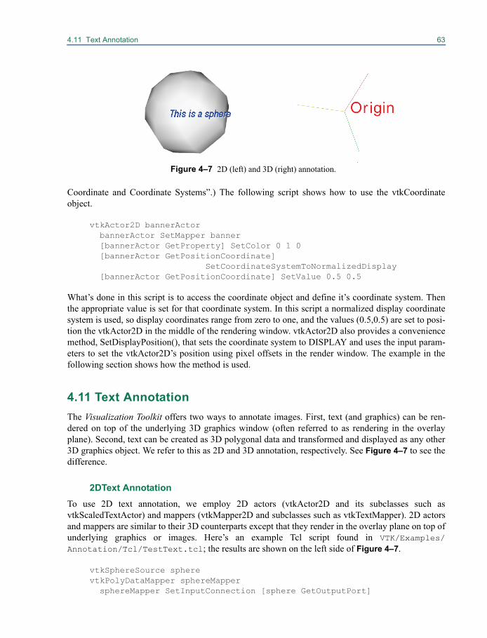
4.11 Text Annotation 63
Coordinate and Coordinate Systems”.) The following script shows how to use the vtkCoordinateobject.
vtkActor2D bannerActor bannerActor SetMapper banner [bannerActor GetProperty] SetColor 0 1 0 [bannerActor GetPositionCoordinate]
SetCoordinateSystemToNormalizedDisplay [bannerActor GetPositionCoordinate] SetValue 0.5 0.5
What’s done in this script is to access the coordinate object and define it’s coordinate system. Thenthe appropriate value is set for that coordinate system. In this script a normalized display coordinatesystem is used, so display coordinates range from zero to one, and the values (0.5,0.5) are set to posi-tion the vtkActor2D in the middle of the rendering window. vtkActor2D also provides a conveniencemethod, SetDisplayPosition(), that sets the coordinate system to DISPLAY and uses the input param-eters to set the vtkActor2D’s position using pixel offsets in the render window. The example in thefollowing section shows how the method is used.
4.11 Text AnnotationThe Visualization Toolkit offers two ways to annotate images. First, text (and graphics) can be ren-dered on top of the underlying 3D graphics window (often referred to as rendering in the overlayplane). Second, text can be created as 3D polygonal data and transformed and displayed as any other3D graphics object. We refer to this as 2D and 3D annotation, respectively. See Figure 4–7 to see thedifference.
2DText AnnotationTo use 2D text annotation, we employ 2D actors (vtkActor2D and its subclasses such asvtkScaledTextActor) and mappers (vtkMapper2D and subclasses such as vtkTextMapper). 2D actorsand mappers are similar to their 3D counterparts except that they render in the overlay plane on top ofunderlying graphics or images. Here’s an example Tcl script found in VTK/Examples/Annotation/Tcl/TestText.tcl; the results are shown on the left side of Figure 4–7.
vtkSphereSource spherevtkPolyDataMapper sphereMapper sphereMapper SetInputConnection [sphere GetOutputPort]
Figure 4–7 2D (left) and 3D (right) annotation.
64 The Basics
sphereMapper GlobalImmediateModeRenderingOnvtkLODActor sphereActor sphereActor SetMapper sphereMapper
vtkTextActor textActor textActor SetTextScaleModeToProp textActor SetDisplayPosition 90 50 textActor SetInput "This is a sphere"
# Specify an initial size [textActor GetPosition2Coordinate] \
SetCoordinateSystemToNormalizedViewport [textActor GetPosition2Coordinate] SetValue 0.6 0.1
set tprop [textActor GetTextProperty] $tprop SetFontSize 18 $tprop SetFontFamilyToArial $tprop SetJustificationToCentered $tprop BoldOn $tprop ItalicOn $tprop ShadowOn $tprop SetColor 0 0 1
# Create the RenderWindow, Renderer and both ActorsvtkRenderer ren1vtkRenderWindow renWin renWin AddRenderer ren1vtkRenderWindowInteractor iren iren SetRenderWindow renWin
# Add the actors to the rendererren1 AddViewProp textActorren1 sphereActor
Instances of the class vtkTextProperty allow you to control font family (Arial, Courier, or Times), settext color, turn bolding and italics on and off, and apply font shadowing. (Shadowing is used to makethe font more readable when placed on top of complex background images.) The position and color ofthe text is controlled by the associated vtkActor2D. (In this example, the position is set using displayor pixel coordinates.)
vtkTextProperty also supports justification (vertical and horizontal) and multi-line text. Use themethods SetJustificationToLeft(), SetJustificationToCentered(), and SetJustificationToRight() to con-trol the horizontal justification. Use the methods SetVerticalJustificationToBottom(),SetVerticalJustificationToCentered(), and SetVerticalJustificationToTop() to control vertical justifica-tion. By default, text is left-bottom justified. To insert multi-line text, use the \n character embeddedin the text. The example in Figure 4–8 demonstrates justification and multi-line text (taken fromVTK/Examples/Annotation/Tcl/multiLineText.tcl). The essence of the example is shownbelow.
vtkTextMapper textMapperL textMapperL SetInput "This is\nmulti-line\ntext output\n(left-top)" set tprop [textMapperL GetTextProperty]
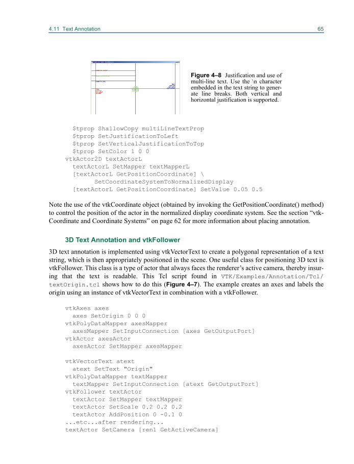
4.11 Text Annotation 65
$tprop ShallowCopy multiLineTextProp $tprop SetJustificationToLeft $tprop SetVerticalJustificationToTop $tprop SetColor 1 0 0vtkActor2D textActorL textActorL SetMapper textMapperL [textActorL GetPositionCoordinate] \
SetCoordinateSystemToNormalizedDisplay [textActorL GetPositionCoordinate] SetValue 0.05 0.5
Note the use of the vtkCoordinate object (obtained by invoking the GetPositionCoordinate() method)to control the position of the actor in the normalized display coordinate system. See the section “vtk-Coordinate and Coordinate Systems” on page 62 for more information about placing annotation.
3D Text Annotation and vtkFollower3D text annotation is implemented using vtkVectorText to create a polygonal representation of a textstring, which is then appropriately positioned in the scene. One useful class for positioning 3D text isvtkFollower. This class is a type of actor that always faces the renderer’s active camera, thereby insur-ing that the text is readable. This Tcl script found in VTK/Examples/Annotation/Tcl/textOrigin.tcl shows how to do this (Figure 4–7). The example creates an axes and labels theorigin using an instance of vtkVectorText in combination with a vtkFollower.
vtkAxes axes axes SetOrigin 0 0 0vtkPolyDataMapper axesMapper axesMapper SetInputConnection [axes GetOutputPort]vtkActor axesActor axesActor SetMapper axesMapper
vtkVectorText atext atext SetText "Origin"vtkPolyDataMapper textMapper textMapper SetInputConnection [atext GetOutputPort]vtkFollower textActor textActor SetMapper textMapper textActor SetScale 0.2 0.2 0.2 textActor AddPosition 0 -0.1 0...etc...after rendering...textActor SetCamera [ren1 GetActiveCamera]
Figure 4–8 Justification and use ofmulti-line text. Use the \n characterembedded in the text string to gener-ate line breaks. Both vertical andhorizontal justification is supported.
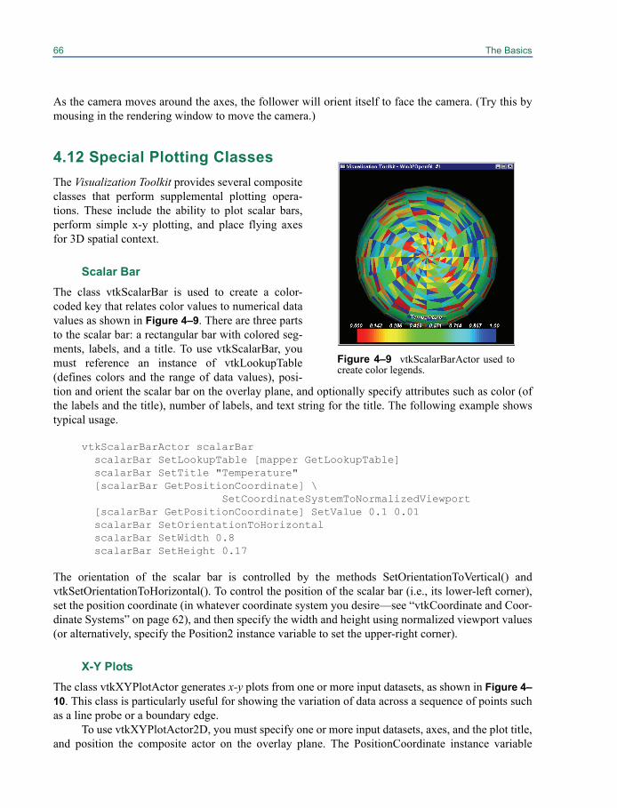
66 The Basics
As the camera moves around the axes, the follower will orient itself to face the camera. (Try this bymousing in the rendering window to move the camera.)
4.12 Special Plotting Classes
The Visualization Toolkit provides several compositeclasses that perform supplemental plotting opera-tions. These include the ability to plot scalar bars,perform simple x-y plotting, and place flying axesfor 3D spatial context.
Scalar BarThe class vtkScalarBar is used to create a color-coded key that relates color values to numerical datavalues as shown in Figure 4–9. There are three partsto the scalar bar: a rectangular bar with colored seg-ments, labels, and a title. To use vtkScalarBar, youmust reference an instance of vtkLookupTable(defines colors and the range of data values), posi-tion and orient the scalar bar on the overlay plane, and optionally specify attributes such as color (ofthe labels and the title), number of labels, and text string for the title. The following example showstypical usage.
vtkScalarBarActor scalarBar scalarBar SetLookupTable [mapper GetLookupTable] scalarBar SetTitle "Temperature" [scalarBar GetPositionCoordinate] \
SetCoordinateSystemToNormalizedViewport [scalarBar GetPositionCoordinate] SetValue 0.1 0.01 scalarBar SetOrientationToHorizontal scalarBar SetWidth 0.8 scalarBar SetHeight 0.17
The orientation of the scalar bar is controlled by the methods SetOrientationToVertical() andvtkSetOrientationToHorizontal(). To control the position of the scalar bar (i.e., its lower-left corner),set the position coordinate (in whatever coordinate system you desire—see “vtkCoordinate and Coor-dinate Systems” on page 62), and then specify the width and height using normalized viewport values(or alternatively, specify the Position2 instance variable to set the upper-right corner).
X-Y PlotsThe class vtkXYPlotActor generates x-y plots from one or more input datasets, as shown in Figure 4–10. This class is particularly useful for showing the variation of data across a sequence of points suchas a line probe or a boundary edge.
To use vtkXYPlotActor2D, you must specify one or more input datasets, axes, and the plot title,and position the composite actor on the overlay plane. The PositionCoordinate instance variable
Figure 4–9 vtkScalarBarActor used tocreate color legends.
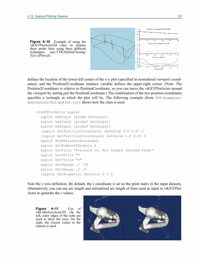
4.12 Special Plotting Classes 67
defines the location of the lower-left corner of the x-y plot (specified in normalized viewport coordi-nates), and the Position2Coordinate instance variable defines the upper-right corner. (Note: ThePosition2Coordinate is relative to PositionCoordinate, so you can move the vtkXYPlotActor aroundthe viewport by setting just the PositionCoordinate.) The combination of the two position coordinatesspecifies a rectangle in which the plot will lie. The following example (from VTK/Examples/Annotation/Tcl/xyPlot.tcl) shows how the class is used.
vtkXYPlotActor xyplot xyplot AddInput [probe GetOutput] xyplot AddInput [probe2 GetOutput] xyplot AddInput [probe3 GetOutput] [xyplot GetPositionCoordinate] SetValue 0.0 0.67 0 [xyplot GetPosition2Coordinate] SetValue 1.0 0.33 0 xyplot SetXValuesToArcLength xyplot SetNumberOfXLabels 6 xyplot SetTitle "Pressure vs. Arc Length (Zoomed View)" xyplot SetXTitle "" xyplot SetYTitle "P" xyplot SetXRange .1 .35 xyplot SetYRange .2 .4 [xyplot GetProperty] SetColor 0 0 0
Note the x axis definition. By default, the x coordinate is set as the point index in the input datasets.Alternatively, you can use arc length and normalized arc length of lines used as input to vtkXYPlot-Actor to generate the x values.
Figure 4–10 Example of using thevtkXYPlotActor2D class to displaythree probe lines using three differenttechniques (see VTK/Hybrid/Testing/Tcl/xyPlot.tcl).
Figure 4–11 Use ofvtkCubeAxisActor2D. On theleft, outer edges of the cube areused to draw the axes. On theright, the closest vertex to thecamera is used.
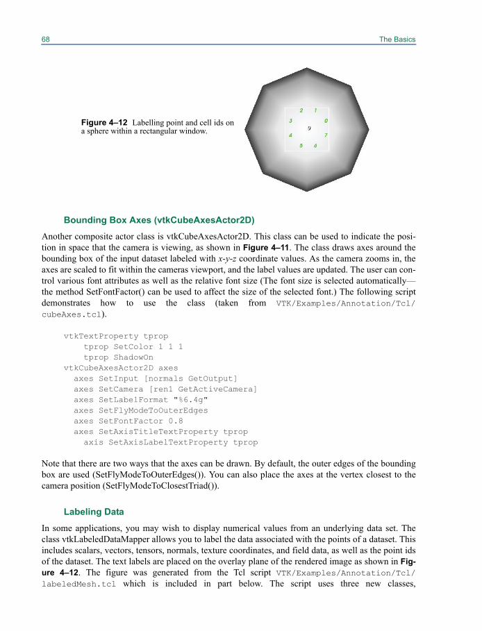
68 The Basics
Bounding Box Axes (vtkCubeAxesActor2D) Another composite actor class is vtkCubeAxesActor2D. This class can be used to indicate the posi-tion in space that the camera is viewing, as shown in Figure 4–11. The class draws axes around thebounding box of the input dataset labeled with x-y-z coordinate values. As the camera zooms in, theaxes are scaled to fit within the cameras viewport, and the label values are updated. The user can con-trol various font attributes as well as the relative font size (The font size is selected automatically—the method SetFontFactor() can be used to affect the size of the selected font.) The following scriptdemonstrates how to use the class (taken from VTK/Examples/Annotation/Tcl/cubeAxes.tcl).
vtkTextProperty tproptprop SetColor 1 1 1tprop ShadowOn
vtkCubeAxesActor2D axes axes SetInput [normals GetOutput] axes SetCamera [ren1 GetActiveCamera] axes SetLabelFormat "%6.4g" axes SetFlyModeToOuterEdges axes SetFontFactor 0.8 axes SetAxisTitleTextProperty tprop
axis SetAxisLabelTextProperty tprop
Note that there are two ways that the axes can be drawn. By default, the outer edges of the boundingbox are used (SetFlyModeToOuterEdges()). You can also place the axes at the vertex closest to thecamera position (SetFlyModeToClosestTriad()).
Labeling Data
In some applications, you may wish to display numerical values from an underlying data set. Theclass vtkLabeledDataMapper allows you to label the data associated with the points of a dataset. Thisincludes scalars, vectors, tensors, normals, texture coordinates, and field data, as well as the point idsof the dataset. The text labels are placed on the overlay plane of the rendered image as shown in Fig-ure 4–12. The figure was generated from the Tcl script VTK/Examples/Annotation/Tcl/labeledMesh.tcl which is included in part below. The script uses three new classes,
Figure 4–12 Labelling point and cell ids ona sphere within a rectangular window.
4.12 Special Plotting Classes 69
vtkCellCenters (to generate points at the parametric centers of cells), vtkIdFilter (to generate ids asscalar or field data from dataset ids), and vtkSelectVisiblePoints (to select those points currently visi-ble), to label the cell and point ids of the sphere. In addition, vtkSelectVisiblePoints has the ability todefine a “window” in display (pixel) coordinates in which it operates—all points outside of the win-dow are discarded.
# Create a spherevtkSphereSource spherevtkPolyDataMapper sphereMapper sphereMapper SetInputConnection [sphere GetOutputPort] sphereMapper GlobalImmediateModeRenderingOnvtkActor sphereActor sphereActor SetMapper sphereMapper# Generate ids for labelingvtkIdFilter ids ids SetInputConnection [sphere GetOutputPort] ids PointIdsOn ids CellIdsOn ids FieldDataOn
vtkRenderer ren1
# Create labels for pointsvtkSelectVisiblePoints visPts visPts SetInputConnection [ids GetOutputPort] visPts SetRenderer ren1 visPts SelectionWindowOn visPts SetSelection $xmin [expr $xmin + $xLength] \
$ymin [expr $ymin + $yLength]vtkLabeledDataMapper ldm ldm SetInput [visPts GetOutput] ldm SetLabelFormat "%g"
ldm SetLabelModeToLabelFieldDatavtkActor2D pointLabels pointLabels SetMapper ldm
# Create labels for cellsvtkCellCenters cc cc SetInputConnection [ids GetOutputPort]vtkSelectVisiblePoints visCells visCells SetInputConnection [cc GetOutputPort] visCells SetRenderer ren1 visCells SelectionWindowOn visCells SetSelection $xmin [expr $xmin + $xLength] \
$ymin [expr $ymin + $yLength]vtkLabeledDataMapper cellMapper cellMapper SetInputConnection [visCells GetOutputPort] cellMapper SetLabelFormat "%g"
cellMapper SetLabelModeToLabelFieldData[cellMapper GetLabelTextProperty] SetColor 0 1 0
vtkActor2D cellLabels
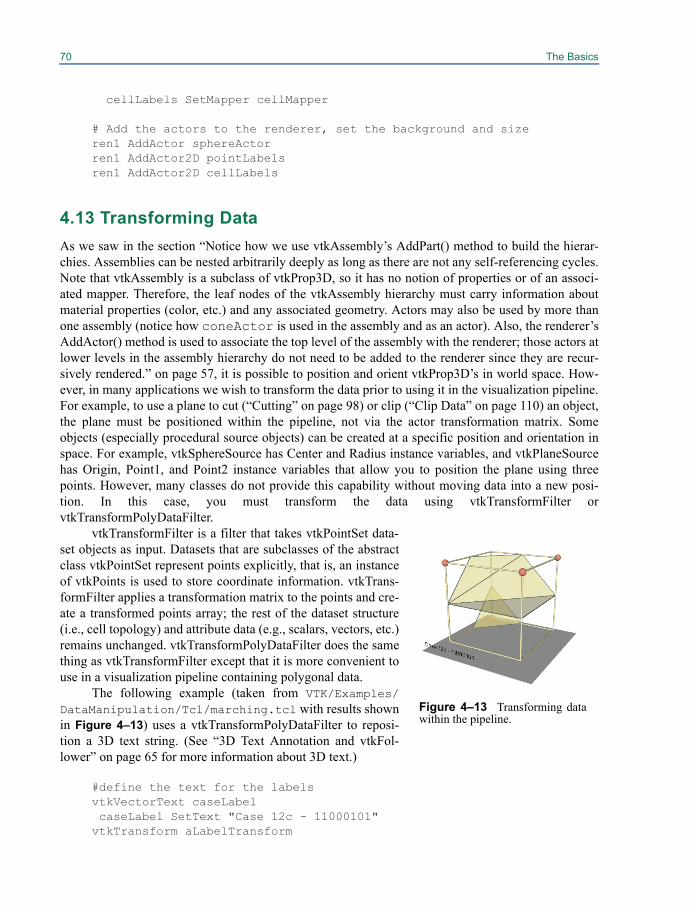
70 The Basics
cellLabels SetMapper cellMapper
# Add the actors to the renderer, set the background and sizeren1 AddActor sphereActorren1 AddActor2D pointLabelsren1 AddActor2D cellLabels
4.13 Transforming DataAs we saw in the section “Notice how we use vtkAssembly’s AddPart() method to build the hierar-chies. Assemblies can be nested arbitrarily deeply as long as there are not any self-referencing cycles.Note that vtkAssembly is a subclass of vtkProp3D, so it has no notion of properties or of an associ-ated mapper. Therefore, the leaf nodes of the vtkAssembly hierarchy must carry information aboutmaterial properties (color, etc.) and any associated geometry. Actors may also be used by more thanone assembly (notice how coneActor is used in the assembly and as an actor). Also, the renderer’sAddActor() method is used to associate the top level of the assembly with the renderer; those actors atlower levels in the assembly hierarchy do not need to be added to the renderer since they are recur-sively rendered.” on page 57, it is possible to position and orient vtkProp3D’s in world space. How-ever, in many applications we wish to transform the data prior to using it in the visualization pipeline.For example, to use a plane to cut (“Cutting” on page 98) or clip (“Clip Data” on page 110) an object,the plane must be positioned within the pipeline, not via the actor transformation matrix. Someobjects (especially procedural source objects) can be created at a specific position and orientation inspace. For example, vtkSphereSource has Center and Radius instance variables, and vtkPlaneSourcehas Origin, Point1, and Point2 instance variables that allow you to position the plane using threepoints. However, many classes do not provide this capability without moving data into a new posi-tion. In this case, you must transform the data using vtkTransformFilter orvtkTransformPolyDataFilter.
vtkTransformFilter is a filter that takes vtkPointSet data-set objects as input. Datasets that are subclasses of the abstractclass vtkPointSet represent points explicitly, that is, an instanceof vtkPoints is used to store coordinate information. vtkTrans-formFilter applies a transformation matrix to the points and cre-ate a transformed points array; the rest of the dataset structure(i.e., cell topology) and attribute data (e.g., scalars, vectors, etc.)remains unchanged. vtkTransformPolyDataFilter does the samething as vtkTransformFilter except that it is more convenient touse in a visualization pipeline containing polygonal data.
The following example (taken from VTK/Examples/DataManipulation/Tcl/marching.tcl with results shownin Figure 4–13) uses a vtkTransformPolyDataFilter to reposi-tion a 3D text string. (See “3D Text Annotation and vtkFol-lower” on page 65 for more information about 3D text.)
#define the text for the labelsvtkVectorText caseLabel caseLabel SetText "Case 12c - 11000101"vtkTransform aLabelTransform
Figure 4–13 Transforming datawithin the pipeline.
4.13 Transforming Data 71
aLabelTransform Identity aLabelTransform Translate -.2 0 1.25 aLabelTransform Scale .05 .05 .05vtkTransformPolyDataFilter labelTransform labelTransform SetTransform aLabelTransform labelTransform SetInputConnection [caseLabel GetOutputPort]vtkPolyDataMapper labelMapper labelMapper SetInputConnection [labelTransform GetOutputPort];vtkActor labelActor labelActor SetMapper labelMapper
Notice that vtkTransformPolyDataFilter requires that you supply it with an instance of vtkTransform.Recall that vtkTransform is used by actors to control their position and orientation in space. Instancesof vtkTransform support many methods, some of the most commonly used are shown here.
• RotateX(angle) — apply rotation (angle in degrees) around the x axis
• RotateY(angle) — apply rotation around the y axis
• RotateZ(angle) — apply rotation around the z axis
• RotateWXYZ(angle,x,y,z) — apply rotation around a vector defined by x-y-z components
• Scale(x,y,z) — apply scale in the x, y, and z directions
• Translate(x,y,z) — apply translation
• Inverse() — invert the transformation matrix
• SetMatrix(m) — specify the 4x4 transformation matrix directly
• GetMatrix(m) — get the 4x4 transformation matrix
• PostMultiply() — control the order of multiplication of transformation matrices. IfPostMultiply() is invoked, matrix operations are applied on the left hand side of the currentmatrix.
• PreMultiply() — matrix multiplications are applied on the right hand side of the currenttransformation matrix
The last two methods described above remind us that the order in which transformations are applieddramatically affects the resulting transformation matrix. (See “Notice how we use vtkAssembly’sAddPart() method to build the hierarchies. Assemblies can be nested arbitrarily deeply as long asthere are not any self-referencing cycles. Note that vtkAssembly is a subclass of vtkProp3D, so it hasno notion of properties or of an associated mapper. Therefore, the leaf nodes of the vtkAssembly hier-archy must carry information about material properties (color, etc.) and any associated geometry.Actors may also be used by more than one assembly (notice how coneActor is used in the assem-bly and as an actor). Also, the renderer’s AddActor() method is used to associate the top level of theassembly with the renderer; those actors at lower levels in the assembly hierarchy do not need to beadded to the renderer since they are recursively rendered.” on page 57.) We recommend that youspend some time experimenting with these methods and the order of application to fully understandvtkTransform.
72 The Basics
Advanced Transformation
Advanced users may wish to use VTK’s extensive transformation hierarchy. (Much of this work wasdone by David Gobbi.) The hierarchy, of which the class hierarchy is shown in Figure 19–17, sup-ports a variety of linear and non-linear transformations.
A wonderful feature of the VTK transformation hierarchy is that different types of transforma-tion can be used in a filter to give very different results. For example, the vtkTransformPolyDataFilteraccepts any transform of type vtkAbstractTransform (or a subclass). This includes transformationtypes ranging from the linear, affine vtkTransform (represented by a 4x4 matrix) to the non-linear,warping vtkThinPlateSplineTransform, which is a complex function representing a correlationbetween a set of source and target landmarks.
3D Widgets
Interactor styles (see “Using VTK Interactors” on page 45) are generally used to control the cameraand provide simple keypress and mouse-oriented interaction techniques. Interactor styles have no rep-resentation in the scene; that is, they cannot be “seen” or interacted with, the user must know what themouse and key bindings are in order to use them. Certain operations, however, are greatly facilitatedby the ability to operate directly on objects in the scene. For example, starting a rake of streamlinesalong a line is easily performed if the endpoints of the line can be interactively positioned.
3D widgets have been designed to provide this functionality. Like the class vtkInteractorStyle,3D widgets are subclasses of vtkInteractorObserver. That is, they watch for events invoked byvtkRenderWindowInteractor. (Recall that vtkRenderWindowInteractor translates windowing-systemspecific events into VTK event invocations.) Unlike vtkInteractorStyle, however, 3D widgetsrepresent themselves in the scene in various ways. Figure 4–14 illustrates some of the many 3Dwidgets found in VTK.
The following is a list of the most important widgets currently found in VTK and a briefdescription of their features. Note that some of the concepts mentioned here have not yet beencovered in this text. Please refer to “Interaction, Widgets and Selections” on page 255 to learn moreabout a particular concept and the various widgets available in VTK.
• vtkScalarBarWidget — Manage a vtkScalarBar including positioning, scaling, and orienting it.(See “Scalar Bar” on page 66 for more information about scalar bars.)
• vtkPointWidget — Position a point x-y-z location in 3D space. The widget produces a polygo-nal output. Point widgets are typically used for probing. (See “Probing” on page 100.)
• vtkLineWidget — Place a straight line with a specified subdivision resolution. The widget pro-duces a polygonal output. A common use of the line widget is to probe (“Probing” on page 100)and plot data (“X-Y Plots” on page 66) or produce streamlines (“Streamlines” on page 95) orstream surfaces (“Stream Surfaces” on page 97).
• vtkPlaneWidget — Orient and position a finite plane. The plane resolution is variable, and thewidget produces an implicit function and a polygonal output. The plane widget is used for prob-ing (“Probing” on page 100) and seeding streamlines (“Streamlines” on page 95).
• vtkImplicitPlaneWidget — Orient and position an unbounded plane. The widget produces animplicit function and a polygonal output. The polygonal output is created by clipping the planewith a bounding box. The implicit plane widget is typically used for probing (“Probing” onpage 100), cutting (“Cutting” on page 98), and clipping data (“Clip Data” on page 110).
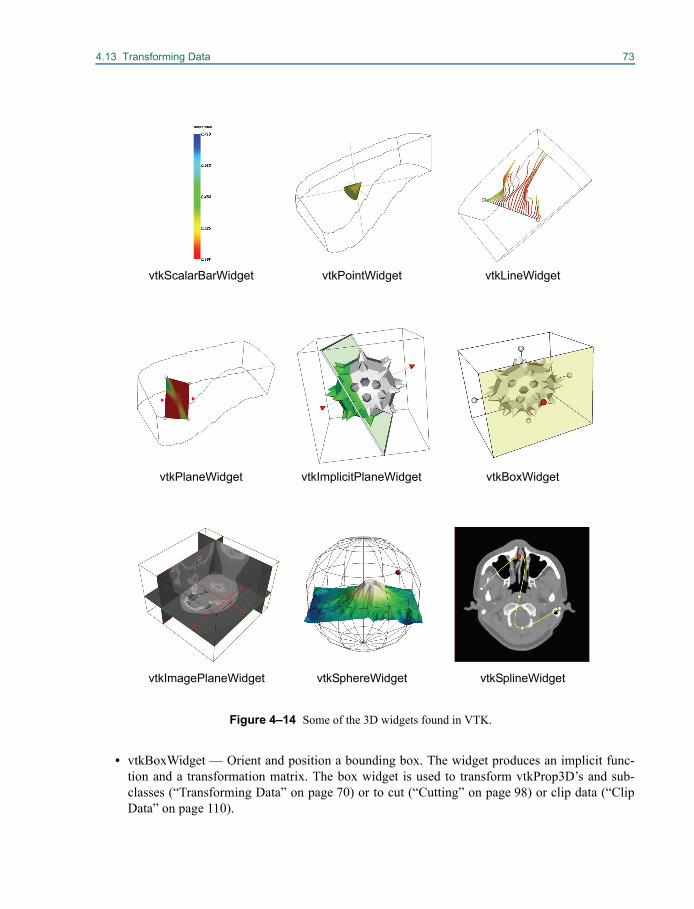
4.13 Transforming Data 73
• vtkBoxWidget — Orient and position a bounding box. The widget produces an implicit func-tion and a transformation matrix. The box widget is used to transform vtkProp3D’s and sub-classes (“Transforming Data” on page 70) or to cut (“Cutting” on page 98) or clip data (“ClipData” on page 110).
Figure 4–14 Some of the 3D widgets found in VTK.
vtkScalarBarWidget vtkPointWidget vtkLineWidget
vtkPlaneWidget vtkImplicitPlaneWidget vtkBoxWidget
vtkImagePlaneWidget vtkSphereWidget vtkSplineWidget

74 The Basics
• vtkImagePlaneWidget — Manipulate three orthogonal planes within a 3D volumetric data set.Probing of the planes to obtain data position, pixel value, and window-level is possible. Theimage plane widget is used to visualize volume data (“Image Processing and Visualization” onpage 103).
• vtkSphereWidget — Manipulate a sphere of variable resolution. The widget produces animplicit function and a transformation matrix and enables the control of focal point and positionto support such classes as vtkCamera and vtkLight. The sphere widget can be used for control-ling lights and cameras (“Controlling The Camera” on page 49 and “Controlling Lights” onpage 51), for clipping (“Clip Data” on page 110), and for cutting (“Cutting” on page 98).
• vtkSplineWidget — Manipulate an interpolating 3D spline (“Creating Movie Files” onpage 248). The widget produces polygonal data represented by a series of line segments ofspecified resolution. The widget also directly manages underlying splines for each of the x-y-zcoordinate values.
While each widget provides different functionality and offers a different API, 3D widgets are similarin how they are set up and used. The general procedure is as follows.
1. Instantiate the widget.
2. Specify the vtkRenderWindowInteractor to observe. The vtkRenderWindowInteractor invokes events that the widget may process.
3. Create callbacks (i.e., commands) as necessary using the Command/Observer mechanism—see “User Methods, Observers, and Commands” on page 29. The widgets invoke the events StartInteractionEvent, InteractionEvent, and EndInteractionEvent.
4. Most widgets require “placing” – positioning in the scene. This typically entails specifying an instance of vtkProp3D, a dataset, or explicitly specifying a bounding box, and then invoking the PlaceWidget() method.
5. Finally, the widget must be enabled. By default, a keypress i will enable the widget and it will appear in the scene.
Note that more than one widget can be enabled at any given time, and the widgets function fine incombination with an instance of vtkInteractorStyle. Thus mousing in the scene not on any particularwidget will engage the vtkInteractorStyle, but mousing on a particular widget will engage just thatwidget—typically no other widget or interactor style will see the events. (One notable exception is theclass vtkInteractorEventRecorder that records events and then passes them along. It can also playbackevents. This is a very useful class for recording sessions and testing.)
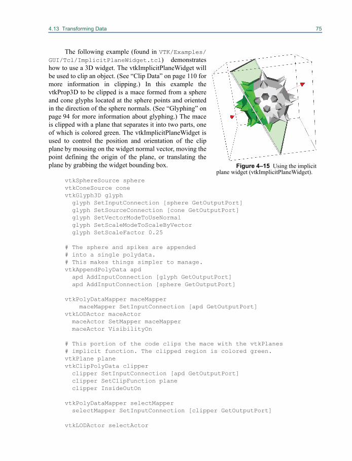
4.13 Transforming Data 75
The following example (found in VTK/Examples/GUI/Tcl/ImplicitPlaneWidget.tcl) demonstrateshow to use a 3D widget. The vtkImplicitPlaneWidget willbe used to clip an object. (See “Clip Data” on page 110 formore information in clipping.) In this example thevtkProp3D to be clipped is a mace formed from a sphereand cone glyphs located at the sphere points and orientedin the direction of the sphere normals. (See “Glyphing” onpage 94 for more information about glyphing.) The maceis clipped with a plane that separates it into two parts, oneof which is colored green. The vtkImplicitPlaneWidget isused to control the position and orientation of the clipplane by mousing on the widget normal vector, moving thepoint defining the origin of the plane, or translating theplane by grabbing the widget bounding box.
vtkSphereSource sphere vtkConeSource conevtkGlyph3D glyph glyph SetInputConnection [sphere GetOutputPort] glyph SetSourceConnection [cone GetOutputPort] glyph SetVectorModeToUseNormal glyph SetScaleModeToScaleByVector glyph SetScaleFactor 0.25
# The sphere and spikes are appended # into a single polydata. # This makes things simpler to manage.vtkAppendPolyData apd apd AddInputConnection [glyph GetOutputPort] apd AddInputConnection [sphere GetOutputPort]
vtkPolyDataMapper maceMappermaceMapper SetInputConnection [apd GetOutputPort]
vtkLODActor maceActor maceActor SetMapper maceMapper maceActor VisibilityOn
# This portion of the code clips the mace with the vtkPlanes # implicit function. The clipped region is colored green.vtkPlane planevtkClipPolyData clipper clipper SetInputConnection [apd GetOutputPort] clipper SetClipFunction plane clipper InsideOutOn
vtkPolyDataMapper selectMapper selectMapper SetInputConnection [clipper GetOutputPort]
vtkLODActor selectActor
Figure 4–15 Using the implicitplane widget (vtkImplicitPlaneWidget).
76 The Basics
selectActor SetMapper selectMapper [selectActor GetProperty] SetColor 0 1 0 selectActor VisibilityOff selectActor SetScale 1.01 1.01 1.01vtkRenderer ren1vtkRenderWindow renWin renWin AddRenderer ren1vtkRenderWindowInteractor iren iren SetRenderWindow renWin
# Associate the line widget with the interactorvtkImplicitPlaneWidget planeWidget planeWidget SetInteractor iren planeWidget SetPlaceFactor 1.25 planeWidget SetInput [glyph GetOutput] planeWidget PlaceWidget planeWidget AddObserver InteractionEvent myCallback
ren1 AddActor maceActorren1 AddActor selectActor
iren AddObserver UserEvent {wm deiconify .vtkInteract}renWin Render
# Prevent the tk window from showing up then start the event loop.wm withdraw .
proc myCallback {} { planeWidget GetPlane plane selectActor VisibilityOn}
As shown above, the implicit plane widget is instantiated and placed. The placing of the widget iswith respect to a dataset. (The Tcl statement “[glyph GetOutput]” returns a vtkPolyData, a subclass ofvtkDataSet.) The PlaceFactor adjusts the relative size of the widget. In this example the widget isgrown 25% larger than the bounding box of the input dataset. The key to the behavior of the widget isthe addition of an observer that responds to the InteractionEvent. StartInteraction and EndInteractionare typically invoked by the widget on mouse down and mouse up respectively; the InteractionEventis invoked on mouse move. The InteractionEvent is tied to the Tcl procedure myCallback that copiesthe plane maintained by the widget to an instance of vtkPlane—an implicit function used to do theclipping. (See “Implicit Modeling” on page 213.)
The 3D widgets are a powerful feature in VTK that can quickly add complex interaction to anyapplication. We encourage you to explore the examples included with the VTK distribution (inExamples/GUI and Hybrid/Testing/Cxx) to see the breadth and power of their capabilities.
4.14 AntialiasingThere are two ways to enable antialiasing with VTK: per primitive type or through multisampling.Multisampling usually gives more pleasant result.
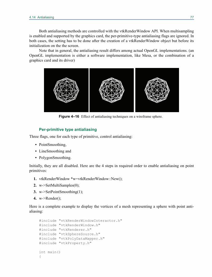
4.14 Antialiasing 77
Both antialiasing methods are controlled with the vtkRenderWindow API. When multisamplingis enabled and supported by the graphics card, the per-primitive-type antialiasing flags are ignored. Inboth cases, the setting has to be done after the creation of a vtkRenderWindow object but before itsinitialization on the the screen.
Note that in general, the antialiasing result differs among actual OpenGL implementations. (anOpenGL implementation is either a software implementation, like Mesa, or the combination of agraphics card and its driver)
Per-primitive type antialiasingThree flags, one for each type of primitive, control antialiasing:
• PointSmoothing,• LineSmoothing and• PolygonSmoothing.
Initially, they are all disabled. Here are the 4 steps in required order to enable antialiasing on pointprimitives:
1. vtkRenderWindow *w=vtkRenderWindow::New();2. w->SetMultiSamples(0);3. w->SetPointSmoothing(1);4. w->Render();
Here is a complete example to display the vertices of a mesh representing a sphere with point anti-aliasing:
#include "vtkRenderWindowInteractor.h"#include "vtkRenderWindow.h"#include "vtkRenderer.h"#include "vtkSphereSource.h"#include "vtkPolyDataMapper.h"#include "vtkProperty.h"
int main(){
Figure 4–16 Effect of antialiasing techniques on a wireframe sphere.
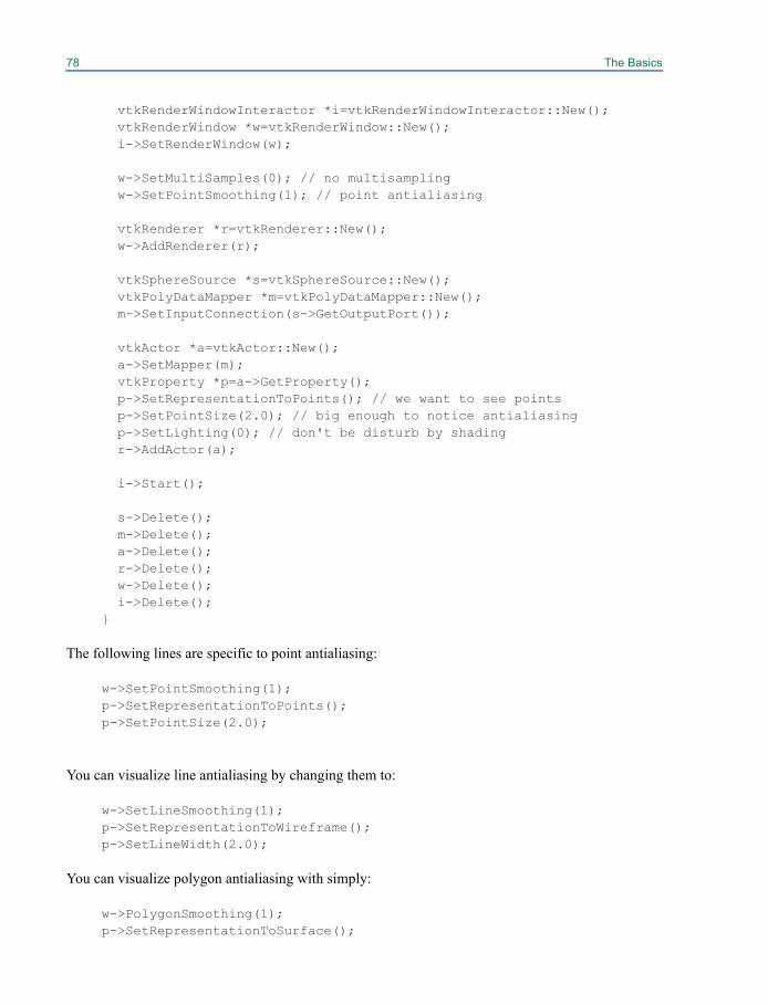
78 The Basics
vtkRenderWindowInteractor *i=vtkRenderWindowInteractor::New(); vtkRenderWindow *w=vtkRenderWindow::New(); i->SetRenderWindow(w); w->SetMultiSamples(0); // no multisampling w->SetPointSmoothing(1); // point antialiasing vtkRenderer *r=vtkRenderer::New(); w->AddRenderer(r); vtkSphereSource *s=vtkSphereSource::New(); vtkPolyDataMapper *m=vtkPolyDataMapper::New(); m->SetInputConnection(s->GetOutputPort());
vtkActor *a=vtkActor::New(); a->SetMapper(m); vtkProperty *p=a->GetProperty(); p->SetRepresentationToPoints(); // we want to see points p->SetPointSize(2.0); // big enough to notice antialiasing p->SetLighting(0); // don't be disturb by shading r->AddActor(a); i->Start(); s->Delete(); m->Delete(); a->Delete(); r->Delete(); w->Delete(); i->Delete();}
The following lines are specific to point antialiasing:
w->SetPointSmoothing(1);p->SetRepresentationToPoints();p->SetPointSize(2.0);
You can visualize line antialiasing by changing them to:
w->SetLineSmoothing(1);p->SetRepresentationToWireframe();p->SetLineWidth(2.0);
You can visualize polygon antialiasing with simply:
w->PolygonSmoothing(1);p->SetRepresentationToSurface();
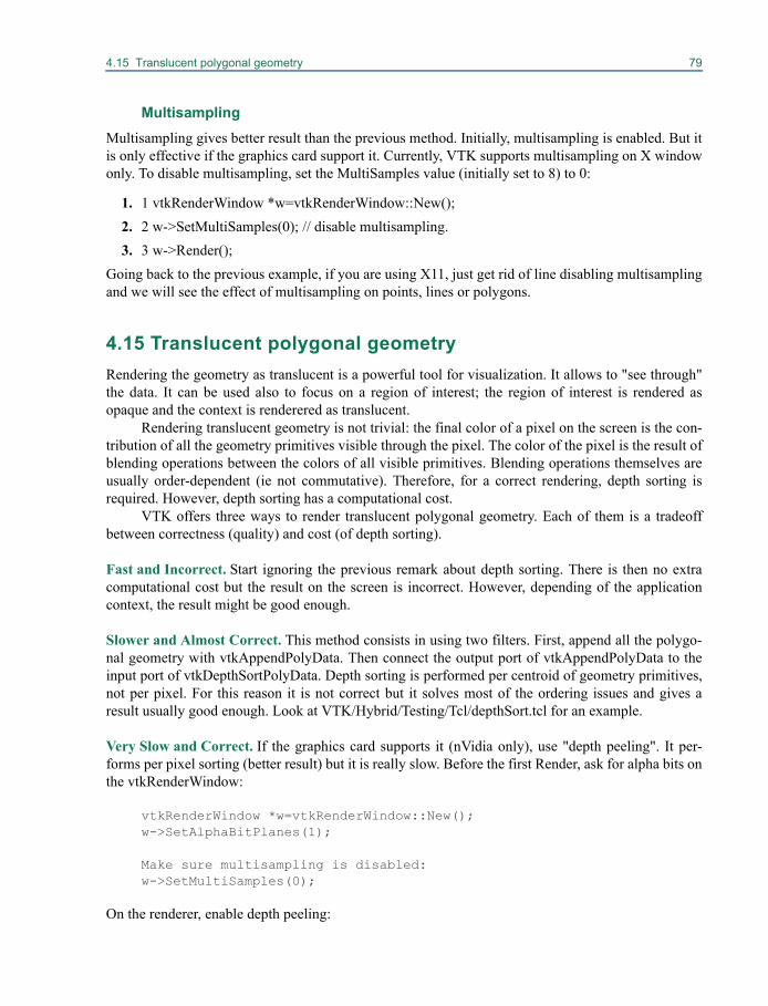
4.15 Translucent polygonal geometry 79
MultisamplingMultisampling gives better result than the previous method. Initially, multisampling is enabled. But itis only effective if the graphics card support it. Currently, VTK supports multisampling on X windowonly. To disable multisampling, set the MultiSamples value (initially set to 8) to 0:
1. 1 vtkRenderWindow *w=vtkRenderWindow::New();2. 2 w->SetMultiSamples(0); // disable multisampling.3. 3 w->Render();
Going back to the previous example, if you are using X11, just get rid of line disabling multisamplingand we will see the effect of multisampling on points, lines or polygons.
4.15 Translucent polygonal geometryRendering the geometry as translucent is a powerful tool for visualization. It allows to "see through"the data. It can be used also to focus on a region of interest; the region of interest is rendered asopaque and the context is renderered as translucent.
Rendering translucent geometry is not trivial: the final color of a pixel on the screen is the con-tribution of all the geometry primitives visible through the pixel. The color of the pixel is the result ofblending operations between the colors of all visible primitives. Blending operations themselves areusually order-dependent (ie not commutative). Therefore, for a correct rendering, depth sorting isrequired. However, depth sorting has a computational cost.
VTK offers three ways to render translucent polygonal geometry. Each of them is a tradeoffbetween correctness (quality) and cost (of depth sorting).
Fast and Incorrect. Start ignoring the previous remark about depth sorting. There is then no extracomputational cost but the result on the screen is incorrect. However, depending of the applicationcontext, the result might be good enough.
Slower and Almost Correct. This method consists in using two filters. First, append all the polygo-nal geometry with vtkAppendPolyData. Then connect the output port of vtkAppendPolyData to theinput port of vtkDepthSortPolyData. Depth sorting is performed per centroid of geometry primitives,not per pixel. For this reason it is not correct but it solves most of the ordering issues and gives aresult usually good enough. Look at VTK/Hybrid/Testing/Tcl/depthSort.tcl for an example.
Very Slow and Correct. If the graphics card supports it (nVidia only), use "depth peeling". It per-forms per pixel sorting (better result) but it is really slow. Before the first Render, ask for alpha bits onthe vtkRenderWindow:
vtkRenderWindow *w=vtkRenderWindow::New();w->SetAlphaBitPlanes(1);
Make sure multisampling is disabled:w->SetMultiSamples(0);
On the renderer, enable depth peeling:
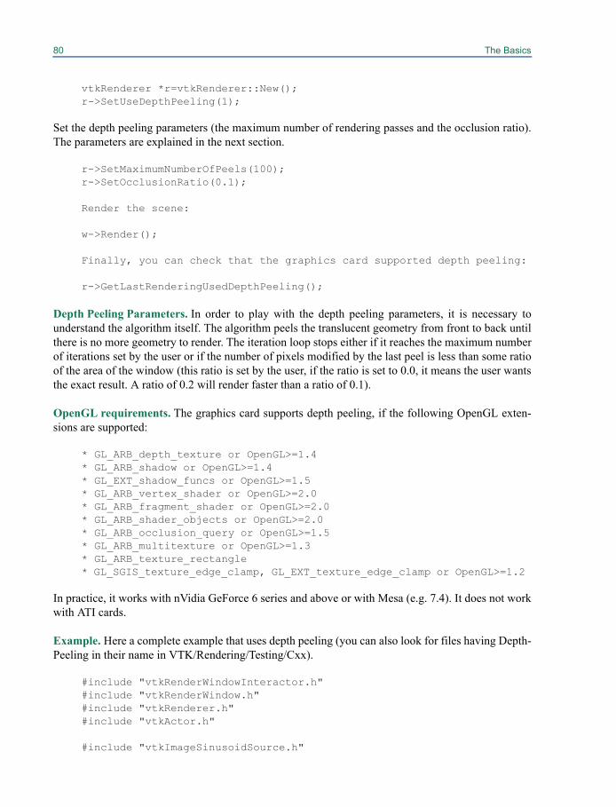
80 The Basics
vtkRenderer *r=vtkRenderer::New();r->SetUseDepthPeeling(1);
Set the depth peeling parameters (the maximum number of rendering passes and the occlusion ratio).The parameters are explained in the next section.
r->SetMaximumNumberOfPeels(100);r->SetOcclusionRatio(0.1);
Render the scene:
w->Render();
Finally, you can check that the graphics card supported depth peeling:
r->GetLastRenderingUsedDepthPeeling();
Depth Peeling Parameters. In order to play with the depth peeling parameters, it is necessary tounderstand the algorithm itself. The algorithm peels the translucent geometry from front to back untilthere is no more geometry to render. The iteration loop stops either if it reaches the maximum numberof iterations set by the user or if the number of pixels modified by the last peel is less than some ratioof the area of the window (this ratio is set by the user, if the ratio is set to 0.0, it means the user wantsthe exact result. A ratio of 0.2 will render faster than a ratio of 0.1).
OpenGL requirements. The graphics card supports depth peeling, if the following OpenGL exten-sions are supported:
* GL_ARB_depth_texture or OpenGL>=1.4* GL_ARB_shadow or OpenGL>=1.4* GL_EXT_shadow_funcs or OpenGL>=1.5* GL_ARB_vertex_shader or OpenGL>=2.0* GL_ARB_fragment_shader or OpenGL>=2.0* GL_ARB_shader_objects or OpenGL>=2.0* GL_ARB_occlusion_query or OpenGL>=1.5* GL_ARB_multitexture or OpenGL>=1.3* GL_ARB_texture_rectangle* GL_SGIS_texture_edge_clamp, GL_EXT_texture_edge_clamp or OpenGL>=1.2
In practice, it works with nVidia GeForce 6 series and above or with Mesa (e.g. 7.4). It does not workwith ATI cards.
Example. Here a complete example that uses depth peeling (you can also look for files having Depth-Peeling in their name in VTK/Rendering/Testing/Cxx).
#include "vtkRenderWindowInteractor.h"#include "vtkRenderWindow.h"#include "vtkRenderer.h"#include "vtkActor.h"
#include "vtkImageSinusoidSource.h"
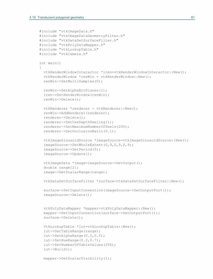
4.15 Translucent polygonal geometry 81
#include "vtkImageData.h"#include "vtkImageDataGeometryFilter.h"#include "vtkDataSetSurfaceFilter.h"#include "vtkPolyDataMapper.h"#include "vtkLookupTable.h"#include "vtkCamera.h"
int main(){ vtkRenderWindowInteractor *iren=vtkRenderWindowInteractor::New(); vtkRenderWindow *renWin = vtkRenderWindow::New(); renWin->SetMultiSamples(0); renWin->SetAlphaBitPlanes(1); iren->SetRenderWindow(renWin); renWin->Delete(); vtkRenderer *renderer = vtkRenderer::New(); renWin->AddRenderer(renderer); renderer->Delete(); renderer->SetUseDepthPeeling(1); renderer->SetMaximumNumberOfPeels(200); renderer->SetOcclusionRatio(0.1); vtkImageSinusoidSource *imageSource=vtkImageSinusoidSource::New(); imageSource->SetWholeExtent(0,9,0,9,0,9); imageSource->SetPeriod(5); imageSource->Update(); vtkImageData *image=imageSource->GetOutput(); double range[2]; image->GetScalarRange(range); vtkDataSetSurfaceFilter *surface=vtkDataSetSurfaceFilter::New(); surface->SetInputConnection(imageSource->GetOutputPort()); imageSource->Delete();
vtkPolyDataMapper *mapper=vtkPolyDataMapper::New(); mapper->SetInputConnection(surface->GetOutputPort()); surface->Delete(); vtkLookupTable *lut=vtkLookupTable::New(); lut->SetTableRange(range); lut->SetAlphaRange(0.5,0.5); lut->SetHueRange(0.2,0.7); lut->SetNumberOfTableValues(256); lut->Build(); mapper->SetScalarVisibility(1);
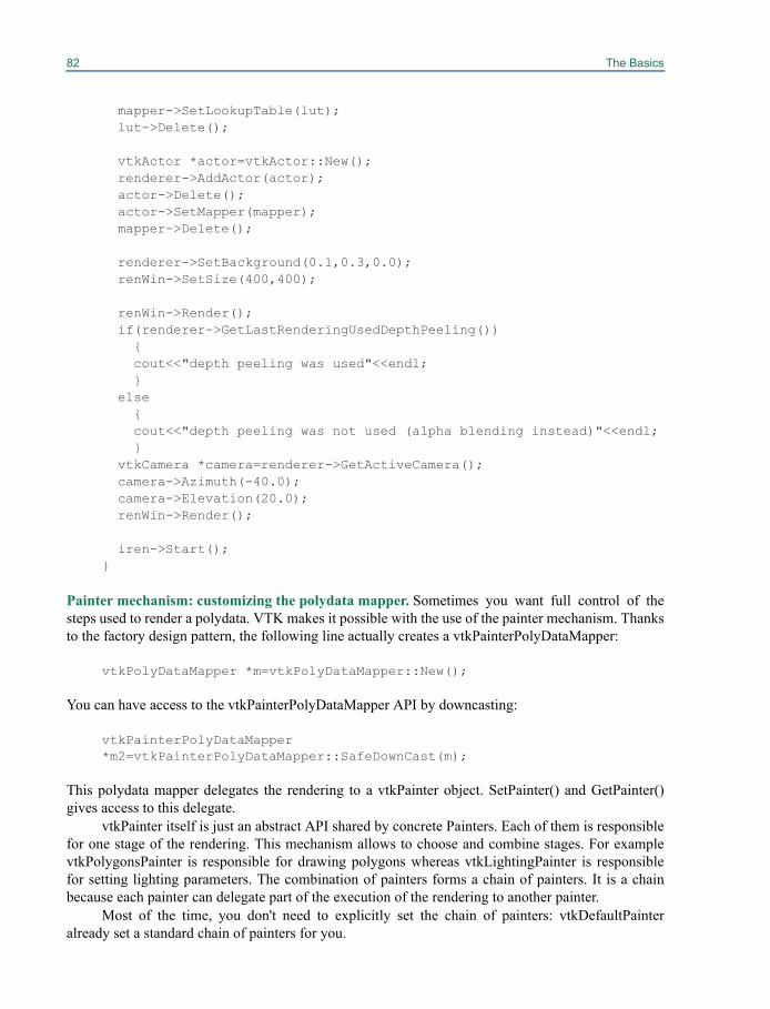
82 The Basics
mapper->SetLookupTable(lut); lut->Delete(); vtkActor *actor=vtkActor::New(); renderer->AddActor(actor); actor->Delete(); actor->SetMapper(mapper); mapper->Delete(); renderer->SetBackground(0.1,0.3,0.0); renWin->SetSize(400,400); renWin->Render(); if(renderer->GetLastRenderingUsedDepthPeeling()) { cout<<"depth peeling was used"<<endl; } else { cout<<"depth peeling was not used (alpha blending instead)"<<endl; } vtkCamera *camera=renderer->GetActiveCamera(); camera->Azimuth(-40.0); camera->Elevation(20.0); renWin->Render(); iren->Start();}
Painter mechanism: customizing the polydata mapper. Sometimes you want full control of thesteps used to render a polydata. VTK makes it possible with the use of the painter mechanism. Thanksto the factory design pattern, the following line actually creates a vtkPainterPolyDataMapper:
vtkPolyDataMapper *m=vtkPolyDataMapper::New();
You can have access to the vtkPainterPolyDataMapper API by downcasting:
vtkPainterPolyDataMapper *m2=vtkPainterPolyDataMapper::SafeDownCast(m);
This polydata mapper delegates the rendering to a vtkPainter object. SetPainter() and GetPainter()gives access to this delegate.
vtkPainter itself is just an abstract API shared by concrete Painters. Each of them is responsiblefor one stage of the rendering. This mechanism allows to choose and combine stages. For examplevtkPolygonsPainter is responsible for drawing polygons whereas vtkLightingPainter is responsiblefor setting lighting parameters. The combination of painters forms a chain of painters. It is a chainbecause each painter can delegate part of the execution of the rendering to another painter.
Most of the time, you don't need to explicitly set the chain of painters: vtkDefaultPainteralready set a standard chain of painters for you.
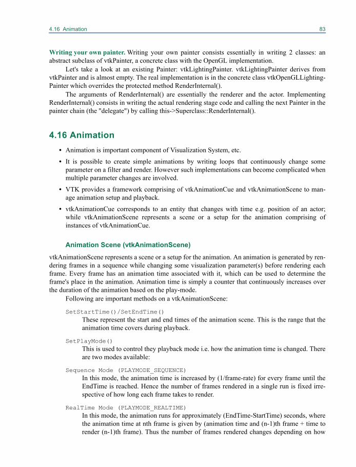
4.16 Animation 83
Writing your own painter. Writing your own painter consists essentially in writing 2 classes: anabstract subclass of vtkPainter, a concrete class with the OpenGL implementation.
Let's take a look at an existing Painter: vtkLightingPainter. vtkLightingPainter derives fromvtkPainter and is almost empty. The real implementation is in the concrete class vtkOpenGLLighting-Painter which overrides the protected method RenderInternal().
The arguments of RenderInternal() are essentially the renderer and the actor. ImplementingRenderInternal() consists in writing the actual rendering stage code and calling the next Painter in thepainter chain (the "delegate") by calling this->Superclass::RenderInternal().
4.16 Animation• Animation is important component of Visualization System, etc.
• It is possible to create simple animations by writing loops that continuously change someparameter on a filter and render. However such implementations can become complicated whenmultiple parameter changes are involved.
• VTK provides a framework comprising of vtkAnimationCue and vtkAnimationScene to man-age animation setup and playback.
• vtkAnimationCue corresponds to an entity that changes with time e.g. position of an actor;while vtkAnimationScene represents a scene or a setup for the animation comprising ofinstances of vtkAnimationCue.
Animation Scene (vtkAnimationScene)
vtkAnimationScene represents a scene or a setup for the animation. An animation is generated by ren-dering frames in a sequence while changing some visualization parameter(s) before rendering eachframe. Every frame has an animation time associated with it, which can be used to determine theframe's place in the animation. Animation time is simply a counter that continuously increases overthe duration of the animation based on the play-mode.
Following are important methods on a vtkAnimationScene:
SetStartTime()/SetEndTime()These represent the start and end times of the animation scene. This is the range that theanimation time covers during playback.
SetPlayMode()This is used to control they playback mode i.e. how the animation time is changed. Thereare two modes available:
Sequence Mode (PLAYMODE_SEQUENCE) In this mode, the animation time is increased by (1/frame-rate) for every frame until theEndTime is reached. Hence the number of frames rendered in a single run is fixed irre-spective of how long each frame takes to render.
RealTime Mode (PLAYMODE_REALTIME) In this mode, the animation runs for approximately (EndTime-StartTime) seconds, wherethe animation time at nth frame is given by (animation time and (n-1)th frame + time torender (n-1)th frame). Thus the number of frames rendered changes depending on how

84 The Basics
long each frame takes to render.
SetFrameRate()Frame rate is the number of frames per unit time. This is used only in sequence play-mode.
AddCue(), RemoveCue(), RemoveAllCue()Methods to add/remove animation cues from the scene.
SetAnimationTime()SetAnimationTime can be used to explicitly advance to a particular frame.
GetAnimationTime()GetAnimationTime() can be called during playback to query the animation clock time.
Play()Starts playing the animation.
SetLoop()When set to True, Play() results in playing the animation in a loop.
Animation Cue (vtkAnimationCue)vtkAnimationCue corresponds to an entity that changes in an animation. vtkAnimation-Cue does not know how to bring about the changes to the parameters. So the user has toeither subclass vtkAnimationCue or use event observers to perform the changes as theanimation progresses.
A cue has a start-time and an end-time in an animation scene. During playback, a cue is active whenthe scene's animation time is within the range specified the start and end times for the cue. When thecue is activated, it fires the vtkCommand::StartAnimationCueEvent. For every subsequent frame, itfires the vtkCommand::AnimationCueTickEvent until the end-time is reached when the vtkCom-mand::EndAnimationCueEvent is fired. Following are the important methods of vtkAnimationCue
SetTimeModeTimeMode defines how the start and time times are specified. There are two modes avail-able.
Relative (TIMEMODE_RELATIVE) In this mode the animation cue times are specified relative to the start of the animationscene.
Normalized (TIMEMODE_NORMALIZED) In this mode, the cue start and end times are always in the range [0, 1] where 0 corre-sponds to the start and 1 corresponds to the end of the animation scene.
SetStartTime/SetEndTimeThese are used to indicate the range of animation time when this cue is active. When theTimeMode is TIMEMODE_RELATIVE, these are specified in the same unit as the ani-mation scene start and end times and are relative to the start of the animation scene. IfTimeMode is TIMEMODE_NORMALIZED, these are in the range [0, 1] where 0 corre-sponds to the start of the animation scene while 1 corresponds to the end of the animationscene.
GetAnimationTime()
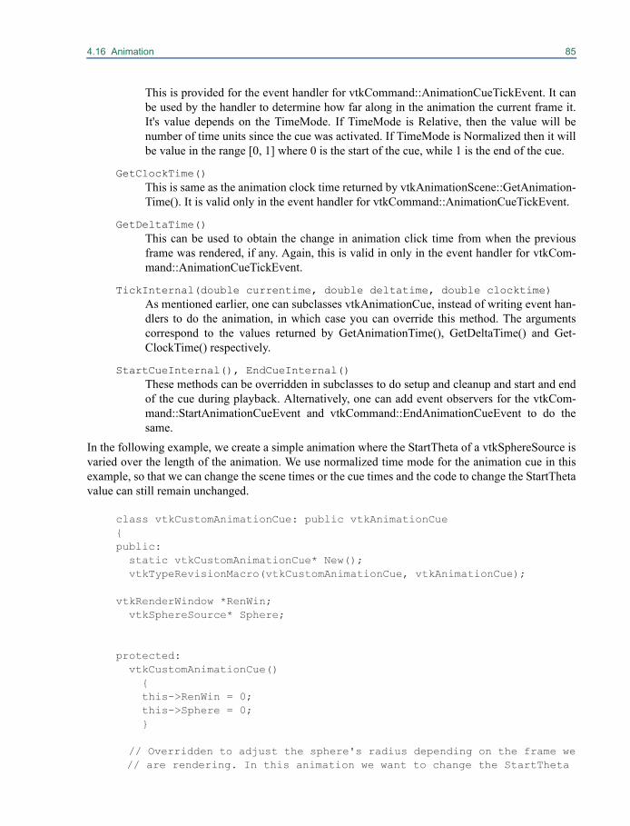
4.16 Animation 85
This is provided for the event handler for vtkCommand::AnimationCueTickEvent. It canbe used by the handler to determine how far along in the animation the current frame it.It's value depends on the TimeMode. If TimeMode is Relative, then the value will benumber of time units since the cue was activated. If TimeMode is Normalized then it willbe value in the range [0, 1] where 0 is the start of the cue, while 1 is the end of the cue.
GetClockTime()This is same as the animation clock time returned by vtkAnimationScene::GetAnimation-Time(). It is valid only in the event handler for vtkCommand::AnimationCueTickEvent.
GetDeltaTime()This can be used to obtain the change in animation click time from when the previousframe was rendered, if any. Again, this is valid in only in the event handler for vtkCom-mand::AnimationCueTickEvent.
TickInternal(double currentime, double deltatime, double clocktime)As mentioned earlier, one can subclasses vtkAnimationCue, instead of writing event han-dlers to do the animation, in which case you can override this method. The argumentscorrespond to the values returned by GetAnimationTime(), GetDeltaTime() and Get-ClockTime() respectively.
StartCueInternal(), EndCueInternal()These methods can be overridden in subclasses to do setup and cleanup and start and endof the cue during playback. Alternatively, one can add event observers for the vtkCom-mand::StartAnimationCueEvent and vtkCommand::EndAnimationCueEvent to do thesame.
In the following example, we create a simple animation where the StartTheta of a vtkSphereSource isvaried over the length of the animation. We use normalized time mode for the animation cue in thisexample, so that we can change the scene times or the cue times and the code to change the StartThetavalue can still remain unchanged.
class vtkCustomAnimationCue: public vtkAnimationCue{public: static vtkCustomAnimationCue* New(); vtkTypeRevisionMacro(vtkCustomAnimationCue, vtkAnimationCue);
vtkRenderWindow *RenWin; vtkSphereSource* Sphere;
protected: vtkCustomAnimationCue() { this->RenWin = 0; this->Sphere = 0; }
// Overridden to adjust the sphere's radius depending on the frame we// are rendering. In this animation we want to change the StartTheta
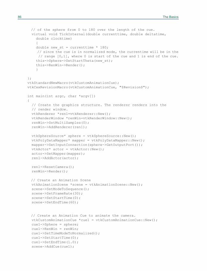
86 The Basics
// of the sphere from 0 to 180 over the length of the cue. virtual void TickInternal(double currenttime, double deltatime, double clocktime) { double new_st = currenttime * 180; // since the cue is in normalized mode, the currentime will be in the // range [0,1], where 0 is start of the cue and 1 is end of the cue. this->Sphere->SetStartTheta(new_st); this->RenWin->Render(); }
};vtkStandardNewMacro(vtkCustomAnimationCue);vtkCxxRevisionMacro(vtkCustomAnimationCue, "$Revision$");
int main(int argc, char *argv[]){ // Create the graphics structure. The renderer renders into the // render window. vtkRenderer *ren1=vtkRenderer::New(); vtkRenderWindow *renWin=vtkRenderWindow::New(); renWin->SetMultiSamples(0); renWin->AddRenderer(ren1);
vtkSphereSource* sphere = vtkSphereSource::New(); vtkPolyDataMapper* mapper = vtkPolyDataMapper::New(); mapper->SetInputConnection(sphere->GetOutputPort()); vtkActor* actor = vtkActor::New(); actor->SetMapper(mapper); ren1->AddActor(actor);
ren1->ResetCamera(); renWin->Render();
// Create an Animation Scene vtkAnimationScene *scene = vtkAnimationScene::New(); scene->SetModeToSequence(); scene->SetFrameRate(30); scene->SetStartTime(0); scene->SetEndTime(60);
// Create an Animation Cue to animate the camera. vtkCustomAnimationCue *cue1 = vtkCustomAnimationCue::New(); cue1->Sphere = sphere; cue1->RenWin = renWin; cue1->SetTimeModeToNormalized(); cue1->SetStartTime(0); cue1->SetEndTime(1.0); scene->AddCue(cue1);
4.16 Animation 87
scene->Play(); scene->Stop();
ren1->Delete(); renWin->Delete(); scene->Delete(); cue1->Delete(); return 0;}

Chapter 5
Visualization Techniques 5
Some basic tools to render and interact with data werepresented in the previous chapter. In this chapter we’ll show you a variety of visualization techniques.These techniques (implemented as filters) are organized according to the type of data they operate on.Some filters are general and can be applied to any type of data—those filters that accept input of classvtkDataSet (or any subclass). Many filters are more specialized to the type of input they accept (e.g.,vtkPolyData). There is one class of filters—those that accept input of type vtkImageData (or its obso-lete subclass vtkStructuredPoints)—that are not addressed in this chapter. Instead, filters of this typeare described in the next chapter (“Image Processing and Visualization” on page 103).
Please keep two things to keep in mind while you read this chapter. First, filters generate a vari-ety of output types, and the output type is not necessarily the same as the input type. Second, filtersare used in combination to create complex data processing pipelines. Often there are patterns ofusage, or common combinations of filters, that are used. In the following examples you may wish tonote these combinations.
5.1 Visualizing vtkDataSet (and Subclasses)In this section, we’ll show you how to perform some common visualization operations on dataobjects of type vtkDataSet. Recall that vtkDataSet is the superclass for all concrete types of visualiza-tion data (see Figure 3–2). Therefore, the methods described here are applicable to all of the variousdata types. (In other words, all filters taking vtkDataSet as input will also accept vtkPolyData, vtkIm-ageData, vtkStructuredGrid, vtkRectilinearGrid, and vtkUnstructuredGrid.)
Working With Data Attributes
Data attributes are information associated with the structure of the dataset (as described in “The Visu-alization Pipeline” on page 25). In VTK, attribute data is associated with points (point attribute data)
90 Visualization Techniques
and cells (cell attribute data). Attribute data, along with the dataset structure, are processed by themany VTK filters to generate new structures and attributes. A general introduction to attribute data isbeyond the scope of this section, but a simple example will demonstrate the basic ideas. (For moreinformation you may wish to refer to “Field and Attribute Data” on page 362 and Figure 16–1.)
Data attributes are simply vtkDataArrays which may be labeled as being one of scalars, vectors,tensors, normals, texture coordinates, global ids (for identifying redundant elements), or pedigree ids(for tracing element history up the pipeline). The points and the cells of a vtkDataSet may have theirown independent data attributes. The data attributes may be associated with the points or cells of avtkDataSet. Every vtkDataArray associated with a vtkDataSet is a concrete subclass of vtkDataArray,such as vtkFloatArray or vtkIntArray. These data arrays can be thought of as contiguous, linearblocks of memory of the named native type. Within this linear block, the data array is thought to con-sist of subarrays or “tuples.” Creating attribute data means instantiating a data array of desired type,specifying the tuple size, inserting data, and associating it with a dataset, as shown in the followingTcl script. The association may have the side effect of labeling the data as scalars, vectors, tensors,texture coordinates, or normals. For example:
vtkFloatArray scalarsscalars InsertTuple1 0 1.0scalars InsertTuple1 1 1.2...etc...
vtkDoubleArray vectorsvectors SetNumberOfComponents 3vectors InsertTuple3 0 0.0 0.0 1.0vectors InsertTuple3 1 1.2 0.3 1.1...etc...
vtkIntArray justAnArrayjustAnArray SetNumberOfComponents 2justAnArray SetNumberOfTuples $numberOfPointsjustAnArray SetName “Solution Attributes”justAnArray SetTuple2 0 1 2justAnArray SetTuple2 1 3 4...etc...
vtkPolyData polyData;#A concrete type of vtkDataSet[polyData GetPointData] SetScalars scalars[polyData GetCellData] SetVectors vectors[polyData GetPointData] AddArray justAnArray
Here we create three arrays of types float, double, and int. The first array (scalars) is instanti-ated and by default has a tuple size of one. The method InsertTuple1() is used to place data into thearray (all methods named Insert___() allocate memory as necessary to hold data). The next data array(vectors) is created with a tuple size of three, because vectors are defined as having three compo-nents, and InsertTuple3 is used to add data to the array. Finally, we create a general array of tuple sizetwo, and allocate memory using SetNumberOfTuples(). We then use SetTuple2() to add data; thismethod assumes that memory has been allocated and is therefore faster than the similar Insert__()methods. Notice that the labelling of what is a scalar, vector, etc. occurs when we associate the dataarrays with the point data or cell data of the dataset (using the methods SetScalars() and SetVectors()).
5.1 Visualizing vtkDataSet (and Subclasses) 91
Please remember that the number of point attributes (e.g., number of scalars in this example) mustequal the number of points in the dataset, and the number of cell attributes (e.g., number of vectors)must match the number of cells in the dataset.
Similarly, to access attribute data, use these methods
set scalars [[polyData GetPointData] GetScalars]set vectors [[polyData GetCellData] GetVectors]
You’ll find that many of the filters work with attribute data specifically. For example, vtkElevation-Filter generates scalar values based on their elevation in a specified direction. Other filters work withthe structure of the dataset, and generally ignore or pass the attribute data through the filter (e.g., vtk-DecimatePro). And finally, some filters work with (portions of) the attribute data and the structure togenerate their output. vtkMarchingCubes is one example. It uses the input scalars in combination withthe dataset structure to generate contour primitives (i.e., triangles, lines or points). Other types ofattribute data, such as vectors, are interpolated during the contouring process and sent to the output ofthe filter.
Another important issue regarding attribute data is that some filters will process only one typeof attribute (point data versus cell data), ignoring or passing to their output the other attribute datatype. You may find that your input data is of one attribute type and you want to process it with a filterthat will not handle that type, or you simply want to convert from one attribute type to another. Thereare two filters that can help you with this: vtkPointDataToCellData and vtkCellDataToPointData,which convert to and from point and cell data attributes. Here’s an example of their use (from the Tclscript VTK/Examples/DataManipulation/Tcl/pointToCellData.tcl).
vtkUnstructuredGridReader reader reader SetFileName "$VTK_DATA_ROOT/Data/blow.vtk" reader SetScalarsName "thickness9" reader SetVectorsName "displacement9"vtkPointDataToCellData p2c p2c SetInputConnection [reader GetOutputPort] p2c PassPointDataOnvtkWarpVector warp warp SetInputConnection [p2c GetOutputPort]vtkThreshold thresh thresh SetInputConnection [warp GetOutputPort] thresh ThresholdBetween 0.25 0.75 thresh SetAttributeModeToUseCellData
This example is interesting because it demonstrates the conversion between attribute data types(vtkPointDataToCellData), and the use of a filter that can process either cell data or point data(vtkThreshold). The method PassPointDataOn() indicates to vtkPointDataToCellData to create celldata and also pass to its output the input point data. The method SetAttributeModeToUseCellData()configures the vtkThreshold filter to use the cell data to perform the thresholding operation.
The conversion between point and cell data and vice versa is performed using an averagingalgorithm. Point data is converted to cell data by averaging the values of the point data associatedwith the points used by a given cell. Cell data is converted to point data by averaging the cell dataassociated with the cells that use a given point.
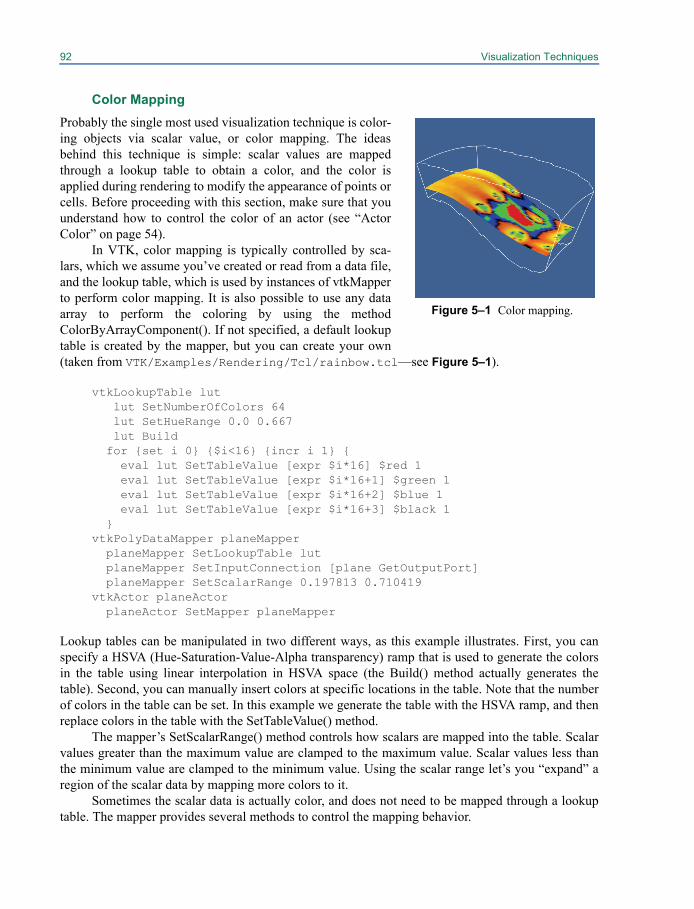
92 Visualization Techniques
Color MappingProbably the single most used visualization technique is color-ing objects via scalar value, or color mapping. The ideasbehind this technique is simple: scalar values are mappedthrough a lookup table to obtain a color, and the color isapplied during rendering to modify the appearance of points orcells. Before proceeding with this section, make sure that youunderstand how to control the color of an actor (see “ActorColor” on page 54).
In VTK, color mapping is typically controlled by sca-lars, which we assume you’ve created or read from a data file,and the lookup table, which is used by instances of vtkMapperto perform color mapping. It is also possible to use any dataarray to perform the coloring by using the methodColorByArrayComponent(). If not specified, a default lookuptable is created by the mapper, but you can create your own(taken from VTK/Examples/Rendering/Tcl/rainbow.tcl—see Figure 5–1).
vtkLookupTable lutlut SetNumberOfColors 64lut SetHueRange 0.0 0.667lut Build
for {set i 0} {$i<16} {incr i 1} { eval lut SetTableValue [expr $i*16] $red 1 eval lut SetTableValue [expr $i*16+1] $green 1 eval lut SetTableValue [expr $i*16+2] $blue 1 eval lut SetTableValue [expr $i*16+3] $black 1 }vtkPolyDataMapper planeMapper planeMapper SetLookupTable lut planeMapper SetInputConnection [plane GetOutputPort] planeMapper SetScalarRange 0.197813 0.710419vtkActor planeActor planeActor SetMapper planeMapper
Lookup tables can be manipulated in two different ways, as this example illustrates. First, you canspecify a HSVA (Hue-Saturation-Value-Alpha transparency) ramp that is used to generate the colorsin the table using linear interpolation in HSVA space (the Build() method actually generates thetable). Second, you can manually insert colors at specific locations in the table. Note that the numberof colors in the table can be set. In this example we generate the table with the HSVA ramp, and thenreplace colors in the table with the SetTableValue() method.
The mapper’s SetScalarRange() method controls how scalars are mapped into the table. Scalarvalues greater than the maximum value are clamped to the maximum value. Scalar values less thanthe minimum value are clamped to the minimum value. Using the scalar range let’s you “expand” aregion of the scalar data by mapping more colors to it.
Sometimes the scalar data is actually color, and does not need to be mapped through a lookuptable. The mapper provides several methods to control the mapping behavior.
Figure 5–1 Color mapping.
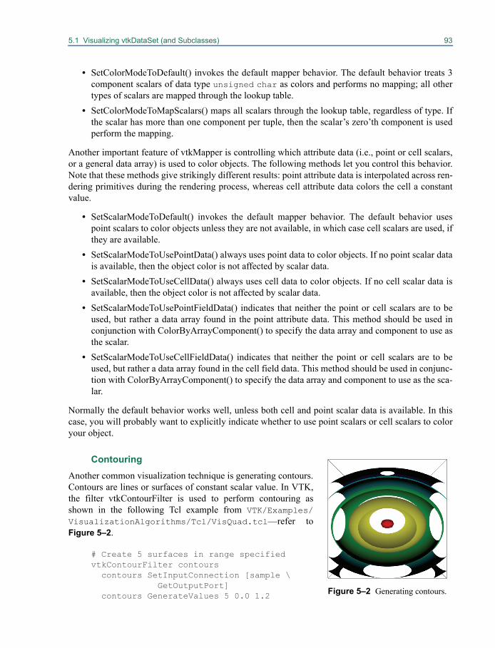
5.1 Visualizing vtkDataSet (and Subclasses) 93
• SetColorModeToDefault() invokes the default mapper behavior. The default behavior treats 3component scalars of data type unsigned char as colors and performs no mapping; all othertypes of scalars are mapped through the lookup table.
• SetColorModeToMapScalars() maps all scalars through the lookup table, regardless of type. Ifthe scalar has more than one component per tuple, then the scalar’s zero’th component is usedperform the mapping.
Another important feature of vtkMapper is controlling which attribute data (i.e., point or cell scalars,or a general data array) is used to color objects. The following methods let you control this behavior.Note that these methods give strikingly different results: point attribute data is interpolated across ren-dering primitives during the rendering process, whereas cell attribute data colors the cell a constantvalue.
• SetScalarModeToDefault() invokes the default mapper behavior. The default behavior usespoint scalars to color objects unless they are not available, in which case cell scalars are used, ifthey are available.
• SetScalarModeToUsePointData() always uses point data to color objects. If no point scalar datais available, then the object color is not affected by scalar data.
• SetScalarModeToUseCellData() always uses cell data to color objects. If no cell scalar data isavailable, then the object color is not affected by scalar data.
• SetScalarModeToUsePointFieldData() indicates that neither the point or cell scalars are to beused, but rather a data array found in the point attribute data. This method should be used inconjunction with ColorByArrayComponent() to specify the data array and component to use asthe scalar.
• SetScalarModeToUseCellFieldData() indicates that neither the point or cell scalars are to beused, but rather a data array found in the cell field data. This method should be used in conjunc-tion with ColorByArrayComponent() to specify the data array and component to use as the sca-lar.
Normally the default behavior works well, unless both cell and point scalar data is available. In thiscase, you will probably want to explicitly indicate whether to use point scalars or cell scalars to coloryour object.
Contouring Another common visualization technique is generating contours.Contours are lines or surfaces of constant scalar value. In VTK,the filter vtkContourFilter is used to perform contouring asshown in the following Tcl example from VTK/Examples/VisualizationAlgorithms/Tcl/VisQuad.tcl—refer toFigure 5–2.
# Create 5 surfaces in range specifiedvtkContourFilter contours
contours SetInputConnection [sample \GetOutputPort]
contours GenerateValues 5 0.0 1.2 Figure 5–2 Generating contours.
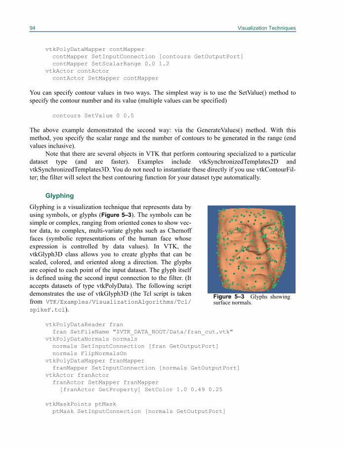
94 Visualization Techniques
vtkPolyDataMapper contMappercontMapper SetInputConnection [contours GetOutputPort]contMapper SetScalarRange 0.0 1.2
vtkActor contActorcontActor SetMapper contMapper
You can specify contour values in two ways. The simplest way is to use the SetValue() method tospecify the contour number and its value (multiple values can be specified)
contours SetValue 0 0.5
The above example demonstrated the second way: via the GenerateValues() method. With thismethod, you specify the scalar range and the number of contours to be generated in the range (endvalues inclusive).
Note that there are several objects in VTK that perform contouring specialized to a particulardataset type (and are faster). Examples include vtkSynchronizedTemplates2D andvtkSynchronizedTemplates3D. You do not need to instantiate these directly if you use vtkContourFil-ter; the filter will select the best contouring function for your dataset type automatically.
Glyphing
Glyphing is a visualization technique that represents data byusing symbols, or glyphs (Figure 5–3). The symbols can besimple or complex, ranging from oriented cones to show vec-tor data, to complex, multi-variate glyphs such as Chernofffaces (symbolic representations of the human face whoseexpression is controlled by data values). In VTK, thevtkGlyph3D class allows you to create glyphs that can bescaled, colored, and oriented along a direction. The glyphsare copied to each point of the input dataset. The glyph itselfis defined using the second input connection to the filter. (Itaccepts datasets of type vtkPolyData). The following scriptdemonstrates the use of vtkGlyph3D (the Tcl script is takenfrom VTK/Examples/VisualizationAlgorithms/Tcl/spikeF.tcl).
vtkPolyDataReader fran fran SetFileName "$VTK_DATA_ROOT/Data/fran_cut.vtk"vtkPolyDataNormals normals normals SetInputConnection [fran GetOutputPort] normals FlipNormalsOnvtkPolyDataMapper franMapper franMapper SetInputConnection [normals GetOutputPort]vtkActor franActor franActor SetMapper franMapper
[franActor GetProperty] SetColor 1.0 0.49 0.25
vtkMaskPoints ptMask ptMask SetInputConnection [normals GetOutputPort]
Figure 5–3 Glyphs showingsurface normals.
5.1 Visualizing vtkDataSet (and Subclasses) 95
ptMask SetOnRatio 10 ptMask RandomModeOn
# In this case we are using a cone as a glyph. We transform the cone so# its base is at 0,0,0. This is the point where glyph rotation occurs.vtkConeSource cone cone SetResolution 6vtkTransform transform transform Translate 0.5 0.0 0.0vtkTransformPolyDataFilter transformF transformF SetInputConnection [cone GetOutputPort] transformF SetTransform transform
vtkGlyph3D glyph glyph SetInputConnection [ptMask GetOutputPort] glyph SetSourceConnection [transformF GetOutputPort] glyph SetVectorModeToUseNormal glyph SetScaleModeToScaleByVector glyph SetScaleFactor 0.004vtkPolyDataMapper spikeMapper spikeMapper SetInputConnection [glyph GetOutputPort]vtkActor spikeActor spikeActor SetMapper spikeMapper eval [spikeActor GetProperty] SetColor 0.0 0.79 0.34
The purpose of the script is to indicate the direction of surface normals using small, oriented cones.An input dataset (from a Cyberware laser digitizing system) is read and displayed. Next, the filter vtk-MaskPoints is used to subsample the points (and associated point attribute data) from the Cyberwaredata. This serves as the input to the vtkGlyph3D instance. A vtkConeSource is used as the Source forthe glyph instance. Notice that the cone is translated (with vtkTransformPolyDataFilter) so that itsbase is on the origin (0,0,0) (since vtkGlyph3D rotates the source object around the origin).
The vtkGlyph3D object glyph is configured to use the point attribute normals as the orienta-tion vector. (Alternatively, use SetVectorModeToUseVector() to use the vector data instead of the nor-mals.) It also scales the cones by the magnitude of the vector value there, with the given scale factor.(You can scale the glyphs by scalar data or turn data scaling off with the methodsSetScaleModeToScaleByScalar() and SetScaleModeToDataScalingOff().)
It is also possible to color the glyphs with scalar or vector data, or by the scale factor. You canalso create a table of glyphs, and use scalar or vector data to index into the table. Refer to the onlinedocumentation for more information.
Streamlines
A streamline can be thought of as the path that a massless particle takes in a vector field (e.g., velocityfield). Streamlines are used to convey the structure of a vector field. Usually multiple streamlines arecreated to explore interesting features in the field (Figure 5–4). Streamlines are computed via numer-ical integration (integrating the product of velocity times ), and are therefore only approximationsto the actual streamlines.
't
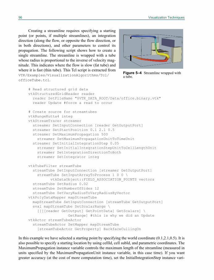
96 Visualization Techniques
Creating a streamline requires specifying a startingpoint (or points, if multiple streamlines), an integrationdirection (along the flow, or opposite the flow direction, orin both directions), and other parameters to control itspropagation. The following script shows how to create asingle streamline. The streamline is wrapped with a tubewhose radius is proportional to the inverse of velocity mag-nitude. This indicates where the flow is slow (fat tube) andwhere it is fast (thin tube). This Tcl script is extracted fromVTK/Examples/VisualizationAlgorithms/Tcl/officeTube.tcl.
# Read structured grid datavtkStructuredGridReader reader reader SetFileName "$VTK_DATA_ROOT/Data/office.binary.vtk" reader Update #force a read to occur
# Create source for streamtubesvtkRungeKutta4 integvtkStreamTracer streamer streamer SetInputConnection [reader GetOutputPort] streamer SetStartPosition 0.1 2.1 0.5 streamer SetMaximumPropagation 500
streamer SetMaximumPropagationUnitToTimeUnit streamer SetInitialIntegrationStep 0.05
streamer SetInitialIntegrationStepUnitToCellLengthUnitstreamer SetIntegrationDirectionToBothstreamer SetIntegrator integ
vtkTubeFilter streamTube streamTube SetInputConnection [streamer GetOutputPort]
streamTube SetInputArrayToProcess 1 0 0 \vtkDataObject::FIELD_ASSOCIATION_POINTS vectors
streamTube SetRadius 0.02 streamTube SetNumberOfSides 12 streamTube SetVaryRadiusToVaryRadiusByVectorvtkPolyDataMapper mapStreamTube mapStreamTube SetInputConnection [streamTube GetOutputPort] eval mapStreamTube SetScalarRange \ [[[[reader GetOutput] GetPointData] GetScalars] \
GetRange] #this is why we did an UpdatevtkActor streamTubeActor streamTubeActor SetMapper mapStreamTube
[streamTubeActor GetProperty] BackfaceCullingOn
In this example we have selected a starting point by specifying the world coordinate (0.1,2.1,0.5). It isalso possible to specify a starting location by using cellId, cell subId, and parametric coordinates. TheMaximumPropagation instance variable controls the maximum length of the streamline (measured inunits specified by the MaximumPropagationUnit instance variable, in this case time). If you wantgreater accuracy (at the cost of more computation time), set the InitialIntegrationStep instance vari-
Figure 5–4 Streamline wrapped witha tube.
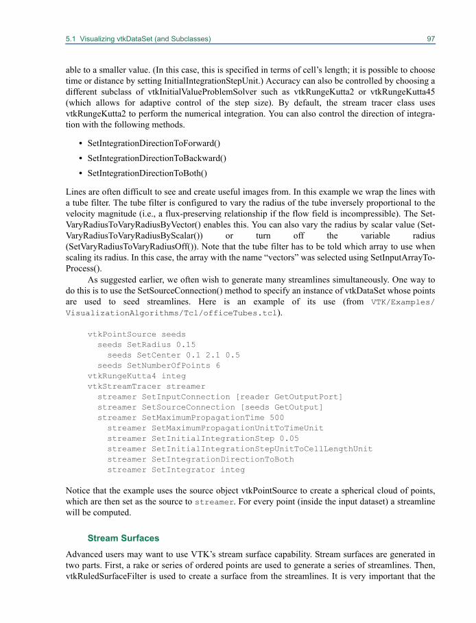
5.1 Visualizing vtkDataSet (and Subclasses) 97
able to a smaller value. (In this case, this is specified in terms of cell’s length; it is possible to choosetime or distance by setting InitialIntegrationStepUnit.) Accuracy can also be controlled by choosing adifferent subclass of vtkInitialValueProblemSolver such as vtkRungeKutta2 or vtkRungeKutta45(which allows for adaptive control of the step size). By default, the stream tracer class usesvtkRungeKutta2 to perform the numerical integration. You can also control the direction of integra-tion with the following methods.
• SetIntegrationDirectionToForward()
• SetIntegrationDirectionToBackward()
• SetIntegrationDirectionToBoth()
Lines are often difficult to see and create useful images from. In this example we wrap the lines witha tube filter. The tube filter is configured to vary the radius of the tube inversely proportional to thevelocity magnitude (i.e., a flux-preserving relationship if the flow field is incompressible). The Set-VaryRadiusToVaryRadiusByVector() enables this. You can also vary the radius by scalar value (Set-VaryRadiusToVaryRadiusByScalar()) or turn off the variable radius(SetVaryRadiusToVaryRadiusOff()). Note that the tube filter has to be told which array to use whenscaling its radius. In this case, the array with the name “vectors” was selected using SetInputArrayTo-Process().
As suggested earlier, we often wish to generate many streamlines simultaneously. One way todo this is to use the SetSourceConnection() method to specify an instance of vtkDataSet whose pointsare used to seed streamlines. Here is an example of its use (from VTK/Examples/VisualizationAlgorithms/Tcl/officeTubes.tcl).
vtkPointSource seeds seeds SetRadius 0.15
seeds SetCenter 0.1 2.1 0.5 seeds SetNumberOfPoints 6vtkRungeKutta4 integvtkStreamTracer streamer streamer SetInputConnection [reader GetOutputPort] streamer SetSourceConnection [seeds GetOutput] streamer SetMaximumPropagationTime 500
streamer SetMaximumPropagationUnitToTimeUnitstreamer SetInitialIntegrationStep 0.05streamer SetInitialIntegrationStepUnitToCellLengthUnitstreamer SetIntegrationDirectionToBothstreamer SetIntegrator integ
Notice that the example uses the source object vtkPointSource to create a spherical cloud of points,which are then set as the source to streamer. For every point (inside the input dataset) a streamlinewill be computed.
Stream Surfaces
Advanced users may want to use VTK’s stream surface capability. Stream surfaces are generated intwo parts. First, a rake or series of ordered points are used to generate a series of streamlines. Then,vtkRuledSurfaceFilter is used to create a surface from the streamlines. It is very important that the
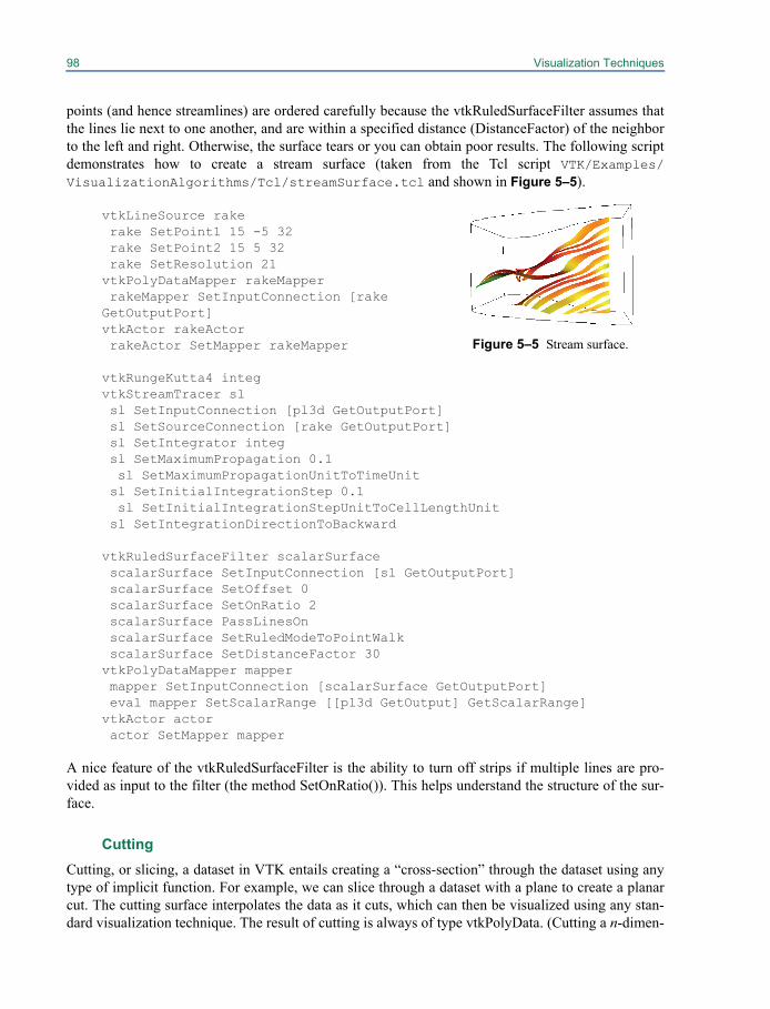
98 Visualization Techniques
points (and hence streamlines) are ordered carefully because the vtkRuledSurfaceFilter assumes thatthe lines lie next to one another, and are within a specified distance (DistanceFactor) of the neighborto the left and right. Otherwise, the surface tears or you can obtain poor results. The following scriptdemonstrates how to create a stream surface (taken from the Tcl script VTK/Examples/VisualizationAlgorithms/Tcl/streamSurface.tcl and shown in Figure 5–5).
vtkLineSource rake rake SetPoint1 15 -5 32 rake SetPoint2 15 5 32 rake SetResolution 21vtkPolyDataMapper rakeMapper rakeMapper SetInputConnection [rake GetOutputPort]vtkActor rakeActor rakeActor SetMapper rakeMapper
vtkRungeKutta4 integvtkStreamTracer sl sl SetInputConnection [pl3d GetOutputPort] sl SetSourceConnection [rake GetOutputPort] sl SetIntegrator integ sl SetMaximumPropagation 0.1
sl SetMaximumPropagationUnitToTimeUnit sl SetInitialIntegrationStep 0.1
sl SetInitialIntegrationStepUnitToCellLengthUnit sl SetIntegrationDirectionToBackward
vtkRuledSurfaceFilter scalarSurface scalarSurface SetInputConnection [sl GetOutputPort] scalarSurface SetOffset 0 scalarSurface SetOnRatio 2 scalarSurface PassLinesOn scalarSurface SetRuledModeToPointWalk scalarSurface SetDistanceFactor 30 vtkPolyDataMapper mapper mapper SetInputConnection [scalarSurface GetOutputPort] eval mapper SetScalarRange [[pl3d GetOutput] GetScalarRange]vtkActor actor actor SetMapper mapper
A nice feature of the vtkRuledSurfaceFilter is the ability to turn off strips if multiple lines are pro-vided as input to the filter (the method SetOnRatio()). This helps understand the structure of the sur-face.
CuttingCutting, or slicing, a dataset in VTK entails creating a “cross-section” through the dataset using anytype of implicit function. For example, we can slice through a dataset with a plane to create a planarcut. The cutting surface interpolates the data as it cuts, which can then be visualized using any stan-dard visualization technique. The result of cutting is always of type vtkPolyData. (Cutting a n-dimen-
Figure 5–5 Stream surface.
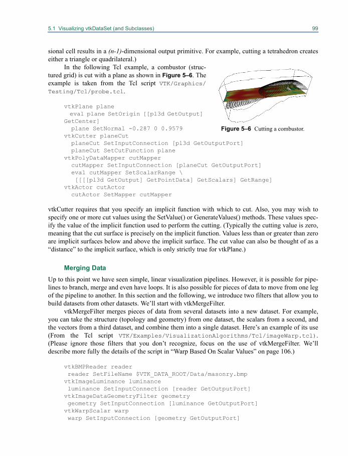
5.1 Visualizing vtkDataSet (and Subclasses) 99
sional cell results in a (n-1)-dimensional output primitive. For example, cutting a tetrahedron createseither a triangle or quadrilateral.)
In the following Tcl example, a combustor (struc-tured grid) is cut with a plane as shown in Figure 5–6. Theexample is taken from the Tcl script VTK/Graphics/Testing/Tcl/probe.tcl.
vtkPlane plane eval plane SetOrigin [[pl3d GetOutput] GetCenter] plane SetNormal -0.287 0 0.9579vtkCutter planeCut planeCut SetInputConnection [pl3d GetOutputPort] planeCut SetCutFunction planevtkPolyDataMapper cutMapper cutMapper SetInputConnection [planeCut GetOutputPort] eval cutMapper SetScalarRange \ [[[[pl3d GetOutput] GetPointData] GetScalars] GetRange]vtkActor cutActor cutActor SetMapper cutMapper
vtkCutter requires that you specify an implicit function with which to cut. Also, you may wish tospecify one or more cut values using the SetValue() or GenerateValues() methods. These values spec-ify the value of the implicit function used to perform the cutting. (Typically the cutting value is zero,meaning that the cut surface is precisely on the implicit function. Values less than or greater than zeroare implicit surfaces below and above the implicit surface. The cut value can also be thought of as a“distance” to the implicit surface, which is only strictly true for vtkPlane.)
Merging DataUp to this point we have seen simple, linear visualization pipelines. However, it is possible for pipe-lines to branch, merge and even have loops. It is also possible for pieces of data to move from one legof the pipeline to another. In this section and the following, we introduce two filters that allow you tobuild datasets from other datasets. We’ll start with vtkMergeFilter.
vtkMergeFilter merges pieces of data from several datasets into a new dataset. For example,you can take the structure (topology and geometry) from one dataset, the scalars from a second, andthe vectors from a third dataset, and combine them into a single dataset. Here’s an example of its use(From the Tcl script VTK/Examples/VisualizationAlgorithms/Tcl/imageWarp.tcl).(Please ignore those filters that you don’t recognize, focus on the use of vtkMergeFilter. We’lldescribe more fully the details of the script in “Warp Based On Scalar Values” on page 106.)
vtkBMPReader reader reader SetFileName $VTK_DATA_ROOT/Data/masonry.bmpvtkImageLuminance luminance luminance SetInputConnection [reader GetOutputPort]vtkImageDataGeometryFilter geometry geometry SetInputConnection [luminance GetOutputPort]vtkWarpScalar warp warp SetInputConnection [geometry GetOutputPort]
Figure 5–6 Cutting a combustor.
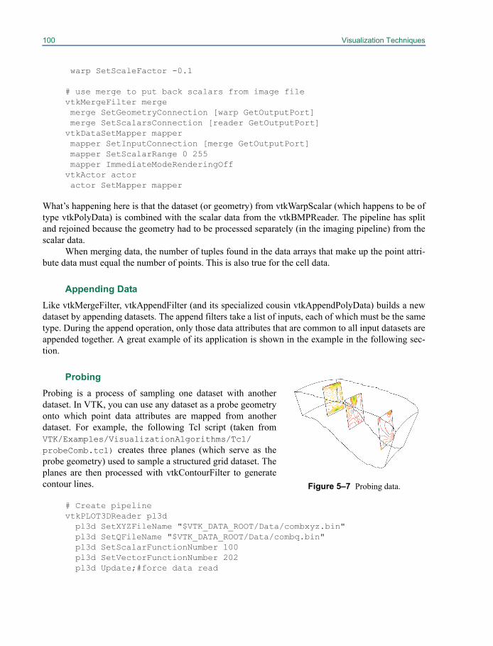
100 Visualization Techniques
warp SetScaleFactor -0.1
# use merge to put back scalars from image filevtkMergeFilter merge merge SetGeometryConnection [warp GetOutputPort] merge SetScalarsConnection [reader GetOutputPort]vtkDataSetMapper mapper mapper SetInputConnection [merge GetOutputPort] mapper SetScalarRange 0 255 mapper ImmediateModeRenderingOffvtkActor actor actor SetMapper mapper
What’s happening here is that the dataset (or geometry) from vtkWarpScalar (which happens to be oftype vtkPolyData) is combined with the scalar data from the vtkBMPReader. The pipeline has splitand rejoined because the geometry had to be processed separately (in the imaging pipeline) from thescalar data.
When merging data, the number of tuples found in the data arrays that make up the point attri-bute data must equal the number of points. This is also true for the cell data.
Appending DataLike vtkMergeFilter, vtkAppendFilter (and its specialized cousin vtkAppendPolyData) builds a newdataset by appending datasets. The append filters take a list of inputs, each of which must be the sametype. During the append operation, only those data attributes that are common to all input datasets areappended together. A great example of its application is shown in the example in the following sec-tion.
Probing Probing is a process of sampling one dataset with anotherdataset. In VTK, you can use any dataset as a probe geometryonto which point data attributes are mapped from anotherdataset. For example, the following Tcl script (taken fromVTK/Examples/VisualizationAlgorithms/Tcl/probeComb.tcl) creates three planes (which serve as theprobe geometry) used to sample a structured grid dataset. Theplanes are then processed with vtkContourFilter to generatecontour lines.
# Create pipelinevtkPLOT3DReader pl3d pl3d SetXYZFileName "$VTK_DATA_ROOT/Data/combxyz.bin" pl3d SetQFileName "$VTK_DATA_ROOT/Data/combq.bin" pl3d SetScalarFunctionNumber 100 pl3d SetVectorFunctionNumber 202 pl3d Update;#force data read
Figure 5–7 Probing data.

5.1 Visualizing vtkDataSet (and Subclasses) 101
# Create the probes. Transform them into right place.vtkPlaneSource plane plane SetResolution 50 50vtkTransform transP1 transP1 Translate 3.7 0.0 28.37 transP1 Scale 5 5 5 transP1 RotateY 90vtkTransformPolyDataFilter tpd1 tpd1 SetInputConnection [plane GetOutputPort] tpd1 SetTransform transP1vtkOutlineFilter outTpd1 outTpd1 SetInputConnection [tpd1 GetOutputPort]vtkPolyDataMapper mapTpd1 mapTpd1 SetInputConnection [outTpd1 GetOutputPort]vtkActor tpd1Actor tpd1Actor SetMapper mapTpd1 [tpd1Actor GetProperty] SetColor 0 0 0
vtkTransform transP2 transP2 Translate 9.2 0.0 31.20 transP2 Scale 5 5 5 transP2 RotateY 90vtkTransformPolyDataFilter tpd2 tpd2 SetInputConnection [plane GetOutputPort] tpd2 SetTransform transP2vtkOutlineFilter outTpd2 outTpd2 SetInputConnection [tpd2 GetOutputPort]vtkPolyDataMapper mapTpd2 mapTpd2 SetInputConnection [outTpd2 GetOutputPort]vtkActor tpd2Actor tpd2Actor SetMapper mapTpd2 [tpd2Actor GetProperty] SetColor 0 0 0
vtkTransform transP3 transP3 Translate 13.27 0.0 33.30 transP3 Scale 5 5 5 transP3 RotateY 90vtkTransformPolyDataFilter tpd3 tpd3 SetInputConnection [plane GetOutputPort] tpd3 SetTransform transP3vtkOutlineFilter outTpd3 outTpd3 SetInputConnection [tpd3 GetOutputPort]vtkPolyDataMapper mapTpd3 mapTpd3 SetInputConnection [outTpd3 GetOutputPort]vtkActor tpd3Actor tpd3Actor SetMapper mapTpd3 [tpd3Actor GetProperty] SetColor 0 0 0
vtkAppendPolyData appendF appendF AddInputConnection [tpd1 GetOutputPort] appendF AddInputConnection [tpd2 GetOutputPort] appendF AddInputConnection [tpd3 GetOutputPort]
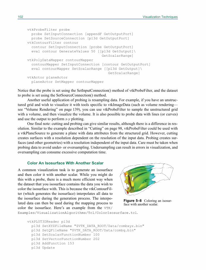
102 Visualization Techniques
vtkProbeFilter probe probe SetInputConnection [appendF GetOutputPort] probe SetSourceConnection [pl3d GetOutputPort]vtkContourFilter contour contour SetInputConnection [probe GetOutputPort] eval contour GenerateValues 50 [[pl3d GetOutput]\
GetScalarRange]vtkPolyDataMapper contourMapper contourMapper SetInputConnection [contour GetOutputPort] eval contourMapper SetScalarRange [[pl3d GetOutput]\
GetScalarRange]vtkActor planeActor planeActor SetMapper contourMapper
Notice that the probe is set using the SetInputConnection() method of vtkProbeFilter, and the datasetto probe is set using the SetSourceConnection() method.
Another useful application of probing is resampling data. For example, if you have an unstruc-tured grid and wish to visualize it with tools specific to vtkImageData (such as volume rendering—see “Volume Rendering” on page 139), you can use vtkProbeFilter to sample the unstructured gridwith a volume, and then visualize the volume. It is also possible to probe data with lines (or curves)and use the output to perform x-y plotting.
One final note: cutting and probing can give similar results, although there is a difference in res-olution. Similar to the example described in “Cutting” on page 98, vtkProbeFilter could be used witha vtkPlaneSource to generate a plane with data attributes from the structured grid. However, cuttingcreates surfaces with a resolution dependent on the resolution of the input data. Probing creates sur-faces (and other geometries) with a resolution independent of the input data. Care must be taken whenprobing data to avoid under- or oversampling. Undersampling can result in errors in visualization, andoversampling can consume excessive computation time.
Color An Isosurface With Another Scalar
A common visualization task is to generate an isosurfaceand then color it with another scalar. While you might dothis with a probe, there is a much more efficient way whenthe dataset that you isosurface contains the data you wish tocolor the isosurface with. This is because the vtkContourFil-ter (which generates the isosurface) interpolates all data tothe isosurface during the generation process. The interpo-lated data can then be used during the mapping process tocolor the isosurface. Here’s an example from the VTK/Examples/VisualizationAlgorithms/Tcl/ColorIsosurface.tcl.
vtkPLOT3DReader pl3d pl3d SetXYZFileName "$VTK_DATA_ROOT/Data/combxyz.bin" pl3d SetQFileName "$VTK_DATA_ROOT/Data/combq.bin" pl3d SetScalarFunctionNumber 100 pl3d SetVectorFunctionNumber 202 pl3d AddFunction 153 pl3d Update
Figure 5–8 Coloring an isosur-face with another scalar.
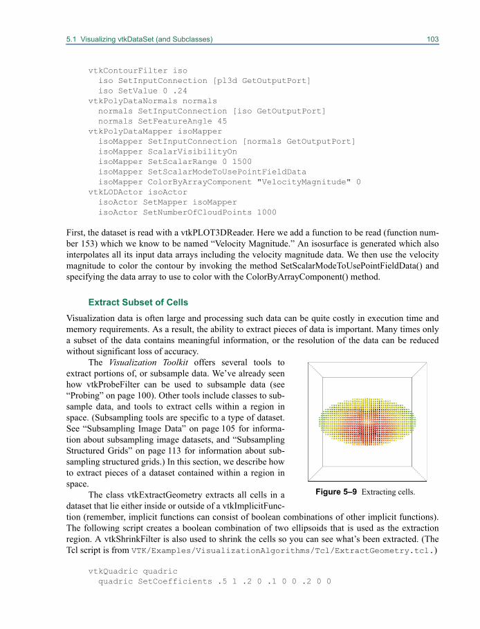
5.1 Visualizing vtkDataSet (and Subclasses) 103
vtkContourFilter iso iso SetInputConnection [pl3d GetOutputPort] iso SetValue 0 .24vtkPolyDataNormals normals normals SetInputConnection [iso GetOutputPort] normals SetFeatureAngle 45vtkPolyDataMapper isoMapper isoMapper SetInputConnection [normals GetOutputPort] isoMapper ScalarVisibilityOn isoMapper SetScalarRange 0 1500 isoMapper SetScalarModeToUsePointFieldData isoMapper ColorByArrayComponent "VelocityMagnitude" 0vtkLODActor isoActor isoActor SetMapper isoMapper isoActor SetNumberOfCloudPoints 1000
First, the dataset is read with a vtkPLOT3DReader. Here we add a function to be read (function num-ber 153) which we know to be named “Velocity Magnitude.” An isosurface is generated which alsointerpolates all its input data arrays including the velocity magnitude data. We then use the velocitymagnitude to color the contour by invoking the method SetScalarModeToUsePointFieldData() andspecifying the data array to use to color with the ColorByArrayComponent() method.
Extract Subset of CellsVisualization data is often large and processing such data can be quite costly in execution time andmemory requirements. As a result, the ability to extract pieces of data is important. Many times onlya subset of the data contains meaningful information, or the resolution of the data can be reducedwithout significant loss of accuracy.
The Visualization Toolkit offers several tools toextract portions of, or subsample data. We’ve already seenhow vtkProbeFilter can be used to subsample data (see“Probing” on page 100). Other tools include classes to sub-sample data, and tools to extract cells within a region inspace. (Subsampling tools are specific to a type of dataset.See “Subsampling Image Data” on page 105 for informa-tion about subsampling image datasets, and “SubsamplingStructured Grids” on page 113 for information about sub-sampling structured grids.) In this section, we describe howto extract pieces of a dataset contained within a region inspace.
The class vtkExtractGeometry extracts all cells in adataset that lie either inside or outside of a vtkImplicitFunc-tion (remember, implicit functions can consist of boolean combinations of other implicit functions).The following script creates a boolean combination of two ellipsoids that is used as the extractionregion. A vtkShrinkFilter is also used to shrink the cells so you can see what’s been extracted. (TheTcl script is from VTK/Examples/VisualizationAlgorithms/Tcl/ExtractGeometry.tcl.)
vtkQuadric quadric quadric SetCoefficients .5 1 .2 0 .1 0 0 .2 0 0
Figure 5–9 Extracting cells.
104 Visualization Techniques
vtkSampleFunction sample sample SetSampleDimensions 50 50 50 sample SetImplicitFunction quadric sample ComputeNormalsOffvtkTransform trans trans Scale 1 .5 .333vtkSphere sphere sphere SetRadius 0.25 sphere SetTransform transvtkTransform trans2 trans2 Scale .25 .5 1.0vtkSphere sphere2 sphere2 SetRadius 0.25 sphere2 SetTransform trans2vtkImplicitBoolean union union AddFunction sphere union AddFunction sphere2 union SetOperationType 0;#union
vtkExtractGeometry extract extract SetInputConnection [sample GetOutputPort] extract SetImplicitFunction unionvtkShrinkFilter shrink shrink SetInputConnection [extract GetOutputPort] shrink SetShrinkFactor 0.5vtkDataSetMapper dataMapper dataMapper SetInputConnection [shrink GetOutputPort]vtkActor dataActor dataActor SetMapper dataMapper
The output of vtkExtractGeometry is always a vtkUnstructuredGrid. This is because the extractionprocess generally disrupts the topological structure of the dataset, and the most general dataset form(i.e., vtkUnstructuredGrid) must be used to represent the output.
As a side note: implicit functions can be transformed by assigning them a vtkTransform. Ifspecified, the vtkTransform is used to modify the evaluation of the implicit function. You may wish toexperiment with this capability.
Extract Cells as Polygonal Data
Most dataset types cannot be directly rendered by graphics hardware or libraries. Only polygonal data(vtkPolyData) is commonly supported by rendering systems. Structured datasets, especially imagesand sometimes volumes, are also supported by graphics systems. All other datasets require specialprocessing if they are to be rendered. In VTK, one approach to rendering non-polygonal datasets is toconvert them to polygonal data. This is the function of vtkGeometryFilter.
vtkGeometryFilter accepts as input any type of vtkDataSet, and generates vtkPolyData on out-put. It performs the conversion using the following rules. All input cells of topological dimension 2 orless (e.g., polygons, lines, vertices) are passed to the output. The faces of cells of dimension 3 are sentto the output if they are on the boundary of the dataset. (A face is on the boundary if it is used by onlyone cell.)
5.2 Visualizing Polygonal Data 105
The principal use of vtkGeometryFilter is as a conversion filter. The following example fromVTK/Examples/DataManipulation/Tcl/pointToCellData.tcl uses vtkGeometryFilter toconvert a 2D unstructured grid into polygonal data for later processing by filters that accept vtkPoly-Data as input. Here, the vtkConnectivityFilter extracts data as vtkUnstructuredGrid which is thenconverted into polygons using vtkGeometryFilter.
vtkConnectivityFilter connect2 connect2 SetInputConnection [thresh GetOutputPort]vtkGeometryFilter parison parison SetInputConnection [connect2 GetOutputPort]vtkPolyDataNormals normals2 normals2 SetInputConnection [parison GetOutputPort] normals2 SetFeatureAngle 60vtkLookupTable lut lut SetHueRange 0.0 0.66667vtkPolyDataMapper parisonMapper parisonMapper SetInputConnection [normals2 GetOutputPort] parisonMapper SetLookupTable lut parisonMapper SetScalarRange 0.12 1.0vtkActor parisonActor parisonActor SetMapper parisonMapper
In fact, the vtkDataSetMapper mapper uses vtkGeometryFilter internally to convert datasets of anytype into polygonal data. (The filter is smart enough to pass input vtkPolyData straight to its outputwithout processing.)
In addition, vtkGeometryFilter has methods that allows you to extract cells based on a range ofpoint ids, cell ids, or whether the cells lie in a particular rectangular region in space. vtkGeometryFil-ter extracts pieces of datasets based on point and cell ids using the methods PointClippingOn(),SetPointMinimum(), SetPointMaximum() and CellClippingOn(), SetCellMinimum(),SetCellMaximum(). The minimum and maximum values specify a range of ids which are extracted.Also, you can use a rectangular region in space to limit what’s extracted. Use the ExtentClippingOn()and SetExtent() methods to enable extent clipping and specify the extent. The extent consists of sixvalues defining a bounding box in space—(xmin,xmax, ymin,ymax, zmin,zmax). You can use point, cell,and extent clipping in any combination. This is a useful feature when debugging data, or when youonly want to look at a portion of it.
5.2 Visualizing Polygonal DataPolygonal data (vtkPolyData) is an important form of visualization data. Its importance is due to itsuse as the geometry interface into the graphics hardware/rendering engine. Other data types must beconverted into polygonal data in order to be rendered with the exception of vtkImageData (imagesand volumes) which uses special imaging or volume rendering technique). You may wish to refer to“Extract Cells as Polygonal Data” on page 104 to see how this conversion is performed.
Polygonal data (vtkPolyData) consists of combinations of vertices and polyvertices; lines andpolylines; triangles, quadrilaterals, and polygons; and triangle strips. Most filters (that input vtkPoly-Data) will process any combination of this data; however, some filters (like vtkDecimatePro and vtk-TubeFilter) will only process portions of the data (triangle meshes and lines).
106 Visualization Techniques
Manually Create vtkPolyDataPolygonal data can be constructed several different ways. Typically, you’ll create a vtkPoints to repre-sent the points, and then one to four vtkCellArrays to represent vertex, line, polygon, and trianglestrip connectivity. Here’s an example taken from VTK/Examples/DataManipulation/Tcl/CreateStrip.tcl. It creates a vtkPolyData with a single triangle strip.
vtkPoints points points InsertPoint 0 0.0 0.0 0.0 points InsertPoint 1 0.0 1.0 0.0 points InsertPoint 2 1.0 0.0 0.0 points InsertPoint 3 1.0 1.0 0.0 points InsertPoint 4 2.0 0.0 0.0 points InsertPoint 5 2.0 1.0 0.0 points InsertPoint 6 3.0 0.0 0.0 points InsertPoint 7 3.0 1.0 0.0vtkCellArray strips strips InsertNextCell 8;#number of points strips InsertCellPoint 0 strips InsertCellPoint 1 strips InsertCellPoint 2 strips InsertCellPoint 3 strips InsertCellPoint 4 strips InsertCellPoint 5 strips InsertCellPoint 6 strips InsertCellPoint 7vtkPolyData profile profile SetPoints points profile SetStrips stripsvtkPolyDataMapper map map SetInput profilevtkActor strip strip SetMapper map [strip GetProperty] SetColor 0.3800 0.7000 0.1600
In C++, here’s another example showing how to create a cube (VTK/Examples/DataManipula-tion/Cxx/Cube.cxx). This time we create six quadrilateral polygons, as well as scalar values at thevertices of the cube.
int i; static double x[8][3]={{0,0,0}, {1,0,0}, {1,1,0}, {0,1,0}, {0,0,1}, {1,0,1}, {1,1,1}, {0,1,1}}; static vtkIdType pts[6][4]={{0,1,2,3}, {4,5,6,7}, {0,1,5,4}, {1,2,6,5}, {2,3,7,6}, {3,0,4,7}}; // Create the building blocks of polydata including data attributes. vtkPolyData *cube = vtkPolyData::New(); vtkPoints *points = vtkPoints::New(); vtkCellArray *polys = vtkCellArray::New(); vtkFloatArray *scalars = vtkFloatArray::New();
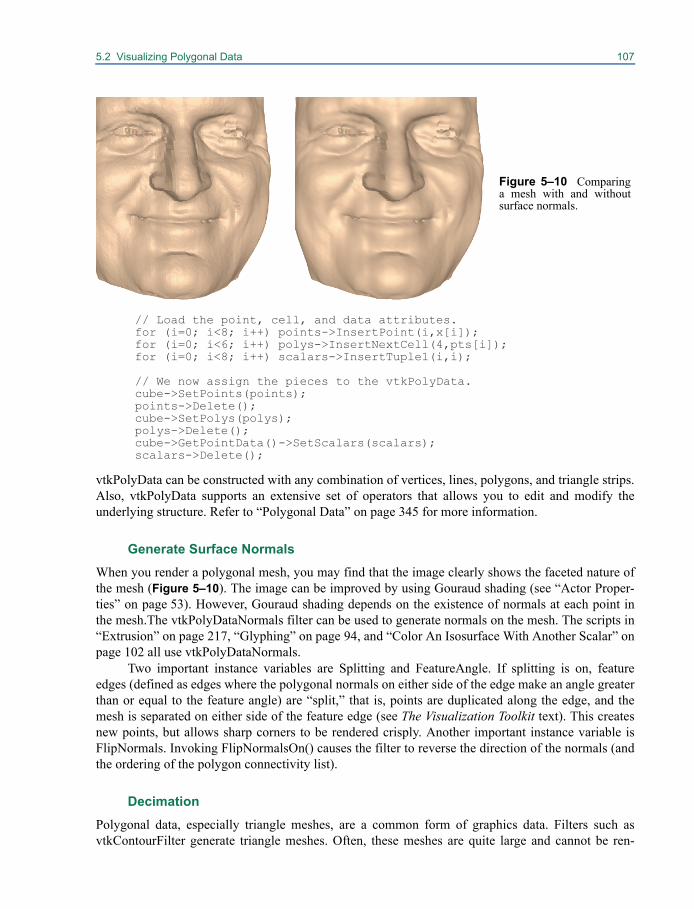
5.2 Visualizing Polygonal Data 107
// Load the point, cell, and data attributes. for (i=0; i<8; i++) points->InsertPoint(i,x[i]); for (i=0; i<6; i++) polys->InsertNextCell(4,pts[i]); for (i=0; i<8; i++) scalars->InsertTuple1(i,i);
// We now assign the pieces to the vtkPolyData. cube->SetPoints(points); points->Delete(); cube->SetPolys(polys); polys->Delete(); cube->GetPointData()->SetScalars(scalars); scalars->Delete();
vtkPolyData can be constructed with any combination of vertices, lines, polygons, and triangle strips.Also, vtkPolyData supports an extensive set of operators that allows you to edit and modify theunderlying structure. Refer to “Polygonal Data” on page 345 for more information.
Generate Surface Normals When you render a polygonal mesh, you may find that the image clearly shows the faceted nature ofthe mesh (Figure 5–10). The image can be improved by using Gouraud shading (see “Actor Proper-ties” on page 53). However, Gouraud shading depends on the existence of normals at each point inthe mesh.The vtkPolyDataNormals filter can be used to generate normals on the mesh. The scripts in“Extrusion” on page 217, “Glyphing” on page 94, and “Color An Isosurface With Another Scalar” onpage 102 all use vtkPolyDataNormals.
Two important instance variables are Splitting and FeatureAngle. If splitting is on, featureedges (defined as edges where the polygonal normals on either side of the edge make an angle greaterthan or equal to the feature angle) are “split,” that is, points are duplicated along the edge, and themesh is separated on either side of the feature edge (see The Visualization Toolkit text). This createsnew points, but allows sharp corners to be rendered crisply. Another important instance variable isFlipNormals. Invoking FlipNormalsOn() causes the filter to reverse the direction of the normals (andthe ordering of the polygon connectivity list).
DecimationPolygonal data, especially triangle meshes, are a common form of graphics data. Filters such asvtkContourFilter generate triangle meshes. Often, these meshes are quite large and cannot be ren-
Figure 5–10 Comparinga mesh with and withoutsurface normals.
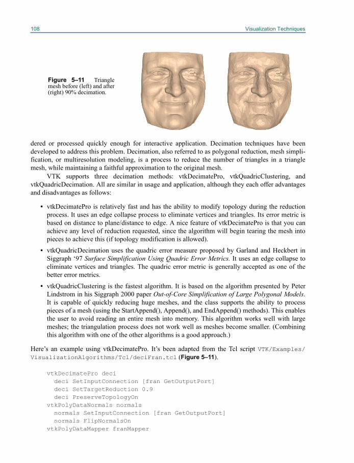
108 Visualization Techniques
dered or processed quickly enough for interactive application. Decimation techniques have beendeveloped to address this problem. Decimation, also referred to as polygonal reduction, mesh simpli-fication, or multiresolution modeling, is a process to reduce the number of triangles in a trianglemesh, while maintaining a faithful approximation to the original mesh.
VTK supports three decimation methods: vtkDecimatePro, vtkQuadricClustering, andvtkQuadricDecimation. All are similar in usage and application, although they each offer advantagesand disadvantages as follows:
• vtkDecimatePro is relatively fast and has the ability to modify topology during the reductionprocess. It uses an edge collapse process to eliminate vertices and triangles. Its error metric isbased on distance to plane/distance to edge. A nice feature of vtkDecimatePro is that you canachieve any level of reduction requested, since the algorithm will begin tearing the mesh intopieces to achieve this (if topology modification is allowed).
• vtkQuadricDecimation uses the quadric error measure proposed by Garland and Heckbert inSiggraph ‘97 Surface Simplification Using Quadric Error Metrics. It uses an edge collapse toeliminate vertices and triangles. The quadric error metric is generally accepted as one of thebetter error metrics.
• vtkQuadricClustering is the fastest algorithm. It is based on the algorithm presented by PeterLindstrom in his Siggraph 2000 paper Out-of-Core Simplification of Large Polygonal Models.It is capable of quickly reducing huge meshes, and the class supports the ability to processpieces of a mesh (using the StartAppend(), Append(), and EndAppend() methods). This enablesthe user to avoid reading an entire mesh into memory. This algorithm works well with largemeshes; the triangulation process does not work well as meshes become smaller. (Combiningthis algorithm with one of the other algorithms is a good approach.)
Here’s an example using vtkDecimatePro. It’s been adapted from the Tcl script VTK/Examples/VisualizationAlgorithms/Tcl/deciFran.tcl (Figure 5–11).
vtkDecimatePro deci deci SetInputConnection [fran GetOutputPort] deci SetTargetReduction 0.9 deci PreserveTopologyOnvtkPolyDataNormals normals normals SetInputConnection [fran GetOutputPort] normals FlipNormalsOnvtkPolyDataMapper franMapper
Figure 5–11 Trianglemesh before (left) and after(right) 90% decimation.
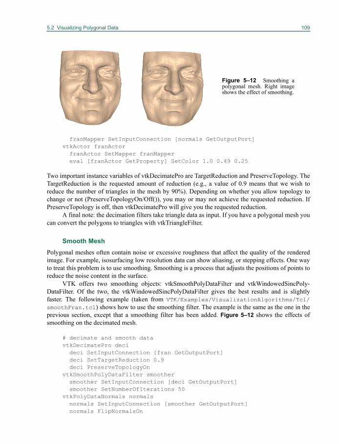
5.2 Visualizing Polygonal Data 109
franMapper SetInputConnection [normals GetOutputPort]vtkActor franActor franActor SetMapper franMapper eval [franActor GetProperty] SetColor 1.0 0.49 0.25
Two important instance variables of vtkDecimatePro are TargetReduction and PreserveTopology. TheTargetReduction is the requested amount of reduction (e.g., a value of 0.9 means that we wish toreduce the number of triangles in the mesh by 90%). Depending on whether you allow topology tochange or not (PreserveTopologyOn/Off()), you may or may not achieve the requested reduction. IfPreserveTopology is off, then vtkDecimatePro will give you the requested reduction.
A final note: the decimation filters take triangle data as input. If you have a polygonal mesh youcan convert the polygons to triangles with vtkTriangleFilter.
Smooth MeshPolygonal meshes often contain noise or excessive roughness that affect the quality of the renderedimage. For example, isosurfacing low resolution data can show aliasing, or stepping effects. One wayto treat this problem is to use smoothing. Smoothing is a process that adjusts the positions of points toreduce the noise content in the surface.
VTK offers two smoothing objects: vtkSmoothPolyDataFilter and vtkWindowedSincPoly-DataFilter. Of the two, the vtkWindowedSincPolyDataFilter gives the best results and is slightlyfaster. The following example (taken from VTK/Examples/VisualizationAlgorithms/Tcl/smoothFran.tcl) shows how to use the smoothing filter. The example is the same as the one in theprevious section, except that a smoothing filter has been added. Figure 5–12 shows the effects ofsmoothing on the decimated mesh.
# decimate and smooth datavtkDecimatePro deci deci SetInputConnection [fran GetOutputPort] deci SetTargetReduction 0.9 deci PreserveTopologyOnvtkSmoothPolyDataFilter smoother smoother SetInputConnection [deci GetOutputPort] smoother SetNumberOfIterations 50vtkPolyDataNormals normals normals SetInputConnection [smoother GetOutputPort] normals FlipNormalsOn
Figure 5–12 Smoothing apolygonal mesh. Right imageshows the effect of smoothing.
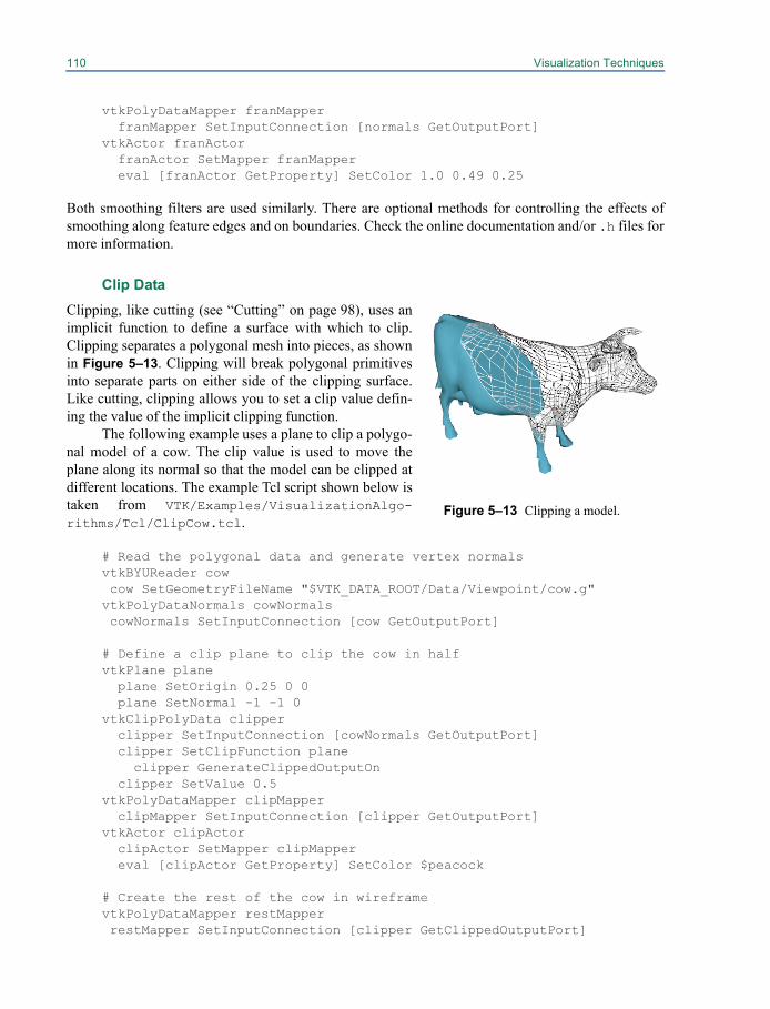
110 Visualization Techniques
vtkPolyDataMapper franMapper franMapper SetInputConnection [normals GetOutputPort]vtkActor franActor franActor SetMapper franMapper eval [franActor GetProperty] SetColor 1.0 0.49 0.25
Both smoothing filters are used similarly. There are optional methods for controlling the effects ofsmoothing along feature edges and on boundaries. Check the online documentation and/or .h files formore information.
Clip Data
Clipping, like cutting (see “Cutting” on page 98), uses animplicit function to define a surface with which to clip.Clipping separates a polygonal mesh into pieces, as shownin Figure 5–13. Clipping will break polygonal primitivesinto separate parts on either side of the clipping surface.Like cutting, clipping allows you to set a clip value defin-ing the value of the implicit clipping function.
The following example uses a plane to clip a polygo-nal model of a cow. The clip value is used to move theplane along its normal so that the model can be clipped atdifferent locations. The example Tcl script shown below istaken from VTK/Examples/VisualizationAlgo-rithms/Tcl/ClipCow.tcl.
# Read the polygonal data and generate vertex normalsvtkBYUReader cow cow SetGeometryFileName "$VTK_DATA_ROOT/Data/Viewpoint/cow.g"vtkPolyDataNormals cowNormals cowNormals SetInputConnection [cow GetOutputPort]
# Define a clip plane to clip the cow in halfvtkPlane plane plane SetOrigin 0.25 0 0 plane SetNormal -1 -1 0vtkClipPolyData clipper clipper SetInputConnection [cowNormals GetOutputPort] clipper SetClipFunction plane
clipper GenerateClippedOutputOn clipper SetValue 0.5vtkPolyDataMapper clipMapper clipMapper SetInputConnection [clipper GetOutputPort]vtkActor clipActor clipActor SetMapper clipMapper eval [clipActor GetProperty] SetColor $peacock
# Create the rest of the cow in wireframevtkPolyDataMapper restMapper restMapper SetInputConnection [clipper GetClippedOutputPort]
Figure 5–13 Clipping a model.
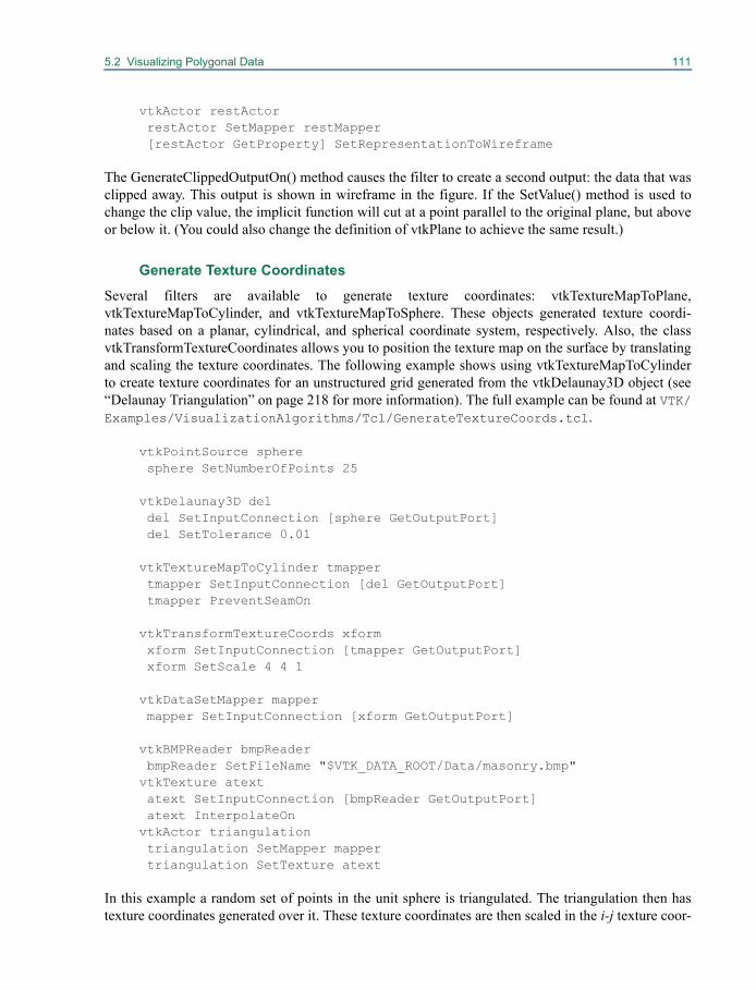
5.2 Visualizing Polygonal Data 111
vtkActor restActor restActor SetMapper restMapper [restActor GetProperty] SetRepresentationToWireframe
The GenerateClippedOutputOn() method causes the filter to create a second output: the data that wasclipped away. This output is shown in wireframe in the figure. If the SetValue() method is used tochange the clip value, the implicit function will cut at a point parallel to the original plane, but aboveor below it. (You could also change the definition of vtkPlane to achieve the same result.)
Generate Texture Coordinates
Several filters are available to generate texture coordinates: vtkTextureMapToPlane,vtkTextureMapToCylinder, and vtkTextureMapToSphere. These objects generated texture coordi-nates based on a planar, cylindrical, and spherical coordinate system, respectively. Also, the classvtkTransformTextureCoordinates allows you to position the texture map on the surface by translatingand scaling the texture coordinates. The following example shows using vtkTextureMapToCylinderto create texture coordinates for an unstructured grid generated from the vtkDelaunay3D object (see“Delaunay Triangulation” on page 218 for more information). The full example can be found at VTK/Examples/VisualizationAlgorithms/Tcl/GenerateTextureCoords.tcl.
vtkPointSource sphere sphere SetNumberOfPoints 25
vtkDelaunay3D del del SetInputConnection [sphere GetOutputPort] del SetTolerance 0.01
vtkTextureMapToCylinder tmapper tmapper SetInputConnection [del GetOutputPort] tmapper PreventSeamOn
vtkTransformTextureCoords xform xform SetInputConnection [tmapper GetOutputPort] xform SetScale 4 4 1
vtkDataSetMapper mapper mapper SetInputConnection [xform GetOutputPort]
vtkBMPReader bmpReader bmpReader SetFileName "$VTK_DATA_ROOT/Data/masonry.bmp"vtkTexture atext atext SetInputConnection [bmpReader GetOutputPort] atext InterpolateOnvtkActor triangulation triangulation SetMapper mapper triangulation SetTexture atext
In this example a random set of points in the unit sphere is triangulated. The triangulation then hastexture coordinates generated over it. These texture coordinates are then scaled in the i-j texture coor-
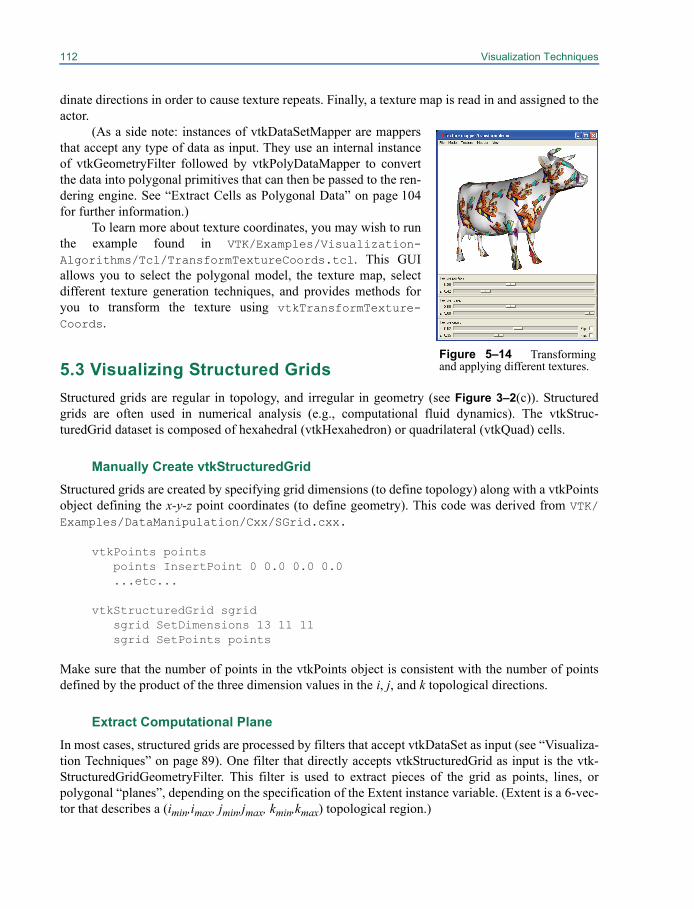
112 Visualization Techniques
dinate directions in order to cause texture repeats. Finally, a texture map is read in and assigned to theactor.
(As a side note: instances of vtkDataSetMapper are mappersthat accept any type of data as input. They use an internal instanceof vtkGeometryFilter followed by vtkPolyDataMapper to convertthe data into polygonal primitives that can then be passed to the ren-dering engine. See “Extract Cells as Polygonal Data” on page 104for further information.)
To learn more about texture coordinates, you may wish to runthe example found in VTK/Examples/Visualization-Algorithms/Tcl/TransformTextureCoords.tcl. This GUIallows you to select the polygonal model, the texture map, selectdifferent texture generation techniques, and provides methods foryou to transform the texture using vtkTransformTexture-Coords.
5.3 Visualizing Structured GridsStructured grids are regular in topology, and irregular in geometry (see Figure 3–2(c)). Structuredgrids are often used in numerical analysis (e.g., computational fluid dynamics). The vtkStruc-turedGrid dataset is composed of hexahedral (vtkHexahedron) or quadrilateral (vtkQuad) cells.
Manually Create vtkStructuredGridStructured grids are created by specifying grid dimensions (to define topology) along with a vtkPointsobject defining the x-y-z point coordinates (to define geometry). This code was derived from VTK/Examples/DataManipulation/Cxx/SGrid.cxx.
vtkPoints pointspoints InsertPoint 0 0.0 0.0 0.0...etc...
vtkStructuredGrid sgridsgrid SetDimensions 13 11 11sgrid SetPoints points
Make sure that the number of points in the vtkPoints object is consistent with the number of pointsdefined by the product of the three dimension values in the i, j, and k topological directions.
Extract Computational PlaneIn most cases, structured grids are processed by filters that accept vtkDataSet as input (see “Visualiza-tion Techniques” on page 89). One filter that directly accepts vtkStructuredGrid as input is the vtk-StructuredGridGeometryFilter. This filter is used to extract pieces of the grid as points, lines, orpolygonal “planes”, depending on the specification of the Extent instance variable. (Extent is a 6-vec-tor that describes a (imin,imax, jmin,jmax, kmin,kmax) topological region.)
Figure 5–14 Transformingand applying different textures.

5.3 Visualizing Structured Grids 113
In the following example, we read a structured grid, extract three planes, and warp the planeswith the associated vector data (from VTK/Examples/VisualizationAlgorithms/Tcl/warp-Comb.tcl).
vtkPLOT3DReader pl3d pl3d SetXYZFileName "$VTK_DATA_ROOT/Data/combxyz.bin" pl3d SetQFileName "$VTK_DATA_ROOT/Data/combq.bin" pl3d SetScalarFunctionNumber 100 pl3d SetVectorFunctionNumber 202 pl3d UpdatevtkStructuredGridGeometryFilter plane plane SetInputConnection [pl3d GetOutputPort] plane SetExtent 10 10 1 100 1 100vtkStructuredGridGeometryFilter plane2 plane2 SetInputConnection [pl3d GetOutputPort] plane2 SetExtent 30 30 1 100 1 100vtkStructuredGridGeometryFilter plane3 plane3 SetInputConnection [pl3d GetOutputPort] plane3 SetExtent 45 45 1 100 1 100vtkAppendPolyData appendF appendF AddInputConnection [plane GetOutputPort] appendF AddInputConnection [plane2 GetOutputPort] appendF AddInputConnection [plane3 GetOutputPort]vtkWarpScalar warp warp SetInputConnection [appendF GetOutputPort] warp UseNormalOn warp SetNormal 1.0 0.0 0.0 warp SetScaleFactor 2.5vtkPolyDataNormals normals normals SetInputConnection [warp GetOutputPort] normals SetFeatureAngle 60vtkPolyDataMapper planeMapper planeMapper SetInputConnection [normals GetOutputPort] eval planeMapper SetScalarRange [[pl3d GetOutput] GetScalarRange]vtkActor planeActor planeActor SetMapper planeMapper
Subsampling Structured GridsStructured grids can be subsampled like image data can be (see “Subsampling Image Data” onpage 105). The vtkExtractGrid performs the subsampling and data extraction.
vtkPLOT3DReader pl3d pl3d SetXYZFileName "$VTK_DATA_ROOT/Data/combxyz.bin" pl3d SetQFileName "$VTK_DATA_ROOT/Data/combq.bin" pl3d SetScalarFunctionNumber 100 pl3d SetVectorFunctionNumber 202 pl3d UpdatevtkExtractGrid extract extract SetInputConnection [pl3d GetOutputPort] extract SetVOI 30 30 -1000 1000 -1000 1000

114 Visualization Techniques
extract SetSampleRate 1 2 3 extract IncludeBoundaryOn
In this example, a subset of the original structured grid (which has dimensions 57x33x25) is extractedwith a sampling rate of (1,2,3) resulting in a structured grid with dimensions (1,17,9). The Include-BoundaryOn method makes sure that the boundary is extracted even if the sampling rate does notpick up the boundary.
5.4 Visualizing Rectilinear GridsRectilinear grids are regular in topology, and semi-regular in geometry (see Figure 3–2(b)). Rectilin-ear grids are often used in numerical analysis. The vtkRectilinearGrid dataset is composed of voxel(vtkVoxel) or pixel (vtkPixel) cells.
Manually Create vtkRectilinearGridRectilinear grids are created by specifying grid dimensions (to define topology) along with three sca-lar arrays to define point coordinates along the x-y-z axes (to define geometry). This code was modi-fied from VTK/Examples/DataManipulation/Cxx/RGrid.cxx.
vtkFloatArray *xCoords = vtkFloatArray::New();
for (i=0; i<47; i++) xCoords->InsertNextValue(x[i]);
vtkFloatArray *yCoords = vtkFloatArray::New();for (i=0; i<33; i++) yCoords->InsertNextValue(y[i]);
vtkFloatArray *zCoords = vtkFloatArray::New();for (i=0; i<44; i++) zCoords->InsertNextValue(z[i]);
vtkRectilinearGrid *rgrid = vtkRectilinearGrid::New();rgrid->SetDimensions(47,33,44);rgrid->SetXCoordinates(xCoords);rgrid->SetYCoordinates(yCoords);rgrid->SetZCoordinates(zCoords);
Make sure that the number of scalars in the x, y, and z directions equals the three dimension values inthe i, j, and k topological directions.
Extract Computational PlaneIn most cases, rectilinear grids are processed by filters that accept vtkDataSet as input (see “Visual-ization Techniques” on page 89). One filter that directly accepts vtkRectilinearGrid as input is thevtkRectilinearGridGeometryFilter. This filter is used to extract pieces of the grid as points, lines, orpolygonal “planes”, depending on the specification of the Extent instance variable. (Extent is a 6-vec-tor that describes a (imin,imax, jmin,jmax, kmin,kmax) topological region.)
The following example, which we continue from the previous found in VTK/Examples/Data-Manipulation/Cxx/RGrid.cxx, we extract a plane as follows
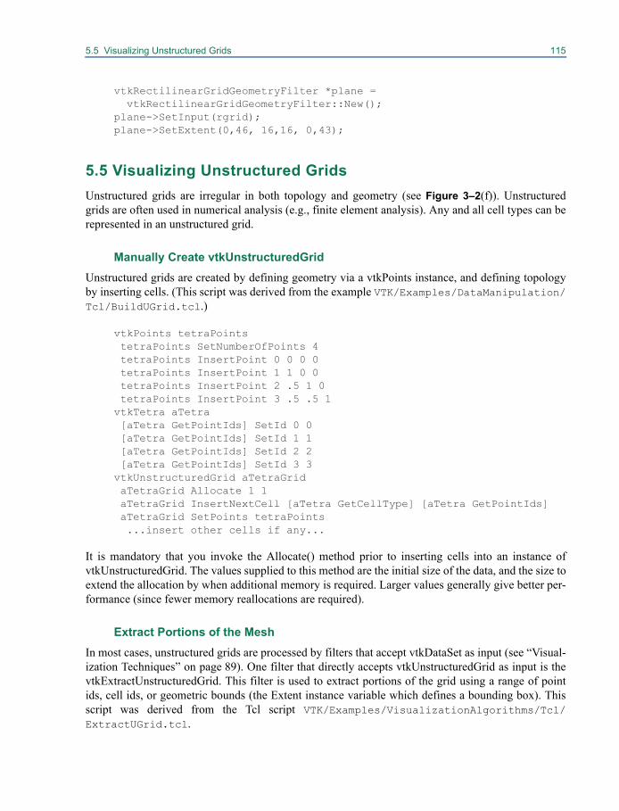
5.5 Visualizing Unstructured Grids 115
vtkRectilinearGridGeometryFilter *plane = vtkRectilinearGridGeometryFilter::New();
plane->SetInput(rgrid);plane->SetExtent(0,46, 16,16, 0,43);
5.5 Visualizing Unstructured GridsUnstructured grids are irregular in both topology and geometry (see Figure 3–2(f)). Unstructuredgrids are often used in numerical analysis (e.g., finite element analysis). Any and all cell types can berepresented in an unstructured grid.
Manually Create vtkUnstructuredGridUnstructured grids are created by defining geometry via a vtkPoints instance, and defining topologyby inserting cells. (This script was derived from the example VTK/Examples/DataManipulation/Tcl/BuildUGrid.tcl.)
vtkPoints tetraPoints tetraPoints SetNumberOfPoints 4 tetraPoints InsertPoint 0 0 0 0 tetraPoints InsertPoint 1 1 0 0 tetraPoints InsertPoint 2 .5 1 0 tetraPoints InsertPoint 3 .5 .5 1vtkTetra aTetra [aTetra GetPointIds] SetId 0 0 [aTetra GetPointIds] SetId 1 1 [aTetra GetPointIds] SetId 2 2 [aTetra GetPointIds] SetId 3 3vtkUnstructuredGrid aTetraGrid aTetraGrid Allocate 1 1 aTetraGrid InsertNextCell [aTetra GetCellType] [aTetra GetPointIds] aTetraGrid SetPoints tetraPoints
...insert other cells if any...
It is mandatory that you invoke the Allocate() method prior to inserting cells into an instance ofvtkUnstructuredGrid. The values supplied to this method are the initial size of the data, and the size toextend the allocation by when additional memory is required. Larger values generally give better per-formance (since fewer memory reallocations are required).
Extract Portions of the MeshIn most cases, unstructured grids are processed by filters that accept vtkDataSet as input (see “Visual-ization Techniques” on page 89). One filter that directly accepts vtkUnstructuredGrid as input is thevtkExtractUnstructuredGrid. This filter is used to extract portions of the grid using a range of pointids, cell ids, or geometric bounds (the Extent instance variable which defines a bounding box). Thisscript was derived from the Tcl script VTK/Examples/VisualizationAlgorithms/Tcl/ExtractUGrid.tcl.
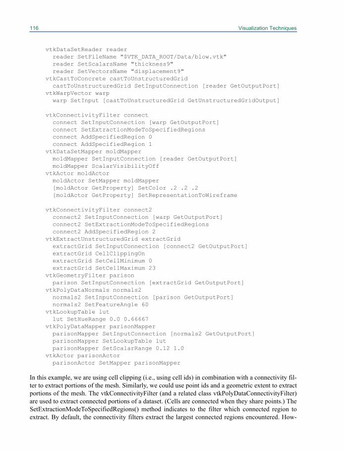
116 Visualization Techniques
vtkDataSetReader reader reader SetFileName "$VTK_DATA_ROOT/Data/blow.vtk" reader SetScalarsName "thickness9" reader SetVectorsName "displacement9"vtkCastToConcrete castToUnstructuredGrid castToUnstructuredGrid SetInputConnection [reader GetOutputPort]vtkWarpVector warp warp SetInput [castToUnstructuredGrid GetUnstructuredGridOutput]
vtkConnectivityFilter connect connect SetInputConnection [warp GetOutputPort] connect SetExtractionModeToSpecifiedRegions connect AddSpecifiedRegion 0 connect AddSpecifiedRegion 1vtkDataSetMapper moldMapper moldMapper SetInputConnection [reader GetOutputPort] moldMapper ScalarVisibilityOffvtkActor moldActor moldActor SetMapper moldMapper [moldActor GetProperty] SetColor .2 .2 .2 [moldActor GetProperty] SetRepresentationToWireframe
vtkConnectivityFilter connect2 connect2 SetInputConnection [warp GetOutputPort] connect2 SetExtractionModeToSpecifiedRegions connect2 AddSpecifiedRegion 2vtkExtractUnstructuredGrid extractGrid extractGrid SetInputConnection [connect2 GetOutputPort] extractGrid CellClippingOn extractGrid SetCellMinimum 0 extractGrid SetCellMaximum 23vtkGeometryFilter parison parison SetInputConnection [extractGrid GetOutputPort]vtkPolyDataNormals normals2 normals2 SetInputConnection [parison GetOutputPort] normals2 SetFeatureAngle 60vtkLookupTable lut lut SetHueRange 0.0 0.66667vtkPolyDataMapper parisonMapper parisonMapper SetInputConnection [normals2 GetOutputPort] parisonMapper SetLookupTable lut parisonMapper SetScalarRange 0.12 1.0vtkActor parisonActor parisonActor SetMapper parisonMapper
In this example, we are using cell clipping (i.e., using cell ids) in combination with a connectivity fil-ter to extract portions of the mesh. Similarly, we could use point ids and a geometric extent to extractportions of the mesh. The vtkConnectivityFilter (and a related class vtkPolyDataConnectivityFilter)are used to extract connected portions of a dataset. (Cells are connected when they share points.) TheSetExtractionModeToSpecifiedRegions() method indicates to the filter which connected region toextract. By default, the connectivity filters extract the largest connected regions encountered. How-
5.5 Visualizing Unstructured Grids 117
ever, it is also possible to specify a particular region as this example does, which of course requiressome experimentation to determine which region is which.
Contour Unstructured GridsA special contouring class is available to generate isocontours for unstructured grids. The classvtkContourGrid is a higher-performing version than the generic vtkContourFilter isocontouring filter.Normally you do not need to instantiate this class directly since vtkContourFilter will automaticallycreate an internal instance of vtkContourGrid if it senses that its input is of type vtkUnstructuredGrid.
This concludes our overview of visualization techniques. You may also wish to refer to the nextchapter which describes image processing and volume rendering. Also, see “Summary Of Filters” onpage 444 for a summary of the filters in VTK.


Chapter 6
Image Processing & Visualization 6
Image datasets, represented by the class vtkImageData,are regular in topology and geometry as shown in Figure 6–1. This data type is structured, meaningthat the locations of the data points are implicitly defined using just the few parameters origin, spac-ing and dimensions. Medical and scientific scanning devices such as CT, MRI, ultrasound scanners,and confocal microscopes often produce data of this type. Conceptually, the vtkImageData dataset iscomposed of voxel (vtkVoxel) or pixel (vtkPixel) cells. However, the structured nature of this datasetallows us to store the data values in a simple array rather than explicitly creating the vtkVoxel orvtkPixel cells.
In VTK, image data is a special data type that can be processed and rendered in several ways.Although not an exhaustive classification, most of the operations performed on image data in VTKfall into one of the three categories—image processing, geometry extraction, or direct rendering.Dozens of image processing filters exist that can operate on image datasets. These filters take vtkIm-ageData as input and produce vtkImageData as output. Geometry extraction filters exist that convertvtkImageData into vtkPolyData. For example, the vtkContourFilter can extract iso-valued contours in
Figure 6–1 The vtkImageData structureis defined by dimensions, spacing, and ori-gin. The dimensions are the number ofvoxels or pixels along each of the majoraxes. The origin is the world coordinateposition of the lower left corner of the firstslice of the data. The spacing is the dis-tance between pixels along each of thethree major axes.
X
Y
Z
X
Y
Z
(0,0,0)
(2.5, 2.4, 3.7) 1.5
2.2
1.8
Dimensions = (4,2,3)Spacing = (1.5, 1.8, 2.2)Origin = (2.5, 2.4, 3.7)
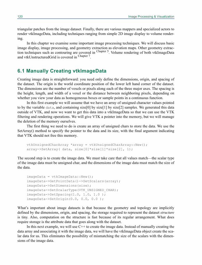
120 Image Processing & Visualization
triangular patches from the image dataset. Finally, there are various mappers and specialized actors torender vtkImageData, including techniques ranging from simple 2D image display to volume render-ing.
In this chapter we examine some important image processing techniques. We will discuss basicimage display, image processing, and geometry extraction as elevation maps. Other geometry extrac-tion techniques such as contouring are covered in Chapter 5. Volume rendering of both vtkImageDataand vtkUnstructuredGrid is covered in Chapter 7.
6.1 Manually Creating vtkImageDataCreating image data is straightforward: you need only define the dimensions, origin, and spacing ofthe dataset. The origin is the world coordinate position of the lower left hand corner of the dataset.The dimensions are the number of voxels or pixels along each of the three major axes. The spacing isthe height, length, and width of a voxel or the distance between neighboring pixels, depending onwhether you view your data as homogeneous boxes or sample points in a continuous function.
In this first example we will assume that we have an array of unsigned character values pointedto by the variable data, and containing size[0] by size[1] by size[2] samples. We generated this dataoutside of VTK, and now we want to get this data into a vtkImageData so that we can use the VTKfiltering and rendering operations. We will give VTK a pointer into the memory, but we will managethe deletion of the memory ourselves.
The first thing we need to do is create an array of unsigned chars to store the data. We use theSetArray() method to specify the pointer to the data and its size, with the final argument indicatingthat VTK should not free this memory.
vtkUnsignedCharArray *array = vtkUnsignedCharArray::New(); array->SetArray( data, size[0]*size[1]*size[2], 1);
The second step is to create the image data. We must take care that all values match—the scalar typeof the image data must be unsigned char, and the dimensions of the image data must match the size ofthe data.
imageData = vtkImageData::New(); imageData->GetPointData()->SetScalars(array); imageData->SetDimensions(size); imageData->SetScalarType(VTK_UNSIGNED_CHAR); imageData->SetSpacing(1.0, 1.0, 1.0 ); imageData->SetOrigin(0.0, 0.0, 0.0 );
What’s important about image datasets is that because the geometry and topology are implicitlydefined by the dimensions, origin, and spacing, the storage required to represent the dataset structureis tiny. Also, computation on the structure is fast because of its regular arrangement. What doesrequire storage is the attribute data that goes along with the dataset.
In this next example, we will use C++ to create the image data. Instead of manually creating thedata array and associating it with the image data, we will have the vtkImageData object create the sca-lar data for us. This eliminates the possibility of mismatching the size of the scalars with the dimen-sions of the image data.
6.2 Subsampling Image Data 121
// Create the image data vtkImageData *id = vtkImageData::New(); id->SetDimensions(10,25,100); id->SetScalarTypeToUnsignedShort(); id->SetNumberOfScalarComponents(1); id->AllocateScalars(); // Fill in scalar values unsigned short *ptr = (unsigned short *) id->GetScalarPointer(); for (int i=0; i<10*25*100; i++) { *ptr++ = i; }
In this example, the convenience method AllocateScalars() is used to allocate storage for theimage data. Notice that this call is made after the scalar type and number of scalar components havebeen set (up to four scalar components can be set). Then the method GetScalarPointer(), whichreturns a void*, is invoked and the result is cast to unsigned short. We can do this knowing that thetype is unsigned short because we specified this earlier. Imaging filters in VTK work on images ofany scalar type. Their RequestData() methods query the scalar type and then switch on the type to atemplated function in their implementation. VTK has by design chosen to avoid exposing the scalartype as a template parameter, in its public interface. This makes it easy to provide an interface towrapped languages, such as Tcl, Java and Python which lack templates.
6.2 Subsampling Image DataAs we saw in “Extract Subset of Cells” on page 103, extracting parts of a dataset is often desirable.The filter vtkExtractVOI extracts pieces of the input image dataset. The filter can also subsample thedata, although vtkImageReslice (covered later) provides more flexibility with resampling data. Theoutput of the filter is also of type vtkImageData.
There are actually two similar filters that perform this clipping functionality in VTK:vtkExtractVOI and vtkImageClip. The reason for two separate versions is historical—the imagingpipeline used to be separate from the graphics pipeline, with vtkImageClip working only on vtkIm-ageData in the imaging pipeline and vtkExtractVOI working only on vtkStructuredPoints in thegraphics pipeline. These distinctions are gone now, but there are still some differences between thesefilters. vtkExtractVOI will extract a subregion of the volume and produce a vtkImageData that con-tains exactly this information. In addition, vtkExtractVOI can be used to resample the volume withinthe VOI. On the other hand, vtkImageClip by default will pass the input data through to the outputunchanged except for the extent information. A flag may be set on this filter to force it to produce theexact amount of data only, in which case the region will be copied into the output vtkImageData. ThevtkImageClip filter cannot resample the volume.
The following Tcl example (taken from VTK/Examples/ImageProcessing/Tcl/Contours2D.tcl) demonstrates how to use vtkExtractVOI. It extracts a piece of the input volume,and then subsamples it. The output is passed to a vtkContourFilter. (You may want to try removingvtkExtractVOI and compare the results.)
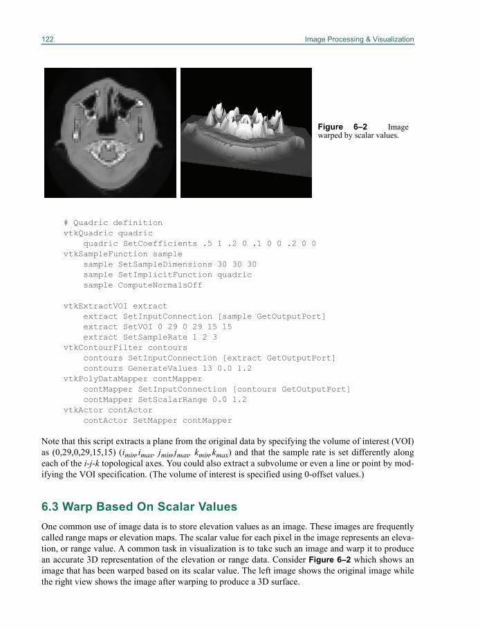
122 Image Processing & Visualization
# Quadric definitionvtkQuadric quadric
quadric SetCoefficients .5 1 .2 0 .1 0 0 .2 0 0vtkSampleFunction sample
sample SetSampleDimensions 30 30 30sample SetImplicitFunction quadricsample ComputeNormalsOff
vtkExtractVOI extractextract SetInputConnection [sample GetOutputPort]extract SetVOI 0 29 0 29 15 15extract SetSampleRate 1 2 3
vtkContourFilter contourscontours SetInputConnection [extract GetOutputPort]contours GenerateValues 13 0.0 1.2
vtkPolyDataMapper contMappercontMapper SetInputConnection [contours GetOutputPort]contMapper SetScalarRange 0.0 1.2
vtkActor contActorcontActor SetMapper contMapper
Note that this script extracts a plane from the original data by specifying the volume of interest (VOI)as (0,29,0,29,15,15) (imin,imax, jmin,jmax, kmin,kmax) and that the sample rate is set differently alongeach of the i-j-k topological axes. You could also extract a subvolume or even a line or point by mod-ifying the VOI specification. (The volume of interest is specified using 0-offset values.)
6.3 Warp Based On Scalar ValuesOne common use of image data is to store elevation values as an image. These images are frequentlycalled range maps or elevation maps. The scalar value for each pixel in the image represents an eleva-tion, or range value. A common task in visualization is to take such an image and warp it to producean accurate 3D representation of the elevation or range data. Consider Figure 6–2 which shows animage that has been warped based on its scalar value. The left image shows the original image whilethe right view shows the image after warping to produce a 3D surface.
Figure 6–2 Imagewarped by scalar values.
6.4 Image Display 123
The pipeline to perform this visualization is fairly simple, but there is an important concept tounderstand. The original data is an image which has implicit geometry and topology. Warping theimage will result in a 3D surface where geometry is no longer implicit. To support this we first con-vert the image to a vtkPolyData representation using vtkImageDataGeometryFilter. Then we performthe warp and connect to a mapper. In the script below you’ll note that we also make use ofvtkWindowLevelLookupTable to provide a greyscale lookup-table instead of the default red to bluelookup table.
vtkImageReader readerreader SetDataByteOrderToLittleEndianreader SetDataExtent 0 63 0 63 40 40reader SetFilePrefix "$VTK_DATA_ROOT/Data/headsq/quarter"reader SetDataMask 0x7fff
vtkImageDataGeometryFilter geometry geometry SetInputConnection [reader GetOutputPort]
vtkWarpScalar warp warp SetInputConnection [geometry GetOutputPort] warp SetScaleFactor 0.005
vtkWindowLevelLookupTable wl
vtkPolyDataMapper mapper mapper SetInputConnection [warp GetOutputPort] mapper SetScalarRange 0 2000 mapper ImmediateModeRenderingOff mapper SetLookupTable wl
vtkActor actor actor SetMapper mapper
This example is often combined with other techniques. If you want to warp the image with its scalarvalue and then color it with a different scalar field you would use the vtkMergeFilter. Another com-mon operation is to reduce the number of polygons in the warped surface. Because these surfaceswere generated from images they tend to have a large number of polygons. You can usevtkDecimatePro to reduce the number. You should also consider using vtkTriangleFilter followed byvtkStripper to convert the polygons (squares) into triangle strips which tend to render faster and con-sume less memory.
6.4 Image DisplayThere are several ways to directly display image data. Two methods that are generally applicable fordisplaying 2D images are described in this section. Volume rendering is the method for directly dis-playing 3D images (volumes) and is described in detail in Chapter 7.
Image ViewervtkImageViewer2 is a convenient class for displaying images. It replaces an earlier version of theclass vtkImageViewer. vtkImageViewer2 internally encapsulates several objects - vtkRenderWindow,vtkRenderer, vtkImageActor and vtkImageMapToWindowLevelColors providing an easy to use class
124 Image Processing & Visualization
that can be dropped into your application. This class also creates an interactor style (vtkInteractor-StyleImage) customized for images, that allows zooming and panning of images, and supports inter-active window/level operations on the image. (See “Interactor Styles” on page 43 and“vtkRenderWindow Interaction Style” on page 283 for more information about interactor styles.)vtkImageViewer2 (unlike vtkImageViewer) uses the 3D rendering and texture mapping engine todraw an image on a plane. This allows for rapid rendering, zooming, and panning. The image isplaced in the 3D scene at a depth based on the depth-coordinate of the particular image slice. Eachcall to SetSlice() changes the image data (slice) displayed and changes the depth of the displayed slicein the 3D scene. This can be controlled by the AutoAdjustCameraClippingRange option on the Inter-actorStyle. You may also set the orientation to display an XY, YZ or an XZ slice.
An example of using an image viewer to browse through the slices in a volume can be found inWidgets/Testing/Cxx/TestImageActorContourWidget.cxx. The following excerpt illustrates a typicalusage of this class.
vtkImageViewer2 *ImageViewer = vtkImageViewer2::New();ImageViewer->SetInput(shifter->GetOutput());ImageViewer->SetColorLevel(127);ImageViewer->SetColorWindow(255);ImageViewer->SetupInteractor(iren);ImageViewer->SetSlice(40);ImageViewer->SetOrientationToXY();ImageViewer->Render();
It is possible to mix images and geometry, for instance :
viewer->SetInput( myImage );viewer->GetRenderer()->AddActor( myActor );
This can be used to annotate an image with a PolyData of "edges" or highlight sections of an image ordisplay a 3D isosurface with a slice from the volume, etc. Any portions of your geometry that are infront of the displayed slice will be visible; any portions of your geometry that are behind the dis-played slice will be obscured.
The window-level transfer function is definedas shown in Figure 6–3. The level is the data valuethat centers the window. The width (i.e., window)defines the range of data values that are mapped tothe display. The slope of the resulting transfer func-tion determines the amount of contrast in the finalimage. All data values outside of the window areclamped to the data values at the boundaries of thewindow..
Image ActorUsing a vtkImageViewer is convenient when you would simply like to display the image in a windowby itself or accompanied by some simple 2D annotation. The vtkImageActor actor class is useful
Figure 6–3 Window-level transfer function.
level
window
6.5 Image Sources 125
when you want to display your image in a 3D rendering window. The image is displayed by creatinga polygon representing the bounds of the image and using hardware texture mapping to paste theimage onto the polygon. On most platforms this enables you to rotate, pan, and zoom your image withbilinear interpolation in real-time. By changing the interactor to a vtkInteractorStyleImage you canlimit rotations so that the 3D render window operates as a 2D image viewer. The advantage to usingthe 3D render window for image display is that you can easily embed multiple images and complex3D annotation into one window.
The vtkImageActor object is a composite class that encapsulates both an actor and a mapperinto one class. It is simple to use, as can be seen in this example.
vtkBMPReader bmpReaderbmpReader SetFileName "$VTK_DATA_ROOT/Data/masonry.bmp"
vtkImageActor imageActorimageActor SetInput [bmpReader GetOutput]
This image actor can then be added to the renderer using the AddProp() method. The vtkImageActorclass expects that its input will have a length of 1 along one of the three dimensions, with the imageextending along the other two dimensions. This allows the vtkImageActor to be connected to a vol-ume through the use of a clipping filter without the need to reorganize the data if the clip is performedalong the X or Y axis. (Note: the input image to vtkImageActor must be of type unsigned char. If yourimage type is different, you can use vtkImageCast or vtkImageShiftScale to convert to unsignedchar.)
vtkImagePlaneWidgetWidgets are covered in “Interaction, Widgets and Selections” on page 255. Suffice it to mention thatthis widget defines a plane that can be interactively placed in an image volume, with the plane dis-playing resliced data through the volume. Interpolation options to reslice the data include nearestneighbor, linear and cubic. The plane position and orientation can be interactively manipulated. Onecan also window level interactively on the resliced plane and optionally display window level andposition annotations.
vtkImagePlaneWidget* planeWidgetX = vtkImagePlaneWidget::New();planeWidgetX->SetInteractor( iren);planeWidgetX->RestrictPlaneToVolumeOn();planeWidgetX->SetResliceInterpolateToNearestNeighbour();planeWidgetX->SetInput(v16->GetOutput());planeWidgetX->SetPlaneOrientationToXAxes();planeWidgetX->SetSliceIndex(32);planeWidgetX->DisplayTextOn();planeWidgetX->On();
6.5 Image SourcesThere are some image processing objects that produce output but do not take any data objects asinput. These are known as image sources, and some of the VTK image sources are described here.
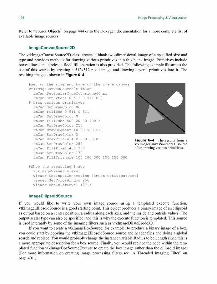
126 Image Processing & Visualization
Refer to “Source Objects” on page 444 or to the Doxygen documentation for a more complete list ofavailable image sources.
ImageCanvasSource2DThe vtkImageCanvasSource2D class creates a blank two-dimensional image of a specified size andtype and provides methods for drawing various primitives into this blank image. Primitives includeboxes, lines, and circles; a flood fill operation is also provided. The following example illustrates theuse of this source by creating a 512x512 pixel image and drawing several primitives into it. Theresulting image is shown in Figure 6–4.
#set up the size and type of the image canvasvtkImageCanvasSource2D imCan
imCan SetScalarTypeToUnsignedCharimCan SetExtent 0 511 0 511 0 0
# Draw various primitivesimCan SetDrawColor 86imCan FillBox 0 511 0 511imCan SetDrawColor 0imCan FillTube 500 20 30 400 5imCan SetDrawColor 255imCan DrawSegment 10 20 500 510imCan SetDrawColor 0imCan DrawCircle 400 350 80.0imCan SetDrawColor 255imCan FillPixel 450 350imCan SetDrawColor 170imCan FillTriangle 100 100 300 150 150 300
#Show the resulting imagevtkImageViewer viewerviewer SetInputConnection [imCan GetOutputPort]viewer SetColorWindow 256viewer SetColorLevel 127.5
ImageEllipsoidSourceIf you would like to write your own image source using a templated execute function,vtkImageEllipsoidSource is a good starting point. This object produces a binary image of an ellipsoidas output based on a center position, a radius along each axis, and the inside and outside values. Theoutput scalar type can also be specified, and this is why the execute function is templated. This sourceis used internally by some of the imaging filters such as vtkImageDilateErode3D.
If you want to create a vtkImageBoxSource, for example, to produce a binary image of a box,you could start by copying the vtkImageEllipsoidSource source and header files and doing a globalsearch and replace. You would probably change the instance variable Radius to be Length since this isa more appropriate description for a box source. Finally, you would replace the code within the tem-plated function vtkImageBoxSourceExecute to create the box image rather than the ellipsoid image.(For more information on creating image processing filters see “A Threaded Imaging Filter” onpage 401.)
Figure 6–4 The results from avtkImageCanvasSource2D sourceafter drawing various primitives.
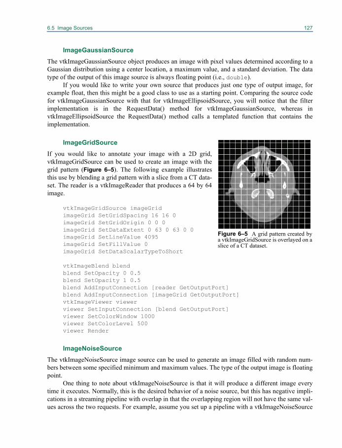
6.5 Image Sources 127
ImageGaussianSourceThe vtkImageGaussianSource object produces an image with pixel values determined according to aGaussian distribution using a center location, a maximum value, and a standard deviation. The datatype of the output of this image source is always floating point (i.e., double).
If you would like to write your own source that produces just one type of output image, forexample float, then this might be a good class to use as a starting point. Comparing the source codefor vtkImageGaussianSource with that for vtkImageEllipsoidSource, you will notice that the filterimplementation is in the RequestData() method for vtkImageGaussianSource, whereas invtkImageEllipsoidSource the RequestData() method calls a templated function that contains theimplementation.
ImageGridSource If you would like to annotate your image with a 2D grid,vtkImageGridSource can be used to create an image with thegrid pattern (Figure 6–5). The following example illustratesthis use by blending a grid pattern with a slice from a CT data-set. The reader is a vtkImageReader that produces a 64 by 64image.
vtkImageGridSource imageGridimageGrid SetGridSpacing 16 16 0imageGrid SetGridOrigin 0 0 0imageGrid SetDataExtent 0 63 0 63 0 0imageGrid SetLineValue 4095imageGrid SetFillValue 0imageGrid SetDataScalarTypeToShort
vtkImageBlend blendblend SetOpacity 0 0.5blend SetOpacity 1 0.5blend AddInputConnection [reader GetOutputPort]blend AddInputConnection [imageGrid GetOutputPort]vtkImageViewer viewerviewer SetInputConnection [blend GetOutputPort]viewer SetColorWindow 1000viewer SetColorLevel 500viewer Render
ImageNoiseSourceThe vtkImageNoiseSource image source can be used to generate an image filled with random num-bers between some specified minimum and maximum values. The type of the output image is floatingpoint.
One thing to note about vtkImageNoiseSource is that it will produce a different image everytime it executes. Normally, this is the desired behavior of a noise source, but this has negative impli-cations in a streaming pipeline with overlap in that the overlapping region will not have the same val-ues across the two requests. For example, assume you set up a pipeline with a vtkImageNoiseSource
Figure 6–5 A grid pattern created bya vtkImageGridSource is overlayed on aslice of a CT dataset.
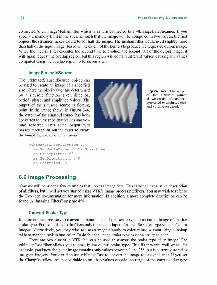
128 Image Processing & Visualization
connected to an ImageMedianFilter which is in turn connected to a vtkImageDataStreamer. If youspecify a memory limit in the streamer such that the image will be computed in two halves, the firstrequest the streamer makes would be for half the image. The median filter would need slightly morethan half of the input image (based on the extent of the kernel) to produce the requested output image.When the median filter executes the second time to produce the second half of the output image, itwill again request the overlap region, but this region will contain different values, causing any valuescomputed using the overlap region to be inconsistent.
ImageSinusoidSourceThe vtkImageSinusoidSource object canbe used to create an image of a specifiedsize where the pixel values are determinedby a sinusoid function given direction,period, phase, and amplitude values. Theoutput of the sinusoid source is floatingpoint. In the image shown in Figure 6–6,the output of the sinusoid source has beenconverted to unsigned char values and vol-ume rendered. This same output waspassed through an outline filter to createthe bounding box seen in the image.
vtkImageSinusoidSource ss ss SetWholeExtent 0 99 0 99 0 99ss SetAmplitude 63ss SetDirection 1 0 0ss SetPeriod 25
6.6 Image ProcessingNow we will consider a few examples that process image data. This is not an exhaustive descriptionof all filters, but it will get you started using VTK’s image processing filters. You may wish to refer tothe Doxygen documentation for more information. In addition, a more complete description can befound in “Imaging Filters” on page 450.
Convert Scalar TypeIt is sometimes necessary to convert an input image of one scalar type to an output image of anotherscalar type. For example, certain filters only operate on input of a specific scalar type such as float orinteger. Alternatively, you may wish to use an image directly as color values without using a lookuptable to map the scalars into color. To do this the image scalar type must be unsigned char.
There are two classes in VTK that can be used to convert the scalar type of an image. ThevtkImageCast filter allows you to specify the output scalar type. This filter works well when, forexample, you know that your image contains only values between 0 and 255, but is currently stored asunsigned integers. You can then use vtkImageCast to convert the image to unsigned char. If you setthe ClampOverflow instance variable to on, then values outside the range of the output scalar type
Figure 6–6 The outputof the sinusoid sourceshown on the left has beenconverted to unsigned charand volume rendered.
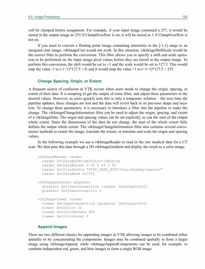
6.6 Image Processing 129
will be clamped before assignment. For example, if your input image contained a 257, it would bestored in the output image as 255 if ClampOverflow is on; it will be stored as 1 if ClampOverflow isnot on.
If you need to convert a floating point image containing intensities in the [-1,1] range to anunsigned char image, vtkImageCast would not work. In this situation, vtkImageShiftScale would bethe correct filter to perform the conversion. This filter allows you to specify a shift and scale opera-tion to be performed on the input image pixel values before they are stored in the output image. Toperform this conversion, the shift would be set to +1 and the scale would be set to 127.5. This wouldmap the value -1 to (-1+1)*127.5 = 0, and it would map the value +1 to (+1+1)*127.5 = 255.
Change Spacing, Origin, or Extent
A frequent source of confusion in VTK occurs when users needs to change the origin, spacing, orextent of their data. It is tempting to get the output of some filter, and adjust these parameters to thedesired values. However, as users quickly note this is only a temporary solution – the next time thepipeline updates, these changes are lost and the data will revert back to its previous shape and loca-tion. To change these parameters, it is necessary to introduce a filter into the pipeline to make thechange. The vtkImageChangeInformation filter can be used to adjust the origin, spacing, and extentof a vtkImageData. The origin and spacing values can be set explicitly, as can the start of the outputwhole extent. Since the dimensions of the data do not change, the start of the whole extent fullydefines the output whole extent. The vtkImageChangeInformation filter also contains several conve-nience methods to center the image, translate the extent, or translate and scale the origin and spacingvalues.
In the following example we use a vtkImageReader to read in the raw medical data for a CTscan. We then pass this data through a 3D vtkImageGradient and display the result as a color image.
vtkImageReader readerreader SetDataByteOrderToLittleEndianreader SetDataExtent 0 63 0 63 1 93reader SetFilePrefix "$VTK_DATA_ROOT/Data/headsq/quarter"reader SetDataMask 0x7fff
vtkImageGradient gradientgradient SetInputConnection [reader GetOutputPort]gradient SetDimensionality 3
vtkImageViewer viewerviewer SetInputConnection [gradient GetOutputPort]viewer SetZSlice 22viewer SetColorWindow 400viewer SetColorLevel 0
Append Images
There are two different classes for appending images in VTK allowing images to be combined eitherspatially or by concatenating the components. Images may be combined spatially to form a largerimage using vtkImageAppend, while vtkImageAppendComponents can be used, for example, tocombine independent red, green, and blue images to form a single RGB image.
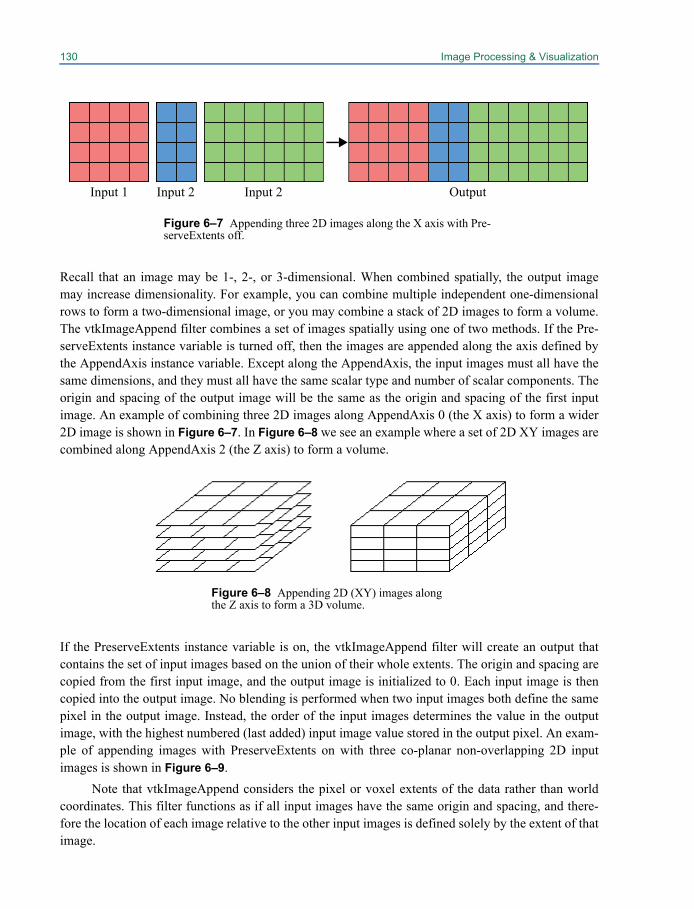
130 Image Processing & Visualization
Recall that an image may be 1-, 2-, or 3-dimensional. When combined spatially, the output imagemay increase dimensionality. For example, you can combine multiple independent one-dimensionalrows to form a two-dimensional image, or you may combine a stack of 2D images to form a volume.The vtkImageAppend filter combines a set of images spatially using one of two methods. If the Pre-serveExtents instance variable is turned off, then the images are appended along the axis defined bythe AppendAxis instance variable. Except along the AppendAxis, the input images must all have thesame dimensions, and they must all have the same scalar type and number of scalar components. Theorigin and spacing of the output image will be the same as the origin and spacing of the first inputimage. An example of combining three 2D images along AppendAxis 0 (the X axis) to form a wider2D image is shown in Figure 6–7. In Figure 6–8 we see an example where a set of 2D XY images arecombined along AppendAxis 2 (the Z axis) to form a volume.
If the PreserveExtents instance variable is on, the vtkImageAppend filter will create an output thatcontains the set of input images based on the union of their whole extents. The origin and spacing arecopied from the first input image, and the output image is initialized to 0. Each input image is thencopied into the output image. No blending is performed when two input images both define the samepixel in the output image. Instead, the order of the input images determines the value in the outputimage, with the highest numbered (last added) input image value stored in the output pixel. An exam-ple of appending images with PreserveExtents on with three co-planar non-overlapping 2D inputimages is shown in Figure 6–9.
Note that vtkImageAppend considers the pixel or voxel extents of the data rather than worldcoordinates. This filter functions as if all input images have the same origin and spacing, and there-fore the location of each image relative to the other input images is defined solely by the extent of thatimage.
Input 1 Input 2 Input 2 Output
Figure 6–7 Appending three 2D images along the X axis with Pre-serveExtents off.
Figure 6–8 Appending 2D (XY) images alongthe Z axis to form a 3D volume.
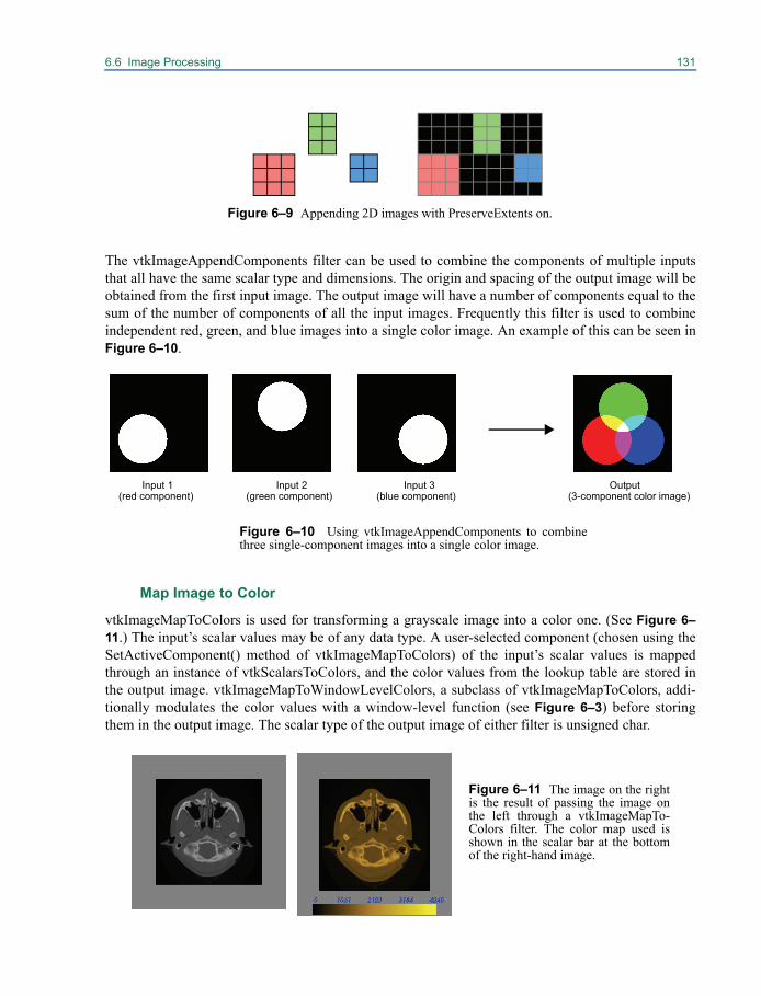
6.6 Image Processing 131
The vtkImageAppendComponents filter can be used to combine the components of multiple inputsthat all have the same scalar type and dimensions. The origin and spacing of the output image will beobtained from the first input image. The output image will have a number of components equal to thesum of the number of components of all the input images. Frequently this filter is used to combineindependent red, green, and blue images into a single color image. An example of this can be seen inFigure 6–10.
Map Image to Color
vtkImageMapToColors is used for transforming a grayscale image into a color one. (See Figure 6–11.) The input’s scalar values may be of any data type. A user-selected component (chosen using theSetActiveComponent() method of vtkImageMapToColors) of the input’s scalar values is mappedthrough an instance of vtkScalarsToColors, and the color values from the lookup table are stored inthe output image. vtkImageMapToWindowLevelColors, a subclass of vtkImageMapToColors, addi-tionally modulates the color values with a window-level function (see Figure 6–3) before storingthem in the output image. The scalar type of the output image of either filter is unsigned char.
Figure 6–9 Appending 2D images with PreserveExtents on.
Input 1 Input 2(green component)
Input 3(blue component)
Output(3-component color image)
Figure 6–10 Using vtkImageAppendComponents to combinethree single-component images into a single color image.
(red component)
Figure 6–11 The image on the rightis the result of passing the image onthe left through a vtkImageMapTo-Colors filter. The color map used isshown in the scalar bar at the bottomof the right-hand image.

132 Image Processing & Visualization
Image Luminance
The vtkImageLuminance filter is basically the opposite of vtkImageMapToColors. (See Figure 6–12.) It converts an RGB image (red, green, and blue color components) to a single-component gray-scale image using the following formula.
luminance = 0.3*R + 0.59*G + 0.11*B
In this formula, R is the first component (red) of the input image, G is the second component (green),and B is the third component (blue). This calculation computes how bright a given color specifiedusing RGB components appears.
Histogram
vtkImageAccumulate is an image filter that produces generalized histograms of up to four dimen-sions. This is done by dividing the component space into discrete bins, then counting the number ofpixels corresponding to each bin. The input image may be of any scalar type, but the output imagewill always be of integer type. If the input image has only one scalar component, then the outputimage will be one-dimensional, as shown in Figure 6–13. (This example is taken from VTK/Examples/ImageProcessing/Tcl/Histogram.tcl.)
Image Logic
vtkImageLogic is an image processing filter that takes one or two inputs and performs a boolean logicoperation on them (Figure 6–14). Most standard operations are supported including AND, OR, XOR,NAND, NOR, and NOT. This filter has two inputs, although for unary operations such as NOT onlythe first input is required. In the example provided below you will notice we usevtkImageEllipsoidSource to generate the two input images.
Figure 6–12 The image on the right is the result ofpassing the image on the left (the output of vtkImage-MapToColors in the previous section) through avtkImageLuminance filter. Note the similarity of theoutput image from this filter (the right-hand image)and the input image passed to vtkImageMapToCol-ors.
Figure 6–13 The vtkImageAccumu-late class is used to generate a onedimensional histogram from a one-component input image.
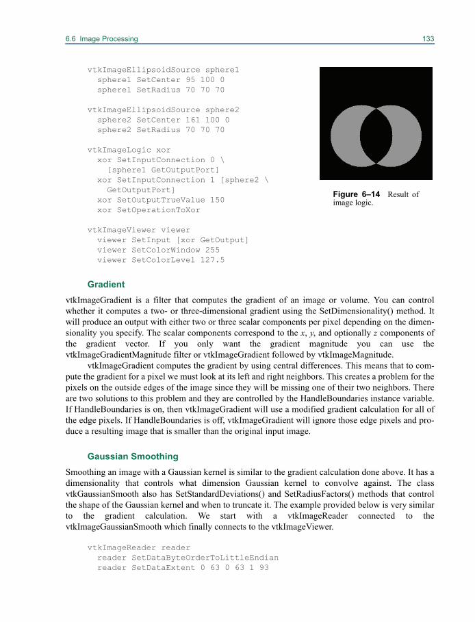
6.6 Image Processing 133
vtkImageEllipsoidSource sphere1 sphere1 SetCenter 95 100 0sphere1 SetRadius 70 70 70
vtkImageEllipsoidSource sphere2sphere2 SetCenter 161 100 0sphere2 SetRadius 70 70 70
vtkImageLogic xor xor SetInputConnection 0 \[sphere1 GetOutputPort]
xor SetInputConnection 1 [sphere2 \GetOutputPort]
xor SetOutputTrueValue 150xor SetOperationToXor
vtkImageViewer viewerviewer SetInput [xor GetOutput]viewer SetColorWindow 255viewer SetColorLevel 127.5
GradientvtkImageGradient is a filter that computes the gradient of an image or volume. You can controlwhether it computes a two- or three-dimensional gradient using the SetDimensionality() method. Itwill produce an output with either two or three scalar components per pixel depending on the dimen-sionality you specify. The scalar components correspond to the x, y, and optionally z components ofthe gradient vector. If you only want the gradient magnitude you can use thevtkImageGradientMagnitude filter or vtkImageGradient followed by vtkImageMagnitude.
vtkImageGradient computes the gradient by using central differences. This means that to com-pute the gradient for a pixel we must look at its left and right neighbors. This creates a problem for thepixels on the outside edges of the image since they will be missing one of their two neighbors. Thereare two solutions to this problem and they are controlled by the HandleBoundaries instance variable.If HandleBoundaries is on, then vtkImageGradient will use a modified gradient calculation for all ofthe edge pixels. If HandleBoundaries is off, vtkImageGradient will ignore those edge pixels and pro-duce a resulting image that is smaller than the original input image.
Gaussian SmoothingSmoothing an image with a Gaussian kernel is similar to the gradient calculation done above. It has adimensionality that controls what dimension Gaussian kernel to convolve against. The classvtkGaussianSmooth also has SetStandardDeviations() and SetRadiusFactors() methods that controlthe shape of the Gaussian kernel and when to truncate it. The example provided below is very similarto the gradient calculation. We start with a vtkImageReader connected to thevtkImageGaussianSmooth which finally connects to the vtkImageViewer.
vtkImageReader readerreader SetDataByteOrderToLittleEndianreader SetDataExtent 0 63 0 63 1 93
Figure 6–14 Result ofimage logic.
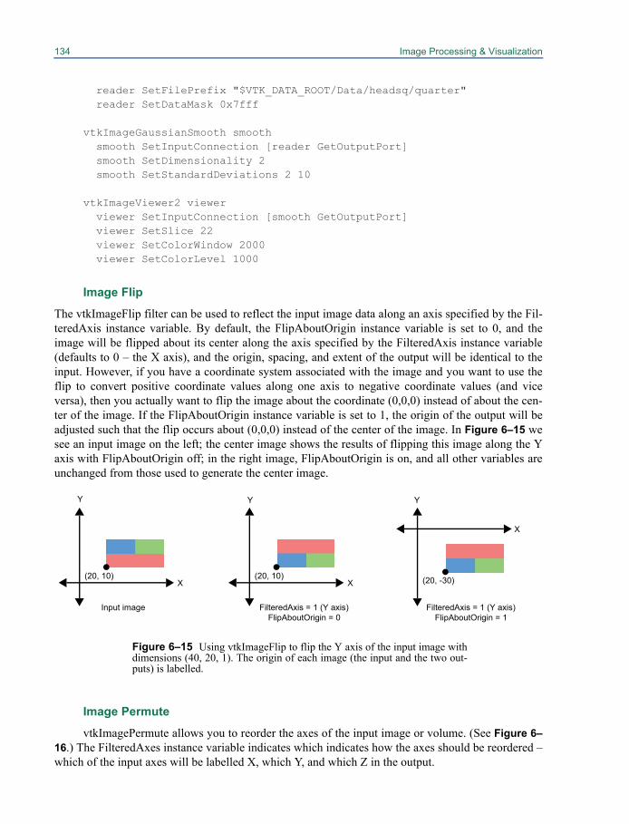
134 Image Processing & Visualization
reader SetFilePrefix "$VTK_DATA_ROOT/Data/headsq/quarter"reader SetDataMask 0x7fff
vtkImageGaussianSmooth smoothsmooth SetInputConnection [reader GetOutputPort]smooth SetDimensionality 2smooth SetStandardDeviations 2 10
vtkImageViewer2 viewerviewer SetInputConnection [smooth GetOutputPort]viewer SetSlice 22viewer SetColorWindow 2000viewer SetColorLevel 1000
Image Flip
The vtkImageFlip filter can be used to reflect the input image data along an axis specified by the Fil-teredAxis instance variable. By default, the FlipAboutOrigin instance variable is set to 0, and theimage will be flipped about its center along the axis specified by the FilteredAxis instance variable(defaults to 0 – the X axis), and the origin, spacing, and extent of the output will be identical to theinput. However, if you have a coordinate system associated with the image and you want to use theflip to convert positive coordinate values along one axis to negative coordinate values (and viceversa), then you actually want to flip the image about the coordinate (0,0,0) instead of about the cen-ter of the image. If the FlipAboutOrigin instance variable is set to 1, the origin of the output will beadjusted such that the flip occurs about (0,0,0) instead of the center of the image. In Figure 6–15 wesee an input image on the left; the center image shows the results of flipping this image along the Yaxis with FlipAboutOrigin off; in the right image, FlipAboutOrigin is on, and all other variables areunchanged from those used to generate the center image.
Image Permute
vtkImagePermute allows you to reorder the axes of the input image or volume. (See Figure 6–16.) The FilteredAxes instance variable indicates which indicates how the axes should be reordered –which of the input axes will be labelled X, which Y, and which Z in the output.
X
Y
(20, 10)X
Y
(20, 10)
X
Y
(20, -30)
FilteredAxis = 1 (Y axis)FlipAboutOrigin = 0
FilteredAxis = 1 (Y axis)FlipAboutOrigin = 1
Figure 6–15 Using vtkImageFlip to flip the Y axis of the input image withdimensions (40, 20, 1). The origin of each image (the input and the two out-puts) is labelled.
Input image
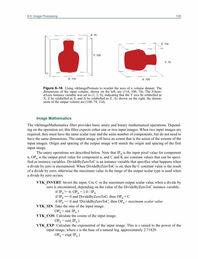
6.6 Image Processing 135
Image Mathematics
The vtkImageMathematics filter provides basic unary and binary mathematical operations. Depend-ing on the operation set, this filter expects either one or two input images. When two input images arerequired, they must have the same scalar type and the same number of components, but do not need tohave the same dimensions. The output image will have an extent that is the union of the extents of theinput images. Origin and spacing of the output image will match the origin and spacing of the firstinput image.
The unary operations are described below. Note that IPn is the input pixel value for componentn, OPn is the output pixel value for component n, and C and K are constant values that can be speci-fied as instance variables. DivideByZeroToC is an instance variable that specifies what happens whena divide by zero is encountered. When DivideByZeroToC is on, then the C constant value is the resultof a divide by zero; otherwise the maximum value in the range of the output scalar type is used whena divide by zero occurs.
VTK_INVERT: Invert the input. Use C or the maximum output scalar value when a divide byzero is encountered, depending on the value of the DivideByZeroToC instance variable.
if IPn != 0; OPn = 1.0 / IPn if IPn == 0 and DivideByZeroToC; then OPn = C if IPn == 0 and !DivideByZeroToC; then OPn = maximum scalar value
VTK_SIN: Take the sine of the input image.OPn = sin( IPn )
VTK_COS: Calculate the cosine of the input image.OPn = cos( IPn )
VTK_EXP: Calculate the exponential of the input image. This is e raised to the power of theinput image, where e is the base of a natural log, approximately 2.71828.
OPn = exp( IPn )
X: 114
Y: 100
Z: 74
Y: 74
X: 100
Z: 114
Figure 6–16 Using vtkImagePermute to reorder the axes of a volume dataset. Thedimensions of the input volume, shown on the left, are (114, 100, 74). The Filtere-dAxes instance variable was set to (1, 2, 0), indicating that the Y axis be relabelled asX, Z be relabelled as Y, and X be relabelled as Z. As shown on the right, the dimen-sions of the output volume are (100, 74, 114).
136 Image Processing & Visualization
VTK_LOG: Calculate the natural log of the input image (the logarithm base e). OPn = log ( IPn )
VTK_ABS: Compute the absolute value of the input image.OPn = fabs( IPn )
VTK_SQR: Square the input image values.OPn = IPc * IPn
VTK_SQRT: Take the square root of the input image values.OPn = sqrt( IPn )
VTK_ATAN: Compute the arctangent of the input image values.OPn = atan( IPn )
VTK_MULTIPLYBYK: Multiple each input image value by the constant K.OPn = IPn * K
VTK_ADDC: Add the constant C to each input image value.OPn = IPn + C
VTK_REPLACECBYK: Replace all input image values that are exactly equal to the constantC, with the constant K.
if IPn == C; OPn = Kif IPn != C; OPn = IPn
VTK_CONJUGATE: To use this operation, the input image must have two-component sca-lars. Convert the two-component scalars into a complex conjugate pair.
OP0 = IP0OP1 = -IP1
The binary operations follow. The notation used is similar to that for the unary operations, except thatIP1n is the first input’s pixel value for component n, and IP2n is the second input’s pixel value forcomponent n.
VTK_ADD: Add the second input image to the first one.OPn = IP1n + IP2nVTK_SUBTRACT: Subtract the second input image’s values from those of the first input.OPn = IP1n - IP2nVTK_MULTIPLY: Multiply the first input image’s values by those of the second input.OPn = IP1n * IP2nVTK_DIVIDE: Divide the first input image’s values by those of the second input. Use C or the
maximum output scalar value when a divide by zero is encountered, depending on thevalue of the DivideByZeroToC instance variable.
if IP2n != 0; OPn = IP1n / IP2n if IP2n == 0 and DivideByZeroToC; then OPn = C if IP2n == 0 and !DivideByZeroToC; then OPn = maximum scalar value
VTK_COMPLEX_MULTIPLY: This operation requires that both input images have two-component scalars. The first component is real-valued, and the second component isimaginary. Multiply the first input image’s values by those of the second input usingcomplex multiplication.
OP0 = IP10 * IP20 - IP11 * IP21OP1 = IP11 * IP20 + IP10 * IP21VTK_MIN: Compare corresponding values in the two images, and return the smaller value.if IP1n < IP2n; OPn = IP1nif IP2n < IP1n; OPn = IP2n
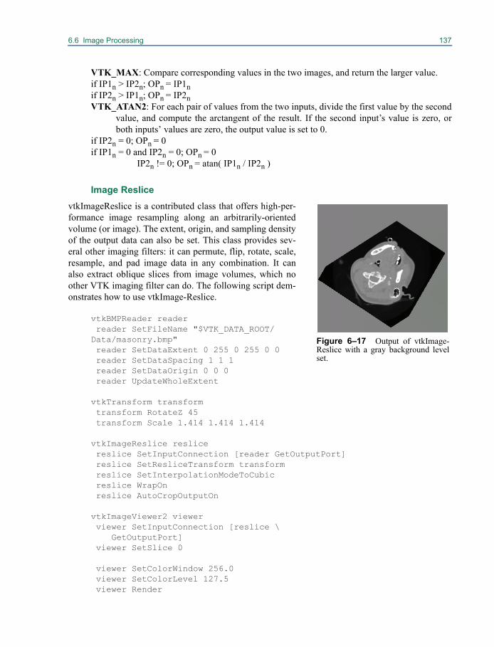
6.6 Image Processing 137
VTK_MAX: Compare corresponding values in the two images, and return the larger value.if IP1n > IP2n; OPn = IP1nif IP2n > IP1n; OPn = IP2nVTK_ATAN2: For each pair of values from the two inputs, divide the first value by the second
value, and compute the arctangent of the result. If the second input’s value is zero, orboth inputs’ values are zero, the output value is set to 0.
if IP2n = 0; OPn = 0if IP1n = 0 and IP2n = 0; OPn = 0
IP2n != 0; OPn = atan( IP1n / IP2n )
Image ReslicevtkImageReslice is a contributed class that offers high-per-formance image resampling along an arbitrarily-orientedvolume (or image). The extent, origin, and sampling densityof the output data can also be set. This class provides sev-eral other imaging filters: it can permute, flip, rotate, scale,resample, and pad image data in any combination. It canalso extract oblique slices from image volumes, which noother VTK imaging filter can do. The following script dem-onstrates how to use vtkImage-Reslice.
vtkBMPReader reader reader SetFileName "$VTK_DATA_ROOT/Data/masonry.bmp" reader SetDataExtent 0 255 0 255 0 0 reader SetDataSpacing 1 1 1 reader SetDataOrigin 0 0 0 reader UpdateWholeExtent
vtkTransform transform transform RotateZ 45 transform Scale 1.414 1.414 1.414
vtkImageReslice reslice reslice SetInputConnection [reader GetOutputPort] reslice SetResliceTransform transform reslice SetInterpolationModeToCubic reslice WrapOn reslice AutoCropOutputOn
vtkImageViewer2 viewer viewer SetInputConnection [reslice \
GetOutputPort] viewer SetSlice 0
viewer SetColorWindow 256.0 viewer SetColorLevel 127.5 viewer Render
Figure 6–17 Output of vtkImage-Reslice with a gray background levelset.
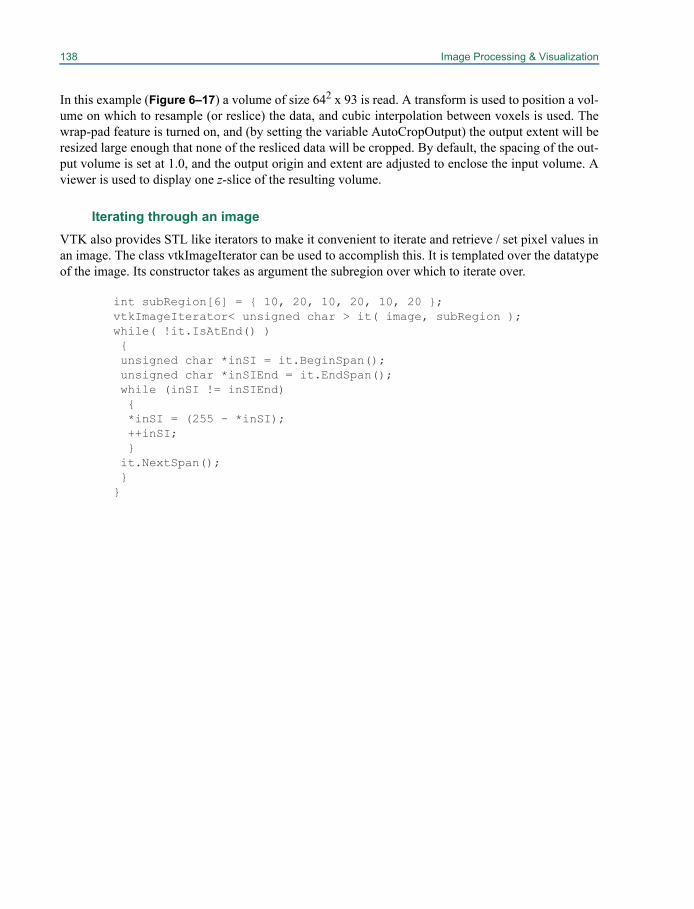
138 Image Processing & Visualization
In this example (Figure 6–17) a volume of size 642 x 93 is read. A transform is used to position a vol-ume on which to resample (or reslice) the data, and cubic interpolation between voxels is used. Thewrap-pad feature is turned on, and (by setting the variable AutoCropOutput) the output extent will beresized large enough that none of the resliced data will be cropped. By default, the spacing of the out-put volume is set at 1.0, and the output origin and extent are adjusted to enclose the input volume. Aviewer is used to display one z-slice of the resulting volume.
Iterating through an imageVTK also provides STL like iterators to make it convenient to iterate and retrieve / set pixel values inan image. The class vtkImageIterator can be used to accomplish this. It is templated over the datatypeof the image. Its constructor takes as argument the subregion over which to iterate over.
int subRegion[6] = { 10, 20, 10, 20, 10, 20 }; vtkImageIterator< unsigned char > it( image, subRegion ); while( !it.IsAtEnd() ) { unsigned char *inSI = it.BeginSpan(); unsigned char *inSIEnd = it.EndSpan(); while (inSI != inSIEnd) { *inSI = (255 - *inSI); ++inSI; } it.NextSpan(); } }
Chapter 7
Volume Rendering 7
Volume rendering is a term used to describe a renderingprocess applied to 3D data where information exists throughout a 3D space instead of simply on 2Dsurfaces defined in 3D space. There is not a clear dividing line between volume rendering and geo-metric rendering techniques. Often two different approaches can produce similar results, and in somecases one approach may be considered both a volume rendering and a geometric rendering technique.For example, you can use a contouring technique to extract triangles representing an isosurface in animage dataset (see “Contouring” on page 93) and then use geometric rendering techniques to displaythese triangles, or you can use a volumetric ray casting technique on the image dataset and terminatethe ray traversal at a particular isovalue. These two different approaches produce similar (althoughnot necessarily identical) results. Another example is the technique of employing texture mappinghardware in order to perform composite volume rendering. This one method may be considered avolume rendering technique since it works on image data, or a geometric technique since it uses geo-metric primitives and standard graphics hardware.
In VTK a distinction is made between volume rendering techniques and geometric renderingtechniques in order to customize the properties of the data being rendered. As you have seen through-out the many example shown thus far, rendering data typically involves creating a vtkActor, a vtk-Property, and some subclass of a vtkMapper. The vtkActor is used to hold position, orientation andscaling information about the data, as well as a pointer to both the property and the mapper. The vtk-Property object captures various parameters that control the appearance of the data such as the ambi-ent lighting coefficient and whether the object is flat, Gouraud, or Phong shaded. Finally, thevtkMapper subclass is responsible for actually rendering the data. For volume rendering, a differentset of classes with very similar functionality are utilized. A vtkVolume is used in place of a vtkActorto represent the data in the scene. Just like the vtkActor, the vtkVolume represents the position, orien-tation and scaling of the data within the scene. However, a vtkVolume contains references to avtkVolumeProperty and a vtkAbstractVolumeMapper. The vtkVolumeProperty represents thoseparameters that affect the appearance of the data in a volume rendering process, which is a differentset of parameters than those used during geometric rendering. A vtkAbstractVolumeMapper subclass
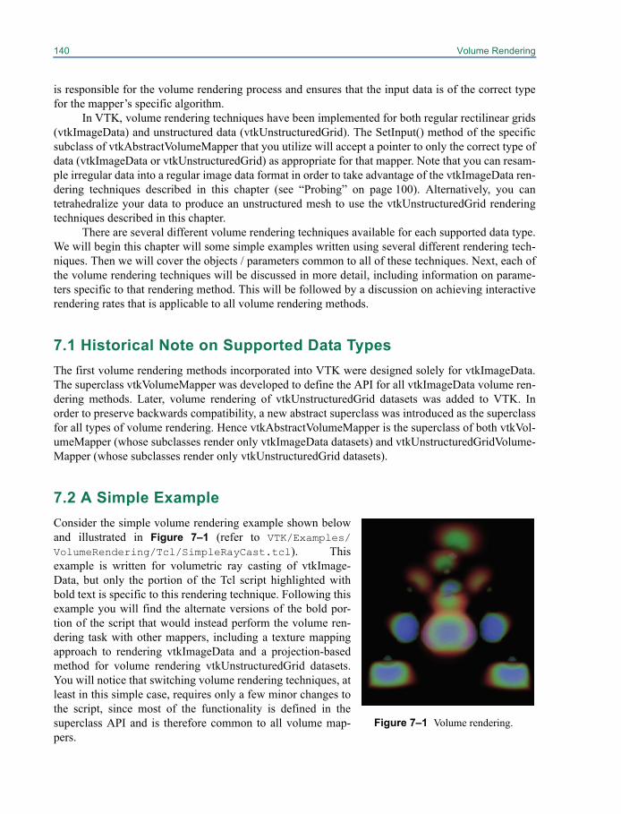
140 Volume Rendering
is responsible for the volume rendering process and ensures that the input data is of the correct typefor the mapper’s specific algorithm.
In VTK, volume rendering techniques have been implemented for both regular rectilinear grids(vtkImageData) and unstructured data (vtkUnstructuredGrid). The SetInput() method of the specificsubclass of vtkAbstractVolumeMapper that you utilize will accept a pointer to only the correct type ofdata (vtkImageData or vtkUnstructuredGrid) as appropriate for that mapper. Note that you can resam-ple irregular data into a regular image data format in order to take advantage of the vtkImageData ren-dering techniques described in this chapter (see “Probing” on page 100). Alternatively, you cantetrahedralize your data to produce an unstructured mesh to use the vtkUnstructuredGrid renderingtechniques described in this chapter.
There are several different volume rendering techniques available for each supported data type.We will begin this chapter will some simple examples written using several different rendering tech-niques. Then we will cover the objects / parameters common to all of these techniques. Next, each ofthe volume rendering techniques will be discussed in more detail, including information on parame-ters specific to that rendering method. This will be followed by a discussion on achieving interactiverendering rates that is applicable to all volume rendering methods.
7.1 Historical Note on Supported Data TypesThe first volume rendering methods incorporated into VTK were designed solely for vtkImageData.The superclass vtkVolumeMapper was developed to define the API for all vtkImageData volume ren-dering methods. Later, volume rendering of vtkUnstructuredGrid datasets was added to VTK. Inorder to preserve backwards compatibility, a new abstract superclass was introduced as the superclassfor all types of volume rendering. Hence vtkAbstractVolumeMapper is the superclass of both vtkVol-umeMapper (whose subclasses render only vtkImageData datasets) and vtkUnstructuredGridVolume-Mapper (whose subclasses render only vtkUnstructuredGrid datasets).
7.2 A Simple ExampleConsider the simple volume rendering example shown belowand illustrated in Figure 7–1 (refer to VTK/Examples/VolumeRendering/Tcl/SimpleRayCast.tcl). Thisexample is written for volumetric ray casting of vtkImage-Data, but only the portion of the Tcl script highlighted withbold text is specific to this rendering technique. Following thisexample you will find the alternate versions of the bold por-tion of the script that would instead perform the volume ren-dering task with other mappers, including a texture mappingapproach to rendering vtkImageData and a projection-basedmethod for volume rendering vtkUnstructuredGrid datasets.You will notice that switching volume rendering techniques, atleast in this simple case, requires only a few minor changes tothe script, since most of the functionality is defined in thesuperclass API and is therefore common to all volume map-pers.
Figure 7–1 Volume rendering.
7.2 A Simple Example 141
# Create the reader for the datavtkStructuredPointsReader reader reader SetFileName "$VTK_DATA_ROOT/Data/ironProt.vtk"
# Create transfer mapping scalar value to opacityvtkPiecewiseFunction opacityTransferFunction opacityTransferFunction AddPoint 20 0.0 opacityTransferFunction AddPoint 255 0.2
# Create transfer mapping scalar value to colorvtkColorTransferFunction colorTransferFunction colorTransferFunction AddRGBPoint 0.0 0.0 0.0 0.0 colorTransferFunction AddRGBPoint 64.0 1.0 0.0 0.0 colorTransferFunction AddRGBPoint 128.0 0.0 0.0 1.0 colorTransferFunction AddRGBPoint 192.0 0.0 1.0 0.0 colorTransferFunction AddRGBPoint 255.0 0.0 0.2 0.0
# The property describes how the data will lookvtkVolumeProperty volumeProperty volumeProperty SetColor colorTransferFunction volumeProperty SetScalarOpacity opacityTransferFunction
# The mapper / ray cast functions know how to render the datavtkVolumeRayCastCompositeFunction compositeFunctionvtkVolumeRayCastMapper volumeMapper volumeMapper SetVolumeRayCastFunction compositeFunction volumeMapper SetInputConnection [reader GetOutputPort]
# The volume holds the mapper and the property and# can be used to position/orient the volumevtkVolume volume volume SetMapper volumeMapper volume SetProperty volumeProperty
ren1 AddProp volumerenWin Render
In this example we start by reading in a data file from disk. We then define the functions that map sca-lar value into opacity and color which are used in the vtkVolumeProperty. Next we create the objectsspecific to volumetric ray casting—a vtkVolumeRayCastCompositeFunction that performs the com-positing of samples along the ray, and a vtkVolumeRayCastMapper that performs some of the basicray casting operations such as transformations and clipping. We set the input of the mapper to the datawe read off the disk, and we create a vtkVolume (a subclass of vtkProp3D similar to vtkActor) to holdthe mapper and property. Finally, we add the volume to the renderer and render the scene.
If you decided to implement the above script with a 2D texture mapping approach instead ofvolumetric ray casting, the bold portion of the script would instead be:
# Create the objects specific to 2D texture mapping approachvtkVolumeTextureMapper2D volumeMappervolumeMapper SetInputConnection [reader GetOutputPort]
142 Volume Rendering
If your graphics card has the required support for 3D texture mapping (nearly all recent cards do havethis support), then you may decide to implement the above script with a 3D texture mappingapproach. The bolded portion of the script would instead be:
# Create the objects specific to 3D texture mapping approachvtkVolumeTextureMapper3D volumeMappervolumeMapper SetInputConnection [reader GetOutputPort]
The vtkFixedPointVolumeRayCastMapper is an alternative to the vtkVolumeRayCastMapper, and isfor most situations the recommended software mapper. The vtkFixedPointVolumeRayCastMapperhandles all data types as well as multicomponent data, and uses fixed pointed computations and spaceleaping for high performance. However, it is not extensible since the blending operations are hard-coded for performance, rather than customizable by writing new ray cast functions. To change thisexample over to using the vtkFixedPointVolumeRayCastMapper, the bold portion of the script wouldinstead be:
# Create the fixed point ray cast mapper vtkFixedPointVolumeRayCastMapper volumeMapper volumeMapper SetInputConnection [reader GetOutputPort]
If you would like to use an unstructured grid volume rendering technique instead, the replacementcode becomes slightly more complex in order to perform the conversion from vtkImageData tovtkUnstructuredGrid before passing the data as input to the mapper. In this case we will use theunstructured grid rendering method that projects a tetrahedral representation of the grid using thegraphics hardware. The replacement code would be:
# Convert data to unstructured gridvtkDataSetTriangleFilter tetraFiltertetraFilter SetInputConnection [reader GetOutputPort]
# Create the objects specific to the Projected Tetrahedra methodvtkProjectedTetrahedraMapper volumeMappervolumeMapper SetInputConnection [tetraFilter GetOutputPort]
Note that it is not recommended to convert from vtkImageData to vtkUnstructuredGrid for renderingsince the mappers that work directly on vtkImageData are typically more efficient, both in memoryconsumption and rendering performance, than the mappers for vtkUnstructuredGrid data.
7.3 Why Multiple Volume Rendering Techniques?As you can see, in this simple example the main thing that changes between rendering strategies is thetype of volume mapper that is instantiated, and perhaps some rendering-method-specific parameterssuch as the ray cast function used in the ray casting technique. This may lead you to the followingquestions: why are there different volume rendering strategies in VTK? Why can’t VTK simply pickthe “best” strategy? First, it is not always easy to predict which strategy will work best—ray castingmay out-perform texture mapping if the image size is reduced, more processors become available, orthe graphics hardware is the bottleneck to the rendering rate. These are parameters that differ from
7.4 Creating a vtkVolume 143
platform to platform, and in fact may change continuously at run time. Second, due to its computa-tional complexity, most volume rendering techniques only produce an approximation of the desiredrendering equation. For example, techniques that take samples through the volume and compositethem with an alpha blending function are only approximating the true integral through the volume.Under different circumstances, different techniques perform better or worse than others in terms ofboth quality and speed. In addition, some techniques work only under certain special conditions. Forexample, some techniques support data with only a single scalar component of unsigned char orunsigned short type, while other techniques support any scalar type and multi-component data. The“best” technique will depend on your specific data, your performance and image quality require-ments, and the hardware configuration of the system on which the code is run. In fact, the “best” tech-nique may actually be a combination of techniques. A section of this chapter is dedicated todescribing the multi-technique level-of-detail strategies that may be employed to achieve interactivevolume rendering in a cross-platform manner.
7.4 Creating a vtkVolume
A vtkVolume is a subclass of vtkProp3D intended for use in volume rendering. Similar to a vtkActor(that is intended for geometric rendering), a vtkVolume holds the transformation information such asposition, orientation, and scale, and pointers to a mapper and property. Additional information onhow to control the transformation of a vtkVolume is covered in “Controlling 3D Props” on page 52.
The vtkVolume class accepts objects that are subclasses of vtkAbstractVolumeMapper as inputto SetMapper(), and accepts a vtkVolumeProperty object as input to SetProperty(). vtkActor andvtkVolume are two separate objects in order to enforce the different types of the mappers and proper-ties. These different types are necessary due to the fact that some parameters of geometric renderingdo not make sense in volume rendering and vice versa. For example, theSetRepresentationToWireframe() method of vtkProperty is meaningless in volume rendering, whilethe SetInterpolationTypeToNearest() method of vtkVolumeProperty has no value in geometric render-ing.
7.5 Using vtkPiecewiseFunction
In order to control the appearance of a 3D volume of scalar values, several mappings or transfer func-tions must be defined. Generally, two transfer functions are required for all volume rendering tech-niques. The first required transfer function, known as the scalar opacity transfer function, maps thescalar value into an opacity or an opacity per unit length value. The second transfer function, referredto simply as the color transfer function, maps the scalar value into a color. An optional transfer func-tion employed in some of the structured volume rendering methods is known as the gradient opacitytransfer function, which maps the magnitude of the gradient of the scalar value into an opacity multi-plier. Any of these mappings can be defined as a single value to single value mapping, which can berepresented with a vtkPiecewiseFunction. For the scalar value to color mapping, avtkColorTransferFunction can also be used to define RGB rather than grayscale colors.
From a user’s point of view, vtkPiecewiseFunction has two types of methods—those that addinformation to the mapping, and those that clear out information from the mapping. When informa-tion is added to a mapping, it is considered to be a point sample of the mapping with interpolation
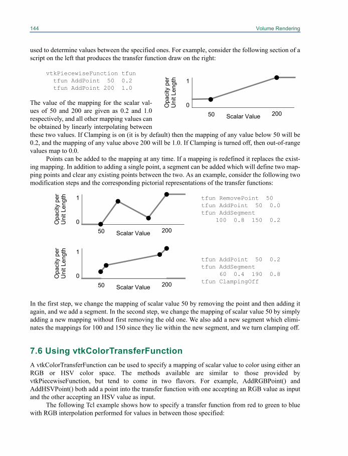
144 Volume Rendering
used to determine values between the specified ones. For example, consider the following section of ascript on the left that produces the transfer function draw on the right:
vtkPiecewiseFunction tfuntfun AddPoint 50 0.2tfun AddPoint 200 1.0
The value of the mapping for the scalar val-ues of 50 and 200 are given as 0.2 and 1.0respectively, and all other mapping values canbe obtained by linearly interpolating betweenthese two values. If Clamping is on (it is by default) then the mapping of any value below 50 will be0.2, and the mapping of any value above 200 will be 1.0. If Clamping is turned off, then out-of-rangevalues map to 0.0.
Points can be added to the mapping at any time. If a mapping is redefined it replaces the exist-ing mapping. In addition to adding a single point, a segment can be added which will define two map-ping points and clear any existing points between the two. As an example, consider the following twomodification steps and the corresponding pictorial representations of the transfer functions:
tfun RemovePoint 50tfun AddPoint 50 0.0tfun AddSegment
100 0.8 150 0.2
tfun AddPoint 50 0.2tfun AddSegment
60 0.4 190 0.8tfun ClampingOff
In the first step, we change the mapping of scalar value 50 by removing the point and then adding itagain, and we add a segment. In the second step, we change the mapping of scalar value 50 by simplyadding a new mapping without first removing the old one. We also add a new segment which elimi-nates the mappings for 100 and 150 since they lie within the new segment, and we turn clamping off.
7.6 Using vtkColorTransferFunctionA vtkColorTransferFunction can be used to specify a mapping of scalar value to color using either anRGB or HSV color space. The methods available are similar to those provided byvtkPiecewiseFunction, but tend to come in two flavors. For example, AddRGBPoint() andAddHSVPoint() both add a point into the transfer function with one accepting an RGB value as inputand the other accepting an HSV value as input.
The following Tcl example shows how to specify a transfer function from red to green to bluewith RGB interpolation performed for values in between those specified:
Scalar Value
Opa
city
per
U
nit L
engt
h
50 2000
1
Scalar Value
Opa
city
per
U
nit L
engt
h
50 2000
1
Scalar Value
Opa
city
per
U
nit L
engt
h
50 2000
1
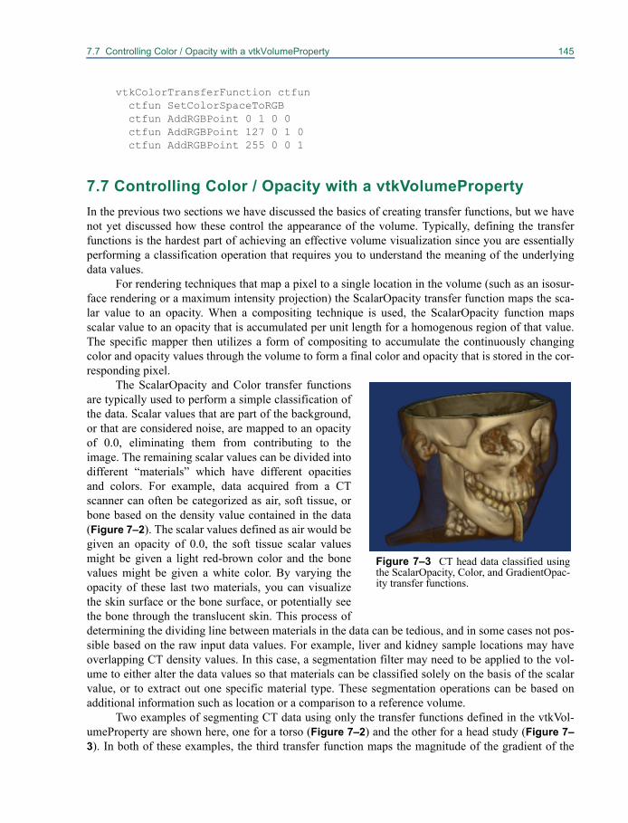
7.7 Controlling Color / Opacity with a vtkVolumeProperty 145
vtkColorTransferFunction ctfun ctfun SetColorSpaceToRGB ctfun AddRGBPoint 0 1 0 0 ctfun AddRGBPoint 127 0 1 0 ctfun AddRGBPoint 255 0 0 1
7.7 Controlling Color / Opacity with a vtkVolumePropertyIn the previous two sections we have discussed the basics of creating transfer functions, but we havenot yet discussed how these control the appearance of the volume. Typically, defining the transferfunctions is the hardest part of achieving an effective volume visualization since you are essentiallyperforming a classification operation that requires you to understand the meaning of the underlyingdata values.
For rendering techniques that map a pixel to a single location in the volume (such as an isosur-face rendering or a maximum intensity projection) the ScalarOpacity transfer function maps the sca-lar value to an opacity. When a compositing technique is used, the ScalarOpacity function mapsscalar value to an opacity that is accumulated per unit length for a homogenous region of that value.The specific mapper then utilizes a form of compositing to accumulate the continuously changingcolor and opacity values through the volume to form a final color and opacity that is stored in the cor-responding pixel.
The ScalarOpacity and Color transfer functionsare typically used to perform a simple classification ofthe data. Scalar values that are part of the background,or that are considered noise, are mapped to an opacityof 0.0, eliminating them from contributing to theimage. The remaining scalar values can be divided intodifferent “materials” which have different opacitiesand colors. For example, data acquired from a CTscanner can often be categorized as air, soft tissue, orbone based on the density value contained in the data(Figure 7–2). The scalar values defined as air would begiven an opacity of 0.0, the soft tissue scalar valuesmight be given a light red-brown color and the bonevalues might be given a white color. By varying theopacity of these last two materials, you can visualizethe skin surface or the bone surface, or potentially seethe bone through the translucent skin. This process ofdetermining the dividing line between materials in the data can be tedious, and in some cases not pos-sible based on the raw input data values. For example, liver and kidney sample locations may haveoverlapping CT density values. In this case, a segmentation filter may need to be applied to the vol-ume to either alter the data values so that materials can be classified solely on the basis of the scalarvalue, or to extract out one specific material type. These segmentation operations can be based onadditional information such as location or a comparison to a reference volume.
Two examples of segmenting CT data using only the transfer functions defined in the vtkVol-umeProperty are shown here, one for a torso (Figure 7–2) and the other for a head study (Figure 7–3). In both of these examples, the third transfer function maps the magnitude of the gradient of the
Figure 7–3 CT head data classified usingthe ScalarOpacity, Color, and GradientOpac-ity transfer functions.
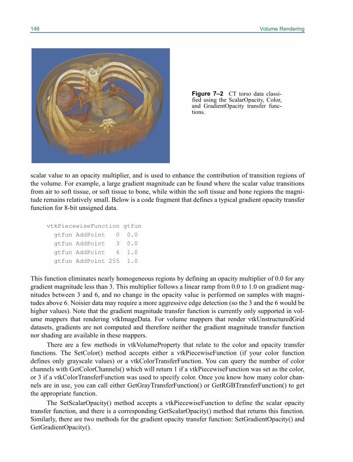
146 Volume Rendering
scalar value to an opacity multiplier, and is used to enhance the contribution of transition regions ofthe volume. For example, a large gradient magnitude can be found where the scalar value transitionsfrom air to soft tissue, or soft tissue to bone, while within the soft tissue and bone regions the magni-tude remains relatively small. Below is a code fragment that defines a typical gradient opacity transferfunction for 8-bit unsigned data.
vtkPiecewiseFunction gtfun gtfun AddPoint 0 0.0gtfun AddPoint 3 0.0gtfun AddPoint 6 1.0gtfun AddPoint 255 1.0
This function eliminates nearly homogeneous regions by defining an opacity multiplier of 0.0 for anygradient magnitude less than 3. This multiplier follows a linear ramp from 0.0 to 1.0 on gradient mag-nitudes between 3 and 6, and no change in the opacity value is performed on samples with magni-tudes above 6. Noisier data may require a more aggressive edge detection (so the 3 and the 6 would behigher values). Note that the gradient magnitude transfer function is currently only supported in vol-ume mappers that rendering vtkImageData. For volume mappers that render vtkUnstructuredGriddatasets, gradients are not computed and therefore neither the gradient magnitude transfer functionnor shading are available in these mappers.
There are a few methods in vtkVolumeProperty that relate to the color and opacity transferfunctions. The SetColor() method accepts either a vtkPiecewiseFunction (if your color functiondefines only grayscale values) or a vtkColorTransferFunction. You can query the number of colorchannels with GetColorChannels() which will return 1 if a vtkPiecewiseFunction was set as the color,or 3 if a vtkColorTransferFunction was used to specify color. Once you know how many color chan-nels are in use, you can call either GetGrayTransferFunction() or GetRGBTransferFunction() to getthe appropriate function.
The SetScalarOpacity() method accepts a vtkPiecewiseFunction to define the scalar opacitytransfer function, and there is a corresponding GetScalarOpacity() method that returns this function.Similarly, there are two methods for the gradient opacity transfer function: SetGradientOpacity() andGetGradientOpacity().
Figure 7–2 CT torso data classi-fied using the ScalarOpacity, Color,and GradientOpacity transfer func-tions.
7.8 Controlling Shading with a vtkVolumeProperty 147
The discussion thus far has considered only single component scalar data where one set oftransfer functions define the appearance of the data. Alternatively, multi-component data may be ren-dered in one of two ways. If the components are independent, then one set of transfer functions can bedefined per component. An example of independent data may be an unstructured grid producedthrough a simulation process that produces both temperature and density values on the grid. Anotherexample of independent components is the data produced by confocal microscopy where the speci-men is scanned multiple times with different fluorescent dyes used to highlight different structureswithin the specimen. When rendering multi-component data where the components are independent,you must define the appearance parameters per component. The SetColor(), SetScalarOpacity(), andSetGradientOpacity() methods accept an optional index value as the first argument to set the transferfunction for a specific component.
Multi-component data may also represent not independent properties, but instead a set of valuesthat define one property. For example, when utilizing a physical sectioning technique, you may havethree or four component data representing RGB or RGBA. Or perhaps you have two components rep-resenting luminance and alpha. Volume mappers that support multiple components support two formsof non-independent components. The first is two component data where the first component is passedthrough the color transfer function in order to determine the sample color, and the second componentis passed through the scalar opacity function to define the sample alpha. The second type of non-inde-pendent multi-component data is four component data where the first three components are takendirectly as RGB, and the fourth is passed through the scalar opacity transfer function in order todefine alpha. In both of these non-independent cases, the last component is used to compute gradi-ents, and therefore controls the gradient magnitude opacity transfer function as well.
Note that not all mappers support multi-component data, please consult the mapper-specificdocumentation provided in the remainder of this chapter for further information on supported func-tionality. For mappers that do support multiple components, the limit is typically four components.
7.8 Controlling Shading with a vtkVolumeProperty
Controlling shading of a volume with a volume property is similar to controlling the shading of a geo-metric actor with a property (see “Actor Properties” on page 53 and “Actor Color” on page 54). Thereis a flag for shading, and four basic parameters: the ambient coefficient, the diffuse coefficient, thespecular coefficient and the specular power. Generally, the first three coefficients will sum to 1.0 butexceeding this value is often desirable in volume rendering to increase the brightness of a renderedvolume. The exact interpretation of these parameters will depend on the illumination equation usedby the specific volume rendering technique that is being used. In general, if the ambient term domi-nates then the volume will appear unshaded, if the diffuse term dominates then the volume willappear rough (like concrete) and if the specular term dominates then the volume will appear smooth(like glass). The specular power can be used to control how smooth the appearance is (such asbrushed metal versus polished metal).
By default, shading is off. You must explicitly call ShadeOn() for the shading coefficients toaffect the scene. Setting the shading flag off is generally the same as setting the ambient coefficient to1.0, the diffuse coefficient to 0.0 and the specular coefficient to 0.0. Note that currently volume map-pers that render vtkUnstructuredGrid datasets do not support shading. In addition, some volume ren-dering techniques for vtkImageData, such as volume ray casting with a maximum intensity rayfunction, do not consider the shading coefficients regardless of the value of the shading flag.
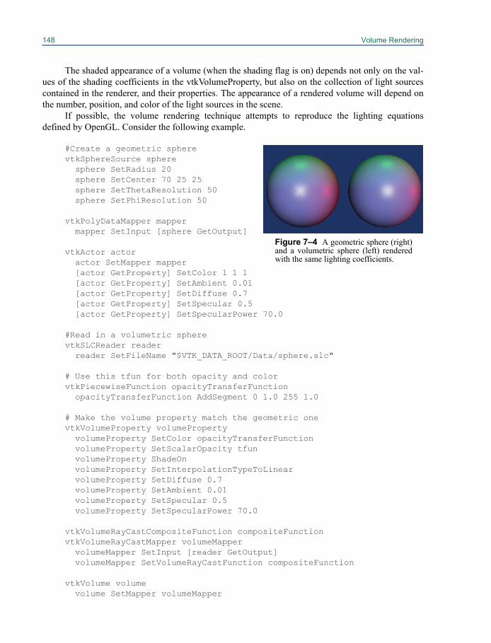
148 Volume Rendering
The shaded appearance of a volume (when the shading flag is on) depends not only on the val-ues of the shading coefficients in the vtkVolumeProperty, but also on the collection of light sourcescontained in the renderer, and their properties. The appearance of a rendered volume will depend onthe number, position, and color of the light sources in the scene.
If possible, the volume rendering technique attempts to reproduce the lighting equationsdefined by OpenGL. Consider the following example.
#Create a geometric spherevtkSphereSource sphere
sphere SetRadius 20sphere SetCenter 70 25 25sphere SetThetaResolution 50sphere SetPhiResolution 50
vtkPolyDataMapper mappermapper SetInput [sphere GetOutput]
vtkActor actoractor SetMapper mapper[actor GetProperty] SetColor 1 1 1[actor GetProperty] SetAmbient 0.01[actor GetProperty] SetDiffuse 0.7[actor GetProperty] SetSpecular 0.5[actor GetProperty] SetSpecularPower 70.0
#Read in a volumetric spherevtkSLCReader reader reader SetFileName "$VTK_DATA_ROOT/Data/sphere.slc"
# Use this tfun for both opacity and colorvtkPiecewiseFunction opacityTransferFunction opacityTransferFunction AddSegment 0 1.0 255 1.0
# Make the volume property match the geometric onevtkVolumeProperty volumeProperty
volumeProperty SetColor opacityTransferFunctionvolumeProperty SetScalarOpacity tfun volumeProperty ShadeOnvolumeProperty SetInterpolationTypeToLinearvolumeProperty SetDiffuse 0.7volumeProperty SetAmbient 0.01volumeProperty SetSpecular 0.5volumeProperty SetSpecularPower 70.0
vtkVolumeRayCastCompositeFunction compositeFunctionvtkVolumeRayCastMapper volumeMapper
volumeMapper SetInput [reader GetOutput]volumeMapper SetVolumeRayCastFunction compositeFunction
vtkVolume volumevolume SetMapper volumeMapper
Figure 7–4 A geometric sphere (right)and a volumetric sphere (left) renderedwith the same lighting coefficients.
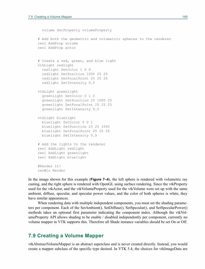
7.9 Creating a Volume Mapper 149
volume SetProperty volumeProperty
# Add both the geometric and volumetric spheres to the rendererren1 AddProp volumeren1 AddProp actor
# Create a red, green, and blue lightvtkLight redlight
redlight SetColor 1 0 0redlight SetPosition 1000 25 25redlight SetFocalPoint 25 25 25redlight SetIntensity 0.5
vtkLight greenlight greenlight SetColor 0 1 0greenlight SetPosition 25 1000 25greenlight SetFocalPoint 25 25 25greenlight SetIntensity 0.5
vtkLight bluelight bluelight SetColor 0 0 1bluelight SetPosition 25 25 1000bluelight SetFocalPoint 25 25 25bluelight SetIntensity 0.5
# Add the lights to the rendererren1 AddLight redlightren1 AddLight greenlightren1 AddLight bluelight
#Render it!renWin Render
In the image shown for this example (Figure 7–4), the left sphere is rendered with volumetric raycasting, and the right sphere is rendered with OpenGL using surface rendering. Since the vtkPropertyused for the vtkActor, and the vtkVolumeProperty used for the vtkVolume were set up with the sameambient, diffuse, specular, and specular power values, and the color of both spheres is white, theyhave similar appearances.
When rendering data with multiple independent components, you must set the shading parame-ters per component. Each of the SetAmbient(), SetDiffuse(), SetSpecular(), and SetSpecularPower()methods takes an optional first parameter indicating the component index. Although the vtkVol-umeProperty API allows shading to be enable / disabled independently per component, currently novolume mapper in VTK supports this. Therefore all Shade instance variables should be set On or Off.
7.9 Creating a Volume MappervtkAbstractVolumeMapper is an abstract superclass and is never created directly. Instead, you wouldcreate a mapper subclass of the specific type desired. In VTK 5.4, the choices for vtkImageData are
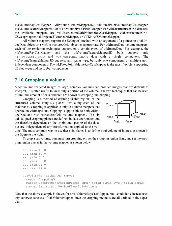
150 Volume Rendering
vtkVolumeRayCastMapper, vtkVolumeTextureMapper2D, vtkFixedPointVolumeRayCastMapper,vtkVolumeTextureMapper3D, or VTKVolumeProVP1000Mapper. For vtkUnstructuredGrid datasets,the available mappers are vtkUnstructuredGridVolumeRayCastMapper, vtkUnstructuredGrid-ZSweepMapper, vtkProjectedTetrahedraMapper, or VTKHAVSVolumeMapper.
All volume mappers support the SetInput() method with an argument of a pointer to a vtkIm-ageData object or a vtkUnstructuredGrid object as appropriate. For vtkImageData volume mappers,each of the rendering techniques support only certain types of vtkImageData. For example, thevtkVolumeRayCastMapper and the vtkVolumeTextureMapper2D both support onlyVTK_UNSIGNED_CHAR and VTK_UNSIGNED_SHORT data with a single component. ThevtkVolumeTextureMapper3D supports any scalar type, but only one component, or multiple non-independent components. The vtkFixedPointVolumeRayCastMapper is the most flexible, supportingall data types and up to four components.
7.10 Cropping a VolumeSince volume rendered images of large, complex volumes can produce images that are difficult tointerpret, it is often useful to view only a portion of the volume. The two techniques that can be usedto limit the amount of data rendered are known as cropping and clipping.
Cropping is a method of defining visible regions of thestructured volume using six planes—two along each of themajor axes. Cropping is applicable only to volume mappers thatoperate on vtkImageData. Clipping is applicable to both vtkIm-ageData and vtkUnstructuredGrid volume mappers. The sixaxis-aligned cropping planes are defined in data coordinates andare therefore dependent on the origin and spacing of the data,but are independent of any transformation applied to the vol-ume. The most common way to use these six planes is to define a subvolume of interest as shown inthe figure to the right.
To crop a subvolume, you must turn cropping on, set the cropping region flags, and set the crop-ping region planes in the volume mapper as shown below.
set xmin 10.0set xmax 50.0set ymin 0.0set ymax 33.0set zmin 21.0set zmax 47.0
vtkVolumeRayCastMapper mappermapper CroppingOnmapper SetCroppingRegionPlanes $xmin $xmax $ymin $ymax $zmin $zmaxmapper SetCroppingRegionFlagsToSubVolume
Note that the above example is shown for a vtkVolumeRayCastMapper, but it could have instead usedany concrete subclass of vtkVolumeMapper since the cropping methods are all defined in the super-class.
xmin xmax
yminymaxzmin
zmax
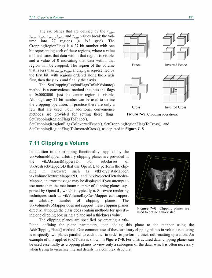
7.11 Clipping a Volume 151
The six planes that are defined by the xmin,xmax, ymin, ymax, zmin, and zmax values break the vol-ume into 27 regions (a 3x3 grid). TheCroppingRegionFlags is a 27 bit number with onebit representing each of these regions, where a valueof 1 indicates that data within that region is visible,and a value of 0 indicating that data within thatregion will be cropped. The region of the volumethat is less than xmin, ymin, and zmin is represented bythe first bit, with regions ordered along the x axisfirst, then the y axis and finally the z axis.
The SetCroppingRegionFlagsToSubVolume()method is a convenience method that sets the flagsto 0x0002000—just the center region is visible.Although any 27 bit number can be used to definethe cropping operation, in practice there are only afew that are used. Four additional conveniencemethods are provided for setting these flags:SetCroppingRegionFlagsToFence(),SetCroppingResgionFlagsToInvertedFence(), SetCroppingRegionFlagsToCross(), andSetCroppingRegionFlagsToInvertedCross(), as depicted in Figure 7–5.
7.11 Clipping a VolumeIn addition to the cropping functionality supplied by thevtkVolumeMapper, arbitrary clipping planes are provided inthe vtkAbstractMapper3D. For subclasses ofvtkAbstractMapper3D that use OpenGL to perform the clip-ping in hardware such as vtkPolyDataMapper,vtkVolumeTextureMapper2D, and vtkProjectedTetrahedra-Mapper, an error message may be displayed if you attempt touse more than the maximum number of clipping planes sup-ported by OpenGL, which is typically 6. Software renderingtechniques such as vtkVolumeRayCastMapper can supportan arbitrary number of clipping planes. ThevtkVolumeProMapper does not support these clipping planesdirectly, although the class does contain methods for specify-ing one clipping box using a plane and a thickness value.
The clipping planes are specified by creating a vtk-Plane, defining the plane parameters, then adding this plane to the mapper using theAddClippingPlane() method. One common use of these arbitrary clipping planes in volume renderingis to specify two planes parallel to each other in order to perform a thick reformatting operation. Anexample of this applied to CT data is shown in Figure 7–6. For unstructured data, clipping planes canbe used essentially as cropping planes to view only a subregion of the data, which is often necessarywhen trying to visualize internal details in a complex structure.
Fence Inverted Fence
Cross Inverted Cross
Figure 7–5 Cropping operations.
Figure 7–6 Clipping planes areused to define a thick slab.
152 Volume Rendering
7.12 Controlling the Normal EncodingThe standard illumination equation relies on a surface normal in order to calculate the diffuse andspecular components of shading. In volume rendering of vtkImageData, the gradient at a location inthe volumetric data is considered to point in the opposite direction of the “surface normal” at thatlocation. A finite differences technique is typically used to estimate the gradient, but this tends to bean expensive calculation, and would make shaded volume rendering prohibitively slow if it had to beperformed at every sample along every ray.
One way to avoid these expensive computations is to precompute the normals at the grid loca-tions, and to use some form of interpolation in between. If done naively, this would require threefloating point numbers per location, and we would still need to take a square root to determine themagnitude. Alternatively, we could store the magnitude so that each normal would require four float-ing point values. Since volumes tend to be quite large, this technique requires too much memory, sowe must somehow quantize the normals into a smaller number of bytes.
In some of the VTKImageData volume mappers we have chosen to quantize the normal direc-tion into two byes, and the magnitude into one. The calculation of the normal is performed by a sub-class of vtkEncodedGradientEstimator (currently only vtkFiniteDifferenceGradientEstimator) and theencoding of the direction into two bytes is performed by a subclass of vtkDirectionEncoder (currentlyvtkRecursiveSphere-DirectionEncoder and VTKSphericalDirectionEncoder). For mappers that usenormal encoding (vtkVolumeRayCastMapper and vtkVolumeTextureMapper2D), these objects arecreated automatically so the typical user need not be concerned with these objects. In the case whereone volume dataset is to be rendered by multiple mappers into the same image, it is often useful tocreate one gradient estimator for use by all the mappers. This will conserve space and computationaltime since otherwise there would be one copy of the normal volume per mapper. An example frag-ment of code is shown below:
# Create the gradient estimatorvtkFiniteDifferenceGradientEstimator gradientEstimator
# Create the first mappervtkVolumeRayCastMapper volumeMapper1
volumeMapper1 SetGradientEstimator gradientEstimatorvolumeMapper1 SetInput [reader GetOutput]
# Create the second mappervtkVolumeRayCastMapper volumeMapper2
volumeMapper2 SetGradientEstimator gradientEstimatorvolumeMapper2 SetInput [reader GetOutput]
If you set the gradient estimator to the same object in two different mappers, then it is important thatthese mappers have the same input. Otherwise, the gradient estimator will be out-of-date each timethe mapper asks for the normals, and will regenerate them for each volume during every frame ren-dered. In the above example, the direction encoding objects were not explicitly created, thereforeeach gradient estimator created its own encoding object. Since this object does not have any signifi-cant storage requirements, this is generally an acceptable situation. Alternatively, onevtkRecursiveSphereDirectionEncoder could be created, and the SetDirectionEncoder() method wouldbe used on each estimator.
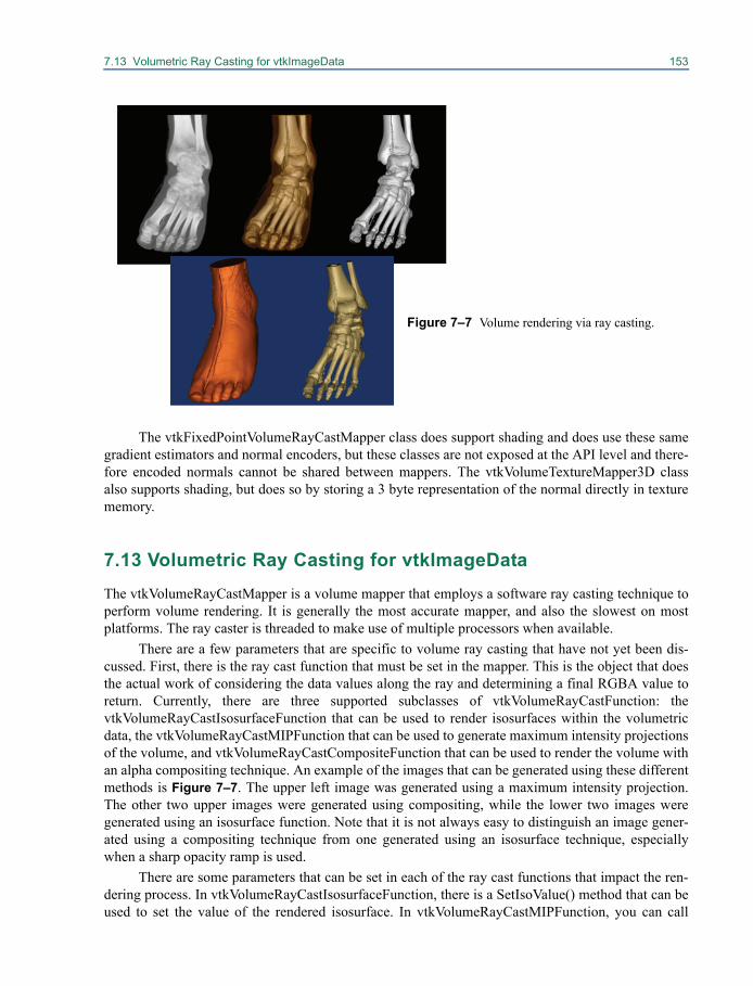
7.13 Volumetric Ray Casting for vtkImageData 153
The vtkFixedPointVolumeRayCastMapper class does support shading and does use these samegradient estimators and normal encoders, but these classes are not exposed at the API level and there-fore encoded normals cannot be shared between mappers. The vtkVolumeTextureMapper3D classalso supports shading, but does so by storing a 3 byte representation of the normal directly in texturememory.
7.13 Volumetric Ray Casting for vtkImageDataThe vtkVolumeRayCastMapper is a volume mapper that employs a software ray casting technique toperform volume rendering. It is generally the most accurate mapper, and also the slowest on mostplatforms. The ray caster is threaded to make use of multiple processors when available.
There are a few parameters that are specific to volume ray casting that have not yet been dis-cussed. First, there is the ray cast function that must be set in the mapper. This is the object that doesthe actual work of considering the data values along the ray and determining a final RGBA value toreturn. Currently, there are three supported subclasses of vtkVolumeRayCastFunction: thevtkVolumeRayCastIsosurfaceFunction that can be used to render isosurfaces within the volumetricdata, the vtkVolumeRayCastMIPFunction that can be used to generate maximum intensity projectionsof the volume, and vtkVolumeRayCastCompositeFunction that can be used to render the volume withan alpha compositing technique. An example of the images that can be generated using these differentmethods is Figure 7–7. The upper left image was generated using a maximum intensity projection.The other two upper images were generated using compositing, while the lower two images weregenerated using an isosurface function. Note that it is not always easy to distinguish an image gener-ated using a compositing technique from one generated using an isosurface technique, especiallywhen a sharp opacity ramp is used.
There are some parameters that can be set in each of the ray cast functions that impact the ren-dering process. In vtkVolumeRayCastIsosurfaceFunction, there is a SetIsoValue() method that can beused to set the value of the rendered isosurface. In vtkVolumeRayCastMIPFunction, you can call
Figure 7–7 Volume rendering via ray casting.
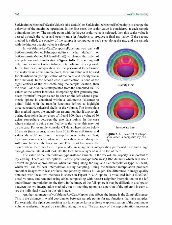
154 Volume Rendering
SetMaximizeMethodToScalarValue() (the default) or SetMaximizeMethodToOpacity() to change thebehavior of the maximize operation. In the first case, the scalar value is considered at each samplepoint along the ray. The sample point with the largest scalar value is selected, then this scalar value ispassed through the color and opacity transfer functions to produce a final ray value. If the secondmethod is called, the opacity of the sample is computed at each step along the ray, and the samplewith the highest opacity value is selected.
In vtkVolumeRayCastCompositeFunction, you can callSetCompositeMethodToInterpolateFirst() (the default) orSetCompositeMethodToClassifyFirst() to change the order ofinterpolation and classification (Figure 7–8). This setting willonly have an impact when trilinear interpolation is being used.In the first case, interpolation will be performed to determinethe scalar value at the sample point, then this value will be usedfor classification (the application of the color and opacity trans-fer functions). In the second case, classification is done at theeight vertices of the cell containing the sample location, thenthe final RGBA value is interpolated from the computed RGBAvalues at the vertex locations. Interpolating first generally pro-duces “prettier” images as can be seen on the left where a geo-metric sphere is contained within a volumetric “distance topoint” field, with the transfer functions defined to highlightthree concentric spherical shells in the volume. The interpolatefirst method makes the underlying assumption that if two neigh-boring data points have values of 10 and 100, then a value of 50exists somewhere between the two data points. In the casewhere material is being classified by scalar value, this may notbe the case. For example, consider CT data where values below20 are air (transparent), values from 20 to 80 are soft tissue, andvalues above 80 are bone. If interpolation is performed first,then bone can never be adjacent to air - there must always besoft tissue between the bone and air. This is not true inside themouth where teeth meet air. If you render an image with interpolation performed first and a highenough sample rate, it will look like the teeth have a layer of skin on top of them.
The value of the interpolation type instance variable in the vtkVolumeProperty is important toray casting. There are two options: SetInterpolationTypeToNearest() (the default) which will use anearest neighbor approximation when sampling along the ray, and SetInterpolationTypeToLinear()which will use trilinear interpolation during sampling. Using the trilinear interpolation producessmoother images with less artifacts, but generally takes a bit longer. The difference in image qualityobtained with these two methods is shown in Figure 7–9. A sphere is voxelized into a 50x50x50voxel volume, and rendered using alpha compositing with nearest neighbor interpolation on the leftand trilinear interpolation on the right. In the image of the full sphere it may be difficult to distinguishbetween the two interpolation methods, but by zooming up on just a portion of the sphere it is easy tosee the individual voxels in the left image.
Another parameter of vtkVolumeRayCastMapper that affects the image is the SampleDistance.This is the distance in world coordinates between sample points for ray functions that take samples.For example, the alpha compositing ray function performs a discrete approximation of the continuousvolume rendering integral by sampling along the ray. The accuracy of the approximation increases
Classify First
Interpolate First
Figure 7–8 The effect of interpo-lation order in composite ray cast-ing.
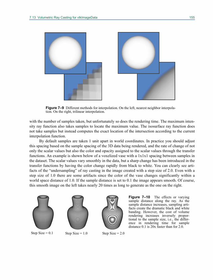
7.13 Volumetric Ray Casting for vtkImageData 155
with the number of samples taken, but unfortunately so does the rendering time. The maximum inten-sity ray function also takes samples to locate the maximum value. The isosurface ray function doesnot take samples but instead computes the exact location of the intersection according to the currentinterpolation function.
By default samples are taken 1 unit apart in world coordinates. In practice you should adjustthis spacing based on the sample spacing of the 3D data being rendered, and the rate of change of notonly the scalar values but also the color and opacity assigned to the scalar values through the transferfunctions. An example is shown below of a voxelized vase with a 1x1x1 spacing between samples inthe dataset. The scalar values vary smoothly in the data, but a sharp change has been introduced in thetransfer functions by having the color change rapidly from black to white. You can clearly see arti-facts of the “undersampling” of ray casting in the image created with a step size of 2.0. Even with astep size of 1.0 there are some artifacts since the color of the vase changes significantly within aworld space distance of 1.0. If the sample distance is set to 0.1 the image appears smooth. Of course,this smooth image on the left takes nearly 20 times as long to generate as the one on the right.
Figure 7–9 Different methods for interpolation. On the left, nearest neighbor interpola-tion. On the right, trilinear interpolation.
Step Size = 0.1 Step Size = 1.0 Step Size = 2.0
Figure 7–10 The effects or varyingsample distance along the ray. As thesample distance increases, sampling arti-facts create the dramatic black and whitebanding. However, the cost of volumerendering increases inversely propor-tional to the sample size, i.e., the differ-ence in rendering time for sampledistance 0.1 is 20x faster than for 2.0.
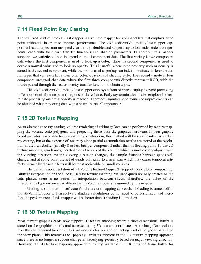
156 Volume Rendering
7.14 Fixed Point Ray CastingThe vtkFixedPointVolumeRayCastMapper is a volume mapper for vtkImageData that employs fixedpoint arithmetic in order to improve performance. The vtkFixedPointVolumeRayCastMapper sup-ports all scalar types from unsigned char through double, and supports up to four independent compo-nents, each with their own transfer functions and shading parameters. In addition, this mappersupports two varieties of non-independent multi-component data. The first variety is two componentdata where the first component is used to look up a color, while the second component is used toderive a normal value and to look up opacity. This is useful when some property such as density isstored in the second component, while the first is used as perhaps an index to indicate different mate-rial types that can each have their own color, opacity, and shading style. The second variety is fourcomponent unsigned char data where the first three components directly represent RGB, with thefourth passed through the scalar opacity transfer function to obtain alpha.
The vtkFixedPointVolumeRayCastMapper employs a form of space leaping to avoid processingin “empty” (entirely transparent) regions of the volume. Early ray termination is also employed to ter-minate processing once full opacity is reached. Therefore, significant performance improvements canbe obtained when rendering data with a sharp “surface” appearance.
7.15 2D Texture MappingAs an alternative to ray casting, volume rendering of vtkImageData can be performed by texture map-ping the volume onto polygons, and projecting these with the graphics hardware. If your graphicboard provides reasonable texture mapping acceleration, this method will be significantly faster thanray casting, but at the expense of accuracy since partial accumulation results are stored at the resolu-tion of the framebuffer (usually 8 or less bits per component) rather than in floating point. To use 2Dtexture mapping, quads are generated along the axis of the volume which is most closely aligned withthe viewing direction. As the viewing direction changes, the sample distance between quads willchange, and at some point the set of quads will jump to a new axis which may cause temporal arti-facts. Generally these artifacts will be most noticeable on small volumes.
The current implementation of vtkVolumeTextureMapper2D supports only alpha compositing.Bilinear interpolation on the slice is used for texture mapping but since quads are only created on thedata planes, there is no notion of interpolation between slices. Therefore, the value of theInterpolationType instance variable in the vtkVolumeProperty is ignored by this mapper.
Shading is supported in software for the texture mapping approach. If shading is turned off inthe vtkVolumeProperty, then software shading calculations do not need to be performed, and there-fore the performance of this mapper will be better than if shading is turned on.
7.16 3D Texture MappingMost current graphics cards now support 3D texture mapping where a three-dimensional buffer isstored on the graphics boards and accessed using 3D texture coordinates. A vtkImageData volumemay then be rendered by storing this volume as a texture and projecting a set of polygons parallel tothe view plane. This removes the “popping” artifacts inherent in the 2D texture mapping approachsince there is no longer a sudden change in underlying geometry based on major viewing direction.However, the 3D texture mapping approach currently available in VTK uses the frame buffer for
7.17 Volumetric Ray Casting for vtkUnstructuredGrid 157
compositing, which is still generally limited to 8 bits. Therefore with large volumes that are fairlytranslucent, banding artifacts will occur and small features may be lost in the image.
The 3D texture mapper is a single-pass mapper that requires the entire volume to be in memory.Therefore a limit is placed on the size of the data transferred to the texture memory. This limit isbased on the type of the data, the number of components, the texture memory available on the graph-ics board, and some hard-coded limits used to avoid problems in buggy OpenGL drivers that reportthe ability to utilize more texture memory than truly available. This is a silent limit - the input data setwill be downsampled to fit within the available texture memory with no warning or error messagesproduced. This mapper supports single component data or any scalar type, and four componentdependent data (RGBA) that is unsigned char. For single component data, the hard-coded limit is256x256x128 voxels, with any aspect ratio provided that each dimension is a power of two. With fourcomponent data, the limit is 256x128x128 voxels.
The 3D volume texture mapper supports two main families of graphics hardware: nVidia andATI. There are two different implementations of 3D texture mapping used - one based on theGL_NV_texture_shader2 and GL_NV_register_combiners2 extensions (supported on some oldernVidia cards), and one based on the GL_ARB_fragment_shader extension (supported by most currentnVidia and ATI boards). To use this class in an application that will run on various hardware configu-rations, you should have a back-up volume rendering method. You should create avtkVolumeTextureMapper3D, assign its input, make sure you have a current OpenGL context (you'verendered at least once), then call IsRenderSupported() with a vtkVolumeProperty as an argument.This method will return 0 if the input has more than one independent component, or if the graphicshardware does not support the set of required extensions for using at least one of the two implementedmethods.
7.17 Volumetric Ray Casting for vtkUnstructuredGridThe vtkUnstructuredGridVolumeRayCastMapper is a volume mapper that employs a software raycasting technique to perform volume rendering on unstructured grids. Using the default ray cast func-tion and integration methods, this mapper is more accurate than the vtkProjectedTetrahedra method,but is also significantly slower. This mapper is generally faster than the vtkUnstructuredGridZSweep-Mapper, but obtains this speed at the cost of memory consumption and is therefore best used withsmall unstructured grids. The ray caster is threaded to make use of multiple processors when avail-able. As with all mappers that render vtkUnstructuredGrid data, this mapper requires that the inputdataset is composed entirely of tetrahedral elements, and may employ a filter to tetrahedralize theinput data if necessary.
This ray cast mapper is customizable in two ways. First, you may specify the method used totraverse the ray through the unstructured grid using the SetRayCastFunction() method. The specifiedfunction must be a subclass of vtkUnstructuredGridVolumeRayCastFunction. Currently one suchsubclass exists within VTK: vtkUnstructuredGridBunykRayCastFunction. This class is based on themethod described in "Simple, Fast, Robust Ray Casting of Irregular Grids" by Paul Bunyk, ArieKaufman, and Claudio Silva. This method is quite memory intensive (with extra explicit copies of thedata) and therefore should not be used for very large data.
You may also specify a method for integrating along the ray between the front entry point andback exit point for the length of ray intersecting a tetrahedra using the SetRayIntegrator() method.The specified method must be a subclass of vtkUnstructuredGridVolumeRayIntegrator. Several avail-able subclasses exist in VTK, and when left unspecified the mapper will select an appropriate sub-
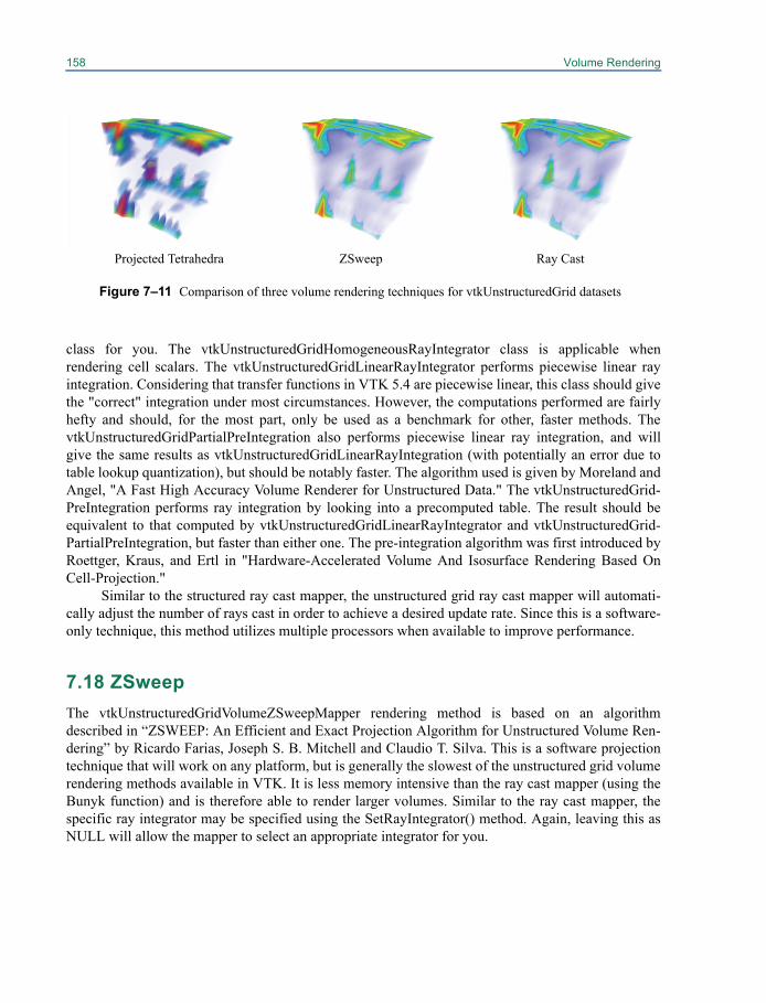
158 Volume Rendering
class for you. The vtkUnstructuredGridHomogeneousRayIntegrator class is applicable whenrendering cell scalars. The vtkUnstructuredGridLinearRayIntegrator performs piecewise linear rayintegration. Considering that transfer functions in VTK 5.4 are piecewise linear, this class should givethe "correct" integration under most circumstances. However, the computations performed are fairlyhefty and should, for the most part, only be used as a benchmark for other, faster methods. ThevtkUnstructuredGridPartialPreIntegration also performs piecewise linear ray integration, and willgive the same results as vtkUnstructuredGridLinearRayIntegration (with potentially an error due totable lookup quantization), but should be notably faster. The algorithm used is given by Moreland andAngel, "A Fast High Accuracy Volume Renderer for Unstructured Data." The vtkUnstructuredGrid-PreIntegration performs ray integration by looking into a precomputed table. The result should beequivalent to that computed by vtkUnstructuredGridLinearRayIntegrator and vtkUnstructuredGrid-PartialPreIntegration, but faster than either one. The pre-integration algorithm was first introduced byRoettger, Kraus, and Ertl in "Hardware-Accelerated Volume And Isosurface Rendering Based OnCell-Projection."
Similar to the structured ray cast mapper, the unstructured grid ray cast mapper will automati-cally adjust the number of rays cast in order to achieve a desired update rate. Since this is a software-only technique, this method utilizes multiple processors when available to improve performance.
7.18 ZSweepThe vtkUnstructuredGridVolumeZSweepMapper rendering method is based on an algorithmdescribed in “ZSWEEP: An Efficient and Exact Projection Algorithm for Unstructured Volume Ren-dering” by Ricardo Farias, Joseph S. B. Mitchell and Claudio T. Silva. This is a software projectiontechnique that will work on any platform, but is generally the slowest of the unstructured grid volumerendering methods available in VTK. It is less memory intensive than the ray cast mapper (using theBunyk function) and is therefore able to render larger volumes. Similar to the ray cast mapper, thespecific ray integrator may be specified using the SetRayIntegrator() method. Again, leaving this asNULL will allow the mapper to select an appropriate integrator for you.
Figure 7–11 Comparison of three volume rendering techniques for vtkUnstructuredGrid datasets
Projected Tetrahedra ZSweep Ray Cast
7.19 Projected Tetrahedra 159
7.19 Projected TetrahedraThe vtkProjectedTetrahedraMapper rendering method is an implementation of the classic ProjectedTetrahedra algorithm presented by Shirley and Tuchman in "A Polygonal Approximation to DirectScalar Volume Rendering". This method utilizes OpenGL to improve rendering performance by con-verting tetrahedra into triangles for a given view point, then rendering these triangles with hardwareacceleration. However, the OpenGL methods utilized in this class are not necessarily supported by alldriver implementations, and may produce artifacts. Typically this mapper will be used in conjunctionwith either the ray caster or the ZSweep mapper to form a level-of-detail approach that provides fastrendering during interactivity followed by a more accurate technique to produce the final image.
In Figure 7–11 you can see a comparison of images generated with the three techniques for vol-ume rendering unstructured grids. The projected tetrahedra technique is interactive, while the othertwo technique require a few seconds per image on a standard desktop system.
The vtkHAVSVolumeMapper is an implementation of the algorithm presented in "Hardware-Assisted Visibility Sorting for Unstructured Volume Rendering" by S. P. Callahan, M. Ikits, J. L. D.Comba, and C. T. Silva.
The code was written and contributed by Steven P. Callahan. The Hardware-Assisted VisibilitySorting (HAVS) algorithm works by first sorting the triangles of the tetrahedral mesh in object space,then they are sorted in image space using a fixed size A-buffer implemented on the GPU called the k-buffer. The HAVS algorithm excels at rendering large datasets quickly. The trade-off is that the algo-rithm may produce some rendering artifacts due to an insufficient k size (currently 2 or 6 is sup-ported) or read/write race conditions.
A built in level-of-detail (LOD) approach samples the geometry using one of two heuristics(field or area). If LOD is enabled, the amount of geometry that is sampled and rendered changesdynamically to stay within the target frame rate. The field sampling method generally works best fordatasets with cell sizes that don't vary much in size. On the contrary, the area sampling approach givesbetter approximations when the volume has a lot of variation in cell size. For more information on thelevel-of-detail method, please see "Interactive Rendering of Large Unstructured Grids UsingDynamic Level-of-Detail" by S. P. Callahan, J. L. D. Comba, P. Shirley, and C. T. Silva.
The HAVS algorithm uses several advanced features on graphics hardware. The k-buffer sort-ing network is implemented using framebuffer objects (FBOs) with multiple render targets (MRTs).Therefore, only cards that support these features can run the algorithm (at least an ATI 9500 or anNVidia NV40 (6600)).
7.20 Speed vs. Accuracy Trade-offsIf you do not have a VolumePro volume rendering board, many fast CPUs, or high-end graphics hard-ware, you will probably not be satisfied with the rendering rates achieved when one or more volumesare rendered in a scene. It is often necessary to achieve a certain frame rate in order to effectivelyinteract with the data, and it may be necessary to trade off accuracy in order to achieve speed. Fortu-nately, there are ways to do this for many of the volume rendering approach. In fact, several of themwill provide this functionality for you automatically by determining an appropriate accuracy level inorder to obtain the desired update rate specified in the vtkRenderWindow.
The support for achieving a desired frame rate for vtkVolumeRayCastMapper, vtkFixedPoint-VolumeRayCastMapper, vtkUnstructuredGridVolumeRayCastMapper, and vtkUnstructuredGridVol-umeZSweepMapper is available by default in VTK. You can set the desired update rate in the

160 Volume Rendering
vtkRenderWindow, or the StillUpdateRate and the DesiredUpdateRate in the interactor if you areusing one. Due to the fact that the time required for these rendering techniques is mostly dependent onthe size of the image, the mapper will automatically attempt to achieve the desired rendering rate byreducing the number of rays that arecast, or the size of the image is generated. By default, the auto-matic adjustment is on. In order to maintain interactivity, an abort check procedure should be speci-fied in the render window so that the user will be able to interrupt the higher resolution image in orderto interact with the data again.
There are limits on how blocky the image will become in order to achieve the desired updaterate. By default, the adjustment will allow the image to become quite blocky - for example, castingonly 1 ray for every 10x10 neighborhood of pixels if necessary to achieve the desired update rate.Also by default these mappers will not generate an image larger than necessary to fill the window onthe screen. These limits can be adjusted in the mapper by setting the MinimumImageSampleDistanceand MaximumImageSampleDistance. In addition AutoAdjustSampleDistances can be turned off, andthe specified ImageSampleDistance will be used to represent the spacing between adjacent pixels onthe image plane. Results for one example are shown in Figure 7–12.
This technique of reducing the number of rays in order to achieve interactive frame rates can bequite effective. For example, consider the full resolution image shown on the left in Figure 7–12. Thisimage may require 4 seconds to compute, which is much too slow for data interaction such as rotatingor translating the data, or interactively adjusting the transfer function. If we instead subsample everyother ray along each axis by setting the ImageSampleDistance to 2.0, we will get an image like theone shown in the middle in only about 1 second. Since this still may be too slow for effective interac-tion, we could subsample every fourth ray, and achieve rendering rates of nearly 4 frames per secondwith the image shown on the right. It may be blocky, but it is far easier to rotate a blocky volume at 4frames per second than a full resolution volume at one frame every four seconds.
There are no built-in automatic techniques for trading off accuracy for speed in a texture map-ping approach. This can be done by the user fairly easily by creating a lower resolution volume usingvtkImageResample, and rendering this new volume instead. Since the speed of the texture mappingapproach is highly dependent on the size of the volume, this will achieve similar results to reducingthe number of rays in a ray casting approach. Another option is to reduce the number of planes sam-pled through the volume. By default, the number of textured quads rendered will be equal to the num-ber of samples along the major axis of the volume (as determined by the viewing direction). You mayset the MaximumNumberOfPlanes instance variable to decrease the number of textured quads and
ImageSampleDistance = 1.0 ImageSampleDistance = 2.0 ImageSampleDistance = 4.0
Figure 7–12 The effect of changing image sample distance on image quality.

7.21 Using a vtkLODProp3D to Improve Performance 161
therefore increase performance. The default value is 0 which implies no limit on the number ofplanes.
7.21 Using a vtkLODProp3D to Improve PerformanceThe vtkLODProp3D is a 3D prop that allows for the collection of multiple levels-of-detail anddecides which to render for each frame based on the allocated rendering time of the prop (see“vtkLODProp3D” on page 57). The allocated rendering time of a prop is dependent on the desiredupdate rate for the rendering window, the number of renderers in the render window, the number ofprops in the renderer, and any possible adjustment that a culler may have made based on screen cov-erage or other importance factors.
Using a vtkLODProp3D, it is possible to collect several rendering techniques into one prop, andallow the prop to decide which technique to use. These techniques may span several different classesof rendering including geometric approaches that utilize a vtkPolyDataMapper, and volumetric meth-ods for both structured and unstructured data.
Consider the following simple example of creating a vtkLODProp3D with three different formsof volume rendering for vtkImageData:
vtkImageResample resamplerresampler SetAxisMagnificationFactor 0 0.5resampler SetAxisMagnificationFactor 1 0.5resampler SetAxisMagnificationFactor 2 0.5
vtkVolumeTextureMapper2D lowresMapperlowresMapper SetInput [resampler GetOutput]
vtkVolumeTextureMapper2D medresMappermedresMapper SetInput [reader GetOutput]
vtkVolumeRayCastMapper hiresMapperhiresMapper SetInput [reader GetOutput]
vtkLODProp3D volumeLODvolumeLOD AddLOD lowresMapper volumeProperty 0.0volumeLOD AddLOD medresMapper volumeProperty 0.0volumeLOD AddLOD hiresMapper volumeProperty 0.0
For clarity, many steps of reading the data and setting up visualization parameters have been left outof this example. At render time, one of the three levels-of-detail (LOD) for this prop will be selectedbased on the estimated time that it will take to render the LODs and the allocated time for this prop. Inthis case, all three LODs use the same property, but they could have used different properties ifdesired. Also, in this case all three mappers are subclasses of vtkVolumeMapper, but we could add abounding box representation as another LOD. If we are rendering a large vtkUnstructuredGrid data-set, we could form an LOD by adding an outline representation using a vtkPolyDataMapper for thelowest resolution, we could resample the data into a vtkImageData and add a level-of-detail that ren-

162 Volume Rendering
ders this with 3D texture mapping, and we could add the full resolution unstructured data renderedwith the ZSweep mapper as the best level-of-detail.
The last parameter of the AddLOD() method is an initial time to use for the estimated timerequired to render this level-of-detail. Setting this value to 0.0 requires that the LOD be rendered oncebefore an estimated render time can be determined. When a vtkLODProp3D has to decide whichLOD to render, it will choose one with 0.0 estimated render time if there are any. Otherwise, it willchoose the LOD with the greatest time that does not exceed the allocated render time of the prop, if itcan find such an LOD. Otherwise, it will choose the LOD with the lowest estimated render time. Thetime required to draw an LOD for the current frame replaces the estimated render time of that LODfor future frames.
Chapter 8
Information Visualization 8
Visualization techniques may be classified into twobroad categories: scientific visualization and information visualization. The two are mainly distin-guished by the types of data they represent. Scientific visualization refers to the display of data hav-ing inherent spatiotemporal attributes, such as simulations, models, or images. With these types ofdata, the relative position of elements is known because each element has an inherent structure andplacement in a three dimensional space.
Information visualization, on the other hand, is the visualization of all other forms of data.Metadata, relational databases, and general tabular data fall into this category. In these cases, theplacement of individual elements is not fixed and an embedding must be performed to place similaror related elements closer together. Consider visualizing a group of people. One simple way to orga-nize the people is to place them in a list or table. If accompanying information is also available, alter-native formats may be helpful to the viewer. People could be presented in a 2D view, grouped bysimilarity in age, gender, occupation, etc. If “friendship” links are known (e.g. from a social network-ing website), they could be grouped into natural friendship groups formed by these links. If each per-son's current location is known, they could be arranged on a map (“Geospatial Visualization” onpage 207 for VTK's capabilities in that regard).
Other examples of data suitable for information visualization are databases, spreadsheets,XML, and any type of metadata such as demographic information of patients or parameters of simu-lation runs. For this type of visualization, algorithms such as clustering and graph layout are used touncover salient relationships or determine a high-level picture of complex, heterogeneous data.
The essential data structures for information visualization are tables, graphs, and trees. A tableis simply a two-dimensional array of data, much like a spreadsheet. In VTK, a table consists of a vec-tor of named arrays which serve as the columns of the table. Each column acts much like an attributein other data objects like vtkImageData. Tables are used to store the results of database queries andcontents of delimited text files.
The graph data structure consists of a collection of entities called vertices, along with linksbetween pairs of vertices called edges. Graphs can be used to store many kinds of data. For example,
164 Information Visualization
in a social network, each vertex may represent a person while each edge may signify a friendshipbetween two people. Another example is a biological pathway network where vertices may representcompounds and edges may indicate that chemical reactions can produce one compound from another.
A tree is a type of graph that does not contain any cycles (sequences of connected edges thatform a full loop). VTK's tree data structure is a rooted tree, which can be thought of as a hierarchy,with the root vertex on top. Trees can organize large amounts of data by grouping entities into multi-ple levels.
Tables, graphs, and trees can represent complex data in several ways. The following sectionsprovide some details about how to perform some basic operations and visualizations with these datastructures.
8.1 Exploring Relationships in Tabular DataTables are a very common form of data. Plain text delimited files, spreadsheets, and relational data-bases all use tables as the basic data structure. A row in the table normally represents a single entity (aperson, an event, a sample, etc.) and columns represent attributes present on those entities. Let's takefor example a table of medals from the Summer 2008 Olympics. This table will have the medal win-ner's name and country, along with the event information. In tabular format, it is not easy to answerquestions such as: Who won the most medals? What country excelled in a certain discipline? In orderto do this, we want to extract relational information from the table in the form of a graph or tree.
Converting a Table to a GraphThe following python example demonstrates how to take this information, and with vtkTableTo-Graph, convert it into a vtkGraph data structure and display it in a graph view. Note that the scriptattempts to find the VTK data path, which may be explicitly defined in this and other examples byadding the parameters “-D <path>” to the command line when running the script. The followingexample is Python code for converting a simple table into a graph.
from vtk import *import vtk.util.miscimport versionUtil
datapath = vtk.util.misc.vtkGetDataRoot()
reader = vtkDelimitedTextReader()reader.SetFileName(datapath + '/Data/Infovis/medals.txt')reader.SetFieldDelimiterCharacters('\t')reader.SetHaveHeaders(True)
ttg = vtkTableToGraph()ttg.SetInputConnection(reader.GetOutputPort())ttg.AddLinkVertex('Name', 'Name', False)ttg.AddLinkVertex('Country', 'Country', False)ttg.AddLinkVertex('Discipline', 'Discipline', False)ttg.AddLinkEdge('Name', 'Country')ttg.AddLinkEdge('Name', 'Discipline')
8.1 Exploring Relationships in Tabular Data 165
category = vtkStringToCategory()category.SetInputConnection(ttg.GetOutputPort())category.SetInputArrayToProcess(0, 0, 0, 4, 'domain')
view = vtkGraphLayoutView()view.AddRepresentationFromInputConnection( category.GetOutputPort())view.SetLayoutStrategyToSimple2D()view.SetVertexLabelArrayName('label')view.VertexLabelVisibilityOn()view.SetVertexColorArrayName('category')view.ColorVerticesOn()view.SetVertexLabelFontSize(18)
theme = vtkViewTheme.CreateMellowTheme()view.ApplyViewTheme(theme)
rw = versionUtil.SetupView(view)versionUtil.ShowView(view)]
First we create a vtkDelimitedTextReader to read in the medals text file. This reader produces a vtk-Table as its output, which is simply a list of named data arrays. The fields in this file are separated bytabs, so we set the field delimiter characters appropriately. We specify SetHaveHeaders(True) in orderto assign column names from the first line in the file. Otherwise the columns would have genericnames “Field 0”, “Field 1”, and so on, and data in the table would be assumed to start on the first line.
You will notice the calls to versionUtil.SetupView and versionUtil.ShowView that are used tohandle code near the end of this and other examples. This reflects a code change after VTK 5.4 whichmakes vtkRenderView contain a vtkRenderWindow. This eliminates the need for creating a renderwindow manually and calling SetupRenderWindow(). Also, instead of calling methods such as Reset-Camera() and Render() on the render window, these methods have been added to vtkRenderView, andshould be called on the view instead. The following listing shows the contents of versionUtil.py. fromvtk import * The following code example demonstrates setting up and displaying a VTK view in ver-sion 5.4 and later.
from vtk import *def VersionGreaterThan(major, minor): v = vtkVersion() if v.GetVTKMajorVersion() > major: return True if v.GetVTKMajorVersion() == major and v.GetVTKMinorVersion() > minor: return True return False
def SetupView(view): if not VersionGreaterThan(5, 4): win = vtkRenderWindow() view.SetupRenderWindow(win) return win else: return view.GetRenderWindow()
166 Information Visualization
def ShowView(view): if VersionGreaterThan(5, 4): view.ResetCamera() view.Render() view.GetInteractor().Start() else: view.GetRenderer().ResetCamera() view.GetRenderWindow().Render() view.GetRenderWindow().GetInteractor().Start()
Now we wish to visualize some of the relationships in this table. The table has the following columns:“Name” contains the name of the athlete, “Country” has the athlete’s country, and “Discipline” con-tains the discipline. The table has the following columns: “Name” contains the name of the athlete,“Country” has the athlete’s country, and “Discipline” contains the disciplineof the event the athleteparticipated in (such as swimming, archery, etc.). One method for viewing the relationships in thegraph is to use vtkTableToGraph to produce a vtkGraph from the table. vtkTableToGraph takes a vtk-Table as input (and optionally a second “vertex table” input described later) and produces a vtkGraphwhose structure, vertex attributes, and edge attributes are taken from the table.
The vtkTableToGraph algorithm needs to know what columns should be used to generate verti-ces, and what pairs of columns should become edges, linking vertices together. So, in our example,we may wish to make a graph whose vertices represent names, countries, and disciplines. To do thiswe call AddLinkVertex() with the name of a column to make vertices from. All distinct values in thatcolumn will become vertices in the graph. So, AddLinkVertex('Country', ...) will make a vertex in theoutput graph for each distinct country name in the “Country” column of the table. The second argu-ment to AddLinkVertex() provides the domain to be associated with those vertices. Domains areimportant for entity resolution. If, for example, “Country” and “Name” were given the same domainname, a country named “Chad” would be merged with a person with the name “Chad”. Giving eachcolumn a different domain will avoid these conflicts. There are situations, however, where two col-umns of the table should be given the same domain. For example, in a table of communications, theremay columns named “From” and “To”. These should be assigned the same domain (perhaps named“Person”), so that a person's vertex would be merged into the same vertex regardless of whether thatperson was a sender or a recipient. The third parameter of AddLinkVertex() is described in “HiddenVertices” on page 168.
Now that the vertices are defined, we can define the set of edges in the graph withAddLinkEdge(). AddLinkEdge() takes two table column names, and produces an edge between twovertices A and B every time A and B appear together in the same row in those two columns. So thecall AddLinkEdge('Name', 'Country') will add an edge in the graph between each athlete and his orher country. Similarly, AddLinkEdge('Name', 'Discipline') will add an edge between an athlete andeach discipline he or she participates in. Figure 8–1 shows the result of converting the table of medalsinto a graph. The colors of the vertices in the graph indicate the domain to which they belong.Sinceyou may only assign colors with a numeric array, the program uses vtkStringToCategory to convertthe domain array (which contains strings), into numeric identifiers for each distinct vertex.
Attributes. The edges in vtkTableToGraph's output have the full set of attributes defined in the table.Namely each edge has associated with it all of the entries in the row of the table that produced theedge.

8.1 Exploring Relationships in Tabular Data 167
The vertices, however, have only three attributes associated with them by default. An attributenamed “domain” will be a string array containing the domain name of each vertex. The “ids” and“label” attributes both contain the same quantity, but present it in different formats. The quantity thatboth contain is the content of the particular cell that defines the vertex. The “ids” attribute stores it inthe original type, which may vary for vertices that belong to different domains. Hence the “ids” arrayis stored in a vtkVariantArray in which the data type of each entry is variable. The “label” attribute isa vtkStringArray containing the string equivalents of those values.
vtkTableToGraph accepts an optional second vtkTable input so that the vertices can have addi-tional attributes assigned to them. While the first input to the filter defines connectivity of edges (andhence is called the “edge table”), the second input defines the additional properties for the graph ver-tices (so is called the “vertex table”).
Therefore, to add vertex attributes, you must create a vertex table that contains columns withidentifiers matching those of the edge table's columns. The vertex table may have any number ofadditional columns containing other vertex attributes. In our example, there may be other tables thatreside in separate files or in a relational database that define athlete properties (e.g. age, gender),country properties (e.g. population, land area), and discipline properties (e.g. number of events). Toadd these as vertex properties in the graph, you need to construct a single table containing all thesecolumns. For example, this can be done with a properly formed SQL query or by applying the vtk-MergeTables algorithm. When this expanded table is set as the second input to vtkTableToGraph, thedomains defined in the second argument of AddLinkVertex() take on a special meaning. The domainname must match the vertex table column name that contains the matching identifiers. So in ourexample code, the vertex table would need to have arrays named “Name”, “Country”, and “Disci-pline” containing values matching those in the edge table.
Figure 8–1 The result of performingvtkTableToGraph to visualize a table of2008 Olympic medals. Medal-winningathletes (blue) are linked to their coun-try (green) and discipline (red).
168 Information Visualization
Hidden Vertices. The third parameter of AddLinkVertex() indicates whether the vertices should behidden. Most frequently, it is worthwhile to show the vertices, so the default is False. However, set-ting it to True allows the creation of advanced link effects, for example connecting athletes to otherathletes who represent the same country, but without displaying countries explicitly. To do this, youwould add “Name” as a non-hidden vertex type, and “Country” as a hidden vertex type. Then you addthe pairs (“Name”, “Country”) and (“Country”, “Name”) with AddLinkEdge(). Internally vtkTable-ToGraph creates the graph with name and country vertices, then deletes the country vertices, creatinga new edge for each two-edge path that passes through a country vertex. Note that hiding vertices canbe prohibitively expensive since the number of edges produced can grow quickly, and can producelarge cliques (i.e. collections of vertices where every pair of vertices is connected by an edge). Forthis reason, this option may be deprecated in the future.
Converting a Table to a TreeWhile a graph represents an arbitrarily complex structure, a tree has a much more restricted, andhence simpler, structure. In VTK, a vtkTree contains a rooted tree in which there is a hierarchy of ver-tices with a single root vertex on top. Outgoing edges flow down the tree, connecting “parent” verti-ces to “child” vertices. One example use for vtkTrees is to examine the structure of arbitrary XMLfiles. A tree can be generated directly from any XML file simply by using the vtkXMLTreeReader.That reader parses the nested XML elements and creates a vtkTree. You may also create a categoricaltree from tabular data. The following python code demonstrates how to use the vtkTableToTreeFilterand vtkGroupLeafVertices algorithms to do this.
VERTICES = 4 # Constant for SetInputArrayToProcessdatapath = vtk.util.misc.vtkGetDataRoot()
reader = vtkDelimitedTextReader()reader.SetFileName(datapath + '/Data/Infovis/medals.txt')reader.SetFieldDelimiterCharacters('\t')reader.SetHaveHeaders(True)if versionUtil.VersionGreaterThan(5,4): reader.OutputPedigreeIdsOn()
ttt = vtkTableToTreeFilter()ttt.SetInputConnection(reader.GetOutputPort())
group_disc = vtkGroupLeafVertices()group_disc.SetInputConnection(ttt.GetOutputPort())group_disc.SetInputArrayToProcess(0, 0, 0, VERTICES, 'Discipline')group_disc.SetInputArrayToProcess(1, 0, 0, VERTICES, 'Name')
group_country = vtkGroupLeafVertices()group_country.SetInputConnection(group_disc.GetOutputPort())group_country.SetInputArrayToProcess(0, 0, 0, VERTICES, 'Country')group_country.SetInputArrayToProcess(1, 0, 0, VERTICES, 'Name')
category = vtkStringToCategory()category.SetInputArrayToProcess(0, 0, 0, VERTICES, 'Name')category.SetInputConnection(group_country.GetOutputPort())
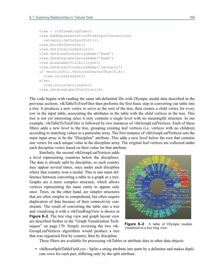
8.1 Exploring Relationships in Tabular Data 169
view = vtkTreeRingView()view.AddRepresentationFromInputConnection( category.GetOutputPort())view.RootAtCenterOn()view.SetInteriorRadius(1)view.SetAreaHoverArrayName('Name')view.SetAreaLabelArrayName('Name')view.AreaLabelVisibilityOn()view.SetAreaColorArrayName('category')if versionUtil.VersionGreaterThan(5,4): view.ColorAreasOn()else: view.ColorVerticesOn()view.SetAreaLabelFontSize(18)
The code begins with reading the same tab-delimited file with Olympic medal data described in theprevious sections. vtkTableToTreeFilter then performs the first basic step in converting our table intoa tree. It produces a new vertex to serve as the root of the tree, then creates a child vertex for everyrow in the input table, associating the attributes in the table with the child vertices in the tree. Thistree is not yet interesting since it only contains a single level with no meaningful structure. In ourexample, vtkTableToTreeFilter is followed by two instances of vtkGroupLeafVertices. Each of thesefilters adds a new level to the tree, grouping existing leaf vertices (i.e. vertices with no children)according to matching values in a particular array. The first instance of vtkGroupLeafVertices sets themain input array to be the “Discipline” attribute. This adds a new level below the root that containsone vertex for each unique value in the discipline array. The original leaf vertices are collected undereach discipline vertex based on their value for that attribute.
Similarly, the second vtkGroupLeafVertices addsa level representing countries below the disciplines.The data is already split by discipline, so each countrymay appear several times, once under each disciplinewhere that country won a medal. This is one main dif-ference between converting a table to a graph or a tree.Graphs are a more complex structure, which allowsvertices representing the same entity to appear onlyonce. Trees, on the other hand, are simpler structuresthat are often simpler to comprehend, but often requireduplication of data because of their connectivity con-straints. The result of converting the table into a treeand visualizing it with a vtkTreeRingView is shown inFigure 8–2. The tree ring view and graph layout vieware described further in the “Graph Visualization Tech-niques” on page 170. Simply reversing the two vtk-GroupLeafVertices algorithms would produce a treethat was organized first by country, then by discipline.
These filters are available for processing vtkTables or attribute data in other data objects:
• vtkBoostSplitTableField.cxx - Splits a string attribute into parts by a delimiter and makes dupli-cate rows for each part, differing only by the split attribute.
Figure 8–2 A table of Olympic medalsvisualized in a tree ring view.
170 Information Visualization
• vtkDataObjectToTable.cxx - Converts the point or cell attribute of a vtkDataSet subclass, orvertex or edge data of a vtkGraph subclass into a vtkTable.
• vtkGenerateIndexArray.cxx - Generate a simple zero-based index array and append it to a dataobject.
• vtkMergeColumns.cxx - Merge multiple columns into a single column.• vtkMergeTables.cxx - Merge multiple tables into a single table containing the union of all col-
umns.• vtkStringToCategory.cxx - Convert a string array to an integer array by assigning an integer to
each unique string in the array.• vtkStringToNumeric.cxx - Automatically detects and converts string arrays containing values
that may be converted to integer or floating-point values.• vtkThresholdTable.cxx - Filter out rows from a vtkTable that have attribute values outside a
given range.
Other graph transformation algorithms include:
• vtkCollapseGraph.cxx - Combine vertices with matching attribute values into a single vertex.• vtkPruneTreeFilter.cxx - Remove a sub-tree from a vtkTree.• vtkRemoveIsolatedVertices.cxx - Delete vertices with no edge connections from a graph.
8.2 Graph Visualization TechniquesGraph visualization is becoming increasingly important as a method for divining relationshipsbetween entities, entity clustering, and higher level abstractions. Graphs are typically visualized intwo- or three-dimensions, with attempts to inject additional dimensional information through vertexand edge coloring, labeling, annotations, clustering, and icons. Because of the diversity available fordisplaying graphs including theoretical, heuristic, empirical and manual layout methods, graph visu-alization has become a mixture of both art and science requiring methods that can handle both flexi-bility and complexity while maintaining a fair amount of generality. These methods are typicallybroken down into methods for vertex layout, methods for edge layout and methods which display ver-tices and relationships with polygonal data structures (e.g., circles, rings, blocks, etc.). In addition tothe layout methods, helper functionality for displaying graph attributes is also desirable (e.g., com-mon coloring themes, labeling mechanisms, annotations and selections, etc.). To accommodate thisflexibility while maintaining a high level of functionality, the graph visualization tools in VTK utilize`strategy' methods for layout of vertices and edges, and 'view' objects for centralizing common helperfunctionality associated with the visualization of graphs.
To demonstrate basic capability, we present a simple example uses layouts and views to creategraph displays in VTK see Figure 8–3. The remainder of this section will discuss additional flexibil-ity available in performing graph visualization. The following code snippet creates a simple graphview of a random graph.
from vtk import *
# create a random graphsource = vtkRandomGraphSource()

8.2 Graph Visualization Techniques 171
source.SetNumberOfVertices(100)source.SetNumberOfEdges(110)source.StartWithTreeOn()
#create a view to display the graphview = vtkGraphLayoutView()view.SetLayoutStrategyToSimple2D()view.ColorVerticesOn()view.SetVertexColorArrayName("vertex id")view.SetRepresentationFromInputConnection(source.GetOutputPort()) # Apply a theme to the viewstheme = vtkViewTheme.CreateMellowTheme()view.ApplyViewTheme(theme)theme.FastDelete()
#view.GetRenderWindow().SetSize(500,500)view.ResetCamera()view.Render()
view.GetInteractor().Start()
A primary step that must take place in information visu-alization is to embed the data into some drawable space.Recall that vertices in a vtkGraph have no relation tovtkPoints in the more traditional vtkDataSet classes.Points have X, Y and Z coordinates, but vertices to not.Depending on how these assignments are made, theresulting picture will vary greatly, and different charac-teristics of the underlying data will be easier to discern.A second degree of freedom in information visualizationis the exact routing of the edges that connect the vertices.
Vertex LayoutTo determine where vertices are positioned, one places a vtkGraphLayout class into the pipeline. Thisclass is responsible for the overall task of assigning coordinates to vertices, but it leaves the details ofcoordinate assignment to a swappable helper class. The helper class is an example of a strategy. Thistwo part structure maximizes flexibility and minimizes complexity. Thus, in a typical graph visualiza-tion, a graph is piped into the vtkGraphLayout class after which each vertex has a vtkPoint assigned.The pipeline author can choose amongst a number of strategies. Strategies may vary from spring-based layouts to clustering methods. Each strategy class is subclassed from vtkGraphLayoutStrategy,all of which can be plugged into vtkGraphLayout. Examples of currently available layout strategiesinclude:
• vtkAssignCoordinatesLayoutStrategy - strategy to allow coordinate assignment from arraysdesignated as the x, y, and z coordinates.
• vtkCircularLayoutStrategy - Assigns points to the vertices around a circle with unit radius.
Figure 8–3 A simple graph view
172 Information Visualization
• vtkClustering2DLayoutStrategy - strategy utilizing a density grid based force directed layoutstrategy. The layout running time is O(V+E) with an extremely high constant.
• vtkCommunity2DLayoutStrategy - similar to vtkClustering2DLayoutStrategy, but looks for acommunity array on its input and strengthens edges within a community and weakens edges notwithin the community.
• vtkConeLayoutStrategy - strategy that positions the nodes of a tree(forest) in 3D space based onthe cone-tree approach first described by Robertson, Mackinlay and Card in the proceedings ofthe ACM Conference on Human Factors in Computing Systems (CHI'91). This implementationalso incorporates refinements to the layout developed by Carriere and Kazman, and by Auber.
• vtkConstrained2DLayoutStrategy - similar to vtkClustering2DLayoutStrategy, but looks for aconstraint array indicating a level of impedance a node has to the force calculations during thelayout optimization.
• vtkCosmicTreeLayoutStrategy - tree layout strategy reminiscent of astronomical systems
• vtkFast2DLayoutStrategy - a simple fast 2D graph layout.
• vtkForceDirectedLayoutStrategy - lays out a graph in 2D or 3D using a force-directed algo-rithm.
• vtkPassThroughLayoutStrategy - a layout strategy that does absolutely simply passes the graphthrough without modifying the data.
• vtkRandomLayoutStrategy - randomly places vertices in 2 or 3 dimensions within a boundedrange.
• vtkSimple2DLayoutStrategy - an implementation of the Fruchterman & Reingold layout strat-egy (see “Graph Drawing by Force-directed Placement” Software-Practice and Experience21(11) 1991)).
• vtkTreeLayoutStrategy - Assigns points to the nodes of a tree in either a standard or radial lay-out.
• vtkTreeOrbitLayoutStrategy - Assigns points to the nodes of a tree to an orbital layout. Eachparent is orbited by its children, recursively.
To simplify the task of visualizing different graphs, the vertex layout strategies can be supplieddirectly to a view class. This is done by calling vtkGraphLayoutView::SetLayoutStrat-egy(vtkGraphLayoutStrategy *s) as in the preceding example. Views are discussed in greater depth in“Views and Representations” on page 176.
Edge Layout
To determine how edges are routed, one again uses a strategy abstraction. Every edge layout strategyis subclassed from vtkEdgeLayoutStrategy, which is then plugged into the vtkEdgeLayout class.Examples of currently available edge layout strategies include:
• vtkArcParallelEdgeStrategy - routes single edges as line segments, routes parallel edges as arcs.
• vtkGeoEdgeStrategy - Layout graph edges on a globe as arcs.
• vtkPassThroughEdgeStrategy - a layout strategy that simply passes the graph through withoutmodifying the data.
8.2 Graph Visualization Techniques 173
The edge layout strategies can also be supplied directly to a view class using vtkGraphLayout-View::SetEdgeLayoutStrategy(vtkEdgeLayoutStrategy *s).
Converting Layouts to GeometryOnce the layouts are complete, the graphs must still be converted to geometry: points, lines, poly-lines, polygons, etc., which can be mapped into actors in order to be displayed in a render window.Classes for helping to accomplish this final conversion include:
• vtkGraphToGlyphs - Converts a vtkGraph to a vtkPolyData containing a glyph (circle, dia-mond, crosses, etc.) for each vertex.
• vtkGraphMapper - Map vtkGraph and derived classes to graphics primitives.• vtkGraphToPolyData - Converts the edges of the graph to polydata, assumes vertex data
already has associated point data and passes this data along.• vtkEdgeCenters - generate points at center of graph edges.
The use of the preceding classes is demonstrated here in the following code example of drawing agraph. We are using a single strategy to do the initial graph layout; however, as noted earlier, the strat-egy classes are interchangeable, and new layout strategies can be applied by swapping out one strat-egy for another in this example.
from vtk import *
# create a random graphsource = vtkRandomGraphSource()source.SetNumberOfVertices(100)source.SetNumberOfEdges(110)source.StartWithTreeOn()source.Update()
# setup a strategy for laying out the graph# NOTE: You can set additional options for each strategy, as desiredstrategy = vtkFast2DLayoutStrategy()#strategy = vtkSimple2DLayoutStrategy()#strategy = vtkCosmicTreeLayoutStrategy()#strategy = vtkForceDirectedLayoutStrategy()#strategy = vtkTreeLayoutStrategy()
# set the strategy on the layoutlayout = vtkGraphLayout()layout.SetLayoutStrategy(strategy)layout.SetInputConnection(source.GetOutputPort())
# create the renderer to help in sizing glyphs for the verticesren = vtkRenderer()
# Pipeline for displaying vertices - glyph -> mapper -> actor -> display# mark each vertex with a circle glyphvertex_glyphs = vtkGraphToGlyphs()
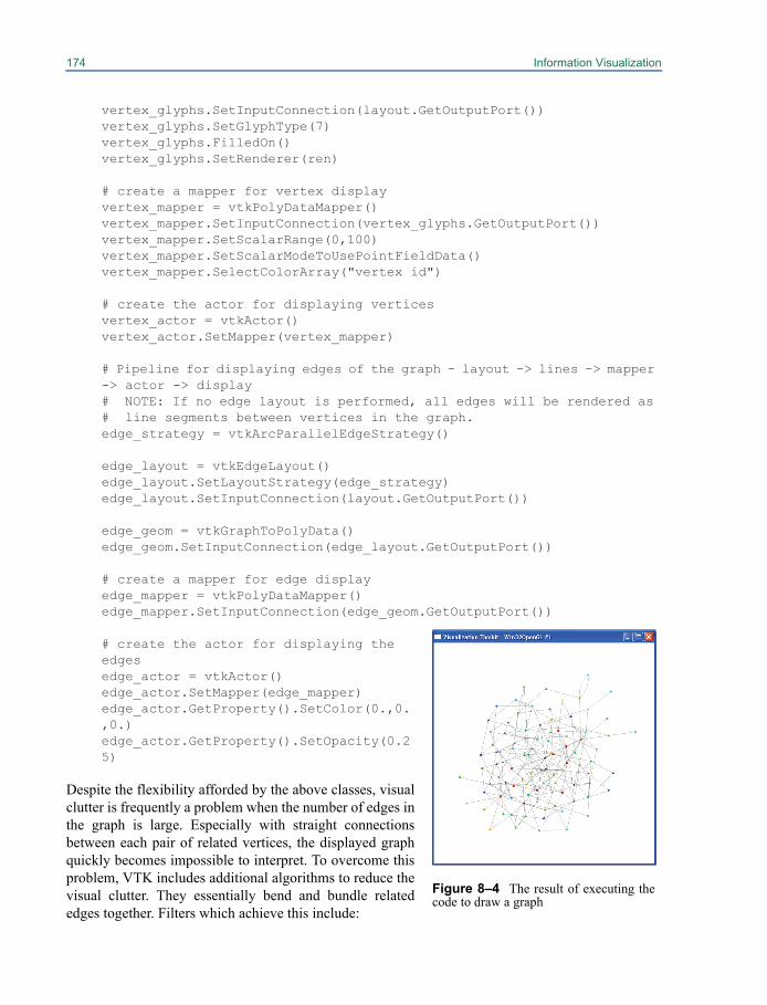
174 Information Visualization
vertex_glyphs.SetInputConnection(layout.GetOutputPort())vertex_glyphs.SetGlyphType(7)vertex_glyphs.FilledOn()vertex_glyphs.SetRenderer(ren)
# create a mapper for vertex displayvertex_mapper = vtkPolyDataMapper()vertex_mapper.SetInputConnection(vertex_glyphs.GetOutputPort())vertex_mapper.SetScalarRange(0,100)vertex_mapper.SetScalarModeToUsePointFieldData()vertex_mapper.SelectColorArray("vertex id")
# create the actor for displaying verticesvertex_actor = vtkActor()vertex_actor.SetMapper(vertex_mapper)
# Pipeline for displaying edges of the graph - layout -> lines -> mapper -> actor -> display# NOTE: If no edge layout is performed, all edges will be rendered as # line segments between vertices in the graph.edge_strategy = vtkArcParallelEdgeStrategy()
edge_layout = vtkEdgeLayout()edge_layout.SetLayoutStrategy(edge_strategy)edge_layout.SetInputConnection(layout.GetOutputPort())
edge_geom = vtkGraphToPolyData()edge_geom.SetInputConnection(edge_layout.GetOutputPort())
# create a mapper for edge display edge_mapper = vtkPolyDataMapper()edge_mapper.SetInputConnection(edge_geom.GetOutputPort())
# create the actor for displaying the edgesedge_actor = vtkActor()edge_actor.SetMapper(edge_mapper)edge_actor.GetProperty().SetColor(0.,0.,0.)edge_actor.GetProperty().SetOpacity(0.25)
Despite the flexibility afforded by the above classes, visualclutter is frequently a problem when the number of edges inthe graph is large. Especially with straight connectionsbetween each pair of related vertices, the displayed graphquickly becomes impossible to interpret. To overcome thisproblem, VTK includes additional algorithms to reduce thevisual clutter. They essentially bend and bundle relatededges together. Filters which achieve this include:
Figure 8–4 The result of executing thecode to draw a graph
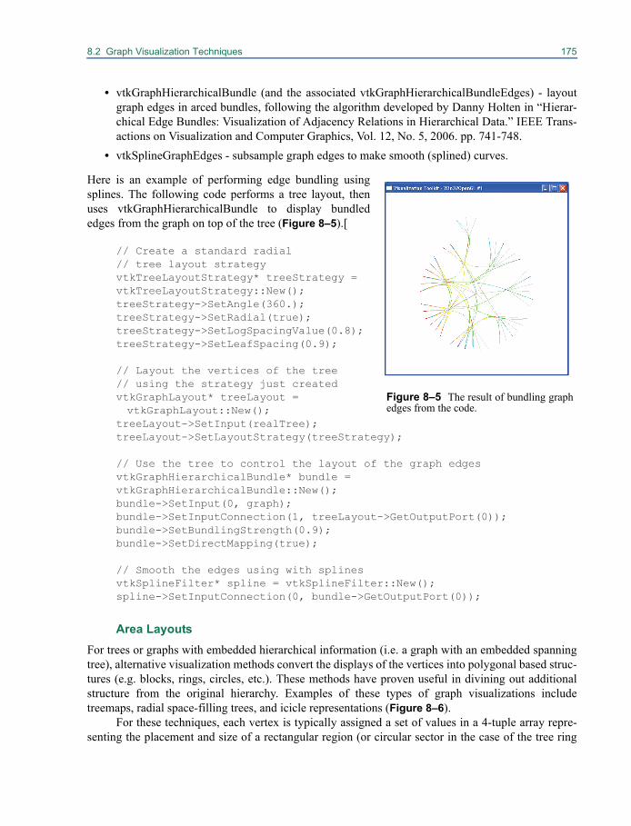
8.2 Graph Visualization Techniques 175
• vtkGraphHierarchicalBundle (and the associated vtkGraphHierarchicalBundleEdges) - layoutgraph edges in arced bundles, following the algorithm developed by Danny Holten in “Hierar-chical Edge Bundles: Visualization of Adjacency Relations in Hierarchical Data.” IEEE Trans-actions on Visualization and Computer Graphics, Vol. 12, No. 5, 2006. pp. 741-748.
• vtkSplineGraphEdges - subsample graph edges to make smooth (splined) curves.
Here is an example of performing edge bundling usingsplines. The following code performs a tree layout, thenuses vtkGraphHierarchicalBundle to display bundlededges from the graph on top of the tree (Figure 8–5).[
// Create a standard radial // tree layout strategyvtkTreeLayoutStrategy* treeStrategy =vtkTreeLayoutStrategy::New();treeStrategy->SetAngle(360.);treeStrategy->SetRadial(true);treeStrategy->SetLogSpacingValue(0.8);treeStrategy->SetLeafSpacing(0.9);
// Layout the vertices of the tree // using the strategy just createdvtkGraphLayout* treeLayout = vtkGraphLayout::New();
treeLayout->SetInput(realTree);treeLayout->SetLayoutStrategy(treeStrategy);
// Use the tree to control the layout of the graph edgesvtkGraphHierarchicalBundle* bundle =vtkGraphHierarchicalBundle::New();bundle->SetInput(0, graph);bundle->SetInputConnection(1, treeLayout->GetOutputPort(0));bundle->SetBundlingStrength(0.9);bundle->SetDirectMapping(true);
// Smooth the edges using with splinesvtkSplineFilter* spline = vtkSplineFilter::New();spline->SetInputConnection(0, bundle->GetOutputPort(0));
Area LayoutsFor trees or graphs with embedded hierarchical information (i.e. a graph with an embedded spanningtree), alternative visualization methods convert the displays of the vertices into polygonal based struc-tures (e.g. blocks, rings, circles, etc.). These methods have proven useful in divining out additionalstructure from the original hierarchy. Examples of these types of graph visualizations includetreemaps, radial space-filling trees, and icicle representations (Figure 8–6).
For these techniques, each vertex is typically assigned a set of values in a 4-tuple array repre-senting the placement and size of a rectangular region (or circular sector in the case of the tree ring
Figure 8–5 The result of bundling graphedges from the code.

176 Information Visualization
view). These methods also utilize a layout strategy which is plugged into vtkAreaLayout. Currentlyavailable strategies include:
• vtkBoxLayoutStrategy (treemap) - a tree map layout that puts vertices in square-ish boxes byrecursive partitioning of the space for children vertices.
• vtkSliceAndDiceLayoutStrategy (treemap) - lays out a tree-map alternating between horizontal and vertical slices.
• vtkSquarifyLayoutStrategy (treemap) - use the squarifiedtree map algorithm proposed in Bruls, D.M., C. Huizing, J.J.van Wijk. Squarified Treemaps. In: W. de Leeuw, R. vanLiere (eds.), Data Visualization 2000, Proceedings of thejoint Eurographics and IEEE TCVG Symposium on Visual-ization, 2000, Springer, Vienna, p. 33-42.
• vtkStackedTreeLayoutStrategy (tree ring and icicle) - laysout tree in stacked boxes or rings.
Conversion to geometry for later display is accomplished throughsome additional helper classes:
• vtkTreeMapToPolyData - converts a tree with an associateddata array to a polygonal data representing a tree map.
• vtkTreeRingToPolyData - converts a tree with an associateddata array to a polygonal data representing an icicle or treering layout.
These classes utilize the 4-tuple array created in the layout classesand convert this data to the standard polygonal primitives for eachvertex represented by the value in the array.
8.3 Views and RepresentationsViews in VTK combine rendering logic, interaction, visualizationparameters, and selection into one place. Datasets are displayed inviews by adding what are called “representations” to the view. Arepresentation prepares an input dataset to be displayed in a view,and contains options for how that data should be rendered in theview, including colors, icons, layout algorithms, and labels. Allviews are subclasses of vtkView, and all view representations aresubclasses of vtkDataRepresentation. The previous sections havealready introduced views such as vtkGraphLayoutView and vtk-TreeRingView.
You can add data objects to a view in two ways. One way is to create the appropriate represen-tation, set the inputs on the representation by calling SetInputConnection() or SetInput(), then callAddRepresentation() on the view. The other way that is normally more convenient is to have the viewautomatically create the default representation for you through calling AddRepresentationFromIn-put() or AddRepresentationFromInputConnection(). These methods accept a data object or algorithm
Figure 8–6 Treemap, tree ring,and icicle views displaying thepartitioning of classes into librar-ies, along with links connectingeach class to its superclass
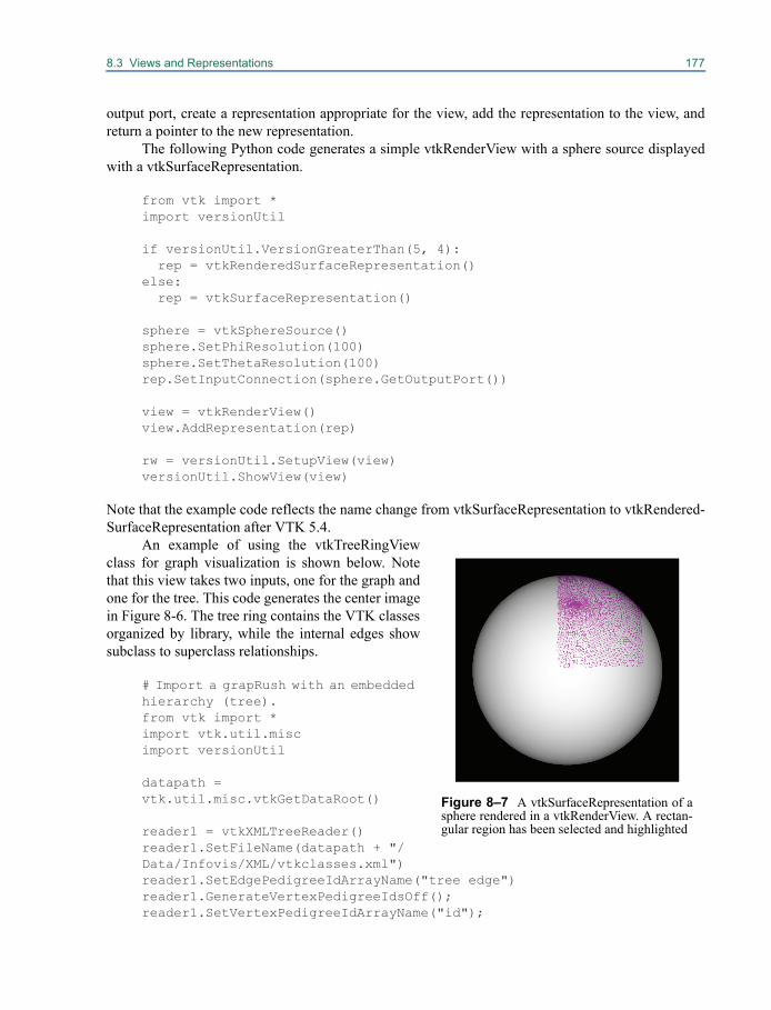
8.3 Views and Representations 177
output port, create a representation appropriate for the view, add the representation to the view, andreturn a pointer to the new representation.
The following Python code generates a simple vtkRenderView with a sphere source displayedwith a vtkSurfaceRepresentation.
from vtk import *import versionUtil
if versionUtil.VersionGreaterThan(5, 4): rep = vtkRenderedSurfaceRepresentation()else: rep = vtkSurfaceRepresentation()
sphere = vtkSphereSource()sphere.SetPhiResolution(100)sphere.SetThetaResolution(100)rep.SetInputConnection(sphere.GetOutputPort())
view = vtkRenderView()view.AddRepresentation(rep)
rw = versionUtil.SetupView(view)versionUtil.ShowView(view)
Note that the example code reflects the name change from vtkSurfaceRepresentation to vtkRendered-SurfaceRepresentation after VTK 5.4.
An example of using the vtkTreeRingViewclass for graph visualization is shown below. Notethat this view takes two inputs, one for the graph andone for the tree. This code generates the center imagein Figure 8-6. The tree ring contains the VTK classesorganized by library, while the internal edges showsubclass to superclass relationships.
# Import a grapRush with an embedded hierarchy (tree).from vtk import *import vtk.util.miscimport versionUtil
datapath = vtk.util.misc.vtkGetDataRoot()
reader1 = vtkXMLTreeReader()reader1.SetFileName(datapath + "/Data/Infovis/XML/vtkclasses.xml")reader1.SetEdgePedigreeIdArrayName("tree edge")reader1.GenerateVertexPedigreeIdsOff();reader1.SetVertexPedigreeIdArrayName("id");
Figure 8–7 A vtkSurfaceRepresentation of asphere rendered in a vtkRenderView. A rectan-gular region has been selected and highlighted
178 Information Visualization
reader2 = vtkXMLTreeReader()reader2.SetFileName(datapath + "/Data/Infovis/XML/vtklibrary.xml")reader2.SetEdgePedigreeIdArrayName("graph edge")reader2.GenerateVertexPedigreeIdsOff();reader2.SetVertexPedigreeIdArrayName("id");
# Setup the view parameters for displaying the graphview = vtkTreeRingView()view.SetTreeFromInputConnection(reader2.GetOutputPort())view.SetGraphFromInputConnection(reader1.GetOutputPort())view.SetAreaColorArrayName("VertexDegree")view.SetEdgeColorToSplineFraction()view.SetAreaHoverArrayName("id")view.SetColorEdges(True)view.SetAreaLabelArrayName("id")view.SetAreaLabelVisibility(True)view.SetShrinkPercentage(0.02)view.SetBundlingStrength(.8)
# Apply a theme to the viewstheme = vtkViewTheme.CreateMellowTheme()view.ApplyViewTheme(theme)
rw = versionUtil.SetupView(view)versionUtil.ShowView(view)
These are the render view subclasses currently implemented in VTK:
• vtkGraphLayoutView - view window for visualizing graphs• vtkHierarchicalGraphView - view window for visualizing graphs with associated, or derived,
hierarchical data.• vtkIcicleView - view for visualizing trees, or graphs with associated or derived hierarchical
data, using an icicle layout.• vtkTreeMapView - view for visualizing trees, or graphs with associated or derived hierarchical
data, using a tree map layout.
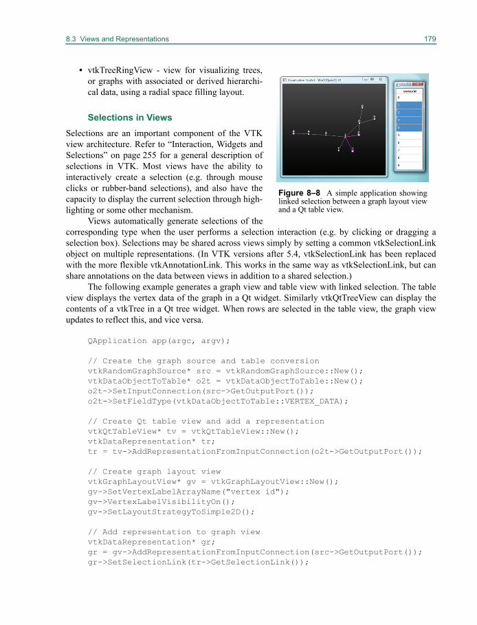
8.3 Views and Representations 179
• vtkTreeRingView - view for visualizing trees,or graphs with associated or derived hierarchi-cal data, using a radial space filling layout.
Selections in ViewsSelections are an important component of the VTKview architecture. Refer to “Interaction, Widgets andSelections” on page 255 for a general description ofselections in VTK. Most views have the ability tointeractively create a selection (e.g. through mouseclicks or rubber-band selections), and also have thecapacity to display the current selection through high-lighting or some other mechanism.
Views automatically generate selections of thecorresponding type when the user performs a selection interaction (e.g. by clicking or dragging aselection box). Selections may be shared across views simply by setting a common vtkSelectionLinkobject on multiple representations. (In VTK versions after 5.4, vtkSelectionLink has been replacedwith the more flexible vtkAnnotationLink. This works in the same way as vtkSelectionLink, but canshare annotations on the data between views in addition to a shared selection.)
The following example generates a graph view and table view with linked selection. The tableview displays the vertex data of the graph in a Qt widget. Similarly vtkQtTreeView can display thecontents of a vtkTree in a Qt tree widget. When rows are selected in the table view, the graph viewupdates to reflect this, and vice versa.
QApplication app(argc, argv);
// Create the graph source and table conversionvtkRandomGraphSource* src = vtkRandomGraphSource::New();vtkDataObjectToTable* o2t = vtkDataObjectToTable::New();o2t->SetInputConnection(src->GetOutputPort());o2t->SetFieldType(vtkDataObjectToTable::VERTEX_DATA);
// Create Qt table view and add a representationvtkQtTableView* tv = vtkQtTableView::New();vtkDataRepresentation* tr;tr = tv->AddRepresentationFromInputConnection(o2t->GetOutputPort());
// Create graph layout viewvtkGraphLayoutView* gv = vtkGraphLayoutView::New();gv->SetVertexLabelArrayName("vertex id");gv->VertexLabelVisibilityOn();gv->SetLayoutStrategyToSimple2D();
// Add representation to graph viewvtkDataRepresentation* gr;gr = gv->AddRepresentationFromInputConnection(src->GetOutputPort());gr->SetSelectionLink(tr->GetSelectionLink());
Figure 8–8 A simple application showinglinked selection between a graph layout viewand a Qt table view.
180 Information Visualization
// Ensure both views update when selection changesvtkViewUpdater* vu = vtkViewUpdater::New();vu->AddView(gv);vu->AddView(tv);
// Start application#if VTK_5_4_OR_EARLIERvtkRenderWindow* win = vtkRenderWindow::New();gv->SetupRenderWindow(win);#endiftv->GetItemView()->show();app.exec();}
8.4 Graph AlgorithmsGraph data structures are an essential part of any informatics application. Many informatics problemsconsist of a myriad of data sources (people, phone calls, emails, publications) and the relationshipsbetween those datatypes. In general, graphs are well suited for the storage, manipulation, and analysisof different entities and the connections between those entities. In semantic graphs entities are repre-sented by the graph vertices and the relationships between entities are represented by the graph edges.The vtkGraph data structure can store arbitrary attributes on both the vertices and edges so propertiesand types (“semantics”) are easily expressed (See Siek, Jeremy, Lie-Quan Lee, and Andrew Lums-daine. 2001. “The Boost Graph Library: User Guide and Reference Manual”. Addison-Wesley Pro-fessional).
The effective processing and analysis of graphs require a large set of graph algorithms. TheVTK toolkit leverages third party libraries to provide them. These libraries include, the Boost GraphLibrary (BGL), the Parallel Boost Graph Library (PBGL) and the Multithreaded Graph Library(MTGL)
One of these libraries is the Boost Graph Library (BGL) which provides a generic C++ templateinterface to many common graph algorithm implementations. VTK provides a 'data-less' adapterwhich implements the required BGL concepts and allows BGL algorithms to process vtkGraphsdirectly.
The usage of any graph algorithm follows the VTK pipeline model. The code example shown inListing <BFS> demonstrates the usage of a graph algorithm. The code includes the header file of thealgorithm, creates the VTK filter for the algorithm (in this case vtkBoostBreadthFirstSearch) and putsthe algorithm in the pipeline. After the pipeline is updated, the results of that algorithm are availableas attributes on the nodes and/or edges of the graph. This example simply labels each vertex with itsdistance from the starting vertex (labeled “0”).
#include "vtkBoostBreadthFirstSearch.h"#include "vtkGraphLayoutView.h"#include "vtkRandomGraphSource.h"#include "vtkRenderWindow.h"#include "vtkRenderWindowInteractor.h"int main(int argc, char* argv[]){
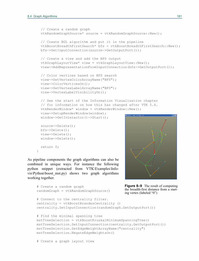
8.4 Graph Algorithms 181
// Create a random graph vtkRandomGraphSource* source = vtkRandomGraphSource::New();
// Create BGL algorithm and put it in the pipeline vtkBoostBreadthFirstSearch* bfs = vtkBoostBreadthFirstSearch::New(); bfs->SetInputConnection(source->GetOutputPort()); // Create a view and add the BFS output vtkGraphLayoutView* view = vtkGraphLayoutView::New(); view->AddRepresentationFromInputConnection(bfs->GetOutputPort());
// Color vertices based on BFS search view->SetVertexColorArrayName("BFS"); view->ColorVerticesOn(); view->SetVertexLabelArrayName("BFS"); view->VertexLabelVisibilityOn(); // See the start of the Information Visualization chapter // for information on how this has changed after VTK 5.4. vtkRenderWindow* window = vtkRenderWindow::New(); view->SetupRenderWindow(window); window->GetInteractor()->Start();
source->Delete(); bfs->Delete(); view->Delete(); window->Delete();
return 0;}
As pipeline components the graph algorithms can also becombined in unique ways. For instance the followingpython snippet (extracted from VTK\Examples\Info-vis\Python\boost_mst.py) shows two graph algorithmsworking together.
# Create a random graphrandomGraph = vtkRandomGraphSource()
# Connect to the centrality filter.centrality = vtkBoostBrandesCentrality ()centrality.SetInputConnection(randomGraph.GetOutputPort())
# Find the minimal spanning treemstTreeSelection = vtkBoostKruskalMinimumSpanningTree()mstTreeSelection.SetInputConnection(centrality.GetOutputPort())mstTreeSelection.SetEdgeWeightArrayName("centrality")mstTreeSelection.NegateEdgeWeightsOn()
# Create a graph layout view
Figure 8–9 The result of computingthe breadth-first distance from a start-ing vertex (labeled “0”)
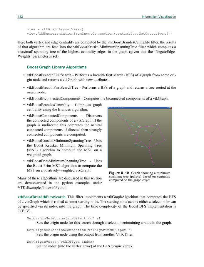
182 Information Visualization
view = vtkGraphLayoutView()view.AddRepresentationFromInputConnection(centrality.GetOutputPort())
Here both vertex and edge centrality are computed by the vtkBoostBrandesCentrality filter, the resultsof that algorithm are feed into the vtkBoostKruskalMinimumSpanningTree filter which computes a'maximal' spanning tree of the highest centrality edges in the graph (given that the ‘NegateEdge-Weights’ parameter is set).
Boost Graph Library Algorithms
• vtkBoostBreadthFirstSearch - Performs a breadth first search (BFS) of a graph from some ori-gin node and returns a vtkGraph with new attributes.
• vtkBoostBreadthFirstSearchTree - Performs a BFS of a graph and returns a tree rooted at theorigin node.
• vtkBoostBiconnectedComponents - Computes the biconnected components of a vtkGraph.• vtkBoostBrandesCentrality - Computes graph
centrality using the Brandes algorithm.• vtkBoostConnectedComponents - Discovers
the connected components of a vtkGraph. If thegraph is undirected this computes the naturalconnected components, if directed then stronglyconnected components are computed.
• vtkBoostKruskalMinimumSpanningTree - Usesthe Boost Kruskal Minimum Spanning Tree(MST) algorithm to compute the MST on aweighted graph.
• vtkBoostPrimMinimumSpanningTree - Usesthe Boost Prim MST algorithm to compute theMST on a positively-weighted vtkGraph.
Many of these algorithms are discussed in this sectionare demonstrated in the python examples underVTK\Examples\Infovis\Python.
vtkBoostBreadthFirstSearch. This filter implements a vtkGraphAlgorithm that computes the BFSof a vtkGraph which is rooted at some starting node. The starting node can be either a selection or canbe specified via its index into the graph. The time complexity of the Boost BFS implementation isO(E+V).
SetOriginSelection(vtkSelection* s) Sets the origin node for this search through a selection cointaining a node in the graph.
SetOriginSelectionConnection(vtkAlgorithmOutput *) Sets the origin node using the output from another VTK filter.
SetOriginVertex(vtkIdType index) Set the index (into the vertex array) of the BFS 'origin' vertex.
Figure 8–10 Graph showing a minimumspanning tree (purple) based on centralitycomputed on the graph edges

8.4 Graph Algorithms 183
SetOriginVertex(arrayName,value) Set the BFS origin vertex. This method allows the application to simply specify an arrayname and value, instead of having to know the specific index of the vertex.
SetOriginVertexString(arrayName,value) Set the BFS 'origin' vertex given an array name and a string value.
SetOutputArrayName(string)Set the name of the vertex attribute array in the output graph. Default is "BFS".
SetOriginFromSelection(bool)If true/on, use the vtkSelection from input port 1 as the origin vertex. The selectionshould be an IDs selection with field type POINTS. The first ID in the selection will beused as the 'origin' vertex. Default is OFF.
SetOutputSelection(bool)If true/on, creates an output selection containing the ID of a vertex based on the outputselection type. The default is to use the maximum distance from the starting vertex.Default is OFF.
SetOutputSelectionType(string) Set the output selection type. The default is to use the maximum distance from the start-ing vertex "MAX_DIST_FROM_ROOT". Additional options such as "ROOT","2D_MAX", etc. may be used.
vtkBoostBreadthFirstSearchTreeThis VTK class uses the Boost BFS generic algorithm to perform a BFS of a vtkGraphfrom a given source vertex. The result of this filter is a vtkTree with root node corre-sponding to the starting node of the search.
SetOriginVertex(index) Sets the index into the vertex array of the origin vertex.
SetOriginVertex(arrayName,value) Set the origin vertex given a value within a named vertex array.
SetCreateGraphVertexIdArray(bool)Stores the graph vertex ids for the tree vertices in an array named "GraphVertexId".Default is OFF.
vtkBoostBiconnectedComponents. This VTK class searches a vtkGraph for biconnected compo-nents. The biconnected components of a graph are maximal regions of the graph where the removal ofany single vertex from the region will not disconnect the graph. This algorithm returns a vertex attri-bute array and an edge attribute array containing their biconnected component ids.
Every edge will belong to exactly one biconnected component and will be given in the edgearray named “biconnected component” by default. Likewise, the biconnected component id of eachvertex is also given in the vertex array named “biconnected component” by default.
Cut vertices (or articulation points) are vertices that belong to multiple biconnected compo-nents, and break the graph apart if removed. These are indicated by assigning a component value of -1. To determine the biconnected components that a cut vertex belongs to, traverse its edge list andcollect the distinct component ids for its incident edges.
184 Information Visualization
The time complexity of the Boost biconnected components algorithms is O(V+E)
SetOutputArrayName(string) Set the output array name for the vertex and edge arrays. If no output array name is spec-ified, "biconnected component" will be used.
vtkBoostBrandesCentrality. This class uses the Boost brandes_betweenness_centrality algorithm tocompute betweenness centrality on a vtkGraph. This filter adds a vertex array and an edge array to thevtkGraph with the name “centrality” and are typed as vtkFloatArray.
The time complexity of Boost Brandes’ betweenness centrality is reported as O(VE) forunweighted graphs and O(VE+V(V+E) log V) for weighted graphs. The space complexity is O(VE).
vtkBoostConnectedComponents. Discovers the connected regions of a vtkGraph, assigning to eachvertex a component ID in the vertex array “components”. If the input graph is an undirected graph theoutput contains the natural connected components of the graph. Conversely, if the input graph is adirected graph, this filter will discover the strongly connected components of the graph (i.e., the max-imal sets of vertices where there is a directed path between any pair of vertices within each set).
For undirected graphs, the time complexity for this algorithm is O(V+E alpha(E,V)) wherealpha is the inverse of Ackermann’s function. For most practical purposes, the time complexity isonly slightly larger than O(V+E). The time complexity of the algorithm used for directed graphs isO(V+E).
vtkBoostKruskalMinimumSpanningTree. This filter finds the Minimum Spanning Tree (MST) ofa vtkGraph using the Boost Kruskal MST generic algorithm given a weighting value for each of theedges in the input graph. This algorithm also allows edge weights to be negated to create a maximalspanning tree if desired. This filter produces a vtkSelection containing the edges of the graph thatdefine the MST.
The time complexity for the Boost Kruskal MST algorithm is O(E log E).
SetEdgeWeightArrayName(string) Sets the name of the edge-weight input array, which must be an array that is part of theedge data of the input graph and contains numeric data. If the edge-weight array is not oftype vtkDoubleArray it will be copied into a temporary vtkDoubleArray.
SetOutputSelectionType(string) Sets the output selection type. The default is to use the set of minimum spanning treeedges “MINIMUM_SPANNING_TREE_EDGES”’. No other options are currentlydefined.
SetNegateEdgeWeights(bool)Toggles whether or not the filter should negate edge weights. By negating edge weightsthis algorithm will attempt to create the 'maximal' spanning tree. A 'maximal' spanningtree is a spanning tree with the highest-weighted edges). Default is OFF.
vtkBoostPrimMinimumSpanningTree. This filter uses the Boost Prim Minimum Spanning Treegeneric algorithm to create a MST on an edge-weighted vtkGraph given an origin vertex. This filterdiffers from Kruskal MST mainly in the following ways:
• An origin vertex must be specified.
8.4 Graph Algorithms 185
• The negate edge weights method cannot be utilized to obtain a 'maximal' spanning tree, and willthrow an exception if any negative edge weights exist.
• The boost implementation of the Prim algorithm returns a vertex predecessor map which resultsin some ambiguity about which edge from the original graph should be utilized if parallel edgesexist; for this reason the current VTK implementation does not copy edge data from the graphto the new tree.
• The edge-weight array must be a vtkDataArray type or a child of vtkDataArray giving moregenerality over the Kruskal variant.The time complexity of the Boost Prim MST algorithm is O(E log V).
SetEdgeWeightArrayName(string) Sets the name of the edge-weight input array. The edge-weight array must be a vtkData-Array.
SetOriginVertex(index) Sets the 'origin' vertex by way of its index into the graph.
SetCreateGraphVertexIdArray(bool)If enabled, stores the graph vertex ids for the tree vertices in an array named “GraphVer-texId”. Default is OFF.
SetNegateEdgeWeights(bool)If on, edge weights are negated. See note in description, this filter will throw an exceptionif negative edge weights exist. Default is OFF.
Creating Graph Algorithmsn practice anyone can add a graph algorithm to VTK. There are several approaches a developer cantake. The first and easiest for a python programmer is to use the vtkProgrammableFilter. The pythoncode in Figure 8–11 demonstrates the use of the programmable python filter to compute vertexdegree (taken from VTK\Examples\Infovis\Python\vertex_degree_programmable.py).def computeVertexDegree():
input = vertexDegree.GetInput() output = vertexDegree.GetOutput()
output.ShallowCopy(input)
# Create output array vertexArray = vtkIntArray() vertexArray.SetName("VertexDegree") vertexArray.SetNumberOfTuples(output.GetNumberOfVertices()) # Loop through all the vertices setting the degree for the new
# attribute array for i in range(output.GetNumberOfVertices()): vertexArray.SetValue(i, output.GetDegree(i)) # Add the new attribute array to the output graph output.GetEdgeData().AddArray(vertexArray)
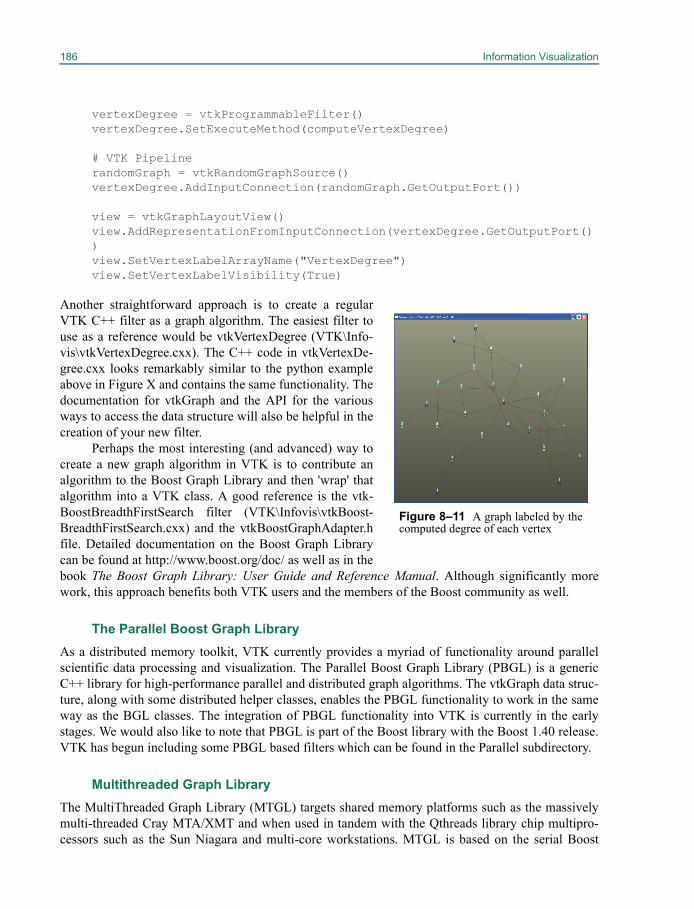
186 Information Visualization
vertexDegree = vtkProgrammableFilter()vertexDegree.SetExecuteMethod(computeVertexDegree)
# VTK PipelinerandomGraph = vtkRandomGraphSource()vertexDegree.AddInputConnection(randomGraph.GetOutputPort())
view = vtkGraphLayoutView()view.AddRepresentationFromInputConnection(vertexDegree.GetOutputPort())view.SetVertexLabelArrayName("VertexDegree")view.SetVertexLabelVisibility(True)
Another straightforward approach is to create a regularVTK C++ filter as a graph algorithm. The easiest filter touse as a reference would be vtkVertexDegree (VTK\Info-vis\vtkVertexDegree.cxx). The C++ code in vtkVertexDe-gree.cxx looks remarkably similar to the python exampleabove in Figure X and contains the same functionality. Thedocumentation for vtkGraph and the API for the variousways to access the data structure will also be helpful in thecreation of your new filter.
Perhaps the most interesting (and advanced) way tocreate a new graph algorithm in VTK is to contribute analgorithm to the Boost Graph Library and then 'wrap' thatalgorithm into a VTK class. A good reference is the vtk-BoostBreadthFirstSearch filter (VTK\Infovis\vtkBoost-BreadthFirstSearch.cxx) and the vtkBoostGraphAdapter.hfile. Detailed documentation on the Boost Graph Librarycan be found at http://www.boost.org/doc/ as well as in thebook The Boost Graph Library: User Guide and Reference Manual. Although significantly morework, this approach benefits both VTK users and the members of the Boost community as well.
The Parallel Boost Graph LibraryAs a distributed memory toolkit, VTK currently provides a myriad of functionality around parallelscientific data processing and visualization. The Parallel Boost Graph Library (PBGL) is a genericC++ library for high-performance parallel and distributed graph algorithms. The vtkGraph data struc-ture, along with some distributed helper classes, enables the PBGL functionality to work in the sameway as the BGL classes. The integration of PBGL functionality into VTK is currently in the earlystages. We would also like to note that PBGL is part of the Boost library with the Boost 1.40 release.VTK has begun including some PBGL based filters which can be found in the Parallel subdirectory.
Multithreaded Graph LibraryThe MultiThreaded Graph Library (MTGL) targets shared memory platforms such as the massivelymulti-threaded Cray MTA/XMT and when used in tandem with the Qthreads library chip multipro-cessors such as the Sun Niagara and multi-core workstations. MTGL is based on the serial Boost
Figure 8–11 A graph labeled by thecomputed degree of each vertex
8.5 Databases 187
Graph Library, as data distribution is not an issue on the platforms in question. Shared memory pro-gramming is a challenge, and algorithm objects in the MTGL can encapsulate much, but not all, ofthis challenge. As in the BGL, the visitor pattern enables users to apply methods at key points of algo-rithm execution. MTGL users write adapters over their graph data structures as BGL users do, butthere is no assumption that Boost and STL are available. MTGL codes for connected components onunstructured graphs, a difficult problem for distributed memory architectures, have scaled almost per-fectly on the Cray MTA-2.
8.5 DatabasesAs part of its information visualization capability, VTK 5.4 provides classes for access to SQL data-bases. Infovis datasets are often a good match for a relational database model. These often containseveral smaller datasets linked by common attributes that fit well into tables. Also, a database allowsan application to offload the task of managing large data by issuing queries for precisely the subset ofinterest.
Low-level database access is separated into two abstract classes. The first, vtkSQLDatabase, isresponsible for opening and closing databases, reporting whether features such as transactions, pre-pared statements and triggers are supported, and creating tables using schema objects. The second,vtkSQLQuery, is responsible for sending an SQL statement to the database for execution, checkingfor errors, and providing access to the results.
The details of connecting to a particular database (MySQL, SQLite, Oracle, etc.) are imple-mented in concrete subclasses of vtkSQLDatabase. Similarly, the details of executing a query andretrieving results for a particular database are implemented in concrete subclasses of vtkSQLQuery.These concrete subclasses are respectively called “database drivers” and “query drivers”.
VTK 5.4 includes drivers for the following databases:
• SQLite 3.4.1
• MySQL 5.0 (and higher)
• PostgreSQL 7.1 (and higher)
• ODBC
A copy of SQLite is included with the VTK source code. In order to interact with other databaseimplementations you must build VTK from source and link against vendor-provided client libraries.If you compiled the database yourself, these libraries were probably built automatically. If youinstalled a pre-compiled package you may need to download them separately (typically in a “develop-ment” package).
Connecting to a Database
In order to connect to a database you must first obtain an instance of an appropriate database driver.There are two ways to do this.
1. Create the driver automatically from a URL:
2. vtkSQLDatabase *db = vtkSQLDatabase::CreateFromURL(“sqlite://mydata.db”);
3. Instantiate the driver directly:

188 Information Visualization
4. vtkSQLiteDatabase *db = vtkSQLiteDatabase::New();
The CreateFromURL() method will attempt to set all of the supplied parameters (username, serveraddress, server port, database name) on the driver object. If you instantiate the driver directly youmust set all of these parameters yourself. If the database requires a password you must supply it in thecall to Open(). You may close a connection by calling Close() or by deleting the database driver. If thedatabase connection could not be opened then Open() will return false. You may retrieve informationabout the reason for the failure using the GetLastErrorText() method. The C++ code for opening adatabase will generally look like the following:
vtkSQLDatabase *db = vtkSQLDatabase::CreateFromURL("sqlite://mydata.db"); bool status = db->Open(""); if (!status) { cout << "Couldn't open database. Error message: " << db->GetLastErrorText() << endl; }
Once a connection has been established you may call GetTables() to obtain a list of the tables in thedatabase. The GetRecord() function, called with the name of one of those tables, will return a list ofthe columns in that table. These functions are useful for applications that connect to databases withoutany foreknowledge of their schemata.
Executing Queries
To actually execute a query you must use an instance of one of the query drivers. Query drivers arenever instantiated directly. To obtain one, call GetQueryInstance() on the database driver once theconnection has been opened successfully. Set up your query by calling SetQuery() with a string con-taining the entire SQL statement. It is not necessary to terminate the statement with a semicolon. Youmust embed all of the query parameters within the string. The query will be sent to the database andexecuted when you call the Execute() method. Execute() will return true or false depending onwhether the query ran successfully or whether it encountered an error. As with the database driver,you may retrieve any error message by calling GetLastErrorText() on the query driver.
vtkSQLQuery* query = db->GetQueryInstance(); const char *queryText = "SELECT name, age, weight " "FROM people WHERE age <= 20"; query->SetQuery(queryText); if (!query->Execute()) { cout << "Query failed. Error message: " << query->GetLastErrorText() << endl; }
You may re-use a single query driver for multiple queries. There is no notion of “closing” a currentlyactive query: you may simply set the new query string with SetQuery() and call Execute(). If thedriver was in the middle of reading a set of query results they will be cleaned up automatically.
8.5 Databases 189
Queries and ThreadsNeither vtkSQLQuery nor vtkSQLDatabase are thread-safe. This is more a limitation of the underly-ing native database APIs, which are themselves rarely thread-safe, than of VTK itself. If your applica-tion needs to access a database concurrently from multiple threads you must create a new databaseconnection (via vtkSQLDatabase) for each thread. Each thread may maintain as many vtkSQLQueryobjects as necessary. In some installations the database administrator may impose limits on how manyconcurrent sessions and queries may be open simultaneously. Check with your system administratorto see if this is a concern.
Reading ResultsOnce a query has been executed successfully, indicated by Execute() returning a value of true, yourprogram may read the query results. There are two kinds of data that may be retrieved here. The querymetadata comprises the number of columns, their names, and their data types. These can be retrievedwith GetNumberOfColumns(), GetColumnName(int) and GetColumnType(int). VTK will do its bestto convert from the database back-end's native data type to standard data types supported in C++,Python and Java.
The result data is read one row at a time. You must call vtkSQLQuery::NextRow() to advanceto the next available row. This method will return true if there is another row available to read andfalse when no more data can be retrieved. Data values within a row may be retrieved either one at atime or all at once. To retrieve the value for a single column, call vtkSQLQuery::DataValue(int) withthe index of the column you want to retrieve. The entire process looks like the following.
while (query->NextRow()) { for (int field = 0; field < query->GetNumberOfFields(); field++) { vtkVariant v = query->DataValue(field); // Process it } }
To retrieve an entire row at once, call vtkSQLQuery::NextRow(vtkVariantArray *) instead of Nex-tRow(). The values for that row will be stored in the array you supply.
vtkVariantArray* va = vtkVariantArray::New(); while (query->NextRow(va)) { // Process it }
When processing query results we often wish to store the entire result set in a vtkTable to be passedthrough the pipeline. The vtkRowQueryToTable filter does exactly this. Use it by obtaining and set-ting up a query driver, then passing the query to the filter as the argument to SetQuery(). The querywill be executed when the filter is updated either manually (by calling Update()) or through a requestfrom further down the pipeline.
vtkRowQueryToTable* reader = vtkRowQueryToTable::New();
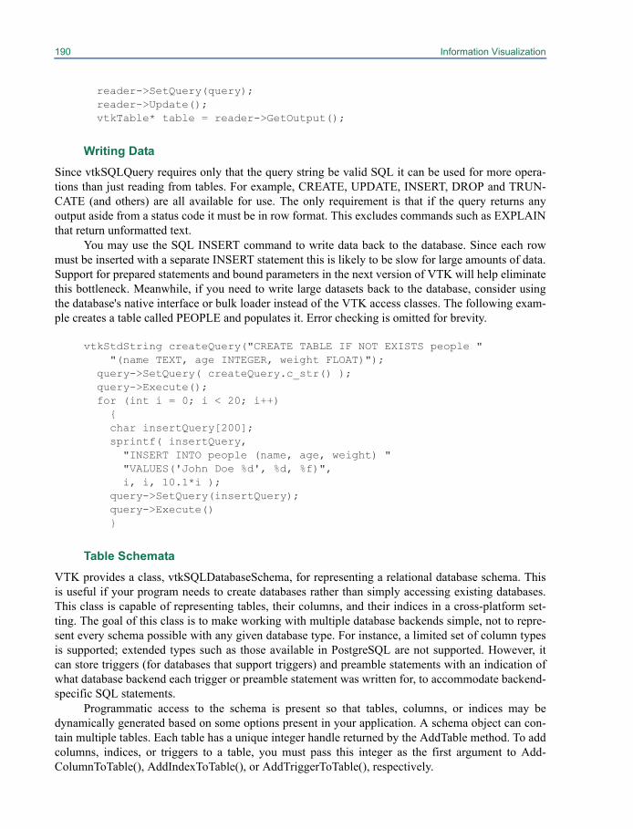
190 Information Visualization
reader->SetQuery(query); reader->Update(); vtkTable* table = reader->GetOutput();
Writing DataSince vtkSQLQuery requires only that the query string be valid SQL it can be used for more opera-tions than just reading from tables. For example, CREATE, UPDATE, INSERT, DROP and TRUN-CATE (and others) are all available for use. The only requirement is that if the query returns anyoutput aside from a status code it must be in row format. This excludes commands such as EXPLAINthat return unformatted text.
You may use the SQL INSERT command to write data back to the database. Since each rowmust be inserted with a separate INSERT statement this is likely to be slow for large amounts of data.Support for prepared statements and bound parameters in the next version of VTK will help eliminatethis bottleneck. Meanwhile, if you need to write large datasets back to the database, consider usingthe database's native interface or bulk loader instead of the VTK access classes. The following exam-ple creates a table called PEOPLE and populates it. Error checking is omitted for brevity.
vtkStdString createQuery("CREATE TABLE IF NOT EXISTS people " "(name TEXT, age INTEGER, weight FLOAT)"); query->SetQuery( createQuery.c_str() ); query->Execute(); for (int i = 0; i < 20; i++) { char insertQuery[200]; sprintf( insertQuery, "INSERT INTO people (name, age, weight) " "VALUES('John Doe %d', %d, %f)", i, i, 10.1*i ); query->SetQuery(insertQuery); query->Execute() }
Table SchemataVTK provides a class, vtkSQLDatabaseSchema, for representing a relational database schema. Thisis useful if your program needs to create databases rather than simply accessing existing databases.This class is capable of representing tables, their columns, and their indices in a cross-platform set-ting. The goal of this class is to make working with multiple database backends simple, not to repre-sent every schema possible with any given database type. For instance, a limited set of column typesis supported; extended types such as those available in PostgreSQL are not supported. However, itcan store triggers (for databases that support triggers) and preamble statements with an indication ofwhat database backend each trigger or preamble statement was written for, to accommodate backend-specific SQL statements.
Programmatic access to the schema is present so that tables, columns, or indices may bedynamically generated based on some options present in your application. A schema object can con-tain multiple tables. Each table has a unique integer handle returned by the AddTable method. To addcolumns, indices, or triggers to a table, you must pass this integer as the first argument to Add-ColumnToTable(), AddIndexToTable(), or AddTriggerToTable(), respectively.
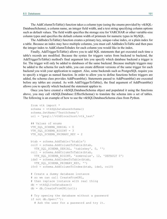
8.5 Databases 191
The AddColumnToTable() function takes a column type (using the enums provided by vtkSQL-DatabaseSchema), a column name, an integer field width, and a text string specifying column optionssuch as default values. The field width specifies the storage size for VARCHAR or other variable-sizecolumn types and specifies the default column width of printouts for numeric types in MySQL.
The AddIndexToTable() function creates a primary key, unique-value index, or a plain index fora table. Because an index may have multiple columns, you must call AddIndexToTable and then passthe integer index to AddColumnToIndex for each column you would like in the index.
Finally, AddTriggerToTable() allows you to add SQL statements that get executed each time atable's records are modified. Because the syntax for triggers varies from backend to backend, theAddTriggerToTable() method's final argument lets you specify which database backend a trigger isfor. The trigger will only be added to databases of the same backend. Because multiple triggers maybe added to the schema for each table, you can create different versions of the same trigger for eachbackend you wish your application to support. Also, some backends such as PostgreSQL require youto specify a trigger as named function. In order to allow you to define functions before triggers areadded, the schema class provides AddPreamble(). Statements passed to AddPreamble() are executedbefore any tables are created. As with AddTriggerToTable(), the final argument of AddPreamble()allows you to specify which backend the statement applies to.
Once you have created a vtkSQLDatabaseSchema object and populated it using the functionsabove, you may call vtkSQLDatabase::EffectSchema() to translate the schema into a set of tables.The following is an example of how to use the vtkSQLDatabaseSchema class from Python.
from vtk import *schema = vtkSQLDatabaseSchema()schema.SetName('TestSchema')url = 'psql://vtk@localhost/vtk_test'
## Values of enumsVTK_SQL_SCHEMA_SERIAL = 0VTK_SQL_SCHEMA_BIGINT = 3VTK_SQL_SCHEMA_PRIMARY_KEY = 2
btab = schema.AddTable('btable')col0 = schema.AddColumnToTable(btab, VTK_SQL_SCHEMA_SERIAL, 'tablekey', 0, '')col1 = schema.AddColumnToTable(btab, VTK_SQL_SCHEMA_BIGINT, 'somevalue', 12, 'DEFAULT 0')idx0 = schema.AddIndexToTable(btab, VTK_SQL_SCHEMA_PRIMARY_KEY, '')i0c0 = schema.AddColumnToIndex(btab, idx0, col0)
# Create a dummy database instance# so we can call CreateFromURL,# then replace instance with real thingdb = vtkSQLiteDatabase()db = db.CreateFromURL(url);
# Try opening the database without a passwordif not db.Open(''): # Ask the user for a password and try it.
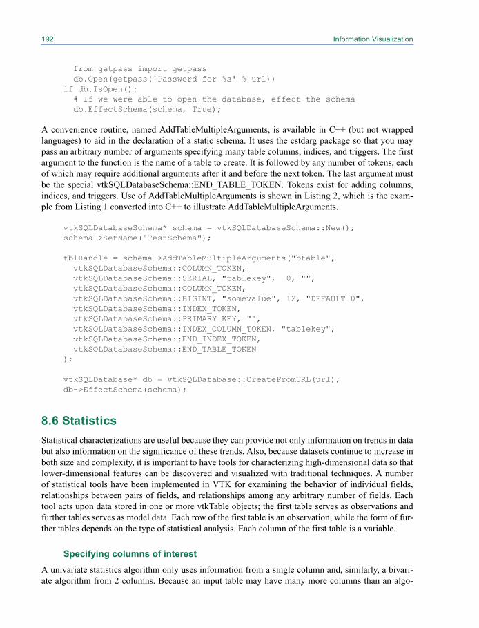
192 Information Visualization
from getpass import getpass db.Open(getpass('Password for %s' % url))if db.IsOpen(): # If we were able to open the database, effect the schema db.EffectSchema(schema, True);
A convenience routine, named AddTableMultipleArguments, is available in C++ (but not wrappedlanguages) to aid in the declaration of a static schema. It uses the cstdarg package so that you maypass an arbitrary number of arguments specifying many table columns, indices, and triggers. The firstargument to the function is the name of a table to create. It is followed by any number of tokens, eachof which may require additional arguments after it and before the next token. The last argument mustbe the special vtkSQLDatabaseSchema::END_TABLE_TOKEN. Tokens exist for adding columns,indices, and triggers. Use of AddTableMultipleArguments is shown in Listing 2, which is the exam-ple from Listing 1 converted into C++ to illustrate AddTableMultipleArguments.
vtkSQLDatabaseSchema* schema = vtkSQLDatabaseSchema::New();schema->SetName("TestSchema");
tblHandle = schema->AddTableMultipleArguments("btable", vtkSQLDatabaseSchema::COLUMN_TOKEN, vtkSQLDatabaseSchema::SERIAL, "tablekey", 0, "", vtkSQLDatabaseSchema::COLUMN_TOKEN, vtkSQLDatabaseSchema::BIGINT, "somevalue", 12, "DEFAULT 0", vtkSQLDatabaseSchema::INDEX_TOKEN, vtkSQLDatabaseSchema::PRIMARY_KEY, "", vtkSQLDatabaseSchema::INDEX_COLUMN_TOKEN, "tablekey", vtkSQLDatabaseSchema::END_INDEX_TOKEN, vtkSQLDatabaseSchema::END_TABLE_TOKEN);
vtkSQLDatabase* db = vtkSQLDatabase::CreateFromURL(url);db->EffectSchema(schema);
8.6 StatisticsStatistical characterizations are useful because they can provide not only information on trends in databut also information on the significance of these trends. Also, because datasets continue to increase inboth size and complexity, it is important to have tools for characterizing high-dimensional data so thatlower-dimensional features can be discovered and visualized with traditional techniques. A numberof statistical tools have been implemented in VTK for examining the behavior of individual fields,relationships between pairs of fields, and relationships among any arbitrary number of fields. Eachtool acts upon data stored in one or more vtkTable objects; the first table serves as observations andfurther tables serves as model data. Each row of the first table is an observation, while the form of fur-ther tables depends on the type of statistical analysis. Each column of the first table is a variable.
Specifying columns of interestA univariate statistics algorithm only uses information from a single column and, similarly, a bivari-ate algorithm from 2 columns. Because an input table may have many more columns than an algo-

8.6 Statistics 193
rithm can make use of, VTK must provide a way for users to denote columns of interest. Because itmay be more efficient to perform multiple analyses of the same type on different sets of columns atonce as opposed to one after another, VTK provides a way for users to make multiple analysisrequests in a single filter.
As an example, consider Figure 8–12. It has 6 observations of 5 variables. If the linear correla-tions between A, B, and C, and also between B, C and D are desired, two requests, R1 and R2 must bemade: The first request R1 would have columns of interest {A,B,C} while R2 would have columns ofinterest {B,C,D}. Calculating linear correlations for R1 and R2 in one pass is more efficient thancomputing each separately since the covariances cov(B,B), cov(C,C), and cov(B,C) are required forboth requests but need only be computed once.
Phases
Each statistics algorithm performs its computations in a sequence of common phases, regardless ofthe particular analysis being performed. The VTK statistics algorithms may be configured to performvarious subsets of these three operations as desired. These phases can be described as:
• Learn: Calculate a “raw” statistical model from an input data set. By “raw”, we mean the min-imal representation of the desired model, that contains only primary statistics. For example, inthe case of descriptive statistics: sample size, minimum, maximum, mean, and centered M2,M3 and M4 aggregates (cf. P. Pébay, Formulas for Robust, One-Pass Parallel Computation ofCovariances and Arbitrary-Order Statistical Moments, Sandia Report SAND2008-6212, Sep-tember 2008, http://infoserve.sandia.gov/sand_doc/2008/086212.pdf). For Table 1 with arequest R1={B}, these values are 6, 1, 11, 4.83..., 68.83..., 159.4..., and 1759.8194..., respec-tively.
• Derive: Calculate a “full” statistical model from a raw model. By “full”, we mean the completerepresentation of the desired model, that contains both primary and derived statistics. For exam-ple, in the case of descriptive statistics, the following derived statistics are calculated from theraw model: unbiased variance estimator, standard deviation, and two estimators (g and G) forboth skewness and kurtosis. For Table 1 with a request R1={B}, these additional values are13.76..., 3.7103, 0.520253, 0.936456, -1.4524, and -1.73616 respectively.
• Assess: Given a statistical model -- from the same or another data set -- mark each datum of agiven data set. For example, in the case of descriptive statistics, each datum is marked with its
Row A B C D E
1 0 1 0 1 1.03315
2 1 2 2 2 0.76363
3 0 3 4 6 0.49411
4 1 5 6 24 0.04492
5 0 7 8 120 0.58935
6 1 11 10 720 1.66202
Figure 8–12 A table of observations that might serve as input to a statistics algorithm

194 Information Visualization
relative deviation with respect to the model mean and standard deviation (this amounts to theone-dimensional Mahalanobis distance). Table 1 shows this distance for R1 = {B} in column E.
An example of the utilization of VTK's statistical tools with the Qt application client <description -paraview application tailored to infovis> is illustrated in Figure 8–13; specifically, the descriptive,correlative, and order statistics classes are used in conjunction with various table views and plots.With the exception of contingency statistics which can be performed on any type (nominal, cardinal,or ordinal) of variables, all currently implemented algorithms require cardinal or ordinal variables asinputs. The following statistics algorithms are currently available in VTK.
Univariate AlgorithmsThese algorithms accept a single column (or a set of single columns) and perform an analysis of thedistribution of data in that column.
Descriptive statistics.
• Learn: calculate minimum, maximum, mean, and centered M2, M3 and M4 aggregates;• Derive: calculate unbiased variance estimator, standard deviation, skewness (g1 and G1 estima-
tors), kurtosis (g2 and G2 estimators);• Assess: mark with relative deviations (one-dimensional Mahlanobis distance).
Order statistics.
• Learn: calculate histogram;• Derive: calculate arbitrary quantiles, such as 5-point statistics (quartiles) for box plots, deciles,
percentiles, etc.;• Assess: mark with the quantile index.
Figure 8–13 An example utilization of VTK'sstatistics algorithms with the OverView client
8.6 Statistics 195
Bivariate statistics:These algorithms accept a pair(s) of columns to operate on, and perform a comparative analysis.
Correlative statistics.
• Learn: calculate minima, maxima, means, and centered M2 aggregates;• Derive: calculate unbiased variance and covariance estimators, Pearson correlation coefficient,
and linear regressions (both ways);• Assess: mark with squared two-dimensional Mahlanobis distance.
Contingency statistics.
• Learn: calculate contingency table;• Derive: calculate joint, conditional, and marginal probabilities, as well as information entro-
pies;• Assess: mark with joint and conditional PDF values, as well as pointwise mutual informations.
Multivariate statistics:These filters all accept multiple requests Ri, each of which is a set of ni variables upon which simulta-neous statistics should be computed.
Multi-correlative statistics.
• Learn: calculate means and pairwise centered M2 aggregates;• Derive: calculate the upper triangular portion of the symmetric ni x ni covariance matrix and its
(lower) Cholesky decomposition;• Assess: mark with squared multi-dimensional Mahlanobis distance.
Principal component analysis (PCA) statistics.
• Learn: identical to the multi-correlative filter;• Derive: everything the multi-correlative filter provides, plus the ni eigenvalues and eigenvec-
tors of the covariance matrix;• Assess: perform a change of basis to the principal components (eigenvectors), optionally pro-
jecting to the first mi components, where mi <= ni is either some user-specified value or isdetermined by the fraction of maximal eigenvalues whose sum is above a user-specified thresh-old. This results in mi additional columns of data for each request Ri.
k-Means statistics (kMeans was added after VTK 5.4).
• Learn: calculate new cluster centers for data using initial cluster centers. When initial clustercenters are provided by the user using an additional input table, multiple sets of new clustercenters are computed. The output metadata is a multiblock dataset containing at a minimum onevtkTable with columns specifying the following for each run: the run ID, number of clusters,number of iterations required for convergence, RMS error associated with the cluster, the num-
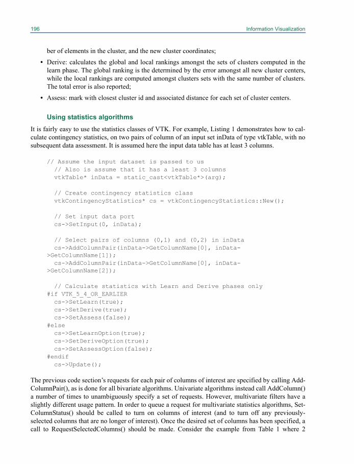
196 Information Visualization
ber of elements in the cluster, and the new cluster coordinates;
• Derive: calculates the global and local rankings amongst the sets of clusters computed in thelearn phase. The global ranking is the determined by the error amongst all new cluster centers,while the local rankings are computed amongst clusters sets with the same number of clusters.The total error is also reported;
• Assess: mark with closest cluster id and associated distance for each set of cluster centers.
Using statistics algorithms
It is fairly easy to use the statistics classes of VTK. For example, Listing 1 demonstrates how to cal-culate contingency statistics, on two pairs of column of an input set inData of type vtkTable, with nosubsequent data assessment. It is assumed here the input data table has at least 3 columns.
// Assume the input dataset is passed to us // Also is assume that it has a least 3 columns vtkTable* inData = static_cast<vtkTable*>(arg);
// Create contingency statistics class vtkContingencyStatistics* cs = vtkContingencyStatistics::New();
// Set input data port cs->SetInput(0, inData);
// Select pairs of columns (0,1) and (0,2) in inData cs->AddColumnPair(inData->GetColumnName[0], inData->GetColumnName[1]); cs->AddColumnPair(inData->GetColumnName[0], inData->GetColumnName[2]);
// Calculate statistics with Learn and Derive phases only#if VTK_5_4_OR_EARLIER cs->SetLearn(true); cs->SetDerive(true); cs->SetAssess(false);#else cs->SetLearnOption(true); cs->SetDeriveOption(true); cs->SetAssessOption(false);#endif cs->Update();
The previous code section’s requests for each pair of columns of interest are specified by calling Add-ColumnPair(), as is done for all bivariate algorithms. Univariate algorithms instead call AddColumn()a number of times to unambiguously specify a set of requests. However, multivariate filters have aslightly different usage pattern. In order to queue a request for multivariate statistics algorithms, Set-ColumnStatus() should be called to turn on columns of interest (and to turn off any previously-selected columns that are no longer of interest). Once the desired set of columns has been specified, acall to RequestSelectedColumns() should be made. Consider the example from Table 1 where 2

8.6 Statistics 197
requests are mentioned: {A,B,C} and {B,C,D}. The code snippet in Listing 2 shows how to queuethese requests for a vtkPCAStatistics object.
vtkPCAStatistics* pps = vtkPCAStatistics::New();
// Turn on columns of interest ps->SetColumnStatus("A", 1); ps->SetColumnStatus("B", 1); ps->SetColumnStatus("C", 1); ps->RequestSelectedColumns();
// Columns A, B, and C are still selected, so first we turn off // column A so it will not appear in the next request. ps->SetColumnStatus("A", 0); ps->SetColumnStatus("D", 1); ps->RequestSelectedColumns();[Listing 2: An example of requesting multiple multi-variate analyses.]
Parallel Statistics AlgorithmsOne of the purposes of building a full statistical model in three phases is parallel computational effi-ciency. In our approach, inter-processor communication and updates are performed only for primarystatistics. The calculations to obtain derived statistics from primary statistics are typically fast andsimple and need only be calculated once, without communication, upon completion of all parallelupdates of primary variables. Data to be assessed is assumed to be distributed in parallel across allprocesses participating in the computation, thus no communication is required as each processassesses its own resident data.
Therefore, in the parallel versions of the statistical engines, inter-processor communication isrequired only for the Learn phase, while both Derive and Assess are executed in an embarrassinglyparallel fashion due to data parallelism. This design is consistent with the data parallelism methodol-ogy used to enable parallelism within VTK, most notably in ParaView. The following 5 parallel sta-tistics classes are currently available in VTK:
• vtkPDescriptiveStatistics• vtkPCorrelativeStatistics• vtkPContingencyStatistics• vtkPMultiCorrelativeStatistics• vtkPPCAStatistics
Each of these parallel algorithms is implemented as a subclass of the respective serial version of thealgorithm and contains a vtkMultiProcessController to handle inter-processor communication. Withineach of the parallel statistics classes, the Learn phase is the only phase whose behavior is changed (byreimplementing its virtual method) due to the data parallelism inherent in the Derive and Assessphases. The Learn phase of the parallel algorithms performs two primary tasks:
1. Calculate correlative statistics on local data by executing the Learn code of the superclass.2. If parallel updates are needed (i.e. the number of processes is greater than 1), perform necessary
data gathering and aggregation of local statistics into global statistics.
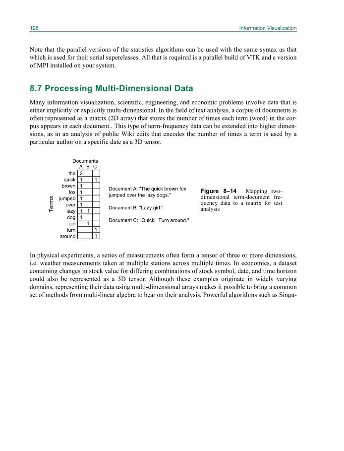
198 Information Visualization
Note that the parallel versions of the statistics algorithms can be used with the same syntax as thatwhich is used for their serial superclasses. All that is required is a parallel build of VTK and a versionof MPI installed on your system.
8.7 Processing Multi-Dimensional DataMany information visualization, scientific, engineering, and economic problems involve data that iseither implicitly or explicitly multi-dimensional. In the field of text analysis, a corpus of documents isoften represented as a matrix (2D array) that stores the number of times each term (word) in the cor-pus appears in each document.. This type of term-frequency data can be extended into higher dimen-sions, as in an analysis of public Wiki edits that encodes the number of times a term is used by aparticular author on a specific date as a 3D tensor.
In physical experiments, a series of measurements often form a tensor of three or more dimensions,i.e. weather measurements taken at multiple stations across multiple times. In economics, a datasetcontaining changes in stock value for differing combinations of stock symbol, date, and time horizoncould also be represented as a 3D tensor. Although these examples originate in widely varyingdomains, representing their data using multi-dimensional arrays makes it possible to bring a commonset of methods from multi-linear algebra to bear on their analysis. Powerful algorithms such as Singu-
Figure 8–14 Mapping two-dimensional term-document fre-quency data to a matrix for testanalysis
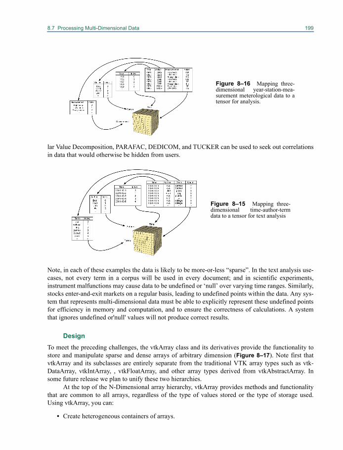
8.7 Processing Multi-Dimensional Data 199
lar Value Decomposition, PARAFAC, DEDICOM, and TUCKER can be used to seek out correlationsin data that would otherwise be hidden from users.
Note, in each of these examples the data is likely to be more-or-less “sparse”. In the text analysis use-cases, not every term in a corpus will be used in every document; and in scientific experiments,instrument malfunctions may cause data to be undefined or ‘null’ over varying time ranges. Similarly,stocks enter-and-exit markets on a regular basis, leading to undefined points within the data. Any sys-tem that represents multi-dimensional data must be able to explicitly represent these undefined pointsfor efficiency in memory and computation, and to ensure the correctness of calculations. A systemthat ignores undefined or'null' values will not produce correct results.
DesignTo meet the preceding challenges, the vtkArray class and its derivatives provide the functionality tostore and manipulate sparse and dense arrays of arbitrary dimension (Figure 8–17). Note first thatvtkArray and its subclasses are entirely separate from the traditional VTK array types such as vtk-DataArray, vtkIntArray, , vtkFloatArray, and other array types derived from vtkAbstractArray. Insome future release we plan to unify these two hierarchies.
At the top of the N-Dimensional array hierarchy, vtkArray provides methods and functionalitythat are common to all arrays, regardless of the type of values stored or the type of storage used.Using vtkArray, you can:
• Create heterogeneous containers of arrays.
Figure 8–15 Mapping three-dimensional time-author-termdata to a tensor for text analysis
Figure 8–16 Mapping three-dimensional year-station-mea-surement meterological data to atensor for analysis.
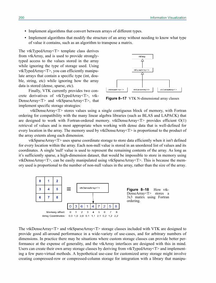
200 Information Visualization
• Implement algorithms that convert between arrays of different types.• Implement algorithms that modify the structure of an array without needing to know what type
of value it contains, such as an algorithm to transpose a matrix.
The vtkTypedArray<T> template class derivesfrom vtkArray, and is used to provide strongly-typed access to the values stored in the arraywhile ignoring the type of storage used. UsingvtkTypedArray<T>, you can efficiently manipu-late arrays that contain a specific type (int, dou-ble, string, etc) while ignoring how the arraydata is stored (dense, sparse, etc).
Finally, VTK currently provides two con-crete derivatives of vtkTypedArray<T>, vtk-DenseArray<T> and vtkSparseArray<T>, thatimplement specific storage strategies:
vtkDenseArray<T> stores values using a single contiguous block of memory, with Fortranordering for compatibility with the many linear algebra libraries (such as BLAS and LAPACK) thatare designed to work with Fortran-ordered memory. vtkDenseArray<T> provides efficient O(1)retrieval of values and is most appropriate when working with dense data that is well-defined forevery location in the array. The memory used by vtkDenseArray<T> is proportional to the product ofthe array extents along each dimension.
vtkSparseArray<T> uses sparse coordinate storage to store data efficiently when it isn't definedfor every location within the array. Each non-null value is stored in an unordered list of values and itscoordinates. A single 'null' value is used to represent the remaining contents of the array. As long asit’s sufficiently sparse, a high-dimension dataset, that would be impossible to store in memory usingvtkDenseArray<T>, can be easily manipulated using vtkSparseArray<T>. This is because the mem-ory used is proportional to the number of non-null values in the array, rather than the size of the array.
The vtkDenseArray<T> and vtkSparseArray<T> storage classes included with VTK are designed toprovide good all-around performance in a wide-variety of use-cases, and for arbitrary numbers ofdimensions. In practice there may be situations where custom storage classes can provide better per-formance at the expense of generality, and the vtkArray interfaces are designed with this in mind.Users can create their own array storage classes by deriving from vtkTypedArray<T> and implement-ing a few pure-virtual methods. A hypothetical use-case for customized array storage might involvecreating compressed-row or compressed-column storage for integration with a library that manipu-
Figure 8–17 VTK N-dimensional array classes
Figure 8–18 How vtk-DenseArray<T> stores a3x3 matirx using Fortranordering.
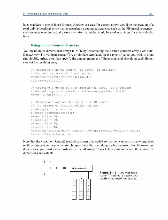
8.7 Processing Multi-Dimensional Data 201
lates matrices in one of those formats. Another use-case for custom arrays would be the creation of aread-only 'procedural' array that encapsulates a computed sequence such as the Fibonacci sequence -such an array wouldn't actually store any information, but could be used as an input for other calcula-tions.
Using multi-dimensional arraysYou create multi-dimensional arrays in VTK by instantiating the desired concrete array class (vtk-DenseArray<T>, vtkSparseArray<T>, or similar) templated on the type of value you wish to store(int, double, string, etc), then specify the extents (number of dimensions and size along each dimen-sion) of the resulting array:
// Creating a dense vector (1D array) of strings:vtkDenseArray<vtkStdString>* vector = vtkDenseArray<vtkStdString>::New(); vector->Resize(10);
// Creating a dense 10 x 20 matrix (2D array) of integers:vtkDenseArray<int>* matrix = vtkDenseArray<int>::New();matrix->Resize(10, 20);
// Creating a sparse 10 x 20 x 30 x 40 tensor// (4D array) of floating-point values:vtkArrayExtents extents;Extents.SetDimensions(4); extents[0] = 10;extents[1] = 20; extents[2] = 30;extents[3] = 40; vtkSparseArray<double>* tensor = vtkSparseArray<double>::New();tensor->Resize(extents);
Note that the vtkArray::Resize() method has been overloaded so that you can easily create one, two,or three-dimensional arrays by simply specifying the size along each dimension. For four-or-moredimensions, you must use an instance of the vtkArrayExtents helper class to encode the number ofdimensions and extents.
Figure 8–19 How vtkSparse-Array<T> stores a sparse 3x3matrix using coordiante storage.
202 Information Visualization
After resizing, the new arrays must be properly initialized. This process will vary depending on thearray storage type - for example, the contents of vtkDenseArray<T> will be undefined after resizing,so vtkDenseArray<T> provides a Fill() method that can be used to overwrite the entire array with asingle value:
matrix->Fill(0);
Sparse arrays will be completely empty (all values will be undefined or ‘null’ values) after resizing,and it is always a good idea to explicitly specify what the 'null' value (the value that is returned when-ever a caller accesses an undefined set of coordinates) should be:
tensor->SetNullValue(0.0);
Having initialized an array, the next step is to populate it using SetValue():
// Overwrite vector[5] with "Hello World!":vector->SetValue(5, "Hello, World!");
// Overwrite matrix[4, 3] with "22":matrix->SetValue(4, 3, 22);
// Overwrite tensor[3, 7, 1, 2] with "1.5":vtkArrayCoordinates coordinates;coordinates.SetDimensions(4); coordinates[0] = 3;coordinates[1] = 7; coordinates[2] = 1;coordinates[3] = 2; tensor->SetValue(coordinates, 1.5);
Note that, as with Resize(), there are overloaded versions of SetValue() that work with one-, two-, orthree-dimensional data, and that a helper class - vtkArrayCoordinates - is used to supply coordinatesfor operations on higher dimension arrays. Not surprisingly, GetValue() is used to retrieve data froman array:
// Access array value [5]:vtkStdString vector_value = vector->GetValue(5);
// Access matrix value [4, 3]:int matrix_value = matrix->GetValue(4, 3);
// Access tensor value [3, 7, 1, 2]:double tensor_value = tensor->GetValue(coordinates);
SetValue() and GetValue() are strongly-typed methods provided by vtkTypedArray<T>, and assumethat you know the type of data stored in the array in advance, either because you created the arrayyourself, or you used SafeDownCast() to cast from vtkArray to vtkTypedArray<T> for some specificT. For situations where you are working with an array of unknown type, there are SetVariantValue() /

8.7 Processing Multi-Dimensional Data 203
GetVariantValue() methods provided by vtkArray that allow you to conveniently set and get valuesfrom any array, regardless of type, albeit with the overhead of conversion to-and-from variant values:
// Print value [8] from any one-dimensional array// to the console, regardless of type:vtkArray* generic_array = /* Defined elsewhere */cout << generic_array->GetVariantValue(8).ToString() << endl;
In this example, GetVariantValue() returns a vtkVariant object, and the vtkVariant::ToString() methodconverts the underlying value to a string, regardless of the original type. Similarly, you could use vari-ants to shuffle data within an array without having to know the type of data it contains:
// Swap values [3] and [7] within an array, regardless of array type:vtkVariant temp = generic_array->GetVariantValue(3);generic_array->SetVariantValue(3, generic_array->GetVariantValue(7));generic_array->SetVariantValue(7, temp);
PerformanceAlthough SetValue() and GetValue() provide an easily-understood, uniform interface to all arraysregardless of their storage type, the convenience of this approach carries an abstraction penalty. In thematerial that follows, we will cover some important techniques for improving the performance ofarray-related code.
Populating Dense ArraysYou will often need to manipulate the contents of vtkDenseArray<T> as a simple block of memory,either for I/O operations or for interoperability with other libraries. For these situations, vtkDenseAr-ray<T> provides the GetStorage() method, which returns a pointer to the memory block that storesthe array contents. You could use this pointer to write the (binary) contents of an array to a file as asingle contiguous block:
// Write the contents of a dense int array as binary data to a streamvoid WriteDenseArray(vtkDenseArray<int>* array, ostream& stream){ stream.write( reinterpret_cast<char*>(array->GetStorage()), array->GetSize() * sizeof(int));}
Alternately, you could pass the memory block to a library that performs dense array calculations, solong as the ordering of the values in the memory block (Fortran) match what the library expects. Youshould try to use this approach whenever practical, since it avoids making deep-copies of your data asyou pass it to a library and retrieve the results.
Populating Sparse Arrays Recall that vtkSparseArray<T> stores values internally using a list of non-null values with their cor-responding coordinates. This means that whenever SetValue() is called, vtkSparseArray<T> must
204 Information Visualization
first determine whether an existing value at those coordinates already exists. If it does, the old value isreplaced with the new value; otherwise, the new value and its coordinates are appended to the end ofthe list. This linear search for existing values makes SetValue() an expensive operation for sparsearrays, compared to a constant-time operation on dense arrays. Used naively, SetValue() makes thecreation of sparse arrays unacceptably slow.
Fortunately, vtkSparseArray<T> provides the AddValue() method, which appends values to theinternal list without performing a search for existing values, and executes in amortized constant time.This provides excellent performance, but means that the caller is responsible to avoid callingAddValue() more than once with the same set of coordinates. In practice, this means that AddValue()should only be used on an array when you are populating it from scratch (as you would do if you wereimplementing a pipeline source that creates new sparse arrays). Never call AddValue() on an arraywith unknown contents (such as the input to a filter), since you run the risk of adding values withduplicate coordinates to the array's internal list (which is not allowed). The following code demon-strates using AddValue() to efficiently create a 10000 x 10000 diagonal matrix:
vtkSparseArray<double>* array = vtkSparseArray<double>::New();array->Resize(10000, 10000);array->SetNullValue(0.0);for(vtkIdType i = 0; i != 10000; ++i) { array->AddValue(i, i, 1.0); }
IterationThe preceding examples demonstrate how to populate arrays efficiently by avoiding the pitfalls of theSetValue() method. However, similar issues arise when accessing arrays using GetValue() - becausevtkSparseArray stores non-null values in an unordered list, GetValue() must perform a linear searchevery time it is called, leading to unacceptably slow performance. To address this, VTK providesanother technique - iteration - that makes it possible to read and write values to dense and sparsearrays in constant time, so long as certain conditions are met. Using iteration, we can:
• Eliminate the cost of linear lookups when getting / setting sparse array values. • Visit only non-null values in sparse arrays. • Implement filters using a consistent interface across dense and sparse arrays. • Implement filters that operate on arbitrary-dimension data.
The iteration interface provided for VTK multi-dimensional arrays works by exposing the valuesstored in an array as a single unordered list. Each value in the array is assigned an index in the half-open range [0, N), where N is the number of non-null values stored in the array, and the vtkArray andvtkTypedArray<T> classes provide methods for accessing values 'by index': SetValueN(), GetVal-ueN(), and GetCoordinatesN(). Using these methods, you can “visit” every value in an array, regard-less of the type of array storage, and regardless of the number of dimensions in the array, using asingle loop. For example, the following code efficiently increments every value in an array of integersby one, without any knowledge of its dimensions or whether the array is sparse or dense:
vtkTypedArray<int>* array = /* Defined elsewhere */for(vtkIdType n = 0; n != array->GetNonNullSize(); ++n)
8.7 Processing Multi-Dimensional Data 205
{ array->SetValueN(n, array->GetValueN(n) + 1); }
Note that the order in which we “visit” the values in the array using GetValueN() / SetValueN() is pur-posefully undefined, and that the above code works because the order is unimportant - regardless ofthe type of underlying array, whether dense or sparse, one-dimensional or 11-dimensional, it does notmatter whether value[3] is incremented before or after value[300], so long as both are eventuallymodified in a consistent manner.
Although you cannot control the order in which values are visited, you can use GetCoordi-natesN() to discover “where you are at” as you iterate over the contents of any array, and this is usu-ally sufficient for most algorithm implementations. For example, the following code computes thesum of the values in each row in a matrix, storing the results in a dense vector. Although we visit thematrix values in arbitrary order, we can use each value's coordinates as a constant time lookup toaccumulate values in our result vector:
vtkTypedArray<double>* matrix = /* Defined elsewhere */vtkIdType row_count = matrix->GetExtents()[0];
vtkTypedArray<double>* vector = vtkDenseArray<double>::New();vector->Resize(row_count);vector->Fill(0.0);
for(vtkIdType n = 0; n != matrix->GetNonNullSize(); ++n) { vtkArrayCoordinates coordinates; matrix->GetCoordinatesN(n, coordinates); vtkIdType row = coordinates[0];
vector->SetValue(row, vector->GetValue(row) + matrix->GetValueN(n)); }
The lack of a specific order of iteration may seem limiting at first, but a surprisingly large number ofalgorithms can be written to work within this constraint, benefiting from constant-time lookups,dimension, and storage-type independence.
Array Data
Now that we can create and manipulate multi-dimension arrays, it's time to move them through theVTK pipeline. Like vtkAbstractArray, vtkArray isn't a vtkDataObject, so it cannot be used directly bythe pipeline. Instead, VTK provides vtkArrayData which acts as a container for arrays, and vtkArray-DataAlgorithm which can be used to implement vtkArrayData sources and filters:
Array Sources
• vtkDiagonalMatrixSource - Produces sparse or dense matrices of arbitrary size, with user-assigned values for the diagonal, superdiagonal, and subdiagonal.
206 Information Visualization
• vtkBoostRandomSparseArraySource - Produces sparse matrices with arbitrary size and numberof dimensions. Provides separate parameters to control generation of random values and ran-dom sparse patterns.
• vtkTableToSparseArray - Converts a vtkTable containing coordinates and values into a sparsearray of arbitrary dimensions.
Array Algorithms
• vtkAdjacencyMatrixToEdgeTable - Converts a dense matrix into a vtkTable suitable for usewith vtkTableToGraph. Dimension labels in the input matrix are mapped to column names inthe output table.
• vtkArrayVectorNorm - Computes an L-norm for each column-vector in a sparse double matrix. • vtkCosineSimilarity - Treats each row or column in a matrix as a vector, and computes the dot-
product similarity between each pair of vectors, producing a vtkTable suitable for use with vtk-TableToGraph. Note: In VTK versions after 5.4, vtkCosineSimilarity has been renamed vtkDot-ProductSimilarity, to better describe its functionality
• vtkDotProductSimilarity -Treats each row or column in a matrix as a vector, and computes thedot-product similarity between each pair of vectors, producing a vtkTable suitable for use withvtkTableToGraph.
• vtkBoostLogWeighting - Replaces each value p in an array with the natural logarithm of p+1.Good example of a filter that works with any array, containing any number of dimensions.
• vtkMatricizeArray - Converts sparse double arrays of arbitrary dimension to sparse matrices.For example, an i x j x k tensor can be converted into an i x jk, j x ik, or ij x k matrix.
• vtkNormalizeMatrixVectors - Normalizes either row vectors or column vectors in a matrix.Good example of a filter that works efficiently with both sparse and dense input matrices. Goodexample of a filter that works with either row or column vectors.
• vtkTransposeMatrix - Computes the transpose of a matrix.
Chapter 9
Geospatial Visualization 9
Geospatial visualization is a discipline that combinestechniques from traditional scientific visualization and information visualization in order to displaygeographically organized data. VTK's geospatial visualization facilities are currently under develop-ment and while VTK 5.4 provides some facilities for rendering high resolution maps, the API is sub-ject to change in the next revision of VTK and may even break backwards compatibility.
9.1 Geographic Views and RepresentationsThe main geospatial visualization functionality provided by VTK is the ability to render extremelylarge texture images onto geometric representations of the Earth. Both the image data and the geome-try it is textured upon must be hierarchical representations that are loaded on demand from disk or anetwork server because they would otherwise consume too much memory and take too long to load.The following Python snippet shows the easiest way to display a map in VTK, along with a picture ofthe result. For information on the contents of versionUtil, which resolves some differences betweenVTK 5.4 and later versions, see “Information Visualization” on page 163. Also note that specifying “-D <path>” will allow the script to find the image data from the VTK data repository.
from vtk import *import vtk.util.miscimport versionUtil
# Read in a small map image from VTKData.rd = vtkJPEGReader()datapath = vtk.util.misc.vtkGetDataRoot()rd.SetFileName(datapath + '/Data/NE2_ps_bath_small.jpg')rd.Update()
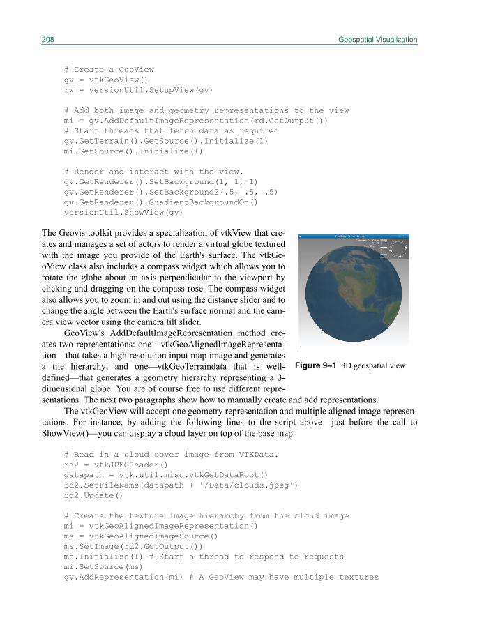
208 Geospatial Visualization
# Create a GeoViewgv = vtkGeoView()rw = versionUtil.SetupView(gv)
# Add both image and geometry representations to the viewmi = gv.AddDefaultImageRepresentation(rd.GetOutput())# Start threads that fetch data as requiredgv.GetTerrain().GetSource().Initialize(1)mi.GetSource().Initialize(1)
# Render and interact with the view.gv.GetRenderer().SetBackground(1, 1, 1)gv.GetRenderer().SetBackground2(.5, .5, .5)gv.GetRenderer().GradientBackgroundOn()versionUtil.ShowView(gv)
The Geovis toolkit provides a specialization of vtkView that cre-ates and manages a set of actors to render a virtual globe texturedwith the image you provide of the Earth's surface. The vtkGe-oView class also includes a compass widget which allows you torotate the globe about an axis perpendicular to the viewport byclicking and dragging on the compass rose. The compass widgetalso allows you to zoom in and out using the distance slider and tochange the angle between the Earth's surface normal and the cam-era view vector using the camera tilt slider.
GeoView's AddDefaultImageRepresentation method cre-ates two representations: one—vtkGeoAlignedImageRepresenta-tion—that takes a high resolution input map image and generatesa tile hierarchy; and one—vtkGeoTerraindata that is well-defined—that generates a geometry hierarchy representing a 3-dimensional globe. You are of course free to use different repre-sentations. The next two paragraphs show how to manually create and add representations.
The vtkGeoView will accept one geometry representation and multiple aligned image represen-tations. For instance, by adding the following lines to the script above—just before the call toShowView()—you can display a cloud layer on top of the base map.
# Read in a cloud cover image from VTKData.rd2 = vtkJPEGReader()datapath = vtk.util.misc.vtkGetDataRoot()rd2.SetFileName(datapath + '/Data/clouds.jpeg')rd2.Update()
# Create the texture image hierarchy from the cloud imagemi = vtkGeoAlignedImageRepresentation()ms = vtkGeoAlignedImageSource()ms.SetImage(rd2.GetOutput())ms.Initialize(1) # Start a thread to respond to requestsmi.SetSource(ms)gv.AddRepresentation(mi) # A GeoView may have multiple textures
Figure 9–1 3D geospatial view
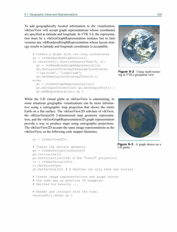
9.1 Geographic Views and Representations 209
To add geographically located information to the visualization,vtkGeoView will accept graph representations whose coordinatesare specified as latitude and longitude. In VTK 5.4, the representa-tion must be a vtkGeoGraphRepresentation instance but in laterversions any vtkRenderedGraphRepresentation whose layout strat-egy results in latitude and longitude coordinates is acceptable.
# Create a graph with lat-long coordinatesgs = vtkGeoRandomGraphSource()if versionUtil.VersionGreaterThan(5, 4): gr = vtkRenderedGraphRepresentation
gr.SetLayoutStrategyToAssignCoordinates('latitude', 'longitude')
gr.SetEdgeLayoutStrategyToGeo(0.1)else: gr = vtkGeoGraphRepresentation()
gr.SetInputConnection( gs.GetOutputPort() )gv.AddRepresentation( gr )
While the 3-D virtual globe in vtkGeoView is entertaining, insome situations geographic visualizations can be more informa-tive using a cartographic map projection that shows the entireEarth on a flat surface. The vtkGeoView2D subclass of vtkView,the vtkGeoTerrain2D 2-dimensional map geometry representa-tion, and the vtkGeoGraphRepresentation2D graph representationprovide a way to produce maps using cartographic projections.The vtkGeoView2D accepts the same image representations as thevtkGeoView, as the following code snippet illustrates.
gv = vtkGeoView2D()
# Create the terrain geometryps = vtkGeoProjectionSource()ps.Initialize(1)ps.SetProjection(138) # The "robin" projectiontr = vtkGeoTerrain2D()tr.SetSource(ps)gv.SetSurface(tr) # A GeoView can only have one terrain
# Create image representations and graph source# the same way as previous 3D examples.# Omitted for brevity ...
# Render and interact with the view.versionUtil.Show( gv )
Figure 9–2 Using multi-textur-ing in VTK's geospatial view
Figure 9–3 A graph drawn on a3-D globe.
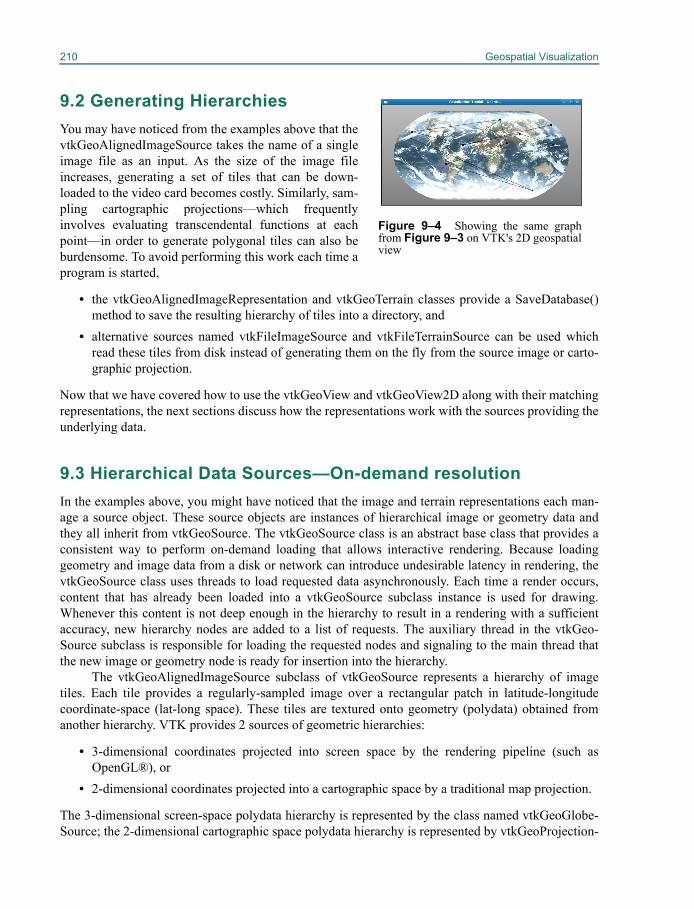
210 Geospatial Visualization
9.2 Generating HierarchiesYou may have noticed from the examples above that thevtkGeoAlignedImageSource takes the name of a singleimage file as an input. As the size of the image fileincreases, generating a set of tiles that can be down-loaded to the video card becomes costly. Similarly, sam-pling cartographic projections—which frequentlyinvolves evaluating transcendental functions at eachpoint—in order to generate polygonal tiles can also beburdensome. To avoid performing this work each time aprogram is started,
• the vtkGeoAlignedImageRepresentation and vtkGeoTerrain classes provide a SaveDatabase()method to save the resulting hierarchy of tiles into a directory, and
• alternative sources named vtkFileImageSource and vtkFileTerrainSource can be used whichread these tiles from disk instead of generating them on the fly from the source image or carto-graphic projection.
Now that we have covered how to use the vtkGeoView and vtkGeoView2D along with their matchingrepresentations, the next sections discuss how the representations work with the sources providing theunderlying data.
9.3 Hierarchical Data Sources—On-demand resolutionIn the examples above, you might have noticed that the image and terrain representations each man-age a source object. These source objects are instances of hierarchical image or geometry data andthey all inherit from vtkGeoSource. The vtkGeoSource class is an abstract base class that provides aconsistent way to perform on-demand loading that allows interactive rendering. Because loadinggeometry and image data from a disk or network can introduce undesirable latency in rendering, thevtkGeoSource class uses threads to load requested data asynchronously. Each time a render occurs,content that has already been loaded into a vtkGeoSource subclass instance is used for drawing.Whenever this content is not deep enough in the hierarchy to result in a rendering with a sufficientaccuracy, new hierarchy nodes are added to a list of requests. The auxiliary thread in the vtkGeo-Source subclass is responsible for loading the requested nodes and signaling to the main thread thatthe new image or geometry node is ready for insertion into the hierarchy.
The vtkGeoAlignedImageSource subclass of vtkGeoSource represents a hierarchy of imagetiles. Each tile provides a regularly-sampled image over a rectangular patch in latitude-longitudecoordinate-space (lat-long space). These tiles are textured onto geometry (polydata) obtained fromanother hierarchy. VTK provides 2 sources of geometric hierarchies:
• 3-dimensional coordinates projected into screen space by the rendering pipeline (such asOpenGL®), or
• 2-dimensional coordinates projected into a cartographic space by a traditional map projection.
The 3-dimensional screen-space polydata hierarchy is represented by the class named vtkGeoGlobe-Source; the 2-dimensional cartographic space polydata hierarchy is represented by vtkGeoProjection-
Figure 9–4 Showing the same graphfrom Figure 9–3 on VTK's 2D geospatialview
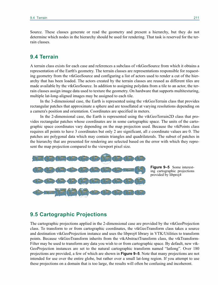
9.4 Terrain 211
Source. These classes generate or read the geometry and present a hierarchy, but they do notdetermine which nodes in the hierarchy should be used for rendering. That task is reserved for the ter-rain classes.
9.4 TerrainA terrain class exists for each case and references a subclass of vtkGeoSource from which it obtains arepresentation of the Earth's geometry. The terrain classes are representations responsible for request-ing geometry from the vtkGeoSource and configuring a list of actors used to render a cut of the hier-archy that has been loaded. The actors created by the terrain classes are reused as different tiles aremade available by the vtkGeoSource. In addition to assigning polydata from a tile to an actor, the ter-rain classes assign image data used to texture the geometry. On hardware that supports multitexturing,multiple lat-long-aligned images may be assigned to each tile.
In the 3-dimensional case, the Earth is represented using the vtkGeoTerrain class that providesrectangular patches that approximate a sphere and are tessellated at varying resolutions depending ona camera's position and orientation. Coordinates are specified in meters.
In the 2-dimensional case, the Earth is represented using the vtkGeoTerrain2D class that pro-vides rectangular patches whose coordinates are in some cartographic space. The units of the carto-graphic space coordinates vary depending on the map projection used. Because the vtkPoints classrequires all points to have 3 coordinates but only 2 are significant, all z coordinate values are 0. Thepatches are polygonal data which may contain triangles and quadrilaterals. The subset of patches inthe hierarchy that are presented for rendering are selected based on the error with which they repre-sent the map projection compared to the viewport pixel size.
9.5 Cartographic ProjectionsThe cartographic projections applied in the 2-dimensional case are provided by the vtkGeoProjectionclass. To transform to or from cartographic coordinates, the vtkGeoTransform class takes a sourceand destination vtkGeoProjection instance and uses the libproj4 library in VTK/Utilities to transformpoints. Because vtkGeoTransform inherits from the vtkAbstractTransform class, the vtkTransform-Filter may be used to transform any data you wish to or from cartographic space. By default, new vtk-GeoProjection instances are set to the natural cartographic transform named “latlong”. Over 180projections are provided, a few of which are shown in Figure 9–5. Note that many projections are notintended for use over the entire globe, but rather over a small lat-long region. If you attempt to usethese projections on a domain that is too large, the results will often be confusing and incoherent.
Figure 9–5 Some interest-ing cartographic projectionsprovided by libproj4
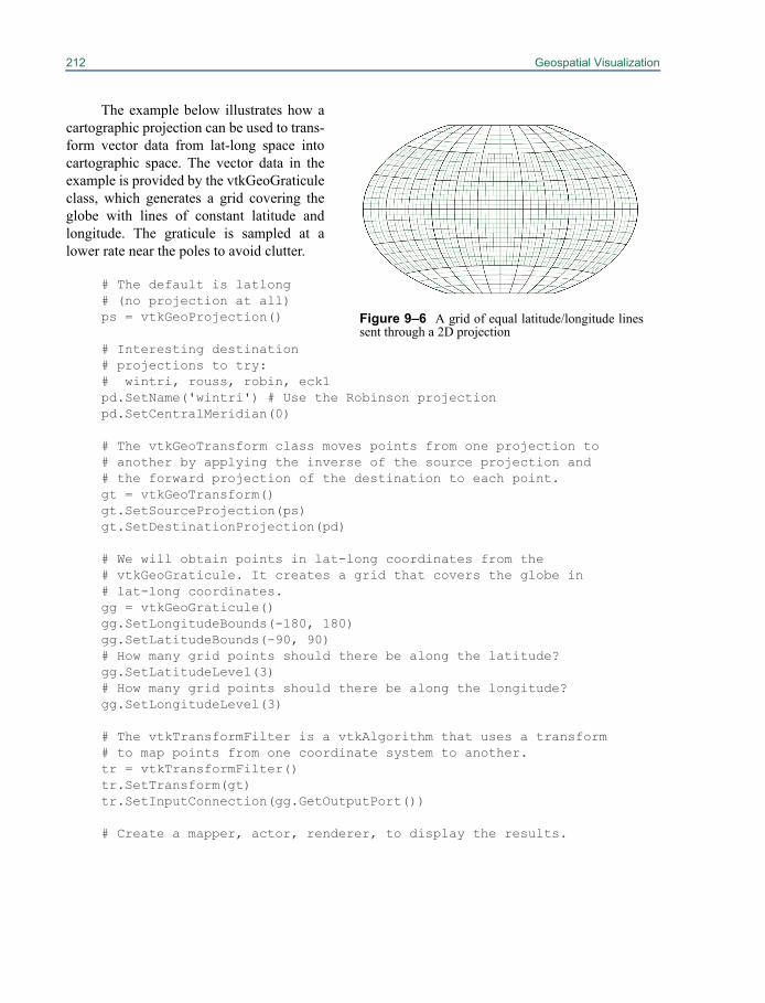
212 Geospatial Visualization
The example below illustrates how acartographic projection can be used to trans-form vector data from lat-long space intocartographic space. The vector data in theexample is provided by the vtkGeoGraticuleclass, which generates a grid covering theglobe with lines of constant latitude andlongitude. The graticule is sampled at alower rate near the poles to avoid clutter.
# The default is latlong # (no projection at all)ps = vtkGeoProjection()
# Interesting destination # projections to try:# wintri, rouss, robin, eck1pd.SetName('wintri') # Use the Robinson projectionpd.SetCentralMeridian(0)
# The vtkGeoTransform class moves points from one projection to# another by applying the inverse of the source projection and# the forward projection of the destination to each point.gt = vtkGeoTransform()gt.SetSourceProjection(ps)gt.SetDestinationProjection(pd)
# We will obtain points in lat-long coordinates from the# vtkGeoGraticule. It creates a grid that covers the globe in# lat-long coordinates.gg = vtkGeoGraticule()gg.SetLongitudeBounds(-180, 180)gg.SetLatitudeBounds(-90, 90)# How many grid points should there be along the latitude?gg.SetLatitudeLevel(3)# How many grid points should there be along the longitude?gg.SetLongitudeLevel(3)
# The vtkTransformFilter is a vtkAlgorithm that uses a transform# to map points from one coordinate system to another.tr = vtkTransformFilter()tr.SetTransform(gt)tr.SetInputConnection(gg.GetOutputPort())
# Create a mapper, actor, renderer, to display the results.
Figure 9–6 A grid of equal latitude/longitude linessent through a 2D projection

Chapter 10
Building Models 10
We have seen how to use source objects (both readersand procedural objects) to create geometry. (See “Creating Simple Models” on page 42.) VTK pro-vides several other techniques to generate more complex models. Three techniques covered in thischapter are implicit modeling, extrusion, and surface reconstruction from unorganized points.
If you are working with data in a form that lacks topological or geometric structure, VTK canrepresent this information as field data (using class vtkDataObject, see “Working With Field Data” onpage 249), which can be further processed to produce datasets for visualization with the techniques inthis chapter. For example, an n-dimensional financial record can be reduced to three dimensions bychoosing three variables as independent variables. Then the techniques described here—Delaunay tri-angulation, Gaussian splatting, and surface reconstruction—can be used to create structure suitablefor visualization by standard methods.
10.1 Implicit ModelingImplicit modeling is a powerful technique employing 3D contouring (isosurface generation) to createpolygonal surface meshes. The contouring operation is applied to a vtkImageData dataset (a regularvolume) whose scalar values have been synthetically generated. The key to implicit modeling is thatthe scalar field can be generated using a wide variety of techniques. These techniques include produc-ing a distance field from generating primitives (e.g., a field representing the distance from a set oflines and/or polygons) as well as using boolean set operations to combine the scalar fields.
Creating An Implicit Model
Here’s an example that uses some lines to generate a complex, polygonal surface. The lines arearranged to spell the word “HELLO” and serve as the generating seed geometry (Figure 10–1). (TheTcl script is taken from VTK/Examples/Modelling/Tcl/hello.tcl.)

214 Building Models
# create linesvtkPolyDataReader reader
reader SetFileName "$VTK_DATA_ROOT/Data/hello.vtk"vtkPolyDataMapper lineMapper
lineMapper SetInputConnection [reader GetOutputPort]vtkActor lineActor
lineActor SetMapper lineMappereval [lineActor GetProperty] SetColor $red
# create implicit modelvtkImplicitModeller imp imp SetInputConnection [reader GetOutputPort] imp SetSampleDimensions 110 40 20 imp SetMaximumDistance 0.25 imp SetModelBounds -1.0 10.0 -1.0 3.0 -1.0 1.0vtkContourFilter contour contour SetInputConnection [imp GetOutputPort] contour SetValue 0 0.25vtkPolyDataMapper impMapper impMapper SetInputConnection [contour GetOutputPort] impMapper ScalarVisibilityOffvtkActor impActor impActor SetMapper impMapper eval [impActor GetProperty] SetColor $peacock [impActor GetProperty] SetOpacity 0.5
What’s happening in this script is that the lines that stroke out the word “hello” serve as the generat-ing primitives. The vtkImplicitModeller class computes the distance from the lines (taking the closestdistance to any line) to the points in the output vtkImageData and assigns this distance as the scalarvalue at each point in the dataset. The output is then passed to the vtkContourFilter which generates apolygonal isosurface. (The isosurface value is the distance from the generating primitives.)
There are a couple of important parameters in vtkImplicitModeller. The MaximumDistanceinstance variable controls how far from the generating primitives to continue the distance calculation.This instance variable, expressed as a fraction of the grid length, has a great effect on the speed of cal-culation: smaller values result in faster computation, but the isosurface may become choppy or breakup if the values are too small. The SampleDimensions instance variable controls the resolution of theoutput vtkImageData, and ModelBounds controls the position and size of the dataset in space.
Figure 10–1 Implicit modeling from lines spelling the word“hello.”
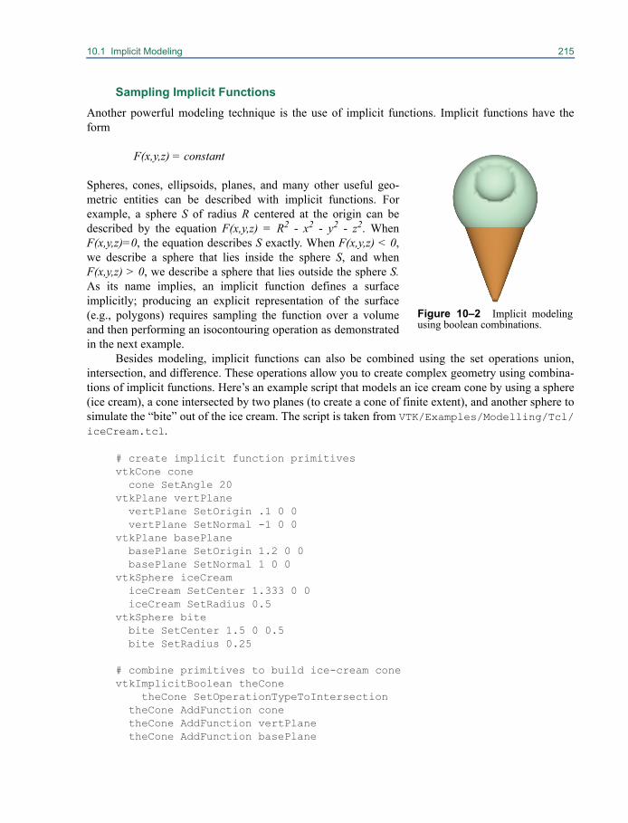
10.1 Implicit Modeling 215
Sampling Implicit FunctionsAnother powerful modeling technique is the use of implicit functions. Implicit functions have theform
F(x,y,z) = constant
Spheres, cones, ellipsoids, planes, and many other useful geo-metric entities can be described with implicit functions. Forexample, a sphere S of radius R centered at the origin can bedescribed by the equation F(x,y,z) = R2 - x2 - y2 - z2. WhenF(x,y,z)=0, the equation describes S exactly. When F(x,y,z) < 0,we describe a sphere that lies inside the sphere S, and whenF(x,y,z) > 0, we describe a sphere that lies outside the sphere S.As its name implies, an implicit function defines a surfaceimplicitly; producing an explicit representation of the surface(e.g., polygons) requires sampling the function over a volumeand then performing an isocontouring operation as demonstratedin the next example.
Besides modeling, implicit functions can also be combined using the set operations union,intersection, and difference. These operations allow you to create complex geometry using combina-tions of implicit functions. Here’s an example script that models an ice cream cone by using a sphere(ice cream), a cone intersected by two planes (to create a cone of finite extent), and another sphere tosimulate the “bite” out of the ice cream. The script is taken from VTK/Examples/Modelling/Tcl/iceCream.tcl.
# create implicit function primitivesvtkCone cone cone SetAngle 20vtkPlane vertPlane vertPlane SetOrigin .1 0 0 vertPlane SetNormal -1 0 0vtkPlane basePlane basePlane SetOrigin 1.2 0 0 basePlane SetNormal 1 0 0vtkSphere iceCream iceCream SetCenter 1.333 0 0 iceCream SetRadius 0.5vtkSphere bite bite SetCenter 1.5 0 0.5 bite SetRadius 0.25
# combine primitives to build ice-cream conevtkImplicitBoolean theCone
theCone SetOperationTypeToIntersection theCone AddFunction cone theCone AddFunction vertPlane theCone AddFunction basePlane
Figure 10–2 Implicit modelingusing boolean combinations.
216 Building Models
# take a bite out of the ice creamvtkImplicitBoolean theCream theCream SetOperationTypeToDifference theCream AddFunction iceCream theCream AddFunction bite
# iso-surface to create geometry of the conevtkSampleFunction theConeSample theConeSample SetImplicitFunction theCone theConeSample SetModelBounds -1 1.5 -1.25 1.25 -1.25 1.25 theConeSample SetSampleDimensions 60 60 60 theConeSample ComputeNormalsOffvtkContourFilter theConeSurface theConeSurface SetInputConnection [theConeSample GetOutputPort] theConeSurface SetValue 0 0.0vtkPolyDataMapper coneMapper coneMapper SetInputConnection [theConeSurface GetOutputPort] coneMapper ScalarVisibilityOffvtkActor coneActor coneActor SetMapper coneMapper eval [coneActor GetProperty] SetColor $chocolate
# iso-surface to create geometry of the ice creamvtkSampleFunction theCreamSample theCreamSample SetImplicitFunction theCream theCreamSample SetModelBound 0 2.5 -1.25 1.25 -1.25 1.25
theCreamSample SetSampleDimensions 60 60 60 theCreamSample ComputeNormalsOffvtkContourFilter theCreamSurface theCreamSurface SetInputConnection [theCreamSample GetOutputPort] theCreamSurface SetValue 0 0.0vtkPolyDataMapper creamMapper creamMapper SetInputConnection [theCreamSurface GetOutputPort] creamMapper ScalarVisibilityOffvtkActor creamActor creamActor SetMapper creamMapper eval [creamActor GetProperty] SetColor $mint
The classes vtkSampleFunction and vtkContourFilter are the keys to building the polygonal geome-try. vtkSampleFunction evaluates the implicit function (actually the boolean combination of implicitfunctions) to generate scalars across a volume (vtkImageData) dataset. vtkContourFilter is then usedto generate an isosurface which approximates the implicit function. The accuracy of the approxima-tion depends on the nature of the implicit function, as well as the resolution of the volume generatedby vtkSampleFunction (specified using the SetSampleDimensions() method).
A couple of usage notes: Boolean combinations can be nested to arbitrary depth. Just make surethe hierarchy does not contain self-referencing loops. Also, you may wish to use vtkDecimatePro toreduce the number of primitives output by the contour filter since the number of triangles can be quitelarge. See “Decimation” on page 107 for more information.
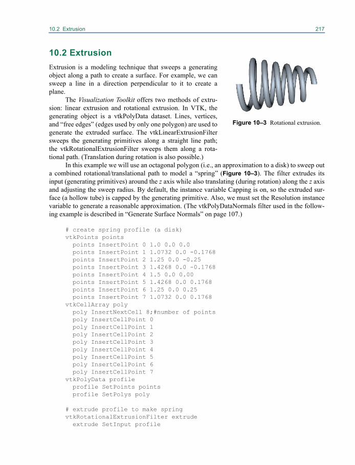
10.2 Extrusion 217
10.2 Extrusion
Extrusion is a modeling technique that sweeps a generatingobject along a path to create a surface. For example, we cansweep a line in a direction perpendicular to it to create aplane.
The Visualization Toolkit offers two methods of extru-sion: linear extrusion and rotational extrusion. In VTK, thegenerating object is a vtkPolyData dataset. Lines, vertices,and “free edges” (edges used by only one polygon) are used togenerate the extruded surface. The vtkLinearExtrusionFiltersweeps the generating primitives along a straight line path;the vtkRotationalExtrusionFilter sweeps them along a rota-tional path. (Translation during rotation is also possible.)
In this example we will use an octagonal polygon (i.e., an approximation to a disk) to sweep outa combined rotational/translational path to model a “spring” (Figure 10–3). The filter extrudes itsinput (generating primitives) around the z axis while also translating (during rotation) along the z axisand adjusting the sweep radius. By default, the instance variable Capping is on, so the extruded sur-face (a hollow tube) is capped by the generating primitive. Also, we must set the Resolution instancevariable to generate a reasonable approximation. (The vtkPolyDataNormals filter used in the follow-ing example is described in “Generate Surface Normals” on page 107.)
# create spring profile (a disk)vtkPoints points points InsertPoint 0 1.0 0.0 0.0 points InsertPoint 1 1.0732 0.0 -0.1768 points InsertPoint 2 1.25 0.0 -0.25 points InsertPoint 3 1.4268 0.0 -0.1768 points InsertPoint 4 1.5 0.0 0.00 points InsertPoint 5 1.4268 0.0 0.1768 points InsertPoint 6 1.25 0.0 0.25 points InsertPoint 7 1.0732 0.0 0.1768vtkCellArray poly poly InsertNextCell 8;#number of points poly InsertCellPoint 0 poly InsertCellPoint 1 poly InsertCellPoint 2 poly InsertCellPoint 3 poly InsertCellPoint 4 poly InsertCellPoint 5 poly InsertCellPoint 6 poly InsertCellPoint 7vtkPolyData profile profile SetPoints points profile SetPolys poly
# extrude profile to make springvtkRotationalExtrusionFilter extrude extrude SetInput profile
Figure 10–3 Rotational extrusion.
218 Building Models
extrude SetResolution 360 extrude SetTranslation 6 extrude SetDeltaRadius 1.0 extrude SetAngle 2160.0;#six revolutions vtkPolyDataNormals normals normals SetInputConnection [extrude GetOutputPort] normals SetFeatureAngle 60vtkPolyDataMapper map map SetInputConnection [normals GetOutputPort]vtkActor spring spring SetMapper map [spring GetProperty] SetColor 0.6902 0.7686 0.8706 [spring GetProperty] SetDiffuse 0.7 [spring GetProperty] SetSpecular 0.4 [spring GetProperty] SetSpecularPower 20 [spring GetProperty] BackfaceCullingOn
The vtkLinearExtrusionFilter is similar, but it is simpler to use than vtkRotationalExtrusionFilter.Linear extrusion can be performed along a user-specified vector(SetExtrusionTypeToVectorExtrusion()) or towards a user-specified point(SetExtrusionTypeToPointExtrusion()); or the extrusion can be performed in the direction of the sur-face normals of the generating surface (SetExtrusionTypeToNormalExtrusion()).
10.3 Constructing SurfacesOften we wish to construct a surface from a set of unstructured points or other data. The points maycome from a laser digitizing system or may be assembled from multi-variate data. In this section weexamine techniques to build new surfaces from data of this form. You may also wish to refer to“Building Models” on page 213 for other methods to create surfaces from generating primitives (i.e.,implicit modeling).
Delaunay TriangulationThe Delaunay triangulation is widely used in computational geometry. The basic application of theDelaunay triangulation is to create a simplicial mesh (i.e., triangles in 2D, tetrahedra in 3D) from a setof points. The resulting mesh can then be used in a variety of ways, including processing with stan-dard visualization techniques. In VTK, there are two objects for creating Delaunay triangulations:vtkDelaunay2D and vtkDelaunay3D.
Note: Delaunay triangulation is numerically sensitive. The current version of vtkDelaunay3Dmay not be robust enough to reliably handle large numbers of points. This will be improved in thenear future.
vtkDelaunay2D. The vtkDelaunay2D object takes vtkPointSet (or any of its subclasses) as input andgenerates a vtkPolyData on output. Typically the output is a triangle mesh, but if you use a non-zeroAlpha value it is possible to generate meshes consisting of triangles, lines, and vertices. (This param-eter controls the “size” of output primitives. The size of the primitive is measured by an n-dimen-sional circumsphere; only those pieces of the mesh whose circumsphere has a circumradius less than

10.3 Constructing Surfaces 219
or equal to the alpha value are sent to the output. For example, if an edge of length L is less than2*Alpha, the edge would be output).
In the following Tcl example we generate points usinga random distribution in the (0,1) x-y plane.(vtkDelaunay2D ignores the z-component during execution,although it does output the z value.) To create a nicer picturewe use vtkTubeFilter and vtkGlyph3D to create tubesaround mesh edges and spheres around the mesh points. Thescript comes from VTK/Examples/Modelling/Tcl/DelMesh.tcl.
# create some pointsvtkMath mathvtkPoints pointsfor {set i 0} {$i<50} {incr i 1} { eval points InsertPoint $i [math Random 0 1] \
[math Random 0 1] 0.0}vtkPolyData profile profile SetPoints points
# triangulate themvtkDelaunay2D del del SetInput profile del SetTolerance 0.001vtkPolyDataMapper mapMesh mapMesh SetInputConnection [del GetOutputPort]vtkActor meshActor meshActor SetMapper mapMesh
[meshActor GetProperty] SetColor .1 .2 .4vtkExtractEdges extract extract SetInputConnection [del GetOutputPort]vtkTubeFilter tubes tubes SetInputConnection [extract GetOutputPort] tubes SetRadius 0.01 tubes SetNumberOfSides 6vtkPolyDataMapper mapEdges mapEdges SetInputConnection [tubes GetOutputPort]vtkActor edgeActor edgeActor SetMapper mapEdges
eval [edgeActor GetProperty] SetColor $peacock [edgeActor GetProperty] SetSpecularColor 1 1 1 [edgeActor GetProperty] SetSpecular 0.3 [edgeActor GetProperty] SetSpecularPower 20 [edgeActor GetProperty] SetAmbient 0.2 [edgeActor GetProperty] SetDiffuse 0.8
vtkSphereSource ball ball SetRadius 0.025 ball SetThetaResolution 12
Figure 10–4 2D Delaunay triangulation
220 Building Models
ball SetPhiResolution 12vtkGlyph3D balls balls SetInputConnection [del GetOutputPort] balls SetSourceConnection [ball GetOutputPort]vtkPolyDataMapper mapBalls mapBalls SetInputConnection [balls GetOutputPort]vtkActor ballActor ballActor SetMapper mapBalls eval [ballActor GetProperty] SetColor $hot_pink [ballActor GetProperty] SetSpecularColor 1 1 1 [ballActor GetProperty] SetSpecular 0.3 [ballActor GetProperty] SetSpecularPower 20 [ballActor GetProperty] SetAmbient 0.2 [ballActor GetProperty] SetDiffuse 0.8
The Tolerance instance variable is used to determine whether points are coincident. Points located adistance Tolerance apart (or less) are considered coincident, and one of the points may be discarded.Tolerance is expressed as a fraction of the length of the diagonal of the bounding box of the inputpoints.
Another useful feature of vtkDelaunay2D is the ability to define constraint edges and polygons.Normally, vtkDelaunay2D will generate a Delaunay triangulation of an input set of points satisfyingthe circumsphere criterion. However, in many cases additional information specifying edges in thetriangulation (constraint edges) or “holes” in the data (constraint polygons) may be available. Byspecifying constraint edges and polygons, vtkDelaunay2D can be used to generate sophisticated trian-gulations of points. The following example (taken from VTK/Examples/Modelling/Tcl/con-strainedDelaunay.tcl) demonstrates this.
vtkPoints points points InsertPoint 0 1 4 0 points InsertPoint 1 3 4 0 points InsertPoint 2 7 4 0
...(more points defined)...vtkCellArray polys polys InsertNextCell 12 polys InsertCellPoint 0 polys InsertCellPoint 1 polys InsertCellPoint 2
...(a total of two polygons defined)...vtkPolyData polyData polyData SetPoints points polyData SetPolys polys
# generate constrained triangulationvtkDelaunay2D del del SetInput polyData del SetSource polyDatavtkPolyDataMapper mapMesh mapMesh SetInputConnection [del GetOutputPort]vtkActor meshActor meshActor SetMapper mapMesh
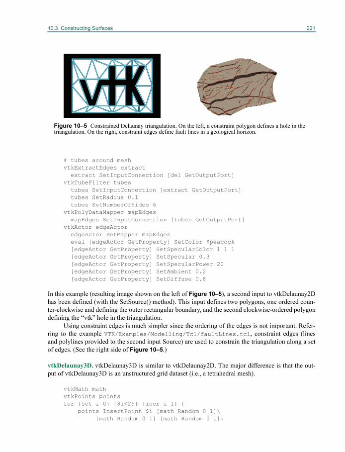
10.3 Constructing Surfaces 221
# tubes around meshvtkExtractEdges extract extract SetInputConnection [del GetOutputPort]vtkTubeFilter tubes tubes SetInputConnection [extract GetOutputPort] tubes SetRadius 0.1 tubes SetNumberOfSides 6vtkPolyDataMapper mapEdges mapEdges SetInputConnection [tubes GetOutputPort]vtkActor edgeActor edgeActor SetMapper mapEdges eval [edgeActor GetProperty] SetColor $peacock [edgeActor GetProperty] SetSpecularColor 1 1 1 [edgeActor GetProperty] SetSpecular 0.3 [edgeActor GetProperty] SetSpecularPower 20 [edgeActor GetProperty] SetAmbient 0.2 [edgeActor GetProperty] SetDiffuse 0.8
In this example (resulting image shown on the left of Figure 10–5), a second input to vtkDelaunay2Dhas been defined (with the SetSource() method). This input defines two polygons, one ordered coun-ter-clockwise and defining the outer rectangular boundary, and the second clockwise-ordered polygondefining the “vtk” hole in the triangulation.
Using constraint edges is much simpler since the ordering of the edges is not important. Refer-ring to the example VTK/Examples/Modelling/Tcl/faultLines.tcl, constraint edges (linesand polylines provided to the second input Source) are used to constrain the triangulation along a setof edges. (See the right side of Figure 10–5.)
vtkDelaunay3D. vtkDelaunay3D is similar to vtkDelaunay2D. The major difference is that the out-put of vtkDelaunay3D is an unstructured grid dataset (i.e., a tetrahedral mesh).
vtkMath mathvtkPoints pointsfor {set i 0} {$i<25} {incr i 1} {
points InsertPoint $i [math Random 0 1]\[math Random 0 1] [math Random 0 1]}
Figure 10–5 Constrained Delaunay triangulation. On the left, a constraint polygon defines a hole in thetriangulation. On the right, constraint edges define fault lines in a geological horizon.

222 Building Models
vtkPolyData profile profile SetPoints points
# triangulate themvtkDelaunay3D del del SetInput profile del BoundingTriangulationOn del SetTolerance 0.01 del SetAlpha 0.2
# shrink the result to help see it bettervtkShrinkFilter shrink shrink SetInputConnection [del GetOutputPort] shrink SetShrinkFactor 0.9vtkDataSetMapper map map SetInputConnection [shrink GetOutputPort]vtkActor triangulation triangulation SetMapper map [triangulation GetProperty] SetColor 1 0 0
In this example (taken from VTK/Examples/Modelling/Tcl/Delaunay3D.tcl) we triangulate arandom set of points in 3D space ranging between (0,1) along each of the coordinate axes. A non-zeroAlpha is used, so the mesh consists of a collection of tetrahedra, triangles, lines, and points. Theresulting tetrahedral mesh is shrunk with vtkShrinkFilter and mapped with vtkDataSetMapper.
Gaussian SplattingMany times data has no inherent structure, or the dimension of the data is high relative to what 2D,3D, or 4D (3D with animation) visualization techniques can represent. An example of one such dataset is scalar values (i.e., temperature) located at random points in space from a thermocouple measur-ing system. Multidimensional financial data (i.e., many records each record having several variables),is another example. One of the simplest and most robust procedures that can used to treat such data isto resample the data on a volume (i.e., vtkImageData dataset) and then visualize the resampled data-set. In the following C++ example (VTK/Examples/Modelling/Cxx/finance.cxx) we showhow to do this with multivariate financial data. You may wish to refer to “Working With Field Data”on page 249 for an alternative way to work with this data.
The data consists of an ASCII text file with 3188 financial records. Each record contains thefollowing information: the time late in paying the loan (TIME_LATE); the monthly payment of theloan (MONTHLY_PAYMENT); the principal left on the loan (UNPAID_PRINCIPAL); the original amountof the loan (LOAN_AMOUNT); the interest rate on the loan (INTEREST_RATE); and the monthly incomeof the loanee (MONTHLY_INCOME).
The purpose of the visualization is to understand the relationship of these variables to the vari-able of major concern: TIME_LATE. Building a mathematical model or understanding of this datahelps financial institutions make less risky loans. What we will do in the example is to show the latepaying loans in context with the total loan population. We begin by choosing MONTHLY_PAYMENT asthe x-axis, INTEREST_RATE as the y-axis, and LOAN_AMOUNT as the z-axis, and then chooseTIME_LATE as the dependent variable (i.e., we reduce the dimensionality of the data by selectingthree variables and ignoring the others). The class vtkGaussianSplatter is used to take the reduced
Figure 10–6 3D Delaunay tri-angulation with non-zero alpha.
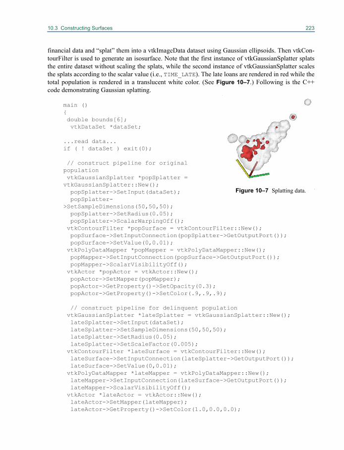
10.3 Constructing Surfaces 223
financial data and “splat” them into a vtkImageData dataset using Gaussian ellipsoids. Then vtkCon-tourFilter is used to generate an isosurface. Note that the first instance of vtkGaussianSplatter splatsthe entire dataset without scaling the splats, while the second instance of vtkGaussianSplatter scalesthe splats according to the scalar value (i.e., TIME_LATE). The late loans are rendered in red while thetotal population is rendered in a translucent white color. (See Figure 10–7.) Following is the C++code demonstrating Gaussian splatting.
main (){ double bounds[6];
vtkDataSet *dataSet; ...read data...if ( ! dataSet ) exit(0);
// construct pipeline for original population vtkGaussianSplatter *popSplatter = vtkGaussianSplatter::New(); popSplatter->SetInput(dataSet); popSplatter->SetSampleDimensions(50,50,50); popSplatter->SetRadius(0.05); popSplatter->ScalarWarpingOff(); vtkContourFilter *popSurface = vtkContourFilter::New(); popSurface->SetInputConnection(popSplatter->GetOutputPort()); popSurface->SetValue(0,0.01); vtkPolyDataMapper *popMapper = vtkPolyDataMapper::New(); popMapper->SetInputConnection(popSurface->GetOutputPort()); popMapper->ScalarVisibilityOff(); vtkActor *popActor = vtkActor::New(); popActor->SetMapper(popMapper); popActor->GetProperty()->SetOpacity(0.3); popActor->GetProperty()->SetColor(.9,.9,.9);
// construct pipeline for delinquent population vtkGaussianSplatter *lateSplatter = vtkGaussianSplatter::New(); lateSplatter->SetInput(dataSet); lateSplatter->SetSampleDimensions(50,50,50); lateSplatter->SetRadius(0.05); lateSplatter->SetScaleFactor(0.005); vtkContourFilter *lateSurface = vtkContourFilter::New(); lateSurface->SetInputConnection(lateSplatter->GetOutputPort()); lateSurface->SetValue(0,0.01); vtkPolyDataMapper *lateMapper = vtkPolyDataMapper::New(); lateMapper->SetInputConnection(lateSurface->GetOutputPort()); lateMapper->ScalarVisibilityOff(); vtkActor *lateActor = vtkActor::New(); lateActor->SetMapper(lateMapper); lateActor->GetProperty()->SetColor(1.0,0.0,0.0);
Figure 10–7 Splatting data.
224 Building Models
// create axes popSplatter->Update(); popSplatter->GetOutput()->GetBounds(bounds); vtkAxes *axes = vtkAxes::New(); axes->SetOrigin(bounds[0], bounds[2], bounds[4]); axes->SetScaleFactor(
popSplatter->GetOutput()->GetLength()/5); vtkTubeFilter *axesTubes = vtkTubeFilter::New(); axesTubes->SetInputConnection(axes->GetOutputPort()); axesTubes->SetRadius(axes->GetScaleFactor()/25.0); axesTubes->SetNumberOfSides(6); vtkPolyDataMapper *axesMapper = vtkPolyDataMapper::New(); axesMapper->SetInputConnection(axesTubes->GetOutputPort()); vtkActor *axesActor = vtkActor::New(); axesActor->SetMapper(axesMapper);
// graphics stuff vtkRenderer *renderer = vtkRenderer::New(); vtkRenderWindow *renWin = vtkRenderWindow::New(); renWin->AddRenderer(renderer); vtkRenderWindowInteractor *iren =
vtkRenderWindowInteractor::New(); iren->SetRenderWindow(renWin);
// read data, set up renderer renderer->AddActor(lateActor); renderer->AddActor(axesActor); renderer->AddActor(popActor); renderer->SetBackground(1,1,1); renWin->SetSize(300,300);
// interact with data iren->Initialize(); iren->Start();...clean up...}
What’s interesting about this example is that the majority of late payments occur in a region of a highinterest rate (expected) and lower monthly payment amount. Therefore, it’s the smaller loans withhigher interest rates which are the problem in this data.
Another filter for resampling data into a volume is vtkShepardMethod. You may wish to mod-ify the previous C++ example to use this class.
Surfaces from Unorganized Points
In computer graphics applications, surfaces are often represented as three-dimensional unorganizedpoints. Laser and other digitizers are often the source of these point sets. Reconstructing surfacesfrom point clouds is both computationally and algorithmically challenging. While the methodsdescribed previously (Delaunay triangulation and Gaussian splatting) may be used with varying lev-

10.3 Constructing Surfaces 225
els of success to reconstruct surfaces from point clouds, VTK has a class designed specifically for thispurpose.
vtkSurfaceReconstructionFilter can be used to reconstruct sur-faces from point clouds. This filter takes as input a vtkDataSet defin-ing points assumed to lie on the surface of a 3D object. The followingscript (VTK/Examples/Modelling/Tcl/reconstructSur-face.tcl) shows how to use the filter. Figure 10–8 shows the results.
vtkProgrammableSource pointSource pointSource SetExecuteMethod readPointsproc readPoints {} { set output [pointSource GetPolyDataOutput] vtkPoints points $output SetPoints points
set file [open "$VTK_DATA_ROOT/Data/cactus.3337.pts" r] while { [gets $file line] != -1 } { scan $line "%s" firstToken if { $firstToken == "p" } { scan $line "%s %f %f %f" firstToken x y z points InsertNextPoint $x $y $z } } points Delete; #okay, reference counting}
# Construct the surface and create isosurfacevtkSurfaceReconstructionFilter surf surf SetInputConnection [pointSource GetOutputPort]vtkContourFilter cf cf SetInputConnection [surf GetOutputPort] cf SetValue 0 0.0vtkReverseSense reverse reverse SetInputConnection [cf GetOutputPort]
reverse ReverseCellsOn reverse ReverseNormalsOnvtkPolyDataMapper map map SetInputConnection [reverse GetOutputPort] map ScalarVisibilityOffvtkActor surfaceActor surfaceActor SetMapper map
The example begins by reading points from a file using vtkProgrammableSource filter. (See “Pro-grammable Filters” on page 419 for more information.) vtkSurfaceReconstructionFilter takes thepoints and generates a volumetric representation (similar to what vtkGaussianSplatter did in the pre-vious section). The volume is contoured (with an isosurface value=0.0) to generate a surface and ver-tex normals. Because of the nature of the data, the vertex normals point inward so vtkReverseSense isused to reverse the normals and polygon ordering. (On some systems inward pointing normals willresult in black surfaces during rendering.)
Figure 10–8 Surfacereconstruction.

226 Building Models
The algorithm works reasonably well as long as the points are close enough together. Theinstance variable SampleSpacing can be set to control the dimensions of the output volume. IfSampleSpacing is given a negative value, the algorithm makes a guess at the voxel size. The outputvolume bounds the input point cloud.
Chapter 11
Time Varying Data 11
11.1 Introduction to temporal supportThe visualization toolkit was created for the purpose of
allowing people to visualize and thus explore features in data with spatial extent. It allows people toanswer questions, such as "Where are the regions of maximum value located within this data?? "Whatshape and value do they have?" and "How are those shapes distributed throughout?" VTK provides aplethora of techniques for displaying and analyzing data, as it exists at a single moment in time.Exploration of data that has temporal extent is also important. One would also like to answer ques-tions such as. "How do those shapes grow, move and shrink over time?”
That goal is complicated by the fact that VTK represents a point with only X, Y and Z coordi-nate values. Adding T is impractical because of backward compatibility requirements and the need toconserve RAM in the most common case in which T unimportant. With previous versions of the visu-alization toolkit, people implemented a variety of workarounds to overcome the basic lack of supportfor time. For instance, multiple attribute array sets (one set for each time step) were sometimes loadedand filters were told to iterate through the sets.
Creating such workarounds was difficult not only because of the lack of support in VTK butalso because of the variety of formats in which time varying data is stored. Some practitioners storean entire dataset in a sequentially named file for each (regularly or irregularly sampled) point in time.Others store just the time varying portions of the data in one or many separate files. Some store the Tcoordinates alongside the X, Y, and Z coordinates as suggested above, and some store the data inhighly compressed encoded formats.
As compute power has grown and become widespread, exploration and analysis of time vary-ing scientific data has become commonplace. Since release 5.2, VTK has included a general-purposeinfrastructure for time varying visualization. The infrastructure is not wasteful of memory and isbackward compatible. In the common case when time is immaterial, no additional RAM or disk spaceis consumed, and the majority of filters that are time insensitive did not need any modification. Theinfrastructure is also opening ended and extensible. In addition to supporting flipbook style anima-
228 Time Varying Data
tions, which would allow one to answer the temporal question posed above, it also allows one to pro-grammatically answer quantitative questions such as:
• “At what time do the shapes take on a maximum volume?”
• “At what point do they move most quickly?”
• “What are the average attribute values over a particular region of time?”
• “What does a 2D plot of values for particular elements or locations look like?”
To do so, one finds, or creates a vtkAlgorithm that takes into account the temporal dimension toanswer the question, and then builds a pipeline that exercises it. A time-aware filter is one that iscapable of: requesting one or more specific time steps from the pipeline behind it, doing some pro-cessing once supplied with the requested data objects, and producing an answer (in the form ofanother data object) for the downstream filters.
The many varieties of temporal representations are facilitated because of the reader abstraction.A reader, as described in Chapter 12, is responsible for reading a file or set of files on the file system,interpreting a specific file format, and producing one or more data objects. A time aware reader is onethat additionally tells the pipeline what the available temporal domain is, and is capable of producingan answer (again in the form of a data object) for the specific time (or times) that the downstreampipeline has requested of it.
11.2 VTK's implementation of time supportVTK supports time varying data at the pipeline level. vtkExecutives are the glue that hold neighbor-ing vtkAlgorithms together and thus make up the pipeline. Besides linking Algorithms together,Executives are also responsible for telling each Algorithm exactly what to do. The Executives do soby communicating meta-information, small pieces of data (stored in vtkInformation containers), upand down the pipeline before causing their attached Algorithms to execute. For example, each Algo-rithm is given a vtkInformation object that specifies where, or what spatial sub domain it is to fill.When doing temporal visualization, Executives also tell each Algorithm when, or at what point intime they are to do so. This each Algorithm can now be given a vtkInformation object that specifieswhat temporal sub domain that processing is supposed to take place in.
To be exact, the pipeline now supports temporal visualization because it recognizes the follow-ing meta-information keys, and understands how and when to transport them and react to their pres-ence in order to drive filter execution.
TIME_RANGE
This key is injected into the pipeline by a reader of time varying data, at the source or beginning of thepipeline. It contains two floating-point numbers, which are the minimum and maximum times that thereader can produce data within, or in other words, the extent of the temporal domain.
TIME_STEPS
When the data produced by the reader is exact at discrete points in time, this key is also injected intothe pipeline by a reader of time varying data. It contains any number of floating point numbers whichmay be regularly or irregularly placed within the temporal domain.
11.2 VTK's implementation of time support 229
UPDATE_TIME_STEPS
This key is injected into the pipeline at downstream end of the pipeline. It contains one or more float-ing point numbers that correspond to the set of times that are to be processed by the pipeline update.
DATA_TIME_STEPS
When the update request reaches the reader, it may or may not be able to provide results for exactlythat time. For example the renderer may ask for a time that lies between two points in theTIME_STEPS. The reader injects this key into the pipeline to indicate the exact data time that corre-sponds to the data it produces in response to the request.
CONTINUE_EXECUTING
This flag is injected into the pipeline to cause the pipeline to keep iterating in order to fulfill a set oftime requests.
Because time support was added at the pipeline level, one must know something about how thevisualization pipeline executes in order to understand the actions that the above meta informationcause, and thus understand what VTK's time support can be used for. VTK's standard streamingdemand driven pipeline operates in four stages. The same four passes are used for time varying visu-alization, but they are often (either for a subset of or for the full pipeline) iterated in a loop.
During the first pass, called REQUEST_DATA_OBJECT , each Executive creates an emptyDataObject of whatever type is needed for the Algorithm. A vtkJPEGReader for example, producesan empty vtkImageData. When a time aware filter requests multiple time steps from a non-time awarefilter upstream, the Executive will change the filter's output type to be a vtkTemporalDataSet. Thatoutput acts as a cache for the actual datasets produces for each requested time.
During the second pass, called REQUEST_INFORMATION, filters produce whatever light-weight meta-information they can about the data they are about to create. A vtkJPEGReader wouldprovide an image extent for example. This pass starts at the upstream end and works forward towardthe display. It is during this pass when time aware readers are required to inject their TIME_RANGEand TIME_STEPS keys, which downstream filters and the application can use to guide their actions.
During the third pass, called REQUEST_UPDATE_EXTENT, the filters agree, starting at thedownstream end and working back toward the reader, what portion of their input will be required toproduce the output they are themselves being asked for. It is at this pass that theUPDATE_TIME_STEPS request moves backwards.
During the last pass, called REQUEST_DATA, Algorithms actually do the work requested ofthem, which means for time varying data, producing data at the time requested and filling in theDATA_TIME_STEPS parameter.
At first this appears to still be a brute force approach. One still makes a flipbook animation bystepping through time, updating the pipeline to draw an image at each time. In older versions of VTKiterating over a loop in which a time parameter was set on the reader and then the display was ren-dered often did this. In modern VTK this is done similarly. The only difference from the user's stand-point is that the requested time is set on the renderer instead of the reader. However, several details inthe implementation make VTK's new time support more efficient, easier to use and more flexible thanit was previously.
First, Algorithms are free to request and provide multiple times. This makes it possible for anyfilter to consider more that one time step together, in effect merging a temporal pipeline. This enables

230 Time Varying Data
more advanced time varying visualizations than flip books, such as interpolation between time stepsand advanced motion blur like effects (time trails).
Second, the Executive has the ability to automatically iterate portions of the pipeline that arenot time aware. This makes it unnecessary for the programmer to explicitly control individual Algo-rithms in the pipeline. To compute a running average, one would simply set the width or support as aparameter on an averaging filter and then tell the pipeline to execute once. Before this would havebeen done by explicitly updating the pipeline over multiple passes and at each pass telling the readerexactly what time is required for the active portion of the running average.
Third, the Executive, and even Algorithms themselves, are able to manipulate the meta-infor-mation keys, which enable techniques such as temporal shifting, scaling and reversion. These are use-ful in cases such as normalize data sources to a common frame of reference.
Finally, the pipeline will, and it is possible to manually cause, caching of temporal results, andto do so without keeping all results from the reader in memory simultaneously. Caching can give sub-stantial speedups and makes techniques like comparative visualization of the same pipeline at differ-ent points in time effective.
Using time support
The default pipeline created by VTK programs consists of Algorithms connected by vtkStreamingDe-mandDrivenPipeline Executives. This Executive does not do automatic iteration or temporal caching.Thus the first step in doing temporal analysis with VTK is to replace the default pipeline with a newerExecutive class that does. The following code fragment does this. To use it, simply place these twolines at the top of your program, before creating any filters.
vtkSmartPointer<vtkCompositeDataPipeline> cdp = vtkSmartPointer<vtkCompositeDataPipeline>::New();vtkAlgorithm::SetDefaultExecutivePrototype(cdp);
As with any other type of data, the most important step towards using VTK to visualize time varyingdata is to get the data into a format that the VTK pipeline can process. As Chapter 9 explains, thisessentially means finding a reader, which can read the file that you are working with. If the data istime varying, you must also be sure that that the reader knows about the new pipeline featuresdescribed in (2 above), or in other words is time aware.
There are a growing number of readers in VTK, which are time aware. Examples include (alongwith subclasses and relatives of the following):
• vtkExodusReader - readers for Sandia National Lab's Exodus file format
• vtkEnsightReader - readers CEI's EnSight file format
• vtkLSDynaReader - reader for Livermore Software Technology Corporation's multiphysicssimulation software package files
• vtkXMLReader - readers for Kitware's newer XML based file format
Once you find such a reader, using it then becomes a matter of instantiating the reader, setting a file-name, and calling update. You can programmatically get the available temporal domain from the fileby calling UpdateInformation on the reader, and can tell it to update at a specific time by calling Set-UpdateTimeStep(int port, double time), followed by a call to Update().
11.2 VTK's implementation of time support 231
The following code segment illustrates how to instantiate a time aware reader and query it forthe time domain in a file.
vtkSmartPointer<vtkGenericEnSightReader> r = vtkSmartPointer<vtkGenericEnSightReader>::New();r->SetCaseFileName(".../VTKData/Data/EnSight/naca.bin.case");
// Update meta-data. This reads time information and other meta-data.r->UpdateInformation();
// The meta-data is in the output informationvtkInformation* outInfo = r->GetExecutive()->GetOutputInformation(0);
if (outInfo.Has(vtkStreamingDemandDrivenPipeline::TIME_STEPS())) { cout << "Times are:" << endl; for(int i=0; i<outInfo->Length(vtkStreamingDemandDrivenPipeline::TIME_STEPS()), i++) { cout << outInfo->Get(vtkStreamingDemandDrivenPipeline::TIME_STEPS(), i) << endl; } }else { cout << "That file has not time content." << endl; }
There are a growing number of readers in VTK which are time aware, but there are many more read-ers that are not. And there are still more file formats for which no reader yet exists. What exactly musta reader do to support temporal visualization? It must do at least two things. It must announce thetemporal range that it has data for, and it must respect the time that is requested of it by the pipeline.
Announcing the range happens during the REQUEST_INFORMATION pipeline pass. Do thisby populating the TIME_STEPS and TIME_RANGE keys.
int vtkTimeAwareReader::RequestInformation( vtkInformation* vtkNotUsed(request), vtkInformationVector** vtkNotUsed(inputVector), vtkInformationVector* outputVector ){ vtkInformation* outInfo = outputVector->GetInformationObject(0);
// Read the time information from the file here. // ...
// Let timeValues be an array of times (type double) // nSteps is the number of time steps in the array. outInfo->Set(vtkStreamingDemandDrivenPipeline::TIME_STEPS(), timeValue, nSteps); double timeRange[2];
232 Time Varying Data
timeRange[0] = timeValue[0]; timeRange[1] = timeValue[nSteps - 1]; outInfo->Set(vtkStreamingDemandDrivenPipeline::TIME_RANGE(), timeRange, 2);
return 1;}
The reader finds out during the REQUEST_DATA pass, what time or times it is being asked of atpresent and responds accordingly. The time request comes in the UPDATE_TIME_STEPS key.
int vtkTimeAwareReader::RequestData( vtkInformation* vtkNotUsed(request), vtkInformationVector** vtkNotUsed(inputVector), vtkInformationVector* outputVector ){ vtkInformation* outInfo = outputVector->GetInformationObject(0);
if (outInfo->Has( vtkStreamingDemandDrivenPipeline::UPDATE_TIME_STEPS())) { // Get the requested time steps. int numRequestedTimeSteps = outInfo->Length(vtkStreamingDemandDrivenPipeline::UPDATE_TIME_STEPS()); double* requestedTimeValues = outInfo->Get(vtkStreamingDemandDrivenPipeline::UPDATE_TIME_STEPS());
double firstTime = requestedTimeValues[0]; double lastTime = requestedTimeValues[numRequestedTimeSteps-1]; // ... }
// ..
return 1;}
The reader is free to interpret this request however it likes. Most use a floor function to find the near-est lesser exact time value for which they have data. For this reason it is useful to provide the exacttime the data produced by the reader actually corresponds to. Placing the DATA_TIME_STEPS keyin the output data object does this.
double myAnswerTime = this->Floor_in_timeValue(firstTime);vtkDataObject *output= outInfo->Get(vtkDataObject::DATA_OBJECT());output->GetInformation()->Set(vtkDataObject::DATA_TIME_STEPS(), &myAnswerTime, 1);
Many readers can satisfy only a single time request in any given call. In this case they are free to pro-duce any particular vtkDataSet subclass. They typically only honor the first requested value as in thepreceding code. Other readers can efficiently satisfy multiple time requests. An example might be a
11.2 VTK's implementation of time support 233
reader for a file format the stores only changed values in subsequent time steps. In that case shallowcopies of the constant portions of the data are effective. When the reader can provide data at multipletimes, it must produce a vtkTemporalDataSet and fill it with the data for each answer. Here is how afilter would create a temporal dataset that has data at times 0.1 and 0.3.
vtkSmartPointer<vtkTemporalDataSet>tds = vtkSmartPointer<vtkTemporalDataSet>::New();
vtkSmartPointer<vtkPolyData> pd0 = vtkSmartPointer<vtkPolyData>::New();pd0->GetInformation()->Append(vtkDataObject::DATA_TIME_STEPS(), 0.1);
tds->SetTimeStep(0, pd0);
vtkSmartPointer<vtkPolyData> pd1 = vtkSmartPointer<vtkPolyData>::New();pd1->GetInformation()->Append(vtkDataObject::DATA_TIME_STEPS(), 0.3);
tds->SetTimeStep(1, pd1);
4) Time aware filters
(Time aware filters using)
There are also a growing number of time aware filters in VTK. The temporal statistics filter is anexample. It computes statistics such as the average, minimum, and maximum values as well as thestandard deviation of, all attribute values for every point and cell in the input data over all time steps.For the most part, given that you are using the proper Executive and have a time aware source orreader somewhere in the pipeline, using a time aware filter is no different than using any standard fil-ter. Simply set up the pipeline and call update. The following code illustrates.
vtkSmartPointer<vtkTemporalStatistics> ts = vtkSmartPointer<vtkTemporalStatistics>::New()ts->SetInputConnection(r->GetOutputPort())ts->Update()
cout << ts->GetOutput()->GetBlock(0)->GetPointData()->GetArray(1)->GetName() << endl;cout << ts->GetOutput()->GetBlock(0)->GetPointData()->GetArray(1)->GetTuple1(0) << endl;
(Time aware filters creating)
Although the number of time aware filters in VTK is growing, it will never cover every possible tem-poral analysis technique. When you find that the toolkit lacks a technique that you need, you canwrite a new filter.
A time aware filter must be able to cooperate with the Executive in order to manipulate the tem-poral dimension in order to do its work. For example, the temporal statistics filter examines all time
234 Time Varying Data
steps on its input and summarizes the information. In doing so, it removes time from considerationfrom downstream filters. A graphing filter that plots value changes over time does the same. The out-put graph, which has time along the X-axis, is "timeless" and does not itself change as time moves.Filters that act like that should remove the TIME keys from their output in theREQUEST_INFORMATION pass.
int vtkTemporalStatistics::RequestInformation( vtkInformation *vtkNotUsed(request), vtkInformationVector **vtkNotUsed(inputVector), vtkInformationVector *outputVector){ vtkInformation *outInfo = outputVector->GetInformationObject(0);
// The output data of this filter has no time associated with it. It is the // result of computations that happen over all time. outInfo->Remove(vtkStreamingDemandDrivenPipeline::TIME_STEPS()); outInfo->Remove(vtkStreamingDemandDrivenPipeline::TIME_RANGE());
return 1;}
The temporal statistics filter produces a single value, but it needs to ask its own input to produce all ofthe time steps that it can. It populates the UPDATE_TIME_STEPS key to ask the input filter whattimes to produce data for. Note, this filter only needs to examine one time step at a time, in effectstreaming time as it aggregates results. Thus in this example we ask for only the next time step. Otherfilters may request more than one time step, or all of them, but should be careful not to overrun mem-ory when doing so.
int vtkTemporalStatistics::RequestUpdateExtent( vtkInformation *vtkNotUsed(request), vtkInformationVector **inputVector, vtkInformationVector *vtkNotUsed(outputVector)){ vtkInformation *inInfo = inputVector[0]->GetInformationObject(0);
// The RequestData method will tell the pipeline Executive to iterate the // upstream pipeline to get each time step in order. On every iteration, // this method will be called first which gives this filter the opportunity // to ask for the next time step. double *inTimes = inInfo->Get(vtkStreamingDemandDrivenPipeline::TIME_STEPS()); if (inTimes) { inInfo->Set(vtkStreamingDemandDrivenPipeline::UPDATE_TIME_STEPS(), &inTimes[this->CurrentTimeIndex], 1); }
11.2 VTK's implementation of time support 235
return 1;}
This filter examines one time step at a time, so it needs to iterate over all the time steps to produce thecorrect result. The application does not have to do the iteration for us, because the filter can tell theExecutive to do it on its own. It sets the CONTINUE_EXECUTING() flag to make the Executiveloop. On the first call, the filter sets up the loop and set the flag. That causes theREQUEST_UPDATE_EXTENT and REQUEST_DATA passes to happen continuously until the fil-ter decides to remove the flag. At each iteration, the filter asks for a different time step (see Request-UpdateExtent above). After examining all time steps, it clears the flag. At this point the output willhave the computed overall statistics.
int vtkTemporalStatistics::RequestData(vtkInformation *request, vtkInformationVector **inputVector, vtkInformationVector *outputVector){ vtkInformation *inInfo = inputVector[0]->GetInformationObject(0); vtkInformation *outInfo = outputVector->GetInformationObject(0);
vtkDataObject *input = vtkDataObject::GetData(inInfo); vtkDataObject *output = vtkDataObject::GetData(outInfo);
if (this->CurrentTimeIndex == 0) { // First execution, initialize arrays. this->InitializeStatistics(input, output); } else { // Subsequent execution, accumulate new data. this->AccumulateStatistics(input, output); }
this->CurrentTimeIndex++;
if ( this->CurrentTimeIndex < inInfo->Length(vtkStreamingDemandDrivenPipeline::TIME_STEPS())) { // There is still more to do. request->Set(vtkStreamingDemandDrivenPipeline::CONTINUE_EXECUTING(), 1); } else { // We are done. Finish up. this->PostExecute(input, output); request->Remove(vtkStreamingDemandDrivenPipeline::CONTINUE_EXECUTING());
236 Time Varying Data
this->CurrentTimeIndex = 0; }
return 1;}
In the previous example, the filter was written to operate by looking at one time step at a time. Forother operation, that may not be practical, geometric interpolation for example requires two timesteps. This example demonstrates how a filter can request multiple time steps simultaneously and pro-cess them together. To request multiple time steps, you set UPDATE_TIME_STEPS to contain morethan one value during the REQUEST_UPDATE_EXTENT pass.
int vtkSimpleTemporalInterpolator::RequestUpdateExtent ( vtkInformation * vtkNotUsed(request), vtkInformationVector **inputVector, vtkInformationVector *outputVector){ // get the info objects vtkInformation* outInfo = outputVector->GetInformationObject(0); vtkInformation *inInfo = inputVector[0]->GetInformationObject(0);
// Find the time step requested by downstream if (outInfo->Has(vtkStreamingDemandDrivenPipeline::UPDATE_TIME_STEPS())) { if (outInfo->Length(vtkStreamingDemandDrivenPipeline::UPDATE_TIME_STEPS()) != 1) { vtkErrorMacro("This filter can only handle 1 time request"); return 0; } upTime = outInfo->Get(vtkStreamingDemandDrivenPipeline::UPDATE_TIME_STEPS())[0];
double inUpTimes[2];// Find two time steps that surround upTime here and set inUpTimes// This requests two time steps from upstream.
inInfo->Set(vtkStreamingDemandDrivenPipeline::UPDATE_TIME_STEPS(), inUpTimes, 2); }
return 1;}
Now REQUEST_DATA will be called only once, but when it does it will be given a temporal data setwhich contains two time steps. These can be extracted and processed as in the following:
int vtkSimpleTemporalInterpolator::RequestData( vtkInformation *vtkNotUsed(request),
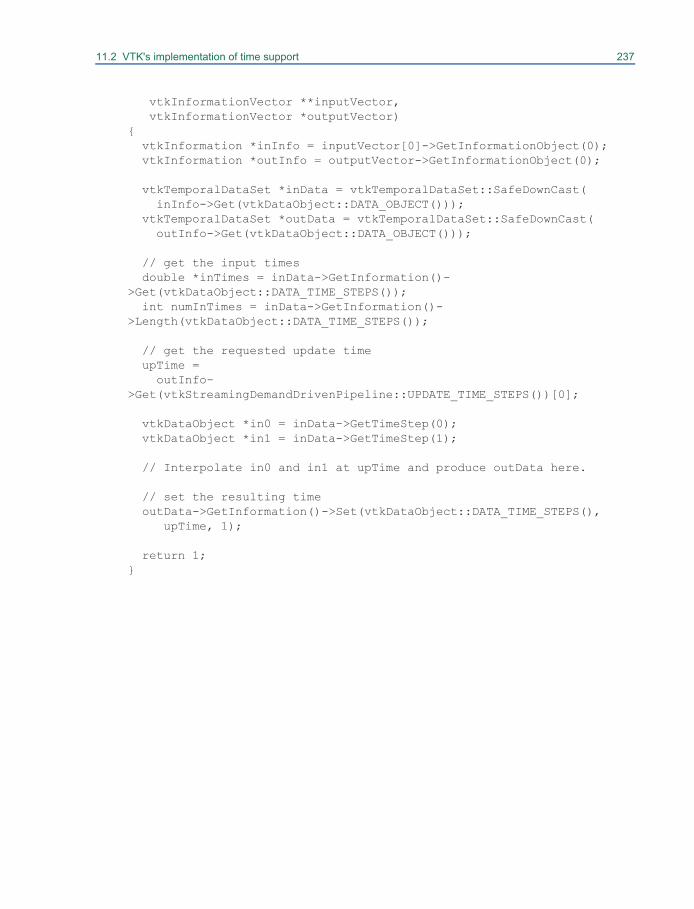
11.2 VTK's implementation of time support 237
vtkInformationVector **inputVector, vtkInformationVector *outputVector){ vtkInformation *inInfo = inputVector[0]->GetInformationObject(0); vtkInformation *outInfo = outputVector->GetInformationObject(0);
vtkTemporalDataSet *inData = vtkTemporalDataSet::SafeDownCast( inInfo->Get(vtkDataObject::DATA_OBJECT())); vtkTemporalDataSet *outData = vtkTemporalDataSet::SafeDownCast( outInfo->Get(vtkDataObject::DATA_OBJECT()));
// get the input times double *inTimes = inData->GetInformation()->Get(vtkDataObject::DATA_TIME_STEPS()); int numInTimes = inData->GetInformation()->Length(vtkDataObject::DATA_TIME_STEPS());
// get the requested update time upTime = outInfo->Get(vtkStreamingDemandDrivenPipeline::UPDATE_TIME_STEPS())[0];
vtkDataObject *in0 = inData->GetTimeStep(0); vtkDataObject *in1 = inData->GetTimeStep(1);
// Interpolate in0 and in1 at upTime and produce outData here.
// set the resulting time outData->GetInformation()->Set(vtkDataObject::DATA_TIME_STEPS(), upTime, 1);
return 1;}

Chapter 12
Reading and Writing Data 12
In this chapter we briefly describe various ways to read,write, import, and export data. Readers ingest a single dataset, while importers create an entire scene,which may include one or more datasets, actors, lights, cameras, and so on. Writers output a singledataset to disk (or stream), and exporters output an entire scene. In some cases, you may want tointerface to data that is not in standard VTK format, or in any other common format that VTK sup-ports. In such circumstances, you may wish to treat data as field data, and convert it in the visualiza-tion pipeline into datasets that the standard visualization techniques can properly handle.
12.1 ReadersWe saw in “Reader Source Object” on page 44 how to use a reader to bring data into the visualizationpipeline. Using a similar approach, we can read many other types of data. Using a reader involvesinstantiating the reader, supplying a filename, and calling Update() somewhere down the pipeline.
There are many different readers in the VTK library, all of which exist to read files and producedata structures that can be processed and visualized by the rest of the visualization pipeline. A readerthen, is any vtkAlgorithm, which does not require input connections and which knows how to readfiles to produce vtkDataObjects.
There are many different readers in VTK because there are many important file formats for sci-entific data. The different file formats exist to make permanent different varieties of data such asstructured, unstructured, polygonal, tabular, or graph. As a user of VTK, an important task is to deter-mine what VTK data structure corresponds to the data of interest to you and then to find a reader thatreads in the files you work with to produce that structure. This section introduces some of the avail-able readers.
There are some points to make note of before diving into the list of readers. For all VTK datastructure types there exists one or two VTK native reader classes. These classes were written in con-cert with developing or extending the corresponding data type. The older native reader class reads
240 Reading and Writing Data
files with the ".vtk" extension, and the newer reads XML based files with the ".vt?" extension (where? describes the type). Both old and new formats support writing data in text or binary formats. Thenewer format is more involved, but it fully supports the most recent vtk features including namedarrays, 32 bit / 64 bit encoding, streamed processing and the all of the latest data structures. Both for-mats have parallel processing extensions, which are implemented with meta files which refer to exter-nal serial files that are meant to be read independently. See “VTK File Formats” on page 469., fordetails of the native file formats.
This chapter lists the VTK native readers for each data type as well as a selection of the readersthat interface with the more well known third party file formats and produce that type.
Finally note that, if a suitable reader does not exist one can write one in C++, or use the tech-niques described in“Working With Field Data” on page 249 to coerce the output of the most genericreader, vtkProgrammableDataObjectSource, into the proper data type.
Data Object Readers
• vtkProgrammableDataObjectSource - an algorithm that executes a user specified function toproduce a vtkDataObject.. The user specified function can be written to read in any particularfile format, or procedurally generate data without reading any file.
• vtkGenericDataObjectReader - read a ".vtk" file, the legacy file format for all of VTK's datastructures and populate a vtkDataObject or the most specific subclass thereof with the structuredefined in the file. This reader will produce vtkTable for example, if the .vtk file contains Tabu-lar Data, and vtkUnstructuredGrid if the chosen .vtk file contains an Unstructured Grid. Thisclass reads the header information to find out what type of data is in the file and then delegatesthe rest of the processing to one of the more specific classes described below.
• vtkDataObjectReader - read a ".vtk" file and populate a DataObject with Field associatedarrays. This differs from vtkGenericDataObjectReader in that it will not produce the specificdata structure best suited to the contents of the file and instead always produces the most gen-eral one, vtkDataObject.
Data Set Readers
These readers produce generic vtkDataSet as output. Typically, the reader requires an Update() invo-cation to determine what kind of concrete vtkDataSet subclass is created.
• vtkDataSetReader - like vtkDataObjectReader, but this class is limited to the more commonvtkDataSet subclasses.
• vtkPDataSetReader - like vtkDataSetReader, but reads parallel vtk (.pvtk) format files, whichare meta files that references several legacy .vtk files which are meant to be processed by differ-ent processors simultaneously
• vtkGenericEnSightReader (and subclasses) - read EnSight files
Image and Volume Readers
• vtkStructuredPointsReader - reads ".vtk" legacy format files containing image data
• vtkXMLImageDataReader - reads ".vti" files, one of the newer XML based VTK file formats
12.1 Readers 241
• vtkXMLPImageDataReader - reads ".pvti" XML based parallel partitioned files that referenceindividual ".vti" files
• vtkImageReader - reads raw image data. Since the file format is a raw dump, you must specifythe image extent, byte ordering, scalar type etc in order to get the correct result from the file.
• vtkDICOMImageReader - reads DICOM (Digital Imaging and Communications in Medicine)images
• vtkGESignaReader - reads GE Signa Imaging files• vtkMINCImageReader - a netCDF based reader for MINC (Montreal Neurological Institute
Center) files• vtkSTLReader - read stereo-lithography files• vtkJPEGReader - reads JPEG files• vtkPNMReader - reads PNM files• vtkTIFFReader - reads TIFF files
Rectilinear Grid Readers
• vtkRectilinearGridReader - reads ".vtk" legacy format files containing rectilinear grid data• vtkXMLRectilinearGridReader - reads ".vtr" XML based VTK files• vtkXMLPRectilinearGridDataReader - reads ".pvtr" XML based parallel partitioned files that
reference individual ".vtr" files• vtkSESAMEReader - reads Los Alamos National Lab Equation of state data base files (http://
t1web.lanl.gov/doc/SESAME_3Ddatabase_1992.html)
Structured Grid Readers
• vtkStructuredGridReader - reads ".vtk" legacy format files containing structured grid data• vtkXMLStructuredGridReader - reads ".vts" XML based VTK files• vtkXMLPStructuredGridReader - reads ".pvts" XML based parallel partitioned files that refer-
ence individual ".vts" files• vtkPLOT3DReader - reads NASA PLOT3D structured CFD computation datasets (http://peo-
ple.nas.nasa.gov/~rogers/plot3d/intro.html)
Polygonal Data Readers• vtkPolyDataReader - reads ".vtk" legacy format files containing polygonal data• vtkXMLPolyDataReader - reads ".vtp" XML based VTK files• vtkXMLPPolyDataReader - reads ".pvtp" XML based parallel partitioned files that reference
individual ".vtp" files• vtkOBJReader - reads Wavefront .obj files• vtkPLYReader - reads Stanford University .ply files• vtkParticleReader - reads particle with scalar data x,y,z,value in ascii or binary format
242 Reading and Writing Data
• vtkSimplePointsReader - example reader, reads points written as X Y Z floating point form andproduce edges and vtk_vertex cells in vtkPolyData (PD)
• vtkSLACParticleReader - reads netCDF files written with conventions for Stanford LinearAccelerator Center processing tools. Output corresponds to particles in space. This differs fromvtkNetCDFReader in that although both understand the NetCDF format, this reader adds con-ventions suited to a particular area of scientific research.
Unstructured Grid Readers
• vtkUnstructuredGridReader - reads ".vtk" legacy format files containing unstructured grid data• vtkXMLUnstructuredGridReader - reads ".vtu" XML based VTK files• vtkXMLPUnstructuredGridReader - reads ".pvtu" XML based parallel partitioned files that
reference individual ".vtu" files• vtkCosmoReader - read Los Alamos National Lab cosmology binary data format files • vtkExodusReader - read Sandia National Lab Exodus format files• vtkPExodusReader - parallel processing specialization of vtkExodusReader in which each pro-
cessor reads its own portion of the blocks from the file simultaneously• vtkChacoReader - reads Sandia Chaco graph package format files and produces Unstruc-
turedGrid data• vtkPChacoReader - reads Sandia Chaco graph format packages on one processor and internally
distributes portions of the data to other parallel processors
Graph Readers
• vtkGraphReader - read ".vtk" legacy format files containing general Graph data• vtkTreeReader - read ".vtk" legacy format files to produce more specialized Trees• vtkXMLTreeReader - reads XML based VTK files• vtkChacoGraphReader - reads a file written in the Sandia Chaco graph package format. This
differs from vtkChacoReader in that it produces a vtkUndirectedGraph instead of the more spa-tially oriented vtkUnstructuredGrid.
• vtkPBGLGraphSQLReader - read vertex and edge tables from an Parallel Boost Graph LibrarySQL database
• vtkSQLGraphReader - read vertex and edge tables from an SQL database• vtkRISReader - read a RIS format bibliographic citation file and produce a vtkTable (TA)
Table Readers
• vtkTableReader - - read ".vtk" legacy format files containing general tabular data• vtkDelimitedTextReader - read text files in which newlines separate each row and a single user
specified delimiter character, for example, comma, tab or space, separates columns• vtkFixedWidthTextReader - read text files in which newlines separate each row and where each
column has a fixed width
12.2 Writers 243
• vtkISIReader - read bibliographic citation records in ISI format
Composite Data Readers
vtkCompositeDataSet’s concrete subclasses vtkMultiPieceDataSet, vtkHierarchicalBoxDataSet, andvtkMultiBlockDataSet are VTK's way of representing compound data objects, or data objects whichcontain other data objects. These structures are useful in parallel processing, for adaptively refinedsimulations and to represent hierarchical relationships between related parts. Several readers importcomplex data and produce composite data outputs. The contents of the composite data may be any orall of the above atomic types, and/or additional composite data objects.
• vtkXMLCompositeDataReader - and its subclasses read XML based VTK files. The standardextensions for these files include ".vtm", ".vth" and ".vtb".
• vtkExodusIIReader - read Sandia Exodus2 format files and directly produce MultiBlock datas-ets. This differs from vtkExodusReader in that the output is not converted to a single vtkUn-structuredGrid, which can potentially conserve memory when the data is regular.
• vtkPExodusIIReader- parallel processing specialization of the preceding each processor inde-pendently and simultaneously reads its own subset of the blocks
• vtkOpenFOAMReader - read file written in OpenFOAM (computational fluid dynamics) for-mat
12.2 WritersWriters output vtkDataObjects to the file system. A writer is any vtkAlgorithm which takes in a vtk-DataObject, usually one produced by the vtkAlgorithm connected to the writer's input, and writes it tothe file system in some standard format. There are many different writers in VTK because there aremany important file formats.
Typically, using a writer involves setting an input and specifying and output file name (or some-times names) as shown in the following.
vtkPolyDataWriter writerwriter SetInput [aFilter GetOutput]writer SetFileName “outFile.vtk”writer SetFileTypeToBinarywriter Write
The legacy VTK writers offer you the option of writing binary (SetFileTypeToBinary()) or ASCII(SetFileTypeToASCII()) files. (Note: binary files may not be transportable across computers. VTKtakes care of swapping bytes, but does not handle transport between 64-bit and 32-bit computers.)
The VTK XML writers also allow you to write in binary (SetDataModeToBinary()) or ASCII(SetDataModeToAscii()); and appended binary mode is also available (SetDataModeToAppended()).The VTK XML readers and writers do handle transporting data between 32-bit and 64-bit computersin addition to taking care of byte swapping.
The following is a list of available writers.
244 Reading and Writing Data
Data Object Writers
• vtkGenericDataObjectWriter - Writes any type of vtkDataObject to file in the legacy ".vtk" fileformat.
• vtkDataObjectWriter -- Write only the vtkDataObject's field data in legacy ".vtk" file format.
Data Set Writers
• vtkDataSetWriter - Writes any type of vtkDataSet to file in legacy ".vtk" file format
• vtkPDataSetWriter - Writes any type of vtkDataSet to file in legacy ".pvtk" parallel partitionedfile format
• vtkXMLDataSetWriters - Writes any type of vtkDataSet to file in the newer XML based ".vt?"format.
Image and Volume Writers
• vtkStructuredPointsWriter - Write image data in legacy ".vtk" format
• vtkPImageWriter - A parallel processing specialization of the preceding
• vtkXMLImageDataWriter - Write image data in XML based ".vti" format
• vtkMINCImageWriter - A netCDF based writer for MINC (Montreal Neurological InstituteCenter) files
• vtkPostScriptWriter - write image into post script format
• vtkJPEGWriter - write into JPEG format
• vtkPNMWriter - write into PNM format
• vtkTIFFWriter - write into TIFF format
Rectilinear Grid Writers
• vtkRectilinearGridWriter - Write rectilinear grid in legacy ".vtk" format
• vtkXMLRectilinearGridWriter - Write rectilinear grid in XML based ".vtr" format
• vtkXMLPRectilinearGridWriter - A parallel processing specialization of the preceding
Structured Grid Writers
• vtkStructuredGridWriter - Write structured grid in legacy ".vtk" format
• vtkXMLStructuredGridWriter - Write structured grid in XML based ".vts" format
• vtkXMLPStructuredGridWriter - A parallel processing specialization of the preceding
Polygonal Data Writers
• vtkPolyDataWriter - Write polygonal data in legacy ".vtk" format
• vtkXMLPolyDataWriter - Write polygonal data in XML based ".vtp" format
12.3 Importers 245
• vtkXMLPPolyDataWriter - A parallel processing specialization of the preceding• vtkSTLWriter - Write stereo-lithography files• vtkIVWriter - Write into OpenInventor 2.0 format• vtkPLYWriter - Writer Stanford University ".ply" files
Unstructured Grid Writers
• vtkUnstructuredGridWriter - Write unstructured data in legacy ".vtk" format• vtkXMLUnstructuredGridWriter - Write unstructured data in XML based ".vtu" format• vtkXMLPUnstructuredGridWriter - A parallel processing specialization of the preceding• vtkEnSightWriter - Write vtk unstructured grid data as an EnSight file
Graph Writers
• vtkGraphWriter - write vtkGraph data to a file in legacy ".vtk" format• vtkTreeWriter - write vtkTree data to a file in legacy ".vtk" format
Table Writers
• vtkTableWriter - write vtkTable data to file in legacy ".vtk" format
Composite Data Writers
• vtkXMLCompositeDataWriter (and its subclasses) - writers for composite data structuresincluding hierarchical box (multires image data) and multi-block (related datasets) data types
• vtkExodusIIWriter - Write composite data in Exodus II format
12.3 ImportersImporters accept data files that contain multiple datasetsand/or the objects that compose a scene (i.e., lights, cam-eras, actors, properties, transformation matrices, etc.).Importers will either generate an instance of vtkRender-Window and/or vtkRenderer, or you can specify them. Ifspecified, the importer will create lights, cameras, actors,and so on, and place them into the specified instance(s).Otherwise, it will create instances of vtkRenderer andvtkRenderWindow, as necessary. The following exampleshows how to use an instance of vtkImporter (in this case avtk3DSImporter—imports 3D Studio files). This Tcl scriptwas taken from VTK/Examples/IO/Tcl/flamingo.tcl(see Figure 12–1). Figure 12–1 Importing a file.
246 Reading and Writing Data
vtk3DSImporter importer importer ComputeNormalsOn importer SetFileName \
"$VTK_DATA_ROOT/Data/iflamigm.3ds" importer Read
set renWin [importer GetRenderWindow]vtkRenderWindowInteractor iren iren SetRenderWindow $renWin
The Visualization Toolkit supports the following importers. (Note that the superclass vtkImporter isavailable for developing new subclasses.)
• vtk3DSImporter — import 3D Studio files• vtkVRMLImporter — import VRML version 2.0 files
12.4 ExportersExporters output scenes in various formats. Instances of vtkExporter accept an instance of vtkRender-Window, and write out the graphics objects supported by the exported format.
vtkRIBExporter exporterexporter SetRenderWindow renWinexporter SetFilePrefix “anExportedFile”exporter Write
The vtkRIBExporter shown above writes out multiple files in RenderMan format. The FilePrefixinstance variable is used to write one or more files (geometry and texture map(s), if any).
The Visualization Toolkit supports the following exporters.
• vtkGL2PSExporter — export a scene as a PostScript file using GL2PS• vtkIVExporter — export an Inventor scene graph• vtkOBJExporter — export a Wavefront .obj files• vtkOOGLExporter — export a scene into GeomView OOGL format• vtkRIBExporter — export RenderMan files• vtkVRMLExporter — export VRML version 2.0 files• vtkPOVExporter - export into file format for the Persistence of Vision Raytracer
(www.povray.org)• vtkX3DExporter - export into X3D format (an XML based 3d scene format similar to VRML)
12.5 Creating HardcopyCreating informative images is a primary objective of VTK, and to document what you’ve done, sav-ing images and series of images (i.e., animations) is important. This section describes various ways tocreate graphical output.
12.5 Creating Hardcopy 247
Saving Images
The simplest way to save images is to use the vtkWindowToImageFilter which grabs the output bufferof the render window and converts it into vtkImageData. This image can then be saved using one ofthe image writers (see “Writers” on page 164 for more information). Here is an example
vtkWindowToImageFilter w2i w2i SetInput renWin
vtkJPEGWriter writer writer SetInput [w2i GetOutput] writer SetFileName "DelMesh.jpg" writer Write
Note that it is possible to use the off-screen mode of the render window when saving an image. Theoff-screen mode can be turned on by setting OffScreenRenderingOn() for the render window.
Saving Large (High-Resolution) Images
The images saved via screen capture or by saving the render window vary greatly in quality depend-ing on the graphics hardware and screen resolution supported on your computer. To improve the qual-ity of your images, there are two approaches that you can try. The first approach allows you to use theimaging pipeline to render pieces of your image and then combine them into a very high-resolutionfinal image. We’ll refer to this as tiled imaging. The second approach requires external software toperform high resolution rendering. We’ll refer to this as the RenderMan solution.
Tiled Rendering. Often we want to save an image of resolution greater than the resolution of thecomputer hardware. For example, generating an image of 4000 x 4000 pixels is not easy on a1280x1024 computer display. The Visualization Toolkit makes this trivial with the classvtkRenderLargeImage. This class breaks up the rendering process into separate pieces, each piececontaining just a portion of the final image. The pieces are assembled into a final image, which can besaved to file using one of the VTK image writers. Here’s how it works (Tcl script taken from VTK/Examples/Rendering/Tcl/RenderLargeImage.tcl).
vtkRenderLargeImage renderLarge renderLarge SetInput ren renderLarge SetMagnification 4
vtkTIFFWriter writer writer SetInputConnection [renderLarge GetOutputPort] writer SetFileName largeImage.tif writer Write
The Magnification instance variable (an integer value) controls how much to magnify the input ren-derer’s current image. If the renderer’s image size is (400,400) and the magnification factor is 5, thefinal image will be of resolution (2000,2000). In this example, the resulting image is written to a filewith an instance of vtkTIFFWriter. Of course, other writer types could be used.
248 Reading and Writing Data
RenderMan. RenderMan is a high-quality software rendering system currently sold by Pixar, thegraphics animation house that created the famous Toy Story movie. RenderMan is a commercial pack-age. A license for a single computer RenderMan rendering plugin for Maya costs $995 at the time ofthis writing.. Fortunately, there is at least one modestly priced (or free system if you’re non-commer-cial) RenderMan compatible system that you can download and use: Pixie (Blue Moon Ray Tracer).Pixie is slower than RenderMan, but it also offers several features that RenderMan does not.
In an earlier section (“Exporters” on page 166) we saw how to export a RenderMan .rib file(and associated textures). You can adjust the size of the image RenderMan produces using theSetSize() method in the vtkRIBExporter. This method adds a line to the rib file that causes Render-Man (or RenderMan compatible system such as Pixie) to create an output TIFF image of size (xres,yres) pixels.
12.6 Creating Movie FilesIn addition to writing a series of images, VTK also has three classes that allow you to write moviefiles directly: vtkAVIWriter, vtkFFMPEGWriter and vtkMPEG2Writer. Both are subclasses of vtkGe-nericMovieWriter. vtkAVIWriter uses Microsoft's multimedia API to create movie files, and is thusonly available on Windows machines. The FFMPEG and MPEG2 media formats are available on allplatforms, but because of license incompatibilities are provided only in source code format, and notwithin the VTK library itself. To use either of these interface classes you must manually downloadand compile the library on your machine and then configure and build VTK to link to them. Instruc-tions for doing so and the library source code are available at http://www.vtk.org/VTK/resources/soft-ware.html#addons. Both of these classes take a 2D vtkImageData as input – often the output of thevtkWindowToImageFilter. The important methods in these classes are as follows.
• Start — Call this method once to start writing a movie file.
• Write— Call this method once per frame added to the movie file.
• End — Call this method once to end the writing process.
Similar to the other writers, the movie writers also have SetInput and SetFileName methods. ExampleTcl code for writing a movie file with 100 frames follows.
vtkMPEG2Writer writerwriter SetInput [aFilter GetOutput]writer SetFileName "movie.mpg"writer Start
for {set i 0} {$i < 100} {incr i} {writer Write
# modify input to create next frame of movie…
}
writer End
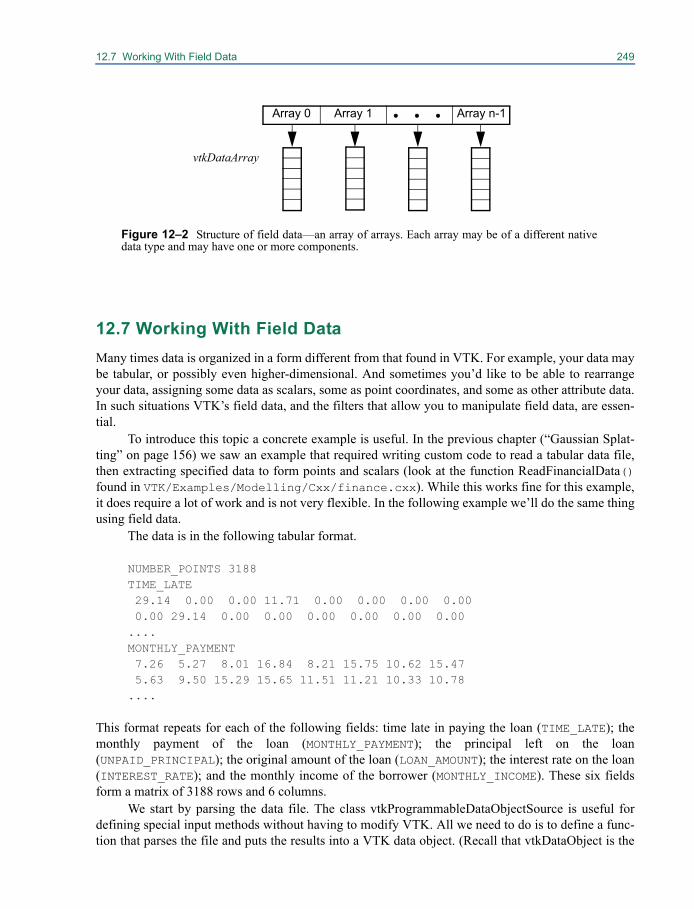
12.7 Working With Field Data 249
12.7 Working With Field DataMany times data is organized in a form different from that found in VTK. For example, your data maybe tabular, or possibly even higher-dimensional. And sometimes you’d like to be able to rearrangeyour data, assigning some data as scalars, some as point coordinates, and some as other attribute data.In such situations VTK’s field data, and the filters that allow you to manipulate field data, are essen-tial.
To introduce this topic a concrete example is useful. In the previous chapter (“Gaussian Splat-ting” on page 156) we saw an example that required writing custom code to read a tabular data file,then extracting specified data to form points and scalars (look at the function ReadFinancialData()found in VTK/Examples/Modelling/Cxx/finance.cxx). While this works fine for this example,it does require a lot of work and is not very flexible. In the following example we’ll do the same thingusing field data.
The data is in the following tabular format.
NUMBER_POINTS 3188TIME_LATE 29.14 0.00 0.00 11.71 0.00 0.00 0.00 0.00 0.00 29.14 0.00 0.00 0.00 0.00 0.00 0.00 ....MONTHLY_PAYMENT 7.26 5.27 8.01 16.84 8.21 15.75 10.62 15.47 5.63 9.50 15.29 15.65 11.51 11.21 10.33 10.78 ....
This format repeats for each of the following fields: time late in paying the loan (TIME_LATE); themonthly payment of the loan (MONTHLY_PAYMENT); the principal left on the loan(UNPAID_PRINCIPAL); the original amount of the loan (LOAN_AMOUNT); the interest rate on the loan(INTEREST_RATE); and the monthly income of the borrower (MONTHLY_INCOME). These six fieldsform a matrix of 3188 rows and 6 columns.
We start by parsing the data file. The class vtkProgrammableDataObjectSource is useful fordefining special input methods without having to modify VTK. All we need to do is to define a func-tion that parses the file and puts the results into a VTK data object. (Recall that vtkDataObject is the
vtkDataArray
Array 1 Array n-1Array 0
Figure 12–2 Structure of field data—an array of arrays. Each array may be of a different nativedata type and may have one or more components.
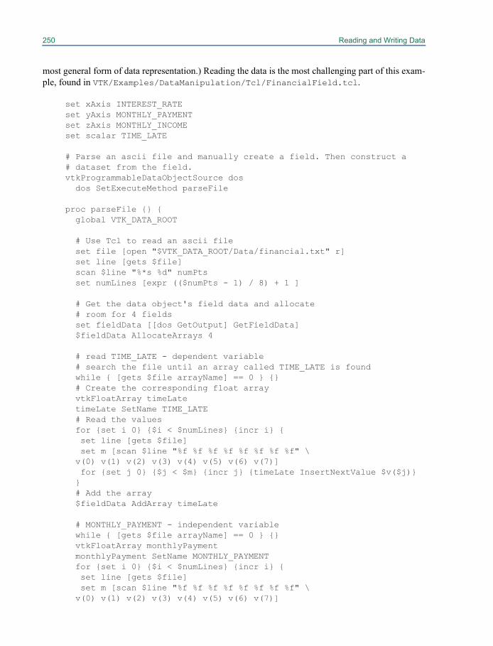
250 Reading and Writing Data
most general form of data representation.) Reading the data is the most challenging part of this exam-ple, found in VTK/Examples/DataManipulation/Tcl/FinancialField.tcl.
set xAxis INTEREST_RATEset yAxis MONTHLY_PAYMENTset zAxis MONTHLY_INCOMEset scalar TIME_LATE
# Parse an ascii file and manually create a field. Then construct a # dataset from the field.vtkProgrammableDataObjectSource dos dos SetExecuteMethod parseFile
proc parseFile {} { global VTK_DATA_ROOT
# Use Tcl to read an ascii file set file [open "$VTK_DATA_ROOT/Data/financial.txt" r] set line [gets $file] scan $line "%*s %d" numPts set numLines [expr (($numPts - 1) / 8) + 1 ]
# Get the data object's field data and allocate # room for 4 fields set fieldData [[dos GetOutput] GetFieldData] $fieldData AllocateArrays 4
# read TIME_LATE - dependent variable # search the file until an array called TIME_LATE is found while { [gets $file arrayName] == 0 } {} # Create the corresponding float array vtkFloatArray timeLate timeLate SetName TIME_LATE # Read the values for {set i 0} {$i < $numLines} {incr i} { set line [gets $file] set m [scan $line "%f %f %f %f %f %f %f %f" \ v(0) v(1) v(2) v(3) v(4) v(5) v(6) v(7)] for {set j 0} {$j < $m} {incr j} {timeLate InsertNextValue $v($j)} } # Add the array $fieldData AddArray timeLate
# MONTHLY_PAYMENT - independent variable while { [gets $file arrayName] == 0 } {} vtkFloatArray monthlyPayment monthlyPayment SetName MONTHLY_PAYMENT for {set i 0} {$i < $numLines} {incr i} { set line [gets $file] set m [scan $line "%f %f %f %f %f %f %f %f" \ v(0) v(1) v(2) v(3) v(4) v(5) v(6) v(7)]
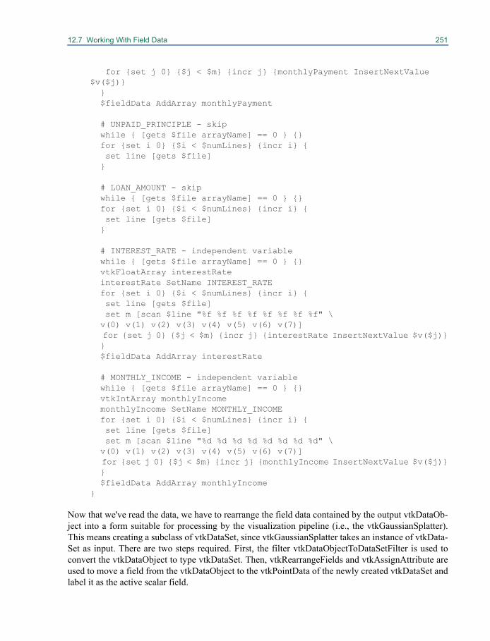
12.7 Working With Field Data 251
for {set j 0} {$j < $m} {incr j} {monthlyPayment InsertNextValue $v($j)} } $fieldData AddArray monthlyPayment
# UNPAID_PRINCIPLE - skip while { [gets $file arrayName] == 0 } {} for {set i 0} {$i < $numLines} {incr i} { set line [gets $file] }
# LOAN_AMOUNT - skip while { [gets $file arrayName] == 0 } {} for {set i 0} {$i < $numLines} {incr i} { set line [gets $file] }
# INTEREST_RATE - independent variable while { [gets $file arrayName] == 0 } {} vtkFloatArray interestRate interestRate SetName INTEREST_RATE for {set i 0} {$i < $numLines} {incr i} { set line [gets $file] set m [scan $line "%f %f %f %f %f %f %f %f" \ v(0) v(1) v(2) v(3) v(4) v(5) v(6) v(7)] for {set j 0} {$j < $m} {incr j} {interestRate InsertNextValue $v($j)} } $fieldData AddArray interestRate
# MONTHLY_INCOME - independent variable while { [gets $file arrayName] == 0 } {} vtkIntArray monthlyIncome monthlyIncome SetName MONTHLY_INCOME for {set i 0} {$i < $numLines} {incr i} { set line [gets $file] set m [scan $line "%d %d %d %d %d %d %d %d" \ v(0) v(1) v(2) v(3) v(4) v(5) v(6) v(7)] for {set j 0} {$j < $m} {incr j} {monthlyIncome InsertNextValue $v($j)} } $fieldData AddArray monthlyIncome }
Now that we've read the data, we have to rearrange the field data contained by the output vtkDataOb-ject into a form suitable for processing by the visualization pipeline (i.e., the vtkGaussianSplatter).This means creating a subclass of vtkDataSet, since vtkGaussianSplatter takes an instance of vtkData-Set as input. There are two steps required. First, the filter vtkDataObjectToDataSetFilter is used toconvert the vtkDataObject to type vtkDataSet. Then, vtkRearrangeFields and vtkAssignAttribute areused to move a field from the vtkDataObject to the vtkPointData of the newly created vtkDataSet andlabel it as the active scalar field.
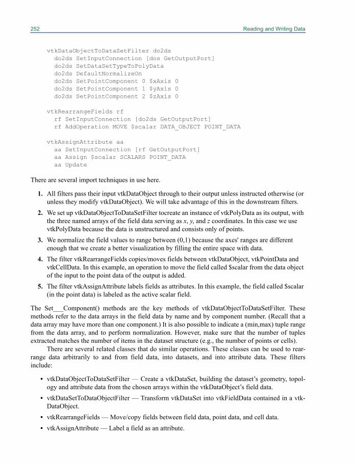
252 Reading and Writing Data
vtkDataObjectToDataSetFilter do2ds do2ds SetInputConnection [dos GetOutputPort] do2ds SetDataSetTypeToPolyData do2ds DefaultNormalizeOn do2ds SetPointComponent 0 $xAxis 0 do2ds SetPointComponent 1 $yAxis 0 do2ds SetPointComponent 2 $zAxis 0
vtkRearrangeFields rf rf SetInputConnection [do2ds GetOutputPort] rf AddOperation MOVE $scalar DATA_OBJECT POINT_DATA
vtkAssignAttribute aa aa SetInputConnection [rf GetOutputPort] aa Assign $scalar SCALARS POINT_DATA aa Update
There are several import techniques in use here.
1. All filters pass their input vtkDataObject through to their output unless instructed otherwise (or unless they modify vtkDataObject). We will take advantage of this in the downstream filters.
2. We set up vtkDataObjectToDataSetFilter tocreate an instance of vtkPolyData as its output, with the three named arrays of the field data serving as x, y, and z coordinates. In this case we use vtkPolyData because the data is unstructured and consists only of points.
3. We normalize the field values to range between (0,1) because the axes' ranges are different enough that we create a better visualization by filling the entire space with data.
4. The filter vtkRearrangeFields copies/moves fields between vtkDataObject, vtkPointData and vtkCellData. In this example, an operation to move the field called $scalar from the data object of the input to the point data of the output is added.
5. The filter vtkAssignAttribute labels fields as attributes. In this example, the field called $scalar (in the point data) is labeled as the active scalar field.
The Set___Component() methods are the key methods of vtkDataObjectToDataSetFilter. Thesemethods refer to the data arrays in the field data by name and by component number. (Recall that adata array may have more than one component.) It is also possible to indicate a (min,max) tuple rangefrom the data array, and to perform normalization. However, make sure that the number of tuplesextracted matches the number of items in the dataset structure (e.g., the number of points or cells).
There are several related classes that do similar operations. These classes can be used to rear-range data arbitrarily to and from field data, into datasets, and into attribute data. These filtersinclude:
• vtkDataObjectToDataSetFilter — Create a vtkDataSet, building the dataset’s geometry, topol-ogy and attribute data from the chosen arrays within the vtkDataObject’s field data.
• vtkDataSetToDataObjectFilter — Transform vtkDataSet into vtkFieldData contained in a vtk-DataObject.
• vtkRearrangeFields — Move/copy fields between field data, point data, and cell data.• vtkAssignAttribute — Label a field as an attribute.
12.7 Working With Field Data 253
• vtkMergeFields — Merge multiple fields into one.• vtkSplitField — Split a field into multiple single component fields.• vtkDataObjectReader — Read a VTK formatted field data file.• vtkDataObjectWriter — Write a VTK formatted field data file.• vtkProgrammableDataObjectSource — Define a method to read data of arbitrary form and rep-
resent it as field data (i.e., place it in a vtkDataObject).


Chapter 13
Interaction, Widgets and Selections 13
The greatest power in a visualization system is not in itsability to process data or create an image, but rather in its mechanism for allowing the user to interactwith the scene in order to guide the visualization in new directions. In VTK this interaction comes ina variety of forms from basic mouse and keyboard interaction allowing you rotate, translate andzoom, to the interactive widget elements in the scene that can be manipulated to control variousparameters of the visualization, to the selection mechanism for identifying portions of the data. Thischapter will cover the basics of interaction and introduce you to the tools you can use to develop yourown customized interaction model for your application.
13.1 InteractorsOnce you've visualized your data, you typically want to interact with it. The Visualization Toolkitoffers several approaches to do this. The first approach is to use the built in class vtkRenderWindow-Interactor. The second approach is to create your own interactor by specifying event bindings. Anddon't forget that if you are using an interpreted language you can type commands at run-time. Youmay also wish to refer to “Picking” on page 59 to see how to select data from the screen. (Note:Developers can also interface to a windowing system of their choice. See “Integrating With The Win-dowing System” on page 421.)
vtkRenderWindowInteractor
vtkRenderWindowInteractor provides a platform-independent interaction mechanism for mouse/key/time events. Platform specific subclasses intercept messages from the windowing system that occurwithin the render window and convert them to platform independent events. Specific classes mayobserve the interactor for these user events and respond to them. One such class is vtkInteractorOb-server. (Remember that multiple renderers can draw into a rendering window and that the renderer
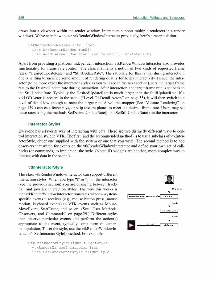
256 Interaction, Widgets and Selections
draws into a viewport within the render window. Interactors support multiple renderers in a renderwindow). We've seen how to use vtkRenderWindowInteractor previously, here's a recapitulation.
vtkRenderWindowInteractor ireniren SetRenderWindow renWiniren AddObserver UserEvent {wm deiconify .vtkInteract}
Apart from providing a platform independent interaction, vtkRenderWindowInteractor also providesfunctionality for frame rate control. The class maintains a notion of two kinds of requested framerates: “DesiredUpdateRate” and “StillUpdateRate”. The rationale for this is that during interaction,one is willing to sacrifice some amount of rendering quality for better interactivity. Hence, the inter-actor (to be more exact the interactor styles as you will see in the next section), sets the target framerate to the DesiredUpdateRate during interaction. After interaction, the target frame rate is set back tothe StillUpdateRate. Typically the DesiredUpdateRate is much larger than the StillUpdateRate. If avtkLODActor is present in the scene (“Level-Of-Detail Actors” on page 55), it will then switch to alevel of detail low enough to meet the target rate. A volume mapper (See “Volume Rendering” onpage 139.) can cast fewer rays, or skip texture planes to meet the desired frame rate. Users may setthese rates using the methods SetDesiredUpdateRate() and SetStillUpdateRate() on the interactor.
Interactor StylesEveryone has a favorite way of interacting with data. There are two distinctly different ways to con-trol interaction style in VTK. The first (and the recommended method) is to use a subclass of vtkInter-actorStyle, either one supplied with the system or one that you write. The second method is to addobservers that watch for events on the vtkRenderWindowInteractor and define your own set of call-backs (or commands) to implement the style. (Note: 3D widgets are another, more complex way tointeract with data in the scene.)
vtkInteractorStyle The class vtkRenderWindowInteractor can support differentinteraction styles. When you type “t” or “j” in the interactor(see the previous section) you are changing between track-ball and joystick interaction styles. The way this works isthat vtkRenderWindowInteractor translates window-system-specific events it receives (e.g., mouse button press, mousemotion, keyboard events) to VTK events such as Mouse-MoveEvent, StartEvent, and so on. (See “User Methods,Observers, and Commands” on page 29.) Different stylesthen observe particular events and perform the action(s)appropriate to the event, typically some form of cameramanipulation. To set the style, use the vtkRenderWindowIn-teractor's SetInteractorStyle() method. For example:
vtkInteractorStyleFlight flightStylevtkRenderWindowInteractor ireniren SetInteractorStyle flightStyle
13.1 Interactors 257
A variety of interactor styles are provided with the toolkit. Below, we list some of the interactor stylesfound in the toolkit:
• vtkInteractorStyleTrackballActor - Allows the user to interact with (rotate, pan, etc.) actors inthe scene independent of each other in a trackball based style. The trackball style is motion sen-sitive, ie. the magnitude of the mouse motion is proportional to the camera motion associatedwith a particular mouse binding.
• vtkInteractorStyleTrackballCamera - Allows the user to interactively manipulate (rotate, pan,etc.) the camera, the viewpoint of the scene in a trackball based style.
• vtkInteractorStyleJoystickActor - allows the user to interact with actors in a joystick style. Thejoystick style is position sensitive; ie. the position of the mouse relative to the center of theobject, rather than the velocity of the mouse motion, determines the speed of the object'smotion.
• vtkInteractorStyleJoystickCamera - Manipulate the camera in a joystick style.• vtkInteractorStyleFlight - Provides flight motion routines. It is suitable for a fly through interac-
tion (for instance through the colon in virtual colonoscopy), or a fly over (for instance over aterrain, or height field).
• vtkInteractorStyleImage - The style is specially designed to work with images that are beingrendered with vtkImageActor. Its interactions support window/level etc.
• vtkInteractorStyleRubberbandZoom - This interactor style allows the user to draw a rectangle(rubberband) in the render window and zooms the camera appropriately into the selectedregion.
• vtkGeoInteractorStyle - Tailored for interaction with a geographic view (for instance a globe).Its interaction capabilities include orbit, zoom and tilt. It also features a compass widget forchanging view parameters.
• vtkInteractorStyleTreeMapHover - works with a tree map (See “Information Visualization” onpage 163.). Interactions allow 2D pan/zoom and balloon annotations for nodes on the tree map,node selection capabilities etc.
• vtkInteractorStyleAreaSelectHover - Similar to vtkInteractorStyleTreeMapHover except that itworks with an area layout (See “Area Layouts” on page 175.)
• vtkInteractorStyleUnicam - Single mouse button, context sensitive interaction.
Adding vtkRenderWindowInteractor ObserversWhile a variety of interactor styles are available in VTK, you may prefer to create your own customstyle to meet the needs of a particular application. In C++ the natural approach is to subclass vtkInter-actorStyle. (See “vtkRenderWindowInteractor” on page 255.) However, in an interpreted language(e.g., Tcl, Python, or Java), this is difficult to do. For interpreted languages the simplest approach is touse observers to define particular interaction bindings. (See “User Methods, Observers, and Com-mands” on page 29.) The bindings can be managed in any language that VTK supports, includingC++, Tcl, Python, and Java. An example of this is found in the Tcl code VTK/Examples/GUI/Tcl/CustomInteraction.tcl, which defines bindings for a simple Tcl application. Here's an excerpt to giveyou an idea of what's going on.
258 Interaction, Widgets and Selections
vtkRenderWindowInteractor ireniren SetInteractorStyle ""iren SetRenderWindow renWin
# Add the observers to watch for particular events# These invoke Tcl proceduresset Rotating 0set Panning 0set Zooming 0
iren AddObserver LeftButtonPressEvent {global Rotating; set Rotating 1}iren AddObserver LeftButtonReleaseEvent \{global Rotating; set Rotating 0}
iren AddObserver MiddleButtonPressEvent {global Panning; set Panning 1}iren AddObserver MiddleButtonReleaseEvent \{global Panning; set Panning 0}
iren AddObserver RightButtonPressEvent {global Zooming; set Zooming 1}iren AddObserver RightButtonReleaseEvent {global Zooming; set Zooming 0}iren AddObserver MouseMoveEvent MouseMoveiren AddObserver KeyPressEvent Keypress
proc MouseMove {} {...
set xypos [iren GetEventPosition] set x [lindex $xypos 0] set y [lindex $xypos 1]...
}
proc Keypress {} {set key [iren GetKeySym]if { $key == "e" } {
vtkCommand DeleteAllObjects exit }...}
Note that a key step in this example is disabling the default interaction style by invoking SetInterac-tionStyle(""). Observers are then added to watch for particular events which are tied to the appropri-ate Tcl procedures. This example is a simple way to add bindings from a Tcl script. If you would liketo create a full GUI using Tcl/Tk, then use the vtkTkRenderWidget, and refer to “Tcl/Tk” on page 433for more details.
13.2 WidgetsInteractor styles are generally used to control the camera and provide simple keypress and mouse-ori-ented interaction techniques. Interactor styles have no representation in the scene; that is, they cannotbe “seen” or interacted with, the user must know what the mouse and key bindings are in order to use
13.2 Widgets 259
them. Certain operations, however, are greatly facilitated by the ability to operate directly on objectsin the scene. For example, starting a rake of streamlines along a line is easily performed if the end-points of the line can be interactively positioned.
VTK's 3D widgets have been designed to provide this functionality. Like the class vtkInterac-torStyle, VTK's widgets are subclasses of vtkInteractorObserver. That is, they listen to mouse andkeyboard events invoked by vtkRenderWindowInteractor. Unlike vtkInteractorStyle, however, thesewidgets have some geometrical representation in the scene, with which the user typically interacts.VTK provides numerous widgets tailored to perform tasks that range from measurements and annota-tions to segmentations, scene parameter manipulation, probing etc.
Since their inception into VTK, the widget architecture has undergone a redesign. The olderwidgets derive from vtk3DWidget. Below, we will discuss the architecture of the newer widgets.These derive from vtkAbstractWidget, which derives from vtkInteractorObserver. This class definesthe behavior of the widget (its interaction, etc). The widget’s geometry (how it appears in the scene) isencapsulated in the form of a prop. This is a class that derives from vtkWidgetRepresentation, whichderives from vtkProp. This decoupling of the behavior (interaction) from the representation (geome-try) allows one to create multiple representations for the same widget. This allows users to overrideexisting representations with their own representations without having to reimplement event process-ing. They are useful in a parallel, distributed computing world where the capabilities for event pro-cessing may not exist. A vtkHandleWidget that is used to represent a seed has four geometricrepresentations namely: vtkPointHandleRepresentation2D, vtkPointHandleRepresentation3D, vtk-SphereHandleRepresentation and vtkPolygonalHandleRepresentation. These render a handle as a 2Dcrosshair, 3D crosshair, a sphere or a user supplied polygonal shape respectively. The following snip-pet found in Widgets/Testing/Cxx/TestHandleWidget.cxx shows how to create a widget and tie it toits representation. Here, we’ll create a handle widget that can be moved around in a 3D world. Thehandle is represented via a 3D crosshair, as dictated by its representation.
// Create a render window interactorvtkRenderWindowInteractor *iren = vtkRenderWindowInteractor::New(); iren->SetRenderWindow(renderWindow);
// Create a 3D cross hair representation for a handledouble worldPos[3] = {-0.0417953, 0.202206, -0.0538641};vtkPointHandleRepresentation3D *handleRep = vtkPointHandleRepresentation3D::New();handleRep->SetHandleSize(10);handleRep->SetWorldPosition(worldPos);
// Create the handle widget.vtkHandleWidget *handleWidget = vtkHandleWidget::New();handleWidget->SetInteractor(iren);handleWidget->SetRepresentation(handleRep);handleWidget->EnabledOn();
While each widget provides different functionality and offers a different API, the 3D widgets are sim-ilar in how they are set up and used. The general procedure is as follows.
1. Instantiate the widget
2. Specify the render window interactor that the widget will observe for user events
260 Interaction, Widgets and Selections
3. Create callbacks (i.e., commands) as necessary using the Command/Observer mechanism.See “User Methods, Observers, and Commands” on page 29. The widgets typically invoke the generic events indicating that they are being interacted with and also widget specific events during interaction, such as StartInteractionEvent, InteractionEvent, and EndInteractionEvent. The user typically observes these events to update data, visualization parameters or the applica-tion's user interface.
4. Create the appropriate representation and provide it to the widget using SetRepresentation, or use the default representation provided by the widget.
5. Finally the widget must be enabled, so that it is visible on the scene. By default, a keypress “i” will enable the widget and it will appear in the scene.
While SetEnabled toggles the visibility of a widget, in some cases, it may be necessary to disable awidget's interaction, while keeping it visible in the scene. Event processing for the newer widgets canbe disabled via:
widget->ProcessEventsOff();
This will cause the widget to stop responding to interactions, which will end up being processed bythe underlying interactor style.
Reconfigurable Bindings
Users may also like to customize mouse / keyboard bindings for a widget, due to personal preferenceor when a different interaction device is used. The newly architected widgets allow you to reconfigurebindings. All user events are associated with specific widget actions. The widgets use an intermediateclass called an “event translator” to translate user events to widget specific events. In turn, the widgetevent is mapped into a method invocation on the widget. The event translator can be used to changethe default bindings as shown in the following code excerpt from Widgets/Testing/Cxx/TestSlider-Widget.cxx
vtkWidgetEventTranslator *translator = sliderWidget->GetEventTranslator();
translator->SetTranslation( vtkCommand::RightButtonPressEvent, vtkWidgetEvent::Select);
translator->SetTranslation( vtkCommand::RightButtonReleaseEvent, vtkWidgetEvent::EndSelect);
As a result, the user can manipulate the slider’s notch using the right mouse button in addition to thedefault left button. The user may also remove existing bindings using the RemoveTranslation method.
translator->RemoveTranslation( vtkCommand::LeftButtonPressEvent );translator->RemoveTranslation( vtkCommand::LeftButtonReleaseEvent );
A list of translations associated with a widget can be obtained by exercising its Print statement:
translator->Print( std::cout );
13.2 Widgets 261
Cursor Management and HighlightingMost widgets also manage the cursor, changing its shape appropriately when hovering over a portionof the widget to indicate an action. Highlighting is another common feature, for instance the handle ofa box widget will change color when hovered upon / selected to indicate its ability to be manipulated.
Widget HierarchiesWidgets also support hierarchies. A widget may be “parented” by another widget to enable creation ofcomposite widgets, using one or more existing widgets. For instance a vtkDistanceWidget internallycomprises two vtkHandleWidgets, as its children, representing the end points. The children listen totheir parent for events, instead of the render window interactor, thereby allowing the parent to modifytheir behavior if necessary. Within VTK, the handle widget is used as a child in several other widgetssuch as the Angle, BiDimensional, Box, Parallelopiped, Line and Seed widgets.
TimersApart from responding to events, from the user, VTK's widgets can also respond to other events, suchas timer events. For instance a vtkBalloonWidget is used to popup text / image annotations when themouse hovers over an actor for a user specified time. To do this, the widget observes the interactor forthe MouseMoveEvent and the TimerEvent, so that the widget may take action when the mouse stag-nates over an actor for a time exceeding a user specified “TimerDuration”.
The following excerpt from Rendering/Testing/Cxx/TestInteractorTimers.cxx illustrates how torequest and observe the render window interactor for timers.
// Observe the interactor for timers with a callbackiren->AddObserver(vtkCommand::TimerEvent, myCallback);
// Create a timer that repeats every 3 millisecondstid = iren->CreateRepeatingTimer(3);
// Create a timer that fires once after 1 second.tid = iren->CreateOneShotTimer(10000);
PrioritiesSeveral classes may observe the render window interactor simultaneously for user events. Theseinclude all subclasses of vtkInteractorObserver, such as the interactor style and one or more widgetsin the scene. Mousing in the scene, not on any particular widget will engage the vtkInteractorStyle,but mousing on a particular widget will engage just that widget-typically no other widget or interactorstyle will see the events. (One notable exception is the class vtkInteractorEventRecorder that recordsevents and then passes them along. This class can also playback events, thereby making it useful forrecording sessions. The class is used in VTK to exercise regression tests for the widgets.). Such a sce-nario may result in event competition. Competition for user events is handled through “priorities”. Allsubclasses of vtkInteractorObserver can be assigned a priority using the SetPriority method. Objectswith a higher priority are given the opportunity to process events before those with a lower priority.They may also choose to abort event processing for a given event, and in effect grab “focus”.
In fact, the reason the widgets handle event processing before the interactor style is due to theirhaving a higher priority than the interactor styles.
262 Interaction, Widgets and Selections
Point PlacersNote that interactions happen in a 2D window. 3D widgets may need to translate 2D coordinates tocoordinates in a 3D world. For instance, consider the use of a vtkHandleWidget to drop a seed pointon a render window. At what depth in the 3D scene should the seed be placed? VTK provides a fewstandard ways define this mapping and a framework to create your own mapping. This is accom-plished via a class called vtkPointPlacer. The contour widget and the handle widget have representa-tions that accept a point placer to which they delegate the responsibility of translating from 2D to 3Dco-ordinates. One may use these to specify constraints on where a node may be moved. For instance,the following excerpt found in Widgets/Testing/Cxx/TestSurfaceConstrainedHandleWidget.cxxrestricts the placement and interaction of seeds to a polygonal surface:
vtkHandleWidget *widget = vtkHandleWidget::New();vtkPointHandleRepresentation3D *rep =vtkPointHandleRepresentation3D::SafeDownCast(widget->GetRepresentation());
// Restrict the placement of seeds to the polygonal surface defined by // "polydata" and rendered as "actor"vtkPolygonalSurfacePointPlacer * pointPlacer= vtkPolygonalSurfacePointPlacer::New();pointPlacer->AddProp(actor);pointPlacer->GetPolys()->AddItem( polydata );rep->SetPointPlacer(pointPlacer);
Similarly, one may use the class vtkImageActorPointPlacer to restrict the placement of control pointsof a contour widget to a slice of an image as shown in the following excerpt from Widgets/Testing/Cxx/TestImageActorContourWidget.cxx.
vtkOrientedGlyphContourRepresentation *rep =vtkOrientedGlyphContourRepresentation::New();
vtkImageActorPointPlacer * imageActorPointPlacer =vtkImageActorPointPlacer::New();imageActorPointPlacer->SetImageActor(ImageViewer->GetImageActor());
rep->SetPointPlacer(imageActorPointPlacer);
13.3 A tour of the widgetsThe following is a selected list of widgets currently found in VTK and a brief description of their fea-tures. Note that some of the concepts mentioned here have not yet been covered in this text. Pleaserefer to the appropriate cross-reference to learn more about a particular concept.
Measurement Widgets
vtkDistanceWidget. The vtkDistanceWidget is used to measure the distance between two points in2D, for instance to measure the diameter of a tumor in a medical image. The two end points can bepositioned independently, and when they are released, a PlacePointEvent is invoked so that you canperform custom operations to reposition the point (snap to grid, snap to an edge, etc.) The widget hastwo different modes of interaction: the first mode is used when you initially define the measurement
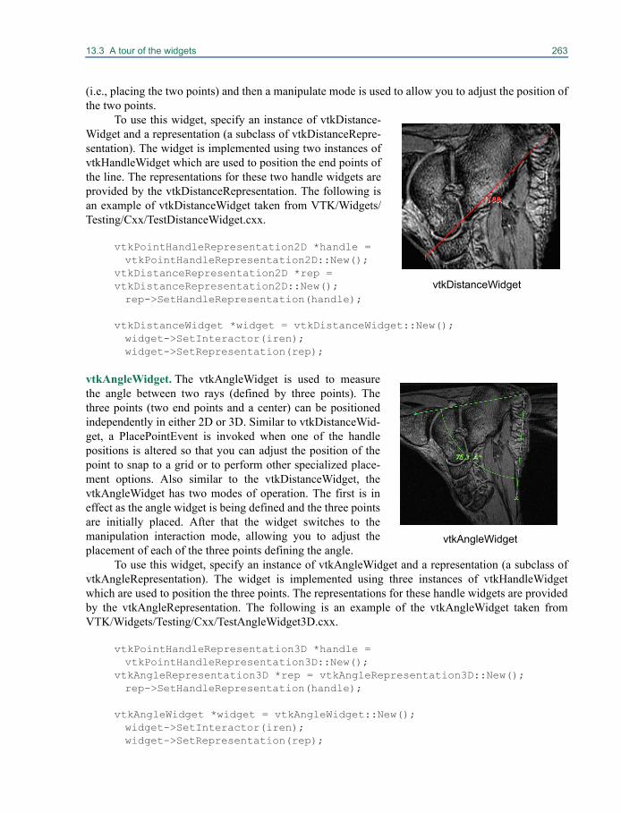
13.3 A tour of the widgets 263
(i.e., placing the two points) and then a manipulate mode is used to allow you to adjust the position ofthe two points.
To use this widget, specify an instance of vtkDistance-Widget and a representation (a subclass of vtkDistanceRepre-sentation). The widget is implemented using two instances ofvtkHandleWidget which are used to position the end points ofthe line. The representations for these two handle widgets areprovided by the vtkDistanceRepresentation. The following isan example of vtkDistanceWidget taken from VTK/Widgets/Testing/Cxx/TestDistanceWidget.cxx.
vtkPointHandleRepresentation2D *handle = vtkPointHandleRepresentation2D::New();
vtkDistanceRepresentation2D *rep = vtkDistanceRepresentation2D::New();rep->SetHandleRepresentation(handle);
vtkDistanceWidget *widget = vtkDistanceWidget::New();widget->SetInteractor(iren);widget->SetRepresentation(rep);
vtkAngleWidget. The vtkAngleWidget is used to measurethe angle between two rays (defined by three points). Thethree points (two end points and a center) can be positionedindependently in either 2D or 3D. Similar to vtkDistanceWid-get, a PlacePointEvent is invoked when one of the handlepositions is altered so that you can adjust the position of thepoint to snap to a grid or to perform other specialized place-ment options. Also similar to the vtkDistanceWidget, thevtkAngleWidget has two modes of operation. The first is ineffect as the angle widget is being defined and the three pointsare initially placed. After that the widget switches to themanipulation interaction mode, allowing you to adjust theplacement of each of the three points defining the angle.
To use this widget, specify an instance of vtkAngleWidget and a representation (a subclass ofvtkAngleRepresentation). The widget is implemented using three instances of vtkHandleWidgetwhich are used to position the three points. The representations for these handle widgets are providedby the vtkAngleRepresentation. The following is an example of the vtkAngleWidget taken fromVTK/Widgets/Testing/Cxx/TestAngleWidget3D.cxx.
vtkPointHandleRepresentation3D *handle = vtkPointHandleRepresentation3D::New();
vtkAngleRepresentation3D *rep = vtkAngleRepresentation3D::New();rep->SetHandleRepresentation(handle);
vtkAngleWidget *widget = vtkAngleWidget::New();widget->SetInteractor(iren);widget->SetRepresentation(rep);
vtkDistanceWidget
vtkAngleWidget
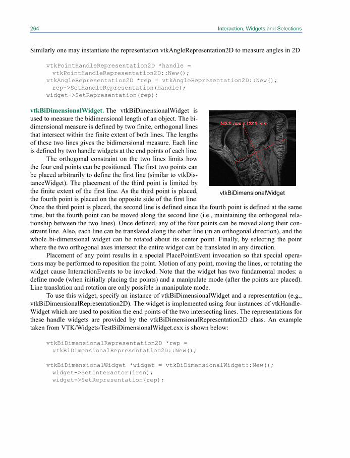
264 Interaction, Widgets and Selections
Similarly one may instantiate the representation vtkAngleRepresentation2D to measure angles in 2D
vtkPointHandleRepresentation2D *handle = vtkPointHandleRepresentation2D::New();
vtkAngleRepresentation2D *rep = vtkAngleRepresentation2D::New();rep->SetHandleRepresentation(handle);
widget->SetRepresentation(rep);
vtkBiDimensionalWidget. The vtkBiDimensionalWidget isused to measure the bidimensional length of an object. The bi-dimensional measure is defined by two finite, orthogonal linesthat intersect within the finite extent of both lines. The lengthsof these two lines gives the bidimensional measure. Each lineis defined by two handle widgets at the end points of each line.
The orthogonal constraint on the two lines limits howthe four end points can be positioned. The first two points canbe placed arbitrarily to define the first line (similar to vtkDis-tanceWidget). The placement of the third point is limited bythe finite extent of the first line. As the third point is placed,the fourth point is placed on the opposite side of the first line.Once the third point is placed, the second line is defined since the fourth point is defined at the sametime, but the fourth point can be moved along the second line (i.e., maintaining the orthogonal rela-tionship between the two lines). Once defined, any of the four points can be moved along their con-straint line. Also, each line can be translated along the other line (in an orthogonal direction), and thewhole bi-dimensional widget can be rotated about its center point. Finally, by selecting the pointwhere the two orthogonal axes intersect the entire widget can be translated in any direction.
Placement of any point results in a special PlacePointEvent invocation so that special opera-tions may be performed to reposition the point. Motion of any point, moving the lines, or rotating thewidget cause InteractionEvents to be invoked. Note that the widget has two fundamental modes: adefine mode (when initially placing the points) and a manipulate mode (after the points are placed).Line translation and rotation are only possible in manipulate mode.
To use this widget, specify an instance of vtkBiDimensionalWidget and a representation (e.g.,vtkBiDimensionalRepresentation2D). The widget is implemented using four instances of vtkHandle-Widget which are used to position the end points of the two intersecting lines. The representations forthese handle widgets are provided by the vtkBiDimensionalRepresentation2D class. An exampletaken from VTK/Widgets/TestBiDimensionalWidget.cxx is shown below:
vtkBiDimensionalRepresentation2D *rep = vtkBiDimensionalRepresentation2D::New();
vtkBiDimensionalWidget *widget = vtkBiDimensionalWidget::New();widget->SetInteractor(iren);widget->SetRepresentation(rep);
vtkBiDimensionalWidget
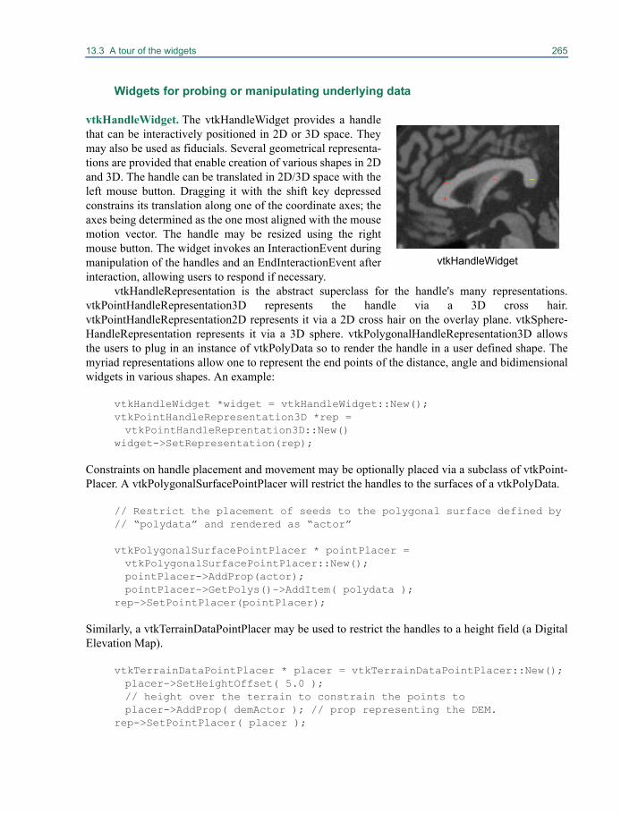
13.3 A tour of the widgets 265
Widgets for probing or manipulating underlying data
vtkHandleWidget. The vtkHandleWidget provides a handlethat can be interactively positioned in 2D or 3D space. Theymay also be used as fiducials. Several geometrical representa-tions are provided that enable creation of various shapes in 2Dand 3D. The handle can be translated in 2D/3D space with theleft mouse button. Dragging it with the shift key depressedconstrains its translation along one of the coordinate axes; theaxes being determined as the one most aligned with the mousemotion vector. The handle may be resized using the rightmouse button. The widget invokes an InteractionEvent duringmanipulation of the handles and an EndInteractionEvent afterinteraction, allowing users to respond if necessary.
vtkHandleRepresentation is the abstract superclass for the handle's many representations.vtkPointHandleRepresentation3D represents the handle via a 3D cross hair.vtkPointHandleRepresentation2D represents it via a 2D cross hair on the overlay plane. vtkSphere-HandleRepresentation represents it via a 3D sphere. vtkPolygonalHandleRepresentation3D allowsthe users to plug in an instance of vtkPolyData so to render the handle in a user defined shape. Themyriad representations allow one to represent the end points of the distance, angle and bidimensionalwidgets in various shapes. An example:
vtkHandleWidget *widget = vtkHandleWidget::New();vtkPointHandleRepresentation3D *rep = vtkPointHandleReprentation3D::New()
widget->SetRepresentation(rep);
Constraints on handle placement and movement may be optionally placed via a subclass of vtkPoint-Placer. A vtkPolygonalSurfacePointPlacer will restrict the handles to the surfaces of a vtkPolyData.
// Restrict the placement of seeds to the polygonal surface defined by // “polydata” and rendered as “actor”
vtkPolygonalSurfacePointPlacer * pointPlacer = vtkPolygonalSurfacePointPlacer::New();pointPlacer->AddProp(actor);pointPlacer->GetPolys()->AddItem( polydata );
rep->SetPointPlacer(pointPlacer);
Similarly, a vtkTerrainDataPointPlacer may be used to restrict the handles to a height field (a DigitalElevation Map).
vtkTerrainDataPointPlacer * placer = vtkTerrainDataPointPlacer::New();placer->SetHeightOffset( 5.0 ); // height over the terrain to constrain the points toplacer->AddProp( demActor ); // prop representing the DEM.
rep->SetPointPlacer( placer );
vtkHandleWidget
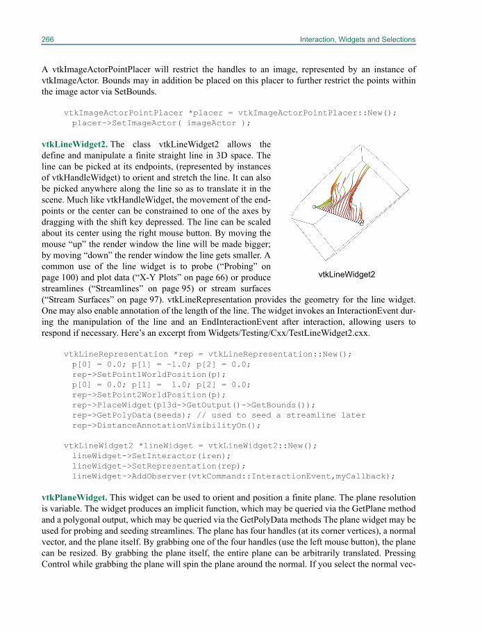
266 Interaction, Widgets and Selections
A vtkImageActorPointPlacer will restrict the handles to an image, represented by an instance ofvtkImageActor. Bounds may in addition be placed on this placer to further restrict the points withinthe image actor via SetBounds.
vtkImageActorPointPlacer *placer = vtkImageActorPointPlacer::New();placer->SetImageActor( imageActor );
vtkLineWidget2. The class vtkLineWidget2 allows thedefine and manipulate a finite straight line in 3D space. Theline can be picked at its endpoints, (represented by instancesof vtkHandleWidget) to orient and stretch the line. It can alsobe picked anywhere along the line so as to translate it in thescene. Much like vtkHandleWidget, the movement of the end-points or the center can be constrained to one of the axes bydragging with the shift key depressed. The line can be scaledabout its center using the right mouse button. By moving themouse “up” the render window the line will be made bigger;by moving “down” the render window the line gets smaller. Acommon use of the line widget is to probe (“Probing” onpage 100) and plot data (“X-Y Plots” on page 66) or producestreamlines (“Streamlines” on page 95) or stream surfaces(“Stream Surfaces” on page 97). vtkLineRepresentation provides the geometry for the line widget.One may also enable annotation of the length of the line. The widget invokes an InteractionEvent dur-ing the manipulation of the line and an EndInteractionEvent after interaction, allowing users torespond if necessary. Here’s an excerpt from Widgets/Testing/Cxx/TestLineWidget2.cxx.
vtkLineRepresentation *rep = vtkLineRepresentation::New();p[0] = 0.0; p[1] = -1.0; p[2] = 0.0;rep->SetPoint1WorldPosition(p);p[0] = 0.0; p[1] = 1.0; p[2] = 0.0;rep->SetPoint2WorldPosition(p);rep->PlaceWidget(pl3d->GetOutput()->GetBounds());rep->GetPolyData(seeds); // used to seed a streamline laterrep->DistanceAnnotationVisibilityOn();
vtkLineWidget2 *lineWidget = vtkLineWidget2::New();lineWidget->SetInteractor(iren);lineWidget->SetRepresentation(rep);lineWidget->AddObserver(vtkCommand::InteractionEvent,myCallback);
vtkPlaneWidget. This widget can be used to orient and position a finite plane. The plane resolutionis variable. The widget produces an implicit function, which may be queried via the GetPlane methodand a polygonal output, which may be queried via the GetPolyData methods The plane widget may beused for probing and seeding streamlines. The plane has four handles (at its corner vertices), a normalvector, and the plane itself. By grabbing one of the four handles (use the left mouse button), the planecan be resized. By grabbing the plane itself, the entire plane can be arbitrarily translated. PressingControl while grabbing the plane will spin the plane around the normal. If you select the normal vec-
vtkLineWidget2
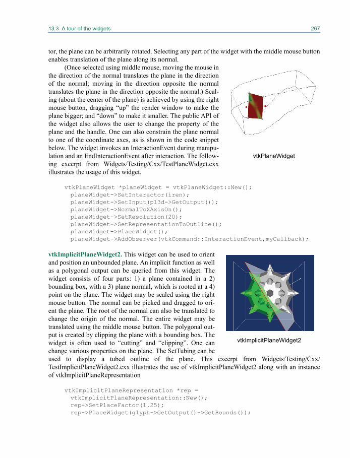
13.3 A tour of the widgets 267
tor, the plane can be arbitrarily rotated. Selecting any part of the widget with the middle mouse buttonenables translation of the plane along its normal.
(Once selected using middle mouse, moving the mouse inthe direction of the normal translates the plane in the directionof the normal; moving in the direction opposite the normaltranslates the plane in the direction opposite the normal.) Scal-ing (about the center of the plane) is achieved by using the rightmouse button, dragging “up” the render window to make theplane bigger; and “down” to make it smaller. The public API ofthe widget also allows the user to change the property of theplane and the handle. One can also constrain the plane normalto one of the coordinate axes, as is shown in the code snippetbelow. The widget invokes an InteractionEvent during manipu-lation and an EndInteractionEvent after interaction. The follow-ing excerpt from Widgets/Testing/Cxx/TestPlaneWidget.cxxillustrates the usage of this widget.
vtkPlaneWidget *planeWidget = vtkPlaneWidget::New();planeWidget->SetInteractor(iren);planeWidget->SetInput(pl3d->GetOutput());planeWidget->NormalToXAxisOn();planeWidget->SetResolution(20);planeWidget->SetRepresentationToOutline();planeWidget->PlaceWidget();planeWidget->AddObserver(vtkCommand::InteractionEvent,myCallback);
vtkImplicitPlaneWidget2. This widget can be used to orientand position an unbounded plane. An implicit function as wellas a polygonal output can be queried from this widget. Thewidget consists of four parts: 1) a plane contained in a 2)bounding box, with a 3) plane normal, which is rooted at a 4)point on the plane. The widget may be scaled using the rightmouse button. The normal can be picked and dragged to ori-ent the plane. The root of the normal can also be translated tochange the origin of the normal. The entire widget may betranslated using the middle mouse button. The polygonal out-put is created by clipping the plane with a bounding box. Thewidget is often used to “cutting” and “clipping”. One canchange various properties on the plane. The SetTubing can beused to display a tubed outline of the plane. This excerpt from Widgets/Testing/Cxx/TestImplicitPlaneWidget2.cxx illustrates the use of vtkImplicitPlaneWidget2 along with an instanceof vtkImplicitPlaneRepresentation
vtkImplicitPlaneRepresentation *rep = vtkImplicitPlaneRepresentation::New();rep->SetPlaceFactor(1.25);rep->PlaceWidget(glyph->GetOutput()->GetBounds());
vtkPlaneWidget
vtkImplicitPlaneWidget2
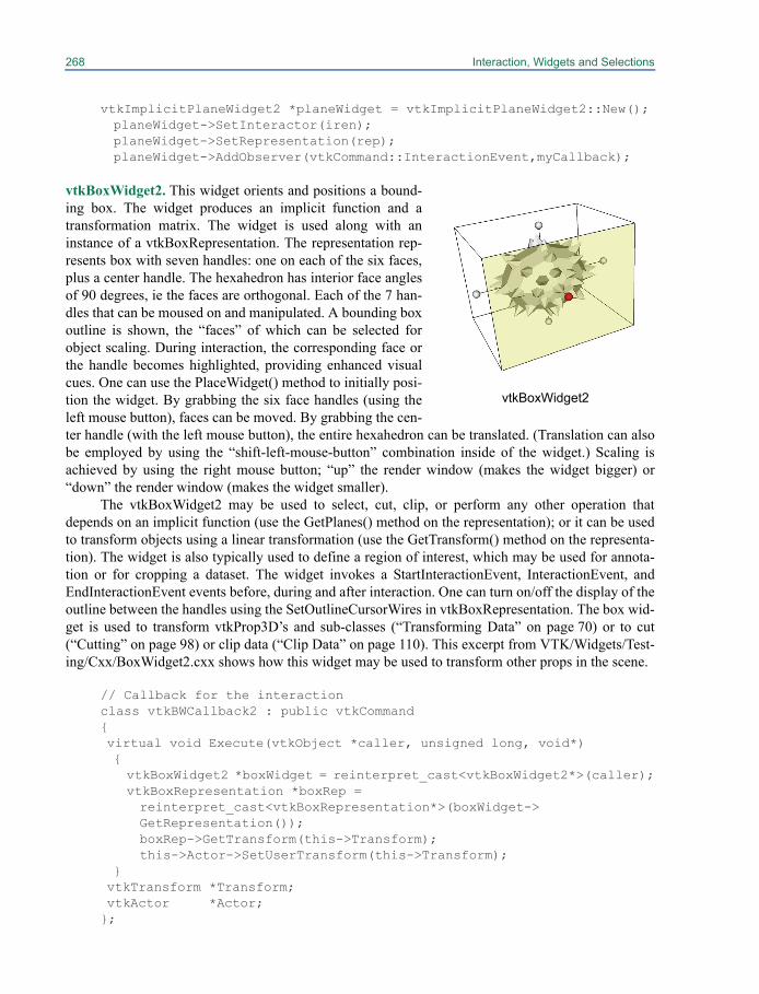
268 Interaction, Widgets and Selections
vtkImplicitPlaneWidget2 *planeWidget = vtkImplicitPlaneWidget2::New();planeWidget->SetInteractor(iren);planeWidget->SetRepresentation(rep);planeWidget->AddObserver(vtkCommand::InteractionEvent,myCallback);
vtkBoxWidget2. This widget orients and positions a bound-ing box. The widget produces an implicit function and atransformation matrix. The widget is used along with aninstance of a vtkBoxRepresentation. The representation rep-resents box with seven handles: one on each of the six faces,plus a center handle. The hexahedron has interior face anglesof 90 degrees, ie the faces are orthogonal. Each of the 7 han-dles that can be moused on and manipulated. A bounding boxoutline is shown, the “faces” of which can be selected forobject scaling. During interaction, the corresponding face orthe handle becomes highlighted, providing enhanced visualcues. One can use the PlaceWidget() method to initially posi-tion the widget. By grabbing the six face handles (using theleft mouse button), faces can be moved. By grabbing the cen-ter handle (with the left mouse button), the entire hexahedron can be translated. (Translation can alsobe employed by using the “shift-left-mouse-button” combination inside of the widget.) Scaling isachieved by using the right mouse button; “up” the render window (makes the widget bigger) or“down” the render window (makes the widget smaller).
The vtkBoxWidget2 may be used to select, cut, clip, or perform any other operation thatdepends on an implicit function (use the GetPlanes() method on the representation); or it can be usedto transform objects using a linear transformation (use the GetTransform() method on the representa-tion). The widget is also typically used to define a region of interest, which may be used for annota-tion or for cropping a dataset. The widget invokes a StartInteractionEvent, InteractionEvent, andEndInteractionEvent events before, during and after interaction. One can turn on/off the display of theoutline between the handles using the SetOutlineCursorWires in vtkBoxRepresentation. The box wid-get is used to transform vtkProp3D’s and sub-classes (“Transforming Data” on page 70) or to cut(“Cutting” on page 98) or clip data (“Clip Data” on page 110). This excerpt from VTK/Widgets/Test-ing/Cxx/BoxWidget2.cxx shows how this widget may be used to transform other props in the scene.
// Callback for the interactionclass vtkBWCallback2 : public vtkCommand{virtual void Execute(vtkObject *caller, unsigned long, void*){vtkBoxWidget2 *boxWidget = reinterpret_cast<vtkBoxWidget2*>(caller);vtkBoxRepresentation *boxRep = reinterpret_cast<vtkBoxRepresentation*>(boxWidget->GetRepresentation());boxRep->GetTransform(this->Transform);this->Actor->SetUserTransform(this->Transform);
}vtkTransform *Transform;vtkActor *Actor;};
vtkBoxWidget2

13.3 A tour of the widgets 269
...
vtkBoxRepresentation *boxRep = vtkBoxRepresentation::New();boxRep->SetPlaceFactor( 1.25 );boxRep->PlaceWidget(glyph->GetOutput()->GetBounds());
vtkBoxWidget2 *boxWidget = vtkBoxWidget2::New();boxWidget->SetRepresentation( boxRep ); boxWidget->AddObserver(vtkCommand::InteractionEvent,myCallback);
vtkTransform *t = vtkTransform::New();vtkBWCallback2 *myCallback = vtkBWCallback2::New();myCallback->Transform = t;myCallback->Actor = maceActor;
vtkAffineWidget. This widget provides support for interac-tively defining affine transformations (shear / rotation / scal-ing / translation). The widget used along with an instance ofvtkAffineRepresentation. vtkAffineRepresentation2D is aconcrete subclass of vtkAffineRepresentation to representaffine transformations in 2D. This representation's geometryconsists of three parts: a box, a circle, and a cross. The box isused for scaling and shearing. The left mouse button can beused to stretch the box along one of the axes by clicking onthe edges, or to stretch along both axes by picking the corner.The circle is used for rotation. The central cross may bepicked to achieve translation. During manipulation of the box, circle and cross respectively, the scale,angle or translation component of the affine transform can optionally displayed as accompanyingannotation. All the geometry is drawn on the overlay plane by vtkAffineRepresentation maintaining aconstant size (width and height) specified in terms of normalized viewport coordinates.
The representation maintains a transformation matrix, which may be queried by users using theGetTransform() method, so as to apply transformations to underlying props or datasets. The transfor-mations generated by this widget assume that the representation lies in the x-y plane. If this is not thecase, the user is responsible for transforming this representation's matrix into the correct coordinatespace (by judicious matrix multiplication). Note that the transformation matrix returned by GetTrans-form() is relative to the last PlaceWidget() invocation. (The PlaceWidget() method sets the originaround which rotation and scaling occurs the origin is the center point of the bounding box pro-vided.). VTK/Widgets/Testing/Cxx/TestAffineWidget.cxx shows how the affine widget may be usedto apply a transform to the underlying image. The widget invokes an InteractionEvent during interac-tion and an EndInteractionEvent after interaction.
class vtkAffineCallback : public vtkCommand{virtual void Execute(vtkObject *caller, unsigned long, void*) { this->AffineRep->GetTransform(this->Transform); this->ImageActor->SetUserTransform(this->Transform); }vtkImageActor *ImageActor;
vtkAffineWidget
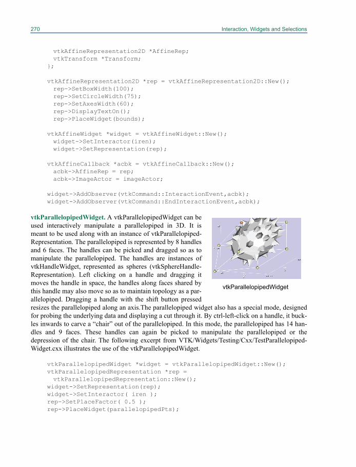
270 Interaction, Widgets and Selections
vtkAffineRepresentation2D *AffineRep;vtkTransform *Transform;
};
vtkAffineRepresentation2D *rep = vtkAffineRepresentation2D::New();rep->SetBoxWidth(100);rep->SetCircleWidth(75);rep->SetAxesWidth(60);rep->DisplayTextOn();rep->PlaceWidget(bounds);
vtkAffineWidget *widget = vtkAffineWidget::New();widget->SetInteractor(iren);widget->SetRepresentation(rep);
vtkAffineCallback *acbk = vtkAffineCallback::New();acbk->AffineRep = rep;acbk->ImageActor = imageActor;
widget->AddObserver(vtkCommand::InteractionEvent,acbk);widget->AddObserver(vtkCommand::EndInteractionEvent,acbk);
vtkParallelopipedWidget. A vtkParallelopipedWidget can beused interactively manipulate a parallelopiped in 3D. It ismeant to be used along with an instance of vtkParallelopiped-Representation. The parallelopiped is represented by 8 handlesand 6 faces. The handles can be picked and dragged so as tomanipulate the parallelopiped. The handles are instances ofvtkHandleWidget, represented as spheres (vtkSphereHandle-Representation). Left clicking on a handle and dragging itmoves the handle in space, the handles along faces shared bythis handle may also move so as to maintain topology as a par-allelopiped. Dragging a handle with the shift button pressedresizes the parallelopiped along an axis.The parallelopiped widget also has a special mode, designedfor probing the underlying data and displaying a cut through it. By ctrl-left-click on a handle, it buck-les inwards to carve a “chair” out of the parallelopiped. In this mode, the parallelopiped has 14 han-dles and 9 faces. These handles can again be picked to manipulate the parallelopiped or thedepression of the chair. The following excerpt from VTK/Widgets/Testing/Cxx/TestParallelopiped-Widget.cxx illustrates the use of the vtkParallelopipedWidget.
vtkParallelopipedWidget *widget = vtkParallelopipedWidget::New();vtkParallelopipedRepresentation *rep = vtkParallelopipedRepresentation::New();
widget->SetRepresentation(rep);widget->SetInteractor( iren );rep->SetPlaceFactor( 0.5 );rep->PlaceWidget(parallelopipedPts);
vtkParallelopipedWidget
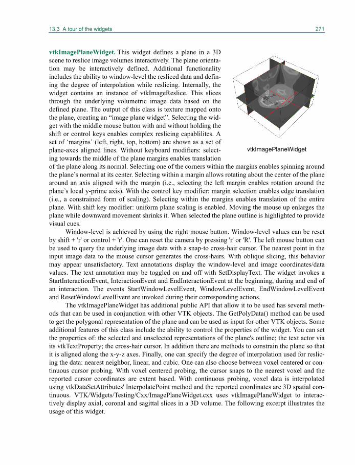
13.3 A tour of the widgets 271
vtkImagePlaneWidget. This widget defines a plane in a 3Dscene to reslice image volumes interactively. The plane orienta-tion may be interactively defined. Additional functionalityincludes the ability to window-level the resliced data and defin-ing the degree of interpolation while reslicing. Internally, thewidget contains an instance of vtkImageReslice. This slicesthrough the underlying volumetric image data based on thedefined plane. The output of this class is texture mapped ontothe plane, creating an “image plane widget”. Selecting the wid-get with the middle mouse button with and without holding theshift or control keys enables complex reslicing capablilites. Aset of ‘margins’ (left, right, top, bottom) are shown as a set ofplane-axes aligned lines. Without keyboard modifiers: select-ing towards the middle of the plane margins enables translationof the plane along its normal. Selecting one of the corners within the margins enables spinning aroundthe plane’s normal at its center. Selecting within a margin allows rotating about the center of the planearound an axis aligned with the margin (i.e., selecting the left margin enables rotation around theplane’s local y-prime axis). With the control key modifier: margin selection enables edge translation(i.e., a constrained form of scaling). Selecting within the margins enables translation of the entireplane. With shift key modifier: uniform plane scaling is enabled. Moving the mouse up enlarges theplane while downward movement shrinks it. When selected the plane outline is highlighted to providevisual cues.
Window-level is achieved by using the right mouse button. Window-level values can be resetby shift + 'r' or control + 'r'. One can reset the camera by pressing 'r' or 'R'. The left mouse button canbe used to query the underlying image data with a snap-to cross-hair cursor. The nearest point in theinput image data to the mouse cursor generates the cross-hairs. With oblique slicing, this behaviormay appear unsatisfactory. Text annotations display the window-level and image coordinates/datavalues. The text annotation may be toggled on and off with SetDisplayText. The widget invokes aStartInteractionEvent, InteractionEvent and EndInteractionEvent at the beginning, during and end ofan interaction. The events StartWindowLevelEvent, WindowLevelEvent, EndWindowLevelEventand ResetWindowLevelEvent are invoked during their corresponding actions.
The vtkImagePlaneWidget has additional public API that allow it to be used has several meth-ods that can be used in conjunction with other VTK objects. The GetPolyData() method can be usedto get the polygonal representation of the plane and can be used as input for other VTK objects. Someadditional features of this class include the ability to control the properties of the widget. You can setthe properties of: the selected and unselected representations of the plane's outline; the text actor viaits vtkTextProperty; the cross-hair cursor. In addition there are methods to constrain the plane so thatit is aligned along the x-y-z axes. Finally, one can specify the degree of interpolation used for reslic-ing the data: nearest neighbor, linear, and cubic. One can also choose between voxel centered or con-tinuous cursor probing. With voxel centered probing, the cursor snaps to the nearest voxel and thereported cursor coordinates are extent based. With continuous probing, voxel data is interpolatedusing vtkDataSetAttributes' InterpolatePoint method and the reported coordinates are 3D spatial con-tinuous. VTK/Widgets/Testing/Cxx/ImagePlaneWidget.cxx uses vtkImagePlaneWidget to interac-tively display axial, coronal and sagittal slices in a 3D volume. The following excerpt illustrates theusage of this widget.
vtkImagePlaneWidget
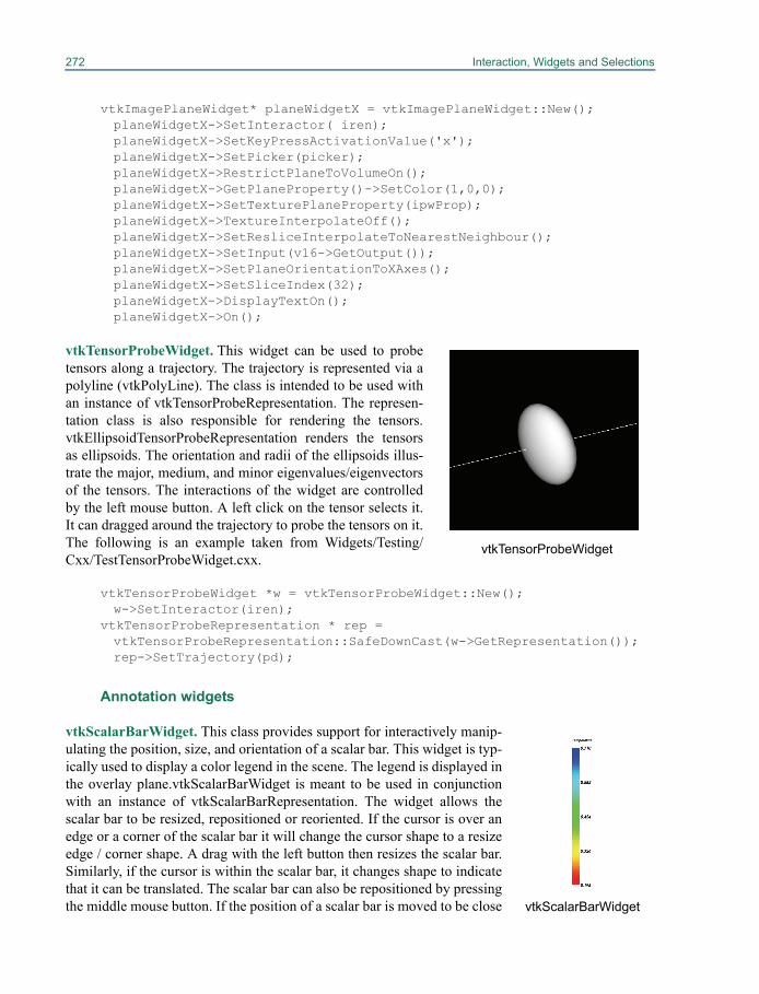
272 Interaction, Widgets and Selections
vtkImagePlaneWidget* planeWidgetX = vtkImagePlaneWidget::New();planeWidgetX->SetInteractor( iren);planeWidgetX->SetKeyPressActivationValue('x');planeWidgetX->SetPicker(picker);planeWidgetX->RestrictPlaneToVolumeOn();planeWidgetX->GetPlaneProperty()->SetColor(1,0,0);planeWidgetX->SetTexturePlaneProperty(ipwProp);planeWidgetX->TextureInterpolateOff();planeWidgetX->SetResliceInterpolateToNearestNeighbour();planeWidgetX->SetInput(v16->GetOutput());planeWidgetX->SetPlaneOrientationToXAxes();planeWidgetX->SetSliceIndex(32);planeWidgetX->DisplayTextOn();planeWidgetX->On();
vtkTensorProbeWidget. This widget can be used to probetensors along a trajectory. The trajectory is represented via apolyline (vtkPolyLine). The class is intended to be used withan instance of vtkTensorProbeRepresentation. The represen-tation class is also responsible for rendering the tensors.vtkEllipsoidTensorProbeRepresentation renders the tensorsas ellipsoids. The orientation and radii of the ellipsoids illus-trate the major, medium, and minor eigenvalues/eigenvectorsof the tensors. The interactions of the widget are controlledby the left mouse button. A left click on the tensor selects it.It can dragged around the trajectory to probe the tensors on it.The following is an example taken from Widgets/Testing/Cxx/TestTensorProbeWidget.cxx.
vtkTensorProbeWidget *w = vtkTensorProbeWidget::New(); w->SetInteractor(iren);
vtkTensorProbeRepresentation * rep = vtkTensorProbeRepresentation::SafeDownCast(w->GetRepresentation());rep->SetTrajectory(pd);
Annotation widgets
vtkScalarBarWidget. This class provides support for interactively manip-ulating the position, size, and orientation of a scalar bar. This widget is typ-ically used to display a color legend in the scene. The legend is displayed inthe overlay plane.vtkScalarBarWidget is meant to be used in conjunctionwith an instance of vtkScalarBarRepresentation. The widget allows thescalar bar to be resized, repositioned or reoriented. If the cursor is over anedge or a corner of the scalar bar it will change the cursor shape to a resizeedge / corner shape. A drag with the left button then resizes the scalar bar.Similarly, if the cursor is within the scalar bar, it changes shape to indicatethat it can be translated. The scalar bar can also be repositioned by pressingthe middle mouse button. If the position of a scalar bar is moved to be close
vtkTensorProbeWidget
vtkScalarBarWidget
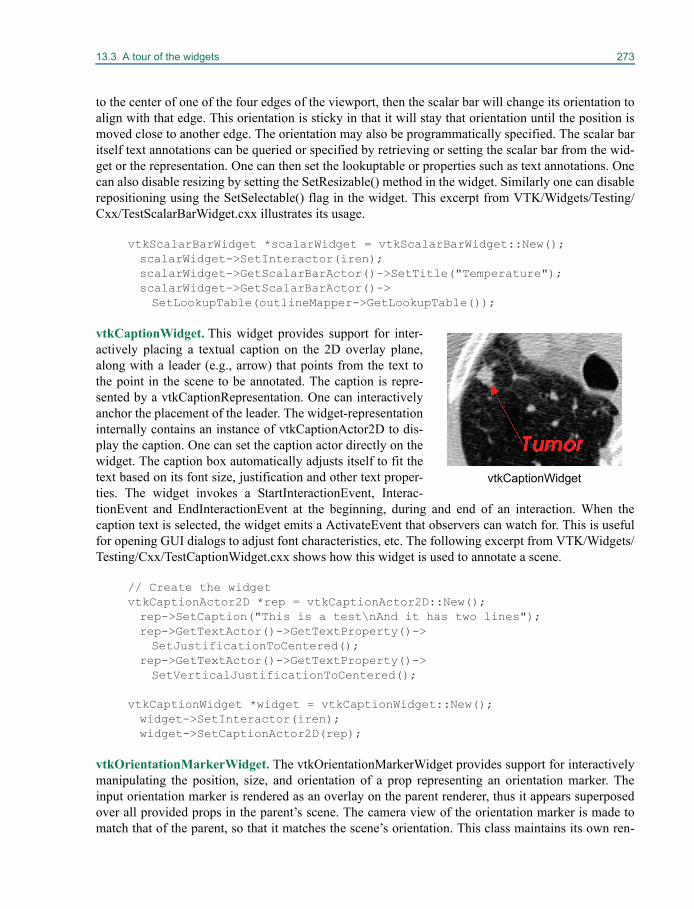
13.3 A tour of the widgets 273
to the center of one of the four edges of the viewport, then the scalar bar will change its orientation toalign with that edge. This orientation is sticky in that it will stay that orientation until the position ismoved close to another edge. The orientation may also be programmatically specified. The scalar baritself text annotations can be queried or specified by retrieving or setting the scalar bar from the wid-get or the representation. One can then set the lookuptable or properties such as text annotations. Onecan also disable resizing by setting the SetResizable() method in the widget. Similarly one can disablerepositioning using the SetSelectable() flag in the widget. This excerpt from VTK/Widgets/Testing/Cxx/TestScalarBarWidget.cxx illustrates its usage.
vtkScalarBarWidget *scalarWidget = vtkScalarBarWidget::New();scalarWidget->SetInteractor(iren);scalarWidget->GetScalarBarActor()->SetTitle("Temperature");scalarWidget->GetScalarBarActor()->SetLookupTable(outlineMapper->GetLookupTable());
vtkCaptionWidget. This widget provides support for inter-actively placing a textual caption on the 2D overlay plane,along with a leader (e.g., arrow) that points from the text tothe point in the scene to be annotated. The caption is repre-sented by a vtkCaptionRepresentation. One can interactivelyanchor the placement of the leader. The widget-representationinternally contains an instance of vtkCaptionActor2D to dis-play the caption. One can set the caption actor directly on thewidget. The caption box automatically adjusts itself to fit thetext based on its font size, justification and other text proper-ties. The widget invokes a StartInteractionEvent, Interac-tionEvent and EndInteractionEvent at the beginning, during and end of an interaction. When thecaption text is selected, the widget emits a ActivateEvent that observers can watch for. This is usefulfor opening GUI dialogs to adjust font characteristics, etc. The following excerpt from VTK/Widgets/Testing/Cxx/TestCaptionWidget.cxx shows how this widget is used to annotate a scene.
// Create the widgetvtkCaptionActor2D *rep = vtkCaptionActor2D::New();rep->SetCaption("This is a test\nAnd it has two lines");rep->GetTextActor()->GetTextProperty()->SetJustificationToCentered();
rep->GetTextActor()->GetTextProperty()->SetVerticalJustificationToCentered();
vtkCaptionWidget *widget = vtkCaptionWidget::New();widget->SetInteractor(iren);widget->SetCaptionActor2D(rep);
vtkOrientationMarkerWidget. The vtkOrientationMarkerWidget provides support for interactivelymanipulating the position, size, and orientation of a prop representing an orientation marker. Theinput orientation marker is rendered as an overlay on the parent renderer, thus it appears superposedover all provided props in the parent’s scene. The camera view of the orientation marker is made tomatch that of the parent, so that it matches the scene’s orientation. This class maintains its own ren-
vtkCaptionWidget
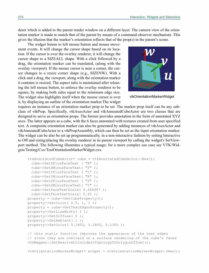
274 Interaction, Widgets and Selections
derer which is added to the parent render window on a different layer. The camera view of the orien-tation marker is made to match that of the parent by means of a command-observer mechanism. Thisgives the illusion that the marker’s orientation reflects that of the prop(s) in the parent’s scene.
The widget listens to left mouse button and mouse move-ment events. It will change the cursor shape based on its loca-tion. If the cursor is over the overlay renderer, it will change thecursor shape to a SIZEALL shape. With a click followed by adrag, the orientation marker can be translated, (along with theoverlay viewport). If the mouse cursor is near a corner, the cur-sor changes to a resize corner shape (e.g., SIZENW). With aclick and a drag, the viewport, along with the orientation markerit contains is resized. The aspect ratio is maintained after releas-ing the left mouse button, to enforce the overlay renderer to besquare, by making both sides equal to the minimum edge size.The widget also highlights itself when the mouse cursor is overit, by displaying an outline of the orientation marker.The widgetrequires an instance of an orientation marker prop to be set. The marker prop itself can be any sub-class of vtkProp. Specifically, vtkAxesActor and vtkAnnoatedCubeActor are two classes that aredesigned to serve as orientation props. The former provides annotation in the form of annotated XYZaxes. The latter appears as a cube, with the 6 faces annotated with textures created from user specifiedtext. A composite orientation marker can also be generated by adding instances of vtkAxesActor andvtkAnnoatedCubeActor to a vtkPropAssembly, which can then be set as the input orientation marker.The widget can be also be set up programmatically, in a non-interactive fashion by setting Interactiveto Off and sizing/placing the overlay renderer in its parent viewport by calling the widget's SetView-port method. The following illustrates a typical usage; for a more complex use case see VTK/Wid-gets/Testing/Cxx/TestOrientationMarkerWidget.cxx.
vtkAnnotatedCubeActor* cube = vtkAnnotatedCubeActor::New(); cube->SetXPlusFaceText ( "A" );cube->SetXMinusFaceText( "P" );cube->SetYPlusFaceText ( "L" );cube->SetYMinusFaceText( "R" );cube->SetZPlusFaceText ( "S" );cube->SetZMinusFaceText( "I" );cube->SetFaceTextScale( 0.666667 );cube->SetFaceTextScale( 0.65 );
property = cube->GetCubeProperty();property->SetColor( 0.5, 1, 1 );property = cube->GetTextEdgesProperty();property->SetLineWidth( 1 );property->SetDiffuse( 0 );property->SetAmbient( 1 );property->SetColor( 0.1800, 0.2800, 0.2300 );
// this static function improves the appearance of the text edges// since they are overlaid on a surface rendering of the cube's facesvtkMapper::SetResolveCoincidentTopologyToPolygonOffset();
vtkOrientationMarkerWidget* widget = vtkOrientationMarkerWidget::New();
vtkOrientationMarkerWidget

13.3 A tour of the widgets 275
widget->SetOutlineColor( 0.9300, 0.5700, 0.1300 );widget->SetOrientationMarker( cube );widget->SetInteractor( iren );widget->SetViewport( 0.0, 0.0, 0.4, 0.4 );widget->SetEnabled( 1 );
vtkBalloonWidget. This widget is used to popup annotationswhen the mouse hovers over an actor for a specified time. Theannotation may be text and/or an images annotation when themouse hovers over an actor for a specified time. The widgetkeeps track of user chosen props by associating an instance ofa vtkProp with an instance of a “balloon”. The balloon encap-sulates annotations (text and/or images). The balloon isbrought up with user specified properties near the vtkProp when the mouse cursor hovers over it for aspecified delay. An instance of vtkBalloonRepresentation is used to draw the balloon. To use this wid-get, first specify an instance of vtkBalloonWidget and the representation. Then list all instances ofvtkProp, a text string, and/or an instance of vtkImageData to be associated with each vtkProp. (Notethat you can specify both text and an image, or just one or the other.) You may also wish to specify thehover delay. The widget invokes a WidgetActivateEvent before a balloon pops up, that observers canwatch for. VTK/Widgets/Testing/Cxx/TestBalloonWidget.cxx illustrates a typical usage.
class vtkBalloonCallback : public vtkCommand{virtual void Execute(vtkObject *caller, unsigned long, void*){vtkBalloonWidget *balloonWidget = reinterpret_cast<vtkBalloonWidget*>(caller);
if ( balloonWidget->GetCurrentProp() != NULL ){cout << "Prop selected\n"; }
}};
...
vtkBalloonRepresentation *rep = vtkBalloonRepresentation::New();rep->SetBalloonLayoutToImageRight();
vtkBalloonWidget *widget = vtkBalloonWidget::New();widget->SetInteractor(iren); widget->SetRepresentation(rep); widget->SetTimerDuration( 3000 ); // hover delay in ms. widget->AddBalloon(sph,"This is a sphere",NULL); widget->AddBalloon(cyl,"This is a\ncylinder",image1->GetOutput()); widget->AddBalloon(cone,"This is a\ncone,\na really big cone,\nyou wouldn't believe how big",image1->GetOutput());
vtkBalloonCallback *cbk = vtkBalloonCallback::New(); widget->AddObserver(vtkCommand::WidgetActivateEvent,cbk);
vtkBalloonWidget
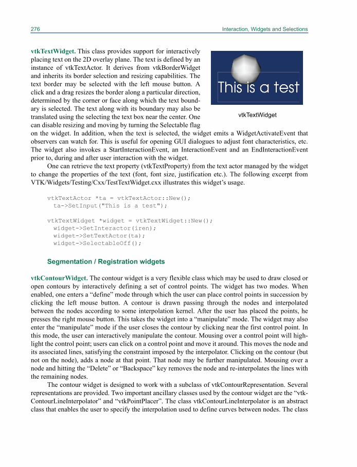
276 Interaction, Widgets and Selections
vtkTextWidget. This class provides support for interactivelyplacing text on the 2D overlay plane. The text is defined by aninstance of vtkTextActor. It derives from vtkBorderWidgetand inherits its border selection and resizing capabilities. Thetext border may be selected with the left mouse button. Aclick and a drag resizes the border along a particular direction,determined by the corner or face along which the text bound-ary is selected. The text along with its boundary may also betranslated using the selecting the text box near the center. Onecan disable resizing and moving by turning the Selectable flagon the widget. In addition, when the text is selected, the widget emits a WidgetActivateEvent thatobservers can watch for. This is useful for opening GUI dialogues to adjust font characteristics, etc.The widget also invokes a StartInteractionEvent, an InteractionEvent and an EndInteractionEventprior to, during and after user interaction with the widget.
One can retrieve the text property (vtkTextProperty) from the text actor managed by the widgetto change the properties of the text (font, font size, justification etc.). The following excerpt fromVTK/Widgets/Testing/Cxx/TestTextWidget.cxx illustrates this widget’s usage.
vtkTextActor *ta = vtkTextActor::New();ta->SetInput("This is a test");
vtkTextWidget *widget = vtkTextWidget::New(); widget->SetInteractor(iren);widget->SetTextActor(ta);widget->SelectableOff();
Segmentation / Registration widgets
vtkContourWidget. The contour widget is a very flexible class which may be used to draw closed oropen contours by interactively defining a set of control points. The widget has two modes. Whenenabled, one enters a “define” mode through which the user can place control points in succession byclicking the left mouse button. A contour is drawn passing through the nodes and interpolatedbetween the nodes according to some interpolation kernel. After the user has placed the points, hepresses the right mouse button. This takes the widget into a “manipulate” mode. The widget may alsoenter the “manipulate” mode if the user closes the contour by clicking near the first control point. Inthis mode, the user can interactively manipulate the contour. Mousing over a control point will high-light the control point; users can click on a control point and move it around. This moves the node andits associated lines, satisfying the constraint imposed by the interpolator. Clicking on the contour (butnot on the node), adds a node at that point. That node may be further manipulated. Mousing over anode and hitting the “Delete” or “Backspace” key removes the node and re-interpolates the lines withthe remaining nodes.
The contour widget is designed to work with a subclass of vtkContourRepresentation. Severalrepresentations are provided. Two important ancillary classes used by the contour widget are the “vtk-ContourLineInterpolator” and “vtkPointPlacer”. The class vtkContourLineInterpolator is an abstractclass that enables the user to specify the interpolation used to define curves between nodes. The class
vtkTextWidget

13.3 A tour of the widgets 277
vtkPointPlacer allows the user to impose constraints on the placement of the control points. Severalpoint placers and interpolators are provided. For instance, the class vtkBezierContourLineInterpola-tor, constrains the interpolation between nodes to be a bezier curve.
vtkOrientedGlyphContourRepresentation *contourRep = vtkOrientedGlyphContourRepresentation::New();
vtkContourWidget *contourWidget = vtkContourWidget::New(); contourWidget->SetInteractor(iren);contourWidget->SetRepresentation(contourRep);
vtkBezierContourLineInterpolator * interpolator = vtkBezierContourLineInterpolator::New();
contourRep->SetLineInterpolator(interpolator);contourWidget->SetEnabled(1);
A user can draw contours on polygonal surfaces using vtkPolygonalSurfaceContourLineInterpolator.This interpolator places its lines on the surface of a specified vtkPolyData. It is meant to be used inconjunction with a vtkPolygonalSurfacePointPlacer. This placer constrains the placement of controlpoint nodes on the surface of the polydata. The interpolator internally uses a Dijkstra single sourceshortest path algorithm to compute the shortest path from one control point to the next. The costs forthe paths are determined by the edge lengths in the mesh. The resulting path traverses along the edgesof the mesh from one node to the next. This example from VTK/Widgets/Testing/Cxx/TestDijk-straGraphGeodesicPath.cxx illustrates its usage.
vtkContourWidget *contourWidget = vtkContourWidget::New();contourWidget->SetInteractor(iren);vtkOrientedGlyphContourRepresentation *rep =vtkOrientedGlyphContourRepresentation::SafeDownCast(contourWidget->GetRepresentation());
vtkPolygonalSurfacePointPlacer * pointPlacer= vtkPolygonalSurfacePointPlacer::New();pointPlacer->AddProp(demActor);pointPlacer->GetPolys()->AddItem( pd );
rep->SetPointPlacer(pointPlacer);
vtkPolygonalSurfaceContourLineInterpolator * interpolator =vtkPolygonalSurfaceContourLineInterpolator::New();
vtkContourWidget
278 Interaction, Widgets and Selections
interpolator->GetPolys()->AddItem( pd );rep->SetLineInterpolator(interpolator);
Using vtkTerranContourLineInterpolator, one can draw contours on height fields, such as Digital Ele-vation Maps vtkTerrainContourLineInterpolator. This interpolator constrains the lines between con-trol points to lie on the surface of the height field. One can also specify an offset for the lines, byusing the SetHeightOffset method on the interpolator. The class internally uses a vtkProjectedTerrain-Path to project a polyline on the surface. Various projection modes may be specified on the projector.This interpolator is meant to be used in conjunction with a vtkTerrainDataPointPlacer, which con-strains the control point nodes to lie on the surface of the terrain. The following code snippet, fromVTK/Widgets/Testing/Cxx/TerrainPolylineEditor.cxx illustrates how one may use this interpolatorand point placer.
vtkContourWidget *contourWidget = vtkContourWidget::New();vtkOrientedGlyphContourRepresentation *rep = vtkOrientedGlyphContourRepresentation::SafeDownCast(contourWidget->GetRepresentation());
vtkTerrainDataPointPlacer * pointPlacer = vtkTerrainDataPointPlacer::New();pointPlacer->AddProp(demActor); // the actor(s) containing the terrain
rep->SetPointPlacer(pointPlacer);
// Set a terrain interpolator. Interpolates points as they are placed,// so that they lie on the terrain.vtkTerrainContourLineInterpolator *interpolator =vtkTerrainContourLineInterpolator::New();
rep->SetLineInterpolator(interpolator);interpolator->SetImageData(demReader->GetOutput());
// Set the default projection mode to hug the terrain, unless user // overrides it.interpolator->GetProjector()->SetProjectionModeToHug();interpolator->GetProjector()->SetHeightOffset(20.0);pointPlacer->SetHeightOffset(20.0);
Of particular interest is the “live wire” interpolator (vtkDijkstraImageContourLineInterpolator) wherethe lines between the control points are interpolated based on the shortest path through the gradientcost function computed on the image, resulting in the contours being attracted to the edges of theimage. As the control points are moved around, a new shortest path is computed. This is ideal forinteractive segmentation of organs, etc. This interpolator internally uses a vtkDijkstraImageGeodesic-Path, which generates a single source shortest path through a cost function image by treating it as agraph with VTK_PIXEL cells. The user is free to plug in the cost function. A typical cost function fora gray scale image might be generated by the following pipeline:
Image --> vtkImageGradientMagnitude --> vtkImageShiftScale
The gradient magnitude image is inverted, so that strong edges have low cost value. Costs in movingfrom one vertex to another are calculated using a weighted additive scheme. One can set the edgelength weight, the curvature weight and the weight associated with the normalized image cost. These
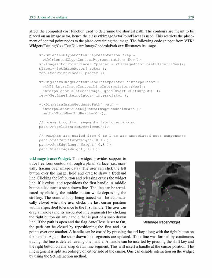
13.3 A tour of the widgets 279
affect the computed cost function used to determine the shortest path. The contours are meant to beplaced on an image actor, hence the class vtkImageActorPointPlacer is used. This restricts the place-ment of control point nodes to the plane containing the image. The following code snippet from VTK/Widgets/Testing/Cxx/TestDijkstraImageGeodesicPath.cxx illustrates its usage.
vtkOrientedGlyphContourRepresentation *rep = vtkOrientedGlyphContourRepresentation::New();
vtkImageActorPointPlacer *placer = vtkImageActorPointPlacer::New();placer->SetImageActor( actor );rep->SetPointPlacer( placer );
vtkDijkstraImageContourLineInterpolator *interpolator =vtkDijkstraImageContourLineInterpolator::New();interpolator->SetCostImage( gradInvert->GetOutput() );
rep->SetLineInterpolator( interpolator );
vtkDijkstraImageGeodesicPath* path = interpolator->GetDijkstraImageGeodesicPath();path->StopWhenEndReachedOn();
// prevent contour segments from overlappingpath->RepelPathFromVerticesOn();
// weights are scaled from 0 to 1 as are associated cost componentspath->SetCurvatureWeight( 0.15 );path->SetEdgeLengthWeight( 0.8 );path->SetImageWeight( 1.0 );
vtkImageTracerWidget. This widget provides support totrace free form contours through a planar surface (i.e., man-ually tracing over image data). The user can click the leftbutton over the image, hold and drag to draw a freehandline. Clicking the left button and releasing erases the widgetline, if it exists, and repositions the first handle. A middlebutton click starts a snap drawn line. The line can be termi-nated by clicking the middle button while depressing thectrl key. The contour loop being traced will be automati-cally closed when the user clicks the last cursor positionwithin a specified tolerance to the first handle. The user candrag a handle (and its associated line segments) by clickingthe right button on any handle that is part of a snap drawnline. If the path is open and the flag AutoClose is set to On,the path can be closed by repositioning the first and lastpoints over one another. A handle can be erased by pressing the ctrl key along with the right button onthe handle. Again, the snap drawn line segments are updated. If the line was formed by continuoustracing, the line is deleted leaving one handle. A handle can be inserted by pressing the shift key andthe right button on any snap drawn line segment. This will insert a handle at the cursor position. Theline segment is split accordingly on either side of the cursor. One can disable interaction on the widgetby using the SetInteraction method.
vtkImageTracerWidget
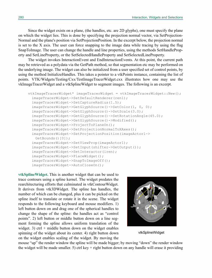
280 Interaction, Widgets and Selections
Since the widget exists on a plane, (the handles, etc. are 2D glyphs), one must specify the planeon which the widget lies. This is done by specifying the projection normal vector, via SetProjection-Normal and the plane's position via SetProjectionPosition. In the excerpt below, the projection normalis set to the X axis. The user can force snapping to the image data while tracing by using the flagSnapToImage. The user can change the handle and line properties, using the methods SetHandleProp-erty and SetLineProperty, or the SetSelectedHandleProperty and SetSelectedLineProperty.
The widget invokes InteractionEvent and EndInteractionEvents. At this point, the current pathmay be retrieved as a polydata via the GetPath method, so that segmentation etc may be performed onthe underlying image. The widget can also be initialized from a user specified set of control points, byusing the method InitializeHandles. This takes a pointer to a vtkPoints instance, containing the list ofpoints. VTK/Widgets/Testing/Cxx/TestImageTracerWidget.cxx illustrates how one may use thevkImageTracerWidget and a vtkSplineWidget to segment images. The following is an excerpt.
vtkImageTracerWidget* imageTracerWidget = vtkImageTracerWidget::New();imageTracerWidget->SetDefaultRenderer(ren1);imageTracerWidget->SetCaptureRadius(1.5);imageTracerWidget->GetGlyphSource()->SetColor(1, 0, 0);imageTracerWidget->GetGlyphSource()->SetScale(3.0);imageTracerWidget->GetGlyphSource()->SetRotationAngle(45.0);imageTracerWidget->GetGlyphSource()->Modified();imageTracerWidget->ProjectToPlaneOn();imageTracerWidget->SetProjectionNormalToXAxes();imageTracerWidget->SetProjectionPosition(imageActor1->GetBounds()[0]);
imageTracerWidget->SetViewProp(imageActor1);imageTracerWidget->SetInput(shifter->GetOutput());imageTracerWidget->SetInteractor(iren);imageTracerWidget->PlaceWidget();imageTracerWidget->SnapToImageOff();imageTracerWidget->AutoCloseOn();
vtkSplineWidget. This is another widget that can be used totrace contours using a spline kernel. The widget predates therearchitecturing efforts that culminated in vtkContourWidget.It derives from vtk3DWidget. The spline has handles, thenumber of which can be changed, plus it can be picked on thespline itself to translate or rotate it in the scene. The widgetresponds to the following keyboard and mouse modifiers. 1)left button down on and drag one of the spherical handles tochange the shape of the spline: the handles act as “controlpoints”. 2) left button or middle button down on a line seg-ment forming the spline allows uniform translation of thewidget. 3) ctrl + middle button down on the widget enablesspinning of the widget about its center. 4) right button downon the widget enables scaling of the widget. By moving themouse “up” the render window the spline will be made bigger; by moving “down” the render windowthe widget will be made smaller. 5) ctrl key + right button down on any handle will erase it providing
vtkSplineWidget
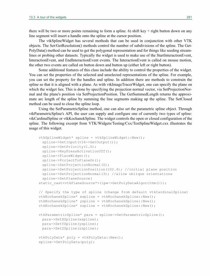
13.3 A tour of the widgets 281
there will be two or more points remaining to form a spline. 6) shift key + right button down on anyline segment will insert a handle onto the spline at the cursor position.
The vtkSplineWidget has several methods that can be used in conjunction with other VTKobjects. The Set/GetResolution() methods control the number of subdivisions of the spline. The Get-PolyData() method can be used to get the polygonal representation and for things like seeding stream-lines or probing other datasets. Typically the widget is used to make use of the StartInteractionEvent,InteractionEvent, and EndInteractionEvent events. The InteractionEvent is called on mouse motion,the other two events are called on button down and button up (either left or right button).
Some additional features of this class include the ability to control the properties of the widget.You can set the properties of the selected and unselected representations of the spline. For example,you can set the property for the handles and spline. In addition there are methods to constrain thespline so that it is aligned with a plane. As with vtkImageTracerWidget, one can specify the plane onwhich the widget lies. This is done by specifying the projection normal vector, via SetProjectionNor-mal and the plane's position via SetProjectionPosition. The GetSummedLength returns the approxi-mate arc length of the spline by summing the line segments making up the spline. The SetClosedmethod can be used to close the spline loop.
Using the SetParametricSpline method, one can also set the parametric spline object. ThroughvtkParametricSpline's API, the user can supply and configure one of currently two types of spline:vtkCardinalSpline or vtkKochanekSpline. The widget controls the open or closed configuration of thespline. The following excerpt from VTK/Widgets/Testing/Cxx/TestSplineWidget.cxx illustrates theusage of this widget.
vtkSplineWidget* spline = vtkSplineWidget::New();spline->SetInput(v16->GetOutput());spline->SetPriority(1.0);spline->KeyPressActivationOff();spline->PlaceWidget();spline->ProjectToPlaneOn();spline->SetProjectionNormal(0);spline->SetProjectionPosition(102.4); //initial plane positionspline->SetProjectionNormal(3); //allow oblique orientationsspline->SetPlaneSource(
static_cast<vtkPlaneSource*>(ipw->GetPolyDataAlgorithm()));
// Specify the type of spline (change from default vtkCardinalSpline)vtkKochanekSpline* xspline = vtkKochanekSpline::New();vtkKochanekSpline* yspline = vtkKochanekSpline::New();vtkKochanekSpline* zspline = vtkKochanekSpline::New();
vtkParametricSpline* para = spline->GetParametricSpline();para->SetXSpline(xspline);para->SetYSpline(yspline);para->SetZSpline(zspline);
vtkPolyData* poly = vtkPolyData::New();spline->GetPolyData(poly);
282 Interaction, Widgets and Selections
vtkCheckerboardWidget. The checkerboard widget is used tointeractively control a checkerboard through an image actor dis-playing two images. This is useful in evaluating the quality ofan image registration. The user can adjust the number of check-erboard divisions in each of the i-j directions in a 2D image. Thewidget is meant to be used in conjunction with a vtkChecker-boardRepresentation. When enabled, a frame appears aroundthe vtkImageActor with sliders along each side of the frame. Atotal of 4 sliders are provided for the two checkerboards, alongboth the i and j directions. (This internally uses avtkSliderRepresentation3D). The user can interactively adjustthe sliders (see vtkSliderWidget) to the desired number ofcheckerboard subdivisions. The user can override the defaultslider representations by setting their own slider representationson the widget. The widget needs an instance of a vtkImage-CheckerBoard which, in turn, takes two images as input to generate the checkerboard. The followingexample from VTK/Widgets/Testing/Cxx/TestCheckerboardWidget.cxx illustrates a typical usage.
vtkImageCheckerboard *checkers = vtkImageCheckerboard::New();checkers->SetInput(0,image1);checkers->SetInput(1,image2);checkers->SetNumberOfDivisions(10,6,1);
vtkImageActor *checkerboardActor = vtkImageActor::New();checkerboardActor->SetInput(checkers->GetOutput());
vtkCheckerboardRepresentation *rep = vtkCheckerboardRepresentation::New();rep->SetImageActor(checkerboardActor);rep->SetCheckerboard(checkers);
vtkCheckerboardWidget *checkerboardWidget = vtkCheckerboardWidget::New();checkerboardWidget->SetInteractor(iren);checkerboardWidget->SetRepresentation(rep);
vtkRectilinearWipeWidget. The vtkRectilinearWipeWidget displays a split view (2x2 checker-board) of a pair of images allowing one to control the location of the split. This is useful in comparingtwo images, typically the registered image from the source image in an image registration pipeline. Arectilinear wipe is a 2x2 checkerboard pattern created by combining two separate images, where vari-ous combinations of the checker squares are possible. It must be noted that although the this widgetappears similar in functionality to the checkerboard widget, there are important differences. Usingthis widget, the user can adjust the layout of the checker pattern, such as moving the center point,moving the horizontal separator, or moving the vertical separator. The location of the wipe (interfacebetween the two images) can be changed to any point in the image, unlike the checkerboard widget,where one can interactively only change the resolution the checkerboard.?One can select the horizon-tal separator and the vertical separator by selecting the separator using the left mouse button. Drag-ging with the button depressed moves the separators. Selecting the center point allows you to move
vtkCheckerboardWidget
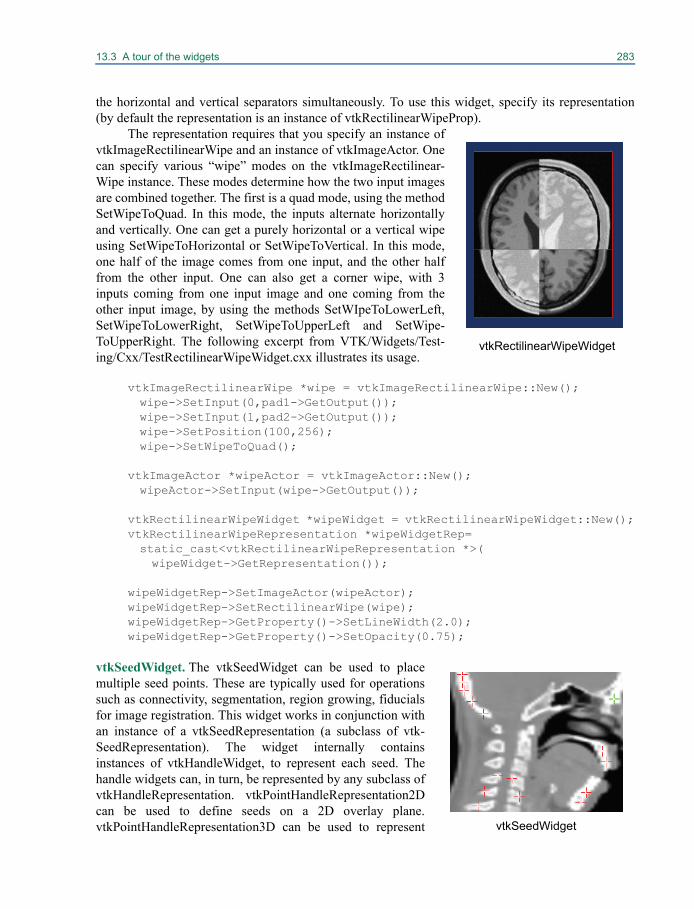
13.3 A tour of the widgets 283
the horizontal and vertical separators simultaneously. To use this widget, specify its representation(by default the representation is an instance of vtkRectilinearWipeProp).
The representation requires that you specify an instance ofvtkImageRectilinearWipe and an instance of vtkImageActor. Onecan specify various “wipe” modes on the vtkImageRectilinear-Wipe instance. These modes determine how the two input imagesare combined together. The first is a quad mode, using the methodSetWipeToQuad. In this mode, the inputs alternate horizontallyand vertically. One can get a purely horizontal or a vertical wipeusing SetWipeToHorizontal or SetWipeToVertical. In this mode,one half of the image comes from one input, and the other halffrom the other input. One can also get a corner wipe, with 3inputs coming from one input image and one coming from theother input image, by using the methods SetWIpeToLowerLeft,SetWipeToLowerRight, SetWipeToUpperLeft and SetWipe-ToUpperRight. The following excerpt from VTK/Widgets/Test-ing/Cxx/TestRectilinearWipeWidget.cxx illustrates its usage.
vtkImageRectilinearWipe *wipe = vtkImageRectilinearWipe::New();wipe->SetInput(0,pad1->GetOutput());wipe->SetInput(1,pad2->GetOutput());wipe->SetPosition(100,256);wipe->SetWipeToQuad();
vtkImageActor *wipeActor = vtkImageActor::New();wipeActor->SetInput(wipe->GetOutput());
vtkRectilinearWipeWidget *wipeWidget = vtkRectilinearWipeWidget::New();vtkRectilinearWipeRepresentation *wipeWidgetRep=static_cast<vtkRectilinearWipeRepresentation *>(wipeWidget->GetRepresentation());
wipeWidgetRep->SetImageActor(wipeActor);wipeWidgetRep->SetRectilinearWipe(wipe);wipeWidgetRep->GetProperty()->SetLineWidth(2.0);wipeWidgetRep->GetProperty()->SetOpacity(0.75);
vtkSeedWidget. The vtkSeedWidget can be used to placemultiple seed points. These are typically used for operationssuch as connectivity, segmentation, region growing, fiducialsfor image registration. This widget works in conjunction withan instance of a vtkSeedRepresentation (a subclass of vtk-SeedRepresentation). The widget internally containsinstances of vtkHandleWidget, to represent each seed. Thehandle widgets can, in turn, be represented by any subclass ofvtkHandleRepresentation. vtkPointHandleRepresentation2Dcan be used to define seeds on a 2D overlay plane.vtkPointHandleRepresentation3D can be used to represent
vtkRectilinearWipeWidget
vtkSeedWidget
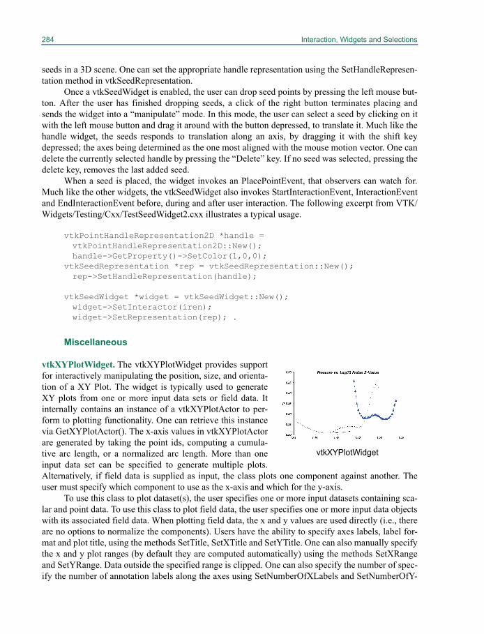
284 Interaction, Widgets and Selections
seeds in a 3D scene. One can set the appropriate handle representation using the SetHandleRepresen-tation method in vtkSeedRepresentation.
Once a vtkSeedWidget is enabled, the user can drop seed points by pressing the left mouse but-ton. After the user has finished dropping seeds, a click of the right button terminates placing andsends the widget into a “manipulate” mode. In this mode, the user can select a seed by clicking on itwith the left mouse button and drag it around with the button depressed, to translate it. Much like thehandle widget, the seeds responds to translation along an axis, by dragging it with the shift keydepressed; the axes being determined as the one most aligned with the mouse motion vector. One candelete the currently selected handle by pressing the “Delete” key. If no seed was selected, pressing thedelete key, removes the last added seed.
When a seed is placed, the widget invokes an PlacePointEvent, that observers can watch for.Much like the other widgets, the vtkSeedWidget also invokes StartInteractionEvent, InteractionEventand EndInteractionEvent before, during and after user interaction. The following excerpt from VTK/Widgets/Testing/Cxx/TestSeedWidget2.cxx illustrates a typical usage.
vtkPointHandleRepresentation2D *handle = vtkPointHandleRepresentation2D::New();handle->GetProperty()->SetColor(1,0,0);
vtkSeedRepresentation *rep = vtkSeedRepresentation::New();rep->SetHandleRepresentation(handle);
vtkSeedWidget *widget = vtkSeedWidget::New();widget->SetInteractor(iren);widget->SetRepresentation(rep); .
Miscellaneous
vtkXYPlotWidget. The vtkXYPlotWidget provides supportfor interactively manipulating the position, size, and orienta-tion of a XY Plot. The widget is typically used to generateXY plots from one or more input data sets or field data. Itinternally contains an instance of a vtkXYPlotActor to per-form to plotting functionality. One can retrieve this instancevia GetXYPlotActor(). The x-axis values in vtkXYPlotActorare generated by taking the point ids, computing a cumula-tive arc length, or a normalized arc length. More than oneinput data set can be specified to generate multiple plots.Alternatively, if field data is supplied as input, the class plots one component against another. Theuser must specify which component to use as the x-axis and which for the y-axis.
To use this class to plot dataset(s), the user specifies one or more input datasets containing sca-lar and point data. To use this class to plot field data, the user specifies one or more input data objectswith its associated field data. When plotting field data, the x and y values are used directly (i.e., thereare no options to normalize the components). Users have the ability to specify axes labels, label for-mat and plot title, using the methods SetTitle, SetXTitle and SetYTitle. One can also manually specifythe x and y plot ranges (by default they are computed automatically) using the methods SetXRangeand SetYRange. Data outside the specified range is clipped. One can also specify the number of spec-ify the number of annotation labels along the axes using SetNumberOfXLabels and SetNumberOfY-
vtkXYPlotWidget
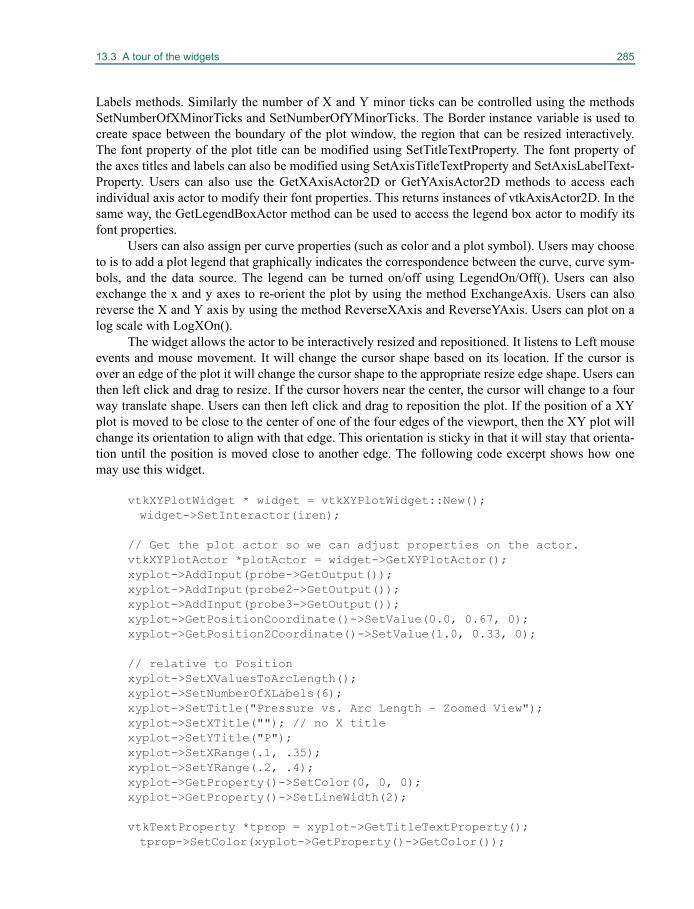
13.3 A tour of the widgets 285
Labels methods. Similarly the number of X and Y minor ticks can be controlled using the methodsSetNumberOfXMinorTicks and SetNumberOfYMinorTicks. The Border instance variable is used tocreate space between the boundary of the plot window, the region that can be resized interactively.The font property of the plot title can be modified using SetTitleTextProperty. The font property ofthe axes titles and labels can also be modified using SetAxisTitleTextProperty and SetAxisLabelText-Property. Users can also use the GetXAxisActor2D or GetYAxisActor2D methods to access eachindividual axis actor to modify their font properties. This returns instances of vtkAxisActor2D. In thesame way, the GetLegendBoxActor method can be used to access the legend box actor to modify itsfont properties.
Users can also assign per curve properties (such as color and a plot symbol). Users may chooseto is to add a plot legend that graphically indicates the correspondence between the curve, curve sym-bols, and the data source. The legend can be turned on/off using LegendOn/Off(). Users can alsoexchange the x and y axes to re-orient the plot by using the method ExchangeAxis. Users can alsoreverse the X and Y axis by using the method ReverseXAxis and ReverseYAxis. Users can plot on alog scale with LogXOn().
The widget allows the actor to be interactively resized and repositioned. It listens to Left mouseevents and mouse movement. It will change the cursor shape based on its location. If the cursor isover an edge of the plot it will change the cursor shape to the appropriate resize edge shape. Users canthen left click and drag to resize. If the cursor hovers near the center, the cursor will change to a fourway translate shape. Users can then left click and drag to reposition the plot. If the position of a XYplot is moved to be close to the center of one of the four edges of the viewport, then the XY plot willchange its orientation to align with that edge. This orientation is sticky in that it will stay that orienta-tion until the position is moved close to another edge. The following code excerpt shows how onemay use this widget.
vtkXYPlotWidget * widget = vtkXYPlotWidget::New();widget->SetInteractor(iren);
// Get the plot actor so we can adjust properties on the actor.vtkXYPlotActor *plotActor = widget->GetXYPlotActor();xyplot->AddInput(probe->GetOutput());xyplot->AddInput(probe2->GetOutput());xyplot->AddInput(probe3->GetOutput());xyplot->GetPositionCoordinate()->SetValue(0.0, 0.67, 0);xyplot->GetPosition2Coordinate()->SetValue(1.0, 0.33, 0);
// relative to Positionxyplot->SetXValuesToArcLength();xyplot->SetNumberOfXLabels(6);xyplot->SetTitle("Pressure vs. Arc Length - Zoomed View");xyplot->SetXTitle(""); // no X titlexyplot->SetYTitle("P");xyplot->SetXRange(.1, .35);xyplot->SetYRange(.2, .4);xyplot->GetProperty()->SetColor(0, 0, 0);xyplot->GetProperty()->SetLineWidth(2);
vtkTextProperty *tprop = xyplot->GetTitleTextProperty();tprop->SetColor(xyplot->GetProperty()->GetColor());
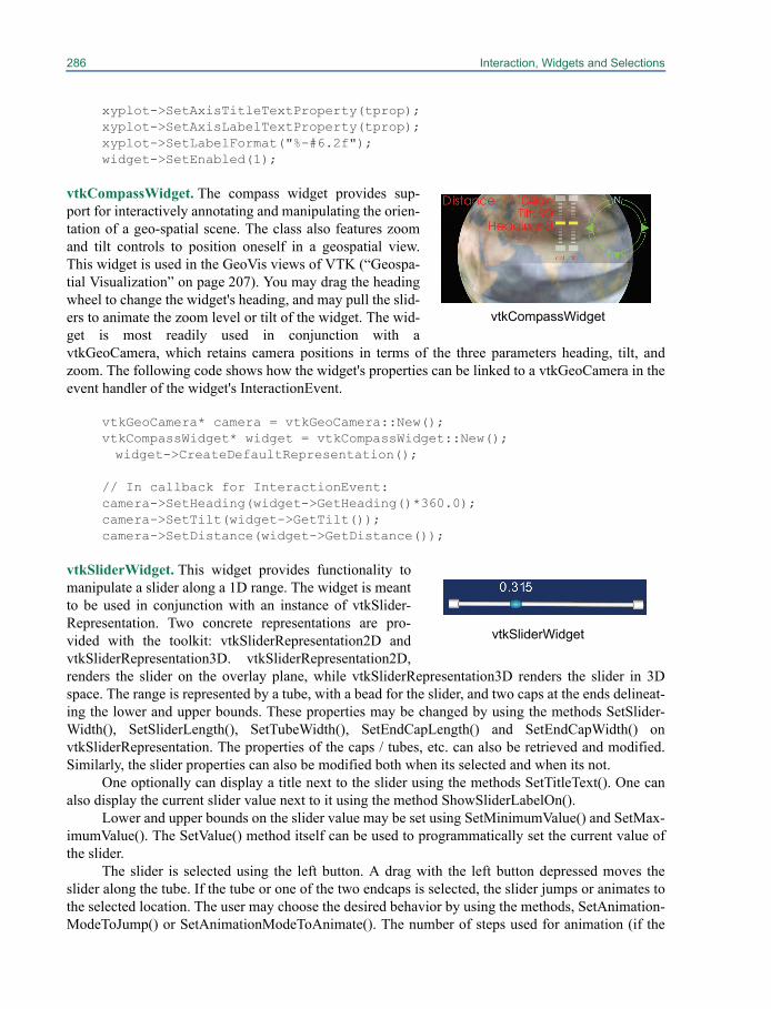
286 Interaction, Widgets and Selections
xyplot->SetAxisTitleTextProperty(tprop);xyplot->SetAxisLabelTextProperty(tprop);xyplot->SetLabelFormat("%-#6.2f");widget->SetEnabled(1);
vtkCompassWidget. The compass widget provides sup-port for interactively annotating and manipulating the orien-tation of a geo-spatial scene. The class also features zoomand tilt controls to position oneself in a geospatial view.This widget is used in the GeoVis views of VTK (“Geospa-tial Visualization” on page 207). You may drag the headingwheel to change the widget's heading, and may pull the slid-ers to animate the zoom level or tilt of the widget. The wid-get is most readily used in conjunction with avtkGeoCamera, which retains camera positions in terms of the three parameters heading, tilt, andzoom. The following code shows how the widget's properties can be linked to a vtkGeoCamera in theevent handler of the widget's InteractionEvent.
vtkGeoCamera* camera = vtkGeoCamera::New();vtkCompassWidget* widget = vtkCompassWidget::New();widget->CreateDefaultRepresentation();
// In callback for InteractionEvent:camera->SetHeading(widget->GetHeading()*360.0);camera->SetTilt(widget->GetTilt());camera->SetDistance(widget->GetDistance());
vtkSliderWidget. This widget provides functionality tomanipulate a slider along a 1D range. The widget is meantto be used in conjunction with an instance of vtkSlider-Representation. Two concrete representations are pro-vided with the toolkit: vtkSliderRepresentation2D andvtkSliderRepresentation3D. vtkSliderRepresentation2D,renders the slider on the overlay plane, while vtkSliderRepresentation3D renders the slider in 3Dspace. The range is represented by a tube, with a bead for the slider, and two caps at the ends delineat-ing the lower and upper bounds. These properties may be changed by using the methods SetSlider-Width(), SetSliderLength(), SetTubeWidth(), SetEndCapLength() and SetEndCapWidth() onvtkSliderRepresentation. The properties of the caps / tubes, etc. can also be retrieved and modified.Similarly, the slider properties can also be modified both when its selected and when its not.
One optionally can display a title next to the slider using the methods SetTitleText(). One canalso display the current slider value next to it using the method ShowSliderLabelOn().
Lower and upper bounds on the slider value may be set using SetMinimumValue() and SetMax-imumValue(). The SetValue() method itself can be used to programmatically set the current value ofthe slider.
The slider is selected using the left button. A drag with the left button depressed moves theslider along the tube. If the tube or one of the two endcaps is selected, the slider jumps or animates tothe selected location. The user may choose the desired behavior by using the methods, SetAnimation-ModeToJump() or SetAnimationModeToAnimate(). The number of steps used for animation (if the
vtkCompassWidget
vtkSliderWidget
13.3 A tour of the widgets 287
mode is animate) may be controlled using SetNumberOfAnimationSteps(). Alternatively, one maydisable this behavior altogether by using SetAnimationModeToOff().
The widget invokes StartInteractionEvent, InteractionEvent and EndInteractionEvent before,during and after user interaction. The following excerpt from VTK/Widgets/Testing/Cxx/TestSlider-Widget.cxx illustrates the usage of the vtkSliderWidget in conjunction with avtkSliderRepresentation3D.
vtkSliderRepresentation3D *sliderRep = vtkSliderRepresentation3D::New();sliderRep->SetValue(0.25);sliderRep->SetTitleText("Spike Size");sliderRep->GetPoint1Coordinate()->SetCoordinateSystemToWorld();sliderRep->GetPoint1Coordinate()->SetValue(0,0,0);sliderRep->GetPoint2Coordinate()->SetCoordinateSystemToWorld();sliderRep->GetPoint2Coordinate()->SetValue(2,0,0);sliderRep->SetSliderLength(0.075);sliderRep->SetSliderWidth(0.05);sliderRep->SetEndCapLength(0.05);
vtkSliderWidget *sliderWidget = vtkSliderWidget::New();sliderWidget->SetInteractor(iren);sliderWidget->SetRepresentation(sliderRep);sliderWidget->SetAnimationModeToAnimate();sliderWidget->EnabledOn();
The following excerpt from VTK/Widgets/Testing/Cxx/TestSliderWidget2D illustrates the usage ofvtkSliderWidget in conjunction with vtkSliderRepresentation2D to render the slider on the overlayplane.
vtkSliderRepresentation2D *sliderRep = vtkSliderRepresentation2D::New();sliderRep->SetValue(0.25);sliderRep->SetTitleText("Spike Size");sliderRep->GetPoint1Coordinate()->SetCoordinateSystemToNormalizedDisplay();
sliderRep->GetPoint1Coordinate()->SetValue(0.2,0.1);sliderRep->GetPoint2Coordinate()->SetCoordinateSystemToNormalizedDisplay();
sliderRep->GetPoint2Coordinate()->SetValue(0.8,0.1);sliderRep->SetSliderLength(0.02);sliderRep->SetSliderWidth(0.03);sliderRep->SetEndCapLength(0.01);sliderRep->SetEndCapWidth(0.03);sliderRep->SetTubeWidth(0.005);
vtkSliderWidget *sliderWidget = vtkSliderWidget::New();sliderWidget->SetInteractor(iren);sliderWidget->SetRepresentation(sliderRep);sliderWidget->SetAnimationModeToAnimate();
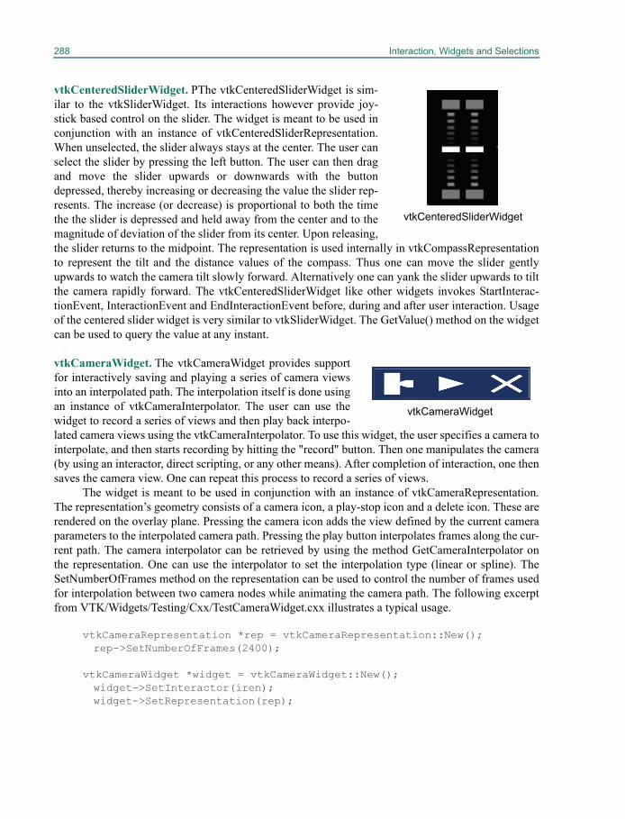
288 Interaction, Widgets and Selections
vtkCenteredSliderWidget. PThe vtkCenteredSliderWidget is sim-ilar to the vtkSliderWidget. Its interactions however provide joy-stick based control on the slider. The widget is meant to be used inconjunction with an instance of vtkCenteredSliderRepresentation.When unselected, the slider always stays at the center. The user canselect the slider by pressing the left button. The user can then dragand move the slider upwards or downwards with the buttondepressed, thereby increasing or decreasing the value the slider rep-resents. The increase (or decrease) is proportional to both the timethe the slider is depressed and held away from the center and to themagnitude of deviation of the slider from its center. Upon releasing,the slider returns to the midpoint. The representation is used internally in vtkCompassRepresentationto represent the tilt and the distance values of the compass. Thus one can move the slider gentlyupwards to watch the camera tilt slowly forward. Alternatively one can yank the slider upwards to tiltthe camera rapidly forward. The vtkCenteredSliderWidget like other widgets invokes StartInterac-tionEvent, InteractionEvent and EndInteractionEvent before, during and after user interaction. Usageof the centered slider widget is very similar to vtkSliderWidget. The GetValue() method on the widgetcan be used to query the value at any instant.
vtkCameraWidget. The vtkCameraWidget provides supportfor interactively saving and playing a series of camera viewsinto an interpolated path. The interpolation itself is done usingan instance of vtkCameraInterpolator. The user can use thewidget to record a series of views and then play back interpo-lated camera views using the vtkCameraInterpolator. To use this widget, the user specifies a camera tointerpolate, and then starts recording by hitting the "record" button. Then one manipulates the camera(by using an interactor, direct scripting, or any other means). After completion of interaction, one thensaves the camera view. One can repeat this process to record a series of views.
The widget is meant to be used in conjunction with an instance of vtkCameraRepresentation.The representation’s geometry consists of a camera icon, a play-stop icon and a delete icon. These arerendered on the overlay plane. Pressing the camera icon adds the view defined by the current cameraparameters to the interpolated camera path. Pressing the play button interpolates frames along the cur-rent path. The camera interpolator can be retrieved by using the method GetCameraInterpolator onthe representation. One can use the interpolator to set the interpolation type (linear or spline). TheSetNumberOfFrames method on the representation can be used to control the number of frames usedfor interpolation between two camera nodes while animating the camera path. The following excerptfrom VTK/Widgets/Testing/Cxx/TestCameraWidget.cxx illustrates a typical usage.
vtkCameraRepresentation *rep = vtkCameraRepresentation::New();rep->SetNumberOfFrames(2400);
vtkCameraWidget *widget = vtkCameraWidget::New();widget->SetInteractor(iren);widget->SetRepresentation(rep);
vtkCenteredSliderWidget
vtkCameraWidget

13.3 A tour of the widgets 289
vtkPlaybackWidget. pThe vtkPlaybackWidget pro-vides support for interactively controlling the playbackof a serial stream of information (e.g., animationsequence, video). Controls for play, stop, advance onestep forward, advance one step backward, jump to begin-ning, and jump to end are available. The widget works in conjunction with an instance of vtkPlay-backRepresentation. The representation exists on the overlay plane and derives fromvtkBorderWidget. It can be interactively resized or repositioned using the corners/edges or near thecenter. Six controls, in the form of icons, are provided by the playback widget. These controls allowfor (a) Jumping to the beginning of the frame (b) Reverting one frame (c) Stop playback (d) Play (e)Jump forward one frame (f) Jump to the end. The implementation is left to the subclass. ie. Users areexpected to subclass vtkPlaybackRepresentation to provide their own implementations for the 6 con-trols above. The following excerpt from VTK/Widgets/Testing/Cxx/TestPlaybackWidget.cxx illus-trates a typical usage.
class vtkSubclassPlaybackRepresentation : public vtkPlaybackRepresentation{public:static vtkSubclassPlaybackRepresentation *New() {return new vtkSubclassPlaybackRepresentation;}
virtual void Play() {cout << "play\n";}virtual void Stop() {cout << "stop\n";}virtual void ForwardOneFrame() {cout << "forward one frame\n";}virtual void BackwardOneFrame() {cout << "backward one frame\n";}virtual void JumpToBeginning() {cout << "jump to beginning\n";}virtual void JumpToEnd() {cout << "jump to end\n";}};
...
vtkSubclassPlaybackRepresentation *rep = vtkSubclassPlaybackRepresentation::New();
vtkPlaybackWidget *widget = vtkPlaybackWidget::New();widget->SetInteractor(iren);widget->SetRepresentation(rep);
An ExampleThe following example from Widgets/Testing/Cxx/TestAffineWidget.cxx uses a vtkAffineWidget totransform (shear / rotate / translate / scale) a 2D image interactively. We will observe the widget forinteractions with the class vtkAffineCallback in order to update the transform on the image actor.
class vtkAffineCallback : public vtkCommand{public:static vtkAffineCallback *New()
{ return new vtkAffineCallback; } virtual void Execute(vtkObject *caller, unsigned long, void*); vtkAffineCallback():ImageActor(0),AffineRep(0)
vtkPlaybackWidget

290 Interaction, Widgets and Selections
{this->Transform = vtkTransform::New();} ~vtkAffineCallback() {this->Transform->Delete();} vtkImageActor *ImageActor; vtkAffineRepresentation2D *AffineRep; vtkTransform *Transform;};
void vtkAffineCallback::Execute(vtkObject*, unsigned long, void*){this->AffineRep->GetTransform(this->Transform);this->ImageActor->SetUserTransform(this->Transform);}
int TestAffineWidget( int argc, char *argv[] ){
// Create the pipeline char* fname = vtkTestUtilities::ExpandDataFileName(
argc, argv, "Data/headsq/quarter"); vtkVolume16Reader* v16 = vtkVolume16Reader::New(); v16->SetDataDimensions(64, 64); v16->SetDataByteOrderToLittleEndian(); v16->SetImageRange(1, 93); v16->SetDataSpacing(3.2, 3.2, 1.5); v16->SetFilePrefix(fname); v16->ReleaseDataFlagOn(); v16->SetDataMask(0x7fff); v16->Update();delete[] fname;
double range[2];v16->GetOutput()->GetScalarRange(range);
vtkImageShiftScale* shifter = vtkImageShiftScale::New(); shifter->SetShift(-1.0*range[0]); shifter->SetScale(255.0/(range[1]-range[0])); shifter->SetOutputScalarTypeToUnsignedChar(); shifter->SetInputConnection(v16->GetOutputPort()); shifter->ReleaseDataFlagOff(); shifter->Update(); vtkImageActor* imageActor = vtkImageActor::New(); imageActor->SetInput(shifter->GetOutput()); imageActor->VisibilityOn(); imageActor->SetDisplayExtent(0, 63, 0, 63, 46, 46); imageActor->InterpolateOn();
double bounds[6];imageActor->GetBounds(bounds);
13.4 Selections 291
// Create the RenderWindow, Renderer and both ActorsvtkRenderer *ren1 = vtkRenderer::New();vtkRenderWindow *renWin = vtkRenderWindow::New();renWin->AddRenderer(ren1);
vtkRenderWindowInteractor *iren = vtkRenderWindowInteractor::New();iren->SetRenderWindow(renWin);
vtkInteractorStyleImage *style = vtkInteractorStyleImage::New();iren->SetInteractorStyle(style);
// VTK widgets consist of two parts: event processing and the// representation that defines how the widget appears in the scene vtkAffineRepresentation2D *rep = vtkAffineRepresentation2D::New();rep->SetBoxWidth(100);
rep->SetCircleWidth(75); rep->SetAxesWidth(60); rep->DisplayTextOn(); rep->PlaceWidget(bounds);
vtkAffineWidget *widget = vtkAffineWidget::New(); widget->SetInteractor(iren); widget->SetRepresentation(rep);
vtkAffineCallback *acbk = vtkAffineCallback::New(); acbk->AffineRep = rep; acbk->ImageActor = imageActor;widget->AddObserver(vtkCommand::InteractionEvent,acbk);widget->AddObserver(vtkCommand::EndInteractionEvent,acbk);
// Add the actors to the renderer, set the background and size ren1->AddActor(imageActor); ren1->SetBackground(0.1, 0.2, 0.4); renWin->SetSize(300, 300);
iren->Initialize(); renWin->Render(); iren->Start();}
13.4 SelectionsIn its most general sense, a selection is a data structure that specifies a subset of something else. Thissubset may be highlighted to show a feature in the data, or may be extracted to analyze a portion ofthe data in more detail. VTK provides a framework for generating, processing, and sharing selectionsin applications using the vtkSelection class, along with related selection sources, filters, and views.
vtkSelection is a container class holding one or more vtkSelectionNode objects. Each node con-tains information indicating what part of the data is selected. A compound selection is interpreted asthe union of the individual node selections. We allow selections to consist of multiple nodes so that in
292 Interaction, Widgets and Selections
one place we can represent selections on multiple parts of the data. For example, a selection on geom-etry may contain a vtkSelectionNode for both points and cells. Another use case is to collect selec-tions from multiple datasets in the same renderer into one place.
13.5 Types of selections
Each vtkSelectionNode has a selection type which indicates how the selection is to be interpreted.The selection types are constants defined in vtkSelectionNode.h. Values associated with a selectionare stored in an array retrieved by GetSelectionList(). For convenience, we will use the term “ele-ment” to refer to the basic building-blocks of datasets to which attributes may be assigned. For vtkDa-taSet subclasses, the elements are points and cells. The elements of vtkGraph subclasses are verticesand edges. For vtkTable, the elements are the rows of the table.
Index selections
This is the most basic type of selection. An index selection's selection list is a vtkIdTypeArray con-taining the raw zero-based indices of the selected elements in a dataset, using the dataset's internalordering. Since these indices may change as a dataset is processed or filtered, an index selection isgenerally only applicable to a single data set. You should not share an index selection between datas-ets with different topologies.
Pedigree ID selections
A pedigree ID is an identifier assigned to each element in a dataset at its source, and is propagateddown the pipeline. You specify pedigree IDs on a dataset in the same way that other special attributeslike scalars and vectors are specified, by calling SetPedigreeIds() on a dataset's attributes. Pedigree IDarrays may be of any type, including vtkStringArray and vtkVariantArray. A pedigree ID selectioncontains a list of values from a dataset's pedigree ID array. Both pedigree ID and global ID selectionsrefer to elements by name, instead of by a dataset-specific offset used in index selections, whichmakes them more robust across different datasets which originate from the same source.
Global ID selections
Global ID selections are much like pedigree ID selections, except that they refer to the global ID attri-bute (set with SetGlobalIds()). Global IDs are used in a way similar to pedigree IDs, except that theymust be numeric, and some filters re-assign global IDs to ensure that IDs are never repeated.
Frustum selections
Frustum selections simply store the geometry of a frustum in the selection. All elements within thefrustum are considered selected. This is most useful in the case that the user drag-selects a region in a3D scene. The rectangular region on the screen translates into a frustum in the 3D scene. The selec-tion list for this type of selection must be a vtkDoubleArray with eight four-component tuples. Thepoints, in the form (x,y,z,1), should be in the following order:
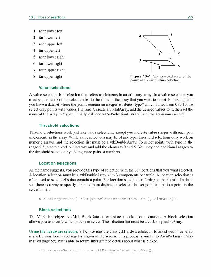
13.5 Types of selections 293
1. near lower left2. far lower left3. near upper left4. far upper left5. near lower right6. far lower right7. near upper right8. far upper right
Value selectionsA value selection is a selection that refers to elements in an arbitrary array. In a value selection youmust set the name of the selection list to the name of the array that you want to select. For example, ifyou have a dataset where the points contain an integer attribute “type” which varies from 0 to 10. Toselect only points with values 1, 3, and 7, create a vtkIntArray, add the desired values to it, then set thename of the array to “type”. Finally, call node->SetSelectionList(arr) with the array you created.
Threshold selectionsThreshold selections work just like value selections, except you indicate value ranges with each pairof elements in the array. While value selections may be of any type, threshold selections only work onnumeric arrays, and the selection list must be a vtkDoubleArray. To select points with type in therange 0-5, create a vtkDoubleArray and add the elements 0 and 5. You may add additional ranges tothe threshold selection by adding more pairs of numbers.
Location selectionsAs the name suggests, you provide this type of selection with the 3D locations that you want selected.A location selection must be a vtkDoubleArray with 3 components per tuple. A location selection isoften used to select cells that contain a point. For location selections referring to the points of a data-set, there is a way to specify the maximum distance a selected dataset point can be to a point in theselection list:
n->GetProperties()->Set(vtkSelectionNode::EPSILON(), distance);
Block selectionsThe VTK data object, vtkMultiBlockDataset, can store a collection of datasets. A block selectionallows you to specify which blocks to select. The selection list must be a vtkUnsignedIntArray.
Using the hardware selector. VTK provides the class vtkHardwareSelector to assist you in generat-ing selections from a rectangular region of the screen. This process is similar to AreaPicking (“Pick-ing” on page 59), but is able to return finer grained details about what is picked.
vtkHardwareSelector* hs = vtkHardwareSelector::New();
Figure 13–1 The expected order of thepoints in a view frustum selection.
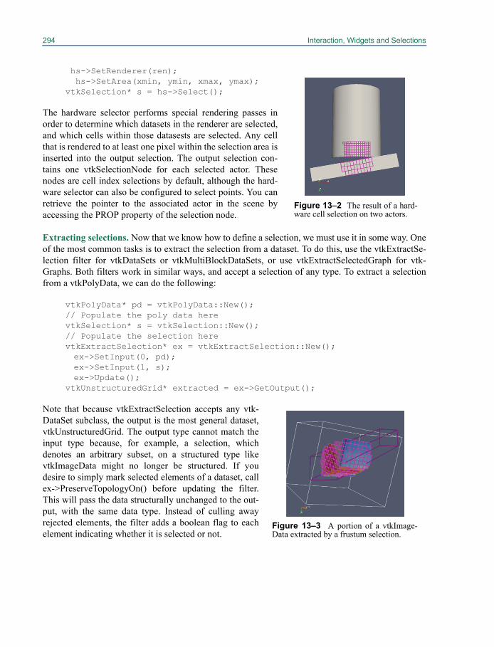
294 Interaction, Widgets and Selections
hs->SetRenderer(ren); hs->SetArea(xmin, ymin, xmax, ymax);vtkSelection* s = hs->Select();
The hardware selector performs special rendering passes inorder to determine which datasets in the renderer are selected,and which cells within those datasests are selected. Any cellthat is rendered to at least one pixel within the selection area isinserted into the output selection. The output selection con-tains one vtkSelectionNode for each selected actor. Thesenodes are cell index selections by default, although the hard-ware selector can also be configured to select points. You canretrieve the pointer to the associated actor in the scene byaccessing the PROP property of the selection node.
Extracting selections. Now that we know how to define a selection, we must use it in some way. Oneof the most common tasks is to extract the selection from a dataset. To do this, use the vtkExtractSe-lection filter for vtkDataSets or vtkMultiBlockDataSets, or use vtkExtractSelectedGraph for vtk-Graphs. Both filters work in similar ways, and accept a selection of any type. To extract a selectionfrom a vtkPolyData, we can do the following:
vtkPolyData* pd = vtkPolyData::New();// Populate the poly data herevtkSelection* s = vtkSelection::New();// Populate the selection herevtkExtractSelection* ex = vtkExtractSelection::New();ex->SetInput(0, pd);ex->SetInput(1, s);ex->Update();
vtkUnstructuredGrid* extracted = ex->GetOutput();
Note that because vtkExtractSelection accepts any vtk-DataSet subclass, the output is the most general dataset,vtkUnstructuredGrid. The output type cannot match theinput type because, for example, a selection, whichdenotes an arbitrary subset, on a structured type likevtkImageData might no longer be structured. If youdesire to simply mark selected elements of a dataset, callex->PreserveTopologyOn() before updating the filter.This will pass the data structurally unchanged to the out-put, with the same data type. Instead of culling awayrejected elements, the filter adds a boolean flag to eachelement indicating whether it is selected or not.
Figure 13–2 The result of a hard-ware cell selection on two actors.
Figure 13–3 A portion of a vtkImage-Data extracted by a frustum selection.

Part IIIVTK Developer’s Guide

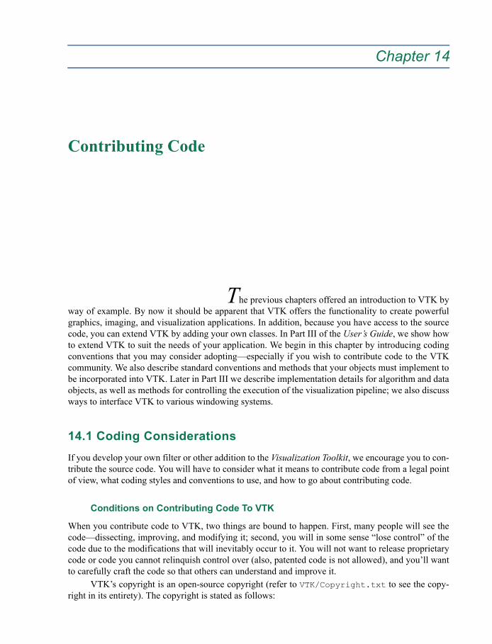
Chapter 14
Contributing Code 14
The previous chapters offered an introduction to VTK byway of example. By now it should be apparent that VTK offers the functionality to create powerfulgraphics, imaging, and visualization applications. In addition, because you have access to the sourcecode, you can extend VTK by adding your own classes. In Part III of the User’s Guide, we show howto extend VTK to suit the needs of your application. We begin in this chapter by introducing codingconventions that you may consider adopting—especially if you wish to contribute code to the VTKcommunity. We also describe standard conventions and methods that your objects must implement tobe incorporated into VTK. Later in Part III we describe implementation details for algorithm and dataobjects, as well as methods for controlling the execution of the visualization pipeline; we also discussways to interface VTK to various windowing systems.
14.1 Coding ConsiderationsIf you develop your own filter or other addition to the Visualization Toolkit, we encourage you to con-tribute the source code. You will have to consider what it means to contribute code from a legal pointof view, what coding styles and conventions to use, and how to go about contributing code.
Conditions on Contributing Code To VTK
When you contribute code to VTK, two things are bound to happen. First, many people will see thecode—dissecting, improving, and modifying it; second, you will in some sense “lose control” of thecode due to the modifications that will inevitably occur to it. You will not want to release proprietarycode or code you cannot relinquish control over (also, patented code is not allowed), and you’ll wantto carefully craft the code so that others can understand and improve it.
VTK’s copyright is an open-source copyright (refer to VTK/Copyright.txt to see the copy-right in its entirety). The copyright is stated as follows:
298 Contributing Code
VTK is an open-source toolkit licensed under the BSD license.Copyright (c) 1993-2008 Ken Martin, Will Schroeder, Bill Lorensen All rights reserved.
Redistribution and use in source and binary forms, with or without modification, are permitted providedthat the following conditions are met:
• Redistributions of source code must retain the above copyright notice, this list of conditions and the fol-lowing disclaimer.
• Redistributions in binary form must reproduce the above copyright notice, this list of conditions and thefollowing disclaimer in the documentation and/or other materials provided with the distribution.
• Neither name of Ken Martin, Will Schroeder, or Bill Lorensen nor the names of any contributors may beused to endorse or promote products derived from this software without specific prior written permis-sion.
THIS SOFTWARE IS PROVIDED BY THE COPYRIGHT HOLDERS AND CONTRIBUTORS “AS IS''AND ANY EXPRESS OR IMPLIED WARRANTIES, INCLUDING, BUT NOT LIMITED TO, THEIMPLIED WARRANTIES OF MERCHANTABILITY AND FITNESS FOR A PARTICULAR PURPOSEARE DISCLAIMED. IN NO EVENT SHALL THE AUTHORS OR CONTRIBUTORS BE LIABLE FORANY DIRECT, INDIRECT, INCIDENTAL, SPECIAL, EXEMPLARY, OR CONSEQUENTIAL DAMAGES(INCLUDING, BUT NOT LIMITED TO, PROCUREMENT OF SUBSTITUTE GOODS OR SERVICES;LOSS OF USE, DATA, OR PROFITS; OR BUSINESS INTERRUPTION) HOWEVER CAUSED ANDON ANY THEORY OF LIABILITY, WHETHER IN CONTRACT, STRICT LIABILITY, OR TORT (INCLUD-ING NEGLIGENCE OR OTHERWISE) ARISING IN ANY WAY OUT OF THE USE OF THIS SOFT-WARE, EVEN IF ADVISED OF THE POSSIBILITY OF SUCH DAMAGE.
Conditions on the copyright are derived from the BSD license (see www.opensource.org) andplaces no constraints on modifying, copying, and redistributing source or binary code, with the excep-tion of the three bulleted clauses, warranty, and indemnification clauses shown above. Other thanrespecting these three clauses, and observing the usual indemnification clause, you can use VTK inany way whatsoever, including in commercial applications.
If these restrictions are acceptable, you can consider contributing code. However, you will needto meet other criteria before your code is accepted. These criteria are not formalized, but have to dowith the usefulness, simplicity, and compatibility with the rest of the system. Important questions toask are:
• Does the code meet the VTK coding standards (also see “Coding Style” on page 299)?
• Is the code documented and commented?
• Is the code general? Or is it specific to a narrow application?
• Does it require extensive modification to the system? (For example, modifications to widely-used object APIs.)
• Does the code duplicate existing functionality?
• Is the code robust?
• Does the code belong in a visualization toolkit?
If you can answer these questions favorably, chances are that the code is a good candidate for inclu-sion in VTK.
14.1 Coding Considerations 299
Coding Style
There are many useful coding styles, but we insist that you follow just one. We know this is a conten-tious issue, but we have found that it is very important to maintain a consistent style. Consistent stylemeans that the code is easier to read, debug, maintain, test, and extend. It also means that the auto-mated documentation facilities operate correctly, and other automated functions are available to allusers of VTK.
Here’s a summary of the coding style. You may wish to examine VTK source code to see whatit looks like.
• Variables, methods, and class names use changing capitalization to indicate separate words.Instance variables and methods always begin with a capital letter. Static variables are discour-aged, but should also begin with a capital letter. Local variables begin with a lower-case letter.SetNumberOfPoints() or PickList are examples of a method name and instance variable.
• Class names are prefixed with vtk followed by the class name starting with a capital letter. Forexample, vtkActor or vtkPolyData are class names. The vtk prefix allows the VTK classlibrary to be mixed with other libraries.
• Class names and files names are the same. For example, vtkObject.h and vtkObject.cxxare the source files for vtkObject.
• Explicit this-> pointers are used in methods. Examples include this->Visibility andthis->Property and this->Update(). We have found that the use of explicit this->pointers improves code understanding and readability.
• Variable, method, and class names should be spelled out. Common abbreviations can be used,but the abbreviation should be entirely in capital letters. For example,vtkPolyDataConnectivityFilter and vtkLODActor are acceptable class names.
• Preprocessor variables are written in capital letters. These variables are the only one to use theunderscore “_” to separate words. Preprocessor variables should also begin with VTK_ as inVTK_LARGE_FLOAT.
• Instance variables are typically protected or private class members. Access to instancevariables is through Set/Get methods. Note that VTK provides Set/Get macros whichshould be used whenever possible. (Look in VTK/Common/vtkSetGet.h for the implementa-tion, and .h header files for example usage.)
• The indentation style can be characterized as the “indented brace” style. Indentations are twospaces, and the curly brace (scope delimiter) is placed on the following line and indented alongwith the code (i.e., the curly brace lines up with the code).
• Use // to comment code. Methods are commented by adding // Description: followed bylines each beginning with //.
How To Contribute Code
Contributing code is fairly easy once you’ve created your class or classes following the coding con-vention described above. First, include the copyright notice in both the .cxx and .h source files. Youmay wish to place your name, organization, and/or other identifying information in the “Thanks:”field of the copyright notice. (See VTK/Graphics/vtkCurvatures.h for an example). Next, sende-mail to [email protected] with an explanation of what the code does, sample data (if

300 Contributing Code
needed), test code (in either C++, Tcl, or Python), and the source code (a single .h and .cxx file perclass). Another method is to send the same information to the vtkusers mailing list. (See “Addi-tional Resources” on page 6 for information about joining the list.) The advantage of sending contrib-uted code to the mailing list is that users can take advantage of the code immediately.
There is no guarantee that contributed code will be incorporated into official VTK releases.This depends upon the quality, usefulness, and generality of the code as outlined in “Conditions onContributing Code To VTK” on page 297.
14.2 Standard Methods: Creating and Deleting ObjectsAlmost every object in VTK responds to a set of standard methods. Many of these methods are imple-mented in vtkObject or vtkObjectBase, from which most VTK classes are derived. However, sub-classes typically require that you extend or implement the inherited methods for proper behavior. Forexample, the New() method should be implemented by every concrete (i.e., non-abstract, instantiable)class, while the Delete() method is generally inherited from its superclass’s vtkObject. Before youdevelop any code you should become familiar with these standard methods, and make sure your ownclasses support them.
New()This static class method is used to instantiate objects. We refer to this method as an“object factory” since it is used to create instances of a class. In VTK, every New()method should be paired with a Delete() method. (See also “Object Factories” onpage 307.)
instance = NewInstance()This method is a virtual constructor. That is, invoking this method causes an object to cre-ate an instance of the same type as itself and then return a pointer to the new object. (Themacro vtkTypeMacro found in VTK/Common/vtkSetGet.h defines this method.)
Delete()Use this method to delete a VTK object created with the New() or NewInstance() method.Depending upon the nature of the object being deleted, this may or may not actuallydelete the object. For example, reference-counted objects will only be deleted if their ref-erence count goes to zero.
DebugOn()/DebugOff()Turn debugging information on or off. These methods are inherited from vtkObject.
Print()Print out the object including superclass information. The Print() method, which isdefined in vtkObjectBase, requires implementation of a PrintSelf() method for each class.The PrintSelf() method is invoked in a chain, each subclass calling its superclass’sPrintSelf() and then printing its own instance variables.
PrintSelf(ostream, indent)Each class should implement this method. The method invokes its parent’s PrintSelf(),followed by the code required to print itself.
name = GetClassName()Return the name of the class as a character string. This method is used for debugging
14.2 Standard Methods: Creating and Deleting Objects 301
information. (The macro vtkTypeMacro found in VTK/Common/tkSetGet.h definesthis method.)
flag = IsA(className)Return non-zero if the named class is a superclass of, or the same type as, this class. (Themacro vtkTypeMacro found in VTK/Common/vtkSetGet.h defines this method.)
<class> *ptr = <class>::SafeDownCast(vtkObject *o)This static class method is available in C++ for performing safe down casts (i.e., casting ageneral class to a more specialized class). If ptr is returned NULL, then the down castfailed, otherwise ptr points to an instance of the class <class>. For example,ptr=vtkActor::SafeDownCast(prop) will return non-NULL if prop is a vtkActor ora subclass of vtkActor. (The macro vtkTypeMacro found in VTK/Common/vtkSetGet.hdefines this method.)
void Modified()This updates the internal modification time stamp for the object. The value is guaranteedto be unique and monotonically increasing.
mtime = GetMTime()Return the last modification time of an object. Normally this method is inherited fromvtkObject, however in some cases you’ll want to overload it. See “Compute ModifiedTime” on page 391 for more information.
The most important information you can take from this section is this: instances should be createdwith the New() method and destroyed with the Delete() method, and for every New() there should bea Delete() method. For example, to create an instance of an actor do the following
vtkActor *anActor = vtkActor::New();... (more stuff)anActor->Delete();
In addition to ::New and ::Delete, VTK provides a smart pointer class that can be used to manageVTK objects. The smart pointer will automatically increment and decrement the reference count ofthe object being pointed to. This can make the code more less likely to leak VTK objects. The smartpointer class is a template class and is used as follows:
#include <vtkSmartPointer.h>…vtkSmartPointer<vtkActor> anActor = vtkSmartPointer<vtkActor>::New();... (more stuff)// when anActor goes out of scope the reference count for that // vtkActor will be decremented.
The New() method is called an object factory: it’s a class method used to create instances of the class.Typically, the New() method first asks the vtkObjectFactory to create an instance of the object, and ifthat fails, it simply invokes the C++ new operator. This is done by adding the vtkStandardNewMacro(found in VTK/Common/vtkSetGet.h) to a .cxx file as is shown below for vtkSphereSource.
vtkStandardNewMacro(vtkSphereSource);
302 Contributing Code
However, the New() method can be more complex, for example, to instantiate device-independentclasses. For example, in vtkGraphicsFactory.cxx, the code used to instantiate a vtkActor lookslike the following.
if(strcmp(vtkclassname, "vtkActor") == 0){return vtkOpenGLActor::New();}
Here the New() method is used to create a device-dependent subclass of vtkActor (i.e., OpenGL),which is then returned as a pointer to a device-independent vtkActor. For example, depending on thecompile-time flags (e.g., VTK_USE_OGLR) and possibly other information such as environment vari-ables, different actor types corresponding to the rendering libraries (e.g., OpenGL, Mesa, et.c) arecreated transparently to the user. Using this mechanism we can create device-independent applica-tions, or at run-time select different classes to use in the application. (See “Object Factories” onpage 307 for more information.)
14.3 Copying Objects and Protected MethodsThe constructor, destructor, operator=, and copy constructor methods are either protected or privatemembers of most every VTK class. This means that for VTK class vtkX, the methods
• vtkX() — constructor• ~vtkX() — destructor
are protected, and the methods
• operator=(const vtkX &) — equivalence operator, and• vtkX(const vtkX &) — copy constructor
are private. In addition, the assignment operator and copy constructors should be declared only, andnot implemented. This prevents the compiler from creating one automatically, and does not generatecode that cannot be covered in the testing process. This means that you cannot use these methods inyour application. (The reason for this is to prevent potentially dangerous misuse of these methods.For example, reference counting can be broken by using the constructor and destructor rather than thestandard New() and Delete() methods described in the previous section.)
Since the copy constructor and operator= methods are private, other methods must be used tocopy instances of an object. The methods to use are DeepCopy() and/or ShallowCopy() as shownbelow.
vtkActor *a1 = vtkActor::New();vtkActor *a2 = vtkActor::New();a2->ShallowCopy(a1);
A shallow copy is a copy of an object that copies references to objects (via reference counting) ratherthan the objects themselves. For example, instances of the class vtkActor refer to a vtkMapperobject (the mapper represents the geometry for the actor). In a shallow copy, replication of data isavoided, and just the reference to the vtkMapper is copied. However, any changes to the shared map-
14.4 Using STL 303
per indirectly affects all instances of vtkActor that refer to it. Alternatively, a DeepCopy() can beused to copy an instance, including any data it represents, without any references to other objects.Here’s an examples:
vtkIntArray *ia1 = vtkIntArray::New();vtkIntArray *ia2 = vtkIntArray::New();ia1->DeepCopy(ia2);
In this example, the data in ia2 is copied into ia1. From this point on, ia1 and ia2 can be modifiedwithout affecting each other.
At the current time, VTK does not support DeepCopy() and ShallowCopy() in all classes.This will be added in the future.
14.4 Using STLThe Standard Template Library (STL) is a C++ library that provides a set of easily composable C++container classes and generic algorithms (templated functions).
• The container classes include vectors, lists, deques, sets, multisets, maps, multimaps, stacks,queues, and priority queues.
• The generic algorithms include a broad range of fundamental algorithms for the most commonkinds of data manipulations, such as searching, sorting, merging, copying, and transforming.
While STL definitely has a lot to offer C++ programmers, it suffers several implementation issues(especially in cross-platform use) requiring VTK programmers to be careful when using STL. Someof these issues including namespace management, DLL (dynamic link library) boundary problems,and threading issues. To address these issues, VTK has a policy in place describing how STL is to beused in conjunction with VTK. Here are the tenets of the policy.
1. STL is for implementation, not interface. All STL references should be contained in a .cxx class implementation file, never in the .h header file.
2. Use the PIMPL idiom to forward reference/contain STL classes. STL-derived classes should be private, not protected or public, to avoid dll boundary issues. DLL boundary issues would arise if a subclass of a class using the PIMPL idiom is in a different VTK kit than the parent class. In some VTK classes that have no subclasses are using the PIMPL idiom, the STL-derived classes are in the protected section instead of the private one. (The PIMPL idiom is a technique for private implementation of class members. Search the Web for “pimpl idiom C++” for more information.)
3. Use the vtkstd:: namespace to refer to STL classes and functions.
Here's an example (from the class vtkInterpolatedVelocityField). In the class .h file create the PIMPLby forward declaring a class and using it to define a data member as follows.
class vtkInterpolatedVelocityFieldDataSetsType; class VTK_FILTERING_EXPORT vtkInterpolatedVelocityField : public vtkFunctionSet {
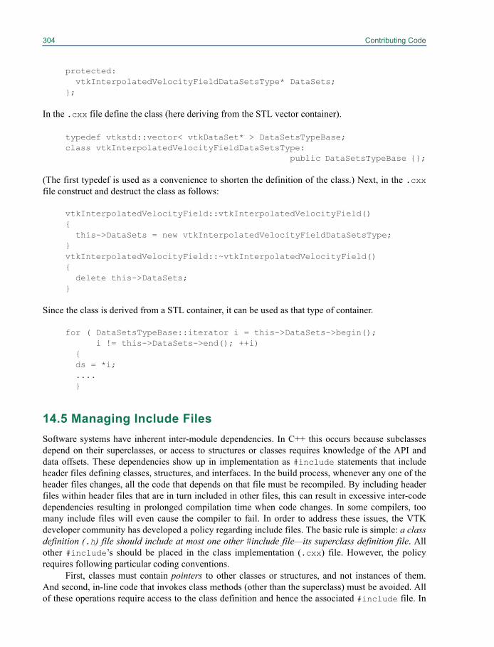
304 Contributing Code
protected:vtkInterpolatedVelocityFieldDataSetsType* DataSets;
};
In the .cxx file define the class (here deriving from the STL vector container).
typedef vtkstd::vector< vtkDataSet* > DataSetsTypeBase;class vtkInterpolatedVelocityFieldDataSetsType:
public DataSetsTypeBase {};
(The first typedef is used as a convenience to shorten the definition of the class.) Next, in the .cxxfile construct and destruct the class as follows:
vtkInterpolatedVelocityField::vtkInterpolatedVelocityField() {
this->DataSets = new vtkInterpolatedVelocityFieldDataSetsType; }vtkInterpolatedVelocityField::~vtkInterpolatedVelocityField() {
delete this->DataSets;}
Since the class is derived from a STL container, it can be used as that type of container.
for ( DataSetsTypeBase::iterator i = this->DataSets->begin();i != this->DataSets->end(); ++i)
{ds = *i;....}
14.5 Managing Include FilesSoftware systems have inherent inter-module dependencies. In C++ this occurs because subclassesdepend on their superclasses, or access to structures or classes requires knowledge of the API anddata offsets. These dependencies show up in implementation as #include statements that includeheader files defining classes, structures, and interfaces. In the build process, whenever any one of theheader files changes, all the code that depends on that file must be recompiled. By including headerfiles within header files that are in turn included in other files, this can result in excessive inter-codedependencies resulting in prolonged compilation time when code changes. In some compilers, toomany include files will even cause the compiler to fail. In order to address these issues, the VTKdeveloper community has developed a policy regarding include files. The basic rule is simple: a classdefinition (.h) file should include at most one other #include file—its superclass definition file. Allother #include’s should be placed in the class implementation (.cxx) file. However, the policyrequires following particular coding conventions.
First, classes must contain pointers to other classes or structures, and not instances of them.And second, in-line code that invokes class methods (other than the superclass) must be avoided. Allof these operations require access to the class definition and hence the associated #include file. In
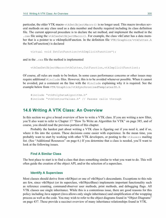
14.6 Writing A VTK Class: An Overview 305
particular, the older VTK macro vtkSetObjectMacro() is no longer used. This macro invokes sev-eral methods on any class used as a data member and thereby required including its class definitionfile. The current approved procedure is to declare the set method, and implement the method in the.cxx file using the vtkCxxSetObjectMacro(). For example, the class vtkCutter has a data mem-ber that is a pointer to a vtkImplicitFunction. In the definition file VTK/Graphics/vtkCutter.hthe SetCutFunction() is declared
virtual void SetCutFunction(vtkImplicitFunction*);
and in the .cxx file the method is implemented
vtkCxxSetObjectMacro(vtkCutter,CutFunction,vtkImplicitFunction);
Of course, all rules are made to be broken. In some cases performance concerns or other issues mayrequire additional #include files. However, this is to be avoided whenever possible. When it cannotbe avoided, put a comment on the line with the #include explaining why it is required. See theexample below from VTK/Graphics/vtkSynchronizedTemplates3D.h
#include “vtkPolyDataAlgorithm.h”#include “vtkContourValues.h” // Passes calls through
14.6 Writing A VTK Class: An OverviewIn this section we give a broad overview of how to write a VTK class. If you are writing a new filter,you’ll also want to refer to Chapter 17 “How To Write an Algorithm for VTK” on page 385, and ofcourse, you should read the previous portion of this chapter.
Probably the hardest part about writing a VTK class is figuring out if you need it, and if so,where it fits into the system. These decisions come easier with experience. In the mean time, youprobably want to start by working with other VTK developers, or posting to the vtkusers mailinglist. (See “Additional Resources” on page 6.) If you determine that a class is needed, you’ll want tolook at the following issues.
Find A Similar Class
The best place to start is to find a class that does something similar to what you want to do. This willoften guide the creation of the object API, and/or the selection of a superclass.
Identify A Superclass
Most classes should derive from vtkObject or one of vtkObject’s descendants. Exceptions to this ruleare few, since vtkObject (or its superclass, vtkObjectBase) implements important functionality suchas reference counting, command/observer user methods, print methods, and debugging flags. AllVTK classes use single inheritance. While this is a contentious issue, there are good reasons for thispolicy including Java support (Java allows only single inheritance) and simplification of the wrappingprocess as well as the code. You may wish to refer to the object diagrams found in “Object Diagrams”on page 437. These provide a succinct overview of many inheritance relationships found in VTK.
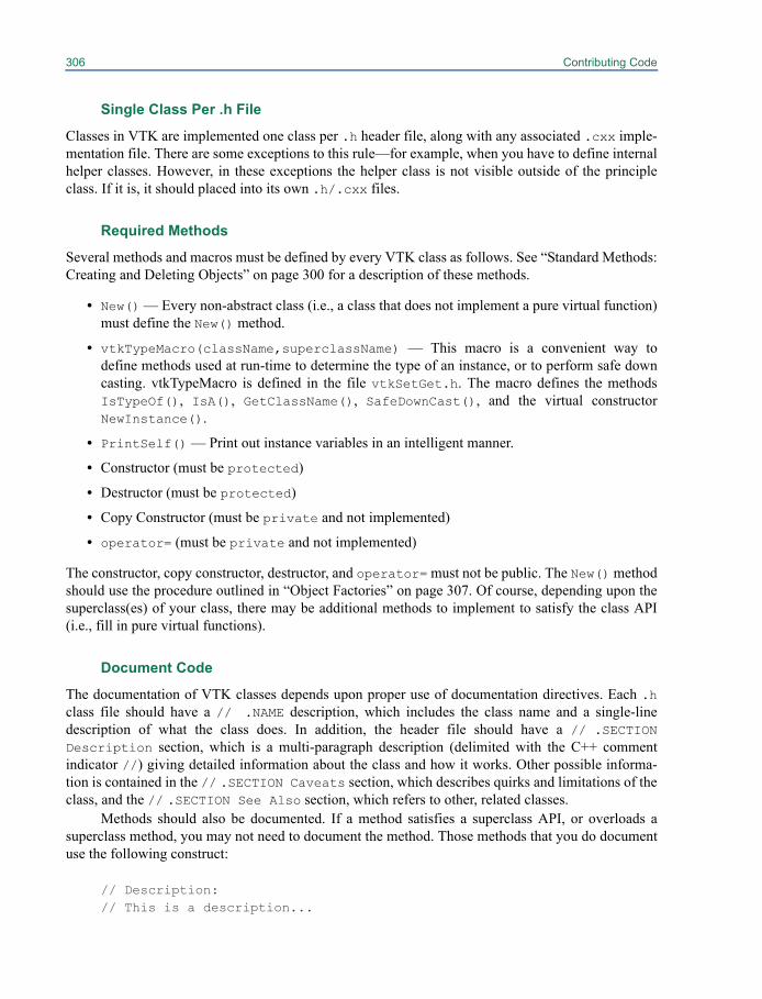
306 Contributing Code
Single Class Per .h File
Classes in VTK are implemented one class per .h header file, along with any associated .cxx imple-mentation file. There are some exceptions to this rule—for example, when you have to define internalhelper classes. However, in these exceptions the helper class is not visible outside of the principleclass. If it is, it should placed into its own .h/.cxx files.
Required Methods
Several methods and macros must be defined by every VTK class as follows. See “Standard Methods:Creating and Deleting Objects” on page 300 for a description of these methods.
• New() — Every non-abstract class (i.e., a class that does not implement a pure virtual function)must define the New() method.
• vtkTypeMacro(className,superclassName) — This macro is a convenient way todefine methods used at run-time to determine the type of an instance, or to perform safe downcasting. vtkTypeMacro is defined in the file vtkSetGet.h. The macro defines the methodsIsTypeOf(), IsA(), GetClassName(), SafeDownCast(), and the virtual constructorNewInstance().
• PrintSelf() — Print out instance variables in an intelligent manner.
• Constructor (must be protected)
• Destructor (must be protected)
• Copy Constructor (must be private and not implemented)
• operator= (must be private and not implemented)
The constructor, copy constructor, destructor, and operator= must not be public. The New() methodshould use the procedure outlined in “Object Factories” on page 307. Of course, depending upon thesuperclass(es) of your class, there may be additional methods to implement to satisfy the class API(i.e., fill in pure virtual functions).
Document Code
The documentation of VTK classes depends upon proper use of documentation directives. Each .hclass file should have a // .NAME description, which includes the class name and a single-linedescription of what the class does. In addition, the header file should have a // .SECTIONDescription section, which is a multi-paragraph description (delimited with the C++ commentindicator //) giving detailed information about the class and how it works. Other possible informa-tion is contained in the // .SECTION Caveats section, which describes quirks and limitations of theclass, and the // .SECTION See Also section, which refers to other, related classes.
Methods should also be documented. If a method satisfies a superclass API, or overloads asuperclass method, you may not need to document the method. Those methods that you do documentuse the following construct:
// Description:// This is a description...
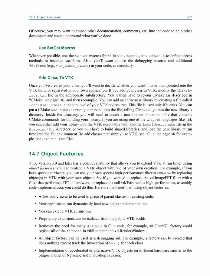
14.7 Object Factories 307
Of course, you may want to embed other documentation, comments, etc. into the code to help otherdevelopers and users understand what you’ve done.
Use SetGet Macros
Whenever possible, use the SetGet macros found in VTK/Common/vtkSetGet.h to define accessmethods to instance variables. Also, you’ll want to use the debugging macros and additional#defines (e.g., VTK_LARGE_FLOAT) in your code, as necessary.
Add Class To VTK
Once you’ve created your class, you’ll want to decide whether you want it to be incorporated into theVTK build or separated in your own application. If you add your class to VTK, modify the CMakeL-ists.txt file in the appropriate subdirectory. You’ll then have to re-run CMake (as described in“CMake” on page 10), and then recompile. You can add an entire new library by creating a file calledLocalUser.cmake in the top level of your VTK source tree. This file is used only if it exits. You canput a CMake add_subdirectory command into the file, telling CMake to go into the new library’sdirectory. Inside the directory, you will need to create a new CMakeLists.txt file that containsCMake commands for building your library. If you are using one of the wrapped languages like Tcl,you can either add your library into the VTK executable with another LocalUser.cmake file in theWrapping/Tcl directory, or you will have to build shared libraries, and load the new library at runtime into the Tcl environment. To add classes that simply use VTK, see “C++” on page 30 for exam-ple CMakeLists.txt files.
14.7 Object FactoriesVTK Version 3.0 and later has a potent capability that allows you to extend VTK at run time. Usingobject factories, you can replace a VTK object with one of your own creation. For example, if youhave special hardware, you can use your own special high-performance filter at run-time by replacingobject(s) in VTK with your own objects. So, if you wanted to replace the vtkImageFFT filter with afilter that performed FFT in hardware, or replace the cell vtkTetra with a high-performance, assemblycode implementation, you could do this. Here are the benefits of using object factories.
• Allow sub-classes to be used in place of parent classes in existing code.
• Your application can dynamically load new object implementations.
• You can extend VTK at run-time.
• Proprietary extensions can be isolated from the public VTK builds.
• Removes the need for many #ifdefs in C++ code; for example, an OpenGL factory couldreplace all of the #ifdefs in vtkRenderer and vtkRenderWindow.
• An object factory can be used as a debugging aid. For example, a factory can be created thatdoes nothing except track the invocation of New() for each class.
• Implementation of accelerated or alternative VTK objects on different hardware similar to theplug-in model of Netscape and Photoshop is easier.
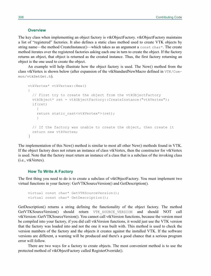
308 Contributing Code
Overview
The key class when implementing an object factory is vtkObjectFactory. vtkObjectFactory maintainsa list of “registered” factories. It also defines a static class method used to create VTK objects bystring name—the method CreateInstance()—which takes as an argument a const char*. The createmethod iterates over the registered factories asking each one in turn to create the object. If the factoryreturns an object, that object is returned as the created instance. Thus, the first factory returning anobject is the one used to create the object.
An example will help illustrate how the object factory is used. The New() method from theclass vtkVertex is shown below (after expansion of the vtkStandardNewMacro defined in VTK/Com-mon/vtkSetGet.h).
vtkVertex* vtkVertex::New() {
// First try to create the object from the vtkObjectFactoryvtkObject* ret = vtkObjectFactory::CreateInstance("vtkVertex"); if(ret) { return static_cast<vtkVertex*>(ret); }
// If the factory was unable to create the object, then create it return new vtkVertex;
}
The implementation of this New() method is similar to most all other New() methods found in VTK.If the object factory does not return an instance of class vtkVertex, then the constructor for vtkVertexis used. Note that the factory must return an instance of a class that is a subclass of the invoking class(i.e., vtkVertex).
How To Write A Factory
The first thing you need to do is to create a subclass of vtkObjectFactory. You must implement twovirtual functions in your factory: GetVTKSourceVersion() and GetDescription().
virtual const char* GetVTKSourceVersion();virtual const char* GetDescription();
GetDescription() returns a string defining the functionality of the object factory. The methodGetVTKSourceVersion() should return VTK_SOURCE_VERSION and should NOT callvtkVersion::GetVTKSourceVersion(). You cannot call vtkVersion functions, because the version mustbe compiled into your factory, if you did call vtkVersion functions, it would just use the VTK versionthat the factory was loaded into and not the one it was built with. This method is used to check theversion numbers of the factory and the objects it creates against the installed VTK. If the softwareversions are different, a warning will be produced and there's a good chance that a serious programerror will follow.
There are two ways for a factory to create objects. The most convenient method is to use theprotected method of vtkObjectFactory called RegisterOverride().
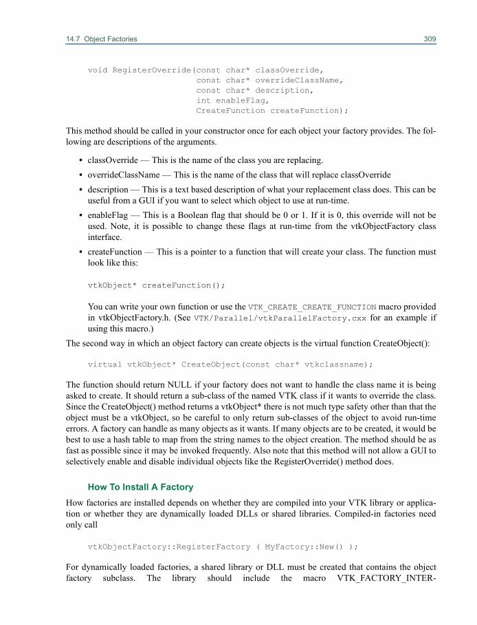
14.7 Object Factories 309
void RegisterOverride(const char* classOverride,const char* overrideClassName,const char* description,int enableFlag,CreateFunction createFunction);
This method should be called in your constructor once for each object your factory provides. The fol-lowing are descriptions of the arguments.
• classOverride — This is the name of the class you are replacing.• overrideClassName — This is the name of the class that will replace classOverride• description — This is a text based description of what your replacement class does. This can be
useful from a GUI if you want to select which object to use at run-time.• enableFlag — This is a Boolean flag that should be 0 or 1. If it is 0, this override will not be
used. Note, it is possible to change these flags at run-time from the vtkObjectFactory classinterface.
• createFunction — This is a pointer to a function that will create your class. The function mustlook like this:
vtkObject* createFunction();
You can write your own function or use the VTK_CREATE_CREATE_FUNCTION macro providedin vtkObjectFactory.h. (See VTK/Parallel/vtkParallelFactory.cxx for an example ifusing this macro.)
The second way in which an object factory can create objects is the virtual function CreateObject():
virtual vtkObject* CreateObject(const char* vtkclassname);
The function should return NULL if your factory does not want to handle the class name it is beingasked to create. It should return a sub-class of the named VTK class if it wants to override the class.Since the CreateObject() method returns a vtkObject* there is not much type safety other than that theobject must be a vtkObject, so be careful to only return sub-classes of the object to avoid run-timeerrors. A factory can handle as many objects as it wants. If many objects are to be created, it would bebest to use a hash table to map from the string names to the object creation. The method should be asfast as possible since it may be invoked frequently. Also note that this method will not allow a GUI toselectively enable and disable individual objects like the RegisterOverride() method does.
How To Install A FactoryHow factories are installed depends on whether they are compiled into your VTK library or applica-tion or whether they are dynamically loaded DLLs or shared libraries. Compiled-in factories needonly call
vtkObjectFactory::RegisterFactory ( MyFactory::New() );
For dynamically loaded factories, a shared library or DLL must be created that contains the objectfactory subclass. The library should include the macro VTK_FACTORY_INTER-
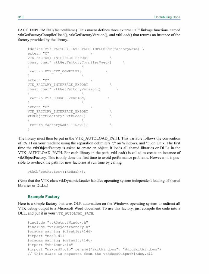
310 Contributing Code
FACE_IMPLEMENT(factoryName). This macro defines three external “C” linkage functions namedvtkGetFactoryCompilerUsed(), vtkGetFactoryVersion(), and vtkLoad() that returns an instance of thefactory provided by the library.
#define VTK_FACTORY_INTERFACE_IMPLEMENT(factoryName) \extern "C" \VTK_FACTORY_INTERFACE_EXPORT \const char* vtkGetFactoryCompilerUsed() \{ \ return VTK_CXX_COMPILER; \} \extern "C" \VTK_FACTORY_INTERFACE_EXPORT \const char* vtkGetFactoryVersion() \{ \ return VTK_SOURCE_VERSION; \} \extern "C" \VTK_FACTORY_INTERFACE_EXPORT \vtkObjectFactory* vtkLoad() \{ \ return factoryName ::New(); \}
The library must then be put in the VTK_AUTOLOAD_PATH. This variable follows the conventionof PATH on your machine using the separation delimiters ";" on Windows, and ":" on Unix. The firsttime the vtkObjectFactory is asked to create an object, it loads all shared libraries or DLLs in theVTK_AUTOLOAD_PATH. For each library in the path, vtkLoad() is called to create an instance ofvtkObjectFactory. This is only done the first time to avoid performance problems. However, it is pos-sible to re-check the path for new factories at run time by calling
vtkObjectFactory::ReHash();
(Note that the VTK class vtkDynamicLoader handles operating system independent loading of sharedlibraries or DLLs.)
Example FactoryHere is a simple factory that uses OLE automation on the Windows operating system to redirect allVTK debug output to a Microsoft Word document. To use this factory, just compile the code into aDLL, and put it in your VTK_AUTOLOAD_PATH.
#include "vtkOutputWindow.h"#include "vtkObjectFactory.h"#pragma warning (disable:4146)#import "mso9.dll"#pragma warning (default:4146)#import "vbe6ext.olb"#import "msword9.olb" rename("ExitWindows", "WordExitWindows")// This class is exported from the vtkWordOutputWindow.dll
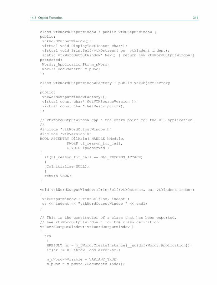
14.7 Object Factories 311
class vtkWordOutputWindow : public vtkOutputWindow {public: vtkWordOutputWindow(); virtual void DisplayText(const char*); virtual void PrintSelf(vtkOstream& os, vtkIndent indent); static vtkWordOutputWindow* New() { return new vtkWordOutputWindow;}protected: Word::_ApplicationPtr m_pWord; Word::_DocumentPtr m_pDoc;};
class vtkWordOutputWindowFactory : public vtkObjectFactory{public: vtkWordOutputWindowFactory(); virtual const char* GetVTKSourceVersion(); virtual const char* GetDescription();};
// vtkWordOutputWindow.cpp : the entry point for the DLL application.//#include "vtkWordOutputWindow.h"#include "vtkVersion.h"BOOL APIENTRY DllMain( HANDLE hModule, DWORD ul_reason_for_call, LPVOID lpReserved ){
if(ul_reason_for_call == DLL_PROCESS_ATTACH) { CoInitialize(NULL); } return TRUE;}
void vtkWordOutputWindow::PrintSelf(vtkOstream& os, vtkIndent indent){ vtkOutputWindow::PrintSelf(os, indent); os << indent << "vtkWordOutputWindow " << endl;}
// This is the constructor of a class that has been exported.// see vtkWordOutputWindow.h for the class definitionvtkWordOutputWindow::vtkWordOutputWindow(){ try { HRESULT hr = m_pWord.CreateInstance(__uuidof(Word::Application)); if(hr != 0) throw _com_error(hr); m_pWord->Visible = VARIANT_TRUE; m_pDoc = m_pWord->Documents->Add();
312 Contributing Code
} catch (_com_error& ComError) { cerr << ComError.ErrorMessage() << endl; }}
void vtkWordOutputWindow::DisplayText(const char* text){ m_pDoc->Content->InsertAfter(text);}
// Use the macro to create a function to return a vtkWordOutputWindowVTK_CREATE_CREATE_FUNCTION(vtkWordOutputWindow);
// Register the one override in the constructor of the factoryvtkWordOutputWindowFactory::vtkWordOutputWindowFactory(){
this->RegisterOverride("vtkOutputWindow", "vtkWordOutputWindow", "OLE Word Window", 1, vtkObjectFactoryCreatevtkWordOutputWindow);}
// Methods to load and insure factory compatibility.VTK_FACTORY_INTERFACE_IMPLEMENT(vtkWordOutputWindowFactory);
// return the version of VTK that the factory was built withconst char* vtkWordOutputWindowFactory::GetVTKSourceVersion(){ return VTK_SOURCE_VERSION;}
// return a text description of the factoryconst char* vtkWordOutputWindowFactory::GetDescription(){ return "vtk debug output to Word via OLE factory";}
14.8 Kitware’s Quality Software ProcessAn outstanding feature of VTK is the software process used to develop, maintain, and test the toolkit.The Visualization Toolkit software continues to evolve rapidly due to the efforts of developers andusers located around the world, so the software process is essential to maintaining its quality. If youare planning to contribute to VTK or to use the CVS source code repository, you need to know some-thing about this process. (See “Obtaining The Software” on page 5.) This information will help youknow when and how to update and work with the software as it changes. The following sectionsdescribe key elements of the process.
14.8 Kitware’s Quality Software Process 313
CVS Source Code Repository
VTK source code, data, and examples are maintained in a source code version control system calledCVS (Concurrent Versions System). The primary purpose of CVS is to keep track of changes to soft-ware. CVS date- and version-stamps every addition to the repository—also providing for specialuser-specified tags—so that it is possible to return to a particular state or point of time wheneverdesired. The differences between any two points is represented by a “diff” file, which is a compact,incremental representation of change. CVS supports concurrent development so that two developerscan edit the same file at the same time; these edits are then (usually) merged together without incident(and marked if there is a conflict). In addition, branches off of the main development trunk provideparallel development of software.
The principal advantage of a system like CVS is that it frees developers to try new ideas andchanges without fear of losing a previous working version of the software. It also provides a simpleway to incrementally update code as new features are added to the repository.
CDash Regression Testing System
One of the unique features of the VTK software process is the CDash regression testing system(http://www.cdash.org). In a nutshell, what CDash does is to provide quantifiable feedback todevelopers as they check in new code and make changes. The feedback consists of the results of avariety of tests, and the results are posted on a publicly-accessible Web page (to which we refer as adashboard as shown in Figure 14–1); VTK’s dashboard is accessible from http://www.cdash.org/CDash/index.php?project=VTK. All users and developers of VTK can viewthe dashboard which produces considerable peer-pressure on developers who check in code withproblems. The Dart dashboard serves as the vehicle for developer communication and should beviewed whenever you consider updating software via CVS.
CDash supports a variety of test types. These include the following.
• Compilation. All source code is compiled and linked. Any resulting errors and warnings arereported.
• Regression. Most VTK tests produce images as output. Testing requires comparing each test’soutput against a valid image. If the images match then the test passes. The comparison must beperformed carefully since many 3D graphics systems (e.g., OpenGL) produce slightly differentresults on different platforms.
• Memory. One of the nastiest of problems to find in any computer program are those related tomemory. Memory leakage, uninitialized memory, and reads and writes beyond allocated spaceare all examples of this sort of problem. VTK checks memory using Purify (a commercial pack-age produced by Rational) or Valgrind (an open-source memory debugger for x86-Linux pro-grams).
• PrintSelf. All classes in VTK are expected to print out all their instance variables correctly.This test checks to make sure that this is the case.
• SetGet. Often developers make assumptions about the values of instance variables; i.e., theyassume that they are non-NULL, etc. The SetGet tests perform a Get on all instance variableswith a Get__() method, followed by a Set method on the instance variable with the valuereturned from the Get__() method. It’s surprising how many times this test identifies problems.
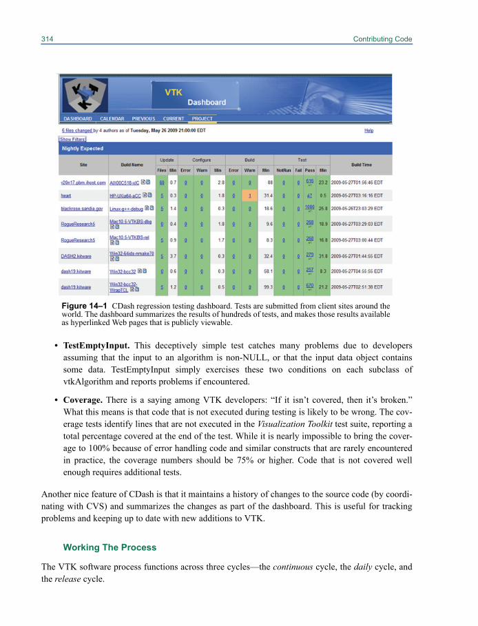
314 Contributing Code
• TestEmptyInput. This deceptively simple test catches many problems due to developersassuming that the input to an algorithm is non-NULL, or that the input data object containssome data. TestEmptyInput simply exercises these two conditions on each subclass ofvtkAlgorithm and reports problems if encountered.
• Coverage. There is a saying among VTK developers: “If it isn’t covered, then it’s broken.”What this means is that code that is not executed during testing is likely to be wrong. The cov-erage tests identify lines that are not executed in the Visualization Toolkit test suite, reporting atotal percentage covered at the end of the test. While it is nearly impossible to bring the cover-age to 100% because of error handling code and similar constructs that are rarely encounteredin practice, the coverage numbers should be 75% or higher. Code that is not covered wellenough requires additional tests.
Another nice feature of CDash is that it maintains a history of changes to the source code (by coordi-nating with CVS) and summarizes the changes as part of the dashboard. This is useful for trackingproblems and keeping up to date with new additions to VTK.
Working The Process
The VTK software process functions across three cycles—the continuous cycle, the daily cycle, andthe release cycle.
Figure 14–1 CDash regression testing dashboard. Tests are submitted from client sites around theworld. The dashboard summarizes the results of hundreds of tests, and makes those results availableas hyperlinked Web pages that is publicly viewable.

14.8 Kitware’s Quality Software Process 315
The continuous cycle revolves aroundthe actions of developers as they check codeinto CVS. When changed or new code ischecked into CVS, the CDash continuoustesting process kicks in. A small number oftests are performed (including compilation),and if something breaks, email is sent to alldevelopers who checked code in during thecontinuous cycle. Developers are expected tofix the problem immediately.
The daily cycle occurs over a 24-hourperiod. Changes to the source base made dur-ing the day are extensively tested by thenightly CDash regression testing sequence.These tests occur on different combinationsof computers and operating systems located around the world, and the results are posted every day tothe CDash dashboard. Developers who checked in code are expected to visit the dashboard andensure their changes are acceptable—that is, they do not introduce compilation errors or warnings orbreak any other tests including regression, memory, print self, and Set/Get. Developers are expectedto fix problems immediately.
The release cycle occurs a small number of times a year. This requires tagging and branchingthe CVS repository, updating documentation, and producing new release packages. Although addi-tional testing is performed to insure the consistency of the package, keeping the daily releases errorfree minimizes the work required to cut a release.
VTK users typically work with releases, since they are the most stable. Developers work withthe CVS repository, or sometimes with periodic snapshots (a particular daily release) in order to takeadvantage of a newly-added feature. It is extremely important that developers watch the dashboardcarefully, and update their software only when the dashboard is in good condition (i.e., is “green”).Failure to do so can cause significant disruption if a particular day’s software release is unstable.
The Effectiveness of the ProcessThe effectiveness of this process is profound. By providing immediate feedback to developersthrough email and Web pages (i.e., the dashboard), the quality of VTK is exceptionally high, espe-cially considering the complexity of the algorithms and system. Errors, when accidently introduced,are caught quickly, as compared to catching them at the point of release. To wait to the point ofrelease is to wait too long, since the causal relationship between a code change or addition and a bugis lost. The process is so powerful that it routinely catches errors in vendor’s graphics drivers (e.g.,OpenGL drivers) or changes to external subsystems such as the Mesa OpenGL software library. Allof these tools that make up the process (CMake, CVS, and CDash are open-source). Many large andsmall systems such as ITK (the Insight Segmentation and Registration Toolkit http://www.itk.org) use the same process with similar results. We encourage the adoption of the processin your environment. (Note: Commercial support, consulting, and training for this process is availablefrom Kitware, Inc. at [email protected].)

Chapter 15
Managing Pipeline Execution 15
The Visualization Toolkit uses a very general executionmechanism. Filters are divided into two basic parts: algorithm and executive objects. An algorithmobject, whose class is derived from vtkAlgorithm, is responsible for processing information and data.An executive object, whose class is derived from vtkExecutive, is responsible for telling an algorithmwhen to execute and what information and data to process. The executive component of a filter maybe created independently of the algorithm component allowing custom pipeline execution mecha-nisms without modifying core VTK classes.
Information and data produced by a filter are stored in one or more output ports. An output portcorresponds to one logical output of the filter. For example, a filter producing a color image and acorresponding binary mask image would define two output ports each holding one of the images.Pipeline-related information is stored in an instance of vtkInformation on each output port. The datafor an output port is stored in an instance of a class derived from vtkDataObject.
Information and data consumed by a filter are retrieved through one or more input ports. Aninput port corresponds to one logical input of the filter. For example, a glyph filter would define oneinput port for the glyph itself and another input port providing the geometry specifying glyph place-ment. Input ports store input connections which reference the output ports of other filters providinginformation and data. Each input connection provides one data object and its corresponding informa-tion obtained from the output port to which the connection is made. Since connections are storedthrough logical ports and not in the data flowing through those ports the data type need not be knownwhen the connection is made. This is particularly useful for creation of pipelines whose source is areader that does not know its output data type until the file is read.
Figure 15–1 depicts the layout of a filter from two viewpoints. The top diagram shows the filteras viewed from the algorithm object. This view of the filter is independent of the pipeline and con-tains all the information about the interface of the algorithm. The second diagram shows the filter asviewed from the executive object. This view of the filter is independent of the details of the algorithmand contains all the information about pipeline connections and the data sent through them.
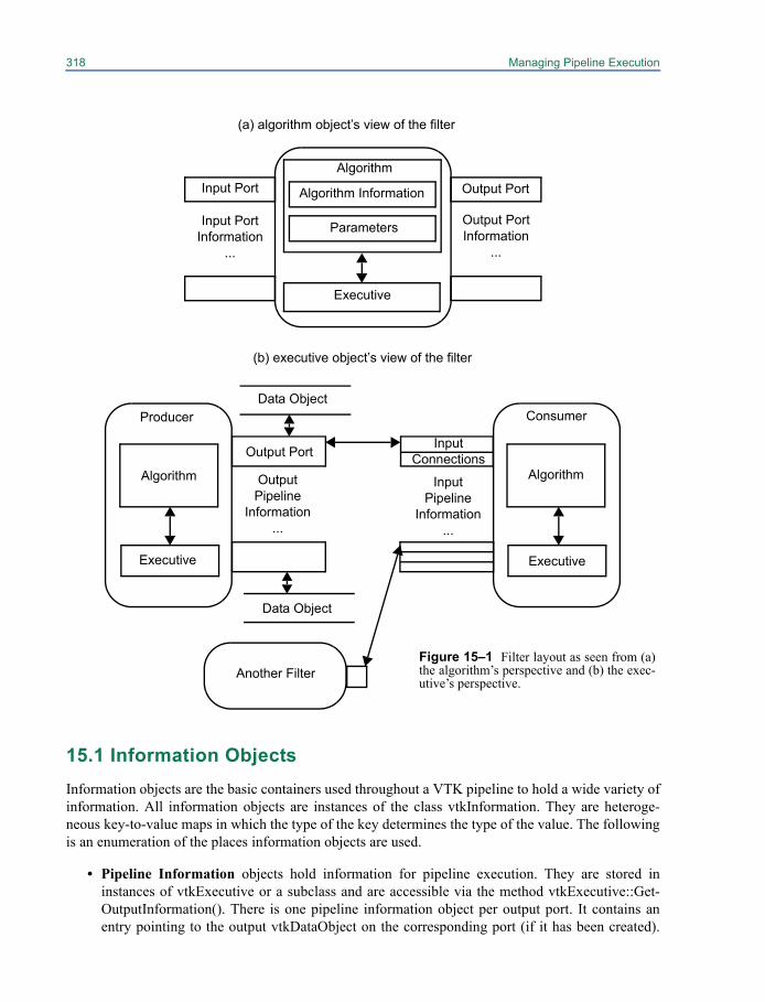
318 Managing Pipeline Execution
15.1 Information ObjectsInformation objects are the basic containers used throughout a VTK pipeline to hold a wide variety ofinformation. All information objects are instances of the class vtkInformation. They are heteroge-neous key-to-value maps in which the type of the key determines the type of the value. The followingis an enumeration of the places information objects are used.
• Pipeline Information objects hold information for pipeline execution. They are stored ininstances of vtkExecutive or a subclass and are accessible via the method vtkExecutive::Get-OutputInformation(). There is one pipeline information object per output port. It contains anentry pointing to the output vtkDataObject on the corresponding port (if it has been created).
Figure 15–1 Filter layout as seen from (a)the algorithm’s perspective and (b) the exec-utive’s perspective.
(a) algorithm object’s view of the filter
(b) executive object’s view of the filter
Input Port Output PortAlgorithm
Algorithm Information
Parameters
Executive
Output Port Information
...
Input Port Information
...
Data Object
Data Object
Output Port
Producer Consumer
Executive Executive
AlgorithmAlgorithm OutputPipeline
Information...
InputPipeline
Information...
InputConnections
Another Filter
15.2 Pipeline Execution Models 319
The vtkDataObject contains a pointer back to its corresponding pipeline information object,accessible via vtkDataObject::GetPipelineInformation(). The pipeline information object alsoholds information about what will populate the data object when the filter executes and gener-ates the output. The actual information contained is determined by the output data type and theexecution model in use. Pipeline information objects for input connections are accessible viathe method vtkExecutive::GetInputInformation(), and they are the pipeline information objectson the output ports to which the input ports are connected.
• Port Information objects hold information about the data types produced on output ports andconsumed by input ports. They are stored by instances of vtkAlgorithm. There is one input portinformation object per input port and one output port information object per output port. Theyare accessible via the methods vtkAlgorithm::GetInputPortInformation() and vtkAlgo-rithm::GetOutputPortInformation(). Port information objects are usually created and populatedby subclasses of vtkAlgorithm in order to specify the interface of the filter.
• Request Information objects hold information about a specific request being sent to an execu-tive or algorithm. There is one entry indicating what request is being sent and possibly otherentries giving additional details about the specific request. These information objects are notaccessible via any public method but are passed to ProcessRequest() methods that implementthe requests.
• Data Information objects hold information about what is currently stored in a vtkDataObject.There is one data information object in each data object, accessible via vtkDataObject::GetIn-formation(). The actual information contained is determined by the data object type.
• Algorithm Information objects hold information about an instance of vtkAlgorithm. There isone algorithm information object per algorithm object, accessible via vtkAlgorithm::GetInfor-mation(). The actual information contained is determined by the algorithm object type.
15.2 Pipeline Execution ModelsThe fundamental pipeline update mechanism is the request. A request is the basic pipeline operation(or "pipeline pass") which generally asks for certain information to be propagated through the pipe-line. An execution model is a set of requests defined by a specific executive.
Requests are generated by the executive object of a filter that has been explicitly asked toupdate by its algorithm due to some user call. For example, when the Write() method of a writer iscalled, the algorithm object asks its executive to update the pipeline, and execute the writer, by callingthis->GetExecutive()->Update(). Several requests may be sent through the pipeline in order to bring itup to date.
A request is implemented as an information object. There is one key of type vtkInformationRe-questKey specifying the request itself. This key is typically defined by the executive's class. Addi-tional information about the request may also be stored in the request information object.
Requests are propagated through the pipeline by the executives of each filter. The vtkExecu-tive::ProcessRequest() method is invoked on an executive and given the request information object.This method is implemented by each executive and is responsible for fulfilling the request as it seesfit. Many requests may be fulfilled for a filter only after it has been fulfilled for the filters providingits inputs. For these requests the executive will pass the request on to the executives of these upstreamfilters and then handle the request itself.
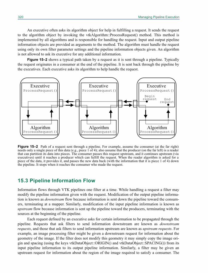
320 Managing Pipeline Execution
An executive often asks its algorithm object for help in fulfilling a request. It sends the requestto the algorithm object by invoking the vtkAlgorithm::ProcessRequest() method. This method isimplemented by all algorithms and is responsible for handling the request. Input and output pipelineinformation objects are provided as arguments to the method. The algorithm must handle the requestusing only its own filter parameter settings and the pipeline information objects given. An algorithmis not allowed to ask its executive for any additional information.
Figure 15–2 shows a typical path taken by a request as it is sent through a pipeline. Typicallythe request originates in a consumer at the end of the pipeline. It is sent back through the pipeline bythe executives. Each executive asks its algorithm to help handle the request.
15.3 Pipeline Information FlowInformation flows through VTK pipelines one filter at a time. While handling a request a filter maymodify the pipeline information given with the request. Modification of the output pipeline informa-tion is known as downstream flow because information is sent down the pipeline toward the consum-ers, terminating at a mapper. Similarly, modification of the input pipeline information is known asupstream flow because information is sent up the pipeline toward the producers, terminating with thesources at the beginning of the pipeline.
Each request defined by an executive asks for certain information to be propagated through thepipeline. Requests that ask filters to send information downstream are known as downstreamrequests, and those that ask filters to send information upstream are known as upstream requests. Forexample, an image processing filter might be given a downstream request for information about thegeometry of the image. If the filter does not modify this geometry it may simply copy the image ori-gin and spacing (using the keys vtkDataObject::ORIGIN() and vtkDataObject::SPACING()) from itsinput pipeline information to its output pipeline information. Similarly, a filter may be given anupstream request for information about the region of the image required to satisfy a consumer. The
ExecutiveProcessRequest()
ProcessRequest()Algorithm
Figure 15–2 Path of a request sent through a pipeline. For example, assume the consumer (at the far right)needs only a single piece of this data (e.g., piece 1 of 4); also assume that the producer (on the far left) is a readerthat can partition its data into pieces. The consumer passes this request upstream, and it continues upstream (viaexecutives) until it reaches a producer which can fulfill the request. When the reader algorithm is asked for apiece of the data, it provides it, and passes the new data back (with the information that it is piece 1 of 4) downthe pipeline. It stops when it reaches the consumer who made the request.
ExecutiveExecutiveProcessRequest() ProcessRequest()
Algorithm AlgorithmProcessRequest() ProcessRequest()
Beginrequest End
request
15.4 Interface of Information Objects 321
filter may simply copy the requested image extent from its output pipeline information to its inputpipeline information or it may change the extent if it needs extra input to complete its computation.
Information about the data being processed by a filter is usually handled by the filter implemen-tation simply because it would not otherwise function. Some algorithms may wish to send additionalinformation through a pipeline. For example, a mapper might decide that it needs information aboutthe number of timesteps available from the source. This mapper can modify the default informationrequest by overriding a virtual method and asking for additional information. This extended request ispropagated to the source without the knowledge of intermediate filters. The source is then free to gen-erate the information and if it does so, the pipeline will propagate it downstream.
15.4 Interface of Information ObjectsThe vtkInformation class provides a heterogeneous key-to-value map. Keys to this map are instancesof the abstract class vtkInformationKey. The address of a key object is used to store and retrieve val-ues in the map, and the type of a key object is used to interpret the values. A key is named by thestatic class method that returns it. An interface for storing and retrieving values with a key is providedby the key itself. For example, consider these information keys defined by vtkDataObject:
vtkInformationStringKey* FIELD_NAME();vtkInformationDoubleVectorKey* ORIGIN();
We can create an vtkInformation instance with which to work.
vtkSmartPointer<vtkInformation> info =vtkSmartPointer<vtkInformation>::New();
FIELD_NAME is a key accessing a value with type "String":
vtkInformationStringKey* FIELD_NAME = vtkDataObject::FIELD_NAME();FIELD_NAME->Has(info); // returns 0FIELD_NAME->Set(info, "ABC"); // sets info{FIELD_NAME} to "ABC"FIELD_NAME->Has(info); // returns 1FIELD_NAME->Get(info); // returns a pointer to "ABC"FIELD_NAME->Remove(info); // removes info{FIELD_NAME}FIELD_NAME->Has(info); // returns 0
ORIGIN is a key accessing a value with type "DoubleVector":
double origin[3] = {1,2,3};vtkInformationDoubleVectorKey* ORIGIN = vtkDataObject::ORIGIN();ORIGIN->Has(info); // returns 0ORIGIN->Set(info, origin, 3); // sets info{ORIGIN} to {1,2,3}ORIGIN->Has(info); // returns 1ORIGIN->Get(info); // returns a pointer to {1,2,3}ORIGIN->Get(info, origin); // stores {1,2,3} in originORIGIN->Length(info); // returns 3ORIGIN->Remove(info); // removes info{ORIGIN}ORIGIN->Has(info); // returns 0
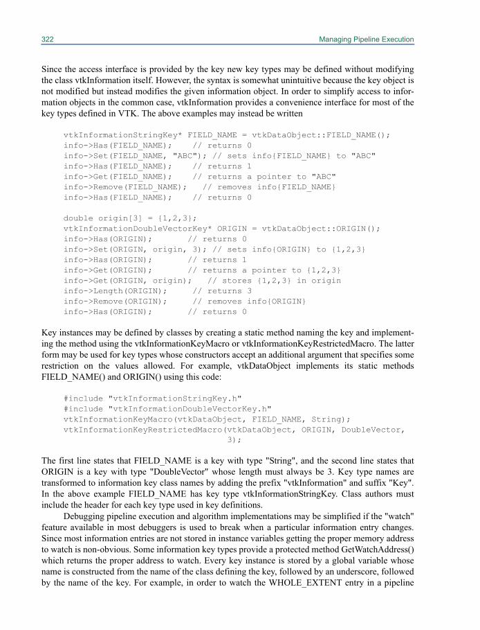
322 Managing Pipeline Execution
Since the access interface is provided by the key new key types may be defined without modifyingthe class vtkInformation itself. However, the syntax is somewhat unintuitive because the key object isnot modified but instead modifies the given information object. In order to simplify access to infor-mation objects in the common case, vtkInformation provides a convenience interface for most of thekey types defined in VTK. The above examples may instead be written
vtkInformationStringKey* FIELD_NAME = vtkDataObject::FIELD_NAME();info->Has(FIELD_NAME); // returns 0info->Set(FIELD_NAME, "ABC"); // sets info{FIELD_NAME} to "ABC"info->Has(FIELD_NAME); // returns 1info->Get(FIELD_NAME); // returns a pointer to "ABC"info->Remove(FIELD_NAME); // removes info{FIELD_NAME}info->Has(FIELD_NAME); // returns 0
double origin[3] = {1,2,3};vtkInformationDoubleVectorKey* ORIGIN = vtkDataObject::ORIGIN();info->Has(ORIGIN); // returns 0info->Set(ORIGIN, origin, 3); // sets info{ORIGIN} to {1,2,3}info->Has(ORIGIN); // returns 1info->Get(ORIGIN); // returns a pointer to {1,2,3}info->Get(ORIGIN, origin); // stores {1,2,3} in origininfo->Length(ORIGIN); // returns 3info->Remove(ORIGIN); // removes info{ORIGIN}info->Has(ORIGIN); // returns 0
Key instances may be defined by classes by creating a static method naming the key and implement-ing the method using the vtkInformationKeyMacro or vtkInformationKeyRestrictedMacro. The latterform may be used for key types whose constructors accept an additional argument that specifies somerestriction on the values allowed. For example, vtkDataObject implements its static methodsFIELD_NAME() and ORIGIN() using this code:
#include "vtkInformationStringKey.h"#include "vtkInformationDoubleVectorKey.h"vtkInformationKeyMacro(vtkDataObject, FIELD_NAME, String);vtkInformationKeyRestrictedMacro(vtkDataObject, ORIGIN, DoubleVector,
3);
The first line states that FIELD_NAME is a key with type "String", and the second line states thatORIGIN is a key with type "DoubleVector" whose length must always be 3. Key type names aretransformed to information key class names by adding the prefix "vtkInformation" and suffix "Key".In the above example FIELD_NAME has key type vtkInformationStringKey. Class authors mustinclude the header for each key type used in key definitions.
Debugging pipeline execution and algorithm implementations may be simplified if the "watch"feature available in most debuggers is used to break when a particular information entry changes.Since most information entries are not stored in instance variables getting the proper memory addressto watch is non-obvious. Some information key types provide a protected method GetWatchAddress()which returns the proper address to watch. Every key instance is stored by a global variable whosename is constructed from the name of the class defining the key, followed by an underscore, followedby the name of the key. For example, in order to watch the WHOLE_EXTENT entry in a pipeline
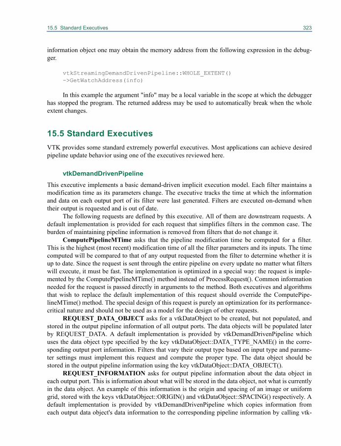
15.5 Standard Executives 323
information object one may obtain the memory address from the following expression in the debug-ger.
vtkStreamingDemandDrivenPipeline::WHOLE_EXTENT()->GetWatchAddress(info)
In this example the argument "info" may be a local variable in the scope at which the debuggerhas stopped the program. The returned address may be used to automatically break when the wholeextent changes.
15.5 Standard ExecutivesVTK provides some standard extremely powerful executives. Most applications can achieve desiredpipeline update behavior using one of the executives reviewed here.
vtkDemandDrivenPipelineThis executive implements a basic demand-driven implicit execution model. Each filter maintains amodification time as its parameters change. The executive tracks the time at which the informationand data on each output port of its filter were last generated. Filters are executed on-demand whentheir output is requested and is out of date.
The following requests are defined by this executive. All of them are downstream requests. Adefault implementation is provided for each request that simplifies filters in the common case. Theburden of maintaining pipeline information is removed from filters that do not change it.
ComputePipelineMTime asks that the pipeline modification time be computed for a filter.This is the highest (most recent) modification time of all the filter parameters and its inputs. The timecomputed will be compared to that of any output requested from the filter to determine whether it isup to date. Since the request is sent through the entire pipeline on every update no matter what filterswill execute, it must be fast. The implementation is optimized in a special way: the request is imple-mented by the ComputePipelineMTime() method instead of ProcessRequest(). Common informationneeded for the request is passed directly in arguments to the method. Both executives and algorithmsthat wish to replace the default implementation of this request should override the ComputePipe-lineMTime() method. The special design of this request is purely an optimization for its performance-critical nature and should not be used as a model for the design of other requests.
REQUEST_DATA_OBJECT asks for a vtkDataObject to be created, but not populated, andstored in the output pipeline information of all output ports. The data objects will be populated laterby REQUEST_DATA. A default implementation is provided by vtkDemandDrivenPipeline whichuses the data object type specified by the key vtkDataObject::DATA_TYPE_NAME() in the corre-sponding output port information. Filters that vary their output type based on input type and parame-ter settings must implement this request and compute the proper type. The data object should bestored in the output pipeline information using the key vtkDataObject::DATA_OBJECT().
REQUEST_INFORMATION asks for output pipeline information about the data object ineach output port. This is information about what will be stored in the data object, not what is currentlyin the data object. An example of this information is the origin and spacing of an image or uniformgrid, stored with the keys vtkDataObject::ORIGIN() and vtkDataObject::SPACING() respectively. Adefault implementation is provided by vtkDemandDrivenPipeline which copies information fromeach output data object's data information to the corresponding pipeline information by calling vtk-

324 Managing Pipeline Execution
DataObject::CopyInformationToPipeline(). Then if any input connection exists information is copiedfrom the first connection to each output pipeline information object. Sources that have no input or fil-ters that change this information from that in the input must implement this request to compute theproper information.
REQUEST_DATA asks for the output data object to be populated with the actual output dataon the output port through which the request arrived. This output port number is given by the keyvtkExecutive::FROM_OUTPUT_PORT() in the request information object. The data object in theoutput port given in the request must be populated, but data objects in other output ports may option-ally be populated also. (Most filters always populate all outputs.) When processing aREQUEST_DATA the vtkDemandDrivenPipeline proceeds with the following steps.
• Send a vtkDemandDrivenPipeline::REQUEST_DATA_NOT_GENERATED() request to thealgorithm part of the filter. The request contains all the information in the originalREQUEST_DATA, including the vtkExecutive::FROM_OUTPUT_PORT() key. Filters that donot always populate all outputs must implement this request to store a vtkDemandDrivenPipe-line::DATA_NOT_GENERATED() with value 1 in the pipeline information of all output portswhose data will not be populated. This tells the executive that those outputs will not be gener-ated by this REQUEST_DATA. Most filters can ignore this request.
• For output ports whose pipeline information does not contain the vtkDemandDrivenPipe-line::DATA_NOT_GENERATED() mark, the output data objects are initialized by calling vtk-DataObject::PrepareForNewData. These objects were previously created by aREQUEST_DATA_OBJECT and are re-initialized to an empty state by this step. Pipelineinformation that was previously set by a REQUEST_INFORMATION and corresponding toeach data object is copied to the objects' data information by calling vtkDataObject::CopyInfor-mationFromPipeline.
• Invoke the StartEvent on the algorithm object, clear the AbortExecute flag, and update theprogress to 0.
• Send REQUEST_DATA to the algorithm. All algorithms must implement this request to popu-late the data objects in output pipeline information for ports not marked by vtkDemandDriven-Pipeline::DATA_NOT_GENERATED().
• Update the progress to 1 if the AbortExecute flag is not set and then always invoke the EndE-vent on the algorithm object.
• For output ports whose pipeline information does not contain the vtkDemandDrivenPipe-line::DATA_NOT_GENERATED() mark, the output data objects are marked as generated bycalling vtkDataObject::DataHasBeenGenerated().
• Remove vtkDemandDrivenPipeline::DATA_NOT_GENERATED() marks from all outputpipeline information.
• For any input connections whose pipeline information contains a vtkDemandDrivenPipe-line::RELEASE_DATA() mark, data are released by calling vtkDataObject::ReleaseData().
This default sequence of events handles most of the pipeline-related part of filter execution. The algo-rithm implementation needs only to process the actual data and compute information about the datathat it is changing from input to output.
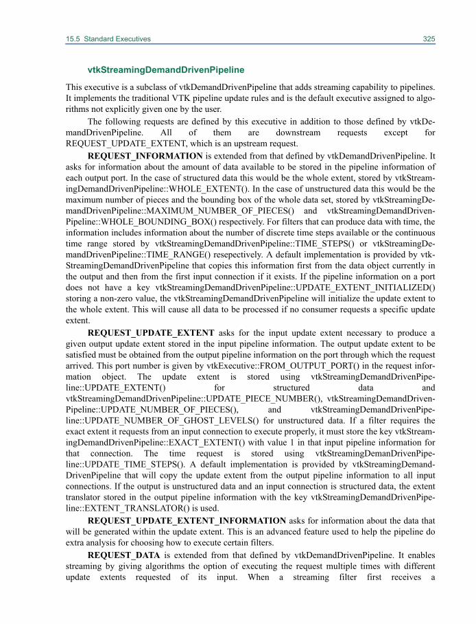
15.5 Standard Executives 325
vtkStreamingDemandDrivenPipeline
This executive is a subclass of vtkDemandDrivenPipeline that adds streaming capability to pipelines.It implements the traditional VTK pipeline update rules and is the default executive assigned to algo-rithms not explicitly given one by the user.
The following requests are defined by this executive in addition to those defined by vtkDe-mandDrivenPipeline. All of them are downstream requests except forREQUEST_UPDATE_EXTENT, which is an upstream request.
REQUEST_INFORMATION is extended from that defined by vtkDemandDrivenPipeline. Itasks for information about the amount of data available to be stored in the pipeline information ofeach output port. In the case of structured data this would be the whole extent, stored by vtkStream-ingDemandDrivenPipeline::WHOLE_EXTENT(). In the case of unstructured data this would be themaximum number of pieces and the bounding box of the whole data set, stored by vtkStreamingDe-mandDrivenPipeline::MAXIMUM_NUMBER_OF_PIECES() and vtkStreamingDemandDriven-Pipeline::WHOLE_BOUNDING_BOX() respectively. For filters that can produce data with time, theinformation includes information about the number of discrete time steps available or the continuoustime range stored by vtkStreamingDemandDrivenPipeline::TIME_STEPS() or vtkStreamingDe-mandDrivenPipeline::TIME_RANGE() resepectively. A default implementation is provided by vtk-StreamingDemandDrivenPipeline that copies this information first from the data object currently inthe output and then from the first input connection if it exists. If the pipeline information on a portdoes not have a key vtkStreamingDemandDrivenPipeline::UPDATE_EXTENT_INITIALIZED()storing a non-zero value, the vtkStreamingDemandDrivenPipeline will initialize the update extent tothe whole extent. This will cause all data to be processed if no consumer requests a specific updateextent.
REQUEST_UPDATE_EXTENT asks for the input update extent necessary to produce agiven output update extent stored in the input pipeline information. The output update extent to besatisfied must be obtained from the output pipeline information on the port through which the requestarrived. This port number is given by vtkExecutive::FROM_OUTPUT_PORT() in the request infor-mation object. The update extent is stored using vtkStreamingDemandDrivenPipe-line::UPDATE_EXTENT() for structured data andvtkStreamingDemandDrivenPipeline::UPDATE_PIECE_NUMBER(), vtkStreamingDemandDriven-Pipeline::UPDATE_NUMBER_OF_PIECES(), and vtkStreamingDemandDrivenPipe-line::UPDATE_NUMBER_OF_GHOST_LEVELS() for unstructured data. If a filter requires theexact extent it requests from an input connection to execute properly, it must store the key vtkStream-ingDemandDrivenPipeline::EXACT_EXTENT() with value 1 in that input pipeline information forthat connection. The time request is stored using vtkStreamingDemanDrivenPipe-line::UPDATE_TIME_STEPS(). A default implementation is provided by vtkStreamingDemand-DrivenPipeline that will copy the update extent from the output pipeline information to all inputconnections. If the output is unstructured data and an input connection is structured data, the extenttranslator stored in the output pipeline information with the key vtkStreamingDemandDrivenPipe-line::EXTENT_TRANSLATOR() is used.
REQUEST_UPDATE_EXTENT_INFORMATION asks for information about the data thatwill be generated within the update extent. This is an advanced feature used to help the pipeline doextra analysis for choosing how to execute certain filters.
REQUEST_DATA is extended from that defined by vtkDemandDrivenPipeline. It enablesstreaming by giving algorithms the option of executing the request multiple times with differentupdate extents requested of its input. When a streaming filter first receives a
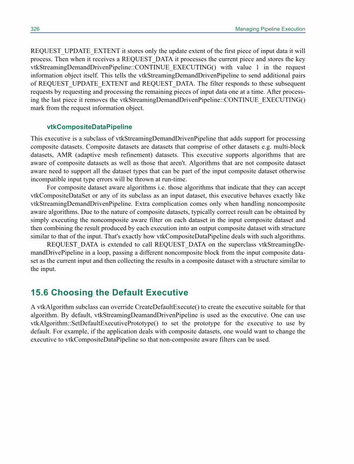
326 Managing Pipeline Execution
REQUEST_UPDATE_EXTENT it stores only the update extent of the first piece of input data it willprocess. Then when it receives a REQUEST_DATA it processes the current piece and stores the keyvtkStreamingDemandDrivenPipeline::CONTINUE_EXECUTING() with value 1 in the requestinformation object itself. This tells the vtkStreamingDemandDrivenPipeline to send additional pairsof REQUEST_UPDATE_EXTENT and REQUEST_DATA. The filter responds to these subsequentrequests by requesting and processing the remaining pieces of input data one at a time. After process-ing the last piece it removes the vtkStreamingDemandDrivenPipeline::CONTINUE_EXECUTING()mark from the request information object.
vtkCompositeDataPipelineThis executive is a subclass of vtkStreamingDemandDrivenPipeline that adds support for processingcomposite datasets. Composite datasets are datasets that comprise of other datasets e.g. multi-blockdatasets, AMR (adaptive mesh refinement) datasets. This executive supports algorithms that areaware of composite datasets as well as those that aren't. Algorithms that are not composite datasetaware need to support all the dataset types that can be part of the input composite dataset otherwiseincompatible input type errors will be thrown at run-time.
For composite dataset aware algorithms i.e. those algorithms that indicate that they can acceptvtkCompositeDataSet or any of its subclass as an input dataset, this executive behaves exactly likevtkStreamingDemandDrivenPipeline. Extra complication comes only when handling noncompositeaware algorithms. Due to the nature of composite datasets, typically correct result can be obtained bysimply executing the noncomposite aware filter on each dataset in the input composite dataset andthen combining the result produced by each execution into an output composite dataset with structuresimilar to that of the input. That's exactly how vtkCompositeDataPipeline deals with such algorithms.
REQUEST_DATA is extended to call REQUEST_DATA on the superclass vtkStreamingDe-mandDrivePipeline in a loop, passing a different noncomposite block from the input composite data-set as the current input and then collecting the results in a composite dataset with a structure similar tothe input.
15.6 Choosing the Default ExecutiveA vtkAlgorithm subclass can override CreateDefaultExecute() to create the executive suitable for thatalgorithm. By default, vtkStreamingDeamandDrivenPipeline is used as the executive. One can usevtkAlgorithm::SetDefaultExecutivePrototype() to set the prototype for the executive to use bydefault. For example, if the application deals with composite datasets, one would want to change theexecutive to vtkCompositeDataPipeline so that non-composite aware filters can be used.
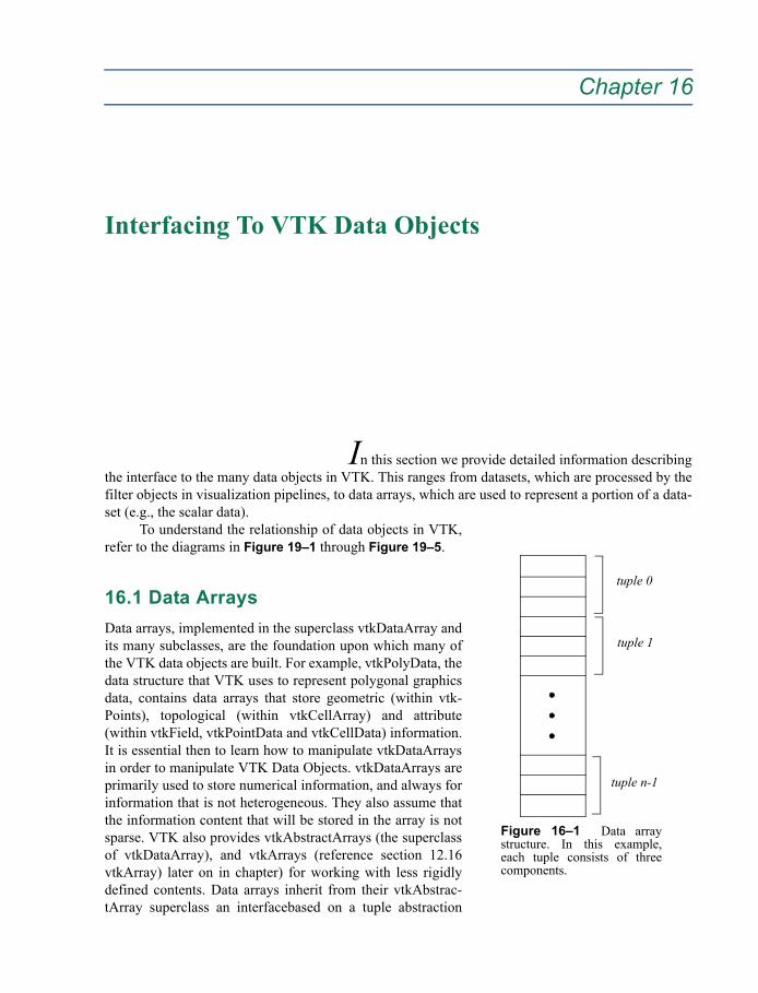
Chapter 16
Interfacing To VTK Data Objects 16
In this section we provide detailed information describingthe interface to the many data objects in VTK. This ranges from datasets, which are processed by thefilter objects in visualization pipelines, to data arrays, which are used to represent a portion of a data-set (e.g., the scalar data).
To understand the relationship of data objects in VTK,refer to the diagrams in Figure 19–1 through Figure 19–5.
16.1 Data ArraysData arrays, implemented in the superclass vtkDataArray andits many subclasses, are the foundation upon which many ofthe VTK data objects are built. For example, vtkPolyData, thedata structure that VTK uses to represent polygonal graphicsdata, contains data arrays that store geometric (within vtk-Points), topological (within vtkCellArray) and attribute(within vtkField, vtkPointData and vtkCellData) information.It is essential then to learn how to manipulate vtkDataArraysin order to manipulate VTK Data Objects. vtkDataArrays areprimarily used to store numerical information, and always forinformation that is not heterogeneous. They also assume thatthe information content that will be stored in the array is notsparse. VTK also provides vtkAbstractArrays (the superclassof vtkDataArray), and vtkArrays (reference section 12.16vtkArray) later on in chapter) for working with less rigidlydefined contents. Data arrays inherit from their vtkAbstrac-tArray superclass an interfacebased on a tuple abstraction
Figure 16–1 Data arraystructure. In this example,each tuple consists of threecomponents.
tuple 0
tuple 1
tuple n-1
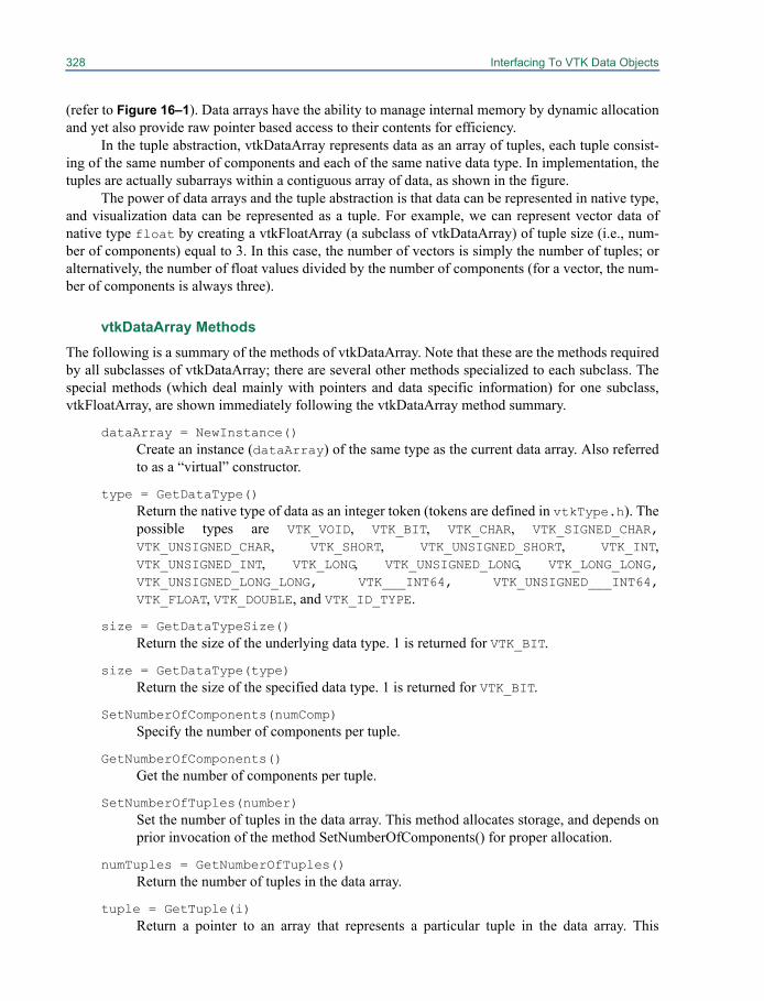
328 Interfacing To VTK Data Objects
(refer to Figure 16–1). Data arrays have the ability to manage internal memory by dynamic allocationand yet also provide raw pointer based access to their contents for efficiency.
In the tuple abstraction, vtkDataArray represents data as an array of tuples, each tuple consist-ing of the same number of components and each of the same native data type. In implementation, thetuples are actually subarrays within a contiguous array of data, as shown in the figure.
The power of data arrays and the tuple abstraction is that data can be represented in native type,and visualization data can be represented as a tuple. For example, we can represent vector data ofnative type float by creating a vtkFloatArray (a subclass of vtkDataArray) of tuple size (i.e., num-ber of components) equal to 3. In this case, the number of vectors is simply the number of tuples; oralternatively, the number of float values divided by the number of components (for a vector, the num-ber of components is always three).
vtkDataArray MethodsThe following is a summary of the methods of vtkDataArray. Note that these are the methods requiredby all subclasses of vtkDataArray; there are several other methods specialized to each subclass. Thespecial methods (which deal mainly with pointers and data specific information) for one subclass,vtkFloatArray, are shown immediately following the vtkDataArray method summary.
dataArray = NewInstance()Create an instance (dataArray) of the same type as the current data array. Also referredto as a “virtual” constructor.
type = GetDataType()Return the native type of data as an integer token (tokens are defined in vtkType.h). Thepossible types are VTK_VOID, VTK_BIT, VTK_CHAR, VTK_SIGNED_CHAR,VTK_UNSIGNED_CHAR, VTK_SHORT, VTK_UNSIGNED_SHORT, VTK_INT,VTK_UNSIGNED_INT, VTK_LONG, VTK_UNSIGNED_LONG, VTK_LONG_LONG,VTK_UNSIGNED_LONG_LONG, VTK___INT64, VTK_UNSIGNED___INT64,VTK_FLOAT, VTK_DOUBLE, and VTK_ID_TYPE.
size = GetDataTypeSize()Return the size of the underlying data type. 1 is returned for VTK_BIT.
size = GetDataType(type)Return the size of the specified data type. 1 is returned for VTK_BIT.
SetNumberOfComponents(numComp)Specify the number of components per tuple.
GetNumberOfComponents()Get the number of components per tuple.
SetNumberOfTuples(number)Set the number of tuples in the data array. This method allocates storage, and depends onprior invocation of the method SetNumberOfComponents() for proper allocation.
numTuples = GetNumberOfTuples()Return the number of tuples in the data array.
tuple = GetTuple(i)Return a pointer to an array that represents a particular tuple in the data array. This
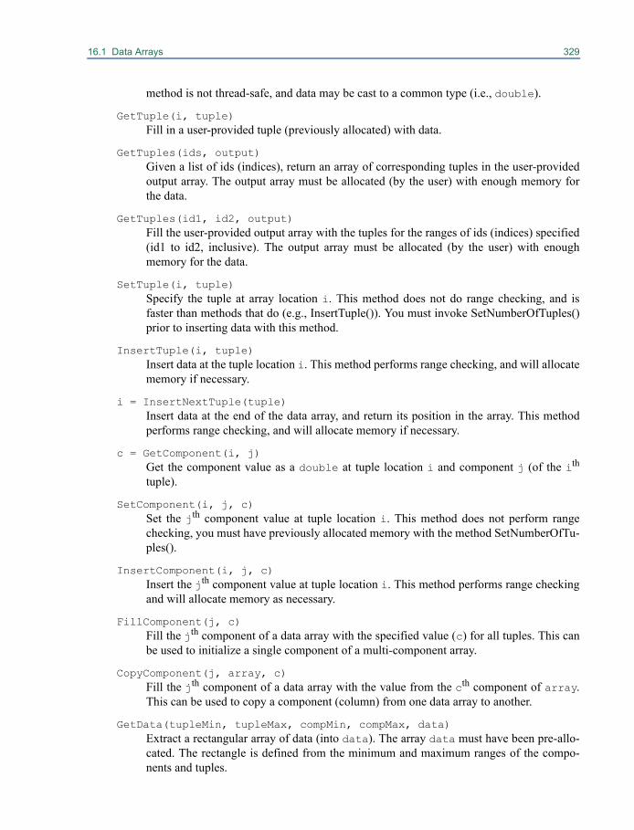
16.1 Data Arrays 329
method is not thread-safe, and data may be cast to a common type (i.e., double).
GetTuple(i, tuple)Fill in a user-provided tuple (previously allocated) with data.
GetTuples(ids, output)Given a list of ids (indices), return an array of corresponding tuples in the user-providedoutput array. The output array must be allocated (by the user) with enough memory forthe data.
GetTuples(id1, id2, output)Fill the user-provided output array with the tuples for the ranges of ids (indices) specified(id1 to id2, inclusive). The output array must be allocated (by the user) with enoughmemory for the data.
SetTuple(i, tuple)Specify the tuple at array location i. This method does not do range checking, and isfaster than methods that do (e.g., InsertTuple()). You must invoke SetNumberOfTuples()prior to inserting data with this method.
InsertTuple(i, tuple)Insert data at the tuple location i. This method performs range checking, and will allocatememory if necessary.
i = InsertNextTuple(tuple)Insert data at the end of the data array, and return its position in the array. This methodperforms range checking, and will allocate memory if necessary.
c = GetComponent(i, j)Get the component value as a double at tuple location i and component j (of the ith
tuple).
SetComponent(i, j, c)Set the jth component value at tuple location i. This method does not perform rangechecking, you must have previously allocated memory with the method SetNumberOfTu-ples().
InsertComponent(i, j, c)Insert the jth component value at tuple location i. This method performs range checkingand will allocate memory as necessary.
FillComponent(j, c)Fill the jth component of a data array with the specified value (c) for all tuples. This canbe used to initialize a single component of a multi-component array.
CopyComponent(j, array, c)Fill the jth component of a data array with the value from the cth component of array.This can be used to copy a component (column) from one data array to another.
GetData(tupleMin, tupleMax, compMin, compMax, data)Extract a rectangular array of data (into data). The array data must have been pre-allo-cated. The rectangle is defined from the minimum and maximum ranges of the compo-nents and tuples.
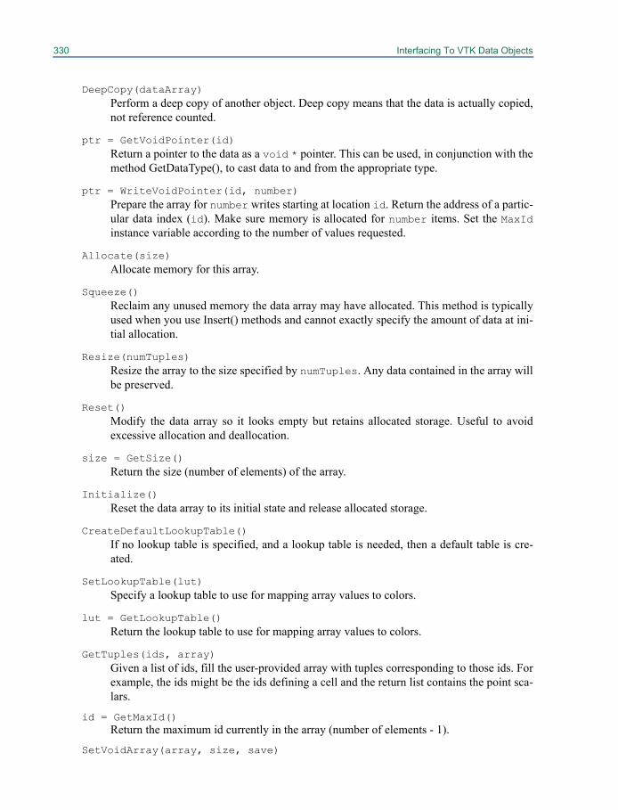
330 Interfacing To VTK Data Objects
DeepCopy(dataArray)Perform a deep copy of another object. Deep copy means that the data is actually copied,not reference counted.
ptr = GetVoidPointer(id)Return a pointer to the data as a void * pointer. This can be used, in conjunction with themethod GetDataType(), to cast data to and from the appropriate type.
ptr = WriteVoidPointer(id, number)Prepare the array for number writes starting at location id. Return the address of a partic-ular data index (id). Make sure memory is allocated for number items. Set the MaxIdinstance variable according to the number of values requested.
Allocate(size)Allocate memory for this array.
Squeeze()Reclaim any unused memory the data array may have allocated. This method is typicallyused when you use Insert() methods and cannot exactly specify the amount of data at ini-tial allocation.
Resize(numTuples)Resize the array to the size specified by numTuples. Any data contained in the array willbe preserved.
Reset()Modify the data array so it looks empty but retains allocated storage. Useful to avoidexcessive allocation and deallocation.
size = GetSize()Return the size (number of elements) of the array.
Initialize()Reset the data array to its initial state and release allocated storage.
CreateDefaultLookupTable()If no lookup table is specified, and a lookup table is needed, then a default table is cre-ated.
SetLookupTable(lut)Specify a lookup table to use for mapping array values to colors.
lut = GetLookupTable()Return the lookup table to use for mapping array values to colors.
GetTuples(ids, array)Given a list of ids, fill the user-provided array with tuples corresponding to those ids. Forexample, the ids might be the ids defining a cell and the return list contains the point sca-lars.
id = GetMaxId()Return the maximum id currently in the array (number of elements - 1).
SetVoidArray(array, size, save)
16.1 Data Arrays 331
Directly set the data array (specified as a void*) from an outside source. This method isuseful when you are interfacing to data and want to pass the data into VTK's pipeline. Thesave flag indicates whether the array passed in should be deleted when the data array isdestructed. A value of 1 indicates that VTK should not delete the data array when it isdone using it.
ExportToVoidPointer(ptr)Copy the data array to the void pointer specified by the user. It is the user's responsibilityto allocate enough memory for the void pointer.
sz = GetActualMemorySize()Return the memory (in kilobytes) used by this data array.
SetName(name)Specify a name for the data array.
name = GetName()Return the name of the data array.
ComputeRange(comp)Determine the range of values contained in the specified component (comp) of the dataarray.
range = GetRange(i)Return the range (min,max) of the ith component. This method is not thread safe.
GetRange(range, i)Fill in the minimum/maximum values of the ith component in a user-provided array.
range = GetRange()Return the range (min, max) of the 0th component. This method is not thread safe.
GetRange(range)Fill in the minimum/maximum values of the 0th component in a user-provided array.
GetDataTypeRange(range)Fill in the minimum/maximum values that can be specified using the underlying datatype.
GetDataTypeRange(type, range)Fill in the minimum/maximum values that can be specified using the data type indicatedby type.
min = GetDataTypeMin()Return the minimum value that can be specified using the underlying data type.
min = GetDataTypeMin(type)Return the minimum value that can be specified using the data type indicated by type.
max = GetDataTypeMax()Return the maximum value that can be specified using the underlyingdata type.
max = GetDataTypeMax(type)Return the maximum value that can be specified using the data type indicated by type.
norm = GetMaxNorm()Return the maximum norm value over all the tuples. This value is computed each timeGetMaxNorm() is called.
332 Interfacing To VTK Data Objects
array = CreateDataArray(type)Create an array of the specified data type. The user is responsible for deleting the dataarray returned.
The following methods are from vtkFloatArray, which is a subclass of vtkDataArray. Note that thereis overlap between the functionality available from the superclass vtkDataArray and its concrete sub-classes. The is because the superclass provides some generic functionality useful for quick/compactcoding, while the subclasses let you get at the data directly, which can be manipulated via pointermanipulation and/or templated functions.
v = GetValue(i)Return the value at the ith data location in the array.
SetNumberOfValues(number)Set the number of values in the array. This method performs memory allocation.
SetValue(i, value)Set the value at the ith data location in the array. This method requires prior invocation ofSetNumberOfValues() or WritePointer(). The method is faster than the insertion methodsbecause no range checking is performed.
InsertValue(i, f)Insert the value at the ith data location in the array. This method perform range checkingand allocates memory as necessary.
id = InsertNextValue(f)Insert the value f at the end of the data array, and return its position in the array. Thismethod performs range checking, and will allocate memory if necessary.
void GetTupleValue(i, tuple)Copy the ith tuple into the user-provided array.
SetTupleValue(i, tuple)Set the tuple at the ith position in the data array.
InsertTupleValue(i, tuple)Insert the tuple into the ith position in the data array. Memory allocation is performed ifnecessary.
InsertNextTupleValue(tuple)Insert the tuple at the end of the data array. Memory allocation is performed if necessary.
ptr = GetPointer(i)Return the pointer to the data array. The pointer is returned from the ith data location(usually i=0 and the method returns the pointer at the beginning of the array).
ptr = WritePointer(i, number)Allocate memory and prepare the array for number direct writes starting at data locationi. A pointer to the data starting at location i is returned.
SetArray(array, size, save)Directly set the data array from an outside source. This method is useful when you areinterfacing to data and want to pass the data into VTK’s pipeline. The save flag indicateswhether the array passed in should be deleted when the data array is destructed. A value
16.2 Datasets 333
of one indicates that VTK should not delete the data array when it is done using it.
16.2 DatasetsOften times the hardest part about writing a filter is interfacing to the VTK data objects. Chances arethat as a filter developer, you are intimately familiar with the algorithm. It’s learning how to manipu-late VTK datasets—reading the input and creating the output—that is the key to writing an efficient,robust, and useful filter. Probably the single most important step in learning how to manipulate datas-ets is understanding the data model. Figure 16–2 summarizes the dataset types in VTK. If you’re notfamiliar with these objects, you’ll want to read The Visualization Toolkit text, and/or spend some timereading the code to understand the data model. The following paragraphs highlight some of theimportant features of the data model.
One important aspect of VTK's data model is the relationship between the structure and thedata attributes of a dataset. vtkDataSet is a subclass of vtkDataObject. The difference between thetwo classes is that data objects represent completely arbitrary data (see the “The Visualization Pipe-line” on page 25) and datasets represent data that has an inherent spatial structure. Several vtkDataO-bject types that are not vtkDataSet including vtkSelection, vtkGraph, and vtkTable are described laterin this chapter. The dataset structure then describes the geometric and topological relationship ofpoints and cells to one another. When we refer to dataset type, we are actually referring to the struc-ture of the data, that is how the geometry and topology is defined, stored and manipulated.
This spatial structure is the framework to which the dataset attributes are attached. Whereas avtkDataObject will contain information in one instance of vtkFieldData, vtkDataSet has threeinstances. One for data set wide, general purpose information, one for values that are associated witheach point and the last for values that are associated with each cell. These point and cell associatedvalues are called dataset attributes and store information such as scalars, vectors, tensors, normals,texture coordinates, and ids. Regardless of the type of dataset, these topologically and geometricallyassociated data attributes are created and manipulated in the same way.
Another important feature of VTK’s data model is the relationship of datasets to cells, andwhether cells are represented implicitly or explicitly. Cells can be thought of as the atoms that form adataset. Cells are a topological organization of the dataset points (x-y-z positions) into an ordered list,or connectivity array. For example, in a polygonal dataset (vtkPolyData), the polygons are the cells ofthe dataset, and each polygonal cell is represented as an ordered list of points (i.e., the vertices of thepolygon). Some datasets represent points and cells explicitly (e.g., a list of points and cells in vtk-PolyData), while others represent the points and cells implicitly (e.g., an image represented in vtkIm-ageData by its dimensions, spacing, and origin). Implicit representation means that we do notexplicitly store point coordinates or cell connectivity. Instead, this information is derived as neces-sary. You may wish to refer to Figure 19–20 to view the cell types found in VTK.
Assuming that you have a thorough understanding of VTK’s data model, you’ll need to knowhow to get data from the datasets, and how to create and put data into the datasets. These activities aredependent on the type of dataset—different datasets have different preferred ways to interface tothem. Also, datasets can be accessed at different levels of abstraction corresponding to the inheritancehierarchy. For example, to get the coordinates of a point in a vtkPolyData, we can invoke the super-class method vtkDataSet::GetPoint(), or we can retrieve the points array in vtkPolyData withpts=vtkPolyData::GetPoints(), followed by access to the point coordinates via pts->GetPoint(). Bothapproaches are valid, and both are used, depending on the circumstances. As a filter writer, you’llhave to determine the correct level of abstraction by which to interface with the datasets.
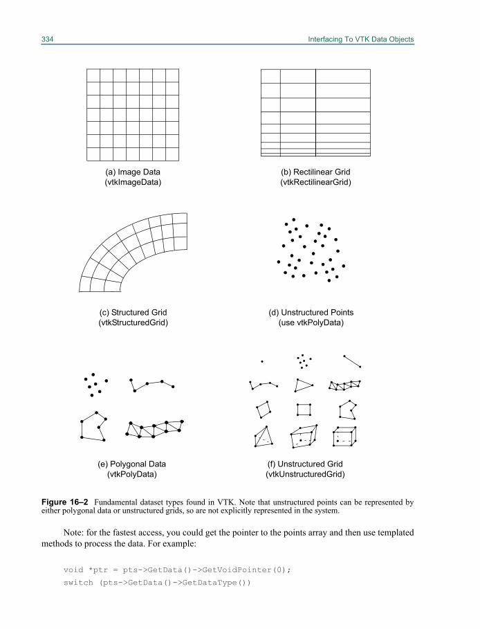
334 Interfacing To VTK Data Objects
Note: for the fastest access, you could get the pointer to the points array and then use templatedmethods to process the data. For example:
void *ptr = pts->GetData()->GetVoidPointer(0);
switch (pts->GetData()->GetDataType())
(a) Image Data(vtkImageData)
(e) Polygonal Data(vtkPolyData)
(c) Structured Grid(vtkStructuredGrid)
(f) Unstructured Grid(vtkUnstructuredGrid)
(b) Rectilinear Grid(vtkRectilinearGrid)
(d) Unstructured Points(use vtkPolyData)
Figure 16–2 Fundamental dataset types found in VTK. Note that unstructured points can be represented byeither polygonal data or unstructured grids, so are not explicitly represented in the system.
16.2 Datasets 335
{case VTK_FLOAT:float *fptr = static_cast<float*>ptr;...etc...
}
The next sections summarize how to manipulate the various types of datasets. You’ll need this infor-mation if you’re going to write a filter. Once you understand the interface to vtkDataSet, the actualconstruction of a graphics filter is relatively straightforward. As you read this material, you may wishto refer to the inheritance hierarchy (Figure 19–4). The summary information for each dataset is bro-ken into three parts:
1. a general description of the dataset,2. methods to create, manipulate, and extract information from the dataset,3. one or more examples demonstrating important concepts.
vtkDataSet is an abstract dataset type. vtkDataSet exists to define a set of accessor methods that all ofits concrete dataset sub-classes inherit. Abstract objects are used as to refer to concrete objects in gen-eral settings, in which the specific concrete type is unknown or unimportant.
Note that abstract objects cannot be (directly) instantiated. Therefore it is common practice touse vtkDataSet's NewInstance() method to create a new instance of a concrete class given a pre-exist-ing vtkDataSet object. This is almost always followed by the CopyStructure() method, which makes acopy of the geometric and topological structure of the dataset. (You may also wish to copy the datasetattributes, see “Field and Attribute Data” on page 362 for more information.)
vtkDataSet MethodsIn practice, the accessor methods that vtkDataSet defines are used within general filters that operateon any type of dataset, without regard for their specific structural characteristics. The following meth-ods can be called on any vtkDataSet subclass.
dataSet = NewInstance()Create an instance of the same type as the current dataset. Also referred to as a “virtual”constructor.
CopyStructure(dataSet)Update the current structure definition (i.e., geometry and topology) with the supplieddataset. Note that copying is done using reference counting.
type = GetDataObjectType()Return the type of data object (e.g., vtkDataObject, vtkPolyData, vtkImageData, vtk-StructuredGrid, vtkRectilinearGrid, or vtkUnstructuredGrid).
numPoints = GetNumberOfPoints()Return the number of points in the dataset.
numCells = GetNumberOfCells()Return the number of cells in the dataset.
x = GetPoint(ptId)Given a point id, return a pointer to the (x,y,z) coordinates of the point.

336 Interfacing To VTK Data Objects
GetPoint(ptId,x)Given a point id, copy the (x,y,z) coordinates of the point into the array x provided. This isa thread-safe variant of the previous method.
cell = GetCell(cellId)Given a cell id, return a pointer to a cell object.
GetCell(cellId, genericCell)Given a cell id, return a cell in the user-provided instance of type vtkGenericCell. This isa thread-safe variant of the previous GetCell() method.
type = GetCellType(cellId)Return the type of the cell given by cell id. The type is an integer flag defined in theinclude file vtkCellType.h.
GetCellTypes(types)Generate a list of types of cells (supplied in types) that compose the dataset.
GetPointCells(ptId, cellIds)Given a point id, return a list of cells that use this point.
GetCellPoints(cellId, ptIds)Given a cell id, return the point ids (e.g., connectivity list) defining the cell.
GetCellNeighbors(cellId, ptIds, neighbors)Given a cell id and a list of points composing a boundary face or edge of the cell, returnthe neighbor(s) of that cell sharing the points.
pointId = FindPoint(x)Locate the closest point to the global coordinate x. Return the closest point or -1 if thepoint x is outside of the dataset.
foundCellId = FindCell(x, cell, cellId, tol2, subId, pcoords, weights)Given a coordinate value x, an initial search cell defined by cell and cellId, and a tol-erance measure (squared), return the cell id and sub-id of the cell containing the point andits interpolation function weights. The initial search cell (if cellId>=0) is used to speedup the search process when the position x is known to be near the cell. If no cell is found,foundCellId < 0 is returned.
foundCellId = FindCell(x, cell, genericCell, cellId, tol2, subIc,pcoords, weights)Same as previous, but the user-provided instance of vtkGenericCell is used in any inter-nal calls to GetCell().
cell = FindAndGetCell(x, cell, cellId, tol2, subId, pcoords, weights)This is a variation of the previous method (FindCell()) that returns a pointer to the cellinstead of the cell id.
pointData = GetPointData()Return a pointer to the object maintaining point attribute data. This includes scalars, vec-tors, normals, tensors, texture coordinates, and field data.
cellData = GetCellData()
16.2 Datasets 337
Return a pointer to the object maintaining cell attribute data. This includes scalars, vec-tors, normals, tensors, texture coordinates, and field data.
bounds = GetBounds()Get the bounding box of the dataset. The return value is an array of (xmin, xmax, ymin,ymax, zmin, zmax).
GetBounds(bounds)Get the bounding box of the dataset. The return value is an array of (xmin, xmax, ymin,ymax, zmin, zmax). This is a thread-safe variant of the previous method.
length = GetLength()Return the length of the diagonal of the bounding box of the dataset.
center = GetCenter()Get the center of the bounding box of the dataset.
GetCenter(center)Get the center of the bounding box of the dataset. This is a thread-safe variant of the pre-vious method.
range = GetScalarRange()A convenience method to return the (minimum, maximum) range of the scalar attributedata associated with the dataset.
GetScalarRange(range)A thread-safe variant of the previous method.
Squeeze()Reclaim any extra memory used to store data. Typically used after creating and insertingdata into the dataset.
GetCellBounds(cellId, bounds)Store the bounds of the cell with the given cellId in the user-provided array.
ComputeBounds()Determine the bounding box of the dataset.
Initialize()Return the dataset to its initial state.
size = GetMaxCellSize()Return the size (defined by number of points in the cell) of the largest cell in the dataset.
size = GetActualMemorySize()Return the size of the dataset in kilobytes.
ShallowCopy(src)Copy the src dataset to this dataset using reference counting.
DeepCopy(src)Copy the src dataset to this dataset, making a second copy of the data.
mismatch = CheckAttributes()Check whether the length of the cell and point attribute arrays matches the number of

338 Interfacing To VTK Data Objects
points/cells in the geometry. Return 1 if there is a mismatch; return 0 otherwise.
GenerateGhostLevelArray()This method computes the ghost arrays for the points of a given dataset.
vtkDataSet ExamplesHere’s a typical example of using the vtkDataSet API. The code fragment is modified from vtkProbe-Filter. vtkProbeFilter samples data attribute values from one dataset onto the points of another (the fil-ter has two inputs). Please ignore the references to point data attributes for now; these methods will beexplained in “Field and Attribute Data” on page 362.
numPts = input->GetNumberOfPoints();pd = source->GetPointData();
// Allocate storage for output PointDataoutPD = output->GetPointData();outPD->InterpolateAllocate(pd);
// Use tolerance as a function of size of source datatol2 = source->GetLength();tol2 = tol2*tol2 / 1000.0;
// Loop over all input points, interpolating source datafor (ptId=0; ptId < numPts; ptId++)
{// Get the xyz coordinate of the point in the input datasetx = input->GetPoint(ptId);// Find the cell that contains xyz and get itcell = source->FindAndGetCell(x,NULL,
-1,tol2,subId,pcoords,weights);if (cell){// Interpolate the point dataoutPD->InterpolatePoint(pd,ptId,
cell->PointIds,weights);}
else{outPD->NullPoint(ptId);}
} delete [] weights;
The following example shows how to create a reference-counted copy of a dataset using the vtkData-Set API. Both the variables newDataSet and dataSet are pointers to vtkDataSet.
newDataSet = dataSet->NewInstance();newDataSet->CopyStructure(dataSet);newDataSet->GetPointData()->
PassData(dataSet->GetPointData());
16.3 Image Data 339
newDataSet->GetCellData()->PassData(dataSet->GetCellData());
Now that we’ve covered the abstract API to vtkDataSet, we move to the concrete dataset types.Remember, every concrete subclass inherits the methods of its superclasses, including vtkDataSet.
16.3 Image DatavtkImageData is a concrete dataset type representing a regular, x-y-z axis-aligned array of points.vtkImageData can represent 1D arrays, 2D images, and 3D volumes. Both the geometry and topologyof the dataset structure are regular, and both are represented implicitly. A vtkImageData dataset isdefined by data dimensions, interpoint spacing, and the origin (i.e., lower-left corner) of the dataset. Ifthe dimension of the dataset is two, then we call the vtkImageData dataset an image, and it is com-posed of vtkPixel cell types. If the dimension of the dataset is three, then we call the vtkImageDatadataset a volume, and it is composed of vtkVoxel cells.
vtkImageData Methods
SetExtent(x1, x2, y1, y2, z1, z2)Set the extent of the image dataset. On each axis, the extent is defined by the index of thefirst point and the index of the last point.
SetExtent(extent)An alternative to the previous method where extent is an integer array of size 6.
ext = GetExtent()Return a pointer to an integer array of size 6 containing the extent (xmin, xmax, ymin, ymax,zmin, zmax) of the image dataset
GetExtent(ext)A thread-safe alternative to the previous method.
SetDimensions(i, j, k)Set the dimensions of the image dataset in terms of number of points, not cells. This isshorthand for the common case when the data starts at 0, 0, 0 and is equivalent to SetEx-tent(0, i-1, 0, j-1, 0, k-1).
SetDimensions(dim)An alternative form of the previous method where dim is an array of size three.
dims = GetDimensions()Return a pointer to an array of size three containing the i-j-k dimensions of the imagedataset.
GetDimensions(dims)Thread-safe form of previous method.
SetSpacing(sx, sy, sz)Set the spacing of the image dataset.
SetSpacing(spacing)
340 Interfacing To VTK Data Objects
An alternative form of the previous method where spacing is an array of size three.
spacing = GetSpacing()Return a pointer to an array of size three containing the spacing of the dataset.
GetSpacing(spacing)Thread-safe form of previous method.
SetOrigin(x, y, z)Set the origin of the image dataset.
SetOrigin(origin)An alternative form of the previous method where origin is an array of size three.
origin = GetOrigin()Return a pointer to an array of size three containing the origin of the image dataset.
GetOrigin(origin)Thread-safe form of previous method.
ComputeStructuredCoordinates(x, ijk, pcoords)Given a point x in the 3D modeling coordinate system, determine the structured coordi-nates i-j-k specifying which cell the point is in, as well as the parametric coordinatesinside the cell.
GetVoxelGradient(i, j, k, scalars, gradient)Given a cell specified by i-j-k structured coordinates, and the scalar data for the imagedata dataset, compute the gradient at each of the eight points defining the voxel.
GetPointGradient(i, j, k, scalars, gradient)Given a point specified by i-j-k structured coordinates, and the scalar data for the imagedata dataset, compute the gradient at the point (an array of size three).
d = GetDataDimension()Return the dimensionality of the dataset ranging from (0,3).
pointId = ComputePointId(int ijk[3])Given a point specified by i-j-k structured coordinates, return the point id.
cellId = ComputeCellId(int ijk[3])Given a cell specified by i-j-k structured coordinates, return the cell id of the point.
size = GetEstimatedMemorySize()Return the estimated memory size of the vtkImageData dataset in kilobytes.
vtkImageData ExampleIn this example, which is taken from the filter vtkExtractVOI, we subsample the input data to gener-ate output data. In the initial portion of the filter (not shown), the dimensions, spacing, and origin ofthe output are determined and then set (shown). We then configure the output and copy the associatedpoint attribute data.
int *inExt = input->GetExtent();
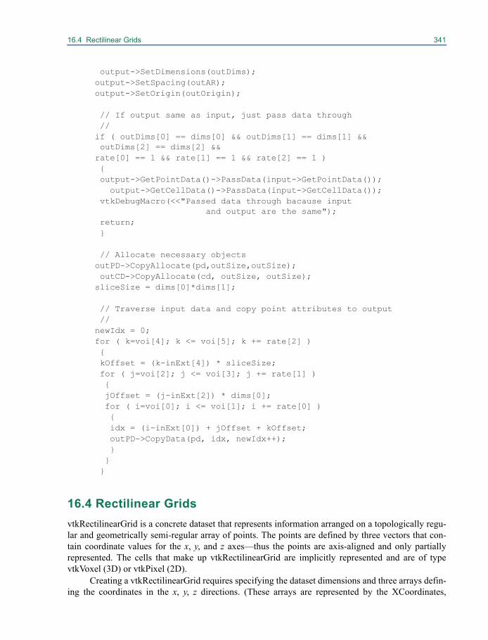
16.4 Rectilinear Grids 341
output->SetDimensions(outDims); output->SetSpacing(outAR); output->SetOrigin(outOrigin);
// If output same as input, just pass data through//
if ( outDims[0] == dims[0] && outDims[1] == dims[1] &&outDims[2] == dims[2] &&
rate[0] == 1 && rate[1] == 1 && rate[2] == 1 ) { output->GetPointData()->PassData(input->GetPointData());
output->GetCellData()->PassData(input->GetCellData()); vtkDebugMacro(<<"Passed data through bacause input
and output are the same"); return; }
// Allocate necessary objects outPD->CopyAllocate(pd,outSize,outSize);
outCD->CopyAllocate(cd, outSize, outSize); sliceSize = dims[0]*dims[1];
// Traverse input data and copy point attributes to output//
newIdx = 0; for ( k=voi[4]; k <= voi[5]; k += rate[2] ) { kOffset = (k-inExt[4]) * sliceSize; for ( j=voi[2]; j <= voi[3]; j += rate[1] ) { jOffset = (j-inExt[2]) * dims[0]; for ( i=voi[0]; i <= voi[1]; i += rate[0] ) { idx = (i-inExt[0]) + jOffset + kOffset; outPD->CopyData(pd, idx, newIdx++); } } }
16.4 Rectilinear GridsvtkRectilinearGrid is a concrete dataset that represents information arranged on a topologically regu-lar and geometrically semi-regular array of points. The points are defined by three vectors that con-tain coordinate values for the x, y, and z axes—thus the points are axis-aligned and only partiallyrepresented. The cells that make up vtkRectilinearGrid are implicitly represented and are of typevtkVoxel (3D) or vtkPixel (2D).
Creating a vtkRectilinearGrid requires specifying the dataset dimensions and three arrays defin-ing the coordinates in the x, y, z directions. (These arrays are represented by the XCoordinates,
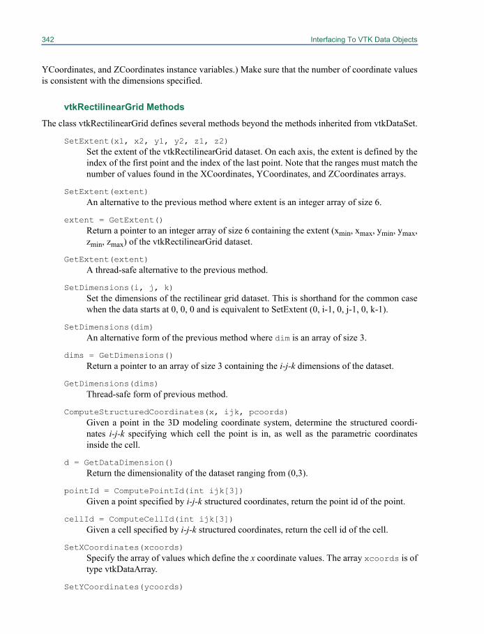
342 Interfacing To VTK Data Objects
YCoordinates, and ZCoordinates instance variables.) Make sure that the number of coordinate valuesis consistent with the dimensions specified.
vtkRectilinearGrid Methods
The class vtkRectilinearGrid defines several methods beyond the methods inherited from vtkDataSet.
SetExtent(x1, x2, y1, y2, z1, z2)Set the extent of the vtkRectilinearGrid dataset. On each axis, the extent is defined by theindex of the first point and the index of the last point. Note that the ranges must match thenumber of values found in the XCoordinates, YCoordinates, and ZCoordinates arrays.
SetExtent(extent)An alternative to the previous method where extent is an integer array of size 6.
extent = GetExtent()Return a pointer to an integer array of size 6 containing the extent (xmin, xmax, ymin, ymax,zmin, zmax) of the vtkRectilinearGrid dataset.
GetExtent(extent)A thread-safe alternative to the previous method.
SetDimensions(i, j, k)Set the dimensions of the rectilinear grid dataset. This is shorthand for the common casewhen the data starts at 0, 0, 0 and is equivalent to SetExtent (0, i-1, 0, j-1, 0, k-1).
SetDimensions(dim)An alternative form of the previous method where dim is an array of size 3.
dims = GetDimensions()Return a pointer to an array of size 3 containing the i-j-k dimensions of the dataset.
GetDimensions(dims)Thread-safe form of previous method.
ComputeStructuredCoordinates(x, ijk, pcoords)Given a point in the 3D modeling coordinate system, determine the structured coordi-nates i-j-k specifying which cell the point is in, as well as the parametric coordinatesinside the cell.
d = GetDataDimension()Return the dimensionality of the dataset ranging from (0,3).
pointId = ComputePointId(int ijk[3])Given a point specified by i-j-k structured coordinates, return the point id of the point.
cellId = ComputeCellId(int ijk[3])Given a cell specified by i-j-k structured coordinates, return the cell id of the cell.
SetXCoordinates(xcoords)Specify the array of values which define the x coordinate values. The array xcoords is oftype vtkDataArray.
SetYCoordinates(ycoords)
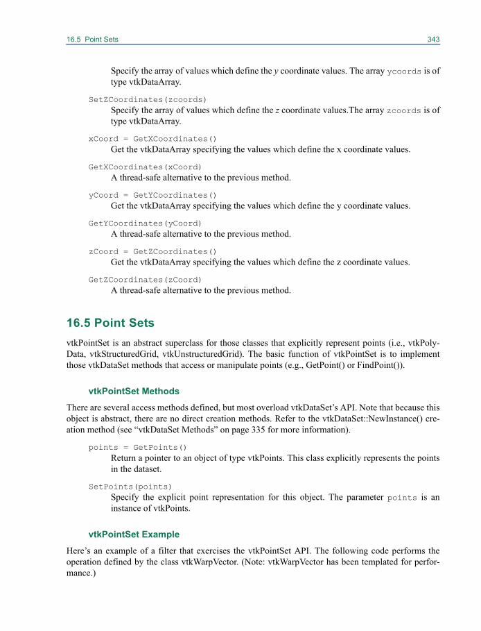
16.5 Point Sets 343
Specify the array of values which define the y coordinate values. The array ycoords is oftype vtkDataArray.
SetZCoordinates(zcoords)Specify the array of values which define the z coordinate values.The array zcoords is oftype vtkDataArray.
xCoord = GetXCoordinates()Get the vtkDataArray specifying the values which define the x coordinate values.
GetXCoordinates(xCoord)A thread-safe alternative to the previous method.
yCoord = GetYCoordinates()Get the vtkDataArray specifying the values which define the y coordinate values.
GetYCoordinates(yCoord)A thread-safe alternative to the previous method.
zCoord = GetZCoordinates()Get the vtkDataArray specifying the values which define the z coordinate values.
GetZCoordinates(zCoord)A thread-safe alternative to the previous method.
16.5 Point SetsvtkPointSet is an abstract superclass for those classes that explicitly represent points (i.e., vtkPoly-Data, vtkStructuredGrid, vtkUnstructuredGrid). The basic function of vtkPointSet is to implementthose vtkDataSet methods that access or manipulate points (e.g., GetPoint() or FindPoint()).
vtkPointSet Methods
There are several access methods defined, but most overload vtkDataSet’s API. Note that because thisobject is abstract, there are no direct creation methods. Refer to the vtkDataSet::NewInstance() cre-ation method (see “vtkDataSet Methods” on page 335 for more information).
points = GetPoints()Return a pointer to an object of type vtkPoints. This class explicitly represents the pointsin the dataset.
SetPoints(points)Specify the explicit point representation for this object. The parameter points is aninstance of vtkPoints.
vtkPointSet Example
Here’s an example of a filter that exercises the vtkPointSet API. The following code performs theoperation defined by the class vtkWarpVector. (Note: vtkWarpVector has been templated for perfor-mance.)
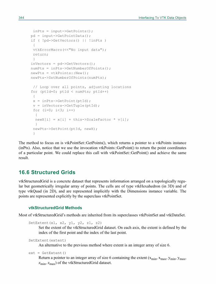
344 Interfacing To VTK Data Objects
inPts = input->GetPoints(); pd = input->GetPointData(); if ( !pd->GetVectors() || !inPts ) { vtkErrorMacro(<<"No input data"); return; } inVectors = pd->GetVectors(); numPts = inPts->GetNumberOfPoints(); newPts = vtkPoints::New(); newPts->SetNumberOfPoints(numPts);
// Loop over all points, adjusting locations for (ptId=0; ptId < numPts; ptId++) { x = inPts->GetPoint(ptId); v = inVectors->GetTuple(ptId); for (i=0; i<3; i++) { newX[i] = x[i] + this->ScaleFactor * v[i]; } newPts->SetPoint(ptId, newX); }
The method to focus on is vtkPointSet::GetPoints(), which returns a pointer to a vtkPoints instance(inPts). Also, notice that we use the invocation vtkPoints::GetPoint() to return the point coordinatesof a particular point. We could replace this call with vtkPointSet::GetPoint() and achieve the sameresult.
16.6 Structured GridsvtkStructuredGrid is a concrete dataset that represents information arranged on a topologically regu-lar but geometrically irregular array of points. The cells are of type vtkHexahedron (in 3D) and oftype vtkQuad (in 2D), and are represented implicitly with the Dimensions instance variable. Thepoints are represented explicitly by the superclass vtkPointSet.
vtkStructuredGrid MethodsMost of vtkStructuredGrid’s methods are inherited from its superclasses vtkPointSet and vtkDataSet.
SetExtent(x1, x2, y1, y2, z1, z2)Set the extent of the vtkStructuredGrid dataset. On each axis, the extent is defined by theindex of the first point and the index of the last point.
SetExtent(extent)An alternative to the previous method where extent is an integer array of size 6.
ext = GetExtent()Return a pointer to an integer array of size 6 containing the extent (xmin, xmax, ymin, ymax,zmin, zmax) of the vtkStructuredGrid dataset.
16.7 Polygonal Data 345
GetExtent(ext)A thread-safe alternative to the previous method.
SetDimensions(i, j, k)Specify the i-j-k dimensions of the structured grid. The number of points for the grid,specified by the product i*j*k, must match the number of points returned fromvtkPointSet::GetNumberOfPoints().This is shorthand for the common case when the datastarts at 0, 0, 0 and is equivalent to SetExtent(0, i-1, 0, j-1, 0, k-1).
SetDimensions(dim)An alternative form of the previous method. Dimensions are specified with an array ofthree integer values.
dims = GetDimensions()Return a pointer to an array of size three containing i-j-k dimensions of dataset.
GetDimensions(dims)Thread-safe form of the previous method.
dim = GetDataDimension() Return the dimension of the dataset, i.e., whether the dataset is 0, 1, 2, or 3-dimensional.
16.7 Polygonal DatavtkPolyData is a concrete dataset type that represents rendering primitives such as vertices, lines,polygons, and triangle strips. The data is completely unstructured: points are represented in the super-class vtkPointSet, and the cells are represented using four instances of vtkCellArray, which is a con-nectivity list (Figure 16–3). The four vtkCellArrays represent vertices and polyvertices; lines andpolylines; triangles, quads, and polygons; and triangle strips, respectively.
Because vtkPolyData is unstructured, cells and points must be explicitly represented. In orderto support some of the required methods of its superclass vtkDataSet (mainly topological methodssuch as GetPointCells() and GetCellNeighbors()), vtkPolyData has a complex internal data structureas shown in Figure 16–3. Besides vtkPoints and the vtkCellArrays, the data structure consists of a listof cell types (vtkCellTypes) and cell links (vtkCellLinks). The cell types array allows random accessinto the cells. This is necessary because vtkCellArray cannot support random access due to the factthat individual cells may vary in size. The cell links array supports topological operations by main-taining references to all cells that use a particular vertex. (See The Visualization Toolkit text for moreinformation.) Instances of these two classes, vtkCellTypes and vtkCellLinks, are only instantiated ifneeded. That is, if random access to cells is required vtkCellTypes is instantiated; or if topologicalinformation is required, vtkCellLinks is instantiated.
While this structure is fairly complex, the good news is that for the most part the managementof the internal structure is taken care of for you. Normally you’ll never need to directly manipulate thestructure as long as you use vtkDataSet’s API to interface the information. In some cases, writing afilter or using some of the vtkPolyData or vtkUnstructuredGrid methods, you may have to explicitlycreate the cell types and/or cell links arrays using the BuildCells() and BuildLinks() methods. In rarecases you may want to directly manipulate the structure—deleting points or cells, and/or modifyingthe link array to reflect changing topology. Refer to section “Supporting Objects for Data Sets” onpage 355 for more information. Examples of code demonstrating the use these complex operators
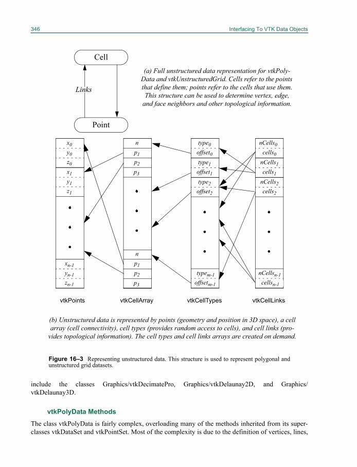
346 Interfacing To VTK Data Objects
include the classes Graphics/vtkDecimatePro, Graphics/vtkDelaunay2D, and Graphics/vtkDelaunay3D.
vtkPolyData Methods
The class vtkPolyData is fairly complex, overloading many of the methods inherited from its super-classes vtkDataSet and vtkPointSet. Most of the complexity is due to the definition of vertices, lines,
np1p2
p3
np1p2
p3
x0y0z0
vtkPoints vtkCellArray vtkCellTypes
x1y1z1
xn-1yn-1zn-1
type1offset1type2offset2
typem-1offsetm-1
type0offset0
vtkCellLinks
nCells1cells1
nCells2cells2
nCellsn-1cellsn-1
nCells0cells0
Cell(a) Full unstructured data representation for vtkPoly-
Data and vtkUnstructuredGrid. Cells refer to the points that define them; points refer to the cells that use them. This structure can be used to determine vertex, edge,
and face neighbors and other topological information.
Links
Point
Figure 16–3 Representing unstructured data. This structure is used to represent polygonal andunstructured grid datasets.
(b) Unstructured data is represented by points (geometry and position in 3D space), a cell array (cell connectivity), cell types (provides random access to cells), and cell links (pro-
vides topological information). The cell types and cell links arrays are created on demand.

16.7 Polygonal Data 347
polygons, and triangle strips in separate vtkCellArrays, and special (geometric) methods for operatingon the mesh.
SetVerts (verts)Specify the list of vertices, verts. The parameter verts is an instance of vtkCellArray.Note: the difference between vertices and points are that Points define geometry; whilevertices represent cells that contain a single point. Cells are directly renderable in VTKand points are not.
verts = GetVerts()Get the list of vertices. The list is an instance of vtkCellArray.
SetLines (lines)Specify the list of lines, lines. The parameter lines is an instance of vtkCellArray.
lines = GetLines()Get the list of lines. The list is an instance of vtkCellArray.
SetPolys(polys)Specify the list of polygons, polys. The parameter polys is an instance of vtkCellArray.
polys = GetPolys()Get the list of polygons. The list is an instance of vtkCellArray.
SetStrips(strips)Specify the list of triangle strips, strips. The parameter strips is an instance of vtk-CellArray.
strips = GetStrips()Get the list of triangle strips. The list is an instance of vtkCellArray.
numVerts = GetNumberOfVerts()Return the number of vertices.
numLines = GetNumberOfLines()Return the number of lines.
numPolys = GetNumberOfPolys()Return the number of polygons.
numStrips = GetNumberOfStrips()Return the number of triangle strips.
Allocate(numCells, extend)Perform initial memory allocation prior to invoking the InsertNextCell() methods(described in next two items). The parameter numCells is an estimate of the number ofcells to be inserted; extend is the size by which to extend the internal structure (ifneeded).
Allocate(inPolyData, numCells, extend)Similar to the above method, this method allocates initial storage for vertex, line, poly-gon, and triangle strip arrays. However, it examines the supplied inPolyData to determinewhich of these arrays to allocate; they are only allocated if there is data in the correspond-ing arrays in inPolyData.
348 Interfacing To VTK Data Objects
cellId = InsertNextCell(type, npts, pts)Given a cell type, type, number of points in the cell, npts, and an integer list of pointids, pts, insert a cell and return its cell id. See Figure 19–20 for a definition of type val-ues. Make sure to invoke Allocate() prior to invoking this method.
cellId = InsertNextCell(type, pts)Given a cell type, type and instance of vtkIdList, pts, insert a cell and return its cell id.Make sure to invoke Allocate() prior to invoking this method.
Reset()Restores this instance of vtkPolyData to its initial condition without releasing allocatedmemory.
BuildCells()Build the internal vtkCellTypes array. This allows random access to cells (e.g., GetCell()and other special vtkPolyData methods). Normally you don’t need to invoke this methodunless you are doing specialized operations on vtkPolyData.
BuildLinks()Build the internal vtkCellLinks array. This enables access to topological information suchas neighborhoods (e.g., vertex, edge, face neighbors). Normally you don’t need to invokethis method unless you are doing special operations on vtkPolyData.
DeleteCells()Release the memory for the internal vtkCellTypes array which allows random access ofthe cells. This method implicitly deletes the cell links too since they are no longer valid.
DeleteLinks()Release the memory for the internal vtkCellLinks array.
GetPointCells(ptId, ncells, cells)Given a point id (ptId), return the number of cells using the point (ncells), and an inte-ger array of cell ids that use the point (cells).
GetCellEdgeNeighbors(cellId, p1, p2, cellIds)Given a cell (cellId) and two points (p1 and p2) forming an edge of the cell, fill in auser-supplied list of all cells using the edge (p1,p2).
GetCellPoints(cellId, npts, pts)Given a cell (cellId), return the number of points (npts) and an integer list of point idswhich define the cell connectivity. This is a specialized version of the method GetCell-Points(npts, ptIds) inherited from its superclass vtkDataSet.
flag = IsTriangle(p1, p2, p3)A special method meant for triangle meshes. Returns a 0/1 flag indicating whether thethree points listed (p1,p2,p3) form a triangle in the mesh.
flag = IsEdge(p1, p2)Returns a 0/1 flag indicating whether the two points listed (p1,p2) form an edge in themesh.
flag = IsPointUsedByCell(ptId,cellId)Return a 0/1 flag indicating whether a particular point given by ptId is used by a partic-
16.7 Polygonal Data 349
ular cell (cellId).
ReplaceCell(cellId, npts, pts)Redefine a cell (cellId) with a new connectivity list (pts). Note that the number ofpoints (npts) must be equal to the original number of points in the cell.
ReplaceCellPoint(cellId, oldPtId, newPtId)Redefine a cell’s connectivity list by replacing one point id (oldPtId) with a new pointid (newPtId).
ReverseCell(cellId)Reverse the order of the connectivity list definition for the cell (cellId). For example, ifa triangle is defined (p1,p2,p3), after invocation of this method it will be defined by thepoints (p3,p2,p1).
DeletePoint(ptId)Delete the point by removing all links from it to cells using it. This method does not actu-ally remove the point from the vtkPoints object.
DeleteCell(cellId)Delete a cell by marking its type as VTK_EMPTY_CELL. This operator only modifies thevtkCellTypes array, it does not actually remove the cell’s connectivity from the vtkCell-Array object.
ptId = InsertNextLinkedPoint(x, numLinks)If the instance of vtkCellLinks has been built, and you wish to insert a new point into themesh, use this method. The parameter numLinks is the initial size of the list of cellsusing the point.
ptId = InsertNextLinkedPoint(numLinks)Similar to the above method, this method is used for allocating memory to add a newpoint in vtkCellLinks. However, this method only allocates memory; it does not insert thepoint.
cellId = InsertNextLinkedCell(type, npts, pts)Insert a new cell into the vtkPolyData after the cell links and cell types structures havebeen built (i.e., BuildCells() and BuildLinks() have been invoked).
ReplaceLinkedCell(cellId, npts, pts)Replace one linked cell with another cell. Note that npts must be the same size for thereplaced and replacing cell.
RemoveCellReference(cellId)Remove all references to the cell cellId from the cell links structure. This effectivelytopologically disconnects the cell from the data structure.
AddCellReference(cellId)Add references to the cell cellId into the cell links structure. That is, the links from allpoints are modified to reflect the use by the cell cellId.
RemoveReferenceToCell(ptId,cellId)Remove the reference from the links of ptId to the cell cellId.
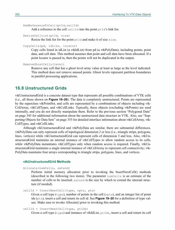
350 Interfacing To VTK Data Objects
AddReferenceToCell(ptId,cellId)Add a reference to the cell cellId into the point ptId’s link list.
ResizeCellList(ptId, size)Resize the link list for the point ptId and make it of size size.
CopyCells(pd, idList, locator)Copy cells listed in idList (a vtkIdList) from pd (a vtkPolyData), including points, pointdata, and cell data. This method assumes that point and cell data have been allocated. If apoint locator is passed in, then the points will not be duplicated in the output.
RemoveGhostCells(level)Remove any cell that has a ghost level array value at least as large as the level indicated.This method does not remove unused points. Ghost levels represent partition boundariesin parallel processing applications.
16.8 Unstructured GridsvtkUnstructuredGrid is a concrete dataset type that represents all possible combinations of VTK cells(i.e., all those shown on Figure 19–20). The data is completely unstructured. Points are representedby the superclass vtkPointSet, and cells are represented by a combinations of objects including vtk-CellArray, vtkCellTypes, and vtkCellLinks. Typically, these objects (excluding vtkPoints) are usedinternally, and you do not directly manipulate them. Refer to the previous section “Polygonal Data”on page 345 for additional information about the unstructured data structure in VTK. Also, see “Sup-porting Objects for Data Sets” on page 355 for detailed interface information about vtkCellArray, vtk-CellTypes, and vtkCellLinks.
Although vtkUnstructuredGrid and vtkPolyData are similar, there are substantial differences.vtkPolyData can only represent cells of topological dimension 2 or less (i.e., triangle strips, polygons,lines, vertices) while vtkUnstructuredGrid can represent cells of dimension 3 and less. Also, vtkUn-structuredGrid maintains an internal instance of vtkCellTypes to allow random access to its cells,while vtkPolyData instantiates vtkCellTypes only when random access is required. Finally, vtkUn-structuredGrid maintains a single internal instance of vtkCellArray to represent cell connectivity; vtk-PolyData maintains four arrays corresponding to triangle strips, polygons, lines, and vertices.
vtkUnstructuredGrid Methods
Allocate(numCells, extend)Perform initial memory allocation prior to invoking the InsertNextCell() methods(described in the following two items). The parameter numCells is an estimate of thenumber of cells to be inserted; extend is the size by which to extend the internal struc-ture (if needed).
cellId = InsertNextCell(type, npts, pts)Given a cell type (type), number of points in the cell (npts), and an integer list of pointids (pts), insert a cell and return its cell id. See Figure 19–20 for a definition of type val-ues. Make sure to invoke Allocate() prior to invoking this method.
cellId = InsertNextCell(type, ptIds)Given a cell type (type) and instance of vtkIdList, ptIds, insert a cell and return its cell
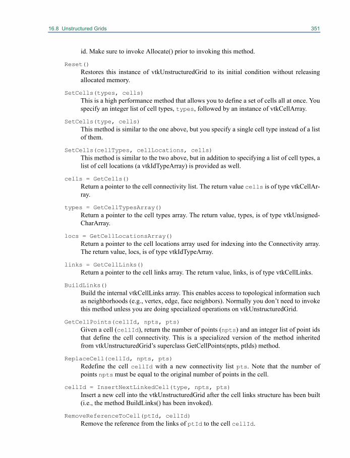
16.8 Unstructured Grids 351
id. Make sure to invoke Allocate() prior to invoking this method.
Reset()Restores this instance of vtkUnstructuredGrid to its initial condition without releasingallocated memory.
SetCells(types, cells)This is a high performance method that allows you to define a set of cells all at once. Youspecify an integer list of cell types, types, followed by an instance of vtkCellArray.
SetCells(type, cells)This method is similar to the one above, but you specify a single cell type instead of a listof them.
SetCells(cellTypes, cellLocations, cells)This method is similar to the two above, but in addition to specifying a list of cell types, alist of cell locations (a vtkIdTypeArray) is provided as well.
cells = GetCells()Return a pointer to the cell connectivity list. The return value cells is of type vtkCellAr-ray.
types = GetCellTypesArray()Return a pointer to the cell types array. The return value, types, is of type vtkUnsigned-CharArray.
locs = GetCellLocationsArray()Return a pointer to the cell locations array used for indexing into the Connectivity array.The return value, locs, is of type vtkIdTypeArray.
links = GetCellLinks()Return a pointer to the cell links array. The return value, links, is of type vtkCellLinks.
BuildLinks()Build the internal vtkCellLinks array. This enables access to topological information suchas neighborhoods (e.g., vertex, edge, face neighbors). Normally you don’t need to invokethis method unless you are doing specialized operations on vtkUnstructuredGrid.
GetCellPoints(cellId, npts, pts)Given a cell (cellId), return the number of points (npts) and an integer list of point idsthat define the cell connectivity. This is a specialized version of the method inheritedfrom vtkUnstructuredGrid’s superclass GetCellPoints(npts, ptIds) method.
ReplaceCell(cellId, npts, pts)Redefine the cell cellId with a new connectivity list pts. Note that the number ofpoints npts must be equal to the original number of points in the cell.
cellId = InsertNextLinkedCell(type, npts, pts)Insert a new cell into the vtkUnstructuredGrid after the cell links structure has been built(i.e., the method BuildLinks() has been invoked).
RemoveReferenceToCell(ptId, cellId)Remove the reference from the links of ptId to the cell cellId.

352 Interfacing To VTK Data Objects
AddReferenceToCell(ptId, cellId)Add a reference to the cell cellId into the point ptId’s link list.
ResizeCellList(ptId, size)Resize the link list for the point ptId and make it of size size.
GetIdsOfCellsOfType(type, array)Fill the specified array (a vtkIdTypeArray) with the ids of all the cells with the specifiedtype.
stat = IsHomogeneous()Determine whether the vtkUnstructuredGrid dataset is composed only of cells of a singletype. Return 1 if this is true; return 0 otherwise.
RemoveGhostCells(level)Remove any cell that has a ghost level array value at least as large as the level indicated.Ghost levels represent partition boundaries in parallel processing applications.
16.9 CellsCells are the atoms of datasets. They are used to perform local operations within the dataset such asinterpolation, coordinate transformation and searching, and various geometric operations. Cells areoften used as a “handle” into a dataset, returning local information necessary to the execution of analgorithm. To obtain a cell from a dataset, the method GetCell(int cellId) is used, and the returned cellcan then be processed.
The class vtkCell represents data using an instance of vtkPoints and vtkIdList (representingpoint coordinates and point ids, respectively). These two instance variables are publicly accessible,one of the few exceptions in VTK where instance variables are public. The following methods areavailable to all subclasses of vtkCell.
vtkCell Methods
type = GetCellType()Return the type of the cell as defined in vtkCellType.h.
dim = GetCellDimension()Return the topological dimensional of the cell (0,1,2, or 3).
flag = IsLinear()Return whether the cell interpolation is linear or not. Usually linear (=1).
points = GetPoints()Get the point coordinates for the cell.
numPts = GetNumberOfPoints()Return the number of points in the cell.
numEdges = GetNumberOfEdges()Return the number of edges in the cell.
numFaces = GetNumberOfFaces()
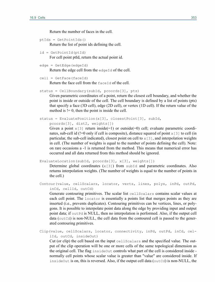
16.9 Cells 353
Return the number of faces in the cell.
ptIds = GetPointIds()Return the list of point ids defining the cell.
id = GetPointId(ptId)For cell point ptId, return the actual point id.
edge = GetEdge(edgeId)Return the edge cell from the edgeId of the cell.
cell = GetFace(faceId)Return the face cell from the faceId of the cell.
status = CellBoundary(subId, pcoords[3], pts)Given parametric coordinates of a point, return the closest cell boundary, and whether thepoint is inside or outside of the cell. The cell boundary is defined by a list of points (pts)that specify a face (3D cell), edge (2D cell), or vertex (1D cell). If the return value of themethod is != 0, then the point is inside the cell.
status = EvaluatePosition(x[3], closestPoint[3], subId, pcoords[3], dist2, weights[])Given a point x[3] return inside(=1) or outside(=0) cell; evaluate parametric coordi-nates, sub-cell id (!=0 only if cell is composite), distance squared of point x[3] to cell (inparticular, the sub-cell indicated), closest point on cell to x[3], and interpolation weightsin cell. (The number of weights is equal to the number of points defining the cell). Note:on rare occasions a -1 is returned from the method. This means that numerical error hasoccurred and all data returned from this method should be ignored.
EvaluateLocation(subId, pcoords[3], x[3], weights[])Determine global coordinates (x[3]) from subId and parametric coordinates. Alsoreturns interpolation weights. (The number of weights is equal to the number of points inthe cell.)
Contour(value, cellScalars, locator, verts, lines, polys, inPd, outPd,inCd, cellId, outCd)Generate contouring primitives. The scalar list cellScalars contains scalar values ateach cell point. The locator is essentially a points list that merges points as they areinserted (i.e., prevents duplicates). Contouring primitives can be vertices, lines, or poly-gons. It is possible to interpolate point data along the edge by providing input and outputpoint data; if outPd is NULL, then no interpolation is performed. Also, if the output celldata (outCd) is non-NULL, the cell data from the contoured cell is passed to the gener-ated contouring primitives.
Clip(value, cellScalars, locator, connectivity, inPd, outPd, inCd, cel-lId, outCd, insideOut)Cut (or clip) the cell based on the input cellScalars and the specified value. The out-put of the clip operation will be one or more cells of the same topological dimension asthe original cell. The flag insideOut controls what part of the cell is considered inside -normally cell points whose scalar value is greater than "value" are considered inside. IfinsideOut is on, this is reversed. Also, if the output cell data (outCd) is non-NULL, the

354 Interfacing To VTK Data Objects
cell data from the clipped cell is passed to the generated clipped primitives.
status = IntersectWithLine(p1[3], p2[3], tol, t, x[3], pcoords[3],subId) Intersect with the ray defined by p1 and p2. Return parametric coordinates (both line andcell). A non-zero return value indicates that an intersection has occurred. You can specifya tolerance tol on the intersection operation.
status = Triangulate(index, ptIds, pts)Generate simplices of the appropriate dimension that approximate the geometry of thiscell. 3D cells will generate tetrahedra,; 2D cells triangles; and so on. If triangulation fail-ure occurs, a zero is returned.
Derivatives(subId, pcoords[3], values, dim, derivs)Compute the derivatives of the values given for this cell.
GetBounds(bounds[6])Set the (xmin, xmax, ymin, ymax, zmin, zmax) bounding box values of the cell.
bounds = GetBounds()Return a pointer to the bounds of the cell.
length2 = GetLength2()Return the length squared of the cell (the length is the diagonal of the cell’s boundingbox).
status = GetParametricCenter(pcoords[3])Return the parametric coordinates of the center of the cell. If the cell is a composite cell,the particular subId that the center is in is returned.
pcoords = GetParametricCoords()Return the parametric coordinates for the points that define this cell.
distance = GetParametricDistance(pcoords[3])Return the distance to the cell given a parametric value.
void ShallowCopy(cell)Perform shallow (reference counted) copy of the cell.
void DeepCopy(cell)Perform deep (copy of all data) copy of the cell.
Initialize(npts, pts, p)Initialize the cell from outside with the point ids (pts) and point coordinates (p, aninstance of vtkPoints) specified. The npts parameter indicates the number of points inthe cell.
req = RequiresInitialization()Returns whether a cell requires initialization prior to access. (For example, the cell mayneed to triangulate itself or set up internal data structures.)
Initialize()Allow the cell to initialize itself as mentioned in the description for the previous method.
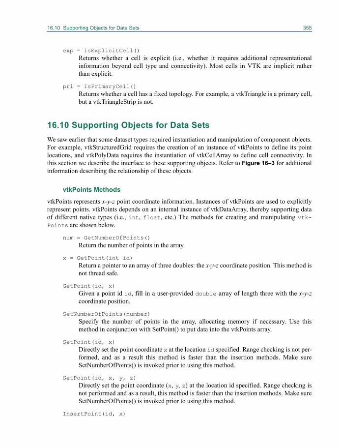
16.10 Supporting Objects for Data Sets 355
exp = IsExplicitCell()Returns whether a cell is explicit (i.e., whether it requires additional representationalinformation beyond cell type and connectivity). Most cells in VTK are implicit ratherthan explicit.
pri = IsPrimaryCell()Returns whether a cell has a fixed topology. For example, a vtkTriangle is a primary cell,but a vtkTriangleStrip is not.
16.10 Supporting Objects for Data SetsWe saw earlier that some dataset types required instantiation and manipulation of component objects.For example, vtkStructuredGrid requires the creation of an instance of vtkPoints to define its pointlocations, and vtkPolyData requires the instantiation of vtkCellArray to define cell connectivity. Inthis section we describe the interface to these supporting objects. Refer to Figure 16–3 for additionalinformation describing the relationship of these objects.
vtkPoints Methods
vtkPoints represents x-y-z point coordinate information. Instances of vtkPoints are used to explicitlyrepresent points. vtkPoints depends on an internal instance of vtkDataArray, thereby supporting dataof different native types (i.e., int, float, etc.) The methods for creating and manipulating vtk-Points are shown below.
num = GetNumberOfPoints()Return the number of points in the array.
x = GetPoint(int id)Return a pointer to an array of three doubles: the x-y-z coordinate position. This method isnot thread safe.
GetPoint(id, x)Given a point id id, fill in a user-provided double array of length three with the x-y-zcoordinate position.
SetNumberOfPoints(number)Specify the number of points in the array, allocating memory if necessary. Use thismethod in conjunction with SetPoint() to put data into the vtkPoints array.
SetPoint(id, x)Directly set the point coordinate x at the location id specified. Range checking is not per-formed, and as a result this method is faster than the insertion methods. Make sureSetNumberOfPoints() is invoked prior to using this method.
SetPoint(id, x, y, z)Directly set the point coordinate (x, y, z) at the location id specified. Range checking isnot performed and as a result, this method is faster than the insertion methods. Make sureSetNumberOfPoints() is invoked prior to using this method.
InsertPoint(id, x)
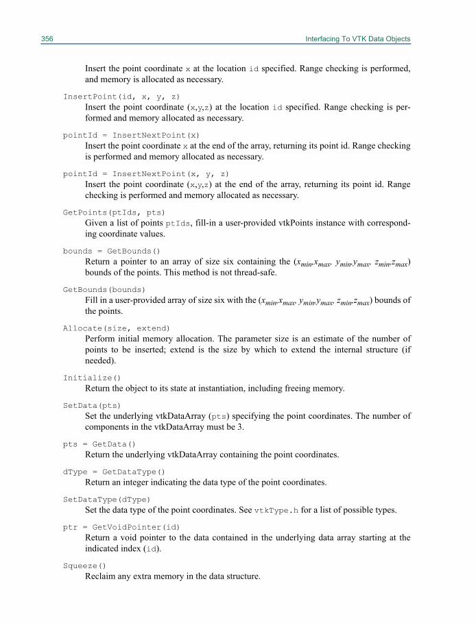
356 Interfacing To VTK Data Objects
Insert the point coordinate x at the location id specified. Range checking is performed,and memory is allocated as necessary.
InsertPoint(id, x, y, z)Insert the point coordinate (x,y,z) at the location id specified. Range checking is per-formed and memory allocated as necessary.
pointId = InsertNextPoint(x)Insert the point coordinate x at the end of the array, returning its point id. Range checkingis performed and memory allocated as necessary.
pointId = InsertNextPoint(x, y, z)Insert the point coordinate (x,y,z) at the end of the array, returning its point id. Rangechecking is performed and memory allocated as necessary.
GetPoints(ptIds, pts)Given a list of points ptIds, fill-in a user-provided vtkPoints instance with correspond-ing coordinate values.
bounds = GetBounds()Return a pointer to an array of size six containing the (xmin,xmax, ymin,ymax, zmin,zmax)bounds of the points. This method is not thread-safe.
GetBounds(bounds)Fill in a user-provided array of size six with the (xmin,xmax, ymin,ymax, zmin,zmax) bounds ofthe points.
Allocate(size, extend)Perform initial memory allocation. The parameter size is an estimate of the number ofpoints to be inserted; extend is the size by which to extend the internal structure (ifneeded).
Initialize()Return the object to its state at instantiation, including freeing memory.
SetData(pts)Set the underlying vtkDataArray (pts) specifying the point coordinates. The number ofcomponents in the vtkDataArray must be 3.
pts = GetData()Return the underlying vtkDataArray containing the point coordinates.
dType = GetDataType()Return an integer indicating the data type of the point coordinates.
SetDataType(dType)Set the data type of the point coordinates. See vtkType.h for a list of possible types.
ptr = GetVoidPointer(id)Return a void pointer to the data contained in the underlying data array starting at theindicated index (id).
Squeeze()Reclaim any extra memory in the data structure.
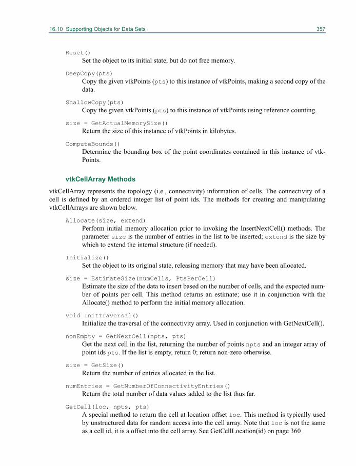
16.10 Supporting Objects for Data Sets 357
Reset()Set the object to its initial state, but do not free memory.
DeepCopy(pts)Copy the given vtkPoints (pts) to this instance of vtkPoints, making a second copy of thedata.
ShallowCopy(pts)Copy the given vtkPoints (pts) to this instance of vtkPoints using reference counting.
size = GetActualMemorySize()Return the size of this instance of vtkPoints in kilobytes.
ComputeBounds()Determine the bounding box of the point coordinates contained in this instance of vtk-Points.
vtkCellArray Methods
vtkCellArray represents the topology (i.e., connectivity) information of cells. The connectivity of acell is defined by an ordered integer list of point ids. The methods for creating and manipulatingvtkCellArrays are shown below.
Allocate(size, extend)Perform initial memory allocation prior to invoking the InsertNextCell() methods. Theparameter size is the number of entries in the list to be inserted; extend is the size bywhich to extend the internal structure (if needed).
Initialize()Set the object to its original state, releasing memory that may have been allocated.
size = EstimateSize(numCells, PtsPerCell)Estimate the size of the data to insert based on the number of cells, and the expected num-ber of points per cell. This method returns an estimate; use it in conjunction with theAllocate() method to perform the initial memory allocation.
void InitTraversal()Initialize the traversal of the connectivity array. Used in conjunction with GetNextCell().
nonEmpty = GetNextCell(npts, pts)Get the next cell in the list, returning the number of points npts and an integer array ofpoint ids pts. If the list is empty, return 0; return non-zero otherwise.
size = GetSize()Return the number of entries allocated in the list.
numEntries = GetNumberOfConnectivityEntries()Return the total number of data values added to the list thus far.
GetCell(loc, npts, pts)A special method to return the cell at location offset loc. This method is typically usedby unstructured data for random access into the cell array. Note that loc is not the sameas a cell id, it is a offset into the cell array. See GetCellLocation(id) on page 360
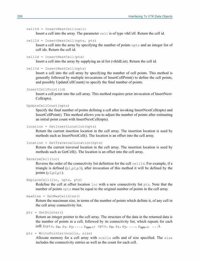
358 Interfacing To VTK Data Objects
cellId = InsertNextCell(cell)Insert a cell into the array. The parameter cell is of type vtkCell. Return the cell id.
cellId = InsertNextCell(npts, pts)Insert a cell into the array by specifying the number of points npts and an integer list ofcell ids. Return the cell id.
cellId = InsertNextCell(pts)Insert a cell into the array by supplying an id list (vtkIdList). Return the cell id.
cellId = InsertNextCell(npts)Insert a cell into the cell array by specifying the number of cell points. This method isgenerally followed by multiple invocations of InsertCellPoint() to define the cell points,and possibly UpdateCellCount() to specify the final number of points.
InsertCellPoint(id)Insert a cell point into the cell array. This method requires prior invocation of InsertNext-Cell(npts).
UpdateCellCount(npts)Specify the final number of points defining a cell after invoking InsertNextCell(npts) andInsertCellPoint(). This method allows you to adjust the number of points after estimatingan initial point count with InsertNextCell(npts).
location = GetInsertLocation(npts)Return the current insertion location in the cell array. The insertion location is used bymethods such as InsertNextCell(). The location is an offset into the cell array.
location = GetTraversalLocation(npts)Return the current traversal location in the cell array. The insertion location is used bymethods such as GetCell(). The location is an offset into the cell array.
ReverseCell(loc)Reverse the order of the connectivity list definition for the cell cellId. For example, if atriangle is defined (p1,p2,p3), after invocation of this method it will be defined by thepoints (p3,p2,p1).
ReplaceCell(loc, npts, pts)Redefine the cell at offset location loc with a new connectivity list pts. Note that thenumber of points npts must be equal to the original number of points in the cell array.
maxSize = GetMaxCellSize()Return the maximum size, in terms of the number of points which definte it, of any cell inthe cell array connectivity list.
ptr = GetPointer()Return an integer pointer to the cell array. The structure of the data in the returned data isthe number of points in a cell, followed by its connectivity list, which repeats for eachcell: (npts, p0, p1, p2,..., pnpts-1; npts, p0, p1, p2, ..., pnpts-1, ...).
ptr = WritePointer(ncells, size)Allocate memory for a cell array with ncells cells and of size specified. The sizeincludes the connectivity entries as well as the count for each cell.
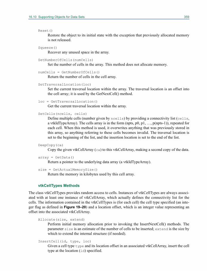
16.10 Supporting Objects for Data Sets 359
Reset()Restore the object to its initial state with the exception that previously allocated memoryis not released.
Squeeze()Recover any unused space in the array.
SetNumberOfCells(numCells)Set the number of cells in the array. This method does not allocate memory.
numCells = GetNumberOfCells()Return the number of cells in the cell array.
SetTraversalLocation(loc)Set the current traversal location within the array. The traversal location is an offset intothe cell array; it is used by the GetNextCell() method.
loc = GetTraversalLocation()Get the current traversal location within the array.
SetCells(ncells, cells)Define multiple cells (number given by ncells) by providing a connectivity list (cells,a vtkIdTypeArray). The cells array is in the form (npts, p0, p1, …, p(npts-1)), repeated foreach cell. When this method is used, it overwrites anything that was previously stored inthis array, so anything referring to these cells becomes invalid. The traversal location isset to the beginning of the list, and the insertion location is set to the end of the list.
DeepCopy(ca)Copy the given vtkCellArray (ca) to this vtkCellArray, making a second copy of the data.
array = GetData()Return a pointer to the underlying data array (a vtkIdTypeArray).
size = GetActualMemorySize()Return the memory in kilobytes used by this cell array.
vtkCellTypes Methods
The class vtkCellTypes provides random access to cells. Instances of vtkCellTypes are always associ-ated with at least one instance of vtkCellArray, which actually defines the connectivity list for thecells. The information contained in the vtkCellTypes is (for each cell) the cell type specified (an inte-ger flag as defined in Figure 19–20) and a location offset, which is an integer value representing anoffset into the associated vtkCellArray.
Allocate(size, extend)Perform initial memory allocation prior to invoking the InsertNextCell() methods. Theparameter size is an estimate of the number of cells to be inserted; extend is the size bywhich to extend the internal structure (if needed).
InsertCell(id, type, loc)Given a cell type type and its location offset in an associated vtkCellArray, insert the celltype at the location (id) specified.
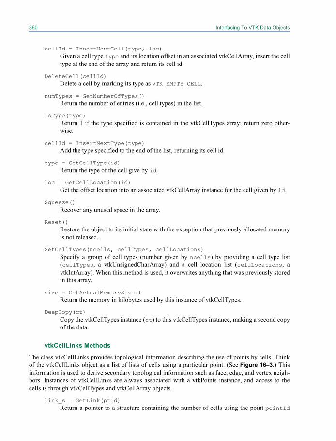
360 Interfacing To VTK Data Objects
cellId = InsertNextCell(type, loc)Given a cell type type and its location offset in an associated vtkCellArray, insert the celltype at the end of the array and return its cell id.
DeleteCell(cellId)Delete a cell by marking its type as VTK_EMPTY_CELL.
numTypes = GetNumberOfTypes()Return the number of entries (i.e., cell types) in the list.
IsType(type)Return 1 if the type specified is contained in the vtkCellTypes array; return zero other-wise.
cellId = InsertNextType(type)Add the type specified to the end of the list, returning its cell id.
type = GetCellType(id)Return the type of the cell give by id.
loc = GetCellLocation(id)Get the offset location into an associated vtkCellArray instance for the cell given by id.
Squeeze()Recover any unused space in the array.
Reset()Restore the object to its initial state with the exception that previously allocated memoryis not released.
SetCellTypes(ncells, cellTypes, cellLocations)Specify a group of cell types (number given by ncells) by providing a cell type list(cellTypes, a vtkUnsignedCharArray) and a cell location list (cellLocations, avtkIntArray). When this method is used, it overwrites anything that was previously storedin this array.
size = GetActualMemorySize()Return the memory in kilobytes used by this instance of vtkCellTypes.
DeepCopy(ct)Copy the vtkCellTypes instance (ct) to this vtkCellTypes instance, making a second copyof the data.
vtkCellLinks Methods
The class vtkCellLinks provides topological information describing the use of points by cells. Thinkof the vtkCellLinks object as a list of lists of cells using a particular point. (See Figure 16–3.) Thisinformation is used to derive secondary topological information such as face, edge, and vertex neigh-bors. Instances of vtkCellLinks are always associated with a vtkPoints instance, and access to thecells is through vtkCellTypes and vtkCellArray objects.
link_s = GetLink(ptId)Return a pointer to a structure containing the number of cells using the point pointId
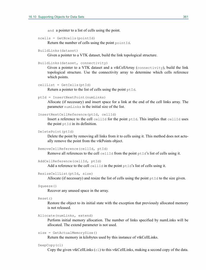
16.10 Supporting Objects for Data Sets 361
and a pointer to a list of cells using the point.
ncells = GetNcells(pointId)Return the number of cells using the point pointId.
BuildLinks(dataset)Given a pointer to a VTK dataset, build the link topological structure.
BuildLinks(dataset, connectivity)Given a pointer to a VTK dataset and a vtkCellArray (connectivity), build the linktopological structure. Use the connectivity array to determine which cells referencewhich points.
cellList = GetCells(ptId)Return a pointer to the list of cells using the point ptId.
ptId = InsertNextPoint(numLinks)Allocate (if necessary) and insert space for a link at the end of the cell links array. Theparameter numLinks is the initial size of the list.
InsertNextCellReference(ptId, cellId)Insert a reference to the cell cellId for the point ptId. This implies that cellId usesthe point ptId in its definition.
DeletePoint(ptId)Delete the point by removing all links from it to cells using it. This method does not actu-ally remove the point from the vtkPoints object.
RemoveCellReference(cellId, ptId)Remove all references to the cell cellId from the point ptId’s list of cells using it.
AddCellReference(cellId, ptId)Add a reference to the cell cellId in the point ptId’s list of cells using it.
ResizeCellList(ptId, size)Allocate (if necessary) and resize the list of cells using the point ptId to the size given.
Squeeze()Recover any unused space in the array.
Reset()Restore the object to its initial state with the exception that previously allocated memoryis not released.
Allocate(numLinks, extend)Perform initial memory allocation. The number of links specified by numLinks will beallocated. The extend parameter is not used.
size = GetActualMemorySize()Return the memory in kilobytes used by this instance of vtkCellLinks.
DeepCopy(cl)Copy the given vtkCellLinks (cl) to this vtkCellLinks, making a second copy of the data.
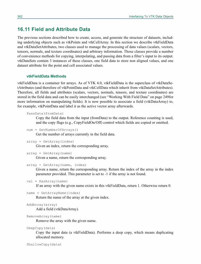
362 Interfacing To VTK Data Objects
16.11 Field and Attribute DataThe previous sections described how to create, access, and generate the structure of datasets, includ-ing underlying objects such as vtkPoints and vtkCellArray. In this section we describe vtkFieldDataand vtkDataSetAttributes, two classes used to manage the processing of data values (scalars, vectors,tensors, normals, and texture coordinates) and arbitrary information. Those classes provide a numberof convenience methods for copying, interpolating, and passing data from a filter’s input to its output.vtkDataSets contain 3 instances of these classes, one field data to store non aligned values, and onedataset attribute for the point and cell associated values.
vtkFieldData MethodsvtkFieldData is a container for arrays. As of VTK 4.0, vtkFieldData is the superclass of vtkDataSe-tAttributes (and therefore of vtkPointData and vtkCellData which inherit from vtkDataSetAttributes).Therefore, all fields and attributes (scalars, vectors, normals, tensors, and texture coordinates) arestored in the field data and can be easily interchanged (see “Working With Field Data” on page 249formore information on manipulating fields). It is now possible to associate a field (vtkDataArray) to,for example, vtkPointData and label it as the active vector array afterwards.
PassData(fromData)Copy the field data from the input (fromData) to the output. Reference counting is used,and the copy flags (e.g., CopyFieldOn/Off) control which fields are copied or omitted.
num = GetNumberOfArrays()Get the number of arrays currently in the field data.
array = GetArray(index)Given an index, return the corresponding array.
array = GetArray(name)Given a name, return the corresponding array.
array = GetArray(name, index)Given a name, return the corresponding array. Return the index of the array in the indexparameter provided. This parameter is set to -1 if the array is not found.
val = HasArray(name)If an array with the given name exists in this vtkFieldData, return 1. Otherwise return 0.
name = GetArrayName(index)Return the name of the array at the given index.
AddArray(array)Add a field (vtkDataArray).
RemoveArray(name)Remove the array with the given name.
DeepCopy(data)Copy the input data (a vtkFieldData). Performs a deep copy, which means duplicatingallocated memory.
ShallowCopy(data)
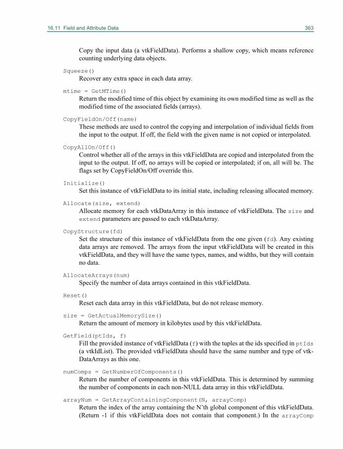
16.11 Field and Attribute Data 363
Copy the input data (a vtkFieldData). Performs a shallow copy, which means referencecounting underlying data objects.
Squeeze()Recover any extra space in each data array.
mtime = GetMTime()Return the modified time of this object by examining its own modified time as well as themodified time of the associated fields (arrays).
CopyFieldOn/Off(name)These methods are used to control the copying and interpolation of individual fields fromthe input to the output. If off, the field with the given name is not copied or interpolated.
CopyAllOn/Off()Control whether all of the arrays in this vtkFieldData are copied and interpolated from theinput to the output. If off, no arrays will be copied or interpolated; if on, all will be. Theflags set by CopyFieldOn/Off override this.
Initialize()Set this instance of vtkFieldData to its initial state, including releasing allocated memory.
Allocate(size, extend)Allocate memory for each vtkDataArray in this instance of vtkFieldData. The size andextend parameters are passed to each vtkDataArray.
CopyStructure(fd)Set the structure of this instance of vtkFieldData from the one given (fd). Any existingdata arrays are removed. The arrays from the input vtkFieldData will be created in thisvtkFieldData, and they will have the same types, names, and widths, but they will containno data.
AllocateArrays(num)Specify the number of data arrays contained in this vtkFieldData.
Reset()Reset each data array in this vtkFieldData, but do not release memory.
size = GetActualMemorySize()Return the amount of memory in kilobytes used by this vtkFieldData.
GetField(ptIds, f)Fill the provided instance of vtkFieldData (f) with the tuples at the ids specified in ptIds(a vtkIdList). The provided vtkFieldData should have the same number and type of vtk-DataArrays as this one.
numComps = GetNumberOfComponents()Return the number of components in this vtkFieldData. This is determined by summingthe number of components in each non-NULL data array in this vtkFieldData.
arrayNum = GetArrayContainingComponent(N, arrayComp)Return the index of the array containing the N’th global component of this vtkFieldData.(Return -1 if this vtkFieldData does not contain that component.) In the arrayComp

364 Interfacing To VTK Data Objects
parameter, returns the particular component of the data array which matches therequested global component.
numTups = GetNumberOfTuples()Return the number of tuples in this vtkFieldData. (The number of tuples in the first dataarray is returned.)
SetNumberOfTuples(num)Set the number of tuples (num) of each data array in this vtkFieldData.
tuple = GetTuple(index)Return a tuple consisting of a concatenation of the specified tuple in each data array con-tained in this vtkFieldData. The returned array is of type double, so all the data values areconverted to double before being returned.
GetTuple(index, tuple)This method provides the same functionality as the one above, but the tuple is returned ina user-provided data array. Be sure that the provided array has enough memory allocated.
SetTuple(index, tuple)Set the tuple at the specified index. No range checking is performed.
InsertTuple(index, tuple)Insert the tuple at the specified index. Range checking is performed, and memory is allo-cated as necessary.
id = InsertNextTuple(tuple)Insert the tuple at the end of this vtkFieldData. Range checking is performed, and mem-ory is allocated as necessary. The id of this tuple is returned.
comp = GetComponent(i, j)Return the value (as a double) at the ith tuple and jth component.
SetComponent(i, j, comp)Set the value at the ith tuple and jth component. Range checking is not performed.
InsertComponent(i, j, comp)Insert the value at the ith tuple and jth component. Range checking is performed, andmemory is allocated as necessary.
vtkDataSetAttributes MethodsRecall that there are two types of attributes: those associated with the points of the dataset (vtkPoint-Data) and those associated with the cells of the dataset (vtkCellData). Both of these classes are sub-classes of vtkDataSetAttributes (which is a subclass of vtkFieldData) and have nearly identicalinterfaces. The following methods are defined by vtkDataSetAttributes and are common to both vtk-PointData and vtkCellData. Remember: all datasets have attribute data (both cell and point), so alldatasets' attribute data respond to these methods.
PassData(fromData)Copy the attribute data from the input (fromData) to the output attribute data. Referencecounting is used, and the copy flags (e.g., CopyScalars) are used to control which attri-bute data is copied.
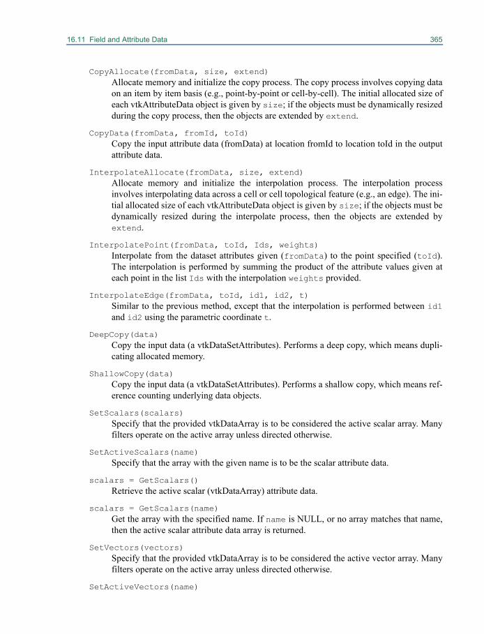
16.11 Field and Attribute Data 365
CopyAllocate(fromData, size, extend)Allocate memory and initialize the copy process. The copy process involves copying dataon an item by item basis (e.g., point-by-point or cell-by-cell). The initial allocated size ofeach vtkAttributeData object is given by size; if the objects must be dynamically resizedduring the copy process, then the objects are extended by extend.
CopyData(fromData, fromId, toId)Copy the input attribute data (fromData) at location fromId to location toId in the outputattribute data.
InterpolateAllocate(fromData, size, extend)Allocate memory and initialize the interpolation process. The interpolation processinvolves interpolating data across a cell or cell topological feature (e.g., an edge). The ini-tial allocated size of each vtkAttributeData object is given by size; if the objects must bedynamically resized during the interpolate process, then the objects are extended byextend.
InterpolatePoint(fromData, toId, Ids, weights)Interpolate from the dataset attributes given (fromData) to the point specified (toId).The interpolation is performed by summing the product of the attribute values given ateach point in the list Ids with the interpolation weights provided.
InterpolateEdge(fromData, toId, id1, id2, t)Similar to the previous method, except that the interpolation is performed between id1and id2 using the parametric coordinate t.
DeepCopy(data)Copy the input data (a vtkDataSetAttributes). Performs a deep copy, which means dupli-cating allocated memory.
ShallowCopy(data)Copy the input data (a vtkDataSetAttributes). Performs a shallow copy, which means ref-erence counting underlying data objects.
SetScalars(scalars)Specify that the provided vtkDataArray is to be considered the active scalar array. Manyfilters operate on the active array unless directed otherwise.
SetActiveScalars(name)Specify that the array with the given name is to be the scalar attribute data.
scalars = GetScalars()Retrieve the active scalar (vtkDataArray) attribute data.
scalars = GetScalars(name)Get the array with the specified name. If name is NULL, or no array matches that name,then the active scalar attribute data array is returned.
SetVectors(vectors)Specify that the provided vtkDataArray is to be considered the active vector array. Manyfilters operate on the active array unless directed otherwise.
SetActiveVectors(name)
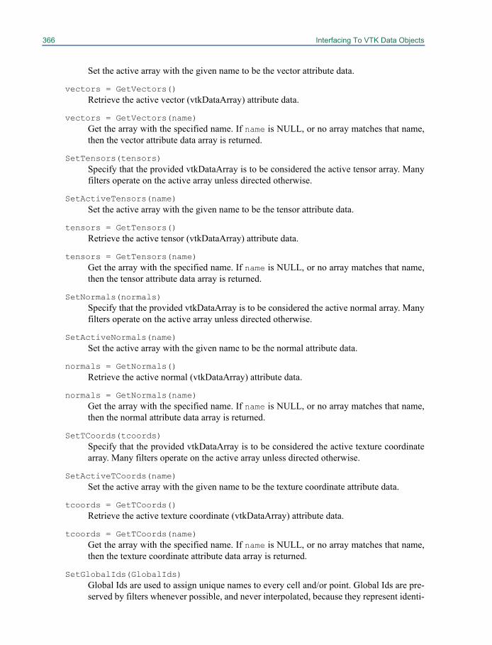
366 Interfacing To VTK Data Objects
Set the active array with the given name to be the vector attribute data.
vectors = GetVectors()Retrieve the active vector (vtkDataArray) attribute data.
vectors = GetVectors(name)Get the array with the specified name. If name is NULL, or no array matches that name,then the vector attribute data array is returned.
SetTensors(tensors)Specify that the provided vtkDataArray is to be considered the active tensor array. Manyfilters operate on the active array unless directed otherwise.
SetActiveTensors(name)Set the active array with the given name to be the tensor attribute data.
tensors = GetTensors()Retrieve the active tensor (vtkDataArray) attribute data.
tensors = GetTensors(name)Get the array with the specified name. If name is NULL, or no array matches that name,then the tensor attribute data array is returned.
SetNormals(normals)Specify that the provided vtkDataArray is to be considered the active normal array. Manyfilters operate on the active array unless directed otherwise.
SetActiveNormals(name)Set the active array with the given name to be the normal attribute data.
normals = GetNormals()Retrieve the active normal (vtkDataArray) attribute data.
normals = GetNormals(name)Get the array with the specified name. If name is NULL, or no array matches that name,then the normal attribute data array is returned.
SetTCoords(tcoords)Specify that the provided vtkDataArray is to be considered the active texture coordinatearray. Many filters operate on the active array unless directed otherwise.
SetActiveTCoords(name)Set the active array with the given name to be the texture coordinate attribute data.
tcoords = GetTCoords()Retrieve the active texture coordinate (vtkDataArray) attribute data.
tcoords = GetTCoords(name)Get the array with the specified name. If name is NULL, or no array matches that name,then the texture coordinate attribute data array is returned.
SetGlobalIds(GlobalIds)Global Ids are used to assign unique names to every cell and/or point. Global Ids are pre-served by filters whenever possible, and never interpolated, because they represent identi-
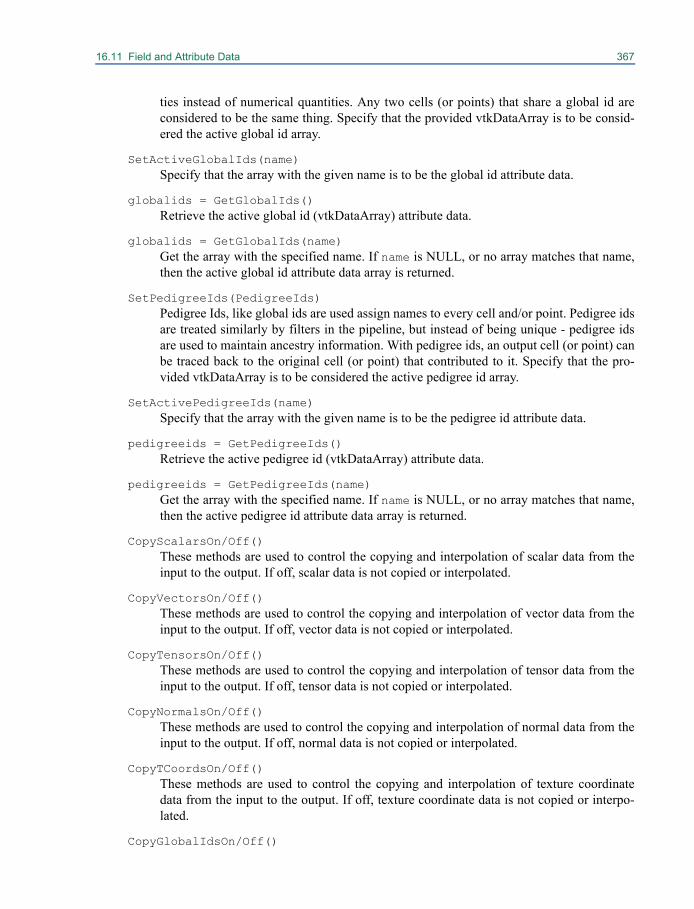
16.11 Field and Attribute Data 367
ties instead of numerical quantities. Any two cells (or points) that share a global id areconsidered to be the same thing. Specify that the provided vtkDataArray is to be consid-ered the active global id array.
SetActiveGlobalIds(name)Specify that the array with the given name is to be the global id attribute data.
globalids = GetGlobalIds()Retrieve the active global id (vtkDataArray) attribute data.
globalids = GetGlobalIds(name)Get the array with the specified name. If name is NULL, or no array matches that name,then the active global id attribute data array is returned.
SetPedigreeIds(PedigreeIds)Pedigree Ids, like global ids are used assign names to every cell and/or point. Pedigree idsare treated similarly by filters in the pipeline, but instead of being unique - pedigree idsare used to maintain ancestry information. With pedigree ids, an output cell (or point) canbe traced back to the original cell (or point) that contributed to it. Specify that the pro-vided vtkDataArray is to be considered the active pedigree id array.
SetActivePedigreeIds(name)Specify that the array with the given name is to be the pedigree id attribute data.
pedigreeids = GetPedigreeIds()Retrieve the active pedigree id (vtkDataArray) attribute data.
pedigreeids = GetPedigreeIds(name)Get the array with the specified name. If name is NULL, or no array matches that name,then the active pedigree id attribute data array is returned.
CopyScalarsOn/Off()These methods are used to control the copying and interpolation of scalar data from theinput to the output. If off, scalar data is not copied or interpolated.
CopyVectorsOn/Off()These methods are used to control the copying and interpolation of vector data from theinput to the output. If off, vector data is not copied or interpolated.
CopyTensorsOn/Off()These methods are used to control the copying and interpolation of tensor data from theinput to the output. If off, tensor data is not copied or interpolated.
CopyNormalsOn/Off()These methods are used to control the copying and interpolation of normal data from theinput to the output. If off, normal data is not copied or interpolated.
CopyTCoordsOn/Off()These methods are used to control the copying and interpolation of texture coordinatedata from the input to the output. If off, texture coordinate data is not copied or interpo-lated.
CopyGlobalIdsOn/Off()
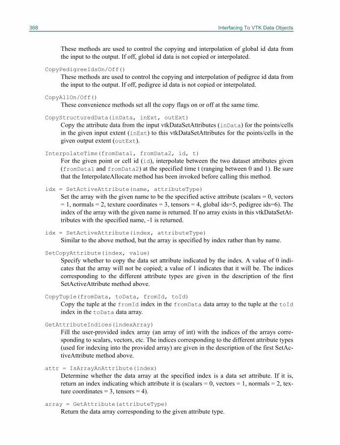
368 Interfacing To VTK Data Objects
These methods are used to control the copying and interpolation of global id data fromthe input to the output. If off, global id data is not copied or interpolated.
CopyPedigreeIdsOn/Off()These methods are used to control the copying and interpolation of pedigree id data fromthe input to the output. If off, pedigree id data is not copied or interpolated.
CopyAllOn/Off()These convenience methods set all the copy flags on or off at the same time.
CopyStructuredData(inData, inExt, outExt)Copy the attribute data from the input vtkDataSetAttributes (inData) for the points/cellsin the given input extent (inExt) to this vtkDataSetAttributes for the points/cells in thegiven output extent (outExt).
InterpolateTime(fromData1, fromData2, id, t)For the given point or cell id (id), interpolate between the two dataset attributes given(fromData1 and fromData2) at the specified time t (ranging between 0 and 1). Be surethat the InterpolateAllocate method has been invoked before calling this method.
idx = SetActiveAttribute(name, attributeType)Set the array with the given name to be the specified active attribute (scalars = 0, vectors= 1, normals = 2, texture coordinates = 3, tensors = 4, global ids=5, pedigree ids=6). Theindex of the array with the given name is returned. If no array exists in this vtkDataSetAt-tributes with the specified name, -1 is returned.
idx = SetActiveAttribute(index, attributeType)Similar to the above method, but the array is specified by index rather than by name.
SetCopyAttribute(index, value)Specify whether to copy the data set attribute indicated by the index. A value of 0 indi-cates that the array will not be copied; a value of 1 indicates that it will be. The indicescorresponding to the different attribute types are given in the description of the firstSetActiveAttribute method above.
CopyTuple(fromData, toData, fromId, toId)Copy the tuple at the fromId index in the fromData data array to the tuple at the toIdindex in the toData data array.
GetAttributeIndices(indexArray)Fill the user-provided index array (an array of int) with the indices of the arrays corre-sponding to scalars, vectors, etc. The indices corresponding to the different attribute types(used for indexing into the provided array) are given in the description of the first SetAc-tiveAttribute method above.
attr = IsArrayAnAttribute(index)Determine whether the data array at the specified index is a data set attribute. If it is,return an index indicating which attribute it is (scalars = 0, vectors = 1, normals = 2, tex-ture coordinates = 3, tensors = 4).
array = GetAttribute(attributeType)Return the data array corresponding to the given attribute type.
16.12 Selections 369
RemoveArray(name)Remove the array with the given name from the list of arrays in this vtkDataSetAttrib-utes.
attr = GetAttributeTypeAsString(attributeType)Given an index corresponding to an attribute type, return the attribute type as a string.
16.12 SelectionsA vtkSelection provides ways to represent a subset of a data object. These include lists of indices oridentifiers, attribute value ranges, locations, frustums, or blocks. A selection may be applied to a par-ticular data object to extract its selected data, or may be modified through filters to expand, reduce, orotherwise change the nature of the selection. Selections are generated by classes such as vtkSelection-Source, which produces a selection based on filter parameters, and vtkHardwareSelector, which usesgraphics hardware to select items rendered within a rectangular region of the screen.
vtkSelection is simply a container of vtkSelectionNode objects. Each selection node containsall the information about its part of the selection. This two level structure allows a single selection tocombine information from different parts of a data object, such as selection on both points and cells,and allows a selection to maintain selection information on different blocks of a multi-block dataset.
vtkSelection Methods
n = GetNumberOfNodes()Return the number of vtkSelectionNode objects in the selection.
node = GetNode(i)Return the i-th vtkSelectionNode.
AddNode(node)Append the vtkSelectionNode to the end of the list of nodes.
RemoveNode(i)Remove the i-th vtkSelectionNode.
RemoveNode(node)Remove the specified vtkSelectionNode if it exists in the selection.
RemoveAllNodes()Remove all vtkSelectionNode objects, leaving an empty selection.
Union(sel)Union this selection with the specified vtkSelection. Attempts to append to existing nodesif properties of the nodes match exactly. Otherwise, it adds new selection nodes to theselection.
Union(node)Union this selection with the specified vtkSelectionNode. Attempts to append to an exist-ing node if properties of the node match exactly. Otherwise, it adds a new selection nodeto the selection.
370 Interfacing To VTK Data Objects
vtkSelectionNode MethodsFundamentally, a vtkSelectionNode is simply a collection of arrays (normally a single array). Addi-tional properties of the selection node indicate exactly how the values in the arrays should be inter-preted.
SetSelectionList(arr)Set the array that will be used as the list of selected items, or interpreted in other waysbased on the content type.
arr = GetSelectionList()Return the selection list.
SetSelectionData(data)Set a collection of arrays for the selection node stored in a vtkDataSetAttributes instance.The first array is interpreted in the same way that a normal selection list's single array is.For VALUES type selections only, the additional arrays are used as further qualifiers sothat more than one data array can be matched with simultaneously.
data = GetSelectionData()Return the collection of arrays for the selection node as a vtkDataSetAttributes instance.
SetContentType(type)Set the content type to one of the constants SELECTIONS, GLOBALIDS, PEDIGREE-IDS, VALUES, INDICES, FRUSTUM, LOCATIONS, THRESHOLDS, BLOCKSdefined in vtkSelectionNode. The content type defines how the selection list is to beinterpreted. The meaning of each type is described in [ref: Selection section].
type = GetContentType()Return the content type.
SetFieldType(type)Set the field type to one of the constants CELL, POINT, FIELD, VERTEX, EDGE, ROWdefined in vtkSelectionNode. This determines what parts of a data object the selectionrefers to (points or cells in vtkDataSet subclasses, field data of vtkDataObject, vertices oredges of vtkGraph, or rows of a vtkTable).
type = GetFieldType()Return the field type.
UnionSelectionList(node)Merge the selection list of another vtkSelectionNode into this node. This assumes thatboth nodes have identical properties.
vtkSelectionNode Property Methods
info = GetProperties()Return the properties of the selection node stored in a vtkInformation general purposecontainer object.
eq = EqualProperties(node, full)Return true if all the properties in this node are also set to the same values in the nodegiven as an argument. The second argument is a flag indicating whether to also fully
16.13 Graphs 371
check properties in the opposite direction before returning true (i.e. that this node con-tains all properties of the node passed as an argument).
GetProperties()->Set(vtkSelectionNode:: INVERSE(), inv)Whether the selection should be inverted, in which case the selection defines what is notof interest rather than what is.
GetProperties()->Set(vtkSelectionNode::EPSILON(), eps)For content type LOCATION, this is a tolerance (geometric distance) within which itemsare accepted and outside of which they are rejected.
GetProperties()->Set(vtkSelectionNode:: CONTAINING_CELLS(), c)This flag tells the extraction filter, when the field type is POINT, that it should alsoextract the cells that contain any of the extracted points.
GetProperties()->Set(vtkSelectionNode:: PIXEL_COUNT(), count)A helper for screen space selection, this is the number of pixels covered by the actorwhose cells are listed in the selection node.
GetProperties()->Set(vtkSelectionNode:: SOURCE(), alg)Pointer to the data or algorithm the selection belongs to.
GetProperties()->Set(vtkSelectionNode:: SOURCE_ID(), id)ID of the data or algorithm the selection belongs to. What the ID means is applicationspecific.
GetProperties()->Set(vtkSelectionNode:: PROP(), obj)Pointer to the prop the selection belongs to.
GetProperties()->Set(vtkSelectionNode:: PROP_ID(), id)ID of the prop the selection belongs to. What the ID means is application specific.
GetProperties()->Set(vtkSelectionNode:: PROCESS_ID(), id)Process ID the selection refers to.
GetProperties()->Set(vtkSelectionNode:: COMPOSITE_INDEX(), i)Used to identify a node in composite datasets.
GetProperties()->Set(vtkSelectionNode:: HIERARCHICAL_LEVEL(), level)Used to identify the level of a dataset in a hiererchical box (AMR) dataset.
GetProperties()->Set(vtkSelectionNode:: HIERARCHICAL_INDEX(), i)Used to identify the index of a dataset in a hiererchical box (AMR) dataset.
16.13 GraphsThe hierarchy for graph classes is shown in [Figure graph-hierachy]. At the top level, we distinguishbetween graphs whose edges have inherent order from source to target (directed graphs) and graphswhose edges do not indicate direction (undirected graphs). The directed graph subclasses are natu-rally structured by specialization. A directed acyclic graph (i.e. a graph with no paths that lead back tothe same place) is a subset of the class of all directed graphs. A vtkTree further restricts this byenforcing a hierarchy: every vertex but the root must have exactly one parent (incoming edge). The
372 Interfacing To VTK Data Objects
mutable classes are used to create or modify graphs. The structure of a graph may be copied into anyother graph instance, if it first passes a compatibility test.
This hierarchy gives us several advantages. Filters that operate on vtkGraph will work for allgraph types. So one can send a vtkTree or a vtkDirectedAcyclicGraph into a filter that takes the moregeneral vtkGraph as an input type (such as vtkVertexDegree). The subclasses also enable filters to bespecific about input type: if a filter requires a tree, that can be specified as the input type. The separatemutable classes allow VTK to enforce that all instances of graph data structures are valid at all times.If vtkGraph itself was mutable, it would have methods for adding edges and vertices. Due to inheri-tance, this method would exist in all subclasses, including vtkTree. The result would be that vtkTreecould at times hold a structure that is not a valid tree. It would be prohibitively expensive in time andcomplexity to check for a valid tree after every edge or vertex addition.
An additional feature of the graph data structures is copy-on-write. Since all graphs share thesame internal representation, multiple objects, even those of different types, may share the samestructure. A deep copy of the structure is only made if the user modifies a graph whose structure isshared with other graphs. To the caller, the graph instances behave as though they were independentof other graphs, while internally memory usage is optimized.
The user may assign an arbitrary number of arrays to the vertices and edges of the graph, inmuch the same way that attributes are assigned to points and cells in vtkDataSet subclasses. Theseattributes may be used in various ways to alter the visualization of the graph, i.e. using them to coloror label the graph.
vtkGraph Methods
vtkGraph is the superclass of all graph types. Since it is not mutable, it only provides read access tothe structure of the graph.
data = GetVertexData()Return the vtkDataSetAttributes structure containing all vertex attributes.
data = GetEdgeData()Return the vtkDataSetAttributes structure containing all edge attributes.
pt = GetPoint(id)Return the location of a particular vertex as a pointer to an array containing x-y-z coordi-nates.
GetPoint(id, pt)An alternative form of the previous method. The coordinates are set in the variable passedas the second argument.
pts = GetPoints()Return the locations of the vertices as a vtkPoints object.
SetPoints(pts)Set the vertex locations.
ComputeBounds()Compute the current bounding box of the graph.
bds = GetBounds()Return the graph bounds as a six component array with values x_min, x_max, y_min,
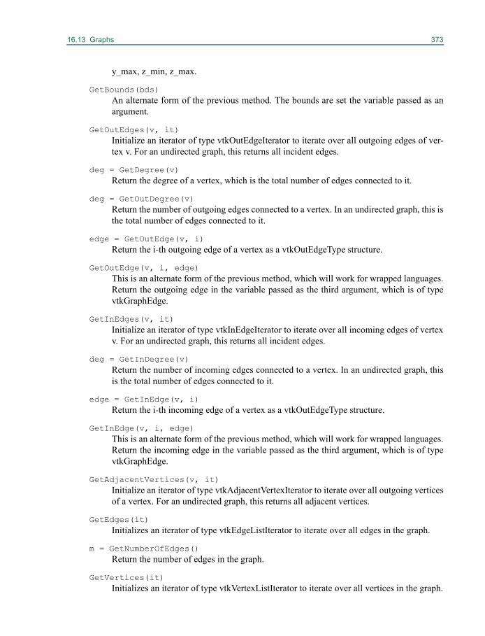
16.13 Graphs 373
y_max, z_min, z_max.
GetBounds(bds)An alternate form of the previous method. The bounds are set the variable passed as anargument.
GetOutEdges(v, it)Initialize an iterator of type vtkOutEdgeIterator to iterate over all outgoing edges of ver-tex v. For an undirected graph, this returns all incident edges.
deg = GetDegree(v)Return the degree of a vertex, which is the total number of edges connected to it.
deg = GetOutDegree(v)Return the number of outgoing edges connected to a vertex. In an undirected graph, this isthe total number of edges connected to it.
edge = GetOutEdge(v, i)Return the i-th outgoing edge of a vertex as a vtkOutEdgeType structure.
GetOutEdge(v, i, edge)This is an alternate form of the previous method, which will work for wrapped languages.Return the outgoing edge in the variable passed as the third argument, which is of typevtkGraphEdge.
GetInEdges(v, it)Initialize an iterator of type vtkInEdgeIterator to iterate over all incoming edges of vertexv. For an undirected graph, this returns all incident edges.
deg = GetInDegree(v)Return the number of incoming edges connected to a vertex. In an undirected graph, thisis the total number of edges connected to it.
edge = GetInEdge(v, i)Return the i-th incoming edge of a vertex as a vtkOutEdgeType structure.
GetInEdge(v, i, edge)This is an alternate form of the previous method, which will work for wrapped languages.Return the incoming edge in the variable passed as the third argument, which is of typevtkGraphEdge.
GetAdjacentVertices(v, it)Initialize an iterator of type vtkAdjacentVertexIterator to iterate over all outgoing verticesof a vertex. For an undirected graph, this returns all adjacent vertices.
GetEdges(it)Initializes an iterator of type vtkEdgeListIterator to iterate over all edges in the graph.
m = GetNumberOfEdges()Return the number of edges in the graph.
GetVertices(it)Initializes an iterator of type vtkVertexListIterator to iterate over all vertices in the graph.
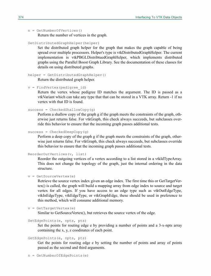
374 Interfacing To VTK Data Objects
n = GetNumberOfVertices()Return the number of vertices in the graph.
SetDistributedGraphHelper(helper)Set the distributed graph helper for the graph that makes the graph capable of beingspread over multiple processors. Helper's type is vtkDistributedGraphHelper. The currentimplementation is vtkPBGLDistribtuedGraphHelper, which implements distributedgraphs using the Parallel Boost Graph Library. See the documentation of these classes fordetails on using distributed graphs.
helper = GetDistributedGraphHelper()Return the distributed graph helper.
v = FindVertex(pedigree_id)Return the vertex whose pedigree ID matches the argument. The ID is passed as avtkVariant which can take any type that that can be stored in a VTK array. Return -1 if novertex with that ID is found.
success = CheckedShallowCopy(g)Perform a shallow copy of the graph g if the graph meets the constraints of the graph, oth-erwise just returns false. For vtkGraph, this check always succeeds, but subclasses over-ride this behavior to ensure that the incoming graph passes additional tests.
success = CheckedDeepCopy(g)Perform a deep copy of the graph g if the graph meets the constraints of the graph, other-wise just returns false. For vtkGraph, this check always succeeds, but subclasses overridethis behavior to ensure that the incoming graph passes additional tests.
ReorderOutVertices(v, list)Reorder the outgoing vertices of a vertex according to a list stored in a vtkIdTypeArray.This does not change the topology of the graph, just the internal ordering in the datastructure.
v = GetSourceVertex(e)Retrieve the source vertex index given an edge index. The first time this or GetTargetVer-tex() is called, the graph will build a mapping array from edge index to source and targetvertex for all edges. If you have access to an edge type such as vtkOutEdgeType,vtkInEdgeType, vtkEdgeType, or vtkGraphEdge, these should be used in preference tothis method, which will consume additional memory.
v = GetTargetVertex(e)Similar to GetSourceVertex(), but retrieves the source vertex of the edge.
SetEdgePoints(e, npts, pts)Set the points for routing edge e by providing a number of points and a 3-x-npts arraycontaining the x, y, z coodinates of each point.
GetEdgePoints(e, npts, pts)Get the points for routing edge e by setting the number of points and array of pointspassed as the second and third arguments.
n = GetNumberOfEdgePoints(e)
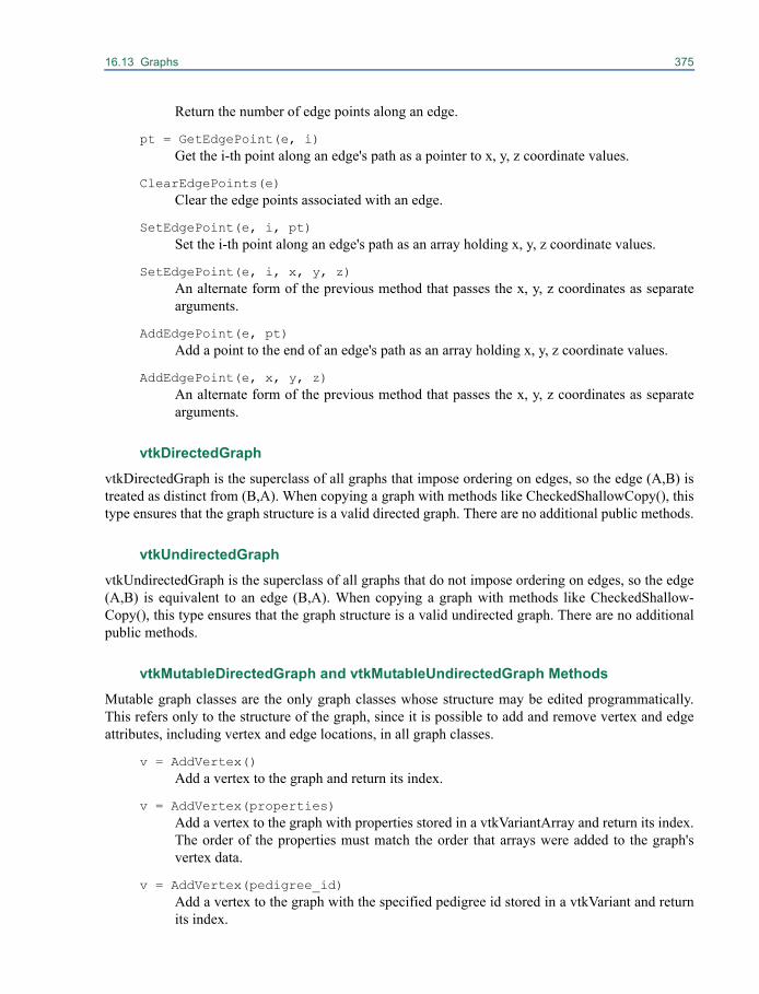
16.13 Graphs 375
Return the number of edge points along an edge.
pt = GetEdgePoint(e, i)Get the i-th point along an edge's path as a pointer to x, y, z coordinate values.
ClearEdgePoints(e)Clear the edge points associated with an edge.
SetEdgePoint(e, i, pt)Set the i-th point along an edge's path as an array holding x, y, z coordinate values.
SetEdgePoint(e, i, x, y, z)An alternate form of the previous method that passes the x, y, z coordinates as separatearguments.
AddEdgePoint(e, pt)Add a point to the end of an edge's path as an array holding x, y, z coordinate values.
AddEdgePoint(e, x, y, z)An alternate form of the previous method that passes the x, y, z coordinates as separatearguments.
vtkDirectedGraph
vtkDirectedGraph is the superclass of all graphs that impose ordering on edges, so the edge (A,B) istreated as distinct from (B,A). When copying a graph with methods like CheckedShallowCopy(), thistype ensures that the graph structure is a valid directed graph. There are no additional public methods.
vtkUndirectedGraph
vtkUndirectedGraph is the superclass of all graphs that do not impose ordering on edges, so the edge(A,B) is equivalent to an edge (B,A). When copying a graph with methods like CheckedShallow-Copy(), this type ensures that the graph structure is a valid undirected graph. There are no additionalpublic methods.
vtkMutableDirectedGraph and vtkMutableUndirectedGraph Methods
Mutable graph classes are the only graph classes whose structure may be edited programmatically.This refers only to the structure of the graph, since it is possible to add and remove vertex and edgeattributes, including vertex and edge locations, in all graph classes.
v = AddVertex()Add a vertex to the graph and return its index.
v = AddVertex(properties)Add a vertex to the graph with properties stored in a vtkVariantArray and return its index.The order of the properties must match the order that arrays were added to the graph'svertex data.
v = AddVertex(pedigree_id)Add a vertex to the graph with the specified pedigree id stored in a vtkVariant and returnits index.
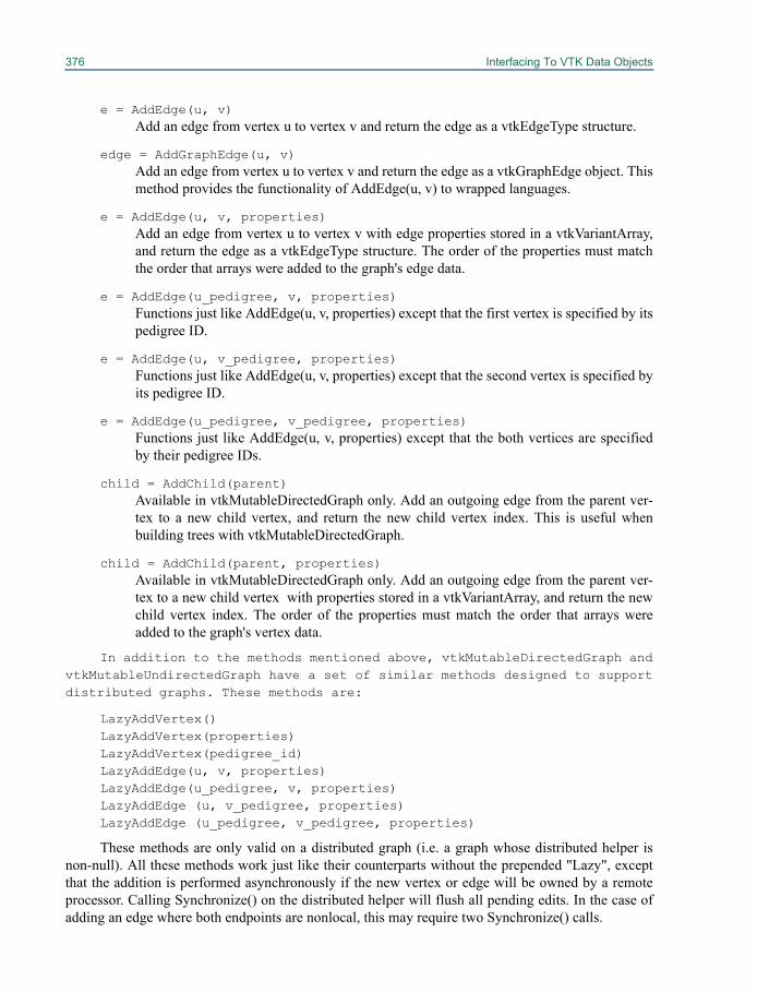
376 Interfacing To VTK Data Objects
e = AddEdge(u, v)Add an edge from vertex u to vertex v and return the edge as a vtkEdgeType structure.
edge = AddGraphEdge(u, v)Add an edge from vertex u to vertex v and return the edge as a vtkGraphEdge object. Thismethod provides the functionality of AddEdge(u, v) to wrapped languages.
e = AddEdge(u, v, properties)Add an edge from vertex u to vertex v with edge properties stored in a vtkVariantArray,and return the edge as a vtkEdgeType structure. The order of the properties must matchthe order that arrays were added to the graph's edge data.
e = AddEdge(u_pedigree, v, properties)Functions just like AddEdge(u, v, properties) except that the first vertex is specified by itspedigree ID.
e = AddEdge(u, v_pedigree, properties)Functions just like AddEdge(u, v, properties) except that the second vertex is specified byits pedigree ID.
e = AddEdge(u_pedigree, v_pedigree, properties)Functions just like AddEdge(u, v, properties) except that the both vertices are specifiedby their pedigree IDs.
child = AddChild(parent)Available in vtkMutableDirectedGraph only. Add an outgoing edge from the parent ver-tex to a new child vertex, and return the new child vertex index. This is useful whenbuilding trees with vtkMutableDirectedGraph.
child = AddChild(parent, properties)Available in vtkMutableDirectedGraph only. Add an outgoing edge from the parent ver-tex to a new child vertex with properties stored in a vtkVariantArray, and return the newchild vertex index. The order of the properties must match the order that arrays wereadded to the graph's vertex data.
In addition to the methods mentioned above, vtkMutableDirectedGraph andvtkMutableUndirectedGraph have a set of similar methods designed to supportdistributed graphs. These methods are:
LazyAddVertex()LazyAddVertex(properties)LazyAddVertex(pedigree_id)LazyAddEdge(u, v, properties)LazyAddEdge(u_pedigree, v, properties)LazyAddEdge (u, v_pedigree, properties)LazyAddEdge (u_pedigree, v_pedigree, properties)
These methods are only valid on a distributed graph (i.e. a graph whose distributed helper isnon-null). All these methods work just like their counterparts without the prepended "Lazy", exceptthat the addition is performed asynchronously if the new vertex or edge will be owned by a remoteprocessor. Calling Synchronize() on the distributed helper will flush all pending edits. In the case ofadding an edge where both endpoints are nonlocal, this may require two Synchronize() calls.
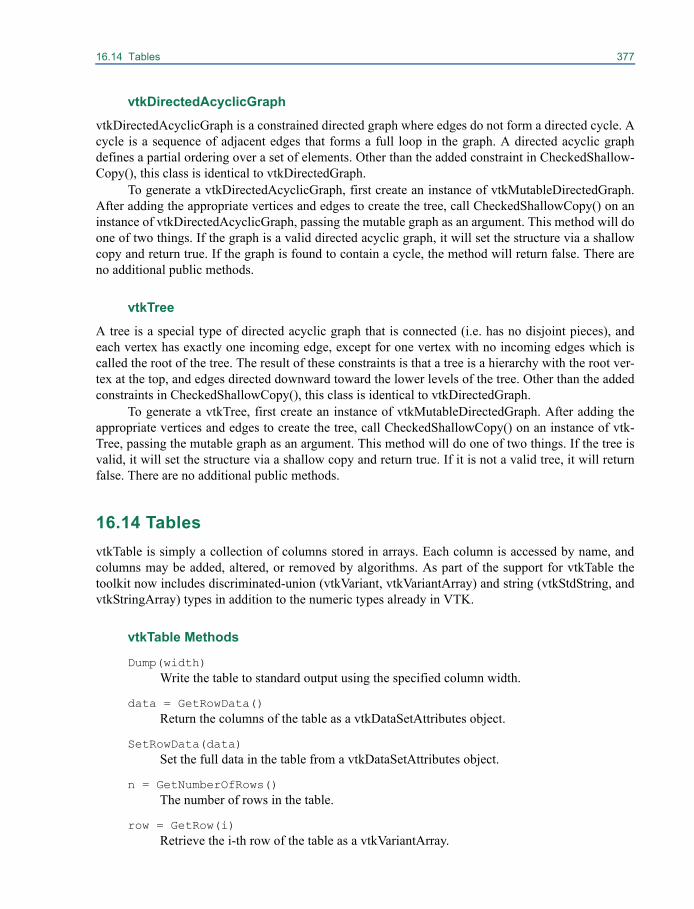
16.14 Tables 377
vtkDirectedAcyclicGraph
vtkDirectedAcyclicGraph is a constrained directed graph where edges do not form a directed cycle. Acycle is a sequence of adjacent edges that forms a full loop in the graph. A directed acyclic graphdefines a partial ordering over a set of elements. Other than the added constraint in CheckedShallow-Copy(), this class is identical to vtkDirectedGraph.
To generate a vtkDirectedAcyclicGraph, first create an instance of vtkMutableDirectedGraph.After adding the appropriate vertices and edges to create the tree, call CheckedShallowCopy() on aninstance of vtkDirectedAcyclicGraph, passing the mutable graph as an argument. This method will doone of two things. If the graph is a valid directed acyclic graph, it will set the structure via a shallowcopy and return true. If the graph is found to contain a cycle, the method will return false. There areno additional public methods.
vtkTree
A tree is a special type of directed acyclic graph that is connected (i.e. has no disjoint pieces), andeach vertex has exactly one incoming edge, except for one vertex with no incoming edges which iscalled the root of the tree. The result of these constraints is that a tree is a hierarchy with the root ver-tex at the top, and edges directed downward toward the lower levels of the tree. Other than the addedconstraints in CheckedShallowCopy(), this class is identical to vtkDirectedGraph.
To generate a vtkTree, first create an instance of vtkMutableDirectedGraph. After adding theappropriate vertices and edges to create the tree, call CheckedShallowCopy() on an instance of vtk-Tree, passing the mutable graph as an argument. This method will do one of two things. If the tree isvalid, it will set the structure via a shallow copy and return true. If it is not a valid tree, it will returnfalse. There are no additional public methods.
16.14 TablesvtkTable is simply a collection of columns stored in arrays. Each column is accessed by name, andcolumns may be added, altered, or removed by algorithms. As part of the support for vtkTable thetoolkit now includes discriminated-union (vtkVariant, vtkVariantArray) and string (vtkStdString, andvtkStringArray) types in addition to the numeric types already in VTK.
vtkTable Methods
Dump(width)Write the table to standard output using the specified column width.
data = GetRowData()Return the columns of the table as a vtkDataSetAttributes object.
SetRowData(data)Set the full data in the table from a vtkDataSetAttributes object.
n = GetNumberOfRows()The number of rows in the table.
row = GetRow(i)Retrieve the i-th row of the table as a vtkVariantArray.
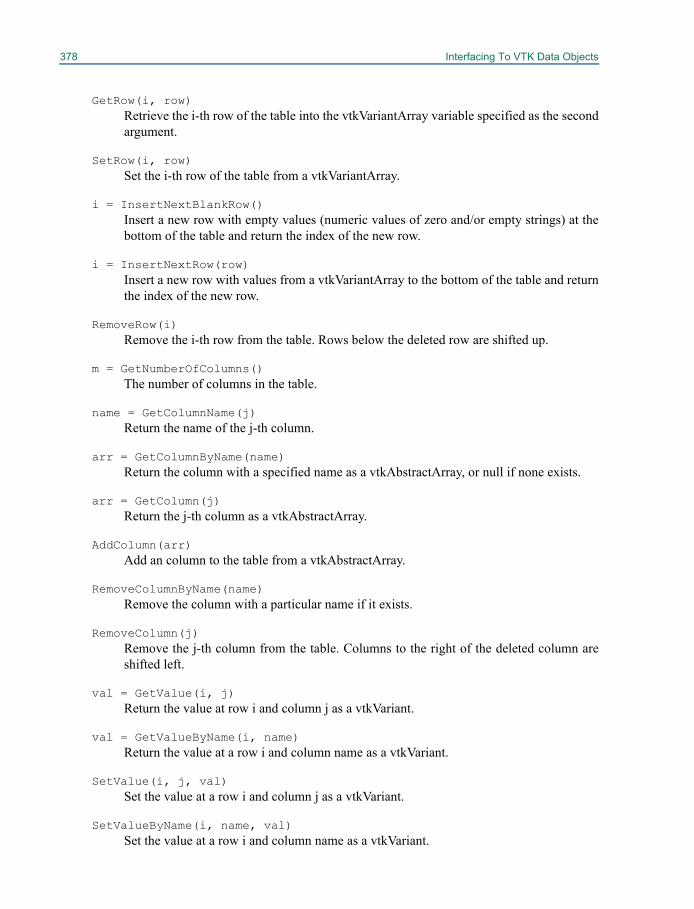
378 Interfacing To VTK Data Objects
GetRow(i, row)Retrieve the i-th row of the table into the vtkVariantArray variable specified as the secondargument.
SetRow(i, row)Set the i-th row of the table from a vtkVariantArray.
i = InsertNextBlankRow()Insert a new row with empty values (numeric values of zero and/or empty strings) at thebottom of the table and return the index of the new row.
i = InsertNextRow(row)Insert a new row with values from a vtkVariantArray to the bottom of the table and returnthe index of the new row.
RemoveRow(i)Remove the i-th row from the table. Rows below the deleted row are shifted up.
m = GetNumberOfColumns()The number of columns in the table.
name = GetColumnName(j)Return the name of the j-th column.
arr = GetColumnByName(name)Return the column with a specified name as a vtkAbstractArray, or null if none exists.
arr = GetColumn(j)Return the j-th column as a vtkAbstractArray.
AddColumn(arr)Add an column to the table from a vtkAbstractArray.
RemoveColumnByName(name)Remove the column with a particular name if it exists.
RemoveColumn(j)Remove the j-th column from the table. Columns to the right of the deleted column areshifted left.
val = GetValue(i, j)Return the value at row i and column j as a vtkVariant.
val = GetValueByName(i, name)Return the value at a row i and column name as a vtkVariant.
SetValue(i, j, val)Set the value at a row i and column j as a vtkVariant.
SetValueByName(i, name, val)Set the value at a row i and column name as a vtkVariant.
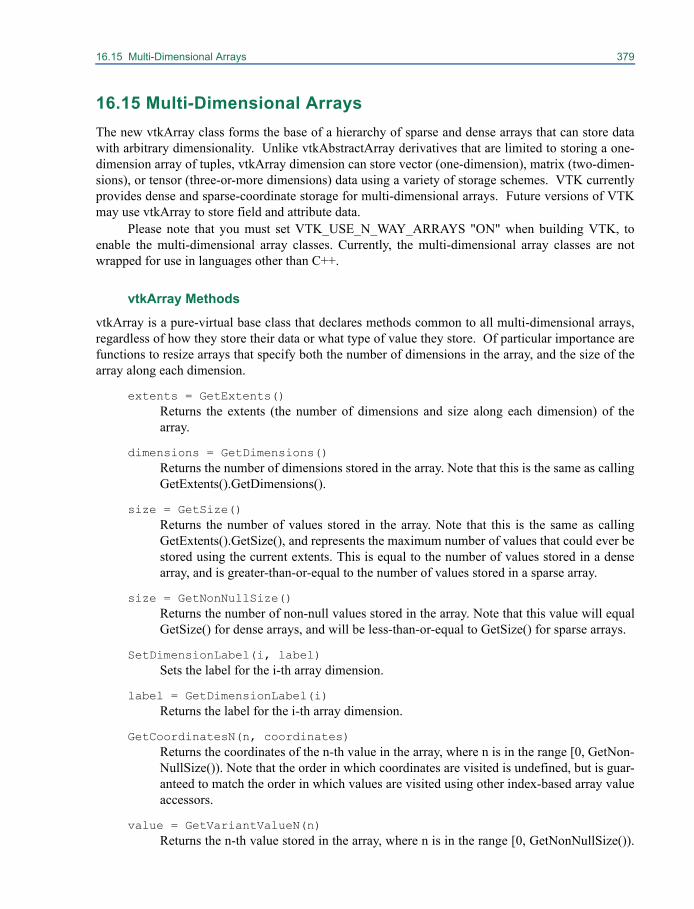
16.15 Multi-Dimensional Arrays 379
16.15 Multi-Dimensional ArraysThe new vtkArray class forms the base of a hierarchy of sparse and dense arrays that can store datawith arbitrary dimensionality. Unlike vtkAbstractArray derivatives that are limited to storing a one-dimension array of tuples, vtkArray dimension can store vector (one-dimension), matrix (two-dimen-sions), or tensor (three-or-more dimensions) data using a variety of storage schemes. VTK currentlyprovides dense and sparse-coordinate storage for multi-dimensional arrays. Future versions of VTKmay use vtkArray to store field and attribute data.
Please note that you must set VTK_USE_N_WAY_ARRAYS "ON" when building VTK, toenable the multi-dimensional array classes. Currently, the multi-dimensional array classes are notwrapped for use in languages other than C++.
vtkArray Methods
vtkArray is a pure-virtual base class that declares methods common to all multi-dimensional arrays,regardless of how they store their data or what type of value they store. Of particular importance arefunctions to resize arrays that specify both the number of dimensions in the array, and the size of thearray along each dimension.
extents = GetExtents()Returns the extents (the number of dimensions and size along each dimension) of thearray.
dimensions = GetDimensions()Returns the number of dimensions stored in the array. Note that this is the same as callingGetExtents().GetDimensions().
size = GetSize()Returns the number of values stored in the array. Note that this is the same as callingGetExtents().GetSize(), and represents the maximum number of values that could ever bestored using the current extents. This is equal to the number of values stored in a densearray, and is greater-than-or-equal to the number of values stored in a sparse array.
size = GetNonNullSize()Returns the number of non-null values stored in the array. Note that this value will equalGetSize() for dense arrays, and will be less-than-or-equal to GetSize() for sparse arrays.
SetDimensionLabel(i, label)Sets the label for the i-th array dimension.
label = GetDimensionLabel(i)Returns the label for the i-th array dimension.
GetCoordinatesN(n, coordinates)Returns the coordinates of the n-th value in the array, where n is in the range [0, GetNon-NullSize()). Note that the order in which coordinates are visited is undefined, but is guar-anteed to match the order in which values are visited using other index-based array valueaccessors.
value = GetVariantValueN(n)Returns the n-th value stored in the array, where n is in the range [0, GetNonNullSize()).

380 Interfacing To VTK Data Objects
This is useful for efficiently visiting every value in the array. Note that the order in whichvalues are visited is undefined, but is guaranteed to match the order used by vtkAr-ray::GetCoordinatesN().
SetVariantValueN(n, value)Overwrites the n-th value stored in the array, where n is in the range [0, GetNonNull-Size()). This is useful for efficiently visiting every value in the array. Note that the orderin which values are visited is undefined, but is guaranteed to match the order used byvtkArray::GetCoordinatesN().
array = DeepCopy()Returns a new array that is a deep copy of this array.
Resize(i)Resize(i, j)Resize(i, j, k)Resize(extents)
Resizes the array to the given extents (number of dimensions and size of each dimen-sion). Note that concrete implementations of vtkArray may place constraints on the theextents that they will store, so you cannot assume that GetExtents() will always return thesame value passed to Resize(). The contents of the array are undefined after callingResize() - you should initialize its contents accordingly. In particular, dimension-labelswill be undefined, dense array values will be undefined, and sparse arrays will be empty.
value = GetVariantValue(i)value = GetVariantValue(i, j)value = GetVariantValue(i, j, k)value = GetVariantValue(coordinates)
Returns the value stored in the array at the given coordinates. Note, the number of dimen-sions in the supplied coordinates must match the number of dimensions in the array.
SetVariantValue(i, value)SetVariantValue(i, j, value)SetVariantValue(i, j, k, value)SetVariantValue(coordinates, value)
Overwrites the value stored in the array at the given coordinates. Note, the number ofdimensions in the supplied coordinates must match the number of dimensions in thearray.
CopyValue(source, source_coordinates, target_coordinates)CopyValue(source, source_index, target_coordinates)CopyValue(source, source_coordinates, target_index)
Where coordinates are provided, they must match the number of dimensions in the corre-sponding array. Overwrites a value with a value retrieved from another array. Both arraysmust store the same data types.
vtkTypedArray MethodsvtkTypedArray provides a type-specific interface for retrieving and updating data in an arbitrary-dimension array. It derives from vtkArray and is templated on the type of value stored in the array.
Methods are provided for retrieving and updating array values based either on their array coor-dinates, or on a 1-dimensional integer index. The latter approach can be used to iterate over the valuesin an array in arbitrary order, which is useful when writing filters that operate efficiently on sparse
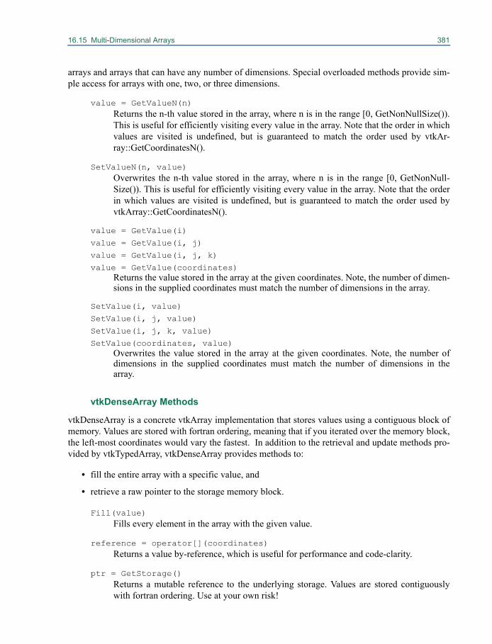
16.15 Multi-Dimensional Arrays 381
arrays and arrays that can have any number of dimensions. Special overloaded methods provide sim-ple access for arrays with one, two, or three dimensions.
value = GetValueN(n)Returns the n-th value stored in the array, where n is in the range [0, GetNonNullSize()).This is useful for efficiently visiting every value in the array. Note that the order in whichvalues are visited is undefined, but is guaranteed to match the order used by vtkAr-ray::GetCoordinatesN().
SetValueN(n, value)Overwrites the n-th value stored in the array, where n is in the range [0, GetNonNull-Size()). This is useful for efficiently visiting every value in the array. Note that the orderin which values are visited is undefined, but is guaranteed to match the order used byvtkArray::GetCoordinatesN().
value = GetValue(i)value = GetValue(i, j)value = GetValue(i, j, k)value = GetValue(coordinates)
Returns the value stored in the array at the given coordinates. Note, the number of dimen-sions in the supplied coordinates must match the number of dimensions in the array.
SetValue(i, value)SetValue(i, j, value)SetValue(i, j, k, value)SetValue(coordinates, value)
Overwrites the value stored in the array at the given coordinates. Note, the number ofdimensions in the supplied coordinates must match the number of dimensions in thearray.
vtkDenseArray Methods
vtkDenseArray is a concrete vtkArray implementation that stores values using a contiguous block ofmemory. Values are stored with fortran ordering, meaning that if you iterated over the memory block,the left-most coordinates would vary the fastest. In addition to the retrieval and update methods pro-vided by vtkTypedArray, vtkDenseArray provides methods to:
• fill the entire array with a specific value, and
• retrieve a raw pointer to the storage memory block.
Fill(value)Fills every element in the array with the given value.
reference = operator[](coordinates)Returns a value by-reference, which is useful for performance and code-clarity.
ptr = GetStorage()Returns a mutable reference to the underlying storage. Values are stored contiguouslywith fortran ordering. Use at your own risk!
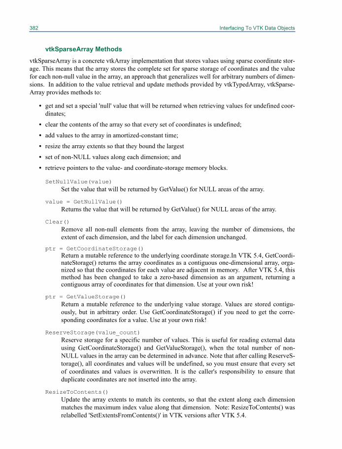
382 Interfacing To VTK Data Objects
vtkSparseArray Methods
vtkSparseArray is a concrete vtkArray implementation that stores values using sparse coordinate stor-age. This means that the array stores the complete set for sparse storage of coordinates and the valuefor each non-null value in the array, an approach that generalizes well for arbitrary numbers of dimen-sions. In addition to the value retrieval and update methods provided by vtkTypedArray, vtkSparse-Array provides methods to:
• get and set a special 'null' value that will be returned when retrieving values for undefined coor-dinates;
• clear the contents of the array so that every set of coordinates is undefined;
• add values to the array in amortized-constant time;
• resize the array extents so that they bound the largest
• set of non-NULL values along each dimension; and
• retrieve pointers to the value- and coordinate-storage memory blocks.
SetNullValue(value)Set the value that will be returned by GetValue() for NULL areas of the array.
value = GetNullValue()Returns the value that will be returned by GetValue() for NULL areas of the array.
Clear()Remove all non-null elements from the array, leaving the number of dimensions, theextent of each dimension, and the label for each dimension unchanged.
ptr = GetCoordinateStorage()Return a mutable reference to the underlying coordinate storage.In VTK 5.4, GetCoordi-nateStorage() returns the array coordinates as a contiguous one-dimensional array, orga-nized so that the coordinates for each value are adjacent in memory. After VTK 5.4, thismethod has been changed to take a zero-based dimension as an argument, returning acontiguous array of coordinates for that dimension. Use at your own risk!
ptr = GetValueStorage()Return a mutable reference to the underlying value storage. Values are stored contigu-ously, but in arbitrary order. Use GetCoordinateStorage() if you need to get the corre-sponding coordinates for a value. Use at your own risk!
ReserveStorage(value_count)Reserve storage for a specific number of values. This is useful for reading external datausing GetCoordinateStorage() and GetValueStorage(), when the total number of non-NULL values in the array can be determined in advance. Note that after calling ReserveS-torage(), all coordinates and values will be undefined, so you must ensure that every setof coordinates and values is overwritten. It is the caller's responsibility to ensure thatduplicate coordinates are not inserted into the array.
ResizeToContents()Update the array extents to match its contents, so that the extent along each dimensionmatches the maximum index value along that dimension. Note: ResizeToContents() wasrelabelled 'SetExtentsFromContents()' in VTK versions after VTK 5.4.
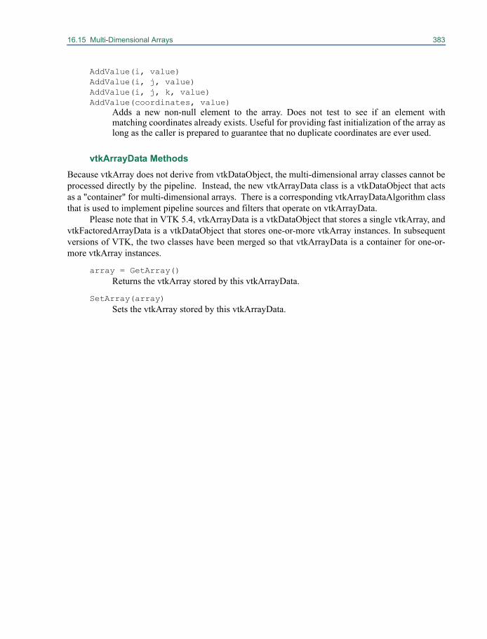
16.15 Multi-Dimensional Arrays 383
AddValue(i, value)AddValue(i, j, value)AddValue(i, j, k, value)AddValue(coordinates, value)
Adds a new non-null element to the array. Does not test to see if an element withmatching coordinates already exists. Useful for providing fast initialization of the array aslong as the caller is prepared to guarantee that no duplicate coordinates are ever used.
vtkArrayData MethodsBecause vtkArray does not derive from vtkDataObject, the multi-dimensional array classes cannot beprocessed directly by the pipeline. Instead, the new vtkArrayData class is a vtkDataObject that actsas a "container" for multi-dimensional arrays. There is a corresponding vtkArrayDataAlgorithm classthat is used to implement pipeline sources and filters that operate on vtkArrayData.
Please note that in VTK 5.4, vtkArrayData is a vtkDataObject that stores a single vtkArray, andvtkFactoredArrayData is a vtkDataObject that stores one-or-more vtkArray instances. In subsequentversions of VTK, the two classes have been merged so that vtkArrayData is a container for one-or-more vtkArray instances.
array = GetArray()Returns the vtkArray stored by this vtkArrayData.
SetArray(array)Sets the vtkArray stored by this vtkArrayData.

Chapter 17
How To Write an Algorithm for VTK 17
This section describes how to create your own algorithmsin VTK. Algorithms are objects that produce data (sources), operate on data to generate new data (fil-ters), and interface the data to graphics systems and/or other systems (mappers). (One may also referto algorithms generically as filters.) You may want to review “The Visualization Pipeline” on page 25for information about the graphics pipeline. Pipeline execution is discussed in more detail in Chapter19.
17.1 OverviewImplementing an algorithm or process as a VTK filter requires three basic steps.
1. Set up the pipeline interface. This specifies the number and type of inputs and/or outputs that are consumed and/or produced by the filter.
2. Set up the user interface. This provides users of the filter a means by which to tune or control algorithm parameters.
3. Write methods to fulfill pipeline requests. These provide the core functionality of the filter and contain the algorithm implementation.
The Pipeline Interface
A filter's pipeline interface determines how it may be connected and used in a VTK pipeline. Filtersthat consume data define one or more input ports, and those that produce data define one or more out-put ports. Each port corresponds to a logical input or output of the algorithm implemented by the fil-ter.
The first part of defining the pipeline interface is to choose the proper superclass from which toderive the class implementing the new algorithm. All filters derive directly or indirectly from vtkAl-
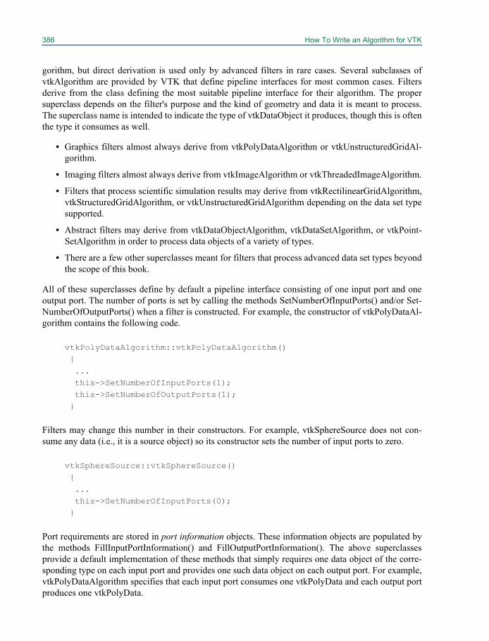
386 How To Write an Algorithm for VTK
gorithm, but direct derivation is used only by advanced filters in rare cases. Several subclasses ofvtkAlgorithm are provided by VTK that define pipeline interfaces for most common cases. Filtersderive from the class defining the most suitable pipeline interface for their algorithm. The propersuperclass depends on the filter's purpose and the kind of geometry and data it is meant to process.The superclass name is intended to indicate the type of vtkDataObject it produces, though this is oftenthe type it consumes as well.
• Graphics filters almost always derive from vtkPolyDataAlgorithm or vtkUnstructuredGridAl-gorithm.
• Imaging filters almost always derive from vtkImageAlgorithm or vtkThreadedImageAlgorithm.
• Filters that process scientific simulation results may derive from vtkRectilinearGridAlgorithm,vtkStructuredGridAlgorithm, or vtkUnstructuredGridAlgorithm depending on the data set typesupported.
• Abstract filters may derive from vtkDataObjectAlgorithm, vtkDataSetAlgorithm, or vtkPoint-SetAlgorithm in order to process data objects of a variety of types.
• There are a few other superclasses meant for filters that process advanced data set types beyondthe scope of this book.
All of these superclasses define by default a pipeline interface consisting of one input port and oneoutput port. The number of ports is set by calling the methods SetNumberOfInputPorts() and/or Set-NumberOfOutputPorts() when a filter is constructed. For example, the constructor of vtkPolyDataAl-gorithm contains the following code.
vtkPolyDataAlgorithm::vtkPolyDataAlgorithm() { ... this->SetNumberOfInputPorts(1); this->SetNumberOfOutputPorts(1); }
Filters may change this number in their constructors. For example, vtkSphereSource does not con-sume any data (i.e., it is a source object) so its constructor sets the number of input ports to zero.
vtkSphereSource::vtkSphereSource() { ... this->SetNumberOfInputPorts(0); }
Port requirements are stored in port information objects. These information objects are populated bythe methods FillInputPortInformation() and FillOutputPortInformation(). The above superclassesprovide a default implementation of these methods that simply requires one data object of the corre-sponding type on each input port and provides one such data object on each output port. For example,vtkPolyDataAlgorithm specifies that each input port consumes one vtkPolyData and each output portproduces one vtkPolyData.
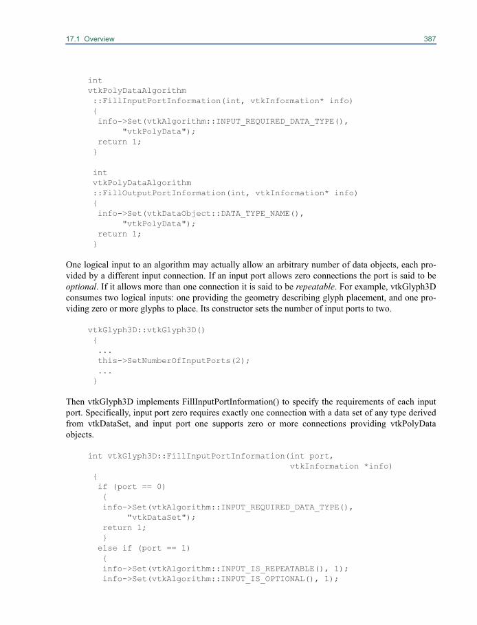
17.1 Overview 387
intvtkPolyDataAlgorithm ::FillInputPortInformation(int, vtkInformation* info) { info->Set(vtkAlgorithm::INPUT_REQUIRED_DATA_TYPE(), "vtkPolyData"); return 1; }
int vtkPolyDataAlgorithm ::FillOutputPortInformation(int, vtkInformation* info) { info->Set(vtkDataObject::DATA_TYPE_NAME(), "vtkPolyData"); return 1; }
One logical input to an algorithm may actually allow an arbitrary number of data objects, each pro-vided by a different input connection. If an input port allows zero connections the port is said to beoptional. If it allows more than one connection it is said to be repeatable. For example, vtkGlyph3Dconsumes two logical inputs: one providing the geometry describing glyph placement, and one pro-viding zero or more glyphs to place. Its constructor sets the number of input ports to two.
vtkGlyph3D::vtkGlyph3D() { ... this->SetNumberOfInputPorts(2); ... }
Then vtkGlyph3D implements FillInputPortInformation() to specify the requirements of each inputport. Specifically, input port zero requires exactly one connection with a data set of any type derivedfrom vtkDataSet, and input port one supports zero or more connections providing vtkPolyDataobjects.
int vtkGlyph3D::FillInputPortInformation(int port, vtkInformation *info)
{ if (port == 0) { info->Set(vtkAlgorithm::INPUT_REQUIRED_DATA_TYPE(), "vtkDataSet"); return 1; } else if (port == 1) { info->Set(vtkAlgorithm::INPUT_IS_REPEATABLE(), 1); info->Set(vtkAlgorithm::INPUT_IS_OPTIONAL(), 1);
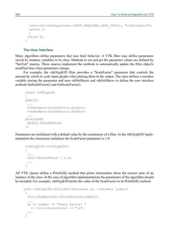
388 How To Write an Algorithm for VTK
info->Set(vtkAlgorithm::INPUT_REQUIRED_DATA_TYPE(), "vtkPolyData"); return 1; } return 0; }
The User InterfaceMany algorithms define parameters that tune their behavior. A VTK filter may define parametersstored by instance variables in its class. Methods to set and get the parameter values are defined by"Set/Get" macros. These macros implement the methods to automatically update the filter object'smodified time when parameters change.
For example, the vtkGlyph3D filter provides a "ScaleFactor" parameter that controls theamount by which to scale input glyphs when placing them in the output. The class defines a membervariable storing the parameter and uses vtkSetMacro and vtkGetMacro to define the user interfacemethods SetScaleFactor() and GetScaleFactor().
class vtkGlyph3D { public: ... vtkSetMacro(ScaleFactor,double); vtkGetMacro(ScaleFactor,double); ... protected: double ScaleFactor; };
Parameters are initialized with a default value by the constructor of a filter. In the vtkGlyph3D imple-mentation the constructor initializes the ScaleFactor parameter to 1.0.
vtkGlyph3D::vtkGlyph3D() { ... this->ScaleFactor = 1.0; ... }
All VTK classes define a PrintSelf() method that prints information about the current state of aninstance of the class. In the case of algorithm implementations the parameters of the algorithm shouldbe included. For example, vtkGlyph3D prints the value of the ScaleFactor in its PrintSelf() method.
void vtkGlyph3D::PrintSelf(ostream& os, vtkIndent indent) { this->Superclass::PrintSelf(os,indent); ... os << indent << "Scale Factor: " << this->ScaleFactor << "\n"; ... }
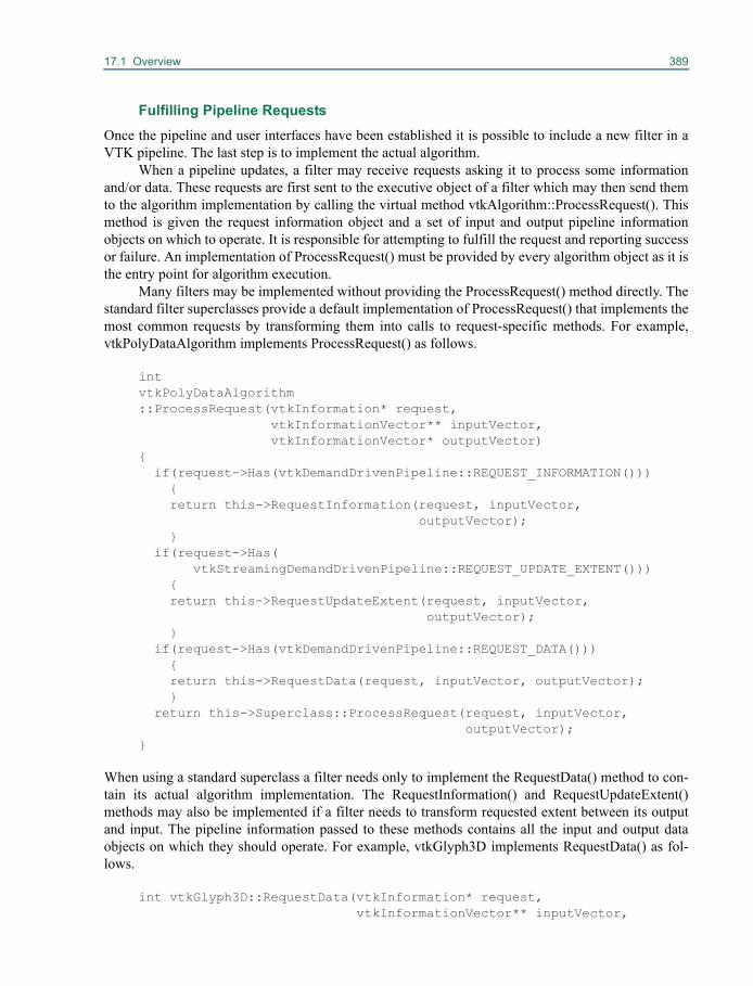
17.1 Overview 389
Fulfilling Pipeline RequestsOnce the pipeline and user interfaces have been established it is possible to include a new filter in aVTK pipeline. The last step is to implement the actual algorithm.
When a pipeline updates, a filter may receive requests asking it to process some informationand/or data. These requests are first sent to the executive object of a filter which may then send themto the algorithm implementation by calling the virtual method vtkAlgorithm::ProcessRequest(). Thismethod is given the request information object and a set of input and output pipeline informationobjects on which to operate. It is responsible for attempting to fulfill the request and reporting successor failure. An implementation of ProcessRequest() must be provided by every algorithm object as it isthe entry point for algorithm execution.
Many filters may be implemented without providing the ProcessRequest() method directly. Thestandard filter superclasses provide a default implementation of ProcessRequest() that implements themost common requests by transforming them into calls to request-specific methods. For example,vtkPolyDataAlgorithm implements ProcessRequest() as follows.
intvtkPolyDataAlgorithm::ProcessRequest(vtkInformation* request,
vtkInformationVector** inputVector,vtkInformationVector* outputVector)
{if(request->Has(vtkDemandDrivenPipeline::REQUEST_INFORMATION())){return this->RequestInformation(request, inputVector,
outputVector);}
if(request->Has(vtkStreamingDemandDrivenPipeline::REQUEST_UPDATE_EXTENT()))
{return this->RequestUpdateExtent(request, inputVector,
outputVector);}
if(request->Has(vtkDemandDrivenPipeline::REQUEST_DATA())){return this->RequestData(request, inputVector, outputVector);}
return this->Superclass::ProcessRequest(request, inputVector,outputVector);
}
When using a standard superclass a filter needs only to implement the RequestData() method to con-tain its actual algorithm implementation. The RequestInformation() and RequestUpdateExtent()methods may also be implemented if a filter needs to transform requested extent between its outputand input. The pipeline information passed to these methods contains all the input and output dataobjects on which they should operate. For example, vtkGlyph3D implements RequestData() as fol-lows.
int vtkGlyph3D::RequestData(vtkInformation* request,vtkInformationVector** inputVector,
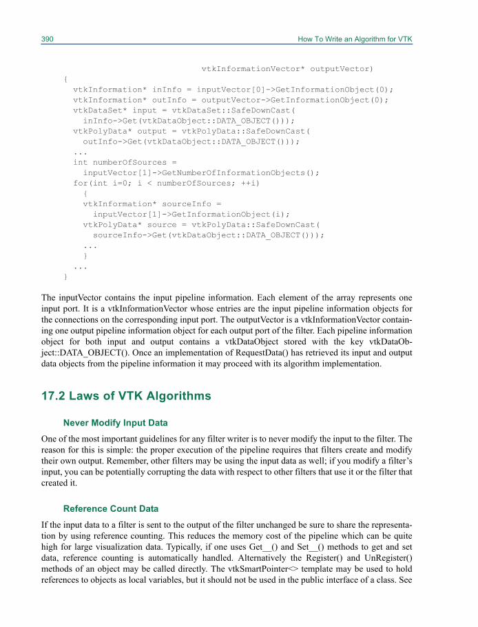
390 How To Write an Algorithm for VTK
vtkInformationVector* outputVector){
vtkInformation* inInfo = inputVector[0]->GetInformationObject(0);vtkInformation* outInfo = outputVector->GetInformationObject(0);vtkDataSet* input = vtkDataSet::SafeDownCast(inInfo->Get(vtkDataObject::DATA_OBJECT()));
vtkPolyData* output = vtkPolyData::SafeDownCast(outInfo->Get(vtkDataObject::DATA_OBJECT()));
...int numberOfSources =inputVector[1]->GetNumberOfInformationObjects();
for(int i=0; i < numberOfSources; ++i){vtkInformation* sourceInfo =
inputVector[1]->GetInformationObject(i);vtkPolyData* source = vtkPolyData::SafeDownCast(
sourceInfo->Get(vtkDataObject::DATA_OBJECT()));...}
...}
The inputVector contains the input pipeline information. Each element of the array represents oneinput port. It is a vtkInformationVector whose entries are the input pipeline information objects forthe connections on the corresponding input port. The outputVector is a vtkInformationVector contain-ing one output pipeline information object for each output port of the filter. Each pipeline informationobject for both input and output contains a vtkDataObject stored with the key vtkDataOb-ject::DATA_OBJECT(). Once an implementation of RequestData() has retrieved its input and outputdata objects from the pipeline information it may proceed with its algorithm implementation.
17.2 Laws of VTK Algorithms
Never Modify Input DataOne of the most important guidelines for any filter writer is to never modify the input to the filter. Thereason for this is simple: the proper execution of the pipeline requires that filters create and modifytheir own output. Remember, other filters may be using the input data as well; if you modify a filter’sinput, you can be potentially corrupting the data with respect to other filters that use it or the filter thatcreated it.
Reference Count DataIf the input data to a filter is sent to the output of the filter unchanged be sure to share the representa-tion by using reference counting. This reduces the memory cost of the pipeline which can be quitehigh for large visualization data. Typically, if one uses Get__() and Set__() methods to get and setdata, reference counting is automatically handled. Alternatively the Register() and UnRegister()methods of an object may be called directly. The vtkSmartPointer<> template may be used to holdreferences to objects as local variables, but it should not be used in the public interface of a class. See
17.2 Laws of VTK Algorithms 391
“Low-Level Object Model” on page 20 for more information about reference counting and smartpointers. Filter authors may wish to use specialized methods for passing data through a filter, see“Field and Attribute Data” on page 362 for more information.
Use Debug Macros
Filters should provide debugging information when the object’s Debug flag is set. This is conve-niently done using VTK’s debug macros defined in VTK/Common/vtkSetGet.h. At a minimum, afilter should report the initiation of execution similar to the following (from VTK/Graphics/vtk-ContourFilter.cxx).
vtkDebugMacro(<< "Executing contour filter");
You may also wish to provide other information as the filter executes, for example, a summary of exe-cution (again from vtkContourFilter.cxx):
vtkDebugMacro(<<"Created: " << newPts->GetNumberOfPoints() << " points, " << newVerts->GetNumberOfCells() << " verts, " << newLines->GetNumberOfCells() << " lines, " << newPolys->GetNumberOfCells() << " triangles");
Do not place debugging macros in the inner portions of a loop, since the macro invokes an if checkthat may affect performance. Also, if debugging is turned on in an inner loop, too much informationwill be output to be meaningfully interpreted.
Reclaim/Delete Allocated Memory
One common mistake that filter writers make is introducing memory leaks or using excessive mem-ory. Memory leaks can be avoided by pairing New() and Delete() methods for all VTK objects andnew and delete methods for all native or non-VTK objects. (See “Standard Methods: Creating andDeleting Objects” on page 300.)
Another way to reduce memory usage is to use the Squeeze() methods provided by vtkDataAr-ray and subclasses. This method reclaims excess memory that an object may be using. Use theSqueeze() method whenever the size of the data object can only be estimated upon initial allocation.
Compute Modified Time
One of the trickiest parts of writing a filter is making sure that its modified time is properly managed.As you may recall, modified time is an internal time stamp that each object maintains in response tochanges in its internal state. Typically, modified time changes when a Set__() method is invoked. Forexample, the method vtkTubeFilter::SetNumberOfSides(num) causes the vtkTubeFilter’s modifiedtime to change when this method is invoked, as long as num is different than the tube filter’s currentinstance variable value.
Normally, the modified time of a filter is maintained without requiring intervention. For exam-ple, if you use the vtkSet/Get macros defined in VTK/Common/vtkSetGet.h to get and setinstance variable values, modified time is properly managed, and the inherited methodvtkObject::GetMTime() returns the correct value. However, if you define your own Set__() methods,
392 How To Write an Algorithm for VTK
or include methods that modify the internal state of the object, you will have to invoke Modified()(i.e., change the internal modified time) on the filter as appropriate. And, if your object definitionincludes references to other objects, the correct modified time of the filter includes both the filter andobjects it depends on. This requires overloading the GetMTime() method.
vtkCutter is an example of a filter demonstrating this behavior. This filter makes reference toanother object, (i.e., the CutFunction), an instance of vtkImplicitFunction. When the implicit functiondefinition changes, we expect the cutter to reexecute. Thus, the GetMTime() method of the filter mustreflect this by considering the modified time of the implicit function; the GetMTime() method inher-ited from its superclass vtkObject must be overloaded. The implementation of thevtkCutter::GetMTime() method is as follows. It’s actually more complicated than suggested herebecause vtkCutter depends on two other objects (vtkLocator and vtkContourValues) as shown below.
unsigned long vtkCutter::GetMTime(){ unsigned long mTime=this->Superclass::GetMTime(); unsigned long contourValuesMTime=this->ContourValues->GetMTime(); unsigned long time;
mTime = ( contourValuesMTime > mTime ? contourValuesMTime : mTime );
if ( this->CutFunction != NULL ) { time = this->CutFunction->GetMTime(); mTime = ( time > mTime ? time : mTime ); } if ( this->Locator != NULL ) { time = this->Locator->GetMTime(); mTime = ( time > mTime ? time : mTime ); } return mTime;}
The class vtkLocator is used to merge coincident points as the filter executes; vtkContourValues is ahelper class used to generate contour values for those functions using isosurfacing as part of their exe-cution process. The GetMTime() method must check all objects that vtkCutter depends on, returningthe largest modified time it finds.
Although the use of modified time and the implicit execution model of the VTK visualizationpipeline is simple, there is one common source of confusion. That is, you must distinguish between afilter’s modified time and its dependency on the data stream. Remember, filters will execute eitherwhen they are modified (the modified time changes), or the input to the filter changes (dependency ondata stream). Modified time only reflects changes to a filter or dependencies on other objects indepen-dent of the data stream.
Use ProgressEvent and AbortExecute The ProgressEvent is invoked at regular intervals during the execution of a source, filter, or mapperobject (i.e., any algorithm). Progress user methods typically perform such functions as updating anapplication user interface (e.g., imagine manipulating a progress bar in the GUI). (See “General
17.2 Laws of VTK Algorithms 393
Guidelines for GUI Interaction” on page 423 and “User Methods, Observers, and Commands” onpage 29 for more information.)
A progress user method is created by invoking AddObserver() with an event type of vtkCom-mand::ProgressEvent. When the progress method is invoked, the filter also sets the current progressvalue (a decimal fraction between (0,1) retrieved with the GetProgress() method). The progressmethod can be used in combination with the vtkAlgorithm’s invocation of StartEvent and EndEvent.For example, Examples/Tutorial/Step2 shows how to use these methods. Here’s a code frag-ment to show how it works.
vtkDecimatePro decideci AddObserver StartEvent {StartProgress deci “Decimating...”}deci AddObserver ProgressEvent {ShowProgress deci “Decimating...”}deci AddObserver EndEvent EndProgress
Not all filters invoke ProgressEvents or invoke them infrequently (depending on the filter implemen-tation). The progress value may not be a true measure of the actual work done by the filter because itis difficult to measure progress in some filters and/or the filter implementor may choose to update thefilter at key points in the algorithm (e.g., after building internal data structures, reading in a piece ofdata, etc.).
Related to progress methods is the concept of a flag that is used to stop execution of a filter.This flag, defined in vtkAlgorithm, is called the AbortExecute flag. When set, some filters will termi-nate their execution, sending to their output some portion of the result of their execution (or possiblynothing). Typically, the flag is set during invocation of a ProgressEvent and is used to prematurelyterminate execution of a filter when it is taking too long or the application is attempting to keep upwith user input events. Not all filters support the AbortExecute flag. Check the source code to be surewhich ones support the flag. (Most do, and those that don’t will in the near future.) An example use ofprogress user methods and the abort flag is shown in the following code fragment taken from VTK/Graphics/vtkDecimatePro.cxx.
for ( ptId=0; ptId < npts && !abortExecute ; ptId++ ) { if ( ! (ptId % 10000) ) { vtkDebugMacro(<<"Inserting vertex #" << ptId); this->UpdateProgress (0.25*ptId/npts);//25% inserting if (this->GetAbortExecute()) { abortExecute = 1; break; } } this->Insert(ptId); }
Note that the filter implementor made some arbitrary decisions: the progress methods are invokedevery 10,000 points; and the portion of the RequestData() method shown is assumed to take approxi-mately 25% of the total execution time. Also, some debug output is combined with the execution ofthe progress method, as well as a status check on the abort flag. This points out an important guide-
394 How To Write an Algorithm for VTK
line: as a filter implementor you do not want to invoke progress methods too often because they canaffect overall performance.
Implement PrintSelf() MethodsAll VTK classes implement a PrintSelf() method that prints the state of the object in a human-read-able format. An implementation of this method must first pass the call to the superclass's implementa-tion of the method and then print the state of the class's instance variables. If one of these instancevariables is itself a VTK class then that object's PrintSelf() method should be invoked with an incre-mented level of indentation. For example, vtkCutter implements PrintSelf() as follows.
void vtkCutter::PrintSelf(ostream& os, vtkIndent indent) { this->Superclass::PrintSelf(os,indent); os << indent << "Cut Function: " << this->CutFunction << "\n"; os << indent << "Sort By: " << this->GetSortByAsString() << "\n"; if ( this->Locator ) { os << indent << "Locator: " << this->Locator << "\n"; } else { os << indent << "Locator: (none)\n"; } this->ContourValues->PrintSelf(os, indent.GetNextIndent()); os << indent << "Generate Cut Scalars: " << (this->GenerateCutScalars ? "On\n" : "Off\n"); }
Get Input/Output Data From Pipeline InformationMany filters provide GetInput() and GetOutput() methods that are useful for users to get the inputsand outputs of a filter they create. It is tempting to use these methods from within the implementationof ProcessRequest() or one of the methods it calls, but this should not be done. The pipeline informa-tion objects passed to ProcessRequest() and related methods contain the data objects that should beused. These may be different from the data objects returned by GetInput() or GetOutput(), particularlywhen one filter is used internally in the implementation of another filter.
17.3 Example AlgorithmsIn this section a few example VTK filters are given. We show how to implement the filters by follow-ing the steps outlined above.
A Graphics FilterThe class vtkShrinkFilter defines a simple graphics filter. Its purpose is to shrink all cells of an inputdata set in order to visualize the structure of each cell. Since all standard VTK cell types are sup-ported, the output type must be vtkUnstructuredGrid. We also want one input port for the input dataset and one output port for the output data set. This makes vtkUnstructuredGridAlgorithm a suitable
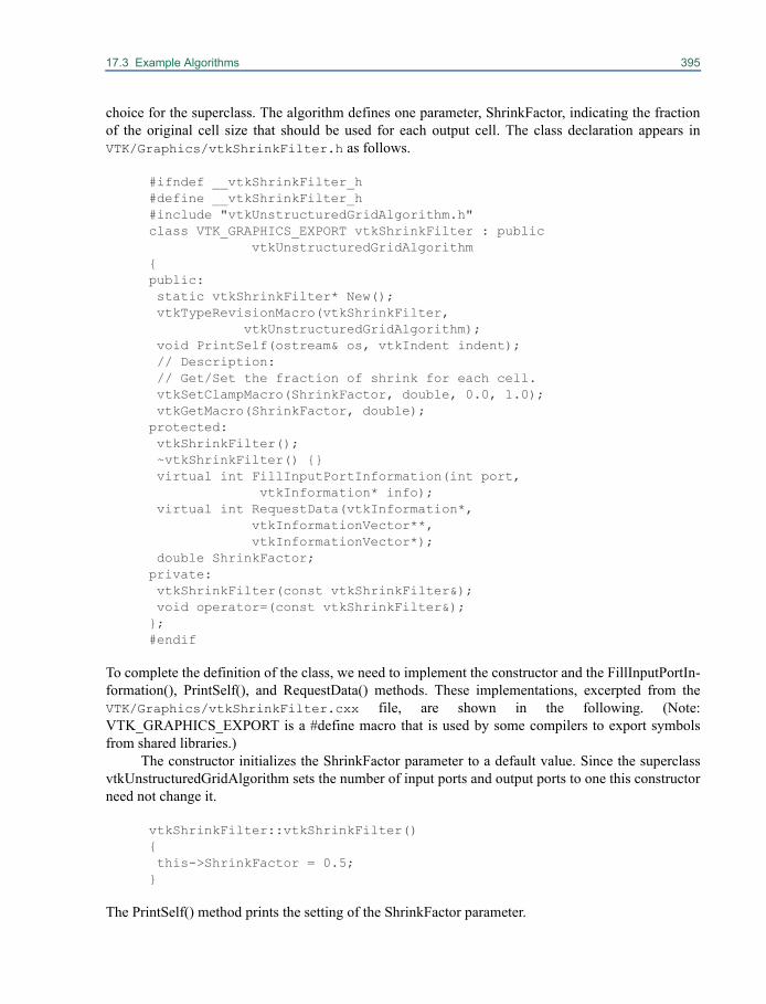
17.3 Example Algorithms 395
choice for the superclass. The algorithm defines one parameter, ShrinkFactor, indicating the fractionof the original cell size that should be used for each output cell. The class declaration appears inVTK/Graphics/vtkShrinkFilter.h as follows.
#ifndef __vtkShrinkFilter_h #define __vtkShrinkFilter_h #include "vtkUnstructuredGridAlgorithm.h" class VTK_GRAPHICS_EXPORT vtkShrinkFilter : public vtkUnstructuredGridAlgorithm { public: static vtkShrinkFilter* New(); vtkTypeRevisionMacro(vtkShrinkFilter, vtkUnstructuredGridAlgorithm); void PrintSelf(ostream& os, vtkIndent indent); // Description: // Get/Set the fraction of shrink for each cell. vtkSetClampMacro(ShrinkFactor, double, 0.0, 1.0); vtkGetMacro(ShrinkFactor, double); protected: vtkShrinkFilter(); ~vtkShrinkFilter() {} virtual int FillInputPortInformation(int port, vtkInformation* info); virtual int RequestData(vtkInformation*, vtkInformationVector**, vtkInformationVector*); double ShrinkFactor; private: vtkShrinkFilter(const vtkShrinkFilter&); void operator=(const vtkShrinkFilter&); }; #endif
To complete the definition of the class, we need to implement the constructor and the FillInputPortIn-formation(), PrintSelf(), and RequestData() methods. These implementations, excerpted from theVTK/Graphics/vtkShrinkFilter.cxx file, are shown in the following. (Note:VTK_GRAPHICS_EXPORT is a #define macro that is used by some compilers to export symbolsfrom shared libraries.)
The constructor initializes the ShrinkFactor parameter to a default value. Since the superclassvtkUnstructuredGridAlgorithm sets the number of input ports and output ports to one this constructorneed not change it.
vtkShrinkFilter::vtkShrinkFilter() { this->ShrinkFactor = 0.5; }
The PrintSelf() method prints the setting of the ShrinkFactor parameter.
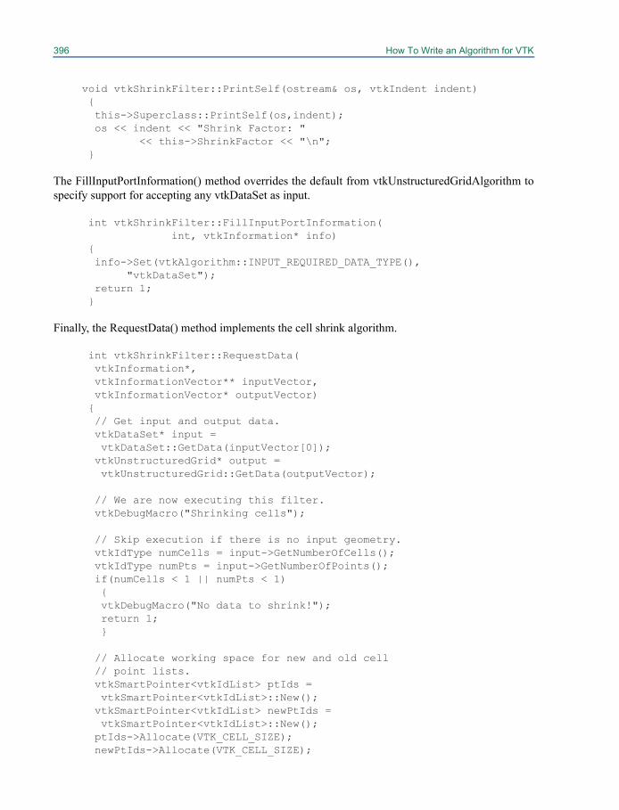
396 How To Write an Algorithm for VTK
void vtkShrinkFilter::PrintSelf(ostream& os, vtkIndent indent) { this->Superclass::PrintSelf(os,indent); os << indent << "Shrink Factor: " << this->ShrinkFactor << "\n"; }
The FillInputPortInformation() method overrides the default from vtkUnstructuredGridAlgorithm tospecify support for accepting any vtkDataSet as input.
int vtkShrinkFilter::FillInputPortInformation( int, vtkInformation* info) { info->Set(vtkAlgorithm::INPUT_REQUIRED_DATA_TYPE(), "vtkDataSet"); return 1; }
Finally, the RequestData() method implements the cell shrink algorithm.
int vtkShrinkFilter::RequestData( vtkInformation*, vtkInformationVector** inputVector, vtkInformationVector* outputVector) { // Get input and output data. vtkDataSet* input = vtkDataSet::GetData(inputVector[0]); vtkUnstructuredGrid* output = vtkUnstructuredGrid::GetData(outputVector);
// We are now executing this filter. vtkDebugMacro("Shrinking cells");
// Skip execution if there is no input geometry. vtkIdType numCells = input->GetNumberOfCells(); vtkIdType numPts = input->GetNumberOfPoints(); if(numCells < 1 || numPts < 1) { vtkDebugMacro("No data to shrink!"); return 1; }
// Allocate working space for new and old cell // point lists. vtkSmartPointer<vtkIdList> ptIds = vtkSmartPointer<vtkIdList>::New(); vtkSmartPointer<vtkIdList> newPtIds = vtkSmartPointer<vtkIdList>::New(); ptIds->Allocate(VTK_CELL_SIZE); newPtIds->Allocate(VTK_CELL_SIZE);

17.3 Example Algorithms 397
// Allocate approximately the space needed for the output cells. output->Allocate(numCells);
// Allocate space for a new set of points. vtkSmartPointer<vtkPoints> newPts =
vtkSmartPointer<vtkPoints>::New(); newPts->Allocate(numPts*8, numPts);
// Allocate space for data associated with the // new set of points. vtkPointData* inPD = input->GetPointData(); vtkPointData* outPD = output->GetPointData(); outPD->CopyAllocate(inPD, numPts*8, numPts);
// Support progress and abort. vtkIdType tenth = (numCells >= 10? numCells/10 : 1); double numCellsInv = 1.0/numCells; int abort = 0;
// Traverse all cells, obtaining node // coordinates. Compute "center" of cell, then // create new vertices shrunk towards center. for(vtkIdType cellId = 0; cellId < numCells && !abort; ++cellId) { // Get the list of points for this cell. input->GetCellPoints(cellId, ptIds); vtkIdType numIds = ptIds->GetNumberOfIds();
// Periodically update progress and check for // an abort request. if(cellId % tenth == 0) { this->UpdateProgress((cellId+1)*numCellsInv); abort = this->GetAbortExecute(); }
// Compute the center of mass of the cell // points. double center[3] = {0,0,0}; for(vtkIdType i=0; i < numIds; ++i) { double p[3]; input->GetPoint(ptIds->GetId(i), p); for(int j=0; j < 3; ++j) { center[j] += p[j]; } }
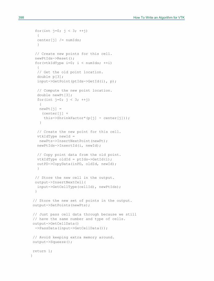
398 How To Write an Algorithm for VTK
for(int j=0; j < 3; ++j) { center[j] /= numIds; }
// Create new points for this cell. newPtIds->Reset(); for(vtkIdType i=0; i < numIds; ++i) { // Get the old point location. double p[3]; input->GetPoint(ptIds->GetId(i), p);
// Compute the new point location. double newPt[3]; for(int j=0; j < 3; ++j) { newPt[j] = (center[j] + this->ShrinkFactor*(p[j] - center[j])); }
// Create the new point for this cell. vtkIdType newId = newPts->InsertNextPoint(newPt); newPtIds->InsertId(i, newId);
// Copy point data from the old point. vtkIdType oldId = ptIds->GetId(i); outPD->CopyData(inPD, oldId, newId); }
// Store the new cell in the output. output->InsertNextCell( input->GetCellType(cellId), newPtIds); }
// Store the new set of points in the output. output->SetPoints(newPts);
// Just pass cell data through because we still // have the same number and type of cells. output->GetCellData() ->PassData(input->GetCellData());
// Avoid keeping extra memory around. output->Squeeze();
return 1; }
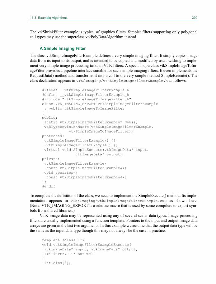
17.3 Example Algorithms 399
The vtkShrinkFilter example is typical of graphics filters. Simpler filters supporting only polygonalcell types may use the superclass vtkPolyDataAlgorithm instead.
A Simple Imaging FilterThe class vtkSimpleImageFilterExample defines a very simple imaging filter. It simply copies imagedata from its input to its output, and is intended to be copied and modified by users wishing to imple-ment very simple image processing tasks in VTK filters. A special superclass vtkSimpleImageToIm-ageFilter provides a pipeline interface suitable for such simple imaging filters. It even implements theRequestData() method and transforms it into a call to the very simple method SimpleExecute(). Theclass declaration appears in VTK/Imaging/vtkSimpleImageFilterExample.h as follows.
#ifndef __vtkSimpleImageFilterExample_h #define __vtkSimpleImageFilterExample_h #include "vtkSimpleImageToImageFilter.h" class VTK_IMAGING_EXPORT vtkSimpleImageFilterExample : public vtkSimpleImageToImageFilter { public: static vtkSimpleImageFilterExample* New(); vtkTypeRevisionMacro(vtkSimpleImageFilterExample, vtkSimpleImageToImageFilter); protected: vtkSimpleImageFilterExample() {} ~vtkSimpleImageFilterExample() {} virtual void SimpleExecute(vtkImageData* input, vtkImageData* output); private: vtkSimpleImageFilterExample( const vtkSimpleImageFilterExample&); void operator=( const vtkSimpleImageFilterExample&); }; #endif
To complete the definition of the class, we need to implement the SimpleExecute() method. Its imple-mentation appears in VTK/Imaging/vtkSimpleImageFilterExample.cxx as shown here.(Note: VTK_IMAGING_EXPORT is a #define macro that is used by some compilers to export sym-bols from shared libraries.)
VTK image data may be represented using any of several scalar data types. Image processingfilters are usually implemented using a function template. Pointers to the input and output image dataarrays are given in the last two arguments. In this example we assume that the output data type will bethe same as the input data type though this may not always be the case in practice.
template <class IT> void vtkSimpleImageFilterExampleExecute( vtkImageData* input, vtkImageData* output, IT* inPtr, IT* outPtr) { int dims[3];
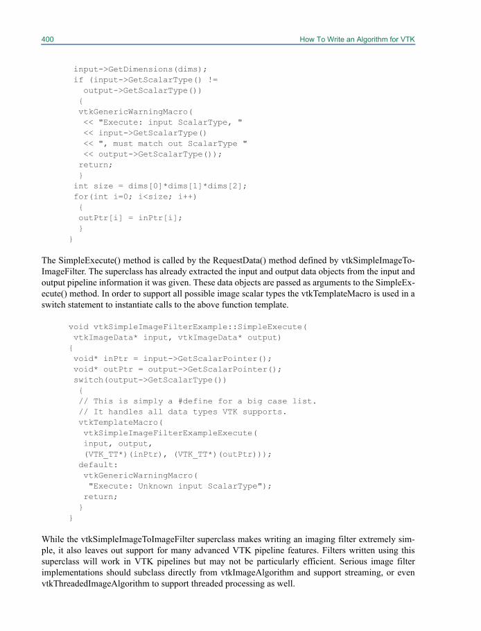
400 How To Write an Algorithm for VTK
input->GetDimensions(dims); if (input->GetScalarType() != output->GetScalarType()) { vtkGenericWarningMacro( << "Execute: input ScalarType, " << input->GetScalarType() << ", must match out ScalarType " << output->GetScalarType()); return; } int size = dims[0]*dims[1]*dims[2]; for(int i=0; i<size; i++) { outPtr[i] = inPtr[i]; } }
The SimpleExecute() method is called by the RequestData() method defined by vtkSimpleImageTo-ImageFilter. The superclass has already extracted the input and output data objects from the input andoutput pipeline information it was given. These data objects are passed as arguments to the SimpleEx-ecute() method. In order to support all possible image scalar types the vtkTemplateMacro is used in aswitch statement to instantiate calls to the above function template.
void vtkSimpleImageFilterExample::SimpleExecute( vtkImageData* input, vtkImageData* output) { void* inPtr = input->GetScalarPointer(); void* outPtr = output->GetScalarPointer(); switch(output->GetScalarType()) { // This is simply a #define for a big case list. // It handles all data types VTK supports. vtkTemplateMacro( vtkSimpleImageFilterExampleExecute( input, output, (VTK_TT*)(inPtr), (VTK_TT*)(outPtr))); default: vtkGenericWarningMacro( "Execute: Unknown input ScalarType"); return; } }
While the vtkSimpleImageToImageFilter superclass makes writing an imaging filter extremely sim-ple, it also leaves out support for many advanced VTK pipeline features. Filters written using thissuperclass will work in VTK pipelines but may not be particularly efficient. Serious image filterimplementations should subclass directly from vtkImageAlgorithm and support streaming, or evenvtkThreadedImageAlgorithm to support threaded processing as well.
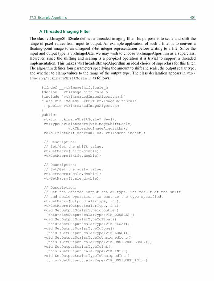
17.3 Example Algorithms 401
A Threaded Imaging FilterThe class vtkImageShiftScale defines a threaded imaging filter. Its purpose is to scale and shift therange of pixel values from input to output. An example application of such a filter is to convert afloating-point image to an unsigned 8-bit integer representation before writing to a file. Since theinput and output type is vtkImageData, we may wish to choose vtkImageAlgorithm as a superclass.However, since the shifting and scaling is a per-pixel operation it is trivial to support a threadedimplementation. This makes vtkThreadedImageAlgorithm an ideal choice of superclass for this filter.The algorithm defines four parameters specifying the amount to shift and scale, the output scalar type,and whether to clamp values to the range of the output type. The class declaration appears in VTK/Imaging/vtkImageShiftScale.h as follows.
#ifndef __vtkImageShiftScale_h #define __vtkImageShiftScale_h #include "vtkThreadedImageAlgorithm.h" class VTK_IMAGING_EXPORT vtkImageShiftScale : public vtkThreadedImageAlgorithm { public: static vtkImageShiftScale* New(); vtkTypeRevisionMacro(vtkImageShiftScale, vtkThreadedImageAlgorithm); void PrintSelf(ostream& os, vtkIndent indent);
// Description: // Set/Get the shift value. vtkSetMacro(Shift,double); vtkGetMacro(Shift,double);
// Description: // Set/Get the scale value. vtkSetMacro(Scale,double); vtkGetMacro(Scale,double);
// Description: // Set the desired output scalar type. The result of the shift // and scale operations is cast to the type specified. vtkSetMacro(OutputScalarType, int); vtkGetMacro(OutputScalarType, int); void SetOutputScalarTypeToDouble() {this->SetOutputScalarType(VTK_DOUBLE);} void SetOutputScalarTypeToFloat() {this->SetOutputScalarType(VTK_FLOAT);} void SetOutputScalarTypeToLong() {this->SetOutputScalarType(VTK_LONG);} void SetOutputScalarTypeToUnsignedLong() {this->SetOutputScalarType(VTK_UNSIGNED_LONG);}; void SetOutputScalarTypeToInt() {this->SetOutputScalarType(VTK_INT);} void SetOutputScalarTypeToUnsignedInt() {this->SetOutputScalarType(VTK_UNSIGNED_INT);}
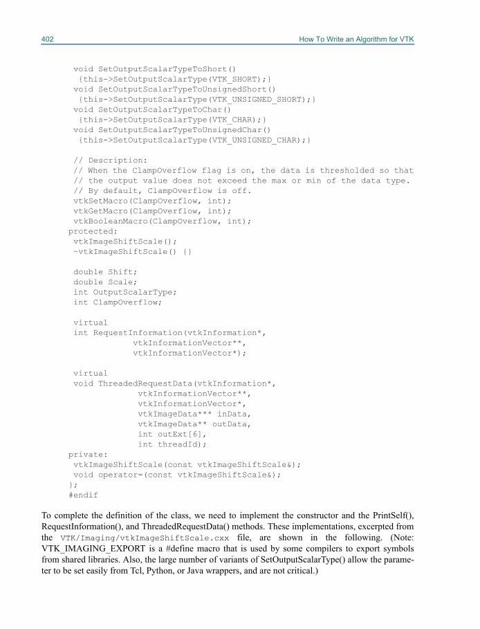
402 How To Write an Algorithm for VTK
void SetOutputScalarTypeToShort() {this->SetOutputScalarType(VTK_SHORT);} void SetOutputScalarTypeToUnsignedShort() {this->SetOutputScalarType(VTK_UNSIGNED_SHORT);} void SetOutputScalarTypeToChar() {this->SetOutputScalarType(VTK_CHAR);} void SetOutputScalarTypeToUnsignedChar() {this->SetOutputScalarType(VTK_UNSIGNED_CHAR);}
// Description: // When the ClampOverflow flag is on, the data is thresholded so that // the output value does not exceed the max or min of the data type. // By default, ClampOverflow is off. vtkSetMacro(ClampOverflow, int); vtkGetMacro(ClampOverflow, int); vtkBooleanMacro(ClampOverflow, int); protected: vtkImageShiftScale(); ~vtkImageShiftScale() {}
double Shift; double Scale; int OutputScalarType; int ClampOverflow;
virtual int RequestInformation(vtkInformation*, vtkInformationVector**, vtkInformationVector*);
virtual void ThreadedRequestData(vtkInformation*, vtkInformationVector**, vtkInformationVector*, vtkImageData*** inData, vtkImageData** outData, int outExt[6], int threadId); private: vtkImageShiftScale(const vtkImageShiftScale&); void operator=(const vtkImageShiftScale&); }; #endif
To complete the definition of the class, we need to implement the constructor and the PrintSelf(),RequestInformation(), and ThreadedRequestData() methods. These implementations, excerpted fromthe VTK/Imaging/vtkImageShiftScale.cxx file, are shown in the following. (Note:VTK_IMAGING_EXPORT is a #define macro that is used by some compilers to export symbolsfrom shared libraries. Also, the large number of variants of SetOutputScalarType() allow the parame-ter to be set easily from Tcl, Python, or Java wrappers, and are not critical.)
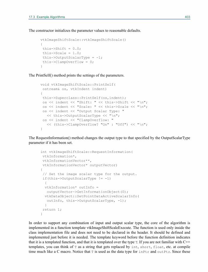
17.3 Example Algorithms 403
The constructor initializes the parameter values to reasonable defaults.
vtkImageShiftScale::vtkImageShiftScale() { this->Shift = 0.0; this->Scale = 1.0; this->OutputScalarType = -1; this->ClampOverflow = 0; }
The PrintSelf() method prints the settings of the parameters.
void vtkImageShiftScale::PrintSelf( ostream& os, vtkIndent indent) { this->Superclass::PrintSelf(os,indent); os << indent << "Shift: " << this->Shift << "\n"; os << indent << "Scale: " << this->Scale << "\n"; os << indent << "Output Scalar Type: " << this->OutputScalarType << "\n"; os << indent << "ClampOverflow: " << (this->ClampOverflow? "On" : "Off") << "\n"; }
The RequestInformation() method changes the output type to that specified by the OutputScalarTypeparameter if it has been set.
int vtkImageShiftScale::RequestInformation( vtkInformation*, vtkInformationVector**, vtkInformationVector* outputVector) { // Set the image scalar type for the output. if(this->OutputScalarType != -1) { vtkInformation* outInfo = outputVector->GetInformationObject(0); vtkDataObject::SetPointDataActiveScalarInfo( outInfo, this->OutputScalarType, -1); } return 1; }
In order to support any combination of input and output scalar type, the core of the algorithm isimplemented in a function template vtkImageShiftScaleExecute. The function is used only inside theclass implementation file and does not need to be declared in the header. It should be defined andimplemented just before it is needed. The template keyword before the function definition indicatesthat it is a templated function, and that it is templated over the type T. If you are not familiar with C++templates, you can think of T as a string that gets replaced by int, short, float, etc. at compiletime much like a C macro. Notice that T is used as the data type for inPtr and outPtr. Since these

404 How To Write an Algorithm for VTK
are functions instead of methods, they do not have access to the this pointer and its associatedinstance variables. Instead, we pass in the this pointer as a variable called self. The self argumentcan then be used to access the values of the class as is done in the examples shown here. For example,in the following we obtain the value of Scale from the instance and place it into a local variablecalled scale. The template will be instantiated and called by the ThreadedRequestData() method forall possible combinations. Each thread is given a region of the output image for which it is responsi-ble. This region is specified by the outExt argument.
This code also introduces a new concept: image iterators. In VTK, several convenience classesare available for looping (or iterating) over the pixels in an image. The class vtkImageIterator is tem-plated over the type of the image, and unlike most other classes in VTK is not instantiated with theNew() factory method. Instead, the image iterator is instantiated on the stack with the standard C++constructor. The constructor takes two arguments: a pointer to an instance of vtkImageData and theassociated extent over which to iterate.
The vtkImageProgressIterator is another convenience class similar to the vtkImageIterator (it isa subclass of vtkImageIterator). However, vtkImageProgressIterator requires two additional parame-ters for instantiation: a pointer to the filter instantiating the progress iterator (i.e., self in the example)and the thread id. What the vtkImageProgressIterator does is to first insure that the thread id is zero(to limit the number of callbacks to a single thread), and periodically invoke UpdateProgress() on thefilter. It also checks the AbortExecute flag on the filter each time IsAtEnd() is called and reports theend of data early if the flag is set.
Note how the BeginSpan() and EndSpan() methods are used to process one row of pixels at atime. The image iterator method IsAtEnd() is used to halt the processing of the image when all pixelshave been processed.
template <class IT, class OT> void vtkImageShiftScaleExecute(vtkImageShiftScale* self, vtkImageData* inData, vtkImageData* outData, int outExt[6], int id, IT*, OT*) { // Create iterators for the input and output extents assigned to // this thread. vtkImageIterator<IT> inIt(inData, outExt); vtkImageProgressIterator<OT> outIt(outData, outExt, self, id);
// Get the shift and scale parameters values. double shift = self->GetShift(); double scale = self->GetScale();
// Clamp pixel values within the range of the output type. double typeMin = outData->GetScalarTypeMin(); double typeMax = outData->GetScalarTypeMax(); int clamp = self->GetClampOverflow();
// Loop through output pixels. while (!outIt.IsAtEnd()) { IT* inSI = inIt.BeginSpan();
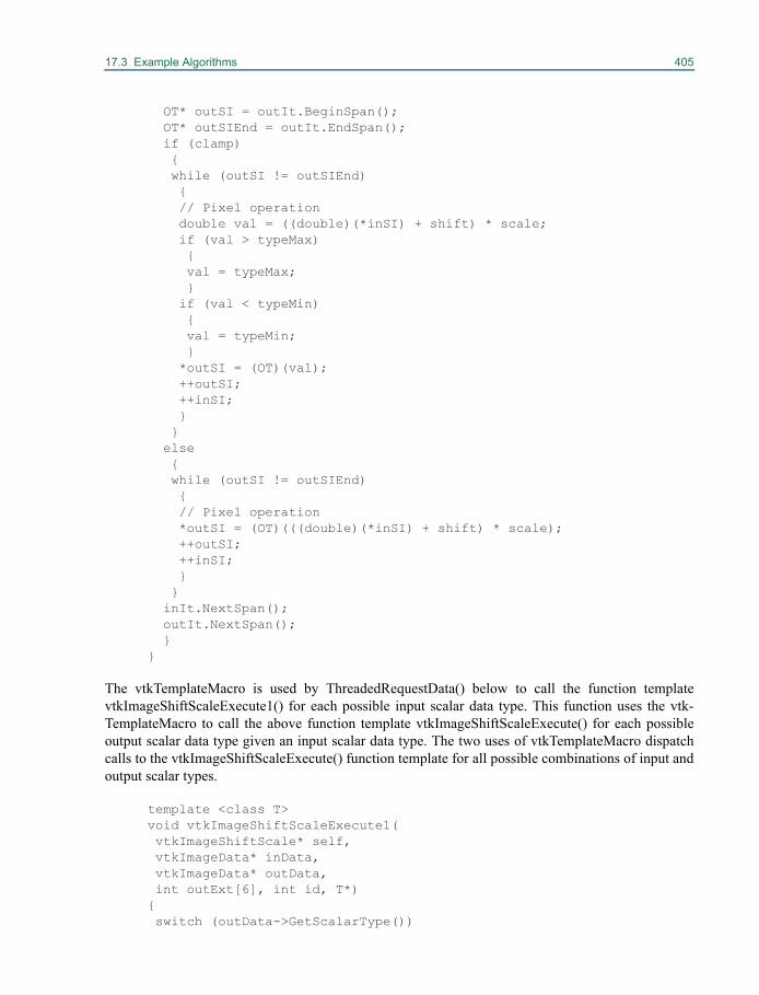
17.3 Example Algorithms 405
OT* outSI = outIt.BeginSpan(); OT* outSIEnd = outIt.EndSpan(); if (clamp) { while (outSI != outSIEnd) { // Pixel operation double val = ((double)(*inSI) + shift) * scale; if (val > typeMax) { val = typeMax; } if (val < typeMin) { val = typeMin; } *outSI = (OT)(val); ++outSI; ++inSI; } } else { while (outSI != outSIEnd) { // Pixel operation *outSI = (OT)(((double)(*inSI) + shift) * scale); ++outSI; ++inSI; } } inIt.NextSpan(); outIt.NextSpan(); } }
The vtkTemplateMacro is used by ThreadedRequestData() below to call the function templatevtkImageShiftScaleExecute1() for each possible input scalar data type. This function uses the vtk-TemplateMacro to call the above function template vtkImageShiftScaleExecute() for each possibleoutput scalar data type given an input scalar data type. The two uses of vtkTemplateMacro dispatchcalls to the vtkImageShiftScaleExecute() function template for all possible combinations of input andoutput scalar types.
template <class T> void vtkImageShiftScaleExecute1( vtkImageShiftScale* self, vtkImageData* inData, vtkImageData* outData, int outExt[6], int id, T*) { switch (outData->GetScalarType())
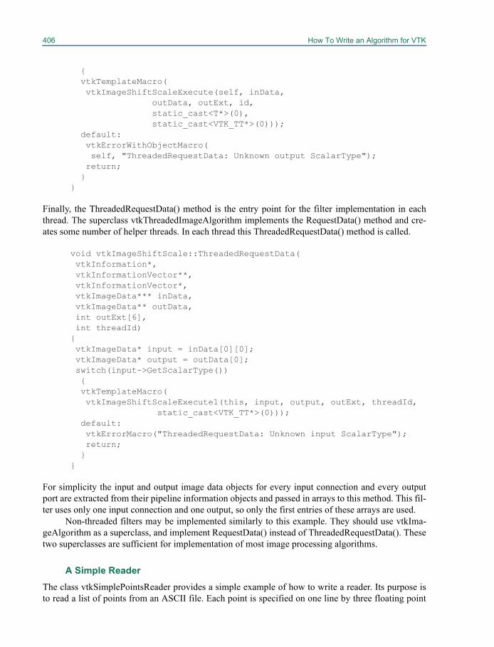
406 How To Write an Algorithm for VTK
{ vtkTemplateMacro( vtkImageShiftScaleExecute(self, inData, outData, outExt, id, static_cast<T*>(0), static_cast<VTK_TT*>(0))); default: vtkErrorWithObjectMacro( self, "ThreadedRequestData: Unknown output ScalarType"); return; } }
Finally, the ThreadedRequestData() method is the entry point for the filter implementation in eachthread. The superclass vtkThreadedImageAlgorithm implements the RequestData() method and cre-ates some number of helper threads. In each thread this ThreadedRequestData() method is called.
void vtkImageShiftScale::ThreadedRequestData( vtkInformation*, vtkInformationVector**, vtkInformationVector*, vtkImageData*** inData, vtkImageData** outData, int outExt[6], int threadId) { vtkImageData* input = inData[0][0]; vtkImageData* output = outData[0]; switch(input->GetScalarType()) { vtkTemplateMacro( vtkImageShiftScaleExecute1(this, input, output, outExt, threadId, static_cast<VTK_TT*>(0))); default: vtkErrorMacro("ThreadedRequestData: Unknown input ScalarType"); return; } }
For simplicity the input and output image data objects for every input connection and every outputport are extracted from their pipeline information objects and passed in arrays to this method. This fil-ter uses only one input connection and one output, so only the first entries of these arrays are used.
Non-threaded filters may be implemented similarly to this example. They should use vtkIma-geAlgorithm as a superclass, and implement RequestData() instead of ThreadedRequestData(). Thesetwo superclasses are sufficient for implementation of most image processing algorithms.
A Simple ReaderThe class vtkSimplePointsReader provides a simple example of how to write a reader. Its purpose isto read a list of points from an ASCII file. Each point is specified on one line by three floating point
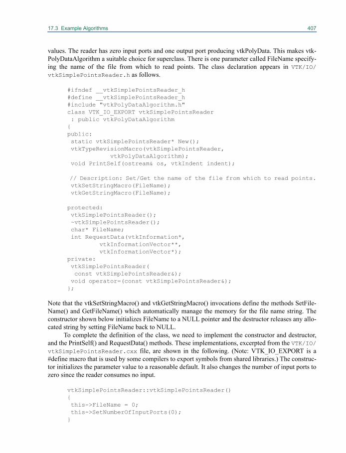
17.3 Example Algorithms 407
values. The reader has zero input ports and one output port producing vtkPolyData. This makes vtk-PolyDataAlgorithm a suitable choice for superclass. There is one parameter called FileName specify-ing the name of the file from which to read points. The class declaration appears in VTK/IO/vtkSimplePointsReader.h as follows.
#ifndef __vtkSimplePointsReader_h #define __vtkSimplePointsReader_h #include "vtkPolyDataAlgorithm.h" class VTK_IO_EXPORT vtkSimplePointsReader : public vtkPolyDataAlgorithm { public: static vtkSimplePointsReader* New(); vtkTypeRevisionMacro(vtkSimplePointsReader, vtkPolyDataAlgorithm); void PrintSelf(ostream& os, vtkIndent indent);
// Description: Set/Get the name of the file from which to read points. vtkSetStringMacro(FileName); vtkGetStringMacro(FileName);
protected: vtkSimplePointsReader(); ~vtkSimplePointsReader(); char* FileName; int RequestData(vtkInformation*, vtkInformationVector**, vtkInformationVector*); private: vtkSimplePointsReader( const vtkSimplePointsReader&); void operator=(const vtkSimplePointsReader&); };
Note that the vtkSetStringMacro() and vtkGetStringMacro() invocations define the methods SetFile-Name() and GetFileName() which automatically manage the memory for the file name string. Theconstructor shown below initializes FileName to a NULL pointer and the destructor releases any allo-cated string by setting FileName back to NULL.
To complete the definition of the class, we need to implement the constructor and destructor,and the PrintSelf() and RequestData() methods. These implementations, excerpted from the VTK/IO/vtkSimplePointsReader.cxx file, are shown in the following. (Note: VTK_IO_EXPORT is a#define macro that is used by some compilers to export symbols from shared libraries.) The construc-tor initializes the parameter value to a reasonable default. It also changes the number of input ports tozero since the reader consumes no input.
vtkSimplePointsReader::vtkSimplePointsReader() { this->FileName = 0; this->SetNumberOfInputPorts(0); }
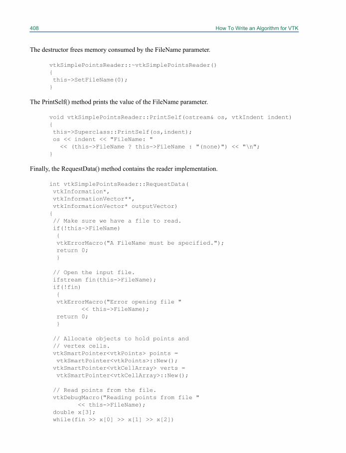
408 How To Write an Algorithm for VTK
The destructor frees memory consumed by the FileName parameter.
vtkSimplePointsReader::~vtkSimplePointsReader() { this->SetFileName(0); }
The PrintSelf() method prints the value of the FileName parameter.
void vtkSimplePointsReader::PrintSelf(ostream& os, vtkIndent indent) { this->Superclass::PrintSelf(os,indent); os << indent << "FileName: " << (this->FileName ? this->FileName : "(none)") << "\n"; }
Finally, the RequestData() method contains the reader implementation.
int vtkSimplePointsReader::RequestData( vtkInformation*, vtkInformationVector**, vtkInformationVector* outputVector) { // Make sure we have a file to read. if(!this->FileName) { vtkErrorMacro("A FileName must be specified."); return 0; }
// Open the input file. ifstream fin(this->FileName); if(!fin) { vtkErrorMacro("Error opening file " << this->FileName); return 0; }
// Allocate objects to hold points and // vertex cells. vtkSmartPointer<vtkPoints> points = vtkSmartPointer<vtkPoints>::New(); vtkSmartPointer<vtkCellArray> verts = vtkSmartPointer<vtkCellArray>::New();
// Read points from the file. vtkDebugMacro("Reading points from file " << this->FileName); double x[3]; while(fin >> x[0] >> x[1] >> x[2])
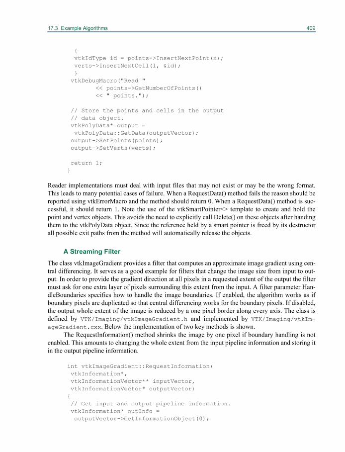
17.3 Example Algorithms 409
{ vtkIdType id = points->InsertNextPoint(x); verts->InsertNextCell(1, &id); } vtkDebugMacro("Read " << points->GetNumberOfPoints() << " points.");
// Store the points and cells in the output // data object. vtkPolyData* output = vtkPolyData::GetData(outputVector); output->SetPoints(points); output->SetVerts(verts);
return 1; }
Reader implementations must deal with input files that may not exist or may be the wrong format.This leads to many potential cases of failure. When a RequestData() method fails the reason should bereported using vtkErrorMacro and the method should return 0. When a RequestData() method is suc-cessful, it should return 1. Note the use of the vtkSmartPointer<> template to create and hold thepoint and vertex objects. This avoids the need to explicitly call Delete() on these objects after handingthem to the vtkPolyData object. Since the reference held by a smart pointer is freed by its destructorall possible exit paths from the method will automatically release the objects.
A Streaming FilterThe class vtkImageGradient provides a filter that computes an approximate image gradient using cen-tral differencing. It serves as a good example for filters that change the image size from input to out-put. In order to provide the gradient direction at all pixels in a requested extent of the output the filtermust ask for one extra layer of pixels surrounding this extent from the input. A filter parameter Han-dleBoundaries specifies how to handle the image boundaries. If enabled, the algorithm works as ifboundary pixels are duplicated so that central differencing works for the boundary pixels. If disabled,the output whole extent of the image is reduced by a one pixel border along every axis. The class isdefined by VTK/Imaging/vtkImageGradient.h and implemented by VTK/Imaging/vtkIm-ageGradient.cxx. Below the implementation of two key methods is shown.
The RequestInformation() method shrinks the image by one pixel if boundary handling is notenabled. This amounts to changing the whole extent from the input pipeline information and storing itin the output pipeline information.
int vtkImageGradient::RequestInformation( vtkInformation*, vtkInformationVector** inputVector, vtkInformationVector* outputVector) { // Get input and output pipeline information. vtkInformation* outInfo = outputVector->GetInformationObject(0);
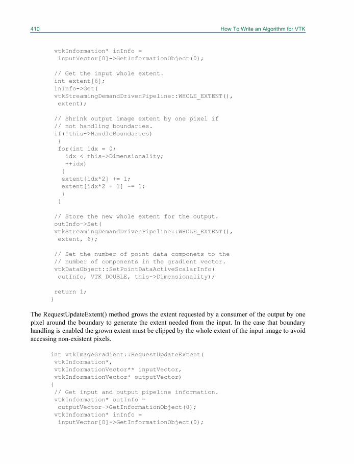
410 How To Write an Algorithm for VTK
vtkInformation* inInfo = inputVector[0]->GetInformationObject(0);
// Get the input whole extent. int extent[6]; inInfo->Get( vtkStreamingDemandDrivenPipeline::WHOLE_EXTENT(), extent);
// Shrink output image extent by one pixel if // not handling boundaries. if(!this->HandleBoundaries) { for(int idx = 0; idx < this->Dimensionality; ++idx) { extent[idx*2] += 1; extent[idx*2 + 1] -= 1; } }
// Store the new whole extent for the output. outInfo->Set( vtkStreamingDemandDrivenPipeline::WHOLE_EXTENT(), extent, 6);
// Set the number of point data componets to the // number of components in the gradient vector. vtkDataObject::SetPointDataActiveScalarInfo( outInfo, VTK_DOUBLE, this->Dimensionality);
return 1; }
The RequestUpdateExtent() method grows the extent requested by a consumer of the output by onepixel around the boundary to generate the extent needed from the input. In the case that boundaryhandling is enabled the grown extent must be clipped by the whole extent of the input image to avoidaccessing non-existent pixels.
int vtkImageGradient::RequestUpdateExtent( vtkInformation*, vtkInformationVector** inputVector, vtkInformationVector* outputVector) { // Get input and output pipeline information. vtkInformation* outInfo = outputVector->GetInformationObject(0); vtkInformation* inInfo = inputVector[0]->GetInformationObject(0);
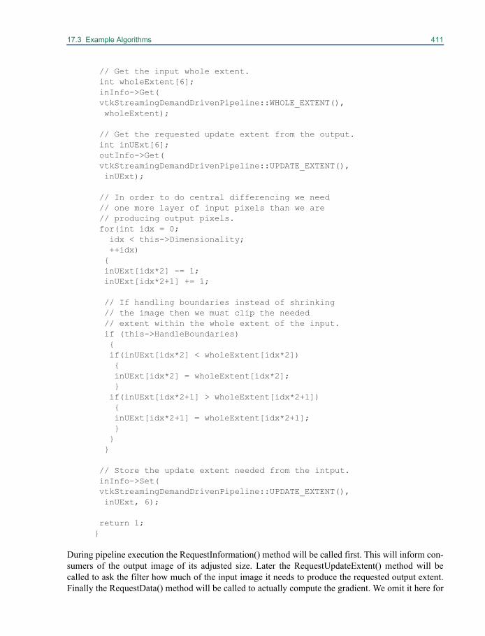
17.3 Example Algorithms 411
// Get the input whole extent. int wholeExtent[6]; inInfo->Get( vtkStreamingDemandDrivenPipeline::WHOLE_EXTENT(), wholeExtent);
// Get the requested update extent from the output. int inUExt[6]; outInfo->Get( vtkStreamingDemandDrivenPipeline::UPDATE_EXTENT(), inUExt);
// In order to do central differencing we need // one more layer of input pixels than we are // producing output pixels. for(int idx = 0; idx < this->Dimensionality; ++idx) { inUExt[idx*2] -= 1; inUExt[idx*2+1] += 1;
// If handling boundaries instead of shrinking // the image then we must clip the needed // extent within the whole extent of the input. if (this->HandleBoundaries) { if(inUExt[idx*2] < wholeExtent[idx*2]) { inUExt[idx*2] = wholeExtent[idx*2]; } if(inUExt[idx*2+1] > wholeExtent[idx*2+1]) { inUExt[idx*2+1] = wholeExtent[idx*2+1]; } } }
// Store the update extent needed from the intput. inInfo->Set( vtkStreamingDemandDrivenPipeline::UPDATE_EXTENT(), inUExt, 6);
return 1; }
During pipeline execution the RequestInformation() method will be called first. This will inform con-sumers of the output image of its adjusted size. Later the RequestUpdateExtent() method will becalled to ask the filter how much of the input image it needs to produce the requested output extent.Finally the RequestData() method will be called to actually compute the gradient. We omit it here for
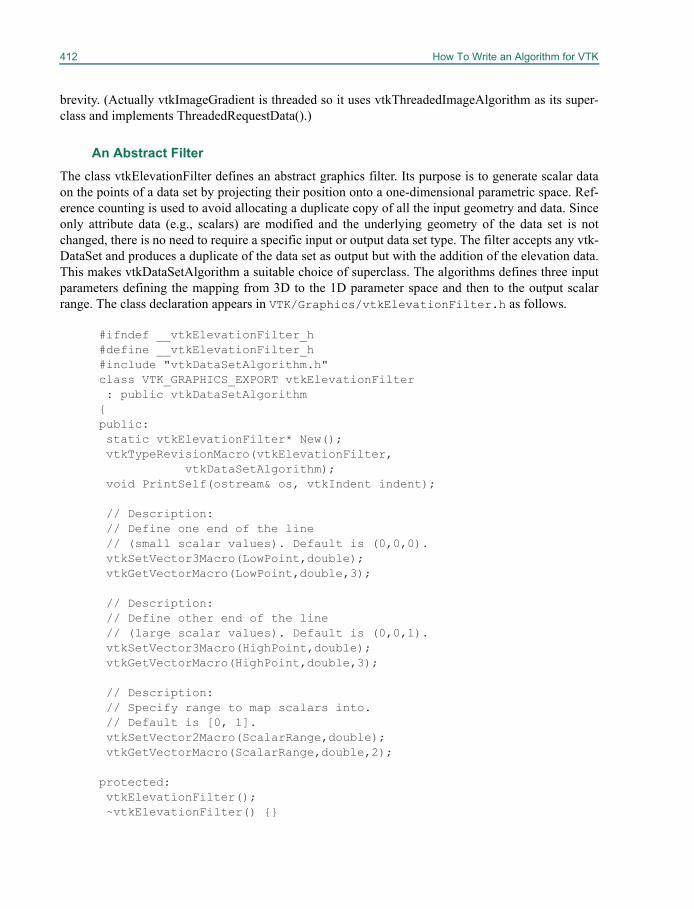
412 How To Write an Algorithm for VTK
brevity. (Actually vtkImageGradient is threaded so it uses vtkThreadedImageAlgorithm as its super-class and implements ThreadedRequestData().)
An Abstract FilterThe class vtkElevationFilter defines an abstract graphics filter. Its purpose is to generate scalar dataon the points of a data set by projecting their position onto a one-dimensional parametric space. Ref-erence counting is used to avoid allocating a duplicate copy of all the input geometry and data. Sinceonly attribute data (e.g., scalars) are modified and the underlying geometry of the data set is notchanged, there is no need to require a specific input or output data set type. The filter accepts any vtk-DataSet and produces a duplicate of the data set as output but with the addition of the elevation data.This makes vtkDataSetAlgorithm a suitable choice of superclass. The algorithms defines three inputparameters defining the mapping from 3D to the 1D parameter space and then to the output scalarrange. The class declaration appears in VTK/Graphics/vtkElevationFilter.h as follows.
#ifndef __vtkElevationFilter_h #define __vtkElevationFilter_h #include "vtkDataSetAlgorithm.h" class VTK_GRAPHICS_EXPORT vtkElevationFilter : public vtkDataSetAlgorithm { public: static vtkElevationFilter* New(); vtkTypeRevisionMacro(vtkElevationFilter, vtkDataSetAlgorithm); void PrintSelf(ostream& os, vtkIndent indent);
// Description: // Define one end of the line // (small scalar values). Default is (0,0,0). vtkSetVector3Macro(LowPoint,double); vtkGetVectorMacro(LowPoint,double,3);
// Description: // Define other end of the line // (large scalar values). Default is (0,0,1). vtkSetVector3Macro(HighPoint,double); vtkGetVectorMacro(HighPoint,double,3);
// Description: // Specify range to map scalars into. // Default is [0, 1]. vtkSetVector2Macro(ScalarRange,double); vtkGetVectorMacro(ScalarRange,double,2);
protected: vtkElevationFilter(); ~vtkElevationFilter() {}
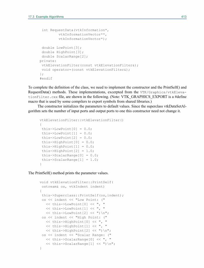
17.3 Example Algorithms 413
int RequestData(vtkInformation*, vtkInformationVector**, vtkInformationVector*);
double LowPoint[3]; double HighPoint[3]; double ScalarRange[2]; private: vtkElevationFilter(const vtkElevationFilter&); void operator=(const vtkElevationFilter&); }; #endif
To complete the definition of the class, we need to implement the constructor and the PrintSelf() andRequestData() methods. These implementations, excerpted from the VTK/Graphics/vtkEleva-tionFilter.cxx file, are shown in the following. (Note: VTK_GRAPHICS_EXPORT is a #definemacro that is used by some compilers to export symbols from shared libraries.)
The constructor initializes the parameters to default values. Since the superclass vtkDataSetAl-gorithm sets the number of input ports and output ports to one this constructor need not change it.
vtkElevationFilter::vtkElevationFilter() { this->LowPoint[0] = 0.0; this->LowPoint[1] = 0.0; this->LowPoint[2] = 0.0; this->HighPoint[0] = 0.0; this->HighPoint[1] = 0.0; this->HighPoint[2] = 1.0; this->ScalarRange[0] = 0.0; this->ScalarRange[1] = 1.0; }
The PrintSelf() method prints the parameter values.
void vtkElevationFilter::PrintSelf( ostream& os, vtkIndent indent) { this->Superclass::PrintSelf(os,indent); os << indent << "Low Point: (" << this->LowPoint[0] << ", " << this->LowPoint[1] << ", " << this->LowPoint[2] << ")\n"; os << indent << "High Point: (" << this->HighPoint[0] << ", " << this->HighPoint[1] << ", " << this->HighPoint[2] << ")\n"; os << indent << "Scalar Range: (" << this->ScalarRange[0] << ", " << this->ScalarRange[1] << ")\n"; }

414 How To Write an Algorithm for VTK
Finally, the RequestData() method implements the algorithm.
int vtkElevationFilter::RequestData( vtkInformation*, vtkInformationVector* outputVector) { // Get the input and output data objects. vtkDataSet* input = vtkDataSet::GetData(inputVector[0]); vtkDataSet* output = vtkDataSet::GetData(outputVector);
// Check the size of the input. vtkIdType numPts = input->GetNumberOfPoints(); if(numPts < 1) { vtkDebugMacro("No input!"); return 1; }
// Allocate space for the elevation scalar data. vtkSmartPointer<vtkFloatArray> newScalars = vtkSmartPointer<vtkFloatArray>::New(); newScalars->SetNumberOfTuples(numPts);
// Set up 1D parametric system and make sure it // is valid. double diffVector[3] = { this->HighPoint[0] - this->LowPoint[0], this->HighPoint[1] - this->LowPoint[1], this->HighPoint[2] - this->LowPoint[2] }; double length2 = vtkMath::Dot(diffVector, diffVector); if(length2 <= 0) { vtkErrorMacro("Bad vector, using (0,0,1)."); diffVector[0] = 0; diffVector[1] = 0; diffVector[2] = 1; length2 = 1.0; }
// Support progress and abort. vtkIdType tenth = (numPts >= 10? numPts/10 : 1); double numPtsInv = 1.0/numPts; int abort = 0;
// Compute parametric coordinate and map into // scalar range. double diffScalar = this->ScalarRange[1] - this->ScalarRange[0];
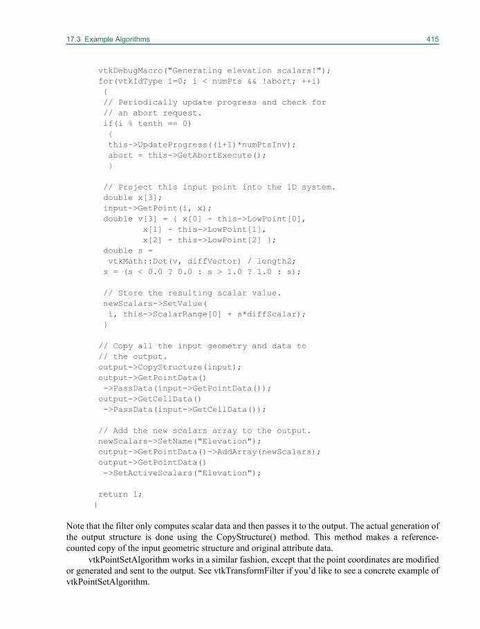
17.3 Example Algorithms 415
vtkDebugMacro("Generating elevation scalars!"); for(vtkIdType i=0; i < numPts && !abort; ++i) { // Periodically update progress and check for // an abort request. if(i % tenth == 0) { this->UpdateProgress((i+1)*numPtsInv); abort = this->GetAbortExecute(); }
// Project this input point into the 1D system. double x[3]; input->GetPoint(i, x); double v[3] = { x[0] - this->LowPoint[0], x[1] - this->LowPoint[1], x[2] - this->LowPoint[2] }; double s = vtkMath::Dot(v, diffVector) / length2; s = (s < 0.0 ? 0.0 : s > 1.0 ? 1.0 : s);
// Store the resulting scalar value. newScalars->SetValue( i, this->ScalarRange[0] + s*diffScalar); }
// Copy all the input geometry and data to // the output. output->CopyStructure(input); output->GetPointData() ->PassData(input->GetPointData()); output->GetCellData() ->PassData(input->GetCellData());
// Add the new scalars array to the output. newScalars->SetName("Elevation"); output->GetPointData()->AddArray(newScalars); output->GetPointData() ->SetActiveScalars("Elevation");
return 1; }
Note that the filter only computes scalar data and then passes it to the output. The actual generation ofthe output structure is done using the CopyStructure() method. This method makes a reference-counted copy of the input geometric structure and original attribute data.
vtkPointSetAlgorithm works in a similar fashion, except that the point coordinates are modifiedor generated and sent to the output. See vtkTransformFilter if you’d like to see a concrete example ofvtkPointSetAlgorithm.
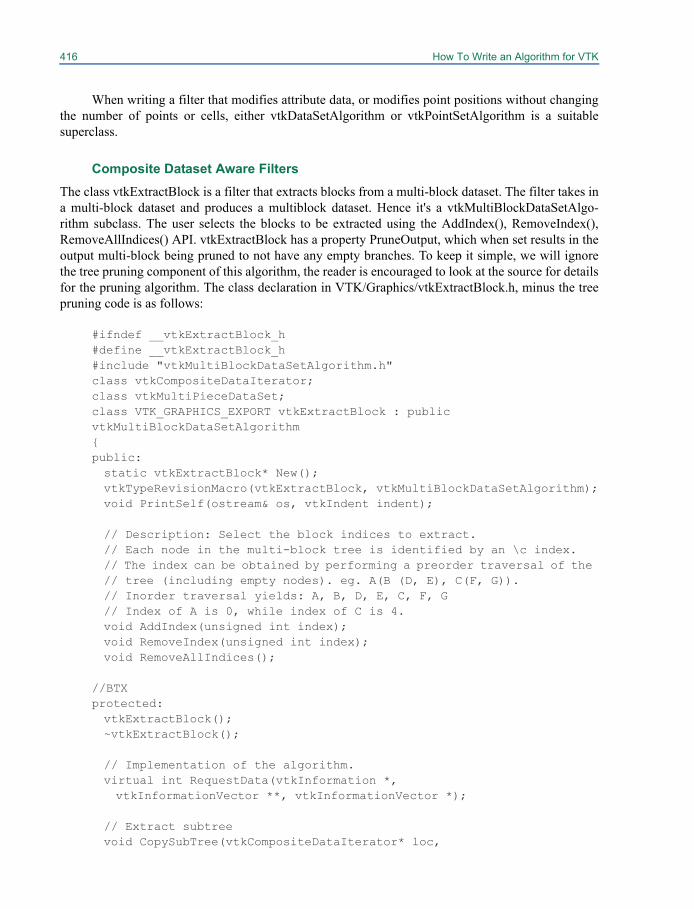
416 How To Write an Algorithm for VTK
When writing a filter that modifies attribute data, or modifies point positions without changingthe number of points or cells, either vtkDataSetAlgorithm or vtkPointSetAlgorithm is a suitablesuperclass.
Composite Dataset Aware FiltersThe class vtkExtractBlock is a filter that extracts blocks from a multi-block dataset. The filter takes ina multi-block dataset and produces a multiblock dataset. Hence it's a vtkMultiBlockDataSetAlgo-rithm subclass. The user selects the blocks to be extracted using the AddIndex(), RemoveIndex(),RemoveAllIndices() API. vtkExtractBlock has a property PruneOutput, which when set results in theoutput multi-block being pruned to not have any empty branches. To keep it simple, we will ignorethe tree pruning component of this algorithm, the reader is encouraged to look at the source for detailsfor the pruning algorithm. The class declaration in VTK/Graphics/vtkExtractBlock.h, minus the treepruning code is as follows:
#ifndef __vtkExtractBlock_h#define __vtkExtractBlock_h#include "vtkMultiBlockDataSetAlgorithm.h"class vtkCompositeDataIterator;class vtkMultiPieceDataSet;class VTK_GRAPHICS_EXPORT vtkExtractBlock : public vtkMultiBlockDataSetAlgorithm{public:static vtkExtractBlock* New();vtkTypeRevisionMacro(vtkExtractBlock, vtkMultiBlockDataSetAlgorithm);void PrintSelf(ostream& os, vtkIndent indent);
// Description: Select the block indices to extract.// Each node in the multi-block tree is identified by an \c index. // The index can be obtained by performing a preorder traversal of the // tree (including empty nodes). eg. A(B (D, E), C(F, G)).// Inorder traversal yields: A, B, D, E, C, F, G// Index of A is 0, while index of C is 4.void AddIndex(unsigned int index);void RemoveIndex(unsigned int index);void RemoveAllIndices();
//BTXprotected:vtkExtractBlock();~vtkExtractBlock();
// Implementation of the algorithm.virtual int RequestData(vtkInformation *, vtkInformationVector **, vtkInformationVector *);
// Extract subtreevoid CopySubTree(vtkCompositeDataIterator* loc,
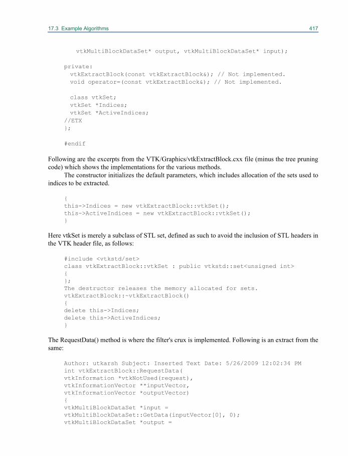
17.3 Example Algorithms 417
vtkMultiBlockDataSet* output, vtkMultiBlockDataSet* input);
private:vtkExtractBlock(const vtkExtractBlock&); // Not implemented.void operator=(const vtkExtractBlock&); // Not implemented.
class vtkSet;vtkSet *Indices;vtkSet *ActiveIndices;
//ETX};
#endif
Following are the excerpts from the VTK/Graphics/vtkExtractBlock.cxx file (minus the tree pruningcode) which shows the implementations for the various methods.
The constructor initializes the default parameters, which includes allocation of the sets used toindices to be extracted.
{this->Indices = new vtkExtractBlock::vtkSet();this->ActiveIndices = new vtkExtractBlock::vtkSet();}
Here vtkSet is merely a subclass of STL set, defined as such to avoid the inclusion of STL headers inthe VTK header file, as follows:
#include <vtkstd/set>class vtkExtractBlock::vtkSet : public vtkstd::set<unsigned int>{};The destructor releases the memory allocated for sets.vtkExtractBlock::~vtkExtractBlock(){delete this->Indices;delete this->ActiveIndices;}
The RequestData() method is where the filter's crux is implemented. Following is an extract from thesame:
Author: utkarsh Subject: Inserted Text Date: 5/26/2009 12:02:34 PMint vtkExtractBlock::RequestData(vtkInformation *vtkNotUsed(request),vtkInformationVector **inputVector,vtkInformationVector *outputVector){vtkMultiBlockDataSet *input = vtkMultiBlockDataSet::GetData(inputVector[0], 0);vtkMultiBlockDataSet *output =
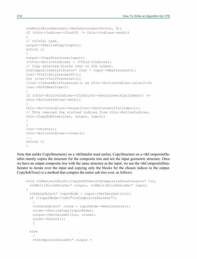
418 How To Write an Algorithm for VTK
vtkMultiBlockDataSet::GetData(outputVector, 0);if (this->Indices->find(0) != this->Indices->end()){// trivial case.output->ShallowCopy(input);return 1;}output->CopyStructure(input);(*this->ActiveIndices) = (*this->Indices);// Copy selected blocks over to the output.vtkCompositeDataIterator* iter = input->NewIterator();iter->VisitOnlyLeavesOff();for (iter->InitTraversal();!iter->IsDoneWithTraversal() && this->ActiveIndices->size()>0;iter->GoToNextItem()){if (this->ActiveIndices->find(iter->GetCurrentFlatIndex()) !=this->ActiveIndices->end()){this->ActiveIndices->erase(iter->GetCurrentFlatIndex());// This removed the visited indices from this->ActiveIndices.this->CopySubTree(iter, output, input);}}iter->Delete();this->ActiveIndices->clear();...return 1;}
Note that unlike CopyStructure() on a vtkDataSet used earlier, CopyStructure on a vtkCompositeDa-taSet merely copies the structure for the composite tree and not the input geometric structure. Oncewe have an output composite tree with the same structure as the input, we use the vtkCompositeData-Iterator to iterate over the input and copying only the blocks for the chosen indices to the output.CopySubTree() is a method that compies the entire sub tree over, as follows:
void vtkExtractBlock::CopySubTree(vtkCompositeDataIterator* loc,vtkMultiBlockDataSet* output, vtkMultiBlockDataSet* input)
{vtkDataObject* inputNode = input->GetDataSet(loc);if (!inputNode->IsA("vtkCompositeDataSet")){vtkDataObject* clone = inputNode->NewInstance();clone->ShallowCopy(inputNode);output->SetDataSet(loc, clone);clone->Delete();}
else{vtkCompositeDataSet* cinput =
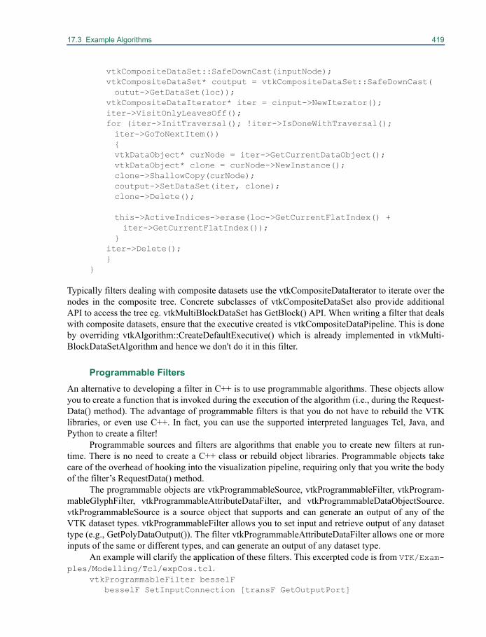
17.3 Example Algorithms 419
vtkCompositeDataSet::SafeDownCast(inputNode);vtkCompositeDataSet* coutput = vtkCompositeDataSet::SafeDownCast(outut->GetDataSet(loc));
vtkCompositeDataIterator* iter = cinput->NewIterator();iter->VisitOnlyLeavesOff();for (iter->InitTraversal(); !iter->IsDoneWithTraversal(); iter->GoToNextItem()){vtkDataObject* curNode = iter->GetCurrentDataObject();vtkDataObject* clone = curNode->NewInstance();clone->ShallowCopy(curNode);coutput->SetDataSet(iter, clone);clone->Delete();
this->ActiveIndices->erase(loc->GetCurrentFlatIndex() +iter->GetCurrentFlatIndex());
}iter->Delete();}
}
Typically filters dealing with composite datasets use the vtkCompositeDataIterator to iterate over thenodes in the composite tree. Concrete subclasses of vtkCompositeDataSet also provide additionalAPI to access the tree eg. vtkMultiBlockDataSet has GetBlock() API. When writing a filter that dealswith composite datasets, ensure that the executive created is vtkCompositeDataPipeline. This is doneby overriding vtkAlgorithm::CreateDefaultExecutive() which is already implemented in vtkMulti-BlockDataSetAlgorithm and hence we don't do it in this filter.
Programmable FiltersAn alternative to developing a filter in C++ is to use programmable algorithms. These objects allowyou to create a function that is invoked during the execution of the algorithm (i.e., during the Request-Data() method). The advantage of programmable filters is that you do not have to rebuild the VTKlibraries, or even use C++. In fact, you can use the supported interpreted languages Tcl, Java, andPython to create a filter!
Programmable sources and filters are algorithms that enable you to create new filters at run-time. There is no need to create a C++ class or rebuild object libraries. Programmable objects takecare of the overhead of hooking into the visualization pipeline, requiring only that you write the bodyof the filter’s RequestData() method.
The programmable objects are vtkProgrammableSource, vtkProgrammableFilter, vtkProgram-mableGlyphFilter, vtkProgrammableAttributeDataFilter, and vtkProgrammableDataObjectSource.vtkProgrammableSource is a source object that supports and can generate an output of any of theVTK dataset types. vtkProgrammableFilter allows you to set input and retrieve output of any datasettype (e.g., GetPolyDataOutput()). The filter vtkProgrammableAttributeDataFilter allows one or moreinputs of the same or different types, and can generate an output of any dataset type.
An example will clarify the application of these filters. This excerpted code is from VTK/Exam-ples/Modelling/Tcl/expCos.tcl.
vtkProgrammableFilter besselF besselF SetInputConnection [transF GetOutputPort]
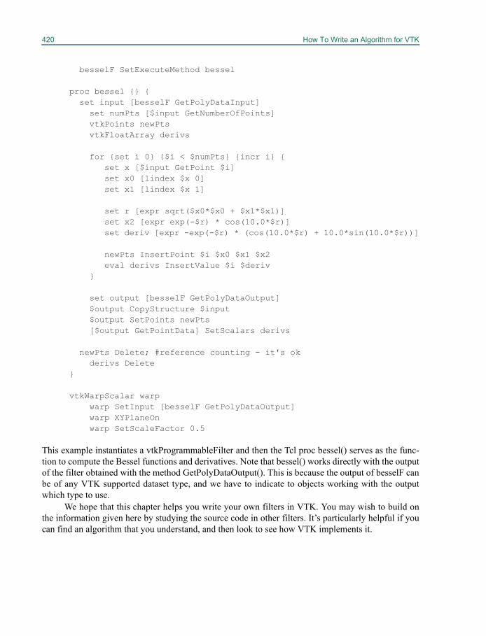
420 How To Write an Algorithm for VTK
besselF SetExecuteMethod bessel
proc bessel {} { set input [besselF GetPolyDataInput]
set numPts [$input GetNumberOfPoints]vtkPoints newPts
vtkFloatArray derivs
for {set i 0} {$i < $numPts} {incr i} {set x [$input GetPoint $i]set x0 [lindex $x 0]set x1 [lindex $x 1]
set r [expr sqrt($x0*$x0 + $x1*$x1)]set x2 [expr exp(-$r) * cos(10.0*$r)]set deriv [expr -exp(-$r) * (cos(10.0*$r) + 10.0*sin(10.0*$r))]
newPts InsertPoint $i $x0 $x1 $x2eval derivs InsertValue $i $deriv
}
set output [besselF GetPolyDataOutput]$output CopyStructure $input$output SetPoints newPts
[$output GetPointData] SetScalars derivs
newPts Delete; #reference counting - it's okderivs Delete
}
vtkWarpScalar warpwarp SetInput [besselF GetPolyDataOutput]warp XYPlaneOnwarp SetScaleFactor 0.5
This example instantiates a vtkProgrammableFilter and then the Tcl proc bessel() serves as the func-tion to compute the Bessel functions and derivatives. Note that bessel() works directly with the outputof the filter obtained with the method GetPolyDataOutput(). This is because the output of besselF canbe of any VTK supported dataset type, and we have to indicate to objects working with the outputwhich type to use.
We hope that this chapter helps you write your own filters in VTK. You may wish to build onthe information given here by studying the source code in other filters. It’s particularly helpful if youcan find an algorithm that you understand, and then look to see how VTK implements it.
Chapter 18
Integrating With The Windowing System 18
At some point in your use of VTK you will probablywant to modify the default interaction behavior (in vtkRenderWindowInteractor) or add a graphicaluser interface (GUI) to your VTK based application. This section will explain how to do this formany common user interface toolkits. Up-to-date and new examples will be found in the VTK/Examples/GUI source directory. To use this chapter effectively, we recommend that you begin byreading the next section on managing interaction style. Then (to embed VTK into a GUI) look at“General Guidelines for GUI Interaction” on page 423 and then only the subsection appropriate toyour user interface. If you are using a GUI other than the ones covered here, read the subsections thatare similar to your GUI.
18.1 vtkRenderWindow Interaction StyleThe class vtkRenderWindowInteractor captures mouse and keyboard events in the render window,translates window system specific events into VTK events (these are defined in Common/vtkCommand.h) and then dispatches the translated VTK events to another class—the interactorstyle. Therefore, to add a new style of interaction to VTK, you need to derive a new class from vtkIn-teractorStyle. For example, the class vtkInteractorStyleTrackball implements the trackball style inter-action described in “vtkRenderWindowInteractor” on page 45. vtkInteractorStyleJoystickActor orvtkInteractorStyleJoystickCamera implements the joystick interaction style described in the samesection. Another option is to use the class vtkInteractorStyleUser. This class allows users to define anew interactor style without subclassing.
Basically, the way this works is as follows. vtkRenderWindowInteractor intercepts eventsoccurring in the vtkRenderWindow with which it is associated. Recall that on instantiation,vtkRenderWindowInteractor actually instantiates a device/windowing-specific implementation—either vtkXRenderWindowInteractor (Unix) or vtkWin32RenderWindowInteractor (Windows). Theevent intercepts are enabled when the vtkRenderWindowInteractor::Start() method is called. These
422 Integrating With The Windowing System
events are in turn forwarded to the vtkRenderWindowInteractor::InteractorStyle instance. The inter-actor style processes the events as appropriate.
Here is a list of the available interactor styles with a brief description of what each one does.
• vtkInteractorStyleJoystickActor — implements joystick style for actor manipulation.• vtkInteractorStyleJoystickCamera — implements joystick style for camera manipulation.• vtkInteractorStyleTrackballActor — implements trackball style for actor manipulation.• vtkInteractorStyleTrackballCamera — implements trackball style for camera manipulation.• vtkInteractorStyleSwitch — manages the switching between trackball and joystick mode, and
camera and object (actor) mode. It does this by intercepting keystrokes and internally switchingto one of the modes listed above. (Recall from “vtkRenderWindowInteractor” on page 45 thatKeypress j / Keypress t toggles between the trackball and joystick modes, and Keypress c/ Keypress a toggles between camera and actor mode.)
• vtkInteractorStyleFlight — a special class that allows the user to “fly-through” complex scenes.• vtkInteractorStyleImage — a specially designed interactor style for 2D images. This class per-
forms window and level adjustment via mouse motion, as well as pan and dolly constrained tothe x-y plane.
• vtkInteractorStyleUnicam — single button camera manipulation. Rotation, zoom, and pan canall be performed with one mouse button.
• vtkInteractorStyleTerrain — Moves the camera around an object with a constant view-up vector(in the z-direction). The camera is moved with combinations of elevation, azimuth and zoom.
• vtkInteractorStyleRubberBandZoom — supports zooming in on an object by drawing a rectan-gle in the render window.
If one of these interactor styles does not suit your needs, you can create your own interactor style.There are two approaches to create your own. First, you can subclass from vtkInteractorStyle andoverride the appropriate virtual methods. Second, you can create observers that directly observe thevtkRenderWindowInteractor (see “Adding vtkRenderWindowInteractor Observers” on page 47) andtake the appropriate actions as registered events are observed.
Subclassing from vtkInteractorStyle requires overriding the following methods (as described inVTK/Rendering/vtkInteractorStyle.h):
// Description: // Generic event bindings must be overridden in subclasses. virtual void OnMouseMove() {} virtual void OnLeftButtonDown() {} virtual void OnLeftButtonUp() {} virtual void OnMiddleButtonDown() {} virtual void OnMiddleButtonUp() {} virtual void OnRightButtonDown() {} virtual void OnRightButtonUp() {}
virtual void OnMouseWheelForward() {}virtual void OnMouseWheelBackward() {}
// Description: // OnChar implements keyboard functions, but subclasses can override
18.2 General Guidelines for GUI Interaction 423
// this behavior. virtual void OnChar() virtual void OnKeyDown() {} virtual void OnKeyUp() {} virtual void OnKeyPress() {} virtual void OnKeyRelease() {}
// Description: // These are more esoteric events, but are useful in some cases.
virtual void OnExpose() {}virtual void OnConfigure() {}
virtual void OnEnter() {} virtual void OnLeave() {}
Then to use the interactor style, associate it with vtkRenderWindowInteractor via theSetInteractorStyle() method.
The second approach for developing your own style involves creating a set of command/observers to implement the desired behavior (see “Adding vtkRenderWindowInteractor Observers”on page 47 for an example). This provides greater flexibility and the capability to tie together codewithout the constraints of object inheritance.
18.2 General Guidelines for GUI InteractionFor the most part VTK has been designed to isolate the functional objects from the user interface.This has been done for portability and flexibility. But sooner or later you will need to create a userinterface, so we have provided a number of hooks to help in this process. These hooks are called usermethods and they are discussed in Chapter 3 (see “User Methods, Observers, and Commands” onpage 29). Recall that the essence of user methods in VTK is that any class can invoke an event. If anobserver is registered with the class that invokes the event, then an instance of vtkCommand is exe-cuted which is the implementation of the callback. There are a variety of events invoked by differentVTK classes that come in handy when developing a user interface. A partial list of the more usefulevents is provided below.
The subclasses of vtkInteractorStyle and vtk3DWidget (subclasses of vtkInteractorObserver)invoke these events:
• StartInteractionEvent
• InteractionEvent
• EndInteractionEvent
In general, these events are invoked when you might expect. Pressing a mouse button starts the inter-action (StartInteractionEvent), moving the mouse requires interactive response (InteractionEvent),and releasing the mouse ends the interaction (EndInteractionEvent). These events are designed to pro-vide the necessary control to change the level-of-detail (see “Level-Of-Detail Actors” on page 55) orto otherwise ensure interactive rendering performance.
All filters (subclasses of vtkAlgorithm) invoke these events:
• StartEvent
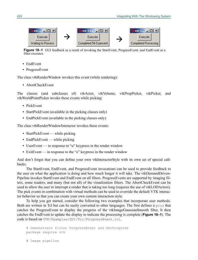
424 Integrating With The Windowing System
• EndEvent• ProgressEvent
The class vtkRenderWindow invokes this event (while rendering):
• AbortCheckEvent
The classes (and subclasses of) vtkActor, vtkVolume, vtkPropPicker, vtkPicker, andvtkWorldPointPicker invoke these events while picking:
• PickEvent• StartPickEvent (available in the picking classes only)• EndPickEvent (available in the picking classes only)
The class vtkRenderWindowInteractor invokes these events:
• StartPickEvent — while picking• EndPickEvent — while picking• UserEvent — in response to “u” keypress in the render window• ExitEvent — in response to the “e” keypress in the render window
And don’t forget that you can define your own vtkInteractorStyle with its own set of special call-backs.
The StartEvent, EndEvent, and ProgressEvent invocations can be used to provide feedback tothe user on what the application is doing and how much longer it will take. The vtkDemandDriven-Pipeline invokes StartEvent and EndEvent on all filters. ProgressEvents are supported by imaging fil-ters, some readers, and many (but not all) of the visualization filters. The AbortCheckEvent can beused to allow the user to interrupt a render that is taking too long (requires the use of vtkLODActors).The pick events in combination with virtual methods can be used to override the default VTK interac-tor behavior so that you can create your own custom interaction style.
To help you get started, consider the following two examples that incorporate user methods.Both are written in Tcl but can be easily converted to other languages. The first defines a proc thatcatches the ProgressEvent to display the progress of the vtkImageGaussianSmooth filter. It thencatches the EndEvent to update the display to indicate the processing is complete (Figure 18–1). Thecode is based on VTK/Examples/GUI/Tcl/ProgressEvent.tcl.
# Demonstrate filter ProgressEvent and GetProgress package require vtk
# Image pipeline
Figure 18–1 GUI feedback as a result of invoking the StartEvent, ProgressEvent, and EndEvent as afilter executes.

18.2 General Guidelines for GUI Interaction 425
vtkImageReader readerreader SetDataByteOrderToLittleEndianreader SetDataExtent 0 255 0 255 1 93reader SetFilePrefix $env(VTK_DATA_ROOT)/Data/headsq/quarterreader SetDataMask 0x7fff
vtkImageGaussianSmooth smoothsmooth SetInputConnection [reader GetOutputPort]smooth AddObserver ProgressEvent {.text configure -text \
Completed [expr [smooth GetProgress]*100.0] percentupdate
} smooth AddObserver EndEvent { .text configure -text Completed Processingupdate
}
button .run -text Execute -command{smooth Modifiedsmooth Update
}label .text -text Waiting to Process pack .run .text
For pipelines consisting of multiple filters, each filter could provide an indication of its progress. Youcan also create generic Tcl procs (rather than define them in-line as here) and assign them to multi-ple filters.
The second example makes use of the AbortCheckEvent to interrupt a long render if a mouseevent is pending. (The script is based on VTK/Examples/Rendering/Tcl/AbortCheckEv-ent.tcl.) Most of the code is typical VTK code. The critical changes are that you must use instancesof vtkLODActor; it is best if you turn on GlobalImmediateModeRendering() since the abort methodcannot be invoked in the middle of display list processing; and finally you must add a few lines ofcode to process the abort check. In this example we define a simple procedure called TkCheckAbortwhich invokes the GetEventPending() method of vtkRenderWindow and then sets the AbortRenderinstance variable to 1 if an event is pending. The resolution of the mace model has been dramaticallyincreased (Figure 18–2(left)) so that you can see the effects of using the AbortRender logic. Feel freeto adjust the resolution of the sphere to suit your system. If everything is working properly then youshould be able to quickly rotate and then zoom without waiting for the full resolution sphere to renderin between the two actions (Figure 18–2(right)).
package require vtkpackage require vtkinteraction# Create the RenderWindow, Renderer and both ActorsvtkRenderer ren1vtkRenderWindow renWin
renWin AddRenderer ren1 vtkRenderWindowInteractor iren
iren SetRenderWindow renWin
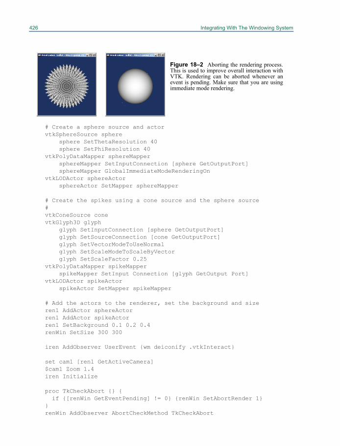
426 Integrating With The Windowing System
# Create a sphere source and actor vtkSphereSource sphere
sphere SetThetaResolution 40 sphere SetPhiResolution 40
vtkPolyDataMapper sphereMapper sphereMapper SetInputConnection [sphere GetOutputPort] sphereMapper GlobalImmediateModeRenderingOn
vtkLODActor sphereActor sphereActor SetMapper sphereMapper
# Create the spikes using a cone source and the sphere source#vtkConeSource cone vtkGlyph3D glyph
glyph SetInputConnection [sphere GetOutputPort] glyph SetSourceConnection [cone GetOutputPort] glyph SetVectorModeToUseNormal glyph SetScaleModeToScaleByVector glyph SetScaleFactor 0.25
vtkPolyDataMapper spikeMapper spikeMapper SetInput Connection [glyph GetOutput Port]
vtkLODActor spikeActor spikeActor SetMapper spikeMapper
# Add the actors to the renderer, set the background and sizeren1 AddActor sphereActor ren1 AddActor spikeActor ren1 SetBackground 0.1 0.2 0.4 renWin SetSize 300 300
iren AddObserver UserEvent {wm deiconify .vtkInteract}
set cam1 [ren1 GetActiveCamera] $cam1 Zoom 1.4iren Initialize
proc TkCheckAbort {} { if {[renWin GetEventPending] != 0} {renWin SetAbortRender 1}
} renWin AddObserver AbortCheckMethod TkCheckAbort
Figure 18–2 Aborting the rendering process.This is used to improve overall interaction withVTK. Rendering can be aborted whenever anevent is pending. Make sure that you are usingimmediate mode rendering.
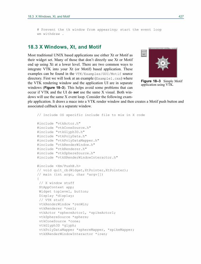
18.3 X Windows, Xt, and Motif 427
# Prevent the tk window from appearing; start the event loop wm withdraw .
18.3 X Windows, Xt, and MotifMost traditional UNIX based applications use either Xt or Motif astheir widget set. Many of those that don’t directly use Xt or Motifend up using Xt at a lower level. There are two common ways tointegrate VTK into your Xt (or Motif) based application. Theseexamples can be found in the VTK/Examples/GUI/Motif sourcedirectory. First we will look at an example (Example1.cxx) wherethe VTK rendering window and the application UI are in separatewindows (Figure 18–3). This helps avoid some problems that canoccur if VTK and the UI do not use the same X visual. Both win-dows will use the same X event loop. Consider the following exam-ple application. It draws a mace into a VTK render window and then creates a Motif push button andassociated callback in a separate window.
// Include OS specific include file to mix in X code
#include "vtkActor.h"#include "vtkConeSource.h"#include "vtkGlyph3D.h"#include "vtkPolyData.h"#include "vtkPolyDataMapper.h"#include "vtkRenderWindow.h"#include "vtkRenderer.h"#include "vtkSphereSource.h"#include "vtkXRenderWindowInteractor.h"
#include <Xm/PushB.h>// void quit_cb(Widget,XtPointer,XtPointer);// main (int argc, char *argv[]){ // X window stuff XtAppContext app; Widget toplevel, button; Display *display; // VTK stuff vtkRenderWindow *renWin; vtkRenderer *ren1; vtkActor *sphereActor1, *spikeActor1; vtkSphereSource *sphere; vtkConeSource *cone; vtkGlyph3D *glyph; vtkPolyDataMapper *sphereMapper, *spikeMapper; vtkXRenderWindowInteractor *iren;
Figure 18–3 Simple Motifapplication using VTK.
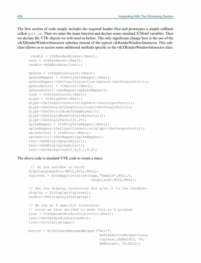
428 Integrating With The Windowing System
The first section of code simply includes the required header files and prototypes a simple callbackcalled quit_cb. Then we enter the main function and declare some standard X/Motif variables. Thenwe declare the VTK objects we will need as before. The only significant change here is the use of thevtkXRenderWindowInteractor subclass instead of the typical vtkRenderWindowInteractor. This sub-class allows us to access some additional methods specific to the vtkXRenderWindowInteractor class.
renWin = vtkRenderWindow::New(); ren1 = vtkRenderer::New(); renWin->AddRenderer(ren1); sphere = vtkSphereSource::New(); sphereMapper = vtkPolyDataMapper::New(); sphereMapper->SetInputConnection(sphere->GetOutputPort()); sphereActor1 = vtkActor::New(); sphereActor1->SetMapper(sphereMapper); cone = vtkConeSource::New(); glyph = vtkGlyph3D::New(); glyph->SetInputConnection(sphere->GetOutputPort()); glyph->SetSourceConnection(cone->GetOutputPort()); glyph->SetVectorModeToUseNormal(); glyph->SetScaleModeToScaleByVector(); glyph->SetScaleFactor(0.25); spikeMapper = vtkPolyDataMapper::New(); spikeMapper->SetInputConnection(glyph->GetOutputPort()); spikeActor1 = vtkActor::New(); spikeActor1->SetMapper(spikeMapper); ren1->AddProp(sphereActor1); ren1->AddProp(spikeActor1); ren1->SetBackground(0.4,0.1,0.2);
The above code is standard VTK code to create a mace.
// Do the xwindow ui stuff XtSetLanguageProc(NULL,NULL,NULL); toplevel = XtVaAppInitialize(&app,"Sample",NULL,0,
&argc,argv,NULL,NULL); // Get the display connection and give it to the renderer display = XtDisplay(toplevel); renWin->SetDisplayId(display); // We use an X specific interactor // since we have decided to make this an X program iren = vtkXRenderWindowInteractor::New(); iren->SetRenderWindow(renWin); iren->Initialize(app); button = XtVaCreateManagedWidget("Exit",
xmPushButtonWidgetClass, toplevel,XmNwidth, 50, XmNheight, 50,NULL);
18.3 X Windows, Xt, and Motif 429
XtRealizeWidget(toplevel); XtAddCallback(button,XmNactivateCallback,quit_cb,NULL); XtAppMainLoop(app);}
// Simple quit callbackvoid quit_cb(Widget w,XtPointer client_data,XtPointer call_data){ exit(0);}
Finally we perform the standard Xt initialization and create our toplevel shell. The next few lines arevery important. We obtain the X display id from the toplevel shell and tell the render window to usethe same display id. Next we create the vtkXRenderWindowInteractor, set its render window andfinally initialize it using the X application context from our earlier XtVaAppInitialize() call. Then weuse standard Xt/Motif calls to create a push button, realize the toplevel shell, and assign a callback tothe pushbutton. The last step is to start the XtAppMainLoop. The quit_cb is a simple callback thatjust exits the application. It is critical in this type of approach that the VTK render window interactoris initialized prior to creating the rest of your user interface. Otherwise some events may not be han-dled correctly.
Now we will modify the preceding example so that the renderingwindow is part of the user interface (Figure 18–4). (The modified sourcecode is in VTK/Examples/GUI/Motif/Example2.cxx.) This willrequire that we create a toplevel shell with a visual that VTK can use forrendering. Fortunately vtkXOpenGLRenderWindow includes somemethods for helping you create an appropriate toplevel shell. Much ofthe code in the following example is the same as the previous example.The differences will be discussed shortly.
// Include OS specific file to mix in X code
#include "vtkActor.h"#include "vtkConeSource.h"#include "vtkGlyph3D.h"#include "vtkPolyData.h"#include "vtkPolyDataMapper.h"#include "vtkRenderer.h"#include "vtkSphereSource.h"#include "vtkXOpenGLRenderWindow.h"#include "vtkXRenderWindowInteractor.h"
#include <Xm/PushB.h>#include <Xm/Form.h>
void quit_cb(Widget,XtPointer,XtPointer);
main (int argc, char *argv[]){ // X window stuff XtAppContext app;
Figure 18–4 SimpleMotif application withintegrated VTK renderwindow.
430 Integrating With The Windowing System
Widget toplevel, form, toplevel2, vtk; Widget button; int depth; Visual *vis; Display *display; Colormap col; // VTK stuff vtkXOpenGLRenderWindow *renWin; vtkRenderer *ren1; vtkActor *sphereActor1, *spikeActor1; vtkSphereSource *sphere; vtkConeSource *cone; vtkGlyph3D *glyph; vtkPolyDataMapper *sphereMapper, *spikeMapper; vtkXRenderWindowInteractor *iren; renWin = vtkXOpenGLRenderWindow::New(); ren1 = vtkRenderer::New(); renWin->AddRenderer(ren1); sphere = vtkSphereSource::New(); sphereMapper = vtkPolyDataMapper::New(); sphereMapper->SetInputConnection(sphere->GetOutputPort()); sphereActor1 = vtkActor::New(); sphereActor1->SetMapper(sphereMapper); cone = vtkConeSource::New(); glyph = vtkGlyph3D::New(); glyph->SetInputConnection(sphere->GetOutputPort()); glyph->SetSourceConnection(cone->GetOutputPort()); glyph->SetVectorModeToUseNormal(); glyph->SetScaleModeToScaleByVector(); glyph->SetScaleFactor(0.25); spikeMapper = vtkPolyDataMapper::New(); spikeMapper->SetInputConnection(glyph->GetOutputPort()); spikeActor1 = vtkActor::New(); spikeActor1->SetMapper(spikeMapper); ren1->AddActor(sphereActor1); ren1->AddActor(spikeActor1); ren1->SetBackground(0.4,0.1,0.2);
// Do the xwindow ui stuff XtSetLanguageProc(NULL,NULL,NULL); toplevel = XtVaAppInitialize(&app,"Sample",NULL,0,
&argc,argv,NULL,NULL);
The initial code is relatively unchanged. In the beginning we have included an additional Motifheader file to support the Motif form widget. In the main function we have added some additionalvariables to store some additional X properties.
// Get the display connection and give it to the renderer
18.3 X Windows, Xt, and Motif 431
display = XtDisplay(toplevel); renWin->SetDisplayId(display); depth = renWin->GetDesiredDepth(); vis = renWin->GetDesiredVisual(); col = renWin->GetDesiredColormap(); toplevel2 = XtVaCreateWidget("top2",
topLevelShellWidgetClass,toplevel, XmNdepth, depth, XmNvisual, vis, XmNcolormap, col, NULL);
Here is where the significant changes begin. We use the first toplevel shell widget to get an X displayconnection. We then set the render window to use that display connection and then query what Xdepth, visual, and colormap would be best for it to use. Then we create another toplevel shell widgetthis time explicitly specifying the depth, colormap, and visual. That way the second toplevel shell willbe suitable for VTK rendering. All of the child widgets of this toplevel shell will have the same depth,colormap, and visual as toplevel2.
form = XtVaCreateWidget("form",xmFormWidgetClass, toplevel2, NULL); vtk = XtVaCreateManagedWidget("vtk",
xmPrimitiveWidgetClass, form, XmNwidth, 300, XmNheight, 300, XmNleftAttachment, XmATTACH_FORM, XmNrightAttachment, XmATTACH_FORM, XmNtopAttachment, XmATTACH_FORM, NULL); button = XtVaCreateManagedWidget("Exit",
xmPushButtonWidgetClass, form, XmNheight, 40, XmNbottomAttachment, XmATTACH_FORM, XmNtopAttachment, XmATTACH_WIDGET, XmNtopWidget, vtk, XmNleftAttachment, XmATTACH_FORM, XmNrightAttachment, XmATTACH_FORM, NULL); XtAddCallback(button,XmNactivateCallback,quit_cb,NULL); XtManageChild(form); XtRealizeWidget(toplevel2); XtMapWidget(toplevel2); // We use a X specific interactor // since we have decided to make this an X program iren = vtkXRenderWindowInteractor::New(); iren->SetRenderWindow(renWin); iren->SetWidget(vtk); iren->Initialize(app); XtAppMainLoop(app);}
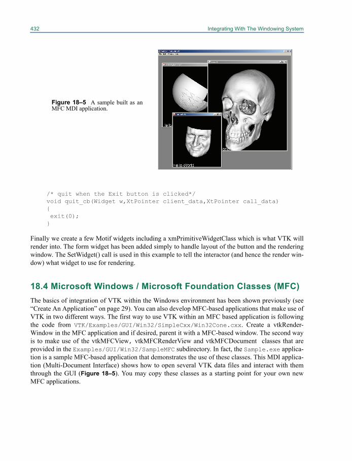
432 Integrating With The Windowing System
/* quit when the Exit button is clicked*/void quit_cb(Widget w,XtPointer client_data,XtPointer call_data){ exit(0);}
Finally we create a few Motif widgets including a xmPrimitiveWidgetClass which is what VTK willrender into. The form widget has been added simply to handle layout of the button and the renderingwindow. The SetWidget() call is used in this example to tell the interactor (and hence the render win-dow) what widget to use for rendering.
18.4 Microsoft Windows / Microsoft Foundation Classes (MFC)The basics of integration of VTK within the Windows environment has been shown previously (see“Create An Application” on page 29). You can also develop MFC-based applications that make use ofVTK in two different ways. The first way to use VTK within an MFC based application is followingthe code from VTK/Examples/GUI/Win32/SimpleCxx/Win32Cone.cxx. Create a vtkRender-Window in the MFC application and if desired, parent it with a MFC-based window. The second wayis to make use of the vtkMFCView, vtkMFCRenderView and vtkMFCDocument classes that areprovided in the Examples/GUI/Win32/SampleMFC subdirectory. In fact, the Sample.exe applica-tion is a sample MFC-based application that demonstrates the use of these classes. This MDI applica-tion (Multi-Document Interface) shows how to open several VTK data files and interact with themthrough the GUI (Figure 18–5). You may copy these classes as a starting point for your own newMFC applications.
Figure 18–5 A sample built as anMFC MDI application.
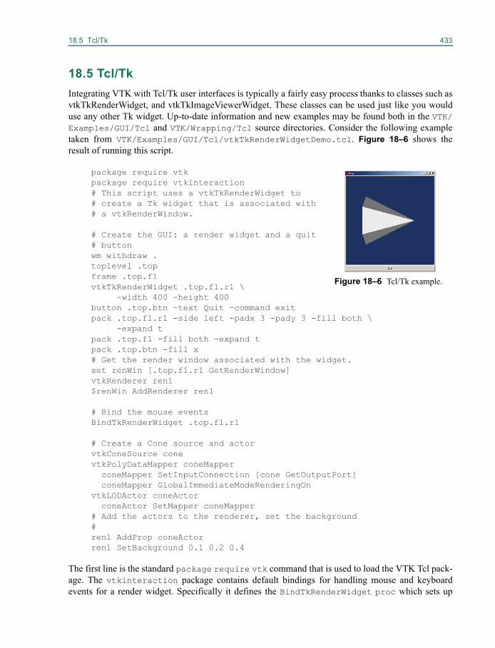
18.5 Tcl/Tk 433
18.5 Tcl/Tk Integrating VTK with Tcl/Tk user interfaces is typically a fairly easy process thanks to classes such asvtkTkRenderWidget, and vtkTkImageViewerWidget. These classes can be used just like you woulduse any other Tk widget. Up-to-date information and new examples may be found both in the VTK/Examples/GUI/Tcl and VTK/Wrapping/Tcl source directories. Consider the following exampletaken from VTK/Examples/GUI/Tcl/vtkTkRenderWidgetDemo.tcl. Figure 18–6 shows theresult of running this script.
package require vtkpackage require vtkinteraction# This script uses a vtkTkRenderWidget to# create a Tk widget that is associated with # a vtkRenderWindow.
# Create the GUI: a render widget and a quit# buttonwm withdraw .toplevel .top frame .top.f1 vtkTkRenderWidget .top.f1.r1 \ -width 400 -height 400
button .top.btn -text Quit -command exitpack .top.f1.r1 -side left -padx 3 -pady 3 -fill both \
-expand tpack .top.f1 -fill both -expand tpack .top.btn -fill x# Get the render window associated with the widget.set renWin [.top.f1.r1 GetRenderWindow]vtkRenderer ren1$renWin AddRenderer ren1
# Bind the mouse eventsBindTkRenderWidget .top.f1.r1
# Create a Cone source and actorvtkConeSource conevtkPolyDataMapper coneMapper coneMapper SetInputConnection [cone GetOutputPort] coneMapper GlobalImmediateModeRenderingOnvtkLODActor coneActor coneActor SetMapper coneMapper# Add the actors to the renderer, set the background#ren1 AddProp coneActorren1 SetBackground 0.1 0.2 0.4
The first line is the standard package require vtk command that is used to load the VTK Tcl pack-age. The vtkinteraction package contains default bindings for handling mouse and keyboardevents for a render widget. Specifically it defines the BindTkRenderWidget proc which sets up
Figure 18–6 Tcl/Tk example.
434 Integrating With The Windowing System
those bindings for a particular vtkTkRenderWidget. Next we withdraw the default toplevel widgetand create a new one called .top. On some systems you may need to create .top with the followingline instead of the one given above.
toplevel .top -visual best
Next we create and pack the frame, vtkTkRenderWidget, and a button in the traditional Tk manner.The next line queries the vtkTkRenderWidget for the underlying render window that it is using. Westore this in a variable called renWin. We then create a renderer, associate it with the render window,and then bind the mouse events to the vtkRenderWidget using the BindTkRenderWidget proc.Finally we create a cone and actor in the normal manner. If you wish, the render window can be pro-vided as an argument on the creation of the vtkTkRenderWidget as follows:
vtkRenderWindow renWinvtkTkRenderWidget .top.f1.r1 \
-width 400 -height 400 -rw renWin
Then simply use renWin instead of $renWin since it is now an instance, not a variable reference. For your application development you will probably want to customize the event handling. The
best way to do this is to make a copy of bindings-rw.tcl and bindings.tcl located in VTK/Wrapping/Tcl/vtkinteraction and then edit it to suit your preferences. The format of the firstfile is fairly straightforward. It defines the BindTkRenderWidget proc that associates events withspecific Tcl procedures. The other file defines these procedures. The same techniques used withvtkTkRenderWidget can be used with vtkTkImageViewerWidget for image processing. Instead ofhaving a -rw option and GetRenderWindow() method, vtkTkImageViewerWidget supports -iv andGetImageViewer().
When using the vtkTkWidget classes you should not use the interactor classes such asvtkRenderWindowInteractor. Normally you should use either an interactor or a vtkTkWidget butnever both for a given window.
18.6 JavaThe Visualization Toolkit includes a class specially designed to help you integrate VTK into your Javabased application. This is a fairly tricky procedure since Java does not provide any “public” classes tosupport native code integration. It is made more difficult by the fact that Java is a multithreaded lan-guage and yet windowing systems such as X11R5 do not support multithreaded user interfaces. Tohelp overcome these difficulties, we have provided a Java class called vtkPanel. This class workswith Java to make a vtkRenderWindow appear like a normal Java AWT Canvas. TheSimpleVTK.java example is in the VTK/Wrapping/Java subdirectory. It makes use of thevtkPanel class. vtkPanel.java is in VTK/Wrapping/Java/vtk.
18.7 Using VTK with QtVTK now contains many classes that make it easy to integrate VTK functionality into Qt applica-tions. The VTK source files related to Qt are located under the VTK/GUISupport/Qt directory. Qtrelated VTK examples are located under the VTK/Examples/GUI/Qt directory. The Qt support in
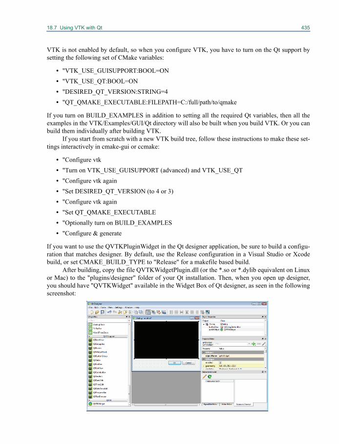
18.7 Using VTK with Qt 435
VTK is not enabled by default, so when you configure VTK, you have to turn on the Qt support bysetting the following set of CMake variables:
• "VTK_USE_GUISUPPORT:BOOL=ON• "VTK_USE_QT:BOOL=ON• "DESIRED_QT_VERSION:STRING=4• "QT_QMAKE_EXECUTABLE:FILEPATH=C:/full/path/to/qmake
If you turn on BUILD_EXAMPLES in addition to setting all the required Qt variables, then all theexamples in the VTK/Examples/GUI/Qt directory will also be built when you build VTK. Or you canbuild them individually after building VTK.
If you start from scratch with a new VTK build tree, follow these instructions to make these set-tings interactively in cmake-gui or ccmake:
• "Configure vtk• "Turn on VTK_USE_GUISUPPORT (advanced) and VTK_USE_QT• "Configure vtk again• "Set DESIRED_QT_VERSION (to 4 or 3)• "Configure vtk again• "Set QT_QMAKE_EXECUTABLE• "Optionally turn on BUILD_EXAMPLES• "Configure & generate
If you want to use the QVTKPluginWidget in the Qt designer application, be sure to build a configu-ration that matches designer. By default, use the Release configuration in a Visual Studio or Xcodebuild, or set CMAKE_BUILD_TYPE to "Release" for a makefile based build.
After building, copy the file QVTKWidgetPlugin.dll (or the *.so or *.dylib equivalent on Linuxor Mac) to the "plugins/designer" folder of your Qt installation. Then, when you open up designer,you should have "QVTKWidget" available in the Widget Box of Qt designer, as seen in the followingscreenshot:
436 Integrating With The Windowing System
The vtkEventQtSlotConnect class is an adapter class that allows you to connect vtkObjectbased events to your QObject based slots such that when the vtkObject event is invoked, your slot iscalled. Example use of this class is located in the Form1::init method in the file VTK/Examples/GUI/Qt/Events/GUI.ui.h. This code snippet from that example demonstrates how easy it is to connect yourslot method to a vtkObject based event:
connections = vtkEventQtSlotConnect::New();
// get right mouse pressed with high priority connections->Connect(qVTK1->GetRenderWindow()->GetInteractor(), vtkCommand::RightButtonPressEvent,
this,SLOT(popup( vtkObject*, unsigned long, void*, void*, vtkCommand*)),
popup1, 1.0);
Chapter 19
Coding Resources 19
This chapter provides information to make the job ofbuilding VTK applications and classes a little easier. Object diagrams are useful when you’d like anoverview of the objects in the system; they are included here in symbolic form known as object mod-eling diagrams. The diagrams we use here are simplified to mainly show inheritance, but some asso-ciations between classes are shown as well. Succinct filter descriptions are provided to help you findthe right filter to do the job at hand. This chapter also documents the VTK legacy and XML file for-mats.
19.1 Object DiagramsThe following section contains abbreviated object diagrams using the OMT graphical language. Thepurpose of this section is to convey the essence of the software structure, particularly inheritance andobject associations. Due to space limitation, not all objects are shown, particularly “leaf” (i.e., bottomof the inheritance tree) objects. Instead, we choose a single leaf object to represent other siblingobjects. (Object diagrams for all classes in VTK are provided in the online documentation.) The orga-nization of the objects follows that of the synopsis.
Foundation
The foundation object diagram is shown in Figure 19–1. These represent the core data objects, aswell as other object manipulation classes.
Cells
The cell object diagram is shown in Figure 19–3. Currently, 21 concrete cell types are supported inVTK. The special class vtkGenericCell is used to represent any type of cell (i.e., supports the thread-
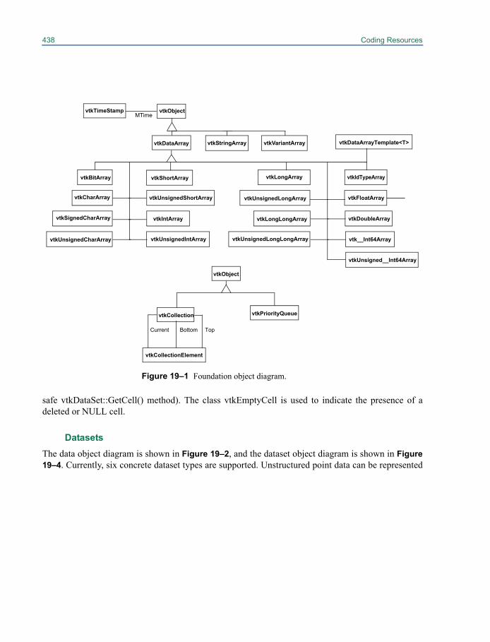
438 Coding Resources
safe vtkDataSet::GetCell() method). The class vtkEmptyCell is used to indicate the presence of adeleted or NULL cell.
DatasetsThe data object diagram is shown in Figure 19–2, and the dataset object diagram is shown in Figure19–4. Currently, six concrete dataset types are supported. Unstructured point data can be represented
vtkIdTypeArray
vtkIntArray
vtkCollection
vtkCollectionElement
BottomCurrent Top
vtkObject
Figure 19–1 Foundation object diagram.
vtkDataArray
vtkBitArray
vtkCharArray
vtkUnsignedCharArray
vtkShortArray
vtkUnsignedShortArray
vtkPriorityQueue
vtkTimeStamp vtkObjectMTime
vtkDataArrayTemplate<T>
vtkDoubleArray
vtkFloatArrayvtkUnsignedLongArray
vtkLongArray
vtkUnsignedIntArray
vtkSignedCharArray
vtkUnsignedLongLongArray
vtkLongLongArray
vtkUnsigned__Int64Array
vtk__Int64Array
vtkStringArray vtkVariantArray
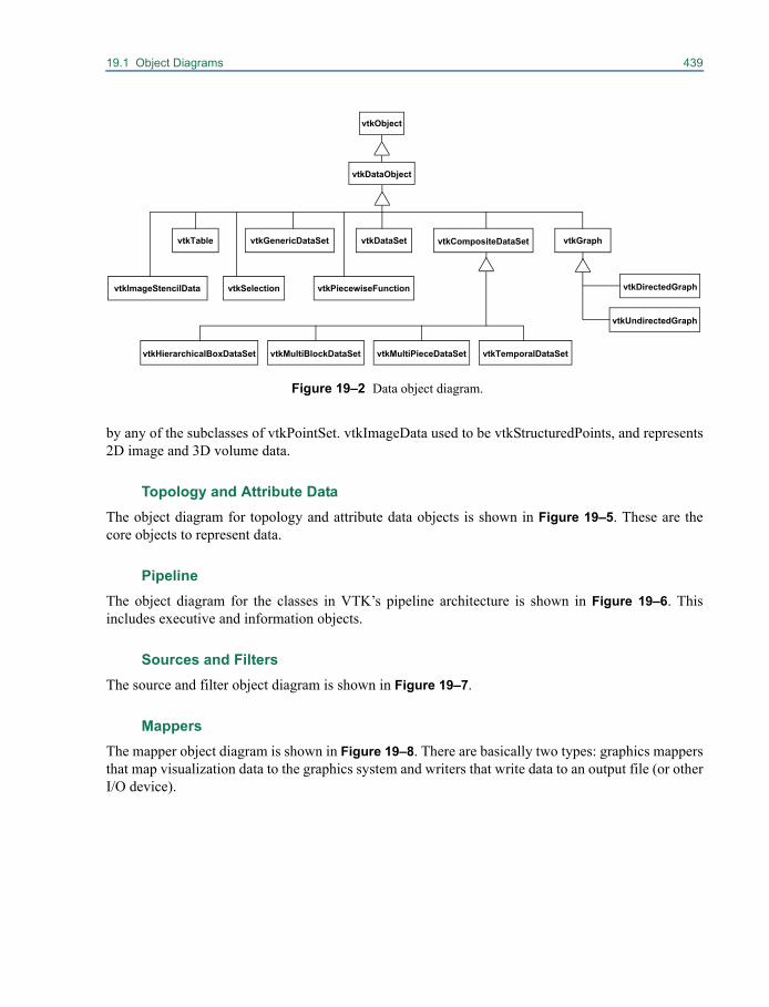
19.1 Object Diagrams 439
by any of the subclasses of vtkPointSet. vtkImageData used to be vtkStructuredPoints, and represents2D image and 3D volume data.
Topology and Attribute DataThe object diagram for topology and attribute data objects is shown in Figure 19–5. These are thecore objects to represent data.
PipelineThe object diagram for the classes in VTK’s pipeline architecture is shown in Figure 19–6. Thisincludes executive and information objects.
Sources and FiltersThe source and filter object diagram is shown in Figure 19–7.
MappersThe mapper object diagram is shown in Figure 19–8. There are basically two types: graphics mappersthat map visualization data to the graphics system and writers that write data to an output file (or otherI/O device).
vtkDataSet
vtkDataObject
vtkObject
Figure 19–2 Data object diagram.
vtkCompositeDataSetvtkGenericDataSet vtkGraph
vtkImageStencilData vtkPiecewiseFunctionvtkSelection
vtkTable
vtkDirectedGraph
vtkUndirectedGraph
vtkMultiBlockDataSet vtkMultiPieceDataSet vtkTemporalDataSetvtkHierarchicalBoxDataSet
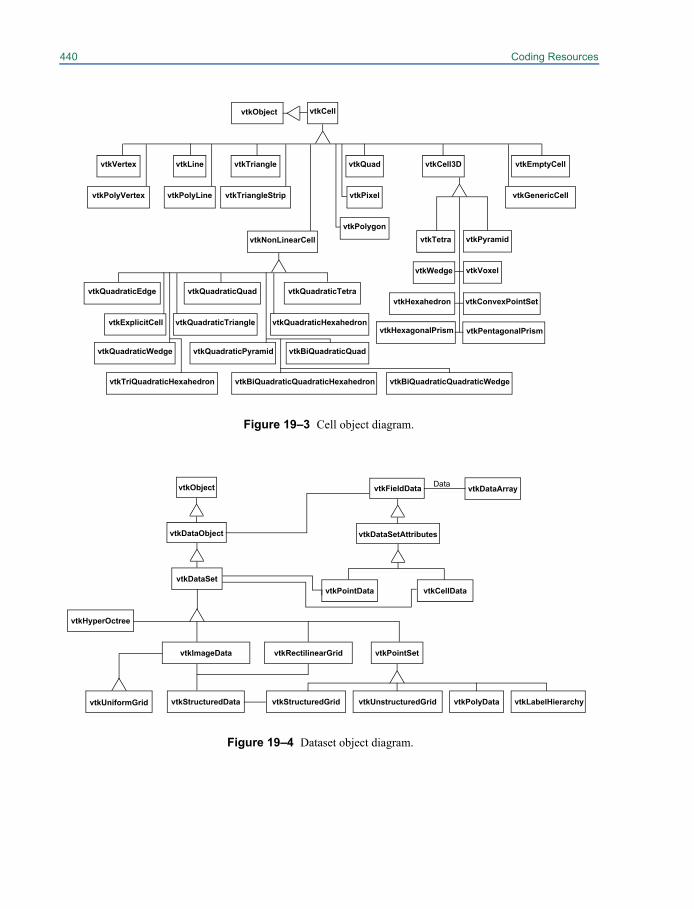
440 Coding Resources
Figure 19–3 Cell object diagram.
vtkPolygon
vtkHexahedron
vtkPolyLine
vtkLine vtkQuad
vtkTriangleStrip
vtkTetra
vtkTriangle
vtkCell
vtkVoxel
vtkVertex
vtkPolyVertex vtkPixel
vtkEmptyCell
vtkGenericCell
vtkNonLinearCell
vtkQuadraticEdge vtkQuadraticQuad vtkQuadraticTetra
vtkQuadraticTriangle vtkQuadraticHexahedron
vtkWedge
vtkPyramid
vtkConvexPointSet
vtkCell3D
vtkObject
vtkPentagonalPrismvtkHexagonalPrism
vtkQuadraticPyramidvtkQuadraticWedge
vtkExplicitCell
vtkTriQuadraticHexahedron vtkBiQuadraticQuadraticHexahedron vtkBiQuadraticQuadraticWedge
vtkBiQuadraticQuad
vtkStructuredData
vtkImageData
vtkPolyDatavtkUnstructuredGridvtkStructuredGrid
vtkPointSet
vtkDataSet
Figure 19–4 Dataset object diagram.
vtkDataObject
vtkRectilinearGrid
vtkObject
vtkDataSetAttributes
vtkFieldData
vtkCellDatavtkPointData
vtkDataArrayData
vtkHyperOctree
vtkUniformGrid vtkLabelHierarchy
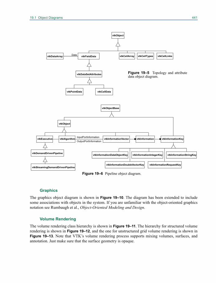
19.1 Object Diagrams 441
GraphicsThe graphics object diagram is shown in Figure 19–10. The diagram has been extended to includesome associations with objects in the system. If you are unfamiliar with the object-oriented graphicsnotation see Rumbaugh et al., Object-Oriented Modeling and Design.
Volume RenderingThe volume rendering class hierarchy is shown in Figure 19–11. The hierarchy for structured volumerendering is shown in Figure 19–12, and the one for unstructured grid volume rendering is shown inFigure 19–13. Note that VTK’s volume rendering process supports mixing volumes, surfaces, andannotation. Just make sure that the surface geometry is opaque.
vtkDataSetAttributes
vtkFieldData
vtkObject
vtkCellLinksvtkCellTypesvtkCellArray
Figure 19–5 Topology and attributedata object diagram.
vtkDataArray Data
vtkCellDatavtkPointData
vtkObjectBase
vtkObject
vtkExecutive
vtkDemandDrivenPipeline
vtkStreamingDemandDrivenPipeline
vtkAlgorithm vtkInformationVectorInputPortInformationOutputPortInformation
vtkInformation vtkInformationKey
vtkInformationStringKeyvtkInformationIntegerKeyvtkInformationDataObjectKey
vtkInformationRequestKeyvtkInformationDoubleVectorKey
Figure 19–6 Pipeline object diagram.
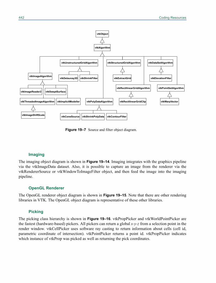
442 Coding Resources
ImagingThe imaging object diagram is shown in Figure 19–14. Imaging integrates with the graphics pipelinevia the vtkImageData dataset. Also, it is possible to capture an image from the renderer via thevtkRendererSource or vtkWindowToImageFilter object, and then feed the image into the imagingpipeline.
OpenGL RendererThe OpenGL renderer object diagram is shown in Figure 19–15. Note that there are other renderinglibraries in VTK. The OpenGL object diagram is representative of these other libraries.
Picking The picking class hierarchy is shown in Figure 19–16. vtkPropPicker and vtkWorldPointPicker arethe fastest (hardware-based) pickers. All pickers can return a global x-y-z from a selection point in therender window. vtkCellPicker uses software ray casting to return information about cells (cell id,parametric coordinate of intersection). vtkPointPicker returns a point id. vtkPropPicker indicateswhich instance of vtkProp was picked as well as returning the pick coordinates.
Figure 19–7 Source and filter object diagram.
vtkObject
vtkAlgorithm
vtkUnstructuredGridAlgorithm
vtkDelaunay3D vtkShrinkFiltervtkImageAlgorithm
vtkImageReader2
vtkThreadedImageAlgorithm
vtkImageShiftScale
vtkSweptSurface
vtkImplicitModeller vtkPolyDataAlgorithm
vtkConeSource vtkShrinkPolyData vtkContourFilter
vtkStructuredGridAlgorithm
vtkExtractGrid
vtkRectilinearGridAlgorithm
vtkRectilinearGridClip
vtkDataSetAlgorithm
vtkElevationFilter
vtkPointSetAlgorithm
vtkWarpVector
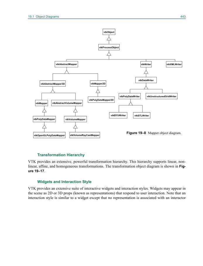
19.1 Object Diagrams 443
Transformation Hierarchy VTK provides an extensive, powerful transformation hierarchy. This hierarchy supports linear, non-linear, affine, and homogeneous transformations. The transformation object diagram is shown in Fig-ure 19–17.
Widgets and Interaction StyleVTK provides an extensive suite of interactive widgets and interaction styles. Widgets may appear inthe scene as 2D or 3D props (known as representations) that respond to user interaction. Note that aninteraction style is similar to a widget except that no representation is associated with an interactor
vtkOpenGLPolyDataMapper
vtkPolyDataMapper
vtkAbstractVolumeMappervtkMapper
vtkWriter
Figure 19–8 Mapper object diagram.
vtkSTLWritervtkBYUWriter
vtkProcessObject
vtkObject
vtkPolyDataWriter vtkUnstructuredGridWriter
vtkDataWriter
vtkAbstractMapper
vtkMapper2DvtkAbstractMapper3D
vtkVolumeRayCastMapper
vtkPolyDataMapper2D
vtkXMLWriter
vtkVolumeMapper
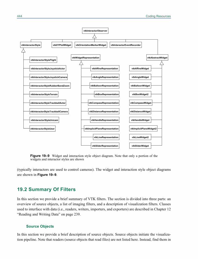
444 Coding Resources
(typically interactors are used to control cameras). The widget and interaction style object diagramsare shown in Figure 19–9.
19.2 Summary Of Filters
In this section we provide a brief summary of VTK filters. The section is divided into three parts: anoverview of source objects, a list of imaging filters, and a description of visualization filters. Classesused to interface with data (i.e., readers, writers, importers, and exporters) are described in Chapter 12“Reading and Writing Data” on page 239.
Source Objects
In this section we provide a brief description of source objects. Source objects initiate the visualiza-tion pipeline. Note that readers (source objects that read files) are not listed here. Instead, find them in
Figure 19–9 Widget and interaction style object diagram. Note that only a portion of thewidgets and interactor styles are shown
vtkInteractorObserver
vtkInteractorStyle vtkXYPlotWIdget vtkOrientationMarkerWidget vtkInteractorEventRecorder
vtkWidgetRepresentation vtkAbstractWidget
vtkBoxWidget2
vtkAffineWidget
vtkCompassWidget
vtkDistanceWidget
vtkSliderWidget
vtkLineWidget2
vtkAngleWidget
vtkHandleWidget
vtkBalloonWidget
vtkImplicitPlaneWidget2
vtkBoxRepresentation
vtkAffineRepresentation
vtkCompassRepresentation
vtkDistanceRepresentation
vtkSliderRepresentation
vtkLineRepresentation
vtkAngleRepresentation
vtkHandleRepresentation
vtkBalloonRepresentation
vtkImplicitPlaneRepresentation
vtkInteractorStyleRubberBandZoom
vtkInteractorStyleFlight
vtkInteractorStyleTerrain
vtkInteractorStyleTrackballActor
vtkInteractorStyleUser
vtkInteractorStyleJoystickActor
vtkInteractorStyleTrackballCamera
vtkInteractorStyleJoystickCamera
vtkInteractorStyleUnicam
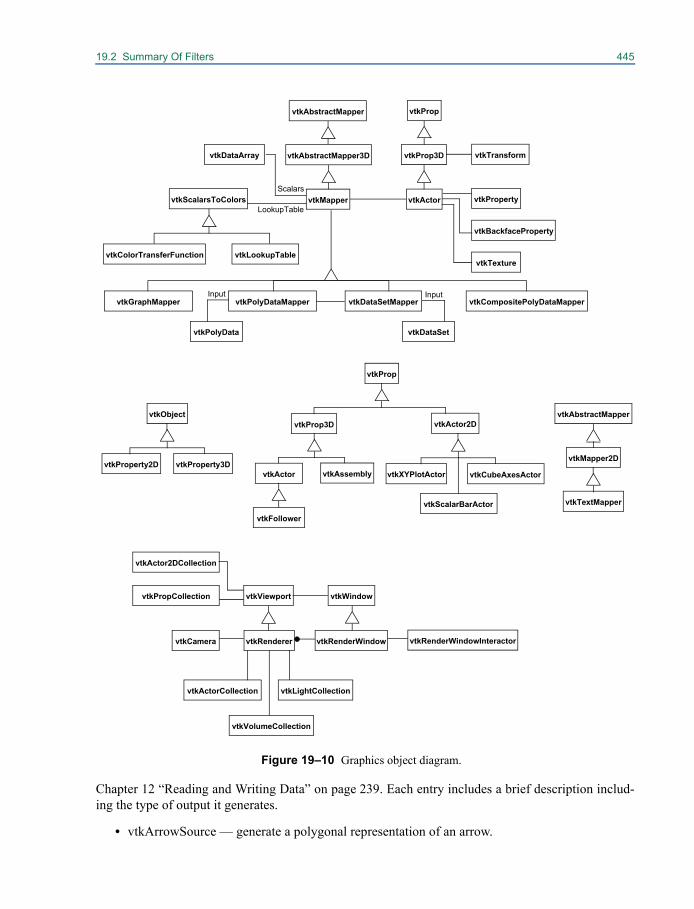
19.2 Summary Of Filters 445
Chapter 12 “Reading and Writing Data” on page 239. Each entry includes a brief description includ-ing the type of output it generates.
• vtkArrowSource — generate a polygonal representation of an arrow.
vtkProperty
vtkBackfaceProperty
vtkMapper
vtkLookupTable
vtkCamera vtkRenderWindow
vtkLightCollectionvtkActorCollection
vtkRenderer
vtkDataSetMappervtkPolyDataMapper
vtkPolyData
Input
vtkActor
Figure 19–10 Graphics object diagram.
vtkRenderWindowInteractor
vtkProp3D vtkTransform
vtkDataSet
Input
vtkViewport vtkWindowvtkPropCollection
vtkVolumeCollection
vtkProperty2D
vtkActor2D
vtkMapper2D
vtkTextMapper
vtkTexture
vtkPropvtkAbstractMapper
vtkProp
vtkAbstractMapper
vtkAbstractMapper3D
vtkObject
vtkProperty3DvtkActor
vtkProp3D
vtkAssembly
vtkFollower
vtkCubeAxesActorvtkXYPlotActor
vtkScalarBarActor
vtkScalarsToColors
vtkColorTransferFunction
vtkDataArray
Scalars
LookupTable
vtkActor2DCollection
vtkGraphMapper vtkCompositePolyDataMapper
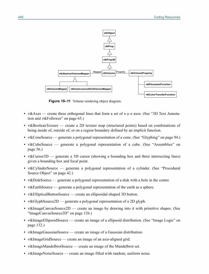
446 Coding Resources
• vtkAxes — create three orthogonal lines that form a set of x-y-z axes. (See “3D Text Annota-tion and vtkFollower” on page 65.)
• vtkBooleanTexture — create a 2D texture map (structured points) based on combinations ofbeing inside of, outside of, or on a region boundary defined by an implicit function.
• vtkConeSource — generate a polygonal representation of a cone. (See “Glyphing” on page 94.)
• vtkCubeSource — generate a polygonal representation of a cube. (See “Assemblies” onpage 56.)
• vtkCursor3D — generate a 3D cursor (showing a bounding box and three intersecting lines)given a bounding box and focal point.
• vtkCylinderSource — generate a polygonal representation of a cylinder. (See “ProceduralSource Object” on page 42.)
• vtkDiskSource — generate a polygonal representation of a disk with a hole in the center.
• vtkEarthSource — generate a polygonal representation of the earth as a sphere.
• vtkEllipticalButtonSource — create an ellipsoidal-shaped 3D button.
• vtkGlyphSource2D — generate a polygonal representation of a 2D glyph.
• vtkImageCanvasSource2D — create an image by drawing into it with primitive shapes. (See“ImageCanvasSource2D” on page 126.)
• vtkImageEllipsoidSource — create an image of a ellipsoid distribution. (See “Image Logic” onpage 132.)
• vtkImageGaussianSource — create an image of a Gaussian distribution.
• vtkImageGridSource — create an image of an axis-aligned grid.
• vtkImageMandelbrotSource — create an image of the Mandelbrot set.
• vtkImageNoiseSource — create an image filled with random, uniform noise.
Figure 19–11 Volume rendering object diagram.
vtkVolumeProperty
vtkVolumeMapper
vtkPiecewiseFunction
vtkColorTransferFunction
vtkVolume
vtkProp3D
vtkAbstractVolumeMapperPropertyMapper
vtkProp
vtkObject
vtkUnstructuredGridVolumeMapper
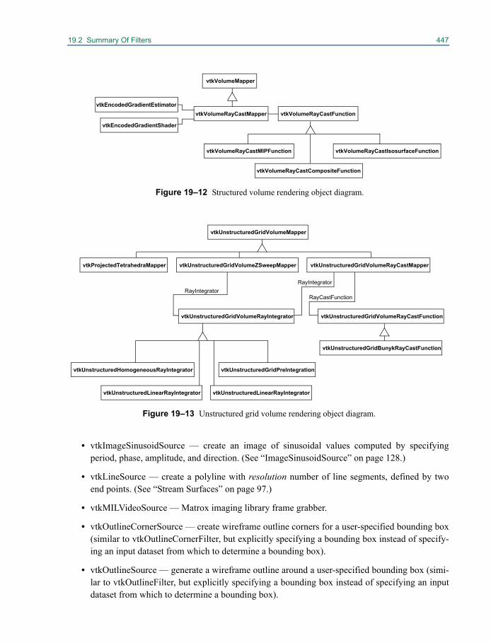
19.2 Summary Of Filters 447
• vtkImageSinusoidSource — create an image of sinusoidal values computed by specifyingperiod, phase, amplitude, and direction. (See “ImageSinusoidSource” on page 128.)
• vtkLineSource — create a polyline with resolution number of line segments, defined by twoend points. (See “Stream Surfaces” on page 97.)
• vtkMILVideoSource — Matrox imaging library frame grabber.
• vtkOutlineCornerSource — create wireframe outline corners for a user-specified bounding box(similar to vtkOutlineCornerFilter, but explicitly specifying a bounding box instead of specify-ing an input dataset from which to determine a bounding box).
• vtkOutlineSource — generate a wireframe outline around a user-specified bounding box (simi-lar to vtkOutlineFilter, but explicitly specifying a bounding box instead of specifying an inputdataset from which to determine a bounding box).
vtkVolumeRayCastFunction
vtkVolumeRayCastCompositeFunction
vtkVolumeRayCastMIPFunction vtkVolumeRayCastIsosurfaceFunction
vtkVolumeRayCastMappervtkEncodedGradientEstimator
vtkEncodedGradientShader
vtkVolumeMapper
Figure 19–12 Structured volume rendering object diagram.
vtkUnstructuredGridVolumeMapper
vtkProjectedTetrahedraMapper vtkUnstructuredGridVolumeZSweepMapper vtkUnstructuredGridVolumeRayCastMapper
vtkUnstructuredGridVolumeRayIntegrator vtkUnstructuredGridVolumeRayCastFunction
RayIntegratorRayIntegrator
RayCastFunction
vtkUnstructuredGridBunykRayCastFunction
vtkUnstructuredHomogeneousRayIntegrator
vtkUnstructuredLinearRayIntegrator
vtkUnstructuredGridPreIntegration
vtkUnstructuredLinearRayIntegrator
Figure 19–13 Unstructured grid volume rendering object diagram.
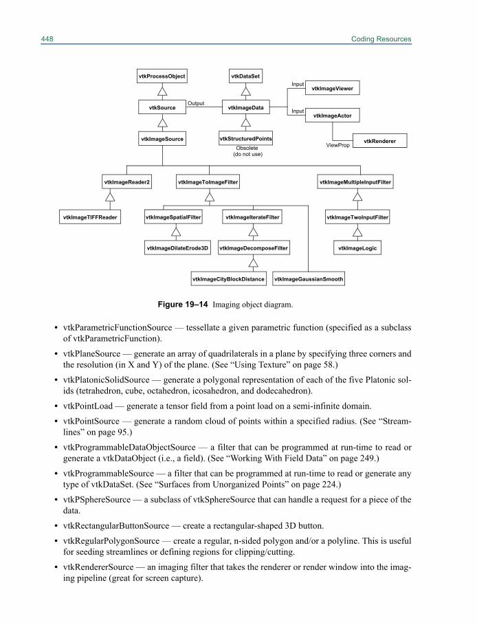
448 Coding Resources
• vtkParametricFunctionSource — tessellate a given parametric function (specified as a subclassof vtkParametricFunction).
• vtkPlaneSource — generate an array of quadrilaterals in a plane by specifying three corners andthe resolution (in X and Y) of the plane. (See “Using Texture” on page 58.)
• vtkPlatonicSolidSource — generate a polygonal representation of each of the five Platonic sol-ids (tetrahedron, cube, octahedron, icosahedron, and dodecahedron).
• vtkPointLoad — generate a tensor field from a point load on a semi-infinite domain.
• vtkPointSource — generate a random cloud of points within a specified radius. (See “Stream-lines” on page 95.)
• vtkProgrammableDataObjectSource — a filter that can be programmed at run-time to read orgenerate a vtkDataObject (i.e., a field). (See “Working With Field Data” on page 249.)
• vtkProgrammableSource — a filter that can be programmed at run-time to read or generate anytype of vtkDataSet. (See “Surfaces from Unorganized Points” on page 224.)
• vtkPSphereSource — a subclass of vtkSphereSource that can handle a request for a piece of thedata.
• vtkRectangularButtonSource — create a rectangular-shaped 3D button.
• vtkRegularPolygonSource — create a regular, n-sided polygon and/or a polyline. This is usefulfor seeding streamlines or defining regions for clipping/cutting.
• vtkRendererSource — an imaging filter that takes the renderer or render window into the imag-ing pipeline (great for screen capture).
Figure 19–14 Imaging object diagram.
vtkImageReader2 vtkImageToImageFilter vtkImageMultipleInputFilter
vtkImageDilateErode3D
vtkImageSpatialFiltervtkImageTIFFReader
vtkImageLogicvtkImageDecomposeFilter
vtkImageIterateFilter
vtkImageViewer
vtkImageTwoInputFilter
vtkImageGaussianSmooth
vtkImageData
vtkDataSet
vtkStructuredPoints
vtkSource
vtkProcessObjectInput
Output
vtkImageCityBlockDistance
Obsolete vtkImageSource
(do not use)
vtkImageActorInput
vtkRendererViewProp
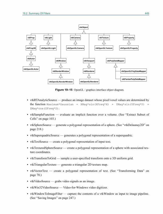
19.2 Summary Of Filters 449
• vtkRTAnalyticSource — produce an image dataset whose pixel/voxel values are determined bythe function Maximum*Gaussian + XMag*sin(XFreq*X) + YMag*sin(YFreq*Y) +
ZMag*cos(ZFreq*Z).
• vtkSampleFunction — evaluate an implicit function over a volume. (See “Extract Subset ofCells” on page 103.)
• vtkSphereSource — generate a polygonal representation of a sphere. (See “vtkDelaunay2D” onpage 218.)
• vtkSuperquadricSource — generates a polygonal representation of a superquadric.
• vtkTextSource — create a polygonal representation of input text.
• vtkTexturedSphereSource — create a polygonal representation of a sphere with associated tex-ture coordinates.
• vtkTransformToGrid — sample a user-specified transform onto a 3D uniform grid.
• vtkTriangularTexture — generate a triangular 2D texture map.
• vtkVectorText — create a polygonal representation of text. (See “Transforming Data” onpage 70.)
• vtkVideoSource — grabs video signals as an image.
• vtkWin32VideoSource — Video-for-Windows video digitizer.
• vtkWindowToImageFilter — capture the contents of a vtkWindow as input to image pipeline.(See “Saving Images” on page 247.)
vtkCameravtkLight
vtkObject
vtkProperty
vtkOpenGLRenderer
vtkRenderervtkRenderWindow
Figure 19–15 OpenGL / graphics interface object diagram.
vtkOpenGLRenderWindow
vtkTexture
vtkActorvtkPolyDataMapper
vtkOpenGLActor
vtkOpenGLLight vtkOpenGLCamera vtkOpenGLProperty
vtkOpenGLPolyDataMapper
vtkOpenGLTexture
vtkProp
vtkViewportvtkWindow
vtkProp3D
vtkPainterPolyDataMapper
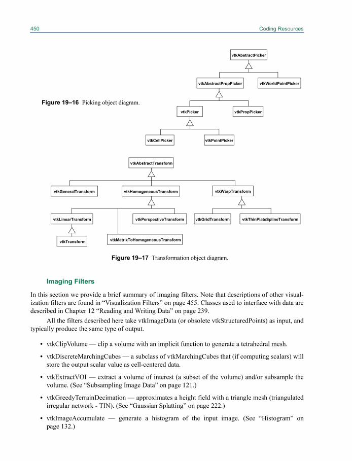
450 Coding Resources
Imaging Filters
In this section we provide a brief summary of imaging filters. Note that descriptions of other visual-ization filters are found in “Visualization Filters” on page 455. Classes used to interface with data aredescribed in Chapter 12 “Reading and Writing Data” on page 239.
All the filters described here take vtkImageData (or obsolete vtkStructuredPoints) as input, andtypically produce the same type of output.
• vtkClipVolume — clip a volume with an implicit function to generate a tetrahedral mesh.
• vtkDiscreteMarchingCubes — a subclass of vtkMarchingCubes that (if computing scalars) willstore the output scalar value as cell-centered data.
• vtkExtractVOI — extract a volume of interest (a subset of the volume) and/or subsample thevolume. (See “Subsampling Image Data” on page 121.)
• vtkGreedyTerrainDecimation — approximates a height field with a triangle mesh (triangulatedirregular network - TIN). (See “Gaussian Splatting” on page 222.)
• vtkImageAccumulate — generate a histogram of the input image. (See “Histogram” onpage 132.)
Figure 19–16 Picking object diagram.
vtkAbstractPicker
vtkAbstractPropPicker vtkWorldPointPicker
vtkPicker vtkPropPicker
vtkCellPicker vtkPointPicker
Figure 19–17 Transformation object diagram.
vtkAbstractTransform
vtkGeneralTransform vtkHomogeneousTransform
vtkThinPlateSplineTransformvtkGridTransformvtkPerspectiveTransform
vtkWarpTransform
vtkMatrixToHomogeneousTransform
vtkLinearTransform
vtkTransform
19.2 Summary Of Filters 451
• vtkImageAnisotropicDiffusion2D — iteratively apply a 2D diffusion filter to perform edge-pre-serving smoothing.
• vtkImageAnisotropicDiffusion3D — iteratively apply a 3D diffusion filter to perform edge-pre-serving smoothing.
• vtkImageAppend — merge multiple input images into one output image; they will be concate-nated along a user-specified axis. (See “Append Images” on page 129.)
• vtkImageAppendComponents — merge the components from two input images; the resultingimage will contain all the components from both images. (See “Append Images” on page 129.)
• vtkImageBlend — combine the components of multiple images according to the alpha valuesand/or the opacity setting for each input; the number of components per input image mustmatch, and the output image will also have this number of components. (See “ImageGrid-Source” on page 127.)
• vtkImageButterworthHighPass — apply a frequency-domain high pass filter.
• vtkImageButterworthLowPass — apply a frequency-domain low pass filter.
• vtkImageCacheFilter — cache (store) images for future use to avoid pipeline re-execution.• vtkImageCast — change the scalar type of an image by casting from the input scalar type to a
user-specified output scalar type. (See “Convert Scalar Type” on page 128.)
• vtkImageChangeInformation — modify the spacing, origin, or extent of the data withoutchanging the data itself. (See “Change Spacing, Origin, or Extent” on page 129.)
• vtkImageCheckerboard — show two images at once using a checkerboard pattern.
• vtkImageCityBlockDistance — create a distance map (distance to the nearest 0-valued pixel/voxel) using the city block (or Manhattan) metric (i.e., stepping along pixel/voxel edges, neverthrough the middle of a cell).
• vtkImageClip — reduce the size (extent) of the input image. (See “Subsampling Image Data”on page 121.)
• vtkImageConstantPad — change the extent of the image, setting any pixels outside the originalextent to a constant user-specified value.
• vtkImageContinuousDilate3D — evaluate the maximum value in an ellipsoidal neighborhood.
• vtkImageContinuousErode3D — evaluate the minimum value in an ellipsoidal neighborhood.
• vtkImageConvolve — convolution of an image with a kernel.• vtkImageCorrelation — create a correlation image for two input images.
• vtkImageCursor3D — add a cursor to the input image, modifying the pixels/voxels covered bythe cursor.
• vtkImageDataGeometryFilter — extract geometry (points, lines, planes) as vtkPolyData. (See“Warp Based On Scalar Values” on page 122.)
• vtkImageDataStreamer — initiate streaming for image data; to satisfy a request for data, thisfilter calls Update() on its input many times, each time requesting a different piece of the data.This is helpful when operating on large data that cannot be stored in memory with all the addi-tional information required by a filter operating on this image/volume data. (See “ImageNoise-Source” on page 127.)

452 Coding Resources
• vtkImageDifference — generate a difference image / error value for two images.
• vtkImageDilateErode3D — increase the size of regions with one scalar value while decreasingthe size of regions with another scalar value along the boundary between the two.
• vtkImageDivergence — create a scalar field that represents the rate of change of the input vec-tor field.
• vtkImageDotProduct — create a dot product image from two vector images.
• vtkImageEuclideanDistance — create a distance map (i.e., distance to the nearest 0-valuedpixel/voxel) 3D Euclidean distance (i.e., straight-line distance).
• vtkImageEuclideanToPolar — convert 2D Euclidean coordinates to polar coordinates.
• vtkImageExport — pass the data in a vtkImageData to a C programming language array, pro-viding applications with direct access to the image data in memory. This is the reverse of vtkIm-ageImport.
• vtkImageExtractComponents — extract a subset of the components of the input image.
• vtkImageFFT — perform a Fast Fourier Transform (i.e., transform from the spatial to the fre-quency domain).
• vtkImageFlip — flip an image about a specified axis (i.e., right becomes left, etc.). (See “ImageFlip” on page 134.)
• vtkImageFourierCenter — shift the zero frequency from the origin to the center.
• vtkImageGaussianSmooth — perform 1D, 2D, or 3D Gaussian convolution to smooth the inputimage. (See “Gaussian Smoothing” on page 133.)
• vtkImageGradient — compute the gradient vector in 2D or 3D at each point of an image; thevector results are stored in the output image as scalar components. (See “Gradient” onpage 133.)
• vtkImageGradientMagnitude — similar to vtkImageGradient, but the magnitude of the gradientvector at each point in the image is stored in the output image. (See “Gradient” on page 133.)
• vtkImageHSIToRGB — convert images stored using the HSI (hue, saturation, intensity) colormodel to the RGB (red, green, blue) one.
• vtkImageHSVToRGB — convert images stored using the HSV (hue, saturation, value) colormodel to the RGB (red, green, blue) one.
• vtkImageHybridMedian2D — perform a median (middle value) filter while preserving lines /corners.
• vtkImageIdealHighPass — perform a simple frequency domain high pass filter.
• vtkImageIdealLowPass — perform a simple frequency domain low pass filter.
• vtkImageImport — create a vtkImageData from data in a C programming language array. Thisis the reverse of vtkImageExport.
• vtkImageIslandRemoval2D — remove small clusters with a specified value from the image.
• vtkImageLaplacian — compute the Laplacian (divergence of the gradient).
• vtkImageLogarithmicScale — perform a log function on each pixel.
19.2 Summary Of Filters 453
• vtkImageLogic — perform a logic operation: AND, OR, XOR, NAND, NOR, NOT; the firstfour operations require two input images; the last two only require one. (See “Image Logic” onpage 132.)
• vtkImageLuminance — calculate luminance of an RGB image (luminance = 0.3*R + 0.59*G +0.11*B). (See “Image Luminance” on page 132.)
• vtkImageMagnify — increase the size of the image by an integer scale factor.
• vtkImageMagnitude — compute a magnitude image from the scalar components of an inputimage. (See “Gradient” on page 133.)
• vtkImageMapToColors — map a single-component image through a lookup table. (See “MapImage to Color” on page 131.)
• vtkImageMapToWindowLevelColors — map the single-component input image through alookup table and window / level it (i.e., modulate the color from the lookup table based on (S -(L - W/2)) / W, where S is the scalar value, L is the level value, and W is the window value).This allows you to highlight scalars in a specified range. (See “Map Image to Color” onpage 131.)
• vtkImageMarchingCubes — a streaming version of marching cubes.
• vtkImageMask — Combine a mask image with an input image. If a mask pixel is non-zero, theoutput pixel is unchanged from the input; if a mask pixel is zero, the input pixel is et to a user-specified “masked value”.
• vtkImageMaskBits — specify four unsigned int values, and use them to compute bitwise logi-cal operations on each component of each input pixel (one unsigned int value per component).
• vtkImageMathematics — apply basic mathematical operations to one or two images. (See“Image Mathematics” on page 135.)
• vtkImageMedian3D — compute a median (middle value) filter in a rectangular neighborhood.
• vtkImageMirrorPad — change the extent of the image; mirror the original image at its boundar-ies to fill pixels outside the original extent.
• vtkImageNonMaximumSuppression — set non-maximum (i.e., not a peak) pixel values to 0.
• vtkImageNormalize — normalize the vector defined by the scalar components of an image.
• vtkImageOpenClose3D — perform opening or closing (image morphology operations) usingtwo dilate / erode operations.
• vtkImagePermute — reorder the axes of an image; use SetFilteredAxes() to specify how the X,Y, and Z axes should be relabelled. (See “Image Permute” on page 134.)
• vtkImageQuantizeRGBToIndex — from an RGB (red, green, blue) image, create an indeximage and a lookup table. The indices in the output image, when passed through the lookuptable, return the corresponding RGB values of the input image. This filter does not supportstreaming because it must operate on the entire image.
• vtkImageRange3D — compute the range (max - min) in an ellipsoidal neighborhood.
• vtkImageRectilinearWipe — make a rectilinear combination of two images.
• vtkImageResample — resample an image to increase or decrease its size. (See “Speed vs.Accuracy Trade-offs” on page 159.)
454 Coding Resources
• vtkImageReslice — permute, rotate, flip, scale, resample, deform, and/or pad image data in anycombination with reasonably high efficiency. (See “Image Reslice” on page 137.)
• vtkImageRFFT — perform a Reverse Fast Fourier Transform (i.e., transform from the fre-quency to the spatial domain).
• vtkImageRGBToHSI — convert images stored using the RGB (red, green, blue) color model tothe HSI (hue, saturation, intensity) one.
• vtkImageRGBToHSV — convert images stored using the RGB (red, green, blue) color modelto the HSV (hue, saturation, value) one.
• vtkImageSeedConnectivity — label the regions connected to user-specified seeds by pixel/vox-els with a specified value.
• vtkImageSeparableConvolution — compute three, 1D convolutions on an image (one alongeach of the X, Y, and Z axes).
• vtkImageShiftScale — Shift the scalar values of the input image by a specified amount, andthen multiply them by the specified scale value. (See “Convert Scalar Type” on page 128.)
• vtkImageShrink3D — shrink (reduce the extent of) an image by subsampling on a uniform grid.• vtkImageSkeleton2D — perform a skeleton operation in 2D.• vtkImageSobel2D — compute the vector field of an image showing the gradient of the intensity
at each pixel using Sobel functions.• vtkImageSobel3D — compute the vector field of a volume showing the gradient of the intensity
at each voxel using Sobel functions.• vtkImageStencil — combine images via a cookie-cutter operation.• vtkImageToImageStencil — converts vtkImageData into an image that can be used with vtkIm-
ageStencil or other VTK classes that apply a stencil to an image.• vtkImageToPolyDataFilter — convert an image to polygons.• vtkImageThreshold — perform binary or continuous thresholding, replacing scalar values that
do or do not meet the thresholding criteria with user-specified values.• vtkImageTranslateExtent — shift the whole extent, but does not change the data, similar to
vtkImageChangeInformation.• vtkImageVariance3D — compute an approximation of the variance within an ellipsoidal neigh-
borhood (i.e., the average of the difference squared between each pixel/voxel in the neighbor-hood and the center pixel/voxel value).
• vtkImageWrapPad — pad an image using a mod operation on the pixel index so that the origi-nal image is tiled across the new image.
• vtkLinkEdgels — link edgels together to form digital curves.• vtkMarchingCubes — high-performance isocontouring algorithm. (See “Working With Data
Attributes” on page 89.)• vtkMarchingSquares — high-performance isocontouring algorithm in 2D.• vtkMemoryLimitImageDataStreamer — a subclass of vtkImageDataStreamer that determines
the number of pieces to use for streaming based on a user-specified memory limit.• vtkRecursiveDividingCubes — generate an isocontour as a cloud of points.
19.2 Summary Of Filters 455
• vtkSimpleImageFilterExample — just copies the input image to the output; provided as a sim-ple example of an imaging filter. Its superclass, vtkSimpleImageToImageFilter hides much ofthe complexity of vtkImageAlgorithm. (See “A Simple Imaging Filter” on page 399.)
• vtkSynchronizedTemplates2D — high-performance isocontouring algorithm in 2D.• vtkSynchronizedTemplates3D — high-performance isocontouring algorithm in 3D.• vtkSynchronizedTemplatesCutter3D — generate a cut surface (by specifying a cut function)
from an image/volume dataset.
Visualization FiltersThe classes listed below are organized to the type of data they input. Each class contains a briefdescription of what it does and any special notations regarding multiple inputs or outputs.
Input Type vtkDataSet. These filters will process any type of dataset (that is, subclasses of vtkData-Set).
• vtkAppendFilter — appends one or more datasets into a single unstructured grid. (See“Appending Data” on page 100.)
• vtkArrayCalculator — perform mathematical operations on data in field data arrays.• vtkAssignAttribute — label a data array as an attribute (scalars, vectors, etc.). (See “Working
With Field Data” on page 249.)• vtkAttributeDataToFieldDataFilter — transform attribute data (either point or cell) into field
data.• vtkBoxClipDataSet — generate an unstructured grid dataset consisting only of the cells (and
pieces of cells) contained in a user-specified box.• vtkBrownianPoints — assign random vectors to points.• vtkCastToConcrete — cast an abstract type of input (e.g., vtkDataSet) to a concrete form (e.g.,
vtkPolyData). (See “Extract Portions of the Mesh” on page 115.)• vtkCellCenters — generate points (vtkPolyData) marking cell centers. (See “Labeling Data” on
page 68.)• vtkCellDataToPointData — convert cell data to point data. (See “Working With Data Attri-
butes” on page 89.)• vtkCellDerivatives — compute derivatives of scalar and vectors.• vtkClipDataSet — cut through the cells of arbitrary vtkDataSets, returning everything con-
tained within a user-specified implicit function (or having a scalar value greater than the onespecified).
• vtkConnectivityFilter — extract geometrically connected cells into an unstructured grid. (See“Extract Cells as Polygonal Data” on page 104.)
• vtkContourFilter — generate isosurface(s). (See “Contouring” on page 93.)• vtkCutMaterial — computes cut plane for a (material, array) pair.• vtkCutter — generate an n-1 dimensional cut surface from an n-dimensional dataset. (See “Cut-
ting” on page 98.)
456 Coding Resources
• vtkDashedStreamLine — generate a streamline with dashes representing elapsed time.(Although this is a subclass of vtkStreamer, vtkStreamTracer does not duplicate its functional-ity.)
• vtkDataSetSurfaceFilter — extract surface geometry from a dataset (faster version of vtkGeom-etryFilter, but with less options).
• vtkDataSetToDataObjectFilter — converts a dataset into a general data object.
• vtkDataSetTriangleFilter — triangulate any type of dataset.
• vtkDicer — abstract superclass for generating data values based on spatial (or other) segrega-tion.
• vtkDistributedDataFilter — redistribute data among processors in a parallel application intospatially contiguous unstructured grid datasets. This filter is sometimes referred to as “D3” for“distributed data decomposition”.
• vtkDistributedStreamTracer — generates streamlines by integrating a vector field for a datasetdistributed across processors.
• vtkEdgePoints — generate points along cell edges that intersect an isosurface.
• vtkElevationFilter — generate scalars according to projection along a vector. (See “An AbstractFilter” on page 412.)
• vtkExtractEdges — extract the cell edges of a dataset as lines. (See “vtkDelaunay2D” onpage 218.)
• vtkExtractGeometry — extract cells that lie either entirely inside or outside of an implicit func-tion. (See “Extract Subset of Cells” on page 103.)
• vtkExtractTensorComponents — extract the components of a tensor as scalars, vectors, nor-mals, or texture coordinates.
• vtkExtractVectorComponents — extract components of vector as separate scalars.
• vtkFieldDataToAttributeDataFilter — convert general field data into point or cell attribute data.
• vtkGaussianSplatter — generate a scalar field in a volume by splatting points (injecting pointsinto a volume, distributing values to nearby voxels) with an elliptical, Gaussian distribution.(See “Gaussian Splatting” on page 222.)
• vtkGeometryFilter — extract surface geometry from a dataset, and store the output as vtkPoly-Data. (See “Extract Cells as Polygonal Data” on page 104.)
• vtkGlyph2D — a 2D specialization of vtkGlyph3D. Translation, rotation, and scaling of theglyphs is constrained to the x-y plane.
• vtkGlyph3D — copy a polygonal glyph (second input to the filter defines the glyph) to everypoint in the (first) input. (See “Glyphing” on page 94.)
• vtkHedgeHog — generate scaled and oriented lines at each point from the associated vectorfield (basically a specialization of vtkGlyph3D).
• vtkHyperStreamline — use tensor data to generate a streamtube; the tube cross section iswarped according to eigenvectors.
• vtkIdFilter — generate scalars or field data from integer point or cells id values (useful for plot-ting). (See “Labeling Data” on page 68.)
19.2 Summary Of Filters 457
• vtkImplicitModeller — generate a distance field by computing the distance from the inputgeometry to the points of an image/volume dataset. (See “Creating An Implicit Model” onpage 213.)
• vtkImplicitTextureCoords — create texture coordinates based on an implicit function.
• vtkInterpolateDataSetAttributes — interpolate point- and cell-centered attribute data (scalars,vectors, etc.) between two datasets (useful for animation).
• vtkMarchingContourFilter — generate isosurfaces/isolines from scalar values. This filter callsvtkMarchingSquares, vtkMarchingCubes, vtkImageMarchingCubes, or vtkContourFilter(depending on the type of the input dataset) to perform the contouring.
• vtkMaskFields — allow control of which fields are passed to the output.
• vtkMaskPoints — select a subset of input points. This filter is often used in conjunction withvtkGlyph3D to limit the number of glyphs produced. (See “Glyphing” on page 94.)
• vtkMergeDataObjectFilter — merge a data object and dataset to form a new dataset (useful forcombining data stored separately as geometry and solution files).
• vtkMergeFields — merge components from multiple arrays (all in one of cell data, point data,or general field data) to form a new array.
• vtkMergeFilter — merge components of data (e.g., geometry, scalars, vectors, etc.) from differ-ent datasets into a single dataset. (See “Merging Data” on page 99.)
• vtkMeshQuality — calculate the geometric quality of tetrahedral meshes.
• vtkOBBDicer — divide a dataset into pieces using oriented bounding boxes.
• vtkOutlineCornerFilter — create wireframe outline corners for arbitrary input dataset (similarto vtkOutlineCornerSource, but using the bounding box of the dataset).
• vtkOutlineFilter — create a wireframe outline around the input dataset (similar to vtkOutline-Source, but using the bounding box of the dataset). (See “Probing” on page 100.)
• vtkPassThroughFilter — filter which shallow copies its input to its output.
• vtkPCellDataToPointData — a subclass of vtkCellDataToPointData that can operate on piecesof the data and produce piece-invariant results.
• vtkPointDataToCellData — convert point data to cell data. (See “Working With Data Attri-butes” on page 89.)
• vtkPOutlineCornerFilter — performs the functionality of vtkOutlineCornerFilter on polygonaldata distributed across processes. It ensures that the outline corners are drawn around the cor-ners of the bounding box of the whole dataset, not around the corners of the bounding box foreach piece of the data.
• vtkPProbeFilter — a parallel version of vtkProbeFilter.
• vtkProbeFilter — probe, or resample, one dataset with another. (See “Probing” on page 100.)
• vtkProcessIdScalars — store in a point or cell scalar array the process id of the process contain-ing this portion of the data. This is useful for visually displaying the partitioning of data acrossprocessors.
• vtkProgrammableAttributeDataFilter — a run-time programmable filter that operates on dataattributes.
458 Coding Resources
• vtkProgrammableFilter — a run-time programmable filter. (See “Programmable Filters” onpage 419.)
• vtkProgrammableGlyphFilter — a run-time programmable filter that can generate glyphs thatvary arbitrarily based on data value.
• vtkProjectedTexture — generate texture coordinates projected onto an arbitrary surface.
• vtkRearrangeFields — move and/or copy data arrays (fields) between general field data, pointdata, and cell data. (See “Working With Field Data” on page 249.)
• vtkReflectionFilter — reflects a dataset across a plane.• vtkSelectVisiblePoints — select the subset of points that are visible; hidden points are culled
(not passed to the output). (See “Labeling Data” on page 68.)• vtkShepardMethod — resample a set of points into a volume.• vtkShrinkFilter — shrink the cells of a dataset by moving the vertices of each cell toward that
cell’s centroid (average position of the vertices); this causes the cells to break apart from oneanother. (See “Extract Subset of Cells” on page 103.)
• vtkSimpleElevationFilter — generate scalars from dot product of points with user-specifiedvector.
• vtkSpatialRepresentationFilter — create a polygonal representation of a spatial search (i.e.,locator) object.
• vtkSplitField — Split a multi-component field (data array) into multiple single-componentfields.
• vtkStreamer — abstract superclass performs vector field particle integration. Deprecated; usevtkStreamTracer and its subclasses instead.
• vtkStreamLine — generate a streamline from a vector field. Deprecated; use vtkStreamTracerand its subclasses instead.
• vtkStreamPoints — generate a set of points along a streamline from a vector field. Deprecated;use vtkStreamTracer and its subclasses instead.
• vtkStreamTracer — generates streamlines by integrating a vector field. (See “Streamlines” onpage 95.)
• vtkSurfaceReconstructionFilter — constructs a surface from unorganized points. (See “Sur-faces from Unorganized Points” on page 224.)
• vtkTensorGlyph — generate glyphs based on tensor eigenvalues and eigenvectors.• vtkTextureMapToCylinder — generate 2-D texture coordinates by projecting data onto a cylin-
der. (See “Generate Texture Coordinates” on page 111.)• vtkTextureMapToPlane — generate 2-D texture coordinates by projecting data onto a plane.• vtkTextureMapToSphere — generate 2-D texture coordinates by projecting data onto a sphere.• vtkThreshold — extract cells whose scalar values lie below, above, or between a threshold
range. (See “Working With Data Attributes” on page 89.)• vtkThresholdPoints — extract points whose scalar values lie below, above, or between a thresh-
old range.
19.2 Summary Of Filters 459
• vtkThresholdTextureCoords — compute texture coordinates based on satisfying a threshold cri-terion.
• vtkTransformTextureCoords — transform (e.g., scale, shift, etc.) texture coordinates. (See“Generate Texture Coordinates” on page 111.)
• vtkVectorDot — store a scalar per point computed from the dot product between the vector andnormal at that point.
• vtkVectorNorm — compute scalars from the Euclidean norm of vectors.
• vtkVoxelModeller — convert an arbitrary dataset into a voxel (image/volume) representation.This filter is similar to vtkImplicitModeller, but it stores occupancy instead of distance.
Input Type vtkPointSet. These filters will process datasets that are a subclass of vtkPointSet. (Theseclasses explicitly represent their points with an instance of vtkPoints.)
• vtkDelaunay2D — create constrained and unconstrained Delaunay triangulations includingalpha shapes. (See “vtkDelaunay2D” on page 218.)
• vtkDelaunay3D — create 3D Delaunay triangulation including alpha shapes. (See“vtkDelaunay3D” on page 221.)
• vtkExtractDataOverTime — extract point data from a time sequence for a specified point id.
• vtkPCAAnalysisFilter — performs principal component analysis of a set of aligned pointsets.
• vtkProcrustesAlignmentFilter — aligns a set of pointset datasets together in a least squaressense to their mutual mean.
• vtkTransformFilter — reposition the points in a vtkPointSet using a 4x4 transformation matrix.(See “Transforming Data” on page 70.)
• vtkWarpLens — transform points according to lens distortion.
• vtkWarpScalar — modify point coordinates by scaling according to scalar values. (See “WarpBased On Scalar Values” on page 122.)
• vtkWarpTo — modify point coordinates by warping towards a point.
• vtkWarpVector — modify point coordinates by scaling in the direction of the point vectors.
• vtkWeightedTransformFilter — transform based on per-point or per-cell weighting functions.
Input Type vtkPolyData. The input type must be vtkPolyData. Remember that filters that acceptvtkDataSet and vtkPointSet will also process vtkPolyData.
• vtkAppendPolyData — collect one or more vtkPolyData datasets into a single vtkPolyData.(See “Appending Data” on page 100.)
• vtkApproximatingSubdivisionFilter — a superclass for classes that subdivide the cells of apolygonal surface using an approximating scheme.
• vtkArcPlotter — plot data along an arbitrary polyline.
• vtkBandedPolyDataContourFilter — generate filled contours (bands of cells that all have thesame cell scalar value).
460 Coding Resources
• vtkButterflySubdivisionFilter — subdivide a triangular, polygonal surface using a butterflysubdivision scheme; four new triangles are created for each triangle of the polygonal surface.
• vtkCleanPolyData — merge coincident points, remove degenerate primitives.
• vtkClipPolyData — clip a polygonal dataset with an implicit function (or scalar value), return-ing all the cells within the implicit function (or greater than the scalar value). (See “Clip Data”on page 110.)
• vtkCollectPolyData — when performing distributed processing of the dataset, collect the dis-tributed polygonal datasets to the 0th process.
• vtkCurvatures — compute the curvature (Gauss and mean) of a vtkPolyData object at eachpoint in the dataset.
• vtkDecimatePro — reduce the number of triangles in a triangle mesh. (See “Decimation” onpage 107.)
• vtkDepthSortPolyData — Sort polygons based on depth (distance from the camera); used fortranslucent rendering. (See “Actor Transparency” on page 55.)
• vtkDuplicatePolyData — when using a distributed tiled display, put an entire copy of the data-set on every process. The filter is used at the end of a pipeline for driving a tiled display.
• vtkExtractPolyDataGeometry — extract polygonal cells that lie entirely inside or outside of animplicit function. This is very similar to the functionality of vtkClipPolyData.
• vtkExtractPolyDataPiece — extract a piece of a polygonal dataset as requested by a down-stream filter or mapper.
• vtkFeatureEdges — extract edges of cells in a polygonal dataset that meet certain conditions(feature, boundary, manifold, non-manifold edges).
• vtkGraphLayoutFilter — distribute an undirected graph network into pleasing arrangement.
• vtkHull — generate a convex hull of a polygonal dataset using six or more independent planesto bound the dataset.
• vtkLinearExtrusionFilter — generate polygonal data by sweeping a vtkPolyData according to aspecified straight-line extrusion function. (See “Extrusion” on page 217.)
• vtkLinearSubdivisionFilter — subdivide a triangular, polygonal surface using a linear subdivi-sion scheme; four new triangles are created for each triangle of the polygonal surface.
• vtkLoopSubdivisionFilter — subdivide a triangular, polygonal surface using Loop’s subdivi-sion scheme (described in Loop, C., "Smooth Subdivision surfaces based on triangles,", Mas-ters Thesis, University of Utah, August 1987).
• vtkMaskPolyData — create a new vtkPolyData by selecting every nth cell of the input vtkPoly-Data; n is user-specified.
• vtkPLinearExtrusionFilter — a subclass of vtkLinearExtrusionFilter that can produce piece-invariant results.
• vtkPolyDataConnectivityFilter — extract geometrically connected regions of the dataset. (See“Extract Portions of the Mesh” on page 115.)
• vtkPolyDataNormals — generate surface normal vectors (i.e., vectors perpendicular to the geo-metric surface) at each point in the dataset. (See “Generate Surface Normals” on page 107.)
19.2 Summary Of Filters 461
• vtkPolyDataStreamer — request pieces one-by-one from the input (upstream filters), andappend the resulting polygonal data (using vtkAppendPolyData) to form a single output dataset.
• vtkPolyDataToImageStencil — converts vtkPolyData into an image that can be used withvtkImageStencil or other VTK classes that apply a stencil to an image.
• vtkPPolyDataNormals — a subclass of vtkPolyDataNormals that can produce piece-invariantresults.
• vtkProjectedTerrainPath — project an input polyline onto a terrain image (a 2D vtkImageDatawhose scalars are height data).
• vtkQuadricClustering — a decimation algorithm (using spatial binning) for very large datasets.(See “Decimation” on page 107)
• vtkQuadricDecimation — a decimation algorithm using the quadric error measure. (See “Deci-mation” on page 107.)
• vtkQuantizePolyDataPoints — quantizes x-y-z coordinates of points (i.e., converts the coordi-nates to integer-valued coordinates) in addition to inherited functionality of vtkCleanPolyData.
• vtkReverseSense — reverse the connectivity order of points in a cell and/or the direction of sur-face normals. (See “Surfaces from Unorganized Points” on page 224.)
• vtkRibbonFilter — create oriented ribbons from lines in a polygonal dataset.
• vtkRotationalExtrusionFilter — generate polygonal data by sweeping a vtkPolyData accordingto a specified rotational path. (See “Extrusion” on page 217.)
• vtkRuledSurfaceFilter — construct a polygonal surface from two or more “parallel” lines. Thisfilter is typically used to create stream surfaces from a rake of streamlines. (See “Stream Sur-faces” on page 97.)
• vtkSelectPolyData — select polygonal data by drawing a loop (i.e., creating a list of x-y-z pointcoordinates). The polygonal output is either the cells contained within the loop or unchangedgeometry with a new scalar array indicating the selected points.
• vtkShrinkPolyData — shrink polygonal data by moving the points of each cell towards thecell’s centroid, causing the polygonal cells to disconnect from one another.
• vtkSmoothPolyDataFilter — use Laplacian smoothing to “relax” the polygonal mesh, makingthe cells “better-shaped” and the vertices more evenly distributed. (See “Smooth Mesh” onpage 109.)
• vtkSplineFilter — generate uniformly subdivided polylines from an input dataset containingpolylines using a vtkSpline.
• vtkStripper — generate triangle strips from input triangles and polylines from input lines in thepolygonal mesh. (See “Warp Based On Scalar Values” on page 122.)
• vtkSubPixelPositionEdgels — adjust edgel (line) positions in the input polygonal dataset basedon gradients contained in the second input (a vtkImageData).
• vtkTransformPolyDataFilter — reposition the points in a polygonal dataset according to a 4x4transformation matrix. This filter is like vtkTransformFilter, but it is specialized for vtkPoly-Data. (See “Transforming Data” on page 70.)
462 Coding Resources
• vtkTransmitPolyDataPiece — when working in a distributed environment and all the polygonaldata is initially on process 0, break the dataset into pieces (one per process), and send each pro-cess its corresponding piece.
• vtkTriangleFilter — generate triangles from polygons or triangle strips.
• vtkTriangularTCoords — generate texture coordinates for the triangles in a polygonal dataset.
• vtkTubeFilter — wrap lines with geometric tubes. (See “vtkDelaunay2D” on page 218.)
• vtkVoxelContoursToSurfaceFilter — convert line contours (stored in a polygonal dataset asvtkPolygon cells) into a surface.
• vtkWindowedSincPolyDataFilter — smooths meshes using a windowed sinc function (a stan-dard signal processing low-pass filter). (See “Smooth Mesh” on page 109.)
Input Type vtkStructuredGrid. The input type must be vtkStructuredGrid. Remember that filtersthat accept vtkDataSet and vtkPointSet will also process vtkStructuredGrid.
• vtkBlankStructuredGrid — convert a specified point scalar array into a blanking field (i.e., anarray containing 0’s for points considered “off” and 1’s for points considered “on”). A point isblanked (marked “off”) if its scalar value lies within a specified scalar range; it is not blanked(i.e., marked “on”) otherwise.
• vtkBlankStructuredGridWithImage — create a blanking field (i.e., an array containing 0’s forpoints considered “off” and 1’s for points considered “on”) for a structured grid with an imagewhose dimensions are the same as those of the structured grid. Zero values in the image indi-cate that the output point is blanked; non-zero values indicate that the output point is visible.
• vtkExtractGrid — extract a region of interest and/or subsample a vtkStructuredGrid. (See “Sub-sampling Structured Grids” on page 113.)
• vtkGridSynchronizedTemplates3D — high-performance isocontouring algorithm specializedfor structured grid datasets.
• vtkStructuredGridClip — reduce the extent of the input structured grid. This filter’s functional-ity is very similar to vtkImageClip, but it operates on a structured grid instead of an image orvolume.
• vtkStructuredGridGeometryFilter — extract a region of the structured grid (by specifying theextents of this region) as polygonal geometry (points, lines, surfaces). (See “Extract Computa-tional Plane” on page 112.)
• vtkStructuredGridOutlineFilter — generate a wireframe outline of the boundaries of the struc-tured grid. This is similar to the vtkOutlineFilter, but the edges of the outline will follow thecurves of the boundaries of the vtkStructuredGrid.
Input Type vtkUnstructuredGrid. These filters take vtkUnstructuredGrid as input. Remember thatfilters that accept vtkDataSet and vtkPointSet will also process vtkUnstructuredGrid’s.
• vtkContourGrid — generate isosurfaces/isolines from scalar values, specialized for unstruc-tured grids. (See “Contour Unstructured Grids” on page 117.)
• vtkExtractUnstructuredGrid — extract a subset of an unstructured grid either by region of inter-est, by point ids, or by cell ids. (See “Extract Portions of the Mesh” on page 115.)
19.2 Summary Of Filters 463
• vtkExtractUnstructuredGridPiece — extract a piece of an unstructured grid dataset as requestedby a downstream filter or mapper.
• vtkExtractUserDefinedPiece — a subclass of vtkExtractUnstructuredGridPiece where the cellscomposing a piece are defined by a user-specified function.
• vtkSubdivideTetra — subdivide a tetrahedral mesh into 12 tetrahedra for every original tetrahe-dron.
• vtkTransmitUnstructuredGridPiece — when working in a distributed environment and all theunstructured grid data is initially on process 0, break the dataset into pieces (one per process),and send each process its corresponding piece.
Input Type vtkRectilinearGrid. The input type must be vtkRectilinearGrid. Remember that filtersthat accept vtkDataSet will also process vtkRectilinearGrid.
• vtkExtractRectilinearGrid — extract a sub-grid (Volume of Interest, or VOI) from the struc-tured rectilinear dataset.
• vtkRectilinearGridClip — reduce the size (extent) of the input rectilinear grid dataset.
• vtkRectilinearGridGeometryFilter — extract a region of the rectilinear grid (by specifying theextents of this region) as polygonal geometry (points, lines, surfaces). (See “Extract Computa-tional Plane” on page 112.)
• vtkRectilinearGridOutlineFilter — create a wireframe outline around the boundaries of a recti-linear grid.
• vtkRectilinearGridToTetrahedra — create a tetrahedral mesh (vtkUnstructuredGrid) from a rec-tilinear grid.
• vtkRectilinearSynchronizedTemplates — generate isosurface from scalar values, specializedfor rectilinear grids.
Mapper Objects
In this section we provide a brief description of mapper objects. Mapper objects terminate the visual-ization pipeline. Note that writers (mapper objects that write files) are not listed here. Instead, findthem in “Reading and Writing Data” on page 239. Each entry includes a brief description includingthe type of input it requires.
• vtkDataSetMapper — maps any type of dataset to the graphics system. (See “Extract Cells asPolygonal Data” on page 104.)
• vtkFixedPointVolumeRayCastMapper — maps a volume (vtkImageData) to an image via soft-ware ray casting (using 15-bit fixed-point precision for calculations) for volumes containing upto 4-component scalar of any data type.
• vtkImageMapper — 2D image display.
• vtkLabeledDataMapper — generates 3D text labels for a dataset based on underlying data val-ues. (See “Labeling Data” on page 68.)
• vtkPolyDataMapper — maps polygonal data to the graphics system. (See “Defining Geometry”on page 53 as well as many of the code examples in this book.)
464 Coding Resources
• vtkPolyDataMapper2D — draws vtkPolyData into the overlay plane.
• vtkProjectedTetrahedraMapper — maps an unstructured grid to an image using the volume ren-dering technique described by Shirley and Tuchman in "A Polygonal Approximation to DirectScalar Volume Rendering" in Computer Graphics, December 1990.
• vtkTextMapper — displays 2D text annotation. (See “2DText Annotation” on page 63.)
• vtkUnstructuredGridVolumeRayCastMapper — maps an unstructured grid to an image via soft-ware ray casting.
• vtkUnstructuredGridVolumeZSweepMapper — maps an unstructured grid to an image usingthe ZSweep technique described by Ricardo Farias, Joseph S. B. Mitchell, and Claudio T. Silvain “ZSWEEP: An Efficient and Exact Projection Algorithm for Unstructured Volume Render-ing” in 2000 Volume Visualization Symposium, pages 91--99, October 2000.
• vtkVolumeRayCastMapper — maps a volume (vtkImageData) to an image via software raycasting for volumes containing single-component unsigned short or unsigned char scalars.
• vtkVolumeTextureMapper2D — maps a volume (vtkImageData) to an image via 2D textures.
• vtkVolumeTextureMapper3D — maps a volume (vtkImageData) to an image via 3D textures,taking advantage of current graphics hardware to perform the 3D texture mapping.
Actor (Prop) Objects
The following is a brief description of the various types of vtkProp (e.g., vtkProp3D and vtkActor)available in the system.
• vtkActor — a type of vtkProp3D whose geometry is defined by analytic primitives such aspolygons and lines; it is often used for representing a dataset in a 3D scene. (See “Actors” onpage 53.)
• vtkActor2D — type of prop drawn in the overlay plane. (See “Controlling vtkActor2D” onpage 62 and “Text Annotation” on page 63.)
• vtkAnnotatedCubeActor — a subclass of vtkProp3D that displays a 3D cube with face labelsindicating coordinate directions. It is intended for use with vtkOrientationMarkerWidget toindicate direction in a 3D scene.
• vtkAssembly — an ordered grouping (hierarchy) of vtkProp3D’s with a shared transformationmatrix. (See “Assemblies” on page 56.)
• vtkAxesActor — a subclass of vtkProp3D that displays three labeled coordinate axes. It isintended for use with vtkOrientationMarkerWIdget to indicate direction in a 3D scene.
• vtkAxisActor2D — a single labeled axis drawn in the overlay plane.
• vtkCaptionActor2D — attach a text caption to an object.
• vtkCornerAnnotation — display text in the four corners of a viewport.
• vtkCubeAxesActor2D — draw the x-y-z axes around a bounding box (specified using a vtkDa-taSet, a vtkProp, or manually specifying the bound). Each axis is labeled with the range of thecoordinates of the bounding box in its associated dimension. (See “Bounding Box Axes(vtkCubeAxesActor2D)” on page 68.)
19.2 Summary Of Filters 465
• vtkFollower — a vtkActor that always faces the camera. (See “3D Text Annotation and vtkFol-lower” on page 65.)
• vtkImageActor — a special type of vtkProp3D that draws an image as a texture map on a singlepolygon. (See “Image Actor” on page 124.)
• vtkLegendBoxActor — used by vtkXYPlotActor to draw curve legends; combines text, sym-bols, and lines into a curve legend for labeling the curves in the vtkXYPlotActor.
• vtkLODActor — a simple level-of-detail scheme for rendering 3D geometry. (See “Level-Of-Detail Actors” on page 55.)
• vtkLODProp3D — level-of-detail method for vtkProp3D’s. It is more general-purpose thanvtkLODActor because it supports any type of vtkProp3D, including vtkVolume (for volumerendering). (See “vtkLODProp3D” on page 57.)
• vtkParallelCoordinatesActor — multivariate visualization technique for displaying a vtkDataO-bject. Parallel coordinates represent N-dimensional data by using a set of N parallel axes (notorthogonal like the usual x-y-z Cartesian axes). Each N-dimensional point is plotted as a poly-line, where each of the N components of the point lie on one of the N axes, and the componentsare connected by straight lines.
• vtkPropAssembly — an ordered grouping (hierarchy) of vtkProps.
• vtkProp3D — a transformable (i.e., has a matrix) type of vtkProp. (See “Controlling 3D Props”on page 52.)
• vtkScalarBarActor — a labeled, colored bar that visually expresses the relationship betweencolor and scalar value. (See “Scalar Bar” on page 66.)
• vtkTextActor — text drawn in the overlay plane that can be set to scale as the viewport changessize. (See “2DText Annotation” on page 63.)
• vtkTextActor3D — a subclass of vtkProp3D for displaying text. Unlike vtkTextActor, it sup-ports oriented text.
• vtkVolume — a vtkProp3D used for volume rendering.
• vtkXYPlotActor — draw an x-y plot of scalar data contained in one or more vtkDataSets. (See“X-Y Plots” on page 66.)
Views and Informatics
VTK version 5.4 and later have extensive support for informatics (information visualization) andrelated classes (e.g., vtkView). Figure 19–18 shows informatics-related object diagrams. Note that issupport for Qt charting is built into a portion of the view hierarchy (only if VTK is compiled againstQt). Finally, many of the classes here require that the Boost Graph Library (http://www.boost.org/doc/libs/1_39_0/libs/graph/doc/index.html) or Parallel Boost Graph Library (PBGL) is built with VTK,which of courses requires enabling this option in the associated CMake build process. For more infor-mation on the Information Visualization capabilities of VTK See “Information Visualization” onpage 163.
vtkGraph Algorithms. The following are algorithms that produce the data object type vtkGraph. Bydefault the algorithms take vtkGraph as input, but this can be changed by overriding the methodFillInputPortInfo().
466 Coding Resources
• vtkBoostBrandesCentrality — compute Brandes betweenness centrality on a vtkGraph.
• vtkBoostBreadthFirstSearch — perform a breadth-first search.
• vtkBoostConnectedComponents — find the connected components of a graph.
• vtkCollapseGraph — collapses vertices onto their neighbors based on an input selection.
• vtkCollectGraph — collect a distributed graph onto vertex 0.
• vtkEdgeLayout — layout a graph using complex edge placement (including curved edges).This is different than vtkGraphLayout which places vertices (connected by straight lines). Mul-tiple strategies are supported.
• vtkExtractSelectedGraph — return a subgraph of the input graph based on a selection.
• vtkGraphHierarchicalBundleEdges — layout a graph with reference to a supplementary vtk-Tree. The vtkGraph defines the topology of the graph; vtkTree defines the geometry.
• vtkGraphLayout — layout a graph’s vertices using a variety of strategies.
• vtkPBGLBreadthFirstSearch — perform a breadth-first search on a distributed graph usingPBGL.
• vtkPBGLCollapseGraph — collapse multiple vertices (with the same value) onto the same ver-tex in a distributed graph using PBGL.
• vtkPBGLCollapseParallelEdges — collapse multiple vertices into a single vertex using PBGL.
• vtkPBGLCollectGraph — collects all the pieces of a distributed vtkGraph onto a single, non-distributed vtkGraph.
• vtkPBGLConnectedComponents — compute connected components on a distributed graphusing PBGL.
• vtkPBGLGraphSQLReader — create a graph using two SQL tables. The edge table must haveone row for each edge, with two columns that define the edge source and target. The vertextable has one romw for each vertex, with field values that match those in the edge table.
• vtkPBGLMinimumSpanningTree — compute the minimal spanning tree in a distributed graph.
• vtkPBGLRandomGraphSource — generate a distributed graph with random edges.
• vtkPBGLRMATGraphSource — generate a distributed, random graph built according to therecursive matrix (R-MAT) model.
• vtkPBGLShortestPaths — compute the shortest path from an origin vertex to all other verticesin a distributed graph.
• vtkPBGLVertexColoring — compute a vertex coloring for a distributed, undirected graphwhere each vertex has a color distinct from its adjacent vertices.
• vtkPerturbCoincidentVertices — moves vertices slightly so they do not overlap.
• vtkRandomGraphSource — generate a random graph with a specified number of vertices.
• vtkRemoveIsolatedVertices — remove vertices of a graph with degree zero.
• vtkSplineGraphEdges — subsample graph edges to make smooth curves.
• vtkSQLDatabaseGraphSource — generate a graph from a SQL query.
• vtkSQLGraphReader — read a graph from a SQL database.
19.2 Summary Of Filters 467
• vtkTableToGraph — convert a vtkTable into a vtkGraph using an auxilliarry link graph.• vtkVertexDegree — adds an attribute data array with the degree of each vertex.
vtkTable Algorithms. The following are algorithms that produce the data object type vtkTable. Bydefault the algorithms take vtkTable as input, but this can be changed by overriding the method FillIn-putPortInfo().
• vtkBoostSplitTableField — splits table fields by creating new rows containined delimited data.• vtkCollectTable — collect a distributed table.• vtkDataObjectToTable — extract VTK field data as a table.• vtkDelimitedTextReader — reader for parsing a text file. A delimiter (which can be any charac-
ter) is used to separate entries in the table.• vtkExtractSelectedRows — return the selected rows of a table.• vtkExtractTemporalFieldData — extract temporal arrays from input field data.• vtkFixedWidthTextReader — read text files with fixed-width fields.• vtkISIReader — read ISI files. ISI is a tagged format for expressing bibliographic citations.• vtkMergeColumns — merge two columns into a single column. If the data is numeric, the val-
ues are summed in the merged column. If the data arrays are strings, the values are concate-nated with a separating space (if both strings are non-empty).
• vtkMergeTables — combine two tables.• vtkRISReader — read RIS files. RIS is a tagged format for expressing bibliographic citations.• vtkRowQueryToTable — execute a SQL query and place the results into a table.• vtkSQLDatabaseTableSource — generate a table from an SQL query.• vtkStatisticsAlgorithm — this is the base class for statistics algorithms including bivariate,
means, multi-correlative, and univariate statistics.• vtkThresholdTable — threshold table rows using user-specified minimum and maximum val-
ues.
vtkTree Algorithms. The following are algorithms that produce the data object type vtkTree. Bydefault the algorithms take vtkTree as input, but this can be changed by overriding the method FillIn-putPortInfo().
• vtkAreaLayout — create a tree ring based on a variety of area layout strategies.• vtkBoostBreadthFirstSearchTree — perform a breadth-first-search from a given source vertex
using BGL.• vtkBoostPrimMinimumSpanningTree — construct a minimum spanning tree from a graph,
starting vertex, and an edge weighting array.• vtkGroupLeafVertices — a filter that expands a tree and categorizes leaf vertices.• vtkNetworkHierarchy — generate a tree from a graph from network IP addressed contained in
the graph.• vtkPruneTreeFilter — removes a subtree rooted at a particular vertex in a vtkTree.
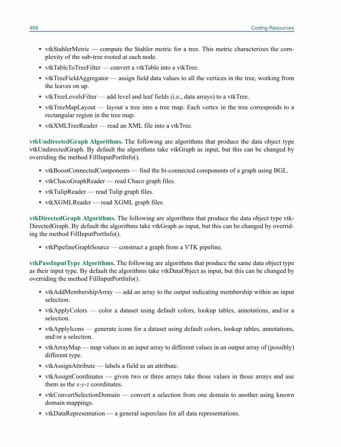
468 Coding Resources
• vtkStahlerMetric — compute the Stahler metric for a tree. This metric characterizes the com-plexity of the sub-tree rooted at each node.
• vtkTableToTreeFilter — convert a vtkTable into a vtkTree.• vtkTreeFieldAggregator — assign field data values to all the vertices in the tree, working from
the leaves on up.• vtkTreeLevelsFilter — add level and leaf fields (i.e., data arrays) to a vtkTree.• vtkTreeMapLayout — layout a tree into a tree map. Each vertex in the tree corresponds to a
rectangular region in the tree map.• vtkXMLTreeReader — read an XML file into a vtkTree.
vtkUndirectedGraph Algorithms. The following are algorithms that produce the data object typevtkUndirectedGraph. By default the algorithms take vtkGraph as input, but this can be changed byoverriding the method FillInputPortInfo().
• vtkBoostConnectedComponents — find the bi-connected components of a graph using BGL.• vtkChacoGraphReader — read Chaco graph files.• vtkTulipReader — read Tulip graph files.• vtkXGMLReader — read XGML graph files.
vtkDirectedGraph Algorithms. The following are algorithms that produce the data object type vtk-DirectedGraph. By default the algorithms take vtkGraph as input, but this can be changed by overrid-ing the method FillInputPortInfo().
• vtkPipelineGraphSource — construct a graph from a VTK pipeline.
vtkPassInputType Algorithms. The following are algorithms that produce the same data object typeas their input type. By default the algorithms take vtkDataObject as input, but this can be changed byoverriding the method FillInputPortInfo().
• vtkAddMembershipArray — add an array to the output indicating membership within an inputselection.
• vtkApplyColors — color a dataset using default colors, lookup tables, annotations, and/or aselection.
• vtkApplyIcons — generate icons for a dataset using default colors, lookup tables, annotations,and/or a selection.
• vtkArrayMap — map values in an input array to different values in an output array of (possibly)different type.
• vtkAssignAttribute — labels a field as an attribute.• vtkAssignCoordinates — given two or three arrays take those values in those arrays and use
them as the x-y-z coordinates.• vtkConvertSelectionDomain — convert a selection from one domain to another using known
domain mappings.• vtkDataRepresentation — a general superclass for all data representations.
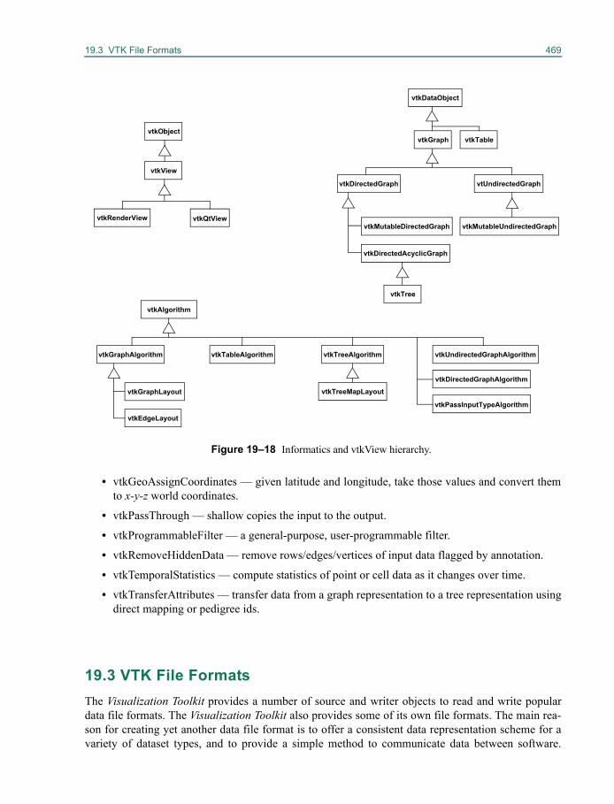
19.3 VTK File Formats 469
• vtkGeoAssignCoordinates — given latitude and longitude, take those values and convert themto x-y-z world coordinates.
• vtkPassThrough — shallow copies the input to the output.
• vtkProgrammableFilter — a general-purpose, user-programmable filter.
• vtkRemoveHiddenData — remove rows/edges/vertices of input data flagged by annotation.
• vtkTemporalStatistics — compute statistics of point or cell data as it changes over time.
• vtkTransferAttributes — transfer data from a graph representation to a tree representation usingdirect mapping or pedigree ids.
19.3 VTK File FormatsThe Visualization Toolkit provides a number of source and writer objects to read and write populardata file formats. The Visualization Toolkit also provides some of its own file formats. The main rea-son for creating yet another data file format is to offer a consistent data representation scheme for avariety of dataset types, and to provide a simple method to communicate data between software.
vtkRenderView
vtkView
Figure 19–18 Informatics and vtkView hierarchy.
vtkQtView
vtkObject
vtkAlgorithm
vtkGraph
vtkPassInputTypeAlgorithm
vtkDataObject
vtkDirectedGraph vtUndirectedGraph
vtkDirectedAcyclicGraph
vtkMutableDirectedGraph vtkMutableUndirectedGraph
vtkTable
vtkTree
vtkGraphAlgorithm vtkTreeAlgorithmvtkTableAlgorithm vtkUndirectedGraphAlgorithm
vtkDirectedGraphAlgorithmvtkTreeMapLayout
vtkEdgeLayout
vtkGraphLayout
470 Coding Resources
Whenever possible, we recommend that you use formats that are more widely used. But if this is notpossible, the Visualization Toolkit formats described here can be used instead. Note that these formatsmay not be supported by many other tools.
There are two different styles of file formats available in VTK. The simplest are the legacy,serial formats that are easy to read and write either by hand or programmatically. However, these for-mats are less flexible than the XML based file formats described later in this section. The XML for-mats support random access, parallel I/O, and portable data compression and are preferred to theserial VTK file formats whenever possible.
Simple Legacy Formats
The legacy VTK file formats consist of five basic parts.
1. The first part is the file version and identifier. This part contains the single line: # vtk DataFile Version x.x. This line must be exactly as shown with the exception of the version number x.x, which will vary with different releases of VTK. (Note: the current version number is 3.0. Version 1.0 and 2.0 files are compatible with version 3.0 files.)
2. The second part is the header. The header consists of a character string terminated by end-of-line character \n. The header is 256 characters maximum. The header can be used to describe the data and include any other pertinent information.
3. The next part is the file format. The file format describes the type of file, either ASCII or binary. On this line the single word ASCII or BINARY must appear.
4. The fourth part is the dataset structure. The geometry part describes the geometry and topology of the dataset. This part begins with a line containing the keyword DATASET followed by a key-word describing the type of dataset. Then, depending upon the type of dataset, other keyword/data combinations define the actual data.
5. The final part describes the dataset attributes. This part begins with the keywords POINT_DATA or CELL_DATA, followed by an integer number specifying the number of points or cells, respec-tively. (It doesn’t matter whether POINT_DATA or CELL_DATA comes first.) Other keyword/data combinations then define the actual dataset attribute values (i.e., scalars, vectors, tensors, nor-mals, texture coordinates, or field data).
An overview of the file format is shown in Figure 19–19. The first three parts are mandatory, but theother two are optional. Thus you have the flexibility of mixing and matching dataset attributes andgeometry, either by operating system file manipulation or using VTK filters to merge data. Keywordsare case insensitive, and may be separated by whitespace.
Before describing the data file formats please note the following.
• dataType is one of the types bit, unsigned_char, char, unsigned_short, short,unsigned_int, int, unsigned_long, long, float, or double. These keywords are used todescribe the form of the data, both for reading from file, as well as constructing the appropriateinternal objects. Not all data types are supported for all classes.
• All keyword phrases are written in ASCII form whether the file is binary or ASCII. The binarysection of the file (if in binary form) is the data proper; i.e., the numbers that define points coor-dinates, scalars, cell indices, and so forth.
• Indices are 0-offset. Thus the first point is point id 0.
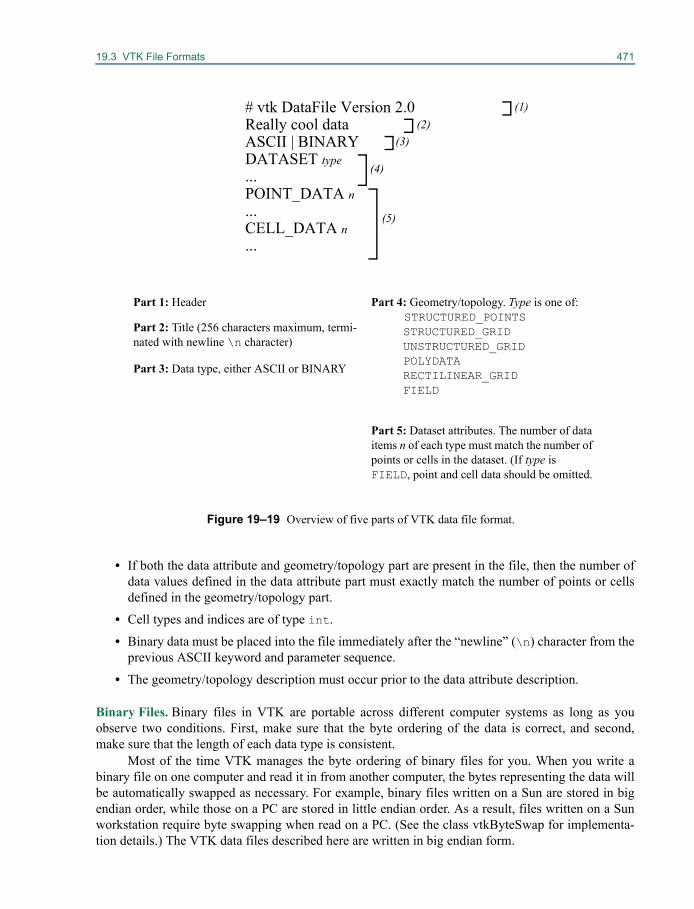
19.3 VTK File Formats 471
• If both the data attribute and geometry/topology part are present in the file, then the number ofdata values defined in the data attribute part must exactly match the number of points or cellsdefined in the geometry/topology part.
• Cell types and indices are of type int.
• Binary data must be placed into the file immediately after the “newline” (\n) character from theprevious ASCII keyword and parameter sequence.
• The geometry/topology description must occur prior to the data attribute description.
Binary Files. Binary files in VTK are portable across different computer systems as long as youobserve two conditions. First, make sure that the byte ordering of the data is correct, and second,make sure that the length of each data type is consistent.
Most of the time VTK manages the byte ordering of binary files for you. When you write abinary file on one computer and read it in from another computer, the bytes representing the data willbe automatically swapped as necessary. For example, binary files written on a Sun are stored in bigendian order, while those on a PC are stored in little endian order. As a result, files written on a Sunworkstation require byte swapping when read on a PC. (See the class vtkByteSwap for implementa-tion details.) The VTK data files described here are written in big endian form.
Part 4: Geometry/topology. Type is one of:STRUCTURED_POINTSSTRUCTURED_GRIDUNSTRUCTURED_GRIDPOLYDATARECTILINEAR_GRIDFIELD
Part 5: Dataset attributes. The number of data items n of each type must match the number of points or cells in the dataset. (If type is FIELD, point and cell data should be omitted.
Figure 19–19 Overview of five parts of VTK data file format.
# vtk DataFile Version 2.0Really cool dataASCII | BINARYDATASET type...POINT_DATA n...CELL_DATA n...
Part 1: Header
Part 2: Title (256 characters maximum, termi-nated with newline \n character)
Part 3: Data type, either ASCII or BINARY
(1)(2)
(3)
(4)
(5)
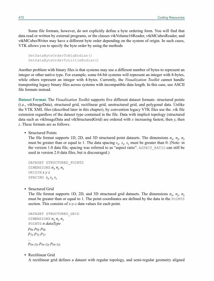
472 Coding Resources
Some file formats, however, do not explicitly define a byte ordering form. You will find thatdata read or written by external programs, or the classes vtkVolume16Reader, vtkMCubesReader, andvtkMCubesWriter may have a different byte order depending on the system of origin. In such cases,VTK allows you to specify the byte order by using the methods
SetDataByteOrderToBigEndian()SetDataByteOrderToLittleEndian()
Another problem with binary files is that systems may use a different number of bytes to represent aninteger or other native type. For example, some 64-bit systems will represent an integer with 8-bytes,while others represent an integer with 4-bytes. Currently, the Visualization Toolkit cannot handletransporting legacy binary files across systems with incompatible data length. In this case, use ASCIIfile formats instead.
Dataset Format. The Visualization Toolkit supports five different dataset formats: structured points(i.e., vtkImageData), structured grid, rectilinear grid, unstructured grid, and polygonal data. Unlikethe VTK XML files (described later in this chapter), by convention legacy VTK files use the .vtk fileextension regardless of the dataset type contained in the file. Data with implicit topology (structureddata such as vtkImageData and vtkStructuredGrid) are ordered with x increasing fastest, then y, thenz. These formats are as follows.
• Structured PointsThe file format supports 1D, 2D, and 3D structured point datasets. The dimensions nx, ny, nzmust be greater than or equal to 1. The data spacing sx, sy, sz must be greater than 0. (Note: inthe version 1.0 data file, spacing was referred to as “aspect ratio”. ASPECT_RATIO can still beused in version 2.0 data files, but is discouraged.)
DATASET STRUCTURED_POINTSDIMENSIONS nx ny nzORIGIN x y zSPACING sx sy sz
• Structured GridThe file format supports 1D, 2D, and 3D structured grid datasets. The dimensions nx, ny, nzmust be greater than or equal to 1. The point coordinates are defined by the data in the POINTSsection. This consists of x-y-z data values for each point.
DATASET STRUCTURED_GRIDDIMENSIONS nx ny nzPOINTS n dataTypep0x p0y p0zp1x p1y p1z...p(n-1)x p(n-1)y p(n-1)z
• Rectilinear GridA rectilinear grid defines a dataset with regular topology, and semi-regular geometry aligned
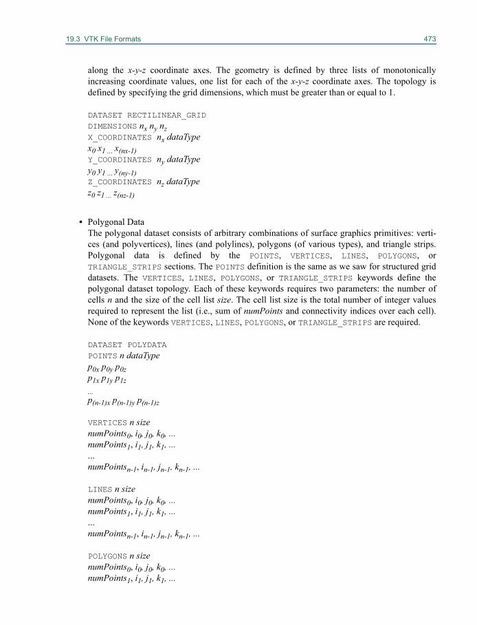
19.3 VTK File Formats 473
along the x-y-z coordinate axes. The geometry is defined by three lists of monotonicallyincreasing coordinate values, one list for each of the x-y-z coordinate axes. The topology isdefined by specifying the grid dimensions, which must be greater than or equal to 1.
DATASET RECTILINEAR_GRIDDIMENSIONS nx ny nzX_COORDINATES nx dataTypex0 x1 ... x(nx-1)Y_COORDINATES ny dataTypey0 y1 ... y(ny-1)Z_COORDINATES nz dataTypez0 z1 ... z(nz-1)
• Polygonal DataThe polygonal dataset consists of arbitrary combinations of surface graphics primitives: verti-ces (and polyvertices), lines (and polylines), polygons (of various types), and triangle strips.Polygonal data is defined by the POINTS, VERTICES, LINES, POLYGONS, orTRIANGLE_STRIPS sections. The POINTS definition is the same as we saw for structured griddatasets. The VERTICES, LINES, POLYGONS, or TRIANGLE_STRIPS keywords define thepolygonal dataset topology. Each of these keywords requires two parameters: the number ofcells n and the size of the cell list size. The cell list size is the total number of integer valuesrequired to represent the list (i.e., sum of numPoints and connectivity indices over each cell).None of the keywords VERTICES, LINES, POLYGONS, or TRIANGLE_STRIPS are required.
DATASET POLYDATAPOINTS n dataTypep0x p0y p0zp1x p1y p1z...p(n-1)x p(n-1)y p(n-1)z
VERTICES n sizenumPoints0, i0, j0, k0, ...numPoints1, i1, j1, k1, ......numPointsn-1, in-1, jn-1, kn-1, ...
LINES n sizenumPoints0, i0, j0, k0, ...numPoints1, i1, j1, k1, ......numPointsn-1, in-1, jn-1, kn-1, ...
POLYGONS n sizenumPoints0, i0, j0, k0, ...numPoints1, i1, j1, k1, ...
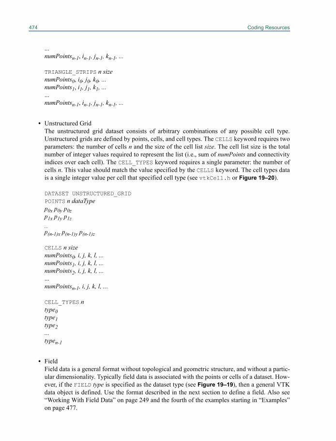
474 Coding Resources
...numPointsn-1, in-1, jn-1, kn-1, ...
TRIANGLE_STRIPS n sizenumPoints0, i0, j0, k0, ...numPoints1, i1, j1, k1, ......numPointsn-1, in-1, jn-1, kn-1, ...
• Unstructured GridThe unstructured grid dataset consists of arbitrary combinations of any possible cell type.Unstructured grids are defined by points, cells, and cell types. The CELLS keyword requires twoparameters: the number of cells n and the size of the cell list size. The cell list size is the totalnumber of integer values required to represent the list (i.e., sum of numPoints and connectivityindices over each cell). The CELL_TYPES keyword requires a single parameter: the number ofcells n. This value should match the value specified by the CELLS keyword. The cell types datais a single integer value per cell that specified cell type (see vtkCell.h or Figure 19–20).
DATASET UNSTRUCTURED_GRIDPOINTS n dataTypep0x p0y p0zp1x p1y p1z...p(n-1)x p(n-1)y p(n-1)z
CELLS n sizenumPoints0, i, j, k, l, ...numPoints1, i, j, k, l, ...numPoints2, i, j, k, l, ... ...numPointsn-1, i, j, k, l, ...
CELL_TYPES ntype0type1type2...typen-1
• FieldField data is a general format without topological and geometric structure, and without a partic-ular dimensionality. Typically field data is associated with the points or cells of a dataset. How-ever, if the FIELD type is specified as the dataset type (see Figure 19–19), then a general VTKdata object is defined. Use the format described in the next section to define a field. Also see“Working With Field Data” on page 249 and the fourth of the examples starting in “Examples”on page 477.

19.3 VTK File Formats 475
Dataset Attribute Format. The Visualization Toolkit supports the following dataset attributes: sca-lars (one to four components), color scalars, vectors, normals, texture coordinates (1D, 2D, and 3D),
tensors, and field data. In addition, a lookup table using the RGBA color specification, associ-ated with the scalar data, can be defined as well. Dataset attributes are supported for both points andcells.
Each type of attribute data has a dataName associated with it. This is a character string (withoutembedded whitespace) used to identify a particular data. The dataName is used by the VTK readers toextract data. As a result, more than one attribute data of the same type can be included in a file. Forexample, two different scalar fields defined on the dataset points, pressure and temperature, can becontained in the same file. (If a matching dataName is not specified in the VTK reader, then the firstdata of that type is extracted from the file.)
• ScalarsScalar definition includes specification of a lookup table. The definition of a lookup table isoptional. If not specified, the default VTK table will be used (and tableName should be“default”). Also note that the numComp variable is optional—by default the number of com-ponents is equal to one. (The parameter numComp must range between (1,4) inclusive; in ver-sions of VTK prior to vtk2.3 this parameter was not supported.)
SCALARS dataName dataType numCompLOOKUP_TABLE tableNames0s1...sn-1
• Color ScalarsThe definition of color scalars (i.e., unsigned char values directly mapped to color) variesdepending upon the number of values (nValues) per scalar. If the file format is ASCII, the colorscalars are defined using nValues float values between (0,1). If the file format is BINARY, thestream of data consists of nValues unsigned char values per scalar value.
COLOR_SCALARS dataName nValuesc00 c01 ... c0(nValues-1)c10 c11 ... c1(nValues-1)...c(n-1)0 c(n-1)1 ... c(n-1)(nValues-1)
• Lookup TableThe tableName field is a character string (without imbedded white space) used to identify thelookup table. This label is used by the VTK reader to extract a specific table.
Each entry in the lookup table is a rgba[4] (red-green-blue-alpha) array (alpha is opacitywhere alpha=0 is transparent). If the file format is ASCII, the lookup table values must befloat values between (0,1). If the file format is BINARY, the stream of data must be fourunsigned char values per table entry.
3 3u
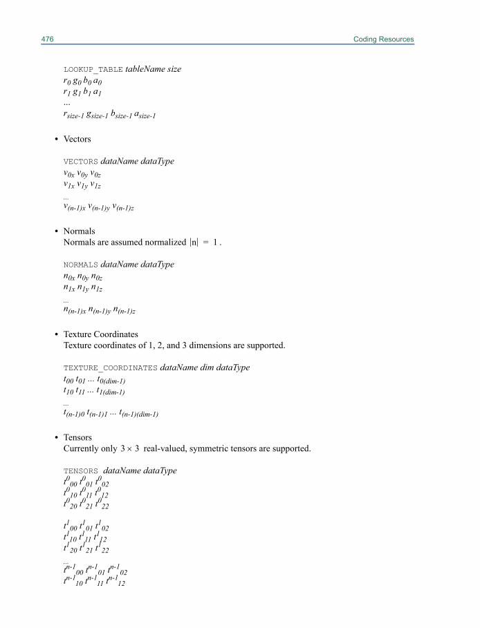
476 Coding Resources
LOOKUP_TABLE tableName sizer0 g0 b0 a0r1 g1 b1 a1...rsize-1 gsize-1 bsize-1 asize-1
• Vectors
VECTORS dataName dataTypev0x v0y v0zv1x v1y v1z...v(n-1)x v(n-1)y v(n-1)z
• NormalsNormals are assumed normalized .
NORMALS dataName dataTypen0x n0y n0zn1x n1y n1z...n(n-1)x n(n-1)y n(n-1)z
• Texture CoordinatesTexture coordinates of 1, 2, and 3 dimensions are supported.
TEXTURE_COORDINATES dataName dim dataTypet00 t01 ... t0(dim-1)t10 t11 ... t1(dim-1)...t(n-1)0 t(n-1)1 ... t(n-1)(dim-1)
• TensorsCurrently only real-valued, symmetric tensors are supported.
TENSORS dataName dataTypet000 t001 t002t010 t011 t012t020 t021 t022
t100 t101 t102t110 t111 t112t120 t121 t122...tn-1
00 tn-101 tn-1
02tn-1
10 tn-111 tn-1
12
n 1=
3 3u
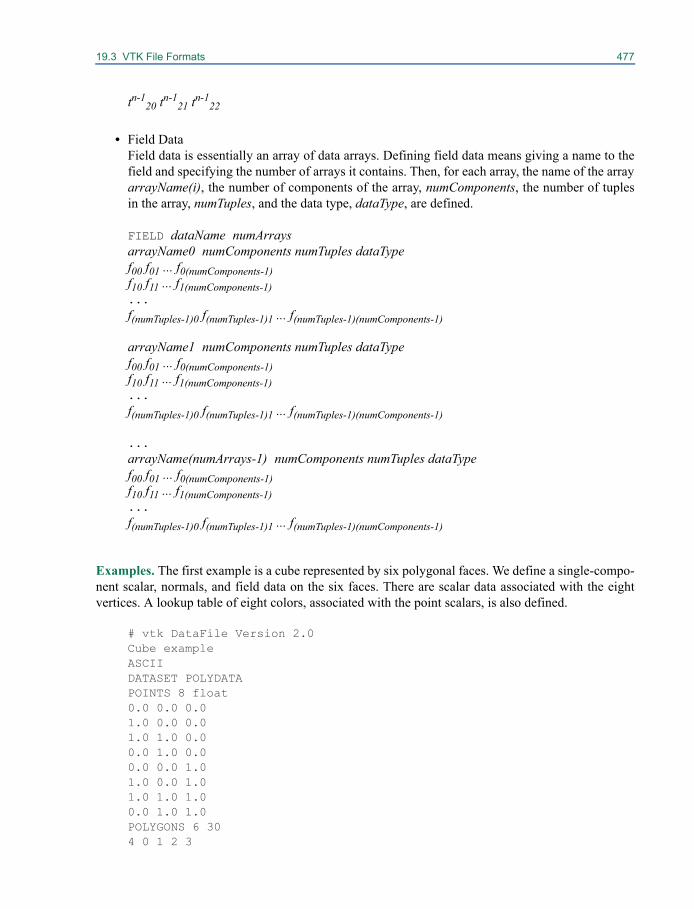
19.3 VTK File Formats 477
tn-120 tn-1
21 tn-122
• Field DataField data is essentially an array of data arrays. Defining field data means giving a name to thefield and specifying the number of arrays it contains. Then, for each array, the name of the arrayarrayName(i), the number of components of the array, numComponents, the number of tuplesin the array, numTuples, and the data type, dataType, are defined.
FIELD dataName numArraysarrayName0 numComponents numTuples dataTypef00 f01 ... f0(numComponents-1)f10 f11 ... f1(numComponents-1)...f(numTuples-1)0 f(numTuples-1)1 ... f(numTuples-1)(numComponents-1)
arrayName1 numComponents numTuples dataTypef00 f01 ... f0(numComponents-1)f10 f11 ... f1(numComponents-1)...f(numTuples-1)0 f(numTuples-1)1 ... f(numTuples-1)(numComponents-1)
...arrayName(numArrays-1) numComponents numTuples dataTypef00 f01 ... f0(numComponents-1)f10 f11 ... f1(numComponents-1)...f(numTuples-1)0 f(numTuples-1)1 ... f(numTuples-1)(numComponents-1)
Examples. The first example is a cube represented by six polygonal faces. We define a single-compo-nent scalar, normals, and field data on the six faces. There are scalar data associated with the eightvertices. A lookup table of eight colors, associated with the point scalars, is also defined.
# vtk DataFile Version 2.0Cube exampleASCIIDATASET POLYDATAPOINTS 8 float0.0 0.0 0.01.0 0.0 0.01.0 1.0 0.00.0 1.0 0.00.0 0.0 1.01.0 0.0 1.01.0 1.0 1.00.0 1.0 1.0POLYGONS 6 304 0 1 2 3
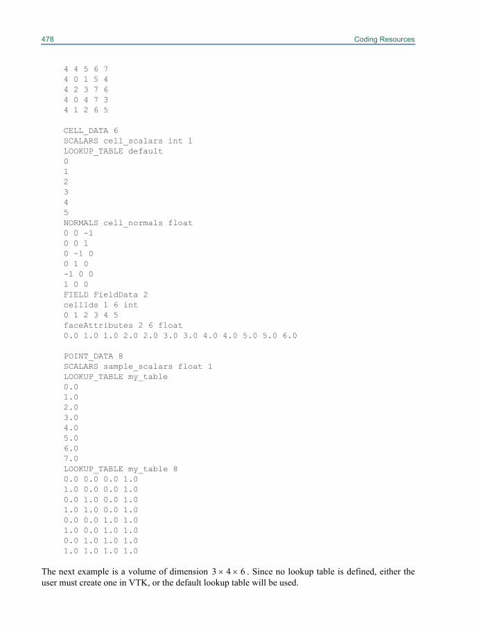
478 Coding Resources
4 4 5 6 74 0 1 5 44 2 3 7 64 0 4 7 34 1 2 6 5
CELL_DATA 6SCALARS cell_scalars int 1LOOKUP_TABLE default012345NORMALS cell_normals float0 0 -10 0 10 -1 00 1 0-1 0 01 0 0FIELD FieldData 2cellIds 1 6 int0 1 2 3 4 5faceAttributes 2 6 float0.0 1.0 1.0 2.0 2.0 3.0 3.0 4.0 4.0 5.0 5.0 6.0
POINT_DATA 8SCALARS sample_scalars float 1LOOKUP_TABLE my_table0.01.02.03.04.05.06.07.0LOOKUP_TABLE my_table 80.0 0.0 0.0 1.01.0 0.0 0.0 1.00.0 1.0 0.0 1.01.0 1.0 0.0 1.00.0 0.0 1.0 1.01.0 0.0 1.0 1.00.0 1.0 1.0 1.01.0 1.0 1.0 1.0
The next example is a volume of dimension . Since no lookup table is defined, either theuser must create one in VTK, or the default lookup table will be used.
3 4 6uu
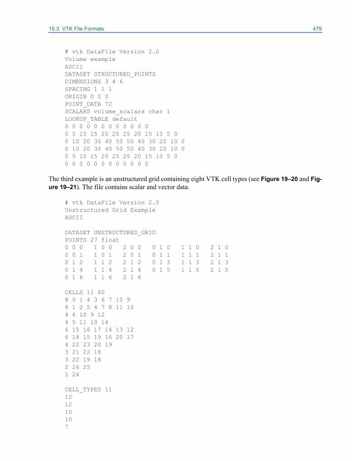
19.3 VTK File Formats 479
# vtk DataFile Version 2.0Volume exampleASCIIDATASET STRUCTURED_POINTSDIMENSIONS 3 4 6SPACING 1 1 1ORIGIN 0 0 0POINT_DATA 72SCALARS volume_scalars char 1LOOKUP_TABLE default0 0 0 0 0 0 0 0 0 0 0 00 5 10 15 20 25 25 20 15 10 5 00 10 20 30 40 50 50 40 30 20 10 00 10 20 30 40 50 50 40 30 20 10 00 5 10 15 20 25 25 20 15 10 5 00 0 0 0 0 0 0 0 0 0 0 0
The third example is an unstructured grid containing eight VTK cell types (see Figure 19–20 and Fig-ure 19–21). The file contains scalar and vector data.
# vtk DataFile Version 2.0Unstructured Grid ExampleASCII
DATASET UNSTRUCTURED_GRIDPOINTS 27 float0 0 0 1 0 0 2 0 0 0 1 0 1 1 0 2 1 00 0 1 1 0 1 2 0 1 0 1 1 1 1 1 2 1 10 1 2 1 1 2 2 1 2 0 1 3 1 1 3 2 1 30 1 4 1 1 4 2 1 4 0 1 5 1 1 5 2 1 50 1 6 1 1 6 2 1 6
CELLS 11 608 0 1 4 3 6 7 10 98 1 2 5 4 7 8 11 104 6 10 9 124 5 11 10 146 15 16 17 14 13 126 18 15 19 16 20 174 22 23 20 193 21 22 183 22 19 182 26 251 24
CELL_TYPES 11121210107
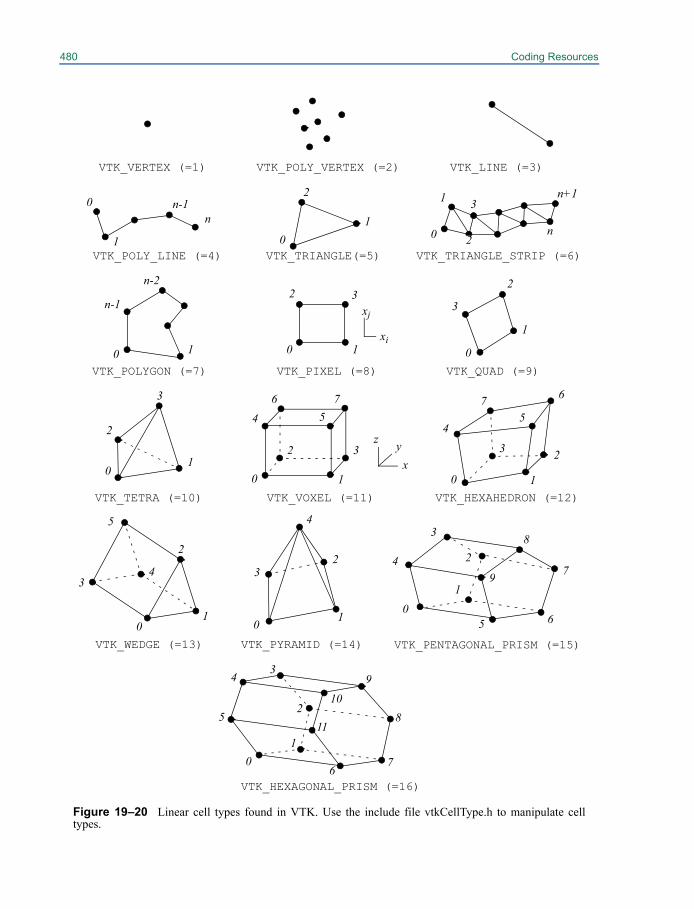
480 Coding Resources
VTK_VERTEX (=1) VTK_LINE (=3) VTK_POLY_VERTEX (=2)
VTK_POLY_LINE (=4) VTK_TRIANGLE_STRIP (=6)VTK_TRIANGLE(=5)
VTK_QUAD (=9)VTK_POLYGON (=7) VTK_PIXEL (=8)
VTK_TETRA (=10) VTK_VOXEL (=11) VTK_HEXAHEDRON (=12)
0 1
23
45
7 6
0 1
2
4 56 7
3
3
01
2
2
3
1
00 1
32
0 1
n-2
n-1
0
1
n-1n
0
2
10
1 3
2n
n+1
xyz
xi
xj
Figure 19–20 Linear cell types found in VTK. Use the include file vtkCellType.h to manipulate celltypes.
VTK_WEDGE (=13)
2
01
5
34
VTK_PYRAMID (=14)
3
0 1
2
4
76
5
43
9
8
VTK_PENTAGONAL_PRISM (=15)
2
01
7
3
4
VTK_HEXAGONAL_PRISM (=16)
01
2
5 6
8
9
11
10
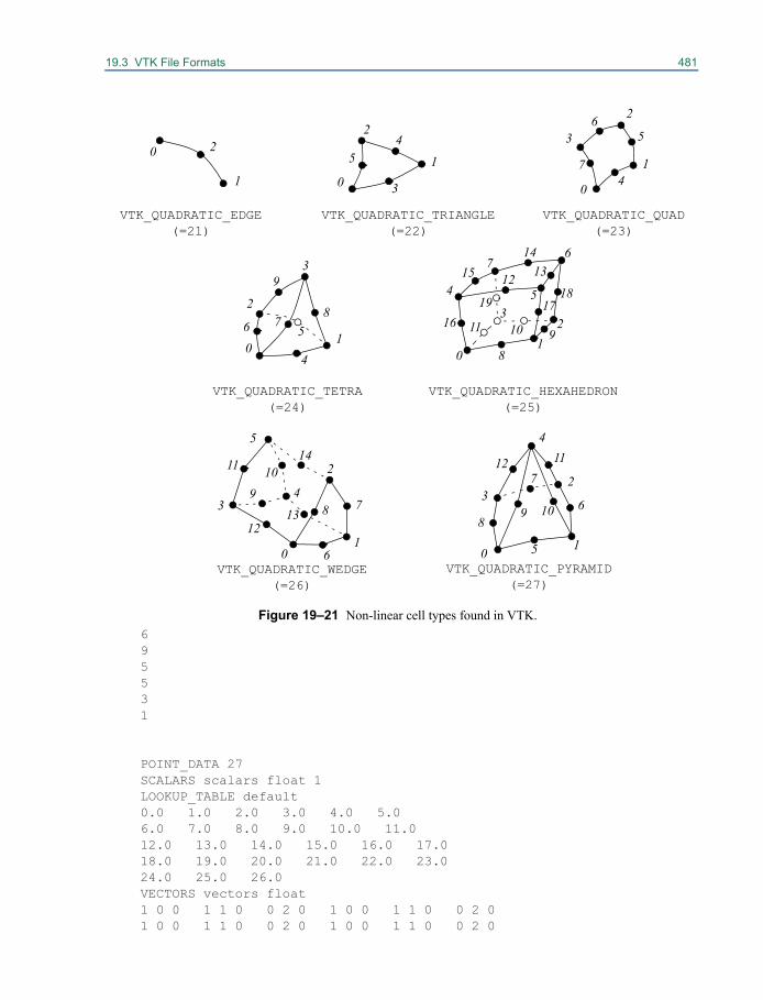
19.3 VTK File Formats 481
695531
POINT_DATA 27SCALARS scalars float 1LOOKUP_TABLE default0.0 1.0 2.0 3.0 4.0 5.06.0 7.0 8.0 9.0 10.0 11.012.0 13.0 14.0 15.0 16.0 17.018.0 19.0 20.0 21.0 22.0 23.024.0 25.0 26.0VECTORS vectors float1 0 0 1 1 0 0 2 0 1 0 0 1 1 0 0 2 01 0 0 1 1 0 0 2 0 1 0 0 1 1 0 0 2 0
Figure 19–21 Non-linear cell types found in VTK.
5
3
74
56
17
15 12
11
89
13
183
5
76
21
0
4
4
6 7
9
5
3
0
21
0
1
2
0
2
1
2
3
1
0
1
8
14
1916 10
0
4
VTK_QUADRATIC_TETRA(=24)
VTK_QUADRATIC_HEXAHEDRON (=25)
VTK_QUADRATIC_EDGE (=21)
VTK_QUADRATIC_QUAD(=23)
VTK_QUADRATIC_TRIANGLE(=22)
VTK_QUADRATIC_WEDGE (=26)
2
01
5
34
VTK_QUADRATIC_PYRAMID (=27)
3
0 1
2
4
6
789
1011
1213
14
6
7
89 10
1112
5
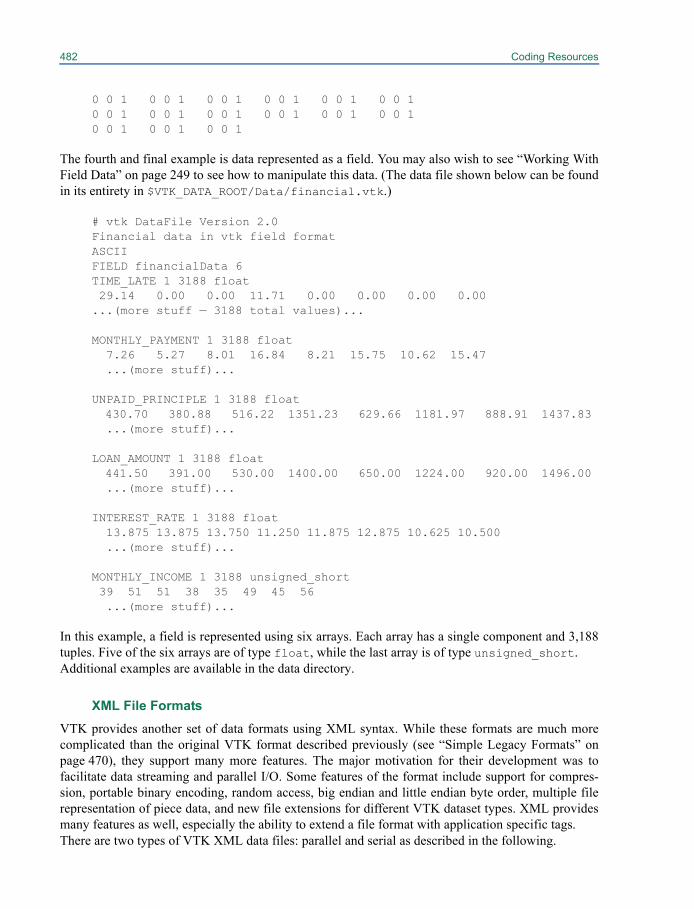
482 Coding Resources
0 0 1 0 0 1 0 0 1 0 0 1 0 0 1 0 0 10 0 1 0 0 1 0 0 1 0 0 1 0 0 1 0 0 10 0 1 0 0 1 0 0 1
The fourth and final example is data represented as a field. You may also wish to see “Working WithField Data” on page 249 to see how to manipulate this data. (The data file shown below can be foundin its entirety in $VTK_DATA_ROOT/Data/financial.vtk.)
# vtk DataFile Version 2.0Financial data in vtk field formatASCIIFIELD financialData 6TIME_LATE 1 3188 float 29.14 0.00 0.00 11.71 0.00 0.00 0.00 0.00 ...(more stuff — 3188 total values)...
MONTHLY_PAYMENT 1 3188 float 7.26 5.27 8.01 16.84 8.21 15.75 10.62 15.47
...(more stuff)...
UNPAID_PRINCIPLE 1 3188 float 430.70 380.88 516.22 1351.23 629.66 1181.97 888.91 1437.83
...(more stuff)...
LOAN_AMOUNT 1 3188 float 441.50 391.00 530.00 1400.00 650.00 1224.00 920.00 1496.00
...(more stuff)...
INTEREST_RATE 1 3188 float13.875 13.875 13.750 11.250 11.875 12.875 10.625 10.500 ...(more stuff)...
MONTHLY_INCOME 1 3188 unsigned_short 39 51 51 38 35 49 45 56
...(more stuff)...
In this example, a field is represented using six arrays. Each array has a single component and 3,188tuples. Five of the six arrays are of type float, while the last array is of type unsigned_short.Additional examples are available in the data directory.
XML File FormatsVTK provides another set of data formats using XML syntax. While these formats are much morecomplicated than the original VTK format described previously (see “Simple Legacy Formats” onpage 470), they support many more features. The major motivation for their development was tofacilitate data streaming and parallel I/O. Some features of the format include support for compres-sion, portable binary encoding, random access, big endian and little endian byte order, multiple filerepresentation of piece data, and new file extensions for different VTK dataset types. XML providesmany features as well, especially the ability to extend a file format with application specific tags.There are two types of VTK XML data files: parallel and serial as described in the following.
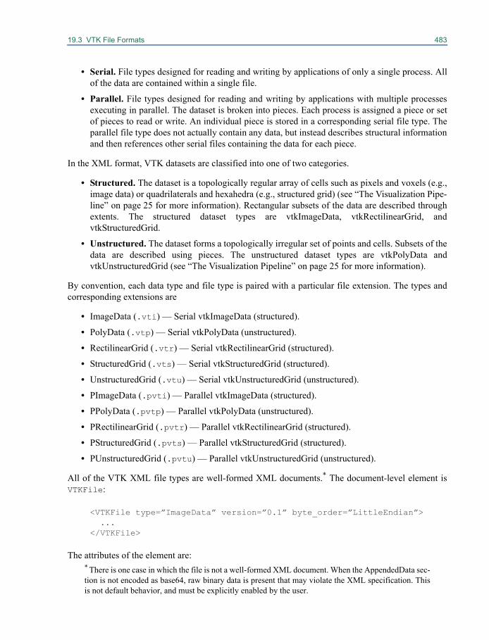
19.3 VTK File Formats 483
• Serial. File types designed for reading and writing by applications of only a single process. Allof the data are contained within a single file.
• Parallel. File types designed for reading and writing by applications with multiple processesexecuting in parallel. The dataset is broken into pieces. Each process is assigned a piece or setof pieces to read or write. An individual piece is stored in a corresponding serial file type. Theparallel file type does not actually contain any data, but instead describes structural informationand then references other serial files containing the data for each piece.
In the XML format, VTK datasets are classified into one of two categories.
• Structured. The dataset is a topologically regular array of cells such as pixels and voxels (e.g.,image data) or quadrilaterals and hexahedra (e.g., structured grid) (see “The Visualization Pipe-line” on page 25 for more information). Rectangular subsets of the data are described throughextents. The structured dataset types are vtkImageData, vtkRectilinearGrid, andvtkStructuredGrid.
• Unstructured. The dataset forms a topologically irregular set of points and cells. Subsets of thedata are described using pieces. The unstructured dataset types are vtkPolyData andvtkUnstructuredGrid (see “The Visualization Pipeline” on page 25 for more information).
By convention, each data type and file type is paired with a particular file extension. The types andcorresponding extensions are
• ImageData (.vti) — Serial vtkImageData (structured).
• PolyData (.vtp) — Serial vtkPolyData (unstructured).
• RectilinearGrid (.vtr) — Serial vtkRectilinearGrid (structured).
• StructuredGrid (.vts) — Serial vtkStructuredGrid (structured).
• UnstructuredGrid (.vtu) — Serial vtkUnstructuredGrid (unstructured).
• PImageData (.pvti) — Parallel vtkImageData (structured).
• PPolyData (.pvtp) — Parallel vtkPolyData (unstructured).
• PRectilinearGrid (.pvtr) — Parallel vtkRectilinearGrid (structured).
• PStructuredGrid (.pvts) — Parallel vtkStructuredGrid (structured).
• PUnstructuredGrid (.pvtu) — Parallel vtkUnstructuredGrid (unstructured).
All of the VTK XML file types are well-formed XML documents.* The document-level element isVTKFile:
<VTKFile type=”ImageData” version=”0.1” byte_order=”LittleEndian”> ...
</VTKFile>
The attributes of the element are:* There is one case in which the file is not a well-formed XML document. When the AppendedData sec-tion is not encoded as base64, raw binary data is present that may violate the XML specification. Thisis not default behavior, and must be explicitly enabled by the user.
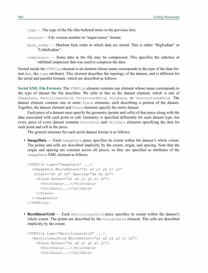
484 Coding Resources
type — The type of the file (the bulleted items in the previous list).
version — File version number in “major.minor” format.
byte_order — Machine byte order in which data are stored. This is either “BigEndian” or“LittleEndian”.
compressor — Some data in the file may be compressed. This specifies the subclass ofvtkDataCompressor that was used to compress the data.
Nested inside the VTKFile element is an element whose name corresponds to the type of the data for-mat (i.e., the type attribute). This element describes the topology of the dataset, and is different forthe serial and parallel formats, which are described as follows.
Serial XML File Formats. The VTKFile element contains one element whose name corresponds tothe type of dataset the file describes. We refer to this as the dataset element, which is one ofImageData, RectilinearGrid, StructuredGrid, PolyData, or UnstructuredGrid. Thedataset element contains one or more Piece elements, each describing a portion of the dataset.Together, the dataset element and Piece elements specify the entire dataset.
Each piece of a dataset must specify the geometry (points and cells) of that piece along with thedata associated with each point or cell. Geometry is specified differently for each dataset type, butevery piece of every dataset contains PointData and CellData elements specifying the data foreach point and cell in the piece.
The general structure for each serial dataset format is as follows:
• ImageData — Each ImageData piece specifies its extent within the dataset’s whole extent.The points and cells are described implicitly by the extent, origin, and spacing. Note that theorigin and spacing are constant across all pieces, so they are specified as attributes of theImageData XML element as follows.
<VTKFile type=”ImageData” ...><ImageData WholeExtent=”x1 x2 y1 y2 z1 z2” Origin=”x0 y0 z0” Spacing=”dx dy dz”> <Piece Extent=”x1 x2 y1 y2 z1 z2”> <PointData>...</PointData> <CellData>...</CellData>
</Piece> </ImageData>
</VTKFile>
• RectilinearGrid — Each RectilinearGrid piece specifies its extent within the dataset’swhole extent. The points are described by the Coordinates element. The cells are describedimplicitly by the extent.
<VTKFile type=”RectilinearGrid” ...><RectilinearGrid WholeExtent=”x1 x2 y1 y2 z1 z2”> <Piece Extent=”x1 x2 y1 y2 z1 z2”> <PointData>...</PointData> <CellData>...</CellData>
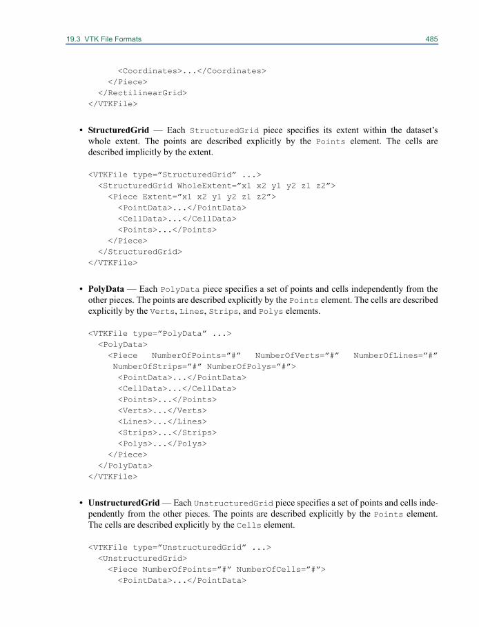
19.3 VTK File Formats 485
<Coordinates>...</Coordinates> </Piece>
</RectilinearGrid> </VTKFile>
• StructuredGrid — Each StructuredGrid piece specifies its extent within the dataset’swhole extent. The points are described explicitly by the Points element. The cells aredescribed implicitly by the extent.
<VTKFile type=”StructuredGrid” ...><StructuredGrid WholeExtent=”x1 x2 y1 y2 z1 z2”> <Piece Extent=”x1 x2 y1 y2 z1 z2”>
<PointData>...</PointData> <CellData>...</CellData> <Points>...</Points>
</Piece> </StructuredGrid>
</VTKFile>
• PolyData — Each PolyData piece specifies a set of points and cells independently from theother pieces. The points are described explicitly by the Points element. The cells are describedexplicitly by the Verts, Lines, Strips, and Polys elements.
<VTKFile type=”PolyData” ...><PolyData> <Piece NumberOfPoints=”#” NumberOfVerts=”#” NumberOfLines=”#”NumberOfStrips=”#” NumberOfPolys=”#”> <PointData>...</PointData> <CellData>...</CellData> <Points>...</Points> <Verts>...</Verts> <Lines>...</Lines> <Strips>...</Strips> <Polys>...</Polys>
</Piece> </PolyData>
</VTKFile>
• UnstructuredGrid — Each UnstructuredGrid piece specifies a set of points and cells inde-pendently from the other pieces. The points are described explicitly by the Points element.The cells are described explicitly by the Cells element.
<VTKFile type=”UnstructuredGrid” ...><UnstructuredGrid> <Piece NumberOfPoints=”#” NumberOfCells=”#”>
<PointData>...</PointData>
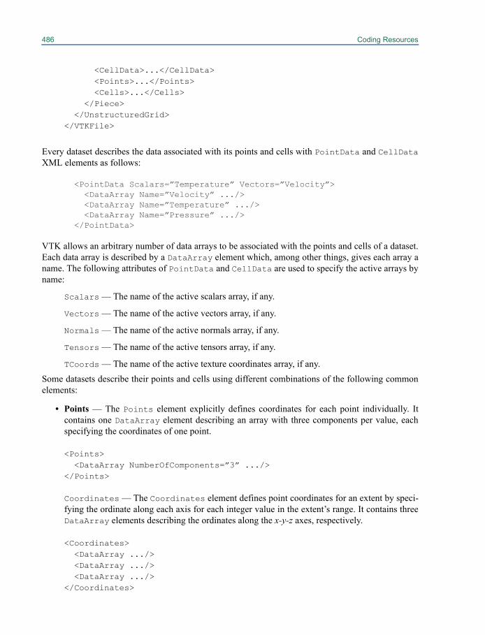
486 Coding Resources
<CellData>...</CellData> <Points>...</Points> <Cells>...</Cells>
</Piece> </UnstructuredGrid>
</VTKFile>
Every dataset describes the data associated with its points and cells with PointData and CellDataXML elements as follows:
<PointData Scalars=”Temperature” Vectors=”Velocity”> <DataArray Name=”Velocity” .../> <DataArray Name=”Temperature” .../> <DataArray Name=”Pressure” .../>
</PointData>
VTK allows an arbitrary number of data arrays to be associated with the points and cells of a dataset.Each data array is described by a DataArray element which, among other things, gives each array aname. The following attributes of PointData and CellData are used to specify the active arrays byname:
Scalars — The name of the active scalars array, if any.
Vectors — The name of the active vectors array, if any.
Normals — The name of the active normals array, if any.
Tensors — The name of the active tensors array, if any.
TCoords — The name of the active texture coordinates array, if any.Some datasets describe their points and cells using different combinations of the following commonelements:
• Points — The Points element explicitly defines coordinates for each point individually. Itcontains one DataArray element describing an array with three components per value, eachspecifying the coordinates of one point.
<Points> <DataArray NumberOfComponents=”3” .../>
</Points>
Coordinates — The Coordinates element defines point coordinates for an extent by speci-fying the ordinate along each axis for each integer value in the extent’s range. It contains threeDataArray elements describing the ordinates along the x-y-z axes, respectively.
<Coordinates> <DataArray .../> <DataArray .../> <DataArray .../>
</Coordinates>
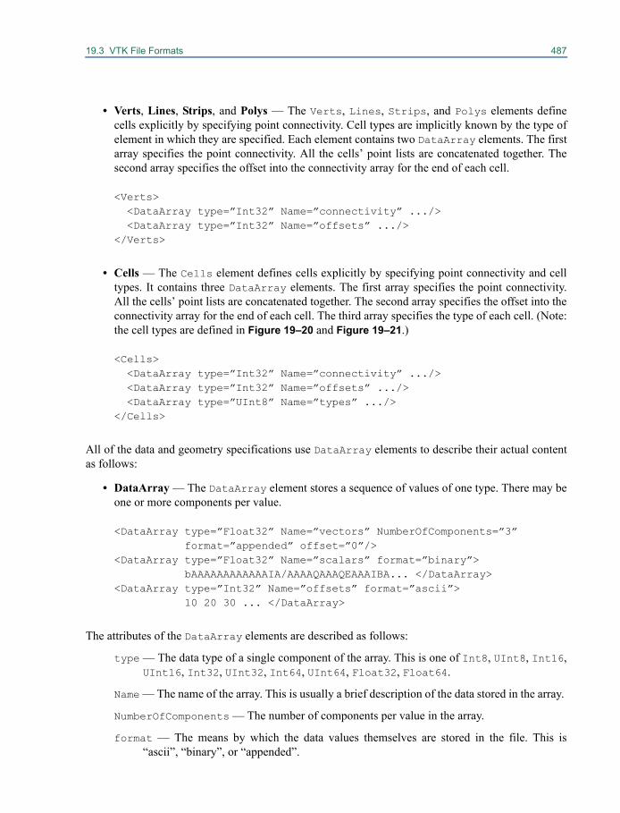
19.3 VTK File Formats 487
• Verts, Lines, Strips, and Polys — The Verts, Lines, Strips, and Polys elements definecells explicitly by specifying point connectivity. Cell types are implicitly known by the type ofelement in which they are specified. Each element contains two DataArray elements. The firstarray specifies the point connectivity. All the cells’ point lists are concatenated together. Thesecond array specifies the offset into the connectivity array for the end of each cell.
<Verts> <DataArray type=”Int32” Name=”connectivity” .../><DataArray type=”Int32” Name=”offsets” .../>
</Verts>
• Cells — The Cells element defines cells explicitly by specifying point connectivity and celltypes. It contains three DataArray elements. The first array specifies the point connectivity.All the cells’ point lists are concatenated together. The second array specifies the offset into theconnectivity array for the end of each cell. The third array specifies the type of each cell. (Note:the cell types are defined in Figure 19–20 and Figure 19–21.)
<Cells> <DataArray type=”Int32” Name=”connectivity” .../><DataArray type=”Int32” Name=”offsets” .../><DataArray type=”UInt8” Name=”types” .../>
</Cells>
All of the data and geometry specifications use DataArray elements to describe their actual contentas follows:
• DataArray — The DataArray element stores a sequence of values of one type. There may beone or more components per value.
<DataArray type=”Float32” Name=”vectors” NumberOfComponents=”3”format=”appended” offset=”0”/>
<DataArray type=”Float32” Name=”scalars” format=”binary”>bAAAAAAAAAAAAIA/AAAAQAAAQEAAAIBA... </DataArray>
<DataArray type=”Int32” Name=”offsets” format=”ascii”> 10 20 30 ... </DataArray>
The attributes of the DataArray elements are described as follows:
type — The data type of a single component of the array. This is one of Int8, UInt8, Int16,UInt16, Int32, UInt32, Int64, UInt64, Float32, Float64.
Name — The name of the array. This is usually a brief description of the data stored in the array.
NumberOfComponents — The number of components per value in the array.
format — The means by which the data values themselves are stored in the file. This is“ascii”, “binary”, or “appended”.
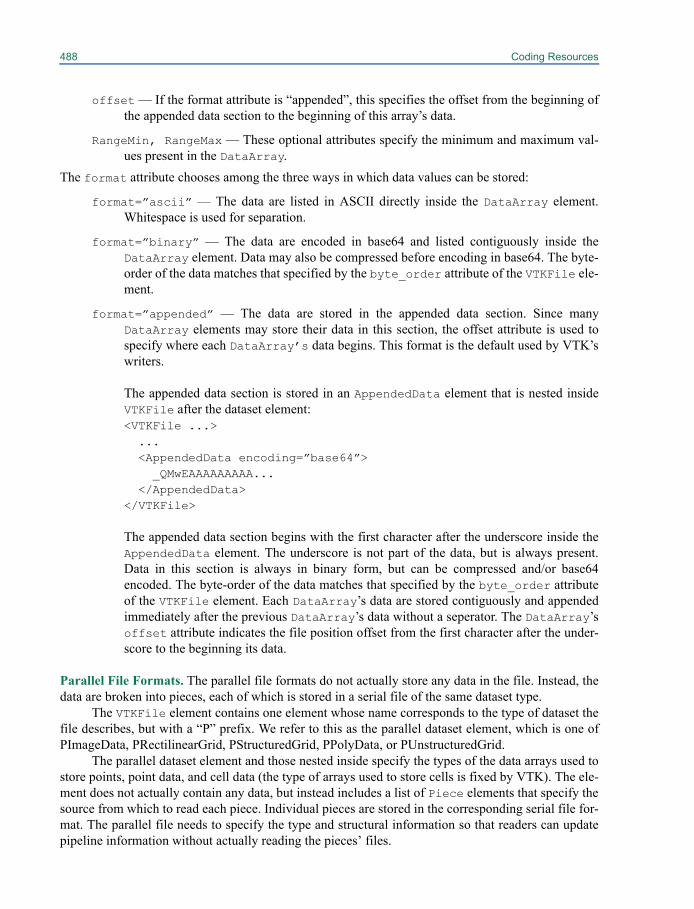
488 Coding Resources
offset — If the format attribute is “appended”, this specifies the offset from the beginning ofthe appended data section to the beginning of this array’s data.
RangeMin, RangeMax — These optional attributes specify the minimum and maximum val-ues present in the DataArray.
The format attribute chooses among the three ways in which data values can be stored:
format=”ascii” — The data are listed in ASCII directly inside the DataArray element.Whitespace is used for separation.
format=”binary” — The data are encoded in base64 and listed contiguously inside theDataArray element. Data may also be compressed before encoding in base64. The byte-order of the data matches that specified by the byte_order attribute of the VTKFile ele-ment.
format=”appended” — The data are stored in the appended data section. Since manyDataArray elements may store their data in this section, the offset attribute is used tospecify where each DataArray’s data begins. This format is the default used by VTK’swriters.
The appended data section is stored in an AppendedData element that is nested insideVTKFile after the dataset element: <VTKFile ...>... <AppendedData encoding=”base64”>
_QMwEAAAAAAAAA... </AppendedData>
</VTKFile>
The appended data section begins with the first character after the underscore inside theAppendedData element. The underscore is not part of the data, but is always present.Data in this section is always in binary form, but can be compressed and/or base64encoded. The byte-order of the data matches that specified by the byte_order attributeof the VTKFile element. Each DataArray’s data are stored contiguously and appendedimmediately after the previous DataArray’s data without a seperator. The DataArray’soffset attribute indicates the file position offset from the first character after the under-score to the beginning its data.
Parallel File Formats. The parallel file formats do not actually store any data in the file. Instead, thedata are broken into pieces, each of which is stored in a serial file of the same dataset type.
The VTKFile element contains one element whose name corresponds to the type of dataset thefile describes, but with a “P” prefix. We refer to this as the parallel dataset element, which is one ofPImageData, PRectilinearGrid, PStructuredGrid, PPolyData, or PUnstructuredGrid.
The parallel dataset element and those nested inside specify the types of the data arrays used tostore points, point data, and cell data (the type of arrays used to store cells is fixed by VTK). The ele-ment does not actually contain any data, but instead includes a list of Piece elements that specify thesource from which to read each piece. Individual pieces are stored in the corresponding serial file for-mat. The parallel file needs to specify the type and structural information so that readers can updatepipeline information without actually reading the pieces’ files.
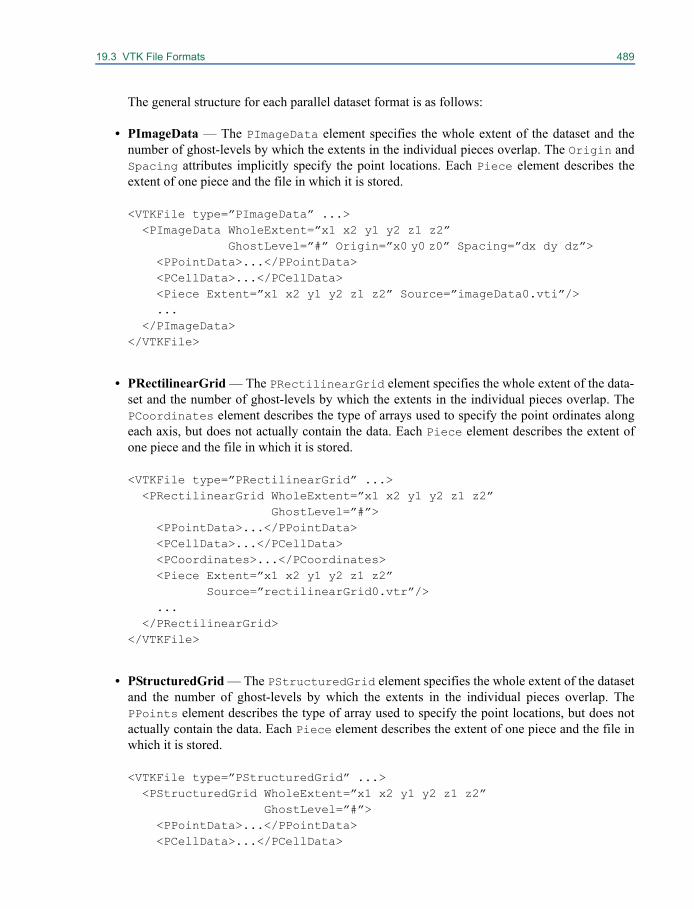
19.3 VTK File Formats 489
The general structure for each parallel dataset format is as follows:
• PImageData — The PImageData element specifies the whole extent of the dataset and thenumber of ghost-levels by which the extents in the individual pieces overlap. The Origin andSpacing attributes implicitly specify the point locations. Each Piece element describes theextent of one piece and the file in which it is stored.
<VTKFile type=”PImageData” ...> <PImageData WholeExtent=”x1 x2 y1 y2 z1 z2”
GhostLevel=”#” Origin=”x0 y0 z0” Spacing=”dx dy dz”><PPointData>...</PPointData> <PCellData>...</PCellData> <Piece Extent=”x1 x2 y1 y2 z1 z2” Source=”imageData0.vti”/>...
</PImageData> </VTKFile>
• PRectilinearGrid — The PRectilinearGrid element specifies the whole extent of the data-set and the number of ghost-levels by which the extents in the individual pieces overlap. ThePCoordinates element describes the type of arrays used to specify the point ordinates alongeach axis, but does not actually contain the data. Each Piece element describes the extent ofone piece and the file in which it is stored.
<VTKFile type=”PRectilinearGrid” ...> <PRectilinearGrid WholeExtent=”x1 x2 y1 y2 z1 z2”
GhostLevel=”#”> <PPointData>...</PPointData> <PCellData>...</PCellData> <PCoordinates>...</PCoordinates> <Piece Extent=”x1 x2 y1 y2 z1 z2”
Source=”rectilinearGrid0.vtr”/>...
</PRectilinearGrid> </VTKFile>
• PStructuredGrid — The PStructuredGrid element specifies the whole extent of the datasetand the number of ghost-levels by which the extents in the individual pieces overlap. ThePPoints element describes the type of array used to specify the point locations, but does notactually contain the data. Each Piece element describes the extent of one piece and the file inwhich it is stored.
<VTKFile type=”PStructuredGrid” ...><PStructuredGrid WholeExtent=”x1 x2 y1 y2 z1 z2”
GhostLevel=”#”><PPointData>...</PPointData> <PCellData>...</PCellData>
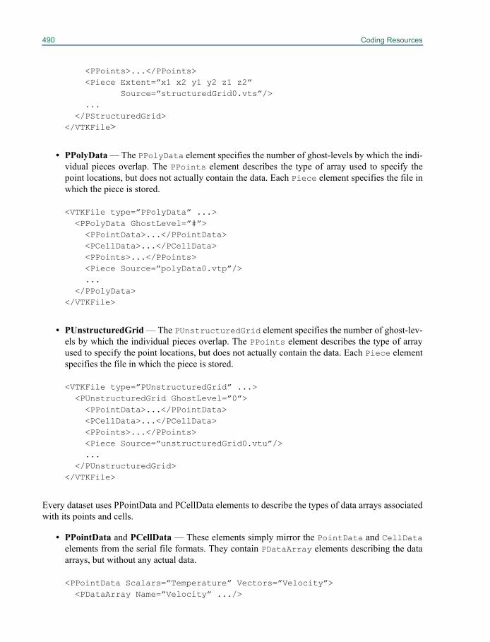
490 Coding Resources
<PPoints>...</PPoints> <Piece Extent=”x1 x2 y1 y2 z1 z2”
Source=”structuredGrid0.vts”/> ...
</PStructuredGrid> </VTKFile>
• PPolyData — The PPolyData element specifies the number of ghost-levels by which the indi-vidual pieces overlap. The PPoints element describes the type of array used to specify thepoint locations, but does not actually contain the data. Each Piece element specifies the file inwhich the piece is stored.
<VTKFile type=”PPolyData” ...> <PPolyData GhostLevel=”#”> <PPointData>...</PPointData> <PCellData>...</PCellData> <PPoints>...</PPoints> <Piece Source=”polyData0.vtp”/> ...
</PPolyData> </VTKFile>
• PUnstructuredGrid — The PUnstructuredGrid element specifies the number of ghost-lev-els by which the individual pieces overlap. The PPoints element describes the type of arrayused to specify the point locations, but does not actually contain the data. Each Piece elementspecifies the file in which the piece is stored.
<VTKFile type=”PUnstructuredGrid” ...> <PUnstructuredGrid GhostLevel=”0”> <PPointData>...</PPointData> <PCellData>...</PCellData> <PPoints>...</PPoints> <Piece Source=”unstructuredGrid0.vtu”/>...
</PUnstructuredGrid> </VTKFile>
Every dataset uses PPointData and PCellData elements to describe the types of data arrays associatedwith its points and cells.
• PPointData and PCellData — These elements simply mirror the PointData and CellDataelements from the serial file formats. They contain PDataArray elements describing the dataarrays, but without any actual data.
<PPointData Scalars=”Temperature” Vectors=”Velocity”> <PDataArray Name=”Velocity” .../>
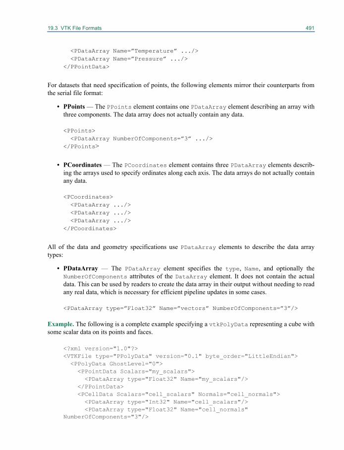
19.3 VTK File Formats 491
<PDataArray Name=”Temperature” .../> <PDataArray Name=”Pressure” .../>
</PPointData>
For datasets that need specification of points, the following elements mirror their counterparts fromthe serial file format:
• PPoints — The PPoints element contains one PDataArray element describing an array withthree components. The data array does not actually contain any data.
<PPoints> <PDataArray NumberOfComponents=”3” .../>
</PPoints>
• PCoordinates — The PCoordinates element contains three PDataArray elements describ-ing the arrays used to specify ordinates along each axis. The data arrays do not actually containany data.
<PCoordinates> <PDataArray .../> <PDataArray .../> <PDataArray .../>
</PCoordinates>
All of the data and geometry specifications use PDataArray elements to describe the data arraytypes:
• PDataArray — The PDataArray element specifies the type, Name, and optionally theNumberOfComponents attributes of the DataArray element. It does not contain the actualdata. This can be used by readers to create the data array in their output without needing to readany real data, which is necessary for efficient pipeline updates in some cases.
<PDataArray type=”Float32” Name=”vectors” NumberOfComponents=”3”/>
Example. The following is a complete example specifying a vtkPolyData representing a cube withsome scalar data on its points and faces.
<?xml version="1.0"?><VTKFile type="PPolyData" version="0.1" byte_order="LittleEndian"> <PPolyData GhostLevel="0"> <PPointData Scalars="my_scalars"> <PDataArray type="Float32" Name="my_scalars"/> </PPointData> <PCellData Scalars="cell_scalars" Normals="cell_normals"> <PDataArray type="Int32" Name="cell_scalars"/> <PDataArray type="Float32" Name="cell_normals" NumberOfComponents="3"/>
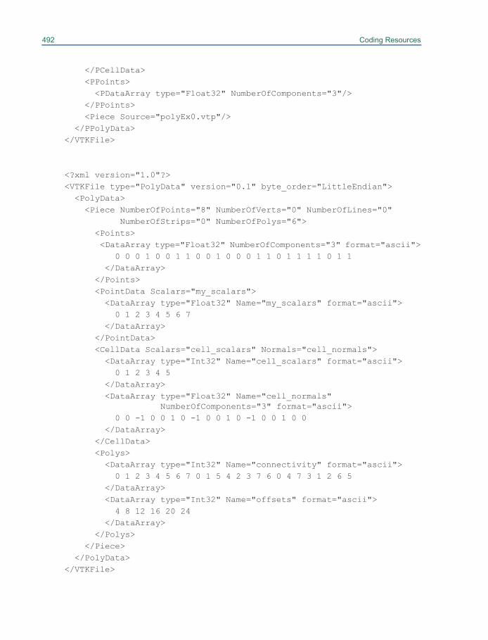
492 Coding Resources
</PCellData> <PPoints> <PDataArray type="Float32" NumberOfComponents="3"/> </PPoints> <Piece Source="polyEx0.vtp"/> </PPolyData></VTKFile>
<?xml version="1.0"?><VTKFile type="PolyData" version="0.1" byte_order="LittleEndian"> <PolyData> <Piece NumberOfPoints="8" NumberOfVerts="0" NumberOfLines="0" NumberOfStrips="0" NumberOfPolys="6"> <Points> <DataArray type="Float32" NumberOfComponents="3" format="ascii"> 0 0 0 1 0 0 1 1 0 0 1 0 0 0 1 1 0 1 1 1 1 0 1 1 </DataArray> </Points> <PointData Scalars="my_scalars"> <DataArray type="Float32" Name="my_scalars" format="ascii"> 0 1 2 3 4 5 6 7 </DataArray> </PointData> <CellData Scalars="cell_scalars" Normals="cell_normals"> <DataArray type="Int32" Name="cell_scalars" format="ascii"> 0 1 2 3 4 5 </DataArray> <DataArray type="Float32" Name="cell_normals"
NumberOfComponents="3" format="ascii"> 0 0 -1 0 0 1 0 -1 0 0 1 0 -1 0 0 1 0 0 </DataArray> </CellData> <Polys> <DataArray type="Int32" Name="connectivity" format="ascii"> 0 1 2 3 4 5 6 7 0 1 5 4 2 3 7 6 0 4 7 3 1 2 6 5 </DataArray> <DataArray type="Int32" Name="offsets" format="ascii"> 4 8 12 16 20 24 </DataArray> </Polys> </Piece> </PolyData></VTKFile>

Index 19
Symbols.NET 31
Numerics2D array 1982D glyphs 2802D graphs 662D grid 1272D image 2822D Props 4432D Texture Mapping 1562D texture mapping 141, 1562D vtkImageData 2483D contouring 2133D data 1393D geospatial view 2083D isosurface 1243D props 4433D scene 2923D space 1393D tensor 1983D Texture Mapping 1563D texture mapping 142, 1563D volume of scalar values 1433D volume texture mapper 1573D widget 75
box widget 73image plane widget 74implicit plane widget 72line widget 72plane widget 72point widget 72scalar bar widget 72sphere widget 74spline widget 74
3D widgets 72, 259
AA tour of the widgets 262AbortExecute flag 324, 393, 404ActivateEvent 273active arrays
serial XML file format 486actor
opacity 55transparency 55
Actor (Prop) Objects 464actor’s opacity 53actors
assemblies 56
color 54follower 65level-of-detail 55properties 53transparency 55
Add Class To VTK 307AddActor() 43, 57AddClippingPlane 151AddColumn 196AddColumnPair 196AddColumnToTable 190, 191AddCue 84AddDefaultImageRepresentation 208AddHSVPoint 144AddIndexToTable 190, 191Adding vtkRenderWindowInteractor Observers 257AddLinkEdge 166, 168AddLinkVertex 166, 167, 168AddLOD 162AddLODMapper() 55AddObserver
see Command/ObserverAddObserver() 29, 30, 46AddOrientation() 52AddPart() 57AddPosition() 52AddPreamble 191AddProp 125AddRenderer() 43AddRepresentation 176AddRepresentationFromInput 176AddRepresentationFromInputConnection 176AddRGBPoint 144AddTableMultipleArguments 192AddTriggerToTable 190, 191AddValue 204Advanced Transformation 72affine 24aFilter 25algorithm 25
filter 25mapper 25source 25
algorithm information 319algorithms
API 388debug macros 391input modification 390input type 386memory management 391
494
output type 386pipeline interface 385pipeline requests 389progress 392reference count data 390user interface 388
Allocate 330Allocate() 115AllocateScalars() 121alpha compositing 156alternative to ray casting 156Animation 83Animation Cue 84Animation Scene 83animations 248annotation 63
2D 633D 65
Annotation widgets 272anotherFilter 25Antialiasing 76anti-aliasing 24append images 129Append() 108appended
serial XML file format 488Appending Data 100appending data 100application developer 4arbitrary array 293architecture 19Area Layouts 175AreaPicking 293Array Algorithms 206Array Data 205Array Sources 205ascii
serial XML file format 488assemblies 56associate .tcl with vtk.exe 11ATI graphics hardware 157attribute data 362
cell 90normals 90object model 439point 90scalars 90tensors 90texture coordinates 90vectors 90
Attributes 166
AutoAdjustCameraClippingRange 124AutoAdjustSampleDistances 160AVI 248azimuth 50Azimuth() 50
BBGL 180Binary Files 471binary files
serial XML file format 488simple legacy format 471–472
Bivariate statistics 195
Block selections 293BMRT 248Boost Brandes 184Boost Graph Library 180, 186, 465Boost Graph Library Algorithms 182Boost Kruskal Minimum Spanning Tree 182Boost Kruskal MST 184Boost Prim Minimum Spanning Tree 184Boost Prim MST 182Border instance variable 285Borland C++ 12box widget 261, 268build VTK 15BuildCells() 345Building Models 213BuildLinks() 345
CC++ 19, 21, 29, 30, 37, 41
Microsoft Visual 31Unix 35
callback 29Callbacks
see also Command/Observercaller 35camera
controlling 49instantiating 49manipulation 50orthogonal view 50perspective view 50saving state 51view direction 50view-up 50vtkCamera 49zoom 50
cartographic projection 212

Index 495
Cartographic Projections 211CDash 313CDash Regression Testing System 313cell
object model 437cell attribute data 90cell connectivity 116cell data
parallel XML file format 490serial XML file format 486
cell data to point data conversion 91cell types
linear 480non-linear 481VTK_HEXAHEDRON 480VTK_LINE 480VTK_PIXEL 480VTK_POLY_LINE 480VTK_POLY_VERTEX 480VTK_POLYGON 480VTK_PYRAMID 480, 481VTK_QUAD 480VTK_QUADRATIC_EDGE 481VTK_QUADRATIC_HEXAHEDRON 481VTK_QUADRATIC_QUAD 481VTK_QUADRATIC_TETRA 481VTK_QUADRATIC_TRIANGLE 481VTK_TETRA 480VTK_TRIANGLE 480VTK_TRIANGLE_STRIP 480VTK_VERTEX 480VTK_VOXEL 480VTK_WEDGE 480, 481
CellClippingOn() 105cells
serial XML file format 487change scalar type 128Choosing the Default Executive 326class
add to build 307add to CMakeLists.txt 307documentation 306how to write 305required methods 306SetGet macros 307
class developer 4class library 19Clipping 110clipping 110Clipping a Volume 151clipping planes 49
Close 188CMake 5, 7, 10, 13, 15, 31, 465
ADD_EXECUTABLE 31book 10build and install (Unix) 15BUILD_SHARED_LIBS 13C compiler 15C++ compiler 15cache entries 10ccmake (terminal-based interface) 16cmake -i (interactive wizard mode) 16CMAKE_INSTALL_PREFIX 17CMakeCache.txt 10CMakeLists.txt 10, 31CMakeSetup GUI 12configure 10download 10, 15EXECUTABLE_OUTPUT_PATH 13generate 10install (Unix) 15LIBRARY_OUTPUT_PATH 13LocalUser.cmake 307NOTFOUND 13Rebuild All in MSVC 13SUBDIR 307Unix 15VTK_WRAP_JAVA 13VTK_WRAP_PYTHON 13VTK_WRAP_TCL 13, 16VTK_WRAP_XXX 17VTK.dsw 13Windows 12
Coding Considerations 297Coding Resources 437Coding Style 299coding style 299Color 145, 146Color Mapping 92color mapping 92color scalars
simple legacy file format 475color transfer function 143, 145ColorByArrayComponent 92ColorByArrayComponent() 103combine images 129Command/Observer 29
AddObserver 29examples 35see also Events
commercial support 315Common 5
496
compilation test 313Compiling the Source Code 17Composite Data Readers 243Composite Data Writers 245Compute Modified Time 391ComputePipelineMTime 323ComputeRange 331ComputeViewPlaneNormal() 49, 50Conditions on Contributing Code To VTK 297confocal microscopes 119Connecting to a Database 187connectivity 116Constructing Surfaces 218constructor 302, 306, 395, 403, 407, 413
in vtk 300Contingency statistics 195CONTINUE_EXECUTING 229, 235continuous cycle 314, 315contouring 93Contributing Code 297contributing code 299Controlling Color / Opacity 145Controlling shading 147Controlling the Normal Encoding 152convert between point and cell data 91Converting a Table to a Graph 164Converting a Table to a Tree 168Converting Layouts to Geometry 173coordinate system
normalized display 65coordinate systems
display 62normalized display 62normalized viewport coordinates 62user defined 62view 62viewport 62world 62
coordinatesparallel XML file format 491
copydeep 302shallow 302
copy constructor 302, 306CopyComponent 329Copying Objects 302Copying the Source Cod 12copyright 297Correlative statistics 195coverage test 314cow model 110
CreateDefaultLookupTable 330CreateFromURL 188CreateInstance() 308CreateObject() 309
vtkObjectFactory 309Creating a Volume Mapper 149Creating a vtkVolume 143Creating An Implicit Model 213Creating and Deleting Objects 300Creating Graph Algorithms 185Creating Hardcopy 246Creating Simple Models 42crop a subvolume 150Cropping a Volume 150CroppingRegionFlags 151CT 119culler 161Cursor Management and Highlighting 261Cut vertices 183Cutting 98cutting 98, 110CVS 5, 313CVS Source Code Repository 313
DD3 456daily cycle 314, 315DART 313dashboard 313
compilation 313coverage test 314memory test 313PrintSelf test 313regression test 313SetGet test 313TestEmptyInput test 314
Data 6data array 327Data Arrays 327data arrays
parallel XML file format 491serial XML file format 487
data attributes 89data information 319data interface 239
exporters 246importers 245readers 239writers 243
data objectas field data 474

Index 497
data object APIattribute data 362data array 327datasets 333field data 362vtkCellArray 357vtkCellLinks 360vtkCellTypes 359vtkDataSetAttributes 364vtkFieldData 362vtkPoints 355
Data Object Readers 240Data Object Writers 244Data Set Readers 240Data Set Writers 244data transformation 70DATA_TIME_STEPS 229dataArray 328Databases 187databases 163dataset
interface to 333object model 438
Dataset Attribute Format 475Dataset Format 472dataset types 334dataType 470debugging pipeline execution 322DebugOff() 300DebugOn() 300Decimation 108decimation 107DEDICOM 199deep copy 302DeepCopy 330DeepCopy() 302Delaunay triangulation 218
2D 2183D 221
Delaunay triangulations 459Delete() 20, 21, 300, 301, 391Depth Peeling Parameters 80depth sorting 79Descriptive statistics 194Design 199DesiredUpdateRate 160, 256destructor 302, 306, 408developer
application 4class 4
directed acyclic graph 371
directed graphs 371display 62DivideByZeroToC 135DLL 309Dolly() 50double clocktime 85double currentime 85downstream flow 320downstream request 320Doxygen 6, 7Doxygen documentation 6, 126, 128
EEdge Layout 172elevation 50Elevation() 50EndAppend() 108EndCueInternal 85EndInteraction 76EndInteractionEvent 266, 273, 276, 281, 284, 287,
288EndInteractionEvents 280environment variables
LD_LIBRARY_PATH 35VTK_AUTOLOAD_PATH 310
event bindings 45Events 33
AbortCheckEvent 424, 425EndEvent 393, 424EndInteractionEvent 423EndPickEvent 46, 61, 62, 424ExitEvent 424InteractionEvent 423PickEvent 61, 424ProgressEvent 393, 424StartEvent 29, 393, 423StartInteractionEvent 423StartPickEvent 46, 61, 424UserEvent 46, 424see also Command/Observer
example object factory 310Examples 5examples
location of 4ExchangeAxis 285Execute 188Execute() 35Executing Queries 188expat 6Exporters 246exporters 246
498
ExportToVoidPointer 331ExtentClippingOn() 105Extract Cells as Polygonal Data 104Extract Subset of Cells 103Extracting selections 294Extrusion 217extrusion 217EyeAngle 51
Ffan-in 27fan-out 27FeatureAngle 107FFMPEG 248Fibonacci sequence 201field data 362
as data object 474example 249example data file 482simple legacy file format 474, 477
File Formats.ply 241, 245.pvti 241.pvtk 240, 244.pvtp 241.pvtr 241.pvts 241.pvtu 242.vtb 243.vth 243.vti 240, 241, 244.vtk 240, 241, 242, 244.vtm 243.vtp 241, 244.vtr 241, 244.vts 241.vtu 2423D Studio 246Chaco 242DICOM 241EnSight 245Exodus 242Exodus II format 245GE Signa Imaging files 241GeomView OOGL 246GL2PS 246Inventor scene graph 246ISI format 243JPEG 244JPEG files 241Los Alamos National Lab cosmology binary data
format files 242MINC 241, 244netCDF files 242OpenFOAM 243OpenInventor 2.0 245Parallel Boost Graph Library SQL database 242Persistence of Vision Raytracer 246PLOT3D 241PNM 244PNM files 241RenderMan 246RIS format bibliographic citation file 242Sandia Chaco graph package format files 242Sandia Exodus2 format files 243Sandia National Lab Exodus format files 242SESAME 241SQL database 242Stanford University .ply files 241stereo-lithography files 241TIFF 244TIFF files 241VRML 246VRML version 2.0 246Wavefront .obj files 241, 246X3D format 246XML 242XML-based parallel partitioned files 241XML-based VTK files 241
file formats 469–482parallel XML 488–492
cell data 490coordinates 491data arrays 491example 491–492image data 489point data 490points 491polygonal data 490rectilinear grid 489structured grid 489unstructured grid 490
serial XML 484–488active arrays 486appended 488ascii 488binary 488cell data 486cells 487data arrays 487image data 484point data 486

Index 499
points 486polygonal data 485rectilinear grid 484structured grid 485unstructured grid 485verts, lines, strips, and polys 487
simple legacy 470color scalars 475examples 477–482field data 474, 477lookup table 475normals 476polygonal data 473rectilinear grid 472scalars 475structured grid 472structured points 472tensors 476texture coordinate 476unstructured grid 474vectors 476
XML 482–492parallel 483serial 483structured 483unstructured 483
FillComponent 329FillInputPortInfo 465, 467, 468FillInputPortInformation() 386, 387, 395, 396FillOutputPortInformation() 386filter
abstract 412programmable 419streaming 409
filter object 25object model 439
Filtering 5Filtering Data 48filtering data 48Filters 28, 174Find A Similar Class 305Fixed Point Ray Casting 156flip image 134FlipAboutOrigin 134FlipNormals 107FlipNormalsOn() 107focal depth 24FocalPoint 49Fortran 203foundation object
object model 437
FROM_OUTPUT_PORT 324Frustum selections 292Fulfilling Pipeline Requests 389
GGaussian Smoothing 133Gaussian smoothing 133Gaussian Splatting 222Gaussian splatting 222GE Signa Imaging files 241general tabular data 163Generate Surface Normals 107generate texture coordinates 111GenerateClippedOutputOn() 111GenerateValues() 94, 99Generating Hierarchies 210GenericFiltering 5Geographic Views and Representations 207Geospatial Visualization 207GeoVis 5, 286Geovis 208GetActor() 59, 60GetActor2D 59GetActualMemorySize 331GetAnimationTime 84, 85GetAssembly() 60GetCameraInterpolator 288GetClassName() 21, 300GetClockTime 85GetColorChannels 146GetColumnName 189GetColumnType 189GetComponent 329GetCoordinatesN 205GetData 329GetDataType 328GetDataTypeMax 331GetDataTypeMin 331GetDataTypeRange 331GetDataTypeSize 328GetDeltaTime 85GetDescription() 308GetEventPending() 425GetGradientOpacity 146GetGrayTransferFunction 146GetLastErrorText 188GetLegendBoxActor 285GetLookupTable 330GetMatrix() 71GetMaxId 330GetMaxNorm 331
500
GetMTime() 301, 392GetName 331GetNumberOfColumns 189GetNumberOfComponents 328GetNumberOfTuples 328GetOutputPort() 27, 48GetPath 280GetPath() 60GetPickPosition() 59GetPlane 266GetPlanes 268GetPoint() 333GetPolyData 266, 271, 281GetPositionCoordinate() 65GetProgress() 393GetProp() 59, 60GetProp3D() 59GetProp3Ds() 60GetPropAssembly() 60GetProperty() 53GetQueryInstance 188GetRange 331GetRecord 188GetRGBTransferFunction 146GetScalarOpacity 146GetScalarPointer() 121GetSelectionList 292GetStorage 203GetSummedLength 281GetTables 188GetTransform 268, 269GetTuple 328GetTuples 330GetTupleValue 332GetValue 202, 203, 204, 288GetVariantValue 203GetVoidPointer 330GetVolume() 60GetVTKSourceVersion() 308GetXAxisActor2D 285GetXYPlotActor 284GetYAxisActor2D 285Global ID selections 292GlobalImmediateModeRendering() 425glyphing 94GNU make 17gradient 133gradient opacity transfer function 143, 145, 146GradientOpacity 145, 146Graph Algorithms 180Graph Readers 242
Graph visualization 170Graph Visualization Techniques 170Graph Writers 245Graphics 6graphics filter 394graphics model 21graphics object
object model 441graphs 163GraphVertexId 183GUI bindings 46GUISupport 6
HHeadlight 23Hidden Vertices 168Hierarchical Data Sources 210histogram 132How To Contribute Code 299How To Write A Factory 308How To Write an Algorithm for VTK 385HSVA 92Hybrid 6
Iicicle 176Identify A Superclass 305Image Actor 124Image and Volume Readers 240Image and Volume Writers 244Image Data 121image data
parallel XML file format 489Image Display 123image gradient 133image histogram 132image plane widget 271Image Processing 28Image Processing & Visualization 119Image Viewer 123ImageData 483ImageEllipsoidSource 126ImageGaussianSource 127imagemathematics 135ImageMedianFilter 128ImageSampleDistance 160Imaging 6imaging
object model 442imaging filter
simple 399
Index 501
threaded 401Implement PrintSelf() Methods 394implementation of time support 228implicit function 215Implicit Modeling 213implicit modelling 213implicit plane widget 75, 76Importers 245importers 245include file policy 304incoming edge 371Index selections 292Informatics 465information
algorithm 319data 319pipeline 318port 319request 319
information key 321information object 321Information Objects 318Information Visualization 163information visualization 465InfoVis 5InitialIntegrationStep 96Initialize 330Initialize() 43InitializeHandles 280input connection 317
optional 387repeatable 387
Input Data 390input pipeline information 389input port 317input ports 385InsertComponent 329InsertNextTuple 329InsertNextTupleValue 332InsertNextValue 332InsertTuple 329InsertTuple1() 90InsertValue 332install an object factory 309installation 9, 163, 227, 291
overview 9Unix 14
Installing CMake 12, 15Installing VTK 17Integrating With The Windowing System 421integration
with windowing systems 421–434Interaction Style 443interaction styles
joystick 45trackball 45
Interaction, Widgets and Selections 255InteractionEvent 76, 281, 286, 287, 288interactor style 46, 421Interactor Styles 256Interactors 255interactors 45InteractorStyle 124Interface of Information Objects 321Interfacing To VTK Data Objects 327Inverse() 71IO 6IsA() 21, 301isosurface
color with another scalar 102isosurface generation 213Isosurface Rendering 158isosurfacing 109IsRenderSupported 157Iterating through an image 138Iteration 204ITK 7, 315
JJava 6, 19, 29, 36, 37, 41jpeg 6justification 64
KKitware’s Quality Software Process 312k-Means statistics 195Kruskal MST 184Kruskal variant 185KWWidgets 14
Llabeling data 68language conversion 37, 43Laws of VTK Algorithms 390lazy evaluation 43LD_LIBRARY_PATH 35LegendOn/Off 285level-of-detail 54, 55LightFollowCameraOff() 46LightFollowCameraOn() 46lights
controlling 51positional 51
502
line widget 266linear cell types 480lines 173LineSmoothing 77Linux 10Location selections 293LOD 159, 161LogXOn 285lookup table 92
simple legacy file format 475
MMacintosh OSX 10Managing Include Files 304Managing Pipeline Execution 317Manually Creating vtkImageData 120mapper object 25
object model 439Mapper Objects 463mathematics
image 135MaximumDistance 214MaximumImageSampleDistance 160MaximumNumberOfPlanes 160MaximumPropagation 96MaximumPropagationUnit 96MDI
Multi-Document Interface 432Measurement Widgets 262memory test 313Merging Data 99merging data 99Mesa 302mesh simplification 108Metadata 163metadata 163Methods 29, 328MFC 6, 432Microsoft
Word 310Microsoft Foundation Classes 432Microsoft Visual C++ 31MinGW 12Minimum Spanning Tree 184MinimumImageSampleDistance 160mirror image 134Miscellaneous 284model
graphics 21ModelBounds 214modeling
clipping 110decimation 107Delaunay triangulation 218extrusion 217from unorganized points 224Gaussian splatting 222generate texture coordinates 111implicit modeling 213procedural source objects 42smoothing 109sufrace construction 218
modified time 301Modified() 44, 301motion blur 24MouseMoveEvent 47MPEG2 248MRI 119MTGL 180Multi-correlative statistics 195multi-dimensional arrays 201Multiple Volume Rendering Techniques 142multiresolution modelling 108MultiSamples 79Multisampling 79Multithreaded Graph Library 180, 186multivariate 222Multivariate statistics
195MySQL 187
NN-Dimensional array 199NegateEdgeWeights 182Netscape 307New() 20, 21, 300, 301, 306, 308, 391NewInstance() 300NMake 12non-linear cell types 481Normalized 84normalized display 62normalized display coordinates 65normals 90
simple legacy file format 476nVidia 79nVidia graphics hardware 157
Oobject
creation 300deletion 300
Object Diagrams 437
Index 503
object factory 300, 301, 307and New() method 308DLL 309example factory 310how to install 309how to write 308ReHash() 310required macro in factory .h file 310VTK_AUTOLOAD_PATH 310vtkDynamicLoader 310vtkGetFactoryCompilerUsed() 310vtkGetFactoryVersion() 310vtkLoad() 310
object modelattribute data 439cell 437dataset 438filter object 439foundation 437graphics object 441imaging 442mapper object 439OpenGL 442picking 442pipeline 439renderer object 442source object 439topology 439transformation 443volume rendering 441VTK 437–443
Observers 29OffScreenRenderingOn() 247OLE automation 310OMT graphical language 437Opacity 145opacity 22, 23, 24, 55Open 188OpenGL 77, 149, 302
object model 442OpenGL requirements 80open-source 3operator= 302, 306optional input connection 387Oracle 187order of multiplication 71Order statistics 194orthogonal camera view 50OrthogonalizeViewUp() 50ouble deltatime 85output pipeline information 389
output port 317output ports 385OverView 194
Ppackage require
vtk 42vtkinteraction 42vtktesting 42
Painter mechanism 82PARAFAC 199Parallel 6Parallel Boost Graph Library 180, 465Parallel Statistics Algorithms 197ParallelProjectionOn() 51ParaView 7ParentId() 32PassPointDataOn() 91PATH
set from batch script 14PATH environment variable 14PBGL 180Pedigree ID selections 292per pixel sorting 79Performance 203Per-primitive type antialiasing 77perspective camera view 50Phases 193Photoshop 307Pick() 59PickableOff() 55picking 59
object model 442piecemeal rendering 247PImageData 483PIMPL 303PIMPL idiom 303pipeline
debugging execution 322downstream flow 320downstream request 320object model 439request 319update mechanism 319upstream flow 320upstream request 320
pipeline execution 317Pipeline Execution Models 319pipeline information 318
data objects 394input 389
504
output 389Pipeline Information Flow 320Pixar 248PlaceFactor 76PlacePointEvent 263, 264, 284PlaceWidget 268, 269plane widget 266Play 84PLAYMODE_REALTIME 83PLAYMODE_SEQUENCE 83png 6point attribute data 89point data
parallel XML file format 490serial XML file format 486
point data to cell data conversion 91point data versus cell data 91Point Placers 262PointClippingOn() 105pointer access 334points 173
parallel XML file format 491serial XML file format 486
PointSmoothing 77PolyData 124, 483polydata mapper 82Polygonal Data 473polygonal data
legacy file format 473parallel XML file format 490serial XML file format 485
Polygonal Data Readers 241Polygonal Data Writers 244Polygonal meshes 109polygonal reduction 108polygons 173PolygonSmoothing 77polylines 173Populating Dense Arrays 203Populating Sparse Arrays 203port information 319, 386Position 49Position2Coordinate 67PositionalOn() 51PositionCoordinate 66PostgreSQL 190, 191PostMultiply() 71PostScript output 246PPolyData 483PRectilinearGrid 483PreMultiply() 71
PreserveTopology 109PreserveTopologyOff() 109PreserveTopologyOn() 109Principal component analysis (PCA) statistics 195Print object state 21Print() 300PrintSelf 300PrintSelf test 313PrintSelf() 306, 388, 394, 395, 403, 407, 408, 413PrintStatus 29Priorities 261probing 100procedural source 42process object
see algorithmProcessing Multi-Dimensional Data 198ProcessRequest() 319, 320, 389programming languages conversion 37, 43ProgressEvent 392Projected Tetrahedra 159projection
parallel (orthogonal) 51perspective 50
PROP 294protected methods 302PStructuredGrid 483PUnstructuredGrid 483Purify 313Python 6, 19, 29, 36, 37, 41
QQt 6, 434Qt tree widget 179Qt widget 179Queries and Threads 189
RRay Casting 153, 156ray casting 142, 153
fixed point arithmetic 156unstructured grid 157
reader 406reader source 44Readers 239readers 239ReadFinancialData 249Reading and Writing Data 239Reading Results 189RealTime Mode 83Reclaim/Delete Allocated Memory 391Reconfigurable Bindings 260
Index 505
Rectilinear Grid 472rectilinear grid
parallel XML file format 489serial XML file format 484simple legacy file format 472
Rectilinear Grid Readers 241Rectilinear Grid Writers 244Rectilinear Grids 114RectilinearGrid 483Reference Count Data 390Reference Counting 20reference-counting 390Register() 20RegisterFactory() 309RegisterOverride() 308
classOverride 309createFunction 309description 309enableFlag 309overrideClassName 309
relational databases 163Relative 84release cycle 314, 315releases 5RemoveAllCue 84RemoveCue 84Render 44, 165Render() 28rendered volume 148renderer object
object model 442Rendering 6Rendering Engine 21RenderMan 247, 248repeatable input 387representations 176, 443request 319request information 319REQUEST_DATA 235, 324, 325REQUEST_DATA_OBJECT 229, 323REQUEST_INFORMATION 229, 323, 325REQUEST_UPDATE_EXTENT 229, 235, 325REQUEST_UPDATE_EXTENT_INFORMATION
325RequestData 121RequestData() 389, 395, 396, 406, 407, 408, 414, 419RequestInformation 409RequestInformation() 389, 403RequestSelectedColumns 197RequestUpdateExtent() 389, 410Required Methods 306
resampling 100ResetCamera 165ResetCamera() 50Resize 202, 330resolution 210resources 6ReverseXAxis 285ReverseYAxis 285rooted tree 164RotateWXYZ() 52, 71RotateX() 52, 71RotateY() 71RotateZ() 71Running CMake 12
SSafeDownCast 202SafeDownCast() 21, 35, 301SampleDimensions 214Sandia Chaco graph format packages 242SaveDatabase 210saving hi-res images 247Saving Images 247saving images 247Saving Large (High-Resolution) Images 247Scalar Bar 66scalar data 24scalar opacity transfer function 143, 145, 146Scalar Values 122ScalarOpacity 145, 146scalars 90
simple legacy file format 475ScalarVisibilityOff() 54Scale() 71SceneLight 23Scientific visualization 163Segmentation / Registration widgets 276segmenting CT data 145selection 291Selections 179, 255Selections in Views 179Sequence Mode 83Set___Component 252Set/GetResolution 281SetAmbient 149SetAnimationModeToAnimate 286SetAnimationModeToJump 286SetAnimationModeToOff 287SetAnimationTime 84SetArray 332SetArray() 120
506
SetAttributeModeToUseCellData() 91SetAxisLabelTextProperty 285SetAxisTitleTextProperty 285SetBackground() 43SetBounds 266SetCellMaximum() 105SetCellMinimum() 105SetClippingPlane() 49SetColor 146, 147SetColor() 51, 54SetColorModeToDefault() 93SetColorModeToMapScalars() 93SetColumnStatus 197SetComponent 329SetCompositeMethodToClassifyFirst 154SetCompositeMethodToInterpolateFirst 154SetConeAngle() 51SetCreateGraphVertexIdArray 183, 185SetCroppingRegionFlagsToCross 151SetCroppingRegionFlagsToFence 151SetCroppingRegionFlagsToInvertedCross 151SetCroppingRegionFlagsToSubVolume 151SetCroppingResgionFlagsToInvertedFence 151SetCutFunction 305SetDataModeToAppended() 243SetDataModeToAscii() 243SetDataModeToBinary() 243SetDesiredUpdateRate 256SetDesiredUpdateRate() 46SetDiffuse 149SetDirectionEncoder 152SetEdgeWeightArrayName 184, 185SetEndCapLength 286SetEndCapWidth 286SetEndTime 83, 84SetExtent() 105SetExtractionModeToSpecifiedRegions 116SetFileName 248SetFileTypeToASCII() 243SetFileTypeToBinary() 243SetFocalPoint() 50, 51SetFontFactor 68SetFrameRate 84SetGet Macros 307SetGet macros 307SetGet test 313SetGlobalIds 292SetGradientOpacity 146, 147SetHandleProperty 280SetHandleRepresentation 284SetHaveHeaders 165
SetHeightOffset 278SetInput 140, 150, 176, 248SetInputArrayToProcess() 97SetInputConnection 176SetInputConnection() 27, 42, 48, 102SetIntegrationDirectionToBackward() 97SetIntegrationDirectionToBoth() 97SetIntegrationDirectionToForward() 97SetInteractionStyle 48, 258SetInteractorStyle 256SetInteractorStyle() 423SetInterpolationTypeToLinear 154SetInterpolationTypeToNearest 143, 154SetIsoValue 153SetLineProperty 280SetLookupTable 330SetLoop 84SetMapper 143SetMapper() 53SetMatrix() 71SetMaximizeMethodToOpacity 154SetMaximizeMethodToScalarValue 154SetMaximumValue 286SetMinimumValue 286SetName 331SetNegateEdgeWeights 184SetNumberOfAnimationSteps 287SetNumberOfComponents 328SetNumberOfFrames 288SetNumberOfInputPorts() 386SetNumberOfOutputPorts() 386SetNumberOfTuples 328SetNumberOfTuples() 90SetNumberOfValues 332SetNumberOfXLabels 284SetNumberOfXMinorTicks 285SetNumberOfYLabels 285SetNumberOfYMinorTicks 285SetOnRatio 98SetOpacity() 55SetOrientation() 52SetOrientationToVertical() 66SetOrigin() 52SetOriginFromSelection 183SetOriginSelection 182SetOriginSelectionConnection 182SetOriginVertex 182, 183, 185SetOriginVertexString 183SetOutputArrayName 183, 184SetOutputSelection 183SetOutputSelectionType 183, 184

Index 507
SetParallelScale() 51SetParametricSpline 281SetPedigreeIds 292SetPicker() 46SetPlayMode 83SetPointMaximum() 105SetPosition() 50, 51, 52SetProjectionNormal 280, 281SetProjectionPosition 280, 281SetProperty 143SetQuery 188, 189SetRayCastFunction 157SetRayIntegrator 157, 158SetRepresentationToWireframe 143SetScalarModeToDefault() 93SetScalarModeToUseCellData() 93SetScalarModeToUsePointData() 93SetScalarModeToUsePointFieldData() 93, 103SetScalarOpacity 146, 147SetScalarRange() 92SetScalars() 90SetScale() 52SetScaleModeToDataScalingOff() 95SetScaleModeToScaleByScalar() 95SetSelectedHandleProperty 280SetSelectedLineProperty 280SetSlice 124SetSliderLength 286SetSliderWidth 286SetSource 221SetSourceConnection() 97, 102SetSpecular 149SetSpecularPower 149SetStartTime 83, 84SetStillUpdateRate 256SetTimeMode 84SetTitle 284SetTitleText 286SetTitleTextProperty 285SetTubeWidth 286SetTubing 267SetTuple 329SetTuple2() 90SetupRenderWindow 165SetValue 202, 203, 204, 286, 332SetValue() 94, 99, 111SetVariantValue 202SetVaryRadiusToVaryRadiusByScalar() 97SetVaryRadiusToVaryRadiusByVector() 97SetVaryRadiusToVaryRadiusOff() 97SetVectorModeToUseVector() 95
SetVectors() 91SetViewAngle() 50SetVoidArray 330SetXRange 284SetXTitle 284SetYRange 284SetYTitle 284Shade instance variables 149ShadeOn 147shallow copy 302ShallowCopy() 302ShowSliderLabelOn 286ShowView 208simple graph view 170Singular Value Decomposition 198slicing. See cuttingsmart pointer 20Smooth Mesh 109smoothing 109software process
continuous cycle 315daily cycle 315release cycle 315
sourceprocedural 42reader 44
Source Code Installation 12, 15source object 25
object model 439Special Plotting Classes 66Specifying columns of interest 193Speed vs. Accuracy Trade-offs 159Splitting 107spreadsheets 163SQL databases 187SQL INSERT 190SQLite 187Squeeze 330Squeeze() 391Standard Executives 323Standard Methods 300standard methods 300Standard Template Library 303StartAppend() 108StartCueInternal 85StartEvent 47StartInteraction 76StartInteractionEvent 273, 281, 287, 288Statistics 192stereo 24, 51stereo-lithography files 241
508
StillUpdateRate 160, 256STL 303
PIMPL 303STL (stereo-lithography) 44stream surface 97streaming 27streamlines 95Structured Grid 472structured grid
parallel XML file format 489serial XML file format 485simple legacy file format 472
Structured Grid Readers 241Structured Grid Writers 244Structured grids 112Structured Points 472structured points
simple legacy file format 472StructuredGrid 483subsampling 121superclass 21Supported Data Types 140surface construction 218surface normal generation 107SwitchOff() 51SwitchOn() 51System Architecture 19
TTable Readers 242Table Schemata 190Table Writers 245tables 163Tabular Data 164TargetReduction 109Tcl 6, 19, 27, 29, 30, 37, 41
under Unix 30under Windows 30
Tcl/Tk 433techniques 89
clipping 110general
appending data 100color isosurface 102color mapping 92contouring 93conversion to vtkPolyData 104cutting 98data attributes 89extract subset of data 103glyphing 94
merging data 99probing 100slicing.See cuttingstream surface 97streamlines 95
image data 139image processing 119modeling 213
Delaunay triangulation 218extrusion 217from unorganized points 224Gaussian splatting 222implicit modeling 213surface construction 218
polygonal data 105clipping 110decimation 107manual creation 106smoothing 109surface normal generation 107texture coordinates 111
rectilinear grids 114extract subgrid 114manually create 114
structured grids 112extract subgrid 112manual creation 112subsampling 113
unstructured grids 115contouring 117extract subset 115isosurfacing 117manual creation 115
temporal support 227tensors 90
simple legacy file format 476Terrain 211TestEmptyInput test 314text justification 64texture coordinates 90
generation 111simple legacy file format 476
texture mapping 58The Parallel Boost Graph Library 186The Pipeline Interface 385The User Interface 388The Visualization Pipeline 25ThreadedRequestData() 404Threshold selections 293TickInternal 85TIFF 248
Index 509
tiff 6Tiled Rendering 247Time Varying Data 227TIME_RANGE 228, 229TIME_STEPS 228, 229TIMEMODE_NORMALIZED 84TIMEMODE_RELATIVE 84Timers 261topology
object model 439transfer functions
color 143, 145gradient opacity 143, 145scalar opacity 143, 145
transformationdata 70object model 443ordering 52
Transforming Data 70Translate() 71Translucent polygonal geometry 79transparency 55tree ring 176, 177tree ring view 169treemap 176trees 163TUCKER 199Types of selections 292
Uultrasound scanners 119undirected graphs 371Univariate Algorithms 194UNIX 15, 31Unix 47
LD_LIBRARY_PATH 35Unorganized Points 224unorganized points 224UnRegister() 20Unstructured Grid 474unstructured grid
contouring 117isosurfacing 117parallel XML file format 490serial XML file format 485simple legacy file format 474
Unstructured Grid Readers 242Unstructured Grid Writers 245Unstructured Grids 115UnstructuredGrid 483Update 239, 240
UPDATE_TIME_STEPS 229Update() 28upstream flow 320upstream request 320Use Debug Macros 391User Methods
see Command/Observeruser-defined coordinates 62Using multi-dimensional arrays 201Using statistics algorithms 196Using STL 303Using the hardware selector 293Using time support 230Utilities 6
VValGrind 313Value selections 293vectors 90
simple legacy file format 476version control system 313Vertex Layout 171verts, lines, strips, and polys
serial XML file format 487view coordinates 62viewport coordinates 62viewports 23Views 5, 465Views and Representations 176ViewUp 50virtual constructor 300VisibilityOff() 55VisibilityOn() 55visualization techniques - see techniques 89visualize relationships in a table 166Visualizing Structured Grids 112Visualizing Unstructured Grids 115Visualizing vtkDataSet 89vkImageTracerWidget 280volume ray casting 147Volume Rendering 139Volume rendering 123volume rendering 139–??
clipping planes 151color transfer function 143, 145cropping
cross 150fence 150inverted cross 150inverted fence 150
cropping regions 150
510
gradient opacity transfer function 143, 145multi-component data 147normal encoding 152object model 441performance 159ray casting 153, 156, 157sample distance 154scalar opacity transfer function 143, 145shading 147space leaping 156use of multiple processors 153, 157
VolumePro 159VolumeRendering 6volumetric ray casting 139Volumetric Ray Casting for vtkImageData 153VTK 5, 7
architecture 19as an object-oriented system 19coding style 299contributing code 299data object API 327–368definition 3directory structure 5documentation 6execution model 27interactors 45object model 437–443obtaining the software 5quality testing dashboard 5, 313regression testing 313software process 312–315standard methods 300STL use 303
VTK File Formats 469VTK libraries 9VTK rendering engine 21VTK view 165VTK_AUTOLOAD_PATH 310VTK_CREATE_FUNCTION 309VTK_FACTORY_INTERFACE_IMPLEMENT 310VTK_GRAPHICS_EXPORT 395VTK_IMAGING_EXPORT 402VTK_IO_EXPORT 407VTK_SOURCE_VERSION 308VTK_UNSIGNED_CHAR 150VTK_UNSIGNED_SHORT 150VTK.sln 13vtk3DSImporter 245, 246, 248vtk3DWidget 259, 280, 423vtkAbstractArray 199vtkAbstractArrays 327
vtkAbstractMapper 23vtkAbstractMapper3D 151vtkAbstractPicker 46, 59, 61
EndPickEvent 61, 62GetPickPosition() 59Pick() 59PickEvent 61StartPickEvent 61
vtkAbstractPropPicker 59, 60GetActor() 59, 60GetActor2D() 59GetAssembly() 60GetPath() 60GetProp() 59, 60GetProp3D() 59GetPropAssembly() 60GetVolume() 60
vtkAbstractTransform 72vtkAbstractVolumeMapper 139, 140, 143, 149vtkAbstractWidget 259vtkActor 21, 23, 25, 56, 59, 139, 143, 149, 424, 464
GetProperty() 53PickEvent 61SetMapper() 53SetProperty() 53
vtkActor2D 21, 59, 62, 63, 64, 464GetPositionCoordinate() 65Position2Coordinate 67PositionCoordinate 66
vtkAddMembershipArray 468vtkAdjacencyMatrixToEdgeTable 206vtkAffineCallback 289vtkAffineRepresentation2D 269vtkAffineWidget 269, 289vtkAlgorithm 25, 228, 239, 243, 317, 385, 423
AbortExecute flag 393FillInputPortInformation() 386, 387, 395, 396FillOutputPortInformation() 386GetOutputPort() 48GetProgress() 393ProcessRequest() 320, 389RequestInformation() 389RequestUpdateExtent() 389SetInputArrayToProcess() 97SetInputConnection() 48SetNumberOfInputPorts() 386SetNumberOfOutputPorts() 386
vtkAlgorithmOutput 182vtkAngleWidget 263vtkAnimationCue 83, 84vtkAnimationScene 83
Index 511
vtkAnnoatedCubeActor 274vtkAnnotatedCubeActor 464vtkAnnotationLink 179vtkAppendFilter 100, 455vtkAppendPolyData 79, 100, 459vtkApplyColors 468vtkApplyIcons 468vtkApproximatingSubdivisionFilter 459vtkArcParallelEdgeStrategy 172vtkArcPlotter 459vtkAreaLayout 467vtkAreaPicker 60vtkArray 199, 204, 379vtkArrayCalculator 455vtkArrayCoordinates 202vtkArrayData 205, 383vtkArrayDataAlgorithm 205vtkArrayExtents 201vtkArrayMap 468vtkArrayVectorNorm 206vtkArrowSource 445vtkAssembly 57, 60, 464
AddPart() 57vtkAssemblyNode 61vtkAssemblyPath 57, 61vtkAssignAttribute 251, 252, 455, 468vtkAssignCoordinates 468vtkAssignCoordinatesLayoutStrategy 171vtkAttributeDataToFieldDataFilter 455vtkAVIWriter 248vtkAxes 446vtkAxesActor 274, 464vtkAxisActor2D 285, 464vtkBalloonWidget 261, 275vtkBandedPolyDataContourFilter 459vtkBezierContourLineInterpolator 277vtkBiDimensionalWidget 264vtkBlankStructuredGrid 462vtkBlankStructuredGridWithImage 462vtkBMPReader 100vtkBooleanTexture 446vtkBoostBiconnectedComponents 182, 183vtkBoostBrandesCentrality 182, 184, 466vtkBoostBreadthFirstSearch 180, 182, 186, 466vtkBoostBreadthFirstSearchTree 182, 183, 467vtkBoostConnectedComponents 182, 184, 466, 468vtkBoostGraphAdapter 186vtkBoostKruskalMinimumSpanningTree 182, 184vtkBoostLogWeighting 206vtkBoostPrimMinimumSpanningTree 182, 184, 467vtkBoostRandomSparseArraySource 206
vtkBoostSplitTableField 169, 467vtkBorderWidget 276, 289vtkBoxClipDataSet 455vtkBoxLayoutStrategy 176vtkBoxWidget 73vtkBoxWidget2 268vtkBrownianPoints 455vtkButterflySubdivisionFilter 460vtkC ontourFilter 107vtkCamera 23, 25, 49, 74
Azimuth() 50ComputeViewPlaneNormal() 49, 50Dolly() 50Elevation() 50EyeAngle 51FocalPoint 49OrthogonalizeViewUp() 50ParallelProjectionOn() 51Position 49ResetCamera() 50SetClippingPlane() 49SetFocalPoint() 50SetParallelScale() 51SetPosition() 50SetStereo() 51SetViewAngle() 50ViewUp 50Zoom() 50
vtkCameraInterpolator 288vtkCameraRepresentation 288vtkCameraWidget 288vtkCaptionActor2D 273, 464vtkCaptionWidget 273vtkCardinalSpline 281vtkCastToConcrete 455vtkCellArray 106, 327, 345, 350, 357vtkCellCenters 69, 455vtkCellDataToPointData 91, 455vtkCellDerivatives 455vtkCellLinks 345, 350, 360vtkCellPicker 60vtkCellTypes 345, 350, 359vtkCenteredSliderRepresentation 288vtkCenteredSliderWidget 288vtkChacoGraphReader 242, 468vtkChacoReader 242vtkCheckerboardRepresentation 282vtkCheckerboardWidget 282vtkCircularLayoutStrategy 171vtkCleanPolyData 460vtkClipDataSet 455
512
vtkClipPolyData 460GenerateClippedOutputOn() 111SetValue() 111
vtkClipVolume 450vtkClustering2DLayoutStrategy 172vtkCollapseGraph 170, 466vtkCollectGraph 466vtkCollectPolyData 460vtkCollectTable 467vtkColorTransferFunction 24, 143, 144, 146
HSV color space 144RGB color space 144
vtkCommand 35vtkCommunity2DLayoutStrategy 172vtkCompassRepresentation 288vtkCompositeDataPipeline 326vtkCompositeDataSet 243vtkCone 215vtkConeLayoutStrategy 172vtkConeSource 95, 446vtkConnectivityFilter 105, 116, 455vtkConstrained2DLayoutStrategy 172vtkContourFilter 93, 100, 102, 117, 119, 216, 455
GenerateValues() 94SetValue() 94
vtkContourGrid 117, 462vtkContourLineInterpolator 276vtkContourValues 392vtkContourWidget 276, 280vtkConvertSelectionDomain 468vtkCoordinate 62, 65vtkCornerAnnotation 464vtkCosineSimilarity 206vtkCosmicTreeLayoutStrategy 172vtkCosmoReader 242vtkCubeAxesActor2D 68, 464
SetFlyModeToClosestTriad() 68SetFlyModeToOuterEdges() 68
vtkCubeSource 446vtkCursor3D 446vtkCurvatures 460vtkCutMaterial 455vtkCutter 99, 305, 392, 455
GenerateValues() 99SetValue() 99
vtkCxxSetObjectMacro() 305vtkCylinderSource 42, 446vtkDashedStreamLine 456vtkDataArray 185, 199, 327, 328, 332
InsertTuple1() 90SetArray() 120
SetNumberOfTuples() 90SetTuple2() 90Squeeze() 391
vtkDataArrays 90vtkDataObject 25, 205, 240, 243, 244, 252, 468vtkDataObjectAlgorithm 386vtkDataObjectReader 240, 253vtkDataObjects 239, 243vtkDataObjectToDataSetFilter 251, 252vtkDataObjectToTable 170, 467vtkDataObjectWriter 244, 253vtkDataRepresentation 176, 468vtkDataSet 25, 76, 89, 104, 112, 115, 170, 171, 232,
240, 251, 292, 333, 455, 459, 462GetPoint() 333
vtkDataSetAlgorithm 386, 412, 416vtkDataSetAttributes 362, 364
SetScalars() 90SetVectors() 91
vtkDataSetMapper 105, 112, 222, 463vtkDataSetReader 240vtkDataSets 294vtkDataSetSurfaceFilter 456vtkDataSetToDataObjectFilter 252, 456vtkDataSetTriangleFilter 456vtkDataSetWriter 244vtkDataWriter
SetFileTypeToASCII() 243SetFileTypeToBinary() 243
vtkDebugMacro() 391vtkDecimatePro 91, 105, 108, 109, 123, 393, 460
PreserveTopology 109PreserveTopologyOff() 109PreserveTopologyOn() 109TargetReduction 109
vtkDelaunay2D 218, 221, 459Tolerance 220
vtkDelaunay3D 111, 218, 221, 459vtkDelimitedTextReader 165, 242, 467vtkDemandDrivenPipeline 323
execution steps 324vtkDenseArray 200, 201, 203, 381vtkDepthSortPolyData 55, 79, 460vtkDiagonalMatrixSource 205vtkDicer 456vtkDICOMImageReader 241vtkDijkstraImageContourLineInterpolator 278vtkDirectedAcyclicGraph 372, 377vtkDirectedGraph 375, 468vtkDirectedGraph Algorithms 468vtkDirectionEncoder 152
Index 513
vtkDiscreteMarchingCubes 450vtkDiskSource 446vtkDistanceRepresentation 263vtkDistanceWidget 261, 262, 263, 264vtkDistributedDataFilter 456vtkDistributedStreamTracer 456vtkDotProductSimilarity 206vtkDoubleArray 292, 293vtkDuplicatePolyData 460vtkDynamicLoader 310vtkEarthSource 446vtkEdgeCenters 173vtkEdgeLayout 172, 466vtkEdgeLayoutStrategy 172vtkEdgePoints 456vtkElevationFilter 29, 91, 412, 456vtkEllipsoidTensorProbeRepresentation 272vtkEllipticalButtonSource 446vtkEmptyCell 438vtkEncodedGradientEstimator 152vtkEnsightReader 230vtkEnSightWriter 245vtkErrorMacro 409vtkExecutive 317
ProcessRequest() 319vtkExecutives 228vtkExodusIIReader 243vtkExodusIIWriter 245vtkExodusReader 230, 242vtkExtractDataOverTime 459vtkExtractEdges 456vtkExtractGeometry 103, 104, 456vtkExtractGrid 113, 462vtkExtractPolyDataGeometry 460vtkExtractPolyDataPiece 460vtkExtractRectilinearGrid 463vtkExtractSelectedGraph 294, 466vtkExtractSelectedRows 467vtkExtractSelection 294vtkExtractTemporalFieldData 467vtkExtractTensorComponents 456vtkExtractUnstructuredGrid 115, 462vtkExtractUnstructuredGridPiece 463vtkExtractUserDefinedPiece 463vtkExtractVectorComponents 456vtkExtractVOI 121, 340, 450vtkFast2DLayoutStrategy 172vtkFeatureEdges 460vtkFFMPEGWriter 248vtkFieldData 26, 333, 362vtkFieldDataToAttributeDataFilter 456
vtkFileImageSource 210vtkFileTerrainSource 210vtkFilteredAxis
FlipAboutOrigin 134vtkFiniteDifferenceGradientEstimator 152vtkFixedPointVolumeRayCastMapper 23, 142, 150,
153, 156, 159, 463vtkFixedWidthTextReader 242, 467vtkFloatArray 90, 184, 199, 332vtkFollower 23, 65, 465vtkForceDirectedLayoutStrategy 172vtkGaussianSmooth 133
SetRadiusFactors() 133SetStandardDeviations() 133
vtkGaussianSplatter 222, 223, 225, 456vtkGenerateIndexArray 170vtkGenericCell 336, 437vtkGenericDataObjectReader 240vtkGenericDataObjectWriter 244vtkGenericEnSightReader 240vtkGenericMovieWriter 248vtkGeoAlignedImageRepresentation 208, 210vtkGeoAlignedImageSource 210vtkGeoAssignCoordinates 469vtkGeoCamera 286vtkGeoEdgeStrategy 172vtkGeoGlobeSource 210vtkGeoGraphRepresentation 209vtkGeoGraphRepresentation2D 209vtkGeoInteractorStyle 257vtkGeometryFilter 104, 105, 112, 456
CellClippingOn() 105ExtentClippingOn() 105PointClippingOn() 105SetCellMaximum() 105SetCellMinimum() 105SetExtent() 105SetPointMaximum() 105
vtkGeoProjection 211vtkGeoProjectionSource 210vtkGeoSource 210, 211vtkGeoTerrain 210vtkGeoTerrain2D 209, 211vtkGeoTerraindata 208vtkGeoTransform 211vtkGeoView 208, 209, 210vtkGeoView2D 209, 210vtkGESignaReader 241vtkGetFactoryCompilerUsed() 310vtkGetFactoryVersion() 310vtkGetMacro 388
514
vtkGetStringMacro() 407vtkGL2PSExporter 246vtkGlyph2D 456vtkGlyph3D 94, 95, 219, 456
SetScaleModeToDataScalingOff() 95SetScaleModeToScaleByScalar() 95
vtkGlyphSource2D 446vtkGraph 164, 170, 171, 180, 182, 186, 292, 372, 465,
468vtkGraphAlgorithm 182vtkGraphHierarchicalBundle 175vtkGraphHierarchicalBundleEdges 175, 466vtkGraphLayout 171, 466vtkGraphLayoutFilter 460vtkGraphLayoutStrategy 171vtkGraphLayoutView 176, 178vtkGraphMapper 173vtkGraphReader 242vtkGraphs 294vtkGraphToGlyphs 173vtkGraphToPolyData 173vtkGraphWriter 245vtkGreedyTerrainDecimation 450vtkGridSynchronizedTemplates3D 462vtkGroupLeafVertices 168, 169, 467vtkHandleRepresentation 265, 283vtkHandleWidget 259, 261, 262, 263, 265, 266, 283vtkHardwareSelector 293vtkHAVSVolumeMapper 159vtkHedgeHog 456vtkHexahedron 112, 344vtkHierarchicalBoxDataSet 243vtkHierarchicalGraphView 178vtkHull 460vtkHyperStreamline 456vtkIcicleView 178vtkIdFilter 69, 456vtkIdType 182vtkIdTypeArray 292vtkImageAccumulate 132, 450vtkImageActor 22, 123, 124, 125, 266, 465vtkImageActorPointPlacer 262, 266, 279vtkImageAlgorithm 386, 400, 401, 406
RequestData() 406RequestInformation() 403
vtkImageAnisotropicDiffusion2D 451vtkImageAnisotropicDiffusion3D 451vtkImageAppend 129, 451
AppendAxis 130PreserveExtents 130
vtkImageAppendComponents 129, 131, 451
vtkImageBlend 451vtkImageBoxSource 126vtkImageBoxSourceExecute 126vtkImageButterworthHighPass 451vtkImageButterworthLowPass 451vtkImageCacheFilter 451vtkImageCanvasSource2D 126, 446vtkImageCast 125, 128, 451
ClampOverflow 128vtkImageChangeInformation 129, 451vtkImageCheckerboard 451vtkImageCityBlockDistance 451vtkImageClip 121, 451vtkImageConstantPad 451vtkImageContinuousDilate3D 451vtkImageContinuousErode3D 451vtkImageConvolve 451vtkImageCorrelation 451vtkImageCursor3D 451VTKImageData 152vtkImageData 28, 58, 89, 102, 105, 119, 120, 121,
140, 142, 147, 149, 150, 152, 153, 156, 161, 163, 213, 222, 229, 247
AllocateScalars() 121dimensions 120GetScalarPointer() 121implicit geometry 120implicit topology 120manual creation 120origin 120scalar type 120spacing 120
vtkImageDataGeometryFilter 123, 451vtkImageDataStreamer 128, 451vtkImageDifference 452vtkImageDilateErode3D 126, 452vtkImageDivergence 452vtkImageDotProduct 452vtkImageEllipsoidSource 126, 127, 132, 446vtkImageEuclideanDistance 452vtkImageEuclideanToPolar 452vtkImageExport 452vtkImageExtractComponents 452vtkImageFFT 307, 452vtkImageFlip 134, 452
FilteredAxis 134vtkImageFourierCenter 452vtkImageGaussianSmooth 133, 424, 452vtkImageGaussianSource 127, 446vtkImageGradient 129, 133, 409, 452
HandleBoundaries 133

Index 515
SetDimensionality() 133vtkImageGradientMagnitude 133, 452vtkImageGridSource 127, 446vtkImageHSIToRGB 452vtkImageHSVToRGB 452vtkImageHybridMedian2D 452vtkImageIdealHighPass 452vtkImageIdealLowPass 452vtkImageImport 452vtkImageIslandRemoval2D 452vtkImageIterator 404vtkImageLaplacian 452vtkImageLogarithmicScale 452vtkImageLogic 132, 453vtkImageLuminance 132, 453vtkImageMagnify 453vtkImageMagnitude 133, 453vtkImageMandelbrotSource 446vtkImageMapper 463vtkImageMapToColors 131, 453
SetActiveComponent() 131vtkImageMapToWindowLevelColors 123, 131, 453vtkImageMarchingCubes 453vtkImageMask 453vtkImageMaskBits 453vtkImageMathematics 135, 453
absolute value 136add constant 136addition 136arctangent 136, 137complex conjugate 136cosine 135division 136exponential 135invert 135maximum 137minimum 136multiplication 136multiply by constant 136multiply complex numbers 136natural logarithm 136replace value 136sine 135square 136square root 136subtraction 136
vtkImageMedian3D 453vtkImageMirrorPad 453vtkImageNoiseSource 127, 446vtkImageNonMaximumSuppression 453vtkImageNormalize 453
vtkImageOpenClose3D 453vtkImagePermute 134, 453
FilteredAxes 134vtkImagePlaneWidget 74, 125, 271vtkImageProgressIterator 404vtkImageQuantizeRGBToIndex 453vtkImageRange3D 453vtkImageReader 127, 129, 133, 241vtkImageRectilinearWipe 453vtkImageResample 160, 453vtkImageReslice 137, 454
AutoCropOutput 138vtkImageRFFT 454vtkImageRGBToHSI 454vtkImageRGBToHSV 454vtkImageSeedConnectivity 454vtkImageSeparableConvolution 454vtkImageShiftScale 125, 129, 401, 454vtkImageShrink3D 454vtkImageSinusoidSource 128, 447vtkImageSkeleton2D 454vtkImageSobel2D 454vtkImageSobel3D 454vtkImageStencil 454vtkImageThreshold 454vtkImageToImageStencil 454vtkImageToPolyDataFilter 454vtkImageTracerWidget 279, 281vtkImageTranslateExtent 454vtkImageVariance3D 454vtkImageViewer 123, 124, 133vtkImageViewer2 123vtkImageWrapPad 454vtkImplicitBoolean 215vtkImplicitFunction 103, 392vtkImplicitModeller 214, 457
MaximumDistance 214ModelBounds 214SampleDimensions 214
vtkImplicitPlaneWidget 72, 75vtkImplicitPlaneWidget2 267vtkImplicitTextureCoords 457vtkImporter 245, 246vtkInformation 228, 317, 318, 321vtkInformationDoubleVectorKey 321vtkInformationKey 321vtkInformationKeyMacro 322vtkInformationKeyRestrictedMacro 322vtkInformationRequestKey 319vtkInformationStringKey 321vtkInitialValueProblemSolver 97
516
vtkIntArray 90, 199, 293vtkInteractorEventRecorder 74vtkInteractorObserver 72, 255, 259, 261, 423vtkInteractorStyle 24, 46, 47, 72, 74, 256, 257, 259,
261, 421, 423required methods 422
vtkInteractorStyleAreaSelectHover 257vtkInteractorStyleFlight 47, 257, 422vtkInteractorStyleImage 124, 125, 257, 422vtkInteractorStyleJoystickActor 257, 421, 422vtkInteractorStyleJoystickCamera 257, 421, 422vtkInteractorStyleRubberBandZoom 422vtkInteractorStyleRubberbandZoom 257vtkInteractorStyleSwitch 422vtkInteractorStyleTerrain 422vtkInteractorStyleTrackball 421vtkInteractorStyleTrackballActor 257, 422vtkInteractorStyleTrackballCamera 257, 422vtkInteractorStyleTreeMapHover 257vtkInteractorStyleUnicam 257, 422vtkInteractorStyleUser 421vtkInterpolateDataSetAttributes 457vtkISIReader 243, 467vtkIVExporter 246vtkIVWriter 245vtkJPEGReader 229, 241vtkJPEGWriter 244, 247vtkKochanekSpline 281vtkLabeledDataMapper 68, 463vtkLegendBoxActor 465vtkLight 23, 25, 51, 74
PositionalOn() 51SetColor() 51SetConeAngle() 51SetFocalPoint() 51SetPosition() 51SwitchOff() 51SwitchOn() 51
vtkLinearExtrusionFilter 217, 460vtkLinearSubdivisionFilter 460vtkLineRepresentation 266vtkLineSource 447vtkLineWidget 72vtkLineWidget2 266vtkLinkEdgels 454vtkLoad() 310vtkLocator 392vtkLODActor 23, 44, 55, 256, 425, 465
AddLODMapper() 55SetDesiredUpdateRate() 46
vtkLODProp3D 23, 161, 162, 465
vtkLookupTable 24, 66, 92vtkLoopSubdivisionFilter 460vtkLSDynaReader 230vtkMapper 92, 93, 139
ColorByArrayComponent() 103ScalarVisibilityOff() 54ScalarVisibilityOn() 54SetColorModeToDefault() 93SetColorModeToMapScalars() 93SetScalarModeToDefault() 93SetScalarModeToUseCellData() 93SetScalarModeToUsePointData() 93SetScalarModeToUsePointFieldData() 93, 103SetScalarRange() 92
vtkMapper2D 62, 63vtkMarchingContourFilter 457vtkMarchingCubes 91, 454vtkMarchingSquares 454vtkMaskFields 457vtkMaskPoints 95, 457vtkMaskPolyData 460vtkMatricizeArray 206vtkMatrix4x4 61vtkMemoryLimitImageDataStreamer 454vtkMergeColumns 170, 467vtkMergeDataObjectFilter 457vtkMergeFields 253, 457vtkMergeFilter 99, 100, 123, 457vtkMergeTables 167, 170, 467vtkMeshQuality 457vtkMFCDocument 432vtkMFCRenderView 432vtkMFCView 432vtkMILVideoSource 447vtkMINCImageReader 241vtkMINCImageWriter 244vtkMPEG2Writer 248vtkMultiBlockDataSet 243vtkMultiBlockDataset 293vtkMultiBlockDataSets 294vtkMultiPieceDataSet 243vtkMultiProcessController 197vtkMutableDirectedGraph 375, 377vtkMutableUndirectedGraph 375vtkNetworkHierarchy 467vtkNormalizeMatrixVectors 206vtkOBBDicer 457vtkObject 29, 305
AddObserver() 29, 46GetMTime() 392SafeDownCast() 21
Index 517
vtkObjectBase 305Delete() 20GetClassName() 21IsA() 21New() 20Print() 21Register() 20UnRegister() 20
vtkObjectFactory 301, 308CreateInstance() 308CreateObject() 309GetDescription() 308GetVTKSourceVersion() 308RegisterFactory() 309RegisterOverride() 308ReHash() 310
vtkOBJExporter 246vtkOBJReader 241vtkOOGLExporter 246vtkOpenFOAMReader 243vtkOpenGLVolumeTextureMapper2D 151vtkOrientationMarkerWidget 273vtkOutlineCornerFilter 457vtkOutlineCornerSource 447vtkOutlineFilter 457vtkOutlineSource 447vtkPainter 83vtkPainterPolyDataMapper 82vtkPanel 434vtkParallelCoordinatesActor 465vtkParallelopipedRepresentation 270vtkParallelopipedWidget 270vtkParametricFunctionSource 448vtkParametricSpline 281vtkParticleReader 241vtkPassInputType Algorithms 468vtkPassThrough 469vtkPassThroughEdgeStrategy 172vtkPassThroughFilter 457vtkPassThroughLayoutStrategy 172vtkPBGLBreadthFirstSearch 466vtkPBGLCollapseGraph 466vtkPBGLCollapseParallelEdges 466vtkPBGLCollectGraph 466vtkPBGLConnectedComponents 466vtkPBGLGraphSQLReader 242, 466vtkPBGLMinimumSpanningTree 466vtkPBGLRandomGraphSource 466vtkPBGLRMATGraphSource 466vtkPBGLShortestPaths 466vtkPBGLVertexColoring 466
vtkPCAAnalysisFilter 459vtkPCellDataToPointData 457vtkPChacoReader 242vtkPContingencyStatistics 197vtkPCorrelativeStatistics 197vtkPDataSetReader 240vtkPDataSetWriter 244vtkPDescriptiveStatistics 197vtkPerturbCoincidentVertices 466vtkPExodusIIReader 243vtkPExodusReader 242vtkPicker 60, 424
GetProp3Ds() 60vtkPiecewiseFunction 24, 143, 146vtkPieChartActor 22vtkPImageWriter 244vtkPipelineGraphSource 468vtkPixel 114, 119, 339, 341vtkPlane 76, 99, 111, 151, 215vtkPlaneSource 58, 70, 102, 448vtkPlaneWidget 72, 266vtkPlatonicSolidSource 448vtkPlaybackRepresentation 289vtkPlaybackWidget 289vtkPLinearExtrusionFilter 460vtkPLOT3DReader 103, 241vtkPLYReader 241vtkPLYWriter 245vtkPMultiCorrelativeStatistics 197vtkPNMReader 241vtkPNMWriter 244vtkPoint 171
GetPoint() 333vtkPointData 251vtkPointDataToCellData 91, 457
PassPointDataOn() 91vtkPointHandleRepresentation2D 259, 265, 283vtkPointHandleRepresentation3D 259, 283vtkPointLoad 448vtkPointPicker 60vtkPointPlacer 262, 265, 276vtkPoints 70, 112, 115, 171, 280, 355vtkPointSet 70, 459, 462vtkPointSetAlgorithm 386, 415vtkPointSource 97, 448vtkPointWidget 72vtkPolyData 76, 89, 104, 105, 106, 107, 119, 123, 265,
294, 327, 333, 459BuildCells() 345BuildLinks() 345cell types 107
518
vtkPolyDataAlgorithm 386, 399, 407vtkPolyDataConnectivityFilter 116, 460vtkPolyDataMapper 23, 25, 42, 53, 112, 151, 161, 463vtkPolyDataMapper2D 464vtkPolyDataNormals 107, 460
FeatureAngle 107FlipNormals 107FlipNormalsOn() 107Splitting 107
vtkPolyDataReader 241vtkPolyDataStreamer 461vtkPolyDataToImageStencil 461vtkPolyDataWriter 244vtkPolygonalHandleRepresentation 259vtkPolygonalHandleRepresentation3D 265vtkPolygonalSurfaceContourLineInterpolator 277vtkPolygonalSurfacePointPlacer 265, 277vtkPostScriptWriter 244vtkPOutlineCornerFilter 457vtkPOVExporter 246vtkPPCAStatistics 197vtkPPolyDataNormals 461vtkPProbeFilter 457vtkProbeFilter 102, 457
SetInputConnection() 102SetSourceConnection() 102
vtkProcessIdScalars 457vtkProcessObject
see vtkAlgorithmvtkProcrustesAlignmentFilter 459vtkProgrammableAttributeDataFilter 419, 457vtkProgrammableDataObjectSource 240, 249, 253,
419, 448vtkProgrammableFilter 185, 419, 458, 469vtkProgrammableGlyphFilter 419, 458vtkProgrammableSource 225, 419, 448vtkProjectedTerrainPath 278, 461vtkProjectedTetrahedra 157vtkProjectedTetrahedraMapper 150, 151, 159, 464vtkProjectedTexture 458vtkProp 21, 59, 259, 274, 464
PickableOff() 55VisibilityOff() 55VisibilityOn() 55
vtkProp3D 23, 59, 70, 73, 75, 141, 143, 464, 465AddOrientation() 52AddPosition() 52RotateWXYZ() 52RotateX() 52SetOrientation() 52SetOrigin(0 52
SetPosition() 52SetScale() 52
vtkPropAssembly 60, 274, 465vtkProperty 23, 25, 53, 139, 143, 149
GetColor() 54SetAmbientColor() 54SetColor() 54SetDiffuseColor() 54SetOpacity() 55SetSpecularColor() 54
vtkProperty2D 62vtkPropPicker 60, 424vtkPruneTreeFilter 170, 467vtkPSphereSource 448vtkQtTreeView 179vtkQuad 112, 344vtkQuadricClustering 108, 461
Append() 108EndAppend() 108StartAppend() 108
vtkQuadricDecimation 108, 461vtkQuantizePolyDataPoints 461vtkRandomGraphSource 466vtkRandomLayoutStrategy 172vtkRearrangeFields 251, 252, 458vtkRectangularButtonSource 448vtkRectilinearGrid 89, 114, 463vtkRectilinearGridAlgorithm 386vtkRectilinearGridClip 463vtkRectilinearGridGeometryFilter 114, 463vtkRectilinearGridOutlineFilter 463vtkRectilinearGridReader 241vtkRectilinearGridToTetrahedra 463vtkRectilinearGridWriter 244vtkRectilinearSynchronizedTemplates 463vtkRectilinearWipeWidget 282vtkRecursiveDividingCubes 454vtkRecursiveSphereDirectionEncoder 152vtkReflectionFilter 458vtkRegularPolygonSource 448vtkRemoveHiddenData 469vtkRemoveIsolatedVertices 170, 466vtkRenderedGraphRepresentation 209vtkRenderedSurfaceRepresentation 177vtkRenderer 23, 25, 43, 123, 245, 307
AddActor() 43, 57ResetCamera() 50SetBackground() 43
vtkRenderers 24vtkRendererSource 448vtkRenderLargeImage 247
Index 519
vtkRenderView 165, 177vtkRenderWindow 23, 25, 32, 34, 123, 160, 165, 245,
307, 421, 425AddRenderer() 43desired update rate 159GetEventPending() 425OffScreenRenderingOn() 247
vtkRenderWindowInteractor 24, 25, 45, 46, 47, 56, 59, 61, 72, 74, 255, 256, 257, 259, 421, 424, 428
Initialize() 43InteractorStyle 422LightFollowCameraOff() 46LightFollowCameraOn() 46SetInteractorStyle() 423SetPicker() 46Start() 421
vtkReverseSense 225, 461vtkRibbonFilter 461vtkRIBExporter 246, 248
SetSize() 248vtkRISReader 242, 467vtkRotationalExtrusionFilter 217, 461vtkRowQueryToTable 189, 467vtkRTAnalyticSource 449vtkRuledSurfaceFilter 97, 98, 461vtkRungeKutta2 97vtkRungeKutta45 97vtkSampleFunction 216, 449vtkScalarBar
SetOrientationToVertical() 66vtkSetOrientationToHorizontal() 66
vtkScalarBarActor 22, 465vtkScalarBarWidget 72, 272vtkScalarsToColors 131vtkScaledTextActor 465vtkSeedRepresentation 283, 284vtkSeedWidget 283, 284vtkSelection 182, 291vtkSelectionLink 179vtkSelectionNode 291, 292, 294, 370vtkSelectPolyData 461vtkSelectVisiblePoints 69, 458vtkSESAMEReader 241vtkSetMacro 388vtkSetOrientationToHorizontal() 66vtkSetStringMacro() 407vtkShepardMethod 224, 458vtkShrinkFilter 103, 222, 394, 395, 458vtkShrinkPolyData 461vtkSimple2DLayoutStrategy 172
vtkSimpleElevationFilter 458vtkSimpleImageFilterExample 399, 455vtkSimpleImageToImageFilter 399vtkSimplePointsReader 242, 406, 407vtkSLACParticleReader 242vtkSliceAndDiceLayoutStrategy 176vtkSliderRepresentation 286vtkSliderRepresentation2D 286, 287vtkSliderRepresentation3D 282, 286vtkSliderWidget 282, 286, 287, 288vtkSmartPointer 20, 321, 409vtkSmoothPolyDataFilter 109, 461vtkSparseArray 200, 201, 203, 204, 382vtkSpatialRepresentationFilter 458vtkSphere 215vtkSphereHandleRepresentation 259, 265, 270vtkSphereSource 70, 449vtkSphereWidget 74vtkSplineFilter 461vtkSplineGraphEdges 175, 466vtkSplineWidget 74, 280vtkSplitField 253, 458vtkSQLDatabase 187, 189vtkSQLDatabaseGraphSource 466vtkSQLDatabaseSchema 190, 191vtkSQLDatabaseTableSource 467vtkSQLGraphReader 242, 466vtkSQLQuery 187, 189, 190vtkSquarifyLayoutStrategy 176vtkStackedTreeLayoutStrategy 176vtkStahlerMetric 468vtkStandardNewMacro 301vtkStatisticsAlgorithm 467vtkStdString 377vtkSTLReader 241vtkSTLWriter 245vtkStreamer 458
SetSourceConnection() 97vtkStreamingDemandDrivenPipeline 230, 325vtkStreamLine 458vtkStreamPoints 458vtkStreamTracer 96, 458
InitialIntegrationStep 96MaximumPropagation 96MaximumPropagationUnit 96SetIntegrationDirectionToBackward() 97SetIntegrationDirectionToBoth() 97SetIntegrationDirectionToForward() 97
vtkStringArray 167, 292, 377vtkStringToCategory 166, 170vtkStringToNumeric 170
520
vtkStripper 123, 461vtkStructuredGrid 89, 112, 462vtkStructuredGridAlgorithm 386vtkStructuredGridClip 462vtkStructuredGridGeometryFilter 112, 462vtkStructuredGridOutlineFilter 462vtkStructuredGridReader 241vtkStructuredGridWriter 244vtkStructuredPoints 89vtkStructuredPointsReader 240vtkStructuredPointsWriter 244vtkSubdivideTetra 463vtkSubPixelPositionEdgels 461vtkSuperquadricSource 449vtkSurfaceReconstructionFilter 225, 458
SampleSpacing 226vtkSurfaceRepresentation 177vtkSynchronizedTemplates2D 94, 455vtkSynchronizedTemplates3D 94, 455vtkSynchronizedTemplatesCutter3D 455vtkTable 165, 167, 170, 189, 192, 196, 206, 467vtkTable Algorithms 467vtkTableReader 242vtkTableToGraph 164, 166, 167, 168, 206, 467vtkTableToSparseArray 206vtkTableToTreeFilter 168, 169, 468vtkTableWriter 245vtkTemplateMacro 400, 405vtkTemporalDataSet 229, 233vtkTemporalStatistics 469vtkTensorGlyph 458vtkTensorProbeWidget 272vtkTerrainContourLineInterpolator 278vtkTerrainDataPointPlacer 265, 278vtkTerranContourLineInterpolator 278vtkTetra 307vtkTextActor 276vtkTextActor3D 465vtkTextMapper 62, 63, 464vtkTextProperty 64, 276
justification 64vtkTextSource 449vtkTexture 58vtkTexturedSphereSource 449vtkTextureMapToCylinder 111, 458vtkTextureMapToPlane 111, 458vtkTextureMapToSphere 111, 458vtkTextWidget 276vtkThinPlateSplineTransform 72vtkThreadedImageAlgorithm 386, 400, 401
ThreadedRequestData() 404
vtkThreshold 91, 458SetAttributeModeToUseCellData() 91
vtkThresholdPoints 458vtkThresholdTable 170, 467vtkThresholdTextureCoords 459vtkTIFFReader 241vtkTIFFWriter 244, 247vtkTkImageViewerWidget 433vtkTkRenderWidget 48, 258, 433vtkTransferAttributes 469vtkTransform 24, 71, 72, 104
GetMatrix() 71Inverse() 71PostMultiply() 71PreMultiply() 71RotateWXYZ() 71RotateX() 71RotateY() 71RotateZ() 71Scale() 71SetMatrix() 71Translate() 71
vtkTransformFilter 70, 459vtkTransformPolyDataFilter 70, 71, 72, 95, 461vtkTransformTextureCoordinates 111vtkTransformTexture-Coords 112vtkTransformTextureCoords 459vtkTransformToGrid 449vtkTransmitPolyDataPiece 462vtkTransmitUnstructuredGridPiece 463vtkTransposeMatrix 206vtkTree 168, 170, 179, 377, 467vtkTree Algorithms 467vtkTreeFieldAggregator 468vtkTreeLayoutStrategy 172vtkTreeLevelsFilter 468vtkTreeMapLayout 468vtkTreeMapToPolyData 176vtkTreeMapView 178vtkTreeOrbitLayoutStrategy 172vtkTreeReader 242vtkTreeRingToPolyData 176vtkTreeRingView 169, 176, 177, 179vtkTreeWriter 245vtkTriangleFilter 109, 123, 462vtkTriangularTCoords 462vtkTriangularTexture 449vtkTubeFilter 96, 105, 219, 391, 462
SetVaryRadiusToVaryRadiusByScalar() 97SetVaryRadiusToVaryRadiusByVector() 97SetVaryRadiusToVaryRadiusOff() 97

Index 521
vtkTulipReader 468vtkTypedArray 200, 202, 204, 380vtkTypeMacro() 306vtkUndirectedGraph 375, 468vtkUndirectedGraph Algorithms 468vtkUnsignedIntArray 293vtkUnstructuredGrid 23, 89, 104, 105, 115, 120, 140,
142, 147, 150, 157, 161, 394, 462Allocate() 115
vtkUnstructuredGridAlgorithm 386, 394RequestData() 395, 396
vtkUnstructuredGridBunykRayCastFunction 157vtkUnstructuredGridHomogeneousRayIntegrator 158vtkUnstructuredGridLinearRayIntegrator 158vtkUnstructuredGridPartialPreIntegration 158vtkUnstructuredGridPreIntegration 158vtkUnstructuredGridReader 242vtkUnstructuredGridVolumeMapper 140vtkUnstructuredGridVolumeRayCastFunction 157vtkUnstructuredGridVolumeRayCastMapper 150,
157, 159, 464vtkUnstructuredGridVolumeRayIntegrator 157vtkUnstructuredGridVolumeZSweepMapper 158,
159, 464vtkUnstructuredGridWriter 245vtkUnstructuredGridZSweepMapper 150, 157vtkusers mailing list 7, 9vtkVariant 377vtkVariantArray 167, 292, 377vtkVectorDot 459vtkVectorNorm 459vtkVectorText 65, 449vtkVersion
GetVTKSourceVersion() 308vtkVertex 308vtkVertexDegree 372, 467vtkVideoSource 449vtkView 176, 208, 465vtkVolume 21, 23, 57, 60, 139, 141, 143, 149, 424,
465vtkVolumeMapper 140, 150, 151, 161vtkVolumeProMapper 150, 151vtkVolumeProperty 23, 139, 141, 143, 145, 146, 147,
148, 149, 154, 156, 157vtkVolumeRayCastCompositeFunction 141, 153, 154vtkVolumeRayCastFunction 153vtkVolumeRayCastIsosurfaceFunction 153vtkVolumeRayCastMapper 141, 142, 150, 151, 152,
153, 154, 159, 464vtkVolumeRayCastMIPFunction 153vtkVolumeTextureMapper2D 150, 152, 156, 464
vtkVolumeTextureMapper3D 150, 153, 157, 464vtkVoxel 114, 119, 339, 341vtkVoxelContoursToSurfaceFilter 462vtkVoxelModeller 459vtkVRMLExporter 246, 248vtkVRMLImporter 246vtkWarpLens 459vtkWarpScalar 100, 459vtkWarpTo 459vtkWarpVector 459vtkWeightedTransformFilter 459vtkWidgetRepresentation 259vtkWin32RenderWindowInteractor 47, 421vtkWin32VideoSource 449vtkWindowedSincPolyDataFilter 109, 462vtkWindowLevelLookupTable 123vtkWindowToImageFilter 247, 248, 449vtkWorldPointPicker 59, 61, 424vtkX3DExporter 246vtkXGMLReader 468vtkXMLCompositeDataReader 243vtkXMLCompositeDataWriter 245vtkXMLDataSetWriters 244vtkXMLImageDataReader 240vtkXMLImageDataWriter 244vtkXMLPImageDataReader 241vtkXMLPolyDataReader 241vtkXMLPolyDataWriter 244vtkXMLPPolyDataReader 241vtkXMLPPolyDataWriter 245vtkXMLPRectilinearGridDataReader 241vtkXMLPRectilinearGridWriter 244vtkXMLPStructuredGridReader 241vtkXMLPStructuredGridWriter 244vtkXMLPUnstructuredGridReader 242vtkXMLPUnstructuredGridWriter 245vtkXMLReader 230vtkXMLRectilinearGridReader 241vtkXMLRectilinearGridWriter 244vtkXMLStructuredGridReader 241vtkXMLStructuredGridWriter 244vtkXMLTreeReader 168, 242, 468vtkXMLUnstructuredGridReader 242vtkXMLUnstructuredGridWriter 245vtkXMLWriter
SetDataModeToAppended() 243SetDataModeToAscii() 243SetDataModeToBinary() 243
vtkXRenderWindowInteractor 47, 421, 428vtkXYPlot-Actor 67vtkXYPlotActor 66, 67, 465

522
vtkXYPlotActor2D 66vtkXYPlotWidget 284
Wwarping 122ways to obtain data 42Widget Hierarchies 261WidgetActivateEvent 276Widgets 6, 125, 255, 258, 443Widgets for probing or manipulating underlying data
265windowing systems
integration with 421–434Java AWT 434MFC 432Motif 427MS Windows 432Tcl/Tk 433X 427Xt 427
window-level transfer function 124Windows
associate .tcl with vtk.exe 11world coordinates 62wrapper 19Wrapping 6write a VTK class 305write an object factory 308WritePointer 332Writers 243writers 243WriteVoidPointer 330writing
abstract filter 412graphics filter 394imaging filter
simple 399threaded 401
reader 406streaming filter 409
Writing Data 190Writing your own painter 83
XXML 163, 482XML File Formats 482Xt 429X-Y plots 66
Zzlib 6Zoom() 50
ZSweep 158