Embed Size (px)
Citation preview

Wave Motion 36 (2002) 367–381
Surface acoustic wave MEMS gyroscope
K.A. Jose, W.D. Suh, P.B. Xavier, V.K. Varadan∗,1, V.V. VaradanCenter for the Engineering of Electronic and Acoustic Materials and Devices, Pennsylvania State University, University Park, PA 16802, USA
Received 1 December 2000; received in revised form 22 March 2002; accepted 1 April 2002
Abstract
The design and performance evaluation of a surface acoustic wave (SAW) MEMS gyroscope is presented in this paper.This gyroscope is an integration of a SAW resonator and a SAW sensor. The SAW resonator is used to setup a stable referencevibration and SAW sensor is used for the detection of the secondary SAW generated by the Coriolis force. Further to thisresonator, strategically positioned metallic dots that form an array along the standing wave anti-node locations are subjectedto the reference vibratory motion. These vibrating dot arrays through the Coriolis effect will generate secondary SAW, whichis picked up by the SAW sensor. The SAW resonator is designed and optimized using coupling-of-modes (COM) theory. Inview of its one-layer planar configuration, this gyroscope can be implemented easily for applications requiring conformalmounting onto a surface of interest. This SAW gyroscope can be competitively priced inherently rugged, reliable and verysensitive. It is also capable of being wirelessly interrogated, without any sensor power source.© 2002 Published by Elsevier Science B.V.
1. Introduction
Microsensors that consist of mechanical and electrical elements are commonly referred to as microelectrome-chanical system (MEMS) sensors. Surface acoustic wave (SAW) devices are considered to be the earliest type ofMEMS since they are working on the principle of converting electrical signals to mechanical or acoustic waves ona piezoelectric substrate at the input transducers and vice versa at the output transducers. The SAW consists of acompressional wave and a shear wave coupled together in a fixed ratio. The design and analysis of SAW devices isvery much a problem of elastic wave propagation even at frequencies approaching GHz.
A SAW gyroscope is designed by integrating a SAW resonator[1,2] and a SAW sensor[3,4], operating atRayleigh mode. The Rayleigh wave is a surface wave which has its energy concentrated within one wavelength ofthe substrate surface[5]. The displacement of particles near the surface due to the Rayleigh wave has out-of-surfacemotion that traces an elliptical path[6]. The Rayleigh wave can be generated at the surface of piezoelectric materialby applying a voltage to an inter-digital transducer (IDT) patterned on the substrate[7]. Lao[8] derived theoreticallythe dependence of SAW velocity on the rotation rate of the wave-propagating medium and it is established that, foran isotropic medium, the rotation rate is a function of Poisson’s ratio. In 1998 Kurosawa et al.[9] proposed a SAW
∗ Corresponding author. Tel.:+1-814-863-4210; fax:+1-814-865-3052.E-mail address: [email protected] (V.K. Varadan).
1 Dedicated to Professor Jan D. Achenbach who was the “Guru” for Vijay K. Varadan helping him in every possible way to be a successfulresearcher and professor. VKV is very grateful to Professor Achenbach for his excellent guidance in research and teaching of the fundamentalswhile he was a graduate student from 1969 to 1973.
0165-2125/02/$ – see front matter © 2002 Published by Elsevier Science B.V.PII: S0165-2125(02)00030-6
368 K.A. Jose et al. / Wave Motion 36 (2002) 367–381
gyrosensor based on the equivalent circuit simulation. It was concluded that the angular velocity could not be detecteddue to the mismatch of resonant frequencies. Varadan and coworkers[10,11]presented the design, fabrication andperformance evaluation of a SAW gyroscope having a two-port resonator and a sensor. In this paper we present theequivalent circuit model analysis and experimental evaluation of SAW gyroscope. The SAW resonator is designedand optimized using coupling-of-modes (COM) theory. Numerical simulation based on cross-field circuit model isused to simulate and optimize the gyroscope. This gyroscope has an added feature for use as a wireless gyroscope,which can be easily integrated to a SAW accelerometer[12].
2. SAW devices
A typical acoustic wave device consists of a piezoelectric material with metallic transducers on the surface tolaunch the acoustic waves whose frequencies range from few MHz to GHz. The piezoelectric material may beeither a polished substrate such as quartz, lithium noibate, lithium tetraborate or a thin film of zinc oxide. Thetransducer metal may be either gold or an acoustic match material such as aluminum. Quartz is most commonlyused piezoelectric substrate because of its temperature stability for certain crystal orientations. However for highacoustoelectric coupling applications, lithium niobate is preferred over quartz. Thin films of zinc oxide deposited ona nonpiezoelectric substrate such as silicon are used when the device needs to be integrated with microelectronicstechnologies. The crystal orientation, the thickness of the piezoelectric material and the geometry of the metaltransducers determine the type and mode of the acoustic waves.
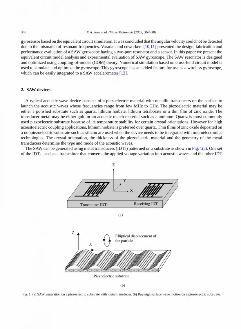
The SAW can be generated using metal transducers (IDTs) patterned on a substrate as shown inFig. 1(a). One setof the IDTs used as a transmitter that converts the applied voltage variation into acoustic waves and the other IDT
Fig. 1. (a) SAW generation on a piezoelectric substrate with metal transducer. (b) Rayleigh surface wave motion on a piezoelectric substrate.

K.A. Jose et al. / Wave Motion 36 (2002) 367–381 369
receives these acoustic waves and converts it back to an output voltage. Physical motion of the particles at the substratesurface can be considered as elliptical path with displacement alongZ-axis is larger than the displacement alongX-direction as shown inFig. 1(b). The amplitude of both these displacements becomes negligible for penetrationdepth greater than one wavelength[13]. In SAW resonator, the IDTs are placed in the center of the device withreflectors on both sides. SAW resonator has been extensively used as stable frequency oscillators and resonant filters.
3. Principle of SAW gyroscope
Mechanical gyroscope has a stable reference vibrating motion (V) of a mass (m) which when subjected to arotation, the angular velocity (�) perpendicular to the reference motion would cause Coriolis force at the samefrequency of the reference vibration. The effect of the Coriolis force (F = 2mV × �) is a measure of the rotationrate. It is well known that in a standing Rayleigh surface wave, the particle has an elliptical displacement at thesurface. This particle vibration alongZ-direction can be cleverly utilized for the creation of reference vibratorymotion for the gyroscope.
The concept of utilizing SAW for the detection of rotation is illustrated inFig. 2. It consists of IDTs, reflectors,and a metallic dot array within the cavity, which are fabricated through micro fabrication techniques on the surfaceof a piezoelectric substrate. The metallic dots of massm serve as proof mass for this gyroscope. The resonator IDTs
Fig. 2. Working principle of the MEMS SAW gyroscope.

370 K.A. Jose et al. / Wave Motion 36 (2002) 367–381
create SAW that propagates back and forth between the reflectors and forms a standing wave pattern within thecavity due to the collective reflection from reflectors. SAW reflection from individual metal strips adds in phaseif the reflector periodicity is equal to half a wavelength. For the established standing wave pattern in the cavity asexplained inFig. 2, a typical substrate particle at the nodes of standing wave has no amplitude of deformation in theZ-direction. However, at or near the anti-nodes of standing wave pattern, such particles experience larger amplitudeof vibration in theZ-direction, which serves as the reference vibrating motion for this gyroscope. Metallic dotsof massm, which serve as the proof mass, are placed in the resonator region where standing waves are formed.To amplify the magnitude of the generated Coriolis force in phase, the metallic dots are positioned strategicallyat the anti-node locations. The rotation (�, X-direction) perpendicular to the velocity (V in ±Z-direction) of theoscillating masses (m) produces Coriolis force (F = 2mV × � in ±Y-direction) in the direction perpendicular tothe both vectors as shown inFig. 2. Since this Coriolis force is applied on a piezoelectric substrate, it generatesa secondary SAW in theY-direction with same frequency as the reference oscillation. The metallic dot array isplaced along theY-direction such that the SAW due to the Coriolis forces adds up coherently. The generated SAWis received by the sensing IDTs placed in theY-direction.
The periodicity of IDTs and reflectors, and the separation between the reflector gratings determine the operatingfrequency of the device. The separation between reflectors is chosen as an integral number of half wavelengths suchthat the standing waves are created between the reflectors. The periodicity of IDT was chosen as half wavelengthλ/2 of SAW.
The substrate used for the fabrication of the gyroscope is lithium niobate (128YX LiNbO3) because of its highelectromechanical coupling coefficient. The wave velocities inX- andY-directions are different due to the anisotropyof the material. The width of IDT fingers and its spacing were determined according to the velocities 3961 and3656 m/s inX- andY-directions, respectively[14]. To reduce the effect of metallic dot array inside the SAW resonator,size of each dot in the array was chosen such that it is sufficiently smaller than the wavelength in both directions.Since the amplitudes of the standing waves are dependent on material damping and electromechanical transductionlosses, the transmitting and sensing IDTs are placed such that they are located at the standing wave maxima in orderto reduce the transduction loss.
To obtain a good resonator performance with this high coupling coefficient substrate, aperture of IDTs and numberof IDT fingers were minimized. Also, larger spacing between IDTs was chosen compared to conventional resonatorsto avoid the electromagnetic coupling between IDTs and to accommodate enough metallic dots within the cavity.The number and aperture of IDTs, electromechanical coupling coefficient and dielectric permittivity of the substratedetermine the electrical impedance of the gyroscope.
4. Design of SAW gyroscope
4.1. SAW resonator design
It is important to know characteristic of impedance, admittance, bandwidth and sensitivity near the operatingfrequency of the SAW gyroscope, because the sensing IDTs have to be designed such that they efficiently pickthe SAW waves generated due to Coriolis force. The numerical simulation of the SAW resonator is done usingCOM theory because a SAW device can be easily represented by several basic elements that are transfer matricesof representative sections of a SAW device. The COM theory[16] has been extensively used since 1950s in variousproblems related to optics and electromagnetism for the description of wave propagation in periodically perturbedmedia. It is a well-designed method for modeling systems with time or spatially varying parameters and the COMtheory provides an efficient and highly flexible approach for modeling various kinds of SAW devices by a set oftransfer matrices[15,17]. The sensor is modeled using Mason’s equivalent circuit concept[13]. For the effectivenumerical calculation of gyroscope output, equivalent circuit model was chosen because Coriolis force can bedirectly related to input force onto the SAW sensor model.

K.A. Jose et al. / Wave Motion 36 (2002) 367–381 371
Fig. 3. (a) Basic elements of gyroscope: IDT, acoustic spacing, and reflector. (b) Schematic representation of a SAW device using transfer matrix.
In general, there are three types of the representative elements for a SAW device: IDT, spacing, and reflector,which can be described as transfer matrices [T], [D] and [G], respectively. [T] matrix is a 3× 3 matrix, whereas[D] and [G] are 2× 2 matrices. The [T] matrix relates the input and output of IDTs as well as the electrome-chanical conversion between electrical signal and SAW. Thus, the [T] matrix has three ports of which two areacoustical ports and one is an electrical port. The transfer matrix [D] describes a SAW propagation path betweentwo representative sections, while matrix [G] represents a reflector array. Depending on the configuration of aSAW device, any number of [T], [D] and [G] matrices can be used, but their basic forms remain the same. Forinstance, the basic elements of this gyroscope consist of an IDT and a reflector can be modeled as shown inFig. 3.
Fig. 3(a)shows device layout, which has IDT, acoustic spacing, and reflector, which can be represented as shownin Fig. 3(b), with [T1], [D2] and [G3]. Numbers 1–3 are just for book keeping purpose. The electrical signals in andout of IDTs are represented by scalar variablesa andb. The SAW coming in and out of each representative sectionis described byW+’s andW−’s, representing the two different propagation directions. Thus, any (n − 1)th SAWamplitudes coming in and out ofnth section has the following relation, where components of the transfer matricesareT, D andG:[
W+n−1
W−n−1
]= [T, D, G]n
[W+
n
W−n
]. (1)
This matrix representation of a lumped system model of SAW devices can be implemented to other SAW structuresalso since any SAW device is a combination of IDTs, reflectors and spacing.Fig. 4shows the model of a two-portSAW resonator used in this gyroscope. Complex SAW structures can also be modeled by adding more transfermatrices at appropriate locations.
It is assumed that there are no incoming waves from outside the reflectors and impedance of all ports are wellmatched. The frequency response can be computed from transmission line matrices for appropriate sections. Theamplitudes of the waves are represented by scalar electric potentialΦ at the surface of the piezoelectric substrate,which can be written in terms of SAW velocityv(x) as[13]
d2Φ
dx2+[
ω2
v2(x)
]Φ = 0, (2)

372 K.A. Jose et al. / Wave Motion 36 (2002) 367–381
Fig. 4. Schematic matrix representation of a two-port SAW resonator.
whereω is the frequency. The wave velocityv(x) is perturbed sinusoidally aboutv0 while passing through themetallic strips and can be written as
v(x) = v0 − 12 v cos(Ax), (3)
whereA = 2π/Λ, Λ is the period. The solution ofEq. (2)gives a pair of coupled-wave equations, which can berepresented as forward and backward SAW waves with amplitudesR andS:
−R′ − jδR = jkS, (4)
−S′ − jδS = jkR. (5)
From the solution of above equations, the grating matrix [G] for an array can be written as[13]
[G] = C
(σ
k+ j
(δ − jα
k
)tanh(σL)
)ejβ0L j e−jθ tanh(σL)ejβ0L
−j e−jθ tanh(σL)ejβ0L
(σ
k− j
(δ − jα
k
)tanh(σL)
)e−jβ0L
, (6)
wherek is the grating mutual coupling coefficient,α the attenuation constant,L the grating length,β0 the unperturbedphase constant,
σ =√
k2 − (δ − jα)2,
and
C = k
σcosh(σL).
Similarly, transmission matrix [T], which relates the electrical and acoustic parameters of IDTs, as shown inFig. 5,can be written as follows[18]:
[T ] =[
t τ
τs t33
], (7)
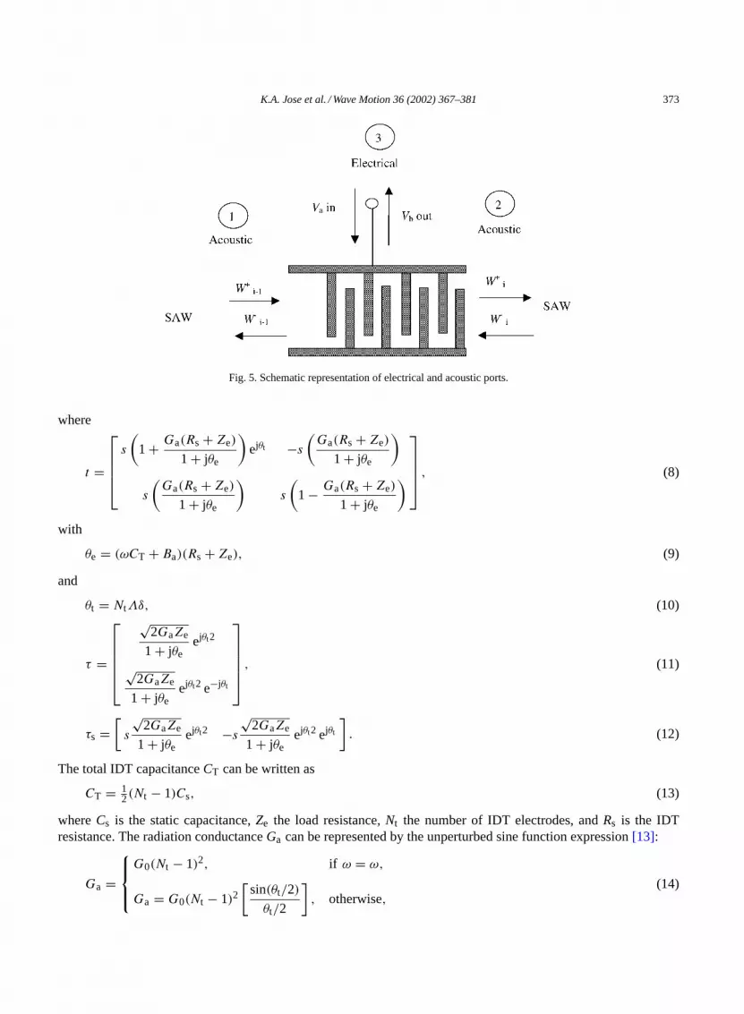
K.A. Jose et al. / Wave Motion 36 (2002) 367–381 373
Fig. 5. Schematic representation of electrical and acoustic ports.
where
t =
s
(1 + Ga(Rs + Ze)
1 + jθe
)ejθt −s
(Ga(Rs + Ze)
1 + jθe
)
s
(Ga(Rs + Ze)
1 + jθe
)s
(1 − Ga(Rs + Ze)
1 + jθe
) , (8)
with
θe = (ωCT + Ba)(Rs + Ze), (9)
and
θt = NtΛδ, (10)
τ =
√2GaZe
1 + jθeejθt2
√2GaZe
1 + jθeejθt2 e−jθt
, (11)
τs =[s
√2GaZe
1 + jθeejθt2 −s
√2GaZe
1 + jθeejθt2 ejθt
]. (12)
The total IDT capacitanceCT can be written as
CT = 12(Nt − 1)Cs, (13)
whereCs is the static capacitance,Ze the load resistance,Nt the number of IDT electrodes, andRs is the IDTresistance. The radiation conductanceGa can be represented by the unperturbed sine function expression[13]:
Ga =
G0(Nt − 1)2, if ω = ω,
Ga = G0(Nt − 1)2[
sin(θt/2)
θt/2
], otherwise,
(14)
374 K.A. Jose et al. / Wave Motion 36 (2002) 367–381
where
G0 = 8K2Csf0 (15)
(K2 is the electromechanical coupling coefficient). Next,
Ba =
0, if ω = ω,
2G0(Nt − 1)2(
sin(θt) − θt
θ2t
), otherwise.
(16)
Lastly,
t33 = 1 − 2 jθc
1 + jθe, (17)
where
θc = ωCT(Rs + Ze). (18)
The transmission matrix [T] can be related to electrical and acoustic parameters for each IDT can be written as
W+i−1
W−i−1
bi
= [T ]
W+i
W−i
ai
. (19)
Thus, the equation for acoustic waves at the(i + 1)th andith reference planes can be written as[13]
[Wi−1] = [ti ][Wi ] + ai [τi ], (20)
whereai is the input electrical signal at theith plane. The acoustic sub-matrix [t1] can be written as
[t1] =(
t11 t12
−t12 t22
)i
, (21)
and
[τi ] =(
t13
−t23
)i
. (22)
Also, space between the IDTs and reflector is represented by
[D] =[
eiβd 0
0 e−iβd
]. (23)
The total acoustic matrix [M] for a two-port resonator can now be written as
[M] = [G1][D2][ t3][D4][ t5][D6][G7]. (24)
Here, [G1] and [G7] are related to two SAW reflectors at the end, and [D2] and [D6] are the spacing between thegratings and adjacent IDTs. [D4] is the separation between IDTs. [t3] and [t5] are the acoustic sub-matrices as shownin Eq. (21). Eq. (24)is solved for the frequency response of the resonator by applying the boundary condition:
W+0 = W−
7 = 0, (25)
K.A. Jose et al. / Wave Motion 36 (2002) 367–381 375
which assumes that there is no external SAW at the input side. It is also noted that the source and load impedancesdetermine the electrical properties of the transmission line. Thus,
[W2] = t3[W3] + a3τ3. (26)
Applying the boundary conditionequation (25)for the transducer [T3], the first order response of two-port resonatorcan be obtained by solving the equation
[W5] = [D6][G7][W7]. (27)
By applying the boundary conditionequation (25)and usingEqs. (26) and (27), the outward-propagating SAWwavesW+
7 andW−0 are related to the input voltagea3 by{
0
W−0
}= [M]
{W+
7
0
}+ a3[G1][D2][τ3]. (28)
The output voltageVout from the IDT can be written as
Vout = b5 = [τ5][W5]. (29)
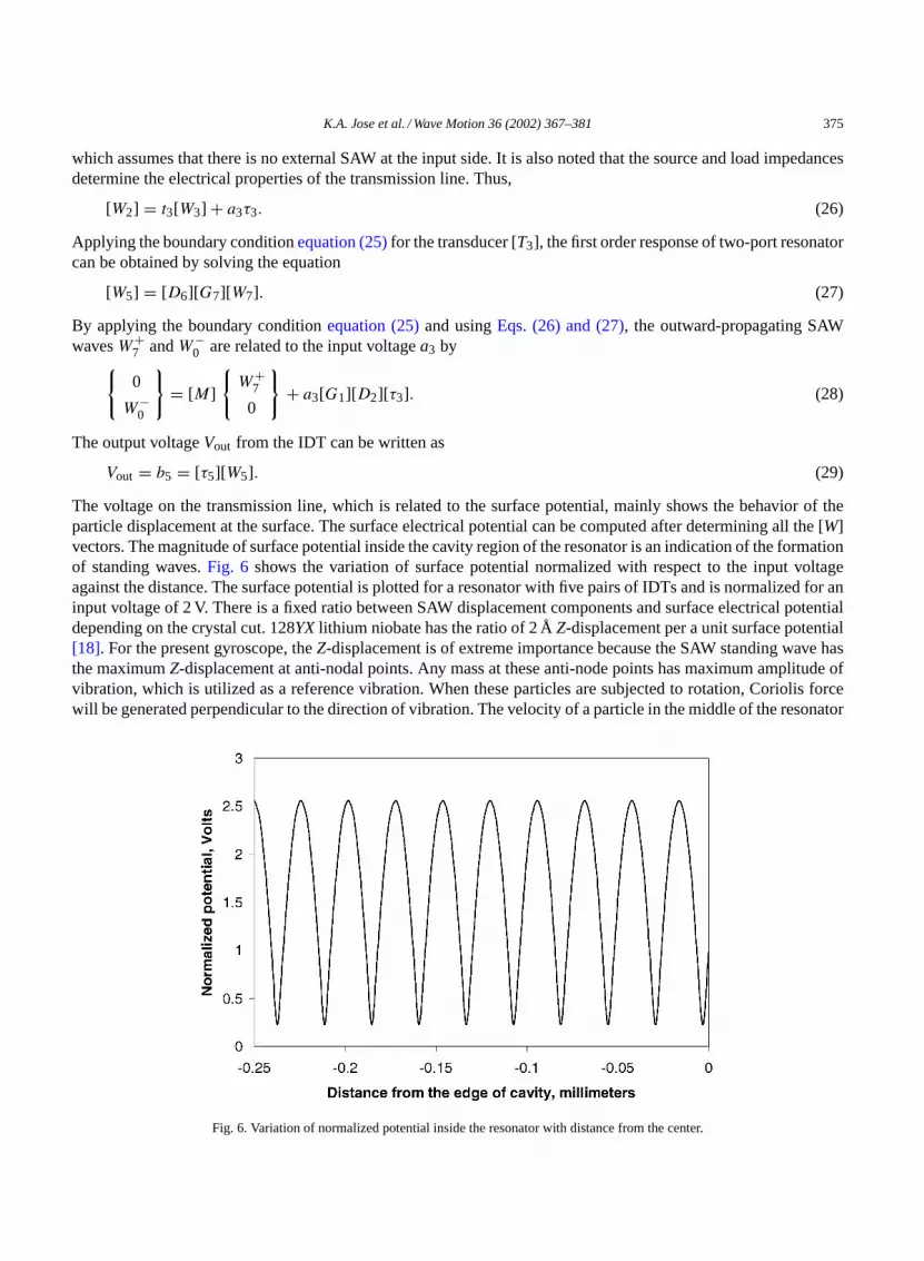
The voltage on the transmission line, which is related to the surface potential, mainly shows the behavior of theparticle displacement at the surface. The surface electrical potential can be computed after determining all the [W]vectors. The magnitude of surface potential inside the cavity region of the resonator is an indication of the formationof standing waves.Fig. 6 shows the variation of surface potential normalized with respect to the input voltageagainst the distance. The surface potential is plotted for a resonator with five pairs of IDTs and is normalized for aninput voltage of 2 V. There is a fixed ratio between SAW displacement components and surface electrical potentialdepending on the crystal cut. 128YX lithium niobate has the ratio of 2 ÅZ-displacement per a unit surface potential[18]. For the present gyroscope, theZ-displacement is of extreme importance because the SAW standing wave hasthe maximumZ-displacement at anti-nodal points. Any mass at these anti-node points has maximum amplitude ofvibration, which is utilized as a reference vibration. When these particles are subjected to rotation, Coriolis forcewill be generated perpendicular to the direction of vibration. The velocity of a particle in the middle of the resonator
Fig. 6. Variation of normalized potential inside the resonator with distance from the center.

376 K.A. Jose et al. / Wave Motion 36 (2002) 367–381
at anti-node point is calculated at the resonant frequency. Using this velocity value and the mass at the anti-nodalpoints, Coriolis force is calculated for different input rates. This Coriolis force is the input to gyroscope sensor,which is discussed in the following section.
4.2. Equivalent circuit model for sensor and gyroscope
Various SAW sensors have been successfully analyzed using cross-field equivalent circuit model derived fromMason circuit. To model the SAW gyroscope which generates a voltage output due to rotation, the induced SAWdue to rotation has to be modeled as input force through transformer ratio in SAW equivalent circuit. In this modelthe electric field distribution under the electrode is approximated as normal to the piezoelectric substrate, which isequivalent to a parallel plate capacitor. A three-port network using a RF transmission line analogy can be used tomodel each IDTs. The acoustic forceF is transformed to electrical equivalent voltageV and particle velocity at thesurfacev is transformed to equivalent currentI. These transformations can be written in terms of a proportionalityconstantf as
V = F
φ, (30)
I = vφ, (31)
whereφ is related to the turns-ratio of an equivalent acoustic-to-electric transformer. This can be written in termsof electromechanical coupling coefficientK2, frequencyf0, and total capacitance of the IDT,C as
φ =√
2f0CK2Aρv. (32)
Hence the mechanical characteristic impedanceZm = F/v of the substrate can be expressed as equivalent trans-mission line characteristic impedanceZ0 (1). For a substrate of densityρ and effective cross-sectional areaA, themechanical impedance for a propagating acoustic wave can be written as
Zm = ρvA, (33)
and the equivalent electric impedance is
Z0 = Zm
φ2. (34)
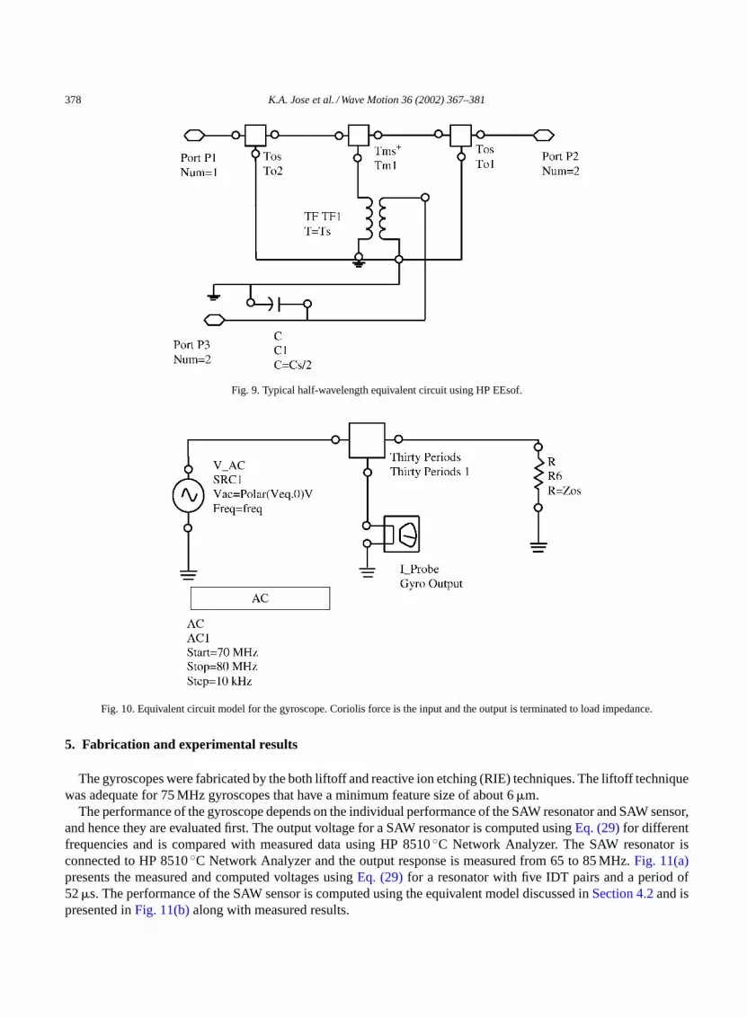
Once the unit cell of IDT pair is modeled, each model can be cascaded depending on number of pairs for the sensorIDTs. Coriolis force is the input force, which is the input voltage at one end of the constructed equivalent circuit asshown inFig. 7. Other end of the model is terminated with load impedance assuming that there are no incomingwaves.Fig. 8presents the equivalent circuit model for the reflectors. Simulation of this model has been achieved byusing commercial RF circuit simulator, HP EEsof.2 Fig. 9shows typical half-wavelength circuit constructed usingEEsof. In order to calculate the response of the sensor, this three-port network has been cascaded electrically inparallel and acoustically in series. The transmission responseS21 that gives a relative output voltage compared tothe input voltage to the sensor is calculated for different frequencies and the results are presented in the next section.
The analysis of SAW generated due to Coriolis force is a 3-D problem, which contains three vectors (referencevibration vector, input rotation vector, and resulting Coriolis vector) in three mutually perpendicular directions.Because Coriolis force has been approximated by 1-D analogy, the secondary SAW generated by Coriolis force hasalso been approximated. Otherwise, a full 3-D finite element model (FEM) is necessary which is computationallydemanding. The generated SAW due to Coriolis force has been approximated over an effective cross-sectionalarea. The effective area is where the SAW power is concentrated on the surface, which is a fraction of wavelength
2 HP EEsof is the high frequency circuit simulation software from Agilent Technologies Inc., Westlake Village, CA,http://www.agilent.com.

K.A. Jose et al. / Wave Motion 36 (2002) 367–381 377
Fig. 7. Cross-field model of IDT pair and its equivalent circuit representation.
times the beam width. The Coriolis force has been represented as an equivalent input voltage to the sensor, whichconsists of 30 pairs of IDTs. The equivalent circuit model of the gyroscope is shown inFig. 10. The output voltageis calculated for a given Coriolis force, which is determined by the rotation rate of the gyroscope and is presentedin next section.
Fig. 8. Representation of reflectors using equivalent circuit model.
378 K.A. Jose et al. / Wave Motion 36 (2002) 367–381
Fig. 9. Typical half-wavelength equivalent circuit using HP EEsof.
Fig. 10. Equivalent circuit model for the gyroscope. Coriolis force is the input and the output is terminated to load impedance.
5. Fabrication and experimental results
The gyroscopes were fabricated by the both liftoff and reactive ion etching (RIE) techniques. The liftoff techniquewas adequate for 75 MHz gyroscopes that have a minimum feature size of about 6�m.
The performance of the gyroscope depends on the individual performance of the SAW resonator and SAW sensor,and hence they are evaluated first. The output voltage for a SAW resonator is computed usingEq. (29)for differentfrequencies and is compared with measured data using HP 8510◦C Network Analyzer. The SAW resonator isconnected to HP 8510◦C Network Analyzer and the output response is measured from 65 to 85 MHz.Fig. 11(a)presents the measured and computed voltages usingEq. (29)for a resonator with five IDT pairs and a period of52�s. The performance of the SAW sensor is computed using the equivalent model discussed inSection 4.2and ispresented inFig. 11(b)along with measured results.

K.A. Jose et al. / Wave Motion 36 (2002) 367–381 379
Fig. 11. Computed and measured performance of (a) SAW resonator and (b) SAW sensor.
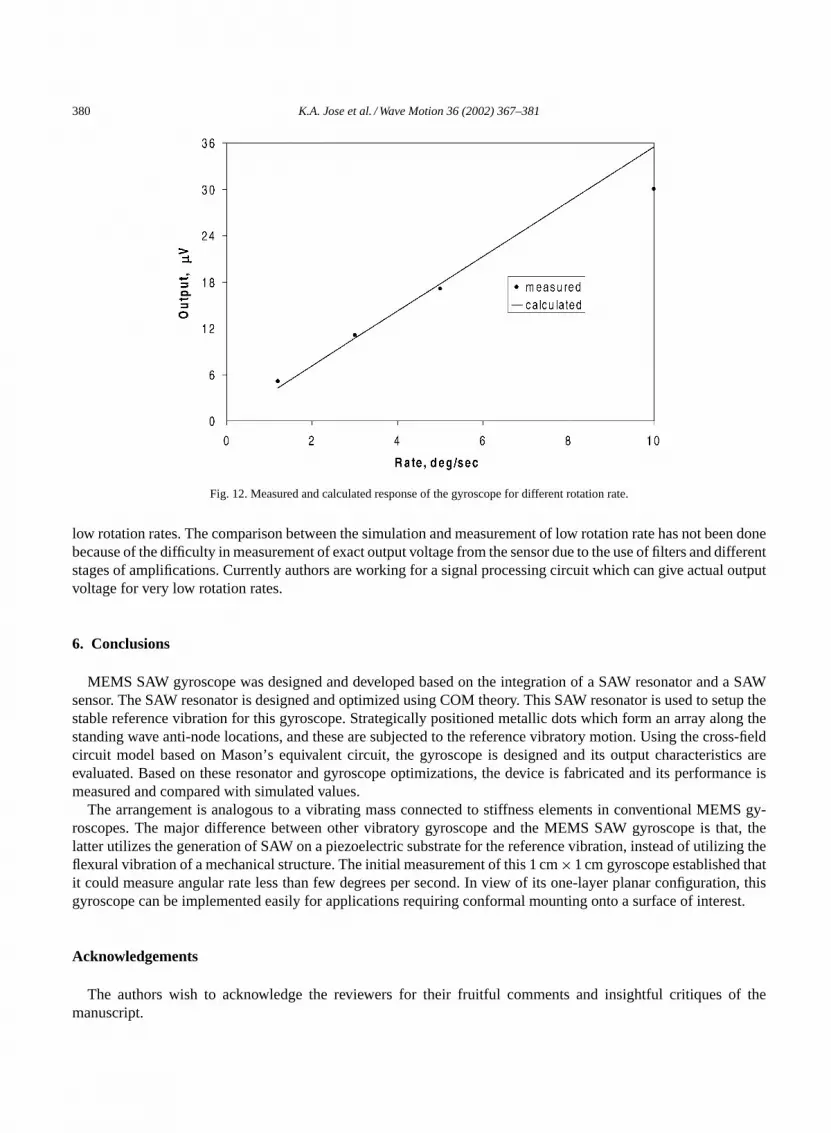
The response of the SAW gyroscope was evaluated using a rate table. The output response was measured usingHP dynamic signal analyzer through RF lock-in amplifier. The gyroscope is fixed on a rate table and giving constantfrequency drives the rate table in oscillations and the output from the gyroscope is measured. The amplitude and thefrequency of the driving signal control the amplitude of oscillations of the table, which in turn varies the rotation rate.Fig. 12presents the measured and computed output voltages from the SAW gyroscope for different rotation rates.
This initial measurement demonstrates the viability of using SAW gyroscope to measure rotation rates. Packagingis an integral part of any device and most MEMS devices must be encased in a hermetic package. A hermetic sealprevents the gases and liquids enter into the package cavity when die is mounted. It will also prevent any gasformation inside the package. Vacuum package will increaseQ of the device by reducing any air damping on thesemicrostructures. Because the hermetic packaging was not done at this stage, the measurements make it difficult todetermine the dynamic range and resolution. However, with proper packaging the gyroscope will be able to measure
380 K.A. Jose et al. / Wave Motion 36 (2002) 367–381
Fig. 12. Measured and calculated response of the gyroscope for different rotation rate.
low rotation rates. The comparison between the simulation and measurement of low rotation rate has not been donebecause of the difficulty in measurement of exact output voltage from the sensor due to the use of filters and differentstages of amplifications. Currently authors are working for a signal processing circuit which can give actual outputvoltage for very low rotation rates.
6. Conclusions
MEMS SAW gyroscope was designed and developed based on the integration of a SAW resonator and a SAWsensor. The SAW resonator is designed and optimized using COM theory. This SAW resonator is used to setup thestable reference vibration for this gyroscope. Strategically positioned metallic dots which form an array along thestanding wave anti-node locations, and these are subjected to the reference vibratory motion. Using the cross-fieldcircuit model based on Mason’s equivalent circuit, the gyroscope is designed and its output characteristics areevaluated. Based on these resonator and gyroscope optimizations, the device is fabricated and its performance ismeasured and compared with simulated values.
The arrangement is analogous to a vibrating mass connected to stiffness elements in conventional MEMS gy-roscopes. The major difference between other vibratory gyroscope and the MEMS SAW gyroscope is that, thelatter utilizes the generation of SAW on a piezoelectric substrate for the reference vibration, instead of utilizing theflexural vibration of a mechanical structure. The initial measurement of this 1 cm×1 cm gyroscope established thatit could measure angular rate less than few degrees per second. In view of its one-layer planar configuration, thisgyroscope can be implemented easily for applications requiring conformal mounting onto a surface of interest.
Acknowledgements
The authors wish to acknowledge the reviewers for their fruitful comments and insightful critiques of themanuscript.

K.A. Jose et al. / Wave Motion 36 (2002) 367–381 381
References
[1] D.T. Bell Jr., R.C.M. Li, Surface acoustic wave resonators, Proc. IEEE 64 (1976) 711–721.[2] E.J. Staples, J.S. Schoenwald, R.C. Rosenfeld, C.S. Hartmann, UHF surface acoustic wave resonators, in: J. de Klerk (Ed.), Proceedings
of the IEEE Ultrasonics Symposium, Newport Beach, CA, May 1974, IEEE, New York, pp. 245–252.[3] R.M. White, Surface acoustic wave sensors, in: B.R. Mc Avoy (Ed.), Proceedings of the IEEE Ultrasonics Symposium, San Francisco, CA,
October 1985, IEEE, New York, pp. 490–494.[4] D.S. Ballantine, R.M. White, S.J. Martin, E.T. Zellers, H. Wohltjen, Acoustic Wave Sensors: Theory, Design and Physico-Chemical
Applications, Academic Press, New York, 1997.[5] J.D. Achenbach, Wave Propagation in Elastic Solids, Elsevier, Amsterdam, 1973, pp. 187–194.[6] A.J. Slobodnik, Surface acoustic waves and SAW materials, Proc. IEEE 64 (5) (1976) 581–595.[7] R.M. White, F.W. Voltmer, Direct piezoelectric coupling to surface acoustic waves, Appl. Phys. Lett. 7 (1965) 314–316.[8] B.Y. Lao, Gyroscopic effect in surface acoustic waves, in: B.R. Mc Avoy (Ed.), Proceedings of the IEEE Ultrasonics Symposium, Boston,
MA, November 1980, IEEE, New York, pp. 687–690.[9] M. Kurosawa, Y. Fukuda, M. Takasaki, T. Higuchi, A surface-acoustic wave gyroscope sensor, Sens. Actuators A 66 (1998) 33–39.
[10] V.K. Varadan, K.A. Jose, P. Xavier, D. Suh, V.V. Varadan, Conformal MEMS-IDT gyroscopes and their performance comparison withfiber optic gyroscope, in: V.K. Varadan (Ed.), Proceedings of the SPIE Symposium on Smart Electronics and MEMS, Vol. 3990, NewportBeach, CA, 2000, pp. 335–344.
[11] V.K. Varadan, W.D. Suh, P.B. Xavier, K.A. Jose, V.V. Varadan, Design and development of a MEMS-IDT gyroscope, J. Smart Mater. Struct.9 (2000) 898–905.
[12] H. Subramanian, V.K. Varadan, V.V. Varadan, M.J. Vellekoop, Design and fabrication of wireless remotely readable MEMS basedmicroaccelerometers, J. Smart Mater. Struct. 6 (1997) 730–738.
[13] C.K. Campbell, Surface Acoustic Wave Devices for Mobile and Wireless Communications, Academic Press, New York, 1998 (Chapter 11).[14] B.A. Auld, Acoustic Fields and Waves in Solids, Vol. 2, Wiley, New York, 1973, p. 383.[15] P.S. Cross, R.V. Schmidt, Coupled surface acoustic wave resonator, Bell Syst. Technol. J. 56 (1977) 1447–1481.[16] J.R. Pierce, Coupling-of-modes of propagation, J. Appl. Phys. 25 (1954) 179–183.[17] H. Haus, P.V. Wright, The analysis of grating structures by coupling-of-modes theory, in: B.R. Mc Avoy (Ed.), Proceedings of the IEEE
Ultrasonics Symposium, Boston, MA, November 1980, IEEE, New York, pp. 277–281.[18] S. Datta, Surface Acoustic Wave Devices, Prentice-Hall, Englewood Cliffs, NJ, 1986 (Chapter 3).


