Embed Size (px)
Citation preview
Precision positioning using MEMS basedmicroactuator
Nitin Afzulpurkar *, Yossawee Weerakamhaeng
Industrial Systems Engineering Program, Asian Institute of Technology, Thailand
Abstract
The critical factor for the hard disk manufacturers when designing the new generation of
high capacity hard disks is ‘areal density’. Although linear density has increased dramatically
increases in track density are limited by servo bandwidths, which are controlled by the ac-
tuator resonance. An approach, which is currently being investigated by the researchers, is the
use of a second high bandwidth actuator at the end of the conventional voice-coil actuator.
After theoretical analysis and discussions with industry electrostatic design in which the
microactuator will sit on the slider between the suspension and the read/write head is selected.
The design factors are: higher servo bandwidth, higher resonant frequency and low voltage
supply. To microfabricate such microactuator we propose to use the latest technology called
microelectromechanical systems technology. After schematic drawing layout design is made, it
has been tested for electrical connections in the electrical layout model and the optimized
design parameters are obtained. Finally it is shown that the design will satisfy the required
specifications.
� 2002 Published by Elsevier Science Ltd.
1. Introduction
The magnetic hard disk drive (HDD) has been maintaining significantly lowercost per megabit in comparison to solid-state memory technology. The areal re-cording density of hard disk drives has been increasing at a rate of 60% per year andthe track density has been increasing at a rate of 30% per year [5]. The most prof-itable way that hard disks have been increased in capacity and speed is by storingmore and more information in the same physical space Fig. 1. The areal density is
Mechatronics 12 (2002) 1213–1223
*Corresponding author.
E-mail address: [email protected] (N. Afzulpurkar).
0957-4158/02/$ - see front matter � 2002 Published by Elsevier Science Ltd.
PII: S0957-4158 (02 )00025-9
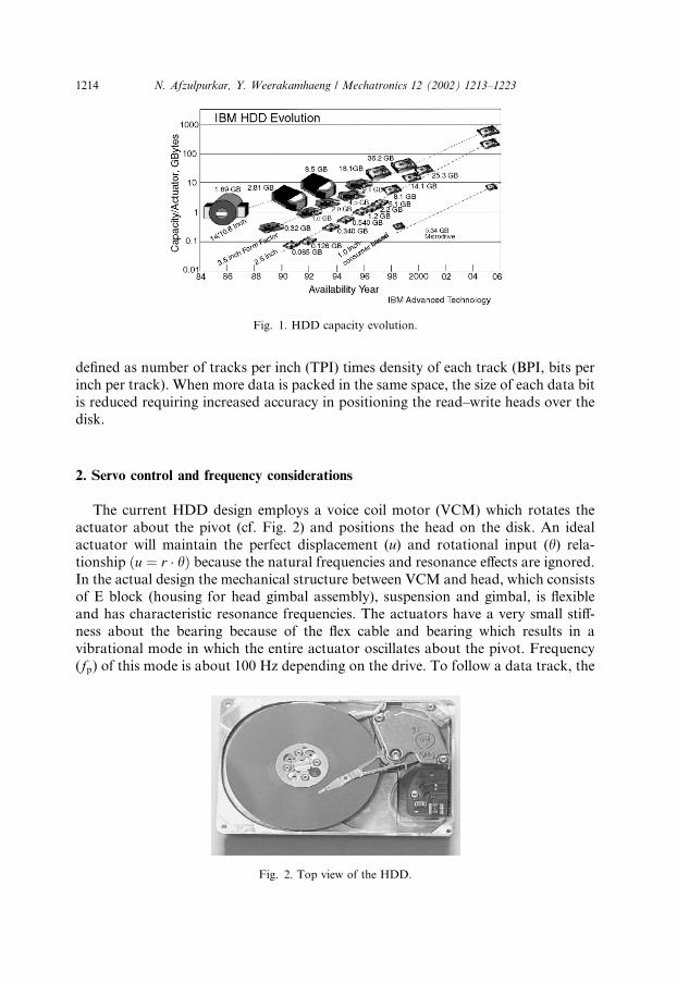
defined as number of tracks per inch (TPI) times density of each track (BPI, bits perinch per track). When more data is packed in the same space, the size of each data bitis reduced requiring increased accuracy in positioning the read–write heads over thedisk.
2. Servo control and frequency considerations
The current HDD design employs a voice coil motor (VCM) which rotates theactuator about the pivot (cf. Fig. 2) and positions the head on the disk. An idealactuator will maintain the perfect displacement (u) and rotational input (h) rela-tionship ðu ¼ r � hÞ because the natural frequencies and resonance effects are ignored.In the actual design the mechanical structure between VCM and head, which consistsof E block (housing for head gimbal assembly), suspension and gimbal, is flexibleand has characteristic resonance frequencies. The actuators have a very small stiff-ness about the bearing because of the flex cable and bearing which results in avibrational mode in which the entire actuator oscillates about the pivot. Frequency(fp) of this mode is about 100 Hz depending on the drive. To follow a data track, the
Fig. 1. HDD capacity evolution.
Fig. 2. Top view of the HDD.
1214 N. Afzulpurkar, Y. Weerakamhaeng / Mechatronics 12 (2002) 1213–1223
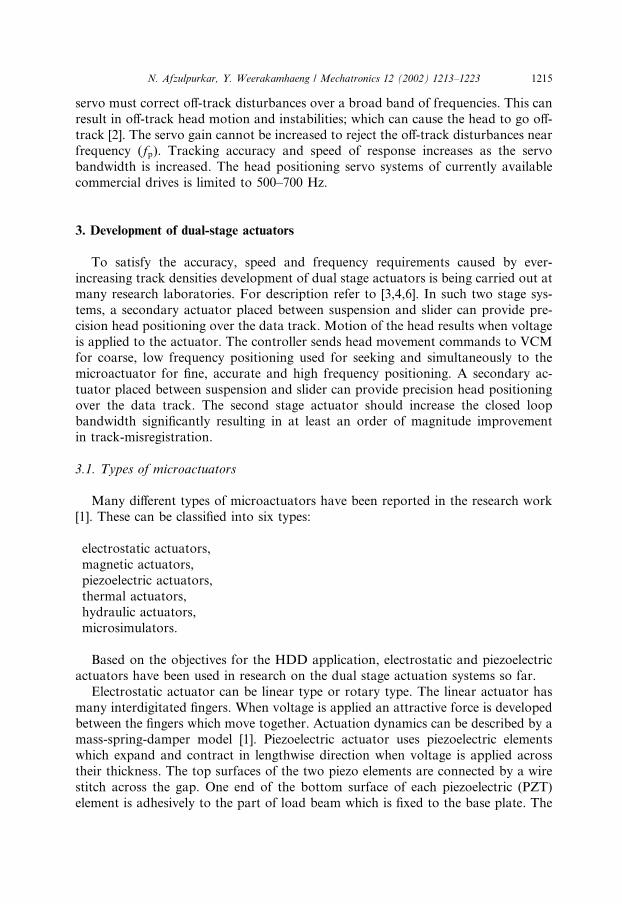
servo must correct off-track disturbances over a broad band of frequencies. This canresult in off-track head motion and instabilities; which can cause the head to go off-track [2]. The servo gain cannot be increased to reject the off-track disturbances nearfrequency (fp). Tracking accuracy and speed of response increases as the servobandwidth is increased. The head positioning servo systems of currently availablecommercial drives is limited to 500–700 Hz.
3. Development of dual-stage actuators
To satisfy the accuracy, speed and frequency requirements caused by ever-increasing track densities development of dual stage actuators is being carried out atmany research laboratories. For description refer to [3,4,6]. In such two stage sys-tems, a secondary actuator placed between suspension and slider can provide pre-cision head positioning over the data track. Motion of the head results when voltageis applied to the actuator. The controller sends head movement commands to VCMfor coarse, low frequency positioning used for seeking and simultaneously to themicroactuator for fine, accurate and high frequency positioning. A secondary ac-tuator placed between suspension and slider can provide precision head positioningover the data track. The second stage actuator should increase the closed loopbandwidth significantly resulting in at least an order of magnitude improvementin track-misregistration.
3.1. Types of microactuators
Many different types of microactuators have been reported in the research work[1]. These can be classified into six types:
electrostatic actuators,magnetic actuators,piezoelectric actuators,thermal actuators,hydraulic actuators,microsimulators.
Based on the objectives for the HDD application, electrostatic and piezoelectricactuators have been used in research on the dual stage actuation systems so far.Electrostatic actuator can be linear type or rotary type. The linear actuator has
many interdigitated fingers. When voltage is applied an attractive force is developedbetween the fingers which move together. Actuation dynamics can be described by amass-spring-damper model [1]. Piezoelectric actuator uses piezoelectric elementswhich expand and contract in lengthwise direction when voltage is applied acrosstheir thickness. The top surfaces of the two piezo elements are connected by a wirestitch across the gap. One end of the bottom surface of each piezoelectric (PZT)element is adhesively to the part of load beam which is fixed to the base plate. The
N. Afzulpurkar, Y. Weerakamhaeng / Mechatronics 12 (2002) 1213–1223 1215
other end is adhesively bonded to the movable portion of the load beam. The PZTelements are oppositely polarized so that application of voltage makes one to expandand other to contract [3]. Operations of piezoelectric piggyback and shear-modemicroactuators are described in [6,7].Electrostatic actuator offers high accuracy and the actuation dynamics are de-
scribed by simple second order linear model. Stiction and backlash is not present inthese devices. On the other side the structure of the actuator has low stiffness springswhich limits the maximum resonant frequency one can achieve.Piezoelectric material has high stiffness and can generate large force when used as
actuator. This results in higher achievable resonant frequencies. The main disad-vantage is that position accuracy is not as high as electrostatic actuator. Anotherdisadvantage is that it cannot be made as an integral part of the head.
4. Microelectromechanical system microactuator
One of the main goals of the development of microelectromechanical systems(MEMS) based devices is to be able to integrate microelectronics circuitry into mi-cromachined structures with moving parts. This will result in completely integratedsystems which will have advantages of low cost, reliability and small size as siliconchips. Using fabrication techniques and materials similar to microelectronics MEMSprocesses construct electrical components to provide computational capabilities andmechanical components which sense, control and provide actuation. Photolitho-graphy is the basic technique used to define the shape of the micromachined struc-tures. Silicon macromachining is a widely used technique for MEMS devicefabrication.MEMS fabrication requires drawing and layout tools to generate the pattern for
adding or removing material. It needs a range of modeling tools such as simulatorsfor mechanical movement, forces, electromagnetic fields, electronic device simulatorsand connective algorithms to reconcile and mix results from different simulators.
5. Structural design of electrostatic actuator
The structural design method and layout for a linear resonant electrostaticmicroactuator (LREM) developed by the authors is described below.Typical microfabricated actuators exhibit very lightly damped resonance resulting
in very poor settling performance if the resonant frequency is near the desired servobandwidth. The approach used is to design the actuator to have an extremely highresonant frequency (5–10 times greater than servo bandwidth) so that actuator dy-namics will have negligible effect on the servo system performance.Based on the above observation, the design criteria used for the design of LREM
are:
1. The actuator should have resonant frequency of 20 KHz or higher so that theclosed loop servo bandwidth can be 2 KHz.
1216 N. Afzulpurkar, Y. Weerakamhaeng / Mechatronics 12 (2002) 1213–1223
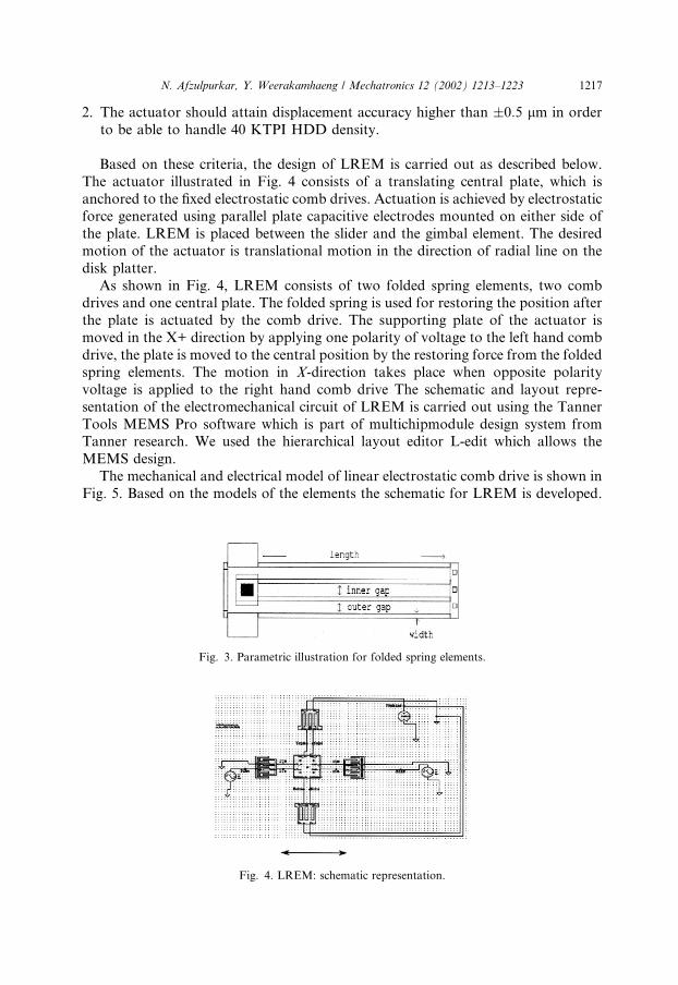
2. The actuator should attain displacement accuracy higher than �0:5 lm in orderto be able to handle 40 KTPI HDD density.
Based on these criteria, the design of LREM is carried out as described below.The actuator illustrated in Fig. 4 consists of a translating central plate, which isanchored to the fixed electrostatic comb drives. Actuation is achieved by electrostaticforce generated using parallel plate capacitive electrodes mounted on either side ofthe plate. LREM is placed between the slider and the gimbal element. The desiredmotion of the actuator is translational motion in the direction of radial line on thedisk platter.As shown in Fig. 4, LREM consists of two folded spring elements, two comb
drives and one central plate. The folded spring is used for restoring the position afterthe plate is actuated by the comb drive. The supporting plate of the actuator ismoved in the X+ direction by applying one polarity of voltage to the left hand combdrive, the plate is moved to the central position by the restoring force from the foldedspring elements. The motion in X-direction takes place when opposite polarityvoltage is applied to the right hand comb drive The schematic and layout repre-sentation of the electromechanical circuit of LREM is carried out using the TannerTools MEMS Pro software which is part of multichipmodule design system fromTanner research. We used the hierarchical layout editor L-edit which allows theMEMS design.The mechanical and electrical model of linear electrostatic comb drive is shown in
Fig. 5. Based on the models of the elements the schematic for LREM is developed.
Fig. 3. Parametric illustration for folded spring elements.
Fig. 4. LREM: schematic representation.
N. Afzulpurkar, Y. Weerakamhaeng / Mechatronics 12 (2002) 1213–1223 1217
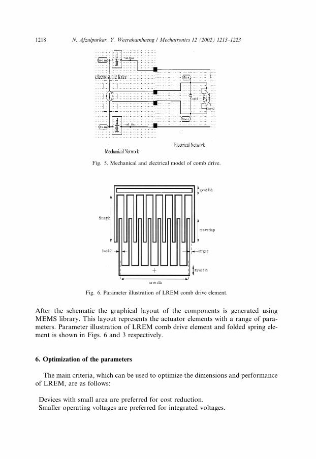
After the schematic the graphical layout of the components is generated usingMEMS library. This layout represents the actuator elements with a range of para-meters. Parameter illustration of LREM comb drive element and folded spring ele-ment is shown in Figs. 6 and 3 respectively.
6. Optimization of the parameters
The main criteria, which can be used to optimize the dimensions and performanceof LREM, are as follows:
Devices with small area are preferred for cost reduction.Smaller operating voltages are preferred for integrated voltages.
Fig. 6. Parameter illustration of LREM comb drive element.
Fig. 5. Mechanical and electrical model of comb drive.
1218 N. Afzulpurkar, Y. Weerakamhaeng / Mechatronics 12 (2002) 1213–1223
The resonant frequency should be as high as possible.Large amplitudes of oscillations are required for better sensing and actuating capa-bilities.
Dimension of the plate needs to be smaller than dimensions of a typical slider.The overall dimension of the microactuator should confirm with the effective area onthe gimbal. Based on this the overall dimension of the microactuator is fixed as3:113 mm� 2:602 mm and the plate width and length are fixed at 0.4 mm each.From the parameter illustrations shown in Figs. 3 and 6, the variables, which can
be optimized, are: width, length, inner gap and outer gap for folded springs, activerotor comb width (arwidth) and supply voltage. LREM behavior is simulated byvarying the following parameters:
spring length,active rotor comb width,voltage supply to comb drive.
Sine wave voltages are applied to the comb drive to generate the electrostaticforces and DC voltage is applied as bias voltage to folded springs to preserve theelectrostatic spring property.Spring length is varied between 150 and 350 lm in the step size of 10 lm. Active
rotor comb width is varied from 510 to 1821 lm in the steps of 69 lm. The voltagesupplied to comb drive is varied from 1 to 20 V in the steps of 1 V.By varying these parameters one at a time the displacement values at right node
(rtm) and the resonant frequencies are calculated. The schematic representationshown in Fig. 4 is used to find relations between:
1. Length of folded spring, displacement of node rtm and resonant frequency.2. Effective area of comb drive (arwidth), displacement of node rtm and resonantfrequency.
3. Voltage supplied to comb drive, displacement of node rtm and resonant fre-quency.
7. Conclusion
The advantages of dual-stage actuator for HDD over single stage actuator areidentified. As areal densities increase, the track density needs to be increased. Asystem with high bandwidth secondary actuator placed between the suspension andthe slider can be realized by MEMS technology.We calculated the optimum dimensions of the electrostatic MEMS actuator by
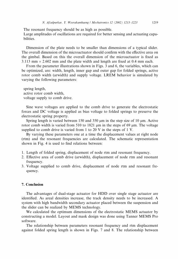
constructing a model. Layout and mask design was done using Tanner MEMS Prosoftware.The relationship between parameters resonant frequency and rtm displacement
against folded spring length is shown in Figs. 7 and 8. The relationship between
N. Afzulpurkar, Y. Weerakamhaeng / Mechatronics 12 (2002) 1213–1223 1219
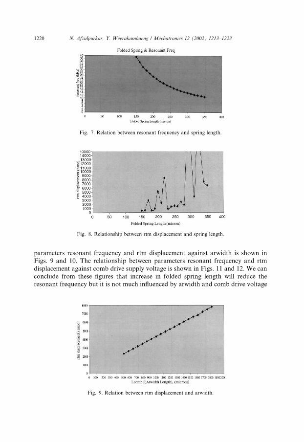
parameters resonant frequency and rtm displacement against arwidth is shown inFigs. 9 and 10. The relationship between parameters resonant frequency and rtmdisplacement against comb drive supply voltage is shown in Figs. 11 and 12. We canconclude from these figures that increase in folded spring length will reduce theresonant frequency but it is not much influenced by arwidth and comb drive voltage
Fig. 7. Relation between resonant frequency and spring length.
Fig. 8. Relationship between rtm displacement and spring length.
Fig. 9. Relation between rtm displacement and arwidth.
1220 N. Afzulpurkar, Y. Weerakamhaeng / Mechatronics 12 (2002) 1213–1223
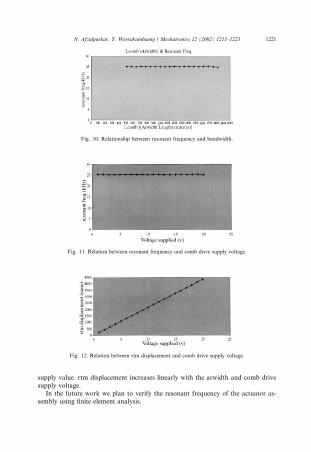
supply value. rtm displacement increases linearly with the arwidth and comb drivesupply voltage.In the future work we plan to verify the resonant frequency of the actuator as-
sembly using finite element analysis.
Fig. 11. Relation between resonant frequency and comb drive supply voltage.
Fig. 12. Relation between rtm displacement and comb drive supply voltage.
Fig. 10. Relationship between resonant frequency and bandwidth.
N. Afzulpurkar, Y. Weerakamhaeng / Mechatronics 12 (2002) 1213–1223 1221
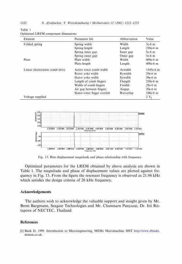
Optimized parameters for the LREM obtained by above analysis are shown inTable 1. The magnitude and phase of displacement values are plotted against fre-quency in Fig. 13. From the figure the resonant frequency is observed as 21.94 kHzwhich satisfies the design criteria of 20 kHz frequency.
Acknowledgements
The authors wish to acknowledge the valuable support and insight given by Mr.Brent Bargmann, Seagate Technologies and Mr. Chumnarn Punyasai, Dr. Itti Rit-taporn of NECTEC, Thailand.
References
[1] Bank D, 1999. Introduction to Microengineering, MEMs Micromachine MST http://www.dbanks.
demon.co.uk.
Fig. 13. Rtm displacement magnitude and phase relationship with frequency.
Table 1
Optimized LREM component dimensions
Element Parameter list Abbreviation Value
Folded spring Spring width Width 5e-6 m
Spring length Length 220e-6 m
Spring inner gap Inner gap 5e-6 m
Spring outer gap Outer gap 5e-6 m
Plate Plate width Width 400e-6 m
Plate length Length 400e-6 m
Linear electrostatic comb drive Active rotor comb width Arwidth 1545e-6 m
Rotor yoke width Rywidth 29e-6 m
Stator yoke width Sywidth 50e-6 m
Length of comb fingers Flength 250e-6 m
Width of comb fingers Fwidth 29e-6 m
Air gap between fingers Airgap 20e-6 m
Stator-rotor finger overlab Rsoverlap 100e-6 m
Voltage supplied 2 Vp
1222 N. Afzulpurkar, Y. Weerakamhaeng / Mechatronics 12 (2002) 1213–1223
[2] Evans RB, Griesbach JS, Messener WC. Extending bandwidth with dual-stage suspensions. Data
Storage 1999:43–6.
[3] Evans RB, Griesbach JS, Messener WC. Piezoelectric Microactuator for Dual Stage Control. IEEE
Trans Magn 1999;35(2):977–82.
[4] Fan L-S, Hirano T, Hong J, Webb PR, Juan WH, Lee WY, et al. Electrostatic microactuator and
design considerations for HDD applications. IEEE Trans Magn 1999;35(2):1000–5.
[5] Horsley A, Wongkomet, Horowitz, Pisano P. Precision positioning using a microfabricated
electrostatic actuator. IEEE Trans Magn 1999;35(2):993–9.
[6] Koganezawa S, Uematsu Y, Yamada T. Dual-stage actuator system for magnetic disk drives using a
shear mode piezoelectric microactuator. IEEE Trans Magn 1999;35(2):988–91.
[7] Yoshikazu S, Shinji I, Takamitsu T, Sato Y, Sato I. Piezoelectric PiggyBack microactuator for hard
disk drive. IEEE Trans Magn 1999;35(2):983–7.
N. Afzulpurkar, Y. Weerakamhaeng / Mechatronics 12 (2002) 1213–1223 1223


