Embed Size (px)
Citation preview

Progress In Electromagnetics Research C, Vol. 9, 155–169, 2009
WIDE RANGE OF ELECTROSTATIC ACTUATIONMEMS FPOTF
N. H. Ngajikin, N. M. Kassim, and A. B. Mohammad
Photonic Technology Centre, Faculty of Electrical EngineeringUniversiti Teknologi MalaysiaUTM Skudai, Johor 81310, Malaysia
G. Witjaksono
MIMOS Berhad, Taman Teknologi MalaysiaKuala Lumpur 57000, Malaysia
Abstract—By employing Microelectromechanical system (MEMS)technology, Fabry-Perot Optical Tunable Filter (FPOTF) with hybridtuning mechanism, varying d and altering incident angle is presented.The proposed structure consists of a floating dual membrane FPOTFwith capability to be tuned at different light incident angles.Three electrostatic cavities have been designed to perform this taskindependently. This technique is capable to increase the tuning rangeup to 2/3 of capacitance gap with additional doubly range of incidentangle. Optic, mechanic and electrostatic analysis of the proposedstructure has been validated by simulation. Analysis in opticalperformance shows the tuning range enhancement is about 1.92% for±2◦ mirror tilting at 6◦ initial angle compared to conventional dualbeam MEMS FPOTF. This analysis validates the principle of hybridtuning method.
1. INTRODUCTION
Due to pull-in voltage phenomena, electrostatic actuation can only offera small beam deflection which is about 1/3 of capacitance gap [1]. Thislimitation leads to a low tuning range of electrostatic actuation MEMSFPOTF. Designing a MEMS FPOTF with large length of cavity willincrease the wavelength range. This option, however, is limited byfabrication technology where it is a challenge to have a thick gap inoptical cavity. Furthermore, increasing the gap size will increase the
Corresponding author: N. H. Ngajikin ([email protected]).
156 Ngajikin, Kassim, and Mohammad
operating voltage. Instead of raising the capacitance gap, this paperproposed an alternative, which is hybrid tuning method to improveMEMS FPOTF tuning range.
In review, two mechanisms, either varying length of cavity oradjusting light incident angle, were realized. Most of the inventionsis by varying length of cavity using electrostatic actuation [2–31]. Asafore mentioned, this type of actuator has limitation in pull in voltage.However, some application with wide spectrum bandwidth requiresFPOTF with higher tuning range. Coarse Wavelength DivisionMultiplexing (CWDM) application, for example, requires at least360 nm wavelength range.
Two techniques have been proposed previously to enhance thetuning range. The first one is by Verghese [8] using dual membraneMEMS FPOTF. Since both of the mirror holders are movable, thetuning range is doubled to 2/3 capacitance gap. Secondly, Milne etal. [16] used doubly supported beam to reduce strain stiffening toincrease the tuning range. The tuning range also can be increasedup to 2/3 of capacitance gap. Another wavelength tuning mechanismfor FPOTF that had been realized using MEMS technology is shiftingthe incident angle by mirror tilting. Output spectrum of the MEMSFPOTF with only one mirror tilted consists of more than one mode.This is applicable to multiplexing and channel monitoring application.Besides that, mirror tilting can also enhance filter finesse. Chang andJuan [7] used this technique to adjust mirror flatness in order to haveMEMS FPOTF with high finesse.
Hybrid tuning method that has been proposed in this paper willimprove tuning range of MEMS FPOTF with electrostatic actuation.The following section will discuss design, working principle and resultanalysis of this novel structure.
2. MEMS FLOATING FPOTF (f-FPOTF)CONFIGURATION
A novel MEMS floating Fabry-Perot Optical Tunable Filter (f-FPOTF)is proposed to enlarge the tuning range of conventional MEMS FPOTFwith electrostatic actuation. This MEMS f-FPOTF has capabilities ofvarying length of optical cavity and tilting the whole floating cavity atone time. These features not only enlarge the tuning range, but alsohave capabilities to improve the filter finesse. Equation (1) gives themathematical expression of FPOTF transmittivity [32].
It = I0
[1− A
1−R
]2 [1
1 + M sin2(φ/2)
](1)
Progress In Electromagnetics Research C, Vol. 9, 2009 157
where M = 4R(1−R2)
and φ = 2n2dk cos θ. I0 is the input light;A is the absorption in optical cavity; R is mirror reflectivity; kis propagation constant. This equation shows that the operatingwavelength of FPOTF can be altered by either adjusting length ofcavity, d, tilting the mirror or by varying the refractive index, n2 ofmaterial inside the optical cavity. Since f-FPOTF combined bothtuning, adjusting d and mirror tilting, analysis is done to studythe relationship among these three tuning variables with operatingwavelength, λ using Equation (2) [42].
λ =2n2d
m
√1−
(sin θ
n2
)(2)
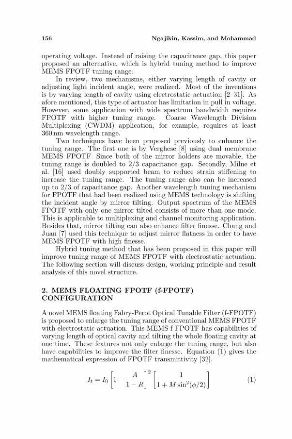
m is the mode number inside the cavity. Let’s say that the filter needsto be tuned within CWDM wavelength region (18 operating channelsdistributed in between 1270 nm to 1610 nm wavelength). Relationshipamong d, optimal initial angle, θ◦o and range of tuning angle, ∆θ◦is plotted in Figure 1. Higher initial incident angle contributes to alower range of tuning angle. However, the range of tuning angle, ∆θ◦,also can be decreased by the increment of d as shown in this graph.Suitable selection of initial angle, θi, and initial length of cavity, di, willcontribute to design that has a large wavelength range with optimalconfiguration.
In general, tilting FPOTF mirror will broaden the full width halfmaximum (FWHM) of this filter. This limitation, however, dependson FWHM value of the proposed application.
Figure 1. Optimal initial angle, θi and range of tuning angle, ∆θ◦ fordifferent value of d.

158 Ngajikin, Kassim, and Mohammad
Figure 2. Working principle: Cross-section view of MEMS f-FPOTF.
(a) (b)
(c)
Figure 3. Electrostatic cavity of MEMS f-FPOTF.
2.1. Working Principle
2-dimensional structure of MEMS f-FPOTF is visualized in Figure 2.As afore mentioned, it consists of three electrostatic cavities controlledby 3 independent voltages, which are V1, V2 and V3. V2 controls thelength of cavity, d, while V1 and V3 adjust the light incident angle by

Progress In Electromagnetics Research C, Vol. 9, 2009 159
activating one of the electrostatic actuator at one time.Assuming input fiber is located at θ◦i from normal line of FPOTF
mirror support. Part 100 which is the first electrostatic cavity willincrease light incident angle from the initial position. In oppose, part300 will decrease the light incident angle. Both of these movementsare visualized in Figure 3(a) and Figure 3(b). These features providewider tuning angle since the floating cavity has potential to deflectboth ways, up and down.
Floating Fabry-Perot optical cavity in this filter is labeled as 200in Figure 2. This is an electrostatic cavity with dual beam actuator.Deflection of dual beam will bring both mirrors closer to each other,
Step
1
Step
2
Step
3
Step
4
Step
5
SOI Wafer
DRIEof 5 µm depth of
Si film
Growth 900 nm thickness
of SiO2 by using dry
oxidation process
RIE of SiO2 to form an
optical cavity
100 nm of CrAu metallic
mirror is sputtered, then
patterned using lift-off
technique
StepBackside DRIE on Si
6substrate
Step
7SiO2 - SiO2 wafer
bonding process
Step
8Wet etch a part of Si3N4
film.L=20 µm
Figure 4. MEMS f-FPOTF fabrication process flow.
160 Ngajikin, Kassim, and Mohammad
hence varying the length of cavity, d. Illustration of this movement isshown in Figure 3(c).
2.2. Structure
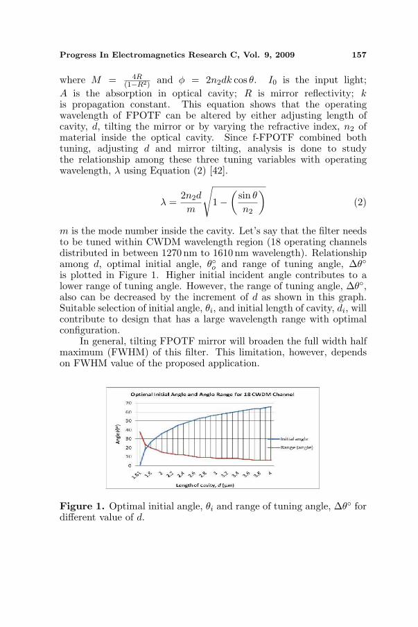
Understanding the whole fabrication process flow will determine thesuitable mechanic analysis approach for this structure. In this analysis,SOI wafer is used to simplify the whole fabrication process. Devicelayer on SOI wafer is etched in order to have two separated beams,BEAM1 and BEAM2. The objective of this separation is to achievedual beam actuation, BEAM1 for controlling angle and BEAM2 forvarying length of cavity. SiO2 film then is grown on top of this wafer toisolate these two beams and also works as a spacer in Fabry-Perot (FP)cavity. Next, the CrAu metallic thin film is sputtered and patternedto be a FP mirror. Both metallic and Distributed Bragg Reflector(DBR) mirror can be applied. However, metallic mirror is chosen dueto its simplicity in fabrication yet limited the initial angle. Then,backside Deep Reactive Ion Etch (DRIE), wafer bonding and Nitrideetch are performed step by step to shape this proposed filter. Figure 4illustrates the fabrication process flow.
Layout and cross-section of the simulated structure are given inFigure 5 and Figure 6 respectively. Insulator between BEAM1 andBEAM2 is not visualized in layout view since the dimension is verysmall compared to other features in this design. Therefore, it canbe neglected in this analysis. Figure 6 also illustrates the electrostaticforce involved in this simulation. F3 and F1 are forces towards BEAM1in both directions, up and down, while F2 is the force towards BEAM2.Physical dimension of this structure is given in Table 1. Si film forBEAM1 and BEAM2 must be as thin as possible in order to have a
Figure 5. Layout of MEMS f-FPOTF.
Figure 6. Cross-section ofMEMS f-FPOTF.

Progress In Electromagnetics Research C, Vol. 9, 2009 161
Table 1. Dimension of MEMS f-FPOTF.
Parameter Value (µm)
BEAM1
LBEAM 1 200
L1 1000
Lb 800
Ls 20
WBEAM 1 500
tSi3N4 2
tsi 4.1
tSiO2 0.9
BEAM2
LBEAM2 85
WBEAM2 100
DMirror-suppor 330
tsi 4.1
tspacer=tSiO2 – 2x(tmirror) 0.6
Other dimension
DMirror 125
tMirror 0.1
H 50
W 600
small value of DC voltage supply. However, in this design, Si film with4.1µm thickness is chosen since it is a challenge to have a floating FPcavity with very thin film.
In this paper, MEMS f-FPOTF is designed as a wavelengthselector for CWDM application. Several aspects have to be consideredin designing optical MEMS device. The main parameter is opticalperformance, especially in terms of transmissivity, tuning range andFWHM of the bandpass region. Since MEMS technology involves otherengineering discipline, understanding of mechanic and electrostaticproperties is useful for an optimal design.
3. ANALYSIS AND DISCUSSION
Analysis is divided into three main parts, optical, mechanic andelectrostatic.

162 Ngajikin, Kassim, and Mohammad
In optical analysis, MEMS f-FPOTF improvement on freespectral range (FSR) and how this design influences the FWHM andtransmissivity of this filter are presented. As afore mentioned, CWDMapplication requires 360 nm tuning range. Thus, this filter needs aminimum 360 nm FSR to avoid overlapping between spectrums. Thefollowing section will discuss this matter.
Second analysis on mechanic will investigate the effect of beamdisplacement to mirror parallelism. This is very crucial since mirrorparallelism will influence FPOTF finesse. Third part, which is theelectrostatic analysis, will provide the expected operating voltage foreach electrostatic cavity.
3.1. Optical Analysis
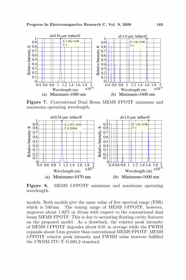
Analytical analysis on FPOTF transfer function is done to evaluatethe performance in terms of tuning range, transmissivity and FWHM.Two simulation models which are conventional dual beam MEMSFPOTF and MEMS f-FPOTF have been developed using Matlab R©mathematical software. Initial optical cavity for both models is 1.6µm.Assuming pull in voltage for both models occurs at 1/3 of capacitancegap, and metallic mirror is used with Si film as a mirror support. Sincemaximum acceptance angle for CrAu in this structure is 8◦, initialincident angle for MEMS f-FPOTF is set at 6◦. Table 2 lists theparameters involved in this simulation.
Figures 7(a), 7(b), 8(a) and 8(b) show the relative intensityspectrum for minimum and maximum spectral for both simulation
Table 2. Optical analysis parameter setting.
ParameterMEMS
f-FPOTFDual Beam
MEMS FPOTFMax. deflection(Optical cavity)
2× 0.533µm 2× 0.533µm
Max. deflection(Electrostatic cavity)
2× (±2◦ beam deflection) None
Initial lightincident angle (θ0)
6◦ 0◦
Refractive Index,n2 (optical cavity)
1.0 1.0
Mirror reflectivity, R 95% 95%
Progress In Electromagnetics Research C, Vol. 9, 2009 163
d=0.54 µm tetha=0`
0.4 0.6 0.8 1 1.2 1.4 1.6 1.8 2x10⁻⁶
00.10.20.30.40.50.60.70.80.9
1X: 1.08e−0.06
Y:1
Rel
ativ
e In
tensi
ty, I
t
(a) Minimum=1080 nmWavelength (m)
(b) Minimum=1600 nm
0.4 0.6 0.8 1 1.2 1.4 1.6 1.8 2x10⁻⁶
Wavelength (m)
00.10.20.30.40.50.60.70.80.9
1
Rel
ativ
e In
tensi
ty, I
t
d=1.6 µm tetha=0`
X: 1.6e−0.06
Y:1
Figure 7. Conventional Dual Beam MEMS FPOTF minimum andmaximum operating wavelength.
d=0.54 µm tetha=8`
0.4 0.6 0.8 1 1.2 1.4 1.6 1.8x10⁻⁶
00.10.20.30.40.50.60.70.80.9
Rel
ativ
e In
tensi
ty, I
t
(a) Minimum=1070 nm
Wavelength (m)
(b) Minimum=1600 nm
0.4 0.6 0.8 1 1.2 1.4 1.6 1.8 2x10⁻⁶
Wavelength (m)
d=1.6 µm tetha=0`1
00.10.20.30.40.50.60.70.80.9
Rel
ativ
e In
tensi
ty, I
t
1X: 1.07e−0.06
Y:0.9966
X: 1.6e−0.06
Y:1
2
Figure 8. MEMS f-FPOTF minimum and maximum operatingwavelength.
models. Both models give the same value of free spectral range (FSR)which is 540 nm. The tuning range of MEMS f-FPOTF, however,improves about 1.92% or 10 nm with respect to the conventional dualbeam MEMS FPOTF. This is due to actuating floating cavity featureson the proposed model. As a drawback, the relative peak intensityof MEMS f-FPOTF degrades about 0.01 in average while the FWHMexpands about 5 nm greater than conventional MEMS FPOTF. MEMSf-FPOTF relative peak intensity and FWHM value however fulfilledthe CWDM ITU-T G.694.2 standard.
164 Ngajikin, Kassim, and Mohammad
3.2. Mechanic Beam Displacement Analysis
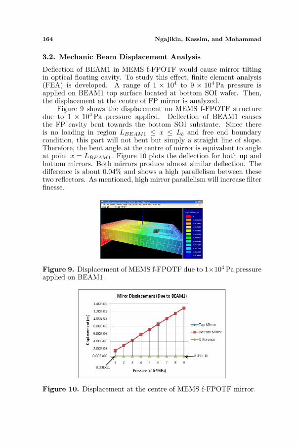
Deflection of BEAM1 in MEMS f-FPOTF would cause mirror tiltingin optical floating cavity. To study this effect, finite element analysis(FEA) is developed. A range of 1 × 10⁴ to 9 × 10⁴ Pa pressure isapplied on BEAM1 top surface located at bottom SOI wafer. Then,the displacement at the centre of FP mirror is analyzed.
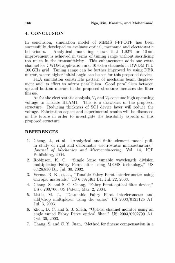
Figure 9 shows the displacement on MEMS f-FPOTF structuredue to 1 × 10⁴ Pa pressure applied. Deflection of BEAM1 causesthe FP cavity bent towards the bottom SOI substrate. Since thereis no loading in region LBEAM1 ≤ x ≤ Lb and free end boundarycondition, this part will not bent but simply a straight line of slope.Therefore, the bent angle at the centre of mirror is equivalent to angleat point x = LBEAM1. Figure 10 plots the deflection for both up andbottom mirrors. Both mirrors produce almost similar deflection. Thedifference is about 0.04% and shows a high parallelism between thesetwo reflectors. As mentioned, high mirror parallelism will increase filterfinesse.
Figure 9. Displacement of MEMS f-FPOTF due to 1×10⁴ Pa pressureapplied on BEAM1.
Figure 10. Displacement at the centre of MEMS f-FPOTF mirror.

Progress In Electromagnetics Research C, Vol. 9, 2009 165
3.3. Electrostatic Analysis
Operating voltages (V1, V2 and V3) of the proposed structure is limitedby pull in voltage, Vpin at each electrostatic cavity. In this analysis, pullin is assumed to occur at 1/3 of capacitance gap. Therefore, voltageat this point is considered as a Vpin.
FEA of electro-mechanic coupling analysis for BEAM1 is plottedin Figure 11. This is the operating voltage for V1 and V3. Thickerfilm needs higher voltage to deflect. As for BEAM1, about 500 voltis needed to deflect 3 nm of BEAM1 at L = Ls. 1 nm deflection ofBEAM1 can shift about 1 nm MEMS f-FPOTF operating wavelength.The first prototype is expected to proof the principle of the proposedstructure. Voltage for BEAM1 can be reduced by using thinner Si film.
Figure 12 gives the displacement of BEAM2 for a given V2.Electrostatic force attracts these two beams, hence decreases theoptical length of cavity, d. Vpin for this dual beam structure is about33Volt.
Figure 11. Displacement of BEAM1 MEMS f-FPOTF structure atL = Ls.
Figure 12. Displacement of BEAM2 MEMS f-FPOTF.
166 Ngajikin, Kassim, and Mohammad
4. CONCLUSION
In conclusion, simulation model of MEMS f-FPOTF has beensuccessfully developed to evaluate optical, mechanic and electrostaticbehaviours. Analytical modelling shows that 1.92% or 10 nmimprovement is achieved in terms of tuning range without sacrificingtoo much in the transmittivity. This enhancement adds one extrachannel for CWDM application and 10 extra channels in DWDM ITU100GHz grid. Tuning range can be further improved by using DBRmirror, where higher initial angle can be set for this proposed device.
FEA simulation constructs pattern of mechanic beam displace-ment and its effect to mirror parallelism. Good parallelism betweenup and bottom mirrors in the proposed structure increases the filterfinesse.
As for the electrostatic analysis, V1 and V3 consume high operatingvoltage to actuate BEAM1. This is a drawback of the proposedstructure. Reducing thickness of SOI device layer will reduce thevoltage. Fabrication aspect and experimental results will be discussedin the future in order to investigate the feasibility aspects of thisproposed structure.
REFERENCES
1. Cheng, J., et al., “Analytical and finite element model pull-in study of rigid and deformable electrostatic microactuators,”Journal of Mechanics and Microengineering, Vol. 14, IOPPublishing, 2004.
2. Robinson, K. C., “Single lense tunable wavelength divisionmultiplexing Fabry Perot filter using MEMS technology,” US6,426,830 B1, Jul. 30, 2002.
3. Verma, R. K., et al., “Tunable Fabry Perot interferometer usingentropic materials,” US 6,597,461 B1, Jul. 22, 2003.
4. Chang, S. and S. C. Chang, “Fabry Perot optical filter device,”US 6,700,706, US Patent, Mar. 2, 2004.
5. Little, M. J., “Detunable Fabry Perot interferometer andadd/drop multiplexer using the same,” US 2003/0123125 A1,Jul. 3, 2003.
6. Zhou, D. C. and S. J. Sheih, “Optical channel monitor using anangle tuned Fabry Perot optical filter,” US 2003/0202799 A1,Oct. 30, 2003.
7. Chang, S. and C. Y. Juan, “Method for finesse compensation in a
Progress In Electromagnetics Research C, Vol. 9, 2009 167
Fabry Perot device and a Fabry Perot device with high finesse,”US 2004/0100678 A1, May 27, 2004.
8. Verghese, P. M., “Dual membrane single cavity Fabry PerotMEMS filter,” US 2005/0134962 A1, Jun. 23, 2005.
9. Kanbara, N., et al., “Precisely tunable Fabry-Perot filter foroptical communications,” IEEE/LEOS International Conferenceon Optical MEMs, 173–174, Aug. 2002.
10. Saadany, B., et al., “Free space tunable add drop optical filtersusing vertical bragg mirrors on silicon,” IEEE Journals of SelectedTopics in Quantum Electronics, Vol. 12, No. 6, Nov./Dec. 2006.
11. Ramam, A., et al., “MEMS tunable Fabry Perot optical filter,”IEEE/LEOS International Conference on Optical MEMS andTheir Applications Conference, 157–158, Aug. 1–4, 2005.
12. Halbritter, H., et al., “MEM tunable and wavelength selectivereceiver front end,” 18th IEEE International Conference on Micro.Electro. Mechanical Systems, 68–71, Jan. 30–Feb. 3, 2005.
13. Hohlfeld, D. and H. Zappe, “Micromachined tunable optical filterswith optimized band pass spectrum,” The 12th InternationalConference on Solid Sensors, Actuators and Micro. Systems,Boston, Jun. 8–12, 2003.
14. Keating, A. J., et al., “Optical characterization of Fabry PerotMEMS filters integrated on tunable short-wave IR detectors,”IEEE Photonics Technology Letters, Vol. 8, No. 9, 2006.
15. Daleiden, J., et al., “Record wavelength tuning of 127 nm forvertical cavity Fabry-Perot filter,” IEEE/LEOS InternationalConference on Optical MEMs, 169–170, Aug. 20–23, 2002.
16. Milne, J., et al., “Extended tuning range FP Etalon withdoubly supported beam actuators,” IEEE/LEOS InternationalConference on Optical MEMS and Their Applications Conference,2006.
17. Chang, S. and C. H. Chang, “Method of manufacturing MEMSFabry Perot devices,” US 2004/0111856 A1, Jun. 17, 2004.
18. Madhumita, D., et al., “Design of MEMS tunable novel monolithicoptical filters in InP with horizontal bragg mirrors,” Solid-StateElectronics, Vol. 48, 2004.
19. Yun, S. S., K. W. Jo, and J. H. Lee, “Crystalline Si-based in-plane tunable FP filter with wide tunable range,” InternationalConference on Optical MEMS, 77–78, Aug. 2003.
20. Huang, H., et al., “Mechanical design and finite element modellingof tunable Fabry Perot MEMS structure for adaptive infrareddetectors,” IEEE Conference on Optoelectron. and Microelectron

168 Ngajikin, Kassim, and Mohammad
Mat. and Dev., Australia, Dec. 8–10, 2004.21. Bazu, M., et al., “Reliability assessment by virtual prototyping
of MEMS tunable Fabry-Perot optical cavity,” 2004 InternationalSemiconductor Conference, CAS 2004 Proceedings, Vol. 1, Oct. 4–6, 2004.
22. Flanders, D. C., P. S. Whitney, and M. F. Miller, “Flexiblemembrane for tunable Fabry-Perot filter,” US 6,341,039 B1 USPatent, Jan. 22, 2002.
23. Meissner, P., et al., “Micromachined two chips filters forWDM transmission system,” 2002 IEEE/LEOS InternationalConference on Optical MEMs, 167–168, Aug. 20–23, 2002.
24. Tucker, R. S. and W. V. Sorin, “Tunable Fabry-Perot filters andlasers,” US 6,400,738 B1 Jun. 4, 2002.
25. Tucker, R. S. and W. V. Sorin, “Optically tunable Fabry-Perotmicroelectromechanical resonator,” US 6,714,565 B1, US Patent,Mar. 30, 2004.
26. Taebati, P., et al., “Microelectromechanically tunable, confocal,vertical cavity surface emitting laser and Fabry Perot filter,” US2002/0031155 A1, US Patent, Mar. 14, 2002.
27. Halbritter, H., et al., “Impact of micro. mechanics on thelinewidth and chirp performance of MEMS VCSEL,” IEEEJournals of Selected Topics in Quantum Electronics, Vol. 13,No. 2, Mar./Apr. 2007.
28. Flanders, D. C., “Dual cavity MEMS tunable Fabry Perot filter,”US 6,424,466 B1 US Patent, Jul. 23, 2002.
29. Cook, C. C., “Dual band Fabry Perot mirror coating,” US2002/0181107 A1, US Patent, Dec. 5, 2002.
30. Lu, L. J., “Tunable Fabry Perot filter,” US 2004/0218865, Nov. 4,2004.
31. Atia, W. A., et al., “MEMS Fabry-Perot filter for integratedspectroscopy system,” US 2006/0197958, Sep. 7, 2006.
32. Iizuka, K., Elements of Photonics, John Wiley & Sons, Inc, 2002.33. Ugural, A. C., Mechanical Design: An Integrated Approach, Mc
Graw Hill, 2004.34. Ngajikin, N. H., et al., “FEM simulation on MEMS FPOTF us-
ing aluminum metallic mirror,” IEEE Fourth International Con-ference on Wireless and Optical Communication Networks, 2008.
35. Ngajikin, N. H., et al., “Modelling of MEMS FP OTF forwavelength tuning in CWDM application,” IEEE InternationalConference on MEMS and Nanotechnology, 2008.
36. Anderson, D. E. and A. L. V. Brocklin, “Fabry Perot
Progress In Electromagnetics Research C, Vol. 9, 2009 169
interferometer,” US 7,061,681 B2, Jun. 13, 2006.37. Missey, et al., “Microelectromechanical tunable Fabry-Perot
wavelength monitor with thermal actuators,” US 2003/0053078A1, Mar. 20, 2003.
38. Spiegelberg, C. P., et al., “Erbium doped phosphate glass tunablesingle mode fiber laser using tunable Fabry Perot filter,” US2004/0196874 A1, Oct. 7, 2004.
39. Hohlfeld, D., M. Epmeier, and H. Zappe, “Tunable thermo optic.filter for WDM applications,” The Fifteenth IEEE InternationalConference on Micro. Electro. Mechanical Systems, 2002.
40. Marty, F., et al., “High aspect ratio nano structures (HARNS) forphotonic MEMs based on vertical DBR architecture,” The 13thInternational Conference on Solid Sensors, Actuators and Micro.Systems, Korea, Jun. 5–9, 2005.
41. Nakagawa, W. and Y. Fainman, “Tunable optical nanocavitybased on modulation of near field coupling between sub-wavelength periodic nanostructure,” IEEE Journals of SelectedTopics in Quantum Electronics, Vol. 10, No. 3, May/Jun. 2004.
42. Tucker, R. S., et al., “Tunable Fabry Perot filters and lasers usingfeedback to reduce frequency noise,” US 6,538,748 B1, US Patent,Mar. 25, 2003.
43. Tucker, R. S. and W. V. Sorin, “Tunable Fabry Perot filters andlasers using feedback to reduce frequency noise,” US 6,724,785 B1,US Patent, Apr. 20, 2004.
44. Tucker, R. S., et al., “Thermal noise and radiation pressure inMEMs Fabry Perot tunable filters and lasers,” IEEE Journalon Selected Topics on Quantum Electronics, Vol. 8, No. 1,Jan./Feb. 2002.
45. Chang, S., “Fabry Perot device compensating for an error of fullwidth at half maximum and method of making the same,” US2004/0075845 A1, Apr. 2, 2004.
46. Bao, Y., “Waferless fiber Fabry-Perot filters,” US 2004/0247244A1, Dec. 9, 2004.


