Embed Size (px)
Citation preview
General rights Copyright and moral rights for the publications made accessible in the public portal are retained by the authors and/or other copyright owners and it is a condition of accessing publications that users recognise and abide by the legal requirements associated with these rights.
Users may download and print one copy of any publication from the public portal for the purpose of private study or research.
You may not further distribute the material or use it for any profit-making activity or commercial gain
You may freely distribute the URL identifying the publication in the public portal If you believe that this document breaches copyright please contact us providing details, and we will remove access to the work immediately and investigate your claim.
Downloaded from orbit.dtu.dk on: Jun 02, 2022
Parallel monostrand stay cable bending fatigueStatic and dynamic experimental investigations
Winkler, Jan Pawel
Publication date:2014
Document VersionPublisher's PDF, also known as Version of record
Link back to DTU Orbit
Citation (APA):Winkler, J. P. (2014). Parallel monostrand stay cable bending fatigue: Static and dynamic experimentalinvestigations. Technical University of Denmark.
DTU Civil Engineering Report R-331(UK)December 2014
Jan Winkler
PhD Thesis
Department of Civil Engineering
2014
Parallel monostrand stay cable bending fatigueStatic and Dynamic experimental investigations
Department of Civil Engineering - Technical University of Denmark
Parallel monostrand stay cable bending
fatigue
(static and dynamic experimental investigations )
Ph.D. thesis
Jan Winkler
Supervisors:
Christos T. Georgakis, Professor
Gregor Fischer, Associate Professor
Technical University of Denmark
Department of Civil Engineering
BYG • DTU
2014
Department of Civil Engineering - Technical University of Denmark
Assessment Committee:
Associate Professor Holger Koss, DTU Byg
Doctor Eilif Svensson, CEO of ES-Consult A/S
Doctor Antonio Caballero, CEO of BBR VT International Ltd
Parallel monostrand stay cable bending fatigue
- Static and dynamic experimental investigations
Copyright © 2014 by Jan Winkler
Printed by DTU-Tryk
Department of Civil Engineering
Technical University of Denmark
ISBN: 9788778774217
i
Department of Civil Engineering - Technical University of Denmark
Preface
This thesis is submitted as a partial fulfilment of the requirements for the Danish Ph.D. degree.
The work has been carried out at the Department of Civil Engineering at the Technical
University of Denmark and took place in the period between March 2011 to April 2014, with
Professor Christos T. Georgakis as main supervisor, Associate Professor Gregor Fischer as co-
supervisor and with Chris Hendy and Jesper Schaarup as company co-supervisors.
This thesis is based upon published and under-review articles in ISI journals. The
introduction is followed by a literature review on stay cable bending fatigue, while each of the
subsequent six chapters are made up by separate reproduction of above mentioned journal
papers and supplemental material on the mechanical aspects of failure modes and application of
the scientific outcome. Lastly, the combined work is discussed and conclusions are made with
respect to the initially introduced problems, together with suggestions for future work.
Kongens Lyngby, the 5th May 2014
Jan Winkler
ii
Department of Civil Engineering - Technical University of Denmark
Preface to published version
The thesis was defended at a public defence on the 5th of December 2014. The official assessment committee consisted of Associate Professor Holger Koss (chairman), Technical University of Denmark, Doctor Eilif Svensson (CEO of ES-Consult A/S) and Doctor Antonio Caballero (CEO of BBR VT International Ltd).
Kongens Lyngby, 2014
Jan Winkler
iii
Department of Civil Engineering - Technical University of Denmark
Acknowledgments
Firstly, I would like to express my deepest thanks to my supervisors Professor Christos T.
Georgakis and Associate Professor Gregor Fischer. I gratefully acknowledge their constant
support and guidance. I owe my gratitude to Christos and Gregor for their encouragement
throughout the entire course of this project and for entrusting me with the freedom to work in
my own way. I hope our professional cooperation will last much longer than this PhD project.
Part of the work was carried out during a four month research stay at the University of Texas at
Austin, USA. The results that I collected during my research visit constitute a vital part of my
thesis. A special thanks to Professor Sharon Wood and Assistant Professor Wassim Ghannoum
for their support, valuable comments and for making the infrastructure of the Ferguson
Structural Engineering Lab (FSEL) available for carrying out the experiments. The role of my
colleagues, Drit Sokoli, Ali Abu Yousef and Sepehr Dara from UT Austin in enthusiastically
contributing to a friendly work environment and readily providing help and advice is gratefully
acknowledged.
I completed this thesis in the course of my professional engagement at ATKINS. For this
reason, I am grateful to the company and my company supervisors Jesper Schaarup and Chris
Hendy for having enabled me to carry out these demanding studies.
I would like to thank my fellow Ph.D students at DTU for their friendship in these years of
intense and interesting work, in particular Anna Emilie Thybo, Giulia Matteoni, Joan Hee
Roldsgaard, Nina Gall Jørgensen, Antonio Acampora, Diego Castiblanco, Kenneth Kleissl,
Rocco Custer and Sebastian Andersen.
I want to thank my parents, my brother and sister for always being there for me. I wanted to
thank my family for the gift of faith that helped me so many times in difficult moments.
Finally, I want to thank my wife Agnieszka Winkler, to whom I dedicate this thesis, for her
love, support, sense of humor and incredible understanding. I would not be “here” without her.

iv
Department of Civil Engineering - Technical University of Denmark
v
Department of Civil Engineering - Technical University of Denmark
Abstract
This dissertation investigates the bending fatigue response of high-strength steel monostrands
and multistrand stay cables to cyclic transverse deformations. Increasing bridge stock numbers
and a push for longer cable-supported span lengths have led to an increased number of reported
incidents of damage and replacement of bridge stay cables due to wind and traffic-induced
fatigue. The understanding of fatigue mechanisms in most steel structures is well established.
However, in the case of cables composed of steel strands, many important aspects related with
bending fatigue remain to be clarified.
The thesis starts with a literature review of the state-of-the-art in the fields of stay cable
fatigue testing and cable fatigue resistance. The study helped to systemize the understanding of
the fatigue characteristics of bridge cables subjected to cyclic transverse displacements, failure
mechanisms associated with variable loading, and different testing procedures.
As most of the contemporary stay cables are comprised of a number of individual high-
strength steel monostrands, the research study started with an extensive experimental work on
the fatigue response of a single monostrand to cyclic flexural loading. Initial analysis of the
deformations showed that, depending on the anchorage type, the bending fatigue behavior of the
monostrand may be controlled either by local bending deformations or by the interwire
movement (fretting) of the helically wound wires. The experimental study involved a detailed
description of the observed failure mechanisms. For this purpose, a digital image correlation
(DIC) technique was employed as an efficient tool for quantifying the interwire movement and
measurement of individual wire strains along the length of the strand. The novel application of
the DIC technique for the measurement of local cable deformations provided relevant data on
the internal state of displacement of the strand specimen under axial and transverse loading and
led to a more in-depth understanding of the underlying fatigue mechanisms. The experimental
data show that the interwire movement due to transverse deformations is the highest at the
neutral axis of the monostrand. Moreover, the results indicate that the midspan and the
anchorage of the monostrand are the two locations where the combination of tensile strains and
the interwire movement is the most unfavorable. It was also shown that, in the absence of a
guide, the high localized curvatures due to bending may cause yielding of the monostrand. From
the conducted series of dynamic tests, the fretting and the localized bending fatigue spectra have
been derived for the estimation of the monostrand fatigue life. Further analysis of mechanical
aspects of monostrand wires under bending load provided information on the failure mode-
vi
Department of Civil Engineering - Technical University of Denmark
dependent cross sectional stress distribution and aimed to explain differences in the observed
fatigue models.
Finally, once the bending fatigue behavior of a single monostrand was described in detail,
the experimental study focused on the response of a full-scale multistrand stay cable to
transverse deformations. The experimental investigation performed on the parallel monostrand
stay cable had three objectives. Firstly, a correlation between the bending fatigue behavior of
the single monostrand and that of the multistrand stay cable was established through full-scale
testing and data obtained from the DIC measurement. Secondly, it was studied whether the
fatigue life of a multistrand cable can be predicted based on the fatigue spectra derived from the
tests on single monostrands. Thirdly, the relationship between the transversal stiffness and the
tensile force variations (hysteresis) of a monostrand and that of a multistrand specimen was
investigated. The results from the full-scale tests led to a better understanding of the structural
response of a modern stay cable to cyclic transverse loading and resulted in significant insight in
the flexural behavior of a multistrand assembly in critical locations with respect to bending
fatigue, i.e. guide deviator and exit of the socket. The thesis ends with an example of how the
outcome of the research work can be used in the estimation of the life-cycle performance of a
cable stayed bridge. Characterization of a bridge monitoring data is shown and a generic method
for the analysis of a cable fatigue in cable supported bridge structure is proposed.
With this research, one of the most basic oversights in the lifetime assessment of cable-
supported structures, namely the bending fatigue resistance of parallel monostrand stay cables,
is addressed.
vii
Department of Civil Engineering - Technical University of Denmark
Resumé
Denne afhandling undersøger udmattelsesresponset ved bøjning af et parallelt enkelstrengs
skråstagskabel af stål udsat for periodisk transverse deformationer. Forøgelse af antal og
efterspørgsel for længere kabelspændvidder har ledt til et forøget antal rapporterede skader samt
udskiftninger af skråstagskabler grundet vind- og trafikforårsaget udmattelse. Forståelse for
udmattelsesmekanismer er veletableret ved størstedelen af alle stålkonstruktioner. Ved kabler
udgjort af stålstrenge mangler mange vigtige aspekter relateret til bøjningsudmattelse dog stadig
at blive klargjort.
Afhandlingen indleder med en litteratur redegørelse af state-of-the-art indenfor
udmattelsestests samt udmattelsesresistens af kabler. Studiet hjalp til at systematisere
forståelsen af udmattelseskarakteristikker af brokabler udsat for periodisk transverse
deformationer, brudmekanismer associeret med variabel belastning samt forskellige
testprocedurer.
Eftersom moderne skråstagskabler er udgjort af et antal individuelle højstyrke stålstrenge
startede forskningsstudiet med en omfattende mængde eksperimentielt arbejde med fokus på
udmattelsesresponset af et enkeltstrengskabel udsat for periodisk bøjningsbelastning. De første
analyser af deformationerne viste, afhængigt af forankringstypen, at udmattelsen ved bøjning
muligvis kontrolleres enten af lokale bøjningsdeformationer eller af interne kabelgnidninger
(slidning) af de spiralbundne strenge. Det eksperimentielle studie involverede en detaljeret
beskrivelse af de observerede brudmekanismer. Til dette formål blev benyttet en digital billede
korrelations (DBK) teknik som et effektivt stykke værktøj til at kvantificere de indre
kabelgnidninger samt måling af individuelle tøjningsmål i strengenes længderetning.
Den nye anvendelse af DBK teknikken til måling af lokal kabeldeformation leverede
relevant information om den interne flytningstilstand af kabelemnet ved aksiel samt transvers
belastning og førte til en mere dybdegående forståelse af den underliggende
udmattelsesmekanisme. De eksperimentielle data indikerer at de indre kabelgnidninger, grundet
transverse deformationer, var størst ved neutralaksen af enkeltstrengskablet. Endvidere viste
resultaterne at kombinationen af træktøjninger samt interne gnidningsbevægelser er mest
ufordelagtig ved midten samt ved forankringen af enkeltstrengskablet. Det blev ligeledes vist, i
mangel på en guide, at høje lokaliserede krumninger grundet bøjning muligvis er skyld i
flydning i enkeltstrengskablet. Ud fra de udførte serier af dynamiske udmattelsestests er
slidningen samt det lokaliserede udmattelsesspektrum ved bøjning blevet udledt til vurdering af
enkeltstrengskablets udmattelseslevetid. Analysen af de mekaniske aspekter af enkeltstrenge
viii
Department of Civil Engineering - Technical University of Denmark
udsat for bøjningsbelastning leverede information omkring spændingsfordelingen over
tværsnittet ved brud og havde til formål at forklare forskellene i de observerede
udmattelsesmodeller.
Endelig, da udmattelsesopførslen ved bøjning af et enkelt enkeltsrengskabel var beskrevet
i detaljer fokuserede det eksperimentielle studie på fuldskala multistrenge skråstagskabler udsat
for transverse deformationer.
De eksperimentielle undersøgelser udført på parallelle enkeltstrengs skråstagskabler
havde tre formål. Først og fremmest blev der opstillet en sammenhæng mellem
udmattelsesopførslen ved bøjning af et enkelt enkeltstrengskabel samt for multistrenge
skråstagskabler gennem fuldskala forsøg ud fra data opnået ved DBK målinger. For det andet
blev det undersøgt om udmattelseslevetiden af et multistrengs skråstagskabel kan forudsiges
baseret på et udmattelsesspektrum udledt fra tests på enkle enkeltstrengskabler. For det tredje
blev forholdet mellem den transverse stivhed og trækkraftens variation (hysteresis) af et
enkeltstrengskabel samt for et multistrengsemne undersøgt. Resultaterne fra fuldskala testsne
leverede relevant information vedrørende det strukturelle respons af et moderne skråstagskabel
udsat for periodisk transvers belastning og resulterede i signifikant indblik i bøjningsopførslen
ved kritiske placeringer i et multistrengs montage med hensyn til bøjningsudmattelse, dvs. ved
deviatoren samt udgang af soklen. Afhandlingen slutter med et eksempel på hvorledes
forskningsarbejdet kan blive benyttet til estimere livscyklusopførslen af en observeret
skråstagsbro. Karakterisering af brodata præsenteres og en generisk metode til analyse af
kabeludmattelse i kabelbroer foreslås.
Med denne forskning er en af de mest elementære oversigter for livstidsevalueringer af
kabel-bærende konstruktioner, navnlig udmattelses resistens ved bøjning af parallelle
enkeltstrengs skråstagskabler blevet adresseret.

ix
Department of Civil Engineering - Technical University of Denmark

x
Department of Civil Engineering - Technical University of Denmark
Table of Contents
Chapter 1 - Introduction............................................................................................................. 2
1.1. The research problem and the methodology ...................................................................... 3
1.2. Thesis outline ..................................................................................................................... 4
Chapter 2 - Literature review .................................................................................................... 8
2.1. Introduction ........................................................................................................................ 9
2.2. Stay cable systems .............................................................................................................. 9
2.3. Research focus ................................................................................................................. 10
2.4. Fatigue analysis of cables ................................................................................................. 11
2.5. Axial fatigue of stay cables .............................................................................................. 13
2.6. Stay cable vibrations ........................................................................................................ 15
2.6.1. Vibration mechanisms ............................................................................................... 15
2.7. Bending fatigue of stay cables ......................................................................................... 18
2.7.1. Review of state of the art in cable fatigue testing ..................................................... 19
2.7.2. Review of experimental investigations of cable bending fatigue behavior ............... 21
2.7.3. Verification of stay cable fatigue resistance in major bridge structures .................... 25
2.7.4. Cable fatigue damage criteria .................................................................................... 27
2.8. Conclusions ...................................................................................................................... 29
Chapter 3 - Localized bending fatigue behavior of monostrand under flexural load ......... 36
3.1. Introduction ...................................................................................................................... 37
3.2. Methodology .................................................................................................................... 38
3.2.1 Specimen and test setup ............................................................................................. 38
3.2.2. Data acquisition system ............................................................................................. 39
3.2.3 Angular deviation ranges for monostrand cable bending fatigue testing ................... 40
3.3. Experimental investigation ............................................................................................... 41
3.3.1. Static tests .................................................................................................................. 41
3.3.1.1. Wire strain due to static inclination and transverse deformations ...................... 41
3.3.2. Dynamic tests ............................................................................................................ 43
3.3.2.1. Experimental derivation of the localized bending fatigue spectrum .................. 43
3.4. Conclusions ...................................................................................................................... 46

xi
Department of Civil Engineering - Technical University of Denmark
Chapter 4 - Novel application of digital image correlation (DIC) technique for the measurement of local cable deformations ............................................................................... 50
4.1. Introduction ...................................................................................................................... 51
4.2. Experimental investigation ............................................................................................... 54
4.2.1. Materials .................................................................................................................... 54
4.2.1. Measurement technique ............................................................................................. 55
4.2.3. Test setup .................................................................................................................. 56
4.3. Validation of DIC ............................................................................................................. 57
4.3.1. Correlation analysis of strains due to axial load ........................................................ 57
4.3.2. Correlation analysis of strains due to transverse deformation ................................... 58
4.4. Results .............................................................................................................................. 59
4.4.1. Localized bending deformations and strain distribution ........................................... 59
4.4.2. Interwire friction and relative movement of monostrand wires ................................ 61
4.4.3. Transverse deformations and yielding of the high-strength steel monostrand .......... 63
4.5. Conclusions ...................................................................................................................... 64
Chapter 5 - Fretting fatigue behavior of monostrand under flexural load .......................... 70
5.1. Introduction ...................................................................................................................... 71
5.2. Methodology .................................................................................................................... 72
5.2.1. Materials .................................................................................................................... 72
5.2.2. Measurement technique ............................................................................................. 73
5.2.3. Test setup .................................................................................................................. 74
5.3. Experimental investigation ............................................................................................... 75
5.3.1. Static tests .................................................................................................................. 75
5.3.1.1. Fretting behavior of the monostrand in the vicinity of the wedge ..................... 75
5.3.1.2. Distribution of the interwire movement along the length of the monostrand .... 77
5.3.1.3. Transverse stiffness of the monostrand .............................................................. 79
5.3.1.4. Bending stiffness of the monostrand .................................................................. 79
5.3.1.5. Measurement of the interwire movement at the guide location ......................... 82
5.3.2. Dynamic tests ............................................................................................................ 85
5.3.2.1. Experimental derivation of the fretting fatigue spectrum ................................... 85
5.3.2.2. Influence of the radius of a guide deviator on the fatigue life ............................ 87
5.3.2.3. Comparison between the localized bending fatigue and the fretting fatigue spectrum .......................................................................................................................... 88
5.4. Conclusions ...................................................................................................................... 90

xii
Department of Civil Engineering - Technical University of Denmark
Chapter 6 - Localized bending and fretting fatigue spectra - mechanical aspects of monostrand failure modes ........................................................................................................ 94
6.1. Introduction ...................................................................................................................... 95
6.2. Helix axial and bending stress due to transverse deformation ......................................... 95
6.3. Stick state and slip state of the monostrand ..................................................................... 96
6.4. Failure mode-dependent cross sectional stress distribution ............................................. 97
Chapter 7 - Bending fatigue behavior of multistrand stay cable specimen under flexural load ........................................................................................................................................... 102
7.1. Introduction .................................................................................................................... 103
7.2. Methodology .................................................................................................................. 104
7.2.1. Materials .................................................................................................................. 104
7.2.2. Measurement technique ........................................................................................... 105
7.2.3. Test setup ................................................................................................................ 106
7.3. Experimental investigation ............................................................................................. 108
7.3.1. Pretensioning operation ........................................................................................... 108
7.3.2. Static tests with a fixed and free guide deviator ...................................................... 109
7.3.2.1. Measurement of the interwire movement ......................................................... 110
7.3.2.2. Measurement of the wire strain ........................................................................ 114
7.3.3. Dynamic test ............................................................................................................ 115
7.3.3.1. Measurement of the tensile force variations and the transverse stiffness of stay cable specimen .............................................................................................................. 115
7.3.3.2. Failure of bolts at the guide deviator ................................................................ 116
7.3.3.3. Inspection of the stay cable specimen after dynamic test ................................. 118
7.4. Correlation between monostrand and multistrand stay cable specimen ......................... 119
7.5. Conclusions .................................................................................................................... 121
Chapter 8 - Life-cycle performance of a cable stayed bridge – application of the scientific outcome .................................................................................................................................... 126
8.1. Introduction .................................................................................................................... 127
8.2. Characterization of vibration data .................................................................................. 127
8.3. Rain-flow analysis .......................................................................................................... 131
8.4. Mean and lower limit fatigue models ............................................................................. 132
Chapter 9 - Conclusions and future work ............................................................................. 138
9.1. Conclusions .................................................................................................................... 138
9.1.1. Novelty and major contributions ............................................................................. 141
9.2. Future work .................................................................................................................... 141

xiii
Department of Civil Engineering - Technical University of Denmark

xiv
Department of Civil Engineering - Technical University of Denmark
Symbols
The following symbols represent the most commonly used notations in this dissertation.
A Amplitude
D Nominal strand diameter
E Modulus of elasticity
EI Bending stiffness
F Pressing force
HFE Horizontal force at fixed end
I Moment of inertia
L Midspan length of the cable
L Total length of the cable
MFE Bending moment at fixed end
M(x) Bending moment along the length of the cable
N Number of cycles to failure
P Force applied in midspan of the cable
R Radius
RFE Vertical force at fixed end
T Tensile force in the cable
b Basquin (SN curve) slope
f Frequency
fGUTS Guaranteed Ultimate Tensile Strength
fn Number of events in particular stress range
i Mode of vibration
n Endurance limit
x Mid-span deflection
Δδ Midspan deflection range
Δσ Axial stress range
Δσ Reference stress range

xv
Department of Civil Engineering - Technical University of Denmark
Δσ Bending stress range
∆ Angular range
α Static inclination of the bearing plate
β Helix angle of the monostrand
γ System angle in multistrand cable anchorage
ε Strain
ε Elongation at maximum load
µε Microstrain
μm Micrometer
σ Stress (tensile strength)
σ Stress amplitude
σ Bending stresses due to applied mid-span deflection
σ _ Bending-induced slip stress
σ _ Bending-induced stick stress
φ Angular deviation
χ Curvature

Chapter 1 1
Department of Civil Engineering - Technical University of Denmark
Chapter 1 2
Department of Civil Engineering - Technical University of Denmark
Chapter 1
Introduction
Stay cables are often employed as main tension elements in the variety of structures ranging
from bridges, telecommunication masts, stadiums and offshore platforms. Cables with their
flexibility and low structural damping are particularly vulnerable to different types of vibrations
that effectively reduce the service life of the cables and in some cases may lead to cable failures
near the anchorages [1]. Large amplitude cable vibrations have been frequently reported [2-4],
however, despite the extensive research on the vibration mechanisms a limited work has been
done to assess the fatigue characteristics of cables subjected to cyclic transverse deformations.
A majority of the cable stayed bridges designed in the last decade were designed to
loading specifications which underestimated the effects of extreme wind speeds and were
inappropriate to deal with the response of this form of structure to gust effects. The most recent
cable anchorage failures on the Olav Sabo Bridge (Minnesota, USA) indicate a lack of attention
to the effect of cable vibrations on the fatigue lifetime and the cumulative fatigue damage of
bridge cables. When the transverse deformations of cables are considered, the fatigue evaluation
is usually based on the simplified assumption that the cable behaves as a solid section, with the
use of arbitrary stress reduction factors to account for the presence of guide deviators installed
within the anchorage [5,6]. Moreover, the commonly applied qualification tests for the fatigue
resistance of stay cables, as outlined in the international recommendations made by the PTI [7]
and fib [8], do not specifically address fatigue issues related to transverse cable vibrations and,
therefore, do not require testing for bending. As a consequence of this, high-strength steel cable
bending fatigue spectra have not yet been developed. Thus, the calculation of the fatigue
lifetime of stay cables is currently only possible for axial variations in stresses.
Wind tunnel studies assist in getting a better understanding of the tendency to stay cable
vibrations. Once the vibration pattern is known, it is equally important to achieve a better
knowledge of the reduction of the fatigue life of the cables caused by bending stresses near the
Chapter 1 3
Department of Civil Engineering - Technical University of Denmark
anchorages. The need for long-life fatigue testing of spiral strands, especially under free-
bending conditions, was frequently emphasized. As the majority of contemporary stay cables
are comprised of a number of individual high-strength steel monostrands, investigations of the
bending fatigue performance of a monostrand has become more relevant. Only several
experimental studies of stay cable fatigue behavior under bending have been carried out to date
[9-11]. Nevertheless, transverse deformations as well as the interwire friction at the critical
locations with regard to bending fatigue have not been measured and analyzed.
The reliability of a cable supported structure designed for fatigue decreases with time in
service because of the ongoing damage of the cables subjected to variable, repetitive loadings.
With a rapid growth in construction of cable stayed structures, requirements regarding design
for cable fatigue become at the same time requirements for sustainable development in bridge
engineering. Cable fatigue considerations should be included in the early phase of the design
process and also during the entire life cycle of a structure which, according to the concepts of
sustainability, is comprised of planning, design, construction, operation and removal [12].
It has been reported that the methods seeking to evaluate the bending fatigue life of the
cable should be further developed to be consistent with observed fatigue failures of cables
subjected to transverse deformations [13, 14]. Therefore, the research work presented in this
thesis was designed to address the abovementioned testing and evaluation deficiencies. The
results obtained from the experimental and analytical studies are a step towards a more
comprehensive estimation of service life of stay cables.
1.1. The research problem and the methodology
Researchers have frequently reported a problem of large-amplitude cable vibrations in the last
decade. Despite a comprehensive study on vibration mechanisms, it remains unclear of what
effect these vibrations may have on the internal forces and the fatigue life of the cable. To
address the issue, work of this thesis is directed toward understanding the cable fatigue
phenomenon and aims at analysis and testing of single monostrands and multistrand stay cable
specimens under cyclic flexural load.
In order to achieve this objective the work was divided in the following parts:
The first part consisted of a review of the state-of-the-art in the fields of stay cable fatigue
testing, cable fatigue resistance and failure mechanisms associated with variable loading.
The purpose of this was to explore the existing research within the field and to provide a
database of knowledge and experience from which the current research could draw from.
Chapter 1 4
Department of Civil Engineering - Technical University of Denmark
Gaps in the existing research were identified, so to plan the experimental work to be
undertaken for this dissertation.
In the second part an extensive experimental work was performed. Fatigue tests on high-
strength steel monostrands were separated into two different categories, i.e. static and
dynamic. During static tests the localized bending and fretting behavior of steel
monostrands was studied in detail. The measurement of local cable deformations using
DIC technique allowed detailed description of the monostrand failure mechanisms. From
the series of dynamic tests on single monostrands the localized bending and the fretting
fatigue spectra were developed. Further analysis of mechanical aspects of monostrand
wires under flexural load aimed to explain differences in the observed fatigue models and
provided information on the failure mode-dependent cross sectional stress distribution.
The third part of the PhD project focused on the experimental study of the bending fatigue
response of a multistrand stay cable specimen and establishment of a correlation between
the bending fatigue behavior of the monostrand and that of the multistrand cable. The
outcome of experimental studies helped to significantly enhance the current understanding
of the fatigue response of a parallel monostrand stay cable subjected to cyclic flexural load.
The fourth and final part shows application of the scientific outcome and sums up
observations, considerations and conclusions based on the results presented in the
preceding sections of the research. Conclusions in relation to the aforementioned objectives
are presented. Ideas about future work on stay cable bending fatigue and further
applications of data obtained from the DIC measurement are given.
1.2. Thesis outline
The thesis is divided into nine chapters which are following the chronological research pattern.
This introduction (Chapter 1) is followed by eight chapters listed below:
Chapter 2 gives a literature review on the stay cable fatigue testing, cable fatigue resistance and
failure mechanisms associated with variable flexural loading.
The five following chapters are made up by separate reproductions of published and under-
review journal articles and supplemental material.
Chapter 1 5
Department of Civil Engineering - Technical University of Denmark
Chapter 3 presents the outcome of the experimental work on the localized bending fatigue
behavior of monostrand cable specimens under cyclic flexural load. The chapter shows the
results from static and dynamic tests and the corresponding fatigue spectrum.
Chapter 4 describes novel application of the digital image correlation (DIC) technique for the
measurement of local cable deformations. The image-based method provided previously
unavailable data on the relative displacement of monostrand wires (fretting fatigue failure
mechanism) and significantly enhanced the analysis of the localized bending failure mode
showed in previous study (Chapter 3).
Chapter 5 shows the results of the experimental work on the fretting fatigue behavior of
monostrand cable specimens under cyclic bending load. The chapter presents the outcome from
static and dynamic tests and the corresponding fatigue spectrum.
Chapter 6 focuses on the analysis of mechanical aspects of monostrand fatigue mechanisms and
describes the failure mode-dependent cross sectional stress distribution. The analysis aims at
explaining differences between the fretting and localized bending spectrum.
Chapter 7 presents the outcome of the experimental work on the bending fatigue response of
multistrand stay cable specimen. The chapter shows the results from static and dynamic tests
and the correlation analysis of the bending fatigue behavior of single monostrand and
multistrand stay cable.
Chapter 8 describes how the outcome of the PhD studies can be used in the estimation of the
life-cycle performance of a cable stayed bridge. Characterization of a bridge monitoring data is
shown and a generic method for the analysis of a cable fatigue in cable supported bridge
structure is proposed.
Chapter 9 presents a summary of the main findings and conclusions as well as suggestions for
future work.
Chapter 1 6
Department of Civil Engineering - Technical University of Denmark
Bibliography
[1] Andersen, H, Hommel, D. L., Veje, E. M. Emergency Rehabilitation of the Zarate-Brazo
Largo Bridges, Argentina, Proceedings of the IABSE Conference, Cable-Stayed Bridges,
Pas,Present, and Future. Malmo, Sweden, 1999, 698-706.
[2] Hikami Y, Shiraishi N. Rain–wind induced vibrations of cables in cable stayed bridges. J
Wind Eng Ind. Aerodyn 1988; 29(1): 409-418.
[3] Savor Z, Radic J, Hrelja G. Cable vibrations at Dubrovnik Bridge. Bridge Structures
2006; 2(2): 97-106.
[4] Gimsing NJ, Georgakis CT. Cable Supported Bridges: Concept and Design, 3rd edition,
New Jersey: John Wiley & Sons 2012; 544-547.
[5] Wyatt TA. Secondary stress in parallel wire suspension cables. J Struc Div (ASCE)
1960; 86(7): 37-59.
[6] Prato CA, Ceballos MA. Dynamic bending stresses near the ends of parallel-bundle stay
cables. Structural Engineering International (SEI) 2003; 13(1): 64-68.
[7] Post Tensioning Institute (PTI), PTI Guide Specification. Recommendations for stay
cable Design, Testing and Installation, 2007.
[8] Fédération internationale du béton (fib), Bulletin 30 Acceptance of stay cable systems
using prestressing steel, 2005.
[9] Miki C, Endo T, Okukawa A. Full-size fatigue test of bridge cables: Length effect on
fatigue of wires and strands. International Association for Bridge and Structural
Engineering (IABSE) 1992; Zurich, 66: 167–178.
[10] Wood S, Frank KH. Experimental investigation of bending fatigue response of grouted
stay cables. J Bridge Eng 2010; 15(2): 123-130.
[11] Rodríguez G, Olabarrieta CJ. Fatigue testing with transverse displacements in stay cable
systems. Proc. 3rd fib International Congress, Washington, May 29-June 2 2010.
[12] Nussbaumer A, Borges L, Davaine L, Fatigue design of steel and composite structures,
ECCS Eurocode Design Manuals, 1st edition, 2011.
[13] J.L. Jensen, N. Bitsch, E. Laursen, “Fatigue Risk Assessment of Hangers on Great Belt
Bridge”
[14] E. Laursen, N. Bitsch, J.E. Andersen, “Analysis and Mitigation of Large Amplitude
Cable Vibrations at the Great Belt East Bridge “

Chapter 1 7
Department of Civil Engineering - Technical University of Denmark
Chapter 2 8
Department of Civil Engineering - Technical University of Denmark
Chapter 2
Literature review
Chapter summary
This chapter presents a review of state-of-the-art in fatigue testing of tension members and
summarizes relevant experimental and analytical work within the field of cable bending fatigue.
Based on the literature review several research problems and complexities related with the
proper estimation of serviceability of cable supported structures were identified.
Chapter 2 9
Department of Civil Engineering - Technical University of Denmark
2.1. Introduction
The next decade in structural engineering with increasing demand for long span structures and
recent economic, environmental, aesthetic issues will require innovative designs and concepts.
Existing and future generations of the cable-net and cable-stayed structures are undoubtedly
intended to be a main part of this future. In general cable-stayed and cable-net structures support
horizontal planes (bridge decks, roofs, floors) with straight or inclined cables that are attached to
towers, pylons or masts. In most cases the main structural member of the aforementioned
structural systems are spiral strands and locked coil strands. They represent two main types of
structural cables used nowadays.
2.2. Stay cable systems
Stay cables are comprised predominantly of high-strength steel formed as high-yield bars,
locked-coil cables, parallel wire cables, multi-layer strands and parallel mono-strand cables.
Spiral strands consist of large diameter galvanized round wires helically spun together. The
wires are stranded in one or more layers, mainly in opposite directions, to form a closed wire
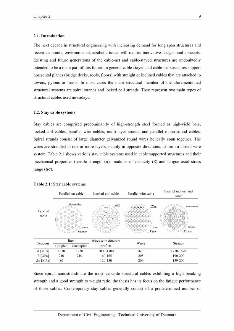
system. Table 2.1 shows various stay cable systems used in cable supported structures and their
mechanical properties (tensile strength (σ), modulus of elasticity (E) and fatigue axial stress
range (∆σ).
Table 2.1: Stay cable systems
Type of cable
Parallel bar cable Locked-coil cable Parallel wire cable Parallel monostrand
cable
Tendons Bars Wires with different
profiles Wires Strands
Coupled Uncoupled
σ [MPa] 1030 1230 1000-1300 1670 1770-1870 E [GPa] 210 210 160-165 205 190-200 ∆σ[MPa] 80 - 120-150 200 159-200
Since spiral monostrands are the most versatile structural cables exhibiting a high breaking
strength and a good strength to weight ratio, the thesis has its focus on the fatigue performance
of those cables. Contemporary stay cables generally consist of a predetermined number of
Chapter 2 10
Department of Civil Engineering - Technical University of Denmark
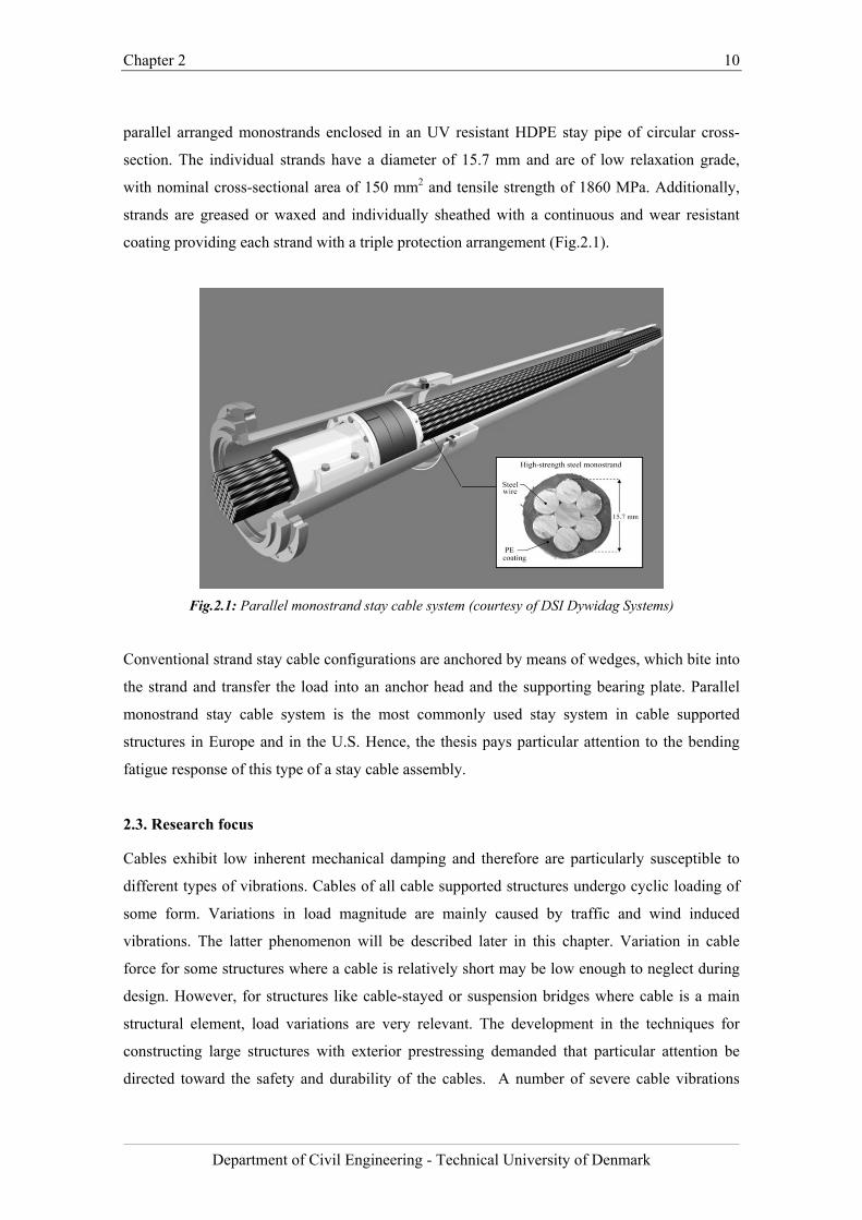
parallel arranged monostrands enclosed in an UV resistant HDPE stay pipe of circular cross-
section. The individual strands have a diameter of 15.7 mm and are of low relaxation grade,
with nominal cross-sectional area of 150 mm2 and tensile strength of 1860 MPa. Additionally,
strands are greased or waxed and individually sheathed with a continuous and wear resistant
coating providing each strand with a triple protection arrangement (Fig.2.1).
Fig.2.1: Parallel monostrand stay cable system (courtesy of DSI Dywidag Systems)
Conventional strand stay cable configurations are anchored by means of wedges, which bite into
the strand and transfer the load into an anchor head and the supporting bearing plate. Parallel
monostrand stay cable system is the most commonly used stay system in cable supported
structures in Europe and in the U.S. Hence, the thesis pays particular attention to the bending
fatigue response of this type of a stay cable assembly.
2.3. Research focus
Cables exhibit low inherent mechanical damping and therefore are particularly susceptible to
different types of vibrations. Cables of all cable supported structures undergo cyclic loading of
some form. Variations in load magnitude are mainly caused by traffic and wind induced
vibrations. The latter phenomenon will be described later in this chapter. Variation in cable
force for some structures where a cable is relatively short may be low enough to neglect during
design. However, for structures like cable-stayed or suspension bridges where cable is a main
structural element, load variations are very relevant. The development in the techniques for
constructing large structures with exterior prestressing demanded that particular attention be
directed toward the safety and durability of the cables. A number of severe cable vibrations
Chapter 2 11
Department of Civil Engineering - Technical University of Denmark
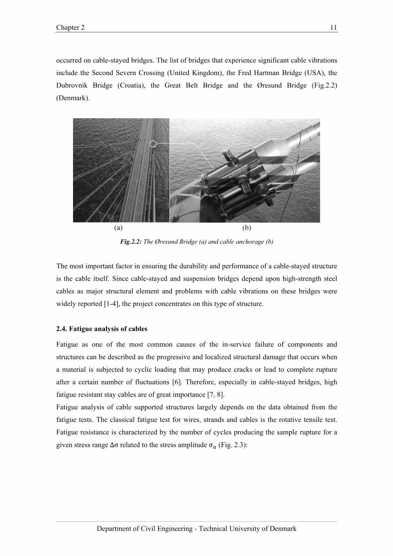
occurred on cable-stayed bridges. The list of bridges that experience significant cable vibrations
include the Second Severn Crossing (United Kingdom), the Fred Hartman Bridge (USA), the
Dubrovnik Bridge (Croatia), the Great Belt Bridge and the Øresund Bridge (Fig.2.2)
(Denmark).
Fig.2.2: The Øresund Bridge (a) and cable anchorage (b)
The most important factor in ensuring the durability and performance of a cable-stayed structure
is the cable itself. Since cable-stayed and suspension bridges depend upon high-strength steel
cables as major structural element and problems with cable vibrations on these bridges were
widely reported [1-4], the project concentrates on this type of structure.
2.4. Fatigue analysis of cables
Fatigue as one of the most common causes of the in-service failure of components and
structures can be described as the progressive and localized structural damage that occurs when
a material is subjected to cyclic loading that may produce cracks or lead to complete rupture
after a certain number of fluctuations [6]. Therefore, especially in cable-stayed bridges, high
fatigue resistant stay cables are of great importance [7, 8].
Fatigue analysis of cable supported structures largely depends on the data obtained from the
fatigue tests. The classical fatigue test for wires, strands and cables is the rotative tensile test.
Fatigue resistance is characterized by the number of cycles producing the sample rupture for a
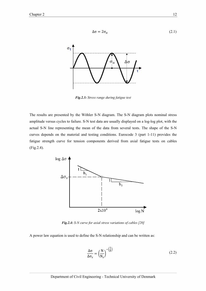
given stress range∆σ related to the stress amplitude σ (Fig. 2.3):
Chapter 2 12
Department of Civil Engineering - Technical University of Denmark
∆σ 2σ (2.1)
Fig.2.3: Stress range during fatigue test
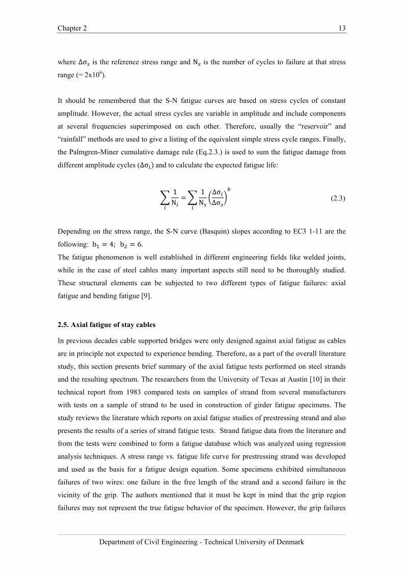
The results are presented by the Wöhler S-N diagram. The S-N diagram plots nominal stress
amplitude versus cycles to failure. S-N test data are usually displayed on a log-log plot, with the
actual S-N line representing the mean of the data from several tests. The shape of the S-N
curves depends on the material and testing conditions. Eurocode 3 (part 1-11) provides the
fatigue strength curve for tension components derived from axial fatigue tests on cables
(Fig.2.4).
Fig.2.4: S-N curve for axial stress variations of cables [20]
A power law equation is used to define the S-N relationship and can be written as:
∆σ∆σ
NN
(2.2)
Chapter 2 13
Department of Civil Engineering - Technical University of Denmark
where ∆σ is the reference stress range and N is the number of cycles to failure at that stress
range (= 2x10⁶).
It should be remembered that the S-N fatigue curves are based on stress cycles of constant
amplitude. However, the actual stress cycles are variable in amplitude and include components
at several frequencies superimposed on each other. Therefore, usually the “reservoir” and
“rainfall” methods are used to give a listing of the equivalent simple stress cycle ranges. Finally,
the Palmgren-Miner cumulative damage rule (Eq.2.3.) is used to sum the fatigue damage from
different amplitude cycles (∆σ and to calculate the expected fatigue life:
1N
1N
∆σ∆σ
(2.3)
Depending on the stress range, the S-N curve (Basquin) slopes according to EC3 1-11 are the
following: b 4;b 6.
The fatigue phenomenon is well established in different engineering fields like welded joints,
while in the case of steel cables many important aspects still need to be thoroughly studied.
These structural elements can be subjected to two different types of fatigue failures: axial
fatigue and bending fatigue [9].
2.5. Axial fatigue of stay cables
In previous decades cable supported bridges were only designed against axial fatigue as cables
are in principle not expected to experience bending. Therefore, as a part of the overall literature
study, this section presents brief summary of the axial fatigue tests performed on steel strands
and the resulting spectrum. The researchers from the University of Texas at Austin [10] in their
technical report from 1983 compared tests on samples of strand from several manufacturers
with tests on a sample of strand to be used in construction of girder fatigue specimens. The
study reviews the literature which reports on axial fatigue studies of prestressing strand and also
presents the results of a series of strand fatigue tests. Strand fatigue data from the literature and
from the tests were combined to form a fatigue database which was analyzed using regression
analysis techniques. A stress range vs. fatigue life curve for prestressing strand was developed
and used as the basis for a fatigue design equation. Some specimens exhibited simultaneous
failures of two wires: one failure in the free length of the strand and a second failure in the
vicinity of the grip. The authors mentioned that it must be kept in mind that the grip region
failures may not represent the true fatigue behavior of the specimen. However, the grip failures
Chapter 2 14
Department of Civil Engineering - Technical University of Denmark
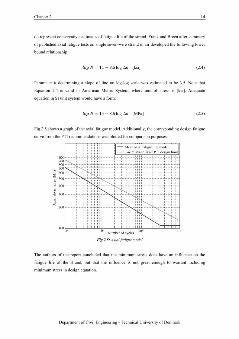
do represent conservative estimates of fatigue life of the strand. Frank and Breen after summary
of published axial fatigue tests on single seven-wire strand in air developed the following lower
bound relationship:
11 3,5 log ∆ [ksi] (2.4)
Parameter determining a slope of line on log-log scale was estimated to be 3.5. Note that
Equation 2.4 is valid in American Metric System, where unit of stress is [ksi]. Adequate
equation in SI unit system would have a form:
14 3,5 log ∆ [MPa] (2.5)
Fig.2.5 shows a graph of the axial fatigue model. Additionally, the corresponding design fatigue
curve from the PTI recommendations was plotted for comparison purposes.
Fig.2.5: Axial fatigue model
The authors of the report concluded that the minimum stress does have an influence on the
fatigue life of the strand, but that the influence is not great enough to warrant including
minimum stress in design equation.
Chapter 2 15
Department of Civil Engineering - Technical University of Denmark
2.6. Stay cable vibrations
Since the mid-1980s, numerous cable-stayed bridges have been observed to exhibit large stay
oscillations under certain environmental conditions. Inclined cables are easily excited by natural
wind due to their reduced stiffness and low structural damping. Vibration of stay cables may be
initiated by a number of mechanisms like vortex shedding, buffeting, galloping, wake effects,
parametric excitation or rain-wind induced vibration. A major concern resulting from this
phenomenon is possibly fatigue damage on the stays. In most cases, the large amplitude
vibrations are caused by a combination of light rain and moderate wind. However, in terms of
fatigue, even small vibrations should be considered as potentially dangerous.
2.6.1. Vibration mechanisms
This section introduces different cable vibration mechanisms which can be regarded as the
sources of bending stresses in stay cable anchorages.
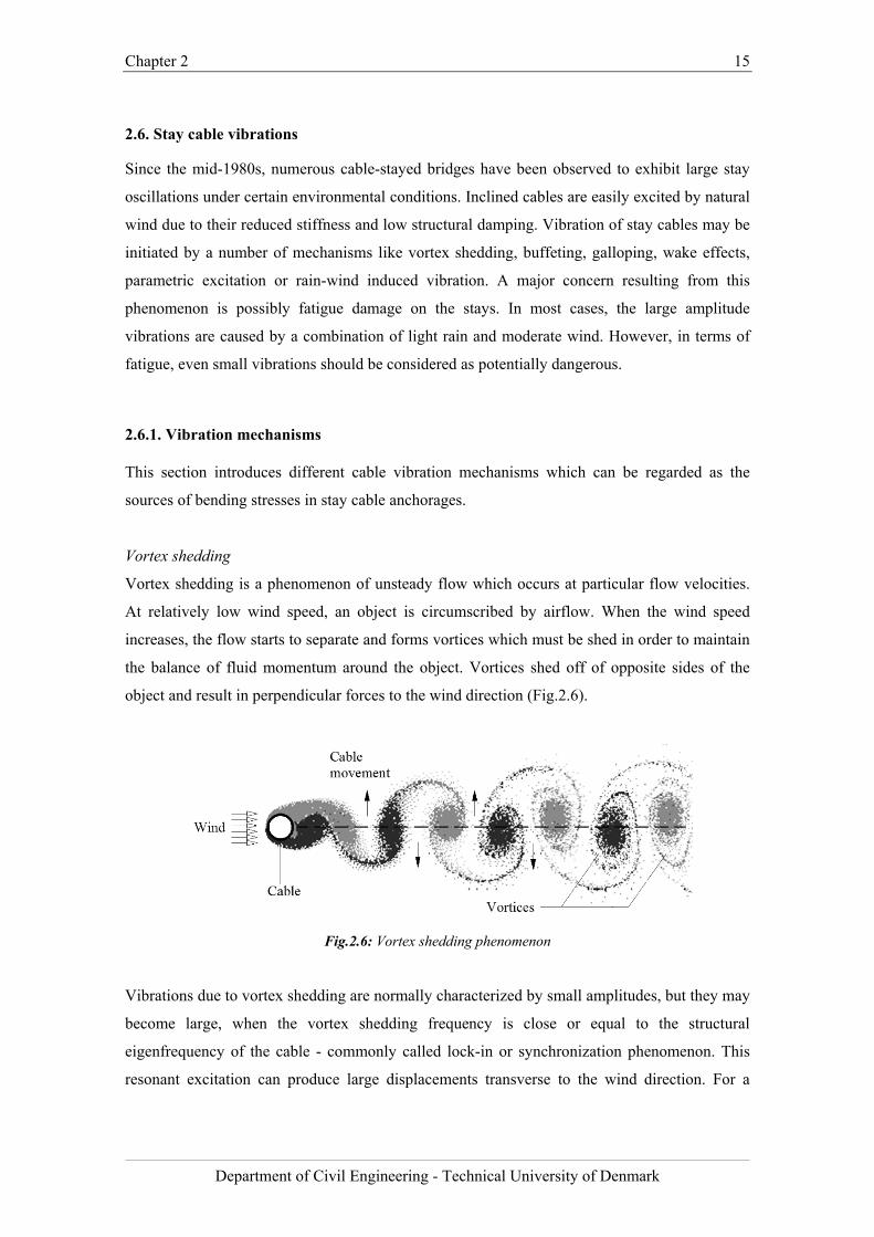
Vortex shedding
Vortex shedding is a phenomenon of unsteady flow which occurs at particular flow velocities.
At relatively low wind speed, an object is circumscribed by airflow. When the wind speed
increases, the flow starts to separate and forms vortices which must be shed in order to maintain
the balance of fluid momentum around the object. Vortices shed off of opposite sides of the
object and result in perpendicular forces to the wind direction (Fig.2.6).
Fig.2.6: Vortex shedding phenomenon
Vibrations due to vortex shedding are normally characterized by small amplitudes, but they may
become large, when the vortex shedding frequency is close or equal to the structural
eigenfrequency of the cable - commonly called lock-in or synchronization phenomenon. This
resonant excitation can produce large displacements transverse to the wind direction. For a
Chapter 2 16
Department of Civil Engineering - Technical University of Denmark
cylinder with diameter D immersed in a steady flow with flow velocity U, the vortex shedding
frequency is described by a dimensionless parameter, the Strouhal number, St defined as:
Stf DU
(2.6)
Therefore, it possible to predict the wind speed, at which vortex shedding causes a resonant
excitation knowing the eigenfrequencies of the stay cable.
Turbulent buffeting
Similar to vortex shedding, buffeting is not a dangerous phenomenon in particular, nevertheless
it may cause fatigue. Buffeting vibrations are caused by turbulent flow conditions with sizeable
forces and significant pressure that influences any flexible structure. Buffeting is basically the
result of high wind loads that change rapidly in time. In contrast to any other vibration
mechanisms, it is not an aerodynamic or resonant phenomenon [11].
Galloping
Galloping is another aerodynamic instability phenomenon where the airflow creates uplift force
around an unsymmetrical cross section. This especially applies to slender objects as well as
cables with formation of ice. This irregularity makes the section unsymmetrical and therefore,
susceptible to galloping. Galloping of stay cables may also occur when the airflow hits at such
an angle that the circular cross-section change to elliptical shape.
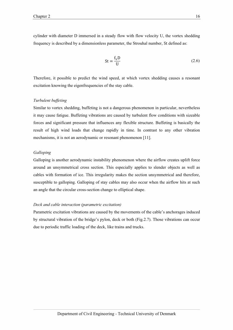
Deck and cable interaction (parametric excitation)
Parametric excitation vibrations are caused by the movements of the cable’s anchorages induced
by structural vibration of the bridge’s pylon, deck or both (Fig.2.7). Those vibrations can occur
due to periodic traffic loading of the deck, like trains and trucks.
Chapter 2 17
Department of Civil Engineering - Technical University of Denmark
Fig 2.7: Dynamic displacements of a cable-stayed bridge in a global structural mode [35]
For instance, train passing over a cable-stayed bridge may cause a periodic load on the deck
arousing the structural vibration which then generates vibration of the stay cables through the
anchorages. Parametric excitation may be avoided by separating the natural frequencies of the
bridge’s structural elements during the design process [12].
Wind and rain induced vibration
Rain-wind induced vibrations are the phenomenon that produces large amplitude cable
vibrations at low frequencies. These kinds of vibrations were first identified during the
construction of the Meiko-Nishi Bridge in Japan in 1984. Since then, this phenomenon has been
observed on other cable-stayed bridges all over the world, for instance at the Fred Hartman
Bridge in USA, the Faroe Bridge in Denmark or Erasmus Bridge in Netherlands and further has
been studied in detail.
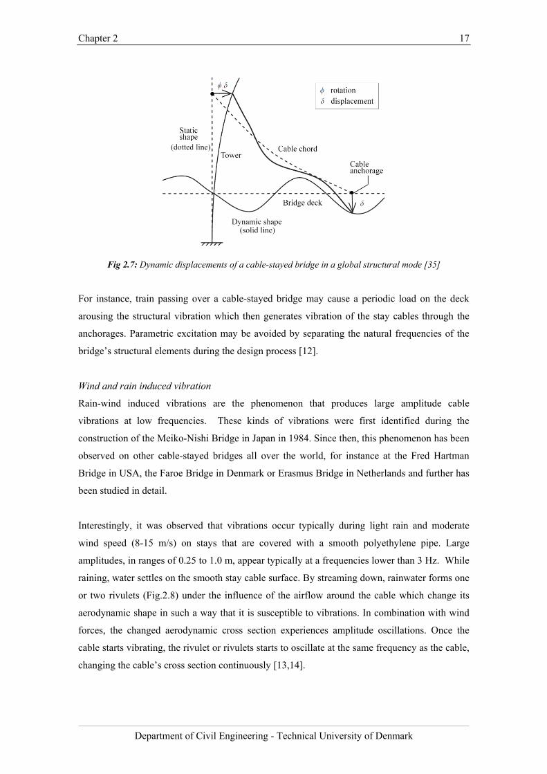
Interestingly, it was observed that vibrations occur typically during light rain and moderate
wind speed (8-15 m/s) on stays that are covered with a smooth polyethylene pipe. Large
amplitudes, in ranges of 0.25 to 1.0 m, appear typically at a frequencies lower than 3 Hz. While
raining, water settles on the smooth stay cable surface. By streaming down, rainwater forms one
or two rivulets (Fig.2.8) under the influence of the airflow around the cable which change its
aerodynamic shape in such a way that it is susceptible to vibrations. In combination with wind
forces, the changed aerodynamic cross section experiences amplitude oscillations. Once the
cable starts vibrating, the rivulet or rivulets starts to oscillate at the same frequency as the cable,
changing the cable’s cross section continuously [13,14].
Chapter 2 18
Department of Civil Engineering - Technical University of Denmark
Fig.2.8: Wind-rain induced vibration mechanism
After many tests and observations, favorable weather conditions for this vibration mechanism
were found. The source of this phenomenon is formations of rivulets; therefore, light rain and
moderate wind may lead to large amplitude oscillations. Wind speed, favorable for this type of
vibration, is assumed to be 5-20 m/s, as heavy wind would blow the water off the cable [15].
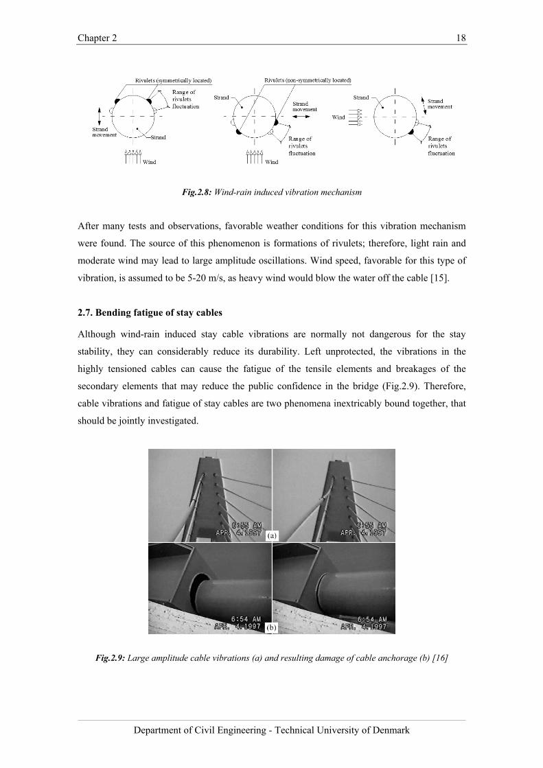
2.7. Bending fatigue of stay cables
Although wind-rain induced stay cable vibrations are normally not dangerous for the stay
stability, they can considerably reduce its durability. Left unprotected, the vibrations in the
highly tensioned cables can cause the fatigue of the tensile elements and breakages of the
secondary elements that may reduce the public confidence in the bridge (Fig.2.9). Therefore,
cable vibrations and fatigue of stay cables are two phenomena inextricably bound together, that
should be jointly investigated.
Fig.2.9: Large amplitude cable vibrations (a) and resulting damage of cable anchorage (b) [16]

Chapter 2 19
Department of Civil Engineering - Technical University of Denmark
2.7.1. Review of state of the art in cable fatigue testing
This section comprises a thorough study of specifications regarding the state of the art in stay
cable fatigue testing. The tests are conducted according to recommendations that specify
requirements with respect to the fatigue performance of stay cables.
The study was made based on the newest editions of following recommendations:
• fib – European specifications regarding acceptance of stay cable systems using prestressing
steel [17]
• PTI – American recommendations for stay cable design, testing and installation [18]
• SETRA – Cable stays recommendations of French Interministerial Commission on
Prestressing [19]
Additionally, relevant European Standard (EN) was reviewed:
• EN 1993 – Eurocode 3: Design of steel structures – Part 1-11: Design of structures with
tension components [20]
Although abovementioned recommendations are not standards, they are widely applied in
fatigue tests performed by cable stay suppliers. Relevant data and qualification testing
requirements gathered from above recommendations are summarized in Table 2.2.
Chapter 2 20
Department of Civil Engineering - Technical University of Denmark
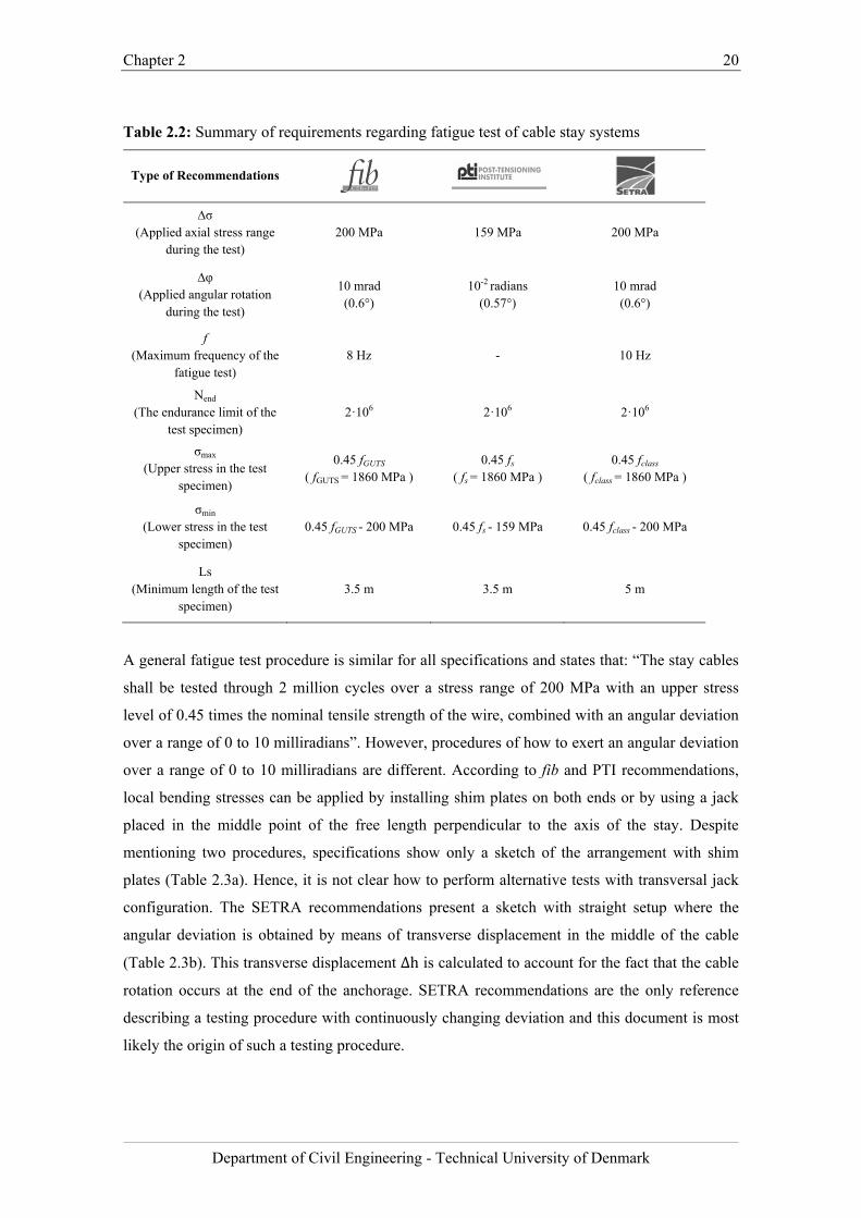
Table 2.2: Summary of requirements regarding fatigue test of cable stay systems
Type of Recommendations
∆σ (Applied axial stress range
during the test) 200 MPa 159 MPa 200 MPa
∆φ (Applied angular rotation
during the test)
10 mrad (0.6°)
10-2 radians (0.57°)
10 mrad (0.6°)
f (Maximum frequency of the
fatigue test) 8 Hz - 10 Hz
Nend (The endurance limit of the
test specimen) 2·106 2·106 2·106
σmax
(Upper stress in the test specimen)
0.45 fGUTS
( fGUTS = 1860 MPa ) 0.45 fs
( fs = 1860 MPa ) 0.45 fclass
( fclass = 1860 MPa )
σmin
(Lower stress in the test specimen)
0.45 fGUTS - 200 MPa 0.45 fs - 159 MPa 0.45 fclass - 200 MPa
Ls (Minimum length of the test
specimen) 3.5 m 3.5 m 5 m
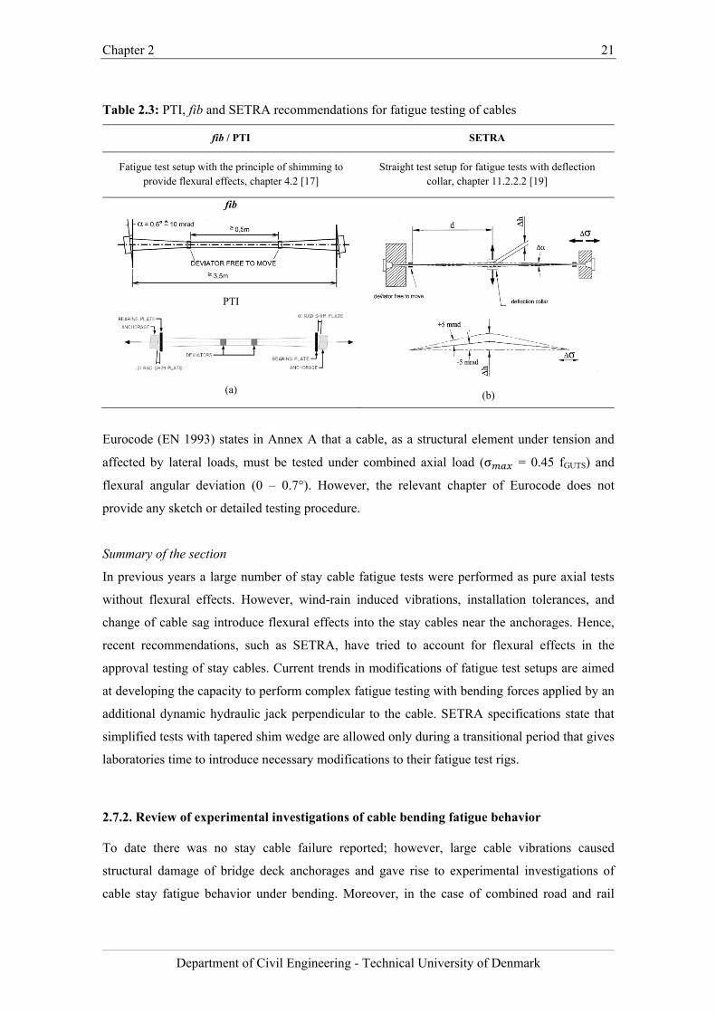
A general fatigue test procedure is similar for all specifications and states that: “The stay cables
shall be tested through 2 million cycles over a stress range of 200 MPa with an upper stress
level of 0.45 times the nominal tensile strength of the wire, combined with an angular deviation
over a range of 0 to 10 milliradians”. However, procedures of how to exert an angular deviation
over a range of 0 to 10 milliradians are different. According to fib and PTI recommendations,
local bending stresses can be applied by installing shim plates on both ends or by using a jack
placed in the middle point of the free length perpendicular to the axis of the stay. Despite
mentioning two procedures, specifications show only a sketch of the arrangement with shim
plates (Table 2.3a). Hence, it is not clear how to perform alternative tests with transversal jack
configuration. The SETRA recommendations present a sketch with straight setup where the
angular deviation is obtained by means of transverse displacement in the middle of the cable
(Table 2.3b). This transverse displacement ∆h is calculated to account for the fact that the cable
rotation occurs at the end of the anchorage. SETRA recommendations are the only reference
describing a testing procedure with continuously changing deviation and this document is most
likely the origin of such a testing procedure.
Chapter 2 21
Department of Civil Engineering - Technical University of Denmark
Table 2.3: PTI, fib and SETRA recommendations for fatigue testing of cables
fib / PTI SETRA
Fatigue test setup with the principle of shimming to provide flexural effects, chapter 4.2 [17]
Straight test setup for fatigue tests with deflection collar, chapter 11.2.2.2 [19]
fib
PTI
(a)
(b)
Eurocode (EN 1993) states in Annex A that a cable, as a structural element under tension and
affected by lateral loads, must be tested under combined axial load (σ = 0.45 fGUTS) and
flexural angular deviation (0 – 0.7°). However, the relevant chapter of Eurocode does not
provide any sketch or detailed testing procedure.
Summary of the section
In previous years a large number of stay cable fatigue tests were performed as pure axial tests
without flexural effects. However, wind-rain induced vibrations, installation tolerances, and
change of cable sag introduce flexural effects into the stay cables near the anchorages. Hence,
recent recommendations, such as SETRA, have tried to account for flexural effects in the
approval testing of stay cables. Current trends in modifications of fatigue test setups are aimed
at developing the capacity to perform complex fatigue testing with bending forces applied by an
additional dynamic hydraulic jack perpendicular to the cable. SETRA specifications state that
simplified tests with tapered shim wedge are allowed only during a transitional period that gives
laboratories time to introduce necessary modifications to their fatigue test rigs.
2.7.2. Review of experimental investigations of cable bending fatigue behavior
To date there was no stay cable failure reported; however, large cable vibrations caused
structural damage of bridge deck anchorages and gave rise to experimental investigations of
cable stay fatigue behavior under bending. Moreover, in the case of combined road and rail
Chapter 2 22
Department of Civil Engineering - Technical University of Denmark
bridges, bending fatigue is of general concern since bending at the anchorage can occur due to
large variations of the live load, combined highway and rail traffic. This section reviews
relevant experimental investigations concerning the bending fatigue of cables.
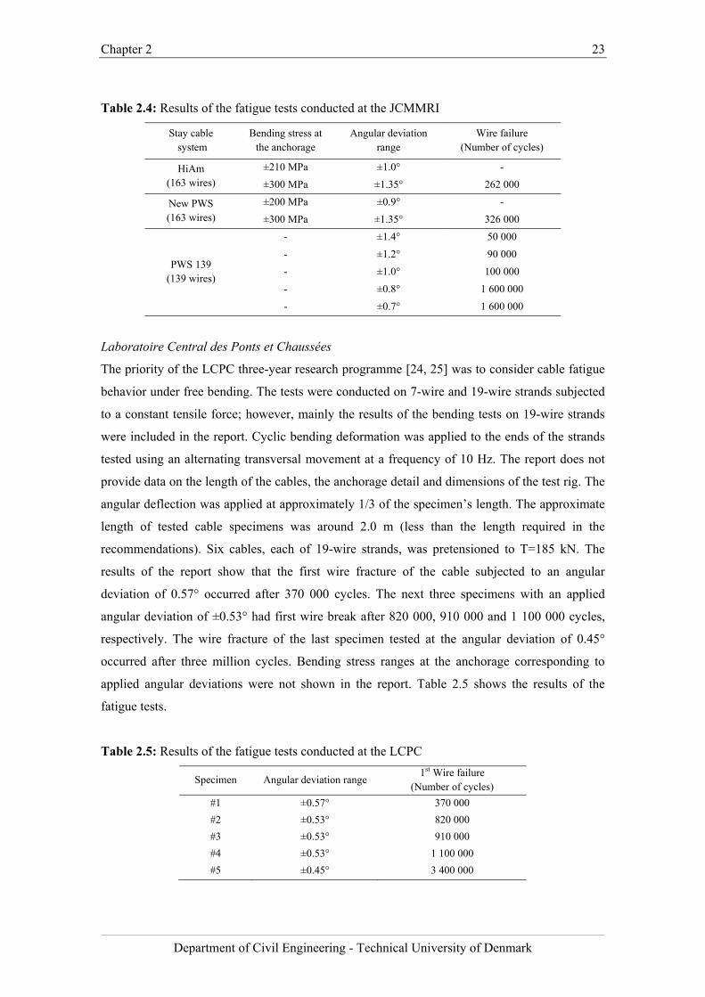
Japan Construction Method and Machinery Research Institute
To evaluate the bending fatigue response of stay cables for the Honshu-Shikoku Bridge Project
in Japan, a series of full-size axial and bending fatigue tests on bridge cables were conducted.
The tests were carried out at the Japan Construction Method and Machinery Research Institute
(JCMMRI) [21, 22]. Axial and bending fatigue due to large variations of the live load and
combined highway and rail traffic were one of the major concerns for the cable-stayed bridges
on the Kojima-Sakaida route. Two types of non-grouted parallel wire stay cables, HiAm (High
Amplitude Fatigue Resistance) and New PWS (Parallel Wire Strand) were tested. Each cable
had 163 individually galvanized wires with a diameter of 7 mm and a tensile strength of 1670
MPa. The bending fatigue tests were performed using a displacement-controlled ram, which
applied a point load at the mid-span of each 10 m cable specimen. The stresses were measured
with strain gages at various locations around the anchor head. Bending stresses at the end of the
socket were estimated to be ±200 MPa for the PWS stay and ±210 MPa for the HiAm stay. The
angular deviations of 0.9° and 1.0° were induced at the anchorages. No fatigue failures were
detected on either cable after two million cycles. The authors stated that the measured stresses
within the socket had large variations. Hence, it was concluded that the cable did not behave as
a single elastic body. A follow-up test using an angle range of ±1.35° produced fatigue failures
at 262 000 cycles for the HiAm stay and 326 000 cycles for the New PWS stay. The estimated
stress range for the follow up test was ±300 MPa. Bending fatigue tests were also conducted on
a cable specimens comprised of 139 wires (PWS 139), however, the article providing fatigue
data [23] is written in Japanese and only readout of the applied angular deviations and the
number of cycles to wire failure was made. It should be noted that the angular deviation of only
1.4° caused bending fatigue fracture after 50 000 cycles. Table 2.4 collates all the results of the
tests conducted at the JCMMRI.
Chapter 2 23
Department of Civil Engineering - Technical University of Denmark
Table 2.4: Results of the fatigue tests conducted at the JCMMRI
Stay cable system
Bending stress at the anchorage
Angular deviation range
Wire failure (Number of cycles)
HiAm (163 wires)
±210 MPa ±1.0° -
±300 MPa ±1.35° 262 000
New PWS (163 wires)
±200 MPa ±0.9° -
±300 MPa ±1.35° 326 000
PWS 139
(139 wires)
- ±1.4° 50 000
- ±1.2° 90 000
- ±1.0° 100 000
- ±0.8° 1 600 000
- ±0.7° 1 600 000
Laboratoire Central des Ponts et Chaussées
The priority of the LCPC three-year research programme [24, 25] was to consider cable fatigue
behavior under free bending. The tests were conducted on 7-wire and 19-wire strands subjected
to a constant tensile force; however, mainly the results of the bending tests on 19-wire strands
were included in the report. Cyclic bending deformation was applied to the ends of the strands
tested using an alternating transversal movement at a frequency of 10 Hz. The report does not
provide data on the length of the cables, the anchorage detail and dimensions of the test rig. The
angular deflection was applied at approximately 1/3 of the specimen’s length. The approximate
length of tested cable specimens was around 2.0 m (less than the length required in the
recommendations). Six cables, each of 19-wire strands, was pretensioned to T=185 kN. The
results of the report show that the first wire fracture of the cable subjected to an angular
deviation of 0.57° occurred after 370 000 cycles. The next three specimens with an applied
angular deviation of ±0.53° had first wire break after 820 000, 910 000 and 1 100 000 cycles,
respectively. The wire fracture of the last specimen tested at the angular deviation of 0.45°
occurred after three million cycles. Bending stress ranges at the anchorage corresponding to
applied angular deviations were not shown in the report. Table 2.5 shows the results of the
fatigue tests.
Table 2.5: Results of the fatigue tests conducted at the LCPC
Specimen Angular deviation range 1st Wire failure
(Number of cycles)
#1 ±0.57° 370 000
#2 ±0.53° 820 000
#3 ±0.53° 910 000
#4 ±0.53° 1 100 000
#5 ±0.45° 3 400 000
Chapter 2 24
Department of Civil Engineering - Technical University of Denmark
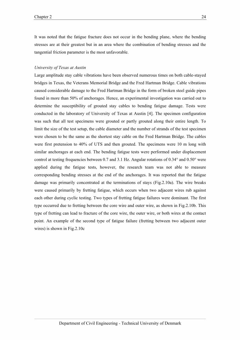
It was noted that the fatigue fracture does not occur in the bending plane, where the bending
stresses are at their greatest but in an area where the combination of bending stresses and the
tangential friction parameter is the most unfavorable.
University of Texas at Austin
Large amplitude stay cable vibrations have been observed numerous times on both cable-stayed
bridges in Texas, the Veterans Memorial Bridge and the Fred Hartman Bridge. Cable vibrations
caused considerable damage to the Fred Hartman Bridge in the form of broken steel guide pipes
found in more than 50% of anchorages. Hence, an experimental investigation was carried out to
determine the susceptibility of grouted stay cables to bending fatigue damage. Tests were
conducted in the laboratory of University of Texas at Austin [4]. The specimen configuration
was such that all test specimens were grouted or partly grouted along their entire length. To
limit the size of the test setup, the cable diameter and the number of strands of the test specimen
were chosen to be the same as the shortest stay cable on the Fred Hartman Bridge. The cables
were first pretension to 40% of UTS and then grouted. The specimens were 10 m long with
similar anchorages at each end. The bending fatigue tests were performed under displacement
control at testing frequencies between 0.7 and 3.1 Hz. Angular rotations of 0.34° and 0.50° were
applied during the fatigue tests, however, the research team was not able to measure
corresponding bending stresses at the end of the anchorages. It was reported that the fatigue
damage was primarily concentrated at the terminations of stays (Fig.2.10a). The wire breaks
were caused primarily by fretting fatigue, which occurs when two adjacent wires rub against
each other during cyclic testing. Two types of fretting fatigue failures were dominant. The first
type occurred due to fretting between the core wire and outer wire, as shown in Fig.2.10b. This
type of fretting can lead to fracture of the core wire, the outer wire, or both wires at the contact
point. An example of the second type of fatigue failure (fretting between two adjacent outer
wires) is shown in Fig.2.10c
Chapter 2 25
Department of Civil Engineering - Technical University of Denmark
Fig.2.10: Cable specimen (a), fretting failure between core and outer wire (b), and fretting fracture
between outer wires (c)
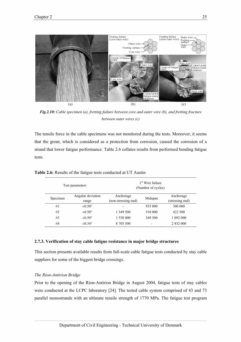
The tensile force in the cable specimens was not monitored during the tests. Moreover, it seems
that the grout, which is considered as a protection from corrosion, caused the corrosion of a
strand that lower fatigue performance. Table 2.6 collates results from performed bending fatigue
tests.
Table 2.6: Results of the fatigue tests conducted at UT Austin
Test parameters 1st Wire failure
(Number of cycles)
Specimen Angular deviation
range Anchorage
(non-stressing end) Midspan
Anchorage (stressing end)
#1 ±0.50° - 935 000 300 000
#2 ±0.50° 1 349 500 510 000 422 500
#3 ±0.50° 1 558 000 349 500 1 092 000
#4 ±0.34° 8 705 500 - 2 832 000
2.7.3. Verification of stay cable fatigue resistance in major bridge structures
This section presents available results from full-scale cable fatigue tests conducted by stay cable
suppliers for some of the biggest bridge crossings.
The Rion-Antirion Bridge
Prior to the opening of the Rion-Antirion Bridge in August 2004, fatigue tests of stay cables
were conducted at the LCPC laboratory [24]. The tested cable system comprised of 43 and 73
parallel monostrands with an ultimate tensile strength of 1770 MPa. The fatigue test program
Chapter 2 26
Department of Civil Engineering - Technical University of Denmark
included two million cycles at an axial stress range of 165 MPa. Relevant cable stays were
tested in frequencies of 1.3 Hz – 1.5 Hz. One of the stay cables, comprised of 73 monostrands,
was tested with a static deviation induced by shim plates installed behind the anchorages. It was
believed that these tapered plates will simulate the effects of angular variations that the stay
cables undergo near sockets when subjected to service loads. Skewed wedge placed between the
anchorage and the machine's support ring introduced an angular deviation of 0.57°. No bending
fatigue tests with a transversal deviation at mid-span of cable specimens were performed.
The Second Severn Crossing
The combined axial and bending fatigue tests have been performed to evaluate the fatigue
response of the Second Severn Crossing stay cable at the National Engineering Laboratories in
Glasgow [16]. The fatigue test for this project was conducted on a 10 m long cable comprised of
193 wires subjected to two million cycles at an axial stress range of 197 MPa. However, cyclic
vertical displacement at mid span of the cable was imposed only during the first one million
cycles and the deviation angle range at the cable anchorage was ± 0.5°. Bending stresses have
not been monitored throughout the fatigue tests.
The River Suir Bridge
Before the opening of the River Suir Bridge in October 2009, six fatigue tests on stay cables
was completed [26].The first tested cable specimen comprised of 73 parallel monostrands. The
total length of the specimen was 4 m with a free length of only 2 m. The cables were
pretensioned to 45% of the ultimate strength and the applied axial stress range was 200 MPa.
The test was performed with flexural effects introduced by applying transversal displacement at
midspan. The range of deviation angles induced at the cable anchorage was ±0.6°. The results
after the first fatigue test showed that 8 wires broke after two million cycles. This result was
acceptable since, according to fib recommendations, the criteria for acceptance is to have less
than 2% of broken wires, which means 10 wires for the tested specimen. However, the rest of
the tests for acceptance of the cable system followed the procedure with shim plates.
Summary of the section
The results of full-scale fatigue tests on cable stays presented in section 2.7.3 show that cable
suppliers mostly examine a stay cable assembly through axial loading, applying a small angular
deviation of the anchorages using shim plates. The authors of the fatigue tests performed on stay
cables of the River Suir Bridge in their conclusions raised doubts whether the testing procedure
with the classical shim plates can be considered as an equivalent one for the procedure with the
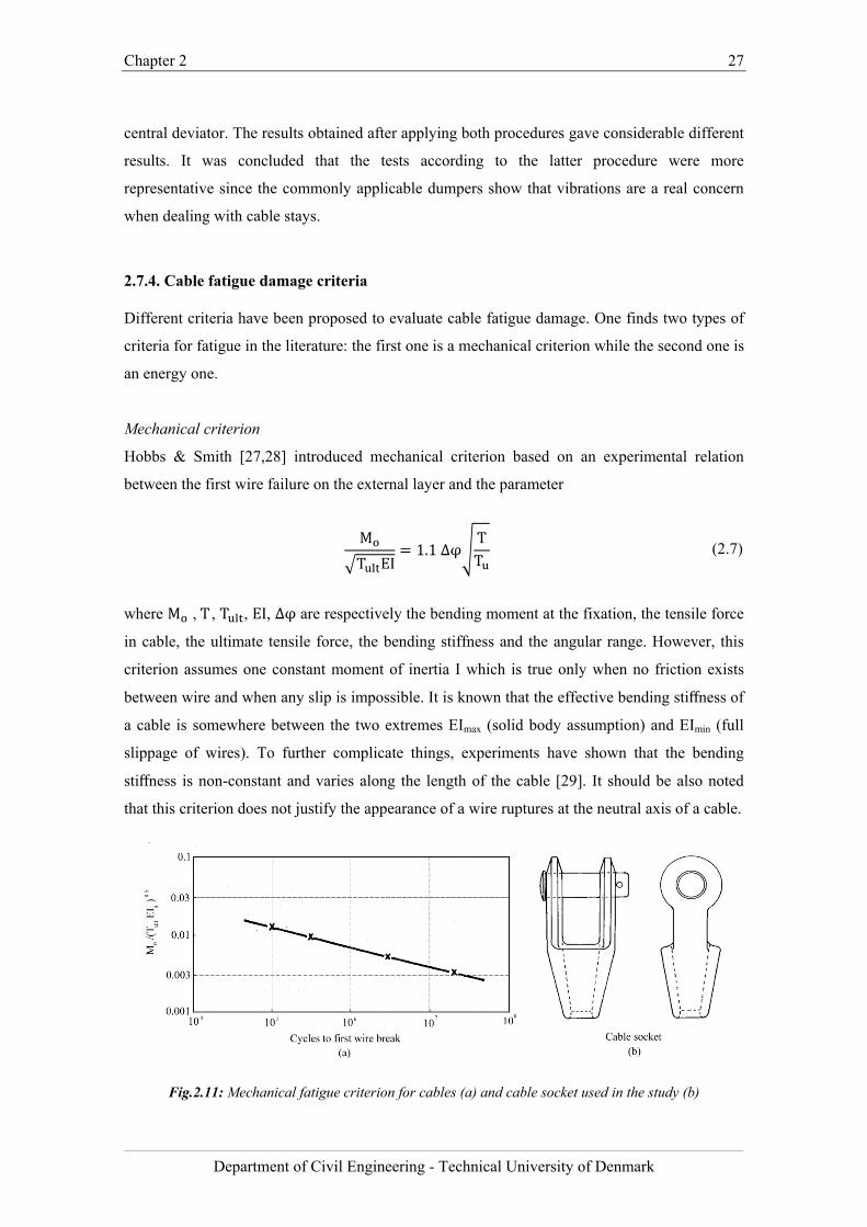
Chapter 2 27
Department of Civil Engineering - Technical University of Denmark
central deviator. The results obtained after applying both procedures gave considerable different
results. It was concluded that the tests according to the latter procedure were more
representative since the commonly applicable dumpers show that vibrations are a real concern
when dealing with cable stays.
2.7.4. Cable fatigue damage criteria
Different criteria have been proposed to evaluate cable fatigue damage. One finds two types of
criteria for fatigue in the literature: the first one is a mechanical criterion while the second one is
an energy one.
Mechanical criterion
Hobbs & Smith [27,28] introduced mechanical criterion based on an experimental relation
between the first wire failure on the external layer and the parameter
M
T EI1.1 ∆φ
TT
(2.7)
where M ,T, T , EI, ∆φ are respectively the bending moment at the fixation, the tensile force
in cable, the ultimate tensile force, the bending stiffness and the angular range. However, this
criterion assumes one constant moment of inertia I which is true only when no friction exists
between wire and when any slip is impossible. It is known that the effective bending stiffness of
a cable is somewhere between the two extremes EImax (solid body assumption) and EImin (full
slippage of wires). To further complicate things, experiments have shown that the bending
stiffness is non-constant and varies along the length of the cable [29]. It should be also noted
that this criterion does not justify the appearance of a wire ruptures at the neutral axis of a cable.
Fig.2.11: Mechanical fatigue criterion for cables (a) and cable socket used in the study (b)
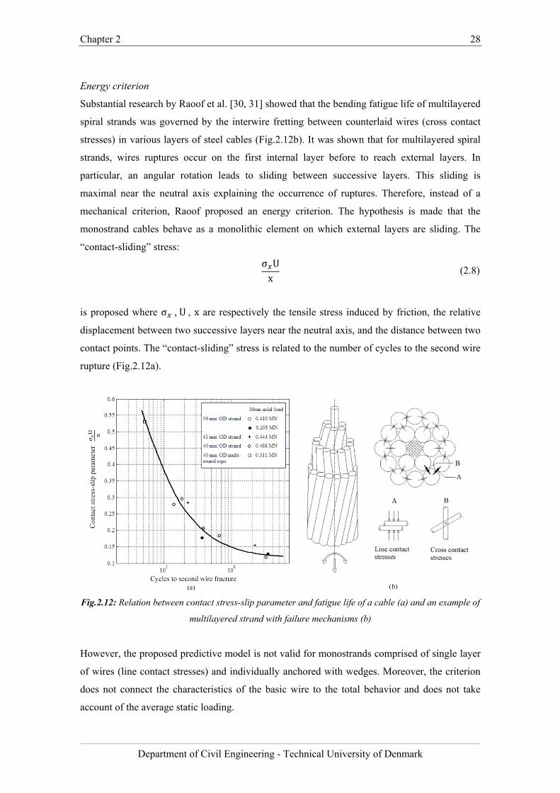
Chapter 2 28
Department of Civil Engineering - Technical University of Denmark
Energy criterion
Substantial research by Raoof et al. [30, 31] showed that the bending fatigue life of multilayered
spiral strands was governed by the interwire fretting between counterlaid wires (cross contact
stresses) in various layers of steel cables (Fig.2.12b). It was shown that for multilayered spiral
strands, wires ruptures occur on the first internal layer before to reach external layers. In
particular, an angular rotation leads to sliding between successive layers. This sliding is
maximal near the neutral axis explaining the occurrence of ruptures. Therefore, instead of a
mechanical criterion, Raoof proposed an energy criterion. The hypothesis is made that the
monostrand cables behave as a monolithic element on which external layers are sliding. The
“contact-sliding” stress:
σ Ux
(2.8)
is proposed where σ ,U, x are respectively the tensile stress induced by friction, the relative
displacement between two successive layers near the neutral axis, and the distance between two
contact points. The “contact-sliding” stress is related to the number of cycles to the second wire
rupture (Fig.2.12a).
Fig.2.12: Relation between contact stress-slip parameter and fatigue life of a cable (a) and an example of
multilayered strand with failure mechanisms (b)
However, the proposed predictive model is not valid for monostrands comprised of single layer
of wires (line contact stresses) and individually anchored with wedges. Moreover, the criterion
does not connect the characteristics of the basic wire to the total behavior and does not take
account of the average static loading.
Chapter 2 29
Department of Civil Engineering - Technical University of Denmark
2.8. Conclusions
After the review of the state-of-the-art in stay cable bending fatigue testing and relevant
experimental and analytical investigations the following problems were identified.
Evaluation deficiencies in cable fatigue testing
Section 2.7.1 and 2.7.3 show that the fatigue resistance of stay cables is predominantly
examined through axial loading of the stay cable assembly, with an anchorages attached and
with a small angular deviation of the anchorages, in relation to the cable chord.
Axial fatigue tests only represent a realistic load case if the cable in question is not subjected to
any form of wind-induced or parametric excitation that can lead to bending vibrations.
Nevertheless, wind-induced vibrations of bridge cables are common, even if the amplitudes
often tend to be rather low due to the introduction of external damping or stiffening systems. It
should be noted that the PTI and fib qualification tests do not specifically address fatigue issues
related to cable vibrations. A setup with the principle of shimming to provide flexural effects
according to PTI and fib recommendations is believed to be sufficiently representative to the
real conditions in a cable-stayed structure.
Lack of experimental investigation on bending fatigue performance of monostrands
Section 2.7.2 presents experimental investigation on parallel wire stay cables [21], grouted
parallel monostrand stay cables [4] and 19-wire strands [25] subjected to flexural load.
However, to date there was no thorough study made specifically on the bending fatigue
performance of a PE coated monostrand and parallel monostrand stay cables. Furthermore, in
most cases research teams were not able to measure bending stresses at the anchorage
corresponding to applied angular deviations. Moreover, none of the published papers and
technical reports provide information about the extent of the interwire movement that caused
wire failure due to fretting.
Local bending deformations in cables - the challenge of measurement
The fatigue life of steel monostrands, depending on the type of anchorage, was shown to be
governed by localized bending effects at the wedge location and by the interwire fretting at the
deviator and exit of the socket [4]. The observation and quantification of deformations in steel
monostrands, particularly in the anchorage region, is challenging. The relative movement
between strand wires has been found difficult to deduce from strain gauge measurements. To
date, there is no information about the distribution of the interwire movement along the length
of the monostrand and the extent of the relative displacement between core and outer wires of
Chapter 2 30
Department of Civil Engineering - Technical University of Denmark
the monostrand undergoing flexural deformations. The fretting problem is not yet fully clarified
and, in the absence of relevant experimental data, it is difficult to draw reliable conclusions
from purely analytical techniques.
Inaccurate assessment of service life of cable supported structures
An important consideration in the design of cable supported structures is the fatigue resistance
of cables under cyclic loading. Monitoring outcomes from bridges show small, medium and
large vibrations of stay cables. However, to date there is no accurate procedure to estimate the
lifetime of cables undergoing cyclic bending. There were a number of bridge projects where
design engineers encountered major problems with the estimation of service life of the cable.
Great Belt Bridge (Denmark)
Large hanger vibrations (up to the order of 2 m) have been observed during the period of
October 2000 – April 2005. The owner of the Great Belt Bridge had to estimate the fatigue risk
associated with these events. The fatigue life of the hangers on the Great Belt Bridge was
initially assessed based on S-N curves derived from the axial loading tests from the
manufacturer although it is recognized that fatigue is most likely to occur at the upper socket
due to bending of the cables [32, 33].
Avonmouth Bridge (United Kingdom)
The Avonmouth Bridge, which carries the M5 motorway over the River Avon near Bristol
(UK), has an externally post-tensioned concrete box girder. Post-tensioned tendons are
comprised of a number of steel strands. The engineers investigating Avonmouth Bridge
experienced difficulties in estimating the cable fatigue lifetime as they have not been able to
obtain any data on the bending fatigue response of steel monostrands. Consequently, the S-N
curve for axial stress variations of cables provided in the EC3 (part 1-11) had to be used to
evaluate the remaining service life of tension members.
Fred Hartman Bridge (USA)
Large amplitude vibrations occurred on the Fred Hartman Bridge in Texas (USA) in 1997 and
resulted in structural damage of the deck anchorages. These large-amplitude vibrations caused
101 of 192 anchorage guide pipes to fracture. Despite thorough fatigue investigation,
researchers from the University of Texas were unable to estimate the remaining fatigue life of
the stay cables [34].
Chapter 2 31
Department of Civil Engineering - Technical University of Denmark
These examples shows that fatigue of stay cables is a phenomenon that is not yet fully
understood by engineers that base design solely on static stress limits [9]. Moreover, examples
shown in this section can also serve as a warning that there might be a series of structures with
unknown long-term fatigue behavior. The safety of aforementioned structures strongly depends
on the reliability of the cable systems and the accurate assessment of the cable service life.
The research work conducted during the PhD project and presented in this thesis aimed to
address the abovementioned research problems and complexities related with the evaluation of
the stay cable bending fatigue.
Chapter 2 32
Department of Civil Engineering - Technical University of Denmark
Bibliography
[1] Z. Savor, J. Radic, G. Hrelja, “Cable vibrations at Dubrovnik bridge”, Bridge Structures,
Vol. 2, No. 2, June 2006, 97–106
[2] H. Takano, M. Ogasawara, N. Ito, T. Shimosato , K. Takeda ,T. Murakami, “Vibrational
damper for cables of the Tsurumi Tsubasa Bridge”, Journal of Wind Engineering and
Industrial Aerodynamics 69 71 (1997) 807-818
[3] H. J. Zhou, Y. L. Xu, “Wind–rain-induced vibration and control of stay cables in a
cable-stayed bridge”, Structural Control and Health Monitoring, 2007; 14:1013–1033
[4] Wood, S.L., Frank, K.H, “Experimental investigation of bending fatigue response of
grouted stay cables”, Journal of Bridge Engineering.
[5] Structural Engineering International, SEI Volume 20, Number 3, August 2010
[6] Advanced Introduction to Fatigue, ESDEP Lecture WG 12
[7] P. Mondorf, “Concrete Bridges”, Polyteknisk Forlag, ISBN 10 87-502-0962-0, 2006
[8] N. Gimsing, “Cable Supported Bridges, Concept & Design”, 2nd edition, 1997
[9] J. Suh, S.P. Chang, “Experimental study on fatigue behaviour of wire ropes”,
International Journal of Fatigue 22 (2000) 339–347, 1999
[10] C. Paulson, K. H. Frank, J.E. Breen, “A Fatigue Study of Prestressing Strand” , Ferguson
Structural, Engineering Laboratory Research Report, 1983
[11] S. Kumarasena, N.P. Jones, P. Irwin, P. Taylor, “Wind Induced Vibration of Stay
Cables”, Interim Final Report, 2005
[12] S. Kumarasena, N.P. Jones, P. Irwin, P. Taylor, “Wind Induced Vibration of Stay
Cables”, U.S. Department of Transportation, 2007
[13] N. Cosentino, “Rain-wind Induced Vibrations of Stay Cables”, University of Bologna,
PhD Thesis, 2002
[14] M. Matsumoto, Y. Daito, T. Kanamura, Y. Shigemura, S.Ishizaki, “Wind-induced
vibration of cables of cable-stayed bridges”, Journal of Wind Engineering and Industrial
Aerodynamics, 1998
[15] H. J. Zhou, Y. L. Xu, “Wind–rain-induced vibration and control of stay cables”, The
Journal of Structural Control and Health Monitoring, 2007
[16] M. Poser, “Full-Scale Bending Fatigue Tests on Stay Cables”, Master Thesis - The
University of Texas at Austin, 2001
[17] Fédération internationale du béton (fib). “Bulletin 30 Acceptance of stay cable systems
using prestressing steel”, 2005
[18] Post Tensioning Institute (PTI). “PTI Guide Specification. Recommendations for stay
Chapter 2 33
Department of Civil Engineering - Technical University of Denmark
cable Design, Testing and installation”, 2007
[19] SETRA Cable Stays Recommendations of French Interministerial Commission on
Prestressing. “Haubans - Recommandations de la CIP.”, 2002
[20] Comité Européen de Normalisation. “pr EN 1993-1-11: Design of structures with tension
components”, 2006.
[21] C. Miki, T. Endo, A. Okukawa, “Full-Size Fatigue Test of Bridge Cables”, Length Effect
on Fatigue of Wires and Strands, International Association for Bridge and Structural
Engineering, Report, Vol. 66, pp. 167-178, 1992
[22] NCHRP Synthesis 353, National Cooperative Highway Resreach Program Inspection
and Maintenance of Bridge Stay Cable Systems, 2001
[23] T. Endo, A. Okukawa, H. Takenouchi, C. Miki, 1994, “Bending fatigue strength of
bridge cable”, Steel Construction Engineering Vol.1, No.3, 91-102. (in Japanese)
[24] http://www.lcpc.fr/en/presentation/moyens/bancdefatigue/index.dml
[25] J.P. Gourmelon , “Stay cable fatigue. Organisation and main results of the research
programme conducted by the LCPC”, Laboratoire Central des Ponts et Chaussées, 2003
[26] G. Rodríguez, C.J Olabarrieta, “Fatigue Testing with Transverse Displacements in Stay
Cable Systems”, the 3rd fib International Congress, 2010
[27] Hobbs R.E., Ghavami K., The fatigue of structural wire strands, Int. J. Fatigue, pp. 69-
72,1982.
[28] Hobbs R.E., Smith B.W., Fatigue performance of socketed terminations to structural
strands, Proceedings of the Institution of Civil Engineers, part 2, 75, 35-48, 1983
[29] Cardou, A., and Jolicoeur, C. Mechanical models of helical strands. Applied Mechanics
Reviews, ASME Vol. 50 , No. 1 (January 1997), pp. 1–14
[30] Raoof M., Free bending tests on large spiral strands, Structural Engineer, Proceedings of
the Institution of Civil Engineers, part 2, 87, 605-626,1989.
[31] Roof M., Design of steel cables against free bending fatigue at terminations, Structural
Engineer, 71, 10/18, 171-178, 1993
[32] J.L. Jensen, N. Bitsch, E. Laursen, “Fatigue Risk Assessment of Hangers on Great Belt
Bridge”
[33] E. Laursen, N. Bitsch, J.E. Andersen, “Analysis and Mitigation of Large Amplitude
Cable Vibrations at the Great Belt East Bridge “
[34] J. Dowd, M. Poser, K. H. Frank, S. L. Wood, E. B. Williamson, “Bending Fatigue Tests
on Stays Cables“, Journal of Bridge Engineering, November/December 2001, 639-644
[35] J. H. G. Macdonald MA, PhD, M. S. Dietz PhD and S. A. Neild MEng, PhD, Dynamic
excitation of cables by deck and/or tower motion, Proceedings of the Institution of Civil
Chapter 2 34
Department of Civil Engineering - Technical University of Denmark
Engineers, Bridge Engineering 163, June 2010 Issue BE2, pp: 101–111

Chapter 2 35
Department of Civil Engineering - Technical University of Denmark
Chapter 3 36
Department of Civil Engineering - Technical University of Denmark
Chapter 3
Localized bending fatigue behavior of monostrand under flexural load
The results presented in this chapter are taken from the expanded version of the paper “A
preliminary bending fatigue spectrum for steel monostrand cables” by J. Winkler, G. Fischer,
C.T. Georgakis and A. Kotas, published in the Journal of International Association for Shell and
Spatial Structures 2011; 52(4): 249-255.
Chapter summary
This chapter presents the results of the first experimental investigation on the bending fatigue
performance of the steel monostrands conducted during the PhD project. The strain was
measured using conventional strain gauges attached to individual strand wires in the vicinity of
the wedge. In all dynamic tests the wire fracture occurred at the wedge location. It was an
indication that it was the location with the high localized curvatures and, therefore, high
bending stresses. From the series of conducted dynamic tests the fatigue spectrum for the
localized bending fatigue failure mechanism was developed. The results provide relevant
information on the bending mechanism and fatigue characteristics of monostrand steel cables in
tension and flexure and show that localized cable bending has a pronounced influence on the
fatigue resistance of cables under dynamic excitations.
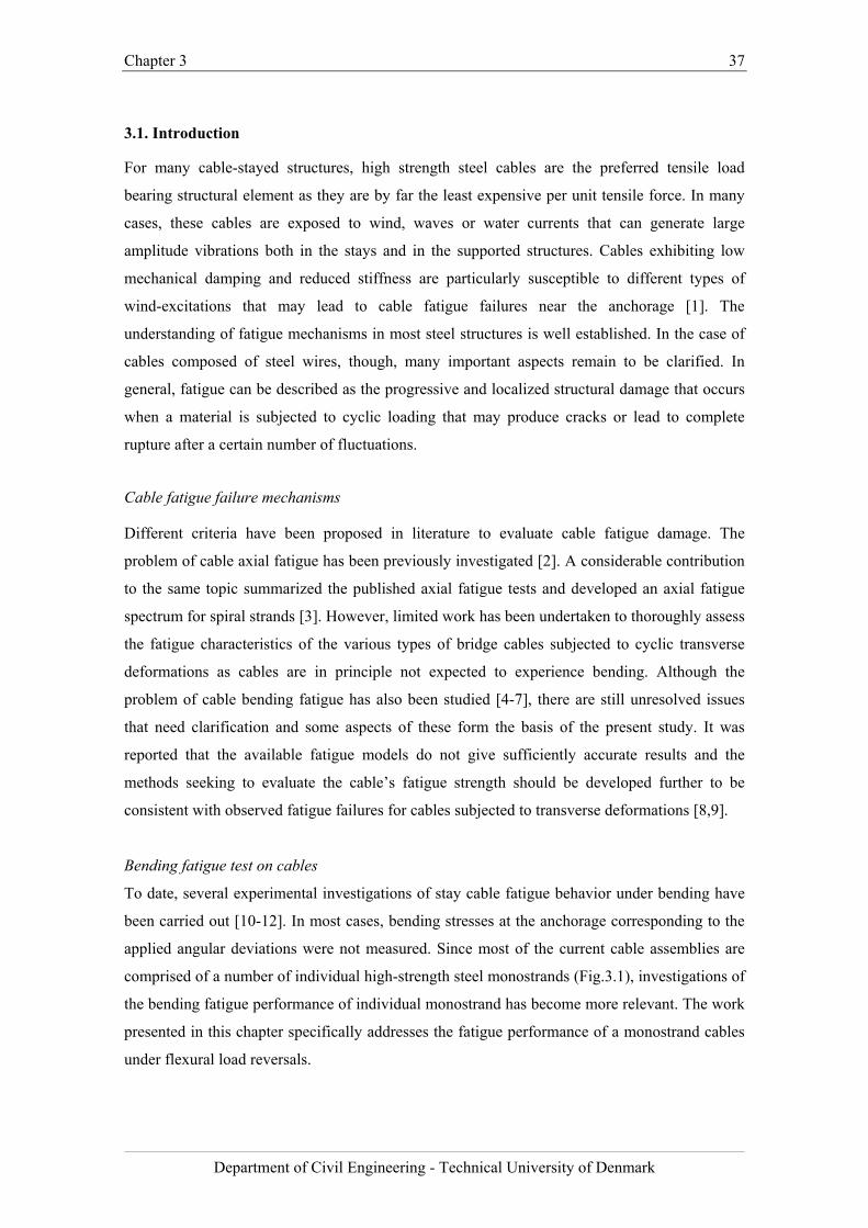
Chapter 3 37
Department of Civil Engineering - Technical University of Denmark
3.1. Introduction
For many cable-stayed structures, high strength steel cables are the preferred tensile load
bearing structural element as they are by far the least expensive per unit tensile force. In many
cases, these cables are exposed to wind, waves or water currents that can generate large
amplitude vibrations both in the stays and in the supported structures. Cables exhibiting low
mechanical damping and reduced stiffness are particularly susceptible to different types of
wind-excitations that may lead to cable fatigue failures near the anchorage [1]. The
understanding of fatigue mechanisms in most steel structures is well established. In the case of
cables composed of steel wires, though, many important aspects remain to be clarified. In
general, fatigue can be described as the progressive and localized structural damage that occurs
when a material is subjected to cyclic loading that may produce cracks or lead to complete
rupture after a certain number of fluctuations.
Cable fatigue failure mechanisms
Different criteria have been proposed in literature to evaluate cable fatigue damage. The
problem of cable axial fatigue has been previously investigated [2]. A considerable contribution
to the same topic summarized the published axial fatigue tests and developed an axial fatigue
spectrum for spiral strands [3]. However, limited work has been undertaken to thoroughly assess
the fatigue characteristics of the various types of bridge cables subjected to cyclic transverse
deformations as cables are in principle not expected to experience bending. Although the
problem of cable bending fatigue has also been studied [4-7], there are still unresolved issues
that need clarification and some aspects of these form the basis of the present study. It was
reported that the available fatigue models do not give sufficiently accurate results and the
methods seeking to evaluate the cable’s fatigue strength should be developed further to be
consistent with observed fatigue failures for cables subjected to transverse deformations [8,9].
Bending fatigue test on cables
To date, several experimental investigations of stay cable fatigue behavior under bending have
been carried out [10-12]. In most cases, bending stresses at the anchorage corresponding to the
applied angular deviations were not measured. Since most of the current cable assemblies are
comprised of a number of individual high-strength steel monostrands (Fig.3.1), investigations of
the bending fatigue performance of individual monostrand has become more relevant. The work
presented in this chapter specifically addresses the fatigue performance of a monostrand cables
under flexural load reversals.
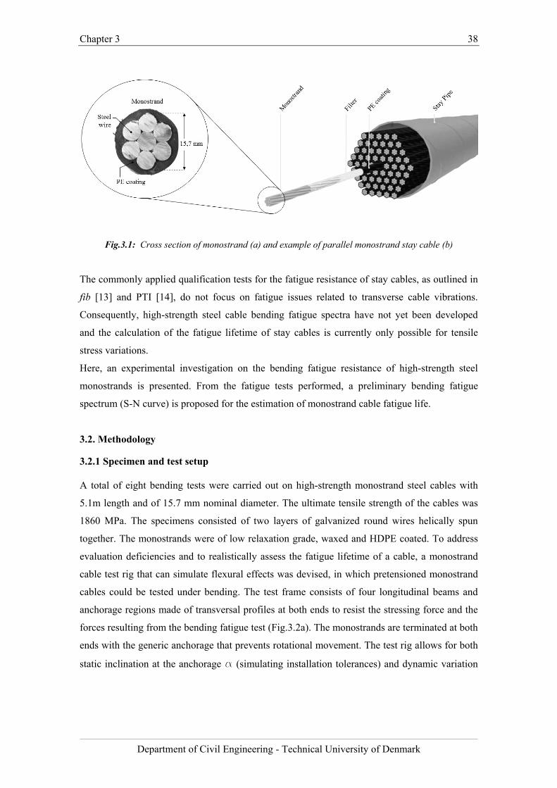
Chapter 3 38
Department of Civil Engineering - Technical University of Denmark
Fig.3.1: Cross section of monostrand (a) and example of parallel monostrand stay cable (b)
The commonly applied qualification tests for the fatigue resistance of stay cables, as outlined in
fib [13] and PTI [14], do not focus on fatigue issues related to transverse cable vibrations.
Consequently, high-strength steel cable bending fatigue spectra have not yet been developed
and the calculation of the fatigue lifetime of stay cables is currently only possible for tensile
stress variations.
Here, an experimental investigation on the bending fatigue resistance of high-strength steel
monostrands is presented. From the fatigue tests performed, a preliminary bending fatigue
spectrum (S-N curve) is proposed for the estimation of monostrand cable fatigue life.
3.2. Methodology
3.2.1 Specimen and test setup
A total of eight bending tests were carried out on high-strength monostrand steel cables with
5.1m length and of 15.7 mm nominal diameter. The ultimate tensile strength of the cables was
1860 MPa. The specimens consisted of two layers of galvanized round wires helically spun
together. The monostrands were of low relaxation grade, waxed and HDPE coated. To address
evaluation deficiencies and to realistically assess the fatigue lifetime of a cable, a monostrand
cable test rig that can simulate flexural effects was devised, in which pretensioned monostrand
cables could be tested under bending. The test frame consists of four longitudinal beams and
anchorage regions made of transversal profiles at both ends to resist the stressing force and the
forces resulting from the bending fatigue test (Fig.3.2a). The monostrands are terminated at both
ends with the generic anchorage that prevents rotational movement. The test rig allows for both
static inclination at the anchorage a (simulating installation tolerances) and dynamic variation
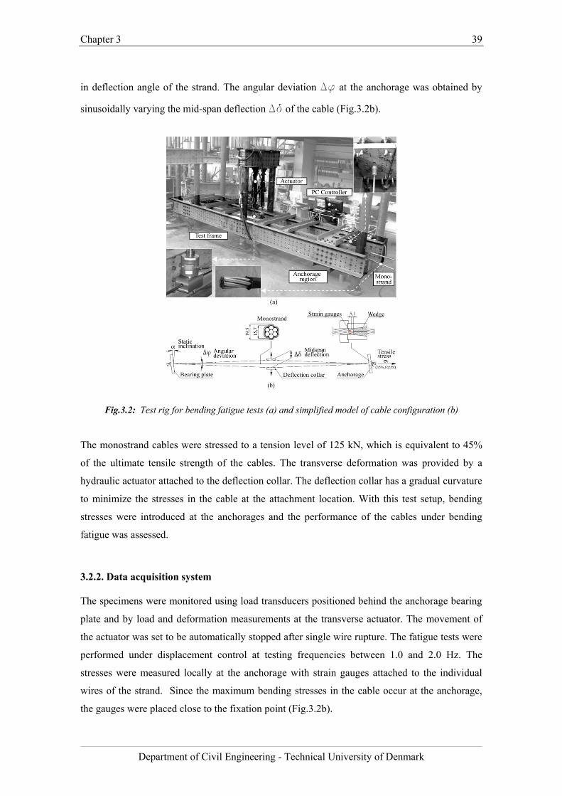
Chapter 3 39
Department of Civil Engineering - Technical University of Denmark
in deflection angle of the strand. The angular deviation Df at the anchorage was obtained by
sinusoidally varying the mid-span deflection Dd of the cable (Fig.3.2b).
Fig.3.2: Test rig for bending fatigue tests (a) and simplified model of cable configuration (b)
The monostrand cables were stressed to a tension level of 125 kN, which is equivalent to 45%
of the ultimate tensile strength of the cables. The transverse deformation was provided by a
hydraulic actuator attached to the deflection collar. The deflection collar has a gradual curvature
to minimize the stresses in the cable at the attachment location. With this test setup, bending
stresses were introduced at the anchorages and the performance of the cables under bending
fatigue was assessed.
3.2.2. Data acquisition system
The specimens were monitored using load transducers positioned behind the anchorage bearing
plate and by load and deformation measurements at the transverse actuator. The movement of
the actuator was set to be automatically stopped after single wire rupture. The fatigue tests were
performed under displacement control at testing frequencies between 1.0 and 2.0 Hz. The
stresses were measured locally at the anchorage with strain gauges attached to the individual
wires of the strand. Since the maximum bending stresses in the cable occur at the anchorage,
the gauges were placed close to the fixation point (Fig.3.2b).
Chapter 3 40
Department of Civil Engineering - Technical University of Denmark
3.2.3 Angular deviation ranges for monostrand cable bending fatigue testing
Based on the information collected from the available literature and the monitoring of the
Øresund Bridge [15], a database comprising of different vibration events was created [16].
Gathered records were used to determine realistic ranges of angular deviations relevant for the
bending fatigue test. Cable vibrations result in an equivalent angular deviation of the cable at the
anchorage that can be determined by means of the amplitude, mode of vibration and cable
length assuming that the cable ends are pinned (Eq. 3.1). By representing the vibrations in terms
of cable rotation, data from different bridges and events are comparable. The motion of
vibrating cables can be described by the function:
f x A ∙ siniπxL
(3.1)
where: i - mode of vibration, L - length of the cable, A - amplitude.
The angular deviations were calculated as a tangent line to the mode shape at its termination, i.e.
at cable’s anchorage (Fig. 3.3):
Fig. 3.3: Calculation of angular deviations
f x A ∙ cosiπxL
∙iπL
(3.2)
f f x 0 A ∙ (3.3)
To illustrate the possible range of vibrations, a histogram of angular deviations (Fig.3.4) was
created based on gathered information.
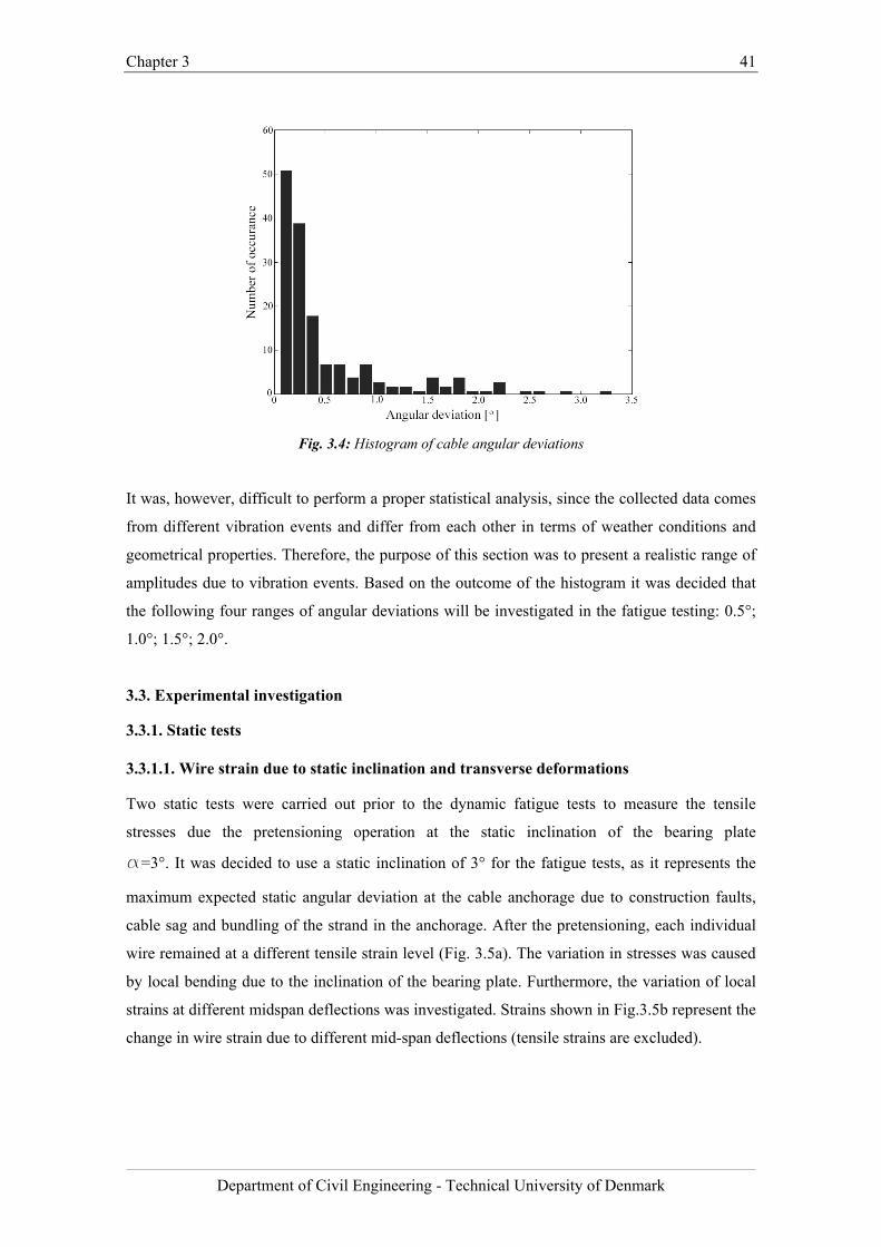
Chapter 3 41
Department of Civil Engineering - Technical University of Denmark
Fig. 3.4: Histogram of cable angular deviations
It was, however, difficult to perform a proper statistical analysis, since the collected data comes
from different vibration events and differ from each other in terms of weather conditions and
geometrical properties. Therefore, the purpose of this section was to present a realistic range of
amplitudes due to vibration events. Based on the outcome of the histogram it was decided that
the following four ranges of angular deviations will be investigated in the fatigue testing: 0.5°;
1.0°; 1.5°; 2.0°.
3.3. Experimental investigation
3.3.1. Static tests
3.3.1.1. Wire strain due to static inclination and transverse deformations
Two static tests were carried out prior to the dynamic fatigue tests to measure the tensile
stresses due the pretensioning operation at the static inclination of the bearing plate
a=3°. It was decided to use a static inclination of 3° for the fatigue tests, as it represents the
maximum expected static angular deviation at the cable anchorage due to construction faults,
cable sag and bundling of the strand in the anchorage. After the pretensioning, each individual
wire remained at a different tensile strain level (Fig. 3.5a). The variation in stresses was caused
by local bending due to the inclination of the bearing plate. Furthermore, the variation of local
strains at different midspan deflections was investigated. Strains shown in Fig.3.5b represent the
change in wire strain due to different mid-span deflections (tensile strains are excluded).
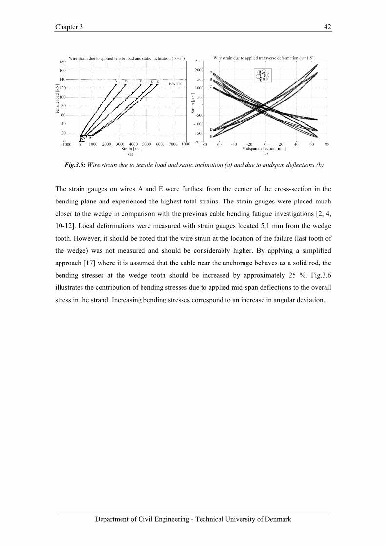
Chapter 3 42
Department of Civil Engineering - Technical University of Denmark
Fig.3.5: Wire strain due to tensile load and static inclination (a) and due to midspan deflections (b)
The strain gauges on wires A and E were furthest from the center of the cross-section in the
bending plane and experienced the highest total strains. The strain gauges were placed much
closer to the wedge in comparison with the previous cable bending fatigue investigations [2, 4,
10-12]. Local deformations were measured with strain gauges located 5.1 mm from the wedge
tooth. However, it should be noted that the wire strain at the location of the failure (last tooth of
the wedge) was not measured and should be considerably higher. By applying a simplified
approach [17] where it is assumed that the cable near the anchorage behaves as a solid rod, the
bending stresses at the wedge tooth should be increased by approximately 25 %. Fig.3.6
illustrates the contribution of bending stresses due to applied mid-span deflections to the overall
stress in the strand. Increasing bending stresses correspond to an increase in angular deviation.
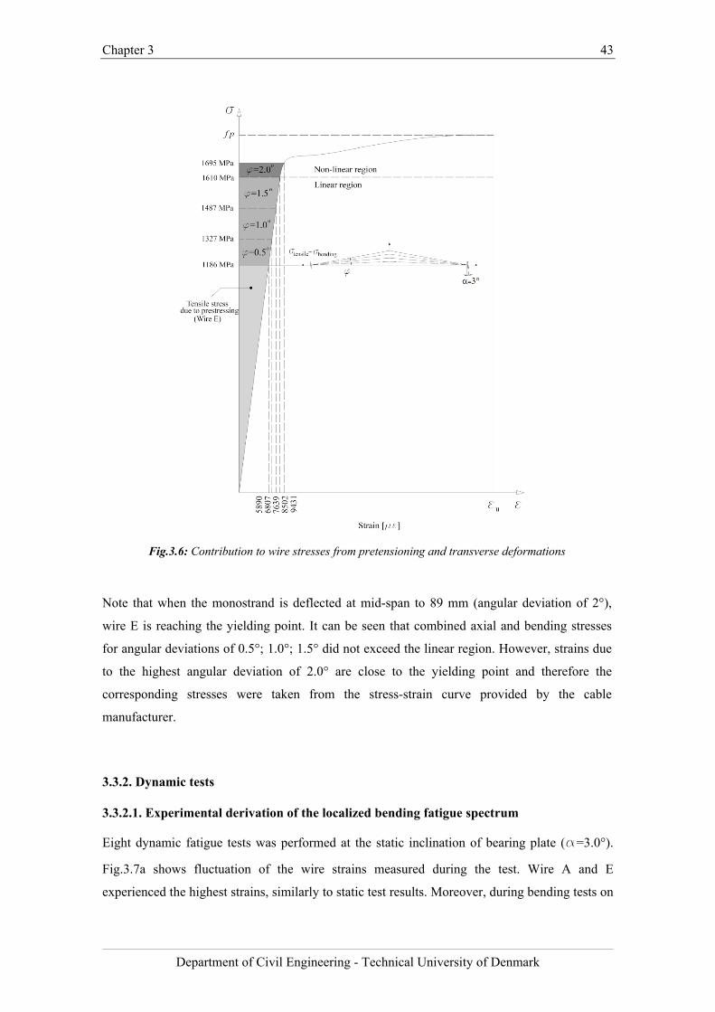
Chapter 3 43
Department of Civil Engineering - Technical University of Denmark
Fig.3.6: Contribution to wire stresses from pretensioning and transverse deformations
Note that when the monostrand is deflected at mid-span to 89 mm (angular deviation of 2°),
wire E is reaching the yielding point. It can be seen that combined axial and bending stresses
for angular deviations of 0.5°; 1.0°; 1.5° did not exceed the linear region. However, strains due
to the highest angular deviation of 2.0° are close to the yielding point and therefore the
corresponding stresses were taken from the stress-strain curve provided by the cable
manufacturer.
3.3.2. Dynamic tests
3.3.2.1. Experimental derivation of the localized bending fatigue spectrum
Eight dynamic fatigue tests was performed at the static inclination of bearing plate (a=3.0°).
Fig.3.7a shows fluctuation of the wire strains measured during the test. Wire A and E
experienced the highest strains, similarly to static test results. Moreover, during bending tests on
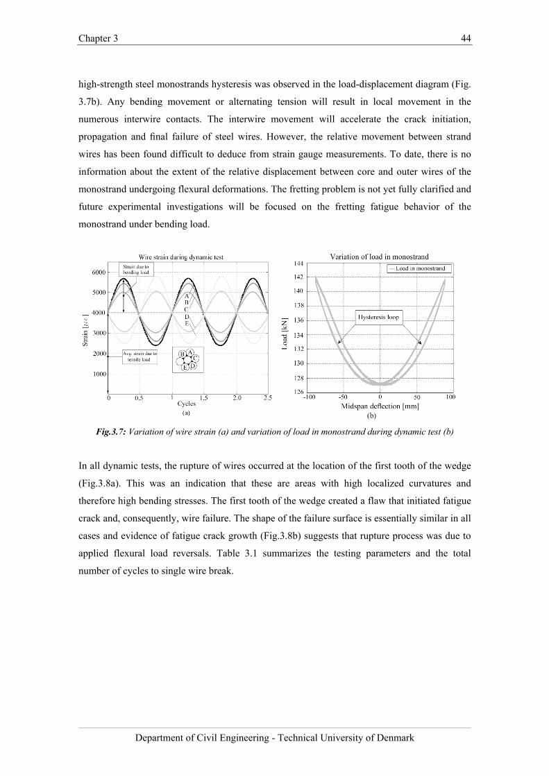
Chapter 3 44
Department of Civil Engineering - Technical University of Denmark
high-strength steel monostrands hysteresis was observed in the load-displacement diagram (Fig.
3.7b). Any bending movement or alternating tension will result in local movement in the
numerous interwire contacts. The interwire movement will accelerate the crack initiation,
propagation and final failure of steel wires. However, the relative movement between strand
wires has been found difficult to deduce from strain gauge measurements. To date, there is no
information about the extent of the relative displacement between core and outer wires of the
monostrand undergoing flexural deformations. The fretting problem is not yet fully clarified and
future experimental investigations will be focused on the fretting fatigue behavior of the
monostrand under bending load.
Fig.3.7: Variation of wire strain (a) and variation of load in monostrand during dynamic test (b)
In all dynamic tests, the rupture of wires occurred at the location of the first tooth of the wedge
(Fig.3.8a). This was an indication that these are areas with high localized curvatures and
therefore high bending stresses. The first tooth of the wedge created a flaw that initiated fatigue
crack and, consequently, wire failure. The shape of the failure surface is essentially similar in all
cases and evidence of fatigue crack growth (Fig.3.8b) suggests that rupture process was due to
applied flexural load reversals. Table 3.1 summarizes the testing parameters and the total
number of cycles to single wire break.
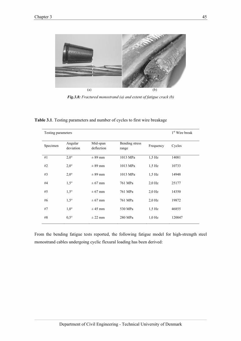
Chapter 3 45
Department of Civil Engineering - Technical University of Denmark
Fig.3.8: Fractured monostrand (a) and extent of fatigue crack (b)
Table 3.1. Testing parameters and number of cycles to first wire breakage
Testing parameters 1st Wire break
Specimen Angular deviation
Mid-span deflection
Bending stress range
Frequency Cycles
#1 2,0° ± 89 mm 1013 MPa 1,5 Hz 14081
#2 2,0° ± 89 mm 1013 MPa 1,5 Hz 10733
#3 2,0° ± 89 mm 1013 MPa 1,5 Hz 14948
#4 1,5° ± 67 mm 761 MPa 2,0 Hz 25177
#5 1,5° ± 67 mm 761 MPa 2,0 Hz 14350
#6 1,5° ± 67 mm 761 MPa 2,0 Hz 19872
#7 1,0° ± 45 mm 530 MPa 1,5 Hz 46855
#8 0,5° ± 22 mm 280 MPa 1,0 Hz 120047
From the bending fatigue tests reported, the following fatigue model for high-strength steel
monostrand cables undergoing cyclic flexural loading has been derived:
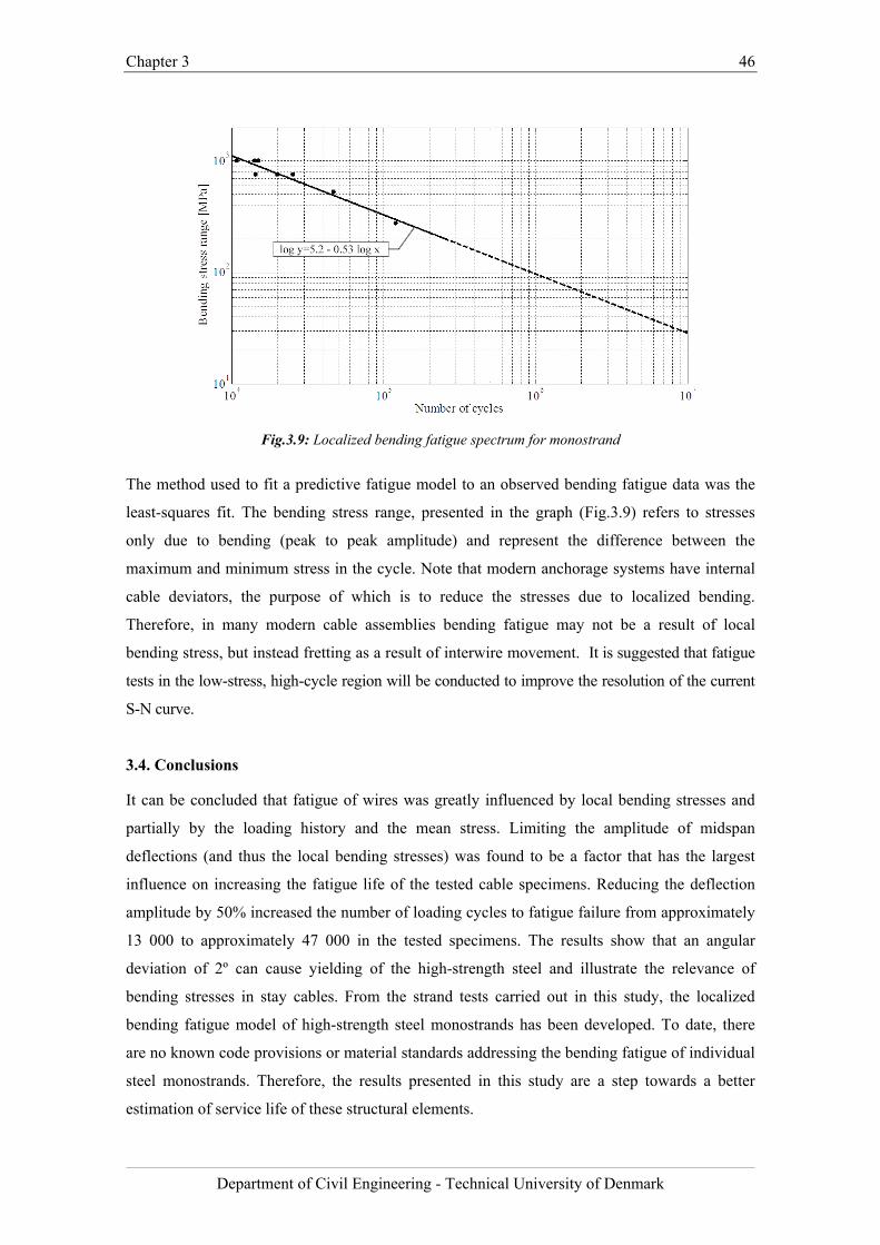
Chapter 3 46
Department of Civil Engineering - Technical University of Denmark
(
Fig.3.9: Localized bending fatigue spectrum for monostrand
The method used to fit a predictive fatigue model to an observed bending fatigue data was the
least-squares fit. The bending stress range, presented in the graph (Fig.3.9) refers to stresses
only due to bending (peak to peak amplitude) and represent the difference between the
maximum and minimum stress in the cycle. Note that modern anchorage systems have internal
cable deviators, the purpose of which is to reduce the stresses due to localized bending.
Therefore, in many modern cable assemblies bending fatigue may not be a result of local
bending stress, but instead fretting as a result of interwire movement. It is suggested that fatigue
tests in the low-stress, high-cycle region will be conducted to improve the resolution of the current
S-N curve.
3.4. Conclusions
It can be concluded that fatigue of wires was greatly influenced by local bending stresses and
partially by the loading history and the mean stress. Limiting the amplitude of midspan
deflections (and thus the local bending stresses) was found to be a factor that has the largest
influence on increasing the fatigue life of the tested cable specimens. Reducing the deflection
amplitude by 50% increased the number of loading cycles to fatigue failure from approximately
13 000 to approximately 47 000 in the tested specimens. The results show that an angular
deviation of 2º can cause yielding of the high-strength steel and illustrate the relevance of
bending stresses in stay cables. From the strand tests carried out in this study, the localized
bending fatigue model of high-strength steel monostrands has been developed. To date, there
are no known code provisions or material standards addressing the bending fatigue of individual
steel monostrands. Therefore, the results presented in this study are a step towards a better
estimation of service life of these structural elements.
Chapter 3 47
Department of Civil Engineering - Technical University of Denmark
Bibliography
[1] Siegert, D., and Brevet, P., Fatigue of stay cables inside end fittings: High frequencies
of wind induced vibrations, Proceedings of the OIPEEC technical meeting, 2003.
[2] Hobbs, R.E., and Ghavami, K., The fatigue of structural wire strands, International
Journal of Fatigue, Vol. 4, 1982, pp. 69–72.
[3] Paulson, C., Frank, K. H., and Breen, J.E., A Fatigue Study of Prestressing Strand,
Center for Transportation Research, The University of Texas at Austin, Research Report
300-1, 1983.
[4] Hobbs, R.E., and Smith, B.W., Fatigue performance of socketed terminations to
structural strands, Proceeding of the Institution of Civil Engineers. Part 2. Research
and theory, Vol. 75, 1983, pp. 35–48.
[5] Hobbs, R.E., and Raoff, M., Behaviour of cables under dynamic or repeated loading,
Journal of Constructional Steel Research, Vol. 39, 1996, pp. 31–50.
[6] Cremona, C., A short note on cable fatigue, Proceedings of the 5th international
symposium on cable dynamics, 2003.
[7] Cluni, F., Gusella, V., and Ubertini, F., A parametric investigation of wind-induced
cable fatigue, Engineering Structures, Vol. 29, 2007, pp. 3094-3105.
[8] Jensen, J.L., Bitsch, N., and Laursen, E., Fatigue Risk Assessment of Hangers on Great
Belt Bridge, Proceedings of the 7th International Symposium on Cable Dynamics,
2007.
[9] Laursen, E., Bitsch, N., and Andersen, J.E., Analysis and Mitigation of Large
Amplitude Cable Vibrations at the Great Belt East Bridge, Proceedings of the IABSE
Conference on Operation, Maintenance and Rehabilitation of Large Infrastructure
Projects, Bridges and Tunnels, 2006, Vol. 91.
[10] Miki, C., Endo, T., and Okukawa, A., Full-Size Fatigue Test of Bridge Cables, IABSE
Reports, Length Effects on Fatigue of Wires and Strands, Vol. 66, 1992, pp. 167-178.
[11] Gourmelon, J.P., Cable fatigue behavior as a major safety factor in cable-stayed
bridges, Bulletin des Laboratoires des Ponts et Chaussees, Issue: 244-245, 2003, pp.
53-71.
[12] Wood, S., and Frank, K.H., Experimental investigation of bending fatigue response of
grouted stay cables, Journal of Bridge Engineering, Vol. 15, 2010, pp. 123-130.
[13] Fédération internationale du béton (fib), Bulletin 30 Acceptance of stay cable systems
using prestressing steel, 2005.
[14] Post Tensioning Institute (PTI), PTI Guide Specification. Recommendations for stay
Chapter 3 48
Department of Civil Engineering - Technical University of Denmark
cable Design, Testing and Installation, 2007.
[15] Acampora, A., and Georgakis, C.T., Recent monitoring of the Øresund Bridge:
Observations of rain-wind induced cable vibrations, Proceedings of the 13th
International Conference on Wind Engineering, Amsterdam, July 10-15, 2011.
[16] Winkler, J., and Kotas, A., Fatigue Analysis of Steel Cables under Bending Load,
Academic dissertation (Master thesis), 2010, Technical University of Denmark.
[17] Wyatt, T.A., Secondary stress in parallel wire suspension cables, Journal of the
Structural Division, Proceedings of the ASCE, 1960.

Chapter 3 49
Department of Civil Engineering - Technical University of Denmark
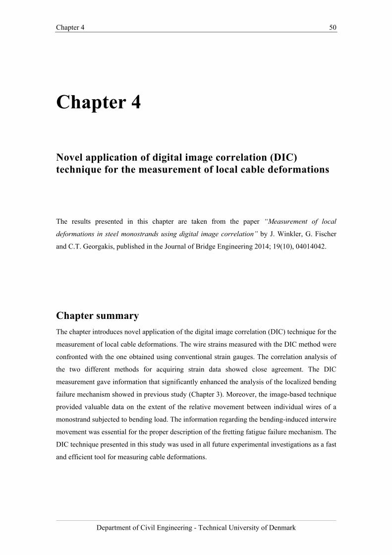
Chapter 4 50
Department of Civil Engineering - Technical University of Denmark
Chapter 4
Novel application of digital image correlation (DIC) technique for the measurement of local cable deformations
The results presented in this chapter are taken from the paper “Measurement of local
deformations in steel monostrands using digital image correlation” by J. Winkler, G. Fischer
and C.T. Georgakis, published in the Journal of Bridge Engineering 2014; 19(10), 04014042.
Chapter summary
The chapter introduces novel application of the digital image correlation (DIC) technique for the
measurement of local cable deformations. The wire strains measured with the DIC method were
confronted with the one obtained using conventional strain gauges. The correlation analysis of
the two different methods for acquiring strain data showed close agreement. The DIC
measurement gave information that significantly enhanced the analysis of the localized bending
failure mechanism showed in previous study (Chapter 3). Moreover, the image-based technique
provided valuable data on the extent of the relative movement between individual wires of a
monostrand subjected to bending load. The information regarding the bending-induced interwire
movement was essential for the proper description of the fretting fatigue failure mechanism. The
DIC technique presented in this study was used in all future experimental investigations as a fast
and efficient tool for measuring cable deformations.
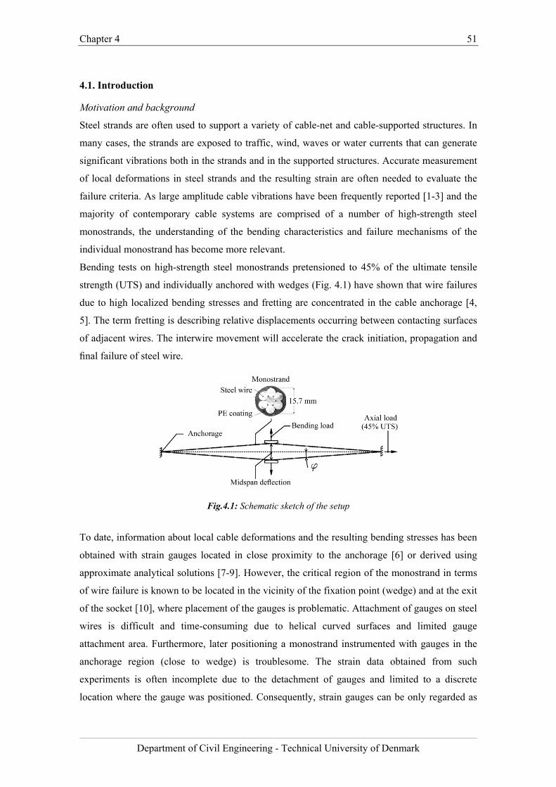
Chapter 4 51
Department of Civil Engineering - Technical University of Denmark
4.1. Introduction
Motivation and background
Steel strands are often used to support a variety of cable-net and cable-supported structures. In
many cases, the strands are exposed to traffic, wind, waves or water currents that can generate
significant vibrations both in the strands and in the supported structures. Accurate measurement
of local deformations in steel strands and the resulting strain are often needed to evaluate the
failure criteria. As large amplitude cable vibrations have been frequently reported [1-3] and the
majority of contemporary cable systems are comprised of a number of high-strength steel
monostrands, the understanding of the bending characteristics and failure mechanisms of the
individual monostrand has become more relevant.
Bending tests on high-strength steel monostrands pretensioned to 45% of the ultimate tensile
strength (UTS) and individually anchored with wedges (Fig. 4.1) have shown that wire failures
due to high localized bending stresses and fretting are concentrated in the cable anchorage [4,
5]. The term fretting is describing relative displacements occurring between contacting surfaces
of adjacent wires. The interwire movement will accelerate the crack initiation, propagation and
final failure of steel wire.
Fig.4.1: Schematic sketch of the setup
To date, information about local cable deformations and the resulting bending stresses has been
obtained with strain gauges located in close proximity to the anchorage [6] or derived using
approximate analytical solutions [7-9]. However, the critical region of the monostrand in terms
of wire failure is known to be located in the vicinity of the fixation point (wedge) and at the exit
of the socket [10], where placement of the gauges is problematic. Attachment of gauges on steel
wires is difficult and time-consuming due to helical curved surfaces and limited gauge
attachment area. Furthermore, later positioning a monostrand instrumented with gauges in the
anchorage region (close to wedge) is troublesome. The strain data obtained from such
experiments is often incomplete due to the detachment of gauges and limited to a discrete
location where the gauge was positioned. Consequently, strain gauges can be only regarded as
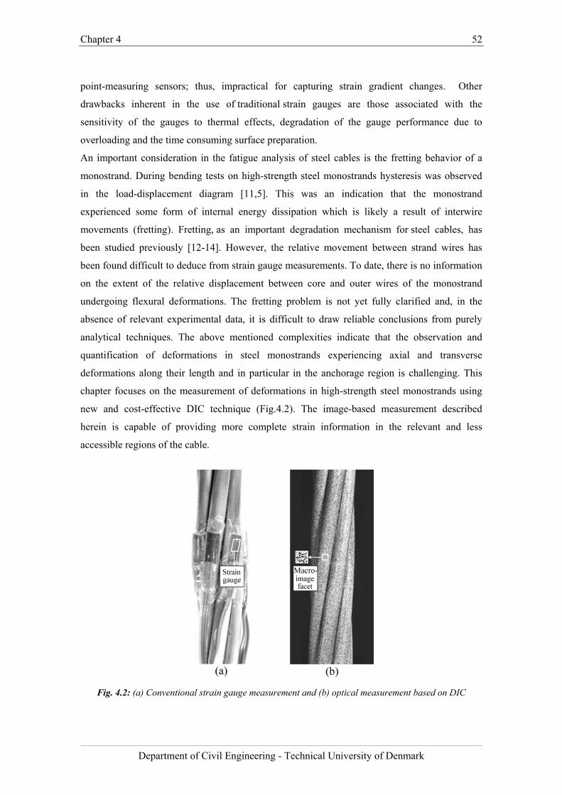
Chapter 4 52
Department of Civil Engineering - Technical University of Denmark
point-measuring sensors; thus, impractical for capturing strain gradient changes. Other
drawbacks inherent in the use of traditional strain gauges are those associated with the
sensitivity of the gauges to thermal effects, degradation of the gauge performance due to
overloading and the time consuming surface preparation.
An important consideration in the fatigue analysis of steel cables is the fretting behavior of a
monostrand. During bending tests on high-strength steel monostrands hysteresis was observed
in the load-displacement diagram [11,5]. This was an indication that the monostrand
experienced some form of internal energy dissipation which is likely a result of interwire
movements (fretting). Fretting, as an important degradation mechanism for steel cables, has
been studied previously [12-14]. However, the relative movement between strand wires has
been found difficult to deduce from strain gauge measurements. To date, there is no information
on the extent of the relative displacement between core and outer wires of the monostrand
undergoing flexural deformations. The fretting problem is not yet fully clarified and, in the
absence of relevant experimental data, it is difficult to draw reliable conclusions from purely
analytical techniques. The above mentioned complexities indicate that the observation and
quantification of deformations in steel monostrands experiencing axial and transverse
deformations along their length and in particular in the anchorage region is challenging. This
chapter focuses on the measurement of deformations in high-strength steel monostrands using
new and cost-effective DIC technique (Fig.4.2). The image-based measurement described
herein is capable of providing more complete strain information in the relevant and less
accessible regions of the cable.
Fig. 4.2: (a) Conventional strain gauge measurement and (b) optical measurement based on DIC
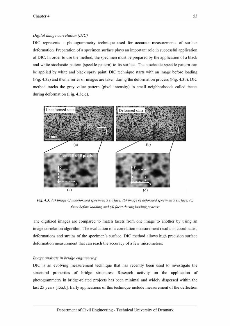
Chapter 4 53
Department of Civil Engineering - Technical University of Denmark
Digital image correlation (DIC)
DIC represents a photogrammetry technique used for accurate measurements of surface
deformation. Preparation of a specimen surface plays an important role in successful application
of DIC. In order to use the method, the specimen must be prepared by the application of a black
and white stochastic pattern (speckle pattern) to its surface. The stochastic speckle pattern can
be applied by white and black spray paint. DIC technique starts with an image before loading
(Fig. 4.3a) and then a series of images are taken during the deformation process (Fig. 4.3b). DIC
method tracks the gray value pattern (pixel intensity) in small neighborhoods called facets
during deformation (Fig. 4.3c,d).
Fig. 4.3: (a) Image of undeformed specimen’s surface, (b) image of deformed specimen’s surface, (c)
facet before loading and (d) facet during loading process
The digitized images are compared to match facets from one image to another by using an
image correlation algorithm. The evaluation of a correlation measurement results in coordinates,
deformations and strains of the specimen’s surface. DIC method allows high precision surface
deformation measurement that can reach the accuracy of a few micrometers.
Image analysis in bridge engineering
DIC is an evolving measurement technique that has recently been used to investigate the
structural properties of bridge structures. Research activity on the application of
photogrammetry in bridge-related projects has been minimal and widely dispersed within the
last 25 years [15a,b]. Early applications of this technique include measurement of the deflection
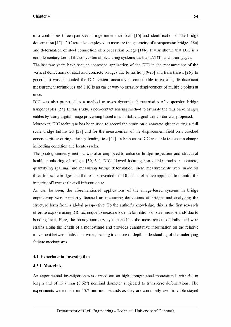
Chapter 4 54
Department of Civil Engineering - Technical University of Denmark
of a continuous three span steel bridge under dead load [16] and identification of the bridge
deformation [17]. DIC was also employed to measure the geometry of a suspension bridge [18a]
and deformation of steel connection of a pedestrian bridge [18b]. It was shown that DIC is a
complementary tool of the conventional measuring systems such as LVDTs and strain gages.
The last few years have seen an increased application of the DIC in the measurement of the
vertical deflections of steel and concrete bridges due to traffic [19-25] and train transit [26]. In
general, it was concluded the DIC system accuracy is comparable to existing displacement
measurement techniques and DIC is an easier way to measure displacement of multiple points at
once.
DIC was also proposed as a method to asses dynamic characteristics of suspension bridge
hanger cables [27]. In this study, a non-contact sensing method to estimate the tension of hanger
cables by using digital image processing based on a portable digital camcorder was proposed.
Moreover, DIC technique has been used to record the strain on a concrete girder during a full
scale bridge failure test [28] and for the measurement of the displacement field on a cracked
concrete girder during a bridge loading test [29]. In both cases DIC was able to detect a change
in loading condition and locate cracks.
The photogrammetry method was also employed to enhance bridge inspection and structural
health monitoring of bridges [30, 31]. DIC allowed locating non-visible cracks in concrete,
quantifying spalling, and measuring bridge deformation. Field measurements were made on
three full-scale bridges and the results revealed that DIC is an effective approach to monitor the
integrity of large scale civil infrastructure.
As can be seen, the aforementioned applications of the image-based systems in bridge
engineering were primarily focused on measuring deflections of bridges and analyzing the
structure form from a global perspective. To the author’s knowledge, this is the first research
effort to explore using DIC technique to measure local deformations of steel monostrands due to
bending load. Here, the photogrammetry system enables the measurement of individual wire
strains along the length of a monostrand and provides quantitative information on the relative
movement between individual wires, leading to a more in-depth understanding of the underlying
fatigue mechanisms.
4.2. Experimental investigation
4.2.1. Materials
An experimental investigation was carried out on high-strength steel monostrands with 5.1 m
length and of 15.7 mm (0.62”) nominal diameter subjected to transverse deformations. The
experiments were made on 15.7 mm monostrands as they are commonly used in cable stayed
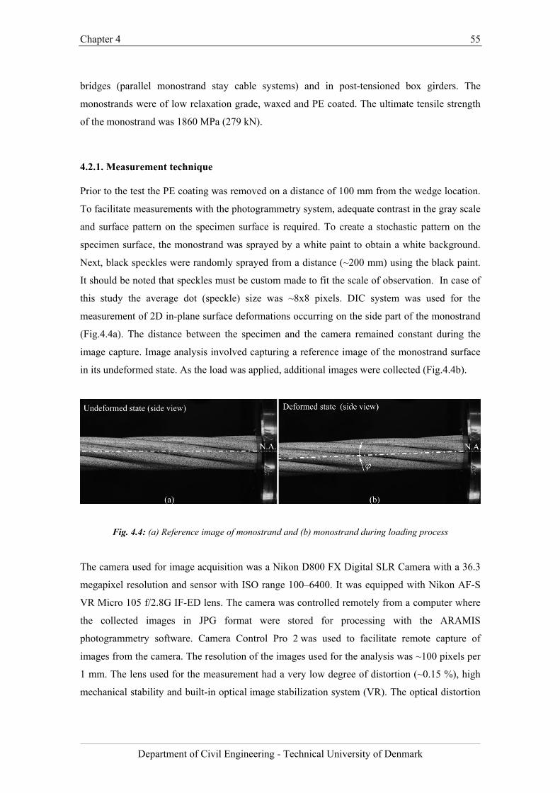
Chapter 4 55
Department of Civil Engineering - Technical University of Denmark
bridges (parallel monostrand stay cable systems) and in post-tensioned box girders. The
monostrands were of low relaxation grade, waxed and PE coated. The ultimate tensile strength
of the monostrand was 1860 MPa (279 kN).
4.2.1. Measurement technique
Prior to the test the PE coating was removed on a distance of 100 mm from the wedge location.
To facilitate measurements with the photogrammetry system, adequate contrast in the gray scale
and surface pattern on the specimen surface is required. To create a stochastic pattern on the
specimen surface, the monostrand was sprayed by a white paint to obtain a white background.
Next, black speckles were randomly sprayed from a distance (~200 mm) using the black paint.
It should be noted that speckles must be custom made to fit the scale of observation. In case of
this study the average dot (speckle) size was ~8x8 pixels. DIC system was used for the
measurement of 2D in-plane surface deformations occurring on the side part of the monostrand
(Fig.4.4a). The distance between the specimen and the camera remained constant during the
image capture. Image analysis involved capturing a reference image of the monostrand surface
in its undeformed state. As the load was applied, additional images were collected (Fig.4.4b).
Fig. 4.4: (a) Reference image of monostrand and (b) monostrand during loading process
The camera used for image acquisition was a Nikon D800 FX Digital SLR Camera with a 36.3
megapixel resolution and sensor with ISO range 100–6400. It was equipped with Nikon AF-S
VR Micro 105 f/2.8G IF-ED lens. The camera was controlled remotely from a computer where
the collected images in JPG format were stored for processing with the ARAMIS
photogrammetry software. Camera Control Pro 2 was used to facilitate remote capture of
images from the camera. The resolution of the images used for the analysis was ~100 pixels per
1 mm. The lens used for the measurement had a very low degree of distortion (~0.15 %), high
mechanical stability and built-in optical image stabilization system (VR). The optical distortion
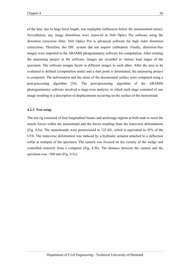
Chapter 4 56
Department of Civil Engineering - Technical University of Denmark
of the lens, due to large focal length, was negligible (influences below the measurement noise).
Nevertheless, any image distortions were removed in Dx0 Optics Pro software using the
distortion correction filter. Dx0 Optics Pro is advanced software for high order distortion
corrections. Therefore, the DIC system did not require calibration. Finally, distortion-free
images were imported to the ARAMIS photgrammetry software for computation. After creating
the measuring project in the software, images are recorded in various load stages of the
specimen. The software assigns facets in different images to each other. After the area to be
evaluated is defined (computation mask) and a start point is determined, the measuring project
is computed. The deformation and the strain of the documented surface were computed using a
post-processing algorithm [36]. The post-processing algorithm of the ARAMIS
photogrammetry software involved a stage-wise analysis, in which each stage consisted of one
image resulting in a description of displacements occurring on the surface of the monostrand.
4.2.3. Test setup
The test rig consisted of four longitudinal beams and anchorage regions at both ends to resist the
tensile forces within the monostrand and the forces resulting from the transverse deformations
(Fig. 4.5a). The monostrands were pretensioned to 125 kN, which is equivalent to 45% of the
UTS. The transverse deformation was induced by a hydraulic actuator attached to a deflection
collar at midspan of the specimen. The camera was focused on the vicinity of the wedge and
controlled remotely from a computer (Fig. 4.5b). The distance between the camera and the
specimen was ~300 mm (Fig. 4.5c).
Chapter 4 57
Department of Civil Engineering - Technical University of Denmark
Fig. 4.5: (a) Test rig for monostrand bending tests, (b) test setup for the DIC measurement, (c) distance
between camera and specimen and (d) anchorage region
The monostrand was terminated at both ends with a generic anchorage preventing rotational
movement (Fig. 4.5d). With this test setup, bending stresses were introduced at the anchorages.
4.3. Validation of DIC
To validate the proposed image‐based system of measurement, two analyses were performed
indicating good agreement between measurements made with traditional strain gauges and those
made using DIC.
4.3.1. Correlation analysis of strains due to axial load
The setup comprised of an axial tensile force applied to a high-strength steel monostrand
instrumented with strain gauges at the upper anchorage and the surface prepared for the DIC
analysis at the lower anchorage (Fig. 4.6a). The load was applied axially (load range: 0 – 125
kN) and the resulting strain was measured using image analysis and by physical strain gauges.
The deformation rate in the tensile machine was ~0.05 mm per second and the images for the
correlation test were taken every second. The measurements were taken 40 mm away from the
wedge on both ends of the specimen. 30 images in total were acquired for the DIC analysis.
Two tests were performed and the strain was collected from three gauges and three DIC
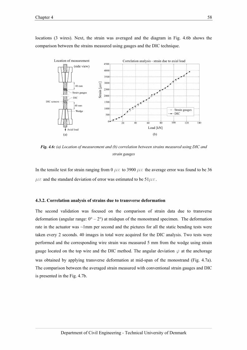
Chapter 4 58
Department of Civil Engineering - Technical University of Denmark
locations (3 wires). Next, the strain was averaged and the diagram in Fig. 4.6b shows the
comparison between the strains measured using gauges and the DIC technique.
Fig. 4.6: (a) Location of measurement and (b) correlation between strains measured using DIC and
strain gauges
In the tensile test for strain ranging from 0 με to 3900 με the average error was found to be 36
με and the standard deviation of error was estimated to be 51με.
4.3.2. Correlation analysis of strains due to transverse deformation
The second validation was focused on the comparison of strain data due to transverse
deformation (angular range: 0° – 2°) at midspan of the monostrand specimen. The deformation
rate in the actuator was ~1mm per second and the pictures for all the static bending tests were
taken every 2 seconds. 40 images in total were acquired for the DIC analysis. Two tests were
performed and the corresponding wire strain was measured 5 mm from the wedge using strain
gauge located on the top wire and the DIC method. The angular deviation f at the anchorage
was obtained by applying transverse deformation at mid-span of the monostrand (Fig. 4.7a).
The comparison between the averaged strain measured with conventional strain gauges and DIC
is presented in the Fig. 4.7b.
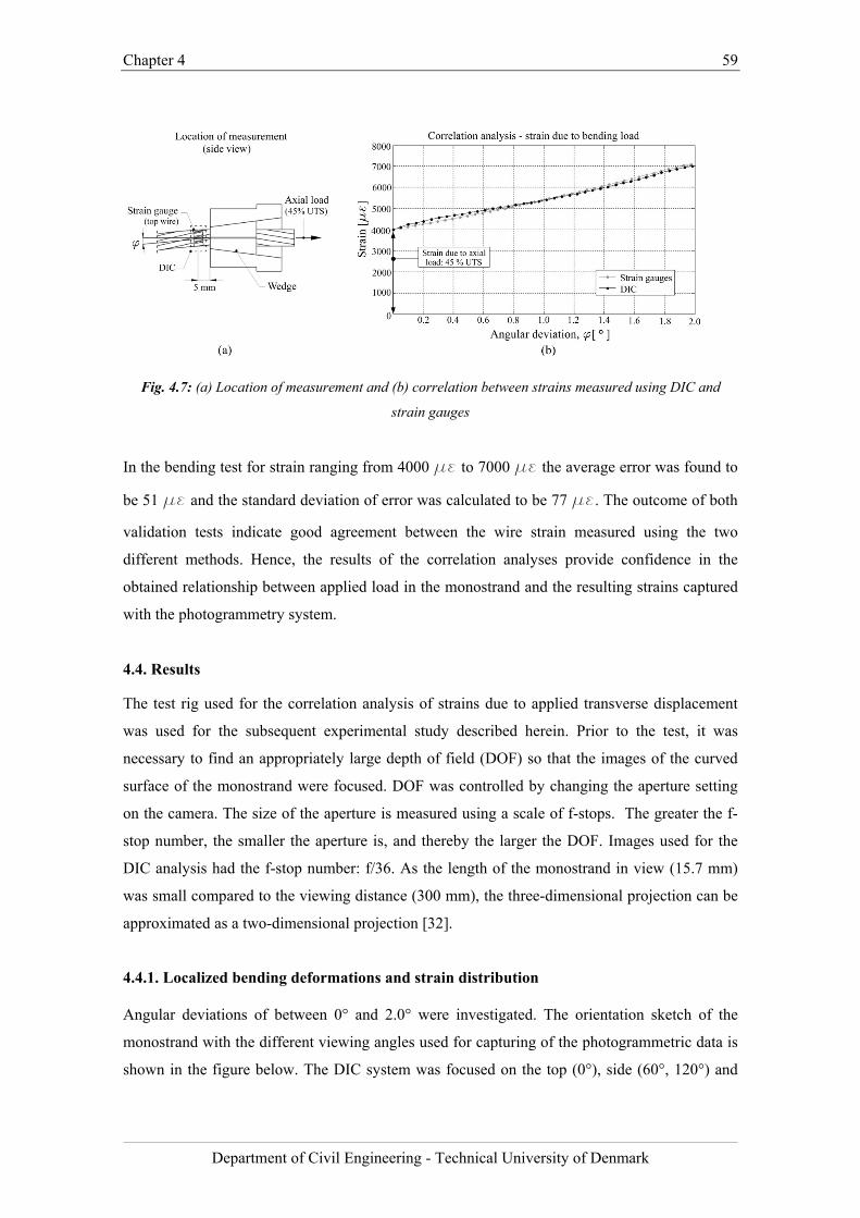
Chapter 4 59
Department of Civil Engineering - Technical University of Denmark
Fig. 4.7: (a) Location of measurement and (b) correlation between strains measured using DIC and
strain gauges
In the bending test for strain ranging from 4000 με to 7000 με the average error was found to
be 51 με and the standard deviation of error was calculated to be 77 με. The outcome of both
validation tests indicate good agreement between the wire strain measured using the two
different methods. Hence, the results of the correlation analyses provide confidence in the
obtained relationship between applied load in the monostrand and the resulting strains captured
with the photogrammetry system.
4.4. Results
The test rig used for the correlation analysis of strains due to applied transverse displacement
was used for the subsequent experimental study described herein. Prior to the test, it was
necessary to find an appropriately large depth of field (DOF) so that the images of the curved
surface of the monostrand were focused. DOF was controlled by changing the aperture setting
on the camera. The size of the aperture is measured using a scale of f-stops. The greater the f-
stop number, the smaller the aperture is, and thereby the larger the DOF. Images used for the
DIC analysis had the f-stop number: f/36. As the length of the monostrand in view (15.7 mm)
was small compared to the viewing distance (300 mm), the three-dimensional projection can be
approximated as a two-dimensional projection [32].
4.4.1. Localized bending deformations and strain distribution
Angular deviations of between 0° and 2.0° were investigated. The orientation sketch of the
monostrand with the different viewing angles used for capturing of the photogrammetric data is
shown in the figure below. The DIC system was focused on the top (0°), side (60°, 120°) and
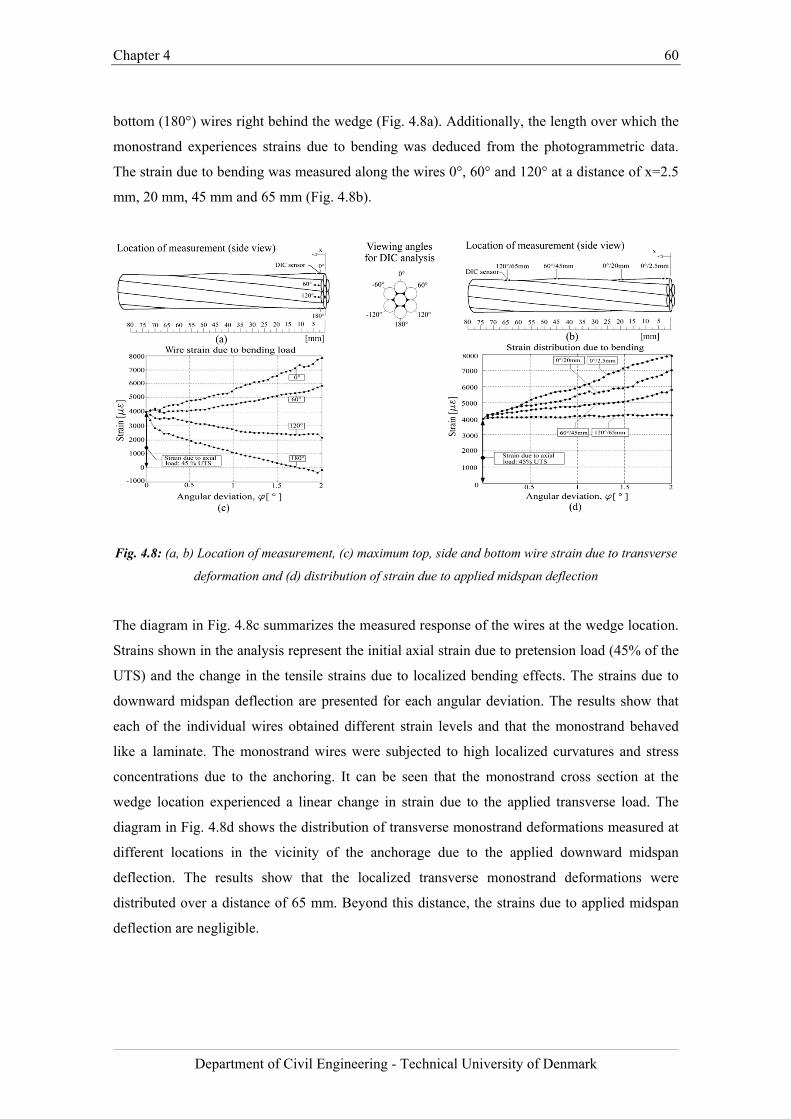
Chapter 4 60
Department of Civil Engineering - Technical University of Denmark
bottom (180°) wires right behind the wedge (Fig. 4.8a). Additionally, the length over which the
monostrand experiences strains due to bending was deduced from the photogrammetric data.
The strain due to bending was measured along the wires 0°, 60° and 120° at a distance of x=2.5
mm, 20 mm, 45 mm and 65 mm (Fig. 4.8b).
Fig. 4.8: (a, b) Location of measurement, (c) maximum top, side and bottom wire strain due to transverse
deformation and (d) distribution of strain due to applied midspan deflection
The diagram in Fig. 4.8c summarizes the measured response of the wires at the wedge location.
Strains shown in the analysis represent the initial axial strain due to pretension load (45% of the
UTS) and the change in the tensile strains due to localized bending effects. The strains due to
downward midspan deflection are presented for each angular deviation. The results show that
each of the individual wires obtained different strain levels and that the monostrand behaved
like a laminate. The monostrand wires were subjected to high localized curvatures and stress
concentrations due to the anchoring. It can be seen that the monostrand cross section at the
wedge location experienced a linear change in strain due to the applied transverse load. The
diagram in Fig. 4.8d shows the distribution of transverse monostrand deformations measured at
different locations in the vicinity of the anchorage due to the applied downward midspan
deflection. The results show that the localized transverse monostrand deformations were
distributed over a distance of 65 mm. Beyond this distance, the strains due to applied midspan
deflection are negligible.
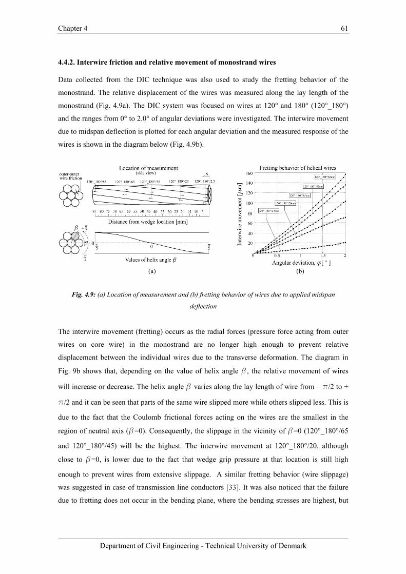
Chapter 4 61
Department of Civil Engineering - Technical University of Denmark
4.4.2. Interwire friction and relative movement of monostrand wires
Data collected from the DIC technique was also used to study the fretting behavior of the
monostrand. The relative displacement of the wires was measured along the lay length of the
monostrand (Fig. 4.9a). The DIC system was focused on wires at 120° and 180° (120°_180°)
and the ranges from 0° to 2.0° of angular deviations were investigated. The interwire movement
due to midspan deflection is plotted for each angular deviation and the measured response of the
wires is shown in the diagram below (Fig. 4.9b).
Fig. 4.9: (a) Location of measurement and (b) fretting behavior of wires due to applied midspan
deflection
The interwire movement (fretting) occurs as the radial forces (pressure force acting from outer
wires on core wire) in the monostrand are no longer high enough to prevent relative
displacement between the individual wires due to the transverse deformation. The diagram in
Fig. 9b shows that, depending on the value of helix angle b, the relative movement of wires
will increase or decrease. The helix angle b varies along the lay length of wire from – p/2 to +
p/2 and it can be seen that parts of the same wire slipped more while others slipped less. This is
due to the fact that the Coulomb frictional forces acting on the wires are the smallest in the
region of neutral axis (b=0). Consequently, the slippage in the vicinity of b=0 (120°_180°/65
and 120°_180°/45) will be the highest. The interwire movement at 120°_180°/20, although
close to b=0, is lower due to the fact that wedge grip pressure at that location is still high
enough to prevent wires from extensive slippage. A similar fretting behavior (wire slippage)
was suggested in case of transmission line conductors [33]. It was also noticed that the failure
due to fretting does not occur in the bending plane, where the bending stresses are highest, but
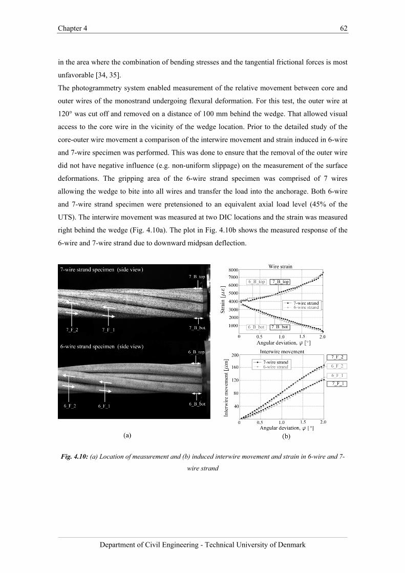
Chapter 4 62
Department of Civil Engineering - Technical University of Denmark
in the area where the combination of bending stresses and the tangential frictional forces is most
unfavorable [34, 35].
The photogrammetry system enabled measurement of the relative movement between core and
outer wires of the monostrand undergoing flexural deformation. For this test, the outer wire at
120° was cut off and removed on a distance of 100 mm behind the wedge. That allowed visual
access to the core wire in the vicinity of the wedge location. Prior to the detailed study of the
core-outer wire movement a comparison of the interwire movement and strain induced in 6-wire
and 7-wire specimen was performed. This was done to ensure that the removal of the outer wire
did not have negative influence (e.g. non-uniform slippage) on the measurement of the surface
deformations. The gripping area of the 6-wire strand specimen was comprised of 7 wires
allowing the wedge to bite into all wires and transfer the load into the anchorage. Both 6-wire
and 7-wire strand specimen were pretensioned to an equivalent axial load level (45% of the
UTS). The interwire movement was measured at two DIC locations and the strain was measured
right behind the wedge (Fig. 4.10a). The plot in Fig. 4.10b shows the measured response of the
6-wire and 7-wire strand due to downward midpsan deflection.
Fig. 4.10: (a) Location of measurement and (b) induced interwire movement and strain in 6-wire and 7-
wire strand
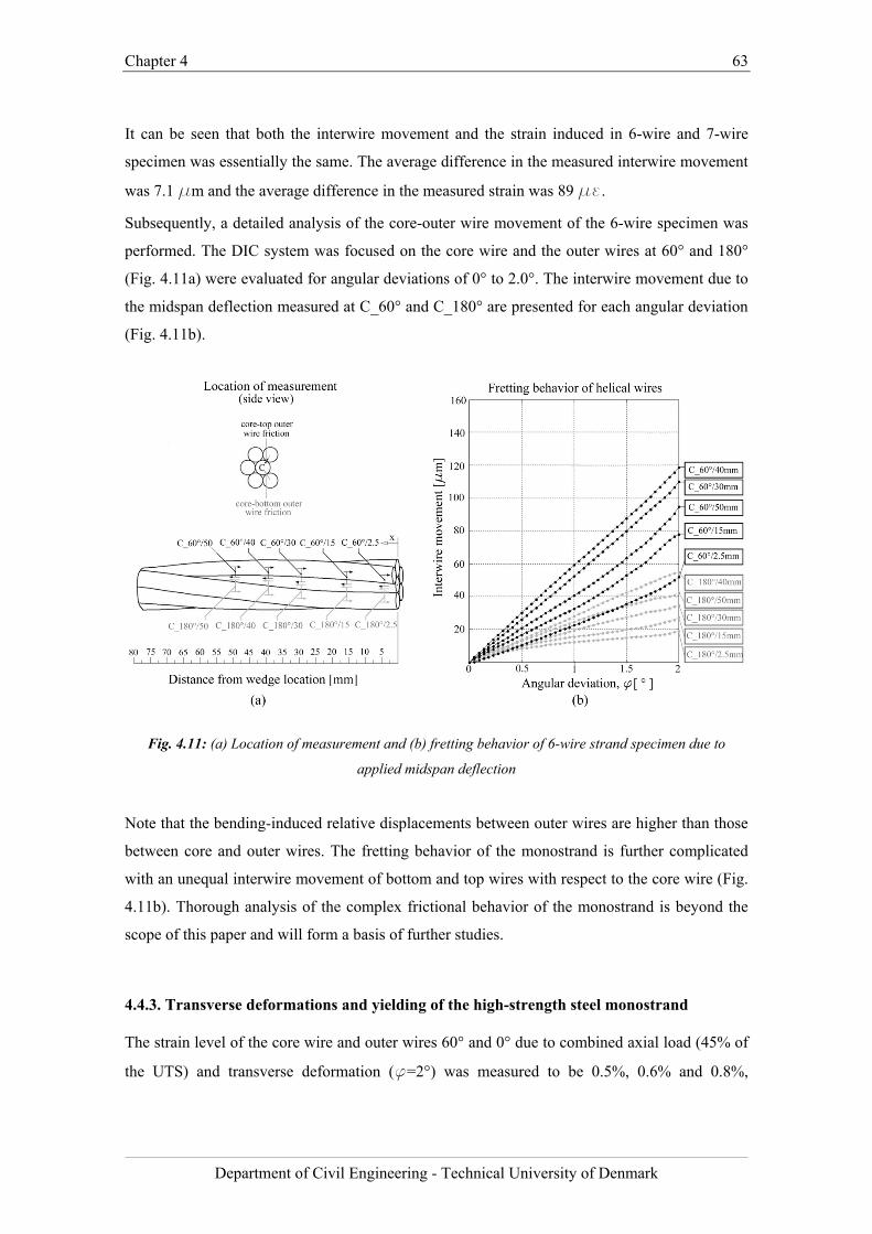
Chapter 4 63
Department of Civil Engineering - Technical University of Denmark
It can be seen that both the interwire movement and the strain induced in 6-wire and 7-wire
specimen was essentially the same. The average difference in the measured interwire movement
was 7.1 μm and the average difference in the measured strain was 89 με.
Subsequently, a detailed analysis of the core-outer wire movement of the 6-wire specimen was
performed. The DIC system was focused on the core wire and the outer wires at 60° and 180°
(Fig. 4.11a) were evaluated for angular deviations of 0° to 2.0°. The interwire movement due to
the midspan deflection measured at C_60° and C_180° are presented for each angular deviation
(Fig. 4.11b).
Fig. 4.11: (a) Location of measurement and (b) fretting behavior of 6-wire strand specimen due to
applied midspan deflection
Note that the bending-induced relative displacements between outer wires are higher than those
between core and outer wires. The fretting behavior of the monostrand is further complicated
with an unequal interwire movement of bottom and top wires with respect to the core wire (Fig.
4.11b). Thorough analysis of the complex frictional behavior of the monostrand is beyond the
scope of this paper and will form a basis of further studies.
4.4.3. Transverse deformations and yielding of the high-strength steel monostrand
The strain level of the core wire and outer wires 60° and 0° due to combined axial load (45% of
the UTS) and transverse deformation (f=2°) was measured to be 0.5%, 0.6% and 0.8%,
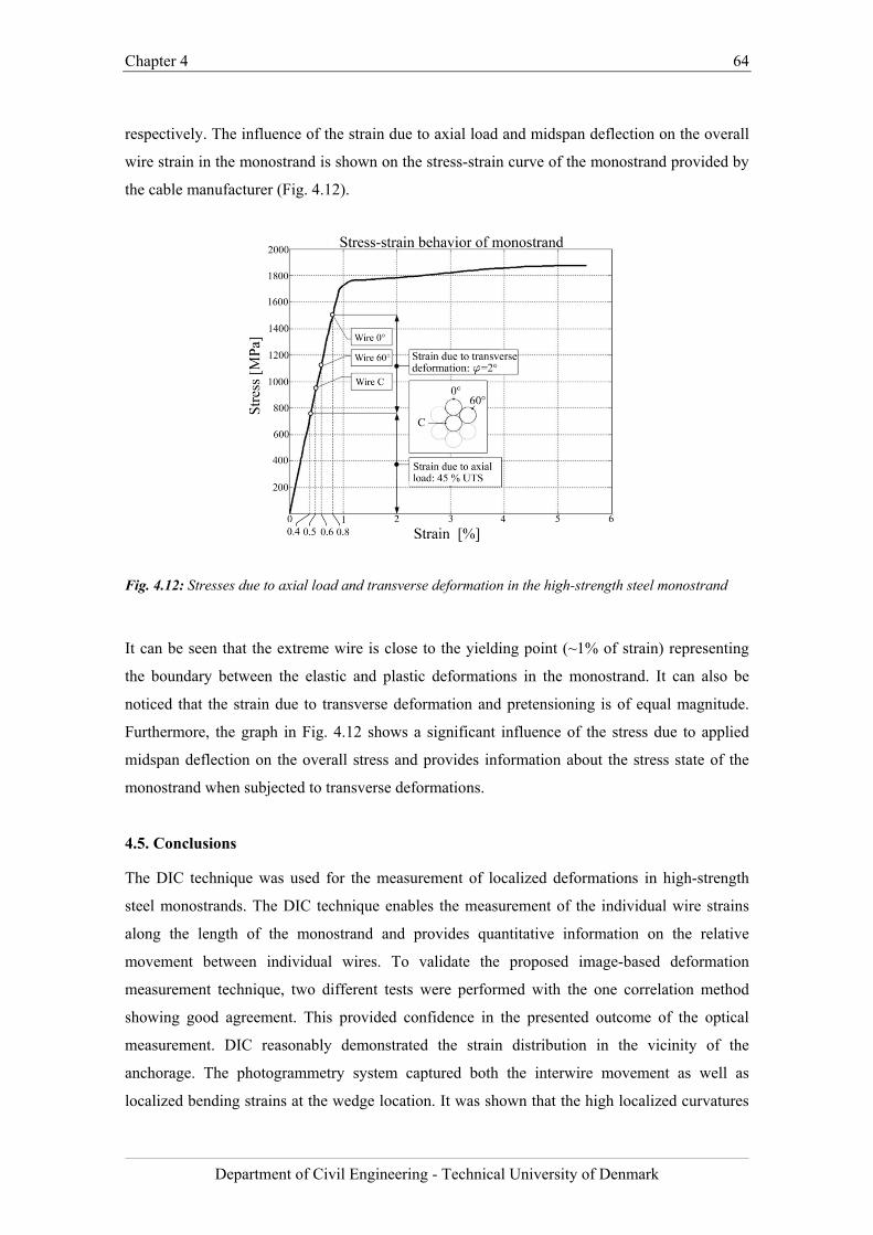
Chapter 4 64
Department of Civil Engineering - Technical University of Denmark
respectively. The influence of the strain due to axial load and midspan deflection on the overall
wire strain in the monostrand is shown on the stress-strain curve of the monostrand provided by
the cable manufacturer (Fig. 4.12).
Fig. 4.12: Stresses due to axial load and transverse deformation in the high-strength steel monostrand
It can be seen that the extreme wire is close to the yielding point (~1% of strain) representing
the boundary between the elastic and plastic deformations in the monostrand. It can also be
noticed that the strain due to transverse deformation and pretensioning is of equal magnitude.
Furthermore, the graph in Fig. 4.12 shows a significant influence of the stress due to applied
midspan deflection on the overall stress and provides information about the stress state of the
monostrand when subjected to transverse deformations.
4.5. Conclusions
The DIC technique was used for the measurement of localized deformations in high-strength
steel monostrands. The DIC technique enables the measurement of the individual wire strains
along the length of the monostrand and provides quantitative information on the relative
movement between individual wires. To validate the proposed image-based deformation
measurement technique, two different tests were performed with the one correlation method
showing good agreement. This provided confidence in the presented outcome of the optical
measurement. DIC reasonably demonstrated the strain distribution in the vicinity of the
anchorage. The photogrammetry system captured both the interwire movement as well as
localized bending strains at the wedge location. It was shown that the high localized curvatures
Chapter 4 65
Department of Civil Engineering - Technical University of Denmark
due to bending may cause yielding of the monostrand and that the transverse deformations were
distributed over a distance of 65 mm from the wedge.
Furthermore, the experimental investigation on the 6-wire strand specimen has been performed
as a part of the analysis of the fretting behavior of the high-strength steel monostrand subjected
to transverse deformations. The DIC measurement provided data on the strain level of the core
wire and the relative displacement between the core and outer wires. Data collected from the
DIC technique creates a basis for the analysis of the fretting and localized bending behavior of
the monostrand and gives relevant information on the internal state of displacement of the
monostrand under bending load.
Chapter 4 66
Department of Civil Engineering - Technical University of Denmark
Bibliography
[1] Hikami, Y. and Shiraishi, N. (1988). “Rain–wind induced vibrations of cables in cable
stayed bridges.”, J. Wind Eng. Ind. Aerodyn., 29(1), 409-418.
[2] Savor, Z., Radic, J., and Hrelja, G. (2006). “Cable vibrations at Dubrovnik bridge.”,
Bridge Structures, 2(2), 97-106.
[3] Gimsing, N. J. and Georgakis, C. T. (2012). ”Cable Supported Bridges: Concept and
Design.”, 3rd edition, John Wiley & Sons, Hoboken, New Jersey, 544-547.
[4] Wood, S. and Frank, K. H. (2010). “Experimental investigation of bending fatigue
response of grouted stay cables.”, J. Bridge Eng.,15(2), 123-130.
[5] Winkler, J., Fischer, G., Georgakis, C.T. and Kotas A. (2011). “A preliminary
bending fatigue spectrum for steel monostrand cables.”, J. IASS, 52(4), 249-255.
[6] Miki, C., Endo, T., and Okukawa, A. (1992). “Full-size fatigue test of bridge cables:
Length effect on fatigue of wires and strands.” International Association for Bridge
and Structural Engineering Rep., International Association for Bridge and Structural
Engineering, Zurich, 66, 167–178.
[7] Wyatt, T.A. (1960). “Secondary stress in parallel wire suspension cables.”, J. Struct.
Div. (ASCE), 86(7), 37-59.
[8] Prato, C. A. and Ceballos, M. A. (2003). “Dynamic bending stresses near the ends of
parallel-bundle stay cables.”, Structural Engineering International (SEI) , 13(1), 64-
68.
[9] Siegert, D. and Brevet, P. (2005). ”Fatigue of stay cables inside end fittings: High
frequencies of wind induced vibrations.”, International Organisation for the Study of
the Endurance of Ropes (OIPEEC) Bulletin 89, Reading, United Kingdom, 43-51.
[10] Gourmelon, J.P. (2002). “Fatigue of staying cables, Organisation and results of the
research programme.” International Organisation for the Study of the Endurance of
Ropes (OIPEEC) Bulletin 84, Reading, United Kingdom, 21-39.
[11] Rodríguez, G. and Olabarrieta, C. J. (2010). “Fatigue testing with transverse
displacements in stay cable systems.”, Proc., 3rd fib International Congress,
Washington, USA.
[12] Raoof, M. (1991). “Methods for analysing large spiral strands.”. J. Strain Anal. Eng.,
26(3), 165-174.
[13] Hobbs, R. E. and Raoof, M. (1994).”Mechanism of fretting fatigue in steel cables.”,
Int. J. Fatigue, 16(4), 273-280.
[14] Wang, D., Zhang, D. and Ge, S. (2011). “Fretting–fatigue behavior of steel wires in
Chapter 4 67
Department of Civil Engineering - Technical University of Denmark
low cycle fatigue.”, Materials and Design, 32(10), 4986-4993.
[15a] Jiang, R., Jauregui, D.V. and White, K.R. (2008). “Close-range photogrammetry
applications in bridge measurement: Literature review.” Measurement, 41(8), 823-
834.
[15b] Jauregui, D.V., White, K.R., Woodward, P.E. and Leitch, K.R. (2003). “Noncontact
photogrammetric measurement of vertical bridge deflection.”, J. Bridge Eng., 8(4),
212-222.
[16] Bales, F.B. (1985). “Close-range photogrammetry for bridge measurement.”.
Transportation Research Record, Washington, D.C., 950, 39-44.
[17] Li, J.C. and Yuan, (1988). B.Z. “Using vision technique for bridge deformation
detection,” Proc., International Conference on Acoustic, Speech and Signal
Processing, New York, 912-915.
[18a] Johnson, G. W. (2001). ‘‘Digital close-range photogrammetry - a portable
measurement tool for public works.’’. Proc., 2001 Coordinate Measurement Systems
Committee Conf., Coordinate Measurement Systems Committee.
[18b] De Roover, C., Vantomme, J. , Wastiels, J. and Taerwe, L. (2002). ”Deformation
analysis of a modular connection system by digital image correlation.”. Experimental
techniques, 26 (6), 37-40.
[19] Lee, J.J. and Shinozuka, M. (2006a). “A vision-based system for remote sensing of
bridge displacement.”, NDT&E Int., 39(5), 425–431.
[20] Lee, J.J. and Shinozuka, M. (2006b). “Real-time displacement measurement of a
flexible bridge using digital image processing techniques.”, Exp.Mech., 46(1), 105–
114.
[21] Santini-Bell, E., Brogan, P., Lefebvre, P. Peddle, J., Brenner, B. abd Sanayei, M.
(2011)."Digital Imaging for Bridge Deflection Measurement of a Steel Girder
Composite Bridge.". Transportation Research Board (TRB 90th Annual Meeting),
Washington, D.C , USA.
[22] Chiang, C., Shih, M., Chen, W. and Yu, C. (2011)” Displacement measurements of
highway bridges using digital image correlation methods.”. Proc., SPIE - The
International Society for Optical Engineering, 8321(1), 83211G-6.
[23] Waterfall, P.M., Macdonald, J.H.G. and McCormick, N.J. (2012). “Targetless
precision monitoring of road and rail bridges using video cameras.”, Proc., 6th
International Conference on Bridge maintenance, Safety and Management (IABMAS
2012), Stresa, Italy.
[24] Yoneyama, S. and Ueda, H. (2009). “Bridge Deflection Measurement Using Digital
Chapter 4 68
Department of Civil Engineering - Technical University of Denmark
Image Correlation with Camera Movement Correction.”. Materials transactions, 53
(2), 285-290.
[25] Yoneyama, S., Kitagawa, A., Iwata, S., Tani, K. and Kikuta, H. (2007).” Bridge
deflection measurement using digital image correlation.”. Experimental techniques,
31(1), 34-40.
[26] Busca, G., Cigada, A., Mazzoleni, P., Zappa and Franzi, M. (2012). ‘‘Cameras as
displacement sensors to get the dynamic motion of a bridge: performance evaluation
against traditional approaches.”, Proc., 6th International Conference on Bridge
maintenance, Safety and Management (IABMAS 2012), Stresa, Italy.
[27] Kim, S. and Kim, N. (2013).” Dynamic characteristics of suspension bridge hanger
cables using digital image processing.”. NDT &E International, 59, 25-33.
[28] Sas, G., Blanksvärd, T., Enochsson, O., Täljsten, B. and Elfgren, L. (2012)
”Photographic strain monitoring during full-scale failure testing of Örnsköldsvik
bridge.”. Structural Health Monitoring, 11(4), 489-498.
[29] Küntz, M., Jolin, M., Bastien, J., Perez, F. and Hild, F. (2006),“Digital Image
Correlation Analysis of Crack Behavior in a Reinforced Concrete Beam During a
Load Test.” Canadian Journal of Civil Engineering, 33(11), 1418-1425.
[30] Malesa, M., Szczepanek, D., Kujawińska, M., Świercz, A. and Kołakowski, P. (2010)
“Monitoring of Civil Engineering Structures Using Digital Image Correlation
Technique.”. 14th International Conference on Experimental Mechanics ICEM, 6,
31014.
[31] Nonis, C., Niezrecki, C., Yu, T., Ahmed, S., Su, C. and Schmidt, T.(2013).”
Structural Health Monitoring of Bridges using Digital Image Correlation.” Proc.,
SPIE - The International Society for Optical Engineering. 8695, 869507.
[32] Woodham, R. J. (1981). “Analysing images of curved surfaces.”, Artificial
Intelligence, 17(1-3), 117-140.
[33] Papailiou, K.O. (1997). “On the bending stiffness of transmission line conductors.”,
IEEE Transactions on Power Delivery, 12(4), 1576-1588.
[34] Raoof, M. and Huang, Y.P. (1992). “Free bending characteristics of axially preloaded
spiral strands.”, Proc., ICE - Structures and Buildings, 94(4), 469-484.
[35] Hobbs, R. E. and Raoof, M. (1996). “Behaviour of cables under dynamic or repeated
loading.”, J. Constr. Steel Res., 39(1), 31-50.
[36] ARAMIS System Manual (2009), version 6.1, GOM, Mittelweg 7–8, 38106
Braunschweig, Germany.

Chapter 4 69
Department of Civil Engineering - Technical University of Denmark
Chapter 5 70
Department of Civil Engineering - Technical University of Denmark
Chapter 5
Fretting fatigue behavior of monostrand under flexural load
The results presented in this chapter are taken from the paper “Fretting fatigue behavior of
high-strength steel monostrands under bending load” by J. Winkler, C.T. Georgakis and G.
Fischer, published in the International Journal of Fatigue 2014; 70:13-23.
Chapter summary
This chapter presents the outcome of the series of static and dynamic bending fatigue tests
conducted on monostrands. In this experimental investigation the focus was directed towards
the fretting response of the monostrand specimens subjected to cyclic transverse deformations.
With the new information on the interwire movement acquired with the DIC method it was
possible to study the fretting fatigue behavior of monostrands in detail. The study provides
previously unavailable information about the monostrand bending stiffness and the extent of
relative displacement between core and outer wires of a monostrand undergoing flexural load.
From the series of conducted dynamic tests the fatigue spectrum for the fretting fatigue failure
mechanism was developed and compared with the localized bending fatigue model.
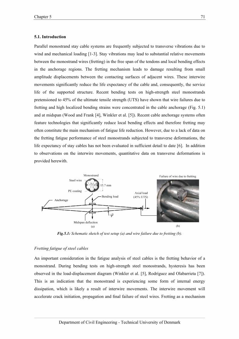
Chapter 5 71
Department of Civil Engineering - Technical University of Denmark
5.1. Introduction
Parallel monostrand stay cable systems are frequently subjected to transverse vibrations due to
wind and mechanical loading [1-3]. Stay vibrations may lead to substantial relative movements
between the monostrand wires (fretting) in the free span of the tendons and local bending effects
in the anchorage regions. The fretting mechanism leads to damage resulting from small
amplitude displacements between the contacting surfaces of adjacent wires. These interwire
movements significantly reduce the life expectancy of the cable and, consequently, the service
life of the supported structure. Recent bending tests on high-strength steel monostrands
pretensioned to 45% of the ultimate tensile strength (UTS) have shown that wire failures due to
fretting and high localized bending strains were concentrated in the cable anchorage (Fig. 5.1)
and at midspan (Wood and Frank [4], Winkler et al. [5]). Recent cable anchorage systems often
feature technologies that significantly reduce local bending effects and therefore fretting may
often constitute the main mechanism of fatigue life reduction. However, due to a lack of data on
the fretting fatigue performance of steel monostrands subjected to transverse deformations, the
life expectancy of stay cables has not been evaluated in sufficient detail to date [6]. In addition
to observations on the interwire movements, quantitative data on transverse deformations is
provided herewith.
Fig.5.1: Schematic sketch of test setup (a) and wire failure due to fretting (b).
Fretting fatigue of steel cables
An important consideration in the fatigue analysis of steel cables is the fretting behavior of a
monostrand. During bending tests on high-strength steel monostrands, hysteresis has been
observed in the load-displacement diagram (Winkler et al. [5], Rodríguez and Olabarrieta [7]).
This is an indication that the monostrand is experiencing some form of internal energy
dissipation, which is likely a result of interwire movements. The interwire movement will
accelerate crack initiation, propagation and final failure of steel wires. Fretting as a mechanism
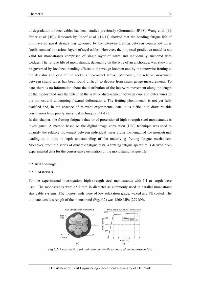
Chapter 5 72
Department of Civil Engineering - Technical University of Denmark
of degradation of steel cables has been studied previously (Gourmelon JP [8], Wang et al. [9],
Périer et al. [10]). Research by Raoof et al. [11-13] showed that the bending fatigue life of
multilayered spiral strands was governed by the interwire fretting between counterlaid wires
(trellis contact) in various layers of steel cables. However, the proposed predictive model is not
valid for monostrands comprised of single layer of wires and individually anchored with
wedges. The fatigue life of monostrands, depending on the type of an anchorage, was shown to
be governed by localized bending effects at the wedge location and by the interwire fretting at
the deviator and exit of the socket (line-contact stress). Moreover, the relative movement
between strand wires has been found difficult to deduce from strain gauge measurements. To
date, there is no information about the distribution of the interwire movement along the length
of the monostrand and the extent of the relative displacement between core and outer wires of
the monostrand undergoing flexural deformations. The fretting phenomenon is not yet fully
clarified and, in the absence of relevant experimental data, it is difficult to draw reliable
conclusions from purely analytical techniques [14-17].
In this chapter, the fretting fatigue behavior of pretensioned high-strength steel monostrands is
investigated. A method based on the digital image correlation (DIC) technique was used to
quantify the relative movement between individual wires along the length of the monostrand,
leading to a more in-depth understanding of the underlying fretting fatigue mechanism.
Moreover, from the series of dynamic fatigue tests, a fretting fatigue spectrum is derived from
experimental data for the conservative estimation of the monostrand fatigue life.
5.2. Methodology
5.2.1. Materials
For the experimental investigation, high-strength steel monostrands with 5.1 m length were
used. The monostrands were 15.7 mm in diameter as commonly used in parallel monostrand
stay cable systems. The monostrands were of low relaxation grade, waxed and PE coated. The
ultimate tensile strength of the monostrand (Fig. 5.2) was 1860 MPa (279 kN).
Fig.5.2: Cross section (a) and ultimate tensile strength of the monostrand (b)
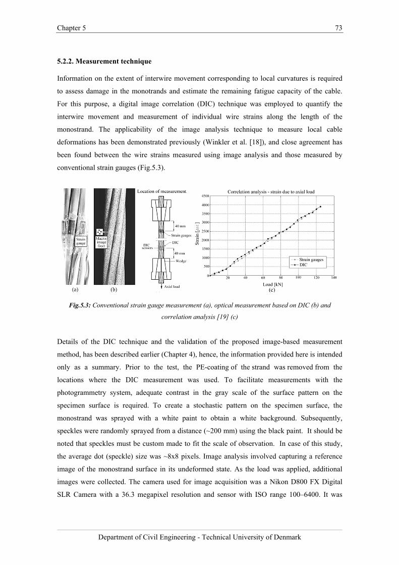
Chapter 5 73
Department of Civil Engineering - Technical University of Denmark
5.2.2. Measurement technique
Information on the extent of interwire movement corresponding to local curvatures is required
to assess damage in the monotrands and estimate the remaining fatigue capacity of the cable.
For this purpose, a digital image correlation (DIC) technique was employed to quantify the
interwire movement and measurement of individual wire strains along the length of the
monostrand. The applicability of the image analysis technique to measure local cable
deformations has been demonstrated previously (Winkler et al. [18]), and close agreement has
been found between the wire strains measured using image analysis and those measured by
conventional strain gauges (Fig.5.3).
Fig.5.3: Conventional strain gauge measurement (a), optical measurement based on DIC (b) and
correlation analysis [19] (c)
Details of the DIC technique and the validation of the proposed image-based measurement
method, has been described earlier (Chapter 4), hence, the information provided here is intended
only as a summary. Prior to the test, the PE-coating of the strand was removed from the
locations where the DIC measurement was used. To facilitate measurements with the
photogrammetry system, adequate contrast in the gray scale of the surface pattern on the
specimen surface is required. To create a stochastic pattern on the specimen surface, the
monostrand was sprayed with a white paint to obtain a white background. Subsequently,
speckles were randomly sprayed from a distance (~200 mm) using the black paint. It should be
noted that speckles must be custom made to fit the scale of observation. In case of this study,
the average dot (speckle) size was ~8x8 pixels. Image analysis involved capturing a reference
image of the monostrand surface in its undeformed state. As the load was applied, additional
images were collected. The camera used for image acquisition was a Nikon D800 FX Digital
SLR Camera with a 36.3 megapixel resolution and sensor with ISO range 100–6400. It was
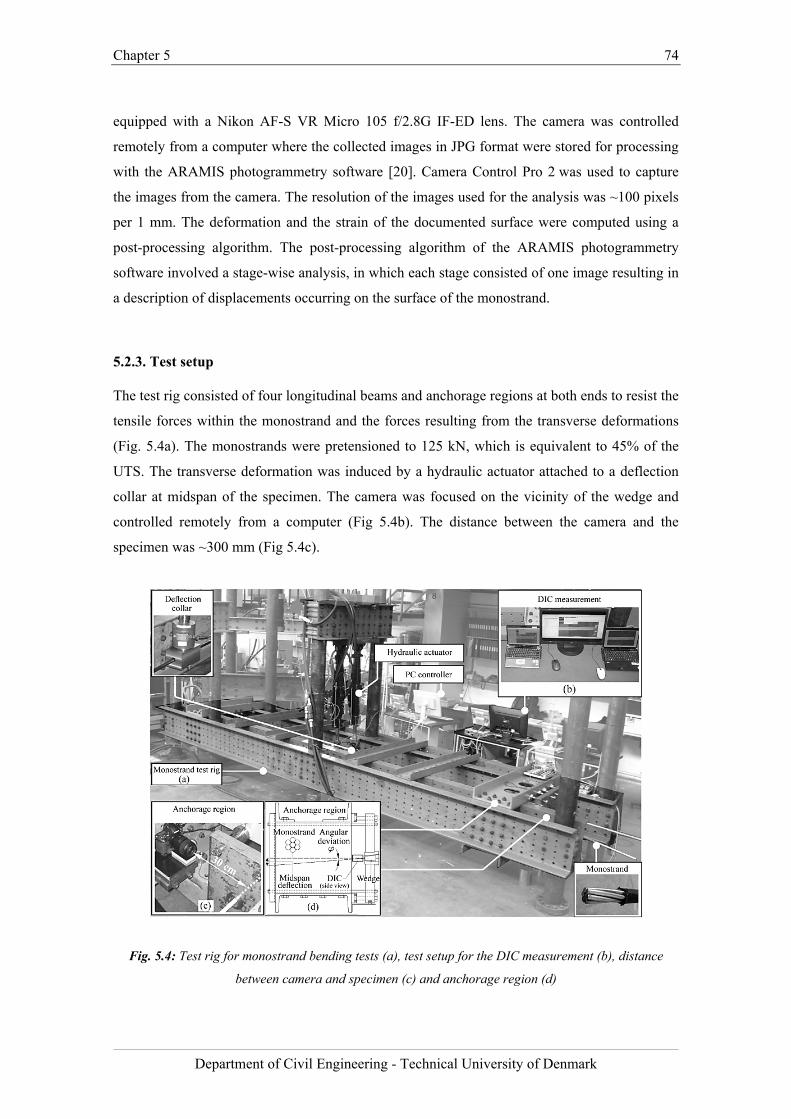
Chapter 5 74
Department of Civil Engineering - Technical University of Denmark
equipped with a Nikon AF-S VR Micro 105 f/2.8G IF-ED lens. The camera was controlled
remotely from a computer where the collected images in JPG format were stored for processing
with the ARAMIS photogrammetry software [20]. Camera Control Pro 2 was used to capture
the images from the camera. The resolution of the images used for the analysis was ~100 pixels
per 1 mm. The deformation and the strain of the documented surface were computed using a
post-processing algorithm. The post-processing algorithm of the ARAMIS photogrammetry
software involved a stage-wise analysis, in which each stage consisted of one image resulting in
a description of displacements occurring on the surface of the monostrand.
5.2.3. Test setup
The test rig consisted of four longitudinal beams and anchorage regions at both ends to resist the
tensile forces within the monostrand and the forces resulting from the transverse deformations
(Fig. 5.4a). The monostrands were pretensioned to 125 kN, which is equivalent to 45% of the
UTS. The transverse deformation was induced by a hydraulic actuator attached to a deflection
collar at midspan of the specimen. The camera was focused on the vicinity of the wedge and
controlled remotely from a computer (Fig 5.4b). The distance between the camera and the
specimen was ~300 mm (Fig 5.4c).
Fig. 5.4: Test rig for monostrand bending tests (a), test setup for the DIC measurement (b), distance
between camera and specimen (c) and anchorage region (d)
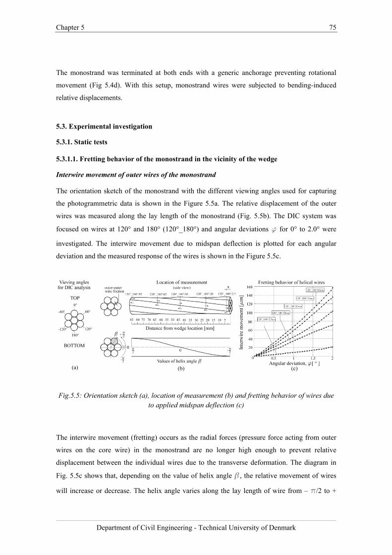
Chapter 5 75
Department of Civil Engineering - Technical University of Denmark
The monostrand was terminated at both ends with a generic anchorage preventing rotational
movement (Fig 5.4d). With this setup, monostrand wires were subjected to bending-induced
relative displacements.
5.3. Experimental investigation
5.3.1. Static tests
5.3.1.1. Fretting behavior of the monostrand in the vicinity of the wedge
Interwire movement of outer wires of the monostrand
The orientation sketch of the monostrand with the different viewing angles used for capturing
the photogrammetric data is shown in the Figure 5.5a. The relative displacement of the outer
wires was measured along the lay length of the monostrand (Fig. 5.5b). The DIC system was
focused on wires at 120° and 180° (120°_180°) and angular deviations f for 0° to 2.0° were
investigated. The interwire movement due to midspan deflection is plotted for each angular
deviation and the measured response of the wires is shown in the Figure 5.5c.
Fig.5.5: Orientation sketch (a), location of measurement (b) and fretting behavior of wires due to applied midspan deflection (c)
The interwire movement (fretting) occurs as the radial forces (pressure force acting from outer
wires on the core wire) in the monostrand are no longer high enough to prevent relative
displacement between the individual wires due to the transverse deformation. The diagram in
Fig. 5.5c shows that, depending on the value of helix angle b, the relative movement of wires
will increase or decrease. The helix angle varies along the lay length of wire from – p/2 to +
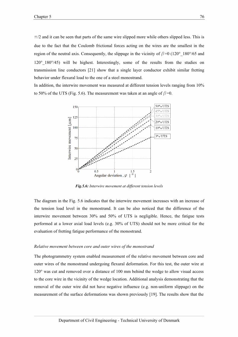
Chapter 5 76
Department of Civil Engineering - Technical University of Denmark
p/2 and it can be seen that parts of the same wire slipped more while others slipped less. This is
due to the fact that the Coulomb frictional forces acting on the wires are the smallest in the
region of the neutral axis. Consequently, the slippage in the vicinity of b=0 (120°_180°/65 and
120°_180°/45) will be highest. Interestingly, some of the results from the studies on
transmission line conductors [21] show that a single layer conductor exhibit similar fretting
behavior under flexural load to the one of a steel monostrand.
In addition, the interwire movement was measured at different tension levels ranging from 10%
to 50% of the UTS (Fig. 5.6). The measurement was taken at an angle of b=0.
Fig.5.6: Interwire movement at different tension levels
The diagram in the Fig. 5.6 indicates that the interwire movement increases with an increase of
the tension load level in the monostrand. It can be also noticed that the difference of the
interwire movement between 30% and 50% of UTS is negligible. Hence, the fatigue tests
performed at a lower axial load levels (e.g. 30% of UTS) should not be more critical for the
evaluation of fretting fatigue performance of the monostrand.
Relative movement between core and outer wires of the monostrand
The photogrammetry system enabled measurement of the relative movement between core and
outer wires of the monostrand undergoing flexural deformation. For this test, the outer wire at
120° was cut and removed over a distance of 100 mm behind the wedge to allow visual access
to the core wire in the vicinity of the wedge location. Additional analysis demonstrating that the
removal of the outer wire did not have negative influence (e.g. non-uniform slippage) on the
measurement of the surface deformations was shown previously [19]. The results show that the
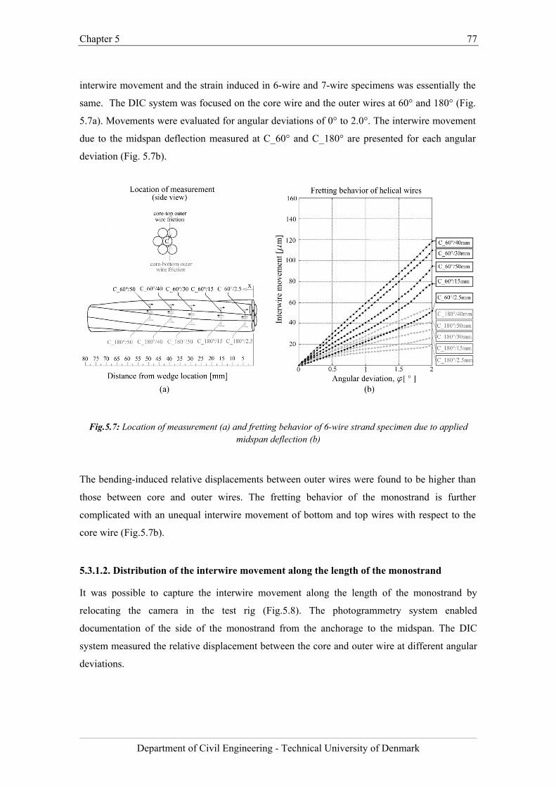
Chapter 5 77
Department of Civil Engineering - Technical University of Denmark
interwire movement and the strain induced in 6-wire and 7-wire specimens was essentially the
same. The DIC system was focused on the core wire and the outer wires at 60° and 180° (Fig.
5.7a). Movements were evaluated for angular deviations of 0° to 2.0°. The interwire movement
due to the midspan deflection measured at C_60° and C_180° are presented for each angular
deviation (Fig. 5.7b).
Fig.5.7: Location of measurement (a) and fretting behavior of 6-wire strand specimen due to applied midspan deflection (b)
The bending-induced relative displacements between outer wires were found to be higher than
those between core and outer wires. The fretting behavior of the monostrand is further
complicated with an unequal interwire movement of bottom and top wires with respect to the
core wire (Fig.5.7b).
5.3.1.2. Distribution of the interwire movement along the length of the monostrand
It was possible to capture the interwire movement along the length of the monostrand by
relocating the camera in the test rig (Fig.5.8). The photogrammetry system enabled
documentation of the side of the monostrand from the anchorage to the midspan. The DIC
system measured the relative displacement between the core and outer wire at different angular
deviations.

Chapter 5 78
Department of Civil Engineering - Technical University of Denmark
Fig.5.8: Test rig for the measurement of interwire movement (a) and schematic sketch (b)
The experimental data show that the midspan and the anchorage of the monostrand are the two
locations where the combination of the tensile strains and the interwire friction was most
unfavorable (Fig. 5.9).
Fig.5.9: Distribution of the interwire movement and strain along the length of the monostrand
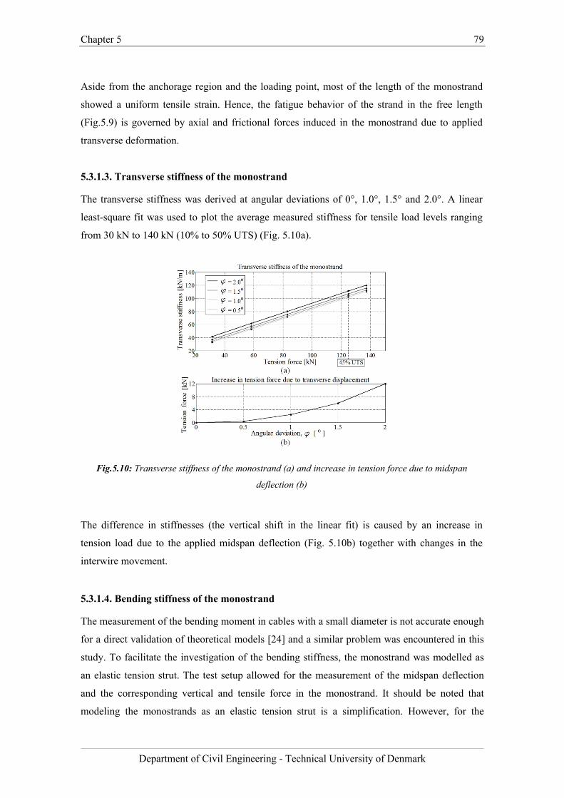
Chapter 5 79
Department of Civil Engineering - Technical University of Denmark
Aside from the anchorage region and the loading point, most of the length of the monostrand
showed a uniform tensile strain. Hence, the fatigue behavior of the strand in the free length
(Fig.5.9) is governed by axial and frictional forces induced in the monostrand due to applied
transverse deformation.
5.3.1.3. Transverse stiffness of the monostrand
The transverse stiffness was derived at angular deviations of 0°, 1.0°, 1.5° and 2.0°. A linear
least-square fit was used to plot the average measured stiffness for tensile load levels ranging
from 30 kN to 140 kN (10% to 50% UTS) (Fig. 5.10a).
Fig.5.10: Transverse stiffness of the monostrand (a) and increase in tension force due to midspan
deflection (b)
The difference in stiffnesses (the vertical shift in the linear fit) is caused by an increase in
tension load due to the applied midspan deflection (Fig. 5.10b) together with changes in the
interwire movement.
5.3.1.4. Bending stiffness of the monostrand
The measurement of the bending moment in cables with a small diameter is not accurate enough
for a direct validation of theoretical models [24] and a similar problem was encountered in this
study. To facilitate the investigation of the bending stiffness, the monostrand was modelled as
an elastic tension strut. The test setup allowed for the measurement of the midspan deflection
and the corresponding vertical and tensile force in the monostrand. It should be noted that
modeling the monostrands as an elastic tension strut is a simplification. However, for the
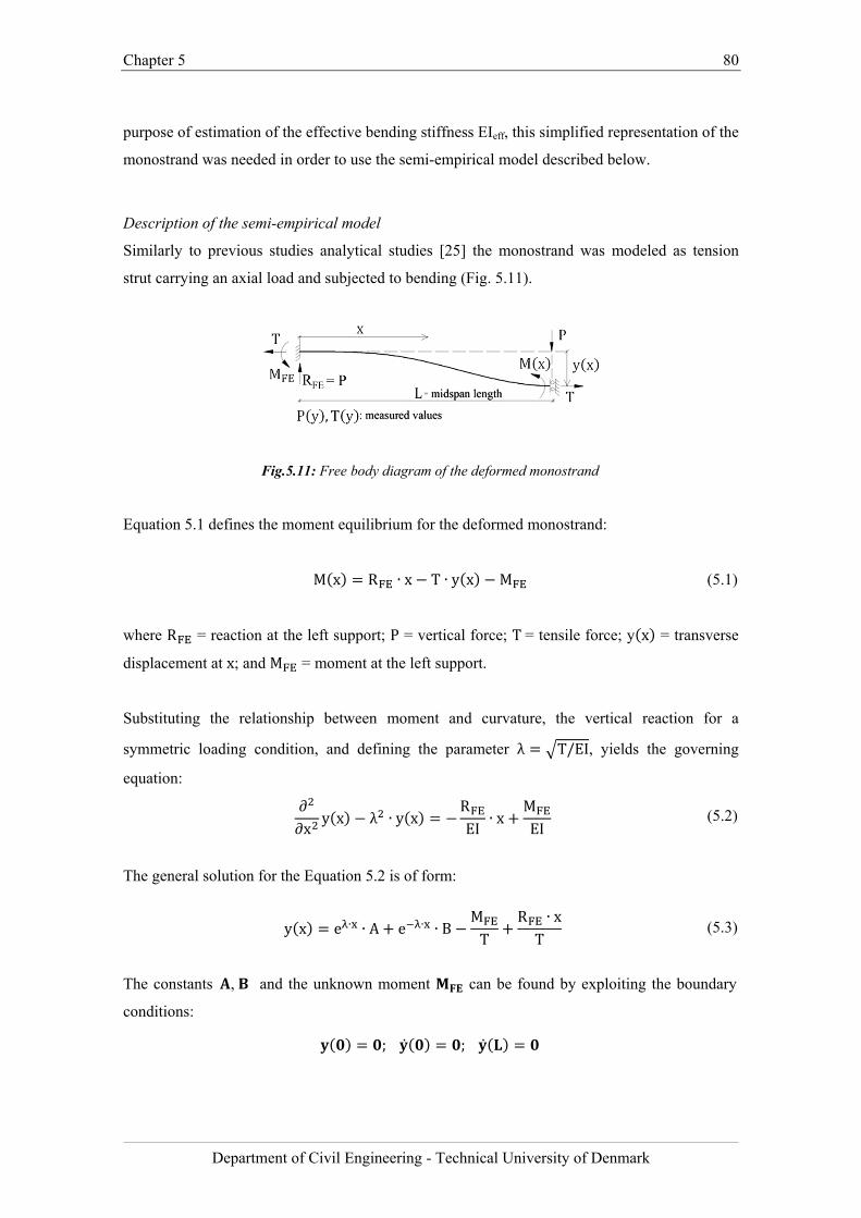
Chapter 5 80
Department of Civil Engineering - Technical University of Denmark
purpose of estimation of the effective bending stiffness EIeff, this simplified representation of the
monostrand was needed in order to use the semi-empirical model described below.
Description of the semi-empirical model
Similarly to previous studies analytical studies [25] the monostrand was modeled as tension
strut carrying an axial load and subjected to bending (Fig. 5.11).
Fig.5.11: Free body diagram of the deformed monostrand
Equation 5.1 defines the moment equilibrium for the deformed monostrand:
M x R ∙ x T ∙ y x M (5.1)
where R = reaction at the left support; P = vertical force; T= tensile force; y x = transverse
displacement at x; and M = moment at the left support.
Substituting the relationship between moment and curvature, the vertical reaction for a
symmetric loading condition, and defining the parameter λ T/EI, yields the governing
equation:
∂∂x
y x λ ∙ y xREI
∙ xMEI
(5.2)
The general solution for the Equation 5.2 is of form:
y x e ∙ ∙ A e ∙ ∙ BMT
R ∙ xT
(5.3)
The constants , and the unknown moment can be found by exploiting the boundary
conditions:
; ;
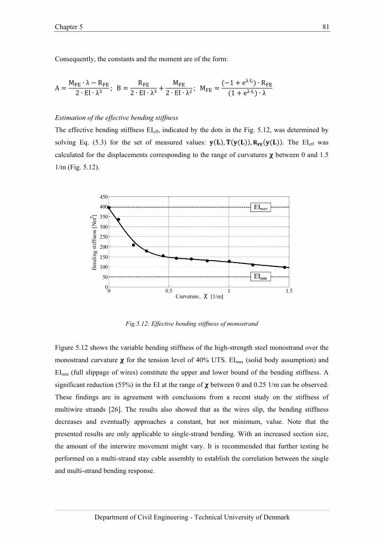
Chapter 5 81
Department of Civil Engineering - Technical University of Denmark
Consequently, the constants and the moment are of the form:
AM ∙ λ R2 ∙ EI ∙ λ
; BR
2 ∙ EI ∙ λM
2 ∙ EI ∙ λ; M
1 e ∙ ∙ R1 e ∙ ∙ λ
Estimation of the effective bending stiffness
The effective bending stiffness EIeff, indicated by the dots in the Fig. 5.12, was determined by
solving Eq. (5.3) for the set of measured values: , , . The EIeff was
calculated for the displacements corresponding to the range of curvatures between 0 and 1.5
1/m (Fig. 5.12).
Fig.5.12: Effective bending stiffness of monostrand
Figure 5.12 shows the variable bending stiffness of the high-strength steel monostrand over the
monostrand curvature for the tension level of 40% UTS. EImax (solid body assumption) and
EImin (full slippage of wires) constitute the upper and lower bound of the bending stiffness. A
significant reduction (55%) in the EI at the range of between 0 and 0.25 1/m can be observed.
These findings are in agreement with conclusions from a recent study on the stiffness of
multiwire strands [26]. The results also showed that as the wires slip, the bending stiffness
decreases and eventually approaches a constant, but not minimum, value. Note that the
presented results are only applicable to single-strand bending. With an increased section size,
the amount of the interwire movement might vary. It is recommended that further testing be
performed on a multi-strand stay cable assembly to establish the correlation between the single
and multi-strand bending response.
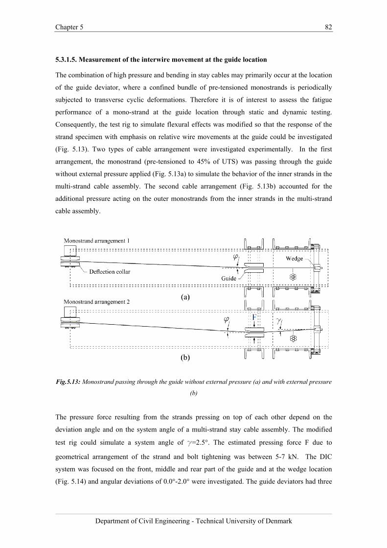
Chapter 5 82
Department of Civil Engineering - Technical University of Denmark
5.3.1.5. Measurement of the interwire movement at the guide location
The combination of high pressure and bending in stay cables may primarily occur at the location
of the guide deviator, where a confined bundle of pre-tensioned monostrands is periodically
subjected to transverse cyclic deformations. Therefore it is of interest to assess the fatigue
performance of a mono-strand at the guide location through static and dynamic testing.
Consequently, the test rig to simulate flexural effects was modified so that the response of the
strand specimen with emphasis on relative wire movements at the guide could be investigated
(Fig. 5.13). Two types of cable arrangement were investigated experimentally. In the first
arrangement, the monostrand (pre-tensioned to 45% of UTS) was passing through the guide
without external pressure applied (Fig. 5.13a) to simulate the behavior of the inner strands in the
multi-strand cable assembly. The second cable arrangement (Fig. 5.13b) accounted for the
additional pressure acting on the outer monostrands from the inner strands in the multi-strand
cable assembly.
Fig.5.13: Monostrand passing through the guide without external pressure (a) and with external pressure
(b)
The pressure force resulting from the strands pressing on top of each other depend on the
deviation angle and on the system angle of a multi-strand stay cable assembly. The modified
test rig could simulate a system angle of g=2.5°. The estimated pressing force F due to
geometrical arrangement of the strand and bolt tightening was between 5-7 kN. The DIC
system was focused on the front, middle and rear part of the guide and at the wedge location
(Fig. 5.14) and angular deviations of 0.0°-2.0° were investigated. The guide deviators had three
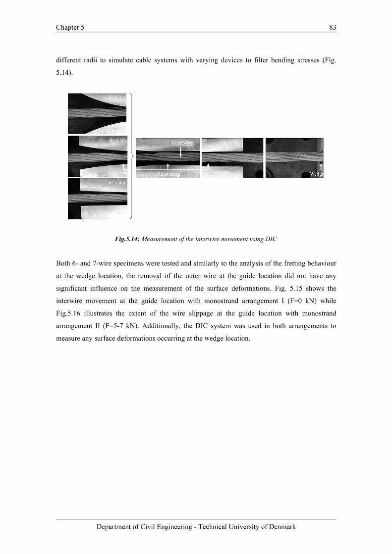
Chapter 5 83
Department of Civil Engineering - Technical University of Denmark
different radii to simulate cable systems with varying devices to filter bending stresses (Fig.
5.14).
Fig.5.14: Measurement of the interwire movement using DIC
Both 6- and 7-wire specimens were tested and similarly to the analysis of the fretting behaviour
at the wedge location, the removal of the outer wire at the guide location did not have any
significant influence on the measurement of the surface deformations. Fig. 5.15 shows the
interwire movement at the guide location with monostrand arrangement I (F=0 kN) while
Fig.5.16 illustrates the extent of the wire slippage at the guide location with monostrand
arrangement II (F=5-7 kN). Additionally, the DIC system was used in both arrangements to
measure any surface deformations occurring at the wedge location.
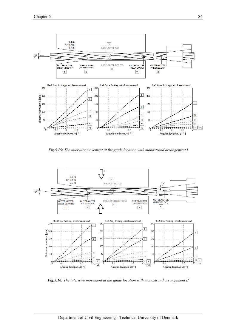
Chapter 5 84
Department of Civil Engineering - Technical University of Denmark
Fig.5.15: The interwire movement at the guide location with monostrand arrangement I
Fig.5.16: The interwire movement at the guide location with monostrand arrangement II
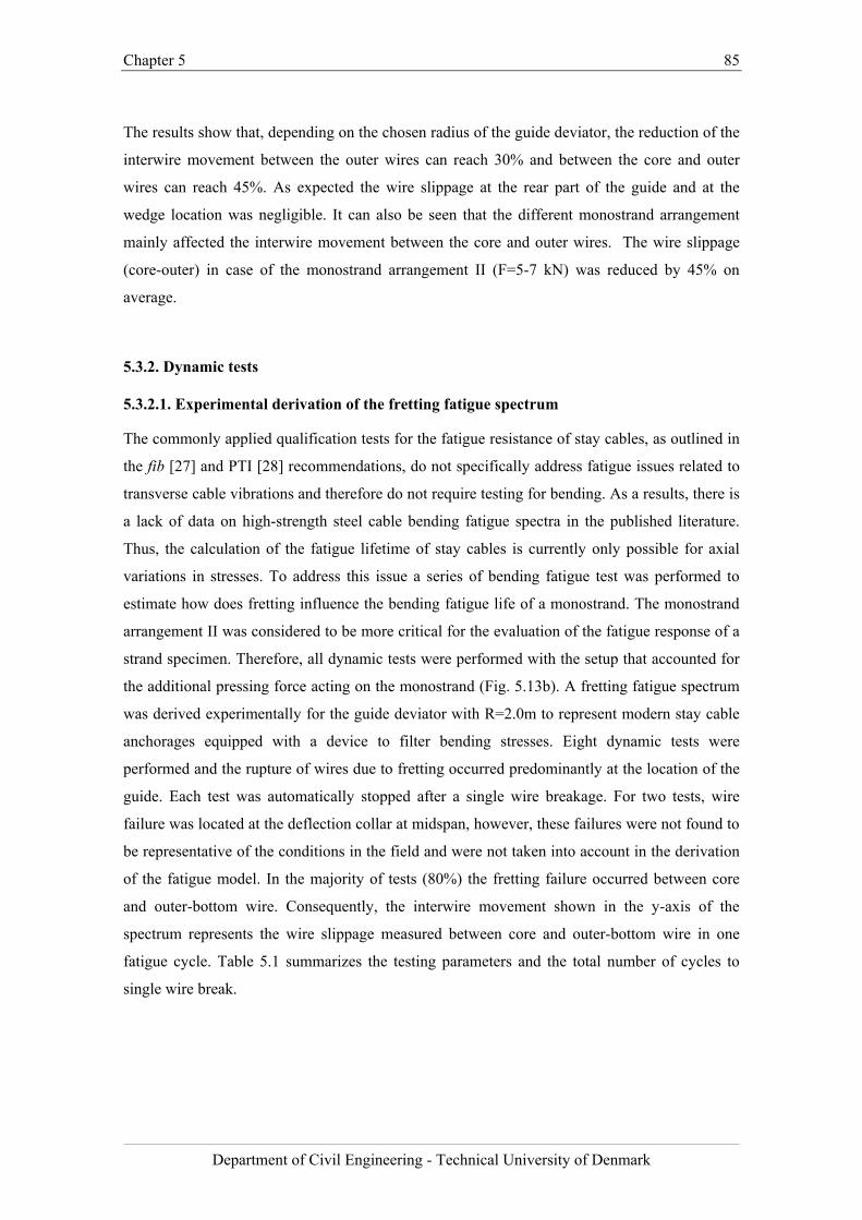
Chapter 5 85
Department of Civil Engineering - Technical University of Denmark
The results show that, depending on the chosen radius of the guide deviator, the reduction of the
interwire movement between the outer wires can reach 30% and between the core and outer
wires can reach 45%. As expected the wire slippage at the rear part of the guide and at the
wedge location was negligible. It can also be seen that the different monostrand arrangement
mainly affected the interwire movement between the core and outer wires. The wire slippage
(core-outer) in case of the monostrand arrangement II (F=5-7 kN) was reduced by 45% on
average.
5.3.2. Dynamic tests
5.3.2.1. Experimental derivation of the fretting fatigue spectrum
The commonly applied qualification tests for the fatigue resistance of stay cables, as outlined in
the fib [27] and PTI [28] recommendations, do not specifically address fatigue issues related to
transverse cable vibrations and therefore do not require testing for bending. As a results, there is
a lack of data on high-strength steel cable bending fatigue spectra in the published literature.
Thus, the calculation of the fatigue lifetime of stay cables is currently only possible for axial
variations in stresses. To address this issue a series of bending fatigue test was performed to
estimate how does fretting influence the bending fatigue life of a monostrand. The monostrand
arrangement II was considered to be more critical for the evaluation of the fatigue response of a
strand specimen. Therefore, all dynamic tests were performed with the setup that accounted for
the additional pressing force acting on the monostrand (Fig. 5.13b). A fretting fatigue spectrum
was derived experimentally for the guide deviator with R=2.0m to represent modern stay cable
anchorages equipped with a device to filter bending stresses. Eight dynamic tests were
performed and the rupture of wires due to fretting occurred predominantly at the location of the
guide. Each test was automatically stopped after a single wire breakage. For two tests, wire
failure was located at the deflection collar at midspan, however, these failures were not found to
be representative of the conditions in the field and were not taken into account in the derivation
of the fatigue model. In the majority of tests (80%) the fretting failure occurred between core
and outer-bottom wire. Consequently, the interwire movement shown in the y-axis of the
spectrum represents the wire slippage measured between core and outer-bottom wire in one
fatigue cycle. Table 5.1 summarizes the testing parameters and the total number of cycles to
single wire break.
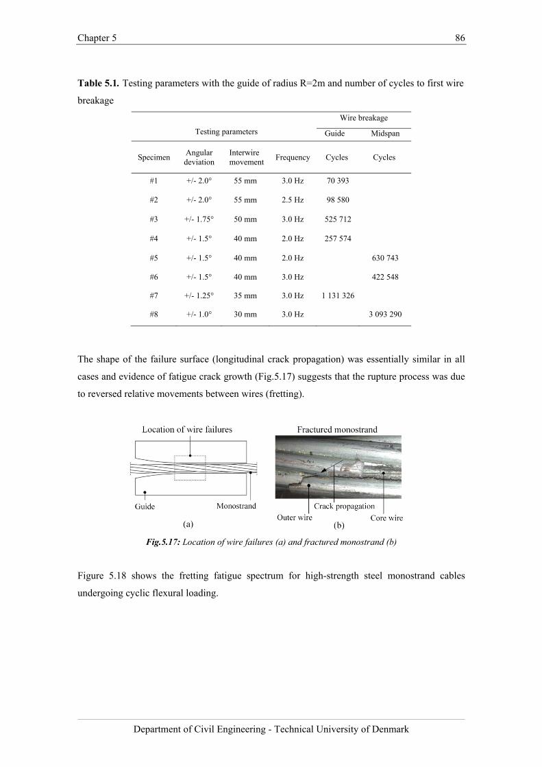
Chapter 5 86
Department of Civil Engineering - Technical University of Denmark
Table 5.1. Testing parameters with the guide of radius R=2m and number of cycles to first wire
breakage
Testing parameters
Wire breakage
Guide Midspan
Specimen Angular deviation
Interwire movement
Frequency Cycles Cycles
#1 +/- 2.0° 55 mm 3.0 Hz 70 393
#2 +/- 2.0° 55 mm 2.5 Hz 98 580
#3 +/- 1.75° 50 mm 3.0 Hz 525 712
#4 +/- 1.5° 40 mm 2.0 Hz 257 574
#5 +/- 1.5° 40 mm 2.0 Hz 630 743
#6 +/- 1.5° 40 mm 3.0 Hz 422 548
#7 +/- 1.25° 35 mm 3.0 Hz 1 131 326
#8 +/- 1.0° 30 mm 3.0 Hz 3 093 290
The shape of the failure surface (longitudinal crack propagation) was essentially similar in all
cases and evidence of fatigue crack growth (Fig.5.17) suggests that the rupture process was due
to reversed relative movements between wires (fretting).
Fig.5.17: Location of wire failures (a) and fractured monostrand (b)
Figure 5.18 shows the fretting fatigue spectrum for high-strength steel monostrand cables
undergoing cyclic flexural loading.
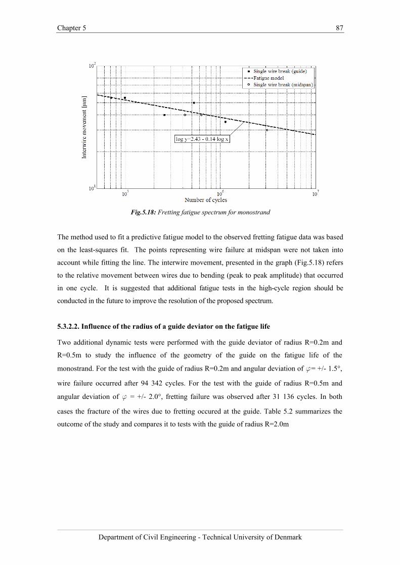
Chapter 5 87
Department of Civil Engineering - Technical University of Denmark
Fig.5.18: Fretting fatigue spectrum for monostrand
The method used to fit a predictive fatigue model to the observed fretting fatigue data was based
on the least-squares fit. The points representing wire failure at midspan were not taken into
account while fitting the line. The interwire movement, presented in the graph (Fig.5.18) refers
to the relative movement between wires due to bending (peak to peak amplitude) that occurred
in one cycle. It is suggested that additional fatigue tests in the high-cycle region should be
conducted in the future to improve the resolution of the proposed spectrum.
5.3.2.2. Influence of the radius of a guide deviator on the fatigue life
Two additional dynamic tests were performed with the guide deviator of radius R=0.2m and
R=0.5m to study the influence of the geometry of the guide on the fatigue life of the
monostrand. For the test with the guide of radius R=0.2m and angular deviation of f= +/- 1.5°,
wire failure occurred after 94 342 cycles. For the test with the guide of radius R=0.5m and
angular deviation of f = +/- 2.0°, fretting failure was observed after 31 136 cycles. In both
cases the fracture of the wires due to fretting occured at the guide. Table 5.2 summarizes the
outcome of the study and compares it to tests with the guide of radius R=2.0m
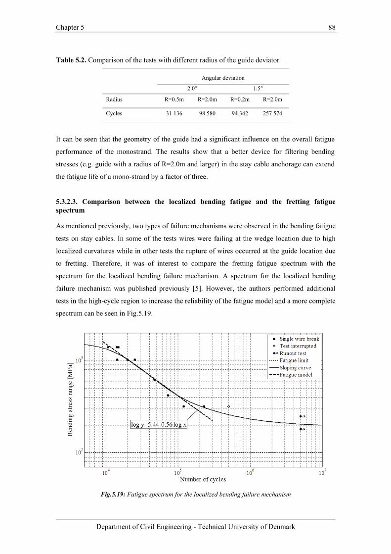
Chapter 5 88
Department of Civil Engineering - Technical University of Denmark
Table 5.2. Comparison of the tests with different radius of the guide deviator
Angular deviation
2.0° 1.5°
Radius R=0.5m R=2.0m R=0.2m R=2.0m
Cycles 31 136 98 580 94 342 257 574
It can be seen that the geometry of the guide had a significant influence on the overall fatigue
performance of the monostrand. The results show that a better device for filtering bending
stresses (e.g. guide with a radius of R=2.0m and larger) in the stay cable anchorage can extend
the fatigue life of a mono-strand by a factor of three.
5.3.2.3. Comparison between the localized bending fatigue and the fretting fatigue spectrum
As mentioned previously, two types of failure mechanisms were observed in the bending fatigue
tests on stay cables. In some of the tests wires were failing at the wedge location due to high
localized curvatures while in other tests the rupture of wires occurred at the guide location due
to fretting. Therefore, it was of interest to compare the fretting fatigue spectrum with the
spectrum for the localized bending failure mechanism. A spectrum for the localized bending
failure mechanism was published previously [5]. However, the authors performed additional
tests in the high-cycle region to increase the reliability of the fatigue model and a more complete
spectrum can be seen in Fig.5.19.
Fig.5.19: Fatigue spectrum for the localized bending failure mechanism
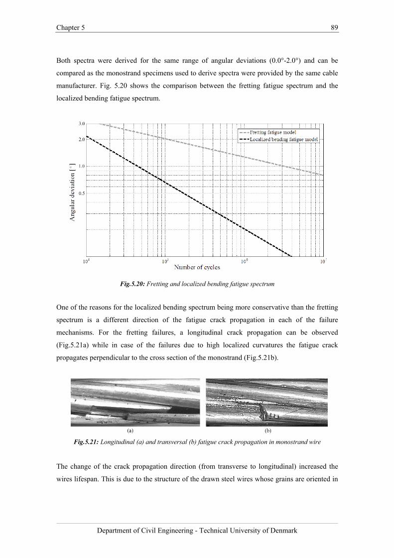
Chapter 5 89
Department of Civil Engineering - Technical University of Denmark
Both spectra were derived for the same range of angular deviations (0.0°-2.0°) and can be
compared as the monostrand specimens used to derive spectra were provided by the same cable
manufacturer. Fig. 5.20 shows the comparison between the fretting fatigue spectrum and the
localized bending fatigue spectrum.
Fig.5.20: Fretting and localized bending fatigue spectrum
One of the reasons for the localized bending spectrum being more conservative than the fretting
spectrum is a different direction of the fatigue crack propagation in each of the failure
mechanisms. For the fretting failures, a longitudinal crack propagation can be observed
(Fig.5.21a) while in case of the failures due to high localized curvatures the fatigue crack
propagates perpendicular to the cross section of the monostrand (Fig.5.21b).
Fig.5.21: Longitudinal (a) and transversal (b) fatigue crack propagation in monostrand wire
The change of the crack propagation direction (from transverse to longitudinal) increased the
wires lifespan. This is due to the structure of the drawn steel wires whose grains are oriented in
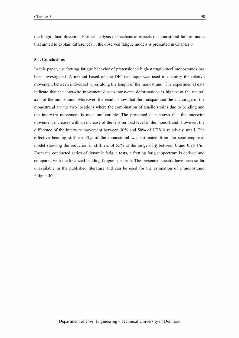
Chapter 5 90
Department of Civil Engineering - Technical University of Denmark
the longitudinal direction. Further analysis of mechanical aspects of monostrand failure modes
that aimed to explain differences in the observed fatigue models is presented in Chapter 6.
5.4. Conclusions
In this paper, the fretting fatigue behavior of pretensioned high-strength steel monostrands has
been investigated. A method based on the DIC technique was used to quantify the relative
movement between individual wires along the length of the monostrand. The experimental data
indicate that the interwire movement due to transverse deformations is highest at the neutral
axis of the monostrand. Moreover, the results show that the midspan and the anchorage of the
monostrand are the two locations where the combination of tensile strains due to bending and
the interwire movement is most unfavorable. The presented data shows that the interwire
movement increases with an increase of the tension load level in the monostrand. However, the
difference of the interwire movement between 30% and 50% of UTS is relatively small. The
effective bending stiffness EIeff of the monostrand was estimated from the semi-empirical
model showing the reduction in stiffness of 55% at the range of between 0 and 0.25 1/m.
From the conducted series of dynamic fatigue tests, a fretting fatigue spectrum is derived and
compared with the localized bending fatigue spectrum. The presented spectra have been so far
unavailable in the published literature and can be used for the estimation of a monostrand
fatigue life.
Chapter 5 91
Department of Civil Engineering - Technical University of Denmark
Bibliography
[1] N.J. Gimsing, C.T. Georgakis, Cable Supported Bridges: Concept and Design, 3rd
edition, New Jersey: John Wiley & Sons 2012; 544-547.
[2] Y. Hikami, N. Shiraishi, Rain–wind induced vibrations of cables in cable stayed
bridges, J. Wind. Eng. Ind. Aerodyn. 29(1) (1988) 409-418.
[3] Z. Savor, J. Radic, G. Hrelja, Cable vibrations at Dubrovnik Bridge, Bridge Structures.
2(2) (2006) 97-106.
[4] S. Wood, K.H. Frank, Experimental investigation of bending fatigue response of
grouted stay cables, J. B. Eng. 15(2) (2010) 123-130.
[5] J. Winkler, G. Fischer, C.T. Georgakis, A. Kotas, A preliminary bending fatigue
spectrum for steel monostrand cables, J. IASS. 52(4) (2011) 249-255.
[6] J.L. Jensen, N. Bitsch, E. Laursen, Fatigue Risk Assessment of Hangers on Great Belt
Bridge. Proc. 7th ISCD, Vienna, 10-13 December 2007.
[7] G. Rodríguez, C.J. Olabarrieta, Fatigue testing with transverse displacements in stay
cable systems. Proc. 3rd fib International Congress, Washington, May 29-June 2 2010.
[8] J.P. Gourmelon, Fatigue of staying cables, Organisation and results of the research
programme. International Organisation for the Study of the Endurance of Ropes
(OIPEEC) Bulletin 84 2002; Reading, United Kingdom: 21-39.
[9] D. Wang, D. Zhang, S. Ge, Fretting–fatigue behavior of steel wires in low cycle
fatigue, Materials and Design. 32(10) (2011) 4986-4993.
[10] V. Périer, L. Dieng, L. Gaillet, C. Tessier, S. Fouvry, Fretting-fatigue behaviour of
bridge engineering cables in a solution of sodium chloride, Wear. 267 (2009) 308-314.
[11] M. Raoof, Methods for analysing large spiral strands, J. Strain Anal. Eng. 26(3) (1991)
165-174.
[12] R.E. Hobbs, M. Raoof, Mechanism of fretting fatigue in steel cables, Int. J. Fatigue.
16(4) (1994) 273-280.
[13] M. Raoof, T.J. Davies, The riddle of free-bending fatigue at end terminations to spiral
strands, J. Constr. Steel Res. 95 (2014) 256-262.
[14] C. Miki, T. Endo, A. Okukawa, Full-size fatigue test of bridge cables: Length effect on
fatigue of wires and strands, International Association for Bridge and Structural
Engineering (IABSE), Zurich, 66 (1992) 167-178.
[15] D. Siegert, P. Brevet, Fatigue of stay cables inside end fittings: High frequencies of
wind induced vibrations. International Organisation for the Study of the Endurance of
Ropes (OIPEEC) Bulletin 89 2005; Reading, United Kingdom: 43-51.
Chapter 5 92
Department of Civil Engineering - Technical University of Denmark
[16] C.A. Prato, M.A. Ceballos, Dynamic bending stresses near the ends of parallel-bundle
stay cables, SEI. 13(1) (2003) 64-68.
[17] T.A. Wyatt, Secondary stress in parallel wire suspension cables, J. Struc. Div. (ASCE).
86(7) (1960) 37-59.
[18] J. Winkler, G. Fischer, C.T. Georgakis, Localized bending fatigue behavior of high-
strength steel monostrands. Proc. 6th IABMAS, Stresa, 8-12 July 2012.
[19] J. Winkler, G. Fischer, C.T. Georgakis, Measurement of local deformations in steel
monostrands using digital image correlation, J. B. Eng. (2014) (available online).
[20] ARAMIS System Manual (2009), version 6.1, GOM, Mittelweg 7–8, 38106
Braunschweig, Germany
[21] K.O. Papailiou, On the bending stiffness of transmission line conductors, IEEE
Transactions on Power Delivery. 12(4) (1997) 1576-1588.
[22] M. Raoof, Y.P. Huang, Free bending characteristics of axially preloaded spiral strands,
Proc., ICE - Structures and Buildings. 94(4) (1992) 469-484.
[23] R.E. Hobbs, M. Raoof, Behaviour of cables under dynamic or repeated loading, J.
Constr. Steel Res. 39(1) (1996) 31-50.
[24] J.P. Gourmelon, P. Brevet, D. Siegert, Failure mechanisms in rotating bending fatigue
on 7-wire strands, IABSE workshop, Madrid 1992: Length effect on fatigue of wires
and strands. 66 (1992) 251-258.
[25] T.A. Wyatt, Secondary stresses in parallel wire suspension cables. J. Struct. Div.,
ASCE, 86(ST7) (1960) 37-60.
[26] S.W. Khan, M. Raoof, Restrained bending fatigue design of bridge cables. Forensic
Engineering 2012: Gateway To a Better Tomorrow - Proceedings of the 6th Congress
on Forensic Engineering 2013, 113-122.
[27] Fédération internationale du béton (fib), Bulletin 30 Acceptance of stay cable systems
using prestressing steel, 2005.
[28] Post Tensioning Institute (PTI), PTI Guide Specification. Recommendations for stay
cable Design, Testing and Installation, 2007.

Chapter 5 93
Department of Civil Engineering - Technical University of Denmark
Chapter 6 94
Department of Civil Engineering - Technical University of Denmark
Chapter 6
Localized bending and fretting fatigue spectra - mechanical aspects of monostrand failure modes
Chapter summary
The comparison of the fatigue spectra shown in previous study (Chapter 5) revealed significant
differences between the fretting and localized bending fatigue models. The analysis presented in
this chapter aims at explaining the discrepancies between the two spectra by focusing on the
mechanical aspects of the observed failure mechanisms. Based on the study of the failure-mode
dependent cross sectional stress distribution it was concluded that, in case of the fretting
mechanism, a relaxation of bending-induced tension due to interwire movement is reducing the
overall stress range and, hence, elongating the monostrand fatigue life.
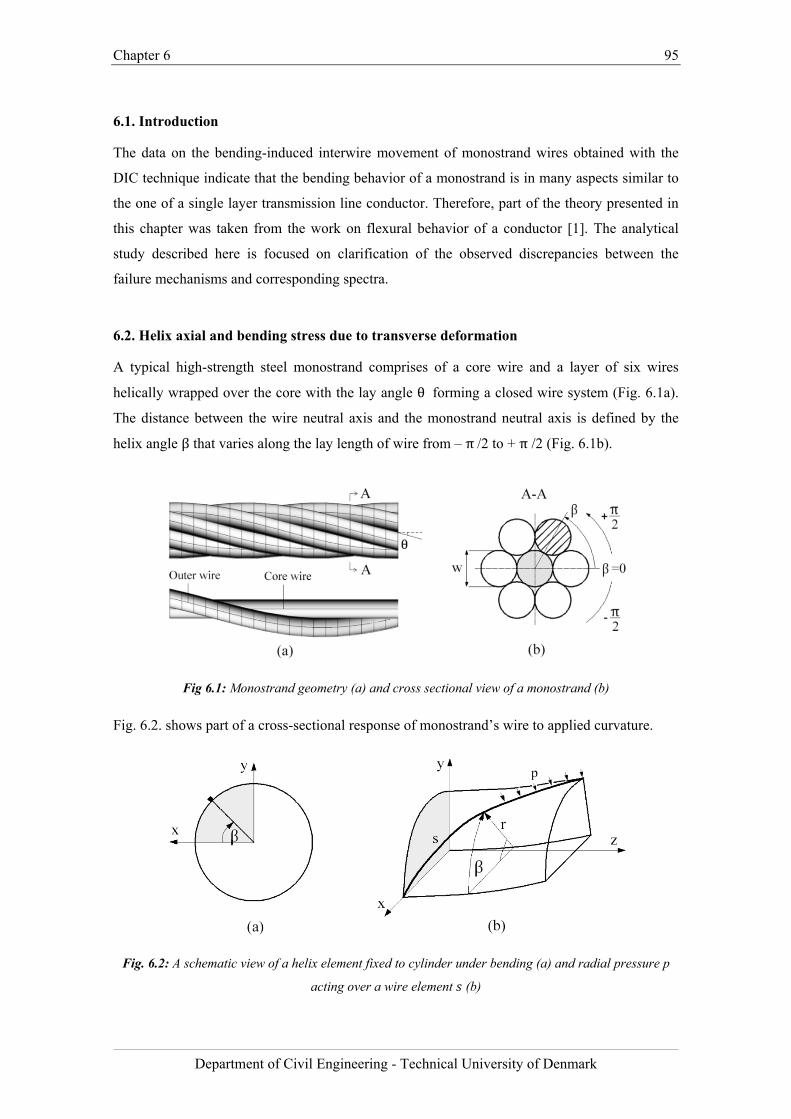
Chapter 6 95
Department of Civil Engineering - Technical University of Denmark
6.1. Introduction
The data on the bending-induced interwire movement of monostrand wires obtained with the
DIC technique indicate that the bending behavior of a monostrand is in many aspects similar to
the one of a single layer transmission line conductor. Therefore, part of the theory presented in
this chapter was taken from the work on flexural behavior of a conductor [1]. The analytical
study described here is focused on clarification of the observed discrepancies between the
failure mechanisms and corresponding spectra.
6.2. Helix axial and bending stress due to transverse deformation
A typical high-strength steel monostrand comprises of a core wire and a layer of six wires
helically wrapped over the core with the lay angle θ forming a closed wire system (Fig. 6.1a).
The distance between the wire neutral axis and the monostrand neutral axis is defined by the
helix angle β that varies along the lay length of wire from – π/2 to + π /2 (Fig. 6.1b).
Fig 6.1: Monostrand geometry (a) and cross sectional view of a monostrand (b)
Fig. 6.2. shows part of a cross-sectional response of monostrand’s wire to applied curvature.
Fig. 6.2: A schematic view of a helix element fixed to cylinder under bending (a) and radial pressure p
acting over a wire element (b)

Chapter 6 96
Department of Civil Engineering - Technical University of Denmark
When a piece of monostrand is bent to a global curvature about x-axis χ the bending stress of
each wire consists of two terms:
a) a bending stress which is caused from the bending of a wire around its own neutral axis:
σ E ∙w2∙ χ (6.1)
where E stands for Young's modulus of the wire, w for wire diameter.
b) an additional friction stress (helix axial stress) which occurs because at the beginning of
bending the radial pressure acting over a wire element s is high enough to prevent relative slip
between the lay wires and the core. This stress varies with the helix angleβ. Helix axial stress
component due to cross-section bending can be derived by use of differential geometry [2]:
σ β E ∙ r ∙ cos θ ∙ sin β ∙ χ (6.2)
6.3. Stick state and slip state of the monostrand
When the applied curvature increases and reaches critical value χ , the internal friction acting
between the wires and the core is not enough to prevent relative slip of the wires on the core.
Consequently, the wire material moves from stick state to slip state (Fig.6.3a). In order to
calculate quantitatively the force and stress situation in the wires during the slip process, the free
body diagram of a wire segment is considered (Fig.6.3b).
Fig. 6.3: Stick and slip state of a wire material (a) and free body diagram of a wire segment (b)

Chapter 6 97
Department of Civil Engineering - Technical University of Denmark
The distributed load p leads to a radial force dR. The radial force dR develops in conjunction
with the friction coefficient μ between a lay wire and the core wire, a friction force dF which
modifies the axial force N in each wire:
dF μ ∙ dR μ ∙ N ∙ sin θ dβ (6.3)
Summation of axial forces in Fig. 6.3b yields:
N dN N dN μ ∙ N ∙ sin θ dβ (6.4)
Integration of Equation 6.4 over β with the boundary condition:
β 0; N β N
yields:
N β N ∙ (6.5)
where N is the tensile force acting on an individual wire prior to bending, i.e. when only
tension T acts on monostrand. It can be readily calculated to:
N β N β N N ∙ 1 (6.6)
This (friction) slip force N β can be converted to a slip stress σ _ β :
σ _ β N β
Aσ ∙ 1 (6.7)
Where σ is a tensile stress in the wire prior to bending and A is the area of a wire cross
section. The slip stressσ _ β is the maximum additional stress which can be taken by a wire
during bending because of the interlayer friction.
6.4. Failure mode-dependent cross sectional stress distribution
The stick stressσ _ β , the slip stressσ _ β and the bending stressσ are shown
schematically in Fig. 6.4 and Fig.6.5 for each of the observed failure mechanisms.
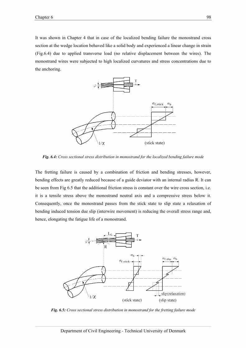
Chapter 6 98
Department of Civil Engineering - Technical University of Denmark
It was shown in Chapter 4 that in case of the localized bending failure the monostrand cross
section at the wedge location behaved like a solid body and experienced a linear change in strain
(Fig.6.4) due to applied transverse load (no relative displacement between the wires). The
monostrand wires were subjected to high localized curvatures and stress concentrations due to
the anchoring.
Fig. 6.4: Cross sectional stress distribution in monostrand for the localized bending failure mode
The fretting failure is caused by a combination of friction and bending stresses, however,
bending effects are greatly reduced because of a guide deviator with an internal radius R. It can
be seen from Fig 6.5 that the additional friction stress is constant over the wire cross section, i.e.
it is a tensile stress above the monostrand neutral axis and a compressive stress below it.
Consequently, once the monostrand passes from the stick state to slip state a relaxation of
bending induced tension due slip (interwire movement) is reducing the overall stress range and,
hence, elongating the fatigue life of a monostrand.
Fig. 6.5: Cross sectional stress distribution in monostrand for the fretting failure mode
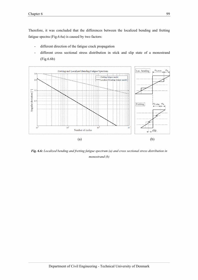
Chapter 6 99
Department of Civil Engineering - Technical University of Denmark
Therefore, it was concluded that the differences between the localized bending and fretting
fatigue spectra (Fig.6.6a) is caused by two factors:
- different direction of the fatigue crack propagation
- different cross sectional stress distribution in stick and slip state of a monostrand
(Fig.6.6b)
(a) (b)
Fig. 6.6: Localized bending and fretting fatigue spectrum (a) and cross sectional stress distribution in
monostrand (b)

Chapter 6 100
Department of Civil Engineering - Technical University of Denmark
Bibliography
[1] K.O. Papailiou, On the bending stiffness of transmission line conductors, IEEE
Transactions on Power Delivery. 12(4) (1997) 1576-1588.
[2] K. Feyrer, Wire ropes: tension, endurance, reliability, ISBN: 3540338217, Publisher:
Springer, (2007), 173-187.

Chapter 6 101
Department of Civil Engineering - Technical University of Denmark
Chapter 7 102
Department of Civil Engineering - Technical University of Denmark
Chapter 7
Bending fatigue behavior of multistrand stay cable specimen under flexural load
The results presented in this chapter are taken from the paper "Experimental investigation of
bending fatigue response of parallel mono-strand stay cable" by J. Winkler, C.T. Georgakis, G.
Fischer, S. Wood and W. Ghannoum, under re-review in the Journal of Structural
Engineering International (to be published in special issue SEI 1/2015: “Tensile and
Membrane Structures”).
Chapter summary
The objective of the full-scale experimental investigation described in this chapter was to study
the structural response of a stay cable to cyclic bending and to establish a correlation between
the bending fatigue behavior of the single strand and that of the multistrand stay cable. For this
purpose, a digital image correlation (DIC) technique was employed as a tool for quantifying the
strain and deformations occurring on the surface of the strand. Moreover, the relationship
between the transversal stiffness, the tensile force variation and the fatigue life of a single strand
and that of a multistrand specimen was studied. The data obtained with the DIC technique
provided relevant information on the internal state of displacement of the multistrand stay cable
under bending and resulted in significant insight in the deformation and fatigue failure
mechanisms of stay cable assemblies under axial and transverse loading.
Chapter 7 103
Department of Civil Engineering - Technical University of Denmark
7.1. Introduction
Cables are often used as main tension elements in a variety of cable supported structures like
suspension and cable-stayed bridges, guyed masts and large membrane roofs. Stay cables play
an essential role in the dynamic behavior of cable-stayed bridges and being characterized by low
mechanical damping are extremely vulnerable to wind excitation. Vibrations of inclined cables
are of concern because they can induce undue stresses and fatigue in the cables themselves and
in the connections to the bridge deck, thus threatening safety and serviceability of the bridge [1].
Large amplitude wind-induced vibrations of inclined cables have been frequently reported [2-4]
and numerous efforts have been made in order to understand the mechanisms of various types of
wind-induced cable vibration phenomena and to find solutions for alleviating vibration
problems. However, a limited work has been done to assess the fatigue characteristics of cables
subjected to cyclic transverse deformations. The most recent cable anchorage failures on the
Olav Sabo Bridge (Minnesota, USA) indicate a lack of attention to the effect of cable vibrations
on the fatigue lifetime and the cumulative fatigue damage of bridge cables. When the transverse
deformations of cables are considered, the fatigue evaluation is usually based on the simplified
assumption that the cable behaves as a solid section, with the use of arbitrary stress reduction
factors to account for the presence of guide deviators installed within the anchorage [5,6].
Fretting fatigue and serviceability of stay cables
Only a few experimental investigations of stay cable fatigue behavior under bending have been
carried out to date [7-9]. Furthermore, in these investigations transverse deformations as well as
the interwire friction at the critical locations with regard to fatigue (exit of a socket, guide
deviator) have not been measured and analyzed. Information about deformations in monostrand
steel cables experiencing axial and transverse displacements is required to properly evaluate the
fatigue resistance of multistrand stay cable assemblies.
The transverse displacements of stay cables may lead to substantial relative movements between
the steel wires (fretting) in the free span of the tendons and local bending deformations in the
anchorage regions. The fretting mechanism leads to damage resulting from small amplitude
displacements between the contacting surfaces of adjacent wires [10,11]. These interwire
movements significantly shorten the life expectancy of the cable and, consequently, the service
life of the supported structure [12]. Current cable assemblies often feature solutions that
considerably reduce local bending effects and, therefore, fretting is often regarded as the main
mechanism of the fatigue life reduction. However, due to lack of data on the fatigue response of
steel monostrands subjected to transverse deformations, the life expectancy of stay cables has
not been evaluated in sufficient detail to date [13].
Chapter 7 104
Department of Civil Engineering - Technical University of Denmark
Structural response of monostrand and multistrand stay cable to cyclic bending load
As the majority of modern stay cables are comprised of a number of individual high-strength
steel monostrands, investigations of the bending fatigue performance of a monostrand has
become more relevant. The fretting and localized bending behavior of individual high strength
steel monostrands subjected to transverse deformations has been investigated in some detail by
Winkler et al. [14,15]. The novel application of the DIC technique for the measurement of local
deformations on monostrand led to a more in-depth understanding of the underlying fatigue
mechanisms [16]. Moreover, from the conducted series of dynamic fatigue tests, the fretting and
the localized bending fatigue spectrum have been derived from experimental data for the
estimation of the monostrand fatigue life [17,18].
Based on these previous studies, the experimental investigation performed on the parallel
monostrand stay cable described herein had three objectives. Firstly, to establish a correlation
between the bending fatigue behavior of the single monostrand and that of the multistrand stay
cable. Secondly, to verify whether the fatigue life of a multistrand cable can be predicted based
on the fatigue spectra derived from the tests on monostrands. Thirdly, to study the relationship
between the transversal stiffness and the tensile force variations (hysteresis) of a monostrand
and that of a multistrand specimen.
The commonly applied qualification tests for the fatigue resistance of stay cables, as outlined in
the international recommendations made by the PTI [19] and fib [20], do not specifically
address fatigue issues related to transverse cable vibrations and, therefore, do not require testing
for bending. Consequently, many important questions regarding cable fatigue characteristics
still need to be answered. In this chapter, an experimental investigation on the bending fatigue
response of a parallel monostrand stay cable is presented. The results described in this study
were not intended to address all aspects of the bending fatigue resistance of the cable. Rather,
the static and dynamic tests were designed to understand the crucial aspects of bending fatigue
response of a modern multistrand stay cable, which are not addressed in the fib and PTI
recommendations.
7.2. Methodology
7.2.1. Materials
An experimental investigation was carried out on a stay cable assembly comprised of 19 high-
strength steel monostrands with 10.3 m length. The monostrands were 15.7 mm in diameter, as
commonly used in cable stayed bridges (parallel monostrand stay cable systems) and in post-
tensioned box girders. The monostrands were of low relaxation grade, waxed and PE coated.
The ultimate tensile strength of the monostrand (Fig.7.1) was 1860 MPa (279 kN).
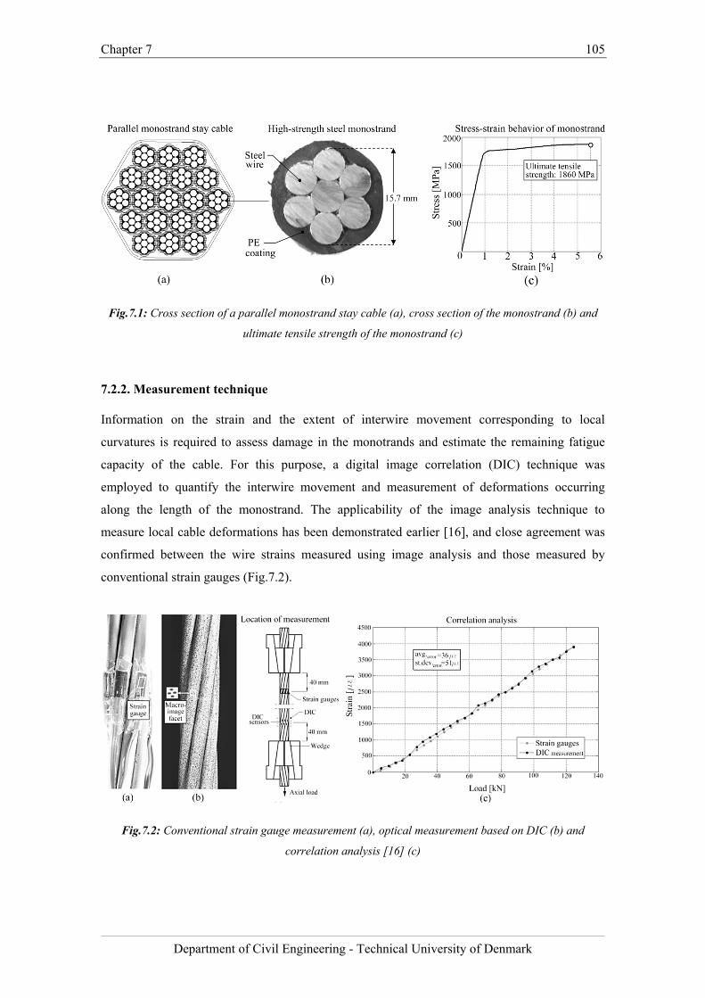
Chapter 7 105
Department of Civil Engineering - Technical University of Denmark
Fig.7.1: Cross section of a parallel monostrand stay cable (a), cross section of the monostrand (b) and
ultimate tensile strength of the monostrand (c)
7.2.2. Measurement technique
Information on the strain and the extent of interwire movement corresponding to local
curvatures is required to assess damage in the monotrands and estimate the remaining fatigue
capacity of the cable. For this purpose, a digital image correlation (DIC) technique was
employed to quantify the interwire movement and measurement of deformations occurring
along the length of the monostrand. The applicability of the image analysis technique to
measure local cable deformations has been demonstrated earlier [16], and close agreement was
confirmed between the wire strains measured using image analysis and those measured by
conventional strain gauges (Fig.7.2).
Fig.7.2: Conventional strain gauge measurement (a), optical measurement based on DIC (b) and
correlation analysis [16] (c)
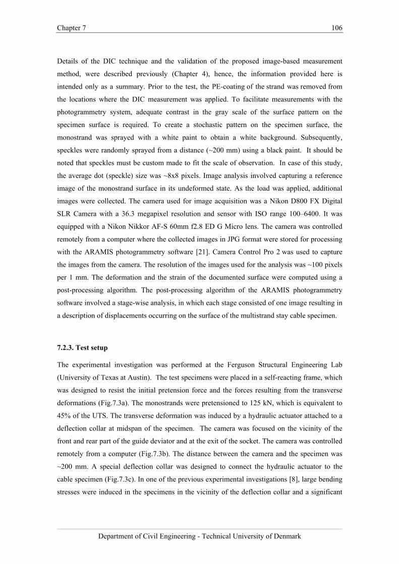
Chapter 7 106
Department of Civil Engineering - Technical University of Denmark
Details of the DIC technique and the validation of the proposed image-based measurement
method, were described previously (Chapter 4), hence, the information provided here is
intended only as a summary. Prior to the test, the PE-coating of the strand was removed from
the locations where the DIC measurement was applied. To facilitate measurements with the
photogrammetry system, adequate contrast in the gray scale of the surface pattern on the
specimen surface is required. To create a stochastic pattern on the specimen surface, the
monostrand was sprayed with a white paint to obtain a white background. Subsequently,
speckles were randomly sprayed from a distance (~200 mm) using a black paint. It should be
noted that speckles must be custom made to fit the scale of observation. In case of this study,
the average dot (speckle) size was ~8x8 pixels. Image analysis involved capturing a reference
image of the monostrand surface in its undeformed state. As the load was applied, additional
images were collected. The camera used for image acquisition was a Nikon D800 FX Digital
SLR Camera with a 36.3 megapixel resolution and sensor with ISO range 100–6400. It was
equipped with a Nikon Nikkor AF-S 60mm f2.8 ED G Micro lens. The camera was controlled
remotely from a computer where the collected images in JPG format were stored for processing
with the ARAMIS photogrammetry software [21]. Camera Control Pro 2 was used to capture
the images from the camera. The resolution of the images used for the analysis was ~100 pixels
per 1 mm. The deformation and the strain of the documented surface were computed using a
post-processing algorithm. The post-processing algorithm of the ARAMIS photogrammetry
software involved a stage-wise analysis, in which each stage consisted of one image resulting in
a description of displacements occurring on the surface of the multistrand stay cable specimen.
7.2.3. Test setup
The experimental investigation was performed at the Ferguson Structural Engineering Lab
(University of Texas at Austin). The test specimens were placed in a self-reacting frame, which
was designed to resist the initial pretension force and the forces resulting from the transverse
deformations (Fig.7.3a). The monostrands were pretensioned to 125 kN, which is equivalent to
45% of the UTS. The transverse deformation was induced by a hydraulic actuator attached to a
deflection collar at midspan of the specimen. The camera was focused on the vicinity of the
front and rear part of the guide deviator and at the exit of the socket. The camera was controlled
remotely from a computer (Fig.7.3b). The distance between the camera and the specimen was
~200 mm. A special deflection collar was designed to connect the hydraulic actuator to the
cable specimen (Fig.7.3c). In one of the previous experimental investigations [8], large bending
stresses were induced in the specimens in the vicinity of the deflection collar and a significant
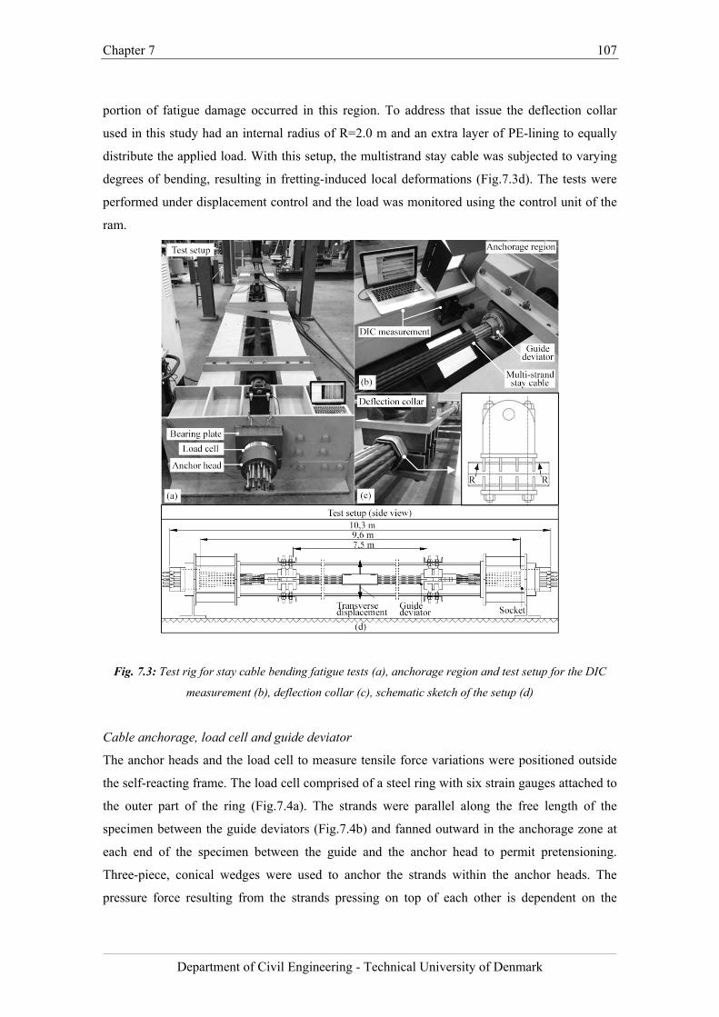
Chapter 7 107
Department of Civil Engineering - Technical University of Denmark
portion of fatigue damage occurred in this region. To address that issue the deflection collar
used in this study had an internal radius of R=2.0 m and an extra layer of PE-lining to equally
distribute the applied load. With this setup, the multistrand stay cable was subjected to varying
degrees of bending, resulting in fretting-induced local deformations (Fig.7.3d). The tests were
performed under displacement control and the load was monitored using the control unit of the
ram.
Fig. 7.3: Test rig for stay cable bending fatigue tests (a), anchorage region and test setup for the DIC
measurement (b), deflection collar (c), schematic sketch of the setup (d)
Cable anchorage, load cell and guide deviator
The anchor heads and the load cell to measure tensile force variations were positioned outside
the self-reacting frame. The load cell comprised of a steel ring with six strain gauges attached to
the outer part of the ring (Fig.7.4a). The strands were parallel along the free length of the
specimen between the guide deviators (Fig.7.4b) and fanned outward in the anchorage zone at
each end of the specimen between the guide and the anchor head to permit pretensioning.
Three-piece, conical wedges were used to anchor the strands within the anchor heads. The
pressure force resulting from the strands pressing on top of each other is dependent on the
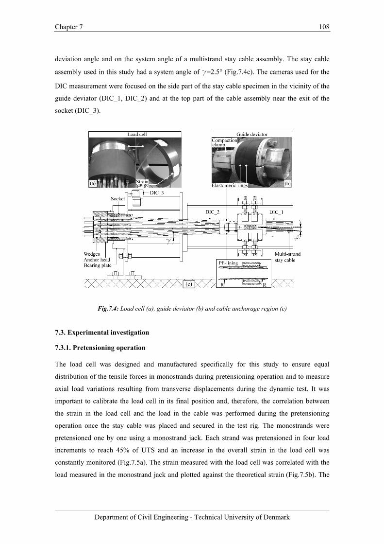
Chapter 7 108
Department of Civil Engineering - Technical University of Denmark
deviation angle and on the system angle of a multistrand stay cable assembly. The stay cable
assembly used in this study had a system angle of g=2.5° (Fig.7.4c). The cameras used for the
DIC measurement were focused on the side part of the stay cable specimen in the vicinity of the
guide deviator (DIC_1, DIC_2) and at the top part of the cable assembly near the exit of the
socket (DIC_3).
Fig.7.4: Load cell (a), guide deviator (b) and cable anchorage region (c)
7.3. Experimental investigation
7.3.1. Pretensioning operation
The load cell was designed and manufactured specifically for this study to ensure equal
distribution of the tensile forces in monostrands during pretensioning operation and to measure
axial load variations resulting from transverse displacements during the dynamic test. It was
important to calibrate the load cell in its final position and, therefore, the correlation between
the strain in the load cell and the load in the cable was performed during the pretensioning
operation once the stay cable was placed and secured in the test rig. The monostrands were
pretensioned one by one using a monostrand jack. Each strand was pretensioned in four load
increments to reach 45% of UTS and an increase in the overall strain in the load cell was
constantly monitored (Fig.7.5a). The strain measured with the load cell was correlated with the
load measured in the monostrand jack and plotted against the theoretical strain (Fig.7.5b). The
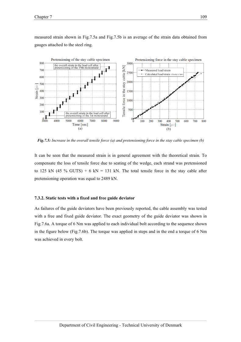
Chapter 7 109
Department of Civil Engineering - Technical University of Denmark
measured strain shown in Fig.7.5a and Fig.7.5b is an average of the strain data obtained from
gauges attached to the steel ring.
Fig.7.5: Increase in the overall tensile force (a) and pretensioning force in the stay cable specimen (b)
It can be seen that the measured strain is in general agreement with the theoretical strain. To
compensate the loss of tensile force due to seating of the wedge, each strand was pretensioned
to 125 kN (45 % GUTS) + 6 kN = 131 kN. The total tensile force in the stay cable after
pretensioning operation was equal to 2489 kN.
7.3.2. Static tests with a fixed and free guide deviator
As failures of the guide deviators have been previously reported, the cable assembly was tested
with a free and fixed guide deviator. The exact geometry of the guide deviator was shown in
Fig.7.6a. A torque of 6 Nm was applied to each individual bolt according to the sequence shown
in the figure below (Fig.7.6b). The torque was applied in steps and in the end a torque of 6 Nm
was achieved in every bolt.
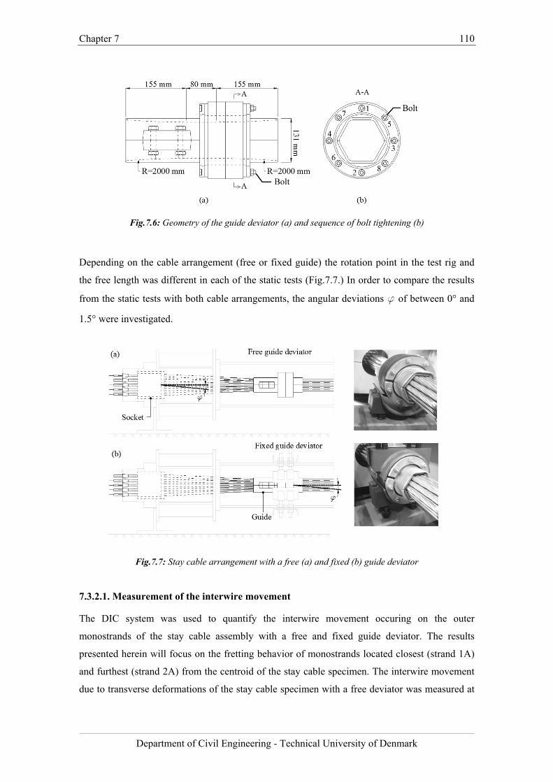
Chapter 7 110
Department of Civil Engineering - Technical University of Denmark
Fig.7.6: Geometry of the guide deviator (a) and sequence of bolt tightening (b)
Depending on the cable arrangement (free or fixed guide) the rotation point in the test rig and
the free length was different in each of the static tests (Fig.7.7.) In order to compare the results
from the static tests with both cable arrangements, the angular deviations f of between 0° and
1.5° were investigated.
Fig.7.7: Stay cable arrangement with a free (a) and fixed (b) guide deviator
7.3.2.1. Measurement of the interwire movement
The DIC system was used to quantify the interwire movement occuring on the outer
monostrands of the stay cable assembly with a free and fixed guide deviator. The results
presented herein will focus on the fretting behavior of monostrands located closest (strand 1A)
and furthest (strand 2A) from the centroid of the stay cable specimen. The interwire movement
due to transverse deformations of the stay cable specimen with a free deviator was measured at
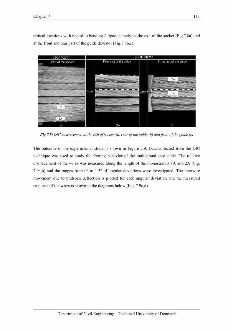
Chapter 7 111
Department of Civil Engineering - Technical University of Denmark
critical locations with regard to bending fatigue, namely, at the exit of the socket (Fig.7.8a) and
at the front and rear part of the guide deviator (Fig.7.8b,c).
Fig.7.8: DIC measurement at the exit of socket (a), rear of the guide (b) and front of the guide (c)
The outcome of the experimental study is shown in Figure 7.9. Data collected from the DIC
technique was used to study the fretting behavior of the multistrand stay cable. The relative
displacement of the wires was measured along the length of the monostrands 1A and 2A (Fig.
7.9a,b) and the ranges from 0° to 1.5° of angular deviations were investigated. The interwire
movement due to midspan deflection is plotted for each angular deviation and the measured
response of the wires is shown in the diagrams below (Fig. 7.9c,d).
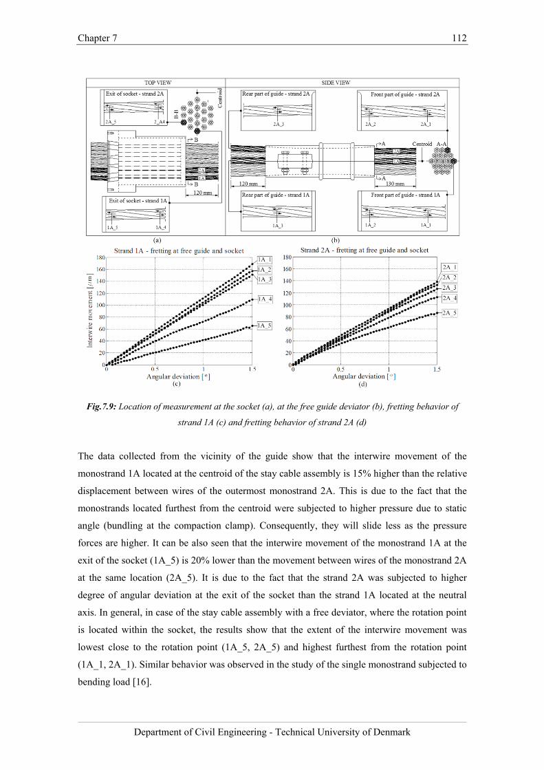
Chapter 7 112
Department of Civil Engineering - Technical University of Denmark
Fig.7.9: Location of measurement at the socket (a), at the free guide deviator (b), fretting behavior of
strand 1A (c) and fretting behavior of strand 2A (d)
The data collected from the vicinity of the guide show that the interwire movement of the
monostrand 1A located at the centroid of the stay cable assembly is 15% higher than the relative
displacement between wires of the outermost monostrand 2A. This is due to the fact that the
monostrands located furthest from the centroid were subjected to higher pressure due to static
angle (bundling at the compaction clamp). Consequently, they will slide less as the pressure
forces are higher. It can be also seen that the interwire movement of the monostrand 1A at the
exit of the socket (1A_5) is 20% lower than the movement between wires of the monostrand 2A
at the same location (2A_5). It is due to the fact that the strand 2A was subjected to higher
degree of angular deviation at the exit of the socket than the strand 1A located at the neutral
axis. In general, in case of the stay cable assembly with a free deviator, where the rotation point
is located within the socket, the results show that the extent of the interwire movement was
lowest close to the rotation point (1A_5, 2A_5) and highest furthest from the rotation point
(1A_1, 2A_1). Similar behavior was observed in the study of the single monostrand subjected to
bending load [16].
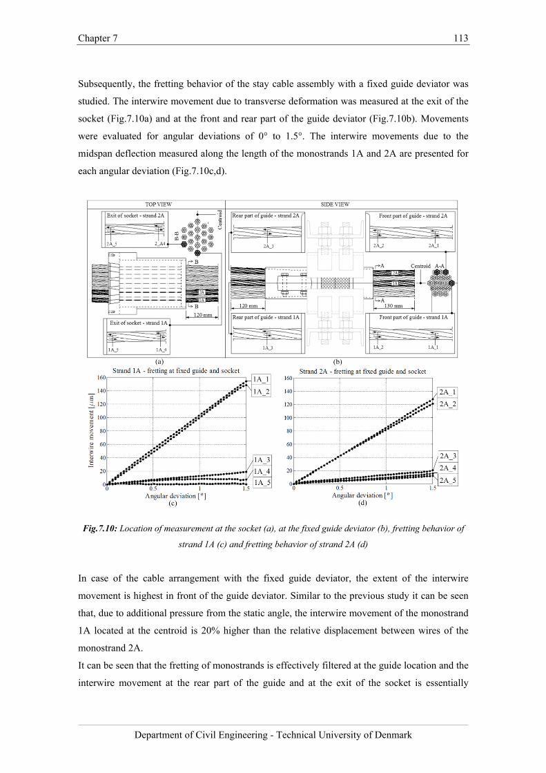
Chapter 7 113
Department of Civil Engineering - Technical University of Denmark
Subsequently, the fretting behavior of the stay cable assembly with a fixed guide deviator was
studied. The interwire movement due to transverse deformation was measured at the exit of the
socket (Fig.7.10a) and at the front and rear part of the guide deviator (Fig.7.10b). Movements
were evaluated for angular deviations of 0° to 1.5°. The interwire movements due to the
midspan deflection measured along the length of the monostrands 1A and 2A are presented for
each angular deviation (Fig.7.10c,d).
Fig.7.10: Location of measurement at the socket (a), at the fixed guide deviator (b), fretting behavior of
strand 1A (c) and fretting behavior of strand 2A (d)
In case of the cable arrangement with the fixed guide deviator, the extent of the interwire
movement is highest in front of the guide deviator. Similar to the previous study it can be seen
that, due to additional pressure from the static angle, the interwire movement of the monostrand
1A located at the centroid is 20% higher than the relative displacement between wires of the
monostrand 2A.
It can be seen that the fretting of monostrands is effectively filtered at the guide location and the
interwire movement at the rear part of the guide and at the exit of the socket is essentially
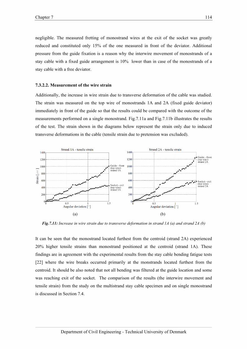
Chapter 7 114
Department of Civil Engineering - Technical University of Denmark
negligible. The measured fretting of monostrand wires at the exit of the socket was greatly
reduced and constituted only 15% of the one measured in front of the deviator. Additional
pressure from the guide fixation is a reason why the interwire movement of monostrands of a
stay cable with a fixed guide arrangement is 10% lower than in case of the monostrands of a
stay cable with a free deviator.
7.3.2.2. Measurement of the wire strain
Additionally, the increase in wire strain due to transverse deformation of the cable was studied.
The strain was measured on the top wire of monostrands 1A and 2A (fixed guide deviator)
immediately in front of the guide so that the results could be compared with the outcome of the
measurements performed on a single monostrand. Fig.7.11a and Fig.7.11b illustrates the results
of the test. The strain shown in the diagrams below represent the strain only due to induced
transverse deformations in the cable (tensile strain due to pretension was excluded).
(a) (b)
Fig.7.11: Increase in wire strain due to transverse deformation in strand 1A (a) and strand 2A (b)
It can be seen that the monostrand located furthest from the centroid (strand 2A) experienced
20% higher tensile strains than monostrand positioned at the centroid (strand 1A). These
findings are in agreement with the experimental results from the stay cable bending fatigue tests
[22] where the wire breaks occurred primarily at the monstrands located furthest from the
centroid. It should be also noted that not all bending was filtered at the guide location and some
was reaching exit of the socket. The comparison of the results (the interwire movement and
tensile strain) from the study on the multistrand stay cable specimen and on single monostrand
is discussed in Section 7.4.
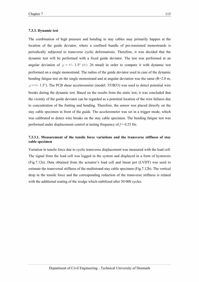
Chapter 7 115
Department of Civil Engineering - Technical University of Denmark
7.3.3. Dynamic test
The combination of high pressure and bending in stay cables may primarily happen at the
location of the guide deviator, where a confined bundle of pre-tensioned monostrands is
periodically subjected to transverse cyclic deformations. Therefore, it was decided that the
dynamic test will be performed with a fixed guide deviator. The test was performed at an
angular deviation of f = +/- 1.5° (+/- 26 mrad) in order to compare it with dynamic test
performed on a single monostrand. The radius of the guide deviator used in case of the dynamic
bending fatigue test on the single monostrand and at angular deviation was the same (R=2.0 m,
f = +/- 1.5°). The PCB shear accelerometer (model: 353B33) was used to detect potential wire
breaks during the dynamic test. Based on the results from the static test, it was concluded that
the vicinity of the guide deviator can be regarded as a potential location of the wire failures due
to concentration of the fretting and bending. Therefore, the sensor was placed directly on the
stay cable specimen in front of the guide. The accelerometer was set in a trigger mode, which
was calibrated to detect wire breaks on the stay cable specimen. The bending fatigue test was
performed under displacement control at testing frequency of f = 0.25 Hz.
7.3.3.1. Measurement of the tensile force variations and the transverse stiffness of stay cable specimen
Variation in tensile force due to cyclic transverse displacement was measured with the load cell.
The signal from the load cell was logged in the system and displayed in a form of hysteresis
(Fig.7.12a). Data obtained from the actuator’s load cell and linear pot (LVDT) was used to
estimate the transversal stiffness of the multistrand stay cable specimen (Fig.7.12b). The vertical
drop in the tensile force and the corresponding reduction of the transverse stiffness is related
with the additional seating of the wedge which stabilized after 50 000 cycles.
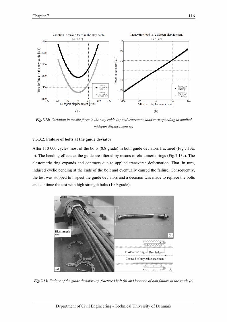
Chapter 7 116
Department of Civil Engineering - Technical University of Denmark
(a) (b)
Fig.7.12: Variation in tensile force in the stay cable (a) and transverse load corresponding to applied
midspan displacement (b)
7.3.3.2. Failure of bolts at the guide deviator
After 110 000 cycles most of the bolts (8.8 grade) in both guide deviators fractured (Fig.7.13a,
b). The bending effects at the guide are filtered by means of elastomeric rings (Fig.7.13c). The
elastomeric ring expands and contracts due to applied transverse deformation. That, in turn,
induced cyclic bending at the ends of the bolt and eventually caused the failure. Consequently,
the test was stopped to inspect the guide deviators and a decision was made to replace the bolts
and continue the test with high strength bolts (10.9 grade).
Fig.7.13: Failure of the guide deviator (a), fractured bolt (b) and location of bolt failure in the guide (c)
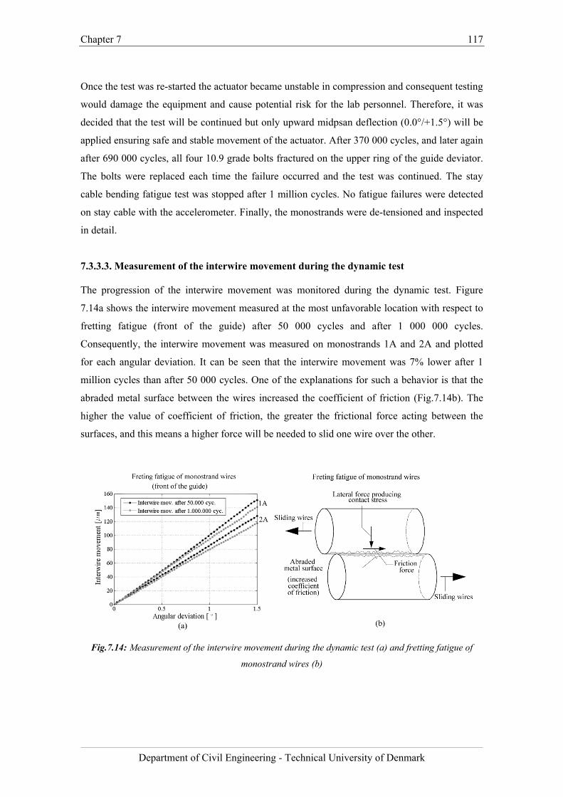
Chapter 7 117
Department of Civil Engineering - Technical University of Denmark
Once the test was re-started the actuator became unstable in compression and consequent testing
would damage the equipment and cause potential risk for the lab personnel. Therefore, it was
decided that the test will be continued but only upward midpsan deflection (0.0°/+1.5°) will be
applied ensuring safe and stable movement of the actuator. After 370 000 cycles, and later again
after 690 000 cycles, all four 10.9 grade bolts fractured on the upper ring of the guide deviator.
The bolts were replaced each time the failure occurred and the test was continued. The stay
cable bending fatigue test was stopped after 1 million cycles. No fatigue failures were detected
on stay cable with the accelerometer. Finally, the monostrands were de-tensioned and inspected
in detail.
7.3.3.3. Measurement of the interwire movement during the dynamic test
The progression of the interwire movement was monitored during the dynamic test. Figure
7.14a shows the interwire movement measured at the most unfavorable location with respect to
fretting fatigue (front of the guide) after 50 000 cycles and after 1 000 000 cycles.
Consequently, the interwire movement was measured on monostrands 1A and 2A and plotted
for each angular deviation. It can be seen that the interwire movement was 7% lower after 1
million cycles than after 50 000 cycles. One of the explanations for such a behavior is that the
abraded metal surface between the wires increased the coefficient of friction (Fig.7.14b). The
higher the value of coefficient of friction, the greater the frictional force acting between the
surfaces, and this means a higher force will be needed to slid one wire over the other.
Fig.7.14: Measurement of the interwire movement during the dynamic test (a) and fretting fatigue of
monostrand wires (b)
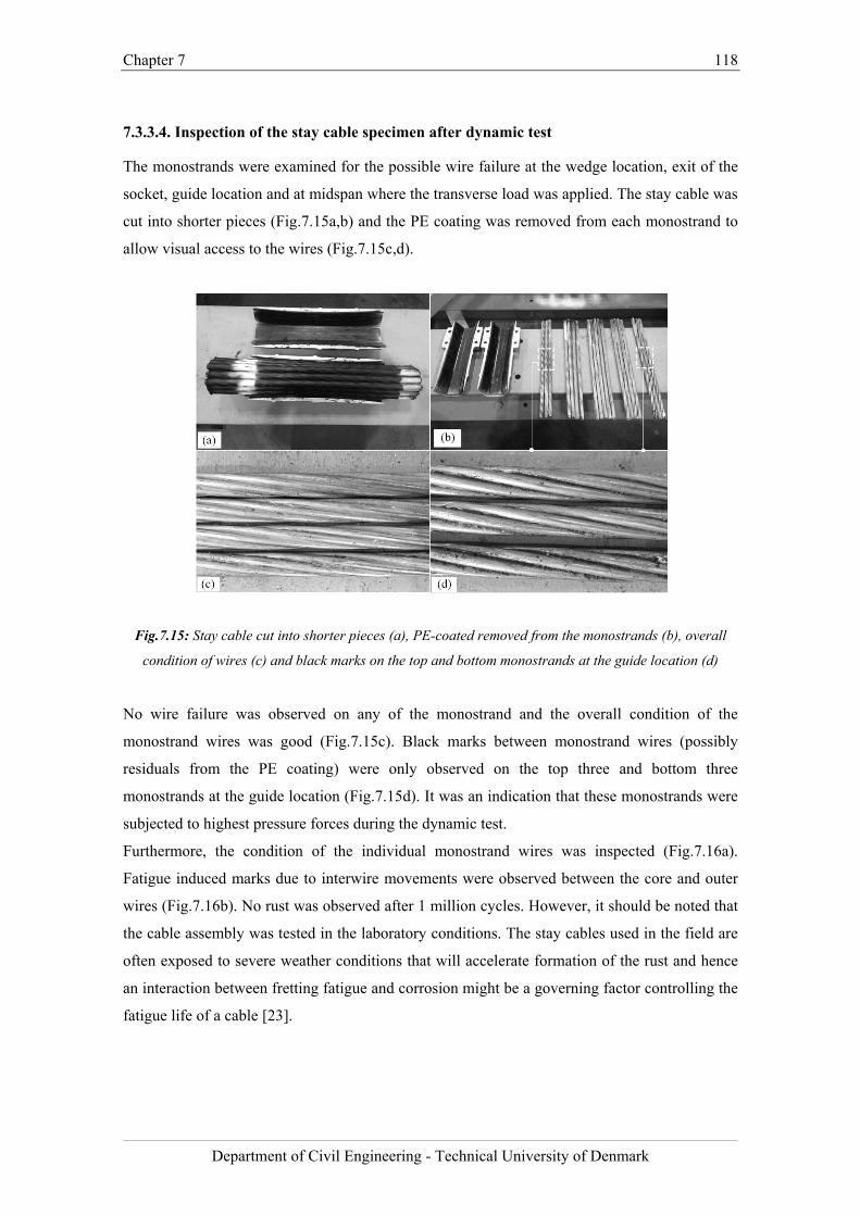
Chapter 7 118
Department of Civil Engineering - Technical University of Denmark
7.3.3.4. Inspection of the stay cable specimen after dynamic test
The monostrands were examined for the possible wire failure at the wedge location, exit of the
socket, guide location and at midspan where the transverse load was applied. The stay cable was
cut into shorter pieces (Fig.7.15a,b) and the PE coating was removed from each monostrand to
allow visual access to the wires (Fig.7.15c,d).
Fig.7.15: Stay cable cut into shorter pieces (a), PE-coated removed from the monostrands (b), overall
condition of wires (c) and black marks on the top and bottom monostrands at the guide location (d)
No wire failure was observed on any of the monostrand and the overall condition of the
monostrand wires was good (Fig.7.15c). Black marks between monostrand wires (possibly
residuals from the PE coating) were only observed on the top three and bottom three
monostrands at the guide location (Fig.7.15d). It was an indication that these monostrands were
subjected to highest pressure forces during the dynamic test.
Furthermore, the condition of the individual monostrand wires was inspected (Fig.7.16a).
Fatigue induced marks due to interwire movements were observed between the core and outer
wires (Fig.7.16b). No rust was observed after 1 million cycles. However, it should be noted that
the cable assembly was tested in the laboratory conditions. The stay cables used in the field are
often exposed to severe weather conditions that will accelerate formation of the rust and hence
an interaction between fretting fatigue and corrosion might be a governing factor controlling the
fatigue life of a cable [23].
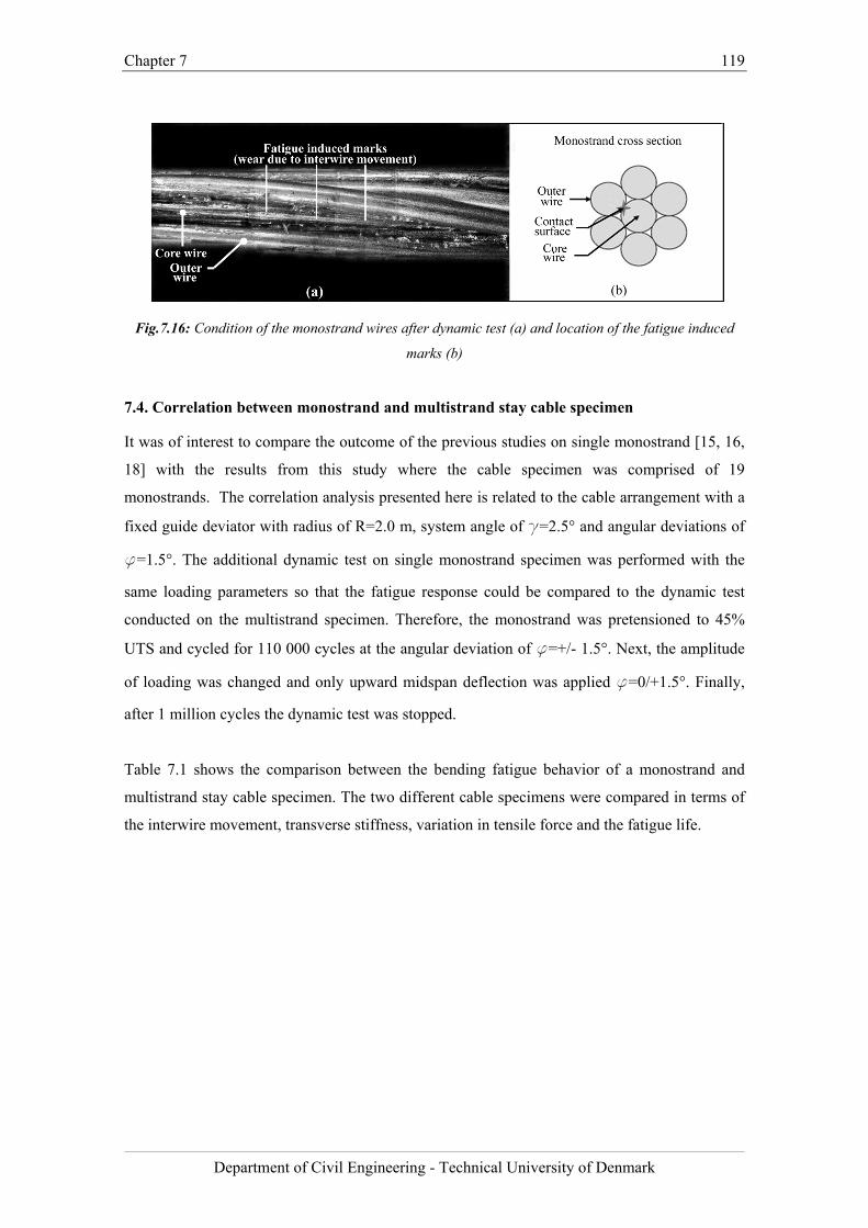
Chapter 7 119
Department of Civil Engineering - Technical University of Denmark
Fig.7.16: Condition of the monostrand wires after dynamic test (a) and location of the fatigue induced
marks (b)
7.4. Correlation between monostrand and multistrand stay cable specimen
It was of interest to compare the outcome of the previous studies on single monostrand [15, 16,
18] with the results from this study where the cable specimen was comprised of 19
monostrands. The correlation analysis presented here is related to the cable arrangement with a
fixed guide deviator with radius of R=2.0 m, system angle of g=2.5° and angular deviations of
f=1.5°. The additional dynamic test on single monostrand specimen was performed with the
same loading parameters so that the fatigue response could be compared to the dynamic test
conducted on the multistrand specimen. Therefore, the monostrand was pretensioned to 45%
UTS and cycled for 110 000 cycles at the angular deviation of f=+/- 1.5°. Next, the amplitude
of loading was changed and only upward midspan deflection was applied f=0/+1.5°. Finally,
after 1 million cycles the dynamic test was stopped.
Table 7.1 shows the comparison between the bending fatigue behavior of a monostrand and
multistrand stay cable specimen. The two different cable specimens were compared in terms of
the interwire movement, transverse stiffness, variation in tensile force and the fatigue life.
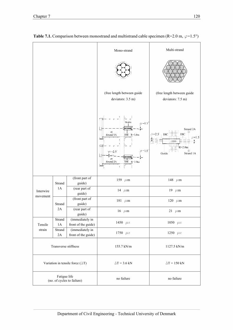
Chapter 7 120
Department of Civil Engineering - Technical University of Denmark
Table 7.1. Comparison between monostrand and multistrand cable specimen (R=2.0 m, f=1.5°)
Mono-strand
(free length between guide
deviators: 3.5 m)
Multi-strand
(free length between guide
deviators: 7.5 m)
Interwire
movement
Strand
1A
(front part of
guide) 159 mm 148 mm
(rear part of
guide) 14 mm 19 mm
Strand
2A
(front part of
guide) 181 mm 120 mm
(rear part of
guide) 16 mm 21 mm
Tensile
strain
Strand
1A
(immediately in
front of the guide) 1450 me 1050 me
Strand
2A
(immediately in
front of the guide) 1750 me 1250 me
Transverse stiffness
155.7 kN/m
1127.5 kN/m
Variation in tensile force (DT) DT = 3.6 kN DT = 150 kN
Fatigue life (no. of cycles to failure)
no failure no failure
Chapter 7 121
Department of Civil Engineering - Technical University of Denmark
The comparison of the fretting response of the strand 1A presented in the Table 7.1 shows that
there is a good correlation between the extent of the interwire movement in case of the
monostrand and the multistrand stay cable specimen. However, the comparison of the measured
interwire movement of the strand 2A indicate that the interwire friction of the single
monostrand specimen was 30% higher than in case of the equivalent monostrand in the
multistrand cable specimen. From the previous studies it is known that the higher the curvature
the higher the interwire movement. This indicates that the combination of pressure forces and
bending effects was different in case of the two different cable specimens. Moreover, the
elastomeric rings dissipated the bending effects and effectively lowered the overall curvature.
Consequently, an increase in tensile strain measured immediately in front of the guide in single
monostrand specimen was 25 % higher than the one on the multistrand specimen.
Although no wire failure was observed after the dynamic tests on a multistrand and monostrand
specimens, the results from the static test show that the internal state of displacement of the
multistrand stay cable under bending is complex. Furthermore, the stiffness of the guide fixture
in case of the multistrand test rig was smaller and the elastomeric rings allowed additional
movement of the stay cable in the guide reducing the bending effects and the pressure forces.
That will have a positive influence on the fatigue life of the multistrand stay cable assembly.
The comparison of the variation in the tensile force and the transverse stiffness is difficult as in
case of the multistrand cable specimen monostrands located at the centroidwere subjected to
different pressure forces and bending effects than the outermost monostrands. Therefore, the
overall transverse stiffness and the total variation in tensile force of the multistrand cannot be
simply divided by the number of monostrands and compared with the results from the test on
single monostrand.
7.5. Conclusions
The objective of the full-scale experimental investigation described here was to study the
structural response of a stay cable to cyclic bending and to establish a correlation between the
bending fatigue behavior of the single strand and that of the multistrand stay cable. For this
purpose, a digital image correlation (DIC) technique was employed as an efficient tool for
quantifying the interwire movement along the length of the multistrand cable specimen. The
application of the DIC technique for the measurement of local cable deformations provided
relevant information on the internal state of displacement of the multistrand stay cable under
bending load, which are not included in the fib [20] and the PTI [19] recommendations.
The experimental data indicate that the interwire movement due to transverse deformations is
highest at the monostrands located at the centroid of the stay cable specimen. This is due to the
Chapter 7 122
Department of Civil Engineering - Technical University of Denmark
fact that the monostrands located furthest from the centroid were subjected to higher pressure
due to static angle. In case of the stay cable assembly with a free deviator, where the rotation
point is located within the socket, the results show that the extent of the interwire movement
was lowest close to the rotation point and highest furthest from the rotation point. In case of the
cable arrangement with the fixed guide deviator the extent of the interwire movement is the
highest in front of the guide deviator. The results show that the guide deviator is a location
where the combination of the pressure, the interwire friction and tensile strain is the most
unfavorable. It can be seen that the fretting of monostrands is effectively filtered at the guide
location and the interwire movement at the rear part of the guide and at the exit of the socket is
negligible. A similar bending and fretting behavior was observed in the single strand tests and
therefore it can be concluded that a partial correlation between the bending fatigue behavior of
the single monostrand and that of the multistrand stay cable was established.
No wire failure was observed in the dynamic test performed on multi strand specimen and in the
equivalent dynamic test conducted on the monostrand specimen. However, in case of the
multistrand test the boundary conditions (stiffness of the guide) were different and the
monostrands were subjected to different pressure forces, and thereby, reduced bending effects.
Consequently, it is suggested that more fatigue tests need to be performed in the future to verify
whether the fatigue life of a multistrand cable can be predicted based on the fatigue spectra
derived from the tests on monostrands. Any estimation of the fatigue life of a multistrand stay
cable based on the single strand fatigue spectra should be treated with caution.
Finally, the relationship between the transversal stiffness and the tensile force variations
(hysteresis) of a monostrand and that of a multistrand specimen was studied. However, the
comparison of the variation in the tensile force and the transverse stiffness is problematic. In
case of the parallel monostrand stay cable specimen different contact pressures were acting on
monostrands located at the centroid and different on the outermost monostrands. Hence, the
total variation in tensile force and the overall transverse stiffness of the parallel monostrand stay
cable specimen cannot be divided by the number of monostrands and directly compared with
the results from the test on single monostrand. On the analytical side, data collected from the
DIC technique creates a basis for developing a model that could be used for the assessment of
stay cable fatigue life.
Chapter 7 123
Department of Civil Engineering - Technical University of Denmark
Bibliography
[1] Andersen, H, Hommel, D. L., Veje, E. M. Emergency Rehabilitation of the Zarate-Brazo
Largo Bridges, Argentina, Proceedings of the IABSE Conference, Cable-Stayed Bridges,
Pas,Present, and Future. Malmo, Sweden, June 1999, 698-706.
[2] Hikami Y, Shiraishi N. Rain–wind induced vibrations of cables in cable stayed bridges. J
Wind Eng Ind. Aerodyn 1988; 29(1): 409-418.
[3] Savor Z, Radic J, Hrelja G. Cable vibrations at Dubrovnik Bridge. Bridge Structures
2006; 2(2): 97-106.
[4] Gimsing NJ, Georgakis CT. Cable Supported Bridges: Concept and Design, 3rd edition,
New Jersey: John Wiley & Sons 2012; 544-547.
[5] Wyatt TA. Secondary stress in parallel wire suspension cables. J Struc Div (ASCE)
1960; 86(7): 37-59.
[6] Prato CA, Ceballos MA. Dynamic bending stresses near the ends of parallel-bundle stay
cables. Structural Engineering International (SEI) 2003; 13(1): 64-68
[7] Miki C, Endo T, Okukawa A. Full-size fatigue test of bridge cables: Length effect on
fatigue of wires and strands. International Association for Bridge and Structural
Engineering (IABSE) 1992; Zurich, 66: 167–178.
[8] Wood S, Frank KH. Experimental investigation of bending fatigue response of grouted
stay cables. J Bridge Eng 2010; 15(2): 123-130.
[9] Rodríguez G, Olabarrieta CJ. Fatigue testing with transverse displacements in stay cable
systems. Proc. 3rd fib International Congress, Washington, May 29-June 2 2010.
[10] Raoof M. Methods for analysing large spiral strands. J Strain Anal Eng 1991; 26(3):
165-174.
[11] Hobbs RE, Raoof M. Mechanism of fretting fatigue in steel cables. Int J Fatigue 1994;
16(4): 273-280.
[12] Siegert D, Brevet P. Fatigue of stay cables inside end fittings: High frequencies of wind
induced vibrations. International Organisation for the Study of the Endurance of Ropes
(OIPEEC) Bulletin 89 2005; Reading, United Kingdom: 43-51.
[13] Jensen JL, Bitsch N, Laursen E. Fatigue Risk Assessment of Hangers on Great Belt
Bridge. Proc. 7th ISCD, Vienna, 10-13 December 2007.
[14] Winkler J, Fischer G, Georgakis CT. Localized bending fatigue behavior of high-
strength steel monostrands. Proc. 6th IABMAS, Stresa, 8-12 July 2012.
[15] Winkler J, Georgakis CT., Fischer G. Experimental evaluation of the fretting fatigue
behavior of high-strength steel monostrands. Proceedings of the 5th International
Chapter 7 124
Department of Civil Engineering - Technical University of Denmark
Conference on Structural Engineering, Mechanics and Computation SEMC 2013, ISBN:
9781138000612, Cape Town, 631-636.
[16] Winkler J, Fischer G, Georgakis CT. Measurement of local deformations in steel
monostrands using digital image correlation. J B Eng 2014.
[17] Winkler J, Fischer G, Georgakis CT, Kotas A. A preliminary bending fatigue spectrum
for steel monostrand cables. J IASS 2011; 52(4): 249-255.
[18] Winkler J, Georgakis CT, Fischer G. Fretting fatigue behavior of high-strength steel
monostrands under bending load. Int J Fatigue, 2014 (submitted).
[19] Post Tensioning Institute (PTI), PTI Guide Specification. Recommendations for stay
cable Design, Testing and Installation, 2007.
[20] Fédération internationale du béton (fib), Bulletin 30 Acceptance of stay cable systems
using prestressing steel, 2005.
[21] ARAMIS System Manual (2009), version 6.1, GOM, Mittelweg 7–8, 38106
Braunschweig, Germany.
[22] Wood, SL., et al. 2008. Bending fatigue response of grouted stay cables. Research Rep.
No. 0-1401-1, Center for Transportation Research, Univ. of Texas at Austin.
[23] V. Périer, L. Dieng, L. Gaillet, C. Tessier, S. Fouvry, Fretting-fatigue behaviour of
bridge engineering cables in a solution of sodium chloride, Wear. 267 (2009) 308-314.

Chapter 7 125
Department of Civil Engineering - Technical University of Denmark
Chapter 8 126
Department of Civil Engineering - Technical University of Denmark
Chapter 8
Life-cycle performance of a cable stayed bridge – application of the scientific outcome
Chapter summary
This chapter presents an example of how the outcome of the research work can be used in the
estimation of the life-cycle performance of a cable stayed bridge. Characterization of a bridge
monitoring data is shown and a generic method for the analysis of a cable fatigue in cable
supported bridge structure is proposed.
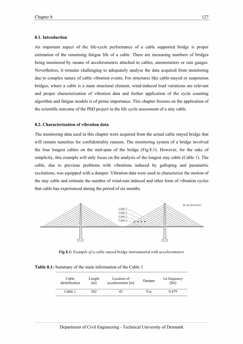
Chapter 8 127
Department of Civil Engineering - Technical University of Denmark
8.1. Introduction
An important aspect of the life-cycle performance of a cable supported bridge is proper
estimation of the remaining fatigue life of a cable. There are increasing numbers of bridges
being monitored by means of accelerometers attached to cables, anemometers or rain gauges.
Nevertheless, it remains challenging to adequately analyse the data acquired from monitoring
due to complex nature of cable vibration events. For structures like cable-stayed or suspension
bridges, where a cable is a main structural element, wind-induced load variations are relevant
and proper characterization of vibration data and further application of the cycle counting
algorithm and fatigue models is of prime importance. This chapter focuses on the application of
the scientific outcome of the PhD project in the life cycle assessment of a stay cable.
8.2. Characterization of vibration data
The monitoring data used in this chapter were acquired from the actual cable stayed bridge that
will remain nameless for confidentiality reasons. The monitoring system of a bridge involved
the four longest cables on the mid-span of the bridge (Fig.8.1). However, for the sake of
simplicity, this example will only focus on the analysis of the longest stay cable (Cable 1). The
cable, due to previous problems with vibrations induced by galloping and parametric
excitations, was equipped with a damper. Vibration data were used to characterize the motion of
the stay cable and estimate the number of wind-rain induced and other form of vibration cycles
that cable has experienced during the period of six months.
Fig.8.1: Example of a cable stayed bridge instrumented with accelerometers
Table 8.1: Summary of the main information of the Cable 1
Cable
identification
Length [m]
Location of accelerometer [m]
Damper 1st frequency
[Hz]
Cable 1 262 43 Yes 0.479
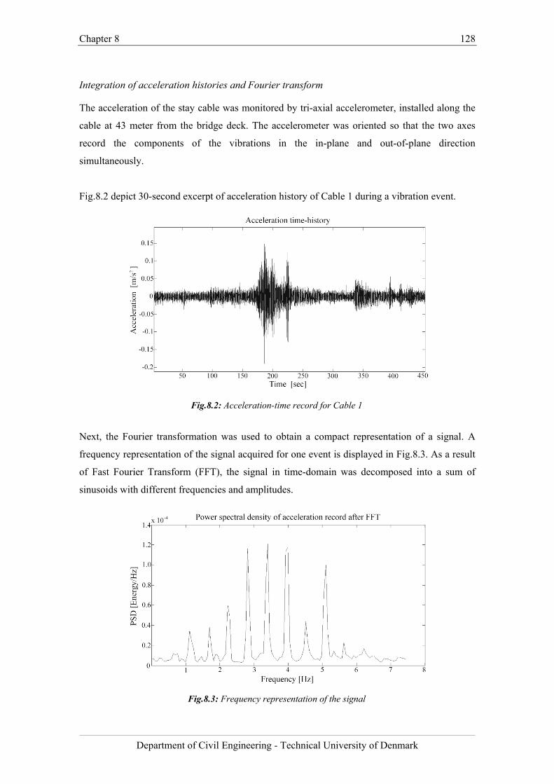
Chapter 8 128
Department of Civil Engineering - Technical University of Denmark
Integration of acceleration histories and Fourier transform
The acceleration of the stay cable was monitored by tri-axial accelerometer, installed along the
cable at 43 meter from the bridge deck. The accelerometer was oriented so that the two axes
record the components of the vibrations in the in-plane and out-of-plane direction
simultaneously.
Fig.8.2 depict 30-second excerpt of acceleration history of Cable 1 during a vibration event.
Fig.8.2: Acceleration-time record for Cable 1
Next, the Fourier transformation was used to obtain a compact representation of a signal. A
frequency representation of the signal acquired for one event is displayed in Fig.8.3. As a result
of Fast Fourier Transform (FFT), the signal in time-domain was decomposed into a sum of
sinusoids with different frequencies and amplitudes.
Fig.8.3: Frequency representation of the signal
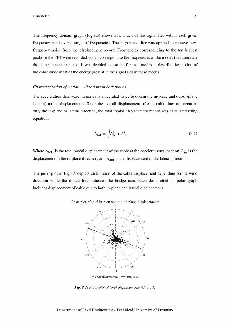
Chapter 8 129
Department of Civil Engineering - Technical University of Denmark
The frequency-domain graph (Fig.8.3) shows how much of the signal lies within each given
frequency band over a range of frequencies. The high-pass filter was applied to remove low-
frequency noise from the displacement record. Frequencies corresponding to the ten highest
peaks in the FFT were recorded which correspond to the frequencies of the modes that dominate
the displacement response. It was decided to use the first ten modes to describe the motion of
the cable since most of the energy present in the signal lies in these modes.
Characterization of motion – vibrations in both planes
The acceleration data were numerically integrated twice to obtain the in-plane and out-of-plane
(lateral) modal displacements. Since the overall displacement of each cable does not occur in
only the in-plane or lateral direction, the total modal displacement record was calculated using
equation:
A A A (8.1)
Where A is the total modal displacement of the cable at the accelerometer location, A is the
displacement in the in-plane direction, and A is the displacement in the lateral direction.
The polar plot in Fig.8.4 depicts distribution of the cable displacement depending on the wind
direction while the dotted line indicates the bridge axis. Each dot plotted on polar graph
includes displacement of cable due to both in-plane and lateral displacement.
Fig. 8.4: Polar plot of total displacements (Cable 1)
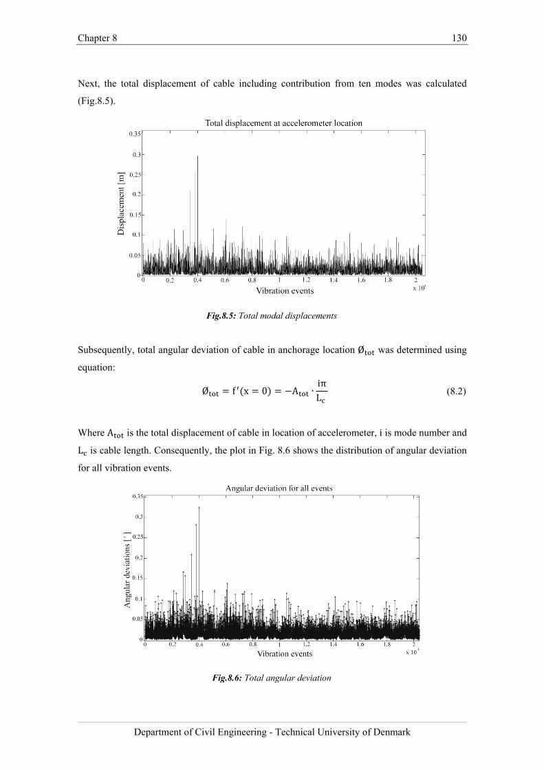
Chapter 8 130
Department of Civil Engineering - Technical University of Denmark
Next, the total displacement of cable including contribution from ten modes was calculated
(Fig.8.5).
Fig.8.5: Total modal displacements
Subsequently, total angular deviation of cable in anchorage location Ø was determined using
equation:
Ø f x 0 A ∙iπL
(8.2)
Where A is the total displacement of cable in location of accelerometer, i is mode number and
L is cable length. Consequently, the plot in Fig. 8.6 shows the distribution of angular deviation
for all vibration events.
Fig.8.6: Total angular deviation
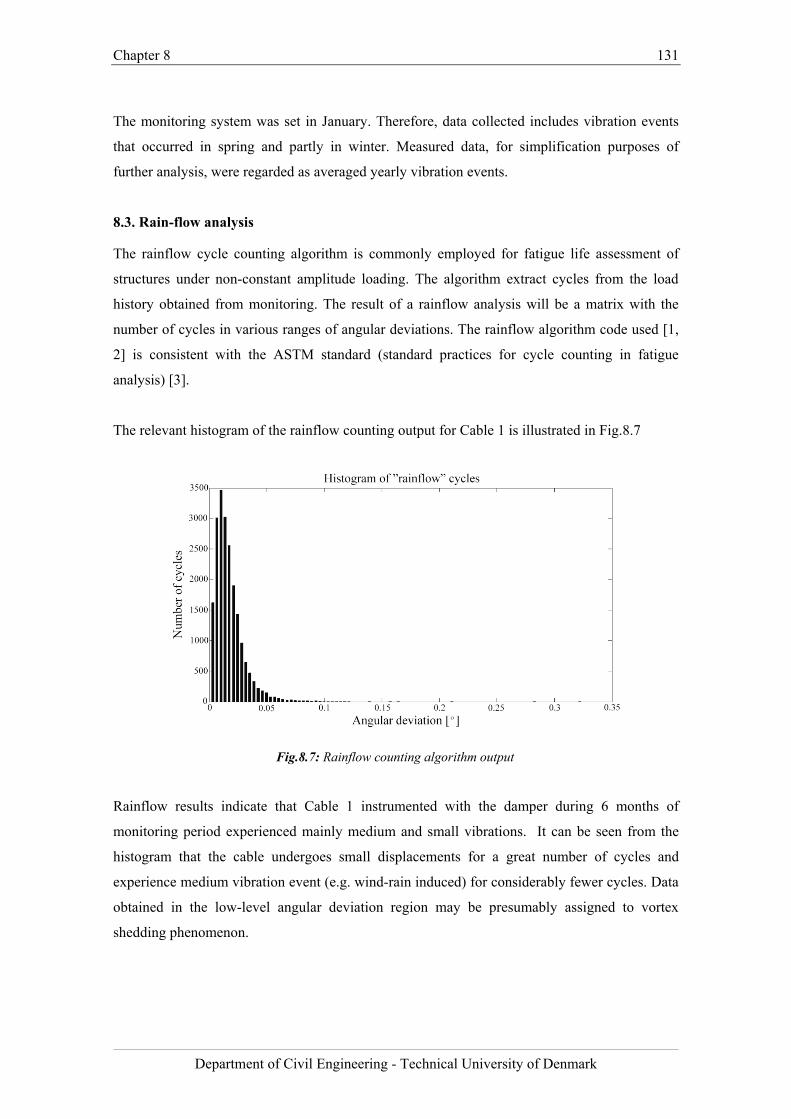
Chapter 8 131
Department of Civil Engineering - Technical University of Denmark
The monitoring system was set in January. Therefore, data collected includes vibration events
that occurred in spring and partly in winter. Measured data, for simplification purposes of
further analysis, were regarded as averaged yearly vibration events.
8.3. Rain-flow analysis
The rainflow cycle counting algorithm is commonly employed for fatigue life assessment of
structures under non-constant amplitude loading. The algorithm extract cycles from the load
history obtained from monitoring. The result of a rainflow analysis will be a matrix with the
number of cycles in various ranges of angular deviations. The rainflow algorithm code used [1,
2] is consistent with the ASTM standard (standard practices for cycle counting in fatigue
analysis) [3].
The relevant histogram of the rainflow counting output for Cable 1 is illustrated in Fig.8.7
Fig.8.7: Rainflow counting algorithm output
Rainflow results indicate that Cable 1 instrumented with the damper during 6 months of
monitoring period experienced mainly medium and small vibrations. It can be seen from the
histogram that the cable undergoes small displacements for a great number of cycles and
experience medium vibration event (e.g. wind-rain induced) for considerably fewer cycles. Data
obtained in the low-level angular deviation region may be presumably assigned to vortex
shedding phenomenon.
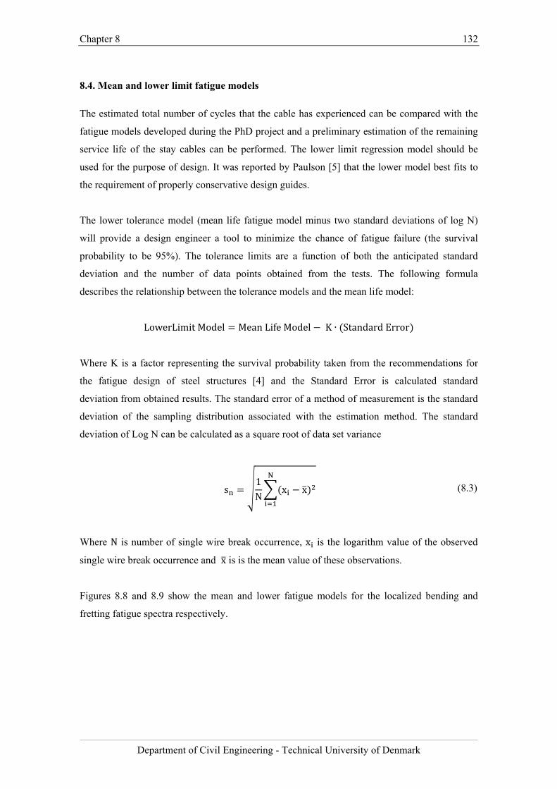
Chapter 8 132
Department of Civil Engineering - Technical University of Denmark
8.4. Mean and lower limit fatigue models
The estimated total number of cycles that the cable has experienced can be compared with the
fatigue models developed during the PhD project and a preliminary estimation of the remaining
service life of the stay cables can be performed. The lower limit regression model should be
used for the purpose of design. It was reported by Paulson [5] that the lower model best fits to
the requirement of properly conservative design guides.
The lower tolerance model (mean life fatigue model minus two standard deviations of log N)
will provide a design engineer a tool to minimize the chance of fatigue failure (the survival
probability to be 95%). The tolerance limits are a function of both the anticipated standard
deviation and the number of data points obtained from the tests. The following formula
describes the relationship between the tolerance models and the mean life model:
LowerLimitModel MeanLifeModel K ∙ StandardError
Where K is a factor representing the survival probability taken from the recommendations for
the fatigue design of steel structures [4] and the Standard Error is calculated standard
deviation from obtained results. The standard error of a method of measurement is the standard
deviation of the sampling distribution associated with the estimation method. The standard
deviation of Log N can be calculated as a square root of data set variance
s1N
x x (8.3)
Where N is number of single wire break occurrence, x is the logarithm value of the observed
single wire break occurrence and x is is the mean value of these observations.
Figures 8.8 and 8.9 show the mean and lower fatigue models for the localized bending and
fretting fatigue spectra respectively.
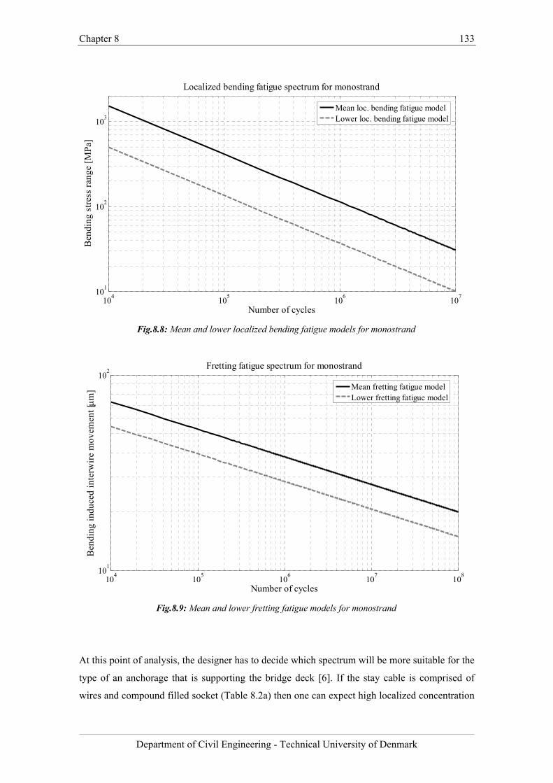
Chapter 8 133
Department of Civil Engineering - Technical University of Denmark
Fig.8.8: Mean and lower localized bending fatigue models for monostrand
Fig.8.9: Mean and lower fretting fatigue models for monostrand
At this point of analysis, the designer has to decide which spectrum will be more suitable for the
type of an anchorage that is supporting the bridge deck [6]. If the stay cable is comprised of
wires and compound filled socket (Table 8.2a) then one can expect high localized concentration
104
105
106
107
101
102
103
Localized bending fatigue spectrum for monostrand
Number of cycles
Ben
ding
str
ess
rang
e [M
Pa]
Mean loc. bending fatigue modelLower loc. bending fatigue model
104
105
106
107
108
101
102
Fretting fatigue spectrum for monostrand
Number of cycles
Ben
ding
ind
uced
int
erw
ire
mov
emen
t [
m]
Mean fretting fatigue modelLower fretting fatigue model
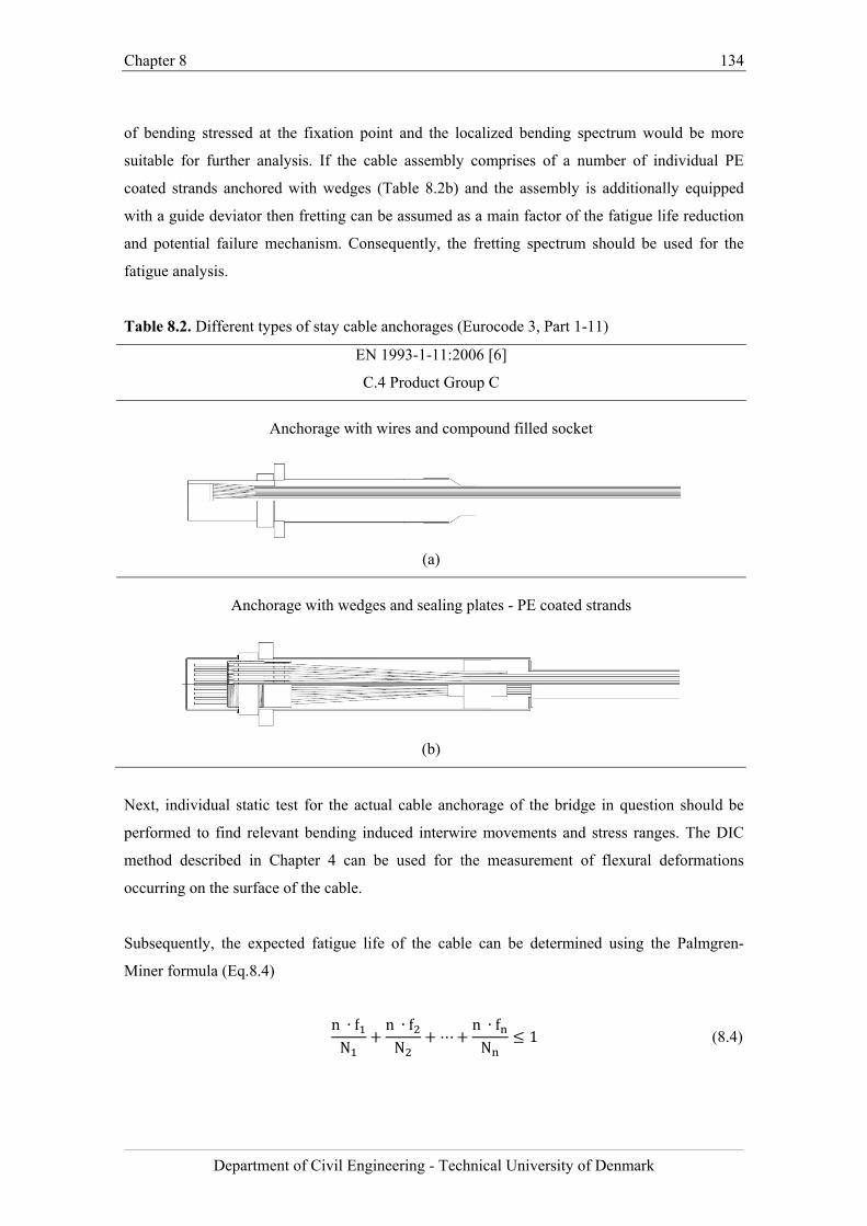
Chapter 8 134
Department of Civil Engineering - Technical University of Denmark
of bending stressed at the fixation point and the localized bending spectrum would be more
suitable for further analysis. If the cable assembly comprises of a number of individual PE
coated strands anchored with wedges (Table 8.2b) and the assembly is additionally equipped
with a guide deviator then fretting can be assumed as a main factor of the fatigue life reduction
and potential failure mechanism. Consequently, the fretting spectrum should be used for the
fatigue analysis.
Table 8.2. Different types of stay cable anchorages (Eurocode 3, Part 1-11)
EN 1993-1-11:2006 [6]
C.4 Product Group C
Anchorage with wires and compound filled socket
(a)
Anchorage with wedges and sealing plates - PE coated strands
(b)
Next, individual static test for the actual cable anchorage of the bridge in question should be
performed to find relevant bending induced interwire movements and stress ranges. The DIC
method described in Chapter 4 can be used for the measurement of flexural deformations
occurring on the surface of the cable.
Subsequently, the expected fatigue life of the cable can be determined using the Palmgren-
Miner formula (Eq.8.4)
n ∙ fN
n ∙ fN
⋯n ∙ fN
1 (8.4)
Chapter 8 135
Department of Civil Engineering - Technical University of Denmark
Where N is the number of cycles to single wire break failure, f is the number of events in
particular stress range (angular deviation) and n is the expected endurance life of cable. As
mentioned before, for the purpose of Fatigue Limit State (FLS) design, the lower limit
regression model should be used since it best fits the requirement of conservative design guides.
Chapter 8 136
Department of Civil Engineering - Technical University of Denmark
Bibliography
[1] A. Nieslony, “Determination of fragments of multiaxial service loading strongly
influencing the fatigue of machine components”, Mechanical Systems and Signal
Processing, Vol. 23(8), 2009, pp. 2712-2721
[2] A. Nieslony, Rainflow Counting Algorithm for MATLAB, Department of Mechanics
and Machine Design, Technical University of Opole
[3] ASTM E 1049-85 (Reapproved 1997), Standard practices for cycle counting in fatigue
analysis, in: Annual Book of ASTM Standards, Vol. 03.01, Philadelphia 1999, pp. 710-
718
[4] Recommendations For the Fatigue Design of Steel Structures, ECCS-Technical
Committee 6 – Fatigue, 1st edition, 1985
[5] C. Paulson, K. H. Frank, J.E. Breen, “A Fatigue Study of Prestressing Strand” , Ferguson
Structural, Engineering Laboratory Research Report, 1983
[6] Comité Européen de Normalisation. “pr EN 1993-1-11: Design of structures with tension
components”, 2006.

Chapter 8 137
Department of Civil Engineering - Technical University of Denmark
Chapter 9 138
Department of Civil Engineering - Technical University of Denmark
Chapter 9
Conclusions and future work
9.1. Conclusions
In the present thesis, the fatigue response of monostrands and multistrand stay cable to cyclic
transverse deformations has been investigated. A literature review of the state-of-the-art in the
fields of stay cable fatigue testing, cable fatigue resistance and bending-induced failure
mechanisms was first undertaken. The study helped to systemize the current knowledge of the
fatigue characteristics of bridge cables subjected to cyclic flexural loading, failure mechanisms
associated with variable load, and different testing procedures. Several aspects related to the
serviceability of stay cables needing more clarification were identified, so to plan the
experimental campaign of fatigue tests.
Static and dynamic bending fatigue tests on high-strength steel monostrands were first
undertaken. Initial analysis of the deformations showed that, depending on the anchorage type,
the bending fatigue behavior of the monostrand may be controlled either by local bending
deformations or by the interwire movement (fretting) of the helically wound wires. Therefore,
during static tests the localized bending and fretting behavior of steel monostrands was studied
in detail. For this purpose, a digital image correlation (DIC) method was employed as a tool for
quantifying the interwire movement and measurement of individual wire strains along the
length of the strand. The experimental data show that the interwire movement due to transverse
deformations is the highest at the centroid of the monostrand. Moreover, the results indicate that
the guide is a location where the combination of tensile strains and the interwire movement is
the most unfavorable. It was also shown that, in the absence of a guide, the high localized
curvatures due to bending may cause yielding of the monostrand at the wedge location.
Furthermore, the results from static tests on monostrands pretensioned to different axial load
Chapter 9 139
Department of Civil Engineering - Technical University of Denmark
levels ranging from 35%-50% of UTS showed negligible difference in the extent of the
bending-induced interwire movement. Since fretting can be seen as the main mechanism of the
fatigue life reduction in most of contemporary stay cable systems, a raise of the code allowable
stress level in stay cables from current 45% to 50% of UTS could be considered.
Subsequently, a series of dynamic bending fatigue tests on steel monostrands was performed. In
some of the tests wires were failing at the wedge location due to high localized curvatures while
in other tests the rupture of wires occurred at the guide location due to fretting. The results from
the dynamic tests were used to develop the localized bending and the fretting fatigue spectra.
The comparison between the two spectra showed that the localized bending fatigue spectrum is
more conservative. The Basquin slope for the localized bending fatigue spectrum is equal to
b=1.8, while in case of the fretting spectrum the slope of the fitting curve is b=7.1. One of the
reasons for the localized bending spectrum being more conservative than the fretting spectrum
is a different direction of the fatigue crack propagation in each of the failure mechanisms. For
the fretting failures, cracking propagates longitudinally while in case of the failures due to high
localized curvatures the fatigue crack propagates perpendicular to the cross section of the
monostrand. The change of the crack propagation direction (from transverse to longitudinal)
increased the wires lifespan. Further analysis of mechanical aspects of monostrand wires under
bending load provided information on the failure mode-dependent cross sectional stress
distribution. It was concluded that, in case of the fretting failure, a relaxation of bending induced
tension due slip (interwire movement) is reducing the overall stress range and, therefore,
elongating the fatigue life of a monostrand.
Finally, once the bending fatigue behavior of a single monostrand was described in detail, the
experimental study focused on the response of multistrand stay cable to transverse deformations
and establishment of a correlation between the bending fatigue behavior of the monostrand and
multistrand cable specimen. Tests were performed with a free and fixed guide deviator. The
experimental data indicate that the interwire movement due to transverse deformations is
highest at the monostrands located at the centroid of the stay cable specimen. This is due to the
fact that the monostrands located furthest from the centroid were subjected to higher pressure
due to static angle. In case of the stay cable assembly with a free deviator, where the rotation
point is located within the socket, the results show that the extent of the interwire movement
was lowest close to the rotation point and highest furthest from the rotation point. In case of the
cable arrangement with a fixed guide deviator the bending-induced relative displacement
between wires is highest in front of the guide. The results show that, similarly to the outcome of
Chapter 9 140
Department of Civil Engineering - Technical University of Denmark
studies on single monostrands, the guide deviator is a location where the combination of the
pressure, the interwire friction and tensile strain is the most unfavorable. It can be seen that the
fretting of monostrands is effectively filtered at the guide deviator and the interwire movement
at the rear part of the guide and at the exit of the socket is negligible. A similar bending and
fretting behavior was observed in the single strand tests and therefore it can be concluded that a
partial correlation between the bending fatigue behavior of the single monostrand and that of the
multistrand stay cable was established.
No wire failure was observed in the dynamic test performed on multistrand specimen and in the
equivalent dynamic test conducted on the single monostrand specimen. However, in case of the
multistrand test the boundary conditions (stiffness of the guide) were different and the bundle of
monostrands was subjected to different pressure forces, and thereby, reduced bending effects.
Consequently, it is suggested that more fatigue tests need to be performed in the future to verify
whether the fatigue life of a multistrand cable can be predicted based on the fatigue spectra
derived from the tests on monostrands. Any estimation of the fatigue life of a multistrand stay
cable based on the single strand fatigue spectra should be treated with caution.
Additionally, the relationship between the transversal stiffness and the tensile force variations of
a monostrand and that of a multistrand specimen was studied. However, the comparison of the
variation in the tensile force and the transverse stiffness is problematic. In case of the parallel
monostrand stay cable specimen different contact pressures were acting on monostrands located
at the centroid and different on the outermost monostrands. Hence, the total variation in tensile
force and the overall transverse stiffness of the parallel monostrand stay cable specimen cannot
be divided by the number of monostrands and directly compared with the results from the test
on single monostrand.
Finally, an example of application of the scientific outcome proposed a generic method for the
fatigue analysis of a stay cable subjected to cyclic transverse deformations. The example
showed how the bridge monitoring data could be analyzed in order to use the fatigue models in
the estimation of the life-cycle performance of a cable stayed bridge.
On the analytical side, data collected from the DIC technique creates a basis for developing a
model that could be used for the assessment of stay cable fatigue life. The novel application of
the DIC technique for the measurement of local cable deformations provided relevant
information on the internal state of displacement of the multistrand stay cable under bending
Chapter 9 141
Department of Civil Engineering - Technical University of Denmark
load, which are not included in the fib and the PTI recommendations. The outcome of
experimental studies study helped to significantly enhance the current understanding of the
fatigue response of a parallel monostrand stay cable to cyclic flexural load.
9.1.1. Novelty and major contributions
This thesis has examined the relevant aspects related with the parallel monostrand stay cable
bending fatigue. The research efforts were directed to address current drawbacks and
shortcomings related with the proper estimation of the serviceability of cable supported
structures. The experimental investigations conducted during the PhD project has led to a
number of findings and the results presented in this dissertation are a step towards a better
estimation of service life of stay cables.
The major contributions and novelty resulted from the research work are listed below:
Novel application of the digital image correlation (DIC) technique for the measurement
of local cable deformations.
Detailed description of the localized bending and fretting fatigue failure mechanisms in
high-strength steel monostrands.
Development of the localized bending fatigue spectrum for high-strength steel
monostrands under cyclic flexural load.
Development of the fretting fatigue spectrum for high-strength steel monostrands under
cyclic flexural load.
Establishment of the correlation between bending fatigue response of monostrand and
multistrand stay cable through full scale testing and data collected from the DIC
measurement.
9.2. Future work
Investigations performed within this dissertation have attempted to understand and explain part
of the stay cable bending fatigue aspects. Nevertheless, several directions for further research
and development of the work presented in this thesis can be identified. A selection of these is
here suggested.
Chapter 9 142
Department of Civil Engineering - Technical University of Denmark
Stay cable fatigue strength under biaxial loading
The reliability of mechanical systems depends in part on the fatigue strength of the material,
whose properties need to be determined by experiments. Dynamic bending fatigue tests
performed during this PhD project assumed constant amplitude. However, it is known that
fatigue life predictions, based on fatigue curves from tests at constant amplitude, often give
systematic prediction errors for service loads at variable amplitude. The discrepancy often
observed is that the damage caused by a cycle with a given amplitude is different for the cases
of constant and variable amplitude loads. The experimental procedure and results for the
uniaxial loading fatigue tests have been previously reported. It would be an important step
forward in the assessment of the fatigue strength of cable under combined loading if a criterion
that connected the fatigue strength under multiaxial loading with that under uniaxial loading
were available. The problem becomes complicated because the flexural load reversals as well as
variation in tensile force in cable due to service loads are happening at all different frequencies.
Therefore the question is: how to account for having axial elongation and transverse
deformation in an optimal (or at least conservative) manner? It would be also interesting to
study the fatigue crack propagation in monostrand wires under biaxial loading and compare it
with the one observed after uniaxial fatigue tests.
Statistical uncertainties in life estimation and prediction
This PhD project focused primarily on the experimental study of the bending fatigue resistance
of high-strength steel monostrands and multistrand stay cables. From the fatigue tests
conducted, the localized bending and fretting fatigue spectra have been developed for the
estimation of monostrand cable service life expectancy. However, due to complexity of the
mechanisms of cable vibrations, the application of the developed bending fatigue spectrum for
cable fatigue life assessments is not trivial. With any fatigue-related study, gathering
information is only a part of the task. To enhance the overall fatigue analysis, the data should be
further interpreted using statistical methods. Therefore it is of interest to establish a probabilistic
risk assessment model that is able to include both axial and bending fatigue of stayed bridge
cables. The research should include a classification of the different vibration mechanisms,
which are inducing fatigue failure of the cables. Having information about the ranges of
temperatures, the attack angle of the wind and the weather condition which could trigger the
large-amplitude displacements one could attempt using statistical and probabilistic methods to
predict dynamic response of cables. Part of the work would include further analysis of tolerance
limits and parameter estimation of the fatigue models developed during this PhD project. The
Chapter 9 143
Department of Civil Engineering - Technical University of Denmark
goal of risk assessment would be the determination of the quantitative value of risk related to
fatigue of cable stays due to vibration.
Development of analytical model using data from DIC measurement
The bending stiffness of stay cables is an important parameter in the study of their dynamic
behavior. A common approach is to model the cable using a constant stiffness value chosen
between two limiting states known as EImin (independent wire behavior) and EImax (wires acting
together as a solid). Because of the presence of friction between the cable’s wires, its flexural
bending stiffness varies during the bending process according to the cable’s deformation,
leading to a non-linear behaviour. Novel application of the DIC method for the measurement of
stay cable deformations provided previously unavailable information about the bending-induced
relative displacements between monostrand wires. The improved analytical model should take
into account the additional frictional stress due to interwire movements and variation of cross-
sectional properties near the end of cable.
This dissertation investigates the bending fatigue response of high-strength steel monostrands and multistrand stay cables to cyclic transverse deformations.
The major contributions resulted from the research work include novel application of the digital image correlation (DIC) technique for the measurement of local cable deformations, detailed description of the localized bending and fretting fatigue failure mechanisms, development of the fretting fatigue and the localized bending fatigue spectrum for steel monostrands under cyclic flexural load and establishment of the correlation between bending fatigue response of a monostrand and a multistrand stay cable. With this research, one of the most basic oversights in the lifetime assessment of cable supported structures, namely the bending fatigue resistance of parallel monostrand stay cables, is addressed.
DTU Civil Engineering
Department of Civil Engineering
Technical University of Denmark
Brovej, Building 1182800 Kgs. Lyngby
Telephone 45 25 17 00
www.byg.dtu.dk
ISBN=9788778774217ISSN: 1601-2917