Embed Size (px)
Citation preview

Thank you for purchasing this manual from Farm Manuals Fast. Your contribution will help us continue to collect and expand our manual database.
Tips for getting the most out of this manual
Keep this manual in a safe place!
Digital files seem to have a habit of getting lost exactly when you need them most. To ensure that you don’t accidentally delete or misplace this file here are some tips you should follow:
• Immediately after downloading your manual (i.e. now) it’s a good idea to save this file in a place you will remember. We recommend putting it in a folder. To make a new folder in Windows just right click -> New -> Folder. Name the folder something like Digital Manuals, Tractor Manual, etc.
• Once you have a folder for this file, go to File -> Save As… Now save the manual file to the folder you created. If you want, rename the file to something you will remember. We recommend including the model number (this is important in case you forget where you saved this file on your computer). Quick Search
If you are looking for something specific in this manual, you are in luck; All our manuals are searchable! Just press CTR + F and type in what you are looking for. Some things to remember when using the quick search feature:
• Your search won’t be 100 percent accurate. The software we use to make the text readable might confuse an “I” with an “l” (L and I ) or a smudge on the paper might have made the text unreadable by the software.
• Quick search will only search the exact words you type into the search bar in the exact order you put them in. For example if you type in 20 millimeters when in the manual it was written 20 mm your search will not work.
Remember: If you have put this file in a safe place on your computer and are unable to find it again the following year, try Windows search feature: Start ->Search. Type in the model number or another keyword that you know is in the file name.
What you should get from this tip is that: Quick Search is not completely reliable. Be sure to check the index and table of contents if you are getting no results when using the quick search feature.
Printing
You will likely want to print out some or all of the pages from this manual to use in the workshop.
Even if you want to print the whole manual you will probably not want to print out these first couple of pages.
All of the printing options are located at File -> Print or CTRL + P. The most important options are in the page range box. If you printed this manual now it’s likely that your printer would automatically print every page. If you want to omit some pages or only print certain page numbers you should to click the Pages button rather than All in the page range box. Now enter the page numbers you wish to print, for example 2-40 or 18-22.
If you are planning to print only a certain section of pages be sure to use the page numbers that are shown on the toolbar and not the page number shown on the actual page.
If you are planning to print this entire manual it is recommended that you print on both sides of the paper. It looks nicer and you use half as much paper. Some printers have duplex printing where the printer can automatically print on both sides. If your printer doesn’t have duplexing capabilities it will take more work. First you need to print off the odd pages. To do this select odd pages only in the print setup. Before you start to print, we recommend you label the different sides of the first sheet in your paper tray because depending on your printer it may be hard to figure out which way to correctly put the paper. Once you have printed out the odd pages just flip the stack of papers around according to the markings you made earlier and print the even side. Then put it in a binder, folder etc
These Tips might be outdated. Check www.FarmManualsFast.com/ Tips-and-Tricks
If you enjoyed the quality of this manual and have some manuals of your own you would like digitized please visit our website at http://farmmanualsfast.com/We-Need-Manuals.html

SHOP SERVICE
II Ill lllllll llll II II I Ill llllllllllll Ill Ill II llll Ill Ill Ill I II lllfl 1111111111111111111111111; Ill llll 111111111111111111111111111111
JOHN DEERE SHOP MANUAL
SERIES • A • B •G •H
MODELS • D •M • MT
• 111111111111111111111111111111llUll111IIII111111111111111111111lnlIllIIII1111 I I I I I I I I I I I I I I I I I I I 111111111111111111111111111111
MANUAL NO. JD·4
KNOWLEDGE The Measure of a Mechank Technical Publications

Information and Instructions
This individual Shop Manual is one unit of a series on agricultural wheel type t ractors . Contained in it are the necessary specifications and the brief but terse procedural data needed by a mechanic when repairing a tractor on which he has had no previous actual experience.
The material is arranged in a systematic order beginning with an index which is followed immediately by a Table of Condensed Service Specifications. These specifications include dimensions. fits, clearances and timing instructions. Next in order of arrangement is the procedures section.
In the procedures section. the order of presentation starts with the front axle system and steering and proceeds toward the rear axle. The last portion of the procedures section is devoted to the power take-off and power lift
systems. Interspersed where needed in this section are additional tabular specifications pertaining to wear l imits, torquing , etc.
HOW TO USE THE INDEX Suppose you want to know the procedure for R&R (remove and reinstall) of the engine camshaft. Your first step is to look in the index under the main head ing of ENGINE until you find the entry " Camshaft." Now read to the right where under the column covering the tractor you are repairing, you will find - a number which indicates the beginning paragraph pertaining to the camshaft. To locate this wanted paragraph in the manual. turn the pages until the running index appearing on the top outside corner of each page contains the number you are seeking. In this paragraph you will find the information concerning the removal of the camshaft.
I& T SHOP SERVICE Published by
TECHNICAL PUBLICATIONS DIV. INTERTEC PUBLISHING CORPORATION
P.O. Box 12901, Overland Park, Kansas 66212
All right• reaerved. Reproduction or uae, without exprus perml1tlon, of edltorl1I or pletorlal content, In any manner, la prohibited. No patent llablllty 11 111umed wllh reapect to the u1e Of the Information contelned herein. Wllll• every precaution hH been taken In the prepuatlon of lhlt book, th• publlther Htume1 no rHpon1lblllty for errors or oml11lon1. Neither 11 any ll1blllty a11umed for d1m1ge1 reaultlng from use of the Information contained herein.
All ln1truellon1 and diagrams have been cheeked for accuracy and e11e of applleatlon; however, 1ueeeu and Hfety In working with tool• depend to a great extent upon lndlvldual accuracy, aklll and caution. For thla rea1on the p11bllthert are not able to guarantee the reault of eny proc:edure contelned herein. Nor can they •Hume r11pon1lblllty for any damage to property or Injury to persona oecaaloned from the proeedurH. Parton• Hg1glng In the proeeduru do to entirely at their own rlak.
SHOP MANUAL
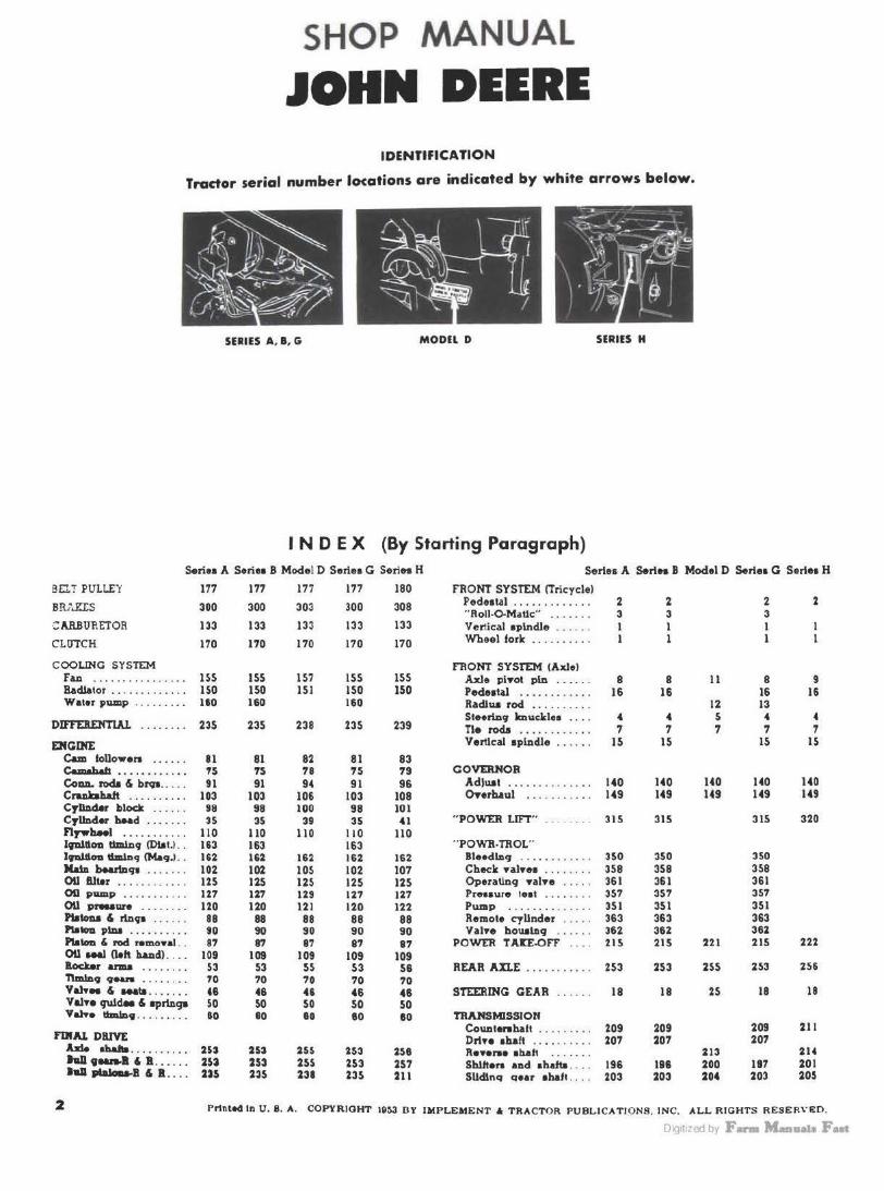
JOHN DEERE IDENTIFICATION
Tractor serial number locations are indicated by white arrows below.
SERIES A, 8 , G MODEL D SERIES H
IND EX (By Starting Paragraph) Seriea A SeriH B Model D Seriea G Series H Serles A S.rln B Model D S.rlea G Serles H
BEI. T PULLEY 177 177 177 177 180 FRONT SYSTEM ('Tricycle)
B Rr"J!'.IS 300 300 303 300 308 Pedeatal ..... . ... .... 2 2 2 2 "Roll-0.Matlc" .... ... 3 3 3
GAR.BUR'ETOR 133 133 133 133 133 Vertical eplndle ..... . l l I CLUTCH 170 170 170 170 170 \Ybeel fork ... ..... . . 1 1 I
COOLING SYSTEM FRONT SYSTEM (Axle) F.ui . ............... 15S lSS 1S7 ISS lSS Axle pi•ol pln . .... . 8 8 11 8 9 Radiator . ..... . ..... . 150 150 ISi ISO 150 Pedeat~ . ........... 16 16 16 16 Water pump . . ...... . 180 160 160 Radlwi rod .......... 12 13
DIFFEBDmAL Steering lmucklu .... 4 4 5 4 4 .... ~ ... 23S 235 238 235 239 n. rod.t 7 7 7 7 7 . ...........
ENGINE Vertlcal 1pindle ...... 15 15 15 IS
Cam follow era ...... 81 81 82 81 83 C.m•befl • • • • • • • • • • • • TS 7S 78 75 79 COVERHOR Co-. roda & brqa ..... 91 91 94 91 96 AdJwit ........ . ..... 140 140 140 140 140 Crub!Wt . .. . .. . .. . 103 103 106 103 108 Onrh.aul ..... .. .. .. 149 149 149 149 149 Cyllllder block ...... 98 98 100 98 101 C71.md.r bead .. . . . .. 35 35 39 35 41 "POWER LIFT" .. . ... . . 315 315 315 320 flywb.HI ........ ' .. 110 110 110 110 110 lpltl.OD timln9 {l)llt.) .. 163 163 163 ..POWB-TROL .. lpld.oo llm1D9 CMa9.) .. 1$2 162 162 162 162 BIHdl.D9 ... .... . . . . . 350 350 350 Xa1n bMl!Dqt ....... 102 102 105 102 107 Check YalH1 ........ 358 358 358 OU 8.lt.r .... . ..... .. 125 125 125 125 125 Operatlnq -nl•e .. ... 361 361 361 00 pamp . . .. . . . . .. . U7 127 129 127 127 PreHwe teal . ... .. . . 357 357 357 OU piwaure 120 120 121 120 122 PWllP ........... . .. 3Sl 3Sl 351 Ptatona & rtn91 88 88 88 88 88 Remote cylinder .. ... 363 363 363 "'-pl.DI ... ....... 90 90 90 90 90 Val•e hou.l119 ...... 362 362 362 Platon & rod remoYal .. 87 87 87 81 87 POWER T All.OFF .... 215 215 221 215 222 OU -1 Clelt hand) ... . 109 109 109 109 109 Boc:.br anu ........ 53 S3 SS 53 56 REAR AllE .......... . 253 253 255 253 256 1\mln9 ., ..... 70 70 70 70 70 v.n .. & ........ . . .. " 46 46 46 46 STEERING GEAR . ..... 18 18 2S 18 18 ValH quid. & 11prln91 so so so 50 50 Vane llmlDv .... ..... ao 80 80 80 80 TRANSMISSION
Countenhalt ..... . ... 209 209 209 211 F11'AJ. DRIVE Drl•• ah.alt 207 207 207
hie . .. .. . . ...
•haaa .... .. .... 2U 253 25$ 253 258 R•••n• abaft 213 214 hD9-B&B ... ...
...... . 253 253 255 253 257 Shl..ften and ahalta .... 196 186 200 197 20 1
11111,.._1 & R . ... ns 235 23' 23S 2J I Slldinq qear 1hlft . . .. 203 203 204 203 205
2 Printed tn U. 8. A. COPYRIGHT 19~ B Y IMPLEMENT A TRACTOR PUBLICATIONS. IN C. ALL RIGHTS RESER\'li:O.
DiQ1t1zed by F- M...a11a1a Fut

JOHN DEERE A·B·D·G·H SECTIONAL VIEWS
SERIES II A" Serial No .. 499000 and up. Bore & Strok~. 5 1
2 x 6~ • . P~oduced in the lollowinq veralona: M<><!•I A. dU.&.I wheel flicycle; Model AH. adj\1111. able u le (H; .Clenaocel; Model AN. single wheel tricycle; Model ANH. s1119le whMI tricycle (Hi·CIHz1ncel; Model AW e dj\ISlab)e
ule; Model A WH. adjUJtabl~ ule <Hi.Clearance). ·
SERIES "B" Serial No .. 96000-200999. Bore .& Stroke. 4 1
. 2 x S 1 2: Serial No .. Z? 1000 and up. Bore & • S1roke. 4 II / ~6 :r S 'h. Produced in the loUowing nr· aions: Model B. due l wbffl tricycle; Model BN, au1gle wheel tncycle: Modul BNH. lln9lo wheel tncycle !Hi-Clearance); Model BW. adjUJI·
able ule: Model BWH. adjustable ule !Hi.Clearaocel.
MODEL "D" Serial No .. 143800 a.nd up. Bore & Stroke. 6~~ z 7. Produced In a 000· 1djuahble axle version only .
SERIES "G" Serial No .. 13000 <?nd up. Bore & Str:>lce. 6 1 e :r 7. Produced In the follow iog versions: Model G. dual wheel tricycle: Model GH. ~djuat.able
axle 1Hl·Cleora nce); Model GN. sin9le wheel lricycle; Model CW. ad justablo axle; Model GM. dual wheel tricycle.
SERIES "H" Serial No .. 1000 and up. Bon & Stro!ce. 3 9 '16 x 5. Produced in the lollowing versions: Model H. dual wheel tricycle; Model HN. •Ingle
wheel tricycle; Model HNH. single wheel lric:yc:le <Hi-Clearance>: Model HWH. adjustable axle 1Hi.Clearance).
Late production series A. The starter is mounted in the crankcase ond the engine is equipped with a c:rankcosc nnt pump.
a..t. ,..-4.ctloe Mrlea I . Notice tho "Powr-Trol" valve boa le1tallotlo11. Tho eqlno 11 equipped with 0 Wlco battery lt•ltloa cUttrilt11tor.

SECTIONAL VIEWS JOHN DEERE A·B·D-G-H
Styled series G tractor. The engine is equipped with o Delco-Remy battery ignition unit. The "Hi-Crop" versions are cltoin driven.
(For Sectional View of Model D, Refer to Page 49)
'-tlo11el view of HrlH H tractor. ''- belt pulley rotote1 on tlio canulioft ot ono·llall en9ln• 1peed,
DiQ1t1zed by F- M-11a1a Fut

JOHN DEERE A-8-D-G·H SERVICE DATA
CONDENSED SERVICE DATA
Tractor Seriu or Model. .. . ... ..• ........ . . Tractor Serial Numben .. .... . . .... . ....... 499000.
S83999 Al.1..Ftm. OR GASOLJN'£ . . .. . . . . .. ....... .. A.F
GENERAL Engine Make ...•.......................... Own Engine Model . .. ......••....•............... A Cylinders .... . ......•.•••... . ..••....• .. ...•. 2 Bore--Inchea •........................•..•. 5~ Stroko--Inche• . . .... ...• •..••• • •• • • •... ...• 6~ Displacement-Cubic Inches •... .. • .••.•... 321.2 Compreaaion Ratio (All Fuel) •••.•. •. •.. . . .. 4.f.5:1 Compreaalon Ratio (GaollDe) •••••••• •• •••••• Compreaaion PrHaure at Cra.nlrinq Speed .... . ... 75 Pistons Removed From: . ..• .. ... .. ... .. .. .. Front Main Bearings Adjustable? ••...•............ Yea
Not Adj~'-bl• Aft•1 SeNl ............... . Rod Bearings Adjuatahle? .•................. Ye.t Cylinder Sleeves .......................... None Forwaid Speeds ....................•....•.•.. 6 Main Bearings, Number of .... ...... ...... .•. •• 2 Generator Make .... .. ......... ... .... .. ... . D-R Starter Make ....... .. .. ... ..... , .. ... ...... D·B
TUNE-UP ·Valve Tappet Gap--II!Let (Hot) ....•......... 0.020 Valve Tappet Gap--Uhaust (Hoo .......•... 0.020 lnlet Va.Ive Face Angle . .••.•..........•....•. 30 Inlet Valve Seat Angle ...................... . 30 Exhaust Valve Face AAgle .........•. .. ...•. .. 45 E:xhauat Valvo Seat Angle .. . . • .....•.......... 45 Ignition Distributor Mate .................. . . Ignition Distributor Model ..... . ............ . Ignition Magneto Make .................... Wlco Ignition Maqneto Model ....................... X Breaker Gap--Dlatrtbutor •••••••••••.••••••• Breaker Gap--Maqneto ..•.. .. ..•.. . •...•.. 0.015 Diatributor T'mU.Dg-Retard ••...• ••.•. ... .••. Diatrl.butor TimJnq-Full Advane9 ...•..•...•. Maqneto lmpalae Trip Point . . • . .... .. . . ... ... TC Meqneto Lag Augle ........... . .. ..... ... 25°-35° Maqneto Run.n.l.nq Timlllq ................... 30°B nywheel Mark Indicating:
Magneto Impulse Tnps ................. Wben Distributor Retard Ti.m.i.Dg ..... . . . ...... .. When
Spark Plug Make .. .. .... . ....... . .. ... Champion Model For Guollne •. ..... . ..•... ... .. ••• Model for Low Octaae ......... . ......... 8 Com Electrode Gap ................. .. . .. .... . 0.030
Carburetor Make ........... . .. . ........... . M.S Model Gaaollne ... . .......•....•......... Model All-Fuel ..... . ................. Dl.TX·24 Float Setting . .. .. . • .. .. .... .. ... . .. .. . . .. . lh
Engine Rated RPM .......................... 97S Engine Hiqh Idle RPM ...................... 1080 P.T.O. RPM .................... ............ 545
----A~------584000 And Up-
Own A 2
s~ 6:Y.
321.2 US:!
75 Front Some
694827 Yea
None 6 2
D-B D-11
0.020 0.020
30 30 45 45
o.a· 1111558
Wico x
0.021 0.015
TC 26°1
TC 2s•
25•9
Own A 2
Slh 6~
321.2
S.60:1 110
Front Some
69'827 Yea
None 6 2
D·R D-R
0.020 0.020
30 30 45 '45
l).!l" 1111558
Wico x
0.021 O.Dl5
TC 26°B
'IC 25•
25°B
----B-----96000- - 201000 And Up-200999 A-F A-F o-
Own B 2
4Yl Slf.i
174.9 4.71: 1
70 Front
Yea
Yea None
6 2
D-R D-R
0.020 0.020
30 30 45 45
Wlco x
0.015
TC 2S 0 .35 °
30°8
Own B 2
4 11/ 16 S¥l
190.4 4.65:1
70 Front
Yes
Yea None
6 2
D-R D-R
0.020 0.020 29~
30 441h
45 Wlco 0
XB Wico
x 0.015 o.oi5
TC 25°B
TC 25•
25°B
Own B 2
4 11 / 16 5 'f.i
190.4
S.87:1 110
Front Yea
Yea None
6 2
D-R l).ft
0.020 0.020 293/•
30 44Yl
4S Wlco"
XB W ico
x 0.015 0.015
TC 25°B
TC 25°
25°8
D 143800 And Up
A ·l'
Own D 2
6~ 1
SOI 3.91:1
60 Front Yet
Yea None
3 2
D-R D-R
0.030 0.030
30 30 30 30
None
Wico x
O.Dl5
TC 3 '.
35°B
G 13000
And Up A·F
Own G 2
6~ 7
412.S 4.20:1
65 Front Yea
v .. None
6 2
D-R D-R
0.020 0.020
30 30 45 45
I).R•
1111558 Wieo
x 0.021 0.015
TC 26°8
TC 25°-30°
25 • .3o•B
dot or "LH IMPULSE.. allqna wtth lndez mark on C:OYer or case
H 1000
And Up A·F
Own H 2
3 9/16 s
99.68 4.75:1
80 Front
No
Some None
3 2
D-B O:R
0.015 0.015
30 30 45 45
None
Wic'" x
0.01:
TC 25 •.JS 0
3D 0 B
do! or "LH IMPULSE" a.li9Jl8 with inde:ir mark on COYW or cue Champion Champion ChaJDpion Champion Champion Champion Champion Champion
8Com 0.030
M.S
DLTX-72 %
97;; 1090 545
6 6
0.030 M.S
DLTX·71
% 97S
1080 545
8Com 0.030 M.S
DLTX-34 ~
USO 13•0 554
8Com 0.030 MS
DLTX-73 ~
1250 1370 540
0.030 M.S
DLTX·67
% 1250 1370 560
2ComL 0.030
M.S
DLTX-63 ~'.!
900 980 525
9Com 0.030
M.S
DLTX-51 '·"l
975 11 15 530
9Com o.o3o
M.S
Dt.TX-46 27!32
1400 1S40 $45
SIZES-CAPACITIES-CLEARANCES !Clearances l.n thouaancltha) Crank.abaft Journal Diameter .....• ... .. .... . 2.749 2.749 2.7'9 2.249 2.249 2.249 2.999 2.999 2.0615 Crankpln Diameter . .. ... ... ............... 2.999 2.999 2.999 2.7495 2.7495 2.7495 3.4995 3.3745 2.061S Platon Pln Diameter ................. .. .... l.7495 l.7495 l.7495 1.4165 l.416S 1.4165 1.7495 1.7495 1.1045 Valve Stem ~eter . ... . .. .............. 0.4965 0.4965 0.4965 0.434 0.434 0.434 0.621 O.SS85 0.372 Main Br91 .. Run. Clearance (Adjustable) .. .... .. 2-6 2-5 2-5 2-6 2·5 2-5 2-6 2~ 2-'
(SIHve Type) . ........... .... , .......... , 4~ U 2
_. 1-3 Rod Brga. Diam. Clearance ...... . ... . ....... .. 2-4 2-' 2_. 2-4 2-4 2_. 2-4 6-S U Pllton Slcirt Clearance •.....................• s-8 5-8 5-8 4.7 5-9 S-9 6-10 ~lO Cranbhaft End Play .. •............• . . .. .. . . S-10 S.10 S· IO 5·10 5-10 5-10 5.10 s-:~ 5~ Cooling Sy1tem-Gallona .. . ... . .. . .......... 9~ 8~ 8~ 6 7 7 1'
11 4~ Crankcue Oil-Quart.I . . . . .. .............. .. 9~ 11 11 7~ 7 7 13 12 Trana. & I>iff.-Quute . . .. . .•. .. . .. .. ... .• .• •. 32 27 27 18 18 18 28 ~
Final Drive, Each-Quuu (AH, GHl .. .• . ...... l ~ 1.. 1 ~ 1 od la. •Battery kjnJUon adopled 11 1tandard equipment lD June. 1950. Field lnatall~Uon of th• battery lqnltlon units can be !Md• on 11rller m •
Oig1t1zed by F- M-11a1a F aat
I

PARAGRAPHS 1-2 JOHN DEERE A-1-D-G-H
FRONT SYSTEM-TRICYCLE TYPE vunCAL Sl'INDLI AND/OR FORK Models A-AN-ANH-B-BN-BNH~M-GN-H-HN-HNH
1. B a B AND OVEIUIA UL. To remove either the wheel fork and vertical spindle assembly on the single wheel version or the vertical spindle and knuckle or "Roll-0-Matic" assembly on the dual wheel version, support front of tractor ln a hoist, remove wheel (or wheels) and proceed as follows: Remove medallion, pedestal cover and tbe nut retaining steering sector to vertical spindle (3-Figs. JDI, 2
& 4). If fork is detachable from the spindle as in Fig. JDl, it may be advis
able to detach same at this time. Drive the vertical spindle down until spindle splines are free from the steering sector. Raise front of tractor and w ith
draw spindle assembly from below,
Inspect all parts and renew any
which are excessively worn. The ver
tical spindle on models B, BN and
BNH should have a free fit in lower
bushing (16).
On model Jil, make certain that
tangs on lower bushing enrare rrooves
of lower thrust washer { 15). On all
except series B, make certain that the
lower ball thrust bearing is installed
with side marked "THRUST" facing
down. Refer to paragraphs 18-21 for
steering gear unit adjustments.
PEDESTAL Models A-AN-ANH-B-BN-BNH· G-GM-GN·H-HN-HNH
2. REMOVE AND REINSTALL. To
remove the pedestal, support front of
tractor and remove steering wheel,
\;\-___ 4
Fi9. JDl - f•ploded Yiew
of model AN 1Jfeeri1t9
spindle, wlteel forlc 011d
ouociotetl porls. Models ANH ond GN ore llmilar. Models IN ontl INH are similarly coestruded ex· cept rltor fltrulf wadter (1$) and bu11tln9 ( HS},
wlticlt or• •ltown In tit• ltox, are useJ /nsteotl of
retoi1ter (17 ), corlc wo•ller (18), wa1her (19) anti llearin9 (20). Modef1 HN
ond HNH ore similar exc.pt rltot the wliHI forlc and wenlcol 1pindle I•
[l-'.-11 c::>-15
•
on into9ral otnlt.
l. S«tor atop plo Z • .!'Keet.al I . Vutjcal eplndlc 4. Wh~I fork 6. Aalo lock plate 6. Axle out lock plate 7. Duat ehleld 8. Beario1 apac~r t . Froot aale
JO. Bcarln11
ll. Retain"' 12. Felt wuber 11. 8carin1 adJualfns nut
grilles and screen. Remove steerlnc
shaft bearing housing and cover from
top of pedestal; then, withdraw steer
ing shaft from front of pedestal. On
G, GN and GM models, remove radia
tor. Remove front wheel (or wheels) .
Remove nuts retaining pedestal to
frame and remove pedestal and ver
tical spindle assembly. Remove the
nut retaining the sector gear to the
vertical spindle. Drive the spindle out
of sector gear and pedestal. The pro
cedure for further disassembly is evi
dent after an examination of the unit.
Inspect all parts and renew any
which are excessively worn. The ver
tical spindle on models B, BN and
BNH should have a free fit in lower
bushing Clf--Figs. JD 1&2).
,;,. JD2-lxploded wiew of model A ,,-. edal and Hrficol lpindle 01H111•ty. Modeh 0 and OM ore llmllar. Model I 11 .i .. ilorly canttroctod eacept fltOf rltnt• wo•ltor ( U ), i>u•ltl1t• (f6) ond plYot pl.re (2J) aro .,,.,, In ploto of corlc wo•ltor
( 11), wo1lter (,,), •eorln• (20), •a9"et (21)
and cop (22). Model H b tlmll•r ••cepl tlillf • retolner 11 u1u l111tead of 8Hlref
(2 J) •'"' cop . (22J.
I. Vertlc&I eplodl• 2•. Kouclrlt

JOHN DEERE A-1-D·G·H
On model B, make certain that tangs on lower bushing engage grooves of lower thrust washer (15). On all except series B , make certain that the lower ball thl'U5t bearing is installed with side marked "THRUST" facing down. Refer to para~raphs 18-21 for steering gear unit adjustments.
"ROLL-0-MA TIC"
Models A·l-G 3. OVERHAUL. To disassemble the
"Roll-0-Matic" unit, remove cap (29 - Fig. JD4), thrust washer (31 ) and pull knuckle and gear from housing. Each knuckle is fitted with two steelbacked, bronze-lined bushings which can be pressed from the knuckles. Install knuckle bushings so that open end of oil groove is toward inside, and make certain that there is a n- rr inch gap between the bushings . Pack the "Roll-0-Matic" housing with wheel bearing grease and install a new felt washer (25). When meshing gear teet,h, make certain that punch marks are iri register.
fie, .ID4--'9.tleUy e•,i..-e •I- of .,_,. .... , A, I ... G "loll·O·M.elc" Hit.
26. ,..It .... 11 .. 24. r.1t retainer 21. B~ebln8 (4 ueecll 21. Knuck le
20. Co.D 30. Ouket 31. Tnruet wcuner 32. Knuc kle houoln•
PARAGUPHs M
FRONT SYSTEM-AXLE TYPE STEERING KNUCKLES
Models AH-AW-AWH-IW-IWHGH-GW-HWH
4. ll&ll AND OVERHAUL. Method of removal is self evident . Spindle
bushings (34 and S>-Figs. JDS and JDS) can be driven from the axle knee
and new bushings can be pressed in. Bushings are pre-sized to provide
:=--_1
2
5Z
0 .009-0.012 clearance. On model HWH,
make certain that long bWlbinc (55-F ig. JD6) is installed at lower end of knee.
When reassembling make certain that the dowel pw engage thnut wa.sben (47) . Vary the number of shim washen to provide not more than 0 .036 vertical end play for the spindle.
38
/ 39
, / 11 }Iii. ~ 1
f1
16
F19. JDs--Elploded Ylew of •Mel AW '""' .... •IHI ,....... ,..... ...... AH, A= GH .... GW - ., ........... IW _, IWH ... ll•li.ty CHlll•cl94 =nu ........ (16) •M .. ,... we-. (UJ .,. 11-4 1....- of,....._ <171, c..ti •
I , Sector etOD Din 2. Ped•lal 3. Vertical eplndl•
18. J<nu~kl• and •olndle 33. Bolt 3f. Buahlnir 3&. A•I• ptvot braeket
• ..._ C1tl -4 Merlae 120).
38. Conter etMrtnir arm 37. Rear ph·ot pin 31. Tie ro4 Cdraa llnll) llMve 39. Tie ro<I (d ..... llnk) 40. Do.II •IUd t..arlns• 41 . Screw PIUI 42. Tie rod (d,.... link) end
4S. StMrln• ann 45. Shim wuner 4 T. ThNeC •&alien 49. Duet •hie.Id 00. Aale knN :u. Axle ce.nter member llo3 Fl"onl DIYOt pin
rJI< 0
1t1 <d by F ....... M_,llAh Fut 7

'ARAGRAPHS 5-13
Model D 5. &lrB AND OVt:IUIAUL. Remove
wheel and hub assembly, disconnect steering arm from knuckle, remove nut from taper bolt (74--Fig. JDS) and drive bolt out of axle main member. Remove knuckle caps (69) and pins (72). Knuckle bushings (70) are pre-1ized and if not distorted during Installation, will require no fi nal sizing.
TIE RODS AND DRAG llNKS Models AH·AW-AWH-BW·BWHD-GH-GW-HWH
7. ADJUSTMENT. An adjustable ball-socket is fitted to both ends of each tie rod. and on model D, an adjustable ball-socket is fitted to both
ends of the drag link. Tie-rod and drag link ends should be adjusted so they have no end play, yet do not bind.
With steering gear centered and wheels pointing straight ahead, adjust tie rod length to provide a recommended toe-in of 1,-i-f, inch.
AXU PIVOT PINS & BUSHINGS Models AH-AW-AWH-BWBWH-GH-GW
8. To renew the front axle pivot pin bushings, support front of tractor and remove the bolt (33--Fig. JD5} which retains pivot pin (37) in the front axle pivot bracket. On GH models so equipped, disconnect radius rod from axle knees. Disconnect tie
3 ~1
2
35
.... .ID~I.._. wlew of ••4-f HWH Mllatdle fro11t ale olld OIMCI._. ,.,._ I. Kector otop pin 37 J, \'ull~&I oplndlo . · RHr pivot pin 4:i. Shim wuher
11'>. Thruot wuller ::::· ~:• •:::: 1:•Ag link) tube <II. l<nucklo and eplndle UI, llueblnw • 11· 11,.~i'et d ;:• 111nk) 41. Thruet wuhoro 34. nuohlnw 4 I ' H U &r n10 :i-0. Axle kl\M :tr.. J' l\<'Ot hrack~t .,., · Tc rew pluc :'1:4 . A•I• center member 341. Center otMrln,a arm 43· a:e ~d ldra1 link) end .•.·:. ~·ront 11lvo1 pin
· •• llC &rm liG. Lowtr knuckle buel\lq
•
JOHN DEERE A-1-D-G.H
rods from center steering arm. Slide axle assembly forward until axle is free from pivots. Pivot pin bushings which are interchangeable with the knuckle and spindle bushings are presized, and if not distorted during installation, will require no final sizing.
If axle pivot pins are to be renewed, remove the center steering arm and pivot bracket and press the pivot pins out of axle and pivot bracket. A mild application of heat will facilitate removal and installation of pins.
Model HWH 9. To renew pivot pin bushings, sup
port front of tractor and remove rear pivot pin (37-Fig. JD6). Slide axle forward and oU front pivot pin (53) . Then, remove pivot bracket (35) from tractor. Bushints for bracket and axle are pre-sized, and if not distorted during installation, will require no final sizing.
If front pivot pin is to be renewed, remove pedestal from tractor and press the pin out of pedestal. A mild application of heat on pedestal will fa cilitate removal and installation of the front pivot pin.
Model D 11. The unbushed front axle pivots
on pin ( 76-Fig . JD8) . The front a.xle ,pivot pin should have a clearance of 0.015 (l&T recommended) in the axle. Method of removal of the pivot pin a evident after an examination of the unit and reference to Fig. JDS.
RADIUS ROD Model D
12. R&R AND OVERHAUL. To remove the radius rod, jack up front end of tractor and disconnect drag link from rlght hand steering arm. Remove axle pivot pin, radius rod pivot stud nut and roll axle and radi\13 rod a:ssembly away from tractor. Remove radius rod to axle retaining nuts and bump radius rod out of axle main member.
The radius rod pivot stud bushing (61) can be removed from p ivot block ( «32 ) at this time. After new bushing i:s Installed, check to make certain that the radlu:s rod pivot stud ha:s a free fJt in the bushing.
Model GH (Some) 13. R•R AND OVERHAUL. Remov
al of the adjwtable type radius rod ls evident after an examination of the unit and refe.rence to Fig. JDI>. Renew pivot (62) and/ or pivot bracket (80) If either Is exceulvely .worn.
After Installing the radlw rod-or changing the front wheel tread, make certaln that Jam null (82) are tJ1ht.
m 1t1 qJ bi F- M-.,., Fut

JOHN DEERE A·B·D·G·H
VERTICAL 5'8NDU Models AH-AW-AWH-BW-BWHGH-GW-HWH
15. R8'R AND OVERHAUL. To remove the vertical spindle, support front of tractor and remove the bolt (33-Fig. JDS) or on model HWH, remove rear pivot pin (37-Fig. JD6). Disconnect center steering arm from vertical spindle and on GH models so equipped, disconnect radius rod from axle knees. Slide axle assembly forward until free from pivot pins. Remove medallion, pedestal top cover and nut which retains sector gear to vertical spindle. Drive the vertical spindle out of sector gear and pedestal.
Inspect all parts and renew any which are excessively worn. The vertical spindle on models BW, BWH, and HWH should have a free fit in lower iJushing ( 16-Fig. JDS or JDS).
Fi9. JIW-Explofled Yiew of radius rod a .. embl11 wlticlt is u1ed on same
OH tractors.
62. Pivot 80. Pivot bracket 8 1. Rear radlua rod 82. Jam nuta sa. Couplinr 84. Front radiu1 rod 86. Radi u• rod lorack•t 86. U-Bolt
'19. JO~xploflefl y/ew of model D front axle and r11uoclCJted parla. VertlHI rteerln9 altoft tu•• (511 and l11,.ltln9 (57} are carried In tlta tractor main ccrM.
at. Cntu at.rlna: ar11n H. VerUe&l aleerlnirabatt 69. Felt wuhu 80. Stud SI . BuahlH 82. Phot block 81. lladlwi ...... 64 . Tit rod
SS. Tie roe! end H . Ball atud bearlnp '1. Serewplus 68. L.H. atttrlns &r111 tll. Duat-p 70. Buablnir 71. Tbruoc wubere
72. Knuclcle pin 78. Knuckle 74. TapeP bolt 76. Aaleatop '18. Pl•ot pin 77. Axle '78. R .R . S-rlos arm 79. Drair link
PARAGRAPHS 15-16
On all except series B, make certain that the lower ball thrust bearing is installed w i t h s i d e m a r k e d "THRUST" facing down. Refer to paragraphs 18-21 for steering gear unit adjustments.
PEDESTAL Models AH-AW-AWH-BW-BWHGH-GW-HWH
16. REMOVE AND REINSTALL. T o remove pedesta l, support front of tractor and remove steering wheel, grilles and screen. Remove steering shalt bearing housing and top cover from pedestal ; then, withdraw steering shaft from front of pedestal. Remove the bolt ( 33-Fig. JD5) or on model HWH. remove rear pivot pin (37-Fig. .106). Disconnect center steering arm from vertical spindle and on GH models so equipped, disconnect radius rod from axle knees. Slide axle assembly forward until axle is free from pivot pins.
On models GH and GW, remove radiator. Remove nuts retaining pedestal to frame and remove pedestal and vertical spindle as:iembly. Remove the nut retaining the sector gear to the vertical spindle and drive the vertical spindle out of sector gear and pedestal. The procedure for further disassembly is evident after an examination of the unit.
The vertical spindle on models BW, BWK and HWH should have a free flt In bushing (16-Figs. JDS or .JD6). On all except series B, make certain that the lower thrust bearing is installed with side marked "THRUST" faclol down. Refer to paragraphs 18-21 for steering gear unit adjustments.
DiQ1t1zed by F- M...a11a1a Fut
PAIAGIAPHS 18-29
Serles A·B-G-H For the purpose• ol thia di.wcuaalon the
m>ering 9ear Wllt wW include the ateerin9
abaft and worm. uctor qear. and all parts
contained in the upper portion of the ped· eetaL For R&R and overhaul of the vertical spllldle. refer to paraqraph l or 15.
18. ADJUSTMENT. Three adjuatments are
pro'rided on the steering gear unit: (l ) steer· Ing shaft (worm-shaft) end play. (2) vertical spindle end play and 13) .backlash between the worm and sector geara.
19. STEERING SHAFT (WORMS.HAFT) END PLAY. Support front of tractor to remove load from steering gear. Remove grille medallion and vary the number or thickness of shim gaskets (88--Fig. JDU) between the pedestal and the steering shaft front bearing housing to remove all end play, yet permit sha1t to rotate freely.
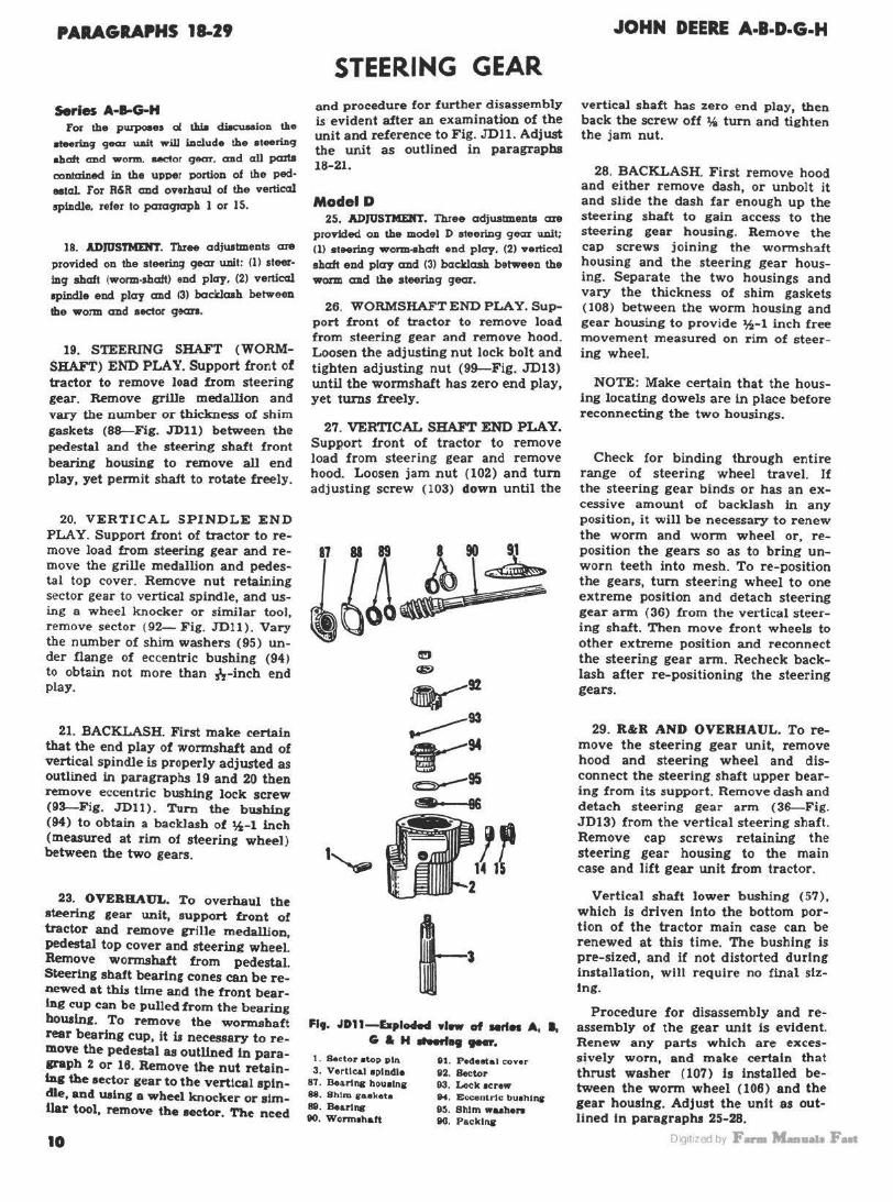
20. VERTICAL SPINDLE END PLAY. Support front of tractor to remove load from steering gear and remove the grille medallion and pedestal top cover. Remove nut retaining sector gear to vertical spindle, and using a wheel knocker or similar tool, remove sector (92- Fig. JDU) . Vary the number of shim washers (95) under flange of eccentric bushing (94) to obtain not more than h-inch end play.
21. BACKLASH. First make certain that the end play of wormshaft and of vertical spindle is properly adjusted as outlined in paragraphs 19 and 20 then remove eccentric bushing lock screw (93-Fig. JDll) . Turn the buahlng (94) to obtain a baclclash of %-1 inch (measured at rim of steering wheel) between the two gears.
23. OVEBBAUL. To overhaul the steering gear unit, support front of tractor and remove erllle medallion, pedestal top cover and steering wheel. Remove wormshaft from pedestal. Steering sbaft bearing cones can be renewed at thh tlme and the front bearing cup can be pulled from the bearing bowing. To remove the wormshaft rear bearing cup, it u necessary to remove the pedestal as outlined in paragraph 2 or 16. Remove the nut retaining the sector gear to the vertical spindle, and using a wheel knocker or slmtlar tool, remove the sector. The need
10
STEERING GEAR and procedure for further disassembly is evident after an examination of the unit and reference to Fig. JDll. Adjust the unit as outlined in paragraphs 18-21.
Model D 25. AI>JtJSTMEllT. Three adjustments are
proTided on the model D steering ge<:a unit; (1) •t-rin9 worm-abaft end play. (2) vertical shaft end play and (3) backlash between the worm and the steering gear.
26. WORMSHAFT END PLAY. Support front of tractor to remove load from steering gear and remove hood. Loosen the adjusting nut lock bolt and tighten adjusting nut (99-Fig. JD13) until the wormshaft has zero end play, yet turns freely.
27. VERTICAL SHAFT END PLAY. SUPP.Ort front of tractor to remove load from steering gear and remove hood. Loosen jam nut (102) and turn adjusting screw (103) down until the
~ @
~92 ....---93 y94 ~95 8 96 1'-Qt:l1r 1-3
Flt. JD11-Explo4ecl •I- of serln A, I, G&H..._.19.,.....
1 . S.etor •top plft
3. Vertical •olndl• 87. Bearlna hou•lna 88. Shlrn 1aekete 89. Burlna 90. Wonn1hart
91. P..Seetal cover 92. S.Ctor 93. Lock 1crew IM. £<>centric bu1hln& 9:1. Shim wuheno 90. Packl,..
JOHN DEERE A·B·D·G·H
vertical shaft has zero end play, then back the screw off 14 tum and tiehten the jam nut.
28. BACKLASH. First remove hood and either remove dash, or unbolt it and slide the dash far enough up the steering shaft to gain access to the steering gear housing. Remove the cap screws joining the wormshaft housing and the steering gear housing. Separate the two housings and vary the thickness of shim gaskets (108) between the worm housing and gear housing to provide ¥.z-1 inch free movement measured on rim of steering wheel.
NOTE: Make certain that the housing locating dowels are ln place before reconnecting the two housings.
Check for b inding through entire range of steering wheel travel. If the steering gear binds or has an excessive amount of backlash in any position, it will be necessary to renew the worm and worm wheel or, reposition the gears so as to bring unworn teeth into mesh. To re-position the gears, tum steering wheel to one extreme position and detach steering gear arm (36) from the vertical steering shaft. Then move front wheels to other extreme position and reconnect the steering gear arm. Recheck backlash after re-positioning the steering gears .
29. R&R AND OVERHAUL. To remove the steering gear unit, remove hood and steering wheel and disconnect the steering shaft upper bearing from its support. Remove dash and detach steering gear arm (36-Fig. JD13) from the vertical steering shaft. Remove cap screws retaining the steering gear housing to the main case and lift gear unit from tractor.
Vertical shaft lower bushing (57), which is driven Into the bottom portion of the tractor main case can be renewed at this time. The bushing is pre-sized, and if not distorted during installation, will require no final sizing.
Procedure for disassembly and reassembly of the gear unit Is evident. Renew any parts which are excess~vely worn, and make certain that thrust washer (107) ls Installed between the worm wheel (106) and the gear housing. Adjust the unit as outlined In paragraphs 25-28.
DiQ1t1zed by F- M-11a1a Fut
JOHN DEERE A·l·D·G·H
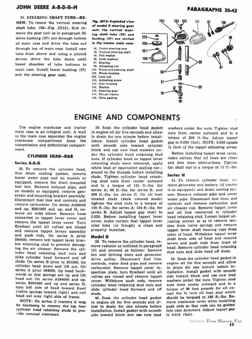
30. STEERING SBA.FT TUBE--BENEW. To renew the vertical steering shaft tube, (58-Fig. JD13), first remove the rear unit as in paraeraph 29.
drive bushinf (57) out through bottom of main case and drive the tube out through top of main case. Install new tube from above and using a piloted driver, drive the tube down until lower shoulder of tube bottoms in
main case. Install lower bushing (57)
and the steering gear unit.
"•· JDJJ-fxplodod yfew of model 0 lf••rint 1•or 9flff. Tiie Y.,t/cal lteer•
i1t9 •""" tu•• (51) •nd •u•llin9 (57) ore carrl-4 In tit• trador main co ...
S6. C..n~r 1te.rinr arm 56. Vertical 1~rlnr 1haft n. Felt wuher U. Coric waahtn 97. Bearlnr 99. Adjuatlnr nut
1 00. Worm and 1tenlnr abaft 101. Worm bomlnr 102. Lock nat 103. Adju1tlnr 1crew 104. C:.ar hol.l91Ds
IOI>. Washer I 06. Ste.rinc r ear I 07. Thruat wuher 108. Shim ruktb
10s..__: 10& ·1ii?
PARAGRAPHS 30-42
56 57____. .Lt---59
3&~ 0 Ill
ENGINE AND COMPONENTS Tile engine crankcase and tractor
main case is an integral unit. A wall m the main case separates the engine crankcase compartment from the transmission and differential compartment.
CYLINDER HEAD-R&R
Series A-8-G 35. To remove the cylinder head,
first drain cooling system, remove lower water pipe and on models so equipped, remove the front mounted tool box. Remove exhaust pipe, and on models so equipped, remove generator and mounting bracket assembly. Disconnect fuel line and controls and remove carburetor. On series A584000 and up, B201000 and up, aDd G, remove air inlet elbow. Remove lines connected to tappet lever cover and remove the tappet lever cover. Turn ftywheel until all valves are closed and remove tappet levers assembly and push r ods. On series A prior 584000, remove left tappet lever bracket retaining stud to prevent damaging the air cleaner. Remove the cylinder head retaining stud nuts and slide cylinder head forward and off studs. On series B prior to 201000 tip cylinder head down and lift out.' On series A prior 584000, tip head backwards so that springs are up and lift hea_d out. On series A:584000 and up, series B201000 and up and series G turn left side of head toward front (valve springs toward right) and roll head out over right side of frame.
NOTE: On 1ertu G tractors it ma11 be necetHT"JI to remove the top four c~Under head retaining studs to pronde reTnoval clearance.
36. Soak the cylinder head gasket in engine oil for five seconds and allow to drain for one minute before installation. Install cylinder head gasket with smooth side toward cylinder block and use new lead washers under the cylinder head retaining stud nuts. If cylinder head or tappet lever retaining studs were removed, apply white lead or equivalent sealing cor:.pound to the threads before installing studs. Tighten cylinder head retaining stud nuts from center outward and to a torque of 125 ft.-lbs. for series A; 96 ft.-lbs. for series B ; and 208 ft.-lbs. for series G . On all heat treated studs (dark colored studs) tighten the stud nuts to a torque of 150 ft.-lbs. for series A: 104 ft .-lbs. for series B. Adjust tappet gap (hot) to 0.020. Before installing tappet lever cover, make certain that tappet lever oiler tube (or trough) is clean and properly installed.
Model D 39. To remove the cylinder head, re
move radiator as outlined in paragraph 151 and proceed as follows: Removf' fan and d.riving discs and generator drive pulley. Disconnect fuel line, controls, water feed pipe and remove carburetor . Remove tappet cover inspection plate, turn flywheel until all valves are closed and remove tappet cover. Withdraw push rods, remove cylinder head retaining stud nuts and slide cylinder head forward and off studs.
40. Soak the cylinder head easket in engine oil for five seconds and allow to drain for one minute before installation. Install gasket with smooth side toward block and uee new lead
washers under the n uts. T ighten stud nuts from center outward and to a torque of 208 !t.-lbs. Adjust tappet gap to 0.030 (hot). NOTE: 0.030 equals ~ tum of the tappet adju..sting sCTew.
Before inst.ailing tappet lever cover. make certain that oil lines are clean and free from obstructions. Tighten fan shaft nut to a torque of 10 ft.-lbs.
Series H 41. To remove cylinder head. re
move generator and battery (if tractor is so equipped) and drain cooling system. Remove exhaust pipe and lower water pipe. Disconnect fuel lines and controls and remove carburetor and air cleaner cup. Remove tappet cover and oil line connected to cylinder head retaining stud. Loosen tappet adjusting screws so as to remove tension from valve springs and remove tappet lever shaft bearing caps from sides of head. Withdraw tappet lever shaft from side of head and remove levers and push rods f rom front ol head. Remove cylinder head retaining stud nuts and slide head oft studs.
42. Soak the cylinder head gasket in engine oil for five seconds and allow to drain for one minute before installation. Install gasket with smooth side toward block and use new lead washers under the nuts. Tighten stud nuts from center outward and to a torque of 96 foot pounds for all except the ~4 inch oil lead stud which should be torqued to 180 tt.-lbs. Remove crankcase cover when installing push rods so that rods can be guided Into cam followers. Adjust tappet PP to 0.015 (hot).
DI< 1t1 'Jd by F- MaalUla Fut 11
PARAGRAPHS 45-51
PUSH ROD SUEVES Series 8
Pu.ab rod a1 ....... (S-Flq. JD20) ahould be elltlllllned wheae.•r cyllnd•r head la r• mond. Renew anr alNH that la co11oded. deteriorated or allow. alqna of coolant Itek· aqe. SIH•• me 110JD,e1imes damaged br manifold atuda that hen'• be.n installed with WTOD9 end oJ atud ln cylinder head.
45. RENEW. To remove pusb rod sleeves when cylinder head is otf, use a drift or special O .T .C. puller, and remove sleeves through front of head. Sleeves can be removed when cylinder bead is on by removing the tappet levers and push rods and using a spttial O.T.C. puller or Its equivalent.
Install sleeves from tront of head with the smaller outside diameter toward crankcase.
NOTE: Rear O.D. of 1leeve ia approxi· mately 0.002 smaller thCJll front. Use while 1-d er equivalent aealinq compoWld on
enda oJ II-•• to aea1 the al-•• aqaioat coolant leakaqe cmd facilitate installation.
VALVES AND SEATS
Serles A·B-G·H·Model D 46. Valves are provided with split
cone type keepers.. Set tappet gap (b ot ) to the values specified below.
Series A , B, C ... . ............ 0.020 Series H ...... ............... 0.015 Model D .. ..... .. ....... . ... . 0.030
47. Intake and exhaust valves are not interchangeable and seat directly in cylinder head. Check the valves and seats against the values listed below. Seats can be narrowed, using 20 and 70 degree stones. Valve s tem diameter
Series A .. . . . ...... .. • 0.4960-0.4970 Seri~ B .............. 0.4335-0.4345 Series G ................ 0.558-0.559 Series H . ...... .. .. .. . 0.3715-0.3725 Model D ... ............. 0.620-0.622
Valve stem clearance in ruides Series A and B ......... 0.004-0.0065 Series G ... .... . ....... 0.004-0.0075 Model D . ... ............ 0.004-0.008 Series H . .. .. ......... . 0.0035-0.006
Valve face angle (Intake) Series A, B (prior 201000),
G and H ............... ... ... 3o• Series B (after 200999) .... . . .. 29% • Model D .... . .............. . ... 30•
Valve seat angle (Intake) ... .. .... 30• Valve face angle (Exhaust)
Series A, B (prior 201000), G and H .. . . ......... . ....... 45•
Sertea B (after 200999) .... .. .. 44% • Model o ....................... Jo•
Valve aeat angle (Exhaust) Sertee A, B, G, H .............•. 45• Model D .... ......... . . .. .. .... so•
12
Valve seat width Series A, B, H ...... .. ... . . 118-inch Series G .. .. .. ....... . .. ll / 64-ioch Model D . ................ 5/32-inch
49. When servicing the valves, make certain that the tappet lever lubrication system is functioning properly. On engines equipped with an oil trough in the tappet lever cover. clean the troueh and make certain that drip holes are open . On models equipped with a pressure fed drip tube, clean the tube and make certain that holes in tube are so positioned that oil Is directed on the exhaust valves only.
VALVE GUIDES AND SPRINGS Series A-B-G-H-Model D
50. lntake and exhaust valve guides are interchangeable and should be pressed into the cylinder head to the dimensions listed below. Ream the guides after installation ( if necessary ) to the dimensions listed b elow.
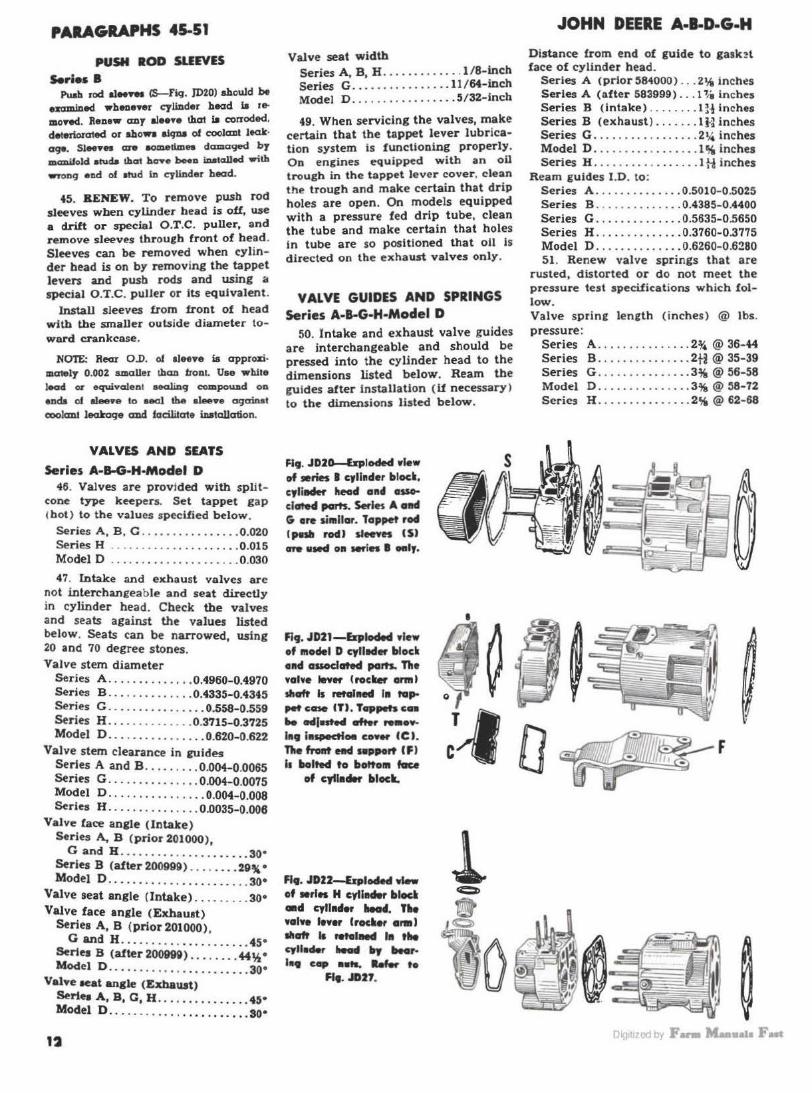
Fl9. JD20--&plodM view of •ries I cylinder block, cylillder head and associated parts. Serles A nd G are si•llar. Tappet rod lpnll rodJ slMYes (SJ
are •Md oa - In I "''·
FJ9. JD21-bploded view of 111odel D cylllCI• block and associated parts. Tllo valve lever I rocll.er amt> slid Is retained I• tap,_.case (T) . Tappets en k •l•stecl .tt.r ,.. ... ln9 f•~Oll COYW (CJ. 11le frOllt Hcl sepport ( F >
11 llolted to botto111 face of cyllader bloc._
Fifi, JDZ2-&ploded view of •rles H cyll.., blod •d cyllader ... ,. , .. valwe low• lroclief araJ ...... .. .......... .. , .. cylloder ..._ 1rJ bearl•fJ c.p •llts. ..,_ ,.
Ff • • JD27.
l
JOHN DEERE A·l·D-G-H
Distance from end of guide to gask?t face of cylinder head.
Series A (prior 584000) ... 2'18 inch~s Serles A (after 583999) ... 1 ~i inches Series B (intake) . .. . .... 1 H inches Series B (exhaust ) ....... lH inches Series G ........... . . . ... 21,4 inches Model D ................. 1 % inches Series H ............. . ... I H inches
Ream guides I.D. to: Series A .............. 0.5010- 0.5025 Series B _ . . .. ......... 0.4385-0.4400 Series G ...... ........ 0.5635-0.5650 Series H ........... ... 0.3760-0.3775 Model D .............. 0.6260-0.6280 51 . Renew valve springs that are
rusted, distorted or do not meet the pressure test specifications which follow. Valve sprine leneth (inches) @ lbs. pressure:
Series A ............... 2% @ 36-44 Series B .......... . .... 2H @ 35-39 Series G ............... 3% @ 56-58 Model D ............... 3i(, @58-72 Series H ............... 2% @ 62-68

JOHN DEERE A·l-D·G·H
VALVE TAPPO LEVERS CROCKER ARMS)
Series A-B-G 53. R.ttR AND OVERHAUL. To re
move the valve tappet levers and shaft assembly, first remove the front mounted tool box if tractor is so equipped; then, remove the valve tappet lever cover.
NOTE:On some tracton, tne tappet lever cover ventilator pipe must be removed and on othe-rs, the taJ>Pet oiler line must be duconnected before the cover can be removed. Turn fl11-t0heel until all valves are closed, then remove tappet levers assembly. Disa.ssembly of the unit is self-evident.
Excessive wear of any of the component parts of the tappet lever assembly ls corrected by renewing the parts. Adjust tappets to 0.020 <hot). Make certain that tappet levers lubrication system is functioning properly : refer to paragraph 49.
Model D 55. Rldl AND OVERHAUL. To re
move the valve tappet levers and sh.aft, remove radiator as outlined in paragraph 151 and proceed as follows: Remove tappet lever inspection plate, turn Bywheel until all valves are closed and remove tappet cover from
cylinder head. Remove Mt screw• (~ Fig. JD26) and expansion plup from ends of tappet lever shaft. Withdraw shaft and levers from cover.
Excessive wear in the tappet lever assembly is corrected by renewal of the component parts. Apply a light coat of sealing compound to the expansion plugs before installing the plugs in the tappet lever cover. Adjust tappets to 0.030 (hot), which equals 1h turn of the adjusting screw. Make certain that tappet levers lubrication system Is functioning properly; refer to paragraph 49.
Series H 56. ll&R AND OVERHAUL. To re
move valve tappet lever:; and shaft, remove tappet lever cover, loosen the tappet adjusting screws to remove any valve spring pressure from the tappet lever shaft and remove tappet lever shaft bearing cap nuts (~Fig. JD27) . Withdraw the tappet lever shaft from side of cylinder bead anti levers from the front.
NOTE: Intake al'ld e:rhaust tappet levers are not interchangeable and the Ti9ht exhaust tappet lever is not interchangeable witli the left.
Excessive wear in the tappet lever assembly is corrected by renewal of
4 1- 5 -I ......... .
o d/1 ,~4o-o1'Jf~0 I I "'' ' ~
2
l . Tapp« levtt • · Lever ab aft I 7 2. Bncbt 6. Split cone lock• ~
a. Oil line clip 7. Sprlnr wuhtr ~ / GS
riiit
0
~ 0 O ~, 1'Clfll>'IS 'l()..-;c 1..-~·o• s
fif. JOl4-fJrploded 'lfiew of aerie• I valve ,.var• aue111bly. Series A la silflil11rly constructed ea~•pt tliat tappet Iowan are r•tal•ed by 1aap rings i•atead af cotter pin• (SJ also, 1prfn9 washers (7 J are 11ot used.
fif. JD2S-faploded 'lfiew of Mrioa 0 valve levers a1 .. 111bly. falloulf Ya"'• pu1ltrod 1leeY01 (I) aro 11reventerl from turnin9 in bracl•h (2) by 1leolfo
pins tPJ. I. Vnlv• l~v"r -l . Lev•r •haft .; . Snop r in1
Flf. JD26-bplod•d view of mMlel 0 valve levers .... ,,..,.,. , • .,., tltaft ,., i1 retained In tappet CO'lf• er •r Ht scrow ($}. Ad· /urtlne screw• (II) ar• loclced by acrew1 (UJ.
'1t• JD2T-bpladotl Ylow of 1erle1 H w•IY• le'lfers asse111Wy. le'lfer tlMdf <•I I• roralnod In rlle ryllnrlor lloarl lty •••rl•• Hft
•"'9 tSJ.
PARAGRAPHS SMl
the component parta. Adjust tappe\9 lo 0.015 (hot). Make certain that tappet levers lubrication system i.. functioning properly; refer to paracraph 49.
VALVE TIMING Series A-B-G-H-Moclel D
60. Valves are properly timed when camshaft gear and crankshaft gear are meshed so that timing marks are in register.
To check valve timing when engine i s assembled, first adjust tappets (hot) :o 0.020 for serie.s A , B and G ; 0.015 ror ser ies H: and 0.030 for model D ; then, check the position of the 8.7-wheel on the crankshaft as outlined in paragraph 110.
If the flywheel has been installed incorrectly, remove flywheel and reinstall in the correct position. Turn flywheel in normal direction of rotation until exhaust valve of left cylinder is just beginning lo open (0.000 tappet 6?ap). At this time, th~ ftywbeel mark "L.B. EXHAUST OPEN" should be in register or within l inch (for all except Series H ) of index mark on gear case or sliding gear shaft cover as shown in Fig. JD30. On series H. the mark should be within ~~ inch. If timing marks are not as specified, it will be necessary to retime the valves as outlined in one of the appropr iate paragraph!which foll ow .
61. On A and G series tractors. loosen governor case retaining cap screws and raise governor until govt-rnor gear and camshaft gear are out of mesh. Remove llywheel and the camshaft left bearing. Lift end of camshaft up so that camshaft gear and crankshaft gear are out of mesh: then, turn crankshaft until valve timing is a.s specified. Recheck tappet adjustment and reset ignition timing as in paragraph 162 or 163.
fl •• JOJO-VolH lf111Jft9 •orlc oo •rle• I _..,w~eol •ll9"ed wltlt -'* - ••Hr wll- H., J cylltt4or (lelf qlllfflot} ••• ltaulf YOIY• .,.. .... S.fl•• A, O •ftll H eftll
...,,., 0 ... ""'"•'·
1 1t1zedby F- aala Fan II
PARAGRAPHS 62-78
62. On B series tractors, remove clutch and belt pulley as outlined in paragraph 177. Remove crankcase cover, reduction gear cover and camshaft right bearing. Loosen governor case retaining cap screws and remove camshaft left bearing. Lift end of camsha!t up so that camshaft gear and crankshaft gear are out of mesh; then turn crankshaft until valve timing i~ as specified. Recheck tappet adjustment and ignition timing.
63. On model D tractors, loosen camshaft right bearing and remove camsha!t left bearing. Push end of camshaft down so that camshaft gear and crankshaft gear are out of mesh; then, turn crankshaft until valve timing is as specified. Recheck tappet adjustment.
64. On H series tractors, loosen the governor case retaining cap screws and remove camshaft left bearing housing (or cover on early models) and remove the left bearing. Remove belt pulley and clutch assembly as outlined in paragraph 180, then remove the reduction gear cover and loosen lhe camshaft right bearing housing. Lift end of camshaft up so that camshaft gear and crankshaft gear are out of mesh: then, turn crankshaft until \'alve timing is as specified. Recheck tappet adjustment and ignition timing.
TIMING GEARS Series A-B·G-H-Mode~ D
70. CAMSHAFT GEAR. To remove carnsha!t gear, it is first necessary to remove camshaft as outlined in paragraph 75, 78 or 79.
71 . CRANKSHAFT GEAR. To remove the crankshaft gear, it is first necessary to remove the crankshaft as outlined in paragraph 103, 106 or 108. Heat gear in boiling water to facilitate installation.
72. GOVERNOR GEAR. To remove the governor eear, it is first necessary to remove the governor as outlined in paragraph 142, 145 or 148.
CAMSHAn AND BEARINGS Series A·!S·G
75. REMOVE AND REINSTALL. To remove camshaft and bearings, .t\rst remove eovernor assembly as outl ined in paragraph 142 and belt pulley and clutch assembly as outlint>d in paragraph 177; then proceed as follows: Remove crankcase cover, oil pump cover and disengage pump drive llhaft from the drive coupling. Remove rleht brake assembly and reduction 1ear cover. On series A, B • G, remove the ftywheel. Remove tappet lever cover and loosen tappet adjust-
14
ing screws. Mark the camshaft cear with respect to the camshaft to assure correct assembly. Remove c.amshaft left bearing. On series B t ractors, disconnect oil line and nipple from camshaft right bearing and remove the rieht bearing. Working inside of crankcase, disconnect oil lines which connect to top of main case. On all models remove cap screws retaining cam follower bracket to main case and cap screws and /or nut attaching camshaft gear to camshaft. Push camsha1t out of the camshaft eear, remove eear and withdraw camshaft.
On A and G series tractors. the camshaft end play is controlled by thrust spring (~Fig. JD33) which is located behind the camshaft right bearing cup. On B series tractors, the
JOHN DEERE A·l·D·G·H
recommended camsha!t end play of 1 / 64-1/ 32 inch is obtained by varying the number of shims ( 12-Fig. JD34).
When reinstalling the shaft, alien the previously aftixed marks on the camshaft gear and camshaft and mesh camshaft gear with crankshaft gear so that timine marks are in register. Mesh governor drive gear with camsha!t gear so that groove in magneto or distributor drive coupling flange is horizontal when depressed dot on flyw heel hub or ftywheel mark .. L .H. IMPULSE" is in register with mark on cover or gear case . Adjust tappets to 0 .020 hot and check ignition timing.
Model D 78. REMOVE AND REINSTALL. To
remove camshaft, remove crankcase
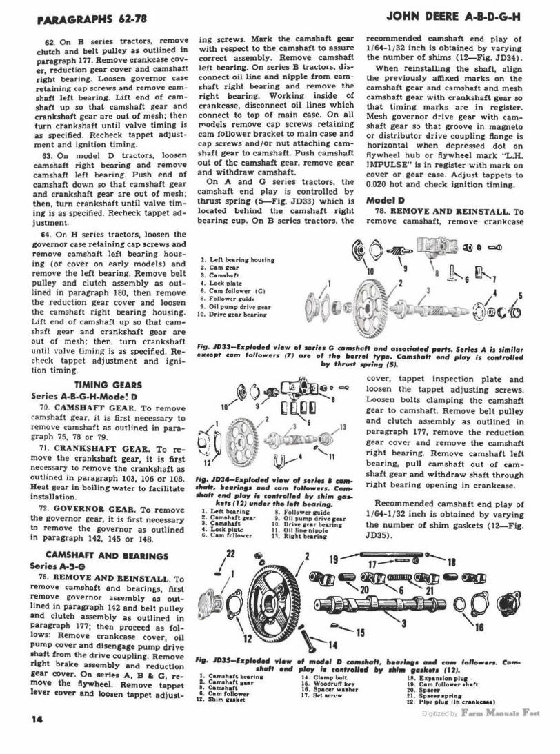
1. ~ft bearinir hou1in1 iO~ 'G ~o ~ ' 's n
2 . Cam ir•ar 3. Cam•haft 4. Loclc p late 1 6. Cam followe.r ICI
·~v2 8 .::.' & ~7 /~~ ~ 3 4 5
~ v~r~ '-· ... { . ..... . , I L ~ f ?r ; ~L ~-~®(;'Ir)
8. Follow<r iruidt 9. Oil pump drive i:ear ~ 10. Drive 1ur bearin11:
~~ Fig. JD33-Exploded view of series G comsltaft and associated parts. Series A is similar oxcept com folrowers 17) are of tlte llarrel type. Camshaft end play is controlled
lty tlirud •ring (5).
li9. JD34-fxploded view of series I cam· slid, bearin9• and cam folrowers. Camtfto~ end play Is controlled liy •lti111 gas-
trets ( J 2) under tlte left ltearin9. 1. Ldt b«Arinir 8. Follower iruide 2. Ca ma haft sear 9. Oil pumo drive ir•r 3. Camahaft 10. Drive star bearina 4. Lock Dlatc 11. 011 line nipple 6. Cam follower 11. Riehl btarlnir
In
i O \
12
cover, tappet inspection plate and loosen the tappet adj usting screws. Loosen bolts clamping the camshaft gear to camshaft. Remove belt pulley and clutch assembly as outlined In paragraph 177, remove the reduction gear cover and remove the camshaft right bearing. Remove camshaft left bearing, pull camshaft out of camshaft gear and withdraw shaft through rieht bearing opening in crankcase.
Recommended camshaft end play of l / 64-1 / 32 inch is obtained by varying the number of shim gaskets ( 12---Fig. JD35) .
"•· JD3S-lxpleded view ., fflodel D camtlHrft, lteerle9• ooll eaM follower•. 1ltaft 011d play i1 co11trollarl •Y 1ltl• 9a1tr•t1 (I 2).
1. Camohafl bcerln1 14. Clamp bolt Ill. Expanelon pl11s . r. Carr111haft sear 16. Woodruff k<'Y 10. Cam follower ahaft I. Camahsft 11. Spacer waahtr 20. Spacer I . Ca111 foll own 17. Sc>t ecr.•w 21. Spa .. r eprlna
l!. Sblm ••k<'t 22 . Plrr plus (in cranlce&H)
11t1·(jJy F-

JOHN DEERE A·l·D·G·H
When reinstalling be sure that Woodruff key (15) is in position in camshaft and gear and that steel spacer washer (16) Is installed on r ight end of camshaft. Mesh camshaft gear with crankshaft gear so that timing marks are in register and mesh governor gear with camshaft gear so that groove in magneto coupling flange is horizontal when flywheel mark .. L .H . IMPULSE" aligns with mark on cover or gear case. Adjust tappets to 0.030 hot and check ignition timing.
Series H 79. REMOVE AND REINSTALL. To
remove camshaft, remove governor assembly as outlined in paragraph 146 and belt pulley and clutch assembly as outlined in paragraph 180. Remove crankcase cover, tappet lever cover and loosen the tappet adjusting screws. Remove reduction gear cover and camshaft right bearing housing, being careful not to damage oil seal (2t>Fig. JD37) . Mark camshaft left bearing housing with respect to the crankcase so that housing can be ~installed in same position. Remove camshaft left bearing, detach gear from camshaft and withdraw shaft through right camshaft bearing opening in crankcase. Pulley journal diameter is 1.499-1.500.
NOTE: Camshaft end play is non-adjust· able.
Reinstall camshaft with "V " mark on camshaft gear in register with "V" mark on camshaft. Mesh governor gear with camshaft gear so that groove in magneto coupling flange is horizontal when flywheel mark "L.H. IMPULSE"
21
is in register with mark on cover or gear case. Adjust tappets to 0.015 hot and check ignition timinc.
NOTE: Gear backluh u controlled by the relative position of the eccentrically machined camshaft left bearing housing witll respect to the mai11 case. To reduce the gear backlash, slide the left beari7111 of! studs, turn the hOU.ting ~ turn to the right and reinstall the housing.
CAM FOLLOWERS
Series A-B-G 81. REMOVE 'ND REINSTALL. To
remove the cam followers and guide assembly, remove camshaft as outlined in paragraph 75. Remove cap screws retaining follower guide (8-Figs. JD33 or 34) to main case and remove followers and guide.
Reinstall cam followers unit a nd adjust tappets to 0.020 (hot) .
Mode' D 62. BEMOVE AND REINSTALL. To
remove the cam followers, first remove the radiator as outlined in paragraph 151, then remove the tappet lever cover and push rods. Remove crankcase cover and set screw ( 17-Fig. JD35) which retains cam follower shaft (19) in right side of crankcase. Remove pipe plug (22) from left side of crankcase, drive the cam follr •wer shaft and expansion plug out through right side of crankcase and withdraw cam followers th.rough crankcase cover opening.
Reinstall in reverse order and seal expansion plug (18) with white lead or equivalent sealing compound. Ad-
t . Lefl bearins houains 2 . Cam1h&ft scar
2• . .l'ollow~r 1h1ft cover &Del oi I cldlector
28
a. Camahatt I . Cam followu
ta. R ltht l>earlnt hou1ins It. Cam follower •hart 21. Space• oprlns 22. Pipe plus (in crankcud 23. Snip r ins
26. 011 atal 27. Cam1bart btarlns co•u
(&f~r t ,ttt l 28. C&mohart be&rlns cover
(1>r ior to 10.0001 20. Left bcarlnir
(prior '° 10,000)
"•· JDJ7-••,.felletl y/ew of HrlH H cam•ltaft and ••-dllfed ~rf.. Oeer AladrfHlt •• Cfllffrolled lty tlte 11CJlltf- •f left ll•arl11• ltoull11• (I) - dud• • ... ,,.., hre 1"
lteud1tt (IJ II ecce1ttr/c wftlt rH-ct to hull119 hr• 111 cra11lct1 ...
PARAGRAPHS 7a.a
ju.t tappeta to 0.030 (hot), which equals ~ tum of the adjuatinc ircrew.
S.riea H 83. REMOVE AND B.&INSTALL. To
remove cam followers, first remove generator and battery if tractor ia 80
equipped. Remove tappet lever cover, loosen tappet adjusting screws to release any valve spring load from the tappet lever shaft and remove the tappet lever shaft cap nuts from side of head. Withdraw tappet lever shaft from side of head and tappet leven and push rods from the front. Remove crankcase cover. Remove clutch and belt pulley unit as ouUined ln paragraph 180. Remove the reducUon gear cover and the first reduction gear. Remove cam follower shaft cover (2:>Fig. JD37), pull shaft from right side of crankcase and withdraw followers through crankcase cover opening.
Reinstall in reverse order. After cam follower shaft cover and reduction gear are installed, bend the oil deflector fi n on side of cam follower shaft cover (if necessary) so that fin covers face of gear . Adjust tappets to 0 .015 hot.
ROD AND PISTON UNITS Series A-1-G-H-Moclel D
87. Connecting rod and piston units can be removed from front of engine after removing the cylinder head as outlined in paragraph 35, 39 or 41 and the crankcase cover as outlined in paragraph 115, 116 or 117.
NOTE : If cast-in type rod bearings are to be ad;u.sted, do ao before removing the connecting rod and p"ton units. Refer to paragraph 91 for rod bearing adjustment.
Install connectinr rods and caps with numbers facing up. Number one cylinder is on left side of tractor . Tighten connecting rod bolts to a torque of 100 ft. -lbs. for series A and D ; 62.5 ft .-lbs. for series B, G and H.
PISTONS AND RINGS Series A-8-G-H-Model D
86. Cast iron pistons are available in standard and 0.045 oversize for series A. B and G; standard, 0.045 and 0.090 oversizes for model D; and standard and 0.030 oversize for serlea
H. 1 Check pistons, piston rings and ey -
lnders against the values listed below. Piston Skirt Clearance
Serles A . . .. · · · · · · · · · · · .0.005-0.008 Serles B (prior 201000) · .0.004-0.00? Serles B (201000 and up) 0.005-o.oo9
Serles G . . . · · · · · · · · · · · · O.OOCJ-0.009 Serles H •.... · · · · · • · · · .o.oo3-0 ·00: Model 0 . ... ......... . . o.ooe-0 .01
m 1t1 qJbi F- M_, Put 11

PARAGRAPHS 18-91
Piston Skirt Diameter Series A ............... 5.493-5.494 Serie.1 B (prior 201000) .. 4.494-4.495 Series B (201000 and up) 4 .681-4.683 Series G ....... . ...•... 6.117-6.118 Serles B ............... 3.557-3.559 Model D ............... 6. 740-6. H2
Cylillder Bore Series A . .............. 5 .499-5.501 Series B (prior 201000) . . 4.499-4.501 Series B (201000 and up ) 4 .688-4.690 ~ries G ............... 6.124-6.126 Series H ............... 3.562-3.563 Model D ............... 6 .748-6.750
Compression Ring End Gap Serles A-G .. .......... . 0.039-0.053 Series B .... ......... .. 0.025-0 .035 Series H ............... 0 .015-0.025 Model D ........... .. . . 0.030-0.040
Oil Ring End Gap Series A -G . ....... . .... 0.028-0.040 Seriu B ............... 0.020-0.030 Series H . . . ............ 0.015-0.025 Model D . . ...•......... 0 .039-0.053
Suggested maximum compression ring side clearance ........... . 0.005
Suggested maximum oil ring side clearance .................... 0.004
PISTON PINS AND BUSHINGS Series A-B·G-H-Model D
90. The full Boating type piston pins are ret.amed in tl\e piston pin bosses by map rings. and are available in standard, 0 .003 and O.OU5 oversizes for series A , B, G and model D; standard and 0.005 oversize for series H.
Piston pin should have a thumb push fit in the unbushed piston and have a clearance of 0 .0002-0.002 in the connecting rod bushing. Check the piston pin against the values listed below.
Piston pin diameter Serles A-G ............. 1.749-1.750 Series B ............. . . 1.416-1.417 Series H .. ...... ....... 1.104-1.105 Model D . .............. 1.749-1.750
CONNECTING RODS AND BEARINGS
Series A-8-G 91. Early production rod bearings
are of the shimmed type and can be
• ~ l)f iiiiiM
adjwted by varyine the number of shims between the rod and the cap. Actual adjustment is best accomplished by using Plastigage clearance measuring threads and obtaining approximately 0.003 running clearance. Check the crankshaft crankpln diameter against the values listed below.
Crankshaft crankpin diameter Series A ............... 2 .998-3.000 Series B . ... . .......... 2 .749- 2.750 Series C ............... 3.374-3.375
Series G tractors after Ser. No. 63924 were factory equipped with slip-in, precision type rod bearines. Series A tractors 488000 and up, series B 96000 and up and all series G can be equipped with precision type rod bearing inserts providing the new type connecting rods are also installed.
Bearing inserts are available in undersizes of 0.002-0.004.
Model D 94. On model D tractors prior to
155345, connecting rod bearings are of the bronze-backed, shimmed, babb itt lined type which can be renewed without removing connecting rods from tractor. Adjust connectine rod bearings as outlined in paragraph 91.
On model D tractors after 155344, connecting rod bearings are of the shimmed spun-babbitt type. Renewal of rod bearings is accomplished by· removing rods and installing re-babbitted connecting rods. Adjust connecting rod bearings as outlined in paragraph 91.
Crankshaft crankpin diameter is 3.499-3.500.
Seriea H 96. On series HlOOO to H21499 trac
tors, connecting rod bearings are shimless steel-backed, babbitt lined, nonadjustable, slip-in, precision type
'1 ). 0000 s 00 0 ~ 0
"•· ~1.,1ot1et1 y/ew ef Hrle• a ,.,.. aect••• ,_, •IHI ,.,"_ ·-... w•••· ,.,,., A A G 11 il1t1ll•r ••c•,,, '"• ,,,.., •r• •MCI. Ul11n••le .,," c-11fftl11• Hfl
... ,, .. , •e H#•lffe4 ftw •Ill•• tSJ.
16
"•· JO.U-lxploded Ylew of rrtodel D ce11· 11ectf119 rod a11d plrto11 oue111llly, Model D ,,,,., to Ser. No, U534$ wa1 eqvlpped wltlt .,.,,.•...!toclit•d, l•Mrf type •earl11••
flJ. •••rl••• •r• etl/unetl 1ty •"'"'' llJ.
JOHN DEERE A·l·D-G-H
which can be renewed without removing connecting rods from tract.or. For working clearance, however, It is necessary to remove the tappet lever push rods from tractor. Crankshaft crankpin diameter is 2 .061-2.062. Bearing inserts are available in standard and 0 .005 undersize.
NOTE: Connecting rod$ can be rtpfaced with the later type, which have spun babbitt, shimmed bearings.
On series H tractors after 21499, connecting rod bearings are of the spun-babbitt shimmed type. Renewal of rod bearings is accomplished by removing rods and installing rebabltted connecting rods. Adjust connecting rod bearings as outlined in paragraph 92.
CYLINDER BLOCK
Serie$ A·l·G
98. To remove cylinder block, first remove connecting rod and piston units as outlined in paragraph 87 and proceed as follows: Remove upper water pipe and on A series tractors 584000 and up, remove the two studs from right side of upper water pipe flange on cylinder block. On A series tractor prior to 584000 and B series tractors prior to 201000, it is necessary to loosen fan shaft front and rear bearings or in some individual cases, remove governor and fanshaft before upper water pipe can be removed. Also, on A series tractors prior to 584000 and B series tractors prior to 201000, disconnect the tappet lever oiler tube from rear of cylinder block. On A series tractors 584000 and up, B series tractors 201000 and up remove spark plugs and compression release cocks. On G series tractors, it is advisable to remove governor and fan shaft assembly. On B series tractors 201000 and up, loosen spark plug
"•· J~aplod•d yfew of aerie• H co11-11ectll11 rod alld plsto• 0Berttlllie1. Steel•aclced, •••Wn lined, •on-odlunollle, ttrecl1/•• type •••ri119 111••_.• t•J were u••rl •• trade" prier to :n ..SOO. 1redon
a~er 2f AH ware e11ulpllf0d witlt •11••· IJa•llltt type l>eorl•t• wlticlt are odlurte4 wltlt •ltlm• (SJ. Notice tllot c-11ectl11• retl upper hit• •re l11dalled wltlt ""' tew•nl ,,,,,. ..
Di~1t1 qj by' F- Maa.m Fut

JOHN DEERE A·l·D·G·H
wire conduit and move wires out of way. Remove stud nuts retaining cylinder block to crankcase, and on tractors so equipped, remove cap screws retaining cylinder block to frame.
Slide cylinder block forward and off studs, tilt block as required and lift block ou t over right side of frame. On late model B tractors, the following procedure may be helpful in removing the cylinder block. Turn block so that head studs are down through bottom opening of frame and upper water pipe 8ange is toward left side of frame. Lift block up until top row of studs is above lower ftange of frame left side and tip block against upper flange of frame right side. Then, while holding block at this angle, lift block up and out over frame rieht side.
Reinstall cylinder block by reversing the removal procedure and, if governor was removed. refer to paragraph 142 for governor installation procedure. On B series tractors 201000 and up, install copper washer on left front cap screw of upper water pipe ftange.
Model D 100. To remove cylinder block, re
move connecting rod and piston units as outlined in paragraph 87 and remove air cleaner a nd heat indicator sending unit. Remove hood and fuel tank. Detach fan shaft rear bearing and fan shaft front bearing retainer and slide the fan shaft forward . Remove upper water pipe.
Support front of tractor under crankcase, detach front support from bottom of cylinder block, remove cylinder block retaining stud nuts and slide block from studs. See Fig. JD48.
"•· J041- Wlten rt111ovl111 cyllndor •lock fro"' ,....,,., O, aupport front of tractor urtdor .,ofn caM a11d dot11d1 fro1tt ,.,,,..,.
fr..,. cylinder •fMk.
Series H 101. To remove cylinder bl~k. re
move connecting rod and piston units as outlined in paragraph 87, disconnect tappet lever oiler tube from Inside of crankcase and remove upper water pipe. Remove spark plugs and shields. Disconnect fuel tank rear bracket from cylinder block, remove stud nut.s and cap screws retainine block to crankcase and frame, and slide cylinder block off studs.
CRANKSHAFT AND MAIN BEARINGS
Series A-B-G On series A (prior to 694828), Band
G (prior to 63384), the split type main bearing shells ar e carried in main bearing housings and shims are provided for adjustment.
On series A (after 694827) and G (after 63383), main bearing bushings are of the aluminum alloy sleeve type which are pressed into the main bearing housings. Main bearing bushings are not available as individual parts, but as a unit with the maln bearing housings, on a factory exchange basis. The exchange main bearing and housing units are pre-sized.
Field installation of the sleeve type bearing and housing units can be made on early production A tractors, p-:-oviding the crankshaft is not excessively worn.
102. LEFT MAIN BEARING-AD· J UST. To adjust the left main bearing on series A (prior 694828), B and G, r emove flywheel as outlined in paragraph 110. Remove left main bearlni cover (2-Fig. JD50) . Punch mark the flywheel spacer and crankshaft to provide an index mark for correct in -
PARAGRAPHS 98-1021
stallation and remove flywheel spacer (3). Remove pipe plugs (5) from mai.n bearing housing. Remove main bearing adjusting bolts ( 6 ) and vary number of shims (9) t o obtain not less than 0.002 and not more than 0.006 clearance. An accurate and fast method of determini.ng the running clearance 11 by the use of Plastigage clearance measuring threads.
When reassembling, do not t ieht.en the bearing adjusting bolts until a.ft.er shims have been positioned against crankshaft. Renew seal ( 4 ) in ftywheel spacer (refer to paragraph 109) and reassemble balance of parts by reversing the disassembly procedure making certain that the main bearing housing cover is centered about the crankshaft.
102A. RIGHT MAIN BEAR.ING-ADJUST. To adjust the right main bearing, remove the belt pulley and clutch assembly as outlined in para~ graph 177. Remove right brake and reduction gear cover. Remove the maln bearing adjusting bolts and vary the number of shims (9) to obtain not le3S t h an 0.002 and not more than 0.006 clearance w hich can be accurately measured by using Plastigage thread.
When r eassembling, do not tighten the bearing adjusting bolts until inner edge of shims has been positioned against crankshaft journal. T hese shims should be against the journal to prevent the passage of an exe<?ssi\·c quantity of oil into the pulley ::.ssembly.
102B. MAIN BEARINGS-RENEW. To renew the main bearings on series A (prior 694828 ), B and G. it is necessary to remove the main bearing housings from tractor. To remove the
I. Spacer d rive pio Z. Lelt bearinr cover S. Flyoob.el •p•c"r 4. Cork 1eal 6. Pipe plus 6. Burin1 boll T. Left bcarins
houains I . Ldt b<:IU"ln~
ioeert '· Shim•
IO. Cra nkaha!I
11. Ri11ht burin11 houeior
12. Ri11ht burioa dowel pin
13. wft bffrl .. s boue ior w ith 1t.arkr bra clcct IC taOOO ud up onl.rl
14. R iirht beerins In.Ur\
f19. JOSO-l•pleded yfow ef 1•rlo1 O cN1nllu'""' •"" 111•111 .... rf .. L Serl•• A r,,,ior 'Nl21J ortd 8 ore d•if•r •••pf "'"• pfllfll (5) .,. of hllf of h•al., (7/ ,..,..,, el
et ,..,, Molrt ... ''"•• .,. ,.,,., A .,,,., .....,, •r• •ltl•I••• fwll den• 'F,.• m 111 qj bi F- M-.,., , ut
17

PARAGRAPHS 1021-109
main bearin1 howings, follow the adjustment procedure given in the preceding paragraph. In addition remove crankcase cover and disconnect oil lines frOm housings and remove the housing retaining cap screws.
To renew the main bearing and housing units on A series tractors aft.er 694827, follow the procedure given for series A (prior 684828), B and G, except renew the bearing and housing units, which are available on a factory exchange basis.
Main bearing diametral clearance of sleeve type bearings is 0.004-0.006.
103. CRAN.KSBAFI'. ·ro remove the crank.shaft, remove crankcase cover, disconnect oil lines at main bearing howsings and remove connecting rod bearing caps. Remove main bearing housings and withdraw crankshaft through side of crankcase. Check the crankshaft against the values listed below. Crankshaft main journal diameter
Series A . ... .......... . 2.748-2.750 Series B ..... ... . ....... 2.248-2.250 Series G ........ . . .... . . 2.998-3.000
Pulley journal diameter Series A ............... 2.245-2.24 7 Serles B (prior 201000) .. 1.745-1.747 Series B ( a1ter 200999) .. 1.994-1.996 Serf es G ............... 2.998-3.000
Crankshaft crankpin diameter Series A ..... . ... . ..... 2.998-3.._000 Series B .. . ... . ........ 2.749-2.750 Series G . .... . .... . . ... 3.374-3.375 Make certain that crankshaft oil
passages are clean and install crankshaft by reversing the removal procedure. Mesh camshaft gear and crankshaft g~ar so that timing marka are in re,wter.
Model D 105. MAIN BEARINGS-ADJUST.
To adjust main bearings, remove crankcase cover as outlined in parall'aph 118. Remove the flywheel, left hand main bearing housing cover and flywheel spacer. Remove the clutch, belt pulley and reduction gear cover. Loosen bearing housing inner bolts, remove outer bolts and vary the num-
ber of shims (~Fig. JD52) to obtain desired 0.002-0.006 clearance which can be easily measured with Plastigage thread.
105A. MAIN BEARINGS-RENEW. To renew the main bearings, remove the crankcase cover and disconnect oil lines from the main bearing housings. Remove the flywheel, left hand main bearing housing cover and ftywbeel spacer. Remove clutch and belt pulley as outlined in paragraph 177 and the reduction gear cover. Unbolt the main bearing housing from the main case, remove the housings and install the bearing shells.
Reassemble the parts by reversing the disassembly procedure and refer to paragraph 109.
106. CRANKSHAFT. To remove crankshaft, remove crankcase cover as outlined in paragraph 116 and remove connecting rod caps and main bearing housings (refer to paragraph IOSA). Work left end of crankshaft through left main bearing housing opening in crankcase. Raise right end of crankshaft up through right rear of crankcase cover opening. Then turn crankshaft into position so that counterbalance will clear and worm the crankshaft out through left main bearing opening. Check crankshaft against the values listed below.
Main journal diameter .. 2.998-3.000 Pulley journal diameter 2.998- 3.000 Rod journal diameter ... 3 .499-3.500
Make certain that crankshaft oil passages are clean and install crankshaft by reversing the removal procedure. Mesh crankshaft gear and camshaft gear so that timing marks are iD register.
JOHN DEERE A·B·D·G-H
Series H 107. MAIN BEARINGS. Bearings are
one-piece, non-adjustable precision type bushings and are supplied, on the exchange basis, installed in the main bearing housings (7 and 11 - Fig. JD53). To renew the main bearings, remove crankcase cover as outlined In paragraph 117 and remove the main bearing oil lines. Remove ftywheel as outlined in paragraph 110. Remove main bearing cover (2) and flywheel spacer (3) . Remove the left main bearing housing. Remove the clutch and belt pulley as outlined in paragraph 180 and reduction gear cover. Remove the right main bearing housing.
Reassemble in reverse order, making certain that crankshaft gear and camshaft gear timing marks are in register and refer to paragraph 109.
108. CRANKSBAIT. To remove crankshaft, remove main bearing housings as in paragraph 107. Remove tappet cover (rocker arm cover), loosen tappet adjusting screws and remove push rods. Disconnect connecting rods from crankshaft and w ithdraw crankshaft from crankcase. Check crankshaft against the values listed below.
Main journal diameter .. 2.061-2.062
Rod journal diameter ... 2.061-2.062
Make certain that crankshaft oil passages are clean and install crankshaft by reversing the removal procedure. Mesh crankshaft gear and camshaft gear so that timing marks are in register.
~1 . •
••• ..
'19 • .ID53-£xpl..,ed view el ••rie• H cranlulta~ ancl main bearing•. rite ••••"• type harln91 are supplied on file oird1an9e !tali• lnlltallod In tlte ltaarln9 ltoual119.c.
Refer to fig. JDSO for l•enfl.
MAIN BEARING OIL SIAL
Series A-8-G-H-Model D
,,. JN._..~...., "'- el ....... D CN•biNrff allfl ••I• ... ,, .... Th harl119 lnHr ..,,. ......... el 115}. W.r .. "9· JD50 ,_ 1 ... .,,.
109. Left main bearing oil seal ( 4-Fig. JDSO, 52 & 53) is located ln fty wheel spacer (3), between cover and left main bearing. To renew oil seal remove ftYWheel as outlined in paragraph 110. If crankshaft Is equipped with ftywheel locating screw, remove the screw. Remove main bearing cover. Punch mark flywheel spacer and crankahaft to provide an inde:K mark ,. Oig1t1zed by F- M.-a.ai. Fut
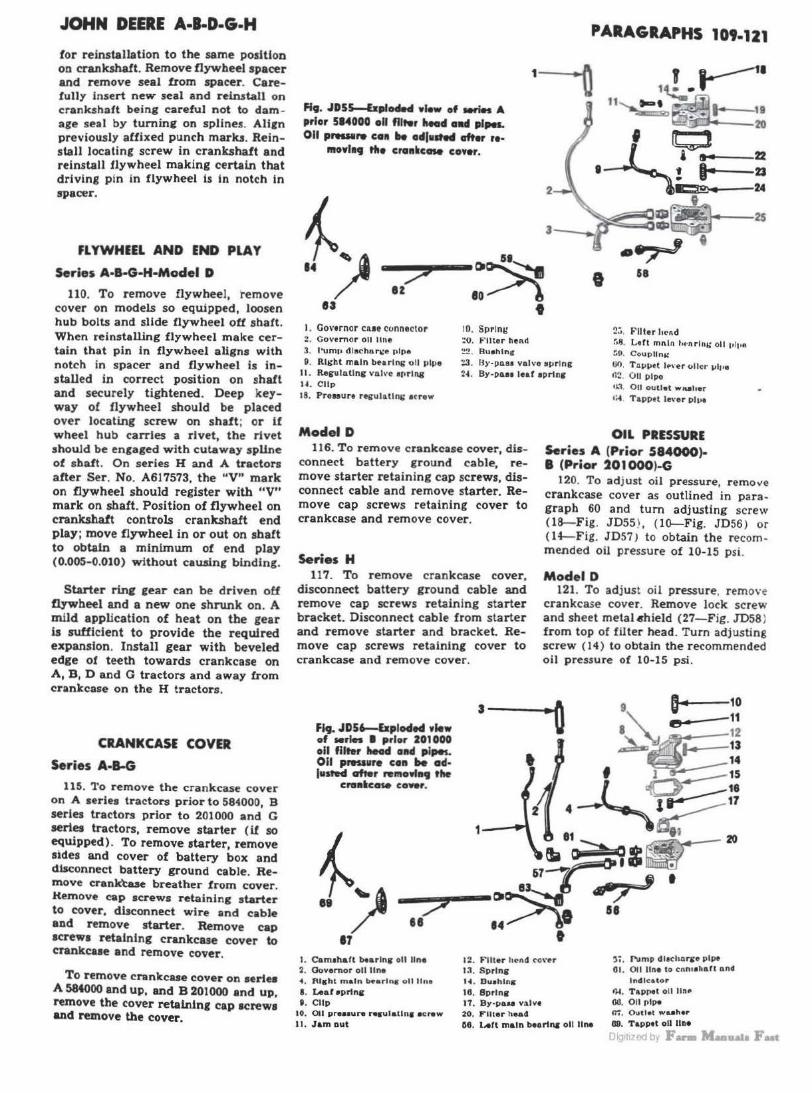
JOHN DEERE A·l·D·G·H
for reinstallation to the same position on crankshaft. Remove flywheel spacer and remove seal from spacer. Carefully insert new seal and reinstall on crankshaft being careful not to dam age seal by turning on splines. Allfn previously affixed punch marks. Reinstall locating screw in crankshalt and reinstaJJ 1lywheel making certain that driving pin in flywheel is in notch In spacer.
Fl YWHEEL AND END PLAY
Serie~ A·B-G·H·Model D
110. To remove flywheel, 'remove cover on models so equipped, loosen hub bolts and slide flywheel ot1 shaft. When reinstalling flywheel make certain that pin in flywheel aligns with notch in spacer and flywheel is installed in correct position on shaft and securely tightened. Deep keyway of flywheel should be placed over locating screw on shaft; or if wheel hub carries a rivet, the rivet should be engaged with cutaway spline of shaft. On series H and A tractors alter Ser. No. A617573, the "V" mark on flywheel should register with "V" mark on shaft. Position of flywheel on crankshaft controls crankshaft end play; move flywheel in or out on shaft to obtain a minimum of end play (0.005-0.010) without causing binding.
Starter rq fear can be driven off flywheel and a new one shrunk on. A mild application of heat on the gear u sufficient to provide the required expansion. Install gear with beveled edge of teeth towards crankcase on A, B, D and G tractors and away from crankcase on the H tractors.
CRANKCASE COVER
Series A-8-G
115. 'l'o remove the crankcase cover on A series tractors prior to 584000, B series tractors prior to 201000 and G series tractors, remove starter (if so equipped) . To remove starter, remove sides and cover of battery box and disconnect battery ground cable. Remove crank'taae breather from cover. Kemove cap screws retaining starter to cover, disconnect wire and cable and remove starter. Remove cap acrewa retaining crankcase cover to crankcue and remove cover.
To remove crankcase cover on series A 584000 and up, and B 201000 and up, remove the cover retaining cap screws and remove the cover.
Ff9. JD55-&plocle4 wlew of -W. A prior 514000 oil flltwr head ollll pfpa. 011 ,,.....,. co11 .. odj111hd ofter ,..
lllOYl•t tho cro111ic ... cower.
PARAGRAPHS 109-121
2
::> ez
~~ •o~)
t
I
I. Governor cue connecto r Z. Covemor 011 line 3. l"Umt• dlachar.:@ t•IP•
10. Sprln11 :o. Filter lleM :.!!.?. Bu•hlnc
!?~. Fiiter l1cnd :-.s. Ltft mf\ltl f1«nrl111; o il 11l11e GO. Coup lln,;
9. Right main bearing oll pipe 11 . RegUICltlns Vllll•e 1prlf18
:!3. ll> .. PllSI valvo aprlng 2~ . BY·PGH leaf 1pr111s
00. T 41111.t 1.-.. er oiler 111f•e 11~ . 0 11 plpo
U . Cllp
18. Pre99ure r~ulatlng l ( rew
Model D 116. To remove crankcase cover, dis
connect battery ground cable, remove starter retaining cap screws, disconnect cable and remove starter. Remove cap screws retaining cover to crankcase and remove cover.
Series H 117. To remove crankcase cover,
disconnect battery ground cable and remove cap screws retaining starter bracket. Disconnect cable from starter and remove starter and bracket. Remove cap screws retaining cover to crankcase and remove cover.
Fit. JD56-bplodocl wlow of Mrles I prior 201000 oil filter head e111cl lllP9L 011 pressure coa be acl· lusted after remo.t .. tho
cre••c- cower.
0.1. 011 outlet wuher
1;4 Tappet le,·er Pl,,.
OIL PRESSURE Series A (Prior 584000)B (Prior 201000)-G
120. To adjust oil pressure, r emo"e crankcase cover as outlined in paragraph 60 and tum adjusting screw (18-Fig. JD55) , ( l{}-Fig. JD56) or ( 14-Fig. JD57) to obtain the recommended oil pressure of 10-15 psi.
Model D 121. To adjust oil pressure, remove
crankcase cover. Remove lock screw and sheet metal•hield (27-Fig. JD58 J from top of filter head. Turn adjusting screw ( l 4) to obtain the recommended oil pressure of 10-15 psi.
·o
I. Cam1hall btarln1 oil lln• 2. Ovvemor oil lln•
12. Fiiier hcnd co\·r r ~;. Pump dl1chnr1t<' P iil"
'4. Right m ain b~arlng oll llne
8. Leaf eprln& t . Clip
10. Ott prea1uA ..._-ulalln a • crew
11. Jam out
13. Sprtns 14. Buohlng 16. 8prln& 17. By-pau valve 20. Fiiter h ead
G6. lAft main l>Hr1"- oll lln•
01 . Oii line lo cnn11hafl Clnd Indicato r
<>I. Tap~I oll llnP GO. 011 pipe m. Outlet waahtr
09. Tapptt oil lln.
>1111 d ,, F- aataFut

PARAGRAPHS 122-125
1. Pump dl• charc• r-•re
2. !Aft ma in b<'arlns 4'>1t line
3. Go,.nnor oil I'll>" • · To.pret oU•r pipe S. Connector 8. Ftlter bend CO\'~r 9. flu•hlnj[
10. l..ea t eprlng 11 . Srrtng
U . rruaUr<' ndJu1t111• e.c~··
1r.. Oo,..•I p in I:-. 9PTinR Ill. 1.AaC a prlni: IU. Fiiter head :.~. R l.,:ht mnln t •('>:\rlm:
o ll llne ::4. J nm nut 3:: . Coupllni:
Series H·A (after 583999)·
B (after 200999) 122. To adjust the oil pressure, re
move pipe plug or eap nut from right side of crankcase under pulley. Tum adjusting screw (14-Fig. JD59 or Fig. JD60) clockwise to in crease oil pressure. DO NOT ADJUST WITH ENGINE RUNNING. Pressure should b~ between 10-15 p ounds with engine at operating temperature.
Oil FIUEI BODY
Series A-8-G-H-Moclel D Zuo or low oil preuure coo be caw1ed by
a dlatoned oil tilter body ()4- Fi9. JD62 or 10- Fig. JD63). Distortbn of filter body is usually cauaed by over tightening of the lower cover nut. This out should be tight· ened only enough to tlimillate leakage of oil at thl$ point. U leakage occurs with nor· mal ti9hten.in9. ren•w rubber gasket, b ut
do not overti9hten the nut.
125. RENEW. To remove the oil filter body, remove the tilter element and crankcase cover. Disconnect oil line~ from filter head and remove the filter head and filter outlet assembly.
If difficulty is encountered in removing the oil filter outlet, use a h ook tool as shown in Fig. JD64. Slip hooks 0£ tool into holc::s 0£ tilter outlet (9-
Fig . .JD63 or 11- Fig. JD62) and hammer on inside of loop while holding books into holes. On all except H. place wooden block in filter body and jack up block forcing body out of crankcase recess. On series H, use wooden block and drive the body rearward. Re.move f ilter body through crankcase cover opening.
To install oil filter body, coat the portion below the "bead" with white lead or equivalent waling compound to prevent leaks and facilitate drawing body into recess of crankcase. Place filter head on the body to make certain that cap scrtw holes in body and head arc aligned and that oil lines will align with filter head connections; then, remove filter head. To draw body into c rankcase, use a long bolt and two steel plates aa shown In Fig. JD6S. Tigh~n the nut until bead of body eeate •Sal.mt crankcue. In8lall remainder of part.I by revenlng the removal procedure.
20
JOHN DEERE A-B-D-G-H
r ···· 3
33
~~1 Fig, JD57-E.,,lode4 wlew of Mt'ln G oll fllter hecicl and pipes. 011 pipe (JJ I was ued
prior to Ser. No. 13910.
I
' •
Fig. JD58-Moclel D oll filter head and pipes. ly0 pau walYo pl•9 (26) Is locotM ••r shield (171. Oii sapply to ••ftfftor Is llmltff by oll let l28l. Rohr to le4J011d for
Ff4J. JDH.
Fl,. JDSt - Elploded view of series A .tt.r 513999 oll filter head
Cllld pipes.
I. rump dl..,harse pip .. 2. Lert main bearing pipe l . <:o,·ernor pip• 4. T:iri>et pipe :i . nuttet wuher 1;. TAPr>et oiler 7 . lndlrAtor tJ1P• 8 . Fiiier he4d co•·er 0 Vnh·• huehln•
10. n~uer valv• 11 . Reller vah-o e"rln8'
2 I
~,I~ t I
1~ u-1 ~ . ..
• 1
8 9 10 11 12 13
.iJ.LaJi,l 14 15
~~ ·--11 ~ 17 12. Bracket
--- 13. Ac1Jue 111111 etrew It •prlni;
"
11 I•. AclJu111n1 : ~c~"" -- 10. Pipe 111uc 19 rn. Powel v111
/ 11. Br·r>u• vol"• a1>nnv
18. Rr·v•u vul•e 10. Fiite r hHd
• ::o. R ight m"I" ,.. bearl,.. pipe
~ :i::. l'um11 ahdl I • ~,,, .. Olg1t1zcd by F- Man.at. Fut
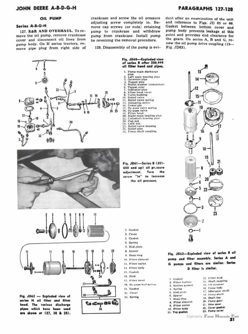
JOHN DEERE A-l·D·G·H
Oil PUMP
Series A·B·G·H 127. R&R AND OVERHAUL. To re
move the oil pump, remove crankcase cover and disconnect oil lines from pump body. On H series tractors, remove pipe plug from r ight side of
20
~-
~. JD6J - Elploded •l•w of •rift H oll fllrer awd filter .... d. 11le YtnloH dlachorte
P'PM w•lc• •-• M. o-4 .,.. ... _. at CU, JO a HI.
crankcase and screw the oil pressure adjusting screw completely in . Remove cap screws (or nuts) retaining pump to crankcase and withdraw pump from crankcase. Install pump be reversing the removal procedure.
128. Disassembly of the pump is evi-
25 I m.!c; ~'rr
24 23
Fig. JD6t-bploded wi.w of -* I att.r 200,t" oll flltw lleod aad pipes.
t . rump main dlacbl\ri:e Pipe
:?. Lc!rt main be11rln& pll'u J. Go\•ernor r>lt>O ~ . T11pptl pl(IO 5. t>ullet wn~her C~on11cc1ur) r.. TaoPtl oiler 7. lndlcnlor pt110 8. ~·111er hond <:over O. \"nlvo bushing
10. no11er vA l \'a 11. RPllcr v11lvc S1'rl11i: 1-t . AdJuatlnM e cru\'" U:. Powel 111n 17 . n)"•J'IQlft; vo1vo "'•rlut; HI. (ly-pass Vl\l\'O 111. Flltor h~ti.d 20. Hh;hl ml\ln ~l\rl n1: I'll'• :.::.:. C"nru ehn.C\ li\.0 1\dn.,; v 1110 :!:I . C11p nut ::~. l .<lCI< nut ::;., Hell~( Yl\h·c houslni; :11. llcllcf r>lflC :1:: . ru1111• •lin ft courlln~
Fi9. JD61-Series I !JOI· 000 ond up) oll pr.:ssure adjutment. Turn the scrow " in" to increase
the oil pressure.
~ Ca11ktl
3. Cover
5. GaKktt
G. Sprlni;
7. End plnlt
8. Srnctr
0. Snop rlu'
10. 1-~ntcr cltn ... nt
11. Fiiter nullt'l
H . ~·111er l>ody
...... C.:\1t"-• l
10. l:;lud
I 7 . 1-' lltc•r h~1ut
t8. Ur · l•A•• l•o' ., ...... w
:!I. · Cukel
:!.J. Cover
:I~ . Sprint;
PARAGRAPHS 127-128
dent after an examination of the unit and reference to Fi11s. JD 63 or 66. Gasket between bottom cover and pump body prevents leakage at th1a point and provides end clearance for the gears. On series A, B and G renew the oil pump drive coupling c'n-Fig. JD63).
13,...1
14~ 12 . - .
~~o . : 10~· • .,.~
• ' I .
I 11 _;_- ~
: 1
11 -<~:·"·;; ~ 16 ,{
i fi 9 u ~ 18
\9
~ 11 8 \ l 111 I · 7 ;fdii,j ~6 s:; 0-- '
v 5 22 -
f:\-4 ~
0-3y 2
0-1
i Flt!. JD6J-E1pleded •iew of IHfes I oll po111p awd filter auet11bly. Series A elHI G pumps 01141 fllten ere sl•llar. Soft.
D filter Is similar •
t <":ask•t 2. to''Hh•r l•ulto•u 3 . Uu rto111 .:a11h .. 1
... S"r lns: r •. ~nd 11l :d ..
n. Spac•r f . Saau rh•J:' 8 . Fiiter •lerurnt D. Filter outlet
10. Fiil•• bo4y
u . Topsuktt
1:! F1U,.r :"l ud 1 :.. :O:hn. tt couplln,:: H . (•U ,.lrnlnf'r
IG. l 'UU1l••~> 10. ldl~r i;~111· sh:\ fl 1:-1, l "luuv •lm rt
U . Shafi ke>·
21. ldlorc••r ::2. Cover 1uk•t ;?J, Pump (QVtr
m 1t1zed bi F- M-,., Fut 21

PARAGRAPHS 129-133
FILTER BODY
Fi9. JD6S.-Su99ested home-made tool for lnstalll119 Deere oil filter body. Tiie loag bolt ~011 be welded to tfie upper plate.
Model D 129. To remove oil pump, remove
flywheel as outlined in paragraph 110. Remo\"e strainer assembly (l~Fig. JD67 ) from left side of crankcase. Remove cap screws retaining pump to side of crankcase and remove pump.
Disassembly of the pump is evident after an examination of the unit and reference to Fig. JD67. Gasket (22) between cover and pump body prevents leaks at this point and provides end clearance for gears.
Install pump by reversing the removal procedure.
MANIFOLD$
Series A·B-G·H-Model D 132. To remove manifolds, remove
cylinder head as outlined in paragraph 35, 39 or 41. Carbon can be removed from intake manifold by directing flame of gasoline blow-torch into manifold and "cooking" carbon loo~. If manifold retaining studs are renioved on series B, make certain that they are reinstalled properly. I! wrong end of stud ii screwed Into cylinder head, It may damage tappet rod (push rod) aleeve1.
'
Fig. JD64-S•99emd home-mact. tool for mnovleg the oll fllter 01tlet. Notice that hoob 011 tool en9a9e holH la the flltwr
outlet.
JOHN DEERE A·l·D·G·H
CARBURETOR Series A-B-G-H-Model D
133. Marvel-Schebler carburetors, series DLTX are used. Refer to carburetor for model number and to Carburetor for model number and to Appendix 1 of this manual for calibration and adjustment data.
1/6 21 5
l~c:;;;;;;;;;;lc; l~
~,13 12
~ 29
14 3
t I 30 32 r; · I ~@/33
Fl9. JD66--E1ploded view of series H oil p1111p aad pipes. Preuure relief valve adfustln9 screw ll 4) is accesslllle
through rl9ht side of cranlicaw.
r"P1~34 ~ 35
~ 2. J.., ft n•:tln loenr1ni; 1••1•0 10. Reller vah·~ ~II nli:hl mnln benrlng :!8. Purnp body :1. Governor 1•l1•e 11. Hellrl \'nh·e ~t•rl lll' 1•l1rc :?fl. Purnp ahoft .f. TGJ>11~t pJp.- ( reor)
:.. Lead rolpe r.. Tnppet pipe Cfrnnt> t. On.u,;e pipe
~- Vnlvo buahlni;
25 _o · . 'AJ. . . ,+
2416 15
1;:. Hr.,cket ZI. 1 ... nd • tu d :10. ShnCt key 1:c. ,\dJuftllni.: ftcrew ~4 . llell cnl drl\'e i:enr 31. Id ler ccor shnrt
aprlng !!:'i. Gur k .. y :!:?. Idler gear 1 L AdJuauna.: 11c1·("w :!f. l'ump i.:nslt~t :s.:l. PUlnp gear
3 4. Co\·~r llr\!tk••t
Fl9. JD67-bpto•ll view of 111oclol D oll pu111p ••-Wy. 14. nu •trainer
IG. Purnp i:aaket 10. Purnp body
'20. run1r gol\r
21. Idler i:enr 22. Cover IG•kot
Z4 . Hollrnl drlv" i:enr 2ti. Our key
DiQ1t1zed by F- M-11a1a Fut

JOHN DEERE A·l·D·G·H
GOVERNOR ADJUSTMENT
5erle5 A·l·G·H-Model D 140. SPEED ADJUSTMENT. On
series A, B, G and H, turn adjusting screw at steering column to limit engine speed to rpm specified below. Speed adjustment on model D ls by changing the position of the sleeve ($-Fig. JD69A) on the throttle rod.
Engine high idle (no-load rpm). Serles A . . ... ... . ... ......... . 1080 Series B (prior 201000) ..... . . . 1340 Series B (after 200999) ... . . . . . 1370 Serles G ... . . ..... . ...... . . .. 1115 Series H (crankshaft) . .. ... .. . 1540 Series H (belt pulley) . . . . . . . . . 770 Model D . ... . . .. .. . . . .. . .... . 980
NOTE: On series A, B and G and model D, the belt pulley speed is the same as the engine speed.
Engine load rpm Series A . . . . . . . . . . . . . . . . . . . . . 975 Series B (prior 201000) .. . ..... 1150 Series B (after 200999) .. . ... . . 1250. S~ries G . . . . . . . . . . . . . . . . . . . . . 975 Series H (crankshaft) .. . . . .... 1400 Series H (belt pulley) ....... . . 700 Model D .. . .... ... ........... 900 See note above.
141. LINKAGE ADJUSTMENT. Free- up and align all linkage to remove any binding. Adjust or renew any parts causing lost motion. Disconnect throttle rod at carburetvr. With hand control in full speed position, adjust length of carburetor throttle rod so that rod is ~ hole short from entering hole in carburetor throttle shaft lever when carburetnr butterfly is in wide open position
Fig • .IDH--5ectle111al view of typical CJOY·
•nt•r _.,,,. le..t .-r -* allcl bac•· la .. Is c .. trolletl br shl111 ....... IAJ
alltl llJ.
REMOVE AND REINSTALL
Series A-1-G 142. On series A prior 584000, B
prior 201000 and G, remove starter. Remove generator if tractor is so equipped. Remove exhaust pipe and governor controls. Remove screws from front of hood. Remove bolts attaching fuel tank rear bracket to governor case. Remove oil pipe to tappet cover and on A series tractors prior to 584000, B series tractors prior to 201-000 and all G series tractors, remove crankcase cover and disconnect oil line to governor case. Remove magneto or distributor. Remove cap screws retaining governor case to crankcase, noting location of dowel-type cap screw ( 1-Fig. JD70) which is used on some models. Remove fan front bearing housing cap screws. On models so equipped, remove ventilator pipe from governor housing. Support fuel tank and hood assembly on block or jack, remove fuel filter bowl and lift governor and fan assembly from tractor.
NOTE: On A seriee tractors 584000 and up and B eerlea tractora 201000 aDd up, It
is uauallr 11ecesaary to re111ove the steer·
inq sbo.ft before the hood a11d fuel tank can be raised; alao, it is 11eceuary to remove
ventilator pipe from fan front bearing hoWl
ing before removing governor assembly.
s
---~~~11)~ •
I . Oowel · IYl><I 1crow 2. Snnp r nlll 3 . Cover 4. Cue 6. M n.,,eto drive flan ire ll. llaarlnR wuher
10. O .. nrtnl: COllt' 11 . Fnn drl \'e !>Inion 13. Devel aecar k"Y U . Shaft Ill. Thruat benrlng JO. Dearlni: aloeve IT. Lever 1haft
PARAGRAPHS 140-145
When reinstalling governor, make certain that timing maru on the governor drive gear and camshaft 1ear are in register. If marks are obliterated, make certain that fiywb~l la correctly Installed as outlined 1n paragraph 110, then turn flywheel until mark "L.H. IMPULSE" on flywheel rim aligns with mark on gear cover or gear case. Tum governor shaft until groove in magneto or distributor drive coupling flange is horizontal and mesh gears. Balance of reinstallation Is reverse of removal. Time the magneto or distributor as outlined In paragraph 162 or 163.
Model D 145. Remove radiator as ouil1ned in
paragraph 151; then, remove fuel tank. Remove magneto. Remove governor controls and ventilator tube from governor to air cleaner. Remove fan assembly and oil line to tappet oiler. Detach fan rear bearine housing an_d remove cap screws from fan front bearing housing. Slide fan shaft forward, remove governor case retaining cap screws and remove governor.
Reinstall governor by reversing the removal procedure and mesh governor gear with idler gear when flywheel mark "L.H. IMPULSE" aligns with mark on gear cover or gear case and the drive slots in the magneto drive coupling are horizontal. Retime magneto as outlined in paragraph 162.
, s
Fi9 J069A-Exploded view cf model D governor alld tllro"le
nn•age.
1. OoarlnQ' pre·lon.d eprlnr ~. D•arhta cup 18. Lever 20. W•l«hl 22. Shim t:A•ktot
"-3. L.efl ~arln8 hou1l1111 0. n.n. and retainer 10. Wataht pin 21. Drive 1 .. r
Oig1t1zed by F- M..-.11"18 F •

PARAGRAPHS 146-156 JOHN DEERE A·l·D·G·H
146. IDLER GEAR-R&R. Remove OVERHAUL Fan drive gears are supplied ln matched pairs only. crankcase cover. U additional working Series A-1-G-H-Moclel D
clearance is required, remove governor as outlined in paragraph 145. Remove nut from idler gear spindle, then drive spindle into crankcase and withdraw gear (33-Fig. JD72) .
Bushing (32) in gear is pre-sized and, if carefully installed, requires no final sizing. Install bushing with chamfered edge towards the right side. When reassemblicg, make certain that thrust washer ( 34) is installed between the gear and crankcase and the locating pin (31) is engaged in the notch of the washer and the notch in the crankcase.
Series H 148. Remove starter and generator
if tractor is so equipped. Remove exhaust pipe and breather pipe. Remove fuel filter bowl. Remove magneto. Remove cap screws retaining governor case to crankcase and remove governor and fan assembly.
When reinstalling governor, make certain that timing mar k s on the governor drive gear and camshaft gear are in register . If marks are obliterated, make certain that flywheel is correctly installed as outlined in paragraph 110; then, turn flywheel until mark " L.H. IMPULSE" on flywheel rim aligns with mark on gear cover or gear case. Turn governor shaft until groove in magneto coupling flange is horizontal and mesh gears. Balance of relnstallation is reverse of removal. Time magneto as outlined in paragraph 162.
A gen~al procedure for overhauling the governor is given in the foLlowi ng paragraphs. Differences in construction are evident after an examination of the unit and reference to Figs. JD70 & 72.
149. Remove left bearing housing ( 2 3 ). Remove set screw from governor arm and remove arm and spring. Governor shalt, gear and bearings assembly can now be removed from case. Use 0 .T.C. puller or equivalent and remove magneto coupling flange (5 ) from shaft. Press shaft out of bearing inner races and gears. Renew worn parts and reassemble in reverse order. For good governor action, no play should exist in weights. weigM p ins, bearings or controls. Be sure driJled oil hole in governor housing is open.
When reassembling, vary number or thickness of shims between rear fan bearing housing and governor case so that rear surface of fan shaft gear is ftush with edge of bevel gear ( 11)
on governor shaft. Vary number or thickness of shims (22) between left bearing h ousing and governor case to provide gear backlash of 0 .004-0.006. Renew felt seal in fan shaft front bearing and pack bearing with a high melting point lubricant. For fan shaft disassembly, refer to paragraph 155 or 157.
149A. NOTE: On model D, the magneto coupling ftange can be removed without removing the governor shaft. Screw cap screws through the flange and against the bearing housing, thereby forcing the flange off of the sba1t.
Fig. JD72-bplocled view of model D governor. 2. Snap rinc ' · c .... 6. Macndo driv.: flanc.: 7. Bearios pr ... Joad 1prin11 8. Cup 9. Ball rdalur
10. Cone 11. Jl'an drive pinion 18. K~ 14. Shaft
16. Thr uat betrina lfl. Bearinc alcevt: 18. Lnt:r 19. Weicht pin 20. Weicht 21 . Drive irear 22. Shim auket 23. L eft btarina houaina
26. Drive rear keJ' 26. Rtsbt 1>earin1 houainc 27. SetaCl'1!W 28. Control levt:r 29. Be.arhic cover 30. ldltr cear apindlt 31. Dow.:l pin 32. C"~ar bu1hin1r sa. ldlor par 3'. Thruol .,, .. her
COOLING SYSTEM RADIATOR
Series A·B·G·H 150. REMOVE AND REINSTALL.
To re~ove the radiator, first remove the grille and the steering (worm) shaft. Remove hood and shutter. Remove air cleaner and fan shroud. Dlscocnect radiator hoses, remove cap screws retaining radiator to frame and remove radiator.
Model D 151· To remove radiator, remove
hood and srille assembly. Detach radiator top tank from upper water pipe and lower tank from cylinder head.
To prevent mlaallgnrnent of radiator flaneea and consequent leakaee.
do not complete tightening of lower tank to cylinder head until after top tank flange has been tightened.
FAN AND SHAFT
Series ·A·B-G-H 155. B.&B AND OVEBBAVL. To re
move fan and shaft assembly, remove governor and fan assembly as a unit as outlined in paragraph 142 or 148. Remove cap screws retaining rear fan bearing housing (31-Fig. JD78) to governor case and remove fan shaft assembly from governor case. With shaft in vertical position and using a bar or preaa, force fan and drive disc11 into front bearins housing and remove split cone lock• (1) and keeper (2)
from front of shaft. Withdraw drive discs, friction washers and fan and Cront bearing parts from front of tube. Remove shaft, gear and rear assembly from rear of tube. Repack front bearing with high melting point lubricant and renew oil seal when reassembling.
156. CRANKCASE VENTILATING PUMP. Series A (584000-692120} and series B (201000-300866) are equipped with a vane type crankcase ventilating pump which is mounted on the rear end of the fanshaft tube. When overhauling the fanshaft, disassemble the pump and check the component parts against the values 81 lilted.
Oig1t1zed by F- M-11a1a Fut
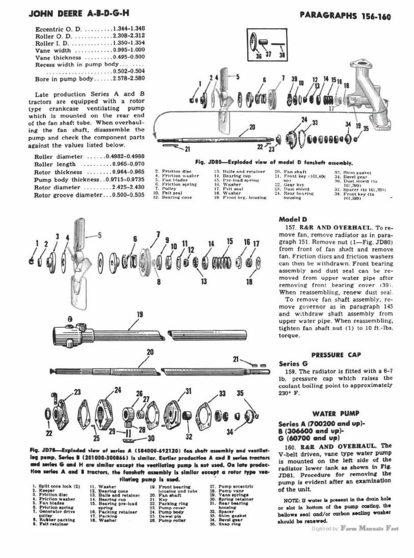
JOHN DEERE A·l·D·G·H
Eccentric 0 . D ......... . 1.344-1.346 Roller O. D .... ... ...... 2.308-2.312 Roller I. D ..... .... .. .. . l.350-1.354 Vane width ..... .. ..... 0.995-1.000 Vane thickness ......... 0.495-0.500 Recess width in p ump body ..... .. .
. . . . . . . . . . . . . . . . . . . . . 0.502-0.504 Bore in pump body .. ... . 2.578-2.580
Late production Series A and .B tractors are equipped with a rotor type crankcase ventilating pump which Is mounted on the rear end of the fan shaft tube. When overhauling the fan shaft, disassemble the pump and check the component parts against the values l isted below.
Roller diameter ...... 0.4982-0.4988
PARAGRAPHS 156-160
Roller length ..... . .... 0.965-0.970 Fig. JD8~Explo4ed view of 111edel D fa11s•aft asse111ltly.
Rotor thickness ........ 0.964-0.965 Pump body thickness .. 0.9715-0.9735 Rotor diameter .... . .... 2.425-2.430 Rotor rroove diameter ... 0.500-0.505
2. F"rl cUo n dltc .f . ~"'r1<· t1on \\'1utll t' r :.. F"n..n hlcid•u• lO. Frlcllun ~J•rlng 7. Pull<t")'
10. ~It SMI I:! . Uenrlnt; cone
t~. Hall• t\nd retnlno r I~ . llt:>.rlng cu p tr •. l' re · tl)o.d ftforlnK lti , " 'nfther 1i. Pelt l!leGI 18. w ... 11er 19. P rnn t br~. h oueln"
1<23.t\ ~24 /21 A1J{l1 /13 l5~
~9 ~"~ t"Oo~~01• ~o 22 25 29~30 32 34
A9. JD7~1941e4 •I- of •rles A Ul4000-'921201 fe•• slt.tt -111•1r n4 ft•tl41t· 1 .. pw•p. Serles I 1201000-JOOl6U la d1Rllar. E.,Her pro411etfH A •ti I -'- tracten -4 .., ... fi •• H sre ll•lf•r Hcept ti. vHtflatl119 PlllBP la •ot 1Md. O• late IP'M•c· ti• ..,._ A nd I tnlcton, the f .... crft Clllllllblr Is almllor e1cept • rotor type \'ff•
I. Split con• lock (2 ) 2. K .. pu 3. F'nctlon dlec 4. Friction waeht1r 5. Fan bldu 8. l"rtctlon eprlnc 1. Generator drlvt
P\1119)' I . RulllHlr packln1 11. F•lt ,...talner
tll41t1.. , ... , 11 ·-· • II. Wuher 12. Bearlna cone 13. Balle and Ntalner U . Bu.rlnt CUP UI. Beartna pre- load
•ortn• 16. Packlnr retainer IT . Padclnc II. Wuh•r
19. Front bearl~ h ouetna end tube
20. Fan eh&ft 21. Key 22. Packlna rlnc 23. Pump cover 24 . Pump body 2., , Dowel pla 4!6. Pump roller
27. Pump ecc•ntrlc 28. Pum1> vanr :.'II . Vane e prln&• 30. 8prlnc Nlaln•r 31. Rear be&rlnr
ho wolns 32. Spacer !Ill. Shim 1ulcel :14. Bevel par SI!. Snap rlnir
~o. F'n n ,.ha.ft ~ I . Front l<ey l I GI .~OU
up, :.!!! . Uenr kt)• :.::1. Ou:1t l'lhleld ~~. Rellr hen r lni:
houolng
Model D
:t.1. $h•m J:B8k4tt :u. (level gear :rn. Oust Jtll lekl ft•)
ll:l.:11'•~ · 37. S1·•~cr r to I GI .:ni~ I ~s. Front key (to
llil ,399)
157. R&R AND OVERHAUL. To remove fan, remove radiator as in paragraph 151. Remove nut ( 1- Fig. JD80) from front of fan sh<\ft and remove ran . Friction discs and friction washers can then be withdrawn. Front bea ring assembly and dust seal can be removed from upper water pipe after removing front bearing cover 1391. When reassembling, renew dust seal
To r emove fan shaft assembly, remove governor as in paragraph 145 and w ithdraw shaft assembly from upper water pipe. When reassembling, tighten fan shaft nut (1 ) to 10 ft .-lbs. torque.
PRESSURE CAP
Series G 159. The radiator is fitted with a 6-7
lb. pressure cap which raises tbe coolant boiling point to approximatety 230° F .
WATER PUMP Series A (700200 and up)-1 (306600 •nd up)-G (60700 and up)
160. ll&ll AND OVEllBAUL. Tbe V-belt driven, vane type water pump is mounted on the Jett side of the radiator lower tank as shown In Fl1. J'D81. Procedure for removlnt the pump it evident after an examination of the unit.
NOTE: U watn la pre .. nt In the dnlln hole or alot In bottom of the pump caatmq. th• bellow• aeal cmd/or carbon MClllDcJ waah•r ahould be Nnewed.
m 1t1 qJ br F- Maallllla Fut
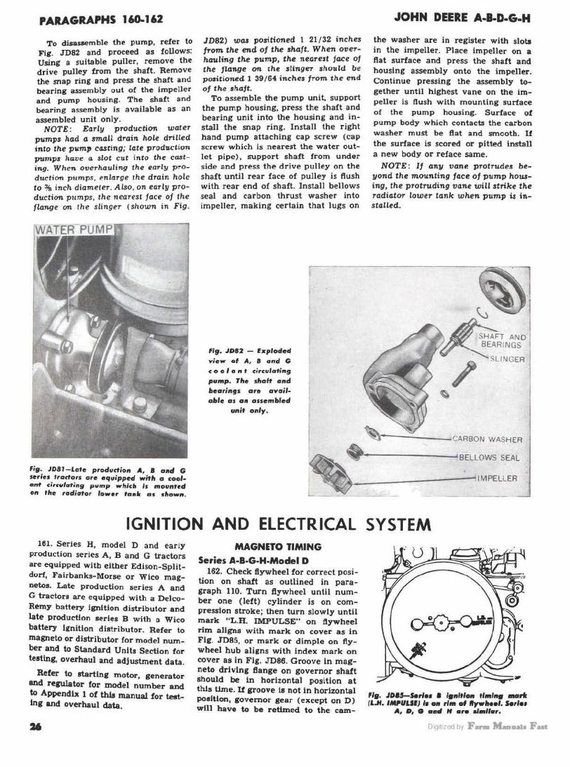
PARAGRAPHS 160-162
To disassemble the pump, refer to Fig. .TD82 and proceed as follows: Using a suitable puller, remove the drive pulley from the shaft. Remove the snap ring and press the shaft and bearing assembly out of the impeller and pump housing. The shaft and bearing assembly is available as an assembled unit only.
NOTE: Early production water pumps had a small drain hole drilled into the p11mp casting; late production pumps have a $lot cut into the ca.sting. When overhauling the early production pumps. enlarge the drain hole to% inch diamete-r. Also, on early production pumps, the nearest face of the flange on the slinger (shown in Fig.
fig. JD81-Lote prodt1dion A, 8 and G series tractors are equipped wiflt o coolant circulating pump wlticlt is mounted on tlto radiator lower tonic os sllown.
JD82) wa.a positioned l 21/32 inches trom the end of the shaft. When overhauling the pump, the nearest face of the flange on the slinger should be positioned l 39/64 inches from the end of the sha.ft.
To assemble the pump unit, support the pump housing, press the shaft and bearing unit into the housing and install the snap ring. Install the right hand pump attaching cap screw (cap screw which is nearest the water outlet pipe), support shaft from under side and press the drive pulley on the shaft until rear face of pulley is ftush with rear end of shaft. Install bellows seal and carbon thrust washer into impeller, making certain that Jugs on
fi9. JD82 - Exploded view of A, II ond G
coo I a 11 f circuloti119
pump. rite sltak 011d bearings ore available os on assembled
unit only.
JOHN DEERE A..a.D-G-H
the washer are in register with slots in the impeller. Place impeller on a ftat surface and press the shaft and housing assembly onto the impeller. Continue pressing the assembly together until highest vane on the impeller is flush with mounting surface of the pump housing. Surface of pump body which contacts the carbon washer must be flat and smooth. If the surface is scored or pitted install a new body or reface same.
NOTE: If any vane protrudes beyond the mounting face of pump housing, the protruding vane will strike the radiator lower tank when pump i$ installed.
~r-·--.::._--~CARBON WASHER
~· BELLOWS SEAL
~--------~IMPELLER
IGNITION AND ELECTRICAL SYSTEM 161. Series H, model D and early
production series A, B and G tractors are equipped witb eitber Edison-Splitdurf, Fairbanks-Morse or Wico magnetos. Late production 1>eries A and G tractors are equipped with a DelcoRemy battery Ignition distributor and late Production series B with a Wico battery Ignition distributor. Refer to rna111eto or distributor for model number and to Standard Units Section for testing, overhaul and adjustment data.
Refer to starting motor, generator and reeuiator for model number and to Appendix 1 of this manual for testing and overhaul data.
MAGNETO TIMING Series A-B·G-H-Model D
162. Check fiywheel for correct position on shaft as outlined in paragraph 110. Turn flywheel until number one (left) cylinder is on compression stroke; then turn slowly until mark "L.B. IMPULSE" on ftywheel rim aligns with mark on cover as in Flg . .TD85, or mark or dimple on flywheel hub aligns with index mark on cover as In Fig. JD86. Groove In magneto driving fiange on governor shaft should be in horizontal position at th.la time. li groove ta not in horizontal poaltlon, governor gear (except on D) wlll have to be retlmed to the cam-
'19, JOIS-S.rlH I l811lfl- tllfll... metrfr (l.H. INUUIJ ,_ - rim of ttyw#Nol. S.rlot
A, O, G aad H oro al•llor.
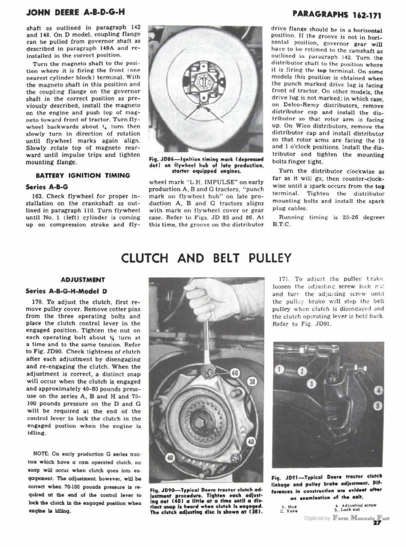
JOHN DEERE A-1-D-G-H
shaft as outlined in paragraph 142 and 148. On D model. coupling flange can be pulled from governor shaft as described In paragraph H9A and reinstalled in the correct position.
Turn the magneto shaft to the position where it is firing the front <one nearest cylinder block) terminal. With the magneto shaft in this position and the coupling f lange on the governor shaft in the correct position as previously described, install the magneto on the engine and push top or magneto toward front of tractor. Turn flywheel backwards about '• turn then slowly tum in direction of rotation until flywheel marks again align. Slowly rotate top of magneto rearward until impulse trips and tighten mounting flange.
BAnERY IGNITION TIMING
Series A·B·G 163. Check flywheel for proper in
stallation on the crankshaft as outlined in paragraph 110. Turn flywheel until No. 1 ( left ) cylinder is coming up on compression stroke and fly-
Fig. JD8'-l9nltio11 tl111ing 111arlt (deprMMd dot I on flywheel hub of late prodwctlon,
starter equipped engines.
wheel mark " L .H. JM PULSE" on early production A, Band G tractors, "punch mark on flywheel hub" on late production A, B and G tractors aligns with mark on flrwheel cover or gear case. Refer to Figs. JD 65 and 86. At this time, the groo ve on the distributor
PARAGRAPHS 162· 171
d r ive flani:e should b(' in a horizontal position. H the groove is not in horizontal position, governor gear will have to lJe rP.timed to the camshaft as outlined in paragraph 142. Turn the dist r ibutor shaft to the position where it is firing the top terminal. On some models this position is obtained when the punch marked driv(' lug is facing front ol tractor. On oth('r models, the drive Jug is not marked; in which case, on Delco-Remy distributors, remove d istributor cap and install the distributor so that rotor arm is (acing up. On Wico distributors, remove the distributor cap and install distributor so that rotor arms are facing the 10 and 1 o'clock positions. Install the distributor and tighten the mounting bolts finger tight.
Tum the distributor clockwise as far as it wiIJ go, then counter-clockwise until a spark occurs from the toD terminal. Tighten the distributor mounting bolts and install the spark plug cables.
Running timing is 25-26 degree:< B.T.C.
CLUTCH AND BELT PULLEY
ADJUSTMENT
Series A·B·G·H-Model D
170. To adjust the clutch, first remove pulley cover. Remove cotter pins from the three operating bolts and place the clutch control lever in the engaged position. Tighten the nut on each operating bolt about 14 turn at a time a nd to the same tension. Refer to Fig. JDQO. Check tightness of clutch after each adjustment by disengaging and re-engaging the clutch . When the adjustment is correct, a distinct snap will occur when the clutch is engaged and approximately 40-80 pounds pressuse on the series A, B and H and 70-100 pounds pressure on the D and G will be required at the end of the control lever to lock the clutch in the engaged postion when the engine is idling.
NOTE: On early produciion G eerlea 1roc·
tors whlch hove a com operated clulch. no
•nap will occur when clutch qoes into en·
qogement. The adjustment. however. wW be
conact when 70·100 pounda preuure la re·
quired at the end of the control lever to
lode the cl11teh Ill the engaged poalUon when enqlne la ldllnq.
Fig. JD90-Trplcal Dee,. tracter clutch afl· (111tmellt proced11N. Tlghte11 .ach adlust· 1119 a.t ( 401 a llttle at a tl111e uatll a di .. tllKt snap Is heGrd whee clutch la _, ...... n.e cllltcli adlu1tl11Q disc 11 dlow11 at CJI}.
I i i. T o adju~ t the puller t r;1k"° loosen th(' adj u~ t in .; screw lvck n·,: and turr the adJu: ting sr:r(' \\. unu l the pull ~·:: broke will slop the bell pulley when dutch is disenc:a!!cd ~nd the clutch opcroting lever is hel d back Refer to Fig . • ID91.
Fi9. JD91-Typlcal DHr• tractor ch1tcll linkage and p1lley brake odjnt-nt. Dlf. fe,.nce1 In con1trvctlo11 .,. evldeitt ofter
all e•a111l11atlo1t of the ••It.
1 . Rod ~. Yoko
.f.. AdJu11tlns: scrow ~ . J,<Kk nut
r:i1g1t1zoo b, F...,.... ~.. t 27
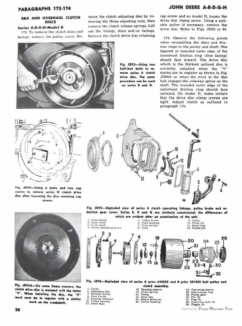
PARAGRAPHS 173-174
R&R AND OVERHAUL CLUTCH DISCS
Series A-B-G-H-Model D Ji3. To rcmoYe the clutch discs and
facings. remo,·c the pulley coyer. Re-
Fig. J094-Usin9 a plate and two cap screws to remove series H clutch drive disc: after loo~ning the disc retaining c;.ap
screws.
Pig. JDHA--011 so111e Dffre tractors. the elite• clrlYe cllac It 1ta111ped with the letter "Y" • W•H lntalll119 the cllac, the "Y" _,. ••" lte I• retister with a llinllar
•arli- ·tlie era......,,
21
move the clutch adjusting disc by remo\•ing the three adjusting nuts, then remove the clutch release springs. Lift out the linings, discs and / or facings. Remove the dutC'h drive disc retaining
Fig. JD93-Uslng two half-inch bolts to re• move series A clutch drive disc. The same procedure can be used
on series 8 and G.
JOHN DEERE A-B·D·G·H
cap screw and on model D, loosen the drive disc clamp screw. Using a suitable puller if necessary, remove the drive disc. Refer to Figs. JD93 or 94.
174. Observe the following points when reinstalling the disc!> and friction rings to the pulley and shaft: The tapered or rounded outer edge of the innermost friction ring (free facing) should face inward. The drive disc which is the thickest unlined disc is correctly installed when the "V" marks are in register as shown in Fig. JD94A or when the rivet In the disc hub engages the cutaway spline on the shaft. The rounded outer edge of the outermost friction ring should face outward. On model D, make certain that the drive dise clamp screws are tight. Adjust clutch as outlined in paragraph 170.
Fig. JD95-Eirploded view of series A clutch operating llnlc119e, pulley brake and reduction gear cower. Serles I, D and G are similarly constructed: the dlffeft11ce1 of
whicll are evident after an examination of tfle ullit. I , n11ttt Ah(eld ~. <: .. a r t~o\·er :i. l• '•.1rh ~1111 It -4, J'rakl· ndju~llt1J.: :o: n •\\'
!">. l'ullcy tirn.ke 1;. Pork b~nrlni; ';-. t"urk arirtru.: " · ~·,,rk
7 4 19
. 12 ~
,~,~ 9 13 18
fl. Collar Ill. Ph•ot 121 11. :";n11p ring 12. 01)wel pin
~·-~~·!· J 33-I ,,.,30
31~,,,32 Fl9. JD96--hplod.d view of Mrles A prior 648000 and I prior 201000 belt pulley aacl
el1tcll cwembly. I. Cover :! . AdJustlni:t die< :1. lle-lt-hfll" "l' rlru.: 4. Fr~n fflclu,:.: If. Jkoarlu..: r~tnlner I~. J•ulley henr1n.: I a. Inner race
18. Bearing waaher 10. Cov•r •Prins; 20. Pulley 21. C•tu key 22. SIHve drive 1>111 :lJ. Pulley buehln,;
2~ . Oper11t1n1 aleeve 26. Sleeve enap ring 29. Pulley gear :io. Pin 13) 31 . Do&' (3) 32. Or.rorn.lln~ bolt (3) 33. Toaal• <31
DiQ1t1zed by F- M...a11a1a Fut
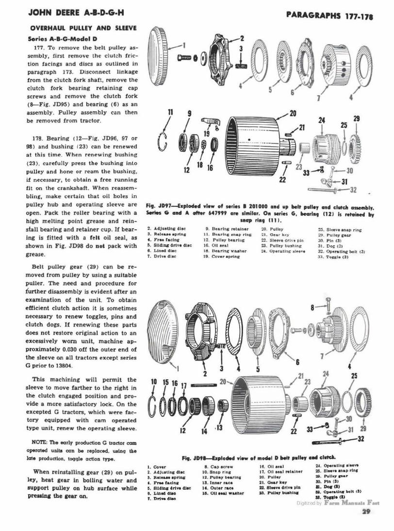
JOHN DEERE A-1-D-G-H
OVERHAUL PULLEY AND SLEEVE
Series A-B·G·Model D 177. To remove the belt pulley as
sembly, first remove the clutch fric
tion facings and discs as outuned in paragraph 173. Disconnect linkage from the clutch fork shaft, remove the clutch fork bearing retaining cap screws and remove the clutch fork (8--Fig. JD95) and bearing (6) as an assembly. Pulley assembly can then be removed from tractor.
178. Bearing <12-Fig. JD96. 97 or 98) and bushine 123) can be renewed at this time. When renewing bushing
(23), carefully press the bushing into pulley and hone or ream the bushing, if necessary, to obtain a free running fit on the crank.shaft . When reassembling, make certain that oil boles in pulley hub and operating sleeve are open. Pack the roller bearing with a high melting point grease and reinstall bearing and retainer cup. If bearing is fitted with a felt oil seal, as shown in Fig. JD98 do not pack with grease.
Belt pulley gear ( 29) can be removed from pulley by using a suitable puller. The need and procedure for further disassembly is evident after an examination of the unit. To obtain efficient clutch action it is sometimes necessary to renew toggles, pins and clutch dogs. If renewing these parts does not restore original action to an excessively wom unit, machine approximately 0.030 off the outer end of the sleeve on all tractors except series G prior to 13804.
This machining will permit the sleeve to move farther to the right in the clutch engaged position and provide a more satisfactory lock. On the excepted G tractors, which were factory equipped with cam operated type unit, renew the operating sleeve.
NOTE: Th• early production G tractor cam
OJ>9rated ua.lta oan be replaced. ualnq the
late produalon, togqle action type.
When relnstalllng gear (29) on pulley, heat gear in bolling water and support pulley on hub surface while s>rellinl the 1ear on.
PARAGRAPHS 177-171
5
11 9
I I j'
G '''' 12 18 16
Fig. JD97-Eaplocled •l•w of Mfles I 201000 amd up belt pelley and chitdt aswmbly. Serles G alld A .tt.r 647999 are 1l111ilar. On seriH G, beorl•CJ (121 Is retoilte4 by
111C1P ria9 (11 I. 2. Ad.Ju.Ung dlec 3. Rel•a.a• eprtng 4. FrM racing !I. Slldlnc drh• dlac II. Lined dlac 1. Drive d lac
9 . Brarlng "lain .. 11. S t a.rin g •nap r lns
12. Pulley bt&rlug IG. 0 11 eul Ill. Dtarlni; " "U her 19. Cover •Prine
:0. Pulloy !:t.. O ear kt!)'
22 . Sleeve drln pin 23. Puller bushing :?4. Oporntlng •lo••
~. Sleeve •nap r ing ;:,, Pulloy .rear 30. P in (31 31. Doi; 131 32. Oi>•rall~ bolt (3) 33. Toes•• t3J
Fi. • .IDtl-IJplodM • lew of Bloclel D ltelt palley .... cllltd.
1. Cov .. 2. AdJuatlng dlac S. Relo&.H aprlq
• · FrM facJ,.. 5. Slldlq 4r1ve 4l8C II, LIJul4 lllH f . Drl-41-
8. Ca p acrew 10. Snap r 1n1 12. Pl.Iller 1>ear1n1 18. Inner race 1'. Outer race 111, 011 Hal WUl\tr
I ll. 011 af&I 11. 011 Hal "talner 20. P\111•1 21. a.&r key 22. 81Mv• drive pin 13. P\llle7 bU11lllaa
24. Operatlnl alee..-2&. SIM•• anap rlnr 28. Pu11•7 ... r 30. Pin <SI ll. Dos (I) U . OperaUnir bolt (S)
sa. 'foal• <" Di~1t1 qj by' F- M_,ll&Ja Fut
29
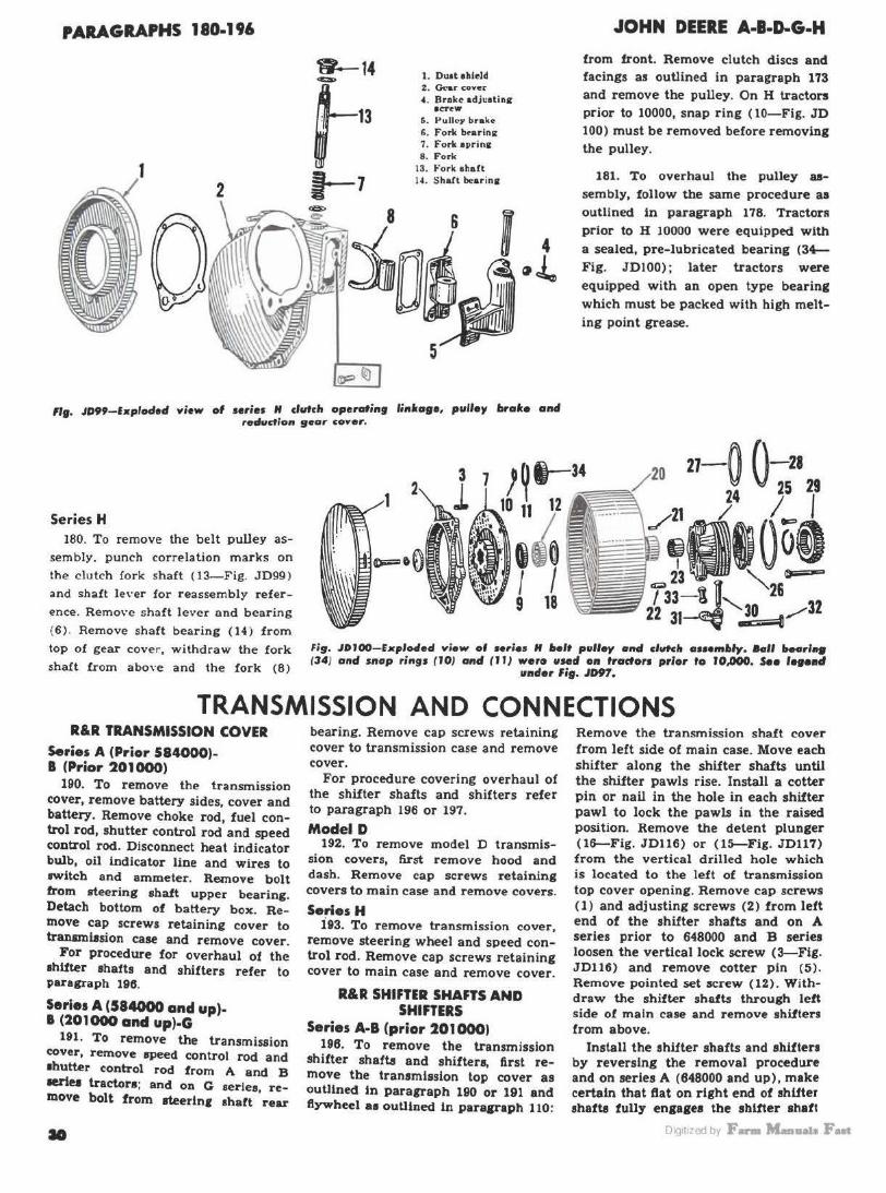
PARAGRAPHS 180-196
~14
1
~13 t--1
1. Duatahlcld z. G<-ar cover 4. Broke adjuatina
ICT'W
6. Pu U~y brak <-6. Fork btarln11 7. Fork aprinc 8. Fo rk
13. Fo rk aha.ft 14. Shart b<!arina
JOHN DEERE A-1-D-G-H
from front. Remove clutch discs and facings as outlined in paragraph 173 and remove the pulley. On H tractors prior to 10000, snap ring ( 10-Fig. JD 100) must be removed before removing the pulley.
181. To overhaul the pulley assembly, follow the same procedure as outlined in paragraph 178. Tractor& prior to H 10000 were equipped with
4 a sealed, pre-lubricated bearing (34-Fig. JDlOO); later tractors were equipped with an open type bearing which must be packed with high melting point grease.
ng. JD99-bploclerl view of uries H clvtch operatin9 linlcage, pulley brafco and redvaion 9eor coYer.
Series H 180. To remove the belt pulley as
sembly, punch correlation marks on the clutch fo rk shaft (13-Fig. JD99 )
and shaft lever for reassembly reference. Remove shaft le\•er and bearing ( 6 ) . Remove shaft bearing (14) from top of gear cover, withdraw the fork shaft from above and the fork (8)
Fi9. JOl00- E•plo4'ed view of Hries H bolt pulley and clutclt a .. embly. lklll ltearl .. (34) and snop rings (10/ anti (11} wer1t used on tractors prior fo 10,000. See r ... ad
1111dor fig. JD97.
TRANSMISSION AND CONNECTIONS R&R TRANSMISSION COVER
Series A (Prior 584000)-1 (Prior 201000)
190. To remove the transmission cover, remove battery sides, cover and battery. Remove choke rod, fuel control rod, shutter control rod and speed control rod. Disconnect heat indicator bulb, oil indicator line and wire3 to switch and ammeter. Remove bolt from steering shaft upper bearing. Detach bottom of battery box. Remove cap screws retaining cover to tranamllsion case and remove cover.
For procedure for overhaul of the lhlfter •hafts and shifters refer to paragraph 196.
Serles A (584000 and up)-8 (201000 and up)-G
191. To remove the transmission cover, remove speed control rod and •butt.er control rod from A and B lel'i~ tractora; and on G aeries, remove bolt from steerln1 shaft rear
bearing. Remove cap screws retaining cover to transmission case and remove cover.
For procedure covering overhaul of the shifter shafts and shifters refer to paragraph 196 or 197.
Model D 192. To remove model D transmis
sion covers, first remove hood and dash. Remove cap screws retaining covers to main case and remove covers.
Series H i93. To remove transmission cover,
remove steering wheel and speed control rod. Remove cap screws retaining cover to main case and remove cover.
R&R SHIFTER SHAFTS AND SHIFTERS
Series A·B (prior 201000) 196. To remove the transmission
shifter shafts and shifters, first remove the transmission top cover as outlined In paragraph 190 or 191 and ftywheel aa outlined In paragraph 110:
Remove the transmission shaft cover from left side of main case. Move each shifter along the shifter shafts until the shifter pawls rise. Install a cotter pin or nail in the hole in each shifter pawl to lock the pawls in the raised position. Remove the detent plunger (16-Fig. JD116) or (15-Fig. JD117) from the vertical drilled hole which is located to the left of transmission top cover opening. Remove cap screws (1) and adjusting screws {2) from left end of the shifter shafts and on A series prior to 648000 and B series loosen the vertical lock screw (3-Fig. JD116) and remove cotter pin (5) . Remove pointed set screw (12) . Withdraw the shifter shafts through left side of main case and remove shifters from above.
Install the shl!ter shafts and shifter• by reversing the removal procedure and on series A (648000 and up), make certain that ftat on right end of shifter shafts fully enga1ea the shifter ahaft
Oig1t1zed by F- M...a11a1a Fut
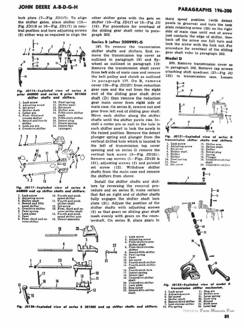
JOHN DEERE A-1-D·G·H
Ioele plate (7-Fig. JD117). To align the shifter gates, place shifter ( 13-Fig. JD116 or IG-Fig. JD117) in neutral position and turn adjusting screws (2) either way as required to align the
"•· .IOJ J6-l•pfofl.., view of 1erie1 A prior '4IOOO attd Hrle1 I prior 201000
1hiftor 1haft1 and 1hifter1. l. Lock acre• I. AcUualina ecrew I . llet •crew ' · Shifter 1balt 6. Cotter p lo f. Flrat. third a nd
nvel'llt ablfter T. Second and tour th
a hitter ~. Lock out pin ' · Overdrive a hlfter
10. Pawl eprinc 11 . Sh iller pawl 12. Sctacrcw IS. Shifter arm 14. Filth-sixth shi fter
ahatt 16. Fllth-1ixth ahiftcr If. Dclent plus 17. Dctent 1prin1 18. Detc!nt ball
(pl1.1n1n)
"•· .IOJ J7- l•plocled view of Mrie1 A '4IOOO alld up 1hifter 11taft1 and 1ltiftor1.
I. Lockacnw z. AdJuaUnir acrew I. Shifter abaft 4. Secoad and fifth
•DM<I ahlfter 5. O•erdrive ahlfter &. Pawl aprlns ?. Lock plate 8. Pawl t . Flnt, third and re
••ra• ahlft.cr
10. Fourth and aixtb apeed ahifter
II. Fourth and aixth shifter a haft
12. Sctacrew 18. Fil'llt, third and re
ven• ahittu abaft 14. Fourth and aixth
•Pft<l •hlflcr arm 16. Detent auembly
other shifter gates with the gate on shifter (lG-Fig. JD117 or l~Fie. JD 116). For procedure for overhaul of the sliding gear shaft refer to paragraph 203.
Series B (after 200999)-G 197. To remove the transm<ssion
shifter shafts and sh ifters. first remove the transmission top cover as ouUined in paragraph 191 and flywheel as outlined in paragraph 110: Remove the transmission shaft cover from lei& side of main case and remove the belt pulley and clutch as outlined in paragraph 177. On B, remove cover (3G-Fig. JD127) from reduction gear case and the nut from the rlcbt end of the sliding gear shaft drive shaft (D) then remove the reduction gear main cover from ricbt side of main case. On series B, remove nut and gear from left end of sliding gear shaft. Move each shifter along the shifter shafts until the shifter pawls rise. Install a cotter pin or nail in the hole in each shifter pawl to lock the pawls in the raised position. Remove the detent plunger spring and plunger from the vertical drilled hole which is located to the left of transmission top cover opening and on series G remove the vertical lock screw (3-Fig. JD121 ). Remove cap screws ( I- Figs. JD120 & 121), adjusting screws (2) and pointed set screw (12) . Withdraw shifter shafts from the main case and remove the shif ters from above.
Install the shifter shafts and shifters by reversing the removal procedure and on series B, make certain that flat on right end of shifter shafts fully engages the shif ter shaft lock plate (21). Adjust the position of the shifter shafts with adjusting screws (2) so that gears on sliding gear shaft mesh evenly with gears on the countershaft. On series B, place gears In
22
f '..k 21
1. Lock a<rew 2. Acljuatinir ocrcw 4. Flnt-t~ird-reverac
1biftcr ahalt 6. Fll'llt-lllird· reverk
1hllur 6 . Second·flfth abifter
10. p ... 1 aprlnc 11. Pawl 12 . S.toc,.• 13. Fourth .. bth ah ifter 14. Fourtb .. lath ahlfl<r
1ha!t 111. Fourth .. lath fork 11. Octenllprloa 18. Dtl<nt ball 19. Underdrlve ahlfter
1ba1t 20. Underdrlvc ahlfter 21. Loc:i plate 22. sio. aere• 2S. S-nd-f\ftb ahlrter
ehaft
PARAGRAPHS 196-200
third speed po1iUon (with dete.nt pawls in grooves) and turn the loek plate retaining screw (22) on the ri&ht ~de of main case until end of screw Just contacts the edge of shi!ter, then back off the screw one full turn and lock the screw with the lock nut. For procedure for overhaul of the slidiDg gear shaft refer to paragraph 203.
Model D 200. Remove transmission cover u
in paragraph 192. Remove cap screws attaching shift quadrant (27-Flg. JD 122) to transmission case. Loosen
·-· 1-n 1--- It
I
14 I
' I
fifl. JDl21-bpfod•d Yi•w of series 0 rranuniuion sltfft•r 1ltaffs and 1llfffera.
I . Lock 1c,..w I!. Shif~r ann 2. Ad juslintr acrew 1'. Shifl<r a hart I . S.t •<•<'"' 16. Shlfkr 4. Shifter shaft 16. Dct.,ot plur '· Sh;tt<-r 17. Sprios ?. Shifter 18. Plu11aer
U. Pawl apr;n11 19. Underdrivt eh tflcr 11. Pawl abaft 12. Sci •Cl'<'W 20. Undcrdrl vo eh itlrr
/ &ti
e l-l e •
"•· 10122-.. ,.Wed 1tfew ., _...., • tra11....iu1o1t 1ltllfer 111ecHl9I ....
I. Lock ac"w 11. Stop pin 2. AdJ ... tlns • c rew U. Shifter ar111 a. Set •en• 21. Lever apnns 4. Shift.er ehaft It. Cork rl"• I . Second·thlrd 1hlft.er 23. Shroud 7. Lo••ttnrw ahirtcr 24. Shift leftr
10. Pl111prln1 H. Leftr '-
rJl< 1t1-c d b1 F ....... ~awFua II

PARAGRAPHS 200-205
clamp bolt on shift lever arm, remove Woodruff key (26) and slide shift lever rearward. Note postion of springs (21), cork (22) and shroud (23) for reassembly.
Remove pulley and clutch as outlined in paragraph 177 and remove reduction gear cover.
Remove lock screw ( l) and adjusting screw (2) from right end of shi!ter shaft. Loosen set screw ( 3) wide of transmission case and withdraw shifter shaft and shifters.
Reassemble in reverse order and adjust position of shifter shaft with adjusting screw (2) so that gears on spline shaft (sliding gear shaft) mesh evenly with gears on differential. When reinstalling the reduction gear cover, make certain that cover is centered around the clutch operating sleeve. For procedure for overhaul of the sliding gear shaft refer to paragraph 204.
Series H 201 . Remove the flywheel as out
lined in paragraph 110 and transmission top cover as outlined in paragraph 193. Slide shifter (6--Fig. JD 123) along the shifter shaft until the pawl rises. Install a cotter pin or nail ln the hole in the shifter pawl to lock the pawl in the raised position. Unbolt the shifter shaft bearing (21) from left side of main case and withdraw bearing and shaft through left side of main ca$e and shifters from above.
Reassemble in reverse order and adjust position of shifter shaft with adjusting screw (2) so that gears on sliding gear shaft mesh evenly with gears on countershaft. For procedure for overhaul of the sliding gear shaft refer to paragraph 205.
SLIDING GEAR (SPLINE) SHAFT
Series A·B-G 203. Remove shifter shafts and shif
ters as outlined in paragraph 196 or 197.
On series A prior to 648000 and aeries B, remove nut from left end of eliding gear shaft.
3. Flflh ond sixth 1!! . 1)(113rln&
drll·e senr 13. Slid I~ i;ear shnCt 4. Oil retnlner drt''" i::e:.r :;. S'nop rlns 1·1. Dua. ring
G. Bearing I~. Gasket ; . Flr1t speed rlnl<>n I G. Renrlni; co\'er 8. Second speed J•lnlon :.:o. t'lrat reduction t-:oar D. Slldlni; i;enr shnfl :! I. Svncer
drh·e pinion :?~. Go.aket 10. Key :?3 . Co,·cr ll. Sttdlni; i:<>o.r ~ha(I :?8. n~arln.:
On all models remove gear, oil retainer and snap ring from left end o1 sliding gear shaft. Pull the shaft out through left side of main case while bumping the drive pinion against the bearing en right end of shaft to remove the bearing. Withdraw the shaft through the left side of case and remove gears from above.
Refer to the transmission exploded views (Figs. JD124, 125, 126, 127 or 129) and install the sliding gear shaft be reversing the removal procedure. Before reinstalling the shielded ball bearing to right hand end of sliding gear shaft pack the open side with wheel bearing grease. Always install this shielded bearing with the shield nearest to the left side of the tractor so as to retain the packed-in lubricant. For procedure for overhaul of the sliding gear shaft drive gear refer to paragraph 207.
Fig. JDI 23 - E1ploded view of Mrles H transmlsalon sllltter lllaft ot1d dilften. Item 1211 Is a slieft
bearln9. I. fA> c:l: twrttw 2. Ac:JJU1t1ni; • c re w 3. S•t acre" t . 8htrtor ehACt
H. Shll l..r o. ShlllH
10. Powl aprlnii II. Shifter pawl
JOHN DEERE A-8-D-G-H
3t. n~nrlng hou1lng 0. DIUerenUal drive :l:?. Sltl111 snskets plnlutt 33. Dearlns cu11 ·U. Spo.ccr 3~ . Cone ~S. Flret speed sear 3:i. Thrust wnsher 4G. Benrlni; cone 3G. ldlor l>cnrlns H. Cur> 37. &: ae. Spacer 48. Snnp rlni; 3!>. Idler i:ear 50. Locking w11.11her ·10. Counterahn!l !JI. Locking nut 41. Si;acor 52. Fifth and sixth .a~. Socond speed gear epeed pinion
Model D 204. Remove cover and shifter
shaft and shifters as outlined in paragraph 200. Remove four cap screws retaining bearing quill ( 17-Fig. JD 130) to transmission case. Remove left cover, snap ring (3) from left end of shaft and remove left bearing (4) by bumping it with high and intermediate sliding gear (7). Withdraw shaft through opening in right side of case. Press reduction gear off shaft and remove bearing and quill. Install the sliding gear shaft by reversing the removal procedure. For procedure for overhauling the reverse gear shaft refer to paragraph 213.
Series H 205. Remove cover and shifter shaft
and shifters as outlined in paragraph 201. Remove pulley and clutch as ou~lined in paragraph 180 and remove reduction gear cover and gear.
Remove cap screws retaining sliding gear shaft rlgb& bearing housing (8-Fig. JD131) to case and remove housing. Withdraw shaft assembly through opening in right side of case. If equipped with power shaft (P.T.0.), remove left bearing housing ( 1) and remove nut, bearing and bevel gear from left end of shaft before removing shaft.
Oig1t1zed by F- M-11a1a Fut

JOHN DEERE A·l·D·G·H
Reassemble in reverse order and vary thickness of gaskets and shims ( 7) between right bearing housing and case to remove all bearing play but permitting shaft to turn freely. Gaskets and shi ms ( 2) between left bearing housing and case control posi-
tlon of bevel gear in relation to bevel gear (not shown) on power shaft. Refer to Power Shaft, paragraph 222 for gear mesh adjustment procedure.
When reinstaJling reduction gear cover, make certain that the reduction gear cover is centered around the
PARAGRAPHS 205-ZOt
clutch operating sleeve. For procedure for overhauling the countenhaft re.fer to paragraph 211 .
SLIDING GEAR SHAR DRIVE GEAR CThJa la port "D" lll ezploded .WW. of
tronamlulon.)
Series A-1-G 207. Remove the sliding gear shaft
as outlined in paragraph %03.
On series B prior to 201000 and oo all series A tractors remove belt pulley and clutch as outlined in paragraph 177, right brake and reduction gear cover.
Remove the reduction gear ( RFigs. JD124, 125, 126, 127 & 129) from right end of the sliding gear shaft drive gear (D) . Remove bearing retainer (cover) from right side of main case and remove the drive ge-;_r through transmission cover opening.
Fig. JD125--lxploded view of terln A after 647999 tra11111ilulo• sha~s a11lll associatecl parts.
Refer to the transmission exploded views and install the drive gear by reversing the removal procedure. For procedure for overhauling the countershaft refer to paragraph 209.
I. Fourth and alxth I'' S11a1• rlnt
aperd (:e&r 1:1. u .. nrhu.: n1llt"f1'
:? . 011 r~talner I I . !'ll<lt11t.: ~:tr lllllllrt
3. " ~- S nn(t r loi.: drl\'<' &:tnr 11;.if!OOQ.
:I. nenrlnt: 1~,;:Ut:.?)
G. First nnd third 1:"'1. Wood rurr kt»
epetd pinion. 1r.. Slldln(: J:t"nr ahn.ft .. "~Y drive c•nr CG~ol:lll3
8. Second e>nd rHth ond u1»
91\Ctd 1•lnlon 17. Uturln~
!\ , !=\.11'11n~ (: ftn r !llh n f t 1R. O il eoollnr
drh'o pinion 10. G:\SkPt
10. Slldlni; conr ~hnrt :.:o. Co,· ~r
'l . B~nrln~ lnnttr ro.co ::?1. Fl r•t r"ductlon C(llnr
·~ ~r•:icer :~ . Gn•ke t :.·,, CO\'l"r
ln. ltr:irlnc 33. Co unterahart 37. nenrlni; h ous lni: :ltl, ~him g:ucl.('t
39. Cup rn. Cone f I . Thru.~t wn:dt«.! r
•Z. ldl•r bonrhu:: ·13. & ~n. S1>Mer H . C ollnr
.. :-.. Idler (:eor ~;. l'tet1n d nnd fifth
s11tl•d ~CQ. f
·18. Plffrrr111l:il d rh <' pinion
>t:•. Sp:H'tr ~.n .,., ,.,_, :..n d 1lili·d
!tl•t (HJ J,!('i. r r,t. Cnnc :'12. Cuv :-.:1. Sno1• rln~ 54. Fourth nnd ~lsth
apoed plnlo11 foll . Covt'r
COUNTERSHAn (Countersbaft is part (40) in Fig. JD124. (33)
in 10125. (43} in JDI26. (45) in JDI27. (4J t L'l 10129 ond (22) in 10131).
Series A-B-G 209. Remove sliding gear shaft and
sliding gear shaft drive gear as in paragraphs 203 and 207. Remove countershaft right bearing housing
p·~ \ \\\~.~ • µ:-( ,. 15 a
.t.11.1 .~r '"' J ~~1111 rQ-51
I
3 . Fifth and al •tl• • l•<•rd i:~ar 4. Oil ntolner G. BHrlnc ; • Sllcllng i:enr 1hnft 8. Flrat . lhlrd e>nd rever•o
pinion 0 . S ocond and fourth plnlol\
10. Slldlnc gear •he>lt drh·~ plnton
F19. JD126-lrplocled view of wrle1 I prior 201000 tNt11111lul01 allafts 11114 gean. 47. Sµncer
11 . Uoarh11C I:!. Slldlni; i;Mr ahalt drl''"
11•ar 13. Collnr 14. Uurlnii 111. Snt.p rln1 1(1, Oaaket 17. Cover 18. Retainer
:.::.:. fo"•lr•t rC"ductlon ti;tl\r ::3. Spa.ct.•r 2~. Snap rlnlt ~~ - Dear1na :!'J. Gl\•kct :io. Oover 311. Uearlnit houaln11 30. Shim gaakata 31. Cup
38. \.'one :re. Tll ru•t wruihcr ~11 . Roll~r hunrln~
.. H • .. "'lr1t hlld tlolnl I'll~'''' .,:t•ur ~II. Co11•
.. . , & '44. ~••R\:'•r :;u. Cup ~:!. Idler 11enr GI. Waaher '4:t , c ounttrellBtt !\~. Locktne 1\'aahflr ~:'> . Socond and rourth 1peod 63. Locklns nut
sea.r u. l"lfth and al,.tll atldlll8 411. Dlffanntlal drive pinion plllloo
m 111 qj bi F- Maaa ., Put •
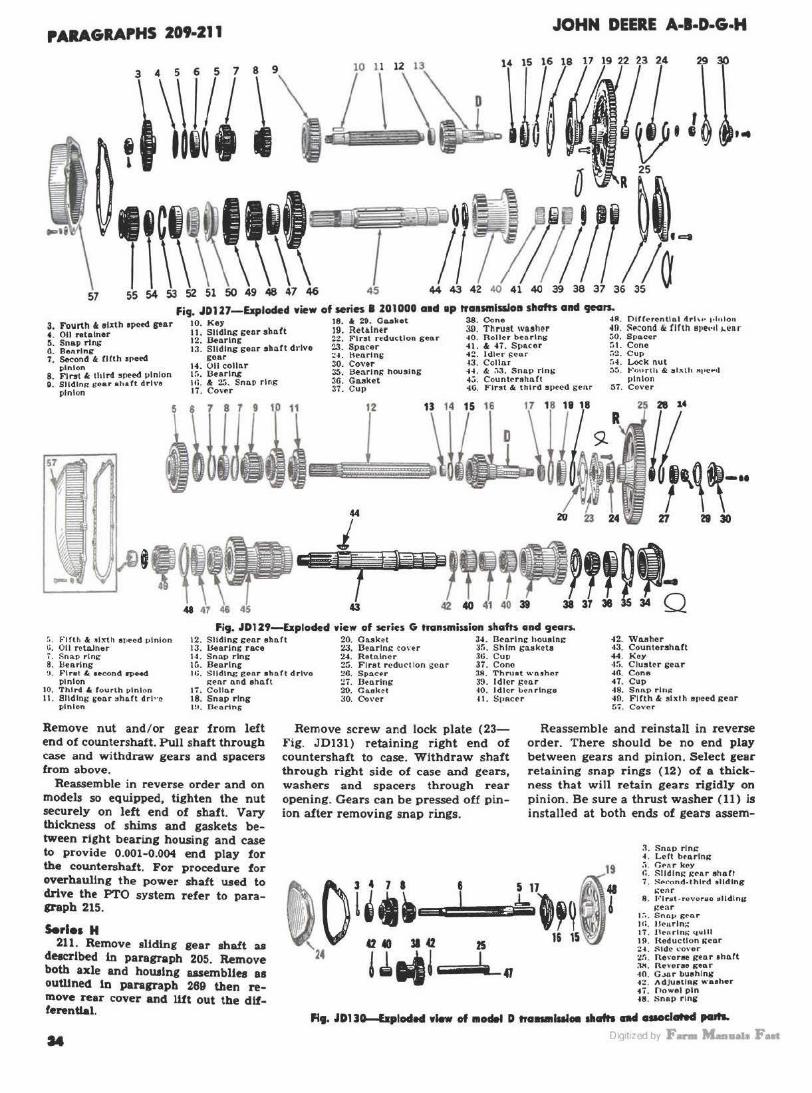
PARA61APHS 209-211 JOHN DEERE A-l·D·G·H
, ..
Fig. JDU7-Ellploded wiew of series I 201000 a•d •P tra•smlaloa sllafts allcl gears. 10 Ke 18. • 29. Oo..olcet 38. Cone .. 8 . DlffNentlnl drl"• ,.1.,1on
3. Fourth t. i!Xth tp<!td par 11 ' Sll:lng genr •hnft 19. RH•lntr 39. Thrust IYUher ~0 . !'f'tond 6t fifth &1•e•••I 1.l!U '· ~!la re~~".er 12· U.,o.rlng 2:!. F'lrat reduc;tlon gear .. o. Roller bc:o.rlnt' vO. Spo.cer g. 9 Pl 6 13: Sliding genr shllft drlvo 23. Spncer 41. & H. Spacer ~1. Cone i S::~ndll&. rtllh spetd gear ~4. ttearlni; .. :!. ldlP.r E<•nr ;:::. Cup
· 1• 011 colhir 30. Cover .. 3. Collar .o4 . Lock nut 8
~nlo".r, I lrd ed 1 Ion 1:;: Dearing :!:). Bearing housing H . &: ~•3. Snap rlni; :.~. l-'our111 & "'"th ~to•~·• · lrst 11 spe I> ~ • a: .,, s In 3G Gn.sket 4;;, Counterehaft !>Inion
~. Slldln" GO&r •h•fl drho th. "':'· nap r g 37' c -IG First" third SP•ed s enr :;T. Co,·er pinion 17. Co, er • up ·
12 1S 14 15 16 17 18 111 18 25 28 14
j 44 20 23 24 'rt 29 30
.,~,~.- i *j?Wa!Ti1. J!f ~'o :>. Firth & 4ixth ar,ecd JJlnlon ~. 0 11 relruner 7'. S llap ring 8. IJearlng !J . 1i~tret le. 1ec:ond 11>M<l
pinion 10. Third 4 f o urth vlnlon ll. Sliding i;eo.r "haft drl"o
pinion
Fig. JD129-bploclecl wiew of wries G transmission shafts ancl gears. 12. Sliding geo.r ahart 20. Casket 34. llearlni: housing 13. Uearlng race 23. Ooo.rlni: co\'tr J!'i . Shim sa.akcta 14. Sn<lp ring 2'. R etnlnc r lti . Cup Iii. Bearing :?5. F irst reduc tion sc o.r 37. Cono It;. Slldlng ~eor eho.rt drlvo :!C. Spa.c•r 38 . Thrust '"' nthol'
i:enr o.nd shaft ~T. O.arlns 39. ldltr sear 17. Coll~r 20. Caekct 40. Idler l>t'nrlnga 18. Snap ring 30. C.,\•cr H . SpRccr tH. Ocnrtns
42. Waahor ~3. Counlershaft -M. Koy ·l!i. ClustH gear .. a. Cone 47. Cup 48. Snnp rln" 40. Fifth & sixth speed geo.r :-;-:. Cover
Remove nut and/or gear from left end of countershaft. Pull shaft through case and withdraw gears and spacers from above.
Reassemble in reverse order and on models so equipped, tighten the nut securely on left end of shaft. Vary thickness of shims and gaskets between right bearing housing and case to provide 0.001-0.004 end play for the countershaft. For procedure for overhauling the power shaft used to drive the PTO system refer to paraP'&Ph 215.
Remove screw and lock plate (23-Fig. JD131) retaining right end of countershaft to case. Withdraw shaft through right side of case and gears, washers and spacers through rear opening. Gears can be pressed off pinion after removing snap rings.
Reassemble and reinstall in reverse order. There should be no end play between gears and pinion. Select gear retaining snap rings (12) of a thickness that will retain gears rigidly on pinion. Be sure a thrust washer (11) is installed at both ends of gears assem-
Serles M 211. Remove sliding gear shaft as
de.cribed in paragraph 205. Remove both axle and housing assemblies as ouWned In paragraph 269 then remove reu cover and Wt out the differential.
=·----~-
3. Snnp rlni: 4. L~ft btarln1t :i . 04"nr koy r.. Slldlni: i:~ar ahaff 1 . Nncond.thlrd 'tiding
.:enr 8 . l·· lrttl-revoraio !llldlng
i::enr 1:-•• Sne\V St'O.r llL Ut:'urln;.; 17 . lleArlns:- quill l!I. Heducllon 1tenr :..a. :::;1deo .. ·over 2:'t. ne\'oree gea.r 1ho.tt :lX. Revorao tt•D r 40. G.>11r buahlng .. 2. AdJuetlng "'·aeher 4i. Oowel pin 48. Snnp r1n11
Fl9. JD110-bploded wlew of 110 .. D trca-llllOll •afrl nd uaoclated pallL
DiQ1t1zed by F- M...a11a1a Fut
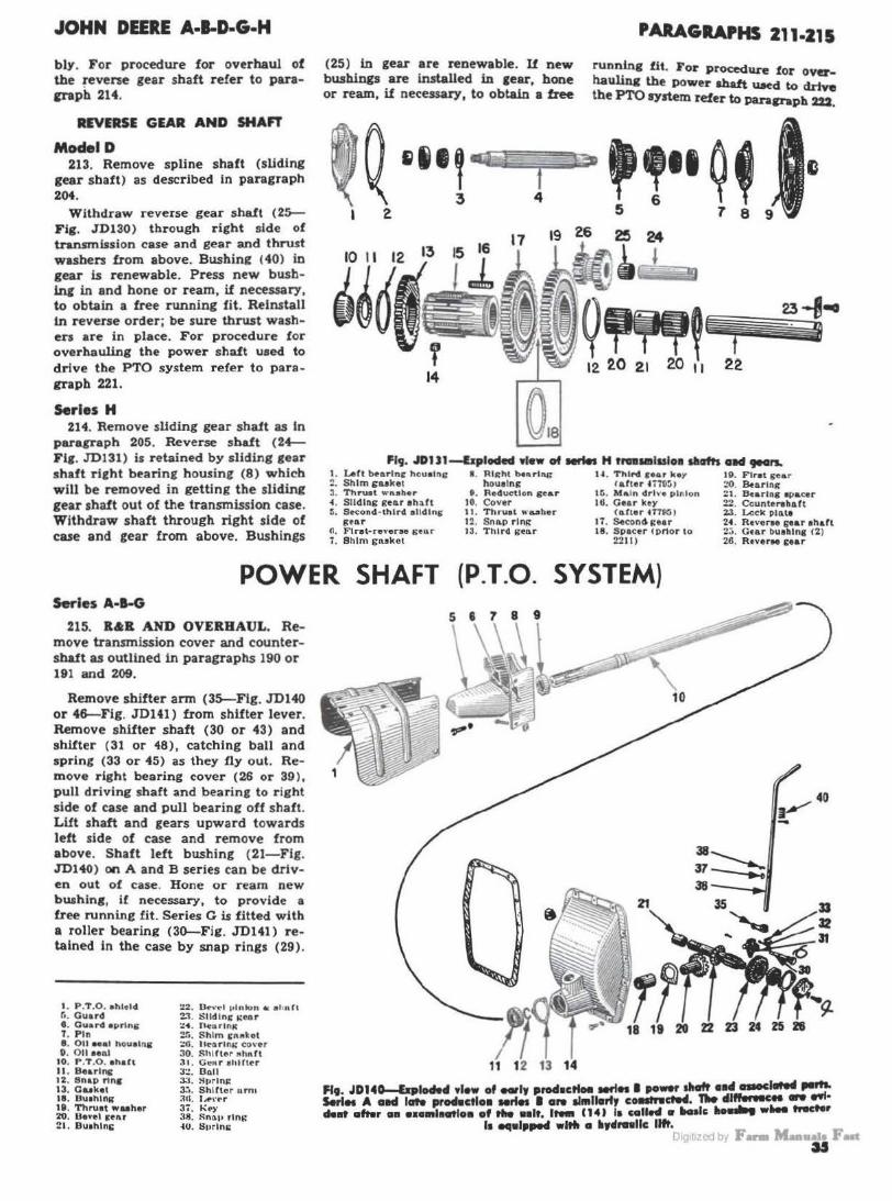
JOHN DEERE A·l-D-G·H
bly. For procedure for overhaul of the reverse gear shaft refer to paracraph 214.
REVERSE GEAR AND SHAFT
Model D 213. Remove spline shaft (sliding
gear shaft) as described in paragraph 204.
Withdraw reverse gear shalt (2~ Fig. .JD130) through right side of transmission case and gear and thrust washers from above. Bushing (40) in gear is renewable. Press new busblni in and bone or ream, if necessary, to obtain a free running fit. Reinstall in reverse order; be sure thrust washers are in place. For procedure for overhauling the power shaft used to drive the PTO system refer to paragraph 221.
Serles H 214. Remove sliding gear sha1t as In
paragraph 205. Reverse shaft (24-Fig. JD131) is retained by sliding gear shaft right bearing housing (8) which will be removed in getting the sliding gear shaft out of the transmission case. Withdraw shaft through right side of case and gear from above. Bushings
(25) in gear are renewable. U new bushings are in.stalled in gear, bone or ream, if necessary, to obtain a free
10 11
PARAGRAPHS 211·215
running fit. For procedure for overhauling lbe power abaft U8ed to drive the PTO syrtem refer to PBraP"aph 222.
24
'
Fl9 • .IDU1--Elploded Ylew of Mfln H tnn11mlul01 sllafts allcl 9"1'S-1. lAtt b~arln' hou•lng ~. Shim guket 3. Thru.t wn•he r ~. Slldlng g~ar ehaft ~. Second-third olldlni;
(t•o.r ri. Flrat·reverae senr 7. Shim i;nakot
I . Rli:hl lat\rlftl> h ouelng
0. Reduction ~ar 10. Cover 11. Thru•l wa.sher 12. Sno.p rlni:: 13. Third 1>•11r
U . Third S•ar k•Y 1arter t no:;1
15. Main drh·o pinion 16. Gear k•Y
(after 4TTP:; I 17. Secon4 i:ear 18. Spacer IPMOr to
2211)
19. F1ret sear :..'O. Bto.rlng 21. Bearing •o acer :?!!. Counterahaft 23. Lock plo.te 24. Reveree gear eh&ft 2;;. Gt&r bueh lng 12) 26. Reveree i:ear
POWER SHAFT (P.T.O. SYSTEM) Serles A-1-G
215. R&R AND OVERHAUL. Remove transmission cover and countersbaft as outlined in paragraphs 190 or 191 and 209.
Remove shifter arm (35-Flg. JD140 or 46-Fig . .JD141) from shifter lever. Remove shifter shaft (30 or 43) and shifter (31 or 48), catching ball and spring (33 or 45) as they fly out. Remove right bearing cover (26 or 39 ), pull driving shaft and bearing to r ight side of case and pull bearine off shaft. Lift shaft and gears upward towards left side of case and remove from above. Shaft left bushing (21-Fig. JD140) on A and B series can be driven out of case. Hone or ream new bwhing, if necessary, to provide a free running fit. Series G is fitted with a roller bearing (30-Fie. JD141) retained in the case by snap rings (29).
I . P .T .O. ehleld r,, Guard • . ou .. .i •prlng T. Pin e. 011 Mat hou11ns 0 . Oii ••111
10. P .T .O . •hart II. Bearing 12. Snap ring 13. Gukel 18. Bu1hln1r 19. Thruot wuher 20. Devel 1mu ::1. Bu1hlni;
!!!!:. D<e-\' t•I ,,1ntun * • llofl 2.1. Slldln~ i;C'or ::•. nearlntc :?Ii. S him CAMkot ~o. HC"tlrln,; cover 30. Shlrter Mhl\fl 31. Genr 1hHtt'r 3:!. Brill 3:1 . :'lllflni: 3."•· Shlrtor urn1 :ltl. l~\'~r 37. K~)' 38. Sn1111 rlni: ~o. Stirlni:
r? 18 19 20 22 23
Flt JD14o-&ploded •'-• of -•Y prodacttoe -'" I po•r shaft •IMI C1110ClllN4 ,..... s.ri .. A aid late pr•ctlH Mrfes I aN ll111llarty collltnctM. 1'e dl,,...Hua .. 991· den oftwr oa Haa1l11C1tlo• of tlle Hit.,,_ C141 la colle4 •._le ......... tNCter
11 tMl•l•..-4 wl,. a htlrnllc llft. 1111·woyF-M.. an
u

PARAGRAPHS 215-221
Remove rear cover or basic housing and pull the driven shaft out of transmission case. Remove map ring, if tractor is so equipped, from the driven bevel gear and remove gear and shaft from front of boss. Bushing (18-Fig. J0140) in boss of A and B series transin.lsslon case is renewable and should be boned or reamed, if necessary, to
provide a free running fit. Series G is fitted with bearings (25 & 27-Fig. JD141).
Reinstall in reverse order, make certain that thrust washer (19--Fig. JD 140 or 28--Fig. JD141) is properly located between gear and transmission boss and adjust the mesh position and backlash as outlined in the following
'19. JOJ41-lxp/odecl view of aeria1 0 power dtalt a11d a•Mdatad pa,..1. /t•111 (15}
i1 coll.., a Italic ltousi119 w•en tractor i1 equipped wit• a hyclraufic Ii~. I. P.T.O. 1hleld 13. P.T.O. thalt 80. Bearinc 42. Lever 6. Gu&rd 18. Plus 31. Pinon and abaft 43. Sblfter 1baft 6. Guerd 1prioc 21. Coupllnc 3Z. Soap rlnc 44. Ball 7. Pin Z3. Gener 31. Beartnsrace 46. Sprlq 8. 011 -1 bouelnr 2'. Shim suk.t S4. Benl irear 46. Shifter arm II. 011 tee.I 26 I: 27. BC'&l'in1 3&. Shaft 48. Sbl.tt.er
10. Gubt 26. So1cer 31. Slidinir c••• 411. Kt7 ll. Soap rfnc 28. Thruatwubu 88. Bearlns 60. Snap rlnr 12. 8-rlnir 211. Snap rinir 19. Co•er 62. Sprinir
JOHN DEERE A·B·D·G·H
paragraph. 220A. BEVEL GEARS ADJUST·
MENT. The power shaft bevel gears should be meshed so that heels are in register and backlash is 0.006-0.010. On series A and B, the mesh po:>ition is controlled by thrust washer (19-Fig. JD140); on series G by shim gaskets (24--Fig. JD141). Backlash is controlled by shim gaskets (25 or 24).
Model D 221. R&R AND OVERHAUL. Re
move cap screws retaining power shaft rear bearing quill (10-Fig. JD142) to transmission case and withdraw driven shaft (63) and quill as a unit. Remove cap screws retaining power shaft housing (38) to left side of transmission case and remove entire unit from left side of case. To remove drive spur gear (44) from sliding gear shaft (59), remove shifter then slide gear off shaft.
To disassemble the unit, remove nut from inner end of spindle (36). Remove cap screws retaining spindle to housing, withdraw spindle and remove gear (43). Remove cap screw and lock plate (25) from bevel driven gear bearing adjusting nut (26) and remove adjusting nut and gear.
Reassemble in reverse order. By means of nut (26) adjust bevel driven gear bearings to provide 0.001-0.004 end play for bevel gear (41). Adjust idler (bevel drive gear) gear bearings to provide 0.001-0.004 end play for idler gear (43) by means of nut on inner end of spindle (36). Gear backlash and mesh is controlled by thickness of shims (34) between outer end
Flt. JD141-hpiodecl vt•w of model D pow• .. aft alld cnaodatecl parts. f. llhllna o. 1: e. BeartDc T. Baarlnr collar
10. Qu1ll 11. <>••ll•l
26. Lock waaher 20. AdJu•tln1 nut 28. • ze. Be&11n1 30. Bearlnc case SI . 8htm1
34. 81llm1 86. Spindle 38. Hou1tn1 39. " 40. Burin& ~l. Revel 1ear
42. Cone 43. Idler 11eo.r 44. Drlvegear 41. Welch DIUIC 48. Shirt lever
49. OllHO.l 60. Wo1her GI. 'Woodrurr key ~:.!. Shift nrm :;a, Dnll
r.1. S11rln,:: [oS. Shlfl fork r.u. Slldlni; gt!nr 1h~ft UI. lleortnir cone (1.3, P.T.O. 1he.fl

JOHN DEERE A-1-D·G-H
of idler (bevel drive) gear spindle and housing and by shims (31) between bevel driven gear bearing cage and housing. I&T recommended backlash is 0 .006-0.010. Power shaft rear bearings in rear quill are adjusted by shims ( 4)
between rear bearing cover and rear quill.
Series H 222. R&R AND OVERHAUL. Re
move shaft rear bearing housing ( +Fig. .JD143) and withdraw driven shaft (6), bearings and gear (9) as a unit. Remove sliding gear shaft left bearing cover (11) and remove nut, bearing, thrust washer (13) and gear (15) from end of shaft. Bushing (14) can be pressed out of gear. New bushing should be honed or reamed, if necessary, to a free fit.
Reassemble in reverse order. Bevel gears should be meshed so that heels are in register and backlash is from 0.006-0.010. Sliding gear shaft bearing end play is controlled by shims (7-Fig. JD131) located under bearing houi::ing (8) which is on ri2bt side of main case. Gear mesh adjustment is controlled by shims and gaskets ( 12--Fig. JD143) between sliding gear shaft bearing housing and transmission case. Gear mesh should be adjusted after the bearing end play has bee.n adjusted. To move driving gear (15) into deeper mesh with driven gear (9) remove a
shim or shims ( 12) and install the same shim or shims between sliding gear shaft right bearing housing (8-Fig. JD131) and transmission case. Reverse this procedure if gear driving
PARAGRAPHS 221-2311
bevel gear is to be moved away from the driven gear. Bevel gear backluh ls controlled by shim gaskets (~Fl1. JD143) between rear bearin1 housing and rear cover plate (10).
fi9. JDJ43-f•ploded Yiew of series H power 11taft assembly.
I. Snap rine 2. Seal waaher 3. Feltaeal •. Housini &: ftippcr
iruard 6. Gear ba(klaah
ahlm euk•t 6. Shaft
7. Snap rina II . Snap rins (1 prior
to HH796l 9. Bevel i<!ar
I 0. Rear (Over 11. Tranamiaslon alitl·
inir gear aha.fl left cover
12. Gear mC3h thim s:uket
13. Thrust washer 14. Gear bushing 16. Driving s;car JG. Shiltintr collar 17. TransmiS11ion alid·
ing v.car shart
18. Shiftu 1Wt 19. Shirt« 20. Shift.rr crank 21. Sprlnc 22. Fdteeal 23. Tran.emieaion ~ovf!r 24. Shift lever
DIFFERENTIAL, FINAL DRIVE AND REAR AXLE
DIFFERENTIAL
Series A-1-G 235. REMOVE AND REINSTALL.
On ALL models remove rear axle assembly as in paragraph 266 or 267, and remove both brake assemblies. Remove differential left bearing quill (Figs. JD145, 146 or 148).
235A. On series B 201000-up perform work outlined in paragraph 235 and remove pulley and clutch as outlined in paragraph 177 and remove reduction gear cover. Move differential right bearing qui.11 (14-Fig. JD146) out approximately one inch after loosening its retaining screws.
235B. On Rieb Crop models. perform work outlined in paragraph 235 and disengage the inner snap ring (9-Flg. JD148) and slide the snap ring and sprocket in and against the differential aide bevel ceara.
Fig. JDJ4$-IJ11plodefl view of series A fliffere11tial. Serio• 8 prior 201000 a11d .. rio• G are arrtilor. Snop ri119• (it} on ••' uad 011 urio• O.
l. L<'ft benrini: Quill 2. Shim ea•ket 3. Bearing cup 4. Snap rine (not
on GI
6. Bearinsr cone 6. Thruat wuh<!r 1. Side eear alld
bull pinion
' 2 3 5 -·
Cit~~,·,'~ 4 6 1 / a
8. Spider with eear 9. Pinion 1baft
10. Pinion 1baft rivet 11. Pinion eear
12. Snap rlna 13. Bcarlns .'Over 14. Risht betrlDI
QUiii 15. Differential 1haft
119• J01"6-bplodod yfow of sorl•• I 20rooo orttl •P flHhrerdl•I. SH "•· JOICS ,., le91rtd except pl•loa I• ,,.,, Ylo• I• ll9t eolW eat.
Oig111zed by F- Mau.wa Fut '7

PARAGRAPHS 236-245
236. On au models, slide difterentlal aaembly to the left side of the transmission case. lift right end ·and move assembly forward or rearward as required so that assembly can be removed through rear opening.
Reinstall in reverse order and vary number of shims (2-Figs. JD145 and 146 or 4-Fig. JDH8) between bearing quill and transmission case to provide 0.001 -0.004 end play for the d ifferential assembly.
237. OVERHAUL. Remove snap rinis (4-Figs. JD 145 and 146 or 6-Fig. JD148 } retaining bearing cones and s ide gears to shaft. Using a puller, remove bearings, gears and thrust washers. Remove rivets retaining bevel pin ion shafts to spider and remove pinion shafts and pinions. Reassemble In reverse order. Select proper thickness of snap rings ( 4) on the A and B series to retain bearing cones firmly against shoulder of shaft. Thoroughly lubricate pinions and shafts before assembly.
Model D 238. UR AND OVERHAUL. Re
move both rear axle housine (quill) aaemblies as in paragraph 268. Support dJ.ft'erentJal in chain hoist. Remove dllferential left quill and left bearing and thrust washer. Remove
0
"•· JD,u-fxpl_,ell .,few of •eclels AH er!HI ON lltl•lt Croft
differe•tfaf.
a. 8-.riDS q uUI 4. Sblma 6. Cup 6. Snap r iDS 7. Cou 8. Tbruat wuher 9. Soap rlos
I 0. Sprocktt 11. Oifforential IM•el
sear 1'. Differential c••r
andapld., 15. Pinion 1haft 16. Rivet 17. Pinion 18. Dri•e cha.ia 1 t . OllTernUal abaft ts. Snap rins t4 . Bearlns cower
right quill. Move a53embly towards left side of transmission case and lift while moving toward rear of case. Pull top of assembly towards right side of case and continue to lift while guiding left end of shaft through notch provided in left side of case. Reinstall in reverse order. Thrust washers ( 16-Fig. JD149) in quills determine end play of the unit which should be approximately 1/ 16 inch. Adjusting washers (11) should be added, if needed, to reduce end play of side gears ( 10) to approximately l / 32 Inch.
Series H 239. REMOVE AND REINSTALL.
Remove rear cover and remove rear axle housing assemblies as ouUined in paragraph 269. Withdraw differential assembly through rear opening. Reinstall in reverse order.
240. OVERHAUL. Remove bolts (10 - Fig. JD150) and nuts retaining spur ring gear (18) to differential case (8) and remove gear. Differential pinion shaft (9) can be withdrawn from case, and pinion and side gears removed. Reassemble in reverse order, making certain that thrust washers (16) are in place between pinion gears and case and pinion ! haft (9) is locked in place by retaining washer (17) .
1. Dltlerentlal abaft t . Dowel pld (2) a. Spider bolt (0) ' · Sttond sear 5. Pinion ehaft (I) • · Spider and third
acar 1. Firat sear 8. Pinion lhruat wuher
(I) t . Pinion sear (I)
10. Side sear and aprodrc:t 11. AdJuallns wubtr Cu
required) 1%. Thruat wuh., (2) U . Inner race H . Bnrlns U. Ou~rwuhcr 16. End thruat wuber 17. Snap rlnc (t) I~. Ou~r race (2) It. Bearlna Qalll (I)
"•· JD'"'-l•11We4 .,,_ el •-'•I o t1•ere11tlal ....... ly.
JOHN DEERE A-1-0.G-H
--9
8
fj~ t
17
Fif. JD150-bpf.decf 11lew of HrlH H differential.
7. Side sear 8. Differential cue 9. Pinion ahaft
10. Gear rdalninc bolt (4)
11. PiDioD ceu 16. Tbrut wubcr 17. Retainlnc wuher 18. lilai11 drl•e sear
REAR WHEELS Series A (except High Crop)-8-G (except High Crop)·H-Model D
245. To remove rear wheels, remove cap screws retaining hub clamp to hub. Lubricate holes in hub clamp and install cap screws in removina holes as in Fig. JD151. Turn cap screws progressively to remove hub clamp. When reinstalling clamp, tighten cap screws progressively to prevent damaging hub or clamp.
HUI CLAM ..
"•· JDfJJ-lte1ruwla• '"' wltHf ••• d••P ,,.,,. .. ,,.. A...t-0 ollfl H. er • ..,, ,.......... ..,,. .,. ,. • ..,e11. .... , .. dolled 111 ltolH 111 d_,, M ,,_, l•••r .,.... ,..,... ,..,.. ,.,,,.,., .. ,,. .. ,..
•OY•I d••P•
1 1t1 ·E.j JY F- Maaaala Fan
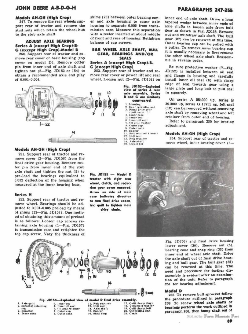
JOHN DEERE A-1-D·G·H
Models AH-GH (High Crop) 247. To remove the rear wheels sup
port rear of tractor and remove the stud nuts which retain the wheel hub to the stub axle shaft.
ADJUST AXLE BEARING Series A (except High Crop)·&. G (except High Crop)·Model D
250. Support rear of tractor and remove rear cover or basic housing ( top cover on model D ). Remove cotter pin from inner end of axle shaft and tighten nut (2-Fig. JD152 or 154) to obtain a recommended axle end play of 0.001-0.004.
0-22
14 I
Models AH-GH (High Crop) 251 . Support rear of tractor and re
move cover (2-Fig. JD156) from the final drive gear h ousing. Remove cotter pin from inner end of the stub axle shaft and tighten the nut (5) to pre-load the bearings equivalent to 0.002 deflection of the housing when measured at the inner bearing boss.
Series H 252. Support rear of tractor and re
move wheel. Bearings should be adjusted to 0.004-0.005 preload by means of shims (23-Flg . JD157 ). One method of obtaining this amount or preload is as follows : Loosen cap screws retaining axle housing (l-Fig. JD157) to transmission case and retighten the top cap screw. Vary the thickness of
shims (23) between outer bearing cover and axle housing to cause axle housing to separate 0.005 from transmission case. Measure this separation with a feeler inserted at about middle of front and rear of housing. Retighten balance of cap screws.
R&R WHEEL AXLE SHAFT, BULL GEAR, BEARINGS AND/ OR
SEALS Series A (except High Crop)-1-G (except High Crop)
253. Support rear of tractor and remove rear cover or power lift and rear wheel. Loosen nut (2-F ig. JD152) on
-)
Fig. JD152~plod.cf wiew of series A rear ade auembly. Serles I and G are shwilarly
COllstruCfed. 1. Houelni; :?. Ce+ur reto.lnlna.: nut :!. ~·1nnl drive ~l'nr
thull ~oar• t~ > ·I . J nn c r cone ~ •. I nne r cu1• 1;. Inne r oll ttN•I 7. • •U ""'"t w o .shcr II. (l\J ter cup fl, Ouh:r cono
Ill. l'l•QCtr 11 . f'• ll rNnlnor cinneri I'..! . ... el t seal t:l. F elt r<>tntner H . A•lo short '.!'.!. Oowtl plo
Fig. JDI 55 - Mode-I D tractor with right rear wheel, clutch, a11d red11ction gear cower re111owed. Arrow 011 1hle of m11 in case indicates dirc<tlo11 to tum flMI drlwe Kc•ntric quill to tl1Jhten main
drfwe chain.
Flt. JD1 54--bploded Ylew of model D fh1al drt•o 11-llly. I. Allle qulll r.. Inner cup 11. Felt retntner 17. Qulll clamp (lug) 2. Sprocket rttalnlng n. lnn~r oll out 12. f' tlt eMI 18. Vellumold wuher
nut T. 1111 oenl relalner 14. Ax le ehnrt 111. Qulll clamp bolt 3. Sprocket 8. fluter cu11 IG. Spacer 20. Oonnocuna link 4. Inner cone 9. Outer cone 18. Snap rlntr 2 1. Chain
PARAGRAPHS 247·255
inner end of axle shaft. Drive a Ione tapered wedge between inner endJI of axle shafts to loosen axle from bull gear as shown in Fig. JD158. Remove nut and withdraw axle shaft. The bull gear (27) can be renewed at this time. Outer bearing cup can be pulled w ltb a puller. T o remove inner bearing cup it is usually necessary to first remove the o ther wheel axle shaft. Reassemble in reverse order.
Be sure protective washer (7-Fig. JD152) is installed between oil seal and flange in housing and carefully install inner oil seal (6) with sharp edge of seal towards gear using a large plate and long bolt to pull seal in squarely.
On series A 584000 up, series B 201000 up, series G 13751 up, felt seal (12) can be removed without removing axle shaft by removing wheel and felt retainer from outer end of housing.
Refer to paragraph 250 !or beariAg adjustment.
Models AH·GH (High Crop) 254. Support rear of tractor and re
move wheel, inner bearing cover (2-
Fig. J0!56) and f inal drive housJnc lower cover (30). Remove nut (5), bearing cone and snap r ing (33 ) from inner end of wheel axle shaft. Drive the axle shaft out of final drive housing and bull gear. The bull gear (32) can be renewed at this time. Tbe need and procedure for further diaassembly Is evident after an examination of the unit. Refer to paragraph 251 for bearing adjustment.
Model D 255. To remove bull sprocket follow
the procedure outlined In parasrapb 268 To renew wheel axle ahafta or bea~ln1s perform the work outlined In paragraph 268, then bump ahatt out o1
m ,,, qj bi F- M-.,., P t i•

PARAGRAPHS 255-260A
Fl9. JD1 U-&ploded view of AH & GH high crop fiacll drlYe hoasi119, wheel ale oad
2. Dearin& cover a. Cuket 6. Nut e. Cone 8. Ouket t . Bea.rtns cup
bull oear CISMtlbly, II. Snap ring 18. Spacer 12. Houolni: 10. Felt Inner 13. Wa1her retainer 14. 011 aeal :!O. Felt wa.ohor 111. Bear1os cup 21. Felt outer retainer 17. Con•
housing. Shaft can be pressed out of outer cone, and cups and oil seal can be driven out of housing. Refer to paragraph 250 for bearing adjustment. Serles H
256. Remove axle housing assembly aa outlined in paragraph 269. The inner •eal (6--Fig. JD157) can be removed from main case at this time. Make certain that oil drain hole In cue is open and clean. Use a puller and remove brake drum from shaft. Remove outer bearing cover (24-Flg. JD157) and pull shaft from bowing. Relrutall ln reverse order and adjwt bear1n1a as outlined In paragraph 252. To prevent oil leakage past Inner bearing 11>acer (28), apply a coat of shellac or equivalent to Inner surface of spacer,
22. Wheel iule 1hart 30. Housln&r <:over 31. Gaaket 32. Finni drive
<bull) gear 33. Snap ring
JOHN DEERE A·B·D·G·H
R&R CHAIN AND SPROCKU
Models AH·GH (High Crop) 260. To remove the drive chain
and/or driven sprocket, remove platform and rear cover or basic housing. Support rear of tractor and turn rear wheels until chain "master link" is accessible. Remove the master link and withdraw the chain. Remove nut and washer from inner end of drive shaft (13-Fig. JD160) and remove the driven sprocket.
Reinstall in reverse order and make certain that the drive chain "master link" is installed with open end toward center of tractor, and check and adjust the chain slack as per the following paragraph.
NOTE: To remove the drlve sprocket. which ia mounted on the differential aide bevel gears, it is necessary to remove the dilferen· tial aa ouUined in paragraph 235.
260A. ADJUST CHAINS. To check and adjust the slack in the drive chains, remove the inspection covers from case. The chains should have not less than lh-inch or not more than l;;. inch slack. To adjust the slack, remove the brake drum and the brake housing retaining stud nuts. Slide the brake housing just off the studs and rotate the brake housing one stud bole at a time, either way, until desired chain $lack is obtained and reinstall the brake housing.
J. Ax lo houelna; <I. Inner cone :;, Inner cup Cln
tranamlaalon case) 6. lnnor oil aeal <In
tranamteslon caae) 8. le 9. Outer cup &<
cone 10. Spncer 11. Felt retnlner I!!. Inner Celt l4. Wheel a.x1e a ha.ft 22. Outer f~lt retainer
27
23. BeArlng ~dJuelllllf ahlm1
2• . S.arlng CO'\'er 25. Ouat excluder 28. BeArlng 1pacer 29. SpAcer 30. Oitterenllal apacer 31. Brak• pedal 32. Pedal aprlng 33. Pedal ah&ft 3~. Brake cam 3.a. A4Ju1Uni: ec rew
4 5 6 I I J... ®ooooou
I I \ 28 29 30
257. The bull 1ear 11 bolted to and removed with the dltterentlal.
- 00:t@
Flt • .IDI 17-llp194iletl view of •rlet H ,.., al• ••4 brab ....... .,.
DiQ1t1zed by F- M-11a1a Fut
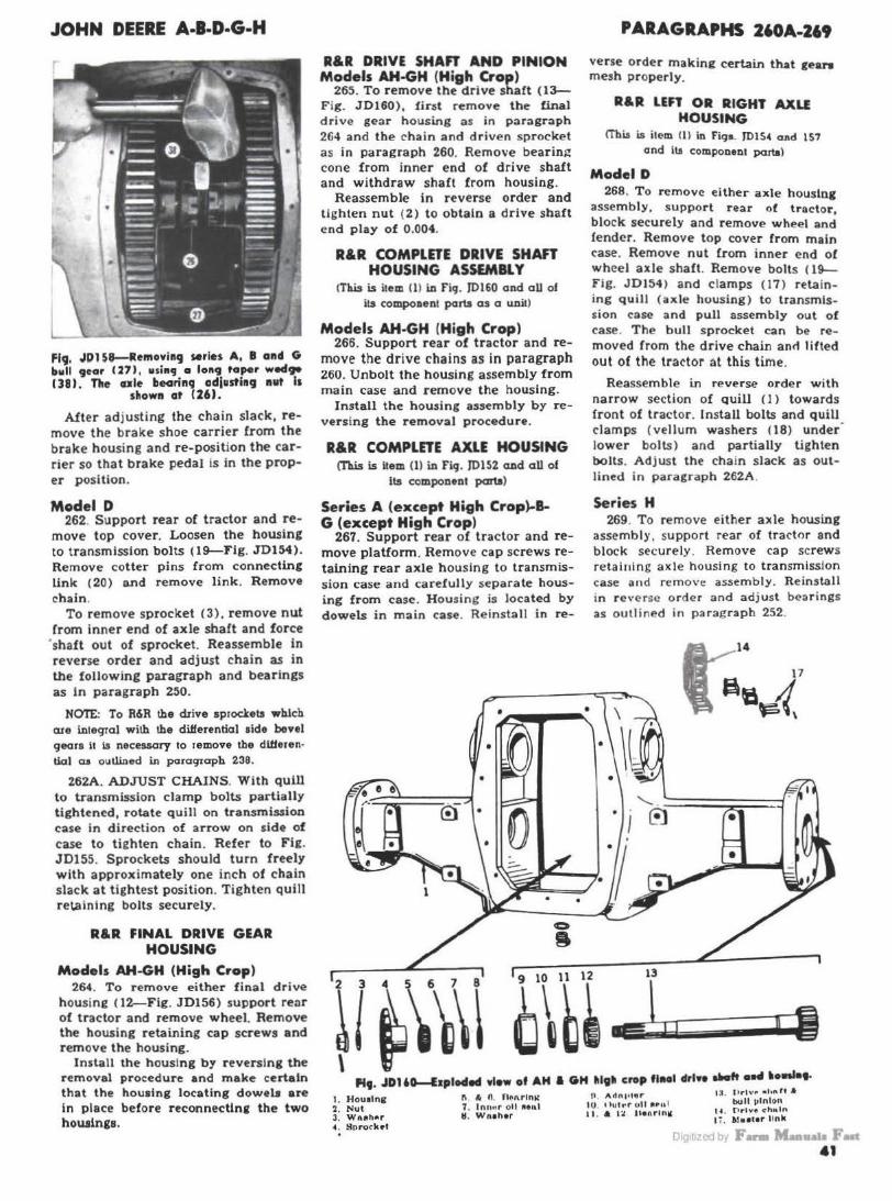
JOHN DEERE A-B·D·G-H
fig, .IPl 59--RemovillCJ series A, I and G bull 9ear <27), using a 10119 taper weclp 138). Tlle ule bearinCJ adjustl119 nut Is
shown at 126).
After ad justing the chain slack, remove the brake shoe carrier from the brake housing and re-position the carrier so that brake pedal is in the proper position.
Model D 262. Support rear of tractor and re
move top cover. Loosen the housing to transmission bolts (19-Flg. JD154). Remove cotter pins from connecting link (20) and remove link. Remove chain.
To remove sprocket (3). remove nut from inner end of axle shaft and force
·shaft out of sprocket. Reassemble in reverse order and adjust chain as in the following paragraph and bearings as in paragraph 250.
NOTE: To R&R the drive sprocleta whlcb are i.nleqral with the differential aide bevel gears It Is necessary to remove the dUferen· tlal aa 011tlined in paracpaph 239.
Z62A. ADJUST CHAINS. With quill to transmission clamp bolts partially tightened, rotate quill on transmis.doo case in direction of arrow on side of case to tighten chain. Refer to Fig. JD155. Sprockets should turn freely with approximately one inch of chain slack at tightest position. Tighten quill ret.ainlng bolts securely.
R&R FINAL DRIVE GEAR HOUSING
Models AH-GH (High Crop) 264. To remove either final drive
housine 02-Fig. JD156) support renr of tractor and remove wheel. Remove the housing retaining cap screws and remove the housing.
Install the housing by reversing the removal procedure and make certain that the housing locating dowels are in place before reconnedln11 the two housln11.
R&R DRIVE SHAn AND PINION Models AH-GH (High Crop)
265. To remove the drive shaft (13-F ig. JD160), first remove the final drive gear housing as in paragraph 264 and the chain and driven sprocket as in paragraph 260. Remove bearini? cone from inner end of drive shaft and withdraw shaft from housing.
Reassemble in reverse order and tighten nut (2) to obtain a drive shaft end play of 0.004.
R&R COMPLETE DRIVE SHAFT HOUSING ASSEMBl Y
!This is ilem (1) iD FlcJ. }0160 and all of its componenl parts as a unit)
Models AH-GH (High Crop) 266. Support rear of tractor and re
move the drive chains as in paragraph 260. Unbolt the housing assembly from main case and remove the housing.
Install the housing assembly by reversing the removal procedure.
R&R COMPLnE AXLE HOUSING (This is item (1) iD Fi9. 10152 a.nd all of
Its component parts)
Series A (except High Crop)..BG (except High Crop)
267. Support rear of tractor and remove platform. Remove cap screws retaining rear axle housing to transmission case and carefully separate housing from case. Housing is located by dowels in main case. Reinstall in re-
PARAGRAPHS 260A-26t
verse order making certain that c~an mesh properly.
•
R&R un OR RIGHT AXLI HOUSING
<This is item (1) in Figa. JDIS4 and 1S7 and ita component part.al
Model D 268. To remove either axle housing
assembly, support rear of tractor, block securely and remove wheel and fender. Remove top cover from main case. Remove nut Crom inner end of wheel axle shaft. Remove bolts ( 19-Fig. JDl54) and c lamps (17) retaining quill (axle housing) to transmission case and pull assembly out of case. The bull sprocket can be removed from the drive chain anc1 lifted out of the tractor at this time.
Reassemble in reverse order with narrow section of quill ( l ) towards front of tractor. Install bolts and quill clamps (vellum washers ( 18) underlower bolts) and partially tighten bolls. Adjus t the chain s lack as outlined in paragraph 262A .
Series H 269. To remove either axle housing
assembly, support rear of tractor and block securely. Remove cap screws retaining axle housing to transmission case and remove assembly. Reinstall in rcvcr:>c order and adjust bearings as outlined in paragraph 252.
~l ~ \\\\ ~\'~~ "•· JD16G--E1pl!Mled view of AH I GH Mtll crop fl•ol clrlwe ....,. 0114 .......
13
\
I. Hou1ln1r 2. Nut 3. Wuh~r • . Sp rork•t .
11 " 11. nonrlnti 7 . lnr1ttr oll ""'' II . Wn1hor
tl . Adn1•••r 10. • 1\1h•r ott 1u•nl 11. A •~ Uenr1nw
1!1. Urh'" -1tn. rt A bull pinion
H . Orlve C"hMlf' i; , &!"'tor link
wl~JI! '( j JY F- a1aFan
"

PARAGRAPHS 300-302
Series A·l-G 300. ADJUSTMENT. Tighten ad
justing screw (3:>-Fig. JD161 or 162) or (23-Fig. JD163) which is located at top of brake housing until pedal tree travel is reduced to approximately 3 inches.
301. R&R SHOES AND LINING. On all models remove platform if interference is encountered.
On A (except high crop) and B series, remove complete brake unit from tractor; then. remove nut from inner end of shaft (1- Fig. JD161) and remove gear (8 or 9) using a suitable puller or wedges. Loosen brake adh:sting screw (35) and withdraw drum and shaft.
On G series (except bJgh crop), remove nut retaining drum (27-Fig. JD162) to shaft, loosen brake adjusting nut and pull drum off shaft.
BRAKES
~, 6 7
8
JOHN DEERE A·B·D·G·H
19 27
25
? 32 33
41 42 43
4=1-~1 ~ On high crop models, remove the nut (6---Fig. JD163) retaining the drum (8) to shaft (41), loosen the adjusting screw (23) and remove the drum.
f19. JDl63-fxploded view of models AH and GH •rcrke unit. Sprocket (42) meshes wltlt tlte frcrctor drive choln.
1. Brake drum ehaft 2. Duet et1ard 3. Outer buahine 4. Dual iruard 6. Brake houaine 6. ln n• r bu1hine 1. Spacer wuher 8. Gear IA) 9. G<iar (8)
27. Br ake drum ~1. Pedal 32. Sprin1 33. Pedal ahart 34. Brak" cam 35. Adjuatine •crew
119. JDl61-fxplocfed "i•w of aerlea A br•lc• unit. Serlea I h aimilor except li11b of ,..,, 191 la ft111lt wifll lloulint lnffeod of extendlnt lflfo hovslng 01 wlflt Hr/e1 A gecrr (IJ.
31
~a ~37 6
I . Brue di-um aha.ft a. Outer tlU1hlns 4. Duatnard 6. Br.i.e "°1Yhas 6. Inner tluahlna 7. Thna.tt wuher (I)
Z7. Brake drum n . Pedal 32. Sprlnc 33. Pedal abaft 34. Braka-36. AdJuetlnc •c:zo-36. Shaft plas 17. Dowel pin
"•· JDH2-l•flloclecl view el .. ,, •• O ltrelce """·
6. Nut 7 . Waahtr 8. Brake drum
16. Wuher 19. Drak" a hoe 20. Adjuatins pins 21. Brake !11cine 22. Rivet 23. Adjuatins acrew 24 . Duat suard 26. Lever abaft 27. Brake a hot carrier
29. Pedal 32. Braltc op.,nine
cover 33. Caaket 3S. Outtr bwih in1 38. Houains 39. Inner bwihinir 40. Gasket 41. Brake shaft 42. Sprocket 43 . Snap ring:
On all models disconnect the shoe retracting springs and remove shoes from housing. Reassemble in reverse order and adjust as In paragraph 300.
302. REBUSH BRAKE SHAFTS. On A (except high crop) and B series, remove shoes as outlined in paragraph 301 and disassemble the unit. On other models, remove shoes as in paragraph 301, remove the housing unit from tractor and disassemble the unit.
NOTE: on high crop models, it is necessary to remove rear cover OT
b0$ic housing and remove sprocket ( 42 -Fig. JD163) before removing the brake unit.
The brake shaft bushings can be driven out of housing and new ones pressed in. New bushings should be honed or reamed, lf necessary, to provide a free fit. Reassemble in reverse order. Select spacer washers or thrust washers (7 or 15) to limit shaft end play to approximately 0.030. The riveted-on A and B drums are available separately from the shaft.
Oig1t1zed by F- M-11a1a Fut

JOHN DEEIE A ... D-G-H
Model D arake 303. AD.J118TMEHT. Tl1hten ad
Juatill& nut (15--JD185) at lower end of bmld unW pedal tree travel Is reduced to the desired amount. Check for clearance between lln1nl and drum.
304. BA& BAND. Remove adjusting nut (15) and pin attaching band to crank (14). Reassemble In reverse order and adjwt u in paragraph 303.
305. OVEB.llAUL UNIT. Remove drum. Remove cap screws retaining brake quill (6) to transmission case. remove quW and withdraw shaft. Inner cone and gear and outer cone can be pressed off shaft and oil seal (8) driven out of quill. Reassemble and re.Install in reverse order. Vary thickness of shims and gaskets (7) between quill and transmission case to provide a shaft end play of 0.001- 0.004.
fig. JOJ6S-fzploded yfew of r11odel D ••,,,ice llrue.
1. Bralce drum 2. Fe-lt re-tainer
3. Felt IHI 4. Brake band 6. Releue oprln& 6. Brake quill ?. Sbimpakd
8. O ile.,al 9. Brake ah aft
10. ~ar ke7 11. Gear lZ. Pl•ot pin 13. IA!ver pin 14. Crank
PARAGRAPHS 303-316
Series H Brakes 308. ADJUSTMENT. Tighten adjust
ing screw (35-Fig. JD157) located near top of each axle housing unW
pedal free travel Is reduced to approximately 3 inches.
309. &All SHOES AND LINING. Remove axle housing as lo paragrapb
269. Remove bearing sp<&cer (2S-Fi1.
JD 157) and drum with puller. Remove shoes. Reinstall in reverse order; adju st brakes as in paragraph 308 and refer to paragraph 252 for axle bear
ing adjustment. To prevent oil leakage past inner spacer, apply a coat of
shellac or equivalent sealing com
pound to inner surface of spacer (28) during reassembly.
HYDRAULIC LI FT The hydraulic 111.um which wcas
uud on smu H tractors and early production 1me1 A, B and G tractors toa.a called a "Power Lift" 1111tem. The h11drauUc SJlltnll which u ustd on lcatt production A, B and G tracton b ea.lied a "Poior- Trol" .ystem. T"e dlffeYeftees bntcieen the "Power-Lift" and "Poui~-Trol" avstems are eoident afkr cu' uamincUion of Fig1. JD168 ancl 187.
NOTE : TM mai1'tenance of absolute cleanline11 of all pcarta ii of utmost im-
pOTtance in tM operation ancl stnltdng of the hydraulic 1111tem. Of equal i~ portance is tht avoidance of 1'icks or burrs on any of the working parts.
"Power Lift" (Used on early production series A, B a•d G, and all series H tractor1)
Series A-B-G 315. R•ll ASSEMBLY. Detach im
plement, remove cap screws retaining assembly to transmission and remove
assembly, carefully d isengaging pump shaft from power shaft coupling. Reverse removal procedure to reinstall.
316. RENEW PISTON CUP. Drain power lift oil and remove valve housing (control box ) (67-Fig. JD168 ) from rear of lift. Partially withdraw r ock shafts (27) by removing cap screw from arm (37) and withdraw piston (11 ) crank and connectini; rO<l as a uni t . Install new leather cup (9) on piston. soak in oil and reassemble in reverse order.
i 2
"•· JDl61-f•ploded view of HrlH e power llff. Serl" A artd I.,. tl•llarly _,,.,.ded, ' · C,lladft 1. Lodi pl.Me I. Cap ""talaer t . Ploo\oD cup
10. Snap rl11a II . PlatoD 11. Platon pin \I. Connec\lns rod H . ROG1ln1 1'. Cnnll pla 17. IC47 -11., :.!1. 'rrlti 11Mtul l lc• flf :.::. l '•t111I 11hnft
2' Trip P"dal (rlshtl '7. Cam trip pin 67. Valve hou.la1 ::· ~::::~:ft ii Shield 60. Chec:k v a lve U . Paeltln1 96. Pump "°Yer 21: Rode ehaft (2) 61. Valve f!'Ulde. ~~· go•~l ::ft n : Do•cl pla (lo-) ta. Rock ah.Ct bearln1 &S. Cam trop lever . Son 1 88. Drift IMr 12. Dowel pin 66. TKbrotUehvalvc ~: · c:!'io':1=•• allaft 911. Pump bod7 n Cranll arm &6. .,, WU er • JOI Paeklq aa: Idler seer 1haft 60. Cam Tl. Relief valft .. 101: Cup U . Idler ... , 61 . Pa•I pin 80. AdSuaUn1 •b 104. 011-1 beu'I• U . Dowel pin (upper) et. Pawl 81. Copper •u n 101. Buahln1 41. Followor !'Oller n . Pawl eprlas 81• Jc•"' nut 101. Coupllq u . Roller pin U . Control Iner H. ap nut tot. Rlwt '5. Cam follower H . BJ·P ... valve ea. Snap rlns 110. Shaft
m 111 qj bi F- Maaa
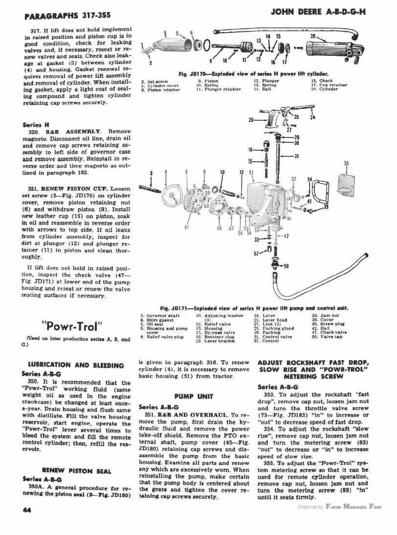
PARAGRAPHS 317-355
31'1. II lift does not hold implement in raised position and piston cup is in good condition, check for leaking valves and, if necessary, reseat or renew valves and seats. Check also leakage at gasket (5) between cylinder (4) and housing. Casket renewal requires removal of power lift assembly and removal of cylinder. When installing gasket, apply a light coat of sealing compound and tighten cylinder retaining cap screws securely.
Series H 320. R&R ASSEMBLY. Remove
magneto. Disconnect oil line, drain oil and remove cap screws retaining assembly to left side of governor case a.ad remove assembly. Reinstall in reverse order and time magneto as outlined in paragraph 162.
321. RENEW PISTON CUP. Loosen set screw (2--Fig. JD170) on cylinder cover, remove piston retaining nut (6) and withdraw piston (9). Install new leather cup (16) on piston, soak JQ oil and reassemble in reverse order with arrows to top side. If oil leaks from cylinder assembly, inspect for dirt at plunger (12) and plunger retainer ( 11) in piston and clean thoroughly.
I! lift does not hold in raised position, inspect the check valve (47-Fig. JDl 71) at lower end of the pwnp housing and reseat or renew the valve seating surfaces if necessary.
"P T I" owr- ro CU8<td OD later productJon aenea A. :&. and
G.)
LUBRICATION AND BLEEDING Series A-8-G
350. It Is recommended that the "Powr-Trol" working fluid (same weight oil aa used In the engine crankcase) be changed at least oocea-year. Drain housing and flush same with distillate. Fill the valve housing reservoir, start engine, operate the "Powr-Trol" lever several tlmes to bleed the system and fill the remote control cylinder; then, refill the reservoir.
RINIW PISTON SEAL S.rlH A-1-G
350A. A general procedure for renewlnir the pi.ton Mal (9-Flg . .JD180)
JOHN DEERE A-l·D·&·H
Fig. JD170-&plocled view of series H power lift cyllacler. 2. Set 1cnw :.. C)'l1nd~r cover 0. Plalon retnlnur
o. Pl>ton to. Sprln.: 11. Plunser relAlner
12. Plungor 13. Spring ll . Ball
15. Check 17. Cup retainer ~11. Cylinder
Fig. JDl 71-Explocled view of series H power Ii~ pump aad coatrol Hit. 3. Go,·emor ahACI •·Shim guket :'>.Oil aeal 6. Hou1lng and 1>ump
cover 8 . Rell•f \"nlve 1>lug
1(1. AdJuatlns wnahcr (3 )
1~ . Reller""'"" I~. HouHlng l!i. BY·llBU VBl\'O IG. Rtllllner plug ~O. Lever brnckel
is given in paragraph 316. To renew cylinder ( 4), it i.s necessary to remove basic housing (51) from tractor.
PUMP UNIT
Series A-B-G 351. R"R AND OVERHAUL. To re
move the pump, first drain the hydraulic fluid and remove the power take-off shield. Remove the PTO external shaft, pump cover (4>-Fig. JD180) retaining cap screws and disassemble the pump from the basic housing. Examine all parts and renew any which are excessively worn. When reinstalling the pump, make certain that the pump body is centered about the gears and tighten the cover retaining cap screws securely.
2 -1. Lo\"er ;i:,, Lo\"er he:i.d :?7 . Link (21 :?9. Packing slnnd 30. PAcklng 31 . Control valvo 32. Control
33. Jo.m nut 36. Co1·er 30. Screw ptur 42. Ball 47 . Check valve 50. Valve cap
ADJUST ROCKSHAFT FAST DROP, SLOW RISE AND "POWR-TROL"
MDEllNG SCREW
Series A·B-G 353. To adjust tbe rockshaft "fast
drop", remove cap nut, loosen jam nut and turn the throttle valve screw (73--Fig. ID183) "in" to increase or "out" to decrease speed of fast drop.
354. To adjust the rocksbaft "slow rise", remove cap nut, loosen jam nut and turn the metering screw (83) "out" to decrease or "in" to increase speed of slow rise.
355. To adjust the "Powr-Trol" system metering screw so that it can be used for remote cylinder operation, remove cap nut, loosen jam nut and turn the metering screw (83) "!n" until it seats firmly .
DiQ1t1zed by F- M-11a1a Fut
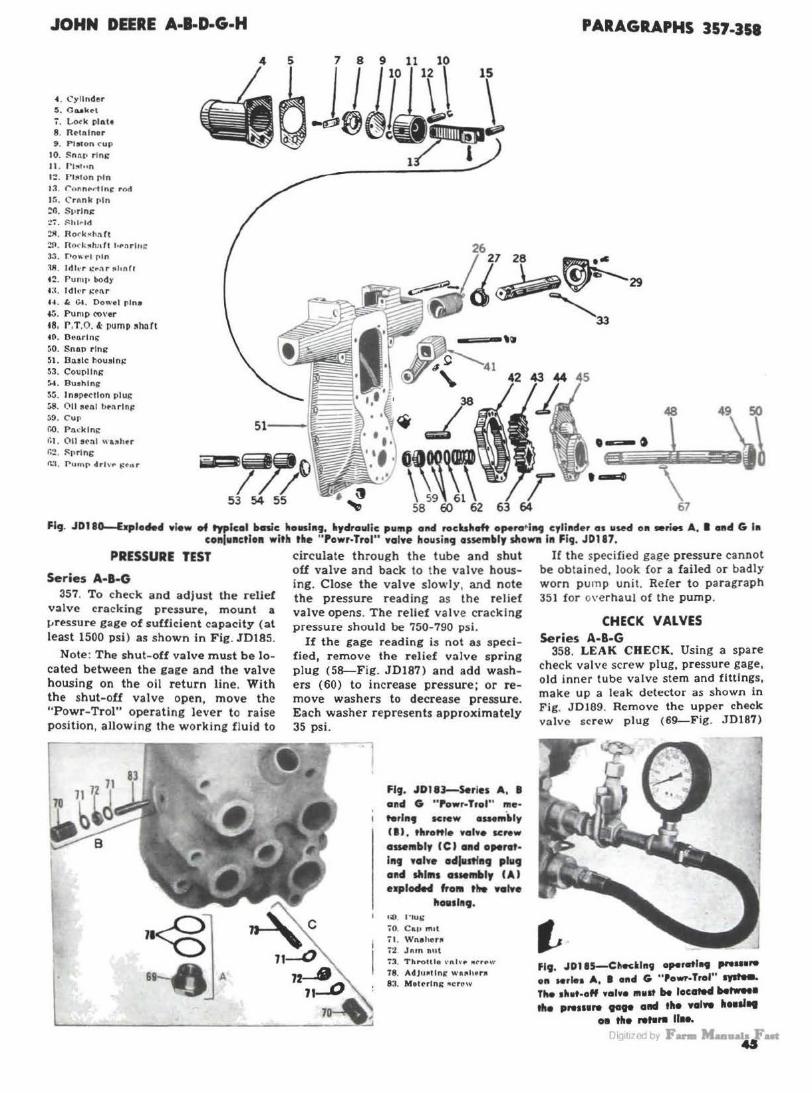
JOHN DEERE A·l-D·G·H
4. Cylinder .5. C&a'c<"t
'i. Lo<k plah 8 . R<-tnlnor 9 . P19tOn ('UP
I 0. Snnl' r lni: It . r1~1un
1:!. rl!'ICOn f'lln 13. <"onnt--rt fn( rod
JG. C rnnk rln ZG. S1•rln1: :.?':'. ~hl,.ld
:?ll. R or k<h:\Ct
:\A. ldh•r ..: .. n r ftll nrt t Z. rump body •:t. ldl•r t:•nr H . I. C~ . Oow•I rlne '5. Pump CO\'er
t8. r .T.O. &: pump ~hart t o. Doo.rtnt; 50. Snon r ing 51. Do.sic hou!lni: 53 . Coupllni: 54. 9u1hlng
5:;. lnapectlon plui: (;8. 0 11 ~ul bMrlnj! ~9. Cur r.o. P M klni:
0.:t. rumr drl v,. t!tnr
PARAGRAPHS 357-351
1 -=.\1 \
63 67
Fig. JD180--&plode4 • lew of typical ltasic honl119, •yclraulic pu111p oncl rocbheft opera•l itg c,lh1der as uwcl oil •ries A. I pd G la co11lu11ctloa with t•e " Powr·Trol" •olve housi19 assem•ly slloWll 111 Fig. J0187.
PRESSURE TEST
Series A-1-G 357. To ch eck and a d just the relief
valve cracking pressure, mount a i.- ressure gage of sufficient capacity (al least 1500 psi) as shown in Fig . JD185.
Note : The shut- off valve must b e locate d b etween the ga i:e and the valve housing on the oil return line. With the shut-ofi valve open, move the "P owr-Trol" operating lever to r aise position , a llowing the wor king fl uid to
68-0 A
circuJate t hrough the tube and shut off valve and back to the valve housing. Close the valve slowly, and note the pressure reading as the relief va lve op ens. The relief valve cracking pressure should be 750-790 psi.
If the ga ge reading is nol as specifi ed, remove the r elief v:ilve spring p lu g (58-F ig. JD187) a nd ad d washe rs (60) to increase pressure; or remove wash ers to decr ease pressure. E ach washer r epresents approximately 35 psi.
Fig. JDJIJ-S.ries A, I and G "Powr-Trol" me·
t terln9 screw e11Mm.~ly (I) . thro"I• Yal•• se .. w asse19bly (CJ 011d o,.,.,. lag .alY• adlutl•9 plug ol!d slll1t1 a1 .. 1Mly (AJ exploded frol9 t"- .....
1101111119. o;o. l"lui;
iO. Ca11 m1t
71 . Wne ho,. i2 Jnrn nut 7'3. Throttle \0 nh·.- ll't,.f' w
78. AdJu •llnt: w• • h.,• 83. Mettrtni: •c row
If the specified gage pressure cannot be obtained, look for a failed or badly worn pump un it. Refer t o paragraph 351 for overhaul of the pump.
CHECK VALVES Series A-B-G
358. LEAK C HECK. Using a spare check valve screw plug, pressure gage, old inner tube valve stem and fit tings, ma ke up a leak detector as shown in Fig. JDJ89. Remove the upper check valve screw plug (69-Fig. J D187}
fl9. JDl IS-Chedl119 operotl119 ,,. ... ,. oil Mrlea A, I end G "Powr-Trol" IJlfel9. The 1het-off •alve 111111t be locllt94 Mtwed tit• prw111re .... aad tit• "'" llull11
011 tit• ,...... 11 ... rJI< 1t1 rd b1 F...,.... Maaa 41

PARAGRAPHS 358-360
' -
f19. JOJ87-bploded Yiew of a typical "Powr0 Jrof" Yahro liov1l119 a110111bly a1 ulOd on .. rl•• A, 8 ond O.
a. Co•er 7. Cam
11. Cam folluw~r um w itb roll<r
13. Pin U . L ink 16. R ivrl l{;. Op~rati na v a lve
w ith link 1?. Spri.n lil 18. Cott.er pin1 1 Q. Cam blade 20. P in ZI. Roller 2~ C om lot.ch pin Z• . C::i m ! ftt("n rolie-r
26. Cam lat.ch arm w ith roller
28. !Utainer 29. S prinr ~O. Latch rod 31. R..leut val•e 32. Cap 3&. Oil lin" p )uii 36. Cap 37. Pivot pin.a SS. Pivot 89. Cap acrnr 40. P luir bracket H. Packins 4P. Waoh•r •9. Spr inc
from the valve housing, install the leak detector and close off the upper hose adapter opening. Apply air pressure to the valve stem (30 psi is sufficient) and observe the pressure gage to see if pr essure Is maintained. Check the lower check valve in the same manner except close off the lower hose adapter opening.
CLOSE NIPPLE
OIL PRESSURE
GAU OE
"•· IDI •-H•••-•d• detector uHd for dNtddltlJ 1001&1 111 Nrle1 A, 8 011d 0 "Pewr.frof" YOIYe ... u1/11g cllec• YolY01.
46
60. V-eeal uaembl7 61. Adapt.er 6Z. Adapter nut 63. Oil l int couplin1 64 . Shear waahtr 66. Oil lint 68. Relict valve 1prin11
pl a ii 69. Cukct 60. Adjuatinir wuhera 61. Sprint' 62. 11.eli<f valve 63. Ball ')4. Out.ie-r check vei•~ 1;5, Inner .:heck valve 66. I ndexin 1 wuher
67. Sprlns 68. Wuher 69. P luc 70. Cap nut n . Wul!en 72. Jam nut 73. Throttle •ahe
acrew 78. Adju1tin11 wul!era 81. T hrottle vahe 82. S princ gs. M@terina a c::r•w 86. Woodruff kt7 P6. v,.l v• h ouel"S 87. Oil a .. t
If the check valves will not hold air pressure, remove the valves and thoroughly clean them. 11 poppet type check valves and seats are slightly scored, they can be cleaned up by lapping with a very fine compound. If ball type check valves are leaking renew the balls and/or seats. Install check valves as outlined in the following paragraph.
359. INSTALL CHECK VALVES. Early production valve housings were factory equipped with poppet type check valves; whereas late and current production tractors are equipped with ball type check valves. On poppet type valves, Fig. JD191, install the Inner
Fl9. JDIH-SerlOI A. a anti 0 early model chedc "a"'•· flto proper •lse ftofe 111 ovter clleck YelYe ( 641 mud all9rt wltfl tit• ffaf 1pot - tlle l11ner cllHlc "olve (UJ, flte proper ro•lder la olltal110fl wltll llldo•lnt
wo1fter (U}.
;~
---·· ~-
JOHN DEERE A·l·D·G·H
check valve with flat spot on outer end in register with the proper size hole in the outer check valve and secure ln this position with the indexing wuher (66). The small hole is used for series B; the medium size hole for series A; and the large hole for series G.
On the ball type check valves (Fig. JD193) as used on series A, B & G with 21h" or 3" remote cylinders, install inner check valve with short relief end toward outside wbicb Will permit one relief passage to open a.s 'hown in upper view. On series G with a 4" remote cylinder, install inner check valve with long relief toward outside which will permit both relief passages to open as shown in lower view.
360. ADJUSTMENT. To adjust either of the inner check valves, remove plug (69- Fig. JD187) and valve lock spring. Insert valve lock (the lock is available from John Deere) in the check valve plug and reinstall the plug in the valve housing. T ighten the plug until both the inner and outer check valves are against their seats as shown in Fig. JD195B. At this time, there should be at least 14 inch movement of the "Powr-Trol" lever when moving from neutral to raise position. If there is less than 14 Inch movement, grind off about 0.001 from inner end of inner check valve and recheck the lever movement.
63 64A
BSA
MA
65A
fi•· JDJP3-Serles A, I, arid G late model chclr yalYo. Correct lnlfalfatton of •••
Inner cite.. "•'"• (65AJ I• 011plolned In ,.,. ••• ,,, 359.
Oig1t1zed by F- M-11a1a Fut

JOHN DEERE A-B-D·G·H
With the inner check valve adjusted, remove the check valve plug, valve lock and inner check valve. Reinstall the check valve plug and valve lock, leaving out the inner check valve. Tighten the plug until outer check valve is against its seat as shown in Fig. JD195C. Re move the valve hou sing cover and move the control lever until the cam blade comes agains t the cam follower roller <21-Fig. JD187). There should b e ~- l2 inch movement of control le ver from this point until the cam on the operating valve tightens agai nst steel hall and o uter l·heck valve. If movement is less than :iii inch, loosen the can1 blade lock
fig. JDJ95A- When chedci11g and adjvrt• ing John Deere "Powr-Trol" checlc waive•, if is necusorv fo obtain the vahre Ioele
from Joltn Deere.
lig. JDl,Sl-Cut-owoy v iew of Deere "Powr-Trof" valve housing showing tlte vaf1re Ioele installed for checl<ing the inner
check valve.
fig. JDJ95C-Cvt-away view of Deere "Powr-Trof" valve ho111l111 1howin1 tlte valYo lode ln .. olled for clteclcln9 tho oortor
checlr traNe.
screw and move blade ln. U lever movement is more than J,li inch, move the cam blade out. CAUTION: Hold blade firmly against milled slot when making the adjustment as in F ig. JD198.
Repeat the above procedure, for checking and a djusting the other check valve.
Fig. JD1'18-Adjusting cam follower blades on John Deere " Powr-Trol" waive housing.
OPERATING VALVE Series A-B-G
361. ADJUST. To adjust the posi tion of the operatin g valve, place control lever in neutral position and r emove the valve housing cover. Place operating valve travel gage ( the travel gage is a vailable from J ohn 0 €'cr e) in the position shown in view (AFig. JD200). with shoulder of gage stem against top of operating valve. Move control lever to lowered position- at which time, the end of the gage stem should just slide over the end of the operating valve as shown in view B . If the opposite end of operating valve s trikes plug (6!>- F ig. JD183) before end of travel gage ste m slides over end of operating valve, add washers (78), which a re available in thicknesses of 0.020 and 0.030. 1f the operating valve travels too far. remove washers to obtain correct trave l.
Move control lever to neutra l p osition and set the travel gage a s shown. in view (B-Fig. JD200) with end of gage just touching end of operati ne valve. Move control lever to raisr position and gage stem to le!t- at w hich time the shoulder on gage stem should just slide over end of operating valve as shown In view (C J. It operating valve has traveled too far, or not enough, adjust stop screw as shown In Fig. JD202 until desired travel is obtained.
PARAGRAPHS 360-361
f ig . JD200-Joltn Deere special lrovel g ogo positions for cltcclr ing the " Powr-Trol" op
erating v olve.
fif. J0202-Ad/v1tln9 Jolin O•oro ""ewr• Traf" 6fop ecrow which co•lfrol• fhe •ft" eroflrtf .,,.,.,. travel from 11evtral ta ,.,,.
~-·-· rJI< 1t1 <d by F- Maaaala Fut 47

PARAGRAPHS 362-364
VALVE HOUSING
Series A·B-G 362. Rct;R AND OVERHAUL. To re
move the "Powr-Trol" valve housing from tractor, drain oil from hydraulic S}'stem and remove valve housing from basic housing.
To disassemble the unit, remove e<>ver, oil line adapters and pipe plugs from housing. Remove check valves. Remove the cam lock screw, bump control shaft out until Woodruff key centers in slot of cam forging, then drift out the Woodruff key as shown in Fig. JD204 and remove the control shaft. Compress the release valve spring and cam follower spring and lift out the cam and operating valve. Remove cam follower pivot pin and lever and cam latch pivot pin . Remove cam latch arm and spring. Remove the relief valve. The need and procedure for further disassembly is evident after an examination of the unit and reference of Fig. JD187.
Reassemble the valve housing by re,·ersing the disassembly procedure and adjust the components as outlined in par;;graphs 357, 360 and 361.
Fl9. JD204-Re1RoYl119 Woodruff key which PG11tloa1 Jolin Deere "Powr-Trol" control
lhoft la the cam foNJliHJ.
REMOTE CONTROL CYLINDER
Serles A-8-G 363. ADJUSTMENT. The double
acting remote control cylinder is equipped with manual adjustments to vary the working stroke from 3 inches minimum to 8 Inches maximum, ln % inch steps. CAUTION: Never attempt to operate the remote control cylinder unleu both stop rod plna are lo place. ..
JOHN DEERE A-B·D-G-H
Fi9. JD206--Ezplodecl Ylew of typical John Deere remote COflh'ol cylinder. The wor•ln9 strob is adiustahl• from l·8 lnclies.
100. AllAchln~ pin 191. End cnp
1!)5. T"Aper \\' l\.sher
!9G. r1eton 200. Scl\i rotAln<"r
201. "V" eeal nasemhly 1!12. C:oeket 197. Spacer 1:13. R•tnlnor 1~8 . Cyllndtr
HH. "U" <Ut> rincklni: 199. Shima
364. DISASSEMBLE AND OVER
HAUL. Remove oil lines and end cap (191-Fig. JD206). Remove the piston retaining nut and piston assembly, taking care not to damage the Neoprene piston rings. Withdraw piston rod and yoke from cylinder. Remove piston rod stop ( 203), adjusting rods
(202), seal retainer (200) and "V" seal assembly (201).
Inspect face of end cap for nicks or
burrs, adjusting rods for being bent
and piston rod for burrs, scratches
and/ or being bent. Bent adjusting rods
will be O .K ., provid ing they can be
thoroughly straightened. Small burrs
and/or scratches can be removed from
piston rod by using a fine hone; how-
I L -
202. Rod 200. Piston rod stop ~<H. rl s ton rod :111 d yok•
ever, piston rod should be renewed U
it is bent. Renew any other questionable parts.
Lubricate the piston rod and reas
semble the cylinder, leaving out the Neoprene piston rings. Attach a spring scale as shown in Fig. JD208 and check the pull required to move the lubri
cated piston rod through the "V" seal assembly. Add or deduct shims ( 199-
Fig. JD206) until a pull of approximately 4 pounds is required. Shims are
0 .010 and n-inch thick. When adjustment is as specified, install the Neoprene piston rings and tighten the piston retaining nut. Using a new gas
ket, install the end cap and tighten the retaining cap screws to a torque of 125 ft.-lbs.
J JD201-Chedd111 pull Nqulred to 111ave l11bflcated plstoa rad thro119h ''Y"-te0I
a11H1blJ n hent '9111ottt comal cyllader.
DiQ1t1zed by F- M-11a1a Fut

JOHN DEERE A·B·D-G-H SECTIONAL VIEW
Styled model D tractor. The front et1d support is bolted to the bottom of the cylinder block.
NOTES
Oig1t1zed by F- Maa.ai. Fut ..

SHOP MANUAL
JOHN DEERE MODELS M-MT
IDENTIFICATION
Tractor serial number stamped on plate at base of instrument panel.
TRACTOR SERIAL NUMBERS BUil T SOMETIME IN THE FOLLOWING YEARS
Model
1947
1948
1949
1950
M
10.000
20.000
30.000
40.000
MT
10.000
20.000
Model M is produced in two versions: Adjustable and non-adjustable a xle types. Model MT is produced in lhree versions: Single and double wheel lricycle. and adjuslable alle types.
JOHN DHRE MODEL M
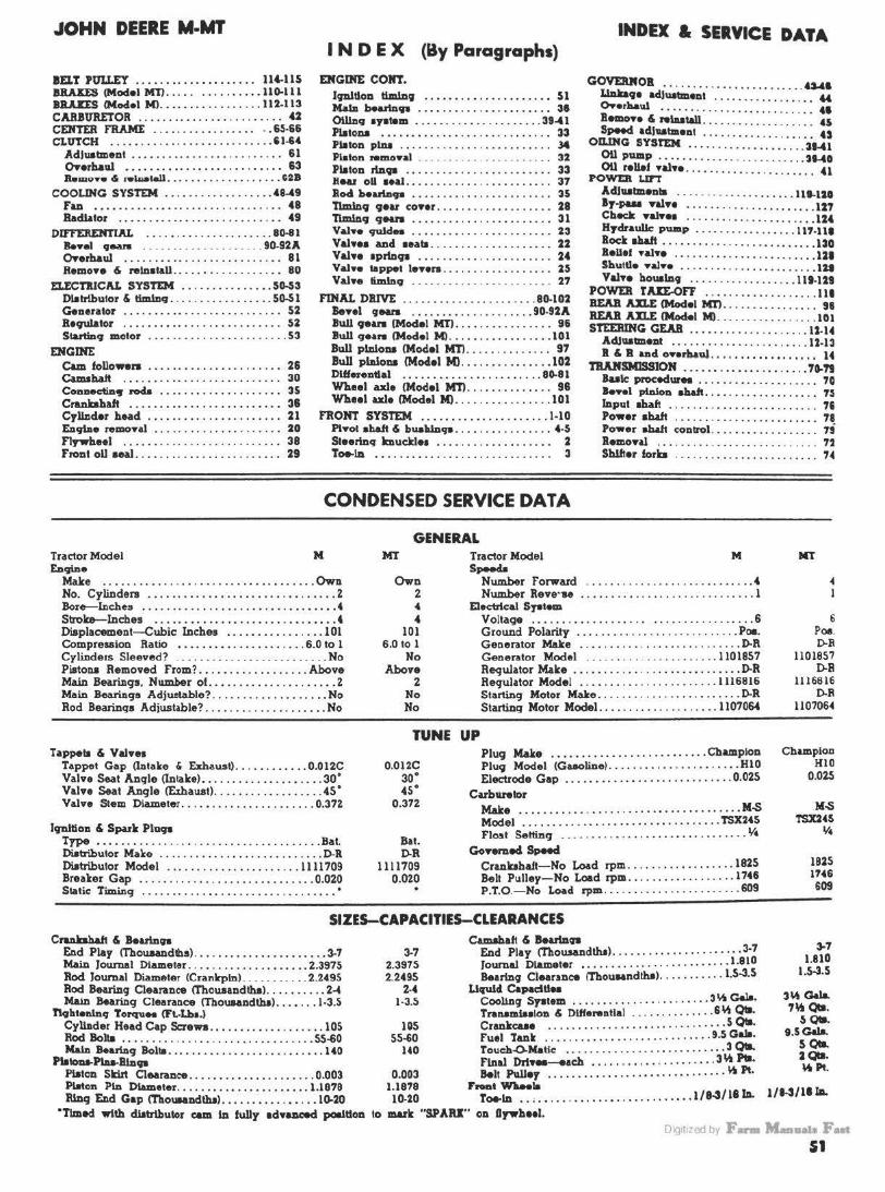
JOHN DEERE M·MT INDEX & SERVICE DATA
IEl.T PtJLLEY .. ... . ... .. ... .... . . 114-115 BBAIES (Model Mll . . . . . . . .. .... .. ll 0.111 BBAUS IMod•I Ml .............. .. . 112.113 CARBURETOR . . . . . . . . . . . . . . . . . . . . . . . • 42 CENTER FRAME . . . . . . . . . . . . . . . . . . . 65·66 CLUTCH .. .•... . ....... . . . . . ....... 51-64
Adluatment . . . . . . . . . . . . . . . . . . . . . . . . . 61 OYerhaul • . . . . . . . . . . . • . . . . . . . . . . . . . 63 &.mo•• .S rell>ai.11 ......... . ..... . . . . $28
COOUNC SYSTEM ... .. . . . ... .. . .... 48-49 Fan ...... . .. .. ..... .. .. . ..... .. ... 48 BadUtor . . . . ... .. .. . . ...... . ... .. .. 49
DIFFERENTIAL ....• . ......... . ..... 81>-81 B.•el 9ean ... .. .... .. . _ . . . . ... 90.92A OYerhaul ..... ... ....... . . . . . ..... . 81 Remo•• & relnat&ll . . . . . . . . . . . . . . . . . . 80
ELECTJUCIU. SYSTEM ••.•.. . ..•..••. 50-53 Dlalrlbutor & tlmlnq . . ... . ....... ... . 50-51 Generator . . . . . . . . . . . . . . . . . . . . . . . . . . 5:Z Be9U1ator . . . . . . . . . . . . . . . . . . . . . . . . . . 5:Z Startinq motor ....................... 53
ENGINE Cam followers . . . . . . . . . . . . . . . . . . . . . . :Z6 Camshaft . . . . . . . . . . . . . . . . . . . . . . . . . . 30 Connectin9 rod.a . •... ... ... . . ... .... 35 Cranbhalt . . . . . . . . . . . . . . . . . . . . . . . . . 38 Crllllder head . ...... .. ..... ..... ... 21 EDc;JlDe remonl . . . . . . . . . . . . . . . . . . . . . 20 Flywhffl .... . ................... .. 38 Front oll aeal . . . . . . . . . . . . . . . . . . . . . . . . :Z9
I N D E X (By Paragraphs)
ENGINE CONT.
19Dillon limlnCJ . . • • . • . . • . . . . . . . . . . . • 51 MalD b.utnv- . . • . . . . . . . . . . . . • . . . . . . 31 Olllnq 1yatem . .. .. .. .... .. .. ... .. . 39-41 Piston.a . . . . . . . . . . . . . . . . . . . . . . . . . . . . 33 Platon plnl . . . . . . . . . . . . . . . . . . . . . . . . . J4 Pl.aton remoYal . . . . • . . . . . . . . . . . . . . . . . 32 Platon rtnc;ra • • . . . . . . . . . . . . . . . . . . . . . . 33 Rear oU ••al. . . . . . . . . . . . . . . . . . . . . . . . 37 Rod bearin99 . . . . . . . . . . . . . . . . . . . . . . . 35 Tlmln9 CJ•&r co•er ........... . ....... 28 Timl.Dq CJNn • . • • . . • . . . . . . . . . . . . . . . • 31 va1 ... 'lQld- . . . . . . . . . . . . . . . . . . . . . . . 23 va1 .... and ..... . . . . . . . . . . . . . . . . . . . . :z:z va1 ... 1prtncia . . . . . . . . . . . . . . . . . . . . . . 24 va1 ... tappet ••••ra. . . . . . . . . . . . . . . . . . 25 va1... timlnq . . . . . . . . . . . . . . . . . . . . . . . 21
FINAL DJllV'E .............. . ....... 80.102 Benl CJN.IS . ••••.... . . . ........ 90·92A Bull qean (Model Mt) . . . . . . . . . . . . . . . . 96 Bull CJHN (Mod•I Ml .. ... .. .... ... ... 101 Bull plnlona (Model Ml'} . . . . . . . . . . . . . . 97 Bull pinions (Model Ml . .... .. ... .. ... 102 DUf-nu.1 . .. ... ... . . .. ......... . 80.81 Wheel axle (Model Ml'} . . . . . . . . . . . . . . 98 Wheel axle (Model Ml .. ... ... ... . .... 101
FRONT SYSTEM ... .... .. ............ 1-10 Pt..ot ah&ft & buab.ln99 . . . . . . . . . . . . . . . . 4-5 SIHrinq bucklff . . . . . . . . . . . . . . . . . . . 2 Toe-ID • • . . . . . • . . . . . . . . . . . . . . . . . . . . . 3
CONDENSED SERVICE DATA
GENERAL
GOVEUOB Lba.lra · · ..•.•...•... . . . •.•.•.. 4MI 9• adluatmenl . . . . . . . . . . . . . . . . . 44
O..erballl ........... . .. . .. . ...... .. 41 llemon & relulllll . . . . . . . . . . . . . . . . . . . 45 o~ adJutment ... . ...... .. ... . . . . 0
Q SYSTEM •. . ... . .•.. . •.• . .... 31-41 OU pump .. . . . ........ . .... . .. . ... 31-40 OU relief •alH ... ..... .... ......... . 41
POWER urr Acllutmenla ... . . . .. . .. .. . . . . •.. 111-lH •r·rua •&In ..... . ........ . ..... . . 127 Check n.lna ... . .... . ........ . .... 124 HydraulJc pwnp . .......... . ..... 117·111 Bock allalt ... .. . . .... . .. .... . ... . . . . 130 Belief •al•• .... ... ..... ..... ....... 121 Sbuttl• •al•• ... . .. ..... ... ......... lit va1 ... houaln9 ......... . ...... . . 111-129
POWER TAIE-OFF ..•... . .. . ..... . ... 111 BEAB AXLE !Model MTl. . . . . . . . . . . . . . . . 91 REAB An.E !Model Ml .. . .. . . . ......... 101 STEERING GEAR ..• .. . . ........ . .... 11-14
Adluatmezat . •.. . .......... . ....... 12·13 B & B ando••r~ul • • •• . . . .... •.. . • .• 14
T'BAMSMJSSION ..... • ... ... ........ . 70.79 Buie procedur" . . . . . . . . . . . . . . . . . . . . 70 le••l plnlon ab.It . .. . ......... . ..... 7~ Input Illa~ ...... . ........... . . . .... 71 Power ab.aft . . . . . . . . . . . . . . . . . . . . . . . . 78 Pow•r alw.11 control .. . .. .. ........... 7; lemonl . . . . . . . . . . . . . . . . . . . . . . . . . . . 72 s~.r forb . . . . . . . . . . . . . . . . . . . . . . . . 74
Tractor Model M Ml Tractor Model M MT En9'n•
Make ...... . .. . .. . . . . . . .... .. . .. ... .. ... Own No. Cylinders ..... .. .. . . .. ...... .. .......... 2 Bore--lnches .... . .............. . .• . ....•..•. 4 Strob-lncbes . . .............. . ..... . •..•... 4 Diaplac:ement-Cubic Inches ... . •...•. .. .... 101 Compression Ratio • ......• .. ... . ...... . 6.0 to l Cylinders Sleeved? . .... . .... .... .... .... ... No Pistou Removed from? ... .. . . .. ... ...... Above Main Bearings. Number of. . . . ................. 2 Main Bea.riA9a Adjustable? .. . ..............•• No Rod Bearing• Adjustlble? .... . ... . ...... . .... No
Own 2
• 4 101
6.0 to l No
Above 2
No No
SP9ffa Number f orward ..................... . .. . .. . 4 Number Reve•we . . •............ . .. . .. . ....... l
Elactrlc:al S19t-Voltage . ........................... . ..... .. 6 Ground Polarity . .............. . ... . .. . ... . Poa. Geaentor Make . .• . ...... . ............. . . . D-R Generator Model .. . . . . . . . .. . . .. . .. .. .. 1101857 Requlator Make .. ...... .. . . ... .. . . .. . . . .. . . D-R Requlator Model .. ... . ........ .. .... . .. 1116816 S tarting Motor Make . .................... . .. D-R Starting Motor Model . .. . ........... . .. . . 1107064
TUNE UP Tappela & Val.ea
Tappet Gap (Intake & Exhaust) ... . .. . ..... 0.012C Valve Seat Angle (Intake) •... . .... ... . .. ... . . 3o• Valve Seat Angle <Exhauat) ....... .. .... . .... 45 • Valve Siem Diameter .. . .•... . ... ... ....... 0.372
lCJDltion & Spulr Ploqa Type ............. . ....... . . . ..... . ... .... Bat. Distributor Mako .......... .... .. ... ... . . . .. [).R Dialri.butor Model .............. . . • .. .. . 1111709 Breaker Gap ....... . .... . .... .. .... .. .... 0.020 Static: Timing . ....... . .. •... . ... .. ... . . .. .. .. '
0 .012C 30° 45°
0.372
Bat. D-R
1111709 0 .020 .
Plug Make ..•... . .. .. . .. ..... . ...... Champion Pl1J9 Model (Guoline) ..................... . HlO Electrode Gap .... . ... . ...... . . . .. . ....... 0.025
Cubv.retor Make .... . .. . . . ...... . .. . ...•.... . ........ N.S Model .. . ... ... ....... . . . ..... . .. . .. . .. TSX24S Flosi Setting .. . .... .. ......... .. .......... . 1/4
GoYerned Speed Crankshaft- No Load rpm .. . ......... . .... . 18:ZS Belt Pulley- No Load rpm . ........ .. ...... . 1746 P.T.0.-No Load rpm .. . .. . .... . ............ 609
SIZES-CAPACITIES-CLEARANCES Cn.nbhaft & Be&rlnp
End Play <Thouaandbs) ..... .. .. .. .... .. .... . 3-7 Main Journal Diameter . . .... . ... ... ... ... . 2.3975 Bod Journal Dia.meter (Crankpln) ...... . . .. . 2.2495 Bod Bearing Clearance <Thousandth.a) . . ..... . .. 2-4 Main Bearing Clearance <Thouaandtha) . •. • ... 1·3.S
nqht..,ln9 Torqu- (Ft.-1.ba.) Cyllllder Head Cap Screws ... . ... .. ... .. ..... lOS Rod Bolla .••....•. . •.. . .. .. ... .. . ... .. .. • SS-60 Main harlnq Bolla . . .. . .......... . .......•.. 140
Pliitona-Ptu-Blnqa
3.7 2.3975 2.2495
2-4 1-3.5
105 55-'0
140
Platon Ski.rt Clearance .. .....•............ . 0.003 0.003 Piaton Pin Diameter ......•... . .. ... ... . . . 1.1879 1.18'78 IUng End Gap <Thousandth.a) . . .. ... .. . .•. . .. 10-20 10-20
Camshaft & a.utncia End Play (Thousandthl) .... . ..... ... . . .... . . . 3·7 Journal Diameter • . ...... . ................ 1.810 Bearlnq Clearance <ThouaandthlJ ....... . . · · 1.5..3.5
Llqu.ld Capac:UIN Cooling Syatem ... ... ... . ....... . .. . . . 3"' GU. Tranaml.ulon & Dlffarenlla l ........ . . . ... 6~ Qta. Crankcase ....... .. . . ...... . .. . ..... . . · · 5 Qta. Fuel Tank ..... . ..... ... .... . .... . ... . 9.S GaJ.. Touc:b.O.Nalic: ............ . ............•. 3 Qta. Final D1h•--each ... .. . .. .... . ... . .... 3 ~ Pia. Bell Pulley ... .. ...•...... .• ... . .... . ... · \.11 Pt.
Fro!..~~ . . ....... . .. . ..... . ... . .. l / 8-3/ lllA. 'Timed with cliltributor cam ln fully ad..aDCed position to mark "SPARI" on Oywh .. l.
• 1
b Poe. D-R
1101857 [).8
11 16816 [).R
1107064
Champion KIO
O.OZ5
M.S TSX24S
1/4
18:Z5 1146 609
3-7 1.810
l.5-3.5
31.t Cala. 7'41 ()a.
5 Qta. 9.S Cala.
5 Qta. 2oa. "'Pt.
1/1-3/ll IL
Oig1t1zed by F- M-11a1a Fut S1

PARAGRAPHS 1-2 JOHN DEERE M-MT
FRONT SYSTEM AND STEERING
(Axle and Tricycle Types)
Model M tractors are available in
either ad;u.stable or non-adjustable a.rle version& only; wherea.t, Model MT tractors. in addition to being avail
able in the single and dual wheel trieycle tJ1pe1, are also avail4ble in an
11;ustable axle version.
LOWER SPINDLE OR FORK
Model MT 1. R & R AND OVERHAUL. Re-
moval of either the fork and front wheel assembly (Fig. JD301) on the single front wheel version or of the lower spindle and knuckle and wheels assembly (Fig. JD300) on the dual wheel versions is accomplished by supporting front of tractor and removing cap screws (27) which retain the fork or lower spindle to the upper spindle. These special cap screws (27) are heat treated and have Allen heads. CAUTION: Do not use ordinary cap ~crews at this point.
26
29 30
27. Ser•.,. (heat treated)
86. Dowela
36. Wh«!I fork
n. Whttl axl•
ts. Outer bearlne
39. Greue ocol
•O. Adjuetine ahima
H. Bearlne re-tainer
•2. Rim half
•8. Axle clamp
44. Oil eeal
.t6. Bearina retainer
•6. Hub A rim
Fifi. JD30 r -lower assemlily of front e1tef unit for Deere MT tricycle type tractor lloving a 1ingfe front wli••'· w11 .. 1 fork (36} is bolted to upper 1plndfe in tlte ••m• mannor a• tlte lower •pindle (26} a1Hmltly
26. Lower apindle
27. Ser"'• (besttre&Ud)
29. Seal
31. Inner "Maring
32. Wheel hub
33. Outer burlne
a•. Hub cap
86. Oowela
sltow11 in lfgure JD300.
Front wheel bearings on the single wheel fork mounted version should be adil,!sted to 0.000-0.003 preload by varying the number of shims (4GFig. JD301) which are located between bearing retainer (41) and hub (46).
STEERING KNUCKLES
Models M-MT 2. To remove knuckles from axle or
axle extensions, support front of tractor and remove wheels and bearings assemblies. On early production M tractors, remove nuts from spindle lock pins (77-Flg. JD305) and drive pins out of steering arms ( 55). On late production M tractors and all MT tractors. remove cap screws (57-Fies. JD304 and 306) and bump steering arms from knuckles. Knuckles can then be withdrawn from below and needle bearings (69) can be driven out of axle or axle extensions.
"•· JD300-lower 1pl1tdfe for Deere MT tricycle type IF•rt•r ,...,, .. dual front wlleels. ftelft (26} 11 bolted •• .,,,,.., •11lndle lty 111ean1 of lleat-treafed 1crew1 f27J In tlla ..... 111•11• .. r •• rite tr/qde farlr ti6J
New needle bearings should be pressed or driven in with a special driver such as John Deere tool number AM-457-T. Apply tool against end of bearing which has name stamped on it. When reassembling, make certain that tangs on thrust washer (64) fit through slots In seal retainer washer (66) and Into notches in fiange of knuckle. On late production tractors, lllew• fa ••• ,. JDJOJ.
12 Oig1t1zed by F- M-11a1s Fut
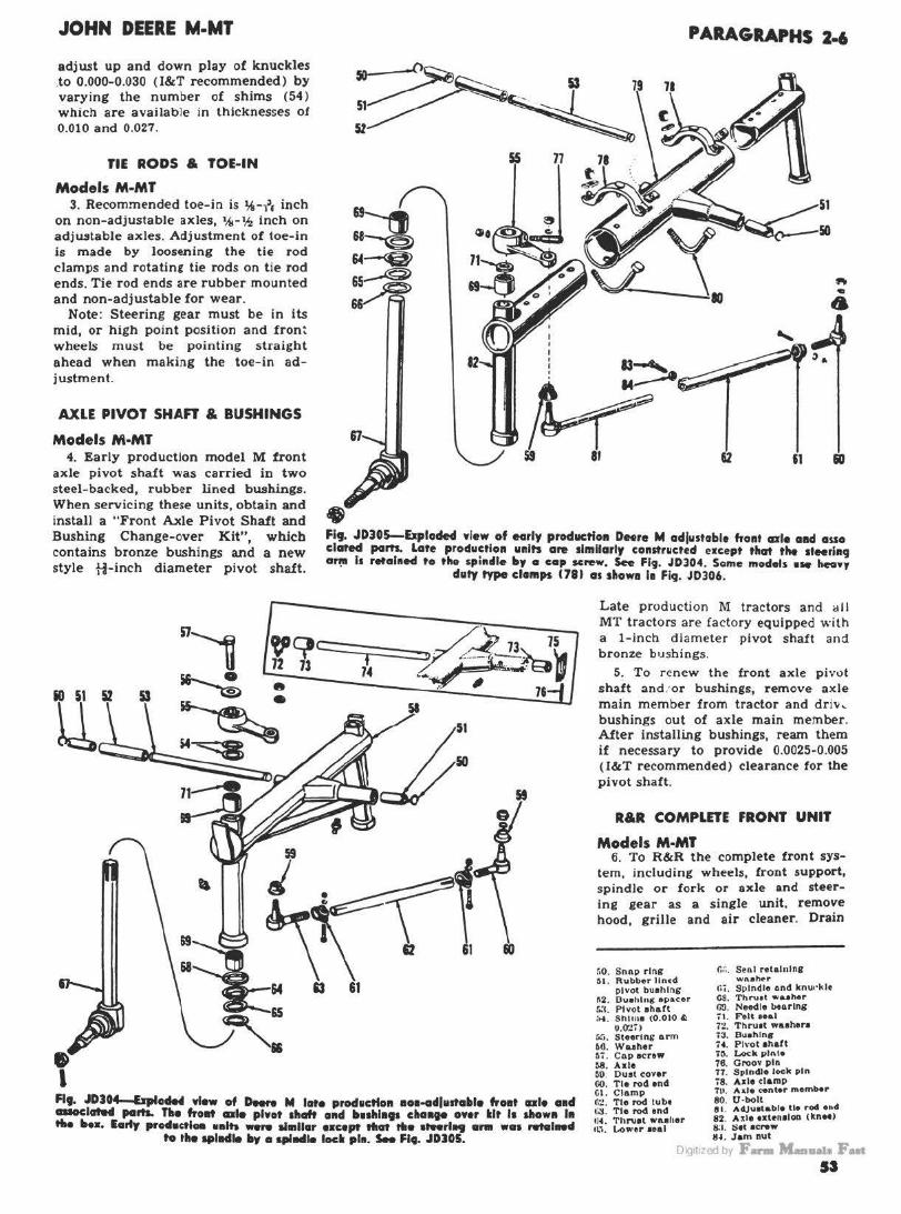
JOHN DEERE M-MT
adjust up and down play of knuckles .to 0.000-0.030 (l&T recommended) by varying the number of shims (54) which are available in thicknesses of 0.010 and 0.027.
TIE RODS & TOE-IN
Models M-MT 3. Recommended toe-in is 1ii!-f, inch
on non-adjustable axles, %-'h Inch on adjustable axles. Adjustment of toe-in is made by loosening the tie rod clamps and rotating tie rods on t ie rod ends. Tie rod ends are rubber mounted and non-adjustable for wear.
Note: Steering gear must be in its mid, or high point position and fron: wheels must be pointing straight ahead when making the toe-in adjustment.
AXLE PIVOT SHAn & BUSHINGS
Models M·MT 4. Early production model M front
axle pivot shaft was carried in two steel-backed, rubber lined bushings. When servicing these units, obtain and install a "Front Axle Pivot Shaft and Bushing Change-over Kit", which contains bronze bushings and a new style ti-inch diameter pivot shaft.
~ 51
5Z
55
I
' I
PARAGRAPHS 2-6
51
~ 59 81
Fig. JD305-&ploded view of early productfo11 Deere M adjustoble hont axle aad asso clcrtecl ports. Lafe producflon units are 1lmllarly constructed escept that the 1teerla9 or~ Is retah1ecl to the sphufl• by o cap screw. See Fig. JD304. Some models •le '-"Y
duty type clamps 1781 as show• 11 Fi9. J0306.
c::::::::::;;::::::::::::::-- - /.",..? 73 75
7~ y~~. ·~~~ .•.. , II .. 7&
~ 61
Late production M tractors and <1 ll MT tractors are factory equipped with a 1-inch diameter pivot shalt and bronze b1Jshings.
5. To renew the front axle pivot shaft and : or bushings, remove axle main m ember from tractor and driv... bushings out of axle main member. After installing bushings, ream them if necessary to provide 0.0025-0.005 (l&T recommended) clearance for the pivot shaft.
R&R COMPLETE FRONT UNIT
Models M·MT 6. To R&R the complete front sys
tem, including wheels, front support, spindle or fork or axle and steering gear as a single unit. remove hood, grille and air cleaner. Drain
r.o. Snnp ring 6l. Rubb-er lined
pl vot buahlni; 1\2. Ouehln,g: epacer r.:c. Pivot ahaft :..i . Shima (0.010 '=
0.0'!;) r.:;. Stffrlng arm bO. Waeher 67. Co.p acrew 38. Ade
c.:;. S•nl retal11ln11 WA•her
1;;. Spindle o.nd kmwklt CS. Thru1t wa..eher ro. Needle btarlna it. Felt •••• 7~. Thru1t waoheno 73. Bu•hlng 74. Pl,·ot ahaft 70. Lock pll\l• 78. Groov pin 77. Spindle lock pin 78. Aile damp
Flf. JD304-&plodff view of Deere M lat• produc:tlo11 e011-adlu1tatile frCltlt ale aad ClllOClat.tl partL Tise frallt axle pivot 1haft a11d ll11hl•t• c••ll99 onr kit 11 show11 111 tlie lltes. l•rfy procl•ctl• ••lh _,. almllar escept that ttl• •'"rl.. ara ••• retal .. d
to the spllldle by a qillldle lad pla. S- Fl,. JDJOS.
60. Ouat cover 00. Tie rod end GI. Clamp II:! . Tie rod tube c:i . Tia rod end ti•. Thniat washer '~'· L.ower aoal
7U. Ad• center member 80. U·boll 91. A4,Ju•tabte tie rod end 82. Axle ut•nalon 1tn .. ) S:I . Set ac"'w 11~. Jam nut
Oig1t1zed by F- Mau..i. Fut 53

PARAGRAPHS 6-10
"•· JD~fxploded Yiew of Deere MT odl11stol»le front axle and aHocioted part•. n . Pivot eh&ft 6•. Sh ima 65. Stevlnc arm 66. Wuher 67. Capacrew S9. Oaat cover , 0. Tie rod cad tl. Clamp tZ. Tie rod tube '"'. Tbr 1,1.• t waahc r
66. Sea.I 66. Sea.I rfl.aininir wuber 67. Spindle and knuckle 68. Thruat wuher 611. N-Ue barinc 71. Felt Hal 79. ~e cmta mftllbu 81. Ad;natable tie rod end 82. Aide u:UD1lo11 Jit..1 . $~ t ~· · rir·\\
86. Pl•ot abaft rear euppor t 8&. B\Llhinc 87. Stttrlnc lever 88. Clamp 89. Pivot abaft frollt aupport 90. Snail rinc 91. !!prhur waaber 112. Wuh..r ~•3 . Sl·al rt"l1tln~r OL Powele
JOHN DEERE M-MT
cooling system, disconnect radiator hoses and disconnect radiator from upper bracket. Remove Allen screws (1-Figs. JD311 and 313) and slide steering tube rearward until free of steering worm. Remove radiator, support front of tractor and remove cap screws retaining front support to engine and roll unit away from tractor.
R & R UPPER SPINDLE
Model MT 10. To remove the upper spindle (25-
Fig. JD312), remove the gear unit as outlined in paragraph 14. Support front of tractor and detach wheel fork or lower spindle from upper spindle, or, on axle type tractors, detach axle from front support and center steering arm from upper spindle. The upper spindle can now be withdrawn from below after first removing the coupling sleeve pin (20-Fig. JD312) . The upper spindle bushing (23) is presized and if carefully installed, will require no final sizing. Renew needle bearing (18) and/ or thrust bearing ( 17 ) if corroded or worn.
~ ~21 1 5 5
rr~Ma~·= d i----11
"•· JO~lo-up,..r portion of DHre MT ,,... •IHI """· ,,_ (2d} CGll .. olt'9or • I-or •plrNlle for luol wlteel1, a forlc fer • IJ .. fe ,,.,,, whel or • tie red ,,, •• for - ... , ....... ,,.fHff •ale. ..,., te l .. eM
•-'ar "•'" JDJl2 & 313.
fig. JD3 I I - fxploded view of Deere M lfeel'ing gear, front 1upporf and a11ocloted parf1. Sltlm1 (T J control worm
dtoft e11d ploy.
I. Allfl>11<:nw 2. Stevinc tube a. s.1 • . Upper buahlDP 6. ~arlnir ueemb))I 6. Wona
JO. Vertical ahalt upper aeal 11. S hafttube 12. Vertltal •halt 13. T op cuYer U . AdJU1tln1 •crew 1&. Cuket 16. Lower b118hl11s 17. Vortlcal •haft lower aeal 18. <Ant.P ataerlnir arm 19. Front aupport 21. Gear boU1lD1 rear cower 22. C..r ho ... lnir 28. Exp&ll81on pluir
... ~.·~· . . ... 14
n!fi ' 13 000~
1~
12 11
c •
Oig1t1zed by F- M-11a1a Fut
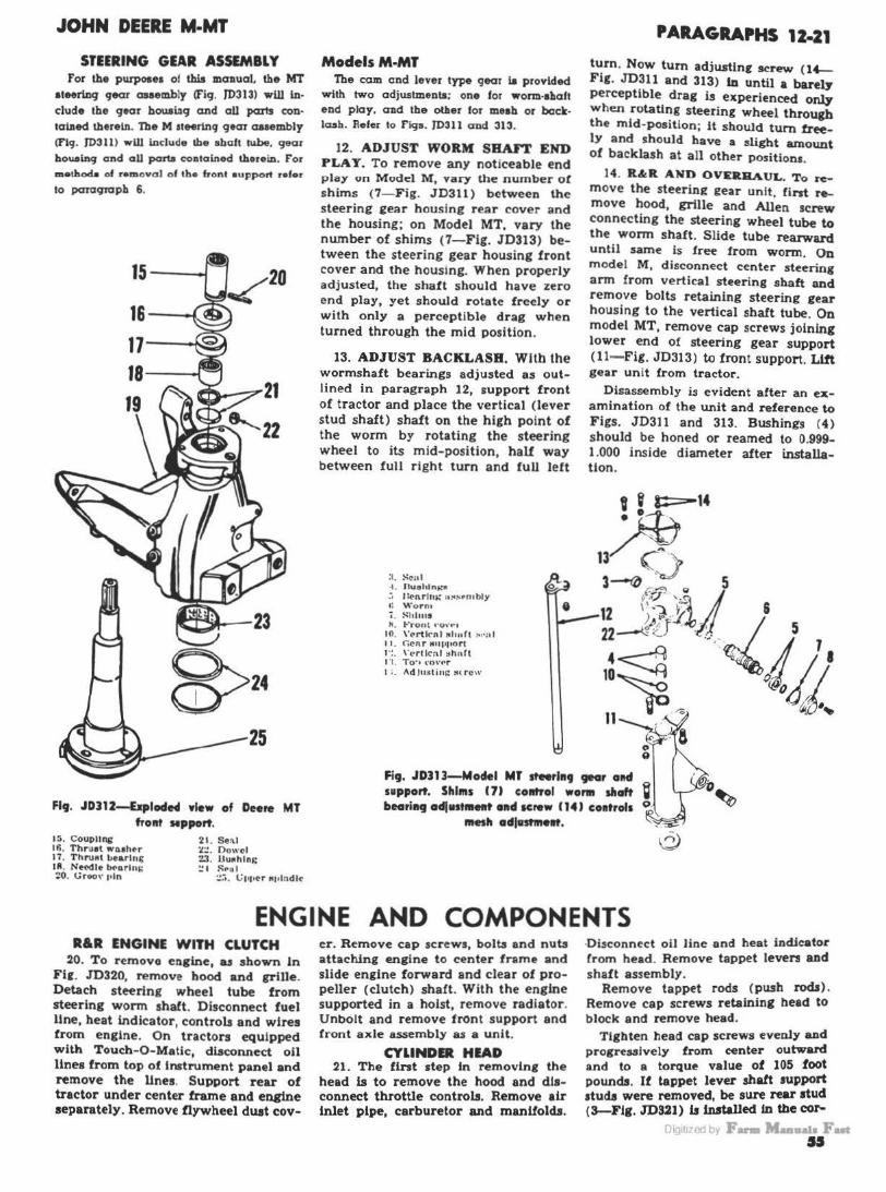
JOHN DEERE M-MT
STEERING GEAR ASSEMBLY For the purposea of this manuaL the MT
aleeri.uq qear maembly (f'i9. JD313) wW ln· elude the 9ear houai.119 and all parts con· tai.lled thereln. The M lleerinq 9em aaaembly (Flq. JD311) wW Include lhe abaft tube. 9ew ho ... 1n9 and all pmta contal.nod therein. For metJ.od.. of removal of the front auppott refer
lo PQTOqroph 6.
16-~
17---i-~
18- ---l
Fig. JDJ12-&plode4 view of Deere MT frollt Mpport.
JS. Coupling 16. Thruat " 'Deher 11. ThruM bearlnc Ill. Net'dle bt-nrl11~ ZO. t;roo,· r•ln
21 . Sel\I °'-.:.. Dowel 23. Uu~hlni; ~ I ~t"al
:.!;';. t;1111~r MJ1lndl~
ModelsM·MT The cam and lever type gear la provided
with two adjwitmenta; one for wonn·ahall end play. and the otber for nieab or backlash. Refer to Fiqs. 10311 and 313.
12. ADJUST WORM SBAJT END PLAT. To remove any noticeable end play on M odel M , vary the number o! shims (7-Fig. JD311) between the steering iear housing rear cover and the housing; on Model MT, vary the number of shims (7-Fig. JD313) between the steering gear housing front cover and the housing. When properly adjusted, the shaft should have zero end play, yet should rotate freely or with only a perceptible drag when turned through the mid position.
13. ADJUST BACKLASH. With the wormshaft bearings adjusted as outlined in paragraph 12, support front of tractor and place the vertical (lever stud shaft) shaft on the high point of the worm by rotating the steering wheel to its mid-position, half way between full right turn and full left
:1. S~nl --1 . Ouahln,..: flll :, Jk-nrho.: 11~s,.n1bly t: Vrorm 7. ~hhus x. 1-"ront ••o,·•·1
10. \'~rtl<-nl Mhuh :-.1•al 11. Ci~n r tt111•1•o rt 1'!. \ ' l'rllc:lt ::. h n rt 1·1. Tu·• \'O\'f'r l •. Ad Ju s t i n~ ~trcw
0
•
PARAGRAPHS 12·21
turn. Now tum adjusting screw (14-Fig. JD~ll and 313) In until a barely perceptible drag is experienced onl7 when rotating steering wheel through the mid-position; it should turn freely and should have a slight amount of backlash at all other positions.
14. R&R AND OVEllllA.UL. To remove the steering gear unit, first remove hood, grille and Allen screw connecting the steering wheel tube to the worm shaft. Slide tube rearward until same ls free from worm. On model M, disconnect center steering arm from vertical steering shaft and remove bolts retaining steering rear housing to the vertical shaft tube. On model MT, remove cap screws joining lower end of steering gear support (11- Fig. JD313) w front support. Lift gear unit from tractor.
Disassembly is evident after an examination of the unit and reference to Figs. JD311 and 313. Bushings (4)
should be honed or reamed to 0.999-1.000 inside diameter after installation.
Fig. JDJ13-Moclel Mr steerl119 '"' alld 111pport. Shims ( 7> c:omtrol worM sllaft bearilHJ adl111tlhllt ••d Krew '14J co11trol1
lllfth adjllst1H1t.
ENGINE AND COMPONENTS R&R ENGINE WITH CLUTCH
20. To remove engine, u shown In Fif. JD320, remove hood and grille. Detach steering wheel tube from steering worm shaft. Disconnect fuel llne, heat indicator, controls and wires from engine. On tractors equipped with Touch-0-Matic, diaconnect oil lines from top of instrument panel and remove the lines. Support rear of tractor under center frame and engine separately. Remove flywheel duat cov-
er. Remove cap screws, bolb and nub attaching engine to center frame and slide engine forward and clear of propeller (clutch) shaft. With the engine supported in a hoist, remove radiator . Unbolt and remove front support and front axle assembly as a unit.
CYLINDER HIAD 21. The flnt step in removing the
head is to remove the hood and dJaconnect throttle controls. Remove air inlet pipe, carburetor and manUolcls.
·Disconnect oil line and heat indJcator Crom head. Remove tappet levers and shaft assembly.
Remove tappet rods (push rods) . Remove cap screws retaining head to block and remove head.
Tighten head cap screws evenly and progressively from center outward and to a torque value of 105 foot pounds. If tappet lever shaft support atud.I were removed, be sw-e rear stud ( 3-FJg. JDS21) b Installed to the cor-
rJI< 1t1 <d by F ........ ~- • SS
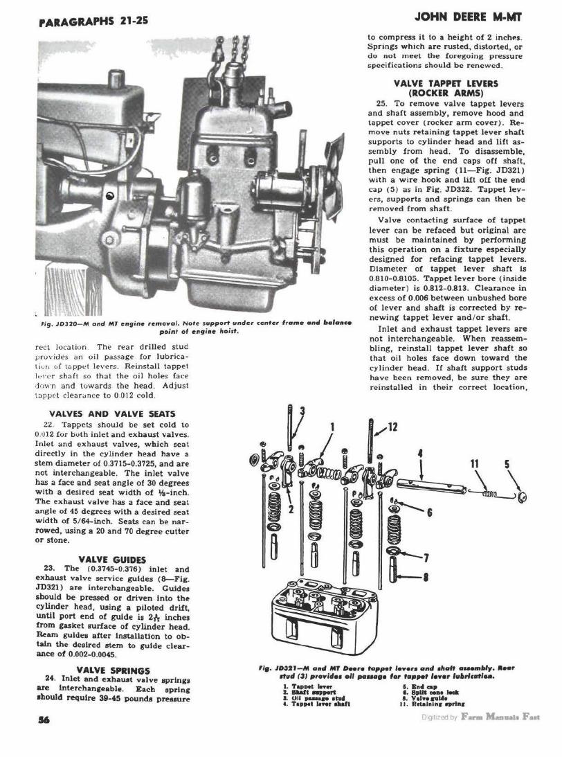
PARAGRAPHS 21-25
fig . JOl :Z0-111 and MT engine removal . Nore support under ~enter f rame and "°lone• point of engine ltoist.
rect location . T he rear d rilled stud provides an oil passage for lubricaliv n o ( t::.pplo"l levers. Reinstall tappet 1..,1·.:-r shaft so that the oi I holes fa ce down and towards t he head. Adjust t:ippct clear-.nce to 0.012 cold.
VALVES AND VALVE SEATS 22. Tappets should be set cold to
0.•)1 2 for bvth inlet a nd exhaust valves. Inle t and ex haust valves, which seat directly in the cyunder head have a stem diameter of 0.3715-0.3725, and are not interchangeable . The inlet valve has a face and seat angle of 30 degrees w ltb a desired seat width of t,i, - incb. The exhaus t valve has a face and seal angle of 45 degre~ with a desired seat w idth of 5/ 64-inch. Seats can be narrowed, using a 20 and 70 degree cutter or stone.
VALVE GUIDES 23. The (0.3745-0.376) inlet and
exhaust valve service guides (8--Fig. JD321) are interchangeable. Guides should be pressed or driven Into the cylinder head, using a piloted drift, until port end of guide is 2/, inches from gasket surface of cylinder head. Ream guides after installation to obtain the desired stem to guide clearance of 0.002-0.0045.
JOHN DEERE M·MT
to compress it to a height of 2 inchP.s. Springs which are rusted, distorted, or do not meet the foregoing pressure specifications should be renewed .
VALVE T APPO LEVERS (ROCKER ARMS)
25. To remove valve tappet levers and shaft assembly, remove hood and tappet cover (rocker arm cover ). Remove nuts retaining tappet lever shaCt supports to cylinder head and lift assembly from head. To disassemble, pull one of the end caps off shaft, then engage spring ( 11-Fig. JD321) with a wire hook and lift off the end cap (5 ) as in Fig. JD322. Tappet leve rs, supports and springs can then be removed from shaft.
Valve contacting surface of tappet lever can be refaced but original arc must be maintained by performing this operation on a fixture especially designed for refacing tappet levers. Diameter o! tappet lever shaft is 0.810-0.8105. Tappet lever bore ( inside diameter ) is 0.812- 0.813. Clearance in excess of 0.006 between unbushed bore of lever and shaft is corrected by renewing tappet lever and/ or shaft.
Inlet and exhaust tappet levers are not interchangeable. When reassembling, reinstall tappet lever shaft so that oil holes face down toward the cylinder head. If shaft support studs have been removed, be sure they are reinstalled in their correct location ,
VALVE SPRINGS 24. Inlet and exhau.t valve springs
are lnterchaneeable. Each spring 1bould require 39-45 pounch preuure
''•· JD~21-M o•d Mr Deere tGflpet 1 • .,.,. and •ltaft ..... ,...iy. •-r stud (iJ proy/cfH ol/ pauoge for tappet fewer fu•rfcatl ...
S6
I. Tap1H1t Iner J. 811aft ..... rt J , Oii p-.. •tad 4. Tappet Iner tiJiaft
5. Bn• cap f , 8pUt eeee l.m a. Val••Pl41•
I J. Rctah1tn1 sprte1
Oig1t1zed by F- M-11a1a Fut

JOHN DEERE M-MT
rear stud (3-Fig. JD321) is drilled to provide an oil passage for lubrication of tappet levers.
CAM FOLLOWERS 26. The m ushroom type cam fol
lowers operate directly in machined bores of the cylinder block. Cam followers are supplied only in the standard size and should have a suggested clearance of 0 .0005-0.0025 in block bores. Any tappet can be removed after removing the camshaft as outlined in paragraph 30.
VALVE TIMING 27. Inlet valve opens at top dead
center and exhaust valve closes ~ degrees after top dead center . Valves are correctly timed when mark on camshaft gear is meshed with an identical mark on crankshaft gear as in Fig. J D325.
To check valve timing when en£in e is assembled, adjust tappets to 0.012 clearance. Turn engine until fron t cylinder inlet valve is just opening. At this time t he D I C mark on flywheel, shown in F ig . JD326, should be within 1~ inch of index l ine on side
fit. JDJ25-M a•d MT valv• tl19l"t _, .. 01 co1111haft ud crollblloft 9H'·
fit. JD322-U1i1g hooked tool to disassemble M and MT top1Nt lenrs osse111blf. Tool con be made kom
weldl11g rod.
ol timing hole. U marks do not register within 1.4 inch, remove camshaft and remesh camshaft gear w ith crankshaft gear .
TIMING GEAR COVER 28. To remove timing gear cover,
remove radiator , front support and front axle as in pa ragraph 6. Remove fan and bracket assembly. Remove generator and, if so equipped, hydraulic pump unit. Disconnect controls and r emove governor . Remove pulley from
fig. JDJ26--M and MT top center podtion is wlle11 flywhe.I niort DC refjisters with
lndea '-• right side of et19ine.
PARAGRAPHS ZS-30
cranksha ft and cover to cylinder block cap screws. When re-installing cover refer to note in paragraph 29. '
CRANKSHAFT FRONT Oil SIAL 29. To renew crankshaft front oil
seal. remove radiator . front support and front ax le as per paragraph ts. Remove fan and bracket assembly . Remove pulley from crankshaft. Kemove front oil seal plate ( 14-F ig. JD330) . Oil sea I C 15) can be pressed out of plate and renewed.
Note: Soak new seal in oil and install in plate with lip of seal facinf toward rear of tractor. Slide seal and plate assembly on crankshaft using a piece of feeler stock as a sleeve to prevent damaging seal.
CAMSHAn AND BEARINGS 30. To r emove camshaft, first re
move the tim ing gear cover and tap- · pet leve rs Crocker arms) assembly. Remove oil pan. o il pump and ignition dis tributor . Unlock thrust plate cap screws show n an F ig . JD329. Remove screws f rnm b lock. Hold cam followers UJJ a11d carefully withdraw camsha ft. T(I re m1.we gear from shaft ,
Fi9. JD329- Removing M nd MT cop screws which retain calllSha~ thnst plate to cylinder blocll. Cap screws hen• tai.
type lock washen.
3S 2t
~~ JO
fkJ. "DU~M alMI MT coinshcrft, b.shh19s a11d cam followen. Hr4roallc ,11•P .,,. coupll... ( 29) I• ltolted to c_ .. oft 9"'·
2. Com•luirt goGr 3. Cam1hGft 4 . Tab w1>1hert1
o. C:l\m rol10\\' tll II"•. Oen.r key ~o. 8na1> rlnll"
:u . Spa~·•r wu•ht-r ;1:.: . Thru•I t•tnto :JJ. l•'ro11t hu1hhlll
~•. near buahln1 30. Eapan•lon plus 30. [low• I pin
11t1·(jJy F-
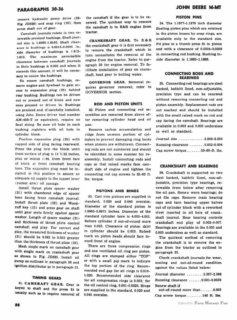
PARAGRAPHS 30-36
remove hydraulic pump drive (29-Fig. JD328) and soap ring (30) ; then
press shaft out of gear. Camshaft journals rotate in two re
newable pre:sized bushings. Shaft journal size is 1.8095-1.8105. Shaft clearance in bu:shings is 0.0015-0.0035. Inside diameter of bushings is 1.812-1.813. The maximum permissible clearance between camshaft journals in their bushings is 0.005 and when it exceeds this amount, it will be necessary to renew the bushings.
To renew camshaft bushings, remove engine and flywheel to gain access to expansion plug (35) behind
rear bushing. Bushings can be driven
out or pressed out of block and new ones pressed or driven in. Bushings are presiz:ed and, if carefully installed, using John Deere driver tool number AM--458-T or equivalent, require no final sizing. Be 11ure oil hole in each bushing registers with oil hole in cylinder block.
Position expansion plug (35) with
cupped side of plug facing rearward. Press the plug into the block until
the camshaft if the gear is to be renewed. The quickest way to remove the camshaft ls to R&R engine from
tractor.
CRANKSHAFT GEAB.. To R & R the crankshaft gear it is first necessary to .. emove the crankshaft which in turn necessitates the removal of the engine from the tractor. Refer to paragraph 20 for engine removal. To fa
cilitate installation of gear on crankshaft, heat gear in boiling water.
GOVERNOR GEAR. Removal requires governor removal; refer to
GOVERNOR section.
ROD AND PISTON UNITS 32. Piston and connecting rod as
semblies are removed from above after removing cylinder head and oil
pan.
Remove carbon accumulation and ridge from unworn portion of cylinders to prevent damaging ring lands
when pistons are withdrawn. Connect
ing rods are not numbered and should front surface of plug is 13 7/32 inches, be identified in some manner for re
plus or minus l / 6~. from front face assembly. Install connecting rods and of block at front camshaft bearing bore. The expansion plug must be installed in this position to assure an adequate oil supply to the tappet lever (rocker arm) oil passage.
Install thrust plate spacer washer (31) with chamfered edge of spacer
bore facing front camshaft journal. Install thrust plate (32) and Woodruff key ( 15) and press gear on shaft until gear seats firmly against spacer
washer. Length of spacer washer (31 >
and thickness of thrust plate control camshaft end play. For correct end play, the measured thickness of washer
(31) should be 0.003 to 0.010 greater than the thickness of thrust plate (32).
Mesh single mark on camshaft gear with single mark on crankshaft gear as shown In Fig. JD325. Install oil Pump as outlined in paragraph 39 and lgnltlon distributor as in paragraph 51.
nMING GEARS
31. CAMSHAFT GEAB.. Gear is keyed to shaft and the press fit Is uaually such as to require removal of
••
caps so that raised marks face camshaft side of engine and tighten the
connecting rod cap screws to 55-60 ft. lbs. torque.
PISTONS AND RINGS
33. Cast iron pistons are supplied in
standard, 0.020 and 0.040 oversize. Diameter of the standard piston ls
3.9965-3.9975 inches. Diameter of the standard cylinder bore is 4.000-4.001.
Rebore cylinder if out-of-round more than 0.003. Clearance of piston skirt in cylinder should be 0.003. Raised
mark on piston heads should face toward front of engine.
There are three compression rings
and one ventilated oil ring per piston. All rings are stamped either "TOP" or with a small pip mark to indicate
the top portion of the ring. Recommended end gap for all rings is 0.010-0.020. Recommended side clearance lor all compression rings is 0.003; for the oil control ring, 0.001-0.0025. Rings are supplied in the standard. 0.020 and 0.040 oversize.
JOHN DEERE M·MI'
PISTON PINS 34. The 1.1877-1.1879 inch diameter
floating piston pins which are retained
in the piston bosses by snap rings, are
available only in the standard size.
Fit pins to a thumb press fit in piston
and with a clearance of 0.0004-0.0009
in connecting rod bushing. Bushing in
side diameter is 1.1883-1.1886.
CONNECTING RODS AND BEARINGS
35. Connecting rod bearings are steel
backed, babbitt lined, non-adjustable,
precision type and can be renewed
without removing connecting rod and
piston assembly. Replacement rods are
not marked and should be installed
with the small raised mark on rod and
cap facing the camshaft. Bearings are
available in 0.003 and 0.005 undersizes
as well as standard.
Journal size . ..... ...... .. 2.249-2.250
Running clearance ........ 0.002-0.004
Cap screw torque ........ 55-60-ft. lbs.
CRANKSHAFT AND BEARINGS
36. Crankshaft is supported on two
steel backed, babbitt lined, non-adjustable, precision type bearings, re
newable from below after removing the oil pan. Rene·.v worn bearings; do not file caps. Remove main bearing
caps and turn bearing upper halves
out of cylinder block with a reworked
rivet inserted in oil hole of crankshaft journal. Rear bearing controls
crankshaft end play of 0.003-0.007.
Bearings are available in the 0.003 and
0.005 undersizes as well as standard. The quickest method of removing
the crankshaft is to remove the engine from the tractor as outlined in paraeraph 20.
Check crankshaft journals for wear,
scoring and out-of-round condition against the values listed below:
Journal diameter ......... 2.397-2.398
Running clearance ....... 0.001-0.0035
Renew shaft I! out-of-round more than ....... 0.003
Cap screw torque ......... HO ft. Iba.
Oig1t1zed by F- M-11a1a Fut
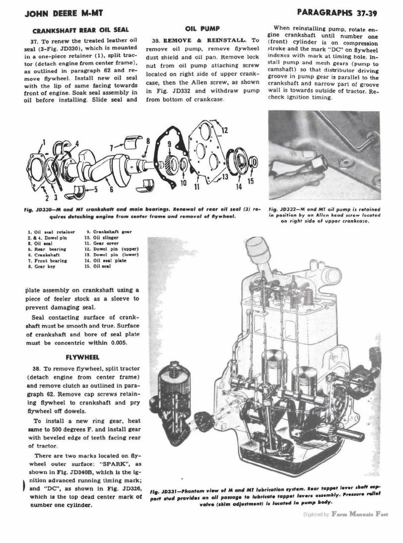
JOHN DEERE M-MT
CRANKSHAFT UAR OIL SEAL
37. To renew the treated leather oil seal (3-Fig. JD330), which is mounted in a one-piece retainer (1), split tractor (detach engine from center frame ), as ouUined in paragraph 62 and remove Bywheel. Install n ew oil seal with the lip of same facing towards front of engine. Soak seal assembly in oil before installing. Slide seal and
OIL PUMP
39. REMOVE & REINSTALL. To remove oil pump, remove flywheel
dust shield and oil pan. Remove lock nut from oil pump attaching screw located on right side of upper crank
case, then the Allen screw, as shown
in Fig. JD332 and withdraw pump
from bottom of crankcase.
PARAGRAPHS 37.39
When reinstalling pump, rotate engine crankshaft until number ooe (front) cy linder is on compression ~troke and the mark "DC" on tJywheel indexes with mark at timing hole. Inst.all pump and mesh gears ( pump to camshaft) so that distributor drivinc groove in pump gear is parallel to the crankshaft and narrow part of groove wall is towards outside of tractor. Recheck Ignition timing.
F19. JD330-M and MJ cranksllaff and main l»earings. aenewaf of rear oil seal (3) re· quires detocllin9 en9ine f rom center frame and remoyof of ftywlleef.
Fi9. J03J2- fl1 and MT oil pump is retained in posit ion f>y on Allen lteod screw l ocated
on r ight side of upper cronlccose .
1. Oil .... n:taiDCI'
2. a ' · Dow~• pin a. Oil Mal i . Rear burinr c. c .. aliahafl 7. Front bcaririr 8. Cur k~7
9. Cranbhalt s .. r to. Oil 1llncer 11. Gear conr lZ. Do-I pin (upper) JS. Dowel pin (low•r) tc . Oil 1eal plate 16. Oil IHI
plate assembly on crankshaft using a
piece of feeler stock as a sleeve to
prevent damaging seal.
Seal contacting surface of crankshaft must be smooth and true. Surface
of crankshaft and bore of seal plate must be concentric within 0.005.
FLYWHEEL
38. To remove flywheel, split tractor (detach engine from center frame)
and remove clutch as outlined in para
graph 62. Remove cap screws retainlng flywheel to crankshaft and pry
flywheel off dowels.
To install a new ring gear, heat
same to 500 decrees F . and install gear with beveled edge of teeth facing rear of tractor.
There are two marks located on fly
wheel outer surface: "SPARK", as shown in Fig. JD340B, which ls the lg-
• nltion advanced running timing mark; J and "DC", as shown In Tlg. JD326,
which 11 the top dead center mark of number one cylinder.
119
• JD33 l-,,1anfom view ef M and Mr lullrltoflon sy Jfe111. a.or hipper lenr ,..,, ~:; port 1tucl proYlde1 an oll pa11a1• to fultrlcato tappet feyer• HHlft.,Y• Preuwre rel
volYe (1lll1rt odfulfntontJ 11 located In puMp ltedy.
Di~1t1LE:id by F- Maallllla Foat
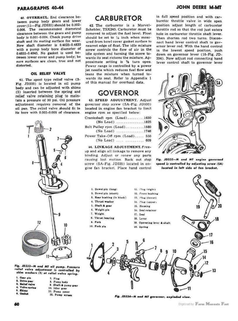
PARAGRAPHS 40-44
40. OVERHAUL. End clearance between pump body gears and lower cover (11-Fig. JD333) should be 0.002-0.006. The recommended diametral clearance between the gears and pump body 1$ 0.001-0.004. Check p ump d r ive shaft and its mating surface for wear. New shaft diameter is 0.4825-0.4830 with a pump body bore diameter of 0.4835-0.4845. No gasket is used between lower cover and pump body; be sure surfaces are clean. true and not distorted.
OIL RELIEF VALVE
41. The sp001 type relief valve (3-F ig . .JD333) is located in oil pump body and can be adjusted with shims (5) Inserted between the spring and relief valve retaining plug to maine l"ain a pressure of 30 psi. Oil pressure adjustment requires removal of the oil pan. T he relief valve should 6t in Its bore with 0 .003-0.005 of clearance.
8
9
12 10
~ "•· J03.33-M and MT oil pump. P1ouu10 rollol .,.,.,. adfunmonr Is con•1ollod by •ltffft •o•hon I SJ ot roflof .,.,.,. •prin9.
l . Gear tla 1. P lus I . Ort ... Sear 8. Pump bodJ' I . llellef ....i.. II. Shaft 6 pump ... , '- V.,,,_ .. "•• JO. ldlu oear I . lhlm.a 11. Pump eo..r I . Otilli« IZ. Pamp ter-..
CARBURETOR 42. The carburetor is a Marvcl
Schebler, TSX245. Carburetor must be removed to adjus t the fuel level. Float should be set to ~4 inch when m easured from bowl cover gasket surface to nearest edge of ftoat. The idle mixture screw controls the fiow of air in the idle system and turning the screw towards its seat r ichens the mixture. Approximate setting Is ~ turn open. Power range is controlled by a power jet needle which reduces fuel fiow and leans the mixture when turned towards its seat. Refer to Appendix 1 of this manual for overhaul data.
GOVERNOR 43. SPEED ADJUSTMENT. Adjust
governor stop screw <SA-Fig. J D:~35 )
located in engine fan bracket to limit engine rpm as spec ified below:
Crankshaft rpm (Load ) ... ... . . . 1650 (No Load ) . ............. . 1825
Belt Pulley rpm (Load) ...... . ... 1580 ( No L oad ) . .. ............ 1746
Power Take-Off rpm (Load) .... . 550 (No Load ) . . . . . ... . ..... 609
44. LINKAGE ADJUSTMENT. F reeup and align aJ I li nkage to remove any bi nd ing. Adjus t or rene w any parts causing lost mot io n Back out stop screw CSA-Fig. J0335 ) located in eng ine fa n bracket. Place hand control
11. l' l u K lri11hl1
JOHN DEERE M·MT
In full speed position and with carburetor throttle valve in wide open position adjus t length of carburetor throttle rod so that the rod just enters hole in carburetor throttle shaft lever. Then shorten rod two turns. Disconnec t hand lever control shaft to governor lever rod. With the hand control in the lowest speed position, push down on governor lever ( 18-Fig . .JD-334 ) . Now adjust rod connecting hand lever control shaft lo governor lever
Fig. JD335-M 011tl MT engine goll'ornod spoofl is con•101led by adjusting screw (SA)
IHatod in loft side of fan bracket.
I. Dowt:I pio (loas l
2. Dowt:I pin (ebort) 12. f" ront bu•hin11
8. Rear bu.ohloa ( ID block )
' · Tbruat wuhtr S. Shaft A aur 6. Welsbt p in
1. Wtlsht
8. Tbrust bt:arios
t . Forlr.
10. Fork pla
2 5
13. l' lu ..- C low~r)
14. Plue t upp1:rr
Iii . Hou1inc
16. ~al retaintr
17. Sul
18. Lever
Ii. Operatios lt:v<!r A ahiaft
~o. Sprlna
~18 ~
0----11 @--1&
•--" 119. JOJ3,,_M aatl MT •-•11tar, o•pleflefl .,Jew.
Oig1t1zed by F- M-11a1o Fut

JOHN DEERE M-MT
so that holes in rod yoke and hole In governor lever are in register; then lengthen rod two turns. Adjust engine speed with governor stop screw as outlined in preceding paragraph.
45. R &: R GOVERNOR. Remove hood and grille. Remove air cleaner and disconnect governor linkage. Remove fan and belts. Remove cap screws retaining governor housing to Urning gear cover and remove housing. Withdraw governor shaft assembly being careful not to drop thrust washer ( 4-Fig. JD334) into timing gear case.
46. OVERHAUL GOVERNOR. Remove spring. Remove upper expansion plug (14). Bump pin (10) out of fork (9) and operating shaft. Remove expansion plug ( 11) from side of case and bump operating shaft out of case. Remove metal retainer ( 16) from side of ca se and renew oil seal. Weight pins (6) can be removed from carrier after grinding staked portion at end of pin. Shaft front bushing ( 12) can be renewed after removing lower front expansion plug (13). To remove shaft rear bushing (3) from cylinder block, tap bushing for ~ inch SAE thread and pull bushing with a cap screw. Bushings are presized and should be installed using a piloted drift.
After housing has been assembled. check condition of fork ( 9) and lever ( 19 ) by placing a new thrust bearing (8 ) under governor fork and laying case on a flat surface as shown in Fig.
fl9. J033$A-M end Mr 90.,ernor and carburetor ll11lco9e. 1ltowlng co11trol rod1 a11d
lll1lc09e odjust111ent1.
JD335B. With operating lever moved upward (fork against bearing) , center of hole in operating lever should measure 13/1 6 inch above flat surface. If this measurement is not within 1 / 64 inch, renew shaft and lever and /or fork . Reassemble and reinstall governor, and adjust engine speed as outlined in preceding paragraphs.
fif. JD3351-Clted1in9 condition el Deer• Mr goYernor operofln9 feyer A •ltaff (19} artd fo,lc (9} 1uin9 a tlot 111rloce and a new tlirus1 bearing (I}. lte11ew the lever 011d/or 1lioft if '3/16 irtclt 111ea1ure111ent
i• rtot olltalned.
en. J(Vu nut ... . \\"n~ht•r
8Z. f"'tlt•r vlute loc k ~·lrcljJ. F'IUl lirncktl &t . Oovtrnor e top e e,...w J&m out
• M
PARAGRAPHS 44-49
COOLING SYSTEM FAN AND RADIATOR
48. To remove fan assembly, remove hood and grille. Remove fan and cenerator belts and detach fan shaft from bracket.
Fan bub is not fitted with bushings. Correction of bearing wear is accomplished by renewing hub, bearing and/or shaft. See Fig. JD340.
49. Radiator can be removed without removing the front support assembly by the following procedure: Remove hood and grille. Remove Allen screw Crom steering tube and detach tube from steering gear worm shaft. Remove bolts from radiator upper bracket. Remove cap screws attaching radiator bracket to fan bracket. Detach lower right side bracket from radiator and lower left bracket from front support. Working on lett side o1 tractor. carefully remove the radiator.
sz
11
., t

PARAGRAPHS 50-61 JOHN DEl!RE M-MT
IGNITION & ELECTRICAL SYSTEM 50. J ohn Deere M and MT are
equipped with a model 1111709 DelcoRemy distributor and uses the Champion HlO spark plug with an electrode gap setting of 0.025.
IGNITION TIMING 51. Distributor rotation is clockwise
when viewed from the drive end. Set breaker contacts to a 0.020 gap ( 32 deg. cam angle) . To time the ignition, crank engine until No. 1 piston (front) is on compression stroke and the flywheel mark "SPARK" (advanced timing mark) aligns with timing port Index as shown in Fig. JD340B. At this time, the distributor drive groove in oil pump drive gear should be parallel to crankshaft and with narrow part of groove wall towards outside of tractor.
Install distributor with retaining cap screws only finger tight. Rotate d istributor cam as far as it will go in direction of normal rotation. While holding cam in fully advanced position. rotate distributor body in the opposite direction until points just begin to open. Tighten distributor retaining cap screws and install number one (front) cylinder spark plug wire in the terminal over the rotor contact.
As indicated a 1>01:e, the dfatributor i s timed with t he breakeT cam in the
,;,. JD3401-M 1111td MT flywlteef mark " SPARK" is the fully adYanced running timing marlt of n11mbor 01to rtlindor. ••fer to lgnirion Timing for ccirrect timing
procedure.
fully advanced positi on. To check action of the distributor governor, operate the engine at 600 rpm or less at which time the spark should occur at top center or when the DC mark on flywheel aligns with in.spectio" port index line.
GENERATOR AND REGULATOR 52. Tractor Is equipped wltb a
Delco-Remy third brush generator model 1101857 and cut- out relay model 1116816. Generator output is controlled
by the third brush and a combination ignition and light switch. Switch baa five positions: (1) Lights and igniUon off; (2) Ignition on and low generator charging rate. In this position, a resistance is inserted in generator field circuit to reduce generator output to approximately two amperes; (3) Ignition on and high generator cbarginc rate. This position removes resistance from generator field circuit and permits maximum generator output of approximately eight to ten amperes !or charging a low battery; ( 4) Ignition and lights on and high generator charging rate; (5) Ughts on, ignition off.
To adjust charging rate (8-10 amperes) , set ignition-light switch at position number three (ignition on and high generator charging rate) and loosen third brush clamp screw on generator end frame; move third brulh up to increase charging rate. Refer to Appendix 1 of this manual for overhaul data.
STARTING MOTOR 53. Starting motor Is Delco-Remy
model 1107064, with a Bendix drive. Starting motor ls mounted on tractor center frame and its pinion engage. flywheel ring gear from the rear.
CLUTCH AND CENTER FRAME
The structural element of the tr.ictor located between the engine and the transmission is designated by the John Deere Co., as the center frame. Thts center fTame functions as the clutch housing and to some extent 11$
a tOTque tube. In subsequent parag-raphs, it will be designated as the center fTame with the other tenna "torque tube" and "clutch housing'' shown sometime• in parenthem.
CLUTCH UNIT The clutch la an Auburn 10-inch,
.,,.ring loaded, single d111 plote type, fitted with a 10001-1 cover a.a1embl11.
61. ADJUSTMENT. Clutch pedal should have 1 lfz inches free travel. Adjust free travel by loosening lock nut and turning adjust.ins cam (16-Fla . .TD343) on front lower left elde of center frame. Turnln~ cam clot!kwile lncreaaee pedal free travel.
62
Fi9. JOUl-Deere Mand MT clutclt I• a 1lntle plate 10 inclt Au•ur• · •tted with o
10001-J NYer a ... 111Wy.
II. Aetuatlns rod 16. Adiuatlnir cam (pedal tnnl) 18. Pnuore plat. 19. R..1~ ... bearlna al_.. 20. R«leue 7olle 21. Clutch ebatt 21. R..1- lenr 24. 1-er ...Uuatment •ct-26. &-leue bcsrlnir 26. Pilot bueblDI 27. Lined plat. 28. Fl7wbeel 28. Center fnme
21
Oig1t1zed by F- M-11a1a Fut

JOHN DEERE M·MT
fit JDJ4l-Clutch pedal free travel of 1 '/; i"'hes ls adjusted with a 'Cl"' ( 16) located on le# side of center fre-. Ro· tatlag ca11 clockwise IMreoses pedal free
travel.
62. SPLl'M'ING TRACTOR. To detach engine from center frame, as shown in Fig. JD320, proceed as follows: Remove hood and grille. Detach steering wheel tube from stee.ring worm sha!t. Disconnect fuel hnes, heat indicator, controls and wires from engine. On tractors equippe~ with Touch-0-Matic, disconnect 011
lines at front of instrument panel. Support rear portion of trac~or under center frame and place engme in a hoist. Remove flywheel dust cover. Remove cap screws, bolts and nuts attaching engine to center frame and slide engine forward and clear of propeller (clutch) shaft.
Fig. JD345 - M aacl MT cetrter MIM (torque t•M)
oad COlllpoutlh.
1. Sn11p rtnc :?. Dr11ke pedo.l buahlni:• 3. Brake p~11I <rll:hll
4. Brake pedo.l rod G. Drake 1>edo.l UdO 6. Tleto.lnln& pin T. P edal oho.ft buahln c
8. Clutch ~d11l 1h11ll 9 . Clut ch pffO.l oprlng
10. Buahlq 11. Clutch pedo.l 12. fl rake 1-edo.I 1h11 ft 13. Ch•tCh 11ctunt1n11 rod U . Center frame l:I. Tlmlnir hole <O\'Or 10. Sto.rtlng motor r•tnlnln~
ecrew 17. FlywhHI duot oovcr 21 . Ptop•U•r (clutch> Rh ofl
22. Groov pin
628. ll&R CLUTCH. Split tractor as outlined in preceeding paragraph. Remove cap screws attaching clutch assembly to flywheel and r emove cover assembly and driven plate.
Before reinstalling the clutch, pack the cavity in front face of flywheel one-half full of high temperature fibrous grease.
The long hub of lined plate should be installed away from flywheel. Align driven plate w ith a clutch aligning tool or a spare propeller (clutch I shaft when reinstalling clutch unil
63. OVERHAUL CLUTCH. Refer lo STANDARD UNITS section for complete clutch overhaul data.
Early production tractor flywheels were equipped with a bushing as the pilot bearing for the forward end of the clutch shaft; on late production tractors, the pilot bearing is of the shielded ball type. The early production bushing type can be converted lo the late production ball type by obtaining and installing the late model clutch shaft, pilot bearing, grease retainer and pilot bearing adapter. Early model pilot bushing inside diameter is 0.991- 0.992 with a clutch shaft pilot journal diameter of 0.987-0.988. Recommended clearance between bushing and clutch shaft is 0.003-0.005 w ith a maximum clearance of 0 .010 for service.
64. OVERHAUL CLUTCH CONTROLS. To remove clutch pedal shaft, disconnect transmission from cen!~r frame as outlined in paragraph 71 .
PARAGRAPHS 62-65
64A. Remove snap ring (1-Fia . JD-345) from right end of brake pedal shaft and remove right brake pedal ( 3 ). Bump pin ( 6) ou t of left brake pedal and remove ped.al. Disconned clutch control rod < 13) from cluub control shaft (8) and withdraw brake pedal shaft (12) . Remove bolt from clutch pedal and remove pedal. Clutch control shaft and spring can be withdrawn from inside of center !rame. Bushings In center frame (torque tube) can be renewed at this time and, if carefully installed using a piloted drut, require no final sizing. Clutch pedal shaft bushing ( 10) inside diameter ls 1.1211-1.1239. Brake shaft and pedal bushings ( 2 and 7 ) inside diameter is 0.8766-0.8794.
CENTER FRAME (CLUTCH HOUSING)
65. R&R UNIT. To remove the center frame (clutch housing or torque · tube) Crom the tractor, proceed as follows: Remove hood and grille. Detach steering wheel tube from steering worm shaft. Disconnect fuel lines, heat indicator, controls and wires from engine. On tractors equipped with Touch-0-Matic, disconnect rockshaft unit to instrument panel oil lines. Support rear portion of tractor under center frame and place engine in a hoist. Remove flywheel dust cover. Remove cap scr ews. bolts and nuts attaching engin e to center frame and slide engine forward and clear of propeller (clutch) shaft. This completes the tro;at split.
<11y uzcd by F- Man..i.s Fast
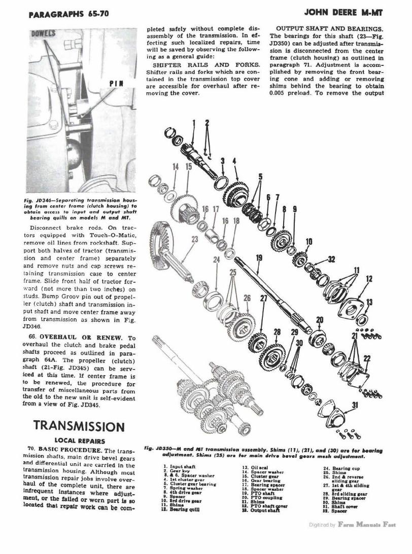
PARAGRAPHS 65-70
Fig. J0346-Separating transmission housing lrom center frame (clutch housing) to obtain access to input ond outpl# shaft
bearing quills on models M ond M1.
Disconnect brake rods. On tractors equipped with Touch-0 -Matic, remove oil lines from rockshaft. Support both halves of tractor (transmission and center frame) separately and remove nuts and cap screws retaining transmission case to center frame. Slide front half of tractor forward (not more than two inches) on studs. Bump Groov pin out of propeller (clutch) shaft and transmission input shaft and move center frame away from transmission as shown in Fig. JD346.
66. OVERHAUL OR RENEW. To overhaul the clutch and brake pedal shafts proceed as outlined in paragraph 64A. The propeller (clutch) shaft (21-Fig. JD345) can be serviced at thU time. If center frame is to be renewed, the procedure for transfer of miscellaneous parts from the old to the new unit is self-evident from a view of Fig. JD345.
TRANSMISSION LOCAL REPAIRS
70. BASIC PROCEDURE. The transmission shafts, main drive bevel gears and differential unit are carried In the transmission housing. Although most transmission repair jobs involve overhaul of the complete unit, there are Infrequent Instances where adjustment, or the faUed or worn part la so located that repair work can be com-
pleted safely without complete disassembly of the transmission. In effecting such localized repairs, time will be saved by observing the following as a general guide:
SHIFTER RAILS AND FORKS. Shifter rails and forks which are contained in the transmission top cover are accessible for overhaul after removing the cover.
JOHN DEERE M-MT
OUTPUT SHAFr AND BEARINGS. The bearings for this shaft (23-Fig. JD350) can be adjusted after transmission Is disconnected from the center frame (clutch housing) as outlined ln paragraph 71. Adjustment is accomplished by removing the front bearing cone and adding or removl.n2 shims behind the bearing to obtain 0.005 preloact. To remove the output
"•· .IO:J5()-M oltd /111 rron1mlHlon auemltly. Sllim1 (II), (21 ), alld (30) are for harl., atf#unme11t. SAim• (25) ore for main llrlve bevel 9oar1 moalt ad#udmont.
1. Input 1haft 2. C-r k•Y I. A 4. Spacer "'·ashu 4. let clual•r aftar 6. Clu1ter 1rear burins 7. Sprfn1r wuher 8. Ub drive 1•r 9. Sp-r
10. lrd drlYO l•r 11. Bbl.ma 11. Bovtnr crvw
13. Oilaal 14. Spacer wuhcr 16. Clu1ter 1ear Ill. Gear bee.rlos Ii. Bearln1 •p-r l8. Spacer waahtt 19, PTO 1haft zo. PTO coupllaa ti. Sblau U. PTO 1~91'fV SI. Ovtllat •ll&ft
24. Barias cup 26. Shim.a 2ti. 2nd A reveree
•lldlna sear 27. lit A •U. llldloa
seer 28. lrd 1lldln1 sear H . Bcarlnr 1111acer 10. 8hl1111 11. Sllan-11. Sp-
Oig1t1zed by F- M-11a1a Fut
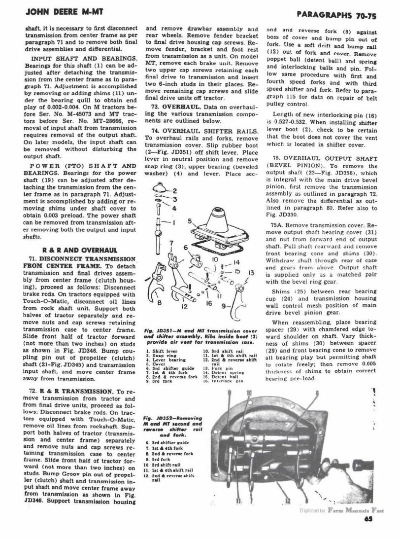
JOHN DEERE M-MT
shaft. it is necessary to first disconnect transmission from center frame as per paragraph 71 and to remove both final drive assemblies and differential.
INPUT SHAFT AND BEARINGS. Bearings for this shaft ( 1) can be adjusted after detaching the transmission from the center frame as lo paragraph 71. Adjustment is accomplished by removing or adding shims (11) un
der the bearlnf quill to obtain end play of 0.002-0.004. On M tractors before Ser. No. M-45073 and MT tractors before Ser. No. MT-28666, removal of input shaft from transmission requires removal of the output shaft. On later models, the input shaft can be removed without disturbing the output shaft.
POWER (PTO) SH AFT AND BEARINGS. Bearings for tbe power shaft (19} can be adjusted after detaching the transmission from the center frame as in paragraph 71. Adjustment is accomplished by adding or removing shims under shaft cover to obtain 0.003 preload. The power shaft can be removed from transmission after removing both the output and input shafts.
R & R AND OVERHAUL 71. DISCONNECT TRANSMISSION
FBOM CENTER FRAME. To detach transmission and final drives assembly from center frame (clutch housing), proceed as follows: Disconnect brake rods. On tractors equipped with Touch-0-Matlc, disconnect oil lines from r ock shaft unit. Support both halves of tractor separately and remove nuts and cap screws retaining transmission case to center frame. Slide front half of tractor forward (not more than two inches) on studs as shown in Fig. JD346. Bump coupling p in out of propeller (clutch) shaft (21-Fig. JD34~) and tra·nsmlssion input shaft, and move center frame away from transmission.
72. R & R TRANSMISSION. To remove transmission from tractor and from final drive units, proceed as follows: Disconnect brake rods. On tractors equipped with Touch-0-Matic, remove oil lines from rockshaft. Support both halves of tractor ( transmission and center frame ) separately and remove nuts and cap screws retaining transmission case to center frame. Slide front half of tractor forward (not m ore than two inches) on studs. Bump Groov pin out of propeller (clutch) shaft and transmission input shaft and move center frame away from transmluion as shown In Fig. JD346. Support transmlaslon housing
and remove drawbar asseml>ly and rear wheels. Remove fender bracket to final drive housing cap screws. Remove fender, bracket and foot rest from transmission as a unit. On model MT, remove each brake unit. Remove two upper cap screws retaining each final drive to transmission and insert two 6-inch studs in their places. Remove remaining cap screws and slide final drive units oft tractor.
73. OVERHAUL. Data on overhauling the various transmission components are outlined below.
74. OVERHAUL SHIFTER RAILS. To overhaul rails and forks, remove transmission cover . Slip rubber boot (2-Fig. JD351) off s hift lever. Place lever in neutral position a nd remove snap ring (3), upper bearing (beveled washer) (4) and lever. Place sec-
6
~ 10 ~ I ,, __ 14 / <> " f ~ ·':;:- 15 13
I ~ ..... o "'-· ·o~J ,~, ·0
\~ 00 \ II
12 16
9 - (
......,
fig. 10351-M and Mr transmiuion coyer and sliiffer asMndlly. Iii•• l111ide lloot (2) pro'lide air Ye•t for fra111111istion case.
1. Shift lnu S. Snap rins • · Lever bearins 6. Cover 6. 3rd 1hifter s ulde T. ht 4 4th fork 8. 2nd " rrvern Cork 9. 3rd fork
,;.. JD352-••-vi119 M and Mr secon' and r.,,.,.. sllifter roil
••" forlc. ' · lrd .hltu r iruid• 7. lll 6 4th fork 8. 2nd 6 re•e~ fork 9. 3rd !erk
10. 3rd ehift rail 11. lat 4 Uh ehirt n il It. 2nd 4 r.,nne •hlft
rail
10. Srd •hilt rall 11. lat 4 Uh •hlrt rall 12. 2nd A rev~n• ehltt
rail 13. ~·ork pin 14 . l>elA'n< •1>rln1 16. D~l~nl hall l6. I nt•· rlock ol n
PARAGRAPHS 70.75
ond and reverse fork (8) against boss of cover and bump pin out of Cork. Use a soft drift and bump rail ( 12) out of fork and cover. Remove poppet ball (detent ball) and sprint and interlocking balls and pin. Follow same procedure with first and fourth speed forks and with third speed shifter and fork . Refer to paragraph 115 !or data on repair of belt pulley control.
Length of new interlocking pin (16) 1s 0.527--0.532. When installing shifter lever boot ( 2) , check to be certain that the boot does not cover the vent which is located in shifter cover.
75. OVERHAUL OUTPUT SHAFT CBEVEL PINION ). To remove the output shaft (23-Fig. JD356). which is integral with the main drive bevel pinion, first remove the transmission assembly as outlined in paragraph 72. Also remove the differential as outlined in paragraph 80. Refer a lso to Fig. JD350.
75A. Remove transmission cover. Remove output shaft bearing cover (31) and nut from forward end of output shaft. Pull shaft rl!arward and remove front bearins cone and shims (30) . Withd1·a w shaft through rear of case and gears from above. Output shaft is supplied only as a matched pair with the bevel ring gear.
Sh ims 125) between rear bearine cup (24) and transmission housing wall control mesh position of main drive bevel pinion gear.
When reassembling, place bearing spacer ( 29) with chamfered edge toward shoulder on shaft. Vary thickness of shims ( 30) between spacer (29) and front bearing cone to remove all bear ing play but permitting shaft to rotate freely; then remove 0.005 thickness of shims to obtain correct bear ine pre-load.
Dlg111zedby F- Maaa ut
6S
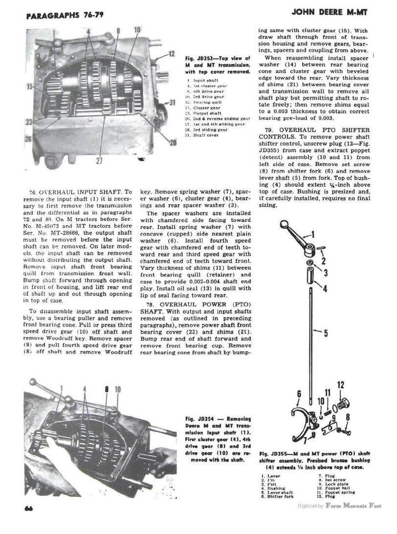
PARAGRAPHS 76-79
i6. O \'ERHAUL INPUT SHAFT. To remo\·e the input shaft ( 1) it is necessary to fi rst remove the transmission and the differential as in paragraphs 72 and 110. On l\I tractors before Ser. No. M-45073 and MT tractors before Ser. No. J\ff-28666, the output shaft must be removed before the input shaft can b~ removed. On later mod els. the input shaft can be removed without distributing the output shaft. Remo\'e input shaft front bearing quill from transmission front wall. Bump shaft forward through opening in front of housing, and lilt rear end of shaft up and out through opening in top of case.
To d isassemble input shaft assembly, use a bearing puller and remove front bearing cone. Pull or press third speed drive gear ( 10) off shaft and remove Woodruff key. Remove spacer ( 9 ) and pull fourth speed drive gear (Bi off shaft and remove Woodruff
Fig. JD35J-Top view of M aad MT transmission, with top cover removed.
I lttput Mhntt
-1 . l;t l ('1uetcr ~cnr
~- ~1 h drl\'O ~t1nr 111. :crd drive Sf'nr 1::. l~<-artng qulU
1 • •. Cluster 1:enr ~:1 . Output ehnrt :!1;. :!nd & re\'erso ell din,:: gear ::7. !el :..nd -I th • lldlng cc~r
~S. J r<I •tiding i:enr :11. ShMI cover
key. Remove spring washer (7), spacer washer ( 6 ) , cluster gear ( 4), bearings and rear spacer washer (3).
The spacer washers are installed with chamfered side facing toward rear. Install spring washer (7) with concave (cupped) side nearest plain washer (6). Install fourth speed gear with chamfered end of teeth toward rear and third speed gear with chamfered end of teeth toward front. Vary thickness of shims (11) between front bearing quill (retainer) and case to provide 0.002-0.004 shaft end play. Install oil seal (13) in quill with lip of seal facing toward rear.
78. OVERHAUL POWER (PTO) SHAFT. With output and input shafts removed (as outlined in preceding paragraphs). remove power shaft front bearing cover (22) and shims (Zt). Bump rear end of shaft forward and remove front bearing cup. Remove rear bearing cone from shaft by bump-
Fig. JD354 - Retn0Yh19 Deere M and MT transmission l1put shaft 11 J. Flnt cl111ter •-r 14), 4tll llrtve ,_, II) acul ]rd drive tear 110) •re re·
"'owed wltfl the shaft.
JOHN DEERE M-MT
ing same with cluster gear (15). With draw shaft through front of transsion housing and remove gears, bearings, spacers and coupling from above.
When reassembling install spacer washer (14) between rear bearing cone and cluster gear with beveled edge toward the rear. Vary thickness of shims ( 21) between bearing cover and transmission wall to remove all shaft play but permitting shaft to rotate freely; then remove shims equal to a 0.003 thickness to obtain correct bearing pre-load of 0.003.
79. OVERHAUL PTO SHIFTER CONTROLS. To remove power shaft shifter control, unscrew plug (12--Fig. JD355) from case and extract poppet ( detent) assembly (10 and 11 ) from left side of case. Remove set screw (8) from shifter fork (6) and remove lever shaft ( 5) from fork. Top of bushing (4) should extent %-inch above top of case. Bushing is presized and, if carefully installed, requires no final sizing.
-5
12 6 11 1 I 10 I()~
~~ J(f Fl9. JD355-M a1td MT pewet' ("OJ shaft shlftw nM111llly. Presbed broiae bushl19
( 41 e1Md1 1/4 lach aboww top ofccne.
I. Lever 2. 1•1n 3. Felt of. llu•hlnll' II. I.ever ehntt 6 . Shlltor fork
1. Plu" tt. Set •crow B. Lock pl a te
10. Poppet ba ll 11. Po1111et •Pring 12. l'lua
Oig1t1zed by F- M-11a1a Fut

JOHN DEERE M·MT
I. Input ehl\ ft 4 . 181 <luatH S~ftr 8 . 4U• drh -c lrf'Ar
1n. 3rd dr ln ro:tar 1:,. PO\\ (lr 1h:. ft du~tf·r f;'tft t
t!:t. row.-r ,.hn U ~IL ~nd & rt\"f'f~~ 11ld ln.:
S:MF :i. 1 st~ .Jtn sUd : n..: t:tnr
~8- 3rd oll dlne: .-eor
PARAGRAPHS 80-91
Alter reassembly, check trueneu of ring gear back face by mounting the unit in its normal operating position. Total run-out should not exceed 0.003.
MAIN DRIVE BEVEL GEARS
90. GEAR MESH. The main drive bevel pinion output shaft fore and aft position in the transmission case is adjustable (by means of shims) to provide the correct cone center distance or mesh position of the pinion with the main drive bevel r ing gear. To adjust the bevel p inion mesh position, it is necessary to first remove the transmission from the tractor and then remove the differential unit.
Fig. JDJS6-Cutaway view of M a11d MT tra11S111lsslo11. Mal11 cfrlv• be·w.I plido11 (2JJ Is
l11t.tral with output sllaft.
The main drive bevel gears are available only as a matched pair. If new gears are being installed or if the original gears require adjustment do so as outlined in the following paragraphs.
FINAL DRIVE 91. SETTING THE PINION. With differential removed and transmission removed from tractor. first step in setting the pinion position is to make certain that pinion (output) shaft bearings are correctly adjusted to 0.005 bearing pre-load. To make this adjustment, remo\·e bearing cover at front of transmission case and nut from front end 0£ pinion shaft. Bump pinion shaft rearward until shims (30--Fig. JD350 ) are accessible. Vary the number of shims until all end p lay is removed but shaft rotates freely ; then remove 0.005 thickness of shims. This
DIFFERENTIAL
80. REMOVE & REINSTALL. To R&R the differential, first remove the final drive assemblies as outlined in paragraph 95 or 100. Remove belt pulley unit or rear cover plate, and on model M, remove b oth brake assemblies. Remove both differential bearing quills (1- Figs. JD360 and 361) . Working through transmission housing rear opening, remove bevel ring gear and d ifferential unit.
On model MT, shims (4) interposed between bearing cones (3) and differential case (9) control differential bearing adjustment and backlash of main drive bevel ring gear and pinion.
On model M, shims (15) interposed between bearing quills (1) and transmission case control bearing adjustment and backlash of main drive bevel ring gear and pinion . Recommended bearing adjustment is 0.002-0.005 pre- load; recommended backlash is 0.006-0.008. Refer to MAIN DRIVE BEVEL GEARS section for adjustment procedure. Install oil seals (2 ) in quills with l ip edge of seal facing differential.
81. OVERHAUL. Neither the bevel pinion nor ring gear are furnished separately, but only as a matched pair. Bevel ring gear (5) is attached to differential case by cap screws. To disassemble the d lfferenUal unit, remove bevel ring gear and bump pinion shaft retalnlnc (Groov) pin (10) out of differential case. Remove dlferentlal pinion shaft, pinions, side 1eara and thrust washers.
Reassemble in reverse order and stake differential case to prevent pinion shaft retaining (Groov) pin from backing out. When new case is installed on model MT, obtain initial bearing adjustment as follows: Insert shims (4) amounting to a thickness of 0.025 between left bearing cone and differential case. For the right bearing cone, insert shims amounting to a thickness of 0.040. Differential carrier bearings are adjusted by varying the amount of shims to provide a 0.002-0.005 pre-load. Shims (4) also control the ring gear to main drive bevel pinion backlash adjustment.
1
. ..... ............. ,. .. Fl9. JDUO-Deere MT dlffereflrfal alM!llblJ. lewe~~l11t •-' ~l~l~tlel ...n ... a..t tlal ca .. (t) by cap ICIWWL Shl1R1 (4) ore for ~u~1Mfft 0
.. cllhnlt of MOia •IH -• .. 9""' I . Rearlni: qulll :! . 011 •••l 3. f\eulns cup .t
con•
4. f;hltlOI t MT I :'\. It Ito: «flA r 8. Pinion ohart
1. TllNll ""eh.-r I . l~nlon 8. 111fferenlla1 <'•••
1 •'· C: roo\' J•ln 12. Sid• i:•ar 13. Thruet v.·••h•r
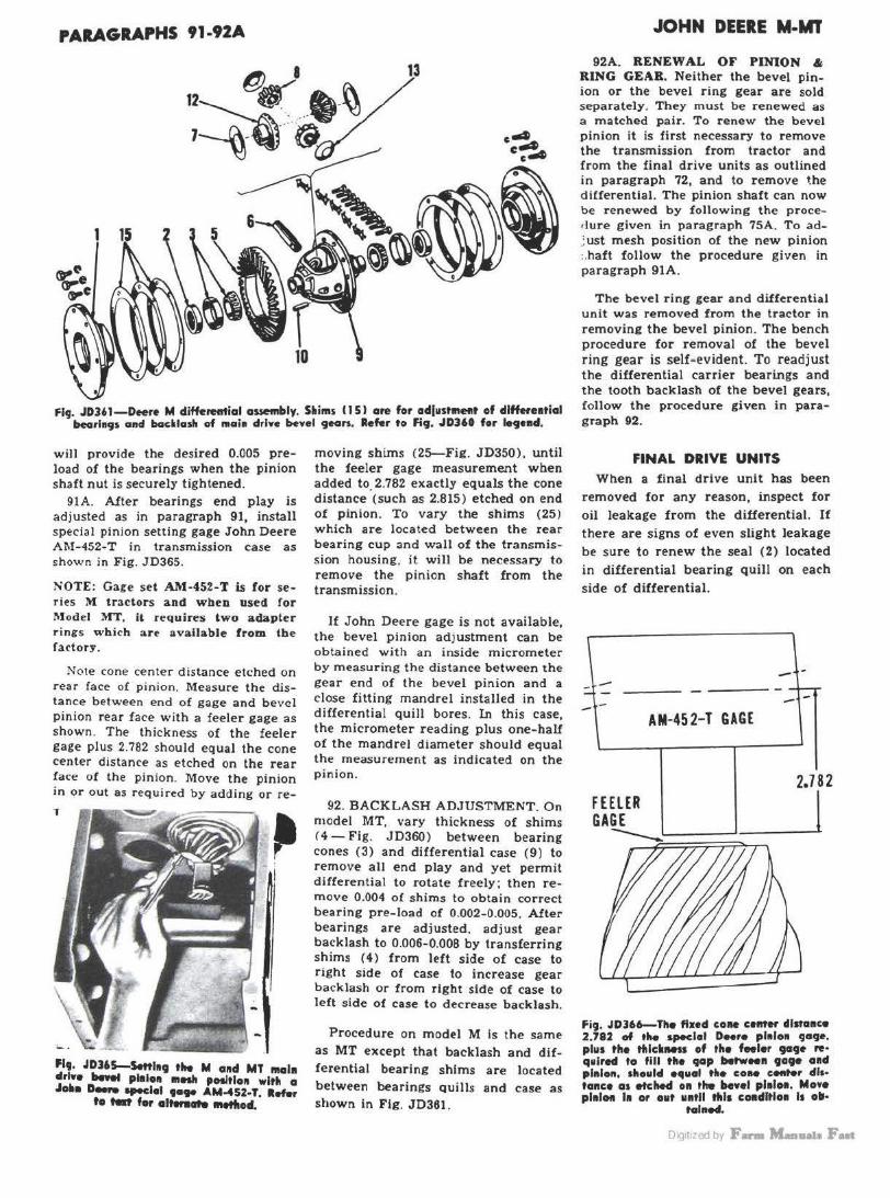
PARAGRAPHS 91-92A
Fl9. JD3'1-Deere M differential assembly. S•ims 115 I are for adjwst111et1t of dlffffe1tial bearl19r. and backlash of main drive bevel gean. Refer to Fig. JD360 for legend,
will provide the desired 0.005 preload of the bearings when the pinion shaft nut is securely tightened.
91A. After bearings end play is adjusted as in paragraph 91, install special pinion setting gage John Deere Al\1-452-T in transmission case as shown in Fig. JD365.
SOTE: Gage set Al\1·452-T is for se ries M tractors and wben used for Model MT, it requires two adapter rings which are available from the fa<'tory.
Note cone center distance etched on rear face 0£ pinion. Measure the distance between end of gage and bevel pinion rear face with a feeler gage as shown. The thickness of the feeler gage plus 2.782 should equal the cone center distance as etched on the rear face of the pinion. Move the pinion in or out as required by adding or re-
1
Flt. JD3'5-Settl19 the M a11d MT 111ala ~rl•e bewel pi.101 """' pOlltlo11 wltlt a .. all• D- ..-dol t•,_ AM-4$2-T. Rmr
te ,_. for alten.._ Metlloll.
moving shims (25-Fig. JD350) , until the feeler gage measurement when added to. 2.782 exactly equals the cone distance (such as 2.815) etched on end of pinion . To vary the shims (25) which are located between the rear bearing cup and wall of the transmission housing, it will be necessary to remove the pinion shaft from the transmission.
lf John Deere gage is not available, the bevel pinion adjustment can be obtained with an inside micrometer by measuring the distance between the gear end of the bevel pinion and a close fitting mandrel installed in the differential quill bores. In this case, the micrometer reading plus one-half of the mandrel diameter should equal the measurement as indicated on the pinion.
92. BACKLASH ADJUSTMENT. On model MT, vary thickness of shims (4- Fig. JD360) between bearing cones (3) and differential case (9) to remove all end play and yet permit differential to rotate freely ; then remove 0.004 ol shims to obtain correct bearing pre-load of 0.002-0.005. After bearings are adjusted, adjust gear backlash to 0.006-0.008 by transferring shims ( 4} from left side of case to right side of case to increase gear backlash or from right side of case to left side of case to decrease backlash.
Procedure on model M is the same as MT except that backlash and differential bearing shims are located between bearings quills and case as shown in Fig. JD361.
JOHN DEERE M-MT
92A. RENEWAL OF PINION & RING GEAR. Neither the bevel pinion or the bevel ring gear are sold separately. They must be renewed as a matched pair. To renew the bevel pinion it is first necessary to remove the transmission from tractor and from the final drive units as outlined in paragraph 72, and to remove the differential. The pinion shaft can now be renewed by following the procedure given in paragraph 75A. To ad; ust mesh position of the new pinion :.haft follow the procedure given in paragraph 91A.
The bevel ring gear and differential unit was removed from the tractor in removing the bevel pinion. The bench procedure for removal of the bevel ring gear is self-evident. To readjust the differential carrier bearings and the tooth backlash of the bevel gears, follow the procedure given in paragraph 92.
FINAL DRIVE UNITS When a final drive unit has been
removed for any reason, inspect for oil leakage from the differential. If
there are signs of even slight leakage be sure to renew the seal (2) located in differential bearing quill on each
side of differential.
::. ----- ---AM-452-T GAGE
2.7 82
L------'__l
fig. JD366-The fixed coM cenrer dlstaace 2.782 of ,.._ special D-r• pl1doa <Jll9•· plus the tfildMts of the feeler 9a9e re· quired to fill the 9ap botwMft 9ate a11d pl11lon, should o~uol tile cono c ..... r dis· tance a1 etched on the IM•el pl11lon. MoYe pl11lot1 11 or out 1111tll this c .. dltloe 11 olll·
talned.
Oig1t1zed by F- M-11a1a Fut

JOHN DEERE M-MT
Model MT 93. WHEEL AXLE BEARING AD-
JUSTMENT. Support rear portion of t ractor and remove wheel. Vary the number of shims ( 18-Fig. JD370) un-
Flt. JDJ71--&p1Med •I- of 0- MT flHI drive. Sltlim (IJ Hd (11) ore llte4 for odl..... tit• dri•• slloft ad wlleef ........ ,. ....
I . Wh .. I ule •llaft !!. 011 ..... 3. Dr1ve •haft 4. 4' ll. Bearlns 6. Drive Cbull) pinion 1. Snap rln1 I . 8hlm1 8. Bearlna qulll
10. Boarlna
II. w .. hM 12. Oil • eal 14. Final drive
hou• ln11 ·~· Drive I bull) aHr H. Beartna 11. Bnlm• tt. Oii .. al quill 21. Houel.,. oll pan
til all end play is r emoved but shaft is still permitted to r otate freely; then remove approximately 0.004 thickness of shims to obtain a desired pre-load of 0.003-0.006.
Fig. JD370-Flnal drive as· sembly for on. II• of D_,. MT tracter. Shhns 18) alld 111) - •tied for edi11tl119 th• drfwe sllcrft and wheel oxl• beorfa9L
:1. ll rl »o ~hnfl 1: . rJ rh·c chull1 l>lnlon ~ . S hlmA
:1. ll•nrlng quill I ~ . ~·111ul drh·t hou•lni; 1;'1. nrh' C (~Hll) J;f'Ur
11:. [lenrln~ If!. !'>hl111e l!t. <•II ~f'n l qulll
~I. H o u• lni; oil non
94. DRIVE (PINION ) SHAFT BEARING ADJUSTMENT. Remove final drive assembly as outlined In paragraph 95. Vary the number of shims (8) to obtain a pre-load of 0.000-0.003.
95. R&R FINAL DRIVE UNIT. Support rear portion of tractor and remove drawbar assembly and rear wheels. Remove fender b racket to final drive housing cap screws. Remove fender, bracket and foot rest from transmission as a unit. Remove brake unit. Remove the two uppermost cap screws which retain final drive housing to transmission housing
Fi .. JDJ73 - Cllt-O•WOf
wlew of hen M flaol dri••·
I. During quill z. Shima U. Bun pln1on
0. Bearing 7. IJull pinion •h1>ft 8 . 011 aeal 8 . H ousing
15. Axle 1e. Bull gea. r
18. Spacer 19. Be1>rlng 20. 011 •eal 21. Bearlni: qulll
PARAGRAPHS 9J.n
and insert two long studs (about 8 Inches) In their place. Using a hoist slide final drive unit off studJ. '
96. R< WHEEL AXLE SB.AFI, BEARINGS AND/ OR BULL GEA&. Remove the final drive assembly as outlined in paraeraph 95. Remove axle shaft quill (19) and inner bearin2 cap screw (10) . With the aid of a reaction pusher , push the shaft toward the wheel end and out of bull gear (15). Inner bearing cup is retained In postion in the final drive housing by a snap ring.
97. R&R. DRIVE SHAFT, BEA.RINGS AND/ OR BULL PINION. Remove final drive assembly from tractor. Shaft, bearings, and bull p inion ( 6 l can be bumped out after removing bearing quill (9).
Bearing cup and/or oil seal can be renewed at this time. Install new seal with the lip facing inward.
When reinstalling the drive shaft assembly, vary the number of shims ( 8 ) to obtain the desired bearing preload of 0.000-0.003.
Model M 98. WHEEL AXLE ADJUSTMENT.
Support rear of tractor. Vary thickness of shims ( 10- Fig. JD374) between bearing cover ( 11) and housing to remove all play but pennitting shaft to turn freely: then remove approximately 0.004 thickness of shims to obtain the desire1 pre-load of 0.003-0.006. Tighten inner bearing cap screws to a torque of 180- 190 ft .-lbs.
99. DRIVE (PINION) SHAFT BEARING ADJUSTMENT. Support rear of tractor and remove wheel. Remove rear cover or belt pulley unit to check shaft end play. Remove Quill

PARAGRAPHS 99-110
(1-Flg. J'D374) from outer bearing. Vary thickness of shims (2) to provide from 0.001 pre-load to 0.002 end play in shaft.
100. K & R. ONE FINAL DRIVE UNIT. Support rear of tractor and remove wheel. Disconnect brake rod, remove clevis and locknut from rod and push rod out through rear of housing. Detach fender from housing. Remove cap screws attaching final drive to housing and remove assembly. Reinstall in reverse order and adjust brake as in paragraph 112.
101. R .t: R WHEEL AXLE SBAFr. BEARINGS AND/OR BULL GEAR. Support rear of tractor and remove wheel. Remove the housing oil pan and
~l~~A ~ LJ
119, 10374-E•procled wlew of Deere M
ltnal drlv•.
1. hrins ouUJ 2. Shhu 3. Snap rlns 4. Bearlns 6. Bull 11l11loft r.. B•arl11s 7 · Bull plnloD ol>&f' " · 011-1
10. Shi-ll. Burin•-
70
12. w ...... la. Bcarins 14. Wuh•r 16. Azl• lr.. Bun s .. r 17. Guk.t 18. Spacer l!I. B<-anns ~o. Oil aeaJ 21. Barios QaUI
outer bearing quill (21). Remove inner bearing cover ( 11) and cap screw and washe.rs from inner end of wheel axle. Drive or press axle out of inner cone and gear and out through outer opening in housing. When shaft is being driven or pressed out, support hub of gear with a length of 3~ inch pipe slipped over outer end of axle. Reassemble in reverse order and adjust bearings as In paragraph 98. Install oil seal (20) in quill with sharp edge oC seal towards gear.
JOHN DEERE M-MT
102. 11 & B DRIVE SHAFT, BEAR· INGS AND/OR BULL PINION AND OIL SEAL. Support rear of tractor and remove wheel. Remove quill ( 1-Fig. JD374) from outer bearing and withdraw shaft, bearings and gear. Gear and bearing cones can be pressed off shaft after removing snap ring ( 3). Inner bearing cup can be removed with a puller. Install oil seal in final drive housing with sharp edge of seal out towards wheel. Adjust bearings as outlined in paragraph 99.
BRAKES
J, Brake bOIUllas I. Boll- dowtl8 I . Drlnn (llntd) .ii. .. '· Aetuatlns diam I. A..n.etln• IMIJC.
4
Model MT 110. ADJUSTMENT. Support rear
portion of tractor, turn adjusting nut (11-Fig. JD381) in until a slight drag is obtained when turning wheel; then retract nut approximately 3 turns. Follow the same procedure for the other brake. Both brakes should be free when pedal is depressed l lk inches, but should lock the wheel when pedal is depressed approximately 21h inches. Synchronize brake pedals by varying length of individual pedal rods.
Fi9. 10380-Deere MT din type hralre. Driven (rined) discs (3) ore splined to out· er end of ffnaf drive (burl pinion) 1ftaft.
See Fig. JD38J for regend.
"•· JD311-Deere Mf din typ• •ralr•. 8. R~l•u• oprlna 11. Adiuotll\S nut 7. Ptdal rod 8. P...t•I rod 7ok~ II. J,..v•r r•turn aprlfts
10. fkturn aprlna clip
12. O~ratlnll' levtr 13. Acl\latl na rod A 7ok .. 14. Oporatlna' l•vtr brack•t lft . Op.r•tlna lever pin
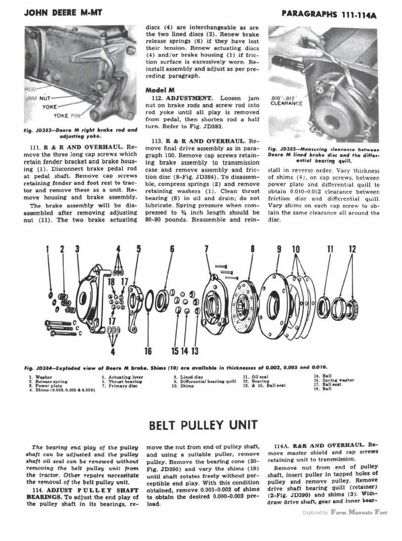
JOHN DEERE M-MT
JAM Nur--
YOKE
fig. J03B3- Deere M ri9ht brake roll and adfustlng yole.
111. R & R AND OVERHAUL. Remove the three Jong cap screws which retain fender bracket and brake housing (I). Disconnect brake pedal rod at pedal shaft. Remove cap screws retaining fender and foot rest to tractor and remove these as a unit. Remove housing and brake assembly.
The brake assembly will be disassembled a1ter removing adjusting nut (11) . The two brake actuating
1 2 3 5
discs (4) are interchangeable as are the two lined discs (3). Renew brake release springs (6) if they have lost their tension. Renew actuating discs ( 4) and I or brake housing ( 1) if friction surface is excessively worn. Reinstall assembly and adjust as per precedin~ paragraph.
Model M 112. ADJUSTMENT. Loosen jam
nut on brake rods and screw rod into rod yoke until all play is removed from pedal, then shorten rod a half turn. Refer to Fig. JD383.
113. R & R AND OVERHAUL. Remove final drive assembly as in paragraph 100. Remove cap screws retaining brake assembly to transmission case and remove assembly and friction disc (8-Fig. JD384) . To disassemble, compress springs (2) and remove retaining washers ( 1 ). Clean thrust bearing (6) in oil and drain ; do not lubricate. Spring pressure when compressed to ~ inch length should be 80-90 pounds. Reassemble and rein-
1 8
16
PARAGRAPHS 111-114A
.010"-.012" CLEARANCE
Fig. JD385-Measuring clearance betwee11 Deere M lined brol<e d isc and the differ·
eritiol '1ooring quill.
stall in reverse order. Vary thickness of shims ( 4 >. on cap screws. between power plate and differential quill to obtain 0.010-0.012 clearance between fri ction d isc and differential quill . Vary shims on each cap screw to obtain the same clearance all around the disc.
9 10 11 12
fi9. JD314-fxplolled view of Deere M bratce. Slli"'' ( JOJ ere OYalloble in tllicknenes of 0.002, 0.005 and O.OJO.
1. Wuher 2. Rol•u• oprlntr a. Power plate 4. Sl.inu co .002 . 0 . 006 A 0.010)
5. Actuatinir Jnu ' · Thru.t bearlDtr 7. Primary di..:
The bearing md play of tile pulle11 •haft can be adju.sted and tile pulley shaft oil seal can be renewed without removi1'g the belt pulley unit from the tractor. OtlieT 1'eJ)air1 neceuttate the removal of the belt pulley unU.
114. ADJUST PULLEY SHAFT BEARINGS. To adjust the end play of the pulley shaft in lts bearings, re-
8. Lintel d lac 11 . Oil 1ul 14. Ball 16. Sprinci wuher Q. Dilrneutial bn.rins quill
10. Shima 12. Boarln•
17. Ba11aeat 13. 4 16. Ball Hat 18. Ball
BELT PULLEY UNIT
move the nut from end of pulley shaft, and using a suitable puller, remove pulley. Remo1;e the bearing cone (20-Fig. JD390) and vary the shims (19) until shaft rotates freely without perceptible end p lay . With this condition obtained, remove 0 .001-0.002 of shims to obtain the desired 0.000-0.003 preload.
114A. R&R AND OVERHAUL. Remove master shield and cap screws retaining unit to transmission.
Remove nut from end of pulley shaft. insert puller In tapped holes of pulley and remove pulley. Remove drive shaft bearing quill (retainer) (2-Fig. JD390) and shims (3). Withdraw drive shaft, gear and inner bear-
Di< 1t1 qJ bi F- M-.,-.Ja Put

PARAGRAPHS 114A-1141
Fig. JOJ90-M and MT belt pulley unit , Shims (3) and (19) are lot bearin9 ocfjuffment. Shims (9) and (17} ore for mesh and bocl<losh adjustment of beYel 9ears.
1. Oil ecal A. Bc:nr ir11t cup 15. Driven stear ·~. Drive- ~ho fl quill l . U··~rin~ ~hims
~. C :1•ur shims It>. Inner ~arin11 cup Ji. Gcar ahime I Cl. C:.s•:
·L Oil sl inS?('r ,j_ [1rl\' 4.~ ~·:CH 6. l•r i\•t.• ehn(t
11 . c; •. :lr CA.!le CO\'Cr
I Z. \\', vdru H kcf 13. f' 1Jll•: » s:hoft
IS . Wuh•r I~. Bcurin11 ahirna ~O. Outt-r bearine 21. Pulley ehaft aeal 7. \',' c.od ru rt k<·Y I~ . \\'o••Jrurr kr.r
111g cone-~ . R emo\·e cover { 11) :irid
bump pull1:y shaft. gear and in n<.- r be:. ring cont- out through left side of case.
If cups for the roller bearing cones are defective they can be removed with pullers otherwise they shouJd not be disturbed. If cups are removed, be sure to avoid damaging the shims (9) and ( 17) which control the mesh and backlash position of the bevel gears. In most every case, the mesh position will be correctly maintained if the original shims or new ones of same: thicknes~ are installed.
114B. During reassembly, observe the following points: Assemble the pulley shaft to the housing before assembling the drive shaft to the housing. Shims {17) control the backlash of bevel gears. If these shims were removed during disassembly, be sure to reinstall the same ones or new ones of exactly the same thickness. Vary the shims (19) until shaft rotates freely without perceptible end play then remove 0.001-0.003 of: shims to obtain desired pre-load of 0.002.
If shims (9) were removed during dlaauembly, be sure to reinstall the same ones or new ones of the same thlckneu. Thete ahlma control the
72
rnesh position of the bevel gear on the d rive$haft (6) . Vary the shims (3) locate<! between quill and housing until shaft rotates freely without perceptible end play, then add an additional 0.003 of shims to obtain the desired end play of 0.002-0 004.
Fig. JD 3 9 1 - Checking mesh position of belt pulley driYe gear will! feelers and John Deere ga9e
number AM-454-f.
JOHN DEERE M-MT
Check gear backlash of assembled unit. If backlash is less than 0.005 or more than 0.010 it should be brought within these limits by disassembling the unit and varying the shims ( 17) located between bearing cup ( 16) and housing. If backlash is measured on splines at front end of drive shaft as shown in Fig. JD392 instead of at the gear teeth, the dial indicator reading should be within the limits of 0.0015-0.003 due to the smaller radius at point of measurement.
If the gear heel faces are within 0.005 of being flush with each other after correct backlash has been obtained, the mesh position is satisfac-
Fig. JDJ92-M ond Mr ltefr pulley gear backlash cannot be measured at the gear teeth. Jo measure gear backlash, use a dial indicator witll the button of the inclicator contacting the splines of tho Jrive sltoft, When measured in this manner, boclclasli re0Jin9 should be O.OOJS-0.003. Gecrr bocl<lash is conrrofled with sltims (17 - Fig. JD390J locatecl behind the pulley
slta~ inner bearing cup.
Oig1t1zed by F- M-11a1a Fut

JOHN DEERE M-MT
tory. U heel faces are not within 0.005 of being flush, it will be necessary to change the position of the drive gear by disassembling the unlt and varying the shims (9 ). The John Deere Company provides a special gauge AM-454-T which saves considerable time in the job of setting the mesh position and backlash of the belt pulley bevel gears.
115. R & R CONTROL. Remove transmission cover and extract detent ball plug ( 10---Fig. JD393) and spring (9) from hole over pulley shifter yoke. Bump pin (2) out of control lever and remove pin connecting shifter ( 4) to shifter yoke and release shifter. Remove differential unit as outlined in paragraph 80 and withdraw shifter yoke (7) and coupling (5 ) through rear opening.
POWER TAKE-OFF 116. The power take-off shaft ls
part of the transmission assembly and extends through the rear of transmission case. Refer to paragraph 78, in TRANSMISSION SECTION for removal and relnstallation.
POWER LIFT UNIT
The maintenance of absolute clean
linen of all parts b of utmost importance in the OJ>l!'Tation and servicing of
the hydraulic system. Of equal importance i$ the avoidance of niclu or burrs on any of the workiftg parts.
PUMP
Models M-MT The two aection pump (Fig. JD401 )
aa U&ed on model M tractors before Ser. No. 32884 b not lnte-rch.angeable with the th,.ee aeetion type (Flg. JD-400) as used Oft lote-r model M tractor.s and all model MT tractors. The aervice procedures tor the two pumps are similar, an.d an11 ditferencea t0iU be indicated in tht following par11-srraphs.
117. REMOVE & llEINSTALL. The gear type pump ls mounted on the engine timing gear cover and receives its drive through coupling (1-Figs. JD400 & 401) which is bolted to the camshaft. To remove pump unit, remove hood and grille, and disconnect oil lines at pump. Remove the three 10cket head screws retalnlnf pump to Umln1 1ear cover and remove pump.
PARAGRAPHS 1141-118
1_18. OVERHAUL. Disassemble pump unit by removing the socket head cap screws. Drive shaft (2 ) can be presaed out of pump gear (9). Needle bearings <6 & ltl) can be pressed out for renewal. However, needle bearings (13 & 18) in pump cover must be collapsed to remove same. Pump drive shaft oil seal (3) is of the two way design, and can be installed with either seal lip facing the pump gears.
On two-section pumps, make certain that mating surfaces of pump body and cover are clean and unmarred. Do not use sealing compound or gaskets on these mating surfaces. On three-section pumps make certain that sealing rings (8 ) are seated in grooves of center section.
'19. JDJ93-M and Mr llelt pulley 1ldffer control i1 lecafed in tron1miHio1t case.
11 drive shaft and gears do not ro- _ tate freely after pump is assembled, then loosen the assembly screws and retighten alternate screws evenly wh.ile rotating pump drive shaft unUl all screws are tightened to a torqut> value of 24-28 ft . pounds.
1 . Shift.er 1 .....
2. Pin
a. F•lt
4. Shifter Ii. Coupllns
6. Cott.r pin
7. Sbllter :roke
8. Poppet ball
9. Poppet1prln1
10. Detent plus
119. JIUOO-Oeere M (fdter Ser. No. 32883) 011rl Mr ltyrlrovlic pvmp 01Hmllly wlticlt 11 -uatecl on t•• engine tl1rtlflfl gear coW'er and rec1iW'H its drive from t•• camsftaft.
1. Drl•e ..,upllns l. Drl•••batt I . Doable--.! 4. PumpMae ' · Dowel pl,..
6. :NHC!le bearinir 1. ~nter uctlon t. Pumpeeal.o t. Drive aur
U. N_.jlc bearins
14. Driven irear Iii. Drivn a .. r 1baf\ lS . N...tl• b.arlns 17. Espan1ion plur 18. Nttdl• wari111r
"•· JDAOl-Deere M (ltelore Ser. No. JJIU) ftyclraullc pu•P· fftl1 two 1ecfl•i;.:;;' ,.. c•"'•• It• drlW'e a1td •p-te• In a sfmllar 111a1111.,. to tkt •hw• '" "•· • 1. Drive coupllns 2. Drive ahaft a. Double .. 1 6 . J>ow,.I pin e. Ne.ell• blutns
9. Drlvepar 10. Mountlns 1crewe 11. Pump cov..-
IS. N4't'dlt beerlns
~: : g~::~ :=abaft 18. N..dle bearl ... 19. Pumpbodr
DiQ1t1zed by F- Maa.ai. Fut

PARAGRAPH 119
VAL VE HOUSING
Models M·MT Tbe M hydiou.Jlc Wt cylinder and •aln
houainq (Fig . fl)406) la al.m..Uar bl coruatruc
Uon and operotH on the same principle cu I.be MT hydraulic lift cylinder ond valve bouslnq (Fi9. 10405). The obvious dUference between the two Wlita is tha t the M boa on•piaton; whereas, the MT has tw o.
The servicio9 p1ocedwes for the two units are basicaUy similar. ood the foUowi.n9 parocpapb.s ca11 be applied to either uni1. l.n qeoeral. boweHr. the M llJl.lt will require only haU of the work which Is ou1l1Jted.
119. OPERATING PRESSURE CHECK & ADJUST. To check and adjwt the operation ot one relief valve, proceed as follows: Remove the 'f.z-inch pipe plug fr om location, ( A F ig. JD405 or 406) and insert a !%-inch pipe plug directly int o the threaded passage beneath the 1,2- in cb plug just removed . Install a pressure gage o1
su!!ident capacity (2000 psi) where the 1;-2-inch plug was removed as show n in F ig. JD408 or 409. Start the engine. Pull hand control lever r earward u ntil relief valve opens. Opening of the relief valve can be noted by an audible clicking sou nd. Note gage pressure read ing when the valve opens. Do n ot oper ate the unit for more than 30 seconds In this posltlon . If the gage reading is less than 820 psi
16 15
A
JOHN DEERE M-MT
To adjust relief valve, separate the r ock shaft housing ( 8-Fig. JD420 or 421) from the valve housing, ( 19-Fig . .10405 or 406). Using a male socket w rench, remove the locking scr ew (21) and turn the slotted adjusting screw (20) In to increase pressure or out to decrease pressure.
Fi9. JD40~Deere M Ii~ H it cylla•r ud volvo hoasla9, eiploded view. hllef valft 11) controls optt11tia9 ,,_,.. Hole IA I ls pol•t fOf lutalll.., a prnsare gage fOf' test•
1119 system pressure. Lat. models are eqalpped with a ball type Nll.f wafv~ l. Reller \'alve 0. Cylinder head HJ. Control rod 2. By-pa.. '\"al vC" 1. Head u:"t &t enap rln~ 17. PlHon aeals 3. Ch~k •·nhe & sprlni; 14. Lever eQUllllZtr 18. Piston .f . AdJu• Ung shims l &. Control ' 'nh·e zo. Rt11er \'tll ve adJuatlnJ: ac:rew :;. Chtck \'ah·e push rod ::1. Relief vnlvo lock scr~w
11
7 8 9
I. R•llof vnh·cs
2. By.pan ' 'nh·c:it
3. Chec k \'O.lve~ nod evrlni;a
4. Valve a.dJua tJng ahl m e
5. Cheek vnJvo puah rod•
6. Cylinder heada
i . Htnd aenl & 1nnp rlns
8. Cover-to·houslne •ta •
0. F ront co•er
10. Shuttle V&lve
II . Control quaclrnnto
12. Lever eh'1ft eC"ala
13. Control l•vor cr-onka
U . Lever e<iuallzers
HI. Control v&lvta
HI. Control rode
Ii. Platon eeale
18. Platona
19. Valve hou11ne
zo. Reller va.h·e a.dJu11tlns: acrew
21 . Relief "nlve lock 1crew
0
Fl9 • .ID415-Doent MT II~ .. It crtllldef d l•lfM .. , ......... roNM ,.,.,. H .. ~~) r··'· "., .. 11 ..... ,. .. d wlow. lollef HIYft 111 coatrol .,., .... , , ..... ,. ..... ,. .... • • • •• two llmllar p ollltl for h11tonat1 .. of a ,,....,. t•t• fw teltl911 .,..._ ,,...,..
U ~~~ F F~
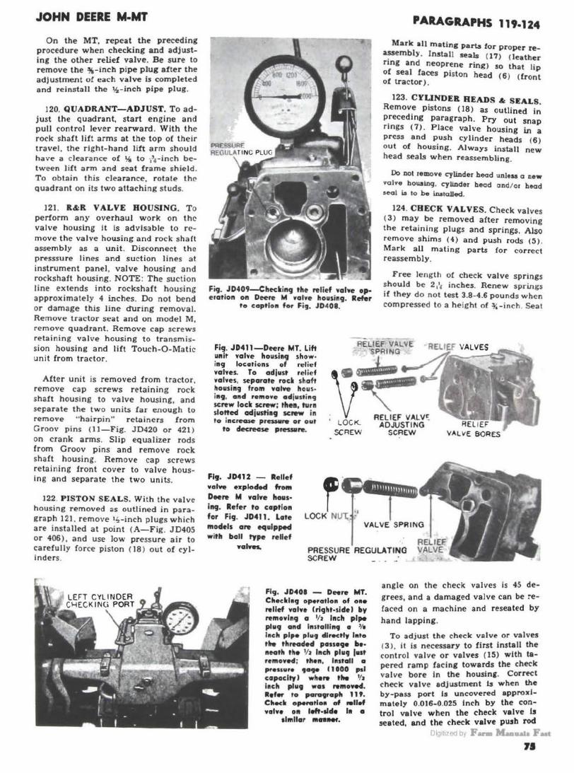
JOHN DEERE M-MT
On the MT, repeat the preceding procedure when checking and adjusting the other relief valve. Be sure to remove the %-inch p ipe plug after the adjustment o! each valve is completed and reins tall the ~-inch pipe plug.
120. QUADRANT-ADJUST. To adjust the quadrant, start engine and pull control lever rearward. With the rock shaft lift arms at the top of their travel, the right-hand lift arm should have a clearance of ~ to -.3.r- inch b etween lift arm and seat frame shie ld. To obtain this clearance , rotate the quadrant on its two attaching studs.
121. R&R VALVE ROUSING. T o perform any overhaul work on the valve houslng it is advisable to remove the valve housing and rock sha ft assembly as a unit. Disconnect the presssure lines and suction lines at instrument panel, valve housing and rockshaft housing. NOTE : The su ction line extends into rockshaft housing approximately 4 inches. Do not bend or damage this line during removal. Remove tractor seat and on model M , remove quadrant. Remove cap scr ew s retaining valve housing to transmission housing and lift Touch-0-Matic unit from tractor.
After unit is removed from tractor, remove cap screws retaining rock shaft housing to valve hous ing, and separate the two units far enough to remove "hairpin" retainers from G roov pins {11-Fig. JD420 or 421 ) on crank arms. Slip equalizer rods from Groov pins and remove rock shaft housing. Remove cap screws retaining front cover to valve h ousing and separate the two units.
122. PISTON SEALS. With th e valve housing removed as outlined in p aragraph l 21. remove 1~-inch plues which are installed at point (A-Fig. JD405 or 406 ). and use low pressure a i r to ca refully force piston ( 18) out of cy linders .
Fig. JD409-Checking the relief valve operation on Deere M valve housing. Refer
to coptlo11 for Fig. JD408.
Fig. JD411-Dtere MT. Lift Hit valve houslag show· ing locations of relief valves. To adjust relief valves, separate rod shaft housing from valve hous· i119, and re111ove ad justi119 screw lock screw; the11, turn slottecl adjusti19 screw in to increase pres141,. or out
to decrecise pressare.
f LOCK NU-C '1
PARAGRAPHS 119·124
Mark all mating part.s for proper rea~embly. Install seals (17) (leather ring and neoprene ring) so that lip of seal faces piston head (6 ) <front of tractor) .
123. CYLINDER READS & SEALS Remove pistons (18) as outlined i~ preceding paragraph . Pry out snap rings ( 7) . Place valve housing in a press and push cylinder heads (6 ) out of housing. Always install new head seals when reassembling.
Do not remove cylinder head unless a new valve bou.alng, cylinder head and/ or head seol is to be i.o.ato.lled.
124. CHECK VALVES. Check valves C 3) may be removed after removing the retaining plugs and springs. Also remove shims ( 4) and push rods ( ~) . Mark aU mating parts !or correct reassembly.
Free length of check valve spr ings should be 2 11, inches. Renew spr ings if they do not test 3.8-4.6 pound s when compressed to a height of ~-inch . Seat
Fl9. JD4'2 - Rellef valve esplaclecl fro11t Deere M valve hoas· ing. Refer ta caption for Fig. JD411. Late models are equipped with boll type relief
VALVE SPRING
valYws,. PRESSURE REGULATING SCREW
Fig, JD401 - D"re MT. Chec•l•g operatlo11 of o•• Nllef voln (rlglit-side) by removing a 1/ 1 Inch pipe plug and l11stallln9 a '/1 h1ch pipe plu9 directly l11to tile threaded PHHl)e beneath the llJ Inch plug l••t romove4; tllen, l111tall a pressur1 9ege (HOO psi capocltr I wliel'9 the 1/J h1ch plug was romoYed. lefer to para9raph 11'. Chee• opeNtlH of Mllef valve 011 left·slde 111 a
1h11llar 111nttef.
angle on the check valves is 45 degrees, and a damaged valve can be ~efaced on a machine and reseated by
hand lapping.
To adjust the check valve or valves (3), it is necessary to first install the control valve or valves ( 15) with tapered ramp facing towards the check valve bore In the housing. Correct check valve adjustment b when the by-pa" port Is uncovered approximately 0.016-0.025 Inch by the control valve when the check valve is seated, and the check valve push rod
i1 111 d ,, F- • 71

PARAGRAPHS 124-129
just contact.3 the control valve tapered ramp, as shown in Fig. JD415.
In lieu of the special John Deere gage set, AM-453-T, the adjustment can be made as follows: Instead of the special Deere gage rod (A-Fig. JD-414) insert a 0.016-0.025 diameter wire in the by-pass port in housing and install the control valve (instead of tool 453Tl until same contacts the wire. Next install check valve, shims and push rod. With the check valve seated, the push rod of same should contact the tapered ramp surface of the control valve. If the push rod contacts the
JOHN DEERE M-MT
Fi9. JD411-D•••• MJ l ift
u11it valve lto11ai1t9 1ltowi1t9 lotation of by-pcus valves. To remove by-pou valves, separate rode sltoft lto"sin9 from valve ltousin9. Remove snap rings; then, remove retainer plus by 11sing a ~.
BY-PASS V'-LVE
RETAINER l PLUG
~-ittd• nandorrl halt.
~o@ \4? SNAP RINGS SPRING
fig. JD•U4-Deere MT-first step in allj"sting the clteclc lfalves l>y using Deer• special 909e set AM-453-T (A&BJ and feeler gage to determine posirion of by· poss relative to machined surloco of co1ttrol valve ltousin9. In lieu of tlte
special ga9e, follow •rl· ju.ting procedures a• ollf• lined in paraf1roph 724.
By-pass valve springs should have a free length of 2 l / 16 inches. Renew springs if they do not test 3.8-4.6 pounds when compressed to a height of 3~ inch. Valves can be seated by lapping. Be sur e that by-pass bleeder hole is open and clean.
·---..;-,;- i:- f.:.:; -·- 9-.. . p4~;-; PORT OPENED U1~1 NCW
128. RELIEF VALVES. With the valve housing removed, remove relief valve lock screw or nut (Fig. JD411 or 412) with an Allen wrench. Unscrew the pressure regulating screw, and at the same time, count the number of revolutions required for complete removal. When reinstalling the regulating screw. thread same in housing the same number of revolutions so as to provide an initial adjustment and the desired operating pressure as listed in paragraph 119.
Relief valve springs should have a free length of 4 inches. Renew springs if they do not test 135-150 pounds at a height of 3 lh inches. Relief valves can be seated by lapping.
.:. ·.i .iJ :· T
ramp surface before the check valve Is seated, remove shims ( 4-Fig. JD405 or 408) until the valve ls just seated .
On model MT, repeat preceding procedure for checking and adjusting the other check valve.
127. BY-PASS VALVE. With the valve housing removed, r emove bypaaa valve (Fla. JD417 or 418 ) after extract1n1 the 1nap rings and pluaa. Plu11 can be removed using a ~ Inch •tandar4 bolt.
76
Al\IE fi9. JD415-Deere MT-Second step in adfu.tin9 tit•
clloclc valves b)' "''"' Doore special 9a9e ond feeler 9a9e to politiott control valve so tltat tlle by-poss port 11 opened o •• 016-0.022. In lieu of tit• special gage, follow arlj"ding procedure as out-lined In paragroplt 124.
flf. J041 I - ly-paH valve oad 1prln9 ••· ploded from Deere M valve ltoudnf. ltefer fo CDpflon for f19. JD417.
Check and adjust the unit operating pressure as outlined in paragraph 119.
129. SHUTTLE VALVE. To remove the MT shuttle valve (10-Fig. JD405), proceed as follows : With front cover removed. remove ball knobs from control levers, and capscrews retaining the quadrants. Remove shuttle valve retaining snap rings and plugs to release shuttle valve.
. . ""--~----
Oig1t1zed by F- M-11a1a Fut

JOHN DEERE M-MT
Check the ground surface of shuttle valve for burrs, sharp edges, scratches and / or any roughness which will prevent valve from operating freely. These conditions may produce a difference in the start and / or speed of lift of one side as compared to the other . Roughness and/ or burrs can be removed with Crocus cloth or a fine bone.
ROCK SHAfT HOUSING 130. R< AND OVERHAUL. Rock
shaft housing and assembly can be removed without disturbing the valve housing. Remove tractor seat and support rock shaft housing. Remove bolts
retaining rock shaft housing to valve housing. Separate the two housings far enough to remove "hairpin" retainers from Groov pins (11- Fig. JD-420 or 421 ) . Disconnect equalizer rods and remove rock shaft housing.
To disassemble the MT unit. proceed as follows: Remove lift arms (5
and 9). To loosen rock shafts in housing, bump on right end of rock shalt, viewed from rear of unit, until shafts are two inches out of housing. Remove hollow shaft ( 3). Pull inner sha!l ( 1} from left side of housing until spline is out of right crank arm ( 10) . Continue to pull shaft until splines contact left crank arm. Align blind spline of inner shaft with that of the left
PARAGRAPHS 129-130
crank arm and separate the shaft from the arm by pulling shaft through crank arm and left side spacing wuber ( 12).
The bushings ( 2) can be removed by splitting same with a chisel. Service bushines are presized and should be installed with a suitable mandrel.
To disassemble the M unit, proceed as follows: Remove lift arms (5 and 9 -Fig . .JD421 ). Drive out the two Groov pins which retain the crank arm to the rockshafts, and using a suitable puller, pull rockshafts from crank arm and housing. Drive out the Groov pin which retains the piston rod to the crank arm. Rockshaft seals can be renewed at this time.
Ft9. JD42~D .. re MT lift .. .rt roeksheft, esplodecl Ylew. l•shla11 (2) a,. pre-sized.
I . Rockohatt 3. Hollow rock1hnft 4. Seal and retainer
G. lAft Utt arm 6. lnelde arm •. Rock aha ft eta I
9
1
8 . Rockohatt houolnir o. Rtsht lift o.rm
10. Crank arm1
II ID
11. Crank arm pine I~- Crank nnn apncer 13. Conne<Ung rod1
flt. JD421--bplocled wlew of Dffrw M rocuhcrft ho11sl19 Hd oaoclated parts n a9d Oii Ser. No. M10001 ·M46204. Late •04lel1 are eq1lpped wltll o OM piece reclll,.afr.
I. Rock1ho.tt II. I.Aft lift t.rm T. a-1 and Nlalnor
8. Rockaht.ft hou1ln1 Y. ltll(hl llrt arm
10. Craftk arm
11. Crank arm pin \!l , Conn.-rtln• rod
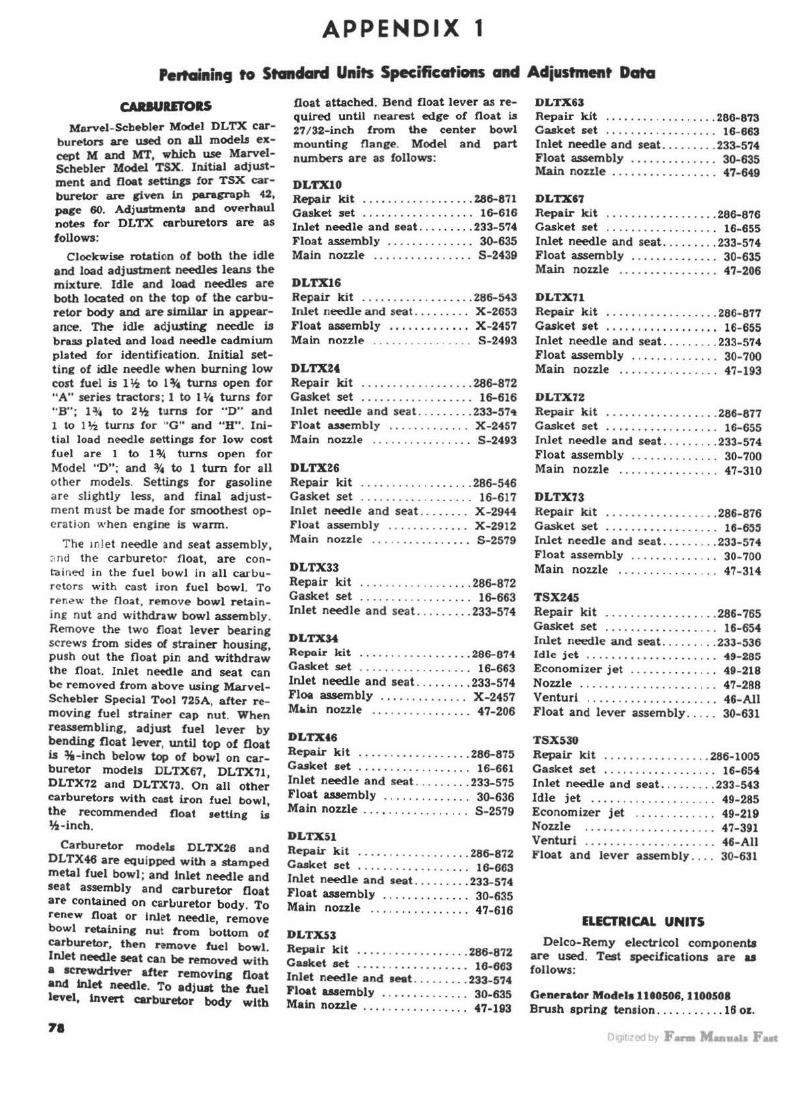
APPENDIX 1
Pertaining to StcBldarcl Units Specifications and Adiustment Data
CAltlUID'OIS Marvel-Schebler Model DLTX car
buretors are used on all models except M and MT, which use MarvelSchebler Model TSX. Initial adjwtment and float settings for TSX carburetor are given in paragraph 42, page 60. Adjwrtmenu and overhaul notes for DLTX carburetors are as follows:
Clockwise rotation of both the idle and load adjustment needles leans the mixture. Idle and load needles are both located on the top of the carburetor body and are similar ln appearance. The idle adju.rting needle ill brass plated and load needle cadmium plated for identification. Initial setting of idle needle when burning low cost fuel is l li2 to l ~ turns open for "A" series tractors ; 1 to 11/4 turns for "B" ; l~ to 2~ turns for "D" and 1 to l 'ii turru for '"G" and "H". Initial load needle settings for low cost fuel are 1 to 1 ~ turns open for Model "D"; and ~ to 1 turn for all o ther models. Settings for gasoline a re slightly less, and final adjustm ent m ust be made for smoothest operation when engine is warm.
The inl et ne-edle and seat assembly, :1nd the carburetor float, are contained in the fuel bowl in all carbure tors with cast iron fuel bowl. To ren.?w the float , remove bowl retaining nut and withdraw bowl assembly. Remove the two float lever bearing screws from sides of strainer housing, push out the float pin and withdraw the float. Inlet nefdle and seat can be removed from above using MarvelSchebler Special Tool 725A, after removing fuel strainer cap nut. When reassembling, adjust fuel lever by bending float lever, until top of float is %-inch below top of bowl on carburetor models DLTX67, DLTX71, DLTX72 and DLTX73. On all other carburetors with cast iron fuel bowl the recommended float setting ~ lh-inch.
Carburetor modela DLTX26 and DLTX46 are equipped with a stamped metal fuel bowl; and inlet needle and seat assembly and carburetor float are contained on car1'uretor body. To renew float or Inlet needle, remove bowl retaining nut from bottom ot carburetor, then remove fuel bowl. Inlet need.le seat can be removed with a screwdriver a&r removing float and inlet needle. To adjust the fuel level, invert carburetor body with
71
.float attached. Bend float lever as required until nearest edge of float Ls 27 /32-inch from the center bowl mounting flange. Model and part numbers are as follows:
DLTXlO Repair kit ... . .... . . . ....... 286-871 Gasket set . ...... .. .. . . .. .. . 16-616 Inlet needle and seat .. ....... 233-574 Float assembly ....... .. . ... . 30-635 Main nozzle . . . . . . . . . . . . . . . . S-2439
DLTX16 Repair kit ... . ..... . ... ... .. 286-543 Inlet needle and seat . . . . . . . . . X-2653 Float auembly . . . . . . . . . . . . . X -2457 Main no7.zle . . . . . . . . . . . . . . . . S-2493
DLTXH Repair kit .......... . .. . .... 286-872 Gasket set . . . . . . . . . . . . . . . . . . 16-616 Inlet needle and sea t ...... .. . 233-57• Float assembly . . . . . . . . . . . . . X -2457 Main nozzle . . . . . . . . . . . . . . . . S-2493
DLTX26 Repair kit ..... . .... . ... . ... 286-546 Gasket set . . . . . . . . . . . . . . . . . . 16- 617 Inlet needle and seat ........ X-2944 Float assembly ......... ... . X-2912 Main nozzle . . . . . . . . . . . . . . . . S-2579
DLTX33 Repair kit ..... .. ... . .. . . ... 286-872 Gasket set ..... . .. . . . .. ... .. 16-663 Inlet needle and seat. .. . . .... 233-574
DLTXM Ropoir kit . ..... ... . .... ... . 286-074 Gasket set .... . ...... ....... 16- 663 Inlet need.le and seat .. .. . . . . . 233-574 Floe assembly ........... . .. X-2457 M"in nozzle . . . . . . . . . . . . . . . . 47-206
DLTXt6
Repair kit ... ........ .. ..... 286-875 Gasket set ............ . ..... 16-661 Inlet needle and seat ......... 233-575 Float assembly ... .. ..... ... . 30-636 Main nozzle . . . . . . . . . . . . . . . . . S-2579
DLTXSl
Repair kit ..... . ............ 286-872 Gasket set ..... . ..... .. ... .. 16-663 Inlet needle and seat ... .... .. 233-574 Float assembly . . . . . . . . . . . . . . 30-635 Main nozzle ..... . . . .. ..... . 47-616
DLTXS3 Repair kit ..... . .......... . . 286-872 Casket set . . . . . . . . . . . . . . . . . . 16-663 Inlet needle and seat .. .. .. . .. 233-574 Float assembly . .... ..... .. .. 30-635 Main nozzle . .. .... .. .... .. .. 47-193
DLTX63 Repair kit .... .. ... . ... . .... 286-873 Gasket set ..... .. .. ... .. . ... 16-663 Inlet needle and seat . .. . . ... . 233-574 Float assembly . . . . . . . . . . . . . . 30-635 Main nozzle . . . . . . . . . . . . . . . . . 47-649
DLTX67 Repair kit ... .. .. .... ....... 286-876 Gasket set ... . . .... . .. ...... 16-655 Inlet needle and seat .. .... . . . 233-574 Float assembly . . ... . ........ 30-635 Main nozzle . . . . . . . . . . . . . . . . 47-206
DLTX71 Repair kit ..... . ..... .... ... 286-877 Gasket set ... .. . . .. . . .... .. . 16- 655 Inlet needle and seat . ..... .. . 233-574 Float assembly . . . . . . . . . . . . . . 30-700 Main nozzle . ....... . .... . .. 47-193
DLTX72 Repair kit .... . . .... . . . .. ... 286-877 Gasket set ......... . . . .... .. 16-655 Inlet needle and seat .... . .. . . 233-574 Float assembly ...... . ....... 30-700 Main nozzle ..... ...... ..... 47-310
DLTX73 Repair kit ............. ..... 286-876 Gasket set . . . . . . . . . . . . . . . . . . 16-655 Inlet needle and seat . . . .. ... . 233-574 Float assembly . . . . . . . . . . . . . . 30- 700 Main nozzle .... . . .. .. ... . .. 47- 314
TSX245 Repair kit . ...... .. . . .... . .. 286-765 Gasket set . . . . . . . . . . . . . . . . . . 16-654 Inlet needle and seat . . . . .. . .. 233-536 Idle jet . . . . . . . . . . . . . . . . . . . . . 49-285 Economizer jet . . . . . . . . . . . . . . 49- 218 Nozzle .. . . . ........ . . . ... .. . 47-288 Venturi .. . ...... . . .... ..... . 46-AII Float and lever assembly . . . . . 30-631
TSX530 Repair klt ......... . . . . .... 286-1005 Gasket set . . . . . . . . . . . . . . . . . . 16-654 Inlet needle and seat . .. . ..... 233- 543 Idle jet . . . . . . . . . . . . . . . . . . . . 49-285 Economizer jet . . . . . . . . . . . . . 49-219 Nozzle . . . . . . . . . . . . . . . . . . . . . 47-391 Venturi ........ .. ... . .... . .. 46-All Float and lever assembly .... 30-631
ELECTRICAL UNITS
Delco-Remy electrlcol componenta are used. Test spttifications are aa follows:
Generator Models 1110506, 1100508 Brush spring tension .... . .. . . .. 16 oz.
Lllguzoduy F- Manaau ut

Field draw Volts ......... , . . . . . . . . . . . . . . 6.0 Amperes ... . .... . ........ . 2.5-2.72
Output (Cold ) Volts . .... .. .... . ..... · · · · · · · 7.0 Amperes .................. . . 20-25 Rpm . . . . ............ . ........ 2400
GenHator Model 1100955 Brush spring tension ... . .... . .. 16 oz. Field draw
Volts ................. . ...... 12.0 Amperes . ........... . .... . 2.0-2.14
Output (Cold ) Volts ......... . .. . ...... .. ... 14.0 Amperes . . . . ........ . ....... 11-13 Rpm . .. .... .. . . .......... ... 2300
Generator Models, 1101356, 11013'11, 1101377 and 1101385
Brush spring tension . .... . . . . . . 16 oz. Field draw
Volts . . . ................... . . 6.0 Amperes . ..... . . .......... . 3.5-4.5
Output (Cold) Volts . ......... . . . .. . ...... 7.5-7.8 Amperes ..... . . . .. . ........ 11-13 Rpm ....... .. . . ............. 1800
GeneratC>r MCHlel 1Hl390 Brush sprine tension ... . ....... 24 oz. Field draw
Volts ....... . ............... . 6.0 Amperes ....... . ........... 2.6-2.9
Output (Cold) Vol ts ............... . . ..... 6.9-7.1 Amperes ....... . ......... . . . 15-17 Rpm .. .. .. . . . . . ............. 2000
Generator Model llt1'755 Brush spring tension ...... . .. . . 16 oz. Field draw
Volts .. ......... . .... . . ... ... 12.0 Amperes . .. . ..•. .. . . . ..... 1.e-1 .69
Output (Cold) Volts ............ . .. ... .. 14.4-14.Q Amperes ..... . . .............. 8-10 Rpm ........... . ............ 2200
Genera&or M04el 1Ul777 Brush spring tenaion . .. . . . . ... . 16 oz. Field draw
Volts ..... . ...... . .. ... ...... 12.0 Amperes ... . . ...... . . .. . .. 1.6-1.69
Output (Cold ) Volts .. . .... . .... . .. . .... 13.8-14.2 Amperes . . ....... . .. . ........ 8-10 Rpm .. ............. . .. . .. . .. 2000
Generator Hodel 1101857 Brush spring tension .... . ...... 16 oz. Field draw
Volts ................. ........ 8.0 Amperes .... . .......... . . . 2.61-3.0
APPENDIX 1 (Cont'd)
Output (Cold) Volts . . . ... .. ..... . ........ . . 7.0 Amperes . .. . ... .. .. . ........ 10- 13 Rpm . .. .... . . .... . .. ........ 2400
Rep.lator Models 1116809 and 111681'
Cut-out relay Air gap, inches . . . . . . . . . . . . . . 0.020 Point gap, im:he:i . . . . . . . . . . . . 0 .022 Closing voltage ( range) ..... 6.4-7.8
RecuJator Model 1116810 Cut-out relay
Air gap, inches. . . . . . . . . . . . . . 0.01~
Point gap, inches. . . . . . . . . . . . 0.020 Closing voltage ( range) ... 13.0- 14.5
Regulator Models 1118265 and 1118305
Cut-out relay Air gap, inches. . . . . . . . . . . . . . 0.020 Point gap, inches . . . . . . . . . . . . 0.020 Closing voltage ( range) . . . .. 5.9-7.0
Adjust to . . . . . . . . . . . . . . . . . . 6.4 Voltage regulator
Air gap, inches . . . . . . . . . . . . . . 0 .075 Voltage range .............. 6.6-7.2
Adjust to . ....... .. .. .. .... . 6.9
Rel'ulator Models 1118266 and 1118306
Cut-out relay Air gap, inches . . . . . . . . . . . . . . 0.020 Point gap, inches . . . . . . . . . . . . 0.020 Closing voltage (range) ... 11.8- 14.0
Adjust to . . ... . .......... . . 12.8 Voltage regulator
Air gap, inch es . . . . . . . . . . . . . . 0.075 Voltage range ....... ... .. 13.6-14.5
Adjust to . .. ... . . . .... . . . . . 14.0
Regulator Model 1118'186 Cut-out relay
.Aic gap, inches . . . . . . . . . . . . . . 0.020 Point gap, inches . . . . . . . . . . . . 0 .020 Closing voltage ( range) .. . .. 5.9-6.7
Voltage reiulator Air gap, inches . .... . . . . . .... 0.075 Voltage range . . . . . .. .. . .... 6.8-7.4
Replator Model 1118'192 Cut- out relay
Air gap, inches ..... . . . . . .... 0.020 Point gap, inches . . . . . . . . . . . . 0.020 Closing voltage (range) ... 11 .8-14.0
Voltage regulator Air gap, inches . . . . . . . . . . . . . . 0.075 Voltage range ........... . 13.6- 14.5
St.artinc Metor Modela '760 and 1108914
Brush spring tension (oz.) . . ..... 36-40 No load test
Volts . . ....... . .. .' .. . .. .. .... 5.65
Maximum amperes . . . . . . . . . . . 70 Rpm ... ... ..... . . .. .. . . . .. .. 3000
Lock test Volts . . . . . . . . . . . . . . . . . . . . . . . . 3.0 Maximum amperes . . . . . . . . . . . 500 Torque, ft .-lbs. . . . . . . . . . . . . . . . 19
Starilnc Mo&or Models 1107424 and 1107ff:I
Brush •pring teMion (oz.) .. . . . 24 min. No load test
Volts . . . . . . . . . . . . . . . . . . . . . . . . 5.0 Maximum amperes . . . . . . . . . . . 65 Rpm ... .. .... . .. . .. .. . .. . ... 5000
Lock test Volts .. ... . .... .. ... .. .. . . .. . 3.15 Maximum amperes . . . . . . . . . . . 65 Torque, ft .- lbs. . . . . . . . . . . . . . . . 15
S&artinc MotC>r Model 1107942 Brush spring tension (oz.) ..... 24 min. No load test
Volts .. .. . ...... . . . . . . . . .. . . . 5.7 Maximum amperes . . . . . . . . . . . 60 Rpm ...... .... . . .. ... .... . .. 6000
Lock test Volts . . . . . . . . . . . . . . . . . . . . . . . . 3.0 Maximum amperes . . . . . . . . . . . 600 Torque, ft.- lbs. . . . . . . . . . . . . . . . 16
S tartlnc Mo&or Models 1108908 and 1108919
Brush spring tension (oz.) ....... 36-40 No load t est
Volts . .. . .. ...... . . . ....... . . 11.2 Maximum amperes . . . . . . . . 80 Rpm . . ....... . .. . . .. . .... . . 4500
Lock test Volts ........ . . . . .. ......... 5.35 Maximum amperes . . . . . . . . . . . 670 Torque, ft.-lbs. . . . . . . . . . . . . . . . 32
St.artinc Motor Model 1108950 Brush spring tension (oz.) . .. . . . . 36-40 No load test
Volts ... .. . . .............. .. . 11.3 Maximum amperes . . . . . . . . . . . 65 Rpm ... .. .. . . . .. .. .. . . .. . . . . 5500
Lock tect Volts . . . . . . . . . . . . . . . . . . . . . . . . 4.0 Maximum amperes . . . . . . . . . . . 675 Torque, ft.- lbs. . . . . . . . . . . . . . . . 30
Startin~ Motor Model 11096t0 Brusb spring tension (oz.) .. . .... 24-28 No load test
Volts . . . . . . . . . . . . . . . . . . . . . . . . 5.7 Maximum amperes . . . . . . . . . . . 60 Rpm ...... . .. .. . . .. . . .... . .. 5000
Lock test Volts ..... . .. . .... ... ..... .. . 3.75 Maximum amperes .. ... . . . .. · 450 Torque, ft.-lbs . . .. . . . .. ... · · · · 8.5
Dig1t1zed by F- Maallllla Fut 79

NOTES
Oig1t1zed by F- M-11a1a Fut

Digrlized by F- MaalUlla Fut

1 440 363 1440