Embed Size (px)
Citation preview
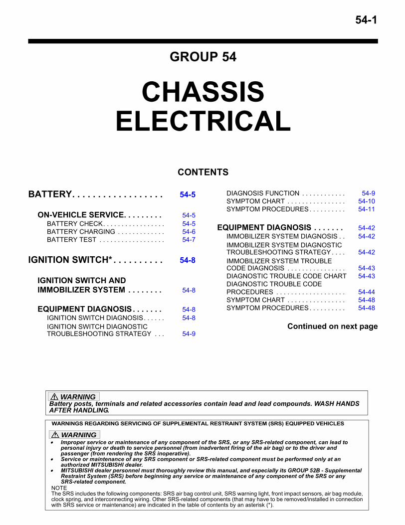
54-1
GROUP 54
CHASSIS ELECTRICAL
CONTENTS
BATTERY. . . . . . . . . . . . . . . . . . 54-5
ON-VEHICLE SERVICE. . . . . . . . . 54-5BATTERY CHECK. . . . . . . . . . . . . . . . . 54-5BATTERY CHARGING . . . . . . . . . . . . . 54-6BATTERY TEST . . . . . . . . . . . . . . . . . . 54-7
IGNITION SWITCH* . . . . . . . . . . 54-8
IGNITION SWITCH AND IMMOBILIZER SYSTEM . . . . . . . . 54-8
EQUIPMENT DIAGNOSIS. . . . . . . 54-8IGNITION SWITCH DIAGNOSIS. . . . . . 54-8IGNITION SWITCH DIAGNOSTIC TROUBLESHOOTING STRATEGY . . . 54-9
DIAGNOSIS FUNCTION . . . . . . . . . . . . 54-9SYMPTOM CHART . . . . . . . . . . . . . . . . 54-10SYMPTOM PROCEDURES . . . . . . . . . . 54-11
EQUIPMENT DIAGNOSIS . . . . . . . 54-42IMMOBILIZER SYSTEM DIAGNOSIS . . 54-42IMMOBILIZER SYSTEM DIAGNOSTIC TROUBLESHOOTING STRATEGY . . . . 54-42IMMOBILIZER SYSTEM TROUBLE CODE DIAGNOSIS . . . . . . . . . . . . . . . . 54-43DIAGNOSTIC TROUBLE CODE CHART 54-43DIAGNOSTIC TROUBLE CODE PROCEDURES . . . . . . . . . . . . . . . . . . . 54-44SYMPTOM CHART . . . . . . . . . . . . . . . . 54-48SYMPTOM PROCEDURES . . . . . . . . . . 54-48
Continued on next page
WARNINGS REGARDING SERVICING OF SUPPLEMENTAL RESTRAINT SYSTEM (SRS) EQUIPPED VEHICLES
WARNING• Improper service or maintenance of any component of the SRS, or any SRS-related component, can lead to
personal injury or death to service personnel (from inadvertent firing of the air bag) or to the driver and passenger (from rendering the SRS inoperative).
• Service or maintenance of any SRS component or SRS-related component must be performed only at an authorized MITSUBISHI dealer.
• MITSUBISHI dealer personnel must thoroughly review this manual, and especially its GROUP 52B - Supplemental Restraint System (SRS) before beginning any service or maintenance of any component of the SRS or any SRS-related component.
NOTEThe SRS includes the following components: SRS air bag control unit, SRS warning light, front impact sensors, air bag module,clock spring, and interconnecting wiring. Other SRS-related components (that may have to be removed/installed in connectionwith SRS service or maintenance) are indicated in the table of contents by an asterisk (*).
Battery posts, terminals and related accessories contain lead and lead compounds. WASH HANDS AFTER HANDLING.
WARNING
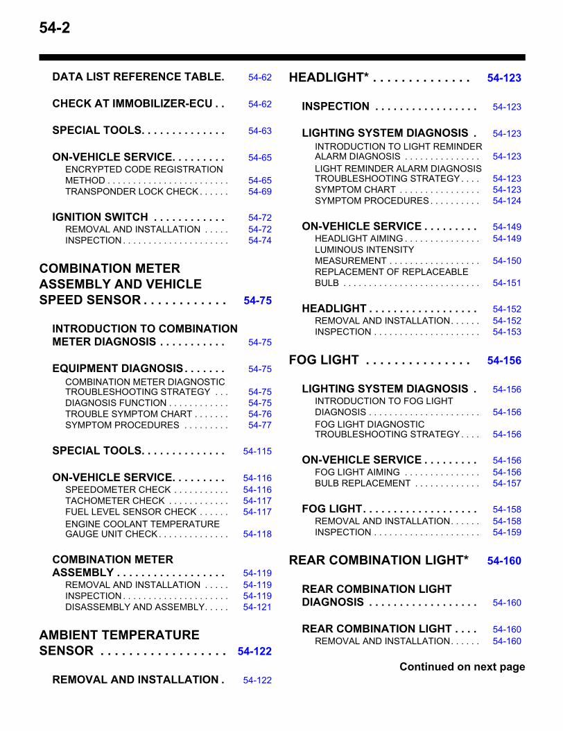
54-2
DATA LIST REFERENCE TABLE. 54-62
CHECK AT IMMOBILIZER-ECU . . 54-62
SPECIAL TOOLS. . . . . . . . . . . . . . 54-63
ON-VEHICLE SERVICE. . . . . . . . . 54-65ENCRYPTED CODE REGISTRATION METHOD . . . . . . . . . . . . . . . . . . . . . . . . 54-65TRANSPONDER LOCK CHECK . . . . . . 54-69
IGNITION SWITCH . . . . . . . . . . . . 54-72REMOVAL AND INSTALLATION . . . . . 54-72INSPECTION . . . . . . . . . . . . . . . . . . . . . 54-74
COMBINATION METER ASSEMBLY AND VEHICLE SPEED SENSOR . . . . . . . . . . . . 54-75
INTRODUCTION TO COMBINATION METER DIAGNOSIS . . . . . . . . . . . 54-75
EQUIPMENT DIAGNOSIS. . . . . . . 54-75COMBINATION METER DIAGNOSTIC TROUBLESHOOTING STRATEGY . . . 54-75DIAGNOSIS FUNCTION . . . . . . . . . . . . 54-75TROUBLE SYMPTOM CHART . . . . . . . 54-76SYMPTOM PROCEDURES . . . . . . . . . 54-77
SPECIAL TOOLS. . . . . . . . . . . . . . 54-115
ON-VEHICLE SERVICE. . . . . . . . . 54-116SPEEDOMETER CHECK . . . . . . . . . . . 54-116TACHOMETER CHECK . . . . . . . . . . . . 54-117FUEL LEVEL SENSOR CHECK . . . . . . 54-117ENGINE COOLANT TEMPERATURE GAUGE UNIT CHECK . . . . . . . . . . . . . . 54-118
COMBINATION METER ASSEMBLY . . . . . . . . . . . . . . . . . . 54-119
REMOVAL AND INSTALLATION . . . . . 54-119INSPECTION . . . . . . . . . . . . . . . . . . . . . 54-119DISASSEMBLY AND ASSEMBLY. . . . . 54-121
AMBIENT TEMPERATURE SENSOR . . . . . . . . . . . . . . . . . . 54-122
REMOVAL AND INSTALLATION . 54-122
HEADLIGHT* . . . . . . . . . . . . . . 54-123
INSPECTION . . . . . . . . . . . . . . . . . 54-123
LIGHTING SYSTEM DIAGNOSIS . 54-123INTRODUCTION TO LIGHT REMINDER ALARM DIAGNOSIS . . . . . . . . . . . . . . . 54-123LIGHT REMINDER ALARM DIAGNOSIS TROUBLESHOOTING STRATEGY . . . . 54-123SYMPTOM CHART . . . . . . . . . . . . . . . . 54-123SYMPTOM PROCEDURES . . . . . . . . . . 54-124
ON-VEHICLE SERVICE . . . . . . . . . 54-149HEADLIGHT AIMING . . . . . . . . . . . . . . . 54-149LUMINOUS INTENSITY MEASUREMENT . . . . . . . . . . . . . . . . . . 54-150REPLACEMENT OF REPLACEABLE BULB . . . . . . . . . . . . . . . . . . . . . . . . . . . 54-151
HEADLIGHT . . . . . . . . . . . . . . . . . . 54-152REMOVAL AND INSTALLATION. . . . . . 54-152INSPECTION . . . . . . . . . . . . . . . . . . . . . 54-153
FOG LIGHT . . . . . . . . . . . . . . . 54-156
LIGHTING SYSTEM DIAGNOSIS . 54-156INTRODUCTION TO FOG LIGHT DIAGNOSIS . . . . . . . . . . . . . . . . . . . . . . 54-156FOG LIGHT DIAGNOSTIC TROUBLESHOOTING STRATEGY . . . . 54-156
ON-VEHICLE SERVICE . . . . . . . . . 54-156FOG LIGHT AIMING . . . . . . . . . . . . . . . 54-156BULB REPLACEMENT . . . . . . . . . . . . . 54-157
FOG LIGHT. . . . . . . . . . . . . . . . . . . 54-158REMOVAL AND INSTALLATION. . . . . . 54-158INSPECTION . . . . . . . . . . . . . . . . . . . . . 54-159
REAR COMBINATION LIGHT* 54-160
REAR COMBINATION LIGHT DIAGNOSIS . . . . . . . . . . . . . . . . . . 54-160
REAR COMBINATION LIGHT . . . . 54-160REMOVAL AND INSTALLATION. . . . . . 54-160
Continued on next page
54-3
DOME LIGHT . . . . . . . . . . . . . . . 54-161
LIGHTING SYSTEM DIAGNOSIS . 54-161INTRODUCTION TO DOME LIGHT AND CARGO SPACE LIGHT DIAGNOSIS <VEHICLES WITH KEYLESS ENTRY SYSTEM> . . . . . . . . . . . . . . . . . . . . . . . 54-161DOME LIGHT AND CARGO SPACE LIGHT DIAGNOSTIC TROUBLESHOOTING STRATEGY <VEHICLES WITH KEYLESS ENTRY SYSTEM>. . . . . . . . . . . . . . . . . 54-161SYMPTOM CHART . . . . . . . . . . . . . . . . 54-161SYMPTOM PROCEDURES . . . . . . . . . 54-162
HIGH-MOUNTED STOPLIGHT . 54-173
REMOVAL AND INSTALLATION . 54-173
RHEOSTAT . . . . . . . . . . . . . . . . 54-174
INSPECTION . . . . . . . . . . . . . . . . . 54-174
HAZARD WARNING LIGHT SWITCH . . . . . . . . . . . . . . . . . . . 54-175
REMOVAL AND INSTALLATION . 54-175
INSPECTION . . . . . . . . . . . . . . . . . 54-175
HORN . . . . . . . . . . . . . . . . . . . . . 54-176
HORN DIAGNOSIS <VEHICLE WITH KEYLESS ENTRY SYSTEM OR THEFT ALARM SYSTEM> . . . . . . 54-176
HORN. . . . . . . . . . . . . . . . . . . . . . . 54-176REMOVAL AND INSTALLATION . . . . . 54-176INSPECTION . . . . . . . . . . . . . . . . . . . . . 54-177
CIGARETTE LIGHTER . . . . . . . 54-178
REMOVAL AND INSTALLATION . 54-178
INSPECTION . . . . . . . . . . . . . . . . . 54-178
ACCESSORY SOCKET . . . . . . 54-179
REMOVAL AND INSTALLATION . 54-179
INSPECTION . . . . . . . . . . . . . . . . . 54-180
RADIO AND TAPE PLAYER . . 54-180
RADIO WITH TAPE PLAYER AND CD PLAYER, SPEAKER AND ANTENNA DIAGNOSIS . . . . . . . . . . . . . . . . . . 54-180
INTRODUCTION TO AUDIO SYSTEM DIAGNOSIS . . . . . . . . . . . . . . . . . . . . . . 54-180TROUBLESHOOTING STRATEGY . . . . 54-180SYMPTOM CHART . . . . . . . . . . . . . . . . 54-181SYMPTOM PROCEDURES . . . . . . . . . . 54-182
SPECIAL TOOL . . . . . . . . . . . . . . . 54-251
ON-VEHICLE SERVICE . . . . . . . . . 54-251PROCEDURE FOR INPUT OF SECURITY CODE FOR ANTI-THEFT SYSTEM. . . . 54-251SPEAKER TEST . . . . . . . . . . . . . . . . . . 54-253
RADIO WITH CD PLAYER. . . . . . . 54-254REMOVAL AND INSTALLATION. . . . . . 54-254
SPEAKER. . . . . . . . . . . . . . . . . 54-255
REMOVAL AND INSTALLATION . 54-255
AMPLIFIER. . . . . . . . . . . . . . . . 54-256
REMOVAL AND INSTALLATION . 54-256
ANTENNA . . . . . . . . . . . . . . . . 54-257
REMOVAL AND INSTALLATION . 54-257
INSPECTION . . . . . . . . . . . . . . . . . 54-259
ANTENNA POLE REPLACEMENT 54-260
Continued on next page
54-4
REAR WINDOW DEFOGGER . . 54-261
ON-VEHICLE SERVICE. . . . . . . . . 54-261PRINTED-HEATER LINES CHECK . . . 54-261
REAR WINDOW DEFOGGER SWITCH . . . . . . . . . . . . . . . . . . . . . 54-262
REMOVAL AND INSTALLATION . . . . . 54-262INSPECTION . . . . . . . . . . . . . . . . . . . . . 54-262
THEFT ALARM . . . . . . . . . . . . . 54-264
THEFT-ALARM SYSTEM DIAGNOSIS . . . . . . . . . . . . . . . . . . 54-264
INTRODUCTION TO THEFT-ALARM SYSTEM DIAGNOSIS . . . . . . . . . . . . . . 54-264
TROUBLE SYMPTOM CHART . . . . . . . 54-264SYMPTOM PROCEDURES . . . . . . . . . . 54-265
THEFT ALARM. . . . . . . . . . . . . . . . 54-306REMOVAL AND INSTALLATION. . . . . . 54-306INSPECTION . . . . . . . . . . . . . . . . . . . . . 54-307
SPECIFICATIONS . . . . . . . . . . 54-308
FASTENER TIGHTENING SPECIFICATIONS . . . . . . . . . . . . . 54-308
SERVICE SPECIFICATIONS . . . . . 54-308
SEALANT . . . . . . . . . . . . . . . . . . . . 54-309
BATTERYCHASSIS ELECTRICAL 54-5
BATTERY
ON-VEHICLE SERVICE
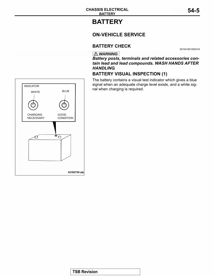
BATTERY CHECKM1541001000319
WARNINGBattery posts, terminals and related accessories con-tain lead and lead compounds. WASH HANDS AFTER HANDLING.BATTERY VISUAL INSPECTION (1) The battery contains a visual test indicator which gives a blue signal when an adequate charge level exists, and a white sig-nal when charging is required.
AC002728 AB
INDICATOR
BLUE
CHARGING NECESSARY
GOODCONDITION
WHITE
TSB Revision
BATTERYCHASSIS ELECTRICAL54-6
BATTERY VISUAL INSPECTION (2) Make sure ignition switch is in "LOCK" (OFF) position and all battery fed accessories are OFF.1. Disconnect the negative cable from battery before
disconnecting the positive cable.WARNING
Care should be taken in the event battery case is cracked or leaking to protect hands from the electro-lyte. A suitable pair of rubber gloves (not the house-hold type) should be worn when removing battery by hand.2. Remove the battery from the vehicle.3. Inspect battery carrier for damage caused by loss of acid
from battery. If acid damage is present, it is necessary to clean area with a solution of clean warm water and baking soda. Scrub area with a stiff bristle brush. Wipe clean with a cloth moistened with ammonia or baking soda in water.
4. Clean the battery, especially the top with same solutions as described in step 3.
5. Inspect the battery case and cover for cracks. If cracks are present, battery must be replaced.
6. Clean the battery post with a suitable battery post cleaning tool.
7. Clean the inside surfaces of the terminal clamps with a suitable battery terminal cleaning tool. Replace damaged or frayed cables and broken terminal clamps.
8. Install the battery in the vehicle.9. Connect the positive and negative cables to the battery in
the order of mention.10.Tighten the clamp nut securely.
BATTERY CHARGINGM1541001100576
WARNINGWhen batteries are being charged, an explosive gas forms beneath the cover of each cell. Do not smoke near batteries on charge or which have recently been charged. Do not break live circuits at the terminals of the batteries on charge. A spark will occur where the live circuit is broken. Keep all open flames away from the battery.Battery electrolyte temperature may temporarily be allowed to rise to 55°C (131°F). Increase of electrolyte temperature above 55 °C (131°F) is harmful to the battery, causing deformation of battery cell, decrease in life of battery, etc.
TSB Revision
BATTERYCHASSIS ELECTRICAL 54-7
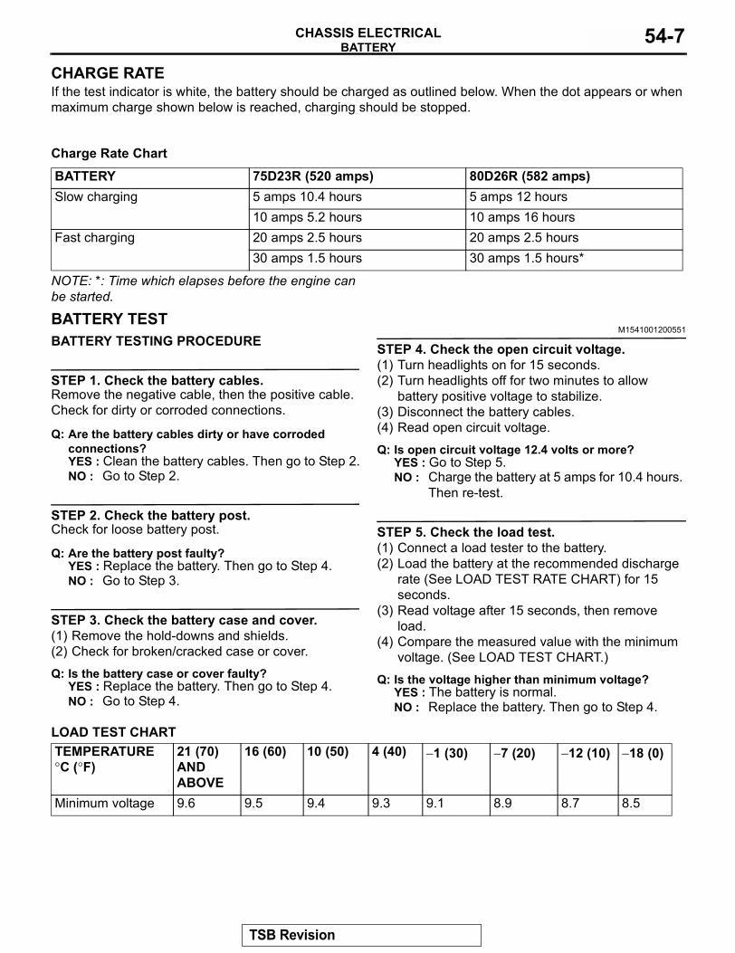
CHARGE RATE If the test indicator is white, the battery should be charged as outlined below. When the dot appears or when maximum charge shown below is reached, charging should be stopped..
Charge Rate Chart
NOTE: *: Time which elapses before the engine can be started.
BATTERY TESTM1541001200551
BATTERY TESTING PROCEDURE
STEP 1. Check the battery cables.Remove the negative cable, then the positive cable.Check for dirty or corroded connections.
Q: Are the battery cables dirty or have corroded connections?YES : Clean the battery cables. Then go to Step 2.NO : Go to Step 2.
STEP 2. Check the battery post.Check for loose battery post.
Q: Are the battery post faulty? YES : Replace the battery. Then go to Step 4.NO : Go to Step 3.
STEP 3. Check the battery case and cover.(1) Remove the hold-downs and shields.(2) Check for broken/cracked case or cover.
Q: Is the battery case or cover faulty?YES : Replace the battery. Then go to Step 4.NO : Go to Step 4.
STEP 4. Check the open circuit voltage.(1) Turn headlights on for 15 seconds.(2) Turn headlights off for two minutes to allow
battery positive voltage to stabilize.(3) Disconnect the battery cables.(4) Read open circuit voltage.
Q: Is open circuit voltage 12.4 volts or more?YES : Go to Step 5.NO : Charge the battery at 5 amps for 10.4 hours.
Then re-test.
STEP 5. Check the load test.(1) Connect a load tester to the battery.(2) Load the battery at the recommended discharge
rate (See LOAD TEST RATE CHART) for 15 seconds.
(3) Read voltage after 15 seconds, then remove load.
(4) Compare the measured value with the minimum voltage. (See LOAD TEST CHART.)
Q: Is the voltage higher than minimum voltage?YES : The battery is normal.NO : Replace the battery. Then go to Step 4.
LOAD TEST CHART
BATTERY 75D23R (520 amps) 80D26R (582 amps)Slow charging 5 amps 10.4 hours 5 amps 12 hours
10 amps 5.2 hours 10 amps 16 hoursFast charging 20 amps 2.5 hours 20 amps 2.5 hours
30 amps 1.5 hours 30 amps 1.5 hours*
TEMPERATURE °C (°F)
21 (70) AND ABOVE
16 (60) 10 (50) 4 (40) −1 (30) −7 (20) −12 (10) −18 (0)
Minimum voltage 9.6 9.5 9.4 9.3 9.1 8.9 8.7 8.5
TSB Revision
IGNITION SWITCHCHASSIS ELECTRICAL54-8
LOAD TEST RATE CHART
IGNITION SWITCHIGNITION SWITCH AND IMMOBILIZER SYSTEM
M1543009900903
GENERAL DESCRIPTION .
Ignition key reminder tone alarmThe ignition key reminder tone alarm will sound under the following condition, and warn the driver to remove the ignition key.The driver's door is opened when the ignition switch is at "LOCK" (OFF) or "ACC" position.However, the light reminder tone alarm will take pre-cedence over this function..
Ignition key hole illumination light If the driver's door is opened when the ignition key is not inserted in the ignition key cylinder or the ignition switch is at "ACC" or "LOCK" (OFF) position, the ignition key hole will be illuminated. Then, after the driver's door is closed, the key hole will be extin-guished in approximately 15 seconds. .
Immobilizer systemThe immobilizer system consists of the ignition key, the key ring antenna, the immobilizer-ECU, and the PCM. The ignition key has a built-in transponder. The key ring antenna is installed on the steering lock key cylinder. Only the registered ignition key permits the engine to start, therefore, the engine can never be started by means of a forged key or by connecting the ignition wiring directly. The system is significantly safe and reliable against theft. In addition, the driver has only to turn the ignition switch to the "ON" posi-tion to activate the immobilizer system. If the require-ments for starting the engine are not satisfied, the engine will be immobilized. If the ignition key is lost or another ignition key is added, the encrypted code can be registered or erased by using scan tool. If the ignition switch is turned to the "ON" position by using the ignition key, which does not include the transpon-der, includes an unregistered transponder, or has an incorrect ID code, "SECURITY" indicator inside the combination meter will flash.
EQUIPMENT DIAGNOSISIGNITION SWITCH DIAGNOSIS
M1543009900914
INTRODUCTION TO IGNITION SWITCH DIAGNOSISAn ETACS-ECU is mounted in all vehicles. This ETACS-ECU controls the ignition key reminder and ignition key hole illumination light timer. The ignition key reminder tone alarm alerts the driver that the ignition key has not been removed. If any of the fol-lowing symptoms occur, there is a malfunction:
• The tone alarm does not stop sounding when the ignition key is turned to the "ON" position.
• The tone alarm does not stop sounding when the ignition key is removed.
• The tone alarm does not sound when the ignition key is inserted (turned to the "OFF" position) and the driver's door is opened.
The ignition key hole illumination light timer illumi-nates the ignition switch for certain conditions. If any of the following symptoms occur, there is a malfunc-tion:
• The ignition key hole illumination light does not go off.
• The ignition key hole illumination light does not illuminate when the driver's door is opened.
• The ignition key hole illumination light does not go out when the ignition key is turned to the "ON" position.
Load test 300 amps 300 ampsCranking ratio [−18°C (0°F)] 520 amps 582 ampsReserve capacity 118 minutes 133 minutesApplication 75D23R 80D26R
TSB Revision
IGNITION SWITCHCHASSIS ELECTRICAL 54-9
IGNITION SWITCH DIAGNOSTIC TROUBLESHOOTING STRATEGYM1543006900487
Use these steps to plan your diagnostic strategy. If you follow them carefully, you will be sure that you have exhausted most of the possible ways to find an ignition switch fault.1. Gather information from the customer.
2. Verify that the condition described by the customer exists.
3. Find the malfunction by following the Symptom Chart.
4. Verify that the malfunction is eliminated.
DIAGNOSIS FUNCTIONM1543007000498
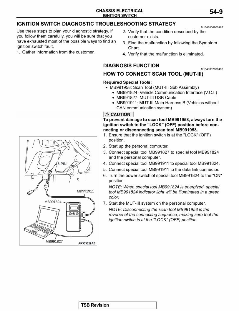
HOW TO CONNECT SCAN TOOL (MUT-III)Required Special Tools:
• MB991958: Scan Tool (MUT-III Sub Assembly)• MB991824: Vehicle Communication Interface (V.C.I.)• MB991827: MUT-III USB Cable• MB991911: MUT-III Main Harness B (Vehicles without
CAN communication system)CAUTION
To prevent damage to scan tool MB991958, always turn the ignition switch to the "LOCK" (OFF) position before con-necting or disconnecting scan tool MB991958.1. Ensure that the ignition switch is at the "LOCK" (OFF)
position.2. Start up the personal computer.3. Connect special tool MB991827 to special tool MB991824
and the personal computer.4. Connect special tool MB991911 to special tool MB991824.5. Connect special tool MB991911 to the data link connector.6. Turn the power switch of special tool MB991824 to the "ON"
position.NOTE: When special tool MB991824 is energized, special tool MB991824 indicator light will be illuminated in a green color.
7. Start the MUT-III system on the personal computer.NOTE: Disconnecting the scan tool MB991958 is the reverse of the connecting sequence, making sure that the ignition switch is at the "LOCK" (OFF) position.
AK303629AB
MB991911
MB991827
MB991824
16-PIN
TSB Revision
IGNITION SWITCHCHASSIS ELECTRICAL54-10
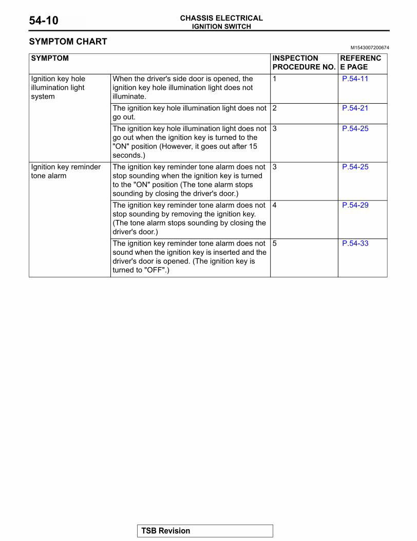
SYMPTOM CHARTM1543007200674
SYMPTOM INSPECTION PROCEDURE NO.
REFERENCE PAGE
Ignition key hole illumination light system
When the driver's side door is opened, the ignition key hole illumination light does not illuminate.
1 P.54-11
The ignition key hole illumination light does not go out.
2 P.54-21
The ignition key hole illumination light does not go out when the ignition key is turned to the "ON" position (However, it goes out after 15 seconds.)
3 P.54-25
Ignition key reminder tone alarm
The ignition key reminder tone alarm does not stop sounding when the ignition key is turned to the "ON" position (The tone alarm stops sounding by closing the driver's door.)
3 P.54-25
The ignition key reminder tone alarm does not stop sounding by removing the ignition key. (The tone alarm stops sounding by closing the driver's door.)
4 P.54-29
The ignition key reminder tone alarm does not sound when the ignition key is inserted and the driver's door is opened. (The ignition key is turned to "OFF".)
5 P.54-33
TSB Revision
IGNITION SWITCHCHASSIS ELECTRICAL 54-11
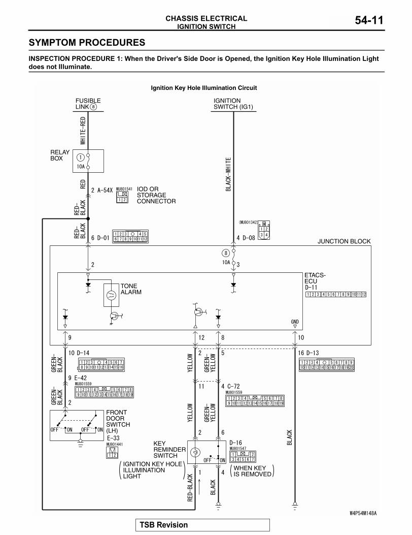
SYMPTOM PROCEDURESINSPECTION PROCEDURE 1: When the Driver's Side Door is Opened, the Ignition Key Hole Illumination Light does not Illuminate.
FUSIBLELINK 8
RELAYBOX
JUNCTION BLOCK
ETACS-ECU
TONEALARM
KEYREMINDERSWITCH
FRONTDOORSWITCH(LH)
IGNITION KEY HOLEILLUMINATIONLIGHT
IOD ORSTORAGECONNECTOR
IGNITIONSWITCH (IG1)
WHEN KEYIS REMOVED
Ignition Key Hole Illumination Circuit
TSB Revision
IGNITION SWITCHCHASSIS ELECTRICAL54-12
.
CIRCUIT OPERATION• The ETACS-ECU monitors the ignition switch by
detecting voltage from the ignition switch.• The ETACS-ECU judges that the driver's side
door is opened or closed by detecting voltage from the front door switch (LH).
• When the driver's door is opened (door switch on), the ignition key hole illumination light will illu-minate. When the driver's door is closed (door switch off), the ignition key hole illumination light will go out within 15 seconds.
.
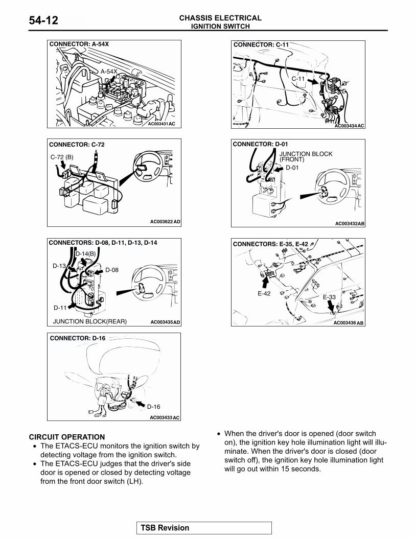
AC003431
CONNECTOR: A-54X
A-54X
AC AC003434
CONNECTOR: C-11
AC
C-11
AC003622
CONNECTOR: C-72
AD
C-72 (B)
AC003432AB
CONNECTOR: D-01
JUNCTION BLOCK(FRONT)
D-01
AC003435AD
CONNECTORS: D-08, D-11, D-13, D-14
D-13
D-14(B)
D-08
D-11
JUNCTION BLOCK(REAR)
AC003433
CONNECTOR: D-16
AC
D-16
AC003436 AB
CONNECTORS: E-35, E-42
E-42E-33
TSB Revision
IGNITION SWITCHCHASSIS ELECTRICAL 54-13
TECHNICAL DESCRIPTION (COMMENT)The cause is probably a malfunction in the key hole illumination light circuit system or input signal from the driver's side door switch..
TROUBLESHOOTING HINTS• Malfunction of the driver's side door switch• Malfunction of the key hole illumination light• Damaged harness wire or connector• Malfunction of the ETACS-ECU
.
DIAGNOSIS
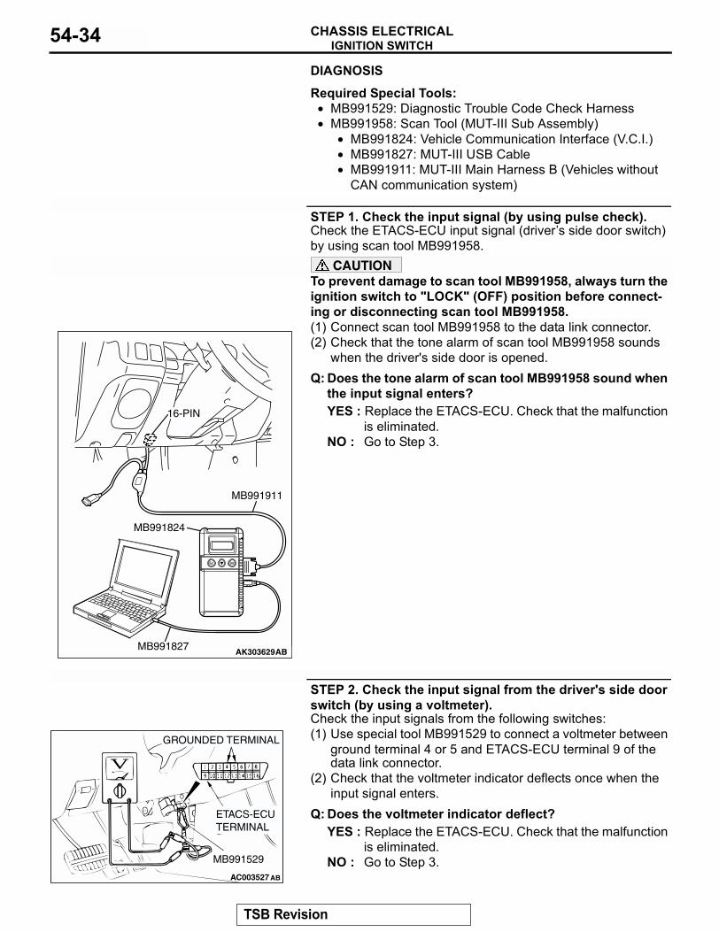
Required Special Tools:• MB991529: Diagnostic Trouble Code Check Harness• MB991958: Scan Tool (MUT-III Sub Assembly)
• MB991824: Vehicle Communication Interface (V.C.I.)• MB991827: MUT-III USB Cable• MB991911: MUT-III Main Harness B (Vehicles without
CAN communication system)
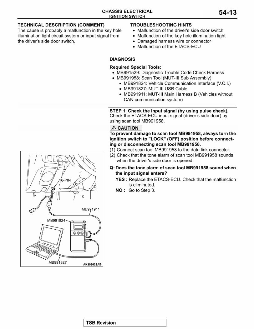
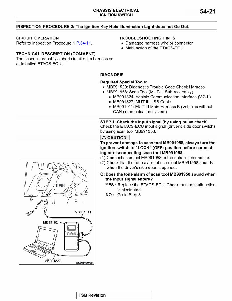
STEP 1. Check the input signal (by using pulse check).Check the ETACS-ECU input signal (drivers side door) by using scan tool MB991958.
CAUTIONTo prevent damage to scan tool MB991958, always turn the ignition switch to "LOCK" (OFF) position before connect-ing or disconnecting scan tool MB991958.(1) Connect scan tool MB991958 to the data link connector.(2) Check that the tone alarm of scan tool MB991958 sounds
when the driver's side door is opened.Q: Does the tone alarm of scan tool MB991958 sound when
the input signal enters?YES : Replace the ETACS-ECU. Check that the malfunction
is eliminated.NO : Go to Step 3.
AK303629AB
MB991911
MB991827
MB991824
16-PIN
TSB Revision
IGNITION SWITCHCHASSIS ELECTRICAL54-14
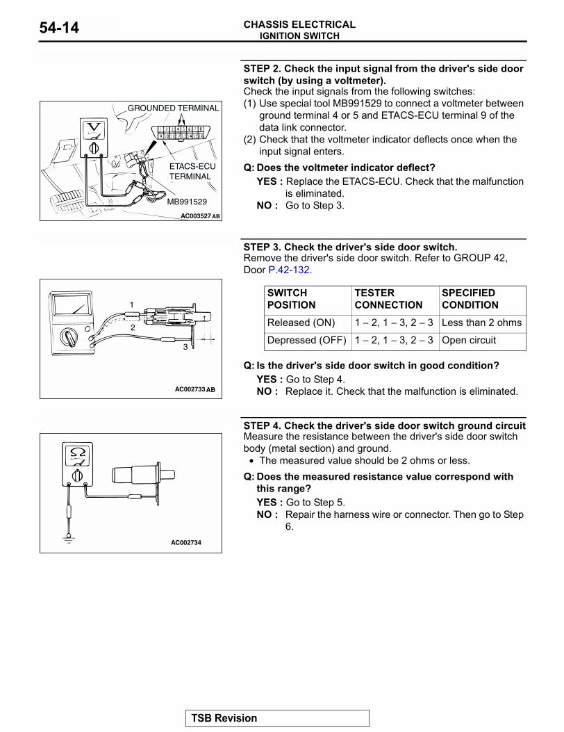
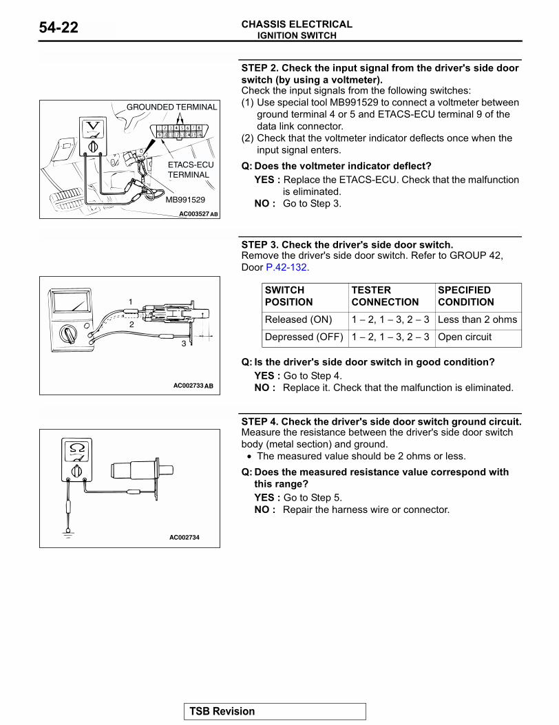
STEP 2. Check the input signal from the driver's side door switch (by using a voltmeter).Check the input signals from the following switches:(1) Use special tool MB991529 to connect a voltmeter between
ground terminal 4 or 5 and ETACS-ECU terminal 9 of the data link connector.
(2) Check that the voltmeter indicator deflects once when the input signal enters.
Q: Does the voltmeter indicator deflect?YES : Replace the ETACS-ECU. Check that the malfunction
is eliminated.NO : Go to Step 3.
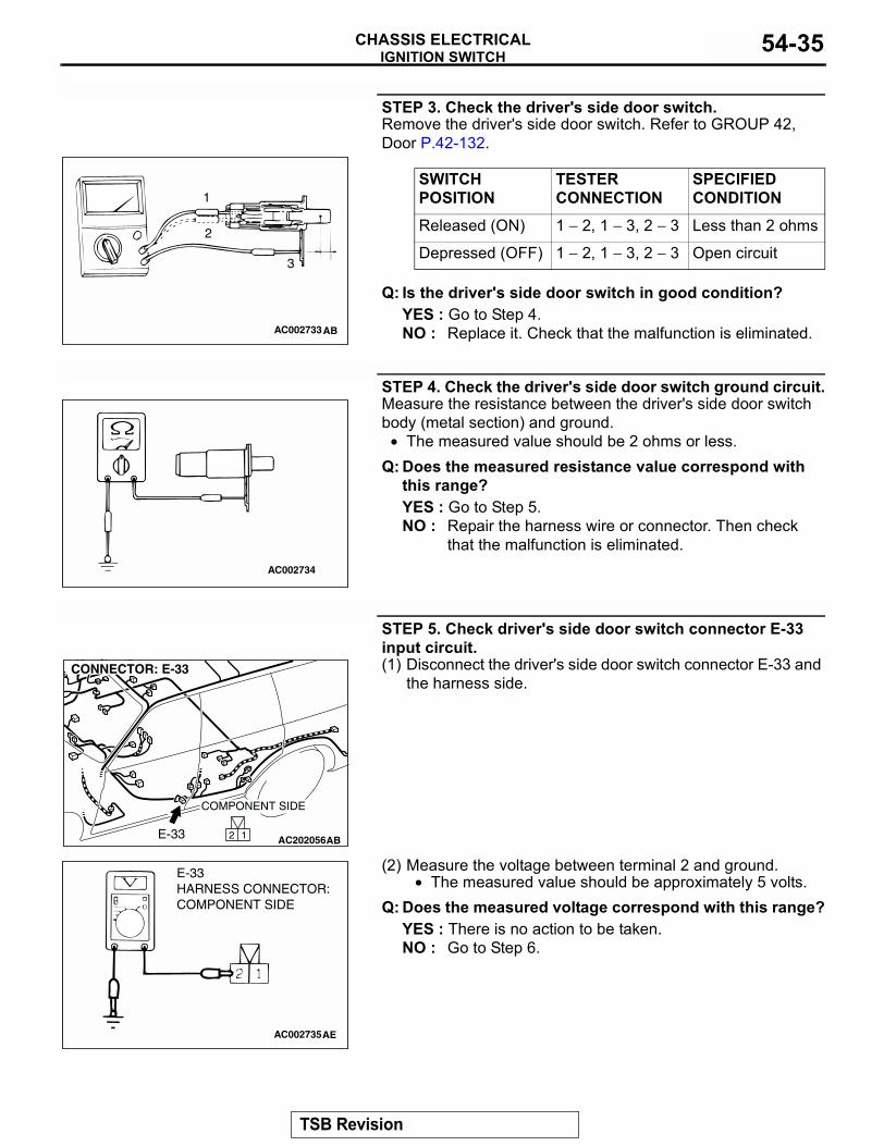
STEP 3. Check the driver's side door switch.Remove the driver's side door switch. Refer to GROUP 42, Door P.42-132.
Q: Is the driver's side door switch in good condition?YES : Go to Step 4.NO : Replace it. Check that the malfunction is eliminated.
STEP 4. Check the driver's side door switch ground circuitMeasure the resistance between the driver's side door switch body (metal section) and ground.
• The measured value should be 2 ohms or less.Q: Does the measured resistance value correspond with
this range?YES : Go to Step 5.NO : Repair the harness wire or connector. Then go to Step
6.
AC003527
GROUNDED TERMINAL
ETACS-ECU TERMINAL
MB991529
AB
SWITCH POSITION
TESTER CONNECTION
SPECIFIED CONDITION
Released (ON) 1 − 2, 1 − 3, 2 − 3 Less than 2 ohms
Depressed (OFF) 1 − 2, 1 − 3, 2 − 3 Open circuit
AC002733AB
1
2
3
AC002734
TSB Revision
IGNITION SWITCHCHASSIS ELECTRICAL 54-15
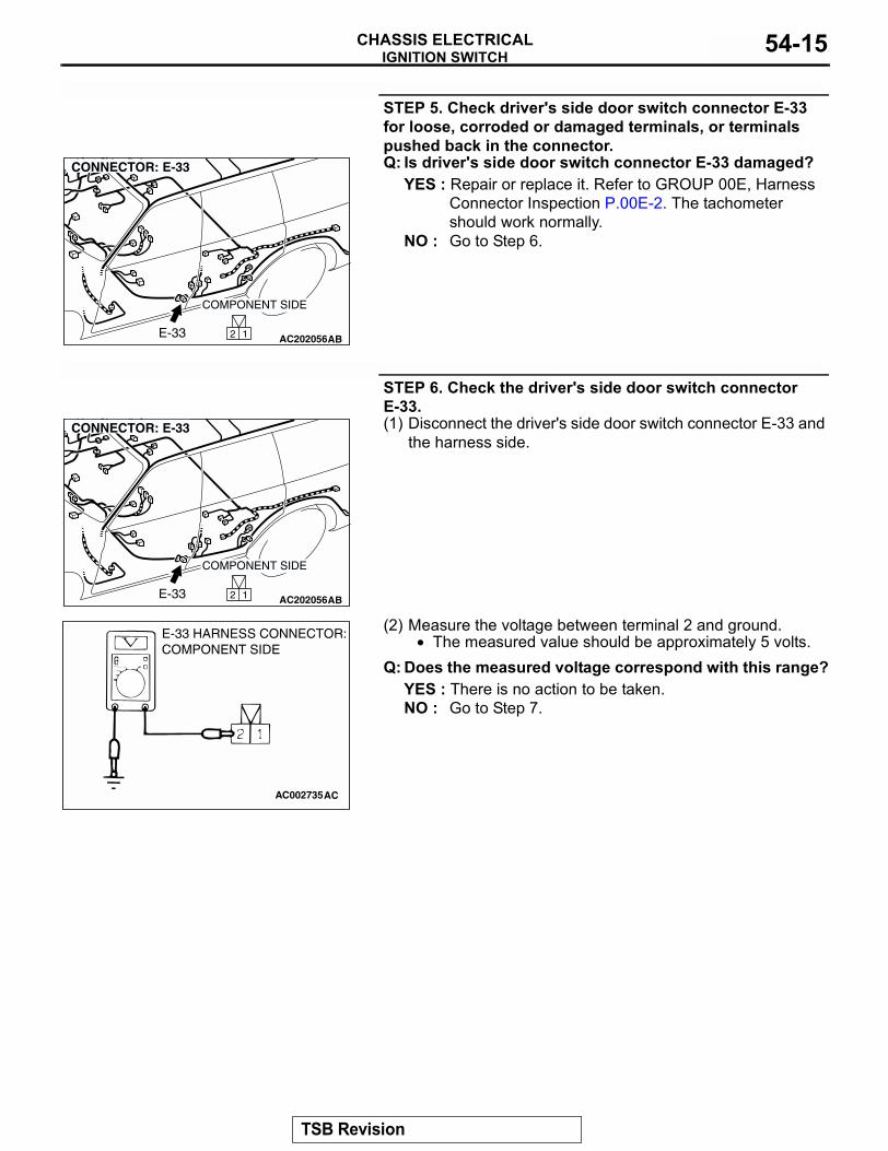
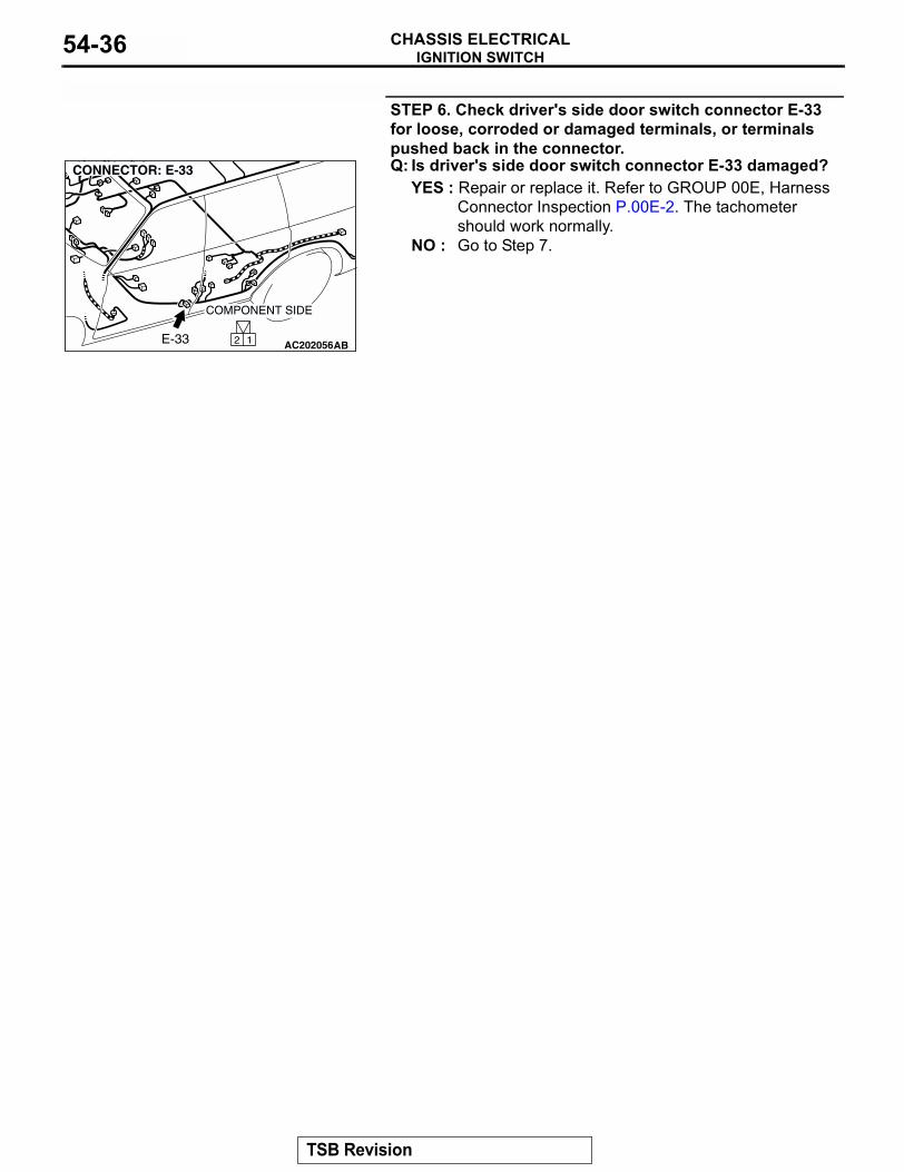
STEP 5. Check driver's side door switch connector E-33 for loose, corroded or damaged terminals, or terminals pushed back in the connector.Q: Is driver's side door switch connector E-33 damaged?
YES : Repair or replace it. Refer to GROUP 00E, Harness Connector Inspection P.00E-2. The tachometer should work normally.
NO : Go to Step 6.
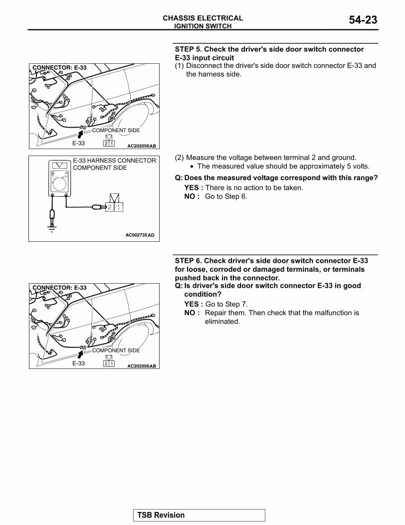
STEP 6. Check the driver's side door switch connector E-33.(1) Disconnect the driver's side door switch connector E-33 and
the harness side.
(2) Measure the voltage between terminal 2 and ground.• The measured value should be approximately 5 volts.
Q: Does the measured voltage correspond with this range?YES : There is no action to be taken.NO : Go to Step 7.
AC2020562 1
COMPONENT SIDE
CONNECTOR: E-33
ABE-33
AC2020562 1
COMPONENT SIDE
CONNECTOR: E-33
ABE-33
AC002735
E-33 HARNESS CONNECTOR:COMPONENT SIDE
AC
TSB Revision
IGNITION SWITCHCHASSIS ELECTRICAL54-16
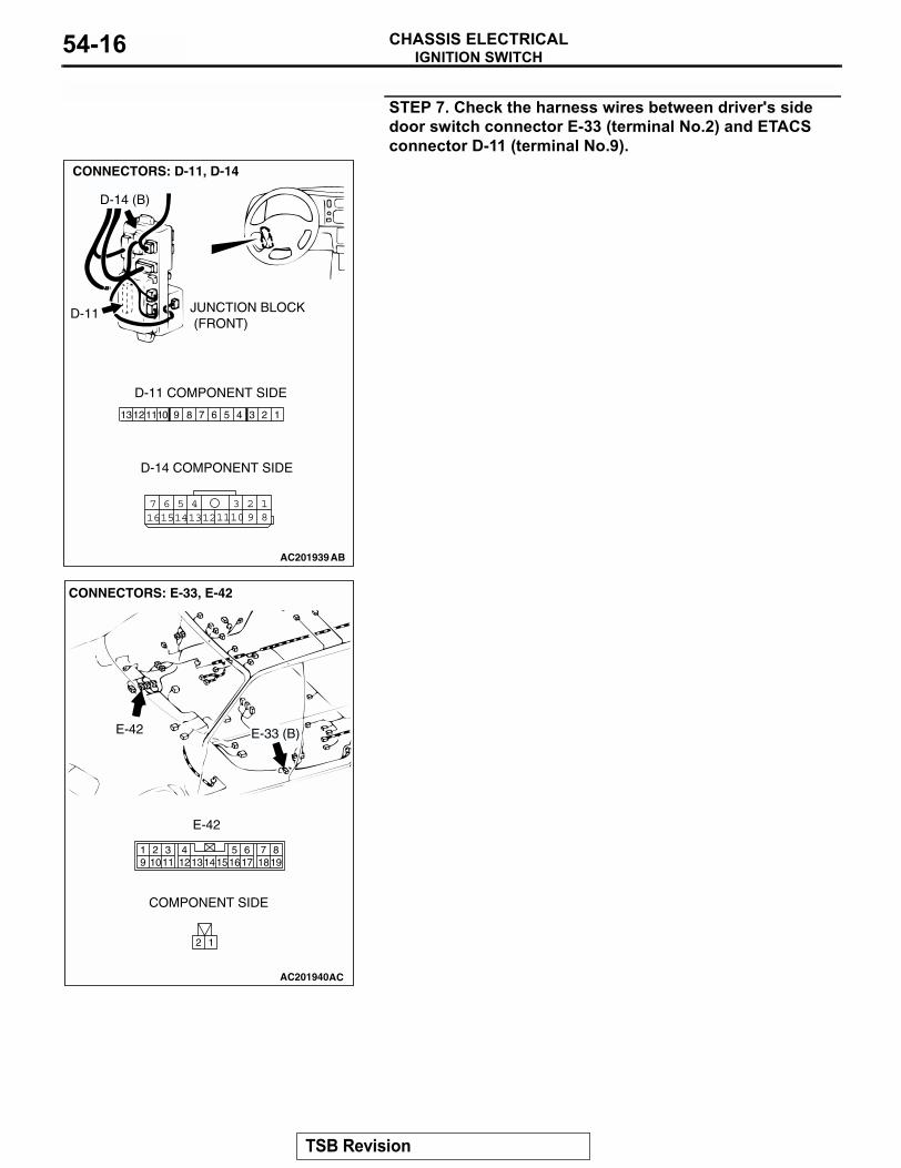
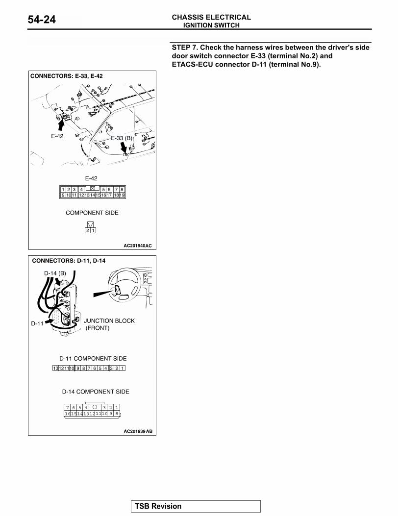
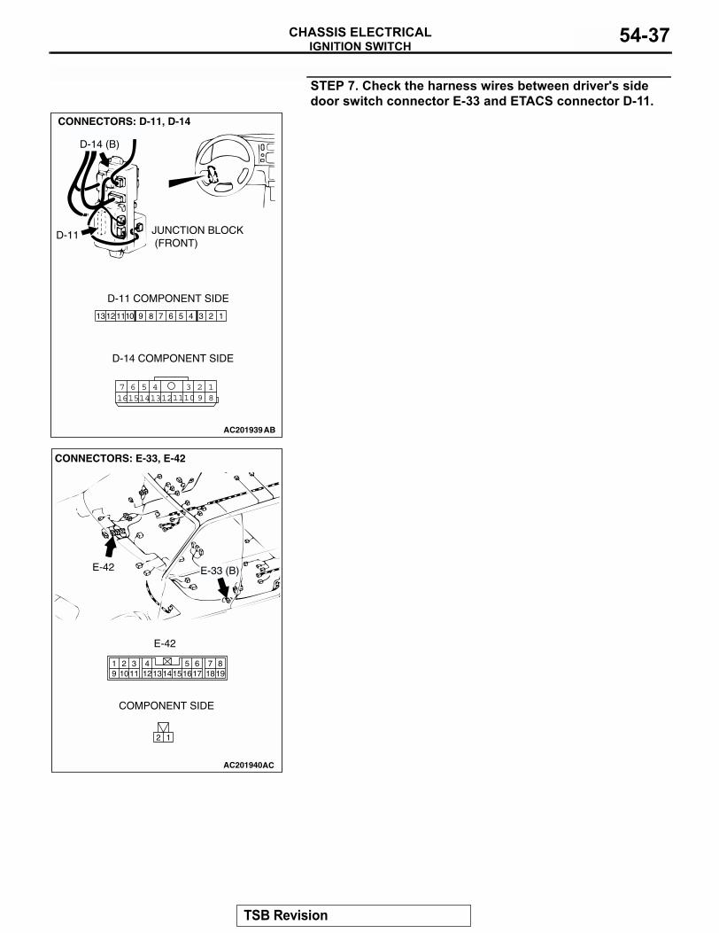
STEP 7. Check the harness wires between driver's side door switch connector E-33 (terminal No.2) and ETACS connector D-11 (terminal No.9).
AC201939
1347 6 5 291112 1013 8
18
3457 6101516 14 1213 11 9
2
CONNECTORS: D-11, D-14
D-11
D-14 (B)
D-11 COMPONENT SIDE
D-14 COMPONENT SIDE
AB
JUNCTION BLOCK (FRONT)
AC201940
2 1
819
7651615 17 18
4321011 1213
19 14
CONNECTORS: E-33, E-42
AC
E-33 (B)E-42
COMPONENT SIDE
E-42
TSB Revision

IGNITION SWITCHCHASSIS ELECTRICAL 54-17
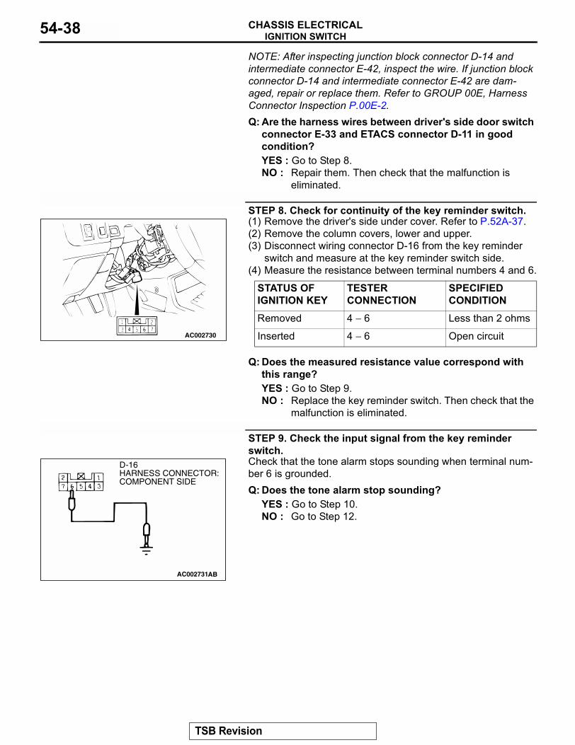
NOTE: After inspecting junction block connector D-14 and intermediate connector E-42, inspect the wire. If junction block connector D-14 and intermediate connector E-42 are dam-aged, repair or replace them. Refer to GROUP 00E, Harness Connector Inspection P.00E-2.Q: Are the harness wires between driver's side door switch
connector E-33 (terminal No.2) and ETACS connector D-11 (terminal No.9) in good condition?YES : Go to Step 8.NO : Repair them. Then check that the malfunction is
eliminated.
STEP 8. Check the ignition key hole illumination light input.(1) Remove the driver's under cover (Refer to P.52A-37).(2) Remove the lower and upper column covers (Refer to
P.52A-37).(3) Disconnect wiring connector D-16 from the key reminder
switch and measure at the switch side.(4) Connect a vehicle battery as shown, and then check the
ignition key hole illumination light illuminates.Q: Does the situation key hole illumination light
illuminate?YES : Go to Step 9.NO : Replace the key reminder switch.
AC20206045 31
672
13
27654
+ -
AC102749
CONNECTOR: D-16
AB
TSB Revision
IGNITION SWITCHCHASSIS ELECTRICAL54-18
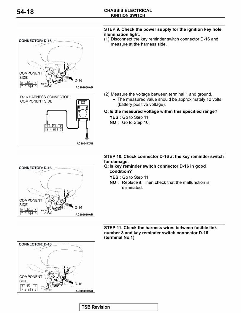
STEP 9. Check the power supply for the ignition key hole illumination light.(1) Disconnect the key reminder switch connector D-16 and
measure at the harness side.
(2) Measure the voltage between terminal 1 and ground.• The measured value should be approximately 12 volts
(battery positive voltage).Q: Is the measured voltage within this specified range?
YES : Go to Step 11.NO : Go to Step 10.
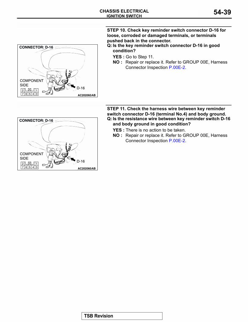
STEP 10. Check connector D-16 at the key reminder switch for damage.Q: Is key reminder switch connector D-16 in good
condition?YES : Go to Step 11.NO : Replace it. Then check that the malfunction is
eliminated.
STEP 11. Check the harness wires between fusible link number 8 and key reminder switch connector D-16 (terminal No.1).
AC20206045 31
672
AC309477
D-16 HARNESS CONNECTOR:COMPONENT SIDE
AB
AC20206045 31
672
AC20206045 31
672
TSB Revision
IGNITION SWITCHCHASSIS ELECTRICAL 54-19
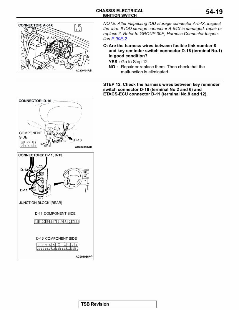
NOTE: After inspecting IOD storage connector A-54X, inspect the wire. If IOD storage connector A-54X is damaged, repair or replace it. Refer to GROUP 00E, Harness Connector Inspec-tion P.00E-2.Q: Are the harness wires between fusible link number 8
and key reminder switch connector D-16 (terminal No.1) in good condition?YES : Go to Step 12.NO : Repair or replace them. Then check that the
malfunction is eliminated.
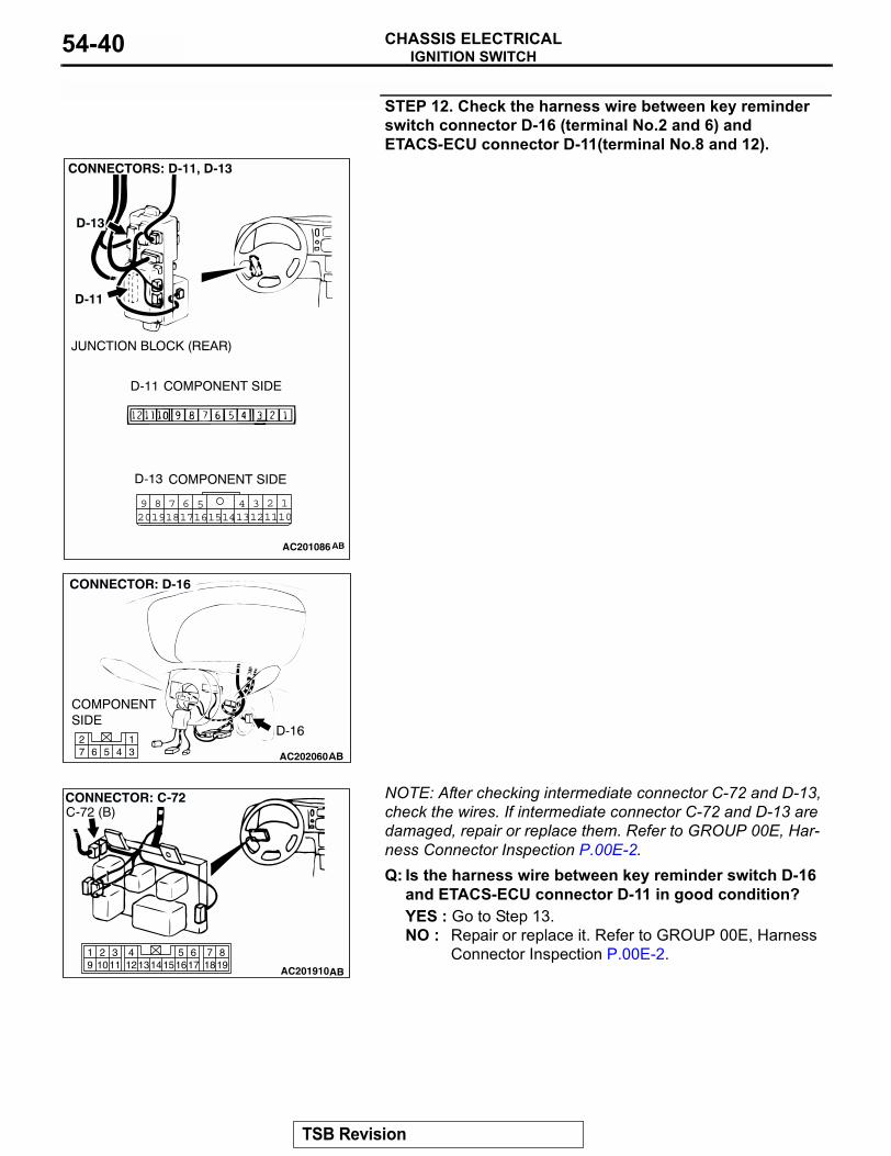
STEP 12. Check the harness wires between key reminder switch connector D-16 (terminal No.2 and 6) and ETACS-ECU connector D-11 (terminal No.8 and 12).
AC200774
21
CONNECTOR: A-54X
AB
A-54X
AC20206045 31
672
1245 3689 710111314 121617201918 15
AC201086
TSB Revision
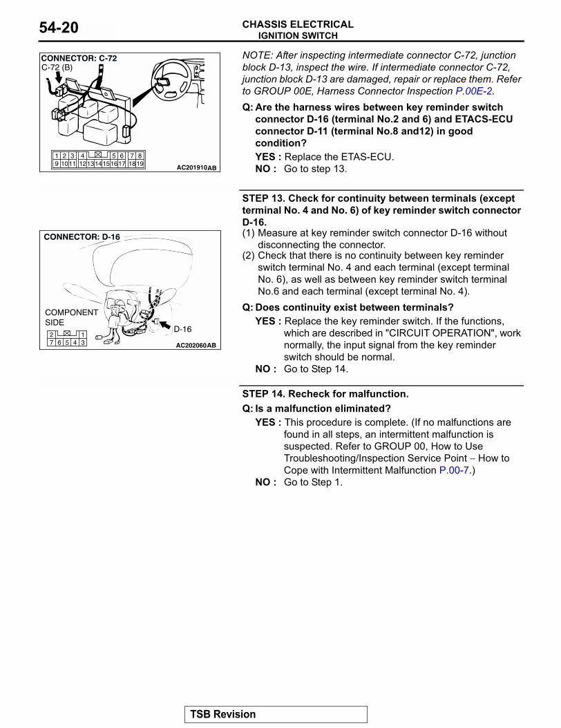
IGNITION SWITCHCHASSIS ELECTRICAL54-20
NOTE: After inspecting intermediate connector C-72, junction block D-13, inspect the wire. If intermediate connector C-72, junction block D-13 are damaged, repair or replace them. Refer to GROUP 00E, Harness Connector Inspection P.00E-2.Q: Are the harness wires between key reminder switchconnector D-16 (terminal No.2 and 6) and ETACS-ECU connector D-11 (terminal No.8 and12) in good condition?YES : Replace the ETAS-ECU.NO : Go to step 13.
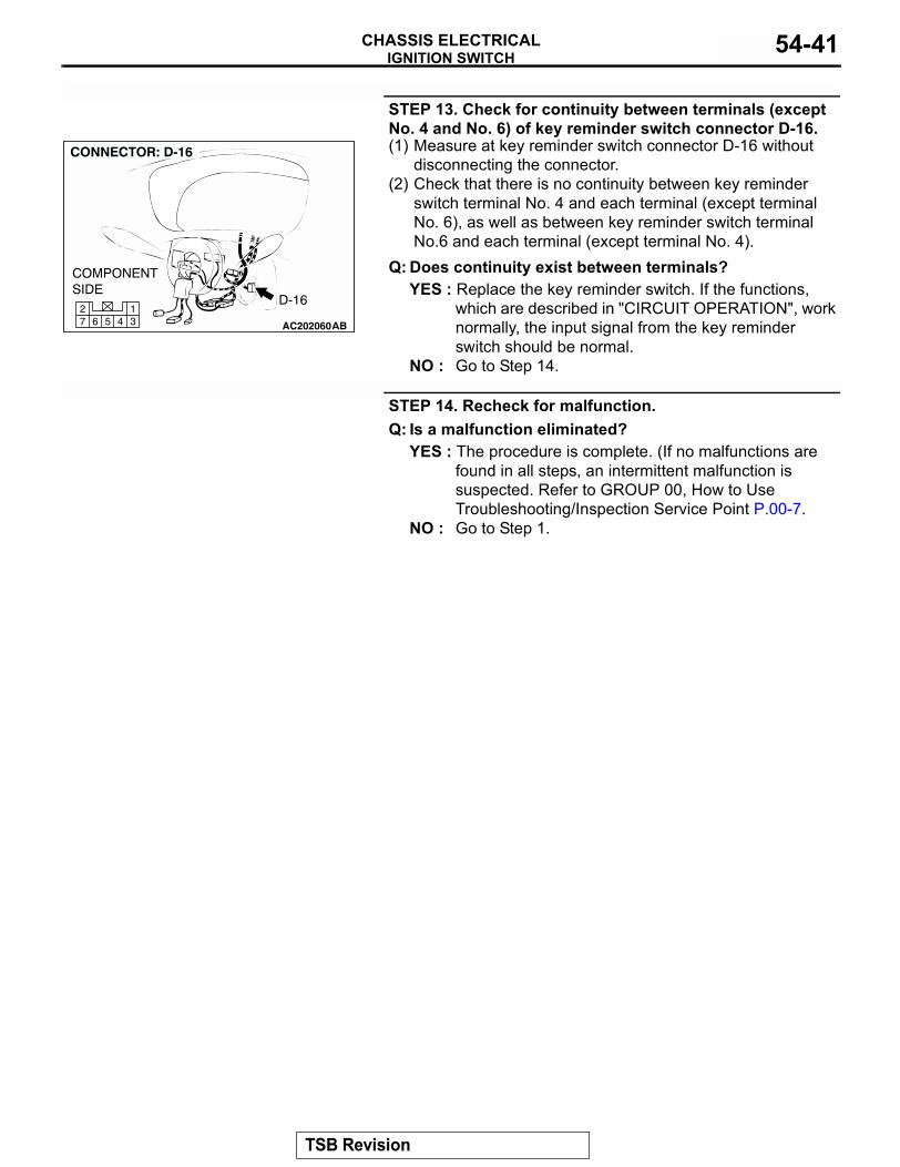
STEP 13. Check for continuity between terminals (except terminal No. 4 and No. 6) of key reminder switch connector D-16.(1) Measure at key reminder switch connector D-16 without
disconnecting the connector.(2) Check that there is no continuity between key reminder
switch terminal No. 4 and each terminal (except terminal No. 6), as well as between key reminder switch terminal No.6 and each terminal (except terminal No. 4).
Q: Does continuity exist between terminals?YES : Replace the key reminder switch. If the functions,
which are described in "CIRCUIT OPERATION", work normally, the input signal from the key reminder switch should be normal.
NO : Go to Step 14.
STEP 14. Recheck for malfunction.Q: Is a malfunction eliminated?
YES : This procedure is complete. (If no malfunctions are found in all steps, an intermittent malfunction is suspected. Refer to GROUP 00, How to Use Troubleshooting/Inspection Service Point − How to Cope with Intermittent Malfunction P.00-7.)
NO : Go to Step 1.
819
7651615 17 18
4321011 1213
19 14
AC201910
CONNECTOR: C-72
AB
C-72 (B)
AC20206045 31
672
TSB Revision
IGNITION SWITCHCHASSIS ELECTRICAL 54-21
INSPECTION PROCEDURE 2: The Ignition Key Hole Illumination Light does not Go Out.
.
CIRCUIT OPERATIONRefer to Inspection Procedure 1 P.54-11..
TECHNICAL DESCRIPTION (COMMENT)The cause is probably a short circuit n the harness or a defective ETACS-ECU.
.
TROUBLESHOOTING HINTS• Damaged harness wire or connector• Malfunction of the ETACS-ECU
.
DIAGNOSIS
Required Special Tools:• MB991529: Diagnostic Trouble Code Check Harness• MB991958: Scan Tool (MUT-III Sub Assembly)
• MB991824: Vehicle Communication Interface (V.C.I.)• MB991827: MUT-III USB Cable• MB991911: MUT-III Main Harness B (Vehicles without
CAN communication system)
STEP 1. Check the input signal (by using pulse check).Check the ETACS-ECU input signal (drivers side door switch) by using scan tool MB991958.
CAUTIONTo prevent damage to scan tool MB991958, always turn the ignition switch to "LOCK" (OFF) position before connect-ing or disconnecting scan tool MB991958.(1) Connect scan tool MB991958 to the data link connector.(2) Check that the tone alarm of scan tool MB991958 sounds
when the driver's side door is opened.Q: Does the tone alarm of scan tool MB991958 sound when
the input signal enters?YES : Replace the ETACS-ECU. Check that the malfunction
is eliminated.NO : Go to Step 3.
AK303629AB
MB991911
MB991827
MB991824
16-PIN
TSB Revision
IGNITION SWITCHCHASSIS ELECTRICAL54-22
STEP 2. Check the input signal from the driver's side door switch (by using a voltmeter).Check the input signals from the following switches:(1) Use special tool MB991529 to connect a voltmeter between
ground terminal 4 or 5 and ETACS-ECU terminal 9 of the data link connector.
(2) Check that the voltmeter indicator deflects once when the input signal enters.
Q: Does the voltmeter indicator deflect?YES : Replace the ETACS-ECU. Check that the malfunction
is eliminated.NO : Go to Step 3.
STEP 3. Check the driver's side door switch.Remove the driver's side door switch. Refer to GROUP 42, Door P.42-132.
Q: Is the driver's side door switch in good condition?YES : Go to Step 4.NO : Replace it. Check that the malfunction is eliminated.
STEP 4. Check the driver's side door switch ground circuit.Measure the resistance between the driver's side door switch body (metal section) and ground.
• The measured value should be 2 ohms or less.Q: Does the measured resistance value correspond with
this range?YES : Go to Step 5.NO : Repair the harness wire or connector.
AC003527
GROUNDED TERMINAL
ETACS-ECU TERMINAL
MB991529
AB
SWITCH POSITION
TESTER CONNECTION
SPECIFIED CONDITION
Released (ON) 1 − 2, 1 − 3, 2 − 3 Less than 2 ohms
Depressed (OFF) 1 − 2, 1 − 3, 2 − 3 Open circuit
AC002733AB
1
2
3
AC002734
TSB Revision
IGNITION SWITCHCHASSIS ELECTRICAL 54-23
STEP 5. Check the driver's side door switch connector E-33 input circuit (1) Disconnect the driver's side door switch connector E-33 and
the harness side.
(2) Measure the voltage between terminal 2 and ground.• The measured value should be approximately 5 volts.
Q: Does the measured voltage correspond with this range?YES : There is no action to be taken.NO : Go to Step 6.
STEP 6. Check driver's side door switch connector E-33 for loose, corroded or damaged terminals, or terminals pushed back in the connector.Q: Is driver's side door switch connector E-33 in good
condition?YES : Go to Step 7.NO : Repair them. Then check that the malfunction is
eliminated.
AC2020562 1
COMPONENT SIDE
CONNECTOR: E-33
ABE-33
AC002735
E-33 HARNESS CONNECTOR: COMPONENT SIDE
AD
AC2020562 1
COMPONENT SIDE
CONNECTOR: E-33
ABE-33
TSB Revision
IGNITION SWITCHCHASSIS ELECTRICAL54-24
STEP 7. Check the harness wires between the driver's side door switch connector E-33 (terminal No.2) and ETACS-ECU connector D-11 (terminal No.9).
AC201940
2 1
819
7651615 17 18
4321011 1213
19 14
CONNECTORS: E-33, E-42
AC
E-33 (B)E-42
COMPONENT SIDE
E-42
AC201939
1347 6 5 291112 1013 8
18
3457 6101516 14 1213 11 9
2
CONNECTORS: D-11, D-14
D-11
D-14 (B)
D-11 COMPONENT SIDE
D-14 COMPONENT SIDE
AB
JUNCTION BLOCK (FRONT)
TSB Revision
IGNITION SWITCHCHASSIS ELECTRICAL 54-25
NOTE: After inspecting intermediate connector E-42, junction block D-14, inspect the wire. If intermediate connector E-42, junction block D-14 are damaged, repair or replace them. Refer to GROUP 00E, Harness Connector Inspection P.00E-2.Q: Are the harness wires between the driver's side door
switch connector E-33 (terminal No.2) and ETACS-ECU connector D-11 (terminal No.9) in good condition?YES : Replace the ETAS-ECU.NO : Go to Step 8.
STEP 8. Recheck for malfunction.Q: Is a malfunction eliminated?
YES : The procedure is complete. (If no malfunctions are found in all steps, an intermittent malfunction is suspected. Refer to GROUP 00, How to Use Troubleshooting/Inspection Service Point − How to Cope with Intermittent Malfunction P.00-7.)
NO : Go to Step 1.
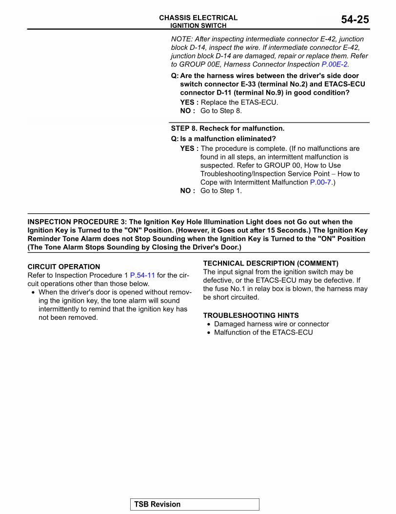
INSPECTION PROCEDURE 3: The Ignition Key Hole Illumination Light does not Go out when the Ignition Key is Turned to the "ON" Position. (However, it Goes out after 15 Seconds.) The Ignition Key Reminder Tone Alarm does not Stop Sounding when the Ignition Key is Turned to the "ON" Position (The Tone Alarm Stops Sounding by Closing the Driver's Door.)
.
CIRCUIT OPERATIONRefer to Inspection Procedure 1 P.54-11 for the cir-cuit operations other than those below.
• When the driver's door is opened without remov-ing the ignition key, the tone alarm will sound intermittently to remind that the ignition key has not been removed.
.
TECHNICAL DESCRIPTION (COMMENT)The input signal from the ignition switch may be defective, or the ETACS-ECU may be defective. If the fuse No.1 in relay box is blown, the harness may be short circuited..
TROUBLESHOOTING HINTS• Damaged harness wire or connector• Malfunction of the ETACS-ECU
.
TSB Revision
IGNITION SWITCHCHASSIS ELECTRICAL54-26
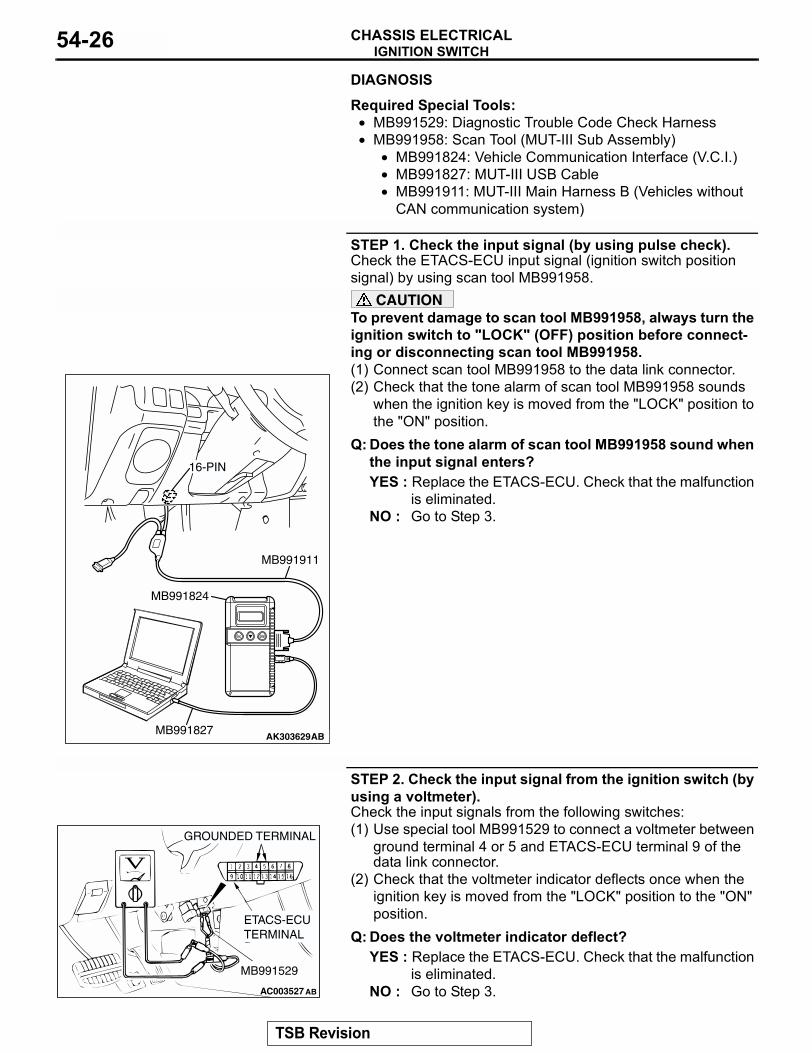
DIAGNOSISRequired Special Tools:• MB991529: Diagnostic Trouble Code Check Harness• MB991958: Scan Tool (MUT-III Sub Assembly)
• MB991824: Vehicle Communication Interface (V.C.I.)• MB991827: MUT-III USB Cable• MB991911: MUT-III Main Harness B (Vehicles without
CAN communication system)
STEP 1. Check the input signal (by using pulse check).Check the ETACS-ECU input signal (ignition switch position signal) by using scan tool MB991958.
CAUTIONTo prevent damage to scan tool MB991958, always turn the ignition switch to "LOCK" (OFF) position before connect-ing or disconnecting scan tool MB991958.(1) Connect scan tool MB991958 to the data link connector.(2) Check that the tone alarm of scan tool MB991958 sounds
when the ignition key is moved from the "LOCK" position to the "ON" position.
Q: Does the tone alarm of scan tool MB991958 sound when the input signal enters?YES : Replace the ETACS-ECU. Check that the malfunction
is eliminated.NO : Go to Step 3.
STEP 2. Check the input signal from the ignition switch (by using a voltmeter).Check the input signals from the following switches:(1) Use special tool MB991529 to connect a voltmeter between
ground terminal 4 or 5 and ETACS-ECU terminal 9 of the data link connector.
(2) Check that the voltmeter indicator deflects once when the ignition key is moved from the "LOCK" position to the "ON" position.
Q: Does the voltmeter indicator deflect?YES : Replace the ETACS-ECU. Check that the malfunction
is eliminated.NO : Go to Step 3.
AK303629AB
MB991911
MB991827
MB991824
16-PIN
AC003527
GROUNDED TERMINAL
ETACS-ECU TERMINAL
MB991529
AB
TSB Revision
IGNITION SWITCHCHASSIS ELECTRICAL 54-27
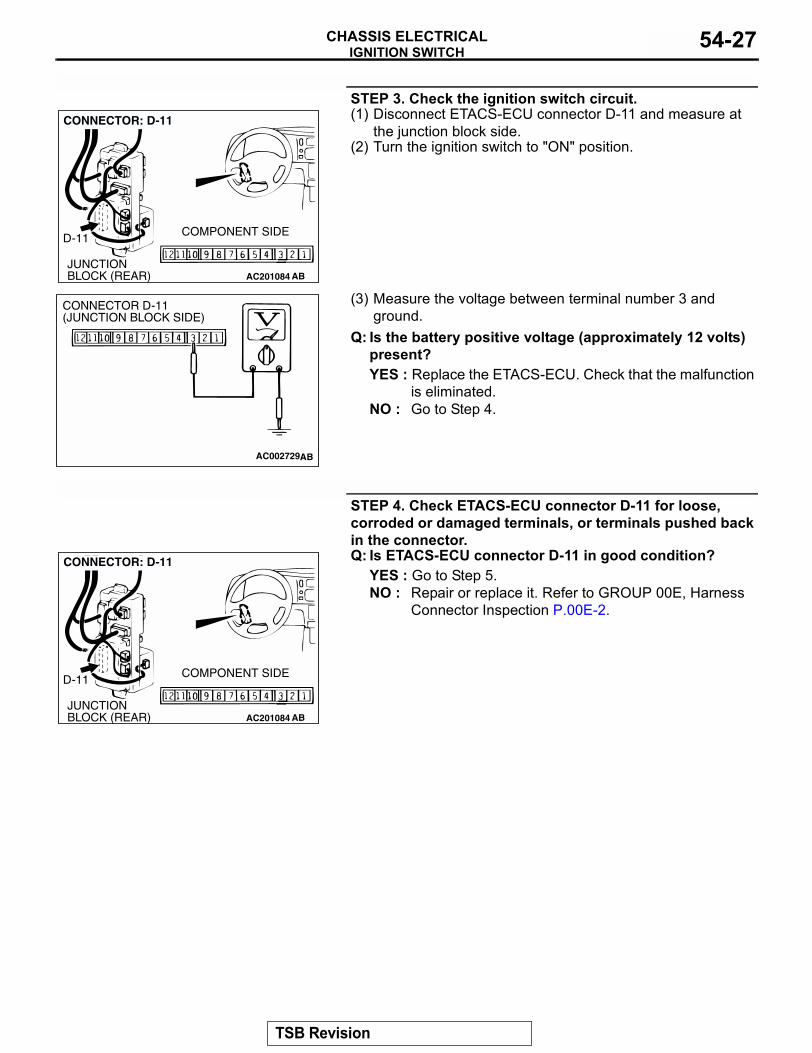
STEP 3. Check the ignition switch circuit.(1) Disconnect ETACS-ECU connector D-11 and measure at
the junction block side.(2) Turn the ignition switch to "ON" position.
(3) Measure the voltage between terminal number 3 and ground.
Q: Is the battery positive voltage (approximately 12 volts) present?YES : Replace the ETACS-ECU. Check that the malfunction
is eliminated.NO : Go to Step 4.
STEP 4. Check ETACS-ECU connector D-11 for loose, corroded or damaged terminals, or terminals pushed back in the connector.Q: Is ETACS-ECU connector D-11 in good condition?
YES : Go to Step 5.NO : Repair or replace it. Refer to GROUP 00E, Harness
Connector Inspection P.00E-2.
AC201084JUNCTION BLOCK (REAR)
D-11 COMPONENT SIDE
AB
CONNECTOR: D-11
AC002729AB
CONNECTOR D-11(JUNCTION BLOCK SIDE)
AC201084JUNCTION BLOCK (REAR)
D-11 COMPONENT SIDE
AB
CONNECTOR: D-11
TSB Revision
IGNITION SWITCHCHASSIS ELECTRICAL54-28
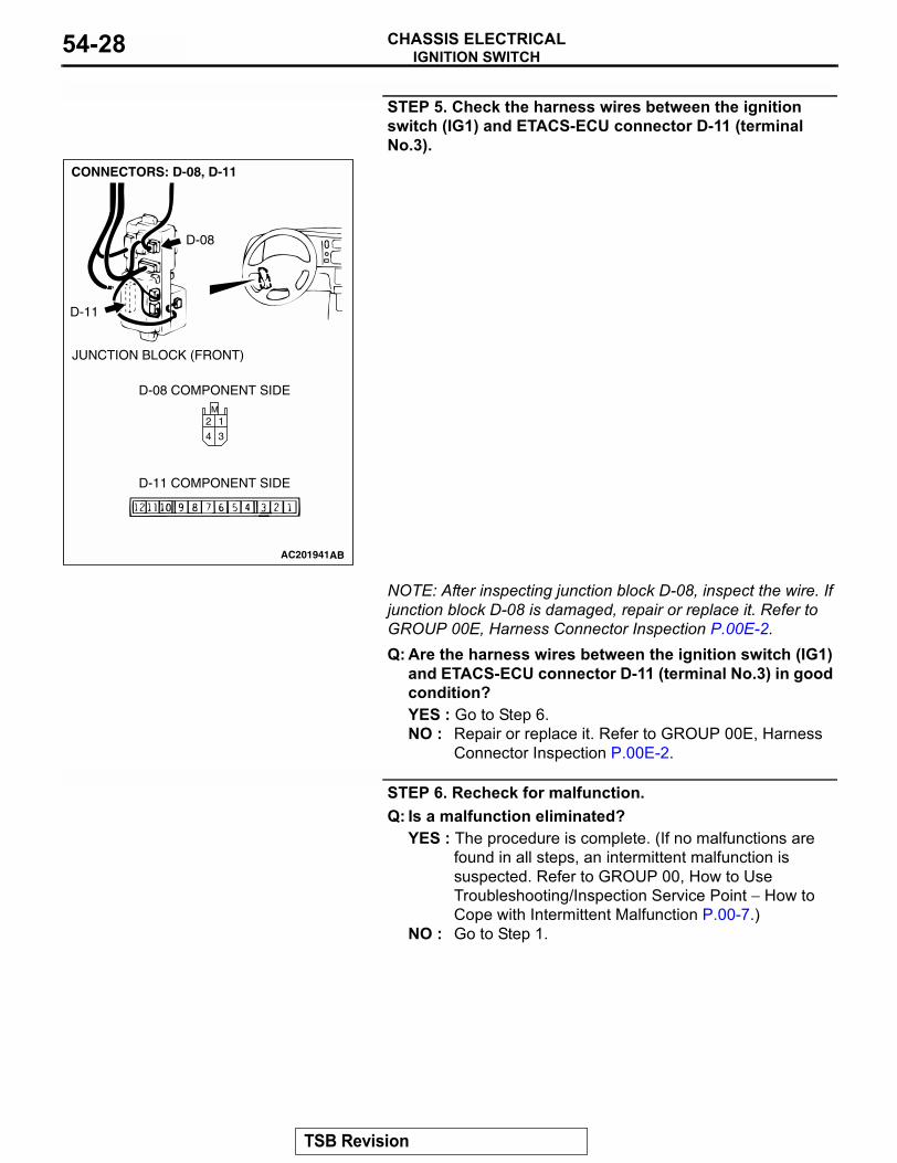
STEP 5. Check the harness wires between the ignition switch (IG1) and ETACS-ECU connector D-11 (terminal No.3).
NOTE: After inspecting junction block D-08, inspect the wire. If junction block D-08 is damaged, repair or replace it. Refer to GROUP 00E, Harness Connector Inspection P.00E-2.Q: Are the harness wires between the ignition switch (IG1)
and ETACS-ECU connector D-11 (terminal No.3) in good condition?YES : Go to Step 6.NO : Repair or replace it. Refer to GROUP 00E, Harness
Connector Inspection P.00E-2.
STEP 6. Recheck for malfunction.Q: Is a malfunction eliminated?
YES : The procedure is complete. (If no malfunctions are found in all steps, an intermittent malfunction is suspected. Refer to GROUP 00, How to Use Troubleshooting/Inspection Service Point − How to Cope with Intermittent Malfunction P.00-7.)
NO : Go to Step 1.
AC201941
M
3
1
4
2
CONNECTORS: D-08, D-11
AB
D-08 COMPONENT SIDE
D-11 COMPONENT SIDE
D-08
D-11
JUNCTION BLOCK (FRONT)
TSB Revision
IGNITION SWITCHCHASSIS ELECTRICAL 54-29
INSPECTION PROCEDURE 4: The Ignition Key Reminder Tone Alarm does not Stop Sounding by Removing the Ignition Key. (The Tone Alarm Stops Sounding by Closing the Driver's Door.)
.
CIRCUIT OPERATIONRefer to Inspection Procedure 1 for circuit operation P.54-11..
TECHNICAL DESCRIPTION (COMMENT)It is possible that there is a malfunction of the input signal from the key reminder switch or the ETACS-ECU.
.
TROUBLESHOOTING HINTS• Damaged harness wire or connector• Malfunction of the ETACS-ECU• Malfunction of the key reminder switch
.
DIAGNOSIS
Required Special Tools:• MB991529: Diagnostic Trouble Code Check Harness• MB991958: Scan Tool (MUT-III Sub Assembly)
• MB991824: Vehicle Communication Interface (V.C.I.)• MB991827: MUT-III USB Cable• MB991911: MUT-III Main Harness B (Vehicles without
CAN communication system)
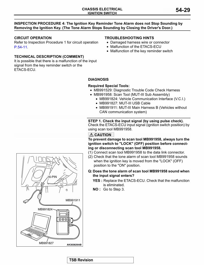
STEP 1. Check the input signal (by using pulse check).Check the ETACS-ECU input signal (ignition switch position) by using scan tool MB991958.
CAUTIONTo prevent damage to scan tool MB991958, always turn the ignition switch to "LOCK" (OFF) position before connect-ing or disconnecting scan tool MB991958.(1) Connect scan tool MB991958 to the data link connector.(2) Check that the tone alarm of scan tool MB991958 sounds
when the ignition key is moved from the "LOCK" (OFF) position to the "ON" position.
Q: Does the tone alarm of scan tool MB991958 sound when the input signal enters?YES : Replace the ETACS-ECU. Check that the malfunction
is eliminated.NO : Go to Step 3.
AK303629AB
MB991911
MB991827
MB991824
16-PIN
TSB Revision
IGNITION SWITCHCHASSIS ELECTRICAL54-30
STEP 2. Check the input signal from the ignition switch (by using a voltmeter).Check the input signals from the following switches:(1) Use special tool MB991529 to connect a voltmeter between
ground terminal 4 or 5 and ETACS-ECU terminal 9 of the data link connector.
(2) Check that the voltmeter indicator deflects once when the ignition key is moved from the "LOCK" position to the "ON" position.
Q: Does the voltmeter indicator deflect?YES : Replace the ETACS-ECU. Check that the malfunction
is eliminated.NO : Go to Step 3.
STEP 3. Measure the continuity of the key reminder switch.(1) Remove the driver's side under cover (Refer to P.52A-37).(2) Remove the column covers, lower and upper (Refer to
P.52A-37).(3) Disconnect wiring connector D-16 from the key reminder
switch and measure at the key reminder switch side.(4) Measure the resistance between terminal numbers 4 and 6.
Q: Does the measured resistance value correspond with this range?YES : Go to Step 4.NO : Replace the key reminder switch. Then check that the
malfunction is eliminated.
STEP 4. Check the input signal from the key reminder switch.Check that the tone alarm stops sounding when terminal num-ber 6 is grounded.Q: Does the tone alarm stop sounding?
YES : Go to Step 5.NO : Go to Step 7.
AC003527
GROUNDED TERMINAL
ETACS-ECU TERMINAL
MB991529
AB
STATUS OF IGNITION KEY
TESTER CONNECTION
SPECIFIED CONDITION
Removed 4 − 6 Less than 2 ohms
Inserted 4 − 6 Open circuitAC002730
AC002731AB
CONNECTOR D-16(HARNESS SIDE)
TSB Revision
IGNITION SWITCHCHASSIS ELECTRICAL 54-31
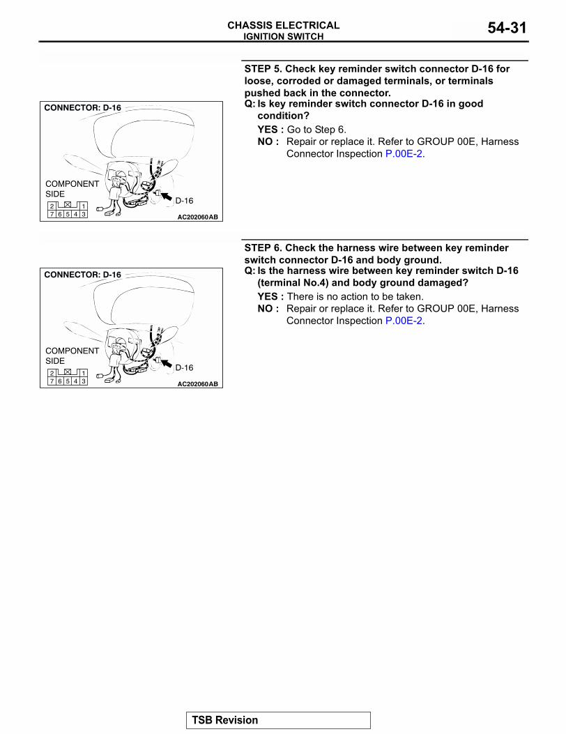
STEP 5. Check key reminder switch connector D-16 for loose, corroded or damaged terminals, or terminals pushed back in the connector.Q: Is key reminder switch connector D-16 in good
condition?YES : Go to Step 6.NO : Repair or replace it. Refer to GROUP 00E, Harness
Connector Inspection P.00E-2.
STEP 6. Check the harness wire between key reminder switch connector D-16 and body ground.Q: Is the harness wire between key reminder switch D-16
(terminal No.4) and body ground damaged?YES : There is no action to be taken.NO : Repair or replace it. Refer to GROUP 00E, Harness
Connector Inspection P.00E-2.
AC20206045 31
672
AC20206045 31
672
TSB Revision
IGNITION SWITCHCHASSIS ELECTRICAL54-32
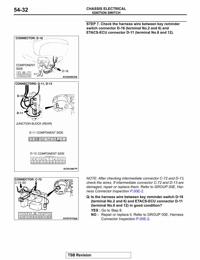
STEP 7. Check the harness wire between key reminder switch connector D-16 (terminal No.2 and 6) and ETACS-ECU connector D-11 (terminal No.8 and 12).
NOTE: After checking intermediate connector C-72 and D-13, check the wires. If intermediate connector C-72 and D-13 are damaged, repair or replace them. Refer to GROUP 00E, Har-ness Connector Inspection P.00E-2.Q: Is the harness wire between key reminder switch D-16
(terminal No.2 and 6) and ETACS-ECU connector D-11 (terminal No.8 and 12) in good condition?YES : Go to Step 8.NO : Repair or replace it. Refer to GROUP 00E, Harness
Connector Inspection P.00E-2.
AC20206045 31
672
1245 3689 710111314 121617201918 15
AC201086
819
7651615 17 18
4321011 1213
19 14
AC201910
CONNECTOR: C-72
AB
C-72 (B)
TSB Revision
IGNITION SWITCHCHASSIS ELECTRICAL 54-33
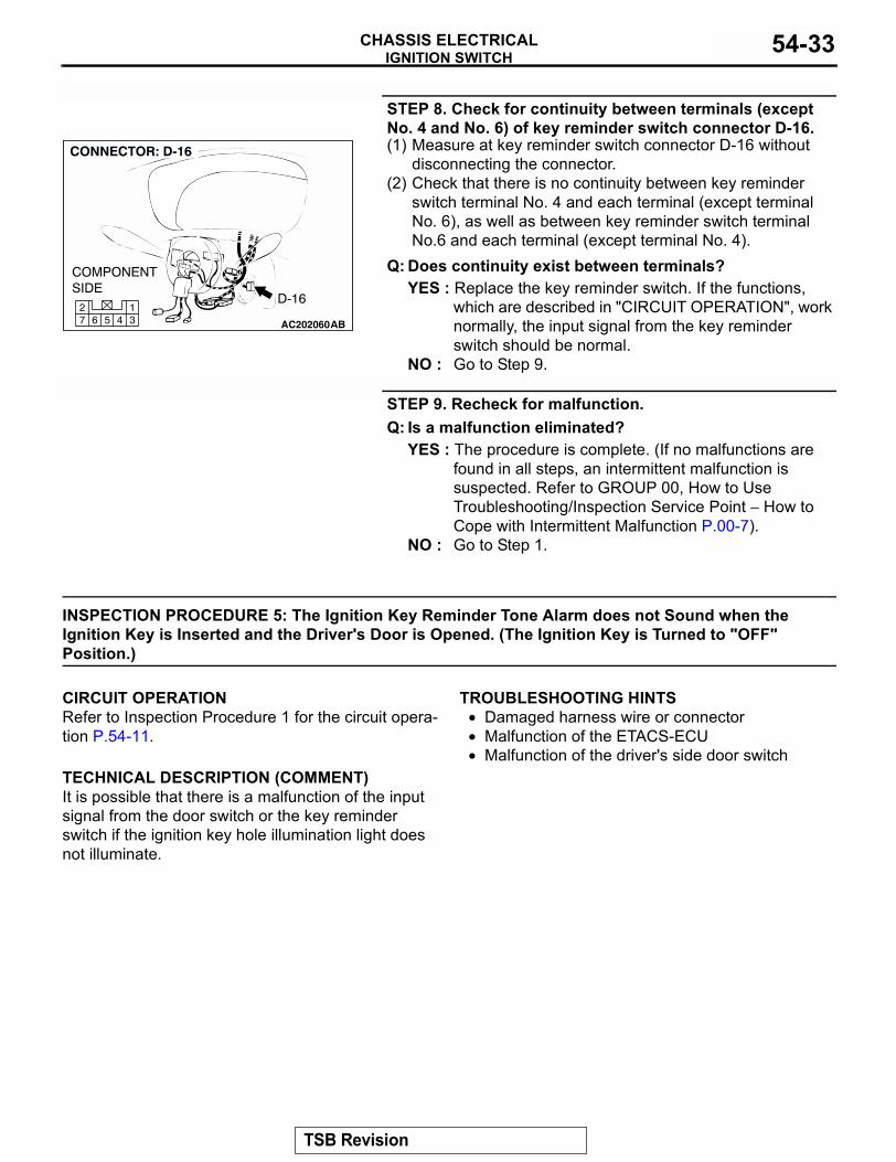
STEP 8. Check for continuity between terminals (except No. 4 and No. 6) of key reminder switch connector D-16.(1) Measure at key reminder switch connector D-16 without
disconnecting the connector.(2) Check that there is no continuity between key reminder
switch terminal No. 4 and each terminal (except terminal No. 6), as well as between key reminder switch terminal No.6 and each terminal (except terminal No. 4).
Q: Does continuity exist between terminals?YES : Replace the key reminder switch. If the functions,
which are described in "CIRCUIT OPERATION", work normally, the input signal from the key reminder switch should be normal.
NO : Go to Step 9.
STEP 9. Recheck for malfunction.Q: Is a malfunction eliminated?
YES : The procedure is complete. (If no malfunctions are found in all steps, an intermittent malfunction is suspected. Refer to GROUP 00, How to Use Troubleshooting/Inspection Service Point − How to Cope with Intermittent Malfunction P.00-7).
NO : Go to Step 1.
INSPECTION PROCEDURE 5: The Ignition Key Reminder Tone Alarm does not Sound when the Ignition Key is Inserted and the Driver's Door is Opened. (The Ignition Key is Turned to "OFF" Position.)
.
CIRCUIT OPERATIONRefer to Inspection Procedure 1 for the circuit opera-tion P.54-11..
TECHNICAL DESCRIPTION (COMMENT)It is possible that there is a malfunction of the input signal from the door switch or the key reminder switch if the ignition key hole illumination light does not illuminate.
.
TROUBLESHOOTING HINTS• Damaged harness wire or connector• Malfunction of the ETACS-ECU• Malfunction of the driver's side door switch
.
AC20206045 31
672
TSB Revision
IGNITION SWITCHCHASSIS ELECTRICAL54-34
DIAGNOSISRequired Special Tools:• MB991529: Diagnostic Trouble Code Check Harness• MB991958: Scan Tool (MUT-III Sub Assembly)
• MB991824: Vehicle Communication Interface (V.C.I.)• MB991827: MUT-III USB Cable• MB991911: MUT-III Main Harness B (Vehicles without
CAN communication system)
STEP 1. Check the input signal (by using pulse check).Check the ETACS-ECU input signal (drivers side door switch) by using scan tool MB991958.
CAUTIONTo prevent damage to scan tool MB991958, always turn the ignition switch to "LOCK" (OFF) position before connect-ing or disconnecting scan tool MB991958.(1) Connect scan tool MB991958 to the data link connector.(2) Check that the tone alarm of scan tool MB991958 sounds
when the driver's side door is opened.Q: Does the tone alarm of scan tool MB991958 sound when
the input signal enters?YES : Replace the ETACS-ECU. Check that the malfunction
is eliminated.NO : Go to Step 3.
STEP 2. Check the input signal from the driver's side door switch (by using a voltmeter).Check the input signals from the following switches:(1) Use special tool MB991529 to connect a voltmeter between
ground terminal 4 or 5 and ETACS-ECU terminal 9 of the data link connector.
(2) Check that the voltmeter indicator deflects once when the input signal enters.
Q: Does the voltmeter indicator deflect?YES : Replace the ETACS-ECU. Check that the malfunction
is eliminated.NO : Go to Step 3.
AK303629AB
MB991911
MB991827
MB991824
16-PIN
AC003527
GROUNDED TERMINAL
ETACS-ECU TERMINAL
MB991529
AB
TSB Revision
IGNITION SWITCHCHASSIS ELECTRICAL 54-35
STEP 3. Check the driver's side door switch.Remove the driver's side door switch. Refer to GROUP 42, Door P.42-132.
Q: Is the driver's side door switch in good condition?YES : Go to Step 4.NO : Replace it. Check that the malfunction is eliminated.
STEP 4. Check the driver's side door switch ground circuit.Measure the resistance between the driver's side door switch body (metal section) and ground.
• The measured value should be 2 ohms or less.Q: Does the measured resistance value correspond with
this range?YES : Go to Step 5.NO : Repair the harness wire or connector. Then check
that the malfunction is eliminated.
STEP 5. Check driver's side door switch connector E-33 input circuit.(1) Disconnect the driver's side door switch connector E-33 and
the harness side.
(2) Measure the voltage between terminal 2 and ground.• The measured value should be approximately 5 volts.
Q: Does the measured voltage correspond with this range?YES : There is no action to be taken.NO : Go to Step 6.
SWITCH POSITION
TESTER CONNECTION
SPECIFIED CONDITION
Released (ON) 1 − 2, 1 − 3, 2 − 3 Less than 2 ohms
Depressed (OFF) 1 − 2, 1 − 3, 2 − 3 Open circuit
AC002733AB
1
2
3
AC002734
AC2020562 1
COMPONENT SIDE
CONNECTOR: E-33
ABE-33
AC002735
E-33 HARNESS CONNECTOR:COMPONENT SIDE
AE
TSB Revision
IGNITION SWITCHCHASSIS ELECTRICAL54-36
STEP 6. Check driver's side door switch connector E-33 for loose, corroded or damaged terminals, or terminals pushed back in the connector.Q: Is driver's side door switch connector E-33 damaged?
YES : Repair or replace it. Refer to GROUP 00E, Harness Connector Inspection P.00E-2. The tachometer should work normally.
NO : Go to Step 7.
AC2020562 1
COMPONENT SIDE
CONNECTOR: E-33
ABE-33
TSB Revision
IGNITION SWITCHCHASSIS ELECTRICAL 54-37
STEP 7. Check the harness wires between driver's side door switch connector E-33 and ETACS connector D-11.
AC201939
1347 6 5 291112 1013 8
18
3457 6101516 14 1213 11 9
2
CONNECTORS: D-11, D-14
D-11
D-14 (B)
D-11 COMPONENT SIDE
D-14 COMPONENT SIDE
AB
JUNCTION BLOCK (FRONT)
AC201940
2 1
819
7651615 17 18
4321011 1213
19 14
CONNECTORS: E-33, E-42
AC
E-33 (B)E-42
COMPONENT SIDE
E-42
TSB Revision
IGNITION SWITCHCHASSIS ELECTRICAL54-38
NOTE: After inspecting junction block connector D-14 and intermediate connector E-42, inspect the wire. If junction block connector D-14 and intermediate connector E-42 are dam-aged, repair or replace them. Refer to GROUP 00E, Harness Connector Inspection P.00E-2.Q: Are the harness wires between driver's side door switchconnector E-33 and ETACS connector D-11 in good condition?YES : Go to Step 8.NO : Repair them. Then check that the malfunction is
eliminated.
STEP 8. Check for continuity of the key reminder switch.(1) Remove the driver's side under cover. Refer to P.52A-37.(2) Remove the column covers, lower and upper.(3) Disconnect wiring connector D-16 from the key reminder
switch and measure at the key reminder switch side.(4) Measure the resistance between terminal numbers 4 and 6.
Q: Does the measured resistance value correspond with this range?YES : Go to Step 9.NO : Replace the key reminder switch. Then check that the
malfunction is eliminated.
STEP 9. Check the input signal from the key reminder switch.Check that the tone alarm stops sounding when terminal num-ber 6 is grounded.Q: Does the tone alarm stop sounding?
YES : Go to Step 10.NO : Go to Step 12.
STATUS OF IGNITION KEY
TESTER CONNECTION
SPECIFIED CONDITION
Removed 4 − 6 Less than 2 ohms
Inserted 4 − 6 Open circuitAC002730
AC002731AB
D-16 HARNESS CONNECTOR:COMPONENT SIDE
TSB Revision
IGNITION SWITCHCHASSIS ELECTRICAL 54-39
STEP 10. Check key reminder switch connector D-16 for loose, corroded or damaged terminals, or terminals pushed back in the connector.Q: Is the key reminder switch connector D-16 in good
condition?YES : Go to Step 11.NO : Repair or replace it. Refer to GROUP 00E, Harness
Connector Inspection P.00E-2.
STEP 11. Check the harness wire between key reminder switch connector D-16 (terminal No.4) and body ground.Q: Is the resistance wire between key reminder switch D-16
and body ground in good condition?YES : There is no action to be taken.NO : Repair or replace it. Refer to GROUP 00E, Harness
Connector Inspection P.00E-2.
AC20206045 31
672
AC20206045 31
672
TSB Revision
IGNITION SWITCHCHASSIS ELECTRICAL54-40
STEP 12. Check the harness wire between key reminder switch connector D-16 (terminal No.2 and 6) and ETACS-ECU connector D-11(terminal No.8 and 12).
NOTE: After checking intermediate connector C-72 and D-13, check the wires. If intermediate connector C-72 and D-13 are damaged, repair or replace them. Refer to GROUP 00E, Har-ness Connector Inspection P.00E-2.Q: Is the harness wire between key reminder switch D-16
and ETACS-ECU connector D-11 in good condition?YES : Go to Step 13.NO : Repair or replace it. Refer to GROUP 00E, Harness
Connector Inspection P.00E-2.
1245 3689 710111314 121617201918 15
AC201086
AC20206045 31
672
819
7651615 17 18
4321011 1213
19 14
AC201910
CONNECTOR: C-72
AB
C-72 (B)
TSB Revision
IGNITION SWITCHCHASSIS ELECTRICAL 54-41
STEP 13. Check for continuity between terminals (except No. 4 and No. 6) of key reminder switch connector D-16.(1) Measure at key reminder switch connector D-16 without
disconnecting the connector.(2) Check that there is no continuity between key reminder
switch terminal No. 4 and each terminal (except terminal No. 6), as well as between key reminder switch terminal No.6 and each terminal (except terminal No. 4).
Q: Does continuity exist between terminals?YES : Replace the key reminder switch. If the functions,
which are described in "CIRCUIT OPERATION", work normally, the input signal from the key reminder switch should be normal.
NO : Go to Step 14.
STEP 14. Recheck for malfunction.Q: Is a malfunction eliminated?
YES : The procedure is complete. (If no malfunctions are found in all steps, an intermittent malfunction is suspected. Refer to GROUP 00, How to Use Troubleshooting/Inspection Service Point P.00-7.
NO : Go to Step 1.
AC20206045 31
672
TSB Revision
IGNITION SWITCHCHASSIS ELECTRICAL54-42
EQUIPMENT DIAGNOSISIMMOBILIZER SYSTEM DIAGNOSIS
M1543009901393
INTRODUCTION TO IMMOBILIZER SYSTEM DIAGNOSIS
CAUTIONThe encrypted code should always be re-regis-tered when replacing the immobilizer-ECU.The immobilizer system consists of the immobi-lizer-ECU, powertrain control module, ignition key and ignition key ring antenna. If the engine cannot be started by using a registered ignition key, one of these components may be defective. In addition, if
the immobilizer system has immobilized the engine, MFI system DTC P1610 will be output. In this case, observe the immobilizer system troubleshooting. Then, if a malfunction is resolved, the MFI system DTC P1610 should not reset.
IMMOBILIZER SYSTEM DIAGNOSTIC TROUBLESHOOTING STRATEGYM1543006900711
Use these steps to plan your diagnostic strategy. If you follow them carefully, you will be sure that you have exhausted most of the possible ways to find an immobilizer system fault.1. Gather information about the problem from the
customer.2. Verify that the condition described by the
customer exists.3. Check the vehicle for any immobilizer system
DTC.4. If you cannot verify the condition and there are no
immobilizer system DTCs, the malfunction is intermittent. Refer to GROUP 00, How to Use Troubleshooting/inspection Service Points - How to Cope with Intermittent Malfunctions P.00-7.
5. If you can verify the condition but there are no immobilizer system DTCs, or the system cannot communicate with scan tool MB991958, refer to Symptom Chart and find the fault P.54-48.
6. If there is an immobilizer system DTC, record the number of the DTC, then erase the DTC from the memory using scan tool MBB991958.
7. Recreate the immobilizer system DTC set conditions to see if the same immobilizer system DTC will set again.(1) If the same immobilize system DTC sets
again, perform the diagnostic procedures for the DTC. Refer to Diagnostic Trouble Code Chart P.54-43.
(2) If you cannot get the same immobilizer system DTC to set again, the malfunction is intermittent. Refer to GROUP 00, How to Use Troubleshooting/inspection Service Points − How to Cope with Intermittent Malfunctions P.00-7.
TSB Revision
IGNITION SWITCHCHASSIS ELECTRICAL 54-43
IMMOBILIZER SYSTEM TROUBLE CODE DIAGNOSIS
M1543007000487
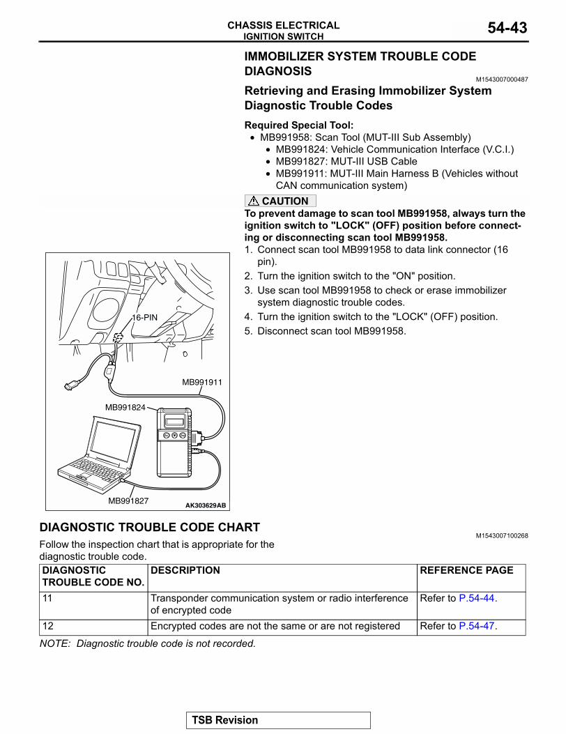
Retrieving and Erasing Immobilizer System Diagnostic Trouble CodesRequired Special Tool:
• MB991958: Scan Tool (MUT-III Sub Assembly)• MB991824: Vehicle Communication Interface (V.C.I.)• MB991827: MUT-III USB Cable• MB991911: MUT-III Main Harness B (Vehicles without
CAN communication system)CAUTION
To prevent damage to scan tool MB991958, always turn the ignition switch to "LOCK" (OFF) position before connect-ing or disconnecting scan tool MB991958.1. Connect scan tool MB991958 to data link connector (16
pin).2. Turn the ignition switch to the "ON" position.3. Use scan tool MB991958 to check or erase immobilizer
system diagnostic trouble codes.4. Turn the ignition switch to the "LOCK" (OFF) position.5. Disconnect scan tool MB991958.
DIAGNOSTIC TROUBLE CODE CHARTM1543007100268
Follow the inspection chart that is appropriate for the diagnostic trouble code.
NOTE: Diagnostic trouble code is not recorded.
AK303629AB
MB991911
MB991827
MB991824
16-PIN
DIAGNOSTIC TROUBLE CODE NO.
DESCRIPTION REFERENCE PAGE
11 Transponder communication system or radio interference of encrypted code
Refer to P.54-44.
12 Encrypted codes are not the same or are not registered Refer to P.54-47.
TSB Revision
IGNITION SWITCHCHASSIS ELECTRICAL54-44
DIAGNOSTIC TROUBLE CODE PROCEDURES
DTC: 11 Transponder Communication System or Radio Interference of Encrypted Code
.
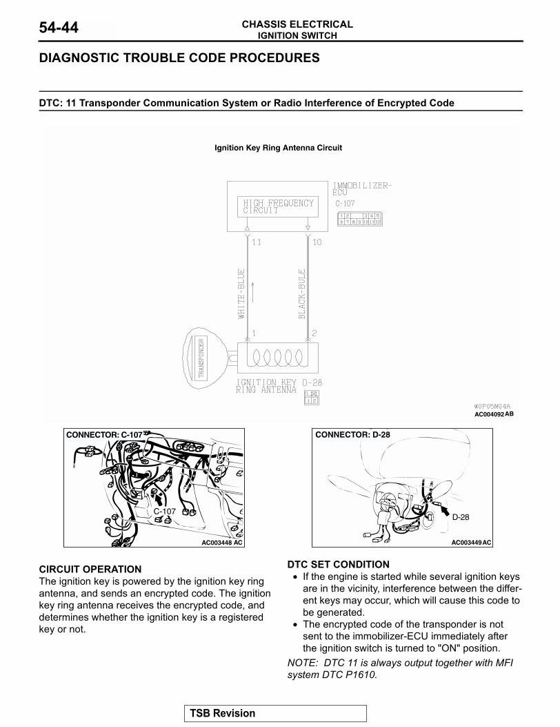
CIRCUIT OPERATIONThe ignition key is powered by the ignition key ring antenna, and sends an encrypted code. The ignition key ring antenna receives the encrypted code, and determines whether the ignition key is a registered key or not..
DTC SET CONDITION• If the engine is started while several ignition keys
are in the vicinity, interference between the differ-ent keys may occur, which will cause this code to be generated.
• The encrypted code of the transponder is not sent to the immobilizer-ECU immediately after the ignition switch is turned to "ON" position.
NOTE: DTC 11 is always output together with MFI system DTC P1610.
.
AC004092 AB
Ignition Key Ring Antenna Circuit
AC003448 AC
CONNECTOR: C-107
C-107
AC003449AC
CONNECTOR: D-28
D-28
TSB Revision
IGNITION SWITCHCHASSIS ELECTRICAL 54-45
TROUBLESHOOTING HINTS• Radio interference of encrypted code• Malfunction of transponder• Malfunction of ignition key ring antenna• Malfunction of immobilizer-ECU• Damaged wiring harness of connectors
.
DIAGNOSIS
Required Special Tools:• MB991223: Harness Set• MB991958: Scan Tool (MUT-III Sub Assembly)
• MB991824: Vehicle Communication Interface (V.C.I.)• MB991827: MUT-III USB Cable• MB991911: MUT-III Main Harness B (Vehicles without
CAN communication system)
STEP 1. Check that there is other key near the key in the ignition.Q: Is there any other key near the key in the ignition?
YES : Move the other key well away from key being used. Confirm that diagnostic trouble code 11 is not output.
NO : Go to Step 2.
STEP 2. Check that the engine starts using the spare ignition key which encrypted code has been registered.Q: Does the engine start using the spare ignition key which
encrypted code has been registered?YES : Replace the ignition key that does not work. Then
register the password (secret code) and encrypted code P.00E-2. Confirm that diagnostic trouble code 11 is not output.
NO : Go to Step 3.
STEP 3. Using scan tool MB991958, read the diagnostic trouble code.Check that DTC 11 or DTC 12 is output.Q: Which DTC is output, DTC 11 or 12?
DTC 12 is output : Refer to DTC 12 P.54-47.DTC 11 is output : Go to Step 4.
TSB Revision
IGNITION SWITCHCHASSIS ELECTRICAL54-46
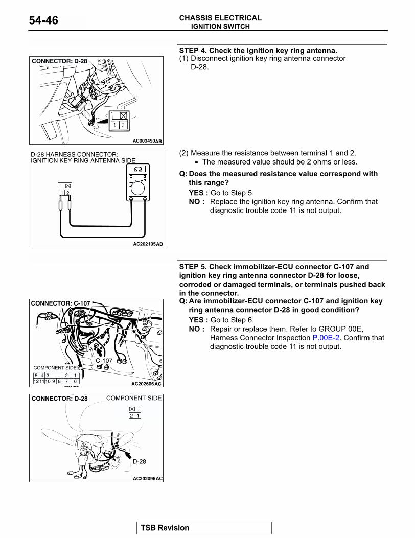
STEP 4. Check the ignition key ring antenna.(1) Disconnect ignition key ring antenna connector
D-28.
(2) Measure the resistance between terminal 1 and 2.• The measured value should be 2 ohms or less.
Q: Does the measured resistance value correspond with this range?YES : Go to Step 5.NO : Replace the ignition key ring antenna. Confirm that
diagnostic trouble code 11 is not output.
STEP 5. Check immobilizer-ECU connector C-107 and ignition key ring antenna connector D-28 for loose, corroded or damaged terminals, or terminals pushed back in the connector.Q: Are immobilizer-ECU connector C-107 and ignition key
ring antenna connector D-28 in good condition?YES : Go to Step 6.NO : Repair or replace them. Refer to GROUP 00E,
Harness Connector Inspection P.00E-2. Confirm that diagnostic trouble code 11 is not output.
AC003450AB
CONNECTOR: D-28
21
AC202105AB
D-28 HARNESS CONNECTOR:IGNITION KEY RING ANTENNA SIDE
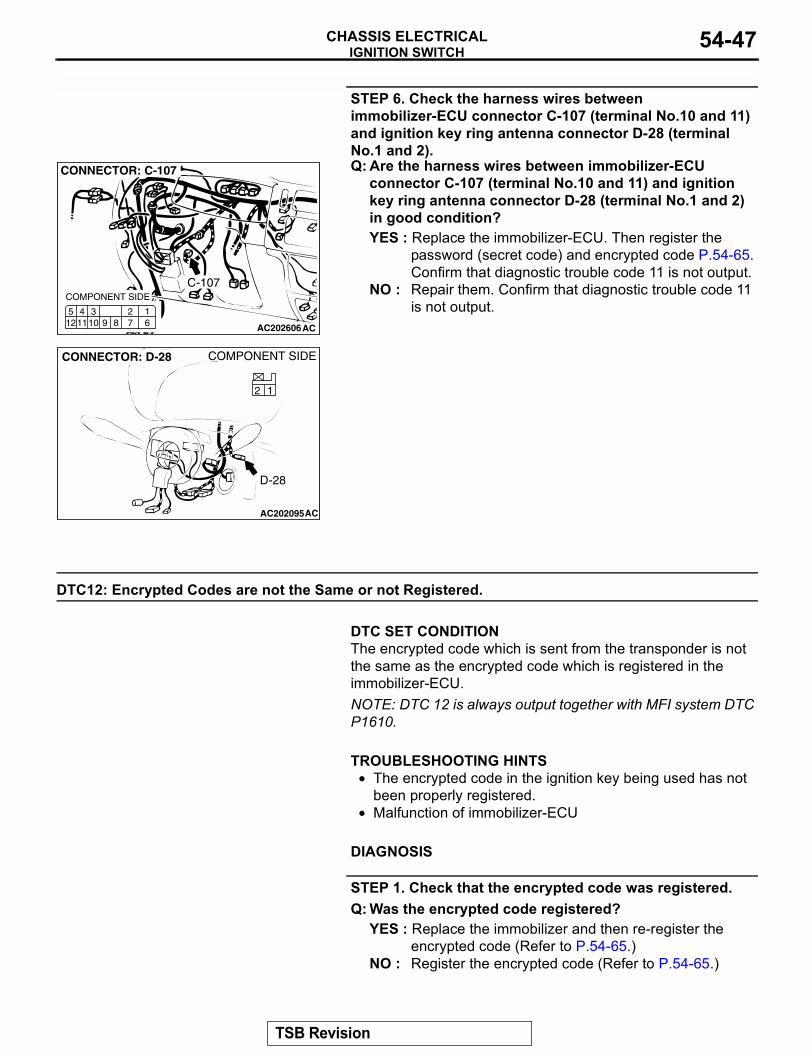
AC202606
C-107
127 6
345121110 9 8
CONNECTOR: C-107
AC
COMPONENT SIDE
AC202095
21
COMPONENT SIDE
AC
D-28
CONNECTOR: D-28
12
TSB Revision
IGNITION SWITCHCHASSIS ELECTRICAL 54-47
STEP 6. Check the harness wires between immobilizer-ECU connector C-107 (terminal No.10 and 11) and ignition key ring antenna connector D-28 (terminal No.1 and 2).Q: Are the harness wires between immobilizer-ECU
connector C-107 (terminal No.10 and 11) and ignition key ring antenna connector D-28 (terminal No.1 and 2) in good condition?YES : Replace the immobilizer-ECU. Then register the
password (secret code) and encrypted code P.54-65. Confirm that diagnostic trouble code 11 is not output.
NO : Repair them. Confirm that diagnostic trouble code 11 is not output.
DTC12: Encrypted Codes are not the Same or not Registered.
.
DTC SET CONDITIONThe encrypted code which is sent from the transponder is not the same as the encrypted code which is registered in the immobilizer-ECU.NOTE: DTC 12 is always output together with MFI system DTC P1610..
TROUBLESHOOTING HINTS• The encrypted code in the ignition key being used has not
been properly registered.• Malfunction of immobilizer-ECU
.
DIAGNOSIS
STEP 1. Check that the encrypted code was registered.Q: Was the encrypted code registered?
YES : Replace the immobilizer and then re-register the encrypted code (Refer to P.54-65.)
NO : Register the encrypted code (Refer to P.54-65.)
AC202606
C-107
127 6
345121110 9 8
CONNECTOR: C-107
AC
COMPONENT SIDE
AC202095
21
COMPONENT SIDE
AC
D-28
CONNECTOR: D-28
12
TSB Revision
IGNITION SWITCHCHASSIS ELECTRICAL54-48
SYMPTOM CHARTM1543007201183
SYMPTOM PROCEDURES
INSPECTION PROCEDURE 1: Communication with Scan Tool MB991958 is Impossible.
SYMPTOM INSPECTION PROCEDURE NO.
REFERENCE PAGE
Communication with scan tool MB991958 is impossible. 1 P.54-48Registering the ignition key is impossible. 2 P.54-55The "SECURITY" indicator does not illuminate. 3 P.54-57Engine does not start (Cranking but no initial combustion). 4 P.54-61
JOINT CONNECTOR (5)
JOINT CONNECTOR (5)
POWERTRAINCONTROLMODULE
MULTIPORTFUELINJECTION RELAY
IMMOBILIZER-ECU
POWERSUPPLYCIRCUIT
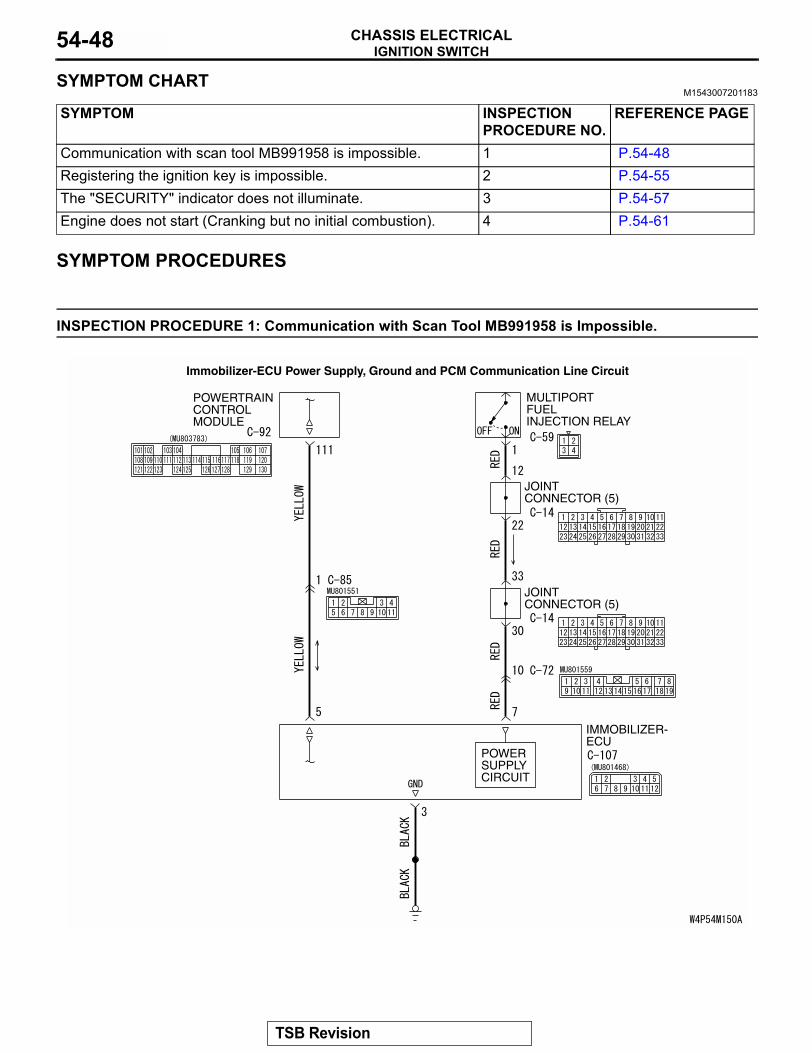
Immobilizer-ECU Power Supply, Ground and PCM Communication Line Circuit
TSB Revision
IGNITION SWITCHCHASSIS ELECTRICAL 54-49
.
CIRCUIT OPERATIONImmobilizer-ECU is energized when the ignition switch is turned "ON," and the engine control relay is turned on. The powertrain control module transmits a signal from scan tool MB991958 to the immobi-lizer-ECU as it is. In the same way, a signal from the immobilizer-ECU is also transmitted to scan tool MB991958 as it is..
TECHNICAL DESCRIPTION (COMMENT)• This malfunction may be caused by a defective
immobilizer-ECU, powertrain control module, or a defect in the communication line between the immobilizer-ECU and powertrain control module. If this malfunction appears when the MFI system and scan tool MB991958 can communicate each other, MFI system DTC P0513 will reset.
• If the MFI system is normal, the MFI relay can be determined as normal. In addition, if the MFI sys-tem and scan tool MB991958 can communicate each other, the circuits between the data link con-nector and the powertrain control module can determined as normal.NOTE: If this malfunction appears, MFI system DTC P0513 will be output.
.
TROUBLESHOOTING HINTS• Malfunction of immobilizer-ECU• Malfunction of powertrain control module• Damaged harness wires or connectors
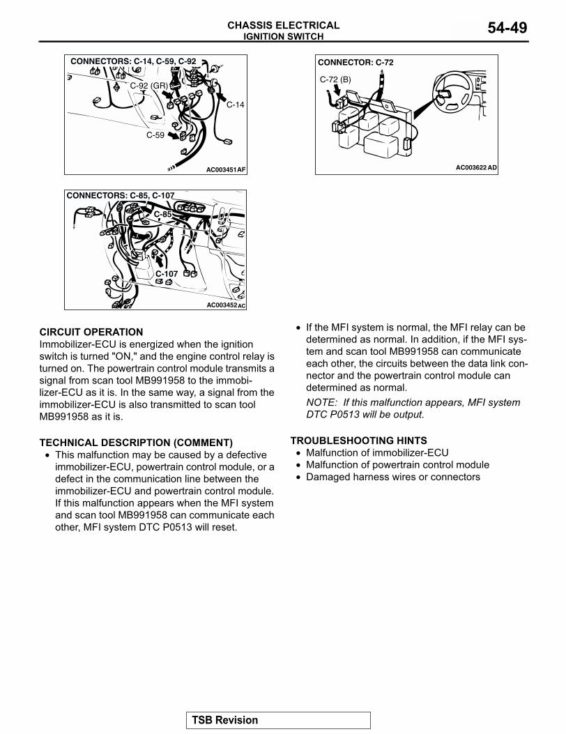
AC003451
CONNECTORS: C-14, C-59, C-92
AF
C-14
C-59
C-92 (GR)
AC003622
CONNECTOR: C-72
AD
C-72 (B)
AC003452AC
CONNECTORS: C-85, C-107
C-85
C-107
TSB Revision
IGNITION SWITCHCHASSIS ELECTRICAL54-50
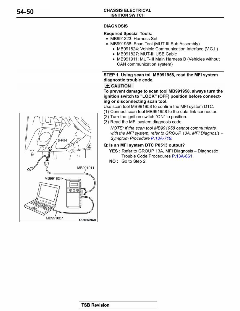
.DIAGNOSIS
Required Special Tools:• MB991223: Harness Set• MB991958: Scan Tool (MUT-III Sub Assembly)
• MB991824: Vehicle Communication Interface (V.C.I.)• MB991827: MUT-III USB Cable• MB991911: MUT-III Main Harness B (Vehicles without
CAN communication system)
STEP 1. Using scan toll MB991958, read the MFI system diagnostic trouble code.
CAUTIONTo prevent damage to scan tool MB991958, always turn the ignition switch to "LOCK" (OFF) position before connect-ing or disconnecting scan tool.Use scan tool MB991958 to confirm the MFI system DTC.(1) Connect scan tool MB991958 to the data link connector.(2) Turn the ignition switch "ON" to position.(3) Read the MFI system diagnosis code.
NOTE: If the scan tool MB991958 cannot communicate with the MFI system, refer to GROUP 13A, MFI Diagnosis − Symptom Procedure P.13A-719.
Q: Is an MFI system DTC P0513 output?YES : Refer to GROUP 13A, MFI Diagnosis − Diagnostic
Trouble Code Procedures P.13A-661.NO : Go to Step 2.
AK303629AB
MB991911
MB991827
MB991824
16-PIN
TSB Revision
IGNITION SWITCHCHASSIS ELECTRICAL 54-51
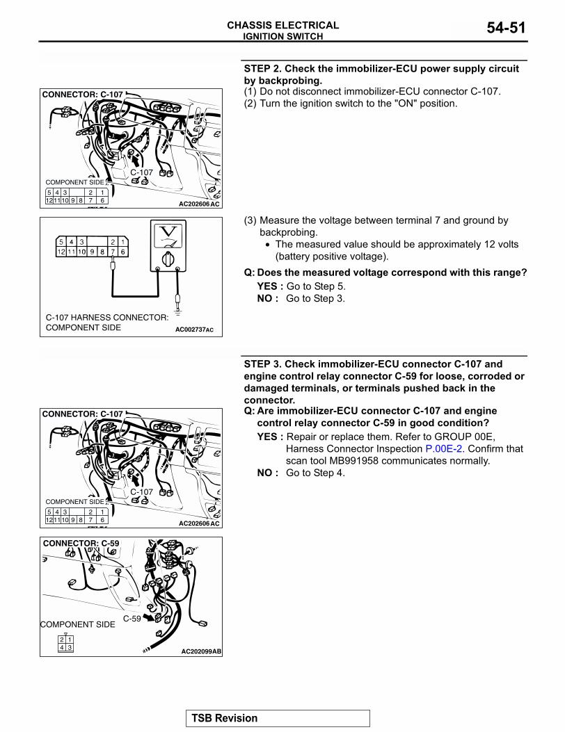
STEP 2. Check the immobilizer-ECU power supply circuit by backprobing.(1) Do not disconnect immobilizer-ECU connector C-107.(2) Turn the ignition switch to the "ON" position.
(3) Measure the voltage between terminal 7 and ground by backprobing.
• The measured value should be approximately 12 volts (battery positive voltage).
Q: Does the measured voltage correspond with this range?YES : Go to Step 5.NO : Go to Step 3.
STEP 3. Check immobilizer-ECU connector C-107 and engine control relay connector C-59 for loose, corroded or damaged terminals, or terminals pushed back in the connector.Q: Are immobilizer-ECU connector C-107 and engine
control relay connector C-59 in good condition?YES : Repair or replace them. Refer to GROUP 00E,
Harness Connector Inspection P.00E-2. Confirm that scan tool MB991958 communicates normally.
NO : Go to Step 4.
AC202606
C-107
127 6
345121110 9 8
CONNECTOR: C-107
AC
COMPONENT SIDE
AC002737AC
C-107 HARNESS CONNECTOR:COMPONENT SIDE
AC202606
C-107
127 6
345121110 9 8
CONNECTOR: C-107
AC
COMPONENT SIDE
AC202099
24
13
CONNECTOR: C-59
AB
C-59COMPONENT SIDE
TSB Revision
IGNITION SWITCHCHASSIS ELECTRICAL54-52
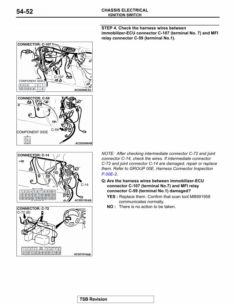
STEP 4. Check the harness wires between immobilizer-ECU connector C-107 (terminal No. 7) and MFI relay connector C-59 (terminal No.1).
NOTE: After checking intermediate connector C-72 and joint connector C-14, check the wires. If intermediate connector C-72 and joint connector C-14 are damaged, repair or replace them. Refer to GROUP 00E, Harness Connector Inspection P.00E-2.Q: Are the harness wires between immobilizer-ECU
connector C-107 (terminal No.7) and MFI relay connector C-59 (terminal No.1) damaged?YES : Replace them. Confirm that scan tool MB991958
communicates normally.NO : There is no action to be taken.
AC202606
C-107
127 6
345121110 9 8
CONNECTOR: C-107
AC
COMPONENT SIDE
AC202099
24
13
CONNECTOR: C-59
AB
C-59COMPONENT SIDE
AC202100
9 1086 7
3132302921201918
5421 3
27262423 251615141312
2817
332211
CONNECTOR: C-14
AB
C-14
819
7651615 17 18
4321011 1213
19 14
AC201910
CONNECTOR: C-72
AB
C-72 (B)
TSB Revision
IGNITION SWITCHCHASSIS ELECTRICAL 54-53
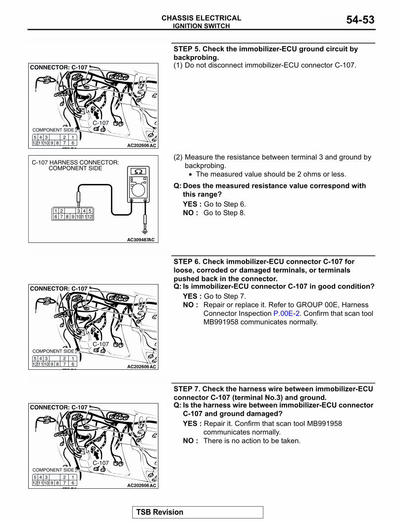
STEP 5. Check the immobilizer-ECU ground circuit by backprobing.(1) Do not disconnect immobilizer-ECU connector C-107.
(2) Measure the resistance between terminal 3 and ground by backprobing.
• The measured value should be 2 ohms or less.Q: Does the measured resistance value correspond with
this range?YES : Go to Step 6.NO : Go to Step 8.
STEP 6. Check immobilizer-ECU connector C-107 for loose, corroded or damaged terminals, or terminals pushed back in the connector.Q: Is immobilizer-ECU connector C-107 in good condition?
YES : Go to Step 7.NO : Repair or replace it. Refer to GROUP 00E, Harness
Connector Inspection P.00E-2. Confirm that scan tool MB991958 communicates normally.
STEP 7. Check the harness wire between immobilizer-ECU connector C-107 (terminal No.3) and ground.Q: Is the harness wire between immobilizer-ECU connector
C-107 and ground damaged?YES : Repair it. Confirm that scan tool MB991958
communicates normally.NO : There is no action to be taken.
AC202606
C-107
127 6
345121110 9 8
CONNECTOR: C-107
AC
COMPONENT SIDE
AC309487
61
125
11109872 3 4
C-107 HARNESS CONNECTOR:COMPONENT SIDE
AC
AC202606
C-107
127 6
345121110 9 8
CONNECTOR: C-107
AC
COMPONENT SIDE
AC202606
C-107
127 6
345121110 9 8
CONNECTOR: C-107
AC
COMPONENT SIDE
TSB Revision
IGNITION SWITCHCHASSIS ELECTRICAL54-54
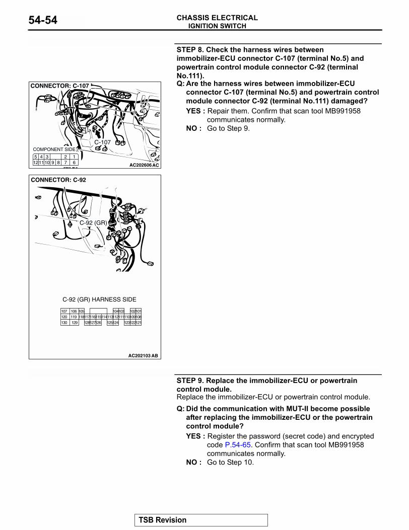
STEP 8. Check the harness wires between immobilizer-ECU connector C-107 (terminal No.5) and powertrain control module connector C-92 (terminal No.111).Q: Are the harness wires between immobilizer-ECU
connector C-107 (terminal No.5) and powertrain control module connector C-92 (terminal No.111) damaged?YES : Repair them. Confirm that scan tool MB991958
communicates normally.NO : Go to Step 9.
STEP 9. Replace the immobilizer-ECU or powertrain control module.Replace the immobilizer-ECU or powertrain control module.Q: Did the communication with MUT-II become possible
after replacing the immobilizer-ECU or the powertrain control module?YES : Register the password (secret code) and encrypted
code P.54-65. Confirm that scan tool MB991958 communicates normally.
NO : Go to Step 10.
AC202606
C-107
127 6
345121110 9 8
CONNECTOR: C-107
AC
COMPONENT SIDE
AC202103
108101
109102
110121
111103
112115114113125124
104118105
117120107 106
122119
130 129 123128116127126
CONNECTOR: C-92
AB
C-92 (GR)
C-92 (GR) HARNESS SIDE
TSB Revision
IGNITION SWITCHCHASSIS ELECTRICAL 54-55
STEP 10. Recheck for malfunction.Q: Is a malfunction eliminated?
YES : The procedure is complete. (If no malfunction are found in all steps, an intermittent malfunction is suspected. Refer to GROUP 00, How to Use Troubleshooting/Inspection Service Points − How to Cope with Intermittent Malfunction P.00-7.)
NO : Replace the immobilizer-ECU or powertrain control module.
INSPECTION PROCEDURE 2: Registering the Ignition Key is Impossible.
.
TECHNICAL DESCRIPTION (COMMENT)The transponder built-in ignition key or the immobi-lizer-ECU is suspected to be defective.
.
TROUBLESHOOTING HINTS• Malfunction of ignition key• Malfunction of immobilizer-ECU
.
DIAGNOSIS
Required Special Tools:• MB991223: Harness Set• MB991958: Scan Tool (MUT-III Sub Assembly)
• MB991824: Vehicle Communication Interface (V.C.I.)• MB991827: MUT-III USB Cable• MB991911: MUT-III Main Harness B (Vehicles without
CAN communication system)
TSB Revision
IGNITION SWITCHCHASSIS ELECTRICAL54-56
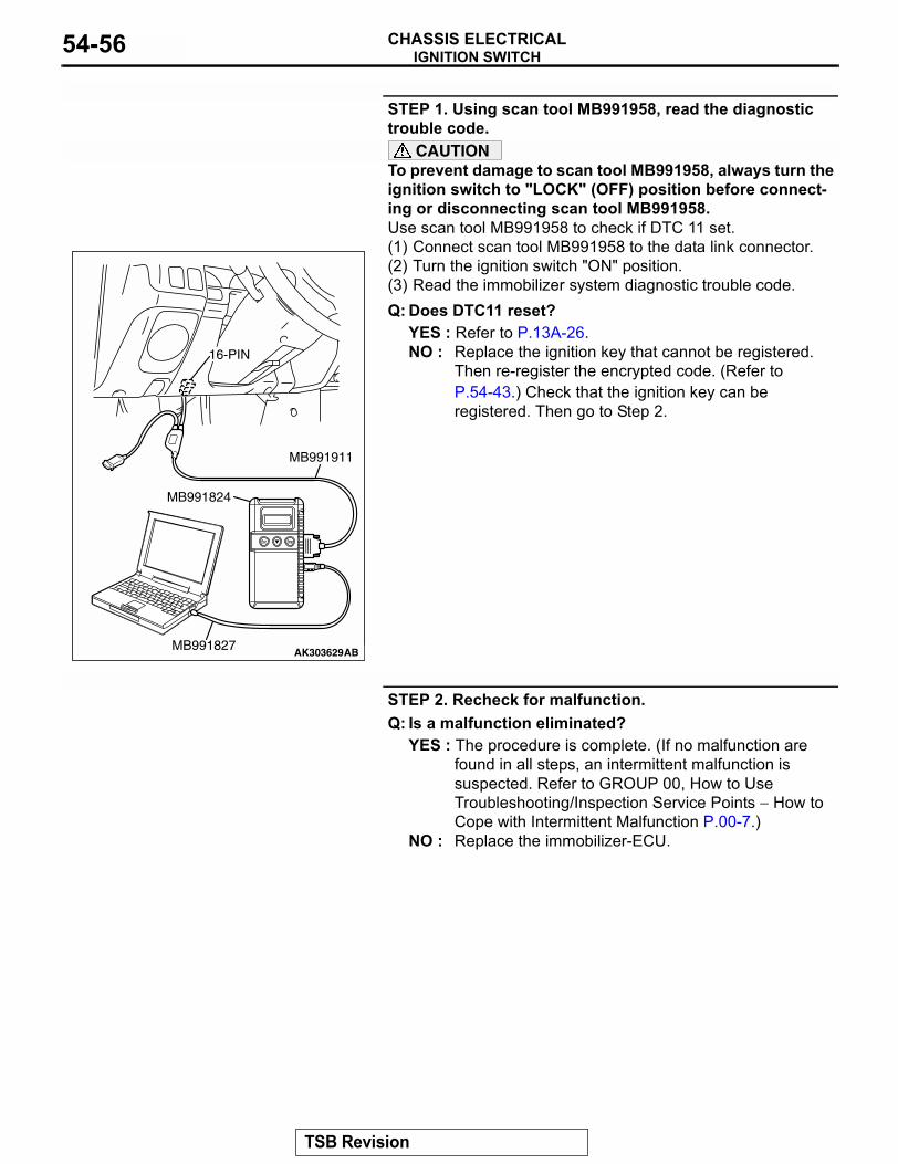
STEP 1. Using scan tool MB991958, read the diagnostic trouble code.
CAUTIONTo prevent damage to scan tool MB991958, always turn the ignition switch to "LOCK" (OFF) position before connect-ing or disconnecting scan tool MB991958.Use scan tool MB991958 to check if DTC 11 set.(1) Connect scan tool MB991958 to the data link connector.(2) Turn the ignition switch "ON" position.(3) Read the immobilizer system diagnostic trouble code.Q: Does DTC11 reset?
YES : Refer to P.13A-26.NO : Replace the ignition key that cannot be registered.
Then re-register the encrypted code. (Refer to P.54-43.) Check that the ignition key can be registered. Then go to Step 2.
STEP 2. Recheck for malfunction.Q: Is a malfunction eliminated?
YES : The procedure is complete. (If no malfunction are found in all steps, an intermittent malfunction is suspected. Refer to GROUP 00, How to Use Troubleshooting/Inspection Service Points − How to Cope with Intermittent Malfunction P.00-7.)
NO : Replace the immobilizer-ECU.
AK303629AB
MB991911
MB991827
MB991824
16-PIN
TSB Revision
IGNITION SWITCHCHASSIS ELECTRICAL 54-57
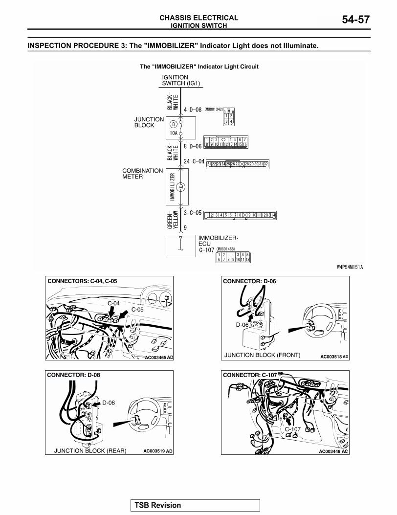
INSPECTION PROCEDURE 3: The "IMMOBILIZER" Indicator Light does not Illuminate.
.
JUNCTION BLOCK
IMMOBILIZER-ECU
IGNITIONSWITCH (IG1)
COMBINATIONMETER
The "IMMOBILIZER" Indicator Light Circuit
AC003465
CONNECTORS: C-04, C-05
AD
C-04C-05
AC003518 AD
CONNECTOR: D-06
JUNCTION BLOCK (FRONT)
D-06
AC003519
CONNECTOR: D-08
ADJUNCTION BLOCK (REAR)
D-08
AC003448 AC
CONNECTOR: C-107
C-107
TSB Revision
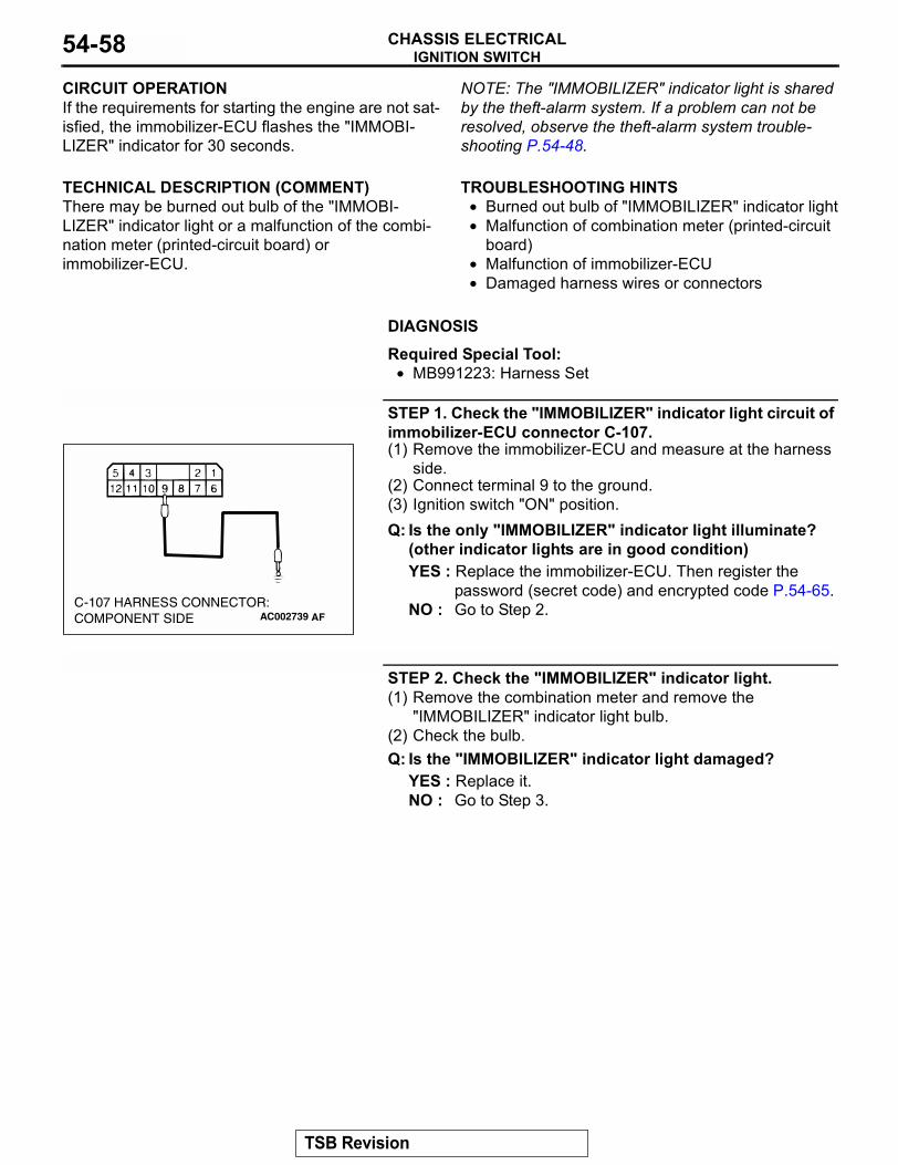
IGNITION SWITCHCHASSIS ELECTRICAL54-58
CIRCUIT OPERATIONIf the requirements for starting the engine are not sat-isfied, the immobilizer-ECU flashes the "IMMOBI-LIZER" indicator for 30 seconds..
TECHNICAL DESCRIPTION (COMMENT)There may be burned out bulb of the "IMMOBI-LIZER" indicator light or a malfunction of the combi-nation meter (printed-circuit board) or immobilizer-ECU.
NOTE: The "IMMOBILIZER" indicator light is shared by the theft-alarm system. If a problem can not be resolved, observe the theft-alarm system trouble-shooting P.54-48..
TROUBLESHOOTING HINTS• Burned out bulb of "IMMOBILIZER" indicator light• Malfunction of combination meter (printed-circuit
board)• Malfunction of immobilizer-ECU• Damaged harness wires or connectors
.
DIAGNOSIS
Required Special Tool:• MB991223: Harness Set
STEP 1. Check the "IMMOBILIZER" indicator light circuit of immobilizer-ECU connector C-107.(1) Remove the immobilizer-ECU and measure at the harness
side.(2) Connect terminal 9 to the ground.(3) Ignition switch "ON" position.Q: Is the only "IMMOBILIZER" indicator light illuminate?
(other indicator lights are in good condition)YES : Replace the immobilizer-ECU. Then register the
password (secret code) and encrypted code P.54-65.NO : Go to Step 2.
STEP 2. Check the "IMMOBILIZER" indicator light. (1) Remove the combination meter and remove the
"IMMOBILIZER" indicator light bulb.(2) Check the bulb. Q: Is the "IMMOBILIZER" indicator light damaged?
YES : Replace it. NO : Go to Step 3.
AC002739C-107 HARNESS CONNECTOR:COMPONENT SIDE AF
TSB Revision
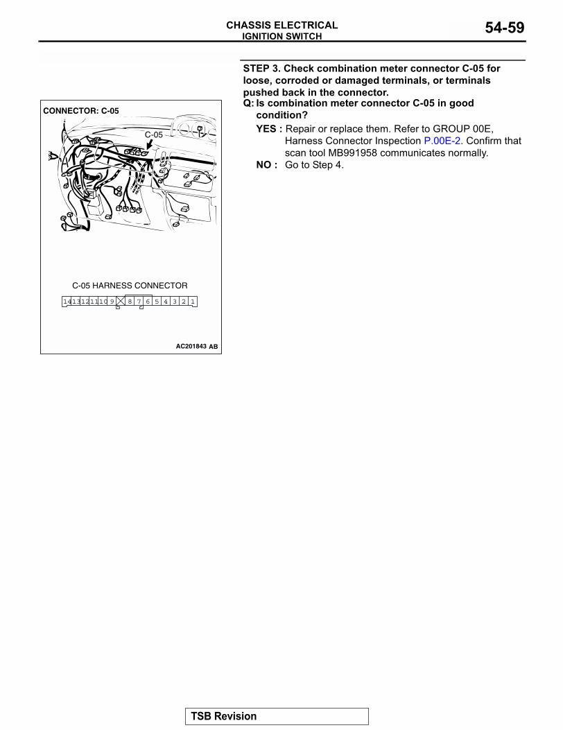
IGNITION SWITCHCHASSIS ELECTRICAL 54-59
STEP 3. Check combination meter connector C-05 for loose, corroded or damaged terminals, or terminals pushed back in the connector. Q: Is combination meter connector C-05 in good
condition?YES : Repair or replace them. Refer to GROUP 00E,
Harness Connector Inspection P.00E-2. Confirm that scan tool MB991958 communicates normally.
NO : Go to Step 4.
AC2018743
3 26 5 47891110 1121413
CONNECTOR: C-05
C-05 HARNESS CONNECTOR
C-05
AC201843 AB
TSB Revision
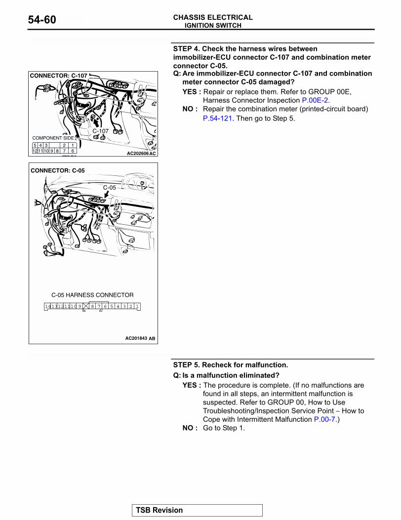
IGNITION SWITCHCHASSIS ELECTRICAL54-60
STEP 4. Check the harness wires between immobilizer-ECU connector C-107 and combination meter connector C-05.Q: Are immobilizer-ECU connector C-107 and combination
meter connector C-05 damaged?YES : Repair or replace them. Refer to GROUP 00E,
Harness Connector Inspection P.00E-2.NO : Repair the combination meter (printed-circuit board)
P.54-121. Then go to Step 5.
STEP 5. Recheck for malfunction.Q: Is a malfunction eliminated?
YES : The procedure is complete. (If no malfunctions are found in all steps, an intermittent malfunction is suspected. Refer to GROUP 00, How to Use Troubleshooting/Inspection Service Point − How to Cope with Intermittent Malfunction P.00-7.)
NO : Go to Step 1.
AC202606
C-107
127 6
345121110 9 8
CONNECTOR: C-107
AC
COMPONENT SIDE
AC2018743
3 26 5 47891110 1121413
CONNECTOR: C-05
C-05 HARNESS CONNECTOR
C-05
AC201843 AB
TSB Revision
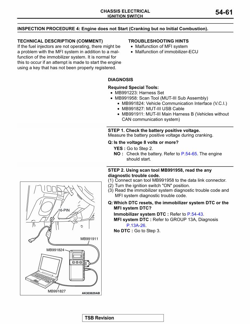
IGNITION SWITCHCHASSIS ELECTRICAL 54-61
INSPECTION PROCEDURE 4: Engine does not Start (Cranking but no Initial Combustion).
.
TECHNICAL DESCRIPTION (COMMENT)If the fuel injectors are not operating, there might be a problem with the MFI system in addition to a mal-function of the immobilizer system. It is normal for this to occur if an attempt is made to start the engine using a key that has not been properly registered.
.
TROUBLESHOOTING HINTS• Malfunction of MFI system• Malfunction of immobilizer-ECU
.
DIAGNOSIS
Required Special Tools:• MB991223: Harness Set• MB991958: Scan Tool (MUT-III Sub Assembly)
• MB991824: Vehicle Communication Interface (V.C.I.)• MB991827: MUT-III USB Cable• MB991911: MUT-III Main Harness B (Vehicles without
CAN communication system)
STEP 1. Check the battery positive voltage.Measure the battery positive voltage during cranking.Q: Is the voltage 8 volts or more?
YES : Go to Step 2.NO : Check the battery. Refer to P.54-65. The engine
should start.
STEP 2. Using scan tool MB991958, read the any diagnostic trouble code.(1) Connect scan tool MB991958 to the data link connector.(2) Turn the ignition switch "ON" position.(3) Read the immobilizer system diagnostic trouble code and
MFI system diagnostic trouble code.Q: Which DTC resets, the immobilizer system DTC or the
MFI system DTC?Immobilizer system DTC : Refer to P.54-43.MFI system DTC : Refer to GROUP 13A, Diagnosis
P.13A-26.No DTC : Go to Step 3.
AK303629AB
MB991911
MB991827
MB991824
16-PIN
TSB Revision
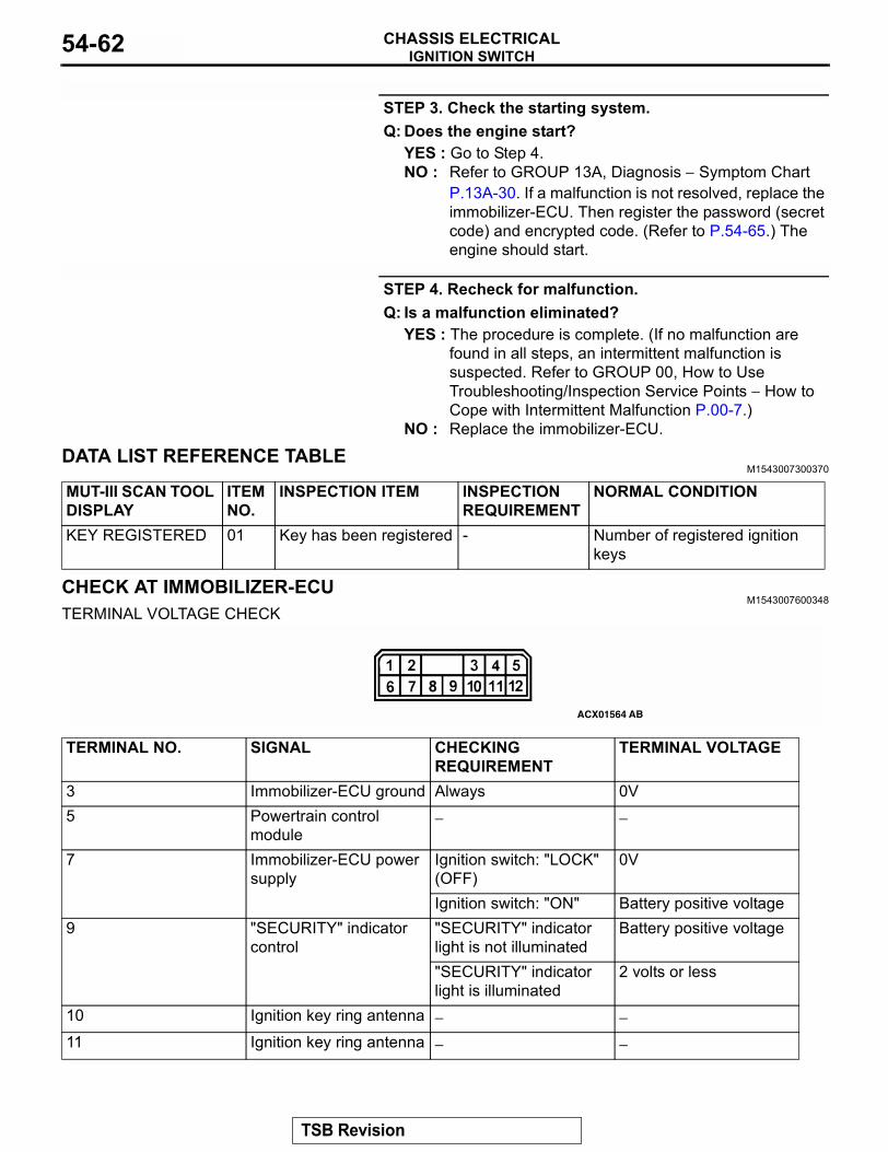
IGNITION SWITCHCHASSIS ELECTRICAL54-62
STEP 3. Check the starting system.Q: Does the engine start?
YES : Go to Step 4.NO : Refer to GROUP 13A, Diagnosis − Symptom Chart
P.13A-30. If a malfunction is not resolved, replace the immobilizer-ECU. Then register the password (secret code) and encrypted code. (Refer to P.54-65.) The engine should start.
STEP 4. Recheck for malfunction.Q: Is a malfunction eliminated?
YES : The procedure is complete. (If no malfunction are found in all steps, an intermittent malfunction is suspected. Refer to GROUP 00, How to Use Troubleshooting/Inspection Service Points − How to Cope with Intermittent Malfunction P.00-7.)
NO : Replace the immobilizer-ECU.
DATA LIST REFERENCE TABLEM1543007300370
CHECK AT IMMOBILIZER-ECU M1543007600348
TERMINAL VOLTAGE CHECK
MUT-III SCAN TOOL DISPLAY
ITEM NO.
INSPECTION ITEM INSPECTION REQUIREMENT
NORMAL CONDITION
KEY REGISTERED 01 Key has been registered - Number of registered ignition keys
ACX01564 AB
TERMINAL NO. SIGNAL CHECKING REQUIREMENT
TERMINAL VOLTAGE
3 Immobilizer-ECU ground Always 0V5 Powertrain control
module− −
7 Immobilizer-ECU power supply
Ignition switch: "LOCK" (OFF)
0V
Ignition switch: "ON" Battery positive voltage9 "SECURITY" indicator
control"SECURITY" indicator light is not illuminated
Battery positive voltage
"SECURITY" indicator light is illuminated
2 volts or less
10 Ignition key ring antenna − −11 Ignition key ring antenna − −
TSB Revision
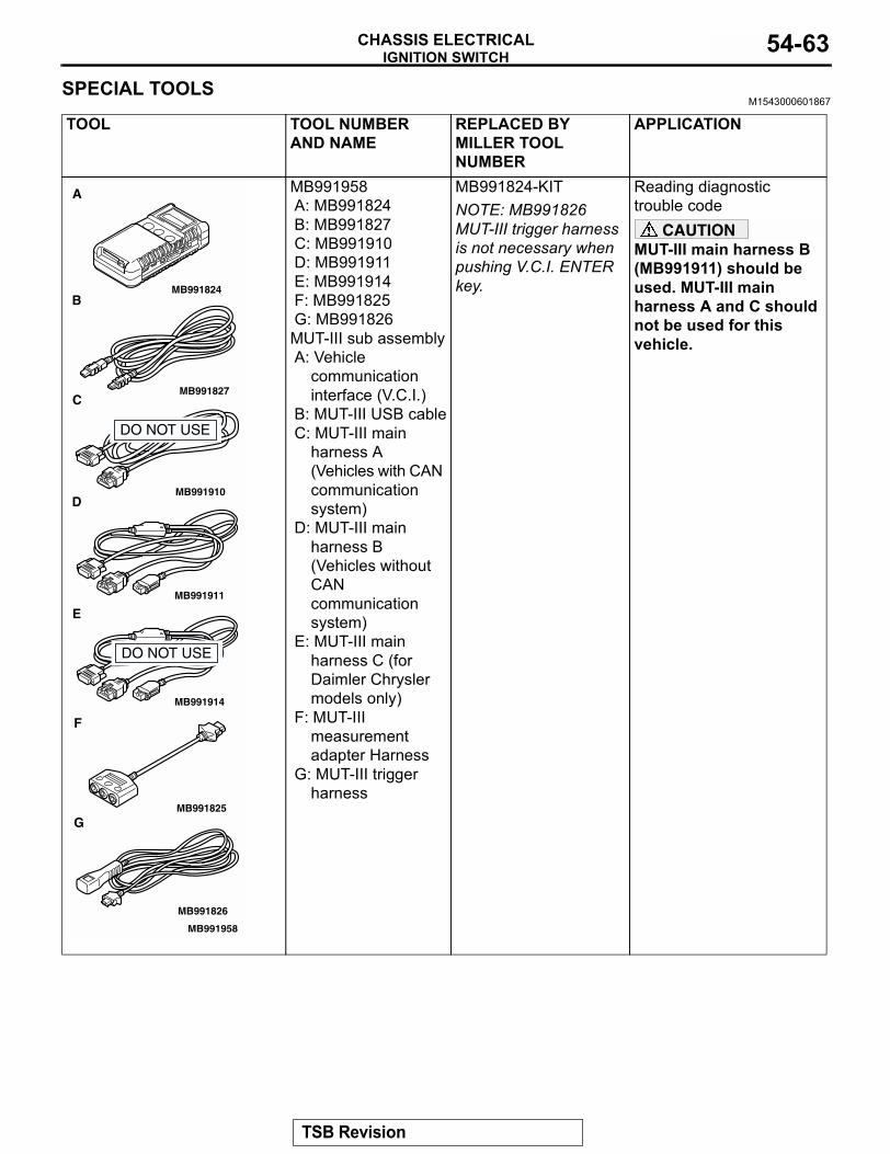
IGNITION SWITCHCHASSIS ELECTRICAL 54-63
SPECIAL TOOLSM1543000601867
TOOL TOOL NUMBER AND NAME
REPLACED BY MILLER TOOL NUMBER
APPLICATION
MB991958A: MB991824B: MB991827C: MB991910D: MB991911E: MB991914F: MB991825G: MB991826MUT-III sub assemblyA: Vehicle
communication interface (V.C.I.)
B: MUT-III USB cableC: MUT-III main
harness A (Vehicles with CAN communication system)
D: MUT-III main harness B (Vehicles without CAN communication system)
E: MUT-III main harness C (for Daimler Chrysler models only)
F: MUT-III measurement adapter Harness
G: MUT-III trigger harness
MB991824-KITNOTE: MB991826 MUT-III trigger harness is not necessary when pushing V.C.I. ENTER key.
Reading diagnostic trouble code
CAUTIONMUT-III main harness B (MB991911) should be used. MUT-III main harness A and C should not be used for this vehicle.
MB991910
MB991826
MB991958
MB991911
MB991914
MB991824
MB991827
MB991825
A
B
C
D
E
F
G
DO NOT USE
DO NOT USE
TSB Revision
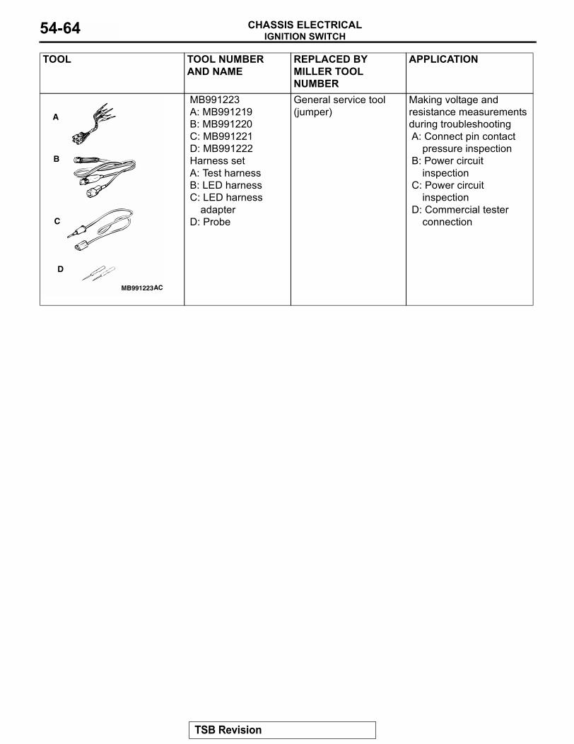
IGNITION SWITCHCHASSIS ELECTRICAL54-64
MB991223A: MB991219B: MB991220 C: MB991221D: MB991222Harness setA: Test harnessB: LED harnessC: LED harness
adapterD: Probe
General service tool (jumper)
Making voltage and resistance measurements during troubleshootingA: Connect pin contact
pressure inspectionB: Power circuit
inspectionC: Power circuit
inspectionD: Commercial tester
connection
TOOL TOOL NUMBER AND NAME
REPLACED BY MILLER TOOL NUMBER
APPLICATION
MB991223
A
B
C
D
AC
TSB Revision
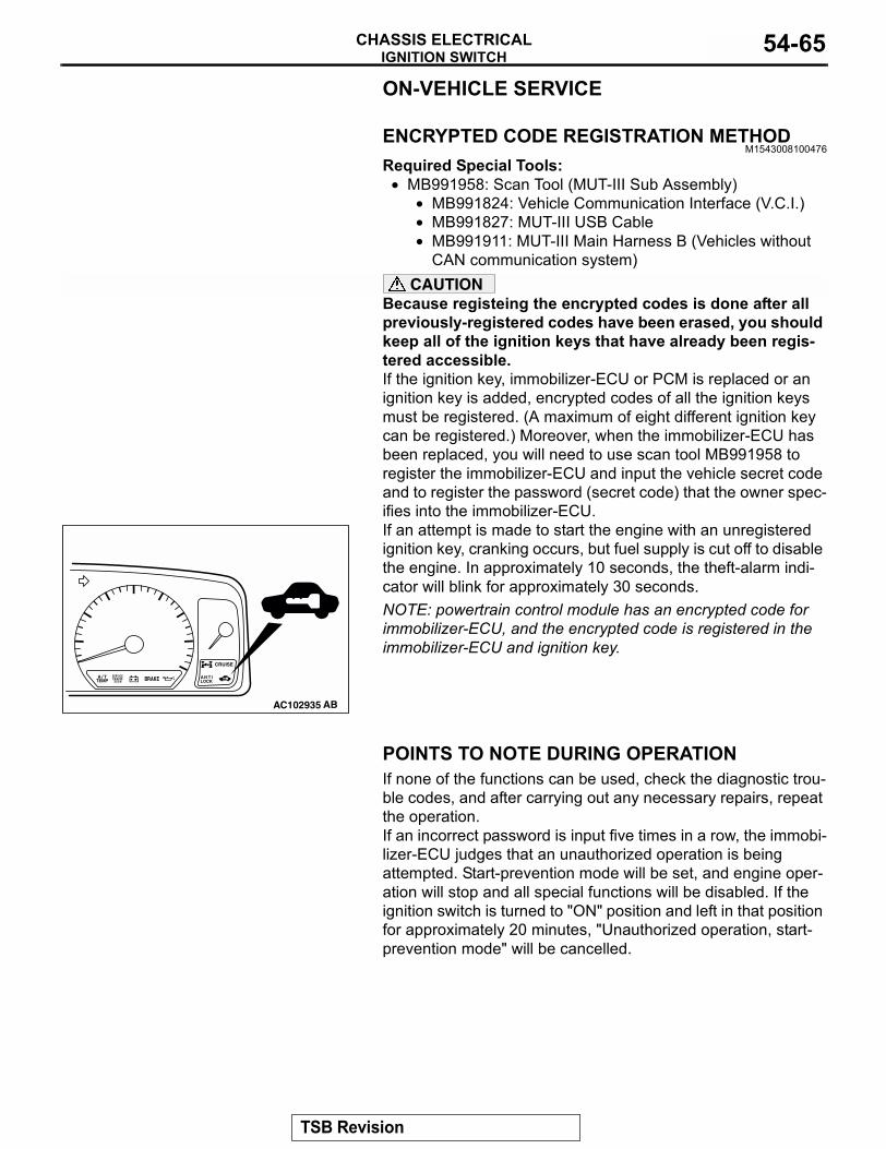
IGNITION SWITCHCHASSIS ELECTRICAL 54-65
ON-VEHICLE SERVICE
ENCRYPTED CODE REGISTRATION METHODM1543008100476
Required Special Tools:• MB991958: Scan Tool (MUT-III Sub Assembly)
• MB991824: Vehicle Communication Interface (V.C.I.)• MB991827: MUT-III USB Cable• MB991911: MUT-III Main Harness B (Vehicles without
CAN communication system)CAUTION
Because registeing the encrypted codes is done after all previously-registered codes have been erased, you should keep all of the ignition keys that have already been regis-tered accessible. If the ignition key, immobilizer-ECU or PCM is replaced or an ignition key is added, encrypted codes of all the ignition keys must be registered. (A maximum of eight different ignition key can be registered.) Moreover, when the immobilizer-ECU has been replaced, you will need to use scan tool MB991958 to register the immobilizer-ECU and input the vehicle secret code and to register the password (secret code) that the owner spec-ifies into the immobilizer-ECU.If an attempt is made to start the engine with an unregistered ignition key, cranking occurs, but fuel supply is cut off to disable the engine. In approximately 10 seconds, the theft-alarm indi-cator will blink for approximately 30 seconds.NOTE: powertrain control module has an encrypted code for immobilizer-ECU, and the encrypted code is registered in the immobilizer-ECU and ignition key.
POINTS TO NOTE DURING OPERATIONIf none of the functions can be used, check the diagnostic trou-ble codes, and after carrying out any necessary repairs, repeat the operation.If an incorrect password is input five times in a row, the immobi-lizer-ECU judges that an unauthorized operation is being attempted. Start-prevention mode will be set, and engine oper-ation will stop and all special functions will be disabled. If the ignition switch is turned to "ON" position and left in that position for approximately 20 minutes, "Unauthorized operation, start- prevention mode" will be cancelled.
AC102935 AB
TSB Revision
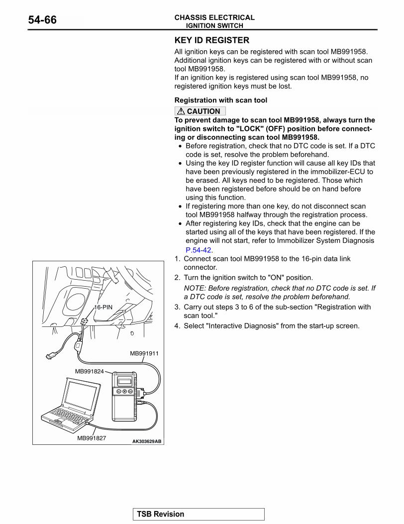
IGNITION SWITCHCHASSIS ELECTRICAL54-66
KEY ID REGISTERAll ignition keys can be registered with scan tool MB991958. Additional ignition keys can be registered with or without scan tool MB991958.If an ignition key is registered using scan tool MB991958, no registered ignition keys must be lost..
Registration with scan tool CAUTION
To prevent damage to scan tool MB991958, always turn the ignition switch to "LOCK" (OFF) position before connect-ing or disconnecting scan tool MB991958.
• Before registration, check that no DTC code is set. If a DTC code is set, resolve the problem beforehand.
• Using the key ID register function will cause all key IDs that have been previously registered in the immobilizer-ECU to be erased. All keys need to be registered. Those which have been registered before should be on hand before using this function.
• If registering more than one key, do not disconnect scan tool MB991958 halfway through the registration process.
• After registering key IDs, check that the engine can be started using all of the keys that have been registered. If the engine will not start, refer to Immobilizer System Diagnosis P.54-42.
1. Connect scan tool MB991958 to the 16-pin data link connector.
2. Turn the ignition switch to "ON" position.NOTE: Before registration, check that no DTC code is set. If a DTC code is set, resolve the problem beforehand.
3. Carry out steps 3 to 6 of the sub-section "Registration with scan tool."
4. Select "Interactive Diagnosis" from the start-up screen.
AK303629AB
MB991911
MB991827
MB991824
16-PIN
TSB Revision
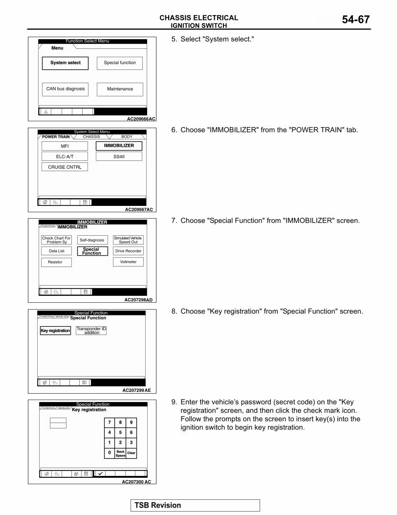
IGNITION SWITCHCHASSIS ELECTRICAL 54-67
5. Select "System select."
6. Choose "IMMOBILIZER" from the "POWER TRAIN" tab.
7. Choose "Special Function" from "IMMOBILIZER" screen.
8. Choose "Key registration" from "Special Function" screen.
9. Enter the vehicles password (secret code) on the "Key registration" screen, and then click the check mark icon. Follow the prompts on the screen to insert key(s) into the ignition switch to begin key registration.
System select Special function
CAN bus diagnosis
Function Select Menu
Menu
AC209666
Maintenance
AC
MFI
ELC-A/T
IMMOBILIZER
SS4II
CRUISE CNTRL
CHASSIS BODYSystem Select Menu
POWER TRAIN
AC209667AC
Check Chart For Problem Sy
Data List Special Function
Self-diagnosis
Voltmeter
Simulated Vehicle Speed Out
Drive Recorder
Resistor
POWERTRAIN IMMOBILIZERIMMOBILIZER
AC207298AD
Key registration Transponder ID addition
POWERTRAIN Special FunctionIMMOBILIZER
Special Function
AC207299AE
POWERTRAIN IMMOBILIZER
Special Function
7 8 9
4 5 6
1 2 3
0 BackBackSpaceSpace
ClearClear
Key registration
AC207300 AC
TSB Revision
IGNITION SWITCHCHASSIS ELECTRICAL54-68
10.If the key ID was registered successfully, "Progress"indication will turn active (gray). Then the registration process completes. If the key ID failed to be registered, "In-Complete" indication will turn active (gray).
11.The number of keys currently registered will be displayed. To register an additional key, replace the ignition key with the next key to be registered within five seconds. Key ID registration screen will be displayed, then register another key.NOTE: A maximum of eight different keys can be registered.
12.This completes the registration operation. Turn the ignition switch "LOCK" (OFF) and leave it off for approximately ten seconds.
13.Check that the engine can be started with each of the ignition keys.
14.Check that the immobilizer system DTC and MFI system DTC did not set.
15.If not DTC is shown, terminate the scan tool MB991958.16.Turn the ignition switch to "LOCK" (OFF) position.17.Disconnect scan tool MB991958..
Registration of additional key(s) without using the scan toolIf the scan tool is not available, new key(s) can be registered by operating two keys which have been registered to the vehicle (A maximum of eight keys can be registered to one vehicle). Follow the procedure below to register new key(s) to the vehi-cle.NOTE: The registered key is the key that allows you to start the engine.1. Turn on the ignition switch by using the first registered key
(key A), and wait for five seconds.2. Within 30 seconds, remove the key.3. Within seven seconds after the ignition switch has been
turned to the "LOCK" (OFF), insert the second registered key (key B) and turn on the ignition switch again. Now the theft-alarm indicator light should blink twice for one second. If it does not blink, you has failed to register. Repeat from step 1.
4. Turn on the key B. Within 30 seconds, remove the key.5. Within seven seconds after the ignition switch has been
turned to the "LOCK" (OFF) position, turn on the ignition switch by using a new key.
6. The immobilizer-ECU identifies the new key to accept or reject it, and operates the theft-alarm indicator (See the table below).
POWERTRAIN IMMOBILIZER
Special Function
IMMOBILIZER-ECU registration
Progress In-Complete
Key registration
AC207302AC
AC102935 AB
TSB Revision
IGNITION SWITCHCHASSIS ELECTRICAL 54-69
7. A maximum of eight ignition keys can be registered to one vehicle (If you attempt to register the ninth key, the immobilizer-ECU rejects the key). Follow the procedure below to register another new key. (1) Within 30 seconds after the new key has been registered
on step 6, remove the key.(2) Within seven seconds after the ignition switch has been
turned to the "LOCK" (OFF), insert another new key and turn on the ignition switch.
(3) To register more other ignition key(s), repeat steps 1 and 2.
8. If any of the following conditions are satisfied, the additional key registration mode will terminate:
• The ignition switch has been on for more than 30 seconds.• After the ignition key has been turned to the "LOCK" (OFF),
the engine control relay is turned off.• The scan tool has started communicating with vehicle sys-
tems.9. After the registration mode has terminated, the additionally
registered key(s) should allow you to start the engine.
TRANSPONDER LOCK CHECKM1543024100164
Required Special Tools:• MB991958: Scan Tool (MUT-III Sub Assembly)
• MB991824: Vehicle Communication Interface (V.C.I.)• MB991827: MUT-III USB Cable• MB991911: MUT-III Main Harness B (Vehicles without
CAN communication system)CAUTION
To prevent damage to scan tool MB991958, always turn the ignition switch to "LOCK" (OFF) position before connect-ing or disconnecting scan tool MB991958.Follow the procedure below to judge if the ignition key can be overwritten (i.e. the ignition key is correct) or not.
The new key is: Registration is: Additional registration mode:
Theft-alarm indicator:
Not registered yet Accepted Continues Comes on for 3 seconds after the ECU judges that the key has not been registered yet.
Already registered Rejected Continues Comes on for 3 seconds after the ECU judges that the key has already been registered
Read error Rejected Continues Blinks three times after the ECU has failed to identify the key.
Eight ignition keys have been registered
Rejected Continues Does not come on and blink
TSB Revision
IGNITION SWITCHCHASSIS ELECTRICAL54-70
1. Connect the scan tool MB991958 to the data link connector.2. Turn the ignition switch to "ON" position.3. Select "Interactive Diagnosis" from the start-up screen.4. Select "System select."
5. Choose "IMMOBILIZER" from the "POWER TRAIN" tab.
AK303629AB
MB991911
MB991827
MB991824
16-PIN
System select Special function
CAN bus diagnosis
Function Select Menu
Menu
AC209666
Maintenance
AC
MFI
ELC-A/T
IMMOBILIZER
SS4II
CRUISE CNTRL
CHASSIS BODYSystem Select Menu
POWER TRAIN
AC209667AC
TSB Revision
IGNITION SWITCHCHASSIS ELECTRICAL 54-71
6. Select "Data List."
7. The multi-center display shows whether the ignition key, which has been inserted in the switch, can be rewritten and how many ignition keys have ever been registered.
TP LOCK CHECK
IGNITION KEY: JUDGMENT OF IGNITION KEY
UNLOCK Can be overwritten Correct
LOCK Can not be overwritten
Incorrect
Check Chart For Problem Sy
Data List Special Function
Self-diagnosis
Voltmeter
Simulated Vehicle Speed Out
Drive Recorder
Resistor
POWERTRAIN IMMOBILIZERIMMOBILIZER
AC210932AB
AC209776
POWERTRAIN IMMOBILIZER
Data List Reference TData List Reference Tableable
Info.Info. No.No.
01 REGD.KEY 3
TP LOCK CHECK UNLOCK02
NameName Valuealue GraphGraph
Data ListData List
AB
TSB Revision
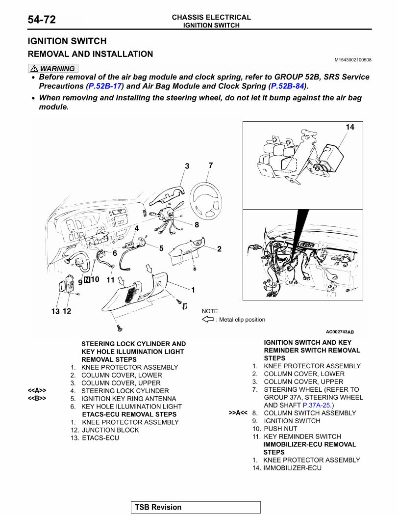
IGNITION SWITCHCHASSIS ELECTRICAL54-72
IGNITION SWITCHREMOVAL AND INSTALLATION
M1543002100508
WARNING• Before removal of the air bag module and clock spring, refer to GROUP 52B, SRS Service
Precautions (P.52B-17) and Air Bag Module and Clock Spring (P.52B-84).• When removing and installing the steering wheel, do not let it bump against the air bag
module.
AC002743
1
2
3
4
56
7
8
9 10 11
1213
14
AB
N
NOTE: Metal clip position
STEERING LOCK CYLINDER AND KEY HOLE ILLUMINATION LIGHT REMOVAL STEPS
1. KNEE PROTECTOR ASSEMBLY2. COLUMN COVER, LOWER3. COLUMN COVER, UPPER
<<A>> 4. STEERING LOCK CYLINDER<<B>> 5. IGNITION KEY RING ANTENNA
6. KEY HOLE ILLUMINATION LIGHTETACS-ECU REMOVAL STEPS
1. KNEE PROTECTOR ASSEMBLY12. JUNCTION BLOCK13. ETACS-ECU
IGNITION SWITCH AND KEY REMINDER SWITCH REMOVAL STEPS
1. KNEE PROTECTOR ASSEMBLY2. COLUMN COVER, LOWER3. COLUMN COVER, UPPER7. STEERING WHEEL (REFER TO
GROUP 37A, STEERING WHEEL AND SHAFT P.37A-25.)
>>A<< 8. COLUMN SWITCH ASSEMBLY9. IGNITION SWITCH10. PUSH NUT11. KEY REMINDER SWITCH
IMMOBILIZER-ECU REMOVAL STEPS
1. KNEE PROTECTOR ASSEMBLY14. IMMOBILIZER-ECU
TSB Revision
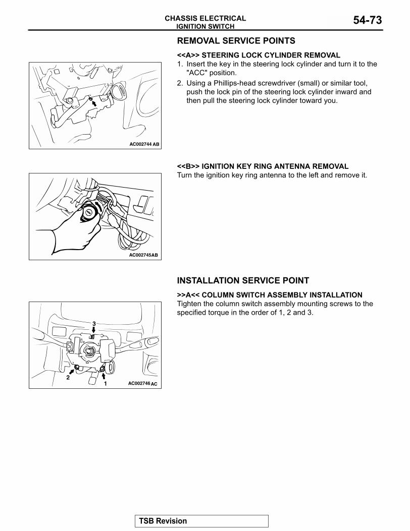
IGNITION SWITCHCHASSIS ELECTRICAL 54-73
REMOVAL SERVICE POINTS.
<<A>> STEERING LOCK CYLINDER REMOVAL1. Insert the key in the steering lock cylinder and turn it to the
"ACC" position.2. Using a Phillips-head screwdriver (small) or similar tool,
push the lock pin of the steering lock cylinder inward and then pull the steering lock cylinder toward you.
.
<<B>> IGNITION KEY RING ANTENNA REMOVALTurn the ignition key ring antenna to the left and remove it.
INSTALLATION SERVICE POINT.
>>A<< COLUMN SWITCH ASSEMBLY INSTALLATIONTighten the column switch assembly mounting screws to the specified torque in the order of 1, 2 and 3.
AC002744 AB
AC002745AB
AC002746AC12
3
TSB Revision
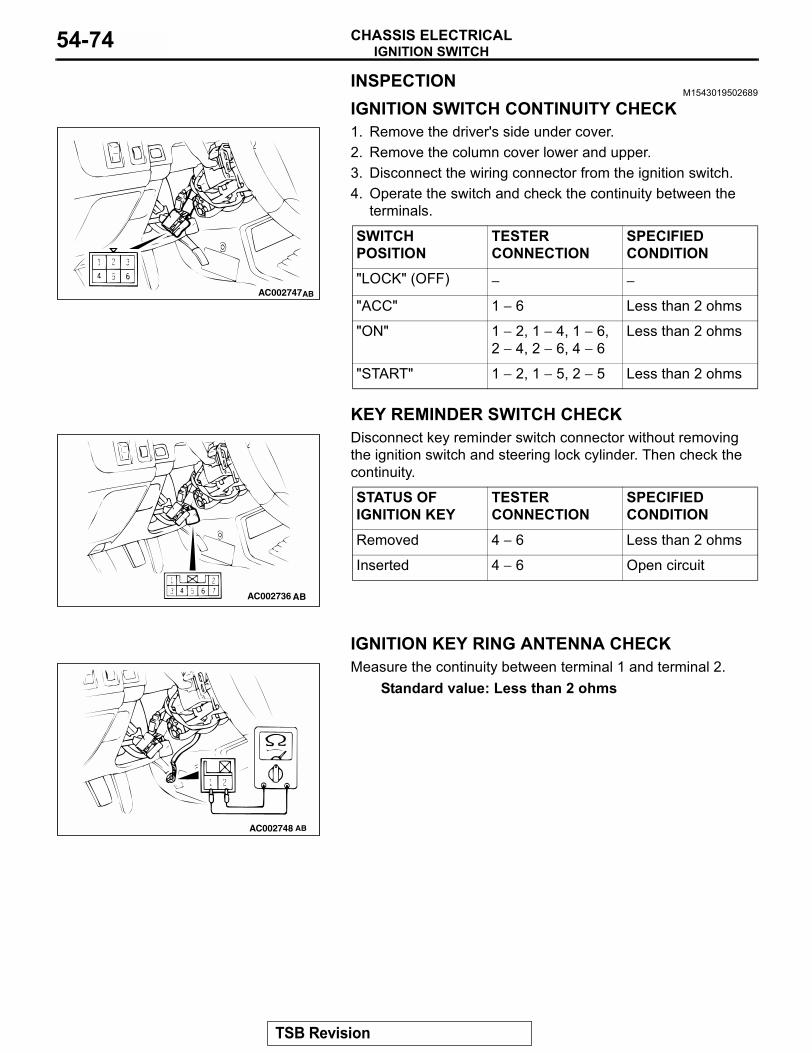
IGNITION SWITCHCHASSIS ELECTRICAL54-74
INSPECTIONM1543019502689
IGNITION SWITCH CONTINUITY CHECK1. Remove the driver's side under cover.2. Remove the column cover lower and upper.3. Disconnect the wiring connector from the ignition switch.4. Operate the switch and check the continuity between the
terminals.
KEY REMINDER SWITCH CHECKDisconnect key reminder switch connector without removing the ignition switch and steering lock cylinder. Then check the continuity.
IGNITION KEY RING ANTENNA CHECKMeasure the continuity between terminal 1 and terminal 2.
Standard value: Less than 2 ohms
SWITCH POSITION
TESTER CONNECTION
SPECIFIED CONDITION
"LOCK" (OFF) − −
"ACC" 1 − 6 Less than 2 ohms
"ON" 1 − 2, 1 − 4, 1 − 6, 2 − 4, 2 − 6, 4 − 6
Less than 2 ohms
"START" 1 − 2, 1 − 5, 2 − 5 Less than 2 ohms
AC002747AB
STATUS OF IGNITION KEY
TESTER CONNECTION
SPECIFIED CONDITION
Removed 4 − 6 Less than 2 ohms
Inserted 4 − 6 Open circuit
AC002736 AB
AC002748 AB
TSB Revision
COMBINATION METER ASSEMBLY AND VEHICLE SPEED SENSORCHASSIS ELECTRICAL 54-75
COMBINATION METER ASSEMBLY AND VEHICLE SPEED SENSOR
INTRODUCTION TO COMBINATION METER DIAGNOSISM1543009900936
An electrical speedometer and tachometer and fuel gauge and engine coolant temperature gauge are mounted on all vehicles. If the speedometer or tachometer or fuel gauge or engine coolant tempera-ture gauge does not function, there may be trouble in the electrical system.
EQUIPMENT DIAGNOSISCOMBINATION METER DIAGNOSTIC TROUBLESHOOTING STRATEGY
M1543006900506Use these steps to plan your diagnostic strategy. If you follow them carefully, you will be sure that you have exhausted most of the possible ways to find a combination meter fault.1. Gather information from the customer.
2. Verify that the condition described by the customer exists.
3. Find the malfunction by following the symptom chart.
4. Verify that the malfunction is eliminated.
DIAGNOSIS FUNCTIONM1543007000540
HOW TO CONNECT SCAN TOOL (MUT-III)Required Special Tools:
• MB991958: Scan Tool (MUT-III Sub Assembly)• MB991824: Vehicle Communication Interface (V.C.I.)• MB991827: MUT-III USB Cable• MB991911: MUT-III Main Harness B
CAUTIONTo prevent damage to scan tool MB991958, always turn the ignition switch to the "LOCK" (OFF) position before con-necting or disconnecting scan tool MB991958.
TSB Revision
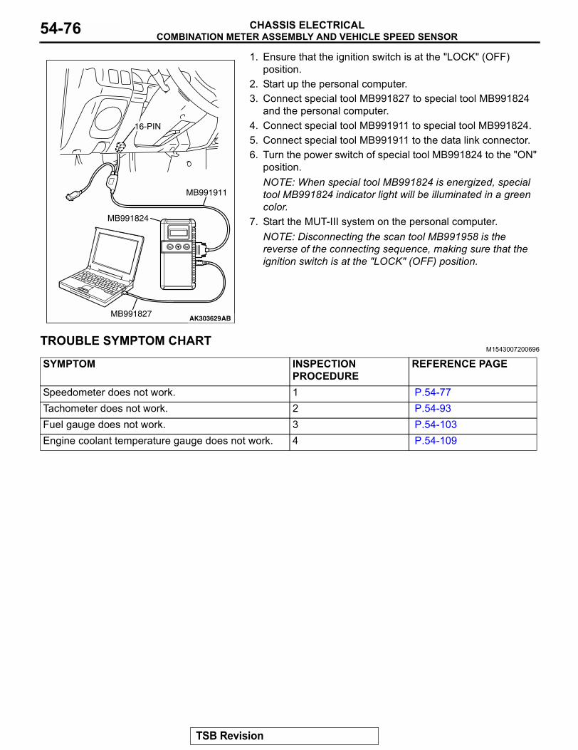
COMBINATION METER ASSEMBLY AND VEHICLE SPEED SENSORCHASSIS ELECTRICAL54-76
1. Ensure that the ignition switch is at the "LOCK" (OFF)position.2. Start up the personal computer.3. Connect special tool MB991827 to special tool MB991824
and the personal computer.4. Connect special tool MB991911 to special tool MB991824.5. Connect special tool MB991911 to the data link connector.6. Turn the power switch of special tool MB991824 to the "ON"
position.NOTE: When special tool MB991824 is energized, special tool MB991824 indicator light will be illuminated in a green color.
7. Start the MUT-III system on the personal computer.NOTE: Disconnecting the scan tool MB991958 is the reverse of the connecting sequence, making sure that the ignition switch is at the "LOCK" (OFF) position.
TROUBLE SYMPTOM CHARTM1543007200696
AK303629AB
MB991911
MB991827
MB991824
16-PIN
SYMPTOM INSPECTION PROCEDURE
REFERENCE PAGE
Speedometer does not work. 1 P.54-77Tachometer does not work. 2 P.54-93Fuel gauge does not work. 3 P.54-103Engine coolant temperature gauge does not work. 4 P.54-109
TSB Revision

COMBINATION METER ASSEMBLY AND VEHICLE SPEED SENSORCHASSIS ELECTRICAL 54-77
SYMPTOM PROCEDURESINSPECTION PROCEDURE 1: Speedometer does not Work.
JUNCTION BLOCK
RELAYBOX
IGNITIONSWITCH (IG1)
IOD ORSTORAGECONNECTOR
FUSIBLELINK 8
COMBINATIONMETER
SPEED
VEHICLESPEEDSENSOR
Speedometer Circuit
TSB Revision
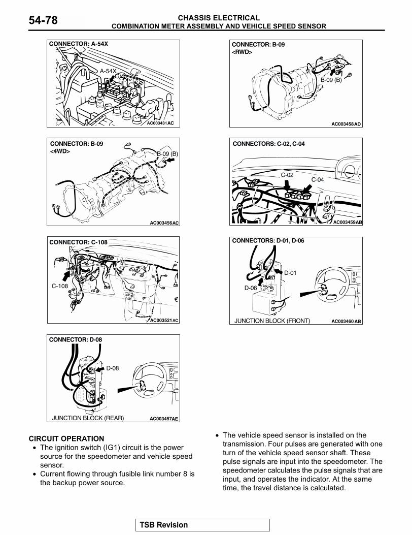
COMBINATION METER ASSEMBLY AND VEHICLE SPEED SENSORCHASSIS ELECTRICAL54-78
.
CIRCUIT OPERATION• The ignition switch (IG1) circuit is the power
source for the speedometer and vehicle speed sensor.
• Current flowing through fusible link number 8 is the backup power source.
• The vehicle speed sensor is installed on the transmission. Four pulses are generated with one turn of the vehicle speed sensor shaft. These pulse signals are input into the speedometer. The speedometer calculates the pulse signals that are input, and operates the indicator. At the same time, the travel distance is calculated.
.
AC003431
CONNECTOR: A-54X
A-54X
AC AC003458AD
CONNECTOR: B-09 <RWD>
B-09 (B)
AC003456AC
CONNECTOR: B-09<4WD> B-09 (B)
AC003459
CONNECTORS: C-02, C-04
C-02C-04
AB
AC003521
CONNECTOR: C-108
AC
C-108
AC003460 AB
CONNECTORS: D-01, D-06
D-01
D-06
JUNCTION BLOCK (FRONT)
AC003457AE
CONNECTOR: D-08
JUNCTION BLOCK (REAR)
D-08
TSB Revision
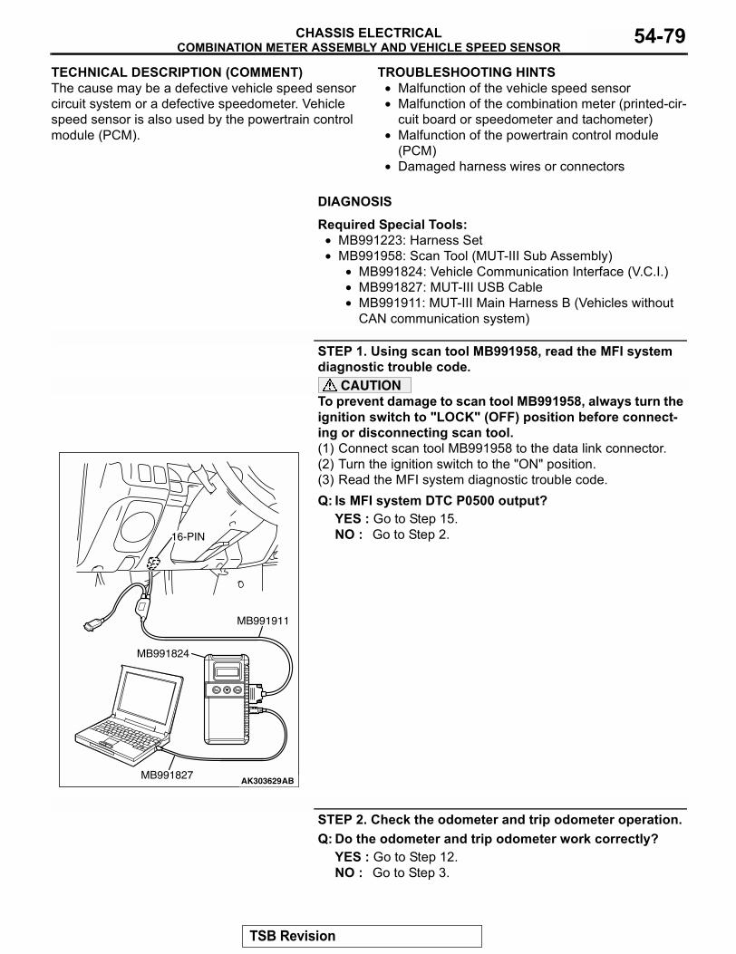
COMBINATION METER ASSEMBLY AND VEHICLE SPEED SENSORCHASSIS ELECTRICAL 54-79
TECHNICAL DESCRIPTION (COMMENT)The cause may be a defective vehicle speed sensor circuit system or a defective speedometer. Vehicle speed sensor is also used by the powertrain control module (PCM)..
TROUBLESHOOTING HINTS• Malfunction of the vehicle speed sensor• Malfunction of the combination meter (printed-cir-
cuit board or speedometer and tachometer)• Malfunction of the powertrain control module
(PCM)• Damaged harness wires or connectors
.
DIAGNOSIS
Required Special Tools:• MB991223: Harness Set• MB991958: Scan Tool (MUT-III Sub Assembly)
• MB991824: Vehicle Communication Interface (V.C.I.)• MB991827: MUT-III USB Cable• MB991911: MUT-III Main Harness B (Vehicles without
CAN communication system)
STEP 1. Using scan tool MB991958, read the MFI system diagnostic trouble code.
CAUTIONTo prevent damage to scan tool MB991958, always turn the ignition switch to "LOCK" (OFF) position before connect-ing or disconnecting scan tool.(1) Connect scan tool MB991958 to the data link connector. (2) Turn the ignition switch to the "ON" position.(3) Read the MFI system diagnostic trouble code.Q: Is MFI system DTC P0500 output?
YES : Go to Step 15.NO : Go to Step 2.
STEP 2. Check the odometer and trip odometer operation.Q: Do the odometer and trip odometer work correctly?
YES : Go to Step 12.NO : Go to Step 3.
AK303629AB
MB991911
MB991827
MB991824
16-PIN
TSB Revision
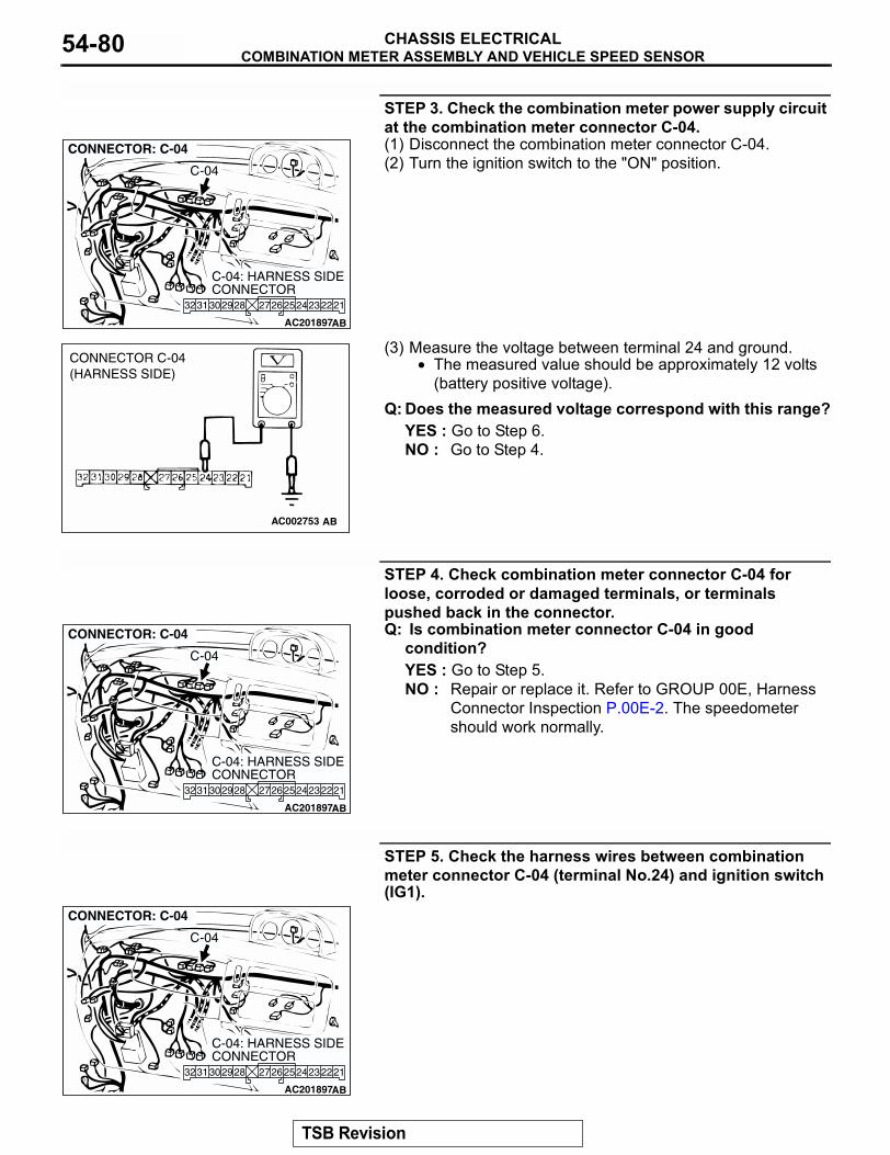
COMBINATION METER ASSEMBLY AND VEHICLE SPEED SENSORCHASSIS ELECTRICAL54-80
STEP 3. Check the combination meter power supply circuit at the combination meter connector C-04.(1) Disconnect the combination meter connector C-04.(2) Turn the ignition switch to the "ON" position.
(3) Measure the voltage between terminal 24 and ground.• The measured value should be approximately 12 volts
(battery positive voltage).Q: Does the measured voltage correspond with this range?
YES : Go to Step 6.NO : Go to Step 4.
STEP 4. Check combination meter connector C-04 for loose, corroded or damaged terminals, or terminals pushed back in the connector.Q: Is combination meter connector C-04 in good
condition?YES : Go to Step 5.NO : Repair or replace it. Refer to GROUP 00E, Harness
Connector Inspection P.00E-2. The speedometer should work normally.
STEP 5. Check the harness wires between combination meter connector C-04 (terminal No.24) and ignition switch (IG1).
AC201897
212324272625 22283031 2932
CONNECTOR: C-04
AB
C-04: HARNESS SIDE CONNECTOR
C-04
AC002753 AB
CONNECTOR C-04(HARNESS SIDE)
AC201897
212324272625 22283031 2932
CONNECTOR: C-04
AB
C-04: HARNESS SIDE CONNECTOR
C-04
AC201897
212324272625 22283031 2932
CONNECTOR: C-04
AB
C-04: HARNESS SIDE CONNECTOR
C-04
TSB Revision
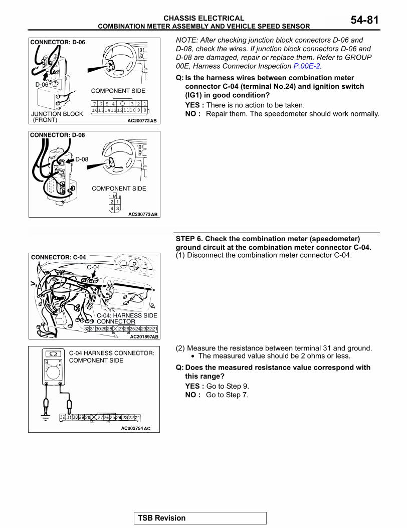
COMBINATION METER ASSEMBLY AND VEHICLE SPEED SENSORCHASSIS ELECTRICAL 54-81
NOTE: After checking junction block connectors D-06 and D-08, check the wires. If junction block connectors D-06 and D-08 are damaged, repair or replace them. Refer to GROUP 00E, Harness Connector Inspection P.00E-2.Q: Is the harness wires between combination meter
connector C-04 (terminal No.24) and ignition switch (IG1) in good condition?YES : There is no action to be taken.NO : Repair them. The speedometer should work normally.
STEP 6. Check the combination meter (speedometer) ground circuit at the combination meter connector C-04.(1) Disconnect the combination meter connector C-04.
(2) Measure the resistance between terminal 31 and ground.• The measured value should be 2 ohms or less.
Q: Does the measured resistance value correspond with this range?YES : Go to Step 9.NO : Go to Step 7.
AC200772
18
3457 6101516 14 1213 11 9
2
COMPONENT SIDE
CONNECTOR: D-06
D-06
JUNCTION BLOCK (FRONT) AB
AC200773
M
3
1
4
2
CONNECTOR: D-08
D-08
COMPONENT SIDE
AB
AC201897
212324272625 22283031 2932
CONNECTOR: C-04
AB
C-04: HARNESS SIDE CONNECTOR
C-04
AC002754 AC
C-04 HARNESS CONNECTOR:COMPONENT SIDE
TSB Revision
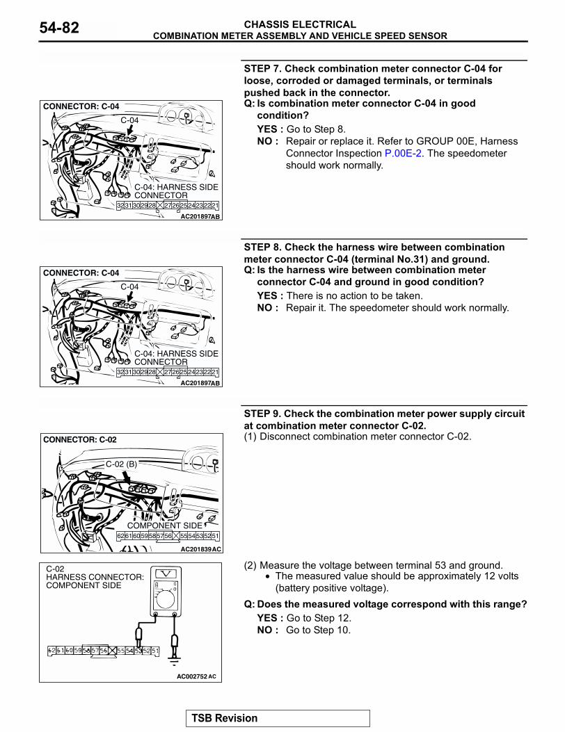
COMBINATION METER ASSEMBLY AND VEHICLE SPEED SENSORCHASSIS ELECTRICAL54-82
STEP 7. Check combination meter connector C-04 for loose, corroded or damaged terminals, or terminals pushed back in the connector.Q: Is combination meter connector C-04 in good
condition?YES : Go to Step 8.NO : Repair or replace it. Refer to GROUP 00E, Harness
Connector Inspection P.00E-2. The speedometer should work normally.
STEP 8. Check the harness wire between combination meter connector C-04 (terminal No.31) and ground.Q: Is the harness wire between combination meter
connector C-04 and ground in good condition?YES : There is no action to be taken.NO : Repair it. The speedometer should work normally.
STEP 9. Check the combination meter power supply circuit at combination meter connector C-02.(1) Disconnect combination meter connector C-02.
(2) Measure the voltage between terminal 53 and ground.• The measured value should be approximately 12 volts
(battery positive voltage).Q: Does the measured voltage correspond with this range?
YES : Go to Step 12.NO : Go to Step 10.
AC201897
212324272625 22283031 2932
CONNECTOR: C-04
AB
C-04: HARNESS SIDE CONNECTOR
C-04
AC201897
212324272625 22283031 2932
CONNECTOR: C-04
AB
C-04: HARNESS SIDE CONNECTOR
C-04
AC201839
CONNECTOR: C-02
AC
5152555453565859 57606162
COMPONENT SIDE
C-02 (B)
AC002752 AC
C-02 HARNESS CONNECTOR:COMPONENT SIDE
TSB Revision
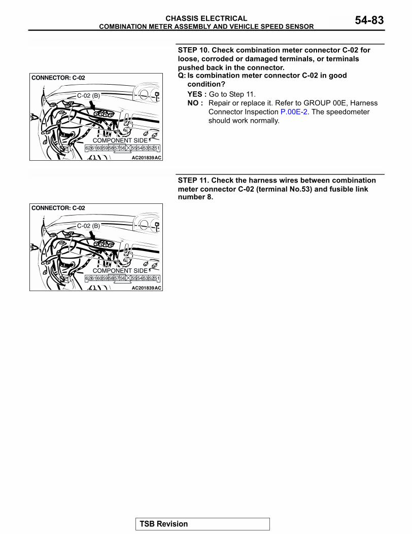
COMBINATION METER ASSEMBLY AND VEHICLE SPEED SENSORCHASSIS ELECTRICAL 54-83
STEP 10. Check combination meter connector C-02 for loose, corroded or damaged terminals, or terminals pushed back in the connector.Q: Is combination meter connector C-02 in good
condition?YES : Go to Step 11.NO : Repair or replace it. Refer to GROUP 00E, Harness
Connector Inspection P.00E-2. The speedometer should work normally.
STEP 11. Check the harness wires between combination meter connector C-02 (terminal No.53) and fusible link number 8.
AC201839
CONNECTOR: C-02
AC
5152555453565859 57606162
COMPONENT SIDE
C-02 (B)
AC201839
CONNECTOR: C-02
AC
5152555453565859 57606162
COMPONENT SIDE
C-02 (B)
TSB Revision
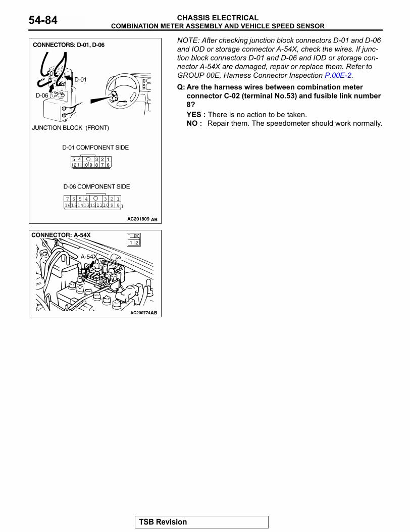
COMBINATION METER ASSEMBLY AND VEHICLE SPEED SENSORCHASSIS ELECTRICAL54-84
NOTE: After checking junction block connectors D-01 and D-06 and IOD or storage connector A-54X, check the wires. If junc-tion block connectors D-01 and D-06 and IOD or storage con-nector A-54X are damaged, repair or replace them. Refer to GROUP 00E, Harness Connector Inspection P.00E-2.Q: Are the harness wires between combination meterconnector C-02 (terminal No.53) and fusible link number 8?YES : There is no action to be taken.NO : Repair them. The speedometer should work normally.
AC201809
2341110 9 8 7
16
512
18
3457 6101516 14 1213 11 9
2
D-01 COMPONENT SIDE
D-06 COMPONENT SIDE
AB
D-01
D-06
JUNCTION BLOCK (FRONT)
CONNECTORS: D-01, D-06
AC200774
21
CONNECTOR: A-54X
AB
A-54X
TSB Revision
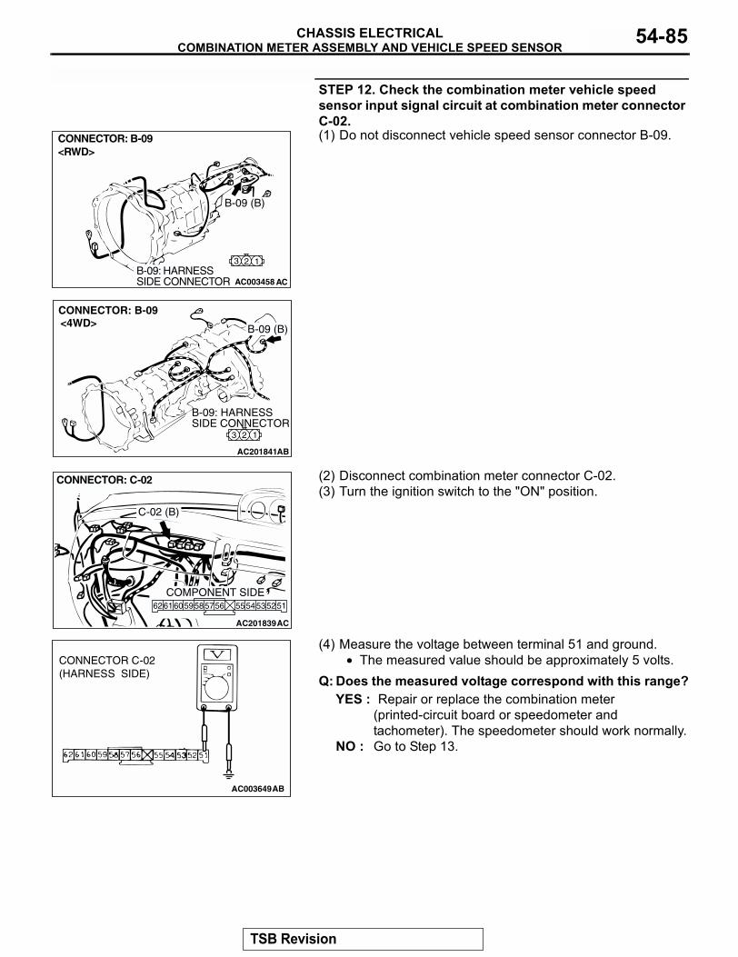
COMBINATION METER ASSEMBLY AND VEHICLE SPEED SENSORCHASSIS ELECTRICAL 54-85
STEP 12. Check the combination meter vehicle speed sensor input signal circuit at combination meter connector C-02.(1) Do not disconnect vehicle speed sensor connector B-09.
(2) Disconnect combination meter connector C-02.(3) Turn the ignition switch to the "ON" position.
(4) Measure the voltage between terminal 51 and ground.• The measured value should be approximately 5 volts.
Q: Does the measured voltage correspond with this range?YES : Repair or replace the combination meter
(printed-circuit board or speedometer and tachometer). The speedometer should work normally.
NO : Go to Step 13.
AC003458 AC
CONNECTOR: B-09 <RWD>
B-09 (B)
123B-09: HARNESS SIDE CONNECTOR
AC201841
3 2 1
CONNECTOR: B-09
AB
B-09: HARNESS SIDE CONNECTOR
<4WD> B-09 (B)
AC201839
CONNECTOR: C-02
AC
5152555453565859 57606162
COMPONENT SIDE
C-02 (B)
AC003649AB
CONNECTOR C-02(HARNESS SIDE)
TSB Revision
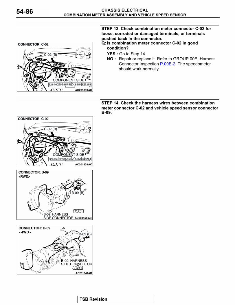
COMBINATION METER ASSEMBLY AND VEHICLE SPEED SENSORCHASSIS ELECTRICAL54-86
STEP 13. Check combination meter connector C-02 for loose, corroded or damaged terminals, or terminals pushed back in the connector.Q: Is combination meter connector C-02 in good
condition?YES : Go to Step 14.NO : Repair or replace it. Refer to GROUP 00E, Harness
Connector Inspection P.00E-2. The speedometer should work normally.
STEP 14. Check the harness wires between combination meter connector C-02 and vehicle speed sensor connector B-09.
AC201839
CONNECTOR: C-02
AC
5152555453565859 57606162
COMPONENT SIDE
C-02 (B)
AC201839
CONNECTOR: C-02
AC
5152555453565859 57606162
COMPONENT SIDE
C-02 (B)
AC003458 AC
CONNECTOR: B-09 <RWD>
B-09 (B)
123B-09: HARNESS SIDE CONNECTOR
AC201841
3 2 1
CONNECTOR: B-09
AB
B-09: HARNESS SIDE CONNECTOR
<4WD> B-09 (B)
TSB Revision
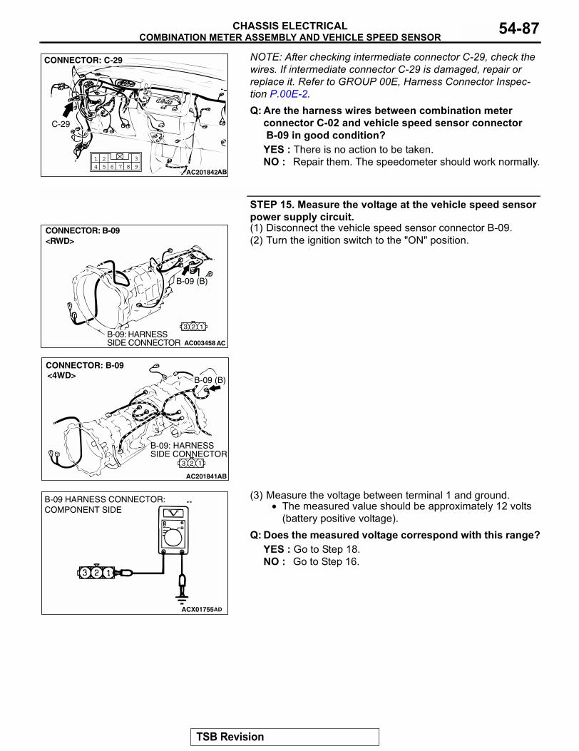
COMBINATION METER ASSEMBLY AND VEHICLE SPEED SENSORCHASSIS ELECTRICAL 54-87
NOTE: After checking intermediate connector C-29, check the wires. If intermediate connector C-29 is damaged, repair or replace it. Refer to GROUP 00E, Harness Connector Inspec-tion P.00E-2.Q: Are the harness wires between combination meter
connector C-02 and vehicle speed sensor connector B-09 in good condition?YES : There is no action to be taken.NO : Repair them. The speedometer should work normally.
STEP 15. Measure the voltage at the vehicle speed sensor power supply circuit. (1) Disconnect the vehicle speed sensor connector B-09.(2) Turn the ignition switch to the "ON" position.
(3) Measure the voltage between terminal 1 and ground.• The measured value should be approximately 12 volts
(battery positive voltage).Q: Does the measured voltage correspond with this range?
YES : Go to Step 18.NO : Go to Step 16.
AC20184293
86 7541 2
AB
CONNECTOR: C-29
C-29
AC003458 AC
CONNECTOR: B-09 <RWD>
B-09 (B)
123B-09: HARNESS SIDE CONNECTOR
AC201841
3 2 1
CONNECTOR: B-09
AB
B-09: HARNESS SIDE CONNECTOR
<4WD> B-09 (B)
ACX01755
B-09 HARNESS CONNECTOR:COMPONENT SIDE
AD
TSB Revision
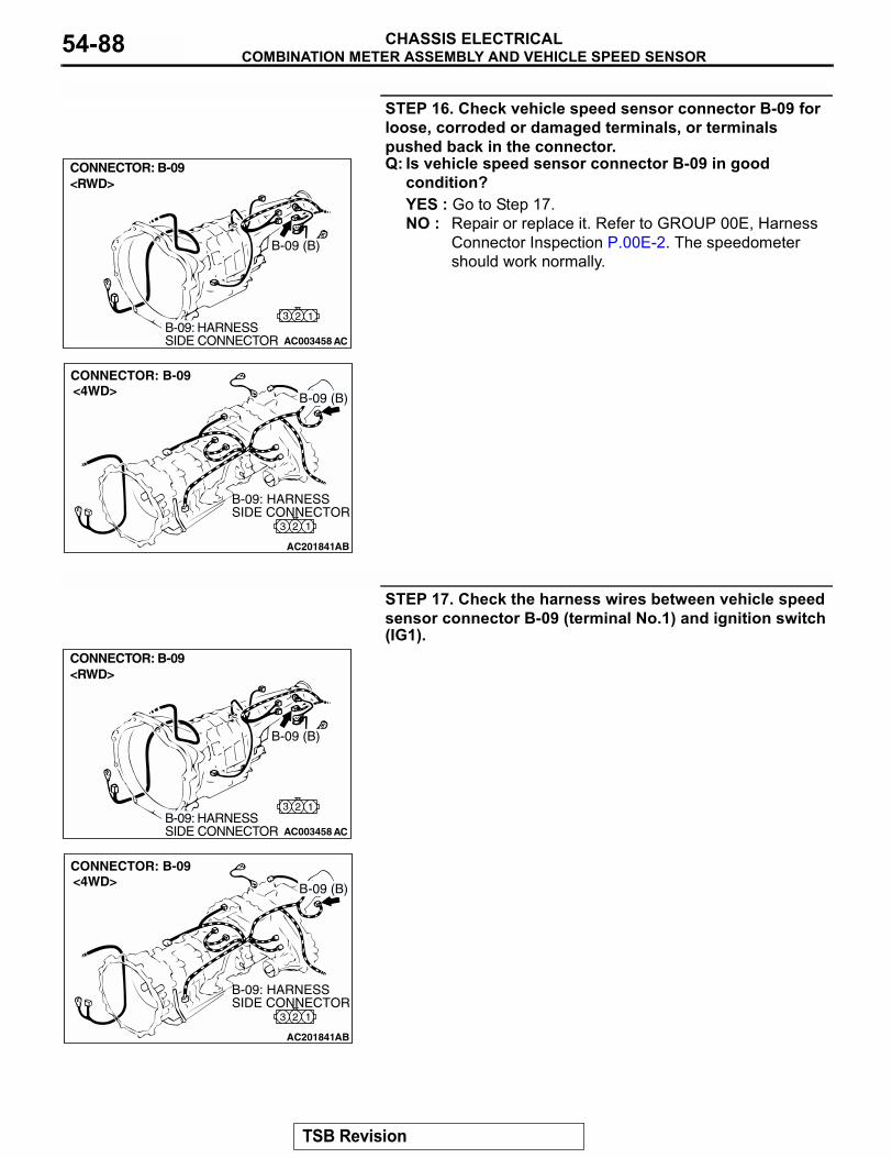
COMBINATION METER ASSEMBLY AND VEHICLE SPEED SENSORCHASSIS ELECTRICAL54-88
STEP 16. Check vehicle speed sensor connector B-09 for loose, corroded or damaged terminals, or terminals pushed back in the connector.Q: Is vehicle speed sensor connector B-09 in good
condition?YES : Go to Step 17.NO : Repair or replace it. Refer to GROUP 00E, Harness
Connector Inspection P.00E-2. The speedometer should work normally.
STEP 17. Check the harness wires between vehicle speed sensor connector B-09 (terminal No.1) and ignition switch (IG1).
AC003458 AC
CONNECTOR: B-09 <RWD>
B-09 (B)
123B-09: HARNESS SIDE CONNECTOR
AC201841
3 2 1
CONNECTOR: B-09
AB
B-09: HARNESS SIDE CONNECTOR
<4WD> B-09 (B)
AC003458 AC
CONNECTOR: B-09 <RWD>
B-09 (B)
123B-09: HARNESS SIDE CONNECTOR
AC201841
3 2 1
CONNECTOR: B-09
AB
B-09: HARNESS SIDE CONNECTOR
<4WD> B-09 (B)
TSB Revision
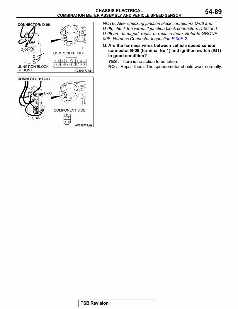
COMBINATION METER ASSEMBLY AND VEHICLE SPEED SENSORCHASSIS ELECTRICAL 54-89
NOTE: After checking junction block connectors D-06 and D-08, check the wires. If junction block connectors D-06 and D-08 are damaged, repair or replace them. Refer to GROUP 00E, Harness Connector Inspection P.00E-2.Q: Are the harness wires between vehicle speed sensor
connector B-09 (terminal No.1) and ignition switch (IG1) in good condition?YES : There is no action to be taken.NO : Repair them. The speedometer should work normally.
AC200772
18
3457 6101516 14 1213 11 9
2
COMPONENT SIDE
CONNECTOR: D-06
D-06
JUNCTION BLOCK (FRONT) AB
AC200773
M
3
1
4
2
CONNECTOR: D-08
D-08
COMPONENT SIDE
AB
TSB Revision
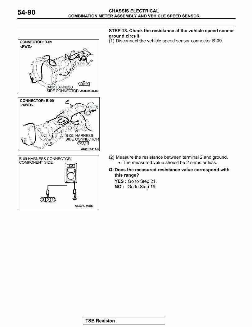
COMBINATION METER ASSEMBLY AND VEHICLE SPEED SENSORCHASSIS ELECTRICAL54-90
STEP 18. Check the resistance at the vehicle speed sensor ground circuit.(1) Disconnect the vehicle speed sensor connector B-09.
(2) Measure the resistance between terminal 2 and ground.• The measured value should be 2 ohms or less.
Q: Does the measured resistance value correspond with this range?YES : Go to Step 21.NO : Go to Step 19.
AC003458 AC
CONNECTOR: B-09 <RWD>
B-09 (B)
123B-09: HARNESS SIDE CONNECTOR
AC201841
3 2 1
CONNECTOR: B-09
AB
B-09: HARNESS SIDE CONNECTOR
<4WD> B-09 (B)
ACX01756AE
B-09 HARNESS CONNECTOR:COMPONENT SIDE
TSB Revision
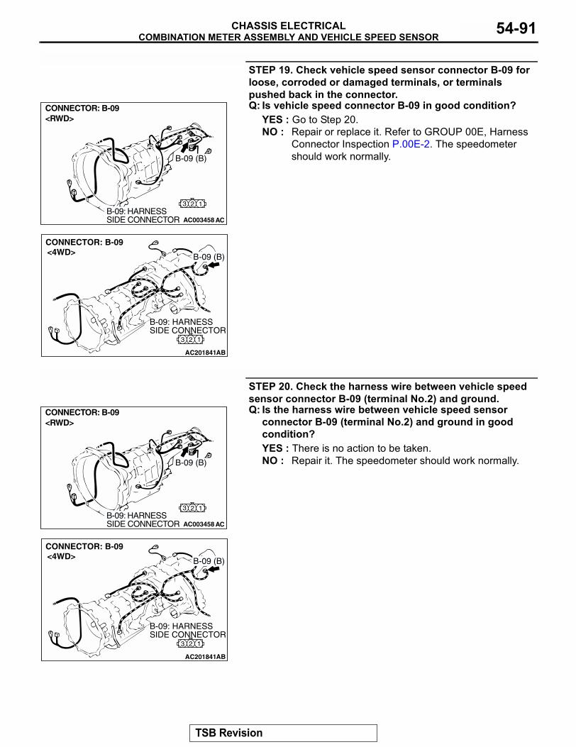
COMBINATION METER ASSEMBLY AND VEHICLE SPEED SENSORCHASSIS ELECTRICAL 54-91
STEP 19. Check vehicle speed sensor connector B-09 for loose, corroded or damaged terminals, or terminals pushed back in the connector.Q: Is vehicle speed connector B-09 in good condition?
YES : Go to Step 20.NO : Repair or replace it. Refer to GROUP 00E, Harness
Connector Inspection P.00E-2. The speedometer should work normally.
STEP 20. Check the harness wire between vehicle speed sensor connector B-09 (terminal No.2) and ground.Q: Is the harness wire between vehicle speed sensor
connector B-09 (terminal No.2) and ground in good condition?YES : There is no action to be taken.NO : Repair it. The speedometer should work normally.
AC003458 AC
CONNECTOR: B-09 <RWD>
B-09 (B)
123B-09: HARNESS SIDE CONNECTOR
AC201841
3 2 1
CONNECTOR: B-09
AB
B-09: HARNESS SIDE CONNECTOR
<4WD> B-09 (B)
AC003458 AC
CONNECTOR: B-09 <RWD>
B-09 (B)
123B-09: HARNESS SIDE CONNECTOR
AC201841
3 2 1
CONNECTOR: B-09
AB
B-09: HARNESS SIDE CONNECTOR
<4WD> B-09 (B)
TSB Revision
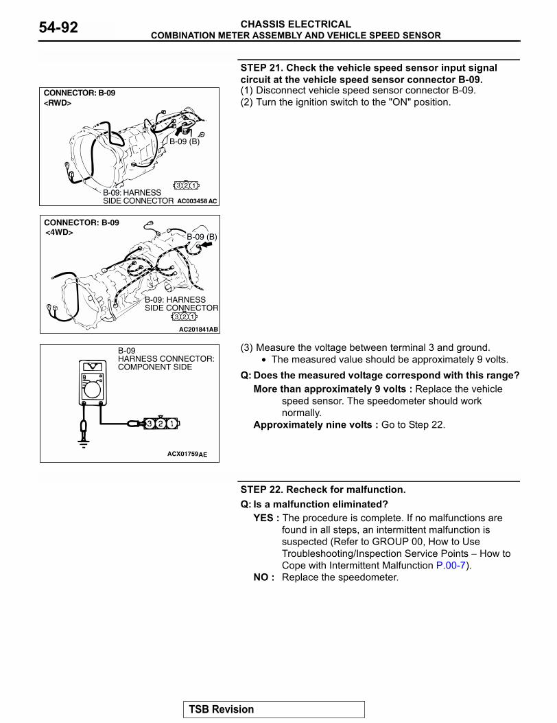
COMBINATION METER ASSEMBLY AND VEHICLE SPEED SENSORCHASSIS ELECTRICAL54-92
STEP 21. Check the vehicle speed sensor input signal circuit at the vehicle speed sensor connector B-09.(1) Disconnect vehicle speed sensor connector B-09.(2) Turn the ignition switch to the "ON" position.
(3) Measure the voltage between terminal 3 and ground.• The measured value should be approximately 9 volts.
Q: Does the measured voltage correspond with this range?More than approximately 9 volts : Replace the vehicle
speed sensor. The speedometer should work normally.
Approximately nine volts : Go to Step 22.
STEP 22. Recheck for malfunction.Q: Is a malfunction eliminated?
YES : The procedure is complete. If no malfunctions are found in all steps, an intermittent malfunction is suspected (Refer to GROUP 00, How to Use Troubleshooting/Inspection Service Points − How to Cope with Intermittent Malfunction P.00-7).
NO : Replace the speedometer.
AC003458 AC
CONNECTOR: B-09 <RWD>
B-09 (B)
123B-09: HARNESS SIDE CONNECTOR
AC201841
3 2 1
CONNECTOR: B-09
AB
B-09: HARNESS SIDE CONNECTOR
<4WD> B-09 (B)
ACX01759AE
B-09 HARNESS CONNECTOR:COMPONENT SIDE
TSB Revision
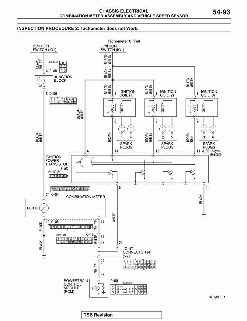
COMBINATION METER ASSEMBLY AND VEHICLE SPEED SENSORCHASSIS ELECTRICAL 54-93
INSPECTION PROCEDURE 2: Tachometer does not Work.
JUNCTION BLOCK
IGNITIONSWITCH (IG1)
IGNITIONPOWERTRANSISTOR
IGNITIONSWITCH (IG1)
IGNITIONCOIL (1)
SPARKPLUGS
SPARKPLUGS
SPARKPLUGS
IGNITIONCOIL (2)
IGNITIONCOIL (3)
COMBINATION METER
TACHO
JOINT CONNECTOR (4)
POWERTRAINCONTROLMODULE(PCM)
Tachometer Circuit
TSB Revision
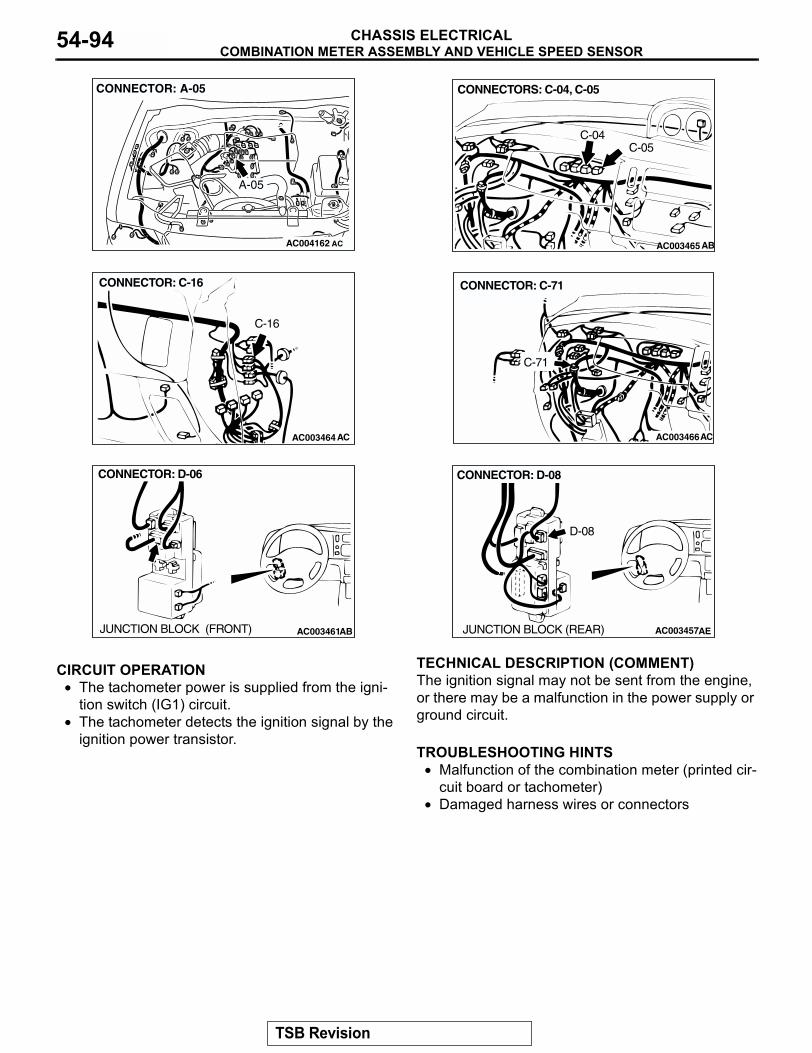
COMBINATION METER ASSEMBLY AND VEHICLE SPEED SENSORCHASSIS ELECTRICAL54-94
.
CIRCUIT OPERATION• The tachometer power is supplied from the igni-
tion switch (IG1) circuit.• The tachometer detects the ignition signal by the
ignition power transistor..
TECHNICAL DESCRIPTION (COMMENT)The ignition signal may not be sent from the engine, or there may be a malfunction in the power supply or ground circuit..
TROUBLESHOOTING HINTS• Malfunction of the combination meter (printed cir-
cuit board or tachometer)• Damaged harness wires or connectors
.
AC004162 AC
CONNECTOR: A-05
A-05
AC003465
CONNECTORS: C-04, C-05
AB
C-04C-05
AC003464AC
CONNECTOR: C-16
C-16
AC003466AC
CONNECTOR: C-71
C-71
AC003461AB
CONNECTOR: D-06
JUNCTION BLOCK (FRONT) AC003457AE
CONNECTOR: D-08
JUNCTION BLOCK (REAR)
D-08
TSB Revision
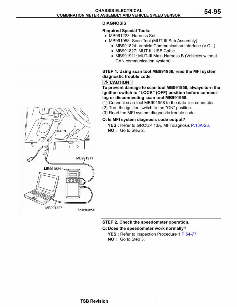
COMBINATION METER ASSEMBLY AND VEHICLE SPEED SENSORCHASSIS ELECTRICAL 54-95
DIAGNOSIS
Required Special Tools:• MB991223: Harness Set• MB991958: Scan Tool (MUT-III Sub Assembly)
• MB991824: Vehicle Communication Interface (V.C.I.)• MB991827: MUT-III USB Cable• MB991911: MUT-III Main Harness B (Vehicles without
CAN communication system)
STEP 1. Using scan tool MB991958, read the MFI system diagnostic trouble code.
CAUTIONTo prevent damage to scan tool MB991958, always turn the ignition switch to "LOCK" (OFF) position before connect-ing or disconnecting scan tool MB991958.(1) Connect scan tool MB991958 to the data link connector. (2) Turn the ignition switch to the "ON" position.(3) Read the MFI system diagnostic trouble code.Q: Is MFI system diagnosis code output?
YES : Refer to GROUP 13A, MFI diagnosis P.13A-26.NO : Go to Step 2.
STEP 2. Check the speedometer operation.Q: Does the speedometer work normally?
YES : Refer to Inspection Procedure 1 P.54-77. NO : Go to Step 3.
AK303629AB
MB991911
MB991827
MB991824
16-PIN
TSB Revision
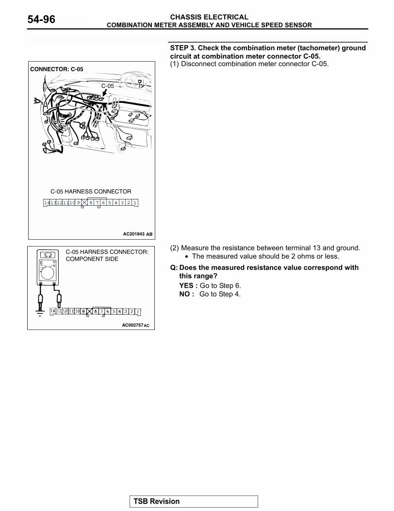
COMBINATION METER ASSEMBLY AND VEHICLE SPEED SENSORCHASSIS ELECTRICAL54-96
STEP 3. Check the combination meter (tachometer) ground circuit at combination meter connector C-05.(1) Disconnect combination meter connector C-05.
(2) Measure the resistance between terminal 13 and ground.• The measured value should be 2 ohms or less.
Q: Does the measured resistance value correspond with this range?YES : Go to Step 6.NO : Go to Step 4.
AC2018743
3 26 5 47891110 1121413
CONNECTOR: C-05
C-05 HARNESS CONNECTOR
C-05
AC201843 AB
AC002757AC
C-05 HARNESS CONNECTOR:COMPONENT SIDE
TSB Revision
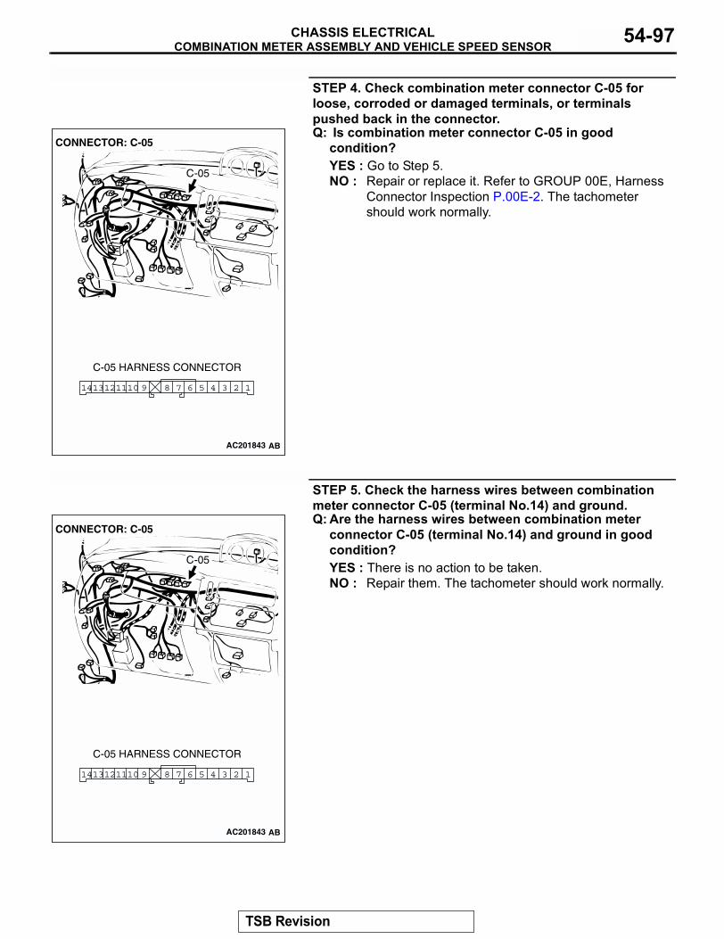
COMBINATION METER ASSEMBLY AND VEHICLE SPEED SENSORCHASSIS ELECTRICAL 54-97
STEP 4. Check combination meter connector C-05 for loose, corroded or damaged terminals, or terminals pushed back in the connector.Q: Is combination meter connector C-05 in good
condition?YES : Go to Step 5.NO : Repair or replace it. Refer to GROUP 00E, Harness
Connector Inspection P.00E-2. The tachometer should work normally.
STEP 5. Check the harness wires between combination meter connector C-05 (terminal No.14) and ground.Q: Are the harness wires between combination meter
connector C-05 (terminal No.14) and ground in good condition?YES : There is no action to be taken.NO : Repair them. The tachometer should work normally.
AC2018743
3 26 5 47891110 1121413
CONNECTOR: C-05
C-05 HARNESS CONNECTOR
C-05
AC201843 AB
AC2018743
3 26 5 47891110 1121413
CONNECTOR: C-05
C-05 HARNESS CONNECTOR
C-05
AC201843 AB
TSB Revision
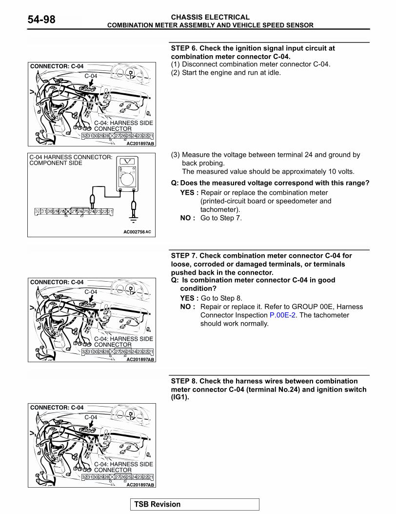
COMBINATION METER ASSEMBLY AND VEHICLE SPEED SENSORCHASSIS ELECTRICAL54-98
STEP 6. Check the ignition signal input circuit at combination meter connector C-04.(1) Disconnect combination meter connector C-04.(2) Start the engine and run at idle.
(3) Measure the voltage between terminal 24 and ground by back probing.The measured value should be approximately 10 volts.
Q: Does the measured voltage correspond with this range?YES : Repair or replace the combination meter
(printed-circuit board or speedometer and tachometer).
NO : Go to Step 7.
STEP 7. Check combination meter connector C-04 for loose, corroded or damaged terminals, or terminals pushed back in the connector.Q: Is combination meter connector C-04 in good
condition?YES : Go to Step 8.NO : Repair or replace it. Refer to GROUP 00E, Harness
Connector Inspection P.00E-2. The tachometer should work normally.
STEP 8. Check the harness wires between combination meter connector C-04 (terminal No.24) and ignition switch (IG1).
AC201897
212324272625 22283031 2932
CONNECTOR: C-04
AB
C-04: HARNESS SIDE CONNECTOR
C-04
AC002756 AC
C-04 HARNESS CONNECTOR:COMPONENT SIDE
AC201897
212324272625 22283031 2932
CONNECTOR: C-04
AB
C-04: HARNESS SIDE CONNECTOR
C-04
AC201897
212324272625 22283031 2932
CONNECTOR: C-04
AB
C-04: HARNESS SIDE CONNECTOR
C-04
TSB Revision
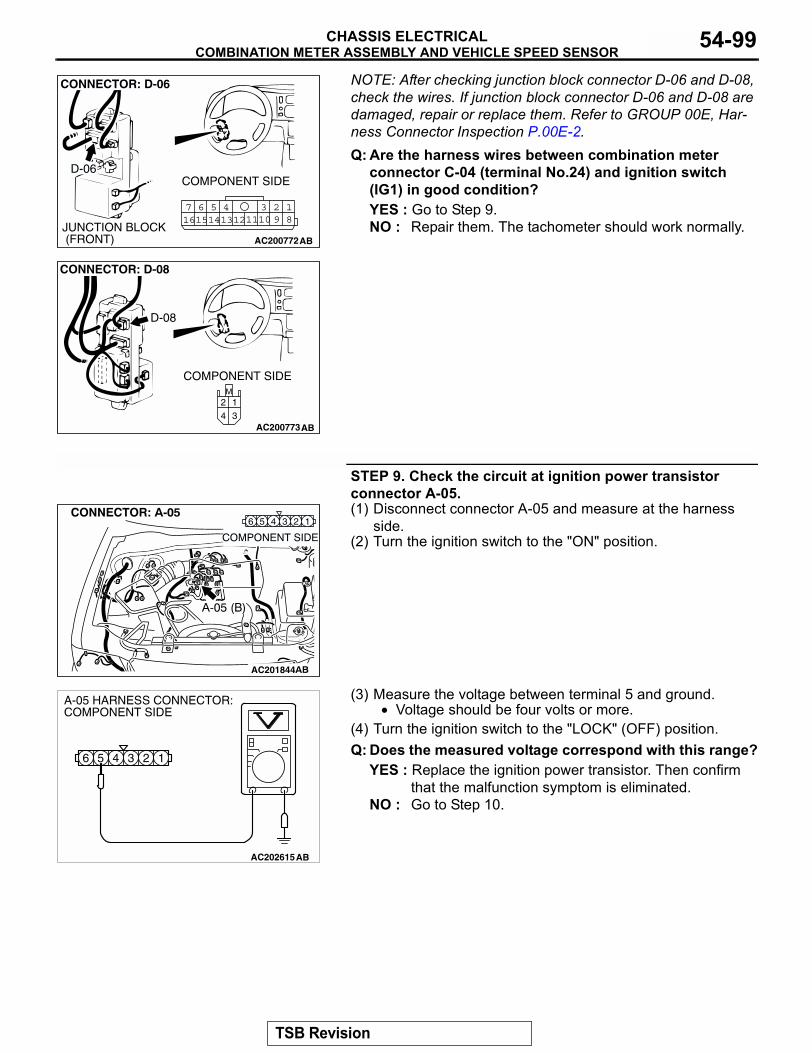
COMBINATION METER ASSEMBLY AND VEHICLE SPEED SENSORCHASSIS ELECTRICAL 54-99
NOTE: After checking junction block connector D-06 and D-08, check the wires. If junction block connector D-06 and D-08 are damaged, repair or replace them. Refer to GROUP 00E, Har-ness Connector Inspection P.00E-2.Q: Are the harness wires between combination meter
connector C-04 (terminal No.24) and ignition switch (IG1) in good condition?YES : Go to Step 9.NO : Repair them. The tachometer should work normally.
STEP 9. Check the circuit at ignition power transistor connector A-05.(1) Disconnect connector A-05 and measure at the harness
side.(2) Turn the ignition switch to the "ON" position.
(3) Measure the voltage between terminal 5 and ground.• Voltage should be four volts or more.
(4) Turn the ignition switch to the "LOCK" (OFF) position.Q: Does the measured voltage correspond with this range?
YES : Replace the ignition power transistor. Then confirm that the malfunction symptom is eliminated.
NO : Go to Step 10.
AC200772
18
3457 6101516 14 1213 11 9
2
COMPONENT SIDE
CONNECTOR: D-06
D-06
JUNCTION BLOCK (FRONT) AB
AC200773
M
3
1
4
2
CONNECTOR: D-08
D-08
COMPONENT SIDE
AB
AC201844
134 26 5
AC202615
6 5 4 3 2 1
A-05 HARNESS CONNECTOR:COMPONENT SIDE
AB
TSB Revision
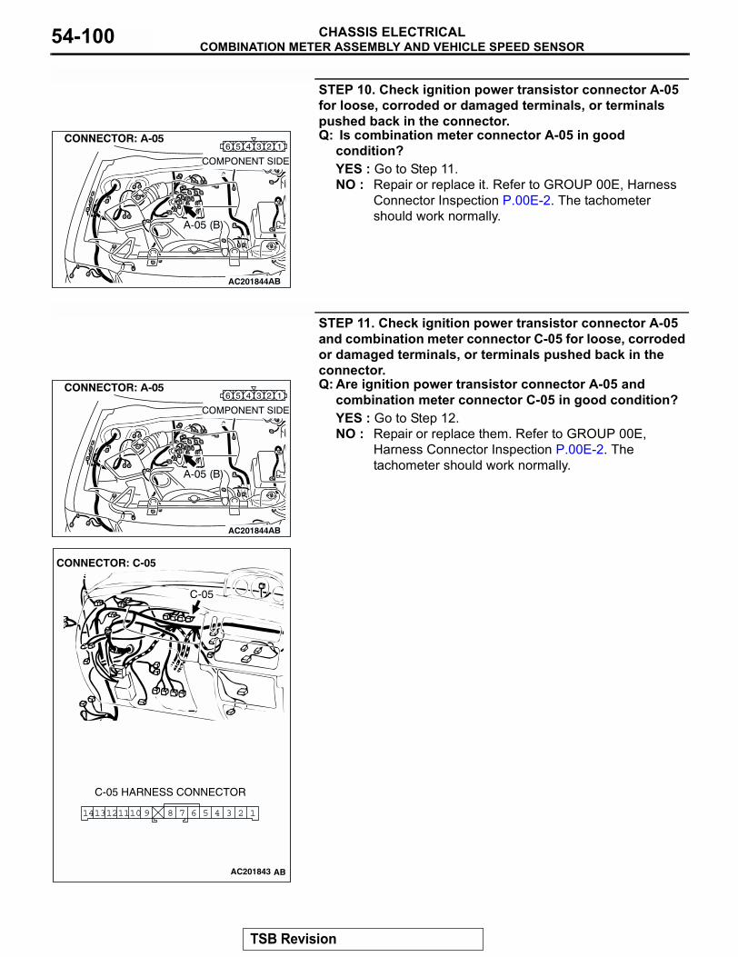
COMBINATION METER ASSEMBLY AND VEHICLE SPEED SENSORCHASSIS ELECTRICAL54-100
STEP 10. Check ignition power transistor connector A-05 for loose, corroded or damaged terminals, or terminals pushed back in the connector.Q: Is combination meter connector A-05 in good
condition?YES : Go to Step 11.NO : Repair or replace it. Refer to GROUP 00E, Harness
Connector Inspection P.00E-2. The tachometer should work normally.
STEP 11. Check ignition power transistor connector A-05 and combination meter connector C-05 for loose, corroded or damaged terminals, or terminals pushed back in the connector.Q: Are ignition power transistor connector A-05 and
combination meter connector C-05 in good condition?YES : Go to Step 12.NO : Repair or replace them. Refer to GROUP 00E,
Harness Connector Inspection P.00E-2. The tachometer should work normally.
AC201844
134 26 5
AC201844
134 26 5
AC2018743
3 26 5 47891110 1121413
CONNECTOR: C-05
C-05 HARNESS CONNECTOR
C-05
AC201843 AB
TSB Revision
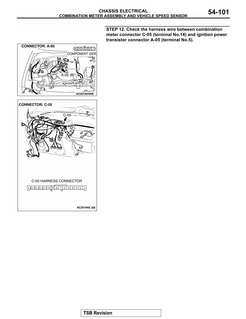
COMBINATION METER ASSEMBLY AND VEHICLE SPEED SENSORCHASSIS ELECTRICAL 54-101
STEP 12. Check the harness wire between combination meter connector C-05 (terminal No.14) and ignition power transistor connector A-05 (terminal No.5).
AC201844
134 26 5
AC2018743
3 26 5 47891110 1121413
CONNECTOR: C-05
C-05 HARNESS CONNECTOR
C-05
AC201843 AB
TSB Revision
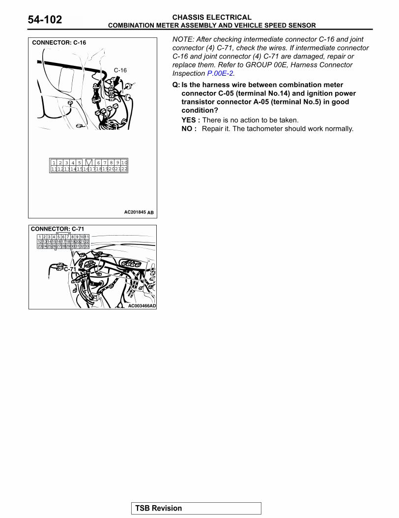
COMBINATION METER ASSEMBLY AND VEHICLE SPEED SENSORCHASSIS ELECTRICAL54-102
NOTE: After checking intermediate connector C-16 and joint connector (4) C-71, check the wires. If intermediate connector C-16 and joint connector (4) C-71 are damaged, repair or replace them. Refer to GROUP 00E, Harness Connector Inspection P.00E-2.Q: Is the harness wire between combination meterconnector C-05 (terminal No.14) and ignition power transistor connector A-05 (terminal No.5) in good condition?YES : There is no action to be taken.NO : Repair it. The tachometer should work normally.
AC201845
2220211098
17186 7191415
4 511121 2 3
13 16
CONNECTOR: C-16
AB
C-16
AC003466AD
C-71
CONNECTOR: C-71
TSB Revision
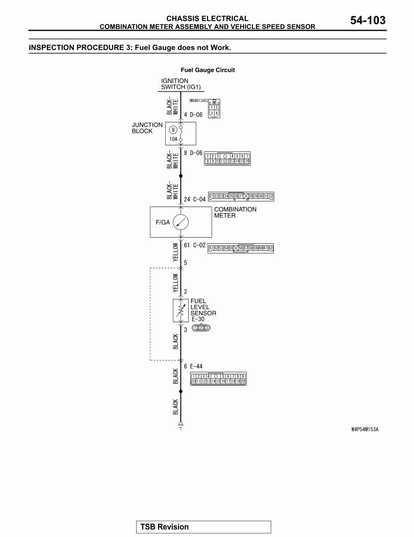
COMBINATION METER ASSEMBLY AND VEHICLE SPEED SENSORCHASSIS ELECTRICAL 54-103
INSPECTION PROCEDURE 3: Fuel Gauge does not Work.
JUNCTION BLOCK
COMBINATIONMETER
FUELLEVELSENSOR
F/GA
IGNITIONSWITCH (IG1)
Fuel Gauge Circuit
TSB Revision
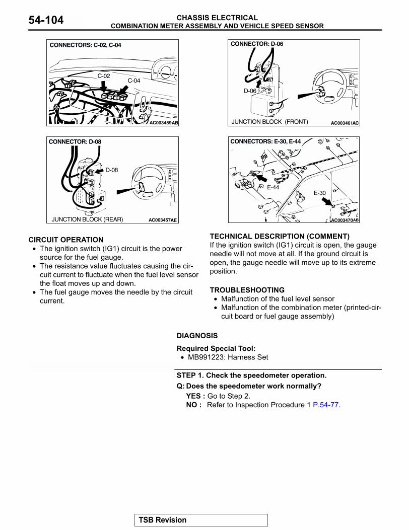
COMBINATION METER ASSEMBLY AND VEHICLE SPEED SENSORCHASSIS ELECTRICAL54-104
.
CIRCUIT OPERATION• The ignition switch (IG1) circuit is the power
source for the fuel gauge.• The resistance value fluctuates causing the cir-
cuit current to fluctuate when the fuel level sensor the float moves up and down.
• The fuel gauge moves the needle by the circuit current.
.
TECHNICAL DESCRIPTION (COMMENT)If the ignition switch (IG1) circuit is open, the gauge needle will not move at all. If the ground circuit is open, the gauge needle will move up to its extreme position..
TROUBLESHOOTING• Malfunction of the fuel level sensor• Malfunction of the combination meter (printed-cir-
cuit board or fuel gauge assembly).
DIAGNOSIS
Required Special Tool:• MB991223: Harness Set
STEP 1. Check the speedometer operation.Q: Does the speedometer work normally?
YES : Go to Step 2.NO : Refer to Inspection Procedure 1 P.54-77.
AC003459
CONNECTORS: C-02, C-04
C-02C-04
AB AC003461AC
CONNECTOR: D-06
JUNCTION BLOCK (FRONT)
D-06
AC003457AE
CONNECTOR: D-08
JUNCTION BLOCK (REAR)
D-08
AC003470AB
CONNECTORS: E-30, E-44
E-30E-44
TSB Revision
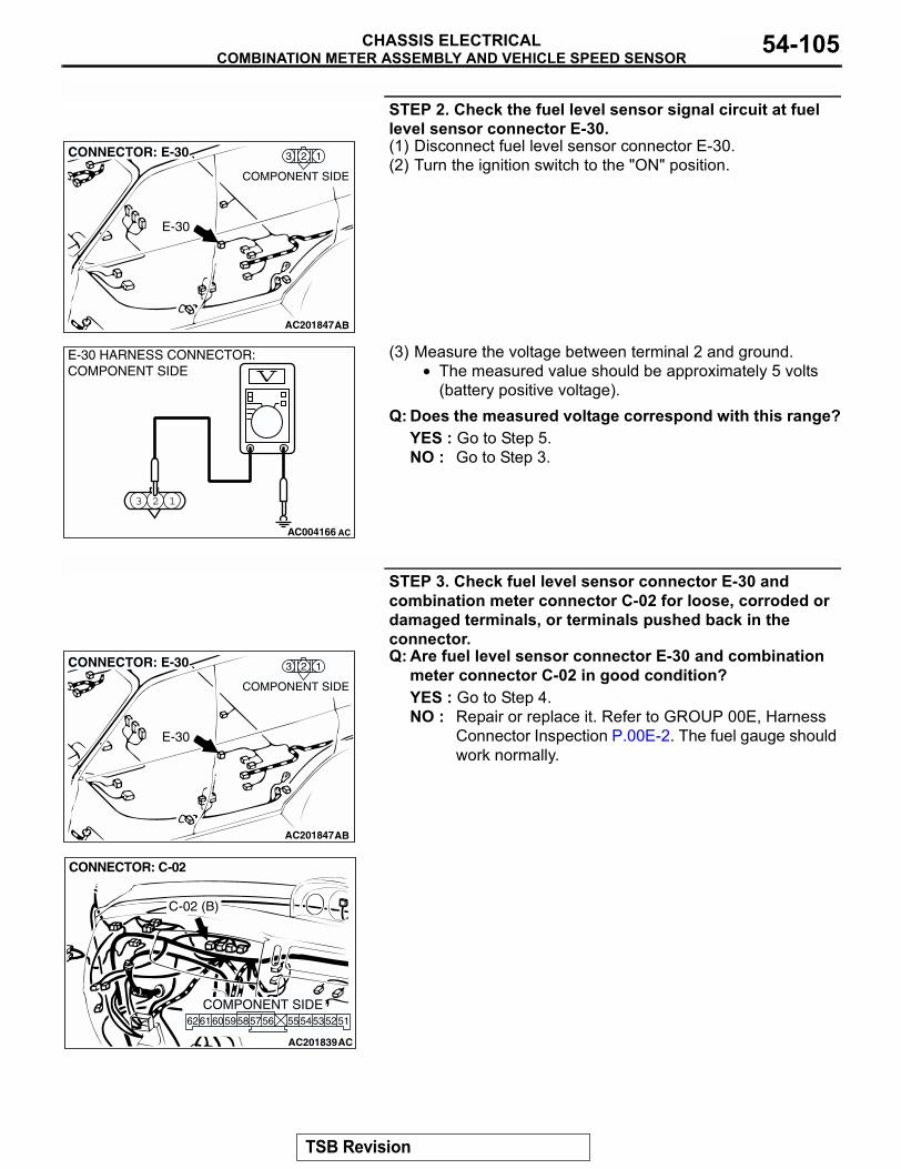
COMBINATION METER ASSEMBLY AND VEHICLE SPEED SENSORCHASSIS ELECTRICAL 54-105
STEP 2. Check the fuel level sensor signal circuit at fuel level sensor connector E-30.(1) Disconnect fuel level sensor connector E-30.(2) Turn the ignition switch to the "ON" position.
(3) Measure the voltage between terminal 2 and ground.• The measured value should be approximately 5 volts
(battery positive voltage).Q: Does the measured voltage correspond with this range?
YES : Go to Step 5.NO : Go to Step 3.
STEP 3. Check fuel level sensor connector E-30 and combination meter connector C-02 for loose, corroded or damaged terminals, or terminals pushed back in the connector.Q: Are fuel level sensor connector E-30 and combination
meter connector C-02 in good condition?YES : Go to Step 4.NO : Repair or replace it. Refer to GROUP 00E, Harness
Connector Inspection P.00E-2. The fuel gauge should work normally.
AC201847
123
COMPONENT SIDE
AB
CONNECTOR: E-30
E-30
3 2 1
AC004166 AC
E-30 HARNESS CONNECTOR:COMPONENT SIDE
AC201847
123
COMPONENT SIDE
AB
CONNECTOR: E-30
E-30
AC201839
CONNECTOR: C-02
AC
5152555453565859 57606162
COMPONENT SIDE
C-02 (B)
TSB Revision
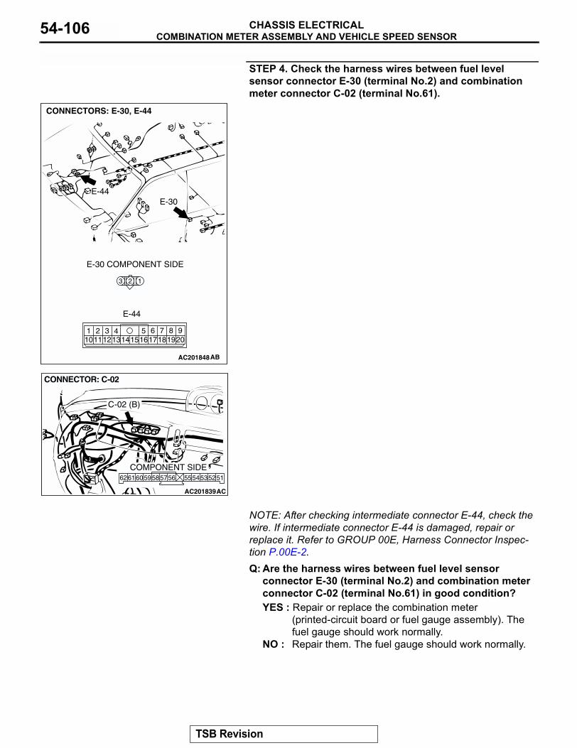
COMBINATION METER ASSEMBLY AND VEHICLE SPEED SENSORCHASSIS ELECTRICAL54-106
STEP 4. Check the harness wires between fuel level sensor connector E-30 (terminal No.2) and combination meter connector C-02 (terminal No.61).
NOTE: After checking intermediate connector E-44, check the wire. If intermediate connector E-44 is damaged, repair or replace it. Refer to GROUP 00E, Harness Connector Inspec-tion P.00E-2. Q: Are the harness wires between fuel level sensor
connector E-30 (terminal No.2) and combination meter connector C-02 (terminal No.61) in good condition?YES : Repair or replace the combination meter
(printed-circuit board or fuel gauge assembly). The fuel gauge should work normally.
NO : Repair them. The fuel gauge should work normally.
AC201848
123
1920617
751514 16
818
31112
42101 9
13
CONNECTORS: E-30, E-44
AB
E-30 COMPONENT SIDE
E-30E-44
E-44
AC201839
CONNECTOR: C-02
AC
5152555453565859 57606162
COMPONENT SIDE
C-02 (B)
TSB Revision
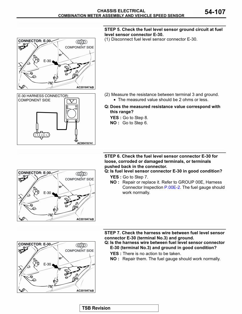
COMBINATION METER ASSEMBLY AND VEHICLE SPEED SENSORCHASSIS ELECTRICAL 54-107
STEP 5. Check the fuel level sensor ground circuit at fuel level sensor connector E-30.(1) Disconnect fuel level sensor connector E-30.
(2) Measure the resistance between terminal 3 and ground.• The measured value should be 2 ohms or less.
Q: Does the measured resistance value correspond with this range?YES : Go to Step 8.NO : Go to Step 6.
STEP 6. Check the fuel level sensor connector E-30 for loose, corroded or damaged terminals, or terminals pushed back in the connector.Q: Is fuel level sensor connector E-30 in good condition?
YES : Go to Step 7.NO : Repair or replace it. Refer to GROUP 00E, Harness
Connector Inspection P.00E-2. The fuel gauge should work normally.
STEP 7. Check the harness wire between fuel level sensor connector E-30 (terminal No.3) and ground.Q: Is the harness wire between fuel level sensor connector
E-30 (terminal No.3) and ground in good condition?YES : There is no action to be taken.NO : Repair them. The fuel gauge should work normally.
AC201847
123
COMPONENT SIDE
AB
CONNECTOR: E-30
E-30
3 2 1
AC00416877AC
E-30 HARNESS CONNECTOR:COMPONENT SIDE
AC201847
123
COMPONENT SIDE
AB
CONNECTOR: E-30
E-30
AC201847
123
COMPONENT SIDE
AB
CONNECTOR: E-30
E-30
TSB Revision
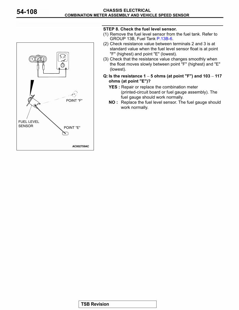
COMBINATION METER ASSEMBLY AND VEHICLE SPEED SENSORCHASSIS ELECTRICAL54-108
STEP 8. Check the fuel level sensor.(1) Remove the fuel level sensor from the fuel tank. Refer to
GROUP 13B, Fuel Tank P.13B-6.(2) Check resistance value between terminals 2 and 3 is at
standard value when the fuel level sensor float is at point "F" (highest) and point "E" (lowest).
(3) Check that the resistance value changes smoothly when the float moves slowly between point "F" (highest) and "E" (lowest).
Q: Is the resistance 1 − 5 ohms (at point "F") and 103 − 117 ohms (at point "E")?YES : Repair or replace the combination meter
(printed-circuit board or fuel gauge assembly). The fuel gauge should work normally.
NO : Replace the fuel level sensor. The fuel gauge should work normally.
AC002759AC
FUEL LEVELSENSOR POINT "E"
POINT "F"
TSB Revision
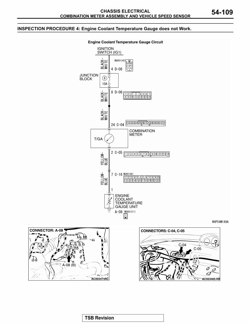
COMBINATION METER ASSEMBLY AND VEHICLE SPEED SENSORCHASSIS ELECTRICAL 54-109
INSPECTION PROCEDURE 4: Engine Coolant Temperature Gauge does not Work.
JUNCTION BLOCK
COMBINATIONMETER
T/GA
ENGINECOOLANTTEMPERATUREGAUGE UNIT
IGNITIONSWITCH (IG1)
Engine Coolant Temperature Gauge Circuit
AC003474
CONNECTOR: A-08
AC
A-08 (B)
AC003465
CONNECTORS: C-04, C-05
AB
C-04C-05
TSB Revision
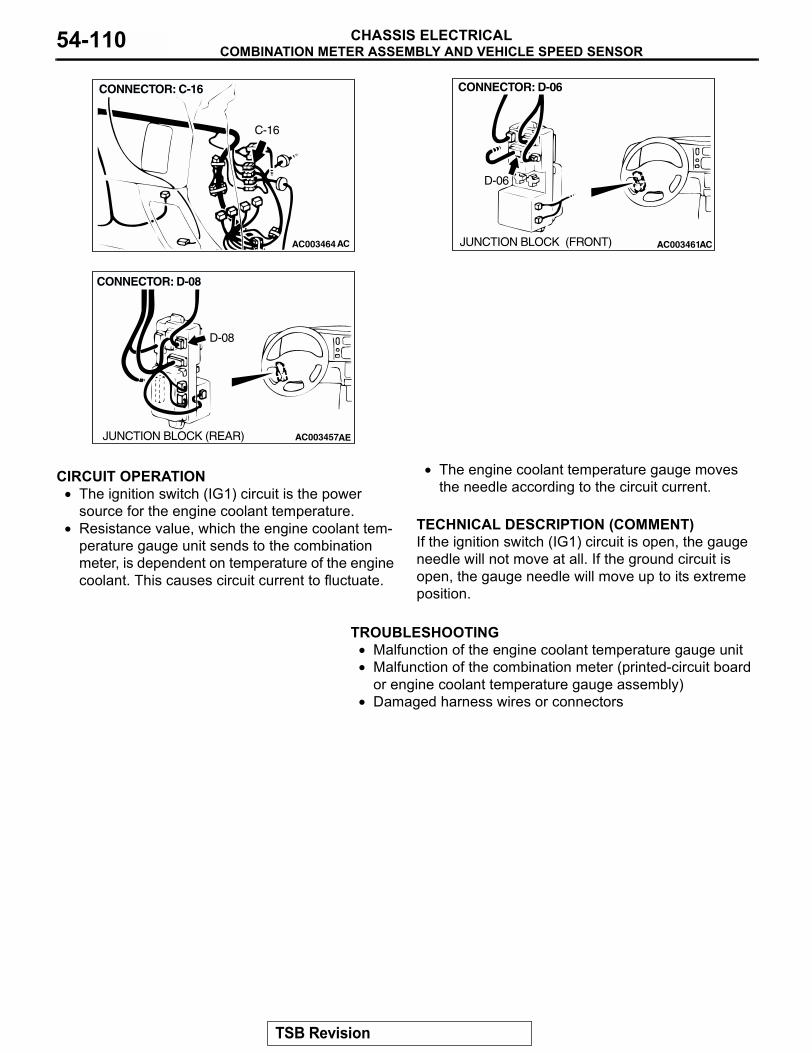
COMBINATION METER ASSEMBLY AND VEHICLE SPEED SENSORCHASSIS ELECTRICAL54-110
.
CIRCUIT OPERATION• The ignition switch (IG1) circuit is the power
source for the engine coolant temperature.• Resistance value, which the engine coolant tem-
perature gauge unit sends to the combination meter, is dependent on temperature of the engine coolant. This causes circuit current to fluctuate.
• The engine coolant temperature gauge moves the needle according to the circuit current.
.
TECHNICAL DESCRIPTION (COMMENT)If the ignition switch (IG1) circuit is open, the gauge needle will not move at all. If the ground circuit is open, the gauge needle will move up to its extreme position.
.
TROUBLESHOOTING• Malfunction of the engine coolant temperature gauge unit• Malfunction of the combination meter (printed-circuit board
or engine coolant temperature gauge assembly)• Damaged harness wires or connectors
.
AC003464AC
CONNECTOR: C-16
C-16
AC003461AC
CONNECTOR: D-06
JUNCTION BLOCK (FRONT)
D-06
AC003457AE
CONNECTOR: D-08
JUNCTION BLOCK (REAR)
D-08
TSB Revision
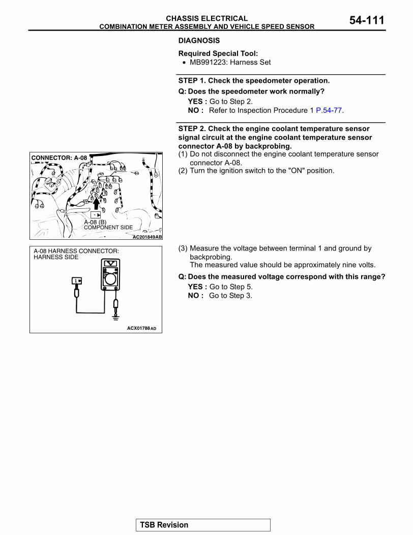
COMBINATION METER ASSEMBLY AND VEHICLE SPEED SENSORCHASSIS ELECTRICAL 54-111
DIAGNOSIS
Required Special Tool:• MB991223: Harness Set
STEP 1. Check the speedometer operation.Q: Does the speedometer work normally?
YES : Go to Step 2.NO : Refer to Inspection Procedure 1 P.54-77.
STEP 2. Check the engine coolant temperature sensor signal circuit at the engine coolant temperature sensor connector A-08 by backprobing.(1) Do not disconnect the engine coolant temperature sensor
connector A-08.(2) Turn the ignition switch to the "ON" position.
(3) Measure the voltage between terminal 1 and ground by backprobing.The measured value should be approximately nine volts.
Q: Does the measured voltage correspond with this range?YES : Go to Step 5.NO : Go to Step 3.
AC201849
1
CONNECTOR: A-08
AB
COMPONENT SIDEA-08 (B)
ACX01788AD
A-08 HARNESS CONNECTOR:HARNESS SIDE
TSB Revision
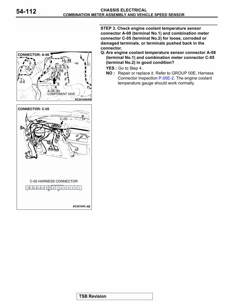
COMBINATION METER ASSEMBLY AND VEHICLE SPEED SENSORCHASSIS ELECTRICAL54-112
STEP 3. Check engine coolant temperature sensor connector A-08 (terminal No.1) and combination meter connector C-05 (terminal No.2) for loose, corroded or damaged terminals, or terminals pushed back in the connector.Q: Are engine coolant temperature sensor connector A-08
(terminal No.1) and combination meter connector C-05 (terminal No.2) in good condition?YES : Go to Step 4.NO : Repair or replace it. Refer to GROUP 00E, Harness
Connector Inspection P.00E-2. The engine coolant temperature gauge should work normally.
AC201849
1
CONNECTOR: A-08
AB
COMPONENT SIDEA-08 (B)
AC2018743
3 26 5 47891110 1121413
CONNECTOR: C-05
C-05 HARNESS CONNECTOR
C-05
AC201843 AB
TSB Revision
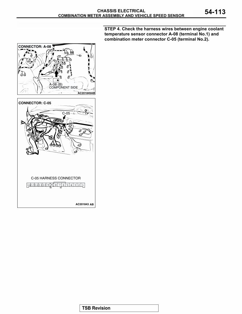
COMBINATION METER ASSEMBLY AND VEHICLE SPEED SENSORCHASSIS ELECTRICAL 54-113
STEP 4. Check the harness wires between engine coolant temperature sensor connector A-08 (terminal No.1) and combination meter connector C-05 (terminal No.2).
AC201849
1
CONNECTOR: A-08
AB
COMPONENT SIDEA-08 (B)
AC2018743
3 26 5 47891110 1121413
CONNECTOR: C-05
C-05 HARNESS CONNECTOR
C-05
AC201843 AB
TSB Revision
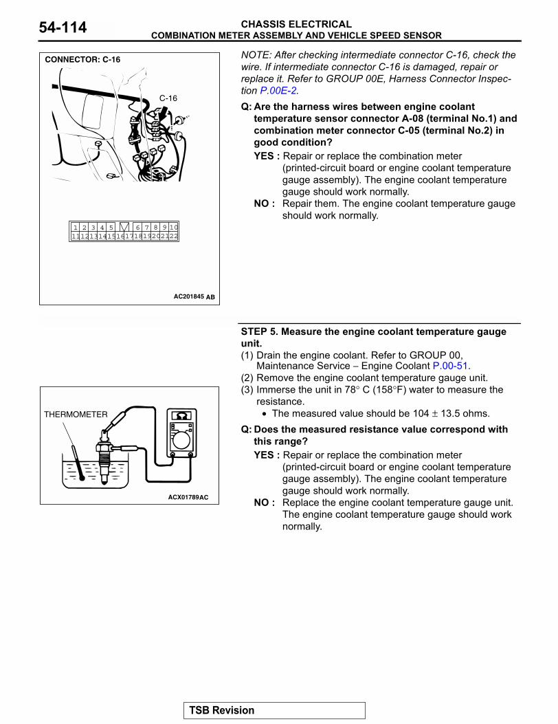
COMBINATION METER ASSEMBLY AND VEHICLE SPEED SENSORCHASSIS ELECTRICAL54-114
NOTE: After checking intermediate connector C-16, check the wire. If intermediate connector C-16 is damaged, repair or replace it. Refer to GROUP 00E, Harness Connector Inspec-tion P.00E-2.Q: Are the harness wires between engine coolanttemperature sensor connector A-08 (terminal No.1) and combination meter connector C-05 (terminal No.2) in good condition?YES : Repair or replace the combination meter
(printed-circuit board or engine coolant temperature gauge assembly). The engine coolant temperature gauge should work normally.
NO : Repair them. The engine coolant temperature gauge should work normally.
STEP 5. Measure the engine coolant temperature gauge unit.(1) Drain the engine coolant. Refer to GROUP 00,
Maintenance Service − Engine Coolant P.00-51.(2) Remove the engine coolant temperature gauge unit.(3) Immerse the unit in 78° C (158°F) water to measure the
resistance.• The measured value should be 104 ± 13.5 ohms.
Q: Does the measured resistance value correspond with this range?YES : Repair or replace the combination meter
(printed-circuit board or engine coolant temperature gauge assembly). The engine coolant temperature gauge should work normally.
NO : Replace the engine coolant temperature gauge unit. The engine coolant temperature gauge should work normally.
AC201845
2220211098
17186 7191415
4 511121 2 3
13 16
CONNECTOR: C-16
AB
C-16
ACX01789
THERMOMETER
AC
TSB Revision
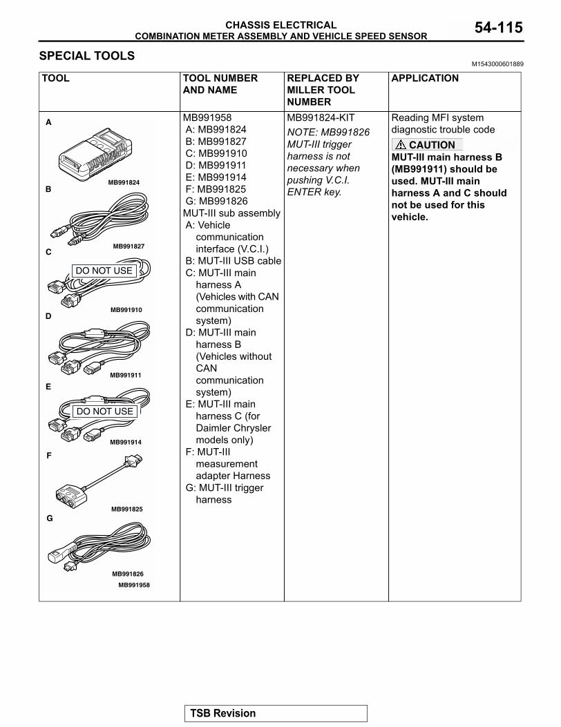
COMBINATION METER ASSEMBLY AND VEHICLE SPEED SENSORCHASSIS ELECTRICAL 54-115
SPECIAL TOOLSM1543000601889
TOOL TOOL NUMBER AND NAME
REPLACED BY MILLER TOOL NUMBER
APPLICATION
MB991958A: MB991824B: MB991827C: MB991910D: MB991911E: MB991914F: MB991825G: MB991826MUT-III sub assemblyA: Vehicle
communication interface (V.C.I.)
B: MUT-III USB cableC: MUT-III main
harness A (Vehicles with CAN communication system)
D: MUT-III main harness B (Vehicles without CAN communication system)
E: MUT-III main harness C (for Daimler Chrysler models only)
F: MUT-III measurement adapter Harness
G: MUT-III trigger harness
MB991824-KITNOTE: MB991826 MUT-III trigger harness is not necessary when pushing V.C.I. ENTER key.
Reading MFI system diagnostic trouble code
CAUTIONMUT-III main harness B (MB991911) should be used. MUT-III main harness A and C should not be used for this vehicle.
MB991910
MB991826
MB991958
MB991911
MB991914
MB991824
MB991827
MB991825
A
B
C
D
E
F
G
DO NOT USE
DO NOT USE
TSB Revision
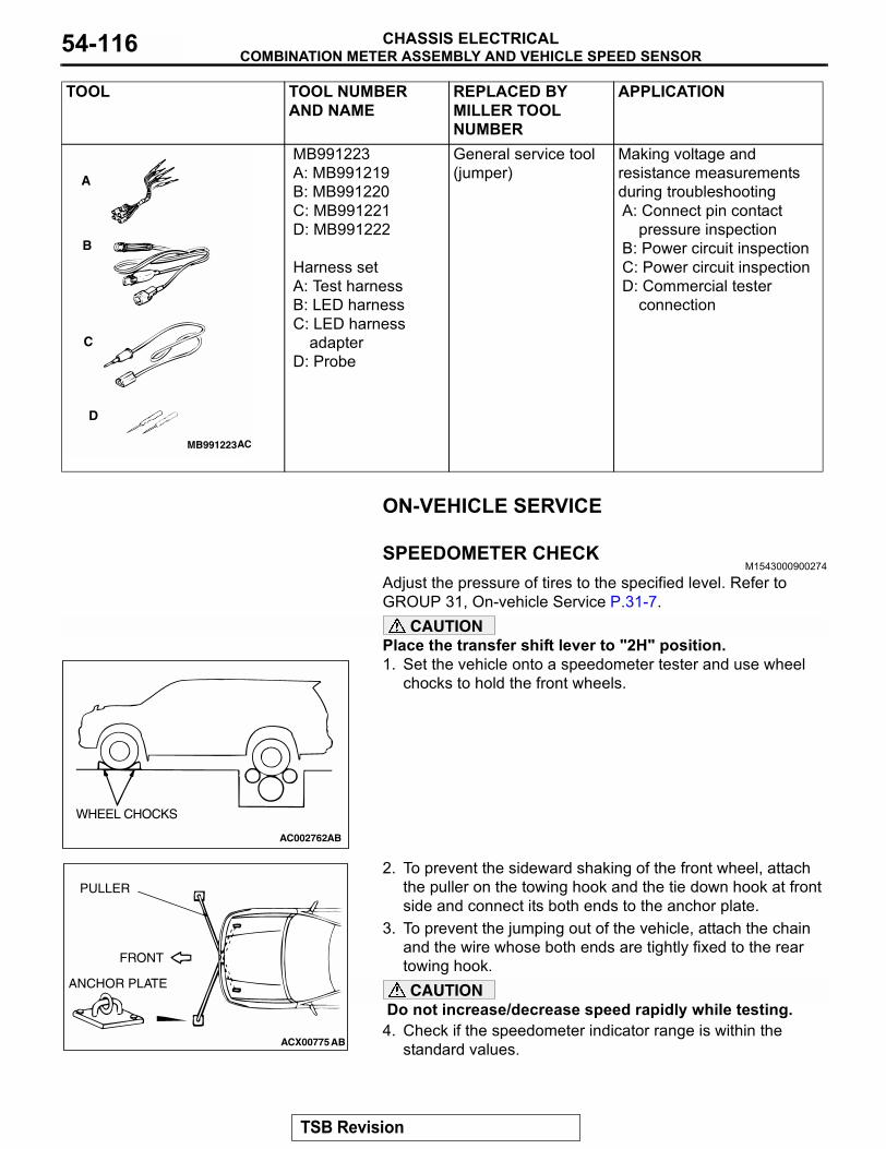
COMBINATION METER ASSEMBLY AND VEHICLE SPEED SENSORCHASSIS ELECTRICAL54-116
ON-VEHICLE SERVICE
SPEEDOMETER CHECKM1543000900274
Adjust the pressure of tires to the specified level. Refer to GROUP 31, On-vehicle Service P.31-7.
CAUTIONPlace the transfer shift lever to "2H" position. 1. Set the vehicle onto a speedometer tester and use wheel
chocks to hold the front wheels.
2. To prevent the sideward shaking of the front wheel, attach the puller on the towing hook and the tie down hook at front side and connect its both ends to the anchor plate.
3. To prevent the jumping out of the vehicle, attach the chain and the wire whose both ends are tightly fixed to the rear towing hook.CAUTION
Do not increase/decrease speed rapidly while testing.4. Check if the speedometer indicator range is within the
standard values.
MB991223A: MB991219B: MB991220 C: MB991221D: MB991222
Harness setA: Test harnessB: LED harnessC: LED harness
adapterD: Probe
General service tool (jumper)
Making voltage and resistance measurements during troubleshootingA: Connect pin contact
pressure inspectionB: Power circuit inspectionC: Power circuit inspectionD: Commercial tester
connection
TOOL TOOL NUMBER AND NAME
REPLACED BY MILLER TOOL NUMBER
APPLICATION
MB991223
A
B
C
D
AC
AC002762AB
WHEEL CHOCKS
ACX00775AB
FRONT
ANCHOR PLATE
PULLER
TSB Revision
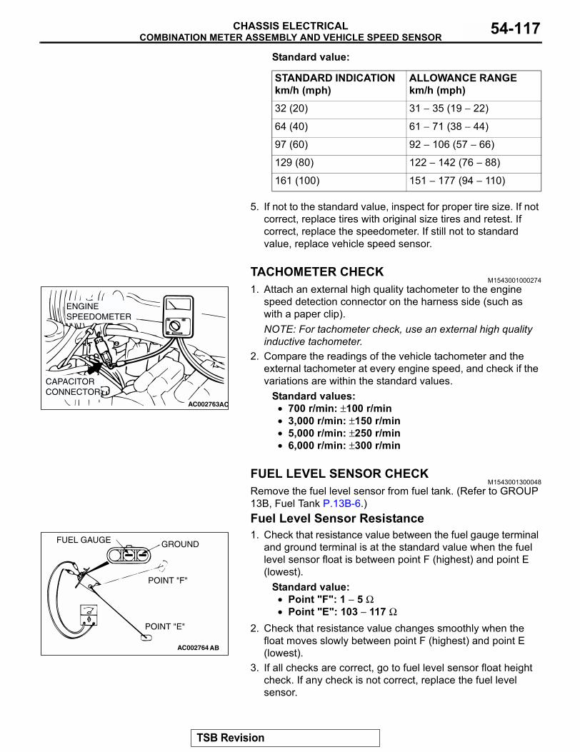
COMBINATION METER ASSEMBLY AND VEHICLE SPEED SENSORCHASSIS ELECTRICAL 54-117
Standard value:
5. If not to the standard value, inspect for proper tire size. If not correct, replace tires with original size tires and retest. If correct, replace the speedometer. If still not to standard value, replace vehicle speed sensor.
TACHOMETER CHECKM1543001000274
1. Attach an external high quality tachometer to the engine speed detection connector on the harness side (such as with a paper clip).NOTE: For tachometer check, use an external high quality inductive tachometer.
2. Compare the readings of the vehicle tachometer and the external tachometer at every engine speed, and check if the variations are within the standard values.
Standard values:• 700 r/min: ±100 r/min• 3,000 r/min: ±150 r/min• 5,000 r/min: ±250 r/min• 6,000 r/min: ±300 r/min
FUEL LEVEL SENSOR CHECKM1543001300048
Remove the fuel level sensor from fuel tank. (Refer to GROUP 13B, Fuel Tank P.13B-6.)Fuel Level Sensor Resistance1. Check that resistance value between the fuel gauge terminal
and ground terminal is at the standard value when the fuel level sensor float is between point F (highest) and point E (lowest).
Standard value:• Point "F": 1 − 5 Ω• Point "E": 103 − 117 Ω
2. Check that resistance value changes smoothly when the float moves slowly between point F (highest) and point E (lowest).
3. If all checks are correct, go to fuel level sensor float height check. If any check is not correct, replace the fuel level sensor.
STANDARD INDICATION km/h (mph)
ALLOWANCE RANGEkm/h (mph)
32 (20) 31 − 35 (19 − 22)
64 (40) 61 − 71 (38 − 44)
97 (60) 92 − 106 (57 − 66)
129 (80) 122 − 142 (76 − 88)
161 (100) 151 − 177 (94 − 110)
AC002763AC
ENGINESPEEDOMETER
CAPACITORCONNECTOR
AC002764 AB
FUEL GAUGE GROUND
POINT "F"
POINT "E"
TSB Revision
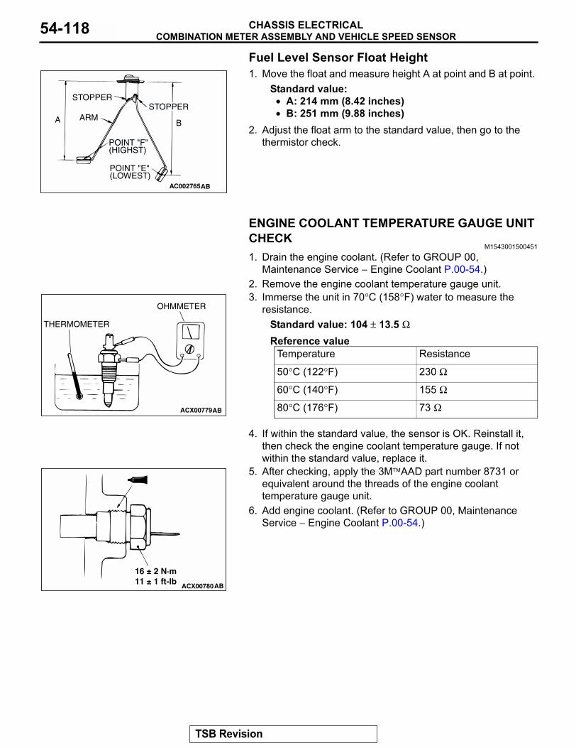
COMBINATION METER ASSEMBLY AND VEHICLE SPEED SENSORCHASSIS ELECTRICAL54-118
Fuel Level Sensor Float Height1. Move the float and measure height A at point and B at point.
Standard value:• A: 214 mm (8.42 inches)• B: 251 mm (9.88 inches)
2. Adjust the float arm to the standard value, then go to the thermistor check.
ENGINE COOLANT TEMPERATURE GAUGE UNIT CHECK
M1543001500451
1. Drain the engine coolant. (Refer to GROUP 00, Maintenance Service − Engine Coolant P.00-54.)
2. Remove the engine coolant temperature gauge unit.3. Immerse the unit in 70°C (158°F) water to measure the
resistance.Standard value: 104 ± 13.5 ΩReference value
4. If within the standard value, the sensor is OK. Reinstall it, then check the engine coolant temperature gauge. If not within the standard value, replace it.
5. After checking, apply the 3MAAD part number 8731 or equivalent around the threads of the engine coolant temperature gauge unit.
6. Add engine coolant. (Refer to GROUP 00, Maintenance Service − Engine Coolant P.00-54.)
AC002765AB
STOPPERSTOPPER
ARM
POINT "F"(HIGHST)
POINT "E"(LOWEST)
A B
Temperature Resistance
50°C (122°F) 230 Ω
60°C (140°F) 155 Ω
80°C (176°F) 73 ΩACX00779AB
THERMOMETER
OHMMETER
ACX00780AB
16 ± 2 N·m11 ± 1 ft-lb
TSB Revision
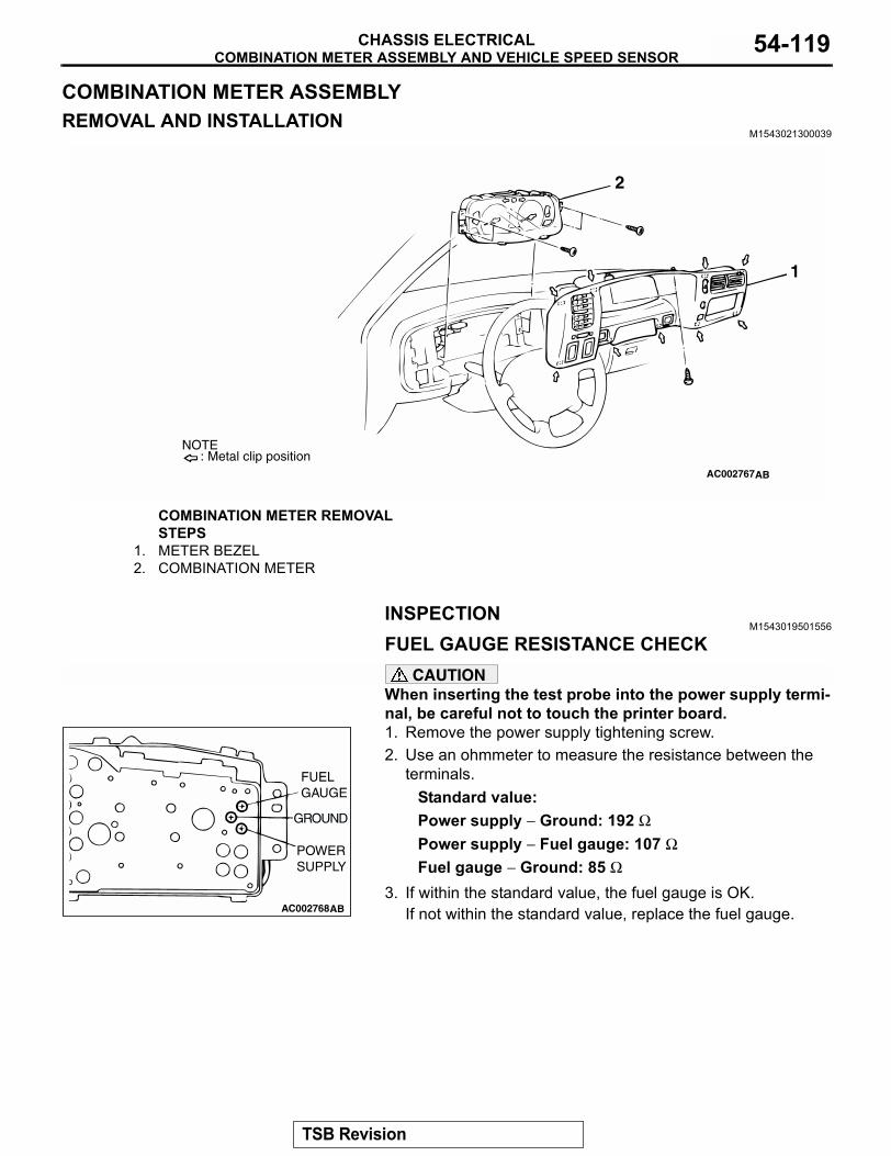
COMBINATION METER ASSEMBLY AND VEHICLE SPEED SENSORCHASSIS ELECTRICAL 54-119
COMBINATION METER ASSEMBLYREMOVAL AND INSTALLATION
M1543021300039
INSPECTIONM1543019501556
FUEL GAUGE RESISTANCE CHECKCAUTION
When inserting the test probe into the power supply termi-nal, be careful not to touch the printer board.1. Remove the power supply tightening screw.2. Use an ohmmeter to measure the resistance between the
terminals.Standard value:Power supply − Ground: 192 ΩPower supply − Fuel gauge: 107 ΩFuel gauge − Ground: 85 Ω
3. If within the standard value, the fuel gauge is OK.If not within the standard value, replace the fuel gauge.
AC002767AB
1
2
: Metal clip positionNOTE
COMBINATION METER REMOVAL STEPS
1. METER BEZEL2. COMBINATION METER
AC002768AB
FUELGAUGE
POWERSUPPLY
GROUND
TSB Revision
COMBINATION METER ASSEMBLY AND VEHICLE SPEED SENSORCHASSIS ELECTRICAL54-120
ENGINE COOLANT TEMPERATURE GAUGE RESISTANCE CHECK
CAUTIONWhen inserting the test probe into the power supply termi-nal, be careful not to touch the printer board.1. Remove the power supply tightening screw.2. Use an ohmmeter to measure the resistance between the
terminals.Standard value:Power supply − Ground: 191 ΩPower supply − Engine coolant temperature gauge: 103 ΩEngine coolant temperature gauge − Ground: 88 Ω
3. If within the standard value, the engine coolant temperature gauge is OK.If not within the standard value, replace the engine coolant temperature gauge.
VEHICLE SPEED SENSOR CHECK1. Remove the vehicle speed sensor and connect a 3 − 10
ohms resistor as shown in the illustration.2. Turn the shaft of the vehicle speed sensor and check that
there is voltage between terminals 2 − 3. (1 turn = 4 pulses)3. If within the standard value, the vehicle speed sensor is OK.
If not within the standard value, replace the vehicle speed sensor.
AC002769AB
ENGINECOOLANTTEMPERATURE GAUGE
GROUND
POWERSUPPLY
AC102349AB
TURN
SHAFT
RESISTOR3 - 10
TSB Revision
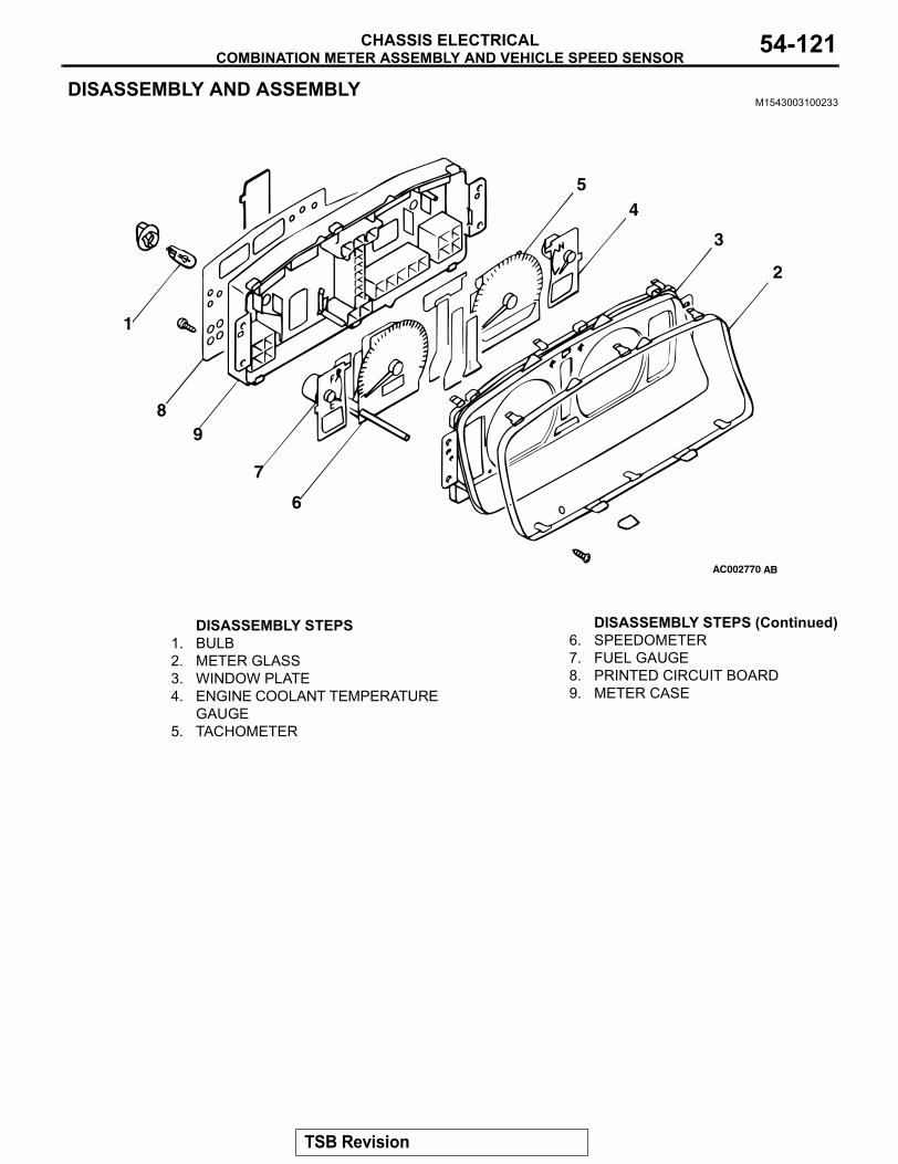
COMBINATION METER ASSEMBLY AND VEHICLE SPEED SENSORCHASSIS ELECTRICAL 54-121
DISASSEMBLY AND ASSEMBLYM1543003100233
AC002770 AB
1
2
3
45
6
7
89
DISASSEMBLY STEPS1. BULB2. METER GLASS3. WINDOW PLATE4. ENGINE COOLANT TEMPERATURE
GAUGE5. TACHOMETER
6. SPEEDOMETER7. FUEL GAUGE8. PRINTED CIRCUIT BOARD9. METER CASE
DISASSEMBLY STEPS (Continued)
TSB Revision
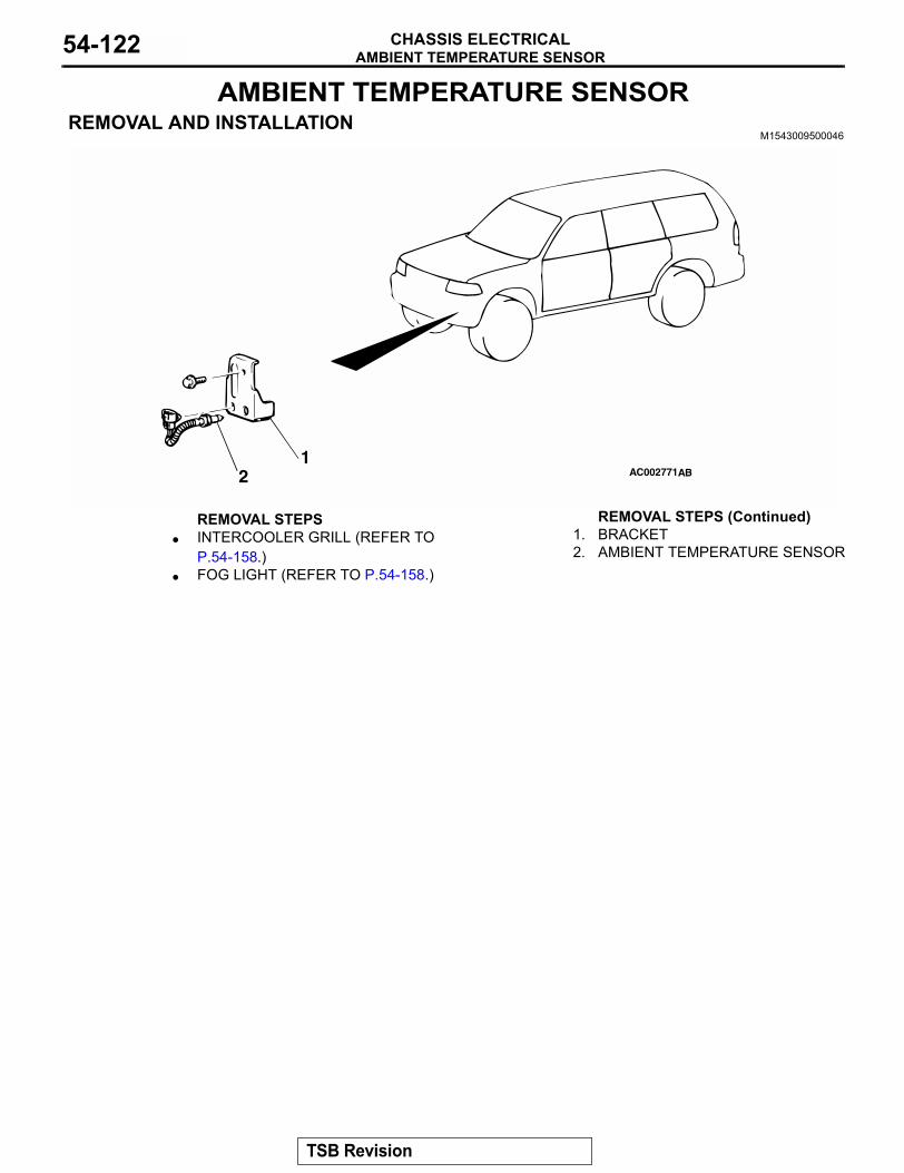
AMBIENT TEMPERATURE SENSORCHASSIS ELECTRICAL54-122
AMBIENT TEMPERATURE SENSOR REMOVAL AND INSTALLATION
M1543009500046
AC0027711
2 AB
REMOVAL STEPS• INTERCOOLER GRILL (REFER TO
P.54-158.)• FOG LIGHT (REFER TO P.54-158.)
1. BRACKET2. AMBIENT TEMPERATURE SENSOR
REMOVAL STEPS (Continued)
TSB Revision
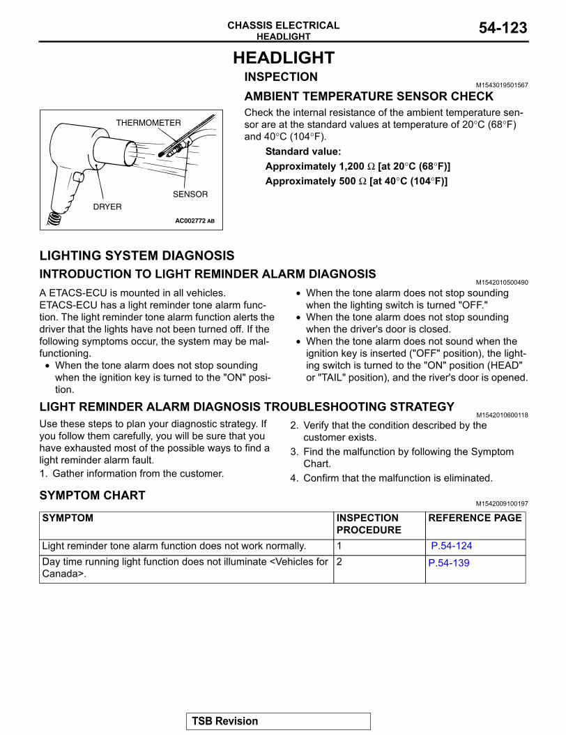
HEADLIGHTCHASSIS ELECTRICAL 54-123
HEADLIGHTINSPECTION
M1543019501567
AMBIENT TEMPERATURE SENSOR CHECKCheck the internal resistance of the ambient temperature sen-sor are at the standard values at temperature of 20°C (68°F) and 40°C (104°F).
Standard value:Approximately 1,200 Ω [at 20°C (68°F)]Approximately 500 Ω [at 40°C (104°F)]
LIGHTING SYSTEM DIAGNOSISINTRODUCTION TO LIGHT REMINDER ALARM DIAGNOSIS
M1542010500490
A ETACS-ECU is mounted in all vehicles. ETACS-ECU has a light reminder tone alarm func-tion. The light reminder tone alarm function alerts the driver that the lights have not been turned off. If the following symptoms occur, the system may be mal-functioning.
• When the tone alarm does not stop sounding when the ignition key is turned to the "ON" posi-tion.
• When the tone alarm does not stop sounding when the lighting switch is turned "OFF."
• When the tone alarm does not stop sounding when the driver's door is closed.
• When the tone alarm does not sound when the ignition key is inserted ("OFF" position), the light-ing switch is turned to the "ON" position (HEAD" or "TAIL" position), and the river's door is opened.
LIGHT REMINDER ALARM DIAGNOSIS TROUBLESHOOTING STRATEGYM1542010600118
Use these steps to plan your diagnostic strategy. If you follow them carefully, you will be sure that you have exhausted most of the possible ways to find a light reminder alarm fault.1. Gather information from the customer.
2. Verify that the condition described by the customer exists.
3. Find the malfunction by following the Symptom Chart.
4. Confirm that the malfunction is eliminated.
SYMPTOM CHARTM1542009100197
AC002772 AB
SENSOR
DRYER
THERMOMETER
SYMPTOM INSPECTION PROCEDURE
REFERENCE PAGE
Light reminder tone alarm function does not work normally. 1 P.54-124Day time running light function does not illuminate <Vehicles for Canada>.
2 P.54-139
TSB Revision
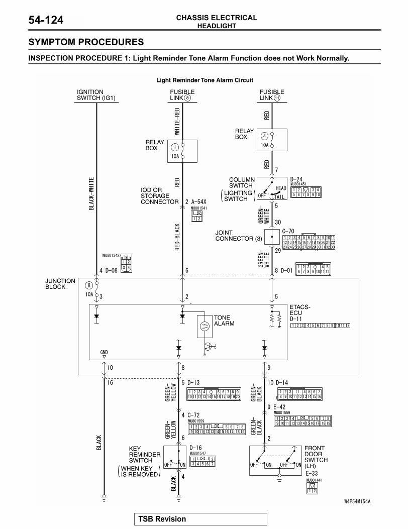
HEADLIGHTCHASSIS ELECTRICAL54-124
SYMPTOM PROCEDURESINSPECTION PROCEDURE 1: Light Reminder Tone Alarm Function does not Work Normally.
FUSIBLELINK 8
FUSIBLELINK
RELAYBOX
RELAYBOX
JUNCTIONBLOCK
ETACS-ECU
TONEALARM
KEYREMINDERSWITCH
FRONTDOORSWITCH(LH)
IOD ORSTORAGECONNECTOR
IGNITIONSWITCH (IG1)
WHEN KEYIS REMOVED
COLUMNSWITCH
LIGHTINGSWITCH
11
JOINT CONNECTOR (3)
Light Reminder Tone Alarm Circuit
TSB Revision
HEADLIGHTCHASSIS ELECTRICAL 54-125
.
AC003431
CONNECTOR: A-54X
A-54X
AC AC003478AC
CONNECTOR: C-70
C-70
AC003622
CONNECTOR: C-72
AD
C-72 (B)
AC003476 AC
CONNECTOR: D-01
JUNCTION BLOCK (FRONT)
D-01
AC003479 AC
CONNECTORS: D-08, D-11, D-13, D-14
D-08
D-11
JUNCTION BLOCK (REAR)
D-13
D-14 (B)
AC003477AB
CONNECTORS: D-16, D-24
D-16
D-24
AC003480 AB
CONNECTORS: E-33, E-42
E-33E-42
TSB Revision
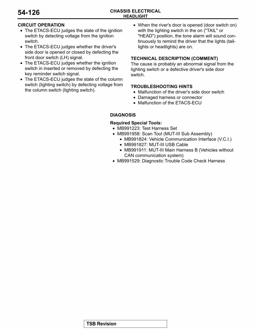
HEADLIGHTCHASSIS ELECTRICAL54-126
CIRCUIT OPERATION• The ETACS-ECU judges the state of the ignition
switch by detecting voltage from the ignition switch.
• The ETACS-ECU judges whether the driver's side door is opened or closed by defecting the front door switch (LH) signal.
• The ETACS-ECU judges whether the ignition switch in inserted or removed by defecting the key reminder switch signal.
• The ETACS-ECU judges the state of the column switch (lighting switch) by defecting voltage from the column switch (lighting switch).
• When the river's door is opened (door switch on) with the lighting switch in the on ("TAIL" or "HEAD") position, the tone alarm will sound con-tinuously to remind the driver that the lights (tail-lights or headlights) are on.
.
TECHNICAL DESCRIPTION (COMMENT)The cause is probably an abnormal signal from the lighting switch or a defective driver's side door switch..
TROUBLESHOOTING HINTS• Malfunction of the driver's side door switch• Damaged harness or connector• Malfunction of the ETACS-ECU
.
DIAGNOSIS
Required Special Tools:• MB991223: Test Harness Set• MB991958: Scan Tool (MUT-III Sub Assembly)
• MB991824: Vehicle Communication Interface (V.C.I.)• MB991827: MUT-III USB Cable• MB991911: MUT-III Main Harness B (Vehicles without
CAN communication system)• MB991529: Diagnostic Trouble Code Check Harness
TSB Revision
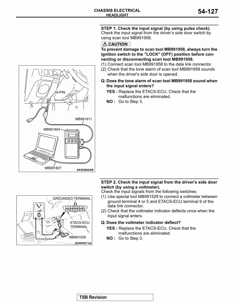
HEADLIGHTCHASSIS ELECTRICAL 54-127
STEP 1. Check the input signal (by using pulse check).Check the input signal from the drivers side door switch by using scan tool MB991958.
CAUTIONTo prevent damage to scan tool MB991958, always turn the ignition switch to the "LOCK" (OFF) position before con-necting or disconnecting scan tool MB991958.(1) Connect scan tool MB991958 to the data link connector.(2) Check that the tone alarm of scan tool MB991958 sounds
when the driver's side door is opened.Q: Does the tone alarm of scan tool MB991958 sound when
the input signal enters?YES : Replace the ETACS-ECU. Check that the
malfunctions are eliminated.NO : Go to Step 3.
STEP 2. Check the input signal from the driver's side door switch (by using a voltmeter).Check the input signals from the following switches:(1) Use special tool MB991529 to connect a voltmeter between
ground terminal 4 or 5 and ETACS-ECU terminal 9 of the data link connector.
(2) Check that the voltmeter indicator deflects once when the input signal enters.
Q: Does the voltmeter indicator deflect?YES : Replace the ETACS-ECU. Check that the
malfunctions are eliminated.NO : Go to Step 3.
AK303629AB
MB991911
MB991827
MB991824
16-PIN
AC003527
GROUNDED TERMINAL
ETACS-ECU TERMINAL
MB991529
AB
TSB Revision
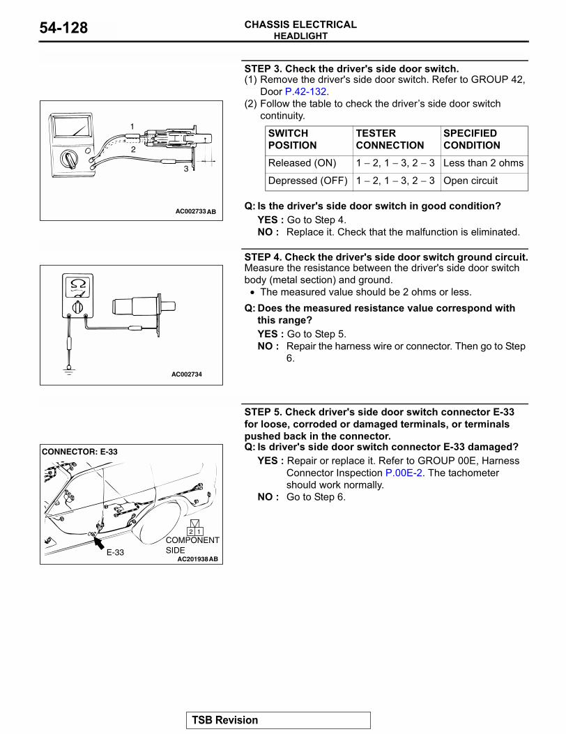
HEADLIGHTCHASSIS ELECTRICAL54-128
STEP 3. Check the driver's side door switch.(1) Remove the driver's side door switch. Refer to GROUP 42,
Door P.42-132.(2) Follow the table to check the drivers side door switch
continuity.
Q: Is the driver's side door switch in good condition?YES : Go to Step 4.NO : Replace it. Check that the malfunction is eliminated.
STEP 4. Check the driver's side door switch ground circuit.Measure the resistance between the driver's side door switch body (metal section) and ground.
• The measured value should be 2 ohms or less.Q: Does the measured resistance value correspond with
this range?YES : Go to Step 5.NO : Repair the harness wire or connector. Then go to Step
6.
STEP 5. Check driver's side door switch connector E-33 for loose, corroded or damaged terminals, or terminals pushed back in the connector.Q: Is driver's side door switch connector E-33 damaged?
YES : Repair or replace it. Refer to GROUP 00E, Harness Connector Inspection P.00E-2. The tachometer should work normally.
NO : Go to Step 6.
SWITCH POSITION
TESTER CONNECTION
SPECIFIED CONDITION
Released (ON) 1 − 2, 1 − 3, 2 − 3 Less than 2 ohms
Depressed (OFF) 1 − 2, 1 − 3, 2 − 3 Open circuit
AC002733AB
1
2
3
AC002734
AC201938
2 1
CONNECTOR: E-33
COMPONENT SIDEE-33
AB
TSB Revision
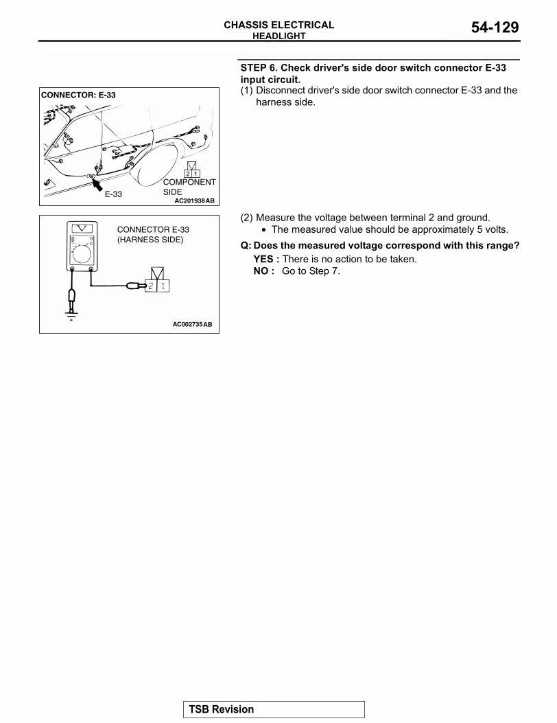
HEADLIGHTCHASSIS ELECTRICAL 54-129
STEP 6. Check driver's side door switch connector E-33 input circuit.(1) Disconnect driver's side door switch connector E-33 and the
harness side.
(2) Measure the voltage between terminal 2 and ground.• The measured value should be approximately 5 volts.
Q: Does the measured voltage correspond with this range?YES : There is no action to be taken.NO : Go to Step 7.
AC201938
2 1
CONNECTOR: E-33
COMPONENT SIDEE-33
AB
AC002735
CONNECTOR E-33(HARNESS SIDE)
AB
TSB Revision
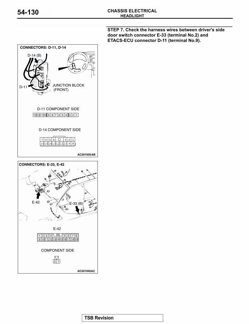
HEADLIGHTCHASSIS ELECTRICAL54-130
STEP 7. Check the harness wires between driver's side door switch connector E-33 (terminal No.2) and ETACS-ECU connector D-11 (terminal No.9).
AC201939
1347 6 5 291112 1013 8
18
3457 6101516 14 1213 11 9
2
CONNECTORS: D-11, D-14
D-11
D-14 (B)
D-11 COMPONENT SIDE
D-14 COMPONENT SIDE
AB
JUNCTION BLOCK (FRONT)
AC201940
2 1
819
7651615 17 18
4321011 1213
19 14
CONNECTORS: E-33, E-42
AC
E-33 (B)E-42
COMPONENT SIDE
E-42
TSB Revision
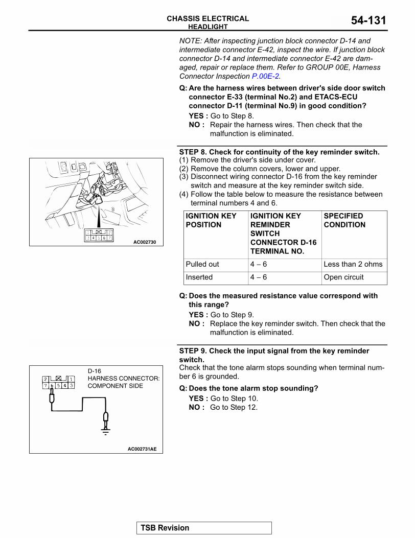
HEADLIGHTCHASSIS ELECTRICAL 54-131
NOTE: After inspecting junction block connector D-14 and intermediate connector E-42, inspect the wire. If junction block connector D-14 and intermediate connector E-42 are dam-aged, repair or replace them. Refer to GROUP 00E, Harness Connector Inspection P.00E-2.Q: Are the harness wires between driver's side door switch
connector E-33 (terminal No.2) and ETACS-ECU connector D-11 (terminal No.9) in good condition?YES : Go to Step 8.NO : Repair the harness wires. Then check that the
malfunction is eliminated.
STEP 8. Check for continuity of the key reminder switch.(1) Remove the driver's side under cover.(2) Remove the column covers, lower and upper.(3) Disconnect wiring connector D-16 from the key reminder
switch and measure at the key reminder switch side.(4) Follow the table below to measure the resistance between
terminal numbers 4 and 6.
Q: Does the measured resistance value correspond with this range?YES : Go to Step 9.NO : Replace the key reminder switch. Then check that the
malfunction is eliminated.
STEP 9. Check the input signal from the key reminder switch.Check that the tone alarm stops sounding when terminal num-ber 6 is grounded.Q: Does the tone alarm stop sounding?
YES : Go to Step 10.NO : Go to Step 12.
IGNITION KEY POSITION
IGNITION KEY REMINDER SWITCH CONNECTOR D-16 TERMINAL NO.
SPECIFIED CONDITION
Pulled out 4 − 6 Less than 2 ohms
Inserted 4 − 6 Open circuit
AC002730
AC002731AE
D-16 HARNESS CONNECTOR:COMPONENT SIDE
TSB Revision
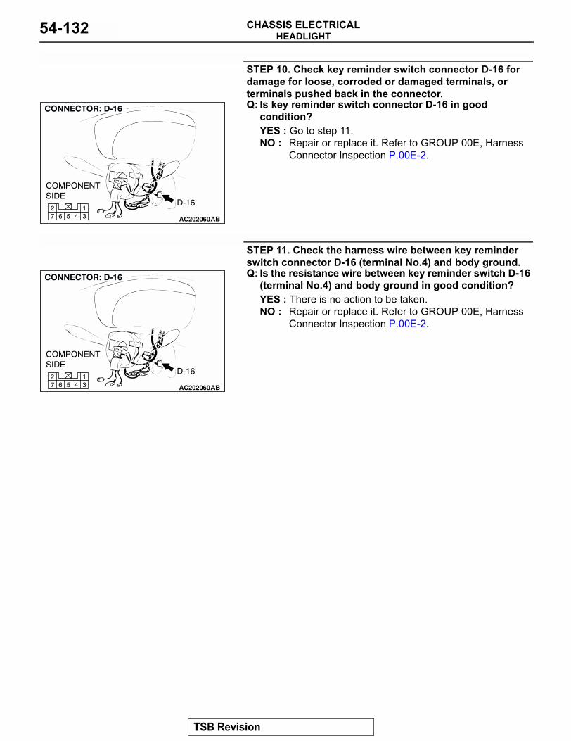
HEADLIGHTCHASSIS ELECTRICAL54-132
STEP 10. Check key reminder switch connector D-16 for damage for loose, corroded or damaged terminals, or terminals pushed back in the connector.Q: Is key reminder switch connector D-16 in good
condition?YES : Go to step 11.NO : Repair or replace it. Refer to GROUP 00E, Harness
Connector Inspection P.00E-2.
STEP 11. Check the harness wire between key reminder switch connector D-16 (terminal No.4) and body ground.Q: Is the resistance wire between key reminder switch D-16
(terminal No.4) and body ground in good condition?YES : There is no action to be taken.NO : Repair or replace it. Refer to GROUP 00E, Harness
Connector Inspection P.00E-2.
AC20206045 31
672
AC20206045 31
672
TSB Revision
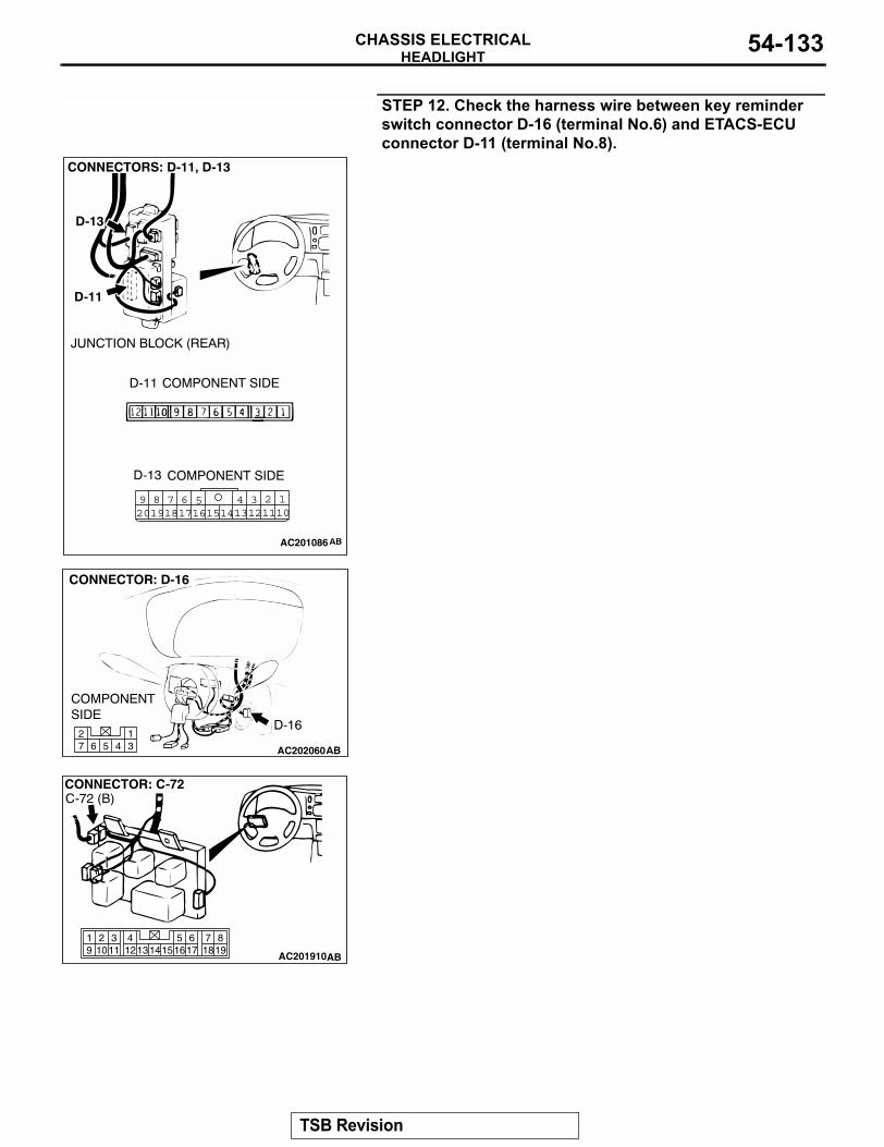
HEADLIGHTCHASSIS ELECTRICAL 54-133
STEP 12. Check the harness wire between key reminder switch connector D-16 (terminal No.6) and ETACS-ECU connector D-11 (terminal No.8).
1245 3689 710111314 121617201918 15
AC201086
AC20206045 31
672
819
7651615 17 18
4321011 1213
19 14
AC201910
CONNECTOR: C-72
AB
C-72 (B)
TSB Revision
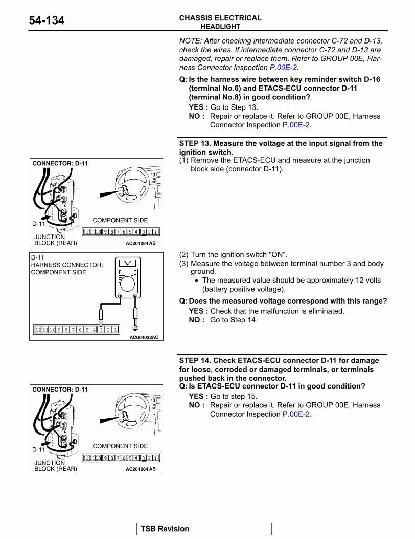
HEADLIGHTCHASSIS ELECTRICAL54-134
NOTE: After checking intermediate connector C-72 and D-13, check the wires. If intermediate connector C-72 and D-13 are damaged, repair or replace them. Refer to GROUP 00E, Har-ness Connector Inspection P.00E-2.Q: Is the harness wire between key reminder switch D-16(terminal No.6) and ETACS-ECU connector D-11 (terminal No.8) in good condition?YES : Go to Step 13.NO : Repair or replace it. Refer to GROUP 00E, Harness
Connector Inspection P.00E-2.
STEP 13. Measure the voltage at the input signal from the ignition switch.(1) Remove the ETACS-ECU and measure at the junction
block side (connector D-11).
(2) Turn the ignition switch "ON".(3) Measure the voltage between terminal number 3 and body
ground.• The measured value should be approximately 12 volts
(battery positive voltage).Q: Does the measured voltage correspond with this range?
YES : Check that the malfunction is eliminated.NO : Go to Step 14.
STEP 14. Check ETACS-ECU connector D-11 for damage for loose, corroded or damaged terminals, or terminals pushed back in the connector.Q: Is ETACS-ECU connector D-11 in good condition?
YES : Go to step 15.NO : Repair or replace it. Refer to GROUP 00E, Harness
Connector Inspection P.00E-2.
AC201084JUNCTION BLOCK (REAR)
D-11 COMPONENT SIDE
AB
CONNECTOR: D-11
123457910 681112
AC004032 AC
D-11 HARNESS CONNECTOR:COMPONENT SIDE
AC201084JUNCTION BLOCK (REAR)
D-11 COMPONENT SIDE
AB
CONNECTOR: D-11
TSB Revision
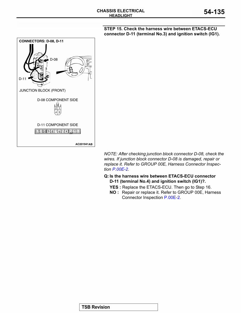
HEADLIGHTCHASSIS ELECTRICAL 54-135
STEP 15. Check the harness wire between ETACS-ECU connector D-11 (terminal No.3) and ignition switch (IG1).
NOTE: After checking junction block connector D-08, check the wires. If junction block connector D-08 is damaged, repair or replace it. Refer to GROUP 00E, Harness Connector Inspec-tion P.00E-2.Q: Is the harness wire between ETACS-ECU connector
D-11 (terminal No.4) and ignition switch (IG1)?.YES : Replace the ETACS-ECU. Then go to Step 16.NO : Repair or replace it. Refer to GROUP 00E, Harness
Connector Inspection P.00E-2.
AC201941
M
3
1
4
2
CONNECTORS: D-08, D-11
AB
D-08 COMPONENT SIDE
D-11 COMPONENT SIDE
D-08
D-11
JUNCTION BLOCK (FRONT)
TSB Revision
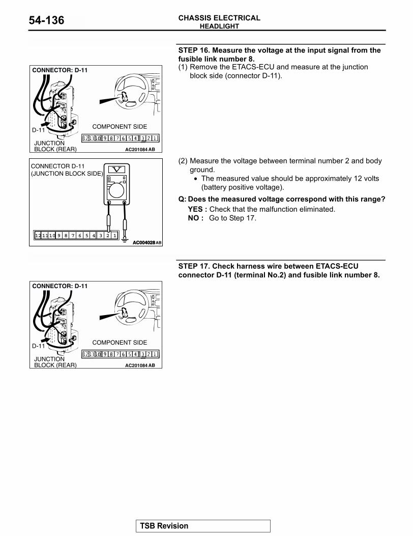
HEADLIGHTCHASSIS ELECTRICAL54-136
STEP 16. Measure the voltage at the input signal from the fusible link number 8.(1) Remove the ETACS-ECU and measure at the junction
block side (connector D-11).
(2) Measure the voltage between terminal number 2 and body ground.
• The measured value should be approximately 12 volts (battery positive voltage).
Q: Does the measured voltage correspond with this range?YES : Check that the malfunction eliminated.NO : Go to Step 17.
STEP 17. Check harness wire between ETACS-ECU connector D-11 (terminal No.2) and fusible link number 8.
AC201084JUNCTION BLOCK (REAR)
D-11 COMPONENT SIDE
AB
CONNECTOR: D-11
123457910 681112AC004028
123457910 681112AC004028AB
CONNECTOR D-11(JUNCTION BLOCK SIDE)
AC201084JUNCTION BLOCK (REAR)
D-11 COMPONENT SIDE
AB
CONNECTOR: D-11
TSB Revision
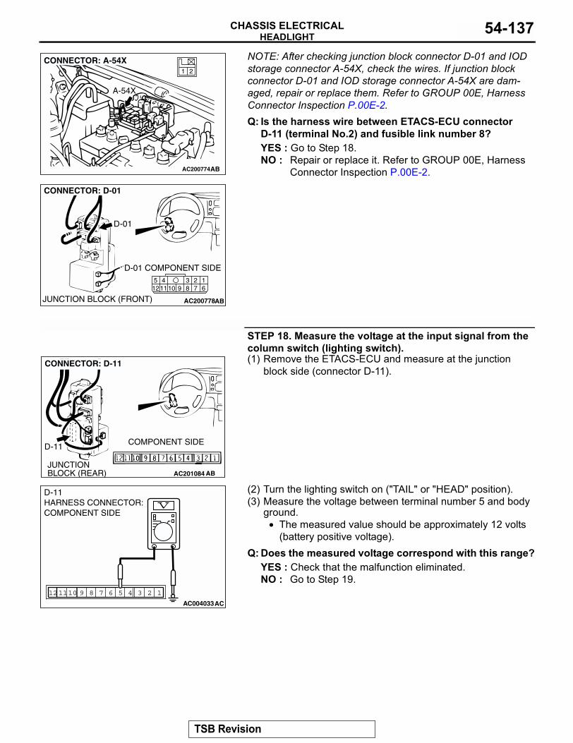
HEADLIGHTCHASSIS ELECTRICAL 54-137
NOTE: After checking junction block connector D-01 and IOD storage connector A-54X, check the wires. If junction block connector D-01 and IOD storage connector A-54X are dam-aged, repair or replace them. Refer to GROUP 00E, Harness Connector Inspection P.00E-2.Q: Is the harness wire between ETACS-ECU connector
D-11 (terminal No.2) and fusible link number 8?YES : Go to Step 18.NO : Repair or replace it. Refer to GROUP 00E, Harness
Connector Inspection P.00E-2.
STEP 18. Measure the voltage at the input signal from the column switch (lighting switch).(1) Remove the ETACS-ECU and measure at the junction
block side (connector D-11).
(2) Turn the lighting switch on ("TAIL" or "HEAD" position).(3) Measure the voltage between terminal number 5 and body
ground.• The measured value should be approximately 12 volts
(battery positive voltage).Q: Does the measured voltage correspond with this range?
YES : Check that the malfunction eliminated.NO : Go to Step 19.
AC200774
21
CONNECTOR: A-54X
AB
A-54X
AC200778
2341110 9 8 7
16
512
CONNECTOR: D-01
AB
D-01 COMPONENT SIDE
JUNCTION BLOCK (FRONT)
D-01
AC201084JUNCTION BLOCK (REAR)
D-11 COMPONENT SIDE
AB
CONNECTOR: D-11
123457910 681112
AC004033 AC
D-11 HARNESS CONNECTOR:COMPONENT SIDE
TSB Revision
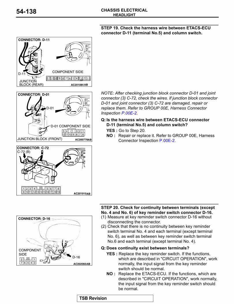
HEADLIGHTCHASSIS ELECTRICAL54-138
STEP 19. Check the harness wire between ETACS-ECU connector D-11 (terminal No.5) and column switch.
NOTE: After checking junction block connector D-01 and joint connector (3) C-72, check the wires. If junction block connector D-01 and joint connector (3) C-72 are damaged, repair or replace them. Refer to GROUP 00E, Harness Connector Inspection P.00E-2.Q: Is the harness wire between ETACS-ECU connector
D-11 (terminal No.5) and column switch?YES : Go to Step 20.NO : Repair or replace it. Refer to GROUP 00E, Harness
Connector Inspection P.00E-2.
STEP 20. Check for continuity between terminals (except No. 4 and No. 6) of key reminder switch connector D-16.(1) Measure at key reminder switch connector D-16 without
disconnecting the connector.(2) Check that there is no continuity between key reminder
switch terminal No. 4 and each terminal (except terminal No. 6), as well as between key reminder switch terminal No.6 and each terminal (except terminal No. 4).
Q: Does continuity exist between terminals?YES : Replace the key reminder switch. If the functions,
which are described in "CIRCUIT OPERATION", work normally, the input signal from the key reminder switch should be normal.
NO : Replace the ETACS-ECU. If the functions, which are described in "CIRCUIT OPERATION", work normally, the input signal from the key reminder switch should be normal.
AC201084JUNCTION BLOCK (REAR)
D-11 COMPONENT SIDE
AB
CONNECTOR: D-11
AC200778
2341110 9 8 7
16
512
CONNECTOR: D-01
AB
D-01 COMPONENT SIDE
JUNCTION BLOCK (FRONT)
D-01
819
7651615 17 18
4321011 1213
19 14
AC201910
CONNECTOR: C-72
AB
C-72 (B)
AC20206045 31
672
TSB Revision
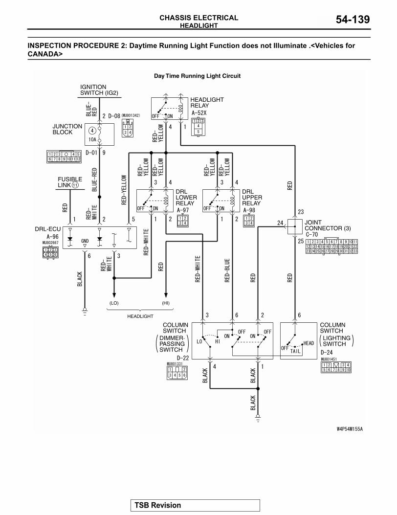
HEADLIGHTCHASSIS ELECTRICAL 54-139
INSPECTION PROCEDURE 2: Daytime Running Light Function does not Illuminate .<Vehicles for CANADA>
FUSIBLELINK
JUNCTIONBLOCK
DRL-ECU
IGNITIONSWITCH (IG2)
COLUMNSWITCH
DRLLOWERRELAY
DRLUPPERRELAY
HEADLIGHTRELAY
(LO)
HEADLIGHT
(HI)
COLUMNSWITCHLIGHTINGSWITCH
11
JOINT CONNECTOR (3)
DIMMER·PASSINGSWITCH
Day Time Running Light Circuit
TSB Revision
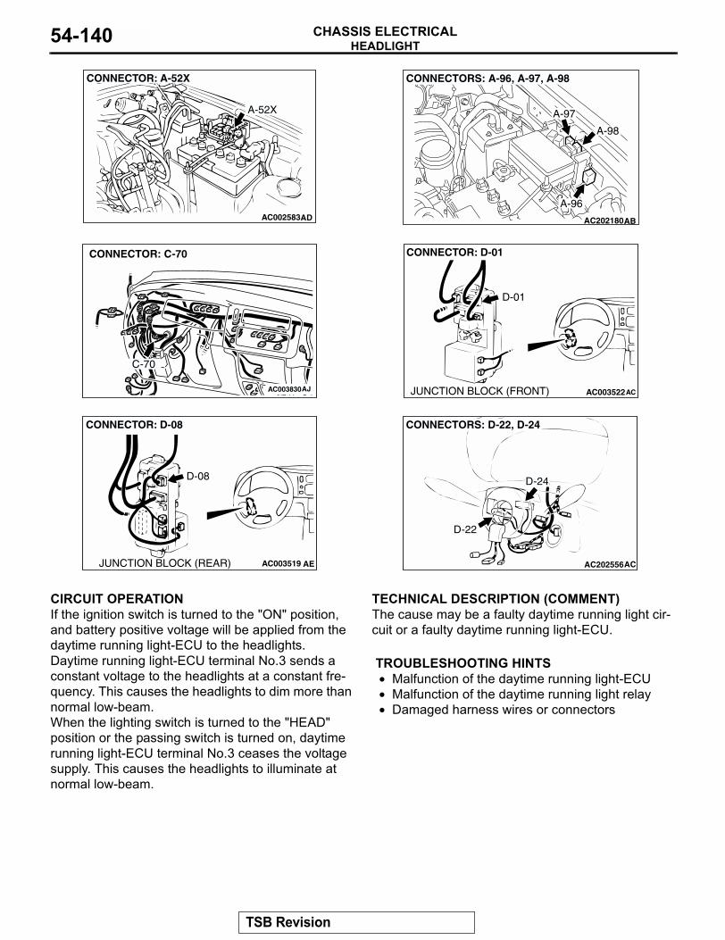
HEADLIGHTCHASSIS ELECTRICAL54-140
.
CIRCUIT OPERATIONIf the ignition switch is turned to the "ON" position, and battery positive voltage will be applied from the daytime running light-ECU to the headlights.Daytime running light-ECU terminal No.3 sends a constant voltage to the headlights at a constant fre-quency. This causes the headlights to dim more than normal low-beam.When the lighting switch is turned to the "HEAD" position or the passing switch is turned on, daytime running light-ECU terminal No.3 ceases the voltage supply. This causes the headlights to illuminate at normal low-beam.
.
TECHNICAL DESCRIPTION (COMMENT)The cause may be a faulty daytime running light cir-cuit or a faulty daytime running light-ECU. .
TROUBLESHOOTING HINTS• Malfunction of the daytime running light-ECU• Malfunction of the daytime running light relay• Damaged harness wires or connectors
.
AC002583AD
CONNECTOR: A-52X
A-52X
AC202180
CONNECTORS: A-96, A-97, A-98
AB
A-96
A-97
A-98
AC003830
CONNECTOR: C-70
AJ
C-70
AC003522
CONNECTOR: D-01
ACJUNCTION BLOCK (FRONT)
D-01
AC003519
CONNECTOR: D-08
AEJUNCTION BLOCK (REAR)
D-08
AC202556
CONNECTORS: D-22, D-24
AC
D-22
D-24
TSB Revision
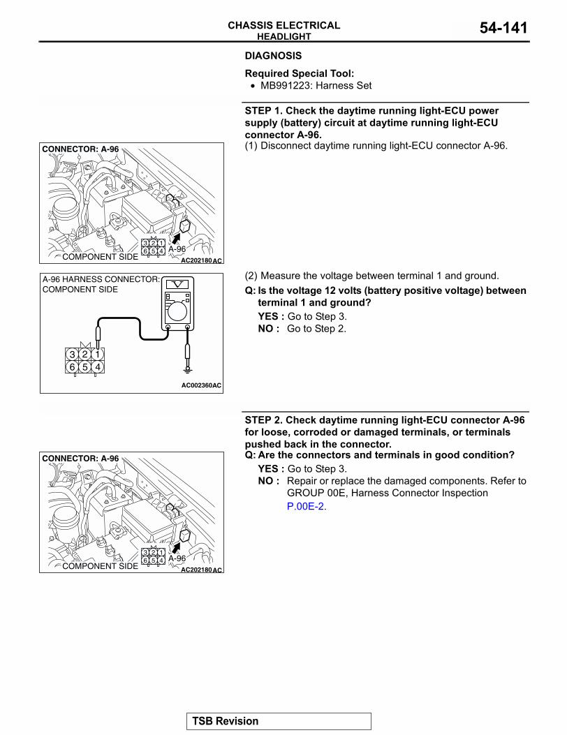
HEADLIGHTCHASSIS ELECTRICAL 54-141
DIAGNOSIS
Required Special Tool:• MB991223: Harness Set
STEP 1. Check the daytime running light-ECU power supply (battery) circuit at daytime running light-ECU connector A-96. (1) Disconnect daytime running light-ECU connector A-96.
(2) Measure the voltage between terminal 1 and ground. Q: Is the voltage 12 volts (battery positive voltage) between
terminal 1 and ground?YES : Go to Step 3.NO : Go to Step 2.
STEP 2. Check daytime running light-ECU connector A-96 for loose, corroded or damaged terminals, or terminals pushed back in the connector.Q: Are the connectors and terminals in good condition?
YES : Go to Step 3.NO : Repair or replace the damaged components. Refer to
GROUP 00E, Harness Connector Inspection P.00E-2.
AC202180
125 4
36
COMPONENT SIDE
CONNECTOR: A-96
AC
A-96
43 2 1
56
AC002360
A-96 HARNESS CONNECTOR:COMPONENT SIDE
AC
AC202180
125 4
36
COMPONENT SIDE
CONNECTOR: A-96
AC
A-96
TSB Revision
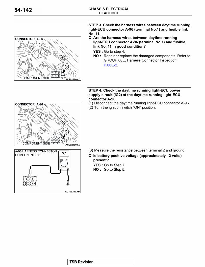
HEADLIGHTCHASSIS ELECTRICAL54-142
STEP 3. Check the harness wires between daytime running light-ECU connector A-96 (terminal No.1) and fusible link No. 11.Q: Are the harness wires between daytime running
light-ECU connector A-96 (terminal No.1) and fusible link No. 11 in good condition?YES : Go to step 4.NO : Repair or replace the damaged components. Refer to
GROUP 00E, Harness Connector Inspection P.00E-2.
STEP 4. Check the daytime running light-ECU power supply circuit (IG2) at the daytime running light-ECU connector A-96.(1) Disconnect the daytime running light-ECU connector A-96.(2) Turn the ignition switch "ON" position.
(3) Measure the resistance between terminal 2 and ground.Q: Is battery positive voltage (approximately 12 volts)
present?YES : Go to Step 7.NO : Go to Step 5.
AC202180
125 4
36
COMPONENT SIDE
CONNECTOR: A-96
AC
A-96
AC202180
125 4
36
COMPONENT SIDE
CONNECTOR: A-96
AC
A-96
43 2 1
56
AC309262AB
A-96 HARNESS CONNECTOR:COMPONENT SIDE
TSB Revision
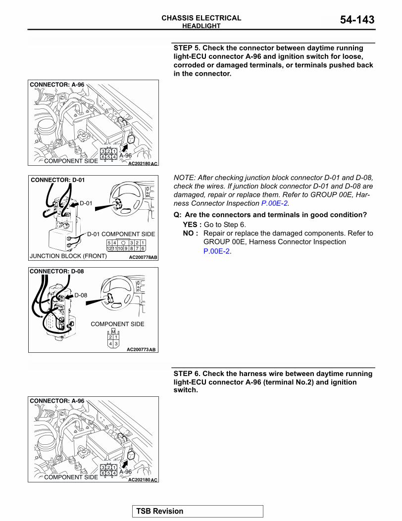
HEADLIGHTCHASSIS ELECTRICAL 54-143
STEP 5. Check the connector between daytime running light-ECU connector A-96 and ignition switch for loose, corroded or damaged terminals, or terminals pushed back in the connector.
NOTE: After checking junction block connector D-01 and D-08, check the wires. If junction block connector D-01 and D-08 are damaged, repair or replace them. Refer to GROUP 00E, Har-ness Connector Inspection P.00E-2.Q: Are the connectors and terminals in good condition?
YES : Go to Step 6.NO : Repair or replace the damaged components. Refer to
GROUP 00E, Harness Connector Inspection P.00E-2.
STEP 6. Check the harness wire between daytime running light-ECU connector A-96 (terminal No.2) and ignition switch.
AC202180
125 4
36
COMPONENT SIDE
CONNECTOR: A-96
AC
A-96
AC200778
2341110 9 8 7
16
512
CONNECTOR: D-01
AB
D-01 COMPONENT SIDE
JUNCTION BLOCK (FRONT)
D-01
AC200773
M
3
1
4
2
CONNECTOR: D-08
D-08
COMPONENT SIDE
AB
AC202180
125 4
36
COMPONENT SIDE
CONNECTOR: A-96
AC
A-96
TSB Revision
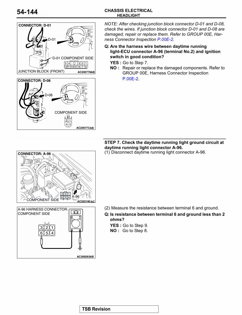
HEADLIGHTCHASSIS ELECTRICAL54-144
NOTE: After checking junction block connector D-01 and D-08, check the wires. If junction block connector D-01 and D-08 are damaged, repair or replace them. Refer to GROUP 00E, Har-ness Connector Inspection P.00E-2.Q: Are the harness wire between daytime runninglight-ECU connector A-96 (terminal No.2) and ignition switch in good condition?YES : Go to Step 7.NO : Repair or replace the damaged components. Refer to
GROUP 00E, Harness Connector Inspection P.00E-2.
STEP 7. Check the daytime running light ground circuit at daytime running light connector A-96.(1) Disconnect daytime running light connector A-96.
(2) Measure the resistance between terminal 6 and ground.Q: Is resistance between terminal 6 and ground less than 2
ohms?YES : Go to Step 9.NO : Go to Step 8.
AC200778
2341110 9 8 7
16
512
CONNECTOR: D-01
AB
D-01 COMPONENT SIDE
JUNCTION BLOCK (FRONT)
D-01
AC200773
M
3
1
4
2
CONNECTOR: D-08
D-08
COMPONENT SIDE
AB
AC202180
125 4
36
COMPONENT SIDE
CONNECTOR: A-96
AC
A-96
43 2 1
56
AC309263AB
A-96 HARNESS CONNECTOR:COMPONENT SIDE
TSB Revision
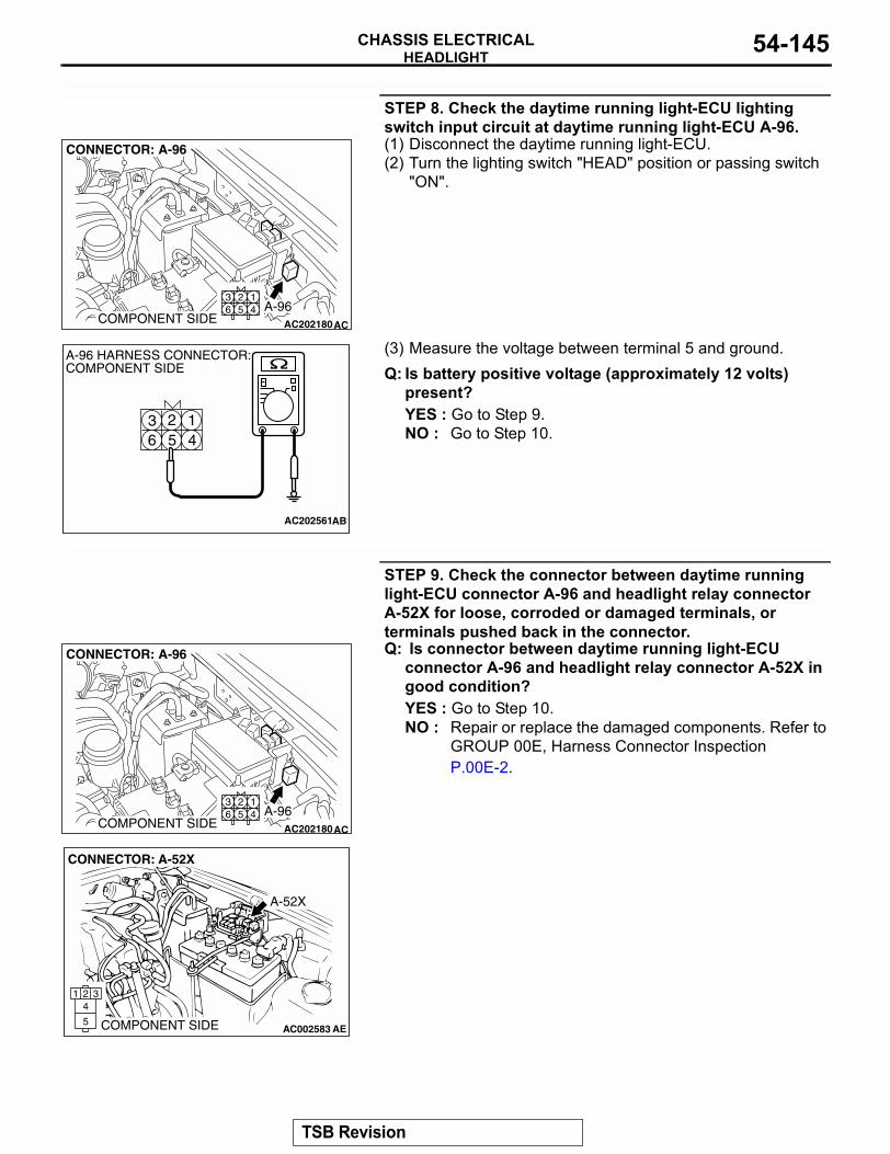
HEADLIGHTCHASSIS ELECTRICAL 54-145
STEP 8. Check the daytime running light-ECU lighting switch input circuit at daytime running light-ECU A-96.(1) Disconnect the daytime running light-ECU.(2) Turn the lighting switch "HEAD" position or passing switch
"ON".
(3) Measure the voltage between terminal 5 and ground.Q: Is battery positive voltage (approximately 12 volts)
present?YES : Go to Step 9.NO : Go to Step 10.
STEP 9. Check the connector between daytime running light-ECU connector A-96 and headlight relay connector A-52X for loose, corroded or damaged terminals, or terminals pushed back in the connector.Q: Is connector between daytime running light-ECU
connector A-96 and headlight relay connector A-52X in good condition?YES : Go to Step 10.NO : Repair or replace the damaged components. Refer to
GROUP 00E, Harness Connector Inspection P.00E-2.
AC202180
125 4
36
COMPONENT SIDE
CONNECTOR: A-96
AC
A-96
43 2 1
56
AC202561
A-96 HARNESS CONNECTOR:COMPONENT SIDE
AB
AC202180
125 4
36
COMPONENT SIDE
CONNECTOR: A-96
AC
A-96
AC002583 AE
CONNECTOR: A-52X
2 3
5
41
A-52X
COMPONENT SIDE
TSB Revision
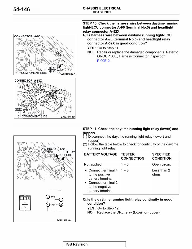
HEADLIGHTCHASSIS ELECTRICAL54-146
STEP 10. Check the harness wire between daytime running light-ECU connector A-96 (terminal No.5) and headlight relay connector A-52XQ: Is harness wire between daytime running light-ECU
connector A-96 (terminal No.5) and headlight relay connector A-52X in good condition?YES : Go to Step 11.NO : Repair or replace the damaged components. Refer to
GROUP 00E, Harness Connector Inspection P.00E-2.
STEP 11. Check the daytime running light relay (lower) and (upper).(1) Disconnect the daytime running light relay (lower) and
(upper).(2) Follow the table below to check for continuity of the daytime
running light relay.
Q: Is the daytime running light relay continuity in good condition?YES : Go to Step 12.NO : Replace the DRL relay (lower) or (upper).
AC202180
125 4
36
COMPONENT SIDE
CONNECTOR: A-96
AC
A-96
AC002583 AE
CONNECTOR: A-52X
2 3
5
41
A-52X
COMPONENT SIDE
BATTERY VOLTAGE TESTER CONNECTION
SPECIFIED CONDITION
Not applied 1 − 3 Open circuit
• Connect terminal 4 to the positive battery terminal
• Connect terminal 2 to the negative battery terminal
1 − 3 Less than 2 ohms
AC202569
1
2
3
4
A-97 DRL RELAY (LOWER)
A-98 DRL RELAY (UPPER)
AB
TSB Revision
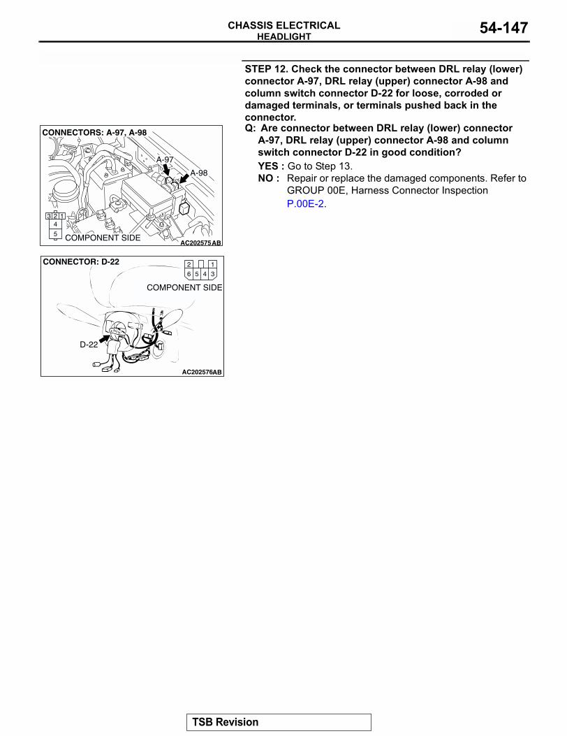
HEADLIGHTCHASSIS ELECTRICAL 54-147
STEP 12. Check the connector between DRL relay (lower) connector A-97, DRL relay (upper) connector A-98 and column switch connector D-22 for loose, corroded or damaged terminals, or terminals pushed back in the connector.Q: Are connector between DRL relay (lower) connector
A-97, DRL relay (upper) connector A-98 and column switch connector D-22 in good condition?YES : Go to Step 13.NO : Repair or replace the damaged components. Refer to
GROUP 00E, Harness Connector Inspection P.00E-2.
AC202575
A-97
A-98
2 1
5
43
CONNECTORS: A-97, A-98
ABCOMPONENT SIDE
AC202576
D-22
12
356 4
AB
CONNECTOR: D-22
COMPONENT SIDE
TSB Revision
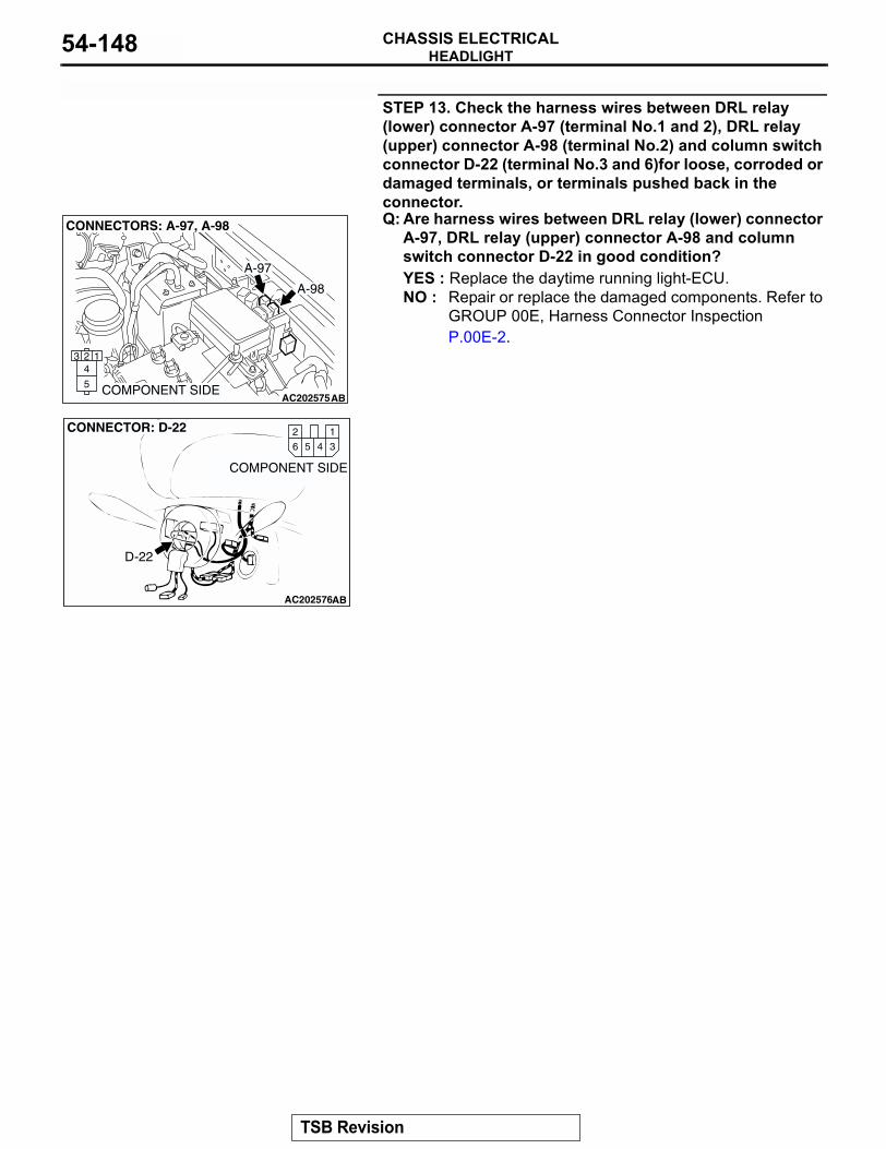
HEADLIGHTCHASSIS ELECTRICAL54-148
STEP 13. Check the harness wires between DRL relay (lower) connector A-97 (terminal No.1 and 2), DRL relay (upper) connector A-98 (terminal No.2) and column switch connector D-22 (terminal No.3 and 6)for loose, corroded or damaged terminals, or terminals pushed back in the connector.Q: Are harness wires between DRL relay (lower) connector
A-97, DRL relay (upper) connector A-98 and column switch connector D-22 in good condition?YES : Replace the daytime running light-ECU.NO : Repair or replace the damaged components. Refer to
GROUP 00E, Harness Connector Inspection P.00E-2.
AC202575
A-97
A-98
2 1
5
43
CONNECTORS: A-97, A-98
ABCOMPONENT SIDE
AC202576
D-22
12
356 4
AB
CONNECTOR: D-22
COMPONENT SIDE
TSB Revision
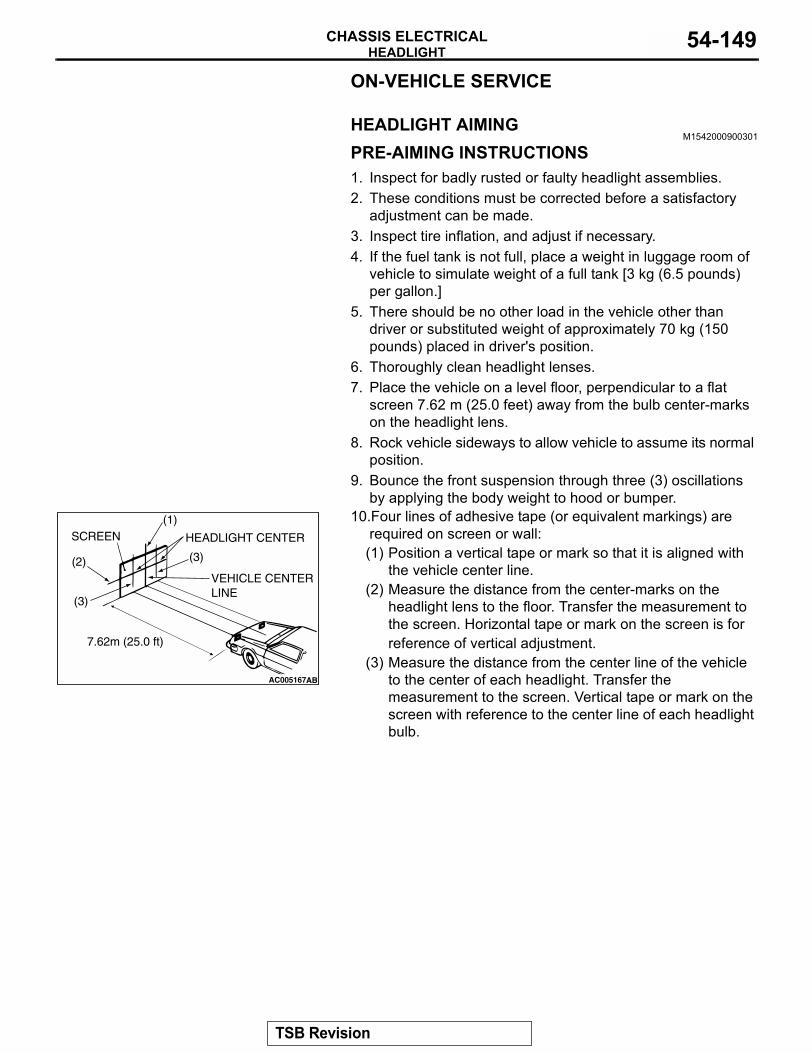
HEADLIGHTCHASSIS ELECTRICAL 54-149
ON-VEHICLE SERVICE
HEADLIGHT AIMINGM1542000900301
PRE-AIMING INSTRUCTIONS1. Inspect for badly rusted or faulty headlight assemblies.2. These conditions must be corrected before a satisfactory
adjustment can be made.3. Inspect tire inflation, and adjust if necessary.4. If the fuel tank is not full, place a weight in luggage room of
vehicle to simulate weight of a full tank [3 kg (6.5 pounds) per gallon.]
5. There should be no other load in the vehicle other than driver or substituted weight of approximately 70 kg (150 pounds) placed in driver's position.
6. Thoroughly clean headlight lenses.7. Place the vehicle on a level floor, perpendicular to a flat
screen 7.62 m (25.0 feet) away from the bulb center-marks on the headlight lens.
8. Rock vehicle sideways to allow vehicle to assume its normal position.
9. Bounce the front suspension through three (3) oscillations by applying the body weight to hood or bumper.
10.Four lines of adhesive tape (or equivalent markings) are required on screen or wall:(1) Position a vertical tape or mark so that it is aligned with
the vehicle center line.(2) Measure the distance from the center-marks on the
headlight lens to the floor. Transfer the measurement to the screen. Horizontal tape or mark on the screen is for reference of vertical adjustment.
(3) Measure the distance from the center line of the vehicle to the center of each headlight. Transfer the measurement to the screen. Vertical tape or mark on the screen with reference to the center line of each headlight bulb.
AC005167
(1)
(2)
(3)
HEADLIGHT CENTER
VEHICLE CENTER LINE
SCREEN
(3)
7.62m (25.0 ft)
AB
TSB Revision
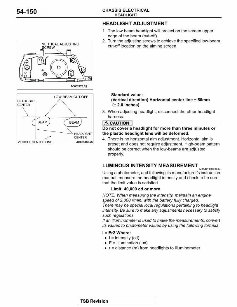
HEADLIGHTCHASSIS ELECTRICAL54-150
HEADLIGHT ADJUSTMENT1. The low beam headlight will project on the screen upper
edge of the beam (cut-off).2. Turn the adjusting screws to achieve the specified low-beam
cut-off location on the aiming screen.
Standard value:(Vertical direction) Horizontal center line ± 50mm (± 2.0 inches)
3. When adjusting headlight, disconnect the other headlight harness.CAUTION
Do not cover a headlight for more than three minutes or the plastic headlight lens will be deformed.4. There is no horizontal aim adjustment. Horizontal aim is
preset and does not require adjustment. High-beam pattern should be correct when the low-beams are adjusted properly.
LUMINOUS INTENSITY MEASUREMENTM1542001000259
Using a photometer, and following its manufacturer's instruction manual, measure the headlight intensity and check to be sure that the limit value is satisfied.
Limit: 40,000 cd or moreNOTE: When measuring the intensity, maintain an engine speed of 2,000 r/min, with the battery fully charged.There may be special local regulations pertaining to headlight intensity. Be sure to make any adjustments necessary to satisfy such regulations.If an illuminometer is used to make the measurements, convert its values to photometer values by using the following formula.
I = Er2 Where:• I = intensity (cd)• E = illumination (lux)• r = distance (m) from headlights to illuminometer
AC002778AB
VERTICAL ADJUSTINGSCREW
AC005166AB
BEAM BEAM
HEADLIGHT CENTER
LOW-BEAM CUT-OFF
VEHICLE CENTER LINE
HEADLIGHT CENTER
TSB Revision
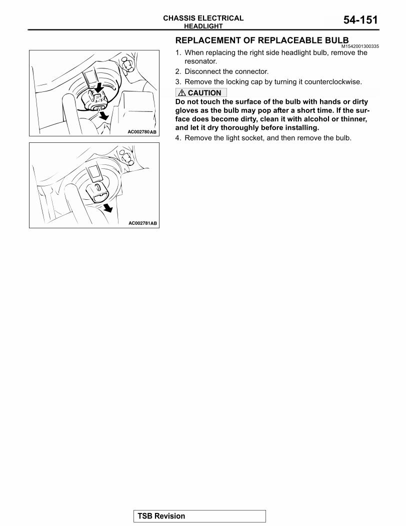
HEADLIGHTCHASSIS ELECTRICAL 54-151
REPLACEMENT OF REPLACEABLE BULBM1542001300335
1. When replacing the right side headlight bulb, remove the resonator.
2. Disconnect the connector.3. Remove the locking cap by turning it counterclockwise.
CAUTIONDo not touch the surface of the bulb with hands or dirty gloves as the bulb may pop after a short time. If the sur-face does become dirty, clean it with alcohol or thinner, and let it dry thoroughly before installing.4. Remove the light socket, and then remove the bulb.
AC002780AB
AC002781AB
TSB Revision
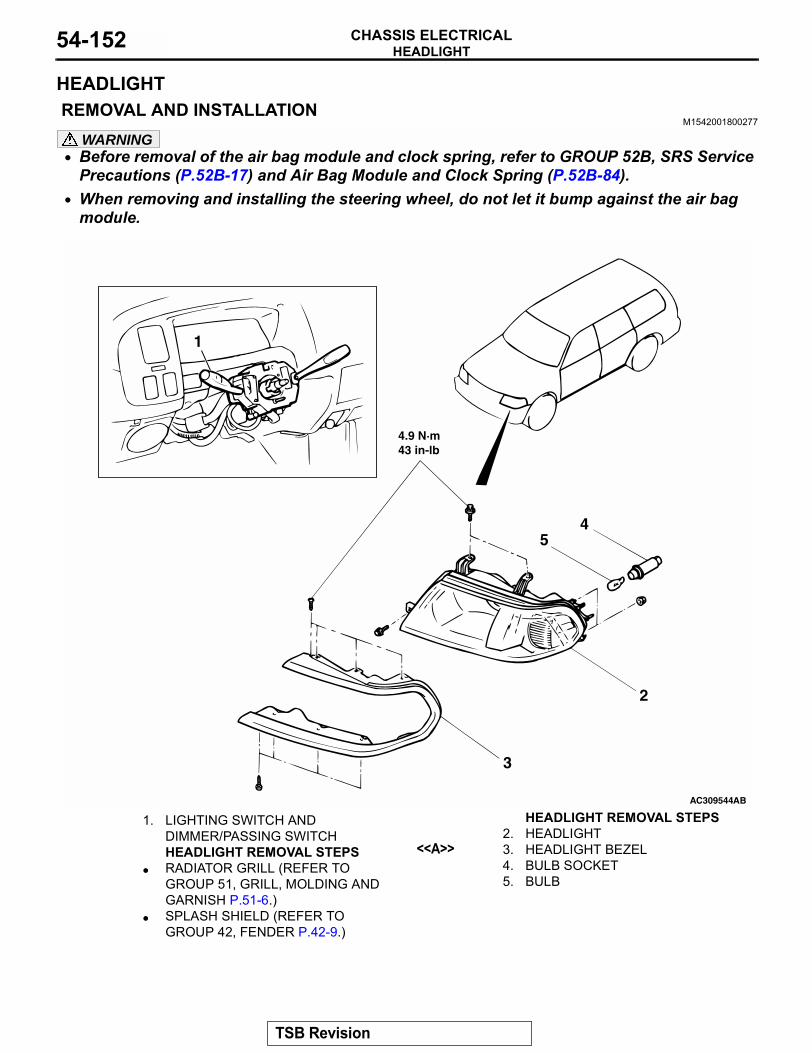
HEADLIGHTCHASSIS ELECTRICAL54-152
HEADLIGHT REMOVAL AND INSTALLATION
M1542001800277
WARNING• Before removal of the air bag module and clock spring, refer to GROUP 52B, SRS Service
Precautions (P.52B-17) and Air Bag Module and Clock Spring (P.52B-84).• When removing and installing the steering wheel, do not let it bump against the air bag
module.
AC309544AB
2
3
4
4.9 N·m43 in-lb
1
5
1. LIGHTING SWITCH AND DIMMER/PASSING SWITCHHEADLIGHT REMOVAL STEPS
• RADIATOR GRILL (REFER TO GROUP 51, GRILL, MOLDING AND GARNISH P.51-6.)
• SPLASH SHIELD (REFER TO GROUP 42, FENDER P.42-9.)
2. HEADLIGHT<<A>> 3. HEADLIGHT BEZEL
4. BULB SOCKET5. BULB
HEADLIGHT REMOVAL STEPS
TSB Revision
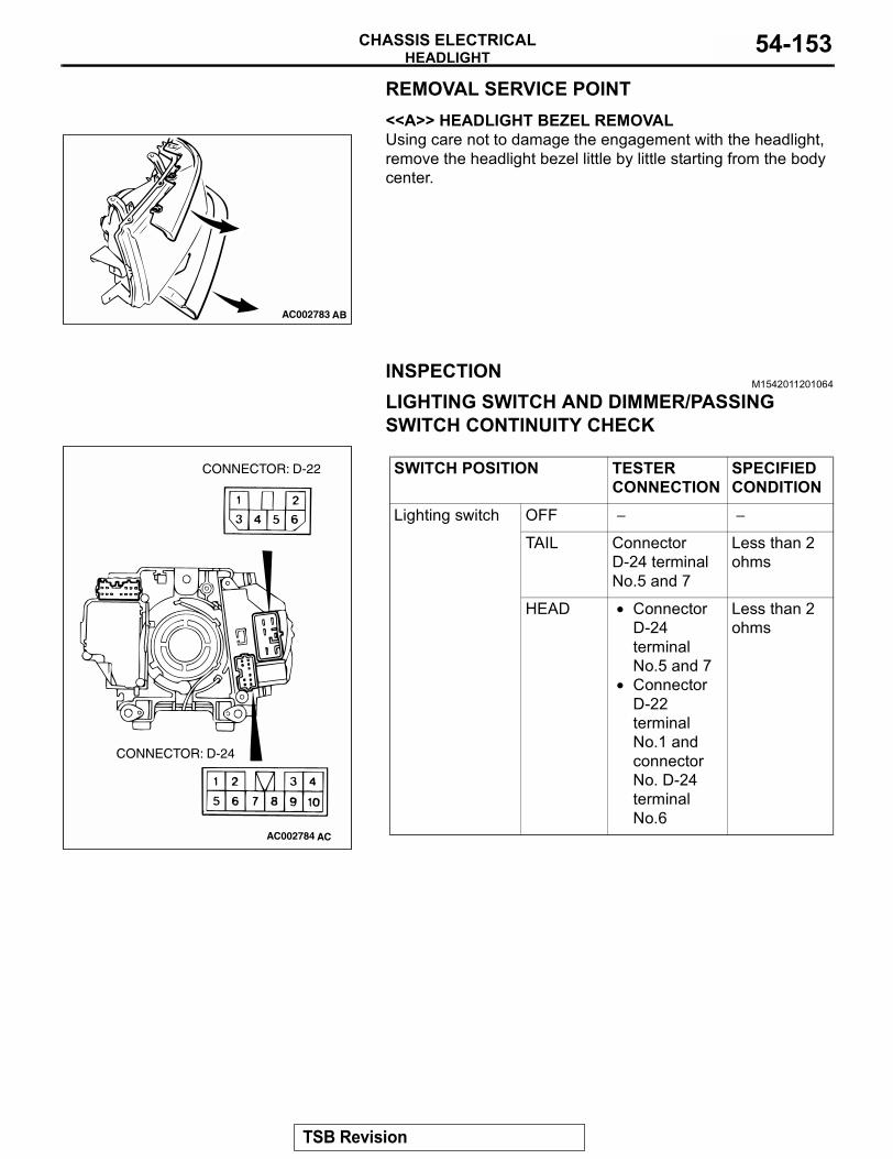
HEADLIGHTCHASSIS ELECTRICAL 54-153
REMOVAL SERVICE POINT.
<<A>> HEADLIGHT BEZEL REMOVALUsing care not to damage the engagement with the headlight, remove the headlight bezel little by little starting from the body center.
INSPECTIONM1542011201064
LIGHTING SWITCH AND DIMMER/PASSING SWITCH CONTINUITY CHECK
AC002783 AB
SWITCH POSITION TESTER CONNECTION
SPECIFIED CONDITION
Lighting switch OFF − −
TAIL Connector D-24 terminal No.5 and 7
Less than 2 ohms
HEAD • Connector D-24 terminal No.5 and 7
• Connector D-22 terminal No.1 and connector No. D-24 terminal No.6
Less than 2 ohms
AC002784
CONNECTOR: D-24
CONNECTOR: D-22
AC
TSB Revision
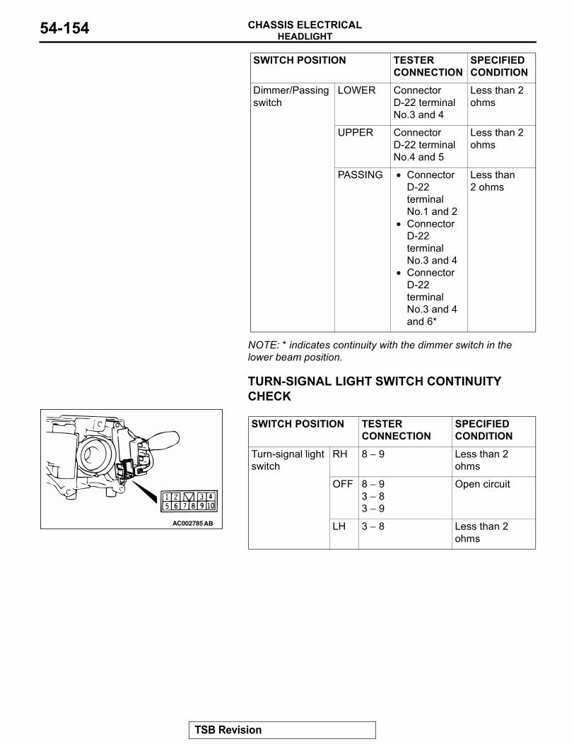
HEADLIGHTCHASSIS ELECTRICAL54-154
NOTE: * indicates continuity with the dimmer switch in the lower beam position.
TURN-SIGNAL LIGHT SWITCH CONTINUITY CHECK
Dimmer/Passing switch
LOWER Connector D-22 terminal No.3 and 4
Less than 2 ohms
UPPER Connector D-22 terminal No.4 and 5
Less than 2 ohms
PASSING • Connector D-22 terminal No.1 and 2
• Connector D-22 terminal No.3 and 4
• Connector D-22 terminal No.3 and 4 and 6*
Less than 2 ohms
SWITCH POSITION TESTER CONNECTION
SPECIFIED CONDITION
SWITCH POSITION TESTER CONNECTION
SPECIFIED CONDITION
Turn-signal light switch
RH 8 − 9 Less than 2 ohms
OFF 8 − 93 − 83 − 9
Open circuit
LH 3 − 8 Less than 2 ohms
AC002785 AB
TSB Revision
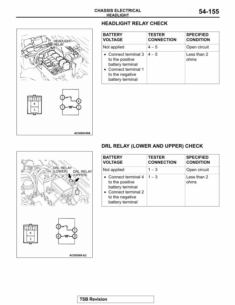
HEADLIGHTCHASSIS ELECTRICAL 54-155
HEADLIGHT RELAY CHECK
DRL RELAY (LOWER AND UPPER) CHECK
BATTERY VOLTAGE
TESTER CONNECTION
SPECIFIED CONDITION
Not applied 4 − 5 Open circuit
• Connect terminal 3 to the positive battery terminal
• Connect terminal 1 to the negative battery terminal
4 − 5 Less than 2 ohms
AC309547AB
HEADLIGHTRELAY
BATTERY VOLTAGE
TESTER CONNECTION
SPECIFIED CONDITION
Not applied 1 − 3 Open circuit
• Connect terminal 4 to the positive battery terminal
• Connect terminal 2 to the negative battery terminal
1 − 3 Less than 2 ohms
AC202569
1
2
3
4
DRL RELAY (LOWER) DRL RELAY
(UPPER)
AC
TSB Revision
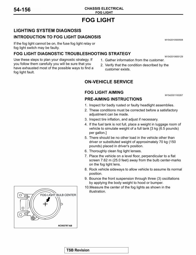
FOG LIGHTCHASSIS ELECTRICAL54-156
FOG LIGHT
LIGHTING SYSTEM DIAGNOSISINTRODUCTION TO FOG LIGHT DIAGNOSIS
M1542010500508
If the fog light cannot be on, the fuse fog light relay or fog light switch may be faulty.
FOG LIGHT DIAGNOSTIC TROUBLESHOOTING STRATEGYM1542010600129
Use these steps to plan your diagnostic strategy. If you follow them carefully you will be sure that you have exhausted most of the possible ways to find a fog light fault.
1. Gather information from the customer.2. Verify that the condition described by the
customer exists.
ON-VEHICLE SERVICE
FOG LIGHT AIMINGM1542001100267
PRE-AIMING INSTRUCTIONS1. Inspect for badly rusted or faulty headlight assemblies.2. These conditions must be corrected before a satisfactory
adjustment can be made.3. Inspect tire inflation, and adjust if necessary.4. If the fuel tank is not full, place a weight in luggage room of
vehicle to simulate weight of a full tank [3 kg (6.5 pounds) per gallon.]
5. There should be no other load in the vehicle other than driver or substituted weight of approximately 70 kg (150 pounds) placed in driver's position.
6. Thoroughly clean fog light lenses.7. Place the vehicle on a level floor, perpendicular to a flat
screen 7.62 m (25.0 feet) away from the bulb center-marks on the fog light lens.
8. Rock vehicle sideways to allow vehicle to assume its normal position.
9. Bounce the front suspension through three (3) oscillations by applying the body weight to hood or bumper.
10.Measure the center of the fog lights as shown in the illustration.
AC002787AB
FOG LIGHT BULB CENTER
TSB Revision
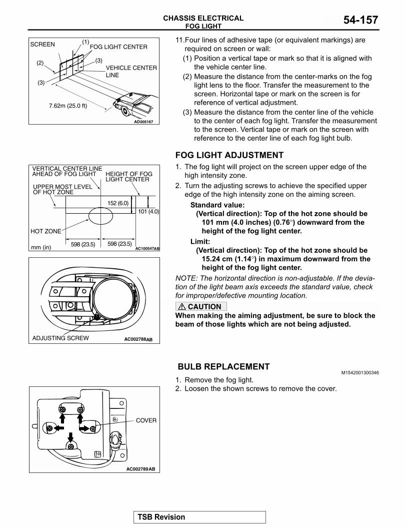
FOG LIGHTCHASSIS ELECTRICAL 54-157
11.Four lines of adhesive tape (or equivalent markings) are required on screen or wall:(1) Position a vertical tape or mark so that it is aligned with
the vehicle center line.(2) Measure the distance from the center-marks on the fog
light lens to the floor. Transfer the measurement to the screen. Horizontal tape or mark on the screen is for reference of vertical adjustment.
(3) Measure the distance from the center line of the vehicle to the center of each fog light. Transfer the measurement to the screen. Vertical tape or mark on the screen with reference to the center line of each fog light bulb.
FOG LIGHT ADJUSTMENT1. The fog light will project on the screen upper edge of the
high intensity zone.2. Turn the adjusting screws to achieve the specified upper
edge of the high intensity zone on the aiming screen.Standard value:
(Vertical direction): Top of the hot zone should be 101 mm (4.0 inches) (0.76°) downward from the height of the fog light center.
Limit:(Vertical direction): Top of the hot zone should be
15.24 cm (1.14°) in maximum downward from the height of the fog light center.
NOTE: The horizontal direction is non-adjustable. If the devia-tion of the light beam axis exceeds the standard value, check for improper/defective mounting location.
CAUTIONWhen making the aiming adjustment, be sure to block the beam of those lights which are not being adjusted.
BULB REPLACEMENTM1542001300346
1. Remove the fog light.2. Loosen the shown screws to remove the cover.
AC005167
SCREEN (1)
(2)
(3)
(3)
FOG LIGHT CENTER
VEHICLE CENTER LINE
7.62m (25.0 ft)
AD
AC100547
HEIGHT OF FOGLIGHT CENTER
VERTICAL CENTER LINE AHEAD OF FOG LIGHT
UPPER MOST LEVEL OF HOT ZONE
HOT ZONE
mm (in) AB
152 (6.0)101 (4.0)
598 (23.5)598 (23.5)
AC002788ABADJUSTING SCREW
AC002789AB
COVER
TSB Revision
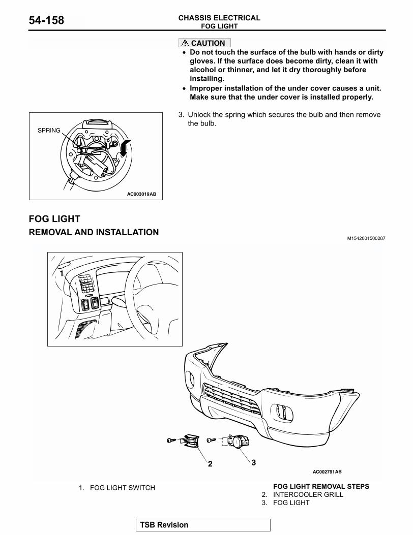
FOG LIGHTCHASSIS ELECTRICAL54-158
CAUTION• Do not touch the surface of the bulb with hands or dirty
gloves. If the surface does become dirty, clean it with alcohol or thinner, and let it dry thoroughly before installing.
• Improper installation of the under cover causes a unit. Make sure that the under cover is installed properly.
3. Unlock the spring which secures the bulb and then remove the bulb.
FOG LIGHTREMOVAL AND INSTALLATION
M1542001500287
AC003019
SPRING
AB
AC002791
1
2AB
3
1. FOG LIGHT SWITCH FOG LIGHT REMOVAL STEPS2. INTERCOOLER GRILL3. FOG LIGHT
TSB Revision
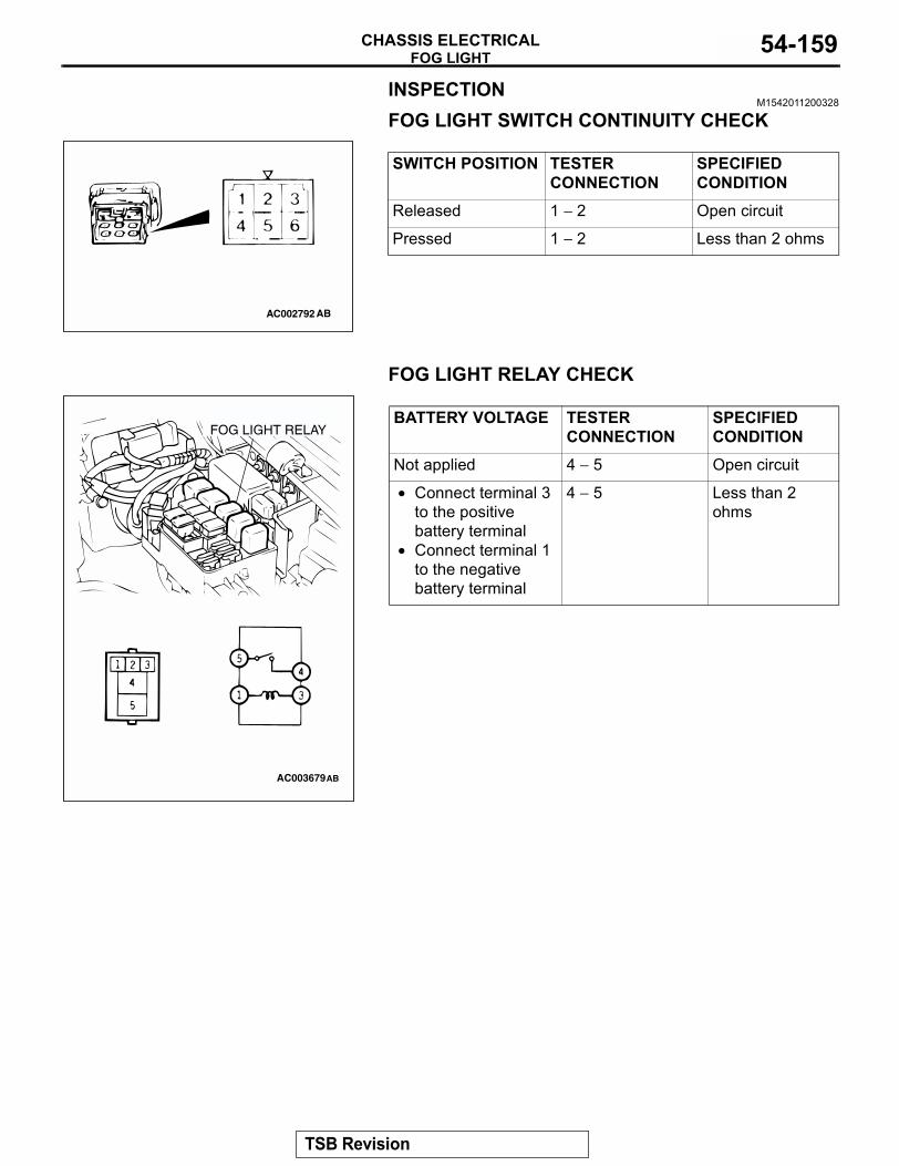
FOG LIGHTCHASSIS ELECTRICAL 54-159
INSPECTIONM1542011200328
FOG LIGHT SWITCH CONTINUITY CHECK
FOG LIGHT RELAY CHECK
SWITCH POSITION TESTER CONNECTION
SPECIFIED CONDITION
Released 1 − 2 Open circuit
Pressed 1 − 2 Less than 2 ohms
AC002792 AB
BATTERY VOLTAGE TESTER CONNECTION
SPECIFIED CONDITION
Not applied 4 − 5 Open circuit
• Connect terminal 3 to the positive battery terminal
• Connect terminal 1 to the negative battery terminal
4 − 5 Less than 2 ohms
AC003679
FOG LIGHT RELAY
AB
TSB Revision
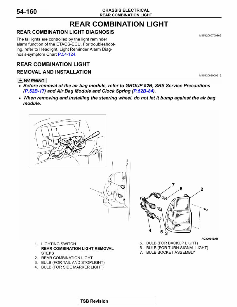
REAR COMBINATION LIGHTCHASSIS ELECTRICAL54-160
REAR COMBINATION LIGHTREAR COMBINATION LIGHT DIAGNOSIS
M1542000700802The taillights are controlled by the light reminder alarm function of the ETACS-ECU. For troubleshoot-ing, refer to Headlight, Light Reminder Alarm Diag-nosis-symptom Chart P.54-124.
REAR COMBINATION LIGHTREMOVAL AND INSTALLATION
M1542003900515
WARNING• Before removal of the air bag module, refer to GROUP 52B, SRS Service Precautions
(P.52B-17) and Air Bag Module and Clock Spring (P.52B-84).• When removing and installing the steering wheel, do not let it bump against the air bag
module.
AC309548AB
1
2
34 5
67
1. LIGHTING SWITCHREAR COMBINATION LIGHT REMOVAL STEPS
2. REAR COMBINATION LIGHT3. BULB (FOR TAIL AND STOPLIGHT)4. BULB (FOR SIDE MARKER LIGHT)
5. BULB (FOR BACKUP LIGHT)6. BULB (FOR TURN-SIGNAL LIGHT)7. BULB SOCKET ASSEMBLY
TSB Revision

DOME LIGHTCHASSIS ELECTRICAL 54-161
DOME LIGHT
LIGHTING SYSTEM DIAGNOSISINTRODUCTION TO DOME LIGHT AND CARGO SPACE LIGHT DIAGNOSIS <VEHICLES WITH KEYLESS ENTRY SYSTEM>
M1542010500519With the dome light switch and cargo space light switch in the "ROOM" position, the ETACS-ECU con-trols the dome light and cargo space light operation as follows:
• When a door is opened from outside or inside [with the ignition switch turned to "LOCK" (OFF)]: When a door is opened, the ETACS-ECU causes the dome light and cargo space light to be illumi-nated at the 100% intensity. When the door is closed, it dims out the dome light to 65% intensity and approximately 30 seconds later, turns out the light completely. During this period (timer con-trolled period), the dome light and cargo space light goes out if the ignition switch is turned "ON" or the doors are locked.
• When a door is opened or closed with the ignition switch in the "ON" position: The dome light and cargo space light illuminates at 100% intensity when a door is opened and turned out when it is closed.
• When no door is opened and the ignition key is removed: When the ignition key is removed with all the doors closed, the dome light and cargo space light are illuminated at an intensity of 100% and turned out approximately 30 seconds later. During that time (time-controlled period), the dome light and cargo space light goes out if the ignition key inserted and turned to "ON" or the door locking system is activated.
• Dome light's and cargo space light's answerback operation in response to door lock control by key-less entry system: To allow the driver to ascertain the result of the door locking/unlocking control action by the use of the keyless entry system, the ETACS-ECU causes the dome light and cargo space light to blink twice when the doors are locked through the system and to illuminate for approximately15 seconds when the doors are locked. The dome light's and cargo space light's answerback operation in response to a keyless entry by operation of the hazard warning lights.
DOME LIGHT AND CARGO SPACE LIGHT DIAGNOSTIC TROUBLESHOOTING STRATEGY <VEHICLES WITH KEYLESS ENTRY SYSTEM>
M1542010600130Use these steps to plan your diagnostic strategy. If you follow them carefully, you will be sure that you have exhausted most of the possible ways to find a dome light and cargo space light fault.1. Gather information from the customer.
2. Verify that the condition described by the customer exists.
3. Find the malfunction by following the Symptom Chart.
4. Verify that the malfunction is eliminated.
SYMPTOM CHARTM1542009100205
SYMPTOM INSPECTION PROCEDURE
REFERENCE PAGE
The dome light and cargo space light does not illuminate.
1 P.54-162
The dome light and cargo space light dimming function does not work normally.
2 P.54-171
TSB Revision
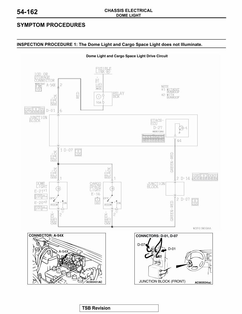
DOME LIGHTCHASSIS ELECTRICAL54-162
SYMPTOM PROCEDURES
INSPECTION PROCEDURE 1: The Dome Light and Cargo Space Light does not Illuminate.
Dome Light and Cargo Space Light Drive Circuit
AC003431
CONNECTOR: A-54X
A-54X
AC AC003534AC
CONNCTORS: D-01, D-07
D-01D-07
JUNCTION BLOCK (FRONT)
TSB Revision
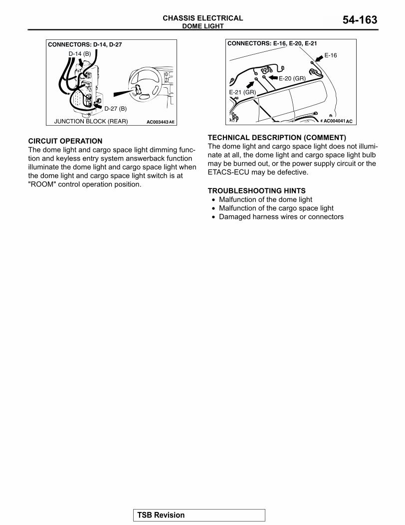
DOME LIGHTCHASSIS ELECTRICAL 54-163
.
CIRCUIT OPERATIONThe dome light and cargo space light dimming func-tion and keyless entry system answerback function illuminate the dome light and cargo space light when the dome light and cargo space light switch is at "ROOM" control operation position..
TECHNICAL DESCRIPTION (COMMENT)The dome light and cargo space light does not illumi-nate at all, the dome light and cargo space light bulb may be burned out, or the power supply circuit or the ETACS-ECU may be defective..
TROUBLESHOOTING HINTS• Malfunction of the dome light • Malfunction of the cargo space light • Damaged harness wires or connectors
AC003443AE
CONNECTORS: D-14, D-27
D-14 (B)
D-27 (B)
JUNCTION BLOCK (REAR) AC004041AC
CONNECTORS: E-16, E-20, E-21
E-16
E-21 (GR)
E-20 (GR)
TSB Revision
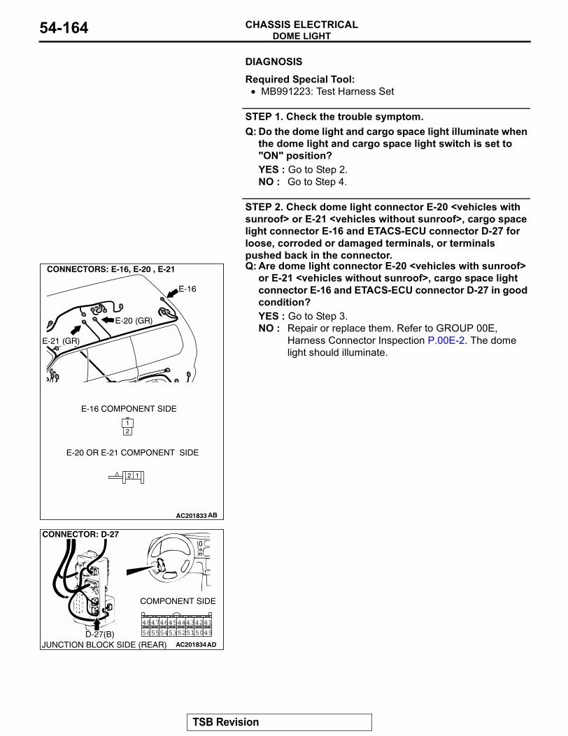
DOME LIGHTCHASSIS ELECTRICAL54-164
.DIAGNOSIS
Required Special Tool:• MB991223: Test Harness Set
STEP 1. Check the trouble symptom.Q: Do the dome light and cargo space light illuminate when
the dome light and cargo space light switch is set to "ON" position?YES : Go to Step 2.NO : Go to Step 4.
STEP 2. Check dome light connector E-20 <vehicles with sunroof> or E-21 <vehicles without sunroof>, cargo space light connector E-16 and ETACS-ECU connector D-27 for loose, corroded or damaged terminals, or terminals pushed back in the connector.Q: Are dome light connector E-20 <vehicles with sunroof>
or E-21 <vehicles without sunroof>, cargo space light connector E-16 and ETACS-ECU connector D-27 in good condition?YES : Go to Step 3.NO : Repair or replace them. Refer to GROUP 00E,
Harness Connector Inspection P.00E-2. The dome light should illuminate.
12
12
AC201833
AC201834
4243
5051
4546
5354 52
4448
5655
47
49
41
ADJUNCTION BLOCK SIDE (REAR)
CONNECTOR: D-27
COMPONENT SIDE
D-27(B)
TSB Revision
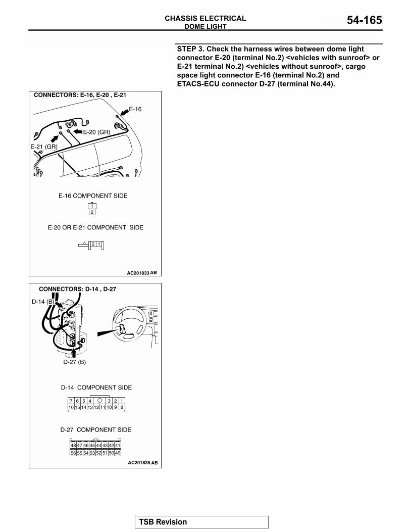
DOME LIGHTCHASSIS ELECTRICAL 54-165
STEP 3. Check the harness wires between dome light connector E-20 (terminal No.2) <vehicles with sunroof> or E-21 terminal No.2) <vehicles without sunroof>, cargo space light connector E-16 (terminal No.2) and ETACS-ECU connector D-27 (terminal No.44).
12
12
AC201833
AC201835
4243
5051
4546
5354 52
4448
56 55
47
49
41
18
3457 6101516 14 1213 11 9
2
AB
CONNECTORS: D-14 , D-27
D-14 (B)
D-27 (B)
D-14 COMPONENT SIDE
D-27 COMPONENT SIDE
TSB Revision
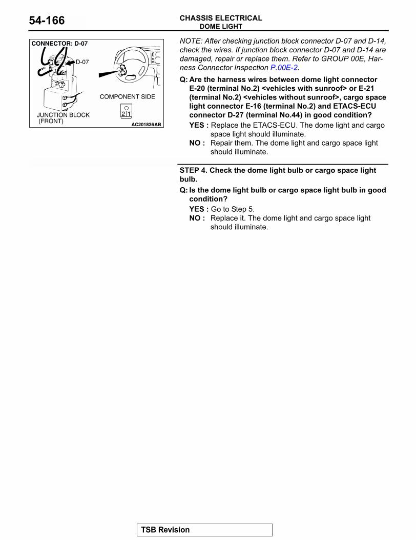
DOME LIGHTCHASSIS ELECTRICAL54-166
NOTE: After checking junction block connector D-07 and D-14, check the wires. If junction block connector D-07 and D-14 are damaged, repair or replace them. Refer to GROUP 00E, Har-ness Connector Inspection P.00E-2.Q: Are the harness wires between dome light connectorE-20 (terminal No.2) <vehicles with sunroof> or E-21 (terminal No.2) <vehicles without sunroof>, cargo space light connector E-16 (terminal No.2) and ETACS-ECU connector D-27 (terminal No.44) in good condition?YES : Replace the ETACS-ECU. The dome light and cargo
space light should illuminate.NO : Repair them. The dome light and cargo space light
should illuminate.
STEP 4. Check the dome light bulb or cargo space light bulb.Q: Is the dome light bulb or cargo space light bulb in good
condition?YES : Go to Step 5.NO : Replace it. The dome light and cargo space light
should illuminate.
AC201836
21
CONNECTOR: D-07
AB
JUNCTION BLOCK (FRONT)
COMPONENT SIDE
12
D-07
TSB Revision
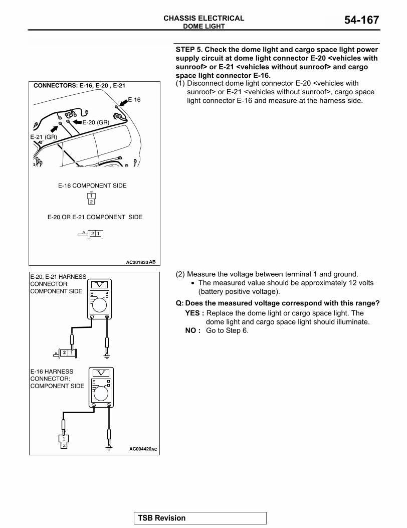
DOME LIGHTCHASSIS ELECTRICAL 54-167
STEP 5. Check the dome light and cargo space light power supply circuit at dome light connector E-20 <vehicles with sunroof> or E-21 <vehicles without sunroof> and cargo space light connector E-16.(1) Disconnect dome light connector E-20 <vehicles with
sunroof> or E-21 <vehicles without sunroof>, cargo space light connector E-16 and measure at the harness side.
(2) Measure the voltage between terminal 1 and ground.• The measured value should be approximately 12 volts
(battery positive voltage).Q: Does the measured voltage correspond with this range?
YES : Replace the dome light or cargo space light. The dome light and cargo space light should illuminate.
NO : Go to Step 6.
12
12
AC201833
21
AC004420
12
AC
E-20, E-21 HARNESS CONNECTOR:COMPONENT SIDE
E-16 HARNESS CONNECTOR:COMPONENT SIDE
TSB Revision
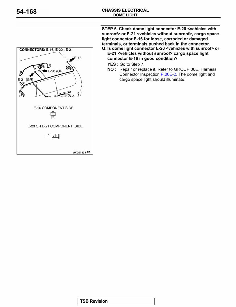
DOME LIGHTCHASSIS ELECTRICAL54-168
STEP 6. Check dome light connector E-20 <vehicles with sunroof> or E-21 <vehicles without sunroof>, cargo space light connector E-16 for loose, corroded or damaged terminals, or terminals pushed back in the connector.Q: Is dome light connector E-20 <vehicles with sunroof> or
E-21 <vehicles without sunroof> cargo space light connector E-16 in good condition?YES : Go to Step 7.NO : Repair or replace it. Refer to GROUP 00E, Harness
Connector Inspection P.00E-2. The dome light and cargo space light should illuminate.
12
12
AC201833
TSB Revision
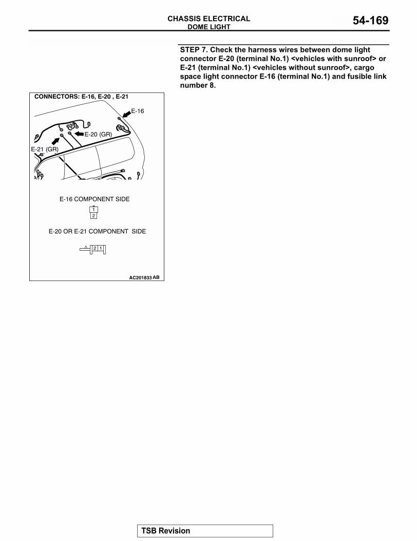
DOME LIGHTCHASSIS ELECTRICAL 54-169
STEP 7. Check the harness wires between dome light connector E-20 (terminal No.1) <vehicles with sunroof> or E-21 (terminal No.1) <vehicles without sunroof>, cargo space light connector E-16 (terminal No.1) and fusible link number 8.
12
12
AC201833
TSB Revision
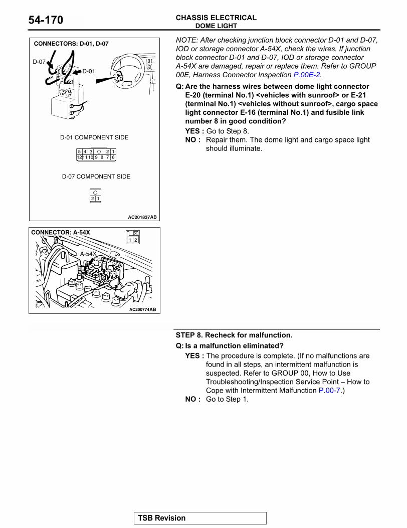
DOME LIGHTCHASSIS ELECTRICAL54-170
NOTE: After checking junction block connector D-01 and D-07, IOD or storage connector A-54X, check the wires. If junction block connector D-01 and D-07, IOD or storage connector A-54X are damaged, repair or replace them. Refer to GROUP 00E, Harness Connector Inspection P.00E-2. Q: Are the harness wires between dome light connectorE-20 (terminal No.1) <vehicles with sunroof> or E-21 (terminal No.1) <vehicles without sunroof>, cargo space light connector E-16 (terminal No.1) and fusible link number 8 in good condition?YES : Go to Step 8.NO : Repair them. The dome light and cargo space light
should illuminate.
STEP 8. Recheck for malfunction.Q: Is a malfunction eliminated?
YES : The procedure is complete. (If no malfunctions are found in all steps, an intermittent malfunction is suspected. Refer to GROUP 00, How to Use Troubleshooting/Inspection Service Point − How to Cope with Intermittent Malfunction P.00-7.)
NO : Go to Step 1.
AC201837
12
2347891110 6
1512
CONNECTORS: D-01, D-07
AB
D-01
D-07
D-01 COMPONENT SIDE
D-07 COMPONENT SIDE
AC200774
21
CONNECTOR: A-54X
AB
A-54X
TSB Revision
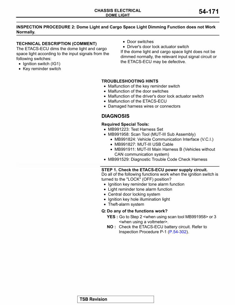
DOME LIGHTCHASSIS ELECTRICAL 54-171
INSPECTION PROCEDURE 2: Dome Light and Cargo Space Light Dimming Function does not Work Normally.
.
TECHNICAL DESCRIPTION (COMMENT)The ETACS-ECU dims the dome light and cargo space light according to the input signals from the following switches:
• Ignition switch (IG1)• Key reminder switch
• Door switches• Driver's door lock actuator switch
If the dome light and cargo space light does not be dimmed normally, the relevant input signal circuit or the ETACS-ECU may be defective.
.
TROUBLESHOOTING HINTS• Malfunction of the key reminder switch• Malfunction of the door switches• Malfunction of the driver's door lock actuator switch• Malfunction of the ETACS-ECU • Damaged harness wires or connectors
DIAGNOSISRequired Special Tools:
• MB991223: Test Harness Set • MB991958: Scan Tool (MUT-III Sub Assembly)
• MB991824: Vehicle Communication Interface (V.C.I.)• MB991827: MUT-III USB Cable• MB991911: MUT-III Main Harness B (Vehicles without
CAN communication system)• MB991529: Diagnostic Trouble Code Check Harness
STEP 1. Check the ETACS-ECU power supply circuit.Do all of the following functions work when the ignition switch is turned to the "LOCK" (OFF) position?
• Ignition key reminder tone alarm function• Light reminder tone alarm function• Central door locking system• Ignition key hole illumination light• Theft-alarm system
Q: Do any of the functions work?YES : Go to Step 2 <when using scan tool MB991958> or 3
<when using a voltmeter>.NO : Check the ETACS-ECU battery circuit. Refer to
Inspection Procedure P-1 (P.54-302).
TSB Revision
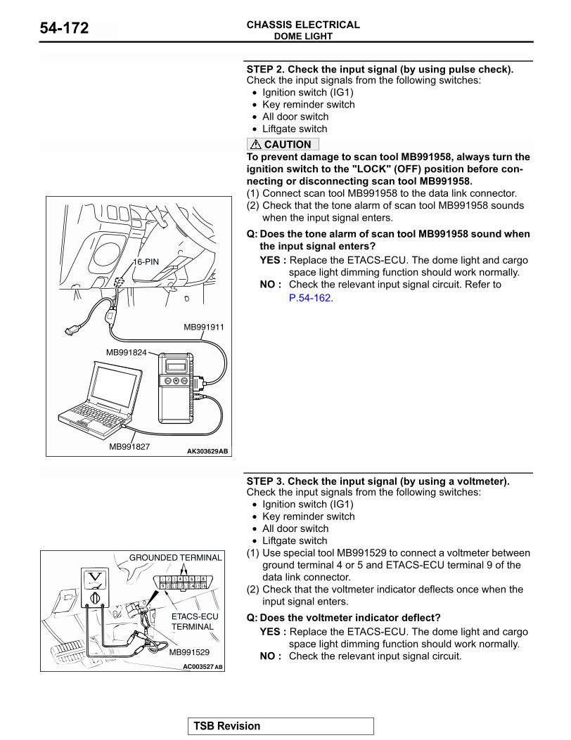
DOME LIGHTCHASSIS ELECTRICAL54-172
STEP 2. Check the input signal (by using pulse check).Check the input signals from the following switches:
• Ignition switch (IG1)• Key reminder switch • All door switch• Liftgate switch
CAUTIONTo prevent damage to scan tool MB991958, always turn the ignition switch to the "LOCK" (OFF) position before con-necting or disconnecting scan tool MB991958.(1) Connect scan tool MB991958 to the data link connector.(2) Check that the tone alarm of scan tool MB991958 sounds
when the input signal enters.Q: Does the tone alarm of scan tool MB991958 sound when
the input signal enters?YES : Replace the ETACS-ECU. The dome light and cargo
space light dimming function should work normally.NO : Check the relevant input signal circuit. Refer to
P.54-162.
STEP 3. Check the input signal (by using a voltmeter).Check the input signals from the following switches:
• Ignition switch (IG1)• Key reminder switch • All door switch• Liftgate switch
(1) Use special tool MB991529 to connect a voltmeter between ground terminal 4 or 5 and ETACS-ECU terminal 9 of the data link connector.
(2) Check that the voltmeter indicator deflects once when the input signal enters.
Q: Does the voltmeter indicator deflect?YES : Replace the ETACS-ECU. The dome light and cargo
space light dimming function should work normally.NO : Check the relevant input signal circuit.
AK303629AB
MB991911
MB991827
MB991824
16-PIN
AC003527
GROUNDED TERMINAL
ETACS-ECU TERMINAL
MB991529
AB
TSB Revision
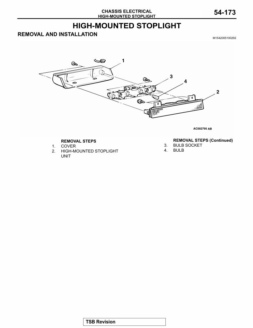
HIGH-MOUNTED STOPLIGHTCHASSIS ELECTRICAL 54-173
HIGH-MOUNTED STOPLIGHTREMOVAL AND INSTALLATION
M1542005100292
AC002795 AB
1
2
34
REMOVAL STEPS1. COVER2. HIGH-MOUNTED STOPLIGHT
UNIT
3. BULB SOCKET 4. BULB
REMOVAL STEPS (Continued)
TSB Revision
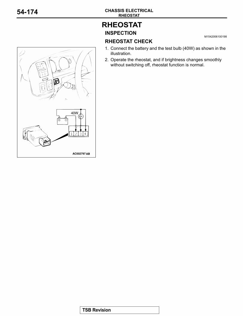
RHEOSTATCHASSIS ELECTRICAL54-174
RHEOSTATINSPECTION
M1542006100198
RHEOSTAT CHECK1. Connect the battery and the test bulb (40W) as shown in the
illustration. 2. Operate the rheostat, and if brightness changes smoothly
without switching off, rheostat function is normal.
AC002797AB
40W
TSB Revision
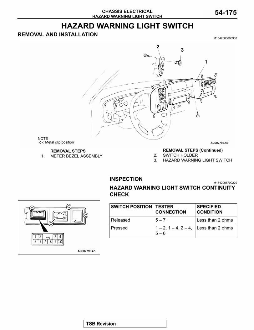
HAZARD WARNING LIGHT SWITCHCHASSIS ELECTRICAL 54-175
HAZARD WARNING LIGHT SWITCHREMOVAL AND INSTALLATION
M1542006600308
INSPECTIONM1542006700220
HAZARD WARNING LIGHT SWITCH CONTINUITY CHECK
AC002798
1
23
AB: Metal clip positionNOTE
REMOVAL STEPS1. METER BEZEL ASSEMBLY 2. SWITCH HOLDER
3. HAZARD WARNING LIGHT SWITCH
REMOVAL STEPS (Continued)
SWITCH POSITION TESTER CONNECTION
SPECIFIED CONDITION
Released 5 − 7 Less than 2 ohms
Pressed 1 − 2, 1 − 4, 2 − 4, 5 − 6
Less than 2 ohms
AC002799 AB
TSB Revision
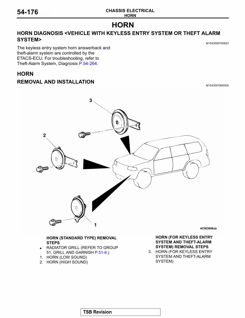
HORNCHASSIS ELECTRICAL54-176
HORNHORN DIAGNOSIS <VEHICLE WITH KEYLESS ENTRY SYSTEM OR THEFT ALARM SYSTEM>
M1543000700623
The keyless entry system horn answerback and theft-alarm system are controlled by the ETACS-ECU. For troubleshooting, refer to Theft-Alarm System, Diagnosis P.54-264.
HORNREMOVAL AND INSTALLATION
M1543007900305
AC003698AB1
2
3
HORN (STANDARD TYPE) REMOVAL STEPS
• RADIATOR GRILL (REFER TO GROUP 51, GRILL AND GARNISH P.51-6.)
1. HORN (LOW SOUND)2. HORN (HIGH SOUND)
HORN (FOR KEYLESS ENTRY SYSTEM AND THEFT-ALARM SYSTEM) REMOVAL STEPS
3. HORN (FOR KEYLESS ENTRY SYSTEM AND THEFT-ALARM SYSTEM)
TSB Revision
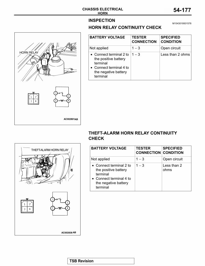
HORNCHASSIS ELECTRICAL 54-177
INSPECTIONM1543019501578
HORN RELAY CONTINUITY CHECK
THEFT-ALARM HORN RELAY CONTINUITY CHECK
BATTERY VOLTAGE TESTER CONNECTION
SPECIFIED CONDITION
Not applied 1 − 3 Open circuit
• Connect terminal 2 to the positive battery terminal
• Connect terminal 4 to the negative battery terminal
1 − 3 Less than 2 ohms
AC002801AB
HORN RELAY
BATTERY VOLTAGE TESTER CONNECTION
SPECIFIED CONDITION
Not applied 1 − 3 Open circuit
• Connect terminal 2 to the positive battery terminal
• Connect terminal 4 to the negative battery terminal
1 − 3 Less than 2 ohms
AC002838 AB
THEFT-ALARM HORN RELAY
TSB Revision
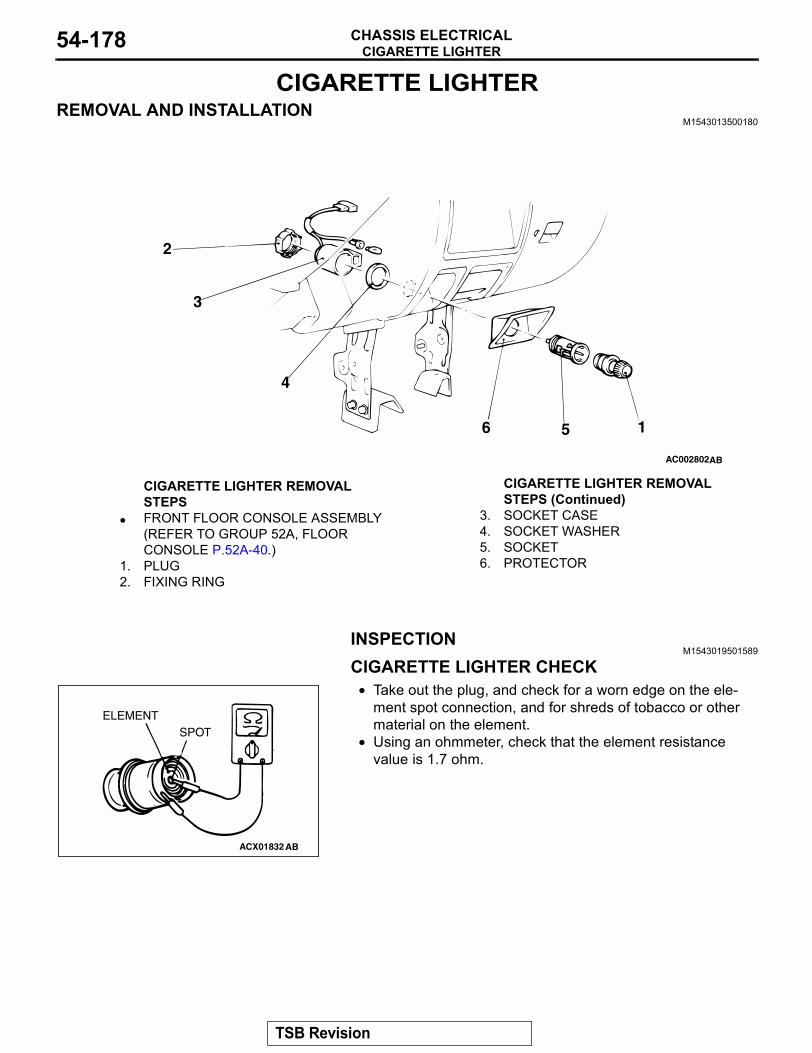
CIGARETTE LIGHTERCHASSIS ELECTRICAL54-178
CIGARETTE LIGHTERREMOVAL AND INSTALLATION
M1543013500180
INSPECTIONM1543019501589
CIGARETTE LIGHTER CHECK• Take out the plug, and check for a worn edge on the ele-
ment spot connection, and for shreds of tobacco or other material on the element.
• Using an ohmmeter, check that the element resistance value is 1.7 ohm.
AC002802AB
1
2
3
4
56
CIGARETTE LIGHTER REMOVAL STEPS
• FRONT FLOOR CONSOLE ASSEMBLY (REFER TO GROUP 52A, FLOOR CONSOLE P.52A-40.)
1. PLUG2. FIXING RING
3. SOCKET CASE4. SOCKET WASHER5. SOCKET6. PROTECTOR
CIGARETTE LIGHTER REMOVAL STEPS (Continued)
ACX01832 AB
ELEMENTSPOT
TSB Revision
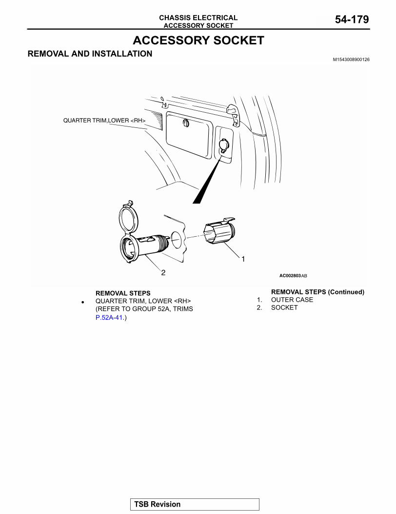
ACCESSORY SOCKETCHASSIS ELECTRICAL 54-179
ACCESSORY SOCKETREMOVAL AND INSTALLATION
M1543008900126
AC002803AB
1
2
QUARTER TRIM,LOWER <RH>
REMOVAL STEPS• QUARTER TRIM, LOWER <RH>
(REFER TO GROUP 52A, TRIMS P.52A-41.)
1. OUTER CASE2. SOCKET
REMOVAL STEPS (Continued)
TSB Revision
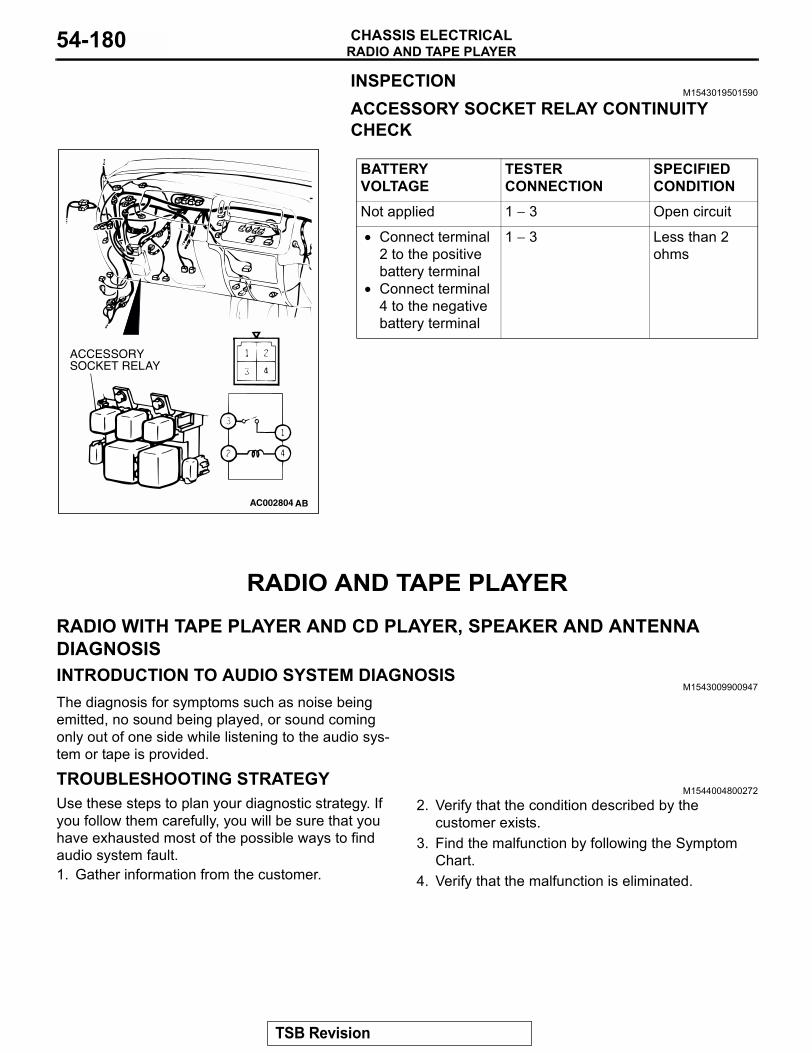
RADIO AND TAPE PLAYERCHASSIS ELECTRICAL54-180
INSPECTIONM1543019501590
ACCESSORY SOCKET RELAY CONTINUITY CHECK
RADIO AND TAPE PLAYER
RADIO WITH TAPE PLAYER AND CD PLAYER, SPEAKER AND ANTENNA DIAGNOSISINTRODUCTION TO AUDIO SYSTEM DIAGNOSIS
M1543009900947
The diagnosis for symptoms such as noise being emitted, no sound being played, or sound coming only out of one side while listening to the audio sys-tem or tape is provided.
TROUBLESHOOTING STRATEGYM1544004800272
Use these steps to plan your diagnostic strategy. If you follow them carefully, you will be sure that you have exhausted most of the possible ways to find audio system fault.1. Gather information from the customer.
2. Verify that the condition described by the customer exists.
3. Find the malfunction by following the Symptom Chart.
4. Verify that the malfunction is eliminated.
BATTERY VOLTAGE
TESTER CONNECTION
SPECIFIED CONDITION
Not applied 1 − 3 Open circuit
• Connect terminal 2 to the positive battery terminal
• Connect terminal 4 to the negative battery terminal
1 − 3 Less than 2 ohms
AC002804 AB
ACCESSORYSOCKET RELAY
TSB Revision
RADIO AND TAPE PLAYERCHASSIS ELECTRICAL 54-181
SYMPTOM CHARTM1544004900309
SYMPTOM INSPECTION PROCEDURE
REFERENCE PAGE
When power switch is turned "ON," no power is available. 1 P.54-182No sound. <vehicles with amplifier> 2 P.54-187No sound from one speaker. 3 P.54-193Noise Noise appears at certain
places when traveling (AM).4 P.54-220
Noise appears at certain places when traveling (FM).
5 P.54-221
Mixed with noise, only at night (AM).
6 P.54-222
Broadcasts can be heard but both AM and FM have a lot of noise.
7 P.54-222
There is more noise on either AM or FM.
8 P.54-224
There is noise when starting the engine.
9 P.54-225
Some noise appears when there is vibration or shocks during traveling.
10 P.54-227
Noise sometimes appears on FM during traveling.
11 P.54-227
Ever-present noise. 12 P.54-228Radio There is noise but no
reception for both AM and FM or no sound from AM, or no sound from FM.
13 P.54-229
Poor reception. 14 P.54-229Distortion on AM or on both AM and FM.
15 P.54-230
Distortion on FM only. 16 P.54-231Using the auto select function, too few automatic stations are selected.
17 P.54-231
Preset stations are erased. 18 P.54-232
TSB Revision
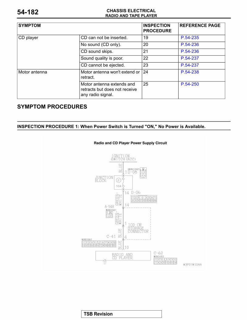
RADIO AND TAPE PLAYERCHASSIS ELECTRICAL54-182
SYMPTOM PROCEDURES
INSPECTION PROCEDURE 1: When Power Switch is Turned "ON," No Power is Available.
CD player CD can not be inserted. 19 P.54-235No sound (CD only). 20 P.54-236CD sound skips. 21 P.54-236Sound quality is poor. 22 P.54-237CD cannot be ejected. 23 P.54-237
Motor antenna Motor antenna won't extend or retract.
24 P.54-238
Motor antenna extends and retracts but does not receive any radio signal.
25 P.54-250
SYMPTOM INSPECTION PROCEDURE
REFERENCE PAGE
Radio and CD Player Power Supply Circuit
TSB Revision
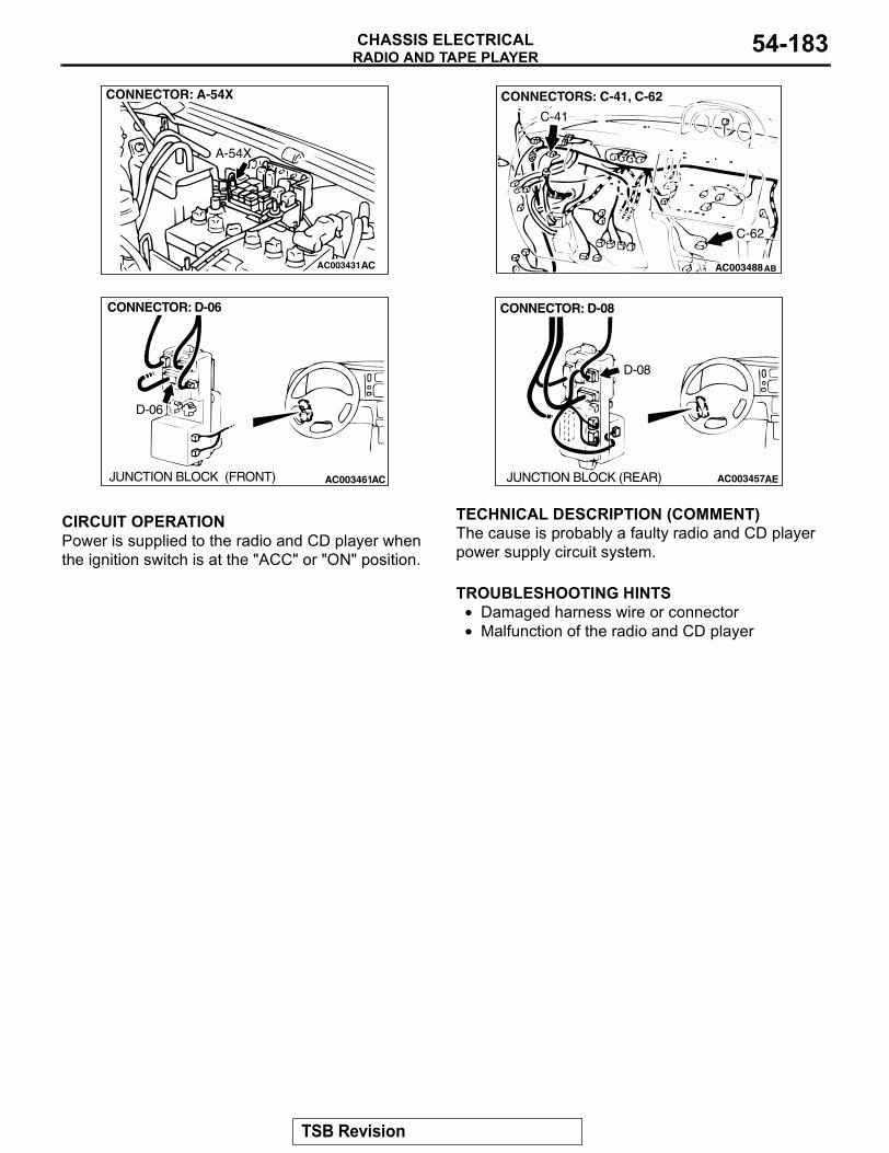
RADIO AND TAPE PLAYERCHASSIS ELECTRICAL 54-183
.
CIRCUIT OPERATIONPower is supplied to the radio and CD player when the ignition switch is at the "ACC" or "ON" position..
TECHNICAL DESCRIPTION (COMMENT)The cause is probably a faulty radio and CD player power supply circuit system..
TROUBLESHOOTING HINTS• Damaged harness wire or connector• Malfunction of the radio and CD player
.
AC003431
CONNECTOR: A-54X
A-54X
AC AC003488
CONNECTORS: C-41, C-62
C-41
C-62
AB
AC003461AC
CONNECTOR: D-06
JUNCTION BLOCK (FRONT)
D-06
AC003457AE
CONNECTOR: D-08
JUNCTION BLOCK (REAR)
D-08
TSB Revision
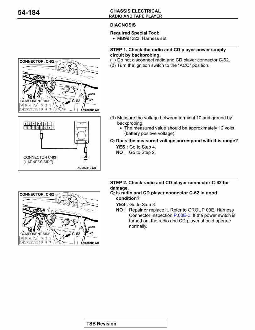
RADIO AND TAPE PLAYERCHASSIS ELECTRICAL54-184
DIAGNOSISRequired Special Tool:• MB991223: Harness set
STEP 1. Check the radio and CD player power supply circuit by backprobing.(1) Do not disconnect radio and CD player connector C-62.(2) Turn the ignition switch to the "ACC" position.
(3) Measure the voltage between terminal 10 and ground by backprobing.
• The measured value should be approximately 12 volts (battery positive voltage).
Q: Does the measured voltage correspond with this range?YES : Go to Step 4.NO : Go to Step 2.
STEP 2. Check radio and CD player connector C-62 for damage.Q: Is radio and CD player connector C-62 in good
condition?YES : Go to Step 3.NO : Repair or replace it. Refer to GROUP 00E, Harness
Connector Inspection P.00E-2. If the power switch is turned on, the radio and CD player should operate normally.
AC200783
17
281011
513
614 12
493
CONNECTOR: C-62
COMPONENT SIDE
AB
C-62
AC002810 AB
CONNECTOR C-62(HARNESS SIDE)
AC200783
17
281011
513
614 12
493
CONNECTOR: C-62
COMPONENT SIDE
AB
C-62
TSB Revision
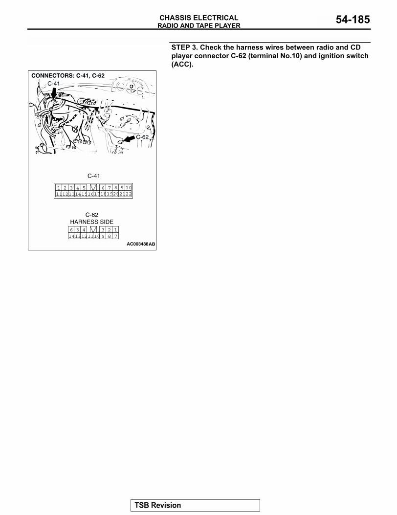
RADIO AND TAPE PLAYERCHASSIS ELECTRICAL 54-185
STEP 3. Check the harness wires between radio and CD player connector C-62 (terminal No.10) and ignition switch (ACC).
AC003488
2220211098
17186 7191415
4 511121 2 3
13 16
17
3 2810
41211
513
614 9
CONNECTORS: C-41, C-62C-41
C-62
AB
C-62HARNESS SIDE
C-41
TSB Revision
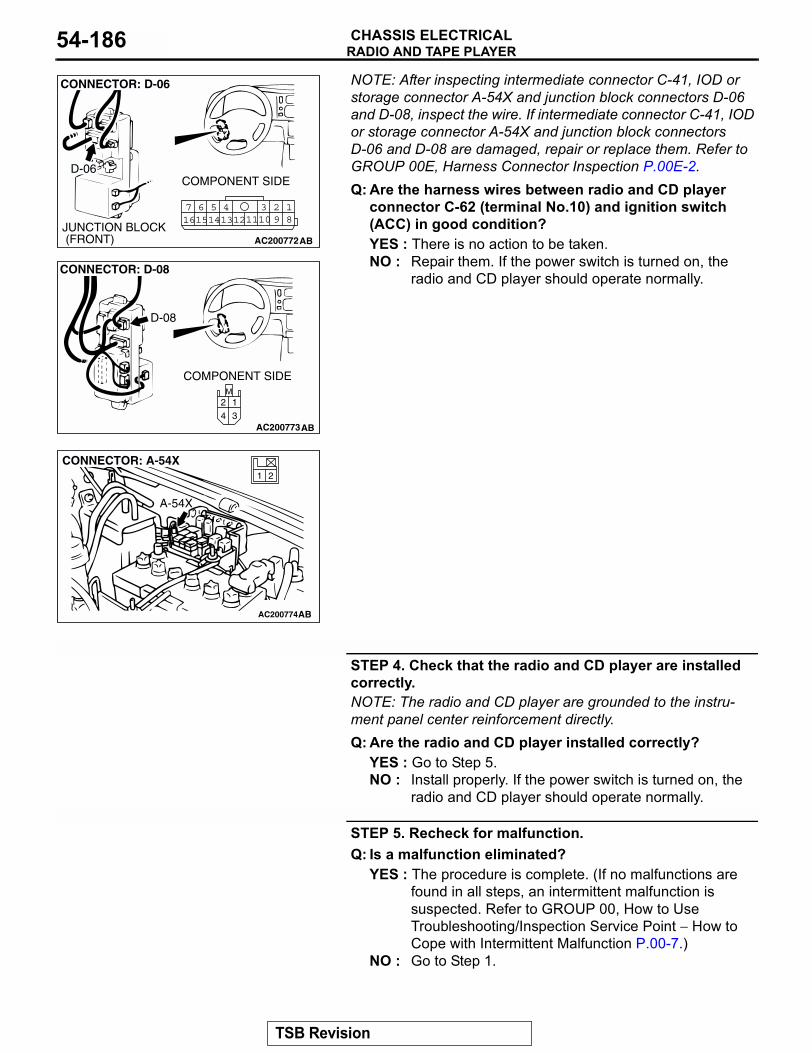
RADIO AND TAPE PLAYERCHASSIS ELECTRICAL54-186
NOTE: After inspecting intermediate connector C-41, IOD or storage connector A-54X and junction block connectors D-06 and D-08, inspect the wire. If intermediate connector C-41, IOD or storage connector A-54X and junction block connectors D-06 and D-08 are damaged, repair or replace them. Refer to GROUP 00E, Harness Connector Inspection P.00E-2.Q: Are the harness wires between radio and CD playerconnector C-62 (terminal No.10) and ignition switch (ACC) in good condition?YES : There is no action to be taken.NO : Repair them. If the power switch is turned on, the
radio and CD player should operate normally.
STEP 4. Check that the radio and CD player are installed correctly.NOTE: The radio and CD player are grounded to the instru-ment panel center reinforcement directly.Q: Are the radio and CD player installed correctly?
YES : Go to Step 5.NO : Install properly. If the power switch is turned on, the
radio and CD player should operate normally.
STEP 5. Recheck for malfunction.Q: Is a malfunction eliminated?
YES : The procedure is complete. (If no malfunctions are found in all steps, an intermittent malfunction is suspected. Refer to GROUP 00, How to Use Troubleshooting/Inspection Service Point − How to Cope with Intermittent Malfunction P.00-7.)
NO : Go to Step 1.
AC200772
18
3457 6101516 14 1213 11 9
2
COMPONENT SIDE
CONNECTOR: D-06
D-06
JUNCTION BLOCK (FRONT) AB
AC200773
M
3
1
4
2
CONNECTOR: D-08
D-08
COMPONENT SIDE
AB
AC200774
21
CONNECTOR: A-54X
AB
A-54X
TSB Revision
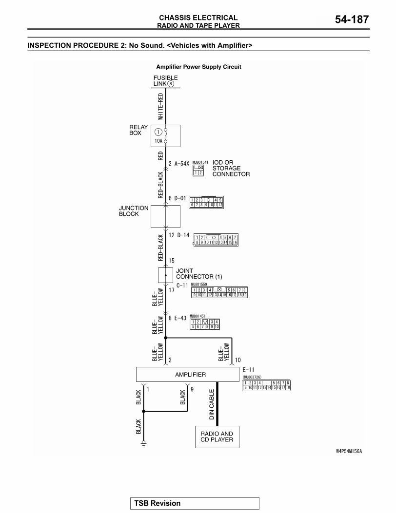
RADIO AND TAPE PLAYERCHASSIS ELECTRICAL 54-187
INSPECTION PROCEDURE 2: No Sound. <Vehicles with Amplifier>
FUSIBLELINK 8
RELAYBOX
JUNCTIONBLOCK
IOD ORSTORAGECONNECTOR
RADIO ANDCD PLAYER
DIN
CA
BLE
AMPLIFIER
JOINT CONNECTOR (1)
Amplifier Power Supply Circuit
TSB Revision
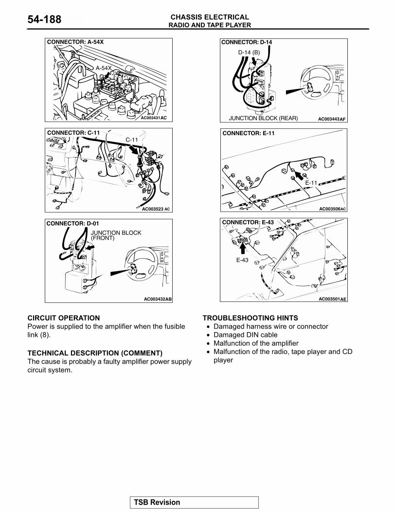
RADIO AND TAPE PLAYERCHASSIS ELECTRICAL54-188
.
CIRCUIT OPERATIONPower is supplied to the amplifier when the fusible link (8)..
TECHNICAL DESCRIPTION (COMMENT)The cause is probably a faulty amplifier power supply circuit system.
.
TROUBLESHOOTING HINTS• Damaged harness wire or connector• Damaged DIN cable• Malfunction of the amplifier• Malfunction of the radio, tape player and CD
player
.
AC003431
CONNECTOR: A-54X
A-54X
AC
AC003523 AC
CONNECTOR: C-11C-11
AC003432AB
CONNECTOR: D-01
JUNCTION BLOCK(FRONT)
AC003443AF
CONNECTOR: D-14
JUNCTION BLOCK (REAR)
D-14 (B)
AC003506
CONNECTOR: E-11
AC
E-11
AC003501AE
CONNECTOR: E-43
E-43
TSB Revision
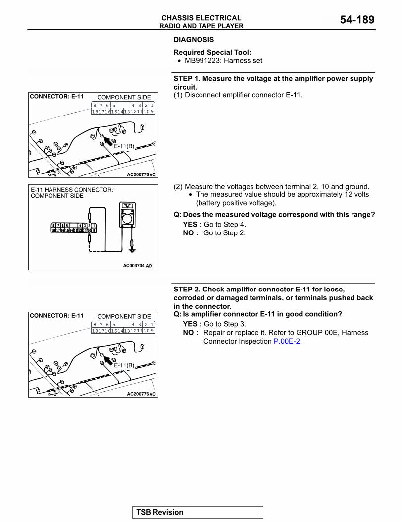
RADIO AND TAPE PLAYERCHASSIS ELECTRICAL 54-189
DIAGNOSIS
Required Special Tool:• MB991223: Harness set
STEP 1. Measure the voltage at the amplifier power supply circuit.(1) Disconnect amplifier connector E-11.
(2) Measure the voltages between terminal 2, 10 and ground.• The measured value should be approximately 12 volts
(battery positive voltage).Q: Does the measured voltage correspond with this range?
YES : Go to Step 4.NO : Go to Step 2.
STEP 2. Check amplifier connector E-11 for loose, corroded or damaged terminals, or terminals pushed back in the connector.Q: Is amplifier connector E-11 in good condition?
YES : Go to Step 3.NO : Repair or replace it. Refer to GROUP 00E, Harness
Connector Inspection P.00E-2.
AC200776
CONNECTOR: E-11
AC
COMPONENT SIDE3 21110
41312
19
561615
781817 14
E-11(B)
AC003704 AD
E-11 HARNESS CONNECTOR:COMPONENT SIDE
AC200776
CONNECTOR: E-11
AC
COMPONENT SIDE3 21110
41312
19
561615
781817 14
E-11(B)
TSB Revision
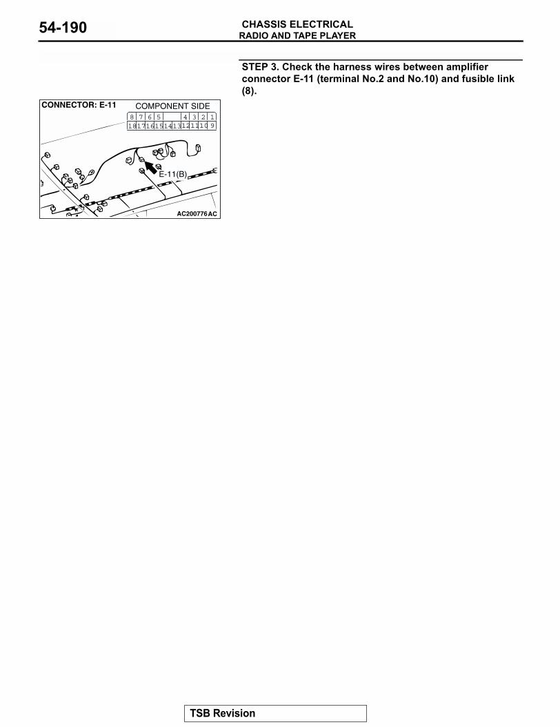
RADIO AND TAPE PLAYERCHASSIS ELECTRICAL54-190
STEP 3. Check the harness wires between amplifier connector E-11 (terminal No.2 and No.10) and fusible link (8).
AC200776
CONNECTOR: E-11
AC
COMPONENT SIDE3 21110
41312
19
561615
781817 14
E-11(B)
TSB Revision
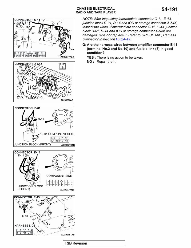
RADIO AND TAPE PLAYERCHASSIS ELECTRICAL 54-191
NOTE: After inspecting intermediate connector C-11, E-43, junction block D-01, D-14 and IOD or storage connector A-54X, inspect the wires. If intermediate connector C-11, E-43, junction block D-01, D-14 and IOD or storage connector A-54X are damaged, repair or replace it. Refer to GROUP 00E, Harness Connector Inspection P.52A-49.Q: Are the harness wires between amplifier connector E-11
(terminal No.2 and No.10) and fusible link (8) in good condition?YES : There is no action to be taken.NO : Repair them.
AC200777
1234561417 1615 1312 1110 9
819
718
CONNECTOR: C-11
AB
C-11
AC200774
21
CONNECTOR: A-54X
AB
A-54X
AC200778
2341110 9 8 7
16
512
CONNECTOR: D-01
AB
D-01 COMPONENT SIDE
JUNCTION BLOCK (FRONT)
D-01
AC200779
123457 616151413121110 9 8
CONNECTOR: D-14
AB
COMPONENT SIDE
JUNCTION BLOCK (FRONT)
D-14 (B)
AC200781104
87651 2 3
9
CONNECTOR: E-43
AB
HARNESS SIDE
E-43
TSB Revision
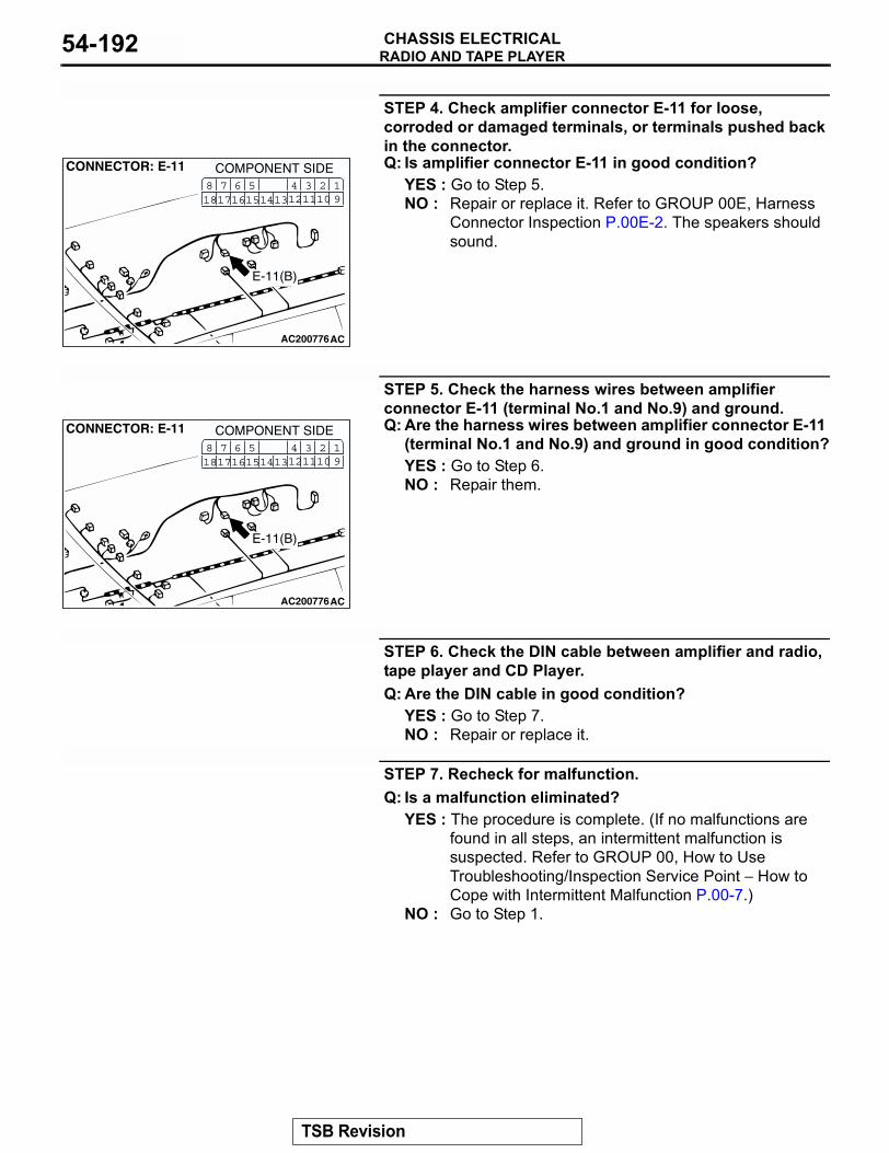
RADIO AND TAPE PLAYERCHASSIS ELECTRICAL54-192
STEP 4. Check amplifier connector E-11 for loose, corroded or damaged terminals, or terminals pushed back in the connector.Q: Is amplifier connector E-11 in good condition?
YES : Go to Step 5.NO : Repair or replace it. Refer to GROUP 00E, Harness
Connector Inspection P.00E-2. The speakers should sound.
STEP 5. Check the harness wires between amplifier connector E-11 (terminal No.1 and No.9) and ground.Q: Are the harness wires between amplifier connector E-11
(terminal No.1 and No.9) and ground in good condition?YES : Go to Step 6.NO : Repair them.
STEP 6. Check the DIN cable between amplifier and radio, tape player and CD Player.Q: Are the DIN cable in good condition?
YES : Go to Step 7.NO : Repair or replace it.
STEP 7. Recheck for malfunction.Q: Is a malfunction eliminated?
YES : The procedure is complete. (If no malfunctions are found in all steps, an intermittent malfunction is suspected. Refer to GROUP 00, How to Use Troubleshooting/Inspection Service Point − How to Cope with Intermittent Malfunction P.00-7.)
NO : Go to Step 1.
AC200776
CONNECTOR: E-11
AC
COMPONENT SIDE3 21110
41312
19
561615
781817 14
E-11(B)
AC200776
CONNECTOR: E-11
AC
COMPONENT SIDE3 21110
41312
19
561615
781817 14
E-11(B)
TSB Revision
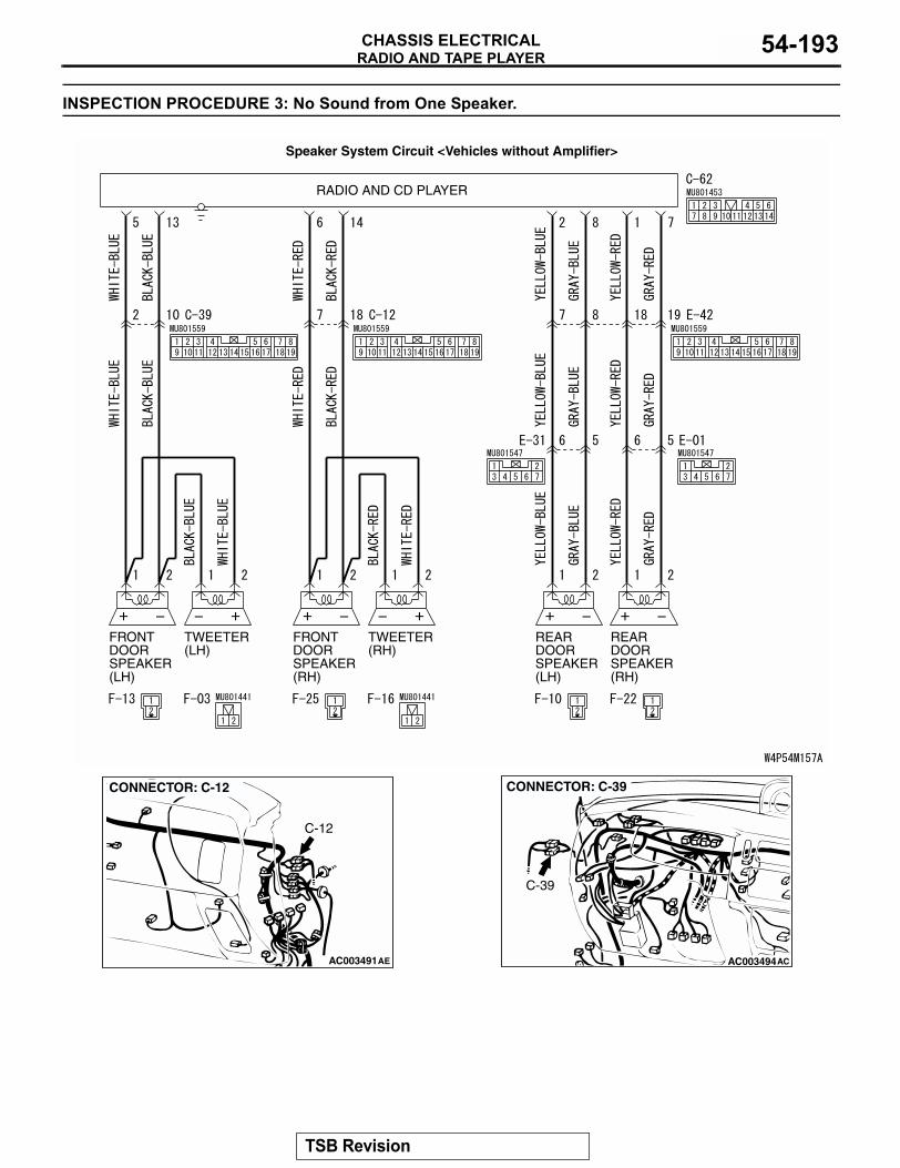
RADIO AND TAPE PLAYERCHASSIS ELECTRICAL 54-193
INSPECTION PROCEDURE 3: No Sound from One Speaker.
RADIO AND CD PLAYER
FRONTDOORSPEAKER(LH)
FRONTDOORSPEAKER(RH)
REARDOORSPEAKER(LH)
REARDOORSPEAKER(RH)
TWEETER(LH)
TWEETER(RH)
Speaker System Circuit <Vehicles without Amplifier>
AC003491AE
CONNECTOR: C-12
C-12
AC003494AC
CONNECTOR: C-39
C-39
TSB Revision
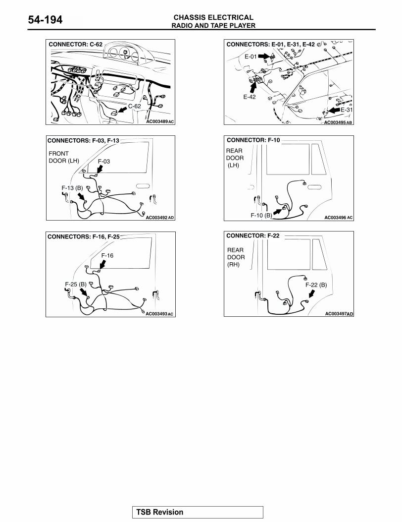
RADIO AND TAPE PLAYERCHASSIS ELECTRICAL54-194
AC003489AC
CONNECTOR: C-62
C-62
AC003495
CONNECTORS: E-01, E-31, E-42
E-01
E-31
E-42
AB
AC003492 AD
CONNECTORS: F-03, F-13
FRONT DOOR (LH) F-03
F-13 (B)
AC003496 AC
CONNECTOR: F-10
REAR DOOR (LH)
F-10 (B)
AC003493AC
CONNECTORS: F-16, F-25
F-16
F-25 (B)
AC003497AD
CONNECTOR: F-22
REAR DOOR (RH)
F-22 (B)
TSB Revision
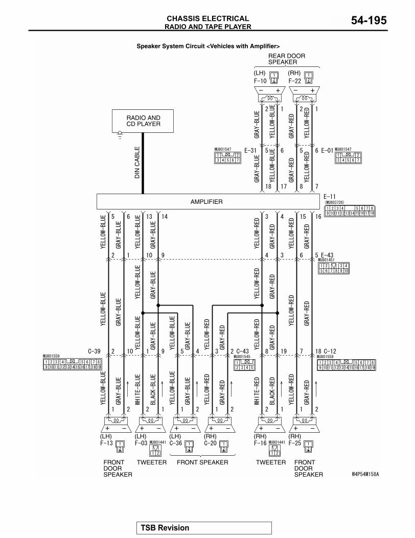
RADIO AND TAPE PLAYERCHASSIS ELECTRICAL 54-195
RADIO ANDCD PLAYER
REAR DOORSPEAKER
FRONTDOORSPEAKER
FRONT SPEAKERTWEETER
(LH)
FRONTDOORSPEAKER
(RH)(LH) (LH)
TWEETER
(RH)(RH)
AMPLIFIER
DIN
CA
BLE
(LH) (RH)
Speaker System Circuit <Vehicles with Amplifier>
TSB Revision
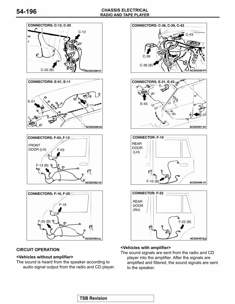
RADIO AND TAPE PLAYERCHASSIS ELECTRICAL54-196
.
CIRCUIT OPERATION
<Vehicles without amplifier>The sound is heard from the speaker according to
audio signal output from the radio and CD player.
<Vehicles with amplifier>The sound signals are sent from the radio and CD
player into the amplifier. After the signals are amplified and filtered, the sound signals are sent to the speaker.
.
AC003498AC
CONNECTORS: C-12, C-20
C-12
C-20 (B) AC003500
CONNECTORS: C-36, C-39, C-43
C-39
C-36 (B)
C-43
AD
AC003499
CONNECTORS: E-01, E-11
E-11E-01
AB AC003501
CONNECTORS: E-31, E-43
E-43
E-31
AB
AC003492 AD
CONNECTORS: F-03, F-13
FRONT DOOR (LH) F-03
F-13 (B)
AC003496 AC
CONNECTOR: F-10
REAR DOOR (LH)
F-10 (B)
AC003493AC
CONNECTORS: F-16, F-25
F-16
F-25 (B)
AC003497AD
CONNECTOR: F-22
REAR DOOR (RH)
F-22 (B)
TSB Revision
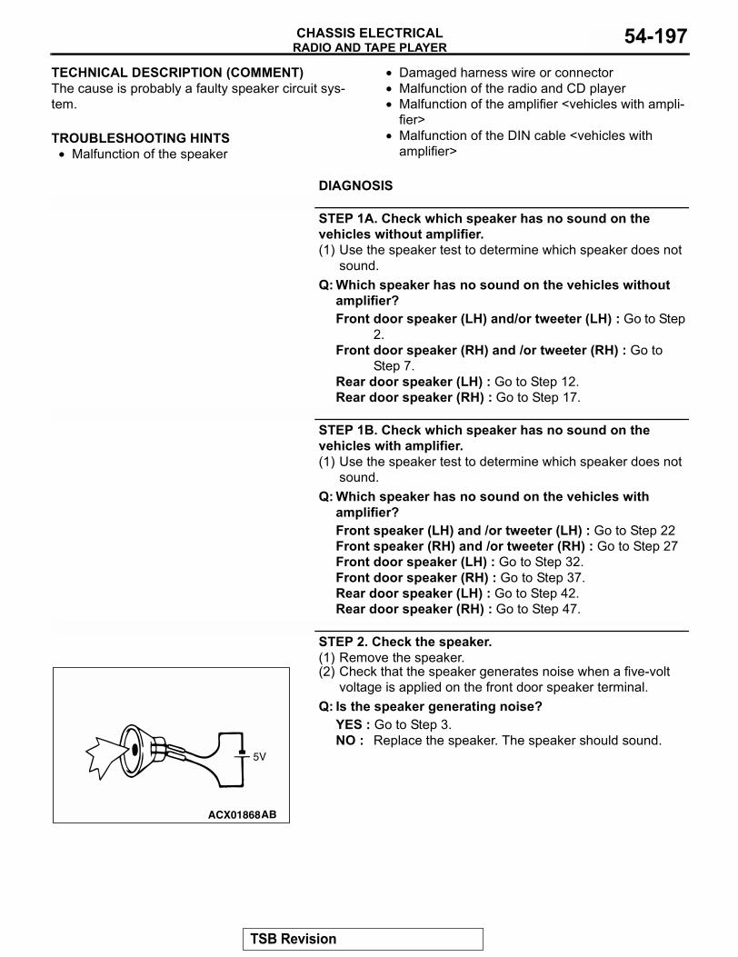
RADIO AND TAPE PLAYERCHASSIS ELECTRICAL 54-197
TECHNICAL DESCRIPTION (COMMENT)The cause is probably a faulty speaker circuit sys-tem..
TROUBLESHOOTING HINTS• Malfunction of the speaker
• Damaged harness wire or connector• Malfunction of the radio and CD player • Malfunction of the amplifier <vehicles with ampli-
fier>• Malfunction of the DIN cable <vehicles with
amplifier>
.
DIAGNOSIS
STEP 1A. Check which speaker has no sound on the vehicles without amplifier.(1) Use the speaker test to determine which speaker does not
sound.Q: Which speaker has no sound on the vehicles without
amplifier?Front door speaker (LH) and/or tweeter (LH) : Go to Step
2.Front door speaker (RH) and /or tweeter (RH) : Go to
Step 7.Rear door speaker (LH) : Go to Step 12.Rear door speaker (RH) : Go to Step 17.
STEP 1B. Check which speaker has no sound on the vehicles with amplifier.(1) Use the speaker test to determine which speaker does not
sound.Q: Which speaker has no sound on the vehicles with
amplifier?Front speaker (LH) and /or tweeter (LH) : Go to Step 22Front speaker (RH) and /or tweeter (RH) : Go to Step 27Front door speaker (LH) : Go to Step 32.Front door speaker (RH) : Go to Step 37.Rear door speaker (LH) : Go to Step 42.Rear door speaker (RH) : Go to Step 47.
STEP 2. Check the speaker.(1) Remove the speaker.(2) Check that the speaker generates noise when a five-volt
voltage is applied on the front door speaker terminal.Q: Is the speaker generating noise?
YES : Go to Step 3.NO : Replace the speaker. The speaker should sound.
ACX01868AB
5V
TSB Revision
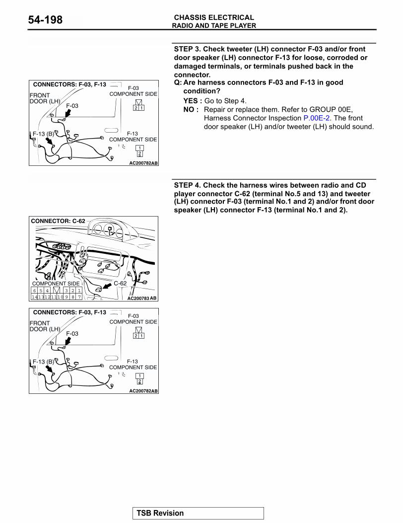
RADIO AND TAPE PLAYERCHASSIS ELECTRICAL54-198
STEP 3. Check tweeter (LH) connector F-03 and/or front door speaker (LH) connector F-13 for loose, corroded or damaged terminals, or terminals pushed back in the connector.Q: Are harness connectors F-03 and F-13 in good
condition?YES : Go to Step 4.NO : Repair or replace them. Refer to GROUP 00E,
Harness Connector Inspection P.00E-2. The front door speaker (LH) and/or tweeter (LH) should sound.
STEP 4. Check the harness wires between radio and CD player connector C-62 (terminal No.5 and 13) and tweeter (LH) connector F-03 (terminal No.1 and 2) and/or front door speaker (LH) connector F-13 (terminal No.1 and 2).
AC200782
2 1
21
CONNECTORS: F-03, F-13
F-03
F-13 (B)
AB
F-03COMPONENT SIDE
F-13 COMPONENT SIDE
FRONT DOOR (LH)
AC200783
17
281011
513
614 12
493
CONNECTOR: C-62
COMPONENT SIDE
AB
C-62
AC200782
2 1
21
CONNECTORS: F-03, F-13
F-03
F-13 (B)
AB
F-03COMPONENT SIDE
F-13 COMPONENT SIDE
FRONT DOOR (LH)
TSB Revision
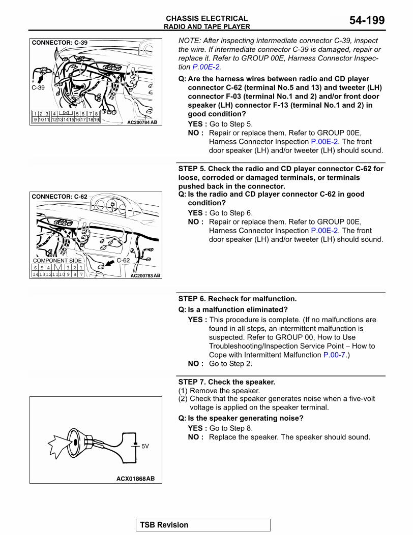
RADIO AND TAPE PLAYERCHASSIS ELECTRICAL 54-199
NOTE: After inspecting intermediate connector C-39, inspect the wire. If intermediate connector C-39 is damaged, repair or replace it. Refer to GROUP 00E, Harness Connector Inspec-tion P.00E-2.Q: Are the harness wires between radio and CD player
connector C-62 (terminal No.5 and 13) and tweeter (LH) connector F-03 (terminal No.1 and 2) and/or front door speaker (LH) connector F-13 (terminal No.1 and 2) in good condition?YES : Go to Step 5.NO : Repair or replace them. Refer to GROUP 00E,
Harness Connector Inspection P.00E-2. The front door speaker (LH) and/or tweeter (LH) should sound.
STEP 5. Check the radio and CD player connector C-62 for loose, corroded or damaged terminals, or terminals pushed back in the connector.Q: Is the radio and CD player connector C-62 in good
condition?YES : Go to Step 6.NO : Repair or replace them. Refer to GROUP 00E,
Harness Connector Inspection P.00E-2. The front door speaker (LH) and/or tweeter (LH) should sound.
STEP 6. Recheck for malfunction.Q: Is a malfunction eliminated?
YES : This procedure is complete. (If no malfunctions are found in all steps, an intermittent malfunction is suspected. Refer to GROUP 00, How to Use Troubleshooting/Inspection Service Point − How to Cope with Intermittent Malfunction P.00-7.)
NO : Go to Step 2.
STEP 7. Check the speaker.(1) Remove the speaker.(2) Check that the speaker generates noise when a five-volt
voltage is applied on the speaker terminal.Q: Is the speaker generating noise?
YES : Go to Step 8.NO : Replace the speaker. The speaker should sound.
AC200784
819
7651615 17 18
4321011 1213
19 14
CONNECTOR: C-39
AB
C-39
AC200783
17
281011
513
614 12
493
CONNECTOR: C-62
COMPONENT SIDE
AB
C-62
ACX01868AB
5V
TSB Revision
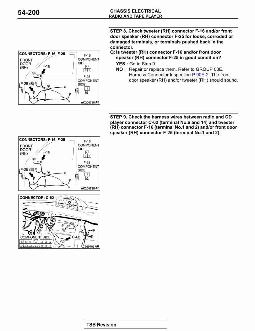
RADIO AND TAPE PLAYERCHASSIS ELECTRICAL54-200
STEP 8. Check tweeter (RH) connector F-16 and/or front door speaker (RH) connector F-25 for loose, corroded or damaged terminals, or terminals pushed back in the connector.Q: Is tweeter (RH) connector F-16 and/or front door
speaker (RH) connector F-25 in good condition?YES : Go to Step 9.NO : Repair or replace them. Refer to GROUP 00E,
Harness Connector Inspection P.00E-2. The front door speaker (RH) and/or tweeter (RH) should sound.
STEP 9. Check the harness wires between radio and CD player connector C-62 (terminal No.6 and 14) and tweeter (RH) connector F-16 (terminal No.1 and 2) and/or front door speaker (RH) connector F-25 (terminal No.1 and 2).
AC200785
2 1
21
CONNECTORS: F-16, F-25
AB
F-16
F-25 (B)
F-16
F-25
COMPONENT SIDE
COMPONENTSIDE
FRONTDOOR(RH)
AC200785
2 1
21
CONNECTORS: F-16, F-25
AB
F-16
F-25 (B)
F-16
F-25
COMPONENT SIDE
COMPONENTSIDE
FRONTDOOR(RH)
AC200783
17
281011
513
614 12
493
CONNECTOR: C-62
COMPONENT SIDE
AB
C-62
TSB Revision
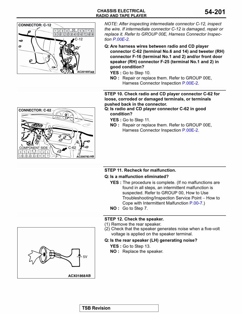
RADIO AND TAPE PLAYERCHASSIS ELECTRICAL 54-201
NOTE: After inspecting intermediate connector C-12, inspect the wire. If intermediate connector C-12 is damaged, repair or replace it. Refer to GROUP 00E, Harness Connector Inspec-tion P.00E-2.Q: Are harness wires between radio and CD player
connector C-62 (terminal No.6 and 14) and tweeter (RH) connector F-16 (terminal No.1 and 2) and/or front door speaker (RH) connector F-25 (terminal No.1 and 2) in good condition?YES : Go to Step 10.NO : Repair or replace them. Refer to GROUP 00E,
Harness Connector Inspection P.00E-2.
STEP 10. Check radio and CD player connector C-62 for loose, corroded or damaged terminals, or terminals pushed back in the connector.Q: Is radio and CD player connector C-62 in good
condition?YES : Go to Step 11.NO : Repair or replace them. Refer to GROUP 00E,
Harness Connector Inspection P.00E-2.
STEP 11. Recheck for malfunction.Q: Is a malfunction eliminated?
YES : The procedure is complete. (If no malfunctions are found in all steps, an intermittent malfunction is suspected. Refer to GROUP 00, How to Use Troubleshooting/Inspection Service Point − How to Cope with Intermittent Malfunction P.00-7.)
NO : Go to Step 7.
STEP 12. Check the speaker.(1) Remove the rear speaker.(2) Check that the speaker generates noise when a five-volt
voltage is applied on the speaker terminal.Q: Is the rear speaker (LH) generating noise?
YES : Go to Step 13.NO : Replace the speaker.
AC201697
819
7651615 17 18
4321011 1213
19 14
CONNECTOR: C-12
AB
C-12
AC200783
17
281011
513
614 12
493
CONNECTOR: C-62
COMPONENT SIDE
AB
C-62
ACX01868AB
5V
TSB Revision
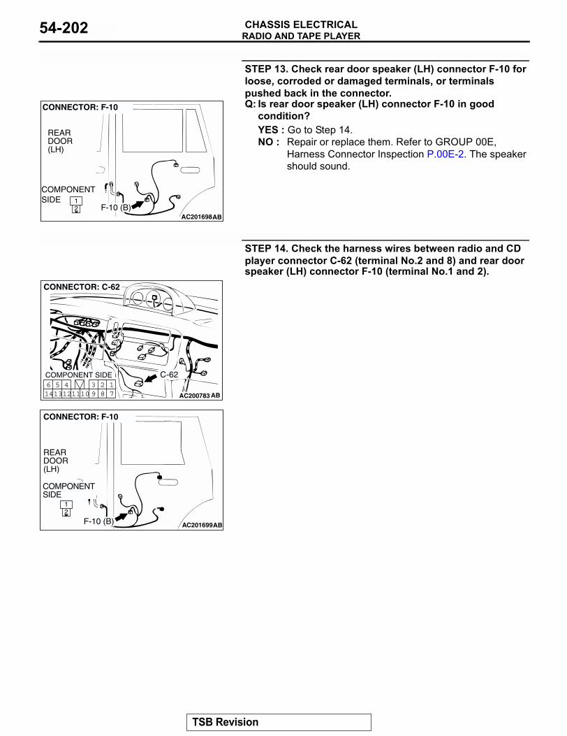
RADIO AND TAPE PLAYERCHASSIS ELECTRICAL54-202
STEP 13. Check rear door speaker (LH) connector F-10 for loose, corroded or damaged terminals, or terminals pushed back in the connector.Q: Is rear door speaker (LH) connector F-10 in good
condition?YES : Go to Step 14.NO : Repair or replace them. Refer to GROUP 00E,
Harness Connector Inspection P.00E-2. The speaker should sound.
STEP 14. Check the harness wires between radio and CD player connector C-62 (terminal No.2 and 8) and rear door speaker (LH) connector F-10 (terminal No.1 and 2).
AC20169821
CONNECTOR: F-10
AB
COMPONENTSIDE
REARDOOR (LH)
F-10 (B)
AC200783
17
281011
513
614 12
493
CONNECTOR: C-62
COMPONENT SIDE
AB
C-62
AC201699
21
CONNECTOR: F-10
REARDOOR(LH)
AB
COMPONENTSIDE
F-10 (B)
TSB Revision
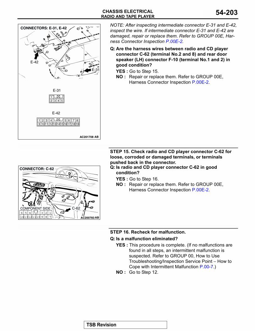
RADIO AND TAPE PLAYERCHASSIS ELECTRICAL 54-203
NOTE: After inspecting intermediate connector E-31 and E-42, inspect the wire. If intermediate connector E-31 and E-42 are damaged, repair or replace them. Refer to GROUP 00E, Har-ness Connector Inspection P.00E-2. Q: Are the harness wires between radio and CD player
connector C-62 (terminal No.2 and 8) and rear door speaker (LH) connector F-10 (terminal No.1 and 2) in good condition?YES : Go to Step 15.NO : Repair or replace them. Refer to GROUP 00E,
Harness Connector Inspection P.00E-2.
STEP 15. Check radio and CD player connector C-62 for loose, corroded or damaged terminals, or terminals pushed back in the connector.Q: Is radio and CD player connector C-62 in good
condition?YES : Go to Step 16.NO : Repair or replace them. Refer to GROUP 00E,
Harness Connector Inspection P.00E-2.
STEP 16. Recheck for malfunction.Q: Is a malfunction eliminated?
YES : This procedure is complete. (If no malfunctions are found in all steps, an intermittent malfunction is suspected. Refer to GROUP 00, How to Use Troubleshooting/Inspection Service Point − How to Cope with Intermittent Malfunction P.00-7.)
NO : Go to Step 12.
AC201708
4 5312
819
7651615 17 18
4321011 1213
19 14
CONNECTORS: E-31, E-42
AB
E-31
E-42
E-31
E-42
AC200783
17
281011
513
614 12
493
CONNECTOR: C-62
COMPONENT SIDE
AB
C-62
TSB Revision
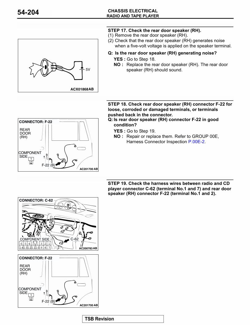
RADIO AND TAPE PLAYERCHASSIS ELECTRICAL54-204
STEP 17. Check the rear door speaker (RH).(1) Remove the rear door speaker (RH). (2) Check that the rear door speaker (RH) generates noise
when a five-volt voltage is applied on the speaker terminal.Q: Is the rear door speaker (RH) generating noise?
YES : Go to Step 18.NO : Replace the rear door speaker (RH). The rear door
speaker (RH) should sound.
STEP 18. Check rear door speaker (RH) connector F-22 for loose, corroded or damaged terminals, or terminals pushed back in the connector.Q: Is rear door speaker (RH) connector F-22 in good
condition?YES : Go to Step 19.NO : Repair or replace them. Refer to GROUP 00E,
Harness Connector Inspection P.00E-2.
STEP 19. Check the harness wires between radio and CD player connector C-62 (terminal No.1 and 7) and rear door speaker (RH) connector F-22 (terminal No.1 and 2).
ACX01868AB
5V
AC201700
21
AB
COMPONENT SIDE
CONNECTOR: F-22
REARDOOR(RH)
F-22 (B)
AC200783
17
281011
513
614 12
493
CONNECTOR: C-62
COMPONENT SIDE
AB
C-62
AC201700
21
AB
COMPONENT SIDE
CONNECTOR: F-22
REARDOOR(RH)
F-22 (B)
TSB Revision
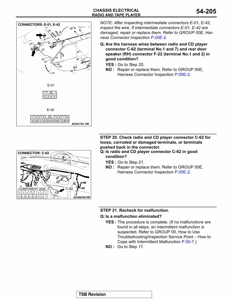
RADIO AND TAPE PLAYERCHASSIS ELECTRICAL 54-205
NOTE: After inspecting intermediate connectors E-01, E-42, inspect the wire. If intermediate connectors E-01, E-42 are damaged, repair or replace them. Refer to GROUP 00E, Har-ness Connector Inspection P.00E-2.Q: Are the harness wires between radio and CD player
connector C-62 (terminal No.1 and 7) and rear door speaker (RH) connector F-22 (terminal No.1 and 2) in good condition?YES : Go to Step 20.NO : Repair or replace them. Refer to GROUP 00E,
Harness Connector Inspection P.00E-2.
STEP 20. Check radio and CD player connector C-62 for loose, corroded or damaged terminals, or terminals pushed back in the connector.Q: Is radio and CD player connector C-62 in good
condition?YES : Go to Step 21.NO : Repair or replace them. Refer to GROUP 00E,
Harness Connector Inspection P.00E-2.
STEP 21. Recheck for malfunction.Q: Is a malfunction eliminated?
YES : The procedure is complete. (If no malfunctions are found in all steps, an intermittent malfunction is suspected. Refer to GROUP 00, How to Use Troubleshooting/Inspection Service Point − How to Cope with Intermittent Malfunction P.00-7.)
NO : Go to Step 17.
AC201701
4 5312
819
7651615 17 18
4321011 1213
19 14
CONNECTORS: E-01, E-42
AB
E-01
E-42
AC200783
17
281011
513
614 12
493
CONNECTOR: C-62
COMPONENT SIDE
AB
C-62
TSB Revision
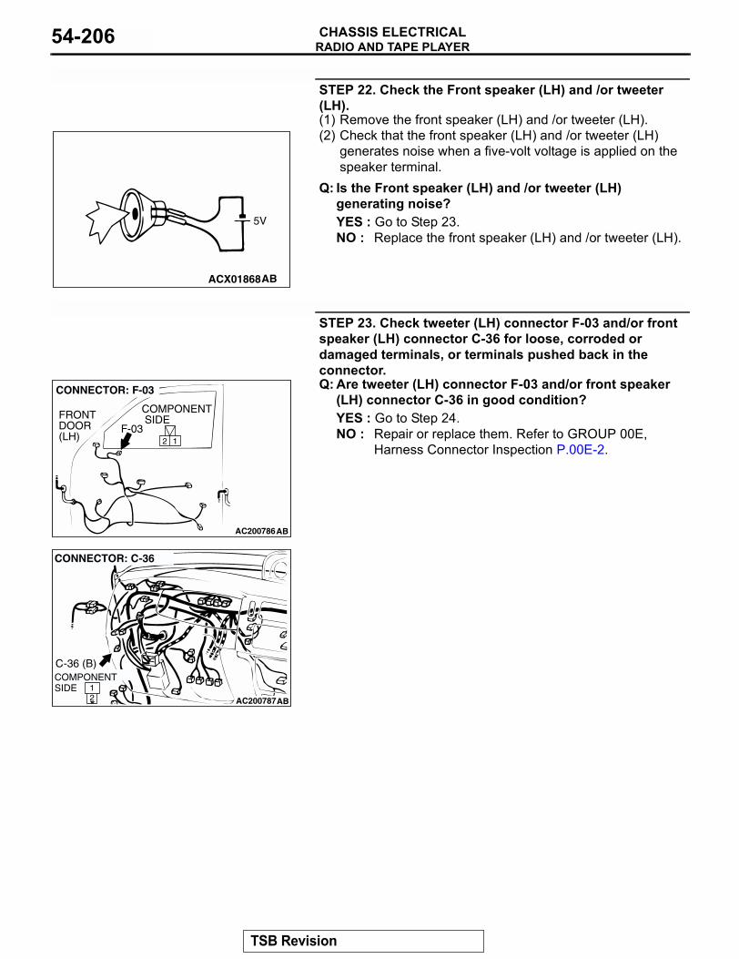
RADIO AND TAPE PLAYERCHASSIS ELECTRICAL54-206
STEP 22. Check the Front speaker (LH) and /or tweeter (LH).(1) Remove the front speaker (LH) and /or tweeter (LH).(2) Check that the front speaker (LH) and /or tweeter (LH)
generates noise when a five-volt voltage is applied on the speaker terminal.
Q: Is the Front speaker (LH) and /or tweeter (LH) generating noise?YES : Go to Step 23.NO : Replace the front speaker (LH) and /or tweeter (LH).
STEP 23. Check tweeter (LH) connector F-03 and/or front speaker (LH) connector C-36 for loose, corroded or damaged terminals, or terminals pushed back in the connector.Q: Are tweeter (LH) connector F-03 and/or front speaker
(LH) connector C-36 in good condition?YES : Go to Step 24.NO : Repair or replace them. Refer to GROUP 00E,
Harness Connector Inspection P.00E-2.
ACX01868AB
5V
AC200786
2 1
CONNECTOR: F-03
AB
COMPONENT SIDEFRONT
DOOR(LH)
F-03
AC20078721
CONNECTOR: C-36
AB
COMPONENT SIDE
C-36 (B)
TSB Revision
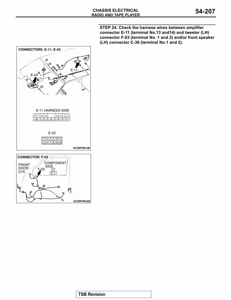
RADIO AND TAPE PLAYERCHASSIS ELECTRICAL 54-207
STEP 24. Check the harness wires between amplifier connector E-11 (terminal No.13 and14) and tweeter (LH) connector F-03 (terminal No. 1 and 2) and/or front speaker (LH) connector C-36 (terminal No.1 and 2).
AC200789
3 21110
41312
19
561615
781817 14
104
87651 2 3
9
AC200786
2 1
CONNECTOR: F-03
AB
COMPONENT SIDEFRONT
DOOR(LH)
F-03
TSB Revision
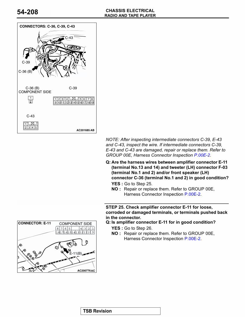
RADIO AND TAPE PLAYERCHASSIS ELECTRICAL54-208
NOTE: After inspecting intermediate connectors C-39, E-43 and C-43, inspect the wire. If intermediate connectors C-39, E-43 and C-43 are damaged, repair or replace them. Refer to GROUP 00E, Harness Connector Inspection P.00E-2.Q: Are the harness wires between amplifier connector E-11
(terminal No.13 and 14) and tweeter (LH) connector F-03 (terminal No.1 and 2) and/or front speaker (LH) connector C-36 (terminal No.1 and 2) in good condition?YES : Go to Step 25.NO : Repair or replace them. Refer to GROUP 00E,
Harness Connector Inspection P.00E-2. .
STEP 25. Check amplifier connector E-11 for loose, corroded or damaged terminals, or terminals pushed back in the connector.Q: Is amplifier connector E-11 for in good condition?
YES : Go to Step 26.NO : Repair or replace them. Refer to GROUP 00E,
Harness Connector Inspection P.00E-2.
AC201685
AC003500
21 8
19765
1615 17 18432
1011 121319 14
4 5312
CONNECTORS: C-36, C-39, C-43
C-36 (B)
C-39
C-43
C-36 (B) C-39
C-43
COMPONENT SIDE
AB
AC200776
CONNECTOR: E-11
AC
COMPONENT SIDE3 21110
41312
19
561615
781817 14
E-11(B)
TSB Revision
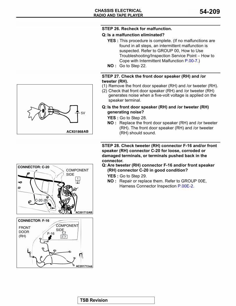
RADIO AND TAPE PLAYERCHASSIS ELECTRICAL 54-209
STEP 26. Recheck for malfunction.Q: Is a malfunction eliminated?
YES : This procedure is complete. (If no malfunctions are found in all steps, an intermittent malfunction is suspected. Refer to GROUP 00, How to Use Troubleshooting/Inspection Service Point − How to Cope with Intermittent Malfunction P.00-7.)
NO : Go to Step 22.
STEP 27. Check the front door speaker (RH) and /or tweeter (RH).(1) Remove the front door speaker (RH) and /or tweeter (RH).(2) Check that front door speaker (RH) and /or tweeter (RH)
generates noise when a five-volt voltage is applied on the speaker terminal.
Q: Is the front door speaker (RH) and /or tweeter (RH) generating noise?YES : Go to Step 28.NO : Replace the front door speaker (RH) and /or tweeter
(RH). The front door speaker (RH) and /or tweeter (RH) should sound.
STEP 28. Check tweeter (RH) connector F-16 and/or front speaker (RH) connector C-20 for loose, corroded or damaged terminals, or terminals pushed back in the connector.Q: Are tweeter (RH) connector F-16 and/or front speaker
(RH) connector C-20 in good condition?YES : Go to Step 29.NO : Repair or replace them. Refer to GROUP 00E,
Harness Connector Inspection P.00E-2.
ACX01868AB
5V
AC201712
21
CONNECTOR: C-20COMPONENTSIDE
AB
C-20 (B)
AC201713
CONNECTOR: F-16
FRONTDOOR(RH)
AB
2 1
COMPONENTSIDE
F-16
TSB Revision
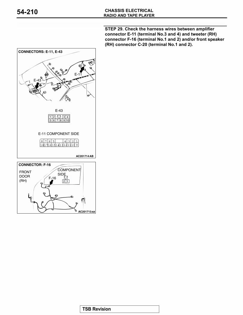
RADIO AND TAPE PLAYERCHASSIS ELECTRICAL54-210
STEP 29. Check the harness wires between amplifier connector E-11 (terminal No.3 and 4) and tweeter (RH) connector F-16 (terminal No.1 and 2) and/or front speaker (RH) connector C-20 (terminal No.1 and 2).
AC201714
3 21110
41312
19
561615
781817 14
104
87651 2 3
9
CONNECTORS: E-11, E-43
E-11
E-43
E-11 COMPONENT SIDE
E-43
AB
AC201713
CONNECTOR: F-16
FRONTDOOR(RH)
AB
2 1
COMPONENTSIDE
F-16
TSB Revision
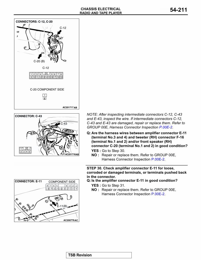
RADIO AND TAPE PLAYERCHASSIS ELECTRICAL 54-211
NOTE: After inspecting intermediate connectors C-12, C-43 and E-43, inspect the wire. If intermediate connectors C-12, C-43 and E-43 are damaged, repair or replace them. Refer to GROUP 00E, Harness Connector Inspection P.00E-2.Q: Are the harness wires between amplifier connector E-11
(terminal No.3 and 4) and tweeter (RH) connector F-16 (terminal No.1 and 2) and/or front speaker (RH) connector C-20 (terminal No.1 and 2) in good condition?YES : Go to Step 30.NO : Repair or replace them. Refer to GROUP 00E,
Harness Connector Inspection P.00E-2.
STEP 30. Check amplifier connector E-11 for loose, corroded or damaged terminals, or terminals pushed back in the connector.Q: Is the amplifier connector E-11 in good condition?
YES : Go to Step 31.NO : Repair or replace them. Refer to GROUP 00E,
Harness Connector Inspection P.00E-2.
AC201717
819
7651615 17 18
4321011 1213
19 14
21
CONNECTORS: C-12, C-20
C-12
C-20 (B)
C-12
C-20 COMPONENT SIDE
AB
AC2017184 53
12
CONNECTOR: C-43
AB
C-43
AC200776
CONNECTOR: E-11
AC
COMPONENT SIDE3 21110
41312
19
561615
781817 14
E-11(B)
TSB Revision
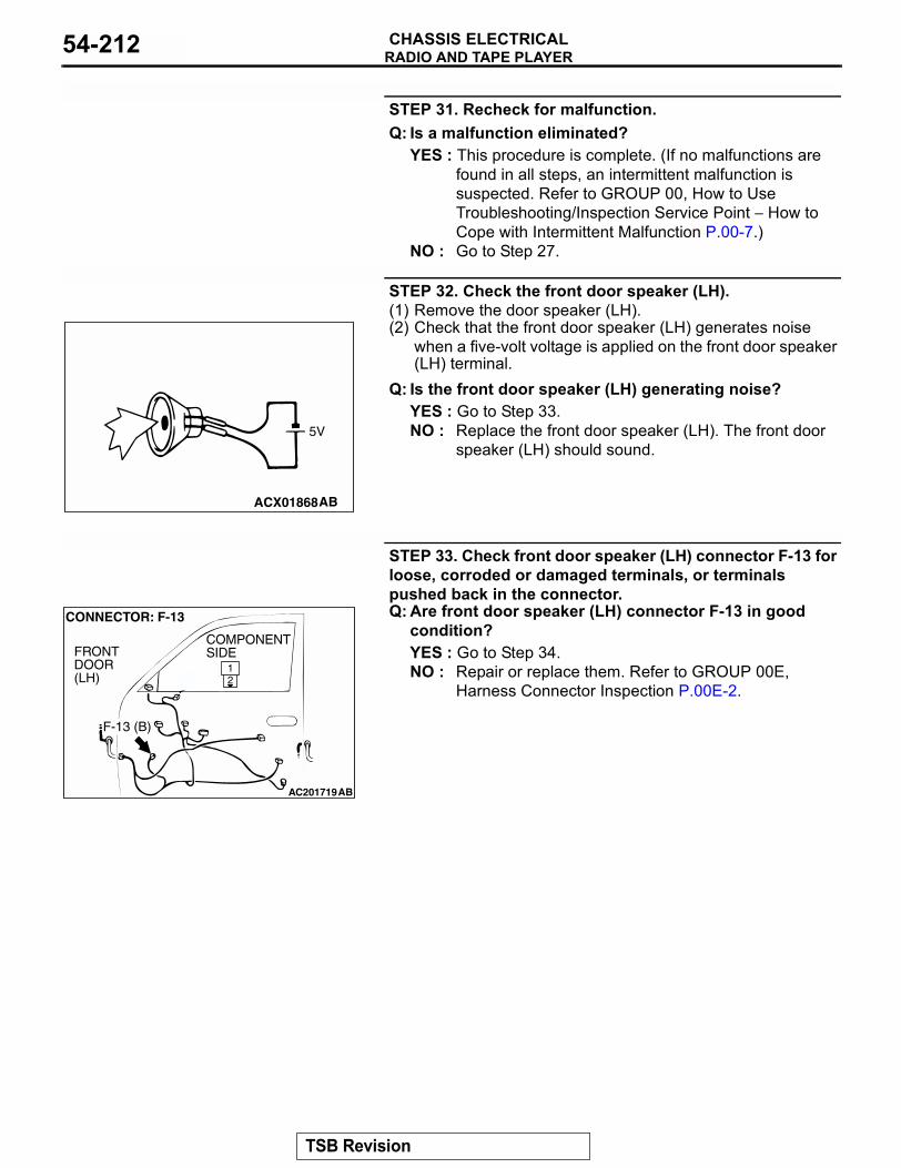
RADIO AND TAPE PLAYERCHASSIS ELECTRICAL54-212
STEP 31. Recheck for malfunction.Q: Is a malfunction eliminated?
YES : This procedure is complete. (If no malfunctions are found in all steps, an intermittent malfunction is suspected. Refer to GROUP 00, How to Use Troubleshooting/Inspection Service Point − How to Cope with Intermittent Malfunction P.00-7.)
NO : Go to Step 27.
STEP 32. Check the front door speaker (LH).(1) Remove the door speaker (LH).(2) Check that the front door speaker (LH) generates noise
when a five-volt voltage is applied on the front door speaker (LH) terminal.
Q: Is the front door speaker (LH) generating noise?YES : Go to Step 33.NO : Replace the front door speaker (LH). The front door
speaker (LH) should sound.
STEP 33. Check front door speaker (LH) connector F-13 for loose, corroded or damaged terminals, or terminals pushed back in the connector.Q: Are front door speaker (LH) connector F-13 in good
condition?YES : Go to Step 34.NO : Repair or replace them. Refer to GROUP 00E,
Harness Connector Inspection P.00E-2.
ACX01868AB
5V
AC201719
21
CONNECTOR: F-13
AB
COMPONENTSIDEFRONT
DOOR(LH)
F-13 (B)
TSB Revision
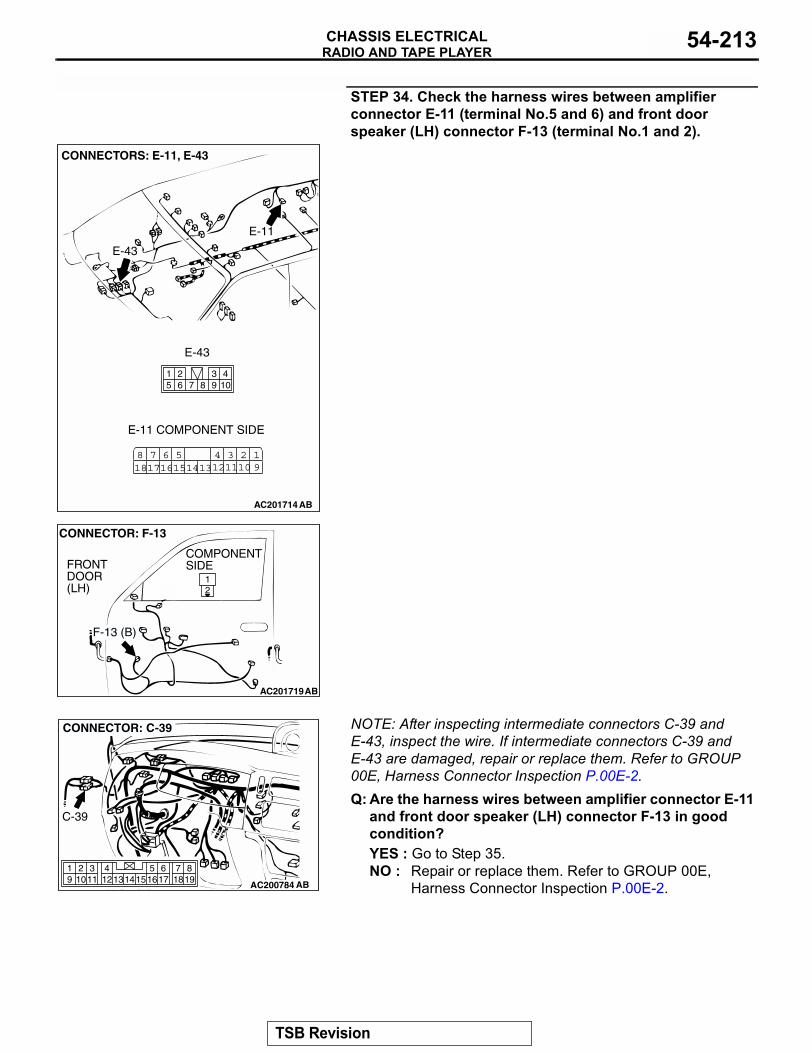
RADIO AND TAPE PLAYERCHASSIS ELECTRICAL 54-213
STEP 34. Check the harness wires between amplifier connector E-11 (terminal No.5 and 6) and front door speaker (LH) connector F-13 (terminal No.1 and 2).
NOTE: After inspecting intermediate connectors C-39 and E-43, inspect the wire. If intermediate connectors C-39 and E-43 are damaged, repair or replace them. Refer to GROUP 00E, Harness Connector Inspection P.00E-2.Q: Are the harness wires between amplifier connector E-11
and front door speaker (LH) connector F-13 in good condition?YES : Go to Step 35.NO : Repair or replace them. Refer to GROUP 00E,
Harness Connector Inspection P.00E-2.
AC201714
3 21110
41312
19
561615
781817 14
104
87651 2 3
9
CONNECTORS: E-11, E-43
E-11
E-43
E-11 COMPONENT SIDE
E-43
AB
AC201719
21
CONNECTOR: F-13
AB
COMPONENTSIDEFRONT
DOOR(LH)
F-13 (B)
AC200784
819
7651615 17 18
4321011 1213
19 14
CONNECTOR: C-39
AB
C-39
TSB Revision
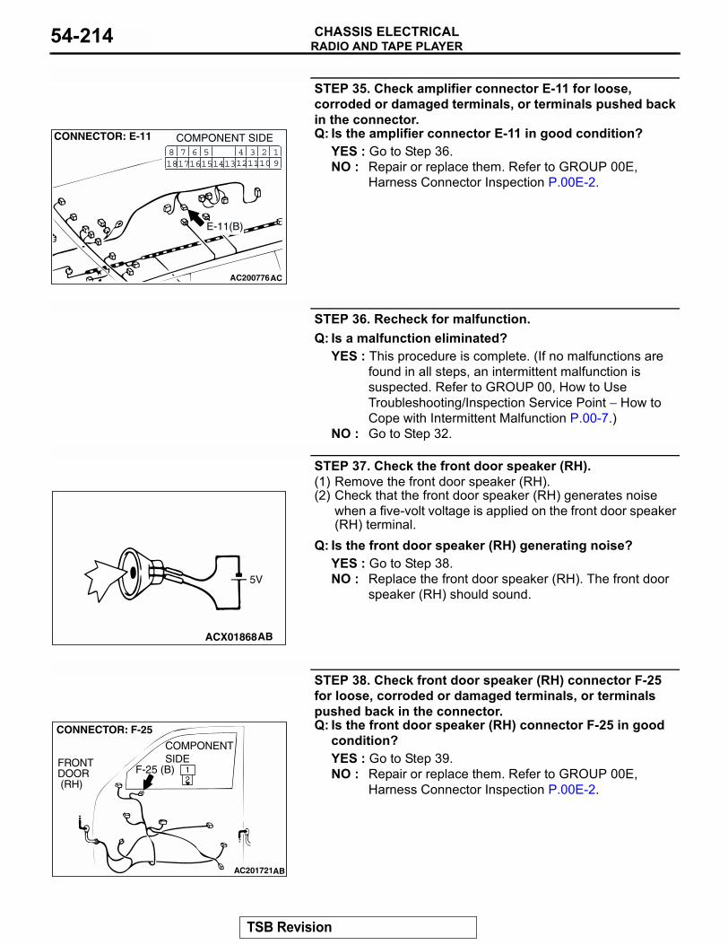
RADIO AND TAPE PLAYERCHASSIS ELECTRICAL54-214
STEP 35. Check amplifier connector E-11 for loose, corroded or damaged terminals, or terminals pushed back in the connector.Q: Is the amplifier connector E-11 in good condition?
YES : Go to Step 36.NO : Repair or replace them. Refer to GROUP 00E,
Harness Connector Inspection P.00E-2.
STEP 36. Recheck for malfunction.Q: Is a malfunction eliminated?
YES : This procedure is complete. (If no malfunctions are found in all steps, an intermittent malfunction is suspected. Refer to GROUP 00, How to Use Troubleshooting/Inspection Service Point − How to Cope with Intermittent Malfunction P.00-7.)
NO : Go to Step 32.
STEP 37. Check the front door speaker (RH).(1) Remove the front door speaker (RH).(2) Check that the front door speaker (RH) generates noise
when a five-volt voltage is applied on the front door speaker (RH) terminal.
Q: Is the front door speaker (RH) generating noise?YES : Go to Step 38.NO : Replace the front door speaker (RH). The front door
speaker (RH) should sound.
STEP 38. Check front door speaker (RH) connector F-25 for loose, corroded or damaged terminals, or terminals pushed back in the connector.Q: Is the front door speaker (RH) connector F-25 in good
condition?YES : Go to Step 39.NO : Repair or replace them. Refer to GROUP 00E,
Harness Connector Inspection P.00E-2.
AC200776
CONNECTOR: E-11
AC
COMPONENT SIDE3 21110
41312
19
561615
781817 14
E-11(B)
ACX01868AB
5V
AC201721
21
CONNECTOR: F-25
COMPONENT SIDE
AB
FRONT DOOR (RH)
F-25 (B)
TSB Revision
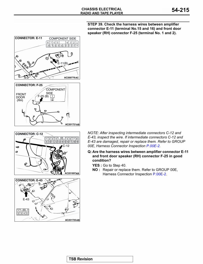
RADIO AND TAPE PLAYERCHASSIS ELECTRICAL 54-215
STEP 39. Check the harness wires between amplifier connector E-11 (terminal No.15 and 16) and front door speaker (RH) connector F-25 (terminal No. 1 and 2).
NOTE: After inspecting intermediate connectors C-12 and E-43, inspect the wire. If intermediate connectors C-12 and E-43 are damaged, repair or replace them. Refer to GROUP 00E, Harness Connector Inspection P.00E-2.Q: Are the harness wires between amplifier connector E-11
and front door speaker (RH) connector F-25 in good condition?YES : Go to Step 40.NO : Repair or replace them. Refer to GROUP 00E,
Harness Connector Inspection P.00E-2.
AC200776
CONNECTOR: E-11
AC
COMPONENT SIDE3 21110
41312
19
561615
781817 14
E-11(B)
AC201721
21
CONNECTOR: F-25
COMPONENT SIDE
AB
FRONT DOOR (RH)
F-25 (B)
AC201697
819
7651615 17 18
4321011 1213
19 14
CONNECTOR: C-12
AB
C-12
AC201725
4 5312
CONNECTOR: E-43
AB
E-43
TSB Revision
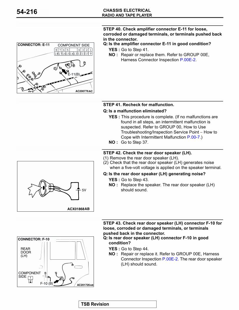
RADIO AND TAPE PLAYERCHASSIS ELECTRICAL54-216
STEP 40. Check amplifier connector E-11 for loose, corroded or damaged terminals, or terminals pushed back in the connector.Q: Is the amplifier connector E-11 in good condition?
YES : Go to Step 41.NO : Repair or replace them. Refer to GROUP 00E,
Harness Connector Inspection P.00E-2.
STEP 41. Recheck for malfunction.Q: Is a malfunction eliminated?
YES : This procedure is complete. (If no malfunctions are found in all steps, an intermittent malfunction is suspected. Refer to GROUP 00, How to Use Troubleshooting/Inspection Service Point − How to Cope with Intermittent Malfunction P.00-7.)
NO : Go to Step 37.
STEP 42. Check the rear door speaker (LH).(1) Remove the rear door speaker (LH).(2) Check that the rear door speaker (LH) generates noise
when a five-volt voltage is applied on the speaker terminal.Q: Is the rear door speaker (LH) generating noise?
YES : Go to Step 43.NO : Replace the speaker. The rear door speaker (LH)
should sound.
STEP 43. Check rear door speaker (LH) connector F-10 for loose, corroded or damaged terminals, or terminals pushed back in the connector.Q: Is rear door speaker (LH) connector F-10 in good
condition?YES : Go to Step 44.NO : Repair or replace it. Refer to GROUP 00E, Harness
Connector Inspection P.00E-2. The rear door speaker (LH) should sound.
AC200776
CONNECTOR: E-11
AC
COMPONENT SIDE3 21110
41312
19
561615
781817 14
E-11(B)
ACX01868AB
5V
AC20172621
CONNECTOR: F-10
AB
COMPONENTSIDE
REARDOOR(LH)
F-10 (B)
TSB Revision
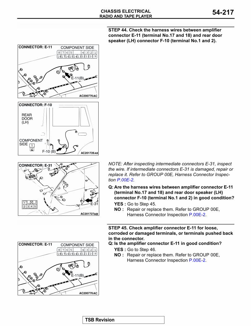
RADIO AND TAPE PLAYERCHASSIS ELECTRICAL 54-217
STEP 44. Check the harness wires between amplifier connector E-11 (terminal No.17 and 18) and rear door speaker (LH) connector F-10 (terminal No.1 and 2).
NOTE: After inspecting intermediate connectors E-31, inspect the wire. If intermediate connectors E-31 is damaged, repair or replace it. Refer to GROUP 00E, Harness Connector Inspec-tion P.00E-2.Q: Are the harness wires between amplifier connector E-11
(terminal No.17 and 18) and rear door speaker (LH) connector F-10 (terminal No.1 and 2) in good condition?YES : Go to Step 45.NO : Repair or replace them. Refer to GROUP 00E,
Harness Connector Inspection P.00E-2.
STEP 45. Check amplifier connector E-11 for loose, corroded or damaged terminals, or terminals pushed back in the connector.Q: Is the amplifier connector E-11 in good condition?
YES : Go to Step 46.NO : Repair or replace them. Refer to GROUP 00E,
Harness Connector Inspection P.00E-2.
AC200776
CONNECTOR: E-11
AC
COMPONENT SIDE3 21110
41312
19
561615
781817 14
E-11(B)
AC20172621
CONNECTOR: F-10
AB
COMPONENTSIDE
REARDOOR(LH)
F-10 (B)
AC201727
4 5312
CONNECTOR: E-31
AB
E-31
AC200776
CONNECTOR: E-11
AC
COMPONENT SIDE3 21110
41312
19
561615
781817 14
E-11(B)
TSB Revision
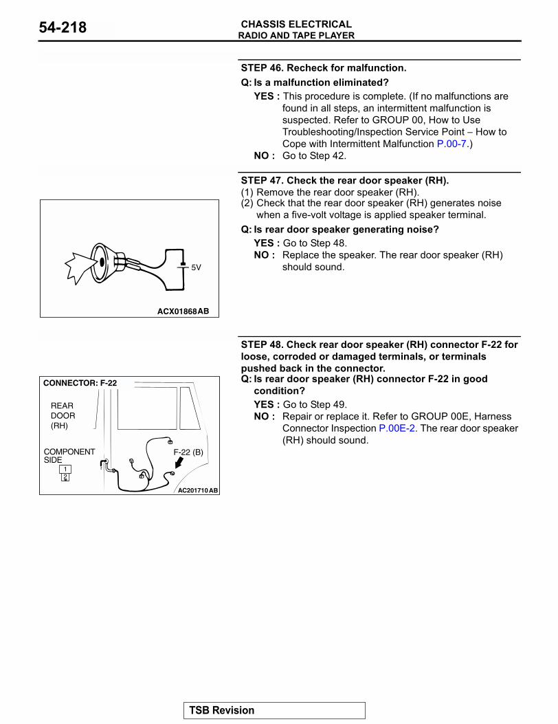
RADIO AND TAPE PLAYERCHASSIS ELECTRICAL54-218
STEP 46. Recheck for malfunction.Q: Is a malfunction eliminated?
YES : This procedure is complete. (If no malfunctions are found in all steps, an intermittent malfunction is suspected. Refer to GROUP 00, How to Use Troubleshooting/Inspection Service Point − How to Cope with Intermittent Malfunction P.00-7.)
NO : Go to Step 42.
STEP 47. Check the rear door speaker (RH).(1) Remove the rear door speaker (RH).(2) Check that the rear door speaker (RH) generates noise
when a five-volt voltage is applied speaker terminal.Q: Is rear door speaker generating noise?
YES : Go to Step 48.NO : Replace the speaker. The rear door speaker (RH)
should sound.
STEP 48. Check rear door speaker (RH) connector F-22 for loose, corroded or damaged terminals, or terminals pushed back in the connector.Q: Is rear door speaker (RH) connector F-22 in good
condition?YES : Go to Step 49.NO : Repair or replace it. Refer to GROUP 00E, Harness
Connector Inspection P.00E-2. The rear door speaker (RH) should sound.
ACX01868AB
5V
AC201710
CONNECTOR: F-22
REAR DOOR (RH)
21
AB
COMPONENT SIDE
F-22 (B)
TSB Revision
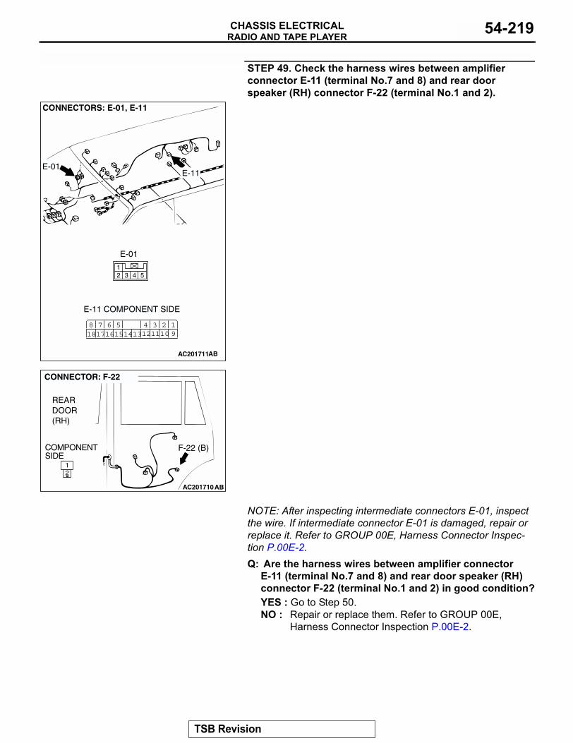
RADIO AND TAPE PLAYERCHASSIS ELECTRICAL 54-219
STEP 49. Check the harness wires between amplifier connector E-11 (terminal No.7 and 8) and rear door speaker (RH) connector F-22 (terminal No.1 and 2).
NOTE: After inspecting intermediate connectors E-01, inspect the wire. If intermediate connector E-01 is damaged, repair or replace it. Refer to GROUP 00E, Harness Connector Inspec-tion P.00E-2.Q: Are the harness wires between amplifier connector
E-11 (terminal No.7 and 8) and rear door speaker (RH) connector F-22 (terminal No.1 and 2) in good condition?YES : Go to Step 50.NO : Repair or replace them. Refer to GROUP 00E,
Harness Connector Inspection P.00E-2.
AC201711
3 21110
41312
19
561615
781817 14
4 5312
CONNECTORS: E-01, E-11
E-11 COMPONENT SIDE
AB
E-01
E-11E-01
AC201710
CONNECTOR: F-22
REAR DOOR (RH)
21
AB
COMPONENT SIDE
F-22 (B)
TSB Revision
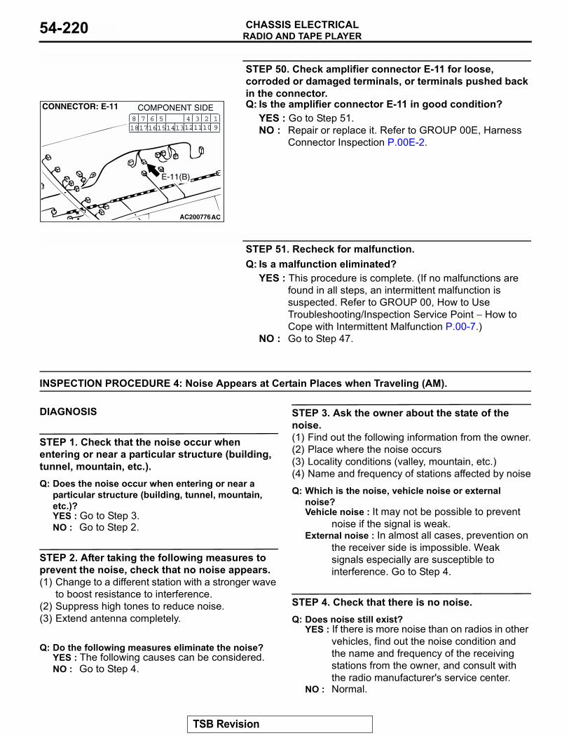
RADIO AND TAPE PLAYERCHASSIS ELECTRICAL54-220
STEP 50. Check amplifier connector E-11 for loose, corroded or damaged terminals, or terminals pushed back in the connector.Q: Is the amplifier connector E-11 in good condition?
YES : Go to Step 51.NO : Repair or replace it. Refer to GROUP 00E, Harness
Connector Inspection P.00E-2.
STEP 51. Recheck for malfunction.Q: Is a malfunction eliminated?
YES : This procedure is complete. (If no malfunctions are found in all steps, an intermittent malfunction is suspected. Refer to GROUP 00, How to Use Troubleshooting/Inspection Service Point − How to Cope with Intermittent Malfunction P.00-7.)
NO : Go to Step 47.
INSPECTION PROCEDURE 4: Noise Appears at Certain Places when Traveling (AM).
.
DIAGNOSIS
STEP 1. Check that the noise occur when entering or near a particular structure (building, tunnel, mountain, etc.).Q: Does the noise occur when entering or near a
particular structure (building, tunnel, mountain, etc.)?YES : Go to Step 3.NO : Go to Step 2.
STEP 2. After taking the following measures to prevent the noise, check that no noise appears.(1) Change to a different station with a stronger wave
to boost resistance to interference.(2) Suppress high tones to reduce noise.(3) Extend antenna completely.
Q: Do the following measures eliminate the noise?YES : The following causes can be considered.NO : Go to Step 4.
STEP 3. Ask the owner about the state of the noise.(1) Find out the following information from the owner.(2) Place where the noise occurs(3) Locality conditions (valley, mountain, etc.)(4) Name and frequency of stations affected by noiseQ: Which is the noise, vehicle noise or external
noise?Vehicle noise : It may not be possible to prevent
noise if the signal is weak.External noise : In almost all cases, prevention on
the receiver side is impossible. Weak signals especially are susceptible to interference. Go to Step 4.
STEP 4. Check that there is no noise.Q: Does noise still exist?
YES : If there is more noise than on radios in other vehicles, find out the noise condition and the name and frequency of the receiving stations from the owner, and consult with the radio manufacturer's service center.
NO : Normal.
AC200776
CONNECTOR: E-11
AC
COMPONENT SIDE3 21110
41312
19
561615
781817 14
E-11(B)
TSB Revision
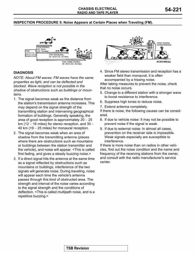
RADIO AND TAPE PLAYERCHASSIS ELECTRICAL 54-221
INSPECTION PROCEDURE 5: Noise Appears at Certain Places when Traveling (FM).
.
DIAGNOSISNOTE: About FM waves: FM waves have the same properties as light, and can be deflected and blocked. Wave reception is not possible in the shadow of obstructions such as buildings or moun-tains.1. The signal becomes weak as the distance from
the station's transmission antenna increases. This may depend on the signal strength of the transmitting station and intervening geographical formation of buildings. Generally speaking, the area of good reception is approximately 20 − 25 km (12 − 16 miles) for stereo reception, and 30 − 40 km (19 − 25 miles) for monaural reception.
2. The signal becomes weak when an area of shadow from the transmitting antenna (places where there are obstructions such as mountains or buildings between the station transmitter and the vehicle), and noise will appear. <This is called first fading, and gives a steady buzzing noise.>
3. If a direct signal hits the antenna at the same time as a signal reflected by obstructions such as mountains or buildings, interference of the two signals will generate noise. During traveling, noise will appear each time the vehicle's antenna passes through this kind of obstructed area. The strength and interval of the noise varies according to the signal strength and the conditions of deflection. <This is called multipath noise, and is a repetitive buzzing.>
4. Since FM stereo transmission and reception has a weaker field than monaural, it is often accompanied by a hissing noise.
After taking measures to prevent the noise, check that no noise occurs.5. Change to a different station with a stronger wave
to boost resistance to interference.6. Suppress high tones to reduce noise.7. Extend antenna completely.If there is noise, the following causes can be consid-ered.8. If due to vehicle noise: It may not be possible to
prevent noise if the signal is weak.9. If due to external noise: In almost all cases,
prevention on the receiver side is impossible. Weak signals especially are susceptible to interference.
If there is more noise than on radios in other vehi-cles, find out the noise condition and the name and frequency of the receiving stations from the owner, and consult with the radio manufacturer's service center.
ACX01869
10kWOUTPUT FMBROAD CAST
FOR STEREO:20 - 25 km(12 - 16 miles)
FOR MONAURAL:30 - 40 km (19 - 25 miles)
FOR HOME STEREO:80 - 90 km (50 - 56 miles)
MULTIPATH INTERFERENCE
FIRST FADINGINTERFERENCE
AC
TSB Revision
RADIO AND TAPE PLAYERCHASSIS ELECTRICAL54-222
INSPECTION PROCEDURE 6: Mixed with Noise, Only at Night (AM).
The following factors can be considered as possible causes of noise appearing at night.1. Factors due to signal conditions: Due to the fact
that long-distance signals are more easily received at night, even stations that are received without problem during the day may experience interference in a general worsening of reception conditions. The weaker a station is the more susceptible it is to interference, and a change to different station or the appearance of a beating sound* may occur.NOTE: Beat sound*: Two signals close in fre-quency interfere with each other, creating a repeti-tious high-pitched sound. This sound is generated not only by sound signals but electrical waves as well.
2. Factors due to vehicles noise: Generator noise may be a cause.
.
DIAGNOSIS
STEP 1. Check that the noise is still obvious even when the lights are off.Q: Is the noise still obvious even when the lights are
off?YES : Go to Step 2.NO : Go to Step 3.
STEP 2. Check that the following actions disappear the noise. (1) Tune to a station with a stronger wave.(2) Tune to a station with a stronger wave without
completely extending the antenna (Mast antenna).
Q: Is there more noise than on radio in other vehicles?YES : Consult the radio manufacturer's service
center.NO : Check that there is no noise.
STEP 3. Check that the noise fades away when the vehicle harness is moved away from the radio (if the harness is not in the proper position).Q: Does the noise fade away when the vehicle
harness is moved any from the radio (If the harness is not in the proper position)?NO : If there is more noise than other radios,
consult the radio manufacturer's service center.
INSPECTION PROCEDURE 7: Broadcasts can be Heard but Both AM and FM Have a Lot of Noise.
DIAGNOSIS
STEP 1. Check that the noise occurs when the engine is stopped or the engine is running.Q: Does noise occur when the engine is stopped or
the engine is running?When the engine is stopped : Go to Step 2.When the engine is running : Check the vehicle's
noise suppressor. (Refer to Inspection Procedure 9 P.54-225.)
STEP 2. Check that the following actions disappear the noise.(1) Tune to a station with a stronger wave.(2) Extend the antenna completely (Mast antenna).(3) Adjust the sound quality to suppress high tones.Q: Is the noise eliminated?
YES : Consult the radio manufacturer's service center.
NO : Go to Step 3.
STEP 3. Check that the radio is correctly grounded.Q: Is the radio correctly grounded?
YES : Go to Step 4.NO : Consult the radio manufacturer's service
center.
TSB Revision
RADIO AND TAPE PLAYERCHASSIS ELECTRICAL 54-223
STEP 4. Check that the antenna plug is properly connected to the radio.Q: Is the antenna plug properly connected to the
radio?YES : Go to Step 7.NO : Go to Step 5.
STEP 5. Check that the noise is eliminated when the antenna plug is properly attached.Q: Is the noise eliminated?
YES : Consult the radio manufacturer's service center.
NO : Go to Step 6.
STEP 6. Check that the antenna is in good condition and is properly mounted.Q: Is the antenna in good condition and is it properly
mounted?YES : Consult the radio manufacturer's service
center.NO : Go to Step 7.
STEP 7. Clean the antenna plug and ground wire mounting area. Mount the antenna securely. On a vehicles with a motor antenna, check the antenna. (Refer to Inspection Procedure 34 or 35.)NOTE: Noise encountered during FM reception only due to differences in FM and AM system, FM is not as susceptible as AM to interference from engines, power lines, lighting, etc. On the other hand, due to the characteristics of FM waves, there are some-
times cases of noise or distortion which are gener-ated by typical noise interference (first fading and multipath). (Refer to Inspection Procedure 8.) <Noise (hissing) occurs in weak signal areas such as moun-tainous regions, but this is not due to a problem with the radio.>NOTE: Furthermore, the amount of interference will be comparatively less for vehicles equipped with a diversity antenna system*. If there is an equivalent amount of distortion in vehicles or radios of the same type, then differences will be because of differences in antenna systems, and this should be explained to the user.NOTE: Diversity antenna system*: A system where two types of antenna (glass main antenna and glass sub antenna) are equipped and the antenna that pro-vides the best reception car be selected.
Q: Is the antenna in good condition?YES : Consult the radio manufacturer's service
center.NO : Clean or repair it. Check that the noise is
eliminated. If the noise is not eliminated, consult the radio manufacturer's service center.
TSB Revision
RADIO AND TAPE PLAYERCHASSIS ELECTRICAL54-224
INSPECTION PROCEDURE 8: There is More Noise on either AM or FM.
.
DIAGNOSISThere is much noise only on AM. Due to differences in AM and FM systems, AM is more susceptible to noise interference.
STEP 1. Check that there is noise under the following state(s).
• A motorcycle was passing.• Lighting was flashing.• A vehicle passed close by, but it appeared to be a
vehicle generating a particularly large amount of noise radiation.
• Passed beneath a power line.• Passed beneath a telephone line.• Passed close by a signal generator.• Passed close by some other sources of electrical
noise.• Passed under a bridge.
Q: Is there noise in the above states?YES : Go to Step 3.NO : Go to Step 2.
STEP 2. Continue to check for static; when static is detected, check for the conditions listed above.Q: Is there noise in the state described in Step 1?
YES : Noise prevention on the radio side is difficult. If the problem is particularly worse than other radios, consult a service center.
NO : Go to Step 3.
STEP 3. Check noise prevention on the radio side is difficult.NOTE: Noise encountered during FM reception only. Due to differences in FM and AM systems, FM is not as susceptible as AM to interference from engines, power lines, lighting, etc. On the other hand, due to the characteristics of FM waves, there are some-times cases of noise or distortion which are gener-ated by typical noise interference (first fading and multipath). (Refer to Inspection Procedure 8.) <Noise (hissing) occurs in weak signal areas such as moun-tainous regions, but this is not due to a problem with the radio.> Furthermore, the amount of interference will be comparatively less for vehicles equipped with a diversity antenna system. If there is an equivalent amount of distortion in vehicles or radios of the same type, then differences will be because of differences in antenna systems, and this should be explained to the user.
Q: Is the noise level worse than other radios?YES : Consult a service center. NO : If the noise level is roughly the same as
other radios, there is no action to be taken.
TSB Revision
RADIO AND TAPE PLAYERCHASSIS ELECTRICAL 54-225
INSPECTION PROCEDURE 9: There is Noise when Starting the Engine.
.
DIAGNOSISCAUTION
• Connecting a high tension cable to the noise filter may destroy the noise filter and should never be done.
• Check that there is no external noise. Since failure to do this may result in an incorrect diagnosis due to the inability to identify the noise source, this operation must be per-formed.
• Noise prevention should be performed by suppressing strong sources of noise step by step.
NOTE: Capacitor: The capacitor does not pass DC current, but as the number of waves increases when it passes AC current, impedance (resistance against AC) decreases, and current flow is facilitated. A noise suppressing capacitor which take advantage of this property is inserted between the power line for the noise source and the ground. This suppresses noise by grounding the noise component (AC or pulse signal) to the body of the vehicle.
NOTE: Coil: The coil passes DC current, but imped-ance rises as the number of waves increases relative to the AC current. A noise suppressing coil which takes advantage of this property is inserted into the power line for the noise source, and works by pre-venting the noise component from flowing or radiat-ing out of the line.
NOISE TYPE SOUNDS ARE IN PARENTHESES
CONDITION CAUSE REMEDY
AM, FM: ignition noise (popping, snapping, cracking, buzzing)
• Increasing the engine speed causes the generator whine sound to speed up and the volume to decrease
• Disappears when the ignition switch turned to "ACC" position.
• Mainly due to the spark plugs
• Due to engine noise
• Check or replace the ground cable. (Refer to figure 1, 2, 3 and 4)
• Check or replace the noise capacitor. (Refer to figure 5.)
Other electrical components
- • Noise may occur as the electrical components become older.
• Repair or replace the electrical components.
Static electricity (cracking, crinkling)
• Disappears when the vehicle is completely stopped.
• Severe when the clutch is engaged.
• Occurs when parts or wiring move for some reason and contact metal parts of the body.
• Return parts or wiring to their proper position.
TSB Revision
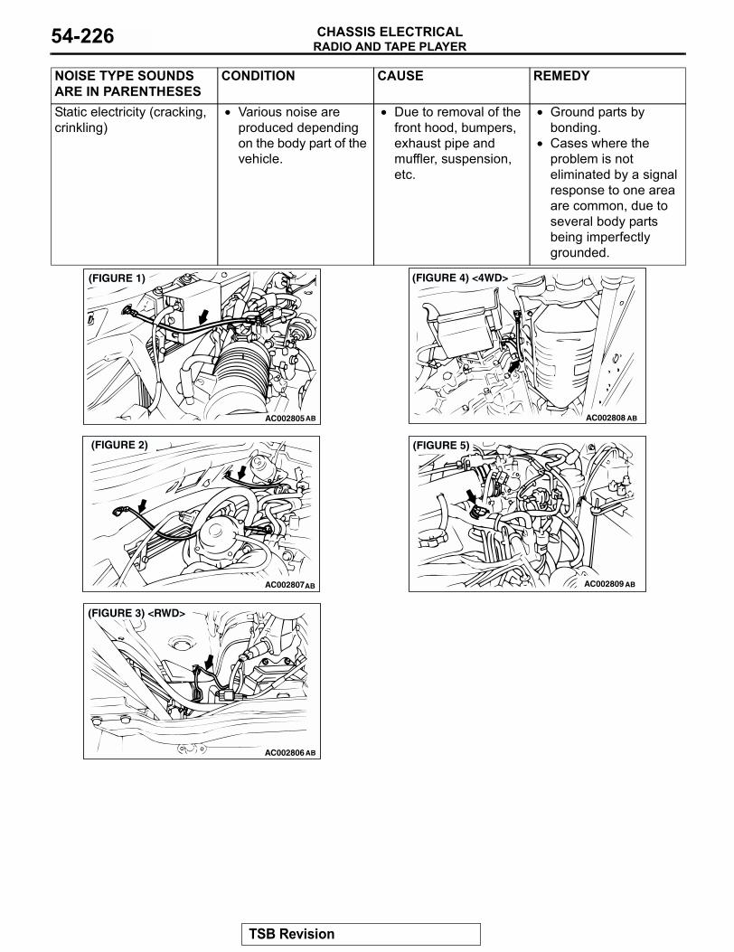
RADIO AND TAPE PLAYERCHASSIS ELECTRICAL54-226
Static electricity (cracking, crinkling)
• Various noise are produced depending on the body part of the vehicle.
• Due to removal of the front hood, bumpers, exhaust pipe and muffler, suspension, etc.
• Ground parts by bonding.
• Cases where the problem is not eliminated by a signal response to one area are common, due to several body parts being imperfectly grounded.
NOISE TYPE SOUNDS ARE IN PARENTHESES
CONDITION CAUSE REMEDY
AC002805
(FIGURE 1)
AB
AC002807
(FIGURE 2)
AB
AC002806
(FIGURE 3) <RWD>
AB
AC002808
(FIGURE 4) <4WD>
AB
AC002809
(FIGURE 5)
AB
TSB Revision
RADIO AND TAPE PLAYERCHASSIS ELECTRICAL 54-227
INSPECTION PROCEDURE 10: Some Noise Appears when there is Vibration or Shocks during Traveling.
.
DIAGNOSIS
STEP 1. Check that the connectors are properly connected.NOTE: For the corresponding connectors, etc., refer to GROUP 90, Radio and Tape Player <vehicles without amplifier.> or <vehicles with amplifier.>
Q: Are the connectors properly connected?YES : Go to Step 2.NO : Check the condition of the connector. Refer
to GROUP 00E, Harness Connector Inspection P.00E-2. Check that there is no noise.
STEP 2. Check that noise appears when the radio switch is turned on while the vehicle is stopped.NOTE: Static electricity noise: Body static electric from the shock absorber rubber bushings used to prevent vibration, tires, etc. occurs because of sepa-ration from the ground, causing a buzzing noise. Since no measures can be taken to discharge the static electricity of the vehicle body. Check that there is no noise.
Q: Does noise appear when the radio switch is turned on while the vehicle is stopped and the radio is tapped while tuned away from a station?YES : Go to Step 3.NO : It may be static electricity noise.
STEP 3. Check that the radio is correctly grounded. Q: Is the radio correctly grounded?
YES : Go to Step 4.NO : Tighten the screw securely. Check that
there is no noise.
STEP 4. Check that the antenna is correctly grounded. (If noise appears when the antenna is moved, this means the ground is not securely connected.)Q: Is the antenna correctly grounded?
YES : Repair or replace the radio. Check that there is no noise.
NO : If rust is present on the antenna ground screw, clean off the rust and tighten the ground screw securely. Check that there is no noise.
INSPECTION PROCEDURE 11: Noise Sometimes Appears on FM during Traveling.
.
Radio and CD Player CircuitRefer to GROUP 90, Radio and Tape Player <vehi-cles without amplifier> or <vehicles with amplifier>..
DIAGNOSIS
STEP 1. Retune the radio, and check that there is no noise.Q: Does the problem clear up when returned?
YES : Check that there is no noise.NO : Go to Step 2.
STEP 2. Check that the noise appears only in certain locations and only with certain stations.NOTE: Multipath noise and fading noise: Because of the frequency of FM waves in extremely high, it is highly susceptible to effects from geological forma-tions and buildings. These effects disrupt the broad-cast signal and obstruct reception in several ways..
• Multipath noiseThis describes the echo that occurs when the broadcast signal is reflected by a large obstruc-tion and enters the receiver with a slight time delay relative to the direct signal (repetitious buzzing).
• Fading noiseThis is a buzzing noise that occurs when the broadcast beam is disrupted by obstructing objects and the signal strength fluctuates intri-cately within a narrow range.
TSB Revision
RADIO AND TAPE PLAYERCHASSIS ELECTRICAL54-228
Q: Does the problem appear only in certain locations and only with certain stations?YES : The effect of an electrical field condition
(multipath noise, fading noise) could be the cause. Check that there is not noise.
NO : Go to Step 3.
STEP 3. Check that the connectors are properly connected.NOTE: For the corresponding connectors, etc., refer to GROUP 90, Radio and Tape Player <vehicles without amplifier.> or <vehicles with amplifier.>.
Q: Are the connectors properly connected?YES : Go to Step 4.NO : Check the condition of the connector. Refer
to GROUP 00E, Harness Connector Inspection P.00E-2. Check that there is no noise.
STEP 4. Check that noise appears when the radio switch is turned on while the vehicle is stopped.NOTE: Static electricity noise: Body static electric from the shock absorber rubber bushings used to prevent vibration, tires, etc. occurs because of sepa-ration from the ground, causing a buzzing noise. There is no measures to discharge the static electric-ity of the vehicle body. Check that there is no noise.
Q: Does noise appear when the radio switch is turned on while the vehicle is stopped and the radio is tapped while tuned away from a station?YES : Go to Step 5.NO : It may be static electricity noise.
STEP 5. Check that the radio is correctly grounded. Q: Is the radio correctly grounded?
YES : Go to Step 6.NO : Tighten the screw securely. Check that
there is no noise.
STEP 6. Check that the antenna is correctly grounded. (If noise appears when the antenna is moved, this means the ground is not securely connected.)Q: Is the antenna correctly grounded?
YES : Repair or replace the radio. Check that there is no noise.
NO : If rust is present on the antenna ground screw, clean off the rust and tighten the ground screw securely. Check that there is no noise.
INSPECTION PROCEDURE 12: Ever-present Noise.
.
DiagnosisNoise is often created by the following factors, and often the radio is OK when it is checked individually.
• Traveling conditions of the vehicle• Terrain of area traveled through• Surrounding buildings• Signal conditions• Time period
For this reason, if there are still problems with noise even after the measures described in inspection procedure 7 to 14 have been taken, get information on the factors listed above as well as determining whether the problem occurs with AM or FM, the station names, frequencies, etc. and contact the radio manu-facturer's service center.
TSB Revision
RADIO AND TAPE PLAYERCHASSIS ELECTRICAL 54-229
INSPECTION PROCEDURE 13: There is Noise but No Reception for Both AM and FM or No Sound from AM, or No Sound from FM.
.
DIAGNOSIS
STEP 1. Make sure that the check is being conducted under special electrical field conditions.Example: In an underground garage or inside a building.
Q: Is the check being conducted under special electrical field conditions?YES : Go to Step 2.NO : Go to Step 3.
STEP 2. Check that proper performance is obtained when the vehicle is moved.Q: Is proper performance obtained when the vehicle is
moved?YES : The radio should sound normally.NO : Go to Step 3.
STEP 3. Check that tuning solves the problem.Q: Does tuning solve the problem?
YES : The radio should sound normally.NO : Go to Step 4.
STEP 4. Check that the antenna plug and radio unit are properly connected.Q: Are the antenna plug and radio unit properly
connected?YES : Go to Step 5.NO : Reconnect the antenna plug and radio unit
properly. The radio should sound normally.
STEP 5. Check that the problem disappear if another radio is used.Q: Does the problem disappear if another radio is
used?YES : Repair or replace the radio. The radio
should sound normally. NO : Either repair or replace the antenna
assembly. The radio should sound normally.
INSPECTION PROCEDURE 14: Poor Reception.
.
DIAGNOSIS
STEP 1. Make sure that the check is being conducted under special electrical field conditions.Q: Is the check being conducted under special
electrical field conditions (such as in an underground garage or inside a building)?YES : Go to Step 2.NO : Go to Step 3.
STEP 2. Check that proper performance is obtained when the vehicle is moved.Q: Is proper performance obtained when the vehicle
is moved?YES : Check that a poor reception is resolved.NO : Go to Step 3.
STEP 3. Check that tuning solves the problem.Q: Does tuning solve the problem?
YES : Check that a poor reception is resolved.NO : Go to Step 4.
TSB Revision
RADIO AND TAPE PLAYERCHASSIS ELECTRICAL54-230
STEP 4. Check that the problem is limited to the reception of a specific radio station from a specific position.NOTE: Multipath noise and fading noise: Because the frequency of FM waves is extremely high, it is highly susceptible to effects from geological forma-tions and buildings. These effects disrupt the broad-cast signal and obstruct reception in several ways. .
• Multipath noiseThis describes the echo that occurs when the broadcast signal is reflected by a large obstruc-tion and enters the receiver with a slight time delay relative to the direct signal (repetitious buzzing).
• Fading noiseThis is a buzzing noise that occurs when the broadcast beam is disrupted by obstructing objects and the signal strength fluctuates intri-cately within a narrow range.
Q: Is the problem limited to the reception of a specific radio station from a specific position?YES : Go to Step 5.NO : Check that a poor reception is resolved.
STEP 5. Check that the antenna plug is connected to the radio properly.Q: Is the antenna plug connected to the radio
properly?YES : Go to Step 6.NO : Reconnect the antenna plug and radio unit
properly. Check that a poor reception is resolved.
STEP 6. Check that the problem disappears when another radio is used.Q: Does the problem disappear if another radio is
used?YES : Repair or replace the radio. Check that a
poor reception is resolved.NO : Either repair or replace the antenna
assembly. Check that a poor reception is resolved.
INSPECTION PROCEDURE 15: Distortion on AM or on Both AM and FM.
.
DIAGNOSIS
STEP 1. Check how much distortion there is.Q: How much distortion is there?
Occasional distortion : Go to Step 2.Constant distortion : Go to Step 3.
STEP 2. Check that there is distortion near the radio station.Q: Is there distortion near the radio station?
YES : The antenna may receive too strong signal.NO : Go to Step 3.
STEP 3. Check that the speaker cords are in contact with the cone paper. Q: Are the speaker cords in contact with the cone
paper?YES : Move the cords away from the cone paper.
Check that a distortion is resolved.NO : Go to Step 4.
STEP 4. Remove the speakers, and check for torn cone paper or foreign material.Q: Is there torn cone paper or foreign material?
YES : Repair or replace the speakers. Check that a distortion is resolved.
NO : Go to Step 5.
STEP 5. Check for distortion with the speaker installed.Q: Does a distortion occur?
YES : Install the speaker securely. Check that a distortion is resolved.
NO : Repair or replace the radio. Check that a distortion is resolved.
TSB Revision
RADIO AND TAPE PLAYERCHASSIS ELECTRICAL 54-231
INSPECTION PROCEDURE 16: Distortion on FM Only.
.
DIAGNOSIS
STEP 1. Check that the distortion persists when the radio is turned to another station.Q: Does the distortion persist when the radio is
turned to another station?YES : Go to Step 2.NO : The signal from that station is too weak.
STEP 2. Check that the distortion increases or decreases when the vehicle is moved.Q: Does distortion increase or decrease when the
vehicle is moved?YES : The cause may be multipath noise.NO : Repair or replace the radio. Check that a
distortion is resolved.
INSPECTION PROCEDURE 17: Using the Auto Select Function, too Few Automatic Stations are Selected.
.
DIAGNOSIS
STEP 1. Consider the number of radio stations. Check that there are enough in the area.Q: Consider the number of radio stations. Are there
enough in the area?YES : Go to Step 2.NO : Confirm automatic selection selects the
strongest signals in the area. If not, go to Step 3.
STEP 2. Consider the distance to the radio stations. Check that the transmitting antennas are within 2 miles.Q: Consider the distance to the radio stations. Are the
transmitting antennas within 2 miles?YES : Go to Step 3.NO : Confirm automatic selection selects the
strongest signals in the area. If not, go to Step 4.
STEP 3. Make sure that the check is being conducted under special field conditions.Q: Is the check being conducted under special
electrical field conditions (such as in an underground garage or inside a building)?YES : Go to Step 4.NO : Go to Step 5.
STEP 4. Check that proper performance is obtained when the vehicle is moved.Q: Is proper performance obtained when the vehicle is
moved?YES : The auto-select function should operate
normally.NO : Go to Step 5.
STEP 5. Check that the antenna plug is connected to the radio properly.Q: Is the antenna plug connected to the radio
properly?YES : Go to Step 6.NO : The antenna plug is reconnected to the
radio properly. The auto-select function should operate normally.
STEP 6. Check that the problem disappears when another radio is used.Q: Does the problem disappear if another radio is
used?YES : Replace the radio. The auto-select function
should operate normally.No : Move the vehicle in an area with good radio
signals. Then go to Step 1 .
TSB Revision
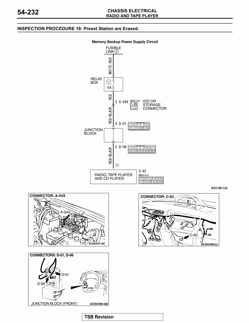
RADIO AND TAPE PLAYERCHASSIS ELECTRICAL54-232
INSPECTION PROCEDURE 18: Preset Station are Erased.
FUSIBLELINK 8
RELAYBOX
JUNCTIONBLOCK
RADIO, TAPE PLAYERAND CD PLAYER
IOD ORSTORAGECONNECTOR
Memory Backup Power Supply Circuit
AC003431
CONNECTOR: A-54X
A-54X
AC AC003489AC
CONNECTOR: C-62
C-62
AC003460 AB
CONNECTORS: D-01, D-06
D-01
D-06
JUNCTION BLOCK (FRONT)
TSB Revision
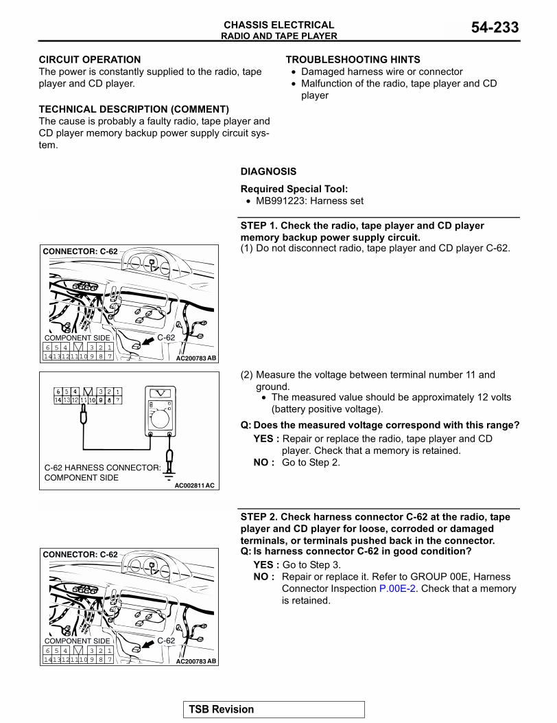
RADIO AND TAPE PLAYERCHASSIS ELECTRICAL 54-233
.
CIRCUIT OPERATIONThe power is constantly supplied to the radio, tape player and CD player..
TECHNICAL DESCRIPTION (COMMENT)The cause is probably a faulty radio, tape player and CD player memory backup power supply circuit sys-tem.
.
TROUBLESHOOTING HINTS• Damaged harness wire or connector• Malfunction of the radio, tape player and CD
player
.
DIAGNOSIS
Required Special Tool:• MB991223: Harness set
STEP 1. Check the radio, tape player and CD player memory backup power supply circuit.(1) Do not disconnect radio, tape player and CD player C-62.
(2) Measure the voltage between terminal number 11 and ground.
• The measured value should be approximately 12 volts (battery positive voltage).
Q: Does the measured voltage correspond with this range?YES : Repair or replace the radio, tape player and CD
player. Check that a memory is retained.NO : Go to Step 2.
STEP 2. Check harness connector C-62 at the radio, tape player and CD player for loose, corroded or damaged terminals, or terminals pushed back in the connector.Q: Is harness connector C-62 in good condition?
YES : Go to Step 3.NO : Repair or replace it. Refer to GROUP 00E, Harness
Connector Inspection P.00E-2. Check that a memory is retained.
AC200783
17
281011
513
614 12
493
CONNECTOR: C-62
COMPONENT SIDE
AB
C-62
AC002811AC
C-62 HARNESS CONNECTOR:COMPONENT SIDE
AC200783
17
281011
513
614 12
493
CONNECTOR: C-62
COMPONENT SIDE
AB
C-62
TSB Revision
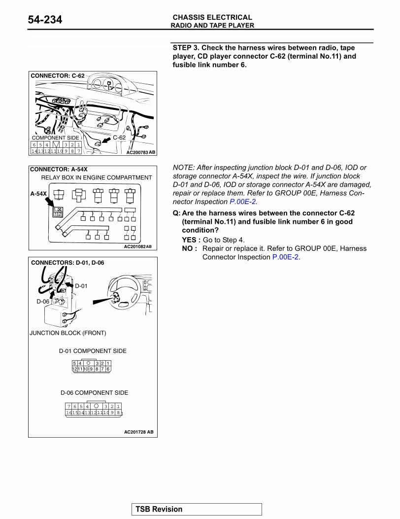
RADIO AND TAPE PLAYERCHASSIS ELECTRICAL54-234
STEP 3. Check the harness wires between radio, tape player, CD player connector C-62 (terminal No.11) and fusible link number 6.
NOTE: After inspecting junction block D-01 and D-06, IOD or storage connector A-54X, inspect the wire. If junction block D-01 and D-06, IOD or storage connector A-54X are damaged, repair or replace them. Refer to GROUP 00E, Harness Con-nector Inspection P.00E-2.Q: Are the harness wires between the connector C-62
(terminal No.11) and fusible link number 6 in good condition?YES : Go to Step 4.NO : Repair or replace it. Refer to GROUP 00E, Harness
Connector Inspection P.00E-2.
AC200783
17
281011
513
614 12
493
CONNECTOR: C-62
COMPONENT SIDE
AB
C-62
AC201082
1 2
AB
A-54X
RELAY BOX IN ENGINE COMPARTMENTCONNECTOR: A-54X
AC201728
238 7910
16
512
411
18
3457 6101516 14 1213 11 9
2
JUNCTION BLOCK (FRONT)
CONNECTORS: D-01, D-06
D-01 COMPONENT SIDE
D-06 COMPONENT SIDE
AB
D-01
D-06
TSB Revision
RADIO AND TAPE PLAYERCHASSIS ELECTRICAL 54-235
STEP 4. Recheck for malfunction.Q: Is a malfunction eliminated?
YES : This procedure is complete. (If no malfunctions are found in all steps, an intermittent malfunction is suspected. Refer to GROUP 00, How to Use Troubleshooting/Inspection Service Point − How to Cope with Intermittent Malfunction P.00-7.)
NO : Go to Step 1.
INSPECTION PROCEDURE 19: CD can not be Inserted.
.
DIAGNOSIS
STEP 1. Check that the shutter opens when a CD is inserted.Q: Does the shutter open when a CD is inserted?
YES : Go to Step 2.NO : Take out the CD. Check that a CD can be
inserted.
STEP 2. Check that the CD is ejected from approximately 15 mm (0.6 inch) inside the insertion panel even though it can be inserted.NOTE: If the key switch is not at "ACC" or "ON," the CD stops at depth of 15 mm(0.6 inch) below the panel surface even when it is inserted, and it will be rejected when pushed farther.
Q: Is the CD ejected from approximately 15 mm (0.6 inch) inside the insertion panel even though it can be inserted?YES : Go to Step 3.NO : Check that a CD can be inserted.
STEP 3. Check that "E" (error) is displayed even though the CD is inserted completely.NOTE: Even though the CD is loaded, "E" (error) is sometimes displayed with the CD rejected because of vibration/shock or dew on the CD face or optical lens.
Q: Though the CD is inserted completely, is "E" (error) displayed and the CD ejected?YES : Go to Step 4.NO : Check that a CD can be inserted.
STEP 4A. Check the CD.Q: Is the labeled side faced downward?
YES : Insert the CD correctly.NO : Replace the CD. Check that a CD can be
inserted.
STEP 4B. Check the CD.Q: Is the recorded face of the CD dirty?
YES : Clean the CD. No : Replace the CD. Check the CD can be
inserted.
STEP 4C. Check the CD.Q: Is there dew on the recorded face of the CD?
YES : Remove the dew.NO : Replace the CD. Check that a CD can be
inserted.
TSB Revision
RADIO AND TAPE PLAYERCHASSIS ELECTRICAL54-236
INSPECTION PROCEDURE 20: No sound. (CD only)
.
DIAGNOSIS
STEP 1. Check that the CD player plays properly if another CD is inserted.Q: Does it play properly if another CD is inserted?
YES : The CD used is defective. The CD player should sound normally.
NO : Go to Step 2.
STEP 2. Return it to the normal temperature, and recheck the operation. Check that the CD player operates properly.Q: Return it to the normal temperature, and recheck
the operation. Does it operate properly?YES : The CD player should sound normally.NO : Repair or replace the CD player. The CD
player should sound normally.
INSPECTION PROCEDURE 21: CD Sound Skips.
.
DIAGNOSIS
STEP 1. Malfunction occurrence state.Q: When does a malfunction occur?
While parking : Go to Step 2.While driving : Stop vehicle, go to Step 4.
STEP 2. Check that the CD face scratched or dirty.Q: Is the CD face scratched or dirty?
YES : CD is defective, or clean the CD. Check that a CD sound skip is resolved.
NO : Go to Step 3.
STEP 3. Check that the CD player plays properly if another CD is started.Q: Does it play properly if another CD is inserted?
YES : CD is defective. Check that a CD sound skip is resolved.
NO : Repair or replace the CD player. Check that a CD sound skip is resolved.
STEP 4. Check that sound skips when the side of the CD player is tapped.NOTE: Check by using a proper CD which is free from scratches, dirt or any other abnormality.
Q: Does sound skip when the side of the CD player is tapped?YES : Securely mount the CD player. Check that a
CD sound skip is resolved.NO : Check the sound skipping state in detail
while driving, and then contact a service shop. Check that a CD sound skip is resolved.
TSB Revision
RADIO AND TAPE PLAYERCHASSIS ELECTRICAL 54-237
INSPECTION PROCEDURE 22: Sound Quality is Poor.
. DIAGNOSIS
STEP 1. Check that the CD player plays properly if another CD is inserted.Q: Does it play properly if another CD is inserted?
YES : CD used is defective. The sound quality should return to normal.
NO : Repair or replace the CD player. The sound quality should return to normal.
INSPECTION PROCEDURE 23: CD can not be Ejected.
.
DIAGNOSIS
STEP 1. Check that the key switch (ignition key) is at "ACC" or "ON".Q: Is the key switch (ignition key) at "ACC" or "ON?"
YES : Go to Step 2.NO : Check the memory backup power supply
circuit. Refer to Inspection Procedure 21.
STEP 2. Check that the combined amplifier or radio set connected securely?Q: Is the combined amplifier or radio set connected
securely?YES : If the CD is not ejected, do not discard it,
because the player may be damaged. Therefore, contact a service shop for repairs. Check that a CD can be ejected normally.
NO : Connect the connectors securely. Check that a CD can be ejected normally.
TSB Revision
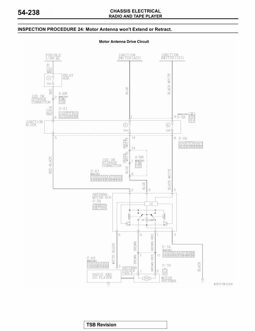
RADIO AND TAPE PLAYERCHASSIS ELECTRICAL54-238
INSPECTION PROCEDURE 24: Motor Antenna won't Extend or Retract.
Motor Antenna Drive Circuit
TSB Revision
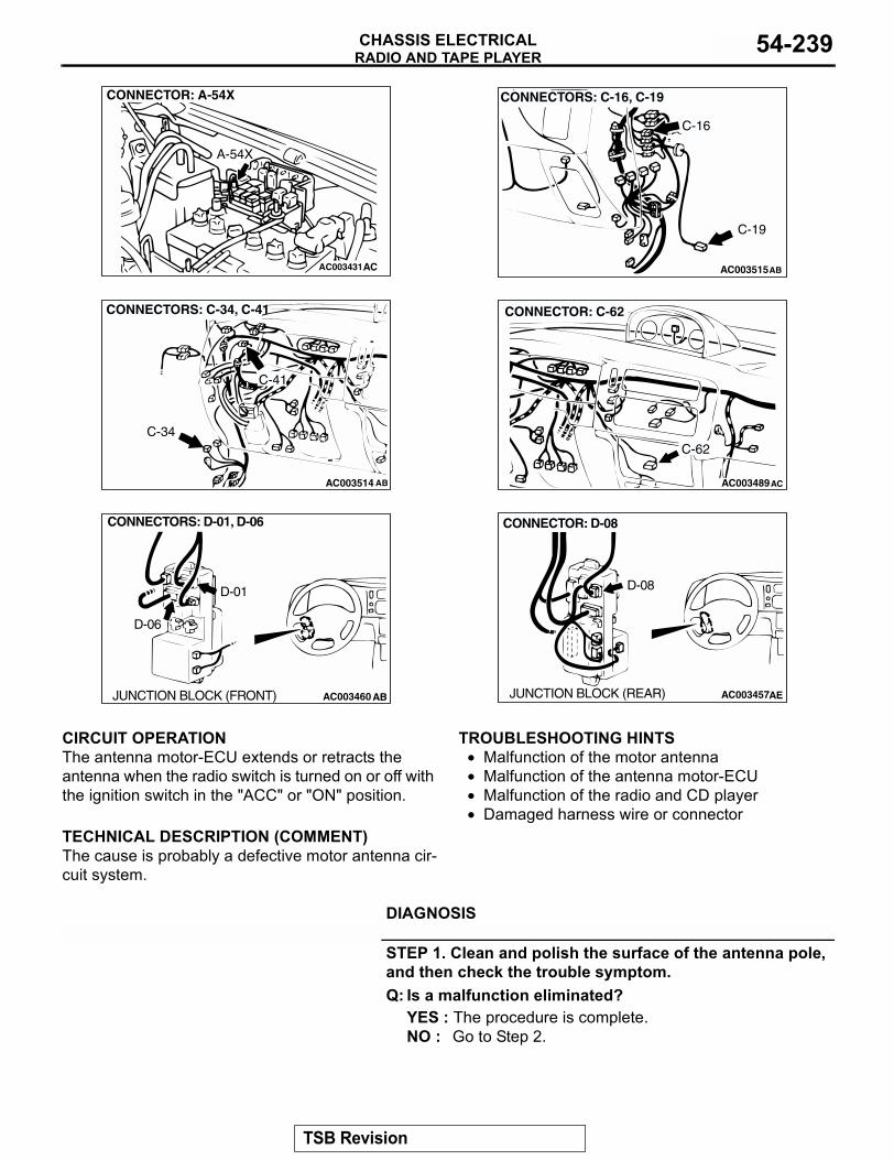
RADIO AND TAPE PLAYERCHASSIS ELECTRICAL 54-239
.
CIRCUIT OPERATIONThe antenna motor-ECU extends or retracts the antenna when the radio switch is turned on or off with the ignition switch in the "ACC" or "ON" position..
TECHNICAL DESCRIPTION (COMMENT)The cause is probably a defective motor antenna cir-cuit system.
.
TROUBLESHOOTING HINTS• Malfunction of the motor antenna• Malfunction of the antenna motor-ECU• Malfunction of the radio and CD player• Damaged harness wire or connector
.
DIAGNOSIS
STEP 1. Clean and polish the surface of the antenna pole, and then check the trouble symptom.Q: Is a malfunction eliminated?
YES : The procedure is complete.NO : Go to Step 2.
AC003431
CONNECTOR: A-54X
A-54X
AC AC003515AB
CONNECTORS: C-16, C-19
C-16
C-19
AC003514
CONNECTORS: C-34, C-41
C-34
C-41
AB AC003489AC
CONNECTOR: C-62
C-62
AC003460 AB
CONNECTORS: D-01, D-06
D-01
D-06
JUNCTION BLOCK (FRONT) AC003457AE
CONNECTOR: D-08
JUNCTION BLOCK (REAR)
D-08
TSB Revision
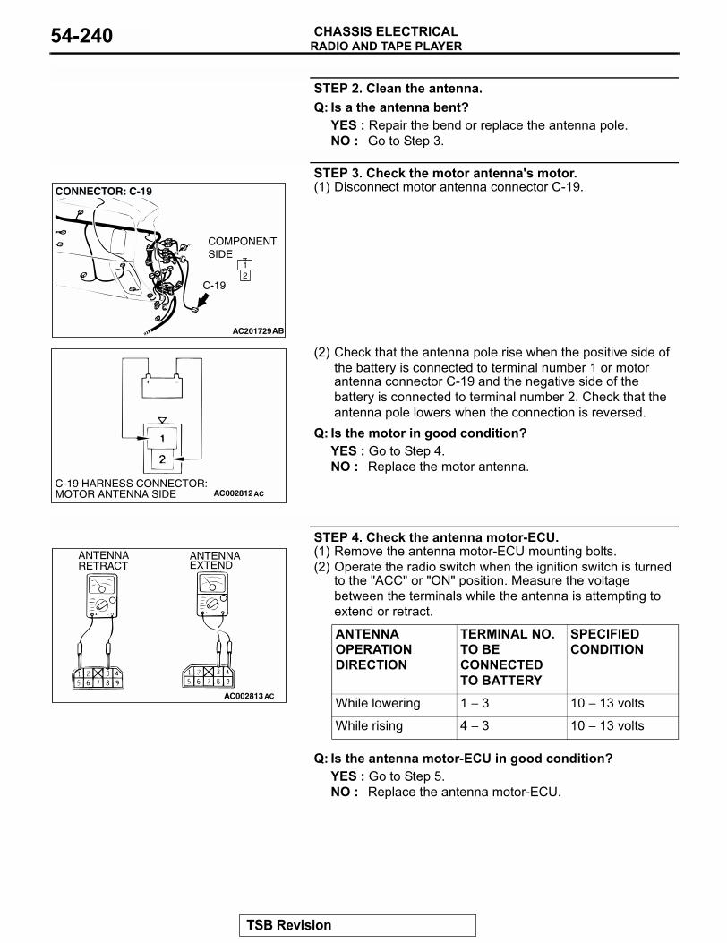
RADIO AND TAPE PLAYERCHASSIS ELECTRICAL54-240
STEP 2. Clean the antenna.Q: Is a the antenna bent?
YES : Repair the bend or replace the antenna pole.NO : Go to Step 3.
STEP 3. Check the motor antenna's motor.(1) Disconnect motor antenna connector C-19.
(2) Check that the antenna pole rise when the positive side of the battery is connected to terminal number 1 or motor antenna connector C-19 and the negative side of the battery is connected to terminal number 2. Check that the antenna pole lowers when the connection is reversed.
Q: Is the motor in good condition?YES : Go to Step 4.NO : Replace the motor antenna.
STEP 4. Check the antenna motor-ECU.(1) Remove the antenna motor-ECU mounting bolts.(2) Operate the radio switch when the ignition switch is turned
to the "ACC" or "ON" position. Measure the voltage between the terminals while the antenna is attempting to extend or retract.
Q: Is the antenna motor-ECU in good condition?YES : Go to Step 5.NO : Replace the antenna motor-ECU.
AC201729
12
COMPONENT SIDE
AB
CONNECTOR: C-19
C-19
AC002812ACC-19 HARNESS CONNECTOR:MOTOR ANTENNA SIDE
ANTENNA OPERATION DIRECTION
TERMINAL NO. TO BE CONNECTED TO BATTERY
SPECIFIED CONDITION
While lowering 1 − 3 10 − 13 volts
While rising 4 − 3 10 − 13 volts
AC002813 AC
ANTENNA RETRACT
ANTENNAEXTEND
TSB Revision
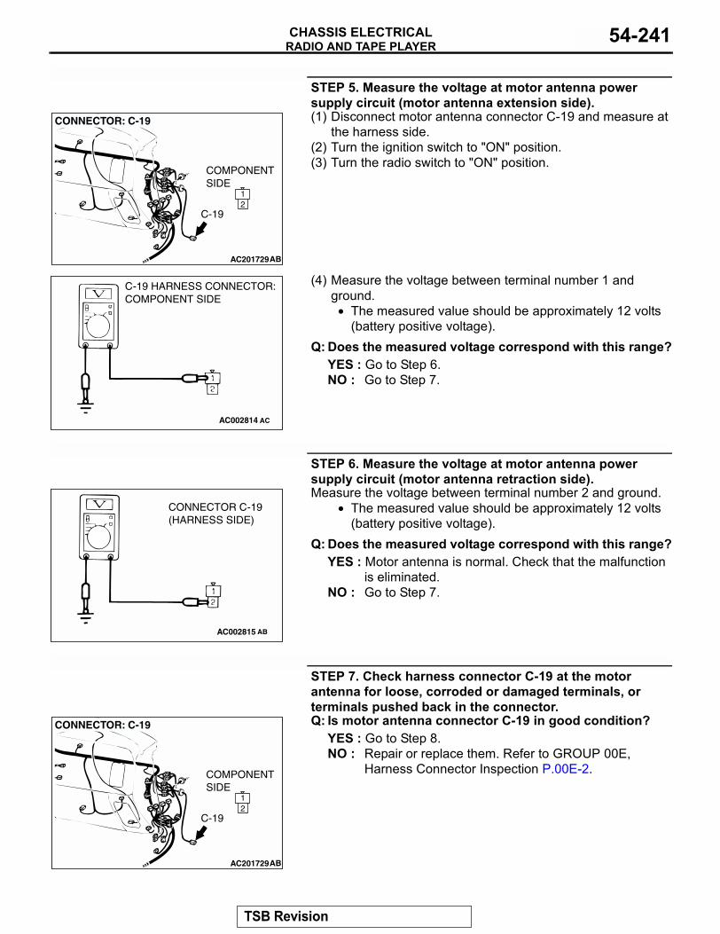
RADIO AND TAPE PLAYERCHASSIS ELECTRICAL 54-241
STEP 5. Measure the voltage at motor antenna power supply circuit (motor antenna extension side).(1) Disconnect motor antenna connector C-19 and measure at
the harness side.(2) Turn the ignition switch to "ON" position.(3) Turn the radio switch to "ON" position.
(4) Measure the voltage between terminal number 1 and ground.
• The measured value should be approximately 12 volts (battery positive voltage).
Q: Does the measured voltage correspond with this range?YES : Go to Step 6.NO : Go to Step 7.
STEP 6. Measure the voltage at motor antenna power supply circuit (motor antenna retraction side).Measure the voltage between terminal number 2 and ground.
• The measured value should be approximately 12 volts (battery positive voltage).
Q: Does the measured voltage correspond with this range?YES : Motor antenna is normal. Check that the malfunction
is eliminated.NO : Go to Step 7.
STEP 7. Check harness connector C-19 at the motor antenna for loose, corroded or damaged terminals, or terminals pushed back in the connector.Q: Is motor antenna connector C-19 in good condition?
YES : Go to Step 8.NO : Repair or replace them. Refer to GROUP 00E,
Harness Connector Inspection P.00E-2.
AC201729
12
COMPONENT SIDE
AB
CONNECTOR: C-19
C-19
AC002814
C-19 HARNESS CONNECTOR:COMPONENT SIDE
AC
AC002815 AB
CONNECTOR C-19(HARNESS SIDE)
AC201729
12
COMPONENT SIDE
AB
CONNECTOR: C-19
C-19
TSB Revision
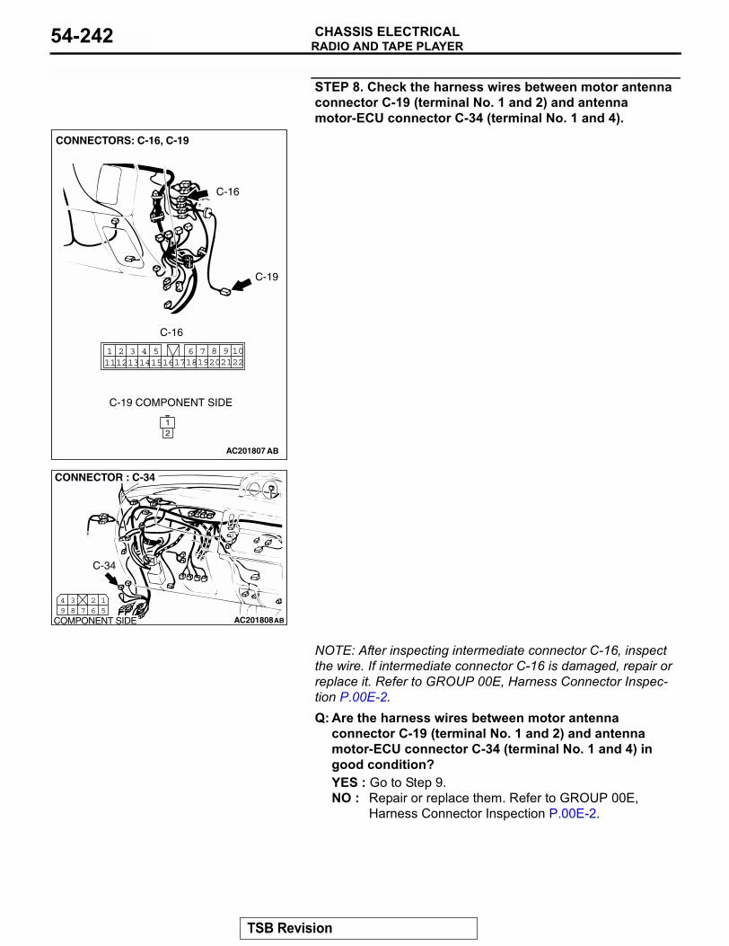
RADIO AND TAPE PLAYERCHASSIS ELECTRICAL54-242
STEP 8. Check the harness wires between motor antenna connector C-19 (terminal No. 1 and 2) and antenna motor-ECU connector C-34 (terminal No. 1 and 4).
NOTE: After inspecting intermediate connector C-16, inspect the wire. If intermediate connector C-16 is damaged, repair or replace it. Refer to GROUP 00E, Harness Connector Inspec-tion P.00E-2.Q: Are the harness wires between motor antenna
connector C-19 (terminal No. 1 and 2) and antenna motor-ECU connector C-34 (terminal No. 1 and 4) in good condition?YES : Go to Step 9.NO : Repair or replace them. Refer to GROUP 00E,
Harness Connector Inspection P.00E-2.
AC201807
12
2220211098
17186 7191415
4 511121 2 3
13 16
C-16
C-19
AB
C-16
C-19 COMPONENT SIDE
CONNECTORS: C-16, C-19
AC201808
15
267
38
49
CONNECTOR : C-34
COMPONENT SIDE AB
C-34
TSB Revision
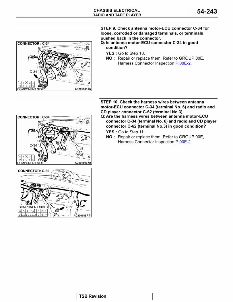
RADIO AND TAPE PLAYERCHASSIS ELECTRICAL 54-243
STEP 9. Check antenna motor-ECU connector C-34 for loose, corroded or damaged terminals, or terminals pushed back in the connector.Q: Is antenna motor-ECU connector C-34 in good
condition?YES : Go to Step 10.NO : Repair or replace them. Refer to GROUP 00E,
Harness Connector Inspection P.00E-2.
STEP 10. Check the harness wires between antenna motor-ECU connector C-34 (terminal No. 6) and radio and CD player connector C-62 (terminal No.3).Q: Are the harness wires between antenna motor-ECU
connector C-34 (terminal No. 6) and radio and CD player connector C-62 (terminal No.3) in good condition?YES : Go to Step 11.NO : Repair or replace them. Refer to GROUP 00E,
Harness Connector Inspection P.00E-2.
AC201808
15
267
38
49
CONNECTOR : C-34
COMPONENT SIDE AB
C-34
AC201808
15
267
38
49
CONNECTOR : C-34
COMPONENT SIDE AB
C-34
AC200783
17
281011
513
614 12
493
CONNECTOR: C-62
COMPONENT SIDE
AB
C-62
TSB Revision
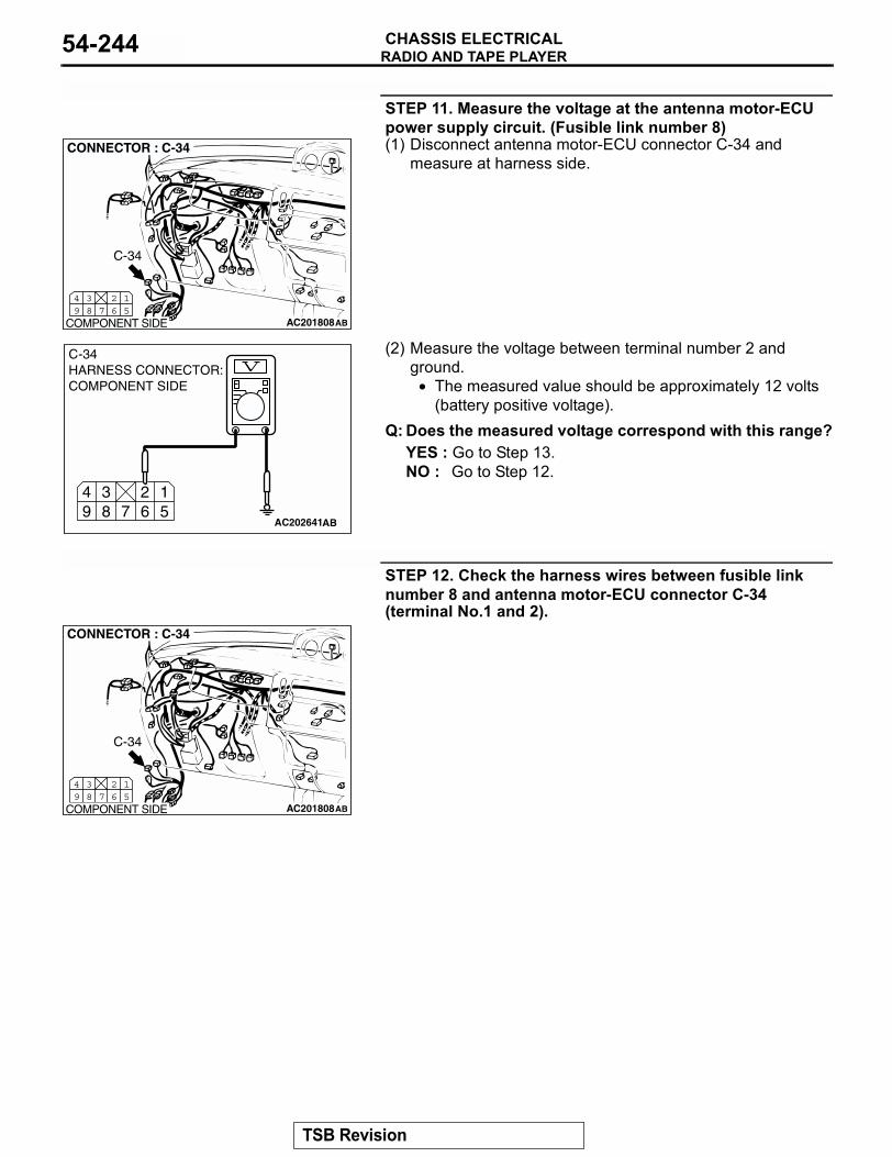
RADIO AND TAPE PLAYERCHASSIS ELECTRICAL54-244
STEP 11. Measure the voltage at the antenna motor-ECU power supply circuit. (Fusible link number 8)(1) Disconnect antenna motor-ECU connector C-34 and
measure at harness side.
(2) Measure the voltage between terminal number 2 and ground.
• The measured value should be approximately 12 volts (battery positive voltage).
Q: Does the measured voltage correspond with this range?YES : Go to Step 13.NO : Go to Step 12.
STEP 12. Check the harness wires between fusible link number 8 and antenna motor-ECU connector C-34 (terminal No.1 and 2).
AC201808
15
267
38
49
CONNECTOR : C-34
COMPONENT SIDE AB
C-34
15
267
38
49
AC202641
C-34 HARNESS CONNECTOR:COMPONENT SIDE
AB
AC201808
15
267
38
49
CONNECTOR : C-34
COMPONENT SIDE AB
C-34
TSB Revision
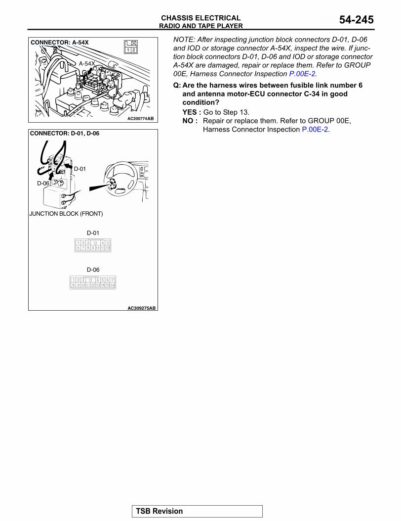
RADIO AND TAPE PLAYERCHASSIS ELECTRICAL 54-245
NOTE: After inspecting junction block connectors D-01, D-06 and IOD or storage connector A-54X, inspect the wire. If junc-tion block connectors D-01, D-06 and IOD or storage connector A-54X are damaged, repair or replace them. Refer to GROUP 00E, Harness Connector Inspection P.00E-2.Q: Are the harness wires between fusible link number 6
and antenna motor-ECU connector C-34 in good condition?YES : Go to Step 13.NO : Repair or replace them. Refer to GROUP 00E,
Harness Connector Inspection P.00E-2. AC200774
21
CONNECTOR: A-54X
AB
A-54X
AC309275AB
CONNECTOR: D-01, D-06
D-01
D-06
JUNCTION BLOCK (FRONT)
D-01
D-06
TSB Revision
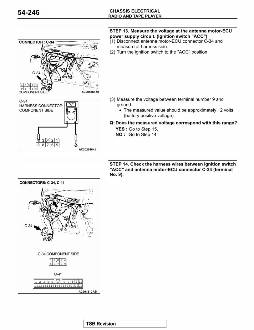
RADIO AND TAPE PLAYERCHASSIS ELECTRICAL54-246
STEP 13. Measure the voltage at the antenna motor-ECU power supply circuit. (Ignition switch "ACC")(1) Disconnect antenna motor-ECU connector C-34 and
measure at harness side.(2) Turn the ignition switch to the "ACC" position.
(3) Measure the voltage between terminal number 9 and ground.
• The measured value should be approximately 12 volts (battery positive voltage).
Q: Does the measured voltage correspond with this range?YES : Go to Step 15.NO : Go to Step 14.
STEP 14. Check the harness wires between ignition switch "ACC" and antenna motor-ECU connector C-34 (terminal No. 9).
AC201808
15
267
38
49
CONNECTOR : C-34
COMPONENT SIDE AB
C-34
15
267
38
49
AC202646
C-34 HARNESS CONNECTOR:COMPONENT SIDE
AB
49
387
26
15
2220211098
17186 7191415
4 511121 2 3
13 16
AC201810
TSB Revision
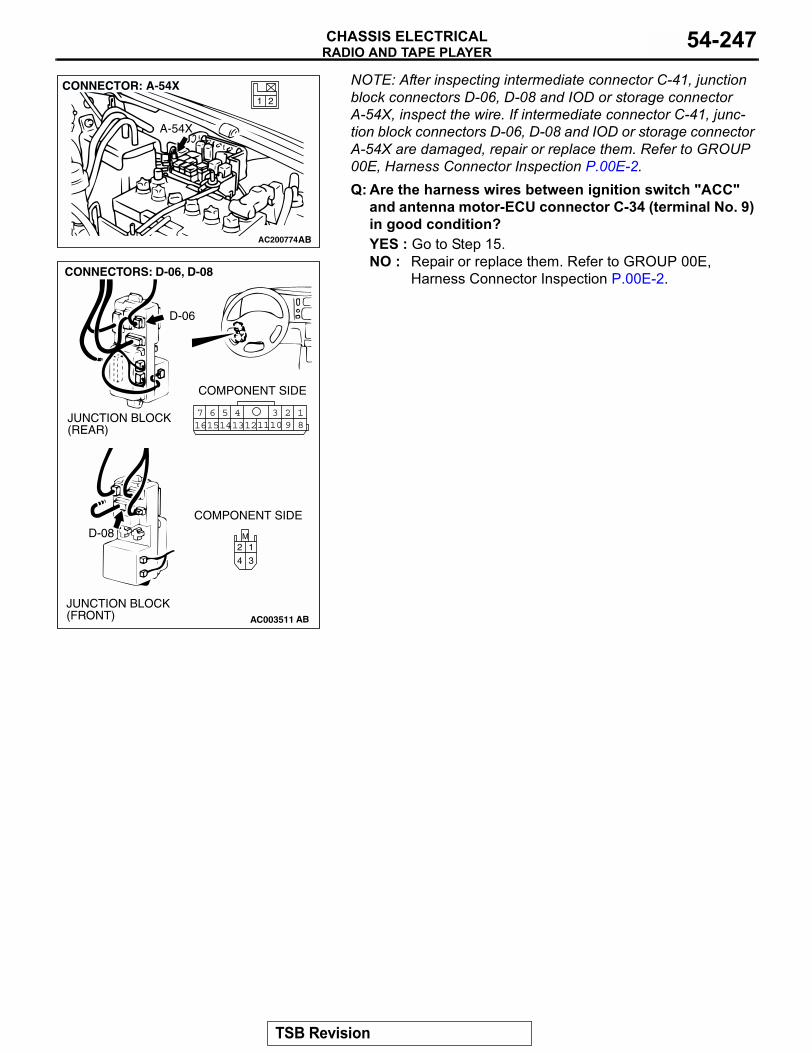
RADIO AND TAPE PLAYERCHASSIS ELECTRICAL 54-247
NOTE: After inspecting intermediate connector C-41, junction block connectors D-06, D-08 and IOD or storage connector A-54X, inspect the wire. If intermediate connector C-41, junc-tion block connectors D-06, D-08 and IOD or storage connector A-54X are damaged, repair or replace them. Refer to GROUP 00E, Harness Connector Inspection P.00E-2.Q: Are the harness wires between ignition switch "ACC"
and antenna motor-ECU connector C-34 (terminal No. 9) in good condition?YES : Go to Step 15.NO : Repair or replace them. Refer to GROUP 00E,
Harness Connector Inspection P.00E-2.
AC200774
21
CONNECTOR: A-54X
AB
A-54X
AC003511
JUNCTION BLOCK(FRONT)
JUNCTION BLOCK(REAR)
CONNECTORS: D-06, D-08
AB
D-06
D-08
COMPONENT SIDE
COMPONENT SIDE
18
3457 6101516 14 1213 11 9
2
M
3
1
4
2
TSB Revision
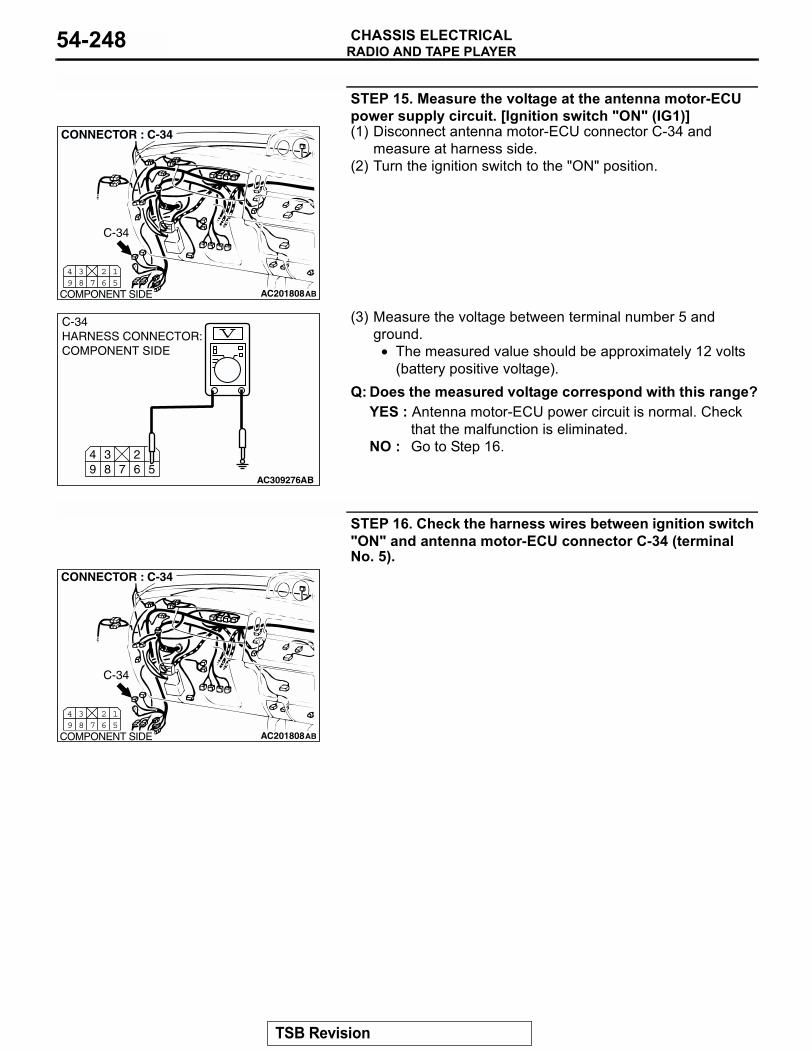
RADIO AND TAPE PLAYERCHASSIS ELECTRICAL54-248
STEP 15. Measure the voltage at the antenna motor-ECU power supply circuit. [Ignition switch "ON" (IG1)](1) Disconnect antenna motor-ECU connector C-34 and
measure at harness side.(2) Turn the ignition switch to the "ON" position.
(3) Measure the voltage between terminal number 5 and ground.
• The measured value should be approximately 12 volts (battery positive voltage).
Q: Does the measured voltage correspond with this range?YES : Antenna motor-ECU power circuit is normal. Check
that the malfunction is eliminated.NO : Go to Step 16.
STEP 16. Check the harness wires between ignition switch "ON" and antenna motor-ECU connector C-34 (terminal No. 5).
AC201808
15
267
38
49
CONNECTOR : C-34
COMPONENT SIDE AB
C-34
15
267
38
49
AC309276AB
C-34HARNESS CONNECTOR:COMPONENT SIDE
AC201808
15
267
38
49
CONNECTOR : C-34
COMPONENT SIDE AB
C-34
TSB Revision
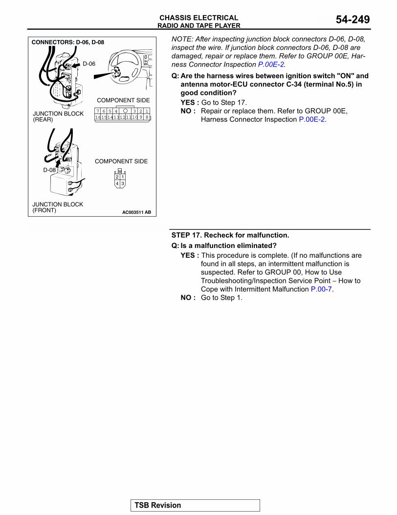
RADIO AND TAPE PLAYERCHASSIS ELECTRICAL 54-249
NOTE: After inspecting junction block connectors D-06, D-08, inspect the wire. If junction block connectors D-06, D-08 are damaged, repair or replace them. Refer to GROUP 00E, Har-ness Connector Inspection P.00E-2.Q: Are the harness wires between ignition switch "ON" and
antenna motor-ECU connector C-34 (terminal No.5) in good condition?YES : Go to Step 17.NO : Repair or replace them. Refer to GROUP 00E,
Harness Connector Inspection P.00E-2.
STEP 17. Recheck for malfunction.Q: Is a malfunction eliminated?
YES : This procedure is complete. (If no malfunctions are found in all steps, an intermittent malfunction is suspected. Refer to GROUP 00, How to Use Troubleshooting/Inspection Service Point − How to Cope with Intermittent Malfunction P.00-7.
NO : Go to Step 1.
AC003511
JUNCTION BLOCK(FRONT)
JUNCTION BLOCK(REAR)
CONNECTORS: D-06, D-08
AB
D-06
D-08
COMPONENT SIDE
COMPONENT SIDE
18
3457 6101516 14 1213 11 9
2
M
3
1
4
2
TSB Revision
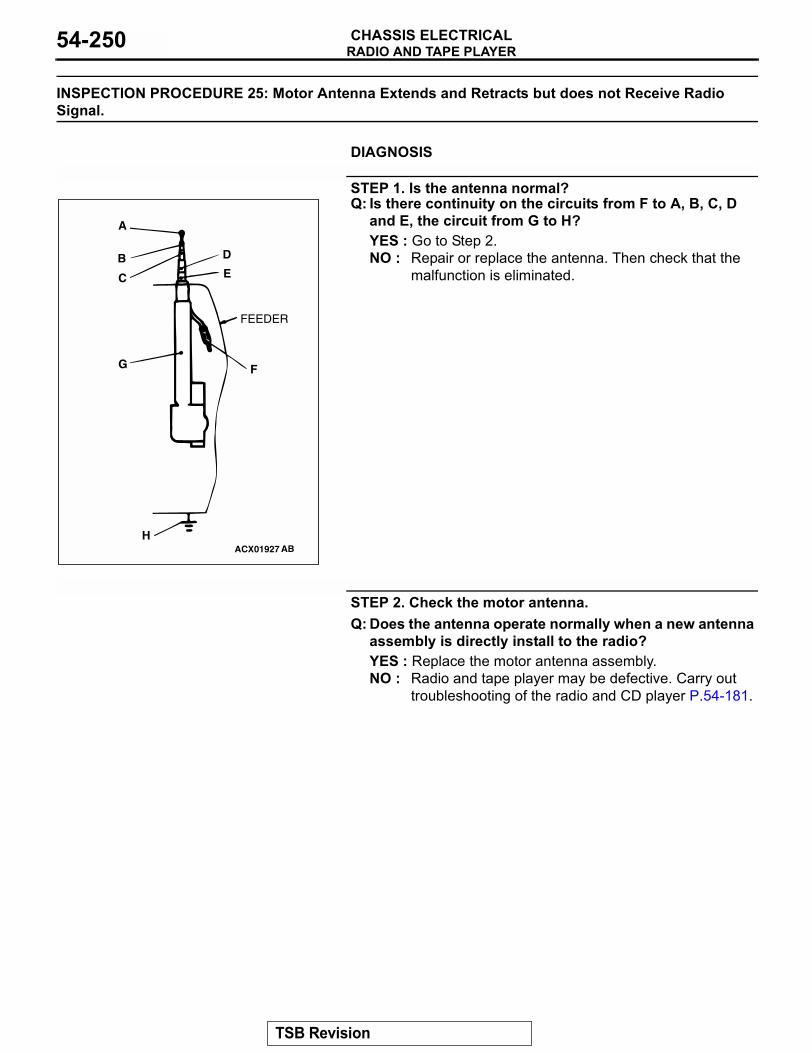
RADIO AND TAPE PLAYERCHASSIS ELECTRICAL54-250
INSPECTION PROCEDURE 25: Motor Antenna Extends and Retracts but does not Receive Radio Signal.
.
DIAGNOSIS
STEP 1. Is the antenna normal?Q: Is there continuity on the circuits from F to A, B, C, D
and E, the circuit from G to H? YES : Go to Step 2.NO : Repair or replace the antenna. Then check that the
malfunction is eliminated.
STEP 2. Check the motor antenna.Q: Does the antenna operate normally when a new antenna
assembly is directly install to the radio?YES : Replace the motor antenna assembly.NO : Radio and tape player may be defective. Carry out
troubleshooting of the radio and CD player P.54-181.
ACX01927 AB
A
B
C
D
E
FG
H
FEEDER
TSB Revision
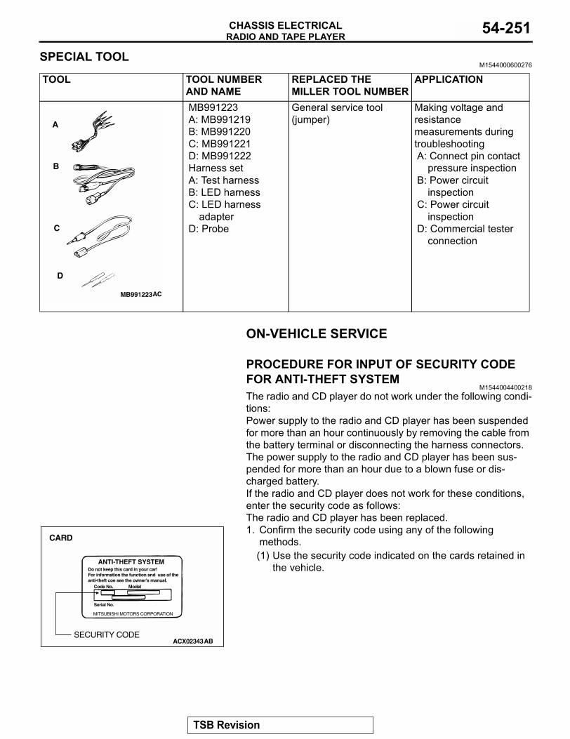
RADIO AND TAPE PLAYERCHASSIS ELECTRICAL 54-251
SPECIAL TOOLM1544000600276
ON-VEHICLE SERVICE
PROCEDURE FOR INPUT OF SECURITY CODE FOR ANTI-THEFT SYSTEM
M1544004400218The radio and CD player do not work under the following condi-tions:Power supply to the radio and CD player has been suspended for more than an hour continuously by removing the cable from the battery terminal or disconnecting the harness connectors.The power supply to the radio and CD player has been sus-pended for more than an hour due to a blown fuse or dis-charged battery.If the radio and CD player does not work for these conditions, enter the security code as follows:The radio and CD player has been replaced.1. Confirm the security code using any of the following
methods.(1) Use the security code indicated on the cards retained in
the vehicle.
TOOL TOOL NUMBER AND NAME
REPLACED THE MILLER TOOL NUMBER
APPLICATION
MB991223A: MB991219B: MB991220 C: MB991221D: MB991222Harness setA: Test harnessB: LED harnessC: LED harness
adapterD: Probe
General service tool (jumper)
Making voltage and resistance measurements during troubleshootingA: Connect pin contact
pressure inspectionB: Power circuit
inspectionC: Power circuit
inspectionD: Commercial tester
connection
MB991223
A
B
C
D
AC
ANTI-THEFT SYSTEMDo not keep this card in your car!For information the function and use of theanti-theft coe see the owner's manual.
Code No. Model
Serial No.
MITSUBISHI MOTORS CORPORATION
ACX02343AB
CARD
SECURITY CODE
TSB Revision
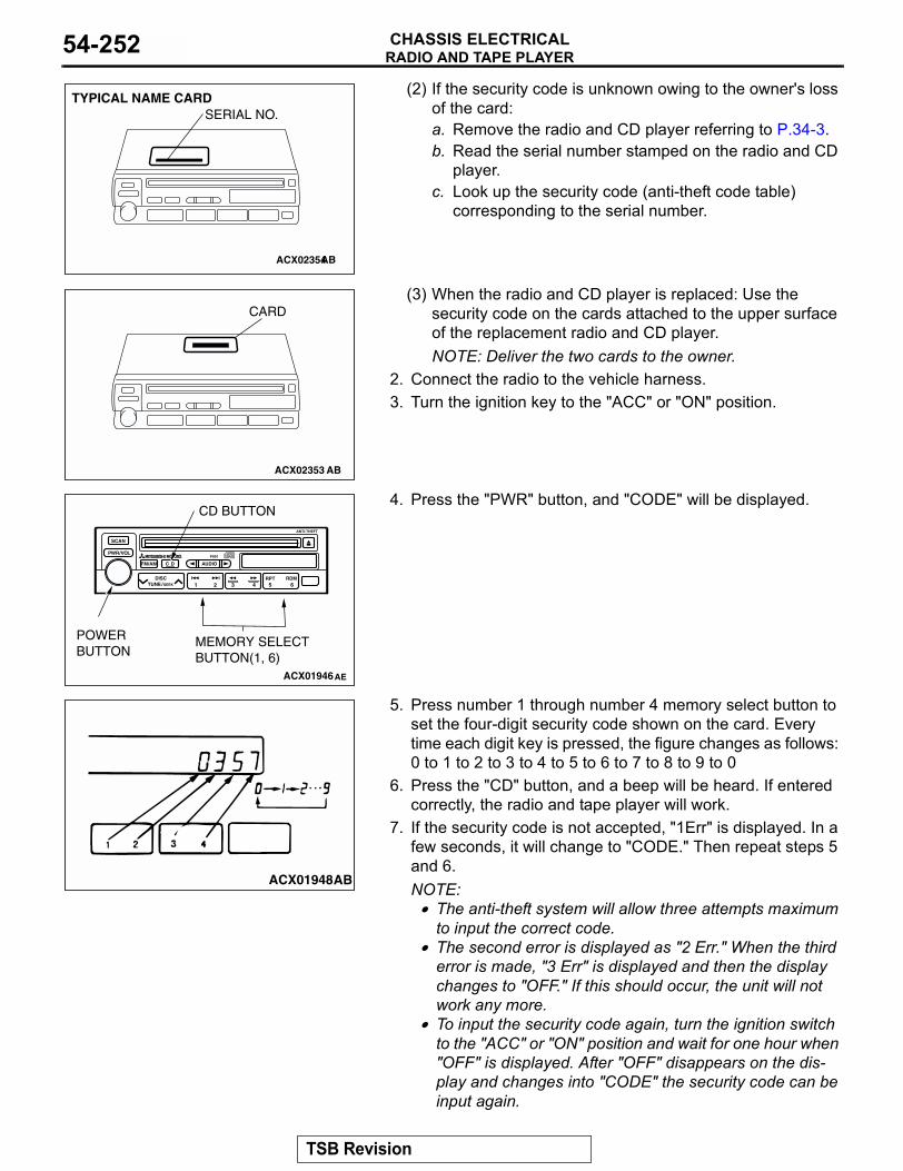
RADIO AND TAPE PLAYERCHASSIS ELECTRICAL54-252
(2) If the security code is unknown owing to the owner's loss of the card:a. Remove the radio and CD player referring to P.34-3.b. Read the serial number stamped on the radio and CD
player.c. Look up the security code (anti-theft code table)
corresponding to the serial number.
(3) When the radio and CD player is replaced: Use the security code on the cards attached to the upper surface of the replacement radio and CD player.NOTE: Deliver the two cards to the owner.
2. Connect the radio to the vehicle harness.3. Turn the ignition key to the "ACC" or "ON" position.
4. Press the "PWR" button, and "CODE" will be displayed.
5. Press number 1 through number 4 memory select button to set the four-digit security code shown on the card. Every time each digit key is pressed, the figure changes as follows: 0 to 1 to 2 to 3 to 4 to 5 to 6 to 7 to 8 to 9 to 0
6. Press the "CD" button, and a beep will be heard. If entered correctly, the radio and tape player will work.
7. If the security code is not accepted, "1Err" is displayed. In a few seconds, it will change to "CODE." Then repeat steps 5 and 6.NOTE: .
• The anti-theft system will allow three attempts maximum to input the correct code.
• The second error is displayed as "2 Err." When the third error is made, "3 Err" is displayed and then the display changes to "OFF." If this should occur, the unit will not work any more.
• To input the security code again, turn the ignition switch to the "ACC" or "ON" position and wait for one hour when "OFF" is displayed. After "OFF" disappears on the dis-play and changes into "CODE" the security code can be input again.
ACX02354AB
SERIAL NO.TYPICAL NAME CARD
ACX02353
CARD
AB
P901
ACX01946AE
POWERBUTTON
MEMORY SELECT BUTTON(1, 6)
CD BUTTON
ACX01948AB
TSB Revision
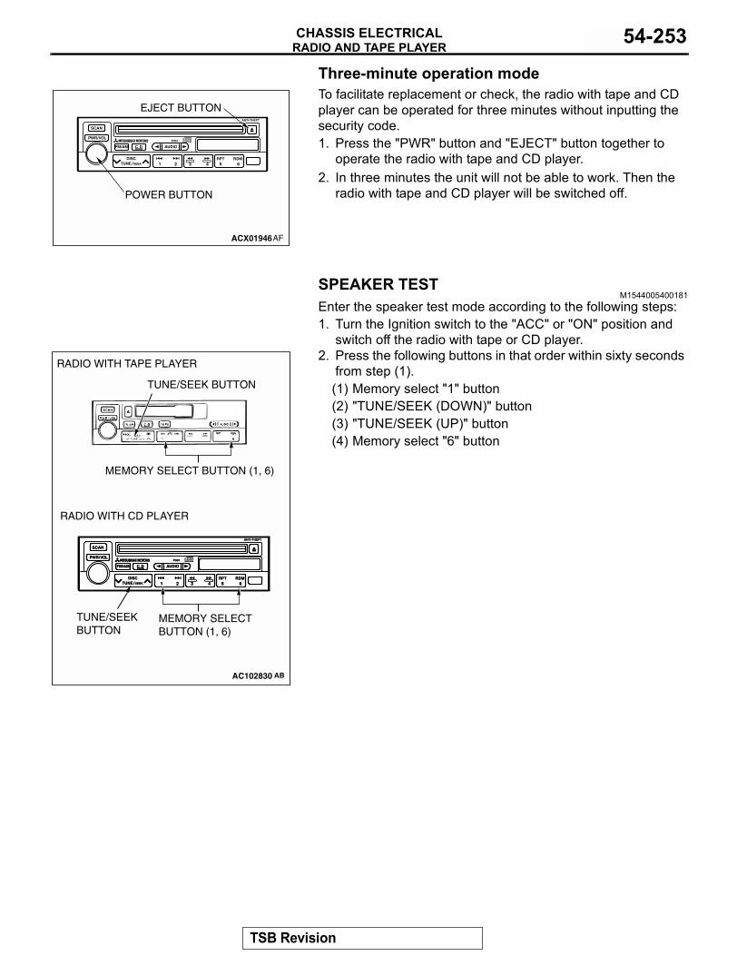
RADIO AND TAPE PLAYERCHASSIS ELECTRICAL 54-253
Three-minute operation modeTo facilitate replacement or check, the radio with tape and CD player can be operated for three minutes without inputting the security code.1. Press the "PWR" button and "EJECT" button together to
operate the radio with tape and CD player.2. In three minutes the unit will not be able to work. Then the
radio with tape and CD player will be switched off.
SPEAKER TESTM1544005400181
Enter the speaker test mode according to the following steps:1. Turn the Ignition switch to the "ACC" or "ON" position and
switch off the radio with tape or CD player.2. Press the following buttons in that order within sixty seconds
from step (1).(1) Memory select "1" button(2) "TUNE/SEEK (DOWN)" button(3) "TUNE/SEEK (UP)" button(4) Memory select "6" button
P901
ACX01946
POWER BUTTON
EJECT BUTTON
AF
P901P901
AC102830 AB
RADIO WITH TAPE PLAYER
RADIO WITH CD PLAYER
TUNE/SEEK BUTTON
TUNE/SEEK BUTTON
MEMORY SELECT BUTTON (1, 6)
MEMORY SELECT BUTTON (1, 6)
TSB Revision
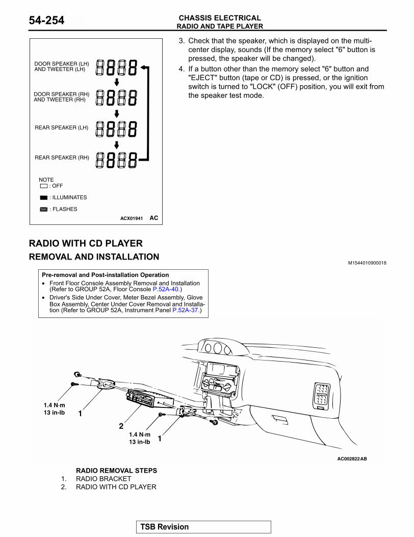
RADIO AND TAPE PLAYERCHASSIS ELECTRICAL54-254
3. Check that the speaker, which is displayed on the multi-center display, sounds (If the memory select "6" button is pressed, the speaker will be changed).
4. If a button other than the memory select "6" button and "EJECT" button (tape or CD) is pressed, or the ignition switch is turned to "LOCK" (OFF) position, you will exit from the speaker test mode.
RADIO WITH CD PLAYERREMOVAL AND INSTALLATION
M1544010900018
ACX01941
DOOR SPEAKER (LH)AND TWEETER (LH)
DOOR SPEAKER (RH)AND TWEETER (RH)
REAR SPEAKER (LH)
REAR SPEAKER (RH)
NOTE
: ILLUMINATES
: FLASHES
: OFF
AC
Pre-removal and Post-installation Operation• Front Floor Console Assembly Removal and Installation
(Refer to GROUP 52A, Floor Console P.52A-40.)• Driver's Side Under Cover, Meter Bezel Assembly, Glove
Box Assembly, Center Under Cover Removal and Installa-tion (Refer to GROUP 52A, Instrument Panel P.52A-37.)
AC002822AB
1
2
1
1.4 N·m13 in-lb
1.4 N·m13 in-lb
RADIO REMOVAL STEPS1. RADIO BRACKET2. RADIO WITH CD PLAYER
TSB Revision
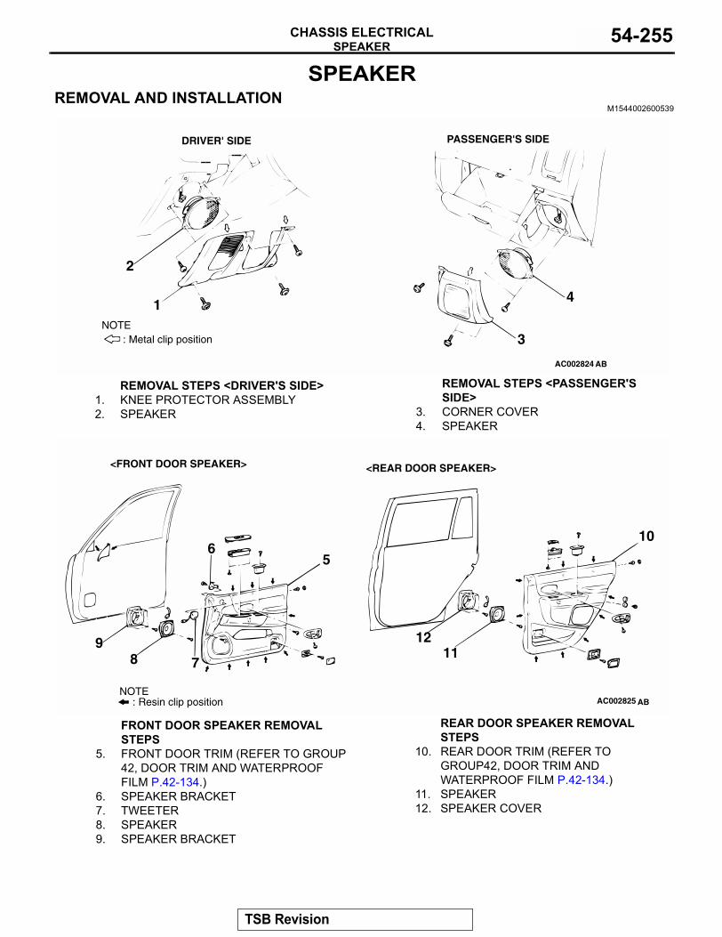
SPEAKERCHASSIS ELECTRICAL 54-255
SPEAKER REMOVAL AND INSTALLATION
M1544002600539
AC002824 AB
DRIVER' SIDE PASSENGER'S SIDE
1
2
3
4
: Metal clip positionNOTE
REMOVAL STEPS <DRIVER'S SIDE>1. KNEE PROTECTOR ASSEMBLY2. SPEAKER
REMOVAL STEPS <PASSENGER'S SIDE>
3. CORNER COVER4. SPEAKER
AC002825 AB
56
789
10
1112
: Resin clip positionNOTE
<FRONT DOOR SPEAKER> <REAR DOOR SPEAKER>
FRONT DOOR SPEAKER REMOVAL STEPS
5. FRONT DOOR TRIM (REFER TO GROUP 42, DOOR TRIM AND WATERPROOF FILM P.42-134.)
6. SPEAKER BRACKET7. TWEETER8. SPEAKER9. SPEAKER BRACKET
REAR DOOR SPEAKER REMOVAL STEPS
10. REAR DOOR TRIM (REFER TO GROUP42, DOOR TRIM AND WATERPROOF FILM P.42-134.)
11. SPEAKER12. SPEAKER COVER
TSB Revision
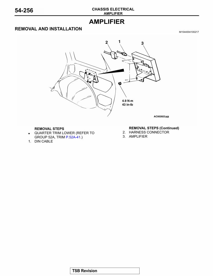
AMPLIFIERCHASSIS ELECTRICAL54-256
AMPLIFIERREMOVAL AND INSTALLATION
M1544004100217
AC002823AB
12 3
4.9 N·m43 in-lb
REMOVAL STEPS• QUARTER TRIM LOWER (REFER TO
GROUP 52A, TRIM P.52A-41.)1. DIN CABLE
2. HARNESS CONNECTOR3. AMPLIFIER
REMOVAL STEPS (Continued)
TSB Revision
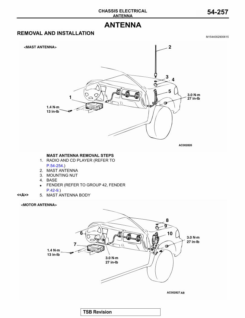
ANTENNACHASSIS ELECTRICAL 54-257
ANTENNAREMOVAL AND INSTALLATION
M1544002900615
AC002826
1
2
3 4
53.0 N·m27 in-lb
1.4 N·m13 in-lb
<MAST ANTENNA>
MAST ANTENNA REMOVAL STEPS1. RADIO AND CD PLAYER (REFER TO
P.54-254.)2. MAST ANTENNA3. MOUNTING NUT4. BASE• FENDER (REFER TO GROUP 42, FENDER
P.42-9.)<<A>> 5. MAST ANTENNA BODY
AC002827 AB
89
106
7
3.0 N·m27 in-lb
3.0 N·m27 in-lb
1.4 N·m13 in-lb
<MOTOR ANTENNA>
TSB Revision
ANTENNACHASSIS ELECTRICAL54-258
6. ANTENNA MOTOR-ECUMOTOR ANTENNA REMOVAL STEPS
7. RADIO AND TAPE PLAYER (REFER TO P.54-254.)
8. RING NUT9. BASE• FENDER (REFER TO GROUP 42, FENDER
P.42-9.)<<A>> 10. MOTOR ANTENNA ASSEMBLY
AC002828
<DIVERSITY ANTENNA>
11
12
1314
15
16
3.0 N·m27 in-lb
3.0 N·m27 in-lb
1.4 N·m13 in-lb
AB
11. ANTENNA MOTOR-ECUMOTOR ANTENNA REMOVAL STEPS
12. RADIO AND CD PLAYER (REFER TO P.54-254.)
13. RING NUT14. BASE• FENDER (REFER TO GROUP 42,
FENDER P.42-9.)<<A>> 15. MOTOR ANTENNA ASSEMBLY
ANTENNA FEEDER CABLE (FOR QUARTER GLASS ANTENNA) REMOVAL STEPS
• FLOOR CONSOLE (REFER TO GROUP 52A, FLOOR CONSOLE P.52A-40.)
• FRONT SEAT ASSEMBLY (REFER TO GROUP 52A, FRONT SEAT P.52A-44.)
• REAR SEAT ASSEMBLY (REFER TO GROUP 52A, REAR SEAT P.52A-52.)
• QUARTER TRIM, UPPER AND LOWER (REFER TO GROUP 52A, TRIMS P.52A-41.)
16. ANTENNA FEEDER CABLE (FOR QUARTER GLASS ANTENNA.)
TSB Revision
ANTENNACHASSIS ELECTRICAL 54-259
REMOVAL SERVICE POINT.
<<A>> MAST ANTENNA OR MOTOR ANTENNA ASSEMBLY REMOVALTo make installation easy, tie a string on the feeder cable of the mast antenna or motor antenna assembly and pull.
INSPECTIONM1543019501608
MOTOR ANTENNA CHECKDisconnect the antenna motor-ECU connector. Check that the antenna extends when the positive terminal of the battery is connected to terminal number 1 and the negative terminal of the battery is connected to terminal number 2. Check that the antenna retracts when the connection is reversed.
ANTENNA MOTOR-ECU CHECK1. Remove the antenna motor-ECU mounting bolts.2. Operate the radio switch when the ignition switch is turned
to the "ACC" or "ON" position. Measure the voltage between the terminals while the antenna is attempting to extend or retract.
AC002829
STRING
AB
AC002830AB
ANTENNA OPERATION DIRECTION
TERMINAL NO. TO BE CONNECTED TO BATTERY
SPECIFIED CONDITION
While lowering 1 − 3 10 − 13 volts
While rising 4 − 3 10 − 13 volts
AC002813 AC
ANTENNA RETRACT
ANTENNAEXTEND
TSB Revision
ANTENNACHASSIS ELECTRICAL54-260
GLASS ANTENNA CHECK1. Wrap an aluminum foil around the tester probe a shown.
CAUTIONBe careful not to damage the print wire.2. Check continuity while pressing the aluminum foil along the
antenna print wire.
ANTENNA POLE REPLACEMENTM1544000900170
1. Remove the ring nut.
2. After setting the ignition switch to the "ACC" or "ON," turn the radio switch on. Extend the antenna pole and remove it together with the rack cable.
3. Pull the antenna out the farthest end.NOTE: If the motor end side of the rack cable is bent, straighten it out.
4. Face the teeth side of the rack cable toward the engine compartment, and feed the rack cable into the motor assembly.
ACX01954AB
TESTER PROBE
ALUMINUM FOIL PRINT WIRE
ACX01953 AB
RING NUT
ANTENNA POLE
ACX01949 AB
RACK CABLE
ANTENNA POLE
ACX01950RACK CABLE
RACK CABLE TEETH
ENGINE COMPARTMENT SIDE
AB
TSB Revision
REAR WINDOW DEFOGGERCHASSIS ELECTRICAL 54-261
5. Turn the teeth side of the rack cable toward the front of the vehicle (90 degree angle to the right), and engage the rack cable with the motor gears.
6. Pull lightly on the rack cable. If there is no resistance and it comes out, it is not engaged with the motor gears. Check that the end of the rack gear is not bent again, and then repeat steps (3) and (4) above again.
7. Set up the antenna pole vertically, and turn the radio off to wind in the rack cable. The antenna pole will be pulled into the motor antenna as the rack cable is wound in.
8. After tightening the ring nut, turn the radio on and off and check the operation of the antenna pole.
REAR WINDOW DEFOGGER
ON-VEHICLE SERVICE
PRINTED-HEATER LINES CHECKM1543001800203
1. Run engine at 2,000 r/min. Check heater element with battery at full.
2. Turn "ON" rear window defogger switch. Measure heater element voltage with circuit tester at rear window glass centre A. Condition is good if it indicates about 6 V.
3. If 12 V is indicated at A, there is a break in the negative terminals from A. Move test bar slowly to negative terminal to detect where voltage changes suddenly (0V).
4. If 0 V is indicated at A, there is a break in the positive terminals from A. Defect where the voltage changes suddenly (12 V) in the same method described above.
ACX01952 AC
RACK CABLE
VEHICLE FRONT DIRECTION
ACX01951AB
RING NUT
ACX00813
NORMAL CHARACTERISTIC CURVE
ABNORMAL CHARACTERISTIC CURVE
VOLTAGE
A (CENTER POINT)APPROXIMATELY 6 V
NEGATIVETERMINAL
PRINTED HEATERLINE
POSITIVETERMINAL
NEGATIVETERMINAL
PRINTED HEATERLINE
POSITIVETERMINAL
OPENCIRCUIT POINT
VOLTAGE
AC
TSB Revision
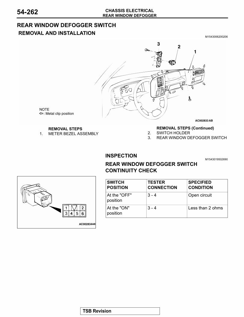
REAR WINDOW DEFOGGERCHASSIS ELECTRICAL54-262
REAR WINDOW DEFOGGER SWITCH REMOVAL AND INSTALLATION
M1543006200206
INSPECTIONM1543019502690
REAR WINDOW DEFOGGER SWITCH CONTINUITY CHECK
AC002833
: Metal clip positionNOTE
123
AB
REMOVAL STEPS1. METER BEZEL ASSEMBLY 2. SWITCH HOLDER
3. REAR WINDOW DEFOGGER SWITCH
REMOVAL STEPS (Continued)
SWITCH POSITION
TESTER CONNECTION
SPECIFIED CONDITION
At the "OFF" position
3 - 4 Open circuit
At the "ON" position
3 - 4 Less than 2 ohms
AC002834AB
TSB Revision
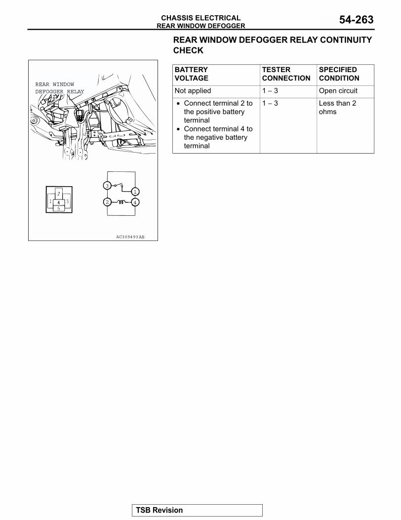
REAR WINDOW DEFOGGERCHASSIS ELECTRICAL 54-263
REAR WINDOW DEFOGGER RELAY CONTINUITY CHECK
BATTERY VOLTAGE
TESTER CONNECTION
SPECIFIED CONDITION
Not applied 1 − 3 Open circuit
• Connect terminal 2 to the positive battery terminal
• Connect terminal 4 to the negative battery terminal
1 − 3 Less than 2 ohms
AC309493
3
2
1
4
REAR WINDOWDEFOGGER RELAY
AB
TSB Revision
THEFT ALARMCHASSIS ELECTRICAL54-264
THEFT ALARM
THEFT-ALARM SYSTEM DIAGNOSISINTRODUCTION TO THEFT-ALARM SYSTEM DIAGNOSIS
M1547002200079
Theft-alarm systemWhen the theft-alarm system has been armed by the correct sequence for locking the doors (including the transmitter of the keyless entry system) if then a door, liftgate or hood is opened in an unauthorized way, the horn will sound and headlight flash intermit-tently for period of 180 seconds, thus providing an audible warning signal.
Panic Alarm FunctionWith the theft alarm function armed, pressing the panic button on the keyless entry system transmitter causes the theft alarm horn to sound for about 180 seconds in an attempt to prevent theft. The alarm is turned off by pressing any switch on the transmitter.
TROUBLE SYMPTOM CHARTM1543007201194
If a malfunction was found with the input signal check, refer to following table and inspect.
SYMPTOM INSPECTION PROCEDURE
REFERENCE PAGE
Theft-alarm system is not armed (security indicator light does not illuminate).
1. P.54-265
The horn does not sound when the theft-alarm-system is triggered. 2. P.54-272The headlight do not flash when the theft-alarm system is triggered. 3. P.54-280The panic alarm function does not work. 4. P.54-280
SYMPTOM INSPECTION PROCEDURE
REFERENCE PAGE
Scan tool MB991958 communication is not possible. 5 P.54-285The key reminder switch is not sent to the ETACS-ECU. 6. P.54-293The hood switch is not input. 7. P.54-298The driver's or passenger's door switch is not input. - GROUP 42, Door
− Door Assembly P.42-133
The driver's or passenger's door lock actuator switch is not input. - GROUP 42, Door − Door Assembly P.42-133
The liftgate switch is not input. - GROUP 42, Liftgate − Liftgate Handle and Latch P.42-152
The gate lock key cylinder switch is not input. - GROUP 42, Liftgate − Liftgate Handle and Latch P.42-152
TSB Revision
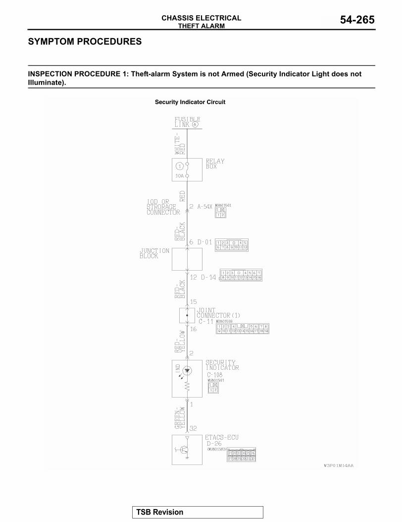
THEFT ALARMCHASSIS ELECTRICAL 54-265
SYMPTOM PROCEDURES
INSPECTION PROCEDURE 1: Theft-alarm System is not Armed (Security Indicator Light does not Illuminate).
Security Indicator Circuit
TSB Revision
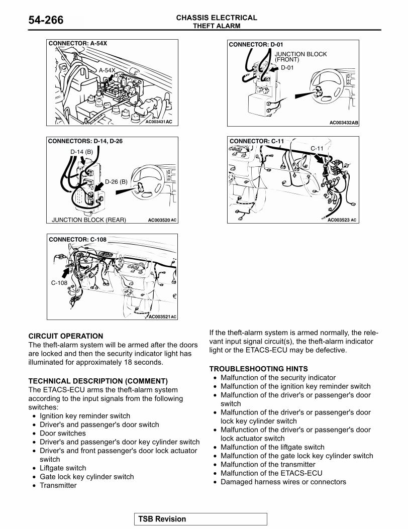
THEFT ALARMCHASSIS ELECTRICAL54-266
.
CIRCUIT OPERATIONThe theft-alarm system will be armed after the doors are locked and then the security indicator light has illuminated for approximately 18 seconds..
TECHNICAL DESCRIPTION (COMMENT)The ETACS-ECU arms the theft-alarm system according to the input signals from the following switches:
• Ignition key reminder switch• Driver's and passenger's door switch• Door switches• Driver's and passenger's door key cylinder switch• Driver's and front passenger's door lock actuator
switch• Liftgate switch• Gate lock key cylinder switch• Transmitter
If the theft-alarm system is armed normally, the rele-vant input signal circuit(s), the theft-alarm indicator light or the ETACS-ECU may be defective..
TROUBLESHOOTING HINTS• Malfunction of the security indicator• Malfunction of the ignition key reminder switch• Malfunction of the driver's or passenger's door
switch• Malfunction of the driver's or passenger's door
lock key cylinder switch • Malfunction of the driver's or passenger's door
lock actuator switch • Malfunction of the liftgate switch• Malfunction of the gate lock key cylinder switch• Malfunction of the transmitter• Malfunction of the ETACS-ECU• Damaged harness wires or connectors
.
AC003431
CONNECTOR: A-54X
A-54X
AC AC003432AB
CONNECTOR: D-01
JUNCTION BLOCK(FRONT)
D-01
AC003520
CONNECTORS: D-14, D-26
D-26 (B)
D-14 (B)
ACJUNCTION BLOCK (REAR) AC003523 AC
CONNECTOR: C-11C-11
AC003521
CONNECTOR: C-108
AC
C-108
TSB Revision
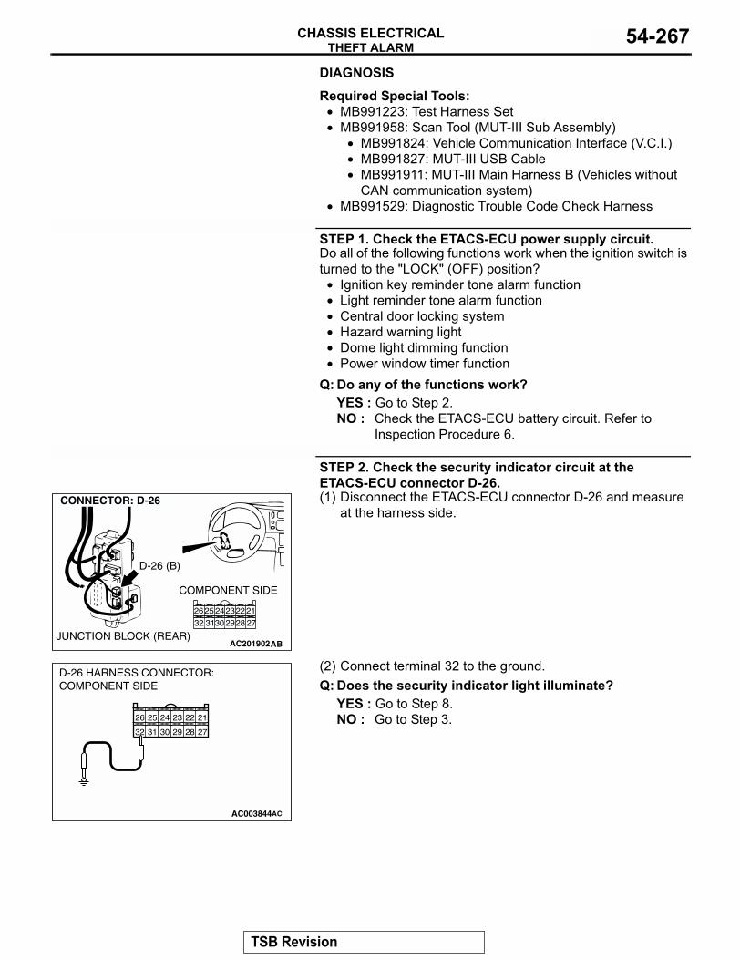
THEFT ALARMCHASSIS ELECTRICAL 54-267
DIAGNOSIS
Required Special Tools:• MB991223: Test Harness Set • MB991958: Scan Tool (MUT-III Sub Assembly)
• MB991824: Vehicle Communication Interface (V.C.I.)• MB991827: MUT-III USB Cable• MB991911: MUT-III Main Harness B (Vehicles without
CAN communication system)• MB991529: Diagnostic Trouble Code Check Harness
STEP 1. Check the ETACS-ECU power supply circuit.Do all of the following functions work when the ignition switch is turned to the "LOCK" (OFF) position?
• Ignition key reminder tone alarm function• Light reminder tone alarm function• Central door locking system• Hazard warning light• Dome light dimming function• Power window timer function
Q: Do any of the functions work?YES : Go to Step 2.NO : Check the ETACS-ECU battery circuit. Refer to
Inspection Procedure 6.
STEP 2. Check the security indicator circuit at the ETACS-ECU connector D-26.(1) Disconnect the ETACS-ECU connector D-26 and measure
at the harness side.
(2) Connect terminal 32 to the ground.Q: Does the security indicator light illuminate?
YES : Go to Step 8.NO : Go to Step 3.
AC201902
12
8 7
4
10
5
1112
6
9
3
CONNECTOR: D-26
AB
COMPONENT SIDE
JUNCTION BLOCK (REAR)
212223242526272829303132
D-26 (B)
212223242526
272829303132
AC003844
D-26 HARNESS CONNECTOR:COMPONENT SIDE
AC
TSB Revision
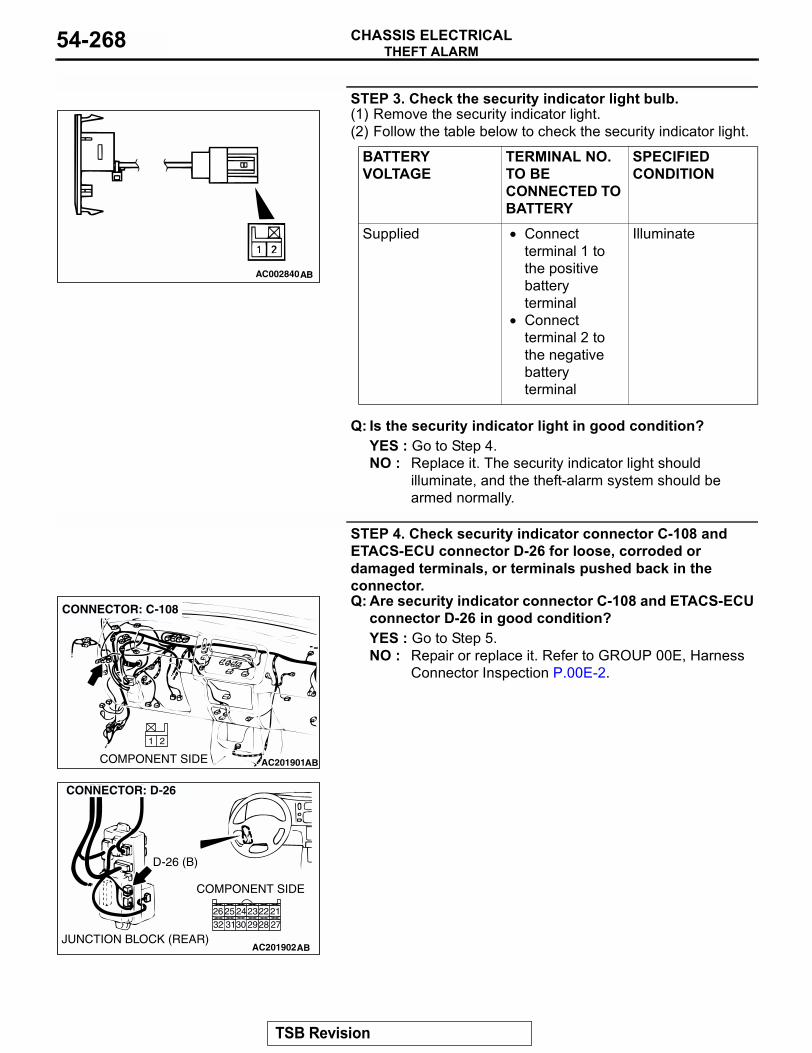
THEFT ALARMCHASSIS ELECTRICAL54-268
STEP 3. Check the security indicator light bulb.(1) Remove the security indicator light.(2) Follow the table below to check the security indicator light.
Q: Is the security indicator light in good condition?YES : Go to Step 4.NO : Replace it. The security indicator light should
illuminate, and the theft-alarm system should be armed normally.
STEP 4. Check security indicator connector C-108 and ETACS-ECU connector D-26 for loose, corroded or damaged terminals, or terminals pushed back in the connector.Q: Are security indicator connector C-108 and ETACS-ECU
connector D-26 in good condition?YES : Go to Step 5.NO : Repair or replace it. Refer to GROUP 00E, Harness
Connector Inspection P.00E-2.
BATTERY VOLTAGE
TERMINAL NO. TO BE CONNECTED TO BATTERY
SPECIFIED CONDITION
Supplied • Connect terminal 1 to the positive battery terminal
• Connect terminal 2 to the negative battery terminal
Illuminate
AC002840AB
AC201901
CONNECTOR: C-108
ABCOMPONENT SIDE
21
AC201902
12
8 7
4
10
5
1112
6
9
3
CONNECTOR: D-26
AB
COMPONENT SIDE
JUNCTION BLOCK (REAR)
212223242526272829303132
D-26 (B)
TSB Revision
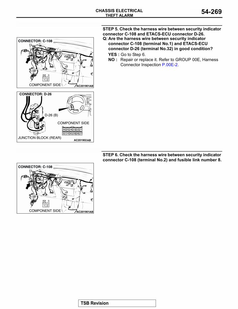
THEFT ALARMCHASSIS ELECTRICAL 54-269
STEP 5. Check the harness wire between security indicator connector C-108 and ETACS-ECU connector D-26.Q: Are the harness wire between security indicator
connector C-108 (terminal No.1) and ETACS-ECU connector D-26 (terminal No.32) in good condition?YES : Go to Step 6.NO : Repair or replace it. Refer to GROUP 00E, Harness
Connector Inspection P.00E-2.
STEP 6. Check the harness wire between security indicator connector C-108 (terminal No.2) and fusible link number 8.
AC201901
CONNECTOR: C-108
ABCOMPONENT SIDE
21
AC201902
12
8 7
4
10
5
1112
6
9
3
CONNECTOR: D-26
AB
COMPONENT SIDE
JUNCTION BLOCK (REAR)
212223242526272829303132
D-26 (B)
AC201901
CONNECTOR: C-108
ABCOMPONENT SIDE
21
TSB Revision
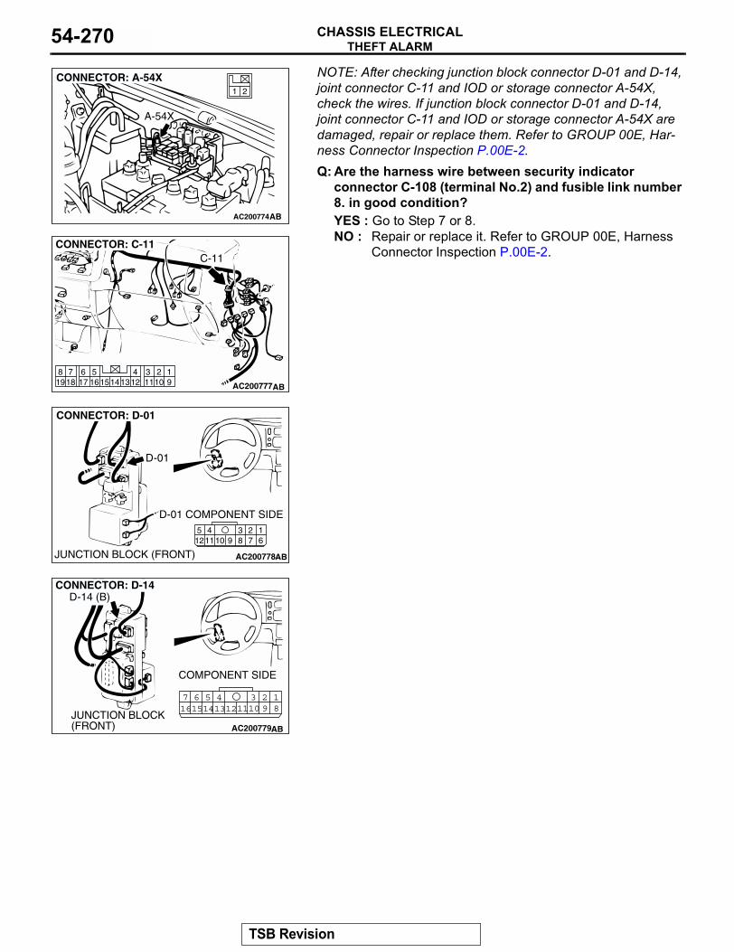
THEFT ALARMCHASSIS ELECTRICAL54-270
NOTE: After checking junction block connector D-01 and D-14, joint connector C-11 and IOD or storage connector A-54X, check the wires. If junction block connector D-01 and D-14, joint connector C-11 and IOD or storage connector A-54X are damaged, repair or replace them. Refer to GROUP 00E, Har-ness Connector Inspection P.00E-2.Q: Are the harness wire between security indicatorconnector C-108 (terminal No.2) and fusible link number 8. in good condition?YES : Go to Step 7 or 8.NO : Repair or replace it. Refer to GROUP 00E, Harness
Connector Inspection P.00E-2.
AC200774
21
CONNECTOR: A-54X
AB
A-54X
AC200777
1234561417 1615 1312 1110 9
819
718
CONNECTOR: C-11
AB
C-11
AC200778
2341110 9 8 7
16
512
CONNECTOR: D-01
AB
D-01 COMPONENT SIDE
JUNCTION BLOCK (FRONT)
D-01
AC200779
123457 616151413121110 9 8
CONNECTOR: D-14
AB
COMPONENT SIDE
JUNCTION BLOCK (FRONT)
D-14 (B)
TSB Revision
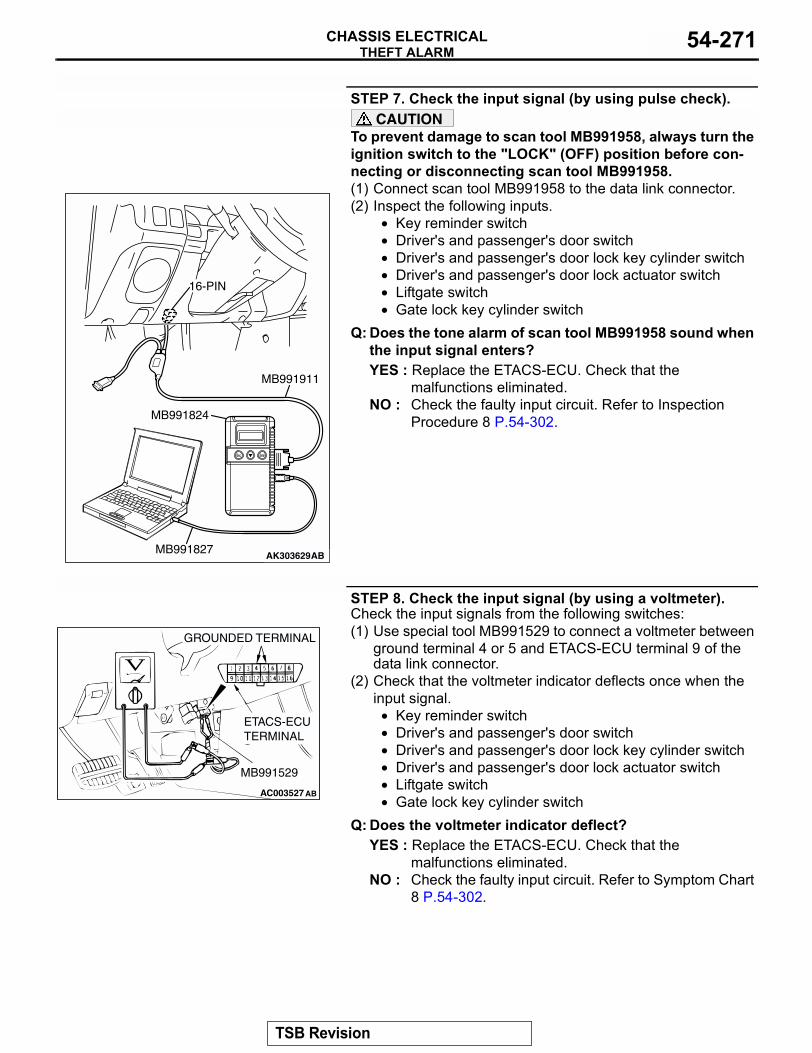
THEFT ALARMCHASSIS ELECTRICAL 54-271
STEP 7. Check the input signal (by using pulse check).CAUTION
To prevent damage to scan tool MB991958, always turn the ignition switch to the "LOCK" (OFF) position before con-necting or disconnecting scan tool MB991958.(1) Connect scan tool MB991958 to the data link connector.(2) Inspect the following inputs.
• Key reminder switch• Driver's and passenger's door switch• Driver's and passenger's door lock key cylinder switch• Driver's and passenger's door lock actuator switch• Liftgate switch• Gate lock key cylinder switch
Q: Does the tone alarm of scan tool MB991958 sound when the input signal enters?YES : Replace the ETACS-ECU. Check that the
malfunctions eliminated.NO : Check the faulty input circuit. Refer to Inspection
Procedure 8 P.54-302.
STEP 8. Check the input signal (by using a voltmeter).Check the input signals from the following switches:(1) Use special tool MB991529 to connect a voltmeter between
ground terminal 4 or 5 and ETACS-ECU terminal 9 of the data link connector.
(2) Check that the voltmeter indicator deflects once when the input signal.
• Key reminder switch• Driver's and passenger's door switch• Driver's and passenger's door lock key cylinder switch• Driver's and passenger's door lock actuator switch• Liftgate switch• Gate lock key cylinder switch
Q: Does the voltmeter indicator deflect?YES : Replace the ETACS-ECU. Check that the
malfunctions eliminated.NO : Check the faulty input circuit. Refer to Symptom Chart
8 P.54-302.
AK303629AB
MB991911
MB991827
MB991824
16-PIN
AC003527
GROUNDED TERMINAL
ETACS-ECU TERMINAL
MB991529
AB
TSB Revision
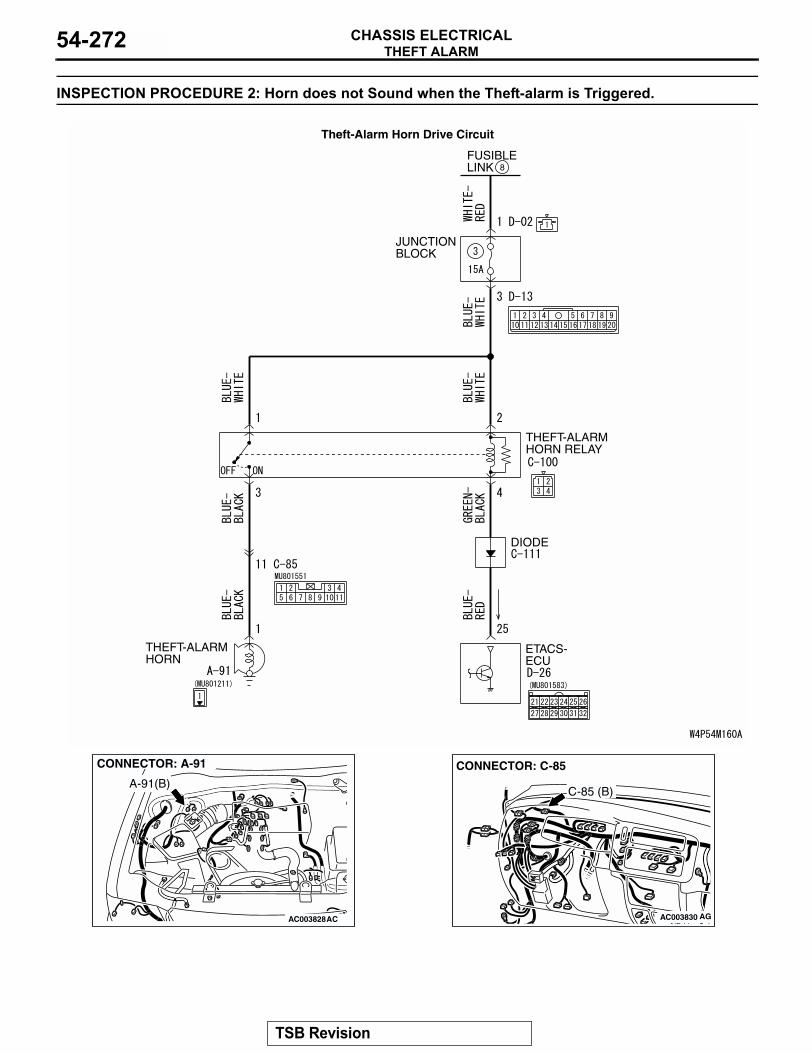
THEFT ALARMCHASSIS ELECTRICAL54-272
INSPECTION PROCEDURE 2: Horn does not Sound when the Theft-alarm is Triggered.
JUNCTION BLOCK
THEFT-ALARMHORN RELAY
THEFT-ALARMHORN
DIODE
ETACS-ECU
FUSIBLELINK 8
Theft-Alarm Horn Drive Circuit
AC003828AC
CONNECTOR: A-91
A-91(B)
AC003830
CONNECTOR: C-85
AG
C-85 (B)
TSB Revision
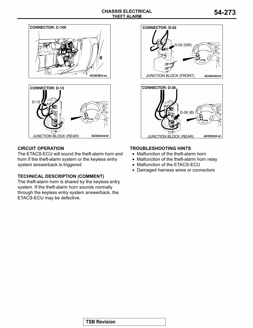
THEFT ALARMCHASSIS ELECTRICAL 54-273
.
CIRCUIT OPERATIONThe ETACS-ECU will sound the theft-alarm horn and horn if the theft-alarm system or the keyless entry system answerback is triggered..
TECHNICAL DESCRIPTION (COMMENT)The theft-alarm horn is shared by the keyless entry system. If the theft-alarm horn sounds normally through the keyless entry system answerback, the ETACS-ECU may be defective.
.
TROUBLESHOOTING HINTS• Malfunction of the theft-alarm horn• Malfunction of the theft-alarm horn relay• Malfunction of the ETACS-ECU• Damaged harness wires or connectors
.
AC003824 AC
CONNECTOR: C-100
C-100
AC003432
CONNECTOR: D-02
JUNCTION BLOCK (FRONT) AF
D-02 (GR)
AC003444AE
CONNECTOR: D-13
JUNCTION BLOCK (REAR)
D-13
AC003524
CONNECTOR: D-26
ACJUNCTION BLOCK (REAR)
D-26 (B)
TSB Revision
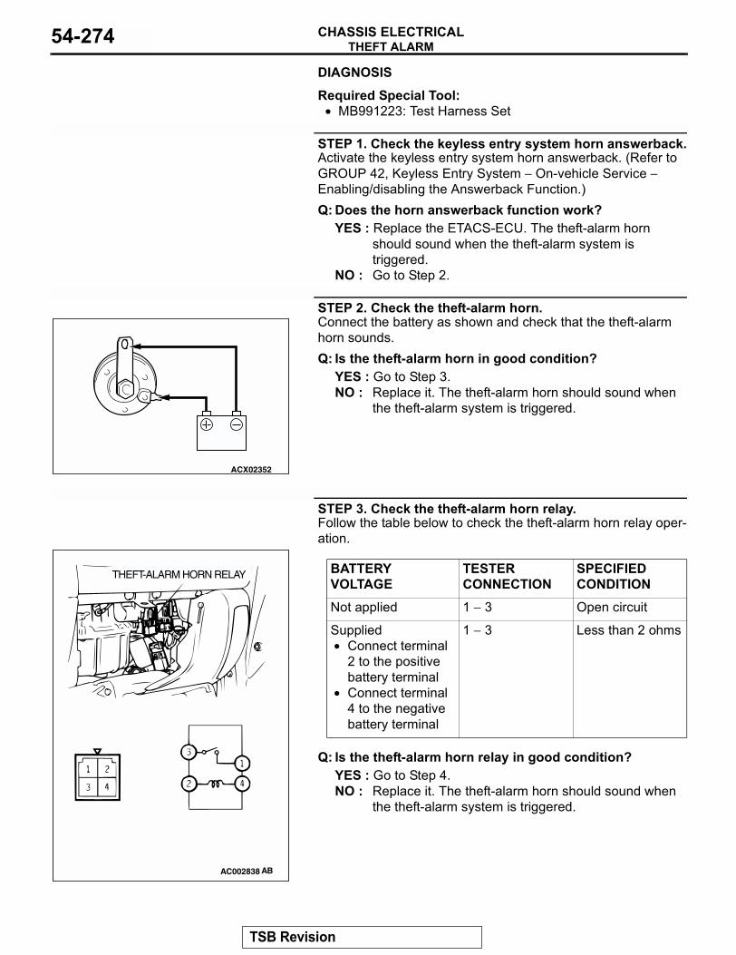
THEFT ALARMCHASSIS ELECTRICAL54-274
DIAGNOSISRequired Special Tool:• MB991223: Test Harness Set
STEP 1. Check the keyless entry system horn answerback.Activate the keyless entry system horn answerback. (Refer to GROUP 42, Keyless Entry System − On-vehicle Service − Enabling/disabling the Answerback Function.)Q: Does the horn answerback function work?
YES : Replace the ETACS-ECU. The theft-alarm horn should sound when the theft-alarm system is triggered.
NO : Go to Step 2.
STEP 2. Check the theft-alarm horn.Connect the battery as shown and check that the theft-alarm horn sounds.Q: Is the theft-alarm horn in good condition?
YES : Go to Step 3.NO : Replace it. The theft-alarm horn should sound when
the theft-alarm system is triggered.
STEP 3. Check the theft-alarm horn relay.Follow the table below to check the theft-alarm horn relay oper-ation.
Q: Is the theft-alarm horn relay in good condition?YES : Go to Step 4.NO : Replace it. The theft-alarm horn should sound when
the theft-alarm system is triggered.
ACX02352
BATTERY VOLTAGE
TESTER CONNECTION
SPECIFIED CONDITION
Not applied 1 − 3 Open circuit
Supplied• Connect terminal
2 to the positive battery terminal
• Connect terminal 4 to the negative battery terminal
1 − 3 Less than 2 ohms
AC002838 AB
THEFT-ALARM HORN RELAY
TSB Revision
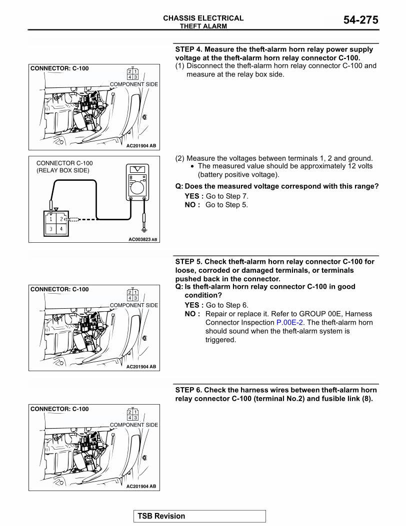
THEFT ALARMCHASSIS ELECTRICAL 54-275
STEP 4. Measure the theft-alarm horn relay power supply voltage at the theft-alarm horn relay connector C-100.(1) Disconnect the theft-alarm horn relay connector C-100 and
measure at the relay box side.
(2) Measure the voltages between terminals 1, 2 and ground.• The measured value should be approximately 12 volts
(battery positive voltage).Q: Does the measured voltage correspond with this range?
YES : Go to Step 7.NO : Go to Step 5.
STEP 5. Check theft-alarm horn relay connector C-100 for loose, corroded or damaged terminals, or terminals pushed back in the connector.Q: Is theft-alarm horn relay connector C-100 in good
condition?YES : Go to Step 6.NO : Repair or replace it. Refer to GROUP 00E, Harness
Connector Inspection P.00E-2. The theft-alarm horn should sound when the theft-alarm system is triggered.
STEP 6. Check the harness wires between theft-alarm horn relay connector C-100 (terminal No.2) and fusible link (8).
AC201904
CONNECTOR: C-100
AB
COMPONENT SIDE
134
2
AC003823
CONNECTOR C-100(RELAY BOX SIDE)
AB
AC201904
CONNECTOR: C-100
AB
COMPONENT SIDE
134
2
AC201904
CONNECTOR: C-100
AB
COMPONENT SIDE
134
2
TSB Revision
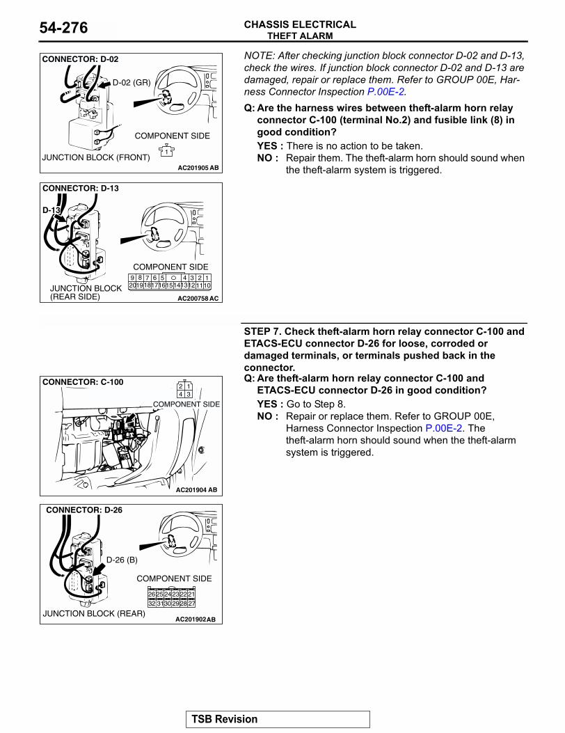
THEFT ALARMCHASSIS ELECTRICAL54-276
NOTE: After checking junction block connector D-02 and D-13, check the wires. If junction block connector D-02 and D-13 are damaged, repair or replace them. Refer to GROUP 00E, Har-ness Connector Inspection P.00E-2.Q: Are the harness wires between theft-alarm horn relayconnector C-100 (terminal No.2) and fusible link (8) in good condition?YES : There is no action to be taken.NO : Repair them. The theft-alarm horn should sound when
the theft-alarm system is triggered.
STEP 7. Check theft-alarm horn relay connector C-100 and ETACS-ECU connector D-26 for loose, corroded or damaged terminals, or terminals pushed back in the connector.Q: Are theft-alarm horn relay connector C-100 and
ETACS-ECU connector D-26 in good condition?YES : Go to Step 8.NO : Repair or replace them. Refer to GROUP 00E,
Harness Connector Inspection P.00E-2. The theft-alarm horn should sound when the theft-alarm system is triggered.
AC201905
1
CONNECTOR: D-02
AB
COMPONENT SIDE
JUNCTION BLOCK (FRONT)
D-02 (GR)
AC200758
110
211
312
4131415
516
617
718
819
920
CONNECTOR: D-13
AC
COMPONENT SIDE
JUNCTION BLOCK (REAR SIDE)
D-13
AC201904
CONNECTOR: C-100
AB
COMPONENT SIDE
134
2
AC201902
12
8 7
4
10
5
1112
6
9
3
CONNECTOR: D-26
AB
COMPONENT SIDE
JUNCTION BLOCK (REAR)
212223242526272829303132
D-26 (B)
TSB Revision
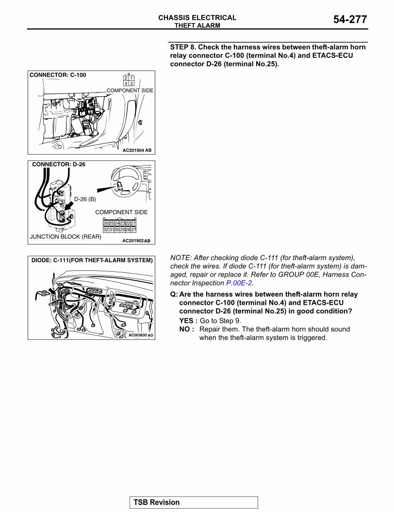
THEFT ALARMCHASSIS ELECTRICAL 54-277
STEP 8. Check the harness wires between theft-alarm horn relay connector C-100 (terminal No.4) and ETACS-ECU connector D-26 (terminal No.25).
NOTE: After checking diode C-111 (for theft-alarm system), check the wires. If diode C-111 (for theft-alarm system) is dam-aged, repair or replace it. Refer to GROUP 00E, Harness Con-nector Inspection P.00E-2.Q: Are the harness wires between theft-alarm horn relay
connector C-100 (terminal No.4) and ETACS-ECU connector D-26 (terminal No.25) in good condition?YES : Go to Step 9.NO : Repair them. The theft-alarm horn should sound
when the theft-alarm system is triggered.
AC201904
CONNECTOR: C-100
AB
COMPONENT SIDE
134
2
AC201902
12
8 7
4
10
5
1112
6
9
3
CONNECTOR: D-26
AB
COMPONENT SIDE
JUNCTION BLOCK (REAR)
212223242526272829303132
D-26 (B)
AC003830 AD
DIODE: C-111(FOR THEFT-ALARM SYSTEM)
TSB Revision
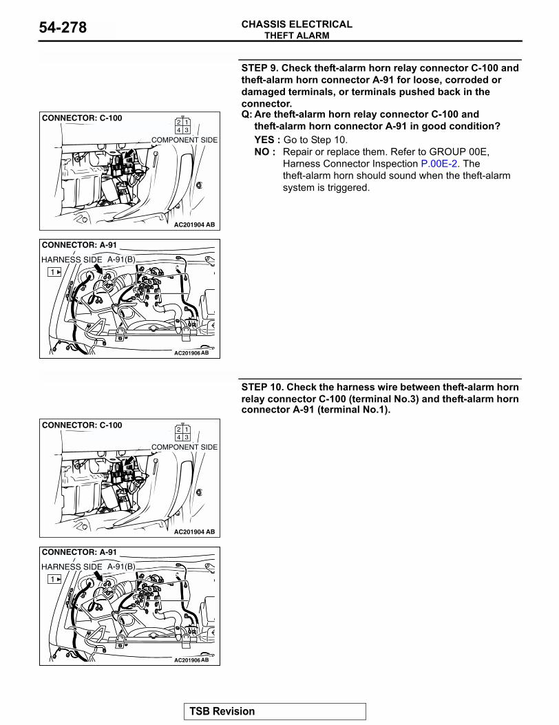
THEFT ALARMCHASSIS ELECTRICAL54-278
STEP 9. Check theft-alarm horn relay connector C-100 and theft-alarm horn connector A-91 for loose, corroded or damaged terminals, or terminals pushed back in the connector.Q: Are theft-alarm horn relay connector C-100 and
theft-alarm horn connector A-91 in good condition?YES : Go to Step 10.NO : Repair or replace them. Refer to GROUP 00E,
Harness Connector Inspection P.00E-2. The theft-alarm horn should sound when the theft-alarm system is triggered.
STEP 10. Check the harness wire between theft-alarm horn relay connector C-100 (terminal No.3) and theft-alarm horn connector A-91 (terminal No.1).
AC201904
CONNECTOR: C-100
AB
COMPONENT SIDE
134
2
AC003828ABAC201906
1
CONNECTOR: A-91
AB
HARNESS SIDE A-91(B)
AC201904
CONNECTOR: C-100
AB
COMPONENT SIDE
134
2
AC003828ABAC201906
1
CONNECTOR: A-91
AB
HARNESS SIDE A-91(B)
TSB Revision
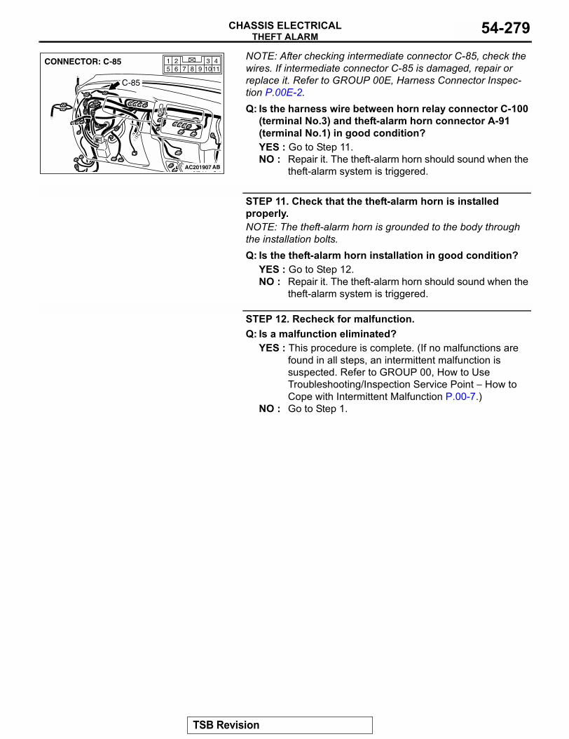
THEFT ALARMCHASSIS ELECTRICAL 54-279
NOTE: After checking intermediate connector C-85, check the wires. If intermediate connector C-85 is damaged, repair or replace it. Refer to GROUP 00E, Harness Connector Inspec-tion P.00E-2.Q: Is the harness wire between horn relay connector C-100
(terminal No.3) and theft-alarm horn connector A-91 (terminal No.1) in good condition?YES : Go to Step 11.NO : Repair it. The theft-alarm horn should sound when the
theft-alarm system is triggered.
STEP 11. Check that the theft-alarm horn is installed properly.NOTE: The theft-alarm horn is grounded to the body through the installation bolts.Q: Is the theft-alarm horn installation in good condition?
YES : Go to Step 12.NO : Repair it. The theft-alarm horn should sound when the
theft-alarm system is triggered.
STEP 12. Recheck for malfunction.Q: Is a malfunction eliminated?
YES : This procedure is complete. (If no malfunctions are found in all steps, an intermittent malfunction is suspected. Refer to GROUP 00, How to Use Troubleshooting/Inspection Service Point − How to Cope with Intermittent Malfunction P.00-7.)
NO : Go to Step 1.
AC201907
1143
98 105 621
7CONNECTOR: C-85
AB
C-85
TSB Revision
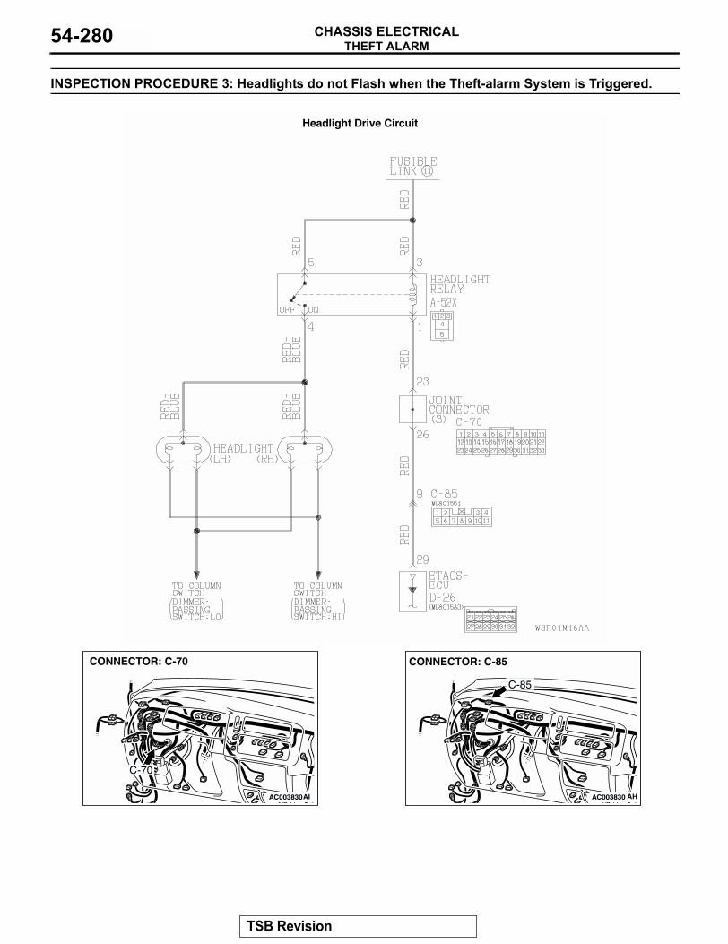
THEFT ALARMCHASSIS ELECTRICAL54-280
INSPECTION PROCEDURE 3: Headlights do not Flash when the Theft-alarm System is Triggered.
Headlight Drive Circuit
AC003830
CONNECTOR: C-70
AI
C-70
AC003830
CONNECTOR: C-85
AH
C-85
TSB Revision
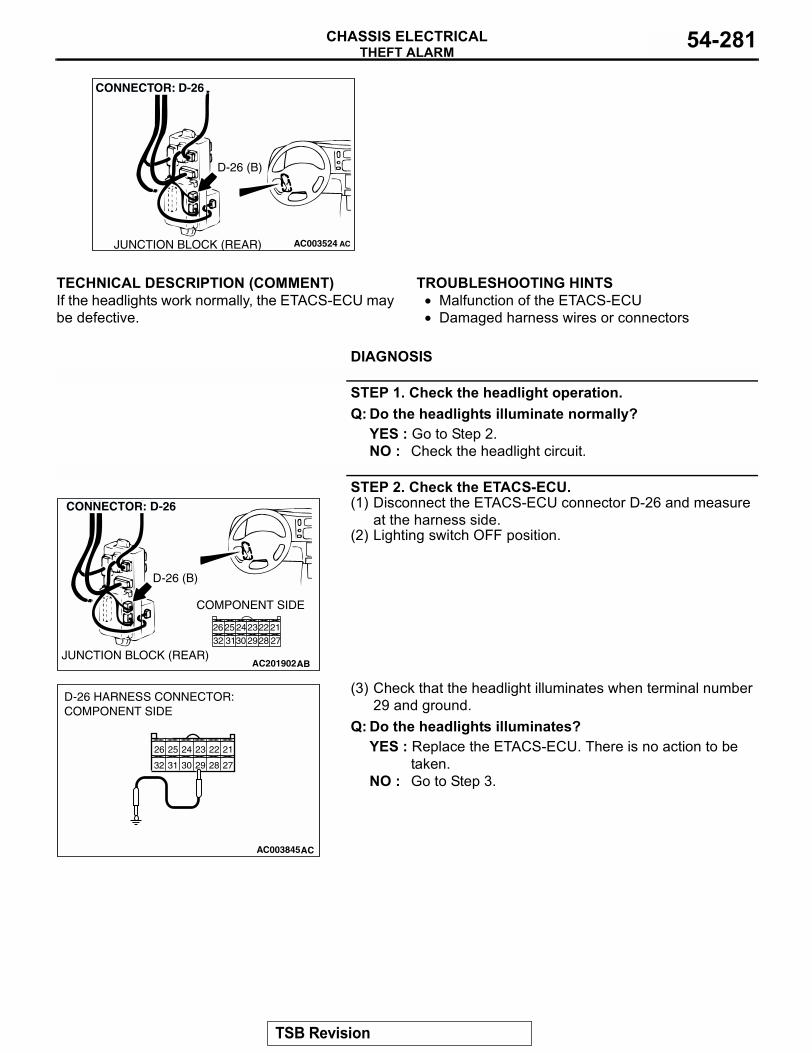
THEFT ALARMCHASSIS ELECTRICAL 54-281
.
TECHNICAL DESCRIPTION (COMMENT)If the headlights work normally, the ETACS-ECU may be defective.
.
TROUBLESHOOTING HINTS• Malfunction of the ETACS-ECU• Damaged harness wires or connectors
.
DIAGNOSIS
STEP 1. Check the headlight operation.Q: Do the headlights illuminate normally?
YES : Go to Step 2.NO : Check the headlight circuit.
STEP 2. Check the ETACS-ECU.(1) Disconnect the ETACS-ECU connector D-26 and measure
at the harness side.(2) Lighting switch OFF position.
(3) Check that the headlight illuminates when terminal number 29 and ground.
Q: Do the headlights illuminates?YES : Replace the ETACS-ECU. There is no action to be
taken.NO : Go to Step 3.
AC003524
CONNECTOR: D-26
ACJUNCTION BLOCK (REAR)
D-26 (B)
AC201902
12
8 7
4
10
5
1112
6
9
3
CONNECTOR: D-26
AB
COMPONENT SIDE
JUNCTION BLOCK (REAR)
212223242526272829303132
D-26 (B)
212223242526
272829303132
AC003845
D-26 HARNESS CONNECTOR:COMPONENT SIDE
AC
TSB Revision
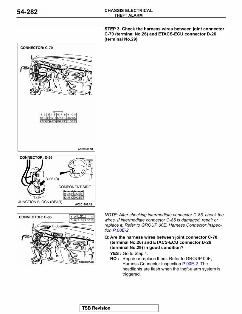
THEFT ALARMCHASSIS ELECTRICAL54-282
STEP 3. Check the harness wires between joint connector C-70 (terminal No.26) and ETACS-ECU connector D-26 (terminal No.29).
NOTE: After checking intermediate connector C-85, check the wires. If intermediate connector C-85 is damaged, repair or replace it. Refer to GROUP 00E, Harness Connector Inspec-tion P.00E-2.Q: Are the harness wires between joint connector C-70
(terminal No.26) and ETACS-ECU connector D-26 (terminal No.29) in good condition?YES : Go to Step 4.NO : Repair or replace them. Refer to GROUP 00E,
Harness Connector Inspection P.00E-2. The headlights are flash when the theft-alarm system is triggered.
AC201908
9 1086 7
3132302918192021
5421 3
27262423 25121314151617
28
112233
CONNECTOR: C-70
AB
C-70
AC201902
12
8 7
4
10
5
1112
6
9
3
CONNECTOR: D-26
AB
COMPONENT SIDE
JUNCTION BLOCK (REAR)
212223242526272829303132
D-26 (B)
AC201907
1143
98 105 621
7CONNECTOR: C-85
AB
C-85
TSB Revision
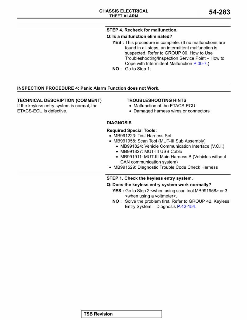
THEFT ALARMCHASSIS ELECTRICAL 54-283
STEP 4. Recheck for malfunction.Q: Is a malfunction eliminated?
YES : This procedure is complete. (If no malfunctions are found in all steps, an intermittent malfunction is suspected. Refer to GROUP 00, How to Use Troubleshooting/Inspection Service Point − How to Cope with Intermittent Malfunction P.00-7.)
NO : Go to Step 1.
INSPECTION PROCEDURE 4: Panic Alarm Function does not Work.
.
TECHNICAL DESCRIPTION (COMMENT)If the keyless entry system is normal, the ETACS-ECU is defective.
.
TROUBLESHOOTING HINTS• Malfunction of the ETACS-ECU • Damaged harness wires or connectors
.
DIAGNOSIS
Required Special Tools:• MB991223: Test Harness Set• MB991958: Scan Tool (MUT-III Sub Assembly)
• MB991824: Vehicle Communication Interface (V.C.I.)• MB991827: MUT-III USB Cable• MB991911: MUT-III Main Harness B (Vehicles without
CAN communication system)• MB991529: Diagnostic Trouble Code Check Harness
STEP 1. Check the keyless entry system.Q: Does the keyless entry system work normally?
YES : Go to Step 2 <when using scan tool MB991958> or 3 <when using a voltmeter>.
NO : Solve the problem first. Refer to GROUP 42. Keyless Entry System − Diagnosis P.42-154.
TSB Revision
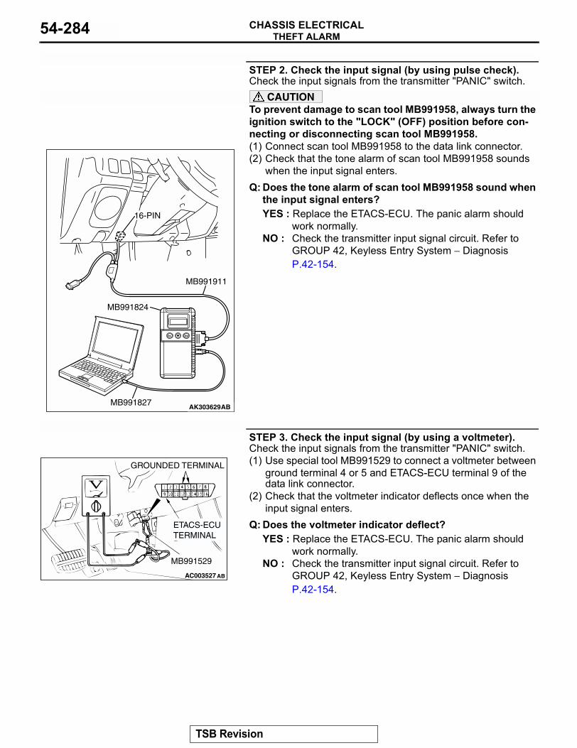
THEFT ALARMCHASSIS ELECTRICAL54-284
STEP 2. Check the input signal (by using pulse check).Check the input signals from the transmitter "PANIC" switch.
CAUTIONTo prevent damage to scan tool MB991958, always turn the ignition switch to the "LOCK" (OFF) position before con-necting or disconnecting scan tool MB991958.(1) Connect scan tool MB991958 to the data link connector.(2) Check that the tone alarm of scan tool MB991958 sounds
when the input signal enters.Q: Does the tone alarm of scan tool MB991958 sound when
the input signal enters?YES : Replace the ETACS-ECU. The panic alarm should
work normally.NO : Check the transmitter input signal circuit. Refer to
GROUP 42, Keyless Entry System − Diagnosis P.42-154.
STEP 3. Check the input signal (by using a voltmeter).Check the input signals from the transmitter "PANIC" switch.(1) Use special tool MB991529 to connect a voltmeter between
ground terminal 4 or 5 and ETACS-ECU terminal 9 of the data link connector.
(2) Check that the voltmeter indicator deflects once when the input signal enters.
Q: Does the voltmeter indicator deflect?YES : Replace the ETACS-ECU. The panic alarm should
work normally.NO : Check the transmitter input signal circuit. Refer to
GROUP 42, Keyless Entry System − Diagnosis P.42-154.
AK303629AB
MB991911
MB991827
MB991824
16-PIN
AC003527
GROUNDED TERMINAL
ETACS-ECU TERMINAL
MB991529
AB
TSB Revision
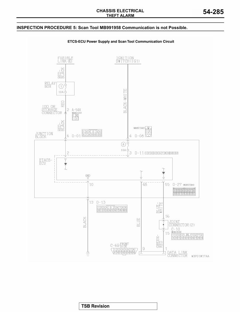
THEFT ALARMCHASSIS ELECTRICAL 54-285
INSPECTION PROCEDURE 5: Scan Tool MB991958 Communication is not Possible.
ETCS-ECU Power Supply and Scan Tool Communication Circuit
TSB Revision
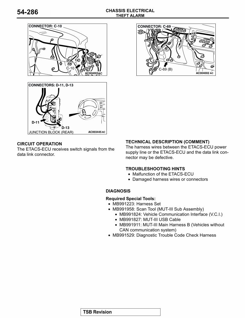
THEFT ALARMCHASSIS ELECTRICAL54-286
.
CIRCUIT OPERATIONThe ETACS-ECU receives switch signals from the data link connector..
TECHNICAL DESCRIPTION (COMMENT)The harness wires between the ETACS-ECU power supply line or the ETACS-ECU and the data link con-nector may be defective..
TROUBLESHOOTING HINTS• Malfunction of the ETACS-ECU• Damaged harness wires or connectors
.
DIAGNOSIS
Required Special Tools:• MB991223: Harness Set• MB991958: Scan Tool (MUT-III Sub Assembly)
• MB991824: Vehicle Communication Interface (V.C.I.)• MB991827: MUT-III USB Cable• MB991911: MUT-III Main Harness B (Vehicles without
CAN communication system)• MB991529: Diagnostic Trouble Code Check Harness
AC004003AC
CONNECTOR: C-10
C-10AC004002 AC
CONNECTOR: C-69
C-69 (B)
AC003445JUNCTION BLOCK (REAR)
D-11
D-13
CONNECTORS: D-11, D-13
AC
TSB Revision
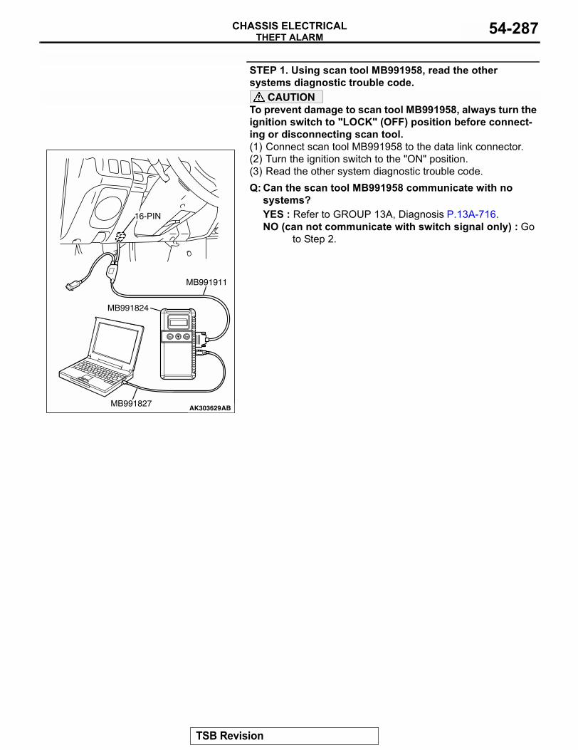
THEFT ALARMCHASSIS ELECTRICAL 54-287
STEP 1. Using scan tool MB991958, read the other systems diagnostic trouble code.
CAUTIONTo prevent damage to scan tool MB991958, always turn the ignition switch to "LOCK" (OFF) position before connect-ing or disconnecting scan tool.(1) Connect scan tool MB991958 to the data link connector.(2) Turn the ignition switch to the "ON" position.(3) Read the other system diagnostic trouble code.Q: Can the scan tool MB991958 communicate with no
systems?YES : Refer to GROUP 13A, Diagnosis P.13A-716.NO (can not communicate with switch signal only) : Go
to Step 2.
AK303629AB
MB991911
MB991827
MB991824
16-PIN
TSB Revision
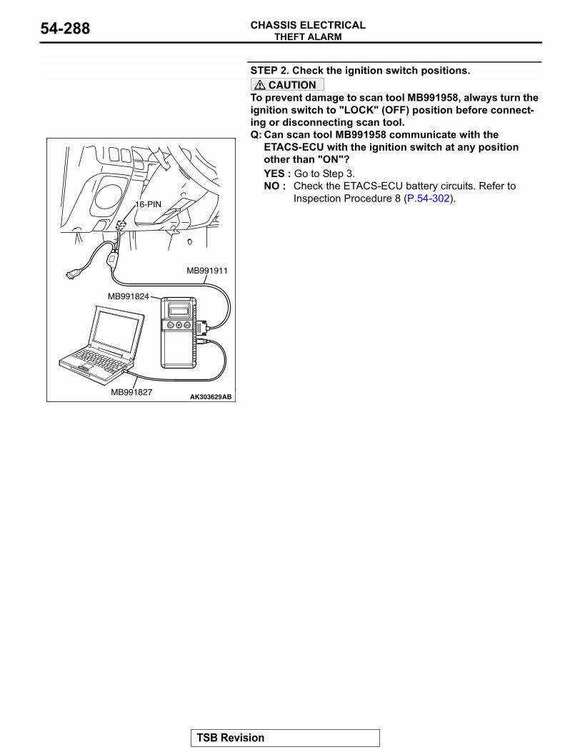
THEFT ALARMCHASSIS ELECTRICAL54-288
STEP 2. Check the ignition switch positions.CAUTION
To prevent damage to scan tool MB991958, always turn the ignition switch to "LOCK" (OFF) position before connect-ing or disconnecting scan tool.Q: Can scan tool MB991958 communicate with the
ETACS-ECU with the ignition switch at any position other than "ON"?YES : Go to Step 3.NO : Check the ETACS-ECU battery circuits. Refer to
Inspection Procedure 8 (P.54-302).
AK303629AB
MB991911
MB991827
MB991824
16-PIN
TSB Revision
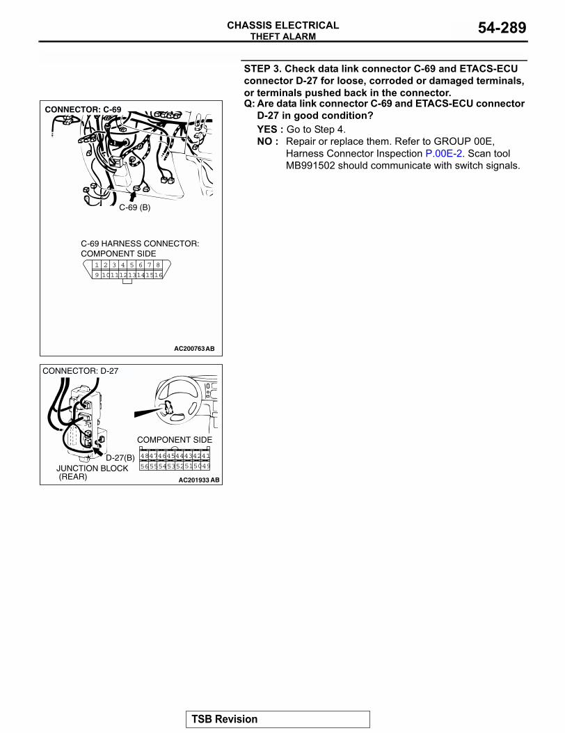
THEFT ALARMCHASSIS ELECTRICAL 54-289
STEP 3. Check data link connector C-69 and ETACS-ECU connector D-27 for loose, corroded or damaged terminals, or terminals pushed back in the connector.Q: Are data link connector C-69 and ETACS-ECU connector
D-27 in good condition?YES : Go to Step 4.NO : Repair or replace them. Refer to GROUP 00E,
Harness Connector Inspection P.00E-2. Scan tool MB991502 should communicate with switch signals.
AC200763
8
16
6
1415
75
13
3
1112
42
109
1
CONNECTOR: C-69
C-69 HARNESS CONNECTOR:COMPONENT SIDE
AB
C-69 (B)
AC201933
4243
4950
4546
5253 51
4448
5554
47
56
41
COMPONENT SIDE
AB
D-27(B)
CONNECTOR: D-27
JUNCTION BLOCK (REAR)
TSB Revision
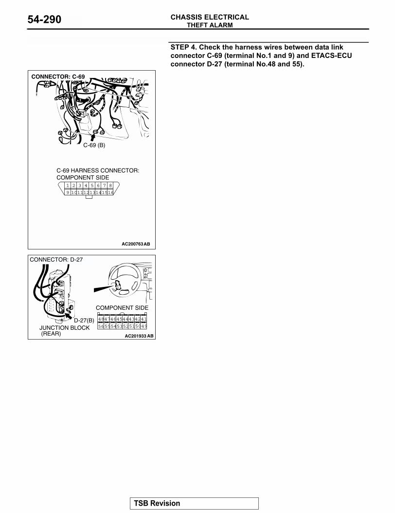
THEFT ALARMCHASSIS ELECTRICAL54-290
STEP 4. Check the harness wires between data link connector C-69 (terminal No.1 and 9) and ETACS-ECU connector D-27 (terminal No.48 and 55).
AC200763
8
16
6
1415
75
13
3
1112
42
109
1
CONNECTOR: C-69
C-69 HARNESS CONNECTOR:COMPONENT SIDE
AB
C-69 (B)
AC201933
4243
4950
4546
5253 51
4448
5554
47
56
41
COMPONENT SIDE
AB
D-27(B)
CONNECTOR: D-27
JUNCTION BLOCK (REAR)
TSB Revision
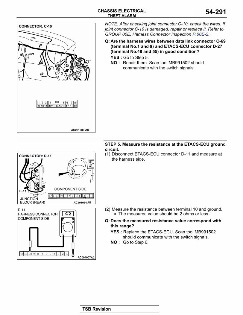
THEFT ALARMCHASSIS ELECTRICAL 54-291
NOTE: After checking joint connector C-10, check the wires. If joint connector C-10 is damaged, repair or replace it. Refer to GROUP 00E, Harness Connector Inspection P.00E-2.Q: Are the harness wires between data link connector C-69
(terminal No.1 and 9) and ETACS-ECU connector D-27 (terminal No.48 and 55) in good condition?YES : Go to Step 5.NO : Repair them. Scan tool MB991502 should
communicate with the switch signals.
STEP 5. Measure the resistance at the ETACS-ECU ground circuit.(1) Disconnect ETACS-ECU connector D-11 and measure at
the harness side.
(2) Measure the resistance between terminal 10 and ground.• The measured value should be 2 ohms or less.
Q: Does the measured resistance value correspond with this range?YES : Replace the ETACS-ECU. Scan tool MB991502
should communicate with the switch signals.NO : Go to Step 6.
AC201909
819
7651615 17 18
4321011 1213
19 14
CONNECTOR: C-10
AB
C-10
AC201084JUNCTION BLOCK (REAR)
D-11 COMPONENT SIDE
AB
CONNECTOR: D-11
123457910 681112AC004007AC
D-11 HARNESS CONNECTOR:COMPONENT SIDE
TSB Revision
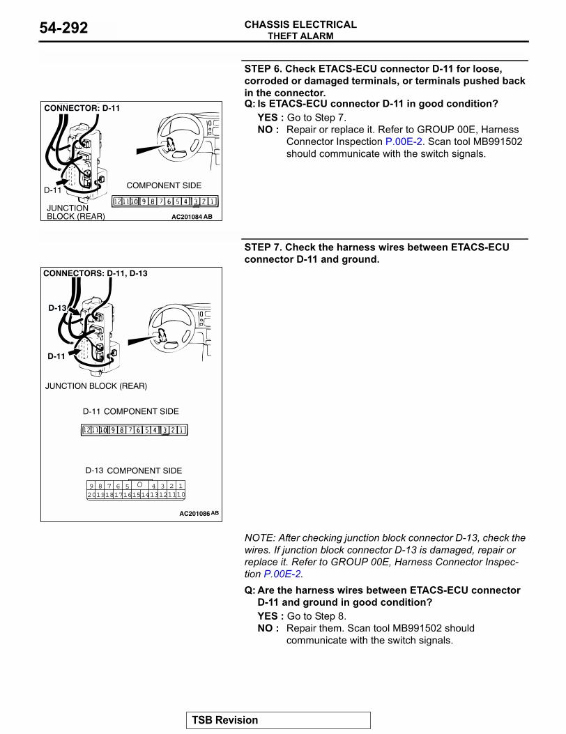
THEFT ALARMCHASSIS ELECTRICAL54-292
STEP 6. Check ETACS-ECU connector D-11 for loose, corroded or damaged terminals, or terminals pushed back in the connector.Q: Is ETACS-ECU connector D-11 in good condition?
YES : Go to Step 7.NO : Repair or replace it. Refer to GROUP 00E, Harness
Connector Inspection P.00E-2. Scan tool MB991502 should communicate with the switch signals.
STEP 7. Check the harness wires between ETACS-ECU connector D-11 and ground.
NOTE: After checking junction block connector D-13, check the wires. If junction block connector D-13 is damaged, repair or replace it. Refer to GROUP 00E, Harness Connector Inspec-tion P.00E-2.Q: Are the harness wires between ETACS-ECU connector
D-11 and ground in good condition?YES : Go to Step 8.NO : Repair them. Scan tool MB991502 should
communicate with the switch signals.
AC201084JUNCTION BLOCK (REAR)
D-11 COMPONENT SIDE
AB
CONNECTOR: D-11
1245 3689 710111314 121617201918 15
AC201086
TSB Revision
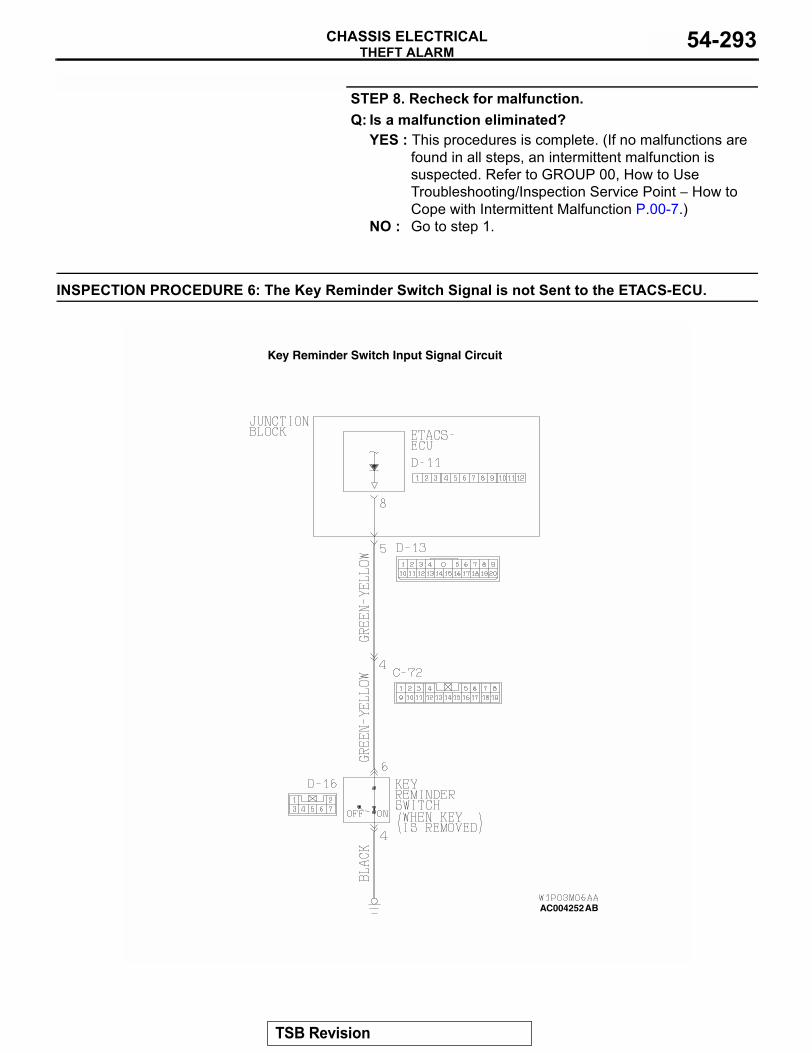
THEFT ALARMCHASSIS ELECTRICAL 54-293
STEP 8. Recheck for malfunction.Q: Is a malfunction eliminated?
YES : This procedures is complete. (If no malfunctions are found in all steps, an intermittent malfunction is suspected. Refer to GROUP 00, How to Use Troubleshooting/Inspection Service Point − How to Cope with Intermittent Malfunction P.00-7.)
NO : Go to step 1.
INSPECTION PROCEDURE 6: The Key Reminder Switch Signal is not Sent to the ETACS-ECU.
AC004252AB
Key Reminder Switch Input Signal Circuit
TSB Revision
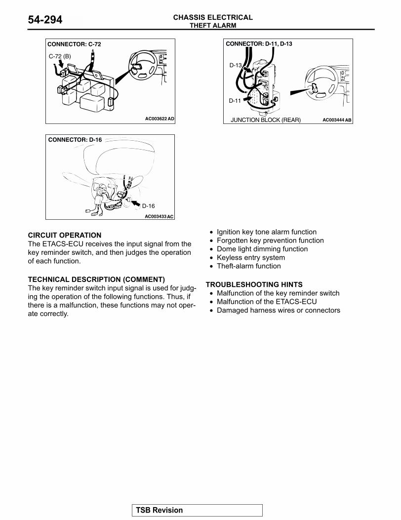
THEFT ALARMCHASSIS ELECTRICAL54-294
.
CIRCUIT OPERATIONThe ETACS-ECU receives the input signal from the key reminder switch, and then judges the operation of each function..
TECHNICAL DESCRIPTION (COMMENT)The key reminder switch input signal is used for judg-ing the operation of the following functions. Thus, if there is a malfunction, these functions may not oper-ate correctly.
• Ignition key tone alarm function• Forgotten key prevention function• Dome light dimming function• Keyless entry system• Theft-alarm function
.
TROUBLESHOOTING HINTS• Malfunction of the key reminder switch• Malfunction of the ETACS-ECU • Damaged harness wires or connectors
.
AC003622
CONNECTOR: C-72
AD
C-72 (B)
AC003444 AB
CONNECTOR: D-11, D-13
D-11
D-13
JUNCTION BLOCK (REAR)
AC003433
CONNECTOR: D-16
AC
D-16
TSB Revision
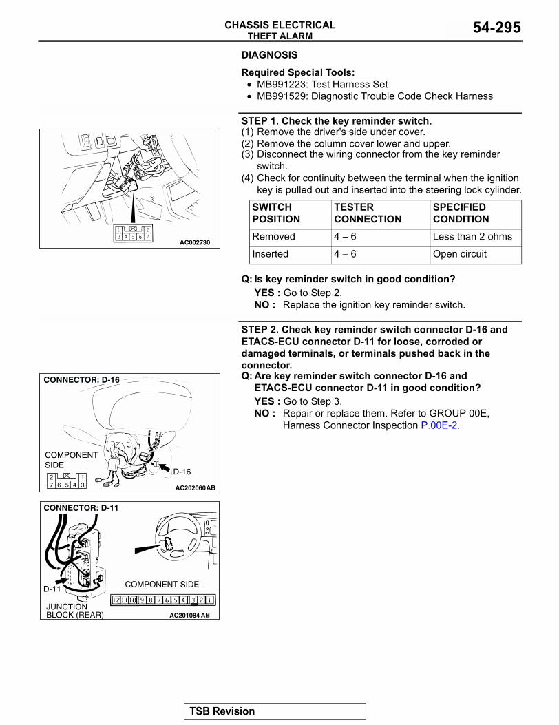
THEFT ALARMCHASSIS ELECTRICAL 54-295
DIAGNOSIS
Required Special Tools:• MB991223: Test Harness Set• MB991529: Diagnostic Trouble Code Check Harness
STEP 1. Check the key reminder switch.(1) Remove the driver's side under cover.(2) Remove the column cover lower and upper.(3) Disconnect the wiring connector from the key reminder
switch.(4) Check for continuity between the terminal when the ignition
key is pulled out and inserted into the steering lock cylinder.
Q: Is key reminder switch in good condition?YES : Go to Step 2.NO : Replace the ignition key reminder switch.
STEP 2. Check key reminder switch connector D-16 and ETACS-ECU connector D-11 for loose, corroded or damaged terminals, or terminals pushed back in the connector.Q: Are key reminder switch connector D-16 and
ETACS-ECU connector D-11 in good condition?YES : Go to Step 3.NO : Repair or replace them. Refer to GROUP 00E,
Harness Connector Inspection P.00E-2.
SWITCH POSITION
TESTER CONNECTION
SPECIFIED CONDITION
Removed 4 − 6 Less than 2 ohms
Inserted 4 − 6 Open circuitAC002730
AC20206045 31
672
AC201084JUNCTION BLOCK (REAR)
D-11 COMPONENT SIDE
AB
CONNECTOR: D-11
TSB Revision
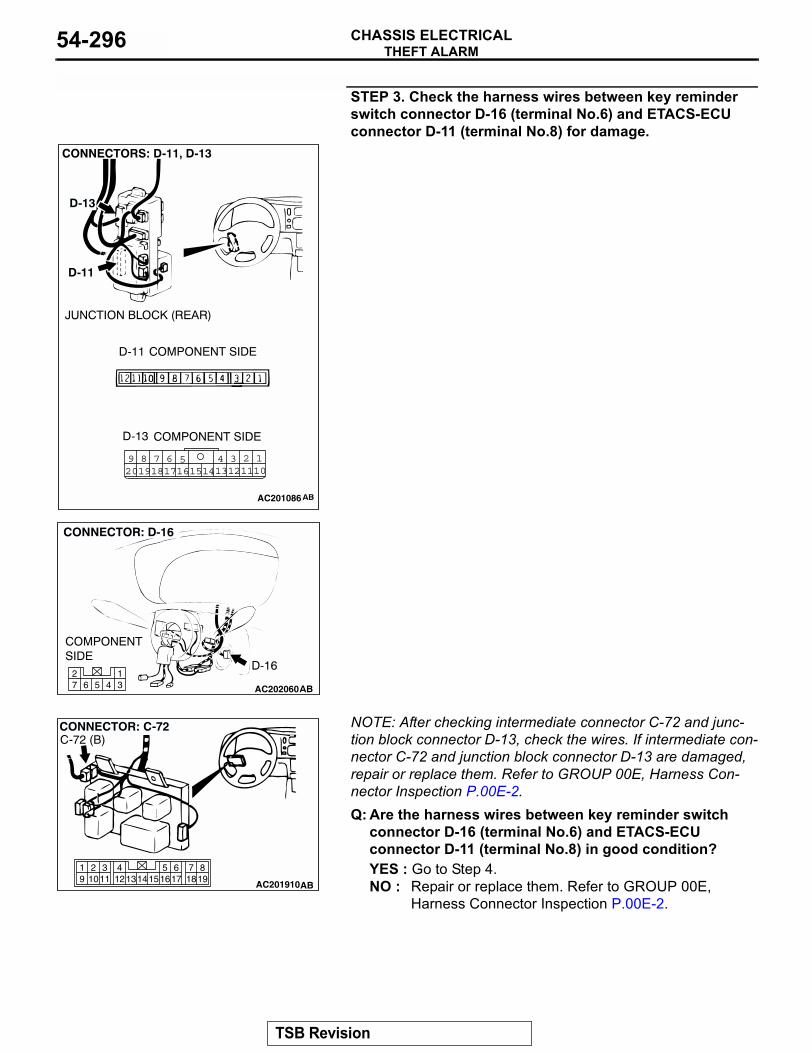
THEFT ALARMCHASSIS ELECTRICAL54-296
STEP 3. Check the harness wires between key reminder switch connector D-16 (terminal No.6) and ETACS-ECU connector D-11 (terminal No.8) for damage.
NOTE: After checking intermediate connector C-72 and junc-tion block connector D-13, check the wires. If intermediate con-nector C-72 and junction block connector D-13 are damaged, repair or replace them. Refer to GROUP 00E, Harness Con-nector Inspection P.00E-2.Q: Are the harness wires between key reminder switch
connector D-16 (terminal No.6) and ETACS-ECU connector D-11 (terminal No.8) in good condition?YES : Go to Step 4.NO : Repair or replace them. Refer to GROUP 00E,
Harness Connector Inspection P.00E-2.
1245 3689 710111314 121617201918 15
AC201086
AC20206045 31
672
819
7651615 17 18
4321011 1213
19 14
AC201910
CONNECTOR: C-72
AB
C-72 (B)
TSB Revision
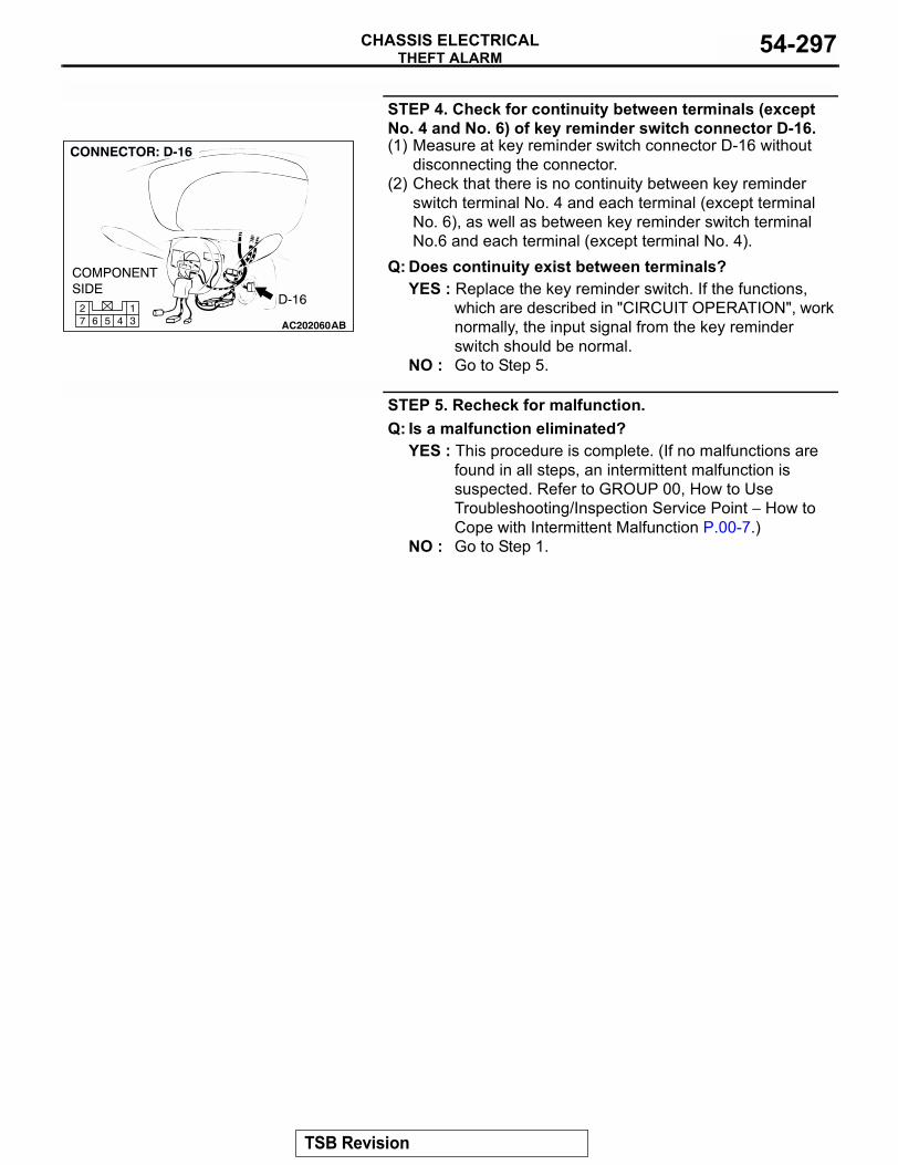
THEFT ALARMCHASSIS ELECTRICAL 54-297
STEP 4. Check for continuity between terminals (except No. 4 and No. 6) of key reminder switch connector D-16.(1) Measure at key reminder switch connector D-16 without
disconnecting the connector.(2) Check that there is no continuity between key reminder
switch terminal No. 4 and each terminal (except terminal No. 6), as well as between key reminder switch terminal No.6 and each terminal (except terminal No. 4).
Q: Does continuity exist between terminals?YES : Replace the key reminder switch. If the functions,
which are described in "CIRCUIT OPERATION", work normally, the input signal from the key reminder switch should be normal.
NO : Go to Step 5.
STEP 5. Recheck for malfunction.Q: Is a malfunction eliminated?
YES : This procedure is complete. (If no malfunctions are found in all steps, an intermittent malfunction is suspected. Refer to GROUP 00, How to Use Troubleshooting/Inspection Service Point − How to Cope with Intermittent Malfunction P.00-7.)
NO : Go to Step 1.
AC20206045 31
672
TSB Revision
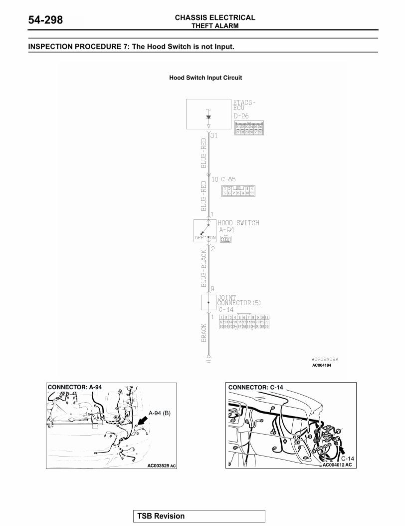
THEFT ALARMCHASSIS ELECTRICAL54-298
INSPECTION PROCEDURE 7: The Hood Switch is not Input.
AC004184
Hood Switch Input Circuit
AC003529
CONNECTOR: A-94
AC
A-94 (B)
AC004012
CONNECTOR: C-14
ACC-14
TSB Revision
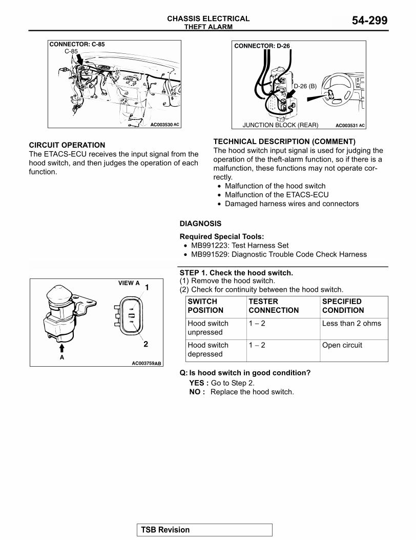
THEFT ALARMCHASSIS ELECTRICAL 54-299
.
CIRCUIT OPERATIONThe ETACS-ECU receives the input signal from the hood switch, and then judges the operation of each function..
TECHNICAL DESCRIPTION (COMMENT)The hood switch input signal is used for judging the operation of the theft-alarm function, so if there is a malfunction, these functions may not operate cor-rectly.
• Malfunction of the hood switch• Malfunction of the ETACS-ECU• Damaged harness wires and connectors
.
DIAGNOSIS
Required Special Tools:• MB991223: Test Harness Set• MB991529: Diagnostic Trouble Code Check Harness
STEP 1. Check the hood switch.(1) Remove the hood switch.(2) Check for continuity between the hood switch.
Q: Is hood switch in good condition?YES : Go to Step 2.NO : Replace the hood switch.
AC003530
CONNECTOR: C-85
AC
C-85
AC003531
CONNECTOR: D-26
JUNCTION BLOCK (REAR) AC
D-26 (B)
SWITCH POSITION
TESTER CONNECTION
SPECIFIED CONDITION
Hood switch unpressed
1 − 2 Less than 2 ohms
Hood switch depressed
1 − 2 Open circuit
AC003759
1
2
VIEW A
AAB
TSB Revision
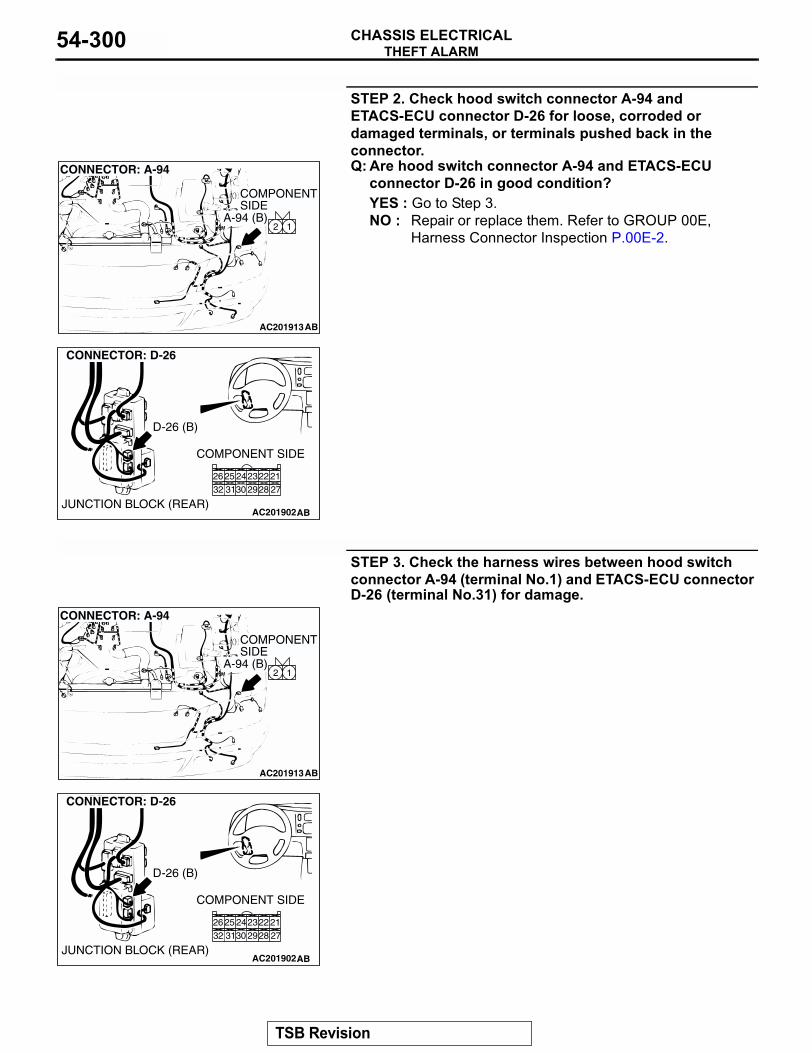
THEFT ALARMCHASSIS ELECTRICAL54-300
STEP 2. Check hood switch connector A-94 and ETACS-ECU connector D-26 for loose, corroded or damaged terminals, or terminals pushed back in the connector.Q: Are hood switch connector A-94 and ETACS-ECU
connector D-26 in good condition?YES : Go to Step 3.NO : Repair or replace them. Refer to GROUP 00E,
Harness Connector Inspection P.00E-2.
STEP 3. Check the harness wires between hood switch connector A-94 (terminal No.1) and ETACS-ECU connector D-26 (terminal No.31) for damage.
AC201913
12
CONNECTOR: A-94
AB
COMPONENT SIDE
A-94 (B)
AC201902
12
8 7
4
10
5
1112
6
9
3
CONNECTOR: D-26
AB
COMPONENT SIDE
JUNCTION BLOCK (REAR)
212223242526272829303132
D-26 (B)
AC201913
12
CONNECTOR: A-94
AB
COMPONENT SIDE
A-94 (B)
AC201902
12
8 7
4
10
5
1112
6
9
3
CONNECTOR: D-26
AB
COMPONENT SIDE
JUNCTION BLOCK (REAR)
212223242526272829303132
D-26 (B)
TSB Revision
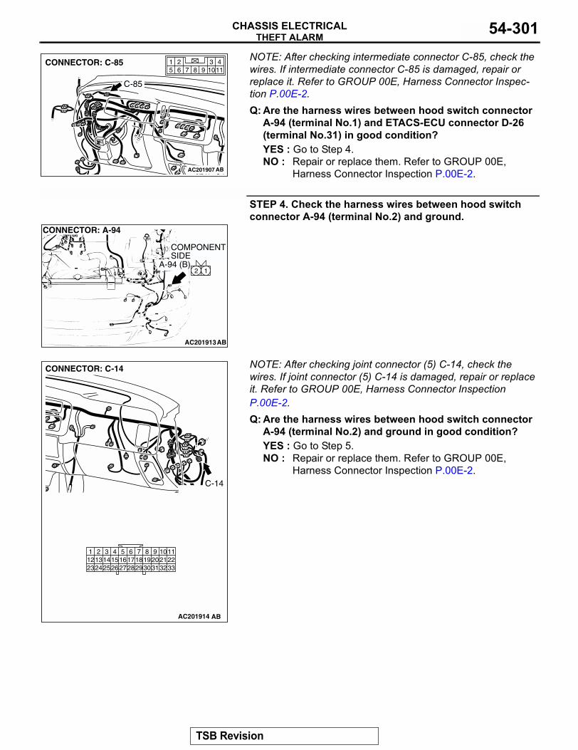
THEFT ALARMCHASSIS ELECTRICAL 54-301
NOTE: After checking intermediate connector C-85, check the wires. If intermediate connector C-85 is damaged, repair or replace it. Refer to GROUP 00E, Harness Connector Inspec-tion P.00E-2.Q: Are the harness wires between hood switch connector
A-94 (terminal No.1) and ETACS-ECU connector D-26 (terminal No.31) in good condition?YES : Go to Step 4.NO : Repair or replace them. Refer to GROUP 00E,
Harness Connector Inspection P.00E-2.
STEP 4. Check the harness wires between hood switch connector A-94 (terminal No.2) and ground.
NOTE: After checking joint connector (5) C-14, check the wires. If joint connector (5) C-14 is damaged, repair or replace it. Refer to GROUP 00E, Harness Connector Inspection P.00E-2.Q: Are the harness wires between hood switch connector
A-94 (terminal No.2) and ground in good condition?YES : Go to Step 5.NO : Repair or replace them. Refer to GROUP 00E,
Harness Connector Inspection P.00E-2.
AC201907
1143
98 105 621
7CONNECTOR: C-85
AB
C-85
AC201913
12
CONNECTOR: A-94
AB
COMPONENT SIDE
A-94 (B)
AC201914
9 1086 7
3132302918192021
5421 3
27262423 25121314151617
28
112233
CONNECTOR: C-14
AB
C-14
TSB Revision
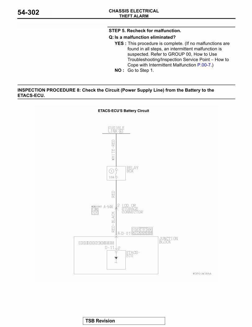
THEFT ALARMCHASSIS ELECTRICAL54-302
STEP 5. Recheck for malfunction.Q: Is a malfunction eliminated?
YES : This procedure is complete. (If no malfunctions are found in all steps, an intermittent malfunction is suspected. Refer to GROUP 00, How to Use Troubleshooting/Inspection Service Point − How to Cope with Intermittent Malfunction P.00-7.)
NO : Go to Step 1.
INSPECTION PROCEDURE 8: Check the Circuit (Power Supply Line) from the Battery to the ETACS-ECU.
ETACS-ECU'S Battery Circuit
TSB Revision
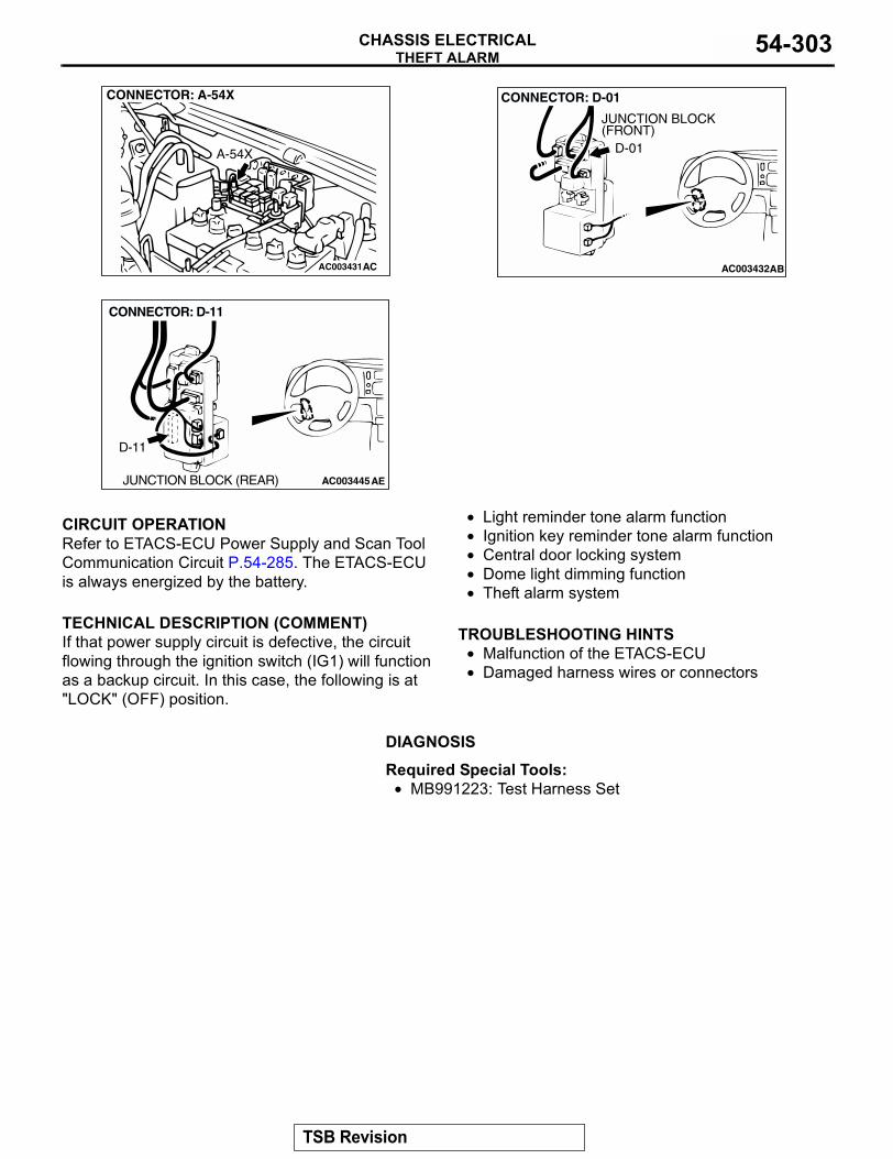
THEFT ALARMCHASSIS ELECTRICAL 54-303
.
CIRCUIT OPERATIONRefer to ETACS-ECU Power Supply and Scan Tool Communication Circuit P.54-285. The ETACS-ECU is always energized by the battery..
TECHNICAL DESCRIPTION (COMMENT)If that power supply circuit is defective, the circuit flowing through the ignition switch (IG1) will function as a backup circuit. In this case, the following is at "LOCK" (OFF) position.
• Light reminder tone alarm function• Ignition key reminder tone alarm function• Central door locking system• Dome light dimming function• Theft alarm system
.
TROUBLESHOOTING HINTS• Malfunction of the ETACS-ECU • Damaged harness wires or connectors
.
DIAGNOSIS
Required Special Tools:• MB991223: Test Harness Set
AC003431
CONNECTOR: A-54X
A-54X
AC AC003432AB
CONNECTOR: D-01
JUNCTION BLOCK(FRONT)
D-01
AC003445AE
CONNECTOR: D-11
JUNCTION BLOCK (REAR)
D-11
TSB Revision
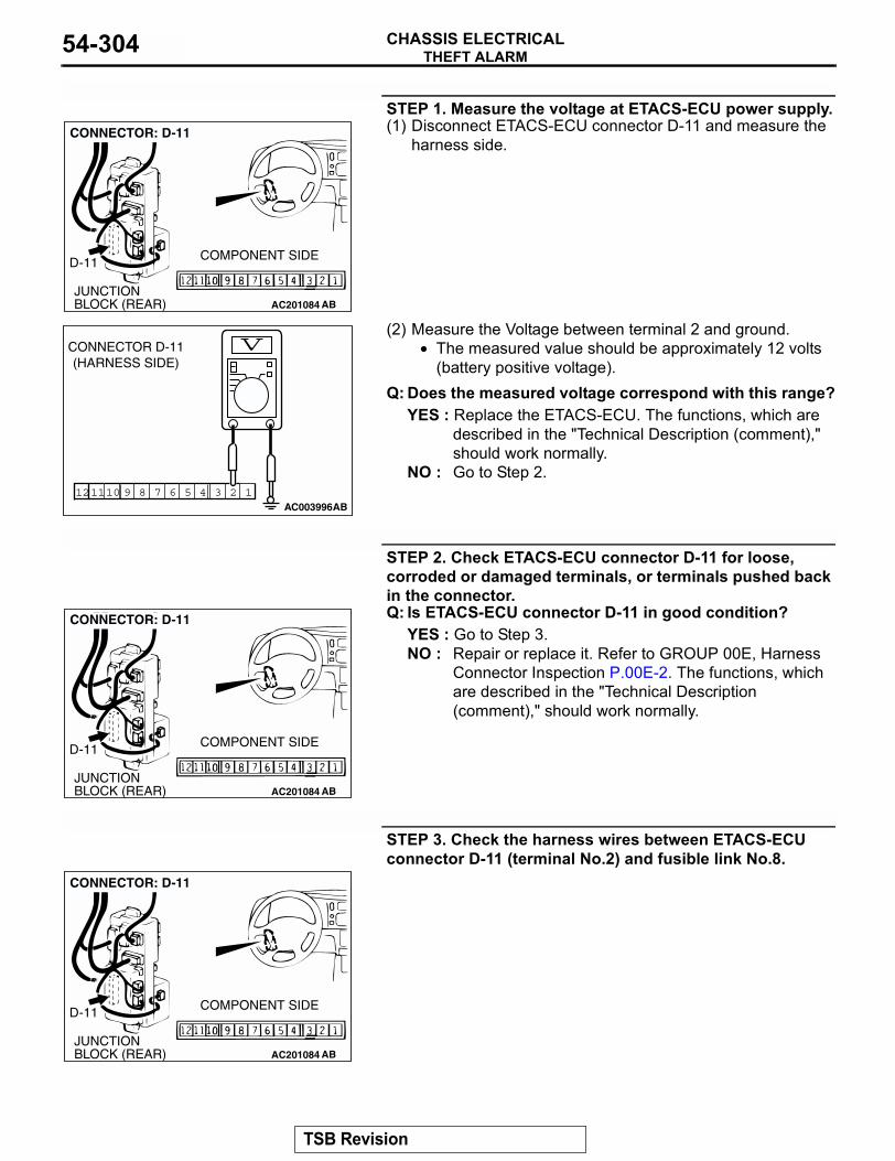
THEFT ALARMCHASSIS ELECTRICAL54-304
STEP 1. Measure the voltage at ETACS-ECU power supply.(1) Disconnect ETACS-ECU connector D-11 and measure the
harness side.
(2) Measure the Voltage between terminal 2 and ground.• The measured value should be approximately 12 volts
(battery positive voltage).Q: Does the measured voltage correspond with this range?
YES : Replace the ETACS-ECU. The functions, which are described in the "Technical Description (comment)," should work normally.
NO : Go to Step 2.
STEP 2. Check ETACS-ECU connector D-11 for loose, corroded or damaged terminals, or terminals pushed back in the connector.Q: Is ETACS-ECU connector D-11 in good condition?
YES : Go to Step 3.NO : Repair or replace it. Refer to GROUP 00E, Harness
Connector Inspection P.00E-2. The functions, which are described in the "Technical Description (comment)," should work normally.
STEP 3. Check the harness wires between ETACS-ECU connector D-11 (terminal No.2) and fusible link No.8.
AC201084JUNCTION BLOCK (REAR)
D-11 COMPONENT SIDE
AB
CONNECTOR: D-11
123457910 681112AC003996AB
CONNECTOR D-11(HARNESS SIDE)
AC201084JUNCTION BLOCK (REAR)
D-11 COMPONENT SIDE
AB
CONNECTOR: D-11
AC201084JUNCTION BLOCK (REAR)
D-11 COMPONENT SIDE
AB
CONNECTOR: D-11
TSB Revision
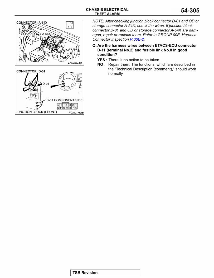
THEFT ALARMCHASSIS ELECTRICAL 54-305
NOTE: After checking junction block connector D-01 and OD or storage connector A-54X, check the wires. If junction block connector D-01 and OD or storage connector A-54X are dam-aged, repair or replace them. Refer to GROUP 00E, Harness Connector Inspection P.00E-2.Q: Are the harness wires between ETACS-ECU connector
D-11 (terminal No.2) and fusible link No.8 in good condition?YES : There is no action to be taken.NO : Repair them. The functions, which are described in
the "Technical Description (comment)," should work normally.
AC200774
21
CONNECTOR: A-54X
AB
A-54X
AC200778
2341110 9 8 7
16
512
CONNECTOR: D-01
AB
D-01 COMPONENT SIDE
JUNCTION BLOCK (FRONT)
D-01
TSB Revision
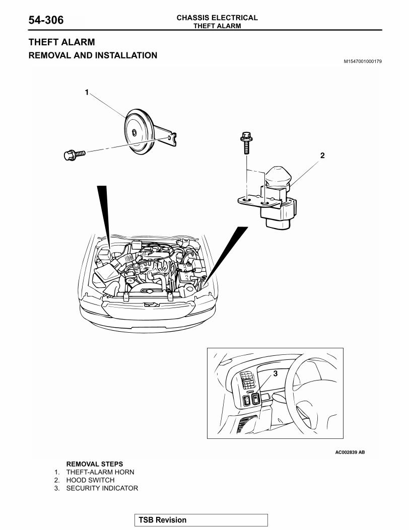
THEFT ALARMCHASSIS ELECTRICAL54-306
THEFT ALARMREMOVAL AND INSTALLATION
M1547001000179
AC002839
1
2
3
AB
REMOVAL STEPS1. THEFT-ALARM HORN2. HOOD SWITCH3. SECURITY INDICATOR
TSB Revision
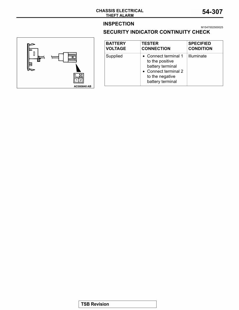
THEFT ALARMCHASSIS ELECTRICAL 54-307
INSPECTIONM1547002500025
SECURITY INDICATOR CONTINUITY CHECK
BATTERY VOLTAGE
TESTER CONNECTION
SPECIFIED CONDITION
Supplied • Connect terminal 1 to the positive battery terminal
• Connect terminal 2 to the negative battery terminal
Illuminate
AC000840 AB
TSB Revision
SPECIFICATIONSCHASSIS ELECTRICAL54-308
SPECIFICATIONSFASTENER TIGHTENING SPECIFICATIONS
M1544004600201
SERVICE SPECIFICATIONSM1543000300391
<IMMOBILIZER SYSTEM>
<COMBINATION METER>
ITEM SPECIFICATIONAmplifier mounting nut 4.9 N⋅m (43 in-lb)Antenna motor-ECU mounting nut 3.0 N⋅m (27 in-lb)Column switch mounting screw 25 N⋅m (18 ft-lb)Headlight mounting bolt 4.9 N⋅m (43 in-lb)Motor antenna mounting bolt 3.0 N⋅m (27 in-lb)Radio bracket mounting screw 1.4 N⋅m (13 in-lb)Mast antenna body mounting bolt 3.0 N⋅m (27 in-lb)
ITEM STANDARD VALUEIgnition key ring antenna resistance Ω 2 or less
ITEM STANDARD VALUESpeedometer indication allowance range km/h (mph)
32 (20) 31 − 35 (19 − 22) 64 (40) 61 − 71 (38 − 44) 97 (60) 92 − 106 (57 − 66) 129 (80) 122 − 142 (76 − 88)161 (100) 151 − 177 (94 − 110)
Tachometer indication error r/min 700 ±100 3,000 ±150 5,000 ±250 6,000 ±300
Fuel gauge unit resistance Ω Float point "F" 1 − 5Float point "E" 103 − 117
Fuel gauge unit float height mm (in) A (Float point "F") 214.1 (8.43)B (Float point "E") 251.2 (9.89)
Engine coolant temperature gauge unit resistance Ω 104 ± 13.5Fuel gauge resistance MΩ Power supply and ground Approximately 1 or more
Power supply and fuel gauge Approximately 1 or moreFuel gauge and ground Approximately 1 or more
Engine coolant temperature gauge resistance Ω
Power supply and ground 191Power supply and engine coolant temperature gauge
103
Engine coolant temperature gauge and ground
88
TSB Revision
SPECIFICATIONSCHASSIS ELECTRICAL 54-309
<HEADLIGHT>
<FOG LIGHT>
SEALANTM1543000500168
<COMBINATION METER>
ITEM STANDARD VALUE LIMITHeadlight aiming Vertical direction Headlight center line ±
50mm (2.1 in)−
Headlight intensity cd[When a screen is set 18.3m (60.0 feet) ahead of the vehicle]
- 40,000 or more
ITEM STANDARD VALUE LIMITFog light aiming Vertical direction 151 mm (5.9 in) below
horizontal (H)−
Horizontal direction Parallel to direction of vehicle travel
−
ITEM SPECIFIED SEALANT REMARKEngine coolant temperature gauge unit threaded portion
3M AAD part No. 8731 or equivalent Drying sealant
TSB Revision

NOTES