Embed Size (px)
Citation preview

Installation, Operation andMaintenance Manual
Active Chilled BeamsType DID631 and DID632
OM/US/DID631-632/8

General Information1.1 Introduction 31.2 Safety 31.3 Symbols used in this manual 31.4 Receiving, Inspection and Storage 31.4 Damage reporting 3
Product Description and Installation Preparation2.1 Product overview 42.2 Construction description 42.3 Application precautions 42.4 Preparation for installation 42.4 Items provided by installer 42.4 Precautions 4
Installation3.1 General procedure 53.2 Installation considerations 53.3 Hanging the chilled beam 53.4 Air connections 63.5 Water connections 63.6 Flushing the water piping system 73.7 Filling and venting the water system 73.8 Typical installations 7
Commissioning4.1 Waterside commissioning 84.2 Airside commissioning 84.3 Airside commissioning tables 8-9
Maintenance5.1 Cleaning instructions 95.2 Replacement parts 9
Troubleshooting6.0 Symptoms & Solutions 10
Warranties7.0 Representations and Warranties 11
Contents
TROX USA, Inc.
4305 Settingdown CircleCumming, Georgia 30028
Phone: 770.569.1433Fax: 770.569.1435
E-Mail: [email protected]
2
© 2016 TROX GmbH All rights reserved.
DID631-632 Installation, Operation & Maintenance Manual (USA) (07/2016)
No part of this document may be reproduced in any form (by printing, photocopying or other means)or processed, duplicated or circulated electronically without prior written approval by TROX GmbH.
DID631-632 Installation, Operation & Maintenance Manual (USA) (07/2016) 3
1 - General Information
1.1 Introduction
This installation, operation and maintenance manual is intended foractive chilled beam Type DID631 and DID632.
You must read all instructions prior to the installation, operation ormaintenance of this product. Take special note of the information thatis accompanied by the symbols described in section 1.3 below.
The DID631 and DID632 active chilled beams are designed fordealing with high internal thermal loads using a combination of airand water. This is achieved by using primary air delivered viaductwork and chilled water delivered via pipe work from the centralplant, directly to the beam. Primary air is ducted to the upper airchamber via a side or top inlet. The primary air is then dischargedthrough nozzles to a lower section containing a 2- or 4-pipe heatexchanger coil. This causes room air to be induced via the perforatedface panel, up and through the heat exchanger coil. The cooled (orheated) room air is then mixed with the primary air before beingdelivered back to the space through the beam’s discharge slot(s).
The beam uses the primary air energy to induce air through the coil;it does not contain any moving parts, fans or motors.
1.2 Safety
The customer must use qualified personnel and follow all applicablebuilding codes and safety regulations when installing, commissioningand performing maintenance of this product. Eye protection, glovesand hard hat should be worn at all times when handling the product.
Consult all local building, occupational safety and other codes appli-cable to the installation.
Please pay particular attention to the symbols used throughout themanual that indicate safety related issues, warnings and importantnotices or information; read the complete manual before installationand be familiar with the meaning of the safety symbols in the nextsection 1.3.
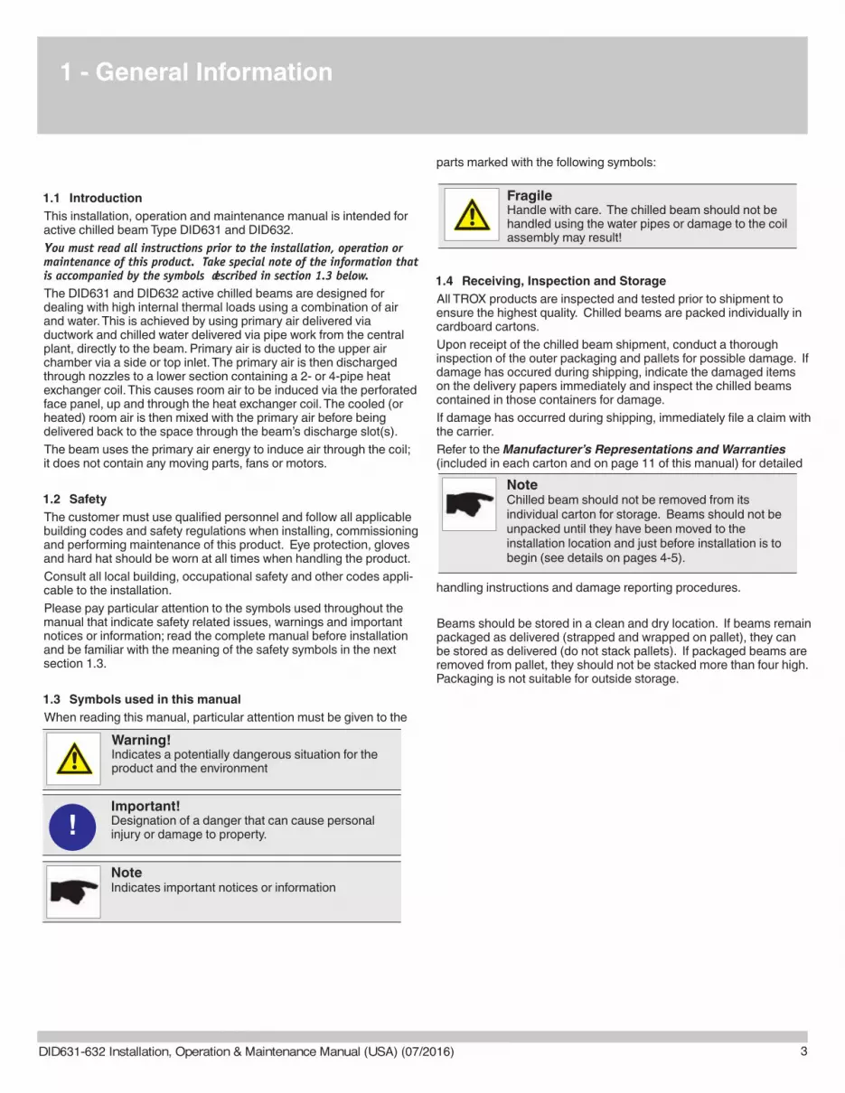
1.3 Symbols used in this manual
When reading this manual, particular attention must be given to the
parts marked with the following symbols:
1.4 Receiving, Inspection and Storage
All TROX products are inspected and tested prior to shipment toensure the highest quality. Chilled beams are packed individually incardboard cartons.
Upon receipt of the chilled beam shipment, conduct a thoroughinspection of the outer packaging and pallets for possible damage. Ifdamage has occured during shipping, indicate the damaged itemson the delivery papers immediately and inspect the chilled beamscontained in those containers for damage.
If damage has occurred during shipping, immediately file a claim withthe carrier.
Refer to the Manufacturer’s Representations and Warranties(included in each carton and on page 11 of this manual) for detailed
handling instructions and damage reporting procedures.
Beams should be stored in a clean and dry location. If beams remainpackaged as delivered (strapped and wrapped on pallet), they canbe stored as delivered (do not stack pallets). If packaged beams areremoved from pallet, they should not be stacked more than four high.Packaging is not suitable for outside storage.
Warning!Indicates a potentially dangerous situation for theproduct and the environment
Important!Designation of a danger that can cause personalinjury or damage to property.
NoteIndicates important notices or information
!
FragileHandle with care. The chilled beam should not behandled using the water pipes or damage to the coilassembly may result!
NoteChilled beam should not be removed from itsindividual carton for storage. Beams should not beunpacked until they have been moved to theinstallation location and just before installation is tobegin (see details on pages 4-5).
The primary air delivered to the space must be of sufficientquantity, temperature and dryness to ensure the room dewpoint temperature is maintained below the temperature of thechilled water supplied to the beam. The chilled water supplytemperature should be maintained above the dew point tem-perature of the room.
2 - Product Description/Installation Preparation
4
2.1 Product overview
Chilled beams are ceiling mounted heat exchangers. Primary air isintroduced into the active chilled beam through induction nozzles.This series of nozzles induces room air into the chilled beam andacross its water coil where the room air is either cooled or heated.The now cooled or heated room air is mixed with the primary air anddischarged back into the space to control the room temperature.TROX DID631 and DID632 active chilled beams should be installedin the quantities, sizes and configurations shown on the project plansand schedules.
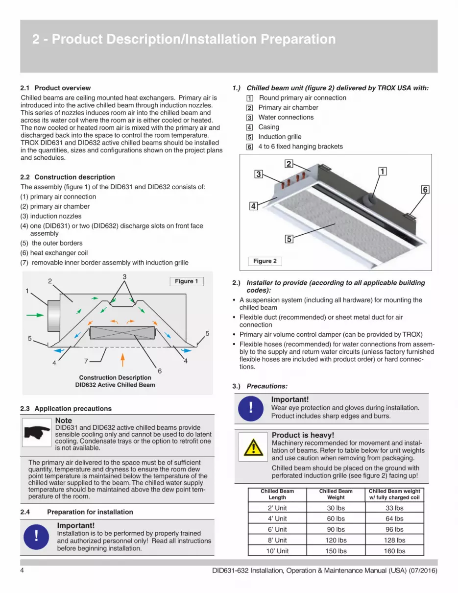
2.2 Construction description
The assembly (figure 1) of the DID631 and DID632 consists of:
(1) primary air connection
(2) primary air chamber
(3) induction nozzles
(4) one (DID631) or two (DID632) discharge slots on front faceassembly
(5) the outer borders
(6) heat exchanger coil
(7) removable inner border assembly with induction grille
2.3 Application precautions
2.4 Preparation for installation
1.) Chilled beam unit (figure 2) delivered by TROX USA with:
Round primary air connection
Primary air chamber
Water connections
Casing
Induction grille
4 to 6 fixed hanging brackets
2.) Installer to provide (according to all applicable buildingcodes):
• A suspension system (including all hardware) for mounting thechilled beam
• Flexible duct (recommended) or sheet metal duct for air connection
• Primary air volume control damper (can be provided by TROX)
• Flexible hoses (recommended) for water connections from assem-bly to the supply and return water circuits (unless factory furnishedflexible hoses are included with product order) or hard connec-tions.
3.) Precautions:
32
1
44
55
6
7
Construction DescriptionDID632 Active Chilled Beam
Important!Installation is to be performed by properly trainedand authorized personnel only! Read all instructionsbefore beginning installation.
!
Important!Wear eye protection and gloves during installation.Product includes sharp edges and burrs.
!
Product is heavy!Machinery recommended for movement and instal-lation of beams. Refer to table below for unit weightsand use caution when removing from packaging.
Chilled beam should be placed on the ground withperforated induction grille (see figure 2) facing up!
Figure 1
2’ Unit 30 lbs 33 lbs
4’ Unit 60 lbs 64 lbs
6’ Unit 90 lbs 96 lbs
8’ Unit 120 lbs 128 lbs
10’ Unit 150 lbs 160 lbs
Chilled BeamLength
Chilled BeamWeight
Chilled Beam weightw/ fully charged coil
NoteDID631 and DID632 active chilled beams providesensible cooling only and cannot be used to do latentcooling. Condensate trays or the option to retrofit oneis not available.
Figure 2
DID631-632 Installation, Operation & Maintenance Manual (USA) (07/2016)

5
3 - Installation
3.1 General procedure
Chilled beams should be mounted and connected prior to installingthe suspended ceiling or drywall. The unit should be installed in thelocation shown on the design drawings. Deviation from the designedmounting position should be avoided as the chilled beam location inrelation to the room walls and other chilled beams is critical to thecomfort of the conditioned space.
The chilled beam leaves thefactory with low tack filmapplied to the face (seephoto) to protect the paintedsurface. Film should remainon beam during installation.
3.2 Installation considerations
3.3 Hanging the chilled beam (by Mechanical Contractor)
STEP ONE —
• Determine beam locations according to design drawings.
• Fix anchors (type dependant on building design and determinedby others) into the structure above the chilled beam mountinglocation.
STEP TWO —
The beam should be suspended 3” above the finished ceilingelevation using building code approved threaded rods (recom-mended) or wires. The rod or wire (both provided by others) allowthe beam’s vertical height to be adjusted so that the beam can belowered into the ceiling grid with which it is to be integrated.
It is recommended that the unit be suspended from linear channelsto provide adjustability in every direction.
The unit is provided with fixed or sliding brackets that allow foradjustment of the beam.
Guidelines when using rods
Install Unistrut with appropriate support to carrythe beam
Fasten studs to Unistrut with Unistrut nut in properlocation above the beam’s hanging brackets
Adjust beam as needed to final hanging location
Guidelines when using Wire/Cable
Wire/cable should run from the bracket straight up or slightlyaway from the beam to the anchor location.
Figure 3
Hanging rod
NoteIt is recommended that chilled beams be installedusing flexible hoses.
If hard connections are used, the connectionsshould be made after the chilled beam islowered into the ceiling grid and is in its finalposition.
LinearChannels
Warning!Care should be taken to avoid any water or conden-sation buildup between the blue film and the beamface during handling and waterside commissioning.Remove film BEFORE the air system is started.
Suspension device requirements
Chilled beams up to 6 ft in length should be supported by aminimum of four (4) suspension devices. Chilled beams above 6 ftin length must be supported by a minimum of six (6) suspensiondevices.
Warning!Each unit must be supported independently from the sus-pended ceiling. The fixing points should only carry theweight of the chilled beam. Separate supports should beprovided for adjacent systems components.
Fixed brackets
Warning!The hanging wire should NEVER angle across the beamas it will put undue stress on the bracket.
LinearChannels
Sliding brackets
DID631-632 Installation, Operation & Maintenance Manual (USA) (07/2016)

3 - Installation
6
Once the chilled beam is lowered into the ceiling grid and is in itsfinal position, the air and water connections can be made.
3.4 Air connections
STEP ONE —
Make the air connection with either sheet metal or flexible duct.
Flexible duct should be limited to a maximum length of 5ft.
The air connections should include a minimum of one duct diameterlength of straight ductwork upstream of the beam connection toprevent excessive turbulence and noise generation.
3.5 Water connections
The chilled beam is fitted with two or four water pipes (see imagebelow for pipe configuration) which terminate in either NPT threadedmale connections or straight pipe ends for field soldering. Each coilis factory tested for leakage and provided clean and capped.
STEP ONE —
Identify the warm and/or chilled water supplyconnections on the beam — noted by labels onthe casing.
STEP TWO —
Remove the plastic cap before making the final water connections.
STEP THREE —
Make water connections. If NPT connections apply, do NOT over-tighten — applying excessive force on the water pipes may damagethe heat exchange coil.
NOTE: See section 3.8 (page 7) for typical installation photographs.
DID632 4-pipe connnection(right-hand shown)
Co
ld w
ate
r re
turn
Co
ld w
ate
r su
pp
ly
Ho
t wa
ter
sup
ply
Ho
t wa
ter
retu
rn
Co
ld w
ate
r re
turn
Co
ld w
ate
r su
pp
ly
DID632 2-pipe connnection - cold or hot(right-hand shown)
Note: Air duct connection location does not affect coil connection configuration
Active Chilled BeamPipe Configurations
NoteFlexible duct, when using in conjunction with flexiblehose for water connections, enables easieralignment of the beam with the ceiling grid!
NoteActive chilled beam systems operate at higherterminal pressures than diffusers in standardVAV systems therefore the ductwork andconnections feeding the beam must be thoroughlysealed to prevent excessive leakage.
DID631-632 Installation, Operation & Maintenance Manual (USA) (07/2016)
7
3 - Installation
3.6 Flushing the water piping system
Before flushing the water system, close all valves that isolate thebeams and flush the main piping system first.
3.7 Filling and venting the water system
To ensure easy venting, the main pipes should be installed at ahigher level than the beams. The horizontal pipes should be installedrising slightly towards the venting points.
Before filling, all shut-off and control valves must be in the fully openposition. The pumps should not be running during the filling-up(static filling). Continuous venting is necessary. The installation ofboth manual and automatic venting systems is recommended. Thepump should only be started when filling is complete.
To remove all air from the system, the majority (>75%) of the systemshould be closed so that the water can circulate fast enough. Wheneach section is full, it should be closed and the procedure repeatedthroughout the system.
NoteThere should be no high points to create“air pockets” within the sytem.
NoteUse non-chilled water when filling up the system!Cold water can cause immediate condensation onthe pipes. Warm water contains less oxygen whichcan limit venting to some extent.
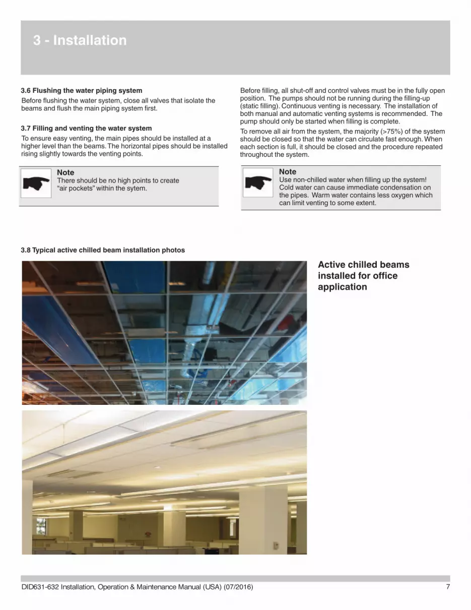
3.8 Typical active chilled beam installation photos
Active chilled beams installed for officeapplication
DID631-632 Installation, Operation & Maintenance Manual (USA) (07/2016)
4 - Commissioning
8
4.1 Waterside commissioning
Fully purge the complete hydronic system of air prior tocommissioning.
Carefully inspect the system for leaks, paying particularattention to the connections.
Carefully inspect flexible hose, if applicable, for leaks.Factory-provided flexible hose shown (not provided onall orders).
4.2 Airside commissioning
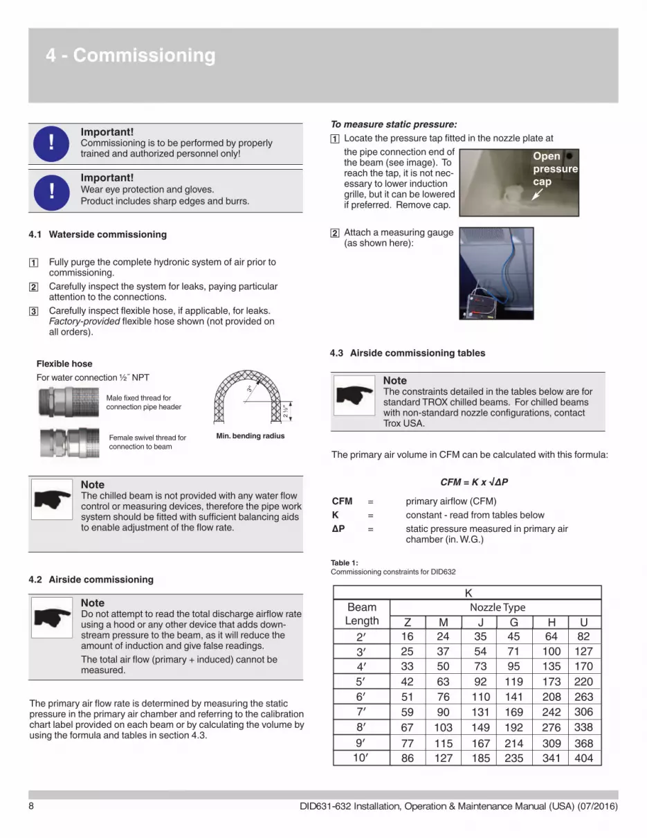
The primary air flow rate is determined by measuring the staticpressure in the primary air chamber and referring to the calibrationchart label provided on each beam or by calculating the volume byusing the formula and tables in section 4.3.
To measure static pressure:
Locate the pressure tap fitted in the nozzle plate at
the pipe connection end ofthe beam (see image). Toreach the tap, it is not nec-essary to lower inductiongrille, but it can be loweredif preferred. Remove cap.
Attach a measuring gauge(as shown here):
4.3 Airside commissioning tables
The primary air volume in CFM can be calculated with this formula:
CFM = K x √ΔP
CFM = primary airflow (CFM)
K = constant - read from tables below
ΔP = static pressure measured in primary air chamber (in. W.G.)
Openpressurecap
3″
2 ½″
Flexible hose
For water connection ½˝ NPT
Female swivel thread forconnection to beam
Male fixed thread forconnection pipe header
Important!Commissioning is to be performed by properlytrained and authorized personnel only!
!
Important!Wear eye protection and gloves. Product includes sharp edges and burrs.
!
NoteThe chilled beam is not provided with any water flowcontrol or measuring devices, therefore the pipe worksystem should be fitted with sufficient balancing aidsto enable adjustment of the flow rate.
NoteDo not attempt to read the total discharge airflow rateusing a hood or any other device that adds down-stream pressure to the beam, as it will reduce theamount of induction and give false readings.
The total air flow (primary + induced) cannot bemeasured.
NoteThe constraints detailed in the tables below are forstandard TROX chilled beams. For chilled beamswith non-standard nozzle configurations, contactTrox USA.
Table 1: Commissioning constraints for DID632
BeamLength Z M G U
Nozzle Type
141
4′
6′
8′
10′
33 50 95 170
51 76 263
67 103 192
86 127 235 404
338
K
9′ 77 115 214 368
7′ 59 90 169 306
1195′ 42 63 220
3′ 25 37 71 1272′ 16 24 45 82
J
110
73
149
185167
131
92
5435
H
208
135
276
341309
242
173
10064
Min. bending radius
DID631-632 Installation, Operation & Maintenance Manual (USA) (07/2016)
9
4 - Commissioning
4/5 - Commissioning/Maintenance
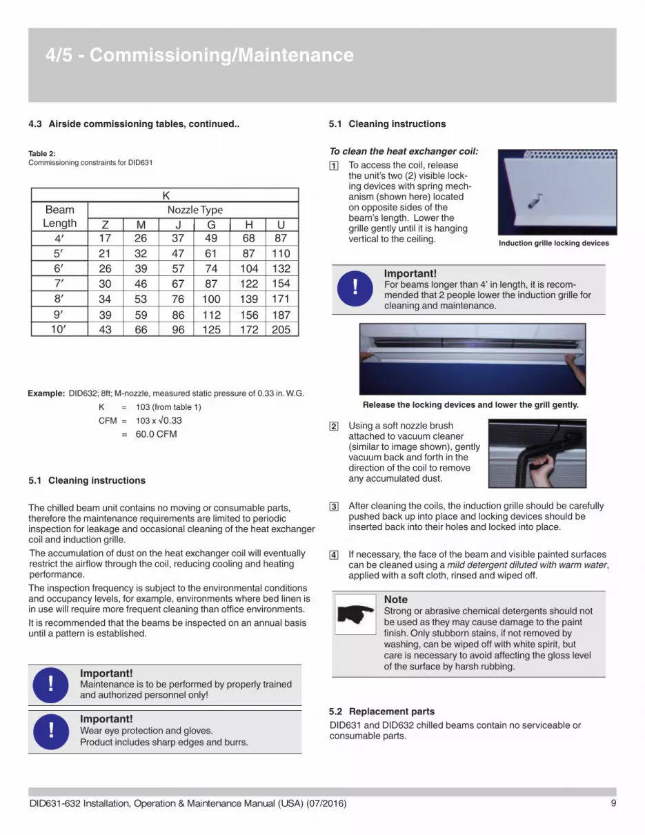
4.3 Airside commissioning tables, continued..
5.1 Cleaning instructions
The chilled beam unit contains no moving or consumable parts,therefore the maintenance requirements are limited to periodicinspection for leakage and occasional cleaning of the heat exchangercoil and induction grille.
The accumulation of dust on the heat exchanger coil will eventuallyrestrict the airflow through the coil, reducing cooling and heatingperformance.
The inspection frequency is subject to the environmental conditionsand occupancy levels, for example, environments where bed linen isin use will require more frequent cleaning than office environments.
It is recommended that the beams be inspected on an annual basisuntil a pattern is established.
5.1 Cleaning instructions
To clean the heat exchanger coil:
To access the coil, releasethe unit’s two (2) visible lock-ing devices with spring mech-anism (shown here) locatedon opposite sides of thebeam’s length. Lower thegrille gently until it is hanging vertical to the ceiling.
Using a soft nozzle brushattached to vacuum cleaner(similar to image shown), gentlyvacuum back and forth in thedirection of the coil to removeany accumulated dust.
After cleaning the coils, the induction grille should be carefullypushed back up into place and locking devices should beinserted back into their holes and locked into place.
If necessary, the face of the beam and visible painted surfacescan be cleaned using a mild detergent diluted with warm water,applied with a soft cloth, rinsed and wiped off.
5.2 Replacement parts
DID631 and DID632 chilled beams contain no serviceable orconsumable parts.
Induction grille locking devices
Release the locking devices and lower the grill gently.
Important!Maintenance is to be performed by properly trainedand authorized personnel only!
!
Important!Wear eye protection and gloves. Product includes sharp edges and burrs.
!
Important!For beams longer than 4’ in length, it is recom-mended that 2 people lower the induction grille forcleaning and maintenance.
NoteStrong or abrasive chemical detergents should notbe used as they may cause damage to the paintfinish. Only stubborn stains, if not removed bywashing, can be wiped off with white spirit, butcare is necessary to avoid affecting the gloss levelof the surface by harsh rubbing.
!
Example: DID632; 8ft; M-nozzle, measured static pressure of 0.33 in. W.G.
K = 103 (from table 1)
CFM = 103 x √0.33
= 60.0 CFM
Table 2: Commissioning constraints for DID631
BeamLength Z M G U
Nozzle Type
74
4′
6′
8′
10′
17 26 49 87
26 39 132
34 53 100
43 66 125 205
171
K
9′ 39 59 112 187
7′ 30 46 87 154
615′ 21 32 110
J
57
37
76
9686
67
47
H
104
68
139
172156
122
87
DID631-632 Installation, Operation & Maintenance Manual (USA) (07/2016)
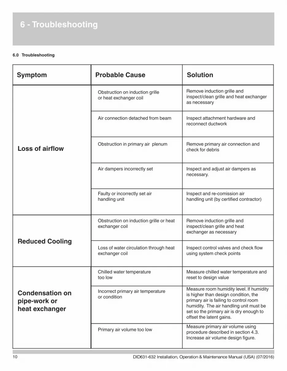
6 - Troubleshooting
6.0 Troubleshooting
Probable Cause SolutionSymptom
Loss of airflow
Reduced Cooling
Condensation on pipe-work orheat exchanger
Incorrect primary air temperatureor condition
Measure room humidity level. If humidity is higher than design condition, the primary air is failing to control room humidity. The air handling unit must be set so the primary air is dry enough to offset the latent gains.
Chilled water temperaturetoo low
Measure chilled water temperature andreset to design value
Primary air volume too lowMeasure primary air volume usingprocedure described in section 4.3.Increase air volume design figure.
Obstruction on induction grilleor heat exchanger coil
Remove induction grille andinspect/clean grille and heat exchangeras necessary
Air connection detached from beam Inspect attachment hardware and reconnect ductwork
Obstruction in primary air plenum Remove primary air connection and check for debris
Air dampers incorrectly set Inspect and adjust air dampers asnecessary.
Faulty or incorrectly set air handling unit
Inspect and re-comission air handling unit (by certified contractor)
Obstruction on induction grille or heat exchanger coil
Remove induction grille and inspect/clean grille and heat exchanger as necessary
Loss of water circulation through heat exchanger coil
Inspect control valves and check flowusing system check points
10 DID631-632 Installation, Operation & Maintenance Manual (USA) (07/2016)

11
7 - Representations and Warranties
7 Warranties
7.1 Manufacturer’s Representations & Warranties
MANUFACTURER’S REPRESENTATIONS AND WARRANTIES
TROX USA, INC. 4305 Settingdown Circle
Cumming, GA 30028
Phone: +1 (770) 569 1433 Fax: +1(770) 569 1435
These Representations and Warranties are applicable to all customers (the “Customers” and each, indi vidually, a “Customer”) purchasing products (the “Products”) manufactured by TROX USA, Inc. (the “Company”). 1. Warranty and Limitations: 1.1. Company warrants solely to the original purchaser of the Products that for the Warranty Period (as defined below), the Products will be free from defects in materials and workmanship under normal use, and will conform to Company’s published speci cations of the Products. Notwithstanding the foregoing, Company retains its right to deviate from its published specifications due to the latest innovations and improvements in function and design of the Products. The foregoing warranty is subject to the proper storage, transportation, installation, use and maintenance of the Products and does not include defects due to normal wear and tear or deterioration, improper modifications of the Products, improper construction of the surrounding facilities and unsuitable static, chemical, electrochemical or electrical conditions. 1.2. In the event of any shipping and freight damages of the Product, Customer shall refer any claims to the shipping company.
1.3. Upon delivery, Customer shall immediately and within seven (7) working days inspect the Products for conformity and visible defects (other than the shipping and freight damages described above in Section 1.2). Customer shall give Company immediate written notice of any non-conformities or visible defects regarding the Products, including photographs of the same, and contact Company in writing concerning return or repair, as the case may be. In order to make a determination regarding the existence of the alleged defect or non-conformity and the proper remedy thereof, the Company shall have the right to inspect the Products at Customer’s premises . In the event that the Customer refuses to give Company access to its premises in order to inspect the Products, Customer shall lose all warranty claims related to the Products to be inspected.
1.4. Any defect or non-conforming Product discovered upon delivery should immediately be stored in a safe place and not be installed. If the defective or non-conforming Product is installed, TROX USA shall not be liable for any labor or charges associated with installation or labor costs, unless specific prior authorization is issued in writing by an officer of the Company. 1.5. Customer shall notify Company in writing of any defects of the Products immediately upon discovery. Any defect or non-compliant Product or part thereof should be put aside for inspection by the Company and should not be installed. Company’s sole obligation under the foregoing warranty is, at Company’s option, to repair or correct any such covered defect or to replace or exchange the Product. Customer shall bear all shipping and handling expenses related to the return of the Products. Any repaired, corrected, replaced or exchanged Products shall be subject to the warranty set forth in 1.1., following their repair, correction, replacement or exchange. If Company has received notification from Customer, and no defects of the Product could be discovered, Customer shall bear the costs that Company incurred as a result of the notice. 1.6. With respect to orders made to custom, any defects of the Products caused by Customer’s speci cations are excluded from the warranty set forth in 1.1. 1.7. Company also makes no warranty that the Products manufactured under an order made to custom do not infringe the intellectual property or other proprietary rights of any third party and Customer is solely responsible for assuring that such Products do not so infringe. 1.8. The “Warranty Period” begins on the invoice date, and continues to be in effect for twelve (12) months.
1.9. Company does not authorize any person or party to assume or create for it any other obligation or liability in connection with the Products except as set forth herein. 1.10. All requests and notices under this Warranty shall be directed to:
TROX USA, Inc.
Attn. Thomas J. Bosko, Production Manager 4305 Settingdown Circle
Cumming, GA 30028
Fax: +1(770) 569 1435 E-Mail: [email protected]
1.11. THE WARRANTY SET FORTH IN SECTION 1.1 IS MADE IN LIEU OF ALL OTHER WARRANTIES (WHETHER EXPRESS OR IMPLIED), RIGHTS OR CONDITIONS, AND CUSTOMER ACKNOWLEDGES THAT EXCEPT FOR SUCH LIMITED WARRANTY, THE PRODUCTS ARE PROVIDED “AS IS.” COMPANY SPECIFICALLY DISCLAIMS, WITHOUT LIMITATION, ALL OTHER WARRANTIES, EXPRESS OR IMPLIED, OF ANY KIND, INCLUDING, WITHOUT LIMITATION, THE IMPLIED WARRANTIES OF MERCHANTABILITY AND FITNESS FOR A PARTICULAR PURPOSE, NON-INFRINGEMENT, AND THOSE WARRANTIES ARISING FROM A COURSE OF PERFORMANCE, A COURSE OF DEALING OR TRADE USAGE. 2. Limitation of Liability: 2.1. IN NO EVENT SHALL COMPANY BE LIABLE FOR ANY INDIRECT, INCIDENTAL, PUNITIVE, SPECIAL OR CONSEQUENTIAL DAMAGES, INCLUDING BUT NOT LIMITED TO, DAMAGES FOR LOSS OF PROFITS, REVENUE, GOODWILL OR USE, INCURRED BY CUSTOMER OR ANY THIRD PARTY, WHETHER IN AN ACTION IN CONTRACT, TORT, STRICT LIABILITY, OR IMPOSED BY STATUTE, OR OTHERWISE, EVEN IF ADVISED OF THE POSSIBILITY OF SUCH DAMAGES. COMPANY’S LIABILITY FOR DAMAGES ARISING OUT OF OR IN CONNECTION WITH THIS AGREEMENT SHALL IN NO EVENT EXCEED THE PURCHASE PRICE OF THE PRODUCTS. IT IS AGREED AND ACKNOWLEDGED THAT THE PROVISIONS OF THIS AGREEMENT ALLOCATE THE RISKS BETWEEN COMPANY AND CUSTOMER, THAT COMPANY’S PRICING REFLECTS THIS ALLOCATION OF RISK, AND BUT FOR THIS ALLOCATION AND LIMITATION OF LIABILITY, COMPANY WOULD NOT HAVE ENTERED INTO THIS AGREEMENT. 2.2. IN JURISDICTIONS THAT LIMIT THE SCOPE OF OR PRECLUDE LIMITATIONS OR EXCLUSION OF REMEDIES OR DAMAGES, OR OF LIABILITY, SUCH AS LIABILITY FOR GROSS NEGLIGENCE OR WILLFUL MISCONDUCT OR DO NOT ALLOW IMPLIED WARRANTIES TO BE EXCLUDED, THE LIMITATION OR EXCLUSION OF WARRANTIES, REMEDIES, DAMAGES OR LIABILITY SET FORTH ABOVE ARE INTENDED TO APPLY TO THE MAXIMUM EXTENT PERMITTED BY APPLICABLE LAW. CUSTOMER MAY ALSO HAVE OTHER RIGHTS THAT VARY BY STATE, COUNTRY OR OTHER JURISDICTION.
***********
DID631-632 Installation, Operation & Maintenance Manual (USA) (07/2016)

12
TROX USA, Inc.
4305 Settingdown CircleCumming, Georgia 30028
Phone: 770.569.1433Fax: 770.569.1435
E-Mail: [email protected]
U.S. Edition - 2016
DID631-632 Installation, Operation & Maintenance Manual
DID631-632 Installation, Operation & Maintenance Manual (USA) (07/2016)