Embed Size (px)
Citation preview

Boo
k
18Ontario Traffic ManualJune 2021
Cycling Facilities
DISCLAIMER
This Guide is not intended to be used as a basis for establishing civil liability. The material presented in this text was carefully researched and presented. However, no warranty expressed or implied is made on the accuracy of the contents or their extraction from reference to publications; nor shall the fact of distribution constitute responsibility by the OTC, MTO or any researchers or contributors for omissions, errors or possible misrepresentations that may result from use of interpretation of the material contained herein. Practitioners should confirm that the selected design elements are consistent with local legislation, regulation and by-laws before implementing them.

Cette publication hautement spécialisée, Ontario Traffic Manual – Book 18 – Cycling Facilities, n’est disponible qu’en anglais conformément au Règlement 671/92, selon lequel il n’est pas obligatoire de la traduire en vertu de la Loi sur les services en français. Pour obtenir des renseignements en français, veuillez communiquer avec le ministère des Transports par courriel à [email protected].
ISBN 978-1-4868-5419-6(Print) 978-1-4868-5420-2 (PDF)
Copyright © 2021
Queen’s Printer for Ontario
All rights reserved
Book 18 · Cycling Facilities
Ontario Traffic Manual · June 2021
i
Book 18 · Cycling Facilities
Ontario Traffic Manual · June 2021
Foreword
The Ontario Traffic Manual (OTM) is a series of traffic engineering and traffic control reference manuals produced by the Ministry of Transportation of Ontario (MTO) for use by municipalities in Ontario. The purpose of the Ontario Traffic Manual (OTM) is to provide information and guidance for transportation practitioners, and to promote uniformity of treatment in the design, application and operation of traffic control devices and systems across Ontario. The objective is safe driving behaviour, achieved by a predictable roadway environment through the consistent, appropriate application of traffic control devices. Additional purposes of the OTM are to provide a set of guidelines consistent with the intent of the Highway Traffic Act, and to provide a basis for road authorities to generate or update their own guidelines and standards.
This new edition of OTM Book 18 – Cycling Facilities (Book 18) has been developed by MTO in association with the Ontario Traffic Council (OTC). Extensive consultation with a diverse group of stakeholders, review of international best practices, and research of emerging design topics have gone into this update. At the time of publication, the design guidelines presented in OTM Book 18 are considered to be consistent with the intent of the Highway Traffic Act (HTA) with respect to municipal roads and infrastructure. MTO acknowledges that as the application of Book 18 evolves over time, the HTA may require further clarification to
accommodate new and evolving cycling facility design solutions. Funding and technical support has come from the Ministry as well as a Steering Committee comprised of sponsoring municipalities. Ontario Traffic Council, through their Active Transportation Committee, will continue to monitor best practices in planning and design, and will also facilitate the exchange of professional and technical knowledge including advancing research needs in collaboration with the academic community.
The OTM is intended as a provincial guidance document for its primary users—transportation practitioners. It incorporates current best practices in the Province of Ontario. The interpretations, recommendations and guidelines in the OTM are intended to provide an understanding of traffic operations over a broad range of traffic situations encountered in practice. They are based on many factors which may determine the specific design and operational effectiveness of traffic control systems. However, no manual can cover all contingencies or all cases encountered in the field. Therefore, field experience and knowledge of application are essential in deciding what to do in the absence of specific direction from the manual itself, and in overriding any recommendations in this manual.
Ontario Traffic Manual
ii
Book 18 · Cycling Facilities
Ontario Traffic Manual · June 2021
OTM Book 18 Acknowledgements
Ontario Traffic Manual Book 18 – Cycling Facilities was made possible as a result of the generous funding support from the Ministry of Transportation of Ontario, Region of Peel and cities of Brampton, Guelph, Hamilton, Ottawa, Toronto and Vaughan. The Ontario Traffic Council would like to thank the following individuals and their organizations for their contribution in the development of the second edition of OTM Book 18:
Project Team MembersDave McLaughlin – WSPShawn Smith – WSPJason Neudorf – WSPJames Schofield – WSPStephen Tam – WSPKarl Tracksdorf – WSPCai de Ridder – WSPHatim Jafferjee – WSPAbram Braithwaite – WSPDave Richardson – WSPKarin Hassner – WSP Kate Whitfield – Alta Planning + DesignMatt Pinder – Alta Planning + DesignNataliya Pekar – Alta Planning + DesignRussell Brownlee – True North Safety GroupMarnie Peters – Accessibility Simplified
The traffic practitioner’s fundamental responsibility is to exercise good engineering judgment and experience on technical matters in the best interests of the public and workers. Guidelines are provided in the OTM to assist in making those judgments, but they should not be used as a substitute for good judgment or to preclude a context-specific design solution that is not identified in these guidelines but satisfies the test of good engineering judgment.
Design, application, operational guidelines and procedures should be used with judicious care and proper consideration of the prevailing circumstances. In some designs, applications or operational features, the traffic practitioner’s judgement is to meet or exceed a guideline. In others, a guideline might not be met for sound reasons, such as space availability, yet still produce a design or operation which may be judged to improve safety. Every effort should be made to stay as close to the guidelines as possible in situations like these, and to document reasons for departures from them. The use of any of the devices and applications discussed in the OTM Books should be considered in conjunction with the contents of other related OTM Books, as appropriate.
Custodial Office
Questions or comments regarding the Ontario Traffic Manual may be directed to:
Ministry of Transportation of Ontario (MTO)Traffic Office301 St. Paul Street, 2nd Floor SouthSt. Catharines, Ontario L2R 7R4Phone: 905-704-2960Fax: 905-704-2888E-mail: [email protected]

iii
Book 18 · Cycling Facilities
Ontario Traffic Manual · June 2021
Technical CommitteeNelson Cadete – City of BramptonBenita Van Miltenburg – City of GuelphDaryl Bender – City of HamiltonMark Dickson – City of KingstonDarren Kropf – City of KitchenerDanny Pimentel – City of KitchenerGeoff Wilkinson – Ontario Traffic CouncilRobert Grimwood – City of OttawaAdam Hortop – City of OttawaMichael Canzi – Ministry of TransportationRoger de Gannes – Ministry of TransportationMichael Pardo – Ministry of TransportationFred Sandoval – City of MississaugaMatthew Sweet – City of MississaugaNeal Smith - Peel RegionManvir Tatla – Peel RegionJudy Yack – Peel RegionJustin Jones – Share the Road Cycling CoalitionJamie Stuckless – Share the Road Cycling CoalitionShawn Dillon – City of TorontoBecky Katz – City of TorontoDorothy Kowpak – City of VaughanDarryl Spencer – Region of WaterlooYvonne Kaczor – York Region
We would also like to thank the many individuals and organizations who attended presentations and provided input regarding suggested changes to the first edition of OTM Book 18.
iv
Book 18 · Cycling Facilities
Ontario Traffic Manual · June 2021
Table of Contents
1. GENERAL INFORMATION .........................................................................................11.1 Introduction ................................................................................................11.2 Evolution of Cycling Facility Design ................................................................21.3 Sections in this Book ....................................................................................31.4 Provincial Context ........................................................................................5
2. DESIGN USERS ....................................................................................................122.1 User Characteristics ...................................................................................122.2 Operational Requirements ...........................................................................15
2.2.1 Bicycle Operating Space ................................................................................. 152.2.2 Design Domain ............................................................................................... 16
2.3 Designing for All Ages and Abilities ..............................................................18
3. NETWORK PLANNING ...........................................................................................203.1 Network Planning Process ...........................................................................20
3.1.1 Mapping and Spatial Analysis .......................................................................... 203.1.2 Multiple Functions of a Cycling Network ........................................................ 223.1.3 Phasing and Prioritization ................................................................................ 22
3.2 Route Selection Criteria ..............................................................................243.3 Integration with Complete Streets Planning and Design ...................................28
3.3.1 Integration with Transit ................................................................................... 283.3.2 Integration with the Public Realm ................................................................... 29
4. CYCLING FACILITIES ............................................................................................314.1 Types of Cycling Facilities ...........................................................................324.2 Signs and Pavement Markings .....................................................................35
4.2.1 Signs ............................................................................................................... 354.2.2 Pavement Markings ........................................................................................ 42
4.3 Physically Separated Bikeways ....................................................................464.3.1 Separation Techniques .................................................................................... 47
4.3.1.1 Considerations for Selection of Separation Technique ................... 494.3.1.2 Overview of Separation Techniques ............................................... 504.3.1.3 Gaps in Separation .......................................................................... 554.3.1.4 Drainage ......................................................................................... 564.3.1.5 Maintenance ................................................................................... 564.3.1.6 Permeability .................................................................................... 574.3.1.7 Types of Curbs ................................................................................ 57
4.3.2 Physically Separated Bicycle Lanes ................................................................ 58
v
Book 18 · Cycling Facilities
Ontario Traffic Manual · June 2021
4.3.2.1 Geometry ........................................................................................ 584.3.2.2 Signs and Pavement Markings ....................................................... 614.3.2.3 Design Applications ........................................................................ 61
4.3.3 Cycle Tracks .................................................................................................... 634.3.3.1 Geometry ........................................................................................ 644.3.3.2 Separation Between Cycle Track and Sidewalk .............................. 654.3.3.3 Signs and Pavement Markings ....................................................... 684.3.3.4 Design Applications ........................................................................ 68
4.3.4 In-Boulevard Multi-use Path ............................................................................ 704.3.4.1 Geometry ........................................................................................ 714.3.4.2 Signs and Pavement Markings ....................................................... 714.3.4.3 Design Applications ........................................................................ 71
4.3.5 In-Boulevard Facility Buffers ........................................................................... 734.4 Bicycle Lanes ............................................................................................74
4.4.1 Conventional Bicycle Lanes ............................................................................ 744.4.1.1 Geometry ........................................................................................ 744.4.1.2 Signs and Pavement Markings ....................................................... 764.4.1.3 Design Applications ........................................................................ 76
4.4.2 Buffered Bicycle Lanes ................................................................................... 784.4.2.1 Geometry ........................................................................................ 784.4.2.2 Signs and Pavement Markings ....................................................... 804.4.2.3 Design Applications ........................................................................ 80
4.4.3 ContraflowBicycleLanes ............................................................................... 824.4.3.1 Geometry ........................................................................................ 824.4.3.2 Signs and Pavement Markings ....................................................... 834.4.3.3 Design Applications ........................................................................ 84
4.5 Shared Cycling Facilities .............................................................................854.5.1 Advisory Bicycle Lanes ................................................................................... 85
4.5.1.1 Geometry ........................................................................................ 864.5.1.2 Signs and Pavement Markings ....................................................... 884.5.1.3 Design Applications ........................................................................ 88
4.5.2 Neighbourhood Bikeways ............................................................................... 914.5.2.1 Design Elements ............................................................................ 924.5.2.2 Design Applications ........................................................................ 95
4.5.3 MixedTrafficOperation .................................................................................. 984.5.3.1 Geometry ........................................................................................ 984.5.3.2 Signs and Pavement Markings ....................................................... 994.5.3.3 Design Applications ...................................................................... 100
4.5.4 Paved Shoulders ........................................................................................... 1034.5.4.1 Geometry ...................................................................................... 104

vi
Book 18 · Cycling Facilities
Ontario Traffic Manual · June 2021
4.5.4.2 Signs and Pavement Markings ..................................................... 1064.5.4.3 Design Applications ...................................................................... 106
5. FACILITY SELECTION PROCESS ...........................................................................1135.1 General Information ..................................................................................113
5.1.1 Principles of Facility Selection ....................................................................... 1135.1.2 Evolution of Facility Selection ...................................................................... 113
5.2 Recommended Facility Selection Process ....................................................1145.2.1 Urban/Suburban & Rural Environment Considerations ................................. 1175.2.2 Level of Separation Overview ....................................................................... 1175.2.3 Step 1: Pre-select Facility Type Options ........................................................ 1205.2.4 Step 2: Detailed & Contextual Evaluation ...................................................... 120
5.2.4.1 Roadway Characteristics .............................................................. 1235.2.4.2 Feasibility ..................................................................................... 1275.2.4.3 Attractiveness ............................................................................... 127
5.2.5 Step 3: Justify & Document Rationale .......................................................... 128
6. INTERSECTIONS AND CROSSINGS .......................................................................1306.1 Intersection Design Principles ....................................................................131
6.1.1 Common Collision Types .............................................................................. 1336.2 Standard Pavement Markings and Signs ......................................................134
6.2.1 Pavement Markings ...................................................................................... 1346.2.1.1 Crossrides ..................................................................................... 1346.2.1.2 Dashed Guide Lines ...................................................................... 1376.2.1.3 Yield Lines (Shark’s Teeth) ............................................................ 137
6.2.2 ConflictZoneMarkings ................................................................................. 1386.2.3 Signs ............................................................................................................. 140
6.3 Intersection Approaches and Crossings .......................................................1456.3.1 Overview of Design Options ......................................................................... 1456.3.2 Setback Crossing .......................................................................................... 145
6.3.2.1 Protected Intersections ................................................................ 1556.3.3 Adjacent Crossings ....................................................................................... 1566.3.4 Bicycle Lane Between Through Lane and Turn Lane .................................... 1606.3.5 MixingZone .................................................................................................. 165
6.4 Bicycle Left Turn Treatments .....................................................................1676.4.1 In-Boulevard Two-Stage Queue Boxes ......................................................... 1696.4.2 Pocket at T-intersection ................................................................................ 1756.4.3 Bike Boxes .................................................................................................... 1766.4.4 Direct Left Turn with Protected Signal Phase ............................................... 177
6.5 Bicycle Traffic Signals ..............................................................................1806.5.1 Signal Phasing ............................................................................................... 180
vii
Book 18 · Cycling Facilities
Ontario Traffic Manual · June 2021
6.5.2 Near-Side Bicycle Signals .............................................................................. 1856.5.3 Detection and Actuation Methods ................................................................ 185
6.6 Facility Transitions ...................................................................................1866.6.1 Introductions and discontinuations ............................................................... 186
6.6.1.1 Facility discontinuation at roadway narrowing .............................. 1866.6.1.2 Facility introduction at roadway widening ..................................... 1866.6.1.3 Facilitydiscontinuationduetolaneconfigurationchange ............. 1886.6.1.4 Facilityintroductionduetolaneconfigurationchange .................. 188
6.6.2 Facility Type Transitions ................................................................................ 1896.6.2.1 Transitions between on-road and in-boulevard facilities ............... 1896.6.2.2 Transitions from multi-use paths to separate facilities .................. 1916.6.2.3 Transitions from one-way to two-way facilities ............................. 192
6.7 Driveway Treatments ...............................................................................1946.7.1 Geometric Considerations ............................................................................ 1946.7.2 Pavement Markings and Signage .................................................................. 195
6.8 Roadway Crossing Treatments ..................................................................2006.8.1 Hierarchy of Crossing Treatments ................................................................ 2006.8.2 Crossing Treatment Selection ....................................................................... 2016.8.3 TrafficSignals................................................................................................ 2026.8.4 Uncontrolled Crossings ................................................................................. 204
6.8.4.1 Sight Distance ............................................................................... 2056.8.4.2 Stop or Yield for Cyclists? ............................................................. 2086.8.4.3 Uncontrolled Crossing Design ...................................................... 208
6.9 Roundabouts ...........................................................................................2126.9.1 Single-Lane Roundabouts ............................................................................. 2126.9.2 Multi-Lane Roundabouts ............................................................................... 217
6.10 Right Turn Channels .................................................................................2196.11 Interchanges and Ramp Crossings ..............................................................223
6.11.1 Lower-Speed(≤50km/h)RampCrossing ..................................................... 2246.11.2 Higher-Speed (>50 km/h) Ramp Crossing ..................................................... 224
6.12 Grade-separated Crossings ........................................................................2276.12.1 Dedicated Pedestrian/Cycling Crossings ...................................................... 2296.12.2 Pedestrian/Cycling Facilities on Grade-Separated Roadways........................ 231
6.13 Railway Crossings ....................................................................................234
7. OTHER FACILITY DESIGN TREATMENTS ...............................................................2377.1 Transit Stops ..........................................................................................238
7.1.1 Island Boarding Transit Stop ......................................................................... 2407.1.2 Shared Cycle Track Transit Stop ................................................................... 2427.1.3 Lay-by Transit Stop ....................................................................................... 2447.1.4 Curbside Transit Stop .................................................................................... 245

viii
Book 18 · Cycling Facilities
Ontario Traffic Manual · June 2021
7.1.5 Additional Considerations ............................................................................. 2467.1.5.1 Two-Way Facilities ........................................................................ 2467.1.5.2 Intersections ................................................................................. 247
7.2 Curbside Management .............................................................................2487.2.1 Cycling Curbside Needs ................................................................................ 2497.2.2 Curbside Management Strategies for Cycling .............................................. 249
7.3 Fences, Railings and Barriers .....................................................................2517.3.1 Clearance from Fences, Railings and Barriers ............................................... 2517.3.2 Barriers on Bridges and Culverts ................................................................... 2527.3.3 Vehicular Access Management .................................................................... 252
7.4 Drainage Grates and Utility Covers .............................................................2547.4.1 Side-Inlet Catch Basins ................................................................................. 2547.4.2 Trench Drains ................................................................................................ 2557.4.3 Grates and Utility Covers ............................................................................. 255
7.5 Lighting ..................................................................................................2577.5.1 Illumination Levels for Cycling Facilities ........................................................ 257
7.6 Temporary Conditions ..............................................................................2587.6.1 ModifiedorTemporaryCyclingFacilities ...................................................... 2597.6.2 MixedTrafficOperations .............................................................................. 2607.6.3 Detours or Alternate Routes ......................................................................... 2607.6.4 Dismount and Walk ....................................................................................... 260
7.7 Informed Facility Design for Universal Accessibility .......................................2617.7.1 Design Applications ...................................................................................... 2617.7.2 Maintaining Curbside Access ........................................................................ 2627.7.3 Delineation at Crossing Locations ................................................................. 2637.7.4 Pedestrian Refuge Islands ............................................................................ 2637.7.5 Curb Ramps and Depressed Curbs (Blended Transition) .............................. 264
8. IMPLEMENTING CYCLING INFRASTRUCTURE ........................................................2688.1 Implementation Process ............................................................................268
8.1.1 Phase 1: Strategic Planning ........................................................................... 2688.1.2 Phase 2: Feasibility Assessment and Functional Design............................... 2698.1.3 Phase 3: Preliminary and Detailed Design ..................................................... 2728.1.4 Phase 4: Construction ................................................................................... 2738.1.5 Phase 5: Post-completion ............................................................................. 274
8.2 Common Project Types .............................................................................2798.2.1 Demonstration and Pilot Projects .................................................................. 2798.2.2 RoadRetrofits ............................................................................................... 2818.2.3 Neighbourhood Bikeways ............................................................................. 2868.2.4 BoulevardRetrofits ....................................................................................... 2868.2.5 Moving the Curb ........................................................................................... 287

ix
Book 18 · Cycling Facilities
Ontario Traffic Manual · June 2021
8.2.6 New Roads ................................................................................................... 287
9. SUPPORT FEATURES ..........................................................................................2899.1 Bicycle Parking Facilities ..........................................................................289
9.1.1 Type and Location of Bicycle Parking Areas ................................................. 2909.1.2 Visibility and Security .................................................................................... 2919.1.3 Types of Bicycle Parking Facilities ................................................................ 2929.1.4 Sheltered and High-Density Parking .............................................................. 2969.1.5 Clearance Considerations ............................................................................. 2979.1.6 Bike Parking and Universal Design ................................................................ 2999.1.7 Bicycle Parking Maintenance Considerations ............................................... 300
9.2 Other End-of-Trip Facilities .......................................................................3019.2.1 Bike Repair Stations ...................................................................................... 3019.2.2 Showers and Change Rooms ....................................................................... 301
9.3 Rest Areas ..............................................................................................3019.4 Cycling Wayfinding .................................................................................302
9.4.1 WayfindingSystemDesign ........................................................................... 3029.4.2 Sign Types, Placement and Design ............................................................... 303
10. MAINTENANCE STRATEGIES ...............................................................................30810.1 Network Considerations ............................................................................308
10.1.1 Minimum Maintenance Standards for Municipal Highways .......................... 30810.1.2 Asset Management ...................................................................................... 31210.1.3 Communication ............................................................................................. 314
10.2 Non-Winter Maintenance Best Practices ......................................................31510.2.1 Sweeping ...................................................................................................... 31710.2.2 Pavement Defects ........................................................................................ 318
10.2.2.1 Surface Discontinuities ................................................................. 31810.2.2.2 Cracking ........................................................................................ 31910.2.2.3 Potholes ........................................................................................ 32110.2.2.4 Pavement Drop-offs at Shoulders ................................................. 32110.2.2.5 Differential Settlement ................................................................. 322
10.2.3 Vegetation Management .............................................................................. 32210.2.4 Drainage Improvements ............................................................................... 32310.2.5 Maintenance of Signage ............................................................................... 32410.2.6 Maintenance of Pavement Markings ............................................................ 324
10.3 Winter Maintenance Best Practices .............................................................32610.3.1 Snow Clearing and Ice Treatment ................................................................. 32710.3.2 Winter Maintenance Equipment ................................................................... 32910.3.3 Priority Winter Cycling Network .................................................................... 329

x
Book 18 · Cycling Facilities
Ontario Traffic Manual · June 2021
APPENDIX A — SIGNAGE REFERENCE .............................................................................332
APPENDIX B — PAVEMENT MARKING REFERENCE ...........................................................344
APPENDIX C — GLOSSARY ............................................................................................352

xi
Book 18 · Cycling Facilities
Ontario Traffic Manual · June 2021
List of FiguresFigure 2.1 – Cyclist Operating Space Requirements .............................................................................. 15Figure 3.1 – Spatial Analysis ................................................................................................................... 21Figure 3.2 – Components of a Multi-Modal Transportation Network ..................................................... 23Figure 3.3 – Direct Routing of Cycling Facilities within an Existing Road Network ................................. 25Figure 3.4 – Integration with Transit ...................................................................................................... 29Figure 3.5 – Bike Parking at Commuter Rail Station, Markham .............................................................. 29Figure 4.1 – Bicycle Route Marker Sign ................................................................................................ 35Figure 4.2 – Share the Road and Shared Use Lane Single File Signs...................................................... 36Figure 4.3 – Motor Vehicle Passing Prohibited Signs ............................................................................. 37Figure 4.4 – Reserved Overhead and Ground-Mounted Bicycle Lane Signs .......................................... 38Figure 4.5 – Reserved Lane Begins and Ends Tabs ................................................................................ 38Figure 4.6 – Reserved Bicycle Lane Ahead Sign .................................................................................... 38Figure 4.7 – Object Marker Signs ........................................................................................................... 39Figure 4.8 – Stopping Prohibited Sign .................................................................................................... 39Figure 4.9 – Bicycles Excepted Tab Sign ................................................................................................ 40Figure 4.10 – Shared Pathway Sign........................................................................................................ 40Figure 4.11 – Pathway Organization Sign ............................................................................................... 41Figure 4.12 – Dismount and Walk Sign .................................................................................................. 41Figure 4.13 – Bicycle Lane Pavement Markings .................................................................................... 42Figure 4.14 – Solid White Edge Line ...................................................................................................... 43Figure 4.15 – Dashed White Bicycle Lane Line ...................................................................................... 43Figure 4.16 – Yellow Contraflow Lane Line ............................................................................................ 43Figure 4.17 – Painted Buffer Strip .......................................................................................................... 44Figure 4.18 – Shared Use Lane (Sharrow) Pavement Marking ............................................................... 45Figure 4.19 – Typical Pavement Markings for Two-Way In-Boulevard Multi-Use Paths ......................... 45Figure 4.20 – Public Art on Concrete Barrier, Toronto ............................................................................ 49Figure 4.21 – Marked Buffer, Toronto .................................................................................................... 50Figure 4.22 – Parking Lane with Marked Buffer, Vancouver .................................................................. 50Figure 4.23 – Flex Bollard Separation, Markham .................................................................................... 51Figure 4.24 – Planters Separating a One-way Separated Bicycle Lane, Toronto .................................... 51Figure 4.25 – Pre-cast Concrete Curb Separating a One-way Separated Bicycle Lane, Ottawa ............. 52Figure 4.26 – Cast-in-place Concrete Curb Separating a One-way Separated Bicycle Lane, Toronto ..... 52Figure 4.27 – Rubber Curb Separating a Two-way Separated Bicycle Lane, Hamilton ........................... 53Figure 4.28 – Low Wall Concrete Barriers Separating a Two-way Separated Bicycle Lane, Toronto ...... 53Figure 4.29 – Guide Rail Protecting a Two-way Physically Separated Bicycle Lane, Toronto ................. 54Figure 4.30 – Mountable Curb Separating a One-way Cycle Track, Toronto .......................................... 54Figure 4.31 – Barrier Curb Separating a One-way Cycle Track, Ottawa .................................................. 55Figure 4.32 – Drainage Options for a Physically Separated Bikeway or Cycle Track ............................... 56
xii
Book 18 · Cycling Facilities
Ontario Traffic Manual · June 2021
Figure 4.33 – Examples of Physically Separated Bicycle Lanes ............................................................. 58Figure 4.34 – Cross-Section of One-Way Physically Separated Bicycle Lanes ....................................... 60Figure 4.35 – Cross-Section of Two-Way Physically Separated Bicycle Lane ......................................... 60Figure 4.36 – One-Way Physically Separated Bicycle Lanes .................................................................. 62Figure 4.37 – Two-Way Physically Separated Bicycle Lane .................................................................... 62Figure 4.38 – Examples of Cycle Tracks ................................................................................................. 64Figure 4.39 – Cross-Section of One-Way Cycle Tracks .......................................................................... 66Figure 4.40 – Cross-Section of Two-Way Cycle Track ............................................................................ 66Figure 4.41 – Separation Between Cycle Track and Sidewalk ................................................................ 67Figure 4.42 – One-Way Cycle Tracks ..................................................................................................... 69Figure 4.43 – Two-Way Cycle Tracks ..................................................................................................... 69Figure 4.44 – Examples of In-Boulevard Multi-Use Paths ...................................................................... 70Figure 4.45 – Cross-Section of In-Boulevard Multi-Use Path .................................................................. 72Figure 4.46 – Examples of Conventional Bicycle Lanes ......................................................................... 75Figure 4.47 – Cross-section of Conventional Bicycle Lanes ................................................................... 76Figure 4.48 – Conventional Bicycle Lane on Two-lane Road with On-street Parking .............................. 77Figure 4.49 – Examples of Buffered Bicycle Lanes ................................................................................ 78Figure 4.50 – Cross-Section of Buffered Bicycle Lanes ......................................................................... 81Figure 4.51 – Buffered Bicycle Lanes with On-street Parking ................................................................ 81Figure 4.52 – Examples of Contraflow Bicycle Lanes ............................................................................ 82Figure 4.53 – Contraflow Bicycle Lane (on-street parking on one side of the road) ................................ 84Figure 4.54 – Examples of Advisory Bicycle Lanes ................................................................................ 85Figure 4.55 – Cross-Sections of Advisory Bicycle Lanes ........................................................................ 87Figure 4.56 – Advisory Bicycle Lanes on Urban Roadway without On-Street Parking ............................ 89Figure 4.57 – Advisory Bicycle Lanes on Urban Roadway with On-Street Parking ................................. 90Figure 4.58 – Advisory Bicycle Lanes at Four-Way Stop-Controlled or Signalized Intersection .............. 90Figure 4.59 – Examples of Neighbourhood Bikeway Design Elements .................................................. 91Figure 4.60 – Sample Design Elements on a Neighbourhood Bikeway .................................................. 94Figure 4.61 – One-Lane Chicane Roadway with Two-Way Traffic .......................................................... 96Figure 4.62 – Shared Use Markings on Two-Lane Chicaned Roadway .................................................. 96Figure 4.63 – Bicycle Lane on Chicaned Roadway ................................................................................. 97Figure 4.64 – Bicycle Lane Markings Across a Speed Hump ................................................................. 97Figure 4.65 – Examples of Mixed Traffic Operations ............................................................................. 98Figure 4.66 – Example of Sharrows in Narrow Shared Lane, Newmarket ............................................ 100Figure 4.67 – Mixed Traffic Operation with Cyclists Positioned in Centre of Lane ............................... 101Figure 4.68 – Mixed Traffic Operation with Wide Lanes ...................................................................... 101Figure 4.69 – Mixed Traffic Operation with On-Street Parking ............................................................. 102Figure 4.70 – Example of Rural Paved Shoulders, Ottawa ................................................................... 103Figure 4.71 – Paved Shoulder and Buffer Widths on Rural Roads with Operating Speeds ≥ 70 km/h .. 105Figure 4.72 – The Aerodynamic Effect of Truck Passing ...................................................................... 105

xiii
Book 18 · Cycling Facilities
Ontario Traffic Manual · June 2021
Figure 4.73 – Roadway with Paved Shoulders ..................................................................................... 107Figure 4.74 – Roadway with Buffered Paved Shoulders ...................................................................... 108Figure 4.75 – Paved Shoulders with Rumble Strips ............................................................................. 108Figure 4.76 – Rumble Strips for 0.5 m Buffer Zone (Detail) .................................................................. 110Figure 5.1 – Three Step Facility Selection Flow Chart .......................................................................... 115Figure 5.2 – Facility Selection Input, Outcome and Process Overview ............................................... 116Figure 5.3 – Rural & Rural Town Environments .................................................................................... 117Figure 5.4 – Urban & Suburban Environments ..................................................................................... 117Figure 5.5 – Desirable Cycling Facility Pre-selection Nomograph — Urban/Suburban Context ............ 121Figure 5.6 – Desirable Cycling Facility Pre-selection Nomograph — Rural Context .............................. 122Figure 6.1 – Common Collision Types .................................................................................................. 133Figure 6.2 – Separate Crossride ........................................................................................................... 135Figure 6.3 – Combined Crossride ......................................................................................................... 135Figure 6.4 – Mixed Crossride ............................................................................................................... 136Figure 6.5 – Dashed Bicycle Guide Line ............................................................................................... 137Figure 6.6 – Condensed Dashed Guide Line ........................................................................................ 137Figure 6.7 – Yield Line on Roadway ..................................................................................................... 137Figure 6.8 – Yield Line on Cycling Facility ............................................................................................. 137Figure 6.9 – Conflict Zone Markings (Crossrides) ................................................................................. 138Figure 6.10 – Conflict Zone Markings (Dashed Guide Lines) ................................................................ 138Figure 6.11 – Recommended Treatment at Merge Conflicts ............................................................... 138Figure 6.12 – Solid Green Treatment on Intersection Approach ........................................................... 139Figure 6.13 – Contraflow Bicycle Lane Crossing Sign .......................................................................... 140Figure 6.14 – Crossing Ahead Signs .................................................................................................... 141Figure 6.15 – Crossing Tab Sign ........................................................................................................... 141Figure 6.16 – Bicycle Path Crossing Side Street Sign ........................................................................... 141Figure 6.17 – Trail/Path Crossing Tab Sign ........................................................................................... 141Figure 6.18 – Turning Vehicles Yield to Bicycles .................................................................................. 142Figure 6.19 – Vehicles Yield to Bicycles (Variant for Weaving Conflict) ................................................ 142Figure 6.20 – No Right/Left Turn on Red .............................................................................................. 142Figure 6.21 – Bicycles Excepted Tab ................................................................................................... 142Figure 6.22 – Bicycles Yield to Pedestrians .......................................................................................... 143Figure 6.23 – Stop and Yield Ahead Signs ............................................................................................ 143Figure 6.24 – Controlled Intersection Ahead Signs .............................................................................. 144Figure 6.25 – Truck Entrance Sign ....................................................................................................... 144Figure 6.26 – Slow Watch For Turning Vehicles Sign ........................................................................... 144Figure 6.27 – Overview of Intersection Approach Design Options ...................................................... 146Figure 6.28 – Typical Setback Crossing Intersection Approach ............................................................ 148Figure 6.29 – Example of Taper on Approach to Setback Crossing, Toronto ........................................ 148Figure 6.30 – Setback Crossing at Stop-Controlled Intersection .......................................................... 149

xiv
Book 18 · Cycling Facilities
Ontario Traffic Manual · June 2021
Figure 6.31 – Setback Crossing at Signalized Intersection ................................................................... 149Figure 6.32 – Alternate Location of Cyclist Stop Bar (Setback Crossing) .............................................. 152Figure 6.33 – Setback Crossing with Multi-Stage Pedestrian Crossing ................................................ 154Figure 6.34 – Setback Crossing with Single-Stage Pedestrian Crossing .............................................. 154Figure 6.35 – Protected Intersection with Two-Way Cycling Facilities ................................................. 156Figure 6.36 – Example of Protected Intersection Corner, Ottawa ........................................................ 156Figure 6.37 – Example of Adjacent Crossing with Two-Way Cycling Facility, Ottawa .......................... 158Figure 6.38 – Adjacent Crossing Intersection Approach ...................................................................... 161Figure 6.39 – Adjacent Crossing Intersection Approach With Reserved Turn Lane ............................. 161Figure 6.40 – Adjacent Crossing Intersection Approach with Multi-use Paths ..................................... 162Figure 6.41 – Adjacent Crossing with Two-Way Cycling Facility .......................................................... 162Figure 6.42 – Bicycle Lane Between Through Lane and Turn Lane, Turn Lane Added ......................... 166Figure 6.43 – Bicycle Lane Between Through Lane and Turn Lane, On-Street Parking Discontinued .. 166Figure 6.44 – Mixing Zone Intersection Approach ................................................................................ 168Figure 6.45 – Example of Mixing Zone, Toronto ................................................................................... 168Figure 6.46 – Example of In-Boulevard Two-Stage Queue Box, Vaughan ............................................ 170Figure 6.47 – In-Boulevard Two-Stage Queue Box Detail .................................................................... 171Figure 6.48 – In-Boulevard Two-Stage Queue Box, Typical Intersection .............................................. 172Figure 6.49 – On-Street Two-Stage Queue Box Detail ......................................................................... 173Figure 6.50 – On-Street Two-Stage Queue Box, Typical Intersection .................................................. 174Figure 6.51 – Pocket at T-Intersection Detail ....................................................................................... 176Figure 6.52 – Example of a Pocket at T-Intersection, Toronto .............................................................. 176Figure 6.53 – Example of Bike Box, Ottawa ......................................................................................... 177Figure 6.54 – Bike Box Detail ............................................................................................................... 178Figure 6.55 – Bike Box, Typical Intersection ........................................................................................ 178Figure 6.56 – Direct Left Turn with Protected Signal Phase ................................................................. 179Figure 6.57 – Permissive Signal Phasing .............................................................................................. 181Figure 6.58 – Leading Bicycle Interval Signal Phasing .......................................................................... 183Figure 6.59 – Split-Leading Bicycle Interval Signal Phasing .................................................................. 183Figure 6.60 – Protected Signal Phasing Option .................................................................................... 184Figure 6.61 – Bicycle Detection Indicator, Calgary ............................................................................... 185Figure 6.62 – Facility Discontinued Mid-block ...................................................................................... 187Figure 6.63 – Facility Introduced Mid-block .......................................................................................... 187Figure 6.64 – Facility Transitions Due to Lane Configuration Changes ................................................. 188Figure 6.65 – Transition Between On-Road and In-Boulevard Facility .................................................. 190Figure 6.66 – Transition Between Multi-Use Path and Separate Pedestrian/Cycling Facilities ............. 191Figure 6.67 – One-way / Two-way Transition at Intersection ............................................................... 193Figure 6.68 – Low-Volume Driveway Treatment, On-road Facility ....................................................... 196Figure 6.69 – High-Volume Driveway Treatment, On-road Facility ....................................................... 196Figure 6.70 – Example of Multi-Use Path Driveway Crossing, Richmond Hill ...................................... 197

xv
Book 18 · Cycling Facilities
Ontario Traffic Manual · June 2021
Figure 6.71 – Low-Volume Driveway Treatment, In-Boulevard Facility (Multi-Use Path) ...................... 198Figure 6.72 – High-Volume Driveway Treatment, In-Boulevard Facility (Multi-Use Path) ..................... 198Figure 6.73 – Hierarchy of Cycling Crossing Treatments ..................................................................... 200Figure 6.74 – Mid-Block Signalized Crossing........................................................................................ 203Figure 6.75 – Approach Sight Triangle ................................................................................................. 207Figure 6.76 – Example of Uncontrolled Crossing, Toronto ................................................................... 210Figure 6.77 – Uncontrolled Crossing (With Raised Crossing) ............................................................... 210Figure 6.78 – Uncontrolled Crossing (With Median Refuge) ................................................................ 211Figure 6.79 – Radial vs. Tangential Roundabout Design ....................................................................... 212Figure 6.80 – Single-Lane Roundabout, Uncontrolled Crossing Treatment (Motorist-Priority) ............. 214Figure 6.81 – Single-Lane Roundabout, PXO Crossing Treatment ....................................................... 215Figure 6.82 – Multi-Lane Roundabout with PXO Crossing Treatment .................................................. 218Figure 6.83 – Right-Turn Channel with Upstream Merge ..................................................................... 220Figure 6.84 – Example of Right-Turn Channel Crossing, Winnipeg, Manitoba ..................................... 221Figure 6.85 – Right-Turn Channel with Turn Channel Crossing ............................................................ 222Figure 6.86 – Grade-separated Multi-use Path Through an Interchange, Sacramento, California ......... 223Figure 6.87 – Ramp Crossing, Cambridge ............................................................................................ 224Figure 6.88 – Lower-Speed (≤ 50 km/h) Diverging Ramp Crossing ...................................................... 225Figure 6.89 – Lower-Speed (≤ 50 km/h) Merging Ramp Crossing ........................................................ 225Figure 6.90 – Higher-Speed (> 50 km/h) Diverging Ramp Crossing ..................................................... 226Figure 6.91 – Higher-Speed (> 50 km/h) Merging Ramp Crossing ....................................................... 226Figure 6.92 – Grade Separated Crossing, Montréal ............................................................................. 227Figure 6.93 – Recommended Target Values for Grade Steepness ....................................................... 228Figure 6.94 – Grade Separated Crossing, East Gwillimbury ................................................................. 229Figure 6.95 – Bridge with Active Transportation Facilities, Ottawa–Gatineau ...................................... 231Figure 6.96 – Rail Crossing with On-Road Cycling Facility .................................................................... 235Figure 6.97 – Rail Crossing with Jug Handle, In-Boulevard Multi-use Path .......................................... 235Figure 7.1 – Island Boarding Transit Stop with Physically Separated Cycling Lanes, London ............... 240Figure 7.2 – Island Boarding Transit Stop with Cycle Track, Ottawa .................................................... 240Figure 7.3 – Island Boarding Transit Stop (Mid-Block) .......................................................................... 241Figure 7.4 – Example of a Shared Cycle Track Transit Stop, Toronto ................................................... 242Figure 7.5 – Shared Cycle Track Transit Stop ....................................................................................... 243Figure 7.6 – Lay-By Transit Stop (Mid-Block) ........................................................................................ 245Figure 7.7 – Curbside Transit Stop ....................................................................................................... 246Figure 7.8 – Two-Way Cycle Track at Transit Stop, Hamilton ............................................................... 247Figure 7.9 – Two-Way Cycle Track at Transit Stop, York Region .......................................................... 247Figure 7.10 – Example of a Curbside Cycling Conflict, Toronto ............................................................ 249Figure 7.11 – Example of a Curbside Bike-share Station, Montréal ...................................................... 249Figure 7.12 – Pick-up and Drop-off Area Integrated with Cycle Track, Toronto .................................... 250Figure 7.13 – Example of Flex Bollards as an Access Management Strategy, Ottawa ........................ 252

xvi
Book 18 · Cycling Facilities
Ontario Traffic Manual · June 2021
Figure 7.14 – Example of Bollards with Reflectors and Directional Edge Lines, Burlington................. 253Figure 7.15 – Side-Inlet Catch Basin .................................................................................................... 254Figure 7.16 – Trench Drain at a Flush Surface ...................................................................................... 255Figure 7.17 – Drainage Grate with Herringbone Openings ................................................................... 255Figure 7.18 – Example of a Cycling Facility Closure with Detour Signs Provided, Ottawa.................... 259Figure 7.19 – Example of a Temporary Alignment for Physically Separated Cycling Lane, Toronto ..... 259Figure 7.20 – Pedestrian Refuge and Cycle Track Crossing, Ottawa.................................................... 263Figure 7.21 – Design and TWSI Placement for a Curb Ramp at a Mid-block Crossing ......................... 265Figure 7.22 – Design and TWSI Placement for a Depressed Curb at an Intersection Crossing ............ 266Figure 8.1 – Process for Implementing Cycling Infrastructure ............................................................. 268Figure 8.2 – Example of a project vision .............................................................................................. 270Figure 8.3 – Visualization example ....................................................................................................... 271Figure 8.4 – 3D Rendering of a Protected Intersection ........................................................................ 271Figure 8.5 – Construction Notification Sign .......................................................................................... 274Figure 8.6 – Pre- and Post-construction Comparison ........................................................................... 275Figure 8.7 – Information Sign Placed Along Future Cycling Facility in Waterloo ................................... 275Figure 8.8 – Information Signage about Left-turn Bike Boxes in York Region ...................................... 275Figure 8.9 – Street Festival and Ribbon-Cutting, East Gwillimbury ...................................................... 276Figure 8.10 – Permanent Counter Post ................................................................................................ 276Figure 8.11 – Infographic on Bloor Street Bike Lane Pilot, Toronto ...................................................... 277Figure 8.12 – Bike Counter Display, Waterloo ...................................................................................... 277Figure 8.13 – York Region Cycling Yearbook ........................................................................................ 278Figure 8.14 – Newly Resurfaced Paved Shoulders, York Region ......................................................... 281Figure 8.15 – Example of a Four-to-Three Lane Conversion to Implement Cycling Facilities ............... 283Figure 8.16 – Example of Narrowing Vehicular Lanes to Implement Cycling Facilities ......................... 284Figure 8.17 – Example of Removing and Narrowing Parking Lanes to Implement Cycling Facilities .... 285Figure 8.18 – Traffic Diversion for Neighbourhood Bikeway, Hamilton ................................................ 286Figure 9.1 – Short-Term Parking, Toronto ............................................................................................ 290Figure 9.2 – On-Street Parking Corral, Toronto .................................................................................... 290Figure 9.3 – Long-Term Parking, Toronto ............................................................................................. 291Figure 9.4 – Sheltered Bicycle Parking and Repair Station, Richmond Hill ........................................... 291Figure 9.5 – Inverted U Bike Rack, Ottawa .......................................................................................... 293Figure 9.6 – Post and Ring, Welland .................................................................................................... 293Figure 9.7 – Post and Ring, Toronto ..................................................................................................... 293Figure 9.8 – Staggered Wheelwell, Toronto ......................................................................................... 293Figure 9.9 – Wave Rack (Not Preferred for Most Situations) ................................................................ 294Figure 9.10 – Schoolyard or Grid Rack (Not Preferred for Most Situations) .......................................... 294Figure 9.11 – Bridge Rack (Not Preferred for Most Situations)............................................................. 294Figure 9.12 – Coat-hanger Rack (Not Preferred for Most Situations).................................................... 294Figure 9.13 – Misuse of a Bike Rack .................................................................................................... 295

xvii
Book 18 · Cycling Facilities
Ontario Traffic Manual · June 2021
Figure 9.14 – Spiral or Ring Rack (Not Preferred for Most Situations) .................................................. 295Figure 9.15 – Digitally Accessible On-Demand Locker ......................................................................... 295Figure 9.16 – Outdoor Bike Lockers, Vaughan ..................................................................................... 296Figure 9.17 – Bike Room, Toronto ....................................................................................................... 296Figure 9.18 – Sheltered Two-Tier Parking, Toronto .............................................................................. 297Figure 9.19 – Indoor Vertical Parking .................................................................................................... 297Figure 9.20 – Sheltered Staggered Wheelwell, Toronto ...................................................................... 297Figure 9.21 – Sheltered Parking at Regional Transit, Vaughan ............................................................. 297Figure 9.22 – Bike Parking Configuration Clearances .......................................................................... 298Figure 9.23 – Bike Repair Station, Ottawa ........................................................................................... 301Figure 9.24 – Wayfinding Signage, Burlington ..................................................................................... 303Figure 9.25 – Wayfinding Signage, Ottawa .......................................................................................... 304Figure 9.27 – Turn Signage, Montreal .................................................................................................. 304Figure 9.26 – Destination Signage, Waterloo ...................................................................................... 304Figure 9.28 – Confirmation Signage, Toronto ...................................................................................... 304Figure 9.29 – Information Kiosk with Bike Share, Hamilton ................................................................. 305Figure 9.30 – Trail Head with Map, Destinations, Distances and Time Information, Toronto ............... 305Figure 9.31 – Directional Sharrows, Portland, OR ................................................................................ 306Figure 10.1 – Winter Maintenance Vehicle, Toronto ............................................................................ 309Figure 10.2 – Interactive Map Showing Snow Clearing Progress, Calgary ........................................... 314Figure 10.3 – Sweeper Clearing a Physically Separated Bikeway, Ottawa ........................................... 317Figure 10.4 – Example of Sand Accumulation and Seasonal Sweeping Requirements ........................ 317Figure 10.5 – Poorly Maintained Bicycle Lane ...................................................................................... 318Figure 10.6 – Well-Maintained Cycling Facility, Hamilton ..................................................................... 318Figure 10.7 – Longitudinal Cracking ..................................................................................................... 319Figure 10.8 – Transverse Cracking ....................................................................................................... 319Figure 10.9 – Alligator Cracking ............................................................................................................ 319Figure 10.10 – Pothole Identified by Hazard Marker ............................................................................ 321Figure 10.11 – Cycle Track Constructed with Concrete Base and Asphalt Surface, Newmarket ......... 322Figure 10.12 – Cycle Track Lined With Trees and Planters, Vancouver, BC ......................................... 323Figure 10.13 – Poor Drainage Causing Ponding in Bike Lane ............................................................... 323Figure 10.14 – Worn Bicycle Pavement Markings ............................................................................... 324Figure 10.15 – Example of Markings on Concrete (Bicycle Symbol Not Visible) .................................. 324Figure 10.16 – Green Surface Treatment, Hamilton ............................................................................. 325Figure 10.17 – Cycling Facility Not Cleared of Snow ............................................................................ 327Figure 10.18 – Cycling Facility Cleared of Snow ................................................................................... 327Figure 10.19 – Multi-use Path on Bridge, Hamilton .............................................................................. 329Figure 10.20 – Cycle Track Plowed with Salt Applied to Surface, Montreal ......................................... 329Figure 10.21 – Cycle Track Cleared by Sweeper with Brine Applied to Surface, Montreal ................... 329Figure 10.22 – Sidewalk Plow Clearing Cycle Track, Toronto ............................................................... 330

xviii
Book 18 · Cycling Facilities
Ontario Traffic Manual · June 2021
Figure 10.23 – Rotating Ice Breaker, Montreal ..................................................................................... 330Figure 10.24 – Winter Maintenance Vehicle with Brush Attachment, Hamilton .................................. 330Figure 10.25 – Protected Bike Lane Cleared of Snow, Toronto ............................................................ 331

xix
Book 18 · Cycling Facilities
Ontario Traffic Manual · June 2021
List of TablesTable 1.1 – Bicycle Specific Rules of the Road ......................................................................................... 6Table 2.1 – Types of Cyclists .................................................................................................................. 13Table 4.1 – Overview of Types of Cycling Facilities ............................................................................... 33Table 4.2 – Summary of Benefits and Costs of Various Separation Techniques .................................... 48Table 4.3 – Desired and Suggested Minimum Widths for Physically Separated Bicycle Lanes .............. 59Table 4.4 – Desired and Suggested Minimum Widths for Cycle Tracks ................................................. 65Table 4.5 – Desired and Suggested Minimum Widths for In-Boulevard Multi-Use Paths ....................... 72Table 4.6 – Desired and Suggested Minimum Buffer Widths for Cycle Tracks and Multi-Use Paths ..... 73Table 4.7 – Desired and Suggested Minimum Widths for Bicycle Lanes ............................................... 77Table 4.8 – Desired and Suggested Minimum Widths for Buffered Bicycle Lanes ................................ 79Table 4.9 – Desired and Suggested Minimum Widths for a Contraflow Bicycle Lanea .................................83Table 4.10 – Desired and Suggested Minimum Widths for Advisory Bicycle Lanes .............................. 87Table 4.11 – Desired and Suggested Minimum Widths for Paved Shoulders ...................................... 106Table 5.1 – Urban & Suburban Levels of Separation ............................................................................ 118Table 5.2 – Rural Levels of Separation ................................................................................................ 119Table 5.3 – Roadway Characteristics Application Heuristics Summary ................................................ 124Table 6.1 – Relationship Between Vehicle Turning Speed, Corner Radius, and Clear Sight Distance .. 150Table 6.2 – Motor Vehicle Turning Volume Thresholds for Protected Signal Phasing .......................... 181Table 6.3 – Application Environment for Crossing Treatments ............................................................ 202Table 6.4 – Application Environment for Uncontrolled Cycling Crossing .............................................. 206Table 6.5 – Minimum Cycling Leg Sight Distance for Uncontrolled Cycling Crossing (a) ...................... 207Table 6.6 – Minimum Roadway Leg Sight Distance for Uncontrolled Cycling Crossing (b) .................. 207Table 6.7 – Desired and Minimum Widths for Active Transportation Bridges/Tunnels ........................ 230Table 6.8 – Common Design Scenarios for Bridges ............................................................................. 232Table 7.1 – Assessment of Design Options for Transit Stops on Cycling Routes ................................. 239Table 7.2 – Horizontal Clearance from Barriers .................................................................................... 251Table 7.3 – Cyclist Considerations for Drainage Grates and Utility Covers ........................................... 256Table 7.4 – Illumination Levels for Cycling Facilities ............................................................................. 257Table 8.1 – Types of Implementation Approaches ............................................................................... 279Table 10.1 – Snow Accumulation for Bicycle Lanes from MMS........................................................... 310Table 10.2 – MMS Classification of Highways ..................................................................................... 310Table 10.3 – Minimum Winter Maintenance Service Levels ................................................................ 311Table 10.4 – Typical Useful Life of Bicycle Infrastructure ..................................................................... 313Table 10.5 – Minimum Recommended Service Levels for Non-Winter Maintenance Activities .......... 316Table 10.6 – Summary of Green Pavement Markings .......................................................................... 326Table 10.7 – Suggested Service Levels for Winter Activities* ............................................................. 327
1
Section 1 · General Information
Ontario Traffic Manual · June 2021
1. General Information
1.1 Introduction
The purpose of Ontario Traffic Manual Book 18 – Cycling Facilities (“OTM Book 18”) is to provide practical guidance on the planning, design and operation of cycling facilities in Ontario. The guidance in this manual applies to on- and off-road facilities within the road right-of-way. Off-road trails through parks, ravines, hydro corridors or open space are beyond its scope. This manual is for use by traffic engineers, planners, road designers and other transportation practitioners, and promotes a uniform approach across the Province. The design of bicycling facilities on provincial highways must conform to the guidance provided in the most recent version of the Ministry of Transportation’s “Bikeways Design Manual”
The goals of OTM Book 18 are:
• Provide a useful reference for communities of all sizes and contexts who want to become bike-friendly
• Provide a widely available resource to increase the consistency and quality of the design of cycling facilities throughout the province
OTM Book 18 includes references to relevant material that is provided in other OTM Books as applicable to cycling facility planning, design and traffic control. It incorporates current best practices from Ontario, Canada and international jurisdictions. The guidelines cover a broad range of traffic situations and are based on many
factors which determine the specific design and operational effectiveness of cycling facilities.
Throughout this manual, the following terms are used:
• The word “must” indicates an absolute requirement imposed by legislation or regulation.
• The word “should” or the adjective “recommended” indicate recommendations. There may be context-specific reasons to disregard a recommendation; these should be substantiated with a careful examination of all relevant factors and the application of good engineering judgment.
• The word “may” or the adjective “optional” indicate optional features or design elements. No requirement for design or implementation is intended. Engineering judgment should be applied with consideration of the application context.
No guidelines can cover all situations encountered in the field. In addition, the design guidelines presented in this manual may not be appropriate in all contexts. Therefore, knowledge of application and field experience are essential in deciding the appropriate course of action. This is especially true if the user is deviating significantly from any recommendations in the manual. Similarly, municipalities may need to adopt policies that reflect local conditions and context. The practitioner’s fundamental responsibility is to exercise good engineering judgement that is in the best interests of the public. Guidelines are provided in the OTM to supplement professional experience and assist in making those judgments.

2
Book 18 · Cycling Facilities
Ontario Traffic Manual · June 2021
of all road users, particularly the most vulnerable. There has also been increasing focus on road safety considerations such as road safety/Vision Zero action plans and Complete Street policies. The resulting priorities for accommodating people on foot, bicycle, transit and in vehicles that reflects the surrounding area’s context, land use and users, means a new and more holistic approach to street design.
In addition, the Accessibility for Ontarians with Disabilities Act, 2005 (AODA) has the overarching goal of making Ontario accessible for people with disabilities by the year 2025. The design of public spaces must now appropriately serve the needs of all users, including children, seniors, parents with strollers and people with a wide range of disabilities.
As with all transportation investments, there are important equity considerations associated with cycling facilities. Physically separated bike lanes are more effective at encouraging people to cycle than conventional, painted bike lanes. This increases access to low-cost mobility for lower income populations, providing a first- or last-mile connection to transit and expanding access to employment opportunities. Providing opportunities for public input throughout the planning and design process can help build local support for cycling facilities while also ensuring that community needs are addressed.
The updated manual reflects these changes and current best practices, adapted to Ontario’s needs and policy context, to assist in the planning, design, implementation and maintenance of cycling facilities. The manual is meant to supplement existing local, provincial and national guidelines, standards and regulations. The manual also goes
1.2 Evolution of Cycling Facility Design
Since the publication of OTM Book 18 in December 2013, the design of cycling facilities has evolved, as seen by several new Ontario Traffic Manuals specific to active transportation facilities, the growth of physically separated bikeway facilities across North America and recognition of the need to create safer and more inviting cycling environments. It has become increasingly important to provide high quality separated facilities with intersection design treatments that appeal to “all ages and abilities”. Building a network of low stress, bike-friendly streets is crucial for municipalities seeking to improve road safety, reduce congestion, improve air quality and public health, provide better and more equitable access to jobs and opportunities, and boost local economies and tourism.
Many of the traditional on-street cycling facilities in the original manual appeal primarily to people who are already comfortable riding in or adjacent to motor vehicle traffic, such as in a conventional bike lane. To attract the wide range of people who are interested in cycling but have a greater concern for their safety, it is necessary to provide lower stress facilities such as quiet streets and physically separated bikeways. This new manual recommends increased separation of cyclists from motorists while introducing lower motor vehicle volume and speed thresholds to make cycling safer and more enjoyable. Cycling facilities need to appeal to a wide range of users including families with children, seniors and new riders so that they consider cycling as an option for most short trips.
The design of streets has become increasingly complex and is no longer focused primarily on maximizing motor vehicle throughput. Designers must consider the mobility needs and the safety

3
Section 1 · General Information
Ontario Traffic Manual · June 2021
1.3 Sections in this Book
This manual is organized in the following order:
Section 1 — General Information: Includes introductory information on the purpose of the manual as well as relevant background and policy information. What’s New: This section discusses changes in cycling facility design since the first edition of Book 18 was developed, highlighting the increased importance of separated facilities, intersection treatments, and “all ages and abilities” design.
Section 2 — Design Users: Informs practitioners of the key design user groups that should be considered to inform how to plan and design cycling facilities. What’s New: A greater focus has been placed on the lower stress tolerance of the “interested but concerned” design cyclist. Non-traditional bicycle types such as adapted cycles and cargo bikes are also considered.
Section 3 — Network Planning: Outlines key considerations for network planning and contains overarching active transportation planning concepts that should be incorporated into a municipal transportation or cycling master plan. Establishing a planning framework for cycling is important to guide cycling facility selection, and design applications that are appropriate for a given location or context. What’s New: There is expanded discussion on route selection criteria, such as transportation equity considerations and integration with Complete Streets Planning and Design.
Section 4 — Linear Bicycle Facility Design: Provides practitioners with the information necessary to design physically-separated bikeways, bicycle lanes and shared cycling facilities. What’s New: This section focuses exclusively on linear
beyond the previous guidance for some topics, adding new material and providing greater depth.
This manual aligns with various publications and primary references produced by MTO and other agencies including:
• Transportation Association of Canada (TAC), including the Geometric Design Guide for Canadian Roads (2017)
• Ontario Traffic Council (OTC)
The guidelines developed in OTM Book 18 were also informed by cycling design references published by:
• National Association of City Transportation Officials (NACTO)
• American Association of State Highway and Transportation Officials (AASHTO)
• U.S. Department of Transportation Federal Highway Administration (FHWA)
• CROW-Fietsberaad, The Netherlands
• Massachusetts Department of Transportation
• Regional Municipality of York
• City of Toronto
• City of Ottawa
• British Columbia Ministry of Transportation and Infrastructure
• Velo Quebec
• Institute of Transportation Engineers (ITE)

4
Book 18 · Cycling Facilities
Ontario Traffic Manual · June 2021
their key challenges and application context. Case studies of successful cycling infrastructure projects in Ontario have been included.
Section 9 — Support Features: provides a description and examples of supplemental features which should be considered for the enhancement and promotion of cycling. These include bicycle parking, end-of-trip facilities and rest areas, as well as emergency and service vehicle access. What’s New: Bicycle repair stations and wayfinding have been in included.
Section 10 — Maintenance Strategies: provides some maintenance best practices for municipalities to consider. It is intended to demonstrate the importance of a planned, regular maintenance program for keeping active transportation facilities comfortable and functional throughout the year. What’s New: This section adds a discussion on Minimum Maintenance Standards, asset management, winter cycling networks, and expanded information on maintenance best practices.
facility design, with an increased level of guidance. Intersection and crossing treatments are now in a separate Section 6. Advisory bicycle lanes are a new facility type.
Section 5 — Facility Selection Process: Provides a framework for practitioners to determine a suitable facility type for a specific roadway corridor and bridges the gap between route selection and infrastructure design. What’s New: The facility selection process has been revised to align with the evolution in bikeway design that recommends implementing physically separated bikeways with lower motor vehicle speed and volume thresholds.
Section 6 — Intersection and Crossings: Describes a range of intersection and crossing design treatments and provides design considerations and application guidance for each treatment option. What’s New: This section includes expanded guidance on topics such as mid-block crossings, roundabouts and grade-separated crossings, as well as new content on protected intersections, adjacent and setback crossings, driveway treatments, and more.
Section 7 — Other Facility Design Treatments: Provides additional design guidance for transit stops, fences, railings, barriers, drainage, lighting and temporary conditions. What’s New: New content related to curbside management as well as accessibility and universal design.
Section 8 — Implementing Cycling Infrastructure: Presents a recommended implementation process that includes the steps required to support strategic planning, feasibility assessment, design, construction and post-completion of cycling facilities on roadways. What’s New: The five-phase framework has been refined. Different types of cycling projects are discussed along with
5
Section 1 · General Information
Ontario Traffic Manual · June 2021
are no age restrictions to operate a bicycle. The legislation also states that a person cycling must wear a bicycle helmet if under 18 years of age and operating their bicycle on the road.
As of September 1, 2015, a motorist must leave at least one metre of space, where practical, when passing someone cycling. Table 1.1 outlines the bicycle specific rules of the road contained in the HTA. This is not an exhaustive list of the legislation or regulations governing cycling as of the publication of this manual and will not be updated in response to a changes to the regulations. Practitioners should reference the regulations directly to ensure that they have current information before making any decisions in respect of the information laid out here. The Highway Traffic Act can be accessed online at ontario.ca/laws/statute/90h08.
Current provincial regulations permit e-bikes anywhere that conventional bikes are permitted, but also allows municipalities to pass by-laws to restrict the use of e-bikes in certain locations. Similarly, under a 5-year pilot program approved by the Province of Ontario in 2020, a framework for the use of e-scooters has been established which includes a requirement to wear a helmet and a minimum age of 16 years. Municipalities who wish to allow the use of e-scooters on their municipal roads must pass an enabling by-law, and may also consider whether to allow e-scooters to be used on off-road facilities, where parking will be located, and how e-scooters will be managed in their municipality. Provincial regulations do not permit e-scooters on sidewalks in Ontario,
1.4 Provincial Context
At the provincial level, a number of relevant regulations, policies and guidelines support improving cycling conditions, such as:
• Ontario’s Provincial Policy Statement
• Growth Plan for the Greater Golden Horseshoe
• Ontario’s Transit-Supportive Guidelines
• MTO Bikeways Design Manual
• Ontario’s Province-Wide Cycling Network
• A Made-in-Ontario Environment Plan
• #CycleON: Ontario’s Cycling Strategy
• Ontario’s Cycling Tourism Plan
• Ontario’s 5-year E-scooter Pilot
The Highway Traffic Act (HTA) defines the rules of the road, and identifies the rights and responsibilities of motorists, people cycling and pedestrians. Currently the HTA defines a bicycle (including electric-assisted e-bikes) as a vehicle. Tricycles and unicycles are also considered to be ‘bicycles’, but those that are motor-assisted as defined by the HTA, such as mopeds, are excluded from this category. As such, people cycling must comply with the rules of the road in the same manner as a motorist.
Bicycles can be operated on most roadways in Ontario, with the exception of 400-series highways and other roadways to which access has been restricted through municipal by-laws or provincial regulations. People cycling in Ontario are not required to have a driver’s license, and there

6
Book 18 · Cycling Facilities
Ontario Traffic Manual · June 2021
Situation Rights and Duties HTA Section
Minimum age to drive motor assisted, power-assisted bicycle
“No person under the age of 16 years shall drive or operate a motor assisted bicycle or power-assisted bicycle on a highway.”
“No person who is the owner or is in possession or control of a motor assisted bicycle or power-assisted bicycle shall permit a person who is under the age of 16 years to ride on, drive or operate the motor assisted bicycle or power-assisted bicycle on a highway.”
38 (1)
38 (2)
Lights and reflectors on bicycles, etc.
“When on a highway at any time from one-half hour before sunset to one-half hour after sunrise and at any other time when, due to insufficient light or unfavourable atmospheric conditions, persons and vehicles on the highway are not clearly discernible at a distance of 150 metres or less, every motor-assisted bicycle and bicycle (other than a unicycle) shall carry a lighted lamp displaying a white or amber light on its front and a lighted lamp displaying a red light or a reflector on its rear, and in addition white reflective material shall be placed on its front forks, and red reflective material covering a surface of not less than 250 millimetres in length and 25 millimetres in width shall be place on its rear.”
“A bicycle may carry a lighted lamp on its rear that produces intermittent flashes of red light at any time, and may carry such a lamp at the times described in subsection (17) instead of or in addition to the lighted lamp displaying a red light or reflector required by that subsection.”
62 (17)
62 (17.1)
Brakes on bicycle
“No person shall ride a bicycle on a highway unless it is equipped with at least one brake system acting on the rear wheel that will enable the rider to make the braked wheel skid on dry, level and clean pavement.”
64 (3)
Alarm bell to be sounded
“Every motor vehicle, motor assisted bicycle and bicycle shall be equipped with an alarm bell, gong or horn, which shall be kept in good working order and sounded whenever it is reasonably necessary to notify pedestrians or others of its approach.”
75 (5)
Power-assisted bicycle equipment, requirements
“Every power-assisted bicycle shall have the prescribed equipment and conform to the prescribed requirements and standards.”
“No person shall ride on, drive or operate a power-assisted bicycle on a highway unless the person is wearing a helmet as required by subsection 104 (1) or (2.1).”
103.1 (1)
103.1 (2)
Table 1.1 – Bicycle Specific Rules of the Road

7
Section 1 · General Information
Ontario Traffic Manual · June 2021
Situation Rights and Duties HTA Section
Cyclists to wear helmet
“Subject to subsection 103.1 (2), no person shall ride or operate a bicycle on a highway unless the person is wearing a bicycle helmet that complies with the regulations and the chin strap of the helmet is securely fastened under the chin.”
Note: R.R.O. 1990, Reg. 610 exempts those aged 18 or older from subsection 104 (2.1) of the HTA.
“No parent or guardian of a person under sixteen years of age shall authorize or knowingly permit that person to ride a bicycle, other than a power-assisted bicycle, on a highway unless the person is wearing a bicycle helmet as required by subsection (2.1).”
104 (2.1)
104 (2.2)
Pedestrian crossover duties of a driver
“When a pedestrian is crossing on the roadway within a pedestrian crossover, the driver of a vehicle approaching the crossover,
(a) shall stop before entering the crossover;(b) shall not overtake another vehicle already stopped at the crossover; and(c) shall not proceed in the crossover until the pedestrian is no longer on the roadway
140 (1) (a) (b) (c)
Riding in pedestrian crossover
“No person shall ride or operate a bicycle across a roadway within a pedestrian crossover.”
140 (6)
Signal for left or right turn
“The driver or operator of a vehicle upon a highway before turning to the left or right at any intersection or into a private road or driveway or from one lane for traffic to another lane for traffic or to leave the roadway shall first see that the movement can be made in safety, and if the operation of any other vehicle may be affected by the movement shall give a signal plainly visible to the driver or operator of the other vehicle of the intention to make the movement.”
142 (1)
Mode of signalling turn
“The signal required in subsections (1) and (2) shall be given either by means of the hand and arm in the manner herein specified or by a mechanical or electrical signal device as described in subsection (6).”
142 (3)

8
Book 18 · Cycling Facilities
Ontario Traffic Manual · June 2021
Situation Rights and Duties HTA Section
How to signal manually
“When the signal is given by means of the hand and arm, the driver or operator shall indicate his or her intention to turn,
(a) to the left, by extending the hand and arm horizontally and beyond the left side of the vehicle; or(b) to the right, by extending the hand and arm upward and beyond the left side of the vehicle.
Despite clause (4) (b), a person on a bicycle may indicate the intention to turn to the right by extending the right hand and arm horizontally and beyond the right side of the bicycle.”
142 (4)
142 (5)
Signal for stop
“The driver or operator of a vehicle upon a highway before stopping or suddenly decreasing the speed of the vehicle, if the operation of any other vehicle may be affected by such stopping or decreasing of speed, shall give a signal plainly visible to the driver or operator of the other vehicle of the intention to stop or decrease speed,
(a) manually by means of the hand and arm extended downward beyond the left side of the vehicle; or signalling device(b) by means of a stop lamp or lamps on the rear of the vehicle which shall emit a red or amber light and which shall be actuated upon application of the service or foot brake and which may or may not be incorporated with one or more rear lamps. R.S.O. 1990, c. H.8, s. 142 (8).”
142 (8)
Yielding to pedestrians
“When under this section a driver is permitted to proceed, the driver shall yield the right of way to pedestrians lawfully within a crosswalk.”
144 (7)
Obeying traffic signals
“Every driver shall obey every traffic control signal that applies to the lane that he or she is in and, for greater certainty, where both a traffic control signal that is not a bicycle traffic control signal and a bicycle traffic control signal apply to the same lane,
(a) a person riding or operating a bicycle in that lane shall obey the bicycle traffic control signal; and(b) a person driving a vehicle other than a bicycle in that lane shall obey the traffic control signal that is not a bicycle traffic control signal. “
144 (10)
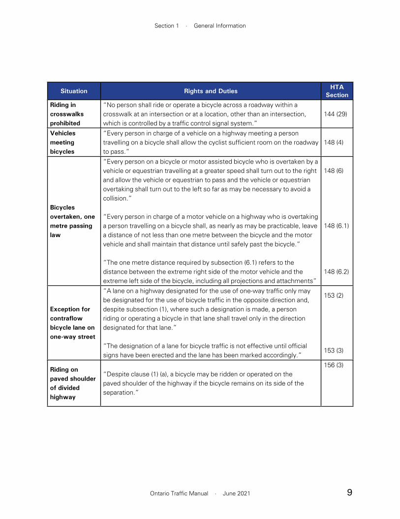
9
Section 1 · General Information
Ontario Traffic Manual · June 2021
Situation Rights and Duties HTA Section
Riding in crosswalks prohibited
“No person shall ride or operate a bicycle across a roadway within a crosswalk at an intersection or at a location, other than an intersection, which is controlled by a traffic control signal system.”
144 (29)
Vehicles meeting bicycles
“Every person in charge of a vehicle on a highway meeting a person travelling on a bicycle shall allow the cyclist sufficient room on the roadway to pass.”
148 (4)
Bicycles overtaken, one metre passing law
“Every person on a bicycle or motor assisted bicycle who is overtaken by a vehicle or equestrian travelling at a greater speed shall turn out to the right and allow the vehicle or equestrian to pass and the vehicle or equestrian overtaking shall turn out to the left so far as may be necessary to avoid a collision.”
“Every person in charge of a motor vehicle on a highway who is overtaking a person travelling on a bicycle shall, as nearly as may be practicable, leave a distance of not less than one metre between the bicycle and the motor vehicle and shall maintain that distance until safely past the bicycle.”
“The one metre distance required by subsection (6.1) refers to the distance between the extreme right side of the motor vehicle and the extreme left side of the bicycle, including all projections and attachments”
148 (6)
148 (6.1)
148 (6.2)
Exception for contraflow bicycle lane on one-way street
“A lane on a highway designated for the use of one-way traffic only may be designated for the use of bicycle traffic in the opposite direction and, despite subsection (1), where such a designation is made, a person riding or operating a bicycle in that lane shall travel only in the direction designated for that lane.”
“The designation of a lane for bicycle traffic is not effective until official signs have been erected and the lane has been marked accordingly.”
153 (2)
153 (3)
Riding on paved shoulder of divided highway
“Despite clause (1) (a), a bicycle may be ridden or operated on the paved shoulder of the highway if the bicycle remains on its side of the separation.”
156 (3)

10
Book 18 · Cycling Facilities
Ontario Traffic Manual · June 2021
Situation Rights and Duties HTA Section
Towing of persons on bicycles, toboggans, etc., prohibited
“No driver of a vehicle or street car shall permit any person riding, riding on or operating a bicycle, coaster, toboggan, sled, skateboard, toy vehicle or any other type of conveyance or wearing roller skates, in-line skates or skis to attach the same, himself or herself to the vehicle or street car on a highway.”
160
Opening Doors of Motor Vehicles
“No person shall,(a) open the door of a motor vehicle on a highway without first taking due precautions to ensure that his or her act will not interfere with the movement of or endanger any other person or vehicle”
165 (1) (a)
Clinging to vehicles, bicycle passengers, etc.Bicycle riders, etc., clinging to vehicles
“A person riding, riding on or operating a motor assisted bicycle, bicycle, coaster, toboggan, sled, skateboard, toy vehicle or any other type of conveyance or wearing roller skates, in-line skates or skis shall not attach it, them, himself or herself to a vehicle or street car on a highway.”
178 (1)
Bicycle passengers
“No person riding or operating a bicycle designed for carrying one person only shall carry any other person thereon.”
178 (2)
Persons clinging to vehicles
“No person shall attach himself or herself to the outside of a vehicle or street car on a roadway for the purpose of being drawn along the highway.”
178 (4)
Duties of pedestrian when walking along highway
Note: A dismounted cyclist is considered a pedestrian
“Where sidewalks are not provided on a highway, a pedestrian walking along the highway shall walk on the left side thereof facing oncoming traffic and, when walking along the roadway, shall walk as close to the left edge thereof as possible.”
“Subsection (1) does not apply to a pedestrian walking a bicycle in circumstances where crossing to the left side of the highway would be unsafe.”
179 (1)
179 (2)

11
Section 1 · General Information
Ontario Traffic Manual · June 2021
Situation Rights and Duties HTA Section
Prohibiting motor assisted bicycles, etc., on municipal highways
“The council of a municipality may by by-law prohibit pedestrians or the use of motor assisted bicycles, bicycles, wheelchairs or animals on any highway or portion of a highway under its jurisdiction.”
185 (2)
Cyclist to identify self
“A police officer who finds any person contravening this Act or any municipal by-law regulating traffic while in charge of a bicycle may require that person to stop and to provide identification of himself or herself.”
“Every person who is required to stop, by a police officer acting under subsection (1), shall stop and identify himself or herself to the police officer.”
218 (1)
218 (2)

12
Book 18 · Cycling Facilities
Ontario Traffic Manual · June 2021
2. Design Users
Prior to planning or designing cycling infrastructure, practitioners should have a thorough understanding of who may use the facility and how they might navigate the broader network. One of the key lessons learned over the past decade of cycling planning and design is that a majority of people of all ages are open to the idea of cycling but are unlikely to regularly ride a bicycle unless they have access to a network of facilities that they feel comfortable using. This means that the full potential for cycling—to improve health, reduce emissions, alleviate congestion and support a vibrant and more equitable public realm—can only be achieved by implementing a network of facilities that provide a comfortable cycling condition for a wide range of users.1 This section describes various user groups and the type of infrastructure that is understood to provide a comfortable condition for each group. Basic operating parameters for different users are also described.
Key Outcome: Inform active transportation practitioners of the key design user groups that should be considered to inform the planning and design of cycling facilities.
2.1 User Characteristics
In North America, people who cycle are often categorized by transportation professionals based on the factors that are understood to influence an individual’s inclination to cycle.2,3 These categories include those who are “interested but concerned”, “somewhat confident” and “highly confident”, as shown in Table 2.1. Approximately two thirds of the population fit into these three categories, with the remaining third consisting of individuals who
are not able to cycle or are not interested in cycling for various reasons; that is, “no way no how”.
People who are considered “highly confident” have advanced cycling skills and are generally comfortable riding alongside motor vehicle traffic. People in this category cycle more frequently and will consider cycling for utilitarian or recreational purposes. In general, the nature of the roadway, which is typically defined by traffic volume or speed, is not a factor in determining whether users in this category will choose to cycle, although they may prefer to use routes with dedicated cycling facilities.
People who are considered “somewhat confident” are those who are comfortable interacting with moderate-speed motor vehicle traffic, but prefer routes with dedicated cycling facilities. People in this category may choose to avoid routes that require cyclists to operate in proximity to higher-speed traffic.
The largest category by far, is the group of individuals who are “interested but concerned”. People in this group are open to the idea of cycling but are uncomfortable sharing the street with motor vehicles except on very low-volume, low-speed neighbourhood streets. The quality and extent of cycling facilities are key factors in determining whether these individuals choose cycling as a viable option for short to moderate length trips.1,2 Factors such as topographic conditions, inconsistent cycling facilities, and high speed motor vehicle traffic also deter individuals in this group from cycling.
Given the size of the “interested but concerned” group, and the central role that infrastructure plays in their choice of travel mode, practitioners

13
Section 2 · Design Users
Ontario Traffic Manual · June 2021
DESIGN CYCLISTInterested but Concerned Somewhat Confident Highly Confident
• Strong preference for separated cycling facilities or very low-volume and low-speed streets
• Cycling frequency depends heavily on having a network of low-stress facilities
• Can generally negotiate simple low-speed interactions with motor vehicles at intersections
• Comfortable cycling on-street and interacting with moderate-speed traffic
• Preference for separated cycling facilities or low-volume and low-speed streets
• Cycling frequency increases as network of low-stress facilities expands
• Comfortable cycling on-street and interacting with higher-speed traffic
• Preference for cycling facilities that allow for easy overtaking and efficient movement
• Cycling frequency not necessarily affected by network
Lower stress tolerance
Higher stresstolerance
% of population • 51–56% • 5–9% • 4–7%
Stress tolerance • Low • Moderate • High
Skill level
• Experience varies
• Ability to anticipate and mitigate basic hazards
• Comparatively experienced
• Ability to anticipate and mitigate common hazards
• Highly experienced
• Well-developed ability to anticipate and mitigate most hazards
Typical demographic profiles
• Age: All*
• Gender: any
• Ability: includes individuals who may have a disability or are new to cycling
• Age: 18–65+
• Gender: women are under-represented
• Ability: individuals with a disability are under-represented
• Age: 18–65+
• Gender: women are under-represented
• Ability: individuals with a disability are under-represented
Typical travel speed
• 10–25 km/h • 15–25 km/h • 20–35 km/h
Table 2.1 – Types of Cyclists
* Children under 12 are an essential cycling demographic but their abilities vary significantly and they may not yet
have the cognitive ability to detect risks, negotiate conflicts or ride a bike independently. Many municipalities have
by-laws allowing children to cycle on sidewalks for this reason.

14
Book 18 · Cycling Facilities
Ontario Traffic Manual · June 2021
Practitioners should consider the network implications of the design cyclist. Implementing the first links of a cycling network is a critical initial step that every municipality must take at some point. The full benefits of these facilities are only likely to be realized, however, once the network expands to connect people to places they want to go and allow them to complete more trips entirely on the network. The success of a single link in the network should therefore be assessed in a long-term network context.
should consider this group to be the “design cyclist”. This term refers to the user category that planners and designers seek to accommodate. By designing facilities to appeal to the “interested but concerned”, practitioners are also accommodating the needs of the other two demographics and significantly increasing the scale of potential benefits associated with cycling.
As indicated in Table 2.1, while the demographic profile and skill level of the design cyclist varies, the stress tolerance of individuals in this group is generally low. The design cyclist may include:
• An adult who is interested in having a more active commute
• A person with a disability who uses an adapted bicycle
• A senior or a low-income individual looking for an affordable transportation option
• A tourist who wants to discover a new place to bike
• A person who doesn’t have a driver’s licence or a car
• A child or youth traveling to school
• A parent making a trip to the store or the park with their children
The circumstances and motivations to cycle vary widely within this group, but what these users share in common is that they are most comfortable cycling on streets with physically separated infrastructure or very low volumes and speeds of motor vehicle traffic. Accommodating these users is essential to encourage more cycling and achieve the full benefits associated with a higher cycling mode share.
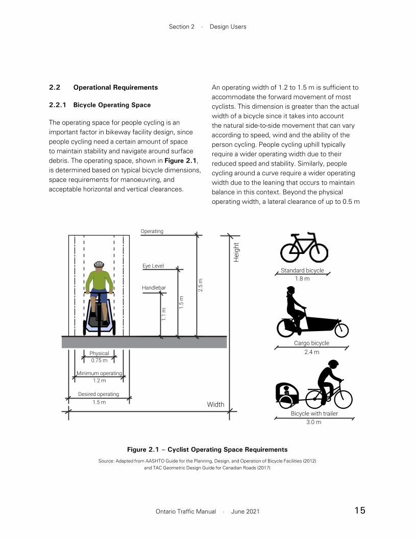
15
Section 2 · Design Users
Ontario Traffic Manual · June 2021
An operating width of 1.2 to 1.5 m is sufficient to accommodate the forward movement of most cyclists. This dimension is greater than the actual width of a bicycle since it takes into account the natural side-to-side movement that can vary according to speed, wind and the ability of the person cycling. People cycling uphill typically require a wider operating width due to their reduced speed and stability. Similarly, people cycling around a curve require a wider operating width due to the leaning that occurs to maintain balance in this context. Beyond the physical operating width, a lateral clearance of up to 0.5 m
2.2 Operational Requirements
2.2.1 Bicycle Operating Space
The operating space for people cycling is an important factor in bikeway facility design, since people cycling need a certain amount of space to maintain stability and navigate around surface debris. The operating space, shown in Figure 2.1, is determined based on typical bicycle dimensions, space requirements for manoeuvring, and acceptable horizontal and vertical clearances.
Figure 2.1 – Cyclist Operating Space Requirements
Source: Adapted from AASHTO Guide for the Planning, Design, and Operation of Bicycle Facilities (2012) and TAC Geometric Design Guide for Canadian Roads (2017)
1.5
m
1.1
m
Minimum operating1.2 m
Physical
Handlebar
Eye Level
2.5
m
Operating
0.75 m
Desired operating
Width
Hei
ght
1.5 m
2.4 mCargo bicycle
3.0 mBicycle with trailer
1.8 mStandard bicycle
16
Book 18 · Cycling Facilities
Ontario Traffic Manual · June 2021
desired and minimum area for queueing space at intersections and crossings. Comprehensive guidance with respect to design speed, sight stopping distances, and curve radii can be found in Section 5 of the 2017 TAC Geometric Design Guide for Canadian Roads (GDGCR).
2.2.2 Design Domain
Throughout OTM Book 18, practitioners are encouraged to design cycling facilities within a design domain. This can be viewed as a range of values that a practitioner may choose for a design parameter given a specific context, though a “typical” design value is recommended. It provides the practitioner with some flexibility in designing a cycling facility that “fits” a location with constraints or other unique conditions, rather than to meet a required standard.
Although the design domain provides some flexibility, the practitioner is always responsible for designing suitable facilities informed by good engineering judgement. This requires an understanding of the design objectives, knowledge of the target user groups and appreciation of contextual factors. In this guide, the design domain is primarily applied to the width of cycling facilities, and is presented as a standard or typical “desired width” and a lower “suggested minimum” value.
It is recommended that the practitioner always start the planning and design process by applying the desired width or greater to the proposed facility and only consider applying the suggested minimum widths in exceptional situations. However, it must be acknowledged that there are many constrained street rights-of-way where there is insufficient space to provide the desired width of all street components. In these situations, the designer may consider implementing a cycling
is desirable on both sides of a cyclist’s path of travel. Detailed guidance on this topic is provided in Section 7.
The operating height of 2.5 m can generally accommodate an average adult cycling while standing upright on the pedals of a bicycle. The length of a bicycle may vary, but typically ranges from 1.8 m for a standard bicycle to 3.0 m for a bicycle towing a trailer.
Other Cycling Facility Users
While people using conventional pedal-operated bicycles are the primary focus of this manual, they are not the only potential users of cycling facilities. Practitioners should also consider the following user groups:
• People riding cargo bikes, e-bikes, recumbent bicycles, tricycles, towing bicycle trailers, adapted bicycles and handcycles
• In-line skaters and skateboarders
• People walking and those using mobility aids, who may choose to make use of cycling facilities where no suitable pedestrian facility exists
• People riding e-scooters and similar micro-mobility devices, as permitted by Ontario’s 5-year e-scooter pilot
Many of these users may require larger queueing spaces, longer stopping distances, larger turn radii and wider operating widths. Where additional space is available, wider facilities may be considered.
Section 4 provides extensive guidance on the desired and minimum widths for various facilities and Section 6 provides guidance on the
17
Section 2 · Design Users
Ontario Traffic Manual · June 2021
Designers are strongly recommended to document their rationale at all stages of the facility selection and design process. This is particularly important where proposals deviate from the desired widths, which are considered optimal from a safety perspective. This will assist the designer should they be required to defend a decision to vary from a desired width because of operational, cost or other reasons. In all cases, decisions to vary from desired widths should be supported by good engineering judgement.
Practitioners should also refer to the TAC GDGCR for further information on the concept of a design domain. Where the design domain may not be met, TAC GDGCR Section 1.5 provides a process to evaluate and document extraordinary situations.
facility less than the desired but no lower than the suggested minimum width. Caution should be used where a minimum cycling facility width is adjacent to a minimum motor vehicle lane width due to the potential for operating spaces to overlap. Designers may also consider methods to reduce motor vehicle speeds or volumes to provide greater flexibility in facility selection and design. In some cases, an alternative corridor may be the most suitable option.
In constrained locations, the following considerations should be evaluated prior to considering designing for the suggested minimum.
• Motor vehicle speed and volume
• Physical separation between the cycling facility and motor vehicle lanes
• Anticipated cycling volume
• Design objectives such as increasing cycling mode share among people of varying ages and with varying abilities
• Permanence of the design and the ability to adjust the allocation of space in the future
• The proximity of alternative parallel cycling routes with dedicated, full width facilities
• The presence of physical obstructions such as poles, transit shelters and curbs on one or both sides of the facility
• Ability for maintenance equipment for snow clearing and sweeping to operate within the stated lower limit width
• Pavement quality and the likelihood that people cycling may need to veer around vertical discontinuities

18
Book 18 · Cycling Facilities
Ontario Traffic Manual · June 2021
— Seeking to manage motor vehicle speeds on neighbourhood streets and in the vicinity of parks and schools through reduced speed limits and various traffic calming measures
• Actively mitigating conflicts between people cycling and other road users such as motorists and pedestrians through “complete streets” design, a roadway design practice that balances the needs of all travel modes, and consideration of accessibility principles in the design of cycling facilities
• Maximizing connectivity through route planning and facility implementation and ensuring equitable access to high quality cycling facilities. Refer to Section 3.
• Selecting appropriate facility types and design treatments for specific contexts. Refer to Section 5.
The AAA design philosophy has been applied throughout this manual. The recommended dimensions and values identify designs that accommodate a broad range of potential users. Practitioners should always seek to implement facilities that are consistent with this philosophy where possible. Where the implementation of an all ages and abilities facility is not feasible due to spatial constraints, financial resources, political support or other reasons, practitioners must use their professional judgement to determine whether an alternate design may be acceptable and whether it would constitute a valuable improvement over the existing cycling conditions and a prudent use of resources. The AAA philosophy should be carried throughout the network planning process to ensure that the cycling network can meet the needs of a wide variety of users.
2.3 Designing for All Ages and Abilities
The All Ages and Abilities (AAA) design philosophy is outlined in the National Association of City Transportation Officials (NACTO) “Urban Bikeway Design Guide” and the subsequent “Designing for All Ages and Abilities” report. The AAA design approach underpins much of the guidance in this manual. The goal of applying a AAA lens to infrastructure development is to encourage more people of all ages and abilities to cycle more often and to mitigate conflicts through facility design to the greatest extent possible. This philosophy implies that infrastructure should be safe and comfortable, and provide equitable access to cycling facilities and key community amenities. The application of these criteria are vital components to improve road safety and support community road safety goals, reduce congestion, improve social and public health and to mitigate the effects of climate change.
Related to a AAA design approach, Vision Zero is an international road safety strategy with the goal of eliminating traffic-related fatalities and serious injuries. Many Canadian municipalities have developed local Vision Zero policies and action plans that outline short- and long-term road safety objectives.
Specific cycling facility design implications that arise from a AAA design approach include:
• Accommodating children and youth by:
— Prioritizing neighbourhood cycling routes to schools with designated bicycle lanes, separated bike lanes or cycle tracks
— Avoiding any visual obstructions, such as parked cars, near intersections and driveways which are more likely to block the visibility of a child cycling due to their shorter height

19
Section 2 · Design Users
Ontario Traffic Manual · June 2021
References
1 National Academies of Sciences, Engineering, and Medicine. (2020) “Bicyclist Facility Prefere nces and Effects on Increasing Bicycle Trips.” Washington, DC: The National Academies Press. https://doi.org/10.17226/25792
2 Dill, J. & McNeil, N. (2013) “Four Types of Cyclists? Examination of Bicycling Behavior and Potential.” Journal of the Transportation Research Board, 2387, 129-138
3 Dill, J. & McNeil, N. (2016) “Revisiting the Four Types of Cyclists: Findings from a National Survey.” Journal of the Transportation Research Board, 2587, 90-99

20
Section 3 · Network Planning
Ontario Traffic Manual · June 2021
3. Network Planning
Network planning is an integral step in building bicycle-friendly communities. Through the application of network planning principles, practitioners can develop comprehensive connected networks that appeal to the “interested but concerned” design user. The planning process is also the first opportunity to mitigate potential road safety challenges before the facility design process begins. Additionally, effective network planning can help to prevent pitfalls later in the implementation process by identifying the most appropriate corridors for inclusion in a cycling network.
Key Outcome: This section outlines key considerations for network planning. This process should occur in advance of facility selection, detailed in Section 5, and facility design, detailed in Section 4 & Section 6.
3.1 Network Planning Process
The network planning process establishes a framework for the implementation and construction of cycling infrastructure. Through the process, several key objectives should be met:
• Minimize risk exposure to cyclists
• Provide access to key destinations
• Provide comfortable routes that are suitable for the design cyclist, and for users of all ages and abilities where feasible
• Respect current, and plan for future, land uses and socio-economic and demographic contexts
3.1.1 Mapping and Spatial Analysis
Mapping and spatial analysis are useful tools to visualize and understand the transportation system. Through the mapping process, planners can visually assess various forms of data to identify where trips are likely to be generated, where there are gaps and barriers within the network and where additional safety improvements should be prioritized. Common types of mapping datasets include:
• Road, transit and pedestrian networks
• Existing and previously proposed cycling networks
• Land use plans
• Census journey to work or household transportation survey data (origins and destinations, mode share and trip length)
• Locations of collisions resulting in serious injuries or fatalities
• Age and income profiles
• Cycling usage such as bicycle counters and mobile app data
Many of the route selection criteria in Section 3.2 can also be mapped where data is available.
In addition to basic map overlays, spatial analysis can be completed by manipulating multiple datasets and using Geographic Information System (GIS) software. Typical spatial analyses that can support route planning include:
• Bike-shed analysis: Origin-specific isochrone maps that show polygons or shaded areas representing the places that a cyclist could

21
Book 18 · Cycling Facilities
Ontario Traffic Manual · June 2021
reach within a certain amount of time on the proposed or existing cycling network.
• Level of Traffic Stress: Classification of each link in the cycling network or entire street network based on the level of stress that an individual would experience riding on that link. Although there are different ways of assessing level of stress, four levels are commonly applied1. This analysis can also include a bike-shed analysis for each level of stress.
• Bikeability: Heat maps highlighting areas that are likely to have comparatively more or less cycling, as shown in Figure 3.1. The indicators used to assess bikeability should relate to existing cycling infrastructure, topography, population density, street connectivity and major destinations, including transit hubs. This analysis is particularly useful when planning for a bike-share system or other cycling amenities such as bike parking or repair stations.
Figure 3.1 – Spatial Analysis
22
Section 3 · Network Planning
Ontario Traffic Manual · June 2021
Practitioners should consider undertaking these analyses to inform and support the decision-making process for planning a cycling network. While these are helpful tools, mapping and spatial analysis should always be supplemented with local knowledge, public input and consideration of route selection criteria.
3.1.2 Multiple Functions of a Cycling Network
A cycling network should serve multiple purposes and address the needs of the design user, as introduced in Section 2. These needs may include supporting recreational cycling and providing convenient access to destinations such as schools, shops, parks, employment centres and transit hubs. While every link in the cycling network should ideally be able to serve a wide range of trips, they may have a primary function. Practitioners may think of the overall cycling network as being composed of three separate systems, as shown in Figure 3.2, which have the following characteristics:
• Recreational / Touring Cycling: Users typically engage in recreational trips to enjoy cycling as an activity and to enjoy the surrounding environment. Trails, parks, waterfronts and in-boulevard trails with few intersections or driveways are key components in the recreational cycling network. Recreational riders generally avoid higher-volume arterial and collector roads, and ride on trails, quiet neighbourhood streets or rural roadways. Recreational cycling routes do not necessarily need to be direct since greater emphasis is placed on the experience of using the facility rather than reaching the destination. These routes are often suitable for all ages and abilities, particularly when intersections and crossings are simple to negotiate.
• Local Neighbourhood Cycling: Cycling routes on local neighbourhood streets can serve both utilitarian and recreational trips. A critical design user is children who often learn to cycle on quiet local streets. Traffic calming and traffic diversion strategies are often necessary to manage motor vehicle speeds and volumes. On routes with higher traffic volumes or speeds, dedicated cycling facilities are often necessary. Local networks serve as important connectors to key community amenities such as community centres, schools and libraries, as well as providing connectivity from residential neighbourhoods to commuter cycling routes.
• Commuter / Spine Cycling: Destination-oriented trips that extend beyond the local neighbourhood depend on a network of commuter cycling routes, also known as a “spine” network. Directness and connectivity across a municipality are important aspects of this network. Major streets with higher volumes and speeds of motor vehicle traffic often play an important role in this network. Low-stress cycling facilities such as separated bikeways are necessary to attract a wide range of potential users.
3.1.3 Phasing and Prioritization
Phasing and prioritization of routes is an essential step of the cycling network planning process. A proposed network should be more than an aspirational goal; it should be a long-term and implementable plan to construct and operate a network of cycling routes. The phasing and prioritization process helps to ensure that resources are used in the most cost-effective way to implement critical connections and core routes as early as possible. It recommended that practitioners consider completing a cost estimate
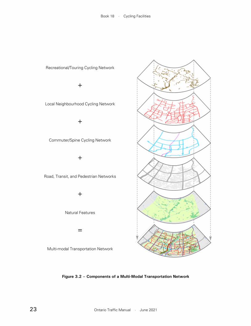
23
Book 18 · Cycling Facilities
Ontario Traffic Manual · June 2021
Figure 3.2 – Components of a Multi-Modal Transportation Network
Recreational/Touring Cycling Network
+
Local Neighbourhood Cycling Network
+
Commuter/Spine Cycling Network
+
Road, Transit, and Pedestrian Networks
+
Natural Features
=
Multi-modal Transportation Network

24
Section 3 · Network Planning
Ontario Traffic Manual · June 2021
for each segment of the cycling network. These estimates are developed from experience with similar types of projects. Typically, unit prices for the various facility types that comprise a proposed network are established and then are applied to the total length for each facility type.
In addition to prioritizing critical gaps and links in the network, a phasing plan should generally align with overall transportation capital works and development plans. This is a cost-effective approach since there can be significant economies of scale achieved from integrating cycling projects into general road improvement projects. The opportunity to achieve these cost efficiencies should not, however, override the importance of addressing critical gaps in the cycling network at an early stage in the implementation process. Missing links and key connections may need to be planned and budgeted separately to fulfill the goals of the cycling network and to achieve linear connectivity. Adopting a phasing strategy exclusively tied to road capital projects and rehabilitation needs can result in discontinuity in the network and therefore limit the appeal to cyclists. The phasing strategy should build on existing infrastructure, implement key links as early as possible and use resources efficiently.
3.2 Route Selection Criteria
Except where prohibited by law, people can cycle on all roadways, whether a cycling facility exists or not. Through the selection of an appropriate facility type and intersection design treatments, most roadways can be designed to create a comfortable cycling network. However, some corridors may be more suitable than others for the implementation of cycling facilities. The process of developing a comprehensive cycling network involves selecting routes that meet the needs of the potential design user while also taking into account the local context.
The process of selecting a cycling route is a multi-faceted activity that often involves weighing trade-offs and developing strategies to mitigate challenges. The following suggested evaluation criteria have been organized into five categories. Each category has several sub-criteria that should be considered when selecting candidate routes.
Network Connectivity
Connectivity and Physical Barriers
As with networks for any other mode of travel, cycling routes that do not connect to other routes are effectively isolated and provide limited benefits until connectivity is achieved. From a network planning perspective, it is beneficial to implement facilities that connect with existing ones or to implement multiple routes in one area concurrently or as part of a planned implementation phase. Together, these routes can provide meaningful connectivity and encourage more cycling in that area. Conversely, the implementation of isolated segments distributed across a large area may not provide existing or potential new users with

25
Book 18 · Cycling Facilities
Ontario Traffic Manual · June 2021
sufficiently connected facilities to encourage more cycling.
In some areas, there may be physical barriers or constraints to bicycle travel caused by hills, rivers, narrow bridges, railroad tracks, highways or other obstacles. When selecting candidate routes that could form part of the designated cycling network, consideration should be given to routes with few or no barriers or constraints that may affect the connectivity, attractiveness and directness of the bike route. If there are no alternative routes that avoid these barriers, a strategy for addressing the barrier should be developed and the costs of implementing this strategy should be understood before including the route in the network.
In some cases, it may be appropriate to adopt a constrained design treatment to carry a cycling facility past a barrier or obstacle. For example, the width of the cycling facility may be reduced as described in Section 4, or a cycle track and sidewalk may be merged into a multi-use path. It is generally not advisable to discontinue a cycling facility and require people cycling to merge with motor vehicles — even for a short distance. Stressful interactions with motor vehicle traffic at a constrained location may reduce the attractiveness of a route and increase risk exposure.
Directness
Cyclists are more sensitive to the directness of a route than motorists, since an increase in trip length not only means an increase in trip time, but also an increase in the physical effort to complete the trip. Cycling routes intended for utilitarian purposes should provide the shortest, quickest, and most convenient connections between origins and destinations, as illustrated in Figure 3.3. This often means that cycling facilities should
be provided in major street rights-of-way, which typically require physically separated facilities. In some cases, particularly in older urban areas with a fine-grained grid pattern, neighbourhood streets can also provide direct routes between origins and destinations. This approach requires comfortable and controlled crossing opportunities at all major streets along the routes.
Apart from routes that primarily serve a recreational purpose, indirect cycling routes are often less successful since more confident cyclists will choose more direct routes without cycling facilities. However, “interested but concerned” cyclists will not see the route as a viable travel option.
Existing and Potential Future Demand
With the exception of recreational cycling, most cycling trips are between specific origins and destinations. For this reason, cycling routes that provide direct access to key destinations should be prioritized. Corridors with high concentrations of residential, employment, commercial and retail land uses, or that provide connectivity to schools, transit hubs, community centres and recreational
Road networkDesirable direct routing between locations of interestUndesirable indirect routing between locations of interest
Location of interest
A B
Figure 3.3 – Direct Routing of Cycling Facilities within an Existing Road Network
26
Section 3 · Network Planning
Ontario Traffic Manual · June 2021
areas may generate a significant number of cycling trips. Parallel routes that bypass these origins and destinations are less likely to be successful cycling corridors.
Existing demand and past annual growth are good predictors of future demand in some circumstances, but a poor predictor of future demand in others. For example, an area with roads that currently feature a high degree of traffic stress may have few cyclists, but significant latent demand. For this reason, future demand should be estimated by the degree to which the density of land uses, average trip lengths, and socio-economic factors in the area would generally be favourable to cycling. If the existing cycling infrastructure in such areas is poor, then installing the appropriate facilities can significantly increase demand for cycling, even if current ridership is low.
Future demand can also be affected by future development. Wherever possible, the provision of cycling infrastructure should precede large-scale development, in order to provide attractive cycling options when individuals or businesses are choosing to relocate to the area and begin to establish their travel behaviours.
Conflict Mitigation
Minimizing risk exposure to cyclists is one of the main goals of cycling network planning. Various roadway conditions such as intersection crossings, high-speed and high-volume traffic, railway crossings, driveways, poor surface conditions and excessive grades can increase the level of risk exposure for cyclists. While many risks can, to some extent, be mitigated through various design treatments, routes that avoid or address key risk factors should be preferred. When there is a candidate route that provides value to the network,
but is challenging with respect to risk exposure, the feasibility, effectiveness and cost of implementing mitigating measures such as physical separation or signalization should be considered prior to including the corridor in the network.
Social & Economic Factors
Equity
Improving social equity is about distributing resources and opportunities fairly while ensuring that under-served populations have the same opportunities that other populations possess. There are several equity implications associated with cycling network planning:
• Municipalities should seek to improve and expand cycling infrastructure in all neighbourhoods within their boundaries in an effort to improve cycling network access for all residents. The cycling network should be reviewed through an equity lens for potential impacts to marginalized communities, such as low-income neighbourhoods.
• The provision of all ages and abilities infrastructure should be considered through an equity lens both for the sake of providing equal access, as well as ensuring the safety of all users. A cycling environment in which only cyclists with a higher risk tolerance, predominantly young adult males, feel comfortable riding, not only denies many potential users the opportunity to ride a bicycle, but also suggests that the environment poses above-average risks to the existing users. A network that appeals to users with all levels of ability plus those with a lower risk tolerance, such as women, children and older adults, should always be the goal.

27
Book 18 · Cycling Facilities
Ontario Traffic Manual · June 2021
• As an affordable and healthy means of transportation, cycling can play an important role in low-income neighbourhoods, and cycling infrastructure should be given higher priority in these areas
• Cycling connections to key destinations such as employment nodes, schools, colleges, universities, healthcare facilities, community centres, transit hubs and grocery stores should be given higher priority
Social and Economic Trends
Social and economic trends define the patterns and behaviours of people that live and work in a community. It is important to consider characteristics such as age distribution, incomes, employment and auto ownership since they can help explain existing and future travel patterns and inform cycling education and marketing campaigns.
Public and Stakeholder Input
Local residents and people who frequently travel through an area can often provide helpful insights to identify challenges and opportunities that can help inform the decision about which routes should be included in a network.
Attractiveness
Natural Scenery and Urban Streetscape
When selecting candidate routes, practitioners should seek to identify attractive routes that take advantage of local scenery. These routes could pass through natural features such as waterfronts or vistas. In urban environments, consideration should be given to candidate routes that pass through vibrant areas such as main streets, and to
improve the streetscape in conjunction with cycling infrastructure implementation.
Local Tourism, Business Strategies and Goals
When selecting candidate routes, practitioners should review the goals identified by regional tourism offices, business improvement associations and related organizations to identify routes that support these strategies. These routes should consider primary regional destinations such as provincial parks and conservation areas, which may also include important local destinations such as community centres, universities and historic sites. Scenic corridors have a high potential for cycling tourism. In urban areas and neighbourhood main streets, it is important to consider how the candidate route implementation would impact local businesses, and to leverage opportunities to improve the public realm in conjunction with cycling facility implementation.
Feasibility
Constructability
The anticipated level of effort to construct a cycling facility should be considered in determining whether to include a candidate route in a network and in which phase it should be implemented. A route that has significant physical barriers such as a narrow bridge or steep grades next to the roadway may not be feasible without incurring significant costs. Key considerations that affect constructability include the need for curb and drainage modifications, as well as utility, tree and property impacts.

28
Section 3 · Network Planning
Ontario Traffic Manual · June 2021
3.3 Integration with Complete Streets Planning and Design
Complete Streets are roadways which have been designed to be an attractive, accessible and integrated environment for all road users. Pedestrians, cyclists, motorists and transit users of all ages and abilities are considered during the design and implementation of Complete Streets. Streets have many different roles, characters, and functions, and it is by examining their specific role in the network that a street’s design objectives begin to emerge.
The benefits of Complete Streets include:
• Improved safety for all users
• More livable communities
• Positive impacts on public health
• Increased economic activity, since vibrant streets attract more people
Cycling infrastructure is a key element of Complete Streets. It improves the accessibility of a community and, if effectively planned and designed, allows for seamless transitions among cycling, walking and transit modes.
3.3.1 Integration with Transit
Transit can complement cycling by providing an alternate mode of transportation on days when cycling may not be an option due to weather, a mechanical issue or a health condition. Cycling, in turn, can complement transit by providing an efficient first or last mile travel option at one or both ends of a transit trip. From a network planning perspective, routes to and from transit hubs should be prioritized. Transit service and cycling facilities
Potential Cost
The evaluation of candidate routes should involve an assessment to identify capital and maintenance costs associated with a cycling route. While funding can be a significant constraint in the development of a cycling network, a lack of funds can never justify a poorly designed, constructed or maintained facility. Where funding is a concern, municipalities should consider the following options:
• Explore additional funding opportunities such as partnering with other levels of government
• Integrate the project with existing road projects or reallocate funds within their transportation budgets to support the project through a complete streets initiative
• Adjust the phasing or timeline for the project
• Identify alternative routes where a facility could be implemented at a lower cost
Since resources for cycling infrastructure are often limited, it is important to understand the opportunity cost associated with implementing large-scale projects. These projects are often necessary and frequently deliver commensurate benefits. However, it is important to understand the anticipated costs and benefits as much as possible during the network planning stage.
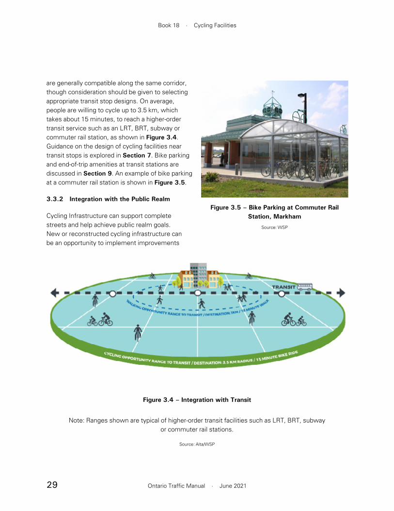
29
Book 18 · Cycling Facilities
Ontario Traffic Manual · June 2021
are generally compatible along the same corridor, though consideration should be given to selecting appropriate transit stop designs. On average, people are willing to cycle up to 3.5 km, which takes about 15 minutes, to reach a higher-order transit service such as an LRT, BRT, subway or commuter rail station, as shown in Figure 3.4. Guidance on the design of cycling facilities near transit stops is explored in Section 7. Bike parking and end-of-trip amenities at transit stations are discussed in Section 9. An example of bike parking at a commuter rail station is shown in Figure 3.5.
3.3.2 Integration with the Public Realm
Cycling Infrastructure can support complete streets and help achieve public realm goals. New or reconstructed cycling infrastructure can be an opportunity to implement improvements
Figure 3.4 – Integration with Transit
Note: Ranges shown are typical of higher-order transit facilities such as LRT, BRT, subwayor commuter rail stations.
Source: Alta/WSP
Figure 3.5 – Bike Parking at Commuter Rail Station, Markham
Source: WSP

30
Section 3 · Network Planning
Ontario Traffic Manual · June 2021
an enhanced sense of place, benefiting local commuters, businesses and property owners
to the public realm. Cyclists help make a street more vibrant, and reduce the number of motor vehicles traveling through a corridor, which reduces noise and air pollution. Customer spending along commercial corridors has been found to increase following the implementation of cycling infrastructure, providing an economic benefit to local businesses.2
Facility design, as shown in Section 4, should consider complete streets design principles that help establish consistent decision-making, building on considerations from the route selection criteria. Design principles3 may include:
• Prioritize safer and more accessible options such that on any street, regardless of the priority mode, all users should feel as safe as possible
• Ensure context sensitivity such that land use and the adjacent transportation infrastructure are integrated where appropriate and supportive of each other
• Embed sustainability into the design of streets through minimizing environmental impacts, supporting energy efficiency and prioritizing active modes of transportation
• Prioritize connectivity by designing complete streets and communities with block sizes, building orientations, neighbourhood configurations and street patterns that maximize connectivity for pedestrians, cyclists and transit users while also considering new connections and greenways
• Emphasize vitality such that new and renewed streets attract pedestrians and cyclists with
References
1 Mekuria, M., Furth, P. & Nixon, H. (2012). Low-Stress Bicycle and Network Connectivity. Mineta Transportation Institute. https://transweb.sjsu.edu/research/low-stress-bicycling-and-network-connectivity
2 Arancibia, Farber, Savan, Verlinden, Smith Lea, Allen, Vernich. (2019). Measuring the Local Economic Impacts of Replacing On-Street Parking with Bike Lanes: A Toronto (Canada) Case Study. Journal of the American Planning Association.
3 City of London (2018). London Complete Streets Design Manual. https://www.london.ca/residents/Roads-Transportation/Transportation-Planning/Pages/Complete-Streets-.aspx
31
Section 4 · Cycling Facilities
Ontario Traffic Manual · June 2021
4. Cycling Facilities
This section provides practitioners with guidance related to the design of on-road and in-boulevard cycling facilities. In-boulevard facilities are those that are placed within the roadway right-of-way, but outside of the travelled portion of the roadway. General geometric considerations, signage and pavement markings are discussed in this section. The detailed design of a cycling facility should occur after the cycling network has been planned and the appropriate facility types have been selected. Practitioners should refer to Section 3 for guidance on cycling network planning, and Section 5 for guidance on the selection of the appropriate cycling facility type.
This section has been organized to provide practitioners with easy reference to the tools recommended for the design of a specific cycling facility type.
Section 4.1 Types of Cycling Facilities provides an overview on all facilities covered in this section.
Section 4.2 Signs and Pavement Markings introduces commonly used signage and pavement markings to support cycling facilities.
Section 4.3 Physically Separated Bikeways provides guidance on the design of physically separated cycling lanes, cycle tracks and in-boulevard multi-use paths.
Section 4.4 Bicycle Lanes relates to the design of conventional, buffered and contraflow cycling lanes with and without on-street parking.
Section 4.5 Shared Cycling Facilities includes information on the design of roadways where
people riding bikes are expected to operate in mixed traffic conditions with motor vehicles. Advisory bike lanes are also covered.
Throughout this section, the design domain is presented as a “desired width” and “suggested minimum” guideline. This design domain is intended to provide the practitioner with flexibility when designing cycling facilities. It is recommended that practitioners design to the desired width. In certain conditions, such as facilities where a high volume of cycling traffic is expected, it may be appropriate to exceed the desired width.
In retrofit situations and along constrained corridors, designing to the desired width may not be consistently achievable. Practitioners should first strive to meet the desired width of cycling facilities by reducing motor vehicle lane widths to minimum acceptable widths, a technique that has been shown in urban environments to reduce motor vehicle travel speed1 without negatively impacting safety2 or lane capacity.3
As with the Facility Selection Process outlined in Section 5, designers are strongly encouraged to document their rationale. This is particularly important where proposed design solutions deviate from desired widths. This will assist the designer should they be required to defend any compromises they may have chosen for operational, cost or other reasons.
The design of cycling facilities will evolve and new ideas will emerge over time. If an engineering review supports an innovative or alternative design solution that differs from the best practice guidelines in OTM Book 18, engineering judgment may be applied by implementing it as a pilot project and monitoring it following implementation.

32
Book 18 · Cycling Facilities
Ontario Traffic Manual · June 2021
Refer to Section 6 for information about designing cycling facilities at intersections, roundabouts, interchanges, ramp crossings, conflict zones, cycling signals, bridge structures and railway crossings.
Key Outcome: To provide practitioners with an understanding of the different types of dedicated cycling facilities and mixed traffic cycling conditions.
4.1 Types of Cycling Facilities
A complete cycling network typically consists of various types of cycling facilities which accommodate different user characteristics and trip purposes. Cycling facility types are summarized in Table 4.1, and can be organized into three categories:
• Physically separated bikeways, which include elements such as curbs, planters or bollards to provide physical separation between people riding bikes and motor vehicle traffic
• Bicycle lanes, which include designated space for cyclists but no physical separation
• Shared cycling facilities, which provide no distinct operating space for cyclists but provide other supporting amenities such as traffic calming and wayfinding
Several facility types exist within each of these categories as summarized in Table 4.1. Practitioners should always refer to the Facility Selection Process outlined in Section 5 for guidance on selecting a facility type.

33
Section 4 · Cycling Facilities
Ontario Traffic Manual · June 2021
Table 4.1 – Overview of Types of Cycling Facilities
Physically Separated Bikeways
Physically Separated Cycling Lanes (Section 4.3.2)
A portion of a roadway which has been designated for the exclusive use of cyclists, and which is separated from adjacent motor vehicle lanes by a horizontal buffer and separation elements that restrict encroachment of traffic. Separation techniques are detailed in Section 4.3.1.
Cycle Tracks (Section 4.3.3)
A physically separated bikeway that is horizontally and vertically separated from the travelled portion of the roadway by a curb and buffer. Cycle tracks are designated exclusively for use by people riding bikes, and often travel parallel to a sidewalk.
In-Boulevard Multi-Use Paths (Section 4.3.4)
A two-way path that is horizontally and vertically separated from the travelled portion of the roadway by a curb and buffer. Multi-use paths are shared by cyclists and pedestrians. In-boulevard multi-use paths are distinct from multi-use trails, which run in a dedicated corridor separate from the road right-of-way.
Bicycle Lanes
Conventional Bicycle Lanes (Section 4.4.1)
A portion of a roadway that has been designated by pavement markings and signage for preferential or exclusive use by people riding bikes. Bicycle lanes are separated from motor vehicle lanes solely by a white painted line. This facility type is for one-way bicycle travel only. A typical configuration on a two-way roadway includes a conventional bicycle lane on each side.
Buffered Bicycle Lanes (Section 4.4.2)
Similar to a conventional bicycle lane, but adds a painted buffer to create additional horizontal separation between the bicycle lane and the adjacent motor vehicle lane. No vertical separation elements are used.
Contraflow Bicycle Lanes (Section 4.4.3)
A bicycle lane that operates in the opposite direction of motor vehicle traffic, enabling two-way bicycle travel on a roadway that has one-way operation for motor vehicles. Contraflow bicycle lanes can be separated from motor vehicle lanes by a painted line only, by a buffer or by a form of physical separation.

34
Book 18 · Cycling Facilities
Ontario Traffic Manual · June 2021
Shared Cycling Facilities
Advisory Bicycle Lanes (Section 4.5.1)
A shared roadway facility that visually delineates space for cycling by dashed lane lines. The roadway contains no centreline, and motor vehicles share the centre roadway space for two-way travel.
Neighbourhood Bikeways (Section 4.5.2)
Low-volume, low-speed streets that prioritize bicycle travel using treatments such as traffic calming, traffic reduction, signage, pavement markings and intersection crossing treatments. These treatments encourage through movements for people riding bikes while discouraging or prohibiting similar through trips by motorized traffic.
Mixed Traffic Operation (Section 4.5.3)
Unless cycling is specifically restricted, people riding bikes are permitted to travel on all roadways, whether designated as a bicycle route or not. Designating a route where cyclists operate in mixed traffic is generally undesirable, unless the street is low-speed and low-volume. Where appropriate conditions are present for mixed traffic operation, supportive signs and pavement marking treatments can be added to the route to support wayfinding and promote safer interactions between cyclists and motorists.
Paved Shoulders (Section 4.5.4)
A portion of a roadway which is contiguous with the travelled way, and is used to accommodate stopped motor vehicles, emergency uses, pedestrians and cyclists, as well as for lateral support of the pavement structure. On higher-speed and higher-volume roads, paved shoulders should typically include a buffer zone to provide greater separation between motorists and people riding bikes travelling in the same direction.

35
Section 4 · Cycling Facilities
Ontario Traffic Manual · June 2021
4.2 Signs and Pavement Markings
Signs and pavement markings are important features to all cycling facilities, and assist in a range of ways including:
• Communicating necessary regulatory information
• Providing navigation wayfinding
• Communicating when space is expected to be shared between cyclists and motorists or pedestrians and cyclists
• Defining dedicated space for cycling
Section 4.3, Section 4.4 and Section 4.5 provide guidance on the application of signage and pavement markings to each type of cycling facility.
4.2.1 Signs
All signs used for cycling facilities should be sized appropriately for interpretation by the intended user, whether it be cyclists, motorists or both. They should be consistent with the TAC Bikeway Traffic Control Guidelines for Canada — 2nd Edition (2012) or the Ontario Traffic Manual series. In designated areas of the Province, English and French versions of textual signs should be installed, either as a single bilingual sign or as separate English and French signs.
Bicycle Route Marker
The Bicycle Route sign (M511 OTM), illustrated in Figure 4.1, is intended primarily to communicate to people riding bikes that they are on a roadway with a shared operating space that is designated as a bicycle route within a cycling network. Green is the standard colour for bicycle route signs; however, alternative sign designs or colours may be implemented by a municipality or partner organization to brand a trail or bike route.
Signs should be placed 20 to 30 m in advance of and following intersections and decision points. A minimum frequency of three signs per kilometre on urban roadways and one sign every 2 km on rural roadways is recommended.
Additional wayfinding signs may be appropriate to provide directional guidance to people cycling. Refer to Section 9.4 for more information on wayfinding.
M511 (OTM)(450 x 450 mm)
Figure 4.1 – Bicycle Route Marker Sign

36
Book 18 · Cycling Facilities
Ontario Traffic Manual · June 2021
Share the Road / Shared Use Lane Single File
In addition to a Bicycle Route sign (M511 OTM), a road authority may also install the warning signs depicted in Figure 4.2 to remind motorists to share the road, and reinforce that a bicycle is defined as a vehicle in the Highway Traffic Act (HTA). These warning signs should only be installed at locations deemed appropriate, consistent with guidance in OTM Book 6 — Warning Signs.
Under the HTA, motorists are required to provide a minimum 1.0 m distance when passing a cyclist. As a result, on a typical roadway without dedicated cycling facilities, motorists must either change lanes or cross the centreline in order to provide the required passing distance for people riding bikes.
Share the Road and Shared Use Lane Single File signs can be used in conjunction with Shared Cycling Facilities (see Section 4.5). A Shared Use Lane Single File sign (Wc-24 OTM) and supplementary tab (Wc-24t OTM) should be applied in constrained conditions where motorists are discouraged from passing cyclists, where the conditions of the roadway make it infeasible or unsafe for a motorist to pass a cyclist with a 1.0 m gap, where there are changes in road configuration or an approach to an up or down grade. Signage will encourage cyclists to use the full lane and discouraging unsafe passing behaviour from motorists. The sign and tab should also be considered in roadway segments where any of the following are present:
• Curves or steep grades
• High oncoming traffic volumes
• Temporary narrowing of the roadway for construction
• Short segments of roadway where a designated cycling facility must be discontinued
In each case, the signs should be used in addition to the appropriate warning sign for the specific condition.
Although people riding bikes are expected to ride as far to the right of the roadway as practicable, they may take the lane at their discretion if they consider riding on the far right of the roadway to be unsafe.
Following the end of a bicycle lane, a Share the Road sign (Wc-19 OTM) and supplementary tab (Wc-19t OTM) should be erected to indicate to users that they are entering a shared space. Practitioners should refer to Section 4.5 for guidance on design of roadways where cyclists operate in mixed traffic.
Wc-19 (OTM)(600 x 600 mm)
Wc-19t (OTM)(300 x 600 mm)
170
145
187
40
45
185
45
Wc-24 (OTM)(600 x 600 mm)
Wc-24t (OTM)(300 x 600 mm)
Figure 4.2 – Share the Road and Shared Use Lane Single File Signs
(Note: Share the Road sign design is currently under review by Transportation Association of Canada. A version has been proposed that
reflects Ontario’s one metre passing law.)
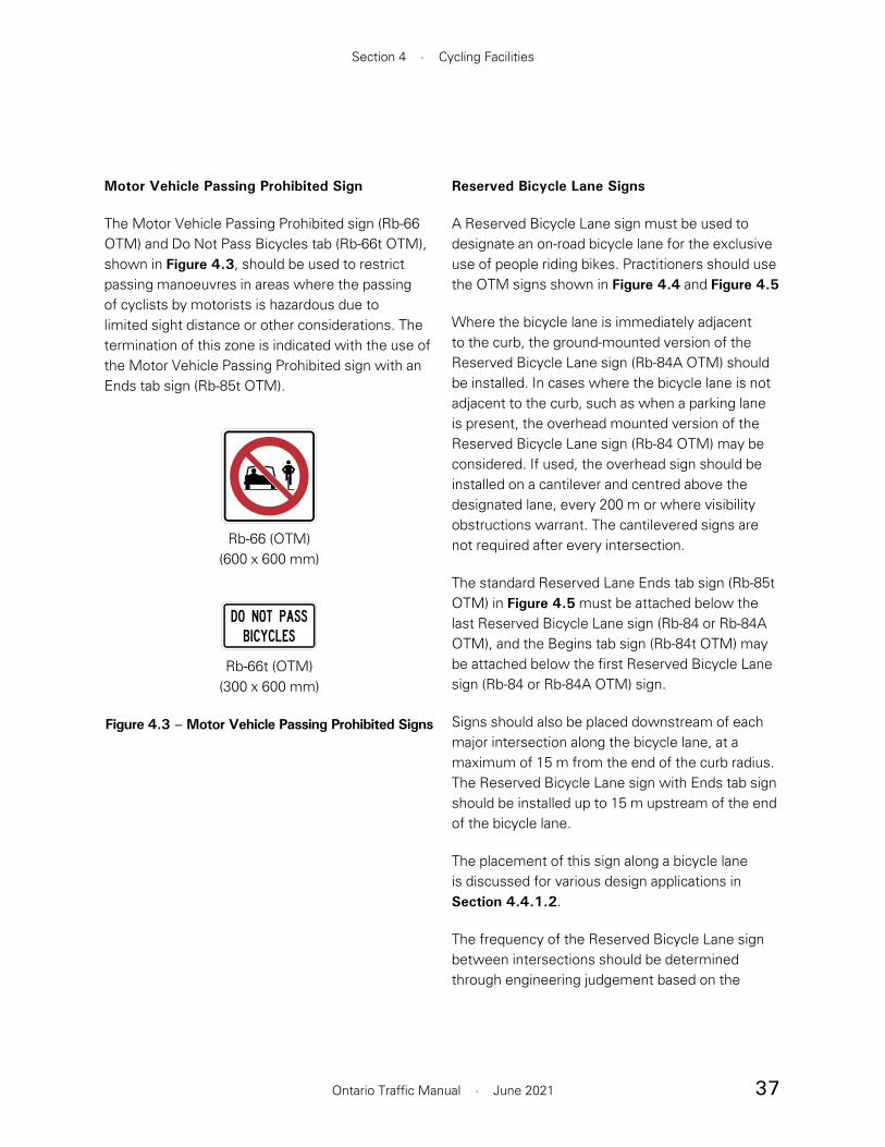
37
Section 4 · Cycling Facilities
Ontario Traffic Manual · June 2021
Motor Vehicle Passing Prohibited Sign
The Motor Vehicle Passing Prohibited sign (Rb-66 OTM) and Do Not Pass Bicycles tab (Rb-66t OTM), shown in Figure 4.3, should be used to restrict passing manoeuvres in areas where the passing of cyclists by motorists is hazardous due to limited sight distance or other considerations. The termination of this zone is indicated with the use of the Motor Vehicle Passing Prohibited sign with an Ends tab sign (Rb-85t OTM).
Rb-66 (OTM)(600 x 600 mm)
Rb-66t (OTM)(300 x 600 mm)
Figure 4.3 – Motor Vehicle Passing Prohibited Signs
Reserved Bicycle Lane Signs
A Reserved Bicycle Lane sign must be used to designate an on-road bicycle lane for the exclusive use of people riding bikes. Practitioners should use the OTM signs shown in Figure 4.4 and Figure 4.5
Where the bicycle lane is immediately adjacent to the curb, the ground-mounted version of the Reserved Bicycle Lane sign (Rb-84A OTM) should be installed. In cases where the bicycle lane is not adjacent to the curb, such as when a parking lane is present, the overhead mounted version of the Reserved Bicycle Lane sign (Rb-84 OTM) may be considered. If used, the overhead sign should be installed on a cantilever and centred above the designated lane, every 200 m or where visibility obstructions warrant. The cantilevered signs are not required after every intersection.
The standard Reserved Lane Ends tab sign (Rb-85t OTM) in Figure 4.5 must be attached below the last Reserved Bicycle Lane sign (Rb-84 or Rb-84A OTM), and the Begins tab sign (Rb-84t OTM) may be attached below the first Reserved Bicycle Lane sign (Rb-84 or Rb-84A OTM) sign.
Signs should also be placed downstream of each major intersection along the bicycle lane, at a maximum of 15 m from the end of the curb radius. The Reserved Bicycle Lane sign with Ends tab sign should be installed up to 15 m upstream of the end of the bicycle lane.
The placement of this sign along a bicycle lane is discussed for various design applications in Section 4.4.1.2.
The frequency of the Reserved Bicycle Lane sign between intersections should be determined through engineering judgement based on the

38
Book 18 · Cycling Facilities
Ontario Traffic Manual · June 2021
roadway speed and the distance between intersections. The maximum recommended spacing is 500 m.
Oversize versions of the Reserved Bicycle Lane sign and tab signs may be used in areas where traffic conditions warrant greater visibility. Practitioners should refer to OTM Book 5 — Regulatory Signs for guidance. OTM Book 5 also includes other details on Reserved Lane Signs which may be used to designate an on-road lane for the preferential use of cyclists with other vehicle classes such as high occupancy or buses.
Rb-84 (OTM)(600 x 600 mm)
Rb-84A (OTM)(600 x 600 mm)
Figure 4.4 – Reserved Overhead and Ground-Mounted Bicycle Lane Signs
Rb-84t (OTM)(200 x 600 mm)
Rb-85t (OTM)(200 x 600 mm)
Figure 4.5 – Reserved Lane Begins and Ends Tabs
Reserved Bicycle Lane Ahead Sign
The Reserved Bicycle Lane Ahead sign (WB-10 TAC), shown in Figure 4.6, may be placed adjacent to or above the curb lane in advance of the start of a reserved bicycle lane. This sign should be considered where motorists are required to modify their trajectory in order to avoid the bicycle lane.
WB-10 (TAC)(600 x 600 mm)
Figure 4.6 – Reserved Bicycle Lane Ahead Sign

39
Section 4 · Cycling Facilities
Ontario Traffic Manual · June 2021
Object Marker Sign
The Object Marker sign (Wa-33R, Wa-33LR, Wa-33L OTM), shown in Figure 4.7, is used to mark obstructions adjacent to or within the road or bikeway. This sign should be used to indicate open ends of physically separated bicycle lanes, such as where the end of a planter faces traffic.
The Wa-33LR sign indicates that travel is possible on both sides of the obstacle, such as where an obstacle separates a bicycle lane from a traffic lane. Where bicycle and motor vehicle traffic is expected to pass on only one side of the obstacle, a directional object marker sign may be used. The Wa-33R is used to mark obstructions on the right side of the road or cycling facility, while the Wa-33L is used for obstructions on the left.
In some instances, such as along in-boulevard facilities in proximity to a utility pole, a half-size version of the sign may be used in the boulevard directed towards cyclists. Pavement markings should also be used to indicate an obstruction within the pathway such as centreline bollards, hydro poles, light poles and other infrastructure.
Wa-33R (OTM)(300 x 900 mm)
Wa-33LR (OTM)(450 x 900 mm)
Wa-33L (OTM)(300 x 900 mm)
Figure 4.7 – Object Marker Signs
Stopping Prohibited Sign
The Stopping Prohibited sign (Rb-55 OTM), shown in Figure 4.8 may be used to indicate that stopping is prohibited at all times on the roadway. Although bicycle lanes are designated for exclusive use by cyclists and thus motor vehicles stopping in them is prohibited, the Stopping Prohibited sign can serve as a reminder to motorists.
Alternatively, where adjacent land uses require curb-side activity such as loading and drop-offs, a parking restriction sign can be applied.
Rb-55 (OTM)(300 x 300 mm)
Figure 4.8 – Stopping Prohibited Sign

40
Book 18 · Cycling Facilities
Ontario Traffic Manual · June 2021
Bicycles Excepted Tab Sign
The Bicycles Excepted tab sign (Rb-17t OTM) shown in Figure 4.9 should be attached below signs that are not intended to apply to cycling traffic. For example, it should be attached below a Do Not Enter sign (Rb-19 OTM) that is located on a roadway with a contraflow bicycle lane. It should also be attached below a No Right Turn sign (Rb-11 OTM) or No Left Turn sign (Rb-12 OTM) that is located on the approach to a roadway with a contraflow bicycle lane. This sign coveys that people riding bikes may make the indicated manoeuvres that are otherwise prohibited for motor vehicles. Refer to Section 4.4.3.3 for details on the application of this sign and OTM Book 5 — Regulatory Signs for information on the Do Not Enter (Rb-19 OTM), No Right Turn (Rb-11 OTM) and No Left Turn (Rb-12 OTM) signs.
Rb-17t (OTM)(200 x 600 mm)
Figure 4.9 – Bicycles Excepted Tab Sign
Shared Pathway Sign
The Shared Pathway sign (Rb-71 OTM), shown in Figure 4.10, may be installed along in-boulevard multi-use paths to indicate that users are expected to share the space on the path. It may be placed on the far side of intersections and other decision points.
Rb-71 (OTM)(300 x 450 mm)
Figure 4.10 – Shared Pathway Sign

41
Section 4 · Cycling Facilities
Ontario Traffic Manual · June 2021
Pathway Organization Sign
The Pathway Organization sign (Rb-72A, Rb-72B OTM) shown in Figure 4.11, may be applied on in-boulevard multi-use paths when separate cycling and pedestrian operating spaces are provided, such as on approach to a crossing, where a separate crossride exists or is planned.
Where pedestrians are directed to the right side of the crossing Rb-72A should be used. Where pedestrians are directed to the left side of the crossing, Rb-72B OTM should be used.
35
260
155
Rb-72A (OTM)(300 x 450 mm)
35
260
155
Rb-72B (OTM)(300 x 450 mm)
Figure 4.11 – Pathway Organization Sign
Dismount and Walk Sign
The Dismount and Walk sign (Rb-70 OTM), shown in Figure 4.12, directs people riding bikes to dismount and walk their bikes where it may be beneficial for safety, such as through very narrow cross-sections, where a multi-use path transitions to a sidewalk, or at crossings where a designated bicycle crossing has not been provided.
Practitioners should recognize that compliance with this sign is generally poor. Instructing cyclists to dismount may create additional barriers for people using bikes as a mobility aid, who may have considerable difficulty dismounting. Design of cycling facilities should seek to minimize or eliminate situations where dismounting is required. Use of this sign should be considered with discretion only as a temporary solution or last-resort option. Section 6 provides guidance on crossing treatments that do not require cyclists to dismount.
Rb-70 (OTM)(300 x 300 mm)
Figure 4.12 – Dismount and Walk Sign

42
Book 18 · Cycling Facilities
Ontario Traffic Manual · June 2021
4.2.2 Pavement Markings
Bicycle Lane and Cycle Track Pavement Markings
Bicycle lanes are typically marked by two white symbols: a diamond and a bicycle. The diamond symbol should be centred in the bicycle lane and should have a stroke width of at least 75 mm. These pavement markings must be used in conjunction with a Reserved Bicycle Lane sign as shown in Section 4.4.1.
The placement of the symbols along a bicycle lane is discussed for various design applications in Section 4.4.1.2. On roadway segments with long distances between intersections and driveways, the symbols may be repeated at intervals of 300 m or more. On roadway segments with frequent occurrences of driveways, the symbol spacing may be reduced to 30 m.
An optional directional arrow may also be used where the direction of travel is not clear or additional guidance is required. For example, the arrow may be used on contraflow bike lanes or at intersections where people riding bikes will take different trajectories at or on the approach to an intersection depending on the turning movement they are making. The cyclist directional arrow is shown with the bicycle and diamond symbols in Figure 4.13.
Figure 4.13 – Bicycle Lane Pavement Markings
Source: Based on the TAC Bikeway Traffic Control Guidelines for Canada, 2012 (Table 7-1)

43
Section 4 · Cycling Facilities
Ontario Traffic Manual · June 2021
Solid White Edge Line
Bicycle lanes and paved shoulders are delineated using a minimum 100 mm wide solid white edge line, shown in Figure 4.14, placed between the travelled portion of the roadway and the bicycle lane or paved shoulder.
100–200 mm
Figure 4.14 – Solid White Edge Line
Dashed White Bicycle Lane Line
The dashed white bicycle lane line, shown in Figure 4.15, indicates that motor vehicles are permitted to cross into the bicycle lane — for example, on the approach to some intersections. Further guidance on the application of this pavement marking is discussed in Section 4.4.
100–200 mm1.0 m 1.0 m
Figure 4.15 – Dashed White Bicycle Lane Line
Yellow Contraflow Lane Line
Contraflow bicycle lanes should be delineated by a 200 mm solid yellow line, shown in Figure 4.16, between the contraflow bicycle lane and the general purpose lane, and are marked by white diamond and bicycle symbols. The diamond symbol should be centred in the bicycle lane and should have a stroke width of at least 75 mm. A directional arrow should be used for contraflow bicycle lanes to provide additional guidance to both people riding bikes and motorists. The cyclist directional arrow is shown with the bicycle symbol and diamond symbol in Figure 4.13.
A designated buffer space, as shown in Figure 4.17, may be applied to separate the bicycle lane from the adjacent motor vehicle lane. Physical barriers such as flexible bollards may be placed within this buffer space to provide added separation between motorists and cyclists, as illustrated in Section 4.3.1.2.
200 mm
Figure 4.16 – Yellow Contraflow Lane Line
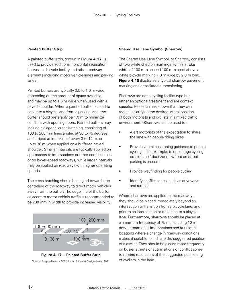
44
Book 18 · Cycling Facilities
Ontario Traffic Manual · June 2021
Painted Buffer Strip
A painted buffer strip, shown in Figure 4.17, is used to provide additional horizontal separation between a bicycle facility and other roadway elements including motor vehicle lanes and parking lanes.
Painted buffers are typically 0.5 to 1.0 m wide, depending on the amount of space available, and may be up to 1.5 m wide when used with a paved shoulder. When a painted buffer is used to separate a bicycle lane from a parking lane, the buffer should preferably be 1.0 m to minimize conflicts with opening doors. Painted buffers may include a diagonal cross hatching, consisting of 100 to 200 mm lines angled at 30 to 45 degrees, and striped at intervals of every 3 to 12 m, or up to 36 m when applied on a buffered paved shoulder. Smaller intervals are typically applied on approaches to intersections or other conflict areas or on lower-speed roadways, while larger intervals may be applied on roadways with higher operating speeds.
The cross hatching should be angled towards the centreline of the roadway to direct motor vehicles away from the buffer. The edge line of the buffer adjacent to motor vehicle traffic is recommended to be 200 mm in width to provide increased visibility.
3–36 m
100–600 mm30–45°
100–200 mm
100 mm
Figure 4.17 – Painted Buffer Strip
Source: Adapted from NACTO Urban Bikeway Design Guide, 2011
Shared Use Lane Symbol (Sharrow)
The Shared Use Lane Symbol, or Sharrow, consists of two white chevron markings, with a stroke width of 100 mm spaced 100 mm apart above a white bicycle marking 1.0 m wide by 2.0 m long. Figure 4.18 illustrates a typical sharrow pavement marking and associated dimensioning.
Sharrows are not a cycling facility type but rather an optional treatment and are context specific. Research has shown that they can assist in clarifying the desired lateral position of both motorists and cyclists in a mixed traffic environment.4 Sharrows can be used to:
• Alert motorists of the expectation to share the lane with people riding bikes
• Provide lateral positioning guidance to people cycling — for example, to encourage cycling outside the “door zone” where on-street parking is present
• Provide wayfinding for people cycling
• Identify conflict zones, such as driveways and ramps
Where sharrows are applied to the roadway, they should be placed immediately beyond an intersection or transition from a bicycle lane, and prior to an intersection or transition to a bicycle lane. Furthermore, sharrows should be placed at a minimum frequency of 75 m, including 10 m downstream of all intersections and at unique locations where a change in roadway conditions makes it suitable to indicate the suggested position of a cyclist. They should be placed more frequently on busier streets or at transitions or conflict zones to remind road users of the suggested positioning of cyclists in the lane.

45
Section 4 · Cycling Facilities
Ontario Traffic Manual · June 2021
The lateral placement of the sharrow within the travel lane is used to communicate where people riding bikes are expected to travel in the lane, whether it be in the middle of a narrow shared lane or about one metre from the edge of a wide shared lane. Refer to Section 4.5.3.2 for guidance on lateral placement.
When a sharrow is used for wayfinding, the chevron markings may be modified to direct people cycling through changes in the route such as turns and offset intersections. This use is discussed further in Section 9.4.
Figure 4.18 – Shared Use Lane (Sharrow) Pavement Marking
Source: Based on the TAC Bikeway Traffic Control Guidelines for Canada, 2012 (Section 7.4.3, p. 52)
In-Boulevard Multi-Use Path Markings
In-boulevard multi-use paths may be marked by a white bicycle symbol, a pedestrian symbol, and a white directional arrow to indicate the direction of travel. These should be placed on the path surface after major intersection crossings or at key entry points.
A solid yellow 100 mm directional dividing line should be applied on in-boulevard facilities where passing is discouraged on horizontal or crest vertical curves with poor sightlines, and for 15 m on the approach to and leaving intersections. A broken yellow 100 mm centreline with 1.0 m line and 3.0 m gap pattern may be provided where sightlines are good and passing is not limited by other geometric restrictions.
Some municipalities may choose to use a solid centreline continuously, or not to use a centreline at all between intersections. A centreline provides a wayfinding benefit, helps to distinguish multi-use paths from sidewalks, alerts users to the presence of two-directional travel and encourages all users to keep to the right. Some municipalities have implemented different centreline colours, route logos and arrow markings as additional wayfinding measures. Figure 4.19 illustrates the typical pavement markings for in-boulevard facilities.
3.0 m1.0 m100 mm
Figure 4.19 – Typical Pavement Markings for Two-Way In-Boulevard Multi-Use Paths
46
Book 18 · Cycling Facilities
Ontario Traffic Manual · June 2021
4.3 Physically Separated Bikeways
Physically separated bikeways reduce risk exposure for people riding bikes from motor vehicles by means of horizontal separation and vertical elements such as curbs, bollards or planters. Separation techniques that can be used to provide the vertical elements are discussed in Section 4.3.1.
Cyclists enjoy more comfort when buffers provide greater levels of physical separation. Studies show that planters, curbs and flexible delineator posts provided the greatest sense of comfort, and that any type of buffer shows a considerable increase in self-reported comfort levels over a conventional bicycle lane.5 Physically separated bikeways have the highest potential to increase cycling.6 A recent study in Toronto found that after the installation of downtown cycle tracks, cycling volumes increased by 2.6 times and the bicycle-vehicle collision rate decreased by 38%.7
Physically separated bikeways can generally be categorized into on-road and in-boulevard facilities. On-road facilities, referred to as physically separated bicycle lanes, operate within the travelled portion of the roadway and are described in Section 4.3.2.
In-boulevard facilities are separated from the roadway by a curb providing vertical separation as well as a horizontal setback. These facilities are within the road right-of-way, but are often set apart from the travelled portion of the street by a boulevard. There are two types of in-boulevard facilities:
• Cycle tracks, as shown in Section 4.3.3, are for the exclusive use of cyclists
• Multi-use paths, as shown in Section 4.3.4, are shared by cyclists and pedestrians
Two-way vs One-Way Bikeways
Physically separated bicycle lanes and cycle tracks may be configured for one-way or two-way movement of cyclists. A multi-use path always functions as a two-way facility.
While one-way facilities are preferred in most contexts, a two-way physically separated cycling facility may be considered when any of the following conditions are present:
• To enable two-way movement for people riding bikes on a one-way street
• For short stretches of roadway connecting to a trail at one or both ends
• On roadways with very infrequent intersections and driveways (three or less per kilometre), such as those adjacent to bodies of water or parks
• Segments with few destinations adjacent to the facility where most movement is through movement
• When physical constraints exist on one side of the roadway, or where the right-of-way is not wide enough to provide one-way facilities on both sides of the roadway
A two-way separated facility may be located on one or both sides of the roadway. In determining where to place a two-way facility, practitioners should consider the available boulevard space, the frequency of conflict points such as driveways and the presence of destinations on each side of the roadway.

47
Section 4 · Cycling Facilities
Ontario Traffic Manual · June 2021
• Incompatible with some left-turn treatments, such as bike boxes
For guidance on the design of two-way facilities at conflict points, including intersections, refer to Section 6.
4.3.1 Separation Techniques
This section provides guidance related to separation techniques that can be applied to physically separated bicycle lanes. This can be provided through elements such as curbs, planters or bollards. Separation options vary in degree of protection, effectiveness at preventing motor vehicle encroachment, cost and aesthetic appeal. Selection of a separation technique requires consideration of drainage, accessibility, maintenance, curbside access, driveways and other factors.
All forms of separation require a horizontal buffer between the bicycle lane and the adjacent motor vehicle lanes to accommodate the separation technique. The desired width for the horizontal buffer is 1.0 m. The suggested minimum width varies by technique and ranges from 0.3 to 1.0 m. Physical separators should be placed as far from the edge of the travelled portion of the bicycle facility as possible to maximize the effective operating space for people riding bikes. Exposed ends of physical separators should be marked with the appropriate Object Marker sign (Wa-33LR).
Practitioners should always consider the feasibility of providing a horizontal separation larger than the stated minimum, since increased separation distance further improves the comfort level for people cycling. The most common separation techniques and the key considerations for each are listed in Table 4.2.
Providing two-way facilities on both sides of the roadway may be considered where there are frequent destinations on both sides or where there are infrequent crossing opportunities for people cycling.
Compared to one-way facilities, two-way cycling facilities offer the following advantages:
• May require less cross-section space than one-way facilities
• Eliminates restrictions associated with maintenance vehicle operating widths
• A single two-way facility is typically lower-cost than providing one-way facilities on both sides of the roadway
• Easier to facilitate connections to paths
• May require less property acquisition
However, there are also several disadvantages associated with two-way facilities, as compared to one-way facilities, including:
• Increased number of conflict points, and more visual search demand for motorists at intersections
• Less predictable and less intuitive cycling movements — for example, motorists are less likely to check for people cycling in the opposite direction of adjacent motor vehicle traffic
• More difficult to access destinations on the opposite side of the roadway
• Intersection design is often more complex, due to transitions between two-way and one-way facilities, and the need to accommodate bicycle turning movements

48
Book 18 · Cycling Facilities
Ontario Traffic Manual · June 2021
Table 4.2 – Summary of Benefits and Costs of Various Separation Techniques
n/a Physically Separated Bicycle Lane (Section 4.3.2)Cycle Track
(Section 4.3.3)
Pai
nted
Buf
fera
Par
king
Lan
e
Flex
Bol
lard
s
Pla
nter
s
Pre
-cas
t C
oncr
ete
Cur
b
Cas
t-in
-pla
ce
Con
cret
e C
urb
Rub
ber C
urb
Con
cret
e B
arrie
r
Gui
de R
ail
Mou
ntab
le
Cur
bb
Bar
rier C
urbb
Protection from Vehicles
none ✔✔ ✔ ✔✔ ✔✔ ✔✔ ✔✔ ✔✔✔ ✔✔✔ ✔ ✔✔
Ease of Implementation
✔✔✔ ✔✔✔ ✔✔ ✔✔ ✔✔ ✔ ✔✔ ✔✔ ✔ ✔ ✔
PedestrianPermeability
✔✔✔ ✔✔ ✔✔✔ ✔✔✔ ✔ ✔ ✔ ✔ ✔ ✔✔✔ ✔✔
Capital Cost (Retrofit)c $ $ $ $$ $$ $$$ $$ $$ $$$ $$$ $$$
Maintenance Cost
$ $ $$$ $$$ $$ $$ $$ $ $$$ $ $
Suitable Posted Speed (km/h)
≤ 40 ≤ 50 ≤ 60 40–60 40–60 ≥ 40 ≤ 40 ≥ 50 ≥ 60 ≤ 40 ≥ 40
Aesthetic Value ✔✔ ✔✔ ✔ ✔✔✔ ✔✔ ✔✔✔ ✔✔ ✔ ✔ ✔✔ ✔✔✔
SuggestedMin. Width (m)d
0.3 0.6 0.3 1.0 0.3 0.3 0.3 1.0 1.0 Var.e Var.e
a A painted buffer used without other vertical forms of separation is not considered a physically separated bikeway. Note: Any separation technique that incorporates a painted buffer is likely to require regular repainting maintenance.
b A bikeway separated by this curb type is considered a cycle track.c Costs for facility construction vary depending on whether it is a retrofit or reconstruction project. Cycle track costs are typically
lower for reconstruction or new construction projects. Refer to Section 8 for more information.d The preferred buffer width is 1.0 m for all physically separated bicycle lanes.e Cycle track buffer width varies by context. In some cases, a railing or fence within the buffer may be appropriate. Refer to
Section 4.3.5 for details.

49
Section 4 · Cycling Facilities
Ontario Traffic Manual · June 2021
4.3.1.1 Considerations for Selection of Separation Technique
The diversity of separation options allows for separated facilities to be implemented in many differing situations. Practitioners should consider the following factors when selecting a separation technique:
• Traffic volumes and speeds
• Width of roadway and right-of-way available
• Availability of capital and operationing budgets
• Whether it is a new construction, reconstruction or retrofit project
• Frequency of intersections and driveways
• On-street parking requirements
• Transit stops and frequency of transit service
• Curbside land uses which may increase the likelihood of motorist encroachment into the cycling facility
• Whether it is desirable to allow cyclists to enter and exit the facility to facilitate left-turns or to navigate around blockages
• Whether it is necessary to allow motor vehicles to enter the cycling facility for waste collection or emergency vehicle access
• Accessibility requirements such as level access across cycling facility
• Aesthetic considerations since some separation techniques provide opportunities for public art or to enhance the public realm, as shown in Figure 4.20
• Drainage considerations
• Street boulevard elements such as trees, street furniture, utility poles
• Design user for the facility
• The role of the facility in the broader cycling network
Separation options that do not require drainage reconfiguration and that use the existing roadway space are more suitable for pilot projects and retrofits, while reconstruction and new construction may enable a wider array of options to be considered.
Figure 4.20 – Public Art on Concrete Barrier, Toronto
Source: WSP

50
Book 18 · Cycling Facilities
Ontario Traffic Manual · June 2021
4.3.1.2 Overview of Separation Techniques
Pavement Marking Buffers
The buffer illustrated in Figure 4.21 is a separation technique exclusively involving pavement markings. These buffers are typically 0.3 to 1.0 m wide. Refer to Section for pavement marking details for painted buffers.
A marked buffer used without other forms of separation is not considered a physically separated bikeway. Flex bollards, planters, or other separation techniques can be used in combination with a marked buffer to increase its effectiveness.
Marked buffers are a low-cost, low-effort separation solution to implement with minimal maintenance requirements. They also widen the operating space for cyclists, allowing them to use the buffer area for passing. However, they provide no physical protection for cyclists, and do not prevent encroachment of stopped or parked motor vehicles in bicycle lanes. Depending on the type of pavement marking used and roadway conditions, these buffers may fade quickly and require annual remarking. Maintenance standards for marked buffers should be the same as for lanes since people riding bikes may use them for overtaking.
Parking Lanes
A parking lane can be used as a separation technique when a bicycle lane is placed between the parking lane and the curb, as illustrated in Figure 4.22. A painted buffer with a recommended width of 1.0 m (minimum 0.6 m) should be provided between the bicycle lane and the parking lane to avoid conflicts between cyclists and opening vehicle passenger doors.
Parking lanes are easily implemented as a form of separation, since they require only pavement markings. Without physical separation between the parking lane and the bikeway, there is a risk that parked motor vehicles will encroach on the bikeway. Flexible bollards, curbs or planters may be added to prevent motor vehicles from encroaching onto the bikeway, particularly in the winter when pavement markings may be temporarily obscured.
Parked motor vehicles can obstruct visibility of people riding bikes, especially children. Practitioners should set back the ends of parking lanes from intersections and driveways to provide adequate sight distance for turning motorists to see cyclists and pedestrians. Refer to Section 6.3.2 for guidance on clear sight distance.
Figure 4.21 – Marked Buffer, Toronto
Source: WSP
Figure 4.22 – Parking Lane with Marked Buffer, Vancouver
Source: Alta

51
Section 4 · Cycling Facilities
Ontario Traffic Manual · June 2021
to strikes from motor vehicles and snowplows. A damaged flex bollard can create a roadway hazard by leaving behind bolts and other mounting materials such as bases protruding from the pavement. Various designs exist, some of which mitigate this problem.
Planters
Planters, shown in Figure 4.24, can be easily implemented and offer an aesthetic enhancement to the street while providing vertical separation between the cycling facility and adjacent vehicle lanes. The minimum buffer width for planters is 1.0 m, and they should be spaced at consistent intervals. Planters tend to have higher maintenance costs than other treatments.
The design and selection of planters should consider the operating speed of the roadway as well as the desired aesthetics. Planters are available in a variety of styles and levels of durability, ranging from plastic to concrete. A consideration for planters is the potential need for crash attenuation for motor vehicles. Concrete planters are stronger and more likely to present a crash hazard for motor vehicles, while plastic planters are lighter and may shift if struck by motor vehicles. Where an end of a row of planters faces oncoming traffic, an Object Marker sign (Wa-33)
Flex Bollards
Flex bollards, illustrated in Figure 4.23, are vertical flexible posts mounted to the roadway within a painted buffer. A typical buffer width used for flex bollards is 0.5 to 1.0 m, and the suggested minimum width is 0.3 m. Flex bollards are typically placed in the middle of the buffer zone and spaced up to every 20 m, with 6 to 12 m being typical for an urban area. Where motor vehicle encroachment is likely, the minimum recommended spacing is 3 m.
Flex bollards may also be mounted to other forms of separation, such as pre-cast curbs, to increase their visibility. There is no standard colour, but practitioners tend to select colours and designs that match their municipality's branding.
Flex bollards are low-cost, easy to install and remove since they are anchored directly into the roadway, making them suitable for removal during special events. Most municipalities remove flex bollards during the winter season if they are not mounted to a physical barrier such as pre-cast curbs.
Flex bollards offer only limited physical deterrence to motor vehicle encroachment. They also have a low durability, and require frequent replacement due
Figure 4.23 – Flex Bollard Separation, Markham
Source: WSP
Figure 4.24 – Planters Separating a One-way Separated Bicycle Lane, Toronto
Source: WSP
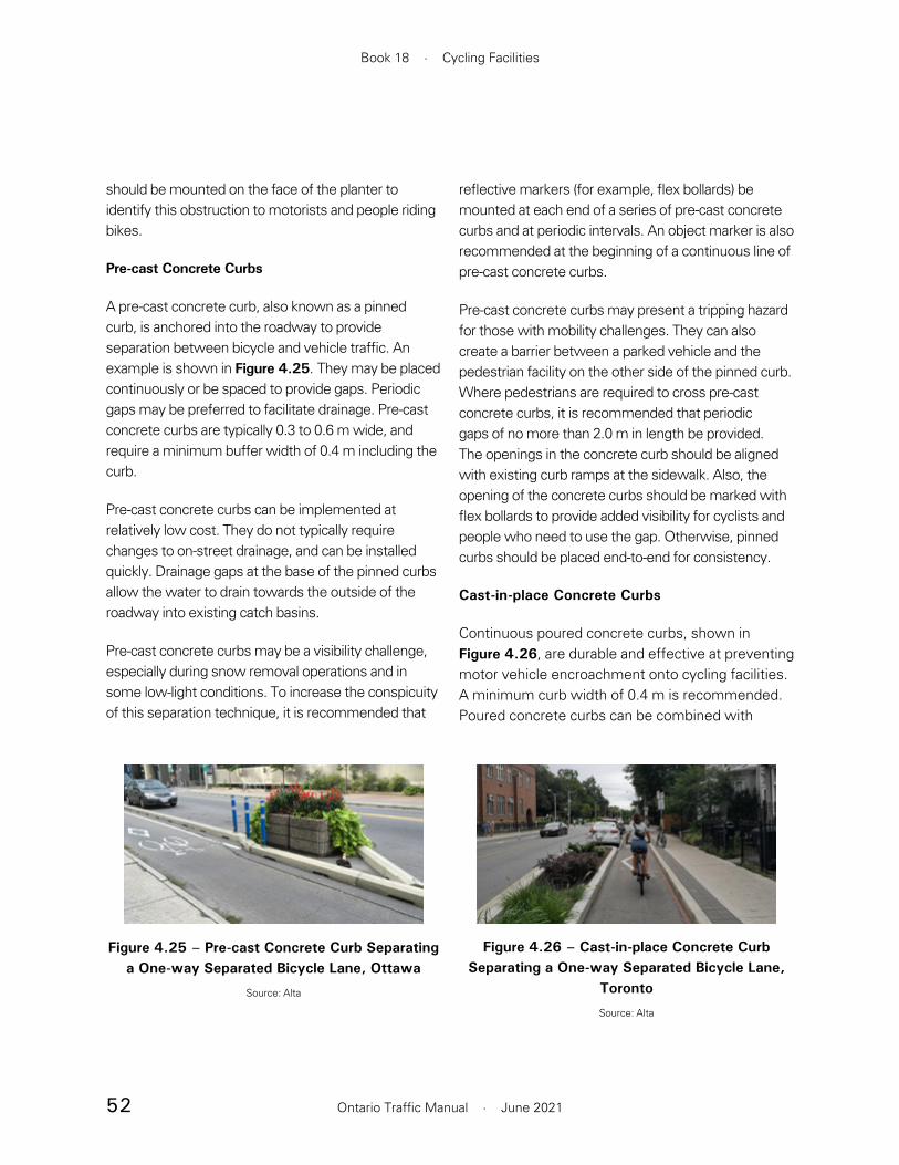
52
Book 18 · Cycling Facilities
Ontario Traffic Manual · June 2021
should be mounted on the face of the planter to identify this obstruction to motorists and people riding bikes.
Pre-cast Concrete Curbs
A pre-cast concrete curb, also known as a pinned curb, is anchored into the roadway to provide separation between bicycle and vehicle traffic. An example is shown in Figure 4.25. They may be placed continuously or be spaced to provide gaps. Periodic gaps may be preferred to facilitate drainage. Pre-cast concrete curbs are typically 0.3 to 0.6 m wide, and require a minimum buffer width of 0.4 m including the curb.
Pre-cast concrete curbs can be implemented at relatively low cost. They do not typically require changes to on-street drainage, and can be installed quickly. Drainage gaps at the base of the pinned curbs allow the water to drain towards the outside of the roadway into existing catch basins.
Pre-cast concrete curbs may be a visibility challenge, especially during snow removal operations and in some low-light conditions. To increase the conspicuity of this separation technique, it is recommended that
reflective markers (for example, flex bollards) be mounted at each end of a series of pre-cast concrete curbs and at periodic intervals. An object marker is also recommended at the beginning of a continuous line of pre-cast concrete curbs.
Pre-cast concrete curbs may present a tripping hazard for those with mobility challenges. They can also create a barrier between a parked vehicle and the pedestrian facility on the other side of the pinned curb. Where pedestrians are required to cross pre-cast concrete curbs, it is recommended that periodic gaps of no more than 2.0 m in length be provided. The openings in the concrete curb should be aligned with existing curb ramps at the sidewalk. Also, the opening of the concrete curbs should be marked with flex bollards to provide added visibility for cyclists and people who need to use the gap. Otherwise, pinned curbs should be placed end-to-end for consistency.
Cast-in-place Concrete Curbs
Continuous poured concrete curbs, shown in Figure 4.26, are durable and effective at preventing motor vehicle encroachment onto cycling facilities. A minimum curb width of 0.4 m is recommended. Poured concrete curbs can be combined with
Figure 4.25 – Pre-cast Concrete Curb Separating a One-way Separated Bicycle Lane, Ottawa
Source: Alta
Figure 4.26 – Cast-in-place Concrete Curb Separating a One-way Separated Bicycle Lane,
Toronto
Source: Alta

53
Section 4 · Cycling Facilities
Ontario Traffic Manual · June 2021
other forms of separation to provide extra durability where damage or strikes from motor vehicles are more likely, such as at intersection approaches.
Concrete curbs require extra consideration for drainage, since they are not permeable like other separation techniques. They also should be clearly marked with reflective markers (for example, flex bollards) to increase visibility. An object marker is also recommended at the beginning of a continuous line of cast-in-place concrete curbs. If it is intended that a sign be mounted on a curb, the curb should be wide enough to accommodate the sign without it posing an obstacle to road users on either side.
Curbs higher than 50 mm narrow the effective width of the bicycle lane, since they present a pedal strike hazard for people riding bikes. To mitigate this risk, practitioners may consider implementing a bevelled or mountable curb adjacent to the cycling facility.
Rubber Curbs
A rubber curb, illustrated in Figure 4.27, is a short polymer curb anchored into the roadway. The minimum buffer width for this treatment is 0.4 m.
Similar to flex bollards, rubber curbs are low-cost and easy to install and remove. They provide more deterrence to motor vehicle encroachment than flex bollards.
While they can be easily traversed by an able-bodied person, rubber curbs may be a tripping hazard. They may require frequent repair or replacement, which can result in higher operating costs. They also have poor visibility in snow. Where rubber curbs are implemented, it is recommended that flex bollards be added to improve their visibility. An object marker is also recommended at the beginning of a continuous line of rubber curbs.
Concrete Barriers
Low-wall concrete barriers, shown in Figure 4.28, can be used as a continuous vertical separation, or implemented with gaps as needed. The height is typically 0.5 m, and the minimum buffer width to accommodate the barrier is 1.0 m. Low-wall concrete barriers are most suitable for higher speed and volume roads with less frequent intersections and driveways. To increase the visibility of low-wall barriers, reflective markers should be installed on top of the barrier, at each end of a series of barriers and at frequent
Figure 4.27 – Rubber Curb Separating a Two-way Separated Bicycle Lane, Hamilton
Source: Alta
Figure 4.28 – Low Wall Concrete Barriers Separating a Two-way Separated Bicycle Lane,
Toronto
Source: WSP

54
Book 18 · Cycling Facilities
Ontario Traffic Manual · June 2021
intervals. An object marker is also recommended at the beginning of a continuous line of concrete barriers.
Standard height concrete barriers provide a higher level of crash protection for cyclists; however, they may not completely prevent encroachment into bicycle facilities. They also do not prevent cyclists from falling over the barrier unless they are 1.37 m or greater in height. This is typically not required when implemented as a bicycle lane separator. Barriers of this height can obstruct the visibility of smaller cyclists and of motorists turning into and out of driveways. They also have a low aesthetic appeal, except when used as a canvas for public art, and introduce an impassable barrier for all pedestrians, regardless of ability.
Special attention to drainage is needed. End treatments or crash cushions may be required to protect against the potential hazard of a head-on collision with the end of the barrier.
Guide Rail
A highway guide rail, shown in Figure 4.29, is typically installed with very infrequent gaps. The minimum buffer required is 1.0 m, and the cycling facility should
be offset by a minimum 0.6 m from the guide rail, demarcated by a solid edge line.
Guide rails are effective at preventing motor vehicle encroachment and are durable, but they have a low aesthetic appeal and more prone to damage than concrete. Solid concrete barriers or other separation treatments are typically preferred over breakaway barriers such as a guide rail.
It is strongly recommended that rails be applied to both sides of the guide rail to avoid exposing people riding bikes to sharp edges, and that end treatments be provided to mitigate the hazard at the ends.
Mountable/Semi-Mountable Curb
Mountable curbs, also referred to as rolled curbs, vertically distinguish the bicycle facility from vehicle lanes while allowing people riding bikes to move comfortably between the two. An example is shown in Figure 4.30. A bicycle facility separated by a mountable curb is considered a cycle track . Refer to Section 4.3.3 for guidance.
Curbs can either be fully mountable or semi-mountable. Refer to Section 4.3.1.7 for more guidance on appropriate selection of curb type.
Figure 4.29 – Guide Rail Protecting a Two-way Physically Separated Bicycle Lane, Toronto
Source: Alta
Figure 4.30 – Mountable Curb Separating a One-way Cycle Track, Toronto
Source: WSP
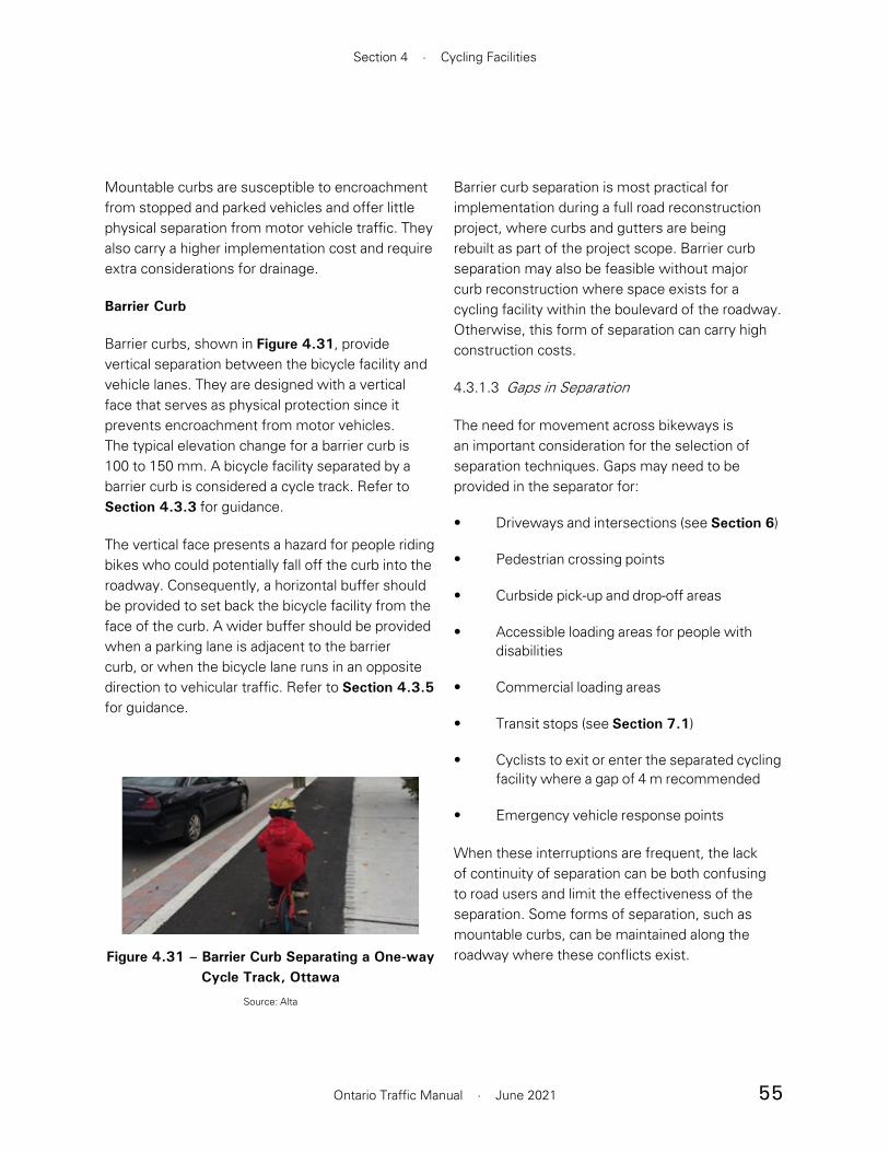
55
Section 4 · Cycling Facilities
Ontario Traffic Manual · June 2021
Mountable curbs are susceptible to encroachment from stopped and parked vehicles and offer little physical separation from motor vehicle traffic. They also carry a higher implementation cost and require extra considerations for drainage.
Barrier Curb
Barrier curbs, shown in Figure 4.31, provide vertical separation between the bicycle facility and vehicle lanes. They are designed with a vertical face that serves as physical protection since it prevents encroachment from motor vehicles. The typical elevation change for a barrier curb is 100 to 150 mm. A bicycle facility separated by a barrier curb is considered a cycle track. Refer to Section 4.3.3 for guidance.
The vertical face presents a hazard for people riding bikes who could potentially fall off the curb into the roadway. Consequently, a horizontal buffer should be provided to set back the bicycle facility from the face of the curb. A wider buffer should be provided when a parking lane is adjacent to the barrier curb, or when the bicycle lane runs in an opposite direction to vehicular traffic. Refer to Section 4.3.5 for guidance.
Barrier curb separation is most practical for implementation during a full road reconstruction project, where curbs and gutters are being rebuilt as part of the project scope. Barrier curb separation may also be feasible without major curb reconstruction where space exists for a cycling facility within the boulevard of the roadway. Otherwise, this form of separation can carry high construction costs.
4.3.1.3 Gaps in Separation
The need for movement across bikeways is an important consideration for the selection of separation techniques. Gaps may need to be provided in the separator for:
• Driveways and intersections (see Section 6)
• Pedestrian crossing points
• Curbside pick-up and drop-off areas
• Accessible loading areas for people with disabilities
• Commercial loading areas
• Transit stops (see Section 7.1)
• Cyclists to exit or enter the separated cycling facility where a gap of 4 m recommended
• Emergency vehicle response points
When these interruptions are frequent, the lack of continuity of separation can be both confusing to road users and limit the effectiveness of the separation. Some forms of separation, such as mountable curbs, can be maintained along the roadway where these conflicts exist.Figure 4.31 – Barrier Curb Separating a One-way
Cycle Track, Ottawa
Source: Alta

56
Book 18 · Cycling Facilities
Ontario Traffic Manual · June 2021
4.3.1.4 Drainage
During the design of physically separated bikeways, it is important to understand the drainage implications, to manage the risk of water pooling, which could result in ice formation and hydroplaning. When separation introduces a continuous barrier between the cycling facility and roadway, modifications to roadway drainage will need to be investigated. During the development of the drainage solution, the designer should be aware of the cross-slope of the facility. Drainage in the wrong direction or a steep cross-slope are common issues when retrofitting a raised cycle track onto an existing road. Cross slopes should not exceed 4% for an asphalt surface or 2% for a concrete surface.
Many separation options do not require any alteration of the existing roadway drainage. Flexible bollards, planters, parked motor vehicles and pre-cast curbs with drainage gaps may typically be installed without introducing any drainage challenges.
Three drainage options for a separated facility are shown in Figure 4.32:
1. The cycling facility is continuously separated and slopes toward the roadway, where a single catch basin provides drainage.
2. The cycling facility is continuously separated and slopes away from the roadway. Dual catch basins are required.
3. The cycling facility is not continuously separated and slopes toward the roadway. A single catch basin placed in a gap in the separator provides drainage.
4.3.1.5 Maintenance
Some forms of separation are more vulnerable to damage, wear, or the accumulation of debris over time. Separation techniques requiring pavement markings require frequent renewal. Flex bollards also require an ongoing replacement effort as they are easily damaged or destroyed by motor vehicles and snowplows. Practitioners should consider replacement costs as part of the overall financial
Figure 4.32 – Drainage Options for a Physically Separated Bikeway or Cycle Track
Image Source: MassDOT Separated Bike Lane Planning and Design Guide, 2015

57
Section 4 · Cycling Facilities
Ontario Traffic Manual · June 2021
assessment of the separation technique being considered.
To accommodate street sweepers and plows, municipalities may require a certain minimum width for the physically separated bikeway. Practitioners should work with maintenance staff to understand the operating requirements of existing equipment.
Practitioners should give consideration to winter maintenance when selecting a separation type. Regular plowing techniques can damage separation techniques such as flex bollards. Physically separated bikeways may require the use of specialized snow removal equipment. More information on winter maintenance considerations can be found in Section 10.3.
4.3.1.6 Permeability
Some road environments in which cycling facilities operate have a high volume of pedestrian activity. Pedestrians may frequently cross cycling facilities to access parked vehicles or to cross the street. Practitioners should take this into consideration, and ensure that where high pedestrian activity is anticipated, the separation treatment selected is designed considering accessibility and AODA requirements, and can be conveniently and as safely as possible traversed by pedestrians.
4.3.1.7 Types of Curbs
Depending on the separation technique used, curbs can be placed between the motor vehicle lanes and the bikeway, between the sidewalk and bikeway, or both. Practitioners should consider the need for and likelihood of movement of different road users between these facilities when selecting a curb type.
For example, cyclists may need to easily exit the bicycle facility to access bicycle parking in the sidewalk area. If cyclists must cross a barrier curb to reach the parking, people using bikes as a mobility aid will not easily be able to access it, so parking should only be installed where there is no barrier curb.
A variety of curb types exist to support the design of curb-separated facilities. Barrier curbs strictly prevent movement between the bicycle facility and the roadway. While this is helpful in preventing motor vehicle encroachment, it can pose a challenge to people riding bikes by preventing them from exiting the facility. It also introduces a potential hazard when cyclists accidentally fall off of the curb.
Curb height is an important consideration as well. When a bikeway is delineated by a vertical barrier curb more than 50 mm in height, it is a pedal-striking hazard and cyclists are likely to travel further from the curb, reducing the effective width of the bicycle facility.
Curb options include:
• Barrier: a vertical faced curb, designed to prevent any movement across the curb by motor vehicles and people riding bikes
• Semi-mountable: at a 1:1 slope ratio, semi-mountable curbs reduce the pedal-strike hazard for cyclists, and allow cyclists to more easily enter and exit the bicycle facility
• Fully Mountable: at a slope ratio of up to 1:4, mountable curbs can be easily traversed by both motor vehicles and people riding bikes.
Refer to the Ontario Provincial Standard Drawings 600.010 to 600.070 for design details of barrier, semi-mountable and mountable curbs, with variations for wide and narrow gutters.

58
Book 18 · Cycling Facilities
Ontario Traffic Manual · June 2021
4.3.2 Physically Separated Bicycle Lanes
A physically separated bicycle lane is a portion of a roadway which has been designated for the exclusive use of people riding bikes. It is separated from adjacent motor vehicle lanes by a horizontal buffer plus vertical elements within the buffer such as flex bollards or a barrier curb. The buffer restricts encroachment of traffic, creating a more secure and comfortable environment for cyclists. Physical separation techniques are detailed in Section 4.3.1 This facility type can be configured for one-way or two-way bicycle travel.
Physically separated bicycle lanes are suitable for roadways with moderate to high motor vehicle speeds and volumes. The added lateral and physical separation of lanes provides most cyclists with a more comfortable riding environment than shared roadways or conventional bicycle lanes.
Examples of physically separated bicycle lanes are shown in Figure 4.33.
Prior to initiating design work on a given link, practitioners should refer to the Facility Selection Process in Section 5. This will confirm whether physically separated bicycle lanes are the most suitable facility type and identify key design considerations.
4.3.2.1 Geometry
The recommended and suggested minimum widths for one-way and two-way physically separated bicycle lanes are shown in Table 4.3.
Where practitioners are considering designing the width of either the bicycle lane or the buffer to less than the desired width, they should give careful consideration to the effective unobstructed width available. The width requirements for street sweeper vehicles are typically 1.8 m. There are
Two-Way Bicycle Lane Separated by Cast-in-place
Concrete Curb, Toronto
Source: WSP
Two-Way Bicycle Lane Separated by Flex Bollards,
Hamilton
Source: Alta
Figure 4.33 – Examples of Physically Separated Bicycle Lanes
Bicycle Lane Separated by Flex Bollards and Planters, Toronto
Source: Alta
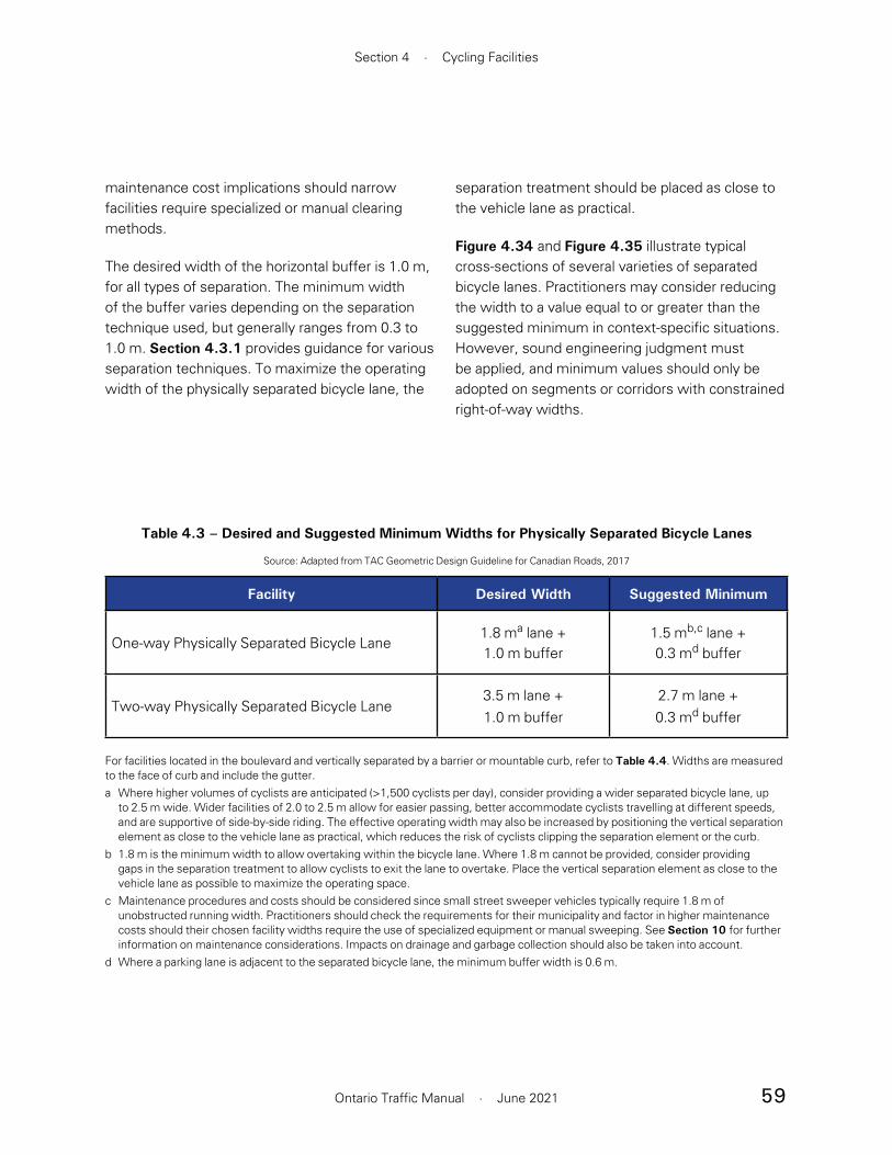
59
Section 4 · Cycling Facilities
Ontario Traffic Manual · June 2021
Table 4.3 – Desired and Suggested Minimum Widths for Physically Separated Bicycle Lanes
Source: Adapted from TAC Geometric Design Guideline for Canadian Roads, 2017
Facility Desired Width Suggested Minimum
One-way Physically Separated Bicycle Lane1.8 ma lane +1.0 m buffer
1.5 mb,c lane +0.3 md buffer
Two-way Physically Separated Bicycle Lane3.5 m lane +1.0 m buffer
2.7 m lane +0.3 md buffer
For facilities located in the boulevard and vertically separated by a barrier or mountable curb, refer to Table 4.4. Widths are measured to the face of curb and include the gutter.a Where higher volumes of cyclists are anticipated (>1,500 cyclists per day), consider providing a wider separated bicycle lane, up
to 2.5 m wide. Wider facilities of 2.0 to 2.5 m allow for easier passing, better accommodate cyclists travelling at different speeds, and are supportive of side-by-side riding. The effective operating width may also be increased by positioning the vertical separation element as close to the vehicle lane as practical, which reduces the risk of cyclists clipping the separation element or the curb.
b 1.8 m is the minimum width to allow overtaking within the bicycle lane. Where 1.8 m cannot be provided, consider providing gaps in the separation treatment to allow cyclists to exit the lane to overtake. Place the vertical separation element as close to the vehicle lane as possible to maximize the operating space.
c Maintenance procedures and costs should be considered since small street sweeper vehicles typically require 1.8 m of unobstructed running width. Practitioners should check the requirements for their municipality and factor in higher maintenance costs should their chosen facility widths require the use of specialized equipment or manual sweeping. See Section 10 for further information on maintenance considerations. Impacts on drainage and garbage collection should also be taken into account.
d Where a parking lane is adjacent to the separated bicycle lane, the minimum buffer width is 0.6 m.
maintenance cost implications should narrow facilities require specialized or manual clearing methods.
The desired width of the horizontal buffer is 1.0 m, for all types of separation. The minimum width of the buffer varies depending on the separation technique used, but generally ranges from 0.3 to 1.0 m. Section 4.3.1 provides guidance for various separation techniques. To maximize the operating width of the physically separated bicycle lane, the
separation treatment should be placed as close to the vehicle lane as practical.
Figure 4.34 and Figure 4.35 illustrate typical cross-sections of several varieties of separated bicycle lanes. Practitioners may consider reducing the width to a value equal to or greater than the suggested minimum in context-specific situations. However, sound engineering judgment must be applied, and minimum values should only be adopted on segments or corridors with constrained right-of-way widths.

60
Book 18 · Cycling Facilities
Ontario Traffic Manual · June 2021
Figure 4.34 – Cross-Section of One-Way Physically Separated Bicycle Lanes
Sidewalk SidewalkVehicle
LaneVehicle
LaneParking
Lane BufferBufferBicycleLane
BicycleLane
1.8 m1.8 m 1.0 m 1.0 m
Figure 4.35 – Cross-Section of Two-Way Physically Separated Bicycle Lane
SidewalkVehicle
LaneVehicle
LaneTwo-way
Bicycle Lane
3.5 m1.0 m
SidewalkBuffer

61
Section 4 · Cycling Facilities
Ontario Traffic Manual · June 2021
Unlike one-way facilities, which should be provided on each side of the roadway, two-way facilities may be located on one side only. Compared to two one-way lanes, two-way facilities may offer some savings in terms of installation cost. Restrictions associated with maintenance vehicle operating widths are also reduced. However, as stated at the beginning of Section 4.3, two-way facilities often result in additional complexity at intersections and at transitions between facility types. Two-way facilities also lead to considerably greater conflicts with turning motor vehicles at intersections.
4.3.2.2 Signs and Pavement Markings
Signage and pavement markings used for physically separated bicycle lanes typically include:
• Reserved Bicycle Lane sign (Rb-84A or Rb-84 OTM)
• Reserved Bicycle Lane Ahead sign (WB-10 TAC)
• Turning Vehicles Yield to Bicycles sign (Ra-18 OTM)
• Object Marker sign (Wa-33 OTM)
• Bicycle Lane Pavement Marking, with optional directional arrow
• Yellow Centreline (for two-way facilities)
• Painted Buffer Strip
Refer to Section 4.2 for illustrations and information on proper use of signs and pavement markings.
4.3.2.3 Design Applications
One-way Physically Separated Bicycle Lanes
Figure 4.37 illustrates the typical signage and design for a one-way physically separated bicycle lane on a roadway with a parking lane on one side. In the westbound direction, flex bollards are used as the separation technique. In the eastbound direction, flex bollards are used in combination with a parking lane to separate the bicycle lane from traffic. Flex bollards supplement a parking lane as a separation technique by preventing motorists from accidentally parking in the bicycle lane.
Where on-street parking is present, physically separated bicycle lanes should usually be positioned between the parking lane and the curb. However, parked vehicles represent sightline obstructions, and it is critical that sufficient clear sight distance be provided at intersections and driveways (see Table 6.1). On streets with low parking turnover and frequent driveways, a buffered bicycle lane between the parking lane and the vehicle lane (see Section 4.4.2) may be appropriate.
Where higher volumes of bicycle traffic are expected, a wider 2.0 to 2.5 m facility is recommended to facilitate easier passing, to better accommodate cyclists travelling at different speeds and to support side-by-side riding. The effective width of the facility may also be maximized by positioning vertical separation elements within the buffer as close to the vehicle travel lane as possible. Volume thresholds may vary depending on the municipality and the local context, but a high volume is generally considered to be greater than 1,500 cyclists per day.
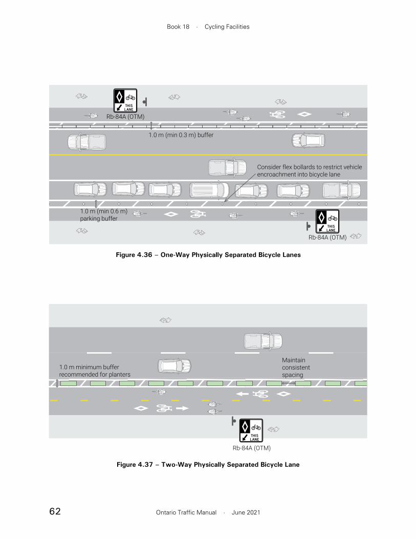
62
Book 18 · Cycling Facilities
Ontario Traffic Manual · June 2021
STANDARD CROSS SECTIONSAME SCALE FOR WIDTH (250:1)SECTION ELEMENT HEIGHT: 0.8CM HIGH(SIDEWALK 0.9CM HIGH)
1.0 m (min 0.3 m) buffer
Consider flex bollards to restrict vehicleencroachment into bicycle lane
Rb-84A (OTM)
Rb-84A (OTM)
1.0 m (min 0.6 m)parking buffer
Figure 4.36 – One-Way Physically Separated Bicycle Lanes
STANDARD CROSS SECTIONSAME SCALE FOR WIDTH (250:1)SECTION ELEMENT HEIGHT: 0.8CM HIGH(SIDEWALK 0.9CM HIGH)
Rb-84A (OTM)
1.0 m minimum bufferrecommended for planters
Maintainconsistentspacing
Figure 4.37 – Two-Way Physically Separated Bicycle Lane

63
Section 4 · Cycling Facilities
Ontario Traffic Manual · June 2021
Two-way Physically Separated Bicycle Lanes
Figure 4.37 illustrates the typical signage and design for a two-way physically separated bicycle lane on a one-way roadway, with a parking lane on one side. When a two-way facility is configured such that contraflow cyclists ride adjacent to oncoming traffic, the minimum recommended buffer width is 0.6 m. Otherwise, the guidance for buffer selection and width for a two-way facility is the same as for a one-way physically separated bicycle lane.
On one-way streets with transit service, it may be advantageous to place a two-way separated facility on the left side of the street to avoid conflicts at transit stops.
Two-way facilities present additional design challenges and increase conflicts at driveways and intersections. For guidance on the appropriate use of two-way facilities, refer to Section 4.3.
4.3.3 Cycle Tracks
Cycle tracks are a physically separated bikeway that is horizontally and vertically separated from the travelled portion of the roadway by a curb plus a horizontal buffer. Cycle tracks often travel parallel to the sidewalk but are designated exclusively for use by people riding bikes. They may be at the same level as the sidewalk, or at an intermediate level between the roadway and sidewalk. Cycle tracks may be placed in the boulevard adjacent to or setback from the curb. Green infrastructure or a furnishing zone may be placed where space is available between the cycle track and the roadway or the cycle track and the sidewalk.
Cycle tracks can be used to accommodate a wide range of bicycle types and users. They are typically suitable for roadways with moderate to high motor vehicle speeds and volumes.
Cycle tracks can carry one-way or two-way bicycle traffic. The selection of one-way or two-way facilities is context sensitive and guidance is provided in Section 4.3.
Cycle track design should enable two-way travel for cyclists within a corridor by providing either:
• One-way cycle tracks on each side of the roadway
• A two-way cycle track on one or both sides of the roadway
• Opposite one-way cycle tracks on adjacent streets (couplet or one-way pair)
Prior to initiating design work on a given link, practitioners should refer to the Bicycle Facility Type Selection process in Section 5. This will confirm whether cycle tracks are the most suitable
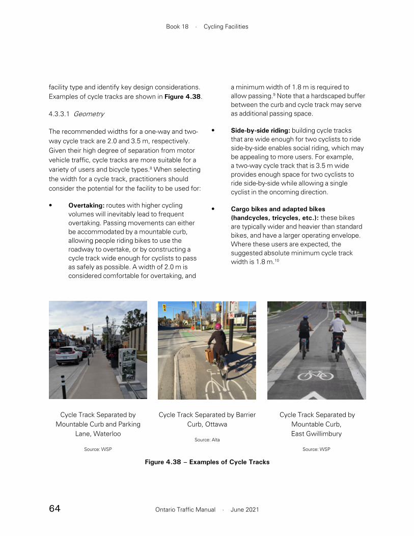
64
Book 18 · Cycling Facilities
Ontario Traffic Manual · June 2021
facility type and identify key design considerations. Examples of cycle tracks are shown in Figure 4.38.
4.3.3.1 Geometry
The recommended widths for a one-way and two-way cycle track are 2.0 and 3.5 m, respectively. Given their high degree of separation from motor vehicle traffic, cycle tracks are more suitable for a variety of users and bicycle types.8 When selecting the width for a cycle track, practitioners should consider the potential for the facility to be used for:
• Overtaking: routes with higher cycling volumes will inevitably lead to frequent overtaking. Passing movements can either be accommodated by a mountable curb, allowing people riding bikes to use the roadway to overtake, or by constructing a cycle track wide enough for cyclists to pass as safely as possible. A width of 2.0 m is considered comfortable for overtaking, and
a minimum width of 1.8 m is required to allow passing.9 Note that a hardscaped buffer between the curb and cycle track may serve as additional passing space.
• Side-by-side riding: building cycle tracks that are wide enough for two cyclists to ride side-by-side enables social riding, which may be appealing to more users. For example, a two-way cycle track that is 3.5 m wide provides enough space for two cyclists to ride side-by-side while allowing a single cyclist in the oncoming direction.
• Cargo bikes and adapted bikes (handcycles, tricycles, etc.): these bikes are typically wider and heavier than standard bikes, and have a larger operating envelope. Where these users are expected, the suggested absolute minimum cycle track width is 1.8 m.10
Cycle Track Separated by Mountable Curb and Parking
Lane, Waterloo
Source: WSP
Cycle Track Separated by Barrier Curb, Ottawa
Source: Alta
Figure 4.38 – Examples of Cycle Tracks
Cycle Track Separated by Mountable Curb, East Gwillimbury
Source: WSP

65
Section 4 · Cycling Facilities
Ontario Traffic Manual · June 2021
Cycle tracks should be separated from the roadway by a horizontal buffer. Guidance on the design of the buffer is provided in Section 4.3.5.
4.3.3.2 Separation Between Cycle Track and Sidewalk
Where cycling facilities such as cycle tracks are designed adjacent to pedestrian walkways, it is important to consider accessibility and coordinate with AODA requirements. Providing effective separation that is cane and visually detectable can improve safety and clarify paths of travel for all users. This can be done through adequate colour and texture contrast.
For installations where the sidewalk and the cycle track are similar in colour and texture, or will become similar with time and weathering, careful
• Electric bikes and kick style e-scooters: if permitted in cycle tracks, e-bikes and e-scooters have a higher rate of acceleration and operating speed and may result in more overtaking movements
The likely (or desired) presence of any of these user or bicycle types should lead the practitioner to consider selecting a wider cycle track. Wider cycle tracks of up to 2.5 m should be considered on facilities with high volumes of bicycle traffic, where passing movements are expected to be frequent, or where side-by-side riding is desired.11
Table 4.4 presents the desired and suggested minimum widths for one-way and two-way cycle tracks. Typical cross-sections of one-way and two-way cycle tracks are shown in Figure 4.39 and Figure 4.40, respectively.
Table 4.4 – Desired and Suggested Minimum Widths for Cycle Tracks
Source: Based on information from the TAC Geometric Design Guideline for Canadian Roads, 2017, and the NACTO Urban Bikeway Design Guide, 2014
Facility Desired Width Suggested Minimum
One-way Cycle Track 2.0 – 2.5 m a 1.5 m b,c
Two-way Cycle Track 3.5 – 4.0 m a 3.0 m c
Facility widths are exclusive of the horizontal buffer between the facility and the roadway. For guidance on buffer width, refer to Section 4.3.5.a Wider cycle tracks (2.5 m for one-way facilities, or 4.0 m for two-way facilities) may be desired on facilities with high volumes
of bicycle traffic (>1,500 cyclists/day), where passing movements are expected to be frequent or where side-by-side riding is desirable.
b Maintenance procedures and costs should be considered since small street sweeper vehicles typically require 1.8 m of unobstructed running width. Practitioners should confirm the requirements for their municipality and factor in higher maintenance costs should their chosen facility widths require the use of specialized equipment or manual sweeping. See Section 10 for further information on maintenance considerations.
c Width may be reduced to 1.2 m (for one-way) or 2.4 m (for two-way) over very short distances, in constrained areas or in complex circumstances, to avoid utility poles or other infrastructure that may be costly to relocate.
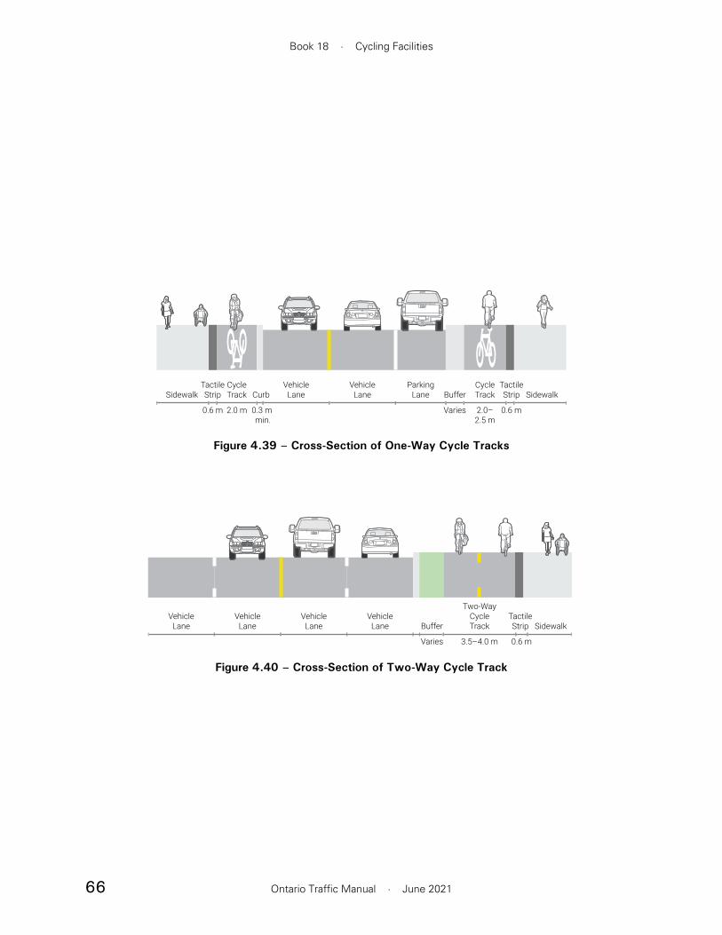
66
Book 18 · Cycling Facilities
Ontario Traffic Manual · June 2021
2.0 m0.6 m 2.0–2.5 m
0.3 m min.
0.6 mVaries
Sidewalk SidewalkBufferVehicle
LaneVehicle
LaneParking
LaneCycleTrack
CycleTrack
TactileStrip
TactileStrip Curb
Figure 4.39 – Cross-Section of One-Way Cycle Tracks
Figure 4.40 – Cross-Section of Two-Way Cycle Track
3.5–4.0 mVaries 0.6 m
VehicleLane
VehicleLane
VehicleLane
VehicleLane
Two-WayCycleTrack SidewalkBuffer
TactileStrip

67
Section 4 · Cycling Facilities
Ontario Traffic Manual · June 2021
consideration should be made in determining a separation treatment and surface material. Using asphalt for cycling facilities and concrete for pedestrian facilities is an example of a practical strategy to consistently communicate intended use of space.
A variety of design tools can be employed to separate pedestrian and cycling spaces, as shown in Figure 4.41:
• Cane-detectable curb between pedestrians and cyclists: If there is an elevation difference between the sidewalk and cycle track, a bevelled curb is recommended to reduce the risk of a tripping hazard and pedal strikes, and to provide an accessible route across the cycle track. A 50 mm high and 150 mm wide bevelled curb is detectable by people with vision impairments using a cane
and also minimizes the hazard for wheelchair users.
• Continuous detectable tactile buffer strip: Where the sidewalk and cycle track are adjacent and at the same elevation, a continuous cane-detectable and visually contrasting buffer strip should be provided. The recommended width of the buffer is 0.6 m. A narrower buffer may be used in constrained areas, or be eliminated if necessary. The preference is no overlap of the buffer strip with the pedestrian clear width and/or cycling operating space. However, in constrained areas this may also be considered. The buffer may be implemented with stamped, patterned or coloured concrete, textured unit pavers, truncated domes or other methods. If unit pavers are used, they should be installed
Continuous Detectable Tactile Buffer Strip, Vaughan
Source: WSP
Detectable Curb Separation, Toronto
Source: Alta
Furnishing Zone Separation, Waterloo
Source: Alta
Figure 4.41 – Separation Between Cycle Track and Sidewalk

68
Book 18 · Cycling Facilities
Ontario Traffic Manual · June 2021
1.0 m splash strip, to protect people riding bikes from the hazard of opening motor vehicle doors.
Practitioners should ensure that the cycle track is distinct from the adjacent sidewalk, using one or more of the techniques discussed in this section.
A mountable curb should not be used when there is a parking lane on the roadway since it may cause motorists to accidentally park in the cycle track.
Two-way Cycle Track in the Boulevard
Figure 4.43 illustrates the typical signage and design for a two-way cycle track in the boulevard of a multi-lane roadway. A wide grassy median is used to separate the cycle track from the roadway, improving comfort and providing additional space for utilities, poles, signs, landscaping elements and snow storage.
with care to minimize potential tripping hazards due to differential settlement.
• Landscaping or street furniture separation between facilities: These features can include street trees, planting strips or bike share docking stations. A preferred lateral clearance of 0.5 m should be provided between these features and the cycling facility (see Section 7.3). Railings may be considered in specific locations where pedestrian encroachment into cycling facilities is a concern.
4.3.3.3 Signs and Pavement Markings
Signage and pavement markings used for cycle tracks typically includes:
• Bicycle lane pavement markings, with optional directional arrow. The reserved lane diamond is not required for cycle tracks.
• Yellow centreline (for two-way cycle tracks)
Since cycle tracks are placed in the boulevard of the roadway, Reserved Bicycle Lane signs (Rb-84A OTM) are not required. Refer to Section 4.2 for illustrations and information on the proper use of signs and pavement markings.
4.3.3.4 Design Applications
One-way Cycle Tracks
Figure 4.42 illustrates the typical signage and design for one-way cycle tracks on a two-way roadway. On the westbound side, the cycle track is separated from the roadway by a mountable curb and a 0.3 m paved “splash strip”. On the eastbound side, a parking lane is present, and the cycle track is separated by a barrier curb plus a

69
Section 4 · Cycling Facilities
Ontario Traffic Manual · June 2021
Figure 4.43 – Two-Way Cycle Tracks
Where minimum recommended separation width cannot be met, consider implementing a fence, railing or barrier
Minimum recommended lateral separation varies, refer to Table 4.6
0.3 m minimum widthfor mountable curbseparation
1.0 m bufferbehind curb
Figure 4.42 – One-Way Cycle Tracks
Note: A pedestrian facility may be added, or the cycle track could be converted to a multi-use path

70
Book 18 · Cycling Facilities
Ontario Traffic Manual · June 2021
Where the volume of path users is high, mixing of pedestrians and cyclists leads to significant conflict between users, creating uncomfortable and potentially hazardous conditions. This is more likely to occur in higher-volume pedestrian areas, such as near transit stops and stations, through shopping areas or along scenic routes. The TAC Geometric Design Guide for Canadian Roads (2017) suggests separating pedestrians and cyclists where there is:
• More than 20% of path users are pedestrians and total user volumes greater than 33 persons per hour per metre of path width, or
• Less than 20% of path users are pedestrians but total user volumes are greater than 50 persons per hour per metre of path width
The choice of a shared multi-use path or a separate sidewalk and cycle track is context dependent. Relevant factors should be reviewed such as available width, pedestrian/cyclist mode
4.3.4 In-Boulevard Multi-use Path
An in-boulevard multi-use path is horizontally and vertically separated from motor vehicle traffic by a curb and a strip of grass which is often referred to as a “boulevard”, or paved “splash strip” within the roadway or highway right-of-way. This facility type provides two-way travel, is shared between people riding bikes and pedestrians, and is suitable for roadways with moderate to high traffic volumes and speeds. Examples of multi-use paths are shown in Figure 4.44.
In-boulevard multi-use paths are distinct from multi-use trails, which run in a dedicated corridor separate from the road right-of-way. Design guidance for multi-use trails is not included in this guide; refer to the MTO Bikeway Design Manual or your local municipal trail design guidelines for guidance.
Multi-Use Path Separated by Grassy Boulevard, Waterloo
Source: Alta
Multi-Use Path Separated by Grassy Boulevard, Richmond Hill
Source: WSP
Figure 4.44 – Examples of In-Boulevard Multi-Use Paths
Multi-Use Path Separated by Grassy Boulevard, Newmarket
Source: WSP
71
Section 4 · Cycling Facilities
Ontario Traffic Manual · June 2021
• Shared Pathway sign (Rb-71 OTM)
• Pathway Organization sign (Rb-72A or Rb-72B OTM)
• Yield to Pedestrians sign (Ra-16 OTM)
• Pedestrian and Bicycle Crossing Ahead sign (Wc-14 OTM)
• In-Boulevard Multi-Use Path pavement markings (Refer to Section )
Refer to Section 4.2 for illustrations and information on proper use of signs and pavement markings.
4.3.4.3 Design Applications
In-Boulevard Multi-Use Path along Major Roadway
The desired buffer width for multi-use pathways varies based on the operating environment. Refer to Section 4.3.5 for guidance on desired buffer widths. When the desired separation distance cannot be provided, consider providing a fence, barrier or other form of physical separation, set back a minimum of 0.5 m from the edge of the multi-use path, or 0.3 m in constrained areas.
Though the multi-use path operates in the boulevard of the roadway, it does not need to follow the exact geometric alignment of the roadway. For example, the path can be routed around significant obstacles, or the grade can be levelled to facilitate more comfortable riding conditions.
split, directional splits, time-of-day variations and geometry to evaluate if providing separate pedestrian and cycling facilities should be considered. Guidance for the design of cycle tracks, including treatments for adjacent cycle tracks and sidewalks, is provided in Section 4.3.3.
Prior to initiating design work on a given link, practitioners should refer to the Facility Selection Process in Section 5. This will confirm whether an in-boulevard multi-use path is the most suitable facility type and to identify key design considerations.
4.3.4.1 Geometry
An in-boulevard multi-use path is located outside the travelled portion of the roadway and does not necessarily follow its geometric design. Practitioners should consider several geometric elements including the width, design speed, grade, stopping sight distance, horizontal curvature, crest vertical curves and lateral clear zones. Refer to the TAC Geometric Design Guide for Canadian Roads (2017) for guidance on the alignment of in-boulevard multi-use paths.
Table 4.5 presents the desired and minimum widths for in-boulevard multi-use paths, based on the desired operating condition and anticipated user volume. Figure 4.45 shows a typical cross-section.
Multi-use paths should be separated from the roadway by a horizontal buffer. Guidance on the design of the buffer is provided in Section 4.3.5.
4.3.4.2 Signs and Pavement Markings
Signage and pavement markings used for in-boulevard multi-use paths typically includes:

72
Book 18 · Cycling Facilities
Ontario Traffic Manual · June 2021
Figure 4.45 – Cross-Section of In-Boulevard Multi-Use Path
VehicleLane
VehicleLane
VehicleLane
VehicleLane
3.0–4.0+ mVaries
Multi-UsePathBuffer
Table 4.5 – Desired and Suggested Minimum Widths for In-Boulevard Multi-Use Paths
Source: Based on information from the TAC Geometric Design Guideline for Canadian Roads, 2017, and the NACTO Urban Bikeway Design Guide, 2014
Design Condition Desired Width Suggested Minimum
Low-to-moderate volume path (< 100 users/hour) a 3.5 m 3.0 m b
High-volume path (> 100 users/hour) a ≥ 4.0 m c 3.0 m b
Facility widths are exclusive of the horizontal buffer between the facility and the roadway. For buffer width guidance for in-boulevard facilities, refer to Section 4.3.5.a Multi-use trail capacity is significantly affected by the pedestrian/cyclist mode split. Narrower trails may accommodate higher user
volumes if there is a very high percentage of cyclists. Wider trails should be considered if there is a high percentage of pedestrians.b Path width may be reduced to 2.4 m over very short distances in constrained areas or in complex circumstances. These include
the avoidance of utility poles or other infrastructure that may be costly to relocate, or in cases where a very low volume of users is anticipated. If a multi-use path needs to narrow below 2.4m due to constraints, a sign should indicate that the path narrows.
c When the volume of users exceeds any one of the following conditions, consider separating pedestrians and cyclists into a two-way cycle track plus an adjacent sidewalk (refer to Section 4.3.3): More than 20% of path users are pedestrians and total user volumes greater than 33 persons per hour per metre of path width OR less than 20% of path users are pedestrians but total user volumes greater than 50 persons per hour per metre of path width.

73
Section 4 · Cycling Facilities
Ontario Traffic Manual · June 2021
recommended adjacent to on-street parking since they are prone to vehicle encroachment and are incapable of providing the minimum 0.6 m buffer width.
Additional buffer width beyond the desired width can be provided to increase comfort and safety of the facility. Buffer space can also serve as:
• A storage space for plowed snow so that it does not obstruct the adjacent cycle track
• An area for installation of signs and poles, which should be installed a desired distance of 0.5 m (minimum 0.3 m) from the edge of the cycle track or multi-use path
• To provide space for sloped approach ramps or aprons at driveways, so that the grade change of cycling facilities is minimized at these locations
4.3.5 In-Boulevard Facility Buffers
For in-boulevard cycle tracks and multi-use paths, it is important to provide a buffer between the facility and the roadway. The recommended buffer width is dependent on the context of the roadway. Table 4.6 provides desired and suggested minimum widths for buffers based on the facility type and motor vehicle speeds.
Buffers may be hard-surfaced, also known as a “splash strip”, or may consist of a strip of grass or plantings, known as a “boulevard”.
Cycle tracks separated by mountable curbs do not require a buffer (other than the width of the mountable curb). In this case, a 100 mm solid white edge line set 200 mm from the back of curb is recommended to encourage cyclists to ride away from the curb edge. Mountable curbs are not
Table 4.6 – Desired and Suggested Minimum Buffer Widths for Cycle Tracks and Multi-Use Paths
Facility Type Posted Speed Limit Desired Width(excluding curb)
Suggested Minimum (excluding curb)
One-way
≤ 50 km/h 0.6 – 1.0 m 0.3 m a,b
60 km/h 1.5 – 2.5 m 0.6 m c
≥ 70 km/h Outside clear zone d
Two-way≤ 60 km/h 1.5 – 2.5 m 0.6 m c,e
≥ 70 km/h Outside clear zone d
a Minimum 0.6 m buffer where on-street parking is adjacent to the cycling facility.b On roadways with speeds of 40 km/h or less, it may be acceptable to provide no buffer beyond the width of the curb. In this case, a
100 mm solid white edge line, marked 200 mm from the back of curb, is recommended to encourage cyclists to ride away from the curb edge.
c 1.0 m is considered the practical lower limit to allow utility poles and signs to be placed in the buffer area while maintaining 0.5 m lateral clearance to the cycling facility. Providing a buffer less than 1.0 m wide may result in these roadway elements needing to be placed elsewhere, and may also hinder the use of the buffer for snow storage.
d The clear zone distance is a function of the design speed, volumes and slopes. Refer to Table 7.3.1 of the TAC Geometric Design Guideline for Canadian Roads (2017). Where the facility cannot be located outside of the clear zone, engineering judgement should be applied to determine an appropriate design solution.
e Where the suggested minimum buffer width cannot be provided, consider adding a continuous vertical element between the facility and the roadway, particularly on roads with higher traffic speeds and volumes, to protect cyclists from falling onto the roadway.

74
Book 18 · Cycling Facilities
Ontario Traffic Manual · June 2021
bicycle lane (refer to Section 4.3.2). In this case, the door zone buffer guidance still applies.
4.4.1 Conventional Bicycle Lanes
A conventional bicycle lane is a portion of a roadway which has been designated by pavement markings and signage for preferential or exclusive use by people riding bikes. Examples of conventional bicycle lanes are shown in Figure 4.46.
This facility type is best suited for two-lane roadways with motor vehicle speeds of 50 km/h or less and low-to-moderate volumes of motor vehicle traffic. Conventional bicycle lanes are suitable for one-way bicycle travel only. A typical configuration on a two-way roadway includes a conventional bicycle lane on each side.
Prior to initiating design work on a given link, practitioners should refer to the Facility Selection Process in Section 5. This will confirm whether conventional bicycle lanes are the most suitable facility type and identify key design considerations.
4.4.1.1 Geometry
While people find riding in conventional bike lanes much more comfortable than riding in mixed traffic, conventional bicycle lanes do not promote greater horizontal passing distances by motorists, and may actually lead to lower overtaking distance compared to mixed traffic.15 Providing a generous bicycle lane width allows people riding bikes to increase their distance from motor vehicles by positioning themselves toward the right side of the bicycle lane. While a narrow bicycle lane may provide enough space for a cyclist to operate, it provides little space for a buffer between the cyclist and a passing motorist.
4.4 Bicycle Lanes
The “Door Zone”
It is common for cycling facilities to operate on a roadway with on-street parking on one or both sides of the roadway. The opening of vehicle doors and alighting passengers both pose a significant threat to the safety of people riding bikes, and as such, appropriate design measures are required.
The “door zone” is defined as the area into which motor vehicle doors extend when open. Dooring is a significant cause of concern, accounting for 12 to 27% of bicycle-motor vehicle collisions.12 Providing a cycling facility immediately adjacent to a parking lane tends to result in the majority of cyclists riding in the door zone, which extends 3.4 m from the curb.13
Facility design should guide people riding bikes to travel outside of the door zone. One option to achieve this is by providing a buffer treatment between the parking lane and the bicycle lane. For example, a 2.4 m parking lane should be complemented with a 1.0 m wide painted buffer. At a minimum, it is strongly recommended that a painted buffer of 0.6 m be provided. A parking buffer is preferred over a wider bicycle lane since buffers have been shown to influence the lateral position of cyclists away from the parking lane.14
The rate of parking turnover is a significant contributor to this hazard. Turnover is dependent on the context; it is higher in commercial and shopping areas and lower on residential streets.
Another alternative design approach is to position the bicycle lane between the parking lane and the curb, which is classified as a physically separated

75
Section 4 · Cycling Facilities
Ontario Traffic Manual · June 2021
Section 4.4.2, which provides more separation between cyclists and moving vehicles, while allowing overtaking movements in the buffer zone.
In some situations, a painted buffer may be appropriate to protect the cyclist from colliding with or clipping stationary objects. People riding bikes will assume that they can safely use the full width of any designated bike facility. Provision of a buffer clarifies where cyclists should ride to minimize their risk. Where there are motor vehicle travel lanes on either side of the bicycle lane, such as between through and right-turn lanes at an intersection, practitioners should provide the maximum 2.0 m width to give people riding bikes added protection from moving traffic.
Figure 4.47 illustrates typical cross-sections of conventional bicycle lanes. Table 4.7 presents the desired and suggested minimum lane widths for conventional bicycle lanes.
The recommended width for a conventional bicycle lane is 1.8 m, measured to the face of the curb or, in its absence, the edge of the roadway. The suggested minimum width is 1.5 m, which still allows for lateral movement within the lane, and for people riding bikes to avoid debris or pavement defects. Under constrained segments of roadway, for lengths of 100 m or less, it is permissible for an absolute minimum facility width of 1.2 m to be used. Sound engineering judgment should be applied when using the absolute minimum width since it reduces the operating space for cyclists and the lateral passing distance between cyclists and motorists. Any continuous facility narrower than 1.5 m should be avoided, or, under appropriate conditions, should be designed and classified as a paved shoulder or an urban shoulder (refer to Section 4.5.4).
Where bicycle volumes are higher, practitioners should consider adding a buffer between the bicycle lane and the vehicle lane, as shown in
Conventional Bicycle Lane, Toronto
Source: Alta
Conventional Bicycle Lane with On-Street Parking, Ottawa
Source: Alta
Figure 4.46 – Examples of Conventional Bicycle Lanes
Conventional Bicycle Lane, Mississippi Mills
Source: Alta
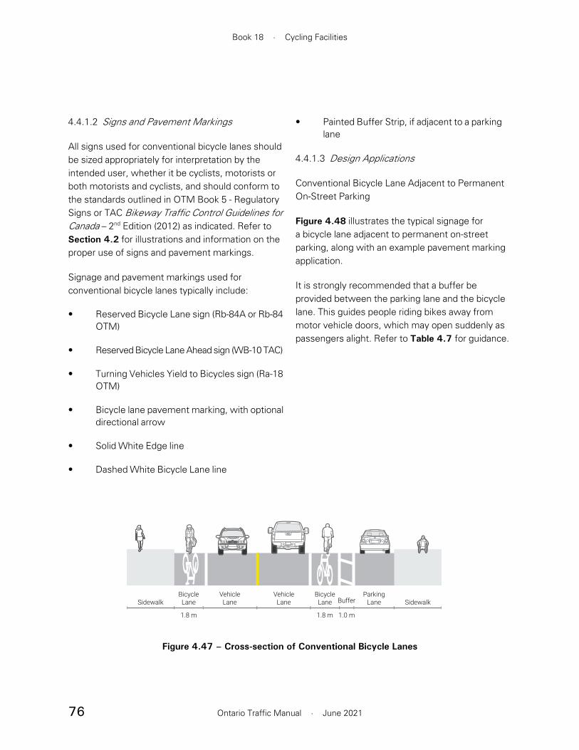
76
Book 18 · Cycling Facilities
Ontario Traffic Manual · June 2021
4.4.1.2 Signs and Pavement Markings
All signs used for conventional bicycle lanes should be sized appropriately for interpretation by the intended user, whether it be cyclists, motorists or both motorists and cyclists, and should conform to the standards outlined in OTM Book 5 - Regulatory Signs or TAC Bikeway Traffic Control Guidelines for Canada – 2nd Edition (2012) as indicated. Refer to Section 4.2 for illustrations and information on the proper use of signs and pavement markings.
Signage and pavement markings used for conventional bicycle lanes typically include:
• Reserved Bicycle Lane sign (Rb-84A or Rb-84 OTM)
• Reserved Bicycle Lane Ahead sign (WB-10 TAC)
• Turning Vehicles Yield to Bicycles sign (Ra-18 OTM)
• Bicycle lane pavement marking, with optional directional arrow
• Solid White Edge line
• Dashed White Bicycle Lane line
• Painted Buffer Strip, if adjacent to a parking lane
4.4.1.3 Design Applications
Conventional Bicycle Lane Adjacent to Permanent On-Street Parking
Figure 4.48 illustrates the typical signage for a bicycle lane adjacent to permanent on-street parking, along with an example pavement marking application.
It is strongly recommended that a buffer be provided between the parking lane and the bicycle lane. This guides people riding bikes away from motor vehicle doors, which may open suddenly as passengers alight. Refer to Table 4.7 for guidance.
Figure 4.47 – Cross-section of Conventional Bicycle Lanes
Sidewalk
1.0 m
SidewalkBicycleLane
BicycleLane
VehicleLane
ParkingLane
VehicleLane Buffer
1.8 m1.8 m
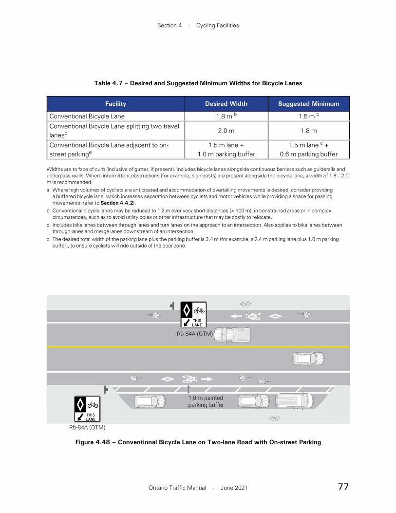
77
Section 4 · Cycling Facilities
Ontario Traffic Manual · June 2021
Table 4.7 – Desired and Suggested Minimum Widths for Bicycle Lanes
Facility Desired Width Suggested Minimum
Conventional Bicycle Lane 1.8 m b 1.5 m c
Conventional Bicycle Lane splitting two travel lanesd 2.0 m 1.8 m
Conventional Bicycle Lane adjacent to on-street parkinge
1.5 m lane +1.0 m parking buffer
1.5 m lane c +0.6 m parking buffer
Widths are to face of curb (inclusive of gutter, if present). Includes bicycle lanes alongside continuous barriers such as guiderails and underpass walls. Where intermittent obstructions (for example, sign posts) are present alongside the bicycle lane, a width of 1.8 – 2.0 m is recommended.a Where high volumes of cyclists are anticipated and accommodation of overtaking movements is desired, consider providing
a buffered bicycle lane, which increases separation between cyclists and motor vehicles while providing a space for passing movements (refer to Section 4.4.2).
b Conventional bicycle lanes may be reduced to 1.2 m over very short distances (< 100 m), in constrained areas or in complex circumstances, such as to avoid utility poles or other infrastructure that may be costly to relocate.
c Includes bike lanes between through lanes and turn lanes on the approach to an intersection. Also applies to bike lanes between through lanes and merge lanes downstream of an intersection.
d The desired total width of the parking lane plus the parking buffer is 3.4 m (for example, a 2.4 m parking lane plus 1.0 m parking buffer), to ensure cyclists will ride outside of the door zone.
Rb-84A (OTM)
Rb-84A (OTM)
1.0 m painted parking buffer
Figure 4.48 – Conventional Bicycle Lane on Two-lane Road with On-street Parking

78
Book 18 · Cycling Facilities
Ontario Traffic Manual · June 2021
4.4.2 Buffered Bicycle Lanes
A buffered bicycle lane is very similar to a conventional bicycle lane, as described in Section 4.4.1, except that a painted buffer is added to create additional horizontal separation between the bicycle lane and the adjacent motor vehicle lane. No vertical elements are used. Examples of buffered bicycle lanes are shown in Figure 4.49.
This facility type is best suited for 40 to 50 km/h roadways with moderate volumes of motor vehicle traffic.
Prior to initiating design work on a given link, practitioners should refer to the Facility Selection Process in Section 5. This will confirm whether buffered bicycle lanes are the most suitable facility type and identify key design considerations.
4.4.2.1 Geometry
The desired width for a buffered bicycle lane is a 1.8 m bicycle lane and 1.0 m painted buffer. The minimum width is 1.5 m bicycle lane and 0.3 m buffer. Measurements are to face of curb and inclusive of the gutter if one is present. The buffer area can be treated as part of the travelled area for people riding bikes, allowing passing and navigation around obstacles. The desired width of the painted buffer is 1.0 m, to provide ample horizontal separation between cyclists and motorists. The suggested minimum painted buffer width is 0.3 m. Cyclists may use the buffer zone for passing movements and as such, the road surface of the buffer zone should be maintained to the same standards as the adjacent bicycle lane. The combined width of the buffers and the bicycle lane (including gutter) should not exceed 2.8 m since the lane may be mistaken for a motor vehicle lane beyond this width.
Buffered Bicycle Lane, Ottawa
Source: Alta
Buffered Bicycle Lane with Floating Curb, Ottawa
Source: Alta
Figure 4.49 – Examples of Buffered Bicycle Lanes
Buffered Bicycle Lane, Toronto
Source: Alta

79
Section 4 · Cycling Facilities
Ontario Traffic Manual · June 2021
When a buffered bicycle lane is adjacent to a parking lane, a recommended parking buffer width of 1.0 m (minimum 0.6 m) should be used to protect people riding bikes from conflicts with motor vehicle doors. Alternatively, the buffered bicycle lane can be aligned between the parking lane and the curb to create a physically-separated bicycle lane. Refer to Section 4.3.1 and Section 4.3.2 for more details on this technique.
Where on-street parking is present and a buffer can only be provided on one side of the bicycle lane, practitioners should decide where to place the buffer based on the context of the roadway. On higher speed and volume roadways with low parking turnover, consider reducing the parking buffer to 0.6 m and increasing the size of the vehicle lane buffer.
Practitioners should consider the use of durable materials for the buffer. If the buffer paint fades, motorists may mistake a buffered bicycle lane for a motor vehicle lane. Applying separation techniques within the buffer zone to create a physically separated bicycle lane, as detailed in Section 4.3.2, is another strategy to avoid this problem.
Figure 4.50 illustrates typical cross-sections of buffered bicycle lanes. Table 4.8 presents the desired and suggested minimum lane widths for buffered bicycle lanes.
Table 4.8 – Desired and Suggested Minimum Widths for Buffered Bicycle Lanes
Facility Desired Width Suggested Minimum
Buffered Bicycle Lane1.8 m lane +1.0 m buffer a
1.5 m lane +0.3 m buffer
Buffered Bicycle Lane adjacent to parking lane 1.0 m parking buffer +
1.5 m lane +0.3 m buffer b
0.6 m parking buffer +1.5 m lane
Widths are to face of curb (inclusive of gutter, if present). Maintenance standards for marked buffers should be the same as for lanes since cyclists may use them for overtaking.a The combined width of the bicycle lane and buffers should not exceed 2.8 m since above this width the facility may be confused as
a motor vehicle lane by motorists, even when properly marked and signed as a bicycle lane. b On higher volume roadways with low parking turnover, consider reducing the parking buffer to 0.6 m and increasing the size of the
vehicle lane buffer.

80
Book 18 · Cycling Facilities
Ontario Traffic Manual · June 2021
4.4.2.2 Signs and Pavement Markings
Signage and pavement markings used for buffered bicycle lanes typically includes:
• Reserved Bicycle Lane sign (Rb-84A or Rb-84 OTM)
• Reserved Bicycle Lane Ahead sign (WB-10 TAC)
• Turning Vehicles Yield to Bicycles sign (Ra-18 OTM)
• Bicycle lane pavement marking, with optional directional arrow
• Solid White Edge line
• Painted Buffer Strip
Refer to Section 4.2 for illustrations and information on proper use of signs and pavement markings.
4.4.2.3 Design Applications
Buffered Bicycle Lane without On-street Parking
The recommended width of a buffered bicycle lane is 1.8 m plus a 1.0 m painted buffer. People riding bikes may use the buffer zone as operating space, to avoid obstacles or overtake other cyclists. As such, the buffer zone should be maintained to the same standards as the bicycle lane.
The combined width of the bicycle lane and the buffer should not exceed 2.8 m, as this may result in motorists using the buffered bicycle lane as a motor vehicle lane, especially if the pavement treatment is faded due to wear.16
Buffered Bicycle Lane Adjacent to Parking Lane
When a buffered bicycle lane is proposed on a street with a parking lane, practitioners should consider routing the bicycle lane between the parking lane and the curb if possible, as a physically separated bicycle lane (refer to Section 4.3.2). When a physically separated bicycle lane is not feasible, and the bicycle lane must pass between the travel lane and the parking lane, the preference is to provide a buffer on both sides of the buffered bicycle lane, as illustrated in Figure 4.51.

81
Section 4 · Cycling Facilities
Ontario Traffic Manual · June 2021
Figure 4.51 – Buffered Bicycle Lanes with On-street Parking
Rb-84A (OTM)
Rb-84A (OTM)
1.0 m painted buffer
1.0 m painted parking buffer
0.3 m painted buffer
Combined width of bicycle lane and buffers should not exceed 2.8 m
Figure 4.50 – Cross-Section of Buffered Bicycle Lanes
Sidewalk
1.8 m
SidewalkParking
LaneBicycleLane
VehicleLane
BicycleLane
VehicleLaneBuffer Buffer
1.5 m 1.0 m0.3 m1.0 m

82
Book 18 · Cycling Facilities
Ontario Traffic Manual · June 2021
4.4.3 Contraflow Bicycle Lanes
A contraflow bicycle lane enables two-way bicycle travel on a roadway that has one-way operation for motor vehicles. A bicycle-only lane is provided in the opposite direction of other traffic flow, which results in a contraflow lane. Other traffic flow is accommodated in a general-purpose lane or separated motor vehicle and cycling facilities. Contraflow bicycle lanes can be separated from motor vehicle lanes by pavement markings only, a buffer or a form of physical separation. They are typically implemented to create more direct cycling connections within a network and exempt people riding bikes from traffic calming measures that result in one-way streets. Figure 4.52 shows several examples of contraflow bicycle lanes.
When planning and designing this facility type, consideration should be given to the number of intersecting driveways and streets on the side of the road with the contraflow bicycle lane. Furthermore, contraflow bicycle lanes may require
the installation of bicycle signals. Practitioners should refer to Section 6.5 and OTM Book 12A — Bicycle Traffic Signals for guidance on bicycle signals.
4.4.3.1 Geometry
The geometry of the contraflow bicycle lane depends on the operating speed and traffic volume of the roadway, as well as the presence of on-street parking and available right-of-way for the roadway corridor. Contraflow bicycle lanes should be 2.0 m wide to allow people riding bikes additional space to manoeuvre around obstacles or overtake other cyclists without crossing the contraflow lane line. A 1.0 m buffer should be provided between the contraflow lane and any on-street parking alongside it. Where there are high oncoming motor vehicle speeds or volumes, a separation technique such as a painted buffer, as shown in Section 4.3.1, may be provided to separate people riding bikes from opposing traffic
Contraflow Bicycle Lane, Ottawa
Source: Alta
Contraflow Bicycle Lane, Ottawa
Source: Alta
Figure 4.52 – Examples of Contraflow Bicycle Lanes
Contraflow Bicycle Lane Separated by Bollards, Toronto
Source: Alta
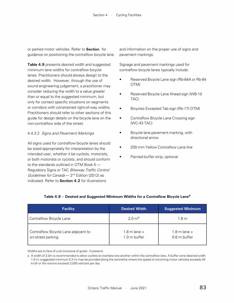
83
Section 4 · Cycling Facilities
Ontario Traffic Manual · June 2021
or parked motor vehicles. Refer to Section for guidance on positioning the contraflow bicycle lane.
Table 4.9 presents desired width and suggested minimum lane widths for contraflow bicycle lanes. Practitioners should always design to the desired width. However, through the use of sound engineering judgement, a practitioner may consider reducing the width to a value greater than or equal to the suggested minimum, but only for context specific situations on segments or corridors with constrained right-of-way widths. Practitioners should refer to other sections of this guide for design details on the bicycle lane on the non-contraflow side of the street.
4.4.3.2 Signs and Pavement Markings
All signs used for contraflow bicycle lanes should be sized appropriately for interpretation by the intended user, whether it be cyclists, motorists, or both motorists or cyclists, and should conform to the standards outlined in OTM Book 5 — Regulatory Signs or TAC Bikeway Traffic Control Guidelines for Canada — 2nd Edition (2012) as indicated. Refer to Section 4.2 for illustrations
and information on the proper use of signs and pavement markings.
Signage and pavement markings used for contraflow bicycle lanes typically include:
• Reserved Bicycle Lane sign (Rb-84A or Rb-84 OTM)
• Reserved Bicycle Lane Ahead sign (WB-10 TAC)
• Bicycles Excepted Tab sign (Rb-17t OTM)
• Contraflow Bicycle Lane Crossing sign (WC-43 TAC)
• Bicycle lane pavement marking, with directional arrow
• 200 mm Yellow Contraflow Lane line
• Painted buffer strip, optional
Table 4.9 – Desired and Suggested Minimum Widths for a Contraflow Bicycle Lanea
Facility Desired Width Suggested Minimum
Contraflow Bicycle Lane 2.0 ma 1.8 m
Contraflow Bicycle Lane adjacent toon-street parking
1.8 m lane +1.0 m buffer
1.8 m lane +0.6 m buffer
Widths are to face of curb (inclusive of gutter, if present).a A width of 2.0m is recommended to allow cyclists to overtake one another within the contraflow lane. A buffer zone (desired width
1.0 m; suggested minimum 0.3 m) may be provided along the centreline where the speed of oncoming motor vehicles exceeds 40 km/h or the volume exceeds 3,000 vehicles per day.

84
Book 18 · Cycling Facilities
Ontario Traffic Manual · June 2021
4.4.3.3 Design Applications
Figure 4.53 illustrates the typical plan view of a contraflow bicycle lane located on the side of the roadway without on-street parking, complete with the recommended signs.
On roadways with on-street parking on one side of the street, the parking should be located on the non-contraflow side of the road. If this is not possible, or where a roadway has on-street parking on both sides of the street, the contraflow bicycle lane should be placed either:
• Between the one-way motor vehicle lane and the parking lane if motor vehicle traffic and parking turnover rates are low, or
• Between the parking lane and the curb, as a physically separated bicycle lane, as shown in Section 4.3.2
In both cases, a 1.0 m (minimum 0.6 m) painted buffer should be provided between the contraflow bicycle lane and the parking lane.
One Way (Rb-21 OTM), No Entry (Rb-19 OTM) and Turn Prohibition (Rb-11 or Rb-12 OTM) signs should be provided as shown in the figures, with a Bicycles Excepted (Rb-17t OTM) tab below each sign. On the approach to intersecting streets, the Contraflow Bicycle Lane Crossing sign (WC-43 TAC) should be posted, to warn road users of two-way bicycle traffic. The application of signage and pavement markings should reflect context-specific conditions.
The optional provision of a bike lane in the non-contraflow direction is based on traffic volumes and speeds in that direction. On low-volume streets, mixed traffic operations may be appropriate. Refer to Section 4.4.1 for the design of the bicycle lane on the non-contraflow side of the road and Section 4.5.3.2 for the design of mixed traffic roadways.
Rb-11 (OTM)Rb-17t (OTM)
Rb-11 (OTM)Rb-17t (OTM)
WC-43 (TAC)
Rb-19 (OTM)Rb-17t (OTM)
Rb-12 (OTM)Rb-17t (OTM)
Rb-21 (OTM)Rb-17t (OTM)
Wc-24 (OTM)Wc-24t (OTM)
Figure 4.53 – Contraflow Bicycle Lane (on-street parking on one side of the road)
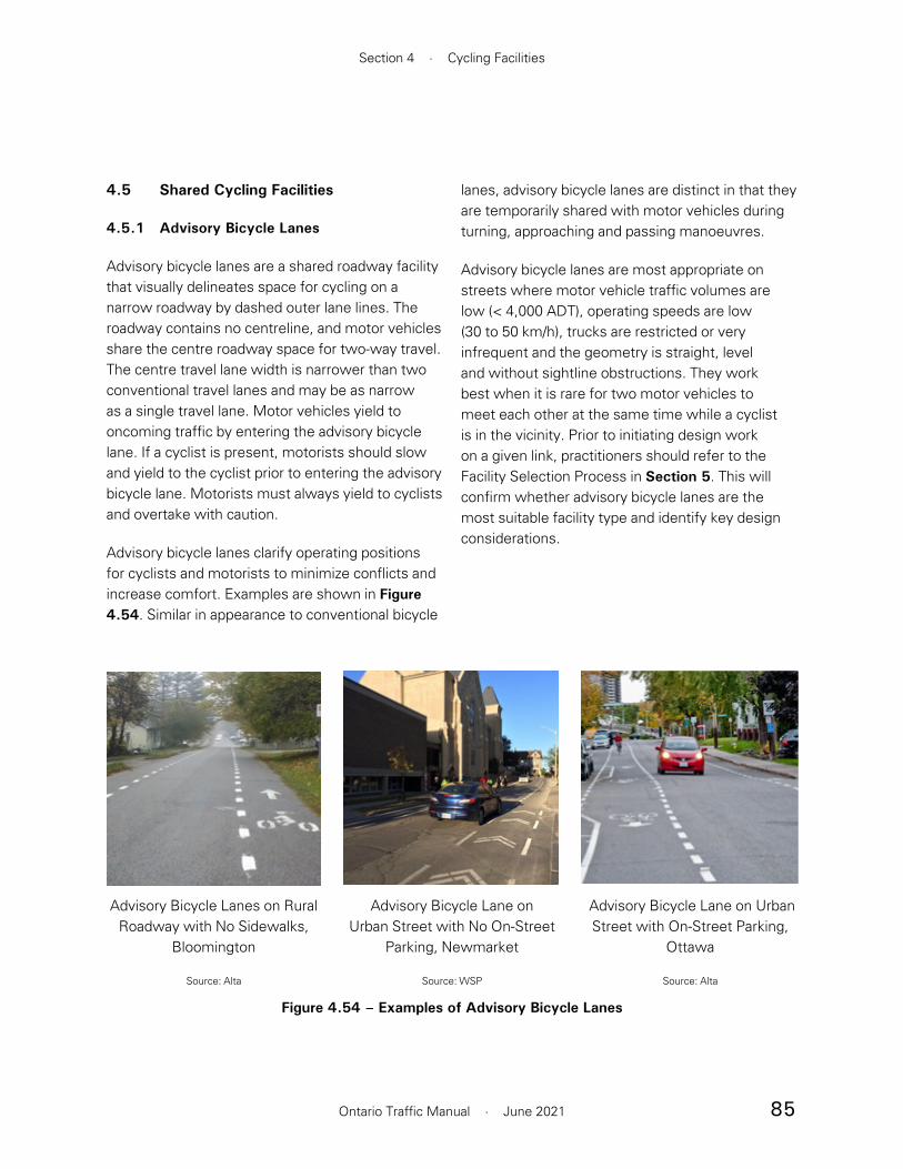
85
Section 4 · Cycling Facilities
Ontario Traffic Manual · June 2021
4.5 Shared Cycling Facilities
4.5.1 Advisory Bicycle Lanes
Advisory bicycle lanes are a shared roadway facility that visually delineates space for cycling on a narrow roadway by dashed outer lane lines. The roadway contains no centreline, and motor vehicles share the centre roadway space for two-way travel. The centre travel lane width is narrower than two conventional travel lanes and may be as narrow as a single travel lane. Motor vehicles yield to oncoming traffic by entering the advisory bicycle lane. If a cyclist is present, motorists should slow and yield to the cyclist prior to entering the advisory bicycle lane. Motorists must always yield to cyclists and overtake with caution.
Advisory bicycle lanes clarify operating positions for cyclists and motorists to minimize conflicts and increase comfort. Examples are shown in Figure 4.54. Similar in appearance to conventional bicycle
lanes, advisory bicycle lanes are distinct in that they are temporarily shared with motor vehicles during turning, approaching and passing manoeuvres.
Advisory bicycle lanes are most appropriate on streets where motor vehicle traffic volumes are low (< 4,000 ADT), operating speeds are low (30 to 50 km/h), trucks are restricted or very infrequent and the geometry is straight, level and without sightline obstructions. They work best when it is rare for two motor vehicles to meet each other at the same time while a cyclist is in the vicinity. Prior to initiating design work on a given link, practitioners should refer to the Facility Selection Process in Section 5. This will confirm whether advisory bicycle lanes are the most suitable facility type and identify key design considerations.
Advisory Bicycle Lanes on Rural Roadway with No Sidewalks,
Bloomington
Source: Alta
Advisory Bicycle Lane on Urban Street with No On-Street
Parking, Newmarket
Source: WSP
Figure 4.54 – Examples of Advisory Bicycle Lanes
Advisory Bicycle Lane on Urban Street with On-Street Parking,
Ottawa
Source: Alta

86
Book 18 · Cycling Facilities
Ontario Traffic Manual · June 2021
4.5.1.1 Geometry
The desired width for advisory bicycle lanes is 1.8 to 2.0 m, measured to the face of the curb or, in its absence, the edge of the roadway. The suggested minimum width is 1.5 m to allow for lateral movement within the lane, and to enable people riding bikes to avoid debris or pavement defects.
The width of the two-way travel lane may vary between 2.7 and 5.7 m depending on the design condition and the available cross section of the roadway. The following guidance applies to the selection of the two-way travel lane width:
• The two-way travel lane should be wide enough such that a design motor vehicle can pass a cyclist travelling in the advisory bicycle lane while leaving a 1.0 m gap. On streets with transit service, the appropriate transit vehicle should be used as the design motor vehicle.
• Most commonly, the two-way travel lane is narrow enough that two motor vehicles cannot pass each other in both directions without crossing the advisory lane line. However, a wider two-way travel lane that allows two motor vehicles to pass each other may also be implemented.
• International guidance suggests that the two-way travel lane should have either a narrow or a wide profile so that there is no uncertainty as to whether two oncoming passenger vehicles can pass each other within the centre travel lane.17 For this reason, two-way centre travel lane widths between 4.0 and 5.0 m are not recommended.
• Wider advisory bicycle lanes should be prioritized over wider two-way travel lanes.
Practitioners should only widen the two-way travel lane after bicycle lanes have reached 2.0 m in width, which allows for more comfortable bicycle travel and promotes slower motor vehicle speeds.18
• Early experience in North America suggests that very narrow two-way travel lanes of 2.7 to 3.0 m perform as intended.19
The alignment of the bike lanes should follow that of the roadway as closely as possible. Frequent bending in and out around parking lanes can cause confusion among users, leading to motorists potentially travelling in the advisory bicycle lane unnecessarily. Parking lanes should be coupled with frequent curb extensions so that when parking lanes are empty, cyclists are still discouraged from riding in parking lanes.
Table 4.10 presents the desired and suggested minimum lane widths for advisory bicycle lanes. Typical cross-sections are shown in Figure 4.55
Though motor vehicles may be prohibited from parking in advisory bicycle lanes if a no parking by-law exists and signs are installed, on-street parking may be allowed on advisory bicycle lane streets if a separate parking lane is provided. In this case, advisory bicycle lanes should be positioned between the motor vehicle travel lane and the parking lane with appropriate buffer. Parking lanes should be highly used and clearly delineated from the travelled area of the roadway through the use of curb extensions, contrasting paving materials or edge striping.
Practitioners should consider the potential hazard of motor vehicle doors opening into the travelled portion of the bicycle lane and impacting people riding bikes. It is recommended that practitioners minimize this risk by providing a 1.0 m buffer to

87
Section 4 · Cycling Facilities
Ontario Traffic Manual · June 2021
Table 4.10 – Desired and Suggested Minimum Widths for Advisory Bicycle Lanes
Facility Desired Width Suggested Minimum
Advisory Bicycle Lane 1.8 – 2.0 m a 1.5 m
Advisory Bicycle Lane adjacent to on-street parking b
1.8 m lane +1.0 m buffer
1.5 m lane +0.6 m buffer
Two-way Travel Lane3.0 – 4.0 m or 5.0 – 5.7 m c
2.7 m
Widths are to face of curb (inclusive of gutter, if present).a Wider bicycle lanes should be prioritized over wider two-way travel lanes. 2.0 m advisory bicycle lanes allow for more comfortable
bicycle travel, while narrower two-way travel lanes promote slower motor vehicle speeds. b To ensure that cyclists are not encouraged to travel in the parking lane, parking lanes should be highly used or coupled with
frequent curb extensions.c The width of a two-way travel lane is expected to vary based on available road width, after allocating space to advisory bicycle lanes.
Widths between 4.0 and 5.0 m are not recommended since they may result in uncertainty as to whether two passenger vehicles may pass each other within the travel lane.
Advisory Bicycle Lane Without On-street Parking
Advisory Bicycle Lane with On-street Parking
Figure 4.55 – Cross-Sections of Advisory Bicycle Lanes
Two-wayTravel Lane
1.8–2.0 m
Sidewalk
AdvisoryBicycleLane
1.8 m
Sidewalk
AdvisoryBicycleLane
ParkingLane
3.0 to 4.0 m or 1.0 m
Buffer
5.0 to 5.7 m
Sidewalk
1.8–2.0 m
AdvisoryBicycleLane
AdvisoryBicycleLane
Two-wayTravel Lane Sidewalk
1.8–2.0 m3.0-4.0 m or5.0-5.7 m

88
Book 18 · Cycling Facilities
Ontario Traffic Manual · June 2021
lanes. Standard bike lane Reserved Bicycle Lane signs (Rb-84 or Rb-84A OTM) should not be used.
In addition, to discourage motorists from entering the advisory lane when it is not necessary, or to encourage motorists to return to the centre travel lane after passing, coloured pavement can be used. This will increase the conspicuity of the advisory lanes along either the full stretch of lanes or in strategic locations.
Note that the centreline is not present on streets with advisory bicycle lanes since the centre lane on an advisory bicycle lane street serves as a two-way travel lane for motor vehicles.
4.5.1.3 Design Applications
Advisory Bicycle Lanes on Rural Roadways with No Sidewalks
On rural roadways and roadways without sidewalks, the advisory bicycle lanes may operate as shared space with pedestrians. The bicycle lane pavement marking is optional in this case, and people riding bikes and motorists are required to yield to pedestrians using the lane.
Advisory Bicycle Lanes on Urban Roadways without On-Street Parking
On urban streets where sidewalks are typically present, advisory bicycle lanes are not intended for use by pedestrians. This is reinforced by placing bicycle stencils and directional arrows in the advisory bicycle lanes before and after each intersection and at intervals of 75 m or less at mid-block locations.
Unlike conventional bicycle lanes, advisory bicycle lanes are not designated for exclusive use by people riding bikes. A Stopping Prohibited sign
guide cyclists away from the conflict zone. In this case, if width constraints exist, it is acceptable for the bicycle lane to be 1.5 m wide, with additional available right-of-way being used for the buffer instead of a wider bicycle lane.
4.5.1.2 Signs and Pavement Markings
Signage should be provided to alert motorists to the presence of two-way travel within the centre lane, and to alert them to the introduction of a facility. Signs may also be used to remind motorists to yield when entering advisory bicycle lanes and to prevent motor vehicles from parking in advisory bicycle lanes.
All signs used for advisory bicycle lanes should be sized appropriately for interpretation by the intended user, whether it be cyclists, motorists, or both motorists or cyclists, and should conform to the TAC Bikeway Traffic Control Guidelines for Canada – 2nd Edition (2012). Refer to Section 4.2 for illustrations and information on proper use of signs and pavement markings.
Signage and pavement markings typically used to support advisory bicycle lanes include:
• Stopping Prohibited Sign (Rb-55 OTM)
• No Parking Sign, to discourage parking while allowing loading activities (Rb-51 OTM)
• Dashed White Bicycle Lane Line
• Bicycle Lane Pavement Marking, with optional direction arrow and no diamond
A two-directional traffic warning sign (Wb-4 OTM) or a custom advisory bicycle lane sign may be installed to communicate to road users the required yielding behaviour on streets with advisory bicycle
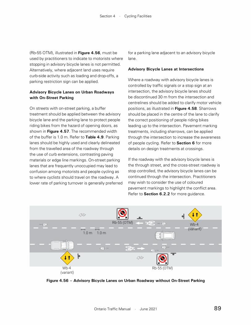
89
Section 4 · Cycling Facilities
Ontario Traffic Manual · June 2021
for a parking lane adjacent to an advisory bicycle lane.
Advisory Bicycle Lanes at Intersections
Where a roadway with advisory bicycle lanes is controlled by traffic signals or a stop sign at an intersection, the advisory bicycle lanes should be discontinued 30 m from the intersection and centrelines should be added to clarify motor vehicle positions, as illustrated in Figure 4.58. Sharrows should be placed in the centre of the lane to clarify the correct positioning of people riding bikes leading up to the intersection. Pavement marking treatments, including sharrows, can be applied through the intersection to increase the awareness of people cycling. Refer to Section 6 for more details on design treatments at crossings.
If the roadway with the advisory bicycle lanes is the through street, and the cross-street roadway is stop controlled, the advisory bicycle lanes can be continued through the intersection. Practitioners may wish to consider the use of coloured pavement markings to highlight the conflict area. Refer to Section 6.2.2 for more guidance.
(Rb-55 OTM), illustrated in Figure 4.56, must be used by practitioners to indicate to motorists where stopping in advisory bicycle lanes is not permitted. Alternatively, where adjacent land uses require curb-side activity such as loading and drop-offs, a parking restriction sign can be applied.
Advisory Bicycle Lanes on Urban Roadways with On-Street Parking
On streets with on-street parking, a buffer treatment should be applied between the advisory bicycle lane and the parking lane to protect people riding bikes from the hazard of opening doors, as shown in Figure 4.57. The recommended width of the buffer is 1.0 m. Refer to Table 4.9. Parking lanes should be highly used and clearly delineated from the travelled area of the roadway through the use of curb extensions, contrasting paving materials or edge line markings. On-street parking lanes that are frequently unoccupied may lead to confusion among motorists and people cycling as to where cyclists should travel on the roadway. A lower rate of parking turnover is generally preferred
Figure 4.56 – Advisory Bicycle Lanes on Urban Roadway without On-Street Parking
Wb-4 (variant)
Wb-4 (variant)
Rb-55 (OTM)
Rb-55 (OTM)
1.0 m 1.0 m

90
Book 18 · Cycling Facilities
Ontario Traffic Manual · June 2021
Figure 4.57 – Advisory Bicycle Lanes on Urban Roadway with On-Street Parking
Rb-55 (OTM)
1.0 m parking buffer
Wb-4(variant)
Wb-4(variant)
Figure 4.58 – Advisory Bicycle Lanes at Four-Way Stop-Controlled or Signalized Intersection
30 m
Centre of lane
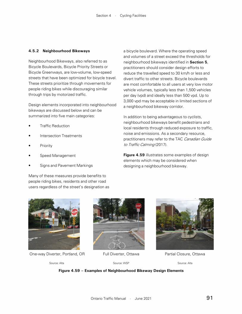
91
Section 4 · Cycling Facilities
Ontario Traffic Manual · June 2021
4.5.2 Neighbourhood Bikeways
Neighbourhood Bikeways, also referred to as Bicycle Boulevards, Bicycle Priority Streets or Bicycle Greenways, are low-volume, low-speed streets that have been optimized for bicycle travel. These streets prioritize through movements for people riding bikes while discouraging similar through trips by motorized traffic.
Design elements incorporated into neighbourhood bikeways are discussed below and can be summarized into five main categories:
• Traffic Reduction
• Intersection Treatments
• Priority
• Speed Management
• Signs and Pavement Markings
Many of these measures provide benefits to people riding bikes, residents and other road users regardless of the street’s designation as
a bicycle boulevard. Where the operating speed and volumes of a street exceed the thresholds for neighbourhood bikeways identified in Section 5, practitioners should consider design efforts to reduce the travelled speed to 30 km/h or less and divert traffic to other streets. Bicycle boulevards are most comfortable to all users at very low motor vehicle volumes, typically less than 1,500 vehicles per day (vpd) and ideally less than 500 vpd. Up to 3,000 vpd may be acceptable in limited sections of a neighbourhood bikeway corridor.
In addition to being advantageous to cyclists, neighbourhood bikeways benefit pedestrians and local residents through reduced exposure to traffic, noise and emissions. As a secondary resource, practitioners may refer to the TAC Canadian Guide to Traffic Calming (2017).
Figure 4.59 illustrates some examples of design elements which may be considered when designing a neighbourhood bikeway.
One-way Diverter, Portland, OR
Source: Alta
Full Diverter, Ottawa
Source: WSP
Figure 4.59 – Examples of Neighbourhood Bikeway Design Elements
Partial Closure, Ottawa
Source: Alta
92
Book 18 · Cycling Facilities
Ontario Traffic Manual · June 2021
Intersection Treatments
Intersection treatments can improve a cyclist’s ability to cross a major roadway more comfortably and safely. Where offset crossings exist, emphasis should be placed on providing clear and safe navigation to people riding bikes.
Examples of intersection treatments include:
• Bike boxes
• Advanced stop bars
• Bicycle actuated signals
• Crossrides
• Refuge islands
Refer to Section 6 for more guidance on the design of intersections.
Priority
Priority should be given to people cycling when a neighbourhood bikeway crosses a minor street, to reduce the travel time for cyclists. It is desirable to provide a continuous bikeway without stop control for cyclists. This should be paired with motor vehicle speed and volume control measures to prevent motorists from using neighbourhood bikeways as shortcuts.
Speed Management
Speed management measures aim to reduce the speed of motor vehicle traffic on a particular roadway and bring it closer to the travelled speed of people riding bikes. Reduced motor vehicle travel speeds benefit cyclists by reducing the severity of collisions if they occur, reducing the frequency of
4.5.2.1 Design Elements
Traffic Reduction
Traffic reduction on neighbourhood bikeways may be achieved through applying restrictions to motor vehicle movements at intersections while allowing them for cyclists.
Traffic reduction examples include:
• Right-in right-out: force motor vehicles to turn right at a cross-street, while allowing cyclists, buses and emergency motor vehicles to pass through
• Median islands/diverters: restrict the through movement of motor vehicles at major crossings, while providing a refuge for cyclists to complete a two-stage crossing
• Diagonal diverters: force motor vehicles to turn at a four-way intersection, while allowing cyclists and pedestrians to travel in any direction
• Choker entrances: allow only one direction of motor vehicle traffic either entering or exiting a side street, while allowing cyclists to pass through
• Full diverters: convert a four-way intersection into a “T” intersection by closing one of the legs to motor vehicles, while allowing cyclists to pass through
• Road closures: close a segment of a roadway to motor vehicles, while allowing cyclists and pedestrians to pass through. Requires consideration of access to driveways on the closed street.

93
Section 4 · Cycling Facilities
Ontario Traffic Manual · June 2021
motor vehicles passing cyclists, and improving the perception time of motorists.
Examples of speed management techniques include:
• Speed tables
• Speed humps
• Raised crosswalks
• Curb extensions or “bulb-outs”
• Chicanes
• Reduced speed limits
• Mini-roundabouts
• Traffic calming bollards
• Narrowing of motor vehicle travel lanes
• Automated speed enforcement
• Dynamic “watch your speed” signs
• Temporary bollards that create choke points
Consideration must be given to ensure traffic calming designs do not adversely affect cyclists such as chicanes and curb extensions without bike lanes. Refer to Section 4.5.4.2 for design guidance.
Signage and Pavement Markings complement physical design interventions on neighbourhood bikeways by communicating information such as:
• The intended travel path of people riding bikes in the roadway through the use of sharrows and either the Share the Road sign
(Wc-19 OTM) or the Shared Use Lane Single File sign (Wc-24 OTM)
• Local and network wayfinding through the use of the Bicycle Route sign (M511 OTM) and sharrows
Signage and pavement markings are already an integral part of on-road cycling facilities such as signed bicycle routes and bicycle lanes.
Section 4.5.3.2 contains detailed information about the placement of supportive signage and pavement markings for mixed traffic operations.
Figure 4.60 illustrates the implementation of these design elements within a typical neighbourhood bikeway.

94
Book 18 · Cycling Facilities
Ontario Traffic Manual · June 2021
Figure 4.60 – Sample Design Elements on a Neighbourhood Bikeway
(Signs omitted for clarity)
Chicanes
Curb extensions
Prioritize bicycle movementsat intersections with minor streets
Speed humps
Sharrows placed in centre ofroadway
Full diverter at major streetcrossing allows through movements for bicycles whileforcing vehicles to turn
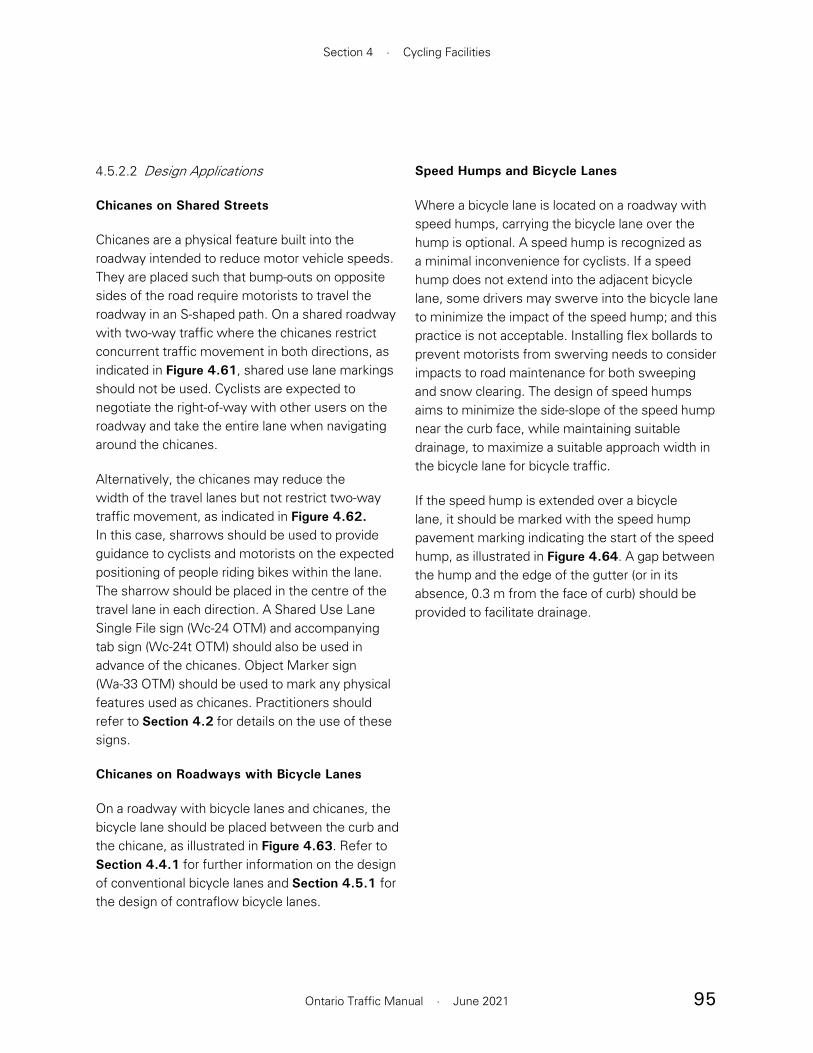
95
Section 4 · Cycling Facilities
Ontario Traffic Manual · June 2021
4.5.2.2 Design Applications
Chicanes on Shared Streets
Chicanes are a physical feature built into the roadway intended to reduce motor vehicle speeds. They are placed such that bump-outs on opposite sides of the road require motorists to travel the roadway in an S-shaped path. On a shared roadway with two-way traffic where the chicanes restrict concurrent traffic movement in both directions, as indicated in Figure 4.61, shared use lane markings should not be used. Cyclists are expected to negotiate the right-of-way with other users on the roadway and take the entire lane when navigating around the chicanes.
Alternatively, the chicanes may reduce the width of the travel lanes but not restrict two-way traffic movement, as indicated in Figure 4.62. In this case, sharrows should be used to provide guidance to cyclists and motorists on the expected positioning of people riding bikes within the lane. The sharrow should be placed in the centre of the travel lane in each direction. A Shared Use Lane Single File sign (Wc-24 OTM) and accompanying tab sign (Wc-24t OTM) should also be used in advance of the chicanes. Object Marker sign (Wa-33 OTM) should be used to mark any physical features used as chicanes. Practitioners should refer to Section 4.2 for details on the use of these signs.
Chicanes on Roadways with Bicycle Lanes
On a roadway with bicycle lanes and chicanes, the bicycle lane should be placed between the curb and the chicane, as illustrated in Figure 4.63. Refer to Section 4.4.1 for further information on the design of conventional bicycle lanes and Section 4.5.1 for the design of contraflow bicycle lanes.
Speed Humps and Bicycle Lanes
Where a bicycle lane is located on a roadway with speed humps, carrying the bicycle lane over the hump is optional. A speed hump is recognized as a minimal inconvenience for cyclists. If a speed hump does not extend into the adjacent bicycle lane, some drivers may swerve into the bicycle lane to minimize the impact of the speed hump; and this practice is not acceptable. Installing flex bollards to prevent motorists from swerving needs to consider impacts to road maintenance for both sweeping and snow clearing. The design of speed humps aims to minimize the side-slope of the speed hump near the curb face, while maintaining suitable drainage, to maximize a suitable approach width in the bicycle lane for bicycle traffic.
If the speed hump is extended over a bicycle lane, it should be marked with the speed hump pavement marking indicating the start of the speed hump, as illustrated in Figure 4.64. A gap between the hump and the edge of the gutter (or in its absence, 0.3 m from the face of curb) should be provided to facilitate drainage.

96
Book 18 · Cycling Facilities
Ontario Traffic Manual · June 2021
Figure 4.61 – One-Lane Chicane Roadway with Two-Way Traffic
Wa-33R(OTM)
Wa-33L(OTM)
Wa-33R(OTM)
Wa-33L(OTM)
Wa-33R(OTM)
Wa-33L(OTM)
Wc-24 (OTM)
Wc-24t (OTM)Wa-33R(OTM)
Wa-33L(OTM)
Wa-33R(OTM)
Wa-33L(OTM)
Wa-33R(OTM)
Wa-33L(OTM)
Wc-24 (OTM)
Wc-24t (OTM)
Figure 4.62 – Shared Use Markings on Two-Lane Chicaned Roadway
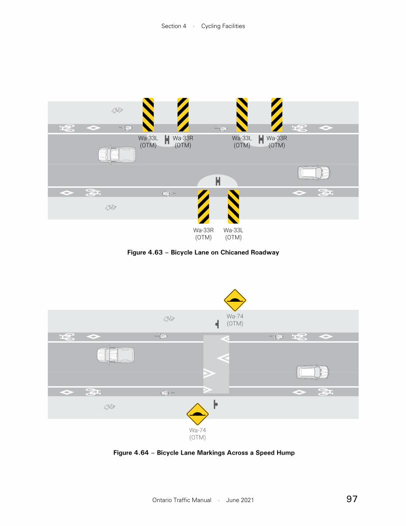
97
Section 4 · Cycling Facilities
Ontario Traffic Manual · June 2021
Wa-33R(OTM)
Wa-33L(OTM)
Wa-33R(OTM)
Wa-33L(OTM)
Wa-33R(OTM)
Wa-33L(OTM)
Figure 4.63 – Bicycle Lane on Chicaned Roadway
Figure 4.64 – Bicycle Lane Markings Across a Speed Hump
Wa-74(OTM)
Wa-74(OTM)

98
Book 18 · Cycling Facilities
Ontario Traffic Manual · June 2021
4.5.3 Mixed Traffic Operation
Unless cycling is specifically restricted, people riding bikes are permitted to travel on all roadways regardless of whether signage is present. Designating a route where cyclists must operate in mixed traffic as a bicycle route is only recommended when the street is low-speed and low-volume. The Facility Selection Process in Section 5 establishes the conditions under which it is appropriate for cyclists to operate in mixed traffic.
Where a cycling route is desired and the conditions established in Section 5 are not present, practitioners should consider an alternative approach, such as:
• Adding a designated cycling facility to the route (see Section 4.3 and Section 4.4)
• Implementing traffic calming or traffic diversion measures to the route to create
a neighbourhood bikeway, as discussed in Section 4.5.2
• Seeking an alternate route for a cycling facility
Examples of mixed traffic operations are shown in Figure 4.65.
4.5.3.1 Geometry
Mixed traffic operation is typically suitable for people riding bikes on low-volume local roads and residential streets. No provisions are needed other than signage. Generally, cyclists are expected to ride on the right of the shared travel lane in accordance with the HTA. However, cyclists can use any part of the lane if necessary for safety. In situations where the lane is not wide enough for side-by-side operation, cyclists have a right to travel in the centre of the lane to discourage motor vehicle passing.
Wide Shared Lane, Toronto
Source: Alta
Narrow Shared Lane with On-street Parking, Toronto
Source: Alta
Figure 4.65 – Examples of Mixed Traffic Operations
Narrow Shared Lane, Toronto
Source: Alta
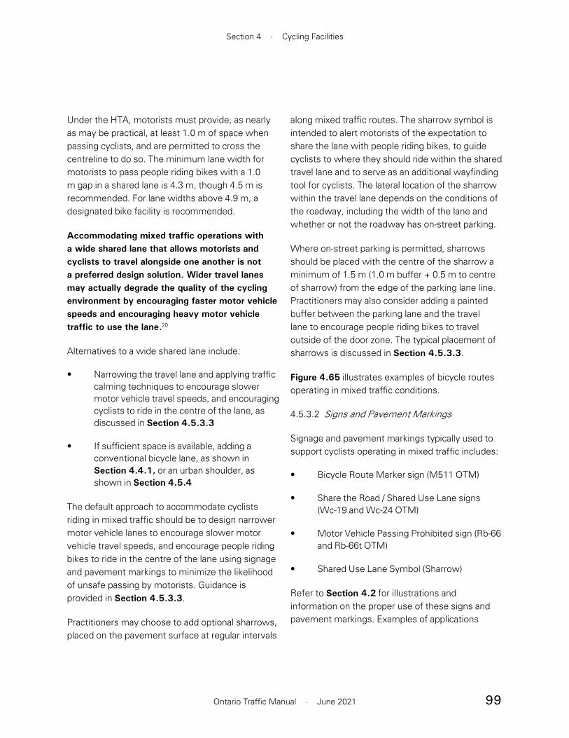
99
Section 4 · Cycling Facilities
Ontario Traffic Manual · June 2021
along mixed traffic routes. The sharrow symbol is intended to alert motorists of the expectation to share the lane with people riding bikes, to guide cyclists to where they should ride within the shared travel lane and to serve as an additional wayfinding tool for cyclists. The lateral location of the sharrow within the travel lane depends on the conditions of the roadway, including the width of the lane and whether or not the roadway has on-street parking.
Where on-street parking is permitted, sharrows should be placed with the centre of the sharrow a minimum of 1.5 m (1.0 m buffer + 0.5 m to centre of sharrow) from the edge of the parking lane line. Practitioners may also consider adding a painted buffer between the parking lane and the travel lane to encourage people riding bikes to travel outside of the door zone. The typical placement of sharrows is discussed in Section 4.5.3.3.
Figure 4.65 illustrates examples of bicycle routes operating in mixed traffic conditions.
4.5.3.2 Signs and Pavement Markings
Signage and pavement markings typically used to support cyclists operating in mixed traffic includes:
• Bicycle Route Marker sign (M511 OTM)
• Share the Road / Shared Use Lane signs (Wc-19 and Wc-24 OTM)
• Motor Vehicle Passing Prohibited sign (Rb-66 and Rb-66t OTM)
• Shared Use Lane Symbol (Sharrow)
Refer to Section 4.2 for illustrations and information on the proper use of these signs and pavement markings. Examples of applications
Under the HTA, motorists must provide, as nearly as may be practical, at least 1.0 m of space when passing cyclists, and are permitted to cross the centreline to do so. The minimum lane width for motorists to pass people riding bikes with a 1.0 m gap in a shared lane is 4.3 m, though 4.5 m is recommended. For lane widths above 4.9 m, a designated bike facility is recommended.
Accommodating mixed traffic operations with a wide shared lane that allows motorists and cyclists to travel alongside one another is not a preferred design solution. Wider travel lanes may actually degrade the quality of the cycling environment by encouraging faster motor vehicle speeds and encouraging heavy motor vehicle traffic to use the lane.20
Alternatives to a wide shared lane include:
• Narrowing the travel lane and applying traffic calming techniques to encourage slower motor vehicle travel speeds, and encouraging cyclists to ride in the centre of the lane, as discussed in Section 4.5.3.3
• If sufficient space is available, adding a conventional bicycle lane, as shown in Section 4.4.1, or an urban shoulder, as shown in Section 4.5.4
The default approach to accommodate cyclists riding in mixed traffic should be to design narrower motor vehicle lanes to encourage slower motor vehicle travel speeds, and encourage people riding bikes to ride in the centre of the lane using signage and pavement markings to minimize the likelihood of unsafe passing by motorists. Guidance is provided in Section 4.5.3.3.
Practitioners may choose to add optional sharrows, placed on the pavement surface at regular intervals
100
Book 18 · Cycling Facilities
Ontario Traffic Manual · June 2021
of these features are discussed in the following section.
4.5.3.3 Design Applications
Mixed Traffic Operation with Cyclists Positioned in Centre of Lane
The default configuration for mixed traffic operations on streets with low speeds and volumes is to encourage cyclists to ride in the centre of the lane, as shown in the example in Figure 4.66. This is accomplished using sharrows and Shared Use Lane Single File sign (Wc-24 OTM) and supplementary tab (Wc-24t OTM), as illustrated in Figure 4.67.
Sharrows should be placed approximately at intervals of 75 m, and more frequently at intersections or points where more guidance is required. The Bicycle Route Marker sign may also be installed at regular intervals to provide navigational support to people riding bikes.
Mixed Traffic Operation with Wide Lanes
A practitioner should use sound engineering judgement to determine whether frequent opportunities for motorists to safely pass cyclists will be present on the roadway. Consideration should be given to travel speed, traffic volumes, lane widths and sightlines.
Wide shared lanes are generally discouraged and are not a suitable design for cyclists of all ages and abilities since they are associated with higher motorist travel speeds and less safe conditions for cyclists. Where travel lanes are 4.3 m wide or greater, it is possible for most motorists and cyclists to operate within the lane alongside each other. However, operators of larger vehicles may need to depart the lane to provide sufficient
passing distance. In this situation, cyclists should be encouraged to ride on the outside of the lane, which can be supported with sharrows and the Share the Road sign (Wc-19 OTM), as illustrated in Figure 4.68.
Sharrows should be placed at a lateral distance of 0.75 to 1.0 m from the curb and spaced at 75 m intervals, or more frequently if driveways, intersections or other road changes are present that require the use of sharrows. Refer to Section 4.2.2 for information on sharrows.
Mixed Traffic Operation with On-Street Parking
On roadways with on-street parking, sharrows should be placed to encourage people cycling to ride outside of the door zone. Sharrows should be placed a minimum of 1.4 m from the edge of the parking lane to the centre of the sharrow, or may be centred in the travel lane, ensuring they are outside of the door zone.
Figure 4.66 – Example of Sharrows in Narrow Shared Lane, Newmarket
Source: WSP

101
Section 4 · Cycling Facilities
Ontario Traffic Manual · June 2021
Figure 4.68 – Mixed Traffic Operation with Wide Lanes
Wc-19 Wc-19t
Wc-19 Wc-19t
4.3 m minimum
75 m (Typical)
0.75-1.0 m
Figure 4.67 – Mixed Traffic Operation with Cyclists Positioned in Centre of Lane
75 m (Typical) Centre of lane
Wc-24 (OTM)Wc-24t (OTM)
Wc-24 (OTM)Wc-24t (OTM)

102
Book 18 · Cycling Facilities
Ontario Traffic Manual · June 2021
Figure 4.69 – Mixed Traffic Operation with On-Street Parking
Centre of lane1.0 m painted parking buffer
Wc-24 (OTM)Wc-24t (OTM)
Wc-24 (OTM)Wc-24t (OTM)

103
Section 4 · Cycling Facilities
Ontario Traffic Manual · June 2021
This placement encourages cyclists to ride in a straight line, discouraging weaving around parked cars. An optional painted parking buffer with a recommended width of 1.0 m may also be added.
On low-volume residential streets where on-street parking is permitted, people riding bikes experience less traffic stress when there is no marked centreline21. Where there are restrictions to on-street parking at certain times, no sharrows should be placed since the conditions and cyclist positioning will change throughout the day.
4.5.4 Paved Shoulders
A paved shoulder is a portion of a roadway which is contiguous with the travelled way and provides lateral support for the pavement structure. It accommodates stopped and emergency motor vehicles, pedestrians and people riding bikes. It is often used by cyclists for travel since it provides them with an area for riding that is adjacent to but separate from the motor travel portion of the roadway. Cyclists must travel in the same direction as the motor vehicle traffic. An example of a paved shoulder is shown in Figure 4.70.
Paved shoulders may be considered “bicycle accessible” if they provide sufficient operating space, a pavement marking separation from adjacent traffic,and a smooth surface clear of snow and debris. Bicycle accessible shoulders do not offer the exclusivity, protection or consistent quality of a separated bikeway facility and should not be considered as such.
Paved shoulders are typically found on rural roads, but can also be implemented on urban and suburban roadways in the form of urban shoulders. Urban shoulders are not a substitute for conventional bicycle lanes, since they do not
prorioritize bicycle travel, and should only be treated as an interim or transitional facility.
In certain rural road contexts, a shared roadway or advisory bicycle lane configuration may be more applicable. Prior to initiating design work on a given link, practitioners should refer to the Facility Selection Process in Section 5. This will confirm whether paved shoulders are the most suitable facility type and identify key design considerations.
Paved shoulders are considered a shared facility because they permit other uses within the same space. In urban and suburban environments, providing dedicated space for cycling is always preferred over an urban shoulder.
Figure 4.70 – Example of Rural Paved Shoulders, Ottawa
Source: Alta

104
Book 18 · Cycling Facilities
Ontario Traffic Manual · June 2021
8 cm. Regular maintenance of paved shoulders is required where designated bicycle routes are present, specifically at driveway locations where pavement deterioration tends to occur.
Aerodynamic Effect of Truck Passing
The differential speed between cyclists and motor vehicles constitutes a risk factor. A cyclist’s balance may be affected by the air displacement caused by heavy truck vehicles on high speed roadways where there is minimal separation distance between the trucks and cyclists. Where truck speeds are high, a greater lateral separation between the cyclist and the motor vehicles is desirable to reduce the aerodynamic interaction on cyclists caused by passing trucks, exclusive of crosswinds, as shown in Figure 4.72. Separation distance is defined as the distance between the assumed edge of the moving vehicle and the edge of the minimum operating space for a cyclist of 1.2 m. Refer to Table 4.11 for guidance on selecting widths for paved shoulders and buffer zones on signed bike routes.
Urban Shoulders
Along wide shared roadways with urban cross-sections, practitioners may choose to apply a white edge line to designate an “urban shoulder”. Cyclists and motorists may interpret this space as a bicycle lane even though no bicycle pavement markings are applied to this area. Urban shoulders are not an alternative to bicycle lanes, but may be used to narrow existing wide travel lanes, to calm traffic or to facilitate on-street parking. Urban shoulders may also be used as an “interim” measure to build local support for a dedicated cycling facility. Where and when sufficient support exists, a bicycle lane is preferred. Urban shoulders
4.5.4.1 Geometry
The recommended paved shoulder width varies based on the speed and volume of the roadway. As motor vehicle volumes increase, practitioners may consider a wider paved shoulder with a buffered zone, or an adjacent multi-use pathway beyond the edge of the roadway. For guidance on suitable facility type and width, refer to Section 5.2 Recommended Facility Selection Process.
The desired widths and suggested minimum widths of paved shoulders are shown in Table 4.11. The desired width of a paved shoulder is 1.5 m or more. However, in situations where the facility type selection process has identified the need for a paved shoulder within a constrained corridor, practitioners may consider providing a minimum paved shoulder width of 1.2 m for people riding bikes after applying engineering judgement and consideration of the context-specific conditions.
Where a paved shoulder is 2.0 m or wider, the shoulder should include a minimum 0.5 m wide buffer zone. The buffer on rural roads may consist of a marked buffer or rumble strips. On roadways where the speed or volume of motor vehicles in the adjacent travel lane is high, the shoulder width and buffer zone should be increased to provide greater separation between motorists and cyclists. Figure 4.71 provides additional guidance on paved shoulder widths for rural roads with operating speeds of 70 km/h or more. Refer to Section 4.5.4.3 for design information on rumble strips.
On rural roads without curbs, practitioners should avoid the creation of edge drop-offs; these occur where the vertical distance between the pavement surface and the adjacent material is greater than

105
Section 4 · Cycling Facilities
Ontario Traffic Manual · June 2021
Figure 4.71 – Paved Shoulder and Buffer Widths on Rural Roads with Operating Speeds ≥ 70 km/h
Source: MTO Bikeways Design Manual, 2014
Figure 4.72 – The Aerodynamic Effect of Truck Passing
Source: Queensland Transportation Guidelines, 2006
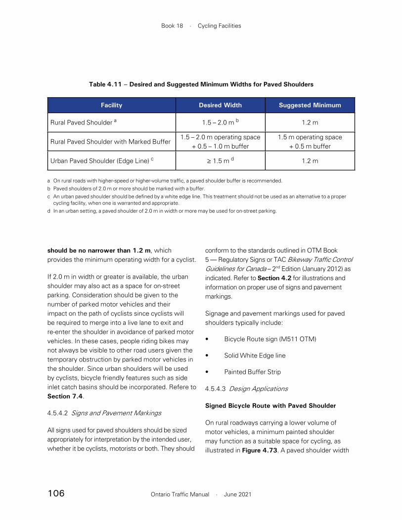
106
Book 18 · Cycling Facilities
Ontario Traffic Manual · June 2021
conform to the standards outlined in OTM Book 5 — Regulatory Signs or TAC Bikeway Traffic Control Guidelines for Canada – 2nd Edition (January 2012) as indicated. Refer to Section 4.2 for illustrations and information on proper use of signs and pavement markings.
Signage and pavement markings used for paved shoulders typically include:
• Bicycle Route sign (M511 OTM)
• Solid White Edge line
• Painted Buffer Strip
4.5.4.3 Design Applications
Signed Bicycle Route with Paved Shoulder
On rural roadways carrying a lower volume of motor vehicles, a minimum painted shoulder may function as a suitable space for cycling, as illustrated in Figure 4.73. A paved shoulder width
should be no narrower than 1.2 m, which provides the minimum operating width for a cyclist.
If 2.0 m in width or greater is available, the urban shoulder may also act as a space for on-street parking. Consideration should be given to the number of parked motor vehicles and their impact on the path of cyclists since cyclists will be required to merge into a live lane to exit and re-enter the shoulder in avoidance of parked motor vehicles. In these cases, people riding bikes may not always be visible to other road users given the temporary obstruction by parked motor vehicles in the shoulder. Since urban shoulders will be used by cyclists, bicycle friendly features such as side inlet catch basins should be incorporated. Refere to Section 7.4.
4.5.4.2 Signs and Pavement Markings
All signs used for paved shoulders should be sized appropriately for interpretation by the intended user, whether it be cyclists, motorists or both. They should
Table 4.11 – Desired and Suggested Minimum Widths for Paved Shoulders
Facility Desired Width Suggested Minimum
Rural Paved Shoulder a 1.5 – 2.0 m b 1.2 m
Rural Paved Shoulder with Marked Buffer1.5 – 2.0 m operating space
+ 0.5 – 1.0 m buffer1.5 m operating space
+ 0.5 m buffer
Urban Paved Shoulder (Edge Line) c ≥ 1.5 m d 1.2 m
a On rural roads with higher-speed or higher-volume traffic, a paved shoulder buffer is recommended.b Paved shoulders of 2.0 m or more should be marked with a buffer. c An urban paved shoulder should be defined by a white edge line. This treatment should not be used as an alternative to a proper
cycling facility, when one is warranted and appropriate.d In an urban setting, a paved shoulder of 2.0 m in width or more may be used for on-street parking.

107
Section 4 · Cycling Facilities
Ontario Traffic Manual · June 2021
diagonal lines is generally a function of vehicular speed. Diagonal lines should be spaced 18 m apart on low- to moderate-speed roadways, and 36 m on high-speed roadways. The frequency of hatching on the near or far side of an intersection may start at 3 m and gradually increase to the recommended spacing above.
Alternatively, the buffer may be defined by two parallel white lines. A 100 mm solid white line defines the boundary between the buffer and the paved shoulder, and a solid white line 100 to 200 mm wide defines the boundary between the buffer and the travel lane.
of 1.5 to 2.0 m is recommended. In constrained areas or on very low volume roadways, a width of 1.2 m may be used. Wider paved shoulders may be considered on more popular cycling routes to enable more comfortable riding.
Paved Shoulder with Buffer
A buffered paved shoulder is delineated using two 100 mm solid white lines spaced 0.5 to 1.0 m apart with diagonal hatching, shown in Figure 4.74, or a “skip pattern” rumble strip between the two edge lines, shown in Figure 4.75.
Diagonal hatched lines are should be 100 mm wide, and placed at an angle of 45 degrees in the direction of travel. The spacing between the
Figure 4.73 – Roadway with Paved ShouldersSTANDARD CROSS SECTIONSAME SCALE FOR WIDTH (250:1)SECTION ELEMENT HEIGHT: 0.8CM HIGH(SIDEWALK 0.9CM HIGH)
Paved shoulder1.5–2.0 m
Gravel shoulder(width varies)
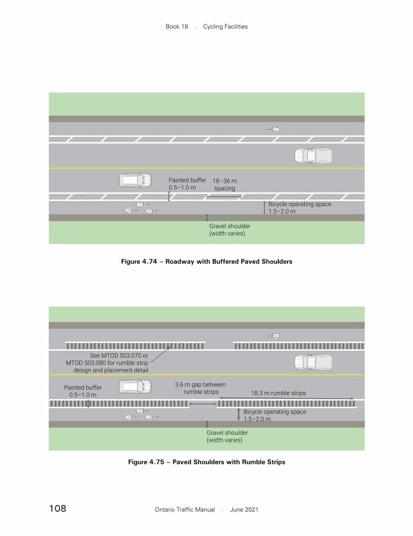
108
Book 18 · Cycling Facilities
Ontario Traffic Manual · June 2021
3.6 m gap between rumble strips
Painted buffer0.5–1.0 m 18.3 m rumble strips
Bicycle operating space1.5–2.0 m
Gravel shoulder(width varies)
See MTOD 503.070 orMTOD 503.080 for rumble strip
design and placement detail
Figure 4.75 – Paved Shoulders with Rumble Strips
Figure 4.74 – Roadway with Buffered Paved Shoulders
Painted buffer0.5–1.0 m
18–36 mspacing
Bicycle operating space1.5–2.0 m
Gravel shoulder(width varies)
109
Section 4 · Cycling Facilities
Ontario Traffic Manual · June 2021
Design Considerations for Rumble Strips
Rumble strips are grooved patterns often used to separate the travelled portion of the roadway from the paved shoulder. Rumble strips are typically implemented as a road safety measure to benefit motorists. They alert motorists through sound and vibrations to the fact that they are drifting out of the travel lane onto the shoulder. However, from a cyclist’s perspective, there are safety issues associated with rumble strips on rural roadways designated as bicycle routes.
At best, rumble strips will cause discomfort for cyclists riding over them. At worst, they may compromise a cyclist’s control of the bicycle, which is particularly dangerous where cyclists are travelling alongside fast-moving or heavy motor vehicles. Similarly, by restricting manoeuvrability around obstacles on the paved shoulder, rumble strips may cause people riding bikes to veer into the travel lane or off the edge of the paved roadway.
If rumble strips are proposed for a road that is designated as a bicycle route, a skip pattern should be implemented, consistent with MTOD 503.070 for 0.5 m wide buffers and MTOD 503.080 for 1.0 m wide buffers. The skip pattern allows people riding bikes to manoeuvre in and out of the paved shoulder to pass stopped motor vehicles and other cyclists, as well as to avoid debris on the shoulder. Periodic gap lengths of 3.6 m should be provided between each 18.3 m minimum set of shoulder rumble strips to provide cyclists with enough room to exit or enter the paved shoulder without riding over the rumble strip, as shown in Figure 4.75 and Figure 4.76.
If shoulder rumble strips with a skip pattern are applied within the buffer, then it is recommended
that the line which is furthest from the motor vehicle travel lanes follow the skip pattern to allow people riding bikes to more easily identify gaps in the rumble strips.

110
Book 18 · Cycling Facilities
Ontario Traffic Manual · June 2021
Figure 4.76 – Rumble Strips for 0.5 m Buffer Zone (Detail)

111
Section 4 · Cycling Facilities
Ontario Traffic Manual · June 2021
sciencedirect.com/science/article/abs/pii/S000145751930658X
8 Risk of injury for bicycling on cycle tracks versus in the street, Injury Prevention (2011), https://www.researchgate.net/publication/49822835_Risk_of_injury_for_bicycling_on_cycle_tracks_versus_in_the_street
9 Capacity and Behaviour on One-way Cycle Tracks of Different Widths, Trafitec (2016), https://www.trafitec.dk/sites/default/files/publications/cap%20and%20behaviour%20one%20way%20cycle%20track.pdf
10 Ibid.
11 Transportation Design Guidelines: All Ages and Abilities Cycling Routes, City of Vancouver (2017), https://vancouver.ca/files/cov/design-guidelines-for-all-ages-and-abilities-cycling-routes.pdf
12 Bike lanes next to on-street parallel parking, Accident Analysis & Prevention (2018), https://www.sciencedirect.com/science/article/abs/pii/S0001457518303981
13 Recommended Bicycle Lane Widths for Various Roadway Characteristics, National Cooperative Highway Research Program (2014), https://www.ssti.us/wp/wp-content/uploads/2014/08/nchrp_bike_lanes.pdf
14 Ibid.
15 How much space do drivers provide when passing cyclists? Understanding the impact of motor vehicle and infrastructure characteristics on passing distance, Accident Analysis & Prevention (2019), https://www.
References
1 Behavioral Adaptations to Changes in the Road Transport System, Organization for Economic Co-operation and Development (1990), https://trid.trb.org/view/350620
2 Relationship of Lane Width to Safety on Urban and Suburban Arterials, Journal of the Transportation Research Board (2007), https://nacto.org/wp-content/uploads/2016/04/1-4_Potts-Harwood-Richard-Relationship-of-Lane-Width-to-Safety-for-Urban-and-Suburban-Arterials_2007.pdf
3 Highway Capacity Manual, Transportation Research Board (2010), http://www.trb.org/Main/Blurbs/164718.aspx
4 Evaluation of Shared Lane Markings, Federal Highway Administration (2010), https://www.fhwa.dot.gov/publications/research/safety/pedbike/10041/10041.pdf
5 Lessons from the Green Lanes: Evaluating Protected Bike Lanes in the U.S., National Institute for Transportation and Communities (2014), https://trec.pdx.edu/research/project/583/Lessons_from_the_Green_Lanes:_Evaluating_Protected_Bike_Lanes_in_the_U.S.
6 NCHRP Research Report 941: Bicyclist Facility Preferences and Effects on Increasing Bicycle Trips (2020). https://www.nap.edu/catalog/25792/bicyclist-facility-preferences-and-effects-on-increasing-bicycle-trips
7 Cyclist-motor vehicle collisions before and after implementation of cycle tracks in Toronto, Canada (2020), https://www.

112
Book 18 · Cycling Facilities
Ontario Traffic Manual · June 2021
sciencedirect.com/science/article/abs/pii/S0001457518309990
16 Recommended Bicycle Lane Widths for Various Roadway Characteristics, National Cooperative Highway Research Program (2014), https://www.ssti.us/wp/wp-content/uploads/2014/08/nchrp_bike_lanes.pdf
17 Design Manual for Bicycle Traffic, CROW-Fietsberaad (2016), https://www.crow.nl/publicaties/design-manual-for-bicycle-traffic
18 Advisory Bike Lanes in North America, Alta Planning + Design (2017), https://altaplanning.com/resources/advisory-bike-lanes-north-america/
19 Ibid.
20 Geometric Design Guide for Canadian Roads, Transportation Association of Canada (2017), https://www.tac-atc.ca/en/publications-and-resources/geometric-design-guide-canadian-roads
21 MTI Report 11-19: Low-Street Bicycling and Network Connectivity (2012) Mineta Transportation Institute. https://transweb.sjsu.edu/sites/default/files/1005-low-stress-bicycling-network-connectivity.pdf
113
Section 5 · Facility Selection Process
Ontario Traffic Manual · June 2021
5. Facility Selection Process
This section provides a detailed overview of the three-step facility selection process that is recommended for cycling facility designers and practitioners. The process provides a consistent framework that is straightforward to apply and uses data that is typically readily available. The development of the facility selection process was informed by research and international best practices. Before proceeding with the facility selection process, a practitioner should have a clear understanding of the form and function of the facility types described in Section 4.
The facility selection process is not prescriptive and is intended to allow for flexibility in decision making. During the process, a practitioner should exercise good engineering judgement to account for the specific physical and operational context of the roadway. This is especially true when there are constraints in retrofitting existing corridors and intersections.
Key Outcome: Provide a framework for practitioners to determine a suitable facility type for a specific roadway corridor.
5.1 General Information
5.1.1 Principles of Facility Selection
Before a practitioner undertakes facility selection, it is important that several key principles are understood.
1. Traffic speed and volumes significantly impact road user safety and level of traffic stress: In designing for an “interested but concerned” target user, practitioners should strive to provide as much physical
separation between motor vehicle lanes and the bikeway as possible. However, the thresholds that are noted in this section for physically separated bikeways are not absolute. Practitioners should recognize that it may not be possible or practical to design all cycling facilities to an all ages and abilities standard.
2. Design criteria need to recognize context: The design criteria and associated thresholds used to select one facility type over another need to be flexible to accommodate site-specific characteristics.
3. The roadway context may be altered: The speed and traffic volume on a street can be changed through traffic calming or traffic diversion. Practitioners may consider altering the roadway context to provide greater flexibility in the facility selection process.
4. The final decision requires professional judgement: The experience and judgement of a qualified engineering designer or practitioner should ultimately influence the facility type and any added design features or enhancements that are selected.
5.1.2 Evolution of Facility Selection
Since the original publication of OTM Book 18 – Cycling Facilities in 2013, there has been an evolution in facility selection guidance. These include publications such as the 2017 Transportation Association of Canada (TAC) Geometric Design Guide for Canadian Roads, the 2017 National Association of City Transportation Officials (NACTO) Designing for All Ages & Abilities guidelines, and the 2019 Federal Highway Administration (FHWA) Bikeway Selection Guide. These documents recommend implementing physically separated bikeways at motor vehicle
114
Book 18 · Cycling Facilities
Ontario Traffic Manual · June 2021
bikeways.2,3 A survey conducted by the OTM Book 18 authors yielded similar conclusions: less than 16% of survey respondents would be comfortable cycling in mixed traffic, while over 85% would be more comfortable in physically separated bikeways. A similar NACTO study found results of 8% and 81%, respectively. As a result of this research, this update to OTM Book 18 lowers the thresholds for when separation should be introduced to better provide for low-stress facilities.
3. Passing frequency is directly related to cycling comfort and conflicts: In rural areas, many roads have low volumes of high-speed motor vehicle traffic. In these environments, the State of Wisconsin’s “Rural Bicycle Planning Guide” notes motorists can often overtake people cycling with relative ease. A conflict arises, however, when a motorist overtaking a cyclist shares the same section of the road as an oncoming motorist. The frequency of these so-called “triple-passing” conflicts increases with motor vehicle volume, and serves as a basis for establishing a volume threshold for paved shoulders on rural roadways. 4
5.2 Recommended Facility Selection Process
The facility selection process has three steps, as shown in Figure 5.1 and Figure 5.2. It is important that practitioners complete each step to ensure that they have selected the best possible facility type for the specific context. Where roadway characteristics vary along a route, practitioners should divide the corridor into sections that have similar form and function. If possible, a consistent facility type should be considered along a given route to maintain cyclist and motorist expectations.
speed and volume thresholds that are generally lower than the prior Book 18 guidance.
There has also been increasing focus on a “Safe System” or “Vision Zero” approach to road design in recent years. This approach is based on the notion that human error is unavoidable, and that the transportation network should be designed and managed to help create a forgiving system that prevents deaths or serious injuries.
The guidance provided in this section is fundamentally premised on the following critical observations:
1. Motor vehicle speed is directly related to cyclist safety: Most vulnerable road users such as pedestrians and cyclists should survive a collision if they are struck by a motor vehicle travelling at 30 km/h or less. At 40 km/h, the risk of fatality doubles. At 50 km/h, the risk of death is four to five times higher than at 30 km/h.1 As a result, in most contexts, shared roadways are only recommended for streets where motor vehicles are generally travelling at or less than 40 km/h.
2. All Ages & Abilities (AAA) design requires low-stress facilities: Practitioners should always strive to select a facility type where people aged 12 or older with a range of abilities feel comfortable riding. Where motor vehicle speeds and volumes are low and can be effectively controlled, shared operating space environments such as bicycle boulevards are viable options for low-stress routes. As motor vehicle speeds and volumes increase, so does the level of stress, and separated facilities are preferred. This guidance is supported by research which shows that potential cyclists are more inclined to cycle on physically separated

115
Section 5 · Facility Selection Process
Ontario Traffic Manual · June 2021
being appropriate, a new facility type or level of separation should be chosen and re-evaluated. Alternatively, practitioners may consider modifying the characteristics of the roadway through measures such as traffic calming or traffic diversion to provide a suitable context for the desired facility type. Practitioners are strongly encouraged to undertake Step 2, and to critically evaluate the situation and apply good engineering judgement to select the most appropriate facility type.
Step 3 guides practitioners in documenting their rationale for their final decision and associated design treatments and considerations.
A public consultation process may be considered depending on the context. Public input is particularly important where significant or costly changes to an existing roadway are proposed.
Step 1 guides practitioners to pre-select the desirable facility type based on the motor vehicle speed and the average daily traffic volume. The outcome of this step is not definitive and must be further refined through Steps 2 and 3. Step 1 is accomplished through the use of the appropriate urban/suburban or rural nomographs found in Section 5.2.3.
In Step 2, practitioners undertake a detailed and contextual evaluation of the cycling route. During this step, practitioners should complete a thorough desktop study with available data, and undertake field investigations to understand site-specific characteristics. These insights and observations are compared with application heuristics which inform the appropriateness of the facility type. If the result of Step 2 is inconclusive or points to the pre-selected facility type (from Step 1) not
Step 3Step 2Step 1
Pre-select facility type
options
Detailed & contextualevaluation
Inventory site-specific conditions
Review key design inputs & application heuristicsRe-select
facility type,consider
alternate route, or modify road
Document & justify rationale
Identify potential design
treatments
Facilty type not suitable
Facilty type suitable
Figure 5.1 – Three Step Facility Selection Flow Chart

116
Book 18 · Cycling Facilities
Ontario Traffic Manual · June 2021
Figure 5.2 – Facility Selection Input, Outcome and Process Overview
ST
EP
1S
TE
P3
ST
EP
2Pre-select facility type options
• Right-of-way and road segment limits
• Adjacent land use• Motor vehicle speed and
volumes
• Identify initial preferred level of separation
• Document pre-selected facility options and continue to step 2
• Select appropropriate nomograph based on road and land use typologies
• Identify the initial preferred level of separation and set of facility types from the nomograph
ruralurban/suburban
Key Inputs
Outcomes
Process Overview Desirable Cycling Facility Pre-Selection NomographRural Context1
Average Daily Traffic Volume (Thousands)
Post
ed S
peed
Lim
it1 (k
m/h
)
10
20
30
40
50
70
80
90
60
100
1 2 3 4 5 60 7 8 10 13 14129 11
1 In rural town/hamlet/village contexts, the urban/suburban nomograph may be used.2 Operating speeds are assumed to be similar to posted speeds. If evidence suggests this is not the case,
practitioners may consider using 85th percentile speeds or implementing measures to reduce operating speeds.
PavedShoulder(or separatemulti-use path)
SharedOperatingSpace
Paved Shoulderwith Buffer(or separatemulti-use path)
Alternate Roadway orMulti-Use Path
(typically beyond clear zoneof roadway)
Desirable Cycling Facility Pre-Selection NomographUrban/Suburban Context
Average Daily Traffic Volume (Thousands)
Post
ed S
peed
Lim
it1 (k
m/h
)
10
20
30
40
50
70
60
≥80
1 2 3 4 5 6 ≥100 7 8 9
1 Operating speeds are assumed to be similar to posted speeds. If evidence suggests this is not the case, practitioners may consider using 85th percentile speeds or implementing measures to reduce operating speeds.
2 Physically separated bikeways may always be considered in the designated operating space area of the nomograph.
3 On roadways with two or more lanes per direction (including multi-lane one-way roadways), a buffered bicycle lane should be considered the minimum with a typical facility being a physically separated bikeway.
PhysicallySeparatedBikeway— Separated Bicycle Lane— Cycle Track— Multi-Use Path
SharedOperatingSpace— Shared Street— Neighbourhood Bikeway— Advisory Bike Lane
DesignatedOperatingSpace2
— Bicycle Lane(maximum one motor vehicle lane per direction)3
— Contraflow Bicycle Lane— Buffered Bicycle Lane
Feasibility• Available space• Project type• Anticipated costs
Attractiveness• User skill level and
stress tolerance• Level of bicycle use• Cycling route function
Detailed & contextual evaluation
Roadway Characteristics• Speed• Volumes• Function• • Vehicle mix• On-street parking• Pedestrian activity• Intersection/driveway
frequency• Intersection
operations
Key Inputs & Application Heuristics
• Apply and evaluate application heuristics to the evaluated corridor
• Review data sources, conduct
documentation including photos
Evaluate initial level of separation
Is the facility appropriate for the
context?Yes Move to
Step 3
No
Re-select facility type or consider alternative
route or way tomodify road
• Identify an appropriate level of separation and facility type that match the context of the road
• Identify road contexts that require a higher level of separation or unique mitigation actions
Process Overview
Outcomes
Document & justify rationale
• If the result of step 2 differs from the level of separation and facility type options in step 1, prepare a rationale for selecting a different facility type or separation option
• come to a conclusion and rationale
• Identify potential design treatments and enhancements that may mitigate potential
Outcomes

117
Section 5 · Facility Selection Process
Ontario Traffic Manual · June 2021
for urban/suburban environments should be applied.
Urban/Suburban Environments (Figure 5.4): Roads in urban and suburban environments are typically surrounded by residential, commercial, industrial, institutional or related land uses. Urban and suburban environments differ primarily in their density, degree of car dependency and level of transit service. Urban environments also tend to have a higher frequency of conflict points due to intersections and driveways.
5.2.2 Level of Separation Overview
People cycling may be accommodated in the same lane as motor vehicles, in a designated lane adjacent to motor vehicles or in a facility that is physically separated from the adjacent motor vehicle travel lane. Examples for each of these levels of separation in urban/suburban and rural environments are shown in Table 5.1 and Table 5.2.
On urban, suburban and rural corridors with high volumes of high-speed motor vehicle traffic, the preferred solution is typically a facility that
5.2.1 Urban/Suburban & Rural Environment Considerations
The cycling facility type selection process has been developed for application in both urban and rural environments. However, when going through the process, practitioners must be aware that urban and rural roadways have different characteristics that affect the result of facility selection. Even in similar speed and volume combinations, the result of urban and rural facility selection will be different to account for the differences in roadway operation. Table 5.1 provides typical characteristics and features of rural and urban environments.
Rural/Rural Town Environment (Figure 5.3): This is characterized by roads that pass through areas with limited current or planned development. The density is low with typically large building setbacks. Sample contexts include farmland and forest. Occasionally, a rural environment will transition into a rural town or a village with mixed retail, institutional and residental land uses. Where these corridors contain closely spaced driveways, on-street parking or pedestrian activity, the guidance
Figure 5.3 – Rural & Rural Town Environments
Source: WSP
Figure 5.4 – Urban & Suburban Environments
Source: WSP

118
Book 18 · Cycling Facilities
Ontario Traffic Manual · June 2021
the directness between major trip generating areas, network connectivity and the spacing of parallel routes. Similarly, when considering the feasibility of a bikeway outside the clear zone, practitioners should consider the frequency of driveways and intersections, sightlines at these locations and the appropriateness of one-way versus two-way cycling facilities.
is physically separated, on a nearby alternate corridor or a bikeway outside of the clear zone of the roadway. The clear zone refers to the area outside of the paved and granular surface of the road, typically beyond a barrier curb, verge or ditch adjacent to the road. When assessing the potential to use an alternate corridor, practitioners should consider cyclists’ access to popular destinations,
Shared Operating Space Designated Operating Space Physically Separated Bikeways
Des
crip
tion
People cycling are expected to share traffic lanes with motor vehicles, which may be indicated with pavement markings or signage. This scenario is most appropriate on roads with low motor vehicle traffic volumes and speeds.
Space in the road right-of-way is designated exclusively for cycling, but there are no physical barriers separating people cycling from motorists. These facilities are preferred on corridors with relatively low motor vehicle speeds and volumes.
People cycling ride on dedicated cycling facilities that are separated from motor vehicle traffic by horizontal space and physical barriers. Various kinds of physical barriers can be used ranging from flexible bollards to curbs, concrete barrier walls and guide rails. These facilities should be considered where motor vehicle volumes and speeds are moderate or high.
Faci
lity
Typ
e
Opt
ions
• Shared Roadway
• Neighbourhood Bikeway
• Advisory Bicycle Lanes
• Bicycle Lanes
• Buffered Bicycle Lanes
• Contraflow Bicycle Lanes
• Separated Bicycle Lanes
• Cycle Tracks
• In-boulevard Multi-use Paths
Table 5.1 – Urban & Suburban Levels of Separation

119
Section 5 · Facility Selection Process
Ontario Traffic Manual · June 2021
Through the selection process, designers must critically evaluate the situation by using sound engineering judgement to select an appropriate facility and identify design features to mitigate context specific challenges.
In rural areas where traffic speeds are high and sightlines are poor, providing designated operating space such as paved shoulders, rather than shared operating space, becomes more critical since motorists cannot see oncoming traffic to safely pass cyclists. Alternatively, traffic calming measures can be used to reduce operating speeds in these areas.
Shared Operating Space Paved Shoulder(may include buffer)
In-Boulevard Multi-use Path orOff-road Trail
Des
crip
tion
Roadways with low motor vehicle volumes and speeds where people cycling share the operating space with motor vehicles. On very low-volume rural roads (< 1000 ADT), there will be few vehicle/cyclist passing events, and a shared lane may provide a comfortable condition.
People on bikes ride on a paved surface adjacent to the traveled portion of the roadway in the same direction as traffic. In a rural context, a paved shoulder may also be used for pedestrian activity. Motorists may be allowed to stop or park on the shoulder, but do not typically operate within the paved shoulder. A buffer may be added for additional separation from motor vehicle traffic and to minimize the aerodynamic effects from large trucks.
A multi-use path beyond the clear zone of the roadway or an off-road trail provide the highest degree of separation between people cycling and motorists. These facilities should be considered where motor vehicle speeds and volumes are high and where there are high volumes of trucks. Consideration should be given to potential sightline issues and conflicts at intersections and driveways, which should be mitigated through design treatments found in Section 6.
Table 5.2 – Rural Levels of Separation
120
Book 18 · Cycling Facilities
Ontario Traffic Manual · June 2021
and consideration may be required to make this determination.
5.2.4 Step 2: Detailed & Contextual Evaluation
The nomograph tool in Step 1 helps in pre-selecting the preferred level of separation and identifying a set of facility type options. However, the facility may not always be the most appropriate or practical solution given site-specific design factors. Completion of Step 2 is critical to ensure that the assumptions embedded in Step 1 of the process are confirmed and validated.
In Step 2, practitioners should conduct desktop reviews and field investigations to better understand the context of the corridor. Site-specific conditions should be documented in the form of a data review summary, field notes, photos and observations or public and stakeholder feedback. The intent is to have sufficient evidence to confirm whether or not the level of separation and facility type pre-selected in Step 1 are suitable for the context of the roadway.
A set of application heuristics or knowledge-based rules have been developed to aid practitioners in Step 2 of the facility selection process. These heuristics link specific site conditions to appropriate facility types and supplementary design features.
The application heuristics are particularly important when the nomograph indicates that a corridor is in the nomograph transition zone. Generally, a higher level of separation in these contexts is preferred unless there are factors suggesting this may be unnecessary or infeasible. If the level of separation or facility type pre-selected in Step 1 is not compatible with the site context, a new facility should be chosen and re-evaluated. The
5.2.3 Step 1: Pre-select Facility Type Options
Facility pre-selection is undertaken through the use of a nomograph which helps practitioners identify an appropriate level of separation and a set of reasonable facility types for a given context based on the motor vehicle posted speed (or operating speed where speeds significantly differ from posted limits) and average daily traffic volume. Separate nomographs have been provided for urban / suburban and rural contexts in Figure 5.5 and Figure 5.6. The outcome of Step 1 is not conclusive in itself. It is very important that the pre-selected facility types be validated through Step 2 and the design decision and rationale documented in Step 3.
The nomograph thresholds are generally consistent with guidance from other frequently used cycling guidelines including NACTO (USA)5, TAC (Canada)6, FHWA (USA)7, and MTO8.
The guidance is intended for corridors with one to three lane cross sections. Streets with two or more through lanes in each direction should at a minimum have a buffered bike lane or buffered paved shoulder, with physical separation being preferred.
If evidence suggests that operating speeds are higher than the posted limit, practitioners may consider using the 85th percentile operating speed as well as implementing traffic calming measures or increasing enforcement to decrease operating speeds.
Both urban / suburban and rural nomographs have transition zones between the solid colours. These zones represent a set of speed and volume parameters that may be compatible with either facility category. Further evaluation

121
Section 5 · Facility Selection Process
Ontario Traffic Manual · June 2021
Desirable Cycling Facility Pre-Selection NomographUrban/Suburban Context (Step 1)
Average Daily Traffic Volume (Thousands)
Post
ed S
peed
Lim
it1 (k
m/h
)
10
20
30
40
50
70
60
≥80
1 2 3 4 5 6 ≥100 7 8 9
1 Operating speeds are assumed to be similar to posted speeds. If evidence suggests this is not the case, practitioners may consider using 85th percentile speeds or implementing measures to reduce operating speeds.
2 Physically separated bikeways may always be considered in the designated operating space area of the nomograph.
3 On roadways with two or more lanes per direction (including multi-lane one-way roadways), a buffered bicycle lane should be considered the minimum with a typical facility being a physically separated bikeway.
PhysicallySeparatedBikeway— Separated Bicycle Lane— Cycle Track— Multi-Use Path
SharedOperatingSpace— Shared Street— Neighbourhood Bikeway— Advisory Bike Lane
DesignatedOperatingSpace2
— Bicycle Lane(maximum one motor vehicle lane per direction)3
— Contraflow Bicycle Lane— Buffered Bicycle Lane
Figure 5.5 – Desirable Cycling Facility Pre-selection Nomograph — Urban/Suburban Context
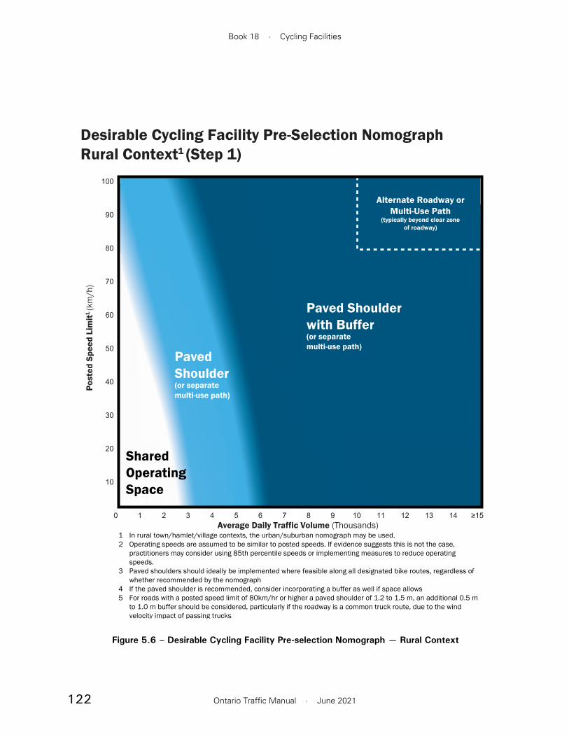
122
Book 18 · Cycling Facilities
Ontario Traffic Manual · June 2021
Desirable Cycling Facility Pre-Selection NomographRural Context1 (Step 1)
Average Daily Traffic Volume (Thousands)
Post
ed S
peed
Lim
it1 (k
m/h
)
10
20
30
40
50
70
80
90
60
100
1 2 3 4 5 6 ≥150 7 8 10 13 14129 11
1 In rural town/hamlet/village contexts, the urban/suburban nomograph may be used.2 Operating speeds are assumed to be similar to posted speeds. If evidence suggests this is not the case,
practitioners may consider using 85th percentile speeds or implementing measures to reduce operating speeds.
3 Paved shoulders should ideally be implemented where feasible along all designated bike routes, regardless of whether recommended by the nomograph
4 If the paved shoulder is recommended, consider incorporating a buffer as well if space allows5 For roads with a posted speed limit of 80km/hr or higher a paved shoulder of 1.2 to 1.5 m, an additional 0.5 m
to 1.0 m buffer should be considered, particularly if the roadway is a common truck route, due to the wind velocity impact of passing trucks
PavedShoulder(or separatemulti-use path)
SharedOperatingSpace
Paved Shoulderwith Buffer(or separatemulti-use path)
Alternate Roadway orMulti-Use Path
(typically beyond clear zoneof roadway)
Figure 5.6 – Desirable Cycling Facility Pre-selection Nomograph — Rural Context
123
Section 5 · Facility Selection Process
Ontario Traffic Manual · June 2021
be more qualitative in nature and are therefore not categorized in a table. Before applying the information in Table 5.3, or conducting analysis from the other application heuristics, the practitioner should have a concrete understanding what each heuristic means and the associated implications for facility selection.
5.2.4.1 Roadway Characteristics
Motor vehicle speed: As the speed differential between motorists and people cycling increases, so does the collision risk for cyclists using that roadway. Moreover, the absolute speed of motor vehicles is directly related to the risk of serious injury or death for a person cycling. When selecting a facility type, the 85th percentile operating speed should be considered, since even small numbers of vehicles traveling at high speeds can increase risk and degrade the comfort level of people cycling. If high outlying speeds are observed, consider measures to calm traffic and deter speeding.
Motor vehicle volume and number of traffic lanes: As motor vehicle volume increases, so does the frequency of passing events for people cycling using the roadway. This increases the level of stress experienced by a person cycling, and increases the risk of collisions. The number of traffic lanes also affects level of stress and, in particular, the complexity and number of conflict points that a road user has to manage at intersections. For planning purposes, the future year traffic volumes should be used when selecting an appropriate facility type. While the values presented are AADTs, peak hour volumes and seasonal variability should also be considered when selecting a facility type.
conclusions and potential next steps should be documented as part of Step 3.
The application heuristics have been grouped into the following functional categories: roadway characteristics, feasibility and attractiveness.
Roadway Characteristics
1. Motor vehicle speed
2. Motor vehicle volume and number of traffic lanes
3. Function of street, road or highway
4. Vehicle mix
5. On-street parking
6. Pedestrian activity
7. Frequency of intersections and crossings
Feasibility
8. Available space
9. Anticipated costs
10. Type of roadway improvement project
Attractiveness
11. User skill level and stress tolerance
12. Level of cycling usage
13. Function of route within the cycling network
Table 5.3 provides a visual summary of the road characteristic heuristics. Roadway characteristics are typically easier to quantify than feasibility and attractiveness considerations, which tend to
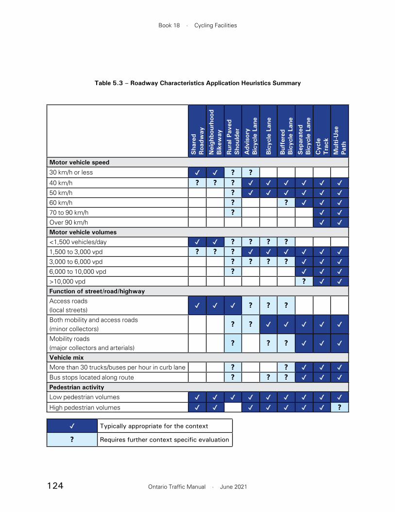
124
Book 18 · Cycling Facilities
Ontario Traffic Manual · June 2021
Table 5.3 – Roadway Characteristics Application Heuristics Summary
✔ Typically appropriate for the context
❓ Requires further context specific evaluation
Sha
red
Roa
dway
Nei
ghbo
urho
od
Bik
eway
Rur
al P
aved
Sho
ulde
r
Adv
isor
y
Bic
ycle
Lan
e
Bic
ycle
Lan
e
Buf
fere
d
Bic
ycle
Lan
e
Sep
arat
ed
Bic
ycle
Lan
e
Cyc
le
Tra
ck
Mul
ti-U
se
Path
Motor vehicle speed
30 km/h or less ✔ ✔ ❓ ❓40 km/h ❓ ❓ ❓ ✔ ✔ ✔ ✔ ✔ ✔50 km/h ❓ ✔ ✔ ✔ ✔ ✔ ✔60 km/h ❓ ❓ ✔ ✔ ✔70 to 90 km/h ❓ ✔ ✔Over 90 km/h ✔ ✔Motor vehicle volumes<1,500 vehicles/day ✔ ✔ ❓ ❓ ❓ ❓1,500 to 3,000 vpd ❓ ❓ ❓ ✔ ✔ ✔ ✔ ✔ ✔3,000 to 6,000 vpd ❓ ❓ ❓ ❓ ✔ ✔ ✔6,000 to 10,000 vpd ❓ ✔ ✔ ✔>10,000 vpd ❓ ✔ ✔Function of street/road/highwayAccess roads (local streets)
✔ ✔ ✔ ❓ ❓ ❓
Both mobility and access roads (minor collectors)
❓ ❓ ✔ ✔ ✔ ✔ ✔
Mobility roads (major collectors and arterials)
❓ ❓ ❓ ✔ ✔ ✔
Vehicle mixMore than 30 trucks/buses per hour in curb lane ❓ ❓ ✔ ✔ ✔Bus stops located along route ❓ ❓ ❓ ✔ ✔ ✔Pedestrian activityLow pedestrian volumes ✔ ✔ ✔ ✔ ✔ ✔ ✔ ✔ ✔High pedestrian volumes ✔ ✔ ✔ ✔ ✔ ✔ ✔ ❓

125
Section 5 · Facility Selection Process
Ontario Traffic Manual · June 2021
and heavy commercial vehicles, and the increased severity of any resulting collision. Air turbulence generated by these high-sided vehicles also has a more significant impact on the difficulty of controlling a bicycle. As the volume of heavy vehicles increases, so too does the desirability of providing buffers or physical separation between people cycling and motorized traffic. Stationary trucks and buses may also occupy a cycling facility if adequate separation techniques are not used. When this occurs, it forces people cycling to merge into motor vehicle lanes elevating the level of stress cyclists experience. These stationary
Sha
red
Roa
dway
Nei
ghbo
urho
od
Bik
eway
Rur
al P
aved
Sho
ulde
r
Adv
isor
y
Bic
ycle
Lan
e
Bic
ycle
Lan
e
Buf
fere
d
Bic
ycle
Lan
e
Sep
arat
ed
Bic
ycle
Lan
e
Cyc
le
Tra
ck
Mul
ti-U
se
Path
On-street parkingParallel parking; low turnover ❓ ❓ ❓ ❓ ❓ ✔ ✔ ✔Parallel parking; high turnover ✔ ✔ ✔Perpendicular or angle parking ✔ ✔ ✔Frequency of intersections and crossingsLimited intersections and driveway crossings ❓ ❓ ✔ ✔ ✔ ✔ ✔ ✔ ✔Low-volume driveways or unsignalized intersections
✔ ✔ ✔ ✔ ✔ ✔ ✔ ✔ ✔
Frequent high-volume driveways or unsignalized intersections
❓ ❓ ✔ ✔ ❓
Signalized intersections with high-volume turning conflicts
❓ ✔ ✔ ❓
✔ Typically appropriate for the context
❓ Requires further context specific evaluation
Function of street, road or highway: While generally reflected in motor vehicle volumes, the function of a roadway for access and mobility on local roads, minor collectors and major arterials differs and should be considered in cycling facility decisions. The significance of this factor will be higher in cases where volume or speed data are unavailable.
Vehicle mix: Heavy vehicles, such as trucks and buses have a greater influence on people cycling than light passenger vehicles. This is partly due to the larger difference in mass between cyclists

126
Book 18 · Cycling Facilities
Ontario Traffic Manual · June 2021
manage potential conflicts and provide extra space for cycling facility implementation.
Pedestrian activity: Consideration of pedestrian activity, flow and demographics is important to minimize potential conflicts between people on bikes and people walking. Where there are very low volumes of pedestrians and few active transportation trip generators adjacent to the cycling route, a multi-use path may be suitable. As pedestrian activity increases along a main street, in an employment centre or at a transit hub, facility types that function as shared pedestrian and cyclist space are not desirable. Thus, separate cycling and pedestrian facilities are recommended. Thresholds for separation can be found in Table 4.5. The analysis should also consider the full diversity of pedestrians by age and ability and how this might impact facility type and separation. Consideration should be given to the delineation between people walking and cycling, especially when a cycling facility is at the same elevation as the sidewalk. More details on accessible pedestrian/cyclist separation techniques can be found in Section 7.
Frequency of intersections and crossings: As the frequency of intersections and access points increases, so does the potential for conflict. Sound engineering judgement must be applied with respect to the specific characteristics of the site and the application of crossing treatments. The potential severity and number of conflicts will vary based on the turning movement volumes. Treatments outlined in Section 6 such as various crossing setback distances, raised corner islands, parking restrictions, raised crossings, protected signal phasing and various pavement markings should be considered based on the site-specific context to mitigate the risk of a collision at these locations.
vehicles can also obstruct sightlines between motorists and people cycling, further increasing risk exposure.
On-street parking: The presence of on-street parking has a considerable influence on both the safety and comfort of cyclists. In particular, the configuration of on-street parking, the turnover rate and separation from the cycling facility affect the level of comfort and risk exposure of people cycling. Turnover is partly related to land use, such as residential or retail, and to parking by-laws that specify maximum parking duration. Practitioners should consider the potential for conflict between motor vehicles entering and leaving parking spots along with the risk of “dooring”. The objective should be to avoid or mitigate conflicts to the extent possible, while recognizing parking needs and alternatives.
Where there is parallel parking and low vehicle turnover, a variety of facility types could be suitable. However, when turnover is expected to be high and the risk of cyclist and motorist conflict increases, consideration should be given to providing physically separated bikeways positioned on the passenger side of the vehicle. This eliminates the risk associated with vehicles entering and exiting parking spaces, often reduces the risk of dooring and is generally more space efficient since only a single buffer zone is required, rather than the two buffer zones that are preferred for cycling facilities between travel lanes and parking lanes. Where there is angled or perpendicular parking, and a vehicle can immediately enter or leave a parking spot without checking blind spots, a physically separated facility on the passenger side is strongly recommended. Where feasible, angled or perpendicular parking should be reconfigured as parallel parking to better

127
Section 5 · Facility Selection Process
Ontario Traffic Manual · June 2021
users given the characteristics of the site. However, cost and lack of funds should not be used to justify poorly designed or functionally substandard facilities. Where sufficient funding levels are not available or if the facility is not cost effective, consider conducting an analysis of alternative options such as choosing a parallel route or different separation techniques listed in Table 4.2.
Type of roadway improvement project: Roadway construction, reconstruction, resurfacing or retrofits often affect the feasibility of a facility type for a given context. The type of improvement may change assumptions regarding available space, cost and other constraints identified in the other application heuristics. Combining a compatible facility with the planned roadway improvement project can result in achieving cost efficiencies. However, practitioners should consider the completeness of the cycling network and not make decisions solely based on economies of scale.
Where there is new construction or road reconstruction, there is often a viable opportunity to implement an All Ages and Abilities (AAA) facility, often without significantly adding to the cost. During reconstruction, additional space may be provided by relocating curbs or reconfiguring lanes.
Where the existing road space will be retained in a resurfacing or retrofit project, redistributing existing road space to accommodate a dedicated or physically separated bikeway is often an effective and affordable approach. Refer to Section 8.2 for more details.
5.2.4.3 Attractiveness
User skill level and stress tolerance: It is important to consider different user skill levels and level of stress tolerance during the design of cycling facilities. It is generally a goal to have facilities that are suited to
5.2.4.2 Feasibility
Available space: The space available to serve all functions and users of a roadway is limited. Consequently, practitioners should consider the constraints imposed by curbs, pinch points and physical barriers when choosing an appropriate facility for a particular section of roadway.
For retrofit projects, where sufficient roadway width exists to adequately accommodate motorists and the preferred cycling facility, typically within the curbs, space can be redistributed through the narrowing of lanes or removal of turn lanes or parking lanes. Where the roadway width is insufficient for the preferred facility type, consideration should be given to implementing a facility adjacent to the roadway or on a nearby parallel alternate route. The TAC Geometric Design Guide for Canadian Roads (2017) provides guidance on recommended lane widths relating to the function of a road.9
At local pinch points there could be significant risk and discomfort if a dedicated cycling facility cannot be continued. Pinch points often occur where a road accommodates a turn lane or narrows due to the proximity of a physical barrier such as a tunnel or narrow bridge. Where feasible, localized widening should be undertaken to provide continuous cycling facilities of consistent width through the area. Where the level of effort to widen the road is too significant or impractical, practitioners should use good engineering judgement and consider the suitability and feasibility of alternative solutions. More details on mitigation measures are provided in Section 6.
Anticipated cost: The implementation of cycling infrastructure projects is often limited based on the availability of funding. Designers should seek to ensure that their solutions are cost-effective, meet project objectives and are appropriate for the intended

128
Book 18 · Cycling Facilities
Ontario Traffic Manual · June 2021
for users of all ages and abilities, which affects the facility selection and design. When a facility is not designed to that level, a suitable rationale should be documented. Where there is an existing parallel route, there may be an opportunity to provide different facility types that appeal to users of various abilities and tolerance to stress. The facility selection process should encourage continuity of adjacent facility types to create better predictability for users.
5.2.5 Step 3: Justify & Document Rationale
Step 3 focuses on confirming and documenting the recommended facility type and the selection process. Once all factors from Steps 1 & 2 are considered, it is possible to make a final decision regarding the appropriateness of the facility type for the specific roadway section being considered. Additional design features or enhancements, such as intersection and crossing design discussed in Section 6, and transit stops and other facility design treatments discussed in Section 7, should be considered in the design phase.
Once the facility type has been selected, it is imperative that the practitioner document each decision made during the facility selection process, the steps taken to reach the decisions, as well as the rationale behind the final facility selection. This will assist the practitioner should they be required to explain any compromises or exceptions they may have made for operational, cost or other considerations based on their engineering judgement.
users of all ages and abilities and that are low stress in nature. AAA facilities are contextual and depend on the speed and volume of traffic. In high-speed and high-volume contexts, they would be a physically separated bikeway. However, it may not be feasible to implement every cycling route as a AAA facility. Where a facility is not AAA, a suitable rationale should be provided explaining the nature of the constraints and the anticipated design users. The network planning process can inform the purpose of the cycling network and provide insight towards the users and their skill level.
Users of rural facilities typically have more experience, and would be completing longer distance cycling trips. It may not be practical to implement a AAA facility in this context. However, there may be locations in the rural context where a AAA facility is desirable. In these cases, a multi-use path separate from the roadway would typically be appropriate.
Level of cycling usage: As the volume of people cycling increases, there are more potential interactions with motor vehicles. Consideration should be given to provide more separation from motor vehicles. Where there is latent cycling demand such as employment centres, neighbourhoods, transit nodes, schools, parks, and recreational or shopping facilities, designated or physically separated facilities should be considered to accommodate the anticipated volume of people cycling coming to and from the trip generator.
Function of route within the cycling network: The various functions of a cycling network are outlined in Section 3. Network Planning. The recreational, local neighbourhood, and commuter spine cycling networks form the overall cycling system. The anticipated user group for each cycling route varies by the function of the route as defined in the system. It should be determined if a facility can be designed

129
Section 5 · Facility Selection Process
Ontario Traffic Manual · June 2021
References
1 International Transport Forum, Speed and Crash Risk, 2018.
2 Dill, J. & McNeil, N. (2016). Revisiting the Four Types of Cyclists: Findings from a National Survey. Journal of the Transportation Research Board, 2587, 90-99.
3 National Association of City Transportation Officials, Equitable Bikeshare Means Bike Lanes, 2016.
4 Wisconsin Department of Transportation, Wisconsin Rural Bicycle Planning Guide, 2006.
5 National Association of City Transportation Officials, Designing for All Ages & Abilities, Contextual Guidance for High-Comfort Bicycle Facilities, 2017.
6 U.S. Department of Transportation Federal Highway Administration, Bikeway Selection Guide, 2019.
7 Transportation Association of Canada, Geometric Design Guide for Canadian Roads, Chapter 5 - Bicycle Integrated Design, 2017.
8 Ministry of Transportation Ontario, MTO Bikeways Design Manual, 2014.
9 Transportation Association of Canada, Geometric Design Guide for Canadian Roads, Chapter 4 - Cross Section Elements, 2017.
130
Book 18 · Cycling Facilities
Ontario Traffic Manual · June 2021
including on-road to in-boulevard transitions and one-way to two-way transitions.
Section 6.7 Driveway Treatments provides guidance on the design of driveway crossings for on-road and in-boulevard cycling facilities.
Section 6.8 Roadway Crossing Treatments outlines the crossing treatment systems available at locations such as mid-block crossings, roundabouts, right-turn channels and freeway ramps. These systems include uncontrolled crossings, pedestrian crossovers and signalized crossings.
Section 6.9 Roundabouts provides design guidance for cycling facilities at neighbourhood traffic circles, single-lane roundabouts and multi-lane roundabouts.
Section 6.10 Right Turn Channels introduces alternative treatments for cycling facilities at channelized turns.
Section 6.11 Interchanges and Ramp Crossings provides design guidance for cycling facilities at interchanges and ramp crossings.
Section 6.12 Grade-Separated Crossings provides design guidance for bridges and tunnels to provide connections across physical barriers and vertically separating people riding bikes from motor vehicle traffic.
Section 6.13 Railway Crossings describes recommended treatments for cycling facilities at railway crossings.
Key Outcome: This section describes a range of intersection and crossing design treatments, and provides design considerations and application guidance for each treatment option.
6. Intersections and Crossings
This section provides guidance related to the design of cycling facilities at intersections and crossings. This includes general geometric considerations and guidance on the use of pavement markings and signage. Signalization considerations are also introduced as they relate to intersection design. However, practitioners should refer to OTM Book 12A – Bicycle Traffic Signals for detailed guidance.
This section is organized as follows:
Section 6.1 Intersection Design Principles provides an overview of design principles that guide the design of cycling facilities at intersections.
Section 6.2 Standard Pavement Markings and Signs introduces signage and pavement markings that are commonly used at intersections and crossings.
Section 6.3 Intersection Approaches and Crossings provides guidance on the design of cycling facilities on approach to, and through intersections.
Section 6.4 Bicycle Left Turn Treatments introduces several design treatments that facilitate left turn movements for bicycles at intersections.
Section 6.5 Bicycle Traffic Signals introduces several signalization strategies for bicycle traffic which may be employed in conjunction with the geometric treatments described in Section 6.3 and Section 6.4.
Section 6.6 Facility Transitions provides design guidance for transitions between facility types,
131
Section 6 · Intersections and Crossings
Ontario Traffic Manual · June 2021
At signalized intersections, separation may be provided in space, in time or both.
Spatial separation typically carries mid-block elements of separation through to the intersection, and applies design treatments that minimize conflicts with turning motor vehicles.
Temporal separation may be provided by operating cycling movements and conflicting turning motor vehicle movements on different signal phases.
The following design principles are applied at intersections:
Reduce motor vehicle speeds. Lower motor vehicle speeds provide increased time for motorists and people riding bikes to recognize a potential threat and to maneuver acccordingly to reduce the severity of collisions. In addition, research has shown that slower turning speeds result in increased motorist yielding rates.2 Where turning motorists permissively cross the path of people cycling, a turning speed of 15 km/h or less is recommended. Where cyclists and motorists merge or weave on the intersection approach, motor vehicle speeds of 30 km/h or less through the conflict zone are recommended. A number of techniques are available to the practitioner to reduce the speed of turning motor vehicles, including:
• Reducing turning radii
• Implementing truck aprons
• Implementing raised cycling/pedestrian crossings
• Implementing median refuges or other “centreline hardening” treatments on the receiving roadway
6.1 Intersection Design Principles
Intersections are the place where most conflicts between bicycles and motor vehicles occur.1 At intersections and crossings, practitioners are faced with the complexity of managing conflicts among pedestrians, cyclists and motorists while developing a design that maximizes safety, comfort and convenience for all road users. Intersection design is critically important in supporting the “interested but concerned” design user, who may be discouraged from cycling if faced with uncomfortable interactions with motor vehicles at intersections.
Intersection design is complex. There are many interdependent geometric design parameters, and there is a relationship between geometric design which must be balanced with the operational requirements of the expected users. In some cases, space constraints may limit available design choices. In other cases, existing intersections may be designed with wide lanes and generous corner radii, which allow motorists to make turns at relatively high speeds. This increases the potential for conflict and decreases safety and comfort for people riding bikes.
In general, the principles of cycling facility selection introduced in Section 5 also apply at intersections. Similar to mid-block locations, the need for separation at intersections increases with motor vehicle speeds and volumes. At low-speed and low-volume intersections, such as at the intersection of two quiet residential streets, it may not be necessary to provide any dedicated treatment for cyclists. However, on roads with higher traffic speeds or volumes, it is desirable to provide separation between motor vehicles and people cycling.

132
Book 18 · Cycling Facilities
Ontario Traffic Manual · June 2021
Use clear and consistent design language. Pavement markings and signage should identify conflict zones and clearly communicate the right-of-way and expected yielding behaviour. Clear and consistent design throughout various intersection types within a municipality and across the Province is important to provide predictability and to minimize confusion among all road users.
Minimize delay. The frequency of risk-taking behaviour by pedestrians, cyclists and motorists increases as intersection delay increases. The safety benefits of design treatments may not be realized if they introduce delays that are perceived to be unnecessary or unreasonable. Strategies to minimize delay for people cycling include:
• Avoiding the use of unnecessary stop signs on low-speed and low-volume cycling routes such as neighbourhood bikeways
• Providing refuge islands to allow a two-stage crossing at unsignalized intersections
• Reducing cycle lengths at signalized intersections
• Coordinating signals along major cycling routes to provide a 20 km/h bicycle “green wave” that reduces the amount of overall wait time for people cycling
• Narrowing the width of the receiving roadway
Separate high-risk conflicts in time or space. Where a high volume of conflicts between people riding bikes and turning motor vehicles is present, or where motor vehicle speed cannot be reduced through geometric design techniques, protected signal phasing is an effective way of mitigating conflicts. This phasing provides separation in time between cycling movements and conflicting motor vehicle turning movements. Protected phasing should be considered for all two-way cycling facilities due to the increased collision risk associated with these facilities at intersections. See Section 6.5 for detailed guidance. In many cases, additional signal phases can be very short, or only called when necessary, and there are often opportunities to overlap with non-conflicting phases.
Maximize visibility. All road users need to have clear sight lines to one another on the approach and through the intersection, to provide sufficient time to identify a potential conflict and react if necessary. To avoid visual obstructions, on-street parking should be restricted for a suitable clear sight distance on the intersection approach as outlined in Table 6.1. At signalized intersections, visibility can be improved by positioning people riding bikes ahead of motor vehicles through treatments such as:
• Advanced stop bars for cyclists (see Section 6.3.3)
• Bike boxes (see Section 6.4.3)
• Leading bicycle signal intervals (see Section 6.5.1)

133
Section 6 · Intersections and Crossings
Ontario Traffic Manual · June 2021
6.1.1 Common Collision Types
Practitioners should review the cyclist-motor vehicle collision history for the particular intersection and similar intersections across the municipality. A review of dominant collision types may provide insight into causal factors which can be explicitly addressed in the design process.3 The three most common types of collision are shown in Figure 6.1. These are:
1. Right hook: A motorist turning right collides with a through-moving cyclist. Possible Countermeasures: Advance stop bar for cyclists; continue solid lane line to stop bar; reduce effective curb radius; leading bicycle interval or separate signal phasing; setback crossing; improve sight distance
Right Hook Left Hook Through Collision
Figure 6.1 – Common Collision Types
2. Left hook: A motorist turning left collides with a through-moving cyclist. Possible Countermeasures: Provide protected left-turn signal phase; conflict zone pavement markings through crossing; physical element on centreline or reduce width of receiving street.
3. Through collision: A motorist entering the intersection from the minor street collides with a cyclist travelling through the intersection. Left and through motor vehicle conflicts typically only apply at unsignalized intersections. Possible Countermeasures: Prohibit right turn on red; reduce effective curb radius; improve sight distance; implement raised crossing.
134
Book 18 · Cycling Facilities
Ontario Traffic Manual · June 2021
6.2 Standard Pavement Markings and Signs
At intersections and crossings, the use of consistent pavement markings and signs is important to clearly communicate expected behaviour to all road users. Pavement markings and signage are critical elements of design language. This section describes common pavement markings and signage that are recommended at intersections and crossings.
6.2.1 Pavement Markings
6.2.1.1 Crossrides
At crosswalks at signalized intersections, and at pedestrian crossovers, cyclists are legally required under the Highway Traffic Act (HTA) to dismount and cross as a pedestrian. A crossride provides a designated space where cyclists are permitted to ride across an intersection or crossing.
Crossrides are denoted by “elephant’s feet” pavement markings, typically 400 x 400 mm in size, which indicate the area in which people riding bikes are expected to travel. Crossride markings may be marked within or adjacent to the cycling path of travel. Bicycle stencils and directional arrows are optional, but may be placed within the path of cycling travel to emphasize the use and the direction of travel.
Crossrides should be marked where in-boulevard cycling facilities or two-way cycling facilities pass through an intersection. Where on-street cycling facilities pass through an intersection, dashed guide lines may be used, as described in Section 6.2.1.2.
Crossride pavement markings do not in themselves have any regulatory effect under the HTA. The
required behaviour of motor vehicles in the presence of a bicycle crossing is established through regulatory signage or traffic signals, consistent with the HTA or municipal by-laws. In keeping with the principle of applying a consistent design language, crossride pavement markings should only be applied where people cycling have the right-of-way over intersecting traffic. These include situations where the cycling movement is governed by traffic signals where turning motor vehicles are required to yield to cyclists on a green indication, at minor intersections where the cross traffic is controlled by a stop or yield sign, or at driveways, where motor vehicles entering or exiting the roadway must yield to pedestrians and cyclists.
In situations where motorists are always required to yield to cyclists, for example, at driveways, a yield line may be marked adjacent to the crossride to reinforce the requirement to yield, as discussed in Section 6.2.1.3.
Crossrides should not be marked in situations where people cycling are required to yield to motor vehicle traffic.
There are three types of crossrides:
• Separate crossride
• Combined crossride
• Mixed crossride
In general, the arrangement of pedestrians and cyclists in the crossride should mimic the arrangement on the approach to the crossing. For example, if pedestrians and cyclists approach a crossing on separate facilities, they should remain separated through the crossing with a separated crossride. If pedestrians and cyclists are mixed on

135
Section 6 · Intersections and Crossings
Ontario Traffic Manual · June 2021
the approach, for example, on a multi-use path, a combined crossride or mixed crossride is preferred.
A “dismount and walk” treatment is discouraged, regardless of intersection size and complexity. Compliance with these treatments is generally poor, and a requirement to dismount may introduce accessibility challenges for some people. Where there are high-risk conflicts, practitioners are encouraged to provide temporal separation with signal phasing.
Separate Crossride
A separate crossride, illustrated in Figure 6.2, provides separate space for people riding bikes and pedestrians. This crossride is generally used when pedestrians and cyclists have separate facilities on the approach to the crossing — for example, a cycle track adjacent to a sidewalk.
The crossride may be designated for either one-way or two-way cycling operation, depending on the nature of the approaching facility which also governs the width of the cycling crossing.
Figure 6.2 – Separate Crossride
0.4 m
0.4 m0.4 m
0.6 m0.6 m
2.5 m(min)
0.3 m(min)
*Match Facility Width
*min 1.5 m (one-way), 2.5 (two-way)
In situations where there is no adjacent pedestrian crossing, a separate crossride may be implemented without an adjacent crosswalk.
The relative positioning of the cyclist and pedestrian crossing areas may be reversed and generally should match the arrangement of the approaching facilities. Separate crossrides may be used at signalized and unsignalized crossings.
Combined Crossride
A combined crossride, illustrated in Figure 6.3, provides a cycling crossing on both sides of a pedestrian crosswalk. Combined crossrides are typically used in conditions where pedestrians and cyclists approach the crossing on a shared facility, such as a multi-use path. Within the crossing, pedestrians are expected to cross in the centre on the crosswalk markings. Tactile Walking Surface Indicators (TWSI) should be placed across the full width of the combined crossride when the pedestrian and cycling space is mixed at the approaches. People riding bikes are expected to travel outside the crosswalk markings. Combined
Figure 6.3 – Combined Crossride
0.4 m
0.6m
2.5 m(2.0 m min)
5.0 m(3.5 m min)
0.4 m 0.4 m
1.25 m(0.75 m
min)

136
Book 18 · Cycling Facilities
Ontario Traffic Manual · June 2021
crossrides may be used at signalized and unsignalized crossings.
Mixed Crossride
A mixed crossride, illustrated in Figure 6.4, is intended for use at low-volume unsignalized crossings and driveways, where pedestrians and cyclists are approaching the crossing on a shared facility such as a multi-use path. Mixed crossrides allow cyclists and pedestrians to operate in shared space through the entire width of the crossride. Compared to the combined crossride, the mixed crossride is more space efficient. However, the combined crossride provides a higher visibility treatment than a mixed crossride and is recommended at higher volume crossings.
Mixed crossrides should only be implemented in locations where cyclist and pedestrian volumes are sufficiently low such that each user can safely traverse across the roadway without impeding another user, and where queueing of pedestrians and cyclists is not expected. It could also be used at a location with high cycling volumes and very few pedestrians, or at a location with high pedestrian volumes and very few cyclists. The HTA does not currently allow mixed crossrides to be implemented at signalized intersections, including at intersection pedestrian signals (IPS) or at mid-block signals. At signalized intersections, a combined or separate crossride should be used.
Figure 6.4 – Mixed Crossride
0.4 m 0.4 m
0.4 mMatchfacilitywidth
(min 3.0 m)

137
Section 6 · Intersections and Crossings
Ontario Traffic Manual · June 2021
6.2.1.3 Yield Lines (Shark’s Teeth)
Yield line markings, also known as “shark’s teeth”, may be used to visually reinforce a requirement to yield, established through regulatory signage or traffic signals. The yield line pavement markings do not in themselves have any regulatory effect under the HTA.
When indicating a requirement for motor vehicles to yield to cyclists, the yield line markings typically have a base of 600 mm and height of 900 mm, as shown in Figure 6.7. When implemented on a cycling facility to indicate a requirement for cyclists to yield to pedestrians, the markings typically have a base of 300 mm and a height of 450 mm, as shown in Figure 6.8.
0.4 x 0.4 m
1.0 m
0.9 m
0.6 m0.3 m
1.0 m
Figure 6.7 – Yield Line on Roadway
0.3 m
0.45 m 0.3 m
≤ 0.3 m
Figure 6.8 – Yield Line on Cycling Facility
6.2.1.2 Dashed Guide Lines
Dashed guide lines, also known as skip lines, are used to provide guidance to people riding bikes through an intersection or crossing. They may be implemented where on-road cycling facilities pass through an intersection. They may also be implemented to denote the cycling path of travel at crossings where motorists are not required to yield to people cycling, and where the use of a crossride would not be appropriate.
Dashed guide lines may be used within an intersection or crossing to define a connection between cycling facilities on both sides of the crossing. They should not be used where cyclists are operating in a shared lane on the receiving side of the intersection — sharrows may be used in these cases.
Dashed guide lines consist of a white 100 to 200 mm line, with a 1.0 m segment and 1.0 m gap, as shown in Figure 6.5. A condensed pattern, shown in Figure 6.6, may be used when the guide line is perpendicular to the path of motor vehicle travel, such as at a mid-block crossing. The condensed pattern consists of a white 100 to 150 mm line, with 0.5 m segment and 0.5 m gap.
100–200 mm1.0 m 1.0 m
Figure 6.5 – Dashed Bicycle Guide Line
100–150 mm0.5 m 0.5 m
Figure 6.6 – Condensed Dashed Guide Line
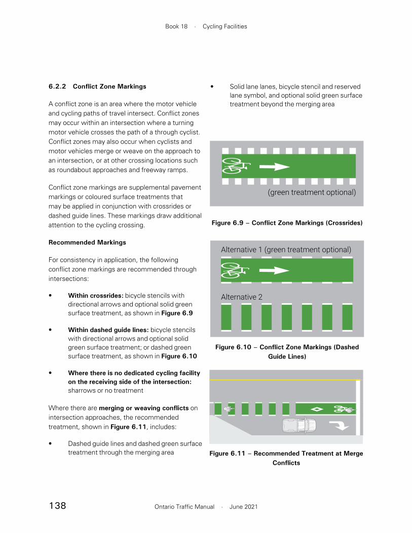
138
Book 18 · Cycling Facilities
Ontario Traffic Manual · June 2021
• Solid lane lanes, bicycle stencil and reserved lane symbol, and optional solid green surface treatment beyond the merging area
6.2.2 Conflict Zone Markings
A conflict zone is an area where the motor vehicle and cycling paths of travel intersect. Conflict zones may occur within an intersection where a turning motor vehicle crosses the path of a through cyclist. Conflict zones may also occur when cyclists and motor vehicles merge or weave on the approach to an intersection, or at other crossing locations such as roundabout approaches and freeway ramps.
Conflict zone markings are supplemental pavement markings or coloured surface treatments that may be applied in conjunction with crossrides or dashed guide lines. These markings draw additional attention to the cycling crossing.
Recommended Markings
For consistency in application, the following conflict zone markings are recommended through intersections:
• Within crossrides: bicycle stencils with directional arrows and optional solid green surface treatment, as shown in Figure 6.9
• Within dashed guide lines: bicycle stencils with directional arrows and optional solid green surface treatment; or dashed green surface treatment, as shown in Figure 6.10
• Where there is no dedicated cycling facility on the receiving side of the intersection: sharrows or no treatment
Where there are merging or weaving conflicts on intersection approaches, the recommended treatment, shown in Figure 6.11, includes:
• Dashed guide lines and dashed green surface treatment through the merging area
(green treatment optional)
Figure 6.9 – Conflict Zone Markings (Crossrides)
Alternative 1 (green treatment optional)
Alternative 2
Figure 6.10 – Conflict Zone Markings (Dashed Guide Lines)
STANDARD CROSS SECTIONSAME SCALE FOR WIDTH (250:1)SECTION ELEMENT HEIGHT: 0.8CM HIGH(SIDEWALK 0.9CM HIGH)
Figure 6.11 – Recommended Treatment at Merge Conflicts

139
Section 6 · Intersections and Crossings
Ontario Traffic Manual · June 2021
Research has shown that cyclists and motorists both have a positive impression of the effect of the green coloured pavement, with cyclists saying they feel safer when the green coloured pavement is present, and motorists saying that it gives them an increased awareness that cyclists might be present and where cyclists are likely to be positioned within the travelled way.4
Green pavement markings are believed to be more effective when used judiciously—for example, at locations with higher volumes of conflicts. Practitioners are discouraged from universally applying green surface treatments at crossings. However, they should consider the value of providing a consistent treatment at all crossings along a continuous corridor.
Green surface treatment may be considered in the following situations:
• Where motor vehicles merge or weave with cyclists on the approach to an intersection, as shown in Figure 6.12.
• In bicycle queueing spaces, where there is potential for motor vehicle encroachment
• At driveways and minor intersections where the cycling movement has the right-of-way, and where is a high volume of motor vehicles are crossing the cycling facility
Figure 6.12 – Solid Green Treatment on Intersection Approach
STANDARD CROSS SECTIONSAME SCALE FOR WIDTH (250:1)SECTION ELEMENT HEIGHT: 0.8CM HIGH(SIDEWALK 0.9CM HIGH)
At cycling crossings where the cyclist does not have the right-of-way, condensed guide lines as shown in Figure 6.6 may be optionally applied to provide guidance through the crossing location. Additional conflict zone markings are not recommended at these locations.
Alternative Markings
Although municipalities are encouraged to implement the recommended conflict zone markings, several alternative markings are available. To minimize confusion, it is recommended that the same treatments be consistently applied throughout a jurisdiction. The available conflict zone markings include:
• Bike stencils with optional directional arrows at 1.5 to 10 m spacing
• Sharrows at 1.5 to 15 m spacing
• Chevrons at 1.5 to 10 m spacing
• Solid green surface treatments
• Broken green surface treatments
Application of Green Surface Treatment
Green surface treatment may be used as a traffic control device to increase the visibility of a cycling facility, highlight areas of conflict and reinforce priority to people riding bikes in conflict areas. Green surface treatment may be applied either as a solid colour treatment, or in a dashed pattern. Dashed green treatments are typically applied at merge zones or bus stops in conjunction with dashed guide lines, as shown in Figure 6.10, with the green treatment following the same 1.0 m segment and 1.0 m gap pattern as the guide lines.

140
Book 18 · Cycling Facilities
Ontario Traffic Manual · June 2021
• At signalized intersections where a high volume of turning motor vehicles permissively crosses the path of a cycling movement
Green surface treatment should not be applied in the following situations:
• Where motor vehicles are not required to yield to people riding bikes, such as at an uncontrolled crossing
• In situations where conflicting cyclist and motor vehicle movements do not operate concurrently, such as when the cycling movement has a protected traffic signal phase
When used at conflict zones, green treatments may be applied through a conflict zone, or for 8 to 15 m preceding the zone, with larger treatment lengths at higher motor vehicle speeds.
6.2.3 Signs
All signs used for cycling facilities on roadways should be sized according to the relevant Ontario Traffic Manual guidelines. Signs used for in-boulevard cycling facilities, which are only intended for use by people cycling, may be reduced in size, as described in the TAC Bikeway Traffic Control Guidelines for Canada – 2nd Edition (January 2012).
Signs placed adjacent to cycling facilities should be placed 1.0 m from the edge of the facility. This distance may be reduced to a minimum of 0.5 m in constrained situations. Signs directed at cycling traffic should be placed at cyclist eye level, approximately 1.5 m above ground.
Contraflow Bicycle Lane Crossing
The Contraflow Bicycle Lane Crossing (WC-43 TAC) sign, shown in Figure 6.13, warns motorists that they are approaching an intersection where cyclists are operating contraflow to the direction of adjacent motor vehicle traffic. This includes most crossings of two-way separated bike lanes, cycle tracks or multi-use paths. It also includes scenarios where a contraflow bike lane is present on a one-way street.
The sign should not be used in the case of a mid-block cycling crossing, where there is no motor vehicle traffic adjacent to the cycling movement.
The contraflow cycling facility warning sign should be installed on the perpendicular approach to the contraflow cycling movement.
Wc-43 (TAC)(600 x 600 mm)
Figure 6.13 – Contraflow Bicycle Lane Crossing Sign
Source: TAC Bikeway Traffic Control Guidelines for Canada, 2012 (Section 4.6.6, p. 39)

141
Section 6 · Intersections and Crossings
Ontario Traffic Manual · June 2021
Bicycle Crossing Ahead
The Bicycle Crossing Ahead (Wc-14 OTM) and Pedestrian and Bicycle Crossing Ahead (Wc-15 OTM) signs, shown in Figure 6.14, warn motorists that they are approaching a bicycle crossing. These signs should be used in advance of a location where a cycling facility crosses a road, such as at mid-block crossings, roundabouts and freeway ramps. The right or left version of the sign should be used as appropriate such that the pedestrian and bicycle symbols are oriented toward the centre of the road. The Crossing tab sign (Wc-32t OTM) shown in Figure 6.15 may be used to reinforce the meaning of the sign.
Wc-14 (OTM)(600 x 600 mm)
Wc-15 (OTM)(600 x 600 mm)
Figure 6.14 – Crossing Ahead Signs
Wc-32T (OTM)(300 x 600 mm
Figure 6.15 – Crossing Tab Sign
Bicycle Trail/Path Crossing Side Street
The Bicycle Trail/Path Crossing Side Street (Wc-37 OTM) sign, shown in Figure 6.16, should be placed along the roadway at the approach to an intersection where an in-boulevard cycling facility crosses the minor street with a setback crossing. It may also be applied to a high volume driveway. The right or left version of the sign should be used as appropriate. If the left version is used, the sign should be installed on both sides of the road so that it is clearly visible to left turning traffic. The Trail Crossing tab sign (WC-44T TAC) or the custom Path Crossing tab sign shown in Figure 6.17 may be attached below Wc-37L or Wc-37R to convey the meaning of the sign.
Wc-37L (OTM)(600 x 600 mm)
Wc-37R (OTM)(600 x 600 mm)
Figure 6.16 – Bicycle Path Crossing Side Street Sign
WC-44T (TAC)(300 x 600 mm)
PATHCROSSING
Wc-32T (Variant)(300 x 600 mm)
Figure 6.17 – Trail/Path Crossing Tab Sign
Source: TAC Bikeway Traffic Control Guidelines for Canada, 2012 (Section 4.6.5, p. 38)
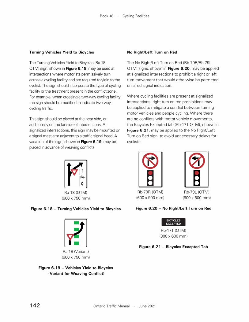
142
Book 18 · Cycling Facilities
Ontario Traffic Manual · June 2021
No Right/Left Turn on Red
The No Right/Left Turn on Red (Rb-79R/Rb-79L OTM) signs, shown in Figure 6.20, may be applied at signalized intersections to prohibit a right or left turn movement that would otherwise be permitted on a red signal indication.
Where cycling facilities are present at signalized intersections, right turn on red prohibitions may be applied to mitigate a conflict between turning motor vehicles and people cycling. Where there are no conflicts with motor vehicle movements, the Bicycles Excepted tab (Rb-17T OTM), shown in Figure 6.21, may be applied to the No Right/Left Turn on Red sign, to avoid unnecessary delays for cyclists.
Rb-79R (OTM)(600 x 900 mm)
Rb-79L (OTM)(600 x 600 mm)
Figure 6.20 – No Right/Left Turn on Red
Rb-17T (OTM)(300 x 600 mm)
Figure 6.21 – Bicycles Excepted Tab
Turning Vehicles Yield to Bicycles
The Turning Vehicles Yield to Bicycles (Ra-18 OTM) sign, shown in Figure 6.18, may be used at intersections where motorists permissively turn across a cycling facility and are required to yield to the cyclist. The sign should incorporate the type of cycling facility or the treatment present in the conflict zone. For example, when crossing a two-way cycling facility, the sign should be modified to indicate two-way cycling traffic.
This sign should be placed at the near-side, or additionally on the far-side of intersections. At signalized intersections, this sign may be mounted on a signal mast arm adjacent to a traffic signal head. A variation of the sign, shown in Figure 6.19, may be placed in advance of weaving conflicts.
161
336
253
Ra-18 (OTM)(600 x 750 mm)
Figure 6.18 – Turning Vehicles Yield to Bicycles
Ra-18 (Variant)(600 x 750 mm)
Figure 6.19 – Vehicles Yield to Bicycles (Variant for Weaving Conflict)
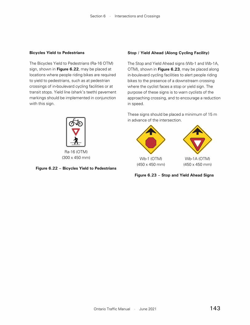
143
Section 6 · Intersections and Crossings
Ontario Traffic Manual · June 2021
Bicycles Yield to Pedestrians
The Bicycles Yield to Pedestrians (Ra-16 OTM) sign, shown in Figure 6.22, may be placed at locations where people riding bikes are required to yield to pedestrians, such as at pedestrian crossings of in-boulevard cycling facilities or at transit stops. Yield line (shark’s teeth) pavement markings should be implemented in conjunction with this sign.
Ra-16 (OTM)(300 x 450 mm)
Figure 6.22 – Bicycles Yield to Pedestrians
Stop / Yield Ahead (Along Cycling Facility)
The Stop and Yield Ahead signs (Wb-1 and Wb-1A, OTM), shown in Figure 6.23, may be placed along in-boulevard cycling facilities to alert people riding bikes to the presence of a downstream crossing where the cyclist faces a stop or yield sign. The purpose of these signs is to warn cyclists of the approaching crossing, and to encourage a reduction in speed.
These signs should be placed a minimum of 15 m in advance of the intersection.
Wb-1 (OTM)(450 x 450 mm)
Wb-1A (OTM)(450 x 450 mm)
Figure 6.23 – Stop and Yield Ahead Signs

144
Book 18 · Cycling Facilities
Ontario Traffic Manual · June 2021
Wa-11A (OTM)(450 x 450 mm)
Wa-13A (OTM)(450 x 450 mm)
Figure 6.24 – Controlled Intersection Ahead Signs
Wc-8R (OTM)(450 x 450 mm)
Figure 6.25 – Truck Entrance Sign
Wc-38 (OTM)(450 x 450 mm)
Figure 6.26 – Slow Watch For Turning Vehicles Sign
Intersection and Driveway Warning Signs (Along Cycling Facility)
Along an in-boulevard cycling facility, it may be necessary to warn cyclists to be alert for turning motor vehicles at an approaching intersection or driveway.
The Controlled Intersection (Wa-11A and Wa-13A) signs, shown in Figure 6.24, may be used along in-boulevard cycling facilities to alert people riding bikes to the presence of an intersection where they have right-of-way. These signs should only be used in circumstances where the intersecting street is under stop or yield control. These signs should not be used at signalized intersections or at intersections where the cyclist is required to stop or yield.
Where appropriate, other warning signs described in OTM Book 6 — Warning Signs may also be applied. For example, the Truck Entrance (Wc-8 OTM) warning sign, shown in Figure 6.25, may be used at a driveway where high volumes of truck traffic cross a cycling facility.
In general, the use of signs that graphically depict the upcoming condition is preferred. However, in scenarios where there is no suitable graphical sign, the textual Slow Watch For Turning Vehicles sign (Wc-38), shown in Figure 6.26, may be applied.
Warning signs should be placed a minimum of 15 m in advance of the intersection or driveway.
In addition to signage, other geometric cues, such as a gentle bend in the cycling facility, may be used to encourage a reduction in speed on the approach to an intersection or driveway.

145
Section 6 · Intersections and Crossings
Ontario Traffic Manual · June 2021
• Mixing Zone: The cycling facility transitions into a shared lane on the intersection approach.
The Setback Crossing treatment is most applicable to in-boulevard facilities such as cycle tracks and multi-use paths. When applied at the intersection of two cycling facilities, setback crossings are a component of a design treatment known as a protected intersection.
The Adjacent Crossing treatment may be applied with on-road or in-boulevard cycling facilities.
The Bicycle Lane Between Through Lane and Turn Lane and Mixing Zone treatments are most suitable for use in lower speed environments with on-road cycling facilities.
6.3.2 Setback Crossing
Overview
Where two intersecting cycling facilities meet at an intersection with setback crossings, this design is often referred to as a “protected intersection”. Intersections are inherently places of conflict and they cannot be fully protected. However, there are opportunities to improve protection through treatment elements such as physical separation, bicycle signal phasing and pavement markings.
In a setback crossing, the cycling facility is offset from the parallel motor vehicle travel lane by a desired distance of 4 to 6 m. In some cases, the cycling facility may naturally approach the intersection at a setback. For example, a cycle track or multi-use path separated from the roadway by a wide buffer will typically approach an intersection at a setback. In other cases, the cycling facility may taper on the intersection approach to create a setback crossing.
6.3 Intersection Approaches and Crossings
6.3.1 Overview of Design Options
On intersection approaches, several design options are available. Some maintain the separation of cyclists and motor vehicles up to the intersection. Others shift the conflict between bicycles and motor vehicles to a point upstream of the intersection. Contextual factors such as geometry, motor vehicle volumes and speeds, space available and traffic signal operations may influence the suitability of these design options at any given intersection.
Often, the same cycling facility at mid-block locations will be carried through the intersection approach. For example, a physically separated bike lane may remain separated on the intersection approach. However, this may not always be the case. For example, it is possible for a bike lane to “ramp up” into the boulevard to become a cycle track on the near-side or far-side of an intersection, or for a physically separated bike lane to transition into a shared lane at an intersection.
The design options described in this section are shown in Figure 6.27, and consist of:
• Setback Crossing: The cycling facility crosses the intersection set back from the adjacent motor vehicle travel lanes
• Adjacent Crossing: The cycling facility crosses the intersection adjacent to, or with minimal set back from, the adjacent motor vehicle travel lanes
• Bicycle Lane Between Through Lane and Turn Lane: The bicycle lane approaches the intersection between a through lane and a dedicated turning lane

146
Book 18 · Cycling Facilities
Ontario Traffic Manual · June 2021
Figure 6.27 – Overview of Intersection Approach Design Options
Setback Crossings Adjacent Crossings
Bicycle Lane BetweenThrough Lane and Turn Lane Mixing Zone

147
Section 6 · Intersections and Crossings
Ontario Traffic Manual · June 2021
Application Environment
The applicable environments for a setback crossing are as follows:
• Typically applied with cycle tracks and multi-use paths. However, can also be applied to any cycling route if the cycling facility tapers into the boulevard on the intersection approach.
• May be applied with one-way or two-way cycling facilities
• May be applied at minor or major signalized intersections. Some elements may also be applicable at driveways and stop-controlled intersections. If applied on a leg of an intersection that is stop controlled, the bicycle movement should also be stop-controlled.
Design Components
A typical setback crossing intersection approach is shown in Figure 6.28. Examples of setback crossings in typical intersection scenarios are shown in Figure 6.30 and Figure 6.31. The following design components are included in a setback crossing:
• Setback crossing. The preferred setback distance is 4 to 6 m. However, in constrained environments at low-volume unsignalized intersections or driveways, the setback may be reduced to a minimum of 2 m. In this case, other mitigating measures should be considered such as small turing radii, raised crossings, partial or fully protected signal phasing and high contrast pavement markings. A 4 to 6 m setback is believed to provide better visibility, particularly for turning trucks and buses. Larger setbacks
At a setback crossing, a turning motor vehicle has mostly completed its turn before it crosses the path of the cyclist resulting in a crossing at close to a perpendicular angle. The setback generally provides sufficient space to allow one passenger vehicle to queue in advance of the crossing without blocking motor vehicles approaching from behind.
The setback crossing positions people riding bikes further away from motor vehicles. It also requires the position of the parallel crosswalk and the side road stop bar to be set back. As a result, a setback crossing usually requires more space than an adjacent crossing. It may also increase travel distances for pedestrians and introduce challenges for people with a variety of disabilities — for example, if additional navigational decisions for people with vision loss are required.
At setback crossings, it is critically important to minimize the speed of conflicting turning motor vehicles and to provide adequate sight distance. A turning motor vehicle speed of 15 to 20 km/h or less is desired. Turning speeds greater than 20 km/h are not recommended in the case of permissive conflicts between people cycling and turning motor vehicles. Design features such as a tight corner radius, a truck apron and a raised crossing are examples of treatments that support low turning speeds. Where it is not possible to slow the speed of turning motor vehicles through geometric design treatments, where there are high volumes of conflicts, or in the case of two-way cycling facility crossings, protected or protected-permissive signal phasing strategies should be considered to provide separation in time between people cycling and turning motor vehicles, as described in Section 6.5.1.

148
Book 18 · Cycling Facilities
Ontario Traffic Manual · June 2021
provide increased storage space for turning motor vehicles, decreasing the likelihood of blocking through traffic. Setbacks greater than 6 m are not recommended unless there is a fully protected movement with a separate signal phase. If a minimum setback cannot be achieved, then an adjacent crossing should be provided by bringing the cycling facility as close to curb as possible to maximize visibility.
• Cycling facility taper. The cycling facility may diverge on the approach to the intersection to reach the desired setback distance, as shown in the example in Figure 6.29. A taper also serves a useful function in reducing the speed of people riding bikes and providing a visual cue that a crossing is approaching. A taper ratio of 1:6 is preferred. A minimum taper of 1:3 may be applied in
Figure 6.29 – Example of Taper on Approach to Setback Crossing, Toronto
Source: WSP
4–6 msetback
4–8 m radius(desired)
1:3–1:6taper
Ra-16
Ra-18
4–6 msetback
Ra-16
Figure 6.28 – Typical Setback Crossing Intersection Approach

149
Section 6 · Intersections and Crossings
Ontario Traffic Manual · June 2021
Figure 6.30 – Setback Crossing at Stop-Controlled Intersection
Ra-18Variant for two-way facility
Ra-16
4–8 m radius mountable curb
1:3–1:6taper
truck apron 4–6 m setback
WC-43 (TAC)
Figure 6.31 – Setback Crossing at Signalized Intersection
4–6 msetback(min 2 m)
4–8 m radius(desired)
Wa-13A
Ra-18
Ra-1Ra-1
1:3–1:6taper
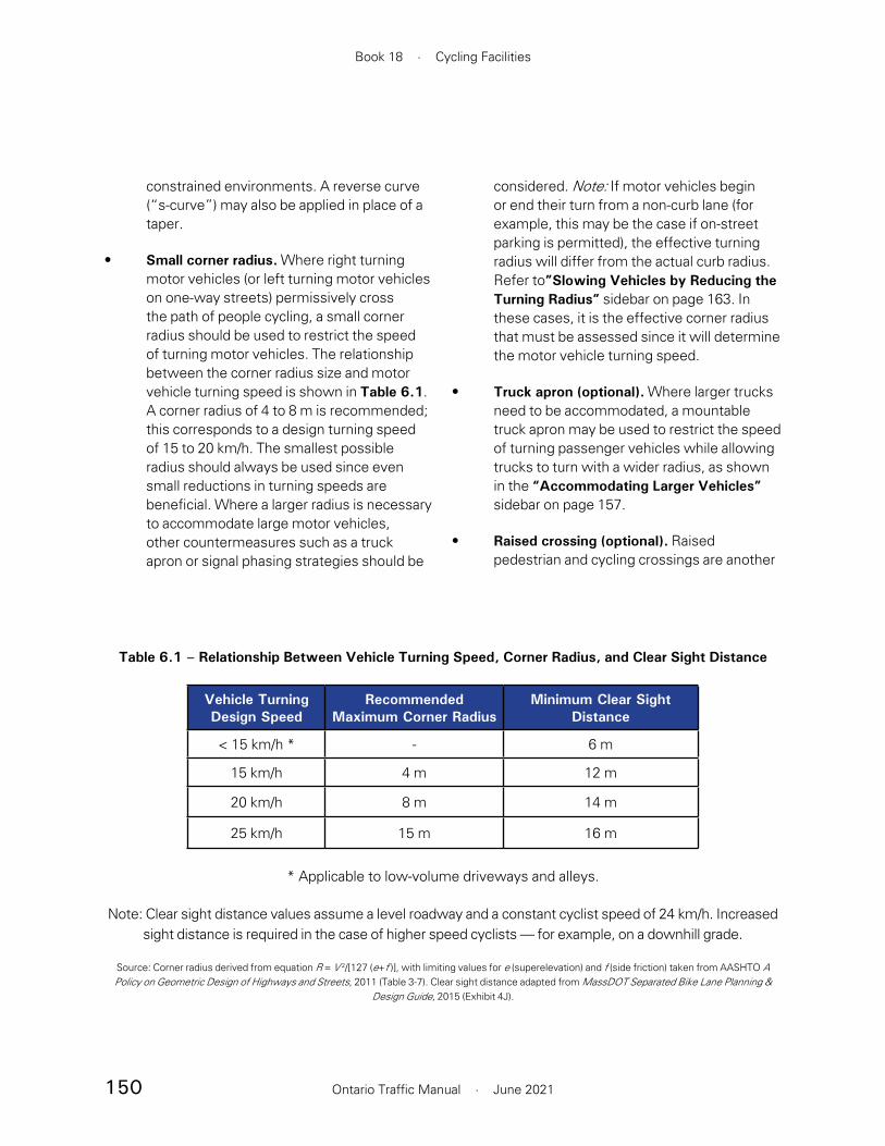
150
Book 18 · Cycling Facilities
Ontario Traffic Manual · June 2021
considered. Note: If motor vehicles begin or end their turn from a non-curb lane (for example, this may be the case if on-street parking is permitted), the effective turning radius will differ from the actual curb radius. Refer to”Slowing Vehicles by Reducing the Turning Radius” sidebar on page 163. In these cases, it is the effective corner radius that must be assessed since it will determine the motor vehicle turning speed.
• Truck apron (optional). Where larger trucks need to be accommodated, a mountable truck apron may be used to restrict the speed of turning passenger vehicles while allowing trucks to turn with a wider radius, as shown in the “Accommodating Larger Vehicles” sidebar on page 157.
• Raised crossing (optional). Raised pedestrian and cycling crossings are another
constrained environments. A reverse curve (“s-curve”) may also be applied in place of a taper.
• Small corner radius. Where right turning motor vehicles (or left turning motor vehicles on one-way streets) permissively cross the path of people cycling, a small corner radius should be used to restrict the speed of turning motor vehicles. The relationship between the corner radius size and motor vehicle turning speed is shown in Table 6.1. A corner radius of 4 to 8 m is recommended; this corresponds to a design turning speed of 15 to 20 km/h. The smallest possible radius should always be used since even small reductions in turning speeds are beneficial. Where a larger radius is necessary to accommodate large motor vehicles, other countermeasures such as a truck apron or signal phasing strategies should be
Table 6.1 – Relationship Between Vehicle Turning Speed, Corner Radius, and Clear Sight Distance
Vehicle Turning Design Speed
Recommended Maximum Corner Radius
Minimum Clear Sight Distance
< 15 km/h * - 6 m
15 km/h 4 m 12 m
20 km/h 8 m 14 m
25 km/h 15 m 16 m
* Applicable to low-volume driveways and alleys.
Note: Clear sight distance values assume a level roadway and a constant cyclist speed of 24 km/h. Increased sight distance is required in the case of higher speed cyclists — for example, on a downhill grade.
Source: Corner radius derived from equation R = V 2/[127 (e+f )], with limiting values for e (superelevation) and f (side friction) taken from AASHTO A Policy on Geometric Design of Highways and Streets, 2011 (Table 3-7). Clear sight distance adapted from MassDOT Separated Bike Lane Planning &
Design Guide, 2015 (Exhibit 4J).

151
Section 6 · Intersections and Crossings
Ontario Traffic Manual · June 2021
Pavement markings and signage
The recommended pavement markings and signage are as shown in Figure 6.30 and Figure 6.31 and include the following features:
• The cycling crossing should be marked as a crossride (see Section 6.2.1.1).
• A yield line (“shark’s teeth”) should be marked on the cycling facility in advance of pedestrian crossings along with a Cyclists Yield to Pedestrians (Ra-16) sign.
• At signalized intersections where there is a permissive conflict between people cycling and turning motor vehicles, a Turning Vehicles Yield to Bicycles (Ra-18) sign should be installed. This sign should be mounted on a near-side pole or the signal mast arm adjacent to the appropriate traffic signal head — typically the primary signal head in the case of a right-turning conflict.
• As an alternative to the Turning Vehicles Yield to Bicycles sign, a Bicycle Trail Crossing Side Street (Wc-37L or Wc-37R) sign may be placed on the major street, about 15 m upstream of the intersection. This sign is intended for multi-use paths crossing a side street.
• At unsignalized intersections where cycling traffic has the right-of-way over motor vehicles approaching on the cross street, a yield line may be placed adjacent to the crossride to reinforce the requirement for motorists to yield to people riding bikes.
• Where there is a two-way cycling facility, a Contraflow Bike Lane Crossing warning sign (WC-43 TAC) should be placed on the cross-street approach
design technique that reduces turning motor vehicle speeds and improves visibility. Raised crossings are particularly suitable to lower volume unsignalized intersections and driveways.
• Median or centreline hardening (optional). Where left turning motor vehicles permissively cross the path of people riding bikes, a median on the cross-street or a hardened centreline may be implemented to prevent left turning motor vehicles from “cutting the corner” and to minimize turning speeds. A hardened centreline may be implemented by placing rubber curbs, bollards, or other delineators on the cross-street centreline.
• Clear sight distance. A minimum clear sight distance is necessary to provide adequate reaction time to motorists and cyclists. On-street parking should be prohibited, and other sight-line obstructions should be eliminated within the clear sight distance. The recommended clear sight distance is determined by cyclist and motor vehicle speeds, and is shown in Table 6.1. Clear sight distance is measured from the point of curvature at the intersection.
• Bicycle signals. Bicycle signals are recommended when setback crossings are implemented at a signalized intersection. Partial or full separation in time by signal phasing should be considered in constrained situations where desired setbacks are not possible. Guidance on the placement of signal heads can be found in OTM Book 12A — Bicycle Signals.

152
Book 18 · Cycling Facilities
Ontario Traffic Manual · June 2021
Accessibility Considerations
A setback crossing may result in a pedestrian refuge space between the roadway and the cycling facility. Two alternative treatments are possible:
Multi-stage pedestrian crossing
In a multi-stage crossing, shown in Figure 6.33, a pedestrian refuge is created between the cycling facility and the roadway. Pedestrians first cross the cycling facility, and then wait in the refuge area prior to crossing the roadway. People riding bikes are required to yield to pedestrians at the pedestrian-cycling crossing.
The multi-stage crossing minimizes the signal-controlled pedestrian crossing distance and supports shorter traffic signal cycles.
The following design guidance applies to a multi-stage crossing:
• The refuge area should have a minimum depth of 2.1 m (consistent with CSA B651-18 guidance), with tactile attention indicator TWSIs at both edges of the refuge, and a minimum 600 mm clear space between the tactile surfaces. However, a larger refuge of 2.4 to 3.0 m is preferred to provide more queueing space for pedestrians, and also to lengthen the adjacent cycling queueing space. If there is insufficient space to provide a 2.1 m refuge, the single-stage treatment is preferred. In urban areas with high volumes of pedestrian activity, it may not be practical to provide a refuge island sufficiently large to accommodate peak pedestrian volumes. This is generally not a problem since pedestrians may queue on the sidewalk side of the cycle track if the refuge space is fully occupied.
Rb-101
Figure 6.32 – Alternate Location of Cyclist Stop Bar (Setback Crossing)
At signalized intersections:
• The preferred position for the bicycle stop bar is a forward stop bar, 0.2 to 0.5 m from the intersecting roadway. If there is insufficient space for people cycling to queue in this location, the stop bar may be positioned prior to the pedestrian crossing, as shown in Figure 6.32. In this case, a Cyclists Stop Here on Red (Rb-101) sign or a near-side bicycle signal may be considered to reinforce the desired stopping position
• A right turn on red restriction (Rb-79R) should be considered for right turn movements that conflict with the cycling movement. Volumes, speed and sightlines should all be factored into the decision using engineering judgment. Right turn on red restrictions are recommended when there is a two-way cycling facility and in cases where protected or protected-permissive signal phasing is implemented, unless there are cases where there is no conflict that needs to be addressed. Electronic blank-out signs may be considered to provide right turn restrictions during specific phases only. Refer to Section 6.5 for more information.
153
Section 6 · Intersections and Crossings
Ontario Traffic Manual · June 2021
• The crosswalk should be continuously marked across the entire crossing distance.
• To minimize the pedestrian crossing distance, the cycling facility may remain adjacent to the roadway for as long as possible, diverging after passing through the pedestrian crossing.
• Tactile Walking Surface Indicators (TWSI)should be placed adjacent to both the roadway crossing and the cycling crossing, in conformance with the technical requirements of the AODA Integrated Accessibility Standards Part IV.1 — Design of Public Spaces (DOPS).
• Accessible pedestrian signals should be situated on the refuge island, adjacent to the roadway crossing, in conformance with DOPS technical requirements. A crosswalk should be marked across the cycling facility and across the roadway, but not in the refuge area.
Single-stage pedestrian crossing
In the single-stage pedestrian crossing, shown in Figure 6.34, pedestrians wait behind the cycling facility, and then cross the cycling facility and the roadway together on a “walk” signal indication. Cyclists yield to pedestrians and use the forward cyclist stop bar, which is important for visibility.
The single-stage treatment results in a more conventional pedestrian crossing. However, this treatment requires a longer signal-controlled pedestrian crossing distance, resulting in longer traffic signal cycle times.
The following design guidance applies to a single-stage crossing:
• Tactile Walking Surface Indicators (TWSI) should be placed on the sidewalk side of the cycling facility only, in conformance with DOPS technical requirements.
• Accessible pedestrian signals should be situated on the sidewalk side of the cycling facility, in conformance with DOPS technical requirements.
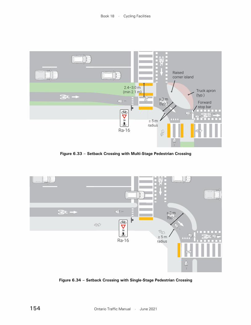
154
Book 18 · Cycling Facilities
Ontario Traffic Manual · June 2021
Figure 6.33 – Setback Crossing with Multi-Stage Pedestrian Crossing
≥ 3 m(typ.)
2.4–3.0 m(min 2.1 m)
≥ 5 mradius
Ra-16
Truck apron(typ.)
Forwardstop bar
Raisedcorner island
Figure 6.34 – Setback Crossing with Single-Stage Pedestrian Crossing
Ra-16≥ 5 m
radius
≥ 3 m(typ.)

155
Section 6 · Intersections and Crossings
Ontario Traffic Manual · June 2021
• Queueing space: 2.4 to 3.0 m of queueing space is preferred for left turning and through cyclists (3.0 m being the minimum to accommodate bicycles with trailers). In constrained environments it is important to ensure that adjacent pedestrian refuge islands have a minimum depth of 2.1 m. Larger queueing spaces may be necessary in locations with high cycling volumes and in the case of two-way cycling facilities.
• Corner island: A raised corner island should be constructed in the space between the two intersecting streets. Typically, the inner edge of the corner island is convex, with a minimum 5 m radius. This results in an “almond” shaped island. However, where high volumes of people cycling are expected, a thinner island may be constructed with a concave inner edge, forming an “eyebrow” shaped island, as shown in Figure 6.34. This allows some of the space that would otherwise be occupied by the corner island to be converted into additional queueing space for cyclists.
Pavement Markings
The pavement markings associated with a standard setback crossing are applicable at protected intersections.
It is preferable to apply “shark’s teeth” markings at the pedestrian crossings to allow people riding bikes to advance to a forward stop bar. However, in constrained environments, if there is minimal queueing space adjacent to the corner island, the cycling stop bar may be set behind the pedestrian crosswalk. This allows the queueing space to be reserved for left turning cyclists.
6.3.2.1 Protected Intersections
When two setback crossings intersect, a corner island may be formed, as shown in Figure 6.36. This setback crossing design treatment is often referred to as a “protected intersection”. The corner island provides physical separation between queueing cyclists and turning motor vehicles. Cyclists making right turns are not usually controlled by traffic signals and may proceed after yielding to pedestrians. The forward cyclist stop bar is important for visibility. Cyclists making left turns complete the turn in two stages, using the queueing space provided adjacent to the corner island.
Typical designs of protected intersections with one-way and two-way cycling facilities are shown in Figures 6.33 to 6.35.
Design Components
All design components associated with a standard setback crossing are applicable. In addition, these design components specific to a protected intersection should be applied:
• Corner radii: All cycling turning movements should be rounded, with a desired minimum radius of 5 m. Radii may be reduced to a minimum of 3 m in constrained environments.
• Cycling circulation space: For one-way cycling facilities, a desired 3 m (minimum 1.5 m) wide cycling circulation area is provided between the corner island and the sidewalk. For two-way facilities, the desired width of this space should be increased to 5 m (minimum 3 m) to mitigate conflicts between cyclists.

156
Book 18 · Cycling Facilities
Ontario Traffic Manual · June 2021
Where the approaching cycling facility is a separated bike lane or cycle track, it is preferable to continue to provide physical separation up to the stop bar. At locations where a multi-use facility approaches an intersection, a combined crossride is suggested, as shown in Figure 6.40. At major intersections, design treatments such as bicycle signals, pavement markings, and signage are required to inform motorists that the crossing is not only for people walking, but for all forms of active transportation.
An adjacent crossing typically requires less space than a setback crossing, and positions people riding bikes closer to the forward cone of vision of adjacent motorists. However, cyclists approaching
6.3.3 Adjacent Crossings
Overview
In an adjacent crossing, the cycling facility is either directly adjacent to or offset no more than 2 m from the parallel travel lanes. Adjacent crossings may be implemented where an on-road cycling facility remains adjacent to the curb through an intersection approach, or where an in-boulevard facility approaches the intersection with a minimal offset from the adjacent roadway. Typical adjacent crossing approaches are shown in Figures 6.38 to 6.41. An example of a two-way cycling facility at an adjacent crossing is shown in Figure 6.37.
Figure 6.36 – Example of Protected Intersection Corner, Ottawa
Source: City of Ottawa
Figure 6.35 – Protected Intersection with Two-Way Cycling Facilities
Ra-16
Ra-16
≥ 5 m(typ.)
2.4–3.0 m(min 2.1 m)
≥ 5 mradius
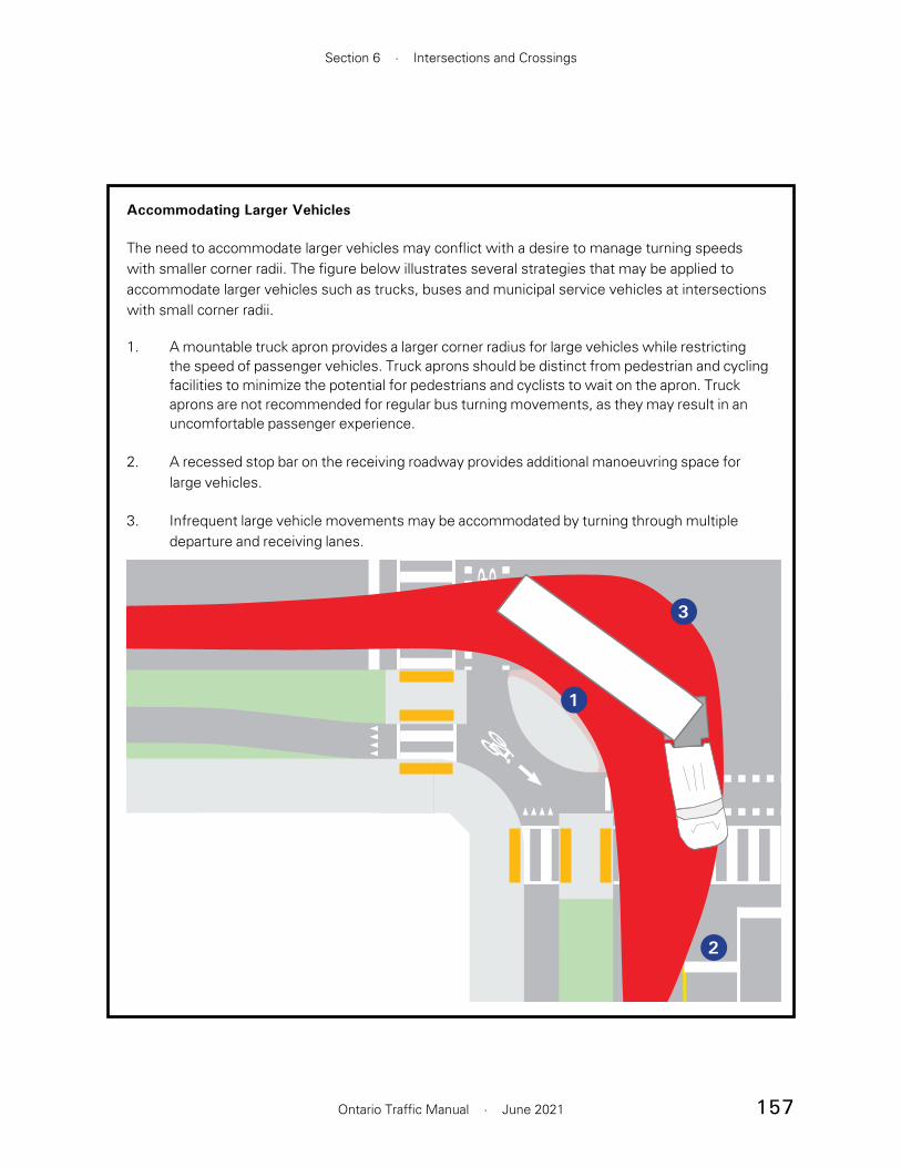
157
Section 6 · Intersections and Crossings
Ontario Traffic Manual · June 2021
Accommodating Larger Vehicles
The need to accommodate larger vehicles may conflict with a desire to manage turning speeds with smaller corner radii. The figure below illustrates several strategies that may be applied to accommodate larger vehicles such as trucks, buses and municipal service vehicles at intersections with small corner radii.
1. A mountable truck apron provides a larger corner radius for large vehicles while restricting the speed of passenger vehicles. Truck aprons should be distinct from pedestrian and cycling facilities to minimize the potential for pedestrians and cyclists to wait on the apron. Truck aprons are not recommended for regular bus turning movements, as they may result in an uncomfortable passenger experience.
2. A recessed stop bar on the receiving roadway provides additional manoeuvring space for large vehicles.
3. Infrequent large vehicle movements may be accommodated by turning through multiple departure and receiving lanes.
1
2
3

158
Book 18 · Cycling Facilities
Ontario Traffic Manual · June 2021
roadway. A taper ratio of 1:6 is preferred. A minimum taper of 1:3 may be applied in constrained environments. The taper should terminate a minimum of 6 m from the stop bar (if present) or intersection so that people cycling are positioned for the adjacent crossing in advance of the conflict points with motorists.
• Parking restrictions. A minimum clear sight distance should be provided to allow adequate time for motorists and people riding bikes to see each other. On-street parking should terminate 12 to 18 m prior to the extension of the curb line of the cross street to provide clear visibility. The recommended clear sight distance depends on the motor vehicle turning speed as shown in Table 6.1. Where on-street parking terminates, the bike lane should converge to be adjacent to the rightmost travel lane. Alternatively, a dedicated right turn lane may be introduced
from behind stopped motor vehicles may be in the motorist’s blind spot.
Application Environments
The applicable environment for an adjacent crossing are as follows:
• Suitable for use with in-boulevard or on-road cycling facilities
• May be applied with one-way or two-way cycling facilities. However, it is not recommended where there are intersecting two-way cycling facilities with indirect (two-stage) left turns, due to complexities in providing queueing space for turning cyclists
• May be applied adjacent to a through/turn motor vehicle lane, or adjacent to an exclusive turn lane. When implemented adjacent to a high volume of turning motor vehicles, protected signal phasing should be considered to mitigate conflicts between turning motor vehicles and people cycling.
• May be applied at minor or major intersections, including stop-controlled and signalized intersections.
Design Components
Typical adjacent crossing intersection treatments are as shown in Figures 6.38 to 6.41. The following design components are included in an adjacent crossing:
• Crossing offset. The leftmost edge of a bicycle crossing is typically 1.0 m or less from the rightmost edge of the adjacent motor vehicle lane of travel
• Cycling facility taper. If necessary, the cycling facility can converge toward the
Figure 6.37 – Example of Adjacent Crossing with Two-Way Cycling Facility, Ottawa
Source: WSP

159
Section 6 · Intersections and Crossings
Ontario Traffic Manual · June 2021
Pavement Markings and Signage
The recommended pavement markings and signage are as shown in Figures 6.38 to 6.41. These include the following features:
• The cycling crossing should be marked as a crossride for two-way cycling facilities or for one-way in-boulevard facilities. Dashed lanes may be used to provide guidance through the intersection for one-way on-road facilities. Additional conflict zone pavement markings may also be applied as discussed in Section 6.2.2.
• A solid line or buffer should be maintained up to the stop bar. The use of a broken line on approach to the intersection remains an option but is not recommended as a preferred design solution. The solid line treatment discourages motorists from entering the cycling facility on the approach to the intersection when making a right turn.
• In cases where there is no physical separation between a bicycle lane and the adjacent travel lane, green surface treatment may optionally be applied within the bicycle lane 10 to 15 m in advance of the stop bar to discourage motorists from encroaching into the bicycle queueing area.
• A staggered stop bar treatment may be applied, with the bicycle stop bar set 2 to 5 m in advance of the motor vehicle stop bar. This allows people cycling to position themselves ahead of motorists during a red signal indication, improving visibility.
• Where there is a permissive conflict between turning motor vehicles and people cycling, a Right Turning Vehicles Yield to Bicycles (Ra-18) sign should be used to remind motorists to yield to cyclists. At signalized
if the cycling facility remains adjacent to the curb, as shown in Figure 6.39.
• Right turn speed reduction (optional). At adjacent crossings, the effective turning radius for right-turning motor vehicles is typically greater than the physical corner radius. Techniques to prevent right turning motor vehicles from “cutting the corner” are shown in the “Slowing Vehicles by Reducing the Turning Radius” sidebar on page 163.
• Median or centreline hardening (optional). Where left turning motor vehicles permissively cross the path of people cycling, a median on the cross-street may be implemented to prevent left turning motor vehicles from “cutting the corner” and to minimize turning speeds. Alternatively, a raised element may be implemented using rubber curbs, bollards, or other delineators on the cross street centreline, as shown in the sidebar on page 163.
• Bicycle signals. At signalized intersections, dedicated bicycle signals should be considered. Bicycle signals allow the implementation of protected or protected-permissive bicycle signal phasing, as described in Section 6.5.1. Protected or protected-permissive signal phasing is recommended in the case of two-way cycling facilities, and whenever an adjacent crossing is implemented adjacent to a reserved motor vehicle turn lane. Bicycle signals must be implemented where a cycling facility operates in a contraflow direction on a one-way street.
160
Book 18 · Cycling Facilities
Ontario Traffic Manual · June 2021
Section 6.3.2 or introducing a refuge island in the median of the roadway.
The following treatments are recommended:
• A continuous crosswalk should be marked across the entire length of the crossing, including the cycling facility
• The cycling stop bar should be set behind the pedestrian crosswalk
• Tactile attention indicator TWSIs and accessible pedestrian signals should be placed on the sidewalk side of the cycling facility
• At intersections, the continuous accessible path of travel is assumed to continue in a straight line from the mid-block position. If the pedestrian route deviates substantially to reach a curb crossing, additional cues such as colour-contrasting tactile route delineators and colour-contrasting tactile directional indicator TWSIs should be used to direct users to the curb crossing.
6.3.4 Bicycle Lane Between Through Lane and Turn Lane
Overview
Where a dedicated right turn lane is introduced at an intersection, the bicycle lane may approach the intersection between the right turn lane and the through motor vehicle lane. This configuration shifts the conflict between turning motor vehicles and people riding bikes upstream of the intersection. The conflict area should be short, and should force motorists to make a slow and deliberate movement into the right turn lane.
intersections, this sign should be mounted near side or on the signal mast arm, adjacent to the traffic signal head.
• Where there is a two-way cycling facility, a Contraflow Bike Lane Crossing (WC-43 TAC) warning sign should be placed on the cross-street approach.
• At signalized intersections, a right turn on red restriction may be considered for turning movements that conflict with cycling movements. This restriction is recommended when there is a two-way cycling facility and in cases where the cycling movement operates with a separate signal phase.
• For shared space corners where two multi-use paths intersect, as shown in Figure 6.40, a “Cyclists Yield to Pedestrians”(Ra-16) sign and shark’s teeth marking should be added at the beginning of the concrete area. The entire corner area should be constructed with concrete. All of these features help to reinforce that cyclists must yield to pedestrians in this area.
Accessibility Considerations
In an adjacent crossing treatment, there should be no pedestrian refuge between the cycling facility and the adjacent travel lane. Pedestrians should cross the cycling facility and the roadway in a single stage. Lengthy pedestrian crossings create difficulties for a range of users including people with disabilities, seniors and children. In cases where the pedestrian crossing is longer than 30 m, practitioners should consider alternative design treatments to interrupt the crossing distance with refuge areas. Alternatives include using a setback crossing design with multi-stage pedestrian crossings as described in

161
Section 6 · Intersections and Crossings
Ontario Traffic Manual · June 2021
Clear sight distance(min 12 m)
2–5 m (typ.)
Ra-18
1:3–1:6taper
Figure 6.38 – Adjacent Crossing Intersection Approach
2–5 m (typ.)
Clear sight distance(min 12 m)
Ra-18
Figure 6.39 – Adjacent Crossing Intersection Approach With Reserved Turn Lane
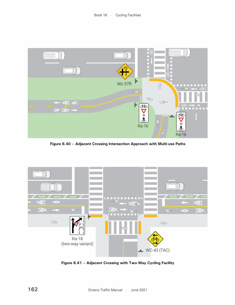
162
Book 18 · Cycling Facilities
Ontario Traffic Manual · June 2021
Figure 6.40 – Adjacent Crossing Intersection Approach with Multi-use Paths
Wc-37R
Ra-16
Ra-16
WC-43 (TAC)
Ra-18 (two-way variant)
Figure 6.41 – Adjacent Crossing with Two-Way Cycling Facility
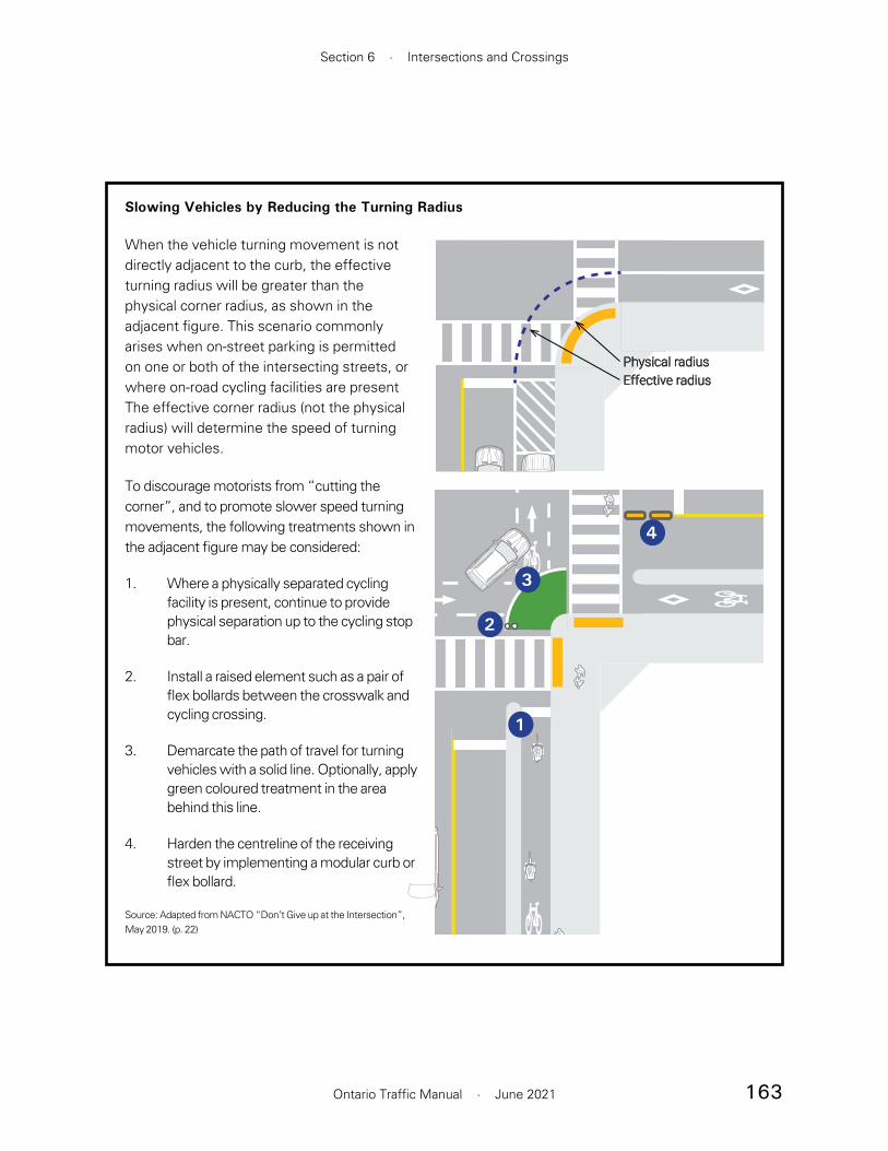
163
Section 6 · Intersections and Crossings
Ontario Traffic Manual · June 2021
Slowing Vehicles by Reducing the Turning Radius
When the vehicle turning movement is not directly adjacent to the curb, the effective turning radius will be greater than the physical corner radius, as shown in the adjacent figure. This scenario commonly arises when on-street parking is permitted on one or both of the intersecting streets, or where on-road cycling facilities are present The effective corner radius (not the physical radius) will determine the speed of turning motor vehicles.
To discourage motorists from “cutting the corner”, and to promote slower speed turning movements, the following treatments shown in the adjacent figure may be considered:
1. Where a physically separated cycling facility is present, continue to provide physical separation up to the cycling stop bar.
2. Install a raised element such as a pair of flex bollards between the crosswalk and cycling crossing.
3. Demarcate the path of travel for turning vehicles with a solid line. Optionally, apply green coloured treatment in the area behind this line.
4. Harden the centreline of the receiving street by implementing a modular curb or flex bollard.
Source: Adapted from NACTO “Don’t Give up at the Intersection”, May 2019. (p. 22)
Physical radiusEffective radius
1
2
3
4

164
Book 18 · Cycling Facilities
Ontario Traffic Manual · June 2021
• May be applied at minor or major intersections, including stop controlled intersections and signalized intersections
Design Components
The typical design components of a bicycle lane between through lane and right turn lane are shown in Figure 6.42 and Figure 6.43:
• The desired length of the merge area is 10 to 15 m. A short merge area is preferred to promote a slower and more deliberate movement on the part of motor vehicles
• The merge area should terminate a minimum of 6 m in advance of the stop bar
• The total queue storage length should be minimized, but should be sufficient to accommodate expected turning volumes. Inadequate queue space may result in turning motor vehicles blocking the merge area. If more than 25 to 30 m of storage length is required (inclusive of the merge area), alternative treatments such as an adjacent crossing or a setback crossing are strongly preferred.
• The desired width of the bicycle lane is 2.0 m (minimum 1.8 m). If additional space is available, a buffer may be added between the bicycle lane and the through lane or buffers may be added on each side of the bicycle lane.
• Where the cycling facility must laterally shift on the intersection approach, for example, where on-street parking is provided between the bicycle lane and the roadway, the cycling facility should be shifted in advance of the merge area, as shown in Figure 6.43. This provides better visibility of people riding bikes, and reinforces the requirement for
This treatment should only be applied when a dedicated right turn lane is introduced as an extra lane on the intersection approach. It should not be applied when a through lane is dropped and converted to a right turn lane at the intersection. It is most appropriate at locations where right turn storage lengths are minimal, and where the posted speed limit is 40 km/h or less. This treatment should not be implemented at locations where the posted speed limit is greater than 50 km/h, or where lengthy storage for right turning motor vehicles is required. A preferred approach to accommodating the right turn lane is to ramp the cycling facility into the boulevard and to transition to a physically separated bikeway through the intersection.
Application Environments
This guidance is applicable to the urban context. In the rural context, the design user may be different and there may be greater flexibility.
• Typically applied with a conventional or buffered bicycle lane on the intersection approach
• May also be applied with separated bicycle lanes, although this requires physical separation to be discontinued in advance of the intersection
• Not suitable for use with two-way facilities, or for use at intersections with double right turn lanes
• May not be suitable at intersections with frequent truck or bus turning movements since larger motor vehicles will need to manoeuvrer through the cycling facility to complete a turn
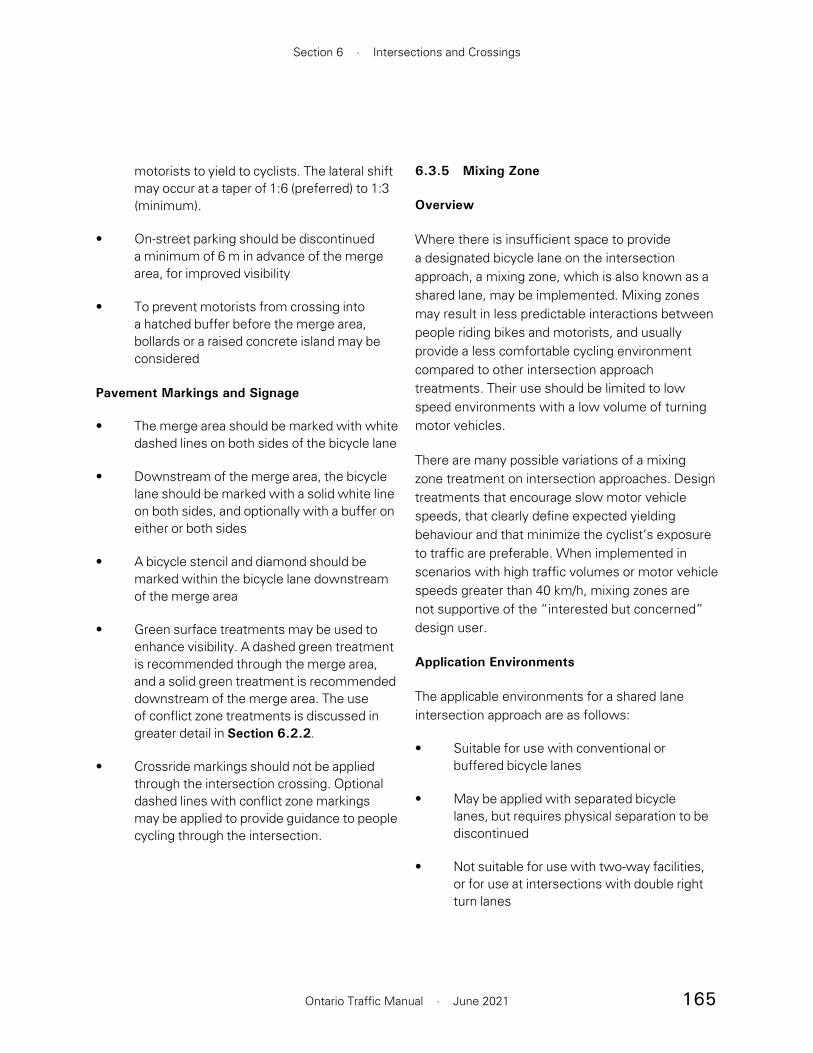
165
Section 6 · Intersections and Crossings
Ontario Traffic Manual · June 2021
6.3.5 Mixing Zone
Overview
Where there is insufficient space to provide a designated bicycle lane on the intersection approach, a mixing zone, which is also known as a shared lane, may be implemented. Mixing zones may result in less predictable interactions between people riding bikes and motorists, and usually provide a less comfortable cycling environment compared to other intersection approach treatments. Their use should be limited to low speed environments with a low volume of turning motor vehicles.
There are many possible variations of a mixing zone treatment on intersection approaches. Design treatments that encourage slow motor vehicle speeds, that clearly define expected yielding behaviour and that minimize the cyclist’s exposure to traffic are preferable. When implemented in scenarios with high traffic volumes or motor vehicle speeds greater than 40 km/h, mixing zones are not supportive of the “interested but concerned” design user.
Application Environments
The applicable environments for a shared lane intersection approach are as follows:
• Suitable for use with conventional or buffered bicycle lanes
• May be applied with separated bicycle lanes, but requires physical separation to be discontinued
• Not suitable for use with two-way facilities, or for use at intersections with double right turn lanes
motorists to yield to cyclists. The lateral shift may occur at a taper of 1:6 (preferred) to 1:3 (minimum).
• On-street parking should be discontinued a minimum of 6 m in advance of the merge area, for improved visibility
• To prevent motorists from crossing into a hatched buffer before the merge area, bollards or a raised concrete island may be considered
Pavement Markings and Signage
• The merge area should be marked with white dashed lines on both sides of the bicycle lane
• Downstream of the merge area, the bicycle lane should be marked with a solid white line on both sides, and optionally with a buffer on either or both sides
• A bicycle stencil and diamond should be marked within the bicycle lane downstream of the merge area
• Green surface treatments may be used to enhance visibility. A dashed green treatment is recommended through the merge area, and a solid green treatment is recommended downstream of the merge area. The use of conflict zone treatments is discussed in greater detail in Section 6.2.2.
• Crossride markings should not be applied through the intersection crossing. Optional dashed lines with conflict zone markings may be applied to provide guidance to people cycling through the intersection.

166
Book 18 · Cycling Facilities
Ontario Traffic Manual · June 2021
STANDARD CROSS SECTIONSAME SCALE FOR WIDTH (250:1)SECTION ELEMENT HEIGHT: 0.8CM HIGH(SIDEWALK 0.9CM HIGH)
2.0 m(min 1.8 m)
Storagemin 6 m
Merge area10–15 m
Ra-18(variant)
Figure 6.42 – Bicycle Lane Between Through Lane and Turn Lane, Turn Lane Added
Parking restrictionmin 6 m
Storagemin 6 m
Merge area10–15 m
Ra-18(variant)
Figure 6.43 – Bicycle Lane Between Through Lane and Turn Lane, On-Street Parking Discontinued

167
Section 6 · Intersections and Crossings
Ontario Traffic Manual · June 2021
6.4 Bicycle Left Turn Treatments
Left turn treatments are critically important in providing connectivity between components of the cycling network. People riding bikes can turn left in two ways:
• Direct Left Turn: People cycling complete a left turn in a single stage. This may be achieved by merging with motor vehicle traffic and turning in the same manner as a motor vehicle. At signalized intersections, a direct turn may also be implemented by providing a protected left turn signal phase for people riding bikes.
• Indirect (Two-Stage) Left Turn: People cycling proceed straight through the intersection and queue on the far side. At signalized intersections, cyclists wait for a green indication on the cross street. They then proceed as if making a through movement on the cross street.
On low-volume and low-speed streets where cyclists are operating in a shared environment, it is often reasonable to allow cyclists to make a direct left turn without any dedicated treatment. However, on higher speed (> 40 km/h), higher volume (> 1,500 vehicles/day) or multi-lane roads, the “interested but concerned” design user will not be comfortable merging across traffic to complete a left turn. In these conditions, a left turn treatment should be provided.
This section introduces several treatments that may be applied to support direct or indirect left turns. Factors such as the speed or volume of motor vehicle traffic, the complexity of the intersection, and the expected volume of turning cyclists may influence the selection of a turning treatment. The alignment of the intersecting
Design Components
The preferred shared lane treatment is shown in Figure 6.44. An example of this treatment is shown in Figure 6.45. Although there are many possible variations, the following guidance is generally applicable:
• It is preferable to implement the shared lane in the motor vehicle turn lane, which tends to have slower speed traffic than the adjacent through lane
• If there is no dedicated cycling facility on the far side of the intersection, people riding bikes should be encouraged to merge into the through lane on the intersection approach to avoid the need to merge with traffic in the intersection itself
• The shared lane should be as wide as possible, preferably 4.0 to 4.8 m. If more than 4.8 m is available, there is typically sufficient space to implement a dedicated cycling facility
• The transition to the shared lane should begin approximately 20 to 30 m in advance of the intersection. Shorter transitions are preferred, as they promote slower motor vehicle speeds
Pavement Markings and Signage
The recommended shared lane treatment is shown in Figure 6.44. Sharrows guide cyclists to pass to the left of right turning motor vehicles. If the shared lane is less than 4.0 m wide, sharrows should be placed in the centre of the lane.
Where through cyclists are accommodated in a dedicated turn lane, a dedicated turn lane sign (Rb-42) with “bicycles excepted” tab (Rb-17t OTM) should be used.
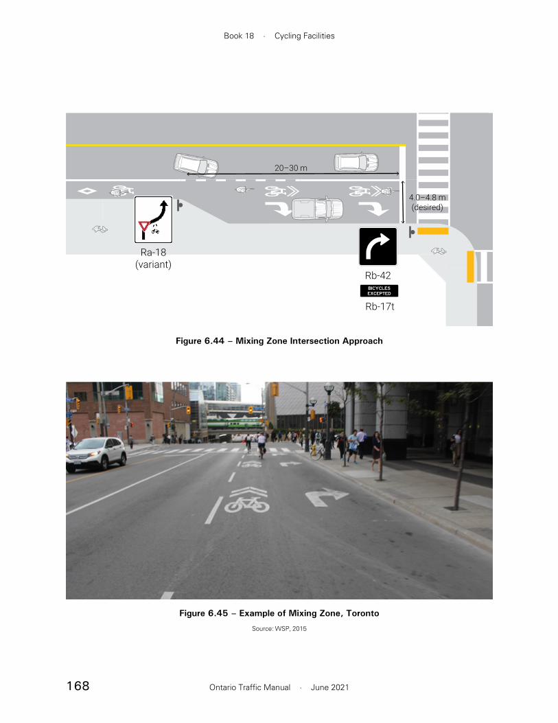
168
Book 18 · Cycling Facilities
Ontario Traffic Manual · June 2021
Rb-42
Rb-17t
4.0–4.8 m(desired)
20–30 m
Ra-18(variant)
Figure 6.44 – Mixing Zone Intersection Approach
Figure 6.45 – Example of Mixing Zone, Toronto
Source: WSP, 2015

169
Section 6 · Intersections and Crossings
Ontario Traffic Manual · June 2021
— On-road two-stage queue box
— Pocket at “T” intersection
• Bike box. This option provides a designated queueing space in front of the motor vehicle stop line. It allows people cycling to complete a direct left turn. This treatment exposes people cycling to more conflicts with motor vehicles compared to an two-stage queue box, and should only be considered on lower speed and lower volume roadways with single through lanes.
• Direct left turn with protected signal phase. This option uses a protected traffic signal phase to facilitate a single stage left turn. This treatment minimizes exposure to motor vehicle conflicts by operating cycling and motor vehicle movements on separate phases.
6.4.1 In-Boulevard Two-Stage Queue Boxes
The in-boulevard two-stage queue box, illustrated in Figure 6.47 and Figure 6.48, provides a designated queueing space for cyclists at the corner of the intersection, within the boulevard. An example is shown in Figure 6.46.
The queue box is located behind the curb between the crosswalk and cycling facility. People cycling complete a left turn by travelling straight though the intersection, then entering the queue box. Once permitted, they proceed as if making a through movement from the cross street.
Application Context
In-boulevard queue boxes are typically implemented in conjunction with on-road cycling facilities, including conventional, buffered or
facilities and operational characteristics (for example, signal phasing) should also be considered in the selection of a treatment.
Design Principles
The following principles should guide the selection and design of bicycle left turn treatments:
• The turn treatment should minimize exposure to motor vehicle conflicts and provide a comfortable left-turn movement for the design user
• Sufficient queueing space should be provided to meet anticipated cyclist demand
• The turn treatment should minimize delay to people cycling
• Pavement markings and signage should apply a consistent design language to clearly communicate the expected pattern of movement
Left turn treatment options
The following design treatments may be used to support left turn cycling movements:
• Protected intersection corner. Where two cycling facilities intersect with setback crossings, this treatment naturally supports an indirect (two-stage) left turn movement. This treatment is described in Section 6.3.2.1.
• Two-stage queue box. This option provides a designated space for people cycling to queue while completing an indirect left turn. There are three variations of this treatment:
— In-boulevard two-stage queue box
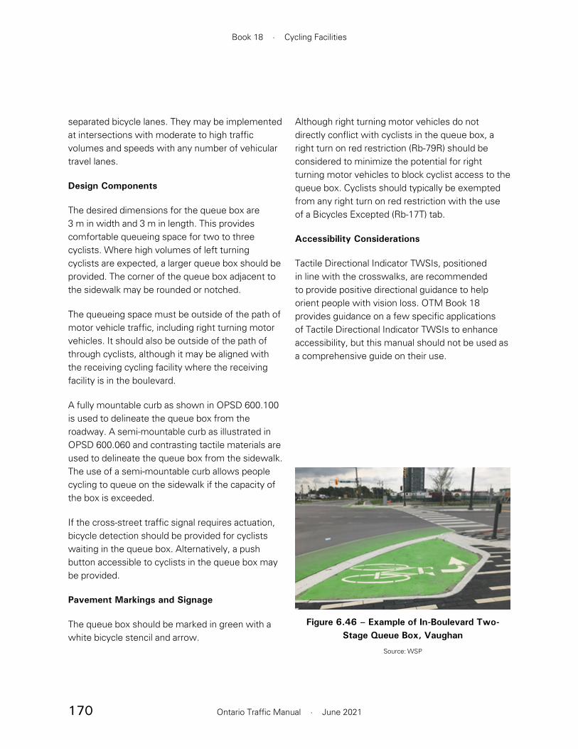
170
Book 18 · Cycling Facilities
Ontario Traffic Manual · June 2021
Although right turning motor vehicles do not directly conflict with cyclists in the queue box, a right turn on red restriction (Rb-79R) should be considered to minimize the potential for right turning motor vehicles to block cyclist access to the queue box. Cyclists should typically be exempted from any right turn on red restriction with the use of a Bicycles Excepted (Rb-17T) tab.
Accessibility Considerations
Tactile Directional Indicator TWSIs, positioned in line with the crosswalks, are recommended to provide positive directional guidance to help orient people with vision loss. OTM Book 18 provides guidance on a few specific applications of Tactile Directional Indicator TWSIs to enhance accessibility, but this manual should not be used as a comprehensive guide on their use.
separated bicycle lanes. They may be implemented at intersections with moderate to high traffic volumes and speeds with any number of vehicular travel lanes.
Design Components
The desired dimensions for the queue box are 3 m in width and 3 m in length. This provides comfortable queueing space for two to three cyclists. Where high volumes of left turning cyclists are expected, a larger queue box should be provided. The corner of the queue box adjacent to the sidewalk may be rounded or notched.
The queueing space must be outside of the path of motor vehicle traffic, including right turning motor vehicles. It should also be outside of the path of through cyclists, although it may be aligned with the receiving cycling facility where the receiving facility is in the boulevard.
A fully mountable curb as shown in OPSD 600.100 is used to delineate the queue box from the roadway. A semi-mountable curb as illustrated in OPSD 600.060 and contrasting tactile materials are used to delineate the queue box from the sidewalk. The use of a semi-mountable curb allows people cycling to queue on the sidewalk if the capacity of the box is exceeded.
If the cross-street traffic signal requires actuation, bicycle detection should be provided for cyclists waiting in the queue box. Alternatively, a push button accessible to cyclists in the queue box may be provided.
Pavement Markings and Signage
The queue box should be marked in green with a white bicycle stencil and arrow.
Figure 6.46 – Example of In-Boulevard Two-Stage Queue Box, Vaughan
Source: WSP

171
Section 6 · Intersections and Crossings
Ontario Traffic Manual · June 2021
Application Context
On-street two-stage queue boxes are typically implemented in conjunction with on-road cycling facilities, including conventional, buffered or separated bicycle lanes. This treatment is most suitable in environments where the intersection area is constrained and there is insufficient space available to implement an in-boulevard queue box. Since this treatment positions people cycling in the path of right turning motor vehicles, a right turn on red prohibition is recommended where on-street two-stage queue boxes are implemented.
Since this treatment results in a greater amount of exposure to motor vehicle traffic as compared to the in-boulevard queue box, it is not recommended in cases where motor vehicle speeds exceed 50 km/h, where there are more than two through travel lanes per direction, or where the intersection geometry is otherwise complex.
On-Street Two-Stage Queue Boxes
The on-street two-stage queue box, shown in Figure 6.49 and Figure 6.50, provides a designated queueing space within the intersection. The preferred location of the queue box is usually to the right of the through cycling movement, adjacent to the crosswalk. However, the location of the queue box may vary depending on the geometry of the intersection. In general, the queue box should be placed in an area that minimizes exposure to conflicts with motor vehicles, and that does not block the path of people riding bikes proceeding in the same direction through the intersection.
As with the in-boulevard queue box, cyclists complete a left turn by travelling straight though the intersection, then entering the queue box. Once permitted, they then proceed as if making a through movement from the cross street.
3.0 m(typ.)
3.0 m (typ.)
Semi-mountable curb
Fully mountable curb
Tactile directional indicator TWSI
Figure 6.47 – In-Boulevard Two-Stage Queue Box Detail

172
Book 18 · Cycling Facilities
Ontario Traffic Manual · June 2021
Figure 6.48 – In-Boulevard Two-Stage Queue Box, Typical Intersection

173
Section 6 · Intersections and Crossings
Ontario Traffic Manual · June 2021
reduced to a minimum of 1.0 m in width and 2.0 m in length.
Pavement Markings and Signage
The queue box should be marked with a white rectangular or square box using 100 mm wide solid lines surrounding a turn arrow pointing in the direction in which people cycling will leave the intersection, plus a bicycle symbol oriented according to the direction from which they entered. Green surface treatment should be applied to the interior of the queue box to enhance its visibility.
Since cyclists in the queue box may obstruct the right turn movement from the cross street, a right turn on red restriction (Rb-79R) is recommended. A Bicycles Excepted tab (Rb-17T) should typically be applied to exempt bicycles from the restriction.
On 60 km/h roads, an in-boulevard queue box or protected intersection corner is preferred. However, retrofitting an existing intersection with an in-boulevard feature may pose a challenge due to space limitations. Municipalities may consider implementing an on-street two-stage queue box if sight lines are adequate.
On-street queue boxes may be implemented at signalized or unsignalized intersections. Bicycle detection should be considered if the intersection signals are actuated.
Design Components
The minimum desired dimension of the queue box is 2.0 m in width and 3.5 m in length. This provides comfortable queueing space for two cyclists. Where high volumes of left turning cyclists are expected, a larger queue box should be provided. Where turning volumes are low and the intersection is constrained, the queue box may be
2.0 m (typ.)
3.5 m (typ.)
Figure 6.49 – On-Street Two-Stage Queue Box Detail
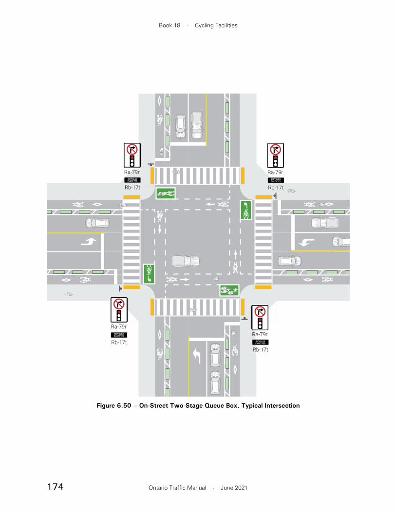
174
Book 18 · Cycling Facilities
Ontario Traffic Manual · June 2021
Ra-79r
Rb-17tRa-79r
Rb-17t
Ra-79r
Rb-17t
Ra-79r
Rb-17t
Figure 6.50 – On-Street Two-Stage Queue Box, Typical Intersection

175
Section 6 · Intersections and Crossings
Ontario Traffic Manual · June 2021
Accessibility Considerations
• A semi-mountable or mountable curb is recommended around the edges of the pocket to minimize the trip hazard.
• Tactile directional indicator TWSIs oriented in line with the crosswalks provide positive directional guidance to help orient people with vision loss.
6.4.2 Pocket at T-intersection
At a “T” intersection, a pocket or jug-handle may be created, as shown in Figure 6.52 and Figure 6.51. The pocket functions as a two-stage queue box, allowing people cycling to orient themselves towards the cross street while providing a dedicated space to queue.
At signalized intersections, bicycle signal heads along with bicycle detection or push-button actuation must be provided, since there is no corresponding vehicular signal that cyclists may use to complete the second stage of their turn.
Application Environment
The pocket treatment may be applied at “T” intersections in both rural and urban contexts.
Design components
The minimum desired dimensions of the pocket are 3.5 m in length and 2.0 m in width. A larger queueing area should be provided where there are high volumes of turning cyclists. The pocket should be aligned to allow people cycling to orient themselves perpendicular to the road and easily cross the intersection and enter a receiving cycling facility or shared roadway on the cross street.
The queueing area should be separated from the pedestrian space by a semi-mountable curb.
Pavement Markings and Signage
The pocket should be marked with a bike stencil and a left turn arrow. Green surface treatment may be applied to enhance visibility.

176
Book 18 · Cycling Facilities
Ontario Traffic Manual · June 2021
6.4.3 Bike Boxes
A bike box, shown in Figure 6.53, is a designated area between the crosswalk and the stop bar for motorized traffic at a signalized intersection. This enables cyclists to wait ahead of queueing traffic during the red signal indication before proceeding ahead of motorists on the green indication. This designated area significantly increases the visibility of people riding bikes. Cyclists can transition from the right side of the roadway towards the centreline during a red indication to allow them to make a direct left turn. Typical bike boxes are shown in Figure 6.54 and Figure 6.55.
Since a bike box supports a direct left turn, it results in less delay for people cycling than two-stage queue boxes. However, a bike box results in greater exposure to motor vehicle traffic than a two-stage
Figure 6.52 – Example of a Pocket at T-Intersection, Toronto
Source: WSP, 2019
2.0 m(typ.)
3.5 m (typ.)
Fully mountable curb
Semi-mountable curb TDI*
* Tactile directional indicator TWSI
TDI*
Figure 6.51 – Pocket at T-Intersection Detail

177
Section 6 · Intersections and Crossings
Ontario Traffic Manual · June 2021
is no right turn possible due to a T-intersection or one-way cross street.
To promote motor vehicle compliance, a Stop Here on Red (Rb-78) sign with Bicycles Excepted (Rb-17T) tab should be placed at the motor vehicle stop bar location.
Right turn on red restrictions (Rb-79R) with a bicycle exemption (Rb-17T) are strongly recommended at locations with bike boxes.
6.4.4 Direct Left Turn with Protected Signal Phase
Overview
At signalized intersections, a direct left turn may be supported by providing a protected turn phase for people riding bikes. The protected phase provides temporal separation between turning cyclists and conflicting motor vehicle movements while providing a straightforward and comfortable left turn movement that is supportive of the design user.
This treatment may be particularly useful along high-volume cycling corridors when the volume of
queue box, particularly for cyclists who arrive on a green signal. For this reason, the use of bike boxes should be limited to low volume intersections with motor vehicle speeds of 40 km/h or less. In most cases, a two-stage queue box will provide a more comfortable left turn facility than a bike box.
Application Context
A bike box is most suitable for use in conjunction with a conventional or buffered bicycle lane. It is implemented at signalized intersections. Bike boxes should only be considered if all of the following criteria are met:
• Traffic volume on the approaching road is 2,500 ADT or less
• Posted speed limit on the approaching road is 40 km/h or less
• Approach lane configuration consists of no more than two lanes (inclusive of turn lanes)
Design Components
The depth of the bike box or distance between the vehicular and the bicycle stop bars is typically 3 to 5 m. Larger values may be used in the case of high volumes of turning cyclists. The bike box is typically set a minimum of 1 m back from the pedestrian crosswalk. The bike box should fully extend across the entire width of the approach lanes.
Pavement Markings and Signage
A bicycle stencil should be applied in the bike box. Green surface treatment should be applied to the bike box to minimize encroachment by motor vehicles. The bike lane approaching the intersection does not have to be green, particularly if it there
Figure 6.53 – Example of Bike Box, Ottawa
Source: WSP
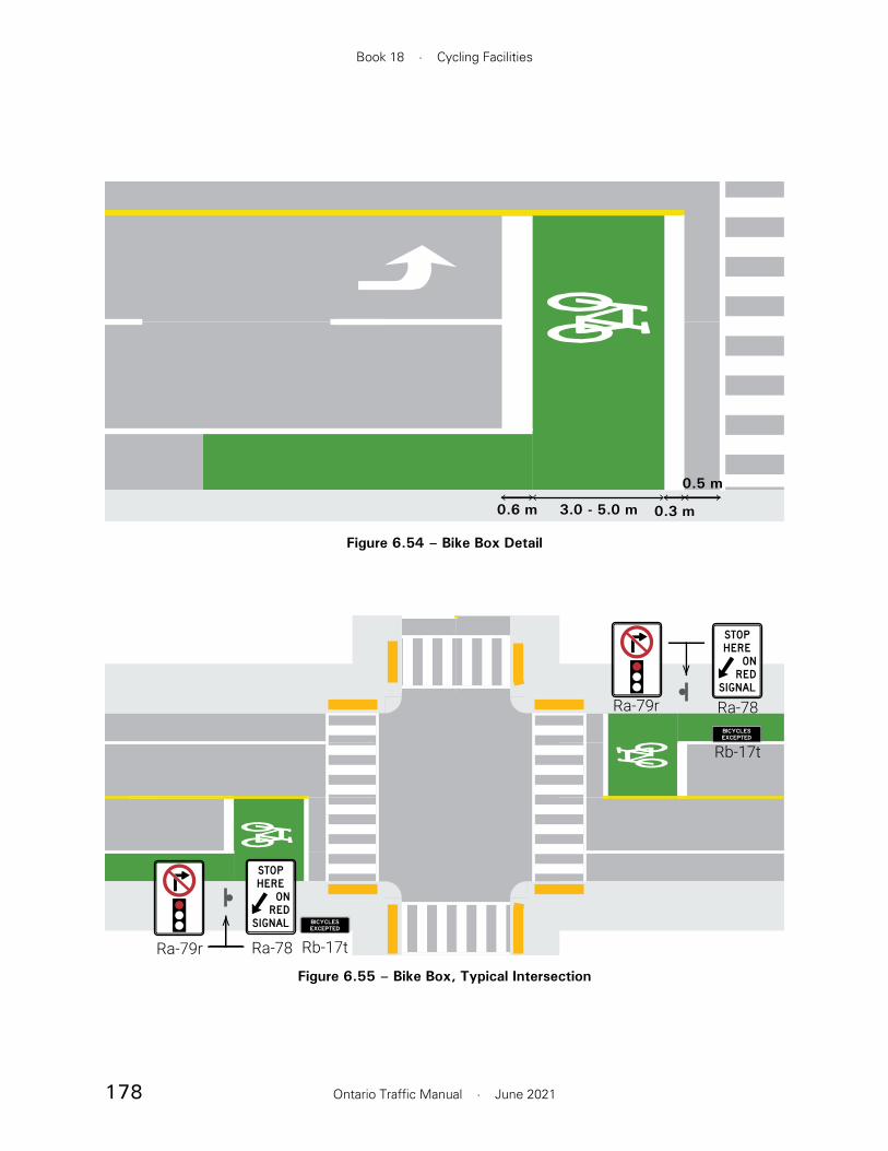
178
Book 18 · Cycling Facilities
Ontario Traffic Manual · June 2021
0.6 m 3.0 - 5.0 m 0.3 m
0.5 m
Figure 6.54 – Bike Box Detail
Ra-78Ra-79r
Rb-17t
Ra-78Ra-79r Rb-17t
Figure 6.55 – Bike Box, Typical Intersection

179
Section 6 · Intersections and Crossings
Ontario Traffic Manual · June 2021
directional left turn arrow should be used to mark the left turn queueing space.
Right turn on red restrictions (Rb-79R) with a bicycle exemption (Rb-17T) tab should be implemented in conjunction with a protected cycling turn phase.
turning cyclists is likely to overwhelm the capacity of a two-stage queue box. Where there are lower volumes of cyclists, a push button or cyclist detection should be implemented to allow the left-turn phase to be actuated only when necessary. Signal cycles should be relatively short to minimize delays to turning cyclists.
It is usually necessary to provide storage space for left turning cyclists on the intersection approach. This may be achieved by slightly widening the cycling facility on the approach, and marking a separate left turn lane within the cycling facility.
Application Context
The applicable environment for this treatment is as follows:
• Most suitable for use in conjunction with an in-boulevard cycling facility with adjacent intersection crossing type
• May be applied with one-way or two-way cycling facilities
• Should only be implemented in conjunction with a right turn on red restriction
Geometry
The cycling facility should be widened on the approach to the intersection to provide queueing space for left turning cyclists as shown in Figure 6.56. The storage area should have a desired width of 1.5 m (minimum 1.2 m).
Pavement Markings and Signage
A left turn lane may be marked on the cycling facility using a dashed or solid white line. A
2807
1.5 m (typ.)
Ra-78 Ra-79r
Rb-17t
Figure 6.56 – Direct Left Turn with Protected Signal Phase

180
Book 18 · Cycling Facilities
Ontario Traffic Manual · June 2021
result in poor cyclist compliance. In situations where turning volumes are relatively low, there is evidence to suggest that protected-permissive phasing may result in fewer conflicts between people cycling and turning motor vehicles than fully protected phasing.5
Right turn on red restrictions should be considered whenever protected or protected-permissive signal phasing is implemented if bicycle/motor vehicle conflicts occur during the bicycle-specific phase operation. Electronic blank-out signs may be considered to provide right turn restrictions during specific phases only.
Protected signal phasing may lead to better safety outcomes in the following cases:
• Where the thresholds for motor vehicle turning volumes shown in Table 6.2 are exceeded
• In the case of high volumes of turning trucks or buses
• Where it is not possible to reduce the speed of turning motor vehicles to 15–20 km/h through geometric design treatments such as smaller corner radii
• On streets with a posted speed limit of 60 km/h or higher
• Where there is more than one turn lane on the conflicting turn movement
• Where there are poor sightlines
In situations where the recommended turning volume thresholds shown in Table 6.2 are not met, or where it is otherwise not feasible to implement protected signal phasing, protected-permissive phasing should be considered.
6.5 Bicycle Traffic Signals
6.5.1 Signal Phasing
At signalized intersections, signal phasing is a critical component of design. This section introduces several signal phasing strategies that complement the geometric design treatments introduced in Section 6.3 and Section 6.4. Detailed guidance on the implementation of bicycle traffic signals is provided in OTM Book 12A – Bicycle Signals.
The following signal phasing strategies are described:
• Permissive Phasing, which allows conflicting turning movements to operate concurrently with cycling movements.
• Protected-Permissive Phasing, which provides a short leading interval in which cyclists proceed while conflicting turning movements are held, followed by a permissive phase. There are two common types of protected-permissive phasing:
— Leading Bicycle Interval
— Split-Leading Bicycle Interval
• Protected Phasing, which separates cycling movements from conflicting turning movements.
In selecting a signal phasing strategy, practitioners must carefully consider the inherent trade-off between maximizing separation and minimizing delay. Protected signal phasing, which fully separates people riding bikes from conflicting motor vehicle movements, is often perceived to provide the greatest cyclist comfort. However, it may also significantly increase delays which may
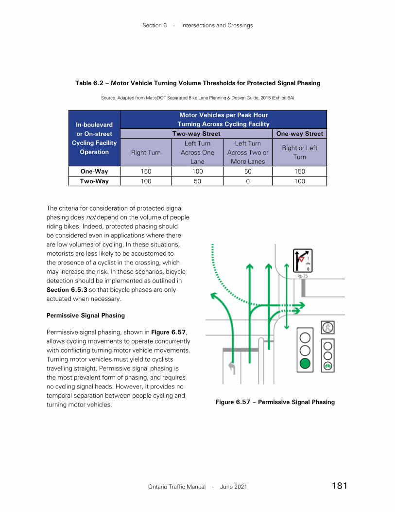
181
Section 6 · Intersections and Crossings
Ontario Traffic Manual · June 2021
The criteria for consideration of protected signal phasing does not depend on the volume of people riding bikes. Indeed, protected phasing should be considered even in applications where there are low volumes of cycling. In these situations, motorists are less likely to be accustomed to the presence of a cyclist in the crossing, which may increase the risk. In these scenarios, bicycle detection should be implemented as outlined in Section 6.5.3 so that bicycle phases are only actuated when necessary.
Permissive Signal Phasing
Permissive signal phasing, shown in Figure 6.57, allows cycling movements to operate concurrently with conflicting turning motor vehicle movements. Turning motor vehicles must yield to cyclists travelling straight. Permissive signal phasing is the most prevalent form of phasing, and requires no cycling signal heads. However, it provides no temporal separation between people cycling and turning motor vehicles.
Table 6.2 – Motor Vehicle Turning Volume Thresholds for Protected Signal Phasing
Source: Adapted from MassDOT Separated Bike Lane Planning & Design Guide, 2015 (Exhibit 6A)
In-boulevard or On-street
Cycling Facility Operation
Motor Vehicles per Peak HourTurning Across Cycling Facility
Two-way Street One-way Street
Right TurnLeft Turn
Across One Lane
Left Turn Across Two or More Lanes
Right or Left Turn
One-Way 150 100 50 150Two-Way 100 50 0 100
Figure 6.57 – Permissive Signal Phasing
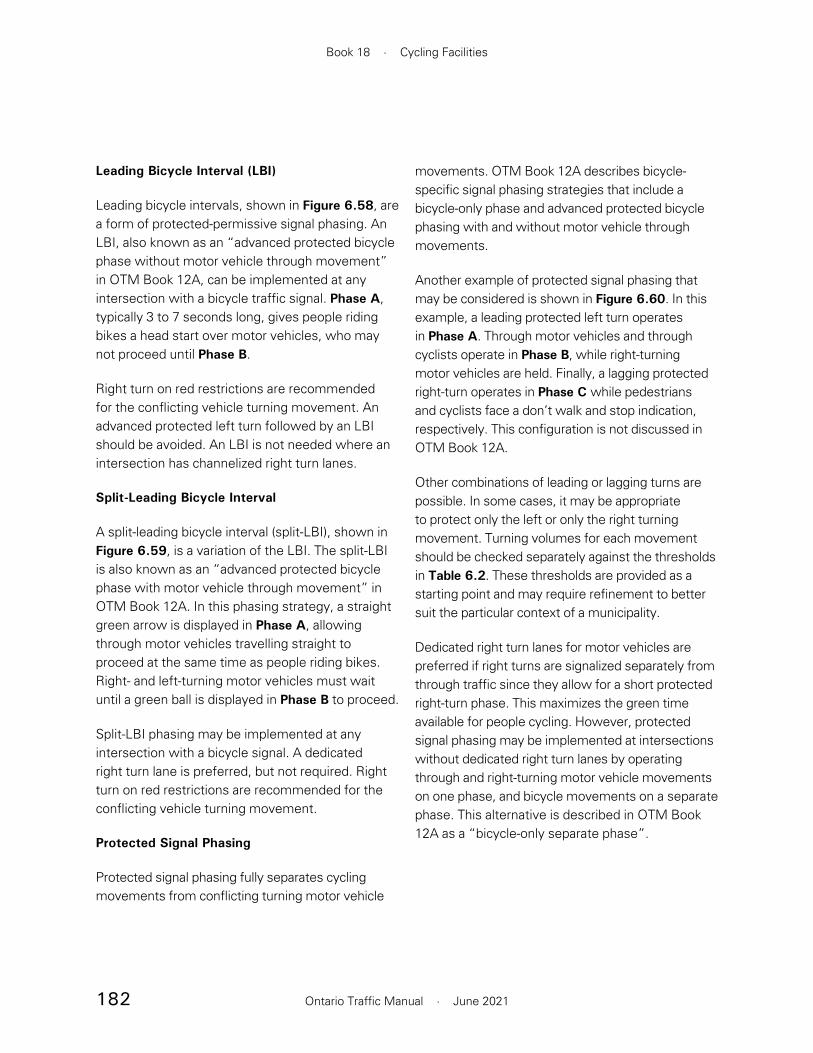
182
Book 18 · Cycling Facilities
Ontario Traffic Manual · June 2021
Leading Bicycle Interval (LBI)
Leading bicycle intervals, shown in Figure 6.58, are a form of protected-permissive signal phasing. An LBI, also known as an “advanced protected bicycle phase without motor vehicle through movement” in OTM Book 12A, can be implemented at any intersection with a bicycle traffic signal. Phase A, typically 3 to 7 seconds long, gives people riding bikes a head start over motor vehicles, who may not proceed until Phase B.
Right turn on red restrictions are recommended for the conflicting vehicle turning movement. An advanced protected left turn followed by an LBI should be avoided. An LBI is not needed where an intersection has channelized right turn lanes.
Split-Leading Bicycle Interval
A split-leading bicycle interval (split-LBI), shown in Figure 6.59, is a variation of the LBI. The split-LBI is also known as an “advanced protected bicycle phase with motor vehicle through movement” in OTM Book 12A. In this phasing strategy, a straight green arrow is displayed in Phase A, allowing through motor vehicles travelling straight to proceed at the same time as people riding bikes. Right- and left-turning motor vehicles must wait until a green ball is displayed in Phase B to proceed.
Split-LBI phasing may be implemented at any intersection with a bicycle signal. A dedicated right turn lane is preferred, but not required. Right turn on red restrictions are recommended for the conflicting vehicle turning movement.
Protected Signal Phasing
Protected signal phasing fully separates cycling movements from conflicting turning motor vehicle
movements. OTM Book 12A describes bicycle-specific signal phasing strategies that include a bicycle-only phase and advanced protected bicycle phasing with and without motor vehicle through movements.
Another example of protected signal phasing that may be considered is shown in Figure 6.60. In this example, a leading protected left turn operates in Phase A. Through motor vehicles and through cyclists operate in Phase B, while right-turning motor vehicles are held. Finally, a lagging protected right-turn operates in Phase C while pedestrians and cyclists face a don’t walk and stop indication, respectively. This configuration is not discussed in OTM Book 12A.
Other combinations of leading or lagging turns are possible. In some cases, it may be appropriate to protect only the left or only the right turning movement. Turning volumes for each movement should be checked separately against the thresholds in Table 6.2. These thresholds are provided as a starting point and may require refinement to better suit the particular context of a municipality.
Dedicated right turn lanes for motor vehicles are preferred if right turns are signalized separately from through traffic since they allow for a short protected right-turn phase. This maximizes the green time available for people cycling. However, protected signal phasing may be implemented at intersections without dedicated right turn lanes by operating through and right-turning motor vehicle movements on one phase, and bicycle movements on a separate phase. This alternative is described in OTM Book 12A as a “bicycle-only separate phase”.
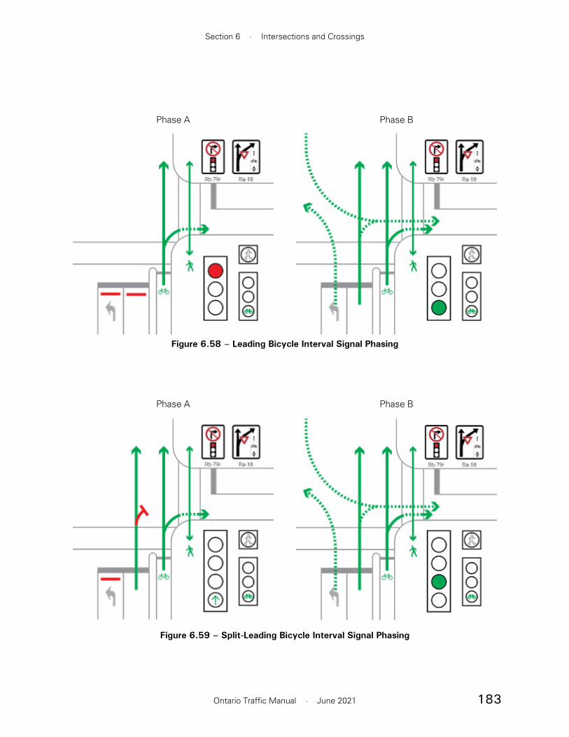
183
Section 6 · Intersections and Crossings
Ontario Traffic Manual · June 2021
Figure 6.58 – Leading Bicycle Interval Signal Phasing
Phase A Phase B
Figure 6.59 – Split-Leading Bicycle Interval Signal Phasing
Phase A Phase B
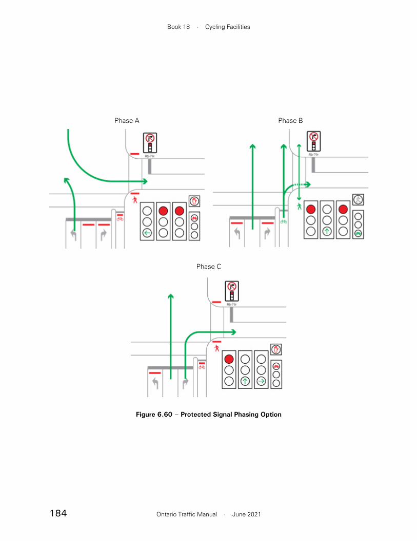
184
Book 18 · Cycling Facilities
Ontario Traffic Manual · June 2021
Figure 6.60 – Protected Signal Phasing Option
Phase A Phase B
Phase C

185
Section 6 · Intersections and Crossings
Ontario Traffic Manual · June 2021
6.5.3 Detection and Actuation Methods
Bicycle detection may be implemented to detect cyclists on the approach or queueing at an intersection. Detection may be implemented to actuate specific phases only when a cyclist is present to extend the length of a phase based on the presence of cyclists. Detection methods may be either active or passive.
• Active Detection: A cyclist push-button is provided. The push-button should be located such that it may be easily accessed from the stop position without dismounting. This type of detection does not allow for extensions should there be a higher cyclist volume.
• Passive Detection: Cyclists are detected by means of inductive loops, video, radar, microwave or optical detectors. Where passive detection is used, an optional indicator light may be implemented to provide positive confirmation that a cyclist has been detected, as shown in Figure 6.61.
Detection methods, criteria and considerations for implementation as well as supplementary signage and pavement markings are discussed in Section 7 of OTM Book 12A.
Bicycle Signal Heads
It is generally advisable to consider bicycle signal heads at intersections and crossings of all cycling facilities. However, bicycle traffic signals heads are necessary in the following situations:
• Where bicycle movements differ from motor vehicle movements such as where bicycle-specific signal phasing is implemented
• Where bicycle movement is in the opposing direction to adjacent motor vehicle traffic such as contraflow facilities or two-way facilities
• Where a cycling facility is in the boulevard, including cycle tracks and in-boulevard multi-use trail crossings
• Where the motor vehicle signal heads are not in the direct field of vision of people riding bikes
Bicycle signal head design specifications and placement are described in OTM Book 12A.
6.5.2 Near-Side Bicycle Signals
Where bicycle signals are implemented, the HTA states that at least one bicycle signal must be placed at the far side of the intersection. A supplementary near-side signal is also permitted and can be mounted less than the minimum height of 2.5 m, such that it can be seen by a cyclist stopped for the signal. Near-side bicycle signals help cyclists and motorists differentiate between the motor vehicle and bicycle specific signals, which is particularly important when there is separate bicycle signal phasing. Near-side signals can also be used to reinforce the correct position for cyclists to stop.
Figure 6.61 – Bicycle Detection Indicator, Calgary
Source: Darren Krause, Livewire Calgary

186
Book 18 · Cycling Facilities
Ontario Traffic Manual · June 2021
• An additional safety buffer of 10 m beyond the end of the merging zone, but before the physical narrowing of the roadway, is recommended
Pavement Markings and Signage
• Dashed lines should be applied throughout the merging zone
• Sharrow markings, spaced a maximum of 15 m apart, should be provided through the merging zone and immediately downstream of the discontinuation
• A Reserved Bicycle Lane sign (Rb-84A) and Ends tab (Rb-85t) should be located at the beginning of the merging zone.
• Optional arrows may be applied, indicating the bicycle lane merges ahead with motor vehicle traffic
6.6.1.2 Facility introduction at roadway widening
Figure 6.63 shows the typical design for a bicycle lane that is introduced at a mid-block location where the roadway is wider.
Pavement Markings & Signage
• A 5 to 10 m dashed line should be used to introduce the cycling facility
• An optional Bicycle Lane Ahead (WB-10 TAC) warning sign may be mounted 50 to 100 m in advance of the bicycle lane introduction
• A Reserved Bicycle Lane sign (Rb-84A) with a Begins tab (Rb-84t) should be located as close as practical to where the facility introduction is initiated
6.6 Facility Transitions
6.6.1 Introductions and discontinuations
Wherever possible, continuous cycling facilities should be provided along a corridor. Discontinuous facilities that require people riding bikes to merge with motor vehicle traffic, even for short distances, are not supportive of the “interested but concerned” design cyclist.
Cycling facilities should not be discontinued on an approach to an intersection conflict point or within an intersection itself. Where it is necessary to discontinue a facility, the preferred location is a minimum of 20 m downstream of the intersection or conflict point.
Facility introductions and discontinuations should be communicated clearly. At introductions, pavement markings and signage should guide motorists to avoid inadvertently entering a cycling facility. At discontinuations, both cyclists and motorists must be alerted in advance to the upcoming conflict.
6.6.1.1 Facility discontinuation at roadway narrowing
Figure 6.62 shows the typical design for a bicycle lane that is discontinued at a mid-block location due to the narrowing of the roadway. As an alternative to terminating a bicycle lane, it may transition into the boulevard as described in Section 6.6.2.1.
Design Components
• A minimum merging zone of 15 m should be provided. The merging zone may be lengthened to 30 m where additional space is required due to higher motor vehicle speeds or volumes.

187
Section 6 · Intersections and Crossings
Ontario Traffic Manual · June 2021
15–30 m
Rb-84aRb-85t
Wc-24Wc-24T
Figure 6.62 – Facility Discontinued Mid-block
30–100 m min 5 m
Rb-84aRb-84t
WB-10 (TAC)
Figure 6.63 – Facility Introduced Mid-block

188
Book 18 · Cycling Facilities
Ontario Traffic Manual · June 2021
Wa-23R Rb-84aRb-84t
Rb-84aRb-85t
Figure 6.64 – Facility Transitions Due to Lane Configuration Changes
Pavement Markings & Signage
• A series of sharrows, spaced a maximum of 15 m apart, should be marked at the introduction of the shared lane
• At the transition point, the solid bicycle lane marking should transition to a dashed lane line marking
• A Reserved Bicycle Lane (Rb-84A) sign and Ends tab (Rb-85t) should be located where the facility discontinuation is initiated
6.6.1.4 Facility introduction due to lane configuration change
A cycling facility may be introduced where a motor vehicle lane is terminated. In this case, it is necessary to clearly communicate the lane termination to motorists. The recommended design treatment is shown in the bottom half of Figure 6.64
6.6.1.3 Facility discontinuation due to lane configuration change
Though undesirable, a cycling facility may be discontinued where an additional motor vehicle lane is introduced. When this occurs at an intersection approach, the mixing zone treatment described in Section 6.3.5 should be applied. At mid-block locations, the recommended design treatment is shown in the top half of Figure 6.64.
As an alternative to terminating a bicycle lane, it may transition into the boulevard as described in Section 6.6.2.1.
Design Components
• The bicycle lane should widen to reach the width of the motor vehicle lane, and then transition from a bicycle lane to a shared lane. This treatment requires motor vehicles to actively change lanes to enter the shared lane.

189
Section 6 · Intersections and Crossings
Ontario Traffic Manual · June 2021
such as a wider roadway or an increase in motor vehicle volumes.
Throughout transitions, the application of consistent design parameters is important to clearly indicate where pedestrians and people riding bikes are expected to travel, and to indicate the permitted direction of travel for cyclists.
Transitions should generally occur upstream of a conflict. For example, a conventional bicycle lane may transition into a cycle track on the approach to a busy intersection. Facility transitions should not occur at the same location as a motor vehicle conflict, and should allow conflicts between pedestrians and cyclists to be resolved separately from conflicts with motor vehicles. An exception is transitions between one-way and two-way cycling facilities, which generally occur at controlled intersections.
6.6.2.1 Transitions between on-road and in-boulevard facilities
A cycling facility may transition from on-road to in-boulevard, or vice-versa, in a straight alignment or by tapering the cycling facility at a maximum 1:3 ratio. These transitions should occur by raising or lowering the elevation of the facility, as necessary. The recommended approach is shown in Figure 6.65.
Design Components
• Where the introduced facility is a separated bicycle lane, separation should be introduced a minimum of 10 m downstream of the motor vehicle lane termination
Pavement Markings & Signage
• The motor vehicle lane should terminate with a solid white 200 mm taper line
• A diamond symbol and bicycle stencil should be marked immediately beyond the termination line to indicate the introduction of a cycling facility. Green surface treatment may also be applied on the far side of the white line to reinforce the introduction of the cycling facility
• A Bicycle Lane Ahead (WB-10 TAC) warning sign should be mounted together with a Lane Ends (Wa-23R) warning sign 30 m upstream of where the motor vehicle lane begins to merge into the adjacent through lane
• A Reserved Bicycle Lane (Rb-84A) sign and Begins tab (Rb-85t) should be placed adjacent to the introduction of the bicycle lane
• Where a separated cycling facility is introduced, an Object Marker (Wa-33R) sign should be placed on the first separation element
6.6.2 Facility Type Transitions
At times, it will be necessary to transition from an on-road to an in-boulevard facility, or to transition from a one-way to two-way facility. Transitions may be necessary to provide network connectivity, to accommodate a spatial constraint such as a bridge or tunnel, to respond to a changing environment

190
Book 18 · Cycling Facilities
Ontario Traffic Manual · June 2021
Figure 6.65 – Transition Between On-Road and In-Boulevard Facility
(Typical cross-slopes shown)
A B C
A B C
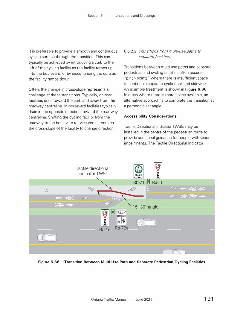
191
Section 6 · Intersections and Crossings
Ontario Traffic Manual · June 2021
It is preferable to provide a smooth and continuous cycling surface through the transition. This can typically be achieved by introducing a curb to the left of the cycling facility as the facility ramps up into the boulevard, or by discontinuing the curb as the facility ramps down.
Often, the change in cross-slope represents a challenge at these transitions. Typically, on-road facilities drain toward the curb and away from the roadway centreline. In-boulevard facilities typically drain in the opposite direction, toward the roadway centreline. Shifting the cycling facility from the roadway to the boulevard (or vice-versa) requires the cross-slope of the facility to change direction.
6.6.2.2 Transitions from multi-use paths to separate facilities
Transitions between multi-use paths and separate pedestrian and cycling facilities often occur at “pinch points” where there is insufficient space to continue a separate cycle track and sidewalk. An example treatment is shown in Figure 6.66. In areas where there is more space available, an alternative approach is to complete the transition at a perpendicular angle.
Accessibility Considerations
Tactile Directional Indicator TWSIs may be installed in the centre of the pedestrian route to provide additional guidance for people with vision impairments. The Tactile Directional Indicator
L
Ra-16
Ra-16
Tactile directionalindicator TWSI
15–30° angle
Rb-71
Rb-72a
Figure 6.66 – Transition Between Multi-Use Path and Separate Pedestrian/Cycling Facilities
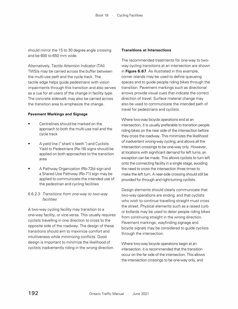
192
Book 18 · Cycling Facilities
Ontario Traffic Manual · June 2021
Transitions at Intersections
The recommended treatments for one-way to two-way cycling transitions at an intersection are shown in Figure 6.67. As illustrated in this example, corner islands may be used to define queueing spaces and to guide people riding bikes through the transition. Pavement markings such as directional arrows provide visual cues that indicate the correct direction of travel. Surface material change may also be used to communicate the intended path of travel for pedestrians and cyclists.
Where two-way bicycle operations end at an intersection, it is usually preferable to transition people riding bikes on the near side of the intersection before they cross the roadway. This minimizes the likelihood of inadvertent wrong-way cycling, and allows all the intersection crossings to be one-way only. However, at locations with significant demand for left turns, an exception can be made. This allows cyclists to turn left onto the connecting facility in a single stage, avoiding the need to cross the intersection three times to make the left turn. A near-side crossing should still be provided for through and right-turning cyclists.
Design elements should clearly communicate that two-way operations are ending, and that cyclists who wish to continue travelling straight must cross the street. Physical elements such as a raised curb or bollards may be used to deter people riding bikes from continuing straight in the wrong direction. Pavement markings, wayfinding signage and bicycle signals may be considered to guide cyclists through the intersection.
Where two-way bicycle operations begin at an intersection, it is recommended that the transition occur on the far side of the intersection. This allows the intersection crossings to be one-way only, and
should mirror the 15 to 30 degree angle crossing and be 600 to 650 mm wide.
Alternatively, Tactile Attention Indicator (TAI) TWSIs may be carried across the buffer between the multi-use path and the cycle track. The tactile edge helps guide pedestrians with vision impairments through this transition and also serves as a cue for all users of the change in facility type. The concrete sidewalk may also be carried across the transition area to emphasize the change.
Pavement Markings and Signage
• Centrelines should be marked on the approach to both the multi-use trail and the cycle track
• A yield line (“shark’s teeth”) and Cyclists Yield to Pedestrians (Ra-16) signs should be applied on both approaches to the transition area
• A Pathway Organization (Rb-72b) sign and a Shared Use Pathway (Rb-71) sign may be applied to communicate the intended use of the pedestrian and cycling facilities
6.6.2.3 Transitions from one-way to two-way facilities
A two-way cycling facility may transition to a one-way facility, or vice-versa. This usually requires cyclists travelling in one direction to cross to the opposite side of the roadway. The design of these transitions should aim to maximize comfort and intuitiveness while minimizing conflicts. Good design is important to minimize the likelihood of cyclists inadvertently riding in the wrong direction.
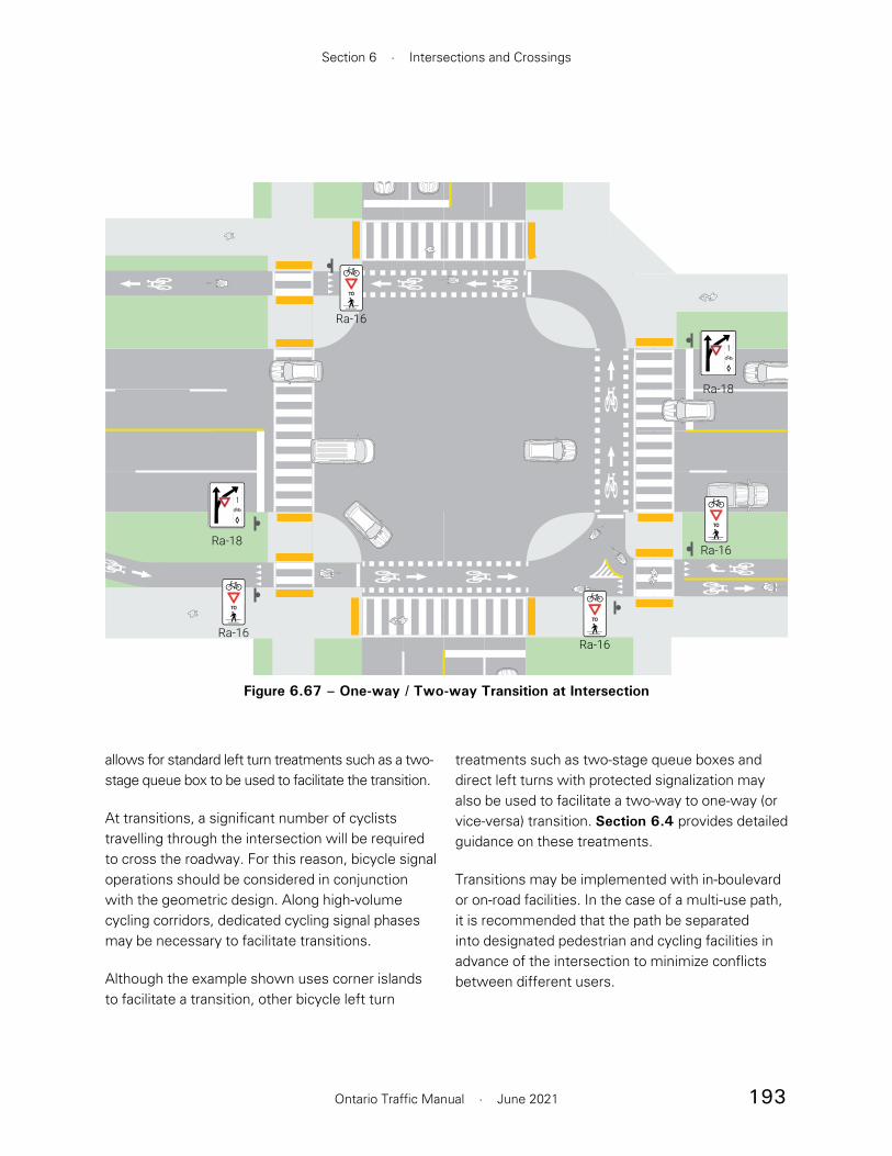
193
Section 6 · Intersections and Crossings
Ontario Traffic Manual · June 2021
treatments such as two-stage queue boxes and direct left turns with protected signalization may also be used to facilitate a two-way to one-way (or vice-versa) transition. Section 6.4 provides detailed guidance on these treatments.
Transitions may be implemented with in-boulevard or on-road facilities. In the case of a multi-use path, it is recommended that the path be separated into designated pedestrian and cycling facilities in advance of the intersection to minimize conflicts between different users.
allows for standard left turn treatments such as a two-stage queue box to be used to facilitate the transition.
At transitions, a significant number of cyclists travelling through the intersection will be required to cross the roadway. For this reason, bicycle signal operations should be considered in conjunction with the geometric design. Along high-volume cycling corridors, dedicated cycling signal phases may be necessary to facilitate transitions.
Although the example shown uses corner islands to facilitate a transition, other bicycle left turn
Ra-18
Ra-18
Ra-16
Ra-16Ra-16
Ra-16
Figure 6.67 – One-way / Two-way Transition at Intersection

194
Book 18 · Cycling Facilities
Ontario Traffic Manual · June 2021
are preferred. Wherever possible, the materials, colour and texture of boulevard elements such as sidewalks and cycle tracks should pass uninterrupted across the driveway entrance, as shown in the “Continuous Cycle Track” sidebar on page 199.
• At driveways, pavement markings require a context-sensitive approach, recognizing the range of driveway types from single-unit residential to high-volume commercial entrances. However, municipalities may choose to provide a consistent treatment along a corridor.
6.7.1 Geometric Considerations
Cycling supportive driveway entrances require the use of design measures to minimize the speed of motor vehicles entering or exiting the driveway. As at intersections, the speed of turning motor vehicles should be 15 km/h or less. Measures that are supportive of minimizing turning speeds include:
• A small corner radius (a 4 m radius corresponds to a design speed of 15 km/h)
• A raised cycling and pedestrian crossing
• A median between the entry and exit lane, which reduces the speed of left-turning motor vehicles
• Narrow entry and exit lane widths
• A continuous cycle track treatment (see sidebar on page 199)
A clear sight distance of 6 m is recommended for low volume driveways . At higher volume driveways, a minimum clear sight distance of 12 m
6.7 Driveway Treatments
At unsignalized driveways, cyclists travelling straight have the right-of-way over motor vehicles entering or exiting the roadway. The design of driveway treatments is similar to minor stop- or yield-controlled intersections, and the design guidance associated with setback or adjacent crossings described in Section 6.3 is generally applicable at driveways. This section describes additional design considerations unique to driveways.
Similar to intersections, the following principles apply at driveways:
• The speed of turning motor vehicles should be minimized through the use of geometric design treatments such as small corner radii and raised crossings. The desired motor vehicle turning speed is 15 km/h or less.
• Adequate visibility should be provided
• Clear and consistent design language should be applied to draw attention to the cycling crossing and communicate the right-of-way
However, at driveways, the following considerations also apply:
• Access controls, which limit certain motor vehicle entry or exit movements, may eliminate certain types of conflicts. For example, some driveways may permit right-in/right-out access only. However, when access controls are implemented through the use of channelized motor vehicle movements, they may increase turning speeds which decreases cyclist safety.
• Design treatments that provide continuous sidewalks and cycle tracks over the driveway

195
Section 6 · Intersections and Crossings
Ontario Traffic Manual · June 2021
increases with the degree of conflict presented by the driveway. High-volume commercial or industrial driveways demand a higher standard of conflict treatment.
On-Road Facilities
At residential driveways, the on-road bicycle lanes and buffered bicycle lanes for pavement markings should change to a dashed line across the driveway entrance as shown in Figure 6.68. Alternatively, at very low-volume driveways, bicycle lane lines and buffers may continue uninterrupted across the driveway. Separated bicycle lanes will require that physical separation be interrupted to provide driveway access. A painted buffer and flexible posts should extend as far as possible to help reduce turning speeds and visually narrow the driveway. At driveways serving multiple residential units, bicycle stencils with optional directional arrows may be marked within the cycling facility.
When a cycling facility crosses a commercial, industrial or high-volume residential driveway, the cycling facility pavement markings should continue up to the point of curvature of the driveway as shown in Figure 6.69. A dashed line should continue across the driveway entrance, with conflict zone pavement markings such as a bicycle stencil with a directional arrow. A yield line or a stop bar may be used on the driveway exit to further reinforce yielding behaviour. Green surface treatments should not be universally applied at all driveway crossings, but may be considered in areas with a high potential for conflict, or where it has been observed that motorists are failing to yield to people riding bikes.
is recommended. Within the clear sight distance, no on-street parking should be permitted.
For in-boulevard facilities, a setback distance of 4 to 6 m is preferred at high-volume driveways. The desired setback may be introduced by tapering the cycling facility at 1:3 to 1:6, or by introducing a reverse curve (“s curve”). The taper or curve provides a visual queue to cyclists that a conflict is approaching.
Access Controls
At driveways, access controls may eliminate certain types of conflicts. For example, some driveways may provide right-in and right-out access only, which avoids the possibility of a left-turning motor vehicle conflicting with the through cycling movement. However, access controls are often implemented with the use of channelized entrances and exits. These channelized accesses usually promote motor vehicle turning movements at speeds greater than 15 km/h.
Where access controls are implemented, it is preferable to use a median in the roadway to restrict turning movements, thereby avoiding the use of channelized entrances and exits. When channelized entrances and exits are necessary, they should be constructed in a manner that forces motor vehicles to make a sharp turn at slow speeds. Consider the use of a truck apron to accommodate large trucks but also provide speed control for light motor vehicles.
6.7.2 Pavement Markings and Signage
Pavement markings at driveways should draw attention to the bicycle crossing and reinforce the requirement for motor vehicles entering and exiting the driveway to yield to cyclists and pedestrians. The complexity of the conflict zone treatment

196
Book 18 · Cycling Facilities
Ontario Traffic Manual · June 2021
Buffer may continue uninterruptedat very low-volume drivewayssuch as single-unit residential
Figure 6.68 – Low-Volume Driveway Treatment, On-road Facility
Ra-1Ra-1
Figure 6.69 – High-Volume Driveway Treatment, On-road Facility

197
Section 6 · Intersections and Crossings
Ontario Traffic Manual · June 2021
per hour. The sign may be placed 5 to 15 m in advance of the cycling crossing.
The following signage is also recommended for higher volume driveway crossings of in-boulevard cycling facilities:
• A Bicycle Crossing Ahead (Wc-14) or Pedestrian and Bicycle Crossing Ahead (Wc-15) sign may be placed 5 to 15 m or less at the driveway exit. This sign is not necessary if a Contraflow Cycling Crossing sign is implemented.
• A Turning Vehicles Yield to Cyclists (Ra-18) sign or Trail Crossing Side Street (Wc-37R or Wc-37L) sign may be placed along the street a minimum of 15 m in advance of the driveway entrance. The Ra-18 is intended for dedicated cycling facilities while the Wc-37 is typically used in the case of multi-use path
• A Slow Watch For Turning Vehicles (Wc-38) sign may be placed along the cycling facility in advance of the driveway
In-boulevard Facilities
At high-volume driveways, in-boulevard facilities should be set back a preferred distance of 4 to 6 m from the curb. This distance may be reduced to a minimum of 2 m in constrained locations. Wherever feasible, a continuous cycle track or multi-use path, discussed in the sidebar on page 199, is the preferred treatment.
Where it is not feasible to implement a continuous cycle track or multi-use path at a driveway, the crossing should be marked as a crossride as shown in Figure 6.72 and Figure 6.72. A separate crossride should be marked where there is a separate cycle track and sidewalk, while a mixed crossride may be marked as in the case of a multi-use path crossing. An example is shown in Figure 6.70.
At low-volume residential driveways as illustrated in Figure 6.71, conflict zone markings are not typically required. At commercial, industrial or high-volume residential driveways as shown in Figure 6.72, a bicycle symbol and directional arrow should be marked within the crossride. Green surface treatments should not be universally applied at all driveway crossings, but may be considered at driveways with a high potential for conflict, or where it has been observed that motorists are failing to yield to people riding bikes. A yield line should be marked adjacent to the crossing for motor vehicles entering the driveway, and a yield line or stop bar should be marked adjacent to the crossing for motor vehicles exiting the driveway.
In the case of two-way cycling facilities, a Contraflow Cycling Crossing (WC-43 TAC) sign should be placed in advance of the driveway exit for all driveways serving more than 10 motor vehicles
Figure 6.70 – Example of Multi-Use Path Driveway Crossing, Richmond Hill
Source: WSP

198
Book 18 · Cycling Facilities
Ontario Traffic Manual · June 2021
Figure 6.71 – Low-Volume Driveway Treatment, In-Boulevard Facility (Multi-Use Path)
15 m
WC-43 (TAC)
4–6 m(desired)
Wc-38
Wc-37R (OTM)Wc-38
Figure 6.72 – High-Volume Driveway Treatment, In-Boulevard Facility (Multi-Use Path)

199
Section 6 · Intersections and Crossings
Ontario Traffic Manual · June 2021
Continuous Cycle Track
Where a cycle track or multi-use path crosses a driveway or a minor street, a continuous cycle track may be implemented. In this treatment, sidewalks and cycling facilities pass through the driveway or intersection without interruption.
This design treatment clearly communicates that pedestrians and cyclists have the right-of-way over motorists, who perceive that they are driving up and over a pedestrian/cyclist space.
The recommended elements of a continuous cycle track treatment are as follows:
• The materials of boulevard elements should continue without interruption across the driveway threshold to the greatest extent possible. For example, if there is an asphalt cycle track, a concrete sidewalk, and unit pavers through a furnishing zone, all of these elements should continue across the driveway.
• There is no change in elevation of the sidewalk or cycle track at the driveway. Instead, an approach ramp with typical 8 to 15% grade should raise the driveway up to meet the elevation of the sidewalk and cycle track.
• There is a continuous curb along the edge of the main road which becomes mountable or semi-mountable at the driveway entrance. There is no curved entrance that indicates where motorists are expected to turn.
• From the perspective of a motorist exiting the driveway or minor street, the road should appear to terminate at the sidewalk or cycle track. This is done through a change in material, a narrowing of the roadway and possibly a ramp up to the elevation of the boulevard elements.
• This treatment relies on design elements such as contrasting materials to clearly communicate pedestrian and cyclist priority. It should not be necessary to provide signage or pavement markings such as crossrides or crosswalks.
Mountablecurb
SidewalkCycleTrack
ApproachRamp
* Tactile strip
Driveway*
Plan View Section View
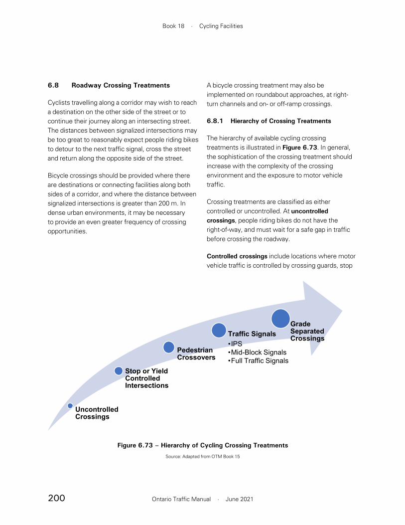
200
Book 18 · Cycling Facilities
Ontario Traffic Manual · June 2021
Figure 6.73 – Hierarchy of Cycling Crossing Treatments
Source: Adapted from OTM Book 15
Uncontrolled Crossings
Stop or Yield Controlled Intersections
Pedestrian Crossovers
Traffic Signals•IPS•Mid-Block Signals•Full Traffic Signals
Grade Separated Crossings
6.8 Roadway Crossing Treatments
Cyclists travelling along a corridor may wish to reach a destination on the other side of the street or to continue their journey along an intersecting street. The distances between signalized intersections may be too great to reasonably expect people riding bikes to detour to the next traffic signal, cross the street and return along the opposite side of the street.
Bicycle crossings should be provided where there are destinations or connecting facilities along both sides of a corridor, and where the distance between signalized intersections is greater than 200 m. In dense urban environments, it may be necessary to provide an even greater frequency of crossing opportunities.
A bicycle crossing treatment may also be implemented on roundabout approaches, at right-turn channels and on- or off-ramp crossings.
6.8.1 Hierarchy of Crossing Treatments
The hierarchy of available cycling crossing treatments is illustrated in Figure 6.73. In general, the sophistication of the crossing treatment should increase with the complexity of the crossing environment and the exposure to motor vehicle traffic.
Crossing treatments are classified as either controlled or uncontrolled. At uncontrolled crossings, people riding bikes do not have the right-of-way, and must wait for a safe gap in traffic before crossing the roadway.
Controlled crossings include locations where motor vehicle traffic is controlled by crossing guards, stop

201
Section 6 · Intersections and Crossings
Ontario Traffic Manual · June 2021
• Step 2. Assess whether an unsignalized crossing is warranted. If a traffic signal is not warranted, assess whether an unsignalized crossing is warranted. If at least two of these three criteria are met, the site is a candidate for an unsignalized crossing:
— A crossing is required to provide network connectivity or access to a destination.
— The crossing site is more than 200 m from the nearest traffic control device. This threshold may be reduced to 100 m in urban environments with a high density of destinations on both sides of the street.
— There is an average latent crossing demand of 15 or more users per hour of pedestrians and cyclists combined. The latent demand may be assessed by counting the actual number of pedestrians or cyclists crossing the roadway in the absence of a formal crossing treatment and estimating the projected demand.
• Step 3. Determine whether an uncontrolled crossing is appropriate. Review the guidance in Section 6.8.4.3 to determine whether an uncontrolled crossing is appropriate. This should consider the context of the proposed crossing location. If the environment is supportive, consider installing an uncontrolled crossing.
• Step 4. Consider alternative options. If a cycling crossing is warranted, but an uncontrolled crossing is not suitable at the proposed crossing location, consider alternative solutions, such as:
or yield signs, intersection pedestrian signals (IPS), mid-block signals or full traffic control signals. The pedestrian crossover (PXO) is also a controlled crossing treatment. Currently, people riding bikes are required to dismount and walk their bicycles at a PXO.
Grade-separated crossings are an alternative to controlled or uncontrolled crossings. These crossings provide the highest degree of separation between people cycling and motor vehicle traffic as discussed in Section 6.12.
6.8.2 Crossing Treatment Selection
The selection of a cycling crossing treatment adheres to similar principles as pedestrian crossing treatment selection. OTM Book 15 provides detailed guidance on this topic. The guidance in this section is intended to promote uniformity in treatment selection throughout a jurisdiction and to help practitioners in making informed decisions. However, this guidance is not a substitute for the application of sound and well-documented engineering judgment.
The following process is recommended to determine the appropriate crossing type:
• Step 1. Determine whether a traffic signal is warranted. Check whether a signal is warranted based on the justifications in OTM Book 12. This includes an analysis of collision history. For the purposes of Justification 6, bicycle volumes may be combined with pedestrian volumes. If a signal is warranted, install an IPS, mid-block signal or full traffic signals based on the guidelines in OTM Books 12 and 15.
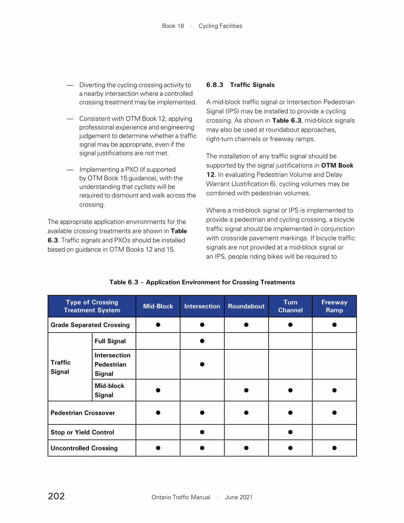
202
Book 18 · Cycling Facilities
Ontario Traffic Manual · June 2021
6.8.3 Traffic Signals
A mid-block traffic signal or Intersection Pedestrian Signal (IPS) may be installed to provide a cycling crossing. As shown in Table 6.3, mid-block signals may also be used at roundabout approaches, right-turn channels or freeway ramps.
The installation of any traffic signal should be supported by the signal justifications in OTM Book 12. In evaluating Pedestrian Volume and Delay Warrant (Justification 6), cycling volumes may be combined with pedestrian volumes.
Where a mid-block signal or IPS is implemented to provide a pedestrian and cycling crossing, a bicycle traffic signal should be implemented in conjunction with crossride pavement markings. If bicycle traffic signals are not provided at a mid-block signal or an IPS, people riding bikes will be required to
— Diverting the cycling crossing activity to a nearby intersection where a controlled crossing treatment may be implemented.
— Consistent with OTM Book 12, applying professional experience and engineering judgement to determine whether a traffic signal may be appropriate, even if the signal justifications are not met.
— Implementing a PXO (if supported by OTM Book 15 guidance), with the understanding that cyclists will be required to dismount and walk across the crossing.
The appropriate application environments for the available crossing treatments are shown in Table 6.3. Traffic signals and PXOs should be installed based on guidance in OTM Books 12 and 15.
Table 6.3 – Application Environment for Crossing Treatments
Type of Crossing Treatment System Mid-Block Intersection Roundabout Turn
ChannelFreeway Ramp
Grade Separated Crossing • • • • •
Traffic Signal
Full Signal •Intersection Pedestrian Signal
•
Mid-block Signal • • • •
Pedestrian Crossover • • • • •Stop or Yield Control • •Uncontrolled Crossing • • • • •
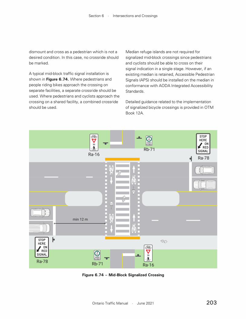
203
Section 6 · Intersections and Crossings
Ontario Traffic Manual · June 2021
Median refuge islands are not required for signalized mid-block crossings since pedestrians and cyclists should be able to cross on their signal indication in a single stage. However, if an existing median is retained, Accessible Pedestrian Signals (APS) should be installed on the median in conformance with AODA Integrated Accessibility Standards.
Detailed guidance related to the implementation of signalized bicycle crossings is provided in OTM Book 12A.
dismount and cross as a pedestrian which is not a desired condition. In this case, no crossride should be marked.
A typical mid-block traffic signal installation is shown in Figure 6.74. Where pedestrians and people riding bikes approach the crossing on separate facilities, a separate crossride should be used. Where pedestrians and cyclists approach the crossing on a shared facility, a combined crossride should be used.
Rb-71
Rb-71
Ra-16
Ra-16
min 12 m
Ra-78
Ra-78
Figure 6.74 – Mid-Block Signalized Crossing

204
Book 18 · Cycling Facilities
Ontario Traffic Manual · June 2021
and two-lane crossings provide the most favourable conditions for an uncontrolled crossing. The crossing distance may be reduced by implementing a refuge island, so that people cycling cross one direction of traffic at a time. Refuges should preferably be 3.0 m deep to accommodate a bicycle with a trailer, but should be a minimum of 2.0 m. Uncontrolled crossings should not be implemented at roadways that require a total crossing of more than four lanes, or three lanes on one-way streets, even if there is a refuge island.
• Motor vehicle speeds. Higher motor vehicle speeds increase the risk and exposure to people riding bikes. Cyclists also encounter more difficulty in identifying a safe gap at higher motor vehicle speeds. In an urban or suburban context, uncontrolled crossings may be considered on streets with a posted speed limit of 60 km/h or less. Wherever possible, traffic calming measures should be implemented to reduce the speed of motor vehicles at the crossing location to 30 km/h. In a rural context, uncontrolled crossings may be considered on roadways with a posted speed of up to 80 km/h if supported by a thorough analysis of site-specific conditions and appropriate geometric design elements.
• Traffic volumes. An uncontrolled crossing should only be considered where traffic volumes are sufficiently low that suitable gaps in motor vehicle traffic will frequently arise so that waiting times are minimized. As traffic volumes and waiting times increase, risk-taking behaviour is likely to increase. Uncontrolled crossings are not recommended in locations where traffic volumes exceed 9,000 ADT.
6.8.4 Uncontrolled Crossings
Uncontrolled crossings are locations where people riding bikes do not have the right-of-way, and are required to wait for a suitable gap in traffic before crossing. The term “uncontrolled” refers to the absence of traffic control devices for approaching motor vehicles. At uncontrolled crossings, a stop or a yield sign should face cycling traffic. Although it is the responsibility of the cyclist to wait for a gap sufficient to allow them to cross the roadway, motorists must make every effort to avoid a collision. Once the opposing user enters the roadway, both have a responsibility to yield, slow or take evasive action to avoid a conflict or collision.
While the lack of right-of-way for people cycling may be perceived to be a disadvantage, uncontrolled crossings may provide a comfortable and convenient crossing treatment when implemented at locations with low traffic volumes and speeds. In these conditions, an uncontrolled crossing may result in less delay to cyclists, as compared to a signalized crossing.
Application Environment
At an uncontrolled crossing, people riding bikes must identify a safe gap in approaching traffic. The task is simplified by ensuring that suitable gaps in motor vehicle traffic occur frequently. This can be done by reducing the speed of motor vehicles which improves the cyclist’s ability to judge a suitable gap. The following criteria should be considered in determining whether to implement an uncontrolled crossing:
• Crossing distance. The length of gap required to safely complete a crossing is directly related to the crossing distance. One-
205
Section 6 · Intersections and Crossings
Ontario Traffic Manual · June 2021
6.8.4.1 Sight Distance
The requirements for sight distance at an uncontrolled crossing are based on the AASHTO sight distance model, described in the TAC Geometric Design Guide for Canadian Roads. The required sight distances may be calculated using the methodology for a yield controlled intersection. The approach sight triangle consists of a sight distance along the cycling facility (variable a) and a sight distance along the roadway (variable b), shown in Figure 6.75.
The minimum sight distance along the cycling facility is shown in Table 6.5, and depends on the approach speed of cyclists. When a yield sign faces approaching cyclists, the design speed of the cycling facility, typically 20 to 30 km/h, should be used. When a stop sign faces approaching cyclists, a slower 10 km/h approach speed may be used. If it is not possible to provide the recommended sight distance along the cycling leg, additional design treatments to reduce the speed of approaching vehicles and cyclists are strongly recommended. Possible treatments are discussed in Section 6.8.4.3.
The minimum sight distance along the roadway approach is shown in Table 6.6, and depends on the speed of approaching motor vehicles and the width of the crossing. In general, the AASHTO sight distance model is applied, treating the cycling approach as a minor road. However, based on guidance in the CROW Design Manual for Bicycle Traffic (2016), an additional safety margin has been added to the crossing time gaps recommended by the AASHTO model. This safety margin accounts for the increased difficulty that people riding bikes encounter in judging a suitable crossing gap in higher speed traffic, and ranges from 1 second at 40 km/h to 5 seconds at 80 km/h.
• Illumination. The crossing location should be well-illuminated. Guidance in OTM Book 15 Section 6.2.6 (Illumination) and the Transportation Association of Canada Guide for the Design of Roadway Lighting (2006) should be applied.
• Sight Distance. Uncontrolled crossings must only be implemented in locations that have adequate sight distance. Sight distance requirements are described in detail in Section 6.8.4.1.
The suggested application environment for an uncontrolled crossing is shown in Table 6.4. For consistency, the traffic volume (ADT) thresholds and lane configurations used in this table are similar to values used in OTM Book 15 and the TAC Pedestrian Crossing Control Guide Decision Support Tools. However, the ADT thresholds for an uncontrolled cycling crossing are more restrictive than for a PXO. This is due to the difference in right-of-way at these crossing types. At a PXO, motorists are required to yield to pedestrians waiting to cross. A PXO may be used at relatively high motor vehicle volumes (up to 35,000 ADT), because crossing opportunities can theoretically be created at any time by indicating an intention to cross the street. Conversely, at an uncontrolled crossing, there is no requirement for motorists to yield to pedestrians or people riding bikes. Therefore, people wishing to cross must wait for crossing opportunities to naturally arise through gaps in the traffic flow.
The ADT thresholds used in Table 6.4 have been selected to provide a maximum average waiting time of approximately 30 seconds during the peak hour. In cases where there is greater exposure, for example at 70–80 km/h motor vehicle speeds and at four-lane crossings without a refuge, the ADT thresholds have been reduced to provide a maximum average waiting time of 15 seconds.
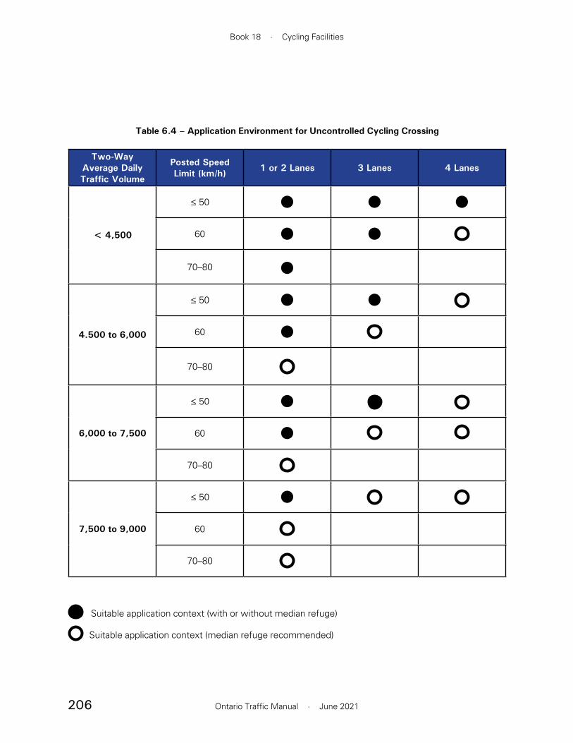
206
Book 18 · Cycling Facilities
Ontario Traffic Manual · June 2021
Table 6.4 – Application Environment for Uncontrolled Cycling Crossing
Two-Way Average Daily Traffic Volume
Posted Speed Limit (km/h) 1 or 2 Lanes 3 Lanes 4 Lanes
< 4,500
≤ 50 • • •60 • •
70–80 •
4.500 to 6,000
≤ 50 • •60 •
70–80
6,000 to 7,500
≤ 50 • •60 •
70–80
7,500 to 9,000
≤ 50 •60
70–80
Suitable application context (with or without median refuge)
Suitable application context (median refuge recommended)

207
Section 6 · Intersections and Crossings
Ontario Traffic Manual · June 2021
Figure 6.75 – Approach Sight Triangle
b
a
Table 6.5 – Minimum Cycling Leg Sight Distance for Uncontrolled Cycling Crossing (a)
Cycling Approach Speed
Cycling Approach Sight Distance
10 km/h 8 m
20 km/h 20 m
30 km/h 30 m
Note: Values must be adjusted if grade exceeds 3%
Table 6.6 – Minimum Roadway Leg Sight Distance for Uncontrolled Cycling Crossing (b)
Motor Vehicle Operating Speed
Crossing Width
7.0 m (2 lanes) 10.5 m (3 lanes) 14.0 m (4 lanes)
30 km/h 55 m 60 m 70 m
40 km/h 85 m 95 m 105 m
50 km/h 120 m 130 m 145 m
60 km/h 160 m 175 m 190 m
70 km/h 205 m 220 m 240 m
80 km/h 260 m 275 m 300 m
Notes: Values must be adjusted if grade exceeds 3%. Where a refuge island (minimum width = 2.0 m) is present, the crossing may be treated as two independent crossings.

208
Book 18 · Cycling Facilities
Ontario Traffic Manual · June 2021
at most two lanes. However, for uncontrolled crossings, the ultimate decision to provide stop or yield control for people cycling requires a thorough evaluation of site-specific conditions and the application of sound engineering judgment.
6.8.4.3 Uncontrolled Crossing Design
As at other intersections and crossings, it is important to use clear and consistent design language at uncontrolled crossings. Pavement markings, signage and geometric design elements may be used to simplify crossings, to maximize awareness on the part of all road users and to reinforce the rules of the road.
Crossride pavement markings and green surface treatment should not be used at uncontrolled crossings. Although these pavement markings do not have any regulatory effect under the HTA, their use in a situation where people riding bikes do not have right-to-way is contrary to the application of a consistent design philosophy.
Traffic calming measures should be considered at uncontrolled crossings. Wherever possible, it is desirable to reduce the operating speed of motor vehicle traffic to 30 km/h and to minimize the crossing width. This has the effect of increasing the frequency of acceptable gaps in traffic and reducing cyclists’ exposure.
Typical uncontrolled crossings are shown in Figure 6.77 and Figure 6.78. An example of an uncontrolled crossing is shown in Figure 6.76.
Design Components
The recommended design components of an uncontrolled crossing are as follows.
The values provided in Table 6.5 and Table 6.6 assume the approaches to the crossing are on level ground with less than a 3% grade. If this is not the case, the values must be adjusted using the procedure described in the AASHTO model. Sightlines should be reviewed from cyclist eye level of 1.5 m.
6.8.4.2 Stop or Yield for Cyclists?
At an uncontrolled crossing, people riding bikes should be faced with either a stop or a yield sign. The choice of stop or yield control is complex. The AASHTO Guide to Bicycle Facilities, 4th Edition notes “a common misconception is that the routine installation of stop control for the pathway is an effective treatment for preventing crashes at path-roadway intersections.” It goes on to note that cyclist compliance with stop signs at path/roadway intersections is poor, and that installing unnecessary stop controls may diminish respect for traffic control at more critical locations.
Yield control is more consistent with typical cyclist behaviour, and with the natural desire of a person riding a bicycle to remain in motion. However, yield control is not appropriate in situations where sight lines are poor, the angle of crossing is not perpendicular, or traffic volumes are such that there is a high likelihood that people riding bikes will be required to stop and wait for some time before a suitable crossing gap is available.
The recommended approach is to implement yield control in conditions where cyclist exposure to traffic is minimal and where adequate approach sight distance for a yield condition is available. In general, candidates for yield control include scenarios where traffic volumes are less than 2,500 vehicles per day, motor vehicle operating speeds are 50 km/h or less and the crossing distance is
209
Section 6 · Intersections and Crossings
Ontario Traffic Manual · June 2021
at the conflict point. It is desirable to reduce traffic speeds to 30 km/h or less at the crossing. The following treatments may be considered:
• A raised crossing
• Curb extensions to narrow the roadway at the crossing
• A refuge island. The desired width of a refuge island is 3.0 m to accommodate bicycles with trailers. In constrained environments, the minimum width is 2.0 m.
Pavement markings and signage
No crossride should be marked, since people riding bikes do not have the right-of-way at an uncontrolled crossing.
Condensed dashed guide lines as shown in Section 6.2.1.2 may optionally be used to define the crossing location. Green surface treatment should not be applied.
On the cycling approach:
• A yield sign should be placed approximately 1 m from the roadway. Where there is a sidewalk adjacent to the roadway, the yield sign should be placed on the approach to the sidewalk.
• A yield line should be placed adjacent to the yield sign
• On two-directional cycling facilities, a solid centreline should be marked within 10 m of the crossing
• Optionally, a Stop Ahead (Wb-1) or Yield Ahead (Wb-1A) warning sign may be placed a minimum of 15 m from the crossing
On the cycling approach:
Design treatments to slow the operating speed of approaching cyclists are recommended. Treatment options include:
• A curve on the cycling approach with a minimum inner radius of 5 m. Where a curve is introduced to control the speed of cyclists, it should terminate with a minimum 5 m straight section in advance of the crossing.
• An uphill grade, with a maximum slope of 5%
• Visual friction along the edge of the cycling facility. Elements such as bollards, fences, edge lines or landscaping may be used to visually narrow the facility. However, any such elements should be outside of the lateral clearance zone.
• A series of transverse white lines on the cycling facility
Physical barriers such as offset gates or swing gates (also known as “P” gates) should not be implemented as a speed reduction measure. Their use should be limited to cases where vehicular access control measures are necessary. Detailed guidance is provided in Section 7.3.
The crossing should approach at as close to a perpendicular angle as possible. The minimum acceptable crossing angle is 60 degrees. Where a sharp turn is necessary to orient the cycling facility perpendicular to the crossing, a minimum 2.5 m of queueing space should be provided, oriented in the direction of the crossing.
On the roadway approach:
Wherever practical, traffic calming treatments should be applied to minimize the speed of motor vehicles

210
Book 18 · Cycling Facilities
Ontario Traffic Manual · June 2021
On the roadway approach:
• A Bicycle and Pedestrian Crossing Ahead (Wc-15) or Bicycle Crossing Ahead (Wc-14) sign should be placed 15 to 30 m in advance of the crossing location
• On roads with a posted speed of 60 km/h or more, a supplementary crossing ahead warning sign (Wc-14 or Wc-15) with distance tab (Wa-23t) should be posted in advance of the crossing, 50 to 100 m from the crossing
Figure 6.76 – Example of Uncontrolled Crossing, Toronto
Source: WSP
15–30 m
Raised crossing
Ra-2
Ra-2
Wc-15
Wc-32t
Figure 6.77 – Uncontrolled Crossing (With Raised Crossing)

211
Section 6 · Intersections and Crossings
Ontario Traffic Manual · June 2021
50–100 m from crossing
15 m
Wb-2
3.0 m (desired)
Wc-15
Wc-32t
Wc-15
Wc-23t(Recommended
where posted speed is 60 km/h
or greater)
15 m
Wc-15
Wc-32t
Ra-2
Ra-2
Figure 6.78 – Uncontrolled Crossing (With Median Refuge)

212
Book 18 · Cycling Facilities
Ontario Traffic Manual · June 2021
should never continue through the circulatory roadway.
6.9.1 Single-Lane Roundabouts
A single lane roundabout contains a single circulating lane and single entry and exit lanes on all approaches.
To reduce exposure at crossing locations, the speed of motor vehicles at crossings should be reduced to 30 km/h or less. A “radial” roundabout design, shown in Figure 6.79, is supportive of lower entry and exit speeds. In a radial design, entries and exits intersect the circulatory roadway at a near-perpendicular angle. By comparison, in a “tangential” design, also shown in Figure 6.79, entries and exits are nearly tangent to the circulatory roadway. This design encourages higher motor vehicle speeds.
A two-stage bicycle crossing should be provided on each roundabout approach. Although North American evidence is limited, international research suggests that better safety outcomes are achieved when people riding bikes do not have the right-of-way at these crossings. However, collision rates at single-lane roundabouts are significantly lower than at signalized intersections, even when people cycling are given priority.6
6.9 Roundabouts
Roundabouts may be divided into two categories:
• Single-lane roundabouts
• Multi-lane roundabouts
The recommended treatment for cycling facilities at a roundabout varies depending on the type of roundabout. At very low volume single-lane roundabouts, the roundabout may be treated as a shared roadway, with cyclists and motor vehicles travelling through the roundabout single-file. This treatment should only be considered if cyclists operate in a shared roadway on all roundabout approaches. Furthermore, all approaches should have a posted speed of 40 km/h or less and the total traffic volume through the roundabout is 3,000 ADT or less. Sharrows may be added in the roundabout to encourage cyclists to take the lane instead of riding on the outside of the circulatory roadway.
In all other cases, a cycle track or multi-use path should be provided around the perimeter of the roundabout. On the roundabout approaches, on-road cycling facilities should transition into the boulevard as shown in Section 6.6.2.1, and people riding bikes should be discouraged from circulating in the roundabout. An on-road cycling facility
Figure 6.79 – Radial vs. Tangential Roundabout Design
Radial Design Tangential Design
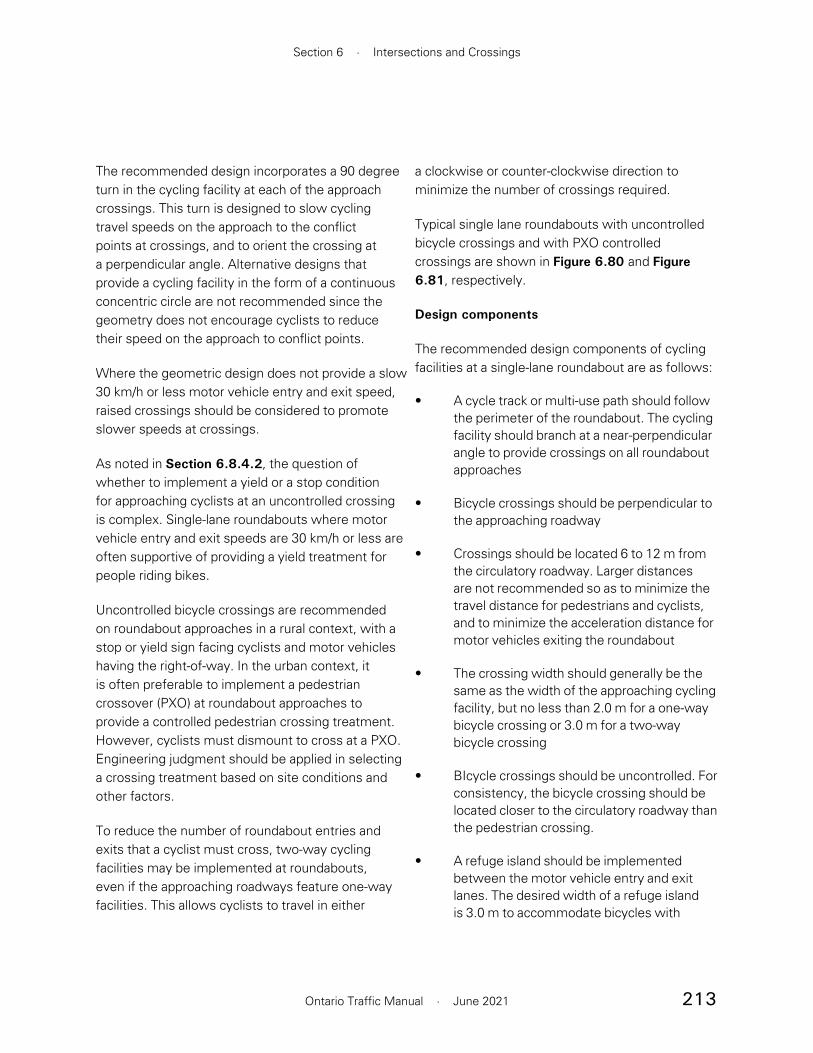
213
Section 6 · Intersections and Crossings
Ontario Traffic Manual · June 2021
a clockwise or counter-clockwise direction to minimize the number of crossings required.
Typical single lane roundabouts with uncontrolled bicycle crossings and with PXO controlled crossings are shown in Figure 6.80 and Figure 6.81, respectively.
Design components
The recommended design components of cycling facilities at a single-lane roundabout are as follows:
• A cycle track or multi-use path should follow the perimeter of the roundabout. The cycling facility should branch at a near-perpendicular angle to provide crossings on all roundabout approaches
• Bicycle crossings should be perpendicular to the approaching roadway
• Crossings should be located 6 to 12 m from the circulatory roadway. Larger distances are not recommended so as to minimize the travel distance for pedestrians and cyclists, and to minimize the acceleration distance for motor vehicles exiting the roundabout
• The crossing width should generally be the same as the width of the approaching cycling facility, but no less than 2.0 m for a one-way bicycle crossing or 3.0 m for a two-way bicycle crossing
• BIcycle crossings should be uncontrolled. For consistency, the bicycle crossing should be located closer to the circulatory roadway than the pedestrian crossing.
• A refuge island should be implemented between the motor vehicle entry and exit lanes. The desired width of a refuge island is 3.0 m to accommodate bicycles with
The recommended design incorporates a 90 degree turn in the cycling facility at each of the approach crossings. This turn is designed to slow cycling travel speeds on the approach to the conflict points at crossings, and to orient the crossing at a perpendicular angle. Alternative designs that provide a cycling facility in the form of a continuous concentric circle are not recommended since the geometry does not encourage cyclists to reduce their speed on the approach to conflict points.
Where the geometric design does not provide a slow 30 km/h or less motor vehicle entry and exit speed, raised crossings should be considered to promote slower speeds at crossings.
As noted in Section 6.8.4.2, the question of whether to implement a yield or a stop condition for approaching cyclists at an uncontrolled crossing is complex. Single-lane roundabouts where motor vehicle entry and exit speeds are 30 km/h or less are often supportive of providing a yield treatment for people riding bikes.
Uncontrolled bicycle crossings are recommended on roundabout approaches in a rural context, with a stop or yield sign facing cyclists and motor vehicles having the right-of-way. In the urban context, it is often preferable to implement a pedestrian crossover (PXO) at roundabout approaches to provide a controlled pedestrian crossing treatment. However, cyclists must dismount to cross at a PXO. Engineering judgment should be applied in selecting a crossing treatment based on site conditions and other factors.
To reduce the number of roundabout entries and exits that a cyclist must cross, two-way cycling facilities may be implemented at roundabouts, even if the approaching roadways feature one-way facilities. This allows cyclists to travel in either

214
Book 18 · Cycling Facilities
Ontario Traffic Manual · June 2021
Figure 6.80 – Single-Lane Roundabout, Uncontrolled Crossing Treatment (Motorist-Priority)

215
Section 6 · Intersections and Crossings
Ontario Traffic Manual · June 2021
Figure 6.81 – Single-Lane Roundabout, PXO Crossing Treatment
Note: Refer to OTM Book 15 for detailedguidance on PXO signage and pavement markings
Ra-16
Ra-16
m 21–63 m
(min 2 m)
Ra-5LRa-4t
Ra-5RRa-4t
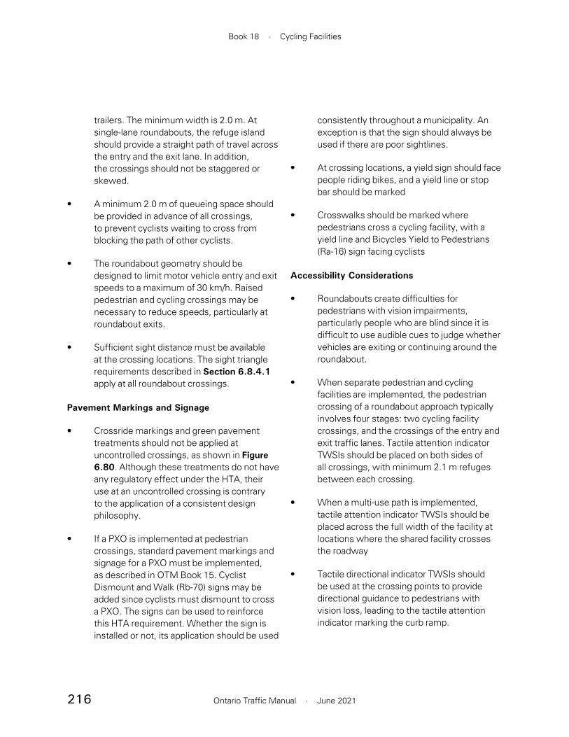
216
Book 18 · Cycling Facilities
Ontario Traffic Manual · June 2021
consistently throughout a municipality. An exception is that the sign should always be used if there are poor sightlines.
• At crossing locations, a yield sign should face people riding bikes, and a yield line or stop bar should be marked
• Crosswalks should be marked where pedestrians cross a cycling facility, with a yield line and Bicycles Yield to Pedestrians (Ra-16) sign facing cyclists
Accessibility Considerations
• Roundabouts create difficulties for pedestrians with vision impairments, particularly people who are blind since it is difficult to use audible cues to judge whether vehicles are exiting or continuing around the roundabout.
• When separate pedestrian and cycling facilities are implemented, the pedestrian crossing of a roundabout approach typically involves four stages: two cycling facility crossings, and the crossings of the entry and exit traffic lanes. Tactile attention indicator TWSIs should be placed on both sides of all crossings, with minimum 2.1 m refuges between each crossing.
• When a multi-use path is implemented, tactile attention indicator TWSIs should be placed across the full width of the facility at locations where the shared facility crosses the roadway
• Tactile directional indicator TWSIs should be used at the crossing points to provide directional guidance to pedestrians with vision loss, leading to the tactile attention indicator marking the curb ramp.
trailers. The minimum width is 2.0 m. At single-lane roundabouts, the refuge island should provide a straight path of travel across the entry and the exit lane. In addition, the crossings should not be staggered or skewed.
• A minimum 2.0 m of queueing space should be provided in advance of all crossings, to prevent cyclists waiting to cross from blocking the path of other cyclists.
• The roundabout geometry should be designed to limit motor vehicle entry and exit speeds to a maximum of 30 km/h. Raised pedestrian and cycling crossings may be necessary to reduce speeds, particularly at roundabout exits.
• Sufficient sight distance must be available at the crossing locations. The sight triangle requirements described in Section 6.8.4.1 apply at all roundabout crossings.
Pavement Markings and Signage
• Crossride markings and green pavement treatments should not be applied at uncontrolled crossings, as shown in Figure 6.80. Although these treatments do not have any regulatory effect under the HTA, their use at an uncontrolled crossing is contrary to the application of a consistent design philosophy.
• If a PXO is implemented at pedestrian crossings, standard pavement markings and signage for a PXO must be implemented, as described in OTM Book 15. Cyclist Dismount and Walk (Rb-70) signs may be added since cyclists must dismount to cross a PXO. The signs can be used to reinforce this HTA requirement. Whether the sign is installed or not, its application should be used

217
Section 6 · Intersections and Crossings
Ontario Traffic Manual · June 2021
Uncontrolled crossings or PXOs may be implemented at the roundabout approaches. Where high volumes of pedestrians and cyclists are anticipated, alternative treatments should be considered, such as:
• Grade-separated pedestrian and cyclist facilities. For example, tunnels or underpasses may be constructed at the roundabout approaches by raising the roadway and lowering the pedestrian and cycling facilities.
• Signalized mid-block crossings on roundabout approaches. When implementing a signalized mid-block crossing, the signal should be a sufficient distance from the circulatory roadway to minimize the likelihood of queues at the exits from extending into the roundabout. However, the distance should also try to minimize the detour for pedestrians and people riding bikes.
A cycle track or multi-use path should always be provided at multi-lane roundabouts, with on-road cycling facilities transitioning into the boulevard on roundabout approaches. It is incumbent on practitioners to use effective design strategies to ensure that people cycling are never forced to operate in the circulatory roadway of a multi-lane roundabout.
Design Components
The recommended design of cycling facilities at a multi-lane roundabout with PXO crossings is shown in Figure 6.82. All design components of a single lane roundabout apply at multi-lane roundabouts, with the following additional guidance:
6.9.2 Multi-Lane Roundabouts
A multi-lane roundabout contains more than one circulating lane, and multi-lane entries or exits on at least one approach leg. Multi-lane roundabouts do not have as strong a safety record as single-lane roundabouts, and present additional risks to pedestrians and cyclists.7 This is due to several factors:
• The crossing distances on roundabout approaches are longer which increases exposure to conflicts
• Multi-lane traffic presents a “multiple threat” conflict, in which a motor vehicle approaching in the median lane may be obscured by a motor vehicle in the curb lane. This risk is particularly pronounced at roundabout exits where motor vehicles are approaching the crossing on a curve, their travel speeds are higher and their path of travel is less predictable.
• Traffic volumes at roundabout approaches are typically higher than at single-lane roundabouts
• Motor vehicle speeds on entry and exit are likely to be faster than at single-lane roundabouts. At single-lane roundabouts, a “radial” design may promote reduced entry and exit speeds. However, it is difficult to implement a radial design at a multi-lane roundabout due to the risk of path overlap between adjacent motor vehicles.
Where multi-lane roundabouts are necessary for capacity reasons, it is preferable to provide multiple lanes only on the approaches where necessary. In particular, the use of multi-lane exits should be limited as much as possible.

218
Book 18 · Cycling Facilities
Ontario Traffic Manual · June 2021
and cyclists reoriented to face oncoming traffic within the refuge island.
• Due to the staggered alignment of the crossing, tactile directional indicator TWSIs are recommended to provide positive directional guidance for people with visual impairments
• Due to the higher entry and exit speeds at a multi-lane roundabout, the use of raised pedestrian and cycling crossings is recommended at all multi-lane entries and exits. However, raised crossings may not be appropriate on transit routes.
• A staggered crossing should be introduced at multi-lane entries and exits, with pedestrians
Figure 6.82 – Multi-Lane Roundabout with PXO Crossing Treatment
Note: Refer to OTM Book 15 for detailedguidance on PXO signage and pavement markings
Ra-5LRa-4t
Ra-5RRa-4t
Tactile directional indicator TWSI
Ra-16
Ra-16

219
Section 6 · Intersections and Crossings
Ontario Traffic Manual · June 2021
where a lane is dropped and becomes a forced right turn at the intersection. It is not applicable in the case of an in-boulevard cycling facility.
The typical design components of this treatment are:
• The channelized turn lane should be introduced approximately 20 to 30 m upstream of the intersection. The lane should be introduced abruptly to encourage motorists to conduct a slow and deliberate lane change.
• The desired length of the merge area is 10 to 15 m
• The minimum width of the bicycle lane is 1.8 m. If additional space is available, buffers may be added to either or both sides of the bicycle lane
• If a right turn lane is required, it may be introduced upstream of the channel, similar to Figure 6.42, if the length of the storage space can be minimized. If a larger storage area is required, it is preferable to transition the cycling facility into the boulevard and apply the Turn Channel Crossing treatment discussed later in this section. Alternatively, consider eliminating the turn channel altogether.
• Where the cycling facility must laterally shift on the intersection approach, for example, where on-street parking is provided between the bicycle lane and the roadway, the cycling facility should be shifted in advance of the merge area. This provides better visibility of people riding bikes, and reinforces the requirement for motorists to yield to people cycling. The lateral shift may occur at a taper of 1:6 (preferred) to 1:3 (minimum).
• On-street parking should be discontinued a minimum of 6.0 m in advance of the merge area, for visibility
6.10 Right Turn Channels
Channelized right turns have typically been implemented at intersections to improve motor vehicle flow and increase capacity. Traditional turn channels often feature a generous corner radius that allows turning motor vehicles to operate at relatively high speeds. However, this style of intersection design is being eliminated in many jurisdictions since it increases risk exposure for both cylists and pedestrians. While newer “smart channel” designs provide some minor improvement in reducing motor vehicle speeds, it remains challenging to provide a comfortable cycling condition in the presence of channelized turns.
It is often preferable and in some cases necessary to remove a turn channel in order to develop an intersection design supportive of the design cyclist. Where the channelized turn remains, there are two options:
• Upstream merge
• Turn channel crossing
Upstream Merge
In this treatment, shown in Figure 6.83, motor vehicles turning right merge across the cycling facility on the approach to the intersection. This is similar to the “Bicycle Lane Between Through Lane and Turn Lane” treatment, described in Section 6.3.4.
This treatment should only be applied in cases where motor vehicle speeds are low, with a desired speed of 40 km/h or less and a maximum of 50 km/h and where a single right turn lane is introduced by adding a lane on the approach to the intersection. This treatment should not be applied

220
Book 18 · Cycling Facilities
Ontario Traffic Manual · June 2021
Ra-5LRa-4t
Ra-18(variant)
Ra-2
Ra-5RRa-4t
Figure 6.83 – Right-Turn Channel with Upstream Merge

221
Section 6 · Intersections and Crossings
Ontario Traffic Manual · June 2021
• The pedestrian and cycling crossings may optionally be raised to reduce the speed of turning motor vehicles
• At yield controlled crossings, an optional green surface treatment may be added to the bicycle crossing
• It is preferable to keep pedestrians and cyclists separated within the refuge island. However, in some cases, there may be insufficient space available to fully separate users. In these cases, the island should be designed to function as a shared pedestrian/cycling environment.
• A minimum 3 m wide cycling and pedestrian circulation area should be provided on the refuge island to allow for bike trailers and cargo bikes. For two-way facilities, the width of this space should be increased to a minimum of 5 m.
Turn Channel Crossing
Alternatively, when the cycling facility is in-boulevard, a crossing may be provided to allow people riding bikes to access the triangular refuge island.
Practitioners must carefully consider the type of crossing treatment provided to facilitate access to the refuge island. At a channelized turn, several alternatives are possible:
• An uncontrolled crossing, shown in the example in Figure 6.84, with pedestrians and cyclists yielding to motor vehicles
• A yield-controlled crossing, shown in Figure 6.85, with motor vehicles yielding to pedestrians and cyclists
• A PXO, with cyclists required to dismount and walk
• A crossing controlled as part of the intersection traffic signal system
The guidance in Section 6.8 should be applied to determine the most suitable crossing treatment.
The typical design components of this treatment are as follows:
• The channelized turn should be designed with a high entry angle (known as a “smart channel”) to maximize visibility of pedestrians and cyclists and to minimize the speed of turning motor vehicles
• A cycling crossing should be implemented to allow people riding bikes to access the refuge island. The type of crossing treatment may vary
Figure 6.84 – Example of Right-Turn Channel Crossing, Winnipeg, Manitoba
Source: WSP, 2019

222
Book 18 · Cycling Facilities
Ontario Traffic Manual · June 2021
Figure 6.85 – Right-Turn Channel with Turn Channel Crossing
Ra-16Ra-2
Ra-2

223
Section 6 · Intersections and Crossings
Ontario Traffic Manual · June 2021
motor vehicles are anticipated at ramp terminals, protected signal phasing for cycling movements is recommended.
• Roundabout. Terminate on- and off-ramps at a roundabout. This solution is most appropriate when traffic volumes are moderate, and a single lane roundabout provides sufficient motor vehicle capacity. Where a multi-lane roundabout is necessary, a signalized intersection is preferred. Guidance on cycling facilities at roundabouts is provided in Section 6.9.
• Signalized mid-block crossing. Implement a signalized mid-block crossing at the ramp crossing. Where it is not practical to reconfigure the geometry of ramps at an existing interchange, this may be the most suitable option. Signalized mid-block crossings are discussed in Section 6.8.3.
Where it is not possible to implement one of these alternatives, an unsignalized on- or off-ramp crossing may be implemented. However, these treatments are less likely to provide a comfortable condition for the design cyclist.
6.11 Interchanges and Ramp Crossings
On- and off-ramp crossings at interchanges present significant challenges in accommodating people riding bikes. Ramps are typically designed to provide a high volume of motor vehicle capacity. At on-ramps, motorists are beginning to accelerate to highway speeds, while at off-ramps, motorists are velocitized, having not yet re-acclimatized to the slower speed environment of local roads. Moreover, there is often a higher proportion of heavy trucks and buses at interchanges. Individually and collectively, these factors often result in an environment that is unsuitable for the “interested but concerned” design cyclist.
In accommodating the design cyclist, it is preferable to avoid cycling crossings at free-flow on- and off-ramps. The following alternatives should be considered:
• Grade separation. Provide a grade-separated crossing for pedestrians and people cycling. Grade-separated crossings may consist of a short crossing to span an on- or off-ramp. Alternatively, a separate bridge or tunnel may provide a parallel highway crossing. This option eliminates conflicts with motor vehicles and minimizes delays for all users. Design guidance on grade separated crossings is provided in Section 6.12.
• Normalized intersection. Terminate on- and off-ramps at signalized or unsignalized intersections. The preferred approach is to terminate ramps at a intersection, where on- and off-ramps are at the same intersection. Channelized turns should be avoided. This approach is often appropriate in urban areas, and allows the intersection treatments described in Section 6.3 to be applied. Where high volumes of turning
Figure 6.86 – Grade-separated Multi-use Path Through an Interchange, Sacramento, California
Source: Sacramento County
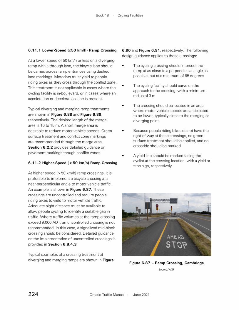
224
Book 18 · Cycling Facilities
Ontario Traffic Manual · June 2021
6.90 and Figure 6.91, respectively. The following design guidance applies to these crossings:
• The cycling crossing should intersect the ramp at as close to a perpendicular angle as possible, but at a minimum of 65 degrees
• The cycling facility should curve on the approach to the crossing, with a minimum radius of 3 m
• The crossing should be located in an area where motor vehicle speeds are anticipated to be lower, typically close to the merging or diverging point
• Because people riding bikes do not have the right-of-way at these crossings, no green surface treatment should be applied, and no crossride should be marked
• A yield line should be marked facing the cyclist at the crossing location, with a yield or stop sign, respectively.
6.11.1 Lower-Speed (≤50 km/h) Ramp Crossing
At a lower speed of 50 km/h or less on a diverging ramp with a through lane, the bicycle lane should be carried across ramp entrances using dashed lane markings. Motorists must yield to people riding bikes as they cross through the conflict zone. This treatment is not applicable in cases where the cycling facility is in-boulevard, or in cases where an acceleration or deceleration lane is present.
Typical diverging and merging ramp treatments are shown in Figure 6.88 and Figure 6.89, respectively. The desired length of the merge area is 10 to 15 m. A short merge area is desirable to reduce motor vehicle speeds. Green surface treatment and conflict zone markings are recommended through the merge area. Section 6.2.2 provides detailed guidance on pavement markings though conflict zones.
6.11.2 Higher-Speed (>50 km/h) Ramp Crossing
At higher speed (> 50 km/h) ramp crossings, it is preferable to implement a bicycle crossing at a near-perpendicular angle to motor vehicle traffic. An example is shown in Figure 6.87. These crossings are uncontrolled and require people riding bikes to yield to motor vehicle traffic. Adequate sight distance must be available to allow people cycling to identify a suitable gap in traffic. Where traffic volumes at the ramp crossing exceed 9,000 ADT, an uncontrolled crossing is not recommended. In this case, a signalized mid-block crossing should be considered. Detailed guidance on the implementation of uncontrolled crossings is provided in Section 6.8.4.3.
Typical examples of a crossing treatment at diverging and merging ramps are shown in Figure
Figure 6.87 – Ramp Crossing, Cambridge
Source: WSP

225
Section 6 · Intersections and Crossings
Ontario Traffic Manual · June 2021
merge areamin. 10-15 m
Rb-84aRa-18
Figure 6.88 – Lower-Speed (≤ 50 km/h) Diverging Ramp Crossing
2807merge areamin. 10-15 m
Rb-84a
Ra-2
Figure 6.89 – Lower-Speed (≤ 50 km/h) Merging Ramp Crossing
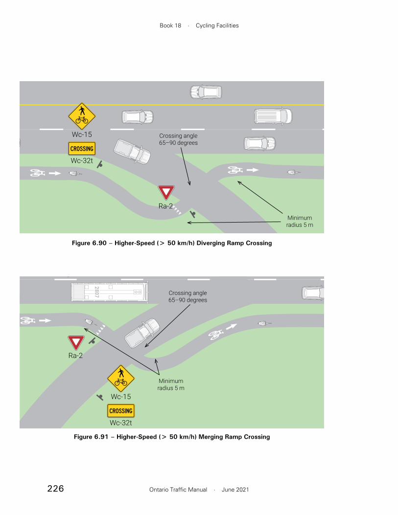
226
Book 18 · Cycling Facilities
Ontario Traffic Manual · June 2021
Minimumradius 5 m
Crossing angle65–90 degrees
Ra-2
Wc-15
Wc-32t
Figure 6.90 – Higher-Speed (> 50 km/h) Diverging Ramp Crossing
Ra-2
2807
Minimumradius 5 m
Crossing angle65–90 degrees
Wc-15
Wc-32t
Figure 6.91 – Higher-Speed (> 50 km/h) Merging Ramp Crossing
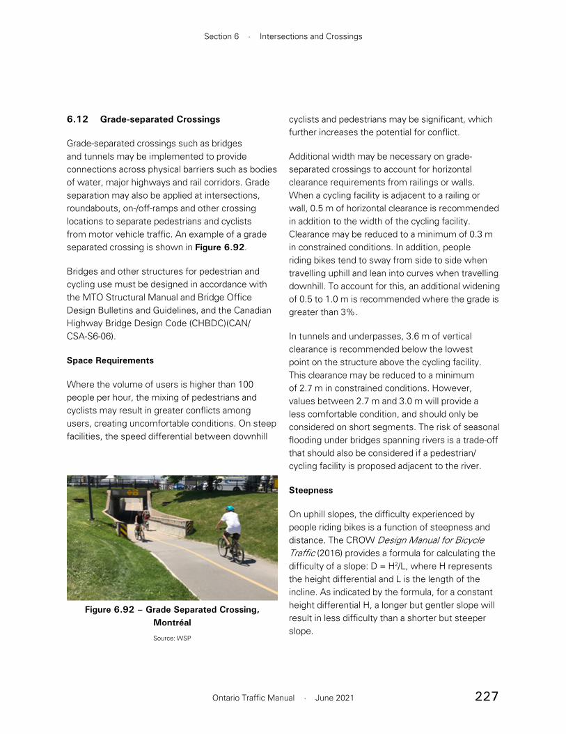
227
Section 6 · Intersections and Crossings
Ontario Traffic Manual · June 2021
cyclists and pedestrians may be significant, which further increases the potential for conflict.
Additional width may be necessary on grade-separated crossings to account for horizontal clearance requirements from railings or walls. When a cycling facility is adjacent to a railing or wall, 0.5 m of horizontal clearance is recommended in addition to the width of the cycling facility. Clearance may be reduced to a minimum of 0.3 m in constrained conditions. In addition, people riding bikes tend to sway from side to side when travelling uphill and lean into curves when travelling downhill. To account for this, an additional widening of 0.5 to 1.0 m is recommended where the grade is greater than 3%.
In tunnels and underpasses, 3.6 m of vertical clearance is recommended below the lowest point on the structure above the cycling facility. This clearance may be reduced to a minimum of 2.7 m in constrained conditions. However, values between 2.7 m and 3.0 m will provide a less comfortable condition, and should only be considered on short segments. The risk of seasonal flooding under bridges spanning rivers is a trade-off that should also be considered if a pedestrian/cycling facility is proposed adjacent to the river.
Steepness
On uphill slopes, the difficulty experienced by people riding bikes is a function of steepness and distance. The CROW Design Manual for Bicycle Traffic (2016) provides a formula for calculating the difficulty of a slope: D = H2/L, where H represents the height differential and L is the length of the incline. As indicated by the formula, for a constant height differential H, a longer but gentler slope will result in less difficulty than a shorter but steeper slope.
6.12 Grade-separated Crossings
Grade-separated crossings such as bridges and tunnels may be implemented to provide connections across physical barriers such as bodies of water, major highways and rail corridors. Grade separation may also be applied at intersections, roundabouts, on-/off-ramps and other crossing locations to separate pedestrians and cyclists from motor vehicle traffic. An example of a grade separated crossing is shown in Figure 6.92.
Bridges and other structures for pedestrian and cycling use must be designed in accordance with the MTO Structural Manual and Bridge Office Design Bulletins and Guidelines, and the Canadian Highway Bridge Design Code (CHBDC)(CAN/CSA-S6-06).
Space Requirements
Where the volume of users is higher than 100 people per hour, the mixing of pedestrians and cyclists may result in greater conflicts among users, creating uncomfortable conditions. On steep facilities, the speed differential between downhill
Figure 6.92 – Grade Separated Crossing, Montréal
Source: WSP

228
Book 18 · Cycling Facilities
Ontario Traffic Manual · June 2021
Steep slopes also present challenges for downhill cyclists, who may build up significant speed. Sharp corners, intersections and other hazards should be avoided at the bottom of a steep decline. A minimum 20 m of flat surface should be provided between the bottom of the incline and any intersections, crossings or other conflict points.
Illumination
Daytime illumination should be considered at underpasses and tunnels to help reduce the illumination contrast. Detailed guidance is provided in the TAC Guide for the Design of Roadway Lighting and the IES Lighting Handbook.
Surface Material
The preferred surface material for cycling facilities on bridges is asphalt or concrete. These materials provide superior skid resistance relative to wood or steel bridge decks. For decks surfaced with
Many people riding bikes will have difficulty sustaining a slope greater than 7.5% for more than a very short distance of 10 to 20 m. Slopes of less than 2% do not generally present difficulty. The prevalence of strong winds will also increase the difficulty of ascending a slope.
A difficulty value of D = 0.075 is considered suitable for an average adult cyclist, while smaller difficulty values provide more comfortable conditions for a wider range of ages and abilities. Values ranging from D = 0.1 to 0.2 will provide less comfortable conditions. The recommended target values are shown in Figure 6.93. These target values correspond to a difficulty value of D = 0.075, with minimum and maximum slopes of 1.75% and 7.5%, respectively.
Where the height difference exceeds 5 m, a flat landing may be provided to give people riding bikes an opportunity to regain momentum.
Figure 6.93 – Recommended Target Values for Grade Steepness
Source: Modified from Brief Dutch Design Manual for Pedestrian and Bicycle Bridges, ipv Delft, June 2015.

229
Section 6 · Intersections and Crossings
Ontario Traffic Manual · June 2021
It may be possible to implement a dedicated pedestrian/cycling crossing under an existing bridge serving motor vehicle traffic. An example is shown in Figure 6.94.
The design of bridges, tunnels and other grade-separated crossings for the exclusive use of pedestrians and people riding bikes should be consistent with facility design guidance provided in Section 4. For example, the design of a shared pedestrian/cycling bridge should be consistent with guidance applicable to a multi-use path.
The recommended widths of a dedicated cycling or pedestrian/cycling facility are shown in Table 6.7. These widths are inclusive of the recommended horizontal clearance adjacent to railings.
wood, the planks should be placed at a 90 degree angle relative to the path of travel to minimize the potential for bicycle wheels to get caught in the gaps. For decks with metal riding surfaces, appropriate texturing or coatings should be applied to provide skid resistance during wet conditions.
6.12.1 Dedicated Pedestrian/Cycling Crossings
Dedicated pedestrian/cycling crossings may be implemented to provide connectivity between communities or destinations separated by physical barriers. These crossings may also be implemented to provide a parallel pedestrian/cycling route that avoids major conflict points with motor vehicle traffic such as at highway interchanges.
Bicycle/pedestrian bridges also provide an opportunity to create architecturally distinctive structures that act as a landmark for communities.
Figure 6.94 – Grade Separated Crossing, East Gwillimbury
Source: WSP
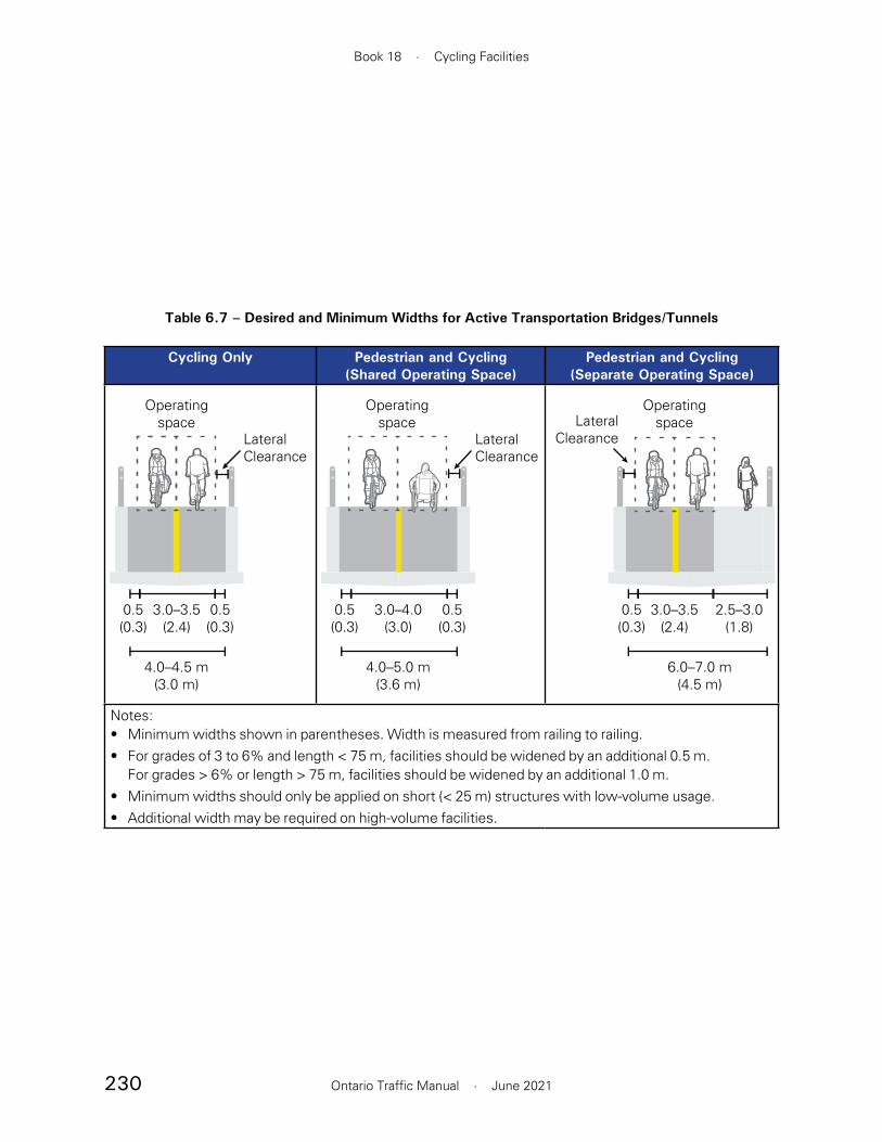
230
Book 18 · Cycling Facilities
Ontario Traffic Manual · June 2021
Table 6.7 – Desired and Minimum Widths for Active Transportation Bridges/Tunnels
Cycling Only Pedestrian and Cycling(Shared Operating Space)
Pedestrian and Cycling(Separate Operating Space)
3.0–3.5(2.4)
0.5(0.3)
0.5(0.3)
4.0–4.5 m(3.0 m)
Operating space
LateralClearance
3.0–4.0(3.0)
0.5(0.3)
0.5(0.3)
4.0–5.0 m(3.6 m)
Operating space
LateralClearance
3.0–3.5(2.4)
0.5(0.3)
2.5–3.0(1.8)
6.0–7.0 m(4.5 m)
Operating spaceLateral
Clearance
Notes:• Minimum widths shown in parentheses. Width is measured from railing to railing.• For grades of 3 to 6% and length < 75 m, facilities should be widened by an additional 0.5 m.
For grades > 6% or length > 75 m, facilities should be widened by an additional 1.0 m. • Minimum widths should only be applied on short (< 25 m) structures with low-volume usage.• Additional width may be required on high-volume facilities.

231
Section 6 · Intersections and Crossings
Ontario Traffic Manual · June 2021
Practitioners must exercise good engineering judgement in designing a cycling facility appropriate for the conditions at the grade separated crossing. Facility selection guidance from Section 5 should be applied, and facility widths should be consistent with guidance provided in Section 4.
Motor vehicle speeds on bridges are often higher than on the approaching roadways due to reduced sources of visual distraction and lateral friction on the bridge. For this reason, physical separation of cycling facilities should be considered on bridges, even if it cannot be applied on the roadway segments approaching the bridge.
If it is not possible to provide a suitable cycling facility that meets the suggested minimum widths, alternate routes that avoid the constrained location should be considered.
Bridges/Overpasses
Common design scenarios are shown in Table 6.8. Where motor vehicle speeds are greater than
6.12.2 Pedestrian/Cycling Facilities on Grade-Separated Roadways
Cycling routes frequently make use of a grade-separated roadway to cross major barriers such as highways and waterways. A bikeway must sometimes continue over a bridge or through a tunnel with constrained widths to overcome these major obstacles. An example of a bridge with active transportation facilities is shown in Figure 6.95.
Existing structures may need to be modified to safely integrate people riding bikes with other roadway users. In retrofit scenarios, the following options should be considered to allow cycling facilities to be implemented within a constrained facility:
• Narrow vehicular travel lanes to minimum widths recommended by the TAC Geometric Design Guide for Canadian Roads
• Remove a motor vehicle lane
• Narrow or remove features such as centre medians, shoulders and gutter pan offsets as much as possible
• Narrow sidewalks to minimum standards permitted by the AODA
• Convert a sidewalk to a multi-use path
The design of new structures or the modification of existing bridges must comply with the CHBDC. The MTO Design Supplement for TAC Geometric Design Guide for Canadian Roads (June 2017) provides additional guidance related to the design of roadways on bridges, including roadway widths, curbs, side clearance requirements and sidewalk widths. Figure 6.95 – Bridge with Active Transportation
Facilities, Ottawa–Gatineau
Source WSP

232
Book 18 · Cycling Facilities
Ontario Traffic Manual · June 2021
60 km/h, the preferred approach is to place the traffic barrier between the motor vehicle travel lanes and the cycling facility, as shown in Scenario 4. A 1.37 m high pedestrian/cycling barrier is required at the edge of the structure.
Tunnels/Underpasses
At underpasses, it is recommended that the cycling facility match the vertical alignment of the sidewalk, provided sufficient vertical clearance is available. This will minimize the steepness of the cycling ascent and descent at the underpass
because less vertical clearance is required than the roadway and the cycling facility can stay at a higher elevation.
Where the cycling facility is at the same elevation as the roadway, it is important to ensure that adequate drainage capacity is provided and that the surface of the cycling facility is maintained to a high quality to prevent the pooling of water.
Scenario Barrier Heights Notes1. On-road cycling facility on bridge deck with no sidewalk
STANDARD CROSS SECTIONSAME SCALE FOR WIDTH (250:1)SECTION ELEMENT HEIGHT: 0.8CM HIGH(SIDEWALK 0.9CM HIGH)
Combination Barrier
Cycling Facility
1.37 m 1.37 m combination vehicle/bicycle
barrier
• Conventional or buffered bike lane may be implemented on bridge deck
• Most suitable at operating speeds of 50 km/h or less
2. On-road cycling facility on bridge deck with adjacent raised sidewalkCombination BarrierUse taller version where warranted by potential bicycle use
Raised Sidewalk
1.37 m
Cycling Facility
1.0 m or 1.37 m combination barrier. A 1.37 m high barrier
should be used if children cycling may potentially use the
sidewalk
• Conventional or buffered bike lane may be implemented on bridge deck
• Most suitable at operating speeds of 50 km/h or less
Table 6.8 – Common Design Scenarios for Bridges
Source: Adapted from TAC Guide to Bridge and Traffic Combination Barriers

233
Section 6 · Intersections and Crossings
Ontario Traffic Manual · June 2021
Scenario Barrier Heights Notes3. Raised cycling facility separated by curb
Combination Barrier
Multi-Use Path
1.37 m
Buffer
0.6 m1.37 m combination
vehicle/bicycle barrier
• Raised area may be divided into a sidewalk and cycle track or may function as a multi-use path
• Recommended where traffic speeds are equal or less than 60 km/h
4. Raised cycling facility separated by traffic barrier
Bicycle/Pedestrian Barrier
Traffic/CombinationBarrier
Multi-Use Path
1.37 m
0.60-1.37 m
1.37 m bicycle/pedestrian barrier at
edge of structure
0.60 to 1.37 m high traffic barrier between cycling
facility and roadway
• Recommended where traffic speeds are equal or greater than 60 km/h
• Also recommended at lower speeds where high volumes of pedestrians or cyclists are present
• Raised area may be divided into a sidewalk and cycle track or may function as a multi-use path
• Minimum traffic barrier heights required by CHBDC were established to provide vehicle containment. Larger vehicles associated with higher performance levels have a higher centre of gravity and therefore require a taller barrier to protect against vehicle vaulting or rollover

234
Book 18 · Cycling Facilities
Ontario Traffic Manual · June 2021
a perpendicular crossing angle. This treatment is applicable to both one-way and two-way facilities, and to on-road or in-boulevard facilities.
Additional Treatments
The following additional treatments may also be considered at railway crossings:
• Rubber inserts in the flangeway, which reduce the size of the gap and reduce the risk of a bicycle tire getting stuck in the flangeway.
• Where no crossing barrier is provided, a “Look both ways for trains” sign should be positioned such that it is visible on the approach and from the stop bar.
• Where a bicycle lane crosses a skewed railway and the road right-of-way is restricted, a dashed bicycle lane may be provided for at least 15 m in advance of the crossing. This indicates to both motorists and people riding bikes that the cyclist may merge into the adjacent lane in order to position themselves to cross the railway.
• Where the centreline alignment of the bicycle facility or shared facility is greater than 3.6 m from the primary warning system or device for the at-grade road crossing, the adjacent active transportation facility needs its own warning system or device.
6.13 Railway Crossings
Railway and streetcar tracks pose a hazard to people riding bikes for the following reasons:
• There may be surface elevation differences between the roadway pavement, grade crossing and rails
• There may be gaps on either side of the rail which can trap a bicycle wheel
• Rails may be extremely slippery when wet
Railway tracks are especially hazardous if the tracks are not perpendicular to the cyclist’s path of travel. Crossings should be designed at as close to a right angle as possible. In situations where the an on-road cycling facility cannot intersect the rails at or near a 90 degree angle, the roadway may be widened in advance of the crossing. This allows people riding bikes to compensate by reducing their speed and adjusting their angle of crossing.
A typical railway crossing on a roadway with on-road cycling facilities is shown in Figure 6.96. Railway crossings should always conform to Transport Canada’s Grade Crossings Regulations and Grade Crossings Standards. Where the angle of crossing is between 60 and 90 degrees, it is not usually necessary to implement any additional cycling treatment for at-grade railway crossings of on-road cycling facilities.
Jug-handle Design
Where the angle of crossing is less than 45 degrees, a jug-handle design, shown in Figure 6.97, is strongly recommended. This design should also be considered for crossings between 45 and 60 degrees. The jug-handle treatment allows the cycling facility to be aligned at close to

235
Section 6 · Intersections and Crossings
Ontario Traffic Manual · June 2021
Rail crossing angle 60–90 degrees
Optional green treatment
Wc-4
Figure 6.96 – Rail Crossing with On-Road Cycling Facility
Note: Separate warning system/devices required if centreline of pedestrian/cycling crossing is more than 3.6 m from primary warning system. Refer to Transport Canada Grade Crossings Standards.
Wc-4
Wc-4
Perpendicular crossing preferred
Figure 6.97 – Rail Crossing with Jug Handle, In-Boulevard Multi-use Path
236
Book 18 · Cycling Facilities
Ontario Traffic Manual · June 2021
References
1 National Association of City Transportation Officials (NACTO). “Don’t Give Up at the Intersection: Designing All Ages and Abilities Bicycle Crossings”, May 2019, p. 5. https://nacto.org/publication/urban-bikeway-design-guide/dont-give-up-at-the-intersection/
2 Ibid., p. 14.
3 National Academies of Sciences, Engineering, and Medicine. “Guidance to Improve Pedestrian and Bicyclist Safety at Intersections,” 2020. Washington, DC: The National Academies Press. https://doi.org/10.17226/25808
4 USDOT Federal Highway Administration. MUTCD - Interim Approval for Optional Use of Green Colored Pavement for Bike Lnaes (IA-14), April 15, 2011.
5 New York City Department of Transportation. “Cycling at a Crossroads: The Design Future of New York City Intersections”, September 2018. http://www.nyc.gov/html/dot/downloads/pdf/cycling-at-a-crossroads-2018.pdf
6 SWOV Institute for Road Safety Research. “Rotondes met vrijiggende fietspaden ook veilig voor fietsers?”, 2005. https://www.swov.nl/sites/default/files/publicaties/rapport/r-2004-14.pdf
7 National Cooperative Highway Research Program Report 672. “Roundabouts: An Informational Guide”, Second Edition. https://nacto.org/docs/usdg/nchrprpt672.pdf

237
Section 7 · Other Facility Design Treatments
Ontario Traffic Manual · June 2021
7. Other Facility Design Treatments
This section provides practitioners with additional information related to designing cycling facilities. It builds upon previous sections and discusses other design considerations including transit stops, curbside management, lighting, fencing, drainage, temporary conditions and accessibility.
Section 7.1 Transit Stops details different design treatments for bikeways at transit stops to help mitigate conflicts between pedestrians and cyclists, and transit vehicles and cyclists.
Section 7.2 Curbside Management introduces the topic of curbside management with a discussion of its implications and some strategies for efficient use of limited space and prioritizing people riding bikes.
Section 7.3 Fences, Railings and Barriers provides guidance for use of these features to protect and guide people riding bikes, while also detailing clearance requirements.
Section 7.4 Drainage Grates and Utility Covers discusses strategies for designing or retrofitting drainage infrastructure to accommodate and enhance the safety for people on bikes.
Section 7.5 Lighting gives direction for how to light cycling facilities, particularly to accommodate all ages and abilities for a variety of infrastructure.
Section 7.6 Temporary Conditions discusses the signage treatments that may be considered when a cycling facility is closed because of a temporary construction zone.
Section 7.7 Informed Facility Design for Universal Accessibility for Universal Accessibility incorporates universal design and accessibility considerations into facility design and for integrated pedestrian and cycling facilities, while providing appropriate delineation as necessary.
Key Outcome: Provides guidance for the integration of cycling infrastructure with other key street features, including public transit, utilities and for construction sites, while working towards achieving universal accessibility.

238
Book 18 · Cycling Facilities
Ontario Traffic Manual · June 2021
7.1 Transit Stops
Transit vehicles create an additional source of conflict for people riding bikes on or adjacent to roadways. This is especially true at transit stops, where buses must access the curb and pedestrian activity is higher. With this in mind, it is important to consider and manage conflicts among cyclists, transit vehicles, motor vehicles and pedestrians at transit stops.
The design of physically separated cycling facilities at bus stops should maintain separation between cyclists and buses while mitigating conflicts among pedestrians, people cycling and transit users. There are several different design treatments that help to mitigate conflicts with pedestrians where they must cross the cycle track to move between the sidewalk and a transit vehicle. Facilities that are not physically separated can also be designed to better mitigate conflicts at transit stops.
Four design approaches are discussed in this section.
1. Island boarding transit stops (Section 7.1.1), where a cycling facility is routed behind the island and passengers cross the cycling facility to travel between the transit stop and sidewalk
2. Shared cycle track transit stops (Section 7.1.2), where transit vehicles stop adjacent to a raised cycle track and passengers board and alight across the cycle track from a waiting area requiring cyclists to yield
3. Lay-by transit stops (Section 7.1.3), where transit vehicles cross an on-road cycling facility to reach a dedicated lay-by area outside of the cycling facility area
4. Curbside transit stops (Section 7.1.4), where transit vehicles pull into and block an on-road cycling facility to stop against the curb
When selecting a bus stop design, practitioners should consider the objectives of the design since each option has a varying impact on user delay, safety and other factors, as summarized in Table 7.1. Contextual factors to be considered include:
• Transit service frequency
• Cyclist volumes, both current and/or expected
• The frequency with which buses stop
• Transit vehicle dwell time at stops, especially if stops are used as time-points
• Desirable level of service for buses and cyclists including level of transit priority and type of cycling facility
• Operating speed of buses and other vehicular traffic
• Location of bus stops (near-side, far-side, mid-block)
• The available right-of-way and road width

239
Section 7 · Other Facility Design Treatments
Ontario Traffic Manual · June 2021
Physically Separated Mixed Traffic
Island Boarding
Transit Stop
Shared Cycle Track Transit
Stop
Lay-by Transit Stop
Curbside Transit Stop
Cyclist-motor vehicle conflicts None None High Medium
Cyclist-pedestrian conflicts Medium High None None
Delay for transit vehicles None None High Low/High1
Delay for people riding bikes Low Medium/High2 Low High
Infrastructure required High Medium High Low
Right-of-way requirements High Medium High Low
Compatible with two-way cycling facility
Yes Yes No No
Disruption to other curb-side uses such as parking and driveways
Low Low High Medium
Elevation of cycling facilitySidewalk-level
preferredSidewalk-level Road-level Road-level
Length of curb affected3 ≤ 30 m Bus Length > 30 m 4 > 30 m
Table 7.1 – Assessment of Design Options for Transit Stops on Cycling Routes
1 Depends whether bus exits motor vehicle lane to access stop2 Depends on transit service frequency and stop activity3 Length of curb affected is also related to the design transit vehicle length4 Lay-by transit stops affect a longer length of curb than curbside stops due to the longer taper requirements for buses to enter and exit traffic lanes.

240
Book 18 · Cycling Facilities
Ontario Traffic Manual · June 2021
but can also be used with conventional and buffered cycling lanes.
Transit operators can also benefit from the boarding island configuration since it avoids the added delay incurred by entering or leaving live traffic lanes, and relieves sidewalk congestion in high pedestrian traffic areas.1
The recommended design features of an island boarding transit stop are shown in Figure 7.3.
Geometry
• The transit island width should be large enough to hold the anticipated volume of waiting passengers. At a minimum, the island should be 2.5 m wide. A width of 3.0 to 3.5 m provides a more comfortable amount of space for passengers.
7.1.1 Island Boarding Transit Stop
The island boarding transit stop configuration, shown in Figure 7.1 and Figure 7.2, places a dedicated passenger waiting area, or “transit island”, within the right-of-way between the general traffic travel lane and bicycle facility. Pedestrians cross the cycling facility from the sidewalk to access the waiting area at yield-controlled crossings, which are indicated by signage and pavement markings, where cyclists must give the right-of-way.
This design completely eliminates conflicts between cyclists and buses while providing the highest level of comfort for people riding bikes. It also establishes clarity for where each road user should be. Cyclists are required to yield to pedestrians crossing to or from the island, which incurs some delay for cyclists.
This stop type is typically used in conjunction with cycle tracks or physically separated cycling lanes,
Figure 7.1 – Island Boarding Transit Stop with Physically Separated Cycling Lanes, London
Source: WSP
Figure 7.2 – Island Boarding Transit Stop with Cycle Track, Ottawa
(Note: This example lacks recommended accessibility features at the pedestrian crossing)
Source: Alta

241
Section 7 · Other Facility Design Treatments
Ontario Traffic Manual · June 2021
• Transit shelters or street furniture may be placed on the island, provided they are set back a desired distance of 0.5 m (minimum 0.3 m) from the edge of the bikeway.
• A minimum clear space of 1.5 m wide should be maintained along the general traffic curb edge for the length of the island.
• On smaller islands (less than 3.0 m wide), it may be preferable to place the shelter off the island (adjacent to the sidewalk). Alternatively, a canopy-style shelter placed on the island may be considered.
• For a far-side stop, the length of the transit island must be sufficient to ensure the rear of a stopped bus (based on the longest bus in a fleet) does not obstruct the crosswalk at an intersection. The length may be extended to accommodate longer or multiple vehicles for high-volume routes. Additional considerations
related to near-side and far-side stop placement are discussed in Section 7.1.5.
• The cycling facility width should be consistent with guidance in Section 4. A narrower width of 1.5 m for one-way facilities, or 2.7 m for two-way facilities, may be considered as a strategy to limit cyclist speed and discourage overtaking, although this should be factored against minimum width requirements for maintenance vehicles.
• If the bikeway is bending in and out around the island, use a taper angle of 1:6 (preferred) to 1:3 (maximum). The taper provides space for the transit island but will also encourage cyclists to slow down in advance of the stop.
• Railings or other landscaping elements may be installed between the transit island and the cycling facility to channel passengers across the cycling facility at the designated crossing
Ra-16
2807
3.0–3.5 m(2.5 m min)
1:3–1:6 taper
Consider using railingto channel pedestrians.
Provide min 0.3 m lateralclearance to bikeway.
Level crossingfor pedestrians
Maintain 1.5 mclear width from shelter
Boarding island length based onlength of design transit vehicle
Tactile directionalindicator TWSI
Bus Shelter
Recommended thatcycling facility be levelwith sidewalk nearplatform
Figure 7.3 – Island Boarding Transit Stop (Mid-Block)

242
Book 18 · Cycling Facilities
Ontario Traffic Manual · June 2021
location. These elements should be installed a desired distance of 0.5 m (minimum 0.3 m) from the edge of the cycling facility.
Accessibility Considerations
• To enable barrier free access to the transit island, at least one level crossing must be provided across the cycling facility, by ramping up the cycling facility at a recommended grade of 1:8 to 1:12.
• Where the cycle track and sidewalk are at the same elevation and abutting one another, a detectable and colour-constrasting delineator should separate the cycle track and sidewalk. Detailed guidance is provided in Section 7.7.
• Tactile attention indicator TWSIs should be placed where transit users cross the cycling facility to access the island stop on both sides of the crossing. A tactile directional indicator TWSI oriented perpendicular to the pedestrian route on the sidewalk should indicate the crossing location.
• Clear space is required for passengers using a mobility device to board using a deployed ramp. This accessible boarding area should be at least 1.5 m wide (measured along the curb) and 2.4 m dee nsp (measured perpendicular to the curb).
Signs and Pavement Markings
At designated cycling facility crossing points, the right-of-way should be given to pedestrians. This is reinforced with a painted crosswalk and a yield line facing people riding bikes. The Bicycles Yield to Pedestrians sign (Ra-16 OTM) should be placed to face cyclists.
In addition, the bicycle lane surface treatment should create a visual contrast from the adjacent island transit stop and sidewalk to discourage passengers from waiting in the cycle track.
7.1.2 Shared Cycle Track Transit Stop
In a shared cycle track stop configuration, shown in Figure 7.4, the cycling facility is at the same elevation as the sidewalk, set back from the curb by a small buffer strip. Passengers wait on the sidewalk side of the cycling facility. When a bus stops, passengers walk across the cycling facility to board or alight the transit vehicle. Cyclists must yield the boarding area to passengers crossing the cycling facility.
The shared cycle track stop eliminates conflict between cyclists and transit vehicles, but creates conflict between cyclists and pedestrians when passengers are boarding and alighting. It also adds delay for people riding bikes. The shared design requires less right-of-way than the island boarding transit stop.
Figure 7.4 – Example of a Shared Cycle Track Transit Stop, Toronto
(Note: This example differs from the recommended design)
Source: WSP

243
Section 7 · Other Facility Design Treatments
Ontario Traffic Manual · June 2021
This type of transit stop is compatible with in-boulevard or on-road cycling facilities. In the case of on-road facilities, the cycling facility ramps up to sidewalk elevation as it passes through the boarding area.
The typical design of a shared cycle track transit stop is shown in Figure 7.5.
Geometry
• A 0.5 to 1.0 m buffer and alighting zone is recommended between the curb and the cycle track to maintain a comfortable separation among cyclists, transit vehicles and motor vehicles, and to provide a place for passengers to alight without immediately stepping into the cycle track. The buffer zone should visually contrast with the adjacent roadway and cycle track. In constrained situations where a buffer cannot be provided, a solid green line may be marked along the
roadway edge of the boarding area. Buffer zones wider than 1.0 m may encourage passengers to wait for transit vehicles in this area, and are not recommended.
• Cycling facilities at intermediate or street-level should ramp up to the sidewalk grade to create a level shared boarding area at a recommended 1:8 to 1:12 slope.
• The cycling facility should narrow to 1.2 m through the shared stop area, to reduce the speed of cyclists and discourage passing in this area.
Accessibility Considerations
• A tactile attention indicator TWSI should be placed between the sidewalk and the shared boarding area, extending the full length of the shared stop area. A tactile directional indicator TWSI oriented perpendicular to
2807
0.5–1.0 m buffer/alighting zone
Tactile attentionindicator TWSI
Shared stop length based onlength of design transit vehicle
Tactile directionalindicator TWSI (alignedwith boarding location)Crosswalk markings
(aligned with typicaldoor locations)
Narrow cyclingfacility to 1.2 m
Ra-16
Figure 7.5 – Shared Cycle Track Transit Stop

244
Book 18 · Cycling Facilities
Ontario Traffic Manual · June 2021
the pedestrian route on the sidewalk should indicate the accessible boarding location.
• If transit shelters are provided at shared cycle track stops, the preferred location is behind the sidewalk. If they are placed between the shared stop and the sidewalk, they should open onto the sidewalk to mitigate conflicts with people riding bikes.
Signs and Pavement Markings
The raised boarding area should be signed and marked to establish appropriate use for both pedestrians and cyclists. When no transit vehicle is stopped, the shared area is used for the through movement of cyclists. When a transit vehicle is stopped, the shared area is for pedestrian boarding and alighting, so cyclists must yield.
• A yield line (shark's teeth) should be marked on the cycle track approaching the shared area.
• A Cyclists Yield to Pedestrians (Ra-16 OTM) sign should be placed adjacent to the yield line.
• Bicycle stencils should be placed in the shared area, or immediately preceding and following the shared area, to remind pedestrians to watch for cyclists. The shared area surface colour should also visually contrast with the curb and sidewalk.
• Crosswalk markings should be provided in the loading zone to align with the front doors of a typical transit vehicle, and optionally for the rear doors.
7.1.3 Lay-by Transit Stop
The lay-by transit stop involves buses crossing an on-road cycling facility to access a road-side bus stop or lay-by facility.
While this treatment causes less delay for cyclists and removes conflicts between cyclists and pedestrians, it exposes cyclists to two conflict points with buses entering and exiting the stop. It also exposes people riding bikes to a higher level of traffic stress. The lay-by stop also requires a significant amount of curb space to accommodate long taper areas on both ends for buses to manoeuvre into and out of the stop. Delay is also incurred for transit vehicles with this stop type since transit vehicles must wait for a gap in traffic in order to merge onto the roadway.
This design is most compatible with a conventional or buffered bicycle lane that is adjacent to the curb or an on-street parking lane. When a bus is stopped, the bicycle lane is not blocked. Curbside uses are significantly disrupted by this design since on-street parking restrictions are needed to accompany bus tapers and stop areas.
Since cyclists and transit vehicles tend to travel at approximately the same average speed, a cyclist and transit vehicle are likely to pass each other several times in an experience called “leapfrogging”. This degrades the level of service and increases conflicts for both cyclists and transit users, particularly in a shared operating space environment.
Near-side and far-side stops require less space than mid-block since one end of the taper is not required. Near-side stops should only be considered where the environment is supportive of a floating bike lane on the intersection approach with the right

245
Section 7 · Other Facility Design Treatments
Ontario Traffic Manual · June 2021
lane designated as right turn only except buses as described in Section 6.3.4. An illustration of a mid-block lay-by transit stop is shown in Figure 7.6.
Geometry and Pavement Markings
• Taper and bus bay length are dictated by the design transit vehicle. Where articulated buses must be accommodated, tapers are typically 30 m long on each end, but depend on the operating requirements of the buses. Near-side and far-side stops require less space than mid-block stops since one side of the taper is not required.
• The bicycle lane should be 2.0 m wide where it splits the motor vehicle lane due presence of the vehicles on either side. The transit lay-by should be marked with white dashed lines on both sides of the bicycle lane.
• A dashed green surface treatment may optionally be used to enhance visibility. Where a green surface treatment is used, a dashed green treatment is recommended through the merge area. The use of conflict
zone treatments is discussed in greater detail in Section 6.2.2.
7.1.4 Curbside Transit Stop
A curbside stop requires buses to stop within a cycling facility. It is most compatible with a conventional or buffered cycling lane. Buses enter the bicycle lane to access the stop, temporarily blocking the bike lane. People riding bikes may either wait behind the bus until it clears the stop or pass the bus on the left by merging with adjacent motor vehicle traffic. This configuration should only be considered for routes where transit vehicle frequency is less than four trips per hour.
In this configuration, cyclists are exposed to conflicts with transit vehicles and to delays, both of which are directly related to the frequency of bus service along the route. Since cyclists and transit vehicles tend to travel at roughly the same average speed, a cyclist is likely to be stopped by the same bus several times while travelling along a corridor as the two experience “leapfrogging”. This degrades
2807
Taper length depends oncontext and design vehicle
2.0 m
Optional greensurface treatment
Figure 7.6 – Lay-By Transit Stop (Mid-Block)

246
Book 18 · Cycling Facilities
Ontario Traffic Manual · June 2021
the level of service and increases conflicts for both cyclists and transit users. Figure 7.8 provides an illustration of a mid-block curbside transit stop.
Geometry and Pavement Markings
• A 30 m long area is required to provide sufficient space for a single bus to enter and exit the bicycle lane to complete a stop. Longer articulated buses, or stops designed to accommodate multiple buses, may require a longer area.
• A dashed line should be applied through the bus stop area, and any bike lane buffers should be discontinued.
• Dashed or solid green surface treatment may optionally be applied in the cycling facility through the bus stop area, to alert cyclists to the conflict zone. The use of conflict zone
treatments is discussed in greater detail in Section 6.2.2.
• A "BUS STOP" pavement messaging may be applied to alert cyclists to the conflict zone.
7.1.5 Additional Considerations
7.1.5.1 Two-Way Facilities
When designing transit stops along a roadway with a two-way cycling facility, practitioners should consider the following:
• If the street carries one-way motor vehicle traffic, consider placing the bidirectional cycle track on the opposite side of the road from the transit stops to remove conflicts with transit vehicles
• The curbside and lay-by transit stop designs are not compatible with two-way facilities
Figure 7.7 – Curbside Transit Stop
2807BUS STOP
Optional green dashed or solidsurface treatment
30 m (typical)May vary based on design vehicle
BUS
ST
OP
4403

247
Section 7 · Other Facility Design Treatments
Ontario Traffic Manual · June 2021
since they expose people riding bikes directly to oncoming vehicular traffic without any physical separation. The island boarding and shared cycle track transit stop designs eliminate conflicts among cyclists, motor vehicles and transit vehicles and are therefore more appropriate for two-way cycling facilities. Pavement markings and signage including yield lines should face people riding bikes approaching from both directions. Signage may be useful to instruct pedestrians to look both ways before crossing two-way facilities while boarding and alighting.
• In-boulevard multi-use paths provide the opportunity for cyclists to be routed behind the transit stop landing pad and shelter, thereby separating cyclists from transit users. In constrained corridors, a modified shared cycle track stop design can be used which emphasizes the requirement that cyclists must yield to pedestrians.
Examples of two-way cycle tracks at transit stops are shown in Figure 7.8 and Figure 7.9.
7.1.5.2 Intersections
Transit stops are often placed at intersections to improve connectivity for pedestrians. Intersections may also act in the place of lengthy tapers required for lay-by transit stops since buses can move laterally while crossing intersections. Practitioners should consider the following when designing transit stops at intersections with cycling facilities:
• Far-side stops at a signalized intersections are often preferred since they prevent stopped buses from obstructing sightlines, encourage pedestrians to cross at the rear of the bus, support transit signal priority and provide more efficient traffic flow. However, on single-lane streets, far-side stops in mixed traffic may result in traffic spilling back into the crosswalk and intersection. At these locations, provide a longer far-side stop that
Figure 7.8 – Two-Way Cycle Track at Transit Stop, Hamilton
Source: City of Hamilton
Figure 7.9 – Two-Way Cycle Track at Transit Stop, York Region
Source: WSP

248
Book 18 · Cycling Facilities
Ontario Traffic Manual · June 2021
accommodates queued vehicles behind the stopped transit vehicle, or consider activating an early red indication after the transit vehicle clears the intersection.
• When transit stops are located at the near-side of an intersection, stopped transit vehicles introduce a sightline obstruction. This is especially the case for island boarding and shared cycle track stops, which place transit vehicles between cyclists and turning motor vehicles. To mitigate this risk, near-side transit stops should be set back a minimum of 15 m from the tangent of the intersecting street.
• At stop-controlled locations with only one travel lane in each direction, near-side in-lane stops eliminate “double-stopping.”
• The island boarding transit stop is compatible with a setback crossing or protected intersection design, as described in Section 6.3.2, because the cycle track is already set back from the roadway as it passes behind the transit island.
7.2 Curbside Management
People riding bikes and the corresponding bicycle infrastructure, such as bike parking and bike-share, are one of many competitors for curbside space. Depending on the context, cyclists may be interacting with a wide range of curbside uses including:
• Motor vehicles
• Street parking
• Accessible parking
• Pedestrians
• Couriers and goods movement
• Taxis and ride-hailing
• Ride-share
• Mobility services such as bike-share and e-scooters
• Transit
• Para-transit
• Waste management
• Emergency vehicles
• Food trucks
• Patios and sidewalk cafés
Curbside management is a set of strategies to organize competing uses ranging from a single block to an entire city. Designing cycling facilities using such strategies can alleviate conflicts such as the example shown in Figure 7.10, and guide the use of limited space efficiently.

249
Section 7 · Other Facility Design Treatments
Ontario Traffic Manual · June 2021
7.2.1 Cycling Curbside Needs
People riding bikes use the curbside as a transportation corridor for parking their bicycles and for using bike-share facilities, as shown in Figure 7.11. Motor vehicles will frequently stop or park within unprotected cycling facilities, creating higher-conflict riding conditions. Bike parking and bike share need allocated space to be readily accessible to pedestrians, while not encroaching on clearways and creating conflicts.
When accessing bicycle parking or bike-share facilities above the curb, cyclists on the roadway may need to stop in the cycling facility to dismount, potentially blocking other cyclists. Meanwhile, when bike-share facilities are placed in the roadway, pedestrians are required to stand adjacent to moving traffic to access bicycles. Accordingly, when designing in-boulevard facilities, practitioners should consider a flush surface, or a bevelled or mountable curb between the cycle track and the sidewalk to allow people riding bikes to dismount outside of the cycling facility.
7.2.2 Curbside Management Strategies for Cycling
Accommodating people riding bikes along a corridor can necessitate the adjustment or removal of other curbside uses. A variety of strategies can be used to meet the needs of all users in a particular context, and avoid conflicts for cyclists while prioritizing them at the curbside.
• Design transit stops to accommodate bikeways. Design transit stops to take into consideration interactions between transit vehicles, transit users and cyclists, as described in Section 7.1.
• Design bikeways to accommodate parking, loading zones and pick-up and drop-off areas. Design on-street parking with appropriate buffers and physical separation from cycling facilities as shown in Section 4, or create dedicated loading or pick-up/drop-off bays, as illustrated in Figure 7.12.
• Provide alternative loading options or shift loading to minor streets: use off-peak or
Figure 7.10 – Example of a Curbside Cycling Conflict, Toronto
Source: Alta
Figure 7.11 – Example of a Curbside Bike-share Station, Montréal
Source: Alta

250
Book 18 · Cycling Facilities
Ontario Traffic Manual · June 2021
overnight loading to manage use of limited loading spaces and reduce non-compliant use of bikeways
• Promote parking on streets with cycling facilities to off-street locations or to nearby corridors
• Provide information for loading and parking availability. Direct users to available parking, loading or pick-up and drop-off sites with access to real-time information such as through a phone application.
• Hatch no parking zones to accommodate pick-up/drop-off
• Increase enforcement of illegally parked vehicles. Under the Highway Traffic Act and municipal by-laws, motor vehicles are prohibited from entering or parking in cycling lanes. Improving enforcement may reduce the rates of motor vehicles blocking cycling lanes.
• Post “No Stopping” or “No Parking” signs along the bikeway. Although motor vehicles are prohibited from stopping in cycling lanes, the addition of signage specifying monetary penalties may further discourage motor vehicles from doing so.
• Elements of curbside waste collection such as bin placement, collection schedules and collection methods should be arranged to minimize intrusion into bike lanes: automated arm or manual collection can prevent intrusion into the cycling facility by the waste collection vehicle.
Figure 7.12 – Pick-up and Drop-off Area Integrated with Cycle Track, Toronto
Source: Alta

251
Section 7 · Other Facility Design Treatments
Ontario Traffic Manual · June 2021
7.3 Fences, Railings and Barriers
Fences, railings or barriers can be used to protect cyclists from potential hazards along the bike route. They can also guide cyclists around conflict areas and obstacles such as vertical drops, steep slopes, and fixed objects. Fences can also be used to channelize pedestrians and cyclists in high-traffic areas, such as at transit stops as shown in Section 7.1. Where used adjacent to cycling and multi-use facilities, fences, railing and barriers should be a minimum height of 1.37 m to prevent people riding bikes from falling over the railing.
The presence of fences, railings and barriers also presents a collision hazard for people riding bikes. With this in mind, when considering whether to use a fence, a practitioner should assess whether the safety benefits produced by the fence, railing or barrier outweigh the additional safety hazard they create. For example, installing a fence may be beneficial along a multi-use path adjacent to a busy roadway since the hazard of striking a fence is less severe than accidentally veering into traffic. However, reflective indicators should also be added to make them visible to people riding bikes in low lighting conditions.
For a discussion on separation techniques used to separate cycling facilities from traffic lanes, refer to Section 4.3.1.
7.3.1 Clearance from Fences, Railings and Barriers
The roadside infrastructure should have a smooth surface and appropriate lateral clearance from any barriers to the cycling facility as detailed in Table 7.2. This guidance also applies to any other object that is more than 0.75 m high such as mailboxes, traffic poles or sign posts to ensure the cyclists on the adjacent facility do not accidentally clip them with their handlebars.
Vertical drop-offs
A drop-off near the edge of a cycling facility poses a hazard to cyclists on the path. Where there is a drop-off within 2.0 m of a cycling facility with a slope of at least 1:3 and a height differential of 0.2 m or more, a protective fence, railing or barrier should be considered. It should be placed at a lateral distance of 0.5 m from the edge of the cycling facility. For drop-offs set back at least 2.0 m from the facility, a barrier is recommended if the height differential is 0.6 m or greater.
Obstruction Height Horizontal Clearance* Rationale
≤ 50 mm None requiredBelow typical bicycle pedal
height (no conflict) 50 – 750 mm 0.2 m To prevent conflicts with pedals
> 750 mm0.5 m desired
(0.3 m minimum)To prevent conflicts with bicycle
handlebars
* Measured laterally from edge of obstruction to edge of cycling facility
Table 7.2 – Horizontal Clearance from Barriers
Source: Adapted from TAC Geometric Design Guide for Canadian Roads (2017)

252
Book 18 · Cycling Facilities
Ontario Traffic Manual · June 2021
• Contextual guidance, such as using concrete or coloured asphalt or providing a curved alignment where the facility meets the roadway
• “Y” Entrances, where the facility entrance is split into two narrower one-way paths, separated by a grass or concrete median. This treatment discourages use by motor vehicles, but allows for emergency vehicle access.
• Flex bollards, shown in Figure 7.13, which deflect in the event of a cycling collision, thereby posing significantly less of a hazard to people riding bikes. This is an inexpensive treatment that can easily be removed for maintenance or driven over in an emergency.
A common measure for restricting motor vehicle access to cycling facilities is the use of barriers such as bollards and gates. While these features may succeed in restricting vehicular access, they also pose a significant hazard to people riding bikes and are responsible for many single-vehicle cycling
7.3.2 Barriers on Bridges and Culverts
Where a designated bike route is identified on a bridge or culvert, a minimum 1.37 m high barrier fence or parapet wall / railing combination should be provided on the outside of the bridge, consistent with the Canadian Highway Bridge Design Code (CAN/CSA-S6-06). Various types of railing can be used such as metal or concrete post and rails, concrete safety shapes or a combination of metal and concrete.
Different treatment heights are suggested depending on the configuration of cycling infrastructure on a bridge.In all options for a barrier on the motor vehicle side, the Canadian Highway Bridge Design Code requires a minimum 0.6 m height. Refer to the TAC Guide to Bridge Traffic and Combination Barriers for more information on the design of fences and barriers on bridges.
7.3.3 Vehicular Access Management
When designing physically separated cycling facilities, especially in-boulevard multi-use paths, it is important to consider motor vehicular access. If designed wide enough, multi-use paths and cycle tracks may provide access for emergency and service vehicles. However, motorists may mistake these facilities for an accessible roadway and travel in them.
When addressing the issue of vehicular access control, practitioners should always assess the additional hazard created by physical measures, and weigh these against the hazard of unauthorized motor vehicle access.
Where unauthorized access is perceived as an issue, recommended strategies for managing vehicular access include:
Figure 7.13 – Example of Flex Bollards as an Access Management Strategy, Ottawa
Source: WSP

253
Section 7 · Other Facility Design Treatments
Ontario Traffic Manual · June 2021
collisions each year. Collisions with bollards are an especially common occurrence among elderly cyclists and at night.2 Access controls may also inadvertently block access for people who use adapted cycles such as handcycles, tricycles or quadracycles.3
For these reasons, the use of solid bollards is generally not recommended. However, where a risk assessment has been conducted and bollards or other solid objects have been determined to be the most suitable vehicular access control measure, the following guidance applies: A minimum of 1.8 m operating envelope should be provided for cyclists between hard objects and facility edges. Where there are two openings for two-way facilities, each opening should be a minimum of 1.8 m to allow access for people using adapted cycles (e.g. handcycles, tricycles, etc.)4
• Painted lane lines should fan out and guide people riding bikes around bollards on each approach, as shown in Figure 7.14, rather than running through the bollard
• Bollards must have a contrasting colour from its surroundings and have reflective materials or lights for night time visibility
• If emergency or maintenance motor vehicle access is desired, removable or retractable bollards should be used that results in a traversable surface (i.e. no collar, base or other vertical discontinuity should be present when the bollard is removed or retracted)
Bollards and other solid objects placed in the bikeway should never be used as a speed control measure for cyclists.
Offset gates and swing gates (also known as ‘P’ gates) are not recommended. These treatments present a significant risk of clipping handle bars, and
present challenges for users of longer dimension bicycles such as cargo bicycles, adapted cycles, tandem bicycles and bicycles with trailers. When trail user volumes are high, congestion can result on both sides of the offset gates as cyclists wait for the opposing direction to clear. This can lead to cyclists becoming frustrated and riding around the gates entirely.
Rocks, curb stops, concrete blocks or chains are also not recommended as access restrictions within or immediately adjacent to a cycling facility since they pose a hazard, particularly for people who are vision impaired.
One particular application where solid bollards may be appropriate is to provide protection in the event of hostile vehicle action in high-traffic areas, such as on the perimeter of major transit stations or public squares. Establishing the need for, and the design of, bollards for this application is beyond the scope of this guide.
Figure 7.14 – Example of Bollards with Reflectors and Directional Edge Lines, Burlington
Source: WSP

254
Book 18 · Cycling Facilities
Ontario Traffic Manual · June 2021
7.4 Drainage Grates and Utility Covers
Drainage grates and utility covers within a cyclist’s path may pose a safety risk. Grates may be slippery when wet and certain designs can trap bicycle tires. When a new roadway is designed, old style grates and utility covers should not be used and, if possible, all grates and utility covers should be kept out of a cyclist’s expected path.
7.4.1 Side-Inlet Catch Basins
Side-inlet catch basins designed in accordance with OPSD 400.082 are preferred for on-street cycling facilities since there is no grate to ride over. This eliminates a cyclist’s exposure to grate inlets and provides a smoother path of travel. This solution also avoids the likelihood of broken pavement and vertical discontinuities around the grate which creates uneven conditions. An example of a side-inlet catch basin is shown in Figure 7.15.
Accessibility Considerations
• Fences, railing and barriers installed to separate cycling facilities from pedestrian routes can be a hazard to people with vision impairments. This is particularly problematic if these devices are not cane detectable and lack sufficient colour and luminance contrast with the surrounding area. To ensure fences, railing and barriers are cane detectable, they must have their lower leading edge at or below a height of 685 mm above the ground.
• Fences, railings and barriers should not create a hazard or reduce the accessibility in the clear pedestrian area.
Figure 7.15 – Side-Inlet Catch Basin
Source: Alta

255
Section 7 · Other Facility Design Treatments
Ontario Traffic Manual · June 2021
7.4.2 Trench Drains
Another option for drainage is a trench drain, shown in Figure 7.16. This drain is a covered channel, often with a metal grate and varying in depth, which can be used where drainage is necessary outside of the standard curb and gutter. Trench drains are often used to provide flush surfaces for travel in shared spaces or on streets without curbs. They provide a solution for spaces where walking is encouraged, and can be designed with detectable edges or as part of a detectable edge.
Trench drains can also be considered to maintain existing stormwater infrastructure at curb extensions, or to solve complicated drainage configurations. Trench drain grates should be designed to have sufficient width to allow debris to move through, and sloped to provide continuous positive drainage on pedestrian paths and bikeways.
7.4.3 Grates and Utility Covers
If grates or utility covers are placed within a cyclist’s path, only bicycle-friendly grates with openings perpendicular or diagonal to the line of travel should be used. A grate with herringbone openings is preferred, as illustrated in Figure 7.17. The design of these grates should be consistent with OPSD 400.020. Alternatively, some municipalities have installed grates with square perforated openings as per OPSD 400.100. While herringbone grates do not trap tires, they may become slippery when wet, which is why a side inlet catch basin is preferred.
Table 7.3 identifies issues and concerns with drainage grates and utility covers and potential solutions to minimize risk. Refer to Section 10 for maintenance considerations.
Figure 7.16 – Trench Drain at a Flush Surface
Source: NACTO
Figure 7.17 – Drainage Grate with Herringbone Openings
Source: Alta
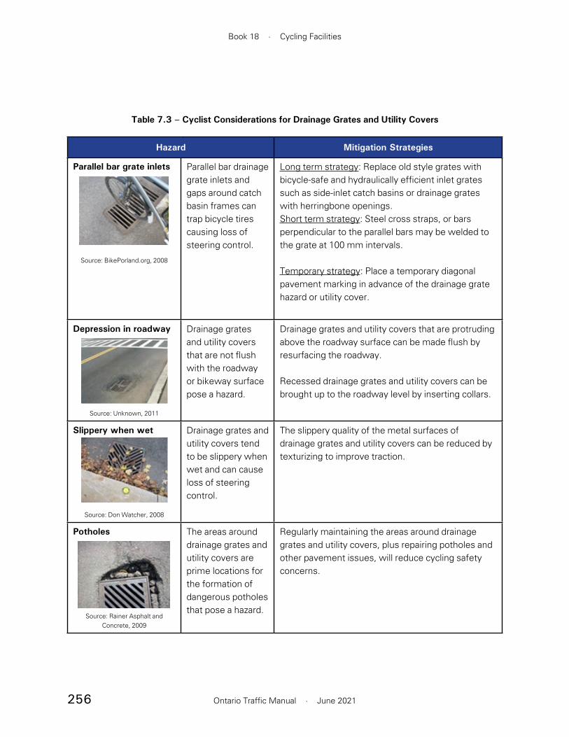
256
Book 18 · Cycling Facilities
Ontario Traffic Manual · June 2021
Hazard Mitigation Strategies
Parallel bar grate inlets
Source: BikePorland.org, 2008
Parallel bar drainage grate inlets and gaps around catch basin frames can trap bicycle tires causing loss of steering control.
Long term strategy: Replace old style grates with bicycle-safe and hydraulically efficient inlet grates such as side-inlet catch basins or drainage grates with herringbone openings.Short term strategy: Steel cross straps, or bars perpendicular to the parallel bars may be welded to the grate at 100 mm intervals.
Temporary strategy: Place a temporary diagonal pavement marking in advance of the drainage grate hazard or utility cover.
Depression in roadway
Source: Unknown, 2011
Drainage grates and utility covers that are not flush with the roadway or bikeway surface pose a hazard.
Drainage grates and utility covers that are protruding above the roadway surface can be made flush by resurfacing the roadway.
Recessed drainage grates and utility covers can be brought up to the roadway level by inserting collars.
Slippery when wet
Source: Don Watcher, 2008
Drainage grates and utility covers tend to be slippery when wet and can cause loss of steering control.
The slippery quality of the metal surfaces of drainage grates and utility covers can be reduced by texturizing to improve traction.
Potholes
Source: Rainer Asphalt and Concrete, 2009
The areas around drainage grates and utility covers are prime locations for the formation of dangerous potholes that pose a hazard.
Regularly maintaining the areas around drainage grates and utility covers, plus repairing potholes and other pavement issues, will reduce cycling safety concerns.
Table 7.3 – Cyclist Considerations for Drainage Grates and Utility Covers
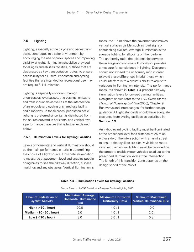
257
Section 7 · Other Facility Design Treatments
Ontario Traffic Manual · June 2021
7.5 Lighting
Lighting, especially at the bicycle and pedestrian-scale, contributes to a safer environment by encouraging the use of public spaces and improving visibility at night. Illumination should be provided for all ages and abilities facilities, or those that are designated as key transportation routes, to ensure accessibility for all users. Pedestrian and cycling facilities that are intended for recreational use may not require full illumination.
Lighting is especially important through underpasses, overpasses, at crossings, on paths and trails in tunnels as well as at the intersection of an in-boulevard cycling or shared use facility and a roadway. In these cases, pedestrian-scale lighting is preferred since light is distributed from the source outward in horizontal and vertical rays, a performance measure that is further explained below.
7.5.1 Illumination Levels for Cycling Facilities
Levels of horizontal and vertical illumination should be the main performance criteria in determining the choice of a light source. Horizontal illumination is measured at pavement level and enables people riding bikes to see the bikeway direction, surface markings and any obstacles. Vertical illumination is
measured 1.5 m above the pavement and makes vertical surfaces visible, such as road signs or approaching cyclists. Average illumination is the average lighting for all points on the roadway. The uniformity ratio, the relationship between the average and minimum illumination, provides a measure for consistency in lighting. Designers should not exceed the uniformity ratio in order to avoid sharp differences in brightness which could interfere with a cyclist’s ability to adjust to variations in illumination intensity. The performance measures shown in Table 7.4 present bikeway illumination levels for on-road cycling facilities. Designers should refer to the TAC Guide for the Design of Roadway Lighting (2006), Chapter 9, Roadways and Interchanges, for further design guidance. All light standards should have adequate clearance from cycling facilities as described in Section 7.3.
An in-boulevard cycling facility must be illuminated at the prescribed level for a distance of 25 m on either side of the intersection with an unlit street to ensure that cyclists are clearly visible to motor vehicles. Transitional lighting must be provided on the street to enable motor vehicles to adjust to the prescribed illumination level at the intersection. The length of this transition zone depends on the design speed of the street.
Level of Pedestrian or Cyclist Activity
Maintained Average Horizontal Illuminance
(lux)
Maximum Horizontal Uniformity Ratio
Minimum Maintained Vertical Illuminance (lux)
High (>50 / hour) 20.0 4.0 : 1 10.0Medium (10–50 / hour) 5.0 4.0 : 1 2.0
Low (<10 / hour) 3.0 6.0 : 1 0.8
Table 7.4 – Illumination Levels for Cycling Facilities
Source: Based on the TAC Guide for the Design of Roadway Lighting, 2006

258
Book 18 · Cycling Facilities
Ontario Traffic Manual · June 2021
Where an in-boulevard facility crosses a lit street, the off-road cycling facility must be illuminated to the same level as the street for a distance of 25 m on either side of the intersection. The uniformity ratio for this section must be at least equal to that of the street.
Where the bikeway facility is separated from the travelled way by more than 5 m, lighting design should follow TAC Guide for Design of Roadway Lighting (2006), Chapter 16, Off-Roadway Facilities. On rural roadways where lighting is not provided and where cycling traffic is anticipated or designed for, the methodology outlined in the TAC Lighting Guide should be used to incorporate overhead lighting if warranted. Lighting should effectively illuminate the entire roadway including the shoulder.
Where a bidirectional cycling facility is designed such that cyclists must ride adjacent to oncoming traffic, motor vehicle headlights can present a significant visual obstruction for people riding bikes, and similarly, the lights of people riding bikes may confuse motor vehicles. This hazard can be reduced by increasing the separation between the bidirectional facility and the roadway, increasing the illumination, or considering shielding.
7.6 Temporary Conditions
If a work zone in or adjacent to a cycling facility is required, every effort should be made to minimize disruption to the facility. Detours and alternative routes should be provided when on-route accommodations are not possible. In some municipalities there are by-laws requiring that cyclists be accommodated. Closing the cycling facility and requiring cyclists to dismount should be avoided wherever possible.
Generally, the level of separation provided during temporary conditions should be consistent with the original infrastructure. If the cycling facility is a physically separated bikeway, it is recommended that physical separation from traffic be maintained through the temporary facility.
Practitioners should refer to OTM Book 7 — Temporary Conditions for the fundamental principles of developing a temporary work zone. OTM Book 7 also provides guidance specific to temporary conditions for people riding bikes, including signage. This section should be treated as a supplement to OTM Book 7, rather than a replacement.
When assessing options for the treatment of the cycling facility through a work zone, a practitioner should consider:
• The volume of cyclists using the route
• Who is using the route, such as children going to school
• The importance of the route in the cycling network and the availability of alternate routes
• The type of cycling facility

259
Section 7 · Other Facility Design Treatments
Ontario Traffic Manual · June 2021
• The operating speed and volumes of the roadway
• The length and timeframe of the closure or disruption
• Whether there are disruptions to the grade or surface quality of the roadway as part of the work
Where the planned road work will affect the operation of a cycling facility, public notifications regarding the work should include information about the cycling facility, to enable cyclists to plan trips accordingly. Public notification should also be provided in advance of the closures through signage and all other appropriate and available channels with due notice.
Accessibility Considerations
• When designing detours for cycling routes it is important to remember that not all people who cycle can walk or see well. Ensuring that detours are clearly marked and accessible is an important part of universal design.
• When cycling routes or pathways are temporarily closed, an alternate route should be signed that does not involve steps or rely on dismounting and walking. See Figure 7.18 for an example of a clearly marked and detailed detour for cyclists.
The following sections provide an overview of four basic types of accommodation of people riding bikes through work zones:
• Modified or temporary cycling facilities
• Mixed traffic operations
• Detours or alternate routes
• Dismount and walk
7.6.1 Modified or Temporary Cycling Facilities
Where a cycling facility exists on the roadway where the temporary disruption is planned, the preference is always to maintain the cycling facility. This can be accomplished by temporarily routing the facility around the work site, as shown in Figure 7.19. If a lateral realignment of the cycling
Figure 7.18 – Example of a Cycling Facility Closure with Detour Signs Provided, Ottawa
Source: Alta
Figure 7.19 – Example of a Temporary Alignment for Physically Separated Cycling Lane, Toronto
Source: WSP

260
Book 18 · Cycling Facilities
Ontario Traffic Manual · June 2021
facility is required, a 6:1 taper is recommended to avoid abrupt changes in direction for cyclists. In constrained conditions, the cycling facility may be narrowed to create a minimum operating space of 1.5 m between physical barriers, or 1.2 m between pavement markings. Where a cycling lane must taper towards motor vehicle lanes, practitioners should assess the risk of motor vehicles infringing on the cycling lane, and consider including temporary elements of physical protection such as construction barrels or flex bollards.
Where temporary construction fencing is placed adjacent to the cycling facility, it should be set back a minimum of 0.5 m from the travelled portion of the facility to provide adequate manoeuvring width for people riding bikes. Construction signage should never be placed in an active cycling lane. Narrowing of motor vehicle lanes where feasible should be prioritized over narrowing the cycling lane.
Where a temporary cycling facility requires a change in elevation, such as the transition of a cycle track onto the roadway, a proper taper should be provided to allow cyclists to comfortably transition to and from the roadway. If a narrowing requires motor vehicles to be diverted into a cycling lane or paved shoulder, signage should be used to notify cyclists that the dedicated facility ends and shared lane operations begins. However, this practice should be avoided wherever possible.
7.6.2 Mixed Traffic Operations
Where there is no dedicated cycling facility through the disrupted roadway, or where a temporary cycling facility cannot be provided, people riding bikes may be accommodated through mixed traffic operations in a shared travel lane. This can be done with pavement markings and signage that is consistent with the guidance in Section 4.5.2.
Shared travel lanes through work zones are not recommended where the posted speed of the roadway exceeds 50 km/h. It is also desirable to reduce the speed of motor vehicles through the work zone to 40 km/h to create more comfortable mixed traffic conditions for people riding bikes. If the work involves trucks turning across cycling facilities, flag persons should be deployed to ensure the safe movement of trucks and people riding bikes.
7.6.3 Detours or Alternate Routes
If a full road closure is required, or if cycling travel in one direction will be prohibited where it is otherwise allowed, a detour should be provided. Where the detour route for cyclists is the same as the one provided for motor vehicles, cycling-specific signage is not required. When selecting a detour route, practitioners should consider minimizing the added delay for people riding bikes while also minimizing exposure to traffic. A cycling-specific detour may be advantageous to allow cyclists to detour onto lower speed streets. Detour signage, including maps, should be placed at the decision point on the route. The use of wayfinding sharrows on the road to supplement signage also helps to indicate the direction cyclists should go for the detour.
7.6.4 Dismount and Walk
For closures over very short distances, it may be acceptable to instruct cyclists to dismount and walk on the pedestrian facility using Dismount and Walk signs (Rb-70 OTM). In some instances, this may be more beneficial for cyclists than providing a detour. Ensure that a temporary ramp is provided up to the sidewalk to allow people using bikes as mobility aids to travel through the site without dismounting.
261
Section 7 · Other Facility Design Treatments
Ontario Traffic Manual · June 2021
Another alternative is to temporarily sign a sidewalk as a shared use facility. This could be a preferred option if children are anticipated to use the cycling facility.
7.7 Informed Facility Design for Universal Accessibility
The Accessibility for Ontarians with Disabilities Act (AODA) means people of all abilities using or interacting with a facility are taken into account when designing and implementing infrastructure. Addressing accessibility includes recognizing and addressing the needs of the wide range of community members with a range of functional abilities, including people with physical, sensory and cognitive disabilities as well as older persons. Although the Accessibility for Ontarians with Disabilities Act (AODA) Integrated Accessibility Standards Section IV.1 Design of Public Spaces does not address cycling facilities specifically, it does provide specific guidance related to elements of pedestrian exterior routes and recreational trails, including the clear width, surfaces, grades, ramps, curb ramps and accessible pedestrian signals.
Accessible cycling networks recognize that people use a variety of non-standard and adapted cycles depending on their needs. For more information on design users, see Section 2.
7.7.1 Design Applications
Accessibility is an important consideration in the design of conflict points between bikeways and pedestrian pathways.
Tactile Walking Surface Indicators (TWSI) are used to provide information to people with vision loss, both visually and by contact under foot or using a long white cane. Two types of TWSIs are commonly used.
• Tactile Attention Indicator TWSIs are comprised of truncated domes, and are used to give warning of hazards, conflict zones or decision making points.

262
Book 18 · Cycling Facilities
Ontario Traffic Manual · June 2021
• Tactile Directional Indicator TWSIs are comprised of flat-topped elongated bars, and are used to facilitate wayfinding in open or challenging spaces. Tactile directional indicators indicate a possible route that may be taken.
Other detectable treatments such as colour contrasting tactile delineators at locations with rough paving stones or cobbles while not a substitute for Tactile Attention Indicator TWSIs, may also be used to provide attention or directional guidance at various facilities.
Locations where people riding bikes and pedestrians interact require consideration for detectable surface treatments. These locations include:
• Intersections and crossings
• Multi-use pathways
• Cycle tracks adjacent to sidewalks
• Transit stops
• Accessible loading areas
7.7.2 Maintaining Curbside Access
Pedestrians require access to the curb to board and alight from motor vehicles, transit vehicles and para-transit vehicles. Physically separated bikeways can create barriers for pedestrians and people with disabilities, especially where it requires people to navigate between different heights to access the curbside from the sidewalk. Two key issues are created when a cycling facility obstructs direct access to the curb from parking transit, and the roadway:
• The path of travel for people with physical disabilities or mobility devices is extended to the nearest curb ramp or other depression such as vehicular driveway
• Access to or from the sidewalk requires crossing an active cycling lane
It should be the goal of design to achieve frequent, direct and simple access to and from the sidewalk for all users. The following best practices for accessibility and universal design should be considered and incorporated to the highest degree possible when designing cycling facilities:
• Ensure separator treatments are spaced at a sufficient distance to allow accessible loading
• Design for frequent and accessible crossing treatments and connections to sidewalks via curb ramps, raised crossings of the cycling facility or at-grade sections with high-visibility features similar to island boarding transit stops in Section 7.1.1.
• Provide a wider and unobstructed cycling facility buffer with a width of 1.3 to 1.4 m to allow pedestrians to travel along the buffer to reach the nearest curb ramp. This ensures that users are not forced to travel along the cycling facility. Where the cycle track design does not allow for accessible curb access, consider providing mid-block accessible loading islands on each block. See design for accessibility features as shown for island boarding transit stops in Section 7.1.1.
For additional considerations related to maintaining accessible curbside access, as well as illustrations of suggested treatments, practitioners are encouraged to refer to Walk San Francisco’s "Getting to the Curb" report dated November 2019.

263
Section 7 · Other Facility Design Treatments
Ontario Traffic Manual · June 2021
7.7.3 Delineation at Crossing Locations
Where pedestrians must cross cycling facilities, design treatments should provide a clear indication of the path of travel for each user and expected yielding behaviour. This type of crossing can be found in a variety of locations such as protected and setback intersections and at transit stops. Where pedestrians must cross cycling facilities, the following design features should be provided:
• Yield lines (shark’s teeth), marked 0.3 m from the crosswalk for all cycling approaches
• A Cyclists Yield to Pedestrians sign (Ra-16 OTM) should be provided on cycling approaches to the crosswalk
• Pedestrian zebra crosswalk markings or alternate pedestrian walkway indications should extend across all cycling/pedestrian crossing locations.
• A colour-contrasting Tactile Attention Indicator TWSI should be provided where a pedestrian must cross a cycling facility, set back 150 to 200 mm from the back edge of the curb, and following any curvature in the curb. TWSIs should have a minimum depth of 610 mm.
• A level crossing should be provided for pedestrians to cross the cycling facility by ramping up the cycling facility to meet the sidewalk.
7.7.4 Pedestrian Refuge Islands
Within a protected intersection or setback crossing design, an island may be provided for pedestrians as shown in Figure 7.20. Pedestrians typically first cross the cycling facility to reach the island in a yield-controlled crossing, then proceed to cross
the roadway from the island in a signal-controlled crossing. While two-stage crossings can greatly reduce pedestrians’ exposure to traffic, they must be accessible and provide clear paths of travel. OTM Book 15 — Pedestrian Crossing Facilities provides guidance on the design of pedestrian crossings on roadways.
Tactile Attention Indicator TWSIs should be placed at both sides of a refuge island. The minimum
Figure 7.20 – Pedestrian Refuge and Cycle Track Crossing, Ottawa
Source: Alta
264
Book 18 · Cycling Facilities
Ontario Traffic Manual · June 2021
depth for an accessible pedestrian refuge is 2.1 m, including the width of TWSIs. A depth of 2.5 to 3.0 m is desirable. If the minimum depth of 2.1 m cannot be provided, alternative design approaches should be explored. Refuge islands should aim to match the width of the crossing and should be bordered by a standard barrier curb to prevent motor vehicle encroachment
If the refuge is less than 2.1 m in depth or is not intended as an area for pedestrians to wait, TWSIs should not be installed.
7.7.5 Curb Ramps and Depressed Curbs (Blended Transition)
At roadway-boulevard transitions for people walking and cycling, it is recommended that curb ramps or depressed curbs be implemented to address accessibility barriers. Curb ramps are sloped transitions with sloped sides that are built into the curb to provide access from sidewalk level to roadway level, as shown in Figure 7.21. They provide clear delineation of the crossing and are to be aligned with the corresponding curb ramp on the opposing side of the roadway. Curb ramps can be found at intersections but are also used for parallel crossings such as at mid-block crossings. Depressed curbs or blended transitions are sloped transitions that follow the curvature of a curb, which often results in sidewalk intersection corners that are entirely at roadway level, as shown in Figure 7.22. Depressed curbs or blended transitions are almost exclusively found at intersection crossing locations.
Whether using curb ramps or depressed curbs, the crosswalk should connect the pedestrian route beyond the vehicular right-of-way, regardless of the elevation of the crossing (raised or roadway level).
Curb ramps and depressed curbs must both feature attention Tactile Walking Surface Indicators (TWSI) to clearly indicate to people walking that they have reached a curb edge at pedestrian or multi-use crossing locations. The design and placement of TWSIs is very similar between curb ramps and depressed curbs, as prescribed by the AODA Integrated Accessibility Standard [Sections 80.26(1) and 80.27 (1)]:
• Visually, the TWSI must have high tonal contrast with the adjacent and surrounding concrete or asphalt
• Texturally, the TWSI must feature raised tactile profiles that are cane-detectable that alert everyone, particularly pedestrians with vision loss, to the crossing location
• TWSI are located with a setback from the curb edge of between 150-200 mm
• TWSI have a minimum depth of at least 610 mm
• It is only the TWSI location that varies slightly between the two transitions, although they have the same curb setback
— At Curb Ramps, the TWSI is located at the bottom of the curb ramp and extends the full width of the curb ramp
— At Depressed Curbs, the TWSI is located at the bottom of the depressed curb where it is flush with the roadway and extends the full length of the curb depression following any curve as necessary
Additional general guidance on the design specifications of curb ramps and depressed curbs (blended transitions) can also be found in the

265
Section 7 · Other Facility Design Treatments
Ontario Traffic Manual · June 2021
The curb design and TWSI placement have been simplified for many of the figures within OTM Book 18 to reduce clutter and draw attention to topic-specific design guidance.
Canadian Standards Association’s (CSA) Accessible Design for the Built Environment Standard [CSA B651-18 [Section 8.3.2)].
Figure 7.21 and Figure 7.22 illustrate the recommended placement of TWSIs at curb ramps and depressed curbs, respectively. The design treatment for curb ramps is the same at intersection and mid-block crossing locations.
Curb transitions at 1:10 running slope
Curb curb ramp at 1:10 to 1:15 cross slope
TWSI610 mm minimum
150 to 200 mm gap between back of curb
and TWSI
Pedestrian clearway1200 mm minimum
1500 mm recommended
SidewalkSidewalk
Figure 7.21 – Design and TWSI Placement for a Curb Ramp at a Mid-block Crossing
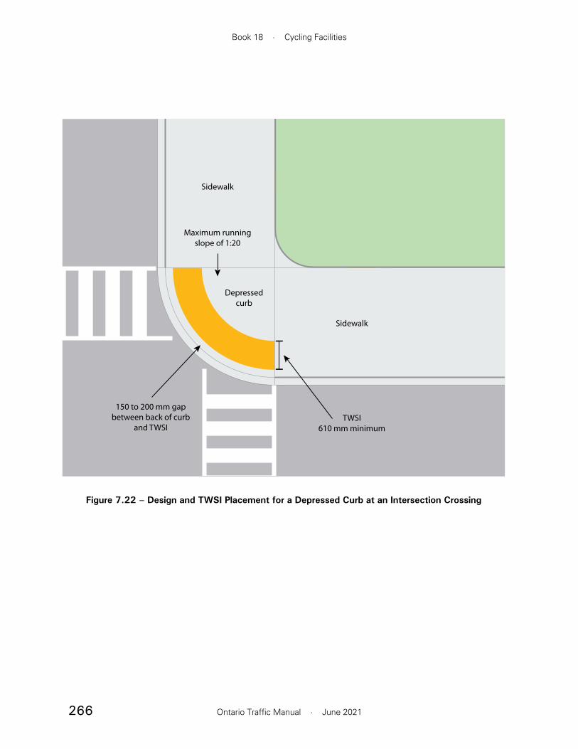
266
Book 18 · Cycling Facilities
Ontario Traffic Manual · June 2021
TWSI610 mm minimum
Maximum running slope of 1:20
150 to 200 mm gap between back of curb
and TWSI
Depressed curb
Sidewalk
Sidewalk
Figure 7.22 – Design and TWSI Placement for a Depressed Curb at an Intersection Crossing

267
Section 7 · Other Facility Design Treatments
Ontario Traffic Manual · June 2021
References
1 Transit Capacity and Quality of Service Manual, Third Edition, Transportation Research Board (2013), http://www.trb.org/Main/Blurbs/169437.aspx
2 Design Manual for Bicycle Traffic, CROW-Fietsberaad (2016), https://www.crow.nl/publicaties/design-manual-for-bicycle-traffic
3 A guide to inclusive cycling, Wheels for Wellbeing (2017), https://wheelsforwellbeing.org.uk/campaigning/guide/
4 Ibid.
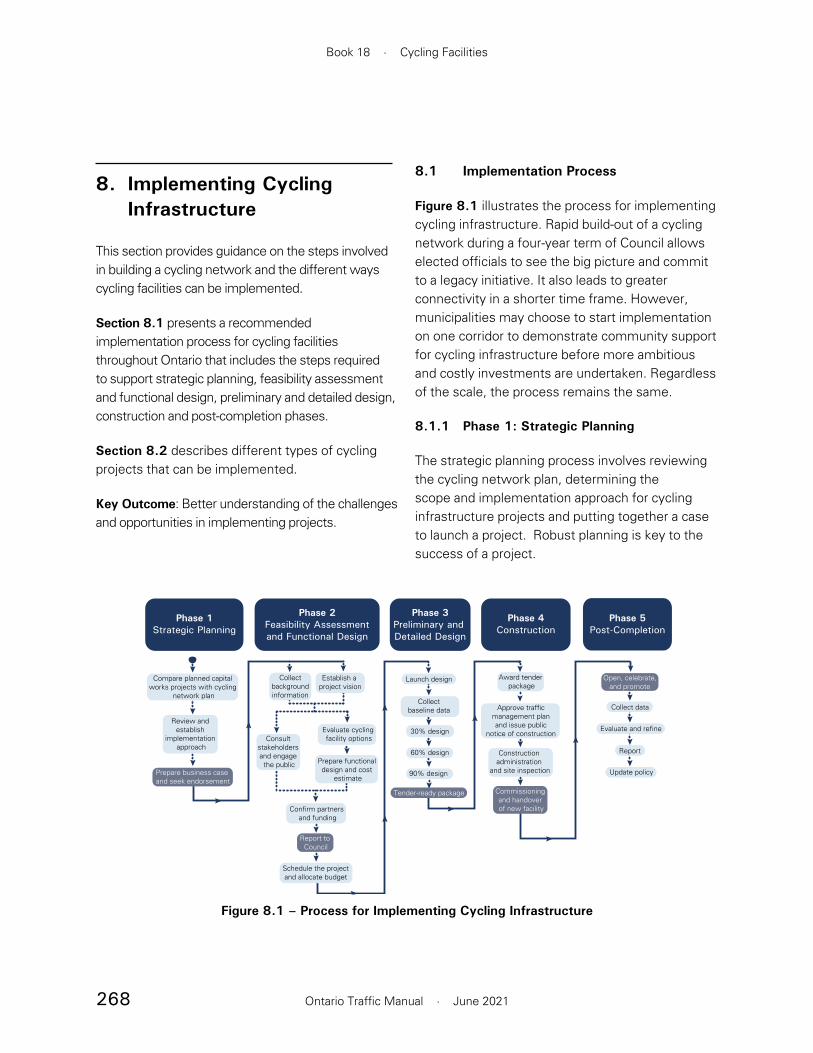
268
Book 18 · Cycling Facilities
Ontario Traffic Manual · June 2021
8. Implementing Cycling Infrastructure
This section provides guidance on the steps involved in building a cycling network and the different ways cycling facilities can be implemented.
Section 8.1 presents a recommended implementation process for cycling facilities throughout Ontario that includes the steps required to support strategic planning, feasibility assessment and functional design, preliminary and detailed design, construction and post-completion phases.
Section 8.2 describes different types of cycling projects that can be implemented.
Key Outcome: Better understanding of the challenges and opportunities in implementing projects.
8.1 Implementation Process
Figure 8.1 illustrates the process for implementing cycling infrastructure. Rapid build-out of a cycling network during a four-year term of Council allows elected officials to see the big picture and commit to a legacy initiative. It also leads to greater connectivity in a shorter time frame. However, municipalities may choose to start implementation on one corridor to demonstrate community support for cycling infrastructure before more ambitious and costly investments are undertaken. Regardless of the scale, the process remains the same.
8.1.1 Phase 1: Strategic Planning
The strategic planning process involves reviewing the cycling network plan, determining the scope and implementation approach for cycling infrastructure projects and putting together a case to launch a project. Robust planning is key to the success of a project.
Update policy
Compare planned capital works projects with cycling
network plan
Phase 1Strategic Planning
Phase 2Feasibility Assessmentand Functional Design
Phase 3Preliminary and Detailed Design
Phase 4Construction
Phase 5Post-Completion
Review and establish
implementation approach
Prepare business case and seek endorsement
Collectbackgroundinformation
Establish a project vision
Consult stakeholders and engage the public Prepare functional
design and cost estimate
Confirm partners and funding
Report to Council
Schedule the project and allocate budget
Launch design
30% design
Collectbaseline data
60% design
Award tender package
Approve traffic management plan and issue public
notice of construction
Construction administration
and site inspection
Commissioning and handover of new facility
Open, celebrate, and promote
Collect data
Evaluate and refine
Tender-ready package
90% design
Report
Evaluate cycling facility options
Figure 8.1 – Process for Implementing Cycling Infrastructure
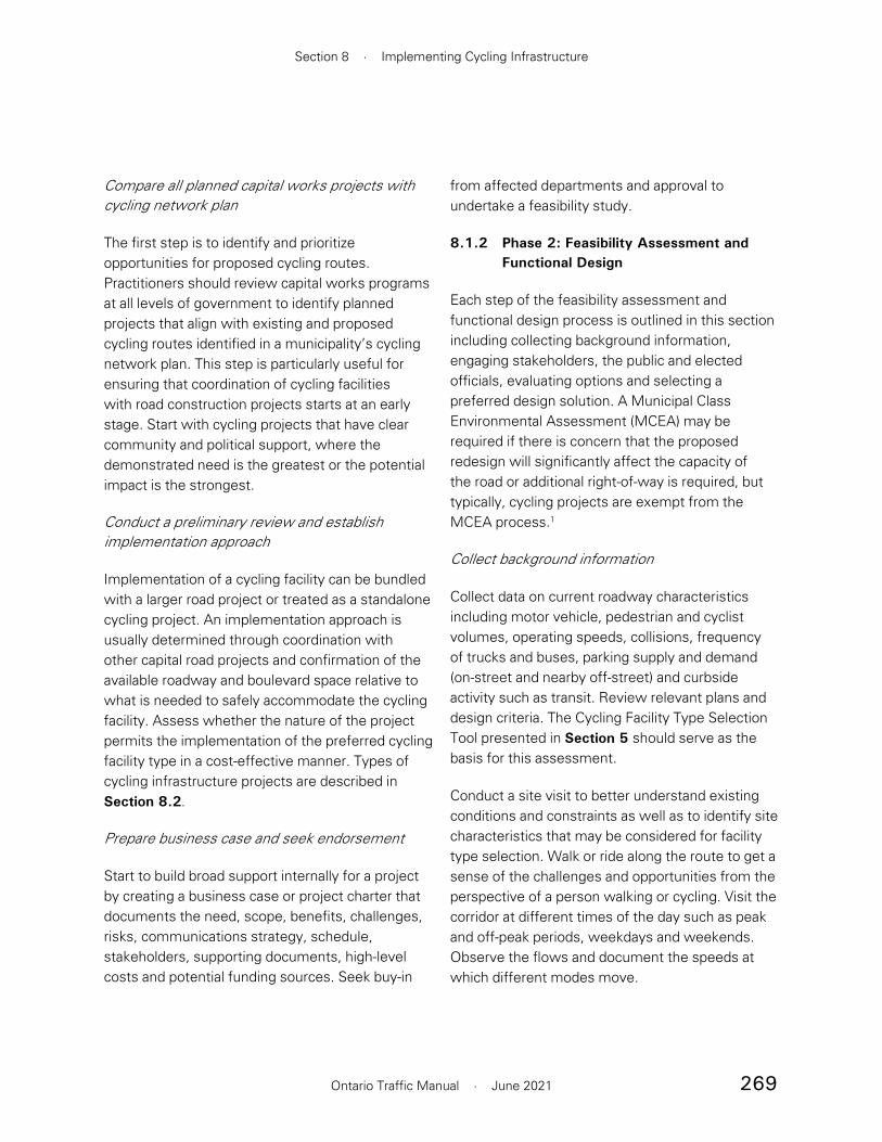
269
Section 8 · Implementing Cycling Infrastructure
Ontario Traffic Manual · June 2021
from affected departments and approval to undertake a feasibility study.
8.1.2 Phase 2: Feasibility Assessment and Functional Design
Each step of the feasibility assessment and functional design process is outlined in this section including collecting background information, engaging stakeholders, the public and elected officials, evaluating options and selecting a preferred design solution. A Municipal Class Environmental Assessment (MCEA) may be required if there is concern that the proposed redesign will significantly affect the capacity of the road or additional right-of-way is required, but typically, cycling projects are exempt from the MCEA process.1
Collect background information
Collect data on current roadway characteristics including motor vehicle, pedestrian and cyclist volumes, operating speeds, collisions, frequency of trucks and buses, parking supply and demand (on-street and nearby off-street) and curbside activity such as transit. Review relevant plans and design criteria. The Cycling Facility Type Selection Tool presented in Section 5 should serve as the basis for this assessment.
Conduct a site visit to better understand existing conditions and constraints as well as to identify site characteristics that may be considered for facility type selection. Walk or ride along the route to get a sense of the challenges and opportunities from the perspective of a person walking or cycling. Visit the corridor at different times of the day such as peak and off-peak periods, weekdays and weekends. Observe the flows and document the speeds at which different modes move.
Compare all planned capital works projects with cycling network plan
The first step is to identify and prioritize opportunities for proposed cycling routes. Practitioners should review capital works programs at all levels of government to identify planned projects that align with existing and proposed cycling routes identified in a municipality’s cycling network plan. This step is particularly useful for ensuring that coordination of cycling facilities with road construction projects starts at an early stage. Start with cycling projects that have clear community and political support, where the demonstrated need is the greatest or the potential impact is the strongest.
Conduct a preliminary review and establish implementation approach
Implementation of a cycling facility can be bundled with a larger road project or treated as a standalone cycling project. An implementation approach is usually determined through coordination with other capital road projects and confirmation of the available roadway and boulevard space relative to what is needed to safely accommodate the cycling facility. Assess whether the nature of the project permits the implementation of the preferred cycling facility type in a cost-effective manner. Types of cycling infrastructure projects are described in Section 8.2.
Prepare business case and seek endorsement
Start to build broad support internally for a project by creating a business case or project charter that documents the need, scope, benefits, challenges, risks, communications strategy, schedule, stakeholders, supporting documents, high-level costs and potential funding sources. Seek buy-in
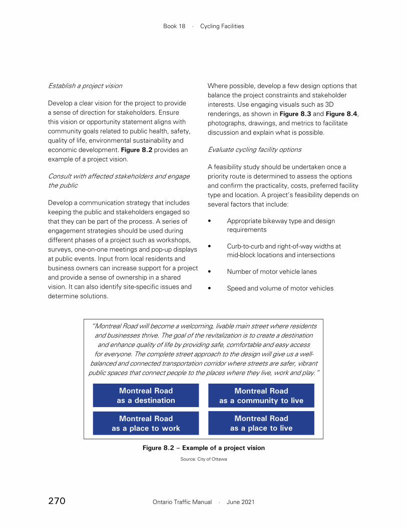
270
Book 18 · Cycling Facilities
Ontario Traffic Manual · June 2021
Where possible, develop a few design options that balance the project constraints and stakeholder interests. Use engaging visuals such as 3D renderings, as shown in Figure 8.3 and Figure 8.4, photographs, drawings, and metrics to facilitate discussion and explain what is possible.
Evaluate cycling facility options
A feasibility study should be undertaken once a priority route is determined to assess the options and confirm the practicality, costs, preferred facility type and location. A project’s feasibility depends on several factors that include:
• Appropriate bikeway type and design requirements
• Curb-to-curb and right-of-way widths at mid-block locations and intersections
• Number of motor vehicle lanes
• Speed and volume of motor vehicles
Establish a project vision
Develop a clear vision for the project to provide a sense of direction for stakeholders. Ensure this vision or opportunity statement aligns with community goals related to public health, safety, quality of life, environmental sustainability and economic development. Figure 8.2 provides an example of a project vision.
Consult with affected stakeholders and engage the public
Develop a communication strategy that includes keeping the public and stakeholders engaged so that they can be part of the process. A series of engagement strategies should be used during different phases of a project such as workshops, surveys, one-on-one meetings and pop-up displays at public events. Input from local residents and business owners can increase support for a project and provide a sense of ownership in a shared vision. It can also identify site-specific issues and determine solutions.
Figure 8.2 – Example of a project vision
Source: City of Ottawa
“Montreal Road will become a welcoming, livable main street where residents and businesses thrive. The goal of the revitalization is to create a destination and enhance quality of life by providing safe, comfortable and easy access
for everyone. The complete street approach to the design will give us a well-balanced and connected transportation corridor where streets are safer, vibrant public spaces that connect people to the places where they live, work and play.”
Montreal Road as a destination
Montreal Road as a place to work
Montreal Road as a community to live
Montreal Road as a place to live
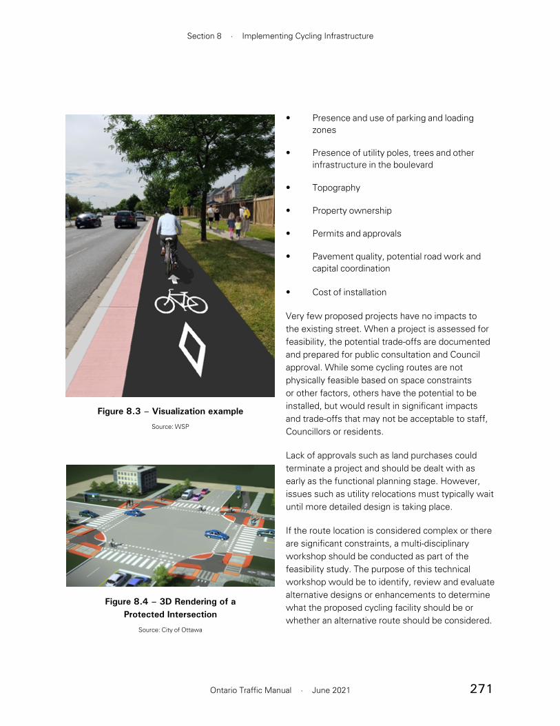
271
Section 8 · Implementing Cycling Infrastructure
Ontario Traffic Manual · June 2021
• Presence and use of parking and loading zones
• Presence of utility poles, trees and other infrastructure in the boulevard
• Topography
• Property ownership
• Permits and approvals
• Pavement quality, potential road work and capital coordination
• Cost of installation
Very few proposed projects have no impacts to the existing street. When a project is assessed for feasibility, the potential trade-offs are documented and prepared for public consultation and Council approval. While some cycling routes are not physically feasible based on space constraints or other factors, others have the potential to be installed, but would result in significant impacts and trade-offs that may not be acceptable to staff, Councillors or residents.
Lack of approvals such as land purchases could terminate a project and should be dealt with as early as the functional planning stage. However, issues such as utility relocations must typically wait until more detailed design is taking place.
If the route location is considered complex or there are significant constraints, a multi-disciplinary workshop should be conducted as part of the feasibility study. The purpose of this technical workshop would be to identify, review and evaluate alternative designs or enhancements to determine what the proposed cycling facility should be or whether an alternative route should be considered.
Figure 8.3 – Visualization example
Source: WSP
Figure 8.4 – 3D Rendering of a Protected Intersection
Source: City of Ottawa

272
Book 18 · Cycling Facilities
Ontario Traffic Manual · June 2021
and feedback from residents and how it has been addressed is important information to highlight.
Schedule the project in the capital program and allocate budget
Schedule the project into the municipality’s capital program. In addition, budget to maintain and manage the asset over the long term. Refer to Section 10 for more information. Staff resources should be assembled to deliver the project in response to its size and complexity. The project scope should be used to determine a schedule with key milestones.
8.1.3 Phase 3: Preliminary and Detailed Design
Design is an iterative process that involves developing a solution that responds to user needs, operational requirements, site-specific constraints and opportunities within the project budget.
Launch design
Start design at least a year prior to construction, and earlier for more complex projects. Align the design with the vision. Establish design criteria for various project elements to document design decisions. Ensure that local conditions, maintenance standards and long-term durability inform decisions about design and materials. Coordinate with relevant stakeholders to clarify budgets, timelines and project scope, as well as to address constraints such as trees, utilities and property. Obtain a topographic survey.
Collect baseline data
Collect baseline data on cycling counts, ideally during the peak cycling season or correlate to the time of year. Take photographs and video of the “before” condition. Determine method of
Prepare functional design and cost estimate of preferred cycling facility type
Once a suitable route, facility type and alignment have been selected, the production of a preliminary functional design for the preferred facility is recommended. This includes a high-level estimate of the construction costs. There are typically many variables to establish a precise and reliable overall cost estimate. However, an approximate budget using major items and unit prices, with contingencies added, should be identified based on comparable recent projects.
Intersection details need to be considered during the functional planning stages because costs may be significant. Depending on the extent of construction required, the scope may need to be reduced if there is inadequate budget.
Confirm partners and funding
Confirm potential partners, funding sources and cost-sharing opportunities. Funding may come from capital budgets, other programs, granting organizations, foundations, private developers, conservation authorities, other levels of government or agencies. Endorsement and partnership from other levels of government or agencies may be vital to moving a project forward.
Report to Council
Council approval may be required to proceed to the preliminary and detailed design phase. The support of Council is an important factor in the successful implementation of a project. Meet and update all affected Councillors throughout the planning, design and construction process. Project goals, milestones, design plans, consultation activities

273
Section 8 · Implementing Cycling Infrastructure
Ontario Traffic Manual · June 2021
90% detailed design and 100% tender-ready package.
The 90% design package is a draft of the 100% submission, and should include all the details necessary to construct the facility. This includes item specifications, quantities, cost estimates and the complete drawing package. Permits and approvals from appropriate agencies should be obtained. The utility relocation plan, arborist report, planting plan and post-construction monitoring program should also be provided.
8.1.4 Phase 4: Construction
The construction process is when street transformation takes place. The process involves awarding the project for construction, notifying the public, performing construction administration activities and commissioning the new cycling facility.
Award tender package
Once the tender package is approved and an appropriate construction budget has been secured, the tender should be posted to solicit bids for a contractor to construct the facility. Account for the time required for the municipality to review and finalize the tender package, advertise and award the construction contract. Schedule construction to avoid paving operations during cold weather. Construct the project in smaller phases over multiple years if the initial budget is limited. Ensure the contractor has an acceptable construction management plan in place.
post-implementation data collection in case the technology requires the installation of a permanent bike counting station during construction. See Section 8.1.5 for more information about data collection.
30% preliminary design
The preferred design solution should be advanced to a 30% preliminary design. This builds upon the functional design and typically includes plan view drawings with the cycling facility alignment and other project elements such as parking, travel lanes, trees and utility poles. Preliminary cross sections should be developed, particularly for the most constrained locations which are often the limiting factor in determining a preferred design. The package should be circulated to utility companies to identify potential conflicts as well as municipal services such as waste collection, transit, emergency services and road maintenance teams.
60% detailed design
The project will continue to be refined through professional design reviews. Intersection details are added at this stage including conflict mitigation strategies such as curb radii, curb type, crossing treatments and queueing areas. In support of Vision Zero, consider conducting a road safety audit or preliminary risk assessment. A 60% design package typically includes all necessary drawings including removals, temporary and permanent traffic signal layouts, illumination, landscaping, pavement markings, signage and construction staging.

274
Book 18 · Cycling Facilities
Ontario Traffic Manual · June 2021
drawings, training sessions and other tools to clearly communicate each step of the process to contractors who may be unfamiliar with building new cycling infrastructure. The long-term durability of the facility will largely be determined by construction practices.
Commissioning and handover of new facility
Prior to the cycling facility being opened to the public, a detailed inspection should be undertaken to ensure the construction meets the design requirements. This includes riding a bicycle along the new facility to experience it from a user’s perspective and to identify possible issues that should be addressed by the contractor or designer.
8.1.5 Phase 5: Post-completion
The post-completion process involves launching the facility then monitoring and evaluating its performance to identify any modifications that could improve operations. It is also important to document outcomes and update local policy and guidelines to improve future projects.
Launch, celebrate and promote
Engaging outreach efforts can help to celebrate, raise awareness and build support for cycling projects. Incorporate a launch event and educational campaign into the project’s communication plan and budget to continue the excitement after a project is completed. The following are some techniques to consider:
• Inform residents and stakeholders that were involved in consultations that the project is complete and ready for use
Approve traffic management plan and issue public notice of construction
Notice must be issued to the public in the affected area to alert them of any impacts of the construction. Temporary alternate routes should be planned for all modes affected by the construction. Appropriate information signage should be placed along with the scope of work, construction timelines and project contact. Various iterations may be required during the course of construction. Construction timelines may be determined in part by the contractor and may require coordination with nearby projects. Figure 8.5 shows an example of a construction notification sign.
Construction administration and site inspection
Once the project is tendered for construction, the designer is often required to liaise with the construction team to address issues that arise in the field. Ensure that appropriate skilled labour, equipment, materials and services are arranged to support quality construction. Use construction
Figure 8.5 – Construction Notification Sign
Source: York Region
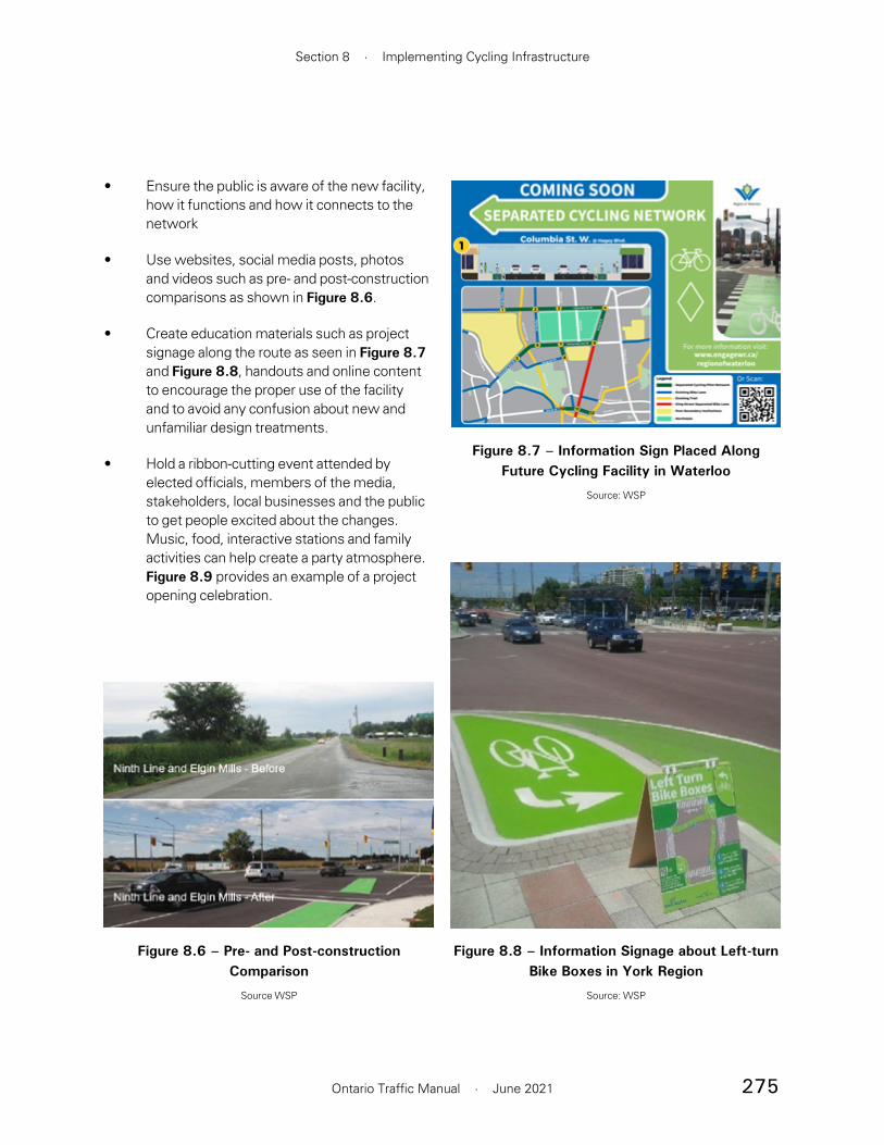
275
Section 8 · Implementing Cycling Infrastructure
Ontario Traffic Manual · June 2021
• Ensure the public is aware of the new facility, how it functions and how it connects to the network
• Use websites, social media posts, photos and videos such as pre- and post-construction comparisons as shown in Figure 8.6.
• Create education materials such as project signage along the route as seen in Figure 8.7 and Figure 8.8, handouts and online content to encourage the proper use of the facility and to avoid any confusion about new and unfamiliar design treatments.
• Hold a ribbon-cutting event attended by elected officials, members of the media, stakeholders, local businesses and the public to get people excited about the changes. Music, food, interactive stations and family activities can help create a party atmosphere. Figure 8.9 provides an example of a project opening celebration.
Figure 8.6 – Pre- and Post-construction Comparison
Source WSP
Figure 8.7 – Information Sign Placed Along Future Cycling Facility in Waterloo
Source: WSP
Figure 8.8 – Information Signage about Left-turn Bike Boxes in York Region
Source: WSP
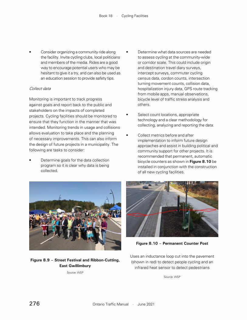
276
Book 18 · Cycling Facilities
Ontario Traffic Manual · June 2021
• Determine what data sources are needed to assess cycling at the community-wide or corridor scale. This could include origin and destination travel diary surveys, intercept surveys, commuter cycling census data, cordon counts, intersection turning movement counts, collision data, hospitalization injury data, GPS route tracking from mobile apps, manual observations, bicycle level of traffic stress analysis and others.
• Select count locations, appropriate technology and a clear methodology for collecting, analyzing and reporting the data.
• Collect metrics before and after implementation to inform future design approaches and assist in building political and community support for other projects. It is recommended that permanent, automatic bicycle counters as shown in Figure 8.10 be installed in conjunction with the construction of all new cycling facilities.
• Consider organizing a community ride along the facility. Invite cycling clubs, local politicians and members of the media. Rides are a good way to encourage potential users who may be hesitant to give it a try, and can also be used as an education session to provide safety tips.
Collect data
Monitoring is important to track progress against goals and report back to the public and stakeholders on the impacts of completed projects. Cycling facilities should be monitored to ensure that they function in the manner that was intended. Monitoring trends in usage and collisions allows evaluation to take place and the planning of necessary improvements. This can also inform the design of future projects in a municipality. The following are tasks to consider:
• Determine goals for the data collection program so it is clear why data is being collected.
Figure 8.10 – Permanent Counter Post
Uses an inductance loop cut into the pavement (shown in red) to detect people cycling and an
infrared heat sensor to detect pedestrians
Source: WSP
Figure 8.9 – Street Festival and Ribbon-Cutting, East Gwillimbury
Source: WSP
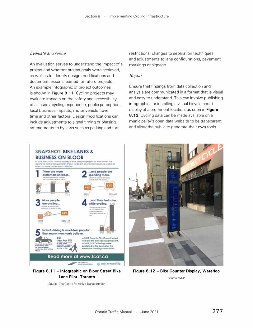
277
Section 8 · Implementing Cycling Infrastructure
Ontario Traffic Manual · June 2021
restrictions, changes to separation techniques and adjustments to lane configurations, pavement markings or signage.
Report
Ensure that findings from data collection and analysis are communicated in a format that is visual and easy to understand. This can involve publishing infographics or installing a visual bicycle count display at a prominent location, as seen in Figure 8.12. Cycling data can be made available on a municipality’s open data website to be transparent and allow the public to generate their own tools
Evaluate and refine
An evaluation serves to understand the impact of a project and whether project goals were achieved, as well as to identify design modifications and document lessons learned for future projects. An example infographic of project outcomes is shown in Figure 8.11. Cycling projects may evaluate impacts on the safety and accessibility of all users, cycling experience, public perception, local business impacts, motor vehicle travel time and other factors. Design modifications can include adjustments to signal timing or phasing, amendments to by-laws such as parking and turn
Figure 8.11 – Infographic on Bloor Street Bike Lane Pilot, Toronto
Source: The Centre for Active Transportation
Figure 8.12 – Bike Counter Display, Waterloo
Source: WSP

278
Book 18 · Cycling Facilities
Ontario Traffic Manual · June 2021
and reports that can lead to positive change. Another technique is to create a report card to provide updates on the current state of cycling within a community, as shown in Figure 8.13.
Update policy
Use the outcome of the evaluation to update local policies and guidelines. Account for changes in active transportation policy and network routes when the next Official Plan update occurs. Revisit policies and guidelines every five years at a minimum to test whether they still reflect the most recent research and best practices. Use precedent-setting cases from pilot projects to inform new cycling policies. Base the policy on the desired future conditions, not on projections of past trends. Periodically check that the cycling facilities comply with current design guidelines to identify those in need of upgrades.
Figure 8.13 – York Region Cycling Yearbook
Source York Region

279
Section 8 · Implementing Cycling Infrastructure
Ontario Traffic Manual · June 2021
of space, while constraints may result in some trade-offs that need to be evaluated. A Municipal Class Environmental Assessment (MCEA) is usually not required for the implementation of cycling facilities as a standalone project.
8.2.1 Demonstration and Pilot Projects
Demonstration and pilot projects are quick-build strategies to install temporary transformations, gather public and political support and make a case for a more permanent project. Pop-up projects, also known as tactical urbanism, are installed for a
8.2 Common Project Types
This section covers the different kinds of projects for implementing cycling facilities which are listed in Table 8.1. Also presented in this section are examples of successful cycling infrastructure projects in Ontario.
For new roadways, it is typically easier to implement physically separated bikeways than existing roadways. For existing roadways, cycling facilities may be accommodated through a retrofit that involves the reconstruction or the reallocation
Project Type Key Challenges Application ContextDemonstration or Pilot Project (8.2.1): Installation of temporary measures but with minimal construction
Changes must be reversible Corridors where there is a desire to test cycling facilities before making a permanent decision
Road Retrofit (8.2.2): Minor construction
May require a reduction in number or width of parking or travel lanes
Reallocation of road space on roadways scheduled for resurfacing
Neighbourhood Bikeway (8.2.3): Minor construction
Establishing support for speed and volume management measures
Quiet streets where the speed and volume of motor vehicles can be adequately managed
Boulevard Retrofit (8.2.4): Construction primarily in the boulevard
May impact trees, utilities,transit stops, sidewalks or private property
Corridors that are not scheduled for reconstruction, where on-street facilities are not feasible or greater physical separation is desired
Moving the Curb (8.2.5): Potentially full right-of-way construction
May require a reduction in travel or parking lanes or intersection reconfiguration
Corridors that are scheduled for reconstruction, typicallydue to utility work, deteriorating surface condition or where additional boulevard space would be beneficial
New Roads (8.2.6): Full right-of-way construction
Negotiating ROW width with land owners
New development
Table 8.1 – Types of Implementation Approaches

280
Book 18 · Cycling Facilities
Ontario Traffic Manual · June 2021
CASE STUDY: Mississauga. As part of a pilot project, the City of Mississauga tested new temporary urban features on the sidewalks and roadway on Living Arts Drive between Princess Royal Drive and City Centre Drive for a week in June 2019. The project’s goal was to see how simple, low-cost enhancements can improve safety and the enjoyment of public space. Known as “tactical urbanism”, the City narrowed traffic lanes and reduced on-street parking to temporarily add new protected bike lanes, planters and other features.
CASE STUDY: Toronto. The City of Toronto piloted bike lanes on Bloor Street West from Shaw Street to Avenue Road in 2016. It involved the most comprehensive performance evaluation undertaken for a cycling project in Toronto, which found:
• The Bloor Street West pilot has become the second highest cycling facility by volume in the City
• The pilot project has improved safety and reduced risk for all road users.
• The impact of the pilot on motorized traffic flow and curbside operations such as parking, loading and deliveries was reduced through operational changes
• Total customer spending at local businesses within the pilot area has continued to keep pace with economic growth
• There is general support for the pilot from cyclists, motorists who sometimes bike, pedestrians and those who live in the area

281
Section 8 · Implementing Cycling Infrastructure
Ontario Traffic Manual · June 2021
very short duration, such as a day or week, using low-cost materials. Demonstration or pilot projects are typically installed for one to two years. These projects provide the opportunity to test different lane configurations, pavement markings, traffic control changes or other design features. An example is using flexible bollards or planters to delineate a cycling facility as a potential precursor to installing a permanent fixed barrier.
Showcasing potential infrastructure provides an opportunity to share concerns that can be used to refine the final design. Pilot projects can become permanent by replacing removable physical barriers with poured concrete medians or by reconstructing the road surface and curb to include cycle tracks.
For emerging design treatments or products that are not included or differ from OTM best practices, it is recommended that a pilot monitoring program be set up to assess the option for long-term implementation and more widespread application. The evaluation process should be comprehensive, balanced, quantifiable, well-documented and shared with MTO for future consideration in OTM Book 18. Guidance on evaluation criteria for alternative treatments can be found in the MTO publication Integration of Cyclists and Pedestrians at Interchanges.2
8.2.2 Road Retrofits
Retrofitting existing roadways without roadway widening involves the reallocation of space for the implementation of cycling facilities. This may include:
• Narrowing of vehicular travel lanes where practical
• Reducing the number of through and turning vehicular travel lanes. Removing turn lanes
may be critical since the highest stress for cycling tends to be at intersections. It may be feasible if traffic patterns change or the original turning lane was not warranted or the warrant condition itself is changed.
• Reconfiguring on-street parking, removing it on roadways with low demand or relocating some of it to minor street or off-street parking lots
• Paving the gravel shoulders on a rural roadway to provide additional space for people cycling as shown in Figure 8.14
Cycling facility widths should adhere to the dimensions given in Section 4. Vehicular lane widths should be consistent with municipal or regional guidance. Where this is not available, practitioners should refer to the TAC Geometric Design Guide for Canadian Roads.
Reallocation of road space involves re-imagining to create complete streets that meet the needs of all roadway users, not only motorists. It requires
Figure 8.14 – Newly Resurfaced Paved Shoulders, York Region
Source: WSP

282
Book 18 · Cycling Facilities
Ontario Traffic Manual · June 2021
A common scenario for reallocating road space is a road diet. This could be the conversion of a four-lane cross section with no existing median to two motor vehicle lanes, a two-way left turn lane and two bicycle lanes as shown in Figure 8.15. The application is dependent on roadway volumes and other operational factors. Key criteria include:
• Annual Average Daily Traffic (AADT) is 20,000 motor vehicles per day or less
• Peak Hour / Peak Direction Traffic is at or below 750 motor vehicles per hour per direction during the peak hour
• Turning Volumes and Patterns
• Impacts to Transit
• Impacts to Goods Movement
Practitioners should conduct further analysis of peak hour volumes, signal spacing, turning volumes and other access points if traffic volumes are near the upper limit. For further information, refer to FHWA’s Road Diet Information Guide.
Figure 8.16 shows an example of how bicycle lanes may be accommodated without the loss of any roadway capacity by taking excess width from vehicular lanes and the median. Figure 8.17 illustrates another case where the number and width of travel lanes remains unchanged, yet enough width has been found for a bicycle lane in each direction by eliminating parking on one side of the street and reducing its width on the other. In all cross section examples, dimensions will vary depending on the context of the roadway.
an evaluation of trade-offs to determine how to best achieve project goals. The City of Ottawa, for example, requires a multi-modal level of service calculation that enables a fair comparison between conditions for all modes.
When considering a reallocation of space, the following questions should be answered:
• What is the street’s function for each mode of travel?
• Can the cycling facilities reasonably enhance the existing network?
• Is there a future land use goal that promotes place-making?
• Are there safety issues to resolve?
• Does the scope and scale allow for a pilot project to support experimentation?
• Will the neighbouring businesses and residents support the project goals?
Also consider how a street’s motor vehicle demand and uses can change dramatically over the course of day. Previously, a road may have been designed to serve motor vehicles during the peak hours. Designing for the peak hours may lead to wide streets that encourage high traffic speeds, resulting in an unwelcoming pedestrian and cycling environment.
If vibrant, compact cities and towns are the goal, then the accompanying transportation system must be increasingly multi-modal to move people efficiently and equitably. Motor vehicles are among the least efficient modes in terms of people-moving capacity as a function of road space.

283
Section 8 · Implementing Cycling Infrastructure
Ontario Traffic Manual · June 2021
Figure 8.15 – Example of a Four-to-Three Lane Conversion to Implement Cycling Facilities

284
Book 18 · Cycling Facilities
Ontario Traffic Manual · June 2021
Figure 8.16 – Example of Narrowing Vehicular Lanes to Implement Cycling Facilities
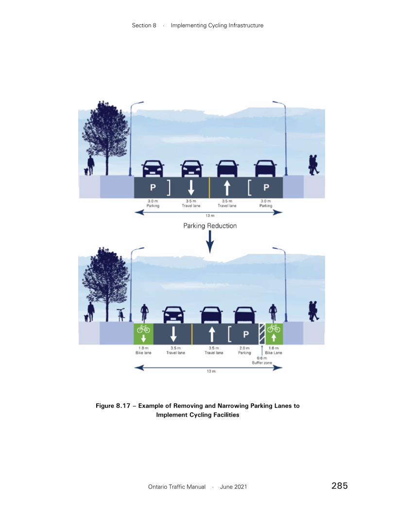
285
Section 8 · Implementing Cycling Infrastructure
Ontario Traffic Manual · June 2021
Figure 8.17 – Example of Removing and Narrowing Parking Lanes to Implement Cycling Facilities

286
Book 18 · Cycling Facilities
Ontario Traffic Manual · June 2021
8.2.4 Boulevard Retrofits
It is generally preferred to retrofit a boulevard with a cycling facility without having to move curbs or acquire property. This minimizes construction costs and road impacts with reconstructing curbs, gutters and associated stormwater infrastructure. Retrofit projects also need to minimize relocation of above and below-ground utilities to control costs and limit impacts. The preservation of existing street trees should also be a key consideration. Even where utility poles, light standards, other municipal infrastructure and trees are present, it may be possible to plot a path around the obstacles with adequate clearance and minimal relocations.
Where spare boulevard width is available on either side of the road, practitioners should undertake a feasibility study to compare the options and evaluate factors such as utility relocations, retaining wall requirements, street trees and curbside activity at transit stops. Intersections are the place where the most motor vehicle-bicycle conflicts occur. It is crucial that cycling facilities include appropriate intersection design treatments to reduce conflicts and increase comfort and safety.
8.2.3 Neighbourhood Bikeways
The implementation of neighbourhood bikeways is a separate category and may not necessarily entail a reallocation of space within the right-of-way. However, these projects typically require the implementation of various traffic calming and diversion measures to manage motor vehicle speed and volume as shown in Figure 8.18.
CASE STUDY: Hamilton. A truck route, Cannon Street, was reduced by one lane to support the installation of a separated two-way cycle track between Sherman Ave and Hess St, the first of its kind in the City of Hamilton. A well-organized campaign by area residents, called “Yes, We Cannon,” was instrumental in changing the proposed design from on-street bike lanes to separated cycle tracks. The project demonstrated that investing in high-quality cycling infrastructure can result in more people choosing to ride a bike. It was also a catalyst for even more improvements in cycling by the City of Hamilton.
Figure 8.18 – Traffic Diversion for Neighbourhood Bikeway, Hamilton
Source: WSP

287
Section 8 · Implementing Cycling Infrastructure
Ontario Traffic Manual · June 2021
8.2.6 New Roads
Roadway widening or new road construction allows for the provision of cycling facilities with greater separation between motorists and people cycling. A new road may involve negotiating for space for people cycling through the development review process. Since there would be no existing traffic volumes to evaluate a suitable facility type, practitioners should rely on the proposed posted speed, number of lanes, and the anticipated volumes of motorists and people cycling to perform the facility selection. Practitioners may also consult the municipality’s Official Plan and complete streets typologies, if available. Where multiple new roads are constructed as part of a larger development, it is recommended that facilities be constructed that connect to and support the municipality’s local cycling network.
8.2.5 Moving the Curb
For corridors that are scheduled for reconstruction, consider a curb realignment that takes space from between the curbs and uses it to widen the boulevard. This may provide enough width for a cycling facility while minimizing impacts due to utility relocations, tree removal and property acquistion. It can also result in a more inviting road environment by slowing traffic through the narrowing or removal of traffic lanes. Drainage impacts must be assessed and a conversion to side inlet catch basins can be considered.
This approach can also be used to upgrade an existing cycling facility, such as an on-street bike lane to a physically-separated cycle track to improve quality, comfort and safety. An Ottawa Study found that the cost to construct a cycling facility in the boulevard cost less than on-street because the full depth road base is not required.3
CASE STUDY: Richmond Hill. The Lake to Lake Route is an initiative to create a 120 kilometre walking and cycling trail through seven municipalities from Lake Simcoe in Georgina to Lake Ontario in Toronto. The segment on Leslie Street from Highway 7 to Elgin Mills in the City of Richmond Hill is being built in three phases with funding from three levels of government. The boulevard has been retrofitted with a multi-use path on the west side plus crossrides at intersections and driveways. In some areas, there is space to accommodate both a sidewalk and cycle track. The project is a key spine in the City’s cycling network for commuting and recreation.

288
Book 18 · Cycling Facilities
Ontario Traffic Manual · June 2021
References
1 Municipal Engineers Association (MEA) Approved Amendments, March 2015 https://www.municipalclassea.ca/amendments/approved.html
2 Integration of Cyclists and Pedestrians at Interchanges Final Technical Report, March 2012, Ministry of Transportation of Ontario (MTO), https://www.library.mto.gov.on.ca/SydneyPLUS/Sydney/Portal/default.aspx
3 Infrastructure Standards Review as part of Building Better Suburbs initiative, Report to Planning Committee and Council, City of Ottawa, May 2017
CASE STUDY: Ottawa. Main Street is the first complete street redevelopment of a major arterial road within the City of Ottawa. Originally constructed as a four-lane high capacity arterial road, with narrow pedestrian sidewalks, the previous design contributed to an undesirable and unsafe environment. The two-year construction project was initiated in 2015 to replace water and storm sewer infrastructure beneath the street. The redevelopment of Main Street included widening the sidewalks and adding cycle tracks. The transformation of Main Street has spurred new interest for infill development to capitalize on the historic character and central location of this community.

289
Section 9 · Support Features
Ontario Traffic Manual · June 2021
9.1 Bicycle Parking Facilities
Parking for bicycles is an essential component of a multi-modal transportation system and necessary for encouraging more bicycle use. A lack of adequate and secure bicycle parking can deter individuals from cycling. Dedicated spaces allow people riding bikes to securely lock their bicycles while contributing to more orderly sidewalks and parking areas. Properly designed, high quality and strategically located bicycle parking facilities can increase cycling and provide an organized and attractive public realm. Principles of good planning and design for bike parking include:
• Convenience of location and access
• Visibility and security
• Weather protection
• Durability and low maintenance costs
• Adequate space and clearances
• Accommodation of a variety of bicycles
• Aesthetically pleasing
Practitioners should consult municipal by-laws governing bike parking requirements, particularly for various building types, before proceeding with bike parking installations.
The City of Toronto has regulations and guidelines in place to ensure that high-quality bicycle parking is provided for locations frequented by cyclists throughout the city. These guidelines ensure that all new developments include adequate and appropriately designed bicycle parking which contributes to making Toronto a bicycle-friendly city. Chapter 230 of the City's Zoning Bylaw sets
9. Support Features
This section provides information on support features that should be considered in the planning and design of cycling networks. Sometimes these features are overlooked, but often they play a key role in completing bikeway systems and encouraging cycling.
Section 9.1 Bicycle Parking Facilities and Section 9.2 Other End-of-Trip Facilities provide guidance regarding short and long-term bicycle storage as well as repair stations, shower and change rooms. These are often collectively referred to as end-of-trip facilities. These components are important for the convenience and security of cyclists at their destinations.
Section 9.3 Rest Areas provides information on rest areas for recreational cycling routes in rural areas and urban centres. Rest areas are most important in locations where users tend to stop, such as lookouts, restaurants, water fountains, access points to trails and along waterfront promenades.
Section 9.4 Cycling Wayfinding provides guidance on implementing cycling wayfinding which includes a system of signs, pavement markings, and other tools to guide people on bikes along the network and to key destinations.
Key Outcome: Guidance on the selection, design and use of key supporting infrastructure to supplement cycling networks.

290
Book 18 · Cycling Facilities
Ontario Traffic Manual · June 2021
out the minimum number of required short- and long-term bicycle parking spaces for a range of residential, commercial, institutional and industrial land uses. Generally, the recommendations are based on the number of dwelling units for residential buildings and the total floor area for other land use classes. The bylaw also sets out bicycle parking installation requirements for both short- and long-term bicycle parking.
9.1.1 Type and Location of Bicycle Parking Areas
There are generally two categories of parking facilities that may be required by cyclists. Short-term parking is targeted at people visiting residences, businesses or institutions for brief periods, typically under two hours. Short-term parking requires a high degree of convenience in terms of ease of use and proximity to the destination. Bicycle racks should be located as close to destination entrances as possible without obstructing pedestrian flows. Racks should be available for public use and visible for passive surveillance. For example, Figure 9.1 illustrates post and ring rack parking along a busy corridor. On a street with narrow pedestrian clearways or reduced bike parking demand, post and ring racks can be installed in a linear configuration, parallel to the curb, as opposed to the perpendicular arrangement shown in Figure 9.1.
Alternatively, bike racks may be installed in place of on-street motor vehicle parking spaces as a retrofit option, as shown in Figure 9.2. On-street bike parking facilities should be designed and located to ensure they do not become roadside hazards, and that cyclists are not required to walk or stand next to live traffic to park their bicycle.
Long-term parking is typically used for periods longer than two hours and in more predictable patterns, for instance by employees, residents and transit users during peak hours. These users value weather protection and a high degree of security such as cameras. Long-term parking is likely to have less people interacting with, or in view of, the bike parking throughout the day. It often includes bicycle racks in an enclosed and secure area with controlled access, or outdoor bicycle lockers as
Figure 9.1 – Short-Term Parking, Toronto
Source: WSP
Figure 9.2 – On-Street Parking Corral, Toronto
Source: WSP
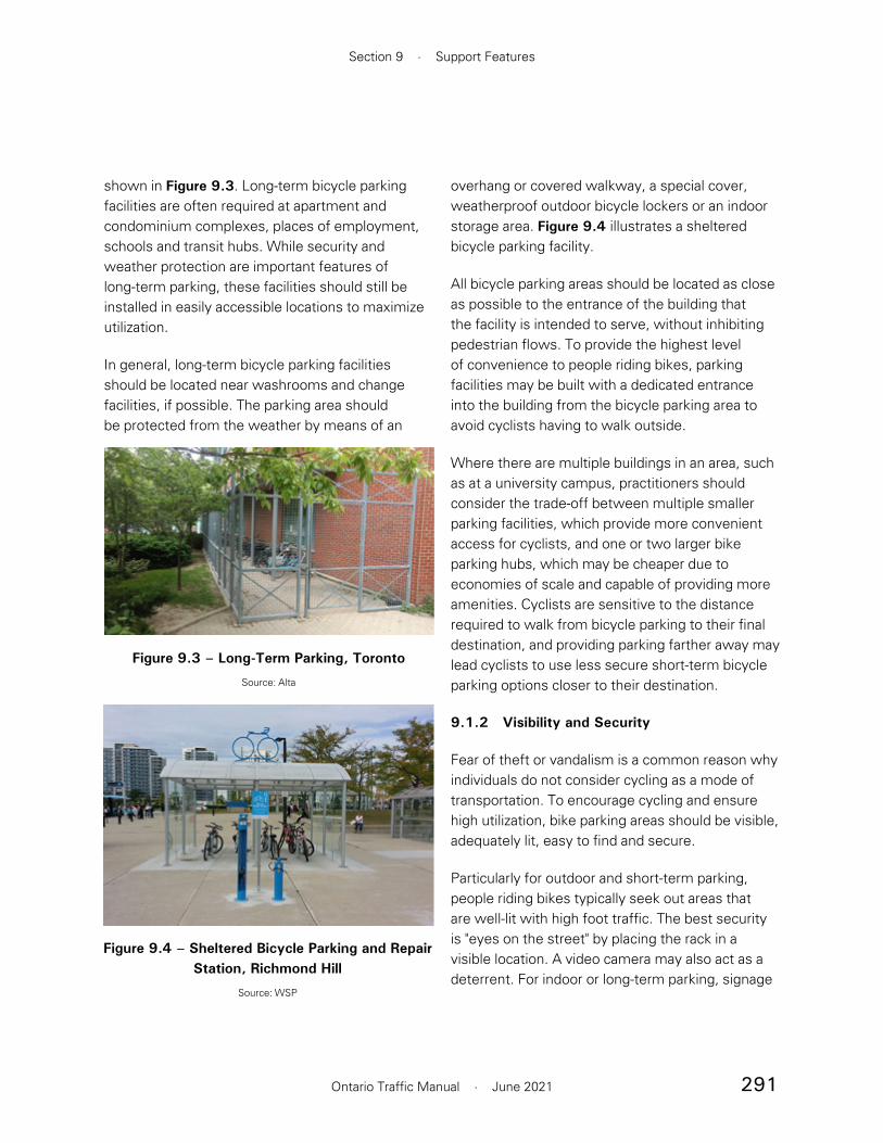
291
Section 9 · Support Features
Ontario Traffic Manual · June 2021
shown in Figure 9.3. Long-term bicycle parking facilities are often required at apartment and condominium complexes, places of employment, schools and transit hubs. While security and weather protection are important features of long-term parking, these facilities should still be installed in easily accessible locations to maximize utilization.
In general, long-term bicycle parking facilities should be located near washrooms and change facilities, if possible. The parking area should be protected from the weather by means of an
overhang or covered walkway, a special cover, weatherproof outdoor bicycle lockers or an indoor storage area. Figure 9.4 illustrates a sheltered bicycle parking facility.
All bicycle parking areas should be located as close as possible to the entrance of the building that the facility is intended to serve, without inhibiting pedestrian flows. To provide the highest level of convenience to people riding bikes, parking facilities may be built with a dedicated entrance into the building from the bicycle parking area to avoid cyclists having to walk outside.
Where there are multiple buildings in an area, such as at a university campus, practitioners should consider the trade-off between multiple smaller parking facilities, which provide more convenient access for cyclists, and one or two larger bike parking hubs, which may be cheaper due to economies of scale and capable of providing more amenities. Cyclists are sensitive to the distance required to walk from bicycle parking to their final destination, and providing parking farther away may lead cyclists to use less secure short-term bicycle parking options closer to their destination.
9.1.2 Visibility and Security
Fear of theft or vandalism is a common reason why individuals do not consider cycling as a mode of transportation. To encourage cycling and ensure high utilization, bike parking areas should be visible, adequately lit, easy to find and secure.
Particularly for outdoor and short-term parking, people riding bikes typically seek out areas that are well-lit with high foot traffic. The best security is "eyes on the street" by placing the rack in a visible location. A video camera may also act as a deterrent. For indoor or long-term parking, signage
Figure 9.4 – Sheltered Bicycle Parking and Repair Station, Richmond Hill
Source: WSP
Figure 9.3 – Long-Term Parking, Toronto
Source: Alta

292
Book 18 · Cycling Facilities
Ontario Traffic Manual · June 2021
may be required to direct users. Enclosed bicycle packing facilities should have at least one fully transparent wall to ensure visibility from both inside and outside of the facility. This is essential for the security of both bicycles and users alike.
Bicycle racks and lockers should be securely mounted to the ground so that they cannot be easily lifted or moved from their position. Bolting to concrete is preferred, whereas soft surfaces such as asphalt may require concrete footings or pads. There are also modular solutions that are unmounted but difficult to move when multiple racks are attached. In addition, bicycle racks and lockers should be designed to resist being easily detached by wrenches and pry bars or cut by common hand tools such as bolt and pipe cutters, which can easily be concealed in backpacks.
9.1.3 Types of Bicycle Parking Facilities
There are many types of bike parking racks and facilities. When choosing a particular type and configuration, it is important to consider the provision of facilities for all user types and bicycle types, with various sizes, attachments and needs. For example, cargo bicycles and adapted cycles such as handcycles and tricycles which are used as mobility aids typically have a wider wheel base and are not designed to be lifted off the ground. Electric bicycles benefit from charging infrastructure while parked.
Bike Racks
Bike racks can vary from a simple post and ring stand for two bicycles, to more elaborate systems for multiple bicycles at destinations where demand is high.
The purpose of a bike rack is to allow people riding bikes to securely and efficiently lock their bicycle in a convenient location and to provide support for the bicycle frame itself. In general, bike racks should:
• Be installed on a hard surface and be held firmly in place
• Support the bicycle upright by its frame in two places
• Prevent the bicycle from tipping over
• Be made of industrial grade materials or galvanized steel
• Enable the bicycle frame and one or both wheels to be secured
• Allow front-in parking so that a ‘U-lock’ may be used to secure the front wheel and the down tube of an upright bicycle
• Allow back-in parking so that a ‘U-lock’ may be used to secure the rear wheel and seat tube of the bicycle
• Allow use of a variety of ‘U-lock’ sizes by avoiding tubes with cross sections larger than 50 mm
• Be space efficient, allowing many bicycles to be parked in a small area without appearing cluttered or protruding into the accessible pedestrian route
Figures 9.5 to 9.8 illustrate a few good examples of bike racks. In particular, the Inverted U and Post and Ring racks are strongly recommended as the best options for meeting the above-noted guidelines.
Bike rack options that generally do not meet these criteria are shown in Figures 9.9 to 9.14, as

293
Section 9 · Support Features
Ontario Traffic Manual · June 2021
Figure 9.6 – Post and Ring, Welland
Source: Alta
Figure 9.7 – Post and Ring, Toronto
Source: WSP
Figure 9.8 – Staggered Wheelwell, Toronto
Source: WSP
Figure 9.5 – Inverted U Bike Rack, Ottawa
Source: Alta
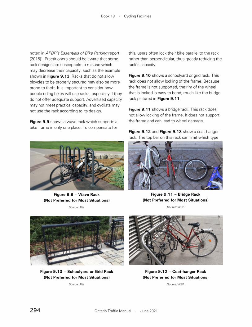
294
Book 18 · Cycling Facilities
Ontario Traffic Manual · June 2021
noted in APBP’s Essentials of Bike Parking report (2015)1. Practitioners should be aware that some rack designs are susceptible to misuse which may decrease their capacity, such as the example shown in Figure 9.13. Racks that do not allow bicycles to be properly secured may also be more prone to theft. It is important to consider how people riding bikes will use racks, especially if they do not offer adequate support. Advertised capacity may not meet practical capacity, and cyclists may not use the rack according to its design.
Figure 9.9 shows a wave rack which supports a bike frame in only one place. To compensate for
this, users often lock their bike parallel to the rack rather than perpendicular, thus greatly reducing the rack's capacity.
Figure 9.10 shows a schoolyard or grid rack. This rack does not allow locking of the frame. Because the frame is not supported, the rim of the wheel that is locked is easy to bend, much like the bridge rack pictured in Figure 9.11.
Figure 9.11 shows a bridge rack. This rack does not allow locking of the frame. It does not support the frame and can lead to wheel damage.
Figure 9.12 and Figure 9.13 show a coat-hanger rack. The top bar on this rack can limit which type
Figure 9.10 – Schoolyard or Grid Rack (Not Preferred for Most Situations)
Source: Alta
Figure 9.11 – Bridge Rack (Not Preferred for Most Situations)
Source: WSP
Figure 9.12 – Coat-hanger Rack (Not Preferred for Most Situations)
Source: WSP
Figure 9.9 – Wave Rack (Not Preferred for Most Situations)
Source: Alta

295
Section 9 · Support Features
Ontario Traffic Manual · June 2021
of bikes can be parked. Minimal clearance between racks can reduce intended density.
Figure 9.14 shows a spiral or ring rack. This rack requires users to lift their bicycle, reducing ease of use.
Bike Lockers
Bike lockers differ from bike racks in that they are individual storage units most often used for long-term parking. They are enclosed and weather-protected. They may be operated by a controlled access system and opened using a key, swipe card or an electronic key pad located on the locker door. Lockers may also be operated on a first come, first served basis, where users bring their own lock. Systems that use digital on-demand access, such as through swipe card or electronic key pad, shown in Figure 9.15, can encourage use by eliminating individualized rental agreements, wait lists and unused space. Cyclists find an available locker, secure their bike in place, and upon return, insert their card or utilize digital access to retrieve their bike and pay a fee.
Bike lockers require more space than bike racks, but are still space efficient relative to motor vehicle parking. On average, two standard motor vehicle parking spaces can accommodate 10 individual bicycle locker spaces depending on the model size.
Figure 9.13 – Misuse of a Bike Rack
Source: Alta
Figure 9.14 – Spiral or Ring Rack (Not Preferred for Most Situations)
Source: WSP
Figure 9.15 – Digitally Accessible On-Demand Locker
Source: BART

296
Book 18 · Cycling Facilities
Ontario Traffic Manual · June 2021
Bike lockers should be installed close to a building, transit entrance or on the first level of a parking garage. Mesh lockers allow for surveillance of the contents, which can deter people from storing contraband items in the bike lockers.
In general, the bike locker design should:
• Be durable
• Be able to withstand regular use and intense weather conditions
• Protect bicycles from theft and vandalism
• Hold the bicycle upright and prevent it from tipping over within the storage unit
9.1.4 Sheltered and High-Density Parking
An indoor bike room is a type of sheltered long-term bicycle parking facility. Bike racks are either securely mounted to the floor or to the walls. Secure entry door systems may provide an additional level of protection. Figure 9.17 illustrates an example of a bike room. Some bike
rooms may also contain self-serve bicycle repair and maintenance stations.
Sheltered and long-term parking facilities often aim to maximize density to meet the needs of their users. Two strategies that are commonly used are two-tier and vertical configurations as shown in Figure 9.18 and Figure 9.19. Staggered wheelwell, shown in Figure 9.20 is also considered a high-density option. Figure 9.21 is an example of sheltered parking near regional transit.
Vertical parking is not always accessible to all users or bikes, but can be used in combination with on-ground parking to increase overall density. Two-tier parking models vary widely and can sometimes include lift assistance.
For both systems, practitioners should provide clear directions and enough space for individuals to park and remove their bicycles safely.
Figure 9.16 – Outdoor Bike Lockers, Vaughan
Source: WSP
Figure 9.17 – Bike Room, Toronto
Source: Alta

297
Section 9 · Support Features
Ontario Traffic Manual · June 2021
9.1.5 Clearance Considerations
For both outdoor and indoor bicycle parking facilities, adequate clearance is required around racks and lockers to give people riding bikes room to manoeuvre, and to prevent conflicts with pedestrians or motor vehicles. Figure 9.22 illustrates basic parking configurations and clearances for individual ‘stand’ type bicycle racks as recommended by APBP’s Essentials of Bike Parking report (2015)2, including:
• Where more than one bicycle rack is installed, they should be separated by aisles, much like a motor vehicle parking lot. The width between aisles should be a minimum of 1.2 m to provide enough space for one person to comfortably walk through with a bicycle.
• Excluding the width of aisles, the footprint allocated to bicycle parking should be sized for the length of a bicycle, which ranges from 1.8 to 2.4 m
Figure 9.19 – Indoor Vertical Parking
Source: Alta
Figure 9.20 – Sheltered Staggered Wheelwell, Toronto
Source: Alta
Figure 9.21 – Sheltered Parking at Regional Transit, Vaughan
Source: WSP
Figure 9.18 – Sheltered Two-Tier Parking, Toronto
Source: Alta

298
Book 18 · Cycling Facilities
Ontario Traffic Manual · June 2021
Figure 9.22 – Bike Parking Configuration Clearances
Adapted from Association of Pedestrian and Bicycle Professionals Essentials of Bike Parking report (2015)

299
Section 9 · Support Features
Ontario Traffic Manual · June 2021
• Parking areas should never obstruct emergency vehicle zones, utility access openings, bus loading areas, delivery zones, taxi zones, garbage disposal bins, doorways or other building access points
• Where bike parking is in a multi-storey parking garage, it should be located on the ground level
• For more guidance, refer to bike rack and locker supplier design specifications for clearance requirements of specific facility types, or for cycling facility parking guidelines as set out by the relevant municipality.
9.1.6 Bike Parking and Universal Design
Bike parking should accommodate a wide range of users and bicycles. Bike rooms and facilities should be accessible to users of adapted cycles. In general, when designing bicycle parking that benefits all users, consider providing:
• An accessible route between bikeways and bicycle parking that avoids people riding bikes needing to dismount and walk to access bicycle parking facilities
• Vertical access via an elevator or ramp (max slope of 1:25) where climbing stairs would otherwise be required to reach parking. It is important to remember that adapted cycles are wider and have a greater turning radius than standard bikes.
• Automatic swing or sliding doors at entrances to bicycle parking rooms
• Entrances that are adequately wide to accommodate a person using adapted cycles (typically 1.8 m)
• Bike lockers should have adequate door clearance such that there is no conflict with other lockers, pedestrians or parked motor vehicles
• Racks on sidewalks or curbside should be installed in the furnishing zone, in line with existing obstructions and street furniture. Racks near motor vehicle parking should be placed to avoid opening motor vehicle doors.
• The preferred orientation for racks is parallel to the curb and sidewalk. Perpendicular racks can also be provided where the furnishing zone is wider.
• Parking facilities should have a minimum 0.6 m clearance from the end of the bicycle to the nearest curb edge
• Inverted “U” racks and ring and post racks mounted in a row should be placed at least 0.9 m apart. This allows enough room for two bicycles to be secured to each rack.
In addition, the following factors should be considered for bike racks and lockers:
• In high traffic areas such as transit hubs, where many users may retrieve their bicycle at the same time, aisles should be a minimum of 1.75 m wide
• Racks and lockers should be placed as close as possible to the entrance of the building that the facility is intended to serve without inhibiting flow in and out of the building
• Large bicycle rack areas with a high turnover of cyclists should have more than one entrance to facilitate user flow. A second entrance or exit may also be desirable from a security perspective.

300
Book 18 · Cycling Facilities
Ontario Traffic Manual · June 2021
• Wider spacing between bicycle racks to accommodate cargo bicycles and adapted cycles
• Designated accessible cycle parking locations with sufficient clear manoeuvring space, designed to accommodate adapted cycles
• Charging points for electric bicycles
9.1.7 Bicycle Parking Maintenance Considerations
In addition to maximizing the number of bicycle parking facilities available, it is also important to keep them in good working order. Routine maintenance and clean facilities will encourage use. Vandalism or errant motor vehicles may cause damage to bicycle parking facilities. Environmental conditions can also affect functionality as a result of corrosion. Utilization of parking can be further reduced by the presence of abandoned bikes that effectively take the racks they occupy out of service.
Snow clearance can be an issue with bike racks. If racks are uncovered, heavy snow may make them unusable, particularly if snow storage blocks access.
Choice of materials and parking systems can impact long-term maintenance requirements. For instance, two-tier parking requires additional maintenance due to its moving parts. Choosing higher durability of coating materials for racks will contribute to lower maintenance requirements.
The following should be included in maintenance routines:
• Inspect parking facilities and undertake on-site repairs where it is practical to do so
• Replace facilities where repair is not feasible or cost-effective
• Where parking is being occupied by a bicycle that is damaged or rusty, it should be tagged for removal. If the bike has not been taken away within the municipality’s designated time-frame, it should be removed. Bikes that are severely damaged or stripped of parts should be removed without notice.
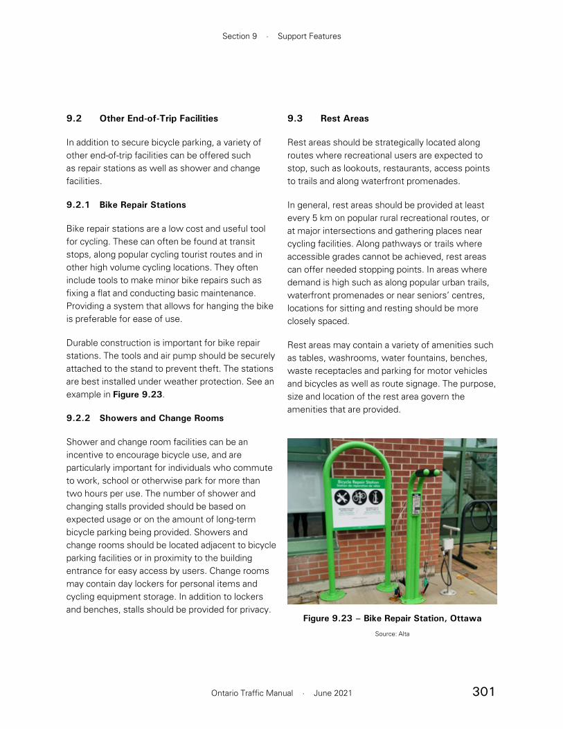
301
Section 9 · Support Features
Ontario Traffic Manual · June 2021
9.2 Other End-of-Trip Facilities
In addition to secure bicycle parking, a variety of other end-of-trip facilities can be offered such as repair stations as well as shower and change facilities.
9.2.1 Bike Repair Stations
Bike repair stations are a low cost and useful tool for cycling. These can often be found at transit stops, along popular cycling tourist routes and in other high volume cycling locations. They often include tools to make minor bike repairs such as fixing a flat and conducting basic maintenance. Providing a system that allows for hanging the bike is preferable for ease of use.
Durable construction is important for bike repair stations. The tools and air pump should be securely attached to the stand to prevent theft. The stations are best installed under weather protection. See an example in Figure 9.23.
9.2.2 Showers and Change Rooms
Shower and change room facilities can be an incentive to encourage bicycle use, and are particularly important for individuals who commute to work, school or otherwise park for more than two hours per use. The number of shower and changing stalls provided should be based on expected usage or on the amount of long-term bicycle parking being provided. Showers and change rooms should be located adjacent to bicycle parking facilities or in proximity to the building entrance for easy access by users. Change rooms may contain day lockers for personal items and cycling equipment storage. In addition to lockers and benches, stalls should be provided for privacy.
9.3 Rest Areas
Rest areas should be strategically located along routes where recreational users are expected to stop, such as lookouts, restaurants, access points to trails and along waterfront promenades.
In general, rest areas should be provided at least every 5 km on popular rural recreational routes, or at major intersections and gathering places near cycling facilities. Along pathways or trails where accessible grades cannot be achieved, rest areas can offer needed stopping points. In areas where demand is high such as along popular urban trails, waterfront promenades or near seniors’ centres, locations for sitting and resting should be more closely spaced.
Rest areas may contain a variety of amenities such as tables, washrooms, water fountains, benches, waste receptacles and parking for motor vehicles and bicycles as well as route signage. The purpose, size and location of the rest area govern the amenities that are provided.
Figure 9.23 – Bike Repair Station, Ottawa
Source: Alta

302
Book 18 · Cycling Facilities
Ontario Traffic Manual · June 2021
9.4 Cycling Wayfinding
A wayfinding strategy consists of a system of signs, pavement markings or tools to orient people riding bikes and guide them to destinations through a network. With the assistance of wayfinding, people riding bikes should be able to navigate intuitively and efficiently regardless of their familiarity with a place. This is accomplished through the effective use of clear and consistent signage designed for use by people of all ages and abilities.
Successful design and implementation of wayfinding can increase the use of bikeways by casual riders and encourage exploration of the network. This is done by familiarizing people with the cycling network, identifying the best routes to destinations and estimating travel time by cycling. Wayfinding can also lend identity to a location, creating a sense of place.
Design of a wayfinding strategy should follow the principles of:
• Simplicity: providing enough information to allow users to make decisions without overloading them
• Consistency: ensuring sign design, materials, symbology and placement is consistent and recognizable throughout the network
• Conspicuity: locating signs to be visible, unobstructed, aimed clearly at cyclists and placed at a height visible to cyclists
• Relevance: providing connections to places to which locals and visitors want to go
• Continuity: ensuring that signs are placed and designed for quick understanding to
maintain motion and avoid frequent stopping for interpretation. Thus, signs should be placed in advance of major decision points and repeated as necessary.
• Integrative: building on existing cycling and trail networks and giving directions on complete and continuous routes rather than scattered interventions
• Universality: delivering information in a way that is accessible to all people riding bikes
9.4.1 Wayfinding System Design
A wayfinding system can be designed for a variety of contexts, from a small municipality, to a big city. This is done through careful consideration of a variety of components described below including destination hierarchies, sign types, design of signage and use of pavement markings.
Destination Hierarchies
A destination hierarchy is a strategy for consistently and predictably choosing which routes and destinations to sign, and at what distance to sign them. Often, this is done with a ranking system that categorizes routes and destinations, typically based on their level of importance within a certain range of distances. While the system should be consistent and predictable, there is significant flexibility in this approach to accommodate varying sizes and types of municipalities by varying distances and criteria for inclusion of routes and destinations.
The following is a list of questions for practitioners to consider when signing routes and destinations within a cycling wayfinding system:
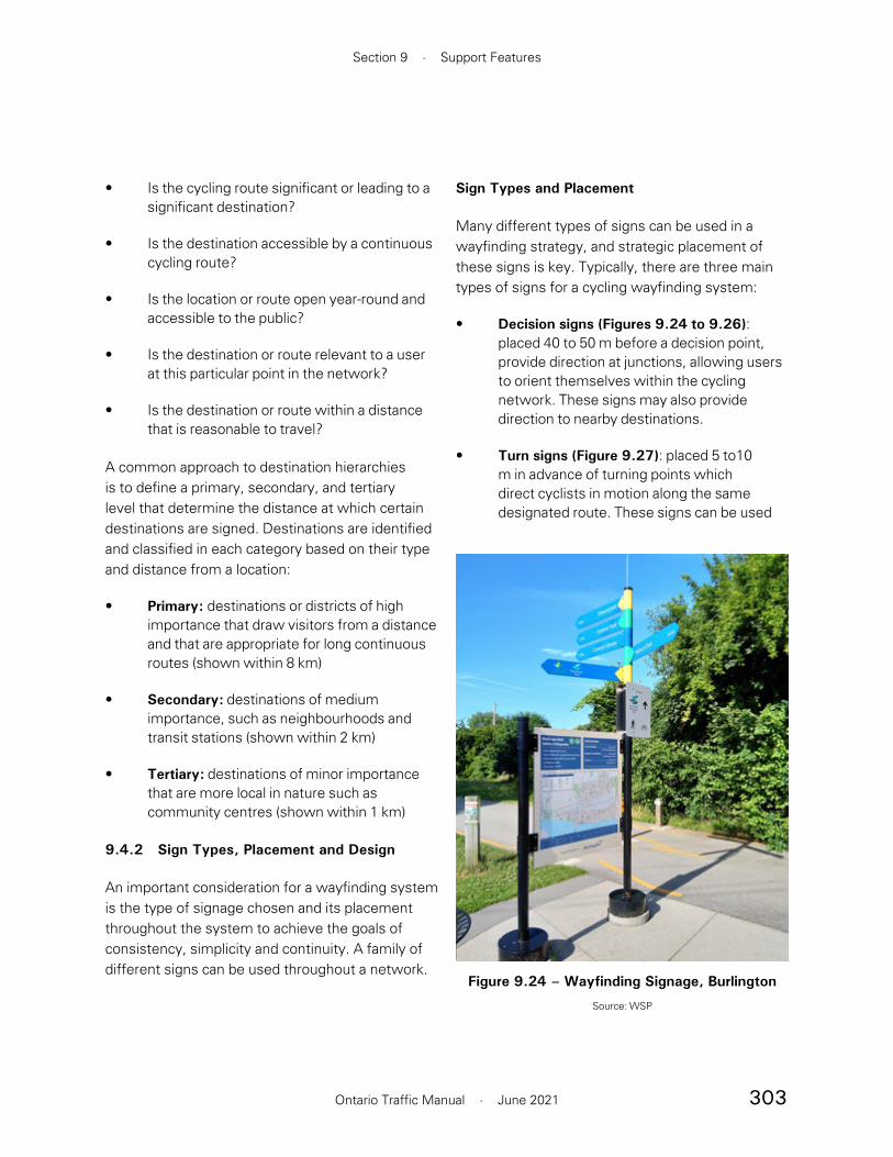
303
Section 9 · Support Features
Ontario Traffic Manual · June 2021
Sign Types and Placement
Many different types of signs can be used in a wayfinding strategy, and strategic placement of these signs is key. Typically, there are three main types of signs for a cycling wayfinding system:
• Decision signs (Figures 9.24 to 9.26): placed 40 to 50 m before a decision point, provide direction at junctions, allowing users to orient themselves within the cycling network. These signs may also provide direction to nearby destinations.
• Turn signs (Figure 9.27): placed 5 to10 m in advance of turning points which direct cyclists in motion along the same designated route. These signs can be used
• Is the cycling route significant or leading to a significant destination?
• Is the destination accessible by a continuous cycling route?
• Is the location or route open year-round and accessible to the public?
• Is the destination or route relevant to a user at this particular point in the network?
• Is the destination or route within a distance that is reasonable to travel?
A common approach to destination hierarchies is to define a primary, secondary, and tertiary level that determine the distance at which certain destinations are signed. Destinations are identified and classified in each category based on their type and distance from a location:
• Primary: destinations or districts of high importance that draw visitors from a distance and that are appropriate for long continuous routes (shown within 8 km)
• Secondary: destinations of medium importance, such as neighbourhoods and transit stations (shown within 2 km)
• Tertiary: destinations of minor importance that are more local in nature such as community centres (shown within 1 km)
9.4.2 Sign Types, Placement and Design
An important consideration for a wayfinding system is the type of signage chosen and its placement throughout the system to achieve the goals of consistency, simplicity and continuity. A family of different signs can be used throughout a network.
Figure 9.24 – Wayfinding Signage, Burlington
Source: WSP
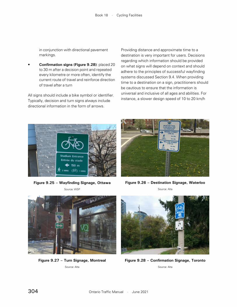
304
Book 18 · Cycling Facilities
Ontario Traffic Manual · June 2021
Providing distance and approximate time to a destination is very important for users. Decisions regarding which information should be provided on what signs will depend on context and should adhere to the principles of successful wayfinding systems discussed Section 9.4. When providing time to a destination on a sign, practitioners should be cautious to ensure that the information is universal and inclusive of all ages and abilities. For instance, a slower design speed of 10 to 20 km/h
in conjunction with directional pavement markings.
• Confirmation signs (Figure 9.28): placed 20 to 30 m after a decision point and repeated every kilometre or more often, identify the current route of travel and reinforce direction of travel after a turn
All signs should include a bike symbol or identifier. Typically, decision and turn signs always include directional information in the form of arrows.
Figure 9.25 – Wayfinding Signage, Ottawa
Source: WSP
Figure 9.26 – Destination Signage, Waterloo
Source: Alta
Figure 9.27 – Turn Signage, Montreal
Source: Alta
Figure 9.28 – Confirmation Signage, Toronto
Source: Alta
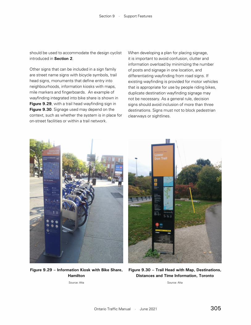
305
Section 9 · Support Features
Ontario Traffic Manual · June 2021
When developing a plan for placing signage, it is important to avoid confusion, clutter and information overload by minimizing the number of posts and signage in one location, and differentiating wayfinding from road signs. If existing wayfinding is provided for motor vehicles that is appropriate for use by people riding bikes, duplicate destination wayfinding signage may not be necessary. As a general rule, decision signs should avoid inclusion of more than three destinations. Signs must not to block pedestrian clearways or sightlines.
should be used to accommodate the design cyclist introduced in Section 2.
Other signs that can be included in a sign family are street name signs with bicycle symbols, trail head signs, monuments that define entry into neighbourhoods, information kiosks with maps, mile markers and fingerboards. An example of wayfinding integrated into bike share is shown in Figure 9.29, with a trail head wayfinding sign in Figure 9.30. Signage used may depend on the context, such as whether the system is in place for on-street facilities or within a trail network.
Figure 9.29 – Information Kiosk with Bike Share, Hamilton
Source: Alta
Figure 9.30 – Trail Head with Map, Destinations, Distances and Time Information, Toronto
Source: Alta

306
Book 18 · Cycling Facilities
Ontario Traffic Manual · June 2021
necessary to make decisions. Unless necessary, punctuation such as periods and commas should be avoided.
Pavement Markings
Pavement markings, such as directional sharrows, can supplement or enhance wayfinding signage. Directional sharrows may be used to notify cyclists of an upcoming decision point, or of the presence of intersecting cycling routes. An example of a directional sharrow is shown in Figure 9.31.
Pavement markings can be vital tools where:
• Vegetation and a high density of traffic or other signage make cycling wayfinding signs difficult to see
• Additional reinforcement is needed to navigate difficult turns or complex intersections
• Pavement markings are an integrated component of cycling wayfinding in the region
Signs should be mounted at a recommended height of 1.5 m that is eye-level and easily visible for people riding bikes. Placement of signs should also meet the requirements for vertical and horizontal clearance described in Section 7.3. Poles should not impede pedestrian clearways.
Sign Design
The design of signage must be consistent so that it is recognizable and conspicuous for cyclists. OTM Book 1B - Direct Traffic Management provides specific guidance on the design of signage and text size for legibility.
Graphic specifications for signs can be developed in significant detail and should consider:
• Panel size: the size of signage should allow for legibility from afar, providing enough distance to read and make decisions at average cycling speeds. The panel size should allow for the sign to be mountable onto a pole or surface.
• Typeface: the font used for signage should allow for legibility from afar, providing enough distance to read and make decisions at average cycling speeds. Typeface can also be used to be consistent with local identity.
• Sign Colours: the colour palette should be consistent and recognizable for people riding bikes, and separate from signage directed at motor vehicles
• Icons and Symbols: icons and symbols can be used to help communicate information quickly and with simplicity, expanding comprehension to those without English or French proficiency. Use of icons and symbols can also save space and improve legibility.
• Volume and Clarity of Text: the amount of information on a sign should be the minimum
Figure 9.31 – Directional Sharrows, Portland, OR
Used to indicate a decision point at the intersection of two cycling routes
Source: Alta

307
Section 9 · Support Features
Ontario Traffic Manual · June 2021
References
1 Association of Pedestrian and Bicycle Professionals. (2015) Essentials of Bike Parking. https://www.apbp.org/assets/docs/EssentialsofBikeParking_FINA.pdf
2 Ibid.

308
Book 18 · Cycling Facilities
Ontario Traffic Manual · June 2021
10. Maintenance Strategies
As cycling networks grow, municipalities can expect that people will use them more often and through all seasons, even in inclement conditions. Bicycle tires are more sensitive to surface conditions such as debris, snow or ice than motor vehicles and therefore, maintenance practices need to be enhanced to accommodate cycling.
Section 10.1 Network Considerations discusses the Minimum Maintenance Standards for Ontario Highways, asset management and communicating with users.
Section 10.2 Non-Winter Maintenance Best Practices discusses activities such as sweeping, pavement deterioration and vegetation management.
Section 10.3 Winter Maintenance Best Practices discusses snow clearing, ice treatment and strategies for identifying and maintaining a priority winter cycling network.
Key Outcome: Demonstrate the importance of a planned, regular maintenance program for keeping active transportation facilities comfortable and functional throughout the year.
10.1 Network Considerations
10.1.1 Minimum Maintenance Standards for Municipal Highways
In 2018, the Minimum Maintenance Standards (MMS) for Municipal Highways (Ontario Regulation 239/02) was amended to include winter maintenance of walking and cycling facilities. Practitioners should go to the MMS for more complete information on the regulations and to confirm the most current version.
Ontario municipalities are encouraged to expand year-round access to active transportation facilities by applying consistent level of service standards. They are also encouraged to increase service levels for higher priority routes since the regulation is written based on the classification of roadways, not bikeways. Additional guidance on winter maintenance can be found in Section 10.3.
The MMS are non-mandatory guidelines but should be applied unless Ontario municipalities have established their own Council-approved level of service maintenance standards. If a municipality develops their own standards, it is still recommended to align with the current MMS.
Municipalities have the flexibility to close certain cycling facilities during winter months to focus resources on facilities that remain open. The regulation also allows a municipality to declare a significant weather event during which, travel by bicycle may not be practical. The standard for addressing winter maintenance during an event is reduced to monitoring the weather in accordance with the standards, and deploying resources to address the issues starting from the time that the municipality deems appropriate to do so.

309
Section 10 · Maintenance Strategies
Ontario Traffic Manual · June 2021
Municipalities are encouraged to exceed these standards such as applying a Class 1 standard on all priority routes identified as part of the winter network.
The regulation also sets service level standards for addressing the prevention of ice formation, icy roadways, potholes, shoulder drop-offs, cracks, debris and surface discontinuities. Ice formation standards for roads apply for bicycle lanes on a roadway, but do not apply to other types of cycling facilities. There are also separate standards for sidewalks, which would also apply to multi-use paths.
The MMS regulation defines “bicycle lanes” as
1. a portion of the roadway that has been designated by pavement markings or signage for the preferential or exclusive use of cyclists; or
2. a portion of a roadway that has been designated for the exclusive use of cyclists by signage and a physical or marked buffer.
This does not include in-boulevard multi-use paths. If a multi-use path commonly functions as a pedestrian facility, then the sidewalk maintenance standard should apply.
The winter level of service for snow accumulation in bicycle lanes is shown in Table 10.1. After the snowfall has ended, snow is to be reduced to a depth less than or equal to that shown in Table 10.1, to provide a minimum bicycle lane width of at least one metre.
While bare pavement is desirable, most cyclists can bike on the Class 1 standard of 2.5 cm of snow. Greater depths of snow may require specialized equipment such as studded tires or a fat bike. Figure 10.1 shows a specialized plow clearing a cycle track.
The roadway classification in Table 10.1 is based on motor vehicle traffic volume and speed, shown in Table 10.2. Since the service levels are intended for vehicular traffic where the busiest and fastest roads would get better treatment, municipalities are encouraged to enhance their service levels to achieve the desired level of comfort for cycling on priority routes.
Table 10.3 shows the service levels for different cycling facility types based on the relevant classification of roadway in the regulations.
Figure 10.1 – Winter Maintenance Vehicle, Toronto
Source: WSP, 2019
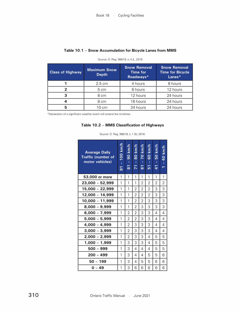
310
Book 18 · Cycling Facilities
Ontario Traffic Manual · June 2021
Average Daily Traffic (number of motor vehicles)
91 –
100 k
m/h
81 –
90 k
m/h
71 –
80 k
m/h
61 –
70 k
m/h
51 –
60 k
m/h
41 –
50 k
m/h
1 –
40 k
m/h
53,000 or more 1 1 1 1 1 1 123,000 – 52,999 1 1 1 2 2 2 215,000 – 22,999 1 1 2 2 2 3 312,000 – 14,999 1 1 2 2 2 3 310,000 – 11,999 1 1 2 2 3 3 38,000 – 9,999 1 1 2 3 3 3 36,000 – 7,999 1 2 2 3 3 4 45,000 – 5,999 1 2 2 3 3 4 44,000 – 4,999 1 2 3 3 3 4 43,000 – 3,999 1 2 3 3 3 4 42,000 – 2,999 1 2 3 3 4 5 51,000 – 1,999 1 3 3 3 4 5 5
500 – 999 1 3 4 4 4 5 5
200 – 499 1 3 4 4 5 5 6
50 – 199 1 3 4 5 5 6 6
0 – 49 1 3 6 6 6 6 6
Table 10.2 – MMS Classification of Highways
Source: O. Reg. 366/18, s. 1 (5), 2018.
Class of Highway Maximum Snow Depth
Snow Removal Time for
Roadways*
Snow Removal Time for Bicycle
Lanes*
1 2.5 cm 4 hours 8 hours2 5 cm 6 hours 12 hours3 8 cm 12 hours 24 hours4 8 cm 16 hours 24 hours5 10 cm 24 hours 24 hours
Table 10.1 – Snow Accumulation for Bicycle Lanes from MMS
Source: O. Reg. 366/18, s. 4.2., 2018
*Declaration of a significant weather event will extend the timelines

311
Section 10 · Maintenance Strategies
Ontario Traffic Manual · June 2021
Cycling Facility Type Snow Clearing Ice Prevention Ice Treatment
Cycle Tracks Not specified in MMS but recommended if part of a winter cycling network
Bicycle Lanes
“After becoming aware of the fact that the snow accumulation on a bicycle lane is greater than the depth”...2.5 to 10 cm,”to deploy resources as soon as practicable to address the snow accumulation” ... and within 8 to 24 hours (O.Reg 366/18 s4.2)
Up to 24 hours preceding the likelihood of ice formation (O.Reg 366/18 s5)
Treat ice within 3 to 16 hours after a municipality becomes aware of icy conditions (O.Reg 366/18 s5).
Multi-Use Paths
Maintain to 8 cm within 48 hours, minimum width of 1 metre (O.Reg 366/18 s16.3)
“Treat the sidewalk if practicable to prevent ice formation or improve traction within 48 hours if the municipality determines that there is a substantial probability of ice forming on a sidewalk, starting from the time that the municipality determines is appropriate to deploy resources for that purpose”(O.Reg 366/18s15)
Under routine weather events, within 48 hours after becoming aware of icy conditions (O.Reg 366/18s15).
Table 10.3 – Minimum Winter Maintenance Service Levels for Different Cycling Facilities from MMS
Source: O.Reg. 239/02, as amended by O.Reg 366/18

312
Book 18 · Cycling Facilities
Ontario Traffic Manual · June 2021
10.1.2 Asset Management
Road authorities owe a duty of care to provide the safest possible conditions for people who cycle. They also must be mindful of reducing their exposure to liability. Regularly scheduled monitoring, inspections and maintenance activities should be undertaken as part of an asset management program to address deficiencies within a reasonable time frame. Life cycle accounting of cycling facilities that plans for preservation, rehabilitation and replacement are critical for ensuring the best return on transportation investments.
It is important to understand the full life cycle costs of new infrastructure to support long-term sustainability of the network. Asset management seeks the most cost-effective way to establish desired levels of service while optimizing resources. Cycling facilities should be considered as assets and appropriately managed by the following tasks:
• During the planning and design process, work with maintenance crews to ensure they have the equipment and resources available to maintain new active transportation facilities
• Track and update an inventory in GIS that includes bicycle infrastructure and other elements such as bollards, bridges, pavement markings, parking, signs and lighting
• Develop maintenance levels of service or quality of service standards and operational policies to meet or exceed the MMS for winter and non-winter maintenance activities
• Schedule routine inspection and maintenance activities according to set standards
• Develop an asset management plan which includes capital and operating life cycle costs based on service levels
• Develop a long-term financial model to compare life cycle needs to current budget forecasts
• Plan for the preservation, rehabilitation and replacement of cycling facilities based on service level conditions identified in the asset management plan, and include these in the capital and operating budgets
• Maintain a current database of actual costs of cycling facilities to help with budgeting for future projects
• Set and adjust asset management plans and budgets as necessary to meet targets
Table 10.4 shows the typical service life for various elements of cycling infrastructure. If there is a 20-year service life, for example, assume that 5% will need to be replaced annually.

313
Section 10 · Maintenance Strategies
Ontario Traffic Manual · June 2021
Type Useful Life Asset Management Strategies
Asphalt bikeway 25 years
• Minor repairs
• Resurfacing
• Rehabilitation
• Full-depth replacement
Concrete bikeway 50 years
• Minor repairs
• Replace deteriorating segments
• Full replacement
Bridge (active transportation or motor vehicle)
25–75 years
• Bridge repairs
• Minor rehabilitation
• Full replacement
Culvert 25–50 years
• Culvert repair
• Minor rehabilitation
• Full replacement
Painted Line Markings and Symbols 1–2 years• Refresh annually or depending on
wear
Durable Line Markings, Symbols and Green Surface Treatments
3–7 years• Depends on type, weather conditions,
amount of wear, preparation of surface during application
Signage 20 years • Replace damaged or faded signs
Physical separation (bollards, curbs, planters, etc.)
Until damaged• Repair or replace damaged or missing
bollards and other separators
Table 10.4 – Typical Useful Life of Bicycle Infrastructure
Source: Adapted from Burlington Asset Management Plan, 2016 and Caledon Asset Management Plan,2014

314
Book 18 · Cycling Facilities
Ontario Traffic Manual · June 2021
Winter:
• Up-to-date winter bike network service level standards
• Static maps indicating which facilities are maintained and their assigned level of priority
• Interactive maps showing the status of maintenance in real-time as illustrated in Figure 10.2, including:
— Planned snow clearing and de-icing operations
— Updates outlining when the facility was last maintained
— Updates about facilities temporarily closed for winter
10.1.3 Communication
Communicating with users is essential for encouraging cycling, particularly in the winter. It helps to manage expectations on the conditions they encounter. The following information may be posted to the relevant section of a municipality’s website:
Non-Winter:
• Schedule and updates about post-winter sweeping
• Updates about facilities temporarily closed for construction or maintenance issues
• Bicycle counts
Figure 10.2 – Interactive Map Showing Snow Clearing Progress, Calgary
Source: calgary.ca
315
Section 10 · Maintenance Strategies
Ontario Traffic Manual · June 2021
10.2 Non-Winter Maintenance Best Practices
Table 10.5 provides suggested service levels for various non-winter maintenance activities and references the MMS for on-road facilities. The MMS covers the main deficiency categories and is primarily related to vehicle travel, but does not include all deficiencies that could be hazards to cyclists. Municipalities should be encouraged to set specific policies for bicycle facilities that would require maintenance more frequently or at lower thresholds than those for motor vehicles in MMS, specifically for cracks, potholes, discontinuities and edge drop-offs. MMS service standards should be exceeded on priority bike routes. Physically separated bikeways are not covered in the MMS, but multi-use paths are also pedestrian facilities so are covered under sidewalks. Municipalities have the flexibility to create their own standards for on- and off-road cycling facilities based on their specific needs and resources.
It is now increasingly common to alert users of temporary closures and maintenance issues using social media or email blasts.
An interface should be provided for residents to report issues with cycling facilities, such as a mobile app or 311 service. Prompt and systematic handling of concerns from the public allows a municipality to manage communication and sustain a high standard of service.
Some communities are soliciting input on their cycling networks through crowd-sourcing tools. With mobile devices, users can provide geo-referenced photographs and describe problems they encounter on the network such as debris or poor surface conditions. This type of input from people who cycle can help identify areas where maintenance operations as required or need to be improved.

316
Book 18 · Cycling Facilities
Ontario Traffic Manual · June 2021
Activity Service Level Criteria
Patrol and Inspection to Check Conditions
3 times every 7 days to once every 30 days (O. Reg 239/02 s.3)
Sweeping (10.2.1)Scheduled sweeping weekly to monthly; deploy resources outside of scheduled sweeping as soon as practicable after becoming aware of debris (O. Reg 239/02 s.9, applies to on-road cycling facilities)
Surface Discontinuities (10.2.2.1)
Greater than 5 cm height within 2 to 21 days after acquiring knowledge of the discontinuity (O. Reg 239/02 s.16)
Cracking (10.2.2.2) Greater than 5 cm wide and 5 cm deep (O. Reg 239/02 s.8)
Potholes (10.2.2.3)600 cm² by 8 cm deep within 4 days after acquiring knowledge of the pothole (O. Reg 239/02 s.6)
Surface Drop-off at Shoulders (10.2.2.4)
Deeper than 8 cm (O. Reg 239/02 s.7)
Differential Settlement (10.2.2.5)
Change in level must be is less than 6 mm (AODA)
Vegetation Management (10.2.3)
Routine mowing including daylight triangles at intersections; annual trimming of bike path trees
Drainage Improvement (10.2.4)
Part of annual inspection; respond to issues as needed
Signage (10.2.5) and Pavement Markings (10.2.6)
Refreshed as needed
Table 10.5 – Minimum Recommended Service Levels for Non-Winter Maintenance Activities
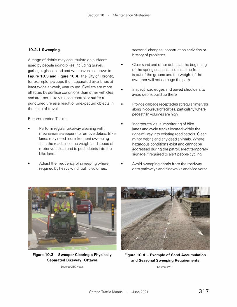
317
Section 10 · Maintenance Strategies
Ontario Traffic Manual · June 2021
10.2.1 Sweeping
A range of debris may accumulate on surfaces used by people riding bikes including gravel, garbage, glass, sand and wet leaves as shown in Figure 10.3 and Figure 10.4. The City of Toronto, for example, sweeps their separated bike lanes at least twice a week, year round. Cyclists are more affected by surface conditions than other vehicles and are more likely to lose control or suffer a punctured tire as a result of unexpected objects in their line of travel.
Recommended Tasks:
• Perform regular bikeway cleaning with mechanical sweepers to remove debris. Bike lanes may need more frequent sweeping than the road since the weight and speed of motor vehicles tend to push debris into the bike lane.
• Adjust the frequency of sweeping where required by heavy wind, traffic volumes,
seasonal changes, construction activities or history of problems
• Clear sand and other debris at the beginning of the spring season as soon as the frost is out of the ground and the weight of the sweeper will not damage the path
• Inspect road edges and paved shoulders to avoid debris build up there
• Provide garbage receptacles at regular intervals along in-boulevard facilities, particularly where pedestrian volumes are high
• Incorporate visual monitoring of bike lanes and cycle tracks located within the right-of-way into existing road patrols. Clear minor debris and any dead animals. Where hazardous conditions exist and cannot be addressed during the patrol, erect temporary signage if required to alert people cycling
• Avoid sweeping debris from the roadway onto pathways and sidewalks and vice versa
Figure 10.3 – Sweeper Clearing a Physically Separated Bikeway, Ottawa
Source: CBC News
Figure 10.4 – Example of Sand Accumulation and Seasonal Sweeping Requirements
Source: WSP

318
Book 18 · Cycling Facilities
Ontario Traffic Manual · June 2021
10.2.2 Pavement Defects
Asphalt pavement is typically used as a surface material for cycling facilities since it is smoother and less expensive than concrete, and pavement markings generally adhere better and are more visible. Asphalt also helps communicate a cycling facility to users since concrete is typically used for sidewalks. However, asphalt usually requires repair or replacement sooner than concrete which needs to be considered as part of the life cycle.
Potential causes of defects include tree roots, freeze-thaw processes and deterioration of the surface due to age or excessive wear, as well as differential settlement of the subsoil. In all cases, the cause of the defect should be identified and addressed so that the chance of recurrence can be minimized. Figure 10.5 and Figure 10.6 show poorly maintained and well-maintained bike lanes.
Pavement defects can include:
• Surface discontinuities
• Cracking
• Potholes
• Pavement drop-offs at shoulders
• Differential settlement
10.2.2.1 Surface Discontinuities
Surface discontinuities such as bumps and depressions can pose a hazard to people cycling. They usually require the offending materials to be removed and repaved. The physical extent of such work should be carefully assessed to avoid the development of new defects at the seam between the repaired area and the existing pavement. Where possible, such measures should be coordinated with municipal resurfacing schedules. That way, the entire pavement area can be refreshed either at the same time as the remedial works, or shortly after temporary works, and before new defects can form.
Figure 10.5 – Poorly Maintained Bicycle Lane
Source: The Baltimore Sun
Figure 10.6 – Well-Maintained Cycling Facility, Hamilton
Source: WSP

319
Section 10 · Maintenance Strategies
Ontario Traffic Manual · June 2021
10.2.2.2 Cracking
There are three principal types of cracking:
• Longitudinal cracks, as shown in Figure 10.7, run parallel to the centreline of the pavement caused by a poorly constructed joint, shrinkage of the asphalt layer, reflection cracking of an underlying layer or segregation due to improper paver operation
• Transverse cracks, as shown in Figure 10.8, run across a pavement, perpendicular to the direction of travel, often caused by thermal expansion or a reflection crack of an underlying layer
• Alligator cracks, as shown in Figure 10.9, form a pattern that looks like reptile scales caused by problems beneath the asphalt in the underlying layers
On paved shoulders, cracking typically occurs perpendicular to the path of bicycle travel. Longitudinal cracking often arises along the line between the outside edge of the motor vehicle travel path and the inside edge of the paved shoulder. Cracks can also form around storm sewer grates and maintenance hole covers.
Crack repair brings several benefits:
• It eliminates or minimizes the intrusion of water into the pavement structure, reducing the occurrence of freeze-thaw processes It helps prevent the loss of aggregate from the edges of the cracks
• It reduces the rate at which the pavement deteriorates, preventing premature failure of the pavement structure
Figure 10.7 – Longitudinal Cracking
Source: WSP
Figure 10.8 – Transverse Cracking
Source: WSP
Figure 10.9 – Alligator Cracking
Source: WSP

320
Book 18 · Cycling Facilities
Ontario Traffic Manual · June 2021
new defects where the freshly-laid surface meets the surrounding pavement
• During resurfacing projects, repave the shoulder of roadways designated as bike routes at the same time as the remainder of the travel lanes to ensure a seamless transition between the roadway and the paved shoulder
The following constraints should be considered for all resurfacing activities:
• Chip sealed surfaces provide a rougher riding surface than asphalt and are disliked by people cycling. However, after some wear by motor vehicles, the surface can become suitably hard and relatively smooth for cycling. This is especially true when a finer granular material is used in the top coat application. Repair and maintenance activities should be carried out regularly in order to retain a smooth profile
• Treatment selection decisions should factor in the type and extent of the distortion as well as any scheduled resurfacing, rehabilitation or upgrade programs
• Winter temperatures and their impact on construction materials and processes may limit the range of treatment options available in the short term
• Mitigating measures should be applied quickly to reduce the safety risks to people cycling due to surface distortions
• Where temporary measures are applied, permanent and durable solutions should be implemented as soon as practicable
Crack sealing should be appropriate for the type, depth and width of crack. Caution should be used when applying this method on large cracks since the sealant may soften during summer months and a bike tire could sink into the crack. Crack sealing should be used to prolong the pavement life under the following conditions:
• Crack widths less than 3 mm
• Alligator cracking
• Moderately to severely cupped transverse cracks
• Closely spaced multiple or transverse cracks less than 10 metres apart, unless a decision has been made to rout and seal the pavement and there are only a few of these cracks
• Longitudinal cracks within 150 mm of the pavement edge. In this case, the cracks can be sealed without routing
Recommended Tasks:
• Seal cracks in accordance with the timelines outlined in the local road authority quality standard, or at the earliest opportunity, unless limitations apply
• For other situations, evaluate the suitability of crack filling as an alternative
• Where crack filling is not appropriate or the surface condition is particularly poor, resurfacing should be considered. However, it should cover a sufficiently large area to avoid negating the benefits by introducing
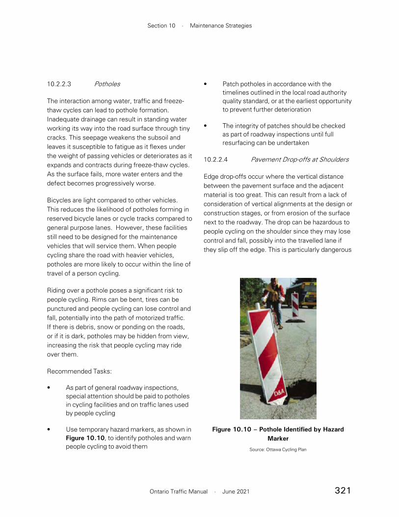
321
Section 10 · Maintenance Strategies
Ontario Traffic Manual · June 2021
• Patch potholes in accordance with the timelines outlined in the local road authority quality standard, or at the earliest opportunity to prevent further deterioration
• The integrity of patches should be checked as part of roadway inspections until full resurfacing can be undertaken
10.2.2.4 Pavement Drop-offs at Shoulders
Edge drop-offs occur where the vertical distance between the pavement surface and the adjacent material is too great. This can result from a lack of consideration of vertical alignments at the design or construction stages, or from erosion of the surface next to the roadway. The drop can be hazardous to people cycling on the shoulder since they may lose control and fall, possibly into the travelled lane if they slip off the edge. This is particularly dangerous
10.2.2.3 Potholes
The interaction among water, traffic and freeze-thaw cycles can lead to pothole formation. Inadequate drainage can result in standing water working its way into the road surface through tiny cracks. This seepage weakens the subsoil and leaves it susceptible to fatigue as it flexes under the weight of passing vehicles or deteriorates as it expands and contracts during freeze-thaw cycles. As the surface fails, more water enters and the defect becomes progressively worse.
Bicycles are light compared to other vehicles. This reduces the likelihood of potholes forming in reserved bicycle lanes or cycle tracks compared to general purpose lanes. However, these facilities still need to be designed for the maintenance vehicles that will service them. When people cycling share the road with heavier vehicles, potholes are more likely to occur within the line of travel of a person cycling.
Riding over a pothole poses a significant risk to people cycling. Rims can be bent, tires can be punctured and people cycling can lose control and fall, potentially into the path of motorized traffic. If there is debris, snow or ponding on the roads, or if it is dark, potholes may be hidden from view, increasing the risk that people cycling may ride over them.
Recommended Tasks:
• As part of general roadway inspections, special attention should be paid to potholes in cycling facilities and on traffic lanes used by people cycling
• Use temporary hazard markers, as shown in Figure 10.10, to identify potholes and warn people cycling to avoid them
Figure 10.10 – Pothole Identified by Hazard Marker
Source: Ottawa Cycling Plan

322
Book 18 · Cycling Facilities
Ontario Traffic Manual · June 2021
Recommended Tasks:
• Consider design solutions based on soil conditions
• Inspect whether any differences in grade between materials is greater than 6 mm, then raise or lower the surface level accordingly
10.2.3 Vegetation Management
Trees, shrubs and other vegetation provide shade and aesthetics to cycling facilities as shown in Figure 10.12. However, they can also present maintenance challenges. Roots may cause surfaces to crack, fallen leaves may block drainage grates and foliage may reduce visibility. Protruding branches, thorns or nettles can catch passing cyclists and reduce the effective width of the facility. The prevalence of vegetation along multi-
Figure 10.11 – Cycle Track Constructed with Concrete Base and Asphalt Surface, Newmarket
Source: WSP
if the soil erosion has migrated beneath the paved shoulder causing parts of it to fail.
The edge drop will make it difficult for people cycling to re-enter the bicycle lane since the side of the tire will rub along the vertical edge of the pavement, potentially causing the person cycling to fall. The cyclist could maintain their balance by providing excessive steering input to overcome the rubbing or friction. However, when the friction diminishes, the person cycling may be propelled across the bicycle lane and into the motor vehicle lane..
Recommended Tasks:
• Review all paved shoulders for edge drop-offs as part of regular roadway inspections
• When roads are constructed or resurfaced, ensure that the gravel adjacent to the paved shoulder is well compacted and is flush with the surface of the asphalt
10.2.2.5 Differential Settlement
Differential settlement between a concrete sidewalk and asphalt bikeway may occur depending on the soil conditions and pavement substructure. Under ideal soil conditions, there may be limited differential settling, but other conditions may require a more robust design solution. Where this is necessary, a common concrete base across the full width of both the sidewalk and cycling facility can minimize differential settlement as well as weed growth in the longitudinal joint. The sidewalk portion would be full depth while the bikeway portion would have a layer of asphalt on top of a concrete base, as was done in the Figure 10.11 example.1
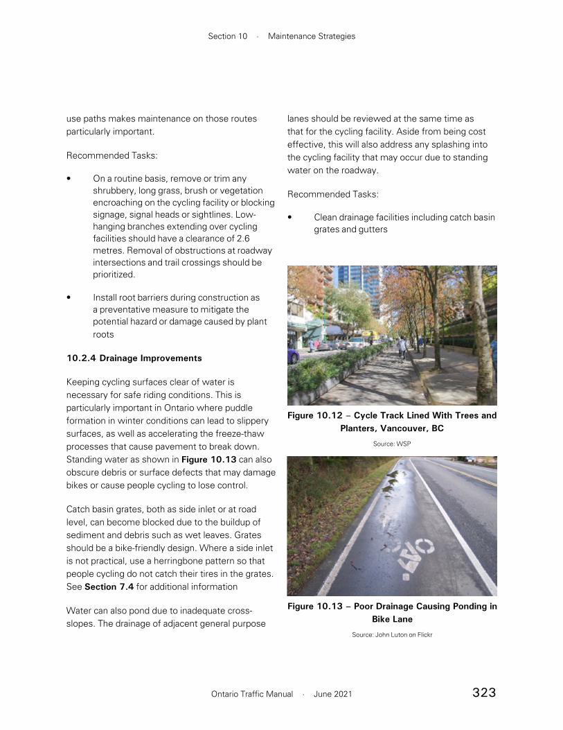
323
Section 10 · Maintenance Strategies
Ontario Traffic Manual · June 2021
lanes should be reviewed at the same time as that for the cycling facility. Aside from being cost effective, this will also address any splashing into the cycling facility that may occur due to standing water on the roadway.
Recommended Tasks:
• Clean drainage facilities including catch basin grates and gutters
use paths makes maintenance on those routes particularly important.
Recommended Tasks:
• On a routine basis, remove or trim any shrubbery, long grass, brush or vegetation encroaching on the cycling facility or blocking signage, signal heads or sightlines. Low-hanging branches extending over cycling facilities should have a clearance of 2.6 metres. Removal of obstructions at roadway intersections and trail crossings should be prioritized.
• Install root barriers during construction as a preventative measure to mitigate the potential hazard or damage caused by plant roots
10.2.4 Drainage Improvements
Keeping cycling surfaces clear of water is necessary for safe riding conditions. This is particularly important in Ontario where puddle formation in winter conditions can lead to slippery surfaces, as well as accelerating the freeze-thaw processes that cause pavement to break down. Standing water as shown in Figure 10.13 can also obscure debris or surface defects that may damage bikes or cause people cycling to lose control.
Catch basin grates, both as side inlet or at road level, can become blocked due to the buildup of sediment and debris such as wet leaves. Grates should be a bike-friendly design. Where a side inlet is not practical, use a herringbone pattern so that people cycling do not catch their tires in the grates. See Section 7.4 for additional information
Water can also pond due to inadequate cross-slopes. The drainage of adjacent general purpose
Figure 10.12 – Cycle Track Lined With Trees and Planters, Vancouver, BC
Source: WSP
Figure 10.13 – Poor Drainage Causing Ponding in Bike Lane
Source: John Luton on Flickr

324
Book 18 · Cycling Facilities
Ontario Traffic Manual · June 2021
• Adjust the maintenance frequency based on need, the season and the amount of vegetation near the cycling facility
10.2.5 Maintenance of Signage
As is the case with all road users, people cycling rely on signage for guidance and direction. Signage allows them to find their way through the cycling network, and a missing or ineffective sign, particularly on a multi-use path, can cause a cyclist to lose their way. Regulatory signage should receive priority for maintenance and repair because they indicate traffic laws. This is of particular importance in the winter when pavement markings may be obscured by snow. Signage can become discoloured and lose reflectivity, and is sometimes subject to theft, damage and vandalism.
Recommended Tasks:
• Include signage in regular roadway inspections to ensure they are kept in good condition. Maintain an inventory of signs for all cycling facilities to check that none are missing
• Replace signage that is discoloured, damaged or has lost reflectivity
10.2.6 Maintenance of Pavement Markings
Since many bike facilities are delineated by pavement markings, keeping them visible to all road users is vital to the safety of people cycling. Pavement markings can be obscured by snow and become worn due to environmental factors, traffic and snow removal operations, as shown in Figure 10.14.
Installation on concrete, as seen in Figure 10.15, requires the additional step of applying a primer or
sealant. Applying coloured pavement to concrete in poor condition will result in a treatment with a much shorter lifespan . The presence of roadway grease, particulate, dust, dirt and other debris on either an asphalt or concrete roadway can result in a poor quality installation. Therefore, it is best to apply to new pavement. However, new concrete needs to cure for a period of time before surface treatment can be applied. Another alternative is to tint the colour of the concrete at the time of installation.
Figure 10.14 – Worn Bicycle Pavement Markings
Source: WSP
Figure 10.15 – Example of Markings on Concrete (Bicycle Symbol Not Visible)
Source: WSP

325
Section 10 · Maintenance Strategies
Ontario Traffic Manual · June 2021
where a thin layer of the coloured pavement is placed on top of conventional pavement, or when the coloured material is used for the entire thickness.
Green pavement marking options include:
• Paint: considered a non-durable pavement marking, and is easily worn off, but is the most common method to mark road surfaces since it is the least expensive
• Durable Liquid Pavement Markings (DLPM) include epoxy and Methyl Methacrylate (MMA). These coatings are applied as a paint or spray
• Thermoplastic: a type of plastic that becomes fluid when heated and hard when cooled. It can be applied in preformed shapes such as lines and symbols, and can also be applied in a liquefied state similar to MMA. Preformed thermoplastic must be applied by using a heating torch
• Coloured pavement: an asphalt or concrete pavement can be tinted with a coloured pigment. It can be installed as a thin layer over conventional asphalt to reduce cost
Table 10.6 provides a summary of different pavement marking materials and their characteristics.
Recommended Tasks:
• For newly paved surfaces, apply pavement markings as soon as practical
• Include pavement markings in regular roadway inspections to ensure they are kept in good condition
• Regularly refresh pavement markings or replace them with permanent materials to ensure visibility and clarity for all road users at any time of year
• Pavement markings can be recessed to increase lifespan on roads with heavy plowing. This is done by milling the area where pavement markings are applied to a depth of 3 millimetres prior to application
Green surface treatment, as shown in Figure 10.16, can be used to mark conflict areas, bike boxes, intersection crossings or other areas where an enhanced visual cue is useful. Most products on the market for this purpose include particulates that are designed to increase traction compared to conventional paint. Coloured pavement for cycling facility applications can take the form of an overlay,
Figure 10.16 – Green Surface Treatment, Hamilton
Source: WSP
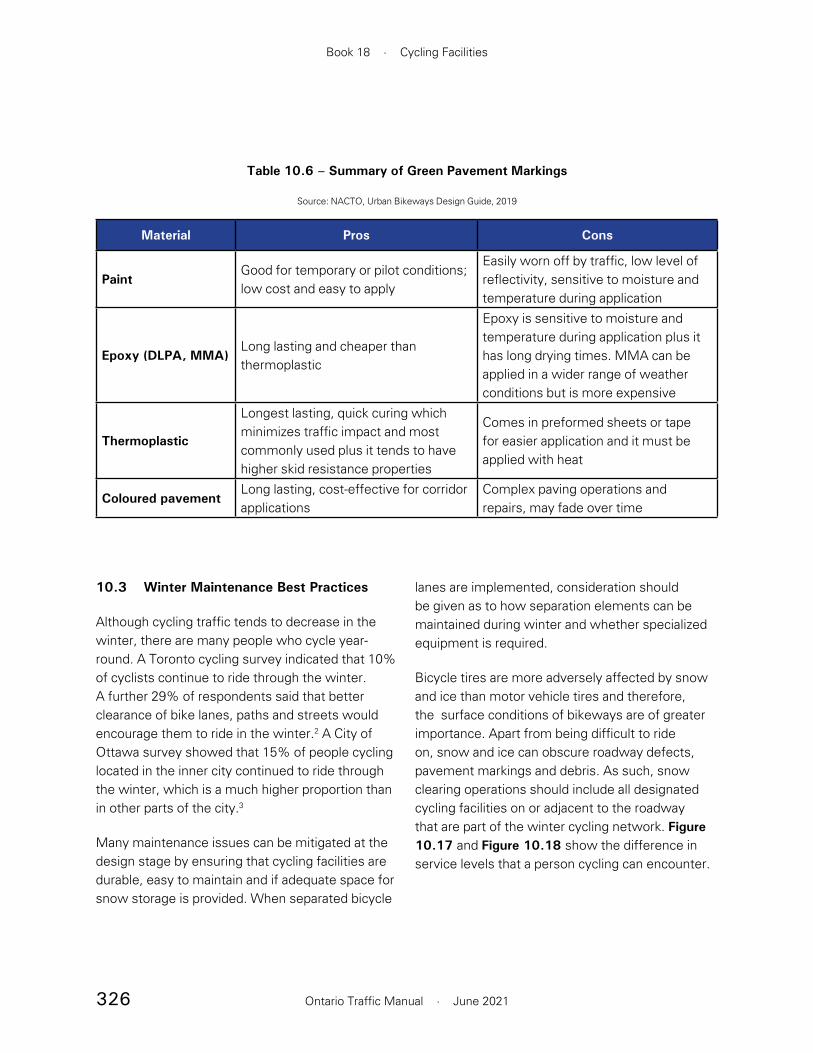
326
Book 18 · Cycling Facilities
Ontario Traffic Manual · June 2021
lanes are implemented, consideration should be given as to how separation elements can be maintained during winter and whether specialized equipment is required.
Bicycle tires are more adversely affected by snow and ice than motor vehicle tires and therefore, the surface conditions of bikeways are of greater importance. Apart from being difficult to ride on, snow and ice can obscure roadway defects, pavement markings and debris. As such, snow clearing operations should include all designated cycling facilities on or adjacent to the roadway that are part of the winter cycling network. Figure 10.17 and Figure 10.18 show the difference in service levels that a person cycling can encounter.
10.3 Winter Maintenance Best Practices
Although cycling traffic tends to decrease in the winter, there are many people who cycle year-round. A Toronto cycling survey indicated that 10% of cyclists continue to ride through the winter. A further 29% of respondents said that better clearance of bike lanes, paths and streets would encourage them to ride in the winter.2 A City of Ottawa survey showed that 15% of people cycling located in the inner city continued to ride through the winter, which is a much higher proportion than in other parts of the city.3
Many maintenance issues can be mitigated at the design stage by ensuring that cycling facilities are durable, easy to maintain and if adequate space for snow storage is provided. When separated bicycle
Material Pros Cons
PaintGood for temporary or pilot conditions; low cost and easy to apply
Easily worn off by traffic, low level of reflectivity, sensitive to moisture and temperature during application
Epoxy (DLPA, MMA)Long lasting and cheaper than thermoplastic
Epoxy is sensitive to moisture and temperature during application plus it has long drying times. MMA can be applied in a wider range of weather conditions but is more expensive
Thermoplastic
Longest lasting, quick curing which minimizes traffic impact and most commonly used plus it tends to have higher skid resistance properties
Comes in preformed sheets or tape for easier application and it must be applied with heat
Coloured pavementLong lasting, cost-effective for corridor applications
Complex paving operations and repairs, may fade over time
Table 10.6 – Summary of Green Pavement Markings
Source: NACTO, Urban Bikeways Design Guide, 2019
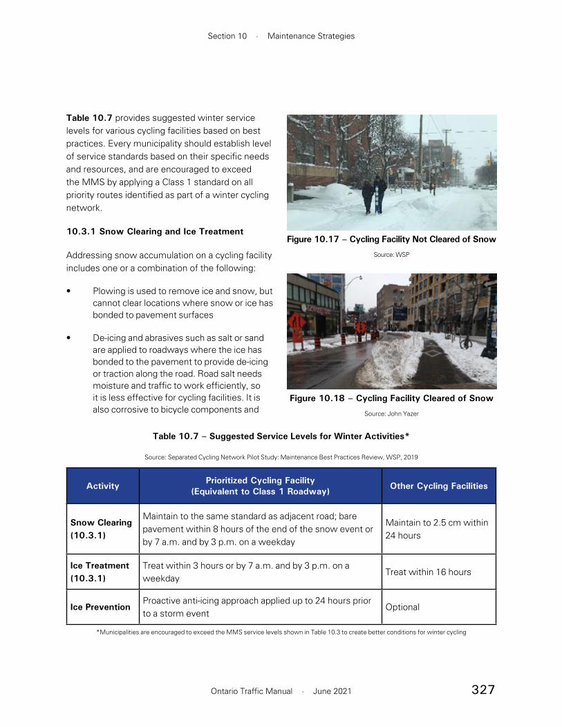
327
Section 10 · Maintenance Strategies
Ontario Traffic Manual · June 2021
Table 10.7 provides suggested winter service levels for various cycling facilities based on best practices. Every municipality should establish level of service standards based on their specific needs and resources, and are encouraged to exceed the MMS by applying a Class 1 standard on all priority routes identified as part of a winter cycling network.
10.3.1 Snow Clearing and Ice Treatment
Addressing snow accumulation on a cycling facility includes one or a combination of the following:
• Plowing is used to remove ice and snow, but cannot clear locations where snow or ice has bonded to pavement surfaces
• De-icing and abrasives such as salt or sand are applied to roadways where the ice has bonded to the pavement to provide de-icing or traction along the road. Road salt needs moisture and traffic to work efficiently, so it is less effective for cycling facilities. It is also corrosive to bicycle components and
Figure 10.17 – Cycling Facility Not Cleared of Snow
Source: WSP
Figure 10.18 – Cycling Facility Cleared of Snow
Source: John Yazer
Activity Prioritized Cycling Facility (Equivalent to Class 1 Roadway) Other Cycling Facilities
Snow Clearing (10.3.1)
Maintain to the same standard as adjacent road; bare pavement within 8 hours of the end of the snow event or by 7 a.m. and by 3 p.m. on a weekday
Maintain to 2.5 cm within 24 hours
Ice Treatment (10.3.1)
Treat within 3 hours or by 7 a.m. and by 3 p.m. on a weekday
Treat within 16 hours
Ice PreventionProactive anti-icing approach applied up to 24 hours prior to a storm event
Optional
Table 10.7 – Suggested Service Levels for Winter Activities*
Source: Separated Cycling Network Pilot Study: Maintenance Best Practices Review, WSP, 2019
*Municipalities are encouraged to exceed the MMS service levels shown in Table 10.3 to create better conditions for winter cycling
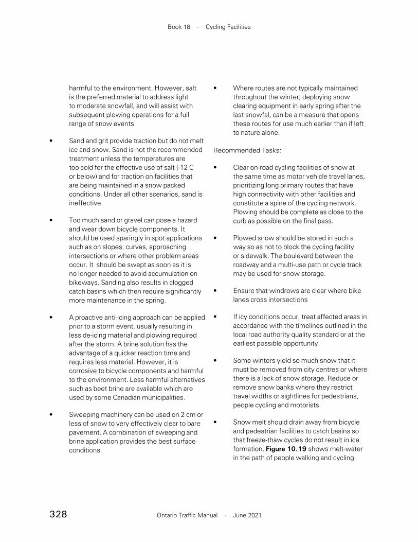
328
Book 18 · Cycling Facilities
Ontario Traffic Manual · June 2021
harmful to the environment. However, salt is the preferred material to address light to moderate snowfall, and will assist with subsequent plowing operations for a full range of snow events.
• Sand and grit provide traction but do not melt ice and snow. Sand is not the recommended treatment unless the temperatures are too cold for the effective use of salt (-12 C or below) and for traction on facilities that are being maintained in a snow packed conditions. Under all other scenarios, sand is ineffective.
• Too much sand or gravel can pose a hazard and wear down bicycle components. It should be used sparingly in spot applications such as on slopes, curves, approaching intersections or where other problem areas occur. It should be swept as soon as it is no longer needed to avoid accumulation on bikeways. Sanding also results in clogged catch basins which then require significantly more maintenance in the spring.
• A proactive anti-icing approach can be applied prior to a storm event, usually resulting in less de-icing material and plowing required after the storm. A brine solution has the advantage of a quicker reaction time and requires less material. However, it is corrosive to bicycle components and harmful to the environment. Less harmful alternatives such as beet brine are available which are used by some Canadian municipalities.
• Sweeping machinery can be used on 2 cm or less of snow to very effectively clear to bare pavement. A combination of sweeping and brine application provides the best surface conditions
• Where routes are not typically maintained throughout the winter, deploying snow clearing equipment in early spring after the last snowfal, can be a measure that opens these routes for use much earlier than if left to nature alone.
Recommended Tasks:
• Clear on-road cycling facilities of snow at the same time as motor vehicle travel lanes, prioritizing long primary routes that have high connectivity with other facilities and constitute a spine of the cycling network. Plowing should be complete as close to the curb as possible on the final pass.
• Plowed snow should be stored in such a way so as not to block the cycling facility or sidewalk. The boulevard between the roadway and a multi-use path or cycle track may be used for snow storage.
• Ensure that windrows are clear where bike lanes cross intersections
• If icy conditions occur, treat affected areas in accordance with the timelines outlined in the local road authority quality standard or at the earliest possible opportunity
• Some winters yield so much snow that it must be removed from city centres or where there is a lack of snow storage. Reduce or remove snow banks where they restrict travel widths or sightlines for pedestrians, people cycling and motorists
• Snow melt should drain away from bicycle and pedestrian facilities to catch basins so that freeze-thaw cycles do not result in ice formation. Figure 10.19 shows melt-water in the path of people walking and cycling.

329
Section 10 · Maintenance Strategies
Ontario Traffic Manual · June 2021
• Clear excess snow that has accumulated adjacent to outdoor bike racks or lockers
10.3.2 Winter Maintenance Equipment
The maintenance of active transportation facilities often requires specialized equipment or attachments which differ from traditional roadway maintenance machinery. Maintenance equipment options should be considered at the design stage by reviewing space limitations with maintenance staff in the municipality to ensure that everyone is aware of equipment requirements. Separated cycling facilities need to have a minimum amount of clear space for truck-mounted plows to be able to clear them.
Some jurisdictions have a fleet of smaller, specialized snow clearing vehicles such as ATVs with attachments.4 They can serve as snow clearing equipment and sweepers. Montreal has tried ice breaking equipment for bikeways that grinds the ice that is frozen to the surface. It is a new approach met with some success for freeze-thaw conditions for in-boulevard facilities. The City of Waterloo has several pieces of equipment that they use year round for summer and winter maintenance on sidewalks. These machines are only 1.2 m wide, and narrow blades, brooms and snow blower attachments are used to plow, salt and sweep sidewalks and in-boulevard cycling facilities. Figure 10.22, Figure 10.23, and Figure 10.24 show some examples of equipment used to maintain cycling facilities in the winter.
10.3.3 Priority Winter Cycling Network
Consistent and reliable maintenance of cycling facilities throughout the winter is important for promoting year-round use. Studies of North American winter cycling cities such as Calgary and Montreal have shown that up to 25% of people
Figure 10.19 – Multi-use Path on Bridge, Hamilton
Source: City of Hamilton
Figure 10.20 – Cycle Track Plowed with Salt Applied to Surface, Montreal
Source: Bartek Komorowski
Figure 10.21 – Cycle Track Cleared by Sweeper with Brine Applied to Surface, Montreal
Source: Bartek Komorowski

330
Book 18 · Cycling Facilities
Ontario Traffic Manual · June 2021
cycling during non-winter months can be expected to continue to ride bicycles through the winter if facilities are well maintained and promoted.5 Figure 10.25 shows a protected bike lane cleared of snow.
A strategic bikeway snow removal and de-icing program that prioritizes routes is key to the accommodation of people cycling in the winter. When identifying a winter cycling network, municipalities should prioritize the highest demand ‘spines’, the long primary routes that have high connectivity with other cycling facilities, other modes and major destinations. These provide the highest benefit from year-round cleaning and snow removal. Building upon the MMS, the following are some suggested cycling network maintenance best practices:
• Develop maintenance service standards with the desired pavement condition targets after plowing and de-icing
• Similar to the approach for roadways, bikeways on the winter cycling network should be monitored throughout the day and winter maintenance operations applied as appropriate, particularly for peak commuting periods. Snow cleared by 7:00 a.m. and by 3:00 p.m., Monday to Friday facilitates commuters going to and from work and school
• Coordinate the clearing of physically separated bikeways with the adjacent road to avoid creating windrows at intersections
• Clear adjacent sidewalks and cycling facilities in a coordinated way so that pedestrians do not choose to use the cleared cycling facility and people cycling do not choose to use the sidewalk
Figure 10.22 – Sidewalk Plow Clearing Cycle Track, Toronto
Photo: WSP, 2019
Figure 10.23 – Rotating Ice Breaker, Montreal
Photo: Bartek Komorowski
Figure 10.24 – Winter Maintenance Vehicle with Brush Attachment, Hamilton
Photo: Hamilton Spectator
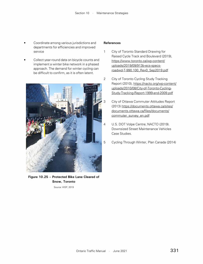
331
Section 10 · Maintenance Strategies
Ontario Traffic Manual · June 2021
• Coordinate among various jurisdictions and departments for efficiencies and improved service
• Collect year-round data on bicycle counts and implement a winter bike network in a phased approach. The demand for winter cycling can be difficult to confirm, as it is often latent.
Figure 10.25 – Protected Bike Lane Cleared of Snow, Toronto
Source: WSP, 2019
References
1 City of Toronto Standard Drawing for Raised Cycle Track and Boulevard (2019), https://www.toronto.ca/wp-content/uploads/2019/09/913b-ecs-specs-roadwd-T-990.100_Rev0_Sep2019.pdf
2 City of Toronto Cycling Study Tracking Report (2010), https://nacto.org/wp-content/uploads/2010/08/City-of-Toronto-Cycling-Study-Tracking-Report-1999-and-2009.pdf
3 City of Ottawa Commuter Attitudes Report (2013) https://documents.ottawa.ca/sites/documents.ottawa.ca/files/documents/commuter_survey_en.pdf
4 U.S. DOT Volpe Centre; NACTO (2019). Downsized Street Maintenance Vehicles Case Studies.
5 Cycling Through Winter, Plan Canada (2014)
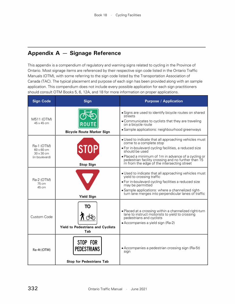
332
Book 18 · Cycling Facilities
Ontario Traffic Manual · June 2021
Appendix A — Signage Reference
This appendix is a compendium of regulatory and warning signs related to cycling in the Province of Ontario. Most signage items are referenced by their respective sign code listed in the Ontario Traffic Manuals (OTM), with some referring to the sign code listed by the Transportation Association of Canada (TAC). The typical placement and purpose of each sign has been provided along with an sample application. This compendium does not include every possible application for each sign practitioners should consult OTM Books 5, 6, 12A, and 18 for more information on proper applications.
Sign Code Sign Purpose / Application
M511 (OTM)45 x 45 cm
Bicycle Route Marker Sign
• Signs are used to identify bicycle routes on shared streets
• Communicates to cyclists that they are traveling on a bicycle route
• Sample applications: neighbourhood greenways
Ra-1 (OTM)60 x 60 cm30 x 30 cm
(in boulevard)
Stop Sign
• Used to indicate that all approaching vehicles must come to a complete stop
• For in-boulevard cycling facilities, a reduced size should be used
• Placed a minimum of 1m in advance of a cycling or pedestrian facility crossing and no further than 15 m from the edge of the intersecting street
Ra-2 (OTM)75 cm45 cm
Yield Sign
• Used to indicate that all approaching vehicles must yield to crossing traffic
• For in-boulevard cycling facilities a reduced size may be permitted
• Sample applications: where a channelized right-turn lane merges into perpendicular lanes of traffic
Custom Code
Yield to Pedestrians and Cyclists Tab
• Placed at a crossing within a channelized right-turn lane to instruct motorists to yield to crossing pedestrians and cyclists
• Accompanies a yield sign (Ra-2)
Ra-4t (OTM)
Stop for Pedestrians Tab
• Accompanies a pedestrian crossing sign (Ra-5t) sign

333
Section A · Signage Reference
Ontario Traffic Manual · June 2021
Sign Code Sign Purpose / Application
Ra-5L (OTM)Ra-5R (OTM)
60 x 75 cm
Pedestrian Crossing Left SignPedestrian Crossing Right Sign
• Used to mark a designated pedestrian crossover (PXO)
• Indicates that crossing pedestrians maintain a right of way and that motorists must yield accordingly
• A sign bearing a left facing (Ra-5L) and right facing (Ra-5R) pedestrian icon are placed on respective sides of the street, which may accompany a “Pedestrian Crossing” tab (Ra-4t) when additional road instructions are specified
• Sample applications: at a controlled pedestrian crossing such as a PXO
Ra-14L (OTM)Ra-14R (OTM)
13 x 20 cm
Signalized Intersection Crossing Left / Right Sign
• Mounted above a pushbutton that actuates both pedestrian and bicycle signals at a signalized intersection or mid-block crossing
• Communicates to cyclists and pedestrians that they are to use the same pushbutton to actuate a crossing signal
• Sample applications: intersections for in-boulevard facilities, mid-block multi-use path crossings, etc.
Rb-11 (OTM)Rb-12 (OTM)
60 x 60 cm
No Right Turn SignNo Left Turn Sign
• Attached to a signal pole or sign post at an intersection where right or left turn movements are not permitted
• Communicates to road users that a right turn or left turn movement is not permitted at the intersection
• Sample applications: parallel to a one-way street which restricts right or left turns from a nearby cross-street
Rb-17t (OTM)20 x 60 cm
Bicycles Expected Tab
• Attached as a tab to regulatory signs for motor vehicles that do not apply to cyclists
• Instructs cyclists that they are exempt from the traffic rule of the sign this tab is affixed to
• Sample applications: attached to right turn on red restriction signs that only apply to motorists
Rb-19 (OTM)60 x 60 cm
Do Not Enter Sign
• Placed at the exit point of a roadway to which traffic or the facing direction is restricted from entering
• May accompany a sign that reads “Do not Enter” or a “Bicycles Expected” (Rb-19t), when additional road instructions are specified
• Sample applications: at the exit from a one-way street to which traffic facing the sign is restricted from entering
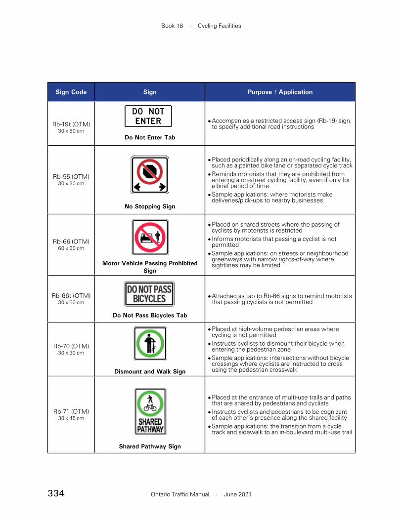
334
Book 18 · Cycling Facilities
Ontario Traffic Manual · June 2021
Sign Code Sign Purpose / Application
Rb-19t (OTM)30 x 60 cm
Do Not Enter Tab
• Accompanies a restricted access sign (Rb-19) sign, to specify additional road instructions
Rb-55 (OTM)30 x 30 cm
No Stopping Sign
• Placed periodically along an on-road cycling facility, such as a painted bike lane or separated cycle track
• Reminds motorists that they are prohibited from entering a on-street cycling facility, even if only for a brief period of time
• Sample applications: where motorists make deliveries/pick-ups to nearby businesses
Rb-66 (OTM)60 x 60 cm
Motor Vehicle Passing Prohibited Sign
• Placed on shared streets where the passing of cyclists by motorists is restricted
• Informs motorists that passing a cyclist is not permitted
• Sample applications: on streets or neighbourhood greenways with narrow rights-of-way where sightlines may be limited
Rb-66t (OTM)30 x 60 cm
Do Not Pass Bicycles Tab
• Attached as tab to Rb-66 signs to remind motorists that passing cyclists is not permitted
Rb-70 (OTM)30 x 30 cm
Dismount and Walk Sign
• Placed at high-volume pedestrian areas where cycling is not permitted
• Instructs cyclists to dismount their bicycle when entering the pedestrian zone
• Sample applications: intersections without bicycle crossings where cyclists are instructed to cross using the pedestrian crosswalk
Rb-71 (OTM)30 x 45 cm
Shared Pathway Sign
• Placed at the entrance of multi-use trails and paths that are shared by pedestrians and cyclists
• Instructs cyclists and pedestrians to be cognizant of each other’s presence along the shared facility
• Sample applications: the transition from a cycle track and sidewalk to an in-boulevard multi-use trail

335
Section A · Signage Reference
Ontario Traffic Manual · June 2021
Sign Code Sign Purpose / Application
Rb-72ab (OTM)
30 x 45 cm
Pathway Organization Sign
• Placed at the end of cyclist-pedestrian mixing zones or shared spaces to direct cyclists and pedestrians to their separate dedicated facilities
• Directs cyclists and pedestrians toward their seperate, adjacent facilities
• Sample applications: the transition from an in-boulevard multi-use trail to cycle track and sidewalk
Ra-16 (OTM)30 x 45 cm
Yield to Pedestrians Sign
• Placed in advance of bicycle-pedestrian mixing zones, shared spaces, or pedestrian crossing areas that are yield controlled for cyclists
• Instructs cyclists to yield the right-of-way to pedestrians
• Sample applications: transit stops, pedestrian access areas, etc
Ra-17 (OTM)45 x 75 cm
Bicycles Yield to Vehicles Sign
• May be placed where there is an uncontrolled crossing of a roadway from a designated bicycle facility and significant conflicts have been identified or are anticipated due to high volumes of cyclists, high volumes of vehicles, high speeds and/or high levels of driver workload
• Instructs cyclists to yield right-of-way to motorists• Sample applications: points where a cycle track
crosses a highway on/off ramp
Ra-18 (OTM)60 x 75 cm
Turning Vehicles Yield to Bicycles Sign
• Placed in advance of an intersection, high-volume ramp, minor street or driveway with a cycling facility crossing its entrance
• The sign variant used should match the type of cycling facility or conflict zone treatment present in the conflict zone. The sign should illustrate two-way bicycle traffic if placed at a two way cycling facility.
• Communicates to motorists that they must yield the right-of-way to cyclists before crossing the cycling facility
• Sample applications: minor streets and intersections with cycle tracks or bicycle lanes

336
Book 18 · Cycling Facilities
Ontario Traffic Manual · June 2021
Sign Code Sign Purpose / Application
Rb-84 (OTM)Rb-84A (OTM)
60 x 60 cm
Reserved Bicycle Lane Sign (overhead & side-mouted)
• Periodically placed adjacent to designated or separated on-street cycling facilities
• Rb-84 signs (top figure) for overhead mounting applications only
• Identifies a reserved lane for bicycles in the road right-of-way
• Samples applications: cycle tracks, designated bicycle lanes.
Rb-84t (OTM)20 x 60 cm
Reserved Bicycle Lane Begins Tab
• Attached as a tab to Rb-84 signs at the beginning of a reserved lane for bicycles
• Informs cyclists and motorists of the beginning of a reserved lane for cycling in the road right-of-way
• Samples applications: cycle tracks, designated bicycle lanes.
Rb-85t (OTM)20 x 60 cm
Reserved Bicycle Lane Ends Tab
• Attached as a tab to Rb-84 sign at the end of a reserved lane for bicycles
• Informs cyclists and motorists that a reserved lane for bicycles is ending
• Sample applications: cycle tracks, designated bicycle lanes.
Rb-101 (OTM)30 x 45 cm
Cyclists Stop Here on Red Signal Sign
• Placed at a signalized intersection or crossing to identify the proper stopping location for cyclists during a red signal indication
• Identifies stopping/queuing location for cyclists during a red signal indication
• Sample applications: intersections where the preferred stopping location for cyclists is in advance of a pedestrian crosswalk

337
Section A · Signage Reference
Ontario Traffic Manual · June 2021
Sign Code Sign Purpose / Application
Rb-102 (OTM)13 x 20 cm
Bicycle Signal Loop Detector Stencil Sign
• Placed at an intersection were bicycle detection is required to actuate a green ball or bicycle signal
• Identifies the queuing location for cyclists to be detected for actuation of a green signal phase
• Sample applications: intersections where detection of bicycles is used to actuate a green signal indication
Rb-79L (OTM)Rb-79R (OTM)
60 x 90 cm
No Left Turn on Red SignNo Right Turn on Red Sign
• Placed at signalized intersections with a right or left turn restriction on red signal.
• Sample applications: — where there is evidence of a relatively large number of vehicle or vehicle-pedestrian/cyclist collisions, which cannot be reduced by other methods — where there are a significant number of crossings by children, elderly or disabled people — where there are conflicts with cycling facilities
Tc-41 (OTM)45 x 45 cm
Bicycle Lane Detour Ahead Sign
• Placed at the entrance of a temporary cycling detour route
• Sample applications: road reconstruction on a major street with a cycling facility that results in a temporary detour route for cyclists on a parallel street
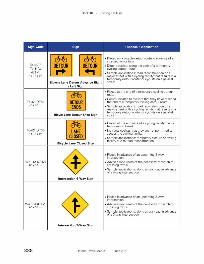
338
Book 18 · Cycling Facilities
Ontario Traffic Manual · June 2021
Sign Code Sign Purpose / Application
Tc-41ARTc-41AL (OTM)
45 x 45 cm
Bicycle Lane Detour Advance Right / Left Sign
• Placed on a bicycle detour route in advance of an intersection or turn
• Directs cyclists along the path of a temporary cycling detour route
• Sample applications: road reconstruction on a major street with a cycling facility that results in a temporary detour route for cyclists on a parallel street
Tc-42 (OTM)45 x 45 cm
Bicyle Lane Detour Ends Sign
• Placed at the end of a temporary cycling detour route
• Communicates to cyclists that they have reached the end of a temporary cycling detour route
• Sample applications: road reconstruction on a major street with a cycling facility that results in a temporary detour route for cyclists on a parallel street
Tc-43 (OTM)45 x 45 cm
Bicycle Lane Closed Sign
• Placed at the entrance of a cycling facility that is temporarily closed
• Instructs cyclists that they are not permitted to access the cycling facility
• Sample applications: temporary closure of cycling facility due to road reconstruction
Wa-11A (OTM)60 x 60 cm
Intersection 4-Way Sign
• Placed in advance of an upcoming 4-way intersection
• Advises road users of the necessity to watch for crossing traffic
• Sample applications: along a rural road in advance of a 4-way intersection
Wa-13A (OTM)60 x 60 cm
Intersection 3-Way Sign
• Placed in advance of an upcoming 3-way intersection
• Advises road users of the necessity to watch for crossing traffic
• Sample applications: along a rural road in advance of a 3-way intersection

339
Section A · Signage Reference
Ontario Traffic Manual · June 2021
Sign Code Sign Purpose / Application
Wa-23RWa-23L (OTM)
75 x 75 cm
Left Lane Ends SignRight Lane Ends Sign
• Placed in advance of a reduction in motor vehicle lanes
• Warns motorists of the reduction in motor vehicle lanes
• Sample applications: in advance of lateral lane alignment shifts due to a left or right lane drop
Wa-33LR30 x 60 cm15 x 30 cm
(in-boulevard)
Wa-33RWa-33L (OTM)
22.5 x 60 cm11.25 x 30 cm (in-boulevard)
Wa-33R Wa-33L Wa-33LR
Object Marker Signs
• Placed where an obstacle separates a bicycle lane from motor vehicle traffic
• Typically used to notify of pass on the right, pass on the left or pass left or right of an obstacle
• When placed within an in-boulevard cycling facility to advise cyclists of an upcoming hazard, a half-sized version may be used
• Sample applications: in advance of a concrete median which channelizes thru and right turn traffic, along a roadway which features a cycling facility
Wa-74 (OTM)45 x 45 cm
Speed Hump Sign
• Placed in advance of a vertical deflection of the road surface, such as a speed hump
• Warns road users of upcoming irregularities in the road surface so they may safely reduce their speed if necessary
• Sample applications: in advance of a speed hump placed along a neighbourhood street
Wb-1 (OTM)60 x 60 cm45 x 45 cm
(in-boulevard)
Stop Ahead Sign
• Placed in advance of an approaching stop sign (Ra-1)
• When placed within an in-boulevard cycling facility, a half-sized version may be used
• Sample applications: in advance of a stop-controlled intersection

340
Book 18 · Cycling Facilities
Ontario Traffic Manual · June 2021
Sign Code Sign Purpose / Application
Wb-1A (OTM)60 x 60 cm45 x 45 cm
(in-boulevard)
Yield Ahead Sign
• Placed in advance of an approaching yield sign (Ra-2)
• When placed within an in-boulevard cycling facility, a half-sized version may be used
• Sample applications: in advance of a merging point where the road user must yield to crossing traffic
Wc-4 (OTM)75 x 75 cm
Railway Crossing Ahead Sign
• Placed in advance of a railroad crossing• Used to alert cyclists of the upcoming hazard
imposed by the uneven surface of a railroad crossing
• Sample applications: along a paved shoulder on the approach of a railroad crossing
Wc-8RWc-8L (OTM)
75 x 75 cm
Truck Entrance Sign
• Placed at a driveway where high volumes of truck traffic cross a cycling route
• Warns road users, including cyclists, of an upcoming driveway where large trucks exit
• Sample applications: in advance of a driveway with high truck volumes that crosses a cycling facility
Wc-8L (OTM)
30 x 60 cm
Truck Entrance Tab
• Attached as a tab to Wc-8R or Wc-8L sign to warn road users of an upcoming driveway where large trucks enter and exit
• Sample applications: in advance of a fire station driveway that exists across a cycling facility
Wc-14 (OTM)60 x 60 cm
Bicycle Crossing Ahead Sign
• Placed in advance of a bicycle crossing• Warns road users of a bicycle crossing ahead• Sample applications: in advance of crossings for
designated bicycle lanes or cycle tracks

341
Section A · Signage Reference
Ontario Traffic Manual · June 2021
Sign Code Sign Purpose / Application
Wc-15 (OTM)60 x 60 cm
Pedestrian and Bicycle Crossing Ahead Sign
• Placed in advance of pedestrian and bicycle crossings
• Warns road users of pedestrian and bicycle crossings ahead
• Sample applications: in advance of in-boulevard multi-use trail crossings, mid-block multi-use path crossings, etc.
Wc-19 (OTM)60 x 60 cm
Share the Road Sign
• Placed on roads with high cycling volumes that do not have designated cycling facilities
• Reminds motorists and cyclists to share the road• Sample applications: shared streets,
neighbourhood greenways
Wc-19t (OTM)30 x 60 cm
Share the Road Tab
• Attached as a tab to Wc-19 to communicate that the road is shared by motorists and cyclists
Wc-24 (OTM)60 x 60 cm
Shared Use Lane / Single File Sign
• Placed on shared roads with narrow rights-of-way where side-by-side travel is not encouraged
• Instructs motorists and cyclists to travel single file along narrow portions of the road
• Sample applications: shared streets, neighbourhood greenways with narrow rights-of-way
Wc-24t (OTM)30 x 60 cm
Single File Tab
• Attached as tab to Wc-24 to communicate that cyclists and motorists are to travel single file along narrow portions of the road

342
Book 18 · Cycling Facilities
Ontario Traffic Manual · June 2021
Sign Code Sign Purpose / Application
Wc-32t (OTM)30 x 60 cm
Crossing Ahead Tab
• Attached as a tab to signage advising road users of an upcoming crossing
• Sample applications: in advance of bicycle and pedestrian crossings
Wc-37LWc-37R(OTM)
60 x 60 cm
Bicycle Path Crossing Side Street Sign
• Placed in advance of an intersection with a setback bicycle crossing on the minor street
• Warns turning motorists to watch for cyclists that could be crossing the setback bicycle crossing
• Sample applications: placed in advance of a street which features the crossing of a multi-use path
Wc-38 (OTM)45 x 45 cm
Slow Watch for Turning Vehicles Sign
• Placed at intersections, minor streets or high-volume driveways with high volumes of turning vehicles
• Warns cyclists to watch for turning vehicles and to travel slowly where sightlines are poor
• Sample applications: corridors with cycling facilities and minor streets with high-volumes of turning vehicles
Wb-10 (TAC)60 x 60 cm
Bicycle Lane Ahead Sign
• Placed in advance of a reserved lane for bicycles• Warns road users to anticipate the beginning of a
reserved lane for bicycles• Sample applications: in advance of cycle tracks or
designated bicycle lanes

343
Section A · Signage Reference
Ontario Traffic Manual · June 2021
Sign Code Sign Purpose / Application
Wa-41 (TAC)45 x 45 cm
Downgrade Warning Sign
• Placed in advance of a downgrade of 10% or is longer than 50 m
• Sample application: in advance of an extended downgrade
Wc-43 (TAC)60 x 60 cm
Contraflow Bicycle Lane Sign
• Placed on the approach to an intersection of a one-way street with bi-directional cycling or contraflow cycling facilities
• Warns motorists to expected cyclists traveling in both crossing directions at the intersection
• Sample applications: one-way streets with bi-directional or contraflow cycling facilities
Wc-44t (TAC)30 x 60 cm
Trail / Path Crossing Ahead Tab
• Attached as a tab to signage advising road users of an upcoming path or trail crossing (sign Wc-44t TAC)
• A variant tab which reads “Path Crossing” may be used for an in-boulevard multi-use path
• Sample applications: in advance of bicycle crossings, pedestrian and bicycle crossings
Wb-4 (OTM)60 x 60 cm
Two-Way Traffic Sign
• Warns drivers of two-way traffic operations. The variant without a marked centre line is applicable along a roadway with an advisory bike lane configuration.
• Sample application: Along roadways with advisory bike lanes
PATHCROSSING
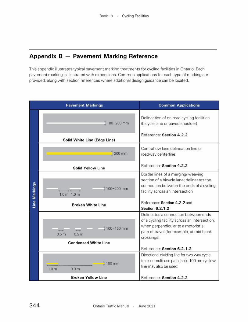
344
Book 18 · Cycling Facilities
Ontario Traffic Manual · June 2021
Appendix B — Pavement Marking Reference
This appendix illustrates typical pavement marking treatments for cycling facilities in Ontario. Each pavement marking is illustrated with dimensions. Common applications for each type of marking are provided, along with section references where additional design guidance can be located.
Pavement Markings Common Applications
Line
Mar
king
s
100–200 mm
Solid White Line (Edge Line)
Delineation of on-road cycling facilities (bicycle lane or paved shoulder)
Reference: Section 4.2.2
200 mm
Solid Yellow Line
Contraflow lane delineation line or roadway centerline
Reference: Section 4.2.2
100–200 mm1.0 m 1.0 m
Broken White Line
Border lines of a merging/ weaving section of a bicycle lane; delineates the connection between the ends of a cycling facility across an intersection
Reference: Section 4.2.2 and Section 6.2.1.2
100–150 mm0.5 m 0.5 m
Condensed White Line
Delineates a connection between ends of a cycling facility across an intersection, when perpendicular to a motorist’s path of travel (for example, at mid-block crossings).
Reference: Section 6.2.1.2
100 mm1.0 m 3.0 m
Broken Yellow Line
Directional dividing line for two-way cycle track or multi-use path (solid 100 mm yellow line may also be used)
Reference: Section 4.2.2
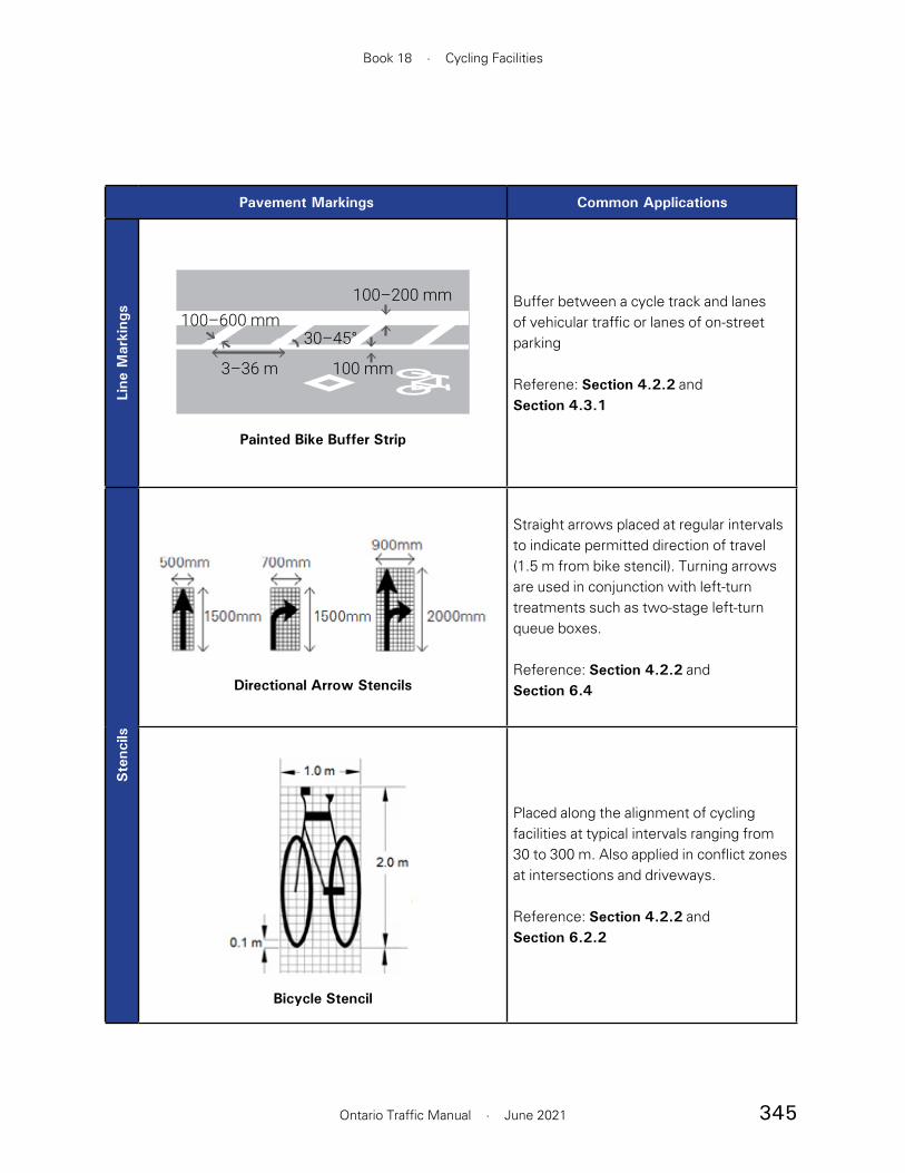
345
Book 18 · Cycling Facilities
Ontario Traffic Manual · June 2021
Pavement Markings Common Applications
Line
Mar
king
s
3–36 m
100–600 mm30–45°
100–200 mm
100 mm
Painted Bike Buffer Strip
Buffer between a cycle track and lanes of vehicular traffic or lanes of on-street parking
Referene: Section 4.2.2 and Section 4.3.1
Ste
ncils
Directional Arrow Stencils
Straight arrows placed at regular intervals to indicate permitted direction of travel (1.5 m from bike stencil). Turning arrows are used in conjunction with left-turn treatments such as two-stage left-turn queue boxes.
Reference: Section 4.2.2 and Section 6.4
Bicycle Stencil
Placed along the alignment of cycling facilities at typical intervals ranging from 30 to 300 m. Also applied in conflict zones at intersections and driveways.
Reference: Section 4.2.2 and Section 6.2.2

346
Book 18 · Cycling Facilities
Ontario Traffic Manual · June 2021
Pavement Markings Common Applications
Ste
ncils
Diamond Stencil
Reserved lane symbol, placed along the alignment of on-road cycling facilities, separated by 1.5 m from bicycle stencil.
Reference: Section 4.2.2
1.0 m
2.0
m
Pedestrian Symbol
Applied along a facility designated for pedestrian travel, such as a multi-use pathway, or at transitions between shared and separate pedestrian/cycling facilities. Reference: Section 4.2.2, Section 6.6.2.2
0.3 - 0.5 m
Railway Crossing Symbol
Placed in advance of a railroad crossing to inform cyclists and motorists of an approaching at-grade crossing.
Reference: Section 6.13

347
Book 18 · Cycling Facilities
Ontario Traffic Manual · June 2021
Pavement Markings Common Applications
Ste
ncils
Sharrow / Shared Lane Marking
Placed along shared roadways to indicate that the travel area is shared by motorists and cyclists; provides wayfinding and lateral positioning guidance to cyclists.
Reference: Section 4.2.2, Section 4.5.3.
1.0 m
2.0 m
1.0 m
0.1 m
1.0 m
1.4 m
0.6 m0.1 m0.1 m0.1 m
Directional Sharrow
May be applied along neighbourhood bikeways or other bicycle routes to provide wayfinding guidance to cyclists.
Reference: Section 4.5.2, Section 9.4
Speed Hump / Raised Crossing Marking
Applied to notify motorists or cyclists of a vertical deflection in the road surface (for example, a speed hump). When applied within a cycling facility, may be scaled by 50%.
Reference: Section 4.5.2, Section 6.8.4
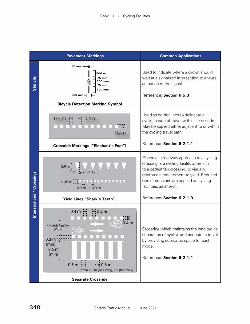
348
Book 18 · Cycling Facilities
Ontario Traffic Manual · June 2021
Pavement Markings Common Applications
Ste
ncils
50 mm
500 mm
75 mm300 mm75 mm
500 mm
250 mm
Bicycle Detection Marking Symbol
Used to indicate where a cyclist should wait at a signalized intersection to ensure actuation of the signal.
Reference: Section 6.5.3
Inte
rsec
tions
/ C
ross
ings
0.4 m0.4 m0.4 m0.4 m
0.4 m0.4 m
Crossride Markings ("Elephant's Feet”)
Used as border lines to delineate a cyclist’s path of travel within a crossride. May be applied either adjacent to or within the cycling travel path.
Reference: Section 6.2.1.1
0.9 m
0.6 m0.3 m
0.3 m ≤ 0.3 m0.45 m
Yield Lines “Shark’s Teeth”.
Placed at a roadway approach to a cycling crossing or a cycling facility approach to a pedestrian crossing, to visually reinforce a requirement to yield. Reduced size dimensions are applied on cycling facilities, as shown.
Reference: Section 6.2.1.3
0.4 m
0.4 m0.4 m
0.6 m0.6 m
2.5 m(min)
0.3 m(min)
*Match Facility Width
*min 1.5 m (one-way), 2.5 (two-way)
Separate Crossride
Crossride which maintains the longitudinal separation of cyclist and pedestrian travel by providing separated space for each mode.
Reference: Section 6.2.1.1

349
Book 18 · Cycling Facilities
Ontario Traffic Manual · June 2021
Pavement Markings Common Applications
Inte
rsec
tions
/ C
ross
ings
0.4 m
0.6m
2.5 m(2.0 m min)
5.0 m(3.5 m min)
0.4 m 0.4 m
1.25 m(0.75 m
min)
Combined Crossride
Typically employed where cyclists and pedestrians approach a crossing within a shared facility, such as a multi-use path. Unidirectional bicycle crossings are placed on each side of a central pedestrian crossing.
Reference: Section 6.2.1.1
0.4 m 0.4 m
0.4 mMatchfacilitywidth
(min 3.0 m)
Mixed Crossride
Applied at intersections with low traffic volumes where cyclists and pedestrians approach within a shared facility, such as a multi-use path. Under the Highway Traffic Act, mixed crossrides cannot be implemented at signalized intersections.
Reference: Section 6.2.1.1

350
Book 18 · Cycling Facilities
Ontario Traffic Manual · June 2021
Pavement Markings Common Applications
Con
flict
Zon
e M
arki
ngs (green treatment optional)
Green Surface Treatment — Crossride
Solid green surface treatment, optionally applied within crossrides.
Reference: Section 6.2.2
Alternative 1 (green treatment optional)
Alternative 2
Green Surface Treatment — Dashed Guidelines
Solid or dashed green surface treatment, optionally applied between dashed guidelines such as in merging/weaving zones or through intersections.
Reference: Section 6.2.2
Left
Tur
n Tre
atm
ents
0.6 m 3.0 - 5.0 m 0.3 m
0.5 m
Bike Box
Provide cyclists with queueing space for direct left turns. This treatment is not recommended on roadways with high traffic volumes or speeds.
Reference: Section 6.4.3
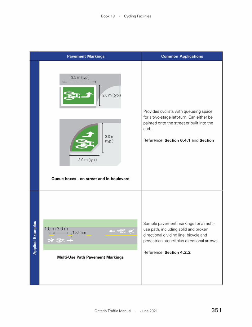
351
Book 18 · Cycling Facilities
Ontario Traffic Manual · June 2021
Pavement Markings Common Applications
2.0 m (typ.)
3.5 m (typ.)
3.0 m(typ.)
3.0 m (typ.)
Queue boxes - on street and in-boulevard
Provides cyclists with queueing space for a two-stage left-turn. Can either be painted onto the street or built into the curb.
Reference: Section 6.4.1 and Section
App
lied
Exam
ples
3.0 m1.0 m100 mm
Multi-Use Path Pavement Markings
Sample pavement markings for a multi-use path, including solid and broken directional dividing line, bicycle and pedestrian stencil plus directional arrows.
Reference: Section 4.2.2
352
Book 18 · Cycling Facilities
Ontario Traffic Manual · June 2021
specific site conditions to appropriate facility types and supplementary design features.
Average Daily Traffic (ADT)The total volume of traffic during a given time period, in whole days, greater than one day and less than one year, divided by the number of days in that time period.1
Average Annual Daily Traffic (AADT)The average 24 hour, two way traffic on a roadway for the period from January 1st to December 31st within a single calendar year.
Barrier CurbA vertical construction element along the edge of a pavement or shoulder forming part of a gutter It strengthens and protects the edge of the pavement, and clearly defines the edge to vehicle operators. It can also be used to provide vertical separation between the bicycle facility and vehicle lanes.
BicycleA bicycle has only two tandem wheels, propelled solely by human power, upon which one or two persons may travel. The Highway Traffic Act definition of a bicycle includes “a tricycle, a unicycle and a power-assisted bicycle, but does not include a motor-assisted bicycle.”
Bicycle BoxSquare or rectangular pavement markings typically used on streets with bike lanes which allow cyclists to queue at a traffic signal ahead of motor vehicles.
Bicycle Detector LoopsUsed to detect the presence of bicycles at actuated traffic signals. Bicycle detection is usually achieved through the use of in-pavement quadrupole or diagonal quadrupole inductive loops because
Appendix C — Glossary
Accessibility for Ontarians with Disabilities Act (AODA)Provincial legislation and associated regulations that set targets and provide for the development of standards for making the Province accessible to all Ontarians by 2025.
Active TransportationAny form of transportation that is “human-powered” such as cycling, walking, running, hiking, in-line skating, skateboarding, etc.
Active Transportation PathSee Multi-Use Path.
Adapted CycleAdapted cycles cover the full range of bikes that may be used by people with a range of disabilities and by seniors. Examples include handcycles, tricycles and pedicab-type trikes with a two-person seat at the front such as those used by Cycling Without Age programs.
Advisory Bicycle LanesA shared roadway with bicycle-priority areas by delineating space for cycling on a narrow roadway by dashed lane lines.
All Ages and AbilitiesAll Ages and Abilities (AAA) bicycle facilities are those that are comfortable for a wide range of cycling abilities and experience levels including families with children, seniors and new riders.
Application HeuristicsKnowledge-based rules developed to aid practitioners with facility type selection. They link
353
Section C · Glossary
Ontario Traffic Manual · June 2021
multi-use trails may all be designed for two-way travel by cyclists if space and site conditions allow for it.
BikewayA generic term for any road, street, path or way provided for bicycle travel, either for the exclusive use of bicycles or shared with other transportation modes. It is made up of one or more bicycle or multi-use lanes.1,2
Bicycle Priority StreetSee Neighbourhood Bikeway
Blended transition A connection with a slope of 1:20 (5%) or less between the level of a pedestrian walkway and the level of a vehicular path of travel. Blended transitions should only be used in traffic calming locations since the shallow slope of a blended transition can be difficult for persons with a vision impairment to detect.
BoulevardA boulevard is located between the travelled portion of a highway and the edge of the right-of-way. It may include a hard surfaced splash pad or landscaped strip used to physically separate a cycling facility from the roadway in an urban context.
ChicaneA physical feature built into the roadway intended to reduce motor vehicle speeds. They are placed such that bump-outs on opposite sides of the road require drivers to travel the roadway in an S-shaped path.
they are bicycle-sensitive over their entire area. Pavement markings should be used to indicate to cyclists where they should position their bicycles in order to be detected.
Bicycle FacilityA general term used to denote facilities designed for use by cyclists. Some examples of cycling facilities are: signed only bike routes, signed bike routes with paved shoulders, urban shoulders, bicycle lanes, separated bicycle lanes, cycle tracks, active transportation paths and off-road multi-use trails.
Bicycle GreenwaySee Neighbourhood Bikeway.
Bicycle LaneA portion of a roadway which has been designated by pavement markings and signage for the exclusive use of cyclists.2
Bicycle NetworkA system of bikeways designated through signing by the jurisdiction having authority. This system may include shared roadways, signed only bike routes, signed bike routes with paved shoulders, bicycle lanes, separated bicycle lanes, cycle tracks, active transportation paths, off-road multi-use trails and other identifiable bicycle facilities.2
Bicycle Signal HeadA traffic signal head specific for cyclists. The circular lenses with a red, amber and green bicycle outline on a black background differentiate the bicycle signal head from the conventional signal head used by motorized vehicles.3
Bidirectional TravelMoving or operating in opposite directions. Cycle tracks, active transportation paths and off-road

354
Book 18 · Cycling Facilities
Ontario Traffic Manual · June 2021
complete streets may also incorporate corridors for wildlife movement.
Conflict Zone, Motorist-CyclistMotorist-cyclist conflict zones are areas where motorists and cyclists cross travel paths and, therefore, the risk of motorist-cyclist collisions or conflicts is higher.
ContextContext is the circumstance that forms a specific situation. See Design Context for more information.
Contraflow Bicycle LanesEnables bidirectional bicycle travel on a roadway that has a one-way operation for motor vehicles. It has a contraflow bicycle lane the opposing direction of motorized traffic, and another type of bicycle facility in the direction of motor vehicle travel.
Conventional Bicycle LaneA bicycle lane that is separated from motor vehicle lanes by pavement markings.
Cross-sectionA diagrammatic presentation of the right-of-way profile which is at right angles to the centre line at a given location.
CrossrideA part of the roadway designated as a crossing for cyclists where they are permitted to ride within the crossing. This is indicated by signs, pavement markings and a traffic signal if the crossing is signalized.
CrosswalkA part of the roadway specifically intended as a crossing for pedestrians. This is indicated by signs, pavement markings and a traffic signal if the crossing is signalized.1
Clearance, HorizontalThe horizontal clearance is the width required for safe passage of a cyclist as measured in a horizontal plane. The width is measured from the edge of the essential manoeuvring space to any fixed object capable of injuring or destabilizing a cyclist using the facility.
Clearance, VerticalThe vertical clearance is the height necessary for the safe passage of a cyclist as measured in a vertical plane.
Clear ZoneThe roadside area immediately adjacent to the curb lane clear of hazards and which may be used safely by errant vehicles.
CollisionAn incident resulting in property damage, personal injury or death. It involves the loss of control or the striking of one or more vehicles with another vehicle, a person, an animal or an inanimate object.
Commuter CyclistAn individual who repetitively cycles over the same or a similar route, and uses a bicycle primarily for travel to and from work or school.
Complete StreetsStreets that are designed to balance the needs of all road users including trucks and service vehicles, pedestrians, cyclists and motorists. Complete streets provide physical environments that make all forms of mobility attractive, comfortable, efficient and as safe as possible. Complete streets also provide a positive physical environment that supports the form of development that is planned or exists adjacent to the street. In some cases,

355
Section C · Glossary
Ontario Traffic Manual · June 2021
Cycle Track Queueing AreaDesignated space for turning cyclists to queue for turning cyclists to queue for a turn at an intersection physically separated from the roadway.
Dashed Guide LinesUsed to provide guidance to cyclists or motorists through an intersection or crossing.
DelineationOne, or a combination of several types of devices (excluding Guide Signs) that regulate, warn or provide tracking information and guidance to motorists and cyclists.
Depressed Curb A seamless gradual slope at transitions between sidewalks and walkways and highways and is usually found at intersections.
Design ContextSite specific factors that are present create a design context that affects both design choices and key mitigation needs for a given situation. Context is very important in the design of bicycle facilities and should be considered during all planning and design phases.
Design SpeedA speed selected for purposes of design and correlation of the geometric features of a road.1
Designated Bicycle RouteA designated bicycle route is a segment of a bikeway network designated through signing or identification on a map by the jurisdiction having authority. Generally, designated bicycle routes are signed using the green Bike Route Marker M511 (OTM). However, it is still necessary to select the appropriate facility for the designated bicycle route given the route location and roadway conditions.2
CurbA vertical or sloping construction element along the edge of a pavement or shoulder forming part of a gutter. It strengthens and protects the edge of the pavement, and clearly defines the edge to vehicle operators. The surface of the curb facing the general direction of the pavement is called the “face”.
Curb Radius / RadiiThe size of the radius at an intersection or driveway corner. Larger curb radii are associated with higher-speed turning movements.
Curb RampA ramp that is cut through a curb or that is built up to a curb. Curb ramps should not be continuous around a corner. Parallel curb ramps have a running slope that is in line with the direction of sidewalk travel and lowers the sidewalk to a level turning space where a turn is made to enter the pedestrian street crossing.
CyclistA person who operates a human-powered or power-assisted bicycle, tricycle or unicycle.
Cyclist Operating SpaceThe space needed to maintain stability when operating a bicycle. The operating space is determined by examining typical bicycle dimensions, space requirements for manoeuvring, plus horizontal and vertical clearance.
Cycle TrackA one-way or two-way cycling facility that physically separates cyclists from motor vehicles through the use of curbs, bollards, planters, or other separation devices.

356
Book 18 · Cycling Facilities
Ontario Traffic Manual · June 2021
First or Last MileThe beginning or end of an individual trip made primarily by public transportation.
Flex BollardsVertical flexible posts mounted to the roadway within a painted buffer.
FreewayA fully controlled access road that is limited to through traffic, with access through interchanges.1
Fully Mountable CurbA curb edge with a concave face and slight gradient to the road surface which can be easily ridden or driven over.
Grade SeparationThe vertical isolation of traveled ways through the use of a structure so that traffic crosses without interruption.
Green IntervalThe period of time at a signalized intersection when a green indication is displayed on a signal head.
GrooveA narrow longitudinal slot in the riding surface that could restrict the steering of a bicycle wheel, such as a gap between two concrete slabs.
Guide RailA form of physical separation that consists of a metal railing that is elevated above the surface by a series of posts.
GuidelineA recommended, but usually not an essential, practice, method or value for a specific design feature or operating procedure.
DesignerA person actively engaged in a discipline, or profession. For the purposes of this manual, a designer refers to a planner or engineer engaged in the planning and design of cycling facilities. Also referred to as Practitioner.
Desired Value or DimensionWhat practitioners should strive to achieve in their designs.
Design of Public Spaces (DOPS) StandardForms part of the Accessibility for Ontarians with Disabilities (AODA) Integrated Accessibility Standards (IAS). The technical requirements in the Exterior Paths of Travel part of the standard are of particular relevance in the design of cycling facilities.
Elephant’s FeetPavement markings used at crossrides to indicate the area in which cyclists are expected to travel. Elephant’s feet are square pavement markings, typically 400 x 400 mm.
Experienced CyclistA rider assumed to have the physical and cognitive skills needed to safely and comfortably manoeuvrer a bicycle in a variety of traffic conditions.
Fitness and Sport CyclistFitness and sport cyclists ride their bicycles for exercise and skill training. Distances can be 100 kilometres or more while often sustaining speeds of over 35 km/h.2
Fitness and Sport TripsThese types of recreational trips are often taken along low volume rural roadways with minimal traffic interruptions, and simulate race conditions in order to improve fitness and skill level.2

357
Section C · Glossary
Ontario Traffic Manual · June 2021
Intersection ApproachThat part of an intersection leg used by traffic approaching the intersection.
Left-Turn ConflictsLeft-turn conflicts may occur when cyclists try to cross one or more lanes of opposing through traffic in order to turn left using the same path as motorized vehicles.
Level of Cyclist ActivityRefers to the number of cyclists observed in a given time period, typically one hour. For the purposes of this manual, cyclist activity may be divided into three categories: “low” (< 50 cyclists per hour), “medium” (50 to 100 cyclists per hour) and “high” (> 100 cyclists per hour).
MaintenanceThe upkeep of highways, traffic control devices, other transportation facilities, property and equipment.
Median IslandA zone or physical island constructed in the centre of a roadway to separate opposing directions of traffic. In the context of traffic calming, it may be used to reduce the overall width of the travel lanes.
Mid-BlockThe segment of the roadway between two intersections.
MinimumSee Suggested Minimum.
Mixed CrossrideAllows cyclists and pedestrians to operate in shared space over the entire width of the crossride.
HighwayA highway is a general term denoting a public roadway for the purposes of vehicular travel, including the entire area within the right-of-way.
Highway Traffic Act (HTA)The Ontario Highway Traffic Act.
Human FactorsThe consideration of human physical, perceptual and mental limitations in engineering design to optimize the relationship between people and things. The objective is to reduce error and increase user comfort.
Inexperienced Adult CyclistA cyclist who may have the judgmental and physical maturity necessary to maneuver a bicycle in a variety of traffic conditions, but typically does not feel secure or comfortable riding in all traffic situations.
Integrated Accessibility Standard (IAS)The Integrated Accessibility Standards contains all of the standards developed under the Accessibility for Ontarians with Disabilities Act (AODA), including Part IV.1 — Design of Public Spaces (DOPS) Standards, which is particularly relevant to the development of cycling infrastructure.
InterchangeA grade-separated intersection with one or more ramps that permit traffic to move from one roadway to another with few, if any, conflicts between traffic streams.
IntersectionThe area embraced by the extension of lateral curb lines or, if none, of the rights-of-way of two or more highways that meet one another at an angle.1,4

358
Book 18 · Cycling Facilities
Ontario Traffic Manual · June 2021
municipal by-law, multi-use trails may also be used by recreational motorized vehicles.
Neighbourhood BikewayA low-volume, low-speed street that prioritizes bicycle traffic through treatments such as traffic calming, traffic reduction, signage, pavement markings and intersection crossing treatments. These streets provide a comfortable cycling environment as well as directness and connectivity in the cycling network. They may also be referred to as a “Bicycle Greenway” or “Bicycle Boulevard”.5
Off-Road Cycling FacilityFor the purposes of this document, it includes any form of cycling facility located outside the travelled portion of the roadway, but may or may not be within the road right-of-way. It may consist of a shared facility for use by cyclists and other non-motorized users.
One-Way TravelSee Unidirectional Travel.
On-Road Cycling FacilityAn on-road cycling facility includes any type of designated cycling facility on the traveled portion of a roadway, as well as a shoulder bikeway.
On-Street ParkingThe use of the roadway surface or the adjacent shoulder for vehicle parking is considered ‘on-street’.
Ontario Building Code Accessibility requirements to Ontario’s Building Code came into force on January 1, 2015 and apply to most new construction and extensive renovations, covering a range of areas such as parking, entrances,elevators, washrooms,
Mixed Traffic OperationUnless cycling is specifically restricted, cyclists are permitted to travel on all roadways regardless of whether signage is present.
MotoristA person who operates a motor vehicle on a highway.
Motor VehicleIncludes automobiles, motorcycles, motor-assisted bicycles (mopeds) and any other vehicle propelled or driven other than with muscular power. It does not include streetcars, or other vehicles designed to operate on rails, power assisted bicycles, motorized snow vehicles, traction engines, farm equipment or road-building machines.
Mountable CurbsAlso referred to as rolled curbs, vertically distinguish the bicycle facility from vehicle lanes while allowing cyclists to move comfortably between the two.
MTOIn this manual, MTO is synonymous with the ‘Ministry of Transportation of Ontario,’ Ministry of Transportation and ‘the Ministry’.
Multi-Use PathA shared pedestrian and cycling facility that is physically separated from motor vehicle traffic by a hard-surfaced splash pad or by a grass strip.It is often referred to as part of a boulevard within the roadway or highway right-of-way.
Multi-Use TrailA shared facility located outside the roadway right-of-way for use by cyclists, pedestrians and other non-motorized users. If permitted by

359
Section C · Glossary
Ontario Traffic Manual · June 2021
PedestrianA person whose mode of transportation is by foot. It also includes a person using a mobility aid such as a walker, a person propelling or being pushed in a manual wheelchair, or a motorized wheelchair that cannot travel at over 10 km/h. A person pushing a bicycle is also considered a pedestrian. It does not include any person who is in a vehicle, either motorized or human powered.
Pinch PointA place in the road network where the width of the roadway narrows which restricts the flow of traffic. Road users must yield to other road users in accordance with the provisions of the Highway Traffic Act at these locations.
Posted SpeedThe maximum vehicular speed permitted on a roadway or highway, and is displayed on a regulatory sign.6
Physically Separated BikewaysA cycling facility with any form of physical separation between people riding bikes and motor vehicle traffic.
PlanterA box that is typically filled with plants and is used as a form of physical separation between cyclists and motor vehicles.
barrier-free access, ramps, stairs, signs and exits. Compliance with the OBC does not constitute compliance with the Ontario Human Rights Code. This is a key reason why additional accessibility design standards for the built environment are required to address the needs of users with varying disabilities.
Ontario Human Rights Code The Ontario Human Rights Code protects all Ontario residents from discrimination and harassment in specific areas including services, housing, contracts and employment. Under the Code, every person has a right to equal treatment with respect to services, goods and facilities, without discrimination because of disability, race, ancestry, place of origin, colour, ethnic origin, citizenship, creed, sex, sexual orientation, age, marital status, same-sex partnership status and family status. Further, the Code recognizes that people with disabilities have the right to be able to access services, jobs and housing, with the right to assume the same responsibilities and duties as everyone else.
Operating Speed (85th Percentile)The speed which no more than 15% of motor vehicle traffic is exceeding during freeflow traffic conditions.
Paved PathA path surfaced with a hard, durable material such as asphalt or concrete.
Pavement MarkingsPainted or durable lines or symbols applied on any paved bikeway or roadway surface for guiding vehicular, cyclist, and pedestrian traffic.

360
Book 18 · Cycling Facilities
Ontario Traffic Manual · June 2021
PractitionerA person actively engaged in a discipline or profession. For the purposes of these guidelines, a practitioner refers to a planner, designer or engineer engaged in the planning and design of bicycle facilities.
Pre-Cast Concrete CurbAlso known as a ‘pinned curb’, is anchored into the roadway to provide separation between bicycle and vehiclar traffic.
Protected Signal PhaseA form of phasing at signalized intersections that provides fully protected movements for motor vehicles or cyclists.
Public RealmAny outdoor spaces between buildings that are publicly accessible.
Railroad CrossingA location where one or more railroad tracks cross a public highway, road, street or private roadway. This includes sidewalks and pathways at the crossing.
Raised Cycle TrackA cycling facility adjacent to and vertically separated from motor vehicle travel lanes. A raised cycle track may be designed for one-way or two-way travel, and is for the exclusive use of cyclists and is distinct from the sidewalk.
RampAn interconnecting roadway at a freeway interchange, or any connection between highways at different elevations or between parallel highways, on which the vehicles may enter or leave a designated roadway.
Recreational CyclistAn individual who uses a bicycle for trip enjoyment, and usually takes relatively short trips at lower speeds. The ultimate destination is of secondary importance. Fitness and sport cyclists are one type of recreational cyclist.
Recreational TripsTrips where the primary objective for the cyclist is to enjoy the ride, the scenery and the company of other cyclists. These trips usually occur along off-road bicycle facilities, on quiet neighbourhood streets and rural roadways.2
Refuge IslandThese are provided on a street for the safety of pedestrians. It can be either a median island on a wide street where the width may not permit pedestrians to easily cross the entire street during a gap in traffic, during a single pedestrian signal indication or as a loading island for buses, streetcars or LRT.
Regulatory SignAdvises drivers of an action they must or must not take under a given set of circumstances. Disregard for a regulatory sign constitutes an offence under the HTA.
RetrofitA roadway may be retrofitted to improve conditions for the road users. These projects are opportunities to redistribute space among different modes of transportation using the existing roadway platform. Retrofitting is often an appropriate and affordable solution for the implementation of bicycle facilities.
Right-of-WayThe area of land acquired for or devoted to the provision of a road.1

361
Section C · Glossary
Ontario Traffic Manual · June 2021
Right-Turn ConflictsThese occur when a cyclist is proceeding straight through an intersection while a motorist is attempting to make a right turn, and to do so must cross over the on-road bicycle facility.
RiskThe probability of a situation involving exposure to danger.
RoadThe entire right-of-way, comprising a public thoroughfare, including a highway, street, bridge and any other incidental structure.1
RoadwayThe part of the road that is improved, designed or ordinarily used for the passage of vehicular traffic.1
RoundaboutA raised circular island located in the centre of an intersection, which requires vehicles to travel through the intersection in a counterclockwise direction around the island.
Route Selection CriteriaThese are used to aid practitioners in selecting bicycle routes that meet the needs of potential users to form a comprehensive bikeway network.
Rubber CurbA short polymer curb anchored into the roadway.
Rumble StripRaised buttons, bars or depressions closely spaced at regular intervals on the roadway or shoulder that create both noise and vibration in a moving vehicle to alert the driver or cyclist of an upcoming situation, or of a potentially hazardous deviation from the normal travel way.
Segregated Bicycle LaneSee Separated Bicycle Lane.
Separated Bicycle LaneThis is the portion of a roadway which has been designated by special pavement markings or a physical barrier and signage for the exclusive use of cyclists. This facility type provides additional spatial or physical separation between motorists and cyclists.
Shared LaneThis is a facility which provides no distinct operating space for bicycles but provides other supporting amenities such as traffic calming and wayfinding.
Shared Lane MarkingsA pavement marking symbol that indicates an appropriate position for a cyclist in a shared lane. See Sharrows for more information.2
Shared Roadway or Signed Bike RouteA road where both motorists and cyclists share the same vehicular travel lane.2
SharrowsThe term used for shared roadway lane markings or shared lane arrows. A sharrow consists of two white chevron markings and a bicycle stencil. Sharrows are intended to guide cyclists as to where they should ride within a travel lane shared by both motorists and cyclists. They are an optional treatment and are context specific.4
ShoulderThis is an area of gravel or hard surface placed adjacent to through or auxiliary lanes. They are intended for emergency stopping and travel by emergency vehicles. They also provide structural support for the pavement.1

362
Book 18 · Cycling Facilities
Ontario Traffic Manual · June 2021
SidewalkA travelled way intended exclusively for pedestrian use, following an alignment generally parallel to that of the adjacent roadway.1
Sight DistanceThis is measured along the normal travel path of a roadway, to the roadway surface or to a specified height above the roadway, when the view for the driver of a motor vehicle or a bicycle is unobstructed by traffic.
SightlinesThe ‘line of sight’ of a motorist or cyclist at any given time. Horizontal and vertical curves along the roadway as well as roadway width should be considered when providing adequate sightlines for road users. Regular maintenance of vegetation is also important in preserving sightlines.
SignA traffic control device mounted on a fixed or portable support which conveys a specific message by means of symbols or words, and is officially erected for the purpose of regulating, warning or guiding traffic.
Signalized IntersectionAn intersection where traffic approaching from all directions is regulated by a traffic control signal.
Signed Bike Route with Paved ShoulderA form of bicycle facility on a road with a rural cross section. A paved shoulder is a portion of a roadway which is contiguous with the travelled way. It provides accommodation for stopped and emergency vehicles, pedestrians and cyclists as well as for lateral support of the pavement structure. A paved shoulder on a designated bike
route may include a buffer zone to provide greater separation between motorists and cyclists.1,2
Skew AngleLess than a right angle to a bikeway; generally, an angle of 45 degrees or less.
Stopping Sight DistanceThe longitudinal space required by a motorist or cyclist, travelling at a given speed, to bring their vehicle to a stop after an object on the roadway becomes visible. It includes the distance travelled during the perception-reaction time plus the vehicle braking distance.
Suggested Minimum Value or DimensionThe minimum that a practitioner should design to in constrained situations. Good engineering judgement should always be applied, and consideration given to the location, context and roadway characteristics. Although consistency in design and signing is an important goal, a practitioner should never assume a “one solution fits all” approach.
Tab SignSmaller than the primary sign with which it is associated, and mounted below it. There are two types of tab signs:
1. Supplementary Tab Sign – contains additional, related information; and
2. Educational Tab Sign – conveys the meaning of symbols during their introductory period.
ThresholdA threshold is a limit value.
363
Section C · Glossary
Ontario Traffic Manual · June 2021
Tactile Walking Surface Indicator (TWSI)A colour contrasting and tactile surface treatment that is used for one of two purposes:
1. Tactile Attention Indicator (TAI): A tactile walking surface indicator (TWSI) comprising truncated domes that alert people to the presence of a hazard or a decision making point, such as a street crossing, impending change in elevation, or conflicts with other transportation modes.7
2. Tactile Direction Indicator (TDI): A tactile walking surface indicator (TWSI) that uses elongated, flat-topped bars to facilitate wayfinding in open areas, including guiding pedestrians with vision loss or other disabilities to crosswalks or transit stops. The elongated bars indicate the travel direction.7
In this manual, unless otherwise specified, the term “TWSI” is used to refer to an attention indicator.
Touring CyclistAn individual who uses a bicycle for long distance travel, usually on multi-day trips and carrying baggage.
Touring TripsOften undertaken over a longer period of time than utilitarian or recreational trips. Trips are generally between urban areas and points of interest. Touring trips require more planning since the route, destinations and accommodations are important factors for the cyclist.2
TrafficIncludes pedestrians, ridden or herded animals, vehicles, bicycles and other conveyances, either singly or together, while using a highway for purposes of travel.
Traffic Control DevicesSigns, signals or other fixtures whether permanent or temporary, placed on or adjacent to a traveled way by authority of a public body having jurisdiction to regulate, warn or guide traffic.
Traffic Control SignalAny power-operated traffic control device, whether manually, electrically or mechanically operated, by which traffic is alternately directed to stop and permitted to proceed. A traffic signal:
1. When used in general discussion, refers to a complete installation including signal heads, wiring, controller, poles and other appurtenances; or
2. When used specifically, it refers to the signal head which conveys a message to the observer. This consists of one set of no less than three coloured lenses, red, amber and green, mounted on a frame.
Traffic VolumeThe number of vehicles that pass a given point during a specified amount of time such as an hour, day or year.
Travelled WayThe part of a roadway intended for vehicular use, excluding the shoulders. It may have a variety of surfaces, such as gravel, but is most commonly hard surfaced with asphalt or concrete.1
Two-Way TravelSee Bidirectional.
Unidirectional TravelMoving or operating in one direction. Most bicycle facilities are designed for one-way travel by cyclists.

364
Book 18 · Cycling Facilities
Ontario Traffic Manual · June 2021
Universal DesignThe design of products, environments, programs and services to be usable by all people, to the greatest extent possible, without the need for adaptation or specialized design. ’Universal design’ does not exclude assistive devices for a particular group.
Unsignalized IntersectionAn intersection where traffic approaching from all directions is regulated by any traffic control device that is not a traffic control signal.
Utilitarian CyclistAn individual who uses a bicycle primarily for travel to and from specific destinations such as work, school, shops or recreation centres.
Utilitarian TripsThose for which the purpose is to reach a particular destination and are often repetitive. These include trips to places of employment, school or shopping, as well as trips that are necessary as part of an individual’s daily activities.2
VehicleFor the purpose of these guidelines, any device which is capable of moving itself and a person, or of being moved, from place to place. This includes a bicycle.
Vision ZeroA strategy to eliminate all traffic fatalities and severe injuries, while increasing safe, healthy, equitable mobility for all.8
YieldTo cede the right-of-way.
Yield Line (shark’s teeth)Also known as “shark’s teeth”, consists of white triangles with a 300 to 600 mm base and a 450 to 900 mm height with a clear spacing of 75 to 300 mm to indicate a requirement to yield. The base of the triangle faces the direction of travel.
Youthful CyclistFor the purpose of determining appropriate bicycle facilities, any person under 13 years of age and usually operating a bicycle with wheels of a maximum diameter of 600 mm is considered a youthful cyclist.
References
1 Geometric Design Standards for Ontario Highways (MTO, 1985)
2 Guide for the Planning, Design and Operation of Bicycle Facilities (AASHTO, 2012)
3 Traffic Signal Guidelines for Bicycles (TAC, 2012)
4 Guidelines for the Design and Application of Bikeway Pavement Markings (TAC, August 2007)
5 City of North Vancouver Bikeway Types Webpage (City of North Vancouver, 2019).
6 TAC Geometric Design Guide for Canadian Roads (TAC, 1999)
7 CSA B651-18 — Accessible Design for the Built Environment (CSA Group, 2018)
8 Vision Zero Network (2019) https://visionzeronetwork.org/