Embed Size (px)
Citation preview

Get the latest PDF manual:
Mobile/online version of this manual:
https://www.lcmeter.com/resources/technical/manuals
https://www.lcmeter.com/manuals
Table of ContentsResources in this Guide ............................................................................................................................ 4
Register Overview ..................................................................................................................................... 5
Publication Updates .................................................................................................................................. 6
Safety Procedures .................................................................................................................................... 7
ESD Protection ......................................................................................................................................... 9
Specifications .......................................................................................................................................... 11
Regulatory & Certifications ..................................................................................................................... 16
FCC Compliance ...................................................................................................................................... 20
Dimensions - Panel Mount ....................................................................................................................... 23
Dimensions - Meter Mount ....................................................................................................................... 25
Setup and Operation ............................................................................................................................... 27
Software License Agreement ............................................................................................................. 31Operational Information & Main Menu ................................................................................................ 32
Delivery Screen Layouts .................................................................................................................... 33Display Screen Types ........................................................................................................................ 36
Keypad Interface ................................................................................................................................ 39
Delivery Details .................................................................................................................................. 45Diagnostics ........................................................................................................................................ 55
Setup Menu ....................................................................................................................................... 59Register Settings ............................................................................................................................................................. 59
Meter Settings ................................................................................................................................................................. 76
Calibration Settings ......................................................................................................................................................... 84
Security ............................................................................................................................................................................. 95
I/O Setup ........................................................................................................................................................................... 97
Customize Home Screen .............................................................................................................................................. 103
Configure Delivery Setup ............................................................................................................................................. 106
Operating the Register .................................................................................................................... 110Performing a basic delivery ......................................................................................................................................... 110
Performing a preset delivery - Preset Key ................................................................................................................ 111
Using the Info button .................................................................................................................................................... 111
Performing a preset delivery - Delivery Setup .......................................................................................................... 112
Using the hose reset feature ....................................................................................................................................... 114
Single-point Calibration ................................................................................................................................................ 114
Multi-point Calibration .................................................................................................................................................. 116
Setting the S1 Close time ............................................................................................................................................. 117
Setting up delivery ticket options ............................................................................................................................... 118
Print the previous ticket ............................................................................................................................................... 119
Upgrading the Firmware by USB ................................................................................................................................. 120
Perform a Clear All Procedure ..................................................................................................................................... 123
Print a transaction ......................................................................................................................................................... 124
Setup custom profiles ................................................................................................................................................... 125
Print a diagnostic ticket ................................................................................................................................................ 126
Appendix A: K-Factor (Pulse/Unit) Chart ............................................................................................... 128
Appendix B: Data Types ........................................................................................................................ 129

LCR.iQ - Setup and Operations Manual
3Get the latest PDF manual: https://www.lcmeter.com/resources/technical/manuals
Mobile/online version of this manual: https://www.lcmeter.com/manuals
LCR.iQ/MasterLoad.iQ Product GuidesCongratulations on ownership of the new LCR.iQ or MASTERLOAD.iQ electronic meter
register and controller. This manual provides the technical details on installation, hardware,
setup, operation, and regulatory information for your register.
NOTE: Throughout this manual, both the LCR.iQ and MASTERLOAD.iQ are
referred to as “Register” (unless otherwise specifically referenced by name).
The Register calculates, monitors and records volumetric data from bulk flow meters, provides
fluid transfer process customization and automation, ties in critical system sensors and inputs,
and bridges data communication between the operator, the equipment, and the operator’s
back office if necessary.
The Register is specially designed to work with leading bulk fuel meters such as LC and
Avery-Hardoll, but will easily retrofit into existing systems with other flow meter brands.
The Register provides many new features, yet supports backward compatibility with LCR-II
and LCR-600.
LCR.iQ - Setup and Operations Manual
4Get the latest PDF manual: https://www.lcmeter.com/resources/technical/manuals
Mobile/online version of this manual: https://www.lcmeter.com/manuals
Resources in this Guide
You can easily download PDF editions of the Installation Guide, Setup and Operations Guide,
and wiring diagrams by clicking the links below.
Otherwise, you may prefer to start with the Register Overview , or proceed directly to
browse both the Installation Guide and the Setup and Operation Guide .
Adobe PDF Guides
Download either of the guides using the links below:
· Installation Guide
· Setup and Operations Guide
Wiring Diagrams
Download a high-resolution PDF edition of these wiring diagrams:
· Rev E board - Download the full-size wiring diagram.
· Rev J board - Download the full-size wiring diagram.
5
27
LCR.iQ - Setup and Operations Manual
5Get the latest PDF manual: https://www.lcmeter.com/resources/technical/manuals
Mobile/online version of this manual: https://www.lcmeter.com/manuals
Register Overview
The Register is a microprocessor-based electronic meter register that can be used for
Weights & Measures approved custody transfer actions in mobile or fixed installations. The
Register is a self-contained unit. All operation, setup, and configuration functions can be
carried out using the Register function keys and alphanumeric keypad. No lap pads, laptops,
or other data entry devices are required.
A complete Liquid Controls meter system not only accurately measures product, it also
regulates product flow and removes contaminants in order to produce the optimal conditions
for measurement. Typical systems include an air/vapor eliminator, strainer, meter, register,
and control valve.
Basic Functions
The principle functions of the Register registers include:
· Weights & Measures custody transfer (product delivery and ticket generation)
· Metrological data collection
· Preset deliveries by volume
· Multiple product selection
· Multi-point meter calibration
· Security settings
· Air and vapor elimination (with proper accessories)
· Single and dual stage valve control (with proper accessories)
· Electronic Temperature Volume Compensation (ETVC)
LCR.iQ - Setup and Operations Manual
6Get the latest PDF manual: https://www.lcmeter.com/resources/technical/manuals
Mobile/online version of this manual: https://www.lcmeter.com/manuals
Publication Updates
The most current versions of all Liquid Controls publications are available on our web site,
www.LCmeter.com/resources/technical/manuals. If there are questions about the language or
interpretation of any LC manuals, instructions, or specification sheets, please first contact your
local distributor for help with your inquiry.
For service related issues that require further support from the Liquid Controls Service Team,
please call the number below.
Liquid Controls Corporate Office:
Phone: +1 847 295-1050
Toll-free: 800 458 5262
Address: Liquid Controls LLC, 105 Albrecht Drive, Lake Bluff, IL 60044 USA
Website: www.LCmeter.com
LCR.iQ - Setup and Operations Manual
7Get the latest PDF manual: https://www.lcmeter.com/resources/technical/manuals
Mobile/online version of this manual: https://www.lcmeter.com/manuals
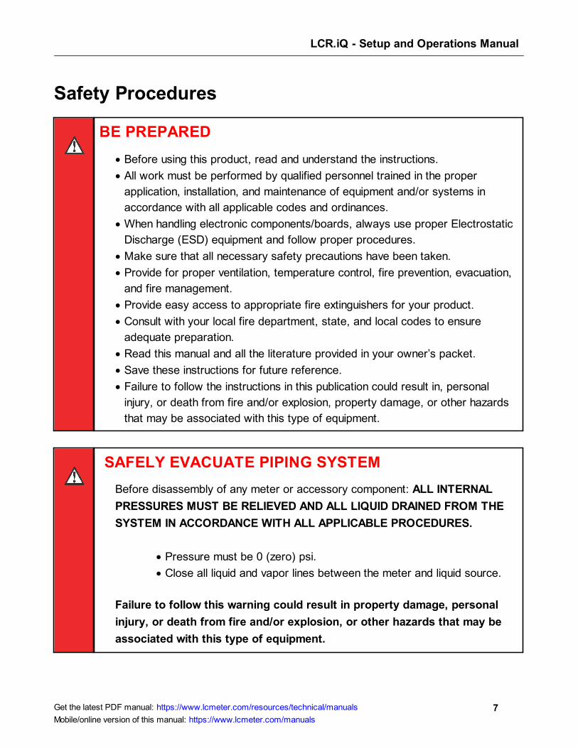
Safety Procedures
BE PREPARED
· Before using this product, read and understand the instructions.
· All work must be performed by qualified personnel trained in the proper
application, installation, and maintenance of equipment and/or systems in
accordance with all applicable codes and ordinances.
· When handling electronic components/boards, always use proper Electrostatic
Discharge (ESD) equipment and follow proper procedures.
· Make sure that all necessary safety precautions have been taken.
· Provide for proper ventilation, temperature control, fire prevention, evacuation,
and fire management.
· Provide easy access to appropriate fire extinguishers for your product.
· Consult with your local fire department, state, and local codes to ensure
adequate preparation.
· Read this manual and all the literature provided in your owner’s packet.
· Save these instructions for future reference.
· Failure to follow the instructions in this publication could result in, personal
injury, or death from fire and/or explosion, property damage, or other hazards
that may be associated with this type of equipment.
SAFELY EVACUATE PIPING SYSTEM
Before disassembly of any meter or accessory component: ALL INTERNAL
PRESSURES MUST BE RELIEVED AND ALL LIQUID DRAINED FROM THE
SYSTEM IN ACCORDANCE WITH ALL APPLICABLE PROCEDURES.
· Pressure must be 0 (zero) psi.
· Close all liquid and vapor lines between the meter and liquid source.
Failure to follow this warning could result in property damage, personal
injury, or death from fire and/or explosion, or other hazards that may be
associated with this type of equipment.
LCR.iQ - Setup and Operations Manual
8Get the latest PDF manual: https://www.lcmeter.com/resources/technical/manuals
Mobile/online version of this manual: https://www.lcmeter.com/manuals
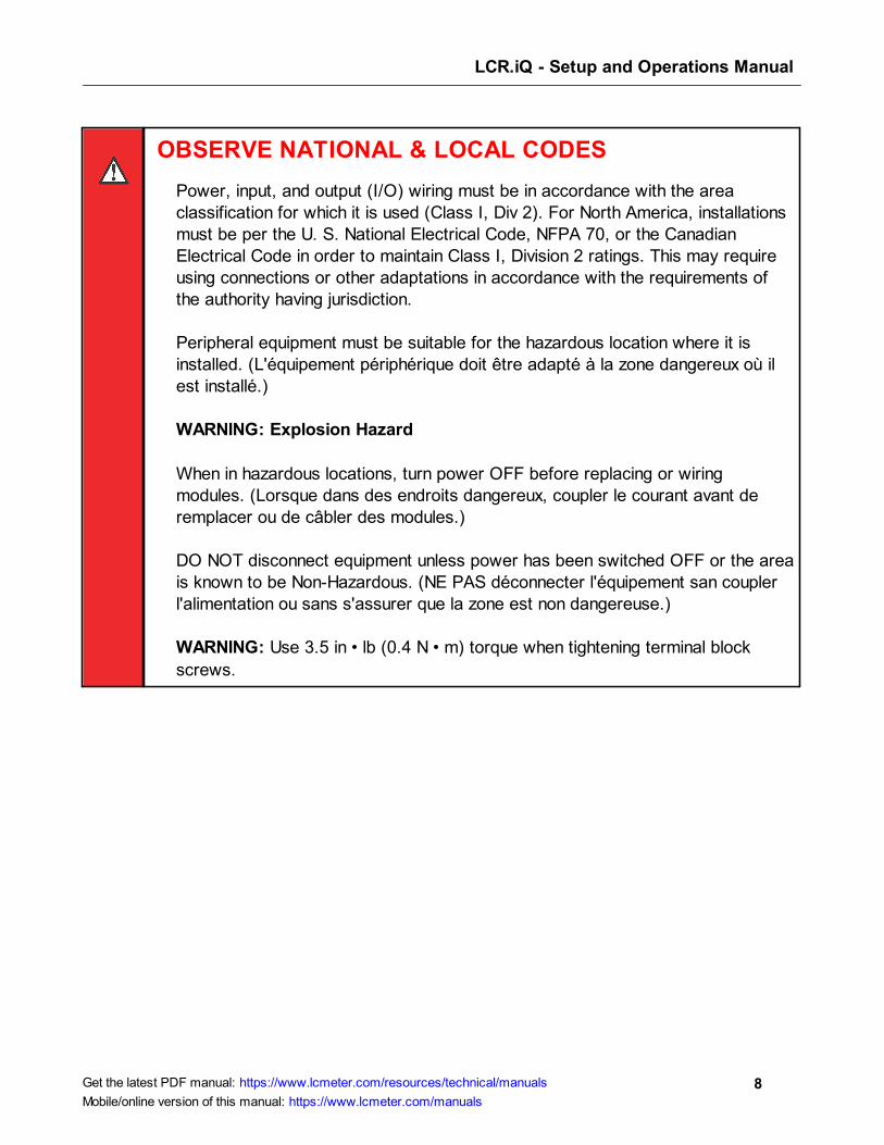
OBSERVE NATIONAL & LOCAL CODES
Power, input, and output (I/O) wiring must be in accordance with the areaclassification for which it is used (Class I, Div 2). For North America, installationsmust be per the U. S. National Electrical Code, NFPA 70, or the CanadianElectrical Code in order to maintain Class I, Division 2 ratings. This may requireusing connections or other adaptations in accordance with the requirements ofthe authority having jurisdiction.
Peripheral equipment must be suitable for the hazardous location where it isinstalled. (L'équipement périphérique doit être adapté à la zone dangereux où ilest installé.)
WARNING: Explosion Hazard
When in hazardous locations, turn power OFF before replacing or wiringmodules. (Lorsque dans des endroits dangereux, coupler le courant avant deremplacer ou de câbler des modules.)
DO NOT disconnect equipment unless power has been switched OFF or the areais known to be Non-Hazardous. (NE PAS déconnecter l'équipement san couplerl'alimentation ou sans s'assurer que la zone est non dangereuse.)
WARNING: Use 3.5 in • lb (0.4 N • m) torque when tightening terminal block
screws.

LCR.iQ - Setup and Operations Manual
9Get the latest PDF manual: https://www.lcmeter.com/resources/technical/manuals
Mobile/online version of this manual: https://www.lcmeter.com/manuals
ESD Protection
ESD PrecautionOpening the Registers
Follow this procedure each time you open the Register or approach it with the door open:
Before opening the Register and handling the CPU board, it's important to discharge any
ESD that may have built up on your person. To discharge ESD from your person, touch a
well-grounded point–such as the Register housing, the meter, truck piping, or the bumper.
When the maintenance is complete and the Register door is closed, the CPU board is
protected from ESD by the Register housing which is grounded to the chassis.
Preventing ESD DamageTo prevent electrostatic discharge (ESD) damage to the Register, truck installations must
properly ground the truck seat cushion and the Epson printer chassis. Prolonged exposure to
ESD over weeks, months, or years can corrupt register memory and damage the electronic
components in Register registers (as well as other electrical components in the truck electrical
system).
Adjustable, shock-absorbing seats, if not grounded correctly, generate significant amounts of
ESD. The pivots and hinges of these seats isolate the seat cushion from an electrical ground.
Without proper bonding, static electric charge builds between the seat cushion and the
operator. This electric charge can enter the Register from any point in the truck electrical
system, including register power and printer cabling.
Liquid Controls Grounding KitsAll truck installations of the Register must have grounded seats and printers using the following
kits:
· Ground Strap Kit (LC Part Number 82185)
· Epson Printer Ground Wire Kit (LC Part Number 82184)
Properly grounded seats allow static electricity to ‘bleed off’ before it can build up, discharge,
and damage the Register or other electrical components.

LCR.iQ - Setup and Operations Manual
10Get the latest PDF manual: https://www.lcmeter.com/resources/technical/manuals
Mobile/online version of this manual: https://www.lcmeter.com/manuals
The Epson Printer Ground Wire Kit is included with each Epson printer cable kit shipment. For
existing installations and previously purchased registers / printers, both ground kits are
available from LC.
Grounding with a Meter Mount or Remote MountIn an installation where the Register is mounted directly to the meter, the Register housing is
grounded through the meter. If the register is not mounted on the meter, you must ensure the
Register housing is grounded properly.
Alternate grounding methods for remote mounted registers
For installations where grounding the register housing through a mount is not possible, an
external grounding screw hole is available. This hole requires a #8-32 x 1/4” ground screw–
which is supplied with the register (the LC part number for the screw is 08254)–and also a 12
gauge or larger stranded wire connected to a known ground (less than 1 ohm).
Another option is to connect the ground screw 8-32 x 1/4” ground screw (inside the Register
housing) to a 12 gauge or larger stranded wire connected to a known ground (less than 1
ohm).
LCR.iQ - Setup and Operations Manual
11Get the latest PDF manual: https://www.lcmeter.com/resources/technical/manuals
Mobile/online version of this manual: https://www.lcmeter.com/manuals
Specifications
Mechanical
Housing and Keypad
The Register housing and bases are aluminum die castings with chromate protective finishing
and powder coated with high durability, urethane powder. The cover internal hinge design
provides easy access to the internal connections and keeps all moving hinge parts out of the
elements to further prevent corrosion. Weights and Measures features are accessible by
using a seal-able fastener on the side of the cover. There are 11 half-inch NPT ports, on the
back of the Register to provide secure cable connections for a wide range of external devices.
Construction Materials
· High grade A360 Die Cast Aluminum, enclosure cover, and enclosure base
· Chromate finish with powder-coat protective coating
· Tempered glass display window
· Silicone display glass seal
· Stainless steel display bracket
· Silicone door seal
· Keypad – Membrane Switch with back-lit silicone overlay
· Stainless steel fasteners/hardware
· Stainless steel bonded silicone sealing washer
Certified Operational Temperature Rating
· The Register is certified for normal operation within the temperature range of -40 to 140 °
F (-40 to 60 °C).
Display
· 7 inch heavy duty, high definition TFT/LCD (Thin Film Transistor Liquid Crystal Display)
video display with LED backlight unit.
· 800 x 480 pixels (152.4 mm x 91.4 mm)
LCR.iQ - Setup and Operations Manual
12Get the latest PDF manual: https://www.lcmeter.com/resources/technical/manuals
Mobile/online version of this manual: https://www.lcmeter.com/manuals
· Luminance: 1500 (cd/m2)
· Display acceptable operation or storage temperature -40 °F to 185 °F (-40 °C to 85 °C).
Weight
· Approximately 12 lbs (Meter Mount Version, no added accessories)
· Approximately 11 lbs (Panel Mount Version, no added accessories)
Cable Entry
· Eleven (11), 1/2" NPT (1/2-14 NPT) threaded ports
Alphanumeric Keypad
The Register alphanumeric keypad is made of petroleum resistant silicone and consists of 12
large alpha-numeric keys, 5 navigation keys, and 5 function keys that relate to the adjacent
display indicators for operator-guided functionality. The keys, when pressed, give the operator
a tactile, positive confirmation of keystrokes. The keypad multi-tap functionality also allows
users to input up to four alpha-numeric characters on a single key.
Electrical
Inputs
Inputs are configurable in the Register to handle a variety of external accessories that provide
data signals in the metering system including pulse input and a variety of external sensors.
Register Input Voltage
· Voltage – 9 to 28 VDC
· Current maximum: 5 A maximum
Pulse Input
In order to calculate flow measurements when mounted to a positive displacement meter, the
Register receives a pulse input from a quadrature pulser that is mechanically connected to the

LCR.iQ - Setup and Operations Manual
13Get the latest PDF manual: https://www.lcmeter.com/resources/technical/manuals
Mobile/online version of this manual: https://www.lcmeter.com/manuals
flow meter output shaft (meter mount option only). A pulse input can also come from an
external device such as a Liquid Controls Pulse Output Device (POD) or another externally
mounted pulse generator. If an external LC POD is purchased, these materials are
necessary, but are not supplied with the POD:
· 16-22 AWG 4 conductor Shielded Cable (Consult the POD manual for complete
specifications)
· Weather Proof flexible conduit or loom
· ½” Conduit connectors or cable glands
RTD Temperature Probe
The Register is equipped with an input for a temperature probe, so the register can read
realtime temperature as well as compensate volume measurements according to the
temperature of the product.
· 4 wire platinum sensor
· 100 Ω resistance at 0 C
· 138.5 Ω resistance at 100 C
Optical Air Eliminator
The Register is equipped to handle an optical air eliminator input:
· Voltage – 10 to 28 VDC
· Current – 0.5 Amp maximum
Digital Inputs 1, 2, 3, 4, 5, and 6
· Active Low, normally pulled high
· Voltage: 5 to 28 VDC
· Current: 3 mA maximum sink current
· Maximum Frequency: 10 kHz
LCR.iQ - Setup and Operations Manual
14Get the latest PDF manual: https://www.lcmeter.com/resources/technical/manuals
Mobile/online version of this manual: https://www.lcmeter.com/manuals
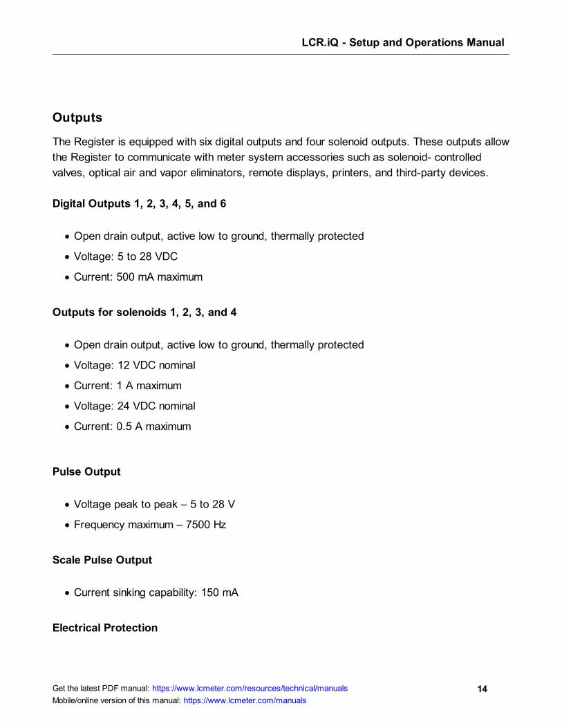
Outputs
The Register is equipped with six digital outputs and four solenoid outputs. These outputs allow
the Register to communicate with meter system accessories such as solenoid- controlled
valves, optical air and vapor eliminators, remote displays, printers, and third-party devices.
Digital Outputs 1, 2, 3, 4, 5, and 6
· Open drain output, active low to ground, thermally protected
· Voltage: 5 to 28 VDC
· Current: 500 mA maximum
Outputs for solenoids 1, 2, 3, and 4
· Open drain output, active low to ground, thermally protected
· Voltage: 12 VDC nominal
· Current: 1 A maximum
· Voltage: 24 VDC nominal
· Current: 0.5 A maximum
Pulse Output
· Voltage peak to peak – 5 to 28 V
· Frequency maximum – 7500 Hz
Scale Pulse Output
· Current sinking capability: 150 mA
Electrical Protection
LCR.iQ - Setup and Operations Manual
15Get the latest PDF manual: https://www.lcmeter.com/resources/technical/manuals
Mobile/online version of this manual: https://www.lcmeter.com/manuals
· 5 A fuse on power cable
Communications
· RS-232
· RS-485
· CAN BUS – Consult the applicable Chassis Builder’s Guide, available from the truck
chassis manufacturer.
· Ethernet (Gigabit)
· Bluetooth (wireless)
· Wi-Fi (wireless)
Printer (Epson Model 295)
· Voltage – 24 VDC
· Current – 0.8 Amp maximum
· Operating Temperature – -22 to 104 ºF (-30 to 40 ºC)
LCR.iQ - Setup and Operations Manual
16Get the latest PDF manual: https://www.lcmeter.com/resources/technical/manuals
Mobile/online version of this manual: https://www.lcmeter.com/manuals
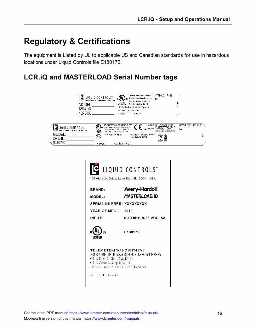
Regulatory & Certifications
The equipment is Listed by UL to applicable US and Canadian standards for use in hazardous
locations under Liquid Controls file E180172.
LCR.iQ and MASTERLOAD Serial Number tags

LCR.iQ - Setup and Operations Manual
17Get the latest PDF manual: https://www.lcmeter.com/resources/technical/manuals
Mobile/online version of this manual: https://www.lcmeter.com/manuals
Class I
· Potentially Explosive Gas/Vapor Atmospheres.
Division 2 and Zone II
· Gases and vapor are not normally present in an explosive concentration but may
accidentally exist during abnormal operations.
Explosive Atmospheres
· This equipment has been found to comply with the European Directive for Equipment For
Potentially Explosive Atmospheres 2014/34/EU (ATEX), Certification Scheme for
Explosive Atmospheres of INTERNATIONAL ELECTROTECHNICAL COMMISSION
(IECEx) and Brazil’s Portaria 179, subject to the following condition of safe use: Wipe with
damp cloth and de-energize before opening. Certificates (if applicable) are issued are
issued by DNV GL and are etched on the tag.
· II - Suitable for use in surface installations.
· 3G - Equipment for explosive gas atmospheres, having a “high” level of protection, which
is not a source of ignition in normal operation or during expected malfunctions.
· Ex ec - Explosion protection is provided by the increased safety method of protection with
the “ec” level of protection.
· GC - Equipment Protection Level level, per IEC 60079-0, EN 60079-0, and ABNT NBR
IEC 60079-0. Suitable for installations in Zone 2.
Grp C&D and Grp IIB
· Flammable/explosive Gas groups.

LCR.iQ - Setup and Operations Manual
18Get the latest PDF manual: https://www.lcmeter.com/resources/technical/manuals
Mobile/online version of this manual: https://www.lcmeter.com/manuals
T4
· Temperature class for surface temperature limitations. T4 means that at the point it
reaches the rated maximum ambient temperature, the equipment will not generate
temperature higher than 135 °C
· Safe limits of ambient temperature.
IP66
· Ingress protection: dust tight and protected against powerful water jetting.
Type 4X
· The enclosure has been evaluated by UL for outdoor use to provide protection against
water and dust and an increased level of protection against corrosion; and that will be
undamaged by the external formation of ice.
CE 2460
· Indicates conformity with all applicable Directives for products sold within the European
Economic Area. DNV GL has performed Quality Assurance Notification under its ATEX
Notified Body number 2460.
LCR.iQ - Setup and Operations Manual
19Get the latest PDF manual: https://www.lcmeter.com/resources/technical/manuals
Mobile/online version of this manual: https://www.lcmeter.com/manuals
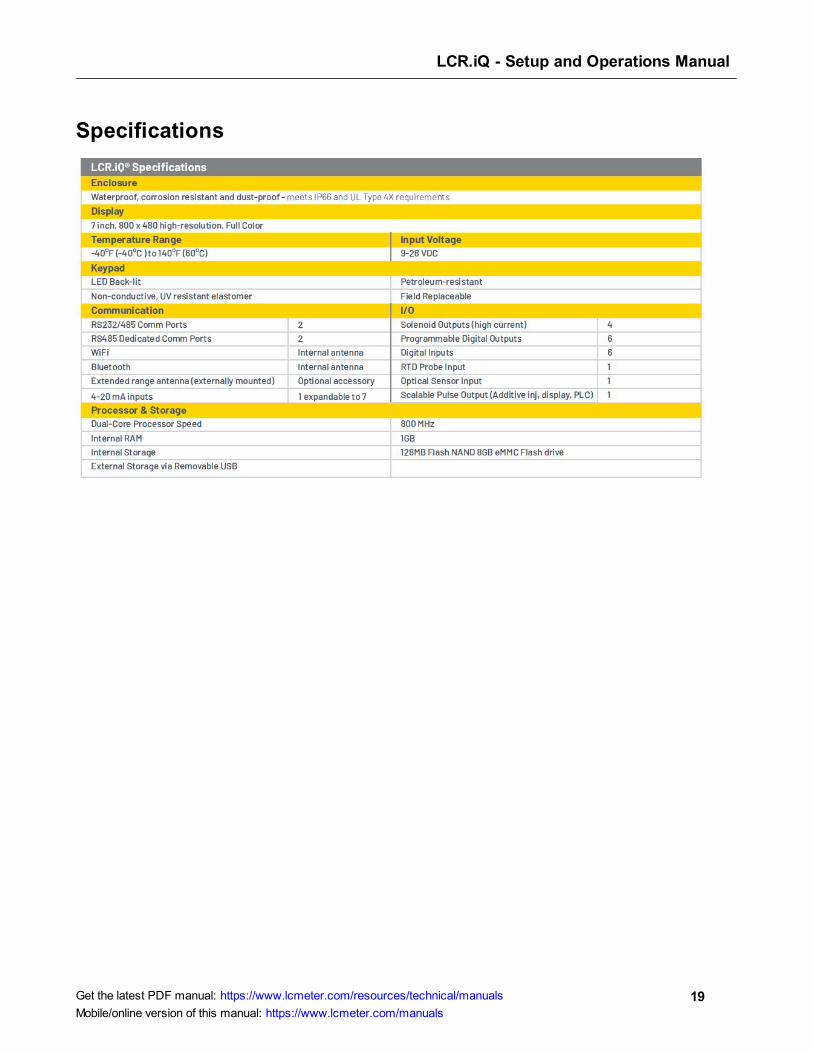
Specifications
LCR.iQ - Setup and Operations Manual
20Get the latest PDF manual: https://www.lcmeter.com/resources/technical/manuals
Mobile/online version of this manual: https://www.lcmeter.com/manuals
FCC Compliance
Unique Identifier: LCR.iQ or MASTERLOAD.iQ
Responsible Party:
Liquid Controls LLC
105 Albrecht Drive
Lake Bluff, IL 60044 USA
www.LCmeter.com
FCC Compliance Statement: This device complies with Part 15 of the FCC Rules. Operation
is subject to the following two conditions: (1) This device may not cause harmful interference,
and (2) this device must accept any interference received, including interference that may
cause undesired operation.
This device contains FCC ID Z64-WL18DBMOD, IC: 451I-WL18DBMOD, and may optionally
contain FCC ID MCQ-XBPS3B, IC: 1846A-XBPS3B (DIGI Module).
This equipment has been tested and found to comply with the limits for a Class B digital
device, pursuant to part 15 of the FCC Rules. These limits are designed to provide reasonable
protection against harmful interference in a residential installation. This equipment generates,
uses, and can radiate radio frequency energy and, if not installed and used in accordance with
the instructions, may cause harmful interference to radio communications. However, there is
no guarantee that interference will not occur in a particular installation. If this equipment does
cause harmful interference to radio or television reception, which can be determined by turning
the equipment off and on, the user is encouraged to try to correct the interference by one or
more of the following measures:
· Reorient or relocate the receiving antenna.
· Increase the separation between the equipment and receiver.

LCR.iQ - Setup and Operations Manual
21Get the latest PDF manual: https://www.lcmeter.com/resources/technical/manuals
Mobile/online version of this manual: https://www.lcmeter.com/manuals
· Connect the equipment into an outlet on a circuit different from that to which the receiver
is connected.
· Consult the dealer or an experienced radio/TV technician for help.
Any changes or modifications to this equipment, not expressly approved by Liquid Controls
could void the user’s authority to operate the equipment.
This device complies with the ISED Canada license-exempt RSS standard(s). Operation is
subject to the following two conditions: (1) This device may not cause harmful interference,
and (2) this device must accept any interference received, including interference that may
cause undesired operation.
Cet appareil est conforme à la norme RSS exempte de licence d'ISED Canada. L'opération
est sous réserve des deux conditions suivantes: (1) Cet appareil ne doit pas causer
d'interférences; et (2) Cet appareil doit accepter toute interference fonctionnement indésirable
de l'appareil CAN ICES-3(B)/NMB-3(B)
This device could automatically discontinue transmission in case of absence of information to
transmit or operational failure. Note that this is not intended to prohibit transmission of control
or signaling information or the use of repetitive codes where required by the technology.
The device for operation in the band 5150-5250 MHz is only for indoor use to reduce the
potential for harmful interference to co-channel mobile satellite systems.
High power radars are allocated primary users (i.e. priority users) of the bands 5250-
5350MHz and 5650-5850MHz and that these radars could cause interference and or damage
to the Wi-Fi transceiver.
This equipment complies with the FCC/IC radiation exposure limits set forth for an uncontrolled
environment.
Only antennas specified by Liquid Controls shall be used with this equipment.
The antenna for this equipment shall be installed and operated to maintain a separation
distance of 20 cm or greater between the antenna and any person.
LCR.iQ - Setup and Operations Manual
22Get the latest PDF manual: https://www.lcmeter.com/resources/technical/manuals
Mobile/online version of this manual: https://www.lcmeter.com/manuals
The antenna for this equipment shall not be co-located with or operated in conjunction with any
other antenna or transmitter. The antennas shall be installed and operated to maintain a
separation distance of 20 cm or greater between any other radiating antenna.
The FCC ID and IC can also be viewed on the Register by pressing <Main Menu> then
<Diagnostics> then <About>.
LCR.iQ - Setup and Operations Manual
23Get the latest PDF manual: https://www.lcmeter.com/resources/technical/manuals
Mobile/online version of this manual: https://www.lcmeter.com/manuals
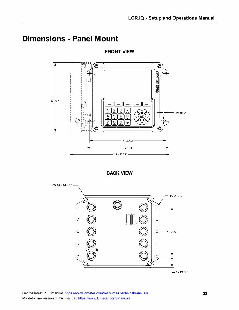
Dimensions - Panel Mount
FRONT VIEW
BACK VIEW

LCR.iQ - Setup and Operations Manual
24Get the latest PDF manual: https://www.lcmeter.com/resources/technical/manuals
Mobile/online version of this manual: https://www.lcmeter.com/manuals
SIDE VIEW
TOP VIEW
LCR.iQ - Setup and Operations Manual
25Get the latest PDF manual: https://www.lcmeter.com/resources/technical/manuals
Mobile/online version of this manual: https://www.lcmeter.com/manuals
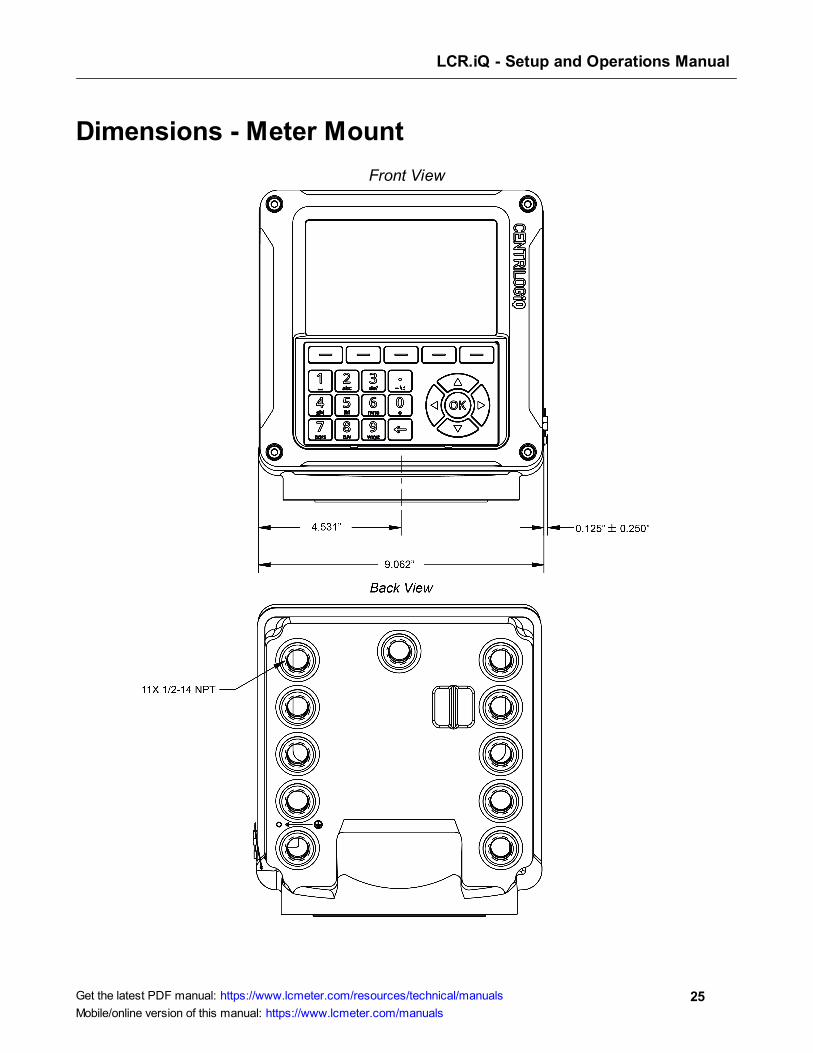
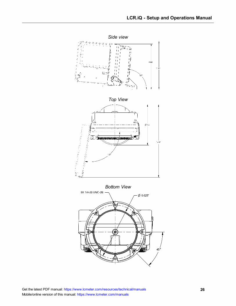
Dimensions - Meter Mount
Front View
LCR.iQ - Setup and Operations Manual
26Get the latest PDF manual: https://www.lcmeter.com/resources/technical/manuals
Mobile/online version of this manual: https://www.lcmeter.com/manuals
Side view
Top View
Bottom View
LCR.iQ - Setup and Operations Manual
27Get the latest PDF manual: https://www.lcmeter.com/resources/technical/manuals
Mobile/online version of this manual: https://www.lcmeter.com/manuals
Setup and Operation
The Liquid Controls LCR.iQ or MASTERLOAD.iQ is a microprocessor-based electronic meter
register that can be used for Weights & Measures approved custody transfer actions in mobile
or fixed installations.
NOTE: Throughout this manual, both the LCR.iQ and MASTERLOAD.iQ are
referred to as “Register” (unless otherwise specifically referenced by name).
The Register is a self-contained unit. All operation, setup, and configuration functions can be
carried out using the Register function keys and alphanumeric keypad. No lap pads, laptops,
or other data entry devices are required.
A complete Liquid Controls meter system not only accurately measures product, it also
regulates product flow and removes contaminants in order to produce the optimal conditions
for measurement. Typical systems include an air/vapor eliminator, strainer, meter, register,
and control valve.
It's just that simple.
Liquid Controls engineers took an aggressive approach by designing the Register from the
operator's perspective, as if little training should be required to use it. The result is a user-
guided, configurable interface that walks the operator through the fueling operation, minimizing
chance for error.
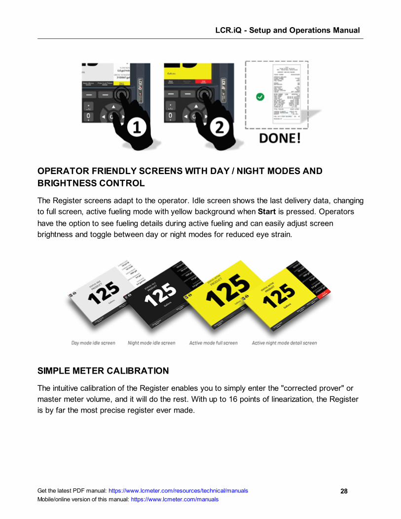
COMMON FUELING PROCESSES COMPLETED IN 3 STEPS OR LESS
User-configurable fueling processes control the number of steps required for the operator to
complete his or her delivery. Pump and print operations are complete in two steps, using one
function key!
LCR.iQ - Setup and Operations Manual
28Get the latest PDF manual: https://www.lcmeter.com/resources/technical/manuals
Mobile/online version of this manual: https://www.lcmeter.com/manuals
OPERATOR FRIENDLY SCREENS WITH DAY / NIGHT MODES AND
BRIGHTNESS CONTROL
The Register screens adapt to the operator. Idle screen shows the last delivery data, changing
to full screen, active fueling mode with yellow background when Start is pressed. Operators
have the option to see fueling details during active fueling and can easily adjust screen
brightness and toggle between day or night modes for reduced eye strain.
SIMPLE METER CALIBRATION
The intuitive calibration of the Register enables you to simply enter the "corrected prover" or
master meter volume, and it will do the rest. With up to 16 points of linearization, the Register
is by far the most precise register ever made.

LCR.iQ - Setup and Operations Manual
29Get the latest PDF manual: https://www.lcmeter.com/resources/technical/manuals
Mobile/online version of this manual: https://www.lcmeter.com/manuals
REAL-TIME ON-SCREEN DIAGNOSTICS
The Register provides the operator with real-time diagnostics. It also provides an error
indicator and message for any error condition that arises. Also, the operator can easily print
the report for corrective action and reference.
SECURITY
The Register has been designed with the highest levels of securit,y according to Center for
Internet Security (CIS) benchmarks. As an Internet-enabled device, it is imperative that any
weights-and-measures-approved devices meet or exceed CIS benchmarks for security. This
level of stringency also provides a robust user level security to prevent tampering or
inadvertent access to forbidden areas and settings on the device. Safety and security go hand-
in-hand, and these are the number one priority at Liquid Controls.

LCR.iQ - Setup and Operations Manual
30Get the latest PDF manual: https://www.lcmeter.com/resources/technical/manuals
Mobile/online version of this manual: https://www.lcmeter.com/manuals
CONFIGURABLE DELIVERY SETUP
Guide the operator through the fueling process of your choosing. From basic pump-and-print to
presetting–either by volume or product weight. It's easy to adjust price per gallon, percent tax,
or select multiple deliveries on a single ticket.
CONFIGURABLE IDLE SCREEN
Easily configure the idle screen fields the operator sees before, during, and after fueling. All
units of measure including date and time formats are also configurable to comply with local
standards.
LCR.iQ - Setup and Operations Manual
31Get the latest PDF manual: https://www.lcmeter.com/resources/technical/manuals
Mobile/online version of this manual: https://www.lcmeter.com/manuals
Software License Agreement
Read this license carefully. You agree that by using the itemized software package, you have agreed to the
software license terms and conditions. This agreement constitutes complete and entire agreement between you
and Liquid Controls with respect to this product.
1. Liquid Controls hereby grants to Licensee a non exclusive license to use SR1000 and SR1010 (hereinafter
referred to as “Licensed Software”).
2. Under the License granted herein, Licensee may use the itemized machine readable (executable code)
copy of the Software, including any subsequent updates which maybe provided. Licensee shall not, without
Liquid Controls prior written consent, (a) rent, lease, lend, sublease or otherwise transfer the materials
hereunder; (b) remove or obscure proprietary or copyright notices which may be set forth on the Licensed
Software; or (c) alter, decompile, or disassemble the program.
3. One (1) copy of the Licensed Software, including any software distributed on disks may be made for
backup purposes only. No other copies may be made or used without the written consent of Liquid
Controls.
4. Title. No title to ownership of any Licensed Software is transferred to the Licensee.
5. Upgrades. License upgrades may become available for the Licensed Software. Any cost associated with
such upgrades will solely be determined by Liquid Controls.
6. Warranty. Liquid Controls makes and licensee receives no warranty, express or implied, and thereby
expressly excludes all warranties of merchantability and fitness for a particular purpose.
7. Limitation of Liability. Licensee shall have the sole responsibility for adequate protection and backup ofits
data in connection with the Licensed Software. In no event shall Liquid Controls be liable for (a) special,
indirect or consequential damages; (b) any damages whatsoever resulting from loss of use, data, or profits,
product, inaccurate input or work delays, or any direct property damage arising out of or in connection
with this agreement or the use or performance of the Licensed Software.
8. Termination. Liquid Controls may terminate this software license granted hereunder and require return of
the Licensed Software if Licensee fails to comply with these license terms and conditions.
9. Licensee acknowledges that it has read this agreement, understands it, and agrees to be bound by its
terms, and further agrees that this is the complete and exclusive statement of the agreement between Liquid
Controls and Licensee, which supersedes and merges all prior proposals, understandings, and all other
agreements, oral or written, between the parties relating to this agreement. This agreement may not be
modified or altered except by written instrument duly executed by both parties.
10. This Agreement and performance hereunder shall be construed and interpreted under the laws of the State
of Illinois.
11. If any provision of this agreement is invalid under any applicable statute or rule of law, it is to that extent to
be deemed omitted.
12. Licensee may not assign or sublicense, without the prior written consent of Liquid Controls, its rights,
duties, or obligations under this Agreement to any person or entity in whole or in part.
13. The waiver or failure of Liquid Controls to exercise in any respect any right provided herein shall not be
deemed a waiver of any further right hereunder.

LCR.iQ - Setup and Operations Manual
32Get the latest PDF manual: https://www.lcmeter.com/resources/technical/manuals
Mobile/online version of this manual: https://www.lcmeter.com/manuals
Operational Information & Main Menu
This figure provides a visual overview of the register. In the sections below, you can find
general information on the operation of the register, screen layout, types of display screens,
and the keypad.
LCR.iQ - Setup and Operations Manual
33Get the latest PDF manual: https://www.lcmeter.com/resources/technical/manuals
Mobile/online version of this manual: https://www.lcmeter.com/manuals
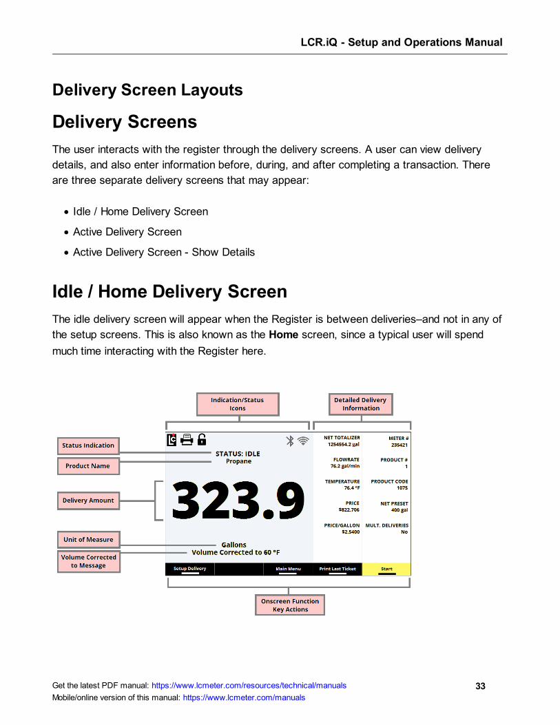
Delivery Screen Layouts
Delivery Screens
The user interacts with the register through the delivery screens. A user can view delivery
details, and also enter information before, during, and after completing a transaction. There
are three separate delivery screens that may appear:
· Idle / Home Delivery Screen
· Active Delivery Screen
· Active Delivery Screen - Show Details
Idle / Home Delivery Screen
The idle delivery screen will appear when the Register is between deliveries–and not in any of
the setup screens. This is also known as the Home screen, since a typical user will spend
much time interacting with the Register here.
LCR.iQ - Setup and Operations Manual
34Get the latest PDF manual: https://www.lcmeter.com/resources/technical/manuals
Mobile/online version of this manual: https://www.lcmeter.com/manuals
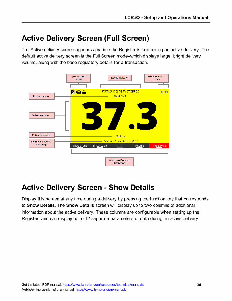
Active Delivery Screen (Full Screen)
The Active delivery screen appears any time the Register is performing an active delivery. The
default active delivery screen is the Full Screen mode–which displays large, bright delivery
volume, along with the base regulatory details for a transaction.
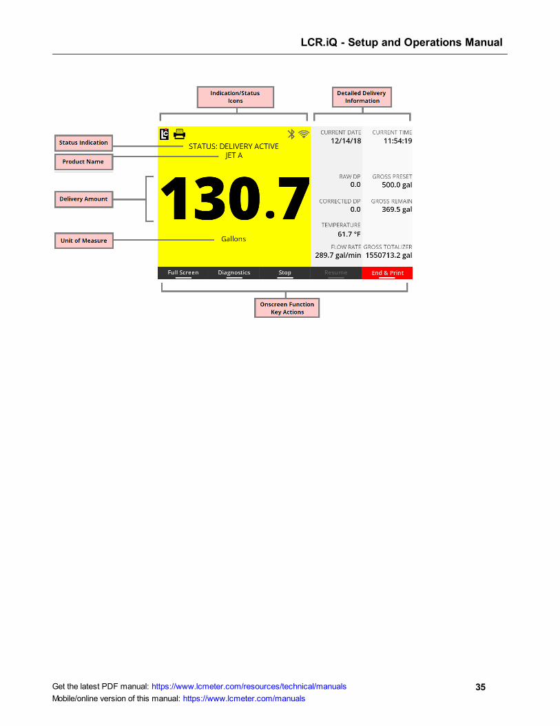
Active Delivery Screen - Show Details
Display this screen at any time during a delivery by pressing the function key that corresponds
to Show Details. The Show Details screen will display up to two columns of additional
information about the active delivery. These columns are configurable when setting up the
Register, and can display up to 12 separate parameters of data during an active delivery.
LCR.iQ - Setup and Operations Manual
35Get the latest PDF manual: https://www.lcmeter.com/resources/technical/manuals
Mobile/online version of this manual: https://www.lcmeter.com/manuals
LCR.iQ - Setup and Operations Manual
36Get the latest PDF manual: https://www.lcmeter.com/resources/technical/manuals
Mobile/online version of this manual: https://www.lcmeter.com/manuals
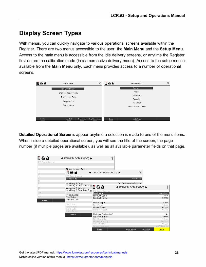
Display Screen Types
With menus, you can quickly navigate to various operational screens available within the
Register. There are two menus accessible to the user, the Main Menu and the Setup Menu.
Access to the main menu is accessible from the idle delivery screens, or anytime the Register
first enters the calibration mode (in a a non-active delivery mode). Access to the setup menu is
available from the Main Menu only. Each menu provides access to a number of operational
screens.
Detailed Operational Screens appear anytime a selection is made to one of the menu items.
When inside a detailed operational screen, you will see the title of the screen, the page
number (if multiple pages are available), as well as all available parameter fields on that page.

LCR.iQ - Setup and Operations Manual
37Get the latest PDF manual: https://www.lcmeter.com/resources/technical/manuals
Mobile/online version of this manual: https://www.lcmeter.com/manuals
Parameter fields display current information that has already been setup. Other general
information may also be shown. There are three main types of parameter fields within an
operation screen: list boxes, text fields, and read-only fields.
List Box parameter fields, when selected, provide the user with a list of options that are
available for that specific parameter. A list may be a drop-down list of available settings, or as
simple Yes/No selection. When the user selects a list box parameter, the list box will display
on the screen and the user can use the navigation keys to scroll up or down through the
available list of options. Press OK to make a selection.
Text box: When a text box parameter field has been selected, the user can manually enter
text information specific to that parameter. Text for these fields can be entered using the
alphanumeric keypad. Keep in mind that a text field can either be numeric (only numbers are

LCR.iQ - Setup and Operations Manual
38Get the latest PDF manual: https://www.lcmeter.com/resources/technical/manuals
Mobile/online version of this manual: https://www.lcmeter.com/manuals
permitted for that parameter) or alphanumeric (either numbers or letters are are permitted
for that specific parameter).
Read-only fields are for informational purposes, and display an Register parameter field that
maybe be useful when setting up or programming the register. Read-only fields always appear
on the screen in a gray text color.
LCR.iQ - Setup and Operations Manual
39Get the latest PDF manual: https://www.lcmeter.com/resources/technical/manuals
Mobile/online version of this manual: https://www.lcmeter.com/manuals
Keypad Interface
Keypad
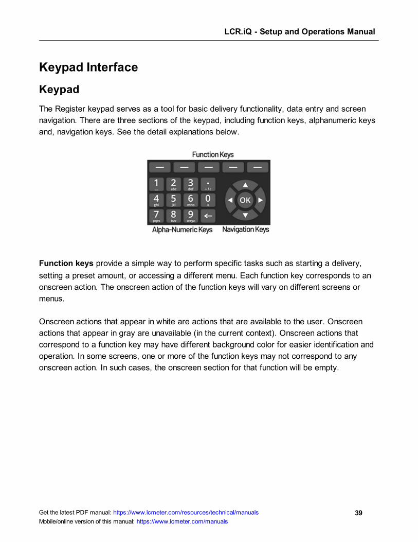
The Register keypad serves as a tool for basic delivery functionality, data entry and screen
navigation. There are three sections of the keypad, including function keys, alphanumeric keys
and, navigation keys. See the detail explanations below.
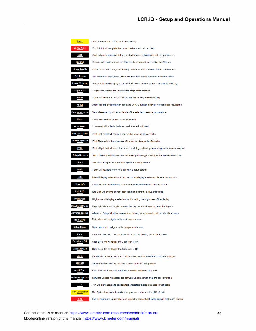
Function keys provide a simple way to perform specific tasks such as starting a delivery,
setting a preset amount, or accessing a different menu. Each function key corresponds to an
onscreen action. The onscreen action of the function keys will vary on different screens or
menus.
Onscreen actions that appear in white are actions that are available to the user. Onscreen
actions that appear in gray are unavailable (in the current context). Onscreen actions that
correspond to a function key may have different background color for easier identification and
operation. In some screens, one or more of the function keys may not correspond to any
onscreen action. In such cases, the onscreen section for that function will be empty.
LCR.iQ - Setup and Operations Manual
40Get the latest PDF manual: https://www.lcmeter.com/resources/technical/manuals
Mobile/online version of this manual: https://www.lcmeter.com/manuals
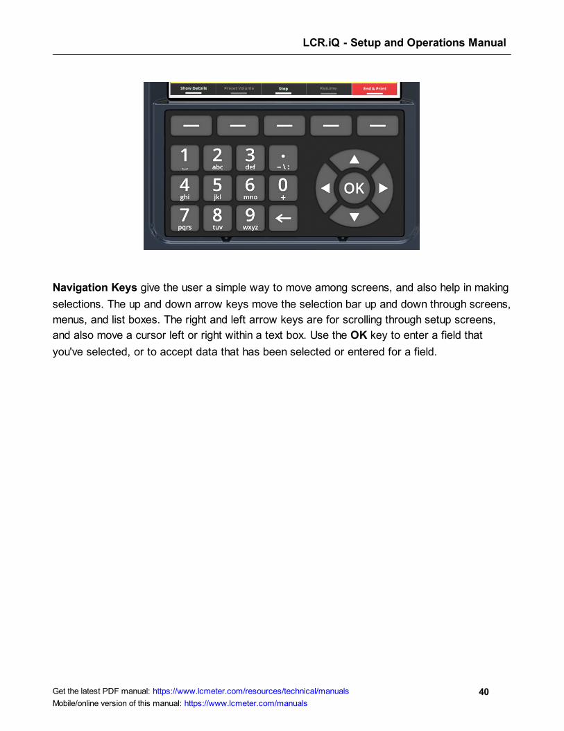
Navigation Keys give the user a simple way to move among screens, and also help in making
selections. The up and down arrow keys move the selection bar up and down through screens,
menus, and list boxes. The right and left arrow keys are for scrolling through setup screens,
and also move a cursor left or right within a text box. Use the OK key to enter a field that
you've selected, or to accept data that has been selected or entered for a field.
LCR.iQ - Setup and Operations Manual
41Get the latest PDF manual: https://www.lcmeter.com/resources/technical/manuals
Mobile/online version of this manual: https://www.lcmeter.com/manuals
LCR.iQ - Setup and Operations Manual
42Get the latest PDF manual: https://www.lcmeter.com/resources/technical/manuals
Mobile/online version of this manual: https://www.lcmeter.com/manuals
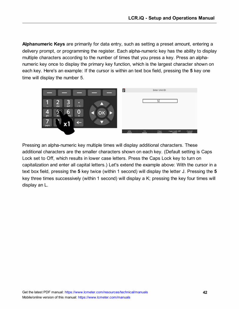
Alphanumeric Keys are primarily for data entry, such as setting a preset amount, entering a
delivery prompt, or programming the register. Each alpha-numeric key has the ability to display
multiple characters according to the number of times that you press a key. Press an alpha-
numeric key once to display the primary key function, which is the largest character shown on
each key. Here's an example: If the cursor is within an text box field, pressing the 5 key one
time will display the number 5.
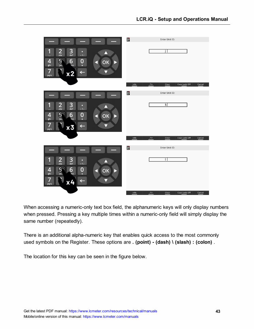
Pressing an alpha-numeric key multiple times will display additional characters. These
additional characters are the smaller characters shown on each key. (Default setting is Caps
Lock set to Off, which results in lower case letters. Press the Caps Lock key to turn on
capitalization and enter all capital letters.) Let's extend the example above: With the cursor in a
text box field, pressing the 5 key twice (within 1 second) will display the letter J. Pressing the 5
key three times successively (within 1 second) will display a K; pressing the key four times will
display an L.
LCR.iQ - Setup and Operations Manual
43Get the latest PDF manual: https://www.lcmeter.com/resources/technical/manuals
Mobile/online version of this manual: https://www.lcmeter.com/manuals
When accessing a numeric-only text box field, the alphanumeric keys will only display numbers
when pressed. Pressing a key multiple times within a numeric-only field will simply display the
same number (repeatedly).
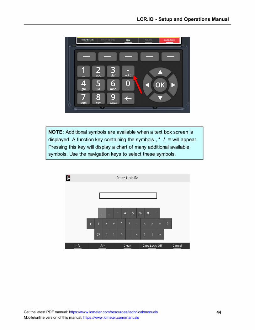
There is an additional alpha-numeric key that enables quick access to the most commonly
used symbols on the Register. These options are . (point) - (dash) \ (slash) : (colon) .
The location for this key can be seen in the figure below.
LCR.iQ - Setup and Operations Manual
44Get the latest PDF manual: https://www.lcmeter.com/resources/technical/manuals
Mobile/online version of this manual: https://www.lcmeter.com/manuals
NOTE: Additional symbols are available when a text box screen is
displayed. A function key containing the symbols , * / = will appear.
Pressing this key will display a chart of many additional available
symbols. Use the navigation keys to select these symbols.

LCR.iQ - Setup and Operations Manual
45Get the latest PDF manual: https://www.lcmeter.com/resources/technical/manuals
Mobile/online version of this manual: https://www.lcmeter.com/manuals
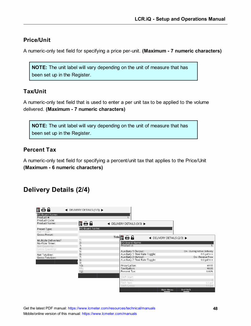
Delivery Details
This section contains additional delivery parameters that you can configure for display on the
Delivery Screens . There are three screens that contains a number of parameters each. See
the explanations for each below.
Delivery Details (1/4)
I/O Board Name
(This appears on each of the three screens)
A text field that is used to identify the currently selected I/O board in the I/O board # field. The
name will display on some other screens where it is necessary to clearly identify the selected
board. (Maximum - 16 Characters)
Product #
(This appears on each of the three screens)
A listing of the 16 products available for setting up and calibrating the Register.
Options: Products 1-16 are available for setup. Only setup and calibrate products that are to
be used by the Register.
33
LCR.iQ - Setup and Operations Manual
46Get the latest PDF manual: https://www.lcmeter.com/resources/technical/manuals
Mobile/online version of this manual: https://www.lcmeter.com/manuals
Product Code
A text field for identifying the selected product with a code. The product code will appear on
most ticket formats to identify the product that was delivered. (Maximum - 5 Alphanumeric
characters)
Product Name
A text field for identifying the selected product with a specific name. This name will appear on
most ticket formats.
Preset Type
A list box for specifying how the Register will react when it reaches the preset amount. The
choice here also affects when the end delivery command is sent and when the ticket will print.
Options:
· Clear – At the point when the Register reaches the preset value, the delivery ends
automatically, the ticket is printed, and the preset value is set to 0.
· Multiple – At the point when the Register reaches the preset value, the delivery is paused
but remains active until the user either (a) presses Resume, (b) sets a new preset and
presses Resume, or (c) ends the delivery by pressing the End & Print button and the
preset value is set to 0.
· Retain – At the point when the Register reaches the preset value, the delivery
automatically ends, the ticket prints, and the original preset value is retained for the next
delivery.
Net Preset
A numeric text field for the net preset value–if net presets are accepted and temperature
compensation is active. (Maximum - 7 numeric characters)
Gross Preset
A numeric text field for the gross preset value–if gross presets are accepted. (Maximum - 7
numeric characters)
LCR.iQ - Setup and Operations Manual
47Get the latest PDF manual: https://www.lcmeter.com/resources/technical/manuals
Mobile/online version of this manual: https://www.lcmeter.com/manuals
Weight Preset
A numeric text field for the weight preset value–if weight presets are accepted. (Maximum - 7
numeric characters)
Price Preset
A numeric text field for the price preset value–if price presets are accepted. (Maximum - 7
numeric characters)
Multiple Deliveries?
A list box in which you can specify if the Multiple Deliveries feature is to be on or off. If
Multiple Deliveries is set to Yes, you can fill multiple tanks at one location without being
affected by the No Flow Timer feature (see below. This only applies to the next delivery, and
will revert back to No automatically when the delivery completes.
If this field is set to No, any deliveries will need to be within the value specified in No Flow
Timer.
NOTE: There is also a printer parameter, Print Multiple Deliveries Per
Site Message in Register 3/3, that is directly affected by this setting.
No Flow Timer
A numeric-only field for specifying the duration of the No Flow Timer. This is an internal timer
that begins when the Register senses that there is no longer any product moving through the
meter. If this timer counts up to its set point, the Register will assume that the delivery is
complete and a ticker will print automatically. The default value for this field is 180 (seconds).
Deactivate this feature by entering 0 seconds, which permits filling multiple tanks at a single
location simultaneously. The timer helps to ensure that deliveries are not split between
authorized and unauthorized locations. If the value is set to 0–or any value greater than 180–
and the Print Multiple Deliveries Per Site message is set to On, the Multiple Deliveries At
One Site message will print on the delivery ticket. (Maximum - 3600 Seconds)
LCR.iQ - Setup and Operations Manual
48Get the latest PDF manual: https://www.lcmeter.com/resources/technical/manuals
Mobile/online version of this manual: https://www.lcmeter.com/manuals
Price/Unit
A numeric-only text field for specifying a price per-unit. (Maximum - 7 numeric characters)
NOTE: The unit label will vary depending on the unit of measure that has
been set up in the Register.
Tax/Unit
A numeric-only text field that is used to enter a per unit tax to be applied to the volume
delivered. (Maximum - 7 numeric characters)
NOTE: The unit label will vary depending on the unit of measure that has
been set up in the Register.
Percent Tax
A numeric-only text field for specifying a percent/unit tax that applies to the Price/Unit
(Maximum - 6 numeric characters)
Delivery Details (2/4)
LCR.iQ - Setup and Operations Manual
49Get the latest PDF manual: https://www.lcmeter.com/resources/technical/manuals
Mobile/online version of this manual: https://www.lcmeter.com/manuals
Auxiliary 1 Output
A list box that determines how any digital output that is set to AUX 1 will operate on the
selected product. To control external components, there are several features in the Register
that can be set to perform according to the Auxiliary 1 and Auxiliary 2 settings. This includes
pumps, injectors, PTO, throttle, alarms, and reset pulse, among others.
Options:
· Off – Any output set to AUX 1 Calibration Mode Settings will always be off (inactive).
· On – Any output set to AUX 1 Calibration Mode Settings will always be on (Active and
Sinking to ground).
· On - During Active Delivery – Any output set to AUX 1 Calibration Mode Settings will
turn on (Sink to ground) when a delivery is started. It will turn off when the delivery is
complete.
· On - During Run State – Any output set to AUX 1 Calibration Mode Settings will turn on
(Sink to ground) when a delivery is active and not paused. The output will be on when a
delivery begins. However, if the delivery pauses, the output will turn off until the delivery
resumes. If the End of delivery command is given, the output will remain off and the
delivery will end.
· On - Flow Rate Monitor – Any output set to AUX 1 Calibration Mode Settings will be on
when a delivery is active. However, it will deactivate if the flow rate meets or exceeds 40
units/time. If the flow rate does not meet or exceed 40 units/time, the output will remain
on.
· On - Reverse Flow – Any output set to AUX 1 Calibration Mode Settings will be off when
a delivery begins. It will only turn on when the register detects flow in the negative or
reverse direction.
· Reset Pulse/Delivery Start – For any delivery that uses 3rd-party remote counters
requiring a reset pulse to 0.0, any output set to AUX 1 Calibration Mode Settings will
output a short pulse at the start of a delivery.
· Toggle Flow Rate – Any output set to AUX 1 Calibration Mode Settings will turn on once
the flow rate of the Register exceeds the set flow rate point in the Auxiliary 1 Flow Rate
Toggle field. See below.

LCR.iQ - Setup and Operations Manual
50Get the latest PDF manual: https://www.lcmeter.com/resources/technical/manuals
Mobile/online version of this manual: https://www.lcmeter.com/manuals
· Calibrated Scaled Pulse Output – Any output set to AUX 1 Calibration Mode Settings
will be a calibrated pulse output that scales according to the Pulse Output
Frequency setting in the calibration mode.
Auxiliary 1 Flow Rate Toggle
A numeric-text field that can be used to program a flow rate set point when the Aux 1 is set to
Toggle flow rate. Auxiliary 1 remains activated above the set flow rate value and deactivates
when the flow rate falls below the value.
A common use for this output is an air operated valve (AOV) on the pump. When the flow rate
value is attained, the AOV is activated switching the pump from low-bypass pressure mode to
full-flow fuel mode (high bypass pressure). When the flow rate falls below the set value, the
AOV deactivates and the pump returns to low-flow.
Another possible output is the engine throttle—to increase and decrease the RPM of the pump
shaft. In applications such as these, the flow rate value in this field should be below the low-
flow rate with a fully open nozzle—or the output will never turn on.
Another application of this field is to set the value as a maximum flow rate at which a valve
should be closed. On fuel delivery trucks, flow valves often activate an internal switch at
approximately 18 GPM (68 LPM). The value of this field is unique to each product.
Auxiliary 2 Output
A listing that determines how any digital output that is set to AUX 2 will operate on the
selected product. To control external components, there are several features in the Register
that can be set to perform according to the Auxiliary 1 and Auxiliary 2 settings. This includes
pumps, injectors, PTO, throttle, alarms, reset pulse, among others
Options:
· Off – Any output set to AUX 2 Calibration Mode Settings will always be off (inactive).
· On – Any output set to AUX 2 Calibration Mode Settings will always be on (Active and
Sinking to ground).
LCR.iQ - Setup and Operations Manual
51Get the latest PDF manual: https://www.lcmeter.com/resources/technical/manuals
Mobile/online version of this manual: https://www.lcmeter.com/manuals
· On - During Active Delivery – Any output set to AUX 1 Calibration Mode Settings will
turn on (Sink to ground) when a delivery is started. It will turn off when the delivery is
complete.
· On - During Run State – Any output set to AUX 1 Calibration Mode Settings will turn on
(Sink to ground) when a delivery is active and not paused. The output will be on when a
delivery begins. However, if the delivery pauses, the output will turn off until the delivery
resumes. If the End of delivery command is given, the output will remain off and the
delivery will end.
· On - Flow Rate Monitor – Any output set to AUX 2 Calibration Mode Settings will be on
when a delivery is active. However, it will deactivate if the flow rate meets or exceeds 40
units/time. If the flow rate does not meet or exceed 40 units/time, the output will remain
on.
· On - Reverse Flow – Any output set to AUX 2 Calibration Mode Settings will be off when
a delivery begins. It will only turn on when the register detects flow in the negative or
reverse direction.
· Reset Pulse/Delivery Start – For any delivery that uses 3rd-party remote counters
requiring a reset pulse to 0.0, any output set to AUX 2 Calibration Mode Settings will
output a short pulse at the start of a delivery.
· Toggle Flow Rate – Any output set to AUX 2 Calibration Mode Settings will turn on once
the flow rate of the Register exceeds the set flow rate point in the Auxiliary 1 Flow Rate
Toggle field. See below.
· Calibrated Scaled Pulse Output – Any output set to AUX 2 Calibration Mode Settings
will be a calibrated pulse output that scales according to the Pulse Output
Frequency setting in the calibration mode.
Auxiliary 2 Flow Rate Toggle
A numeric-text field that can be used to program a flow rate set point when the AUX 2 is set to
Toggle flow rate. Auxiliary 2 remains activated above the set flow rate value and deactivates
when the flow rate falls below the value.
Shift Start
A read-only field that displays the time and date that the current active shift began.
LCR.iQ - Setup and Operations Manual
52Get the latest PDF manual: https://www.lcmeter.com/resources/technical/manuals
Mobile/online version of this manual: https://www.lcmeter.com/manuals
Deliveries
A read-only field that displays the number of deliveries made during the currently active shift.
This value will reset each time the Clear-Shift command is given and the shift ticket prints.
Shift Net
A read-only field that will display the total net volume that was delivered during the currently
active shift. This value will reset each time the Clear-Shift command is given and the shift
ticket prints.
Shift Gross
A read-only field that will display the total gross volume that was delivered during the currently
active shift. This value will reset each time the Clear-Shift command is given and the shift
ticket prints.
Net Quantity
A read-only numeric field that displays the current net delivery quantity.
Gross Quantity
A read-only numeric field that displays the current gross delivery quantity.
Net Totalizer
A numeric-text field that display the current accumulative net totalizer value of the selected
product. This is a non-resettable totalizer. However, it is programmable in the Weight and
Measures (Calibration) mode–if reprogramming is necessary. (Maximum - 9 numeric
characters)
Gross Totalizer
A numeric-text field that displays the current accumulative gross totalizer value of the selected
product. This is a non-resettable totalizer. However, it is programmable in the Weight and
Measures (Calibration) mode–if reprogramming is necessary. (Maximum - 9 numeric
characters)
LCR.iQ - Setup and Operations Manual
53Get the latest PDF manual: https://www.lcmeter.com/resources/technical/manuals
Mobile/online version of this manual: https://www.lcmeter.com/manuals
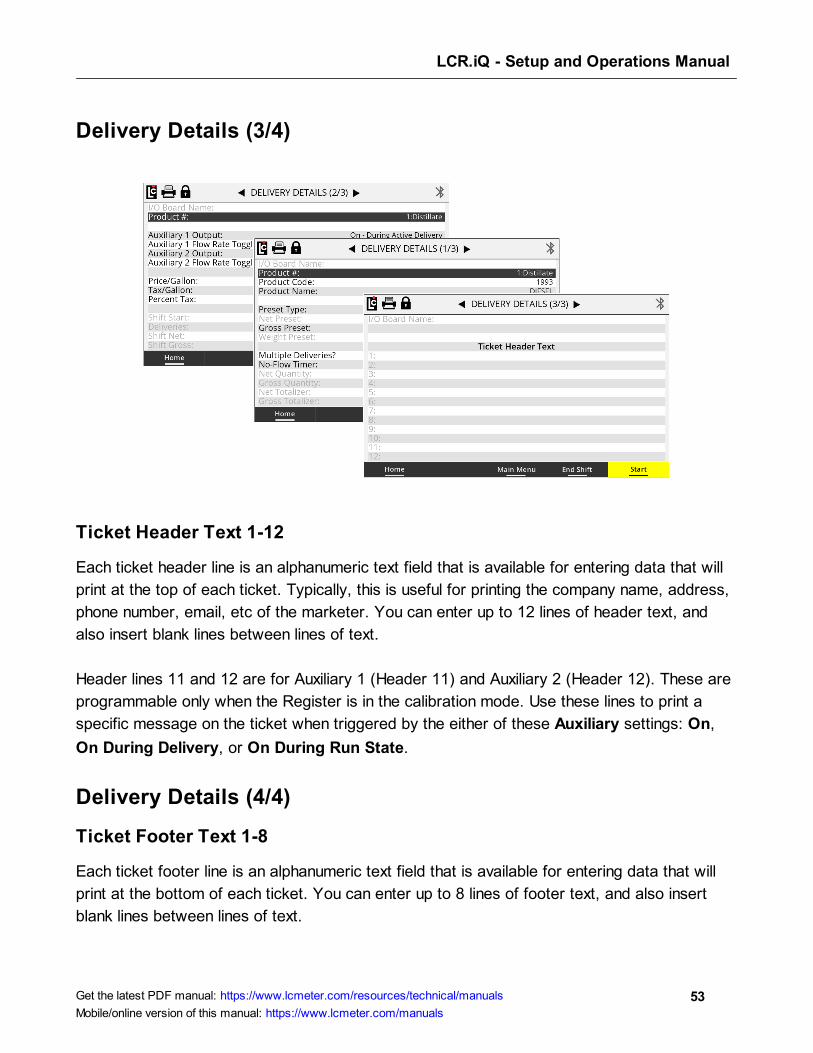
Delivery Details (3/4)
Ticket Header Text 1-12
Each ticket header line is an alphanumeric text field that is available for entering data that will
print at the top of each ticket. Typically, this is useful for printing the company name, address,
phone number, email, etc of the marketer. You can enter up to 12 lines of header text, and
also insert blank lines between lines of text.
Header lines 11 and 12 are for Auxiliary 1 (Header 11) and Auxiliary 2 (Header 12). These are
programmable only when the Register is in the calibration mode. Use these lines to print a
specific message on the ticket when triggered by the either of these Auxiliary settings: On,
On During Delivery, or On During Run State.
Delivery Details (4/4)
Ticket Footer Text 1-8
Each ticket footer line is an alphanumeric text field that is available for entering data that will
print at the bottom of each ticket. You can enter up to 8 lines of footer text, and also insert
blank lines between lines of text.
LCR.iQ - Setup and Operations Manual
54Get the latest PDF manual: https://www.lcmeter.com/resources/technical/manuals
Mobile/online version of this manual: https://www.lcmeter.com/manuals
End Shift
Pressing the End Shift function key to end the shift. Respond to the prompt “Are you sure
you want to end your shift?” with either the Yes or No function keys:
· No - Returns the Register back to the Delivery Details screen.
· Yes - Prints the end-of-shift ticket if a ticket printer is available and ready.
LCR.iQ - Setup and Operations Manual
55Get the latest PDF manual: https://www.lcmeter.com/resources/technical/manuals
Mobile/online version of this manual: https://www.lcmeter.com/manuals
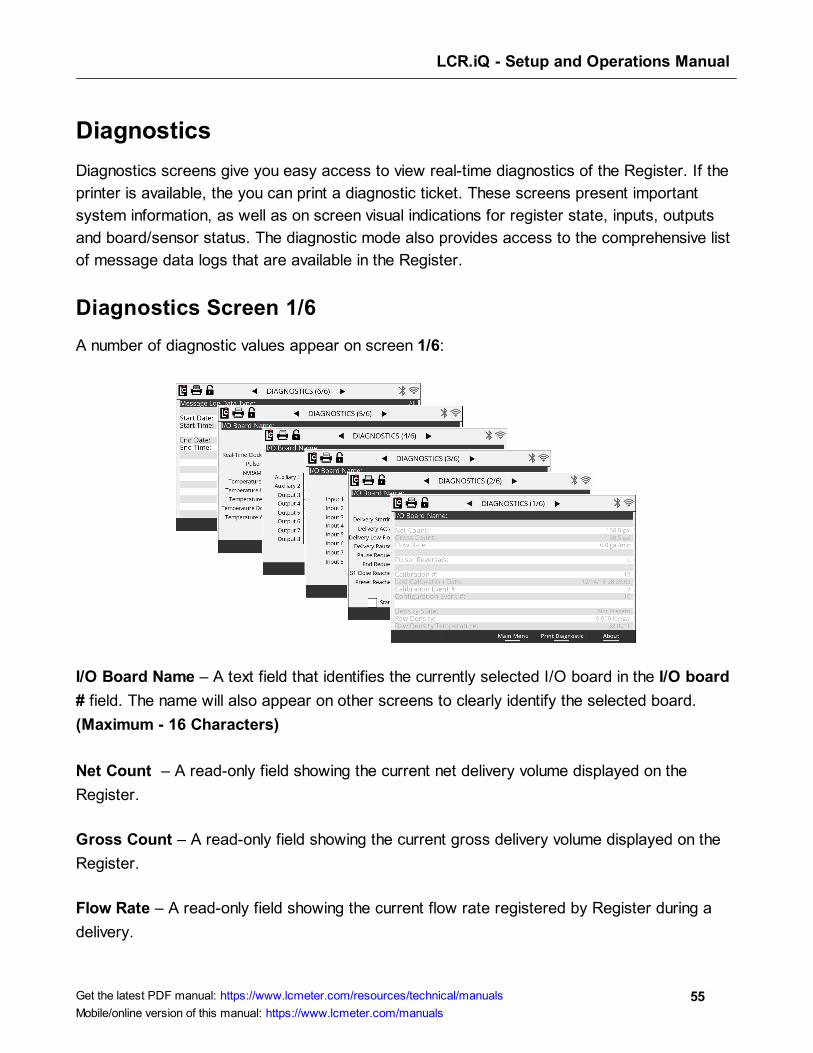
Diagnostics
Diagnostics screens give you easy access to view real-time diagnostics of the Register. If the
printer is available, the you can print a diagnostic ticket. These screens present important
system information, as well as on screen visual indications for register state, inputs, outputs
and board/sensor status. The diagnostic mode also provides access to the comprehensive list
of message data logs that are available in the Register.
Diagnostics Screen 1/6
A number of diagnostic values appear on screen 1/6:
I/O Board Name – A text field that identifies the currently selected I/O board in the I/O board
# field. The name will also appear on other screens to clearly identify the selected board.
(Maximum - 16 Characters)
Net Count – A read-only field showing the current net delivery volume displayed on the
Register.
Gross Count – A read-only field showing the current gross delivery volume displayed on the
Register.
Flow Rate – A read-only field showing the current flow rate registered by Register during a
delivery.
LCR.iQ - Setup and Operations Manual
56Get the latest PDF manual: https://www.lcmeter.com/resources/technical/manuals
Mobile/online version of this manual: https://www.lcmeter.com/manuals
Pulser Reversals – A read-only field that accounts for any quadrature pulser faults registered
by the Register during a delivery.
Calibration # – A read-only counter that increments one number each time the Register enters
the calibration mode. This field is for metrological and troubleshooting use only.
Last Calibration Date – A read-only field displaying the last date and time the Register
entered into the calibration mode.
Calibration Event # – A read-only counter that increments one number each time the Register
enters the calibration mode and a calibration change is made. This field only increments one
time per entry into calibration even if multiple changes are made. This field is for metrological
and troubleshooting use only.
Configuration Event # – A read-only counter that increments one number each time (a) the
Register enters the calibration mode and (b) a configuration field changes. This field only
increments one time per entry into calibration even if multiple changes are made. This field is
for metrological and troubleshooting use only.
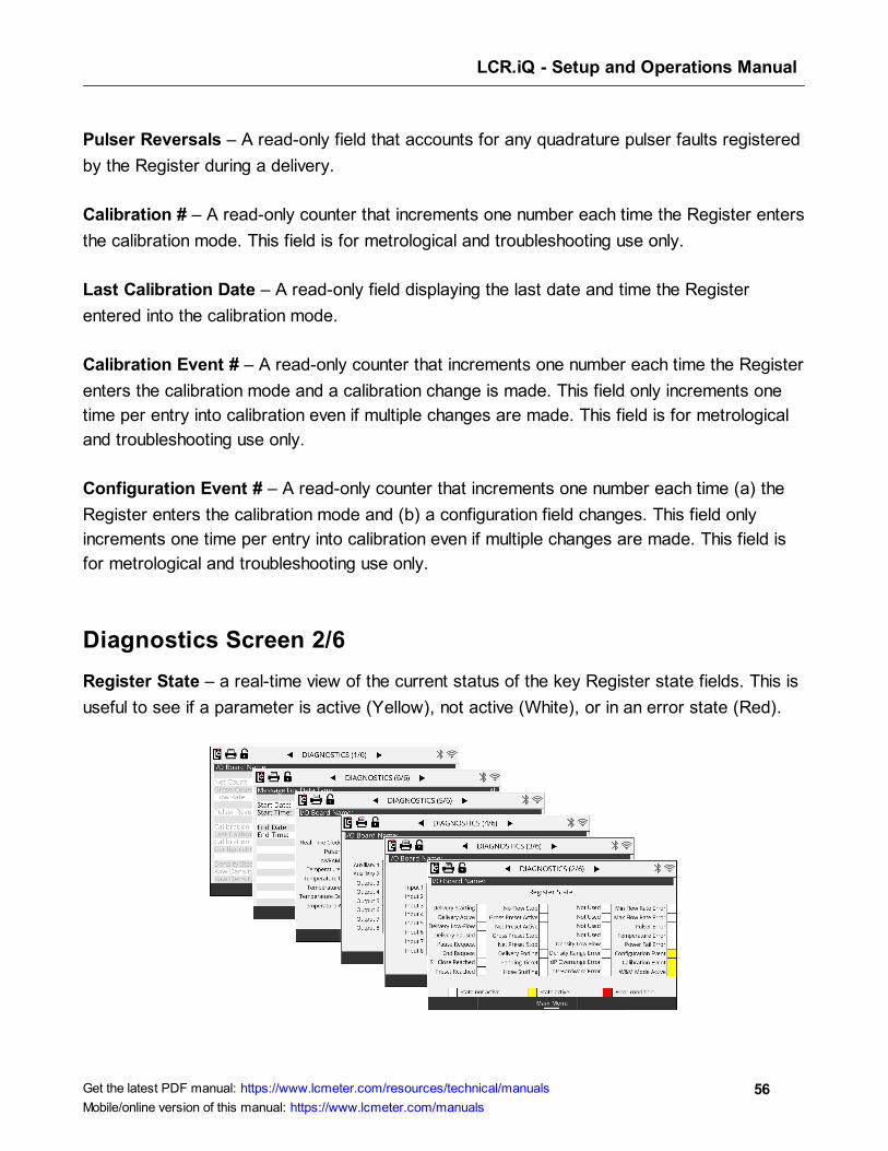
Diagnostics Screen 2/6
Register State – a real-time view of the current status of the key Register state fields. This is
useful to see if a parameter is active (Yellow), not active (White), or in an error state (Red).

LCR.iQ - Setup and Operations Manual
57Get the latest PDF manual: https://www.lcmeter.com/resources/technical/manuals
Mobile/online version of this manual: https://www.lcmeter.com/manuals
Diagnostics Screens 3/6 and 4/6
I/O Board inputs and outputs appear on screens 3/6 and 4/6. These provide a real-time view
of the current status of Register I/O board digital inputs and outputs. These are useful in
monitoring inputs and outputs that may have a status of on (Yellow), off (White), or error
(Red).
Diagnostics Screen 5/6
Potential error conditions are shown on Diagnostics Screen 5/6. The status will be either off
(White) or error (Red).

LCR.iQ - Setup and Operations Manual
58Get the latest PDF manual: https://www.lcmeter.com/resources/technical/manuals
Mobile/online version of this manual: https://www.lcmeter.com/manuals
Diagnostics Screen 6/6
Message Logging is a tool within the register that allows a user to pull log files from the
register and display, print and export log information within a given date range.
Message Log Data Type
A list box that can be used to select a data log that can be viewed on screen and printed.
Upon selecting Message Log Data Type, a drop-down menu appears and provides the
following log file types you can view.
Message Log Data Types include the following: All, Calibration, Errors, Flow Start/End,
Hardware Diagnostics, LCP Diagnostics, Operator Actions, Parameter Changes, Shift
Start/End, Software Diagnostics, and Warnings.
Once a log file type is selected, press the function key View Logs to display the logs on the
screen within the given date range. Once the log is viewable on screen, you can press the
function key Print to print the log (if printer is installed).

LCR.iQ - Setup and Operations Manual
59Get the latest PDF manual: https://www.lcmeter.com/resources/technical/manuals
Mobile/online version of this manual: https://www.lcmeter.com/manuals
Setup Menu
The Setup Menu contains a list of menu options for configuring the Register for operation.
Typically, the setup menu options are set up when the register is installed or calibrated.
Settings that are programmed using the setup menu options will affect how the register will
display, print, report and operate. When setting up the Register, it is important to understand
how each of these settings affect the Register register and contribute to proper operation for
the application.
Register Settings
Register menu options can be found on three screens. These parameters are for configuring
general functionality of the Register, and how it will interact with components in the system.

LCR.iQ - Setup and Operations Manual
60Get the latest PDF manual: https://www.lcmeter.com/resources/technical/manuals
Mobile/online version of this manual: https://www.lcmeter.com/manuals
Register (1/3)
W&M Jurisdiction – Selecting the proper local jurisdiction option will automatically adjust the
available setup menu options and remove options that are not acceptable based on the
selection.
Options:
· NTEP - National Type Evaluation Program - US W&M
· Measurement Canada
Unit ID – A text field for identifying the equipment or meter that the Register is associated
with. (Maximum - 10 alphanumeric characters)
Volume Unit of Measure – A list box for setting the volumetric unit of measure to be used by
the register for flow measurement.
Options:
· Gallon
· Litre
LCR.iQ - Setup and Operations Manual
61Get the latest PDF manual: https://www.lcmeter.com/resources/technical/manuals
Mobile/online version of this manual: https://www.lcmeter.com/manuals
· Cubic Meter
· LB (Pound)
· KG (Kilograms)
· Barrel
· Other
Residual Processing – A list box for selecting how the Register will display volumes less than
the least significant digit.
Options:
· Round - Adjust delivery amount to the closest least significant digit.
· Truncate - Throw away the remaining value and always round down.
Flow Rate Base – A list box for selecting the time unit for flow measurement. This field will
affect how the unit of flow rate measure will display on the screen–and what appears on
printed tickets and transactional records.
Options:
· Per Minute
· Per Hour
· Per Secord
Temperature Unit of Measure – A list box for selecting the unit of measure used when a
temperature probe is connected to the Register.
Options:
· °F - Fahrenheit
· °C - Celsius
Monetary Unit of Measure – A text field for identifying the type of currency. (Maximum - 3
alphanumeric characters)
LCR.iQ - Setup and Operations Manual
62Get the latest PDF manual: https://www.lcmeter.com/resources/technical/manuals
Mobile/online version of this manual: https://www.lcmeter.com/manuals
Monetary Precision – A list box that is used to select the number of decimal places to be
used when printing and displaying pricing.
Options:
· 0 (0) - No decimal place
· 1 (0.0) - One digit after the decimal place
· 2 (0.00) - Two digits after the decimal place
· 3 (0.000) - Three digits after the decimal place
· 4 (0.0000) - Four digits after the decimal place
Date Format – A list box that is used to set the format for displaying and printing the Register
date.
Options:
· MM/DD/YY - Month/Day/Year
· DD/MM/YY - Day/ Month/Year
Current Date – A fixed data entry field setting the internal calendar of the Register according
to the date format field option. The Register will update the calendar automatically according
to this setting. The date can be displayed on screen, printed on the ticket, and appear in each
transaction record.
Time Format – A list box that is used to set the format for displaying and printing the Register
time.
Options:
· HH/MM/SS - Time will display with Hours/Minutes/Second
· AM/PM - Time will display with Hours/Minutes with am or pm
LCR.iQ - Setup and Operations Manual
63Get the latest PDF manual: https://www.lcmeter.com/resources/technical/manuals
Mobile/online version of this manual: https://www.lcmeter.com/manuals
Current Time – A fixed-data entry field for setting the register time clock of the Register
according to the time format field option. The Register will update the time according to this
setting. The time can be displayed on screen, printed on the ticket, and appear in each
transaction record.
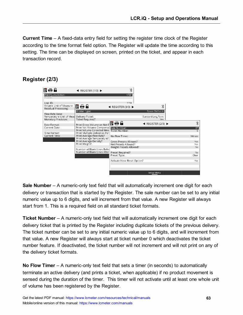
Register (2/3)
Sale Number – A numeric-only text field that will automatically increment one digit for each
delivery or transaction that is started by the Register. The sale number can be set to any initial
numeric value up to 6 digits, and will increment from that value. A new Register will always
start from 1. This is a required field on all standard ticket formats.
Ticket Number – A numeric-only text field that will automatically increment one digit for each
delivery ticket that is printed by the Register including duplicate tickets of the previous delivery.
The ticket number can be set to any initial numeric value up to 6 digits, and will increment from
that value. A new Register will always start at ticket number 0 which deactivates the ticket
number feature. If deactivated, the ticket number will not increment and will not print on any of
the delivery ticket formats.
No Flow Timer – A numeric-only text field that sets a timer (in seconds) to automatically
terminate an active delivery (and prints a ticket, when applicable) if no product movement is
sensed during the duration of the timer. This timer will not activate until at least one whole unit
of volume has been registered by the Register.
LCR.iQ - Setup and Operations Manual
64Get the latest PDF manual: https://www.lcmeter.com/resources/technical/manuals
Mobile/online version of this manual: https://www.lcmeter.com/manuals
Setting this field to 0 will deactivate the No Flow Timer. Also, setting this field to a value of 0 or
a value greater than 180 (up to 3600) may activate the “Print Multiple Deliveries Per Site
Message”
NOTE: See Register (3/3) to setup the “Print Multiple Deliveries Per
Site Message”.
The No Flow Timer can also be toggled on and off (180 to 0) in the Setup Delivery mode by
activating the Multiple Deliveries Per Site option in Configure Delivery Setup menu.
Gross Presets Allowed? – A list box that enables or disables the option and the ability to
use gross presets when making a delivery.
Options:
· No - Gross presets are not allowed
· Yes - Gross presets are allowed
Net Presets Allowed? – A list box that enables or disables the option and the ability to use
gross presets when making a delivery. Net presets require an ETVC kit to be installed and
temperature compensation to be active on the Register.
Options:
· No - Net presets are not allowed
· Yes - Net presets are allowed
Weight Presets Allowed? – A list box that enables or disables the option and the ability to
use weight presets during a delivery.
Weight presets require that an automatic density sensor be installed, or otherwise that the
manual density entry is active on the Register.
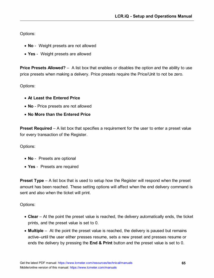
LCR.iQ - Setup and Operations Manual
65Get the latest PDF manual: https://www.lcmeter.com/resources/technical/manuals
Mobile/online version of this manual: https://www.lcmeter.com/manuals
Options:
· No - Weight presets are not allowed
· Yes - Weight presets are allowed
Price Presets Allowed? – A list box that enables or disables the option and the ability to use
price presets when making a delivery. Price presets require the Price/Unit to not be zero.
Options:
· At Least the Entered Price
· No - Price presets are not allowed
· No More than the Entered Price
Preset Required – A list box that specifies a requirement for the user to enter a preset value
for every transaction of the Register.
Options:
· No - Presets are optional
· Yes - Presets are required
Preset Type – A list box that is used to setup how the Register will respond when the preset
amount has been reached. These setting options will affect when the end delivery command is
sent and also when the ticket will print.
Options:
· Clear – At the point the preset value is reached, the delivery automatically ends, the ticket
prints, and the preset value is set to 0.
· Multiple – At the point the preset value is reached, the delivery is paused but remains
active–until the user either presses resume, sets a new preset and presses resume or
ends the delivery by pressing the End & Print button and the preset value is set to 0.
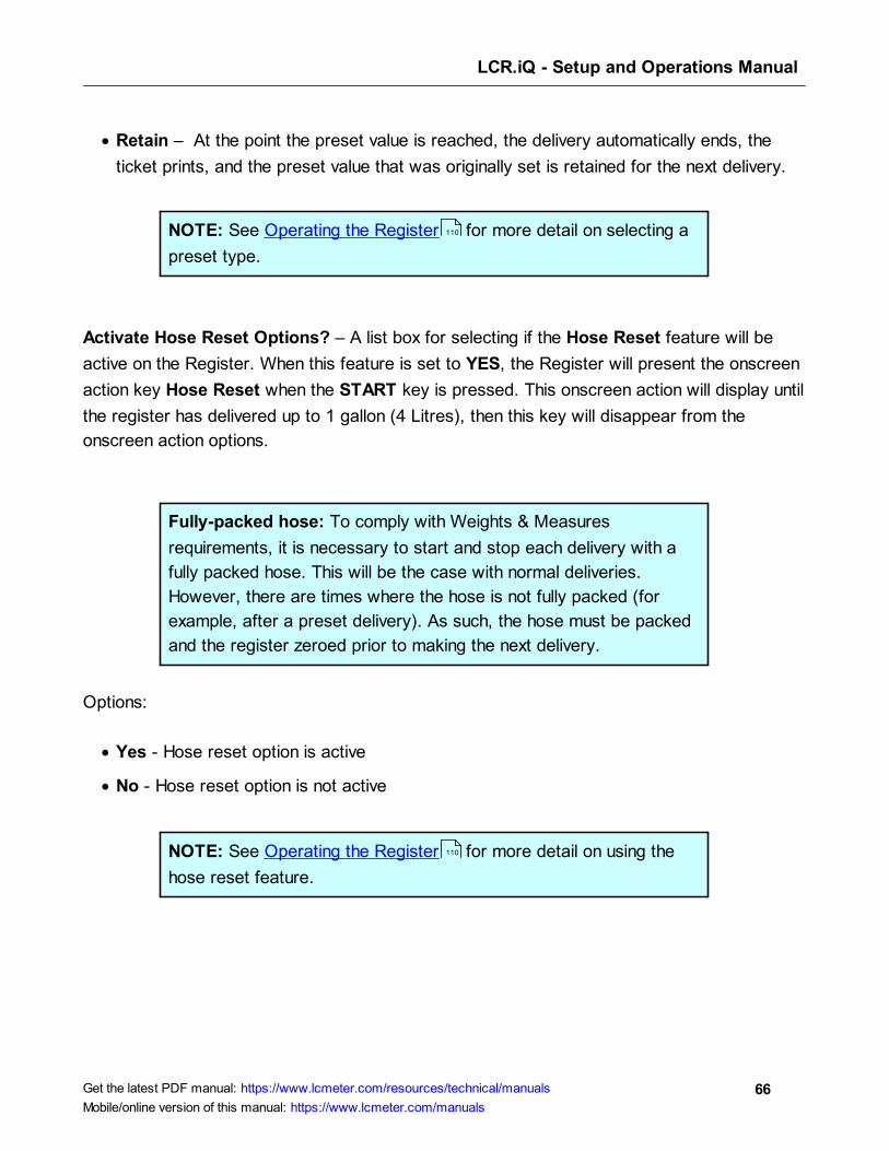
LCR.iQ - Setup and Operations Manual
66Get the latest PDF manual: https://www.lcmeter.com/resources/technical/manuals
Mobile/online version of this manual: https://www.lcmeter.com/manuals
· Retain – At the point the preset value is reached, the delivery automatically ends, the
ticket prints, and the preset value that was originally set is retained for the next delivery.
NOTE: See Operating the Register for more detail on selecting a
preset type.
Activate Hose Reset Options? – A list box for selecting if the Hose Reset feature will be
active on the Register. When this feature is set to YES, the Register will present the onscreen
action key Hose Reset when the START key is pressed. This onscreen action will display until
the register has delivered up to 1 gallon (4 Litres), then this key will disappear from the
onscreen action options.
Fully-packed hose: To comply with Weights & Measures
requirements, it is necessary to start and stop each delivery with a
fully packed hose. This will be the case with normal deliveries.
However, there are times where the hose is not fully packed (for
example, after a preset delivery). As such, the hose must be packed
and the register zeroed prior to making the next delivery.
Options:
· Yes - Hose reset option is active
· No - Hose reset option is not active
NOTE: See Operating the Register for more detail on using the
hose reset feature.
110
110

LCR.iQ - Setup and Operations Manual
67Get the latest PDF manual: https://www.lcmeter.com/resources/technical/manuals
Mobile/online version of this manual: https://www.lcmeter.com/manuals
Register (3/3)
Printer Type – A list box for selecting type of printer connect to the Register–if a printer is
necessary.
Options:
· EPSON NewFontB - For use with EPSON 220 roll printers
· EPSON NewFontA - For use with EPSON TM-T88iii (Wired) and EPSON TM-P80
(wireless Bluetooth) thermal printers
· EPSON OldFontA - For use with EPSON 295 Slip printers
· EPSON OldFontB - For use with EPSON 300 Roll Printers
· OKIDATA ML184T - For use with Okidata ML184T
· BLASTER - For use with Cognitive Solutions Thermal Printer
Delivery Ticket – A list box that is used to select the desired Register base ticket format to
be used when printing tickets. There are four base ticket formats available, however additional
information such as price, tax, header, average temperature, average flow rate, and more can
be added to each base ticket format when setting up the Register.
Options:

LCR.iQ - Setup and Operations Manual
68Get the latest PDF manual: https://www.lcmeter.com/resources/technical/manuals
Mobile/online version of this manual: https://www.lcmeter.com/manuals
· Standard Long Form - For tickets when a larger area is available for printing more ticket
details.
· Standard Short Form - For tickets with a small fixed printing area such as a preprinted
ticket previously used with mechanical registration.
· Detailed with Totalizers - For markets such as terminals and aviation that require start
and end totalizers printed on the ticket.
· Long Form without Time - For use by 3rd party devices that pass through date/time,
and do not require the Register time stamp on the ticket.
· English/French Long Form – Similar to the Standard Long Form ticket but with French.
· English/French Short Form - Similar to the Standard Short Form ticket but with French.
· English/French Custom – For specific Canadian markets.
· No Ticket - When Register will not print any ticket. However, a 3rd party may still pass-
through print information by means of the LCP communication protocol.
In the ticket options shown above, the minimum amount of information available is shown for
each format type. Information such as ticket headers, pricing, and ticket number are options
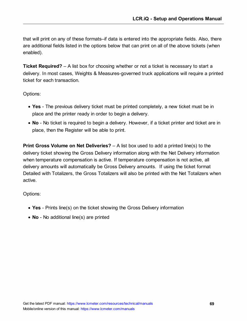
LCR.iQ - Setup and Operations Manual
69Get the latest PDF manual: https://www.lcmeter.com/resources/technical/manuals
Mobile/online version of this manual: https://www.lcmeter.com/manuals
that will print on any of these formats–if data is entered into the appropriate fields. Also, there
are additional fields listed in the options below that can print on all of the above tickets (when
enabled).
Ticket Required? – A list box for choosing whether or not a ticket is necessary to start a
delivery. In most cases, Weights & Measures-governed truck applications will require a printed
ticket for each transaction.
Options:
· Yes - The previous delivery ticket must be printed completely, a new ticket must be in
place and the printer ready in order to begin a delivery.
· No - No ticket is required to begin a delivery. However, if a ticket printer and ticket are in
place, then the Register will be able to print.
Print Gross Volume on Net Deliveries? – A list box used to add a printed line(s) to the
delivery ticket showing the Gross Delivery information along with the Net Delivery information
when temperature compensation is active. If temperature compensation is not active, all
delivery amounts will automatically be Gross Delivery amounts. If using the ticket format
Detailed with Totalizers, the Gross Totalizers will also be printed with the Net Totalizers when
active.
Options:
· Yes - Prints line(s) on the ticket showing the Gross Delivery information
· No - No additional line(s) are printed
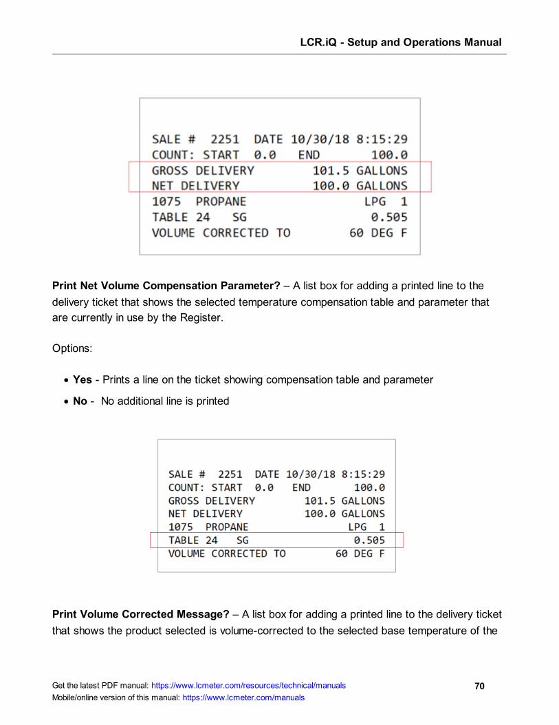
LCR.iQ - Setup and Operations Manual
70Get the latest PDF manual: https://www.lcmeter.com/resources/technical/manuals
Mobile/online version of this manual: https://www.lcmeter.com/manuals
Print Net Volume Compensation Parameter? – A list box for adding a printed line to the
delivery ticket that shows the selected temperature compensation table and parameter that
are currently in use by the Register.
Options:
· Yes - Prints a line on the ticket showing compensation table and parameter
· No - No additional line is printed
Print Volume Corrected Message? – A list box for adding a printed line to the delivery ticket
that shows the product selected is volume-corrected to the selected base temperature of the
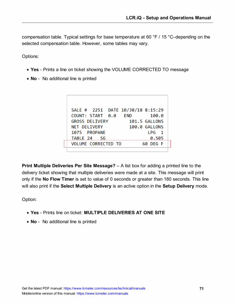
LCR.iQ - Setup and Operations Manual
71Get the latest PDF manual: https://www.lcmeter.com/resources/technical/manuals
Mobile/online version of this manual: https://www.lcmeter.com/manuals
compensation table. Typical settings for base temperature at 60 °F / 15 °C–depending on the
selected compensation table. However, some tables may vary.
Options:
· Yes - Prints a line on ticket showing the VOLUME CORRECTED TO message
· No - No additional line is printed
Print Multiple Deliveries Per Site Message? – A list box for adding a printed line to the
delivery ticket showing that multiple deliveries were made at a site. This message will print
only if the No Flow Timer is set to value of 0 seconds or greater than 180 seconds. This line
will also print if the Select Multiple Delivery is an active option in the Setup Delivery mode.
Option:
· Yes - Prints line on ticket: MULTIPLE DELIVERIES AT ONE SITE
· No - No additional line is printed
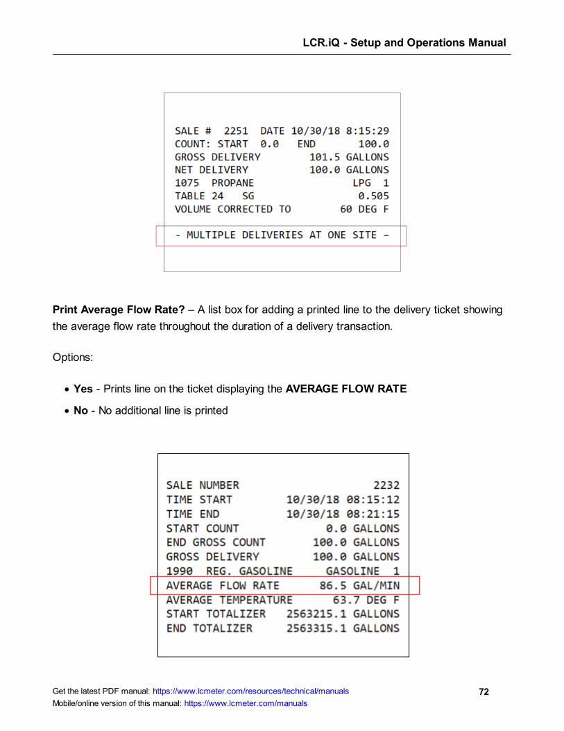
LCR.iQ - Setup and Operations Manual
72Get the latest PDF manual: https://www.lcmeter.com/resources/technical/manuals
Mobile/online version of this manual: https://www.lcmeter.com/manuals
Print Average Flow Rate? – A list box for adding a printed line to the delivery ticket showing
the average flow rate throughout the duration of a delivery transaction.
Options:
· Yes - Prints line on the ticket displaying the AVERAGE FLOW RATE
· No - No additional line is printed
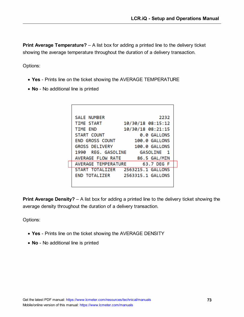
LCR.iQ - Setup and Operations Manual
73Get the latest PDF manual: https://www.lcmeter.com/resources/technical/manuals
Mobile/online version of this manual: https://www.lcmeter.com/manuals
Print Average Temperature? – A list box for adding a printed line to the delivery ticket
showing the average temperature throughout the duration of a delivery transaction.
Options:
· Yes - Prints line on the ticket showing the AVERAGE TEMPERATURE
· No - No additional line is printed
Print Average Density? – A list box for adding a printed line to the delivery ticket showing the
average density throughout the duration of a delivery transaction.
Options:
· Yes - Prints line on the ticket showing the AVERAGE DENSITY
· No - No additional line is printed
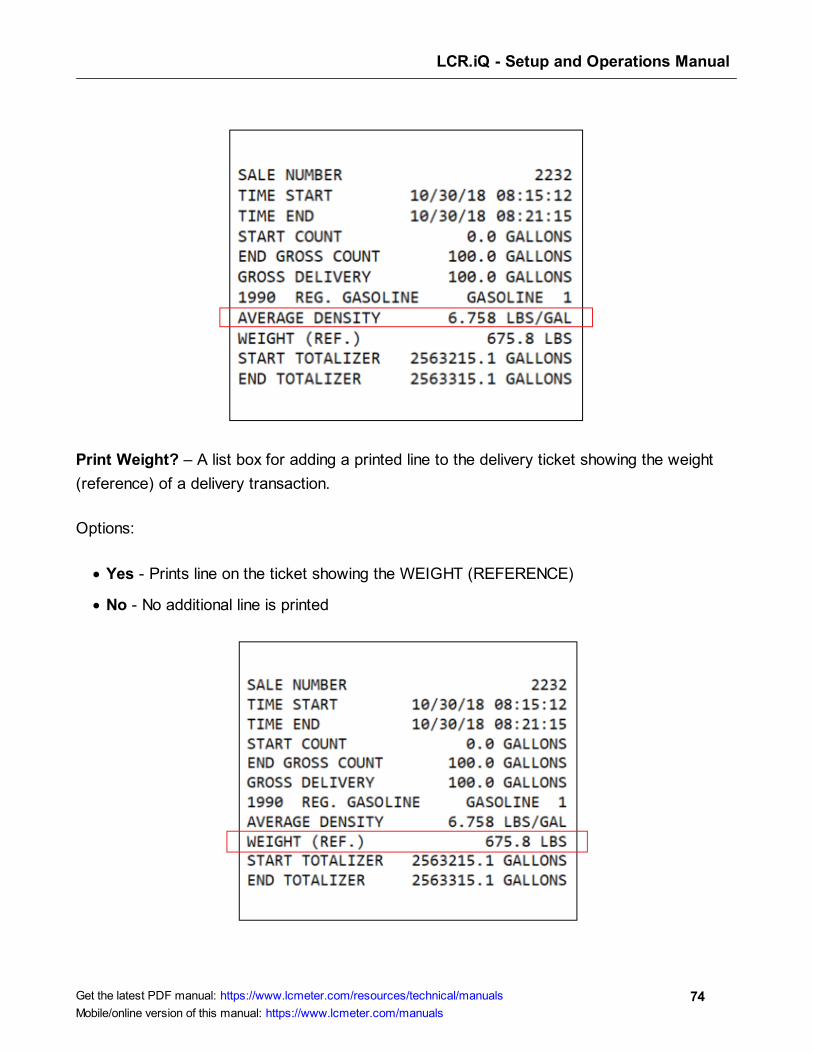
LCR.iQ - Setup and Operations Manual
74Get the latest PDF manual: https://www.lcmeter.com/resources/technical/manuals
Mobile/online version of this manual: https://www.lcmeter.com/manuals
Print Weight? – A list box for adding a printed line to the delivery ticket showing the weight
(reference) of a delivery transaction.
Options:
· Yes - Prints line on the ticket showing the WEIGHT (REFERENCE)
· No - No additional line is printed
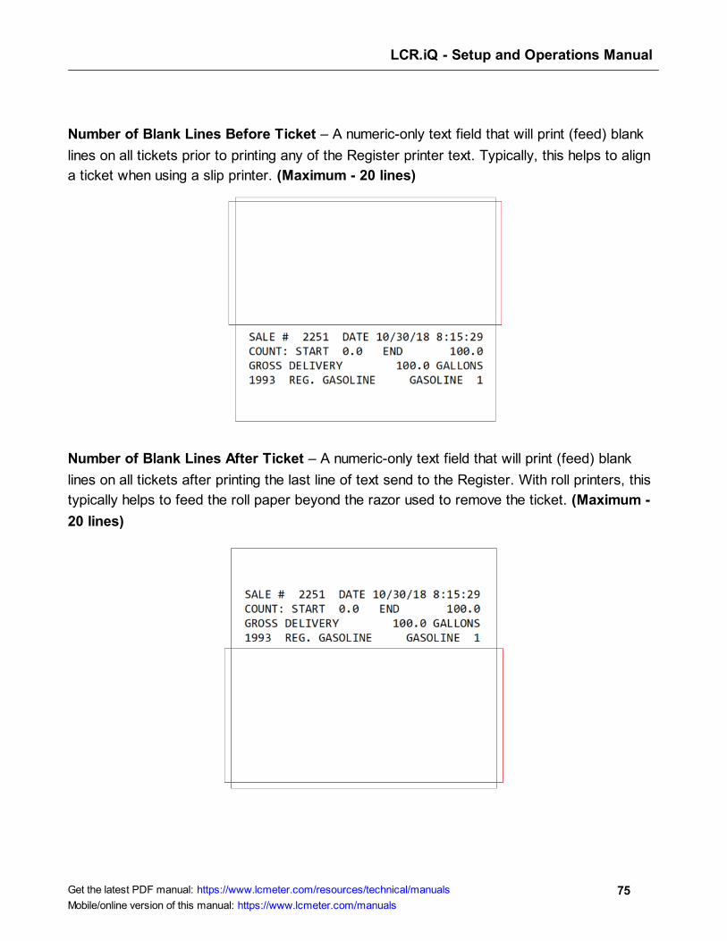
LCR.iQ - Setup and Operations Manual
75Get the latest PDF manual: https://www.lcmeter.com/resources/technical/manuals
Mobile/online version of this manual: https://www.lcmeter.com/manuals
Number of Blank Lines Before Ticket – A numeric-only text field that will print (feed) blank
lines on all tickets prior to printing any of the Register printer text. Typically, this helps to align
a ticket when using a slip printer. (Maximum - 20 lines)
Number of Blank Lines After Ticket – A numeric-only text field that will print (feed) blank
lines on all tickets after printing the last line of text send to the Register. With roll printers, this
typically helps to feed the roll paper beyond the razor used to remove the ticket. (Maximum -
20 lines)

LCR.iQ - Setup and Operations Manual
76Get the latest PDF manual: https://www.lcmeter.com/resources/technical/manuals
Mobile/online version of this manual: https://www.lcmeter.com/manuals
Meter Settings
Meter menu options allow the user to set up information specific to the meter that is connected
to the Register. It will be identified by the I/O Board #, UID, and Name fields.
Meter (1/3)
IOBoard# – A numeric-only text field for identifying an I/O board that is connected to the
Register. Settings for the each I/O board can be made when the selected I/O board appears
in this field. The main I/O board in the Register is always I/O board 0. (Maximum setting is
currently 0)
I/O Board UID – This read-only fields displays the serial number of the I/O board# that is
currently selected.
I/O Board Name – A text field for identifying the currently selected I/O board in the I/O board
# field. The name will also appear in other screens to clearly identify the selected board.
(Maximum - 16 alphanumeric characters)
Meter ID – A text field for identifying a meter that is connected to the Register, Typically, the
serial number of the meter is entered here. The value of this field is also printed on the
Register calibration ticket. (Maximum - 10 alphanumeric characters)
LCR.iQ - Setup and Operations Manual
77Get the latest PDF manual: https://www.lcmeter.com/resources/technical/manuals
Mobile/online version of this manual: https://www.lcmeter.com/manuals
Pulser Input Type – A list box for selecting the type of pulse input signal that will be
connected to the selected I/O board.
Options:
· Dual Channel - 2 channel quadrature pulser signal such as the Register internal pulser or
a POD pulser.
· All Single Channel - Single channel square wave signal
· Triple Channel - 3 channel pulser square wave signal
· None - No pulser is connected to the Register
Flow Direction – A list box field for inverting the direction of flow within the Register. If the
register is counting in the reverse direction when first installed, inverting the flow direction will
cause the register to count in the opposite direction.
Options:
· ==>
· <==
Pulser Input Mode Between Deliveries – A list box field for specifying how the Register will
respond to any registered pulse signal when the register is not in an active delivery.
Options:
· Count Forward and Reverse - A registered pulse signal–either forward or reverse–will
directly affect the accumulative totalizer readings. It will also display the volume on the idle
delivery screen.
· Forward Count Only - A registered pulse signal, in the forward direction only, will directly
affect the accumulative totalizer readings. It will also display the volume on the idle
delivery screen.
· Ignore - Any pulse signal that is detected when a delivery is not active will be ignored by
the Register.
LCR.iQ - Setup and Operations Manual
78Get the latest PDF manual: https://www.lcmeter.com/resources/technical/manuals
Mobile/online version of this manual: https://www.lcmeter.com/manuals
· Reverse Count Only - A registered pulse signal, in the reverse direction only, will directly
affect the accumulative totalizer readings. It will also display the volume on the idle
delivery screen.
HEPCV In Use? – A list box for enabling or disabling the Hose End Press Control Valve. This
feature is to be enabled only when using a hose end press control valve in an aviation fueling
system. This feature is designed to reduce back pressure and flow surges in the system.
Options:
· Yes – Enables HEPCV
· No – Disables HEPCV
Decimal Digits – A list box field that sets the decimal place for the displayed volume and also
the shift and accumulative totalizers.
Options:
· Tenths - Sets the decimal place to the tenth unit position (xxxxx.x)
· Whole - Sets the decimal place to the whole units position (xxxxxx)
· Hundredths - Sets the decimal place to the hundredths position (xxxx.xx)
Temperature – This numeric-only text field displays the current temperature sensed by the
Register temperature probe when installed. Use this field to set a temperature offset, if the
value is within the allowed range of the temperature offset field below. If no probe is installed,
this value will read --.- .
Temperature Offset – A numeric-only text field for specifying an offset to the value of the
current temperature reading. A value of +/- .54 degrees F or +/- .3 degrees C is allowed by
Weights and Measures. When an offset is entered and within the acceptable range, the
current temperature will automatically be adjusted by the amount of this value. (Floating
point from -.30 to +.30°C or -.54 to +54°F)

LCR.iQ - Setup and Operations Manual
79Get the latest PDF manual: https://www.lcmeter.com/resources/technical/manuals
Mobile/online version of this manual: https://www.lcmeter.com/manuals

LCR.iQ - Setup and Operations Manual
80Get the latest PDF manual: https://www.lcmeter.com/resources/technical/manuals
Mobile/online version of this manual: https://www.lcmeter.com/manuals
Meter (2/3)
Valve Logic Type – A list box field that is used to select the logic to be used when connecting
a solenoid valve to the Register.
Options:
· Two-Stage Preset Valve - This logic is to be used with standard 2 stage preset valves.
With this logic, only S1 will open for full flow when a delivery starts. S2 will only open for
dwell (slow) flow. This logic is the same as in the LCR-II and LCR 600 registers.
· Single/Dual Option Preset Valve - This logic can be used when using single or dual
stage preset valves. With this logic both S1 and S2 will energize at the start of a delivery.
If an S1 close time is set, S1 will drop out when the S1 close is reached and S2 will
remain open until the final closure amount reached.
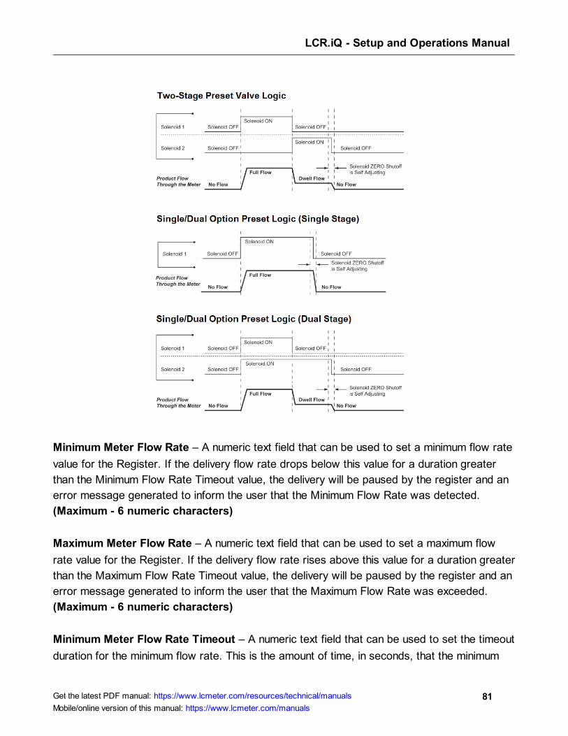
LCR.iQ - Setup and Operations Manual
81Get the latest PDF manual: https://www.lcmeter.com/resources/technical/manuals
Mobile/online version of this manual: https://www.lcmeter.com/manuals
Minimum Meter Flow Rate – A numeric text field that can be used to set a minimum flow rate
value for the Register. If the delivery flow rate drops below this value for a duration greater
than the Minimum Flow Rate Timeout value, the delivery will be paused by the register and an
error message generated to inform the user that the Minimum Flow Rate was detected.
(Maximum - 6 numeric characters)
Maximum Meter Flow Rate – A numeric text field that can be used to set a maximum flow
rate value for the Register. If the delivery flow rate rises above this value for a duration greater
than the Maximum Flow Rate Timeout value, the delivery will be paused by the register and an
error message generated to inform the user that the Maximum Flow Rate was exceeded.
(Maximum - 6 numeric characters)
Minimum Meter Flow Rate Timeout – A numeric text field that can be used to set the timeout
duration for the minimum flow rate. This is the amount of time, in seconds, that the minimum

LCR.iQ - Setup and Operations Manual
82Get the latest PDF manual: https://www.lcmeter.com/resources/technical/manuals
Mobile/online version of this manual: https://www.lcmeter.com/manuals
flow rate can drop below the set Minimum Flow Rate valve before the delivery pauses.
(Maximum setting - 15 sec)
Maximum Meter Flow Rate Timeout – A numeric text field that can be used to set the
timeout duration for the maximum flow rate. This is the amount of time, in seconds, the
maximum flow rate can rise above the set Maximum Flow Rate valve before the delivery
pauses. (Maximum setting - 15 sec)
Meter (3/3)
Maximum Filter Flow Rate – A numeric only text field that is used along with a Liquid Controls
Differential Pressure Transducer (dP) to calculate corrected differential pressure based on the
maximum rated flow rate of the filter vessel. This field should be set to the maximum flow rate
rated on the filter housing. This option only applies when a Liquid Controls dP transducer is
connected to the Register. (Maximum setting - 9999.9)
dP Shutdown Value – A numeric only text field that should be set to the maximum differential
pressure allowed (JIG Standard 15 PSI) when using the Liquid Controls Differential Pressure
Transducer. This option only applies when a Liquid Controls dP transducer is connected to the
Register. The maximum setting is 60 psi (The Current JIG standard is 15 PSI)
LCR.iQ - Setup and Operations Manual
83Get the latest PDF manual: https://www.lcmeter.com/resources/technical/manuals
Mobile/online version of this manual: https://www.lcmeter.com/manuals
Weight – A read only field that displays a weight value when using Liquid Controls Automatic
Density Sensor or entering a manual density value into the Register.
Weight Unit of Measure – A list box field that is used to select the unit of measure for weight
when using this feature.
Options:
· kgs - Kilograms
· lbs - Pounds
Density – A numeric only text box that can either have a density value manually entered or
automatically generated using the Liquid Controls Automatic Density Sensor. The maximum
setting is 999.999
Density Offset – A numeric only text box that can be used to add an offset to the value
measured by the Automatic Density Sensor when installed. This setting has a fixed adjustment
of +/- 0.8 units.
Density Unit of Measure – A list box field that is used to select the unit of measure for
density when using this feature.
Options:
· kg/L - Kilograms per Litre
· kg/bbl - Kilograms per Barrel
· kg/gal - Kilograms per Gallon
· kg/m3 - Kilograms per Meter Cubed
· lb/L - Pounds per Litre
· lb/bbl - Pounds per Barrel
· lb/gal - Pounds per Gallon
· lb/m3 - Pounds per Meter Cubed
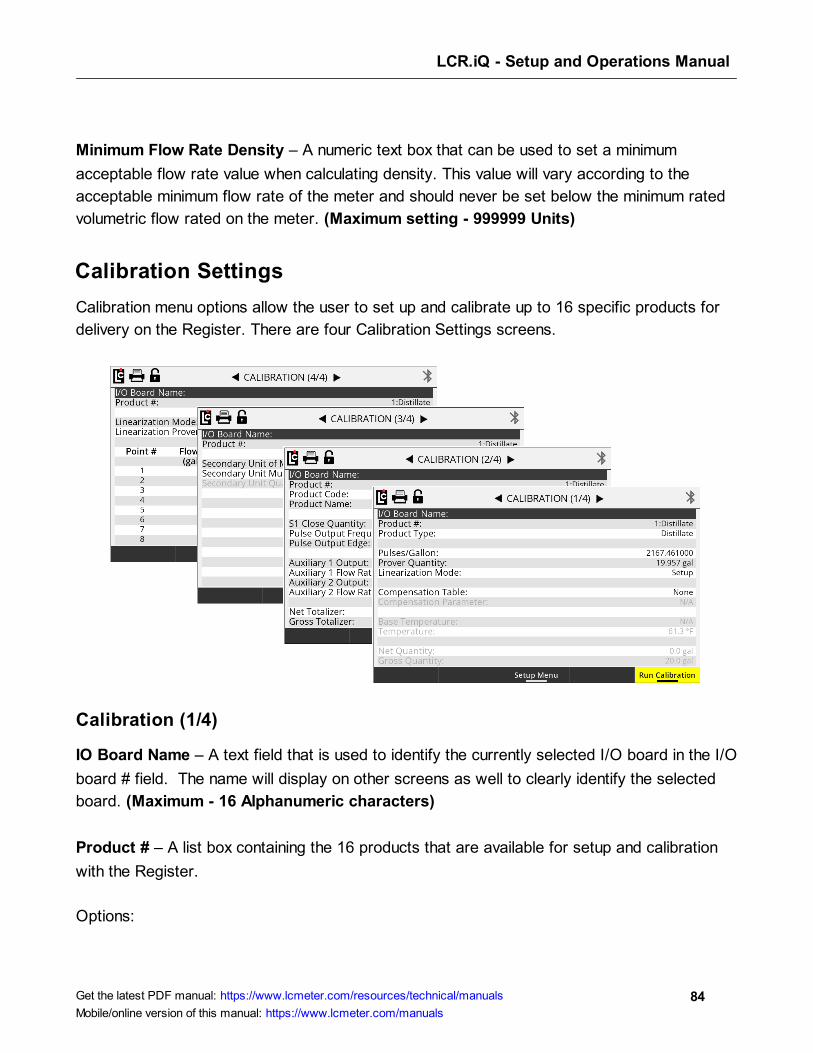
LCR.iQ - Setup and Operations Manual
84Get the latest PDF manual: https://www.lcmeter.com/resources/technical/manuals
Mobile/online version of this manual: https://www.lcmeter.com/manuals
Minimum Flow Rate Density – A numeric text box that can be used to set a minimum
acceptable flow rate value when calculating density. This value will vary according to the
acceptable minimum flow rate of the meter and should never be set below the minimum rated
volumetric flow rated on the meter. (Maximum setting - 999999 Units)
Calibration Settings
Calibration menu options allow the user to set up and calibrate up to 16 specific products for
delivery on the Register. There are four Calibration Settings screens.
Calibration (1/4)
IO Board Name – A text field that is used to identify the currently selected I/O board in the I/O
board # field. The name will display on other screens as well to clearly identify the selected
board. (Maximum - 16 Alphanumeric characters)
Product # – A list box containing the 16 products that are available for setup and calibration
with the Register.
Options:
LCR.iQ - Setup and Operations Manual
85Get the latest PDF manual: https://www.lcmeter.com/resources/technical/manuals
Mobile/online version of this manual: https://www.lcmeter.com/manuals
· Products 1-16 are available for setup. Only setup and calibrate products that are to be
used by the Register.
Product Type – A list box for selecting the product (classification) type. The product type will
print on all calibration and diagnostic ticket,s and it will designate the Product Type for each
Product Number. The product type will also appear on all delivery tickets to assist in identifying
the delivered product.
Options:
· Ammonia
· Aviation
· Distillate
· Gasoline
· LPG
· Lube Oil
· Methanol
· Blank
Pulses/Unit (Gallon, Liter…) – A numeric-only text field for specifying the number of pulses
that equal the whole-unit of measure for the product being setup on the Register. This number
is most important, since it directly affects the calibration of the meter. (Maximum setting -
20000.000000 units)
NOTE: A chart of starting reference calibration factors can be
found in an appendix to this manual. Refer to this chart for assistance
in selecting a starting Pulses/Unit number.
Prover Quantity – A numeric-only text field for calibrating the product currently being set up.
This field is used during calibration to enter the known prover quantity of a volumetric proving
device or master meter. After a calibration run, entering a value into this field will automatically
adjust the Pulse/Unit field by the percent error that is calculated. Learn more in Single-point
Calibration .
128
114
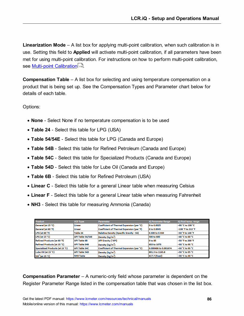
LCR.iQ - Setup and Operations Manual
86Get the latest PDF manual: https://www.lcmeter.com/resources/technical/manuals
Mobile/online version of this manual: https://www.lcmeter.com/manuals
Linearization Mode – A list box for applying multi-point calibration, when such calibration is in
use. Setting this field to Applied will activate multi-point calibration, if all parameters have been
met for using multi-point calibration. For instructions on how to perform multi-point calibration,
see Multi-point Calibration .
Compensation Table – A list box for selecting and using temperature compensation on a
product that is being set up. See the Compensation Types and Parameter chart below for
details of each table.
Options:
· None - Select None if no temperature compensation is to be used
· Table 24 - Select this table for LPG (USA)
· Table 54/54E - Select this table for LPG (Canada and Europe)
· Table 54B - Select this table for Refined Petroleum (Canada and Europe)
· Table 54C - Select this table for Specialized Products (Canada and Europe)
· Table 54D - Select this table for Lube Oil (Canada and Europe)
· Table 6B - Select this table for Refined Petroleum (USA)
· Linear C - Select this table for a general Linear table when measuring Celsius
· Linear F - Select this table for a general Linear table when measuring Fahrenheit
· NH3 - Select this table for measuring Ammonia (Canada)
Compensation Parameter – A numeric-only field whose parameter is dependent on the
Register Parameter Range listed in the compensation table that was chosen in the list box.
116
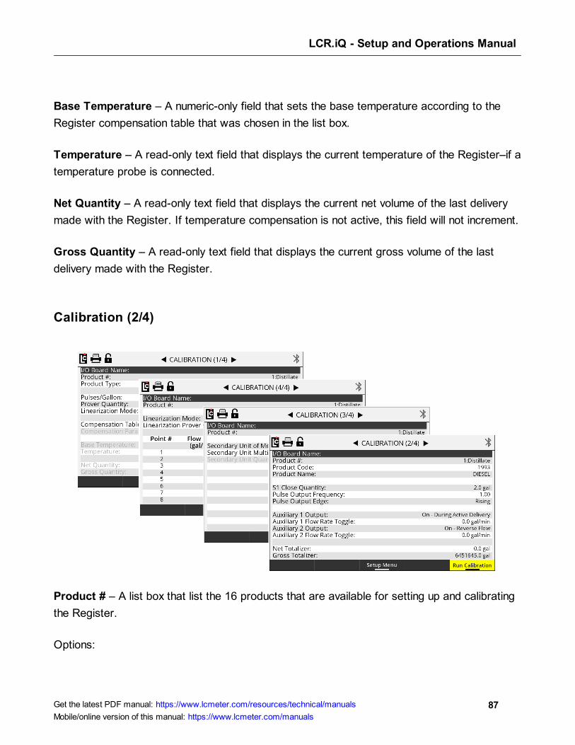
LCR.iQ - Setup and Operations Manual
87Get the latest PDF manual: https://www.lcmeter.com/resources/technical/manuals
Mobile/online version of this manual: https://www.lcmeter.com/manuals
Base Temperature – A numeric-only field that sets the base temperature according to the
Register compensation table that was chosen in the list box.
Temperature – A read-only text field that displays the current temperature of the Register–if a
temperature probe is connected.
Net Quantity – A read-only text field that displays the current net volume of the last delivery
made with the Register. If temperature compensation is not active, this field will not increment.
Gross Quantity – A read-only text field that displays the current gross volume of the last
delivery made with the Register.
Calibration (2/4)
Product # – A list box that list the 16 products that are available for setting up and calibrating
the Register.
Options:

LCR.iQ - Setup and Operations Manual
88Get the latest PDF manual: https://www.lcmeter.com/resources/technical/manuals
Mobile/online version of this manual: https://www.lcmeter.com/manuals
· Products 1-16 are available for setup. Only setup and calibrate products that are to be
used by the Register.
Product Code – A text field for identifying the selected product with a code.The product code
will appear on all ticket formats to identify the product that was delivered, as shown above.
(Maximum - 5 alphanumeric characters)
Product Name – A text field for identifying the selected product with a specific name. The
product name will appear on all ticket formats to identify the product that was delivered as
shown above. (Maximum - 18 alphanumeric characters)
S1 Close Quantity – A numeric text field that is used with 2 stage preset valves. This value
sets the number based on the unit of measure that will transition a 2 stage valve from high flow
to low flow–for an accurate preset stop. For more information on setting up the S1 closure,
see Setting the S1 Close time . (Maximum - 5 alphanumeric characters)
Pulse Output Frequency – A numeric text field that determines the number of output pulses
per unit of measure when using the calibrated pulse output feature of the Register. Setting this
field to 1 will result in a 1:1 pulse output to the unit of measure. The maximum value that can
be set for this field will vary depending on the decimal setting for the unit of measure and the
K-Factor (Pulses/Unit) of the product.
· Hundredths - Max 1% of the K-Factor
· Tenths - Max 10% of the K-Factor
· Whole - Max 50% of the K-Factor
117
LCR.iQ - Setup and Operations Manual
89Get the latest PDF manual: https://www.lcmeter.com/resources/technical/manuals
Mobile/online version of this manual: https://www.lcmeter.com/manuals
Pulse Output Edge – A list box that determines the signal direction of the calibrated pulse
output. Toggling this setting can help align the pulse output of the Register with a remote
counter or injection system by inverting the output square wave resulting in an opposite
adjustment in the signal.
Options:
· Rising - The pulse output square wave from the Register
· Falling - The inverted pulse output square wave from the Register
Auxiliary 1 Output – A list box that determines how any digital output that is set to AUX 1 will
operate based on the selected product on the Register. There are several features in the
Register that can be performed based on the Aux settings to control external components such
as pumps, injectors, PTO, throttle, alarms, reset pulse, etc.
Options:
· Off - Any output set to AUX 1 Calibration Mode Settings will always be off (Not active)
· On - Any output set to AUX 1 Calibration Mode Settings will always be on (Active and
Sinking to ground)
· On - During Active Delivery - Any output set to AUX 1 Calibration Mode Settings will turn
on (Sink to ground) when a delivery is started and will turn off when End is pressed and
the delivery is complete.
· On - During Run State - Any output set to AUX 1 Calibration Mode Settings will turn on
(Sink to ground) when a delivery is active and not paused. The output will be on when a
delivery starts. However, if the delivery is paused by issuing a stop command, the output
will turn off until the resume command is given. If the end of delivery command is given, the
output will remain off and the delivery will end.
· On - Flow Rate Monitor - Any output set to AUX 1 Calibration Mode Settings will be on
when a delivery is active, however it will deactivate if the flow rate meets or exceeds 40
units/time. If the flow rate does not meet or exceed 40 units/time, the output will remain
on.
LCR.iQ - Setup and Operations Manual
90Get the latest PDF manual: https://www.lcmeter.com/resources/technical/manuals
Mobile/online version of this manual: https://www.lcmeter.com/manuals
· On - Reverse Flow - Any output set to AUX 1 Calibration Mode Settings will be off when
a delivery starts, and will only turn on when the register detect flow in the negative or
reverse direction.
· Reset Pulse/Delivery Start - Any output set to AUX 1 Calibration Mode Settings will
output a short pulse at the start of a delivery that is used with 3rd party remote counters
that require a reset pulse to reset to 0.0.
· Toggle Flow Rate - Any output set to AUX 1 Calibration Mode Settings will turn on once
the flow rate of the Register exceeds the set flow rate point in the Auxiliary 1 Flow
RateToggle field below.
· Calibrated Scaled Pulse Output - Any output set to AUX 1 Calibration Mode Settings will
output a calibrated pulse output–that is scaled according to the Pulse Output Frequency
setting in the calibration mode.
Auxiliary 1 Flow Rate Toggle – A numeric text field that can be used to program a flow rate
set point when the Aux 1 is set to Toggle flow rate. Auxiliary 1 remains activated above the set
flow rate value and deactivates when the flow rate falls below the value.
A common use for this output is an air operated valve (AOV) on the pump. When the flow rate
value is attained, the AOV is activated and switches the pump from low-bypass pressure
mode to full-flow fuel mode (high bypass pressure). When the flow rate falls below the set
value, the AOV deactivates and the pump returns to low flow. Another possible use for this
output is the engine throttle—to increase and decrease the RPM of the pump shaft. In
applications such as these, the flow rate value in this field should be below the low flow rate
with a fully open nozzle or the output will never turn on. Another application of this field is to set
the value as a maximum flow rate at which a valve should be closed. On fuel delivery trucks,
flow valves often activate an internal switch at approximately 18 GPM (68 LPM). The value of
this field is unique to each product.
Auxiliary 2 Output – A list box that determines how any digital output that is set to AUX 2 will
operate based on the selected product on the Register. There are several features in the
Register that can be performed based on the Aux settings to control external components such
as pumps, injectors, PTO, Throttle, alarms, and reset pulse.
Options:
· Off - Any output set to AUX 2 Calibration Mode Settings will always be off (Not active)
LCR.iQ - Setup and Operations Manual
91Get the latest PDF manual: https://www.lcmeter.com/resources/technical/manuals
Mobile/online version of this manual: https://www.lcmeter.com/manuals
· On - Any output set to AUX 2 Calibration Mode Settings will always be on (Active and
Sinking to ground)
· On - During Active Delivery - Any output set to AUX 2 Calibration Mode Settings will be
on (Active and Sinking to ground) when a delivery is active on the Register. The output
will be on when a delivery is started and will not turn off until an end of delivery command
is given.
· On - During Run State - Any output set to AUX 2 Calibration Mode Settings will be on
(Active and Sinking to ground) when a delivery is active and not paused. The output will be
on when a delivery starts. However, if the delivery is paused by issuing a stop command,
the output will turn off until the resume command is given. If the end of delivery command
is given, the output will remain off and the delivery will end.
· On - Flow Rate Monitor - Any output set to AUX 2 Calibration Mode Settings will be on
when a delivery is active. However, it will deactivate if the flow rate meets or exceeds 40
units/time. If the flow rate does not meet or exceed 40 units/time, the output will remain
on.
· On - Reverse Flow - Any output set to AUX 2 Calibration Mode Settings will be off when
a delivery is started and will only turn on when the register detects flow in the negative or
reverse direction.
· Reset Pulse/Delivery Start - Any output set to AUX 2 Calibration Mode Settings will
output a short pulse at the start of a delivery that is used with 3rd-party remote counters
that require a reset pulse to reset to 0.0.
· Toggle Flow Rate - Any output set to AUX 2 Calibration Mode Settings will turn on once
the flow rate of the Register exceeds the set flow rate point in the Auxiliary 1 Flow Rate
Toggle field below.
· Calibrated Scaled Pulse Output - Any output set to AUX 2 Calibration Mode Settings will
output a calibrated pulse output that is scaled according to the Pulse Output Frequency
setting in the calibration mode.
Auxiliary 2 Flow Rate Toggle – A numeric text field for programming a flow rate set point,
when the Aux 2 is set to Toggle flow rate. Auxiliary 2 remains activated above the set flow rate
value, and deactivates when the flow rate falls below the value.
Net Totalizer – A numeric text field that shows the current accumulative net totalizer value of
the current selected product on the Register. The Net Totalizer uses a non-resettable totalizer.

LCR.iQ - Setup and Operations Manual
92Get the latest PDF manual: https://www.lcmeter.com/resources/technical/manuals
Mobile/online version of this manual: https://www.lcmeter.com/manuals
However, it can be programmed as necessary in the Weight and Measures (Calibration) mode
if reprogramming is required. (Maximum setting - 999999999 units)
Gross Totalizer – A numeric text field that shows the current accumulative gross totalizer
value of the current selected product on the Register. The Gross Totalizer uses a non-
resettable totalizer. However, it can be programmed as necessary in the Weight and
Measures (Calibration) mode if reprogramming is required. (Maximum setting - 999999999
units)
Calibration (3/4)
Product # – A list box containing 16 products that are available for setup and calibration of the
Register.
Options:
· Products 1-16 are available for setup. Only setup and calibrate products that are to be
used by the Register.
Secondary Unit of Measure – A list box that can be set up to be the unit of measure label
when printing or displaying a secondary unit of measure. See the Secondary Unit Multiplier
below for setting descriptions.
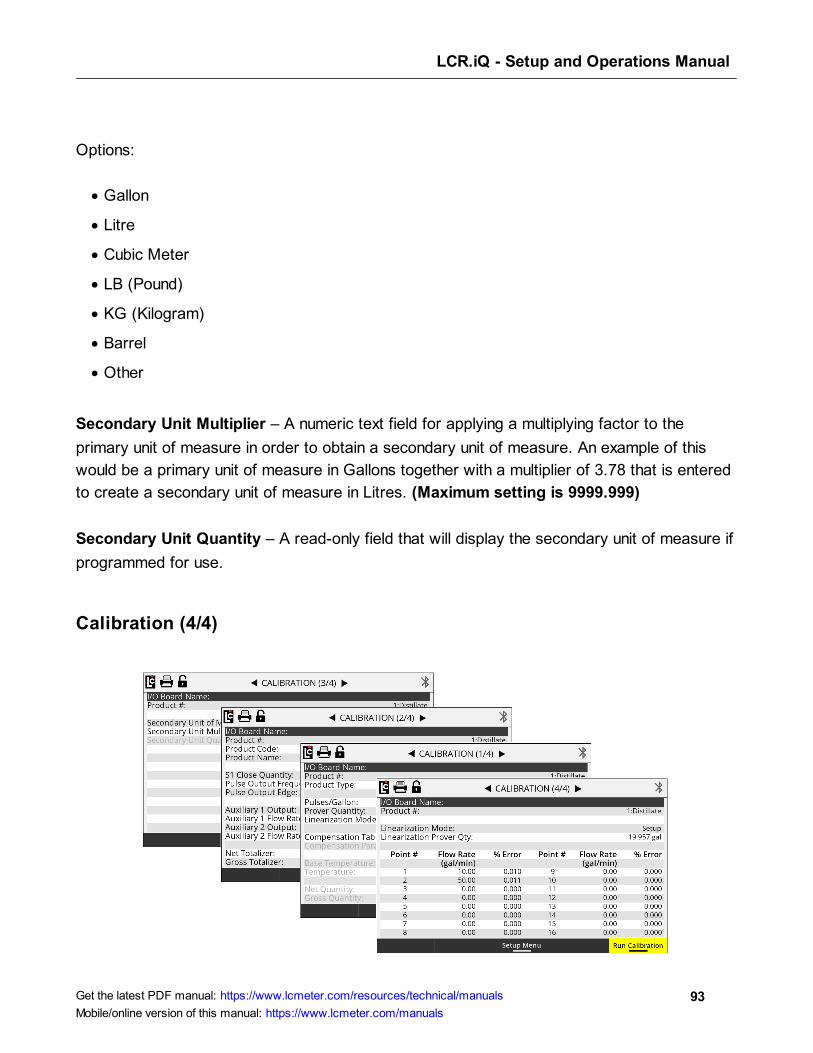
LCR.iQ - Setup and Operations Manual
93Get the latest PDF manual: https://www.lcmeter.com/resources/technical/manuals
Mobile/online version of this manual: https://www.lcmeter.com/manuals
Options:
· Gallon
· Litre
· Cubic Meter
· LB (Pound)
· KG (Kilogram)
· Barrel
· Other
Secondary Unit Multiplier – A numeric text field for applying a multiplying factor to the
primary unit of measure in order to obtain a secondary unit of measure. An example of this
would be a primary unit of measure in Gallons together with a multiplier of 3.78 that is entered
to create a secondary unit of measure in Litres. (Maximum setting is 9999.999)
Secondary Unit Quantity – A read-only field that will display the secondary unit of measure if
programmed for use.
Calibration (4/4)
LCR.iQ - Setup and Operations Manual
94Get the latest PDF manual: https://www.lcmeter.com/resources/technical/manuals
Mobile/online version of this manual: https://www.lcmeter.com/manuals
Product # – A list box containing the 16 products that are available for setting up and
calibrating the Register.
NOTE:
· Products 1-16 are available for setup. Only setup and calibrate products that are to be
used by the Register.
The Register provides two means of calibration, single-point [Calibration screen (1/4)] or multi-
point calibration [Calibration screen (4/4)].
A “point” corresponds to a particular flow rate along the meter linearity curve. Single-point
calibration adjusts one point along the linearity curve to zero percent error—typically at a flow
rate representative of a normal delivery. Since meter linearity varies at different flow rates,
and every meter behaves differently, the more points of calibration will generally result in more
accurate fluid measurement.
Multi-point calibration zeroes the percent error at multiple flow rates (between the rated
lowest flow rate and highest flow rate of the meter) in order to zero-out the linearity curve
across the rated flow range.
To multi-point calibrate the meter using the Register (Calibration screen 4/4), first select point
#1 and enter the lowest flow rate measured. Then, enter the % error measured at that flow
rate. Repeat this for points 2 through the highest number of points measured (up to 16 points
available).
Linearization Mode – A list box for applying a multi-point calibration. Setting this field to
Applied will activate multi-point calibration–if all parameters are met for using multi-point
calibration.
Linearization Prover Qty – A numeric only text field for performing a multi-point calibration on
the currently selected product on the Register. This field is used during multi-point calibration
to enter the known prover quantity of a volumetric proving device or master meter. Following a
multi-point calibration run, entering a value into this field will automatically prompt the user to
select a point to apply the run to, followed by a prompt to enter the flow rate that was used

LCR.iQ - Setup and Operations Manual
95Get the latest PDF manual: https://www.lcmeter.com/resources/technical/manuals
Mobile/online version of this manual: https://www.lcmeter.com/manuals
during the multi-point calibration run. This action will store the point and flow rate, then
calculate the percent error to be applied to the selected point.
Point – A list box for selecting the calibration point for the multi-point calibration. The Register
is able to perform a multi-point calibration on as many as 16 separate points.
Options:
· Linearization Points 1-16 are available for setup.
Flow Rate – A numeric text field for entering the actual flow rate at which a multi-point
calibration run was made.
% Error – A numeric field that is used when the Register calculates the percent error for a
multi-point calibration point. The percent error field can also be manually entered for meter
systems that have a factory supplied accuracy curve.
Security
Security settings are for setting up and configuring the user level security, and also access to
the Clear All process, software upgrades, Audit Trails and Reset Register Fields feature.
Setting the security level to Locked will prevent an operator from accessing fields that the
owner may want to restrict.
LCR.iQ - Setup and Operations Manual
96Get the latest PDF manual: https://www.lcmeter.com/resources/technical/manuals
Mobile/online version of this manual: https://www.lcmeter.com/manuals
Date Format – A list box for setting the display and print format for the Register date.
Options:
· MM/DD/YY - Month/Day/Year
· DD/MM/YY - Day/ Month/Year
Current Date – A fixed data entry field for setting the internal calendar of the Register–based
on the date format field option. The Register will update the calendar automatically according
to this setting, and the date can be displayed on screen, printed on the ticket, and recorded in
each transaction record.
Calibration # – A read-only field that will display the number of times the Register been
placed into the calibration mode.
Serial ID – A read-only text field that will display the serial number of the main board inside the
Register.
User Key – A text field for entering a unique key code for unlocking access to specific menus
and features in the Register. This user defined key should be set and saved by an owner or
maintenance manager for secure access to these menus and features. Contact Liquid Controls
customer support if you misplace or forget your user key. The user key is retrievable through
the factory-calibration mode only.
User Security – A list box for toggling the security level between the locked and unlocked
mode.
Options:
· Locked - When set to locked, access to certain screens and menu options is blocked
without entering the user key.
· Unlocked - When unlocked, access to all menus is available–while menu options may still
be unavailable based on the security current mode of the Register.
LCR.iQ - Setup and Operations Manual
97Get the latest PDF manual: https://www.lcmeter.com/resources/technical/manuals
Mobile/online version of this manual: https://www.lcmeter.com/manuals
Menu Access Protection – A list box to configure which menus will require the entry of the
user key to access different menus.
Options:
· Main Menu - Setting this field to Main Menu will require the user to enter a user key to
access any of the main menu screens outside of the delivery screens.
· Setup Menu - Setting this field to Setup Menu will permit the user to access the main
menu. However, it will restrict access to the Setup menu and require a user key for
access.
· None - No menu level restriction is applied. However, access to screen options may still
be unavailable based on the current security mode of the Register.
Reset Register Fields – A list box that permits access to the Clear All and Rebuild functions
of the Register when in the Weights and Measures calibration mode. This process should only
be performed by a trained technician or Liquid Controls factory representative.
Options:
· Clear All - Performing a Clear All will remove all current settings and set all parameters
back to factory default (except Time and Date). This process should only be performed by
a trained technician or Liquid Controls factory representative.
· Rebuild - Performing a rebuild will attempt to repair an Register, in case an area of the
Register memory become corrupt. This process should only be performed by a trained
technician or Liquid Controls factory representative.
· No - Make no selection and return to the Security Mode screen (or press Cancel)
Factory Key – Consult Liquid Controls for factory Key information and access.
I/O Setup
I/O setup screen are used to setup and configure the various available inputs and outputs of
the Register, and also activate and deactivate services such as printing, LCP communication,
dP, Density and other sensing equipment.
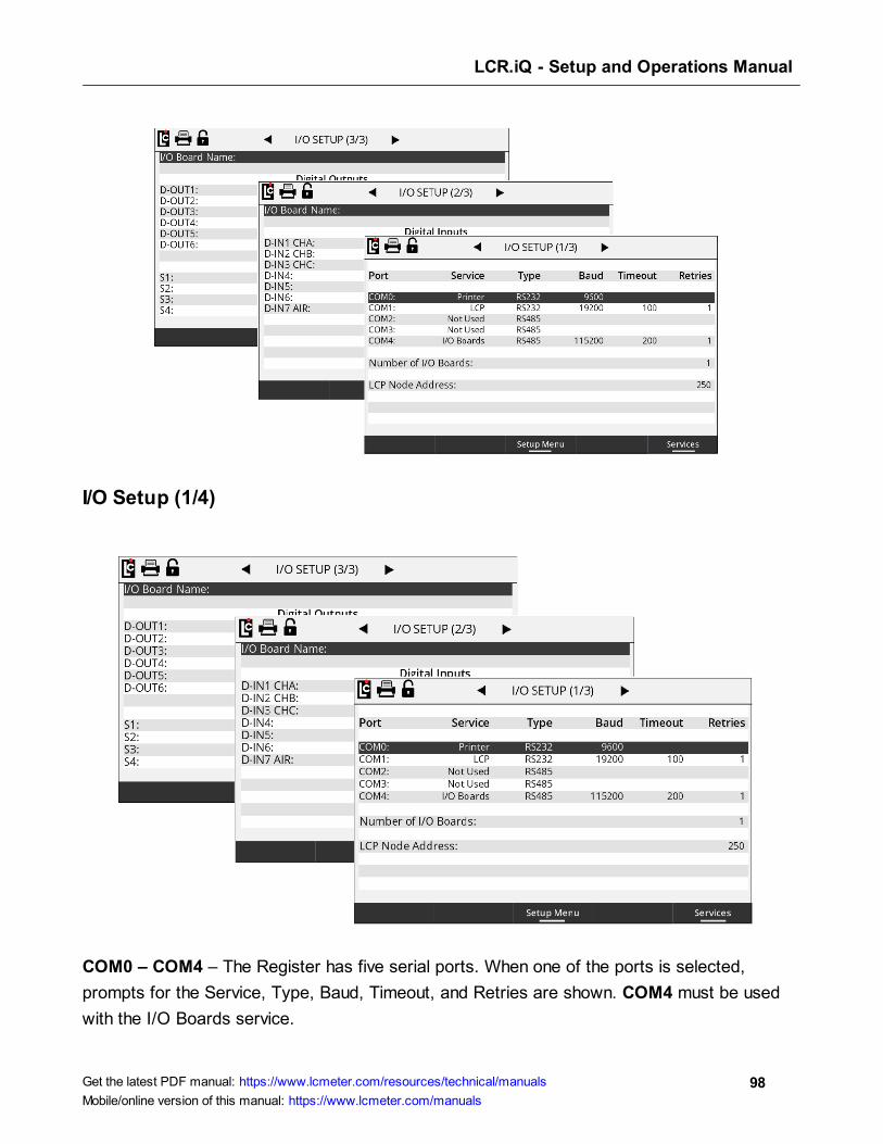
LCR.iQ - Setup and Operations Manual
98Get the latest PDF manual: https://www.lcmeter.com/resources/technical/manuals
Mobile/online version of this manual: https://www.lcmeter.com/manuals
I/O Setup (1/4)
COM0 – COM4 – The Register has five serial ports. When one of the ports is selected,
prompts for the Service, Type, Baud, Timeout, and Retries are shown. COM4 must be used
with the I/O Boards service.
LCR.iQ - Setup and Operations Manual
99Get the latest PDF manual: https://www.lcmeter.com/resources/technical/manuals
Mobile/online version of this manual: https://www.lcmeter.com/manuals
Service – A list box that permits the user to select between the services that have been
enabled on the Services screen. Not Used can be selected to disable the use of the port.
Type – A list box permits the user to select between the types of serial communication for the
serial port.
Options:
· RS232
· RS485
Baud – A list box that permits the user to select the baud rate for the serial port.
Options:
· 2400
· 4800
· 9600 – This is the standard baud rate used for the Printer service.
· 19200
· 57600
· 115200 – The I/O Boards service must use this baud rate.
Timeout – A numeric text field that shows the amount of time, in milliseconds, the Register will
wait for a response, once a serial signal is sent out the port. This field is only used for the LCP
and LCR.iQ Network services.
Retries – After a serial signal has been sent out the port, if a response isn’t seen within the
Timeout, this is the number of attempts the Register will attempt to retry sending the serial
signal. This field is only used for the LCP and LCR.iQ Network services.
Number of I/O Boards – The number of I/O boards within the Register. The current limit is 1.
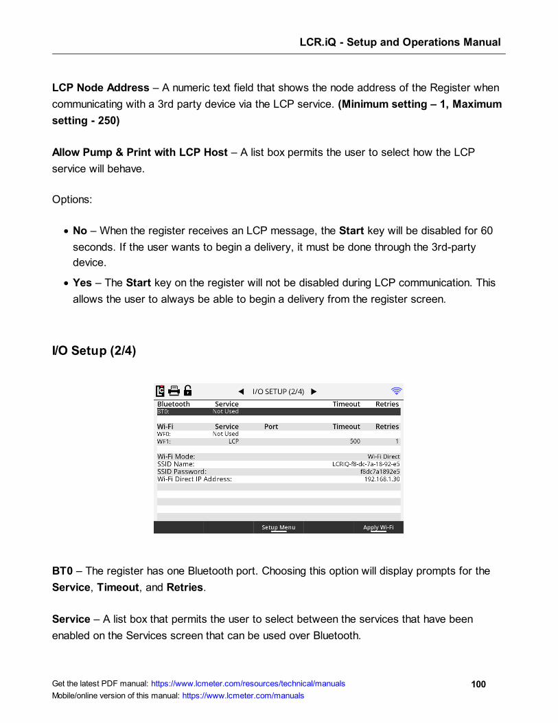
LCR.iQ - Setup and Operations Manual
100Get the latest PDF manual: https://www.lcmeter.com/resources/technical/manuals
Mobile/online version of this manual: https://www.lcmeter.com/manuals
LCP Node Address – A numeric text field that shows the node address of the Register when
communicating with a 3rd party device via the LCP service. (Minimum setting – 1, Maximum
setting - 250)
Allow Pump & Print with LCP Host – A list box permits the user to select how the LCP
service will behave.
Options:
· No – When the register receives an LCP message, the Start key will be disabled for 60
seconds. If the user wants to begin a delivery, it must be done through the 3rd-party
device.
· Yes – The Start key on the register will not be disabled during LCP communication. This
allows the user to always be able to begin a delivery from the register screen.
I/O Setup (2/4)
BT0 – The register has one Bluetooth port. Choosing this option will display prompts for the
Service, Timeout, and Retries.
Service – A list box that permits the user to select between the services that have been
enabled on the Services screen that can be used over Bluetooth.

LCR.iQ - Setup and Operations Manual
101Get the latest PDF manual: https://www.lcmeter.com/resources/technical/manuals
Mobile/online version of this manual: https://www.lcmeter.com/manuals
Options:
· Not Used – This disables the use of Bluetooth.
· LCP – LCP communication over Bluetooth.
· Printer – To be used with a Bluetooth printer.
Timeout – A numeric text field that shows the amount of time, in milliseconds, the register will
wait for a response, once a serial signal is sent out the port. This field is only used for the LCP
service.
Retries – After a serial signal has been sent out the port, if a response isn’t seen within the
Timeout, this is the number of attempts the register will attempt to retry sending the serial
signal. This field is only used for the LCP service.
WF0 & WF1 – The register can establish two wi-fi connections. Choosing this option will
display prompts for the Service, Timeout, and Retries.
Wi-Fi Mode – A list box permits the user to select which Wi-Fi Mode to use.
Options:
· Wi-Fi Direct – Does not require a wireless access point, allowing two devices to establish
a direct Wi-Fi connection without requiring a wireless router.
· Wi-Fi Stationary – Requires a wireless access point to act as a hub for Wi-Fi
communication.
SSID Name – An alpha-numeric text field that shows the service set identifier for the register.
Other devices will use this name to identify the register and establish a connection. The default
value begins with "LCRIQ", which is followed by a unique identifier.
SSID Password – An alpha-numeric text field that shows the password for wireless
communication with the Register. Other devices will use this password to establish a
connection.
Wi-Fi Direct IP Address – The IP address of the register when in Wi-Fi Direct Mode.

LCR.iQ - Setup and Operations Manual
102Get the latest PDF manual: https://www.lcmeter.com/resources/technical/manuals
Mobile/online version of this manual: https://www.lcmeter.com/manuals
Apply Wi-Fi – The user must press Apply Wi-Fi for any changes to the Wi-Fi Mode, SSID
Name, SSID Password, or Wi-Fi Direct IP Address to take effect.
I/O Setup (3/4)
· Digital Inputs 1-7
I/O Setup (4/4)
· Digital Outputs 1-6 and Solenoid Outputs S1-S4
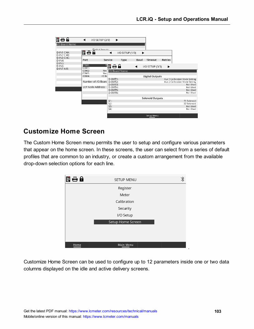
LCR.iQ - Setup and Operations Manual
103Get the latest PDF manual: https://www.lcmeter.com/resources/technical/manuals
Mobile/online version of this manual: https://www.lcmeter.com/manuals
Customize Home Screen
The Custom Home Screen menu permits the user to setup and configure various parameters
that appear on the home screen. In these screens, the user can select from a series of default
profiles that are common to an industry, or create a custom arrangement from the available
drop-down selection options for each line.
.
Customize Home Screen can be used to configure up to 12 parameters inside one or two data
columns displayed on the idle and active delivery screens.
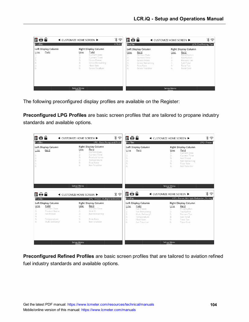
LCR.iQ - Setup and Operations Manual
104Get the latest PDF manual: https://www.lcmeter.com/resources/technical/manuals
Mobile/online version of this manual: https://www.lcmeter.com/manuals
The following preconfigured display profiles are available on the Register:
Preconfigured LPG Profiles are basic screen profiles that are tailored to propane industry
standards and available options.
Preconfigured Refined Profiles are basic screen profiles that are tailored to aviation refined
fuel industry standards and available options.
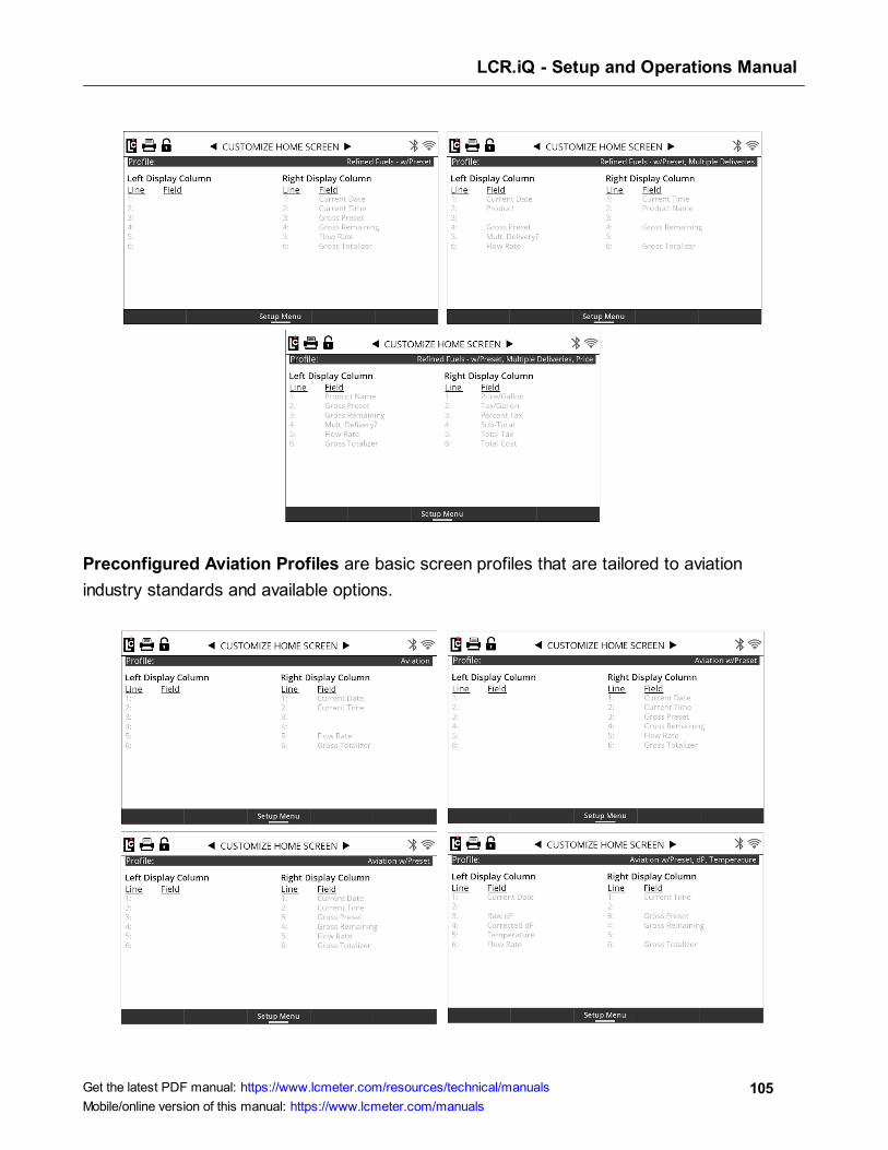
LCR.iQ - Setup and Operations Manual
105Get the latest PDF manual: https://www.lcmeter.com/resources/technical/manuals
Mobile/online version of this manual: https://www.lcmeter.com/manuals
Preconfigured Aviation Profiles are basic screen profiles that are tailored to aviation
industry standards and available options.
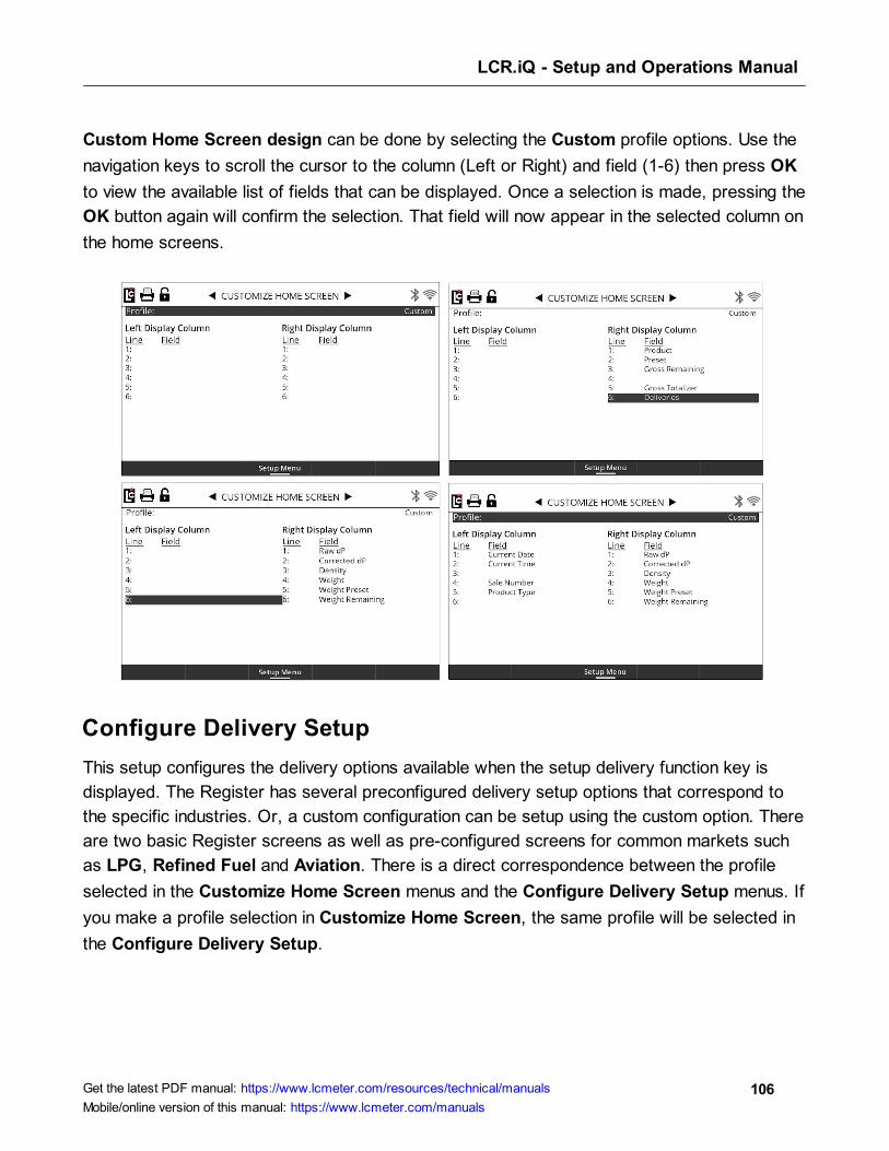
LCR.iQ - Setup and Operations Manual
106Get the latest PDF manual: https://www.lcmeter.com/resources/technical/manuals
Mobile/online version of this manual: https://www.lcmeter.com/manuals
Custom Home Screen design can be done by selecting the Custom profile options. Use the
navigation keys to scroll the cursor to the column (Left or Right) and field (1-6) then press OK
to view the available list of fields that can be displayed. Once a selection is made, pressing the
OK button again will confirm the selection. That field will now appear in the selected column on
the home screens.
Configure Delivery Setup
This setup configures the delivery options available when the setup delivery function key is
displayed. The Register has several preconfigured delivery setup options that correspond to
the specific industries. Or, a custom configuration can be setup using the custom option. There
are two basic Register screens as well as pre-configured screens for common markets such
as LPG, Refined Fuel and Aviation. There is a direct correspondence between the profile
selected in the Customize Home Screen menus and the Configure Delivery Setup menus. If
you make a profile selection in Customize Home Screen, the same profile will be selected in
the Configure Delivery Setup.
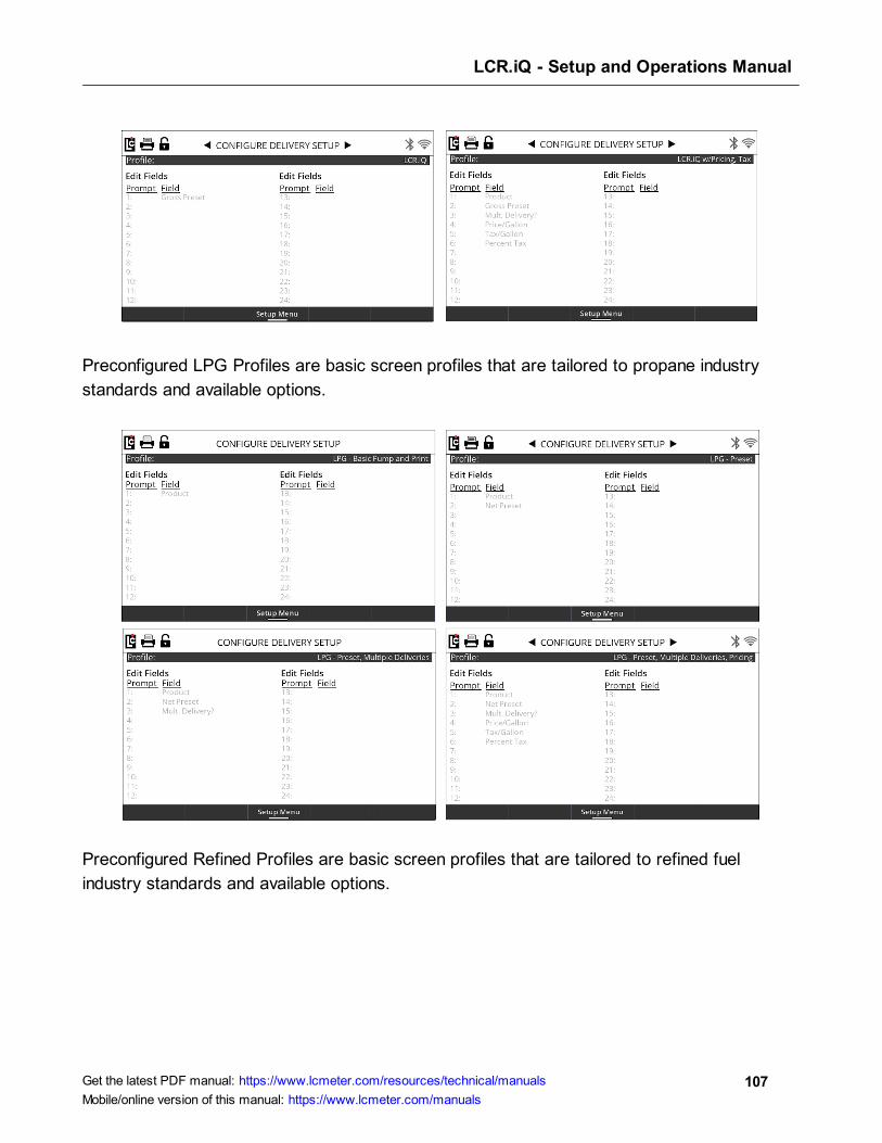
LCR.iQ - Setup and Operations Manual
107Get the latest PDF manual: https://www.lcmeter.com/resources/technical/manuals
Mobile/online version of this manual: https://www.lcmeter.com/manuals
Preconfigured LPG Profiles are basic screen profiles that are tailored to propane industry
standards and available options.
Preconfigured Refined Profiles are basic screen profiles that are tailored to refined fuel
industry standards and available options.
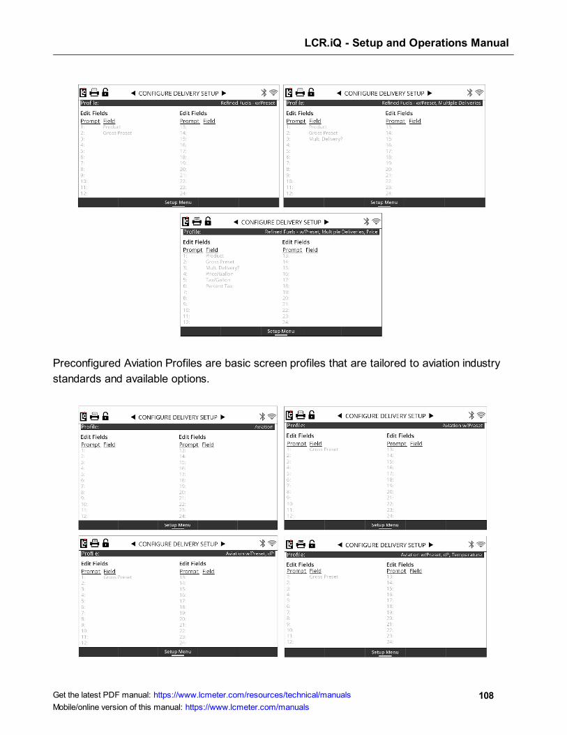
LCR.iQ - Setup and Operations Manual
108Get the latest PDF manual: https://www.lcmeter.com/resources/technical/manuals
Mobile/online version of this manual: https://www.lcmeter.com/manuals
Preconfigured Aviation Profiles are basic screen profiles that are tailored to aviation industry
standards and available options.
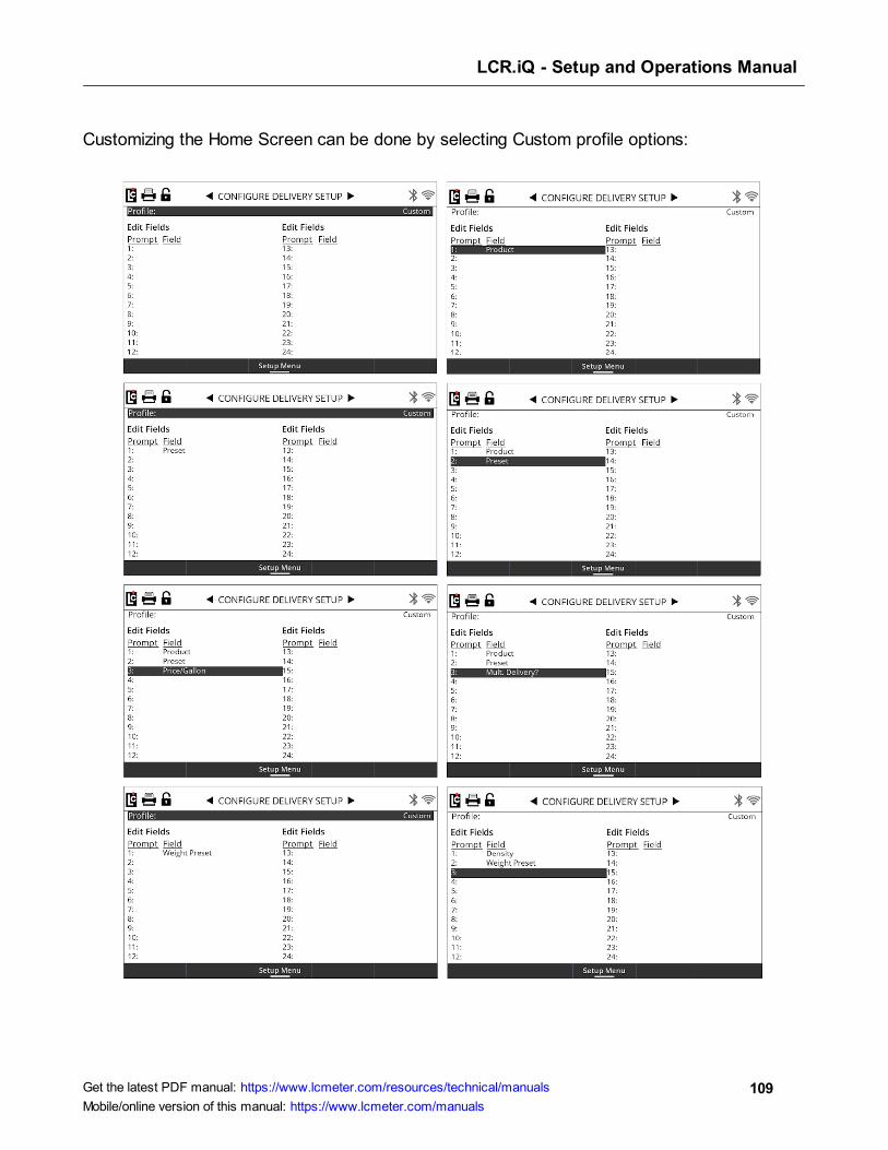
LCR.iQ - Setup and Operations Manual
109Get the latest PDF manual: https://www.lcmeter.com/resources/technical/manuals
Mobile/online version of this manual: https://www.lcmeter.com/manuals
Customizing the Home Screen can be done by selecting Custom profile options:
LCR.iQ - Setup and Operations Manual
110Get the latest PDF manual: https://www.lcmeter.com/resources/technical/manuals
Mobile/online version of this manual: https://www.lcmeter.com/manuals
Operating the Register
This chapter covers all of the operations that you can perform with the Register:
· Performing a basic delivery
· Performing a preset delivery - Preset Key
· Using the Info button
· Performing a preset delivery - Delivery Setup
· Using the hose reset feature
· Single-point Calibration
· Multi-point Calibration
· Setting the S1 Close time
· Setting up delivery ticket options
· Print the previous ticket
· Upgrading the Firmware by USB
· Perform a Clear All Procedure
· Print a transaction
· Setup custom profiles
· Print a diagnostic ticket
Performing a basic delivery
Simple and easy. That was the goal when designing the operation of the Register. Making a
delivery with the Register can be as simple and easy as pressing the yellow Start key.
When you're ready to begin a basic delivery, press the Start key. The register will start the
reset process by completing a display test, then will reset to zero. At this time if the Register
is connected to a flow control valve, the register will send a signal to open the valve and
possibly signal a pump to start . With the pump on, fuel will be begin to flow through the meter
and register on the display. The main delivery screen of the Register will always default to the
active fueling screen with large, high resolution digits.
While a delivery is active, it is possible to view detailed delivery information by pressing the
Show Details button. The detailed information displayed is configurable depending on the
110
111
111
112
114
114
116
117
118
119
120
123
124
125
126
LCR.iQ - Setup and Operations Manual
111Get the latest PDF manual: https://www.lcmeter.com/resources/technical/manuals
Mobile/online version of this manual: https://www.lcmeter.com/manuals
profile which can be configured on any register. A separate how to instruction on setting up a
profile is available.
To return to the default fueling screen, simply press the Full Screen button and the default
delivery screen will now be displayed.
At any time during the delivery, pressing the Stop key will pause the delivery by sending a
signal to the flow control valve (if installed) to close. You'll also see that the display now has a
Resume key.
Pressing the Resume key will resume the delivery after it is stopped by sending a signal to the
flow control valve to open.
To end a delivery, pressing the End or End and Print button will complete the transaction. If a
printer is connected, this will also print the delivery ticket.
Once the delivery is complete, the display will return to the Idle home screen and the Register
is ready for the next delivery.
Performing a preset delivery - Preset Key
Presetting with the Register is simple. There are a few different ways to enter a preset
depending on how the register is configured. The most basic way if presets are configured for
use, is when presetting is the only delivery setup option. In this case the Register will display a
preset function key on the main delivery idle screen. If a preset is desired, simply press the
preset function key and a prompt to enter the preset amount will appear on the screen. Use
the alphanumeric keypad to type in the preset amount, then press OK to accept the amount
entered. Start the delivery as normal and your system will stop at the entered preset amount.
Using the Info button
The Info button is a helpful tool for the technician or user that does not have access to the
setup and operation manual when setting up and programming the register. Like the manual,
the Info button will give the user valuable information about the field and available
parameters.
Follow these steps:

LCR.iQ - Setup and Operations Manual
112Get the latest PDF manual: https://www.lcmeter.com/resources/technical/manuals
Mobile/online version of this manual: https://www.lcmeter.com/manuals
1. To access information using the Info button, navigate to any available field and press OK
to access the field data.
2. Once in the field data, the screen will display a function key labeled Info.
3. Press the Info button and the screen will now display the info details.
List Boxes will display the default setting, current setting, field description and a list of
options that may also include detailed description information. Text Boxes will display the
default value, current value, minimum and maximum number of characters for the field or
minimum and maximum value for the field, accepted data type and a field description.
4. While in an info screen, text data can be entered, however the user must exit the info
screen to make a list box selection.
5. To exit an info screen, press the Close Info function key.
Performing a preset delivery - Delivery Setup
If you have configured delivery setup prompts including the preset field, press the Setup
Delivery function key and follow the on screen prompts until you see Enter Preset. After
entering the preset, press OK to accept the amount entered. Continue with any remaining
setup delivery prompts, then start the delivery as normal and your system will stop at the
entered preset amount.
Add to a Preset
If you have started a preset delivery and you need to add to the amount, or if you are using
the multiple preset type option, it is possible to add to or append the preset amount. Simply
press the Stop key, then press the Preset key and a prompt will be shown on the screen to
LCR.iQ - Setup and Operations Manual
113Get the latest PDF manual: https://www.lcmeter.com/resources/technical/manuals
Mobile/online version of this manual: https://www.lcmeter.com/manuals
enter a new preset volume. Once the new volume is entered, press OK to accept the change
and then press the Resume button to continue fueling.
Selecting a Preset Type
When selecting a preset type, it is important to know how the register will be used in the
preset process. There are 3 options when selecting a preset type: Clear, Retain, and
Multiple. The best way to describe each is by example.
Clear a Preset
If you are currently using a mechanical preset, the clear option will best match this
functionality. A clear preset allows the user to set up a preset amount for a specific delivery.
Using the Register keypad, enter the desired preset value by pressing the preset key or if
using the delivery setup mode, enter a preset when prompted. Once the preset is entered and
the delivery is started, the Register will deliver the set preset amount and complete the
delivery once the amount is reached. With electronic registration this means that the end of
delivery command will be generated and if applicable, the completed delivery ticket will be
generated. This action will set the preset field back to zero (Clear) so the register is ready for
the next delivery. If the next delivery also requires a preset, the user will need to enter a new
preset amount following the same steps.
Retain a Preset
If you are planning to use the Register for batching, the retain preset is the best option for this
process. Retain preset allows the user to set a preset amount on the register and retain that
amount from delivery to delivery, each time issuing an end of delivery command and resetting
the delivery amount back to zero but retaining the preset amount. The preset amount will be
retained until an operator sets a new preset mount or sets the preset back to zero for no
preset.
Multiple Presets
For applications in which you have an initial preset volume, but the final preset volume has not
been determined, it is best to use the multiple preset option. Multiple preset allows the user to
set a preset amount. However, once the preset is reached, the delivery is paused, not
completed. This allows the user to either add more fuel on top of the preset amount or set
another preset amount for the remaining amount. This process can be repeated over again
until such time that a final amount is determined. Once the final amount is determined, the
LCR.iQ - Setup and Operations Manual
114Get the latest PDF manual: https://www.lcmeter.com/resources/technical/manuals
Mobile/online version of this manual: https://www.lcmeter.com/manuals
user issues the end of delivery command by pressing the End/Print key terminating the
delivery. At this time, the preset amount is set back to zero and the user must set a new
preset amount, if desired, for the next delivery.
Using the hose reset feature
The hose reset feature is a Weights and Measures requirement that allows the user a one-
time reset of the register back to zero after a delivery is started in order to charge the hose
with system pressure. This assumes that the amount to charge the hose is within the hose
reset features limits. The reason this feature is permitted, is that following a preset delivery,
the meters preset valve (on the outlet of the meter) closes once the preset amount is reached,
yet the fueling nozzle at the end of the hose is still open. This causes a small void in the
packing of the hose because of the loss of system pressure.
To use this feature, start a delivery on the Register and engage the pump (apply system
pressure)–while leaving the nozzle closed. If the meter jumps up a few tenth of a unit, this is
because there was a void in the hose that has now been filled by adding the pump pressure. If
the amount is less than 1 gallon (or 4 Liters), the user is able to reset the register back to zero
by pressing the Stop key, followed by the Hose Reset key. At this time, the register will be
reading zero again and by pressing the Resume key, the user can continue with normal
delivery functions.
Single-point Calibration
Single-point calibration of the Register is designed to be quick and easy. Calibration of the
Register should be performed by a qualified Weights and Measures authorized or factory
trained technician. Typical calibrations are done using a volumetric prover, master meter or
inline SVP (Small Volume Prover). Ensure that all equipment is properly connected and lines
fully charged (pressurized) between the meter and proving device.
To begin the calibration process, you must first put the Register into the calibration mode by
removing any existing seal wire and loosening the calibration bolt on the side of the register
housing approximately 5-6 turns. If a ticket printer is connected to the Register, make sure a
ticket is in place and the printer is ready. If connected, the register will print a calibration ticket
showing the current calibration information of the register. If no ticket printer is connected or
the calibration ticket is not desired, press the Abort key to skip the print process.
LCR.iQ - Setup and Operations Manual
115Get the latest PDF manual: https://www.lcmeter.com/resources/technical/manuals
Mobile/online version of this manual: https://www.lcmeter.com/manuals
Once in the calibration mode, select the calibration option from the main menu to access the
calibration screens. If this is the first calibration for the register or if the calibration factor
(Pulse/Unit) has not been set for the meter that the register is connected to, it is recommend
to set a starting factor. This will save time and additional calibration runs as the register
adjusts the meters accuracy closer to zero error. See the recommended starting calibration
factor chart in the appendix of this manual for typical starting calibration factors and enter this
value in the Pulse/Unit field.
NOTE: Unit label will vary depending on the unit of measure that has
been set up in the Register.
In the calibration screens you will notice that there is a yellow key labeled Run Calibration.
Pressing this key will begin the actual calibration process by performing the meter screen test
and resetting the delivery volume to 000.000. At the same time, the Register will provide the
permissive signal to the valve output to allow flow through the meter.
NOTE: All deliveries in the calibration mode have a resolution to the
thousandths decimal place allowing for very precise calibration.
Flow product into or through the proving device at the normal (nominal) operating flow rate for
the meter until the desired calibration volume is reached. When calibrating the flow meter, it is
recommended that the calibration volume be greater than or equal to the high end flow rate
rating of the metering device (100 GPM = Minimum 100 Gallon prover).
Once the desired calibration volume is reached, pressing the End button will return the
Register back to the calibration menu screens. Navigate the selection bar to the Prover
quantity field, and press OK. Enter the exact volume to the greatest detail that was registered
on the proving device, then press OK. At this point, the Register will calculate the percent of
error between the prover and register, and automatically adjust the Pulses/Unit accordingly.
Repeat this process until the Register register is within local Weights and Measures tolerance
or company regulations. Once all calibrations are made and setup is complete, tighten the
calibration bolt on the side of the Register housing. If a ticket printer is connected and a final
calibration ticket is desired, insert a ticket before exiting calibration mode and a ticket will print
when prompted.
LCR.iQ - Setup and Operations Manual
116Get the latest PDF manual: https://www.lcmeter.com/resources/technical/manuals
Mobile/online version of this manual: https://www.lcmeter.com/manuals
Multi-point Calibration
Multi-point calibration is used to improve the accuracy of a flow meter across its full rated flow
rate range, resulting in a much flatter accuracy curve. Accuracy of a flow meter tends to
lessen at lower flow rates however repeatability of the meter remains consistent. A meter
might not be perfectly accurate at low flow rates, but it is inaccurate by the same amount each
time. Multi-point calibration takes advantage of the steadfast repeatability of a Liquid Controls
meter by identifying the amount of inaccuracy and correcting it with a linearizing algorithm
during deliveries. In order to apply the linearizing algorithm, the degree of error for points along
the accuracy curve must be identified by making a number of deliveries at different flow rates
into a volumetric prover. Multi-point calibration is very beneficial for meter systems that
experience a wide range of flow rates (for example, trucks that fill tanks of varying sizes) and
for meter systems that have recently undergone maintenance or other alterations that could
change the accuracy curve itself.
To begin the multi-point calibration process, ensure the Register is in the calibration mode by
removing any existing seal wire and loosening the calibration bolt on the side of the register
housing approx 5-6 turns. If a ticket printer is connected to the Register, make sure a ticket is
in place and the printer is ready. If connected, the register will print a calibration ticket
showing the current calibration as well as any existing multi-point calibration information of the
register. If no ticket printer is connected or the calibration ticket is not desired, press the
Abort key to skip the print process.
Before starting the process of multi-point calibration, ensure that the initial single point
calibration has been completed and the meter is accurate and repeatable. All multi-point
factors are based on this initial calibration.
Once in the calibration mode, select Calibration from the main menu to access the calibration
screens. Scroll to Calibration screen 4/4 to access the multi-point calibration fields.
In the Calibration screen 4/4 you will notice that there is a yellow key labeled Run Calibration.
Pressing this key will begin the actual calibration process by performing the meter screen test
and resetting the delivery volume to 000.000. At the same time, the Register will provide the
permissive signal to the valve output to allow flow through the meter.
NOTE: All deliveries in the calibration mode have a resolution to the
thousandths decimal place allowing for precise calibration.

LCR.iQ - Setup and Operations Manual
117Get the latest PDF manual: https://www.lcmeter.com/resources/technical/manuals
Mobile/online version of this manual: https://www.lcmeter.com/manuals
Begin to flow product into or through the proving device ensuring that the metering system is
delivering at the flow rate for the desired multipoint calibration point.
Once the desired mult-ipoint calibration volume is reached, pressing the End button will return
the Register to the Calibration menu screen 4/4. Navigate the selection bar to the Linearization
Prover Quantity field, and press OK. Enter the exact volume to the greatest detail that was
registered on the proving device, then press OK. The Register will automatically display a
prompt to select which of the 16 available multi-point fields to perform the calibration. Next the
Register will display a prompt to the flow rate of the previous delivery. Enter the flow rate that
was used for the multi-point calibration that was just performed. At this point, the Register will
calculate the percent of error between the prover and register for the multi-point and
automatically add the % error amount. When complete, the screen will show the point on the
screen–together with the flowrate and % error.
Repeat this process, ensuring that the calibration process is accurate, repeatable and within
local Weights and Measures tolerance–or company regulations. Repeat this process for each
of the different multi-point calibration flow rate points that are desired.
Once all multi-point calibrations are complete, you must apply multi-point calibration. To do
this, you must ensure that the difference between adjacent multi-point flow rate errors does
not exceed +/- .25% or the Register will not allow you to apply multi-point. If all adjacent %
error points are within this range, change the Linearization mode setting from Setup to
Applied. If within tolerance, the field will remain at Applied. If out of tolerance, this field will
toggle back to Setup and require additional low rate points to further improve the linear
accuracy with the +/- .25% range.
Once all multipoint calibrations are made and linearization has been applied, tighten the
calibration bolt on the side of the Register housing. If a ticket printer is connected and a final
calibration ticket is desired, insert a ticket before exiting calibration mode and a ticket will print
when prompted.
Setting the S1 Close time
Setting the S1 closure time properly is an important part of the setup process when using a 2-
stage preset valve. If this value is not set correctly, it may cause the Register to over or under
LCR.iQ - Setup and Operations Manual
118Get the latest PDF manual: https://www.lcmeter.com/resources/technical/manuals
Mobile/online version of this manual: https://www.lcmeter.com/manuals
shoot the desired preset volume or cause long delays in reaching the final preset amount. S1
closure rates will depend on the flow rate of the system as well as the viscosity of the product.
A 2 stage preset valve is designed to allow a soft closure of the valve by transitioning from
high flow, to low flow before reaching final closure. This process greatly improves the ability of
the preset to stop at the exact volume desired. For the most accurate closure, it is best that
once the transition from high flow to low flow is made, the flow rate should stabilize at the low
flow rate for a few seconds before the final closure is reached.
The best way to figure out a proper setting for the S1 field is to set up the register for a
normal, non preset delivery, and then begin flow at the normal operating flow rate. Once at a
normal flow rate, press the Stop button on the register and watch the register closely to see
how many units are measure between normal flow to a full stop. This will help to determine
how many units of measure it takes to close the valve fully. Repeat this process two more
times and find the average close time.
Next, take the normal flow rate of the meter, calculate 2% of this number (for example, 2% of
100GPM = 2 units), then add this value to the valve close time. This number should represent
a closure time that is not too long or too short for the user and allow for accurate preset
volumes.
Here's an example: The valve close time of 2 gallons + 2% of normal flow rate is 2 GPM = 4
units to be set in S1 close field.
Enter the calculated value into the S1 close time field and give the system a final test to ensure
the Register is now presetting accurately. If you find that the closure time is to long, minor
adjustments can be made to the S1 closure.
If you see that the unit is not presetting accurately, or it is over or under-shooting, then
increase the S1 closure until the issue is resolved or consult with a Liquid Controls factory
trained technician.
Setting up delivery ticket options
Setup of a delivery ticket on the Register can primarily be completed in the Register screen
3/3. In this screen, the base ticket format can be selected as well as additional printed lines
that are available.
LCR.iQ - Setup and Operations Manual
119Get the latest PDF manual: https://www.lcmeter.com/resources/technical/manuals
Mobile/online version of this manual: https://www.lcmeter.com/manuals
The Register has incorporated the 4 most common ticket formats from the past LCR family of
tickets as a baseline for setting up a ticket.
· Standard Long Form - This format is based on the original LCR ticket ST200. It contains
many details about the Register setup, as well as the metrological data that is required to
print on every ticket.
· Standard Short Form - This format is based on the available LCR compressed ticket
formats ST202, ST208, ST215, ST221, etc. This format was originally designed to fit the
small print space of a mechanical ticket for customers that did not want to change their
ticket design. The base version of this ticket prints just the minimum required Weights and
Measures printed fields.
· Detailed With Totalizers - This format replicates the original LCR aviation ticket formats
ST210, ST247, ST250. This format contains detailed delivery information as well as prints
the start and end accumulative totalizers which is common in aviation and load rack
applications.
· Long Form without Time - This format replicates ST203.
Print the previous ticket
From the Idle delivery screen, it is always possible to reprint a copy of the transaction ticket
for the previous delivery. Press the function key labeled Print Last Ticket. Ensure that there is
a ticket in place and the Register will issue the reprint command and print the ticket.
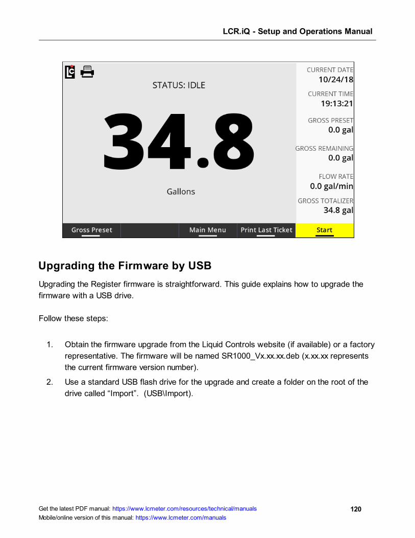
LCR.iQ - Setup and Operations Manual
120Get the latest PDF manual: https://www.lcmeter.com/resources/technical/manuals
Mobile/online version of this manual: https://www.lcmeter.com/manuals
Upgrading the Firmware by USB
Upgrading the Register firmware is straightforward. This guide explains how to upgrade the
firmware with a USB drive.
Follow these steps:
1. Obtain the firmware upgrade from the Liquid Controls website (if available) or a factory
representative. The firmware will be named SR1000_Vx.xx.xx.deb (x.xx.xx represents
the current firmware version number).
2. Use a standard USB flash drive for the upgrade and create a folder on the root of the
drive called “Import”. (USB\Import).
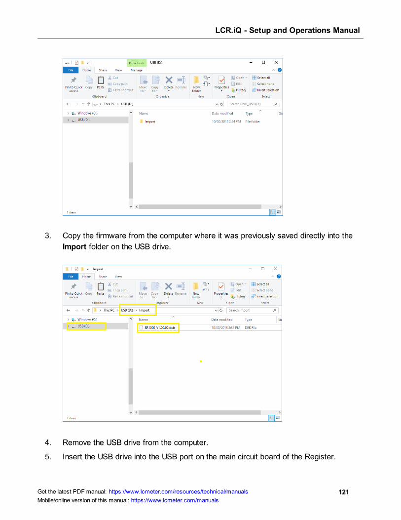
LCR.iQ - Setup and Operations Manual
121Get the latest PDF manual: https://www.lcmeter.com/resources/technical/manuals
Mobile/online version of this manual: https://www.lcmeter.com/manuals
3. Copy the firmware from the computer where it was previously saved directly into the
Import folder on the USB drive.
4. Remove the USB drive from the computer.
5. Insert the USB drive into the USB port on the main circuit board of the Register.
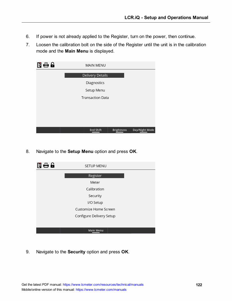
LCR.iQ - Setup and Operations Manual
122Get the latest PDF manual: https://www.lcmeter.com/resources/technical/manuals
Mobile/online version of this manual: https://www.lcmeter.com/manuals
6. If power is not already applied to the Register, turn on the power, then continue.
7. Loosen the calibration bolt on the side of the Register until the unit is in the calibration
mode and the Main Menu is displayed.
8. Navigate to the Setup Menu option and press OK.
9. Navigate to the Security option and press OK.
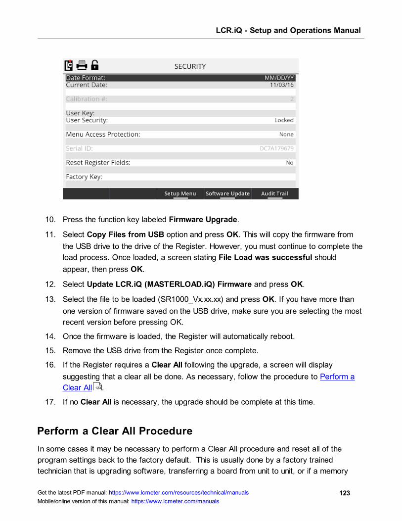
LCR.iQ - Setup and Operations Manual
123Get the latest PDF manual: https://www.lcmeter.com/resources/technical/manuals
Mobile/online version of this manual: https://www.lcmeter.com/manuals
10. Press the function key labeled Firmware Upgrade.
11. Select Copy Files from USB option and press OK. This will copy the firmware from
the USB drive to the drive of the Register. However, you must continue to complete the
load process. Once loaded, a screen stating File Load was successful should
appear, then press OK.
12. Select Update LCR.iQ (MASTERLOAD.iQ) Firmware and press OK.
13. Select the file to be loaded (SR1000_Vx.xx.xx) and press OK. If you have more than
one version of firmware saved on the USB drive, make sure you are selecting the most
recent version before pressing OK.
14. Once the firmware is loaded, the Register will automatically reboot.
15. Remove the USB drive from the Register once complete.
16. If the Register requires a Clear All following the upgrade, a screen will display
suggesting that a clear all be done. As necessary, follow the procedure to Perform a
Clear All .
17. If no Clear All is necessary, the upgrade should be complete at this time.
Perform a Clear All Procedure
In some cases it may be necessary to perform a Clear All procedure and reset all of the
program settings back to the factory default. This is usually done by a factory trained
technician that is upgrading software, transferring a board from unit to unit, or if a memory
123
LCR.iQ - Setup and Operations Manual
124Get the latest PDF manual: https://www.lcmeter.com/resources/technical/manuals
Mobile/online version of this manual: https://www.lcmeter.com/manuals
clear is needed. It is recommended that you save a configuration file of the current program
settings or copy all of the settings to a notepad before performing a clear all if you plan to
preprogram the unit with the same information.
Follow these steps to perform a clear all:
1. Enter the calibration mode by loosening the calibration bolt on the side of the Register
until the Main Menu is displayed on the screen.
2. Navigate to the Setup Menu and press OK.
3. Navigate to the Security option and press OK.
4. Navigate to Reset Register Fields option and press OK.
5. Select Clear All from the list box that is displayed and press OK.
6. A prompt will appear: “Are you sure you want to clear all settings? All settings will revert
back to factory defaults including custom settings.”
7. To proceed with the clear all, press the Yes function key and the clear all process will
begin.
8. Once complete, all programmable fields (except Time and Date) will be reset to factory
default settings.
9. Reprogram the unit as appropriate.
Print a transaction
The Register is capable of reprinting transaction using the transactions data log screens. The
register is able to store a number of transactions in its memory, corresponding with the
number of days retained (which is set in the Logging setup). The default setting is to retain
transaction logs for 365 days before deleting them from memory.
Follow these steps:
1. To reprint a transaction log, press the Main Menu function key to access the main menu.
2. Navigate to the Transaction Data option and press OK.
3. Use the navigation key pad to scroll between the screen pages or up and down in the
screen to select a transaction record. Transaction records are sorted in order by date.
Time and sale number are also displayed for quick identification of the record.

LCR.iQ - Setup and Operations Manual
125Get the latest PDF manual: https://www.lcmeter.com/resources/technical/manuals
Mobile/online version of this manual: https://www.lcmeter.com/manuals
4. Select the needed record and press OK
5. The transaction information will now be displayed on the screen for review.
6. If the correct record is selected and a printer is connected to the Register, the user can
print the transaction data by pressing the Print function button.
7. Once the ticket is printed, or if this is not the desired record, press the Close function key
to return to the transaction list, or press the Home button to return to the Home screen.
Setup custom profiles
The Register is capable of displaying and prompting for detailed delivery information that may
be useful when making a delivery. Customize Home Screen and Configure Delivery Setup can
be used to setup preconfigured or custom delivery detail screens, and setup user prompts that
can be used to collect additional transaction information.
Both the Customize Home Screen and the Configure Delivery Setup screens share a profile
field. The profile field setting will determine the information that is to be displayed on the
delivery screen and in the Delivery setup options. Liquid Controls has included several pre-
configured profiles in the Register to help simplify the setup process. Optionally, you can
create a custom profile.
Follow these steps to select a profile:
1. Place the Register into the calibration mode and access the Main Menu.
2. Navigate to the Setup Menu and press OK.
3. Navigate to Setup Home Screen option and press OK.
4. From either screen 1 (Customize Home Screen) or screen 2 (Configure Delivery
Setup) the user can select the desired profile from the profile field.
Follow these steps to set up a custom profile (Customize Home Screen):
1. Select Custom from the Profile field list box and press OK.
2. Setup the left and right columns in Customize Home Screen by using the navigation keys
to move the selection bar up and down to the desired column and line number, and press
OK.
LCR.iQ - Setup and Operations Manual
126Get the latest PDF manual: https://www.lcmeter.com/resources/technical/manuals
Mobile/online version of this manual: https://www.lcmeter.com/manuals
3. Select the desired field to be displayed in that location from the list box and then press
enter.
4. The selected item should now be displayed in the Customize Home Screen in the
desired location.
5. Continue setting up any desired locations with options as needed remembering that it is
good practice to keep like items grouped together on the screen for easy viewing by the
user.
Follow these steps to set up a custom profile (Configure Delivery Setup):
1. Navigate to the Configure Delivery Setup screen by pressing the left or right navigation
keys.
2. Select the Custom profile from the Profile list box and press OK.
3. Use the navigation keys to scroll to Prompt 1 and press OK.
4. Select the desired first prompt from the Edit Fields list box remembering that is it good
practice to setup the prompts in a logical order that makes sense for the user.
5. Repeat this step for each additional prompt that is desired when making a delivery.
Print a diagnostic ticket
Printing a diagnostic ticket is very simple with the Register.
Follow these steps:
1. From the home screen, press the Main Menu key to access the main menu options.
2. Navigate to the Diagnostics menu option and press OK.
3. Ensure you have a ticket in the printer, then press the Print Diagnostic key.
At this point, the Register will print the current diagnostic ticket. Below is an example of a
calibration ticket. The number of products that will print out will depend on the number of
calibrations that have been set up on the register.

LCR.iQ - Setup and Operations Manual
127Get the latest PDF manual: https://www.lcmeter.com/resources/technical/manuals
Mobile/online version of this manual: https://www.lcmeter.com/manuals
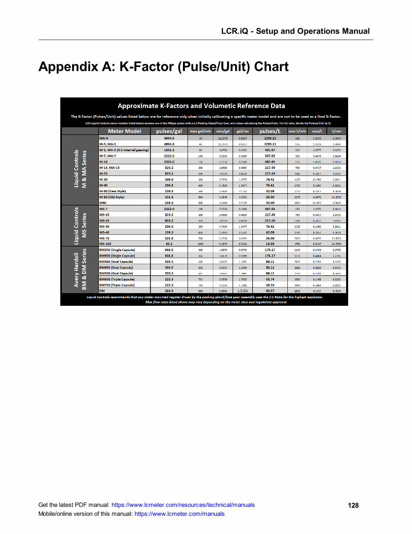
LCR.iQ - Setup and Operations Manual
128Get the latest PDF manual: https://www.lcmeter.com/resources/technical/manuals
Mobile/online version of this manual: https://www.lcmeter.com/manuals
Appendix A: K-Factor (Pulse/Unit) Chart
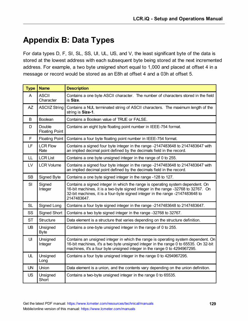
LCR.iQ - Setup and Operations Manual
129Get the latest PDF manual: https://www.lcmeter.com/resources/technical/manuals
Mobile/online version of this manual: https://www.lcmeter.com/manuals
Appendix B: Data Types
For data types D, F, SI, SL, SS, UI, UL, US, and V, the least significant byte of the data is
stored at the lowest address with each subsequent byte being stored at the next incremented
address. For example, a two byte unsigned short equal to 1,000 and placed at offset 4 in a
message or record would be stored as an E8h at offset 4 and a 03h at offset 5.
Type Name Description
A ASCIICharacter
Contains a one byte ASCII character. The number of characters stored in the fieldis Size.
AZ ASCIIZ String Contains a NUL terminated string of ASCII characters. The maximum length of thestring is Size-1.
B Boolean Contains a Boolean value of TRUE or FALSE.
D DoubleFloating Point
Contains an eight byte floating point number in IEEE-754 format.
F Floating Point Contains a four byte floating point number in IEEE-754 format.
LF LCR FlowRate
Contains a signed four byte integer in the range -2147483648 to 2147483647 withan implied decimal point defined by the decimals field in the record.
LL LCR List Contains a one byte unsigned integer in the range of 0 to 255.
LV LCR Volume Contains a signed four byte integer in the range -2147483648 to 2147483647 withan implied decimal point defined by the decimals field in the record.
SB Signed Byte Contains a one byte signed integer in the range -128 to 127.
SI SignedInteger
Contains a signed integer in which the range is operating system dependent. On16-bit machines, it is a two-byte signed integer in the range -32768 to 32767. On32-bit machines, it is a four-byte signed integer in the range -2147483648 to2147483647.
SL Signed Long Contains a four byte signed integer in the range -2147483648 to 2147483647.
SS Signed Short Contains a two byte signed integer in the range -32768 to 32767.
ST Structure Data element is a structure that varies depending on the structure definition.
UB UnsignedByte
Contains a one-byte unsigned integer in the range of 0 to 255.
UI UnsignedInteger
Contains an unsigned integer in which the range is operating system dependent. On16-bit machines, it's a two byte unsigned integer in the range 0 to 65535. On 32-bitmachines, it's a four byte unsigned integer in the range 0 to 4294967295.
UL UnsignedLong
Contains a four byte unsigned integer in the range 0 to 4294967295.
UN Union Data element is a union, and the contents vary depending on the union definition.
US UnsignedShort
Contains a two-byte unsigned integer in the range 0 to 65535.