Embed Size (px)
Citation preview

表1:豪州E
read carefully and keep in the vehicle.
For your safety and comfort,
Not For R
epro
duction

i
Foreword
Welcome to the growing group of value−conscious people who drive Toyotas. Weare proud of the advanced engineering and quality construction of each vehicle webuild.
This Owner’s Manual explains the operation of your new Toyota. Please readit thoroughly and have all the occupants follow the instructions carefully.Doing so will help you enjoy many years of safe and trouble−free motoring.For important information about this manual and your Toyota, read the follow-ing pages carefully.
When it comes to service, remember that your Toyota dealer knows your vehiclevery well and is interested in your complete satisfaction. Your Toyota dealer willprovide quality maintenance and any other assistance you may require.
Please leave this Owner’s Manual in this vehicle at the time of resale. The nextowner will need this information also.
All information and specifications in this manual are current at the time of printing.However, because of Toyota’s policy of continual product improvement, we reservethe right to make changes at any time without notice.
Please note that this manual applies to all models and explains all equipment,including options. Therefore, you may find some explanations for equipmentnot installed on your vehicle.
2008 TOYOTA MOTOR CORPORATION
All rights reserved. This material may not be reproduced or copied, in whole or inpart, without the written permission of Toyota Motor Corporation.
L/C120 AE (OM60D50E) 08/01/22
Not For R
epro
duction
ii
Important information about this manual
Safety and vehicle damage warnings
Throughout this manual, you will see safety and vehicledamage warnings. You must follow these warnings carefullyto avoid possible injury or damage.
The types of warnings, what they look like, and how theyare used in this manual are explained as follows:
CAUTION
This is a warning against anything which may causeinjury to people if the warning is ignored. You areinformed about what you must or must not do inorder to reduce the risk of injury to yourself andothers.
NOTICE
This is a warning against anything which may causedamage to the vehicle or its equipment if the warningis ignored. You are informed about what you must ormust not do in order to avoid or reduce the risk ofdamage to your vehicle and its equipment.
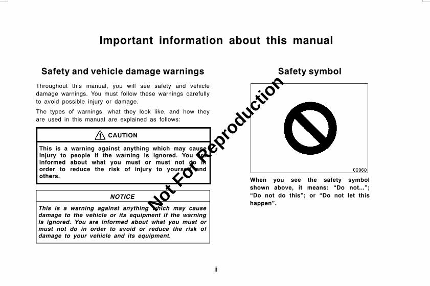
Safety symbol
When you see the safety symbolshown above, it means: “Do not...”;“Do not do this”; or “Do not let thishappen”.
L/C120 AE (OM60D50E) 08/01/22
Not For R
epro
duction

iii
Important information about your Toyota
Occupant restraint systems
Toyota encourages you and your family to take the time toread Section 1−3 of this Owner’s Manual carefully. Interms of helping you understand how you can receive themaximum benefit of the occupant restraint systems thisvehicle provides, Section 1−3 of this Owner’s Manual isthe most important Section for you and your family toread.
Section 1−3 describes the function and operation concern-ing seats, seat belts, SRS airbags and child restraint sys-tems of this vehicle and some potential hazards youshould be aware of. These systems work together alongwith the overall structure of this vehicle in order to provideoccupant restraint in the event of a crash. The effect ofeach system is enhanced when it is used properly andtogether with other systems. No single occupant restraintsystem can, by itself, provide you or your family with theequal level of restraint which these systems can providewhen used together. That is why it is important for you andyour family to understand the purpose and proper use ofeach of these systems and how they relate to each other.
The purpose of all occupant restraint systems is to helpreduce the possibility of death or serious injury in theevent of a collision. None of these systems, either individ-ually or together, can ensure that there is no injury in theevent of collision. However, the more you know aboutthese systems and how to use them properly, the greateryour chances become of surviving an accident withoutdeath or serious injury.
Seat belts provide the primary restraint to all occupants ofthe vehicle, and every occupant of the vehicle should wearseat belts properly at all times. Children should always besecured in child restraint systems that are appropriate fortheir age and size. SRS (Supplemental Restraint System)airbags are, as their names imply, designed to work with,and be supplemental to, seat belts and are not substitutesfor them. SRS airbags can be very effective in reducingthe risk of head and chest injuries by preventing contact ofthe head and chest with interior portions of the vehicle.
L/C120 AE (OM60D50E) 08/01/22
Not For R
epro
duction

iv
In order to be effective, the SRS airbags must deploy withtremendous speed. The rapid deployment of the SRS air-bags makes the SRS airbags themselves potential sourcesof death or serious injury if an occupant is too close to anairbag, or if an object or some part of his or her body hasbeen placed between the occupant and the airbag at thetime of deployment. This is just one example of how theinstructions in Section 1−3 of this Owner’s Manual will helpensure proper use of the occupant restraint systems, andincrease the safety they can provide to you and your fami-ly in the event of an accident.
Toyota recommends you to read the provisions in Section1−3 carefully and refer to them as needed during your timeof ownership of this vehicle.
Accessories, spare parts andmodification of your Toyota
A wide variety of non−genuine spare parts and accessoriesfor Toyota vehicles are currently available in the market.Using these spare parts and accessories which are notgenuine Toyota products may adversely affect the safety ofyour vehicle, even though these parts may be approved bycertain authorities in your country. Toyota therefore cannotaccept any liability or guarantee spare parts and accesso-ries which are not genuine Toyota products, nor for re-placement or installation involving such parts.
This vehicle should not be modified with non−genuineToyota products. Modification with non−genuine Toyotaproducts could affect its performance, safety or durability,and may even violate governmental regulations. In addi-tion, damage or performance problems resulting from themodification may not be covered under warranty.
L/C120 AE (OM60D50E) 08/01/22
Not For R
epro
duction

v
Installation of a mobiletwo−way radio system
As the installation of a mobile two−way radio system inyour vehicle could affect electronic systems such as multi-port fuel injection system/sequential multiport fuel injectionsystem, electronically controlled fuel pump, electronicthrottle control system, cruise control system, anti−lockbrake system, active traction control system, vehicle sta-bility control system, rear height control air suspension,Toyota electronic modulated suspension, SRS airbag sys-tem and seat belt pretensioner system, be sure to checkwith your Toyota dealer for precautionary measures or spe-cial instructions regarding installation.
Maintenance schedule
Please refer to the separate “Warranty and Service Book-let”.
Scrapping of your Toyota
The SRS airbag and front seat belt pretensioner devices inyour Toyota contain explosive chemicals. If the vehicle isscrapped with the airbags and pretensioners left as theyare, this may cause an accident such as fire. Be sure tohave the systems of the SRS airbag and seat belt preten-sioner removed and disposed of by a qualified serviceshop or by your Toyota dealer before you dispose of yourvehicle.
L/C120 AE (OM60D50E) 08/01/22
Not For R
epro
duction
vi
On−pavement and off−roaddriving tips
This vehicle belongs to the utility vehicle class. Utility ve-hicles have a significantly higher rollover rate than othertypes of vehicles. This vehicle will handle and maneuverdifferently from an ordinary passenger car because it isdesigned for off−road use also. In addition, this vehiclehas a higher ground clearance and center of gravity thanthat of an ordinary passenger car. This vehicle design fea-ture causes this type of vehicle to be more likely to rol-lover. Failure to operate this vehicle correctly may result inloss of control, accidents or vehicle rollover causing deathor serious injury. Be sure to read “Off−road vehicle precau-tions” on page 230 in Section 2 and “Off−road driving pre-cautions” on page 254 in Section 3.
L/C120 AE (OM60D50E) 08/01/22
Not For R
epro
duction
vii
1 OPERATION OF INSTRUMENTS AND CONTROLS Page1 Overview of instruments and controls 1. . . . . . . . . . . . . . . . . . . . . . . . . . . .2 Keys and Doors 11. . . . . . . . . . . . . . . . . . . . . . . . . . . . . . . . . . . . . . . . . . . .3 Occupant restraint systems 35. . . . . . . . . . . . . . . . . . . . . . . . . . . . . . . . . . .4 Steering wheel and Mirrors 101. . . . . . . . . . . . . . . . . . . . . . . . . . . . . . . . . .5 Lights, Wipers and Defogger 107. . . . . . . . . . . . . . . . . . . . . . . . . . . . . . . . .6 Gauges, Meters and Service reminder indicators 115. . . . . . . . . . . . . . . . .7 Engine (ignition) switch, Transmission and Parking brake 133. . . . . . . . . . . .8 Audio system 173. . . . . . . . . . . . . . . . . . . . . . . . . . . . . . . . . . . . . . . . . . . . .9 Air conditioning system 189. . . . . . . . . . . . . . . . . . . . . . . . . . . . . . . . . . . . .10 Other equipment 209. . . . . . . . . . . . . . . . . . . . . . . . . . . . . . . . . . . . . . . . . . .
2 INFORMATION BEFORE DRIVING YOUR TOYOTA 229. . . . . . . . . . . . .3 STARTING AND DRIVING 247. . . . . . . . . . . . . . . . . . . . . . . . . . . . . . . . . . . .4 IN CASE OF AN EMERGENCY 265. . . . . . . . . . . . . . . . . . . . . . . . . . . . . . .5 CORROSION PREVENTION AND APPEARANCE CARE 291. . . . . . . .6 MAINTENANCE REQUIREMENTS 299. . . . . . . . . . . . . . . . . . . . . . . . . . . .7 DO−IT−YOURSELF MAINTENANCE
1 Introduction 303. . . . . . . . . . . . . . . . . . . . . . . . . . . . . . . . . . . . . . . . . . . . . . .2 Engine and Chassis 311. . . . . . . . . . . . . . . . . . . . . . . . . . . . . . . . . . . . . . . .3 Electrical components 323. . . . . . . . . . . . . . . . . . . . . . . . . . . . . . . . . . . . . .
8 SPECIFICATIONS 335. . . . . . . . . . . . . . . . . . . . . . . . . . . . . . . . . . . . . . . . . . .9 INDEX 345. . . . . . . . . . . . . . . . . . . . . . . . . . . . . . . . . . . . . . . . . . . . . . . . . . . . . .
L/C120 AE (OM60D50E) 08/01/22
Table of contents
Not For R
epro
duction

viii
L/C120 AE (OM60D50E) 08/01/22
Not For R
epro
duction

1
OPERATION OF INSTRUMENTS ANDCONTROLSOverview of instruments and controlsInstrument panel overview 2. . . . . . . . . . . . . . . . . . . . . . . . . . . . . . . . . . . . .Instrument cluster overview 6. . . . . . . . . . . . . . . . . . . . . . . . . . . . . . . . . . . .Indicator symbols on the instrument panel 8. . . . . . . . . . . . . . . . . . . . . . .
L/C120 AE (OM60D50E) 08/01/22
SECTION 1−1
Not For R
epro
duction
2
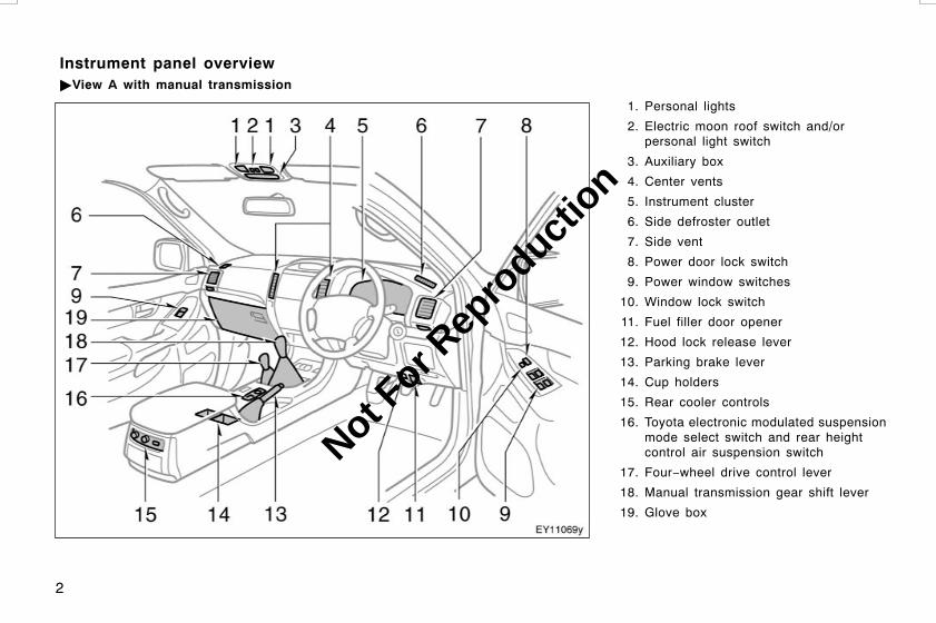
1. Personal lights
2. Electric moon roof switch and/orpersonal light switch
3. Auxiliary box
4. Center vents
5. Instrument cluster
6. Side defroster outlet
7. Side vent
8. Power door lock switch
9. Power window switches
10. Window lock switch
11. Fuel filler door opener
12. Hood lock release lever
13. Parking brake lever
14. Cup holders
15. Rear cooler controls
16. Toyota electronic modulated suspensionmode select switch and rear heightcontrol air suspension switch
17. Four−wheel drive control lever
18. Manual transmission gear shift lever
19. Glove box
L/C120 AE (OM60D50E) 08/01/22
Instrument panel overview"View A with manual transmission
Not For R
epro
duction

3
1. Personal lights
2. Electric moon roof switch and/orpersonal light switch
3. Auxiliary box
4. Center vents
5. Instrument cluster
6. Side defroster outlet
7. Side vent
8. Power door lock switch
9. Power window switches
10. Window lock switch
11. Fuel filler door opener
12. Hood lock release lever
13. Toyota electronic modulated suspensionmode select switch and rear heightcontrol air suspension switch
14. Downhill assist control (DAC) switch
15. Parking brake lever
16. Cup holders
17. Rear cooler controls
18. Automatic transmission selector lever
19. Four−wheel drive control lever
20. Glove box
L/C120 AE (OM60D50E) 08/01/22
"View A with automatic transmission
Not For R
epro
duction

4
1. Clock/outside temperature display ormulti−information display
2. Emergency flasher switch
3. Tilt steering lock release lever
4. Wiper and washer switches
5. Headlight, turn signal and front foglight switches
6. Engine switch
7. Power rear view mirror control switches
8. Instrument panel light control dial
9. Cruise control switch
10. Telescopic steering lock release lever
11. Audio remote control switches
12. Rear differential lock switch
13. “2nd STRT” (second start) modeselector button
14. Power outlet
15. Center differential lock switch
16. Ashtray
17. Cigarette lighter
18. Air conditioning controls
19. Rear window defogger switch
20. Front passenger’s seat belt reminderlight
21. Audio system
L/C120 AE (OM60D50E) 08/01/22
"View B with manual air conditioning controls
Not For R
epro
duction

5
1. Clock/outside temperature display ormulti−information display
2. Emergency flasher switch
3. Tilt steering lock release lever
4. Wiper and washer switches
5. Headlight, turn signal and front foglight switches
6. Engine switch
7. Power rear view mirror control switches
8. Instrument panel light control dial
9. Cruise control switch
10. Telescopic steering lock release lever
11. Audio remote control switches
12. Rear differential lock switch
13. “2nd STRT” (second start) modeselector button
14. Power outlet
15. Center differential lock switch
16. Ashtray
17. Cigarette lighter
18. Air conditioning controls
19. Rear window defogger switch
20. Front passenger’s seat belt reminderlight
21. Audio system
L/C120 AE (OM60D50E) 08/01/22
"View B with automatic air conditioning controls
Not For R
epro
duction
6
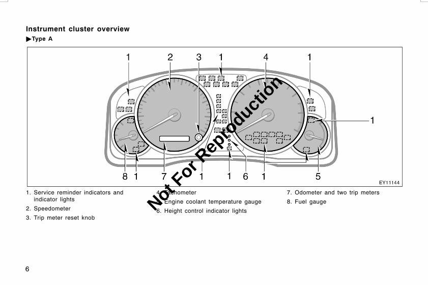
1. Service reminder indicators andindicator lights
2. Speedometer
3. Trip meter reset knob
4. Tachometer
5. Engine coolant temperature gauge
6. Height control indicator lights
7. Odometer and two trip meters
8. Fuel gauge
L/C120 AE (OM60D50E) 08/01/22
Instrument cluster overview"Type A
Not For R
epro
duction

7
1. Service reminder indicators andindicator lights
2. Speedometer
3. Trip meter reset knob
4. Tachometer
5. Engine coolant temperature gauge
6. Height control indicator lights
7. Odometer and two trip meters
8. Fuel gauge
L/C120 AE (OM60D50E) 08/01/22
"Type B
Not For R
epro
duction

8
Brake system warning light*1
Charging system warning light*1
Low engine oil pressure warning light*1
Malfunction indicator lamp*1
Low fuel level warning light*1
Open door warning light*1
SRS warning light*1
Anti−lock brake system warning light*1
Unengaged “Park” warning light*1
Automatic transmission fluid temperaturewarning light*1
Driver’s seat belt reminder light*1
Low engine oil level warning light*1
Timing belt replacement warning light*1
Fuel filter warning light*1
Front passenger’s seat belt reminder light*1
Fuel system warning light*1
L/C120 AE (OM60D50E) 08/01/22
Indicator symbols on the instrument panel
Not For R
epro
duction

9
Automatic transmission indicator lights(4−speed)
Headlight high beam indicator light
Turn signal indicator lights
Center differential lock indicator light*3
Rear differential lock indicator light*3
Slip indicator light
Vehicle stability control system off indicator light
Tail light indicator light
Front fog light indicator light
“90L” indicator light*2
Automatic transmission “2nd STRT” (secondstart) indicator light
Downhill assist control system indicator light
Height control “OFF” indicator light*4
Automatic transmission indicator lights(5−speed)
Vehicle stability control system and activetraction control system warning light*1
Engine immobilizer system/theft deterrentsystem indicator light
L/C120 AE (OM60D50E) 08/01/22
Not For R
epro
duction

10
*1: For details, see “Service reminder indicators and warningbuzzers” on page 121 in Section 1−6.
*2: If this light flashes, see “Fuel gauge” on page 116 in Section1−6.
*3: If this light flashes, see “Four−wheel drive system” on page146 in Section 1−7.
*4: If this light flashes, see “Rear height control air suspension”on page 162 in Section 1−7.
*5: If this light flashes, see “Cruise control” on page 169 inSection 1−7.
Cruise control indicator light*5
Engine preheating indicator light
L/C120 AE (OM60D50E) 08/01/22
Not For R
epro
duction

11
OPERATION OF INSTRUMENTS ANDCONTROLSKeys and DoorsKeys 12. . . . . . . . . . . . . . . . . . . . . . . . . . . . . . . . . . . . . . . . . . . . . . . . . . . . . . .Engine immobilizer system 14. . . . . . . . . . . . . . . . . . . . . . . . . . . . . . . . . . .Wireless remote control 15. . . . . . . . . . . . . . . . . . . . . . . . . . . . . . . . . . . . . .Side doors 19. . . . . . . . . . . . . . . . . . . . . . . . . . . . . . . . . . . . . . . . . . . . . . . . . .Power windows 22. . . . . . . . . . . . . . . . . . . . . . . . . . . . . . . . . . . . . . . . . . . . .Quarter windows 24. . . . . . . . . . . . . . . . . . . . . . . . . . . . . . . . . . . . . . . . . . . .Back door 25. . . . . . . . . . . . . . . . . . . . . . . . . . . . . . . . . . . . . . . . . . . . . . . . . .Hood 28. . . . . . . . . . . . . . . . . . . . . . . . . . . . . . . . . . . . . . . . . . . . . . . . . . . . . . .Theft deterrent system 29. . . . . . . . . . . . . . . . . . . . . . . . . . . . . . . . . . . . . . .Fuel tank cap 30. . . . . . . . . . . . . . . . . . . . . . . . . . . . . . . . . . . . . . . . . . . . . . .Electric moon roof 32. . . . . . . . . . . . . . . . . . . . . . . . . . . . . . . . . . . . . . . . . . .
L/C120 AE (OM60D50E) 08/01/22
SECTION 1−2
Not For R
epro
duction

12
Without wireless remote control system
With wireless remote control system
Your vehicle is supplied with two kindsof keys.
1. Master keys—
These keys work in every lock. YourToyota dealer will need one of them tomake a new key with a built−in trans-ponder chip.
Since the side doors and back doorcan be locked without a key, youshould always carry a spare masterkey in case you accidentally lock yourkeys inside the vehicle.
With wireless remote control system—
These keys are fitted with the wirelessremote control transmitter. For informa-tion on use of the wireless remote con-trol transmitter, see “Wireless remotecontrol” on page 15 in this Section.
2. Sub key—
This key will not work in the glove box.
To protect items locked in the glovebox when using valet parking, leavethe sub key with the attendant.
A transponder chip for engine immobilizersystem has been placed in the head ofthe master and sub keys. These chips areneeded to enable the system to functioncorrectly, so be careful not to lose thesekeys. If you make your own duplicate key,you will not be able to cancel the systemor start the engine.
L/C120 AE (OM60D50E) 08/01/22
Keys
Not For R
epro
duction
13
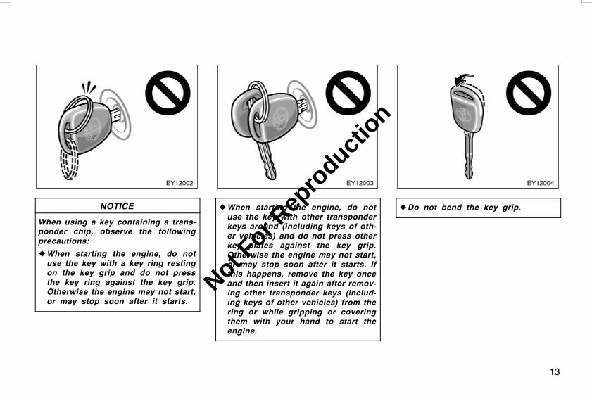
NOTICE
When using a key containing a trans-ponder chip, observe the followingprecautions:
zWhen starting the engine, do notuse the key with a key ring restingon the key grip and do not pressthe key ring against the key grip.Otherwise the engine may not start,or may stop soon after it starts.
zWhen starting the engine, do notuse the key with other transponderkeys around (including keys of oth-er vehicles) and do not press otherkey plates against the key grip.Otherwise the engine may not start,or may stop soon after it starts. Ifthis happens, remove the key onceand then insert it again after remov-ing other transponder keys (includ-ing keys of other vehicles) from thering or while gripping or coveringthem with your hand to start theengine.
z Do not bend the key grip.
L/C120 AE (OM60D50E) 08/01/22
Not For R
epro
duction

14
z Do not cover the key grip with anymaterial that cuts off electromagnet-ic waves.
z Do not knock the key hard againstother objects.
z Do not leave the key exposed tohigh temperatures for a long period,such as on the dashboard and hoodunder direct sunlight.
z Do not put the key in water orwash it in an ultrasonic washer.
z Do not use the key with electromag-netic materials. KEY NUMBER PLATE
Your key number is shown on the plate.Keep the plate in a safe place such asyour wallet, not in the vehicle.
If you should lose your keys or if youneed additional keys, duplicates can bemade by a Toyota dealer using the keynumber.
We recommend writing down the key num-ber and storing it in a safe place.
The engine immobilizer system is atheft prevention system. When you in-sert the key in the engine switch, thetransponder chip in the key’s headtransmits an electronic code to the ve-hicle. The engine will start only whenthe electronic code in the chip corre-sponds to the registered ID code forthe vehicle.
L/C120 AE (OM60D50E) 08/01/22
Engine immobilizer system
Not For R
epro
duction

15
The system is automatically set when thekey is removed from the engine switch.The indicator light will start flashing toshow the system is set.
If any of the following indicator conditionsoccurs, contact your Toyota dealer.
D The indicator light stays on.
D The indicator light does not start flash-ing when the key is removed from theengine switch.
D The indicator light flashes inconsistent-ly.
Inserting the registered key in the engineswitch automatically cancels the system,which enables the engine to start. Theindicator light will go off.
For your Toyota dealer to make you anew key with built−in transponder chip,your dealer will need your key numberand master key. However, there is a limitto the number of additional keys yourToyota dealer can make for you.
If you make your own duplicate key,you will not be able to cancel the sys-tem or start the engine.
NOTICE
Do not modify, remove or disas-semble the engine immobilizer sys-tem. If any unauthorized changes ormodifications are made, proper opera-tion of the system cannot be guaran-teed.
1. “LOCK” switch
2. Indicator light
3. “UNLOCK” switch
L/C120 AE (OM60D50E) 08/01/22
Wireless remote control—
Not For R
epro
duction
16
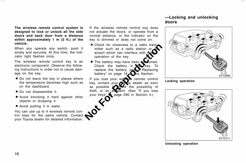
The wireless remote control system isdesigned to lock or unlock all the sidedoors and back door from a distancewithin approximately 1 m (3 ft.) of thevehicle.When you operate any switch, push itslowly and securely. At this time, the indi-cator light flashes once.
The wireless remote control key is anelectronic component. Observe the follow-ing instructions in order not to cause dam-age on the key.
D Do not leave the key in places wherethe temperature becomes high such ason the dashboard.
D Do not disassemble it.
D Avoid knocking it hard against otherobjects or dropping it.
D Avoid putting it in water.
You can use up to 4 wireless remote con-trol keys for the same vehicle. Contactyour Toyota dealer for detailed information.
If the wireless remote control key doesnot actuate the doors, or operate from anormal distance, or the indicator on thekey is dimmed or does not come on.
D Check for closeness to a radio trans-mitter such as a radio station or anairport which can interfere with normaloperation of the key.
D The battery may have been consumed.Check the battery in the key. Toreplace the battery, see “—Replacingbattery” on page 18 in this Section.
If you lose your wireless remote controlkey, contact your Toyota dealer as soonas possible to avoid the possibility oftheft, or an accident. (See “If you loseyour keys” on page 290 in Section 4.)
Locking operation
Unlocking operation
L/C120 AE (OM60D50E) 08/01/22
—Locking and unlockingdoors
Not For R
epro
duction

17
To lock and unlock all the side doorsand back door, push the switches ofthe key slowly and securely.
When you lock with the wireless remotecontrol, all the side doors and back doorcannot be unlocked with the power doorlock switch. The power door lock switchcan be reset by unlocking with the wire-less remote control key. (See “Side doors”on page 19 in this Section.)
To lock: Push the “LOCK” switch. All theside doors and back door are locked si-multaneously. At this time, the turn signallights flash once.Check to see that all the side doors andback door are securely locked.If any of the side doors or back door isnot securely closed, or if the key is in theengine switch, locking cannot be per-formed by the “LOCK” switch.To unlock: Push the “UNLOCK” switch. Allthe side doors and back door are un-locked simultaneously. At this time theturn signal lights flash twice.
When all the side doors and back doorare unlocked simultaneously with a wire-less remote control key, the interior light(center) and personal lights come on forabout 15 seconds and then fade out, evenif the door is not opened. (For furtherinformation, see “Interior lights” on page110 and “Personal lights” on page 111 inSection 1−5.)
The turn signal lights can be set not toflash. For details, contact your Toyotadealer.
If the key is in the engine switch, unlock-ing cannot be performed by the “UNLOCK”switch.
You have 30 seconds to open a door afterusing the wireless remote unlock feature.If a door is not opened by then, all theside doors and back door will be automati-cally locked again.The timing for the automatic door lockfunction can be changed. For details, con-tact your Toyota dealer.
If the “LOCK” or “UNLOCK” switch is keptpressed in, the locking or unlocking opera-tion is not repeated. Release the switchand then push again.
The wireless door locking or unlockingfunction can be erased. For details, con-tact your Toyota dealer.
L/C120 AE (OM60D50E) 08/01/22
Not For R
epro
duction

18
For replacement, use a CR1616 lithiumbattery or equivalent and a special screw-driver.
CAUTION
Special care should be taken to pre-vent small children from swallowingthe removed battery or components.
NOTICE
zWhen replacing the battery, be care-ful not to lose the components.
z Replace only with the same orequivalent type recommended by aToyota dealer.
z Dispose of used batteries accordingto the local laws.
Replace the battery by following theseprocedures:
1. Remove the screw, and then the cover. 2. Remove the module from the keyframe.
L/C120 AE (OM60D50E) 08/01/22
—Replacing battery
Not For R
epro
duction

19
3. Remove the 2 screws to take out thelid of the module. Take out the dis-charged battery and put in a new bat-tery with the positive side up.
NOTICE
Do not bend the terminals.
4. Install the lid with the 2 screws.
5. Install the module into the key frameand secure the cover with the screw.
6. When pushing either switch on thewireless key, make sure the indicatorlight comes on.
NOTICE
zMake sure the positive side andnegative side of the battery arefaced correctly.
z Do not replace the battery with wethands. Water may cause unexpectedrust.
z Do not touch or move any compo-nents inside the transmitter, or itmay interfere with proper operation.
z Be careful not to bend the electrodewhen inserting the battery and thatdust or oils do not adhere to thecase.
z Take care not to lose the screws.
z Close the cover securely.
After replacing the battery, check that thekey operates properly. If the key still doesnot operate properly, contact your Toyotadealer.
LOCKING AND UNLOCKING WITH KEY
Insert the key into the keyhole and turnit.
To lock: Turn the key forward.To unlock: Turn the key backward.
All the side doors and back door lock orunlock simultaneously with the driver’sdoor. When the interior light (center) andpersonal light switches are in the “DOOR”position, and all the side doors and backdoor are unlocked simultaneously usingeither the key or the wireless remote con-trol, the interior light (center) and personallights will come on and remain on forabout 15 seconds before fading out.
L/C120 AE (OM60D50E) 08/01/22
Side doors
Not For R
epro
duction

20
For further information, see “Interior lights”on page 110 and “Personal lights” on page111 in Section 1−5.
LOCKING AND UNLOCKING WITHINSIDE LOCK KNOB
Move the lock knob.
To lock: Push the knob forward.To unlock: Pull the knob backward.
If you want to lock the door from theoutside, set the knob in the lock positionbefore closing the door. The outside doorhandle must be held up while the door isbeing closed. Be careful not to lock yourkeys in the vehicle.
The driver’s door cannot be locked if youleave the key in the engine switch withthe door open.
The driver’s door can be opened from theinside even with the inside lock knob inthe lock position.
L/C120 AE (OM60D50E) 08/01/22
Not For R
epro
duction

21
LOCKING AND UNLOCKING WITHPOWER DOOR LOCK SWITCH
Push the switch.
To lock: Push the switch down on thefront side.To unlock: Push the switch down on therear side.
Operating the switch simultaneously locksor unlocks all the side doors and backdoor.
If you do any of the following, no doorcan be unlocked with the power door lockswitch.
D Vehicles with the wireless remote con-trol—Lock all the side doors and backdoor with the wireless remote controlkey.
D Set the driver’s door inside lock knobin the lock position, and close the driv-er’s door while holding up the outsidedoor handle.
D Lock all the doors simultaneously withthe driver’s door.
The power door lock switch can be resetin the following ways.
D Turn the engine switch to “ON”.
D Unlock all the doors simultaneouslywith the driver’s door.
D Vehicles with the wireless remote con-trol—Unlock all the doors with the wire-less remote control key.
D Unlock the driver’s door with the insidelock knob, and then unlock all thedoors with the power door lock switch.
REAR DOOR CHILD−PROTECTORS
Move the lock lever to the “LOCK”position as shown on the label.
When the child−protector is locked, youcannot open the rear door by the insidedoor handle. We recommend using thisfeature whenever small children are in thevehicle.
L/C120 AE (OM60D50E) 08/01/22
Not For R
epro
duction

22
CAUTION
Before driving, be sure that the doorsare closed and locked, especiallywhen small children are in the ve-hicle. Along with the proper use ofseat belts, locking the doors help pre-vent the driver and passengers frombeing thrown out from the vehicle inan accident. It also helps prevent thedoors from being opened unintention-ally.
Driver’s door
Passengers’ doors
The windows can be operated with theswitch on each door. The passengers’windows can also be controlled by theswitches on the driver’s door.
The engine switch must be in the “ON”position.
OPERATING THE WINDOWS
Use the switch on each door.
Normal operation: The window moves aslong as you hold the switch.
To open: Lightly push down the switch.To close: Lightly pull up the switch.
Automatic operation: Push the switchcompletely down or pull it completely up,and then release it. The window will fullyopen or close. To stop the window part-way, lightly move the switch in the oppo-site direction and then release it.
Key off operation: If both front doors areclosed, they work for about 43 secondseven after the engine switch is turned off.They stop working when either front dooris opened.
L/C120 AE (OM60D50E) 08/01/22
Power windows
Not For R
epro
duction
23
Jam protection function: During automat-ic closing operation or key off closing op-eration, the window stops and opens halfway if something gets caught between thewindow and window frame.
If the window receives a strong impact,this function may work even if nothing iscaught.
CAUTION
D Never try jamming any part of yourbody to activate the jam protectionfunction intentionally, as it could re-sult in a death or serious injury.
D The jam protection function maynot work if something gets caughtjust before the window fully closed.
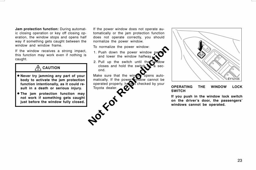
If the power window does not operate au-tomatically or the jam protection functiondoes not operate correctly, you shouldnormalize the power window.
To normalize the power window:
1. Push down the power window switchand lower the window halfway.
2. Pull up the switch until the windowcloses and hold the switch for a sec-ond.
Make sure that the window opens auto-matically. If the power window cannot beoperated properly, have it checked by yourToyota dealer. OPERATING THE WINDOW LOCK
SWITCH
If you push in the window lock switchon the driver’s door, the passengers’windows cannot be operated.
L/C120 AE (OM60D50E) 08/01/22
Not For R
epro
duction
24
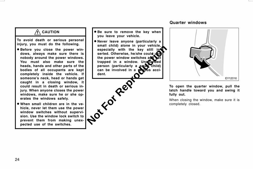
CAUTION
To avoid death or serious personalinjury, you must do the following.
D Before you close the power win-dows, always make sure there isnobody around the power windows.You must also make sure theheads, hands and other parts of thebodies of all occupants are keptcompletely inside the vehicle. Ifsomeone’s neck, head or hands getcaught in a closing window, itcould result in death or serious in-jury. When anyone closes the powerwindows, make sure he or she op-erates the windows safely.
DWhen small children are in the ve-hicle, never let them use the powerwindow switches without supervi-sion. Use the window lock switch toprevent them from making unex-pected use of the switches.
D Be sure to remove the key whenyou leave your vehicle.
D Never leave anyone (particularly asmall child) alone in your vehicle,especially with the key still in-serted. Otherwise, he/she could usethe power window switches and gettrapped in a window. Unattendedperson (particularly a small child)can be involved in a serious acci-dent.
To open the quarter window, pull thelatch handle toward you and swing itfully out.
When closing the window, make sure it iscompletely closed.
L/C120 AE (OM60D50E) 08/01/22
Quarter windows
Not For R
epro
duction
25
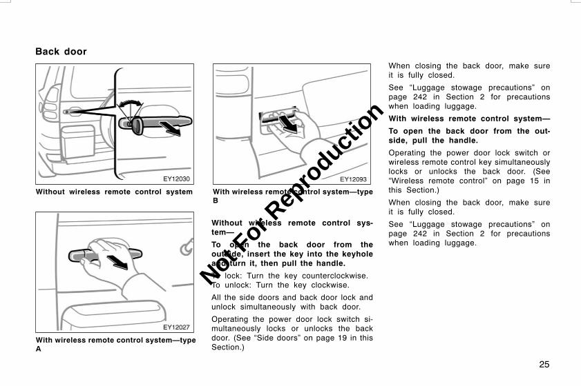
Without wireless remote control system
With wireless remote control system—typeA
With wireless remote control system—typeB
Without wireless remote control sys-tem—
To open the back door from theoutside, insert the key into the keyholeand turn it, then pull the handle.
To lock: Turn the key counterclockwise.To unlock: Turn the key clockwise.
All the side doors and back door lock andunlock simultaneously with back door.
Operating the power door lock switch si-multaneously locks or unlocks the backdoor. (See “Side doors” on page 19 in thisSection.)
When closing the back door, make sureit is fully closed.
See “Luggage stowage precautions” onpage 242 in Section 2 for precautionswhen loading luggage.
With wireless remote control system—
To open the back door from the out-side, pull the handle.
Operating the power door lock switch orwireless remote control key simultaneouslylocks or unlocks the back door. (See“Wireless remote control” on page 15 inthis Section.)
When closing the back door, make sureit is fully closed.
See “Luggage stowage precautions” onpage 242 in Section 2 for precautionswhen loading luggage.
L/C120 AE (OM60D50E) 08/01/22
Back door
Not For R
epro
duction

26
LOCKING AND UNLOCKING FROMINSIDE (on some models)
To lock: Turn the knob on the left side.To unlock: Turn the knob on the rightside.
To open the back door, pull the handle.
Operating the power door lock switch si-multaneously locks or unlocks the backdoor. (See “Side doors” on page 19 in thisSection.)
When closing the back door, make sureit is fully closed.
See “Luggage stowage precautions” onpage 242 in Section 2 for precautionswhen loading luggage.
CAUTION
D Keep the back door closed whiledriving. This not only keeps theluggage from being thrown out butalso prevents exhaust gases fromentering the vehicle.
D If the open back door hides thestop and tail lights, rear turn signallights or rear retro reflectors whileyou are parked, other road usersmust be warned of the presence ofyour vehicle by a warning triangleor other device. BACK DOOR OPENING
The back door can be held open in thefollowing position.
1. Half−open position
2. Fully−open position
L/C120 AE (OM60D50E) 08/01/22
Not For R
epro
duction

27
BACK DOOR STOPPER
For your safety, lock the back door withthe door stopper when you fully open theback door.
To lock: Push the lever.To unlock: Pull the lever.
When closing the back door, check thatthe back door stopper is unlocked.
CAUTION
DWhen keeping the back door open,use only the lock lever of the backdoor stopper without touching theother parts.
D To avoid serious personal injury,make sure not to get your handscaught in the back door stay whenclosing the back door.
BACK DOOR CHILD−PROTECTOR
Move the lock lever to the “LOCK”position as shown on the label.
When the child−protector is locked, youcannot open the back door by the insidedoor handle. We recommend using thisfeature whenever small children are in thevehicle.
L/C120 AE (OM60D50E) 08/01/22
Not For R
epro
duction

28
CAUTION
Before driving, be sure that the backdoor is closed and locked, especiallywhen small children are in the ve-hicle. Along with the proper use ofseat belts, locking the doors helpsprevent the driver and passengersfrom being thrown out from the ve-hicle in an accident. It also helps pre-vent the doors from being openedunintentionally.
To open the hood:
1. Pull up the hood lock release lever.The hood will spring up slightly.
CAUTION
Before driving, be sure that the hoodis closed and securely locked. Other-wise, the hood may open unexpected-ly while driving and an accident mayoccur.
2. In front of the vehicle, pull up theauxiliary catch lever and lift thehood.
Before closing the hood, check to see thatyou have not forgotten any tools, rags,etc. Then lower the hood make sure itlocks into place. If necessary, press downgently on the front edge to lock it.
L/C120 AE (OM60D50E) 08/01/22
Hood
Not For R
epro
duction

29
The system sounds alarm and flasheslights when forcible entry is detected.The alarm is triggered if any of theside doors, back door or hood is forci-bly unlocked or opened, or the batteryterminal is disconnected and then re-connected when the vehicle is locked.
SETTING THE SYSTEM
1. Turn the engine switch to the “LOCK”position and remove the key.
The indicator light will start flashing whenthe key is removed from the engineswitch. (See “Engine immobilizer system”on page 14 in this Section for details.)
2. Have all passengers get out of thevehicle.
3. Close and lock all the side doors, backdoor and hood.
The indicator light will remain on when allthe side doors, back door and hood areclosed and locked.
The system will automatically be set after30 seconds. When the system is set, theindicator light will start flashing again.
4. After making sure the indicator lightstarts flashing, you may leave the ve-hicle.
Never leave anyone in the vehicle whenyou set the system, because unlockingfrom the inside will activate the system.
Canceling the system
The system will cancel within 30 secondsbefore the system is set automatically un-der any of the following conditions:
D Any of the side doors, back door orhood is opened.
D Any of the side doors or back door isunlocked.
D The key is inserted into the engineswitch.
D The battery terminal is reconnected.
WHEN THE SYSTEM IS SET
Activating the system
The system will sound the alarm underthe following conditions:
D If any of the side doors is unlocked oropened without the key or wireless re-mote control key, or if the back dooror hood is forcibly opened.
L/C120 AE (OM60D50E) 08/01/22
Theft deterrent system
Not For R
epro
duction
30
D If the battery terminal is disconnectedand then reconnected.
D If the engine switch is hot−wired.
The indicator light will come on when thesystem is activated.
If the alarm has been activated and thekey is not in the engine switch, all theside doors and back door will re−lock au-tomatically.
After 28 seconds, the alarm will automati-cally stop and the indicator light will startflashing again.
Reactivating the alarm
Once set, the system automatically resetsthe alarm after the alarm stops.
The alarm will activate again under thesame circumstances described in“Activating the system”.
Stopping the alarm
The alarm will be stopped by the followingways:
D Turn the engine switch from the“LOCK” to “ON” position.
D Unlock any of the side doors or backdoor with the key.
These ways cancel the system at thesame time.
If the battery becomes discharged due tothe vehicle being unused for a long time,etc., when the battery is recharged or re-placed, the system will give the alarm. Ifthis happens, immediately unlock any ofthe side doors or the back door with thekey or the wireless remote control key,and the alarm will stop.
TESTING THE SYSTEM
1. Open all the windows.
2. Set the system as described above.The side doors and back door shouldbe locked with the key or wireless re-mote control key. Be sure to wait untilthe indicator light goes off or startsflashing.
3. Unlock any side door from the inside.The system should activate the alarm.
4. Stop the alarm as described above.
5. Repeat this operation for the otherdoors and hood. When testing thehood, also check that the system isactivated when the battery terminal isdisconnected and then reconnected.
If the system does not work properly,have it checked by your Toyota dealer.
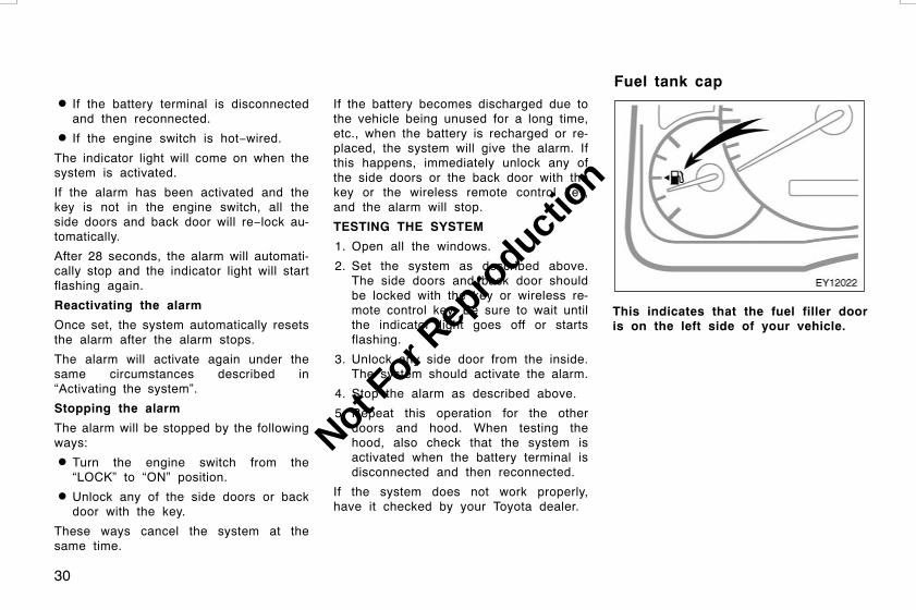
This indicates that the fuel filler dooris on the left side of your vehicle.
L/C120 AE (OM60D50E) 08/01/22
Fuel tank cap
Not For R
epro
duction

31
1. To open the fuel filler door, pull thelever up.
When refueling, turn off the engine.
CAUTION
D Do not smoke, cause sparks or al-low open flames when refueling.The fumes are flammable.
DWhen opening the cap, do not re-move the cap quickly. In hot weath-er, fuel under pressure could causeinjury by spraying out of the fillerneck if the cap is suddenly re-moved.
2. To remove the fuel tank cap, turnthe cap counterclockwise by 90 de-grees (to the pressure point 1), andthen turn it an additional 30 degrees(to point 2). Pause slightly beforeremoving it.
It is not unusual to hear a slight swooshwhen the cap is opened.
L/C120 AE (OM60D50E) 08/01/22
Not For R
epro
duction
32
3. The removed cap can be stored onthe back side of the fuel filler door.
Position the cap so that the hooks pointto the left and right or up and down, andset it in the receptacle on the back sideof the door.
When installing the cap, turn the capclockwise until you hear a click. Whenyou hear the click, the cap is fullyclosed.
CAUTION
D Make sure the cap is tightened se-curely to prevent fuel spillage inthe event of an accident.
D Use only a genuine Toyota fuel tankcap for replacement. It is designedto regulate fuel tank pressure.
NOTICE
To prevent damage to the cap, applyforce only in the turning direction tothe cap. Do not pull or pry it.
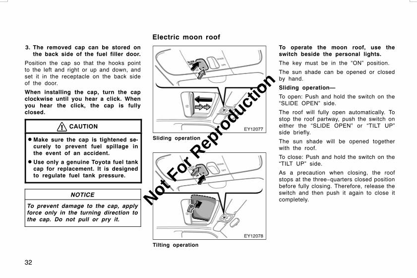
Sliding operation
Tilting operation
To operate the moon roof, use theswitch beside the personal lights.
The key must be in the “ON” position.
The sun shade can be opened or closedby hand.
Sliding operation—
To open: Push and hold the switch on the“SLIDE OPEN” side.
The roof will fully open automatically. Tostop the roof partway, push the switch oneither the “SLIDE OPEN” or “TILT UP”side briefly.
The sun shade will be opened togetherwith the roof.
To close: Push and hold the switch on the“TILT UP” side.
As a precaution when closing, the roofstops at the three−quarters closed positionbefore fully closing. Therefore, release theswitch and then push it again to close itcompletely.
L/C120 AE (OM60D50E) 08/01/22
Electric moon roof
Not For R
epro
duction
33
Tilting operation—
To tilt up: Push and hold the switch onthe “TILT UP” side.
The roof will fully tilt up automatically. Tostop the roof partway, push the switch oneither the “SLIDE OPEN” or “TILT UP”side briefly.
To lower: Push and hold the switch on the“SLIDE OPEN” side.
You may stop the moon roof at any de-sired position. The roof will move whilethe switch is being pushed and stop whenreleased.
Key off operation: If both front doors areclosed, it works for about 43 secondseven after the engine switch is turned off.However, the roof will not fully tilt up au-tomatically. It stops working when either ofthe front doors are opened.
Jam protection function:
D If something gets caught between themoon roof and frame during slide clos-ing operation, the moon roof stops andopens half way, the deflector stops andraises fully.
D If something gets caught between themoon roof and frame during tiltingdown operation, the moon roof stopsand opens fully.
If the moon roof receives a strong impact,this function may work even if nothing iscaught.
NORMALIZATION OF THE MOON ROOF
If the moon roof does not operate auto-matically or the jam protection functiondoes not operate correctly, you shouldnormalize the moon roof.
To normalize the moon roof, push andhold the switch on the “TILT UP” side untilthe moon roof tilts all the way up andthen tilts down a little automatically.
Make sure that the moon roof opens auto-matically. If the moon roof cannot be oper-ated properly, have it checked by yourToyota dealer.
CAUTION
To avoid death or serious injury, youmust do the following.
DWhile the vehicle is moving, alwayskeep the heads, hands and otherparts of the bodies of all occupantsaway from the roof opening. Other-wise, they could be killed or seri-ously injured if the vehicle stopssuddenly or if the vehicle is in-volved in an accident.
L/C120 AE (OM60D50E) 08/01/22
Not For R
epro
duction

34
D Before you close the moon roof,always make sure there is nobodyaround the moon roof. You mustalso make sure nobody places hisor her head, hands and other partsof the body in the roof opening. Ifsomeone’s neck, head or hands getcaught in the closing roof, it couldresult in death or serious injury.When anyone closes the moon roof,first make sure it is safe to do so.
D Be sure to remove the key whenyou leave your vehicle.
D Never leave anyone (particularly asmall child) alone in your vehicle,especially with the key still in-serted. Otherwise, he/she could usethe moon roof switches and gettrapped in the roof opening. Unat-tended person (particularly a smallchild) can be involved in a seriousaccident.
D Never sit on top of the vehiclearound the roof opening.
D Never try jamming any part of yourbody to activate the jam protectionfunction intentionally, as it could re-sult in a death or serious injury.
D The jam protection function maynot work if something gets caughtjust before the moon roof is fullyclosed.
L/C120 AE (OM60D50E) 08/01/22
Not For R
epro
duction

35
OPERATION OF INSTRUMENTS ANDCONTROLSOccupant restraint systemsSeats 36. . . . . . . . . . . . . . . . . . . . . . . . . . . . . . . . . . . . . . . . . . . . . . . . . . . . . . .Front seats 36. . . . . . . . . . . . . . . . . . . . . . . . . . . . . . . . . . . . . . . . . . . . . . . . .Rear seats 42. . . . . . . . . . . . . . . . . . . . . . . . . . . . . . . . . . . . . . . . . . . . . . . . . .Head restraints 58. . . . . . . . . . . . . . . . . . . . . . . . . . . . . . . . . . . . . . . . . . . . .Armrest 59. . . . . . . . . . . . . . . . . . . . . . . . . . . . . . . . . . . . . . . . . . . . . . . . . . . .Seat belts 59. . . . . . . . . . . . . . . . . . . . . . . . . . . . . . . . . . . . . . . . . . . . . . . . . .SRS driver airbag and front passenger airbag 69. . . . . . . . . . . . . . . . .SRS side airbags and curtain shield airbags 76. . . . . . . . . . . . . . . . . . .Child restraint 83. . . . . . . . . . . . . . . . . . . . . . . . . . . . . . . . . . . . . . . . . . . . . . .
L/C120 AE (OM60D50E) 08/01/22
SECTION 1−3
Not For R
epro
duction
36
While the vehicle is being driven, all ve-hicle occupants should have the seatbackupright, sit well back in the seat and prop-erly wear the seat belts provided.
CAUTION
D Do not drive the vehicle unless theoccupants are properly seated. Donot allow any passengers to sit ontop of a folded−down seatback, orin the luggage compartment or car-go area. Persons not properlyseated and/or not properly re-strained by seat belts can be killedor severely injured in the event ofemergency braking or a collision.
D During driving, do not allow anypassengers to stand up or movearound between seats. Otherwise,death or severe injuries can occurin the event of emergency brakingor a collision.
Driver seat
CAUTION
The SRS driver airbag deploys withconsiderable force, and can causedeath or serious injury especially ifthe driver is very close to the airbag.
Since the risk zone for driver airbagis the first 50—75 mm (2—3 in.) ofinflation, placing yourself 250 mm (10in.) from your driver airbag providesyou with a clear margin of safety.This distance is measured from thecenter of the steering wheel to yourbreastbone. If you sit less than 250mm (10 in.) away now, you canchange your driving position in sever-al ways:
D Move your seat to the rear as faras you can while still reaching thepedals comfortably.
D Slightly recline the back of theseat. Although vehicle designs vary,many drivers can achieve the 250mm (10 in.) distance, even with thedriver seat all the way forward, sim-ply by reclining the back of theseat somewhat. If reclining the backof your seat makes it hard to seethe road, raise yourself by using afirm, non−slippery cushion, or raisethe seat if your vehicle has thatfeature.
D If your steering wheel is adjustable,tilt it downward. This points the air-bag toward your chest instead ofyour head and neck.
The seat should be adjusted as rec-ommended above, while still maintain-ing control of the foot pedals, steer-ing wheel, and your view of the in-strument panel controls.
L/C120 AE (OM60D50E) 08/01/22
SeatsFront seats——Front seat precautions
Not For R
epro
duction

37
Front passenger seat
CAUTION
The SRS front passenger airbag alsodeploys with considerable force, andcan cause death or serious injury es-pecially if the front passenger is veryclose to the airbag. The front passen-ger seat should be as far from theairbag as possible with the seatbackadjusted, so the front passenger sitsupright.
Front seats (with SRS side airbags)
CAUTION
The SRS side airbags are installed inthe driver and front passenger seats.Observe the following precautions.
D Do not lean against the front doorwhen the vehicle is in use, sincethe side airbag inflates with consid-erable speed and force. Otherwise,you may be killed or seriously in-jured.
D Do not use seat accessories whichcover the area where the side air-bags inflate. Such accessories mayprevent the side airbags from acti-vating correctly, causing death orserious injury.
D Do not modify or replace the seatsor upholstery of the seats with sideairbags. Such change may preventthe side airbag system from activat-ing correctly, disable the system orcause the side airbags to inflate ac-cidentally, resulting in death or seri-ous injury.
CAUTION
D Do not adjust the seat while thevehicle is moving as the seat mayunexpectedly move and cause thedriver to lose control of the vehicle.
D Be careful that the seat does nothit a passenger or luggage.
D After adjusting the seat position, re-lease the lever and try sliding theseat forward and backward to makesure it is locked in position.
D After adjusting the seatback, pushyour body back against the seat tomake sure the seat is locked inposition.
D Do not put objects under the seats.Otherwise, the objects may interferewith the seat−lock mechanism orunexpectedly push up the seat posi-tion adjusting lever and the seatmay suddenly move, causing thedriver to lose control of the vehicle.
DWhile adjusting the seat, do not putyour hands under the seat or nearthe moving parts. Otherwise, yourhands or fingers may be caught andinjured.
L/C120 AE (OM60D50E) 08/01/22
—Seat adjustmentprecautions
Not For R
epro
duction

38
1. SEAT POSITION ADJUSTING LEVER
Hold the center of the lever and pull itup. Then slide the seat to the desiredposition with slight body pressure andrelease the lever.
2. SEAT CUSHION ANGLE ADJUSTINGKNOB—FOR FRONT
Turn the knob either way.
3. SEAT CUSHION ANGLE ADJUSTINGLEVER—FOR REAR
Pull up or push down the lever.
4. SEATBACK ANGLE ADJUSTINGLEVER
Lean forward and pull the lever up.Then lean back to the desired angleand release the lever.
CAUTION
Avoid reclining the seatback anymore than needed. The seat belts pro-vide maximum protection in a frontalor rear collision when the driver andthe front passenger are sitting upstraight and well back in the seats. Ifyou are reclined, the lap belt mayslide past your hips and apply re-straint forces directly to the abdomenor your neck may contact the shoul-der belt. In the event of a frontalcollision, the more the seat is re-clined, the greater the risk of deathor serious injury.
L/C120 AE (OM60D50E) 08/01/22
—Adjusting front seats(manual type)
Not For R
epro
duction

39
5. SEAT LUMBAR SUPPORTADJUSTING SWITCH (on somemodels)
Press either side of the switch.
The amount of lumbar support will changewhile the switch is pressed.
1. SEAT POSITION AND SEAT CUSHIONANGLE ADJUSTING SWITCH
Move the adjusting switch in the de-sired direction.
Releasing the switch will stop the seat atthat position.
Do not place anything under the frontseats, as this might interfere with the seatmovement.
2. SEATBACK ANGLE ADJUSTINGSWITCH
Move the adjusting switch in the de-sired direction.
Releasing the switch will stop the seat-back at that position.
L/C120 AE (OM60D50E) 08/01/22
—Adjusting front seats(power type)
Not For R
epro
duction

40
CAUTION
Avoid reclining the seatback anymore than needed. The seat belts pro-vide maximum protection in a frontalor rear collision when the driver andthe front passenger are sitting upstraight and well back in the seats. Ifyou are reclined, the lap belt mayslide past your hips and apply re-straint forces directly to the abdomenor your neck may contact the shoul-der belt. In the event of a frontalcollision, the more the seat is re-clined, the greater the risk of deathor serious injury.
3. SEAT LUMBAR SUPPORTADJUSTING SWITCH
Press either side of the switch.
The amount of lumbar support will changewhile the switch is pressed.
1. Remove the head restraint. Hold thecenter of the lever and pull it up.Then slide the seat further forwardthan the front−most lock position.
2. Pull the seatback angle adjusting le-ver to unlock and push down theseatback.
When returning the seatback upright, becareful not to make yourself hit by theseatback which will bound with consid-erable spring force.
After returning the seat to its originalposition, be certain to replace the headrestraint.
L/C120 AE (OM60D50E) 08/01/22
—Flattening seatbacks(manual seat)
Not For R
epro
duction

41
CAUTION
D Do not allow passengers to ride onthe flattened seat while driving; usethe seat in the normal position.
D After putting back the seat, trypushing the seat and seatback for-ward and rearward to make sure itis secured in place. Be certain toreplace head restraint.
1. Remove the head restraint. Push theseat position adjusting switch for-ward to slide the seat to the front−most position.
2. Move the seatback angle adjustingswitch backward to flatten the seat-back.
After returning the seat to its originalposition, be certain to replace the headrestraint.
CAUTION
D Do not allow passengers to ride onthe flattened seat while driving; usethe seat in the normal position.
DWhen returning the seatback to itsoriginal position, be certain to re-place head restraint.
L/C120 AE (OM60D50E) 08/01/22
—Flattening seatbacks(power seat)
Not For R
epro
duction
42
CAUTION
D Adjustment should not be madewhile the vehicle is moving.
DWhen adjusting the seat, be carefulnot to hit the seat against a pas-senger or luggage.
D After adjusting the seatback, pushback your body to make sure it islocked in position.
DWhen returning seats to their origi-nal position, observe the followingprecautions in order to preventdeath or serious injury in a colli-sion or sudden stop:
Make sure the seat is securelylocked by pushing forward and rear-ward on the top of the seatback orby trying to pull up the edge of thebottom cushion. Failure to do sowill prevent the seat belt from oper-ating properly.
Make sure the seat belts are nottwisted or caught under the seatand are arranged in their properposition and are ready to use.
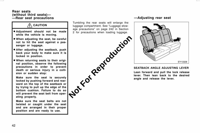
Tumbling the rear seats will enlarge theluggage compartment. See “Luggage stow-age precautions” on page 242 in Section2 for precautions when loading luggage.
SEATBACK ANGLE ADJUSTING LEVER
Lean forward and pull the lock releaselever. Then lean back to the desiredangle and release the lever.
L/C120 AE (OM60D50E) 08/01/22
Rear seats(without third seats)——Rear seat precautions —Adjusting rear seat
Not For R
epro
duction
43
CAUTION
D Avoid reclining the seatback anymore than needed. The seat beltsprovide maximum protection in afrontal or rear collision when thepassengers are sitting up straightand well back in the seats. If youare reclined, the lap belt may slidepast your hips and apply restraintforces directly to the abdomen oryour neck may contact the shoulderbelt. In the event of a frontal colli-sion, the more the seat is reclined,the greater the risk of death or ser-ious injury.
D Do not adjust the seat while thevehicle is moving.
D After adjusting the seatback, pushyour body back against the seat tomake sure the seat is locked inposition.
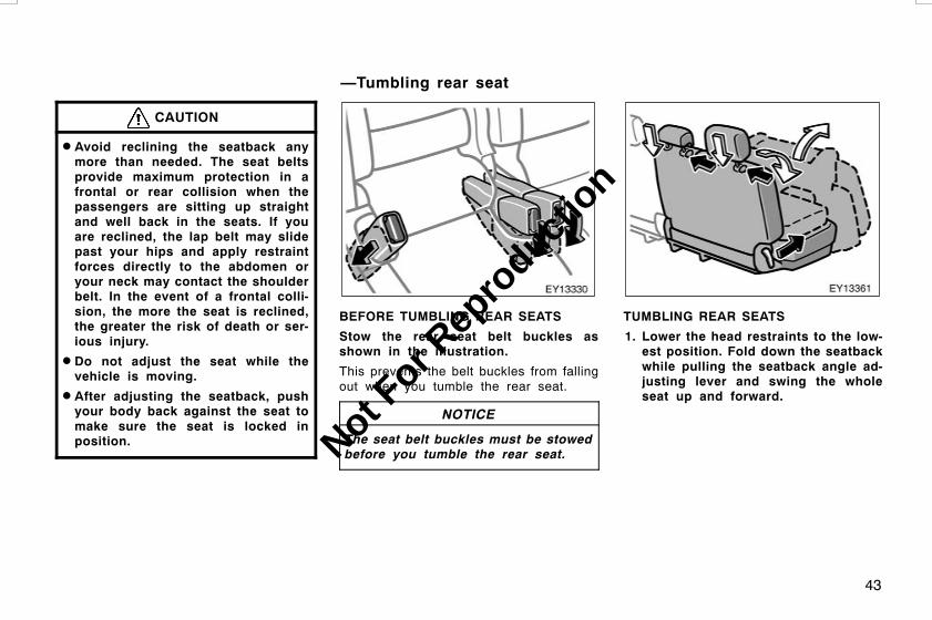
BEFORE TUMBLING REAR SEATS
Stow the rear seat belt buckles asshown in the illustration.
This prevents the belt buckles from fallingout when you tumble the rear seat.
NOTICE
The seat belt buckles must be stowedbefore you tumble the rear seat.
TUMBLING REAR SEATS
1. Lower the head restraints to the low-est position. Fold down the seatbackwhile pulling the seatback angle ad-justing lever and swing the wholeseat up and forward.
L/C120 AE (OM60D50E) 08/01/22
—Tumbling rear seat
Not For R
epro
duction

44
CAUTION
D Make sure people or luggage areclear from the seat. Then, hold theseat and slowly move it. Otherwise,people may be injured or luggagemay be damaged, if the seat hitsthem.
D To avoid serious injury, do not siton the folded seatback.
Tumbling the rear seats will enlarge theluggage compartment. See “Luggage stow-age precautions” on page 242 in Section2 for precautions when loading luggage.
WHEN RETURNING REAR SEATS
Push the knob to unlock the seat,swing the whole seat down and swingthe seatback up.
If you cannot raise the seatback be-cause of the locked seat belt, do nottry it forcibly. Release the lock of theseat belt in the following way. Push inthe lower front edge of the seatbackcushion to slacken the seat belt (1) andlet the seat belt retract a little (2).
L/C120 AE (OM60D50E) 08/01/22
Not For R
epro
duction

45
CAUTION
When returning seats to their originalposition, observe the following pre-cautions in order to prevent death orserious injury in a collision or sud-den stop:
D Be careful not to get your hands orfeet pinched in the seat.
D Make sure the seat is securelylocked by pushing forward and rear-ward on the top of the seatback orby trying to pull up the edge of thebottom cushion. Failure to do sowill prevent the seat belt from oper-ating properly.
D Make sure the seat belts are nottwisted or caught under the seatand are arranged in their properposition and are ready to use.
CAUTION
D Adjustment should not be madewhile the vehicle is moving.
DWhen adjusting the seat, be carefulnot to hit the seat against a pas-senger or luggage.
D Third seat only: Align both seat-backs at the same angle when aperson sits in the third seat centerposition. Otherwise, the person can-not wear seat belt properly and thismay cause death or serious injuriesin a collision.
D After adjusting the seatback, pushback your body to make sure it islocked in position.
DWhen returning seats to their origi-nal position, observe the followingprecautions in order to preventdeath or serious injury in a colli-sion or sudden stop:
Make sure the seat is securelylocked by pushing forward and rear-ward on the top of the seatback orby trying to pull up the edge of thebottom cushion. Failure to do sowill prevent the seat belt from oper-ating properly.
Make sure the seat belts are nottwisted or caught under the seatand are arranged in their properposition and are ready to use.
Tumbling the rear seat will enlarge theluggage compartment. See “Luggage stow-age precautions” on page 242 in Section2 for precautions when loading luggage.
L/C120 AE (OM60D50E) 08/01/22
Rear seats (with third seat)——Rear seat precautions
Not For R
epro
duction

46
Second seat
Third seat
SEATBACK ANGLE ADJUSTING LEVER
Lean forward and pull the lock releaselever. Then lean back to the desiredangle and release the lever.
Third seat only: When a person sits inthe third center position, align bothseatbacks at the same angle.
CAUTION
D Third seat only: Align both seat-backs at the same angle when aperson sits in the third seat centerposition. Otherwise, the person can-not wear seat belt properly and thismay cause death or serious injuriesin a collision.
D Avoid reclining the seatback anymore than needed. The seat beltsprovide maximum protection in afrontal or rear collision when thepassengers are sitting up straightand well back in the seats. If youare reclined, the lap belt may slidepast your hips and apply restraintforces directly to the abdomen oryour neck may contact the shoulderbelt. In the event of a frontal colli-sion, the more the seat is reclined,the greater the risk of death or se-rious injury.
L/C120 AE (OM60D50E) 08/01/22
—Adjusting rear seats
Not For R
epro
duction
47
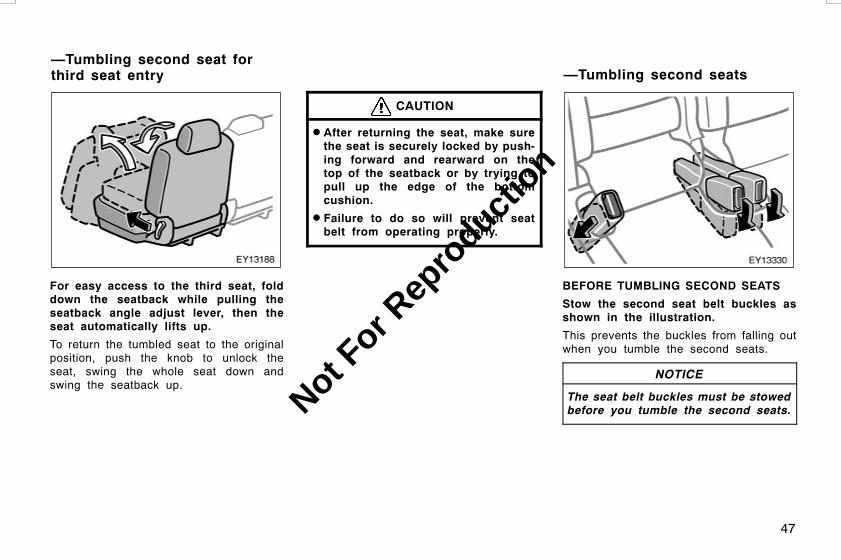
For easy access to the third seat, folddown the seatback while pulling theseatback angle adjust lever, then theseat automatically lifts up.
To return the tumbled seat to the originalposition, push the knob to unlock theseat, swing the whole seat down andswing the seatback up.
CAUTION
D After returning the seat, make surethe seat is securely locked by push-ing forward and rearward on thetop of the seatback or by trying topull up the edge of the bottomcushion.
D Failure to do so will prevent seatbelt from operating properly.
BEFORE TUMBLING SECOND SEATS
Stow the second seat belt buckles asshown in the illustration.
This prevents the buckles from falling outwhen you tumble the second seats.
NOTICE
The seat belt buckles must be stowedbefore you tumble the second seats.
L/C120 AE (OM60D50E) 08/01/22
—Tumbling second seat forthird seat entry —Tumbling second seats
Not For R
epro
duction

48
TUMBLING SECOND SEATS
Lower the head restraints to the lowestposition. Fold down the seatback whilepulling the seatback angle adjusting le-ver and swing the whole seat up andforward.
CAUTION
D Make sure people or luggage areclear from the seat. Then, hold theseat and slowly move it. Otherwise,people may be injured or luggagemay be damaged, if the seat hitsthem.
D To avoid serious injury, do not siton the folded seatback.
Tumbling the second seats will enlarge thefloor space for third seat passenger’s.
WHEN RETURNING SECOND SEATS
Push the knob to unlock the seat,swing the whole seat down and swingthe seatback up.
L/C120 AE (OM60D50E) 08/01/22
Not For R
epro
duction

49
If you cannot raise the seatback be-cause of the locked seat belt, do nottry it forcibly. Release the lock of theseat belt in the following way. Push inthe lower front edge of the seatbackcushion to slacken the seat belt (1) andlet the seat belt retract a little (2).
CAUTION
When returning seats to their originalposition, observe the following pre-cautions in order to prevent death orserious injury in a collision or sud-den stop:
D Be careful not to get your hands orfeet pinched in the seat.
D Make sure the seat is securelylocked by pushing forward and rear-ward on the top of the seatback orby trying to pull up the edge of thebottom cushion. Failure to do sowill prevent the seat belt from oper-ating properly.
D Make sure the seat belts are nottwisted or caught under the seatand are arranged in their properposition and are ready to use.
BEFORE FOLDING UP THIRD SEATS
1. Stow the third seat belt buckles asshown in the illustration.
This prevents the buckles from falling outwhen you fold up the third seats.
NOTICE
The seat belt buckles must be stowedbefore you fold up the third seats.
L/C120 AE (OM60D50E) 08/01/22
—Folding up third seats
Not For R
epro
duction

50
2. Make sure the shoulder belts passthrough the hanger when folding thethird seats.
This prevents the shoulder belt from beingdamaged.
CAUTION
The seat belt must be removed fromthe hanger when the seat belt is inuse.
3. To stow the center seat belt, pull itslightly out of its cover. It will auto-matically roll back partway. Roll theseat belt backwards as shown aboveand insert it into the slot of its cov-er. Make sure the tabs are securelylocked in the cover.
NOTICE
The seat belt must be stowed beforeyou fold the seatback.
FOLDING UP THIRD SEATS
1. Lower the outside head restraints tothe lowest position and remove thecenter head restraint, unlock theseatbacks and fold them down.
Folding up the third seats will enlarge theluggage compartment. See “Luggage stow-age precautions” on page 242 in Section2 for precautions when loading luggage.
L/C120 AE (OM60D50E) 08/01/22
Not For R
epro
duction

51
2. Unfasten the zippers, stow the cen-ter head restraint in the back of theright side seatback.
3. Unlock the seat leg, and swing thewhole seat up and sideward.
4. Push down the inner leg into theback of the seat cushion. Take theholding strap out of its holder, andhang the strap to the assist grip.Pull the end of the strap to eliminatethe slackness and fix it with the Vel-cro.
CAUTION
When folding up the third seats, fixthe seats securely by adjusting thelength of the holding strap. Failure todo so may cause an unexpecteddeath or serious injury in the eventof emergency braking or collision.
L/C120 AE (OM60D50E) 08/01/22
Not For R
epro
duction

52
When returning the third seats to its origi-nal position, stow the holding straps intothe holders facing the direction shown inthe illustration. Be certain to replace thecenter head restraint.
CAUTION
When returning seats to their originalposition, observe the following pre-cautions in order to prevent death orserious injury in a collision or sud-den stop:
D Make sure the seat is securelylocked by pushing forward and rear-ward on the top of the seatback orby trying to pull up the edge of thebottom cushion. Be certain to repla-ce the center head restraint. Failureto do so will prevent the seat beltfrom operating properly.
D Make sure the seat belts are nottwisted or caught under the seatand are arranged in their properposition and are ready to use.
BEFORE REMOVING THIRD SEATS
1. Stow the third seat belt buckles asshown in the illustration.
This prevents the buckles from falling outwhen you remove the third seats.
NOTICE
The seat belt buckles must be stowedbefore you remove the third seats.
L/C120 AE (OM60D50E) 08/01/22
—Removing third seats
Not For R
epro
duction

53
2. When removing the third seats, passthe third seat belts through thehangers.
This prevents the shoulder belt from beingdamaged.
CAUTION
The seat belt must be removed fromthe hanger when the seat belt is inuse.
3. To stow the center seat belt, pull itslightly out of its cover. It will auto-matically roll back partway. Roll theseat belt backwards as shown aboveand insert it into the slot of its cov-er. Make sure the tabs are securelylocked in the cover.
NOTICE
The seat belt must be stowed beforeyou fold the seatback.
REMOVING THIRD SEATS
1. Lower the outside head restraints tothe lowest position, then remove thecenter head restraint and seat lockcover.
L/C120 AE (OM60D50E) 08/01/22
Not For R
epro
duction

54
2. Unlock the seatback and fold itdown.
3. Unfasten the zippers, stow the cen-ter head restraint in the back of theright side seatback.
4. Unlock the seat leg, and swing thewhole seat up. Push down the innerleg into the back of the seat cush-ion. Then, place the seat on thefloor.
L/C120 AE (OM60D50E) 08/01/22
Not For R
epro
duction

55
5. Push the seat lock release lever out-ward to unlock the seat lock, thenpull up the whole seat and removeit.
Removing the third seats will enlarge theluggage compartment. See “Luggage stow-age precautions” on page 242 in Section2 for precautions when loading luggage.
6. Install the seat lock cover.
When returning the third seats to its origi-nal position, be certain to replace centerhead restraint.
CAUTION
Make sure the seat is securely lockedby pushing forward and rearward onthe top of the seatback or by tryingto pull up the edge of the bottomcushion. Failure to do so will preventthe seat belt from operating properly.
NOTICE
Avoid putting heavy loads on the re-moved seat. The metallic tips of theseat leg may be damaged and theseat cannot be reinstalled.
L/C120 AE (OM60D50E) 08/01/22
Not For R
epro
duction

56
1. Remove the seat lock cover.
2. Hold the seat and engage the seatstriker to the seat lock, then placethe seat on the floor. Press downthe seatback to securely lock theseat to the body.
L/C120 AE (OM60D50E) 08/01/22
—Reinstalling third seats
Not For R
epro
duction

57
3. Pull down the inner leg from theback of the seat cushion. Swing thewhole seat down. Then, install theseat lock cover.
4. Raise the seatback while pushingdown the seatback angle adjustinglever.
CAUTION
When removing or reinstalling theseat, observe the following to preventdeath or serious injury:
D Do not fold or remove the seatwhile the vehicle is moving.
D Be careful not to get your hands orfeet pinched in the seat.
D Be careful not to hit the removedseat against a person or drop it onyourself.
D After folding or installing the seat,push it forward and backward tomake sure it is locked in position.
To prevent death or serious injury ina collision or sudden stop:
D Do not sit on or place anything onthe folded seatback while driving.
D Do not leave the removed seatloose in the vehicle.
D Do not try to sit on or place any-thing on the removed seat.
DWhen reinstalling the seat, be care-ful not to hit the seat against youor inside of the vehicle.
D Install each seat in the same posi-tion from which it was removed.Failure to do so will prevent thirdseat occupants from using seatbelts properly.
L/C120 AE (OM60D50E) 08/01/22
Not For R
epro
duction

58
Front seat
Second seat
Third seat
For your safety and comfort, adjust thehead restraint before driving.
To raise: Pull it up.To lower: Push it down while pressing thelock release button.
Front seat—On some models, you canalso move the front head restraint forwardor backward. If such adjustment is de-sired, pull or push the head restraint.
Second seat—When an occupant sits onthe second center seat, always pull up thecenter head restraint to the lock position.
The head restraint is most effective whenit is close to your head. Therefore, usinga cushion on the seatback is not recom-mended.
CAUTION
D Adjust the center of the head re-straint so that it is closest to thetop of your ears.
D After adjusting the head restraint,make sure it is locked in position.
D Do not drive with the head re-straints removed.
L/C120 AE (OM60D50E) 08/01/22
Head restraints
Not For R
epro
duction

59
To use the armrest, pull the armrest outas shown in the illustration.
NOTICE
To prevent damage to the armrest,avoid putting heavy loads on it.
Toyota strongly urges that the driver andpassengers in the vehicle be properly re-strained at all times with the seat beltsprovided. Failure to do so could increasethe chance of injury and/or the severity ofinjury in accidents.
The seat belts provided for your vehicleare designed for people of adult size,large enough to properly wear them.
Child. Use a child restraint system ap-propriate for the child until the child be-comes large enough to properly wear thevehicle’s seat belts. See “Child restraint”on page 83 in this Section for details.
If a child is too large for a child restraintsystem, the child should sit in the rearseat and must be restrained using thevehicle’s seat belt. According to accidentstatistics, the child is safer when properlyrestrained in the rear seat than in thefront seat.
If a child must sit in the front seat, theseat belts should be worn properly. If anaccident occurs and the seat belts are notworn properly, the force of the rapid infla-tion of the airbag may cause death orserious injury to the child.
Do not allow any children to stand up orkneel on either rear or front seats. Anunrestrained child could suffer serious in-jury or death during emergency braking ora collision. Also, do not let the child siton your lap. Holding a child in your armsdoes not provide sufficient restraint.
Pregnant woman. Toyota recommends theuse of a seat belt. Ask your doctor forspecific recommendations. The lap beltshould be worn securely and as low aspossible over the hips and not on thewaist.
Injured person. Toyota recommends theuse of a seat belt. Depending on the inju-ry, first check with your doctor for specificrecommendations.
If seat belt regulations exist in the countrywhere you reside, please contact yourToyota dealer for seat belt replacement orinstallation.
L/C120 AE (OM60D50E) 08/01/22
ArmrestSeat belts——Seat belt precautions
Not For R
epro
duction

60
CAUTION
Persons should ride in their seatsproperly wearing their seat beltswhenever the vehicle is moving.Otherwise, they are much more likelyto suffer serious bodily injury ordeath in the event of sudden brakingor a collision.
When using the seat belts, observethe following:
D Use the belt for only one person ata time. Do not use a single belt fortwo or more people–even children.
D Avoid reclining the seatback anymore than needed. The seat beltsprovide maximum protection in afrontal or rear collision when thedriver and the front passenger aresitting up straight and well back inthe seats. If you are reclined, thelap belt may slide past your hipsand apply restraint forces directlyto the abdomen or your neck maycontact the shoulder belt. In theevent of a frontal collision, themore the seat is reclined, the great-er the risk of death or serious inju-ry.
D Be careful not to damage the beltwebbing or hardware. Take care thatthey do not get caught or pinchedin the seat or doors.
D Inspect the belt system periodically.Check for cuts, fraying, and looseparts. Damaged parts should be re-placed. Do not disassemble ormodify the system.
D Keep the belts clean and dry. Ifthey need cleaning, use a mild soapsolution or lukewarm water. Neveruse bleach, dye, or abrasive clean-ers, or allow them to come intocontact with the belts—they mayseverely weaken the belts. (See“Cleaning the interior” on page 295in Section 5.)
D Replace the belt assembly (includ-ing bolts) if it has been used in asevere impact. The entire assemblyshould be replaced even if damageis not obvious.
D Australian owners: Observe the fol-lowing additional WARNINGS.
WARNING: Seat belts are designedto bear upon the bony structure ofthe body, and should be worn lowacross the front of the pelvis or thepelvis, chest and shoulders, as ap-plicable; wearing the lap section ofthe belt across the abdominal areamust be avoided.
Seat belts should be adjusted asfirmly as possible, consistent withcomfort, to provide the protectionfor which they have been designed.A slack belt will greatly reduce theprotection afforded to the wearer.
Care should be taken to avoid con-tamination of the webbing with po-lishes, oils and chemicals, and par-ticularly battery acid. Cleaning maysafely be carried out using mildsoap and water. The belt should bereplaced if webbing becomesfrayed, contaminated or damaged.
It is essential to replace the entireassembly after it has been worn ina severe impact even if damage tothe assembly is not obvious.
L/C120 AE (OM60D50E) 08/01/22
Not For R
epro
duction

61
Belts should not be worn withstraps twisted.
Each belt assembly must only beused by one occupant; it is danger-ous to put a belt around a childbeing carried on the occupant’s lap.
WARNING: No modifications oradditions should be made by theuser which will either prevent theseat belt adjusting devices from op-erating to remove slack, or preventthe seat belt assembly from beingadjusted to remove slack.
Tab
Buckle
Adjust the seat as needed and sit upstraight and well back in the seat. Tofasten your belt, pull it out of the re-tractor and insert the tab into thebuckle.
You will hear a click when the tab locksinto the buckle.
The seat belt length automatically adjuststo your size and the seat position.
The retractor will lock the belt during asudden stop or on impact. It also maylock if you lean forward too quickly. Aslow, easy motion will allow the belt toextend, and you can move around freely.
When a passenger’s shoulder belt (onsecond seat) is completely extended andis then retracted even slightly, the belt islocked in that position and cannot be ex-tended. This feature is used to hold thechild restraint system securely. (For de-tails, see “Child restraint” on page 83 inthis Section.) To free the belt again, fullyretract the belt and then pull the belt outonce more.
If the seat belt cannot be pulled out of theretractor, firmly pull the belt and releaseit. You will then be able to smoothly pullthe belt out of the retractor.
CAUTION
D After inserting the tab, make surethe tab and buckle are locked andthat the belt is not twisted.
D Do not insert coins, clips, etc. inthe buckle as this may prevent youfrom properly latching the tab andbuckle.
L/C120 AE (OM60D50E) 08/01/22
—Fastening front and rearseat belts
Not For R
epro
duction

62
D If the seat belt does not functionnormally, immediately contact yourToyota dealer. Do not use the seatuntil the seat belt is fixed, becauseit cannot protect an adult occupantor your child from death or seriousinjury.
Take upslack
Toohigh
Keep as low onhips as position
Adjust the position of the lap andshoulder belts.
Position the lap belt as low as possibleon your hips–not on your waist, then ad-just it to a snug fit by pulling the shoulderportion upward through the latch plate.
CAUTION
D Both high−positioned lap belts andloose−fitting belts could causedeath or serious injuries due tosliding under the lap belt during acollision or other unintended event.Keep the lap belt positioned as lowon hips as possible.
D Do not place the shoulder belt un-der your arm.
L/C120 AE (OM60D50E) 08/01/22
Not For R
epro
duction
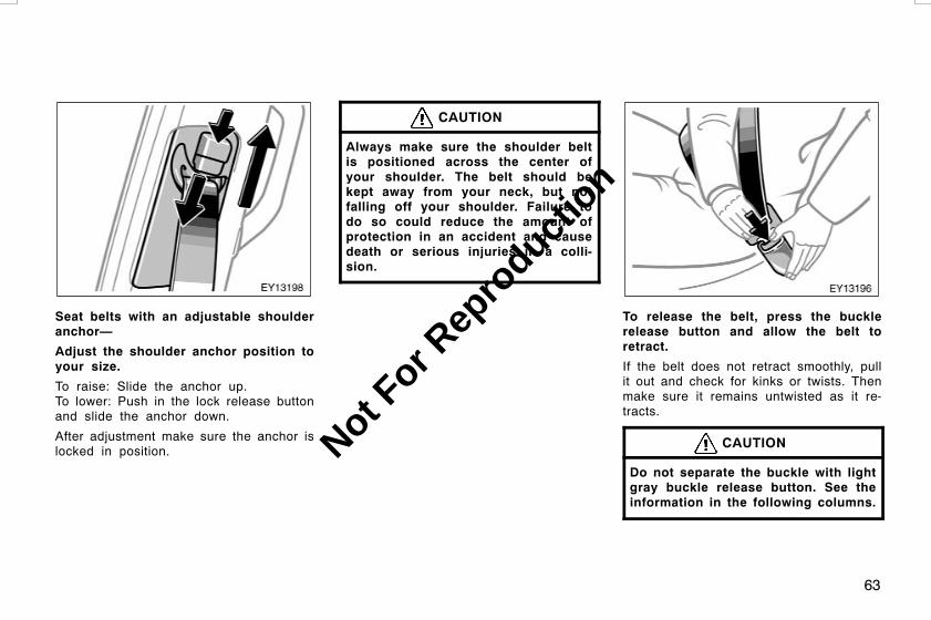
63
Seat belts with an adjustable shoulderanchor—
Adjust the shoulder anchor position toyour size.
To raise: Slide the anchor up.To lower: Push in the lock release buttonand slide the anchor down.
After adjustment make sure the anchor islocked in position.
CAUTION
Always make sure the shoulder beltis positioned across the center ofyour shoulder. The belt should bekept away from your neck, but notfalling off your shoulder. Failure todo so could reduce the amount ofprotection in an accident and causedeath or serious injuries in a colli-sion.
To release the belt, press the bucklerelease button and allow the belt toretract.
If the belt does not retract smoothly, pullit out and check for kinks or twists. Thenmake sure it remains untwisted as it re-tracts.
CAUTION
Do not separate the buckle with lightgray buckle release button. See theinformation in the following columns.
L/C120 AE (OM60D50E) 08/01/22
Not For R
epro
duction
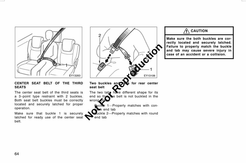
64
CENTER SEAT BELT OF THE THIRDSEATS
The center seat belt of the third seats isa 3−point type restraint with 2 buckles.Both seat belt buckles must be correctlylocated and securely latched for properoperation.
Make sure that buckle 1 is securelylatched for ready use of the center seatbelt.
Two buckles and tabs for rear centerseat belt
The two tabs have different shape for itsend so that the belt is not buckled in thewrong place.
Buckle 1—Properly matches with con-cave end tabBuckle 2—Properly matches with roundend tab
CAUTION
Make sure the both buckles are cor-rectly located and securely latched.Failure to properly match the buckleand tab may cause severe injury incase of an accident or a collision.
L/C120 AE (OM60D50E) 08/01/22
Not For R
epro
duction

65
To release the concave end tab, insert thekey into the hole on buckle 1 and allowthe belt to retract.
CAUTION
Do not use the center seat belt of thethird seats with either buckle re-leased. Fastening only the shoulderbelt or lap belt may cause severe per-sonal injury in case of sudden brak-ing or a collision.
Second seat
Third seat
L/C120 AE (OM60D50E) 08/01/22
—Stowing seat belt bucklesof the second and third seats
Not For R
epro
duction

66
The seat belt buckles of the secondand third seats can be stowed whennot in use.
Seat belt buckles must be stowed beforeyou fold the seatback. (See “—Tumblingsecond seats” on page 47, “—Folding upthird seats” on page 49 and “—Removingthird seats” on page 52 in this Section.)
STOWING THE CENTER SEAT BELT OFTHE THIRD SEATS
To stow the center seat belt of the thirdseats, pull the seat belt out of its cov-er. It will automatically roll back part-way. Roll the seat belt backward andinsert it into the slot of its cover asshown above. Make sure the tabs aresecurely locked in the cover.
Seat belt must be stowed before you foldthe seatback. (See “—Folding up thirdseats” on page 49 and “—Removing thirdseats” on page 52 in this Section.)
NOTICE
Stow the center seat belt of the thirdseats except when you are wearing it.
L/C120 AE (OM60D50E) 08/01/22
—Stowing the center seatbelt of the third seats
Not For R
epro
duction
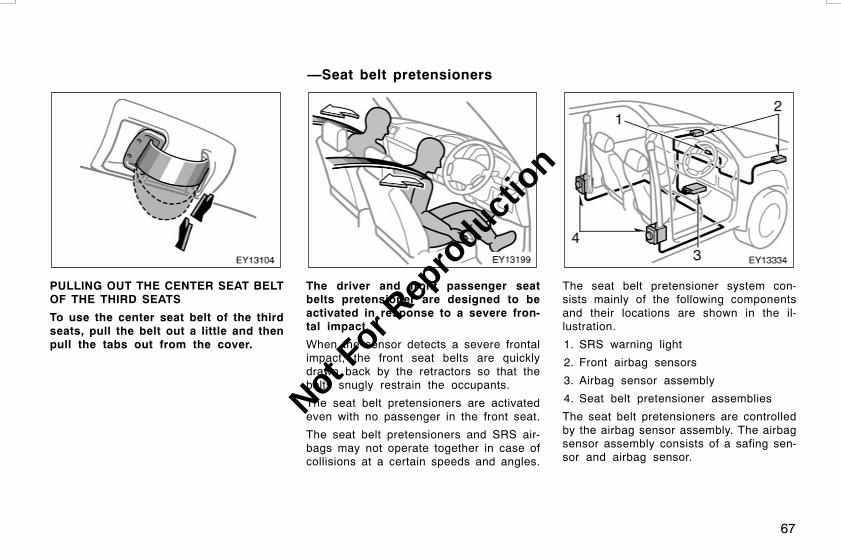
67
PULLING OUT THE CENTER SEAT BELTOF THE THIRD SEATS
To use the center seat belt of the thirdseats, pull the belt out a little and thenpull the tabs out from the cover.
The driver and front passenger seatbelts pretensioner are designed to beactivated in response to a severe fron-tal impact.
When the sensor detects a severe frontalimpact, the front seat belts are quicklydrawn back by the retractors so that thebelts snugly restrain the occupants.
The seat belt pretensioners are activatedeven with no passenger in the front seat.
The seat belt pretensioners and SRS air-bags may not operate together in case ofcollisions at a certain speeds and angles.
The seat belt pretensioner system con-sists mainly of the following componentsand their locations are shown in the il-lustration.
1. SRS warning light
2. Front airbag sensors
3. Airbag sensor assembly
4. Seat belt pretensioner assemblies
The seat belt pretensioners are controlledby the airbag sensor assembly. The airbagsensor assembly consists of a safing sen-sor and airbag sensor.
L/C120 AE (OM60D50E) 08/01/22
—Seat belt pretensioners
Not For R
epro
duction

68
When the seat belt pretensioners are acti-vated, an operating noise may be heardand a small amount of non−toxic gas maybe released. This does not indicate that afire is occurring. This gas is normallyharmless.Once the seat belt pretensioners havebeen activated, the seat belt retractors re-main locked.If the vehicle is involved in multiple colli-sions, the pretensioner will activate for thefirst collision, but will not activate for thesecond or subsequent collisions.
CAUTION
Observe the following precautions toreduce the risk of injury in the eventof sudden breaking or an accident.Failure to do so may cause death orsevere injury.D If the pretensioner has activated,the seat belt becomes locked: itcannot be further extended, nor willit return to the stowed position.The seatbelt cannot be used againand must be replaced at yourToyota dealer.
D Do not modify, remove, strike oropen the seat belt pretensioner as-semblies, airbag sensor or sur-rounding area or wiring. Consultyour Toyota dealer about any repairand modification.
NOTICE
Do not perform any of the followingchanges without consulting yourToyota dealer. Such changes caninterfere with proper operation of theseat belt pretensioners in somecases.
z Installation of electronic devicessuch as a mobile two−way radio,cassette tape player or compactdisc player
z Repairs on or near the front seatbelt retractor assemblies
zModification of the suspension sys-tem
zModification of the front end struc-ture
z Attachment of a grille guard (bullbar, kangaroo bar, etc.), snowplow,winches or any other equipment tothe front end
z Repairs made on or near the frontfenders, front end structure or con-sole
This indicator comes on when the en-gine switch is turned to the “ON” posi-tion. It goes off after about 6 seconds.This means the seat belt pretensionersare operating properly.
This warning light system monitors theairbag sensor assembly, front airbag sen-sors, side and curtain shield airbag sen-sors, curtain shield airbag sensors, driv-er’s seat position sensor, driver’s seat beltbuckle switch, seat belt pretensioner as-semblies, inflators, interconnecting wiringand power sources. (For details, see “Ser-vice reminder indicators and warning buzz-ers” on page 121 in Section 1−6.)
L/C120 AE (OM60D50E) 08/01/22
Not For R
epro
duction

69
If any of the following conditions occurs,this indicates a malfunction of the airbagsor seat belt pretensioners. Contact yourToyota dealer as soon as possible.
D The light does not come on when theengine switch is turned to the “ON”position or remains on for more than6 seconds or flashes.
D The light comes on or starts flashingwhile driving.
D If any front seat belt does not retractor cannot be pulled out due to a mal-function or activation of the relevantseat belt pretensioner.
D The seat belt pretensioner assembly orsurrounding area has been damaged.
In the following cases, contact your Toyotadealer as soon as possible:
D The front of the vehicle (shaded in theillustration) was involved in an accidentthat was not severe enough to causethe seat belt pretensioners to operate.
D Either seat belt pretensioner assemblyor surrounding area is scratched,cracked, or otherwise damaged.
The SRS (Supplemental Restraint Sys-tem) front airbags are designed to pro-vide further protection for the driverand front passenger in addition to theprimary safety protection provided bythe seat belts.
In response to a severe frontal impact,the SRS front airbags work with the seatbelts to help reduce injury by inflating.The SRS front airbags help reduce injuriesmainly to the driver’s or front passenger’shead or chest caused by hitting the ve-hicle interior.
The front passenger airbag is activatedeven with no passenger in the front seat.
Always wear your seat belt properly.
L/C120 AE (OM60D50E) 08/01/22
SRS driver airbag and frontpassenger airbag
Not For R
epro
duction

70
CAUTION
D The SRS front airbag system is de-signed only as a supplement to theprimary protection of the driver andfront passenger seat belt systems.The driver and front passenger canbe killed or seriously injured by theinflating airbags if they do not wearthe available seat belts properly.During sudden braking just beforea collision, an unrestrained driveror front passenger can move for-ward into direct contact with orclose proximity to the airbag whichmay then deploy during the colli-sion. To ensure maximum protectionin an accident, the driver and allpassengers in the vehicle mustwear their seat belts properly. Wear-ing a seat belt properly during anaccident reduces the chances ofdeath or serious injury or beingthrown out of the vehicle. For in-structions and precautions concern-ing the seat belt system, see “Seatbelts” on page 59 in this Section.
D Improperly seated and/or restrainedinfants and children can be killedor seriously injured by the deploy-ing airbags. An infant or child whois too small to use a seat beltshould be properly secured using achild restraint system. Toyotastrongly recommends that all in-fants and children be placed in therear seat of the vehicle and proper-ly restrained. The rear seat is thesafest for infants and children. Forinstructions concerning the installa-tion of a child restraint system, see“Child restraint” on page 83 in thisSection.
The SRS front airbags are designed todeploy in severe (usually frontal) colli-sions where the magnitude and durationof the forward deceleration of the ve-hicle exceeds the designed thresholdlevel.
The SRS front airbags will deploy if theseverity of the impact is above the de-signed threshold level, comparable to anapproximate 25 km/h (15 mph) collisionwhen the vehicle has the impact straightinto a fixed barrier that does not move ordeform.
However, this threshold velocity will beconsiderably higher if the vehicle strikesan object, such as a parked vehicle orsign pole, which can move or deform onimpact, or if the vehicle is involved in anunderride collision (e.g. a collision inwhich the front of the vehicle “underrides”,or goes under, the bed of a truck, etc.).
It is possible that in some collisionswhere the forward deceleration of the ve-hicle is very close to the designed thresh-old level, the SRS front airbags and theseat belt pretensioners may not activatetogether.
Always wear your seat belts properly.
L/C120 AE (OM60D50E) 08/01/22
Not For R
epro
duction

71
Collision fromthe rear
Collision from the side
Vehicle rollover
The SRS front airbags are not generallydesigned to inflate if the vehicle is in-volved in a side or rear collision, if itrolls over, or if it is involved in a low−speed frontal collision. But, whenever acollision of any type causes sufficientforward deceleration of the vehicle, de-ployment of the SRS front airbags mayoccur.
Hitting a curb,edge of pavementor hard surface
Falling into orjumping over adeep hole
Landing hard or vehicle falling
The SRS front airbags may also deployif a serious impact occurs to the under-side of your vehicle. Some examplesare shown in the illustration.
The SRS front airbag system consistsmainly of the following components, andtheir locations are shown in the illustra-tion.
1. Airbag module for front passenger(airbag and inflator)
2. SRS warning light
3. Front airbag sensors
4. Airbag module for driver(airbag and inflator)
5. Airbag sensor assembly
6. Driver’s seat position sensor
7. Driver’s seat belt buckle switch
The airbag sensor assembly consists of asafing sensor and airbag sensor.
L/C120 AE (OM60D50E) 08/01/22
Not For R
epro
duction
72
The front airbag sensors constantly moni-tor the forward deceleration of the vehicle.If an impact results in a forward decelera-tion beyond the designed threshold level,the system triggers the airbag inflators. Atthis time a chemical reaction in the infla-tors very quickly fills the airbags withnon−toxic gas to help restrain the forwardmotion of the occupants. The front airbagsthen quickly deflate, so that there is noobstruction of the driver’s vision should itbe necessary to continue driving.
When the airbags inflate, they produce aloud noise and release some smoke andresidue along with non−toxic gas. Thisdoes not indicate a fire. This smoke mayremain inside the vehicle for some time,and may cause some minor irritation tothe eyes, skin or breathing. Be sure towash off any residue as soon as possibleto prevent any potential skin irritation withsoap and water. If you can safely exitfrom the vehicle, you should do so imme-diately.
Deployment of the airbags happens in afraction of a second, so the airbags mustinflate with considerable force. While thesystem is designed to reduce serious inju-ries, primarily to the head and chest, itmay also cause other, less severe injuriesto the face, chest, arms and hands. Theseare usually in the nature of minor burnsor abrasions and swelling, but the force ofa deploying airbag can cause more seri-ous injuries, especially if an occupant’shands, arms, chest or head is in closeproximity to the airbag module at the timeof deployment. This is why it is importantfor the occupant to: avoid placing anyobject or part of the body between theoccupant and the airbag module; sitstraight and well back into the seat; wearthe available seat belt properly; and sit asfar as possible from the airbag module,while still maintaining control of the ve-hicle.
Parts of the airbag module (steering wheelhub, airbag cover and inflator) may be hotfor several minutes after deployment, sodo not touch! The airbags inflate onlyonce. The windshield may be damaged byabsorbing some of the force of the inflat-ing airbag.
CAUTION
The driver or front passenger who istoo close to the steering wheel ordashboard during airbag deploymentcan be killed or seriously injured.Toyota strongly recommends that:
D The driver sit as far back as pos-sible from the steering wheel whilestill maintaining control of the ve-hicle.
D The front passenger sit as far backas possible from the dashboard.
D All vehicle occupants be properlyrestrained using the available seatbelts.
For instructions and precautions con-cerning the seating position, see“—Front seat precautions” on page36 in this Section.
L/C120 AE (OM60D50E) 08/01/22
Not For R
epro
duction

73
D Do not sit on the edge of the seator lean against the dashboard whenthe vehicle is in use, since thefront passenger airbag could inflatewith considerable speed and force.Anyone who is up against, or veryclose to, an airbag when it inflates,can be killed or seriously injured.Sit up straight and well back in theseat, and always use your seat beltproperly.
D Toyota strongly recommends that allinfants and children be placed inthe rear seat of the vehicle and beproperly restrained.
D Do not allow a child to stand up orkneel on the front passenger seat,since the front passenger airbagcould inflate with considerablespeed and force. Otherwise thechild may be killed or seriously in-jured.
D Do not hold a child on your lap orin your arms. Use a child restraintsystem in the rear seat. For instruc-tions concerning the installation ofa child restraint system, see “Childrestraint” on page 83 in this Sec-tion.
L/C120 AE (OM60D50E) 08/01/22
Not For R
epro
duction

74
D Do not put anything or any part ofyour body on or in front of thedashboard or steering wheel padthat houses the front airbag sys-tem. They might restrict inflation orcause death or serious injury asthey are projected rearward by theforce of the deploying airbags. Like-wise, the driver and front passengershould not hold objects in theirarms or on their knees.
D Do not modify or remove any wir-ing. Do not modify, remove, strikeor open any components such asthe steering wheel pad, steeringwheel, column cover, dashboardnear the front passenger airbag,front passenger airbag cover, frontpassenger airbag or airbag sensorassembly. Doing so may prevent thefront airbag system from activatingcorrectly, cause sudden activationof the system or disable the sys-tem, which could result in death orserious injury.
Failure to follow these instructionscan result in death or serious injury.Consult your Toyota dealer about anyrepair and modification.
NOTICE
Do not perform any of the followingchanges without consulting yourToyota dealer. Such changes caninterfere with proper operation of theSRS airbag system in some cases.
z Installation of electronic devicessuch as a mobile two−way radio,cassette tape player or compactdisc player
zModification of the suspension sys-tem
zModification of the front end struc-ture
z Attachment of a grille guard (bullbar, kangaroo bar, etc.), snowplow,winches or any other equipment tothe front end
z Repairs made on or near the frontfenders, front end structure, con-sole, steering column, steeringwheel or dashboard near the frontpassenger airbag
L/C120 AE (OM60D50E) 08/01/22
Not For R
epro
duction

75
This indicator comes on when the en-gine switch is turned to the “ON” posi-tion. It goes off after about 6 seconds.This means the SRS front airbags areoperating properly.
This warning light system monitors theairbag sensor assembly, front airbag sen-sors, side and curtain shield airbag sen-sors, curtain shield airbag sensors, driv-er’s seat position sensor, driver’s seat beltbuckle switch, seat belt pretensioner as-semblies, inflators, interconnecting wiringand power sources. (For details, see “Ser-vice reminder indicators and warning buzz-ers” on page 121 in Section 1−6.)
If any of the following conditions occurs,this indicates a malfunction of the airbagsor seat belt pretensioners. Contact yourToyota dealer as soon as possible.
D The light does not come on when theengine switch is turned to the “ON”position or remains on for more than6 seconds or flashes.
D The light comes on or starts flashingwhile driving.
In the following cases, contact your Toyotadealer as soon as possible:
D The SRS front airbags have been in-flated.
D The front of the vehicle (shaded in theillustration) was involved in an accidentthat was not severe enough to causethe SRS airbags to inflate.
D The pad section of the steering wheelor dashboard (shaded in the illustra-tion) is scratched, cracked, or other-wise damaged.
L/C120 AE (OM60D50E) 08/01/22
Not For R
epro
duction

76
NOTICE
Do not disconnect the battery cablesbefore contacting your Toyota dealer.
The SRS (Supplemental Restraint Sys-tem) side airbags and curtain shield air-bags are designed to provide furtherprotection for the driver, front passen-ger and second outside passengers inaddition to the primary safety protec-tion provided by the seat belts.
In response to a severe side impact, theSRS side airbags and curtain shield air-bags work with the seat belts to helpreduce injury by inflating. The SRS sideairbags help reduce injuries mainly to thedriver’s or front passenger’s chest and theSRS curtain shield airbags help reduceinjuries mainly to the driver’s, front pas-senger’s or second outside passenger’shead.
The SRS side airbag and curtain shieldairbag on the passenger side are activatedeven with no passenger in the front seator second outside seat.
The curtain shield airbags may activateeven when the side airbags are not acti-vated.
Always wear your seat belt properly.
CAUTION
D The SRS side airbag and curtainshield airbag system is designedonly as a supplement to the prima-ry protection of the driver, andfront passenger and second outsidepassenger seat belt systems. To en-sure maximum protection in an ac-cident, the driver and all passen-gers in the vehicle must wear theirseat belts properly. Wearing a seatbelt properly during an accident re-duces the chances of death or seri-ous injury or being thrown out ofthe vehicle. For instructions andprecautions concerning the seatbelt system, see “Seat belts” onpage 59 in this Section.
L/C120 AE (OM60D50E) 08/01/22
SRS side airbags and curtainshield airbags
Not For R
epro
duction
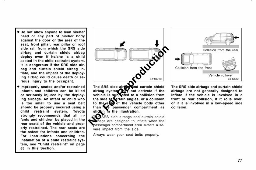
77
D Do not allow anyone to lean his/herhead or any part of his/her bodyagainst the door or the area of theseat, front pillar, rear pillar or roofside rail from which the SRS sideairbag and curtain shield airbagdeploy even if he/she is a childseated in the child restraint system.It is dangerous if the SRS side air-bag and curtain shield airbag in-flate, and the impact of the deploy-ing airbag could cause death or se-rious injury to the occupant.
D Improperly seated and/or restrainedinfants and children can be killedor seriously injured by the deploy-ing airbags. An infant or child whois too small to use a seat beltshould be properly secured using achild restraint system. Toyotastrongly recommends that all in-fants and children be placed in therear seats of the vehicle and prop-erly restrained. The rear seats arethe safest for infants and children.For instructions concerning theinstallation of a child restraint sys-tem, see “Child restraint” on page83 in this Section.
The SRS side airbag and curtain shieldairbag system may not activate if thevehicle is subjected to a collision fromthe side at certain angles, or a collisionto the side of the vehicle body otherthan the passenger compartment asshown in the illustration.
The SRS side airbags and curtain shieldairbags are designed to inflate when thepassenger compartment area suffers a se-vere impact from the side.
Always wear your seat belts properly.
Collision from the rear
Collision from the front
Vehicle rollover
The SRS side airbags and curtain shieldairbags are not generally designed toinflate if the vehicle is involved in afront or rear collision, if it rolls over,or if it is involved in a low−speed sidecollision.
L/C120 AE (OM60D50E) 08/01/22
Not For R
epro
duction

78
The SRS side airbag and curtain shieldairbag system consists mainly of the fol-lowing components, and their locations areshown in the illustration.
1. Side airbag modules(airbag and inflator)
2. Curtain shield airbag modules(airbag and inflator)
3. SRS warning light
4. Airbag sensor assembly
5. Side and curtain shield airbag sensors
6. Curtain shield airbag sensors
The SRS side airbag and curtain shieldairbag system is controlled by the airbagsensor assembly. The airbag sensor as-sembly consists of a safing sensor andairbag sensor.
In a severe side impact, the side andcurtain shield airbag sensor and/or thecurtain shield airbag sensor trigger(s) theside airbag inflators and/or the curtainshield airbag inflators. At this time achemical reaction in the inflators quicklyfills the airbags with non−toxic gas to helprestrain the lateral motion of the front andsecond outside occupants.
When the airbags inflate, they produce afairly loud noise and release some smokeand residue along with non−toxic gas. Thisdoes not indicate a fire. This smoke mayremain inside the vehicle for some time,and may cause some minor irritation tothe eyes, skin or breathing. Be sure towash off any residue as soon as possibleto prevent any potential skin irritation withsoap and water. If you can safely exitfrom the vehicle, you should do so imme-diately.
Deployment of the airbags happens in afraction of a second, so the airbags mustinflate with considerable force. While thesystem is designed to reduce serious inju-ries, it may also cause minor burns orabrasions and swelling.
Front seats as well as parts of the frontand rear pillars, front, center and reargarnish and roof interior may be hot forseveral minutes, but the airbags them-selves will not be hot. The airbags aredesigned to inflate only once.
CAUTION
SRS side airbags and curtain shieldairbags inflate with considerableforce. To reduce the possibility ofdeath or serious injury when they in-flate, the driver, front passenger andsecond outside passengers must:
DWear their seat belts properly.
D Remain properly seated with theirbacks upright and against the seatsat all times.
L/C120 AE (OM60D50E) 08/01/22
Not For R
epro
duction

79
D Do not allow anyone to lean againstthe door when the vehicle is in use,since the side airbag and curtainshield airbag could inflate with con-siderable speed and force. Other-wise, he/she may be killed or seri-ously injured. Special care shouldbe taken especially when you havea small child in the vehicle.
D Sit up straight and well back in theseat, distributing your weight evenlyin the seat. Do not apply excessiveweight to the outer side of theseats with a side airbag, and to thefront pillar, rear pillar and roof siderail with a curtain shield airbag.
D Do not allow anyone to get his/herhead closer to the area where theside airbag and curtain shield air-bag inflate, since these airbagscould inflate with considerablespeed and force. Otherwise, he/shemay be killed or seriously injured.Special care should be taken espe-cially when you have a small childin the vehicle.
D Do not allow anyone to kneel onthe passenger seat, facing the pas-senger’s side door, since the sideairbag and curtain shield airbagcould inflate with considerablespeed and force. Otherwise, he/shemay be killed or seriously injured.Special care should be taken espe-cially when you have a small childin the vehicle.
L/C120 AE (OM60D50E) 08/01/22
Not For R
epro
duction

80
D Do not allow anyone to get his/herhead or hands out of windowssince the curtain shield airbagscould inflate with considerablespeed and force. Otherwise, he/shemay be killed or seriously injured.Special care should be taken espe-cially when you have a small childin the vehicle.
D Do not attach a cup holder or anyother device or object on or aroundthe door. When the side airbag in-flates, the cup holder or any otherdevice or object will be hurled withgreat force or the side airbag maynot activate correctly, resulting indeath or serious injury. Likewise,the driver and front passengershould not hold objects in theirarms or on their knees.
D Do not attach a microphone or anyother device or object around thearea where the curtain shield airbagactivates such as on the windshieldglass, side door glass, front, centerand roof side garnish, roof interioror assist grips. When the curtainshield airbag inflates, the micro-phone or other device or object willbe thrown away with great force orthe curtain shield airbag may notactivate correctly, resulting in deathor serious injury.
L/C120 AE (OM60D50E) 08/01/22
Not For R
epro
duction

81
D Do not hook a hanger, heavy orsharp pointed objects on the coathook. If the curtain shield airbaginflates, those items will be thrownaway with great force or the curtainshield airbag may not activate cor-rectly, resulting in death or seriousinjury. When you hang clothes,hang them on the coat hook direct-ly.
D Do not use seat accessories whichcover the parts where the side air-bags inflate. Such accessories mayprevent the side airbags from acti-vating correctly, causing death orserious injury.
D Do not modify or replace the seatsor upholstery of the seats with sideairbags. Such changes may preventthe side airbag system from activat-ing correctly, disable the system orcause the side airbags to inflate ac-cidentally, resulting in death or seri-ous injury.
D Do not disassemble or repair thefront and rear pillars and roof siderail containing the curtain shieldairbags. Such changes may disablethe system or cause the curtainshield airbags to inflate accidental-ly, resulting in death or serious in-jury.
Failure to follow these instructionscan result in death or serious injury.Consult your Toyota dealer about anyrepair and modification.
NOTICE
Do not perform any of the followingchanges without consulting yourToyota dealer. Such changes caninterfere with proper operation of theSRS side airbag and curtain shieldairbag system in some cases.
z Installation of electronic devicessuch as a mobile two−way radio,cassette tape player or compactdisc player
zModification of the suspension sys-tem
zModification of the side structure ofthe passenger compartment
z Repairs made on or near the con-sole or front seat
L/C120 AE (OM60D50E) 08/01/22
Not For R
epro
duction

82
This indicator comes on when the en-gine switch is turned to the “ON” posi-tion. It goes off after about 6 seconds.This means the SRS side airbags andcurtain shield airbags are operatingproperly.
This warning light system monitors theairbag sensor assembly, front airbag sen-sors, side and curtain shield airbag sen-sors, curtain shield airbag sensors, driv-er’s seat position sensor, driver’s seat beltbuckle switch, seat belt pretensioner as-semblies, inflators, interconnecting wiringand power sources. (For details, see “Ser-vice reminder indicators and warning buzz-ers” on page 121 in Section 1−6.)
If any of the following conditions occurs,this indicates a malfunction of the airbagsor seat belt pretensioners. Contact yourToyota dealer as soon as possible.
D The light does not come on when theengine switch is turned to the “ON”position or remains on for more than6 seconds or flashes.
D The light comes on or starts flashingwhile driving.
L/C120 AE (OM60D50E) 08/01/22
Not For R
epro
duction

83
In the following cases, contact your Toyotadealer as soon as possible:
D Any of the SRS side airbags and cur-tain shield airbags have been inflated.
D The portion of the doors (shaded in theillustration) was involved in an accidentthat was not severe enough to causethe SRS side airbags and curtainshield airbags to inflate.
D The surface of the seats with the sideairbag (shaded in the illustration) isscratched, cracked, or otherwise dam-aged.
D The portion of the front pillars or roofside rail garnishes (padding) containingthe curtain shield airbags inside(shaded in the illustration) is scratched,cracked, or otherwise damaged.
NOTICE
Do not disconnect the battery cablesbefore contacting your Toyota dealer.
Toyota strongly urges the use of ap-propriate child restraint systems forchildren.
If a child is too large for a child restraintsystem, the child should sit in the rearseat and must be restrained using thevehicle’s seat belt. See “Seat belts” onpage 59 in this Section for details.
CAUTION
D For effective protection in automo-bile accidents and sudden stops, achild must be properly restrained,using a seat belt or child restraintsystem depending on the age andsize of the child. Holding a child inyour arms is not a substitute for achild restraint system. In an acci-dent, the child can be crushedagainst the windshield, or betweenyou and the vehicle’s interior.
D Toyota strongly urges use of aproper child restraint system whichconforms to the size of the child,installed on the rear seat. Accord-ing to accident statistics, the childis safer when properly restrained inthe rear seat than in the front seat.
D Never install a rear−facing child re-straint system on the front passen-ger seat. In the event of an acci-dent, the force of the rapid inflationof the front passenger airbag cancause death or serious injury to thechild if the rear−facing child re-straint system is installed on thefront passenger seat.
D A forward−facing child restraint sys-tem should be allowed to beinstalled on the front passengerseat only when it is unavoidable.Always move the seat as far backas possible, because the front pas-senger airbag could inflate withconsiderable speed and force.Otherwise, the child may be killedor seriously injured.
L/C120 AE (OM60D50E) 08/01/22
Child restraint——Child restraint precautions
Not For R
epro
duction

84
D On vehicles with side airbags andcurtain shield airbags, do not allowthe child to lean his/her head orany part of his/her body against thedoor or the area of the seat, frontor rear pillar or roof side rail fromwhich the side airbags or curtainshield airbags deploy even if thechild is seated in the child restraintsystem. It is dangerous if the sideairbag and/or curtain shield airbaginflate, and the impact could causedeath or serious injury to the child.
D If child restraint system regulationsexist in the country where you re-side, please contact your Toyotadealer for the installation of thechild restraint system in the frontseat.
D Make sure you have complied withall installation instructions providedby the child restraint manufacturerand that the system is properly se-cured. If it is not secured properly,it may cause death or serious injuryto the child in the event of a sud-den stop or accident.
A child restraint system for a smallchild or baby must itself be properlyrestrained on the seat with the lap por-tion of the lap/shoulder belt. You mustcarefully consult the manufacturer’s in-structions which accompany the childrestraint system.
To provide proper restraint, use a childrestraint system following the manufactur-er’s instructions about the applicablechild’s age and size for the child restraintsystem.
Install the child restraint system correctlyfollowing the instructions provided by itsmanufacturer. General directions are alsoprovided under the following illustrations.
The child restraint system should beinstalled. According to accident statistics,the child is safer when properly restrainedin the rear seat than in the front seat.
CAUTION
When the child restraint system is not inuse:
D Keep the child restraint systemproperly secured on the seat evenif it is not in use. Do not store therestraint unsecured in the passen-ger compartment.
D If it is necessary to detach thechild restraint system, remove itfrom the vehicle or store it securelyin the luggage compartment.
This will prevent it from injuringpassengers in the event of a sud-den stop or accident.
L/C120 AE (OM60D50E) 08/01/22
—Child restraint system
Not For R
epro
duction

85
Types of seat belts
There are two types of seat belt. Checkthe type before installing a child restraintsystem.
ALR/ELR (Automatic Locking Retractor/Emergency Locking Retractor) belt—
This belt locks when the belt is pulled outquickly. Also, this belt has an additionalfully−extended lock mode; When theshoulder belt is completely extended andis then retracted even slightly, the retrac-tor locks the belt in that position and thebelt cannot be extended. When installinga child restraint system, fully extend thebelt to put it in the lock mode.
ALR/ELR belts are equipped for the sec-ond seat belts.
ELR (Emergency Locking Retractor) belt—
This belt also locks when the belt ispulled out quickly but it does not have anadditional fully−extended lock mode. Wheninstalling a child restraint system, you willneed a locking clip.
If your child restraint system does notprovide a locking clip, you can purchasethe following item from your Toyota dealer.
Locking clip for child restraint system(Part No. 73119−22010)
Child restraint systems are classified intothe following 3 types depending on thechild’s age and size.
(A) Baby (infant) seat(B) Child (convertible) seat(C) Junior (booster) seat
Install the child restraint system followingthe instructions provided by its manufac-turer.
An ISOFIX child restraint system approvedfor your vehicle may also be used. See“—Installation with ISOFIX rigid anchors”on page 99 in this Section.
(A) Baby (infant) seat
(B) Child (convertible) seat
L/C120 AE (OM60D50E) 08/01/22
—Types of child restraintsystem
Not For R
epro
duction

86
(C) Junior (booster) seat(A) BABY (INFANT) SEAT INSTALLATION
A baby (infant) seat must be used inrear−facing position only.
CAUTION
D Do not install a child restraint sys-tem on the second seat if it inter-feres with the lock mechanism ofthe front seats. Otherwise, the childor front seat occupant(s) may bekilled or seriously injured in caseof sudden braking or a collision.
D If the driver’s seat position doesnot allow sufficient space for safeinstallation, install the child re-straint system on the left secondseat.
L/C120 AE (OM60D50E) 08/01/22
—Installation with ALR/ELRseat belt
Not For R
epro
duction

87
1. Run the lap and shoulder belt throughor around the baby (infant) seat follow-ing the instructions provided by itsmanufacturer and insert the tab intothe buckle taking care not to twist thebelt. Keep the lap portion of the belttight.
CAUTION
D After inserting the tab, make surethe tab and buckle are locked andthat the lap and shoulder portionsof the belt is not twisted.
D Do not insert coins, clips, etc. inthe buckle as this may prevent youfrom properly latching the tab andbuckle.
D If the seat belt does not functionnormally, it cannot protect yourchild from death or serious injury.Contact your Toyota dealer immedi-ately. Do not install the childrestraint system on the seat untilthe seat belt is fixed.
2. Fully extend the shoulder belt to put itin the lock mode. When the belt isthen retracted even slightly, it cannotbe extended.
To hold the baby (infant) seat securely,make sure the belt is in the lock modebefore letting the belt retract.
L/C120 AE (OM60D50E) 08/01/22
Not For R
epro
duction
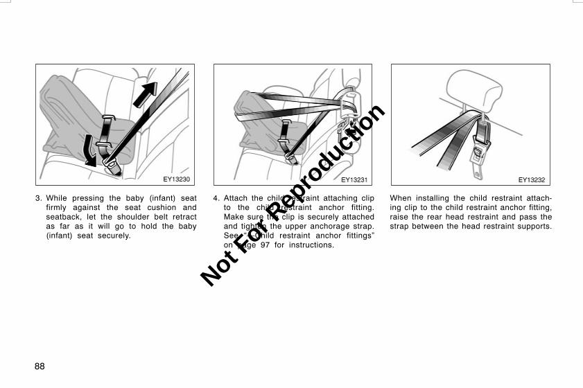
88
3. While pressing the baby (infant) seatfirmly against the seat cushion andseatback, let the shoulder belt retractas far as it will go to hold the baby(infant) seat securely.
4. Attach the child restraint attaching clipto the child restraint anchor fitting.Make sure the clip is securely attachedand tighten the upper anchorage strap.See “—Child restraint anchor fittings”on page 97 for instructions.
When installing the child restraint attach-ing clip to the child restraint anchor fitting,raise the rear head restraint and pass thestrap between the head restraint supports.
L/C120 AE (OM60D50E) 08/01/22
Not For R
epro
duction

89
CAUTION
Push and pull the child restraint sys-tem in different directions to be sureit is secure. Follow all the installationinstructions provided by its manufac-turer.
5. To remove the baby (infant) seat, pressthe buckle release button and allow thebelt to retract completely. The belt willmove freely again and be ready towork for an adult or older child passen-ger. Unhook the child restraint attach-ing clip from the child restraint anchorfitting.
(B) CHILD (CONVERTIBLE) SEATINSTALLATION
A child (convertible) seat must be usedin forward−facing or rear−facing posi-tion depending on the age and size ofthe child. When installing, follow themanufacturer’s instructions about theapplicable age and size of the child aswell as directions for installing thechild restraint system.
L/C120 AE (OM60D50E) 08/01/22
Not For R
epro
duction

90
CAUTION
D Do not install a child restraint sys-tem on the second seat if it inter-feres with the lock mechanism ofthe front seats. Otherwise, the childor front seat occupant(s) may bekilled or seriously injured in caseof sudden braking or a collision.
D If the driver’s seat position doesnot allow sufficient space for safeinstallation, install the child re-straint system on the left secondseat.
1. Run the lap and shoulder belt throughor around the child (convertible) seatfollowing the instructions provided byits manufacturer and insert the tab intothe buckle taking care not to twist thebelt. Keep the lap portion of the belttight.
CAUTION
D After inserting the tab, make surethe tab and buckle are locked andthat the lap and shoulder portionsof the belt is not twisted.
D Do not insert coins, clips, etc. inthe buckle as this may prevent youfrom properly latching the tab andbuckle.
D If the seat belt does not functionnormally, it cannot protect yourchild from death or serious injury.Contact your Toyota dealer immedi-ately. Do not install the childrestraint system on the seat untilthe seat belt is fixed.
L/C120 AE (OM60D50E) 08/01/22
Not For R
epro
duction
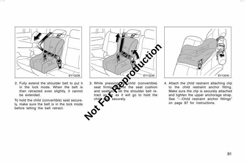
91
2. Fully extend the shoulder belt to put itin the lock mode. When the belt isthen retracted even slightly, it cannotbe extended.
To hold the child (convertible) seat secure-ly, make sure the belt is in the lock modebefore letting the belt retract.
3. While pressing the child (convertible)seat firmly against the seat cushionand seatback, let the shoulder belt re-tract as far as it will go to hold thechild seat securely.
4. Attach the child restraint attaching clipto the child restraint anchor fitting.Make sure the clip is securely attachedand tighten the upper anchorage strap.See “—Child restraint anchor fittings”on page 97 for instructions.
L/C120 AE (OM60D50E) 08/01/22
Not For R
epro
duction
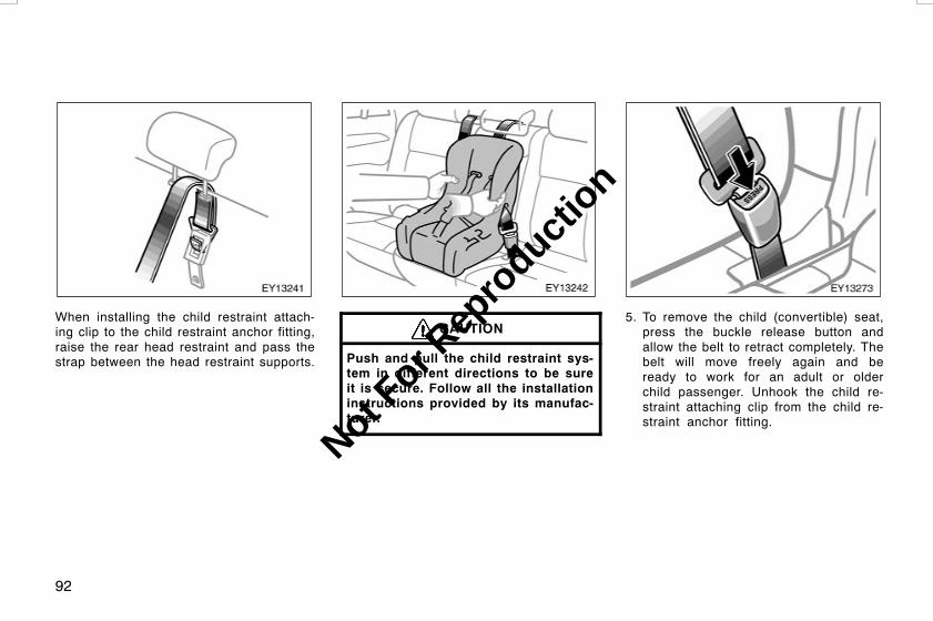
92
When installing the child restraint attach-ing clip to the child restraint anchor fitting,raise the rear head restraint and pass thestrap between the head restraint supports.
CAUTION
Push and pull the child restraint sys-tem in different directions to be sureit is secure. Follow all the installationinstructions provided by its manufac-turer.
5. To remove the child (convertible) seat,press the buckle release button andallow the belt to retract completely. Thebelt will move freely again and beready to work for an adult or olderchild passenger. Unhook the child re-straint attaching clip from the child re-straint anchor fitting.
L/C120 AE (OM60D50E) 08/01/22
Not For R
epro
duction

93
(C) JUNIOR (BOOSTER) SEATINSTALLATION
A junior (booster) seat must be used inforward−facing position only.
1. Sit the child on a junior (booster) seat.Run the lap and shoulder belt throughor around the junior (booster) seat andacross the child following the instruc-tions provided by its manufacturer andinsert the tab into the buckle takingcare not to twist the belt.
Make sure the shoulder belt is correctlyacross the child’s shoulder and that thelap belt is positioned as low as possibleon the child’s hips. See “Seat belts” onpage 59 in this Section for details.
CAUTION
D Always make sure the shoulder beltis positioned across the center ofchild’s shoulder. The belt should bekept away from child’s neck, butnot falling off child’s shoulder.Otherwise, the child may be killedor seriously injured in case of sud-den braking or a collision.
D Both high−positioned lap belts andloose−fitting belts could causedeath or serious injuries due tosliding under the lap belt during acollision or other unintended event.Keep the lap belt positioned as lowon a child’s hips as possible.
D For child’s safety, do not place theshoulder belt under child’s arm.
D After inserting the tab, make surethe tab and buckle are locked andthat the lap and shoulder portionsof the belt are not twisted.
D Do not insert coins, clips, etc. inthe buckle as this may prevent youfrom properly latching the tab andbuckle.
L/C120 AE (OM60D50E) 08/01/22
Not For R
epro
duction
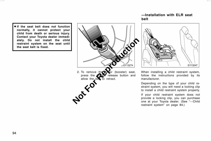
94
D If the seat belt does not functionnormally, it cannot protect yourchild from death or serious injury.Contact your Toyota dealer immedi-ately. Do not install the childrestraint system on the seat untilthe seat belt is fixed.
2. To remove the junior (booster) seat,press the buckle release button andallow the belt to retract.
When installing a child restraint system,follow the instructions provided by itsmanufacturer.
Depending on the type of your child re-straint system, you will need a locking clipto install a child restraint system properly.
If your child restraint system does notprovide a locking clip, you can purchaseone at your Toyota dealer. (See “—Childrestraint system” on page 84.)
L/C120 AE (OM60D50E) 08/01/22
—Installation with ELR seatbelt
Not For R
epro
duction

95
CAUTION
D Extreme Hazard! Do not use a rear-ward facing child restraint on aseat protected by an airbag in frontof it! This is because the force ofthe rapid inflation of the front pas-senger airbag can cause death orserious injury to the child. Vehicleswith the front passenger airbag dis-play a warning label on the passen-ger side instrument panel as shownabove to remind you not to installa rear−facing child restraint systemon the front passenger seat at anytime.
Move seat fullyback
D A forward−facing child restraint sys-tem should be allowed to beinstalled on the front passengerseat only when it is unavoidable.Always move the seat as far backas possible, because the front pas-senger airbag could inflate withconsiderable speed and force.Otherwise, the child may be killedor seriously injured.
D On vehicles with side airbags andcurtain shield airbags, do not allowthe child to lean his/her head orany part of his/her body against thedoor or the area of the seat, frontor rear pillar or roof side rail fromwhich the side airbags or curtainshield airbags deploy even if thechild is seated in the child restraintsystem. It is dangerous if the sideairbag and/or curtain shield airbaginflate, and the impact could causedeath or serious injury to the child.
D If child restraint system regulationsexist in the country where you re-side, please contact your Toyotadealer for the installation of thechild restraint system in the frontseat.
L/C120 AE (OM60D50E) 08/01/22
Not For R
epro
duction

96
D Do not install a child restraint sys-tem on the third seat if it interfereswith the lock mechanism of the sec-ond seats. Otherwise, the child orsecond seat occupant(s) may bekilled or seriously injured in caseof sudden braking or a collision.
D After inserting the tab, make surethe tab and buckle are locked andthat the lap and shoulder portionsof the belt are not twisted.
D Do not insert coins, clips, etc. inthe buckle as this may prevent youfrom properly latching the tab andbuckle.
D If the seat belt does not functionnormally, it cannot protect yourchild from death or serious injury.Contact your Toyota dealer immedi-ately. Do not install the childrestraint system on the seat untilthe seat belt is fixed.
Same angle
D Push and pull the child restraintsystem in different directions to besure it is secure. Follow all theinstallation instructions provided byits manufacturer.
D Third seat only: When installing achild restraint system in the thirdseat center position, align bothseatbacks at the same angle. Other-wise, the child restraint system can-not be securely restrained and thismay cause death or serious injuriesin a collision.
L/C120 AE (OM60D50E) 08/01/22
Not For R
epro
duction

97
Child restraint anchor fittings
Symbol
Front of vehicle
For easy installation of child restraints,your vehicle has three child restraintanchor fittings on the second seat-backs.
This symbol indicates the location of childrestraint anchor fitting.
When installing a child restraint, followboth the instructions here and those pro-vided by the manufacturer of your childrestraint.
CAUTION
WARNING: child restraint anchoragesare designed to withstand only thoseloads imposed by correctly fittedchild restraints. Under no circum-stances are they to be used for adultseat belts, harnesses or for attachingother items or equipment to the ve-hicle.
TO USE THE CHILD RESTRAINTANCHOR FITTING
1. Open the child restraint anchor fit-ting cover with the symbol markshown in the illustration.
L/C120 AE (OM60D50E) 08/01/22
—Child restraint anchorfittings
Not For R
epro
duction

98
Anchor fitting
Upperanchoragestrap
Attaching clip
2. Fix the child restraint system withthe seat belt.
Attach the child restraint anchor at-taching clip to the exposed child re-straint anchor fitting. Make sure theclip is securely attached and tightenthe upper anchorage strap.
For instructions to install the child re-straint system, see “Child restraint” onpage 83 in this Section.
CAUTION
Make sure the seat belt is securelylocked, and check that the child re-straint system is secure by pushingand pulling it in different directions.Follow all the installation instructionsprovided by its manufacturer.
Be sure to close all covers when the childrestraint anchor fittings are not in use.
L/C120 AE (OM60D50E) 08/01/22
Not For R
epro
duction
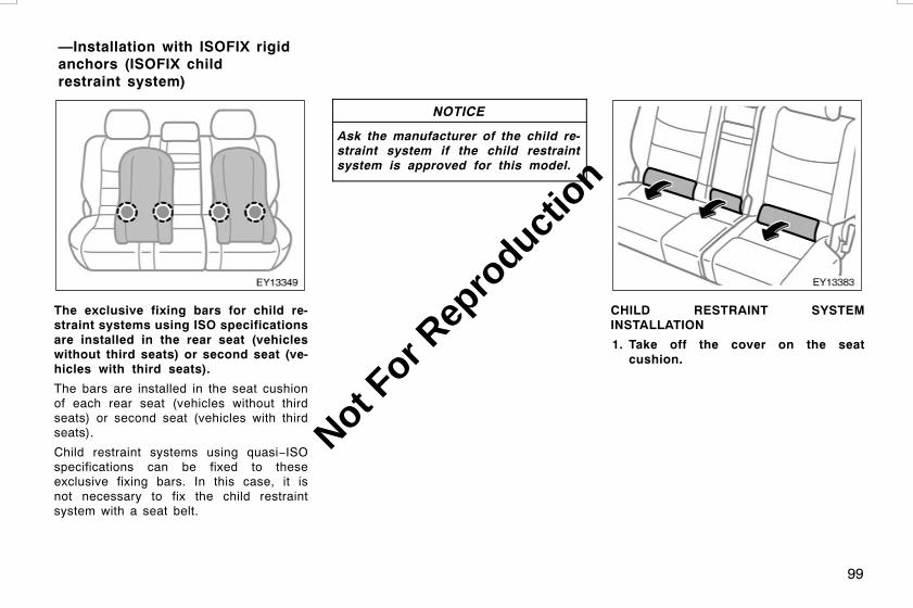
99
The exclusive fixing bars for child re-straint systems using ISO specificationsare installed in the rear seat (vehicleswithout third seats) or second seat (ve-hicles with third seats).
The bars are installed in the seat cushionof each rear seat (vehicles without thirdseats) or second seat (vehicles with thirdseats).
Child restraint systems using quasi−ISOspecifications can be fixed to theseexclusive fixing bars. In this case, it isnot necessary to fix the child restraintsystem with a seat belt.
NOTICE
Ask the manufacturer of the child re-straint system if the child restraintsystem is approved for this model.
CHILD RESTRAINT SYSTEMINSTALLATION
1. Take off the cover on the seatcushion.
L/C120 AE (OM60D50E) 08/01/22
—Installation with ISOFIX rigidanchors (ISOFIX childrestraint system)
Not For R
epro
duction

100
2. Widen the slits of the seat cushionslightly and confirm the position ofthe exclusive fixing bars near thetag on the seatback.
3. Latch the buckles onto the bars.
For installation details, refer to the instruc-tion manual equipped with each product.
CAUTION
DWhen using the exclusive fixingbars for the child restraint system,be sure that there are no irregularobjects around the bars or that theseat belt is not caught.
D Push and pull the child restraintsystem in different directions to besure it is secure. Follow all theinstallation instructions provided byits manufacturer.
D After securing the child restraintsystem, never recline the seat.
D Do not install a child restraint sys-tem on the rear seat if it interfereswith the lock mechanism of thefront seats. Otherwise, the child orfront seat occupant(s) may be killedor seriously injured in case of sud-den braking or a collision.
DWhen an ISOFIX child restraint sys-tem is installed on the second rightseat, do not sit in the center seat.The performance of the center seatbelt cannot be brought out suffi-ciently because the belt may behigh−positioned or the seat beltmay be loose−fitting, posing therisk of serious injury in the case ofcollision.
L/C120 AE (OM60D50E) 08/01/22
Not For R
epro
duction
101
OPERATION OF INSTRUMENTS ANDCONTROLSSteering wheel and MirrorsTilt steering wheel 102. . . . . . . . . . . . . . . . . . . . . . . . . . . . . . . . . . . . . . . . . .Tilt and telescopic steering wheel 102. . . . . . . . . . . . . . . . . . . . . . . . . . . .Outside rear view mirrors 103. . . . . . . . . . . . . . . . . . . . . . . . . . . . . . . . . . .Anti−glare inside rear view mirror 105. . . . . . . . . . . . . . . . . . . . . . . . . . . .Vanity mirrors 106. . . . . . . . . . . . . . . . . . . . . . . . . . . . . . . . . . . . . . . . . . . . . .
L/C120 AE (OM60D50E) 08/01/22
SECTION 1−4
Not For R
epro
duction

102
To change the steering wheel angle,hold the steering wheel, pull the lockrelease lever toward you, tilt the steer-ing wheel to the desired angle and re-lease the lever.
When the steering wheel is in a low posi-tion, it will spring up as you release thelock release lever.
CAUTION
D Do not adjust the steering wheelwhile the vehicle is moving. Doingso may cause the driver to mishan-dle the vehicle and an accident mayoccur resulting in death or seriousinjuries.
D After adjusting the steering wheel,try moving it up and down to makesure it is locked in position.
ADJUSTMENT OF STEERING WHEELTILT
To change the steering wheel angle,hold the steering wheel, pull the lockrelease lever toward you, tilt the steer-ing wheel to the desired angle and re-lease the lever.
When the steering wheel is in a low posi-tion, it will spring up as you release thelock release lever.
L/C120 AE (OM60D50E) 08/01/22
Tilt steering wheelTilt and telescopic steeringwheel
Not For R
epro
duction

103
ADJUSTMENT OF TELESCOPICSTEERING COLUMN
To change the steering wheel length,push down the lock release lever, setthe steering wheel to the desired lengthand return the lever to its original posi-tion.
CAUTION
D Do not adjust the steering wheelwhile the vehicle is moving. Doingso may cause the driver to mishan-dle the vehicle and an accident mayoccur resulting in death or seriousinjuries.
D After adjusting the steering wheel,try moving it up and down or for-ward and rearward to make sure itis locked in position.
Adjust the mirror so that you can justsee the side of your vehicle in the mir-ror.
Be careful when judging the size or dis-tance of any object seen in the outsiderear view mirror on the passenger’s sidebecause it is a convex mirror. Any objectseen in a convex mirror will look smallerand farther away than when seen in a flatmirror.
L/C120 AE (OM60D50E) 08/01/22
Outside rear view mirrors—
Not For R
epro
duction

104
CAUTION
Do not adjust the mirror while thevehicle is moving. Doing so maycause the driver to mishandle the ve-hicle and an accident may occur re-sulting in death or serious injuries.
To adjust a mirror, use the switches.
1. Master switch—To select the mirror tobe adjustedPush the switch at “L” (left) or “R”(right).
2. Control switch—To move the mirrorPush the switch in the desired direc-tion.
Mirrors can be adjusted when the key isin the “ACC” or “ON” position.
NOTICE
If ice should jam the mirror, do notoperate the control or scrape the mir-ror face. Use a spray de−icer to freethe mirror.
L/C120 AE (OM60D50E) 08/01/22
—Power rear view mirrorcontrol
Not For R
epro
duction

105
The rear view mirrors can be foldedbackward for parking in compact areas.
To fold the rear view mirror, push back-ward.
Before driving, return the mirror until youhear a click.
CAUTION
Do not drive with the mirrors foldedbackward. Both the driver and pas-senger side rear view mirrors mustbe extended and properly adjustedbefore driving.
Adjust the mirror so that you can justsee the rear of your vehicle in the mir-ror.
To reduce glare from the headlights ofthe vehicle behind you during nightdriving, operate the lever on the loweredge of the mirror.
Daylight driving—Lever at position 1
The reflection in the mirror has greaterclarity at this position.
Night driving—Lever at position 2
Remember that by reducing glare you alsolose some rear view clarity.
CAUTION
Do not adjust the mirror while thevehicle is moving. Doing so maycause the driver to mishandle the ve-hicle and an accident may occur re-sulting in death or serious injuries.
L/C120 AE (OM60D50E) 08/01/22
—Folding rear view mirrorsAnti−glare inside rear viewmirror
Not For R
epro
duction

106
Type A
Type B
To use the vanity mirror, swing downthe sun visor and slide the cover.
Type A only—The vanity light comes onwhen you slide the cover.
L/C120 AE (OM60D50E) 08/01/22
Vanity mirrors
Not For R
epro
duction

107
OPERATION OF INSTRUMENTS ANDCONTROLSLights, Wipers and DefoggerHeadlights and turn signals 108. . . . . . . . . . . . . . . . . . . . . . . . . . . . . . . . .Emergency flashers 109. . . . . . . . . . . . . . . . . . . . . . . . . . . . . . . . . . . . . . . .Instrument panel light control 110. . . . . . . . . . . . . . . . . . . . . . . . . . . . . . .Front fog lights 110. . . . . . . . . . . . . . . . . . . . . . . . . . . . . . . . . . . . . . . . . . . . .Interior lights 110. . . . . . . . . . . . . . . . . . . . . . . . . . . . . . . . . . . . . . . . . . . . . . .Personal lights 111. . . . . . . . . . . . . . . . . . . . . . . . . . . . . . . . . . . . . . . . . . . . . .Windshield wipers and washer 112. . . . . . . . . . . . . . . . . . . . . . . . . . . . . .Rear window wiper and washer 113. . . . . . . . . . . . . . . . . . . . . . . . . . . . . .Rear window defogger 114. . . . . . . . . . . . . . . . . . . . . . . . . . . . . . . . . . . . . .
L/C120 AE (OM60D50E) 08/01/22
SECTION 1−5
Not For R
epro
duction
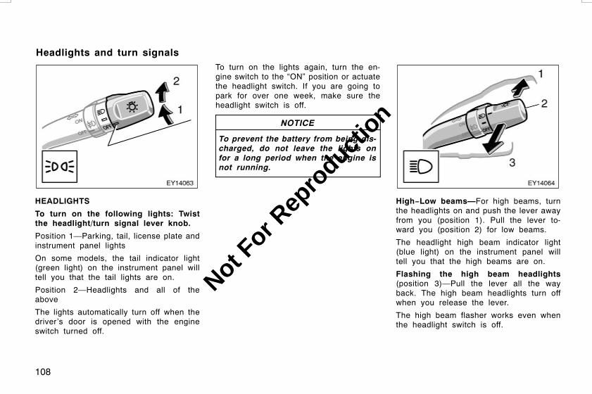
108
HEADLIGHTS
To turn on the following lights: Twistthe headlight/turn signal lever knob.
Position 1—Parking, tail, license plate andinstrument panel lights
On some models, the tail indicator light(green light) on the instrument panel willtell you that the tail lights are on.
Position 2—Headlights and all of theabove
The lights automatically turn off when thedriver’s door is opened with the engineswitch turned off.
To turn on the lights again, turn the en-gine switch to the “ON” position or actuatethe headlight switch. If you are going topark for over one week, make sure theheadlight switch is off.
NOTICE
To prevent the battery from being dis-charged, do not leave the lights onfor a long period when the engine isnot running.
High−Low beams—For high beams, turnthe headlights on and push the lever awayfrom you (position 1). Pull the lever to-ward you (position 2) for low beams.
The headlight high beam indicator light(blue light) on the instrument panel willtell you that the high beams are on.
Flashing the high beam headlights(position 3)—Pull the lever all the wayback. The high beam headlights turn offwhen you release the lever.
The high beam flasher works even whenthe headlight switch is off.
L/C120 AE (OM60D50E) 08/01/22
Headlights and turn signals
Not For R
epro
duction

109
TURN SIGNALS
To signal a turn, push the headlight/turn signal lever up or down to position1.
The key must be in the “ON” position.
The lever automatically returns after youmake a turn, but you may have to returnit by hand after you change lanes.
To signal a lane change, move the leverup or down to the pressure point (position2) and hold it.
If the turn signal indicator lights (greenlights) on the instrument panel flash fasterthan normal, a front or rear turn signalbulb is burned out. See “Replacing lightbulbs” on page 328 in Section 7−3.
To turn on the emergency flashers,push the switch.
All the turn signal lights will flash. To turnthem off, push the switch once again.
Turn on the emergency flashers to warnother drivers if your vehicle must bestopped where it might be a traffic hazard.
Always pull as far off the road as pos-sible.
The turn signal light switch will not workwhen the emergency flashers are operat-ing.
NOTICE
To prevent the battery from being dis-charged, do not leave the switch onlonger than necessary when the en-gine is not running.
L/C120 AE (OM60D50E) 08/01/22
Emergency flashers
Not For R
epro
duction

110
To adjust the brightness of the instru-ment panel lights, turn the dial.
On some models, with the dial turned fullup, the intensity of the instrument panellight will not reduced when the headlightsare turned on.
To turn on the front fog lights, twistthe band of the headlight/turn signalswitch lever. They will come on whenthe tail lights are turned on.
Front fog light indicator light on the instru-ment panel will tell you that the front foglights are on.
Center
Rear
L/C120 AE (OM60D50E) 08/01/22
Instrument panel light control Front fog lights Interior lights
Not For R
epro
duction

111
To turn on the interior light, slide theswitch.
The interior light switch has the followingpositions:
“ON”—Keeps the light on all the time.
“OFF”—Turns the light off.
“DOOR”—
Center: Turns the light on when any of theside doors or back door is opened.
Rear: Turns the light on when the backdoor is opened.
ILLUMINATED ENTRY SYSTEM
Center only—
Door linked operation—When the switch isin the “DOOR” position and any of theside doors or back door is opened, thelight will come on. After all side doors andback door are closed, the light remains onfor about 15 seconds before fading out.
Engine switch linked operation—With theswitch in the “DOOR” position, the lightcomes on when the engine switch isturned to the “LOCK” position. The lightremains on for about 15 seconds beforefading out.
However, in the following cases, the lightgoes out immediately:
D All the side doors and back door areclosed when the engine switch is in the“ACC” or “ON” position.
D The engine switch is turned to “ACC”or “ON” when all the side door andback door are closed.
D All the side doors and back door arelocked when the light is still on.
When all the side doors and back doorare unlocked using either the key or wire-less remote control key simultaneously,the light will come on and remain on forabout 15 seconds before fading out.
The duration of lighting can be changedand system can be canceled. For details,contact your Toyota dealer.
With moon roof
Without moon roof
L/C120 AE (OM60D50E) 08/01/22
Personal lights
Not For R
epro
duction

112
The personal lights operate separatelywith each lens.
To turn on the light, push the lens on yourside. To turn the light off, push the lensonce again.
The center switch has the following posi-tions:
“DOOR”—Turns the lights on when any ofthe side doors or back door is opened.
“OFF”—The lights are off unless you oper-ate either lens.
ILLUMINATED ENTRY SYSTEM
Door linked operation—When the switch isin the “DOOR” position and any of theside doors or back door is opened. Afterall side doors and back door are closed,the lights remain on for about 15 secondsbefore fading out.
Engine switch linked operation—With theswitch in the “DOOR” position, the lightscome on when the engine switch is turnedto “LOCK”. The lights come on for about15 seconds before fading out.
However, in the following cases, the lightgoes out immediately:
D All the side doors and back door areclosed when the engine switch is in the“ACC” or “ON” position.
D The engine switch is turned to “ACC”or “ON” when all the side doors andback door are closed.
D All the side doors and back door arelocked when the light is still on.
When all the side doors and back doorare unlocked using either the key or wire-less remote control key simultaneously,the light will come on and remain on forabout 15 seconds before fading out.
The duration of lighting can be changedand system can be canceled. For details,contact your Toyota dealer.
To turn on the windshield wipers, movethe lever to the desired setting.
The key must be in the “ON” position.
Lever position Speed setting
Position 1 Intermittent
Position 2 Slow
Position 3 Fast
The “INT TIME” band lets you adjust thewiping time interval when the wiper leveris in the intermittent position (position 1).Twist the band upward to increase thetime between sweeps, and downward todecrease it.
L/C120 AE (OM60D50E) 08/01/22
Windshield wipers andwasher
Not For R
epro
duction

113
To squirt washer fluid, pull the levertoward you.
If the windshield wipers are off, they willoperate a couple of times after the washersquirts.
For instructions on adding washer fluid,see “Adding washer fluid” on page 327 inSection 7−3.
In freezing weather, warm the windshieldwith the defroster before using the washer.This will help prevent the washer fluidfrom freezing on your windshield, whichcan block your vision.
NOTICE
Do not operate the wipers if the wind-shield is dry. It may scratch theglass.
To turn on the rear window wiper, twistthe lever knob upward.
The key must be in the “ON” position.
Lever position Speed setting
Position 1 Intermittent
Position 2 Normal
To squirt washer fluid on the rear window,twist the knob upward or downward as faras it will go (position 3 or 4). The knobautomatically returns from these positionsafter you release it.
For instructions on adding washer fluid,see “Adding washer fluid” on page 327 inSection 7−3.
NOTICE
Do not operate the rear wiper if therear window is dry. It may scratch theglass.
L/C120 AE (OM60D50E) 08/01/22
Rear window wiper andwasher
Not For R
epro
duction

114
With manual air conditioning controls
With automatic air conditioning controls
To defog or defrost the rear window,push the switch.
The key must be in the “ON” position.
The thin heater wires on the inside of therear window will quickly clear the windowsurface. An indicator light will illuminate toindicate the defogger is operating.
Push the switch once again to turn thedefogger off.
The system will automatically shut off af-ter the defogger has operated about 15minutes.
Make sure you turn the defogger off whenthe window is clear. Leaving the defoggeron for a long time could cause the batteryto discharge, especially during stop−and−go driving. The defogger is not designedfor drying rain water or for melting snow.
NOTICE
When cleaning the inside of the rearwindow, be careful not to scratch ordamage the heater wires or connec-tors.
L/C120 AE (OM60D50E) 08/01/22
Rear window defogger
Not For R
epro
duction

115
OPERATION OF INSTRUMENTS ANDCONTROLSGauges, Meters and Service reminder indicatorsFuel gauge 116. . . . . . . . . . . . . . . . . . . . . . . . . . . . . . . . . . . . . . . . . . . . . . . .Engine coolant temperature gauge 118. . . . . . . . . . . . . . . . . . . . . . . . . .Tachometer 119. . . . . . . . . . . . . . . . . . . . . . . . . . . . . . . . . . . . . . . . . . . . . . . .Odometer and two trip meters 119. . . . . . . . . . . . . . . . . . . . . . . . . . . . . . .Service reminder indicators and warning buzzers 121. . . . . . . . . . . . .
L/C120 AE (OM60D50E) 08/01/22
SECTION 1−6
Not For R
epro
duction

116
Type A
Type B
Type C
Type D
The gauge indicates the approximatequantity of fuel remaining in the tankwhen the engine switch is on.
Type A and C—Nearly full—Needle at “F”Nearly empty—Needle at “E”
Type B and D—Nearly full—Needle at “1/1”Nearly empty—Needle at “R”
It is a good idea to keep the tank over1/4 full.
The needle moves when braking, acceler-ating or making turns. This is caused bythe movement of the fuel in the tank.
If the fuel level approaches “E”, “R” or thelow fuel level warning light comes on, fillthe fuel tank as soon as possible.
On inclines or curves, due to the move-ment of fuel in the tank, the fuel gaugeneedle may fluctuate or the low fuel levelwarning light may come on earlier thanusual.
L/C120 AE (OM60D50E) 08/01/22
Fuel gauge(without sub fuel tank)
Not For R
epro
duction
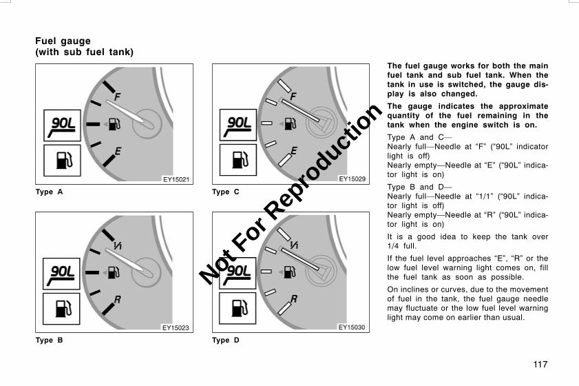
117
Type A
Type B
Type C
Type D
The fuel gauge works for both the mainfuel tank and sub fuel tank. When thetank in use is switched, the gauge dis-play is also changed.
The gauge indicates the approximatequantity of the fuel remaining in thetank when the engine switch is on.
Type A and C—Nearly full—Needle at “F” (“90L” indicatorlight is off)Nearly empty—Needle at “E” (“90L” indica-tor light is on)
Type B and D—Nearly full—Needle at “1/1” (“90L” indica-tor light is off)Nearly empty—Needle at “R” (“90L” indica-tor light is on)
It is a good idea to keep the tank over1/4 full.
If the fuel level approaches “E”, “R” or thelow fuel level warning light comes on, fillthe fuel tank as soon as possible.
On inclines or curves, due to the movementof fuel in the tank, the fuel gauge needlemay fluctuate or the low fuel level warninglight may come on earlier than usual.
L/C120 AE (OM60D50E) 08/01/22
Fuel gauge(with sub fuel tank)
Not For R
epro
duction

118
The fuel tank will be automaticallychanged from the main fuel tank to thesub fuel tank according as the remainedfuel in the main fuel tank.
The “90L” indicator light in the gaugecomes on when the sub fuel tank is beingused. At the same time, the fuel gaugechanges. When the indicator light is off,the needle at “F” or “1/1” means approxi-mately 180 L (47.6 gal., 39.6 lmp. gal),and when the indicator light is on, theneedle at “F” or “1/1” means approximate-ly 87 L (23.0 gal., 19.1 lmp. gal.).
Type A
Type B
The gauge indicates the engine coolanttemperature when the engine switch ison. The engine operating temperaturewill vary with changes in weather andengine load.
If the needle points to the red zone orhigher, stop your vehicle and allow theengine to cool.
Your vehicle may overheat during severeoperating conditions, such as:
D Driving up a long hill on a hot day
D Reducing speed or stopping after highspeed driving
D Idling for a long period with the airconditioning on in stop−and−go traffic
D Towing a trailer
L/C120 AE (OM60D50E) 08/01/22
Engine coolant temperaturegauge
Not For R
epro
duction

119
NOTICE
z Do not remove the thermostat inthe engine cooling system as thismay cause the engine to overheat.The thermostat is designed to con-trol the flow of coolant to keep thetemperature of the engine withinthe specified operating range.
z Do not continue driving with anoverheated engine. See “If your ve-hicle overheats” on page 272 inSection 4.
The tachometer indicates engine speedin thousands of rpm (revolutions perminute). Use it while driving to selectcorrect shift points and to prevent en-gine lugging and over−revving.
Driving with the engine running too fastcauses excessive engine wear and poorfuel economy. Remember, in most casesthe slower the engine speed, the greaterthe fuel economy.
NOTICE
Do not let the indicator needle getinto the red zone. This may causesevere engine damage.
This meter displays the odometer andtwo trip meters.
1. Odometer—Shows the total distancethe vehicle has been driven.
2. Two trip meters—Show two differentdistances independently driven sincethe last time each trip meter was setto zero.
You can use one trip meter to calculatethe fuel economy and the other tomeasure the distance on each trip. Alltrip meter data is cancelled if the elec-trical power source is disconnected.
3. Trip meter reset knob—Resets the twotrip meters to zero, and also changethe meter display.
L/C120 AE (OM60D50E) 08/01/22
TachometerOdometer and two tripmeters
Not For R
epro
duction

120
To change the meter display, quicklypush and release the knob. The meterdisplay changes in the order from theodometer to trip meter A to trip meterB, then back to the odometer eachtime you push.
To reset the trip meter A to zero, dis-play the meter A reading, then pushand hold the knob until the meter isset to zero. The same process can beapplied for resetting the trip meter B.
L/C120 AE (OM60D50E) 08/01/22
Not For R
epro
duction

121
If the indicator or buzzer comes on... Do this.
(a)(indicator and buzzer*)
If parking brake is off, stop immediately and contact Toyota dealer.
*: For vehicles with the vehicle stability control system only
(b) Fasten driver’s seat belt.
(c) Fasten front passenger’s seat belt.
(d) Stop immediately and contact Toyota dealer.
(e) Stop and check.
(f) Add engine oil.
(g) Take vehicle to Toyota dealer.
L/C120 AE (OM60D50E) 08/01/22
Service reminder indicators and warning buzzers
Not For R
epro
duction

122
If the indicator or buzzer comes on... Do this.
(h) Fill up tank.
(i) Take vehicle to Toyota dealer immediately.
(j) Take vehicle to Toyota dealer. If brake system warning light is also on, stopimmediately and contact Toyota dealer.
(k) Close all side doors and back door.
(l) Take vehicle to Toyota dealer.
(m)(indicator and buzzer)
Drain water.
(n)(indicator and buzzer)
Take vehicle to Toyota dealer. If flashing, drain water.
L/C120 AE (OM60D50E) 08/01/22
Not For R
epro
duction

123
If the indicator or buzzer comes on... Do this.
(o) Shift four−wheel drive control lever out of “N”.
(p) Stop and check.
(q) Take vehicle to Toyota dealer.
L/C120 AE (OM60D50E) 08/01/22
Not For R
epro
duction

124
(a) Brake System Warning Light andBuzzer
This light comes on in the following caseswhen the engine switch is in the “ON”position.
D When the parking brake is applied...
With the anti−lock brake system—
This light comes on for a few secondswhen the engine switch is turned to the“ON” position even after the parking brakeis released.
D When the brake fluid level is low...
CAUTION
It is dangerous to continue drivingnormally when the brake fluid level islow.
D When vacuum is low (diesel−poweredvehicles without the vehicle stabilitycontrol system)...
D When the hydraulic brake boosterfails (with the vehicle stability con-trol system)...
If the hydraulic booster causes a problemresulting in poor braking performance, thewarning light comes on and buzzer soundscontinuously.
Have your vehicle checked at yourToyota dealer in the following cases:
D The light does not come on even if theparking brake is applied when the en-gine switch is in the “ON” position.
With the anti−lock brake system—
D The light does not come on even if theengine switch is turned on with theparking brake released.
A warning light turning on briefly duringoperation does not indicate a problem.
CAUTION
Without the anti−lock brake system—
If the light does not turn off evenafter the parking brake is releasedwhile the engine is running, immedi-ately stop your vehicle at a safeplace and contact your Toyota dealer.In this case, the brakes may not workproperly and your stopping distancewill become longer. Depress the brakepedal firmly and bring the vehicle toan immediate stop.
With the anti−lock brake system—
If any of the following conditions oc-curs, immediately stop your vehicle ata safe place and contact your Toyotadealer.
D The light does not turn off evenafter the parking brake is releasedwhile the engine is running.
L/C120 AE (OM60D50E) 08/01/22
Not For R
epro
duction

125
DWith the vehicle stability controlsystem—The warning buzzer comeson together with the warning light.
In either case, this can indicate thatthe brakes may not work properlyand your stopping distance will be-come longer. Depress the brakepedal firmly and bring the vehicleto an immediate stop.
D The brake system warning light re-mains on together with the “ABS”warning light.
In this case, not only the anti−lockbrake system will fail but also thevehicle will become extremely un-stable during braking.
With the vehicle stability control sys-tem—
Any of the following conditions may oc-cur, but do not indicate the malfunc-tion:
D The light may stay on for about 60seconds after the engine switch isturned to the “ON” position. It is nor-mal if it turns off after a while.
D Depressing the brake pedal repeatedlymay turn on the warning light andbuzzer. It is normal if the light turns offand the buzzer stops sounding after afew seconds.
D You may hear a small sound in theengine compartment after the engine isstarted or the brake pedal is depressedrepeatedly. This is a pump pulsatingsound of the brake system, and it isnot a malfunction.
(b) Driver’s Seat Belt Reminder Light
The light acts as a reminder to buckle upthe driver’s seat belt.
Once the engine switch is turned to “ON”or “START”, the reminder light flashes ifthe driver’s seat belt is not fastened. Un-less the driver fastens the belt, the lightcontinues flashing.
(c) Front Passenger’s Seat Belt Re-minder Light
The light acts as a reminder to have thefront passenger buckle up the seat belt.
Once the engine switch is turned to “ON”,the reminder light flashes if a passengersits in the front passenger seat and doesnot fasten the seat belt. However, if afront passenger uses an additional seatcushion, the light may not flash evenwhen the seat belt is not buckled up.
If luggage or other load is placed on thefront outside passenger seat, dependingon its weight and how it is placed on theseat, built−in sensors in the seat cushionmay detect the pressure, causing the re-minder light to flash.
L/C120 AE (OM60D50E) 08/01/22
Not For R
epro
duction

126
(d) Charging System Warning Light
This warning light comes on when theengine switch is turned to the “ON” posi-tion, and goes off when the engine isstarted.
When there are problems in the chargingsystem while the engine is running, thewarning light comes on.
NOTICE
When the charging system warninglight comes on while the engine isrunning, malfunctions such as the en-gine drive belt being broken may haveoccurred. If the warning light comeson, immediately stop the vehicle in asafe place and contact your Toyotadealer.
(e) Low Engine Oil Pressure WarningLight
This light warns that the engine oil pres-sure is too low.
If it flickers or stays on while you aredriving, pull off the road to a safe placeand stop the engine immediately. Call aToyota dealer or qualified repair shop forassistance.
The light may occasionally flicker whenthe engine is idling or it may come onbriefly after a hard stop. There is nocause for concern if it then goes out whenthe engine is accelerated slightly.
The light may come on when the oil levelis extremely low. It is not designed toindicate low oil level, and the oil levelmust be checked using the level dipstick.
NOTICE
Do not drive the vehicle with thewarning light on—even for one block.It may ruin the engine.
(f) Low Engine Oil Level Warning Light(diesel−powered vehicles)
This light indicates that the engine oil le-vel needs to be checked. If the lightcomes on while you are driving on roughroads or steep inclines, take your vehicleto a level spot to see whether the lightgoes off. If it remains on, check the oillevel following the instructions of “Check-ing the engine oil level” on page 312 inSection 7−2.
While driving on steep inclines or roughroads which causes the vehicle to sub-stantially sway or on curves, this lightmay come on due to the movement ofengine oil in the engine.
In normal conditions, due to engine oilconsumption, this light may come on earli-er than the specified service interval ofthe scheduled maintenance. This is be-cause the engine oil is consumed to thelow level within the scheduled mainte-nance interval and does not indicate aproblem. (For detailed information, see“Facts about engine oil consumption” onpage 236 in Section 2.)
NOTICE
Continued engine operation with lowengine oil will damage the engine.
L/C120 AE (OM60D50E) 08/01/22
Not For R
epro
duction

127
(g) Malfunction Indicator Lamp
This lamp warns that there is a problemsomewhere in your engine electrical sys-tem, electronic engine control system,electronic throttle control system or auto-matic transmission electrical system.
If it comes on while you are driving, haveyour vehicle checked/repaired by yourToyota dealer as soon as possible.
Gasoline engine—
If engine speed does not increase whenthe accelerator pedal is depressed, theremay be a problem somewhere in yourelectronic throttle control system.
At this time, vibration may occur. Howev-er, if you depress the accelerator pedalmore firmly and slowly, you can drive yourvehicle at low speeds. Have your vehiclechecked by your Toyota dealer as soon aspossible.
Even if the abnormality of the electronicthrottle control system is corrected duringlow speed driving, the system may not berecovered until the engine is stopped andthe engine switch is turned to “ACC” or“LOCK” position.
CAUTION
Be especially careful to prevent erro-neous pedal operation.
Diesel engine—
If engine speed does not increase whenthe accelerator pedal is depressed, theremay be a problem somewhere in the elec-tronic engine control system. Stop the ve-hicle and contact your Toyota dealer ortake your vehicle carefully, since the ve-hicle performance will be lower than nor-mal, to your Toyota dealer as soon aspossible.
Even if the abnormality of the electronicthrottle control system is corrected duringlow speed driving, the system may not berecovered until the engine is stopped andthe engine switch is turned to “ACC” or“LOCK” position.
(h) Low Fuel Level Warning Light
This light comes on when the fuel levelin the tank becomes nearly empty. Fill upthe tank as soon as possible.
On inclines or curves, due to the move-ment of fuel in the tank, the low fuel levelwarning light may come on earlier thanusual.
(i) SRS Warning Light
This indicator comes on when the en-gine switch is turned to the “ON” posi-tion. It goes off after about 6 seconds.This means the SRS airbags and seatbelt pretensioner system are operatingproperly.
This warning light system monitors theairbag sensor assembly, front airbag sen-sors, side and curtain shield airbag sen-sors, curtain shield airbag sensors, driv-er’s seat position sensor, driver’s seat beltbuckle switch, seat belt pretensioner as-semblies, inflators, interconnecting wiringand power sources.
If any of the following conditions occurs,this indicates a malfunction of the airbagsor seat belt pretensioners. Contact yourToyota dealer as soon as possible.
D The light does not come on when theengine switch is turned to the “ON”position or remains on for more than6 seconds or flashes.
D The light comes on or starts flashingwhile driving.
L/C120 AE (OM60D50E) 08/01/22
Not For R
epro
duction

128
(j) “ABS” Warning Light
Without the vehicle stability controlsystem—
The light comes on when the engineswitch is turned to the “ON” position. Ifthe anti−lock brake system works properly,the light turns off after a few seconds.Thereafter, if the system malfunctions, thelight comes on again.
When the “ABS” warning light is on (andthe brake system warning light is off), theanti−lock brake system does not operate,but the brake system still operates con-ventionally.
When the “ABS” warning light is on (andthe brake system warning light is off), theanti−lock brake system does not operatebut the brake assist system still operates.In this case, the wheels could lock upduring a sudden braking or braking onslippery road surfaces.
If either of the following conditions oc-curs, this indicates a malfunction some-where in the components monitored bythe warning light system. Contact yourToyota dealer as soon as possible toservice the vehicle.
D The light does not come on when theengine switch is turned to the “ON”position, or remains on.
D The light comes on while you are driv-ing.
A warning light turning on briefly duringoperation does not indicate a problem.
CAUTION
If the “ABS” warning light remains ontogether with the brake system warn-ing light, immediately stop your ve-hicle at a safe place and contact yourToyota dealer.
In this case, not only the anti−lockbrake system will fail but also thevehicle will become extremely unsta-ble during braking.
With rear differential lock: However, it isa normal operation for the light to be onwith rear differential locked. At this time,the anti−lock brake system does not oper-ate.
With the vehicle stability control sys-tem—
The light comes on when the engineswitch is turned to the “ON” position. Ifthe anti−lock brake system and the brakeassist system work properly, the lightturns off after a few seconds. Thereafter,if either of the systems malfunctions, thelight comes on again.
When the “ABS” warning light is on (andthe brake system warning light is off), thefollowing system do not operate, but thebrake system still operates conventionally.
D Anti−lock brake system
D Brake assist system
D Active traction control system
D Vehicle stability control system
D Downhill assist control system
D Hill−start assist control system
L/C120 AE (OM60D50E) 08/01/22
Not For R
epro
duction

129
When the “ABS” warning light is on (andthe brake system warning light is off), theanti−lock brake system does not operateso that the wheels could lock up duringa sudden braking or braking on slipperyroad surfaces.
If either of the following conditions oc-curs, this indicates a malfunction some-where in the components monitored bythe warning light system. Contact yourToyota dealer as soon as possible toservice the vehicle.
D The light does not come on when theengine switch is turned to the “ON”position, or remains on.
D The light comes on while you are driv-ing.
A warning light turning on briefly duringoperation does not indicate a problem.
CAUTION
If the “ABS” warning light remains ontogether with the brake system warn-ing light, immediately stop your ve-hicle at a safe place and contact yourToyota dealer.
In this case, not only the anti−lockbrake system will fail but also thevehicle will become extremely unsta-ble during braking.
Either of the following conditions mayoccur, but do not indicate a malfunc-tion:
D The light may stay on for about 60seconds after the engine switch isturned to the “ON” position. It is nor-mal if it turns off after a while.
D Depressing the brake pedal repeatedlymay turn on the light. It is normal if itturns off after a few seconds.
(k) Open Door Warning Light
This light remains on until all the sidedoors and back door are completelyclosed.
(l) Timing Belt Replacement WarningLight (diesel engine)
This light will come on every time whenthe trip amount gets between 140000 kmand 150000 km in kilometer reading or90000 miles to indicate that the timingbelt should be replaced. Therefore, whenit comes on, have the belt replaced im-mediately and the warning light reset byyour Toyota dealer.
NOTICE
Continued driving without having thebelt replaced will result in a brokenbelt and engine damage.
(m) Fuel Filter Warning Light and Buzz-er (1KZ−TE engine only)
The light and buzzer warn you that theamount of accumulated water in the fuelfilter has reached the specified level.
If they come on, drain the water immedi-ately. (See page 317 Section 7−2 forinstructions for how to drain the water.)
L/C120 AE (OM60D50E) 08/01/22
Not For R
epro
duction

130
NOTICE
Never drive the vehicle with the warn-ing light and buzzer on. Continueddriving with water accumulated in thefuel filter will damage the fuel injec-tion pump.
(n) Fuel System Warning Light (1KD−FTV engine only)
The light has two modes:
When the light flashes, it warns that theamount of accumulated water in the fuelfilter has reached the specified level.
In this case, drain the water immediately.(See page 317 for instructions for how todrain the water.)
A buzzer will also sound at the same timethe warning light flashes.
When the light comes on, it warns thatthere may be a problem with the fuelsystem.
In this case, have your vehicle checkedand the warning light reset by your Toyotadealer as soon as possible.
NOTICE
Never drive the vehicle with the warn-ing light flashing. Continued drivingwith water accumulated in the fuelfilter will damage the fuel injectionpump.
If either of the following conditions occurs,this indicates a malfunction somewhere inthe components monitored by the warninglight system. Contact your Toyota dealeras soon as possible to service the ve-hicle.
D The light does not come on when theengine switch is turned to the “ON”position or remains on for more thanabout 6 seconds.
D The light comes on while driving.
(o) Unengaged “Park” Warning Light
This light warns that the transmission“Park” mechanism is not engaged. If thefour−wheel drive control lever is in the “N”position while the selector lever is in the“P” position, the transmission will disen-gage and the wheels will not lock.
CAUTION
To restore the park function, shift thefour−wheel drive control lever out of“N”, or the vehicle can move.
(p) Automatic Transmission Fluid Tem-perature Warning Light
This light warns that the automatic trans-mission fluid temperature is too high.
If this light comes on while you are driv-ing, slow down and pull off the road. Stopthe vehicle at a safe place and put theselector lever in “P”. With the engine id-ling, wait until the light goes off. If thelight goes off, you may start the vehicleagain. If the light does not go off, call aToyota dealer or qualified repair shop forassistance.
NOTICE
Continued driving with the warninglight on may damage the automatictransmission.
L/C120 AE (OM60D50E) 08/01/22
Not For R
epro
duction
131
(q) “VSC TRC” Warning Light
This light warns that there is a problemsomewhere in the following.
D Active traction control system
D Vehicle stability control system
D Downhill assist control system
D Hill−start assist control system
The lights will come on when the engineswitch turned to “ON”, and will go off aftera few seconds.
The lights may come on for 60 secondsafter the engine switch is turned to the“ON” position. It is normal if they go outafter a while.
Depressing the brake pedal repeatedlymay turn on the lights. It is normal if theygo out after a few seconds.
There is no problem when the “VSC TRC”warning light comes on when the brakeactuator temperature becomes high.
If the light comes on while driving, thesystem does not work. However, as con-ventional braking operates when applied,there is no problem to continue your driv-ing.
In the following cases, contact your Toyotadealer:
D The warning light does not come onafter the engine switch is turned to“ON”.
D The warning light remains on after theengine switch is turned to “ON”.
D The warning light comes on while driv-ing.
Gasoline engine—When the brake fluidlevel is too low, the above−mentioned sys-tems will not operate and the warning lightcomes on.
CHECKING SERVICE REMINDERINDICATORS (except the low fuel levelwarning light)
1. Apply the parking brake.
2. Open one of the side doors or backdoor.The open door warning light shouldcome on.
3. Close the door.The open door warning light should gooff.
4. Turn the engine switch to “ON”, but donot start the engine.
All the service reminder indicators ex-cept the open door warning light shouldcome on.
Without the vehicle stability controlsystem—The following service reminder indica-tors go off after a few seconds.
D “ABS” warning light
D Height control indicator light
D Height control “OFF” indicator light
The SRS warning light goes off afterabout 6 seconds.
L/C120 AE (OM60D50E) 08/01/22
Not For R
epro
duction
132
With the vehicle stability control sys-tem—The following service reminder indica-tors go off after a few seconds.
D “ABS” warning light
D “VSC TRC” warning light
D “VSC OFF” indicator light
D Slip indicator light
D Height control indicator light
D Height control “OFF” indicator light
D Downhill assist control systemindicator light
The SRS warning light goes off afterabout 6 seconds.
There may be the case that the “ABS”warning light (brake assist systemwarning light), “VSC TRC” and “VSCOFF” indicator light stay on for about60 seconds after the engine switch isturned to the “ON” position. It is nor-mal if they go out after a while.
5. Vehicles with automatic transmissiononly: Place the four−wheel control leverin “N” position and the selector leverin “P” position.The unengaged “Park” warning lightshould come on.
6. Vehicles with automatic transmissiononly: Shift the four−wheel drive controllever out of “N”.The unengaged “Park” warning lightshould go off.
If any service reminder indicator or warn-ing buzzer does not function as describedabove, have it checked by your Toyotadealer as soon as possible.
L/C120 AE (OM60D50E) 08/01/22
Not For R
epro
duction

133
OPERATION OF INSTRUMENTS ANDCONTROLSEngine (ignition) switch, Transmission and ParkingbrakeEngine (ignition) switch 134. . . . . . . . . . . . . . . . . . . . . . . . . . . . . . . . . . . . .Automatic transmission 136. . . . . . . . . . . . . . . . . . . . . . . . . . . . . . . . . . . . .Manual transmission 144. . . . . . . . . . . . . . . . . . . . . . . . . . . . . . . . . . . . . . .Four−wheel drive system 146. . . . . . . . . . . . . . . . . . . . . . . . . . . . . . . . . . .Rear differential lock system 150. . . . . . . . . . . . . . . . . . . . . . . . . . . . . . . .Active traction control system 152. . . . . . . . . . . . . . . . . . . . . . . . . . . . . . .Vehicle stability control system 154. . . . . . . . . . . . . . . . . . . . . . . . . . . . . .Downhill assist control (DAC) system 156. . . . . . . . . . . . . . . . . . . . . . . .Hill−start assist control system 160. . . . . . . . . . . . . . . . . . . . . . . . . . . . . .Rear height control air suspension 162. . . . . . . . . . . . . . . . . . . . . . . . . . .Toyota electronic modulated suspension 168. . . . . . . . . . . . . . . . . . . . .Parking brake 169. . . . . . . . . . . . . . . . . . . . . . . . . . . . . . . . . . . . . . . . . . . . . .Cruise control 169. . . . . . . . . . . . . . . . . . . . . . . . . . . . . . . . . . . . . . . . . . . . . .
L/C120 AE (OM60D50E) 08/01/22
SECTION 1−7
Not For R
epro
duction

134
“START”—Starter motor on. The keywill return to the “ON” position whenreleased.
For starting tips, see page 247 in Section3.
“ON”—Engine on and all accessorieson.
This is the normal driving position.
“ACC”—Accessories such as the radiooperate, but the engine is off.
“LOCK”—Engine is off and the steeringwheel is locked. The key can be re-moved only at this position.
You must push in the key to turn the keyfrom “ACC” to the “LOCK” position. Onvehicles with an automatic transmission,the selector lever must be put in the “P”position before pushing the key.
Once you remove the key, the engine im-mobilizer system is automatically set. (See“Engine immobilizer system” on page 14in Section 1−2.)
When starting the engine, the key mayseem stuck at the “LOCK” position. Tofree it, first be sure the key is pushed allthe way in, and then rock the steeringwheel slightly while turning the key gently.
It is not a malfunction if the needles onall meters and gauges move slightly whenthe key is turned to the “ACC”, “ON” or“START” position.
CAUTION
For manual transmission:
Never remove the key when the ve-hicle is moving, as this will lock thesteering wheel and result in loss ofsteering control.
NOTICE
Do not leave the key in the “ON”position if the engine is not running.The battery will discharge and theignition could be damaged.
L/C120 AE (OM60D50E) 08/01/22
Engine (ignition) switch(gasoline engine)
Not For R
epro
duction

135
“START”—Starter motor on. The keywill return to the “ON” position whenreleased.
For starting tips, see page 247 in Section3.
“ON”—Engine on and all accessorieson. Before starting, glow plugs on andengine preheated.
This is the normal driving position.
“ACC”—Accessories such as the radiooperate, but the engine is off.
“LOCK”—Engine is off and the steeringwheel is locked. The key can be re-moved only at this position.
You must push in the key to turn the keyfrom “ACC” to the “LOCK” position. Onvehicles with an automatic transmission,the selector lever must be put in the “P”position before pushing the key.
Once you remove the key, the engine im-mobilizer system is automatically set. (See“Engine immobilizer system” on page 14in Section 1−2.)
When starting the engine, the key mayseem stuck at the “LOCK” position. Tofree it, first be sure the key is pushed allthe way in, and then rock the steeringwheel slightly while turning the key gently.
It is not a malfunction if the needles onall meters and gauges move slightly whenthe key is turned to the “ACC”, “ON” or“START” position.
CAUTION
For manual transmission:
Never remove the key when the ve-hicle is moving, as this will lock thesteering wheel and result in loss ofsteering control.
NOTICE
Do not leave the key in the “ON”position if the engine is not running.The battery will discharge.
L/C120 AE (OM60D50E) 08/01/22
Engine (ignition) switch(diesel engine)
Not For R
epro
duction
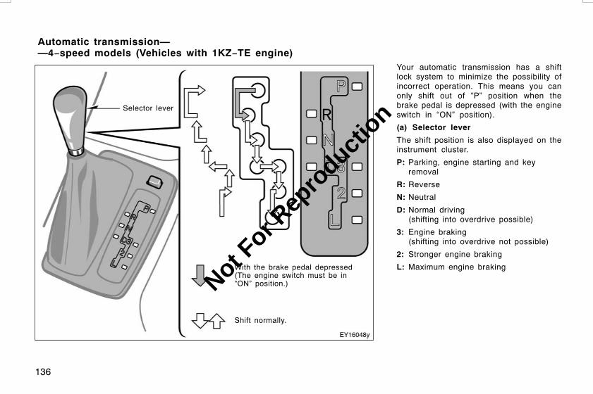
136
Your automatic transmission has a shiftlock system to minimize the possibility ofincorrect operation. This means you canonly shift out of “P” position when thebrake pedal is depressed (with the engineswitch in “ON” position).
(a) Selector lever
The shift position is also displayed on theinstrument cluster.
P: Parking, engine starting and keyremoval
R: Reverse
N: Neutral
D: Normal driving(shifting into overdrive possible)
3: Engine braking(shifting into overdrive not possible)
2: Stronger engine braking
L: Maximum engine braking
L/C120 AE (OM60D50E) 08/01/22
Automatic transmission——4−speed models (Vehicles with 1KZ−TE engine)
Selector lever
With the brake pedal depressed(The engine switch must be in“ON” position.)
Shift normally.
Not For R
epro
duction
137
(b) Normal driving
1. Start the engine as instructed in “Howto start the engine” on page 248 inSection 3. The transmission must be in“P” or “N”.
When the four−wheel drive control lever isin “LL” or “L” (low−speed position, centerdifferential locked), the driving pattern se-lector setting has no effect on gear shifttiming. (See “Four−wheel drive system” onpage 146 in this Section for information ofthe four−wheel drive control lever.)
2. With your foot holding down the brakepedal, shift the selector lever to “D”.
When the lever is in the “D” position, theautomatic transmission system will selectthe most suitable gear for running condi-tions such as normal cruising, hill climb-ing, hard towing, etc.
Always use the “D” position for better fueleconomy and quieter driving. If the enginecoolant temperature is low or when thefour−wheel drive control lever is in “LL” or“L” (low−speed position, center differentiallocked), the transmission will not shift intothe overdrive gear even in the “D” posi-tion. (See “Four−wheel drive system” onpage 146 in this Section for information ofthe four−wheel drive control lever.)
CAUTION
Never put your foot on the accelera-tor pedal while shifting.
3. Release the parking brake and brakepedal. Depress the accelerator pedalslowly for smooth starting.
(c) Using engine braking
To use engine braking, you can downshiftthe transmission as follows:
D Shift into the “3” position. The trans-mission will downshift to third gear andengine braking will be enabled.
D Shift into the “2” position. The trans-mission will downshift to second gearwhen the vehicle speed drops down toor lower than the following speed, andstronger engine braking will be en-abled.
Four−wheel drive control lever in “HL”or “H” 88 km/h (54 mph). . . . . . . . . . . .
Four−wheel drive control lever in “L” or“LL” 34 km/h (21 mph). . . . . . . . . . . . . .
D Shift into the “L” position. The trans-mission will downshift to first gearwhen the vehicle speed drops down toor lower than the following speed, andmaximum engine braking will be en-abled.
Four−wheel drive control lever in “HL”or “H” 51 km/h (31 mph). . . . . . . . . . . .
Four−wheel drive control lever in “L” or“LL” 10 km/h (6 mph). . . . . . . . . . . . . . . .
Vehicles with cruise control—When thecruise control is being used, even if youdownshift from “D” to “3”, engine brakingwill not be enabled because the cruisecontrol is not cancelled.
For ways to decrease the vehicle speed,see “Cruise control” on page 169 in thisSection.
CAUTION
Be careful when downshifting on aslippery surface. Abrupt shiftingcould cause the vehicle to skid orspin.
L/C120 AE (OM60D50E) 08/01/22
Not For R
epro
duction

138
(d) Using the “2” and “L” positions
The “2” and “L” positions are used forstrong engine braking as described pre-viously.
With the selector lever in “2” or “L”, youcan start the vehicle in motion as with thelever in “D”.
With the selector lever in “2”, the vehiclewill start in first gear and automaticallyshift to second gear.
With the selector lever in “L”, the trans-mission is engaged in first gear.
NOTICE
z Be careful not to over−rev the en-gine. Watch the tachometer to keepengine rpm from going into the redzone. The approximate maximum al-lowable speed for each position isgiven below for your reference:
Four−wheel drive control lever in“H” or “HL”“2” 101 km/h (62 mph). . . . . . . . . . .“L” 55 km/h (34 mph). . . . . . . . . . .
Four−wheel drive control lever in“L” or “LL”“2” 39 km/h (24 mph). . . . . . . . . . . .“L” 21 km/h (13 mph). . . . . . . . . . .
z Do not continue hill climbing orhard towing for a long time in the“2” or “L” position. This may causesevere automatic transmission dam-age from overheating. To preventsuch damage, “D” or “3” positionshould be used in hill climbing orhard towing.
(e) Backing up
1. Bring the vehicle to a complete stop.
2. With the brake pedal held down withyour foot, shift the selector lever to the“R” position.
NOTICE
Never shift into reverse while the ve-hicle is moving.
(f) Parking
1. Bring the vehicle to a complete stop.
2. Pull the parking brake lever fully tosecurely apply the parking brake.
3. With the brake pedal pressed down,shift the selector lever to the “P” posi-tion.
CAUTION
Never attempt to move the selectorlever into “P” position under any cir-cumstances while the vehicle is mov-ing. Serious mechanical damage andloss of vehicle control may result.
(g) Good driving practice
D If the transmission repeatedly shifts upand down between third gear and over-drive gears when climbing a gentleslope, shift the selector lever to the “3”position. Be sure to shift the selectorlever to the “D” position immediatelyafterward.
D When towing a trailer, in order to main-tain engine braking efficiency, do notuse “D” position. The selector levermust be in the “3” position.
CAUTION
Always keep your foot on the brakepedal while stopped with the enginerunning. This prevents the vehiclefrom creeping.
L/C120 AE (OM60D50E) 08/01/22
Not For R
epro
duction

139
NOTICE
Always use the brake pedal or theparking brake to hold the vehicle onan upgrade. Do not attempt to holdthe vehicle using the accelerator ped-al, as this can cause the transmissionto overheat.
(h) Driving in “2nd STRT” (secondstart) mode
In the “2nd STRT” (second start) mode,the transmission system shifts up fromsecond gear. Use this mode when startingyour vehicle in sand, mud, ice or snow.
To set the “2nd STRT” mode, push the“2nd STRT” mode selector button. In the“2nd STRT” mode, the “2nd STRT” indica-tor light comes on.
(i) If you cannot shift the selector le-ver out of “P” position
If you cannot shift the selector lever from“P” position even though the brake pedalis depressed, use “SHIFT LOCK” button.For instructions, see “If you cannot shiftautomatic transmission selector lever” onpage 290 in Section 4.
L/C120 AE (OM60D50E) 08/01/22
Not For R
epro
duction

140
Your automatic transmission has a shiftlock system to minimize the possibility ofincorrect operation. This means you canonly shift out of “P” position when thebrake pedal is depressed (with the engineswitch in “ON” position).
(a) Selector lever
The shift position is also displayed on theinstrument cluster.
P: Parking, engine starting and keyremoval
R: Reverse
N: Neutral
D: Normal driving(shifting into overdrive possible)
4: Engine braking(shifting into overdrive not possible)
3, 2: Stronger engine braking
L: Maximum engine braking
L/C120 AE (OM60D50E) 08/01/22
—5−speed models (Vehicles with 1GR−FE and 1KD−FTV engines)
Selectorlever
With the brake pedal depressed(The engine switch must be in“ON” position.)
Shift normally.
Not For R
epro
duction

141
(b) Normal driving
1. Start the engine as instructed in “Howto start the engine” on page 248 inSection 3. The transmission must be in“P” or “N”.
When the four−wheel drive control lever isin “LL” or “L” (low−speed position, centerdifferential locked), the driving pattern se-lector setting has no effect on gear shifttiming. (See “Four−wheel drive system” onpage 146 in this Section for information ofthe four−wheel drive control lever.)
2. With your foot holding down the brakepedal, shift the selector lever to “D”.
When the lever is in the “D” position, theautomatic transmission system will selectthe most suitable gear for running condi-tions such as normal cruising, hill climb-ing, hard towing, etc.
Always use the “D” position for better fueleconomy and quieter driving. If the enginecoolant temperature is low or when thefour−wheel drive control lever is in “LL” or“L” (low−speed position, center differentiallocked), the transmission will not shift intothe overdrive gear even in the “D” posi-tion. (See “Four−wheel drive system” onpage 146 in this Section for information ofthe four−wheel drive control lever.)
CAUTION
Never put your foot on the accelera-tor pedal while shifting.
3. Release the parking brake and brakepedal. Depress the accelerator pedalslowly for smooth starting.
(c) Using engine braking
To use engine braking, you can downshiftthe transmission as follows:
D Shift into the “4” position. The trans-mission will downshift to fourth gearand engine braking will be enabled.
D Shift into the “3” position. The trans-mission will downshift to third gearwhen the vehicle speed drops down toor lower than the following speed, andstronger engine braking will be en-abled.
Four−wheel drive control lever in “HL”or “H”
1GR−FE engine130 km/h (80 mph). . . . . . . . . . .
1KD−FTV engine100 km/h (62 mph). . . . . . . . . . .
Four−wheel drive control lever in “L” or“LL”
1GR−FE engine50 km/h (31 mph). . . . . . . . . . . .
1KD−FTV engine38 km/h (24 mph). . . . . . . . . . . .
D Shift into the “2” position. The trans-mission will downshift to second gearwhen the vehicle speed drops down toor lower than the following speed, andstronger engine braking will be en-abled.
Four−wheel drive control lever in “HL”or “H”
1GR−FE engine86 km/h (53 mph). . . . . . . . . . . .
1KD−FTV engine66 km/h (41 mph). . . . . . . . . . . .
Four−wheel drive control lever in “L” or“LL”
1GR−FE engine33 km/h (20 mph). . . . . . . . . . . .
1KD−FTV engine25 km/h (15 mph). . . . . . . . . . . .
L/C120 AE (OM60D50E) 08/01/22
Not For R
epro
duction
142
D Shift into the “L” position. The trans-mission will downshift to first gearwhen the vehicle speed drops down toor lower than the following speed, andmaximum engine braking will be en-abled.
Four−wheel drive control lever in “HL”or “H”
1GR−FE engine41 km/h (25 mph). . . . . . . . . . . .
1KD−FTV engine22 km/h (13 mph). . . . . . . . . . . .
Four−wheel drive control lever in “L” or“LL”
1GR−FE engine15 km/h (9 mph). . . . . . . . . . . . . .
1KD−FTV engine8 km/h (5 mph). . . . . . . . . . . . . . .
Vehicles with cruise control—When thecruise control is being used, even if youdownshift from “D” to “4”, engine brakingwill not be enabled because the cruisecontrol is not cancelled.
For ways to decrease the vehicle speed,see “Cruise control” on page 169 in thisSection.
CAUTION
Be careful when downshifting on aslippery surface. Abrupt shiftingcould cause the vehicle to skid orspin.
(d) Using “3”, “2” and “L” positions
The “3”, “2” and “L” positions are used forstrong engine braking as described pre-viously.
With the selector lever in ”3”, “2” or “L”,you can start the vehicle in motion aswith the lever in “D”.
With the selector lever in “3” or “2”, thevehicle will start in first gear and automat-ically shift to third gear or second gear.
With the selector lever in “L”, the trans-mission is engaged in first gear.
NOTICE
z Be careful not to over−rev the en-gine. Watch the tachometer to keepengine rpm from going into the redzone. The approximate maximum al-lowable speed for each position isgiven below for your reference:
Four−wheel drive control lever in“H” or “HL”
1GR−FE engine“3” 138 km/h (85 mph). . . . . .“2” 95 km/h (59 mph). . . . . . .“L” 55 km/h (34 mph). . . . . . .
1KD−FTV engine“3” 121 km/h (75 mph). . . . . .“2” 83 km/h (51 mph). . . . . . .“L” 48 km/h (29 mph). . . . . . .
Four−wheel drive control lever in“L” or “LL”
1GR−FE engine“3” 54 km/h (33 mph). . . . . . .“2” 37 km/h (22 mph). . . . . . .“L” 21 km/h (13 mph). . . . . . .
1KD−FTV engine“3” 47 km/h (29 mph). . . . . . .“2” 32 km/h (20 mph). . . . . . .“L” 19 km/h (12 mph). . . . . . .
L/C120 AE (OM60D50E) 08/01/22
Not For R
epro
duction

143
z Do not continue hill climbing orhard towing for a long time in the“3”, “2” or “L” position. This maycause severe automatic transmis-sion damage from overheating. Toprevent such damage, “4” positionshould be used in hill climbing orhard towing.
(e) Backing up
1. Bring the vehicle to a complete stop.
2. With the brake pedal held down withyour foot, shift the selector lever to the“R” position.
NOTICE
Never shift into reverse while the ve-hicle is moving.
(f) Parking
1. Bring the vehicle to a complete stop.
2. Pull the parking brake lever up fully tosecurely apply the parking brake.
3. With the brake pedal pressed down,shift the selector lever to the “P” posi-tion.
CAUTION
Never attempt to move the selectorlever into “P” position under any cir-cumstances while the vehicle is mov-ing. Serious mechanical damage andloss of vehicle control may result.
(g) Good driving practice
D If the transmission repeatedly shifts upand down between fourth gear andoverdrive when climbing a gentle slope,shift the selector lever to the “4” posi-tion. Be sure to shift the selector leverto the “D” position immediately after-ward.
D When towing a trailer, in order to main-tain engine braking efficiency, do notuse “D” position.
CAUTION
Always keep your foot on the brakepedal while stopped with the enginerunning. This prevents the vehiclefrom creeping.
NOTICE
Always use the brake pedal or theparking brake to hold the vehicle onan upgrade. Do not attempt to holdthe vehicle using the accelerator ped-al, as this can cause the transmissionto overheat.
L/C120 AE (OM60D50E) 08/01/22
Not For R
epro
duction
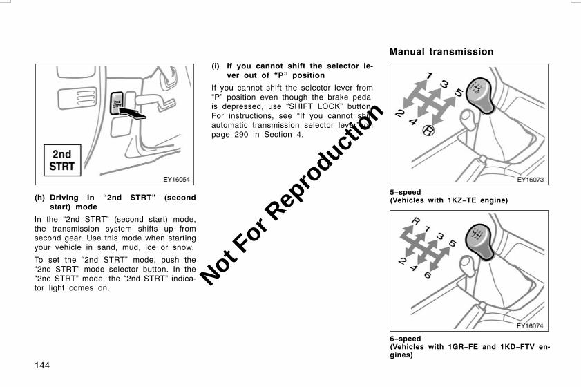
144
(h) Driving in “2nd STRT” (secondstart) mode
In the “2nd STRT” (second start) mode,the transmission system shifts up fromsecond gear. Use this mode when startingyour vehicle in sand, mud, ice or snow.
To set the “2nd STRT” mode, push the“2nd STRT” mode selector button. In the“2nd STRT” mode, the “2nd STRT” indica-tor light comes on.
(i) If you cannot shift the selector le-ver out of “P” position
If you cannot shift the selector lever from“P” position even though the brake pedalis depressed, use “SHIFT LOCK” button.For instructions, see “If you cannot shiftautomatic transmission selector lever” onpage 290 in Section 4.
5−speed(Vehicles with 1KZ−TE engine)
6−speed(Vehicles with 1GR−FE and 1KD−FTV en-gines)
L/C120 AE (OM60D50E) 08/01/22
Manual transmission
Not For R
epro
duction
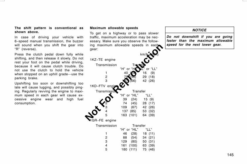
145
The shift pattern is conventional asshown above.
In case of driving your vehicle with6−speed manual transmission, the buzzerwill sound when you shift the gear into“R” (reverse).
Press the clutch pedal down fully whileshifting, and then release it slowly. Do notrest your foot on the pedal while driving,because it will cause clutch trouble. Donot use the clutch to hold the vehiclewhen stopped on an uphill grade—use theparking brake.
Upshifting too soon or downshifting toolate will cause lugging, and possibly ping-ing. Regularly revving the engine to maxi-mum speed in each gear will cause ex-cessive engine wear and high fuelconsumption.
Maximum allowable speeds
To get on a highway or to pass slowertraffic, maximum acceleration may be nec-essary. Make sure you observe the follow-ing maximum allowable speeds in eachgear:
km/h (mph)
1KZ−TE engine
Transmission Transfer“H” or “HL” “L” or “LL”
1 40 (24) 16 (9)2 75 (46) 29 (18)3 107 (66) 42 (26)
1KD−FTV engine
Transmission Transfer“H” or “HL” “LL”
1 39 (24) 15 (9)2 74 (45) 28 (17)3 109 (67) 42 (26)4 137 (85) 53 (32)5 163 (101) 64 (39)
1GR−FE engine
Transmission Transfer“H” or “HL” “LL”
1 46 (28) 18 (11)2 88 (54) 34 (21)3 129 (80) 50 (31)4 161 (100) 63 (39)5 180 (111) 75 (46)
NOTICE
Do not downshift if you are goingfaster than the maximum allowablespeed for the next lower gear.
L/C120 AE (OM60D50E) 08/01/22
Not For R
epro
duction

146
Good driving practice
D If it is difficult to shift into reverse, putthe transmission in neutral, release theclutch pedal momentarily, and then tryagain.
D When towing a trailer, in order to main-tain engine braking efficiency, do notuse fifth gear (5−speed) or sixth gear(6−speed).
CAUTION
Be careful when downshifting on aslippery surface. Abrupt shiftingcould cause the vehicle to skid orspin.
NOTICE
z Do not use any gears other thanfirst gear when starting off andmoving forward. Doing so may dam-age the clutch.
zMake sure the vehicle is completelystopped before shifting into reverse.
Use the four−wheel drive control leverto select the following transfer modes.
“H” (high speed position): Lever at “H”Use this for normal driving on dry hard-surfaced roads. This position gives greatereconomy, quietest ride and least wear.
“HL” (high speed position, center differ-ential locked): Lever at “HL”Use this for driving only on tracks thatpermit the tires slide, like off−road, icy orsnow−covered roads.
“N” (neutral position): Lever at “N”No power is delivered to the wheels. Thevehicle must be stopped.
“LL” (low speed position, center differ-ential locked): Lever at “LL”Use this for maximum power and traction.Use “LL” for climbing or descending steephills, off−road driving, and hard pulling insand, mud or deep snow.
The center differential lock indicator lightcomes on when the “HL” or “LL” mode isselected.
See “(b) Shifting procedure” on page 147for further instructions.
L/C120 AE (OM60D50E) 08/01/22
Four−wheel drive system—(a) Four−wheel drive control(lever type)
Not For R
epro
duction

147
SHIFTING BETWEEN “H” AND “HL”
To shift from “H” to “HL”, move thefour−wheel drive control lever.
This can be done at any vehicle speed.You need not depress the clutch pedal.
If the indicator light does not come onwhen you shift the transfer into “HL”, drivestraight ahead while accelerating or decel-erating.
CAUTION
Never move the four−wheel drive con-trol lever if wheels are slipping. Stopthe slipping or spinning before shift-ing.
To shift from “HL” to “H”, simply movethe four−wheel drive control lever.
This can be done at any vehicle speed.You need not depress the clutch pedal.
If the indicator light does not go off whenyou shift the transfer into “H”, drivestraight ahead while accelerating or decel-erating, or drive in reverse.
SHIFTING BETWEEN “HL” AND “LL”
To shift from “HL” to “LL”, stop thevehicle or reduce your speed to less than8 km/h (5 mph). With your foot off theaccelerator pedal, depress the clutch ped-al and move the four−wheel drive controllever.
To shift from “LL” to “HL”, depress theclutch pedal and move the four−wheeldrive control lever.
This can be done at any vehicle speed.
SHIFTING BETWEEN “H” AND “HL”
To shift from “H” to “HL”, move thefour−wheel drive control lever.
This can be done at any vehicle speed.If the indicator light does not come onwhen you shift the transfer into “HL”, drivestraight ahead while accelerating or decel-erating.
CAUTION
Never move the four−wheel drive con-trol lever if wheels are slipping. Stopthe slipping or spinning before shift-ing.
To shift from “HL” to “H”, simply movethe four−wheel drive control lever.
This can be done at any vehicle speed.
If the indicator light does not go off whenyou shift the transfer into “H”, drivestraight ahead while accelerating or decel-erating, or drive in reverse.
SHIFTING BETWEEN “HL” AND “LL”
To shift between “HL” and “LL”, stopthe vehicle and put the transmission in“N”. With your foot holding down thebrake pedal, move the four−wheel drivecontrol lever.
L/C120 AE (OM60D50E) 08/01/22
(b) Shifting procedure(with manual transmission)
(b) Shifting procedure(with automatic transmission)
Not For R
epro
duction

148
Use the four−wheel drive control leverand center differential lock button toselect the transfer and center differen-tial modes.
The “H” and “L” position of the four−wheeldrive control lever provides either lock orunlock mode of the center differential de-pending on the center differential lock but-ton position.
Use the center differential lock system ifyour wheels get stuck in a ditch, or whenyou are driving on a slippery or bumpysurface. When the center differential islocked, the vehicle stability control systemis automatically turned off and the centerdifferential lock and “VSC OFF” indicatorlights come on because the function thatcontrols engine performance interfereswith the process of freeing your wheels.
NOTICE
As soon as the center differential lockswitch is turned on, the “VSC OFF”indicator light comes on. After thewheels are out of the ditch or off theslippery or bumpy surface, turn thecenter differential lock switch off.Make sure that the center differentiallock indicator light and vehicle stabil-ity control system off indicator lightturn off.
“H” (high speed position, center differ-ential unlocked): Lever at “H”, center dif-ferential lock button left out
Use this for normal driving on all types ofroads, from dry hard−surfaced roads towet, icy or snow−covered roads. Thisposition gives greater economy, quietestride, least wear and better vehicle control.
“H” (high speed position, center differ-ential locked): Lever at “H”, center differ-ential lock button pushed in
Use this for greater traction when youexperience a loss of power, such aswheel slipping, in the center differentialunlock mode.
“N” (neutral position): Lever at “N”
No power is delivered to the wheels.The vehicle must be stopped.
“L” (low speed position, center differen-tial unlocked): Lever at “L”, center differ-ential lock button left out
Use this for maximum power and traction.Use this for climbing or descending steephills, off−road driving, and hard pulling insand or mud.
In this mode, the braking feeling that oc-curs when the wheels are negotiating asharp corner is further reduced than in the“L” (low position, center differential locked)mode.
L/C120 AE (OM60D50E) 08/01/22
Four−wheel drive system—(a) Four−wheel drive control(lever/button type)
Not For R
epro
duction
149
“L” (low speed position, center differen-tial locked): Lever at “L”, center differen-tial lock button pushed in
Use this for maximum power and traction.Use this for hard pulling in situations thevehicle cannot negotiate even in the “L”(low speed position, center differential un-locked) mode. Also, using this mode whendriving down steep off−road inclines willhelp contribute to increased vehicle stabil-ity.
The indicator light tells when the differen-tial lock is engaged. Note that the differ-ential is not still locked as long as theindicator light remains off.
When the operation is not completed, theindicator blinks. If the indicator light doesnot go off when you push out the centerdifferential lock button, drive straightahead while accelerating or decelerating,or drive in reverse.
The center differential lock system opera-tion is not completed within 5 secondswhile the cruise control system is set,cancel the cruise control system. To can-cel the cruise control system, see “Cruisecontrol” on page 169 in this Section.
If the indicator blinks even if doing so,contact your Toyota dealer as soon aspossible. There may be a trouble in thecenter differential lock system.
See “(b) Shifting procedure” on page 150for further instructions.
SHIFTING BETWEEN “H” (UNLOCKED)AND “H” (LOCKED)
To shift between unlock and lockmodes in “H”, push the center differentiallock button.
SHIFTING BETWEEN “L” (UNLOCKED)AND “L” (LOCKED)
To shift between unlock and lockmodes in “L”, push the center differentiallock button.
SHIFTING BETWEEN “H” AND “L”
Stop the vehicle or reduce your speed toless than 8 km/h (5 mph). With your footoff the accelerator pedal, depress theclutch pedal and move the four−wheel dri-ve control lever.
CAUTION
Never move the four–wheel drive con-trol lever if wheels are slipping. Waituntil the wheels have stopped slip-ping or spinning before shifting.
L/C120 AE (OM60D50E) 08/01/22
(b) Shifting procedure(with manual transmission)
Not For R
epro
duction

150
SHIFTING BETWEEN “H” (UNLOCKED)AND “H” (LOCKED)
To shift between unlock and lockmodes in “H”, push the center differentiallock button.
SHIFTING BETWEEN “L” (UNLOCKED)AND “L” (LOCKED)
To shift between unlock and lockmodes in “L”, push the center differentiallock button.
SHIFTING BETWEEN “H” AND “L”
Stop the vehicle, put the transmission into“N” and move the four−wheel drive controllever.
CAUTION
Never move the four–wheel drive con-trol lever if wheels are slipping. Waituntil the wheels have stopped slip-ping or spinning before shifting.
The rear differential lock system is pro-vided for use only when wheel spinningoccurs in a ditch or on a slippery orragged surface.
This differential lock system is effective incase one of the rear wheels is spinning.
First shift the four−wheel drive control into“LL” or “L” with the center differentiallocked to see if you can move forward. Ifthis does not work, use the rear differen-tial lock system also.
CAUTION
Do not use the rear differential lockin the conditions other than above.Large steering effort and careful cor-nering control will be required.
L/C120 AE (OM60D50E) 08/01/22
(b) Shifting procedure(with automatictransmission) Rear differential lock system
Not For R
epro
duction

151
To lock the rear differential, push andturn the switch clockwise until it clicks.
Be sure to stop the wheels before lockingthe differential.
For easy locking on vehicles with manualtransmission, depress the clutch pedal,turn the lock switch and slowly releasethe clutch pedal. On vehicles with auto-matic transmission, turn the lock switchand gently depress the accelerator pedal.
The indicator light will blink when theswitch is turned on. Wait a few secondsfor the system to complete operation. Af-ter the differential is locked, the light willstop blinking and remain on.
The anti−lock brake system does not oper-ate when the rear differential is locked. Itis normal operation for the “ABS” warninglight to be on at this time.
CAUTION
D Do not lock the differential until thewheels have stopped spinning.Otherwise, the vehicle may move inan unexpected direction when thedifferential lock is engaged, result-ing in an accident. This may alsolead to possible damage to differen-tial lock component parts.
D Do not drive over 8 km/h (5 mph)when the differential is locked.
To unlock the differential, push andturn the switch fully counterclockwise.
Unlock the differential as soon as the ve-hicle moves out.
For easy unlocking, slightly turn the steer-ing wheel in either direction while the ve-hicle is in motion.
When the differential lock is disengaged,the indicator light will go out.
The differential will also unlock if you shiftthe four−wheel drive control lever to “H”or “HL”. Never forget to turn off the switchafter using this feature.
To check the indicator bulb, turn the en-gine switch to the “ON” position, but donot start the engine.
CAUTION
Do not keep driving with the differen-tial lock switch on.
L/C120 AE (OM60D50E) 08/01/22
Not For R
epro
duction

152
The active traction control system auto-matically helps prevent the spinning of4 wheels when the vehicle is started oraccelerated on slippery road surfaces.
When the engine switch is turned to “ON”,the system automatically turns on.
CAUTION
Under certain slippery road condi-tions, full traction of the vehicle andpower to the 4 wheels cannot bemaintained, even though the tractioncontrol system is in operation. Do notdrive the vehicle under any speed ormaneuvering conditions which maycause the vehicle to lose tractioncontrol. In situations where the roadsurface is covered with ice or snow,your vehicle should be fitted withsnow tires or tire chains. Alwaysdrive at an appropriate and cautiousspeed for the present road condi-tions.
Leave the system on during the ordi-nary driving so that it can operatewhen needed.
You may hear a sound in the enginecompartment for a few seconds when theengine is started or just after the vehiclebegins to move. This means that the ac-tive traction control system is in the self−check mode, but does not indicate a mal-function.
When the active traction control system isoperating, the following conditions occur:
D The system controls the spinning of the4 wheels. At this time, the slip indica-tor light blinks.
D You may feel vibration or noise in yourvehicle, caused by operation of thebrakes. This indicates the system isfunctioning properly.
The slip indicator light comes on for a fewseconds when the engine switch is turnedto “ON”. If the indicator light does notcome on when the engine switch is turnedon, contact your Toyota dealer.
L/C120 AE (OM60D50E) 08/01/22
Active traction controlsystem
Not For R
epro
duction

153
Vehicles with 1GR−FE and 1KD−FTV en-gines—
The brake actuator temperature increasesduring continuous operation of the follow-ing systems such as on slippery roads.
D Active traction control system
D Vehicle stability control system
D Downhill assist control system
D Hill−start assist control system
If the brake actuator temperature becomestoo high while any of the systems is oper-ating, a buzzer will start to sound intermit-tently to indicate that the active tractioncontrol system can no longer operate. Inthis case, immediately stop your vehicle ata safe place.
If the system continues to operate, thebuzzer sound changes from intermittent tocontinuous. (The continuous buzzersounds for about 3 seconds.)
At the time, the slip indicator light willcome on and the active traction controlsystem temporarily stops operating in or-der to protect the brake actuator. (Al-though the active traction control systemdoes not operate, there is no problem tocontinue your driving.) The system will beautomatically restored after a short timeand the slip indicator light goes out.
“VSC TRC” warning light
This light warns that there is a problemsomewhere in the following.
D Active traction control system
D Vehicle stability control system
D Downhill assist control system
D Hill−start assist control system
The light will come on when the engineswitch is turned to “ON”, and will go offafter about a few seconds.
The light may come on for 60 secondsafter the engine switch is turned to the“ON” position. It is normal if they go outafter a while.
If the “VSC TRC” warning light and slipindicator light come on while driving, theactive traction control system does notwork. However, as conventional brakingoperates when applied, there is no prob-lem to continue your driving.
In the following cases, contact your Toyotadealer:
D The warning light does not come onafter the engine switch is turned to“ON”.
D The warning light remains on after theengine switch is turned to “ON”.
D The warning light comes on while driv-ing.
Depressing the brake pedal repeatedlymay turn on the light. It is normal if itgoes out after a few seconds.
L/C120 AE (OM60D50E) 08/01/22
Not For R
epro
duction
154
Vehicles with 1KZ−TE engine—
The brake actuator temperature increasesduring continuous operation of the abovementioned systems such as on slipperyroads.
If the brake actuator temperature becomestoo high while any of the systems is oper-ating, a buzzer will start to sound intermit-tently to indicate that the active tractioncontrol system can no longer operate. Inthis case, immediately stop your vehicle ata safe place.
If the system continues to operate, thebuzzer sound changes from intermittent tocontinuous. (The continuous buzzersounds for about 3 seconds.)
At the time, the “VSC TRC” warning lightwill come on and the active traction con-trol system temporarily stops operating inorder to protect the brake actuator. (Al-though the active traction control systemdoes not operate, there is no problem tocontinue your driving.) The system will beautomatically restored after a short timeand the “VSC TRC” warning light goesout.
The vehicle stability control systemhelps provide integrated control of thesystems such as anti−lock brake sys-tem, traction control, engine control,etc. This system automatically controlsthe output of the brakes or engine tohelp prevent the vehicle from skiddingwhen cornering on a slippery road sur-face or operating steering wheel abrupt-ly.
The vehicle stability control system is acti-vated when the vehicle speed is morethan 15 km/h (9 mph).
You may hear a sound in the enginecompartment for a few seconds when theengine is started or just after the vehiclebegins to move. This means that the sys-tem is in the self−check mode, but doesnot indicate a malfunction.
CAUTION
D Do not rely excessively on the ve-hicle stability control system. Evenif the vehicle stability control sys-tem is operating, you must alwaysdrive carefully and attentively toavoid serious injury. Reckless driv-ing will result in an unexpected ac-cident. If the slip indicator lightblinks, sounding an alarm sounds,special care should be taken whiledriving.
D Only use tires of specified size. Thesize, manufacturer, brand and treadpattern for all 4 tires should be thesame. If you use the tires otherthan specified, or different type orsize, the vehicle stability controlsystem may not function correctly.When replacing the tires or wheels,contact your Toyota dealer. (See“Checking and replacing tires” onpage 318 in Section 7−2.)
L/C120 AE (OM60D50E) 08/01/22
Vehicle stability controlsystem
Not For R
epro
duction

155
If the vehicle is going to skid during driv-ing, the slip indicator light blinks and analarm sounds intermittently. Special careshould be taken while driving.
Vehicles with 1GR−FE and 1KD−FTV en-gines—If the brake pedal is depressedwhile the vehicle stability control systemis active, the brake pedal will becomehard at an earlier position than usual.However, the brakes will respond to thepedal force if depressed further.
The slip indicator light comes on for a fewseconds when the engine switch is turnedto “ON”. If the indicator light does notcome on when the engine switch is turnedon, contact your Toyota dealer.
Pushing the center differential lockswitch automatically turns the vehiclestability control system off. At thistime, the “VSC OFF” indicator comeson with the center differential lock indi-cator light.
“VSC OFF” indicator light comes on for afew seconds when the engine switch isturned to “ON”. It will come on againwhen you push the center differential lockswitch to turn off the system.
In the following cases, contact your Toyotadealer:
D The indicator light does not come onwhen the engine switch is turned “ON”.
D The indicator light remains on after theengine switch is turned on.
D The indicator light comes on when thesystem is on while driving.
NOTICE
Make sure that the center differentiallock indicator light goes off beforenormal driving.
L/C120 AE (OM60D50E) 08/01/22
Not For R
epro
duction

156
“VSC TRC” warning light
This light warns that when there is aproblem somewhere in the following.
D Active traction control system
D Vehicle stability control system
D Downhill assist control system
D Hill−start assist control system
The light will come on when the engineswitch is turned to “ON”, and will go offafter about a few seconds.
The light may come on for 60 secondsafter the engine switch is turned to the“ON” position. It is normal if they go outafter a while.
Depressing the brake pedal repeatedlymay turn on the light. It is normal if theygo out after a few seconds.
If the “VSC TRC” warning light and slipindicator light come on while driving, thevehicle stability control system does notwork. However, as conventional brakingoperates when applied, there is no prob-lem to continue your driving.
In the following cases, contact your Toyotadealer:
D The warning light does not come onafter the engine switch is turned to“ON”.
D The warning light remains on after theengine switch is turned to “ON”.
D The warning light comes on while driv-ing.
The downhill assist control system is asystem that assists the deceleration ofthe engine brake when you drive downa steep hill. When you are driving downa hill with the four−wheel drive controllever in the “L” position, push the“DAC” switch to limit the vehicle’s ac-celeration. If the vehicle is traveling ata speed of 25 km/h (15 mph) or less,you can descend at a constant speed.
CAUTION
Do not rely excessively on the down-hill assist control system. It may notbe able to maintain a low speed overroad surfaces or off−road surfaces onwhich sliding can easily occur, suchas extremely steep slopes or icy ormuddy roads.
L/C120 AE (OM60D50E) 08/01/22
Downhill assist control (DAC)system
Not For R
epro
duction

157
TO ACTIVATE THE DOWNHILL ASSISTCONTROL SYSTEM
1. Put the four−wheel drive control le-ver in the “L” position.
The system will not operate if the four−wheel drive control lever is in the “H”position.
2. In order to make full use of the en-gine brake, putting the transmissionin “L” or “2” is recommended.
The system will operate even if the trans-mission selector lever is in “D”, “4”, “3”or “N”. However, when it is in “L” or “2”the engine brake can also be utilized, en-abling the system to operate more effec-tively.
3. Push the “DAC” switch to turn thesystem on. The downhill assist con-trol system indicator light on the in-strument panel will come on.
If the downhill assist control system indi-cator light flashes, the selector lever maybe in “N” or the four−wheel drive controllever may be in the “H” position.
If the indicator light does not come onwhen the switch is pushed, contact yourToyota dealer.
With the vehicle traveling at a speed of25 km/h (15 mph) or less, release yourfoot from the accelerator or brake pedalto activate the system. The vehicle willdescend the hill at a low speed. While thesystem is operating, the slip indicator lighton the instrument panel will flash and thestop lights and high mounted stoplight willbe lit.
If you push the “DAC” switch to turn thesystem off while it is in operation, thesystem will stop operating gradually. Thedownhill assist control system indicatorlight will flash to alert the driver. To con-tinue driving at a low speed, push the“DAC” switch to turn the system on.
L/C120 AE (OM60D50E) 08/01/22
Not For R
epro
duction

158
The slip indicator light and downhill assistcontrol system indicator light come on fora few seconds when the engine switch isturned to “ON”. If any of the indicatorlights does not come on when the engineswitch is turned on, contact your Toyotadealer.
Vehicles with 1GR−FE and 1KD−FTV en-gines—
The brake actuator temperature increasesduring continuous operation of the follow-ing systems.
D Active traction control system
D Vehicle stability control system
D Downhill assist control system
D Hill−start assist control system
If the brake actuator temperature becomestoo high while any of the systems is oper-ating, a buzzer will start to sound intermit-tently to indicate that the downhill assistcontrol system can no longer operate. Inthis case, stop your vehicle immediately ata safe place.
If the system continues to operate, thebuzzer sound changes from intermittent tocontinuous. (The continuous buzzersounds for about 3 seconds.)
At this time, the slip indicator light willcome on, the downhill assist control sys-tem indicator light flash and the downhillassist control system temporarily stopsoperating in order to protect the brakeactuator. (Although the downhill assistcontrol system does not operate, it is noproblem to continue your driving.) Thesystem will be automatically restored aftera short time and the slip indicator lightand the downhill assist control system in-dicator light go out.
L/C120 AE (OM60D50E) 08/01/22
Not For R
epro
duction

159
If there is any abnormality in the sys-tem, the “VSC TRC” warning light willcome on. When the “DAC” switch ispushed, the downhill assist control sys-tem indicator light will also flash.
If the “VSC TRC” warning light comes on,there may be an abnormality in one of thefollowing systems in addition to thedownhill assist control system.
D Active traction control system
D Vehicle stability control system
D Hill−start assist control system
“VSC TRC” warning light
When the system is normal, the warninglight will come on when the engine switchis turned to “ON”, and will go off after afew seconds.
The warning light may come on for 60seconds after the engine switch is turnedto the “ON” position. It is normal if theygo out after a while.
If the “VSC TRC” warning light and slipindicator light come on while driving, thesystem does not work. However, as con-ventional braking operates when applied,it is no problem to continue your driving.
In the following cases, contact your Toyotadealer:
D The warning light does not come onafter the engine switch is turned to“ON”.
D The warning light remains on after theengine switch is turned to “ON”.
D The warning light comes on while driv-ing.
Depressing the brake pedal repeatedlymay turn on the light. It is normal if itgoes out after a few seconds.
Vehicles with 1KZ−TE engine—
The brake actuator temperature increasesduring continuous operation of the abovementioned systems.
If the brake actuator temperature becomestoo high while any of the systems is oper-ating, a buzzer will start to sound intermit-tently to indicate that the downhill assistcontrol system can no longer operate. Inthis case, stop your vehicle immediately ata safe place.
If the system continues to operate, thebuzzer sound changes from intermittent tocontinuous. (The continuous buzzersounds for about 3 seconds.)
At this time, the “VSC TRC” warning lightwill come on and the downhill assist con-trol system temporarily stops operating inorder to protect the brake actuator. (Al-though the downhill assist control systemdoes not operate, it is no problem to con-tinue your driving.) The system will beautomatically restored after a short timeand the “VSC TRC” warning light goesout.
L/C120 AE (OM60D50E) 08/01/22
Not For R
epro
duction

160
The hill−start assist control system as-sists you in starting to move up asteep or slippery hill. When you startto move up the hill slope, the systemhelps to prevent the vehicle from roll-ing backward in the interval while youmove your foot from the brake pedal tothe accelerator pedal.
CAUTION
D Do not rely excessively on the hill−start assist control system. The ve-hicle may not be able to startsmoothly on road surfaces or off−road surfaces such as extremelysteep slopes or icy roads, on whichsliding can occur very easily.
D Do not use the hill−start assist con-trol system to stop the vehicle. Thissystem is not designed as a func-tion for stopping the vehicle on auphill slope.
The hill−start assist control system willoperate for 5 seconds maximally whenall of the following conditions apply.
D When the transmission is in “D”,“4”, “3”, “2” or “L”
D When the brake pedal is not de-pressed
The system is designed to operate whenthe vehicle is starting on an uphill slope;therefore, if the transmission is in “P” or“N” it will not operate. It will not operateeither if the vehicle starts to move inreverse on a slope with the transmissionin the “R”. When the hill−start assist control system
is operating, the slip indicator light flashesand an alarm sounds intermittently. At thesame time, the stop lamps and highmounted stoplight are lit.
The slip indicator light comes on for a fewseconds when the engine switch is turnedto “ON”. If the indicator light does notcome on when the engine switch is turnedon, contact your Toyota dealer.
L/C120 AE (OM60D50E) 08/01/22
Hill−start assist controlsystem
Not For R
epro
duction

161
Keep in mind the following when driv-ing.
D The hill−start assist control system op-erates for 5 seconds maximally. If boththe brake and accelerator pedals re-main undepressed for longer than 5seconds, the buzzer will sound at morefrequent intervals and the system willgradually stop operating.
D The hill−start assist control system isnot designed as a function for stoppingthe vehicle on a uphill slope. Whenstopping the vehicle, be sure to de-press the brake pedal.
Vehicles with 1GR−FE and 1KD−FTV en-gines—
The brake actuator temperature increasesduring continuous operation of the follow-ing systems.
D Active traction control system
D Vehicle stability control system
D Downhill assist control system
D Hill−start assist control system
If the brake actuator temperature becomestoo high while any of the systems is oper-ating, a buzzer will start to sound intermit-tently to indicate that the hill−start assistcontrol system can no longer operate. Inthis case, stop your vehicle immediately ata safe place.
If the system continues to operate, thebuzzer sound changes from intermittent tocontinuous. (The continuous buzzersounds for about 3 seconds.)
At this time, the slip indicator light willcome on and the hill−start assist controlsystem stops operating temporarily in or-der to protect the brake actuator. (Al-though the hill−start assist control systemdoes not operate, it is no problem to con-tinue your driving.) The system will beautomatically restored after a short timeand the slip indicator light goes out.
If there is any abnormality in the sys-tem, the “VSC TRC” warning light willcome on.
If the system malfunctions, the “VSCTRC” warning light will come on.
If the “VSC TRC” warning light comes on,there may be an abnormality in any of thefollowing systems in addition to the hill−start assist control system.
D Active traction control system
D Vehicle stability control system
D Downhill assist control system
L/C120 AE (OM60D50E) 08/01/22
Not For R
epro
duction

162
“VSC TRC” warning light
When the system is normal and the en-gine switch is turned to “ON”, the warninglight will come on and will go off after afew seconds.
It is not a malfunction that the warninglight may stay on for 60 seconds after theengine switch is turned to the “ON” posi-tion.
If the “VSC TRC” warning light and slipindicator light come on while driving, thesystem does not work. However, as nor-mal braking operates when being applied,it is no problem to continue your driving.
In the following cases, contact your Toyotadealer:
D The warning light does not come onafter the engine switch is turned to“ON”.
D The warning light remains on after theengine switch is turned to “ON”.
D The warning light comes on while driv-ing.
Depressing the brake pedal repeatedlymay turn on the light. It is normal if itgoes out after a few seconds.
Vehicles with 1KZ−TE engine—
The brake actuator temperature increasesduring continuous operation of the abovementioned system.
If the brake actuator temperature becomestoo high while any of the systems is oper-ating, a buzzer will start to sound intermit-tently to indicate that the hill−start assistcontrol system can no longer operate. Inthis case, stop your vehicle immediately ata safe place.
If the system continues to operate, thebuzzer sound changes from intermittent tocontinuous. (The continuous buzzersounds for about 3 seconds.)
At this time, the “VSC TRC” warning lightwill come on and the hill−start assist con-trol system stops operating temporarily inorder to protect the brake actuator. (Al-though the hill−start assist control systemdoes not operate, it is no problem to con-tinue your driving.) The system will beautomatically restored after a short timeand the “VSC TRC” warning light goesout.
With manual transmission
With automatic transmission
L/C120 AE (OM60D50E) 08/01/22
Rear height control airsuspension
Not For R
epro
duction

163
This rear height control air suspensioncontrols the vehicle height dependingon the vehicle driving conditions. Selectyour desired height among the “HI”(high), “N” (normal) and “LO” (low)modes with the height select switch.
(a) Vehicle height modes
“N” (normal) mode—
The vehicle height in this mode is stan-dard. Regardless of the number of occu-pants or the luggage loading condition, thevehicle height is always automatically ad-justed to a fixed height in this mode whilethe engine is running.
This mode is suitable for ordinary driving.
“HI” (high) mode—
The vehicle height is about 40 mm (1.6in.) higher at rear than the “N” modeheight.
This mode is suitable when driving on thebumpy roads and through water.
However, when the vehicle speed exceedsabout 50 km/h (31 mph) or over in the“HI” mode, the “N” mode is automaticallyselected.
CAUTION
The “HI” mode should be used forsevere off−road driving conditiononly. Because the vehicle’s center ofgravity is higher in this setting, thevehicle may become unstable whenturning abruptly, resulting in an unex-pected accident.
“LO” (low) mode—
The vehicle height is about 30 mm (1.2in.) lower at rear than the “N” modeheight.
This mode allows you easy access to thevehicle (getting in and out) and easy load-ing and unloading operation.
This mode is available when the vehiclespeed is under about 12 km/h (7 mph)
NOTICE
Use the “LO” mode when the vehicleis stopped. Otherwise, when the ve-hicle speed exceeds 12 km/h (7 mph),“N” mode is selected automatically.So be careful when you drive in anyplane where the overhead height islimited.
(b) Vehicle height mode changing con-dition
To change the vehicle height, it is neces-sary to meet the following conditions.
D The engine should be running.
D The height control “OFF” indicator lightshould go off.
D When selecting a mode, there is a ve-hicle speed limit. Refer to the followingtable.
Yes = The mode can be selected.No = The mode cannot be selected.
“LO”mode
“N”mode
“HI”mode
Under about12 km/h(7 mph)
Yes Yes Yes
Under about50 km/h(31 mph)
No Yes Yes
About50 km/h(31 mph) orover
No Yes No
L/C120 AE (OM60D50E) 08/01/22
Not For R
epro
duction

164
However, when you are driving on bumpyroads, which may cause the suspension tofully elongate, the rear height control airsuspension will not operate.
(c) Vehicle height adjustment
To change the mode, push the heightselect switch on either side of “Y”(higher) or “B” (lower).
The height control indicator light indicateswhich mode is selected. (See “(e) Heightcontrol indicator lights” described below.)
Selecting the “HI” mode—
Push the height select switch on the “Y”side when the vehicle speed is underabout 30 km/h (19 mph).
To change the “N” mode to “HI”, pushthe switch once.
To change the “LO” mode to “HI”, pushthe switch twice. It takes about 30 sec-onds until the “LO” mode changes to the“HI” mode.
Selecting the “N” mode—
To change the “HI” mode to “N”, pushthe height select switch on the “B” sideonce.
If the underbody of the vehicle hastouched the surface on bumpy roads, thevehicle height cannot be lowered with theheight select switch.
To change the “LO” mode to “N”, pushthe height select switch on the “Y” sideonce.
Selecting the “LO” mode—
Push the height select switch on the “B”side while the vehicle is stopped.
To change the “N” mode to “LO”, pushthe switch once.
To change the “HI” mode to “LO”, pushthe switch twice.
If the underbody of the vehicle hastouched the surface on bumpy roads, thevehicle height cannot be lowered with theheight select switch.
L/C120 AE (OM60D50E) 08/01/22
Not For R
epro
duction

165
Even if the engine is stopped while thevehicle height is being lowered, the opera-tion continues for up to 25 seconds. If,within this 25 seconds, any of the sidedoors or the back door is opened, opera-tion will continue for a further 15 seconds.
When adjusting the vehicle height withone or more doors open, make sure thatthere is nothing that might come into con-tact with the vehicle body or around thedoors.
NOTICE
z If the vehicle height is changed fre-quently when the vehicle is heavilyloaded, the compressor may over-heat, causing the vehicle height ad-justment operation to stop.
z Before you lower the vehicle heightwith the height select switch, checkunder the vehicle to make surenothing to damage the vehicle orno one to be injured is there andthat the underbody of the vehicledoes not touch the ground.
z After unloading, the height of a ve-hicle equipped with the rear heightcontrol air suspension becomesslightly higher than the normal ve-hicle height. Take sufficient carewhere the overhead height is re-stricted.
z Do not select the “LO” mode in thebumpy roads. If the underbody ofthe vehicle touches the rugged roadsurface, the vehicle may be dam-aged.
(d) Turning off the rear height controlair suspension
To turn off the rear height control airsuspension with the vehicle stopped,push the “HEIGHT CONTROL OFF”switch. The height control “OFF” indi-cator light comes on and the vehicleheight is fixed in the same mode as theheight control switch is pushed.
This status is memorized in the systemeven after the engine is stopped.
If you push the switch again, the heightcontrol “OFF” indicator light goes out andthe rear height control air suspension isturned on.
L/C120 AE (OM60D50E) 08/01/22
Not For R
epro
duction

166
Even after the rear height control air sus-pension is turned off with the “HEIGHTCONTROL OFF” switch, if the vehiclespeed exceeds 30 km/h (19 mph), therear height control air suspension automat-ically selects the “N” mode.
If you attempt to adjust the vehicle heightwith anything such as snow, ice, or stonesin contact with the vehicle body, the ve-hicle height may not change. In this case,stop the vehicle, press the vehicle“HEIGHT CONTROL OFF” switch, andcheck that the height control “OFF” indica-tor lights up. Then remove the obstruction.
CAUTION
If you drive through deep water overabout 700 mm (28 in.) in depth, putthe vehicle height in the “HI” modewith the height select switch and thenturn off the rear height control airsuspension by pushing the “HEIGHTCONTROL OFF” switch.
NOTICE
zWhen jacking up or installing tirechains, be sure to turn off the rearheight control air suspension bypushing the “HEIGHT CONTROLOFF” switch and stop the engine.Otherwise, the vehicle height maychange because of the automaticleveling function, resulting in an un-expected accident.
z If your vehicle must be towed, putthe vehicle height in the “N” modeand turn off the rear height controlair suspension. Otherwise, the ve-hicle height may change because ofthe automatic leveling function, re-sulting in an unexpected accident.
z If your vehicle gets ditched, turn offthe rear height control air suspen-sion with the “HEIGHT CONTROLOFF” switch. Otherwise, the vehicleheight may change because of theautomatic leveling function resultingin an unexpected accident.
(e) Height control indicator lights
1. Height control indicator lights
2. Height control “OFF” indicator light
When the engine switch is turned on, allthe indicator lights come on. The indicatorlight showing the present mode only re-mains on and all other lights go off aftera few seconds. This means the systemoperates correctly.
L/C120 AE (OM60D50E) 08/01/22
Not For R
epro
duction

167
If you change the vehicle height mode,the indicator lights change as follows:
When changing the vehicle height fromthe “N” mode to “HI”:
1. The “N” mode indicator light goes offand the “HI” mode indicator light blinks.
2. After the vehicle height control reachesthe “HI” mode, the “HI” mode indicatorlight remains on.
If the underbody of the vehicle hastouched the surface on bumpy roads orthe area around the rear suspension iscoated with ice, the vehicle height cannotbe changed with the height select switch.The height control indicator lights changeas follows:
1. The present mode indicator light goesoff and the selected mode indicatorlight blinks.
2. The selected mode indicator light goesoff. (The vehicle height does notchange.) The present mode indicatorlight comes on again.
In this case, even if the vehicle is movedto its usual location or the ice is removedand the height select switch is pressed,vehicle height control cannot be operated.Turn off the engine once and then restartit.
Height control “OFF” indicator light:When the engine switch is turned on, thislight comes on. If it goes out after a fewseconds, the rear height control air sus-pension operates correctly. If you push the“HEIGHT CONTROL OFF” switch, the rearheight control air suspension is turned off.The height control “OFF” indicator lightcomes on.
In the following cases, there is a problemsomewhere in you rear height control airsuspension. Although there is no problemto continue normal driving, have the rearheight control air suspension checked byyour Toyota dealer as soon as possible.
D The height control “OFF” indicator lightdoes not come on when the engineswitch is turned on.
D The height control “OFF” indicator lightblinks.
(f) Parking and stopping tips
If you immediately stop the engine to parkthe vehicle after off−road driving, the ve-hicle height is lowered slightly as the ve-hicle becomes cool. When parking, makesure there is nothing that will be in con-tact with the underbody of the vehicle.When you start the engine, the vehiclereturns to the previous height.
If you park the vehicle for a long time,the vehicle height may be gradually low-ered. When parking for a long time, makesure there is nothing that will be in con-tact with the underbody of the vehicle.When you start the engine, the vehiclereturns to the previous height.
L/C120 AE (OM60D50E) 08/01/22
Not For R
epro
duction

168
If you stop the engine, the vehicle heightmay change in accordance with thechange in the temperature. When youstart the engine, the vehicle returns to theprevious height.
(g) Rear height control failure warning
If there is a problem somewhere in therear height control air suspension, the “N”mode is automatically selected. If this oc-curs, the height control “OFF” indicatorlight blinks and the vehicle height controlcannot be activated until the malfunctionis corrected. If this is the case, bring yourvehicle to your Toyota dealer as soon aspossible and have it checked.
Toyota electronic modulated suspensionadjusts the damping effect on theshock absorbers with the dampingmode select switch. Select one of the4 modes which is suited to the drivingconditions with the damping mode se-lect switch to provide good riding com-fort and stability.
1. For driving on a bumpy road
2. For ordinary driving such as in the citytraffic
3. For moderate high speed driving
4. For sporty type driving such as onwinding mountain roads and high speeddriving
We recommend you to select the mode 2for ordinary driving. The damping effectwill be changed automatically to providegood riding comfort.
When your vehicle is loaded heavily oryou are driving in an unpaved road, themode 3 or 4 will be recommended. Toprovide good vehicle stability, the dampingeffect will be harder than for ordinary driv-ing mode.
With the four−wheel drive control lever at“LL” or “L”, the damping effect suitable foroff−road driving will be harder in anymode.
L/C120 AE (OM60D50E) 08/01/22
Toyota electronic modulatedsuspension
Not For R
epro
duction

169
When parking, firmly apply the parkingbrake to avoid inadvertent creeping.
To set: Pull up the lever. For better hold-ing power, first depress the brake pedaland hold it while setting the parkingbrake.To release: Pull up the lever slightly (1),press the lock release button (2), and low-er (3).
To remind you that the parking brake isset, the parking brake reminder light inthe instrument panel remains on until yourelease the parking brake.
CAUTION
Before driving, be sure the parkingbrake is fully released and the park-ing brake reminder light is off.
The cruise control is designed to main-tain a set cruising speed without requir-ing the driver to operate the accelera-tor. Cruising speed can be set to anyspeed above 40 km/h (25 mph).
Within the limits of the engine’s capabili-ties, cruising speed can be maintained upor down grades. However, changes in ve-hicle speed may occur on steeper grades.
CAUTION
D To help maintain maximum controlof your vehicle, do not use thecruise control when driving inheavy or varying traffic, or on slip-pery (rainy, icy or snow−covered) orwinding roads.
D Avoid vehicle speed increases whendriving downhill. If the vehiclespeed is too fast in relation to thecruise control set speed, cancel thecruise control then downshift thetransmission to use engine brakingto slow down.
L/C120 AE (OM60D50E) 08/01/22
Parking brake Cruise control
Not For R
epro
duction
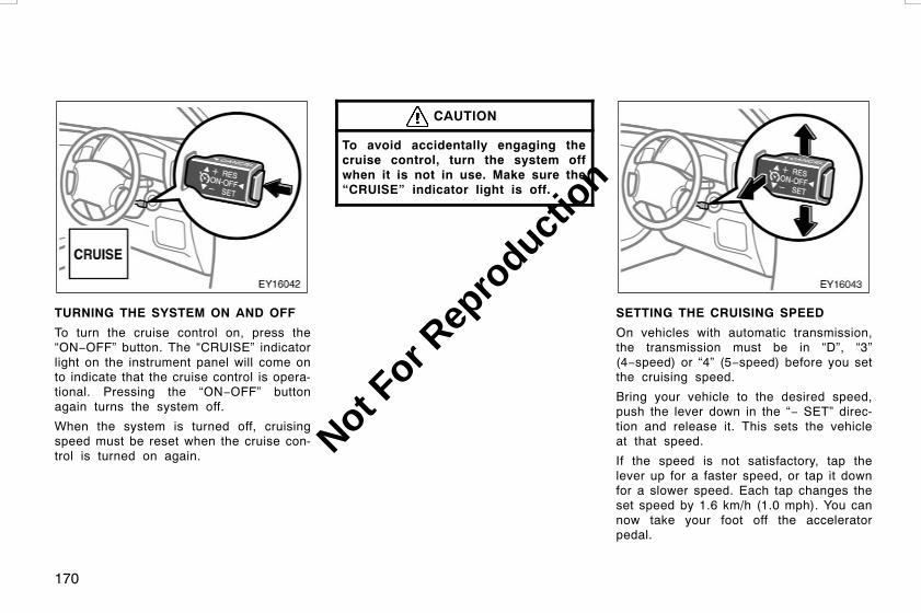
170
TURNING THE SYSTEM ON AND OFF
To turn the cruise control on, press the“ON−OFF” button. The “CRUISE” indicatorlight on the instrument panel will come onto indicate that the cruise control is opera-tional. Pressing the “ON−OFF” buttonagain turns the system off.
When the system is turned off, cruisingspeed must be reset when the cruise con-trol is turned on again.
CAUTION
To avoid accidentally engaging thecruise control, turn the system offwhen it is not in use. Make sure the“CRUISE” indicator light is off.
SETTING THE CRUISING SPEED
On vehicles with automatic transmission,the transmission must be in “D”, “3”(4−speed) or “4” (5−speed) before you setthe cruising speed.
Bring your vehicle to the desired speed,push the lever down in the “− SET” direc-tion and release it. This sets the vehicleat that speed.
If the speed is not satisfactory, tap thelever up for a faster speed, or tap it downfor a slower speed. Each tap changes theset speed by 1.6 km/h (1.0 mph). You cannow take your foot off the acceleratorpedal.
L/C120 AE (OM60D50E) 08/01/22
Not For R
epro
duction
171
If you need acceleration—for example,when passing—depress the acceleratorpedal enough for the vehicle to exceedthe set speed. When you release it, thevehicle will return to the speed set priorto the acceleration.
CAUTION
For manual transmission:
While driving with the cruise controlon, do not shift to neutral withoutdepressing the clutch pedal, as thismay cause engine racing orover−revving.
CANCELLING THE CRUISE CONTROL
The cruise control may be temporarilycancelled by the driver or by the systemitself under certain circumstances. Tempo-rary cancellation allows the set cruisingspeed to remain in memory.
The cruise control can be temporarily can-celled by doing the following:
D Pulling the lever in the “CANCEL” di-rection and releasing it
D Depressing the brake pedal
D Depressing the clutch pedal (manualtransmission)
Under certain circumstances, the cruisecontrol is temporarily cancelled:
D When vehicle speed falls below 40km/h (25 mph)
D When vehicle stability control is acti-vated
When vehicle speed drops 16 km/h (10mph) below the set speed, the cruise con-trol is cancelled and the set speed iserased from memory.
The “CRUISE” indicator light remains onto indicate that the system is still in op-eration.
To turn the cruise control off, press the“ON−OFF” button. Make sure the“CRUISE” indicator light is off.
If the cruise control automatically cancelsout other than for the above cases, haveyour vehicle checked by your Toyota deal-er at the earliest opportunity.
RESUMING THE CRUISE CONTROL
If the cruise control is temporarily can-celled, the cruising speed can be resumedby pushing the lever up in the “+ RES”direction.
Vehicle speed must be above 40 km/h (25mph).
RESETTING TO A FASTER SPEED
Push the lever up in the “+ RES” directionand hold it. Release the lever when thedesired speed is attained. While the leveris held up, the vehicle will gradually gainspeed.
However, a faster way to reset is to ac-celerate the vehicle and then push thelever down in the “− SET” direction.
RESETTING TO A SLOWER SPEED
Push the lever down in the “− SET” direc-tion and hold it. Release the lever whenthe desired speed is attained. While thelever is held down, the vehicle speed willgradually decrease.
However, a faster way to reset is to de-press the brake pedal and then push thelever down in the “− SET” direction.
On vehicles with automatic transmission,even if you downshift the transmissionfrom the “D” position to “3” (4−speed) or“4” (5−speed) with the cruise control on,engine braking will not be applied becausethe cruise control is not cancelled. To de-crease the vehicle speed, reset to a slow-er speed with the cruise control lever ordepress the brake pedal. If you use thebrake pedal, cruise control is cancelled.
L/C120 AE (OM60D50E) 08/01/22
Not For R
epro
duction

172
CRUISE CONTROL FAILURE WARNING
If the “CRUISE” indicator light flasheswhen using the cruise control, press the“ON−OFF” button to turn the system offand then press it again to turn it on.
If any of the following conditions then oc-curs, there is some trouble in the cruisecontrol system.
D The indicator light does not come on.
D The indicator light flashes again.
D The indicator light goes out after itcomes on.
If this is the case, contact your Toyotadealer and have your vehicle inspected.
L/C120 AE (OM60D50E) 08/01/22
Not For R
epro
duction

173
OPERATION OF INSTRUMENTS ANDCONTROLSAudio systemReference 174. . . . . . . . . . . . . . . . . . . . . . . . . . . . . . . . . . . . . . . . . . . . . . . . .Using your audio system 174. . . . . . . . . . . . . . . . . . . . . . . . . . . . . . . . . . . .CD (compact disc) changer 181. . . . . . . . . . . . . . . . . . . . . . . . . . . . . . . . .Audio remote controls 183. . . . . . . . . . . . . . . . . . . . . . . . . . . . . . . . . . . . . .Audio system operating hints 185. . . . . . . . . . . . . . . . . . . . . . . . . . . . . . . .
L/C120 AE (OM60D50E) 08/01/22
SECTION 1−8
Not For R
epro
duction
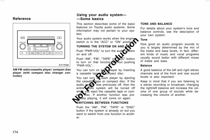
174
AM·FM radio/cassette player/ compact discplayer (with compact disc changer con-troller)
This section describes some of the basicfeatures on Toyota audio systems. Someinformation may not pertain to your sys-tem.
Your audio system works when the engineswitch is in the “ACC” or “ON” position.
TURNING THE SYSTEM ON AND OFF
Push “PWR·VOL” to turn the audio systemon and off.
Push “AM”, “FM”, “TAPE” or “DISC” buttonto turn on that function without pushing“PWR·VOL”.
You can turn on each player by insertinga cassette tape or compact disc.
You can turn off each player by ejectingthe cassette tape or compact disc. If theaudio system was previously off, then theentire audio system will be turned offwhen you eject the cassette tape or com-pact disc. If another function was pre-viously playing, it will come on again.
SWITCHING BETWEEN FUNCTIONS
Push the “AM”, “FM”, “TAPE” or “DISC”button if the system is already on but youwant to switch from one function to anoth-er.
TONE AND BALANCE
For details about your system’s tone andbalance controls, see the description ofyour own system.
Tone
How good an audio program sounds toyou is largely determined by the mix ofthe treble and bass levels. In fact, differ-ent kinds of music and vocal programsusually sound better with different mixesof treble and bass.
Balance
A good balance of the left and right stereochannels and of the front and rear soundlevels is also important.
Keep in mind that if you are listening toa stereo recording or broadcast, changingthe right/left balance will increase the vol-ume of one group of sounds while de-creasing the volume of another.
L/C120 AE (OM60D50E) 08/01/22
ReferenceUsing your audio system——Some basics
Not For R
epro
duction

175
YOUR RADIO ANTENNA
Your vehicle has an antenna printed onthe inside of each rear quarter window.
NOTICE
Putting a film (especially a conductiveor metallic film) on the rear quarterwindow will noticeably reduce thesensitivity of the radio.
YOUR CASSETTE PLAYER
When you insert a cassette, the exposedtape should face to the right.
NOTICE
Never try to disassemble or oil anypart of the cassette player. Do notinsert anything other than cassettetapes into the slot.
YOUR COMPACT DISC PLAYER
When you insert a disc, gently push it inwith label side up. The compact disc play-er will play from track 1 through to theend of the disc. Then it will play fromtrack 1 again.
NOTICE
Never try to disassemble or oil anypart of the compact disc player. Donot insert anything except other thandiscs into the slot.
8 cm (3 in.) compact disc singles
Your compact disc player does not needan adaptor to play compact disc singles.Compact disc singles are about 8 cm (3in.) in diameter−smaller than standarddiscs.
After you eject a compact disc single, donot insert a standard 12 cm (4.7 in.) discuntil “CD IN” disappears from the display.
NOTICE
Do not use an adaptor for compactdisc singles—it could cause trackingerrors or interfere with the ejection ofcompact discs.
YOUR COMPACT DISC CHANGER
Your compact disc player has a changerwhich stores up to 6 discs. To insert discsin the changer, see “CD (compact disc)changer”. The compact disc changer willplay from track 1 through the end of thedisc. Then it will play from track 1 of thenext disc.
NOTICE
Never try to disassemble or oil anypart of the compact disc player. Donot insert anything other than com-pact discs into the slot.
The changer is intended for use with 12cm (4.7 in.) discs only.
L/C120 AE (OM60D50E) 08/01/22
Not For R
epro
duction

176
Details of specific buttons, controls andfeatures are described in the alphabeticallist that follows.
L/C120 AE (OM60D50E) 08/01/22
—Controls and features
Not For R
epro
duction

177
1 2 3 4 5 6 (Preset buttons)
These buttons are used to preset andtune in radio stations.
To preset a station to a button: Tune inthe desired station. (See “TUNE” or“SEEK/TRACK”.) Push and hold down thebutton until you hear a beep—this will setthe station to the button. The button num-ber will appear on the display.
To recall a preset station: Push the buttonfor the station you want. The button num-ber and station frequency will appear onthe display.
These systems can store one AM and twoFM stations for each button. (The displaywill show “AM”, “FM1” or “FM2” when youpush the “AM” or “FM” button.)
(Eject button)
Push this button to eject a cassette. Pushthe compact disc eject button to eject acompact disc.
(Program)
Push “ ” button to select the otherside of a cassette tape. The display indi-cates which side is currently selected(“ ” indicates the top side, “ ” indi-cates the bottom side).
Auto−reverse feature: After the cassetteplayer reaches the end of a tape side, itautomatically reverses and begins to playthe other side. This is true whether thecassette was playing or fast forwarding.
(Reverse/Fast−forward button)
Cassette player
Push “ ” button to fast−forward a cas-sette tape. “FF” will appear on the display.Push “ ” button to rewind a tape.“REW” will appear on the display.
To stop the tape while it is fast−forward-ing, push “ ” or “TAPE” button. To stop
the tape while it is rewinding, push “ ”or “TAPE” button.
If a tape rewinds completely, the cassetteplayer will stop and then play that sameside. If a tape fast−forwards completely,the cassette will play the other side of thetape using the auto−reverse feature.
Compact disc player
Push and hold “ ” button or “ ” but-ton to fast forward or reverse within acompact disc. When you release the but-ton, the compact disc player will resumeplaying.
AM
Push the “AM” button to turn on the radioand select the AM band. “AM” will appearon the display.
AUDIO (Tone and sound balance adjust-ment and on/off of the automatic soundlevelizer function)
By using the “AUDIO·TUNE” knob, youcan adjust the tone and sound balanceand turn on or off ASL (Automatic SoundLevelizer) function. ASL function is de-signed to adjust the volume automaticallyaccording to the noise in the vehicle.
Each time you push the “AUDIO·TUNE”knob, the mode changes. To adjust thetone and balance and turn on or off theASL function, turn the knob.
BAS: Adjusts low−pitched tones. The dis-play ranges from −5 to 5.
TRE: Adjusts high−pitched tones. The dis-play ranges from −5 to 5.
L/C120 AE (OM60D50E) 08/01/22
Not For R
epro
duction

178
FAD: Adjusts the sound balance betweenthe front and rear speakers. The displayranges from R7 to F7.
BAL: Adjusts the sound balance betweenthe right and left speakers. The displayranges from L7 to R7.
ASL: To turn the ASL function on, turn theknob clockwise. “ASL” will appear on thedisplay. To turn the function off, turn theknob counterclockwise.
DISC (Compact disc)
Push the “DISC” button to play a compactdisc. Each time you push this button, thesystem changes between the compact discplayer and the changer of separate unit ifit is equipped.
When the audio system is set into com-pact disc operation, the display shows thetrack, or track and disc number currentlybeing played.
Error messages
If the player malfunctions, your audio sys-tem will display following error messages.
“WAIT”: The compact disc player unitmay be too hot. Allow the player to cooldown.
“ERROR 1”: The disc may be dirty, dam-aged or inserted incorrectly (up−sidedown). Clean the disc and re−insert it.
“ERROR 3”: There is a problem insidethe system. Eject the disc or magazine.Set the disc or magazine again.
“ERROR 4”: Over−current. Ask yourToyota dealer to inspect.
“CD OPEN”: The compact disc changerlid of separate unit is open. Close thecompact disc changer lid.
If the malfunction still exists, take yourvehicle to your Toyota dealer.
DISC With compact disc changer only—
Use these buttons to select the disc youwant to listen to.
Push “” (preset button 3) or “” (presetbutton 4) until the number of the disc youwant to listen appears on the display.
Dolbyr B NR*
If you are listening to a tape that wasrecorded with Dolbyr B Noise Reduction,push “ ” (preset button 3). “ ” willappear on the display. Push the buttonagain to turn off Dolbyr B NR.
The Dolby NR mode reduces tape noiseby about 10 dB. For best sound reproduc-tion, play your tapes with this button onor off according to the mode used forrecording the tape.*: Dolby noise reduction manufactured under license fromDolby Laboratories Licensing Corporation. “DOLBY” and thedouble D symbol are trademarks of Dolby LaboratoriesLicensing Corporation.
FM
Push the “FM” button to turn on the radioand select the FM band. “FM1” or “FM2”will appear on the display.
L/C120 AE (OM60D50E) 08/01/22
Not For R
epro
duction
179
MUTE
Push the “MUTE” button to turn the vol-ume off momentarily. “MUTE” will appearon the display. To cancel the mute func-tion, push this button again.
PWR·VOL (Power and Volume)
Push “PWR·VOL” to turn the audio systemon and off. Turn “PWR·VOL” to adjust thevolume.
RAND (Random)
There are two random features—You caneither listen to the tracks on one compactdisc in random order, or listen to thetracks on all the compact discs in themagazine in random order.
To play the tracks on one disc in randomorder:Quickly push and release “RAND” (presetbutton 1). “ ” will appear on thedisplay and the player will perform thetracks on the disc you are listening to inrandom order. To turn off the random fea-ture, push this button again.
With compact disc changer only—
To play all the tracks in the magazine inrandom order:Push and hold “RAND” (preset button 1)until you hear a beep. “ ” will ap-pear on the display and the player willperform all the tracks on all the discs inthe magazine in random order. To turn offthe random feature, push this buttonagain.
RPT (Repeat)
Cassette player
Push “RPT” (preset button 2) while thetrack is playing. “ ” will appear onthe display. When the track ends, it willautomatically rewind and replay. To turnoff the repeat feature, push this buttonagain.
There must be at least 3 seconds of blankspace between tracks in order for the re-peat feature to work correctly.
Compact disc player
There are two repeat features—You caneither replay a disc track or a whole com-pact disc.
Repeating a track:Quickly push and release “RPT” (presetbutton 2) while the track is playing.“ ” will appear on the display. Whenthe track ends, it will automatically replay.To turn off the repeat feature, push thisbutton again.
With compact disc changer only—
Repeating a disc:Push and hold “RPT” (preset button 2)until you hear a beep. “ ” will ap-pear on the display. The player will repeatall the tracks on the disc you are listeningto. When the disc ends, the player willautomatically go back to the first track onthe disc and replay. To turn off the repeatfeature, push this button again.
L/C120 AE (OM60D50E) 08/01/22
Not For R
epro
duction

180
SCAN
Radio
You can either scan all the frequencies ona band or scan only the preset stationsfor that band.
To scan the preset stations:Push and hold the “SCAN” button untilyou hear a beep. The radio will tune inthe next preset station up the band, staythere for 5 seconds, and then move to thenext preset station. To stop scanning,push this button again.
To scan all the frequencies:Quickly push and release the “SCAN” but-ton. The radio will find the next station upthe station band, stay there for 5 seconds,and then scan again to the next station.To stop scanning, push this button again.
Compact disc player
There are two scan features—You can ei-ther scan the tracks on a specific disc orscan the first tracks of all the discs in themagazine.
Scanning for the tracks on a disc:Quickly push and release the “SCAN” but-ton. “SCAN” will appear on the displayand the player will scan all the tracks onthe disc you are listening to. To stopscanning, push this button again. If theplayer scanned all the tracks on the disc,it will stop scanning.
With compact disc changer only—
Scanning the first tracks of all the discsin the magazine:Push the “SCAN” button until you hear abeep. “ ·SCAN” will appear on the dis-play and the player will scan the firsttrack of the next disc. To stop scanning,push this button again. If the player hasscanned all the discs, it will stop scan-ning.
SEEK/TRACK (Seeking/Track up/down)
Radio
In the seek mode, the radio finds andplays the next station up or down thestation band.
To seek the next station, quickly push andrelease “” or “” side of the “SEEK/TRACK” button. Do this again to find thestation after that.
Cassette Player
Use this button to skip up or down tolocate a song or recording.
You can select up to nine recordings (in-cluding current one).
Push the up or down side of the button.“FF 1” or “REW 1” will appear on thedisplay. Next, push either side of this but-ton until the number of tracks you wantto skip appear on the display. If you pushthe button ten times, the skip feature willbe turned off.
A blank space of at least 3 seconds isconsidered to be a start of a recording.
When the beginning of a tape is reached,the player automatically resumes play.
When the end of the tape is reached, theplayer automatically reverses sides andresumes normal play.
In addition, the feature may not work wellwith some spoken word, live, or classicalrecordings.
L/C120 AE (OM60D50E) 08/01/22
Not For R
epro
duction
181
Compact disc player
Use this button to skip up or down to adifferent track.
Push “” or “” side of the “SEEK/TRACK” button until the number of thetrack you want to listen to appears on thedisplay. If you want to return to the begin-ning of the current track, quickly push thedown side of the button one time.
ST (Stereo reception) display
Your radio automatically changes to stereoreception when a stereo broadcast is re-ceived. “ST” appears on the display. If thesignal becomes weak, the radio reducesthe amount of channel separation to prev-ent the weak signal from creating noise.If the signal becomes extremely weak, theradio switches from stereo to mono recep-tion.
TAPE
Push the “TAPE” button to play a cassettetape.
TEXT
Compact disc player only—
This button is used to change the displayfor the compact disc that contains textdata.
To change the display, quickly push andrelease the “TEXT” button while the com-pact disc is playing. The display changesin the order from the elapsed time to disctitle to track title, then back to theelapsed time.
If this button is pushed while a compactdisc that does not contain text data isplaying, “NO TITLE” will appear on thedisplay.
If the entire disc or track title does notappear on the display, push and hold thebutton until you hear a beep. The rest ofthe title will appear.
TUNE (Tuning)
Turn the “AUDIO·TUNE” knob clockwise tostep up the frequency. Turn the knobcounterclockwise to step down the fre-quency.
Some models have a compact disc chang-er which stores up to six discs. To oper-ate the compact disc player, put the com-pact discs into the magazine and set themagazine in the player.
L/C120 AE (OM60D50E) 08/01/22
CD (compact disc) changer
Not For R
epro
duction

182
Inserting compact discs
1. Pull the lever and open the glove boxdoor.
2. Slide open the cover of the CD chang-er. The magazine will come out fromthe CD changer.
3. Pull out the tray while pushing the lockrelease button.
L/C120 AE (OM60D50E) 08/01/22
Not For R
epro
duction

183
4. Place a disc on the tray with its labelface up, and insert the tray into theslot.
The magazine can store six discs of 12cm (4.7 in.).
The player will skip any empty disc trays.
5. Insert the magazine into the CD chang-er as shown above. Then close thecover of the CD changer.
The switches are installed on the left sideof the steering wheel.
“MODE” switch: Use this switch tochange the mode. If a tape or compactdisc is not inserted, the “TAPE” or “CD”mode is skipped. When you push theswitch with the audio system turned off,the audio system turns on.
“ ” switches: Use this switches to ad-just the volume. Push “+” to increase thevolume and “–” to decrease the volume.The volume continues to increase or de-crease while the switch is being pressed.
L/C120 AE (OM60D50E) 08/01/22
Audio remote controls(steering switches)
Not For R
epro
duction
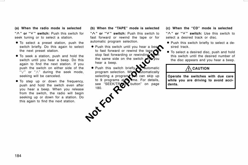
184
(a) When the radio mode is selected
“ ” or “ ” switch: Push this switch forseek tuning or to select a station.
D To select a preset station, push theswitch briefly. Do this again to selectthe next preset station.
D To seek a station, push and hold theswitch until you hear a beep. Do thisagain to find the next station. If youpush the switch on either side of the“” or “” during the seek mode,seeking will be canceled.
D To step up or down the frequency,push and hold the switch even afteryou hear a beep. When you releasefrom the switch, the radio will beginseeking up or down for a station. Dothis again to find the next station.
(b) When the “TAPE” mode is selected
“ ” or “ ” switch: Push this switch tofast forward or rewind the tape or forautomatic program selection.
D Push this switch until you hear a beepto fast forward or rewind the tape. Tostop fast forwarding or rewinding, pushthe same side on the switch until youhear a beep.
D Push this switch briefly for automaticprogram selection. When automaticallyselecting a program, you can skip upto 9 programs at a time. For details,see “SEEK/TRACK button” on page180.
(c) When the “CD” mode is selected
“ ” or “ ” switch: Use this switch toselect a desired track or disc.
D Push this switch briefly to select a de-sired track.
D To select a desired disc, push and holdthis switch until the desired number ofthe disc appears and you hear a beep.
CAUTION
Operate the switches with due carewhile you are driving to avoid acci-dents.
L/C120 AE (OM60D50E) 08/01/22
Not For R
epro
duction

185
NOTICE
To ensure correct audio system op-erations:
z Be careful not to spill beveragesover the audio system.
z Do not put anything other than acassette tape, Compact Disc andmagazine into the cassette tapeslot, Compact Disc slot or changer.
z The use of a cellular phone insideor near the vehicle may cause anoise from the speakers of the au-dio system which you are listeningto. However, this does not indicatea malfunction.
RADIO RECEPTION
FM broadcasts have a range of about 40km or 25 miles. When driving away froma station you may have to fine−tune yourradio and turn up the volume as the sta-tion gets weaker. Because FM uses aline−of−sight signal, tall buildings or hillsmay sometimes block reception. Theseare all normal characteristics of FM recep-tion and do not indicate any problem withthe radio itself.
CARING FOR YOUR CASSETTE PLAYERAND TAPES
For the best performance for your cas-sette player and tapes:
Clean the tape head and other parts regu-larly.
D A dirty tape head or tape path candecrease sound quality and tangle yourcassette tapes. The easiest way toclean them is by using a cleaning tape.(A wet type is recommended.)
Use high−quality cassettes.
D Low−quality cassette tapes can causemany problems, including poor sound,inconsistent playing speed, andconstant auto−reversing. They can alsoget stuck or tangled in the cassetteplayer.
D Do not use a cassette if it has beendamaged or tangled or if its label ispeeling off.
D Do not leave a cassette in the playerif you are not listening to it, especiallyif it is hot outside.
D Store cassettes in their cases and outof direct sunlight.
D Avoid using cassettes with a total play-ing time longer than 100 minutes (50minutes per side). The tape used inthese cassettes is thin and could getstuck or tangled in the cassette player.
L/C120 AE (OM60D50E) 08/01/22
Audio system operating hints
Not For R
epro
duction

186
CARING FOR YOUR COMPACT DISCPLAYER AND DISC
D Extremely high temperatures can keepyour compact disc player from working.On hot days, use the air conditioningto cool the vehicle interior before youlisten to a disc.
D Bumpy roads or other vibrations maymake your compact disc player skip.
D If moisture gets into your compact discplayer, you may not hear any soundeven though your compact disc playerappears to be working. Remove thedisc from the player and wait until itdries.
CAUTION
Compact disc players use an invisiblelaser beam which could cause hazard-ous radiation exposure if directedoutside the unit. Be sure to operatethe player correctly.
D Use only compact discs marked asshown above. The following productsmay not be playable on your compactdisc player.
Copy−protected CDCD−ROM
Special shaped discs
Transparent/translucent discs
L/C120 AE (OM60D50E) 08/01/22
Not For R
epro
duction

187
Low quality discs
Labeled discs
NOTICE
z Do not use special shaped, trans-parent/translucent, low quality or la-beled discs such as those shown inthe illustrations. The use of suchdiscs may damage the player orchanger, or it may be impossible toeject the disc.
z This system is not designed for useof Dual Disc. Do not use Dual Discbecause it may cause damage tothe player or changer.
Correct Wrong
D Handle compact discs carefully, espe-cially when you are inserting them.Hold them on the edge and do notbend them. Avoid getting fingerprintson them, particularly on the shiny side.
D Dirt, scratches, warping, pin holes, orother disc damage could cause theplayer to skip or to repeat a section ofa track. (To see a pin hole, hold thedisc up to the light.)
D Remove discs from the compact discplayer when you are not listening tothem. Store them in their plastic casesaway from moisture, heat, and directsunlight.
L/C120 AE (OM60D50E) 08/01/22
Not For R
epro
duction

188
To clean a compact disc: Wipe it with asoft, lint−free cloth that has been damp-ened with water. Wipe in a straight linefrom the center to the edge of the disc(not in circles). Dry it with another soft,lint−free cloth. Do not use a conventionalrecord cleaner or anti−static device.
L/C120 AE (OM60D50E) 08/01/22
Not For R
epro
duction

189
OPERATION OF INSTRUMENTS ANDCONTROLSAir conditioning systemManual air conditioning system
Controls 190. . . . . . . . . . . . . . . . . . . . . . . . . . . . . . . . . . . . . . . . . . . . . . . .Air flow selector settings 193. . . . . . . . . . . . . . . . . . . . . . . . . . . . . . . . .Operating tips 193. . . . . . . . . . . . . . . . . . . . . . . . . . . . . . . . . . . . . . . . . . .
Automatic air conditioning systemControls 196. . . . . . . . . . . . . . . . . . . . . . . . . . . . . . . . . . . . . . . . . . . . . . . .Air flow selector settings 200. . . . . . . . . . . . . . . . . . . . . . . . . . . . . . . . .Operating tips 200. . . . . . . . . . . . . . . . . . . . . . . . . . . . . . . . . . . . . . . . . . .
Instrument panel vents 203. . . . . . . . . . . . . . . . . . . . . . . . . . . . . . . . . . . . .Rear cooler system 204. . . . . . . . . . . . . . . . . . . . . . . . . . . . . . . . . . . . . . . . .Air conditioning filter 205. . . . . . . . . . . . . . . . . . . . . . . . . . . . . . . . . . . . . . . .
L/C120 AE (OM60D50E) 08/01/22
SECTION 1−9
Not For R
epro
duction

190
1. Air flow selector
2. Fan speed selector
3. Temperature selector
4. Air intake selector
5. “A/C” button (on some models)
L/C120 AE (OM60D50E) 08/01/22
Manual air conditioning system——Controls
Not For R
epro
duction

191
Fan speed selector
Turn the knob to adjust the fan speed—tothe right to increase, to the left to de-crease.
Temperature selector
Turn the knob to adjust the temperature—to the right to warm, to the left to cool.
Air flow selector
Turn the knob to select the vents used forair flow.
1. Panel—Air flows mainly from theinstrument panel vents.
2. Bi−level—Air flows from both the floorvents and the instrument panel vents.
3. Floor—Air flows mainly from the floorvents.
4. Floor/Windshield—Air flows mainlyfrom the floor vents and windshieldvents.
5. Windshield—Air flows mainly from thewindshield vents.
For details about air flow selector settings,see “—Air flow selector settings” de-scribed below.
L/C120 AE (OM60D50E) 08/01/22
Not For R
epro
duction

192
Air intake selector
Press the button to select the air source.An indicator light will illuminate to showwhich air intake mode is being selected.
1. Recirculate (indicator light is on)—Re-circulates the air inside the vehicle.
2. Fresh (indicator light is off)—Drawsoutside air into the system.
“A/C” button (on some models)
To turn on the air conditioning, press the“A/C” button. The “A/C” button indicatorwill come on. To turn the air conditioningoff, press the button again.
If the “A/C” button indicator flashes, thereis a problem in the air conditioning systemor the cool box, and the air conditioningautomatically shuts off. If this happens,take your vehicle to your Toyota dealer forservice.
L/C120 AE (OM60D50E) 08/01/22
Not For R
epro
duction

193
D To cool off your Toyota after it hasbeen parked in the hot sun, drive withthe windows open for a few minutes.This vents the hot air, allowing the airconditioning to cool the interior morequickly.
D Make sure the air intake grilles in frontof the windshield are not blocked (byleaves or snow, for example).
D Keep the area under the front seatsclear to allow air to circulate through-out the vehicle.
D On cold days, set the fan speed tohigh for a minute to help clear theintake ducts of snow or moisture. Thiscan reduce the amount of fogging onthe windows.
D When driving on dusty roads, close allwindows. If dust thrown up by the ve-hicle is still drawn into the vehicle afterclosing the windows, it is recommendedthat the air intake selector be set toFRESH and the fan speed selector toany setting except “OFF”.
L/C120 AE (OM60D50E) 08/01/22
—Air flow selector settings —Operating tips
Not For R
epro
duction

194
D If following another vehicle on a dustyroad, or driving in windy and dustyconditions, it is recommended that theair intake selector be temporarily set toRECIRCULATE, which will close off theoutside passage and prevent outsideair and dust from entering the vehicleinterior.
CAUTION
To prevent the windshield from fog-ging up, do not select the windshieldair outlets during cool air operationin extremely humid weather. The dif-ference between the temperature ofthe outside air and that of the wind-shield can cause the outer surface ofthe windshield to fog up, blockingyour vision.
NOTICE
To prevent battery discharge, do notleave the air conditioning system onlonger than necessary when the en-gine is stopped.
Heating
For best results, set controls as follow:
Fan speed—Any setting except “OFF”Temperature—Towards WARM
(red zone)Air intake—FRESH (outside air)Air flow—FLOORAir conditioning—OFF
D For quick heating, select recirculatedair for a few minutes. To keep thewindows from fogging, select fresh af-ter the vehicle interior has beenwarmed.
D Press the “A/C” button on for dehumidi-fied heating.
D Choose floor/windshield air flow to heatthe vehicle interior while defrosting ordefogging the windshield.
Air conditioning
For best results, set controls as follow:
Fan speed—Any setting except “OFF”Temperature—Towards COLD
(blue zone)Air intake—FRESH (outside air)Air flow—PANELAir conditioning—ON
D For quick cooling, select recirculatedair for a few minutes.
Ventilation
For best results, set controls as follow:
Fan speed—Any setting except “OFF”Temperature—Towards COLD
(blue zone)Air intake—FRESH (outside air)Air flow—PANELAir conditioning—OFF
L/C120 AE (OM60D50E) 08/01/22
Not For R
epro
duction
195
Defogging
The inside of the windshield
For best results, set controls as follow:
Fan speed—Any setting except “OFF”Temperature—Towards WARM
(red zone) to heat;COLD (blue zone) tocool
Air intake—FRESH (outside air)Air flow—WINDSHIELD
D On humid days, do not blow cold airon the windshield—the difference be-tween the outside and inside tempera-tures could make the fogging worse.
Defrosting
The outside of the windshield
For best results, set controls as follow:
Fan speed—Any setting except “OFF”Temperature—Towards WARM
(red zone)Air intake—FRESH (outside air)Air flow—WINDSHIELD
D To heat the vehicle interior while de-frosting the windshield, choosefloor/windshield air flow.
L/C120 AE (OM60D50E) 08/01/22
Not For R
epro
duction

196
1. Windshield air flow button
2. “OFF” button
3. “AUTO” button
4. Temperature selector(At the independent mode: Mainly fordriver and secondarily for front passen-ger)(At the linked mode: For driver)
5. Air intake selector
6. Fan speed selector
7. “MODE” button (air flow selector)
8. “A/C” button
9. “DUAL” button
10. Temperature selector(At the independent mode: For frontpassenger)
L/C120 AE (OM60D50E) 08/01/22
Automatic air conditioning system——Controls
Not For R
epro
duction

197
“AUTO” button
For automatic operation of the air condi-tioning, press the “AUTO” button. An indi-cator light will illuminate to show that theautomatic operation mode has been se-lected.
In the automatic operation mode, the airconditioning selects the most suitable fanspeed, air flow, air intake and on−off ofthe air conditioning according to the tem-perature.
When you press the “AUTO” button withthe air intake mode at FRESH, internalcirculation may be applied for maximumcooling.
You may use manual controls if you wantto select your own settings.
Fan speed selector
Push the “>” (increase) or “<” (decrease)side of the button to adjust the fan speed.
In automatic operation, you do not haveto adjust the fan speed unless you desireanother fan speed mode.
Temperature selector
To increase the temperature, press the“” side, to decrease it, press the “”side.
“MAX. COLD” appears when you adjust tomaximum cooling, and “MAX. HOT” whenyou adjust to maximum warming.
“DUAL” button
This switch is used to set the tempera-tures independently for the driver’s seatand front passenger seat.
Pushing the button changes the modefrom independent and linked.
Independent mode: Temperatures can beset independently for the driver’s seat andfront passenger’s seat. An indicator lightwill illuminate to show that the indepen-dent mode has been selected.
Linked mode: The same temperature isset for the driver’s seat and front passen-ger’s seat.
When the temperature for the front pas-senger’s seat is changed in linked mode,the mode is changed automatically to in-dependent mode.
“OFF” button
Push the “OFF” button to turn off the airconditioning system.
Vehicles with cool box—The air conditioning system cannot beturned off while the cool box is on.When the cool box is off, the air condi-tioning system can be turned off by press-ing the “OFF” button.
L/C120 AE (OM60D50E) 08/01/22
Not For R
epro
duction

198
“MODE” button (air flow selector)
Push the “MODE” button to select thevents used for air flow.
In automatic operation, you do not haveto select the air flow unless you desireanother air flow mode.
1. Panel—Air flows mainly from theinstrument panel vents.
2. Bi−level—Air flows from both the floorvents and the instrument panel vents.
3. Floor—Air flows mainly from the floorvents.
4. Floor/Windshield—Air flows mainlyfrom the floor vents and windshieldvents.
For details about air flow selector settings,see “—Air flow selector settings” de-scribed below.
Windshield air flow button
When this button is pressed, air flowsmainly from the windshield vents andturns on the defogging function with thepurpose of clearing the front view.
Pressing this button once again returnsthe air flow mode to the last one used.
Pressing the windshield button turns onthe defroster−linked air conditioning. Atthis time, the “A/C” button indicator comeson regardless of whether or not the “A/C”button is pressed in. This is to clean upthe front view more quickly.
To turn off the air conditioning alone,press the “A/C” button once again.
L/C120 AE (OM60D50E) 08/01/22
Not For R
epro
duction
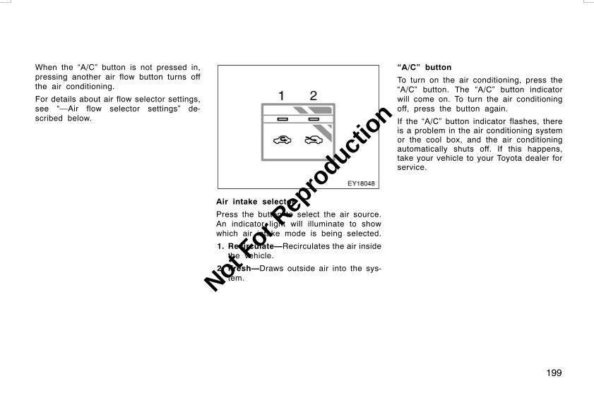
199
When the “A/C” button is not pressed in,pressing another air flow button turns offthe air conditioning.
For details about air flow selector settings,see “—Air flow selector settings” de-scribed below.
Air intake selector
Press the button to select the air source.An indicator light will illuminate to showwhich air intake mode is being selected.
1. Recirculate—Recirculates the air insidethe vehicle.
2. Fresh—Draws outside air into the sys-tem.
“A/C” button
To turn on the air conditioning, press the“A/C” button. The “A/C” button indicatorwill come on. To turn the air conditioningoff, press the button again.
If the “A/C” button indicator flashes, thereis a problem in the air conditioning systemor the cool box, and the air conditioningautomatically shuts off. If this happens,take your vehicle to your Toyota dealer forservice.
L/C120 AE (OM60D50E) 08/01/22
Not For R
epro
duction
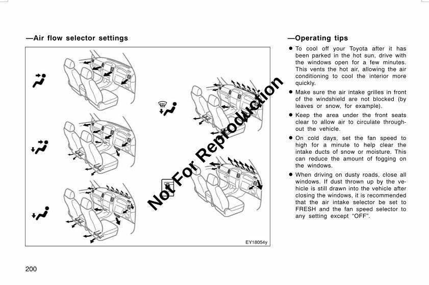
200
D To cool off your Toyota after it hasbeen parked in the hot sun, drive withthe windows open for a few minutes.This vents the hot air, allowing the airconditioning to cool the interior morequickly.
D Make sure the air intake grilles in frontof the windshield are not blocked (byleaves or snow, for example).
D Keep the area under the front seatsclear to allow air to circulate through-out the vehicle.
D On cold days, set the fan speed tohigh for a minute to help clear theintake ducts of snow or moisture. Thiscan reduce the amount of fogging onthe windows.
D When driving on dusty roads, close allwindows. If dust thrown up by the ve-hicle is still drawn into the vehicle afterclosing the windows, it is recommendedthat the air intake selector be set toFRESH and the fan speed selector toany setting except “OFF”.
L/C120 AE (OM60D50E) 08/01/22
—Air flow selector settings —Operating tips
Not For R
epro
duction

201
D If following another vehicle on a dustyroad, or driving in windy and dustyconditions, it is recommended that theair intake selector be temporarily set toRECIRCULATE, which will close off theoutside passage and prevent outsideair and dust from entering the vehicleinterior.
CAUTION
To prevent the windshield from fog-ging up, do not use the windshieldair flow button during cool air opera-tion in extremely humid weather. Thedifference between the temperature ofthe outside air and that of the wind-shield can cause the outer surface ofthe windshield to fog up, blockingyour vision.
NOTICE
To prevent battery discharge, do notleave the air conditioning system onlonger than necessary when the en-gine is stopped.
Heating
For best results, set controls as follow:
—For automatic operation
Press in the “AUTO” button.Temperature—To the desired
temperatureAir intake—FRESH (outside air)Air conditioning—OFF
—For manual operation
Fan speed—To the desired fan speedTemperature—Towards high temperatureAir intake—FRESH (outside air)Air flow—FLOORAir conditioning—OFF
D For quick heating, select recirculatedair for a few minutes. To keep thewindows from fogging, select fresh af-ter the vehicle interior has beenwarmed.
D Press the “A/C” button on for dehumidi-fied heating.
D Choose floor/windshield air flow to heatthe vehicle interior while defrosting ordefogging the windshield.
Air conditioning
For best results, set controls as follow:
—For automatic operation
Press in the “AUTO” button.Temperature—To the desired
temperatureAir intake—FRESH (outside air)Air conditioning—ON
—For manual operation
Fan speed—To the desired fan speedTemperature—Towards low temperatureAir intake—FRESH (outside air)Air flow—PANELAir conditioning—ON
D For quick cooling, select recirculatedair for a few minutes.
L/C120 AE (OM60D50E) 08/01/22
Not For R
epro
duction

202
Ventilation
For best results, set controls as follow:
—For automatic operation
Press in the “AUTO” button.Temperature—Towards low temperatureAir intake—FRESH (outside air)Air conditioning—OFF
—For manual operation
Fan speed—To the desired fan speedTemperature—Towards low temperatureAir intake—FRESH (outside air)Air flow—PANELAir conditioning—OFF
Defogging and defrosting
—The inside of the windshield
For best results, set controls as follow:
—For automatic operation
Press in the “AUTO” button.Temperature—Towards high temperature
to heat; low temperatureto cool
Air intake—FRESH (outside air)Air flow—WINDSHIELD
—For manual operation
Fan speed—To the desired fan speedTemperature—Towards high temperature
to heat; low temperatureto cool
Air intake—FRESH (outside air)Air flow—WINDSHIELD
Pressing the windshield air flow buttonturns on the defogging function with thepurpose of clearing the front view.
Pressing the windshield button turns onthe defroster−linked air conditioning. Atthis time, the “A/C” button indicator comeson regardless of whether or not the “A/C”button is pressed in. This is to clean upthe front view more quickly.
To turn off the air conditioning alone,press the “A/C” button once again.
When the “A/C” button is not pressed in,pressing another air flow button turns offthe air conditioning.
D On humid days, do not blow cold airon the windshield—the difference be-tween the outside and inside tempera-tures could make the fogging worse.
—The outside of the windshield
For best results, set controls as follow:
—For automatic operation
Press in the “AUTO” button.Temperature—Towards high temperatureAir intake—FRESH (outside air)Air flow—WINDSHIELD
—For manual operation
Fan speed—To the desired fan speedTemperature—Towards high temperatureAir intake—FRESH (outside air)Air flow—WINDSHIELD
Pressing the windshield air flow buttonturns on the defrosting function with thepurpose of clearing the front view.
L/C120 AE (OM60D50E) 08/01/22
Not For R
epro
duction

203
Pressing the windshield button turns onthe defroster−linked air conditioning. Atthis time, the “A/C” button indicator comeson regardless of whether or not the “A/C”button is pressed in. This is to clean upthe front view more quickly.
To turn off the air conditioning alone,press the “A/C” button once again.
When the “A/C” button is not pressed in,pressing another air flow button turns offthe air conditioning.
D To heat the vehicle interior while de-frosting the windshield, choosefloor/windshield air flow. Side vents
Center vents
If air flow control is not satisfactory, checkthe instrument panel vents. The instrumentpanel vents may be opened or closed asshown.
L/C120 AE (OM60D50E) 08/01/22
Instrument panel vents
Not For R
epro
duction

204
1. Temperature selector
This knob is used to adjust the tempera-ture of the cooled air.
Turn the knob to the left to lower thetemperature. You can adjust the tempera-ture of the rear cooler system to 5_Cof the temperature of the front cooler sys-tem.
2. Fan speed selector
Turn the knob to adjust the fan speed.
Switchposition
AUTO LO−HI
Fanspeed
Automaticallyadjusted
Decrease↔Increase
In “AUTO” position, the fan speed can beautomatically adjusted only when the airflow selector in the front air conditioningsystem is set in the face position.
3. Main switch
Push the switch to turn on or off the rearcooler system with front air conditioningon.
When you turn the rear cooler on with thefront air conditioning off, the cooling de-vice is not operated.
L/C120 AE (OM60D50E) 08/01/22
Rear cooler system
Not For R
epro
duction
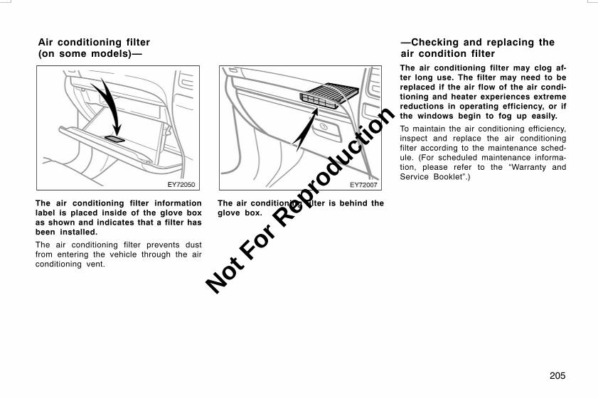
205
The air conditioning filter informationlabel is placed inside of the glove boxas shown and indicates that a filter hasbeen installed.
The air conditioning filter prevents dustfrom entering the vehicle through the airconditioning vent.
The air conditioning filter is behind theglove box.
The air conditioning filter may clog af-ter long use. The filter may need to bereplaced if the air flow of the air condi-tioning and heater experiences extremereductions in operating efficiency, or ifthe windows begin to fog up easily.
To maintain the air conditioning efficiency,inspect and replace the air conditioningfilter according to the maintenance sched-ule. (For scheduled maintenance informa-tion, please refer to the “Warranty andService Booklet”.)
L/C120 AE (OM60D50E) 08/01/22
Air conditioning filter(on some models)—
—Checking and replacing theair condition filter
Not For R
epro
duction
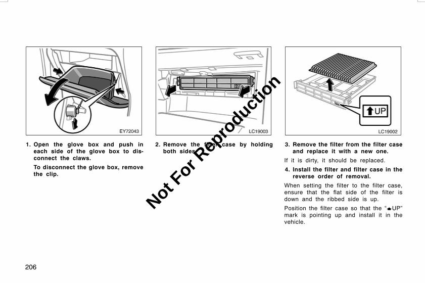
206
1. Open the glove box and push ineach side of the glove box to dis-connect the claws.
To disconnect the glove box, removethe clip.
LC19003
2. Remove the filter case by holdingboth sides.
LC19002
3. Remove the filter from the filter caseand replace it with a new one.
If it is dirty, it should be replaced.
4. Install the filter and filter case in thereverse order of removal.
When setting the filter to the filter case,ensure that the flat side of the filter isdown and the ribbed side is up.
Position the filter case so that the “yUP”mark is pointing up and install it in thevehicle.
L/C120 AE (OM60D50E) 08/01/22
Not For R
epro
duction

207
INFORMATION
The air filter should be installed prop-erly in position. The use of air condi-tioning with the air filter removedmay cause deteriorated dustproof per-formance and then affect air condi-tioning performance.
L/C120 AE (OM60D50E) 08/01/22
Not For R
epro
duction

208
L/C120 AE (OM60D50E) 08/01/22
Not For R
epro
duction

209
OPERATION OF INSTRUMENTS ANDCONTROLSOther equipmentClock 210. . . . . . . . . . . . . . . . . . . . . . . . . . . . . . . . . . . . . . . . . . . . . . . . . . . . . .Outside temperature display 210. . . . . . . . . . . . . . . . . . . . . . . . . . . . . . . .Multi−information display 211. . . . . . . . . . . . . . . . . . . . . . . . . . . . . . . . . . .Cigarette lighter and ashtrays 221. . . . . . . . . . . . . . . . . . . . . . . . . . . . . . .Power outlets 222. . . . . . . . . . . . . . . . . . . . . . . . . . . . . . . . . . . . . . . . . . . . . .Glove box 223. . . . . . . . . . . . . . . . . . . . . . . . . . . . . . . . . . . . . . . . . . . . . . . . .Auxiliary boxes 223. . . . . . . . . . . . . . . . . . . . . . . . . . . . . . . . . . . . . . . . . . . . .Tie−down hooks 224. . . . . . . . . . . . . . . . . . . . . . . . . . . . . . . . . . . . . . . . . . . .Mesh pocket 225. . . . . . . . . . . . . . . . . . . . . . . . . . . . . . . . . . . . . . . . . . . . . . .Front cup holders 225. . . . . . . . . . . . . . . . . . . . . . . . . . . . . . . . . . . . . . . . . .Rear cup holders 226. . . . . . . . . . . . . . . . . . . . . . . . . . . . . . . . . . . . . . . . . . .Console box 226. . . . . . . . . . . . . . . . . . . . . . . . . . . . . . . . . . . . . . . . . . . . . . .Tissue pocket 227. . . . . . . . . . . . . . . . . . . . . . . . . . . . . . . . . . . . . . . . . . . . . .Cool box 227. . . . . . . . . . . . . . . . . . . . . . . . . . . . . . . . . . . . . . . . . . . . . . . . . . .Floor mat 228. . . . . . . . . . . . . . . . . . . . . . . . . . . . . . . . . . . . . . . . . . . . . . . . . .
L/C120 AE (OM60D50E) 08/01/22
SECTION 1−10
Not For R
epro
duction

210
To reset the hour: Push the “H” button.To reset the minutes: Push the “M” button.
The key must be in the “ACC” or “ON”position.
If the electrical power source has beendisconnected from the clock, the time dis-play will automatically be set to 1:00 (oneo’clock).
When the instrument panel lights areturned on, the brightness of the time in-dication will be reduced.
The displayed temperature ranges from−30_C (−22_F) up to 50_C (122_F).
The key must be in the “ON” position.
If some abnormality exist in theconnection of the outside air temperaturesensor, “−−” will appear on the display. If“−−” appears on the display, contact yourToyota dealer.
There may be a case that “−−” appearsmomentarily when the engine switch isquickly turned to “ON”. It is normal if itgoes out soon.
L/C120 AE (OM60D50E) 08/01/22
Clock Outside temperature display
Not For R
epro
duction
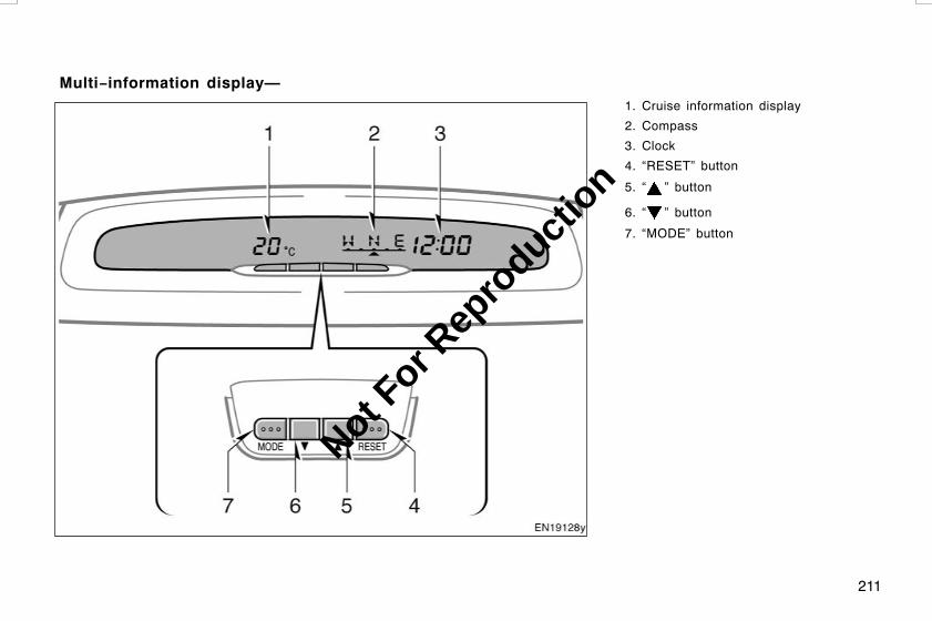
211
1. Cruise information display
2. Compass
3. Clock
4. “RESET” button
5. “ ” button
6. “ ” button
7. “MODE” button
L/C120 AE (OM60D50E) 08/01/22
Multi−information display—
Not For R
epro
duction

212
The multi−information display providesvarious information such as the follow-ings.
1. Clock (For details, see “—Clock” onpage 213 in this Section.)
2. Cruise information (For details, see“—Cruise information display” onpage 213 in this Section.)
3. Compass (For details, see “—Com-pass” on page 217 in this Section.)
When the engine switch is turned to the“ON” position, the last mode displayed justbefore the engine switch was turned offwill appear.
If the electrical power source has beendisconnected from the multi−informationdisplay, the display will automatically beset to the initial mode.
When the instrument panel lights areturned on, the brightness of the displaywill be reduced.
You can adjust the brightness of thedisplay. To adjust the brightness, see“ADJUSTING THE BRIGHTNESS OF THEDISPLAY”.
CAUTION
Do not operate the buttons while thevehicle is moving. Make sure to oper-ate the buttons when the vehicle isstopped.
ADJUSTING THE BRIGHTNESS OF THEDISPLAY
The key must be in the “ACC” or “ON”position. To adjust the brightness of thedisplay, push and hold the “MODE” buttonfor more than 2 seconds. “ILL” will appearon the display.
To increase the brightness—Push the “ ”button.To decrease the brightness—Push the“ ” button.
You can adjust the brightness to 3 levels(when the tail lights are off) or 6 levels(when the tail lights are on).
After adjusting, the display automaticallyreturn to the previous display.
L/C120 AE (OM60D50E) 08/01/22
Not For R
epro
duction

213
The digital clock indicates the timewhen the key is in the “ACC” or “ON”.
To reset the time, push and hold the“MODE” button for 2 seconds. “ILL” willappear on the display. Then push the“MODE” button once. The time will blink.
To reset the hour: Push the “ ” button.To reset the minutes: Push the “ ” butto-n.
To adjust the time to the nearest hour,push the “RESET” button. For example, ifthe “RESET” button is depressed whenthe time is between 1:01−1:29, the timewill change to 1:00. If the time is between1:30−1:59, the time will change to 2:00.
If the electric power source has been dis-connected, the time display will automati-cally be set to 1:00.
The display indicates the following in-formation when the key is in the “ON”position.
Every time you push the “MODE” button,the display toggles through this informa-tion.
1. Outside temperature mode
2. Average fuel consumption mode
3. Instantaneous fuel consumption mode
4. Driving range mode
5. Average vehicle speed mode
6. Barometer mode
7. Altimeter mode
8. Elapsed time mode
The displayed values in the cruise infor-mation display indicate general drivingconditions. Accuracy varies with drivinghabits and road conditions.
L/C120 AE (OM60D50E) 08/01/22
—Clock —Cruise information display
Not For R
epro
duction

214
1. Outside temperature mode (“_C”)
In outside temperature mode, outsideair temperatures are displayed.
The displayed value is updated every 1second.
The displayed temperature ranges from−30_C (−22_F) up to 50_C (122_F).
If there is some abnormality in theconnection of the outside air temperaturesensor, “−−” will appear on the display. If“−−” appears on the display, contact yourToyota dealer.
In some cases, “−−” may appear momen-tarily when the engine switch is quicklyturned to “ON”. It is normal if it goes outsoon.
2. Average fuel consumption mode(“AVG. L/100km”)
Average fuel consumption is calculatedand displayed based on the total driv-ing distance and total fuel consumptionwith the engine running.
The displayed value is updated every 10seconds.
To reset the calculations, push and holdthe “RESET” button for more than 1 sec-ond.
3. Instantaneous fuel consumptionmode (“L/100km”)
Instantaneous fuel consumption is cal-culated and displayed based on dis-tance and fuel consumption for 2 sec-onds with the engine running.
The displayed value is updated every 2seconds.
Note that an accurate figure may not beshown in the following cases.
D When the vehicle is stopped with theengine running, the display will indicateextremely high fuel consumption.
L/C120 AE (OM60D50E) 08/01/22
Not For R
epro
duction

215
D When the vehicle is driving down along slope with the engine brake ap-plied, the display will indicate extremelylow fuel consumption.
4. Driving range mode (“RANGE km”)
The distance the vehicle can travel withthe remaining fuel is calculated anddisplayed based on the quantity of re-maining fuel and past fuel consumption.
The driving range display indicates theapproximate distance that you can driveuntil the fuel gauge reaches “E” or “R”. Itis different from the actual distance trav-eled.
The displayed value is updated every timewhen the fuel required to travel 1 km (0.6miles) is consumed.
Every time you refuel the vehicle, the cal-culation is reset. However, when only asmall amount of fuel is added to the tank,the display may not be reset.
The actual driving range varies with driv-ing habits and road conditions. If fuel con-sumption is good, the driving range will belonger. If fuel consumption is poor, thedriving range will be shorter.
If the low fuel level warning light comeson, refuel even if the display indicatesthat the vehicle can be driven further.
L/C120 AE (OM60D50E) 08/01/22
Not For R
epro
duction

216
5. Average vehicle speed mode(“AVG. km/h”)
Average vehicle speed is calculated anddisplayed based on total driving dis-tance and total driving time with theengine running.
The displayed value is updated every 10seconds.
To reset the calculations, push and holdthe “RESET” button for more than 1 sec-ond.
6. Barometer mode(“BARO hPa”)
In barometer mode, the atmosphericpressure in the vehicle is displayed.
The displayed atmospheric pressureranges from 600 hPa up to 1050 hPa.
The displayed value is updated every 2seconds.
The displayed value may deviate from theactual atmospheric pressure depending onopening or closing of the windows anddoors and the driving conditions.
7. Altimeter mode (“ALTI m”)
In altimeter mode, the approximate alti-tude is displayed.
The displayed altitude ranges from −500m (−1641 ft.) up to 4000 m (13124 ft.).
As the altitude value is converted from theatmospheric pressure, it can be easily af-fected by air motion and temperature, sothe indication may vary. The indicated alti-tude of a single position may deviate ac-cording to the atmospheric pressure andtemperature.
The displayed value is updated every 2seconds.
L/C120 AE (OM60D50E) 08/01/22
Not For R
epro
duction

217
RECTIFICATION OF THE ALTITUDE
Rectification is valid only when the correctaltitude is known. While the altitude modeis on the display, push the “ ” or “ ”button to increase or decrease the altitudeby 10 m (32.8 ft.).
To reset the rectified altitude, push andhold the “RESET” button for more than 1second.
8. Elapsed time mode (“E/T”)
The time that has elapsed since theengine start is displayed.
When the engine is started, driving timeis counted from 0:00. Up to 19:59 (19hours, 59 minutes) can be displayed.When the driving time exceeds 19:59, thecounter returns to 0:00.
To reset the calculations, push and holdthe “RESET” button for more than 1 sec-ond.
The compass indicates the direction inwhich the vehicle is heading. In theabove case, it shows that the vehicle isheading north.
Display Directions
NESW
NorthEastSouthWest
L/C120 AE (OM60D50E) 08/01/22
—Compass
Not For R
epro
duction

218
The compass may not show the correctdirection under the following conditions:
D The vehicle is stopped immediately af-ter turning.
The compass does not adjust while thevehicle is stopped.
D The engine switch is turned off immedi-ately after turning.
D The vehicle is on an inclined surface.
D The vehicle is in a place where theearth’s magnetic field is subject to in-terference by artificial magnetic fields(underground parking, under a steeltower, between buildings, roof parking,near a crossing, near a large vehicle,etc.).
D The vehicle is magnetized. (There is amagnet or a metal object on or nearthe multi−information display.)
D The battery has been disconnected.
If the deviation is small, the compassworks to calibrate the direction automati-cally while the vehicle is in motion.
For additional precision or for completecalibrating, see “CALIBRATING THECOMPASS”.
Compass sensor
The compass sensor is behind the mul-ti−information display.
NOTICE
Do not put magnets or a metal objecton or near the multi−information dis-play. Doing so may cause malfunctionof the compass sensor.
If the vehicle is magnetized, the compassdoes not show the correct direction andthe compass display blinks as shown.However, if the compass works to rectifythe direction automatically during driving,the blinking of the compass display will bestopped. For additional precision of thedirection, and for an earlier completion ofthe rectification, rectify the directionmanually. For detailed information, see“CALIBRATING THE COMPASS” thatfollows.
L/C120 AE (OM60D50E) 08/01/22
Not For R
epro
duction

219
CALIBRATING THE COMPASS (deviationcalibration)
The direction display on the compassdeviates from the true direction deter-mined by the earth’s magnetic field. Theangle of deviation varies according to thegeographic position of the vehicle.
To adjust this deviation, stop the vehicleand push and hold the “MODE” button formore than 2 seconds. “ILL” will appear onthe display. Then push the “MODE” buttontwo times. The zone number appears andblinks on the display. Select the zonenumber by pushing the “ ” or “ ” but-ton, referring to the following map to de-termine where the vehicle is.
Zone numbers
L/C120 AE (OM60D50E) 08/01/22
Not For R
epro
duction

220
After calibration, leave the system for 6seconds or push and hold the “MODE”button for more than 2 seconds. The dis-play will return to compass mode.
CAUTION
Do not adjust the display while thevehicle is moving. Be sure to adjustthe display only when the vehicle isstopped.
CALIBRATING THE COMPASS (circlingcalibration)
Sometimes the direction display on thecompass may not change after a turn. Torectify this, stop the vehicle and do asfollows.
1. Push and hold the “MODE” button formore than 2 seconds. “ILL” will appearon the display. Then push the “MODE”button three times. The “NNNNN” ap-pears on the display.
2. Push the “RESET” button. “NNNNN”will start blinking.
3. Drive the vehicle in a circle until theblinking stops.
If there is not enough space to drivein a circle, drive around the block untilthe blinking stops.
When the compass display returns to nor-mal mode, calibration is complete.
If you want to cancel the calibration be-fore it is complete, push the “MODE” but-ton again.
L/C120 AE (OM60D50E) 08/01/22
Not For R
epro
duction
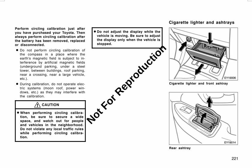
221
Perform circling calibration just afteryou have purchased your Toyota. Thenalways perform circling calibration afterthe battery has been removed, replacedor disconnected.
D Do not perform circling calibration ofthe compass in a place where theearth’s magnetic field is subject to in-terference by artificial magnetic fields(underground parking, under a steeltower, between buildings, roof parking,near a crossing, near a large vehicle,etc.).
D During calibration, do not operate elec-tric systems (moon roof, power win-dows, etc.) as they may interfere withthe calibration.
CAUTION
DWhen performing circling calibra-tion, be sure to secure a widespace, and watch out for peopleand vehicles in the neighborhood.Do not violate any local traffic ruleswhile performing circling calibra-tion.
D Do not adjust the display while thevehicle is moving. Be sure to adjustthe display only when the vehicle isstopped.
Cigarette lighter and front ashtray
Rear ashtray
L/C120 AE (OM60D50E) 08/01/22
Cigarette lighter and ashtrays
Not For R
epro
duction

222
CIGARETTE LIGHTER
To use the cigarette lighter, press it in.After it finishes heating up, it automati-cally pops out ready for use.
If the engine is not running, the key mustbe in the “ACC” position.
Do not hold the cigarette lighter pressedin.
Use a Toyota genuine cigarette lighter orequivalent for replacement.
ASHTRAYS
Front: To use the ashtray, pull it out.Rear: To use the ashtray, raise the lid.
When finished with your cigarette, thor-oughly extinguish it in the ashtray to pre-vent other cigarette butts from catchingfire. After using the ashtray, close the lidcompletely.
Front—To remove the ashtray, press downon the lock spring plate and pull out.
Rear—To remove the ashtray, pull it out.
CAUTION
To reduce the chance of injury incase of an accident or sudden stopwhile driving, always completely closethe ashtray after use.
Front
Rear
The power outlets are designed forpower supply for car accessories.
The key must be in the “ACC” or “ON”position for the power outlets to be used.
NOTICE
z To prevent the fuse from beingblown, do not use the electricityover the total vehicle capacity of12V/120W (front and rear outlets to-gether).
z To prevent the battery from beingdischarged, do not use the poweroutlets longer than necessary whenthe engine is not running.
z Close the power outlet lids whenthe power outlets are not in use.Inserting anything other than an ap-propriate plug that fits the outlet,or allowing any liquid to get intothe outlet may cause electrical fail-ure or short circuits.
L/C120 AE (OM60D50E) 08/01/22
Power outlets
Not For R
epro
duction

223
To use the glove box:
Open by pulling the lever.
Lock by inserting the master key and turn-ing it clockwise.
Unlock by inserting the master key andturning it counterclockwise.
CAUTION
To reduce the chance of injury incase of an accident or a sudden stop,always keep the glove box doorclosed while driving.
On some models, an auxiliary box islocated inside the glove box.
To use the auxiliary boxes, open thelids as shown in the following illustra-tions.
CAUTION
D To reduce the chance of injury incase of an accident or a suddenstop, always keep the auxiliary boxclosed while driving.
D Type A—As this holder is designedfor holding a light object such asan glasses, do not place any heavyobjects in them. Heavy objects maycause the holder to open and thecontents to fly out resulting in inju-ries.
NOTICE
Type A—During hot weather, the inte-rior of the vehicle becomes very hot.Do not leave anything flammable ordeformable such as a lighter, glasses,etc. inside.
L/C120 AE (OM60D50E) 08/01/22
Glove box Auxiliary boxes—
Not For R
epro
duction
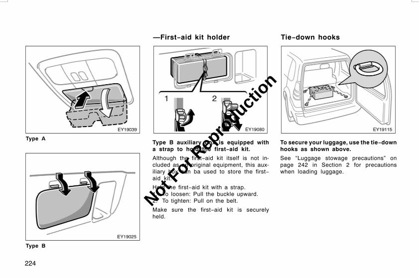
224
Type A
Type B
Type B auxiliary box is equipped witha strap to hold the first−aid kit.
Although the first−aid kit itself is not in-cluded as an original equipment, this aux-iliary box can ba used to store the first−aid kit.
Hold the first−aid kit with a strap.1. To loosen: Pull the buckle upward.2. To tighten: Pull on the belt.
Make sure the first−aid kit is securelyheld.
To secure your luggage, use the tie−downhooks as shown above.
See “Luggage stowage precautions” onpage 242 in Section 2 for precautionswhen loading luggage.
L/C120 AE (OM60D50E) 08/01/22
—First−aid kit holder Tie−down hooks
Not For R
epro
duction

225
The inside of back door is equippedwith a mesh pocket.
Although the warning reflector is not in-cluded as a standard equipment, thismesh pocket can be used to store thewarning reflector.
Hold the warning reflector with a strap.
Make sure the warning reflector is secure-ly held.
The cup holders are designed for hold-ing cups or drink−cans securely.
The cup holder can be adjustable to thesize of the cups by changing the separa-tor position or moving the separator arms.
CAUTION
Do not place anything else other thancups or drink−cans on the cup holder,as such items may be thrown aboutin the compartment and possibly in-jure people in the vehicle during asudden braking or in an accident. Ifpossible, cover hot drinks to preventburns.
NOTICE
Do not slide the console box lid if thecup holder is in use. The drink maybe thrown about in the compartmentor the holder may be damaged.
L/C120 AE (OM60D50E) 08/01/22
Mesh pocket Front cup holders
Not For R
epro
duction

226
Type A
Type B
The cup holders are designed for hold-ing cups or drink−cans securely.
Type A—To use the holder, pull the arm-rest out and push the lid.
CAUTION
D Do not place anything else otherthan cups or drink−cans on the cupholder, as such items may bethrown about in the compartmentand possibly injure people in thevehicle during a sudden braking orin an accident. If possible, coverhot drinks to prevent burns.
D Type A—To reduce the chance ofinjury in case of an accident orsudden stop while driving, keep thecup holder closed when not in use.
D Type A—Do not lift the armrest up-right when the cup holder is pulledout.
To open or slide the console box lid,pull up on the lock release lever.
L/C120 AE (OM60D50E) 08/01/22
Rear cup holders Console box
Not For R
epro
duction
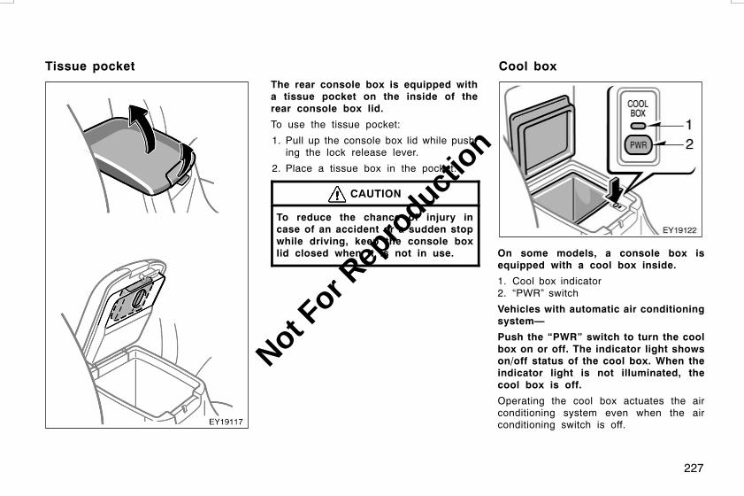
227
The rear console box is equipped witha tissue pocket on the inside of therear console box lid.
To use the tissue pocket:
1. Pull up the console box lid while push-ing the lock release lever.
2. Place a tissue box in the pocket.
CAUTION
To reduce the chance of injury incase of an accident or a sudden stopwhile driving, keep the console boxlid closed when it is not in use. On some models, a console box is
equipped with a cool box inside.
1. Cool box indicator2. “PWR” switch
Vehicles with automatic air conditioningsystem—
Push the “PWR” switch to turn the coolbox on or off. The indicator light showson/off status of the cool box. When theindicator light is not illuminated, thecool box is off.
Operating the cool box actuates the airconditioning system even when the airconditioning switch is off.
L/C120 AE (OM60D50E) 08/01/22
Tissue pocket Cool box
Not For R
epro
duction
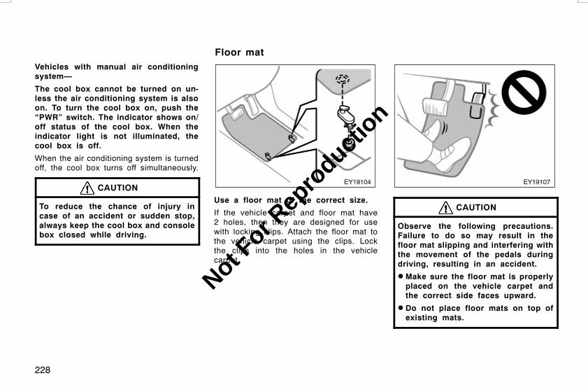
228
Vehicles with manual air conditioningsystem—
The cool box cannot be turned on un-less the air conditioning system is alsoon. To turn the cool box on, push the“PWR” switch. The indicator shows on/off status of the cool box. When theindicator light is not illuminated, thecool box is off.
When the air conditioning system is turnedoff, the cool box turns off simultaneously.
CAUTION
To reduce the chance of injury incase of an accident or sudden stop,always keep the cool box and consolebox closed while driving.
Use a floor mat of the correct size.
If the vehicle carpet and floor mat have2 holes, then they are designed for usewith locking clips. Attach the floor mat tothe vehicle carpet using the clips. Lockthe clips into the holes in the vehiclecarpet.
CAUTION
Observe the following precautions.Failure to do so may result in thefloor mat slipping and interfering withthe movement of the pedals duringdriving, resulting in an accident.
D Make sure the floor mat is properlyplaced on the vehicle carpet andthe correct side faces upward.
D Do not place floor mats on top ofexisting mats.
L/C120 AE (OM60D50E) 08/01/22
Floor mat
Not For R
epro
duction

229
INFORMATION BEFORE DRIVING YOURTOYOTAOff−road vehicle precautions 230. . . . . . . . . . . . . . . . . . . . . . . . . . . . . . . .Break−in period 231. . . . . . . . . . . . . . . . . . . . . . . . . . . . . . . . . . . . . . . . . . . .Fuel 231. . . . . . . . . . . . . . . . . . . . . . . . . . . . . . . . . . . . . . . . . . . . . . . . . . . . . . .Fuel pump shut off system 232. . . . . . . . . . . . . . . . . . . . . . . . . . . . . . . . . .Operation in foreign countries 233. . . . . . . . . . . . . . . . . . . . . . . . . . . . . . .Three−way catalytic converters 233. . . . . . . . . . . . . . . . . . . . . . . . . . . . .Catalytic converter 234. . . . . . . . . . . . . . . . . . . . . . . . . . . . . . . . . . . . . . . . .Engine exhaust cautions 235. . . . . . . . . . . . . . . . . . . . . . . . . . . . . . . . . . . .Facts about engine oil consumption 236. . . . . . . . . . . . . . . . . . . . . . . . . .Brake system 237. . . . . . . . . . . . . . . . . . . . . . . . . . . . . . . . . . . . . . . . . . . . . .Brake pad wear indicators 242. . . . . . . . . . . . . . . . . . . . . . . . . . . . . . . . . .Luggage stowage precautions 242. . . . . . . . . . . . . . . . . . . . . . . . . . . . . . .Roof luggage carrier precautions 243. . . . . . . . . . . . . . . . . . . . . . . . . . . .Rear step bumper 244. . . . . . . . . . . . . . . . . . . . . . . . . . . . . . . . . . . . . . . . . .Limited−slip differential 244. . . . . . . . . . . . . . . . . . . . . . . . . . . . . . . . . . . . .Your Toyota’s identification 245. . . . . . . . . . . . . . . . . . . . . . . . . . . . . . . . . .Suspension and chassis 246. . . . . . . . . . . . . . . . . . . . . . . . . . . . . . . . . . . .
L/C120 AE (OM60D50E) 08/01/22
SECTION 2
Not For R
epro
duction

230
This vehicle belongs to the utility ve-hicle class, which has higher groundclearance and narrower tread in relationto the height of its center of gravity tomake it capable of performing in a widevariety of off−road applications. Specificdesign characteristics give it a highercenter of gravity than ordinary passen-ger cars. This vehicle design featurecauses this type of vehicle to be morelikely to rollover. And, utility vehicleshave a significantly higher rollover ratethan other types of vehicles. An advan-tage of the higher ground clearance isa better view of the road allowing youto anticipate problems. It is not de-signed for cornering at the samespeeds as ordinary passenger cars anymore than low−slung sports cars de-signed to perform satisfactorily underoff−road conditions. Therefore, sharpturns at excessive speeds may causerollover.
CAUTION
Always observe the following precau-tions to minimize the risk of seriouspersonal injury or damage to your ve-hicle:
D In a rollover crash, an unbelted per-son is significantly more likely todie than a person wearing a seatbelt. Therefore, the driver and allpassengers should fasten their seatbelts whenever the vehicle is mov-ing.
D Avoid sharp turns or abrupt maneu-vers, if at all possible. Failure tooperate this vehicle correctly mayresult in loss of control or vehiclerollover causing death or seriousinjury.
D Loading cargo on the roof luggagecarrier will make the center of thevehicle gravity higher. Avoid highspeeds, sudden starts, sharp turns,sudden braking or abrupt maneu-vers, otherwise it may result in lossof control or vehicle rollover due tofailure to operate this vehicle cor-rectly.
L/C120 AE (OM60D50E) 08/01/22
Off−road vehicle precautions
Not For R
epro
duction

231
D Always slow down in gusty cross-winds. Because of its profile andhigher center of gravity, your ve-hicle is more sensitive to sidewinds than an ordinary passengercar. Slowing down will allow you tohave better control.
DWhen driving off−road or in ruggedterrain, do not drive at excessivespeeds, jump, make sharp turns,strike objects, etc. This may causeloss of control or vehicle rollovercausing death or serious injury. Youare also risking expensive damageto your vehicle’s suspension andchassis.
D Do not drive horizontally acrosssteep slopes. Driving straight up orstraight down is preferred. Your ve-hicle (or any similar off−road ve-hicle) can tip over sideways muchmore easily than forward or back-ward.
Drive gently and avoid high speeds.
Your vehicle does not need an elaboratebreak−in. But following a few simple tipsfor the first 1000 km (600 miles) can addto the future economy and long life ofyour vehicle:
D Avoid full throttle acceleration whenstarting and driving.
D Avoid racing the engine.
D Try to avoid hard stops during the first300 km (200 miles).
D Do not drive slowly with the manualtransmission in a high gear.
D Do not drive for a long time at anysingle speed, either fast or slow.
D Do not tow a trailer during the first 800km (500 miles).
Selecting the proper fuel is essentialfor satisfactory engine performance.
Engine damage caused by use of improp-er fuels is not covered under Toyota’s newvehicle warranty.
FUEL TYPE
Gasoline engine—Use only unleadedgasoline.
To help prevent gas station mixups, yourvehicle has a smaller fuel tank opening.The special nozzle on pumps with un-leaded fuel will fit it, but the larger stan-dard nozzle on pumps with leaded gas willnot.
NOTICE
Do not use leaded gasoline on yourvehicle. Use of leaded gasoline willcause damage to the engine. Also,this can increase maintenance costs.
Diesel engine—Use only diesel fuel.
L/C120 AE (OM60D50E) 08/01/22
Break−in period Fuel
Not For R
epro
duction
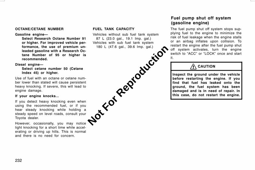
232
OCTANE/CETANE NUMBER
Gasoline engine—Select Research Octane Number 91or higher. For improved vehicle per-formance, the use of premium un-leaded gasoline with a Research Oc-tane Number of 95 or higher isrecommended.
Diesel engine—Select cetane number 50 (CetaneIndex 45) or higher.
Use of fuel with an octane or cetane num-ber lower than stated will cause persistentheavy knocking. If severe, this will lead toengine damage.
If your engine knocks...
If you detect heavy knocking even whenusing the recommended fuel, or if youhear steady knocking while holding asteady speed on level roads, consult yourToyota dealer.
However, occasionally, you may noticelight knocking for a short time while accel-erating or driving up hills. This is normaland there is no need for concern.
FUEL TANK CAPACITY
Vehicles without sub fuel tank system87 L (23.0 gal., 19.1 Imp. gal.)
Vehicles with sub fuel tank system180 L (47.6 gal., 39.6 Imp. gal.)
The fuel pump shut off system stops sup-plying fuel to the engine to minimize therisk of fuel leakage when the engine stallsor an airbag inflates upon collision. Torestart the engine after the fuel pump shutoff system activates, turn the engineswitch to “ACC” or “LOCK” once and startit.
CAUTION
Inspect the ground under the vehiclebefore restarting the engine. If youfind that fuel has leaked onto theground, the fuel system has beendamaged and is in need of repair. Inthis case, do not restart the engine.
L/C120 AE (OM60D50E) 08/01/22
Fuel pump shut off system(gasoline engine)
Not For R
epro
duction

233
If you plan to drive your Toyota inanother country...
First, comply with the vehicle registrationlaws.
Second, confirm the availability of the cor-rect fuel.
The three−way catalytic converters areemission control devices installed inthe exhaust system.
The purpose is to reduce pollutants in theexhaust gas.
CAUTION
D Keep people and combustible mate-rials away from the exhaust pipewhile the engine is running. Theexhaust gas is very hot.
D Do not idle or park your vehicleover anything that might burn easi-ly such as grass, leaves, paper orrags.
NOTICE
A large amount of unburned gasesflowing into the three−way catalyticconverter may cause it to overheatand create a fire hazard. To preventthis and other damage, observe thefollowing precautions:
z Use only unleaded gasoline.
z Do not drive with an extremely lowfuel level; running out of fuel couldcause the engine to misfire, creat-ing an excessive load on the three−way catalytic converter.
z Do not allow the engine to run atidle speed for more than 20 min-utes.
z Avoid racing the engine.
z Do not push−start or pull−start yourvehicle.
z Do not turn off the engine switchwhile the vehicle is moving.
L/C120 AE (OM60D50E) 08/01/22
Operation in foreigncountries
Three−way catalyticconverters(Vehicles with 1GR−FE engine)
Not For R
epro
duction

234
z Keep your engine in good runningorder. Malfunctions in the engineelectrical system, electronic ignitionsystem/distributor ignition systemor fuel system could cause an ex-tremely high three−way catalyticconverter temperature.
z If the engine becomes difficult tostart or stalls frequently, take yourvehicle in for a check−up as soonas possible. Remember, your Toyotadealer knows your vehicle and itsthree−way catalytic converter sys-tem best.
z To ensure that the three−way cata-lytic converter and the entire emis-sion control system operate proper-ly, your vehicle must receive theperiodic inspections required by theToyota Maintenance Schedule. Forscheduled maintenance information,refer to the “Warranty and ServiceBooklet”.
The catalytic converter is an emissioncontrol device installed in the exhaustsystem.
The purpose is to reduce pollutants in theexhaust gas.
CAUTION
D Keep people and combustible mate-rials away from the exhaust pipewhile the engine is running. Theexhaust gas is very hot.
D Do not drive, idle or park your ve-hicle over anything that might burneasily such as grass, leaves, paperor rags.
NOTICE
A large amount of unburned gasesflowing into the catalytic convertermay cause it to overheat and create afire hazard. To prevent this and otherdamage, observe the following precau-tions:
z Use only diesel fuel.
z Do not drive with an extremely lowfuel level; running out of fuel couldcause the engine to misfire, creat-ing an excessive load on the cata-lytic converter.
z Do not allow the engine to run atidle speed for more than 20 min-utes.
z Do not push−start or pull−start yourvehicle.
z Do not turn off the engine switchwhile the vehicle is moving.
L/C120 AE (OM60D50E) 08/01/22
Catalytic converter(Vehicles with 1KD−FTVengine)
Not For R
epro
duction

235
z Keep your engine in good runningorder. Malfunctions in the engineelectrical system or fuel systemcould cause an extremely high cata-lytic converter temperature.
z If the engine becomes difficult tostart or stalls frequently, take yourvehicle in for a check−up as soonas possible. Remember, your Toyotadealer knows your vehicle and itscatalytic converter system best.
z To ensure that the catalytic convert-er and the entire emission controlsystem operate properly, your ve-hicle must receive the periodic in-spections required by the ToyotaMaintenance Schedule. For sched-uled maintenance information, referto the “Warranty and Service Book-let”.
CAUTION
D Exhaust gases include harmful car-bon monoxide (CO) that is colorlessand odorless. Inhaling exhaustgases may lead to death or a seri-ous health hazard.
D The exhaust should be checked oc-casionally. If there is a hole orcrack caused by corrosion, damageto a joint or abnormal exhaustnoise, be sure to have the vehicleinspected and repaired by yourToyota dealer. Failure to do so mayallow exhaust gases to enter thevehicle, resulting in death or a seri-ous health hazard.
D If the vehicle is in a poorly venti-lated area, turn the engine off. In aclosed area, such as a garage, ex-haust gases may collect and enterthe vehicle. This may lead to deathor a serious health hazard.
D Do not remain for a long time in aparked vehicle with the engine run-ning. If it is unavoidable, however,do so only in an unconfined areaand adjust the heating or coolingsystem to force outside air into thevehicle.
D Keep the back door and quarterwindows closed while driving. Anopen or unsealed back door andquarter windows may cause exhaustgases to be drawn into the vehicle.
D To allow proper operation of yourvehicle’s ventilation system, keepthe inlet grilles in front of the wind-shield clear of snow,leaves, or oth-er obstructions.
D If the smell of exhaust is noticedinside the vehicle, open the win-dows. Large amounts of exhaust inthe vehicle can cause driver drowsi-ness and an accident, resulting indeath or a serious health hazard.Have the vehicle inspected by yourToyota dealer immediately.
L/C120 AE (OM60D50E) 08/01/22
Engine exhaust cautions
Not For R
epro
duction

236
D Do not leave the engine running inan area with snow build−up, orwhere it is snowing. If snowbanksbuild up around the vehicle whilethe engine is running, exhaustgases may collect and enter the ve-hicle. This may lead to death or aserious health hazard.
DWhen taking a nap in the vehicle,always turn the engine off. Other-wise, you may accidentally movethe shift lever or depress the accel-erator pedal, which could cause anaccident or fire due to engine over-heating. Additionally, if the vehicleis parked in a poorly ventilatedarea, exhaust gases may collect andenter the vehicle, leading to deathor a serious health hazard.
FUNCTIONS OF ENGINE OIL
Engine oil has the primary functions oflubricating and cooling the inside of theengine, and plays a major role in main-taining the engine in proper working order.
ENGINE OIL CONSUMPTION
It is normal that an engine should con-sume some engine oil during normalengine operation. The causes of oilconsumption in a normal engine are asfollows.
D Oil is used to lubricate pistons, pistonrings and cylinders. A thin film of oilis left on the cylinder wall when a pis-ton moves downwards in the cylinder.High negative pressure generated whenthe vehicle is decelerating sucks someof this oil into the combustion chamber.This oil as well as some part of the oilfilm left on the cylinder wall is burnedby the high temperature combustiongases during the combustion process.
D Oil is also used to lubricate the stemsof the intake valves. Some of this oilis sucked into the combustion chambertogether with the intake air and isburned along with the fuel. High tem-perature exhaust gases also burn theoil used to lubricate the exhaust valvestems.
The amount of engine oil consumed de-pends on the viscosity of the oil, thequality of the oil and the conditions thevehicle is driven under.
More oil is consumed by high−speed driv-ing and frequent acceleration and decel-eration.
A new engine consumes more oil, sinceits pistons, piston rings and cylinder wallshave not become conditioned.
Oil consumption: Max. 1.0 L per 1000km (1.1 qt./600 miles, 0.9 lmp. qt./600miles)
When judging the amount of oil con-sumption, note that the oil maybe comediluted and make it difficult to judgethe true level accurately.
As an example, if a vehicle is used forrepeated short trips, and consumes a nor-mal amount of oil, the dipstick may notshow any drop in the oil level at all, evenafter 1000 km (600 miles) or more. Thisis because the oil is gradually becomingdiluted with fuel or moisture, making itappear that the oil level has not changed.
The diluting ingredients evaporate outwhen the vehicle is then driven at highspeeds, as on an expressway, making itappear that oil is excessively consumedafter driving at high speeds.
L/C120 AE (OM60D50E) 08/01/22
Facts about engine oilconsumption
Not For R
epro
duction

237
IMPORTANCE OF ENGINE OIL LEVELCHECK
One of the most important points in prop-er vehicle maintenance is to keep the en-gine oil at the optimum level so that oilfunction will not be impaired. Therefore, itis essential that the oil level be checkedregularly. Toyota recommends that the oillevel be checked every time you refuelthe vehicle.
NOTICE
Failure to check the oil level regularlycould lead to serious engine troubledue to insufficient oil.
For detailed information on oil level check,see “Checking the engine oil level” onpage 312 in Section 7−2.
Without the vehicle stability control sys-tem—The tandem master cylinder brakesystem is a hydraulic system with twoseparate sub−systems. If either sub−sys-tem should fail, the other will still work.However, the pedal will be harder topress, and your stopping distance will in-crease. Also, the brake system warninglight may come on.
With the vehicle stability control sys-tem—This brake system has 2 indepen-dent hydraulic circuits. If either circuitshould fail, the other will still work. How-ever, the pedal will be harder to press,and your stopping distance will increase.Also, the brake system warning light maycome on.
CAUTION
Do not drive your vehicle with only asingle brake system. Have yourbrakes fixed immediately.
BRAKE BOOSTER
Without the vehicle stability controlsystem—
The brake booster uses engine vacuum topower−assist the brakes. If the engineshould quit while you are driving, you canbring the vehicle to a stop with normalpedal pressure. There is enough reservedvacuum for one or two stops—but nomore!
CAUTION
D Do not pump the brake pedal if theengine stalls. Each push on thepedal uses up your reserved vacu-um.
D Even if the power assist is com-pletely lost, the brakes will stillwork. But you will have to push thepedal hard, much harder than nor-mal. And your braking distance willincrease.
L/C120 AE (OM60D50E) 08/01/22
Brake system
Not For R
epro
duction

238
With the vehicle stability control sys-tem—
The brake booster uses brake fluid pres-surized by the pump to power−assist thebrakes. If the brake booster fails duringdriving, the brake system warning lightcomes on and buzzer sounds continuous-ly. In this case, the brakes may not workproperly. If they do not work well, depressthe brake pedal firmly. If the brake systemwarning light comes on, immediately stopyour vehicle and contact your Toyota deal-er.
The brake system warning light may stayon for about 60 seconds after the engineswitch is turned to the “ON” position. It isnormal if the light turns off after a while.
Depressing the brake pedal repeatedlymay turn on the brake system warninglight and buzzer. It is normal if the lightturns off and the buzzer stops soundingafter a few seconds.
You may hear a small sound in the enginecompartment after the engine is started orthe brake pedal is depressed repeatedly.This is a pump pulsating sound of thebrake system, and it is not a malfunction.
CAUTION
D Do not pump the brake pedal if theengine stalls. Each push on thepedal uses up your brake fluidpressure reserve.
D Even if the power assist is com-pletely lost, the brakes will stillwork. But you will have to push thepedal hard, much harder than nor-mal. And your braking distance willincrease.
ANTI−LOCK BRAKE SYSTEM (with“ABS” warning light)
The anti−lock brake system is designedto help prevent lock−up of the wheelsduring a sudden braking or braking onslippery road surfaces. This assists inproviding directional stability and steer-ing performance of the vehicle underthese circumstances.
Effective way to press the ABS brakepedal: When the anti−lock brake systemfunction is in action, you may feel thebrake pedal pulsating and hear a noise.In this situation, to let the anti−lockbrake system work for you, just hold thebrake pedal down more firmly. Do notpump the brake in a panic stop. Thiswill result in reduced braking performan-ce.
The anti−lock brake system becomes op-erative after the vehicle has acceleratedto a speed in excess of approximately 10km/h (6 mph). It stops operating when thevehicle decelerates to a speed belowapproximately 5 km/h (3 mph).
L/C120 AE (OM60D50E) 08/01/22
Not For R
epro
duction
239
Depressing the brake pedal on slipperyroad surfaces such as on a manhole cov-er, a steel plate at a construction site,joints in a bridge, etc. on a rainy daytends to activate the anti−lock brake sys-tem.
You may hear a click or motor sound inthe engine compartment for a few secondswhen the engine is started or just afterthe vehicle begins to move. This meansthat the anti−lock brake system is in theself−check mode, and does not indicate amalfunction.
When the anti−lock brake system is ac-tivated, the following conditions mayoccur. They do not indicate a malfunc-tion of the system:
D You may hear the anti−lock brake sys-tem operating and feel the brake pedalpulsating and the vibrations of the ve-hicle body and steering wheel. Youmay also hear the motor sound in theengine compartment even after the ve-hicle is stopped.
D At the end of the anti−lock brake sys-tem activation, the brake pedal maymove a little forward.
CAUTION
Do not overestimate the anti−lockbrake system: Although the anti−lockbrake system assists in providing ve-hicle control, it is still important todrive with all due care and maintaina moderate speed and safe distancefrom the vehicle in front of you, be-cause there are limits to the vehiclestability and effectiveness of steeringwheel operation even with the anti−lock brake system on.
If tire grip performance exceeds itscapability, or if hydroplaning occursduring high speed driving in the rain,the anti−lock brake system does notprovide vehicle control.
Anti−lock brake system is not de-signed to shorten the stopping dis-tance: Always drive at a moderatespeed and maintain a safe distancefrom the vehicle in front of you.Compared with vehicles without ananti−lock brake system, your vehiclemay require a longer stopping dis-tance in the following cases:
D Driving on rough, gravel or snow−covered roads.
D Driving with tire chains installed.
D Driving over the steps such as thejoints on the road
D Driving on roads where the roadsurface is pitted or has other differ-ences in surface height.
Install all 4 tires of specified size atappropriate pressure: The anti−lockbrake system detects vehicle speedsusing the speed sensors for respec-tive wheels’ turning speeds. The useof tires other than specified may failto detect the accurate turning speedresulting in a longer stopping dis-tance.
L/C120 AE (OM60D50E) 08/01/22
Not For R
epro
duction

240
“ABS” warning light
Without the vehicle stability controlsystem—
The light comes on when the engineswitch is turned to the “ON” position. Ifthe anti−lock brake system works properly,the light turns off after a few seconds.Thereafter, if the system malfunctions, thelight comes on again.
When the “ABS” warning light is on (andthe brake system warning light is off), theanti−lock brake system does not operate,but the brake system still operates con-ventionally.
When the “ABS” warning light is on (andthe brake system warning light is off), theanti−lock brake system does not operatebut the brake assist system still operates.In this case, the wheels could lock upduring a sudden braking or braking onslippery road surfaces.
If either of the following conditions oc-curs, this indicates a malfunction some-where in the components monitored bythe warning light system. Contact yourToyota dealer as soon as possible toservice the vehicle.
D The light does not come on when theengine switch is turned to the “ON”position, or remains on.
D The light comes on while driving.
A warning light turning on briefly duringoperation does not indicate a problem.
CAUTION
If the “ABS” warning light remains ontogether with the brake system warn-ing light, immediately stop your ve-hicle at a safe place and contact yourToyota dealer.
In this case, not only the anti−lockbrake system will fail but also thevehicle will become extremely unsta-ble during braking.
With rear differential lock: However, it isa normal operation for the light to be onwith rear differential locked. At this time,the anti−lock brake system does not oper-ate.
L/C120 AE (OM60D50E) 08/01/22
Not For R
epro
duction

241
With vehicle stability control system—
The light comes on when the engineswitch is turned to the “ON” position. Ifthe anti−lock brake system and the brakeassist system work properly, the lightturns off after a few seconds. Thereafter,if the systems malfunctions, the lightcomes on again.
When the “ABS” warning light is on (andthe brake system warning light is off), theanti−lock brake system, the brake assistsystem, the traction control system andthe vehicle stability control system do notoperate, but the brake system still oper-ates conventionally.
When the “ABS” warning light is on (andthe brake system warning light is off), theanti−lock brake system does not operateso that the wheels could lock up duringa sudden braking or braking on slipperyroad surfaces.
“VSC TRC” warning light may come onwith the “ABS” warning light (brake assistsystem warning light) when there is a mal-function somewhere in the anti−lock brakesystem (brake assist system).
If either of the following conditions oc-curs, this indicates a malfunction some-where in the components monitored bythe warning light system. Contact yourToyota dealer as soon as possible toservice the vehicle.
D The light does not come on when theengine switch is turned to the “ON”position, or remains on.
D The light comes on while you are driv-ing.
A warning light turning on briefly duringoperation does not indicate a problem.
CAUTION
If the “ABS” warning light remains ontogether with the brake system warn-ing light, immediately stop your ve-hicle at a safe place and contact yourToyota dealer.
In this case, not only the anti−lockbrake system will fail but also thevehicle will become extremely unsta-ble during braking.
Either of the following conditions mayoccur, but do not indicate a malfunc-tion:
D The light may stay on for about 60seconds after the engine switch isturned to the “ON” position. It is nor-mal if it turns off after a while.
D Depressing the brake pedal repeatedlymay turn on the light. It is normal if itturns off after about a few seconds.
DRUM−IN−DISC TYPE PARKING BRAKESYSTEM
Your vehicle has a drum−in−disc typeparking brake system. This type of brakesystem needs bedding−down of the brakeshoes periodically or whenever the parkingbrake shoes and/or drums are replaced.
Have your Toyota dealer perform the bed-ding−down.
L/C120 AE (OM60D50E) 08/01/22
Not For R
epro
duction

242
BRAKE ASSIST SYSTEM
When you slam the brakes on, thebrake assist system judges as an emer-gency stop and provides more powerfulbraking for a driver who cannot holddown the brake pedal firmly.
When you slam the brakes on, more pow-erful braking will be applied. At this time,you may hear a sound in the enginecompartment and feel the vibrations of thebrake pedal. This does not indicate a mal-function.
With vehicle stability control system—
The brake assist system becomes opera-tive after the vehicle has accelerated toa speed in excess of approximately 10km/h (6 mph). It stops operating when thevehicle decelerates to a speed belowapproximately 5 km/h (3 mph).
For an explanation of this system’s warn-ing light, see “Service reminder indicatorsand warning buzzers” on page 121 in Sec-tion 1−6.
The brake pad wear indicators on yourdisc brakes give a warning noise whenthe brake pads are worn to where re-placement is required.
If you hear a squealing or scraping noisewhile driving, have the brake padschecked and replaced by your nearestToyota dealer immediately.
Avoid continuous driving with the warningnoise.
Continuous driving without replacing thebrake pads will cause expensive rotordamage and increasing brake pedal effortto get the same stopping distance.
When stowing cargo and luggage in thevehicle, observe the following:
D Put cargo and luggage in the luggagecompartment when at all possible. Besure all items are secured in place.
D Be careful to keep the vehicle bal-anced. Locating the weight as far for-ward as possible helps maintain bal-ance.
D For better fuel economy, do not carryunneeded weight.
CAUTION
D To prevent cargo and luggage fromsliding forward during braking, donot stack anything in the luggagecompartment higher than the seat-backs. Keep cargo and luggage low,as close to the floor as possible.
D Do not place anything on the flat-tened seat or it may slide forwardduring braking.
L/C120 AE (OM60D50E) 08/01/22
Brake pad wear indicators Luggage stowage precautions
Not For R
epro
duction
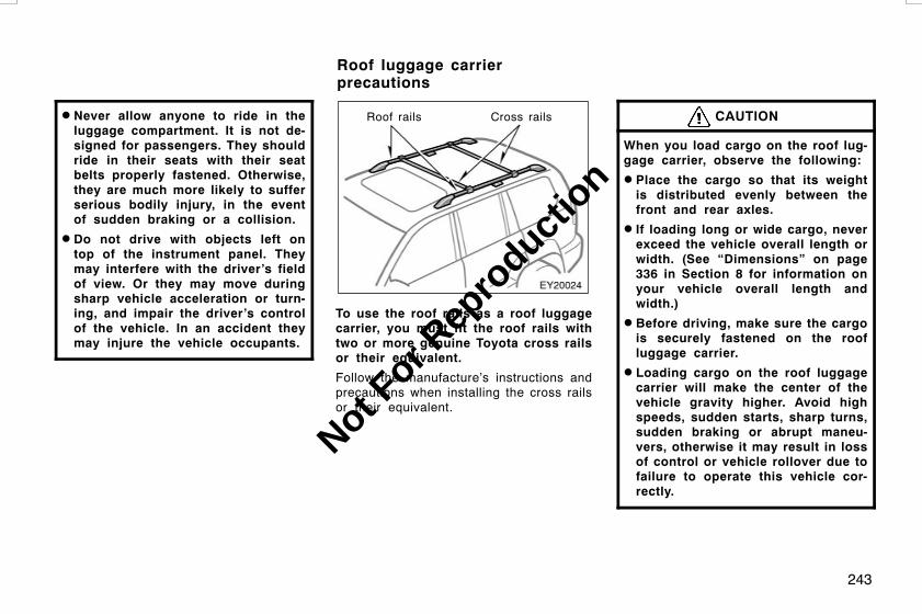
243
D Never allow anyone to ride in theluggage compartment. It is not de-signed for passengers. They shouldride in their seats with their seatbelts properly fastened. Otherwise,they are much more likely to sufferserious bodily injury, in the eventof sudden braking or a collision.
D Do not drive with objects left ontop of the instrument panel. Theymay interfere with the driver’s fieldof view. Or they may move duringsharp vehicle acceleration or turn-ing, and impair the driver’s controlof the vehicle. In an accident theymay injure the vehicle occupants.
Roof rails Cross rails
To use the roof rails as a roof luggagecarrier, you must fit the roof rails withtwo or more genuine Toyota cross railsor their equivalent.
Follow the manufacture’s instructions andprecautions when installing the cross railsor their equivalent.
CAUTION
When you load cargo on the roof lug-gage carrier, observe the following:
D Place the cargo so that its weightis distributed evenly between thefront and rear axles.
D If loading long or wide cargo, neverexceed the vehicle overall length orwidth. (See “Dimensions” on page336 in Section 8 for information onyour vehicle overall length andwidth.)
D Before driving, make sure the cargois securely fastened on the roofluggage carrier.
D Loading cargo on the roof luggagecarrier will make the center of thevehicle gravity higher. Avoid highspeeds, sudden starts, sharp turns,sudden braking or abrupt maneu-vers, otherwise it may result in lossof control or vehicle rollover due tofailure to operate this vehicle cor-rectly.
L/C120 AE (OM60D50E) 08/01/22
Roof luggage carrierprecautions
Not For R
epro
duction

244
D If driving for a long distance, onrough roads, or at high speeds,stop the vehicle now and then dur-ing the trip to make sure the cargoremains in its place.
D Do not exceed 80 kg (176 lb.) cargoweight on the roof rails. However,if the allowable cargo weight of thecrossrails is under 80 kg (176 lb.)observe the load limit and otherinstructions for the cross rails.
NOTICE
When loading the luggages, be carefulnot to scratch the surface of themoon roof.
The rear step bumper is for rear endprotection and easier step−up loading.
To get on the rear step bumper, use theshaded area between the arrows in theillustration.
CAUTION
D Do not allow more than one personto get on the rear step bumper ata time. It is designed for only oneperson.
D Never drive the vehicle with anyoneon the rear step bumper.
Your Toyota is equipped with a limited−slipcenter differential (transfer). If one wheelbegins to spin, the limited−slip center dif-ferential (transfer) is designed to aid trac-tion by automatically transmitting drivingforce to the wheels on the other driveaxle. It transmits driving force to the frontwheel if a rear wheel spins, and to therear wheels if a front wheel spins.
On some models—
Your Toyota is also equipped with a lim-ited−slip rear differential. If one rear wheelbegins to spin, the limited−slip rear differ-ential is designed to aid traction by auto-matically transmitting driving force to theother rear wheel. If you are not surewhether your vehicle is equipped with one,you can ask your Toyota dealer.
CAUTION
Do not start or run the engine whileyour vehicle is supported by a jack.The vehicle could be driven off thejack and could pose a danger or re-sult in serious injury.
L/C120 AE (OM60D50E) 08/01/22
Rear step bumper Limited−slip differential
Not For R
epro
duction
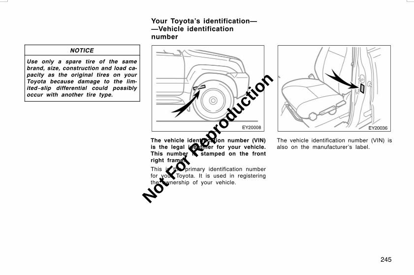
245
NOTICE
Use only a spare tire of the samebrand, size, construction and load ca-pacity as the original tires on yourToyota because damage to the lim-ited−slip differential could possiblyoccur with another tire type.
The vehicle identification number (VIN)is the legal identifier for your vehicle.This number is stamped on the frontright frame.
This is the primary identification numberfor your Toyota. It is used in registeringthe ownership of your vehicle.
The vehicle identification number (VIN) isalso on the manufacturer’s label.
L/C120 AE (OM60D50E) 08/01/22
Your Toyota’s identification——Vehicle identificationnumber
Not For R
epro
duction

246
1GR−FE engine
1KD−FTV engine
1KZ−TE engine
The engine number is stamped on theengine block as shown.
CAUTION
Do not modify the suspension/chassiswith lift kits, spacers, springs, etc. Itcan cause dangerous handling charac-teristics resulting in loss of control.
L/C120 AE (OM60D50E) 08/01/22
—Engine number Suspension and chassis
Not For R
epro
duction

247
STARTING AND DRIVINGBefore starting the engine 248. . . . . . . . . . . . . . . . . . . . . . . . . . . . . . . . . . .How to start the engine 248. . . . . . . . . . . . . . . . . . . . . . . . . . . . . . . . . . . . .Precautions for turning off an engine with turbocharger 250. . . . . . . .Pre−trip safety check 251. . . . . . . . . . . . . . . . . . . . . . . . . . . . . . . . . . . . . . .Tips for driving in various conditions 252. . . . . . . . . . . . . . . . . . . . . . . . .Driving in the rain 253. . . . . . . . . . . . . . . . . . . . . . . . . . . . . . . . . . . . . . . . . .Off−road driving precautions 254. . . . . . . . . . . . . . . . . . . . . . . . . . . . . . . .Winter driving tips 255. . . . . . . . . . . . . . . . . . . . . . . . . . . . . . . . . . . . . . . . . .Trailer towing 256. . . . . . . . . . . . . . . . . . . . . . . . . . . . . . . . . . . . . . . . . . . . . .How to save fuel and make your vehicle last longer 262. . . . . . . . . . .
L/C120 AE (OM60D50E) 08/01/22
SECTION 3
Not For R
epro
duction
248
1. Check the area around the vehicle be-fore entering it.
2. Adjust seat position, seatback angle,seat cushion angle, head restraintheight and steering wheel angle.
3. Adjust the inside and outside rear viewmirrors.
4. Lock all the side doors and back door.
5. Fasten seat belts.
Once you turn the engine switch to“START” position and release the key, thecranking hold function continues to crankthe engine in “ON” position until it starts.
The function stops cranking the engineafter about 25 seconds maximum if theengine has not started yet. When youcrank the engine again, wait a few sec-onds and restart it.
If you hold the key in “START” position,the function will keep cranking for about30 seconds maximum.
1. Apply the parking brake firmly.
2. Turn off unnecessary lights and acces-sories.
3. Manual transmission: Press the clutchpedal to the floor and shift the trans-mission into neutral. Hold the clutchpedal to the floor until the engine isstarted.
Automatic transmission: Put the se-lector lever in “P”. If you need to re-start the engine while the vehicle ismoving, put the selector lever in “N”.A starter safety device will prevent thestarter from operating if the selectorlever is in any drive position.
4. Automatic transmission only: De-press the brake pedal and hold it tothe floor until driving off.
L/C120 AE (OM60D50E) 08/01/22
Before starting the engine
How to start the engine——Cranking hold function(gasoline engine with automatictransmission) (a) Before cranking
Not For R
epro
duction
249
Before starting the engine, be sure to fol-low the instructions in “(a) Before crank-ing”.
With manual transmission—
Normal starting procedure
The multiport fuel injection system/sequen-tial multiport fuel injection system in yourengine automatically controls the properair−fuel mixture for starting. You can starta cold or hot engine as follows:
With your foot off the accelerator pedal,crank the engine by turning the key to“START”. Release it when the enginestarts.
Engine should be warmed up by driving,not in idle. For warming up, drive withsmoothly turning engine until engine cool-ant temperature is within normal range.
If the engine stalls...
Simply restart it, using the correct proce-dure given in normal starting.
If the engine will not start...
See “If your vehicle will not start” on page266 in Section 4.
NOTICE
z Do not crank for more than 30 se-conds at a time. This may overheatthe starter and wiring systems.
z Do not race a cold engine.
z If the engine becomes difficult tostart or stalls frequently, have theengine checked immediately.
With automatic transmission—
Normal starting procedure
The multiport fuel injection system/sequen-tial multiport fuel injection system in yourengine automatically controls the properair−fuel mixture for starting. You can starta cold or hot engine as follows:
With your foot off the accelerator pedal,turn the engine switch to “START” posi-tion, then release the key.
Engine should be warmed up by driving,not in idle. For warming up, drive withsmoothly turning engine until engine cool-ant temperature is within normal range.
If the engine stalls...
Simply restart it, using the correct proce-dure given in normal starting.
If the engine will not start...
See “If your vehicle will not start” on page266 in Section 4.
NOTICE
z Do not race a cold engine.
z If the engine becomes difficult tostart or stalls frequently, have theengine checked immediately.
L/C120 AE (OM60D50E) 08/01/22
(b) Starting the engine(gasoline engine)
Not For R
epro
duction

250
Before starting the engine, be sure to fol-low the instructions in “(a) Before crank-ing”.
Normal starting procedure
1. Turn the key to “ON” and verify thatthe engine preheating indicator lighthas come on. Keep the key in the“ON” position until the light goes off.
2. With your foot off the accelerator ped-al, crank the engine by turning the keyto “START”. Release it when the en-gine starts.
Engine should be warmed up by driving,not in idle. For warming up, drive withsmoothly turning engine until engine cool-ant temperature is within normal range.
If the engine stalls...
Simply restart it, using the correct proce-dure given above, depending on the en-gine temperature.
If the engine will not start...
See “If your vehicle will not start” on page266 in Section 4.
NOTICE
z Do not crank for more than 30 se-conds at a time. This may overheatthe starter and wiring systems.
z Do not race a cold engine.
z If the engine becomes difficult tostart or stalls frequently, have theengine checked immediately.
After high−speed or extended driving, etc.,requiring a heavy engine load, the engineshould be allowed to idle, as shown in thechart, before turning it off.
Driving condition and required idlingtime
Normal city drivingIdling time—Not necessary
High−speed drivingAbout 80 km/h (50 mph)Idling time—About 20 seconds
About 100 km/h (63 mph)Idling time—About 1 minute
Steep mountain slopes or continueddriving above 100 km/h (63 mph)
Idling time—About 2 minutes
NOTICE
Do not turn the engine off immediate-ly after a heavy load has been placedon the engine in order to prevent en-gine damage.
L/C120 AE (OM60D50E) 08/01/22
(b) Starting the engine(diesel engine)
Precautions for turning off anengine with turbocharger(diesel engine)
Not For R
epro
duction

251
It is a good idea to do a safety checkbefore starting out on a trip. A few min-utes of checking can help ensure safe andpleasant driving. Just a basic familiaritywith your vehicle is required and a carefuleye! Or, if you would like, your Toyotadealer will be pleased to make this checkfor you at a nominal cost.
CAUTION
If you make this check in an enclosedgarage, make sure there is adequateventilation. Engine exhaust is poison-ous.
BEFORE STARTING THE ENGINE
Outside the vehicle
Tires (spare included). Check the pres-sure with a gauge and look carefully forcuts, damage, or excessive wear.
Wheel nuts. Make sure no nuts are mis-sing or loose.
Fluid leaks. After the vehicle has beenparked for a while, check underneath forleaking fuel, oil, water, or fluid. (Waterdripping from the air conditioning after useis normal.)
Lights. Make sure the headlights, stoplights, tail lights, turn signals and otherlights are all working. Check the headlightaim.
Inside the vehicle
Jack and wheel nut wrench. Make sureyou have your jack and wheel nut wrench.
Seat belts. Check that the buckles locksecurely. Make sure the belts are notworn or frayed.
Instruments and controls. Especiallymake sure the service reminder indicators,instrument lights, and defroster are work-ing.
Brakes. Make sure the pedal has enoughclearance.
In the engine compartment
Spare fuses. Make sure you have sparefuses. They should cover all the amperageratings designated on the fuse box lid.
Coolant level. Make sure the coolant lev-el is correct. (See page 316 in Section7−2 for instructions.)
Battery and cables. All the battery cellsshould be filled to the proper level withdistilled water. Look for corroded or looseterminals and a cracked case. Check thecables for good condition and connections.
Wiring. Look for damaged, loose, or dis-connected wires.
Fuel lines. Check the lines for leaks orloose connections.
AFTER STARTING THE ENGINE
Exhaust system. Listen for any leakage.Have any leaks fixed immediately. (See“Engine exhaust cautions” on page 235 inSection 2.)
Engine oil level. Stop the engine andcheck the dipstick with the vehicle parkedon a level spot. (See page 312 in Section7−2 for instructions.)
WHILE DRIVING
Instruments. Make sure the speedometerand gauges are working.
Brakes. In a safe place, check that thebrakes do not pull to one side when ap-plied.
Anything unusual? Look for loose partsand leaks. Listen for abnormal noises.
If everything looks O.K., set your mind atease and enjoy your trip!
L/C120 AE (OM60D50E) 08/01/22
Pre−trip safety check
Not For R
epro
duction

252
D Always slow down in gusty crosswinds.This will allow you much better control.
D Drive slowly onto curbs and, if pos-sible, at a right angle. Avoid drivingonto high, sharp−edged objects andother road hazards. Failure to do socan lead to severe tire damage suchas a tire burst.
Drive slowly when passing over bumpsor travelling on a bumpy road. Other-wise, the impact could cause severedamage to the tires and/or wheels.
D When parking on a hill, turn the frontwheels until they touch the curb sothat the vehicle will not roll. Apply theparking brake, and place the transmis-sion in “P” (automatic) or in first orreverse (manual). If necessary, blockthe wheels.
D Washing your vehicle or driving throughdeep water may get the brakes wet. Tosee whether they are wet, check thatthere is no traffic near you, and thenpress the pedal lightly. If you do notfeel a normal braking force, the brakesare probably wet. To dry them, drivethe vehicle cautiously while lightlypressing the brake pedal with the park-ing brake applied. If they still do notwork safely, pull to the side of the roadand call a Toyota dealer for assistance.
D Vehicles with rear height control airsuspension: When you drive on abumpy road, it is recommended thatthe vehicle height should be set in the“N” (normal) or “HI” (high) mode.
CAUTION
D Before driving off, make sure theparking brake is fully released andthe parking brake reminder light isoff.
D Do not leave your vehicle unat-tended while the engine is running.
D Do not rest your foot on the brakepedal while driving. It can causedangerous overheating, needlesswear, and poor fuel economy.
D To drive down a long or steep hill,reduce your speed and downshift.Remember, if you ride the brakesexcessively, they may overheat andnot work properly.
D Be careful when accelerating, up-shifting, downshifting or braking ona slippery surface. Sudden accelera-tion or engine braking could causethe vehicle to skid or spin.
D Do not continue normal drivingwhen the brakes are wet. If they arewet, your vehicle will require alonger stopping distance, and itmay pull to one side when thebrakes are applied. Also, the park-ing brake will not hold the vehiclesecurely.
D Vehicle with rear height control airsuspension: If you drive throughdeep water over about 700 mm (28in.) in depth, put the vehicle heightin the “HI” (high) mode with theheight select switch and then turnoff the rear height control air sus-pension by pushing the HEIGHTCONTROL “OFF” switch. Drive yourvehicle at 30 km/h (19 mph) or low-er speed.
L/C120 AE (OM60D50E) 08/01/22
Tips for driving in variousconditions
Not For R
epro
duction
253
Driving on a slippery road surface
Drive carefully when it is raining, becausevisibility will be reduced, the windows maybecome fogged−up, and the road will beslippery.
D Drive carefully when it starts to rain,because the road surface will be espe-cially slippery.
D Refrain from high speeds when drivingon an expressway in the rain, becausethere may be a layer of water betweenthe tires and the road surface,preventing the steering and brakesfrom operating properly.
CAUTION
D Sudden braking, acceleration andsteering when driving on a slipperyroad surface may cause tire slip-page and reduce your ability tocontrol the vehicle, resulting in anaccident.
D Sudden changes in engine speed,such as sudden engine braking,may cause the vehicle to skid, re-sulting in an accident.
D After driving through a puddle,lightly depress the brake pedal tomake sure that the brakes are func-tioning properly. Wet brake padsmay prevent the brakes from func-tioning properly. If the brakes ononly one side are wet and not func-tioning properly, steering controlmay be affected, resulting in an ac-cident.
When encountering flooded roadsDo not drive on a road that has floodedafter heavy rain etc. Doing so may causeserious damage to the vehicle.
NOTICE
Driving on a flooded road may causethe engine to stall as well as causeserious vehicle malfunctions such asshorts in electrical components andengine damage from water immersion.In the event that you drive on aflooded road and the vehicle isflooded, be sure to have your Toyotadealer check brake function, changesin quantity and quality of oil and fluidused for the engine, transmission,transfer, differentials, etc. and lubri-cant condition for the propeller shaft,bearings and suspension joints (wherepossible) and the function of all jointsand bearings.
L/C120 AE (OM60D50E) 08/01/22
Driving in the rain
Not For R
epro
duction
254
CAUTION
Always observe the following precau-tions to minimize the risk of seriouspersonal injury or damage to your ve-hicle:
D Drive carefully when off the road.Do not take unnecessary risks bydriving in dangerous places.
D Do not grip the steering wheelspokes when driving off−road. Abad bump could jerk the wheel andinjure your hands. Keep both handsand especially your thumbs on theoutside of the rim.
D Always check your brakes for effec-tiveness immediately after driving insand, mud, water or snow.
D After driving through tall grass,mud, rock, sand, rivers, etc., checkthat there is no grass, bush, paper,rags, stone, sand, etc. adhering ortrapped on the underbody. Clear offany such matter from the under-body. If the vehicle is used withthese materials trapped or adheringto the underbody, a breakdown orfire could occur.
D In a rollover crash, an unbelted per-son is significantly more likely todie than a person wearing a seatbelt. Therefore, the driver and allpassengers should fasten their seatbelts whenever the vehicle is mov-ing.
DWhen driving off−road or in ruggedterrain, do not drive at excessivespeeds, jump, make sharp turns,strike objects, etc. This may causeloss of control or vehicle rollovercausing death or serious injury. Youare also risking expensive damageto your vehicle’s suspension andchassis.
NOTICE
z If driving through water, such aswhen crossing shallow streams,firstcheck the depth of the water andbottom of the river bed for firm-ness. Drive slowly and avoid deepwater.
z Take all necessary safety measuresto ensure that water damage to theengine or other components doesnot occur.
zWater entering the automatic trans-mission will cause deterioration inshift quality, locking up of yourtransmission accompanied by ribra-tion, and ultimately damage.
zWater entering the engine air intakewill cause severe engine damage.
zWater can wash the grease fromwheel bearings, causing rusting andpremature failure, and may also en-ter the differentials, transmissionand transfer case, reducing the gearoil’s lubricating qualities.
L/C120 AE (OM60D50E) 08/01/22
Off−road driving precautions
Not For R
epro
duction

255
z Sand and mud that has accumulatedin brake drums and around brakediscs may affect braking efficiencyand may damage brake system com-ponents.
z Always perform a maintenance in-spection after each day of off−roaddriving that has taken you throughrough terrain, sand, mud, or water.
Make sure your coolant is properly pro-tected against freezing.
Only use “Toyota Super Long Life Coolant”or similar high quality ethylene glycolbased non−silicate, non−amine, non−nitrite,and non−borate coolant with long−lifehybrid organic acid technology. (Coolantwith long−life hybrid organic acidtechnology is a combination of lowphosphates and organic acids.)
See “Checking the engine coolant level”on page 316 in Section 7−2 for details ofcoolant type selection.
“Toyota Super Long Life Coolant” is a mix-ture of 50% coolant and 50% deionizedwater. This coolant provides protectiondown to about −35_C (−31_F).
NOTICE
Do not use plain water alone.
Check the condition of the battery andcables.
Cold temperatures reduce the capacity ofany battery, so it must be in top shapeto provide enough power for winter start-ing. Section 7−3 tells you how to visuallyinspect the battery. Your Toyota dealerand most service stations will be pleasedto check the level of charge.
Make sure the engine oil viscosity issuitable for the cold weather.
See page 313 in Section 7−2 for recom-mended viscosity. Leaving a heavy sum-mer oil in your vehicle during wintermonths may cause harder starting. If youare not sure about which oil to use, callyour Toyota dealer—they will be pleasedto help.
Keep the door locks from freezing.
Squirt lock de−icer or glycerine into thelocks to keep them from freezing.
Use a washer fluid containing an anti-freeze solution.
This product is available at your Toyotadealer and most auto parts stores. Followthe manufacturer’s directions for howmuch to mix with water.
L/C120 AE (OM60D50E) 08/01/22
Winter driving tips
Not For R
epro
duction

256
NOTICE
Do not use engine antifreeze or anyother substitute because it may dam-age your vehicle’s paint.
Do not use your parking brake whenthere is a possibility it could freeze.
When parking, put the transmission into“P” (automatic) or into first or reverse(manual) and block the front wheels. Donot use the parking brake, or snow orwater accumulated in and around theparking brake mechanism may freeze,making it hard to release.
Keep ice and snow from accumulatingunder the fenders.
Ice and snow built up under your fenderscan make steering difficult. During badwinter driving, stop and check under thefenders occasionally.
Depending on where you are driving,we recommend you carry some emer-gency equipment.
Some of the things you might put in thevehicle are tire chains, window scraper,bag of sand or salt, flares, small shovel,jumper cables, etc.
Your vehicle is designed primarily as apassenger−and−load−carrying vehicle.Towing a trailer will have an adverseeffect on handling, performance, braking,durability and driving economy (fuelconsumption, etc.). Your safety andsatisfaction depend on the proper use ofcorrect equipment and cautious drivinghabits. For your safety and the safety ofothers, you must not overload your vehicleor trailer. Ask your local Toyota dealer forfurther details before towing, as there areadditional legal requirements in somecountries.
For towing purposes, we recommend useof the following parts:
D When towing a caravan trailer etc., usea distributing hitch.
D When the total trailer weight is greaterthan the vehicle weight, use a swaycontrol device.
CAUTION
Vehicles with rear height control airsuspension: When disconnecting atrailer, put the vehicle height in the“LO” (low) mode and push the“HEIGHT CONTROL OFF” switch toturn off the rear height control airsuspension system. Otherwise, thevehicle height may be changed in theautomatic leveling function, resultingin unexpected accident. For details,see “Rear height control air suspen-sion” on page 162 in Section 1−7.
NOTICE
When towing a trailer, be sure to con-sult your Toyota dealer for further in-formation on additional requirementssuch as a towing kit, etc.
L/C120 AE (OM60D50E) 08/01/22
Trailer towing
Not For R
epro
duction

257
WEIGHT LIMITS
Before towing, make sure the total trail-er weight, gross vehicle weight, grossaxle weight and trailer tongue load areall within the limits.
The total trailer weight and tongue loadcan be measured with platform scalesfound at a public weighbridge, buildingsupply company, trucking company, junkyard, etc.
CAUTION
D The total trailer weight (trailerweight plus its cargo load) mustnot exceed 2500 kg (5511 lb.). Ex-ceeding this weight is dangerous.
D Trailer hitch assemblies have differ-ent weight capacities established bythe hitch manufacturer. Even thoughthe vehicle may be physically capa-ble of towing a higher weight, theoperator must determine the maxi-mum weight rating of the particularhitch assembly and never exceedthe maximum weight rating speci-fied for the trailer−hitch. Exceedingthe maximum weight rating set bythe trailer hitch manufacturer cancause an accident resulting in seri-ous personal injuries.
D The gross vehicle weight must notexceed the following. The gross ve-hicle weight is the sum of weightsof the unloaded vehicle, driver, pas-sengers, luggage, hitch and trailertongue load. It also includes theweight of any special equipmentinstalled on your vehicle.
Gasoline engine2850 kg (6284 lb.)
Diesel engine2900 kg (6393 lb.)
D The load on either the front or rearaxle resulting from distribution ofthe gross vehicle weight on bothaxles must not exceed the follow-ing.
Front 1290 kg (2844 lb.)Rear 1800 kg (3963 lb.)
L/C120 AE (OM60D50E) 08/01/22
Not For R
epro
duction
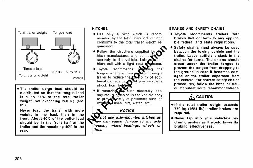
258
Total trailer weight Tongue load
Tongue load
Total trailer weight× 100 = 9 to 11%
D The trailer cargo load should bedistributed so that the tongue loadis 9 to 11% of the total trailerweight, not exceeding 250 kg (551lb.).
Never load the trailer with moreweight in the back than in thefront. About 60% of the trailer loadshould be in the front half of thetrailer and the remaining 40% in therear.
HITCHES
D Use only a hitch which is recom-mended by the hitch manufacturer andconforms to the total trailer weight re-quirement.
D Follow the directions supplied by thehitch manufacturer, and bolt the hitchsecurely to the vehicle. Lubricate thehitch ball with a light coat of grease.
D Toyota recommends removing thetongue whenever you are not towing atrailer to reduce the possibility of addi-tional damage caused if your vehicle isstruck from behind.
D If removing the hitch assembly, sealany mounting holes in the vehicle bodyto prevent entry of pollutants such asexhaust fumes, dirt, water, etc.
NOTICE
Do not use axle−mounted hitches asthey can cause damage to the axlehousing, wheel bearings, wheels ortires.
BRAKES AND SAFETY CHAINS
D Toyota recommends trailers withbrakes that conform to any applica-ble federal and state regulations.
D Safety chains must always be usedbetween the towing vehicle and thetrailer. Leave sufficient slack in thechains for turns. The chains shouldcross under the trailer tongue toprevent the tongue from dropping tothe ground in case it becomes dam-aged or the trailer separates fromthe vehicle. For correct safety chainsprocedures, follow the hitch or trail-er manufacturer’s recommendations.
CAUTION
D If the total trailer weight exceeds750 kg (1654 lb.), trailer brakes arerequired.
D Never tap into your vehicle’s hy-draulic system as it would lower itsbraking effectiveness.
L/C120 AE (OM60D50E) 08/01/22
Not For R
epro
duction

259
D Never tow a trailer without usingsafety chains securely attached toboth the trailer and the vehicle. Ifdamage occurs to the coupling unitor hitch ball, there is danger of thetrailer wandering over into anotherlane.
TIRES
D Ensure that your vehicle’s tires areproperly inflated. See page 317 in Sec-tion 7−2 and page 341 in Section 8 forinstructions.
D The trailer tires should be inflated tothe pressure recommended by the trail-er manufacturer in respect to the totaltrailer weight.
TRAILER LIGHTS
D Trailer lights must comply with federaland state regulations. See your localrecreational vehicle dealer or rentalagency for the correct type of wiringand relays for your trailer. Check forcorrect operation of the turn signalsand stop lights each time you hitch up.Direct splicing may damage your ve-hicle’s electrical system and cause amalfunction of your lights.
BREAK−IN SCHEDULE
D Toyota recommends that you do nottow a trailer with a new vehicle or avehicle with any new power train com-ponent (engine, transmission,differential,wheel bearing, etc.) for the first 800km (500 miles) of driving.
MAINTENANCE
D If you tow a trailer, your vehicle willrequire more frequent maintenance dueto the additional load. For this informa-tion, please refer to the scheduledmaintenance information in the “War-ranty and Service Booklet”.
D Retighten all fixing bolts of the towingball and bracket after approximately1000 km (600 miles) of trailer driving.
CONNECTING A TRAILER (models withrear height control air suspension)
Stop your vehicle and a trailer in line andperform the following:
1. Put the rear height control air suspen-sion in the “LO” (low) mode. Turn theengine switch off or push the “HEIGHTCONTROL OFF” switch to turn off therear height control air suspension.
2. Connect a trailer.
3. Turn the engine switch on or push the“HEIGHT CONTROL OFF” switch toturn on the rear height control air sus-pension. Select the “N” (normal) modewith the height select switch.
DISCONNECTING A TRAILER (modelswith rear height control air suspension)
Stop your vehicle and a trailer in line andperform the following:
1. Put the rear height control air suspen-sion in the “LO” mode. (Make sure thevehicle height is in the “LO” mode bypushing the height select switch on the“B” side.)
2. Turn the engine switch off or push the“HEIGHT CONTROL OFF” switch toturn off the rear height control air sus-pension.
L/C120 AE (OM60D50E) 08/01/22
Not For R
epro
duction

260
3. Set the supporting leg of a trailer onthe ground and raise the hitch by 100mm (4 in.).
4. Turn the engine switch on or push the“HEIGHT CONTROL OFF” switch toturn on the rear height control air sus-pension.
5. Wait for about 20 seconds until therear vehicle height is lowered by theautomatic leveling function.
6. Make sure the hitch is disconnected. Ifnot, raise the hitch higher and repeatsteps 2 through 5.
7. Move the vehicle forward in the “LO”mode where the hitch does not touchanything in the “N” mode.
8. Put the rear height control air suspen-sion in the “N” mode.
PRE−TOWING SAFETY CHECK
D Check that your vehicle remains levelwhen a loaded or unloaded trailer ishitched. Do not drive if the vehicle hasan abnormal nose−up or nose−downcondition, and check for impropertongue load, overload, worn suspensionor other possible causes.
D Make sure the trailer cargo is securelyloaded so that it cannot shift.
D Check that your rear view mirrors con-form to any applicable federal andstate regulations. If not, install the rearview mirrors required for towing pur-pose.
TRAILER TOWING TIPS
When towing a trailer, your vehicle willhandle differently than when not tow-ing. The three main causes of vehicle−trailer accidents are driver error, exces-sive speed and improper trailer loading.Keep these in mind when towing:
D Before starting out, check operation ofthe lights and all vehicle−trailer connec-tions. After driving a short distance,stop and recheck the lights and con-nections. Before actually towing a trail-er,practice turning, stopping and back-ing with a trailer in an area away fromtraffic until you learn the feel.
D Backing with a trailer is difficult andrequires practice. Grip the bottom ofthe steering wheel and move your handto the left to move the trailer to theleft. Move your hand to the right tomove the trailer to the right. (This pro-cedure is generally opposite to thatwhen backing without a trailer.) Also,just turn the steering wheel a little ata time, avoiding sharp or prolongedturning. Have someone guide you whenbacking to reduce the risk of an acci-dent.
L/C120 AE (OM60D50E) 08/01/22
Not For R
epro
duction

261
D Because stopping distance may be in-creased, vehicle−to−vehicle distanceshould be increased when towing atrailer. For each 10 km/h (6 mph) ofspeed, allow at least one vehicle andtrailer length between you and the ve-hicle ahead. Avoid sudden braking asyou may skid, resulting in jackknifingand loss of control. This is especiallytrue on wet or slippery surfaces.
D Avoid jerky starts or sudden accelera-tion. If your vehicle has a manualtransmission, prevent excessive clutchslippage by keeping engine rpm lowand not racing the engine. Always startout in first gear.
D Avoid jerky steering and sharp turns.The trailer could hit your vehicle in atight turn. Slow down before making aturn to avoid the necessity of suddenbraking.
D Remember that when making a turn,the trailer wheels will be closer thanthe vehicle wheels to the inside of theturn. Therefore,compensate for this bymaking a larger than normal turningradius with your vehicle.
D Crosswinds and rough roads will ad-versely affect handling of your vehicleand trailer, causing sway. Pay attentionto the rear from time to time to pre-pare yourself for being passed by largetrucks or buses, which may cause yourvehicle and trailer to sway. If swayinghappens,firmly grip the steering wheeland reduce speed immediately butgradually. Never increase speed. If it isnecessary to reduce speed, brakeslowly. Steer straight ahead. If youmake no extreme correction with thesteering or brakes, the vehicle andtrailer will stabilize.
D Be careful when passing other ve-hicles. Passing requires considerabledistance. After passing a vehicle, donot forget the length of your trailer andbe sure you have plenty of room be-fore changing lanes.
D In order to maintain engine braking effi-ciency, do not use the highest gear(manual transmission) or “D” (automatictransmission).
D Because of the added load of the trail-er, your vehicle’s engine may overheaton hot days (at temperatures over30_C [85_F]) when going up a long orsteep grade with a trailer. If the enginecoolant temperature gauge indicatesoverheating, immediately turn off the airconditioning (if in use), pull off the roadand stop in a safe spot. Refer to “Ifyour vehicle overheats” on page 272 inSection 4.
D Always place wheel blocks under boththe vehicle and trailer wheels whenparking. Apply the parking brake firmly.Put the transmission in “P” (automatic)or in first or reverse (manual). Avoidparking on a slope with a trailer, butif it cannot be avoided, do so onlyafter performing the following:
L/C120 AE (OM60D50E) 08/01/22
Not For R
epro
duction

262
1. Apply the brakes and hold.
2. Have someone place wheel blocks un-der both the vehicle and trailer wheels.
3. When the wheel blocks are in place,release your brakes slowly until theblocks absorb the load.
4. Apply the parking brake firmly.
5. Shift into first or reverse (manual) or“P” (automatic) and turn off the engine.
When restarting out after parking on aslope:
1. With the transmission in “P” position(automatic) or the clutch pedal de-pressed (manual), start the engine.(With an automatic transmission, besure to keep the brake pedal de-pressed.)
2. Shift into gear.
3. Release the parking brake (also footbrake on automatic transmission ve-hicles) and slowly pull or back awayfrom the wheel blocks. Stop and applyyour brakes.
4. Have someone retrieve the blocks.
CAUTION
D Observe the legal maximum speedsfor trailer towing.
D Slow down and downshift beforedescending steep or long downhillgrades. Do not make sudden down-shifts.
D Avoid holding the brake pedal downtoo long or too frequently. Thiscould cause the brakes to overheatand result in reduced braking effi-ciency.
Improving fuel economy is easy—just takeit easy. It will help make your vehicle lastlonger, too. Here are some specific tipson how to save money on both fuel andrepairs:
D Keep your tires inflated at the cor-rect pressure. Underinflation causestire wear and wastes fuel. See page317 in Section 7−2 for instructions.
D Do not carry unneeded weight inyour vehicle. Excess weight puts aheavier load on the engine, causinggreater fuel consumption.
D Avoid lengthy warm−up idling. Oncethe engine is running smoothly, begindriving—but gently. Remember, howev-er, that on cold winter days this maytake a little longer.
D Put the selector lever into the “D”when engine braking is not required.Driving with the selector lever in “3”(4−speed) or “4” (5−speed) will reducethe fuel economy. (For details, see“Automatic transmission” on page 136or 140 in Section 1−7.)
D Accelerate slowly and smoothly.Avoid jackrabbit starts. Get into highgear as quickly as possible.
L/C120 AE (OM60D50E) 08/01/22
How to save fuel and makeyour vehicle last longer
Not For R
epro
duction

263
D Avoid long engine idling. If you havea long wait and you are not in traffic,it is better to turn off the engine andstart again later.
D Avoid engine lugging or over−rev-ving. Use a gear position suitable forthe road on which you are travelling.
D Avoid continuous speeding up andslowing down. Stop−and−go drivingwastes fuel.
D Avoid unnecessary stopping andbraking. Maintain a steady pace. Tryto time the traffic signals so you onlyneed to stop as little as possible ortake advantage of through streets toavoid traffic lights. Keep a proper dis-tance from other vehicles to avoid sud-den braking. This will also reduce wearon your brakes.
D Avoid heavy traffic or traffic jamswhenever possible.
D Do not rest your foot on the clutchor brake pedal. This causes prematurewear, overheating and poor fuel econo-my.
D Maintain a moderate speed on high-ways. The faster you drive, the greaterthe fuel consumption. By reducing yourspeed, you will cut down on fuel con-sumption.
D Keep the front wheels in proper al-ignment. Avoid hitting the curb andslow down on rough roads. Improperalignment not only causes faster tirewear but also puts an extra load onthe engine, which, in turn, wastes fuel.
D Keep the bottom of your vehicle freefrom mud, etc. This not only lessensweight but also helps prevent corro-sion.
D Keep your vehicle tuned−up and intop shape. A dirty air cleaner, improp-er valve clearance, dirty plugs, dirty oiland grease, brakes not adjusted, etc.all lower engine performance and con-tribute to poor fuel economy. For longerlife of all parts and lower operatingcosts, keep all maintenance work onschedule, and if you often drive undersevere conditions, see that your vehiclereceives more frequent maintenance.
CAUTION
Never turn off the engine to coastdown hills. Your power steering andbrake booster will not function with-out the engine running. Also, theemission control system operatesproperly only when the engine is run-ning.
L/C120 AE (OM60D50E) 08/01/22
Not For R
epro
duction

264
L/C120 AE (OM60D50E) 08/01/22
Not For R
epro
duction
265
IN CASE OF AN EMERGENCYIf your vehicle will not start 266. . . . . . . . . . . . . . . . . . . . . . . . . . . . . . . . . .If your engine stalls while driving 271. . . . . . . . . . . . . . . . . . . . . . . . . . . .If you cannot increase engine speed 271. . . . . . . . . . . . . . . . . . . . . . . . .If your vehicle overheats 272. . . . . . . . . . . . . . . . . . . . . . . . . . . . . . . . . . . .If you have a flat tire 273. . . . . . . . . . . . . . . . . . . . . . . . . . . . . . . . . . . . . . . .If your vehicle becomes stuck 286. . . . . . . . . . . . . . . . . . . . . . . . . . . . . . .If your vehicle needs to be towed 286. . . . . . . . . . . . . . . . . . . . . . . . . . . .If you cannot shift automatic transmission selector lever 290. . . . . . .If you lose your keys 290. . . . . . . . . . . . . . . . . . . . . . . . . . . . . . . . . . . . . . . .
L/C120 AE (OM60D50E) 08/01/22
SECTION 4
Not For R
epro
duction
266
Before making these checks, make sureyou have followed the correct starting pro-cedure given in “How to start the engine”on page 248 in Section 3 and that youhave sufficient fuel. Also, check whetherthe other keys will start the engine. Ifthey work, your key may be broken. Havethe key checked at your Toyota dealer. Ifnone of your keys work, there may be amalfunction in the immobilizer system. Callyour Toyota dealer. (See “Keys” on page12 in Section 1−2.)
If the engine is not turning over or isturning over too slowly—
1. Check that the battery terminals aretight and clean.
2. If the battery terminals are O.K., switchon the interior light.
3. If the light is out, dim or goes outwhen the starter is cranked, the batteryis discharged. You may try jump start-ing or, if your vehicle has a manualtransmission, push starting. A vehiclewith an automatic transmission cannotbe push started. Diesel−powered ve-hicles may not be push−started if thebattery is discharged too much. See“(d) Jump starting” on page 268 forfurther instructions.
If the light is O.K., but the engine still willnot start, it needs adjustment or repair.Call a Toyota dealer or qualified repairshop.
NOTICE
For vehicles with manual transmis-sion: Do not pull or push−start thevehicle. It may damage the vehicle orcause a collision when the enginestarts. Also the three−way catalyticconverter may overheat and become afire hazard.
If the engine turns over at its normalspeed but will not start—
Gasoline−powered vehicles
1. Turn the engine switch to “ACC” or“LOCK” and try starting the engineagain.
2. If the engine will not start, the enginemay be flooded because of repeatedcranking. See “(b) Starting a floodedengine” on page 267 for further instruc-tions.
3. If the engine still will not start, it needsadjustment or repair. Call a Toyotadealer or qualified repair shop.
L/C120 AE (OM60D50E) 08/01/22
If your vehicle will not start—(a) Simple checks
Not For R
epro
duction
267
Diesel−powered vehicles
1. If you are starting the engine that hasdied from an empty tank, you mayhave needed to bleed the fuel systembefore cranking the engine. See “(c)Bleeding the fuel system” on page 268for further instructions.
2. Models with sub fuel tank—If you parkthe vehicle for a long time with a smallamount of fuel in the tank, the enginemay not start. You may have neededto bleed the fuel system before crank-ing the engine. See “(c) Bleeding thefuel system” on page 268 for furtherinstructions.
3. If the fuel system is O.K., but the en-gine still will not start, it needs adjust-ment or repair. Call a Toyota dealer orqualified repair shop for assistance.
If the engine will not start, your enginemay be flooded because of repeatedcranking.
With manual transmission—
If this happens, turn the key to “START”with the accelerator pedal fully depressed.Keep the key and accelerator pedal inthese positions for 15 seconds and re-lease them. Then try starting the enginewith your foot off the accelerator pedal.
If the engine does not start after 15 se-conds of cranking, release the key, waita few minutes and try again.
If the engine still will not start, it needsadjustment or repair. Call a Toyota dealeror qualified repair shop for assistance.
NOTICE
Do not crank for more than 30 se-conds at a time. This may overheatthe starter and wiring systems.
With automatic transmission—
If this happens, turn the engine switch to“START” with the accelerator pedal fullydepressed, and hold the key at this posi-tion for about 30 seconds. Then thecranking hold function stops cranking au-tomatically, and you can try starting theengine with your foot off the acceleratorpedal.
If the engine does not start, wait a fewminutes and try again.
If the engine still will not start, it needsadjustment or repair. Call a Toyota dealeror qualified repair shop for assistance.
L/C120 AE (OM60D50E) 08/01/22
(b) Starting a flooded engine(gasoline engine)
Not For R
epro
duction

268
If you run out of fuel and the enginedies, the engine may not restart afterrefueling.
Models with sub fuel tank—If you parkthe vehicle for a long time with a smallamount of fuel in the tank, the enginemay not start.
In such case, operate the priming pumpuntil you feel more resistance.
To avoid serious personal injury anddamage to your vehicle which might re-sult from battery explosion, acid burns,electrical burns, or damaged electroniccomponents, these instructions must befollowed precisely.
For vehicles with automatic transmission:The engine cannot be started by push−starting.
If you are unsure about how to follow thisprocedure, we strongly recommend thatyou seek the help of a competent me-chanic or towing service.
CAUTION
D Batteries contain sulfuric acidwhich is poisonous and corrosive.Wear protective safety glasses whenjump starting, and avoid spillingacid on your skin, clothing, or ve-hicle.
D If you should accidentally get acidon yourself or in your eyes, removeany contaminated clothing and flushthe affected area with water imme-diately. Then get immediate medicalattention. If possible, continue toapply water with a sponge or clothwhile en route to the medical office.
D The gas normally produced by abattery will explode if a flame orspark is brought near. Use onlystandardized jumper cables and donot smoke or light a match whilejump starting.
NOTICE
The battery used for boosting mustbe 12 V. Do not jump start unless youare sure that the booster battery iscorrect.
L/C120 AE (OM60D50E) 08/01/22
(c) Bleeding the fuel system(diesel engine) (d) Jump starting
Not For R
epro
duction

269
JUMP STARTING PROCEDURE
1. If the booster battery is installed inanother vehicle, make sure the vehiclesare not touching. Turn off all unneces-sary lights and accessories.
When boosting, use the battery ofmatching or higher quality. Any otherbattery may be difficult to jump startwith.
If jump starting is difficult, charge thebattery for several minutes.
2. If required, remove all the vent plugsfrom the booster and discharged batter-ies. Lay a cloth over the open ventson the batteries. (This helps reduce theexplosion hazard, personal injuries andburns.)
3. If the engine in the vehicle with thebooster battery is not running, start itand let it run for a few minutes. Duringjump starting, run the engine at about2000 rpm with the accelerator pedallightly depressed.
Dischargedbattery
Positiveterminal(“+” mark) Jumper
cablePositive terminal(“+” mark)
Boosterbattery
4. Make the cable connections in the or-der a, b, c, d.
a. Connect the clamp of the positive(red) jumper cable to the positive (+)terminal on the discharged battery.
b. Connect the clamp at the other endof the positive (red) jumper cable tothe positive (+) terminal on the boosterbattery.
Jumpercable
Dischargedbattery Negative terminal
(“−” mark)
Boosterbattery
c. Connect the clamp of the negative(black) jumper cable to the negative (−)terminal on the booster battery.
d. Connect the clamp at the other endof the negative (black) jumper cable toa solid, stationary, unpainted, metallicpoint of the vehicle with the dischargedbattery.
The recommended connecting pointsare shown in the following illustrations:
L/C120 AE (OM60D50E) 08/01/22
Not For R
epro
duction

270
Connecting point for 1GR−FE engine
Connecting point for 1KD−FTV engine
Connecting point for 1KZ−TE engine
Do not connect the cable to or nearany part that moves when the engineis cranked.
CAUTION
When making the connections, toavoid serious injury, do not lean overthe battery or accidentally let thejumper cables or clamps touch any-thing except the correct battery termi-nals or the ground.
5. Diesel−powered vehicles only:Charge the discharged battery withjumper cable connected for approxi-mately 5 minutes. At this time, run theengine in the vehicle with the boosterbattery at about 2000 rpm with the ac-celerator pedal lightly depressed.
6. Start your engine in the normal way.After starting, run it at about 2000 rpmfor several minutes with the acceleratorpedal lightly depressed.
7. Carefully disconnect the cables in theexact reverse order: the negative cableand then the positive cable.
8. Carefully dispose of the battery covercloths—they may now contain sulfuricacid.
9. If removed, replace all the battery ventplugs.
If the cause of your battery discharging isnot apparent (for example, lights left on),you should have it checked at your Toyotadealer.
L/C120 AE (OM60D50E) 08/01/22
Not For R
epro
duction

271
If the first start attempt is not success-ful...
Check that the clamp on the jumpercables are tight. Recharge the dischargedbattery with the jumper cables connectedfor several minutes and restart your en-gine in the normal way.
If the another attempt is not successful,the battery may be depleted. Have it ch-ecked at your Toyota dealer.
If your engine stalls while driving...
1. Reduce your speed gradually, keepinga straight line. Move cautiously off theroad to a safe place.
2. Turn on your emergency flashers.
3. Turn the engine switch to “ACC” or“LOCK”, and try starting the engineagain.
If the engine will not start, see “If yourvehicle will not start” on page 266 in thisSection.
CAUTION
If the engine is not running, the pow-er assist for the brakes and steeringwill not work so steering and brakingwill be much harder than usual.
If engine speed does not increase whenthe accelerator pedal is depressed, theremay be a problem somewhere in yourelectronic throttle control system.
At this time, vibration may occur. Howev-er, if you depress the accelerator pedalmore firmly and slowly, you can drive yourvehicle at low speeds. Have your vehiclechecked by your Toyota dealer as soon aspossible.
Even if the abnormality of the electronicthrottle control system is corrected duringlow speed driving, the system may not berecovered until the engine is stopped andthe engine switch is turned to “ACC” or“LOCK” position.
CAUTION
Be especially careful to prevent erro-neous pedal operation.
L/C120 AE (OM60D50E) 08/01/22
If your engine stalls whiledriving
If you cannot increase enginespeed (gasoline engine)
Not For R
epro
duction

272
If engine speed does not increase whenthe accelerator pedal is depressed, theremay be a problem somewhere in the elec-tronic engine control system. Stop the ve-hicle and contact your Toyota dealer ortake your vehicle carefully, since the ve-hicle performance will be lower than nor-mal, to your Toyota dealer as soon aspossible.
Even if the abnormality of the electronicthrottle control system is corrected duringlow speed driving, the system may not berecovered until the engine is stopped andthe engine switch is turned to “ACC” or“LOCK” position.
If your engine coolant temperaturegauge indicates overheating, if you ex-perience a loss of power, or if you heara loud knocking or pinging noise, theengine has probably overheated. Youshould follow this procedure...
1. Pull safely off the road, stop the ve-hicle and turn on your emergencyflashers. Put the transmission in “P”(automatic) or neutral (manual) and ap-ply the parking brake. Turn off the airconditioning if it is being used.
2. If coolant or steam is boiling out of theradiator or reservoir, stop the engine.Wait until the steam subsides beforeopening the hood. If there is no coolantboiling over or steam, leave the enginerunning.
CAUTION
To help avoid personal injury, keepthe hood closed until there is nosteam. Escaping steam or coolant isa sign of very high pressure.
3. Visually check to see if the enginedrive belt (fan belt) is broken or loose.Look for obvious coolant leaks from theradiator, hoses, and under the vehicle.However, note that water draining fromthe air conditioning is normal if it hasbeen used.
CAUTION
When the engine is running, keephands and clothing away from themoving fan and engine drive belts.
4. If the engine drive belt is broken or thecoolant is leaking, stop the engine im-mediately. Call a Toyota dealer for as-sistance.
5. If the engine drive belt is O.K. andthere are no obvious leaks, you mayhelp the engine cool down more quicklyby running it at about 1500 rpm for afew minutes with the accelerator pedallightly depressed.
6. Check the coolant reservoir. If it is dry,add coolant to the reservoir while theengine is running. Fill it about half full.For the coolant type, see “Coolant typeselection” on page 316 in Section 7−2.
L/C120 AE (OM60D50E) 08/01/22
If you cannot increase enginespeed (diesel engine) If your vehicle overheats
Not For R
epro
duction

273
CAUTION
Do not attempt to remove the radiatorcap (gasoline engine), or the coolantreservoir cap or air release valve (die-sel engine) when the engine and ra-diator are hot. Serious injury couldresult from scalding hot fluid andsteam blown out under pressure.
7. After the engine coolant temperaturehas cooled to normal, again check thecoolant level in the reservoir. If neces-sary, bring it up to half full again. Seri-ous coolant loss indicates a leak in thesystem. You should have it checked assoon as possible at your Toyota dealer.
1. Reduce your speed gradually, keepinga straight line. Move cautiously off theroad to a safe place well away fromthe traffic. Avoid stopping on the centerdivider of a highway. Park on a levelspot with firm ground.
2. Stop the engine and turn on youremergency flashers.
3. Firmly set the parking brake and putthe transmission in “P” (automatic) orreverse (manual).
4. Have everyone get out of the vehicleon the side away from traffic.
5. Read the following instructions thor-oughly.
CAUTION
When jacking, be sure to observe thefollowing to reduce the possibility ofdeath or serious injury:
D Follow jacking instructions.
D Do not put any part of your bodyunder the vehicle supported by thejack. Personal injury may occur.
D Do not start or run the engine whileyour vehicle is supported by thejack.
D Stop the vehicle on a level firmground, firmly set the parking brakeand put the transmission in “P”(automatic) or reverse (manual).Block the wheel diagonally oppositeto the one being changed if neces-sary.
D Make sure to set the jack properlyin the jack point. Raising the ve-hicle with jack improperly posi-tioned will damage the vehicle ormay allow the vehicle to fall off thejack and cause injury to the person.
D Never get under the vehicle whenthe vehicle is supported by the jackalone; use vehicle support stands.
D Use the jack only for lifting yourvehicle during wheel changing.
D Do not raise the vehicle with some-one in the vehicle.
DWhen raising the vehicle, do notplace any objects on top of or un-derneath the jack.
L/C120 AE (OM60D50E) 08/01/22
If you have a flat tire—
Not For R
epro
duction

274
NOTICE
z Do not continue driving with a de-flated tire. Driving even a short dis-tance can damage a tire and wheelbeyond repair.
z Vehicles with rear height control airsuspension: When jacking up orinstalling the tire chains, be sure toturn off the rear height control andstop the engine. Otherwise, the ve-hicle height may change in the au-tomatic leveling function, resultingin an unexpected accident.
1. Get the required tools.
1. Jack2. Tool tray
To prepare yourself for an emergency, youshould familiarize yourself with the use ofthe jack, each of the tools and their stor-age locations.
When storing the jack, put it in place andsecure to prevent it from flying forwardduring a collision or sudden braking.
L/C120 AE (OM60D50E) 08/01/22
—Required tools and sparetire
Not For R
epro
duction

275
Turn the jack joint by hand.
To remove: Turn the joint in direction 1until the jack is free.To store: Turn the joint in direction 2 untilthe jack is firmly secured to prevent itflying forward during a collision or suddenbraking.
Spare tire location is shown in the illustra-tion.
1. Models with back door mounted sparetire
2. Models with under floor mounted sparetire
To remove the spare tire on the backdoor:
1. On some models, turn the hold−downnut counterclockwise with the wheel nutwrench and remove the spare tire cov-er.
L/C120 AE (OM60D50E) 08/01/22
Not For R
epro
duction

276
2. On some models, insert the key intothe cylinder and remove the nut cover.
3. Turn the hold−down nuts counterclock-wise with the wheel nut wrench andremove them.
When storing the spare tire, put it in placeand secure it to prevent it from flyingforward during a collision or sudden brak-ing.
On some models, when reinstalling the nutcover, put the nut cover on with the keyinserted in the cylinder. Remove the keywhile pushing on the cylinder. Use the nutlock only for the spare tire.
To remove the spare tire under the lug-gage compartment:
1. Put a jack handle and jack handle ex-tension together as shown in the il-lustration.
1. Jack handle extensions2. Jack handle
CAUTION
Make sure they are securely fixedwith the screw.
L/C120 AE (OM60D50E) 08/01/22
Not For R
epro
duction

277
When connecting a jack handle extensionsand jack handle end, use a Phillips−headscrewdriver or jack handle to tighten thebolts on the joints as shown in the il-lustration.
When connecting the jack handle with ex-tension, tighten the wing bolt on the jointsecurely.
Make sure the hollow faces to the bolt onany joint when you tighten the bolts.
NOTICE
Tighten all joints securely. Otherwise,the extension may come off and itmay damage the paint or vehiclebody.
2. Open the back door.
3. Remove the access hole cover on therear bumper with a flat−blade screw-driver.
L/C120 AE (OM60D50E) 08/01/22
Not For R
epro
duction

278
4. Insert the end of the jack handle exten-sion into the lowering screw and turnit counterclockwise with the handle,making sure the handle remains firmlyfitted onto the jack handle extension.
5. After the tire is lowered completely tothe ground, remove the holding bracketas shown in the illustration.
When storing the spare tire, put it in placewith the outer side of the wheel facing up.Then secure the tire, taking care that thetire goes straight up without catching onany other part, to prevent it from flyingforward during a collision or sudden brak-ing.
Check the tire from the side to see thatthe tire is stored horizontally.
L/C120 AE (OM60D50E) 08/01/22
Not For R
epro
duction

279
2. Block the wheel diagonally oppositethe flat tire to keep the vehicle fromrolling when it is jacked up.
When blocking the wheel, place a wheelblock in front of one of the front wheelsor behind one of the rear wheels.
Steel wheels
Aluminum wheels
3. Remove the wheel ornament.
Pry off the wheel ornament, using thebeveled end of the wheel nut wrench asshown.
CAUTION
Do not try to pull off the ornament byhand. Take due care in handling theornament to avoid unexpected person-al injury.
L/C120 AE (OM60D50E) 08/01/22
—Blocking the wheel —Removing wheel ornament
Not For R
epro
duction

280
4. Loosen all the wheel nuts.
Always loosen the wheel nuts before rais-ing the vehicle.
Turn the wheel nuts counterclockwise toloosen. To get maximum leverage, fit thewrench to the nut so that the handle ison the right side, as shown above. Grabthe wrench near the end of the handleand pull up on the handle. Be careful thatthe wrench does not slip off the nut.
Do not remove the nuts yet—just unscrewthem about one−half turn.
CAUTION
Never use oil or grease on the boltsor nuts. The nuts may loose and thewheels may fall off, which could cau-se a serious accident.
Front Rear
5. Position the jack at the followingjack point.
Front—Under the frame side railRear—Under the rear axle housing
Make sure the jack is positioned on alevel and solid place.
L/C120 AE (OM60D50E) 08/01/22
—Loosening wheel nuts —Positioning the jack
Not For R
epro
duction

281
Put a jack handle, jack handle extensionsand jack handle end together as shown inthe illustration.
1. Jack handle end2. Jack handle extensions3. Jack handle
When connecting a jack handle extensionwith jack handle end, use a Phillips−headscrewdriver or jack handle to tighten thebolts on the joints as shown in the il-lustration.
When connecting the jack handle with ex-tension, tighten the wing bolt on the jointsecurely.
Make sure that the hollow faces to thebolt on any joint when you tighten thebolts.
NOTICE
Tighten all joints securely. Otherwise,the extension may come off and itmay damage the paint or vehiclebody.
L/C120 AE (OM60D50E) 08/01/22
Not For R
epro
duction

282
Front ofvehicle
6. After making sure that no one is inthe vehicle, as the jack touches thevehicle and begins to fit, double−check that it is properly positioned.
Rear side only—When positioning the jack under the rearaxle housing, make sure the groove onthe top of the jack fits with the rear axlehousing.
7. Raise the vehicle high enough sothat the spare tire can be installed.
Remember you will need more groundclearance when putting on the spare tirethan when removing the flat tire.
To raise the vehicle, insert the jack handleend into the jack (it is a loose fit) andturn it clockwise with the handle.
CAUTION
Never get under the vehicle when thevehicle is supported by the jackalone; use vehicle support stands.
8. Remove the wheel nuts and changetires.
Lift the flat tire straight off and put itaside.
Roll the spare wheel into position andalign the holes in the wheel with the bolts.Then lift up the wheel and get at least thetop bolt started through its hole. Wigglethe tire and press it back over the otherbolts.
L/C120 AE (OM60D50E) 08/01/22
—Raising your vehicle —Changing wheels
Not For R
epro
duction

283
Before putting on wheels, remove any cor-rosion on the mounting surfaces with awire brush or such. Installation of wheelswithout good metal−to−metal contact at themounting surface can cause wheel nuts toloosen and eventually cause a wheel tocome off while driving.
9. Reinstall all the wheel nuts fingertight.
Reinstall the wheel nuts (tapered end in-ward) and tighten them as much as youcan by hand. Press back on the tire andsee if you can tighten them more.
CAUTION
Never use oil or grease on the boltsor nuts. Doing so may lead to over-tightening the nuts and damaging thebolts. The nuts may loose and thewheels may fall off, which could cau-se a serious accident. If there is oilor grease on any bolt or nut, cleanit.
L/C120 AE (OM60D50E) 08/01/22
—Reinstalling wheel nuts
Not For R
epro
duction

284
10. Lower the vehicle completely andtighten the wheel nuts.
Turn the jack handle extension counter-clockwise with handle to lower the vehicle,making sure the handle remains firmlyfitted onto the jack handle extension.
Use only the wheel nut wrench and turnit clockwise to tighten the nuts. Do notuse other tools or any additional leverageother than your hands, such as a hammer,pipe or your foot. Make sure the wrenchis securely engaged over the nut.
Tighten each nut a little at a time in theorder shown. Repeat the process until allthe nuts are tight.
CAUTION
DWhen lowering the vehicle, makesure all portions of your body andall other persons around will not beinjured as the vehicle is lowered tothe ground.
D Have the wheel nuts tightened withtorque wrench to 113 N·m (11.5kgf·m, 83 ft·lbf), as soon as pos-sible after changing wheels. Other-wise, the nuts may loosen and thewheels may fall off, which couldcause a serious accident.
Steel wheels
Aluminum wheels
L/C120 AE (OM60D50E) 08/01/22
—Lowering your vehicle—Reinstalling wheelornament
Not For R
epro
duction

285
11. Reinstall the wheel ornament.
Put the wheel ornament into position andthen tap it firmly with the side or heel ofyour hand to snap it into place.
CAUTION
D Take due care in handling the orna-ment to avoid unexpected personalinjury.
D Do not attach a heavily damagedplastic wheel ornament. It may flyoff the wheel and cause accidentswhile the vehicle is moving.
12. Check the air pressure of the re-placed tire.
Adjust the air pressure to the specificationdesignated on page 341 in Section 8. Ifthe pressure is lower, drive slowly to thenearest service station and fill to the cor-rect pressure.
Do not forget to reinstall the tire inflationvalve cap as dirt and moisture could getinto the valve core and possibly cause airleakage. If the cap is missing, have a newone put on as soon as possible.
13. Restow all the tools, jack and flattire securely.
As soon after changing wheels as pos-sible, tighten the wheel nuts to the torquespecified on page 341 in Section 8 witha torque wrench. Have a technician repairthe flat tire.
This is the same procedure for changingor rotating your tires.
CAUTION
Before driving, make sure all thetools, jack and flat tire are securelyin place in their storage location toreduce the possibility of personal in-jury during a collision or suddenbraking.
L/C120 AE (OM60D50E) 08/01/22
—After changing wheels
Not For R
epro
duction
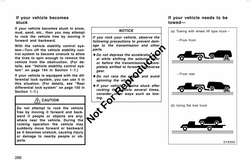
286
If your vehicle becomes stuck in snow,mud, sand, etc., then you may attemptto rock the vehicle free by moving itforward and backward.
With the vehicle stability control sys-tem—Turn off the vehicle stability con-trol system to become unstuck to allowthe tires to spin enough to remove thevehicle from the obstruction. (For de-tails, see “Vehicle stability control sys-tem” on page 154 in Section 1−7.)
If your vehicle is equipped with the dif-ferential lock system, you can use it inthis situation. (For details, see “Reardifferential lock system” on page 150 inSection 1−7.)
CAUTION
Do not attempt to rock the vehiclefree by moving it forward and back-ward if people or objects are any-where near the vehicle. During therocking operation the vehicle maysuddenly move forward or backwardas it becomes unstuck, causing injuryor damage to nearby people or ob-jects.
NOTICE
If you rock your vehicle, observe thefollowing precautions to prevent dam-age to the transmission and otherparts.
z Do not depress the accelerator ped-al while shifting the selector leveror before the transmission is com-pletely shifted to forward or reversegear.
z Do not race the engine and avoidspinning the wheels.
z If your vehicle remains stuck afterrocking the vehicle several times,consider other ways such as tow-ing.
(a) Towing with wheel lift type truck—
(b) Using flat bed truck
—From front
—From rear
L/C120 AE (OM60D50E) 08/01/22
If your vehicle becomesstuck
If your vehicle needs to betowed—
Not For R
epro
duction
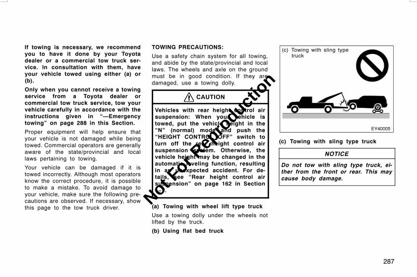
287
If towing is necessary, we recommendyou to have it done by your Toyotadealer or a commercial tow truck ser-vice. In consultation with them, haveyour vehicle towed using either (a) or(b).
Only when you cannot receive a towingservice from a Toyota dealer orcommercial tow truck service, tow yourvehicle carefully in accordance with theinstructions given in “—Emergencytowing” on page 288 in this Section.
Proper equipment will help ensure thatyour vehicle is not damaged while beingtowed. Commercial operators are generallyaware of the state/provincial and locallaws pertaining to towing.
Your vehicle can be damaged if it istowed incorrectly. Although most operatorsknow the correct procedure, it is possibleto make a mistake. To avoid damage toyour vehicle, make sure the following pre-cautions are observed. If necessary, showthis page to the tow truck driver.
TOWING PRECAUTIONS:
Use a safety chain system for all towing,and abide by the state/provincial and locallaws. The wheels and axle on the groundmust be in good condition. If they aredamaged, use a towing dolly.
CAUTION
Vehicles with rear height control airsuspension: When your vehicle istowed, put the vehicle height in the“N” (normal) mode and push the“HEIGHT CONTROL OFF” switch toturn off the rear height control airsuspension system. Otherwise, thevehicle height may be changed in theautomatic leveling function, resultingin an unexpected accident. For de-tails, see “Rear height control airsuspension” on page 162 in Section1−7.
(a) Towing with wheel lift type truck
Use a towing dolly under the wheels notlifted by the truck.
(b) Using flat bed truck
(c) Towing with sling typetruck
(c) Towing with sling type truck
NOTICE
Do not tow with sling type truck, ei-ther from the front or rear. This maycause body damage.
L/C120 AE (OM60D50E) 08/01/22
Not For R
epro
duction
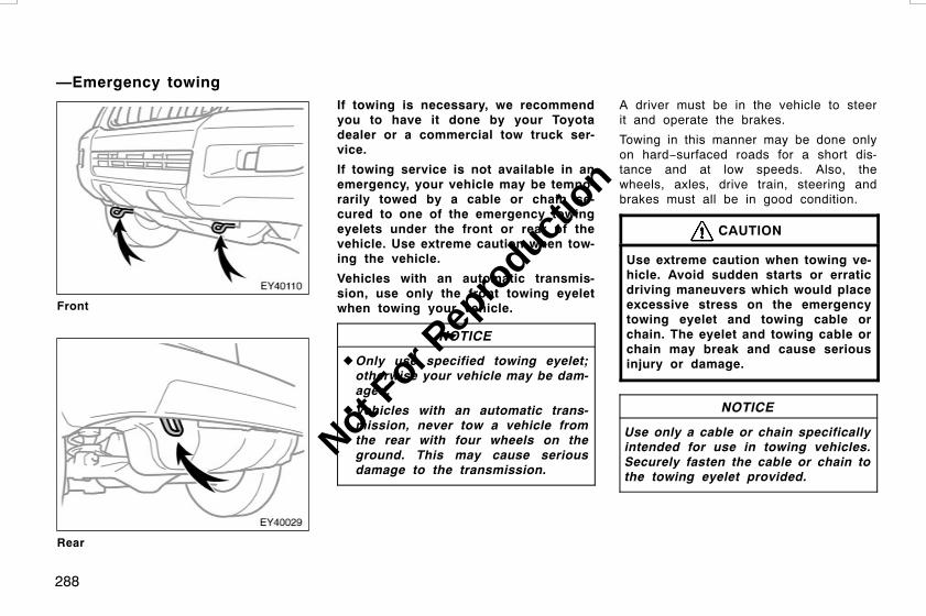
288
Front
Rear
If towing is necessary, we recommendyou to have it done by your Toyotadealer or a commercial tow truck ser-vice.
If towing service is not available in anemergency, your vehicle may be tempo-rarily towed by a cable or chain se-cured to one of the emergency towingeyelets under the front or rear of thevehicle. Use extreme caution when tow-ing the vehicle.
Vehicles with an automatic transmis-sion, use only the front towing eyeletwhen towing your vehicle.
NOTICE
zOnly use specified towing eyelet;otherwise your vehicle may be dam-aged.
z Vehicles with an automatic trans-mission, never tow a vehicle fromthe rear with four wheels on theground. This may cause seriousdamage to the transmission.
A driver must be in the vehicle to steerit and operate the brakes.
Towing in this manner may be done onlyon hard−surfaced roads for a short dis-tance and at low speeds. Also, thewheels, axles, drive train, steering andbrakes must all be in good condition.
CAUTION
Use extreme caution when towing ve-hicle. Avoid sudden starts or erraticdriving maneuvers which would placeexcessive stress on the emergencytowing eyelet and towing cable orchain. The eyelet and towing cable orchain may break and cause seriousinjury or damage.
NOTICE
Use only a cable or chain specificallyintended for use in towing vehicles.Securely fasten the cable or chain tothe towing eyelet provided.
L/C120 AE (OM60D50E) 08/01/22
—Emergency towing
Not For R
epro
duction

289
Before towing, release the parking brake,put the transmission in neutral (manual) or“N” (automatic). Unlock the center differ-ential. The key must be in “ACC” (engineoff) or “ON” (engine running).
CAUTION
If the engine is not running, the pow-er assist for the brakes and steeringwill not work so steering and brakingwill be much harder than usual.
D Before emergency towing, check thatthe eyelet is not broken or damagedand that the installation bolts are notloose.
D Fasten the towing cable or chain se-curely to the eyelet.
D Do not jerk the eyelet. Apply steadyand even force.
D To avoid damaging the eyelet, do notpull from the side or at a verticalangle. Always pull straight ahead.
CAUTION
If the emergency towing hook is usedto get out when your vehicle becomesstuck in mud, sand or other conditionfrom which the vehicle cannot bedriven out under its own power, makesure to observe the precautions men-tioned below. Otherwise, excessivestress will be put on the hook andthe towing cable or chain may break,causing serious injury or damage.
D If the towing vehicle can hardlymove, do not forcibly continue thetowing. Contact your Toyota dealeror a commercial tow truck servicefor assistance.
D Tow the vehicle as straight aheadas possible.
D Keep away from the vehicle duringtowing.
L/C120 AE (OM60D50E) 08/01/22
—Emergency towing eyeletprecautions
Not For R
epro
duction

290
The following methods are effective touse when your vehicle is stuck in themud, sand or other condition fromwhich the vehicle cannot be driven outunder its own power. Use extreme cau-tion when towing the vehicles. In addi-tion, keep away from the vehicles andtowing cable or chain when towing.
D Remove the sand soil in the front andthe back of the tires.
D Place stones or wood under the tires.
If you cannot shift the selector leverout of “P” position to other positionseven though the brake pedal is de-pressed, use the “SHIFT LOCK” buttonas follows:
1. Turn the engine switch to the“LOCK” position. Make sure theparking brake is applied.
2. Push the “SHIFT LOCK” button. Youcan shift out of the “P” positiononly while pushing the button.
3. Shift into the “N” position.
4. Start the engine. For your safety,keep the brake pedal depressed.
Be sure to have the system checked byyour Toyota dealer as soon as possible.
You can purchase a new key at yourToyota dealer if you can give them thekey number and master key.
Even if you lose only one key, contactyour Toyota dealer to make a new key. Ifyou lose all your master keys, you cannotmake new keys; the whole engine immobi-lizer system must be replaced.
See the suggestion given in “Keys” onpage 12 in Section 1−2.
If your keys are locked in the vehicle andyou cannot get a duplicate, many Toyotadealers can still open the door for you,using their special tools. If you mustbreak a window to get in, we suggestbreaking the smallest side window be-cause it is the least expensive to replace.Be extremely cautious to avoid cuts fromthe glass.
L/C120 AE (OM60D50E) 08/01/22
—Tips for towing a stuckvehicle
If you cannot shift automatictransmission selector lever If you lose your keys
Not For R
epro
duction
291
CORROSION PREVENTION ANDAPPEARANCE CAREProtecting your Toyota from corrosion 292. . . . . . . . . . . . . . . . . . . . . . . .Washing and waxing your Toyota 293. . . . . . . . . . . . . . . . . . . . . . . . . . . .Cleaning the interior 295. . . . . . . . . . . . . . . . . . . . . . . . . . . . . . . . . . . . . . . .
L/C120 AE (OM60D50E) 08/01/22
SECTION 5
Not For R
epro
duction
292
Toyota, through the diligent research, de-sign and use of the most advancedtechnology available, helps prevent corro-sion and provides you with the finest qual-ity vehicle construction. Now, it is up toyou. Proper care of your Toyota can helpensure long−term corrosion prevention.
The most common causes of corrosionto your vehicle are:
D The accumulation of road salt, dirt andmoisture in hard−to−reach areas underthe vehicle.
D Chipping of paint, or undercoatingcaused by minor accidents or bystones and gravel.
Care is especially important if you livein particular areas or operate your ve-hicle under certain environmental condi-tions:
D Road salt or dust control chemicals willaccelerate corrosion, as will the pres-ence of salt in the air near the sea−coast or in areas of industrial pollution.
D High humidity accelerates corrosion es-pecially when temperatures range justabove the freezing point.
D Wetness or dampness to certain partsof your vehicle for an extended periodof time, may cause corrosion eventhough other parts of the vehicle maybe dry.
D High ambient temperatures can causecorrosion to those components of thevehicle which do not dry quickly due tolack of proper ventilation.
The above signifies the necessity to keepyour vehicle, particularly the underside, asclean as possible and to repair any dam-age to paint or protective coatings assoon as possible.
To help prevent corrosion on yourToyota, follow these guidelines:
Wash your vehicle frequently. It is, ofcourse, necessary to keep your vehicleclean by regular washing, but to preventcorrosion, the following points should beobserved:
D If you drive on salted roads in thewinter or if you live near the ocean,you should hose off the undercarriageat least once a month to minimize cor-rosion.
D High pressure water or steam is effec-tive for cleaning the vehicle’s undersideand wheel housings. Pay particularattention to these areas as it is difficultto see all the mud and dirt. It will domore harm than good to simply wet themud and debris without removing. Thelower edge of doors, rocker panels andframe members have drain holes whichshould not be allowed to clog with dirtas trapped water in these areas cancause corrosion.
D Wash the underside of the vehicle thor-oughly when winter is over.
See “Washing and waxing your Toyota” onpage 293 for more tips.
Check the condition of your vehicle’spaint and trim. If you find any chips orscratches in the paint, touch them up im-mediately to prevent corrosion from start-ing. If the chips or scratches have gonethrough the bare metal, have a qualifiedbody shop make the repair.
L/C120 AE (OM60D50E) 08/01/22
Protecting your Toyota fromcorrosion
Not For R
epro
duction
293
Check the interior of your vehicle. Wa-ter and dirt can accumulate under thefloor mats and could cause corrosion. Oc-casionally check under the mats to makesure the area is dry. Be particularly care-ful when transporting chemicals, cleans-ers, fertilizers, salt, etc.; these should betransported in proper containers. If a spillor leak should occur, immediately cleanand dry the area.
Use mud shields on your wheels. If youdrive on salted or gravel roads, mudshields help protect your vehicle. Full−sizeshields, which come as near to the groundas possible, are the best. We recommendthat the fittings and the area where theshields are installed be treated to resistcorrosion. Your Toyota dealer will behappy to assist in supplying and installingthe shields if they are recommended foryour area.
Keep your vehicle in a well ventilatedgarage or a roofed place. Do not parkyour vehicle in a damp, poorly venti-lated garage. If you wash your vehicle inthe garage, or if you drive it covered withwater or snow, your garage may be sodamp as to cause corrosion. Even if yourgarage is heated, a wet vehicle can cor-rode if the ventilation is poor.
Washing your Toyota
Keep your vehicle clean by regularwashing.
The following cases may cause weaknessto the paint or corrosion to the body andparts. Wash your vehicle as soon as pos-sible.
D When driving in a coastal area
D When driving on a road sprinkled withantifreeze
D When exposed to coal tar, tree sap,bird droppings and carcass of an insect
D When driving in areas where there isa lot of smoke, soot, dust, iron dust orchemical substances
D When the vehicle becomes remarkablydirty with dust and mud
Hand−washing your Toyota
Work in the shade and wait until thevehicle body is not warm to the touch.
CAUTION
DWhen cleaning under floor or chas-sis, be careful not to injure yourhands.
D Exhaust gases cause the exhaustpipe to become quite hot. Whenwashing the vehicle, be careful notto touch the pipe until it has cooledsufficiently, as touching a hot ex-haust pipe can cause burns.
1. Rinse off loose dirt with a hose. Re-move any mud or road salt from theunderside of the vehicle or the wheelwells.
2. Wash with a mild car−wash soap,mixed according to the manufacturer’sinstructions. Use a soft cotton mitt andkeep it wet by dipping it frequently intothe wash water. Do not rub hard–letthe soap and water remove the dirt.
Plastic wheel ornaments: The plasticwheel ornaments are damaged easily byorganic substances. If any organic sub-stances splash an ornament, be sure towash them off with water and check if theornament is damaged.
L/C120 AE (OM60D50E) 08/01/22
Washing and waxing yourToyota
Not For R
epro
duction

294
Aluminum wheels: Use only a mild soapor neutral detergent.
NOTICE
z Do not use corrosive chemical−based cleaners on your wheels.(Example: hydrofluoric acid)
z Do not use steam cleaners or thechemicals therein to clean yourwheels.
z Do not use scouring pads, wirebrushes, or coarse abrasives toclean your wheels.
z Do not use alcohol, solvents, gaso-line, or other non−neutral deter-gents, because they may alter thewheel’s appearance and resistanceto corrosion.
Plastic bumpers: Wash carefully. Do notscrub with abrasive cleaners. The bumperfaces are soft.
Exterior lights: Wash carefully. Do not useorganic substances or scrub them with ahard brush. This may damage the sur-faces of the lights.
Road tar: Remove with turpentine orcleaners that are marked safe for paintedsurfaces.
3. Rinse thoroughly—dried soap cancause streaking. In hot weather youmay need to rinse each section rightafter you wash it.
4. To prevent water spots, dry the vehicleusing a clean soft cotton towel. Do notrub or press hard—you might scratchthe paint.
NOTICE
z Do not use organic substances(gasoline, kerosene, benzine orstrong solvents), which may be tox-ic or cause damage.
z Do not scrub any part of the ve-hicle with a hard brush, which maycause damage.
Automatic car wash
Your vehicle may be washed in an auto-matic car wash, but remember that thepaint can be scratched by some types ofbrushes, unfiltered washing water, or thewashing process itself. Scratching reducespaint durability and gloss, especially ondarker colors. The manager of the carwash should be able to advise you wheth-er the process is safe for the paint onyour vehicle.
Waxing your Toyota
Polishing and waxing is recommendedto maintain the original beauty of yourToyota’s finish.
Apply wax once a month or if the vehiclesurface does not repel water well.
1. Always wash and dry the vehicle be-fore you begin waxing, even if you areusing a combined cleaner and wax.
2. Use a good quality polish and wax. Ifthe finish has become extremely weath-ered, use a car−cleaning polish, fol-lowed by a separate wax. Carefully fol-low the manufacturer’s instructions andprecautions. Be sure to polish and waxthe chrome trim as well as the paint.
L/C120 AE (OM60D50E) 08/01/22
Not For R
epro
duction

295
Exterior lights: Do not apply wax on thesurfaces of the lights. Wax may causedamage to the lenses. If you accidentallyput wax on the light surfaces, wipe orwash it off.
3. Wax the vehicle again when waterdoes not bead but remains on the sur-face in large patches.
Touch−up paint
Touch−up paint may be used to coversmall chips or scratches.
Apply the paint soon after the damageoccurs or corrosion may set in. To do agood job, use a small artist’s brush andstir the paint well. Make sure the area isclean and dry. To apply the touch−up paintso it is hardly noticeable, the trick is toapply it only to the bare spots. Apply onlythe smallest amount possible and do notpaint the surface around the scratch orchip.
CAUTION
D On vehicles with side airbags andcurtain shield airbags, be carefulnot to splash water or spill liquidon the floor. This may prevent theside airbags and curtain shield air-bags from activating correctly, re-sulting in serious injury.
D Do not wash the vehicle floor withwater, or allow water to get ontothe floor when cleaning the vehicleinterior or exterior. Water may getinto audio components or otherelectrical components above or un-der the floor carpet (or mat) andcause a malfunction; and it maycause body corrosion.
Vinyl interior
The vinyl upholstery may be easilycleaned with a mild soap or detergentand water.
First vacuum over the upholstery to re-move loose dirt. Then, using a sponge orsoft cloth, apply the soap solution to thevinyl. After allowing it to soak in for a fewminutes to loosen the dirt, remove the dirtand wipe off the soap with a clean dampcloth. If all the dirt do not come off, re-peat the procedure. Commercial foaming−type vinyl cleaners are also availablewhich work well. Follow the manufacturer’sinstructions.
NOTICE
Do not use solvent, thinner, gasolineor window cleaner on the interior.
L/C120 AE (OM60D50E) 08/01/22
Cleaning the interior
Not For R
epro
duction

296
Carpets
Use a good foam−type shampoo toclean the carpets.
Begin by vacuuming thoroughly to removeas much dirt as possible. Several types offoam cleaners are available; some are inaerosol can sand others are powders orliquids which you mix with water to pro-duce a foam. To shampoo the carpets,use a sponge or brush to apply the foam.Rub in overlapping circles.
Do not apply water—the best results areobtained by keeping the carpet as dry aspossible. Read the shampoo instructionsand follow them closely.
Seat belts
The seat belts may be cleaned withmild soap and water or with lukewarmwater.
Use a cloth or sponge. As you are clean-ing, check the belts for excessive wear,fraying, or cuts.
NOTICE
z Do not use dye or bleach on thebelts—it may weaken them.
z Do not use the belts until they be-come dry.
Windows
The windows may be cleaned with anyhousehold window cleaner.
NOTICE
When cleaning the inside of the rearwindow, be careful not to scratch ordamage the heater wires or connec-tors.
Air conditioning control panel, audiopanel, instrument panel, console paneland switches
Use a soft damp cloth for cleaning.
Soak a clean soft cloth in water or luke-warm water then lightly wipe off dirt.
NOTICE
z Do not use organic substances (sol-vents, kerosene, alcohol, gasoline,etc.) or alkaline or acidic solutions.These chemicals can cause discol-oring, staining or peeling of thesurface.
z If you use cleaners or polishingagents, make sure their ingredientsdo not include the substances men-tioned above.
z If you use a liquid car freshener, donot apill the liquid onto the ve-hicle’s interior surfaces. It may con-tain the ingredients mentionedabove. Immediately clean any spillusing the method mentioned above.
Leather interior
The leather upholstery may be cleanedwith neutral detergent for wool.
Remove dirt using a soft cloth dampenedwith 5% solution of neutral detergent forwool. Then thoroughly wipe off all tracesof detergent with a clean damp cloth.
L/C120 AE (OM60D50E) 08/01/22
Not For R
epro
duction

297
After cleaning or whenever any part of theleather gets wet, dry with a soft cleancloth. Allow the leather to dry in a venti-lated shaded area.
NOTICE
z If a stain should fail to come outwith a neutral detergent, apply acleaner that does not contain anorganic solvent.
z Never use organic substances suchas benzine, alcohol or gasoline, oralkaline or acid solutions for clean-ing the leather as these couldcause discoloring.
z Use of a nylon brush or syntheticfiber cloth, etc. may scratch thefine grained surface of the leather.
zMildew may develop on soiled leath-er upholstery. Be especially carefulto avoid oil spots. Try to keep yourupholstery always clean.
z Long exposure to direct sunlightmay cause the leather surface toharden and shrink. Keep your ve-hicle in a shaded area, especially inthe summer.
z The interior of your vehicle is aptto heat up on hot summer days, soavoid placing on the upholsteryitems made of vinyl or plastic orcontaining wax as these tend tostick to leather when warm.
z Improper cleaning of the leather up-holstery could result in discolor-ation or staining.
If you have any questions about thecleaning of your Toyota, your localToyota dealer will be pleased to answerthem.
L/C120 AE (OM60D50E) 08/01/22
Not For R
epro
duction

298
L/C120 AE (OM60D50E) 08/01/22
Not For R
epro
duction

299
MAINTENANCE REQUIREMENTSMaintenance facts 300. . . . . . . . . . . . . . . . . . . . . . . . . . . . . . . . . . . . . . . . . .Does your vehicle need repairing? 301. . . . . . . . . . . . . . . . . . . . . . . . . . .
L/C120 AE (OM60D50E) 08/01/22
SECTION 6
Not For R
epro
duction
300
Regular maintenance is essential.
We urge you to protect your new vehicleby having your Toyota serviced accordingto the maintenance schedule given in theseparate booklet. Regular maintenance willaid:
D Good fuel economy
D Long vehicle life
D Driving enjoyment
D Safety
D Reliability
D Warranty coverage
D Compliance with government regula-tions
Your Toyota has been designed for eco-nomical driving and economical mainte-nance. Many formerly required mainte-nance items are no longer required or arenot required as often. To make sure yourvehicle runs at peak efficiency, follow themaintenance schedule.
For full details of your maintenanceschedule, read the separate “Warrantyand Service Booklet”.
Where to go for service?
It makes good sense to take your vehicleto your local Toyota dealer for service.
Toyota technicians are well−trained spe-cialists. And they are receiving the latestservice information through technical bulle-tins, service tips, and in−dealership train-ing programs. They learn to work onToyotas before they work on your vehicle,rather than while they are working on it.Doesn’t that seem like the best way?
Your Toyota dealer has invested a lot ofmoney in special Toyota tools and serviceequipment. It helps do the job better andat less cost.
Your Toyota dealer’s service departmentwill perform all of the scheduled mainte-nance on your vehicle—reliably and eco-nomically.
What about do−it−yourself maintenance?
Many of the maintenance items are easyto do yourself if you have a little mechani-cal ability and a few basic automotivetools. Simple instructions for how to per-form them are presented on page 303 inSection 7.
Note, however, that some maintenancetasks require special tools and skills.These are best performed by qualifiedtechnicians. Even if you are an experi-enced do−it−yourself mechanic, we recom-mend that repairs and maintenance beconducted by your Toyota dealer who willkeep a record of maintenance on yourToyota. This record could be helpfulshould you ever require Warranty Service.
The service interval for scheduled main-tenance is determined by the odometerreading or time interval, whichevercomes first, shown in the schedule.
Rubber hoses (for cooling and heatersystem, brake system and fuel system)should be inspected by a qualified tech-nician in accordance with the Toyotamaintenance schedule.
L/C120 AE (OM60D50E) 08/01/22
Maintenance facts
Not For R
epro
duction

301
They are particularly important mainte-nance items. Have any deteriorated ordamaged hoses replaced immediately.Note that rubber hoses will deterioratewith age, resulting in swelling, chafing orcracks.
Be on the alert for changes in perfor-mance, sounds, and visual tip−offs thatindicate service is needed. Some impor-tant clues are as follows:
D Engine missing, stumbling, or pinging
D Appreciable loss of power
D Strange engine noises
D A leak under the vehicle (However, wa-ter dripping from the air conditioningafter use is normal.)
D Change in exhaust sound (This mayindicate a dangerous carbon monoxideleak. Drive with the windows open andhave the exhaust system checked im-mediately.)
D Flat−looking tire; excessive tire squealwhen cornering; uneven tire wear
D Vehicle pulls to one side when drivingstraight on a level road
D Strange noises related to suspensionmovement
D Loss of brake effectiveness; spongyfeeling brake or clutch pedal; pedal al-most touches floor; vehicle pulls to oneside when braking
D Engine coolant temperature continuallyhigher than normal
D Engine continually runs hot; oil pres-sure gauge stays low.
If you notice any of these clues, take yourvehicle to your Toyota dealer as soon aspossible. It probably needs adjustment orrepair.
CAUTION
Do not continue driving with the ve-hicle unchecked. It could result in se-rious vehicle damage and possiblypersonal injury.
L/C120 AE (OM60D50E) 08/01/22
Does your vehicle needrepairing?
Not For R
epro
duction

302
L/C120 AE (OM60D50E) 08/01/22
Not For R
epro
duction

303
DO−IT−YOURSELF MAINTENANCEIntroductionEngine compartment overview 304. . . . . . . . . . . . . . . . . . . . . . . . . . . . . .Fuse locations 307. . . . . . . . . . . . . . . . . . . . . . . . . . . . . . . . . . . . . . . . . . . . .Do−it−yourself service precautions 307. . . . . . . . . . . . . . . . . . . . . . . . . .
L/C120 AE (OM60D50E) 08/01/22
SECTION 7−1
Not For R
epro
duction

304
1. Windshield washer and rear windowwasher fluid tank
2. Engine oil level dipstick
3. Engine coolant reservoir
4. Engine oil filler cap
5. Fuse block
6. Battery
7. Condenser
8. Electric cooling fan
9. Radiator
L/C120 AE (OM60D50E) 08/01/22
Engine compartment overview"1GR−FE engine
Not For R
epro
duction
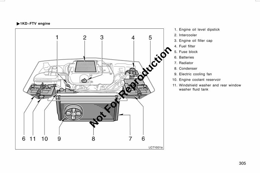
305
1. Engine oil level dipstick
2. Intercooler
3. Engine oil filler cap
4. Fuel filter
5. Fuse block
6. Batteries
7. Radiator
8. Condenser
9. Electric cooling fan
10. Engine coolant reservoir
11. Windshield washer and rear windowwasher fluid tank
L/C120 AE (OM60D50E) 08/01/22
"1KD−FTV engine
LC71001a
Not For R
epro
duction

306
1. Engine oil level dipstick
2. Intercooler
3. Engine oil filler cap
4. Fuel filter
5. Fuse block
6. Battery
7. Radiator
8. Condenser
9. Electric cooling fan
10. Windshield washer and rear windowwasher fluid tank
11. Engine coolant reservoir
L/C120 AE (OM60D50E) 08/01/22
"1KZ−TE engine
Not For R
epro
duction

307
Spare fuses
If you perform maintenance by yourself,be sure to follow the correct proceduregiven in this Section.
You should be aware that improper or in-complete servicing may result in operatingproblems.
This Section gives instructions only forthose items that are relatively easy for anowner to perform. As explained in Section6, there are still a number of items thatmust be done by a qualified technicianwith special tools.
Utmost care should be taken when work-ing on your vehicle to prevent accidentalinjury. Here are a few precautions thatyou should be especially careful to ob-serve:
L/C120 AE (OM60D50E) 08/01/22
Fuse locationsDo−it−yourself serviceprecautions
Not For R
epro
duction
308
CAUTION
DWhen the engine is running, keephands, clothing, and tools awayfrom the moving fan and enginedrive belts. (Removing rings,watches, and ties is advisable.)
D Right after driving, the enginecompartment—the engine, radiator,exhaust manifold, power steeringfluid reservoir and spark plugboots, etc.—will be hot. So be care-ful not to touch them. Oil, fluidsand spark plugs may also be hot.
D If the engine is hot, do not removethe radiator cap (gasoline engine),or the coolant reservoir cap or airrelease valve (diesel engine), orloosen the drain plugs to preventburning yourself.
D Do not leave anything that mayburn easily, such as paper or rags,in the engine compartment.
D Do not smoke, cause sparks or al-low open flames around fuel or thebattery. Their fumes are flammable.
D Be extremely cautious when work-ing on the battery. It contains poi-sonous and corrosive sulfuric acid.
D Do not get under your vehicle withjust the body jack supporting it. Al-ways use automotive jack stands orother solid supports.
D Be sure that the engine switch isoff if you work near the electriccooling fan or radiator grille. Withthe engine switch on, the electriccooling fan will automatically startto run if the air conditioning is on.
D Use eye protection whenever youwork on or under your vehiclewhere you may be exposed to flyingor falling material, fluid spray, etc.
D Used engine oil contains potentiallyharmful contaminants which maycause skin disorders such as in-flammation or skin cancer, so careshould be taken to avoid prolongedand repeated contact with it. To re-move used engine oil from yourskin, wash thoroughly with soapand water.
D Do not leave used oil within thereach of children.
D Dispose of used oil and filter onlyin a safe and acceptable manner.Do not dispose of used oil and fil-ter in household trash, in sewers oronto the ground. Call your dealer ora service station for informationconcerning recycling or disposal.
D Take care when filling the brake andclutch fluid reservoirs becausebrake fluid can harm your hands oreyes. If fluid gets on your hands orin your eyes, flush the affected areawith clean water immediately. If youstill feel uncomfortable with yourhands or eyes, go to the doctor.
L/C120 AE (OM60D50E) 08/01/22
Not For R
epro
duction
309
NOTICE
z Remember that battery and ignitioncables carry high currents or volt-ages. Be careful of accidentallycausing a short circuit.
z Add only “Toyota Super Long LifeCoolant” or similar high quality eth-ylene glycol based non−silicate,non−amine, non−nitrite, and non−bo-rate coolant with long−life hybridorganic acid technology to fill theradiator. “Toyota Super Long LifeCoolant” is a mixture of 50% cool-ant and 50% deionized water.
z If you spill some of the coolant, besure to wash it off with water toprevent it from damaging the partsor paint.
z Do not allow dirt or anything elseto fall through the spark plug holes.
z Do not pry the outer electrode of aspark plug against the center elec-trode.
z Use only spark plugs of the speci-fied type. Using other types willcause engine damage, loss of per-formance or radio noise.
z Do not overfill automatic transmis-sion fluid and power steeringfluid—the automatic transmissionand power steering could be dam-aged.
z 1GR−FE and 1KD−FTV engines withthe vehicle stability control sys-tem—Before you check or addbrake fluid, be sure to turn the en-gine switch off and depress thebrake pedal more than 20 times (un-til the brake pad resistance de-creases and pedal travel increases).Otherwise, the indicated fluid levelwill be lower than the actual level.
z 1KZ−TE engine with the vehicle sta-bility control system—Before youcheck or add brake fluid, be sure toturn the engine switch off and de-press brake pedal more than 40times (until the brake pad resist-ance increases and pedal travel de-creases). Otherwise, the indicatedfluid level will be lower than theactual level.
z If you spill brake and clutch fluid,be sure to wash it off with water toprevent it from damaging the partsor paint.
z Do not drive with the air cleanerfilter removed, or excessive enginewear could result. Also backfiringcould cause a fire in the enginecompartment.
z Be careful not to scratch the glasssurface with the wiper frame.
zWhen closing the engine hood,check to see that you have not for-gotten any tools, rags, etc.
L/C120 AE (OM60D50E) 08/01/22
Not For R
epro
duction

310
L/C120 AE (OM60D50E) 08/01/22
Not For R
epro
duction

311
DO−IT−YOURSELF MAINTENANCEEngine and ChassisChecking the engine oil level 312. . . . . . . . . . . . . . . . . . . . . . . . . . . . . . . .Checking the engine coolant level 316. . . . . . . . . . . . . . . . . . . . . . . . . . .Checking the radiator, condenser and intercooler 317. . . . . . . . . . . . .Draining fuel filter water 317. . . . . . . . . . . . . . . . . . . . . . . . . . . . . . . . . . . .Checking tire inflation pressure 317. . . . . . . . . . . . . . . . . . . . . . . . . . . . . .Checking and replacing tires 318. . . . . . . . . . . . . . . . . . . . . . . . . . . . . . . .Rotating tires 320. . . . . . . . . . . . . . . . . . . . . . . . . . . . . . . . . . . . . . . . . . . . . .Installing snow tires and chains 320. . . . . . . . . . . . . . . . . . . . . . . . . . . . .Replacing wheels 322. . . . . . . . . . . . . . . . . . . . . . . . . . . . . . . . . . . . . . . . . .Aluminum wheel precautions 322. . . . . . . . . . . . . . . . . . . . . . . . . . . . . . . .
L/C120 AE (OM60D50E) 08/01/22
SECTION 7−2
Not For R
epro
duction

312
Low level Full level
Add oil O.K. Too full
1GR−FE engine
Low level Full level
Add oil O.K. Too full
1KD−FTV and 1KZ−TE engines
With the engine at operating tempera-ture and turned off, check the oil levelon the dipstick.
1. To get a correct reading, the vehicleshould be on level ground. After turningoff the engine, wait a few minutes forthe oil to drain back into the bottom ofthe engine.
2. Pull the dipstick out, hold a rag underthe end and wipe it clean.
3. Reinsert the dipstick–push it in as faras it will go, or the reading will not becorrect.
4. Pull the dipstick out and look at the oillevel while holding a rag under theend.
CAUTION
Be careful not to touch the hot ex-haust manifold.
NOTICE
Be careful not to drop engine oil onthe vehicle components.
If the oil level is below or only slightlyabove the low level, add engine oil ofthe same type as already in the engine.
Remove the oil filler cap and add engineoil in small quantities at a time, checkingthe dipstick. We recommend that you usea funnel when adding oil.
The approximate quantity of oil needed toraise the level between low and full on thedipstick is indicated as follows:
1GR−FE and 1KD−FTV engines1.5 L (1.6 qt., 1.3 Imp. qt.)
1KZ−TE engine1.2 L (1.3 qt., 1.1 Imp. qt.)
For the engine oil capacity, see “Servicespecifications” on page 337 in Section 8.
When the level reaches within the correctrange, install the filler cap hand−tight.
NOTICE
z Be careful not to spill engine oil onthe vehicle components.
z Avoid overfilling, or the enginecould be damaged.
z Check the oil level on the dipstickonce again after adding the oil.
L/C120 AE (OM60D50E) 08/01/22
Checking the engine oil level
Not For R
epro
duction

313
ENGINE OIL SELECTION
Gasoline engine—
“Toyota Genuine Motor Oil” is used inyour Toyota vehicle. Use Toyota approved“Toyota Genuine Motor Oil” or equivalentto satisfy the following grade andviscosity.
Oil grade:
20W−50 and 15W−40—API grade SL or SM multigrade engineoil
10W−30 and 5W−30—API grade SL “Energy−Conserving”,SM “Energy−Conserving” or ILSACmultigrade engine oil
Recommended viscosity (SAE):
Temperature range anticipated beforenext oil change
If you use SAE 10W−30 or a higherviscosity engine oil in extremely lowtemperatures, the engine may becomedifficult to start, so SAE 5W−30 engineoil is recommended.
API service symbol
ILSAC certification mark
L/C120 AE (OM60D50E) 08/01/22
Not For R
epro
duction

314
Oil identification marks
Either or both API registered marks areadded to some oil containers to helpyou select the oil you should use.
The API Service Symbol is located any-where on the outside of the container.
The top portion of the label shows the oilquality by API (American PetroleumInstitute) designations such as SM. Thecenter portion of the label shows the SAEviscosity grade such as SAE 10W−30.“Energy−Conserving” shown in the lowerportion, indicates that the oil hasfuel−saving capabilities.
The ILSAC (International Lubricant Stan-dardization and Approval Committee) Certi-fication Mark is displayed on the front ofthe container.
Diesel engine—
“Toyota Genuine Motor Oil” is used inyour Toyota vehicle. Use Toyota approved“Toyota Genuine Motor Oil” or equivalentto satisfy the following grade andviscosity.
Oil grade:1KD−FTV engineG−DLD−1, API CF−4, API CF orACEA B1(You may also use API CE or CD.)
1KZ−TE engineG−DLD−1, API CF−4 or API CF(You may also use API CE or CD.)
Recommended viscosity (SAE):
Temperature range anticipated beforenext oil change
1KD−FTV engine
Temperature range anticipated beforenext oil change
1KZ−TE engine
L/C120 AE (OM60D50E) 08/01/22
Not For R
epro
duction

315
SAE 5W−30 is the best choice for yourvehicle, for good fuel economy, andgood starting in cold weather.
If you use SAE 10W−30 or a higherviscosity engine oil in extremely lowtemperatures, the engine may becomedifficult to start, so SAE 5W−30 engineoil is recommended.
DLD logo mark
The Global DLD−1 logo mark, attachedon some oil containers to help in se-lecting the oil you should use, indicatesthat the oil meets the guidelines recom-mended by the following associations:
D ACEA $(Association desConstructeurs Européensd’Automobiles)$
D AAM $(Alliance of AutomobileManufacturers)$
D EMA $(Engine ManufacturersAssociation)$
D JAMA $(Japan AutomobileManufacturers Association)$
To ensure excellent lubrication perfor-mance for your engine, “Toyota GenuineMotor Oil” is available, which has beenspecifically tested and approved for allToyota engines.
Please contact your Toyota dealer for fur-ther details about “Toyota Genuine MotorOil”.
L/C120 AE (OM60D50E) 08/01/22
Not For R
epro
duction

316
Look at the see−through coolant reser-voir when the engine is cold. The cool-ant level is satisfactory if it is betweenthe “F” and “L” lines on the reservoir.If the level is low, add the coolant. (Forthe coolant type, see “Coolant typeselection” described below.)
The coolant level in the reservoir will varywith engine temperature. However, if thelevel is on or below the “L” line, addcoolant. Bring the level up to the “F” line.
If the coolant level drops within a shorttime after replenishing, there may be aleak in the system. Visually check theradiator, hoses, radiator cap and draincock and water pump.
If you can find no leak, have your Toyotadealer test the cap pressure and checkfor leaks in the cooling system.
CAUTION
To prevent burning yourself, do notremove the radiator cap (gasoline en-gine), or the coolant reservoir cap orair release valve (diesel engine) whenthe engine is hot.
Coolant type selection
Use of improper coolants may damageyour engine cooling system.
Only use “Toyota Super Long Life Coolant”or similar high quality ethylene glycolbased non−silicate, non−amine, non−nitrite,and non−borate coolant with long−lifehybrid organic acid technology. (Coolantwith long−life hybrid organic acidtechnology is a combination of lowphosphates and organic acids.)
“Toyota Super Long Life Coolant” is a mix-ture of 50% coolant and 50% deionizedwater. This coolant provides protectiondown to about −35_C (−31_F).
NOTICE
Do not use plain water alone.
Toyota recommends “Toyota Super LongLife Coolant”, which has been tested toensure that it will not cause corrosion norresult in malfunction of your enginecoolant system with proper usage. “ToyotaSuper Long Life Coolant” is formulatedwith long−life hybrid organic acidtechnology and has been specificallydesigned to avoid engine cooling systemmalfunction on Toyota vehicles.
Please contact your Toyota dealer forfurther details.
L/C120 AE (OM60D50E) 08/01/22
Checking the engine coolantlevel
Not For R
epro
duction
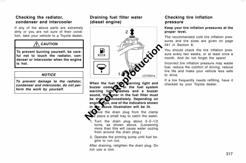
317
If any of the above parts are extremelydirty or you are not sure of their condi-tion, take your vehicle to a Toyota dealer.
CAUTION
To prevent burning yourself, be care-ful not to touch the radiator, con-denser or intercooler when the engineis hot.
NOTICE
To prevent damage to the radiator,condenser and intercooler, do not per-form the work by yourself.
LC72001a
When the fuel filter warning light andbuzzer come on, or the fuel systemwarning light flashes and a buzzersound, the water in the fuel filter mustbe drained immediately. Depending onengine type, one of the indicators shownin the above illustration will be lit.
Remove the drain plug from the clampand place a small tray to catch the water.
1. Turn the drain plug about 2–2−1/2turns, as shown above. (Looseningmore than this will cause water oozingfrom around the drain plug.)
2. Operate the priming pump until fuel be-gins to run out.
After draining, retighten the drain plug. Donot use a tool.
Keep your tire inflation pressures at theproper level.
The recommended cold tire inflation pres-sures and tire sizes are given on page341 in Section 8.
You should check the tire inflation pres-sure every two weeks, or at least once amonth. And do not forget the spare!
Incorrect tire inflation pressure may wastefuel, reduce the comfort of driving, reducetire life and make your vehicle less safeto drive.
If a tire frequently needs refilling, have itchecked by your Toyota dealer.
L/C120 AE (OM60D50E) 08/01/22
Checking the radiator,condenser and intercooler
Draining fuel filter water(diesel engine)
Checking tire inflationpressure
Not For R
epro
duction

318
The following instructions for checkingtire inflation pressure should be ob-served:
D The pressure should be checked onlywhen the tires are cold. If your ve-hicle has been parked for at least 3hours and has not been driven formore than 1.5 km or 1 mile since, youwill get an accurate cold tire inflationpressure reading.
D Always use a tire pressure gauge.The appearance of a tire can be mis-leading. Besides, tire inflation pressur-es that are even just a few pounds offcan degrade ride and handling.
D Do not bleed or reduce tire inflationpressure after driving. It is normal forthe tire inflation pressure to be higherafter driving.
D Be sure to reinstall the tire valvecaps. Without the valve caps, dirt ormoisture could get into the valve coreand cause air leakage. If the capshave been lost, have new ones put onas soon as possible.
CAUTION
Keep your tires properly inflated.Otherwise, the following conditionsmay occur and cause an accident re-sulting in death or serious injuries.
Low tire pressure (underinflation)—
D Excessive wear
D Uneven wear
D Poor handling
D Possibility of blowouts from anoverheated tire
D Poor sealing of the tire bead
DWheel deformation and/or tire sepa-ration
D A greater possibility of tire damagefrom road hazards
High tire pressure (overinflation)—
D Poor handling
D Excessive wear
D Uneven wear
D A greater possibility of tire damagefrom road hazards
Treadwear indicator
CHECKING YOUR TIRES
Check the tire’s tread for treadwear in-dicators. If the indicators show, replacethe tires. The location of treadwear in-dicators is shown by the “TWI” or “∆”marks, etc., molded on the sidewall ofeach tire.
The tires on your Toyota have built−intreadwear indicators to help you knowwhen the tires need replacement. Whenthe tread depth wears to 1.6 mm (0.06in.) or less, the indicators will appear. Ifyou can see the indicators in two or moreadjacent grooves, the tire should be re-placed. The lower the tread, the higherthe risk of skidding.
L/C120 AE (OM60D50E) 08/01/22
Checking and replacing tires
Not For R
epro
duction
319
The effectiveness of snow tires is lostif the tread wears down below 4 mm(0.16 in.).
If you have tire damage such as cuts,splits, cracks deep enough to exposethe fabric, or bulges indicating internaldamage, the tire should be replaced.
If a tire often goes flat or cannot be prop-erly repaired due to the size or locationof a cut or other damage, it should bereplaced. If you are not sure, consult withyour Toyota dealer.
If air loss occurs while driving, do notcontinue driving. Driving even a short dis-tance can damage a tire beyond repair.
Any tires which are over 6 years oldmust be checked by a qualified techni-cian even if damage is not obvious.
Tires deteriorate with age even if theyhave never or seldom been used.
This applies also to the spare tire andtires stored for future use.
REPLACING YOUR TIRES
When replacing a tire, use a tire of thesame size and construction, and thesame or greater load capacity as theoriginally installed tires. Also, all thetires must be the same brand and havethe same tread patterns.
Using any other size or type of tire mayseriously affect handling, ride, speedome-ter/odometer calibration, ground clearance,and clearance between the body and tiresor snow chains.
CAUTION
Observe the following instructions.Otherwise, an accident may occur re-sulting in death or serious injuries.
D Do not mix radial, bias belted, orbias−ply tires on your vehicle, asthis may cause dangerous handlingcharacteristics resulting in loss ofcontrol.
D Do not use tires other than themanufacturer’s recommended size,as this may cause dangerous han-dling characteristics resulting inloss of control.
With the vehicle stability control sys-tem—
D Do not use tires of different brands,sizes and constructions. This maydamage the drive system and pre-vent the vehicle stability controlsystem from functioning correctly.
Never use second−hand tires on yourToyota.
Using tires whose previous history is un-known is a risk.
Toyota recommends all four tires, or atleast both front or rear tires be re-placed at a time as a set.
See “If you have a flat tire” on page 273in Section 4 for tire change procedure.
When a tire is replaced, the wheelshould always be balanced.
An unbalanced wheel may affect vehiclehandling and tire life. Wheels can get outof balance with regular use and shouldtherefore be balanced occasionally.
When replacing a tubeless tire, the airvalve should also be replaced with anew one.
L/C120 AE (OM60D50E) 08/01/22
Not For R
epro
duction

320
With back door mounted spare tire
With under floor mounted spare tire
To equalize tire wear and help extendtire life, Toyota recommends that yourotate your tires approximately every5000 km (3000 miles). However, themost appropriate timing for tire rotationmay vary according to your driving hab-its and road surface conditions.
See “If you have a flat tire” on page 273in Section 4 for tire change procedure.
When rotating tires, check for unevenwear and damage. Abnormal wear is usu-ally caused by incorrect tire pressure, im-proper wheel alignment, out−of−balancewheels, or severe braking.
WHEN TO USE SNOW TIRES ORCHAINS
Snow tires or chains are recommendedwhen driving on snow or ice.
On wet or dry roads, conventional tiresprovide better traction than snow tires.
SNOW TIRE SELECTION
If you need snow tires, select tires ofthe same size, construction and loadcapacity as the originally installed tires.Also, all the tires must be the samebrand and have the same tread pat-terns.
Do not use tires other than those men-tioned above. Do not install studded tireswithout first checking local regulations forpossible restrictions.
CAUTION
Observe the following instructions.Otherwise, an accident may occur re-sulting in death or serious injuries.
D Do not use snow tires other thanthe manufacturer’s recommended si-ze, as this may cause dangeroushandling characteristics resulting inloss of control.
L/C120 AE (OM60D50E) 08/01/22
Rotating tiresInstalling snow tires andchains
Not For R
epro
duction
321
D Do not use snow tires of differentbrands, sizes, construction or treadpatterns, as this may cause danger-ous handling characteristics result-ing in loss of control.
SNOW TIRE INSTALLATION
Snow tires should be installed on allwheels.
Installing snow tires on the rear wheelsonly can lead to an excessive differencein road grip capability between the frontand rear tires which could cause loss ofvehicle control.
When storing tires, you should store themin a cool dry place. Mark the direction ofrotation and be sure to install them in thesame direction when replacing.
CAUTION
D Do not drive with the snow tiresincorrectly inflated.
D Observe permissible maximumspeed for your snow tires and thelegal speed limit.
TIRE CHAIN SELECTION
Use the tire chains of correct size.
Regulations regarding the use of tirechains vary according to location ortype of road, so always check local reg-ulations before installing chains.
CHAIN INSTALLATION
Install the chains on the rear tires astightly as possible. Do not use tirechains on the front tires. Retightenchains after driving 0.5—1.0 km(1/4—1/2 mile).
When installing chains on your tires, care-fully follow the instructions of the chainmanufacturer.
If wheel covers are used, they will bescratched by the chain band, so removethe covers before putting on the chains.
CAUTION
D Do not exceed 50 km/h (30 mph) orthe chain manufacturer’s recom-mended speed limit, whichever islower.
D Drive carefully avoiding bumps,holes, and sharp turns, which maycause the vehicle to bounce.
D Avoid sharp turns or locked−wheelbraking as use of chains may ad-versely affect vehicle handling.
DWhen driving with chains installed,be sure to drive carefully. Slowdown before entering curves toavoid losing control of the vehicle.Otherwise an accident may occur.
L/C120 AE (OM60D50E) 08/01/22
Not For R
epro
duction

322
WHEN TO REPLACE YOUR WHEELS
If you have wheel damage such asbending, cracks or heavy corrosion, thewheel should be replaced.
If you fail to replace a damaged wheel,the tire may slip off the wheel or causeloss of handling control.
WHEEL SELECTION
When replacing wheels, care should betaken to ensure that the wheels are re-placed by ones with the same load ca-pacity, diameter, rim width, and offset.
Correct replacement wheels are availableat your Toyota dealer.
A wheel of a different size or type mayadversely affect handling, wheel and bear-ing life, brake cooling, speedometer/odom-eter calibration, stopping ability, headlightaim, bumper height, vehicle ground clear-ance, and tire or snow chain clearance tothe body and chassis.
Replacement with used wheels is not rec-ommended as they may have been sub-jected to rough treatment or high mileageand could fail without warning. Also, bentwheels which have been straightened mayhave structural damage and thereforeshould not be used. Never use an innertube in a leaking wheel which is designedfor a tubeless tire.
CAUTION
Observe the following instructions.Otherwise, an accident may occur re-sulting in death or serious injuries.
D Do not use wheels other than themanufacturer’s recommended size,as this may cause dangerous han-dling characteristics resulting inloss of control.
D Do not use wheels of differentbrands, sizes and types, as thismay cause dangerous handlingcharacteristics resulting in loss ofcontrol.
D When installing aluminum wheels,check that the wheel nuts are tightafter driving your vehicle the first 1600km (1000 miles).
D If you have rotated, repaired orchanged your tires, check that thewheel nuts are still tight after driving1600 km (1000 miles).
D When using tire chains, be careful notto damage the aluminum wheels.
D Use only Toyota wheel nuts andwrench designed for your aluminumwheels.
D When balancing your wheels, use onlyToyota balance weights or equivalentand a plastic or rubber hammer.
D As with any wheel, periodically checkyour aluminum wheels for damage. Ifdamaged, replace immediately.
L/C120 AE (OM60D50E) 08/01/22
Replacing wheels Aluminum wheel precautions
Not For R
epro
duction

323
DO−IT−YOURSELF MAINTENANCEElectrical componentsChecking battery condition 324. . . . . . . . . . . . . . . . . . . . . . . . . . . . . . . . . .Battery recharging precautions 325. . . . . . . . . . . . . . . . . . . . . . . . . . . . . .Checking and replacing fuses 326. . . . . . . . . . . . . . . . . . . . . . . . . . . . . . .Adding washer fluid 327. . . . . . . . . . . . . . . . . . . . . . . . . . . . . . . . . . . . . . . .Replacing light bulbs 328. . . . . . . . . . . . . . . . . . . . . . . . . . . . . . . . . . . . . . .
L/C120 AE (OM60D50E) 08/01/22
SECTION 7−3
Not For R
epro
duction
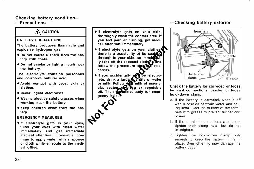
324
CAUTION
BATTERY PRECAUTIONS
The battery produces flammable andexplosive hydrogen gas.
D Do not cause a spark from the bat-tery with tools.
D Do not smoke or light a match nearthe battery.
The electrolyte contains poisonousand corrosive sulfuric acid.
D Avoid contact with eyes, skin orclothes.
D Never ingest electrolyte.
DWear protective safety glasses whenworking near the battery.
D Keep children away from the bat-tery.
EMERGENCY MEASURES
D If electrolyte gets in your eyes,flush your eyes with clean waterimmediately and get immediatemedical attention. If possible, con-tinue to apply water with a spongeor cloth while en route to the medi-cal office.
D If electrolyte gets on your skin,thoroughly wash the contact area. Ifyou feel pain or burning, get medi-cal attention immediately.
D If electrolyte gets on your clothes,there is a possibility of its soakingthrough to your skin, so immediate-ly take off the exposed clothing andfollow the procedure above, if nec-essary.
D If you accidentally swallow electro-lyte, drink a large quantity of wateror milk. Follow with milk of magne-sia, beaten raw egg or vegetableoil. Then go immediately for emer-gency help.
Terminals
Hold−downclamp
Ground cable
Check the battery for corroded or looseterminal connections, cracks, or loosehold−down clamp.
a. If the battery is corroded, wash it offwith a solution of warm water and bak-ing soda. Coat the outside of the termi-nals with grease to prevent further cor-rosion.
b. If the terminal connections are loose,tighten their clamp nuts—but do notovertighten.
c. Tighten the hold−down clamp onlyenough to keep the battery firmly inplace. Overtightening may damage thebattery case.
L/C120 AE (OM60D50E) 08/01/22
Checking battery condition——Precautions —Checking battery exterior
Not For R
epro
duction

325
NOTICE
z Be sure the engine and all accesso-ries are off before performing main-tenance.
zWhen checking the battery, removethe ground cable from the negativeterminal (“−” mark) first and rein-stall it last.
z Be careful not to cause a short cir-cuit with tools.
z Take care no solution gets into thebattery when washing it.
If the battery is disconnected or rundown, the power window and moon roofmay not operate automatically and the jamprotection function will not function cor-rectly after you reconnect, replace or re-charge the battery. In any of these cases,you should normalize the power windowand moon roof. To normalize the powerwindow and moon roof, see “Power win-dows” on page 22 and “Electric moonroof” on page 32 in Section 1−2.
Type A
Green DarkClear orlight yellow
Type B
Blue White Red
CHECKING BY INDICATOR
Check the battery condition by the indi-cator color.
Indicator colorCondition
Type A Type BCondition
Green Blue Good
Dark White
Charging necessary.Have batterychecked by yourToyota dealer.
Clear orlightyellow
RedHave batterychecked by yourToyota dealer.
During recharging, the battery is pro-ducing hydrogen gas.
Therefore, before recharging:
1. If recharging with the battery installedon the vehicle, be sure to disconnectthe ground cable.
2. Be sure the power switch on the re-charger is off when connecting thecharger cables to the battery and whendisconnecting them.
CAUTION
D Always charge the battery in an un-confined area. Do not charge thebattery in a garage or closed roomwhere there is not sufficient ventila-tion.
D Be sure to remove the vent plugsbefore recharging.
NOTICE
Never recharge the battery while theengine is running. Also, be sure allaccessories are turned off.
L/C120 AE (OM60D50E) 08/01/22
—Checking battery conditionBattery rechargingprecautions
Not For R
epro
duction

326
Good Blown
Type A
Good Blown
Type B
BlownGood
Type C
Good Blown
Type D
If the headlights or other electricalcomponents do not work, check thefuses. If any of the fuses are blown,they must be replaced.
See “Fuse locations” on page 307 in Sec-tion 7−1 for locations of the fuses.
Turn the engine switch and inoperativecomponent off. Pull the suspected fusestraight out and check it.
Determine which fuse may be causing theproblem. The lid of the fuse box showsthe name of the circuit for each fuse. Seepage 342 in Section 8 for the functionscontrolled by each circuit.
L/C120 AE (OM60D50E) 08/01/22
Checking and replacing fuses
Not For R
epro
duction

327
Type A fuses can be pulled out by thepull−out tool. The location of the pull−outfool is shown in the illustration.
If you are not sure whether the fuse hasblown, try replacing the suspected fusewith one that you know is good.
If the fuse has blown, push a new fuseinto the clip.
Only install a fuse with the amperage rat-ing designated on the fuse box lid.
If you do not have a spare fuse, in anemergency you can pull out the “DOME”,“PWR OUTLET” or “RADIO NO.1” fuse,which may be dispensable for normal driv-ing, and use it if its amperage rating isthe same.
If you cannot use one of the same amper-age, use one that is lower, but as closeto the rating as possible. If the amperageis lower than that specified, the fusemight blow out again but this does notindicate anything wrong. Be sure to getthe correct fuse as soon as possible andreturn the substitute to its original clip.
It is a good idea to purchase a set ofspare fuses and keep them in your ve-hicle for emergencies.
If the new fuse immediately blows out,there is a problem with the electrical sys-tem. Have your Toyota dealer correct it assoon as possible.
You should normalize the power windowand moon roof if it does not operate auto-matically or the jam protection functiondoes not operate correctly after replacingblown fuses. To normalize the power win-dow and moon roof, see “Power windows”on page 22 and “Electric moon roof” onpage 32 in Section 1−2.
CAUTION
Never use a fuse with a higher am-perage rating, or any other object, inplace of a fuse. This may cause ex-tensive damage and possibly a fire.
If any washer does not work, the wash-er tank may be empty. Check the wash-er fluid level on the level gauge. If thewasher fluid level is below “LOW” oronly slightly above the “LOW” level,add washer fluid.
You may use plain water as washer fluid.However, in cold areas where tempera-tures range below the freezing point, usewasher fluid containing antifreeze. Thisproduct is available at your Toyota dealerand most auto parts stores. Follow themanufacturer’s directions for how much tomix with water.
L/C120 AE (OM60D50E) 08/01/22
Adding washer fluid
Not For R
epro
duction

328
NOTICE
z Do not use engine antifreeze or anyother substitute because it maydamage your vehicle’s paint.
z Do not fill washer fluid over the“NORMAL” level.
The following illustrations show how togain access to the bulbs. When replacinga bulb, make sure the engine switch andlight switch are off. Use bulbs with thewattage ratings given in the table.
The high mounted stoplight consists of anumber of LEDs. If any of the LEDs burnout, take your vehicle to your Toyota deal-er to have the light replaced.
CAUTION
D To prevent burning yourself, do notreplace the light bulbs while theyare hot.
D Halogen bulbs have pressurized gasinside and require special handling.They can burst or shatter ifscratched or dropped. Hold a bulbonly by its plastic or metal case.Do not touch the glass part of abulb with bare hands.
NOTICE
Only use a bulb of the listed type.
The inside of the lens of exterior lightssuch as headlights may temporarily fog upwhen the lens becomes wet in the rain orin a car wash. This is not a problembecause the fogging is caused by thetemperature difference between the outsideand inside of the lens, just like thewindshield fogs up in the rain. However, ifthere is a large drop of water on theinside of the lens, or if there is waterpooled inside the light, contact yourToyota dealer.
L/C120 AE (OM60D50E) 08/01/22
Replacing light bulbs—
Not For R
epro
duction

329
Light Bulbs W Type
Headlights 60/55 A
Front fog lights 51 B
Front turn signal lights 21 C
Parking lights 5 C
Side turn signal lights 5 C
Rear turn signal lights 21 D
Stop/tail lights 21/5 C
Back−up lights 16 C
License plate lights 5 C
Vanity lights 2 E
Interior lights 8 E
Personal lights 8 F
Door courtesy lights 3.8 F
Glove box light 1.2 C
A: H4 halogen bulbsB: HB4 halogen bulbsC: Wedge base bulbs (clear)D: Wedge base bulbs (amber)E: Double end bulbsF: Single end bulbs
1. Open the hood. Unplug the connec-tor. Remove the rubber cover.
If the connector is tight, wiggle it.
2. Release the bulb retaining springand remove the bulb. Install a newbulb and the bulb retaining spring.
To install a bulb, align the tabs of thebulb with the cutouts of the mountinghole.
L/C120 AE (OM60D50E) 08/01/22
—Headlights
Not For R
epro
duction
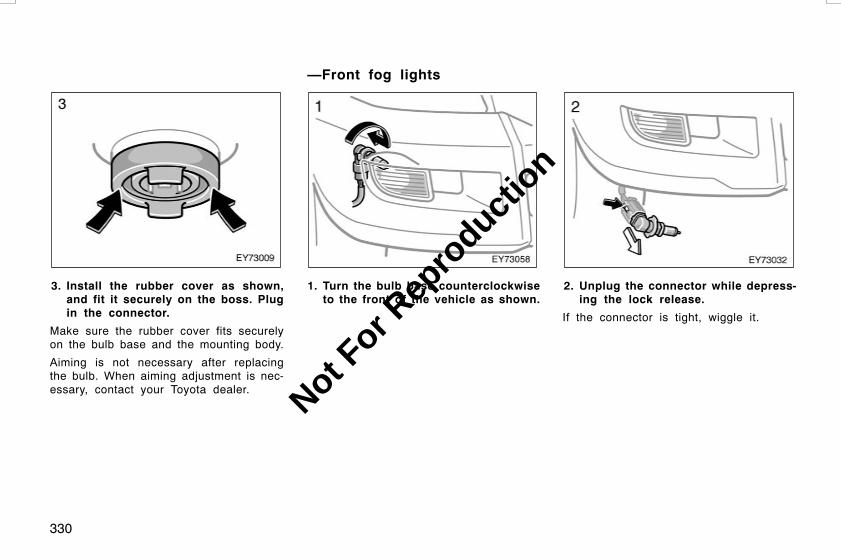
330
3. Install the rubber cover as shown,and fit it securely on the boss. Plugin the connector.
Make sure the rubber cover fits securelyon the bulb base and the mounting body.
Aiming is not necessary after replacingthe bulb. When aiming adjustment is nec-essary, contact your Toyota dealer.
1. Turn the bulb base counterclockwiseto the front of the vehicle as shown.
2. Unplug the connector while depress-ing the lock release.
If the connector is tight, wiggle it.
L/C120 AE (OM60D50E) 08/01/22
—Front fog lights
Not For R
epro
duction

331
3. Install a new bulb and connectorinto the mounting hole and turnthem clockwise to the front of thevehicle.
If either the left or right parking lightsburns out, contact your Toyota dealer.
NOTICE
Do not try to replace any of the lightbulbs mentioned above by yourself.You may damage the vehicle.
L/C120 AE (OM60D50E) 08/01/22
—Parking lights —Front turn signal lights
Not For R
epro
duction

332
Front of vehicle
Use a Phillips−head screwdriver.
L/C120 AE (OM60D50E) 08/01/22
—Side turn signal lights—Rear turn signal, stop/tailand back−up lights (left side)
Not For R
epro
duction

333
a: Stop/tail lightb: Rear turn signal lightc: Back−up light
Use a Phillips−head screwdriver. a: Stop/tail lightb: Rear turn signal lightc: Back−up light
L/C120 AE (OM60D50E) 08/01/22
—Rear turn signal, stop/tailand back−up lights (right side)
Not For R
epro
duction

334
Use a Phillips−head screwdriver.
L/C120 AE (OM60D50E) 08/01/22
—License plate lights(type A)
—License plate lights(type B)
Not For R
epro
duction

335
SPECIFICATIONSDimensions 336. . . . . . . . . . . . . . . . . . . . . . . . . . . . . . . . . . . . . . . . . . . . . . . .Engine 336. . . . . . . . . . . . . . . . . . . . . . . . . . . . . . . . . . . . . . . . . . . . . . . . . . . .Fuel 337. . . . . . . . . . . . . . . . . . . . . . . . . . . . . . . . . . . . . . . . . . . . . . . . . . . . . . .Service specifications 337. . . . . . . . . . . . . . . . . . . . . . . . . . . . . . . . . . . . . .Tires 341. . . . . . . . . . . . . . . . . . . . . . . . . . . . . . . . . . . . . . . . . . . . . . . . . . . . . .Fuses 342. . . . . . . . . . . . . . . . . . . . . . . . . . . . . . . . . . . . . . . . . . . . . . . . . . . . .
L/C120 AE (OM60D50E) 08/01/22
SECTION 8
Not For R
epro
duction
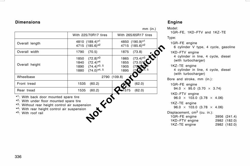
336
Model:1GR−FE, 1KD−FTV and 1KZ−TE
Type:
1GR−FE engine6 cylinder V type, 4 cycle, gasoline
1KD−FTV engine4 cylinder in line, 4 cycle, diesel(with turbocharger)
1KZ−TE engine4 cylinder in line, 4 cycle, diesel(with turbocharger)
Bore and stroke, mm (in.):
1GR−FE engine94.0 × 95.0 (3.70 × 3.74)
1KD−FTV engine96.0 × 103.0 (3.78 × 4.06)
1KZ−TE engine96.0 × 103.0 (3.78 × 4.06)
Displacement, cm3 (cu. in.):1GR−FE engine 3956 (241.4)1KD−FTV engine 2982 (182.0)1KZ−TE engine 2982 (182.0)
L/C120 AE (OM60D50E) 08/01/22
Dimensions
mm (in.)
Overall length
Overall width
Overall height
Wheelbase
Front tread
Rear tread
With 225/70R17 tires
4810 (189.4)*14715 (185.6)*2
1790 (70.5)
1850 (72.8)*31840 (72.4)*4
1890 (74.4)*3, 51880 (74.0)*4, 5
2790 (109.8)
1535 (60.2)
1535 (60.2)
With 265/65R17 tires
4850 (190.9)*14715 (185.6)*2
1875 (73.8)
1865 (73.4)*31855 (73.0)*4
1905 (75.0)*3, 51895 (74.6)*4, 5
1575 (62.0)
1575 (62.0)
*1: With back door mounted spare tire*2: With under floor mounted spare tire*3: Without rear height control air suspension*4: With rear height control air suspension*5: With roof rail
Engine
Not For R
epro
duction

337
Fuel type:
Gasoline engine—Unleaded gasoline, Research OctaneNumber 91 or higher. For improvedvehicle performance, the use of pre-mium unleaded gasoline with a Re-search Octane Number of 95 or higheris recommended.
Diesel engine—Diesel fuel, cetane number 50(Cetane Index 45) or higher
Fuel tank capacity, L (gal., Imp. gal.):Without sub fuel tank system
87 (23.0, 19.1)With sub fuel tank system
180 (47.6, 39.6)
ENGINE
Valve clearance, mm (in.):
1GR−FE engineIntake 0.15—0.25 (0.006—0.010)Exhaust 0.29—0.39 (0.011—0.015)
1KD−FTV engineIntake 0.20—0.30 (0.008—0.012)Exhaust 0.35—0.45 (0.014—0.017)
1KZ−TE engineIntake 0.20—0.30 (0.008—0.012)Exhaust 0.25—0.35 (0.010—0.014)
Spark plug type:DENSO K20HR−U11NGK LFR6C11
Spark plug gap, mm (in.):1.1 (0.043)
Airconditioningcompressor
Generator
Idler
Fan
Crankshaft
1KZ−TE engine
Drive belt deflection with 98 N (10 kgf, 22lbf) thumb pressure (used belt), mm (in.):
Diesel engine1. 8—12 (0.31—0.47)2. 15—21 (0.59—0.83)
Except 1KZ−TE engineAutomatic adjustment
L/C120 AE (OM60D50E) 08/01/22
Fuel Service specifications
Not For R
epro
duction
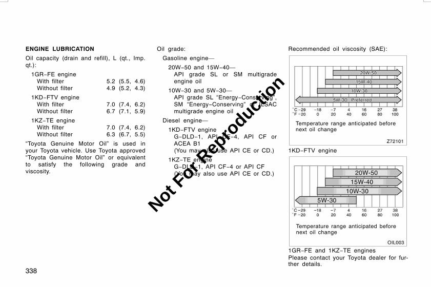
338
ENGINE LUBRICATION
Oil capacity (drain and refill), L (qt., Imp.qt.):
1GR−FE engineWith filter 5.2 (5.5, 4.6)Without filter 4.9 (5.2, 4.3)
1KD−FTV engineWith filter 7.0 (7.4, 6.2)Without filter 6.7 (7.1, 5.9)
1KZ−TE engineWith filter 7.0 (7.4, 6.2)Without filter 6.3 (6.7, 5.5)
“Toyota Genuine Motor Oil” is used inyour Toyota vehicle. Use Toyota approved“Toyota Genuine Motor Oil” or equivalentto satisfy the following grade andviscosity.
Oil grade:
Gasoline engine—
20W−50 and 15W−40—API grade SL or SM multigradeengine oil
10W−30 and 5W−30—API grade SL “Energy−Conserving”,SM “Energy−Conserving” or ILSACmultigrade engine oil
Diesel engine—
1KD−FTV engineG−DLD−1, API CF−4, API CF orACEA B1(You may also use API CE or CD.)
1KZ−TE engineG−DLD−1, API CF−4 or API CF(You may also use API CE or CD.)
Recommended oil viscosity (SAE):
Temperature range anticipated beforenext oil change
1KD−FTV engine
Temperature range anticipated beforenext oil change
1GR−FE and 1KZ−TE enginesPlease contact your Toyota dealer for fur-ther details.
L/C120 AE (OM60D50E) 08/01/22
Not For R
epro
duction
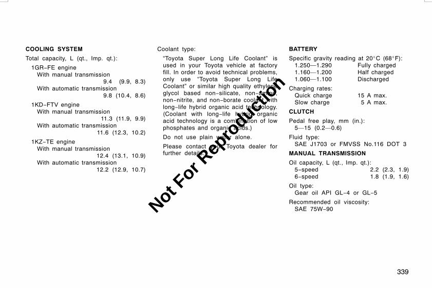
339
COOLING SYSTEM
Total capacity, L (qt., Imp. qt.):
1GR−FE engineWith manual transmission
9.4 (9.9, 8.3)With automatic transmission
9.8 (10.4, 8.6)
1KD−FTV engineWith manual transmission
11.3 (11.9, 9.9)With automatic transmission
11.6 (12.3, 10.2)
1KZ−TE engineWith manual transmission
12.4 (13.1, 10.9)With automatic transmission
12.2 (12.9, 10.7)
Coolant type:
“Toyota Super Long Life Coolant” isused in your Toyota vehicle at factoryfill. In order to avoid technical problems,only use “Toyota Super Long LifeCoolant” or similar high quality ethyleneglycol based non−silicate, non−amine,non−nitrite, and non−borate coolant withlong−life hybrid organic acid technology.(Coolant with long−life hybrid organicacid technology is a combination of lowphosphates and organic acids.)
Do not use plain water alone.
Please contact your Toyota dealer forfurther details.
BATTERY
Specific gravity reading at 20_C (68_F):1.250—1.290 Fully charged1.160—1.200 Half charged1.060—1.100 Discharged
Charging rates:Quick charge 15 A max.Slow charge 5 A max.
CLUTCH
Pedal free play, mm (in.):5—15 (0.2—0.6)
Fluid type:SAE J1703 or FMVSS No.116 DOT 3
MANUAL TRANSMISSION
Oil capacity, L (qt., Imp. qt.):5−speed 2.2 (2.3, 1.9)6−speed 1.8 (1.9, 1.6)
Oil type:Gear oil API GL−4 or GL−5
Recommended oil viscosity:SAE 75W−90
L/C120 AE (OM60D50E) 08/01/22
Not For R
epro
duction

340
AUTOMATIC TRANSMISSION (4−speed)
Fluid capacity (drain and refill),L (qt., lmp. qt):Up to 2.7 (2.9, 2.4)
Fluid type:Toyota Genuine ATF Type T−IV
Change automatic transmission fluid onlyas necessary.
Generally, it is necessary to changeautomatic transmission fluid only if yourvehicle is driven under one of the SpecialOperating Conditions listed in your“Warranty and Service Booklet”. Whenchanging the automatic transmission fluid,use only “Toyota Genuine ATF Type T−IV”(ATF JWS3309 or NWS6500) to aid inassuring optimum transmission perfor-mance.
Notice: Using automatic transmissionfluid other than “Toyota Genuine ATFType T−IV” may cause deterioration inshift quality, locking up of your trans-mission accompanied by vibration, andultimately damage the automatic trans-mission of your vehicle.
Please contact your Toyota dealer for fur-ther details.
AUTOMATIC TRANSMISSION (5−speed)Fluid capacity (drain and refill),L (qt., Imp. qt.):1GR−FE engineUp to 10.9 (11.5, 9.6)*
1KD−FTV engineUp to 10.6 (11.2, 9.3)*
*: The fluid capacity is the quantity of ref-erence. If replacement is necessary,contact your Toyota dealer.
Fluid type:Toyota Genuine ATF WS
Change automatic transmission fluid onlyas necessary.Generally, it is necessary to changeautomatic transmission fluid only if yourvehicle is driven under one of the SpecialOperating Conditions listed in your“Warranty and Service Booklet”. Whenchanging the automatic transmission fluid,use only “Toyota Genuine ATF WS” (ATFJWS3324 or NWS9638) to aid in assuringoptimum transmission performance.Notice: Using automatic transmissionfluid other than “Toyota Genuine ATFWS” may cause deterioration in shiftquality, locking up of your transmissionaccompanied by vibration, and ultimate-ly damage the automatic transmissionof your vehicle.Please contact your Toyota dealer for fur-ther details.
TRANSFER
Oil capacity, L (qt., Imp. qt.):1.4 (1.5, 1.2)
Oil type:Hypoid gear oil API GL−5
Recommended oil viscosity:SAE 75W−90
DIFFERENTIAL
Oil capacity, L (qt., Imp. qt.):Front 1.4 (1.5, 1.2)RearWithout rear differential lock system
3.05 (3.2, 2.7)With rear differential lock system
2.95 (3.1, 2.6)
“Toyota Genuine Differential Gear Oil” isused in your Toyota vehicle. Use Toyotaapproved “Toyota Genuine DifferentialGear Oil” or equivalent to satisfy the fol-lowing specification.
Oil type:
Standard differentialHypoid gear oil API GL−5
Limited slip differentialHypoid gear oil LSD API GL−5
L/C120 AE (OM60D50E) 08/01/22
Not For R
epro
duction

341
Recommended oil viscosity:
Above −18_C (0_F)SAE 90
Below −18_C (0_F)SAE 80W or 80W−90
Please contact your Toyota dealer for fur-ther details.
CHASSIS LUBRICATION
Propeller shafts:
Spiders:Lithium base chassis grease, NLGINo.2
Slide yoke:Molybdenum−disulfide lithium basechassis grease, NLGI No.2 or lithiumbase chassis grease, NLGI No.2
BRAKES
Minimum pedal clearance when depressedwith the force of 490 N (50 kgf, 110 lbf)with the engine running, mm (in.):
Gasoline engineWithout the anti−lock brake system
55 (2.17)With the anti−lock brake system
52 (2.05)
Diesel engineWithout the vehicle stability controlsystem 44 (1.73)With the vehicle stability control sys-tem 55 (2.17)
Pedal free play, mm (in.):1—6 (0.04—0.24)
Parking brake adjustment when pulled withthe force of 196 N (20 kgf, 44 lbf):5—7 clicks
Fluid type:SAE J1703 or FMVSS No.116 DOT 3
STEERING
Wheel free play:Less than 30 mm (1.2 in.)
Power steering fluid type:Automatic transmission fluid DEXRONrIIor III
Tire size and cold tire inflation pres-sure:
Tire sizeCold tire inflation pressurekPa (kgf/cm2 or bar, psi)Tire sizeFront Rear
225/70R17108S 200 (2.0, 29) 200 (2.0, 29)
260 (2.7, 38)*
265/65R17112S 190 (1.9, 28) 190 (1.9, 28)
*: Standard inflation for all loads includingfull rated loads
Wheel size:With 225/70R17 tires
17 × 6 JWith 265/65R17 tires
17 × 7 1/2 J or 17 × 7 1/2JJ
Wheel nut torque, N·m (kgf·m, ft·lbf):113 (11.5, 83)
NOTE: For a complete information ontires (e.g. replacing tires or re-placing wheels), see “Checkingtire inflation pressure” through“Aluminum wheel precautions” onpages 317 through 322, in Section7−2.
L/C120 AE (OM60D50E) 08/01/22
Tires
Not For R
epro
duction
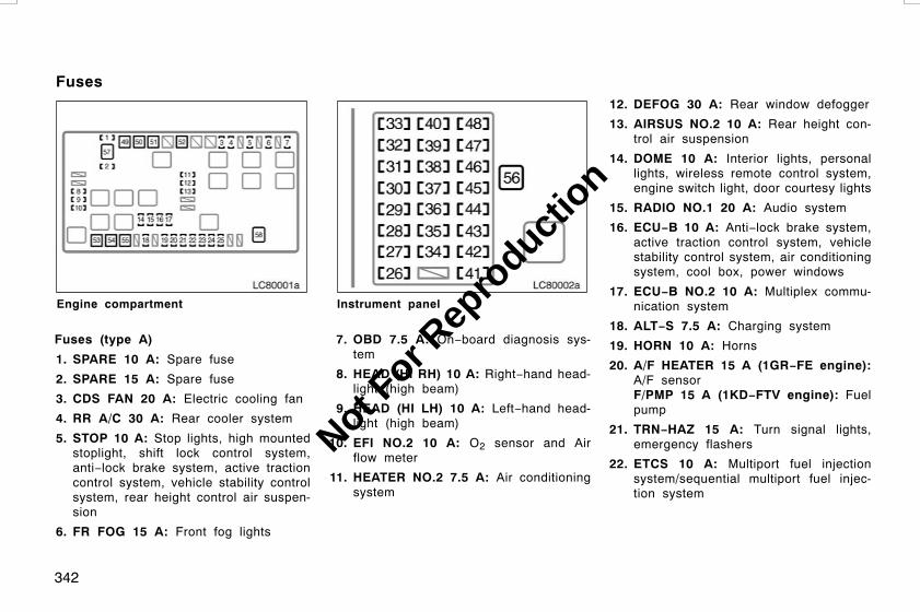
342
LC80001a
Engine compartment
Fuses (type A)
1. SPARE 10 A: Spare fuse
2. SPARE 15 A: Spare fuse
3. CDS FAN 20 A: Electric cooling fan
4. RR A/C 30 A: Rear cooler system
5. STOP 10 A: Stop lights, high mountedstoplight, shift lock control system,anti−lock brake system, active tractioncontrol system, vehicle stability controlsystem, rear height control air suspen-sion
6. FR FOG 15 A: Front fog lights
LC80002b
Instrument panel
7. OBD 7.5 A: On−board diagnosis sys-tem
8. HEAD (HI RH) 10 A: Right−hand head-light (high beam)
9. HEAD (HI LH) 10 A: Left−hand head-light (high beam)
10. EFI NO.2 10 A: O2 sensor and Airflow meter
11. HEATER NO.2 7.5 A: Air conditioningsystem
12. DEFOG 30 A: Rear window defogger
13. AIRSUS NO.2 10 A: Rear height con-trol air suspension
14. DOME 10 A: Interior lights, personallights, wireless remote control system,engine switch light, door courtesy lights
15. RADIO NO.1 20 A: Audio system
16. ECU−B 10 A: Anti−lock brake system,active traction control system, vehiclestability control system, air conditioningsystem, cool box, power windows
17. ECU−B NO.2 10 A: Multiplex commu-nication system
18. ALT−S 7.5 A: Charging system
19. HORN 10 A: Horns
20. A/F HEATER 15 A (1GR−FE engine):A/F sensorF/PMP 15 A (1KD−FTV engine): Fuelpump
21. TRN−HAZ 15 A: Turn signal lights,emergency flashers
22. ETCS 10 A: Multiport fuel injectionsystem/sequential multiport fuel injec-tion system
L/C120 AE (OM60D50E) 08/01/22
Fuses
Not For R
epro
duction

343
23. EFI 20 A (1GR−FE and 1KZ−TE en-gines)/EFI 25 A (1KD−FTV engine):Electronically controlled fuel pump, fuelpump, multiport fuel injection system/sequential multiport fuel injection sys-tem
24. D FR P/W 20 A: Driver’s power win-dow
25. DR/LCK 25 A: Power door lock system
26. IGN 10 A: Electronically controlled fuelpump, multiport fuel injection system/sequential multiport fuel injection sys-tem, anti−lock brake system, activetraction control system, vehicle stabilitycontrol system
27. SRS 10 A: SRS airbags
28. GAUGE 7.5 A: Gauges and meters
29. ST2 7.5 A: Multiport fuel injection sys-tem/sequential multiport fuel injectionsystem
30. FR WIP−WSH 30 A: Windshield wipersand washer
31. TEMS 20 A: Toyota electronic modu-lated suspension
32. DIFF 20 A: Rear differential lock sys-tem, center differential lock system
33. RR WIP 15 A: Rear window wiper
34. D P/SEAT 30 A: Driver’s power seat
35. P P/SEAT 30 A: Front passenger’spower seat
36. PWR OUTLET 15 A: Power outlets
37. IG1 NO.2 10 A: Air conditioning sys-tem, cool box
38. RR WSH 15 A: Rear window washer
39. ECU−IG 10 A: Shift lock control sys-tem, power windows, anti−lock brakesystem, active traction control system,vehicle stability control system, air con-ditioning system, electric moon roof,power outlets
40. IG1 10 A: Anti−lock brake system, ac-tive traction control system, vehiclestability control system, air conditioningsystem, charging system, rear windowdefogger, back−up lights, turn signallights, emergency flashers
41. STA 7.5 A: Electronically controlledfuel pump
42. P FR P/W 20 A: Front passenger’spower window
43. D RR P/W 20 A: Rear passenger’spower window (left side)
44. P RR P/W 20 A: Rear passenger’spower window (right side)
45. PANEL 10 A: Instrument panel lights
46. TAIL 10 A: Tail lights, license platelights, parking lights
47. ACC 7.5 A: Electronically controlledautomatic transmission system, poweroutlets, outside rear view mirrors, audiosystem
48. CIG 10 A: Cigarette lighter
L/C120 AE (OM60D50E) 08/01/22
Not For R
epro
duction

344
Fuses (type B)
49. HEATER 50 A: Air conditioning system
50. AIRSUS 50 A: Rear height control airsuspension
51. AM1 50 A: All components in “ACC”,“CIG”, “IG1”, “IG1 NO.2”, “ECU−IG”,“FR WIP−WSH”, “RR WIP”, “RR WSH”,“DIFF”, “TEMS” and “STA” fuses
52. J/B 50 A: All components in “PWROUTLET”, “P FR P/W”, “P RR P/W”, “DRR P/W”, “D P/SEAT”, “P P/SEAT”,“POWER”, “TAIL” and “PANEL” fuses
53. ABS MTR 40 A: Anti−lock brake sys-tem, active traction control system, ve-hicle stability control system
54. AM2 30 A: Starter system, “IGN”,“GAUGE” and “SRS” fuses
55. ABS SOL 30 A (without the vehiclestability control system): Anti−lockbrake systemABS SOL 50 A (with the vehicle sta-bility control system): Anti−lock brakesystem, active traction control system,vehicle stability control system
56. POWER 30 A: Power windows, electricmoon roof
Fuses (type C)
57. ALT 140 A: All components in “HEAT-ER”, “CDS FAN”, “FR FOG”, “AIRSUS”,“RR A/C” and “STOP” fuses
58. GLOW 80 A (diesel engine): Engineglow system
L/C120 AE (OM60D50E) 08/01/22
Not For R
epro
duction

345
INDEX
L/C120 AE (OM60D50E) 08/01/22
SECTION 9
Not For R
epro
duction

346
AActive traction control system 152. . . . . . . .Adding washer fluid 327. . . . . . . . . . . . . . . . . .AdjustmentFront seats 38, 39. . . . . . . . . . . . . . . . . . . . .Rear seat 42. . . . . . . . . . . . . . . . . . . . . . . . . .Rear seats 46. . . . . . . . . . . . . . . . . . . . . . . . .Seat belt 59. . . . . . . . . . . . . . . . . . . . . . . . . . .
Air bleeding 268. . . . . . . . . . . . . . . . . . . . . . . . .Air conditioning filter 205. . . . . . . . . . . . . . . . .Air conditioning systemAutomatic air conditioningsystem 196. . . . . . . . . . . . . . . . . . . . . . . . .
Manual air conditioning system 190. . . . .Airbags 69, 76. . . . . . . . . . . . . . . . . . . . . . . . . . .Aluminum wheel precautions 322. . . . . . . . .Anti−glare inside rear view mirror 105. . . . .Anti−lock brake systemwarning light 121. . . . . . . . . . . . . . . . . . . . . .
Anti−theft steeringcolumn lock 134, 135. . . . . . . . . . . . . . . . . . .
Appearance careCleaning the interior 295. . . . . . . . . . . . . . .Protecting your Toyotafrom corrosion 292. . . . . . . . . . . . . . . . . .
Washing and waxing 293. . . . . . . . . . . . . . .Armrest 59. . . . . . . . . . . . . . . . . . . . . . . . . . . . . .Ashtray 221. . . . . . . . . . . . . . . . . . . . . . . . . . . . .Audio system 174. . . . . . . . . . . . . . . . . . . . . . .Audio system operating tips 185. . . . . . . . . .Automatic air conditioning system 196. . . .
Automatic transmissionDriving with an automatictransmission 136, 140. . . . . . . . . . . . . . . .
Shift lock override button 290. . . . . . . . . . .Shift pattern 136, 140. . . . . . . . . . . . . . . . . . .Shifting speed 136, 140. . . . . . . . . . . . . . . . .
Automatic transmission fluidtemperature warning light 121. . . . . . . . . .
Auxiliary box 223. . . . . . . . . . . . . . . . . . . . . . . .Auxiliary catch, Engine hood 28. . . . . . . . . .
BBack door 25. . . . . . . . . . . . . . . . . . . . . . . . . . . .Back door lock 25. . . . . . . . . . . . . . . . . . . . . . .BatteryChecking battery condition 324. . . . . . . . .Gas caution 324. . . . . . . . . . . . . . . . . . . . . . .Handling safety 324. . . . . . . . . . . . . . . . . . .Recharging precautions 325. . . . . . . . . . . .Winter driving tips 255. . . . . . . . . . . . . . . . .
Before starting the engine 248. . . . . . . . . . . .Brake pad wear indicators 242. . . . . . . . . . . .Brake system 237. . . . . . . . . . . . . . . . . . . . . . .Brake system warning buzzer 121. . . . . . . .Brake system warning light 121. . . . . . . . . . .BrakesPad wear indicators 242. . . . . . . . . . . . . . .Parking 169. . . . . . . . . . . . . . . . . . . . . . . . . . .
Break−in tips 231. . . . . . . . . . . . . . . . . . . . . . . .Brightness control 110. . . . . . . . . . . . . . . . . . .
CCarbon monoxide caution 235. . . . . . . . . . . .Cassette player 174. . . . . . . . . . . . . . . . . . . . .Catalytic converter 234. . . . . . . . . . . . . . . . . .Charging system warning light 121. . . . . . . .Checking and replacing fuses 326. . . . . . . .Checking and replacingthe air conditioning filter 205. . . . . . . . . . .
Checking the engine oil level 312. . . . . . . . .Checking the radiator,condenser and intercooler 317. . . . . . . . .
Child restraintChild restraint system 84. . . . . . . . . . . . . . .Installation 86, 94. . . . . . . . . . . . . . . . . . . . . .Installation withISOFIX rigid anchor 99. . . . . . . . . . . . . .
ISOFIX child restraint system 99. . . . . . . .Precautions 83. . . . . . . . . . . . . . . . . . . . . . . .Types of child restraint system 85. . . . . . .
Child restraint anchor fittings 97. . . . . . . . . .Cigarette lighter 221. . . . . . . . . . . . . . . . . . . . .Cleaning the interior 295. . . . . . . . . . . . . . . . .Clock 210, 213. . . . . . . . . . . . . . . . . . . . . . . . . . .Cold weatherOperation 255. . . . . . . . . . . . . . . . . . . . . . . . .
Compact disc changer controller 174. . . . . .Compact disc player 174. . . . . . . . . . . . . . . . .Compass 217. . . . . . . . . . . . . . . . . . . . . . . . . . .CondenserChecking the condenser 317. . . . . . . . . . .
Console box 226. . . . . . . . . . . . . . . . . . . . . . . .Controls, Instrument panel 2, 6. . . . . . . . . . .Cool box 227. . . . . . . . . . . . . . . . . . . . . . . . . . . .
L/C120 AE (OM60D50E) 08/01/22
Not For R
epro
duction

347
Cooling systemCoolant level 316. . . . . . . . . . . . . . . . . . . . . .Engine overheating 272. . . . . . . . . . . . . . . .Radiator and reservoir 316. . . . . . . . . . . . .Radiator cap 272. . . . . . . . . . . . . . . . . . . . . .Winter driving tips 255. . . . . . . . . . . . . . . . .
Corrosion prevention 292. . . . . . . . . . . . . . . .Cranking hold function 248. . . . . . . . . . . . . . .Cruise control 169. . . . . . . . . . . . . . . . . . . . . . .Cruise information display 213. . . . . . . . . . . .Cup holderFront 225. . . . . . . . . . . . . . . . . . . . . . . . . . . . .Rear 226. . . . . . . . . . . . . . . . . . . . . . . . . . . . .
DDefogger, Rear window 114. . . . . . . . . . . . . .Differential, Limited slip 244. . . . . . . . . . . . . .Dimmer switch, Headlight 108. . . . . . . . . . . .Directional signals 108. . . . . . . . . . . . . . . . . . .Do−it−yourself maintenanceService precautions 307. . . . . . . . . . . . . . .
Does your vehicle need repairing? 301. . . .DoorsSide doors 19. . . . . . . . . . . . . . . . . . . . . . . . .
Downhill assist control system 156. . . . . . . .Driver’s seat belt reminder light 121. . . . . . .DrivingAutomatic transmission 136, 140. . . . . . . .Driving tips 248. . . . . . . . . . . . . . . . . . . . . . .Manual transmission 144. . . . . . . . . . . . . . .
Driving in the rain 253. . . . . . . . . . . . . . . . . . . .Driving tipsDriving in the rain 253. . . . . . . . . . . . . . . . . .Driving tips invarious conditions 252. . . . . . . . . . . . . . .
Driving with a manualtransmission 144. . . . . . . . . . . . . . . . . . . .
Driving with an automatictransmission 136, 140. . . . . . . . . . . . . . . .
Economical driving 262. . . . . . . . . . . . . . . .Good driving practice 136, 140, 144. . . . .Pre−trip safety check 251. . . . . . . . . . . . . .Winter driving tips 255. . . . . . . . . . . . . . . . .
DuringBreak−in 231. . . . . . . . . . . . . . . . . . . . . . . . . .
EEconomical drivingSaving money on both fueland repairs 262. . . . . . . . . . . . . . . . . . . . .
Electric moon roof 32. . . . . . . . . . . . . . . . . . . .Electrical systemBattery 324, 325. . . . . . . . . . . . . . . . . . . . . . .Fuse locations 307. . . . . . . . . . . . . . . . . . . .Fuses 326. . . . . . . . . . . . . . . . . . . . . . . . . . . .
Emergency flasher switch 109. . . . . . . . . . . .
Emergency, In case ofBleeding the fuel system 268. . . . . . . . . . .Blown fuse 326. . . . . . . . . . . . . . . . . . . . . . . .Emergency flasher switch 109. . . . . . . . . .Flat tire 273. . . . . . . . . . . . . . . . . . . . . . . . . . .If you cannot increaseengine speed 271, 272. . . . . . . . . . . . . . .
If you cannot shift automatictransmission selector lever 290. . . . . . .
If you lose your keys 290. . . . . . . . . . . . . . .If your engine stalls while driving 271. . . .If your vehicle becomes stuck 286. . . . . .If your vehicle needs to be towed 286. . .If your vehicle will not start 266. . . . . . . . .Jump starting 268. . . . . . . . . . . . . . . . . . . . .Overheating 272. . . . . . . . . . . . . . . . . . . . . .Towing 286. . . . . . . . . . . . . . . . . . . . . . . . . . .
EngineBefore starting the engine 248. . . . . . . . . .Catalytic converter 234. . . . . . . . . . . . . . . .Checking the coolant level 316. . . . . . . . .Emission control device 233, 234. . . . . . . .Engine compartment 304. . . . . . . . . . . . . . .Exhaust gas caution 235. . . . . . . . . . . . . . .Hood release 28. . . . . . . . . . . . . . . . . . . . . .Identification number 246. . . . . . . . . . . . . .Oil consumption 236. . . . . . . . . . . . . . . . . . .Oil level 312. . . . . . . . . . . . . . . . . . . . . . . . . .Overheating 272. . . . . . . . . . . . . . . . . . . . . .Starting procedure 248. . . . . . . . . . . . . . . . .Three−way catalytic converters 233. . . . .Turning off an enginewith turbocharger 250. . . . . . . . . . . . . . . .
L/C120 AE (OM60D50E) 08/01/22
Not For R
epro
duction

348
Engine coolantTemperature gauge 118. . . . . . . . . . . . . . . .Winter driving tips 255. . . . . . . . . . . . . . . . .
Engine coolant temperature gauge 118. . . .Engine immobilizer system 14. . . . . . . . . . . .Engine oilWinter driving tips 255. . . . . . . . . . . . . . . . .
Engine switch 134, 135. . . . . . . . . . . . . . . . . . .Exhaust gas caution 235. . . . . . . . . . . . . . . . .
FFacts about engine oil consumption 236. . .First−aid kit holder 224. . . . . . . . . . . . . . . . . . .Flasher, Headlight 108. . . . . . . . . . . . . . . . . . .Flat tireAfter changing wheels 285. . . . . . . . . . . . .Changing tire 282. . . . . . . . . . . . . . . . . . . . .If you have a flat tire 273. . . . . . . . . . . . . . .Jack point 280. . . . . . . . . . . . . . . . . . . . . . . . .Jacking precautions 273. . . . . . . . . . . . . . .Jacking up 282. . . . . . . . . . . . . . . . . . . . . . . .Loosening wheel nuts 280. . . . . . . . . . . . . .Lowering vehicle 284. . . . . . . . . . . . . . . . . .Reinstalling wheel ornament 284. . . . . . .Removing wheel ornament 279. . . . . . . . .Wheel block 279. . . . . . . . . . . . . . . . . . . . . . .Wheel nuts 283. . . . . . . . . . . . . . . . . . . . . . . .
Floor mat 228. . . . . . . . . . . . . . . . . . . . . . . . . . .
Fluid levelWasher fluid 327. . . . . . . . . . . . . . . . . . . . . .
Fog light switch, Front 110. . . . . . . . . . . . . . .Foreign countries, Operation in 233. . . . . . .Four−wheel driveOperating the four−wheeldrive system 146, 148. . . . . . . . . . . . . . . .
Front air conditioning system 190, 196. . . . .Front cup holder 225. . . . . . . . . . . . . . . . . . . . .Front fog light switch 110. . . . . . . . . . . . . . . . .Front passenger’s seat beltreminder light 121. . . . . . . . . . . . . . . . . . . . .
Front seatSeatback flattening 40, 41. . . . . . . . . . . . . .
Front seats 37, 38, 39. . . . . . . . . . . . . . . . . . .FuelBleeding the fuel system 268. . . . . . . . . . .Draining fuel filter water 317. . . . . . . . . . . .Filler door opener 30. . . . . . . . . . . . . . . . . .Fuel economy 262. . . . . . . . . . . . . . . . . . . . .Fuel pump shut off system 232. . . . . . . . . .Gauge 116, 117. . . . . . . . . . . . . . . . . . . . . . . .Operation in foreign countries 233. . . . . .Tank cap 30. . . . . . . . . . . . . . . . . . . . . . . . . . .
Fuel filterDraining fuel filter water 317. . . . . . . . . . . .
Fuel filter warning light 121. . . . . . . . . . . . . . .Fuel information 231. . . . . . . . . . . . . . . . . . . . .Fuel pump shut off system 232. . . . . . . . . . . .FuseFuse box 326. . . . . . . . . . . . . . . . . . . . . . . . .
Fuse locations 307. . . . . . . . . . . . . . . . . . . . . .
GGaugeEngine coolant temperature 118. . . . . . . .Fuel 116, 117. . . . . . . . . . . . . . . . . . . . . . . . . .
Glove box 223. . . . . . . . . . . . . . . . . . . . . . . . . . .Good driving practice 136, 140, 144. . . . . . .
HHazard switch 109. . . . . . . . . . . . . . . . . . . . . . .Head restraints 58. . . . . . . . . . . . . . . . . . . . . . .Headlight switch 108. . . . . . . . . . . . . . . . . . . . .Height controlRear height controlair suspension 162. . . . . . . . . . . . . . . . . .
High speed operation 231. . . . . . . . . . . . . . . .During break−in 231. . . . . . . . . . . . . . . . . . .
Hill−start assist control system 160. . . . . . .Hood release, Engine 28. . . . . . . . . . . . . . . . .How to start the engine 248. . . . . . . . . . . . . .
IIdentificationEngine 246. . . . . . . . . . . . . . . . . . . . . . . . . . .Vehicle 245. . . . . . . . . . . . . . . . . . . . . . . . . . .
Ignition switch 134, 135. . . . . . . . . . . . . . . . . . .Indicator symbols 8. . . . . . . . . . . . . . . . . . . . . .
L/C120 AE (OM60D50E) 08/01/22
Not For R
epro
duction

349
Instrument panelAshtray 221. . . . . . . . . . . . . . . . . . . . . . . . . . .Brightness control 110. . . . . . . . . . . . . . . . .Cigarette lighter 221. . . . . . . . . . . . . . . . . . .Clock 210. . . . . . . . . . . . . . . . . . . . . . . . . . . . .Fuel gauge 116, 117. . . . . . . . . . . . . . . . . . .Indicator symbols 8. . . . . . . . . . . . . . . . . . . .Odometer 119. . . . . . . . . . . . . . . . . . . . . . . . .Tachometer 119. . . . . . . . . . . . . . . . . . . . . . .Trip meter 119. . . . . . . . . . . . . . . . . . . . . . . .
Instrument panel light control 110. . . . . . . . .Instrument panel overview 2, 6. . . . . . . . . . .IntercoolerChecking the intercooler 317. . . . . . . . . . .
JJackLocation 274. . . . . . . . . . . . . . . . . . . . . . . . . .
Jump starting 268. . . . . . . . . . . . . . . . . . . . . . .
KKeys 12, 290. . . . . . . . . . . . . . . . . . . . . . . . . . . .
LLight bulbsBack−up lights 332, 333. . . . . . . . . . . . . . . .Front fog lights 330. . . . . . . . . . . . . . . . . . . .Front turn signal lights 331. . . . . . . . . . . . .Headlights 329. . . . . . . . . . . . . . . . . . . . . . . .License plate lights 334. . . . . . . . . . . . . . . .Parking lights 331. . . . . . . . . . . . . . . . . . . . .Rear turn signal lights 332, 333. . . . . . . . . .Stop and tail lights 332. . . . . . . . . . . . . . . . .Stop/tail lights 332, 333. . . . . . . . . . . . . . . . .Tail lights 332, 333. . . . . . . . . . . . . . . . . . . . .
Light bulbs, Replacing 328. . . . . . . . . . . . . . .Light, Interior 110, 111. . . . . . . . . . . . . . . . . . . .Interior light 110. . . . . . . . . . . . . . . . . . . . . . .Personal light 111. . . . . . . . . . . . . . . . . . . . . .
Limited slip differential 244. . . . . . . . . . . . . . .LockBack door 25. . . . . . . . . . . . . . . . . . . . . . . . . .Side doors 19. . . . . . . . . . . . . . . . . . . . . . . . .Steering column 134, 135. . . . . . . . . . . . . . .
Low engine oil levelwarning light 121. . . . . . . . . . . . . . . . . . . . . .
Low engine oil pressurewarning light 121. . . . . . . . . . . . . . . . . . . . . .
Low fuel level warning light 121. . . . . . . . . . .Luggage stowage precautions 242. . . . . . . .
MMaintenanceDo−it−yourself maintenance 307. . . . . . . .Does your vehicleneed repairing? 301. . . . . . . . . . . . . . . . .
Maintenance facts 300. . . . . . . . . . . . . . . . .Where to go for service 300. . . . . . . . . . . .
Malfunction indicator lamp 121. . . . . . . . . . .Manual air conditioning system 190. . . . . . .Manual transmissionDriving with a manualtransmission 144. . . . . . . . . . . . . . . . . . . .
Shift pattern 144. . . . . . . . . . . . . . . . . . . . . . .Maximum allowable speedAutomatic transmission 136, 140. . . . . . . .Manual transmission 144. . . . . . . . . . . . . . .
Mesh pocket 225. . . . . . . . . . . . . . . . . . . . . . . .MirrorAnti−glare inside rear view 105. . . . . . . . .Vanity 106. . . . . . . . . . . . . . . . . . . . . . . . . . . .
MirrorsFolding rear view 105. . . . . . . . . . . . . . . . . .Outside rear view 103. . . . . . . . . . . . . . . . . .Power rear view 104. . . . . . . . . . . . . . . . . . .
Moon roof 32. . . . . . . . . . . . . . . . . . . . . . . . . . . .Multi−information display 211. . . . . . . . . . . .
L/C120 AE (OM60D50E) 08/01/22
Not For R
epro
duction

350
NNew vehicle break−in 231. . . . . . . . . . . . . . . .
OOdometer 119. . . . . . . . . . . . . . . . . . . . . . . . . . .Off−road driving precautions 254. . . . . . . . .Off−road vehicle precautions 230. . . . . . . . .OilConsumption 236. . . . . . . . . . . . . . . . . . . . . .Viscosity and grade 312. . . . . . . . . . . . . . . .
Oil consumption 236. . . . . . . . . . . . . . . . . . . . .Open door warning light 121. . . . . . . . . . . . . .Operation in foreign countries 233. . . . . . . .Outside temperature display 210. . . . . . . . .Overheating, Engine 272. . . . . . . . . . . . . . . . .Overheating, Engine coolant 118. . . . . . . . .OverviewEngine compartment 304. . . . . . . . . . . . . . .
PParking brakeOperation 169. . . . . . . . . . . . . . . . . . . . . . . . .Reminder light 169. . . . . . . . . . . . . . . . . . . .
Polishing 293. . . . . . . . . . . . . . . . . . . . . . . . . . .Power outlet 222. . . . . . . . . . . . . . . . . . . . . . . .Power rear view mirror control 104. . . . . . . .Power window switches 22. . . . . . . . . . . . . . .Pre−trip safety check 251. . . . . . . . . . . . . . . .
Precautions for turning offan engine with turbocharger 250. . . . . . . .
Preloaders(seat belt pretensioners) 67. . . . . . . . . . . .
Pretensioners(seat belt pretensioners) 67. . . . . . . . . . . .
Protecting your Toyotafrom corrosion 292. . . . . . . . . . . . . . . . . . . .
QQuarter windows 24. . . . . . . . . . . . . . . . . . . . .
RRadiatorChecking the radiator 317. . . . . . . . . . . . . .Coolant, Engine 316. . . . . . . . . . . . . . . . . . .
Radio 174. . . . . . . . . . . . . . . . . . . . . . . . . . . . . .Rear cooler system 204. . . . . . . . . . . . . . . . . .Rear cup holder 226. . . . . . . . . . . . . . . . . . . . .Rear differential lock system 150. . . . . . . . .Rear height control air suspension 162. . . .Rear seatThird seat entry 47. . . . . . . . . . . . . . . . . . . .
Rear seat precautions 45. . . . . . . . . . . . . . . .Rear seats 42, 45, 46. . . . . . . . . . . . . . . . . . . .Rear step bumper 244. . . . . . . . . . . . . . . . . . .Rear view mirror 105. . . . . . . . . . . . . . . . . . . . .Anti−glare inside 105. . . . . . . . . . . . . . . . . .
Rear view mirrorsFolding 105. . . . . . . . . . . . . . . . . . . . . . . . . . .Outside 103. . . . . . . . . . . . . . . . . . . . . . . . . . .Power 104. . . . . . . . . . . . . . . . . . . . . . . . . . . .
Rear window defogger switch 114. . . . . . . .Rear window wiper andwasher switch 113. . . . . . . . . . . . . . . . . . . . .
Roof luggage carrier precautions 243. . . . .
SSafety check, Pre−trip 251. . . . . . . . . . . . . . .Seat adjustment precautionsFront seats 37. . . . . . . . . . . . . . . . . . . . . . . .
Seat beltsChild restraint anchor fittings 97. . . . . . . .Cleaning 295. . . . . . . . . . . . . . . . . . . . . . . . . .Fastening 59. . . . . . . . . . . . . . . . . . . . . . . . . .Seat belt precautions 59. . . . . . . . . . . . . . .Seat belt pretensioners 67. . . . . . . . . . . . .
Seats 36. . . . . . . . . . . . . . . . . . . . . . . . . . . . . . . .Second seat 47. . . . . . . . . . . . . . . . . . . . . . . . .Service and maintenance 300. . . . . . . . . . . .Service reminder indicator 121. . . . . . . . . . .Side door locks 19. . . . . . . . . . . . . . . . . . . . . . .Side doors 19. . . . . . . . . . . . . . . . . . . . . . . . . . .Spare fuse 326. . . . . . . . . . . . . . . . . . . . . . . . . .Spare tire 274. . . . . . . . . . . . . . . . . . . . . . . . . . .Specifications 336. . . . . . . . . . . . . . . . . . . . . . .SRS driver airbag andfront passenger airbag 69. . . . . . . . . . . . . .
SRS side airbags andcurtain shield airbags 76. . . . . . . . . . . . . . .
SRS warning light 121. . . . . . . . . . . . . . . . . . .StartingCold weather 248. . . . . . . . . . . . . . . . . . . . . .Engine 248. . . . . . . . . . . . . . . . . . . . . . . . . . .Jump starting 268. . . . . . . . . . . . . . . . . . . . .
L/C120 AE (OM60D50E) 08/01/22
Not For R
epro
duction
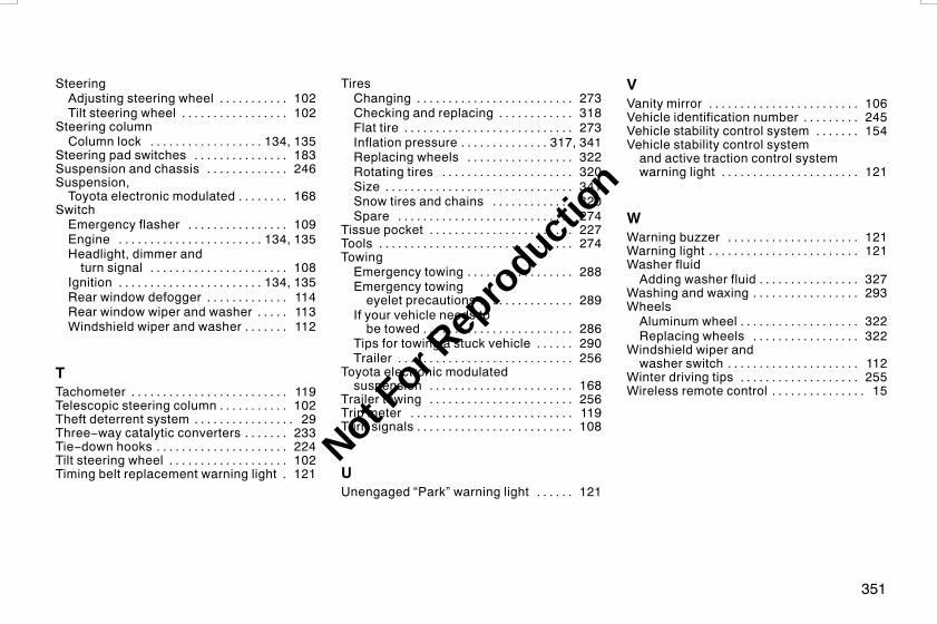
351
SteeringAdjusting steering wheel 102. . . . . . . . . . .Tilt steering wheel 102. . . . . . . . . . . . . . . . .
Steering columnColumn lock 134, 135. . . . . . . . . . . . . . . . . .
Steering pad switches 183. . . . . . . . . . . . . . .Suspension and chassis 246. . . . . . . . . . . . .Suspension,Toyota electronic modulated 168. . . . . . . .
SwitchEmergency flasher 109. . . . . . . . . . . . . . . .Engine 134, 135. . . . . . . . . . . . . . . . . . . . . . .Headlight, dimmer andturn signal 108. . . . . . . . . . . . . . . . . . . . . .
Ignition 134, 135. . . . . . . . . . . . . . . . . . . . . . .Rear window defogger 114. . . . . . . . . . . . .Rear window wiper and washer 113. . . . .Windshield wiper and washer 112. . . . . . .
TTachometer 119. . . . . . . . . . . . . . . . . . . . . . . . .Telescopic steering column 102. . . . . . . . . . .Theft deterrent system 29. . . . . . . . . . . . . . . .Three−way catalytic converters 233. . . . . . .Tie−down hooks 224. . . . . . . . . . . . . . . . . . . . .Tilt steering wheel 102. . . . . . . . . . . . . . . . . . .Timing belt replacement warning light 121.
TiresChanging 273. . . . . . . . . . . . . . . . . . . . . . . . .Checking and replacing 318. . . . . . . . . . . .Flat tire 273. . . . . . . . . . . . . . . . . . . . . . . . . . .Inflation pressure 317, 341. . . . . . . . . . . . . .Replacing wheels 322. . . . . . . . . . . . . . . . .Rotating tires 320. . . . . . . . . . . . . . . . . . . . .Size 341. . . . . . . . . . . . . . . . . . . . . . . . . . . . . .Snow tires and chains 320. . . . . . . . . . . . .Spare 274. . . . . . . . . . . . . . . . . . . . . . . . . . . .
Tissue pocket 227. . . . . . . . . . . . . . . . . . . . . . .Tools 274. . . . . . . . . . . . . . . . . . . . . . . . . . . . . . .TowingEmergency towing 288. . . . . . . . . . . . . . . . .Emergency towingeyelet precautions 289. . . . . . . . . . . . . . .
If your vehicle needs tobe towed 286. . . . . . . . . . . . . . . . . . . . . . . .
Tips for towing a stuck vehicle 290. . . . . .Trailer 256. . . . . . . . . . . . . . . . . . . . . . . . . . . .
Toyota electronic modulatedsuspension 168. . . . . . . . . . . . . . . . . . . . . . .
Trailer towing 256. . . . . . . . . . . . . . . . . . . . . . .Trip meter 119. . . . . . . . . . . . . . . . . . . . . . . . . .Turn signals 108. . . . . . . . . . . . . . . . . . . . . . . . .
UUnengaged “Park” warning light 121. . . . . .
VVanity mirror 106. . . . . . . . . . . . . . . . . . . . . . . .Vehicle identification number 245. . . . . . . . .Vehicle stability control system 154. . . . . . .Vehicle stability control systemand active traction control systemwarning light 121. . . . . . . . . . . . . . . . . . . . . .
WWarning buzzer 121. . . . . . . . . . . . . . . . . . . . .Warning light 121. . . . . . . . . . . . . . . . . . . . . . . .Washer fluidAdding washer fluid 327. . . . . . . . . . . . . . . .
Washing and waxing 293. . . . . . . . . . . . . . . . .WheelsAluminum wheel 322. . . . . . . . . . . . . . . . . . .Replacing wheels 322. . . . . . . . . . . . . . . . .
Windshield wiper andwasher switch 112. . . . . . . . . . . . . . . . . . . . .
Winter driving tips 255. . . . . . . . . . . . . . . . . . .Wireless remote control 15. . . . . . . . . . . . . . .
L/C120 AE (OM60D50E) 08/01/22
Not For R
epro
duction
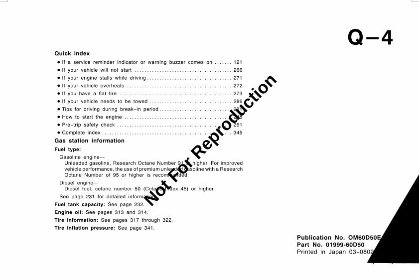
L/C120 AE (OM60D50E) 08/01/22
Publication No. OM60D50EPart No. 01999-60D50Printed in Japan 03−0802−02 Z
ランドクルーザープラド (豪州E)
Quick indexD If a service reminder indicator or warning buzzer comes on 121. . . . . . .
D If your vehicle will not start 266. . . . . . . . . . . . . . . . . . . . . . . . . . . . . . . . . . . . . . .
D If your engine stalls while driving 271. . . . . . . . . . . . . . . . . . . . . . . . . . . . . . . . . .
D If your vehicle overheats 272. . . . . . . . . . . . . . . . . . . . . . . . . . . . . . . . . . . . . . . . . .
D If you have a flat tire 273. . . . . . . . . . . . . . . . . . . . . . . . . . . . . . . . . . . . . . . . . . . . .
D If your vehicle needs to be towed 286. . . . . . . . . . . . . . . . . . . . . . . . . . . . . . . . .
D Tips for driving during break−in period 231. . . . . . . . . . . . . . . . . . . . . . . . . . . . .
D How to start the engine 248. . . . . . . . . . . . . . . . . . . . . . . . . . . . . . . . . . . . . . . . . . .
D Pre−trip safety check 251. . . . . . . . . . . . . . . . . . . . . . . . . . . . . . . . . . . . . . . . . . . . . .
D Complete index 345. . . . . . . . . . . . . . . . . . . . . . . . . . . . . . . . . . . . . . . . . . . . . . . . . . . .
Gas station informationFuel type:
Gasoline engine—Unleaded gasoline, Research Octane Number 91 or higher. For improvedvehicle performance, the use of premium unleaded gasoline with a ResearchOctane Number of 95 or higher is recommended.
Diesel engine—Diesel fuel, cetane number 50 (Cetane Index 45) or higher
See page 231 for detailed information.
Fuel tank capacity: See page 232.
Engine oil: See pages 313 and 314.
Tire information: See pages 317 through 322.
Tire inflation pressure: See page 341.
モQ−4
Not For R
epro
duction