Embed Size (px)
Citation preview
COOLING
COOLANT CO–1. . . . . . . . . . . . . . . . . . . . . . . . . . . . . .
WATER PUMP CO–3. . . . . . . . . . . . . . . . . . . . . . . . . . .
THERMOSTAT CO–8. . . . . . . . . . . . . . . . . . . . . . . . . .
RADIATOR CO–12. . . . . . . . . . . . . . . . . . . . . . . . . . . . . .
ELECTRIC COOLING FAN CO–20. . . . . . . . . . . . . . . .
COOLING FAN RELAY CO–26. . . . . . . . . . . . . . . . . . .

CO04D–02
–COOLING COOLANTCO–1
1ZZ–FE, 3ZZ–FE ENGINE (RM782E)
COOLANTINSPECTIONHINT:Check the coolant level when the engine is cold.1. CHECK ENGINE COOLANT LEVEL AT RESERVOIRThe engine coolant level should be between the ”LOW” and ”FULL” line.If low, check for leaks and add ”Toyota Long Life Coolant” or equivalent up to the ”FULL” line.2. CHECK ENGINE COOLANT QUALITY(a) Remove the radiator cap.CAUTION:To avoid the danger of being burned, do not remove the radiator the cap while the engine and radiatorare still hot, as fluid and steam can be blown out under pressure.(b) There should not be any excessive deposits of rust or scale around the radiator cap or radiator filler
hole, and the coolant should be free from oil.If excessively dirty, replace the coolant.(c) Reinstall the radiator cap.
CO15E–01
B12369Radiator Drain Plug
Engine Drain Plug
CO–2–COOLING COOLANT
1ZZ–FE, 3ZZ–FE ENGINE (RM782E)
REPLACEMENTCAUTION:To avoid the danger of being burned, do not remove the ra-diator cap while the engine and radiator are still hot, as fluidand steam can be blown out under pressure.1. DRAIN ENGINE COOLANT(a) Remove the radiator cap.
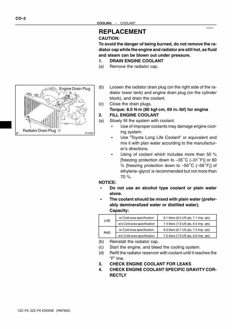
(b) Loosen the radiator drain plug (on the right side of the ra-diator lower tank) and engine drain plug (on the cylinderblock), and drain the coolant.
(c) Close the drain plugs.Torque: 8.0 N·m (80 kgf·cm, 69 in.·lbf) for engine
2. FILL ENGINE COOLANT(a) Slowly fill the system with coolant.
� Use of improper coolants may damage engine cool-ing system.
� Use ”Toyota Long Life Coolant” or equivalent andmix it with plan water according to the manufactur-er’s directions.
� Using of coolant which includes more than 50 %[freezing protection down to –35�C (–31�F)] or 60% [freezing protection down to –50�C (–58�F)] ofethylene–glycol is recommended but not more than70 %.
NOTICE:� Do not use an alcohol type coolant or plain water
alone.� The coolant should be mixed with plain water (prefer-
ably demineralized water or distilled water).Capacity:
LHDw/ Cold area specification 8.1 liters (8.5 US qts, 7.1 Imp. qts)
LHDw/o Cold area specification 7.4 liters (7.8 US qts, 6.5 Imp. qts)
RHDw/ Cold area specification 8.3 liters (8.7 US qts, 7.3 Imp. qts)
RHDw/o Cold area specification 7.5 liters (7.9 US qts, 6.6 Imp. qts)
(b) Reinstall the radiator cap.(c) Start the engine, and bleed the cooling system.(d) Refill the radiator reservoir with coolant until it reaches the
”F” line.3. CHECK ENGINE COOLANT FOR LEAKS4. CHECK ENGINE COOLANT SPECIFIC GRAVITY COR-
RECTLY
CO0XL–03
B10232
Turn
–COOLING WATER PUMPCO–3
1ZZ–FE, 3ZZ–FE ENGINE (RM782E)
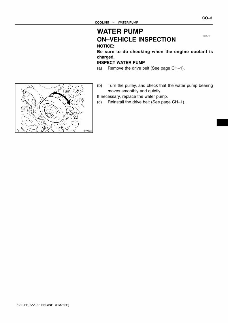
WATER PUMPON–VEHICLE INSPECTIONNOTICE:Be sure to do checking when the engine coolant ischarged.INSPECT WATER PUMP(a) Remove the drive belt (See page CH–1).
(b) Turn the pulley, and check that the water pump bearingmoves smoothly and quietly.
If necessary, replace the water pump.(c) Reinstall the drive belt (See page CH–1).
CO04F–13
B08593
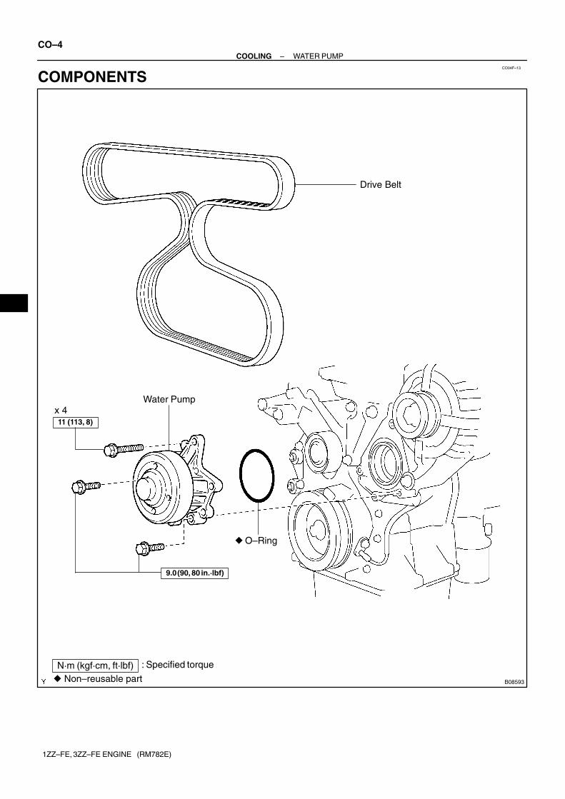
Drive Belt
Water Pump
� O–Ring
9.0 (90, 80 in.·lbf)
11 (113, 8)
N·m (kgf·cm, ft·lbf) : Specified torque
� Non–reusable part
x 4
CO–4–COOLING WATER PUMP
1ZZ–FE, 3ZZ–FE ENGINE (RM782E)
COMPONENTS
CO04G–05
B00150
–COOLING WATER PUMPCO–5
1ZZ–FE, 3ZZ–FE ENGINE (RM782E)
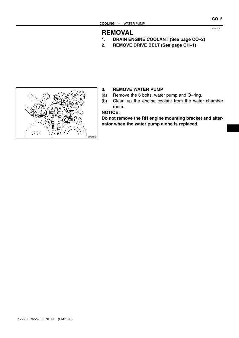
REMOVAL1. DRAIN ENGINE COOLANT (See page CO–2)2. REMOVE DRIVE BELT (See page CH–1)
3. REMOVE WATER PUMP(a) Remove the 6 bolts, water pump and O–ring.(b) Clean up the engine coolant from the water chamber
room.NOTICE:Do not remove the RH engine mounting bracket and alter-nator when the water pump alone is replaced.
CO04H–06
B10233Hole
CO–6–COOLING WATER PUMP
1ZZ–FE, 3ZZ–FE ENGINE (RM782E)
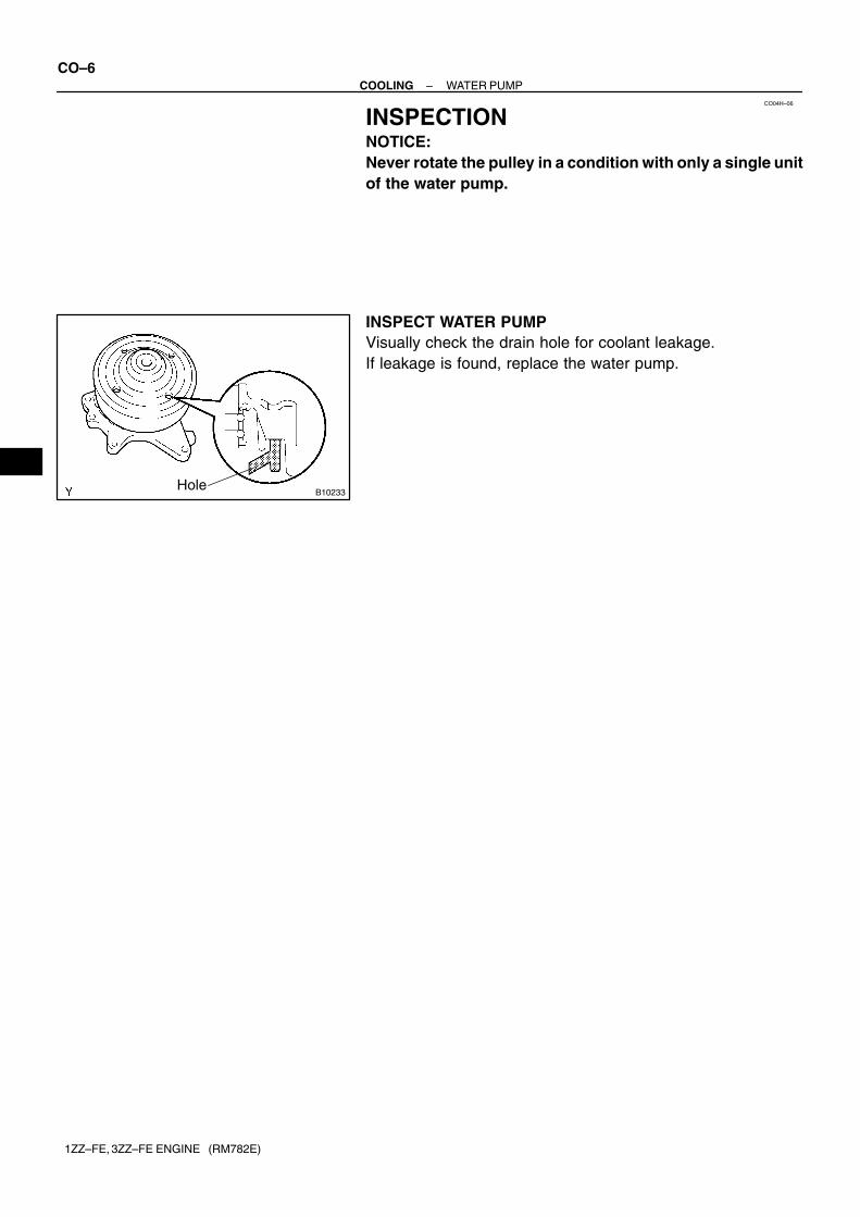
INSPECTIONNOTICE:Never rotate the pulley in a condition with only a single unitof the water pump.
INSPECT WATER PUMPVisually check the drain hole for coolant leakage.If leakage is found, replace the water pump.
B00150
B
A
A
B
B
B
CO04I–05
–COOLING WATER PUMPCO–7
1ZZ–FE, 3ZZ–FE ENGINE (RM782E)
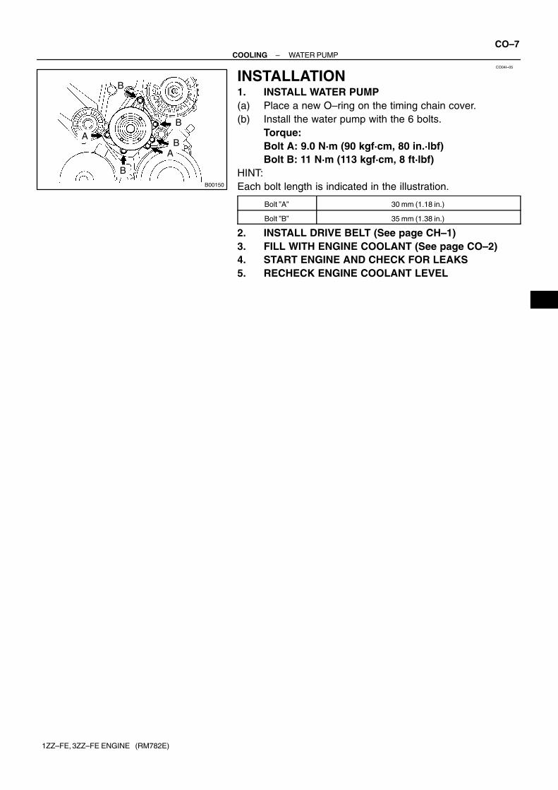
INSTALLATION1. INSTALL WATER PUMP(a) Place a new O–ring on the timing chain cover.(b) Install the water pump with the 6 bolts.
Torque:Bolt A: 9.0 N·m (90 kgf·cm, 80 in.·lbf)Bolt B: 11 N·m (113 kgf·cm, 8 ft·lbf)
HINT:Each bolt length is indicated in the illustration.
Bolt ”A” 30 mm (1.18 in.)
Bolt ”B” 35 mm (1.38 in.)
2. INSTALL DRIVE BELT (See page CH–1)3. FILL WITH ENGINE COOLANT (See page CO–2)4. START ENGINE AND CHECK FOR LEAKS5. RECHECK ENGINE COOLANT LEVEL
CO04J–14
B08594
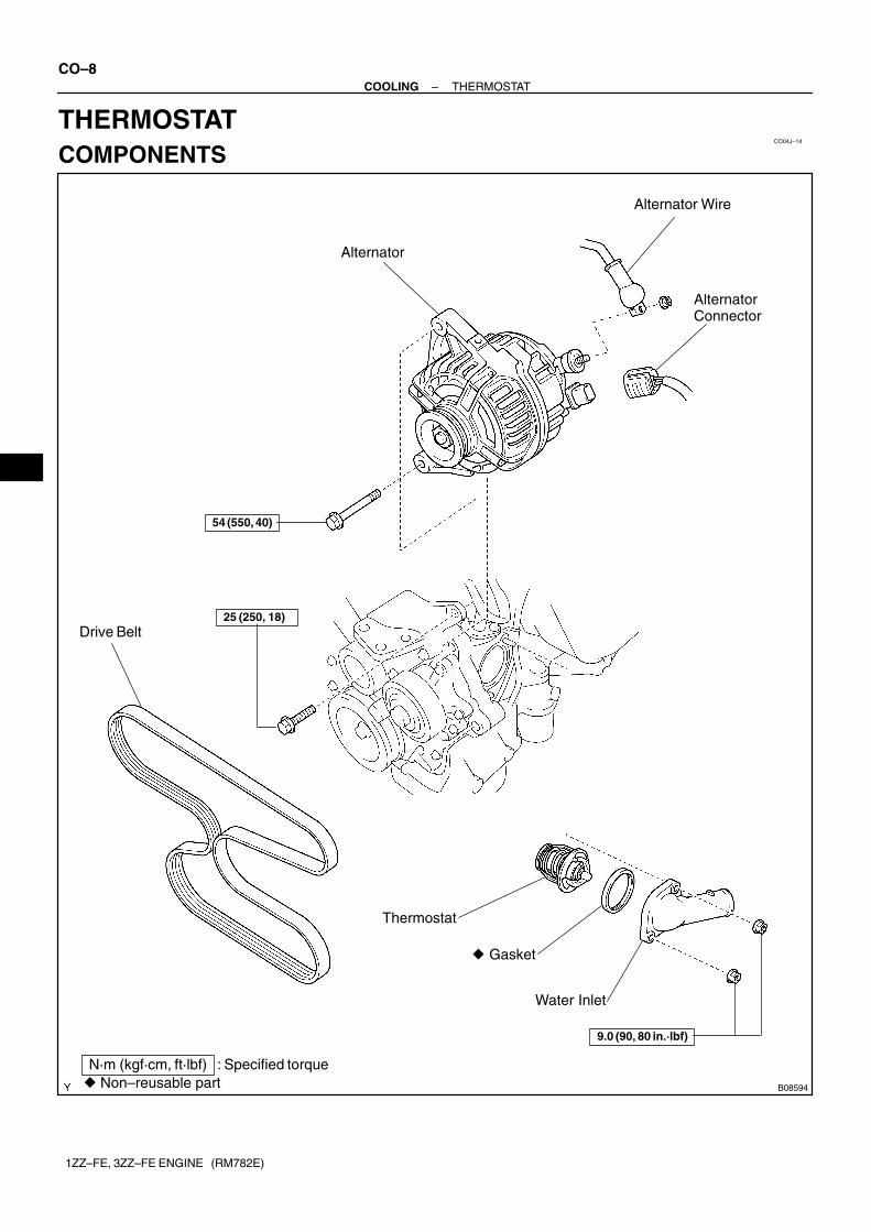
Alternator
Alternator Wire
AlternatorConnector
Drive Belt
Thermostat
� Gasket
Water Inlet
� Non–reusable partN·m (kgf·cm, ft·lbf) : Specified torque
9.0 (90, 80 in.·lbf)
54 (550, 40)
25 (250, 18)
CO–8–COOLING THERMOSTAT
1ZZ–FE, 3ZZ–FE ENGINE (RM782E)
THERMOSTATCOMPONENTS
CO04K–13
B08595
–COOLING THERMOSTATCO–9
1ZZ–FE, 3ZZ–FE ENGINE (RM782E)
REMOVALHINT:Removal of the thermostat would have an adverse effect, caus-ing a lowering of cooling efficiency. Do not remove the thermo-stat, even if the engine tends to overheat.1. DRAIN ENGINE COOLANT (See page CO–2)2. REMOVE DRIVE BELT AND ALTERNATOR (See page
CH–1)
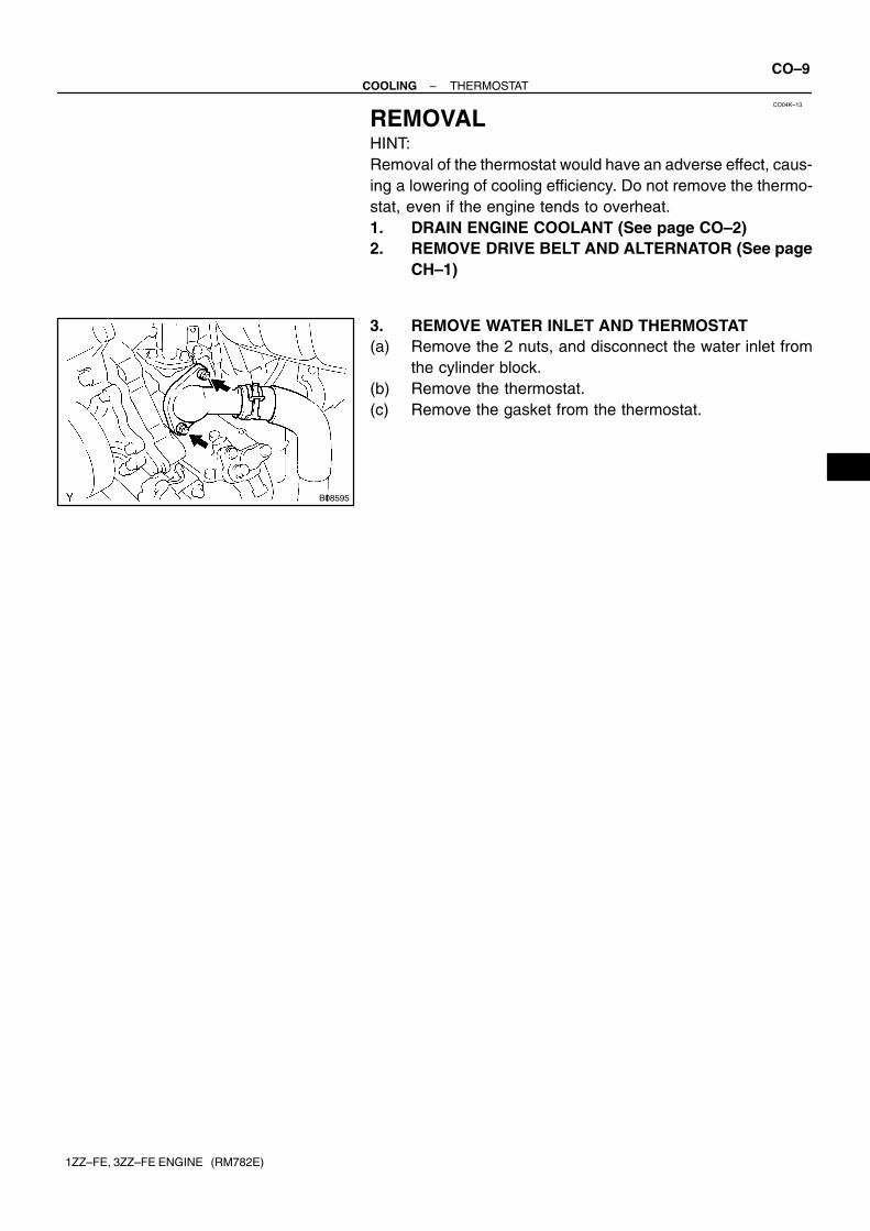
3. REMOVE WATER INLET AND THERMOSTAT(a) Remove the 2 nuts, and disconnect the water inlet from
the cylinder block.(b) Remove the thermostat.(c) Remove the gasket from the thermostat.
CO04L–11
P13560
P00436
P24125
Valve Lift
CO–10–COOLING THERMOSTAT
1ZZ–FE, 3ZZ–FE ENGINE (RM782E)
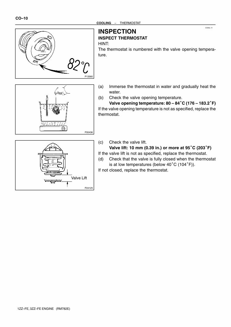
INSPECTIONINSPECT THERMOSTATHINT:The thermostat is numbered with the valve opening tempera-ture.
(a) Immerse the thermostat in water and gradually heat thewater.
(b) Check the valve opening temperature.Valve opening temperature: 80 – 84�C (176 – 183.2�F)
If the valve opening temperature is not as specified, replace thethermostat.
(c) Check the valve lift.Valve lift: 10 mm (0.39 in.) or more at 95�C (203�F)
If the valve lift is not as specified, replace the thermostat.(d) Check that the valve is fully closed when the thermostat
is at low temperatures (below 40�C (104�F)).If not closed, replace the thermostat.
CO0XM–04
B00153
Upward10�10�
B08595
–COOLING THERMOSTATCO–11
1ZZ–FE, 3ZZ–FE ENGINE (RM782E)
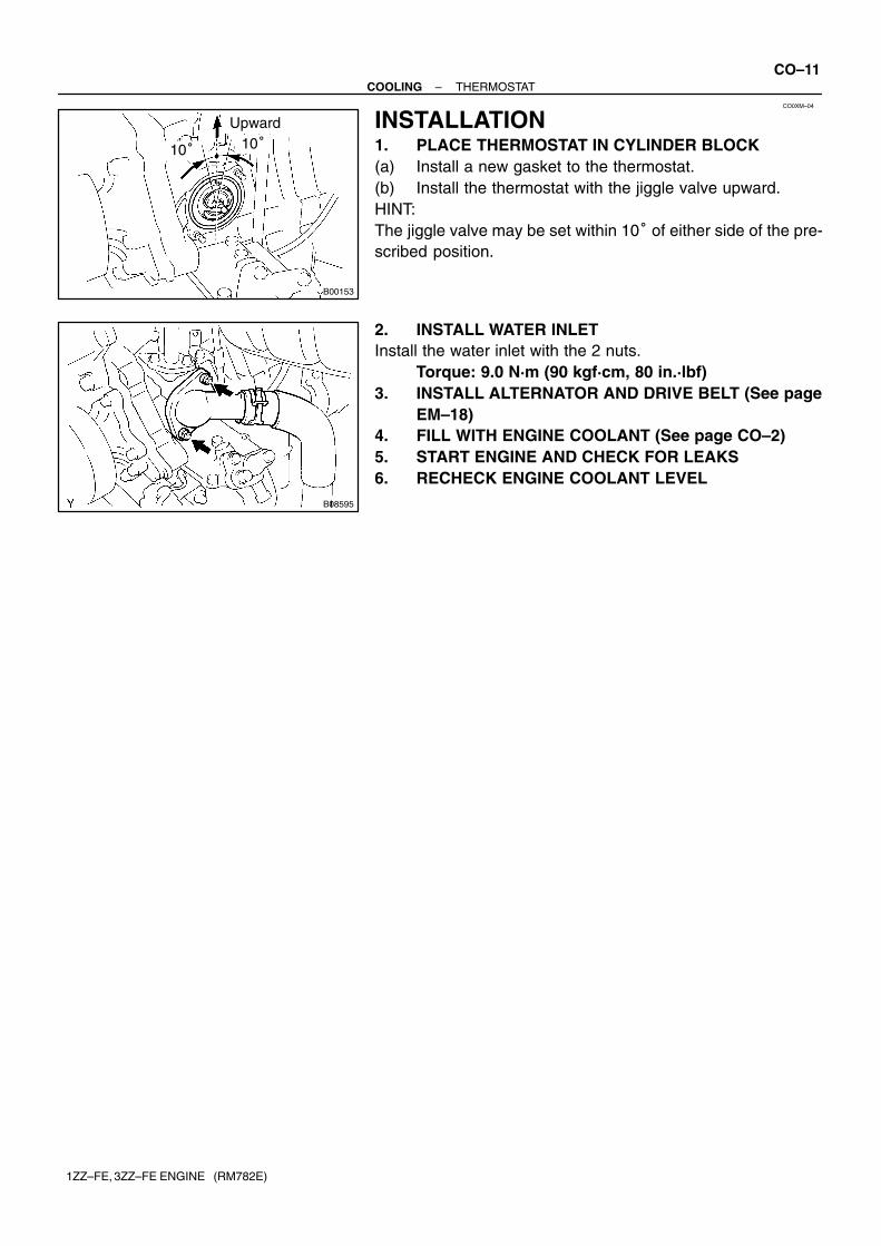
INSTALLATION1. PLACE THERMOSTAT IN CYLINDER BLOCK(a) Install a new gasket to the thermostat.(b) Install the thermostat with the jiggle valve upward.HINT:The jiggle valve may be set within 10� of either side of the pre-scribed position.
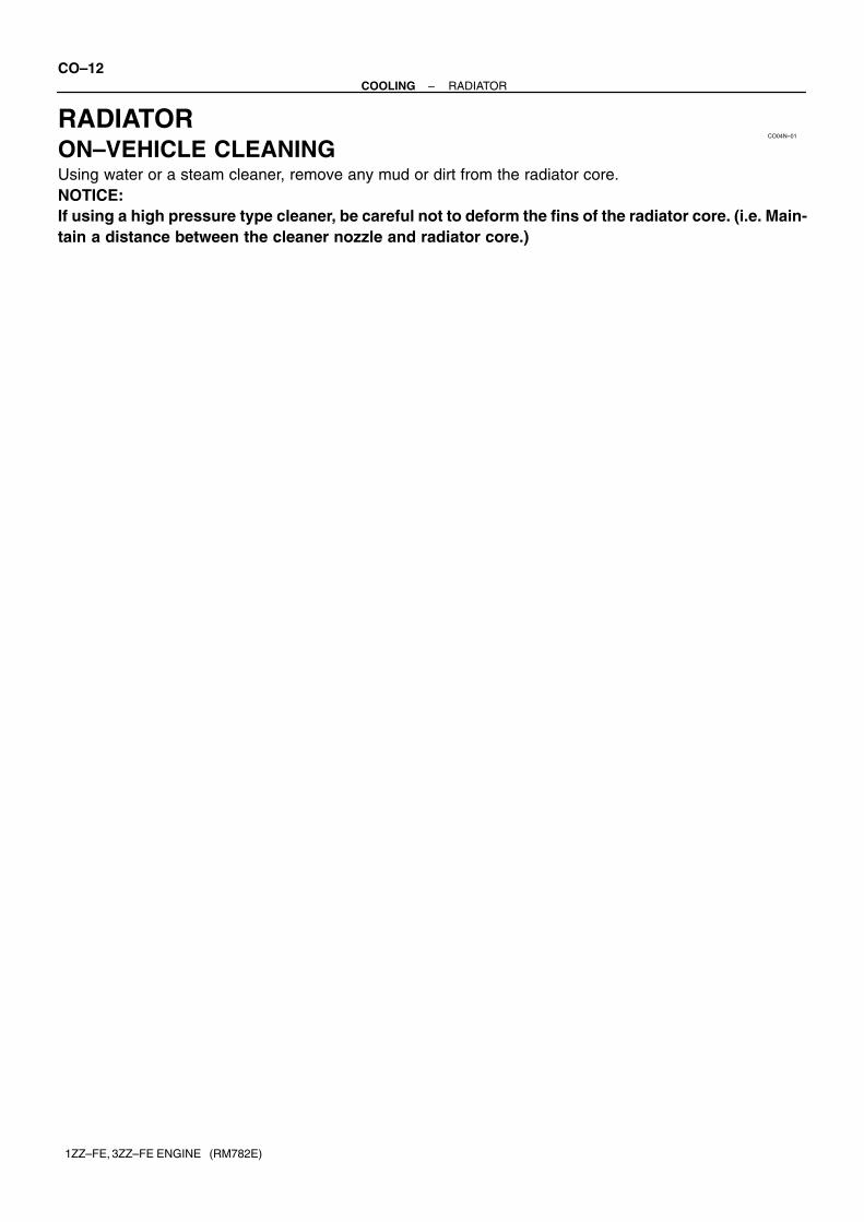
2. INSTALL WATER INLETInstall the water inlet with the 2 nuts.
Torque: 9.0 N·m (90 kgf·cm, 80 in.·lbf)3. INSTALL ALTERNATOR AND DRIVE BELT (See page
EM–18)4. FILL WITH ENGINE COOLANT (See page CO–2)5. START ENGINE AND CHECK FOR LEAKS6. RECHECK ENGINE COOLANT LEVEL
CO04N–01
CO–12–COOLING RADIATOR
1ZZ–FE, 3ZZ–FE ENGINE (RM782E)
RADIATORON–VEHICLE CLEANINGUsing water or a steam cleaner, remove any mud or dirt from the radiator core.NOTICE:If using a high pressure type cleaner, be careful not to deform the fins of the radiator core. (i.e. Main-tain a distance between the cleaner nozzle and radiator core.)
CO04O–13
Z00570
Radiator Cap TesterRadiator Cap
30� or More
–COOLING RADIATORCO–13
1ZZ–FE, 3ZZ–FE ENGINE (RM782E)
ON–VEHICLE INSPECTION1. REMOVE RADIATOR CAPCAUTION:To avoid the danger of being burned, do not remove the ra-diator cap while the engine and radiator are still hot, as fluidand steam can be blown out under pressure.2. INSPECT RADIATOR CAPNOTICE:� If the radiator cap has contaminations, always rinse
it with water.� Before using a radiator cap tester, wet the relief valve
and pressure valve with engine coolant or water.� When performing steps (a) and (b) below, keep the ra-
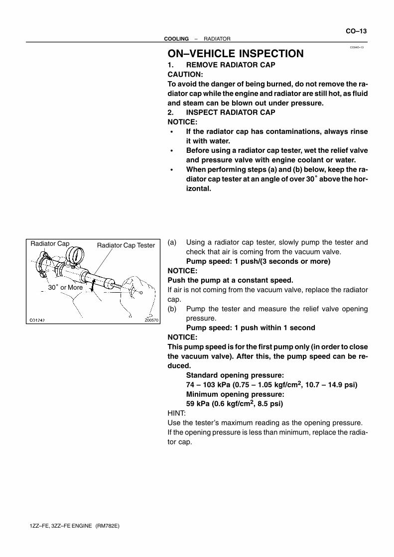
diator cap tester at an angle of over 30� above the hor-izontal.
(a) Using a radiator cap tester, slowly pump the tester andcheck that air is coming from the vacuum valve.Pump speed: 1 push/(3 seconds or more)
NOTICE:Push the pump at a constant speed.If air is not coming from the vacuum valve, replace the radiatorcap.(b) Pump the tester and measure the relief valve opening
pressure.Pump speed: 1 push within 1 second
NOTICE:This pump speed is for the first pump only (in order to closethe vacuum valve). After this, the pump speed can be re-duced.
Standard opening pressure:74 – 103 kPa (0.75 – 1.05 kgf/cm2, 10.7 – 14.9 psi)Minimum opening pressure:59 kPa (0.6 kgf/cm2, 8.5 psi)
HINT:Use the tester’s maximum reading as the opening pressure.If the opening pressure is less than minimum, replace the radia-tor cap.
B12400
CO–14–COOLING RADIATOR
1ZZ–FE, 3ZZ–FE ENGINE (RM782E)
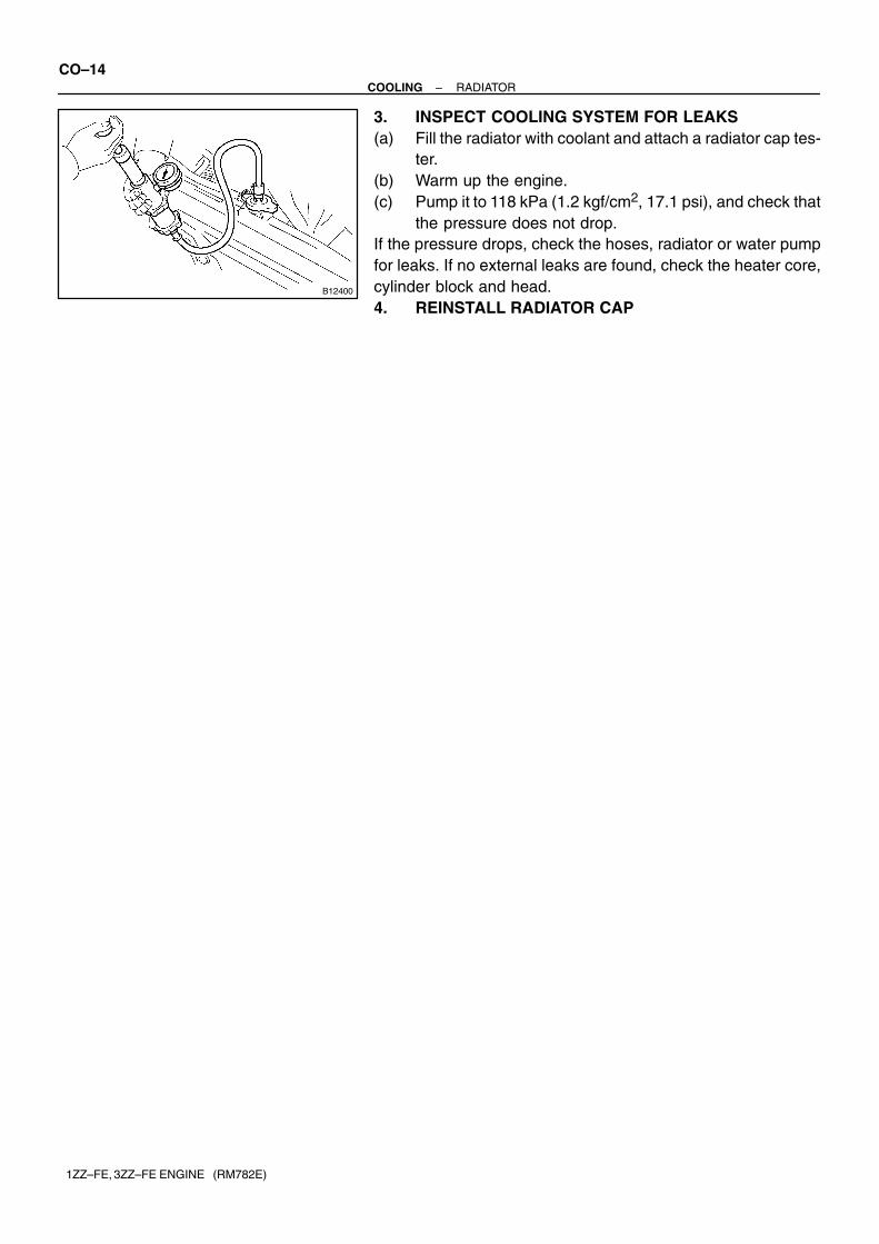
3. INSPECT COOLING SYSTEM FOR LEAKS(a) Fill the radiator with coolant and attach a radiator cap tes-
ter.(b) Warm up the engine.(c) Pump it to 118 kPa (1.2 kgf/cm2, 17.1 psi), and check that
the pressure does not drop.If the pressure drops, check the hoses, radiator or water pumpfor leaks. If no external leaks are found, check the heater core,cylinder block and head.4. REINSTALL RADIATOR CAP
CO0XN–03
B12359
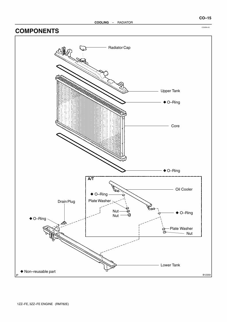
Upper Tank
� O–Ring
Core
� O–Ring
� Non–reusable part
Radiator Cap
Oil Cooler
� O–Ring
Plate Washer
Plate Washer
� O–Ring
NutNut
� O–Ring
Drain Plug
A/T
Lower Tank
Nut
–COOLING RADIATORCO–15
1ZZ–FE, 3ZZ–FE ENGINE (RM782E)
COMPONENTS
CO14Y–01
B12361Drain Plug
CO1205Overhaul HandleClaw
Dimension ”B”SST Stopper Bolt
Part ”A”
P17548
StopperBolt
SST
LockPlate
Tank
P13991
LightlyTap
B12368
Plate Washer
Lower Tank
O–RingPlate Washer
Nut
Oil Cooler
O–Ring
Nut
A/T
CO–16–COOLING RADIATOR
1ZZ–FE, 3ZZ–FE ENGINE (RM782E)
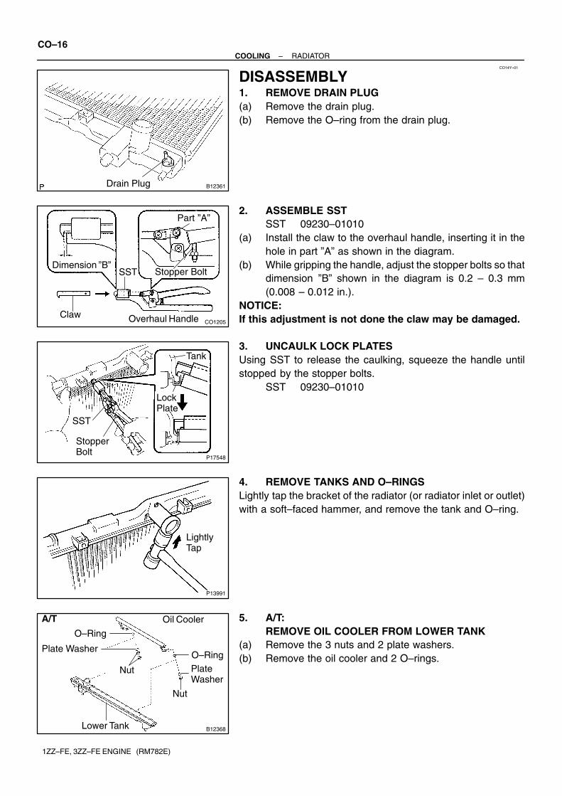
DISASSEMBLY1. REMOVE DRAIN PLUG(a) Remove the drain plug.(b) Remove the O–ring from the drain plug.
2. ASSEMBLE SSTSST 09230–01010
(a) Install the claw to the overhaul handle, inserting it in thehole in part ”A” as shown in the diagram.
(b) While gripping the handle, adjust the stopper bolts so thatdimension ”B” shown in the diagram is 0.2 – 0.3 mm(0.008 – 0.012 in.).
NOTICE:If this adjustment is not done the claw may be damaged.
3. UNCAULK LOCK PLATESUsing SST to release the caulking, squeeze the handle untilstopped by the stopper bolts.
SST 09230–01010
4. REMOVE TANKS AND O–RINGSLightly tap the bracket of the radiator (or radiator inlet or outlet)with a soft–faced hammer, and remove the tank and O–ring.
5. A/T:REMOVE OIL COOLER FROM LOWER TANK
(a) Remove the 3 nuts and 2 plate washers.(b) Remove the oil cooler and 2 O–rings.
CO14Z–01
B12368
Plate Washer
Lower Tank
O–RingPlate Washer
Nut
Oil Cooler
O–Ring
Nut
A/T
CO1267
Lock Plate Lock Plate
Core
CO0317
� Normal X Twisted
X TwistedO–Ring
P13992
CORRECTTank
WRONG
O–Ring
LockPlate
–COOLING RADIATORCO–17
1ZZ–FE, 3ZZ–FE ENGINE (RM782E)
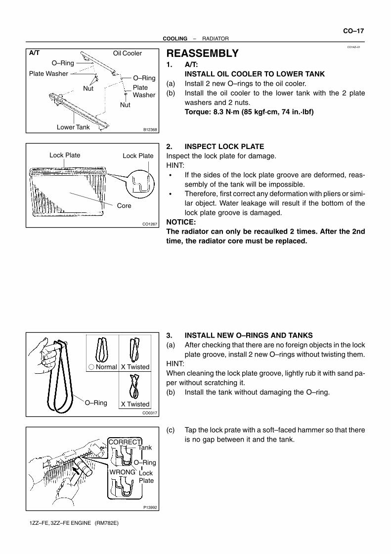
REASSEMBLY1. A/T:
INSTALL OIL COOLER TO LOWER TANK(a) Install 2 new O–rings to the oil cooler.(b) Install the oil cooler to the lower tank with the 2 plate
washers and 2 nuts.Torque: 8.3 N·m (85 kgf·cm, 74 in.·lbf)
2. INSPECT LOCK PLATEInspect the lock plate for damage.HINT:� If the sides of the lock plate groove are deformed, reas-
sembly of the tank will be impossible.� Therefore, first correct any deformation with pliers or simi-
lar object. Water leakage will result if the bottom of thelock plate groove is damaged.
NOTICE:The radiator can only be recaulked 2 times. After the 2ndtime, the radiator core must be replaced.
3. INSTALL NEW O–RINGS AND TANKS(a) After checking that there are no foreign objects in the lock
plate groove, install 2 new O–rings without twisting them.HINT:When cleaning the lock plate groove, lightly rub it with sand pa-per without scratching it.(b) Install the tank without damaging the O–ring.
(c) Tap the lock prate with a soft–faced hammer so that thereis no gap between it and the tank.
CO1206
Dimension ”B”
Part ”A”
Stopper BoltSST
Overhaul HandlePunch Assembly
Z11882
SST
Stopper Bolt
LockPlate
5 3 7
1
6 4 8
2
B12360
Z11873
CO–18–COOLING RADIATOR
1ZZ–FE, 3ZZ–FE ENGINE (RM782E)
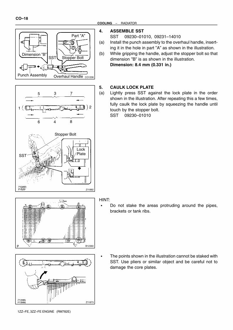
4. ASSEMBLE SSTSST 09230–01010, 09231–14010
(a) Install the punch assembly to the overhaul handle, insert-ing it in the hole in part ”A” as shown in the illustration.
(b) While gripping the handle, adjust the stopper bolt so thatdimension ”B” is as shown in the illustration.Dimension: 8.4 mm (0.331 in.)
5. CAULK LOCK PLATE(a) Lightly press SST against the lock plate in the order
shown in the illustration. After repeating this a few times,fully caulk the lock plate by squeezing the handle untiltouch by the stopper bolt.SST 09230–01010
HINT:� Do not stake the areas protruding around the pipes,
brackets or tank ribs.
� The points shown in the illustration cannot be staked withSST. Use pliers or similar object and be careful not todamage the core plates.
P13997
H
P00017
SST
S01713
Tank
LockPlate
O–Ring
–COOLING RADIATORCO–19
1ZZ–FE, 3ZZ–FE ENGINE (RM782E)
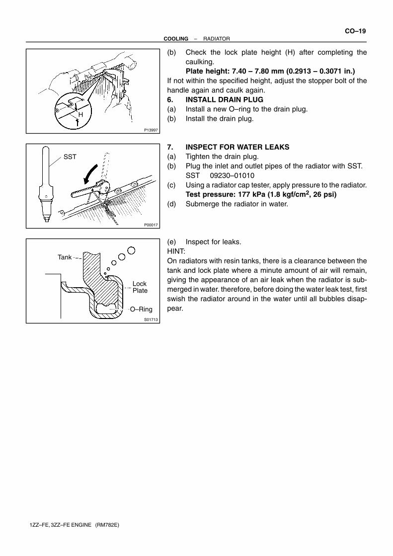
(b) Check the lock plate height (H) after completing thecaulking.Plate height: 7.40 – 7.80 mm (0.2913 – 0.3071 in.)
If not within the specified height, adjust the stopper bolt of thehandle again and caulk again.6. INSTALL DRAIN PLUG(a) Install a new O–ring to the drain plug.(b) Install the drain plug.
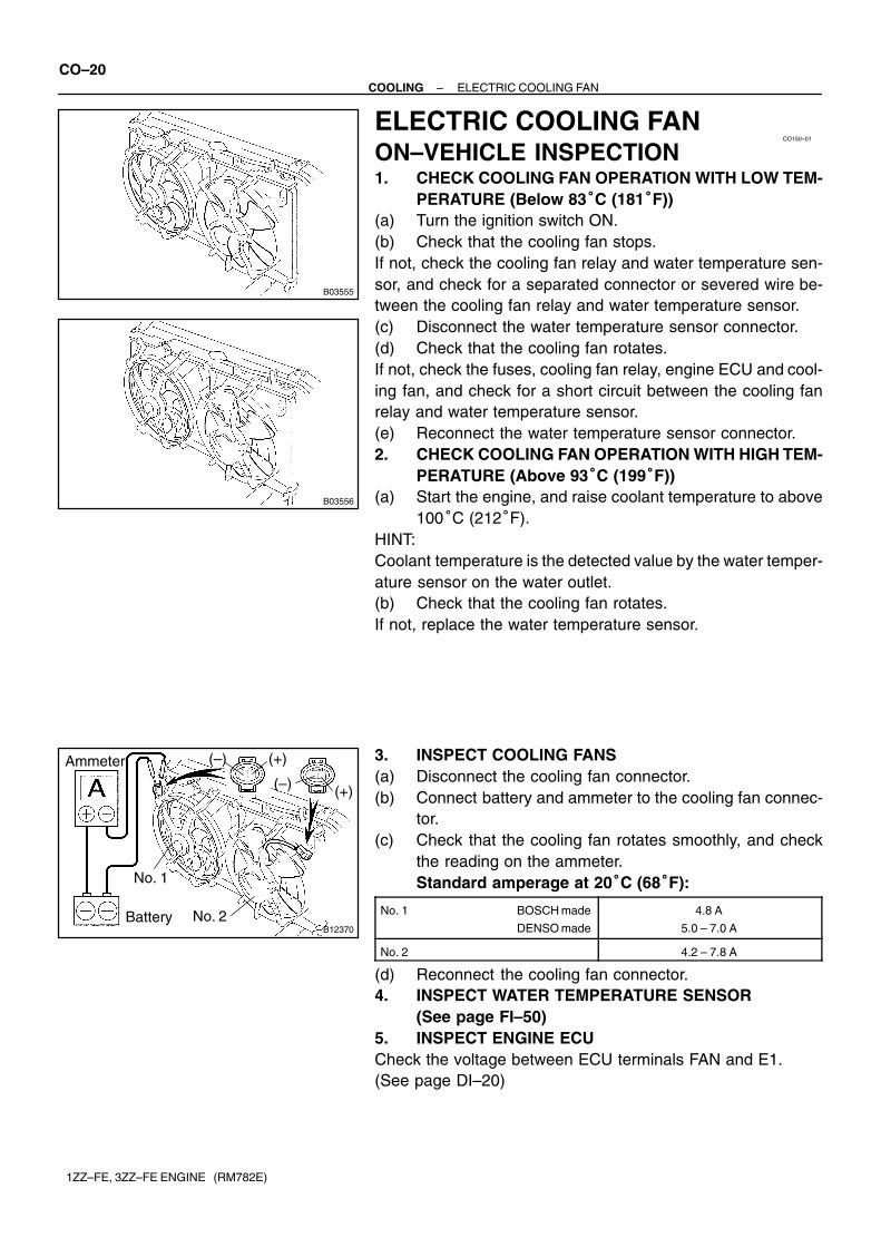
7. INSPECT FOR WATER LEAKS(a) Tighten the drain plug.(b) Plug the inlet and outlet pipes of the radiator with SST.
SST 09230–01010(c) Using a radiator cap tester, apply pressure to the radiator.
Test pressure: 177 kPa (1.8 kgf/cm2, 26 psi)(d) Submerge the radiator in water.
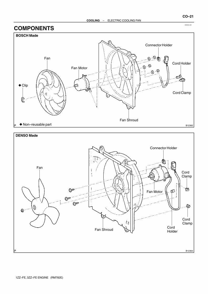
(e) Inspect for leaks.HINT:On radiators with resin tanks, there is a clearance between thetank and lock plate where a minute amount of air will remain,giving the appearance of an air leak when the radiator is sub-merged in water. therefore, before doing the water leak test, firstswish the radiator around in the water until all bubbles disap-pear.
B03555
CO150–01
B03556
B12370
Ammeter
Battery
No. 1
No. 2
(–) (+)
(–) (+)
CO–20–COOLING ELECTRIC COOLING FAN
1ZZ–FE, 3ZZ–FE ENGINE (RM782E)
ELECTRIC COOLING FANON–VEHICLE INSPECTION1. CHECK COOLING FAN OPERATION WITH LOW TEM-
PERATURE (Below 83�C (181�F))(a) Turn the ignition switch ON.(b) Check that the cooling fan stops.If not, check the cooling fan relay and water temperature sen-sor, and check for a separated connector or severed wire be-tween the cooling fan relay and water temperature sensor.(c) Disconnect the water temperature sensor connector.(d) Check that the cooling fan rotates.If not, check the fuses, cooling fan relay, engine ECU and cool-ing fan, and check for a short circuit between the cooling fanrelay and water temperature sensor.(e) Reconnect the water temperature sensor connector.2. CHECK COOLING FAN OPERATION WITH HIGH TEM-
PERATURE (Above 93�C (199�F))(a) Start the engine, and raise coolant temperature to above
100�C (212�F).HINT:Coolant temperature is the detected value by the water temper-ature sensor on the water outlet.(b) Check that the cooling fan rotates.If not, replace the water temperature sensor.
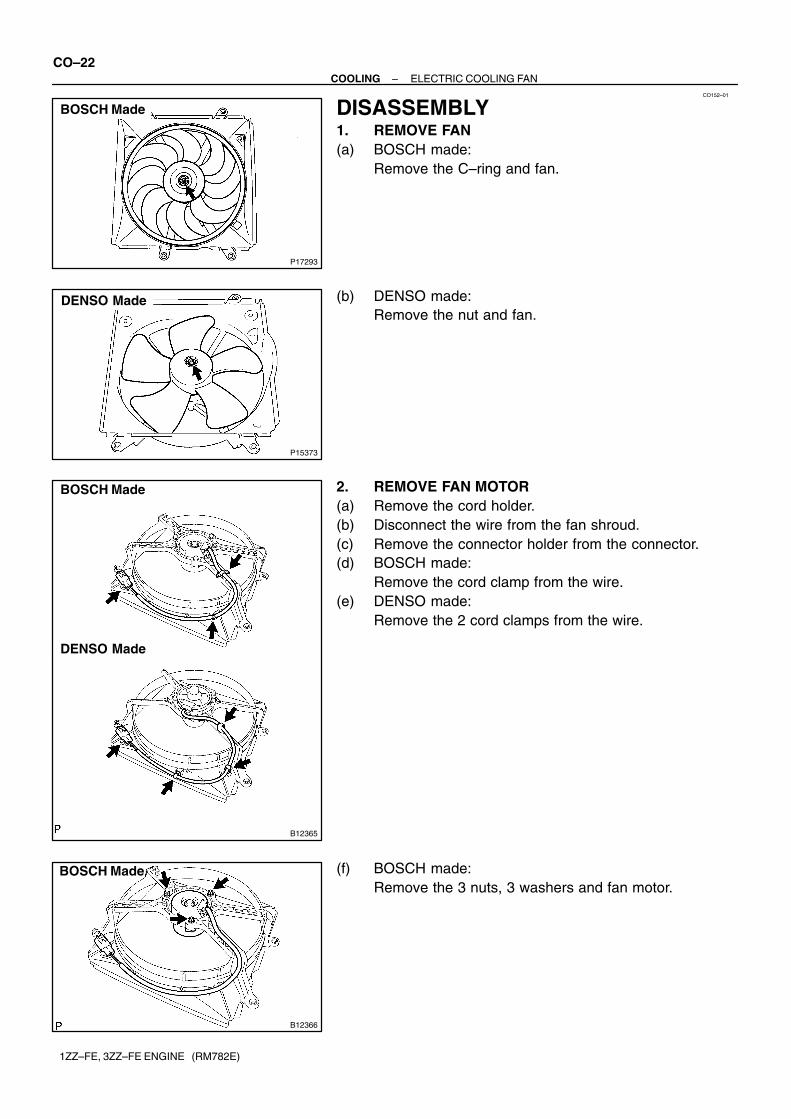
3. INSPECT COOLING FANS(a) Disconnect the cooling fan connector.(b) Connect battery and ammeter to the cooling fan connec-
tor.(c) Check that the cooling fan rotates smoothly, and check
the reading on the ammeter.Standard amperage at 20�C (68�F):
No. 1 BOSCH made
DENSO made
4.8 A
5.0 – 7.0 A
No. 2 4.2 – 7.8 A
(d) Reconnect the cooling fan connector.4. INSPECT WATER TEMPERATURE SENSOR
(See page FI–50)5. INSPECT ENGINE ECUCheck the voltage between ECU terminals FAN and E1.(See page DI–20)
CO151–01
B12362
Fan
Connector Holder
Fan Motor
Fan Shroud
Cord Clamp
� Clip
BOSCH Made
� Non–reusable part
Cord Holder
B12363
Fan
Connector Holder
Cord Clamp
Cord Clamp
Cord Holder
DENSO Made
Fan Shroud
Fan Motor
–COOLING ELECTRIC COOLING FANCO–21
1ZZ–FE, 3ZZ–FE ENGINE (RM782E)
COMPONENTS
P17293
BOSCH MadeCO152–01
P15373
DENSO Made
B12365
BOSCH Made
DENSO Made
B12366
BOSCH Made
CO–22–COOLING ELECTRIC COOLING FAN
1ZZ–FE, 3ZZ–FE ENGINE (RM782E)
DISASSEMBLY1. REMOVE FAN(a) BOSCH made:
Remove the C–ring and fan.
(b) DENSO made:Remove the nut and fan.
2. REMOVE FAN MOTOR(a) Remove the cord holder.(b) Disconnect the wire from the fan shroud.(c) Remove the connector holder from the connector.(d) BOSCH made:
Remove the cord clamp from the wire.(e) DENSO made:
Remove the 2 cord clamps from the wire.
(f) BOSCH made:Remove the 3 nuts, 3 washers and fan motor.
B12367
DENSO Made
–COOLING ELECTRIC COOLING FANCO–23
1ZZ–FE, 3ZZ–FE ENGINE (RM782E)
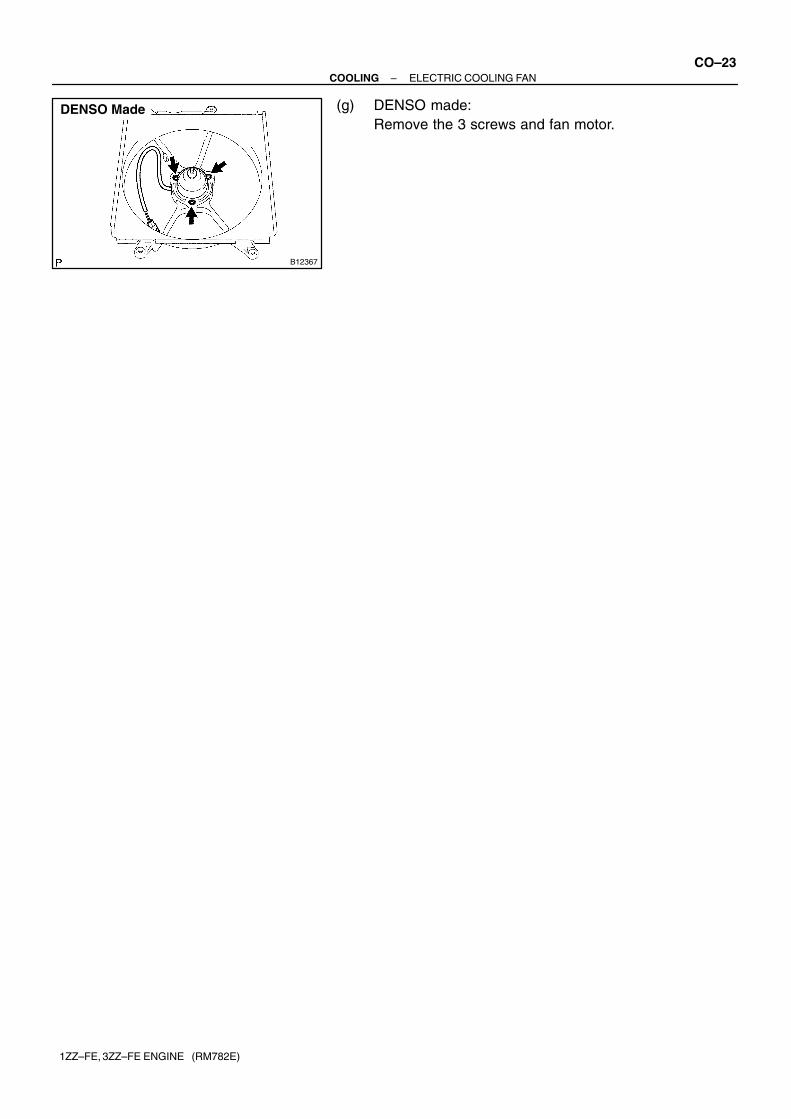
(g) DENSO made:Remove the 3 screws and fan motor.
CO153–01
B12366
BOSCH Made
B12367
DENSO Made
B12365
BOSCH Made
DENSO Made
P17293
BOSCH Made
CO–24–COOLING ELECTRIC COOLING FAN
1ZZ–FE, 3ZZ–FE ENGINE (RM782E)
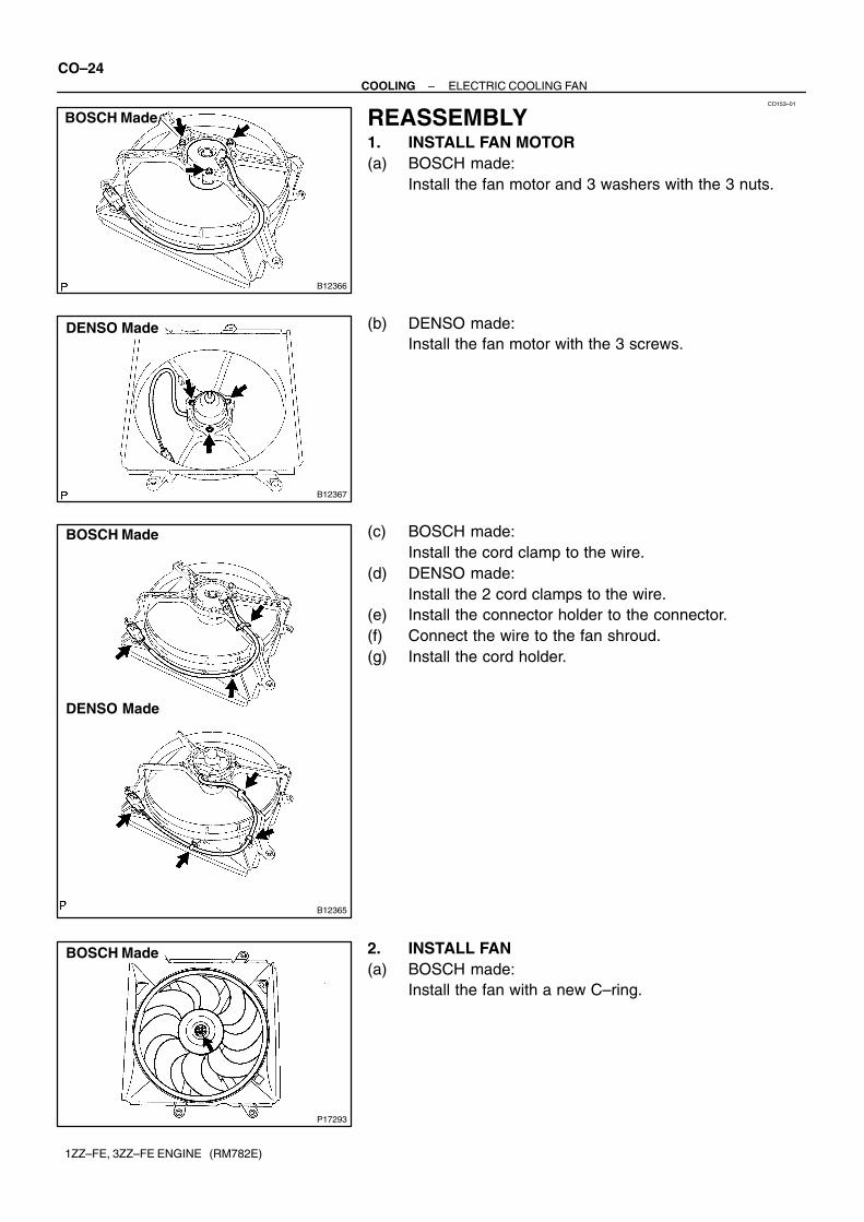
REASSEMBLY1. INSTALL FAN MOTOR(a) BOSCH made:
Install the fan motor and 3 washers with the 3 nuts.
(b) DENSO made:Install the fan motor with the 3 screws.
(c) BOSCH made:Install the cord clamp to the wire.
(d) DENSO made:Install the 2 cord clamps to the wire.
(e) Install the connector holder to the connector.(f) Connect the wire to the fan shroud.(g) Install the cord holder.
2. INSTALL FAN(a) BOSCH made:
Install the fan with a new C–ring.
P15373
DENSO Made
–COOLING ELECTRIC COOLING FANCO–25
1ZZ–FE, 3ZZ–FE ENGINE (RM782E)
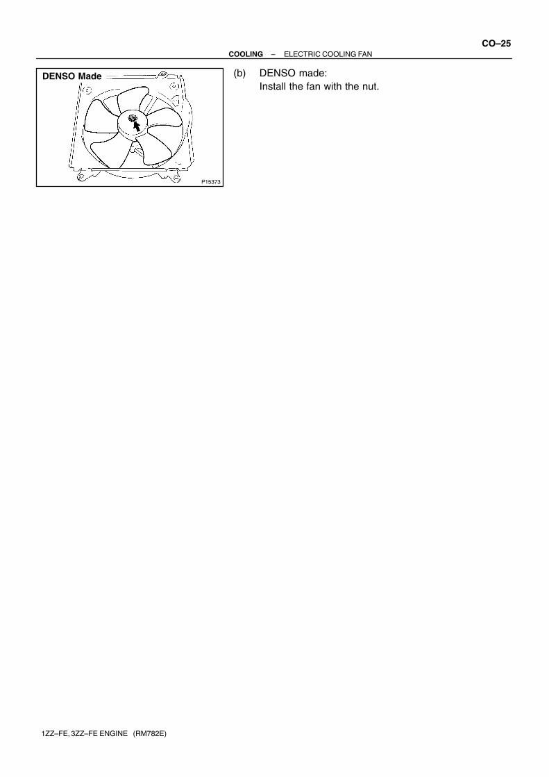
(b) DENSO made:Install the fan with the nut.
B03561
No. 1 CoolingFan Relay
CO054–09
B03969
Ohmmeter
No Continuity
Ohmmeter
Continuity
87
86
30
85
B03968
Continuity
Ohmmeter
Battery
87
86
3085
B03560
No. 2 CoolingFan Relay
B03550
ContinuityOhmmeter
No ContinuityContinuity
41
3
2
Ohmmeter5
Ohmmeter
CO–26–COOLING COOLING FAN RELAY
1ZZ–FE, 3ZZ–FE ENGINE (RM782E)
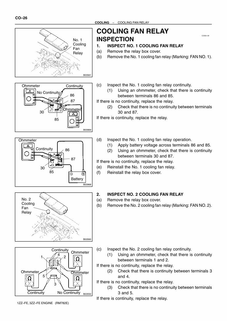
COOLING FAN RELAYINSPECTION1. INSPECT NO. 1 COOLING FAN RELAY(a) Remove the relay box cover.(b) Remove the No. 1 cooling fan relay (Marking: FAN NO. 1).
(c) Inspect the No. 1 cooling fan relay continuity.(1) Using an ohmmeter, check that there is continuity
between terminals 86 and 85.If there is no continuity, replace the relay.
(2) Check that there is no continuity between terminals30 and 87.
If there is continuity, replace the relay.
(d) Inspect the No. 1 cooling fan relay operation.(1) Apply battery voltage across terminals 86 and 85.(2) Using an ohmmeter, check that there is continuity
between terminals 30 and 87.If there is no continuity, replace the relay.(e) Reinstall the No. 1 cooling fan relay.(f) Reinstall the relay box cover.
2. INSPECT NO. 2 COOLING FAN RELAY(a) Remove the relay box cover.(b) Remove the No. 2 cooling fan relay (Marking: FAN NO. 2).
(c) Inspect the No. 2 cooling fan relay continuity.(1) Using an ohmmeter, check that there is continuity
between terminals 1 and 2.If there is no continuity, replace the relay.
(2) Check that there is continuity between terminals 3and 4.
If there is no continuity, replace the relay.(3) Check that there is no continuity between terminals
3 and 5.If there is continuity, replace the relay.
B03551
Ohmmeter
Continuity
Ohmmeter
No Continuity
41
3
2
5
Battery
B03559
No. 3 CoolingFan Relay
B03548No Continuity
Continuity
1 2
Ohmmeter
5
Ohmmeter
3
B03549
Ohmmeter
Continuity
1
3
2
5
Battery
–COOLING COOLING FAN RELAYCO–27
1ZZ–FE, 3ZZ–FE ENGINE (RM782E)
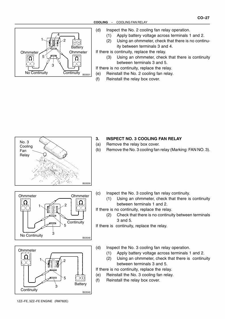
(d) Inspect the No. 2 cooling fan relay operation.(1) Apply battery voltage across terminals 1 and 2.(2) Using an ohmmeter, check that there is no continu-
ity between terminals 3 and 4.If there is continuity, replace the relay.
(3) Using an ohmmeter, check that there is continuitybetween terminals 3 and 5.
If there is no continuity, replace the relay.(e) Reinstall the No. 2 cooling fan relay.(f) Reinstall the relay box cover.
3. INSPECT NO. 3 COOLING FAN RELAY(a) Remove the relay box cover.(b) Remove the No. 3 cooling fan relay (Marking: FAN NO. 3).
(c) Inspect the No. 3 cooling fan relay continuity.(1) Using an ohmmeter, check that there is continuity
between terminals 1 and 2.If there is no continuity, replace the relay.
(2) Check that there is no continuity between terminals3 and 5.
If there is continuity, replace the relay.
(d) Inspect the No. 3 cooling fan relay operation.(1) Apply battery voltage across terminals 1 and 2.(2) Using an ohmmeter, check that there is continuity
between terminals 3 and 5.If there is no continuity, replace the relay.(e) Reinstall the No. 3 cooling fan relay.(f) Reinstall the relay box cover.