Embed Size (px)
Citation preview

Tool Customer Service
[email protected] or call 1-800-629-3325 (option 3) Monday - Friday 7am to 5pm. PST
Product Support (Product: information, application, and service info & warranty questions)
[email protected] or call 1-800-629-3325 (option 4) Monday - Friday 7am to 5pm. PST
This manual provides information regarding the operation and maintenance of these products. We have made every effort to ensure the accuracy of the information in this manual. We reserve the right to change this product at any time without prior notice.

1
The generator is a potential source of electrical shock if misused. Do not expose the generator to moisture, rain or snow. Do not let the generator get wet, and do not operate it with wet hands.
These labels warn you of potential hazards that can cause serious injury. Read them carefully.

2
SAFETY INFORMATION Read and understand this instruction manual before operating your generator. You can help prevent accidents by being familiar with your generator’s controls, and by observing safe operating procedures.
Operator Responsibility Know how to stop the generator quickly in case of emergency.
Understand the use of all generator controls, output receptacles, and connections. Do not let children operate the generator without parental supervision.
Carbon Monoxide Hazards Exhaust contains poisonous carbon monoxide, a colorless and odorless gas. Breathing exhaust
can cause loss of consciousness and may lead to death. If you run the generator in an area that is confined, or even partially enclosed, the air you breathe
could contain a dangerous amount of exhaust gas. To keep exhaust gas from accumulating, provide adequate ventilation.
Electric Shock Hazards The generator produces enough electric power to cause a serious shock or electrocution if misused.
Using a generator or electrical appliance in wet conditions, such as rain or snow, or near a pool or sprinkler system, or when your hands are wet, could result in electrocution. Keep the generator dry. If the generator is stored outdoors, unprotected from the weather, check all of the electrical components on the control panel, before each use. Moisture or ice can cause a malfunction or short circuit in electrical components, which could result in electrocution. Do not connect to a building electrical system unless a qualified electrician has installed an isolation switch.
Fire and Burn Hazards The exhaust system gets hot enough to ignite some materials.
-Keep the generator at least 3 feet (1 meter) away from buildings and other equipment during operation.
-Do not enclose the generator in any structure. -Keep flammable materials away from the generator.
The muffler becomes very hot during operation and remains hot for a while after stopping the engine.
Be careful not to touch the muffler while it is hot. Let the engine cool before storing the generator indoors.
Gasoline is extremely flammable and is explosive under certain conditions. Do not smoke or allow flames or sparks where the generator is refueled or where gasoline is stored. Refuel in a well-ventilated area with the engine stopped.
Fuel vapors are extremely flammable and may ignite after the engine has started. Make sure that any spilled fuel has been wiped up before starting the generator.
3
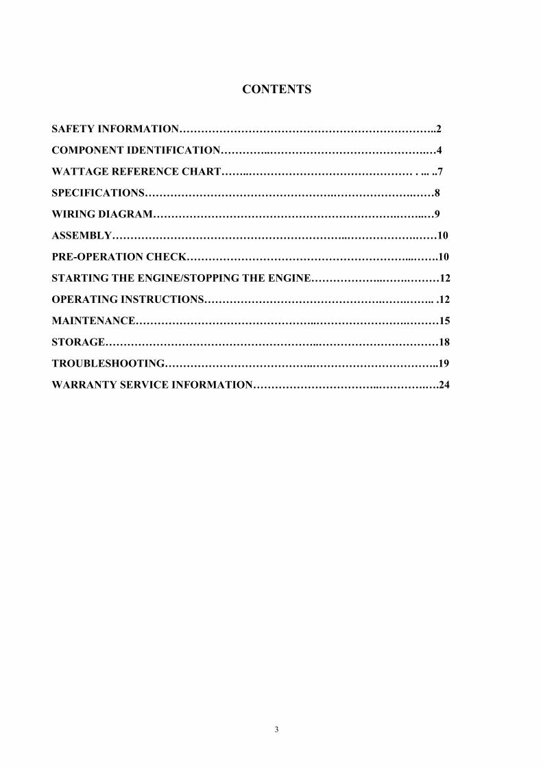
CONTENTS SAFETY INFORMATION……………………………………………………………..2
COMPONENT IDENTIFICATION…………..…………………………………….…4
WATTAGE REFERENCE CHART……..……………………………………… . ... ..7
SPECIFICATIONS…………………………………………….………………….……8
WIRING DIAGRAM………………………………………………………….……..…9
ASSEMBLY………………………………………………………..……………….……10
PRE-OPERATION CHECK……………………………………………………...…….10
STARTING THE ENGINE/STOPPING THE ENGINE………………..…….………12
OPERATING INSTRUCTIONS………………………………………….…….…….. .12
MAINTENANCE…………………………………………..…………………….………15
STORAGE…………………………………………………..……………………………18
TROUBLESHOOTING…………………………………..……………………………..19
WARRANTY SERVICE INFORMATION……………………………..………….….24

4

5
.
Engine Key To start and stop the engine. Key position:
OFF: To stop the engine. Key can be removed / inserted.
ON: To run the engine after starting, or to pull start the unit. START: To start the engine by operating the starter motor.
Do not turn the key switch to START position when the engine is running to prevent damage to the starting motor.
Recoil Starter To start the engine, turn the key to on, pull the starter grip lightly until resistance is felt, then pull briskly.
Do not allow the starter grip to snap back against the engine. Return it gently to prevent damage to the starter.
Fuel Valve Lever The fuel valve is located between the fuel tank and carburetor. When the valve lever is in the ON position, fuel is allowed to flow from the fuel tank to the carburetor. Be sure to return the fuel valve lever to the OFF position after stopping the engine.
Choke Rod The choke is used to provide an enriched fuel mixture when starting a cold engine. It can be opened and closed by operating the choke rod manually. Pull the rod out toward CLOSED to enrich the mixture for cold starting
Voltage Selector Switch The voltage selector switch switches the main power carrying windings of the generator to produce ‘‘120V ’’ or ‘‘120/240V’’. If a 240V appliance is connected to the 4-prong receptacles, the switch must be in the ‘‘120/240V’’ position. If only a 120V appliance is being connected select the "120V" position.
Switch Position
120/240V: The 120V and 120/240V receptacles can be used simultaneously.
120V: Do not use the 120/240V twist lock receptacle in this position. The most power will be available at the 50A 120/240V receptacle.

6
Change the Voltage Selector Switch after turning the AC circuit breaker to OFF. The generator may be damaged if the Voltage Selector Switch is changed with the breaker in the ON position.
Ground Terminal The generator ground terminal is connected to the frame of the generator, the metal non-current-carrying parts of the generator, and the ground terminals of each receptacle.
DC Receptacle The DC receptacle may ONLY be used for charging 12 volt automotive type batteries. The battery must be connected to the generator DC receptacle with the proper polarity (battery positive to generator positive (+) and battery negative to the generator negative (-).
Do not start the vehicle while the battery charging cable is connected and the generator is running. The vehicle or the generator may be damaged.
DC Circuit Protector The DC circuit protector automatically shuts off the DC battery charging circuit when the DC charging circuit is overloaded, when there is a problem with the battery, or when the connections between the battery and the generator are improper.
Oil Alert System The Oil Alert system is designed to prevent engine damage caused by an insufficient amount of oil in the crankcase. Before the oil level in the crankcase can fall below a safe limit, the Oil Alert system will automatically stop the engine (the engine switch will remain in the ON position). The Oil Alert system should not take the place of checking the oil level before each use. If the engine stops and will not restart, check the engine oil level before troubleshooting in other areas.
AC Circuit Breaker The AC circuit breaker will automatically switch OFF if there is a short circuit or a significant overload of the generator at the receptacle. If the AC circuit breaker is switched OFF automatically, check that the appliance is working properly and does not exceed the rated load capacity of the circuit before switching the AC circuit breaker ON again. The AC circuit breaker may be used to switch the generator power ON or OFF.
AC Circuit Protector The AC circuit protectors will automatically switch OFF if there is a short circuit or a significant overload of the generator at the 20A 120V, 30A 120V plug. If an AC circuit protector switches OFF automatically, check that the appliance is working properly and does not exceed the rated load capacity of the circuit before resetting the AC circuit protector ON.

7
WATTAGE REFERENCE CHART
Electric equipment, especially engines produce strong current when being started. The table below offers references when you connect those installations to generator.
Tool or Appliance Rated* (Running) Watts Additional Surge (Starting) Watts Essentials Light Bulb-75 watt 75 - Deep Freezer 500 800 Sump Pump 800 1200 Refrigerator/Freezer-18 Cu. Ft. 800 1600 Water Well Pump-1/3 HP 1000 2000 Heating/Cooling Window Air Conditioner-12000 BTU 1200 1800 Window Fan 300 600 Furnace Fan Blower-1/2 HP 800 1300 Kitchen Microwave Oven-1000 watt 1000 2000 Coffee Maker 1500 - Electric Stove- Single Element 1500 - Hot Plate 2500 - Family Room DVD/CD Player 100 - VCR 100 - Stereo Receiver 450 - Color Television- 27” 500 - Personal Computer w/17” Monitor 800 - Other Security System 180 - AM/FM Clock Radio 300 - Garage Door Opener- 1/2 HP 480 520 Electric Water Heater- 40 Gallon 4000 - DIY / Job Site Quartz Halogen Work Light 1000 - Airless Sprayer- 1/3 HP 600 1200 Reciprocating Saw 960 960 Electric Drill- 1/2 HP 1000 1000 Circular Saw- 7 1/4” 1500 1500 Miter Saw- 10” 1800 1800 Table Planer- 6” 1800 1800 Table Saw / Radial Arm Saw- 10” 2000 2000 Air Compressor- 1- 1/2 HP 2500 2500
*Wattages listed are approximate only. Check tool or appliance for actual wattage.

8
SPECIFICATIONS
Generator
Model XP12000EH
Frequency 60 HZ
Max. AC Output 12000 Watt
Rated AC Output 9500 Watt
Run Time 8 hour
Engine
Standard Features
Model XP18HPE
Type Air Cooled, OHV, 4-Stroke
Displacement 457 cc
Output 9.5kw / 3600 rpm
Fuel Unleaded Gasoline
Fuel Tank Capacity 8.3 Gallon
Decibel <72 dBA
Oil Alert Standard
Battery 12V 18A/hr.
Fuel Gauge Standard
Air Cleaner Standard
Silencer Standard
Voltmeter Standard Receptacle
2×NEMA 5-20R 1×NEMA 5-30R 1×NEMA L14-30R 1×NEMA 14-50R
Plug(Not included with your generator)
2×NEMA 5-20P 1×NEMA 5-30P 1×NEMA L14-30P 1×NEMA 14-50P
Voltage Selector Standard
DC Circuit Breaker Standard
DC Receptacle Standard
AC Circuit Breaker Standard
AC Circuit Protector Standard AC Receptacle 2 Pole 120V AC
3 Pole 120V/240V AC
Dimensions
Length 34"
Width 27"
Height 32" Gross Weight 240 lbs.

10
ASSEMBLY
Wheel Kit Installation 1 Install the axle assembly on the generator. 2 Install the two wheels on the axle shaft using the flange nuts. 3 Install the two stands on the under frame using the flange nuts.
Starter Cables Connection 1 Route the starter cable under the tank.
2 Connect the starter cable to the battery positive (+) terminal first, then to the negative (-) terminal. When disconnecting, disconnect at the battery negative (-) terminal first.
Battery posts, terminals and related accessories contain lead and lead compounds. Wash hands after handling.
Engine Oil
PRE-OPERATION CHECK
Engine oil is a major factor affecting engine performance and service life. Non-detergent and 2-stroke engine oils will damage the engine and are not recommended. Check the oil level BEFORE EACH USE with the
generator on a level surface and the engine stopped. Use 4-stroke motor oil that meets or exceeds the
requirements for API service classification SJ.
Always check the API SERVICE label on the oil container to be sure it includes the letter SJ.

11
SAE 10W-30 is recommended for general, all-temperature use. Other viscosities shown in the chart may be used when the average temperature in your area is within the indicated range.
1 Remove the oil filler cap and wipe the dipstick clean. 2 Check the oil level by inserting the dipstick into the filler neck without screwing it in. 3 If the level is low, fill to the top of the oil filler neck with the recommended oil.
Fuel Check the fuel gauge, and refill the tank if the fuel level is low.
Refuel carefully to avoid spilling fuel. Do not fill above the shoulder of the fuel strainer.
Gasoline is highly flammable and explosive, and you can be burned or seriously injured when refueling.
● Stop engine and keep heat, sparks, and flame away. ● Refuel only outdoors. ● Wipe up spills immediately.
Use unleaded gasoline with an octane rating of 86 or higher. This engine is certified to operate ONLY on unleaded gasoline.
Unleaded gasoline produces fewer engine and spark plug deposits and extends exhaust system life.
Never use stale or contaminated gasoline or an oil/gasoline mixture. Avoid getting dirt or water in the fuel tank.
12
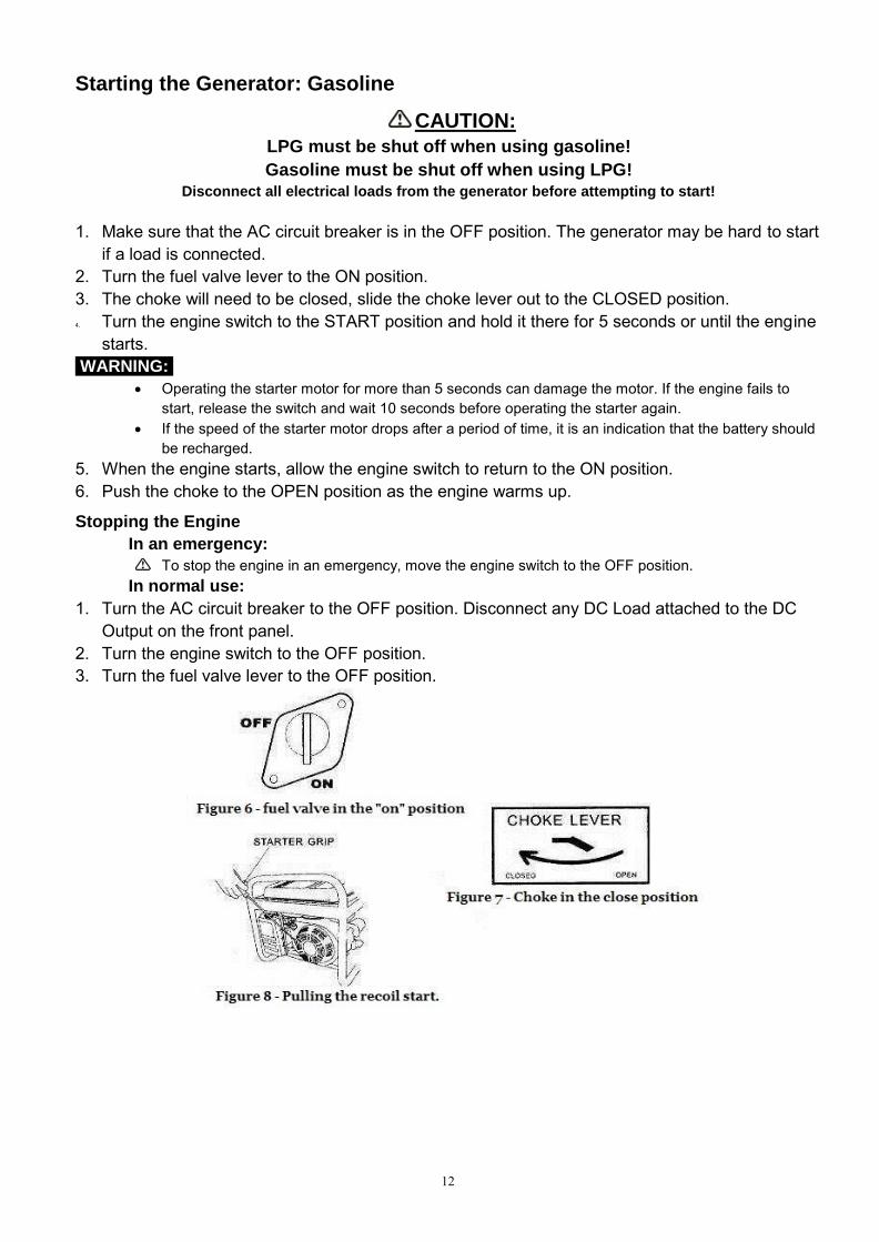
Starting the Generator: Gasoline
CAUTION: LPG must be shut off when using gasoline! Gasoline must be shut off when using LPG!
Disconnect all electrical loads from the generator before attempting to start!
1. Make sure that the AC circuit breaker is in the OFF position. The generator may be hard to start if a load is connected.
2. Turn the fuel valve lever to the ON position. 3. The choke will need to be closed, slide the choke lever out to the CLOSED position. 4. Turn the engine switch to the START position and hold it there for 5 seconds or until the engine
starts.
WARNING: Operating the starter motor for more than 5 seconds can damage the motor. If the engine fails to
start, release the switch and wait 10 seconds before operating the starter again. If the speed of the starter motor drops after a period of time, it is an indication that the battery should
be recharged. 5. When the engine starts, allow the engine switch to return to the ON position. 6. Push the choke to the OPEN position as the engine warms up.
Stopping the Engine In an emergency:
To stop the engine in an emergency, move the engine switch to the OFF position. In normal use:
1. Turn the AC circuit breaker to the OFF position. Disconnect any DC Load attached to the DC Output on the front panel.
2. Turn the engine switch to the OFF position. 3. Turn the fuel valve lever to the OFF position.

13
Starting the Generator: Propane
CAUTION: LPG must be shut off when using gasoline! Gasoline must be shut off when using LPG!
Disconnect all electrical loads from the generator before attempting to start!
1. Make sure that the AC circuit breaker is in the OFF position. The generator may be hard to start if a load is connected.
2. Turn the gasoline fuel valve to the "OFF" position. 3. Connect the propane gas hose to the regulator/decompression valve. 4. Connect the propane collar to the gas supply and then turn on the propane gas supply. 5. Press the button on top of the pressure release valve down two or three times. 6. The choke operates differently on propane gas.
a. If the engine is warm (the unit was run recently) start with the choke half open. i. Wait 30 seconds and then push the choke lever all the way to the "OPEN" position.
b. If the engine is cold (the unit was not run recently) start with the choke "OPEN". 7. Turn the engine key switch to the START position and hold it there for 5 seconds, or until the engine
starts. WARNING:
Operating the starter motor for more than 5 seconds can damage the motor. If the engine fails to start, release the switch and wait 10 seconds before operating the starter again.
If the speed of the starter motor drops after a period of time, it is an indication that the battery should be recharged.
8. When the engine starts, allow the engine switch to return to the ON position.
Stopping the Engine In an emergency:
To stop the engine in an emergency, move the engine switch to the OFF position. In normal use: 1. Turn the AC circuit breaker to the OFF position. Disconnect DC battery charging cables. 2. Turn the engine switch to the OFF position. 3. Turn OFF the Propane Gas Supply.

14
Starting the Generator: Propane (Continued)
WARNING: WHEN USING THE GENERATOR WITH LPG MAKE SURE THERE IS NO POSSIBLE IGNITION SOURCE CLOSE TO THE GENERATOR.
1. Before using, make sure all of the LPG connectors and hoses are well connected and sealed. 2. Connect electrical devices to generator ONLY after the engine runs smoothly. (There may be
remnant gasoline in the carburetor; this can cause unsteady engine performance for several minutes)
3. If the propane gas leaks, shut off the LPG supply first and then quickly unplug or turn off any electrical devices powered by the unit.
4. When stopping the engine, unplug or turn off any electrical devices, turn off the Main Circuit Breaker and then turn off the LPG Supply. After the engine has stopped turn the KEY to ‘OFF" position.
OPERATING INSTRUCTIONS Connections to a Building Electrical System
Connections for standby power to a building electrical system must be made by a qualified electrician. The connection must isolate the generator power from utility power, and must comply with all applicable laws and electrical codes. A transfer switch, which isolates generator power from utility power, is prerequisite.
Improper connections to a building electrical system can allow electrical current from the generator to back feed into the utility lines. Such back feed may electrocute utility company workers or others who contact the lines during a power outage, and the generator may explode, burn, or cause fires when utility power is restored. Consult the utility company or a qualified electrician.
Ground System The portable generators have a system ground that connects generator frame components to the ground terminals in the AC output receptacles. The system ground is not connected to the AC neutral wire. AC Applications Before connecting an appliance or power cord to the generator: Make sure that it is in good working order. Faulty appliances or power cords can create a
15
potential for electrical shock. If an appliance begins to operate abnormally, becomes sluggish or stops suddenly, turn it off
immediately. Disconnect the appliance, and determine whether the problem is the appliance, or if the rated load capacity of the generator has been exceeded.
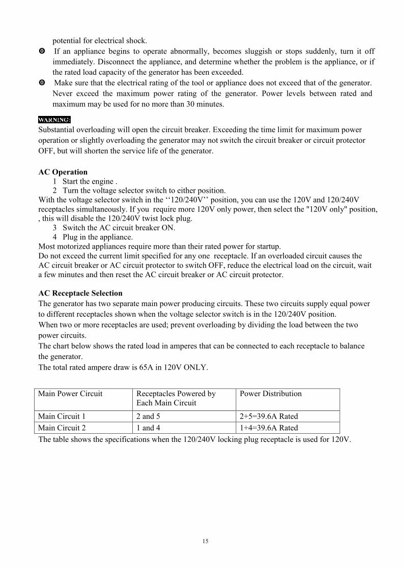
Make sure that the electrical rating of the tool or appliance does not exceed that of the generator. Never exceed the maximum power rating of the generator. Power levels between rated and maximum may be used for no more than 30 minutes.
Substantial overloading will open the circuit breaker. Exceeding the time limit for maximum power operation or slightly overloading the generator may not switch the circuit breaker or circuit protector OFF, but will shorten the service life of the generator.
AC Operation 1 Start the engine . 2 Turn the voltage selector switch to either position.
With the voltage selector switch in the ‘‘120/240V’’ position, you can use the 120V and 120/240V receptacles simultaneously. If you require more 120V only power, then select the "120V only" position, , this will disable the 120/240V twist lock plug.
3 Switch the AC circuit breaker ON. 4 Plug in the appliance.
Most motorized appliances require more than their rated power for startup. Do not exceed the current limit specified for any one receptacle. If an overloaded circuit causes the AC circuit breaker or AC circuit protector to switch OFF, reduce the electrical load on the circuit, wait a few minutes and then reset the AC circuit breaker or AC circuit protector.
AC Receptacle Selection The generator has two separate main power producing circuits. These two circuits supply equal power to different receptacles shown when the voltage selector switch is in the 120/240V position. When two or more receptacles are used; prevent overloading by dividing the load between the two power circuits. The chart below shows the rated load in amperes that can be connected to each receptacle to balance the generator. The total rated ampere draw is 65A in 120V ONLY.
Main Power Circuit Receptacles Powered by Each Main Circuit
Power Distribution
Main Circuit 1 2 and 5 2+5=39.6A Rated Main Circuit 2 1 and 4 1+4=39.6A Rated The table shows the specifications when the 120/240V locking plug receptacle is used for 120V.
16
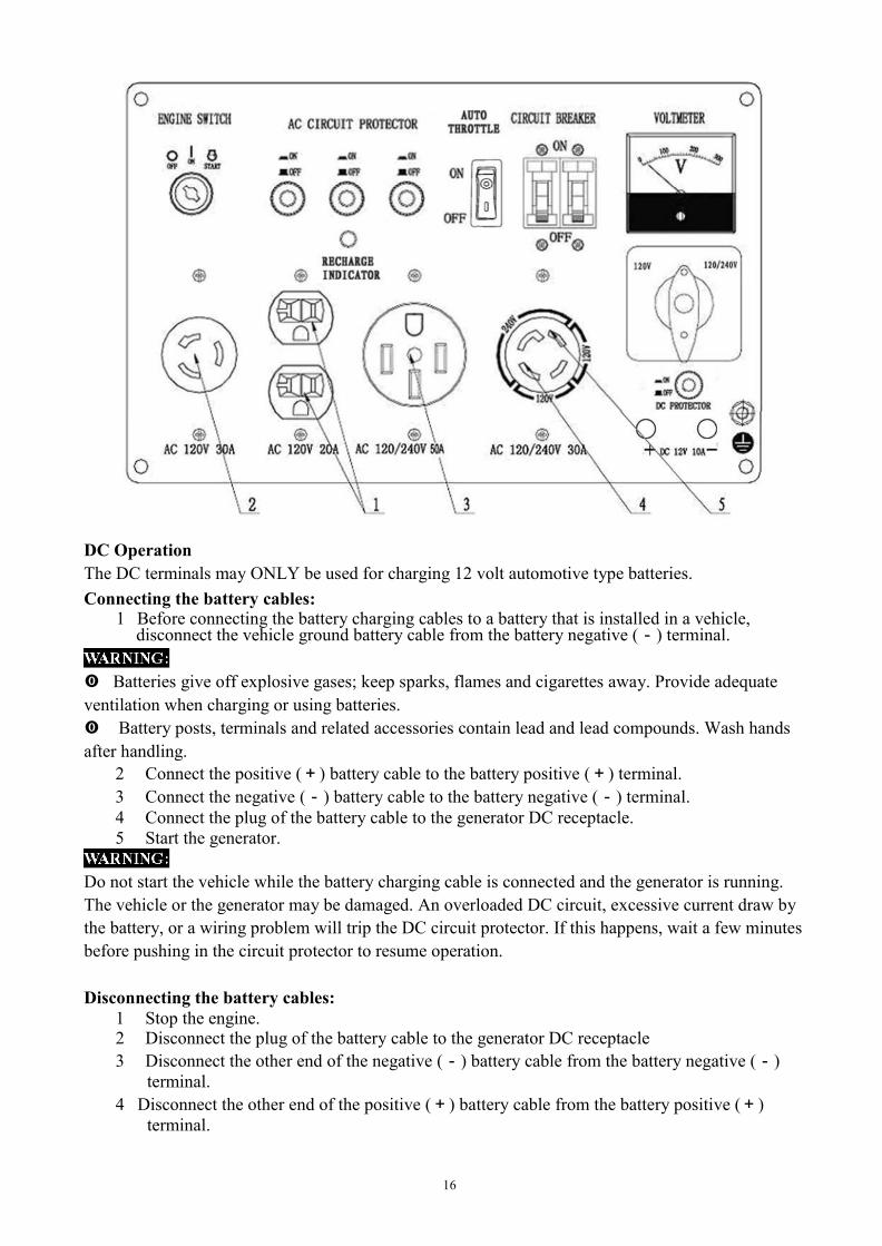
DC Operation The DC terminals may ONLY be used for charging 12 volt automotive type batteries. Connecting the battery cables:
1 Before connecting the battery charging cables to a battery that is installed in a vehicle, disconnect the vehicle ground battery cable from the battery negative (-) terminal.
Batteries give off explosive gases; keep sparks, flames and cigarettes away. Provide adequate ventilation when charging or using batteries. Battery posts, terminals and related accessories contain lead and lead compounds. Wash hands after handling.
2 Connect the positive (+) battery cable to the battery positive (+) terminal. 3 Connect the negative (-) battery cable to the battery negative (-) terminal. 4 Connect the plug of the battery cable to the generator DC receptacle. 5 Start the generator.
Do not start the vehicle while the battery charging cable is connected and the generator is running. The vehicle or the generator may be damaged. An overloaded DC circuit, excessive current draw by the battery, or a wiring problem will trip the DC circuit protector. If this happens, wait a few minutes before pushing in the circuit protector to resume operation.
Disconnecting the battery cables:
1 Stop the engine. 2 Disconnect the plug of the battery cable to the generator DC receptacle 3 Disconnect the other end of the negative (-) battery cable from the battery negative (-)
terminal. 4 Disconnect the other end of the positive (+) battery cable from the battery positive (+)
terminal.

17
5 Reconnect the vehicle ground battery cable to the battery negative (-) terminal. High Altitude Operation At high altitude, the standard carburetor air/fuel mixture will be too rich. Performance will decrease, and fuel consumption will increase. A very rich mixture will also foul the spark plug and cause hard starting. Operation at an altitude that differs from that at which this engine was certified, for extended periods of time, may increase emissions. High altitude performance can be improved by specific modifications to the carburetor. If you always operate your generator at altitudes above 5,000 feet (1,500 meters), have a dealer perform this carburetor modification. This engine, when operated at high altitude with the carburetor modifications for high altitude use, will meet each emission standard throughout its useful life. Even with carburetor modification, engine horsepower will decrease about 3.5% for each 1,000-foot (300-meter) increase in altitude. The effect of altitude on horsepower will be greater than this if no carburetor modification is made.
When the carburetor has been modified for high altitude operation, the air/fuel mixture will be too lean for low altitude use. Operation at altitudes below 5,000 feet (1,500 meters) with a modified carburetor may cause the engine to overheat and result in serious engine damage.
The Importance of Maintenance.
MAINTENANCE
Good maintenance is essential for safe, economical, and trouble-free operation. It will also help reduce air pollution.
Improper maintenance, or failure to correct a problem before operation, can cause a malfunction in which you can be seriously injured or killed. Always follow the inspection and maintenance recommendations and schedules in this instruction manual.
Maintenance Safety Make sure the engine is off before you begin any maintenance or repairs. Let the engine and exhaust system cool before touching. To reduce the possibility of fire or explosion, be careful when working around gasoline. Use only
a nonflammable solvent, not gasoline, to clean parts. Keep cigarettes, sparks, and flames away from all fuel-related parts.
Maintenance Schedule Remember that this schedule is based on the assumption that your machine will be used for its designed purpose. Sustained high-load or high-temperature operation, or use in unusually wet or dusty conditions, will require more frequent service.

18
REGULAR SERVICE PERIOD(2) Before each use
First month or 20 Hrs.
Every3 months or 50 Hrs.
Every6 months or 100 Hrs.
Every year or 300 Hrs.
ITEM Performed at every indicated month or operating hour interval, whichever comes first.
● Engine oil
Check ○ Change ○ ○
● Air cleaner
Check ○ Clean ○ (1)
● Sediment cup Clean ○
● Spark plug
Clean-Adjust ○ Replace ○
● Spark arrester Clean ○ ● Idle speed Check-Adjust ○ ● Valve clearance Check-Adjust ○ ● Combustion
chamber
Clean
After every 500 Hrs.
● Fuel tank and filter
Clean ○
● Fuel tube Check Every 2 years(replace if necessary) (1) Service more frequently when used in dusty areas. (2) For commercial use, log hours of operation to determine proper maintenance intervals.
Engine Oil Change Drain the oil while the engine is warm to assure rapid and complete draining.
1 Remove the drain plug and sealing washer, remove the oil filler cap, and drain the oil. 2 Reinstall the drain plug and sealing washer. Tighten the plug securely. 3 Refill with the recommended oil and check the oil level.
Wash your hands with soap and water after handling used oil.
Air Cleaner Service A dirty air cleaner will restrict air flow to the carburetor. To prevent carburetor malfunction, service the air cleaner regularly. Service more frequently when operating the generator in extremely dusty areas.

19
Never run the generator without the air filter. Rapid engine wear will result.
1 Unsnap the air cleaner cover clips, remove the air cleaner cover, and remove the element. 2 Wash the air cleaner element in a solution of household detergent and warm water, then rinse
thoroughly, or wash in nonflammable or high flashpoint solvent. Allow the air cleaner element to dry thoroughly.
3 Soak the air cleaner element in clean engine oil and squeeze out the excess oil. The engine will smoke during initial startup if too much oil is left in the air cleaner element.
4 Reinstall the air cleaner element and the cover.
Fuel Sediment Cup Cleaning The sediment cup prevents dirt or water, which may be in the fuel tank from entering the carburetor. If the engine has not been running for a long time, the sediment cup should be cleaned.
1 Turn the fuel valve lever to the OFF position. Remove the sediment cup, O-ring, and filter.
2 Clean the sediment cup, O-ring, and filter in nonflammable or high flash point solvent.
3 Reinstall the filter, O-ring, and sediment cup. 4 Turn the fuel valve lever ON and check for leaks.
Spark Plug Service To ensure proper engine operation, the spark plug must be properly gapped and free of deposits. If the engine has been running, the muffler will be very hot. Be careful not to touch the muffler.
1 Remove the spark plug cap. 2 Clean any dirt from around the spark plug base. 3 Use a spark plug wrench to remove the spark plug. 4 Visually inspect the spark plug. Discard it if the insulator is cracked, chipped or fouled. 5 Measure the plug gap with a feeler gauge. Correct as necessary by carefully bending the side
electrode.

20
The gap should be: 0.028 0.031 in (0.70 0.80 mm) 6 Check that the spark plug washer is in good condition, and
thread the spark plug in by hand to prevent cross-threading. 7 After the spark plug is seated, tighten with a spark plug
wrench to compress the washer. -If installing a new spark plug, tighten 1/2 turn after the spark plug
seats to compress the washer. If reinstalling a used spark plug, tighten 1/8 -1/4 turn after the spark plug seats to compress the washer.
The spark plug must be securely tightened. An improperly tightened spark plug can become very hot and could damage the engine. Never use spark plugs which have an improper heat range.
STORAGE
Before storing the unit for an extended period: Be sure the storage area is free of excessive humidity and dust. Service according to the table below:
STORAGE TIME
TO PREVENT HARD STARTING RECOMMENDED SERVICE PROCEDURE
Less than 1 month
No preparation required
1 to 2 months Fill with fresh gasoline and add gasoline conditioner. 2 months to 1 year
Fill with fresh gasoline and add gasoline conditioner. Drain the carburetor float bowl. Drain the fuel sediment cup.
1 year or more
Fill with fresh gasoline and add gasoline conditioner. Drain the carburetor float bowl. Drain the fuel sediment cup. Remove the spark plug and put a tablespoon of engine oil into the cylinder head. Pull recoil starter slowly to distribute the oil evenly in the cylinder. Reinstall the spark plug. Change the engine oil.
After removal from storage, drain the stored gasoline into a suitable container and fill with fresh gasoline before starting.
21
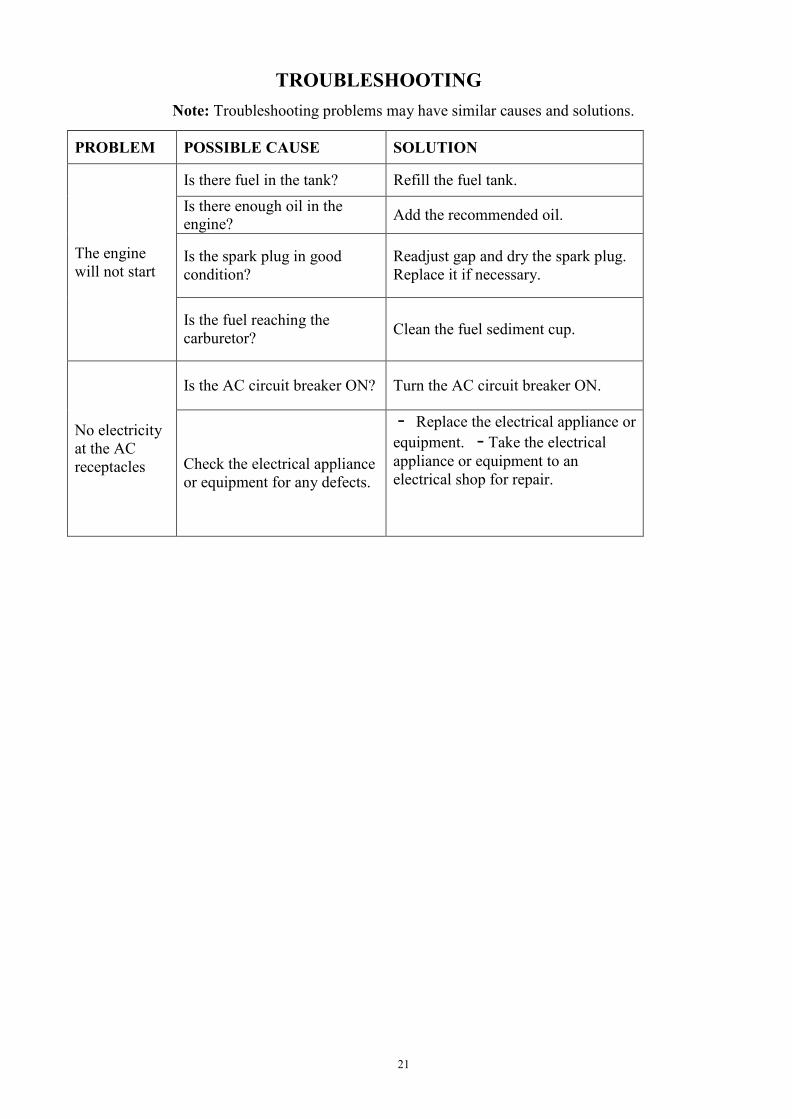
TROUBLESHOOTING
Note: Troubleshooting problems may have similar causes and solutions.
PROBLEM
POSSIBLE CAUSE
SOLUTION The engine will not start
Is there fuel in the tank? Refill the fuel tank. Is there enough oil in the engine?
Add the recommended oil. Is the spark plug in good condition?
Readjust gap and dry the spark plug. Replace it if necessary.
Is the fuel reaching the carburetor?
Clean the fuel sediment cup.
No electricity at the AC receptacles
Is the AC circuit breaker ON?
Turn the AC circuit breaker ON.
Check the electrical appliance or equipment for any defects.
· Replace the electrical appliance or equipment. ·Take the electrical appliance or equipment to an electrical shop for repair.
22
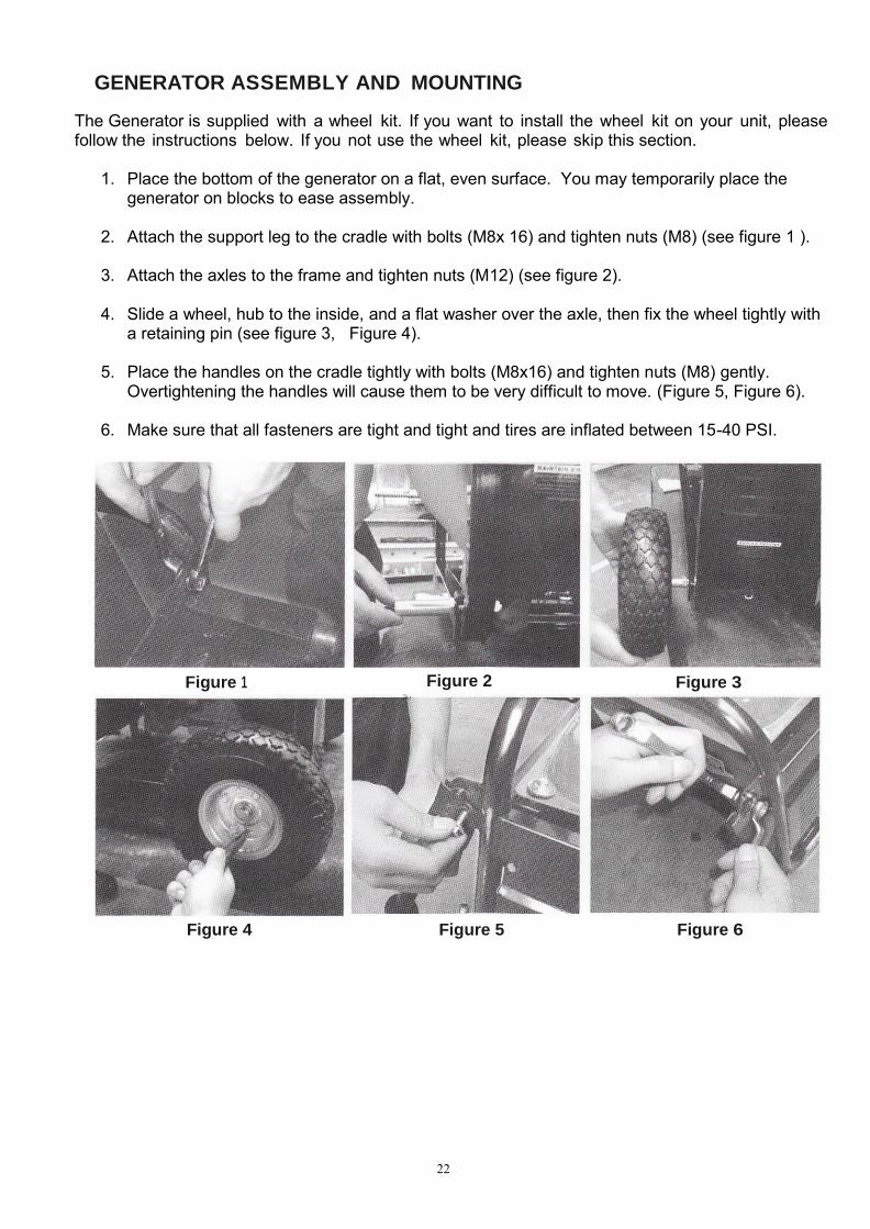
GENERATOR ASSEMBLY AND MOUNTING
The Generator is supplied with a wheel kit. If you want to install the wheel kit on your unit, please follow the instructions below. If you not use the wheel kit, please skip this section.
1. Place the bottom of the generator on a flat, even surface. You may temporarily place the generator on blocks to ease assembly.
2. Attach the support leg to the cradle with bolts (M8x 16) and tighten nuts (M8) (see figure 1 ).
3. Attach the axles to the frame and tighten nuts (M12) (see figure 2).
4. Slide a wheel, hub to the inside, and a flat washer over the axle, then fix the wheel tightly with a retaining pin (see figure 3, Figure 4).
5. Place the handles on the cradle tightly with bolts (M8x16) and tighten nuts (M8) gently.
Overtightening the handles will cause them to be very difficult to move. (Figure 5, Figure 6).
6. Make sure that all fasteners are tight and tight and tires are inflated between 15-40 PSI.
Figure 1 Figure 2 Figure 3
Figure 4 Figure 5 Figure 6

22
CHANGE THE CARBON-BRUSH CHANGE THE AVR

Maintenance Log
MODEL: XP12000EH Date Generator Hrs. Maintenance Performed

Product Support Product Information, Application, Service Info & Warranty Questions
Please email us at [email protected] or call (800) 629-3325 Monday - Friday 7am to 5pm. PST